Embed Size (px)
Citation preview
Recent advances in thermoelectric materials andsolar thermoelectric generators – a critical review
Pradeepkumar Sundarraj,a Dipak Maity,*a Susanta Sinha Royb and Robert A. Taylorc
Due to the fact that much of the world's best solar resources are inversely correlated with population
centers, significant motivation exists for developing technology which can deliver reliable and
autonomous conversion of sunlight into electricity. Thermoelectric generators are gaining incremental
ground in this area since they do not require moving parts and work well in remote locations.
Thermoelectric materials have been extensively used in space satellites, automobiles, and, more recently,
in solar thermal applications as power generators, known as solar thermoelectric generators (STEG).
STEG systems are gaining significant interest in both concentrated and non-concentrated systems and
have been employed in hybrid configurations with solar thermal and photovoltaic systems. In this article,
the key developments in the field of thermoelectric materials and on-going research work on STEG
design conducted by various researchers to date are critically reviewed. Finally, we highlight the strategic
research directions being undertaken to make highly efficient thermoelectric materials for developing a
cost-effective STEG system, which could serve to bring this technology towards commercial readiness.
A. IntroductionThe average global electric power consumption in 2011 wasestimated at 17.4 terawatts,1 but it is projected to be more thandouble and triple by 2050 and 2100, respectively.2–4 At theirpresent rate of use, economically recoverable fossil fuelresources will be severely depleted on these time scales(particularly if their full environmental cost is considered).5–8
Hence, a major global challenge is how to meet future energydemand in a renewable and sustainable manner. Solar-derivedelectricity represents a vast, largely untapped renewable energyresource, which can be harvested through either photovoltaic orthermal routes.5,9 In this paper, we review the progress of onethermal route in particular, solar thermoelectric generators(STEGs), which have recently been gaining research attentiondue to improvements in thermoelectric materials properties aswell as in STEG system design. These improvements, if sus-tained, could eventually result in a new class of efficient, costeffective solar to electricity conversion systems.8,10
A.1. Solar-to-electricity conversion technology
The average solar radiation received on Earth is about 162 000TW, whereas only a vanishingly small fraction of this power are
diverted towards electricity generation.1 Solar photovoltaic cells(PV) convert some of the solar spectrum directly into elec-tricity,11 while concentrated solar thermal (CST) technologiesrst convert incident solar energy to heat and then (usually) usethis heat to boil a working uid which drives a Rankine cycle.4,12
Various PV cells and CST system are compared in Table 1 withrespect to their operational temperature, concentration ratio(CR ¼ area of the collector/area of the receiver), and maximumefficiency. Laboratory scale PV modules have reached amaximum efficiency of about "29% and "44% was attained forPV and Concentrated photovoltaic (CPV) cell respectively(Table 1).13 However, commercially available solar PV modules,have efficiencies between 10–20%.14 Commercially, large-scaleCST projects have proven to be more efficient than PV cells.15
Solar thermal technologies use a structure (a collector) toreceive and absorb solar thermal radiation; these collectors canbe broadly classied into two types, non-concentrating andconcentrating. Collectors, which do not concentrate sunlight,can be stationary and do not require tracking mechanisms. Formost solar thermal electricity generation systems, however,concentration (and thus tracking) is required which adds to thesystem's capital cost. Another key component of the collector isthe receiver – a heat exchanger that absorbs sunlight andtransfers this energy as heat to a uid passing through it.7,16,17
Non-concentrating collectors are limited to a temperature rangefrom ambient to 240 #C, while, depending on the CR, concen-trating collectors (CST) can operate up to 1500 #C.7
Three prominent technologies dominate CST – parabolictrough collectors, solar towers, and dish systems.4 Linear Fres-nel system is rapidly emerging due to ease of manufacturing,
aDepartment of Mechanical Engineering, School of Engineering, Shiv Nadar University,203207, India. E-mail: [email protected]; Tel: +91-120-266700bDepartment of Physics, School of Natural Science, Shiv Nadar University, 203207,IndiacSchool of Mechanical and Manufacturing Engineering, School of Photovoltaic andRenewable Energy Engineering, University of New South Wales, Australia
Cite this: RSC Adv., 2014, 4, 46860
Received 4th June 2014Accepted 16th September 2014
DOI: 10.1039/c4ra05322b
www.rsc.org/advances
46860 | RSC Adv., 2014, 4, 46860–46874 This journal is © The Royal Society of Chemistry 2014
RSC Advances
REVIEW
operation and cost effectiveness,18 which can achieve peak plantefficiency of about 18%.15 Parabolic trough collectors haveproven to be the most successful commercial solar thermaltechnology,19 achieving a peak plant efficiency of about 20%.15
Even though parabolic troughs and solar towers have theiradvantages on large scale, dish systems where a Stirling engineis placed at the receiver can achieve a maximum efficiency ofabout 30%. Solar Dish-Stirling (SDS) systems have garnered a lotof interest because they are well suited for decentralized powersupply and stand-alone power applications.15,20,21 However,more information about the long term performance of CPV andSDS may be required in order to commercialize these system.
A.2. STEG technology
A thermoelectric device consists of both n- and p-type-semiconducting materials connected electrically in series andthermally in parallel.22–24 Thermoelectric generators (TEG)utilize the Seebeck effect, which generates voltage when oneside of the TEG is maintained at a higher temperaturecompared to the other side, due to the random thermal motionof charge carriers, which cause current to ow when the circuitis closed.22,23,25 As such, thermoelectrics represent reliable solid-state devices that convert heat directly into electricity and vice
versa.26,27 They are widely used in refrigerators, space applica-tions, remote sensing, electronics cooling, the automobileindustry, and have good potential for solar thermal powergeneration.28,29
The efficiency of a thermoelectric device depends on thematerials used. The most important material properties can belumped into a dimensionless gure of merit (zT) – dened aszT ¼ (S2s/k)T, where S, s, k and T are the Seebeck coefficient,electrical conductivity, thermal conductivity and absolutetemperature respectively.9,30–32 The numerator, S2s, constitutesto the electrical properties of the materials and is known widelyas thermoelectric power factor.33 The efficiency of an idealthermoelectric device, hTEG, can be written as a function of thetemperatures and the gure of merit, as follows:
hTEG ¼TH $ TC
ffiffiffiffiffiffiffiffiffiffiffiffiffiffiffiffiffiffiffiffiffiffiffiffiffiffiffiffiffi1þ ðzTMÞ $ 1
p
TH
ffiffiffiffiffiffiffiffiffiffiffiffiffiffiffiffiffiffiffiffiffiffiffiffiffiffiffiffiffiffiffiffiffi1þ ðzTMÞ þ
TC
TH
r (1)
where TC is the cold-side temperature, TH is the hot-sidetemperature, and (zTM) is the effective gure of merit of thethermoelectric material between TC and TH.9,32,34 Considerableglobal research efforts have been dedicated to enhance the zT ofthermoelectric materials.35–41
Table 1 Efficiency and operating temperature of few solar energy conversion technologies13,15
System T #C CR h – max
I. Solar photovoltaic (PV)Silicon (Si) crystalline 25 1 25.0 ( 0.5Gallium arsenide (GaAs) thin lm 25 1 28.8 ( 0.9Indium phosphide (InP) crystalline 25 1 22.1 ( 0.7Copper Indium Gallium Diselenide (CIS/CIGS) cell 25 1 19.8 ( 0.6Cadmium Telluride (CdTe) cell 25 1 19.6 ( 0.4Dye-sensitized solar cell (DSSC) 25 1 11.9 ( 0.4Organic or Polymer (OPV) thin lm 25 1 10.7 ( 0.3
II. Concentrated photovoltaic (CPV)Copper Indium Gallium Diselenide (CIS/CIGS) thin lm — 15 22.8 ( 0.9Silicon (Si) single cell — 92 27.6 ( 1.0Gallium arsenide (GaAs) single cell — 117 29.1 ( 1.3InGaP/GaAs/InGaAs — 302 44.4 ( 2.6
III. Concentrated solar thermal (CST)Linear Fresnel Lens (LFL) 390 60–80 18Parabolic Trough Collector (PTC) 350–550 70–80 20Solar Tower (ST) 250–565 >1000 20Solar Dish-Stirling (SDS) 550–750 >1300 30
Fig. 1 Thermoelectric generator deployed in different solar thermal systems.
This journal is © The Royal Society of Chemistry 2014 RSC Adv., 2014, 4, 46860–46874 | 46861
Review RSC Advances
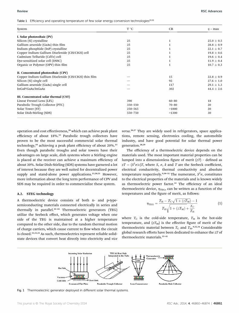
The use of solar thermal technologies for electrical powergeneration with the help of thermoelectric materials was knownsince 19th century.42,43 Solar Thermoelectric Generators, use acollector, a thermoelectric generator, and a heat sink. Incidentsolar ux on the thermoelectric generator can be varied withseveral collector options such as evacuated at plate; parabolictroughs; Fresnel lenses; and parabolic dishes (as shown inFig. 1). Heat sink are used a cooling system to dissipate heatfrom the cold side of the TEG. Recently, instead of using heatsinks, the rejected heat from the cold side of the TEG has beenutilized in heating/absorption cooling applications or even forsecondary power generation cycles (increasing the overall effi-ciency of the system),44,45 and these modied systems are calledas hybrid systems.
STEG system efficiency depends on the optical and thermalefficiency of the collector and the zT value of the thermoelectricmaterials.46–48 The maximum efficiency for a STEG enclosed inan evacuated glass chamber where hot side coated with aselective absorber coating can be evaluated as follows:46
hSTEG ¼"sgaShop $
3esB
#TH
4 $ TC4$
CR) qi
%) ½hTEG+ (2)
where sg,aS,hop,3e,sB and qi are the transmittance of the glassenclosure, absorptance of the selective surface to the solar ux,optical concentration efficiency, effective emittance of theabsorber and the envelope, Stephen Boltzmann constant andthe incident solar ux, respectively. Effect of enclosing the STEGinside an evacuated chamber is discussed in later in section C1.Improvements in STEG system design can be achieved byincreasing the temperature difference across the TEG and/or byreducing the heat loss from the system and by several othermeans. Materials enhancements can be achieved by increasingthe zT values by tuning the materials properties throughcontrolled synthesis techniques.
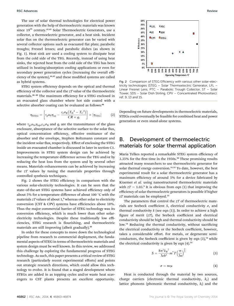
Fig. 2 shows the STEG efficiency in comparison with thevarious solar-electricity technologies. It can be seen that thestate–of-the-art STEG systems have achieved efficiency only ofabout 5% for a temperature difference of about 100 #C with thematerials zT values of about 1,9 whereas other solar to electricityconversion (CST & CPV) systems have efficiencies above 18%.Thus the major commercial barrier of STEG technology was itsconversion efficiency, which is much lower than other solar-electricity technologies. Despite these traditionally low effi-ciencies, STEG research is ourishing, and thermoelectricmaterials are still improving (albeit gradually).49
In order for these concepts to move down the technologicalpipeline from research to commercial deployment, the funda-mental aspects of STEG in terms of thermoelectricmaterials andsystem design must be well known. In this review, we addressedthis challenge by exploring the fundamental progress of STEGtechnology. As such, this paper presents a critical review of STEGresearch (particularly recent experimental efforts) and pointsout strategic research directions, which could allow this tech-nology to evolve. It is found that a staged development whereSTEGs are added in as topping cycles and/or waste heat scav-engers to CST plants presents an excellent opportunity.
Depending on future developments in thermoelectric materials,STEGs could eventually be feasible for combined heat and powergeneration or even stand-alone systems.
B. Development of thermoelectricmaterials for solar thermal applicationMaria Telkes reported a remarkable STEG system efficiency of3.35% for the rst time in the 1950s.50 These promising resultsattracted many researchers to use thermoelectric generator forsolar thermal energy conversion.51,52 To date, however, the bestexperimental result for a solar thermoelectric generator has amaximum efficiency of around 5% for a device fabricated byKraemer et al. using nanostructured thermoelectric materialswith zT ¼ 1.03.9 It is obvious from eqn (1) that improving theefficiency of solar thermoelectric generators is possible if higherzT materials can be employed.53
The parameters that control the zT of thermoelectric mate-rials are Seebeck coefficient S, electrical conductivity s, andthermal conductivity k (see eqn (1)). In order to achieve a highgure of merit (zT), the Seebeck coefficient and electricalconductivity should be high and thermal conductivity should below.54 Reducing the thermal conductivity, without sacricingthe electrical conductivity or the Seebeck coefficient, however,takes a considerable effort. For metals, or degenerate semi-conductors, the Seebeck coefficient is given by eqn (3),54 whilethe electrical conductivity is given by eqn (4).55
S ¼ 8p2kB2
3eh2m*T
&p
3n
'23 (3)
s ¼ nem (4)
Heat is conducted through the material by two sources,charge carriers (electronic thermal conductivity, ke) andlattice phonons (phononic thermal conductivity, kl) and the
Fig. 2 Comparison of STEG Efficiency with various other solar-elec-tricity technologies (STEG – Solar Thermoelectric Generator, LFL –Linear Fresnel Lens, PTC – Parabolic Trough Collector, ST – SolarTower, SDS – Solar Dish Stirling, CPV – Concentrated Photovoltaic):ref. 9, 13 and 15.
46862 | RSC Adv., 2014, 4, 46860–46874 This journal is © The Royal Society of Chemistry 2014
RSC Advances Review
thermal conductivity will be low when kl and ke are low (seeeqn (5) and (6)).32,56,57
k ¼ kl + ke (5)
ke ¼ LnemT (6)
From eqn (3)–(6), we can see that conicts arise in optimizingthe zT of the thermoelectric materials. For an example, if we justconcentrate on increasing the Seebeck coefficient, the effectivemass (m*) should be high, but on the other hand the electricalconductivity will be reduced (as mobility, m is inversely propor-tional to m*). Recent studies, however, show that the key forachieving higher zT through band structure engineering shouldbe low effective mass along the transport direction.58 Hencematerial scientists are trying to nd different ways to optimizethe material properties to maximize the zT values.23,59,60
Different elements from group III–VI and their alloys werestudied to have better understanding about the thermoelectricphenomenon, in order to enhance the thermoelectric zT.61–74
Conventional bulk thermoelectric materials reached their limitsof zT $ 1,75,76 but recent advances in nanostructured thermo-electric materials have opened the door to obtain higher zTvalues.25,54,76 The idea of nanostructuring to enhance the ther-moelectric effect of materials was rst showed by Hicks andDresselhaus in their theoretical study.53 Hicks et al. publishedexperimental data verifying this in 1996.77 They estimated thatthe zT value can be larger than 2 for PbTe quantum wellsconned by a Pb0.927Eu0.073Te barrier layer. Subsequently ther-moelectric materials with zT values of "2 (Bi2Te3/Sb2Te Super-lattices Nanodots) and "2.4 (PbTe/PbTeSe Superlattices) atroom temperature have been reported by Harman et al.78 andVenkatasubramanian et al.,79 respectively. A remarkable zTvalue of "3 (Bi doped PbSeTe/PbTe Quantum dot Superlattices)at 277 #C was recently reported by Harman et al.80 However,thermoelectric materials with superlattices and nanodotsstructures have proven to be challenging for use in large-scaleenergy-conversion applications, due to restrictions in heattransfer, reproducibility and high manufacturing cost.81
Nanocomposites have proven to overcome these problemsmentioned above. The most common route of nanocompositesynthesis is a two-step method; high-energy ball milling and hotpressing. Enhancements in zT are attained by effectivelyreducing the particle size to nano scale dimension.76,82 Anothertechnique used to nd thermoelectric bulk materials withcomplex crystal structures (with enhanced zT values) was rstproposed by Slack.32,83 Slack suggested that ideal bulk thermo-electric materials should have thermal conductivity like glassand electrical conductivity like a crystal known as phonon-glasselectron-crystal (PGEC).32,83 Skutterudites and calthrates are thetypical materials that exhibit this kind of structure. Thesematerials have intrinsic void in the open cage crystal structure,where by introducing a guest atom or molecule into the voidfound to reduce the lattice thermal conductivity.56 Researchermostly utilized these two techniques over the last two decades tond efficient thermoelectric materials – both of which serve toreduce the lattice thermal conductivity.54,82
Even aer several decades of research, the best commerciallyavailable bulk thermoelectric materials are bismuth telluridebased alloys (maximum zT " 1).84 Several other materials areproven to have high zT on a laboratory scale, but are not usefulas commercial products. For example, type I calthrates have apeak zT " 1.35 at 627 #C for n-type Ba8Ga16Ge30,85 but, unfor-tunately its p-type (Ba8Ga16Al3Ge27) has a relatively low value zTof"0.6 at 487 #C.86 Thus, unless improvements in zT values of p-type calthrates are made, the overall device is unlikely to besignicantly better than bismuth telluride. As another example,p-type b-Zn4Sb3 has a tendency to show a decay in its thermo-electric properties upon thermal cycling (a key operationalrequirement for a solar power system).87 For many potentialthermoelectric materials, rarity in the Earth's crust (e.g. Tellu-rium) and their demand in other products, raise their pricesabove levels which would not allow them to be competitive withother technologies like solar photovoltaic cells.88,89 Toxicity andother handling issues, also present problems.33,88
In the next section, developments of potential thermoelectricmaterials like Bi2Te3 alloys, PbTe/PbSe alloys, Skutterudites,Half-heuslers compounds and SiGe alloys and its zT enhance-ments are discussed (shown in Table 2). Followed which, theirimpact on solar thermoelectric energy conversion is briefed.
B.1. BiTe alloys
The most established material in the eld of thermoelectrics isBi2Te3 and its alloys Bi2Se3 and Sb2Te3.122 Bismuth and tellu-rium are heavy elements, which make them suitable for ther-moelectrics, since heavy elements have small phonon groupvelocity, low thermal conductivity, small band gaps and largecharge mobility.55 Experimental results for various bismuthtelluride alloys are listed in Table 2. Nanocomposites (p-typeBi0.5Sb1.5Te3 and n-type Bi2Te2.7Se0.3) synthesized by high-energy ball milling and hot pressing achieved a peak value ofzT " 1.4 at 100 #C and "1.04 at 125 #C, respectively. This ismuch improved from the baseline bulk material which has azT " 1.81,90 Poudel et al. found that the average grain size is20 nm for p-type Bi0.5Sb1.5Te3.81 An average grain size of about1–2 mmwas calculated for n-type Bi2Te2.7Se0.3 by Yan et al.90 Theenhanced zT value of p-type Bi0.5Sb1.5Te3 and n-typeBi2Te2.7Se0.3 was achieved, due to the signicant reduction inthe lattice thermal conductivity by strong boundary scattering(owing to the presence of small grain sizes) of phonon at theinterfaces of the nanostructures.81,90
p-type Bi0.48Sb1.52Te3, Bi0.52Sb1.48Te3, 0.3 vol.% Al2O3/Bi0.5-Sb1.5Te3 materials, synthesized by spark plasma-sinteringmethod (have zT $ 1.5 as listed in Table 2), are better thanthe nanocomposite prepared by high-energy ball millingmethod.92,93,95 This is because the nanocomposite prepared byspark plasma-sintering method have coherent grain bound-aries, whereas nanocomposites prepared by ball milling arerandom.92 Inclusion of nanostructured particles in either bulkor nanocomposite materials is known as “nanoinclusion”, andhas been shown to reduce the lattice thermal conductivitywithout signicantly affecting the thermoelectric power factor.94
Fan et al., using above technique, synthesized p-type
This journal is © The Royal Society of Chemistry 2014 RSC Adv., 2014, 4, 46860–46874 | 46863
Review RSC Advances
Bi0.4Sb1.6Te3 to make a nanocomposite which consist of 40%nanostructured particles (<200 nm) and 60% micron-sizedparticles and reported a high zT value of 1.8 at 43 #C.94
Cao et al. utilized a simple hydrothermal technique tosynthesize p-type (BiSb)2Te3, where a zT " 1.47 at 167 #C wasachieved.91 Keunakim et al. used a cost effective strain assistedtechnique to synthesize p-type Bi0.45Sb1.55Te3, where Z wasincreasedby a factorof"2over thenon-strainedsamples.123Eventhough the zT values are less for the materials synthesizedthrough these procedures than thehighest value of zT attained inBi2Te3, however, these synthesis procedures have a lot of poten-tial due to their simplicity, scalability, and cost effectiveness.
B.2. PbTe and PbSe alloys
PbTe is also a heavy material, like Bi2Te3, and its bulk alloyhas a zT of "0.7 at 467 #C. PbTe alloys with PbSe and SnTeexhibited a zT of "1, were used in power generation.30,124
(AgSbTe2)x(PbTe)1$x (also known by the acronym LAST) and(AgSbTe2)1$x(GeTe)x (known as TAGS) are other classicalthermoelectric materials which display very good thermo-electric properties, and have been extensively studied sincethe 1960s.30,54,125 TAGS, with zT " 1.2 p-type, has beenemployed in power generation for a long time, due to itssuperior thermal stability over LAST.54 PbTe and its alloyshave been dominant in thermoelectric power generation overthe past few decades for temperature above 300 #C.54,84
Experimental results of various PbTe alloys, with respectivezT values ranges from 1.20 to 2.20 are listed in Table 2. A peak zTof 2.2 at 527 #C was achieved for n-type AgPb18SbTe20 synthe-sized using the melt growth method.96 Such high values of zTwere achieved through placement of nano precipitates (Ag andSb) in the crystal matrix, which enabled a reduction of latticethermal conductivity.100,126 Similar effects were found for n-type(Pb0.95Sn0.05Te)0.92(PbS)0.08 and Ag0.53Pb18Sb1.2Te20 as well as p-type Ag0.5Pb6Sn2Sb0.2Te10, Na0.95Pb20SbTe22 and 2% Na dopedPbTe–PbS.98,100–102,104 Alternatively, enhancement in the ther-moelectric power factor found in n-type Pb9.6Sb0.2Te3Se7 and p-type Tl0.02Pb0.98Te was due multiple valance bands and theintroduction of resonant electronic states in the valance band,respectively.97,103 Another high value of zT " 2.2 at 642 #C wasachieved in PbTe–SrTe doped with Na, due to the nanoinclusionof 2–10 nm endotaxial SrTe nanocrystals in Na doped PbTematrix.106
PbSe is considered an alternative to PbTe, since the abun-dance of Tellurium in the Earth's crust is less than 0.001 ppm,while Selenium is 0.5 ppm.88 Aluminum doped PbSe (n-type)has a zT of "1.3 and Sodium doped PbSe (p-type) has a zT of"1.2 at 577 #C, but both zT values are less than that of goodPbTe alloys.107,108 Recently, adding small quantities of Sr in PbSeshowed that enhances in zT, where maximum zT was "1.5 at657 #C, was demonstrated by JeffreyaSnyder et al.109
B.3. Skutterudites
Skutterudites are another potential thermoelectric material,which has lower thermal conduction due their complex crystalstructures and are widely explored for power generation appli-cations.84 MX3 is the chemical formula for skutterudites, whereM is Co, Rh or Ir and X is P, As or Sb. Because of large voids inthe crystal cage structure, it favors incorporation of small guestions into its intrinsic sites which forms the lled skutterudites(TyM4X12).56,127 Ty, the guest atom in the crystal structure isresponsible for strong low frequency phonon scattering, thephenomenon known widely as “rattling effect”.56,84 Scattering oflow frequency phonons through conventional methods is ratherdifficult.56 CoSb3 based skutterudites have been studied exten-sively because of the abundance of the constituent elementsand its versatility of accepting various lanthanides, actinides,alkaline earth metals, alkalis, and Group IV elements for use invoid-lling.82,127 Filled, unlled andmultiple lled Skutterudites
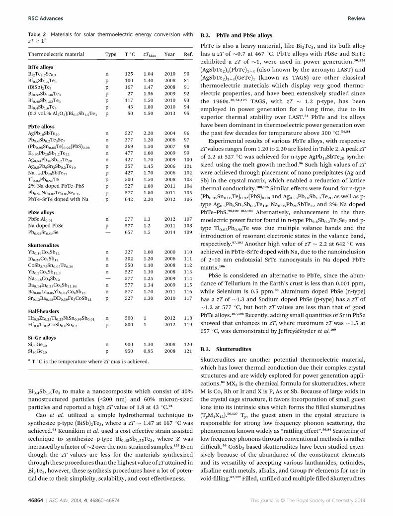
Table 2 Materials for solar thermoelectric energy conversion withzT $ 1a
Thermoelectric material Type T #C zTMax Year Ref.
BiTe alloysBi2Te2.7Se0.3 n 125 1.04 2010 90Bi0.5Sb1.5Te3 p 100 1.40 2008 81(BiSb)2Te3 p 167 1.47 2008 91Bi0.52Sb1.48Te3 p 27 1.56 2009 92Bi0.48Sb1.52Te3 p 117 1.50 2010 93Bi0.4Sb1.6Te3 p 43 1.80 2010 94(0.3 vol.% Al2O3)/Bi0.5Sb1.5Te3 p 50 1.50 2013 95
PbTe alloysAgPb18SbTe20 n 527 2.20 2004 96Pb9.6Sb0.2Te3Se7 n 377 1.20 2006 97(Pb0.95Sn0.05Te)0.92(PbS)0.08 n 369 1.50 2007 98K0.95Pb20Sb1.2Te22 n 477 1.60 2009 99Ag0.53Pb18Sb1.2Te20 n 427 1.70 2009 100Ag0.5Pb6Sn2Sb0.2Te10 p 357 1.45 2006 101Na0.95Pb20SbTe22 p 427 1.70 2006 102Tl0.02Pb0.98Te p 500 1.50 2008 1032% Na doped PbTe–PbS p 527 1.80 2011 104Pb0.98Na0.02Te0.85Se0.15 p 577 1.80 2011 105PbTe–SrTe doped with Na p 642 2.20 2012 106
PbSe alloysPbSe:Al0.01 n 577 1.3 2012 107Na doped PbSe p 577 1.2 2011 108Pb0.92Sr0.08Se — 657 1.5 2014 109
SkutteruditesYb0.19Co4Sb12 n 327 1.00 2000 110In0.25Co4Sb12 n 302 1.20 2006 111CoSb2.75Sn0.05Te0.20 n 550 1.10 2008 112Yb0.2Co4Sb12.3 n 527 1.30 2008 113Na0.48Co4Sb12 — 577 1.25 2009 114Ba0.14In0.23Co4Sb11.84 n 577 1.34 2009 115Ba0.08La0.05Yb0.04Co4Sb12 n 577 1.70 2011 116Sr0.12Ba0.18DD0.39Fe3CoSb12 p 527 1.30 2010 117
Half-heuslersHf0.5Zr0.25Ti0.25NiSn0.99Sb0.01 n 500 1 2012 118Hf0.8Ti0.2CoSb0.8Sn0.2 p 800 1 2012 119
Si–Ge alloysSi80Ge20 n 900 1.30 2008 120Si80Ge20 p 950 0.95 2008 121
a T #C is the temperature where zT max is achieved.
46864 | RSC Adv., 2014, 4, 46860–46874 This journal is © The Royal Society of Chemistry 2014
RSC Advances Review
that have zT$ 1 is listed in Table 2.112–117 It has to be noted thatnano structuring skutterudites will further decrease the thermalconductivity and a peak value zT " 1.7 at 577 #C reported for n-type Ba0.08La0.05Yb0.04Co4Sb12 synthesized using high-energyball milling and spark plasma-sintering nano structuringmethods.116 Improvements in the zT values of p-type skutter-udites were not in same pace in comparison to its n-typecounterpart, because lling tends to push them into stronglytowards n-type materials.128
B.4. Half-heuslers
Another promising thermoelectric material which has highthermal stability is half heuslers (HH) compounds.32 Halfheuslers compounds are intermetallic compounds with highSeebeck coefficient and relatively higher thermal conduc-tivity.32,84 Higher thermal conductivity in HH is the reason,which hindered the development of these materials.Conversely, nano structuring of these compounds proved toreduce their lattice thermal conductivity due to phonon scat-tering. Similar effect is evident in the n-type Hf0.5Zr0.25Ti0.25-NiSn0.99Sb0.01 synthesized using high-energy ball milling andhot pressing and p-type Hf0.8Ti0.2CoSb0.8Sn0.2 synthesized usingArc Melting, high-energy ball milling and hot pressing. Thesenanostructuredmaterials had a peak zT" 1 at 500 #C and zT" 1at 800 #C, which was higher than that of their bulkstructure.118,119
B.5. SiGe alloys
SiGe alloys are other important materials, which are suitable forhigh temperature applications because they have very lowdegradation, even up to 1000 #C. Bulk Si0.8Ge0.2 has a zT of "1
and 0.6, for n and p-type, respectively.129 Nanostructured silicongermanium alloys were proven to have an enhanced zT valuescompared to their bulk alloys. SiGe nanocomposite, prepared byhigh-energy ball milling and hot Pressing, have zT " 1.3 at 900#C and zT " 1 at 900–950 #C, where its bulk material possess zT" 1 and zT "0.6.120,121 SiGe alloys are costlier than other ther-moelectric materials and mostly used in space power applica-tions where solar cells could not be used.130
Overall, nanocomposites thermoelectric materials haveplayed a signicant role in improving zT values. These materialseffectively decrease the thermal conductivity by reducingparticle size, which helps to scatter the phonon at the inter-faces. In some of the nanocomposite, nanoprecipitate in thecrystal matrix tends to scatter low frequency phonons throughrattling effect, which reduces the thermal conductivity withoutsignicantly affecting the power factor. Thermoelectric powerfactor on the other hand was improved by having multiple and/or resonant electronic state in the valance band. Some the bulkthermoelectric materials also found to reduce the thermalconductivity by having complex crystal structure through therattling effect. Nanocomposite thermoelectric materials couldbe used in solar thermal power generation applications, if theycan be developed cost effective and efficient. These develop-ments would lead to lay the pathway for energy efficient solarconversion technology.
C. Development of solarthermoelectric generator (STEG)For solar thermal applications, different types of thermoelectricmaterials with a wide temperature range (from 30 #C to 1000 #C)are available that can be used for power generation. For
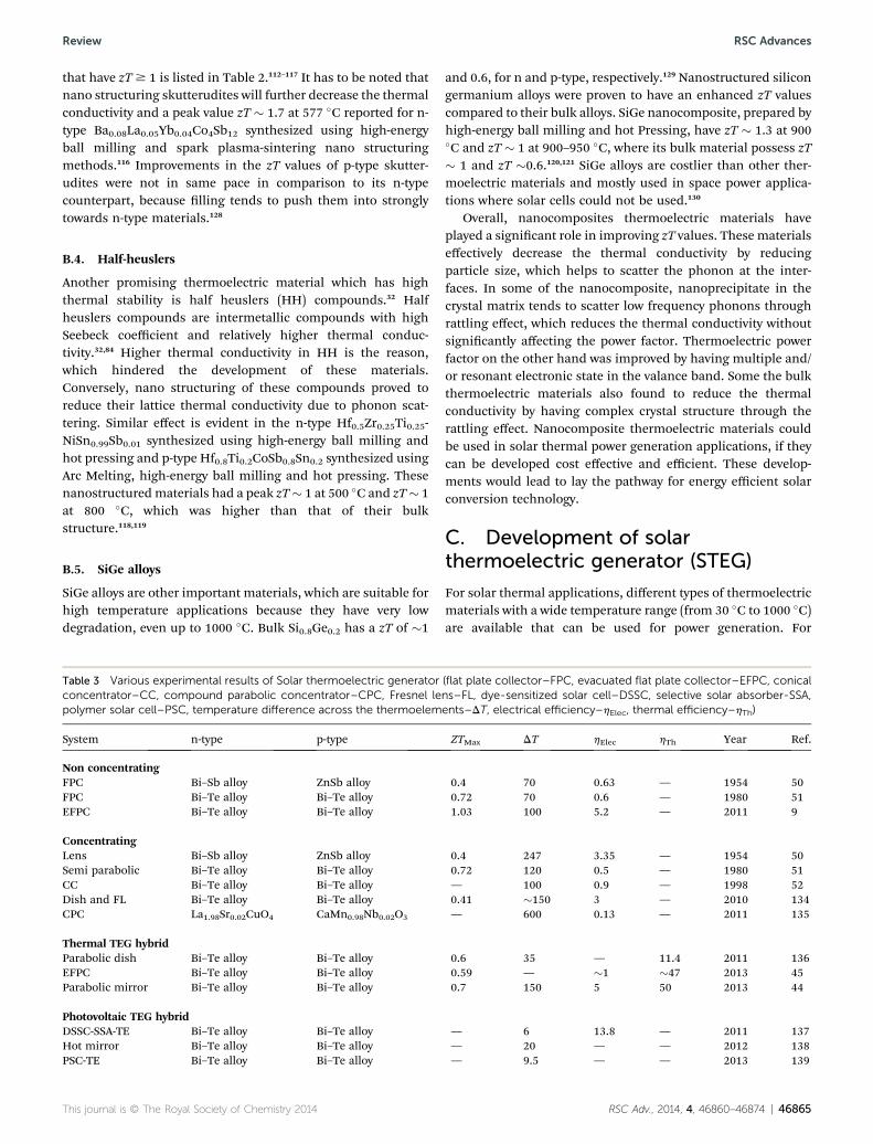
Table 3 Various experimental results of Solar thermoelectric generator (flat plate collector–FPC, evacuated flat plate collector–EFPC, conicalconcentrator–CC, compound parabolic concentrator–CPC, Fresnel lens–FL, dye-sensitized solar cell–DSSC, selective solar absorber-SSA,polymer solar cell–PSC, temperature difference across the thermoelements–DT, electrical efficiency–hElec, thermal efficiency–hTh)
System n-type p-type ZTMax DT hElec hTh Year Ref.
Non concentratingFPC Bi–Sb alloy ZnSb alloy 0.4 70 0.63 — 1954 50FPC Bi–Te alloy Bi–Te alloy 0.72 70 0.6 — 1980 51EFPC Bi–Te alloy Bi–Te alloy 1.03 100 5.2 — 2011 9
ConcentratingLens Bi–Sb alloy ZnSb alloy 0.4 247 3.35 — 1954 50Semi parabolic Bi–Te alloy Bi–Te alloy 0.72 120 0.5 — 1980 51CC Bi–Te alloy Bi–Te alloy — 100 0.9 — 1998 52Dish and FL Bi–Te alloy Bi–Te alloy 0.41 "150 3 — 2010 134CPC La1.98Sr0.02CuO4 CaMn0.98Nb0.02O3 — 600 0.13 — 2011 135
Thermal TEG hybridParabolic dish Bi–Te alloy Bi–Te alloy 0.6 35 — 11.4 2011 136EFPC Bi–Te alloy Bi–Te alloy 0.59 — "1 "47 2013 45Parabolic mirror Bi–Te alloy Bi–Te alloy 0.7 150 5 50 2013 44
Photovoltaic TEG hybridDSSC-SSA-TE Bi–Te alloy Bi–Te alloy — 6 13.8 — 2011 137Hot mirror Bi–Te alloy Bi–Te alloy — 20 — — 2012 138PSC-TE Bi–Te alloy Bi–Te alloy — 9.5 — — 2013 139
This journal is © The Royal Society of Chemistry 2014 RSC Adv., 2014, 4, 46860–46874 | 46865
Review RSC Advances
instance, bismuth telluride alloys can be used in low tempera-ture solar thermal applications (e.g. evacuated tube systems),that can operate from 30 to 200 #C.9,131 PbTe/PbSe alloys, skut-terudites and half-heuslers compounds can be utilized in themedium temperature solar thermal applications (e.g. parabolictrough and linear Fresnel collectors) that can operate from 200to 500 #C.131 For high temperature solar thermal applications(e.g. solar towers and larger parabolic dishes), SiGe alloys aresuitable since they can operate under extreme temperature forlong time periods with small degradation in the materialproperties.130,131 This implies that detailed experimental studieson solar thermoelectric generators fabricated using thesematerials are needed and may lead to develop solar thermo-electric system competitive to solar PV and CST technologies.4
Recent developments in the eld of thermoelectrics (as dis-cussed above) have attracted many researchers to integratethermoelectric materials into solar-electricity conversion tech-nologies. These systems can be broadly classied into four types(i) non-concentrated STEGs, (ii) concentrated STEGs, (iii)thermal TEG hybrids, and (iv) photovoltaic TEG hybrids. Inliterature good theoretical design and proposal on STEG areavailable,132,133 however, in the forth-coming sections onlyprominent experimental works are considered for review.Table 3 shows experimental values of different types of STEGsystem.
C.1. Non-concentrated and concentrated STEG
The idea of using thermoelectric generator in solar thermaltechnologies has been an area of interest since 1954, whenTelkes published a detailed summary of her remarkable work.50
Telkes used four different types of thermoelements and foundthat the most efficient were thermoelements made of a p-typeZnSb (Sn, Ag, Bi) and an n-type 91% Bi+9% Sb. The maximumefficiency of these (zT ¼ 0.4) with a double-paned at platecollector was 0.63% for a 70 #C temperature difference acrossthe thermoelements.50 Using a concentrated system with a lens(50 times optical concentrations), an efficiency of 3.35% wasreported for a temperature difference of "247 #C across ther-moelements.50 She also suggested that use of water, as thecoolant for the cold side of the thermoelements would providehot water as the byproduct. Even almost aer six decades ofresearch since 1950s, the efficiency of STEG hasn't improved alot; even some of the STEG systems have efficiency lesser thanthat of Telkes system. Brief studies on the experimental resultsof the researchers are presented in this section to show readerabout the further scope for improvements in STEG systemdesign.
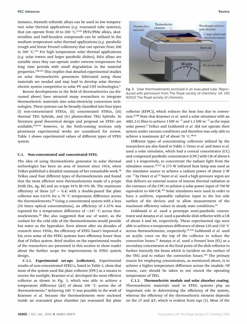
C.1.1. Experimental set-ups (collectors). Experimentalresults of non-concentrated STEG's, listed in Table 3, show thatmost of the system used at plate collector (FPC) as a means toreceive the sunlight. Kraemer et al. developed the most efficientcollector as shown in Fig. 3, which was able to achieve atemperature difference (DT) of about 100 #C across the ofthermoelements.9 Achieving 100 #C was possible in the work ofKraemer et al. because the thermoelements were enclosedinside an evacuated glass chamber (an evacuated at plate
collector (EFPC)), which reduces the heat loss due to convec-tion.9,140 Note that Kraemer et al. used a solar simulator with anAM1.5 G lter to achieve 1 kWm$2 and 1.5 kWm$2 as the inputsolar power.9 Telkes and Goldsmid et al. did not operate theirsystem under vacuum conditions and therefore was only able toachieve a maximum DT of about 70 #C.50,51
Different types of concentrating collectors utilized by theresearchers are also listed in Table 3. Omer et al. and Suter et al.used a solar simulator, which had a conical concentrator (CC)and compound parabolic concentrator (CPC) with CR of about 6and 1.4 respectively, to concentrate the radiant light from thesimulator source.52,135 A 175 W infrared heat lamp was used asthe simulator source to achieve a radiant power of about 2 Wcm$2 by Omer et al.52 Suter et al. used a high-pressure argon arcthat delivers an external source of intense thermal radiation atthe entrance of the CPC to achieve a solar power input of 700 Wequivalent to 600 CR.135 Solar simulators were used in order tohave a uniform, repeatable radiation input to the hot sidesurface of the devices and to allow measurement of themaximum efficiency values in steady state conditions.52
Goldsmid et al. used a prototype semi-parabolic concen-trator and Amatya et al. used a parabolic dish reector with a CRof about 4 and 66, respectively. These experimental rigs wereable to achieve a temperature difference of about 120 and 150 #Cacross thermoelements, respectively.51,134 Goldsmid et al. usedan acrylic cover on the top of the collector to reduce theconvection losses.51 Amatya et al. used a Fresnel lens (FL) as asecondary concentrator at the focal point of the dish reector tofurther intensify the beam which is incident on the surface ofthe TEG and to reduce the convection losses.134 The primaryreason for employing concentrators, as mentioned above, is toachieve a higher temperature difference across the module. Ofcourse, care should be taken to not exceed the operatingtemperature of TEG.
C.1.2. Thermoelectric module and solar absorber coating.Thermoelectric materials used in STEG systems play animportant role in determining the efficiency of the system,whereas the efficiency of the thermoelectric element dependson the zT and DT, which is evident from eqn (1). Most of the
Fig. 3 Solar thermoelements enclosed in an evacuated tube. Repro-duced with permission from The Royal society of chemistry: ref. 140©2012 The Royal society of chemistry.
46866 | RSC Adv., 2014, 4, 46860–46874 This journal is © The Royal Society of Chemistry 2014
RSC Advances Review
non-concentrated and concentrated systems listed in Table 3used TEG made using bulk bismuth telluride alloys having ZTaround 0.4 to 0.7, which are most widely available. Goldsmidet al. used a single junction Bi2Te3 TEG having nickel-platedends soldered to copper connectors to withstand a tempera-ture of about 180 #C with an aluminum heat sink.51 Suter et al.used n-type La1.98Sr0.02CuO4 and p-type CaMn0.98Nb0.02O3 as thethermoelements with Al2O3 as the absorber and cooling plateswith water cooled system to cool the cavity.135 Even though Suteret al. used thermoelements with a low ZT, it demonstrates theconcept of using a solar cavity-receiver in a 1 kW prototype(consisting of 18 TEG modules).135 Kraemer et al. used nano-structured thermoelements of n- and p-type bismuth telluridealloys having a relatively high zT of "1.03, sandwiched betweencopper plates.9
The hot side of the TEGs in all tests was either painted blackor coated with a Selective Solar Absorber (SSA) to improve theabsorbance of solar radiation and to reduce the emission losses,which in turn increases the hot side temperature.52,134 Goldsmidet al., Omer et al. and Suter et al. used matt black paint, blackpaint and a graphite coating respectively.51,52,135 Amatya et al.used a SSA consists of silicon polymer as a binder with an oxidepigment with absorptivity and emissivity of about (0.88–0.95)and (0.2–0.4), respectively.134 Kraemer et al. used a SSA with anabsorptivity and emissivity of about 0.94 and 0.5 respectively.9
Temperature difference across the TEG (SSA coated) is found tobe increased by 10% as compared to the ordinary blackpaints.134
C.1.3. Efficiency and cost of the STEG system. Electricalefficiencies (hElec) of the reviewed non-concentrated andconcentrated systems are listed in Table 3. Overall these were inthe ranges of 0.13–5.20% with the best non-concentratedcollector system developed by Kraemer et al. achieved a peakefficiency of 4.6% at 1 kWm$2 and 5.2% at 1.5 kWm$2 (with thecold side maintained at 20 #C.9 Kraemer et al. estimated the costof the thermoelectric materials to be about $0.17 per electricalWatt generated and predicted that further reduction is possibleby using smaller thermoelements. They also predicted that theefficiency of the system can reach a maximum of 14%, when thematerials zT values, optical concentration, and absorbertemperature are kept at 2, 10) and "300 #C, respectively.9
Though some of the non-concentrated systems utilized ther-moelectric material with nominal ZT value, the resulting systemefficiencies are lower than those predicted by eqn (1).50,51 This isdue to heat losses in the system that could potentially beimproved with good design like Kraemer et al. had used.9,50,51
Concentrated system developed by Amatya et al. achieved asystem efficiency of about 3% with output power of 1.8 W andthey have proposed that the use of novel thermoelectric mate-rials such as n-type ErAs:(InGaAs)1$x(InAlAs)x and p-type(AgSbTe)x(PbSnTe)1$x with a CR of 120 suns, the conversionefficiency can reach maximum value of 5.6%.134 Amatya et al.calculated the cost of the module to be about $1.6 per Watt,which is an order of magnitude higher than the thermoelectricmaterial cost estimated by Kraemer et al. The discrepancy is dueto the cost of the ceramics used to fabricate the TEG module.141
However, a very recent and detailed estimate by Yee et al. shows
that the cost of the total TEG system could be as low as $0.41 perWatt, which implies that STEG has potential to be competitivewith other solar to electricity conversion technologies.89,134
Concentrated STEG systems used by Goldsmid et al., Omer et al.and Suter et al. have shown very low system efficiencies thanthose predicted by eqn (1), because of the use of poor systemdesign as discussed above (in the previous sub sections).51,52,135
In essence a good STEG should use (1) thermoelectricmodules with nominal ZT > 0.7, (2) SSA with absorptivity andemissivity of about (0.88–0.95) and (0.2–0.5), and (3) propersystem design to reduce convective losses (e.g. vacuum pack-aging and/or proper glazing).9,134 Also, engineering controlsshould be in place to ensure the operating temperature of theSTEG to not exceed materials limits. Theoretical studies showthat the efficiency of thermoelectric materials with zT > 2 in theintermediate temperature range (300 to 600 #C) may achieveefficiencies of around 16 to 20%.106 However, this has yet to beexperimentally veried. While competitive stand-alone systemsmay be forthcoming, hybrid systems where an STEG is added toa conventional power system (as a topping or bottominggenerator) are feasible today.
C.2. STEG hybrid system
In order for the STEG to be competent with other solar toelectricity conversion technologies, the waste heat from TEGcold side can be utilized for heating water or for running otherthermal cycles (power generation or cooling), to compensate forthe low electrical efficiency. These systems can be classied ashybrid system.
C.2.1. Thermal TEG hybrid system. Zhang et al. developeda thermal hybrid system (a small pilot project) where a TEGmodule is placed at one end of an evacuated tube of solar waterheater (as shown in Fig. 4).45 This thermal hybrid system consistof 36 TEG modules integrated with 36 evacuated tubes wassuccessfully commissioned in China for water heating andpower generation purpose.45 The thermal efficiency of thissystem was about "47% and electrical efficiency was only about"1%. Electrical energy output was about 0.19 kW h in additionto the thermal energy, which raised 300 liter tank of water to55 #C. The electrical efficiency of this system was reducedmainly due to low DT and ZT value of about 0.59 of the TEGmodule. The total cost of the system was estimated to be about$2400 with a payback period of around eight years.45
Vorobiev et al. developed a thermal hybrid system as shownin Fig. 5.44 This system used a parabolic mirror, which achievedDT of about 150 #C across the TEG. It also used thermosyphoneffect (passive heat exchange based on natural convection,which circulates a liquid) for cooling the TEG, which does notrequire a mechanical pump for circulating the water.34,44 Elec-trical efficiency of this system was about 5% producing theelectrical energy output of 0.12 kW h in addition to the thermalenergy output of 1.2 kW h (for raising water temperature to 50#C in over six hours).44 A thermal TEG hybrid system developedby Fan et al. used parabolic dish collector, that achieved athermal efficiency of about 11% and the actual TEG efficiencywas not provided. The thermal efficiency of the system was low,
This journal is © The Royal Society of Chemistry 2014 RSC Adv., 2014, 4, 46860–46874 | 46867
Review RSC Advances
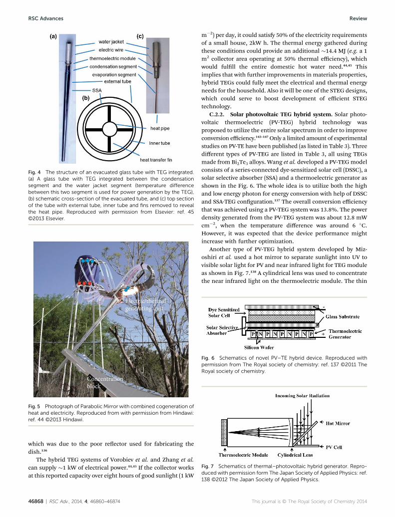
which was due to the poor reector used for fabricating thedish.136
The hybrid TEG systems of Vorobiev et al. and Zhang et al.can supply "1 kW of electrical power.44,45 If the collector worksat this reported capacity over eight hours of good sunlight (1 kW
m$2) per day, it could satisfy 50% of the electricity requirementsof a small house, 2kW h. The thermal energy gathered duringthese conditions could provide an additional "14.4 MJ (e.g. a 1m2 collector area operating at 50% thermal efficiency), whichwould fulll the entire domestic hot water need.44,45 Thisimplies that with further improvements in materials properties,hybrid TEGs could fully meet the electrical and thermal energyneeds for the household. Also it will be one of the STEG designs,which could serve to boost development of efficient STEGtechnology.
C.2.2. Solar photovoltaic TEG hybrid system. Solar photo-voltaic thermoelectric (PV-TEG) hybrid technology wasproposed to utilize the entire solar spectrum in order to improveconversion efficiency.142–147Only a limited amount of experimentalstudies on PV-TE have been published (as listed in Table 3). Threedifferent types of PV-TEG are listed in Table 3, all using TEGsmade from Bi2Te3 alloys. Wang et al. developed a PV-TEGmodelconsists of a series-connected dye-sensitized solar cell (DSSC), asolar selective absorber (SSA) and a thermoelectric generator asshown in the Fig. 6. The whole idea is to utilize both the highand low energy photon for energy conversion with help of DSSCand SSA-TEG conguration.137 The overall conversion efficiencythat was achieved using a PV-TEG system was 13.8%. The powerdensity generated from the PV-TEG system was about 12.8 mWcm$2, when the temperature difference was around 6 #C.However, it was expected that the device performance mightincrease with further optimization.
Another type of PV-TEG hybrid system developed by Miz-oshiri et al. used a hot mirror to separate sunlight into UV tovisible solar light for PV and near infrared light for TEG moduleas shown in Fig. 7.138 A cylindrical lens was used to concentratethe near infrared light on the thermoelectric module. The thin
Fig. 4 The structure of an evacuated glass tube with TEG integrated.(a) A glass tube with TEG integrated between the condensationsegment and the water jacket segment (temperature differencebetween this two segment is used for power generation by the TEG),(b) schematic cross-section of the evacuated tube, and (c) top sectionof the tube with external tube, inner tube and fins removed to revealthe heat pipe. Reproduced with permission from Elsevier: ref. 45©2013 Elsevier.
Fig. 5 Photograph of Parabolic Mirror with combined cogeneration ofheat and electricity. Reproduced from with permission from Hindawi:ref. 44 ©2013 Hindawi.
Fig. 6 Schematics of novel PV–TE hybrid device. Reproduced withpermission from The Royal society of chemistry: ref. 137 ©2011 TheRoyal society of chemistry.
Fig. 7 Schematics of thermal–photovoltaic hybrid generator. Repro-duced with permission form The Japan Society of Applied Physics: ref.138 ©2012 The Japan Society of Applied Physics.
46868 | RSC Adv., 2014, 4, 46860–46874 This journal is © The Royal Society of Chemistry 2014
RSC Advances Review
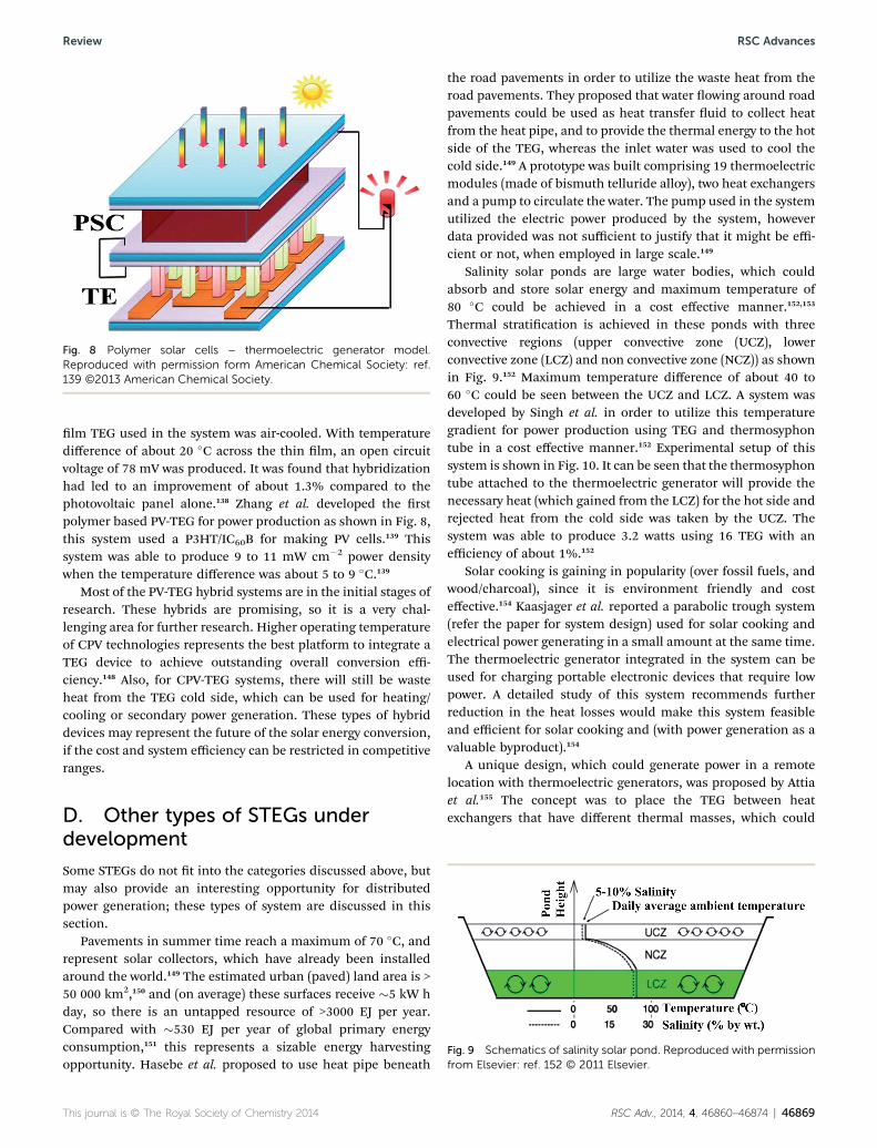
lm TEG used in the system was air-cooled. With temperaturedifference of about 20 #C across the thin lm, an open circuitvoltage of 78 mV was produced. It was found that hybridizationhad led to an improvement of about 1.3% compared to thephotovoltaic panel alone.138 Zhang et al. developed the rstpolymer based PV-TEG for power production as shown in Fig. 8,this system used a P3HT/IC60B for making PV cells.139 Thissystem was able to produce 9 to 11 mW cm$2 power densitywhen the temperature difference was about 5 to 9 #C.139
Most of the PV-TEG hybrid systems are in the initial stages ofresearch. These hybrids are promising, so it is a very chal-lenging area for further research. Higher operating temperatureof CPV technologies represents the best platform to integrate aTEG device to achieve outstanding overall conversion effi-ciency.148 Also, for CPV-TEG systems, there will still be wasteheat from the TEG cold side, which can be used for heating/cooling or secondary power generation. These types of hybriddevices may represent the future of the solar energy conversion,if the cost and system efficiency can be restricted in competitiveranges.
D. Other types of STEGs underdevelopmentSome STEGs do not t into the categories discussed above, butmay also provide an interesting opportunity for distributedpower generation; these types of system are discussed in thissection.
Pavements in summer time reach a maximum of 70 #C, andrepresent solar collectors, which have already been installedaround the world.149 The estimated urban (paved) land area is >50 000 km2,150 and (on average) these surfaces receive "5 kW hday, so there is an untapped resource of >3000 EJ per year.Compared with "530 EJ per year of global primary energyconsumption,151 this represents a sizable energy harvestingopportunity. Hasebe et al. proposed to use heat pipe beneath
the road pavements in order to utilize the waste heat from theroad pavements. They proposed that water owing around roadpavements could be used as heat transfer uid to collect heatfrom the heat pipe, and to provide the thermal energy to the hotside of the TEG, whereas the inlet water was used to cool thecold side.149 A prototype was built comprising 19 thermoelectricmodules (made of bismuth telluride alloy), two heat exchangersand a pump to circulate the water. The pump used in the systemutilized the electric power produced by the system, howeverdata provided was not sufficient to justify that it might be effi-cient or not, when employed in large scale.149
Salinity solar ponds are large water bodies, which couldabsorb and store solar energy and maximum temperature of80 #C could be achieved in a cost effective manner.152,153
Thermal stratication is achieved in these ponds with threeconvective regions (upper convective zone (UCZ), lowerconvective zone (LCZ) and non convective zone (NCZ)) as shownin Fig. 9.152 Maximum temperature difference of about 40 to60 #C could be seen between the UCZ and LCZ. A system wasdeveloped by Singh et al. in order to utilize this temperaturegradient for power production using TEG and thermosyphontube in a cost effective manner.152 Experimental setup of thissystem is shown in Fig. 10. It can be seen that the thermosyphontube attached to the thermoelectric generator will provide thenecessary heat (which gained from the LCZ) for the hot side andrejected heat from the cold side was taken by the UCZ. Thesystem was able to produce 3.2 watts using 16 TEG with anefficiency of about 1%.152
Solar cooking is gaining in popularity (over fossil fuels, andwood/charcoal), since it is environment friendly and costeffective.154 Kaasjager et al. reported a parabolic trough system(refer the paper for system design) used for solar cooking andelectrical power generating in a small amount at the same time.The thermoelectric generator integrated in the system can beused for charging portable electronic devices that require lowpower. A detailed study of this system recommends furtherreduction in the heat losses would make this system feasibleand efficient for solar cooking and (with power generation as avaluable byproduct).154
A unique design, which could generate power in a remotelocation with thermoelectric generators, was proposed by Attiaet al.155 The concept was to place the TEG between heatexchangers that have different thermal masses, which could
Fig. 8 Polymer solar cells – thermoelectric generator model.Reproduced with permission form American Chemical Society: ref.139 ©2013 American Chemical Society.
Fig. 9 Schematics of salinity solar pond. Reproduced with permissionfrom Elsevier: ref. 152 © 2011 Elsevier.
This journal is © The Royal Society of Chemistry 2014 RSC Adv., 2014, 4, 46860–46874 | 46869
Review RSC Advances
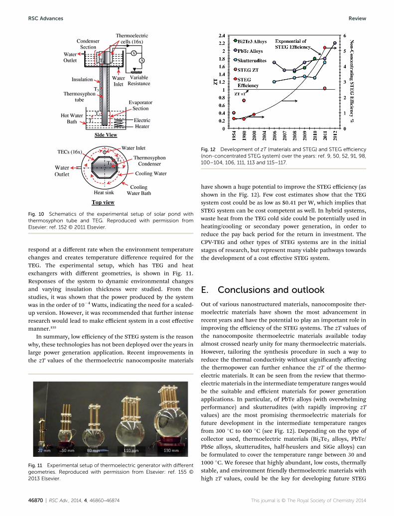
respond at a different rate when the environment temperaturechanges and creates temperature difference required for theTEG. The experimental setup, which has TEG and heatexchangers with different geometries, is shown in Fig. 11.Responses of the system to dynamic environmental changesand varying insulation thickness were studied. From thestudies, it was shown that the power produced by the systemwas in the order of 10$4 Watts, indicating the need for a scaled-up version. However, it was recommended that further intenseresearch would lead to make efficient system in a cost effectivemanner.155
In summary, low efficiency of the STEG system is the reasonwhy, these technologies has not been deployed over the years inlarge power generation application. Recent improvements inthe zT values of the thermoelectric nanocomposite materials
have shown a huge potential to improve the STEG efficiency (asshown in the Fig. 12). Few cost estimates show that the TEGsystem cost could be as low as $0.41 per W, which implies thatSTEG system can be cost competent as well. In hybrid systems,waste heat from the TEG cold side could be potentially used inheating/cooling or secondary power generation, in order toreduce the pay back period for the return in investment. TheCPV-TEG and other types of STEG systems are in the initialstages of research, but represent many viable pathways towardsthe development of a cost effective STEG system.
E. Conclusions and outlookOut of various nanostructured materials, nanocomposite ther-moelectric materials have shown the most advancement inrecent years and have the potential to play an important role inimproving the efficiency of the STEG systems. The zT values ofthe nanocomposite thermoelectric materials available todayalmost crossed nearly unity for many thermoelectric materials.However, tailoring the synthesis procedure in such a way toreduce the thermal conductivity without signicantly affectingthe thermopower can further enhance the zT of the thermo-electric materials. It can be seen from the review that thermo-electric materials in the intermediate temperature ranges wouldbe the suitable and efficient materials for power generationapplications. In particular, of PbTe alloys (with overwhelmingperformance) and skutterudites (with rapidly improving zTvalues) are the most promising thermoelectric materials forfuture development in the intermediate temperature rangesfrom 300 #C to 600 #C (see Fig. 12). Depending on the type ofcollector used, thermoelectric materials (Bi2Te3 alloys, PbTe/PbSe alloys, skutterudites, half-heuslers and SiGe alloys) canbe formulated to cover the temperature range between 30 and1000 #C. We foresee that highly abundant, low costs, thermallystable, and environment friendly thermoelectric materials withhigh zT values, could be the key for developing future STEG
Fig. 10 Schematics of the experimental setup of solar pond withthermosyphon tube and TEG. Reproduced with permission fromElsevier: ref. 152 © 2011 Elsevier.
Fig. 11 Experimental setup of thermoelectric generator with differentgeometries. Reproduced with permission from Elsevier: ref. 155 ©2013 Elsevier.
Fig. 12 Development of zT (materials and STEG) and STEG efficiency(non-concentrated STEG system) over the years: ref. 9, 50, 52, 91, 98,100–104, 106, 111, 113 and 115–117.
46870 | RSC Adv., 2014, 4, 46860–46874 This journal is © The Royal Society of Chemistry 2014
RSC Advances Review

systems, in order to compete with other solar energy conversionsystem.
Various non-concentrated and concentrated STEG systemswere critically reviewed, it can be seen that improvement in thematerial properties, SSA coating and certain heat loss reductiontechnique have led to achieve a maximum efficiency of about5%, but still the efficiency values can be further improved byenhancing these parameters. This review also nds thatalthough stand-alone STEG congurations are possible, hybridcongurations are more commercially feasible today. That is,STEG systems are much more likely to be adopted in conjunc-tion with other power cycles and/or in situations where heatoutputs can be utilized. We propose that the efficient thermo-electric materials with high zT values must be utilized, espe-cially for the medium temperature STEGs (200–600 #C), in orderto exploit the inherent advantages of the STEGs to compete withother cost effective solar to electricity conversion systems. Weexpect that the thermal TEG hybrid and the CPV-TEG (largelyunexplored) systems might enable a step-change in the tech-nology in the near future, if global efforts are taken to furtherintensify the research on these systems.
References1 A. Mojiri, R. Taylor, E. Thomsen and G. Rosengarten,Renewable Sustainable Energy Rev., 2013, 28, 654–663.
2 S. Mekhilef, R. Saidur and A. Safari, Renewable SustainableEnergy Rev., 2011, 15, 1777–1790.
3 N. S. Lewis and G. Crabtree, Basic Research Needs for SolarEnergy Utilization-Report of the Basic Energy SciencesWorkshop on Solar Energy Utilization, DOE Office ofScience, 18–21 April 2005, http://www.er.doe.gov/bes/reports/abstracts.html.
4 M. Xie and D. M. Gruen, J. Phys. Chem. B, 2010, 114, 14339–14342.
5 M. Ortega, P. del Rıo and E. A. Montero, RenewableSustainable Energy Rev., 2013, 27, 294–304.
6 A. Ummadisingu and M. S. Soni, Renewable SustainableEnergy Rev., 2011, 15, 5169–5175.
7 S. A. Kalogirou, Prog. Energy Combust. Sci., 2004, 30, 231–295.
8 G. W. Crabtree and N. S. Lewis, Phys. Today, 2007, 60, 37–42.9 D. Kraemer, B. Poudel, H.-P. Feng, J. C. Caylor, B. Yu,X. Yan, Y. Ma, X. Wang, D. Wang and A. Muto, Nat.Mater., 2011, 10, 532–538.
10 R. A. Taylor and G. L. Solbrekken, IEEE Trans. Compon.Packag. Technol., 2008, 31, 23–31.
11 B. Parida, S. Iniyan and R. Goic, Renewable SustainableEnergy Rev., 2011, 15, 1625–1636.
12 H. L. Zhang, J. Baeyens, J. Degreve and G. Caceres,Renewable Sustainable Energy Rev., 2013, 22, 466–481.
13 M. A. Green, K. Emery, Y. Hishikawa, W. Warta andE. D. Dunlop, Prog. Photovoltaics, 2014, 22, 1–9.
14 Renewable Energy Technologies – Cost analysis series (PV), IntEnergy Agency, 2012, http://www.irena.org.
15 S. Kuravi, J. Trahan, D. Y. Goswami, M. M. Rahman andE. K. Stefanakos, Prog. Energy Combust. Sci., 2013, 39,285–319.
16 D. Y. Goswami, F. Kreith and J. F. Kreider, Principles of solarengineering, CRC PressI Llc, 2000.
17 J. Mariyappan and D. Anderson, Solar Thermal thematicreview. SolarPACES Annual Report, 2001.
18 W. T. Xie, Y. J. Dai, R. Z. Wang and K. Sumathy, RenewableSustainable Energy Rev., 2011, 15, 2588–2606.
19 A. Fernandez-Garcıa, E. Zarza, L. Valenzuela and M. Perez,Renewable Sustainable Energy Rev., 2010, 14, 1695–1721.
20 M. H. Ahmadi, A. H. Mohammadi, S. Dehghani andM. A. Barranco-Jimenez, Energy Convers. Manage., 2013,75, 438–445.
21 S. H. Alawaji, Renewable Sustainable Energy Rev., 2001, 5,59–77.
22 F. J. DiSalvo, Science, 1999, 285, 703–706.23 J.-c. Zheng, Front. Phys. China, 2008, 3, 269–279.24 H. Xi, L. Luo and G. Fraisse, Renewable Sustainable Energy
Rev., 2007, 11, 923–936.25 P. Vaqueiro and A. V. Powell, J. Mater. Chem., 2010, 20,
9577–9584.26 J. R. Lim, J. F. Whitacre, J. P. Fleurial, C. K. Huang,
M. A. Ryan and N. V. Myung, Adv. Mater., 2005, 17, 1488–1492.
27 F. Meng, L. Chen and F. Sun, Int. J. Energy Environ., 2012, 3,137–150.
28 H. Scherrer, L. Vikhor, B. Lenoir, A. Dauscher and P. Poinas,J. Power Sources, 2003, 115, 141–148.
29 N. Vatcharasathien, J. Hirunlabh, J. Khedari andM. Daguenet, Int. J. Renewable Sustainable Energy, 2005,24, 115–127.
30 T. M. Tritt and M. Subramanian, MRS Bull., 2006, 31, 188–198.
31 G. Min, J. Electron. Mater., 2010, 39, 1782–1785.32 W. Xie, A. Weidenkaff, X. Tang, Q. Zhang, J. Poon and
T. M. Tritt, Nanomaterials, 2012, 2, 379–412.33 M. Hamid Elsheikh, D. A. Shnawah, M. F. M. Sabri,
S. B. M. Said, M. Haji Hassan, M. B. Ali Bashir andM. Mohamad, Renewable Sustainable Energy Rev., 2014, 30,337–355.
34 E. Chavez-Urbiola, Y. V. Vorobiev and L. Bulat, Sol. Energy,2012, 86, 369–378.
35 A. Soni, Z. Yanyuan, Y. Ligen, M. K. K. Aik,M. S. Dresselhaus and Q. Xiong, Nano Lett., 2012, 12,1203–1209.
36 Y. Zhang, M. L. Snedaker, C. S. Birkel, S. Mubeen, X. Ji,Y. Shi, D. Liu, X. Liu, M. Moskovits and G. D. Stucky,Nano Lett., 2012, 12, 1075–1080.
37 S. Wang, X. Tan, G. Tan, X. She, W. Liu, H. Li, H. Liu andX. Tang, J. Mater. Chem., 2012, 22, 13977–13985.
38 T. Zhang, J. Jiang, Y. Xiao, Y. Zhai, S. Yang and G. Xu, J.Mater. Chem. A, 2013, 1, 966–969.
39 L. Ivanova, L. Petrova, Y. V. Granatkina, V. Leontyev,A. Ivanov, S. Varlamov, Y. P. Prilepo, A. Sychev, A. Chuikoand I. Bashkov, Inorg. Mater., 2013, 49, 120–126.
This journal is © The Royal Society of Chemistry 2014 RSC Adv., 2014, 4, 46860–46874 | 46871
Review RSC Advances
40 H. Sevinçli, C. Sevik, T. Çagın and G. Cuniberti, Sci. Rep.,2013, 3, 1228.
41 M. Ioannou, G. Polymeris, E. Hatzikraniotis, A. Khan,K. Paraskevopoulos and T. Kyratsi, J. Electron. Mater.,2013, 42, 1827–1834.
42 E. Weston, US Pat., US389124 A, 4 Sep 1888.43 L. Weinstein, K. McEnaney and G. Chen, J. Appl. Phys., 2013,
113, 164504.44 Y. Vorobiev, Int. J. Photoenergy, 2013, 2013, 704087.45 M. Zhang, L. Miao, Y. P. Kang, S. Tanemura, C. A. Fisher,
G. Xu, C. X. Li and G. Z. Fan, Appl. Energy, 2013, 109, 51–59.46 G. Chen, J. Appl. Phys., 2011, 109, 104908.47 W. He, Y. Su, S. B. Riffat, J. Hou and J. Ji, Appl. Energy, 2011,
88, 5083–5089.48 L. L. Baranowski, G. J. Snyder and E. S. Toberer, Energy
Environ. Sci., 2012, 5, 9055–9067.49 J. Karni, Nat. Mater., 2011, 10, 481–482.50 M. Telkes, J. Appl. Phys., 1954, 25, 765.51 H. Goldsmid, J. Giutronich and M. Kaila, Sol. Energy, 1980,
24, 435–440.52 S. Omer and D. Ineld, Sol. Energy Mater. Sol. Cells, 1998,
53, 67–82.53 L. Hicks and M. Dresselhaus, Phys. Rev. B: Condens. Matter
Mater. Phys., 1993, 47, 12727.54 G. J. Snyder and E. S. Toberer, Nat. Mater., 2008, 7, 105–114.55 A. Bulusu and D. Walker, Superlattices Microstruct., 2008,
44, 1–36.56 T. M. Tritt, Thermal conductivity:– theory, properties and
applications, Kluwer Academic/Plenum Publishers,Dordrecht, 2004.
57 N. Yang, X. Xu, G. Zhang and B. Li, AIP Adv., 2012, 2, 041410.58 Y. Pei, A. D. LaLonde, H. Wang and G. J. Snyder, Energy
Environ. Sci., 2012, 5, 7963–7969.59 G. J. Snyder, M. Christensen, E. Nishibori, T. Caillat and
B. B. Iversen, Nat. Mater., 2004, 3, 458–463.60 C. B. Vining, Nat. Mater., 2009, 8, 83–85.61 N. Mott, Proc. R. Soc. London, Ser. A, 1936, 156, 368–382.62 R. L. Powell, W. J. Hall and H. M. Roder, J. Appl. Phys., 1960,
31, 496–503.63 C. Bradley, Philos. Mag., 1962, 7, 1337–1347.64 D. MacDonald, W. Pearson and I. Templeton, Proc. R. Soc.
London, Ser. A, 1962, 266, 161–184.65 J. Perron, Adv. Phys., 1967, 16, 657–666.66 M. Vedernikov, Adv. Phys., 1969, 18, 337–370.67 A. K. Sinha, Phys. Rev. B: Condens. Matter Mater. Phys., 1970,
1, 4541.68 R. Huebener, Solid State Phys., 1972, 27, 63–134.69 P. Nielsen and P. Taylor, Phys. Rev. B: Condens. Matter
Mater. Phys., 1974, 10, 4061.70 M. Baibich, W. Muir, G. Belanger, J. Destry, H. Elzinga and
P. Schroeder, Phys. Rev. A, 1979, 73, 328–330.71 B. Gallagher, J. Phys. F: Met. Phys., 1981, 11, L207.72 B. Gallagher and D. Greig, J. Phys. F: Met. Phys., 1982, 12,
1721.73 C. Domenicali and F. Otter, Phys. Rev., 1954, 95, 1134.74 J. S. Dugdale, The electrical properties of disordered metals,
Cambridge University Press Cambridge, 1995.
75 M. S. Dresselhaus, G. Chen, M. Y. Tang, R. Yang, H. Lee,D. Wang, Z. Ren, J. P. Fleurial and P. Gogna, Adv. Mater.,2007, 19, 1043–1053.
76 A. Minnich, M. Dresselhaus, Z. Ren and G. Chen, EnergyEnviron. Sci., 2009, 2, 466–479.
77 L. Hicks, T. Harman, X. Sun and M. Dresselhaus, Phys. Rev.B: Condens. Matter Mater. Phys., 1996, 53, R10493–R10496.
78 T. Harman, P. Taylor, M. Walsh and B. LaForge, Science,2002, 297, 2229–2232.
79 R. Venkatasubramanian, E. Siivola, T. Colpitts andB. O'quinn, Nature, 2001, 413, 597–602.
80 T. Harman, M. Walsh and G. Turner, J. Electron. Mater.,2005, 34, L19–L22.
81 B. Poudel, Q. Hao, Y. Ma, Y. Lan, A. Minnich, B. Yu, X. Yan,D. Wang, A. Muto and D. Vashaee, Science, 2008, 320, 634–638.
82 Z. G. Chen, G. Han, L. Yang, L. Cheng and J. Zou, Prog. Nat.Sci., 2012, 22, 535–549.
83 X. Shi, L. Xi, J. Fan, W. Zhang and L. Chen, Chem. Mater.,2010, 22, 6029–6031.
84 W. Liu, X. Yan, G. Chen and Z. Ren, Nano Energy, 2012, 1,42–56.
85 A. Saramat, G. Svensson, A. Palmqvist, C. Stiewe, E. Mueller,D. Platzek, S. Williams, D. Rowe, J. Bryan and G. Stucky, J.Appl. Phys., 2006, 99, 023708.
86 S. Deng, X. Tang, P. Li and Q. Zhang, J. Appl. Phys., 2008,103, 073503.
87 B. B. Iversen, J. Mater. Chem., 2010, 20, 10778–10787.88 R. Amatya and R. J. Ram, J. Electron. Mater., 2012, 41, 1011–
1019.89 S. K. Yee, S. LeBlanc, K. E. Goodson and C. Dames, Energy
Environ. Sci., 2013, 6, 2561–2571.90 X. Yan, B. Poudel, Y. Ma, W. Liu, G. Joshi, H. Wang, Y. Lan,
D. Wang, G. Chen and Z. Ren, Nano Lett., 2010, 10, 3373–3378.
91 Y. Cao, X. Zhao, T. Zhu, X. Zhang and J. Tu, Appl. Phys. Lett.,2008, 92, 143106.
92 W. Xie, X. Tang, Y. Yan, Q. Zhang and T. M. Tritt, Appl. Phys.Lett., 2009, 94, 102111.
93 W. Xie, J. He, H. J. Kang, X. Tang, S. Zhu, M. Laver, S. Wang,J. R. Copley, C. M. Brown and Q. Zhang, Nano Lett., 2010, 10,3283–3289.
94 S. Fan, J. Zhao, J. Guo, Q. Yan, J. Ma and H. H. Hng, Appl.Phys. Lett., 2010, 96, 182104.
95 K. T. Kim and G. H. Ha, J. Nanomater., 2013, 2013, 821657.96 K. F. Hsu, S. Loo, F. Guo, W. Chen, J. S. Dyck, C. Uher,
T. Hogan, E. Polychroniadis and M. G. Kanatzidis,Science, 2004, 303, 818–821.
97 P. F. Poudeu, J. D'Angelo, H. Kong, A. Downey, J. L. Short,R. Pcionek, T. P. Hogan, C. Uher and M. G. Kanatzidis, J.Am. Chem. Soc., 2006, 128, 14347–14355.
98 J. Androulakis, C.-H. Lin, H.-J. Kong, C. Uher, C.-I. Wu,T. Hogan, B. A. Cook, T. Caillat, K. M. Paraskevopoulosand M. G. Kanatzidis, J. Am. Chem. Soc., 2007, 129, 9780–9788.
99 P. F. P. Poudeu, A. Gueguen, C.-I. Wu, T. Hogan andM. G. Kanatzidis, Chem. Mater., 2009, 22, 1046–1053.
46872 | RSC Adv., 2014, 4, 46860–46874 This journal is © The Royal Society of Chemistry 2014
RSC Advances Review
100 B. A. Cook, M. J. Kramer, J. L. Harringa, M. K. Han,D. Y. Chung and M. G. Kanatzidis, Adv. Funct. Mater.,2009, 19, 1254–1259.
101 J. Androulakis, K. F. Hsu, R. Pcionek, H. Kong, C. Uher,J. J. D'Angelo, A. Downey, T. Hogan and M. G. Kanatzidis,Adv. Mater., 2006, 18, 1170–1173.
102 P. F. Poudeu, J. D'Angelo, A. D. Downey, J. L. Short,T. P. Hogan and M. G. Kanatzidis, Angew. Chem., 2006,118, 3919–3923.
103 J. P. Heremans, V. Jovovic, E. S. Toberer, A. Saramat,K. Kurosaki, A. Charoenphakdee, S. Yamanaka andG. J. Snyder, Science, 2008, 321, 554–557.
104 S. N. Girard, J. He, X. Zhou, D. Shoemaker, C. M. Jaworski,C. Uher, V. P. Dravid, J. P. Heremans and M. G. Kanatzidis,J. Am. Chem. Soc., 2011, 133, 16588–16597.
105 Y. Pei, X. Shi, A. LaLonde, H. Wang, L. Chen andG. J. Snyder, Nature, 2011, 473, 66–69.
106 K. Biswas, J. He, I. D. Blum, C.-I. Wu, T. P. Hogan,D. N. Seidman, V. P. Dravid and M. G. Kanatzidis, Nature,2012, 489, 414–418.
107 Q. Zhang, H. Wang, W. Liu, H. Wang, B. Yu, Q. Zhang,Z. Tian, G. Ni, S. Lee and K. Esfarjani, Energy Environ.Sci., 2012, 5, 5246–5251.
108 H.Wang, Y. Pei, A. D. LaLonde and G. J. Snyder, Adv. Mater.,2011, 23, 1366–1370.
109 H. Wang, Z. M. Gibbs, Y. Takagiwa and G. J. Snyder, EnergyEnviron. Sci., 2014, 7, 804–811.
110 G. Nolas, M. Kaeser, R. Littleton and T. Tritt, Appl. Phys.Lett., 2000, 77, 1855–1857.
111 T. He, J. Chen, H. D. Rosenfeld andM. Subramanian, Chem.Mater., 2006, 18, 759–762.
112 W. S. Liu, B. P. Zhang, L. D. Zhao and J. F. Li, Chem. Mater.,2008, 20, 7526–7531.
113 H. Li, X. Tang, Q. Zhang and C. Uher, Appl. Phys. Lett., 2008,93, 252109.
114 Y. Pei, J. Yang, L. Chen, W. Zhang, J. Salvador and J. Yang,Appl. Phys. Lett., 2009, 95, 042101.
115 W. Zhao, P. Wei, Q. Zhang, C. Dong, L. Liu and X. Tang, J.Am. Chem. Soc., 2009, 131, 3713–3720.
116 X. Shi, J. Yang, J. R. Salvador, M. Chi, J. Y. Cho, H. Wang,S. Bai, J. Yang, W. Zhang and L. Chen, J. Am. Chem. Soc.,2011, 133, 7837–7846.
117 G. Rogl, A. Grytsiv, P. Rogl, E. Bauer, M. Kerber,M. Zehetbauer and S. Puchegger, Intermetallics, 2010, 18,2435–2444.
118 G. Joshi, T. Dahal, S. Chen, H. Wang, J. Shiomi, G. Chenand Z. Ren, Nano Energy, 2013, 2, 82–87.
119 X. Yan, W. Liu, H. Wang, S. Chen, J. Shiomi, K. Esfarjani,H. Wang, D. Wang, G. Chen and Z. Ren, Energy Environ.Sci., 2012, 5, 7543–7548.
120 X. W. Wang, H. Lee, Y. C. Lan, G. H. Zhu, G. Joshi,D. Z. Wang, J. Yang, A. J. Muto, M. Y. Tang, J. Klatsky,S. Song, M. S. Dresselhaus, G. Chen and Z. F. Ren, Appl.Phys. Lett., 2008, 93, 193121.
121 G. Joshi, H. Lee, Y. Lan, X. Wang, G. Zhu, D. Wang,R. W. Gould, D. C. Cuff, M. Y. Tang andM. S. Dresselhaus, Nano Lett., 2008, 8, 4670–4674.
122 H. Goldsmid and R. Douglas, Br. J. Appl. Phys., 1954, 5, 386.123 S. KeunaKim, Phys. Chem. Chem. Phys., 2014, 16, 3529–
3533.124 Z. Dughaish, Phys. B, 2002, 322, 205–223.125 J. R. Salvador, J. Yang, X. Shi, H. Wang and A. Wereszczak, J.
Solid State Chem., 2009, 182, 2088–2095.126 D. Medlin and G. Snyder, Curr. Opin. Colloid Interface Sci.,
2009, 14, 226–235.127 S. Bai, X. Shi and L. Chen, Appl. Phys. Lett., 2010, 96, 202102.128 Z. Tian, S. Lee and G. Chen, J. Heat Transfer, 2013, 135,
061605.129 C. B. Vining, W. Laskow, J. O. Hanson, R. R. Van der Beck
and P. D. Gorsuch, J. Appl. Phys., 1991, 69, 4333–4340.130 M. S. El-Genk, H. H. Saber and T. Caillat, Energy Convers.
Manage., 2003, 44, 1755–1772.131 D. Mills, Sol. Energy, 2004, 76, 19–31.132 P. Li, L. Cai, P. Zhai, X. Tang, Q. Zhang and M. Niino, J.
Electron. Mater., 2010, 39, 1522–1530.133 T. Yang, J. Xiao, P. Li, P. Zhai and Q. Zhang, J. Electron.
Mater., 2011, 40, 967–973.134 R. Amatya and R. Ram, J. Electron. Mater., 2010, 39, 1735–
1740.135 C. Suter, P. Tomes, A. Weidenkaff and A. Steinfeld, Sol.
Energy, 2011, 85, 1511–1518.136 H. Fan, R. Singh and A. Akbarzadeh, J. Electron. Mater.,
2011, 40, 1311–1320.137 N. Wang, L. Han, H. He, N.-H. Park and K. Koumoto, Energy
Environ. Sci., 2011, 4, 3676.138 M. Mizoshiri, M. Mikami and K. Ozaki, Jpn. J. Appl. Phys.,
2012, 51, 06FL07.139 Y. Zhang, J. Fang, C. He, H. Yan, Z. Wei and Y. Li, J. Phys.
Chem. C, 2013, 117, 24685–24691.140 M. Zebarjadi, K. Esfarjani, M. Dresselhaus, Z. Ren and
G. Chen, Energy Environ. Sci., 2012, 5, 5147–5162.141 S. LeBlanc, S. K. Yee, M. L. Scullin, C. Dames and
K. E. Goodson, Renewable Sustainable Energy Rev., 2014,32, 313–327.
142 Y. Vorobiev, J. Gonzalez-Hernandez, P. Vorobiev andL. Bulat, Sol. Energy, 2006, 80, 170–176.
143 D. Kraemer, L. Hu, A. Muto, X. Chen, G. Chen andM. Chiesa, Appl. Phys. Lett., 2008, 92, 243503.
144 Y. Li, S. Witharana, H. Cao, M. Lasfargues, Y. Huang andY. Ding, Particuology, 2014, 15, 39–44.
145 T. Liao, B. Lin and Z. Yang, Int. J. Therm. Sci., 2014, 77, 158–164.
146 M. Fisac, F. X. Villasevil and A. M. Lopez, J. Power Sources,2014, 252, 264–269.
147 X. Zhang, X. Zhao, S. Smith, J. Xu and X. Yu, RenewableSustainable Energy Rev., 2012, 16, 599–617.
148 C. Y. Lu, Eur Pat EP2660880 A2, 15 April 2012.149 M. Hasebe, Y. Kamikawa and S. Meiarashi, in International
Conference on Thermoelectrics, IEEE, Vienna, 2006, pp. 697–700.
150 A. Schneider, M. A. Friedl and D. Potere, Environ. Res. Lett.,2009, 4, 044003.
151 Key World Energy Statistics, Int Energy Agency, 2012, http://www.irena.org.
This journal is © The Royal Society of Chemistry 2014 RSC Adv., 2014, 4, 46860–46874 | 46873
Review RSC Advances

152 R. Singh, S. Tundee and A. Akbarzadeh, Sol. Energy, 2011,85, 371–378.
153 K. R. Ranjan and S. C. Kaushik, Renewable SustainableEnergy Rev., 2014, 32, 123–139.
154 A. Kaasjager and G. Moeys, in Global HumanitarianTechnology Conference, IEEE, Seattle, WA, 21–24 October2012, pp. 6–11.
155 P. M. Attia, M. R. Lewis, C. C. Bomberger, A. K. Prasad andJ. M. Zide, Energy, 2013, 60, 453–456.
46874 | RSC Adv., 2014, 4, 46860–46874 This journal is © The Royal Society of Chemistry 2014
RSC Advances Review


