Embed Size (px)
Citation preview

A N E W S L E T T E R P U B L I S H E D B Y S S P A S W E D E N A B 5 6 / 2 0 1 2
HIGHLIGHTSContents
2 Deep Green
4 Escort towing and risk control options – assessing the risk of oil spills
6 Wind propulsion – to be or not to be?
8 Spillman – a systematic approach to oil spills in Arctic conditions
10 Local ferries in a city divided by a river
12 Short comments

2
56/2012
Minesto has developed a new concept for tidal power plants called Deep Green. Deep Green converts energy from tidal stream flows into electricity by way of a novel principle, somewhat similar to the posture of a wind kite. The kite assembly, consisting of a wing and turbine, is attached by a tether to a fixed point on the ocean bed. As water flows over the hydrodynamic wing, a lift force is generated which allows the device to move smoothly through the water causing the turbine to rotate and produce electricity.
The kite consists of a wing, which carries a nacelle and turbine that is direct coupled to a generator inside the nacelle. The wing is attached to the seabed by struts and a tether. The tether to seabed accommodates both power and communication cables for further connection to shore. The kite is steered in a predestined trajectory by means of a rudder and servo system located in the rear cone of the nacelle along with a control system. The tether attaches the kite to a swivel mounted on a foun-dation on the seabed. The kite velocity in the trajectory is significantly higher than the current velocity. Thus, the method increases the flow velocity into the turbine with up to 10 times the tidal current speed.
Ocean Energy Ocean energy has the potential for providing a substantial amount of new renewable energy around the world. The oceans represent a major source of renewable energy. Different technologies employ different strategies for harvesting that energy. The main sources of ocean energy are:- Ocean currents- Tidal currents- Tidal range (rise and fall)- Waves- Ocean thermal energy- Salinity gradients
Deep Green efficiently harvests the energy in ocean and tidal currents. The Deep Green technology utilises low
velocity currents with a velocity of 1.5-2.5m/s as opposed to other technologies that compete for tidal hot spot locations where velocities are in excess of 2.5 m/s.
Model scale tests at SSPAModel scale testing has played an important role in the development of Deep Green. The hydrodynamic proper-ties and control system have been successfully verified on a scaled model. Several test campaigns have been performed in SSPAs towing tank. Various rudder configu-rations, tethers and trajectories have been tested to opti-
Deep Green
Artist impression of a Deep Green array. ILLUSTRATION: MINESTO
The kite consists of a wing, which carries a nacelle and turbine that is direct coupled to a generator inside the nacelle. The wing is attached to the seabed by struts and a tether. ILLUSTRATION: MINESTO
Underwater photo of the kite in SSPAs towing tank. Model scale testing has played an important role in the develop-ment of Deep Green. PHOTO: MINESTO
My sincerest Season’s Greetings...
...to all of SSPA’s clients, part-ners and colleagues in the maritime society.
Thank you all for the opportunities given and con-fidence shown to us working together with you during 2012.
Enlightened by the activi-ties going on in the maritime world today I am totally confident to conclude that the ocean have had much to offer the world in the past but even more for the future.
To safe guard the value the ocean has to offer, sus-tainable resource utilization is preferred and it´s recognized by a growing number of stakeholders.
The energy branch con-tinues to explore assets hidden in the ocean and the body of knowledge on how to also harness the formi-dable power of current and waves are steadily increasing. Researcher and engineers are exploring a variety of ways to harvest and transform this power into something that can greatly benefit mankind – renewable energy. Although this field is still emerging, it has a great potential for the future.
The shipping industry is very much focused on green technology and energy effi-ciency in order to continue supporting globalization. Significant progress has been made and huge investments are foreseen in this area in the future. In order to making the paradigm shift happen joint efforts from the stake-holders will be essential.
At SSPA we remain com-mitted doing our best sup-porting our clients and mak-ing a blue sustainable future come true.
Susanne Abrahamsson

3
56/2012
Jan Hallander M.Sc. (1991) in Mechanical Engi-neering and Ph.D. (2002) in Naval Architecture from Chal-mers has been employed as Project Manager at SSPA since 1998. He has been involved in various research and consul-tancy projects within the areas of general hydromechanics, propulsion and underwater acoustic signatures, especially with phenomena related to cavitation and noise induced by the propeller. He has previ-ously worked on cavitation noise research at Chalmers.Telephone: +46 31 772 90 57 E-mail: [email protected]
Deep Green
MINESTO
Minesto’s technology originates from the wind depart-ment at SAAB Group in Sweden. However, because it was beyond the scope of SAAB’s core business, it was spun off in the form of Minesto, which was created in 2007.
The company has now grown to 20 employees and they will soon be 25. It is now the largest ocean energy company in Scandinavia, according to CEO Anders Jansson.
In 2010, Time Magazine selected Minesto as one of the Top 50 Best Innovations in the world and in 2011 Minesto was nominated for Top 15 Utility Solutions in the USA.
Minesto’s CEO Anders Jansson: “Our design methodology is to perform hands-on tests in the laboratory and field, rather than spending a lot of time on computer simulations.”PHOTO: MINESTO
mise the performance. Essential parts, like the swivel and nacelle, have also been verified. Knowledge that is directly transferable to the full-scale product has been obtained and implemented in the mechanical design and control system. “Our design methodology is to perform hands-on tests in the laboratory and field, rather than spending a lot of time on computer simulations” says Minesto’s CEO Anders Jansson.
Tests have been performed both with the model towed in its tether, as well as captive tests. The first towed tests were performed with a model that is slightly denser than water and the tether attached to the carriage at the surface. In later tests, an attachment point close to the bottom in combination with a buoy-ant model was used. In the captive tests, the model was attached to a six-component balance in order to measure the forces on the model. These tests play a fundamental role in the development and verification of control algorithms for the Deep Green underwater kite. The next step is to perform cavitation tunnel tests for verification of the hydrodynamic performance of the turbine.
In situ tests During winter 2011/2012, a prototype on a scale of 1:10 was tested at sea in Strangford Lough outside the coast of Northern Ireland. The prototype was the same as the one used in laboratory tests, but with a longer tether and different foundation. The focus was on demonstrat-ing that the technology operates efficiently and safely in the ocean. “In laboratory tests, you have absolute control of the testing conditions. This is a big advantage, but also the main drawback. Now, we were able to prove that
Minesto staff (Christian Norinder och Patrik Pettersson) preparing the kite for the next run in the SSPA towing tank. Various rudder configurations, tethers and trajectories have been tested to optimise the performance. PHOTO: MINESTO
Deep Green behaved as expected in an uncontrolled environment,” says Anders Jansson. The hydrodynamic properties and control system were successfully verified on the scaled model. All systems were in proportion to the full scale, resulting in a massive leap in confidence and knowledge.
Minesto is now working on the next prototype on a 1:4 scale. It will be installed at sea in the end of 2012 and will be tested over a period of one year. The main focus in these tests will be electricity production.
Minesto is pursuing a focused development plan where the goal is to deploy the first full scale prototype in 2014, a 3MW Deep Green array in 2015, and increas-ing to a 10MW array in 2016.
Jan Hallander

4
56/2012
Escort tugs could help reduce the risk of technical faults on tankers when they visit ports or are travel-ling in confined or environmentally sensitive areas. In a study conducted by SSPA in 2011 on behalf of Nynas AB, escort towing was compared with other risk-reducing measures. It was concluded that, for certain types of waters and vessels, alternative measures should be considered to enhance safety and minimize the risk of serious accidents with consequential oil spills. A follow-up simulation study of risk control options is currently underway.
The challenge is to understand why accidents occur, assess the probabilities and then study potential measures for mitigating such risks. This is a complicated but vital task for ensuring that oil transports are conducted as effi-ciently as possible and at an acceptable level of risk.
Risk control options – low speed… Escort tugboats are mainly used for guiding tankers through critical passages and providing assistance in the event of a technical fault on the vessel. However, this introduces yet another risk, i.e. that the vessels will collide due to being in close proximity of one another for an extended period of time. Speed reduction is, accordingly, a particularly interesting risk control option because it allows the bridge team more time to evaluate situations and take proper action to correct any mistakes or deal with an equipment failure. Hull penetration is typically also less extensive for ships that hit ground, provided that they are travelling at a low speed. However, because drift angle increases at lower speeds, time is required for mak-ing course adjustments. Accordingly, this option is more suitable in broader fairways.
…enhanced equipment… Another safety measure is the use of enhanced equip-ment for improved traffic surveillance, e.g. electronic charts and AIS that is integrated with radar and ECDIS.This helps in the selection of optimal routes, where
Escort towing and risk control options – assessing the risk of oil spills
there is maximum distance to shallow areas and thus fewer maneuvers close to shore. The bridge team then has more time to evaluate complicated situations and take appropriate action. However, as explained above, this option is not suitable for vessels travelling in narrow fairways.
…increased manning and detecting deficienciesAnother proactive safety measure is to increase the manning of the bridge when vessels pass through nar-row fairways. Adherence to statutory rest periods is also important. Furthermore, regular reviews of safety records and management can help detect deficiencies in vessel maintenance or the organization. Steering and propulsion redundancy systems can also be useful in the event of a technical failure. However, a certain amount of time is required to activate such systems, so this may or may not be an option (depending on the width of the fairway).
Risk assessmentInformation and knowledge of fairway characteristics is vital when conducting risk assessment and evaluating safety precaution measures.- Fairway dimensions and traffic density determine the
limits of maneuverability. In narrow passages, there are fewer alternative routes and shorter distances to no-go zones and other vessels. In wider fairways, where there is less traffic, the navigator has more time and options available in the event of a failure.
- Knowledge of the characteristics of the sea bottom in fairways is also crucial in order to avoid collision with rocks resulting in hull rips and oil spills.
- Winds and tides must be considered when determin-ing a speed that is appropriate for the fairway width and acceptable drifting angle.
Maria Bännstrand, Project Manager at SSPA. M.Sc. in Shipping Systems and Technology with a Major in Shipping Management and Logistics from Chalmers Uni-versity of Technology (2003). Master Mariner (1999). Employed at SSPA since April 2012, working primarily with simulation studies and with projects linked to alternative fuels. Previous employments in-clude work at sea and as ship operations manager and as hull insurance underwriter.Telephone: +46 31 772 90 70E-mail: [email protected]
Erland Wilske, Project Manager. He graduated in 1988 (M.Sc. in electronic engineering) from Chalmers University of Technology. After graduation he worked with re-search of opto-electronics sen-sors and software development of cargo handling systems. In 1994 he joined SSPA and has since then been involved in projects linked to development and use of simulation tools.Telephone: +46 31 772 90 34E-mail: [email protected]
Time (hrs)
Prob
abili
ty fo
r re
cove
ry o
f fai
lure
(%
)
100
90
80
70
60
50
40
30
20
10
00 5 10 15 20 25 30
Real time simulations can be used for training and assessment of how the human factor and technical aspects impact risk.
Frequency distribution of time to recovery of main engine failures. (Ellis, Forsman, Hüffmeier, & Johansson, 2008)

5
56/2012
Escort towing and risk control options – assessing the risk of oil spills
operators, vessel traffic services (VTSs) and the suitability of using escort tugs to coordinate actions in a failure situation. However, real-time simulation also has some drawbacks, i.e. because it is very time-consuming, it is not frequently used. So, conclusions are based on very few scenarios. But, high-fidelity, real-time simulations are also very valuable because they enable experts from vari-ous disciplines to cooperate in assessments and better understand how the human factor and technical aspects impact risks.
Compressed time simulationsIn compressed time simulations, the ship is controlled by a track-keeping algorithm to follow a designated route and maintain a certain speed. Failure scenarios (such as degradation of main propulsion or rudder) and navigational errors are introduced and combined with environmental conditions (tide, wind, current) and traffic. The human factor and technical aspects are considered when selecting risk-mitigating actions. With this type of simulation, it is possible to run numerous iterations and cover virtually all situations at all positions along the des-ignated route. The simulations also reveal grounding risks (location and speed) and high resolution bathymetric data can be used to estimate the damage location and distribution. The results from grounding simulations are then compared to actual damage data in order to esti-mate the extent of damage (e.g. penetration of inner or outer hull for a double hull tanker). Finally, the simulation results are projected onto the frequency distribution of various types of failures to assess the likelihood of an oil spill for a specific ship type under specified operational conditions.
Hence, simulations provide a solid basis for assessing the risk of an oil spill when various risk-mitigating meas-ures are used.
Maria Bännstrand Erland Wilske
Nynäshamn
Brofjorden
Göteborg
Oxelösund
Fairway distance (nm)
Min
imum
dis
tanc
e to
fair
way
lim
it (m
)
2500240023002200210020001900180017001600150014001300120011001000900800700600500400300200100
00 2 4 6 8 10 12
Tug in escort operation. PHOTO: CHRISTER GREEN
Extent of damage shown via a grounding simulation.
Maneuverability limits.- Wave effects – if the ship hits ground in rough sea
conditions, there is a higher risk of incurring severe damage.
- Navigational difficulties – certain tools can assist with positioning in different visibilities.
Real-time simulationsReal-time simulations with full-mission bridge simulators are a useful tool for hazard identification, obtaining an overview of risks and assessing risk-control options. For example, they can be used to assess (and train) tanker

6
56/2012
Everyone currently involved in the maritime sector is undoubtedly aware of the continual efforts to reduce emissions from ships. New regulations, like the EEDI (Energy Efficiency Design Index for new ships) are important components of such efforts, even though it will take years before such mandatory global emis-sion reduction schemes make a noticeable impact on the environment. However, more immediate results are already possible to detect from slow steaming. For example, many ships that were designed for speeds of around 16 knots are now sailing at much slower speeds, which saves fuel and reduces emissions. When speed is reduced from 16 to 8 knots, the fuel consumption is reduced to 20% or less per time unit, but sailing time doubles. This results in net fuel savings of around 60%.
This equation applies when sea conditions are relatively calm. However, in high seas, fuel consumption is much higher, despite the slower speed. Likewise, when there are strong beam winds or tailwinds, fuel consumption can be reduced to nearly zero by using wind propulsion.
What is wind propulsion? The feasibility of using wind propulsion is being studied in two research projects, EffShip (Swedish project) and Ulysses (European project).
Both projects are investigating the use of Flettner rotors and kites. The EffShip project is also examining a
new type of sail called EffSails, while Ulysses is explor-ing the use of suction sails. Both of these are rigid sails, i.e. they are comprised of metal or perhaps a composite material. Rotors can of course also be manufactured from either, while kites are made of textiles.
Other textile sail types are being investigated in research elsewhere, but they are not considered in the EffShip and Ulysses projects. These studies focus on wind propulsors that can be “packed up” when there is no wind or too much wind. For example, kites are taken down, the EffSail has a telescopic design and may be folded and the suction sail and rotor can be folded.
Use of kites during tail winds…The only wind propulsor of the ones studied that can be considered to be on the market today is the kite. ‘To be on the market’ means in this sense that there is a number of them existing on a commercial basis. Studies show that the kite is a superior wind propulsor in tail winds, as well as being quite effective in beam winds. From simulations carried out with SSPA’s inhouse program SEAMAN it can be seen that even very large ships, like Panamax tankers, can reach a speed of around 8 knots with a wind speed of 10 m/s using a 640 m2 kite. Although such large kites do not currently exist on the market, it is not unlikely that they will be available sometime in the future. The potential benefits are significant: using a kite for the entire
Wind propulsion – to be or not to be?
The EffShip Pan-amax tanker equipped with Flettner rotors and EffSails. The 4 rotors have a diameter of 4.7 m and a height of 28.2 m, while the maximum height of the 4 sails are 52 m and they have a chord length of 17 m. With these sizes, the rotors and the sails produce the same wind thrust in beam winds, however the projected area of the sails is 7 times higher.
Facts
EffShip (Efficient Shipping with low emissions, www.effship.com) is a Swedish project that is jointly funded by VINNOVA (the Swedish Governmental Agency for Innovation Systems), industry and academia. EffShip is founded on the vision of a sustainable and successful maritime transport industry – one which is energy-efficient and has minimal environmental impact. The project has a total budget around 2 MEUR, and a significant portion is provided by industry.
Ulysses (Ultra Slow Ships, www.ultraslowships.com) is a European funded project with a budget of around 4 MEUR. The objective of the ULYSSES project is to demonstrate (through a combination of ultra slow speeds and com-plementary technologies) that the efficiency of the world fleet can be increased to a point where the following CO2 targets are met;– Before 2020, reducing greenhouse gas emissions by 30%
compared to 1990 levels,– Beyond 2050, reducing greenhouse gas emissions by 80%
compared to 1990 levels.
Flettner rotor is a rotating cylinder that uses the Magnus effect to create a very high lift force (compared to ordinary sails).
EffSail is a fixed azimuth symmetric sail that is telescopic and can be folded. It was developed as part of the EffShip project.
Suction sails are also azimuth. Compared to ordinary sails, they have a much higher lift because the boundary layer is sucked out from the aft part of the wing section. Kite is, as the word says, a wing shaped kite that is flying often in a figure 8 (∞) pattern 200 to 300 meters above the water surface pulling the ship forward.
Björn Allenström, Vice President at SSPA. He graduated (M.Sc.) from Chal-mers University of technology in 1976 and has since been employed at SSPA except for two years. He has during the years been involved in several research and development pro-jects within the field of hydro-dynamics, but most work has been focused on propulsion problems.Telephone: +46 31 772 90 66E-mail: [email protected]

7
56/2012
journey with a 10 m/s tail wind and speed of around 8 knots would result in fuel savings of almost 100 % for the propulsion of the ship.
…and beam windsWhen there is more of a side wind, simulations have shown that when the propeller is turned off, relatively large rudder angles are sometimes required to com-pensate for the transverse forces acting on the ship. In a pure side wind without the propeller running it can be impossible to even keep the course. Accordingly, the best way to use such winds is to keep the engine running at around 20% of the maximum power, which increases the speed by 2-3 knots.
In beam winds – sails and rotorSo, while the kite is regarded to be superior in tail winds, the sails and the rotor are the best ones in beam winds and can also operate in conditions relatively close to the wind. For sails, significant fuel saving can already be achieved with wind directions of 30-40 degrees from the bow. Rotors typically require another 10 degrees to be effective. However, sails have about 7 times higher projected area compared to rotors and this can impede sight from the bridge. This could be solved by designing future sailing ships that have the bridge at the bow.
Feasibility of wind propulsors Given the possible benefits, why is the use of wind pro-pulsion still so limited? There are several possible answers to this:- To be effective, the wind speed must be relatively high.
As explained above, a wind speed of 10 m/s is ade-quate for a ship speed of 8 knots. However, for ships designed and required to sail at twice the speed, 16 knots, a 10 m/s wind speed gives a relatively low wind thrust especially in tail winds.
- The price of fuel is still not high enough to motivate retrofitting or even installations on new buildings of wind propulsors (pay- back time is not attractive enough). Perhaps this will change in the future, if the fuel prices will raise considerably.
- There are probably uncertainties about operational safety when using wind propulsors. What happens if a kite suddenly dives? Will rotors be exposed to vibra-tions? Will large sails hinder visibility from the bridge?
If slow steaming predominates in the future, existing wind speeds worldwide will be suitable for sailing. If fuel prices rise, pay-back time on an investment in wind propulsors will become more attractive. Furthermore, technological solutions will also surely be developed to address and eliminate uncertainties concerning operational safety.
Björn Allenström
Wind propulsion – to be or not to be?
The graph shows calculated fuel consumption for a Panamax tanker doing a journey of 3500 nautical miles in a wind speed of 10 m/s in different wind directions and is based on simulations with SSPA’s in house program SEA-MAN. A reduction in speed from 16 knots to around 8 knots represents a major fuel reduction, but the journey then takes 440 hours instead of 220. Since the engine will not allow for lower power outtake than 20%, the speed never goes under 8.6 knots. With rotor and sail in opera-tion the speed is often around 12-13 knots. At 16 knots the additional thrust from the ro-tors and the sails also offers a significant fuel reduction, often around 30%. This ship speed is too high for the kite at a wind speed of 10 m/s. Using the 20% engine power the kite presents the largest fuel reduction among these three wind propulsors in tail winds (180 degrees). However, for this condition the use of wind propulsors offers ‘only’ an ad-ditional fuel saving of 15-20 %. If the engine is stopped then the fuel consumption using a kite in tail winds could be zero, but to reach the port within 440 hours the ship has to use the engine for around 25% of the time, with sails or ro-tors around 50% of the time. Without the propeller working even the kite has problems keeping the ship on course in beam winds.
6 to 8 knots using 0 to 20% engine and Flettner rotor or EffSail or kite
8 knots using 20% engine and Flettner rotor or EffSail or kite
16 knots using engine and Flettner rotor or EffSail
fue
l co
nsu
me
d (
ton
) 16 knots without wind propulsor 16 knots with rotor 16 knots with EffSail 8.7 to 10.8 knots without wind propulsor,
20% engine power 9.7 to 12.9 knots with rotor, 20% engine power
Simulated fuel consumption for 3500 nm at 10 m/s wind speed
9.9 knots to 12.3 knots with EffSail, 20% engine power 11 to 12.9 knots with kite, 20% engine power with rotor and 1 to 20% engine power with EffSail and 0 to 20% engine power with kite and 0 to 20% engine power
true wind and wave direction (degr.)
500
450
400
350
300
250
200
150
100
50
00 30 60 90 120 150 180

8
56/2012
Much effort goes into reducing the risks associated with Arctic operations and progress has certainly been made. Accidents resulting in major oil spills must not be an option. However, if an accident does occur, we still need a systematic way of dealing with the spill and min-imizing the damage. Preparedness is of utmost impor-tance and for this reason, SSPA has developed Spillman, a tool that enables a systematic approach to oil spills in Arctic conditions.
Spillman uses a wide range of inputs in order to encom-pass the entire operation – from contingency planning and emergency preparedness to full operational decision support, including a safe retreat.
A comprehensive toolBased on season and area of operation, Spillman collects data and accumulates necessary knowledge about the environmental conditions, navigational routes, available ports (including capacities and infrastructure), local laws & regulations, and more. Further, by including available response units, their capacities, locations and performances, it is possible to determine the level of preparedness for dealing with a specific spill scenario. Conversely, it is possi-ble to determine the appropriate scope of response units based on a specific spill scenario, e.g. in permit processes.
Spillman is a valuable asset for both the planning and execution of operations. The intended users are all enti-ties that conduct operations in Arctic conditions, including governments as well as rescue and response organiza-tions.
The Arctic conditionsIn many ways, an oil spill response operation in Arctic conditions differs from such operations in other climates. The level of complexity is much higher due to low tem-peratures, the presence of ice and considerable seasonal variations. This causes variation in oil properties, response
and recovery methods, equipment and crew capacities, which, unfortunately, often has a negative impact on per-formance. Prior to all operations, it is necessary to con-sider and resolve factors such as equipment winterizing, crew training and the additional ice breaking resources required for effective ice management.
Further complicating the situation is the remoteness of most of the Arctic region. The distance to strategic ports with basic infrastructure is often considerable, so a well-functioning logistics chain is thus lacking. The opera-tion must therefore be self-supporting, which means that preparedness and an understanding of the limitations are critical. Operational limits are set by identifying the response gaps, which are strongly associated with the emergency preparedness.
Planning capabilities of SpillmanPrior to any Arctic operation, planning is of the utmost highly important. The aim is not only to perform the operational task, but also, no matter what happens, to get there and back safely, to be self-supporting and to achieve a high level of cost and resource efficiency. A thorough understanding of the operational limitations is crucial so that decisions to retreat or abort can be reached before it is too late. Spillman is a valuable tool for performing gap analysis, which establishes the opera-tional limitations for each specific case.
The permit process is another important aspect of operational planning. It involves establishing and produc-ing contingency plans, as well as ensuring that there is adequate emergency preparedness. Provided with operational knowledge and a dimensioning spill scenario Spillman contributes to the planning efforts.
Operational capabilities of SpillmanIf a spill does occur during an on-going Arctic opera-tion, it is crucial for the response effort to use methods, equipment and units with high recovery capabilities. Spillman considers input data, such as current position, time, environmental conditions, forecasts and details about the spill (including available response units). Based
Spillman – a systematic approach to oil spills in Arctic conditions
Victor Westerberg, M.Sc (2012) Naval Architec-ture from the Royal Institute of Technology joined SSPA after graduation. Active within Arctic oil spill response as well as ice management, winter naviga-tional projects and simulations.Telephone: +46 31 772 91 34E-mail: [email protected]
PHOTOS: ERLAND WILSKE
Björn Forsman, Manager at SSPA, M.Sc. Mech. Eng. From 1980, when he joined SSPA. He has been active in areas related to marine environment, oil spill prevention and spill clean-up. For the last ten years, mari-time safety and risk analysis have also become important fields of expertise in his pro-jects as well as in the research projects that he is engaged in. He has also been programme manager for a number of ad-vanced international training programmes.Telephone: +46 31 772 90 59E-mail: [email protected]

9
56/2012
Spillman – a systematic approach to oil spills in Arctic conditions
on the available response methods and emergency preparedness, Spillman then generates the window of opportunity, which refers to the feasible response meth-ods for a specific case, including estimations on method potentials. Based on the information provided by Spillman, decision makers are able to appropriately invest time and energy in mobilizing units and select the best methods for minimizing the impact of the spill.
Pre-defined input User-defined input
SPILLMAN
Sub-models:1 External Conditions2 Oil Properties3 Response4 Logistics5 Evaluation & Performance
• Window of Opportunity – Feasible response methods• Operation/Recovery Performance• Response Gap Analysis
Statistics(Metocean & Ice)
Infrastructure
Laws & Regulations
Response Units & Methodscapacities & limitations
Spill scenario
Emergency preparedness
Real time conditions
Expanding the SSPA Arctic toolboxWith Spillman, SSPA has added yet another valuable tool to its Arctic toolbox, which already includes such assets as SEAMAN and IceMaster. These are tools that support the operational planning process by helping to determine the requisite ice breaking resources for successful ice management, as well as assessing seasonal duration. High operational safety and resource optimization are always prioritized. Spillman is a valuable, complementary tool that facilitates oil spill preparedness into the operational planning and decision support if an accident occurs.
SSPA also recognizes the value of skilled crew mem-bers and the important role that they play in making on-site assessments based on their own knowledge and experience. Accordingly, this is a valuable input to Spillman and SSPA has also developed the Oil in Ice Code, which is a quick and easy way to categorize ice conditions based on the vast experience of crew members.
Customized solutionsArctic operations require a customized approach due to the highly vulnerable environment, remoteness and severe climate. Prior to or during any Arctic operation, an up-to-date and easily accessible decision support tool is a valuable asset for ensuring that there is sufficient knowledge concerning emergency preparedness and oil spill response operations. Spillman is tailored to individual needs and it delivers results in an easy and accessible way to decision makers.
Victor Westerberg Björn Forsman
General flow graph of Spillman describing different input, sub-models and results.
10
56/2012
SSPA has been engaged to help the public transport authority, Västtrafik, in its procurement of new ferries for traffic across Gothenburg’s Göta Älv River. There has been ferry traffic on Göta Älv River since the 1800s and management responsibilities have passed between a number of different companies over the years. The current manager, Västtrafik, has opted for a model whereby it owns the ferries themselves, but uses a procurement strategy for traffic services.
The aim is for the new ferries to provide commuters with reliable, year-round transport back and forth across the river. Ferries provide a link for pedestrian commut-ers who travel by bus on each side of the river, and they
are also used by cyclists. More and more Gothenburg residents are biking to work and it is hoped that the new ferries will help boost this trend even more. They should have capacity for 300 passengers, of which 80 are cyclists, and designed with environmental considerations in mind as well.
Assisting a novice ferry operatorAlthough Västtrafik is a novice ferry operator, it has nev-ertheless been eager to meet the various requirements and demands of its stakeholders in Gothenburg. SSPA was engaged to help conduct workshops where differ-ent objectives were discussed pertaining to the layout of ferries, safety issues and operating with low emission propulsion. Based on the input from these workshops, a set of requirements and priorities were established for the ongoing project.
Due to time constraints, it was not possible to pro-duce a complete basic design for the ferries. However, a number of different concepts were produced and used to ensure the feasibility of the project. The final choice was a double-ended monohull ferry design with azimuth thruster propellers. The hull would be constructed of steel, due to winter operation in ice, with a superstruc-ture of aluminum or some other light-weight alternative.
The passenger deck was designed to accommodate passengers travelling both with and without bicycles, shar-ing a single, weather-protected compartment, with quick turnaround for loading and unloading.
Local ferries in a city divided by a river
A typical route operation profile with possibility of charging batteries during transit.
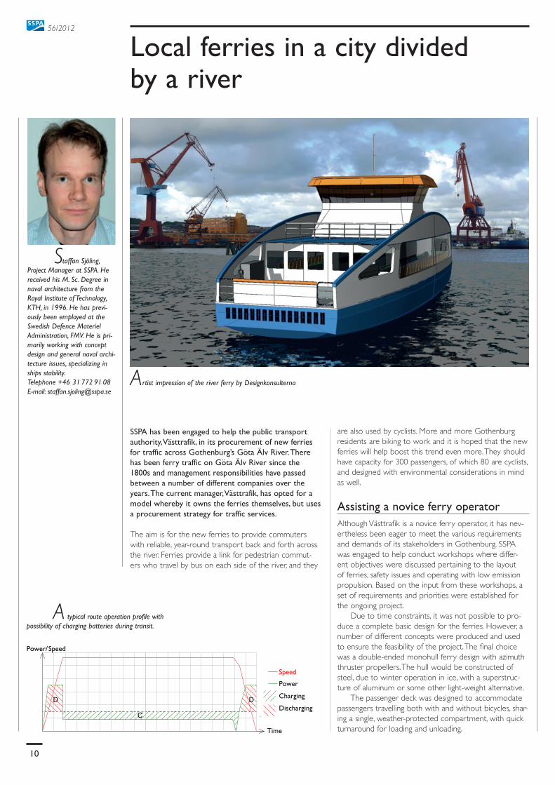
Artist impression of the river ferry by Designkonsulterna
Power
Charging
DischargingC
D D
Time
Power/Speed
Speed
Staffan Sjöling, Project Manager at SSPA. He received his M. Sc. Degree in naval architecture from the Royal Institute of Technology, KTH, in 1996. He has previ-ously been employed at the Swedish Defence Materiel Administration, FMV. He is pri-marily working with concept design and general naval archi-tecture issues, specializing in ships stability. Telephone +46 31 772 91 08 E-mail: [email protected]

11
56/2012
MES
MES
MES
Lindholmen
MES
En
viro
nm
en
t
Sta
tion
T-D
ISP
L
Sta
tio
n
T-D
ISP
L
T-D
ISP
L
En
vir
onm
en
t
T-D
ISP
LU
UD
H/C
Bunker
Clean. locker
Deck store
AP FP
H/C
Local ferries in a city divided by a river
Preliminary layout of the ferry.
Propulsion engines for tomorrow’s developmentOne of the challenges of the project was to design fer-ries equipped with low emission propulsion engines. The pros and cons of a number of alternatives were evaluated. It was finally decided to equip the ferries with conventional diesel-electric engines. This was mostly due to the uncertainty of new technologies and the need to satisfy certain regulatory requirements. In order to make power exchange possible in the future, a direct current power distribution system was chosen (rather than an alternating current distribution system). With a direct current power distribution system, the source of power can more easily be exchanged or supplemented with batteries.
Different power systemsSuper capacitors are energy storage systems that are particularly suitable for these types of ferries. Super capacitors are similar to batteries, but they can be recharged more quickly, i.e. seconds rather than minutes or hours. This is a major advantage, since ferries only makes short stops at the end terminals. Furthermore the distance across the river is short and stops are frequent, which enables frequent recharging. Another alternative power system could be a hybrid system with conven-tional batteries. In this case, diesel-electric engines could be supplemented with batteries. Ferries require the most
power during acceleration/deceleration at the end termi-nals and that power can be generated during transit and stored in batteries. With such a battery-hybrid system, smaller diesel generators could be used, resulting in lower emissions.
Using ferries as a test benchThe design of the ferries should also allow for possible modification of the power system. However, the details of such a modification are not currently known. The fer-ries must be able to accommodate additional weight and have sufficient space for future installations. A separate study, also performed by SSPA, investigated possible developments of the power system to ensure adequate design margins. One option is to use ferries as a test bench for new technologies in power generation.
SSPA provided Västtrafik with technical specifica-tions, a basic layout for the ferries and support during the procurement process, which is currently under way. It is hoped that a contract will be in place with a shipyard sometime in the near future.
SSPA is associated with among other things its test-ing facilities, hydrodynamic knowledge and research. The above example is yet another area of expertise; perform requirement analyses, offer design assistance and provide customer support services.
SSPA eagerly looks forward to seeing these new river ferries out on the Göta Älv River very soon.
Staffan Sjöling

12
Short comments
SSPA HIGHLIGHTS IS PUBLISHED BY:
SSPA SWEDEN AB
P.O. BOX 24001
SE-400 22 GÖTEBORG, SWEDEN
PHONE INT. + 46 -31 772 90 00
TELEFAX + 46-31 772 91 24
E-MAIL [email protected]
WEB SITE www.sspa.se
EDITOR IN CHIEF: HELÉN JANSSON
EDITOR: NILS LINDSKOUG
GRAPHIC DESIGN: WERNER SCHMIDT
PHOTO: ANDERS MIKAELSSON
PRINTED IN SWEDEN
ISSN 1401-3711
PHOTO FRONTPAGE
ERLAND WILSKE
Please visit our websitewww.sspa.sewww
AQUO
SSPA participates in AQUO, a col-laborative project funded by the European Commission. AQUO is an acronym that stands for “Achieve QUieter Oceans by shipping noise footprint reduction.” It has been funded under the 7th Framework Program, Theme 7: Transport (including aeronautics) – Sustainable Surface Transport. The topic that this project addresses is: assessment and mitigation of noise impacts of the maritime transport on the marine environment (a coordinated topic within the framework, Ocean of Tomorrow).
To some extent, AQUO is a continuation of another EC project, SILENV (Ship oriented Innovative soLutions to rEduce Noise and Vibrations). However, SILENV addressed almost all aspects of noise related to ships: Underwater Radiated Noise (URN), noise radi-ated in harbours and noise & vibra-tions inside ships. AQUO, on the other hand, is dedicated to noise impacts on the marine underwater environment and special attention is given to cavitating propellers.
The overall objective of AQUO is:- To assess and mitigate noise
impacts of maritime transports on the marine underwater envi-ronment, mainly for the protec-tion of marine species,
- To support the requirements of Directive 2008/56/EC (Marine Strategy Framework Directive) and related Commission Decision on criteria for Good Environmental Status.
At the end of the project, the main deliverable will be practical guidelines providing support to policy makers aimed at meeting the requirements of the Marine Strategy Framework directive (MSFD), including:- A good knowledge and predic-
tion of the shipping noise level and spatio-temporal distribution thanks to a Noise Footprint Assessment tool,
- Practical and economically fea-sible design recommendations for the reduction of underwater radiated noise (URN), of ships,
- Measures for the mitigation of impacts from shipping noise on the marine environment, with respect to living species.
Safety upgrade on naval vessels
SSPA has supported the Swedish Defense Material Administration (FMV) in a project to upgrade safe-ty on Swedish Navy “Bevakningsbåt 80” class vessels (22 meter patrol vessel). The upgrade was done to meet safety requirements for a new, increased operational area in the role as surveillance and border patrol vessels.
The project initially only included an upgrade to fulfill one-compart-ment damage stability by rebuilding a forward interior bulkhead to a watertight bulkhead. Here, SSPA assisted with stability evaluations, strength calculations for the bulk-head and detailed design sugges-tions to meet the requirements. The scope also included investigation of the current physical condition of the bulkhead and surrounding hull structure on each vessel. SSPA also supported FMV with all quality inspections at the yards during the
Papers 2012
Claudepierre, M., Klanac, A., Allenström, B.: “ULYSSES – the ultra slow ship of the future”, Green Ship Technology, Copenhagen, 2012
Li, D.-Q., Grekula, M., Lindell, P., Hallander, J.: “Prediction of cavitation for the INSEAN propeller E779A operating in uniform flow and non-uniform wakes”, Proceedings of the 8th International Symposium on Cavitation (CAV2012), Singapore, 2012
Hallander, J., Li, D.-Q., Allenström, B., Valdenazzi, F. Barras, C.: “Predicting underwater radiated noise due to a cavitating propel-ler in a ship wake”, Proceedings of the 8th International
SSPAs main efforts concerning this project involve:- Numerical modelling of pro-
peller cavitation and URN by Computational Fluid Dynamics,
- Model scale investigation of pro-peller cavitation and URN,
- Full scale observations of propel-ler cavitation and measurements of URN.
A coastal tanker will be the target for all of these efforts. Thus, full scale result will be compared to numerical predictions and to predic-tions by scale model tests.
In the work package, “Guidelines to reduce ship noise footprint,” SSPA is involved in the following tasks: “Effectiveness of solutions to reduce ship URN” and “Impact of solutions on fuel efficiency.”
Jan Hallander
Symposium on Cavitation (CAV2012), Singapore, 2012
Li, D.-Q., Leer-Andersen, M., Allenström, B.: Vortex for-mation of ”Flettner rotors” at high Reynolds numbers, 29th Symposium on Naval Hydrodynamics, Gothenburg, 2012
Kim, K., Leer-Andersen, M., Werner, S., Orych, M., Choi, Y.: “Hydrodynamic Optimization of Pre-swirl Stator by CFD and Model Testing”, 29th Symposium on Naval Hydrodynamics, Gothenburg, 2012
Shiri, A., Bensow, R., Leer-Andersen, M., Norrby, J.: “Study of Air Cavity Hydrodynamics for Displacement Ships”, 29th Symposium on Naval Hydrodynamics, Gothenburg, 2012
Ran, H., Rask, I., Janson, C.-E.,: “Damaged Ro-Pax Vessel Time to Capesiz”, 11th International Conference on Stability of Ships and Ocean Vehicles (STAB 2012), Athens, 2012
Bengtsson, S., Andersson, K., Ellis, J., Haraldsson, L., Ramne, B., Stefenson, P.: “Criteria for Future Marine Fuels”. Proceedings of the International Association of Maritime Economists (IAME) 2012 Conference, Taipei, Taiwan, 2012
building period as well as all deliv-ery inspections.
A second part of the project arose as a result of the initial work. During the hull structure inspec-tions, an earlier problem with occasional leakages in the fore ship on two vessels was addressed. After removing the forward interior, an inspection of the hulls revealed fail-ures of several structural elements. These failures resulted in cracks in the hull plating, which caused the leakages. Further inspections showed that the problem was com-mon for all vessels, i.e. this was not an isolated case. SSPA was assigned to investigate the reason for the fail-ures and suggest how to repair and strengthen the structure in order to meet the requirements related to the new operational area and the planned remaining lifetime of the vessels.
The investigation was based on analysis of the loads on individual structural members and on direct calculations of the hull strength and comparison to DNV regula-tions. The results showed two main reasons for the failure. The current operational profile resulted in higher loads than originally dimensioned for. The original structural design contained some unfortunate weak points.
In cooperation with the Shipyard Ö-varvet (responsible for conduct-ing the repair work on the first vessels), new detailed designs for repairing and strengthening the structure were produced (the pic-ture shows reinforced web frames). As in the first part of the project, SSPA then performed the continu-ous quality inspections and delivery inspections at the yards. A total of 11 vessels were upgraded at four different yards.
Niclas Dahlström


