Embed Size (px)
Citation preview

57
CHAPTER6
6.0 GeneralWidespread attention is nowbeing given to the installationof more expensive instrumenta-tion for study of the behavior ofdams and reservoirs and fore-casting of any adverse trends.
—Jansen (1980: 25)
The means and methods available to
monitor phenomena that can lead to dam
failure include a wide spectrum of
instruments and procedures, ranging from
very simple to very complex. Any program
of dam safety instrumentation must be
properly designed and consistent with
other project components, must be based
on prevailing geotechnical conditions at
the dam, and must consider the hydrologic
and hydraulic factors present both before
and after the project is in operation. Every
instrument should have a specific purpose
and expected design response.
Instruments designed for monitoring
potential deficiencies at existing dams
must take into account the threat to lifeand property that the dam presents. Thus,
the extent and nature of the instrumenta-
tion depends not only on the complexityof the dam and the size of the reservoir,
but also on the potential for loss of life and
property downstream.An instrumentation program should
involve instruments and evaluation
methods that are as simple and straightfor-ward as the project will allow. Beyond
that, the dam owner should make a
definite commitment to an ongoingmonitoring program or the installation ofinstruments probably will be wasted.
This chapter discusses deficiencies indams that may be discovered and the typesof instruments that may be used tomonitor those deficiencies. Increasedknowledge of these deficiencies acquiredthrough a monitoring program is useful indetermining both the cause of the deficien-cies and the necessary remedies. Contin-ued monitoring is important to determinethat the remedy remains effective.
Involvement of qualified personnel inthe design, installation, monitoring, andevaluation of an instrumentation systemis of prime importance to the success ofthe program.
6.1 Reasons forInstrumentation
Instrumentation and proper monitor-ing and evaluation are extremely valuablein determining the performance of a dam.Specific reasons for instrumentation include:
■ Warning of a Problem—Often,instruments can detect unusualchanges, such as fluctuations in waterpressure within the dam, that are notvisible. In other cases, gradual progres-sive changes in seepage flow, whichwould go unnoticed visually, can bemonitored regularly. This monitoringcan warn of the development of aserious seepage problem.
■ Analyzing and Defining a Problem—Instrumentation data are frequently
used to obtain engineering information
necessary for analyzing and defining the
extent of a problem. For example,
downstream movement of a dam
because of high reservoir-water pressure
must be analyzed to determine if the
movement is uniformly distributed
along the dam; whether the movement
is in the dam, the foundation, or both;
and whether the movement is constant,
increasing, or decreasing. Such infor-
mation can then be used to design
corrective measures.
■ Proving Behavior Is as Expected—
Instruments installed at a dam may
infrequently (or even never) show any
anomaly or problem. However, even
that information is valuable because it
shows that the dam is performing as
designed, offering peace of mind to
you, the owner. Also, although a problem
may appear to be extant or imminent,
instrument readings might show that
the deficiency (for example, increased
seepage) is normal (merely a result of
higher than normal reservoir level) and
was foreseen in the dam’s design.
■ Evaluating Remedial Action Perfor-
mance—Many dams, particularly older
ones, are modified to allow for in-
creased capacity or to correct a defi-
ciency. Instrument readings before and
after the change allow analysis and
evaluation of the performance of the
modification.
Chapter 6:Instrumentation andMonitoring Guidelines

58 TEXAS COMMISSION ON ENVIRONMENTAL QUALITY
Guidelines for Operation and Maintenance of Dams in Texas
6.2 InstrumentTypes and Usage
A wide variety of devices and procedures
are used to monitor dams. The features of
dams and dam sites most often monitored
by instruments include: [throughout
chapter: lowercased bullet items]
■ movements (horizontal, vertical,
rotational and lateral)
■ pore pressure and uplift pressures
■ water level and flow
■ seepage flow
■ water quality
■ temperature
■ crack and joint size
■ seismic activity
■ weather and precipitation
■ stress and strain
A thorough treatment of instrument
types and their usage is presented in
Dunnicliff 1993. Both the U.S. Bureau of
Reclamation and the U.S. Army Corps of
Engineers publish guides specific to the
instrumentation and monitoring of dams.
The Association of State Dam Safety
Officials <www.damsafety.org> and the U.S.
Society of Dams <www.USSDams.org>
offer technical conferences, reports, and
papers related to instrumentation and
dam-safety monitoring.
6.2.1 ObservationsAs discussed in Chapter 5, observa-
tions by you, the dam owner , or your
representative may be the most important
and effective means of monitoring the
performance of a dam. An inspector, upon
each visit to the dam site, should inspect it
visually—at a minimum, walking along
the dam alignment and looking for any
signs of distress or unusual conditions.
6.2.2 MovementsMovements occur in every dam. They
are caused by stresses induced by reservoir
water pressure, unstable slopes (lowshearing strength), low foundationshearing strength, settlement (compress-ibility of foundation and dam materials),thrust due to arching, expansion resultingfrom temperature change, and heaveresulting from hydrostatic uplift pressures.They can be categorized by direction:
■ Horizontal or translational movementcommonly occurs in an upstream-downstream direction in both embank-ment and concrete dams. It involves themovement of an entire dam massrelative to its abutments or foundation.In an embankment dam, instruments
commonly used for monitoring such
movement include:
• extensometers, including multi-point
extensometers
• inclinometers
• embankment measuring points
• shear strips
• structural measuring points
• time-domain reflectometry (TDR)
Installation of simple measuring
points is illustrated in Figure 6.1, a and b,
a simple crack monitoring system is shown
in Figure 6.2, and inclinometer systems
and plots are shown in Figures 6.3a–c.
Axis of Dam
Res.
Outlet Works
Station
Line of Sight(Established
OutsideTraffic Area)
Target Station
LocatedWhereit Will
Not MoveWhen Dam
Moves
PointsMarked
by Rebar
Figure 6.1bPlan of Alignment System
4” minimum
Convex to PreventWater Ponding on
Concrete 1” Rebar
3 F
ee
t
Figure 6.1aInstallation of Permanent Points

59TEXAS COMMISSION ON ENVIRONMENTAL QUALITY
Guidelines for Operation and Maintenance of Dams in Texas
For a concrete dam or concrete spillway, instruments for
monitoring horizontal movements may include:
■ crack measuring devices
■ extensometers, including multi-point extensometers
■ inclinometers
■ structural measuring points
■ tape gauges
■ strain meters
■ plumb lines
■ foundation-deformation gauges
■ tilt meters
■ 2D or 3D joint-movement indicators
■ electro-level beams
■ a GPS monitoring system
Examples of monitoring of concrete structure movements areshown in Figures 6.4a-d.
■ Vertical movement is commonly a result of consolidation of
embankment or foundation materials resulting in settlement ofthe dam. Another cause is heave (particularly at the toe of a dam)
caused by hydrostatic uplift pressures.
Figure 6.3aInclinometer—
Detail at Surface
Backfill
Figure 6.2Monitoring Cracks on Embankment
SteelTape
3”
A(Initial)
Rebar3” MinimumEmbedment
Carpenter’s Level(Spirit Level)
HorizontalDisplacement
InitialSecondReading
VerticalDisplacement
B(Subsequent)
SecondReading
Initial
3”
Figure 6.3bPlot of Inclinometer Readings
-1.0 0 +1.0 -1.0 0 +1.040
35
30
25
20
15
10
5
0
A-Direction B-Direction
1stReading
2ndReading
1stReading
2ndReading
Deflection in Inches
De
pth
in F
ee
t
Figure 6.3cInclinometer and Casing
Inclinometer
Instrumentin Place
A+
A+
A-
A-
B- B+Top

60 TEXAS COMMISSION ON ENVIRONMENTAL QUALITY
Guidelines for Operation and Maintenance of Dams in Texas
In an embankment dam, vertical movements may be moni-
tored by:
• settlement plates and sensors
• extensometers
• embankment survey monuments
• structural measuring points
• inclinometer casing measurements
In a concrete dam or concrete spillway, vertical movement
monitoring devices may include:
• settlement sensors
• extensometers
• a GPS monitoring system
• structural measuring points
• foundation-deformation gauges
■ Rotational movement is commonly a result of high reservoir water
pressure in combination with low shearing strength in an embank-
ment or foundation; it may occur in either component of a dam.
This kind of movement may be measured in either embankment
or concrete dams by instruments such as:
• extensometers
• inclinometers
• tilt meters
• surface measurement points
• crack-measurement devices
• electro-level beam sensors
• foundation-deformation gauges
• plumb lines (concrete only)
■ Lateral movement (parallel with the crest of a dam) is common in
concrete arch and gravity dams. The structure of an arch dam
causes reservoir water pressure to be translated into a horizontal
thrust against each abutment. Gravity dams also exhibit some
lateral movement because of expansion and contraction due to
temperature changes. These movements may be detected by:
• structural measurement points
• tilt meters
• extensometers
• crack-measurement devices
• plumb lines
• strain meters
• stress meters
• inclinometers
• joint meters
• load cells
Wall
Look for Changes Here
String orTwine
(C) Plumb Bob
Plumb Bobor Weight
(B) Straight Edge and TapePlus Reference Points
LateralDisplacementLead Plugs
Steel Tape
Look for Changes Here
(A) Straight Edge and Tape
VerticalDisplacement
Steel TapeStraight Edge
Side ofConcreteSpillway
Wall
StructuralCrack
Look for CrackingThrough Patch
(D) Mortar Marker
Mortar orEpoxy Patch
Figure 6.4Measuring Displacements
61TEXAS COMMISSION ON ENVIRONMENTAL QUALITY
Guidelines for Operation and Maintenance of Dams in Texas
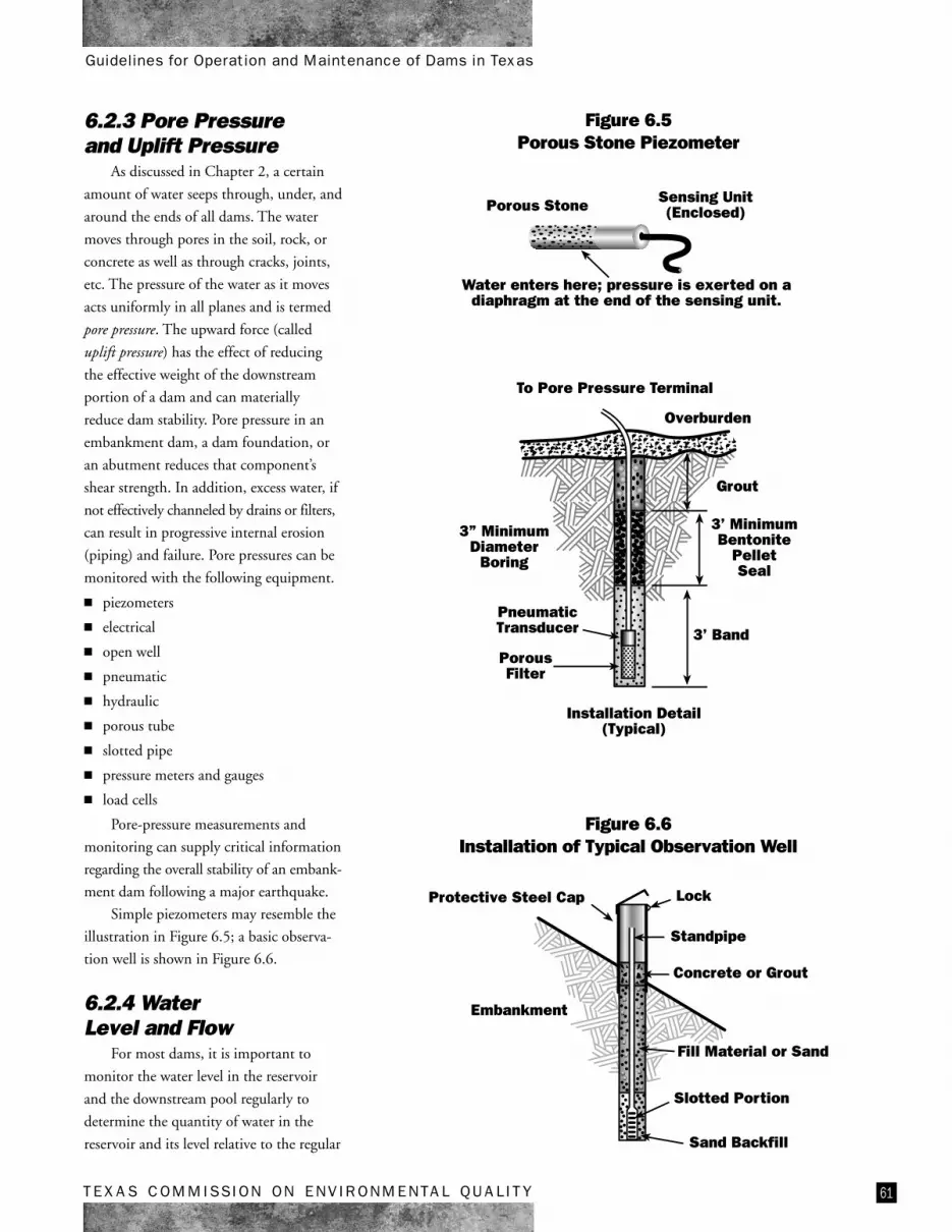
6.2.3 Pore Pressureand Uplift Pressure
As discussed in Chapter 2, a certain
amount of water seeps through, under, and
around the ends of all dams. The water
moves through pores in the soil, rock, or
concrete as well as through cracks, joints,
etc. The pressure of the water as it moves
acts uniformly in all planes and is termed
pore pressure. The upward force (called
uplift pressure) has the effect of reducing
the effective weight of the downstream
portion of a dam and can materially
reduce dam stability. Pore pressure in an
embankment dam, a dam foundation, or
an abutment reduces that component’s
shear strength. In addition, excess water, if
not effectively channeled by drains or filters,
can result in progressive internal erosion
(piping) and failure. Pore pressures can be
monitored with the following equipment.
■ piezometers
■ electrical
■ open well
■ pneumatic
■ hydraulic
■ porous tube
■ slotted pipe
■ pressure meters and gauges
■ load cells
Pore-pressure measurements and
monitoring can supply critical information
regarding the overall stability of an embank-
ment dam following a major earthquake.
Simple piezometers may resemble the
illustration in Figure 6.5; a basic observa-
tion well is shown in Figure 6.6.
6.2.4 WaterLevel and Flow
For most dams, it is important to
monitor the water level in the reservoir
and the downstream pool regularly to
determine the quantity of water in the
reservoir and its level relative to the regular
Protective Steel Cap
Embankment
Lock
Concrete or Grout
Standpipe
Fill Material or Sand
Slotted Portion
Sand Backfill
Figure 6.6Installation of Typical Observation Well
Installation Detail(Typical)
Overburden
PorousFilter
PneumaticTransducer 3’ Band
3’ MinimumBentonite
PelletSeal
3” MinimumDiameter
Boring
To Pore Pressure Terminal
Grout
Porous Stone Sensing Unit(Enclosed)
Water enters here; pressure is exerted on adiaphragm at the end of the sensing unit.
Figure 6.5Porous Stone Piezometer
62 TEXAS COMMISSION ON ENVIRONMENTAL QUALITY
Guidelines for Operation and Maintenance of Dams in Texas
outlet works and the emergency spillway.
The water level is also used to computewater pressure and pore pressure; the
volume of seepage is usually directly
related to the reservoir level. It is alsoimportant to establish the normal or
typical flow through the outlet works for
legal purposes.Water levels may be measured by
simple elevation gauges—either staff
gauges or numbers painted on permanent,fixed structures in the reservoir—or by
complex devices that sense water levels.
Flows are often computed from a knowl-edge of the dimensions of the outlet works
and the depth of flow in the outlet channel
or pipe.
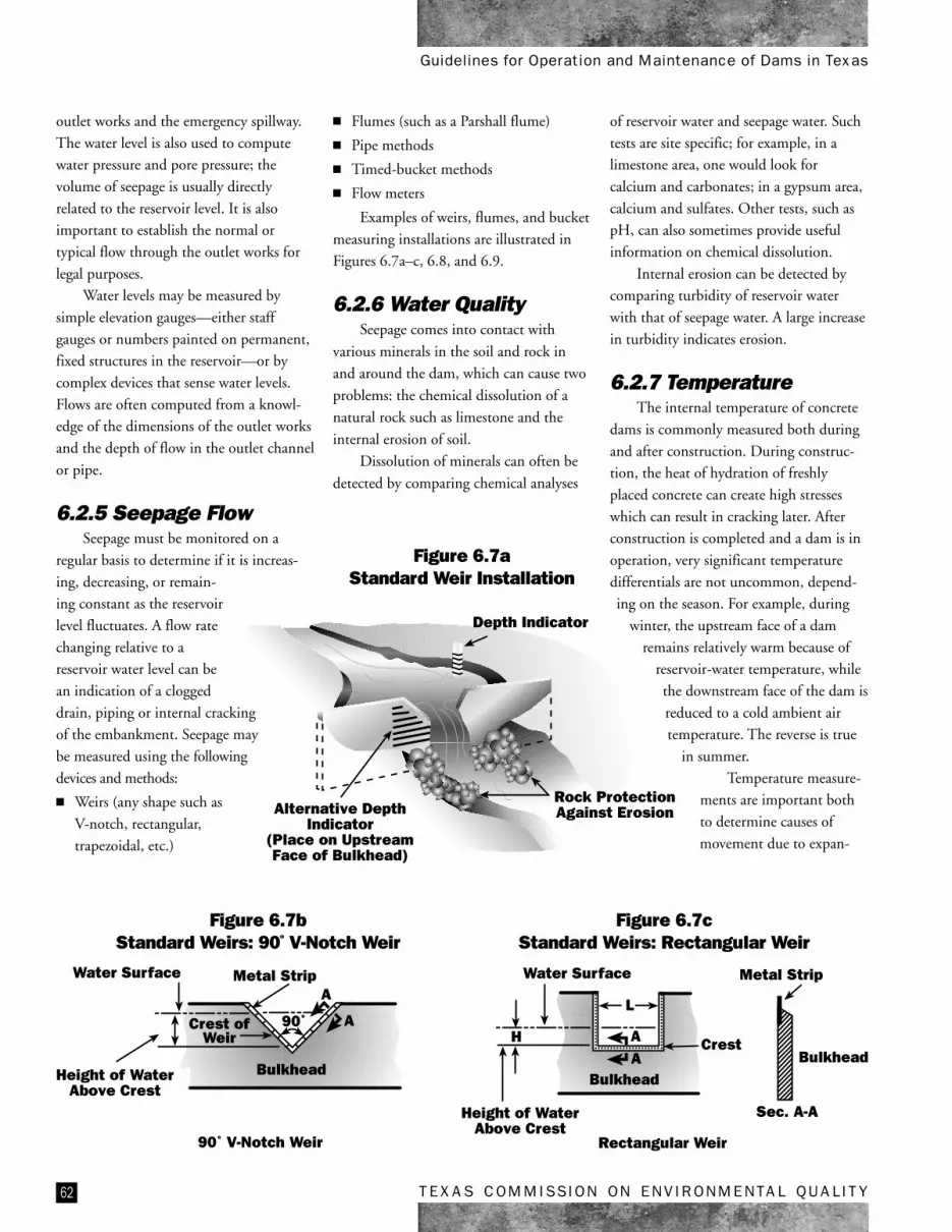
6.2.5 Seepage FlowSeepage must be monitored on a
regular basis to determine if it is increas-
ing, decreasing, or remain-ing constant as the reservoir
level fluctuates. A flow rate
changing relative to areservoir water level can be
an indication of a clogged
drain, piping or internal crackingof the embankment. Seepage may
be measured using the following
devices and methods:
■ Weirs (any shape such as
V-notch, rectangular,
trapezoidal, etc.)
■ Flumes (such as a Parshall flume)
■ Pipe methods
■ Timed-bucket methods
■ Flow meters
Examples of weirs, flumes, and bucket
measuring installations are illustrated inFigures 6.7a–c, 6.8, and 6.9.
6.2.6 Water QualitySeepage comes into contact with
various minerals in the soil and rock in
and around the dam, which can cause two
problems: the chemical dissolution of a
natural rock such as limestone and the
internal erosion of soil.
Dissolution of minerals can often be
detected by comparing chemical analyses
of reservoir water and seepage water. Such
tests are site specific; for example, in alimestone area, one would look for
calcium and carbonates; in a gypsum area,
calcium and sulfates. Other tests, such aspH, can also sometimes provide useful
information on chemical dissolution.
Internal erosion can be detected bycomparing turbidity of reservoir water
with that of seepage water. A large increase
in turbidity indicates erosion.
6.2.7 TemperatureThe internal temperature of concrete
dams is commonly measured both during
and after construction. During construc-tion, the heat of hydration of freshly
placed concrete can create high stresses
which can result in cracking later. Afterconstruction is completed and a dam is in
operation, very significant temperature
differentials are not uncommon, depend-ing on the season. For example, during
winter, the upstream face of a dam
remains relatively warm because ofreservoir-water temperature, while
the downstream face of the dam is
reduced to a cold ambient airtemperature. The reverse is true
in summer.
Temperature measure-ments are important both
to determine causes of
movement due to expan-
Bulkhead
Sec. A-A
Metal Strip
Rectangular Weir
Height of WaterAbove Crest
Bulkhead
CrestAA
L
H
Water Surface
90˚ V-Notch Weir
Height of WaterAbove Crest
Bulkhead
Crest ofWeir
A
A
Metal Strip
90˚
Water Surface
Alternative DepthIndicator
(Place on UpstreamFace of Bulkhead)
Depth Indicator
Rock ProtectionAgainst Erosion
Figure 6.7aStandard Weir Installation
Figure 6.7bStandard Weirs: 90º V-Notch Weir
Figure 6.7cStandard Weirs: Rectangular Weir

63TEXAS COMMISSION ON ENVIRONMENTAL QUALITY
Guidelines for Operation and Maintenance of Dams in Texas
sion or contraction and to compute actual
movement. Temperature may be measured
using any of several different kinds of
embedded thermometers or by simulta-
neous temperature readings on devices
such as stress and strain meters, which
allow for indirect measurement of the
temperature of the mass.
6.2.8 Crackand Joint Size
Knowing the locations and widths of
cracks and joints in concrete dams and in
concrete spillways and other concrete
appurtenances of embankment dams is
important because of the potential for
seepage through those openings. It is even
more important to know if the width of
such openings is increasing or decreasing.
Various measuring devices are available for
cracks and joints, most allowing very
accurate measurement. Some use simple
tape or dial gauges; others, complex
electronics.
6.2.9 Seismic ActivitySeismic measuring devices record the
intensity and duration of large-scale earth
movements such as earthquakes. Many
federal and state dams use these instru-
ments because they are part of the U.S.
Geological Survey’s network of seismic
recording stations. It may or may not be
necessary for a private dam to contain
seismic devices depending upon the area’s
seismic risk. Seismic instruments can also
be used to monitor any blasting conducted
near a dam site.
6.2.10 WeatherMonitoring the weather at a dam site
can provide valuable information about
both day-to-day performance and
developing problems. A rain gauge,
thermometer, and wind gauge can be
easily purchased, installed, maintained,
and monitored at a dam site.
6.2.11 Stress and StrainMeasurements to determine stress and
strain are common in concrete dams and,
to a lesser extent, in embankment dams.
The monitoring devices previously listed
for measuring dam movements, crack and
joint size, and temperature are also
appropriate for measuring stress and strain.
Monitoring for stress and strain permits
very early detection of movement.
6.3 AutomatedData-AcquisitionSystems
Over the last 20 years, there have
been significant efforts, primarily led by
federal dam-safety organizations, to
advance the state of practice in automat-
ing dam-safety instrumentation. These
projects were initially targeted towards
high hazard dams that posed significant
potential risk to downstream communi-
ties. These two decades have seen many
advances in sensor technology, data
acquisition equipment, and data manage-
ment that have made automated data
acquisition more reliable, cost-effective,
and readily available for broader applica-
tions in dam-safety monitoring.
An automated data-acquisition system
(or ADAS) can range from a simple data
logger temporarily connected to one or
more instruments to a permanent system
Depth of Flume
Throat Width
Figure 6.8Parshall Flume
Container of KnownVolume
Record TimeIt Takes to Fill
ContainerCollection
Ditch
Dike to ControlFlow
Figure 6.9Bucket-and-Stopwatch Method

64 TEXAS COMMISSION ON ENVIRONMENTAL QUALITY
Guidelines for Operation and Maintenance of Dams in Texas
that automates up to several hundred
instruments at a dam. Generally, an ADAS
for dam-safety monitoring includes the
following key components:
■ one or more electronic sensors (for
water levels, displacements, etc.)
■ a remote data logger (permanent or
portable)
■ a communication link to the dam for
remote access (cell phone, landline,
radio, or satellite)
An ADAS usually consists of one or
more solar-powered remote monitoring
units (RMUs) located on the dam
connected to key instruments to be
automated. The RMUs communicate via
radio, hardwire, or cell phone with a
central network monitor—a conventional
desktop PC with vendor-supplied interface
and communication software to provide
access to the on-site RMUs by remote
users. Typically, the monitor is located on-
site; however, it can be located at a remote
location (such as a district or administra-
tion building). Instrument readings are
stored in memory for either manual or
automatic downloading for plotting and
tabular reporting.
These systems can send out an alarm
via cell phone, pagers, or e-mail if user-
defined instrument thresholds are exceeded.
More recently, ADASes now incorporate
remote digital still or video cameras.
Since these systems are employed
outdoors, it is important to use only data-
acquisition equipment that is designed
for geotechnical instrumentation and
dam-safety monitoring. Pay special
attention to lightning protection and
grounding, surge protection, and backup
power supplies. You would be wise to
contact engineering companies and
vendors that are experienced in this area if
you are considering an ADAS for your
dam-monitoring requirements.
A properly designed and installed
ADAS can provide cost-effective and
reliable instrumentation data acquisition
and presentation to assist dam safety
personnel in both long-term monitoring
and during safety events. These systems
provide the ability to adjust the frequency
of instrument readings and provide the
ability to quickly assess trends from remote
locations. When coupled with downstream
warning sirens, ADAS can provide early
warning to downstream residents during a
safety problem.
For more information on ADASes for
dam-safety monitoring, refer to U.S.
Society of Dams (2002).
6.4 Frequencyof Monitoring
The frequency of instrument readings
or making observations at a dam depends
on several factors including:
■ the relative hazard to life and property
it represents
■ its height or overall size
■ the relative quantity of water impounded
■ the relative seismic risk at the site
■ its age
■ the frequency and amount of water-level fluctuation in the reservoir
In general, as each of the above factors
increases, the frequency of monitoring
should increase. For example, veryfrequent (even daily) readings should be
taken during the first filling of a reservoir,
and more frequent readings should betaken when water levels are high and after
significant storms and earthquakes. As arule of thumb, simple visual observations
should be made during each visit to the
dam and not less than monthly. Daily orweekly readings should be made during
the first filling, immediate readings should
be taken following a storm or earthquake,and significant seepage, movement, and
stress-strain readings should probably be
made at least monthly.
Source for information in this chapter: Jim Hummert, URS Corporation. St. Louis


