Embed Size (px)
Citation preview

SQUARE BALERSUSER GUIDE
Alpler Super S 8002 2KT Square Baler Machine - 2 Knotters TwineAlpler Super S 8002 3KT Square Baler Machine - 3 Knotters Twine
Alpler Super S 8002 3KT C Square Baler Machine - 3 Knotters Twine - with ChopperAlpler Super S 8002 E 2KT Square Baler Machine - 2 Knotters TwineAlpler Super S 8002 E 3KT Square Baler Machine - 3 Knotters Twine
Alpler Super S 8002 E 3KT C Square Baler Machine - 3 Knotters Twine - with Chopper

ATTENTION

5
5
5
6
6
6
7
7
8
8
8
9
9
9
9
10
11
12
12
12
12
12
12
13
13
13
13
14
14
14
14
15
15
16
INDEX
1. CONDITIONS OF USAGE
2. PREPARATION OF DELIVERABLES
2.1. Cautıons Durıng Transport and Shipping
3. WARRANTY
4. WARNINGS
4.1. Measures Prior to Usage
4.2. Measures During Travel to and From The Field
4.3. Attachment to Tractor
4.4. Shaft Connection
4.5. On Road Transport
4.6. Measures After Working
5. MACHINE ASSEMBLAGE
6. DESCRIPTIVE AND FUNDAMENTAL INFORMATION ABOUT MACHINE SPECIFICATIONS
7. OPERATION
7.1. Connection the machine to tractor and start-up
8. SPECIFICATIONS
9. MAIN SECTIONS AND FUNCTIONAL PARTS OF THE MACHINE
10. SECURITY SYSTEMS
10.1. Clutches
10.1.1. Flywheel Clutch
10.1.2. Narrow Clutch
10.1.3. Connection Group Clutch
10.1.4. Cradle Clutch
11. SAFETY BOLTS
11.1. Flywheel Safety Bolt
11.2. Knotter Group Safety Bolt
11.3. Pitchfork Safety Bolts
12. SETTING
12.1. Feed Arrangement Setting
12.1.1. Harrow unit Setting
12.1.2. Pitchfork Arms and Piston Settings
12.2. Star Gear and Needle-Star Gear Adjustment
12.3. Baler Height Setup
12.4. Bale tighness Settings

INDEX
SQUARE BALERS USER GUIDE2 www.a lp le r.com. t r
12.5. Needle Adjustment Via Piston Safety Catch
12.6. Piston, Piston Knife and Main Body Adjustment
12.6.1.Horizontal Configuration
12.6.2. Vertical Configuration
12.7. Flywheel Clutching Adjustment
13. BUNDLE-KNOTTING CONFIGURATION
13.1. Bundle Log
13.2. Needle Unit
13.3. Rollers and Tappets
14. FIRST TWINE STRINGING
15. SERIAL TWINE ATTACHMENT
16. BUNDLE-KNOTTING CONFIGURATION SETTINGS
16.1. Bundle-Knotting Setup
17. BUNDLE KNOT CHECK IN BUNDLE MECHANISM
18. MAIN SYNCHRONIZATION SETTINGS
19. SETTING GROUP SENT KNOTTING
20. PITCHFORK SETTINGS
21. KNOTTERS TROUBLESHOOTING
22. GENERAL MALFUCTION TABLE
23. USAGE ERRORS
23.1. Piston Speed too high or too low
23.2. Erroneous Twine Tension
24. PERIODICAL MAINTENENCE AND LUBRICATION
24.1. Daily Maintenence and Lubrication
24.2. Short-Time Parking
24.3. Parts to be Lubricated With Oil at the end of Each 10 Work Hours
24.4. Parts to be Lubricated With Oil at the end of Each 50 Work Hours
25. ACTIONS AT THE END OF EACH WORKING SEASON
26. LUBRICATED MACHINE PARTS
27. REPAIR
27.1. Rules to Obey Regarding Reparation
27.2. Reparations By Client
28. SERVICE AND SPARE PARTS
29. THE MACHINE OF HYDRAULIC TURN ON & TURN OFF
ANNEX / DISMANTLING THE CHOOPER
16
16
17
17
17
18
18
18
18
19
20
20
20
21
23
24
25
25
27
28
28
28
28
28
28
29
29
29
30
31
31
31
31
32
33

INTRODUCTION
SQUARE BALERS USER GUIDE3www.a lp le r.com. t r
Dear Farmer,
Firstly, we congratulate you for your correct preference on the way to efficiency by selecting the brand “ALPLER”. As your agricultural partner, we offer
you our product in which we combined high quality, low operational cost and effective after-sale service concept.
All of “ALPLER” products are designed for the most efficient and the safest use and tested accordingly in cooperation with the relevant university
departments, agricultural establishments and farmers. We request you to read the user manual before the first operation in order to use our product in
a more effective manner as well as for product and your own safety. The failures that may result from using the product beyond the instructions for use
specified in this manual are not covered by “ALPLER” warranty. “ALPLER” products are manufactured for agricultural utilization purposes only, and our
company does not assume any liability against the conditions arising from misuse. Maintenance, repair and operation of our products must be carried out
by those who were informed on the relevant and possible dangers.
Enjoy your new product and we wish you productive and fruitful years.
We hope to serve you for a long time...

WARNING SIGNS & MEANINGS
CAUTION
CAUTION
This sign warms that the operations described
could cause damage to machine, if they are not
carried out correctly.
WARNING
This sign warms that the operations described could
cause serious lesions or long term health risks, if they
are not carried out correctly.
DANGER
The arrows can be moved left and right.
READ MANUAL FIRST
Read the “Operating and Maintenance Manual”
carefully before first start and keep the manual
nearest.
KEEP CHILDREN AWAY
This symbol expresses to keep the children away
against any risk.
DO NOT STAND NEAR THE MACHINE WHILE IT IS WORKING
This symbol expresses not to stand near the machine
while it is working to avoid any injury.
SQUARE BALERS USER GUIDE4 www.a lp le r.com. t r
WARNING
Danger of getting caught of the turning companents.
3BAR
4BAR
DO NOT PUT YOUR HAND
Do not open or remove safety shields while the
engine is running.
P.T.O.
The shaft rotation direction and speed
Pressure of large wheel tire is 3 Bar
Pressure of large wheel tire is 3 Bar
Locations which need to be greased in each use.
During installation the machine is checked using a
three point of balance remove.
DANGER
DANGER
Danger of death.
1. CONDITIONS OF USAGE
SQUARE BALERS USER GUIDE5www.a lp le r.com. t r
• Any other use is not allowed. Our company is not responsible for the damages caused by the not prescribed operation. The user is fully responsible
• Correct usage means that the operator works regarding the service and maintenance conditions specified by the manufacturer.
• Only people familiar with this sprayer and well aware of its risks can use, repair and maintain it.
• All the conditions regarding the safety and prevention of accidents must be taken into consideration and satisfied.
• Baler is designed to be used if all safety measurements, specified in the manual, are taken.
• The manufacturer is not responsible for damages caused by non-authorized changes made on this machine.
• The misuse and mistakes of the operator may cause a serious injury or damage to himself and other living beings.
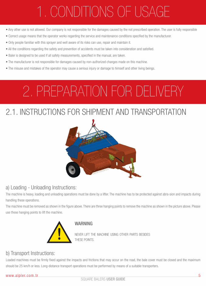
2. PREPARATION FOR DELIVERY2.1. INSTRUCTIONS FOR SHIPMENT AND TRANSPORTATION
WARNING
NEVER LIFT THE MACHINE USING OTHER PARTS BESIDES
THESE POINTS.
b) Transport Instructions:Loaded machines must be firmly fixed against the impacts and frictions that may occur on the road, the bale cover must be closed and the maximum
should be 25 km/h or less. Long-distance transport operations must be performed by means of a suitable transporters.
a) Loading - Unloading Instructions:The machine is heavy, loading and unloading operations must be done by a lifter. The machine has to be protected against abra-sion and impacts during
handling these operations.
The machine must be removed as shown in the figure above. There are three hanging points to remove the machine as shown in the picture above. Please
use these hanging points to lift the machine.

3. WARRANTY
SQUARE BALERS USER GUIDE6 www.a lp le r.com. t r
1. The repairs except the ones the consumer is allowed and may manage himself, cause the termination of war-ranty obligations.
2. If original parts are not used during reparations, the machine will be out of the scope of warranty; and also the responsibilities of damages on human
bodies and environment arising from such situation shall be belong to the consumer.
4. WARNINGSWARNINGS REGARDING SITUATIONS THAT CAN BE DANGEROUS OR HARMFUL FOR HUMAN AND ENVIRON-MENTAL HEALTH DURING USAGE
4.1 MEASURES PRIOR TO USAGE
1. If you will start the machine for the first time, please read all instructions attentively. Consult the manufacturer regarding issues on which you hesitate.
2. Make sure that the person driving the tractor to which your machine is attached has a driving license (F), is experienced and well-trained.
3. Start working with your machine only after taking all security measures on tractor.
4. Before connecting the machine to tractor, stop tractor en-gineset the parking brake and declutch.
5. Once you attach the machine to tractor and are in traffic, respect traffic rules and take security measures. Strictly follow the instructions about secure
driving and accident prevention.
6. Danger signs on the baler indicates short warnings for preventing accidents.
7. Before starting the baler, make sure that it is properly con-nected and adjusted.
8. Before starting tractor and baler, make sure that no other persons, especially no children and pets, are around the baler; take necessary measures in
order to see environment comfortably.
ATTENTION
The present manual is an integral part of BALERS under brand of ALPLER ZİRAAT ALETLERİ A.Ş. Warnings and instructions in this manual should be read attentively,
since they comprise significant information about usage and maintenance. Keep the
manual at a reachable and secure place.
WARNING
This machine should be used only pursuant to purpose it is designed for. Any other usage
should be known as wrong and erroneous. The manufacturer shall not be responsible
for damages to arise from inappropriate, wrong and unreasonable usage. Please pay
attention to security warnings that are indicated in order to prevent accidents.
4. WARNINGS
SQUARE BALERS USER GUIDE7www.a lp le r.com. t r
9. Do not start your machine before setting it to baling position on the field.
10. Before start-up, make some practice on controllers and functions to gain skill.
4.2. MEASURES DURING TRAVEL TO AND FROM THE FIELD
1. When you connect the machine to tractor and are in traffic, respect traffic rules and take security measures.
2. Strictly obey to safe drive and accident prevention instructions.
3. Do not enter between tractor and machine while the tractor is running and the shaft with movable head is revolving, also when the parking break is
not set and there is no mount in front of wheels.
4. Do not put any weight, do not let anyone to get on the machine, and do not put your hand in it during running.
5. When any operation or adjustment will be made on machine, both the machine and the tractor should be stopped.
6. Do not wear full clothes, long jackets or shirts during working. Such clothes may get caught and wrapped by moving parts. If it is necessary to wear
long shirt due to the operation, it should be totally buttoned and necessary attention should be paid during working.
7. Do not eat or drink anything during work.
8. Do not use the machine without protection and covers.
9. Before dismounting the baler from tractor, make sure that balance bases, as well as the parking brake of tractor are set; the engine is stopped and
the ignition key is removed.
10. The load, cranking speed, etc. limits of the machine should not be impelled.
11. Never get on and off tractor while it is on the move.
12. Do not declutch while advancing downhill.
13. Before detaching the drawbar of baler from tractor hook, dismount the power take-off shaft from the tractor and open the balance (lifting jack)
pedestal.
14. If possible, park the tractor on a flat surface, gear it, and set the parking brake. If it will be parked on a slope, you should gear the low for uphill and
the reverse for downhill, and set the parking brake in both situations.
Shaft connection must be necessarily unbound.
4.3. ATTACHMENT TO TRACTOR
1. During the attachment of machine to tractor, there should be nobody between machine and tractor.
2. Baler must be connected to tractor by a drawbar. After support leg is adjusted, draw pole is connected near the middle of drawbar; and the machine
is set to running in road mode.
3. Anchor pins on baler and tractor should be the same type.
4. It is absolutely inconvenient to stay within the moving area of lifting arms.
5. Pay attention while attaching and detaching the baler to and from tractor.
6. During machine attachment to tractor, there should be nobody between machine and tractor.
7. While the engine is running and the parking brake is not set, it is forbidden to stand in the opening between tractor and equipment.
8. Attachment of additional equipment to tractor causes imposing different intermissions on axles. After the baler is connected to tow hook, check the
performance and adaptation of tractor. Consult to seller if you have any doubts.
4. WARNINGS4.4 SHAFT CONNECTION
1. Stop the engine during shaft connection or disconnection on machine and tractor. Make sure that shaft is rightly attached.
2. Shaft length should be well set. The baler should be in the same direction with shaft and tractor. After the shaft is connected, the case should be
attached to chassis in order to prevent turning.
3. During operation on field, the movement should be ceased at turns.
4. The passing on shaft should be minimum 30 cm.
5. Keep away from juncture area while the engine is running.
6. The movement of shaft should be interrupted at sharp bends.
7. Keep yourself and others away from the machine while it is running.
SQUARE BALERS USER GUIDE8 www.a lp le r.com. t r
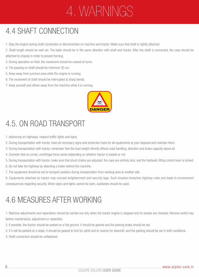
DANGER
4.5. ON ROAD TRANSPORT
1. Advancing on highways, respect traffic lights and signs.
2. During transportation with tractor, have all necessary signs and protection tools for all equipments at your disposal and maintain them.
3. During transportation with tractor, remember that the load weight directly effects road handling, direction and brake capacity above all.
4. Consider that at curves, centrifugal force varies depending on whether tractor is loaded or not.
5. During transportation with tractor, make sure that shunt chains are adjusted; the caps are entirely shut, and the hydraulic lifting control lever is locked.
6. Do not take the highway by attaching a trailer behind the machine.
7. The equipment should be set to transport position during transportation from working area to another site.
8. Equipments attached on tractor may conceal enlightenment and security tags. Such situation breaches highway rules and leads to inconvenient
consequences regarding security. When signs and lights cannot be seen, auxiliaries should be used.
4.6 MEASURES AFTER WORKING
1. Machine adjustments and reparations should be carried out only when the tractor engine is stopped and its wheels are chocked. Remove switch key
before maintenance, adjustment or reparation.
2. If possible, the tractor should be parked on a flat ground; it should be geared and the parking brake should be set.
3. If it will be parked on a slope, it should be geared to first for uphill and to reverse for downhill; and the parking should be set in both conditions.
4. Shaft connection should be unfastened.
5. MACHINE ASSEMBLAGE
SQUARE BALERS USER GUIDE9www.a lp le r.com. t r
1. We recommend you to use the machine with a tractor that possesses technical specifications indicated in the manual.
2. When the machine is delivered, it has twines at same number with fixture, and all necessary adjustments and lubricating on sections are made.
3. After reading the manual, start the engine by connecting it to tractor pursuant to explanations.
6. DESCRIPTIVE AND FUNDAMENTAL INFORMATION ABOUT MACHINE
SPECIFICATIONSThe balers are started after connecting behind a tractor, and they transform the hay into matchbox-like big packages. It is very hard to carry to the storage
and to store the hay, alfalfa or other plants, cereal stems or hays that are mown and dried on the field and that can be used as feedstuff in winter. In order
to facilitate this process, the above-mentioned products are carried after being packed. Thus, well-shaped hay packages can be easily transported and
stored without occupying too much room. Besides, possible losses during transportation and storage are minimized.
7. OPERATION7.1. CONNECTING THE MACHINE TO TRACTOR AND START-UP
1. Lift the machine by the jack on balance pedestal and set parallel to the ground, connect it to tow hook on tractor. In order to do that, you may have
to adjust also the ground clearance of tow hook on tractor. Do not attach your machine to the drawbar that is connected to side suspension arms. After
machine-tractor connection, lift the jack on the drawbar and determine its place on the bar. Connect the pickup system hydraulic jacks and the power
plug at their places on tractor. After machine-tractor connection, the shaft, which transmits the movement from tractor to machine, should be attached.
After affixing one end of the shaft to machine and the other to tractor, tie the security chain on shaft case to an appropriate place.
2. Do not start your machine before setting it to a position available for baling on field.
In the course of field work, in order to decrease the load on junctures during curves, reduce the revolution of tail axle and pay attention not to make sharp
turns.
3. After respecting all above given recommendations and making sure that there is no one around the machine and that you have not forgotten any tools
within, start the machine gradually. Check if all parts work freely and silently.
4. Set the tail axle revolutions to 200-250 rpm, and run the machine out of gear for a while.
5. Loosen the bale seize springs and after increasing the tail axle revolutions to 500-550 rpm, begin working.
6. Bale first one hundred packages for settling the operating systems.

7. OPERATION
SQUARE BALERS USER GUIDE10 www.a lp le r.com. t r
7. By the way, check the length, tightness and smoothness of bale. After first one hundred bales, stop machine and look over. Make the smoothness,
length and tightness adjustments of bale if needed.
8. Your baler is manufactured according to 540 rpm of tail axle revolutions. The maximum revolution during operation should be 610 rpm. Pay attention
to that and do not work on higher revolution.
Max.
Rpm.
540
8. SPECIFICATIONS1. Baler can bale dry or semi-dry hay.
2. Bale size and tightness can be adjusted according to purpose.
3. Height setting of harrow mechanism can be adjusted from tractor seat.
4. The harrow is sufficiently wide.
5. It can be easily and handily switched to operation and road positions.
6. The vibration and clicking is at maximum level during opera-tion.
7. Thanks to its tire equipment, it does not sink on soft lands.
8. Important mechanisms are protected by security devices.
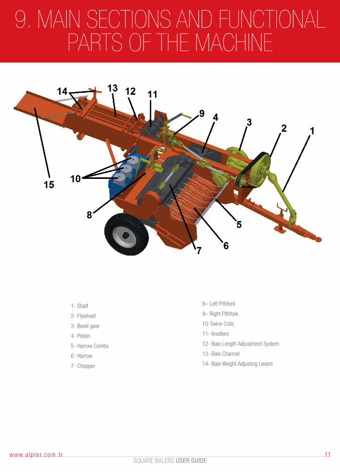
9. MAIN SECTIONS AND FUNCTIONAL PARTS OF THE MACHINE
SQUARE BALERS USER GUIDE11www.a lp le r.com. t r
1- Shaft
2- Flywheel
3- Bevel gear
4- Piston
5- Harrow Combs
6- Harrow
7- Chopper
8– Left Pithfork
9– Right Pithfork
10-Twine Coils
11- Knotters
12- Bale Length Adjustment System
13- Bale Channel
14- Bale Weight Adjusting Levers
10. SECURITY SYSTEMS
SQUARE BALERS USER GUIDE12 www.a lp le r.com. t r
For that baler is not harmed in case of a possible jamming, certain security systems are designed.
1. Clutches
2. Safety bolts
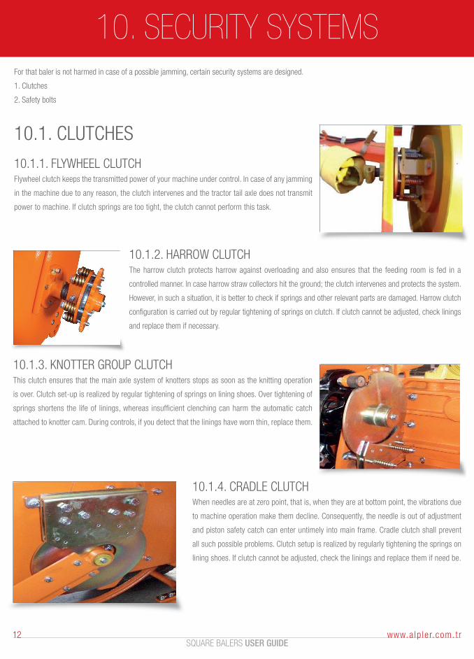
10.1. CLUTCHES
10.1.1. FLYWHEEL CLUTCHFlywheel clutch keeps the transmitted power of your machine under control. In case of any jamming
in the machine due to any reason, the clutch intervenes and the tractor tail axle does not transmit
power to machine. If clutch springs are too tight, the clutch cannot perform this task.
10.1.3. KNOTTER GROUP CLUTCHThis clutch ensures that the main axle system of knotters stops as soon as the knitting operation
is over. Clutch set-up is realized by regular tightening of springs on lining shoes. Over tightening of
springs shortens the life of linings, whereas insufficient clenching can harm the automatic catch
attached to knotter cam. During controls, if you detect that the linings have worn thin, replace them.
10.1.4. CRADLE CLUTCHWhen needles are at zero point, that is, when they are at bottom point, the vibrations due
to machine operation make them decline. Consequently, the needle is out of adjustment
and piston safety catch can enter untimely into main frame. Cradle clutch shall prevent
all such possible problems. Clutch setup is realized by regularly tightening the springs on
lining shoes. If clutch cannot be adjusted, check the linings and replace them if need be.
10.1.2. HARROW CLUTCHThe harrow clutch protects harrow against overloading and also ensures that the feeding room is fed in a
controlled manner. In case harrow straw collectors hit the ground; the clutch intervenes and protects the system.
However, in such a situation, it is better to check if springs and other relevant parts are damaged. Harrow clutch
configuration is carried out by regular tightening of springs on clutch. If clutch cannot be adjusted, check linings
and replace them if necessary.
11. SAFETY BOLTS
SQUARE BALERS USER GUIDE13www.a lp le r.com. t r
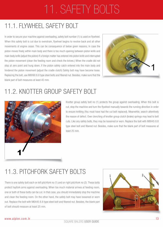
11.1. FLYWHEEL SAFETY BOLT
In order to secure your machine against overloading, safety bolt number (1) is used on flywheel.
When this safety bolt is cut due to overstrain, flywheel begins to revolve back and all other
movements of engine cease. This can be consequence of below given reasons; In case the
piston moves freely within main body and there is too much opening between piston knife and
main body knife (adjust the piston) If a foreign matter has entered into piston knife and interrupted
the piston movement (clean the feeding room and check the knives.) When the cradle did not
stop at zero point and hung down, if the piston safety catch entered into the main body and
hindered the piston movement (adjust the cradle clutch) Safety bolt may have become loose.
Replacing the bolt, use M8X90 8.8 type steel bolts and fibered nut. Besides, make sure that the
blank part of bolt measures at least 45 mm.
11.2. KNOTTER GROUP SAFETY BOLT
11.3. PITCHFORK SAFETY BOLTS
There is one safety bolt each on left pitchfork no (1) and on right pitchfork no (2). These bolts
protect hayfork arms against overloading. When too much material arrives at feeding room,
one or both of these bolts can be cut. In that case, you should immediately stop the machine
and clean the feeding room. On the other hand, the safety bolt may have loosened or worn
out. Replace the bolt with M6X45 8.8 type steel bolt and fibered nut. Besides, the blank part
of bolt should measure at least 25 mm.
Knotter group safety bolt no (1) protects the group against overloading. When this bolt is
cut, stop the machine and turn the flywheel manually towards the running direction in order
to ensure knitting (You must have had the cut bolt replaced). Meanwhile, search attentively
the reason of defect. Over clenching of knotter group clutch (brake) springs may lead to bolt
cuts. Like any safety bolts, they may be loosened or worn. Replace the bolt with M8X45 8.8
type steel bolt and fibered nut. Besides, make sure that the blank part of bolt measures at
least 25 mm.
12. SETTINGS
SQUARE BALERS USER GUIDE14 www.a lp le r.com. t r
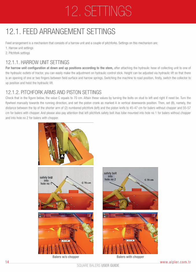
12.1. FEED ARRANGEMENT SETTINGSFeed arrangement is a mechanism that consists of a harrow unit and a couple of pitchforks. Settings on this mechanism are;
1. Harrow unit settings
2. Pitchfork settings
12.1.1. HARROW UNIT SETTINGSFor harrow unit configuration at down and up positions according to the stem, after attaching the hydraulic hose of collecting unit to one of
the hydraulic outlets of tractor, you can easily make the adjustment on hydraulic control stick. Height can be adjusted via hydraulic lift so that there
is an opening of one or two fingers between field surface and harrow springs. Switching the machine to road position, firstly, switch the collector to
up position and hoist the hydraulic lift.
12.1.2. PITCHFORK ARMS AND PISTON SETTINGSCheck that in the figure below, the value C equals to 70 cm. Attain these values by turning the bolts on stud to left and right if need be. Turn the
flywheel manually towards the running direction, and set the piston crank as marked A in vertical downwards position. Then, set (B), namely, the
distance between the tip of the shorter arm of (2) numbered pitchfork (left) and the piston knife to 45-47 cm for balers without chopper and 55-57
cm for balers with chopper. And please also pay attention that left pitchfork safety bolt ihas tobe mounted into hole no 1 for balers without chopper
and into hole no 2 for balers with chopper.
Balers w/o chopper Balers with chopper
safety boltinto
hole no 1
safety boltinto
hole no 2
12. SETTINGS
SQUARE BALERS USER GUIDE15www.a lp le r.com. t r
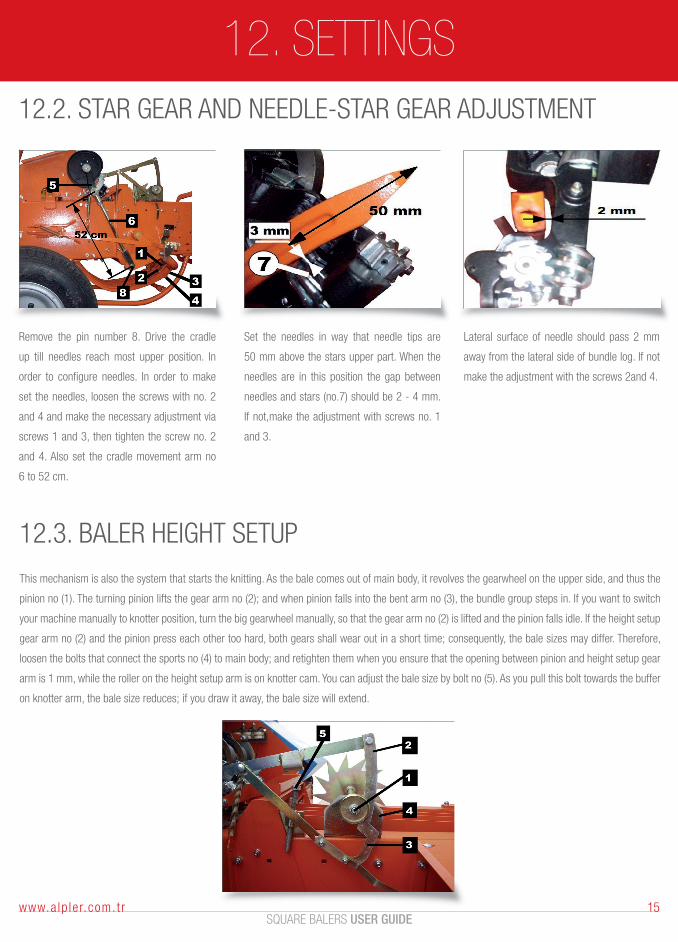
12.2. STAR GEAR AND NEEDLE-STAR GEAR ADJUSTMENT
Remove the pin number 8. Drive the cradle
up till needles reach most upper position. In
order to configure needles. In order to make
set the needles, loosen the screws with no. 2
and 4 and make the necessary adjustment via
screws 1 and 3, then tighten the screw no. 2
and 4. Also set the cradle movement arm no
6 to 52 cm.
Set the needles in way that needle tips are
50 mm above the stars upper part. When the
needles are in this position the gap between
needles and stars (no.7) should be 2 - 4 mm.
If not,make the adjustment with screws no. 1
and 3.
Lateral surface of needle should pass 2 mm
away from the lateral side of bundle log. If not
make the adjustment with the screws 2and 4.
12.3. BALER HEIGHT SETUP
This mechanism is also the system that starts the knitting. As the bale comes out of main body, it revolves the gearwheel on the upper side, and thus the
pinion no (1). The turning pinion lifts the gear arm no (2); and when pinion falls into the bent arm no (3), the bundle group steps in. If you want to switch
your machine manually to knotter position, turn the big gearwheel manually, so that the gear arm no (2) is lifted and the pinion falls idle. If the height setup
gear arm no (2) and the pinion press each other too hard, both gears shall wear out in a short time; consequently, the bale sizes may differ. Therefore,
loosen the bolts that connect the sports no (4) to main body; and retighten them when you ensure that the opening between pinion and height setup gear
arm is 1 mm, while the roller on the height setup arm is on knotter cam. You can adjust the bale size by bolt no (5). As you pull this bolt towards the buffer
on knotter arm, the bale size reduces; if you draw it away, the bale size will extend.
12. SETTINGS
SQUARE BALERS USER GUIDE16 www.a lp le r.com. t r
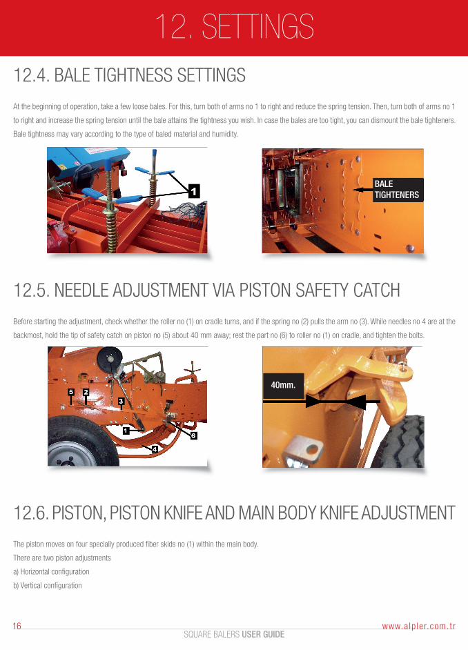
12.4. BALE TIGHTNESS SETTINGS
At the beginning of operation, take a few loose bales. For this, turn both of arms no 1 to right and reduce the spring tension. Then, turn both of arms no 1
to right and increase the spring tension until the bale attains the tightness you wish. In case the bales are too tight, you can dismount the bale tighteners.
Bale tightness may vary according to the type of baled material and humidity.
BALETIGHTENERS
12.5. NEEDLE ADJUSTMENT VIA PISTON SAFETY CATCH
Before starting the adjustment, check whether the roller no (1) on cradle turns, and if the spring no (2) pulls the arm no (3). While needles no 4 are at the
backmost, hold the tip of safety catch on piston no (5) about 40 mm away; rest the part no (6) to roller no (1) on cradle, and tighten the bolts.
40mm.
12.6. PISTON, PISTON KNIFE AND MAIN BODY KNIFE ADJUSTMENT
The piston moves on four specially produced fiber skids no (1) within the main body.
There are two piston adjustments
a) Horizontal configuration
b) Vertical configuration
12. SETTINGS
SQUARE BALERS USER GUIDE17www.a lp le r.com. t r
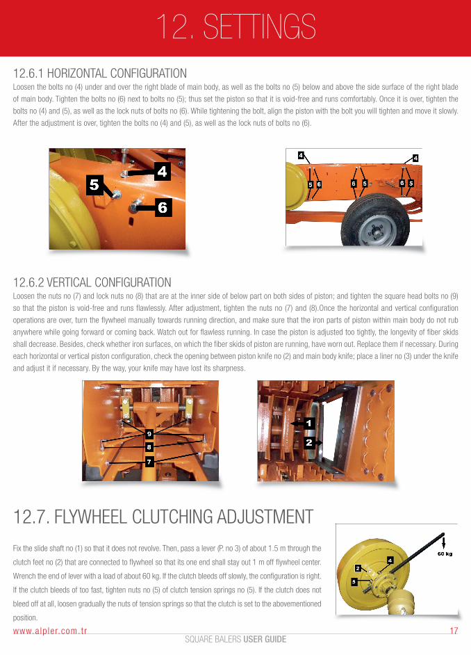
12.6.1 HORIZONTAL CONFIGURATIONLoosen the bolts no (4) under and over the right blade of main body, as well as the bolts no (5) below and above the side surface of the right blade
of main body. Tighten the bolts no (6) next to bolts no (5); thus set the piston so that it is void-free and runs comfortably. Once it is over, tighten the
bolts no (4) and (5), as well as the lock nuts of bolts no (6). While tightening the bolt, align the piston with the bolt you will tighten and move it slowly.
After the adjustment is over, tighten the bolts no (4) and (5), as well as the lock nuts of bolts no (6).
12.6.2 VERTICAL CONFIGURATIONLoosen the nuts no (7) and lock nuts no (8) that are at the inner side of below part on both sides of piston; and tighten the square head bolts no (9)
so that the piston is void-free and runs flawlessly. After adjustment, tighten the nuts no (7) and (8).Once the horizontal and vertical configuration
operations are over, turn the flywheel manually towards running direction, and make sure that the iron parts of piston within main body do not rub
anywhere while going forward or coming back. Watch out for flawless running. In case the piston is adjusted too tightly, the longevity of fiber skids
shall decrease. Besides, check whether iron surfaces, on which the fiber skids of piston are running, have worn out. Replace them if necessary. During
each horizontal or vertical piston configuration, check the opening between piston knife no (2) and main body knife; place a liner no (3) under the knife
and adjust it if necessary. By the way, your knife may have lost its sharpness.
12.7. FLYWHEEL CLUTCHING ADJUSTMENT
Fix the slide shaft no (1) so that it does not revolve. Then, pass a lever (P. no 3) of about 1.5 m through the
clutch feet no (2) that are connected to flywheel so that its one end shall stay out 1 m off flywheel center.
Wrench the end of lever with a load of about 60 kg. If the clutch bleeds off slowly, the configuration is right.
If the clutch bleeds of too fast, tighten nuts no (5) of clutch tension springs no (5). If the clutch does not
bleed off at all, loosen gradually the nuts of tension springs so that the clutch is set to the abovementioned
position.
13. BUNDLE - KNOTTING CONFIGURATION
SQUARE BALERS USER GUIDE18 www.a lp le r.com. t r
13.1. BUNDLE LOG
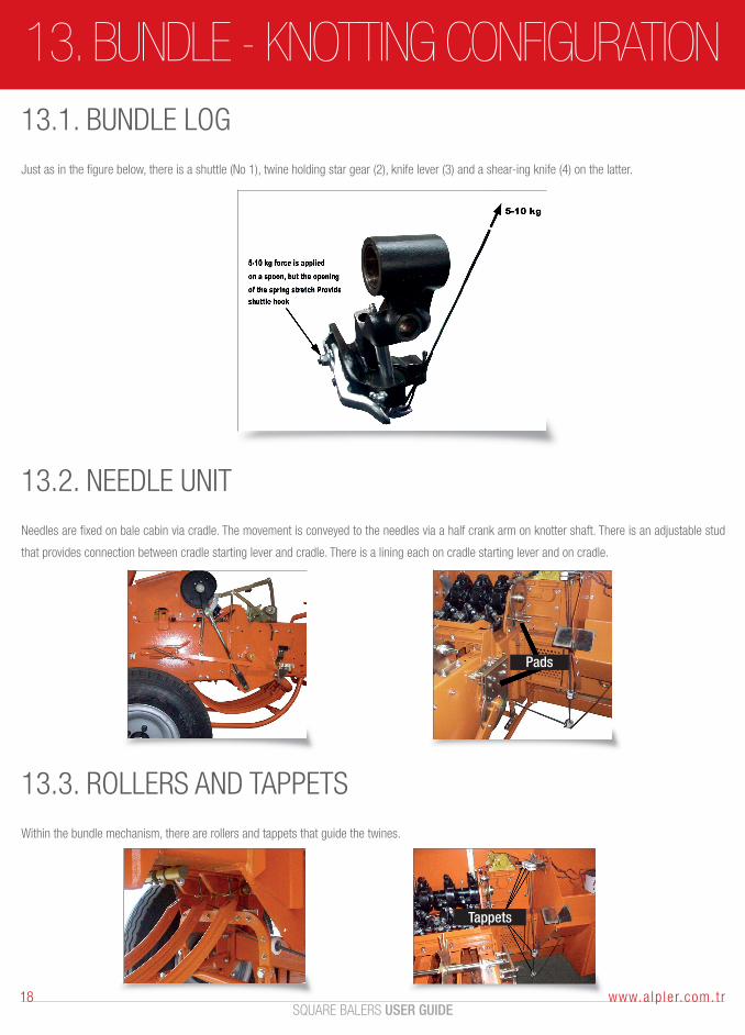
Just as in the figure below, there is a shuttle (No 1), twine holding star gear (2), knife lever (3) and a shear-ing knife (4) on the latter.
13.2. NEEDLE UNIT
Needles are fixed on bale cabin via cradle. The movement is conveyed to the needles via a half crank arm on knotter shaft. There is an adjustable stud
that provides connection between cradle starting lever and cradle. There is a lining each on cradle starting lever and on cradle.
Pads
13.3. ROLLERS AND TAPPETS
Within the bundle mechanism, there are rollers and tappets that guide the twines.
Tappets
14. FIRST TWINE STRINGING
SQUARE BALERS USER GUIDE19www.a lp le r.com. t r
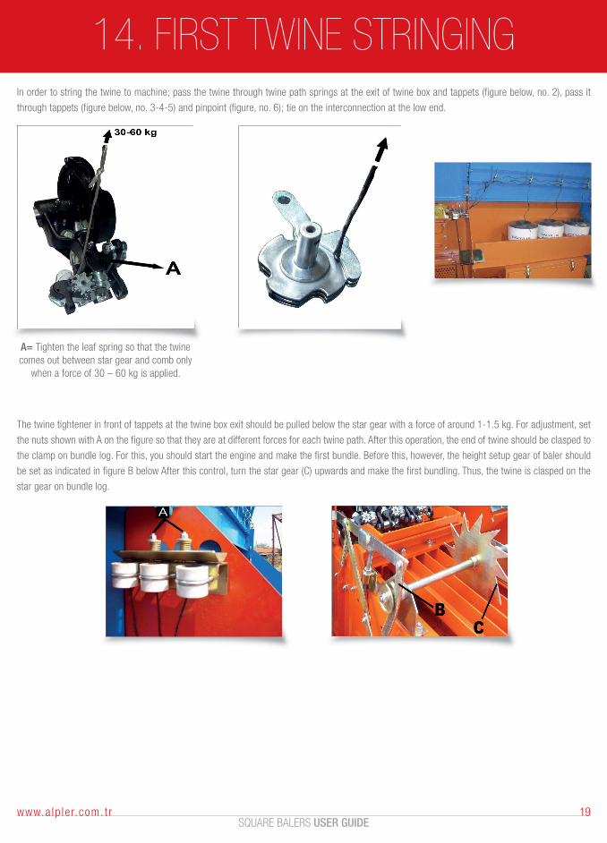
In order to string the twine to machine; pass the twine through twine path springs at the exit of twine box and tappets (figure below, no. 2), pass it
through tappets (figure below, no. 3-4-5) and pinpoint (figure, no. 6); tie on the interconnection at the low end.
The twine tightener in front of tappets at the twine box exit should be pulled below the star gear with a force of around 1-1.5 kg. For adjustment, set
the nuts shown with A on the figure so that they are at different forces for each twine path. After this operation, the end of twine should be clasped to
the clamp on bundle log. For this, you should start the engine and make the first bundle. Before this, however, the height setup gear of baler should
be set as indicated in figure B below After this control, turn the star gear (C) upwards and make the first bundling. Thus, the twine is clasped on the
star gear on bundle log.
A= Tighten the leaf spring so that the twine comes out between star gear and comb only
when a force of 30 – 60 kg is applied.
15. SERIAL TWINE ATTACHMENT
SQUARE BALERS USER GUIDE20 www.a lp le r.com. t r
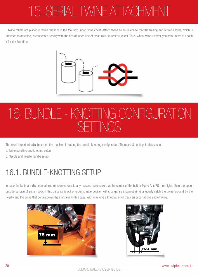
6 twine rollers are placed in twine chest or in the tool box under twine chest. Attach these twine rollers so that the trailing end of twine roller, which is
attached to machine, is connected serially with the tips at inner side of twine roller in reserve chest. Thus, when twine expires, you won’t have to attach
it for the first time.
The most important adjustment on the machine is setting the bundle-knotting configuration. There are 3 settings in this section.
a. Twine bundling and knotting setup
b. Needle and needle handle setup
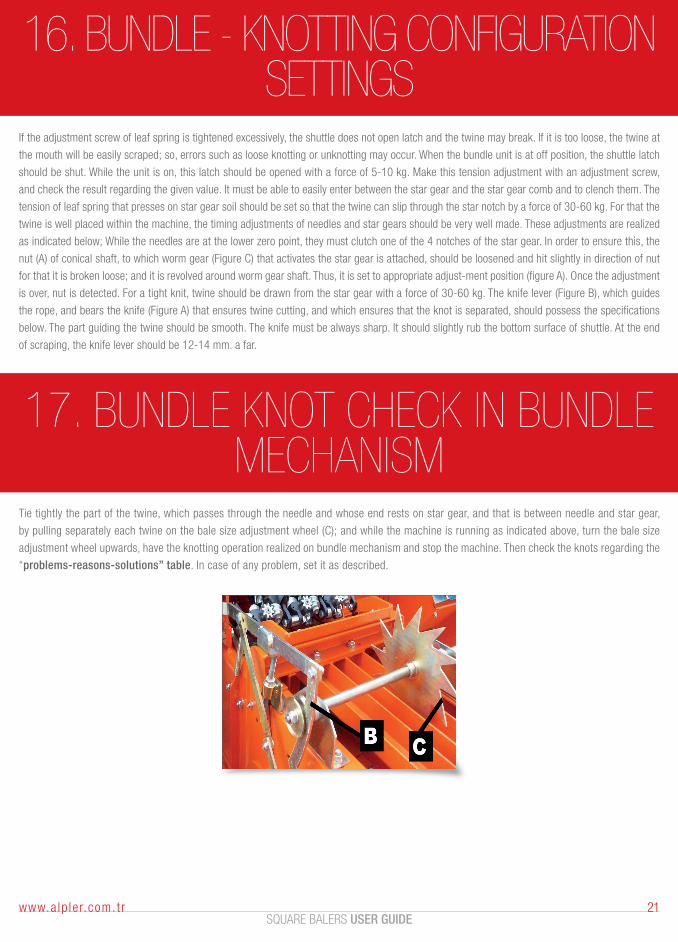
16.1. BUNDLE-KNOTTING SETUP
In case the bolts are dismounted and remounted due to any reason, make sure that the center of the bolt in figure A is 70 mm higher than the upper
outside surface of piston body. If this distance is out of order, shuttle position will change; so it cannot simultaneously catch the twine brought by the
needle and the twine that comes down the star gear. In this case, knot may give a knotting error that can occur at one end of twine.
16. BUNDLE - KNOTTING CONFIGURATION SETTINGS
SQUARE BALERS USER GUIDE21www.a lp le r.com. t r
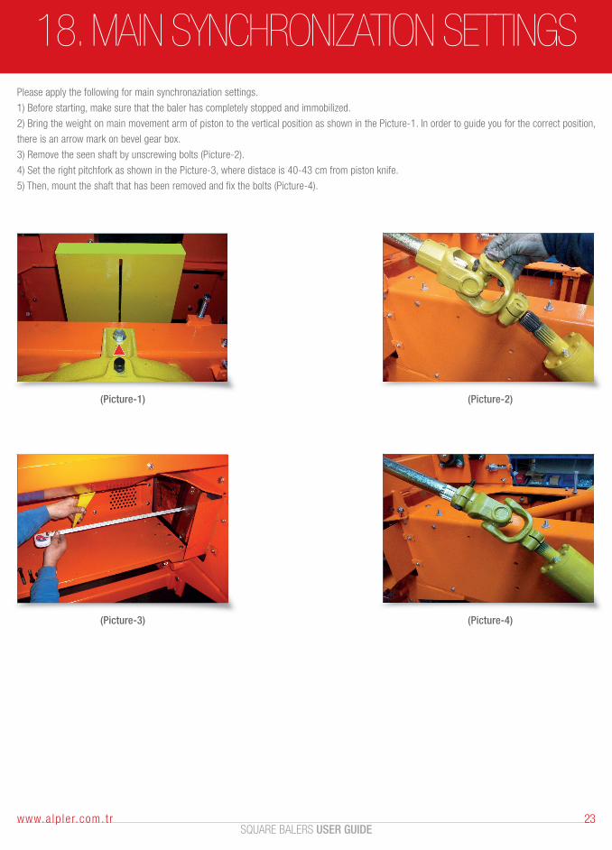
If the adjustment screw of leaf spring is tightened excessively, the shuttle does not open latch and the twine may break. If it is too loose, the twine at
the mouth will be easily scraped; so, errors such as loose knotting or unknotting may occur. When the bundle unit is at off position, the shuttle latch
should be shut. While the unit is on, this latch should be opened with a force of 5-10 kg. Make this tension adjustment with an adjustment screw,
and check the result regarding the given value. It must be able to easily enter between the star gear and the star gear comb and to clench them. The
tension of leaf spring that presses on star gear soil should be set so that the twine can slip through the star notch by a force of 30-60 kg. For that the
twine is well placed within the machine, the timing adjustments of needles and star gears should be very well made. These adjustments are realized
as indicated below; While the needles are at the lower zero point, they must clutch one of the 4 notches of the star gear. In order to ensure this, the
nut (A) of conical shaft, to which worm gear (Figure C) that activates the star gear is attached, should be loosened and hit slightly in direction of nut
for that it is broken loose; and it is revolved around worm gear shaft. Thus, it is set to appropriate adjust-ment position (figure A). Once the adjustment
is over, nut is detected. For a tight knit, twine should be drawn from the star gear with a force of 30-60 kg. The knife lever (Figure B), which guides
the rope, and bears the knife (Figure A) that ensures twine cutting, and which ensures that the knot is separated, should possess the specifications
below. The part guiding the twine should be smooth. The knife must be always sharp. It should slightly rub the bottom surface of shuttle. At the end
of scraping, the knife lever should be 12-14 mm. a far.
16. BUNDLE - KNOTTING CONFIGURATION SETTINGS
17. BUNDLE KNOT CHECK IN BUNDLE MECHANISM
Tie tightly the part of the twine, which passes through the needle and whose end rests on star gear, and that is between needle and star gear,
by pulling separately each twine on the bale size adjustment wheel (C); and while the machine is running as indicated above, turn the bale size
adjustment wheel upwards, have the knotting operation realized on bundle mechanism and stop the machine. Then check the knots regarding the
“problems-reasons-solutions” table. In case of any problem, set it as described.

MACHINE SETTINGSFOR MODELS 2010
AND LATER
SQUARE BALERS USER GUIDE23www.a lp le r.com. t r
Please apply the following for main synchronaziation settings.
1) Before starting, make sure that the baler has completely stopped and immobilized.
2) Bring the weight on main movement arm of piston to the vertical position as shown in the Picture-1. In order to guide you for the correct position,
there is an arrow mark on bevel gear box.
3) Remove the seen shaft by unscrewing bolts (Picture-2).
4) Set the right pitchfork as shown in the Picture-3, where distace is 40-43 cm from piston knife.
5) Then, mount the shaft that has been removed and fix the bolts (Picture-4).
18. MAIN SYNCHRONIZATION SETTINGS
(Picture-1)
(Picture-3)
(Picture-2)
(Picture-4)
19. KNOTTERS SYNCHRONIZATION SETTINGS
SQUARE BALERS USER GUIDE24 www.a lp le r.com. t r
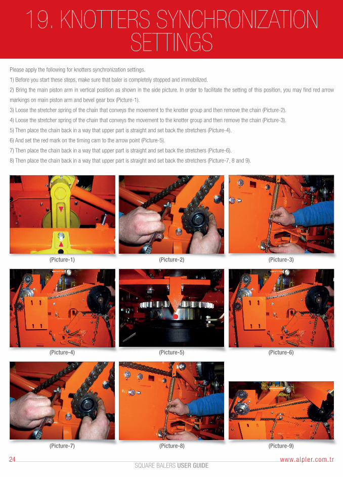
Please apply the following for knotters synchronization settings.
1) Before you start these steps, make sure that baler is completely stopped and immobilized.
2) Bring the main piston arm in vertical position as shown in the side picture. In order to facilitate the setting of this position, you may find red arrow
markings on main piston arm and bevel gear box (Picture-1).
3) Loose the stretcher spring of the chain that conveys the movement to the knotter group and then remove the chain (Picture-2).
4) Loose the stretcher spring of the chain that conveys the movement to the knotter group and then remove the chain (Picture-3).
5) Then place the chain back in a way that upper part is straight and set back the stretchers (Picture-4).
6) And set the red mark on the timing cam to the arrow point (Picture-5).
7) Then place the chain back in a way that upper part is straight and set back the stretchers (Picture-6).
8) Then place the chain back in a way that upper part is straight and set back the stretchers (Picture-7, 8 and 9).
(Picture-1) (Picture-2) (Picture-3)
(Picture-4) (Picture-5) (Picture-6)
(Picture-7) (Picture-8) (Picture-9)

SQUARE BALERS USER GUIDE25www.a lp le r.com. t r
Please apply the following for pitchfork settings.
1) Before you start these steps, make sure that baler is completely stopped and immobilized.
2) Remove the pitchfork chain as shown in the Picture-1.
3) Set the pitchfork arms crosswise as shown in the Picture-2.
4) While the pitchfork arms are crosswise, replace the chain as the lower part is strait and tight and then tighten the chain by means of tightener
gear (Picture-3).
20. PITCHFORK SETTINGS
21. KNOTTERS TROUBLESHOOTINGA standard made knot is comprising of a proper knot and equaly cut twine ends as shown on the left.
Unless it is indicated with number, numbers in bracket, refers 13101 part list and picture in spare part section
of this book.
(Picture-1) (Picture-2) (Picture-3)

SQUARE BALERS USER GUIDE26 www.a lp le r.com. t r
21. KNOTTERS TROUBLESHOOTING
PROBLEMS
knot forming a loop that can
catch the bill hook and this loop
hooks the bill tonque and twine
bre-aks off.
the knot is not made
the ends of the knot are of
unequal length
The knots do not slip free of the
bill.
One end only of the twine is
knotted.
REASONS SOLUTIONS
bill spoon spring (22) is loose
turn the bolt a quarter to increase
the pressure on the bill spoon
spring (24).
HOW IT IS SEEN

SQUARE BALERS USER GUIDE27www.a lp le r.com. t r
22. GENERAL MALFUNCTION TABLE
DEFECT
1. The shaft is knocking
2. V-belt is sliding or skidding
3. The harrow does not turn
4. The hay squashes between harrow bearings
5. Pitchforks stop
6. Machine slogs and the stress increases
7. Piston stops
8. Bale is uneven
9. Bale is too loose
10. One side of bale is uneven
11. Machine breaks needles
12. Knot too tight
13. Knot loop is too long
14. Knot loop is too short
15. Knot cannot be tied at all
16. The knot loop is long, its end is scattered and twine wastes are seen on twine holder
17. The knot seems tightly tied; but one pulling end escapes
18. Knot is short, but the ends come short
19. The knot twines fall in disconnected pieces of 5 cm.
20. Knot is tied at one end, and the tip of twine goes to the other bale without cutting
21. Knot is tied on one end and the tip of twine is short
22. Knot is tied by single twine and one end of the knot is long
23. Irregular feeding
POSSIBLE REASON SOLUTION
a. Machine revolves short during operationb. Machine is wrongly connected to tractor
a. Too much hay in the pressb. Insufficient tension
a. Chocked up/jammed due to abundant hay; U belt slidesb. Harrow springs contact the soil
a. Too much hayb. Hay is too short and thin
a. Machine is overloaded and safety bolts are cut
a. Hay is wetb. Piston knives are bluntc. Press channel is stony and blocking
a. Safety pinb. Foreign matter in channel
a. Pitchforks are not adjusted
a. Press channel is too wide
a. Too much hay in piston; so improper cuttingb. Piston and opposite knives are blunt
a. Needle is slant and it has crashed somewhere on motion pathb. Needle has hit the pistonc. Twine does not easily pass through the ball; so pulls the needle to one side and constrains itd. Out of adjustment
a. Twine brake within twine box does not arrive at loosen nose plate
The spring pressing on shuttle latch roller is tightened
a. Shuttle spoon spring is too loose
a. Shuttle spoon spring does not hold the loose twine
a. Tension spring of twine holder is tight
a. Leaf spring is looseb. Shuttle spoon spring is loose
a. Leaf spring too looseb. Shuttle spoon spring is loose
a. Leaf spring is too tight
a. Needle and star gear are too much separated. Star gear cannot hold the shuttle and one end goes to other bale.
a. Leaf spring is loose, and the tip of twine escapes due to press
a. Shuttle cannot hold the twine coming withneedle, twine guide in the box is loose
a. At the end of irregular feeding, one end of bales can come short whereas others are long
a. Movement at turns should be cutb. It should be connect properly
a. You should advance slowerb. The belt should be stretched
a. Run it slowerb. The belt should be stretched
a. Advance slower
a. Advance slower and assemble the safety pin
a. Use hayb. Sharpen the knivesc. Clean the channel
b. Clean the channel
a. Adjust pitchforks
a. Narrow the press channel
a. Advance slowly; the conduit should be thickb. Sharpen the knives
a. If a new needle is mounted, check the needle pathb. Adjust needle to the pistonc. Check where the twine passes, as well as the twine braked. Make adjustments pursuant to catalog
a. Adjust twine tension rod
b. Clean the twine spring
a. Loosen the coil spring (pliers tension spring)
a. Loosen the spring of shuttle spoon
a. Shuttle spoon spring too tight
a. Loosen the spring screw and pay attention to the size
a. Adjust the leaf spring and tightenb. Adjust and tighten
a. Adjust and tighten the spring.b. Adjust and tighten the spring.
a. Clean and adjust the spring; clean the star gear
a. Straighten the needle and make the lateral space adjustments
a. Adjust and tighten the spring
a. Check needle adjustments and set all of them.
a. It results from the improper adjustment of length of studs on front fork of pitchfork. It should be set as indicated in front pitchfork feeding yoke settings in pitchfork setting chapter.
SQUARE BALERS USER GUIDE28 www.a lp le r.com. t r
23. USAGE ERRORSYou can face certain problems due to usage errors. These problems are listed as follows:
23.1. PISTON SPEED TOO HIGH OR TOO LOW
In case the bolts are dismounted and remoun If the piston speed is too high or too low, bundle operation will be erroneous. As indicated in the introduction
chapter, pursuant to appropriate piston speed, do not run the tail axle at more than 540 rpm. Regular running revolution of tractor tail axle should be
between 540 and 550 rpm. It is inconvenient to run the bundle mechanism at low revolution.
All working parts of your baler move on ball bearings or custom-engineered bronze bearings. If you obey the below given lubrication principles, the lon-
gevity of machine shall increase, as well as the efficiency.
23.2. ERRONEOUS TWINE TENSION
For an efficient running of machine, each twine should be able to slide when it is drawn from the tension rod system via a force of 1-1,5 kg.
Piston – needle timing adjustment may be erroneous.
There may be lack of tune between bundle system and needles.
Pinholes or rollers may be excessively corroded.
24. PERIODICAL MAINTENANCE AND LUBRICATION
24.1. DAILY MAINTENANCE AND LUBRICATION
Grease universal joint kits and all greasers on bundle mechanism with rubber-free grease Check the loosened screws and components of the machine
and tighten them if need be. Clean any dust, dirt, oil, etc. that accumulates on bundle system.
24.2. SHORT-TIME PARKING
Remove the last two bales within the machine.
Clean any dust, dirt and oil on bundle group.

SQUARE BALERS USER GUIDE29www.a lp le r.com. t r
24. PERIODICAL MAINTENANCE AND LUBRICATION
24.3. PARTS TO BE LUBRICATED WITH OIL AT THE END OF EACH 10 WORK HOURS
• All ball bearings
• Bundle group and bundle group spots
• Harrow left-side bearing
• Harrow right-side bearing
• Pitchfork system
• Piston safety bolt and cradle
• Lower chain tension gears
24.4. PARTS TO BE LUBRICATED WITH OIL AND TO BE CHECKED AT THE END OF EACH 50 WORK HOURS
• All fork crosses
• Flywheel, flywheel ratchet, stalk cutter ratchet
• Apply oil from greaser via grease pump.
• Dismount and check the oil level valve caps of final drive and straw chopper reducer; add SAE 140 oil if need be.
• Check the tightness of bundle group clutch and cradle clutch
25. ACTIONS AT THE END OF EACH WORKING SEASON
• Clean all parts of your machine attentively.
• Change the oil of final drive and of straw chopper reducer.
• Lubricate pitchfork and harrow chains with a mixture of 50% oil and 50% gas oil.
• Apply grease until the former oil comes out of all greasers and wipe the out-coming dirty oil.
• Clean and re-grease all exposed gears.
• Grease knives and star gears on bundle group.
• Grease piston skids and all discolored and bright parts within the main body.
• Park your machine to an indoor area; and support it so that tires do not contact the ground.

SQUARE BALERS USER GUIDE30 www.a lp le r.com. t r
26. LUBRICATED MACHINE PARTS
1 Gudgeon Cross 1 Pump until clean grease comes out.
2 Fuse 1 ‘’
3 Flywheel 1 ‘’
4 Flywheel pulley bearings 1 ‘’
5 Straw chopper drive crosses 4 ‘’
6 Ratchet 1 ‘’
7 Upper straw chopper tension pulley 2 ‘’
8 Straw chopper ball 2 ‘’
9 Harrow bearings (right-left) 2 ‘’
10 Lower chain tension gears 2 ‘’
11 Piston rod bearings 2 ‘’
12 Pitchfork reducer within sheet metal cover 1 Open the cap and fill once a year.
13 Pitchfork bearing house 1 ‘’
14 Pitchfork ball cap 2 ‘’
15 Pitchfork spiders 2 ‘’
16 U – Crank bearing house 2 ‘’
17 U - Crank pitchfork bearing 1 ‘’
18 Pitchfork spring lever 2 ‘’
19 Pitchfork stationary lever 2 ‘’
20 Z- Crank bearing house 1 ‘’
21 Z- Crank Bearing 1 ‘’
22 Piston safety catch 1 ‘’
23 Cradle 2 ‘’
24 Cradle starting lever roll joint 1 ‘’
25 Bale size setting wheel bearings 2 ‘’
26 Bundle group sport (left) 1 ‘’
27 Bundle group sport (right) 2 ‘’
28 Bundle group sport (left) logs 11 ‘’
29 Star Gear 3 ‘’
30 Timing adjustment conical gear (buffered) 1 ‘’
31 Timing adjustment conical gear shaft 1 ‘’
32 Wheel hub 2 Grease manually during assembly and at the begin-ning of each season
33 Harrow heart 1 ‘’
34 Final drive body 1 No. 140 until oil comes out of level holes
35 Straw chopper reducer 1 Complete until 140 level valve cap
R/N PART PCS. ACTIONS TO BE TAKEN

SQUARE BALERS USER GUIDE31www.a lp le r.com. t r
27. REPAIRDuring run duration, your machine shall face certain defects due to usage or production errors. In order to eliminate such failures, you should respect
the below given issues. As for repair, the owner has no reparation authorization on the machine. Reparation can be realized only by authorized services
prescribed by our company, and by the authorized service department of our factory.
27.1. RULES TO OBEY REGARDING REPARATION
• Before reparation, detach the machine from tractor. Do not begin reparation until the machine stops completely.
• During reparation, do not breach the rules indicated in the manual.
• For reparation, use necessarily the original spare parts manufactured by our factory.
• Make sure that necessary security measures are taken before reparation.
27.2. REPARATIONS BY CONSUMER
• The client can make no reparations except for the adjust-ments indicated in the manual.
• In case of a machine failure, the machine owner should inform the nearest service station. If you cannot approach the service station, you can inform
the failure by calling service department of our factory.
WARNING
Do not dismount any conservation part on the machine
28. SERVICE AND SPARE PARTSSpare part of your baler are sufficiently manufactured and stoked for season or sent to authorized retailers or services. The repairs except the ones the
consumer is allowed and may manage himself, cause the termination of warranty obligations. If original parts are not used during maintenance and
repairs, the machine will be out of the scope of warranty; and also the responsibilities of damages on human bodies and environment arising from such
situation shall be belong to the consumer. Therefore for the repairs except the ones the consumer is allowed and may be managed by yourself, please
contact our authorized retailers.
PHYSICAL LIFE: According to statement TRKGM 97/10-11, the physical life of baler is 10 years.
STANDARD: TS 7512
SQUARE BALERS USER GUIDE32 www.a lp le r.com. t r
29. THE MACHINE OF HYDRAULICTURN ON & TURN OFF
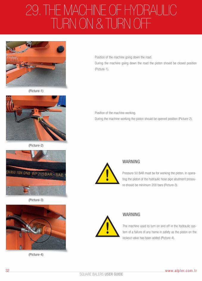
Position of the machine going down the road.
During the machine going down the road the piston should be closed position
(Picture-1).
Position of the machine working.
During the machine working the piston should be opened position (Picture-2).
WARNING
Pressure 50 BAR must be for working the piston. In opera-
ting the piston of the hydraulic hose pipe abutment pressu-
re should be minimum 200 bars (Picture-3).
WARNING
The machine used to turn on and off in the hydraulic sys-
tem of a failure of any home in safety as the piston on the
lockout valve has been added (Picture-4).
(Picture-1)
(Picture-2)
(Picture-3)
(Picture-4)

ANNEX / DISMANTLING THE CHOOPER

CONVERTING STRAW (DRY)BALER TO HAY BALER (SEMI-DRY)
(DISMANTLING CHOOPER)The procedure to convert strawer chooper baler to hay baler is follows;
Please make sure that your baler is stopped completely before you start this prosedure.
(Picture-1) (Picture-2) (Picture-3)
(Picture-4)
1. DISMANTLING PICK-UP UNIT• Take the pick-up unit on hang by using rotor shaft of pick-up as shown in Picture-1.
• Remove the connect, on between pick-up hydrolic and pick-up as shown in Picture-2.
• Remove the bolts shown in Picture-3 to remove the part shown in Picture-4.
• Remove the chain of pick-up ratchet gear shown in Picture-5 and also connection bolts in Picture-6.
• Release the pick-up unit from main body as shown in the pictures. Pull left first and then forward. And put a side (Picture7 & 8).
5. Removing bale holder profiles for hay bales
6. Front pitchfork safety bolt adjusstment
7. Replacing pick-up unit back.
1. Dismantling pick-up unit
2. Dismantling chopper unit
3. Changing front support for straw chamber.
4. Removing limiter barrier of straw chamber
(Picture-5) (Picture-6)
(Picture-7) (Picture-8)
SQUARE BALERS USER GUIDE34 www.a lp le r.com. t r
SQUARE BALERS USER GUIDE35www.a lp le r.com. t r
(Picture-1) (Picture-2)
(Picture-3) (Picture-4)
CONVERTING STRAW (DRY)BALER TO HAY BALER (SEMI-DRY)
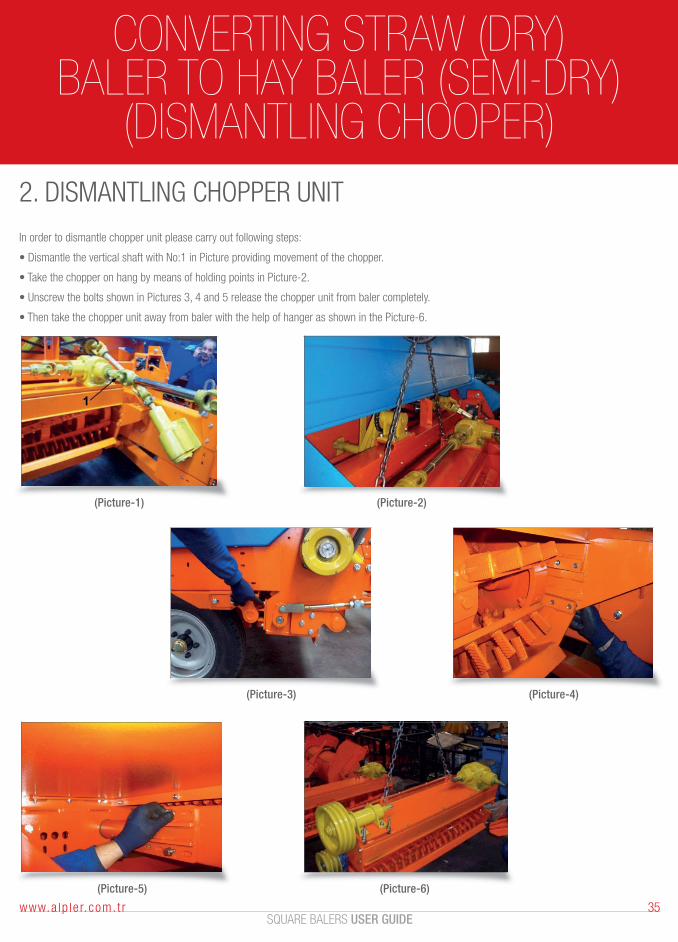
(DISMANTLING CHOOPER)2. DISMANTLING CHOPPER UNIT
In order to dismantle chopper unit please carry out following steps:
• Dismantle the vertical shaft with No:1 in Picture providing movement of the chopper.
• Take the chopper on hang by means of holding points in Picture-2.
• Unscrew the bolts shown in Pictures 3, 4 and 5 release the chopper unit from baler completely.
• Then take the chopper unit away from baler with the help of hanger as shown in the Picture-6.
(Picture-5) (Picture-6)
CONVERTING STRAW (DRY)BALER TO HAY BALER (SEMI-DRY)
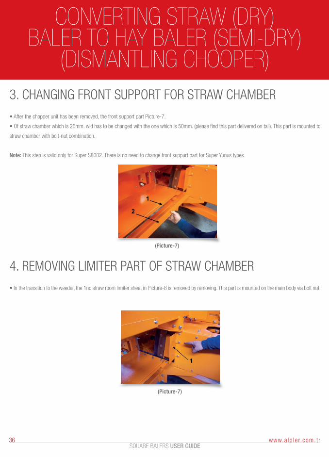
(DISMANTLING CHOOPER)3. CHANGING FRONT SUPPORT FOR STRAW CHAMBER
• After the chopper unit has been removed, the front support part Picture-7.
• Of straw chamber which is 25mm. wid has to be changed with the one which is 50mm. (please find this part delivered on tail). This part is mounted to
straw chamber with bolt-nut combination.
Note: This step is valid only for Super S8002. There is no need to change front suppurt part for Super Yunus types.
(Picture-7)
4. REMOVING LIMITER PART OF STRAW CHAMBER
• In the transition to the weeder, the 1nd straw room limiter sheet in Picture-8 is removed by removing. This part is mounted on the main body via bolt nut.
(Picture-7)
SQUARE BALERS USER GUIDE36 www.a lp le r.com. t r
(Picture-1)
CONVERTING STRAW (DRY)BALER TO HAY BALER (SEMI-DRY)
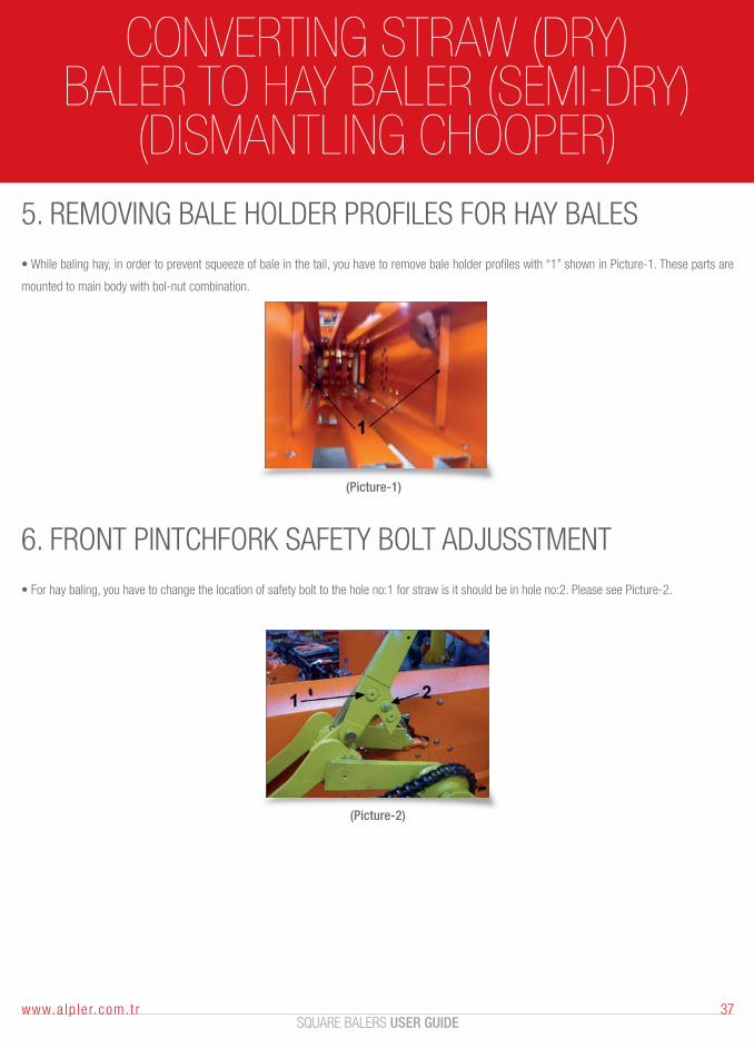
(DISMANTLING CHOOPER)5. REMOVING BALE HOLDER PROFILES FOR HAY BALES
• While baling hay, in order to prevent squeeze of bale in the tail, you have to remove bale holder profiles with “1” shown in Picture-1. These parts are
mounted to main body with bol-nut combination.
(Picture-2)
6. FRONT PINTCHFORK SAFETY BOLT ADJUSSTMENT
• For hay baling, you have to change the location of safety bolt to the hole no:1 for straw is it should be in hole no:2. Please see Picture-2.
SQUARE BALERS USER GUIDE37www.a lp le r.com. t r
CONVERTING STRAW (DRY)BALER TO HAY BALER (SEMI-DRY)
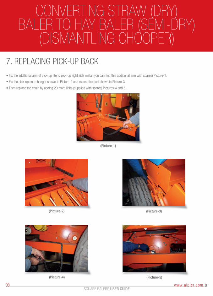
(DISMANTLING CHOOPER)7. REPLACING PICK-UP BACK
• Fix the additional arm of pick-up life to pick-up right side metal (you can find this additional arm with spares) Picture-1.
• Fix the pick-up on to hanger shown in Picture-2 and mount the part shown in Picture-3
• Then replace the chain by adding 20 more links (supplied with spares) Pictures-4 and 5.
(Picture-1)
(Picture-2) (Picture-3)
(Picture-4) (Picture-5)
SQUARE BALERS USER GUIDE38 www.a lp le r.com. t r

NOTES

ALPLER AGRICULTURAL MACHINERYUmurlu Organize Sanayi Bölgesi Umurlu-AYDIN / TÜRKİYETel: +90 (256) 259 1055 Fax: +90 (256) 259 1066Web: www.alpler.com.tr E-mail: [email protected]


