Embed Size (px)
Citation preview
2Spine AnatomyJohn M. Mathis
Percutaneous vertebroplasty (PV), kyphoplasty (KP), and percuta-neous sacroplasty (PS) require accurate localization of the bone regionto be treated and careful identification of the trajectory that must befollowed for safe device insertion. The normal anatomic structures andpathologic factors that affect the spine must be understood to accom-plish this goal. This chapter describes the pertinent anatomy of thespine for these image-guided procedures and discusses how specialvariations or situations can affect the choice of devices and appropri-ate needle trajectories.
General Spine Anatomy
The spine is made up of 33 bones: 24 vertebrae consisting of 7 cervical,12 thoracic, and 5 lumbar elements. The sacrum and coccyx provideunique variations. The sacrum is composed of 5 segments that arefused. The coccyx has 4 segments that are variably fused (1).
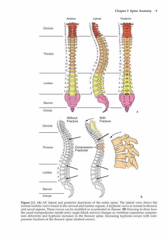
The multiple spine segments are joined by intervening discs andstructurally augmented by connecting ligaments and muscles. Theentire spine is depicted in Figure 2.1A, demonstrating the natural cur-vature that changes from segment to segment. Viewed from the lateralprojection, there is normally lordosis in the cervical and lumbar seg-ments and mild kyphosis in the thoracic and sacral regions. These vari-ations in curvature are important as they affect the orientation of theindividual vertebra and critical vertebral components like the pediclesthat are commonly used for device access to the vertebral body in PVand KP (Figure 2.1B).
The vertebrae progressively enlarge from the cervical through thelumbar region. There is also variability in vertebra size at any particu-lar level based on the individual’s size. For instance, an upper thoracicvertebra in a small woman may have a diameter of only 2–2.5cm(similar to a U.S. quarter). A large male may have a vertebra at the samelevel that is one to two times larger. These variations in size affect theinitial volume of each vertebra, which will ultimately affect the amount
8
Chapter 2 Spine Anatomy 9
Anterior Lateral Posterior
Cervical
Thoracic
Lumbar
Sacrum
Coccyx
12345671234567
89
1011
12
1
2
3
4
5
12345671234567
89
1011
12
1
2
3
4
5
123456712345678
910
11
12
1
2
3
4
5
WithFracture
WithoutFracture
Cervical
Thoracic
Lumbar
Sacrum
Coccyx
CompressionFractures
12345
1
2
3
4
5
67123456789
1011
12
Figure 2.1. (A) AP, lateral and posterior depictions of the entire spine. The lateral view shows thenormal lordotic curve found in the cervical and lumbar regions. A kyphotic curve is normal in thoracicand sacral regions. These curves can be modified or accentuated in disease. (B) Drawing to show howthe usual transpedicular needle entry angle (black arrows) changes as vertebrae experience compres-sion deformity and kyphosis increases in the thoracic spine. Increasing kyphosis occurs with com-pression fractures of the thoracic spine (dashed arrow).
A
B
of cement that can be used safely to augment a fracture without overfilling. Variations in vertebral volume are also affected by theamount of collapse a vertebra has experienced during fracture. Theoriginal and ultimate (postcollapse) sizes of the vertebra are of extremeimportance when one is performing PV or KP. In both procedures, the most common side effects are created by cement leaks (2). Thisresults from natural and pathologic holes in the vertebra as well asoverfilling.
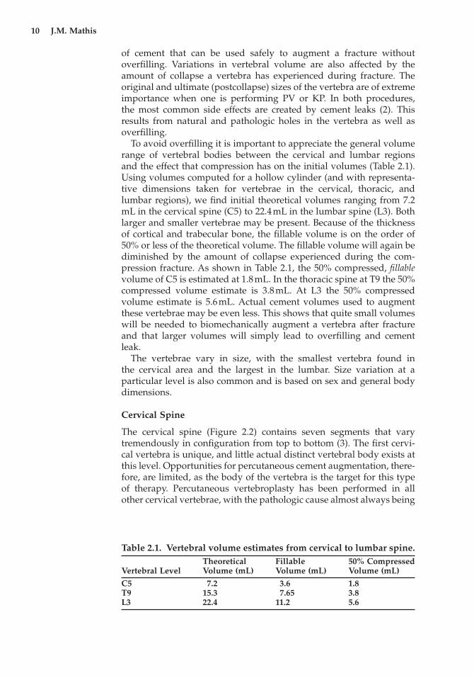
To avoid overfilling it is important to appreciate the general volumerange of vertebral bodies between the cervical and lumbar regions and the effect that compression has on the initial volumes (Table 2.1).Using volumes computed for a hollow cylinder (and with representa-tive dimensions taken for vertebrae in the cervical, thoracic, andlumbar regions), we find initial theoretical volumes ranging from 7.2mL in the cervical spine (C5) to 22.4mL in the lumbar spine (L3). Bothlarger and smaller vertebrae may be present. Because of the thicknessof cortical and trabecular bone, the fillable volume is on the order of50% or less of the theoretical volume. The fillable volume will again bediminished by the amount of collapse experienced during the com-pression fracture. As shown in Table 2.1, the 50% compressed, fillablevolume of C5 is estimated at 1.8mL. In the thoracic spine at T9 the 50%compressed volume estimate is 3.8mL. At L3 the 50% compressedvolume estimate is 5.6mL. Actual cement volumes used to augmentthese vertebrae may be even less. This shows that quite small volumeswill be needed to biomechanically augment a vertebra after fractureand that larger volumes will simply lead to overfilling and cement leak.
The vertebrae vary in size, with the smallest vertebra found in the cervical area and the largest in the lumbar. Size variation at a particular level is also common and is based on sex and general bodydimensions.
Cervical Spine
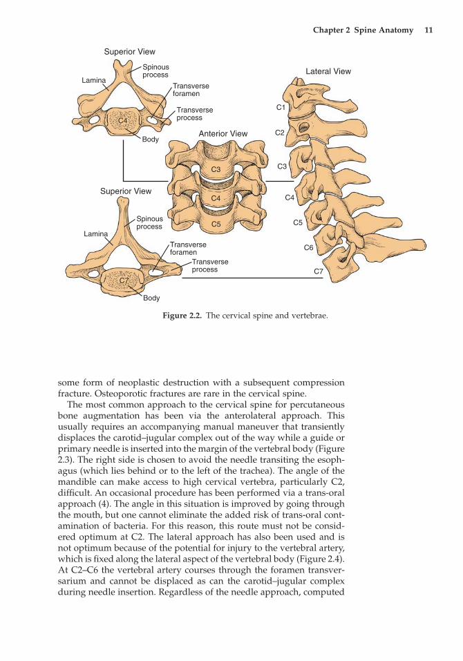
The cervical spine (Figure 2.2) contains seven segments that varytremendously in configuration from top to bottom (3). The first cervi-cal vertebra is unique, and little actual distinct vertebral body exists atthis level. Opportunities for percutaneous cement augmentation, there-fore, are limited, as the body of the vertebra is the target for this typeof therapy. Percutaneous vertebroplasty has been performed in allother cervical vertebrae, with the pathologic cause almost always being
10 J.M. Mathis
Table 2.1. Vertebral volume estimates from cervical to lumbar spine.Theoretical Fillable 50% Compressed
Vertebral Level Volume (mL) Volume (mL) Volume (mL)
C5 7.2 3.6 1.8T9 15.3 7.65 3.8L3 22.4 11.2 5.6
some form of neoplastic destruction with a subsequent compressionfracture. Osteoporotic fractures are rare in the cervical spine.
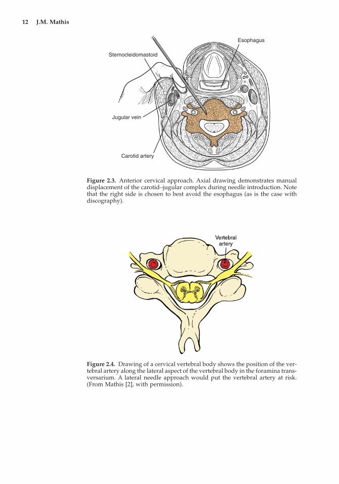
The most common approach to the cervical spine for percutaneousbone augmentation has been via the anterolateral approach. Thisusually requires an accompanying manual maneuver that transientlydisplaces the carotid–jugular complex out of the way while a guide orprimary needle is inserted into the margin of the vertebral body (Figure2.3). The right side is chosen to avoid the needle transiting the esoph-agus (which lies behind or to the left of the trachea). The angle of themandible can make access to high cervical vertebra, particularly C2,difficult. An occasional procedure has been performed via a trans-oralapproach (4). The angle in this situation is improved by going throughthe mouth, but one cannot eliminate the added risk of trans-oral cont-amination of bacteria. For this reason, this route must not be consid-ered optimum at C2. The lateral approach has also been used and isnot optimum because of the potential for injury to the vertebral artery,which is fixed along the lateral aspect of the vertebral body (Figure 2.4).At C2–C6 the vertebral artery courses through the foramen transver-sarium and cannot be displaced as can the carotid–jugular complexduring needle insertion. Regardless of the needle approach, computed
Chapter 2 Spine Anatomy 11
Superior View
Superior View
Lateral View
Anterior View
Lamina
Lamina
Spinousprocess
Spinousprocess
Transverseforamen
Transverseforamen
Transverseprocess
Transverseprocess
Body
Body
C1
C2
C3C3
C4C4
C4
C5C5
C6
C7C7
Figure 2.2. The cervical spine and vertebrae.
12 J.M. Mathis
Esophagus
Sternocleidomastoid
Jugular vein
Carotid artery
Figure 2.3. Anterior cervical approach. Axial drawing demonstrates manualdisplacement of the carotid–jugular complex during needle introduction. Notethat the right side is chosen to best avoid the esophagus (as is the case withdiscography).
Figure 2.4. Drawing of a cervical vertebral body shows the position of the ver-tebral artery along the lateral aspect of the vertebral body in the foramina trans-versarium. A lateral needle approach would put the vertebral artery at risk.(From Mathis [2], with permission).
tomography (CT) offers an accurate method of visualizing structurethat must be avoided during needle introduction.
Thoracic Spine
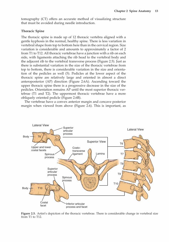
The thoracic spine is made up of 12 thoracic vertebra aligned with agentle kyphosis in the normal, healthy spine. There is less variation invertebral shape from top to bottom here than in the cervical region. Sizevariation is considerable and amounts to approximately a factor of 2from T1 to T12. All thoracic vertebrae have a junction with a rib on eachside, with ligaments attaching the rib head to the vertebral body andthe adjacent rib to the vertebral transverse process (Figure 2.5). Just asthere is substantial variation in the size of the thoracic vertebrae fromtop to bottom, there is considerable variation in the size and orienta-tion of the pedicles as well (5). Pedicles at the lower aspect of the thoracic spine are relatively large and oriented in almost a directanteroposterior (AP) direction (Figure 2.6A). Ascending toward theupper thoracic spine there is a progressive decrease in the size of thepedicles. Orientation remains AP until the most superior thoracic ver-tebrae (T1 and T2). The uppermost thoracic vertebrae have a moreobliquely oriented pedicle (Figure 2.6B).
The vertebrae have a convex anterior margin and concave posteriormargin when viewed from above (Figure 2.6). This is important, as
Chapter 2 Spine Anatomy 13
Body
Body
Superiorarticularprocess
Superiorarticularprocess
T6
Costo-transverseligament Lamina
Superior View
Lateral ViewLateral View
T6
T6Upper and lowercostal facets
Spinousprocess
Spinousprocess
Costalfacet
Inferior articularprocess and facet
T10
T10
T7
T8
T9
Figure 2.5. Artist’s depiction of the thoracic vertebrae. There is considerable change in vertebral sizefrom T1 to T12.
14 J.M. Mathis
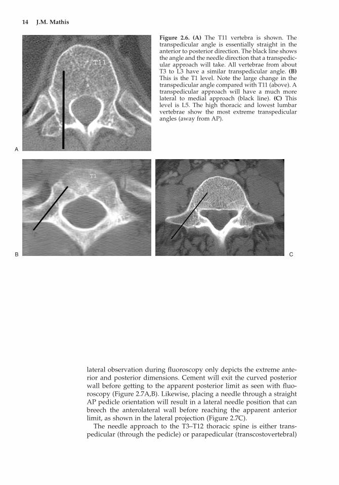
Figure 2.6. (A) The T11 vertebra is shown. Thetranspedicular angle is essentially straight in theanterior to posterior direction. The black line showsthe angle and the needle direction that a transpedic-ular approach will take. All vertebrae from aboutT3 to L3 have a similar transpedicular angle. (B)This is the T1 level. Note the large change in thetranspedicular angle compared with T11 (above). Atranspedicular approach will have a much morelateral to medial approach (black line). (C) Thislevel is L5. The high thoracic and lowest lumbarvertebrae show the most extreme transpedicularangles (away from AP).
A
B C
lateral observation during fluoroscopy only depicts the extreme ante-rior and posterior dimensions. Cement will exit the curved posteriorwall before getting to the apparent posterior limit as seen with fluo-roscopy (Figure 2.7A,B). Likewise, placing a needle through a straightAP pedicle orientation will result in a lateral needle position that canbreech the anterolateral wall before reaching the apparent anteriorlimit, as shown in the lateral projection (Figure 2.7C).
The needle approach to the T3–T12 thoracic spine is either trans-pedicular (through the pedicle) or parapedicular (transcostovertebral)
Chapter 2 Spine Anatomy 15
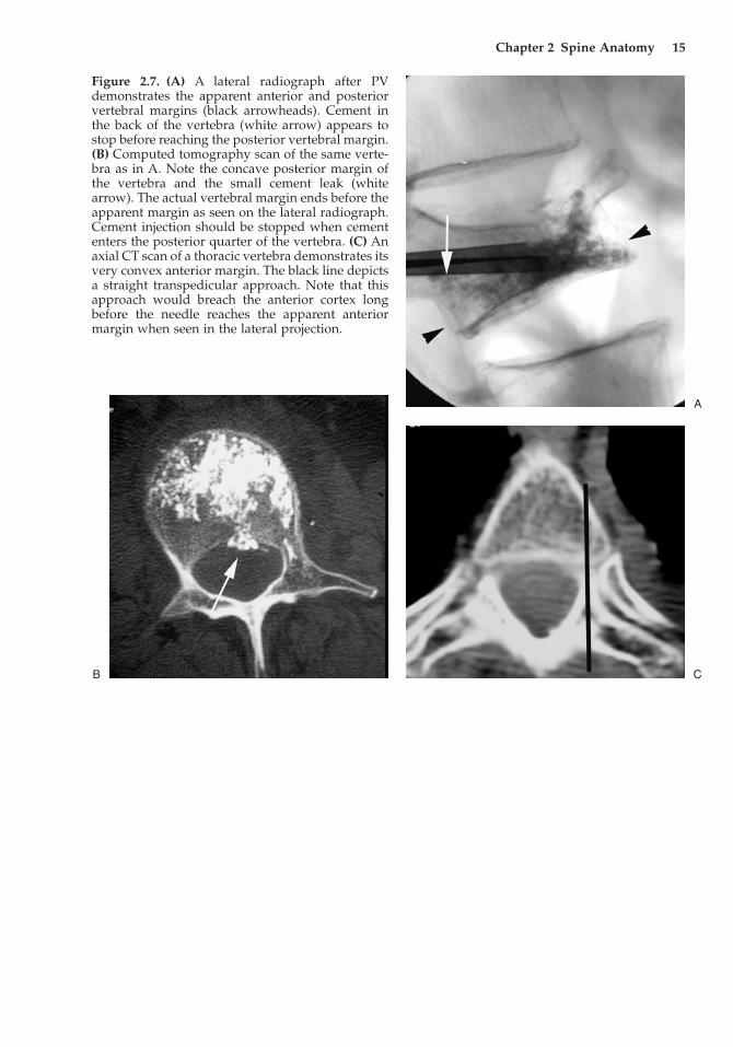
Figure 2.7. (A) A lateral radiograph after PVdemonstrates the apparent anterior and posteriorvertebral margins (black arrowheads). Cement inthe back of the vertebra (white arrow) appears tostop before reaching the posterior vertebral margin.(B) Computed tomography scan of the same verte-bra as in A. Note the concave posterior margin ofthe vertebra and the small cement leak (whitearrow). The actual vertebral margin ends before theapparent margin as seen on the lateral radiograph.Cement injection should be stopped when cemententers the posterior quarter of the vertebra. (C) Anaxial CT scan of a thoracic vertebra demonstrates itsvery convex anterior margin. The black line depictsa straight transpedicular approach. Note that thisapproach would breach the anterior cortex longbefore the needle reaches the apparent anteriormargin when seen in the lateral projection.
A
CB
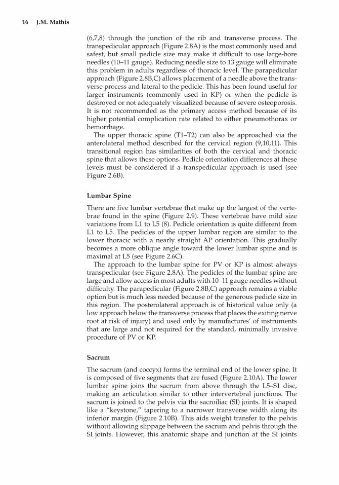
(6,7,8) through the junction of the rib and transverse process. Thetranspedicular approach (Figure 2.8A) is the most commonly used andsafest, but small pedicle size may make it difficult to use large-boreneedles (10–11 gauge). Reducing needle size to 13 gauge will eliminatethis problem in adults regardless of thoracic level. The parapedicularapproach (Figure 2.8B,C) allows placement of a needle above the trans-verse process and lateral to the pedicle. This has been found useful forlarger instruments (commonly used in KP) or when the pedicle isdestroyed or not adequately visualized because of severe osteoporosis.It is not recommended as the primary access method because of itshigher potential complication rate related to either pneumothorax orhemorrhage.
The upper thoracic spine (T1–T2) can also be approached via theanterolateral method described for the cervical region (9,10,11). Thistransitional region has similarities of both the cervical and thoracicspine that allows these options. Pedicle orientation differences at these levels must be considered if a transpedicular approach is used (seeFigure 2.6B).
Lumbar Spine
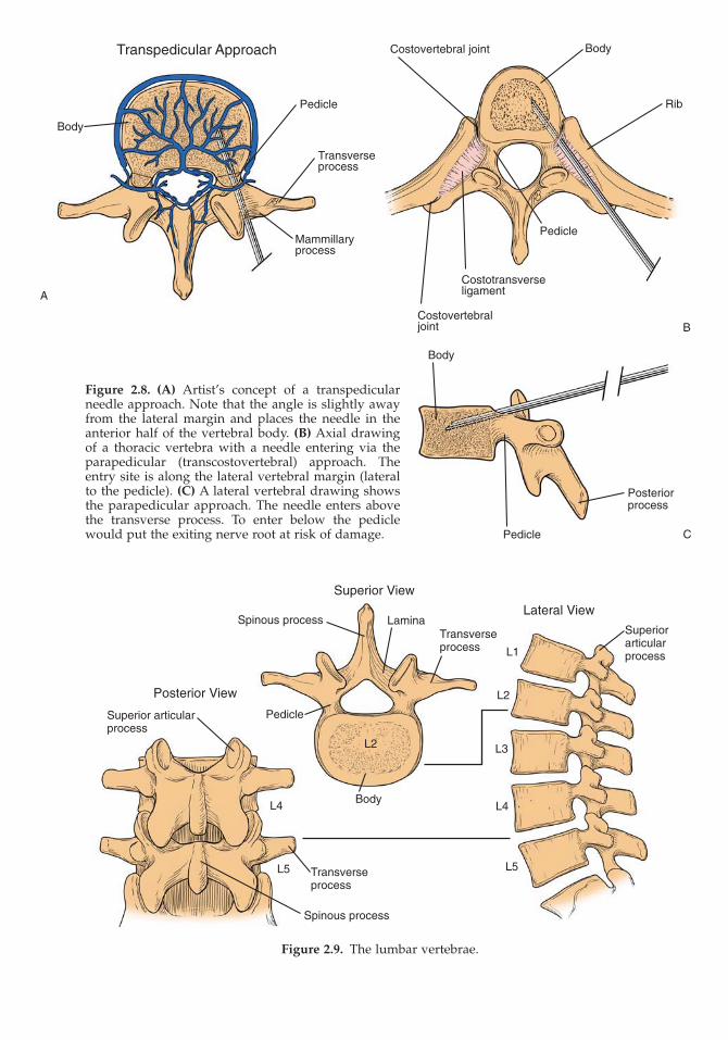
There are five lumbar vertebrae that make up the largest of the verte-brae found in the spine (Figure 2.9). These vertebrae have mild sizevariations from L1 to L5 (8). Pedicle orientation is quite different fromL1 to L5. The pedicles of the upper lumbar region are similar to thelower thoracic with a nearly straight AP orientation. This graduallybecomes a more oblique angle toward the lower lumbar spine and ismaximal at L5 (see Figure 2.6C).
The approach to the lumbar spine for PV or KP is almost alwaystranspedicular (see Figure 2.8A). The pedicles of the lumbar spine arelarge and allow access in most adults with 10–11 gauge needles withoutdifficulty. The parapedicular (Figure 2.8B,C) approach remains a viableoption but is much less needed because of the generous pedicle size inthis region. The posterolateral approach is of historical value only (alow approach below the transverse process that places the exiting nerveroot at risk of injury) and used only by manufactures’ of instrumentsthat are large and not required for the standard, minimally invasiveprocedure of PV or KP.
Sacrum
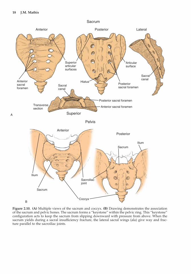
The sacrum (and coccyx) forms the terminal end of the lower spine. Itis composed of five segments that are fused (Figure 2.10A). The lowerlumbar spine joins the sacrum from above through the L5–S1 disc,making an articulation similar to other intervertebral junctions. Thesacrum is joined to the pelvis via the sacroiliac (SI) joints. It is shapedlike a “keystone,” tapering to a narrower transverse width along itsinferior margin (Figure 2.10B). This aids weight transfer to the pelviswithout allowing slippage between the sacrum and pelvis through theSI joints. However, this anatomic shape and junction at the SI joints
16 J.M. Mathis
Transpedicular Approach
Pedicle
Transverseprocess
Body
Mammillaryprocess
Costovertebral joint Body
Rib
Pedicle
Costotransverseligament
Costovertebraljoint
Body
Posteriorprocess
Pedicle
Figure 2.8. (A) Artist’s concept of a transpedicularneedle approach. Note that the angle is slightly awayfrom the lateral margin and places the needle in theanterior half of the vertebral body. (B) Axial drawingof a thoracic vertebra with a needle entering via theparapedicular (transcostovertebral) approach. Theentry site is along the lateral vertebral margin (lateralto the pedicle). (C) A lateral vertebral drawing showsthe parapedicular approach. The needle enters abovethe transverse process. To enter below the pediclewould put the exiting nerve root at risk of damage.
A
B
C
Figure 2.9. The lumbar vertebrae.
Superior View
Lateral View
Posterior View
Spinous process
Spinous process
LaminaTransverseprocess
Transverseprocess
Superiorarticularprocess
Body
PedicleSuperior articularprocess
L2
L2
L1
L3
L4L4
L5L5
18 J.M. Mathis
Sacrum
Anterior Posterior Lateral
Superiorarticularsurfaces
Anteriorsacralforamen
Anterior sacral foramen
Sacralcanal
Transversesection
Superior
Posterior sacral foramen
Posteriorsacral foramen
Hiatus
Articularsurface
Sacralcanal
Pelvis
AnteriorPosterior
Ilium
Ilium
Sacrum
Sacrum
Sacroiliacjoint
Coccyx
Figure 2.10. (A) Multiple views of the sacrum and coccyx. (B) Drawing demonstrates the associationof the sacrum and pelvic bones. The sacrum forms a “keystone” within the pelvic ring. This “keystone”configuration acts to keep the sacrum from slipping downward with pressure from above. When thesacrum yields during a sacral insufficiency fracture, the lateral sacral wings (ala) give way and frac-ture parallel to the sacroiliac joints.
A
B
Chapter 2 Spine Anatomy 19
does create the unique fractures seen in the sacrum due to osteoporo-sis and trauma (see below).
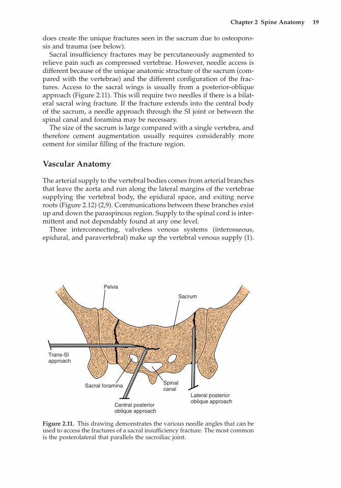
Sacral insufficiency fractures may be percutaneously augmented torelieve pain such as compressed vertebrae. However, needle access isdifferent because of the unique anatomic structure of the sacrum (com-pared with the vertebrae) and the different configuration of the frac-tures. Access to the sacral wings is usually from a posterior-obliqueapproach (Figure 2.11). This will require two needles if there is a bilat-eral sacral wing fracture. If the fracture extends into the central bodyof the sacrum, a needle approach through the SI joint or between thespinal canal and foramina may be necessary.
The size of the sacrum is large compared with a single vertebra, andtherefore cement augmentation usually requires considerably morecement for similar filling of the fracture region.
Vascular Anatomy
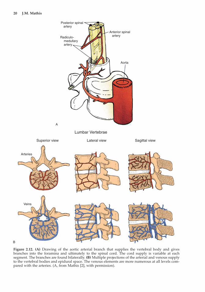
The arterial supply to the vertebral bodies comes from arterial branchesthat leave the aorta and run along the lateral margins of the vertebraesupplying the vertebral body, the epidural space, and exiting nerveroots (Figure 2.12) (2,9). Communications between these branches existup and down the paraspinous region. Supply to the spinal cord is inter-mittent and not dependably found at any one level.
Three interconnecting, valveless venous systems (interosseous,epidural, and paravertebral) make up the vertebral venous supply (1).
Pelvis
Sacrum
Trans-SIapproach
Lateral posterior oblique approach
Central posterior oblique approach
Sacral foramina Spinalcanal
Figure 2.11. This drawing demonstrates the various needle angles that can beused to access the fractures of a sacral insufficiency fracture. The most commonis the posterolateral that parallels the sacroiliac joint.
20 J.M. Mathis
Posterior spinal artery
Anterior spinal arteryRadiculo-
medullary artery
Aorta
Lumbar Vertebrae
Superior view Lateral view Sagittal view
Arteries
Veins
Figure 2.12. (A) Drawing of the aortic arterial branch that supplies the vertebral body and givesbranches into the foramina and ultimately to the spinal cord. The cord supply is variable at eachsegment. The branches are found bilaterally. (B) Multiple projections of the arterial and venous supplyto the vertebral bodies and epidural space. The venous elements are more numerous at all levels com-pared with the arteries. (A, from Mathis [2], with permission).
A
B
Through these systems there is intimate communication with theintraosseous, intertrabecular space (Figure 2.12B). Blood products and marrow fat are harbored in this space and commingled withflowing blood at venous pressure. This space in the axial skeletonbecomes a primary source of blood-forming elements in the olderadult. It is this space into which the cement is injected during PV orKP. Communication of the intertrabecular space via connecting venoussystems can allow potential posterior, lateral, or anterior cement leaksto occur. Posterior communication is via the basivertebral venoussystem (Figure 2.13A–C), which usually forms the largest drainingveins from the vertebrae. These veins connect directly to the epiduralvenous system that surrounds the exiting nerve roots and the thecalsac.
Lateral drainage from the vertebrae communicates to the paraverte-bral veins. Paravertebral veins form a system along the lateral aspectof the vertebrae running in both vertical and horizontal directions andthat interconnect the posterior epidural and anterior central venous ele-ments (Figure 2.13D,E). The central venous elements are large centralchannels composed of the azygos and caval veins that ultimately returnvenous blood to the lungs.
Direct entry of cement into the exiting vascular channels is mini-mized by needle placement away from the majority of these vessels.This risk is highest in the posterior aspect of the vertebra. Lateral andanterior communications are generally much smaller than to thebasivertebral plexus (Figure 2.13A). The cement distribution is con-trolled by least resistance flow. Injecting away from the large (low pressure) channels forces intertrabecular distribution of cement preferentially. Large channels can be encountered accidentally, andcontinuous observation for this type of cement filling and distributionwill limit leaks and prevent serious consequences.
Percutaneous Needle Approaches (Additional Considerations)
Individual needle approaches were generally described above witheach segment of the spine for which they are applicable. Thetranspedicular approach is the most commonly used and provides thesafest method of accessing the vertebral body (see Figure 2.8A). Thisoccurs because the pedicle provides a discreet target that is visualizedduring image-guided needle placement. There are no structures withinthe pedicle that can be damaged during accurate transpedicular needleinsertion. Percutaneous vertebroplasty can be accomplished in 85%–95% of cases using this route, as most compression fractures occur fromT6 to L5 and the pedicle structure is adequate for needle insertionthroughout this region. Complications that can occur with alternateroutes (pneumothorax and bleeding with parapedicular; damage tovascular structures with anterolateral) are avoided with the transpedic-ular route. It should be the mainstay for needle placement with alter-nate routes reserved for relatively rare situations.
Chapter 2 Spine Anatomy 21
22 J.M. Mathis
A
B
C
D
E
The parapedicular route may be used when the pedicle is absent (dueto tumor), not seen because of severe osteoporosis, or too small (seeFigure 2.8B,C). It does suffer from the potential for pneumothorax orbleeding. Also known as the transcostovertebral needle route, it passesalong the rib margin in the thoracic spine. In some patients the lungmay bulge beyond the lateral rib margin and put it at risk for pneu-mothorax. Bleeding may occur to a greater degree than found with thetranspedicular approach, as the entry site into bone in the parapedic-ular approach is along the lateral aspect of the vertebra. Paravertebralarteries and veins run in this location. They can be quite large (Figure2.13D,E) and are put at risk for puncture or transaction with this needleapproach. The needle puncture site can be easily compressed with pres-sure over the stick site in the transpedicular approach. This is not avail-able for the parapedicular region to help limit bleeding, and thereforepuncture of the large lateral vertebral vessels may produce moreparaspinous bleeding.
The anterolateral approach is not used much as there is relativelylittle call for cervical or high thoracic PV. Needle placement can beeasily accomplished with fluoroscopy in this approach using manualpressure to move the carotid–jugular complex laterally. Confirmationthat the needle has missed the vascular structures, however, may bedifficult with fluoroscopy alone. For this reason, CT guidance is com-monly used for needle placement with this route. As stated above, thetrans-oral route is less optimal than the anterolateral approach, as it isimpossible to avoid the potential for bacterial contamination goingthrough the mouth.
Fracture Anatomy
Fractures of the vertebrae and sacrum present with typical patterns thatare influenced by the biomechanics of each particular spine element.Most compression fractures of the spine result from primary (age-related) or secondary (drug-related) osteoporosis. Relatively minortrauma or vertebra stress may result in compression fracture. Thesefractures are referred to as simple (as opposed to burst or chance frac-
Chapter 2 Spine Anatomy 23
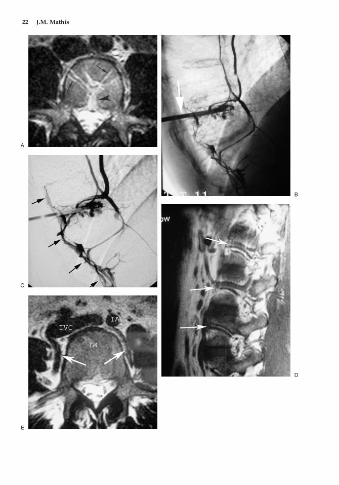
Figure 2.13. (A) Axial magnetic resonance image (MRI) demonstrates confluence of vessels at the pos-terior aspect of the vertebral body (black arrowhead). Vascular channels are much smaller, communi-cating with the paraspinous regions (black arrows). All of the channels give potential avenues forcement leak during injection. (B,C) Lateral intraosseous venograms (C is subtracted) of a lower tho-racic vertebra. Posterior epidural vessels communicate over multiple levels (black arrows). There isfilling of the lateral (paraspinous) channels and anterior vessels that ultimately communicate with thevena cava and lungs. (D,E) Lateral and axial MRI images show the large vessels that lie along the lateralaspect of the vertebral bodies in the paraspinous region (white arrows). These vessels are always atrisk of injury with the parapedicular needle approach. IVC, inferior vena cava; IA, intraaortic.
�
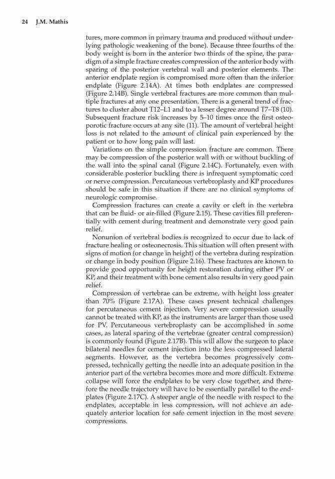
tures, more common in primary trauma and produced without under-lying pathologic weakening of the bone). Because three fourths of thebody weight is born in the anterior two thirds of the spine, the para-digm of a simple fracture creates compression of the anterior body withsparing of the posterior vertebral wall and posterior elements. Theanterior endplate region is compromised more often than the inferiorendplate (Figure 2.14A). At times both endplates are compressed(Figure 2.14B). Single vertebral fractures are more common than mul-tiple fractures at any one presentation. There is a general trend of frac-tures to cluster about T12–L1 and to a lesser degree around T7–T8 (10).Subsequent fracture risk increases by 5–10 times once the first osteo-porotic fracture occurs at any site (11). The amount of vertebral heightloss is not related to the amount of clinical pain experienced by thepatient or to how long pain will last.
Variations on the simple compression fracture are common. Theremay be compression of the posterior wall with or without buckling ofthe wall into the spinal canal (Figure 2.14C). Fortunately, even withconsiderable posterior buckling there is infrequent symptomatic cordor nerve compression. Percutaneous vertebroplasty and KP proceduresshould be safe in this situation if there are no clinical symptoms of neurologic compromise.
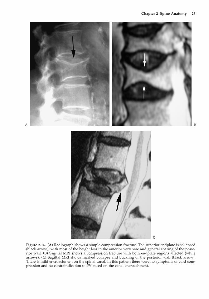
Compression fractures can create a cavity or cleft in the vertebra that can be fluid- or air-filled (Figure 2.15). These cavities fill preferen-tially with cement during treatment and demonstrate very good painrelief.
Nonunion of vertebral bodies is recognized to occur due to lack offracture healing or osteonecrosis. This situation will often present withsigns of motion (or change in height) of the vertebra during respirationor change in body position (Figure 2.16). These fractures are known toprovide good opportunity for height restoration during either PV orKP, and their treatment with bone cement also results in very good painrelief.
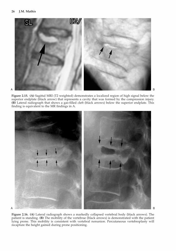
Compression of vertebrae can be extreme, with height loss greaterthan 70% (Figure 2.17A). These cases present technical challenges for percutaneous cement injection. Very severe compression usuallycannot be treated with KP, as the instruments are larger than those usedfor PV. Percutaneous vertebroplasty can be accomplished in somecases, as lateral sparing of the vertebrae (greater central compression)is commonly found (Figure 2.17B). This will allow the surgeon to placebilateral needles for cement injection into the less compressed lateralsegments. However, as the vertebra becomes progressively com-pressed, technically getting the needle into an adequate position in theanterior part of the vertebra becomes more and more difficult. Extremecollapse will force the endplates to be very close together, and there-fore the needle trajectory will have to be essentially parallel to the end-plates (Figure 2.17C). A steeper angle of the needle with respect to theendplates, acceptable in less compression, will not achieve an ade-quately anterior location for safe cement injection in the most severecompressions.
24 J.M. Mathis
Chapter 2 Spine Anatomy 25
Figure 2.14. (A) Radiograph shows a simple compression fracture. The superior endplate is collapsed(black arrow), with most of the height loss in the anterior vertebrae and general sparing of the poste-rior wall. (B) Sagittal MRI shows a compression fracture with both endplate regions affected (whitearrows). (C) Sagittal MRI shows marked collapse and buckling of the posterior wall (black arrow).There is mild encroachment on the spinal canal. In this patient there were no symptoms of cord com-pression and no contraindication to PV based on the canal encroachment.
A B
C
26 J.M. Mathis
Figure 2.15. (A) Sagittal MRI (T2 weighted) demonstrates a localized region of high signal below thesuperior endplate (black arrow) that represents a cavity that was formed by the compression injury.(B) Lateral radiograph that shows a gas-filled cleft (black arrows) below the superior endplate. Thisfinding is equivalent to the MR findings in A.
A B
Figure 2.16. (A) Lateral radiograph shows a markedly collapsed vertebral body (black arrows). Thepatient is standing. (B) The mobility of the vertebrae (black arrows) is demonstrated with the patientlying prone. This mobility is consistent with vertebral nonunion. Percutaneous vertebroplasty willrecapture the height gained during prone positioning.
A B
Chapter 2 Spine Anatomy 27
A B
Figure 2.17. (A) Sagittal MR image in the midline shows nearly complete collapse of the vertebra cen-trally. (B) A more lateral image of the same patient demonstrates that less compression is present laterally (white arrows). (C) With severe compression, a needle angle that is nearly parallel to the end-plates (B) is required to access the anterior vertebral body. The angle of needle A, acceptable for mildcompression, will not work well for extreme compression.
Lateral Slight obliqueAP projection
AP oblique
Mild fracture
Severe compressionfracture
A
B
C
28 J.M. Mathis
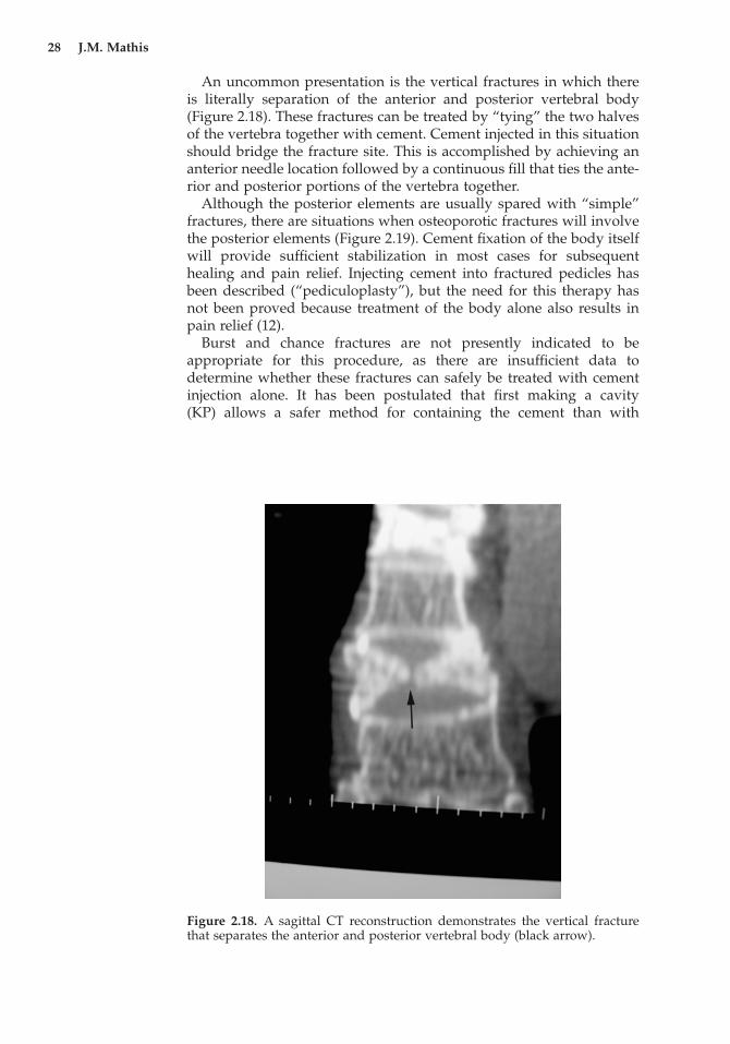
Figure 2.18. A sagittal CT reconstruction demonstrates the vertical fracturethat separates the anterior and posterior vertebral body (black arrow).
An uncommon presentation is the vertical fractures in which thereis literally separation of the anterior and posterior vertebral body(Figure 2.18). These fractures can be treated by “tying” the two halvesof the vertebra together with cement. Cement injected in this situationshould bridge the fracture site. This is accomplished by achieving ananterior needle location followed by a continuous fill that ties the ante-rior and posterior portions of the vertebra together.
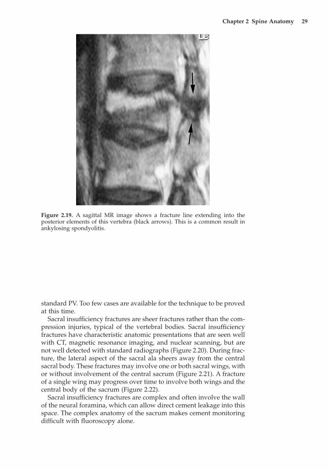
Although the posterior elements are usually spared with “simple”fractures, there are situations when osteoporotic fractures will involvethe posterior elements (Figure 2.19). Cement fixation of the body itselfwill provide sufficient stabilization in most cases for subsequenthealing and pain relief. Injecting cement into fractured pedicles hasbeen described (“pediculoplasty”), but the need for this therapy hasnot been proved because treatment of the body alone also results inpain relief (12).
Burst and chance fractures are not presently indicated to be appropriate for this procedure, as there are insufficient data to determine whether these fractures can safely be treated with cementinjection alone. It has been postulated that first making a cavity (KP) allows a safer method for containing the cement than with
Chapter 2 Spine Anatomy 29
Figure 2.19. A sagittal MR image shows a fracture line extending into the posterior elements of this vertebra (black arrows). This is a common result inankylosing spondyolitis.
standard PV. Too few cases are available for the technique to be provedat this time.
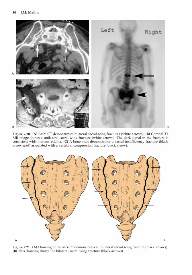
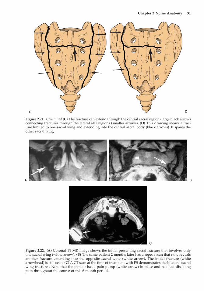
Sacral insufficiency fractures are sheer fractures rather than the com-pression injuries, typical of the vertebral bodies. Sacral insufficiencyfractures have characteristic anatomic presentations that are seen wellwith CT, magnetic resonance imaging, and nuclear scanning, but arenot well detected with standard radiographs (Figure 2.20). During frac-ture, the lateral aspect of the sacral ala sheers away from the centralsacral body. These fractures may involve one or both sacral wings, withor without involvement of the central sacrum (Figure 2.21). A fractureof a single wing may progress over time to involve both wings and thecentral body of the sacrum (Figure 2.22).
Sacral insufficiency fractures are complex and often involve the wallof the neural foramina, which can allow direct cement leakage into thisspace. The complex anatomy of the sacrum makes cement monitoringdifficult with fluoroscopy alone.
30 J.M. Mathis
Figure 2.20. (A) Axial CT demonstrates bilateral sacral wing fractures (white arrows). (B) Coronal T1MR image shows a unilateral sacral wing fracture (white arrows). The dark signal in the fracture isconsistent with marrow edema. (C) A bone scan demonstrates a sacral insufficiency fracture (blackarrowhead) associated with a vertebral compression fracture (black arrow).
A
B C
A B
Figure 2.21. (A) Drawing of the sacrum demonstrates a unilateral sacral wing fracture (black arrows).(B) This drawing shows the bilateral sacral wing fracture (black arrows).
Chapter 2 Spine Anatomy 31
DC
Figure 2.21. Continued (C) The fracture can extend through the central sacral region (large black arrow)connecting fractures through the lateral alar regions (smaller arrows). (D) This drawing shows a frac-ture limited to one sacral wing and extending into the central sacral body (black arrows). It spares theother sacral wing.
Figure 2.22. (A) Coronal T1 MR image shows the initial presenting sacral fracture that involves onlyone sacral wing (white arrow). (B) The same patient 2 months later has a repeat scan that now revealsanother fracture extending into the opposite sacral wing (white arrow). The initial fracture (whitearrowhead) is still seen. (C) A CT scan at the time of treatment with PS demonstrates the bilateral sacralwing fractures. Note that the patient has a pain pump (white arrow) in place and has had disablingpain throughout the course of this 6-month period.
A B
C
32 J.M. Mathis
References
1. Ortiz OO, Deramond H. Spine anatomy. In Percutaneous Vertebroplasty,JM Mathis, H Deramond, and SM Belkoff (eds). New York: Springer, 2001:7–24.
2. Mathis JM, Shaibani A, Wakhloo AK. Spine anatomy. In Image-GuidedSpine Interventions, JM Mathis JM (ed). New York: Springer, 2003:1–26.
3. Christenson PC. The radiologic study of the normal spine: cervical, tho-racic and lumbar and sacral. Radiol Clin North Am 1977; 15:133–154.
4. Tong FC, Cloft HJ, Joseph GJ, et al. Transoral approach to cervical verte-broplasty for multiple myeloma. Am J Roentgenol 2000; 175:1322–1324.
5. Kothe R, O’Holleran JD, Liu W, et al. Internal architecture of the thoracicpedicle. An anatomic study. Spine 1996; 21:264–270.
6. Brugieres P, Gaston A, Heran F, et al. Percutaneous biopsies of the thoracicspine under CT guidance: transcostovertebral approach. J Comput AssistTomogr 1990; 14:446–448.
7. Dufresne AC, Brunet E, Sola-Martinez MT, et al. Percutaneous vertebro-plasty of the cervico-thoracic junction using an anterior route. J Neurora-diol 1998; 25:123–126.
8. Panjabi MM, Goel V, Oxland T, et al. Human lumbar vertebrae. Quantita-tive three-dimensional anatomy. Spine 1992; 17:299–306.
9. Lasjaunias P, Berenstein A. Surgical Neuroangiography. New York:Springer, 1990.
10. Nevitt MC, Ross PD, Palermo L, et al. Association of prevalent vertebralfractures, bone density, and alendronate treatment with incident vertebralfractures: effect of number and spinal location of fractures. Bone 1999;25:613–619.
11. Cooper C, O’Neill T, Silman A. The epidemiology of vertebral fractures.Bone 1993; 14:S89–S97.
12. Eyheremendy EP, De Luca SE, Sanabria E. Percutaneous pediculoplasty in osteoporotic compression fractures. J Vasc Intervent Radiol 2004; 15:869–874.


