Embed Size (px)
Citation preview

SPARTAN: Developing a Vision System for FutureAutonomous Space Exploration Robots
• • • • • • • • • • • • • • • • • • • • • • • • • • • • • • • • • • • •
Ioannis KostavelisLaboratory of Robotics and Automation, Production and Management Engineering Dept., Democritus University of Thrace, Greecee-mail: [email protected] NalpantidisRobotics, Vision and Machine Intelligence Lab., Dept. of Mechanical and Manufacturing Engineering, Aalborg UniversityCopenhagen, Denmarke-mail: [email protected] BoukasLaboratory of Robotics and Automation, Production and Management Engineering Dept., Democritus University of Thrace, Greecee-mail: [email protected] Aviles RodrigalvarezAdvanced Space Systems and Technologies, GMV, Spaine-mail: [email protected] Stamoulias, George Lentaris, Dionysios Diamantopoulos, Kostas Siozios, and Dimitrios SoudrisMicroprocessors and Digital Systems Lab., School of Electrical and Computer Engineering, National Technical University of Athens,Greecee-mail: [email protected], [email protected], [email protected], [email protected],[email protected] GasteratosLaboratory of Robotics and Automation, Production and Management Engineering Dept., Democritus University of Thrace, Greecee-mail: [email protected]
Received 7 December 2012; accepted 13 August 2013
Mars exploration is expected to remain a focus of the scientific community in the years to come. A Mars rovershould be highly autonomous because communication between the rover and the terrestrial operation center isdifficult, and because the vehicle should spend as much of its traverse time as possible moving. Autonomousbehavior of the rover implies that the vision system provides both a wide view to enable navigation and three-dimensional (3D) reconstruction, and at the same time a close-up view ensuring safety and providing reliableodometry data. The European Space Agency funded project “SPAring Robotics Technologies for AutonomousNavigation” (SPARTAN) aimed to develop an efficient vision system to cover all such aspects of autonomousexploratory rovers. This paper presents the development of such a system, starting from the requirements upto the testing of the working prototype. The vision system was designed with the intention of being efficient,low-cost, and accurate and to be implemented using custom-designed vectorial processing by means of fieldprogrammable gate arrays (FPGAs). A prototype of the complete vision system was developed, mounted ona basic mobile robot platform, and tested. The results on both real-world Mars-like and long-range simulateddata are presented in terms of 3D reconstruction and visual odometry accuracy, as well as execution speed. Thedeveloped system is found to fulfill the set requirements. C© 2013 Wiley Periodicals, Inc.
1. INTRODUCTION
1.1. Scope
The possibility of extraterrestrial life has been stimulat-ing the human imagination throughout our history. Mars
Direct correspondence to: Lazaros Nalpantidis, e-mail: [email protected]
has been at the center of this discussion for many years.The scientific community has been arguing whether lifeever existed on the red planet, but it is only during thepast few decades that our engineering abilities have al-lowed us to actively pursue answers to these questions.Many exploration missions, both on-orbit and surface, werelaunched to Mars, and they resulted in substantial findings.The on-orbit missions [NASA’s Mars Global Surveyor, Mars
Journal of Field Robotics, 1–34 C© 2013 Wiley Periodicals, Inc.View this article online at wileyonlinelibrary.com • DOI: 10.1002/rob.21484

2 • Journal of Field Robotics—2013
Figure 1. The ExoMars rover (credit: ESA) and its vision sys-tem have defined the basic framework of the system consideredin this work.
Odyssey, Mars Reconnaissance Orbiter, and the EuropeanSpace Agency’s (ESA’s) Mars Express] have yielded cru-cial information about Mars’ environment. More recently,robotic exploration rovers have been deployed as part ofsurface exploration missions on Mars (NASA’s Curiosityrover, Mars Exploration rovers, Phoenix), and they haveprovided evidence about the planet’s evolution. A thoroughreview of the past Mars rovers missions can be found inBajracharya et al. (2008). The aforementioned expedi-tions initiated a general discussion about joint Mars ex-ploration efforts, such as the ExoMars rover shown inFigure 1, where different rovers would be controlled bymore than one control center in a joint way (Grant et al.,2010).
While multiple and valuable investigations can be per-formed on the surface of Mars, there is a clear consensuswithin the scientific community that the major scientific ob-jectives of Martian exploration can only be achieved withthe return of a sample to Earth. The Mars Sample Return(MSR) mission, targeted for the third decade of the 21st cen-tury, is also a joint endeavor of various space agencies andincludes among others a Lander platform featuring a Sam-ple Fetching Rover (SFR), which will be assigned to collectsamples either from the surface or the subsurface, or even topick up cached samples from previous missions (EuropeanSpace Agency, 2010). To fulfill the challenging scientific ob-jectives of MSR, the design of a “high” mobility rover withlong traverse capabilities and up to 10 times the speed of presentrovers is required (Rekleitis et al., 2007). Teleoperation ofsuch future rovers is difficult, due to sparse communicationwindows between Earth and Mars with high delays andlimited bandwidth. As a result, if Mars exploratory roversare to cover long distances within a limited period of time,they should rely on autonomous navigation and localiza-tion to succeed in their mission.
Thereupon, it is evident that present-day space rovers,or space analog on-earth experiments, make extensive use ofvisual perception and the respective computer vision algo-rithms in order to provide reliable autonomous navigationand localization. In normal operation, a large number ofimages are collected from navigation and localization cam-eras in every motion cycle. This collection of image data istransferred to an onboard central computer and processedutilizing a large portion of the computational capacity. How-ever, the onboard computational resources are limited andthere is a strong need to minimize factors such as powerconsumption, mass, and volume for the sake of missionfeasibility and cost. Furthermore, an additional delimitingfactor is that the available space qualified components pro-vide only for computing elements of limited performance.
To overcome the aforementioned limitations, ESA ini-tiated the “SPAring Robotics Technologies for AutonomousNavigation” (SPARTAN) project, focusing on the hard-ware implementation of suitable computer vision algo-rithms. There is a plethora of possible computer visionalgorithms, and many of them can be inherently paral-lelized and implemented in hardware (Nalpantidis et al.,2008a). Custom-designed vectorial processing, by meansof field programmable gate arrays (FPGAs), can providea much more efficient navigation system in terms of com-puting power requirements, memory footprint, communi-cation needs, energy use, and speed (Siozios et al., 2011).This work presents all the involved steps toward the de-velopment of a vision system that integrates software andhardware solutions and discusses the results obtained, aswell as the challenges that had to be faced during thisattempt.
1.2. State of the Art
Interest in robotic exploration and mapping of the surfaceof Mars began several decades ago (Giralt and Boissier,1992). More precisely, in 1989 the French Space Agency(CNES) undertook a study project aiming to assess the stateof the art and to develop base-line system concepts for aplanetary rover. In this work, the functionalities and sys-tem components that describe a Mars mission have beenoutlined. In the years that followed, persistent researchwas conducted toward the development of such systems,which yielded robust autonomous navigation and local-ization robotic rovers (Pedersen et al., 2003). The interestamong the contemporary scientific community is focusednot only on the development of vision systems that willequip future rovers, but also on the algorithms that areapt to deliver safe and accurate localization in the unex-plored environments of an extraterrestrial environment. Re-garding the visual system, Griffiths et al. (2006) appendeda detailed description of the Panoramic navigation cam-era mounted on the ExoMars rover. It is a light-weightstereo camera especially designed to fulfill the digital terrain
Journal of Field Robotics DOI 10.1002/rob

Kostavelis et al.: SPARTAN: Vision System for Future Autonomous Space Exploration Robots • 3
mapping requirements of the targeted missions. The expe-riences gained from NASA’s two Mars Exploration Rovers(MERs) reveal the significance of this research (Maimoneet al., 2007). These rovers are able to perform accurate tra-jectory estimations based on vision sensors. It is shownthat visual odometry (VO) provides the rovers with ac-curate knowledge of their position, allowing them to au-tonomously detect and compensate for any unforeseenslip encountered during a drive. Along those same lines,Helmick et al. (2006) demonstrated laborious work in whicha system that enables continuous slip compensation for aMars rover was designed. This system employed VO, ve-hicle kinematics, a Kalman filter pose estimator, and a slip-compensated path follower, integrated into a common nav-igation framework capable of reaching intended trajectoriesin environments of high slippage. Finally, in a sophisticatedapproach in Lambert et al. (2012), a planetary rover local-ization framework that feeds data from a sun sensor and aninclinometer directly into a stereo VO pipeline is described.Thereby, the absolute orientation information provided bythe nonvisual sensors significantly reduces the error accu-mulation in the VO path estimation procedure.
Considering the findings in the aforementioned work,it is clear that successful autonomous rover navigation onharsh terrain, such as Mars, requires accurate localizationalgorithms. A comprehensive summary of VO algorithmscan be found in Scaramuzza and Fraundorfer (2011) andin Fraundorfer and Scaramuzza (2012). However, local-ization commonly involves also the use of sensors otherthan vision ones. There is a plethora of applications thatconcern the development of long-range localization meth-ods either for terrestrial or space applications. In an earlywork described in Herbert et al. (1989), a prototype leggedvehicle equipped with a scanning laser rangefinder sen-sor was introduced. The authors developed an algorithmcapable of modeling the geometric terrain in an eleva-tion map fashion by exploiting range imagery data. More-over, a two-stage matching routine has been introducedin order to calculate the rover’s displacement betweentwo successive steps. In a recent work (Furgale and Bar-foot, 2010a, 2010b) an autonomous localization algorithmis presented that is suitable for long-range navigation. Inthose works, a visual teach-and-repeat method is adoptedin which first a manifold map of overlapping submapsis created during the robot exploration, and then, in apostprocessing step, those maps are exploited for the repeatof long routes without the need for an accurate global map.Moreover, in Konolige et al. (2006), an outdoor mapping andnavigation method suitable for deployment in unstructuredoutdoor environments is presented. The robots employedin this work were equipped with stereo cameras, while thelocalization output was fused with GPS and IMU readings.The goal achieved in this work comprises the robots’ agilityto robustly move to a target position several hundred metersaway. However, this method is a very resource-demanding
one as it utilizes four Pentium-M 2GHz computers, one foreach stereo device, one for planning and map-making, andone for the control of the robot, rendering such an attemptprohibitive for space exploration. Along the same lines asSibley et al. (2008), a sliding window filter for incremen-tal simultaneous localization and mapping was developed.The main attribute of this work is that it gathers all the com-putational resources on the accurate estimation of the im-mediate spatial surroundings using a sliding time windowof the most recent sensor measurements. Therefore, it is ableto fuse spatially high-resolution, dense structure estimatesproviding good results. Additionally, in Kaess et al. (2009) afast and robust stereo VO algorithm that deals with nearlydegenerate situations is introduced. The main attribute ofthis method is that it addresses the problem of nearly de-generate data, under which RANSAC returns inconsistentresults, by computing the rotation and the translation ofthe robot asynchronously. Even though this method provedto be faster than estimating the motion in one step with astandard RANSAC, it is very source-consuming for integra-tion in a space application considering the limited availablecomputational resources. The VO algorithm presented inJohnson et al. (2008) was developed for NASA’s Mars Sci-ence Laboratory (MSL) mission, and it is based on robustfeature tracking and stereo vision. The goal in this workwas to minimize the computation time by guiding a featurecorrelation search when integrating the motion estimationand stereo feature tracking loop. It substituted the Mars Ex-ploration Rover (MER) mission’s VO algorithm, improvingits computational efficiency by a factor of 4 and being ableto track significantly more features. Moreover, the work ofRekleitis et al. (2009, 2013) developed at the Canadian SpaceAgency (CSA) presents an autonomous robot navigationmethod utilizing LIDAR data. Counterbalancing the harshlighting conditions of space, the adoption of LIDAR rangesensors exhibited a series of advantages, such as accuracy,robustness, and a long range. This method uses a novel spa-tial representation of the environment and also introduces apath-planning technique capable of guiding the rover accu-rately and safely, avoiding obstacles. Finally, an advancedpath-planning method suitable for planetary explorationrovers has been implemented and described in Ishigamiet al. (2011). In this, multiple paths accompanied by weight-ing factors of a modeled terrain are designed, and each oneis examined with respect to different dynamic simulations.The output of these simulations is a metric that captures sig-nificant attributes related to the current state of the rover,e.g., wheel slippage, energy consumption, etc. Based on thismetric, the most preferable path is then selected.
It becomes obvious that the testing of algorithms andthe preparation of future space robotic missions requireextraterrestrial analog sites. The Pacific International SpaceCenter for Exploration Systems (PISCES) project of-fered NASA a surface simulation on Hawaii, so that itcould study planetary surface architectures and operations
Journal of Field Robotics DOI 10.1002/rob

4 • Journal of Field Robotics—2013
(Guest et al. 2008). Similarly, a number of ExoMars experi-ments were assessed at the Svalbard island in the Norwe-gian High Arctic (Steele et al., 2011), while most recentlyESA conducted extensive tests in the Atacama Desert inChile. This project, called Seeker (Woods et al., 2012), fo-cused on an analysis of autonomous navigation, mapping,and localization and resulted in useful dataset collectionsfor the assessment of such activities. Lastly, a similar activitywas undertaken within the framework of the CSA’s Cana-dian Analog Research Network, capturing a large datasetgathered at the Mars/Moon analog site of Devon Island inthe Canadian High Arctic (Furgale et al., 2012).
Toward the elimination of the computer-vision bot-tleneck of planetary rover navigation, several works thatproposed hardware solutions have been developed. Forexample, Wei et al. (2006) introduced hardware solutionsapplied on an FPGA board maximizing the parallel pro-cessing for real-time robot control. In addition, Furgale andBarfoot (2010b) introduced a highly autonomous rover thatis equipped with a stereo vision camera as the sole visionsensor, and, in order to achieve high frame rates, a GPU-accelerated stereo feature extraction is utilized. Moreover,Jin et al. (2010) designed and implemented a stereo-visionalgorithm on an FPGA board capable of producing densedisparity maps of subpixel accuracy. Toward the goal ofdiminishing the computational time required for variousrobotic applications, Bouris et al. (2010) presented the FPGAimplementation of the SURF (Speeded-Up Robust Features)detector that proved capable of computing up to 56 framesper second for 640 × 480 resolution images. Considering thedifficulties faced when attempting to implement computer-vision algorithms in hardware (Bianchi and Reali-Costa,2002; Nalpantidis et al., 2008a), the restricted amount of re-lated works is justifiable, especially when it comes to spaceapplications.
1.3. Paper Layout
This paper documents the considerations, analyzes theadopted solutions [as briefly described in our previous work(Kostavelis et al., 2011)], and finally assesses the vision sys-tem developed within the SPARTAN project. More specifi-cally, this paper presents:
� the required software components and their architecture,� the cameras arrangement,� the selected computer-vision algorithms on an algorith-
mic level,� their hardware implementation characteristics,� the physical integration of the prototype vision system,� experimental results related to the algorithm’s accuracy
and hardware implementation characteristics.
The ultimate goal of this work was to develop a visionsystem able to significantly reduce all navigation-related
budgets with respect to the present state of the art (Exo-Mars) using FPGA acceleration, while improving perfor-mance, e.g., the accuracy of the 3D reconstruction and ofthe VO algorithm.
During the development phase, data from both sim-ulated and real-world environments that closely resembleMartian ones were considered. Figure 2 shows two plat-forms that were used for this purpose. 3DROV is a completevirtual simulator based on SimSat (Poulakis et al., 2008) thatwas used to provide images from a Martian environment.On the other hand, our prototype vision system, comply-ing with the requirements of ESA, was mounted on a mobilerobotic platform and used to simulate rover field operationsand gather real-world outdoor test data.
The rest of this paper is organized as follows: After thisintroductory section, Section 2 presents the requirements, asposed by ESA, and the architecture of the developed systemboth regarding the camera arrangement and the softwaremodules. The considerations and choices made to meet theset requirements are analyzed in Section 3. Subsequently,we present in detail the used algorithms in Section 4, theirimplementation in Section 5, and the development of a com-plete prototype in Section 6. Section 7 presents the results ofthe experimental validation, Section 8 discusses the lessonslearned during the design, development, and testing of thissystem, and finally we conclude the work in Section 9.
2. SYSTEM ARCHITECTURE
The architecture of our system was implied by the require-ments that ESA posed. Both the arrangement and the char-acteristics of the cameras, as well as the adopted softwarearchitecture, were chosen so as to ensure the demandedlevel of accuracy and speed.
2.1. System Requirements
According to the system’s requirements as defined by theEuropean Space Agency (2010), the robotic rover and itsvision system should exhibit certain characteristics, as sum-marized below:
� Two stereo cameras should be onboard the robotic plat-form:– a navigation stereo camera with a wide baseline of at
least 0.1 m, placed on a mast at least 1 m above theground surface,
– a localization stereo camera with a narrow baseline,placed lower on the robot platform.
� The system should use the navigation camera to produce3D local maps:– covering a circular sector area of 120o and of 4 m radius
ahead of the rover,– with a resolution of 2 cm at the farthest distance (i.e.,
4 m),– within 20 s since the acquisition of the last image used.
Journal of Field Robotics DOI 10.1002/rob

Kostavelis et al.: SPARTAN: Vision System for Future Autonomous Space Exploration Robots • 5
(a) 3DROV simulation environment (b) Our vision system prototype on mobile platform
Figure 2. Virtual and real platforms used for the development and testing of the vision system.
� The system should use the localization camera to produceestimates of the location of the rover at a distance of100 m:
– with an accuracy of 2%,– with an accuracy of 5o in attitude,– with a rate of 1 Hz, including the image acquisition
time.
The developed vision system is going to be part of alarger system, i.e., a mobile robot. As a result, the devel-oped algorithms need to interact with other componentsof the rover navigation system for them to be useful. Theoverall architecture of the complete robotic system is highlymodular. Figure 3 shows the functional components in atypical rover navigation system and the relationship of oursystem’s algorithms with them. The components compris-ing our system are grouped within the highlighted red area.The imaging module grabs images from the cameras and ap-plies appropriate corrections to rectify and enhance them.The results of this module are used either by the 3D recon-struction module or by the VO one. Then, the results of VO
Figure 3. A functional diagram of a complete robotic systemarchitecture.
are used by the localization module. The interfacing withother modules and the connection of sensor inputs, otherthan the cameras [such as wheel encoders, Inertial Mea-surement Units (IMUs), and a compass] is foreseen in oursystem.
2.2. Camera Arrangement
In accordance with the requirements of Section 2.1, twostereo cameras are considered in the developed system. Thenavigation stereo camera is placed on a mast, 1 m above theground (taking into account also the height of the carryingrobotic platform). The localization stereo camera is placedlower on the robotic platform and provides a close-up viewof the ground in front of the robot, ensuring safety andproviding data for VO. The arrangement of the two camerasonboard a mobile platform is shown in Figure 4(a), whilethe floor plan projection of the areas covered by the twocameras is shown in Figure 4(b).
2.3. Software Architecture
The basic goal of the processing algorithms of the system isto convert the raw visual data acquired by the rover cam-eras into 3D local maps and location estimates, useful forthe navigation process. Computer-vision algorithms suit-able for localization and 3D map reconstruction have beenselected and implemented into a parallel processing chainto achieve high performance while maintaining efficiencyin terms of energy use, computing power, and memoryfootprint.
The system software architecture is hierarchically struc-tured in three levels, as shown in Figure 5. Level 0 corre-sponds to the major blocks of the system, and it is imple-mented on top of the ROS (robot operating system). Thecomponents in Level 1 are the C++ classes implementingthe functionality of the higher-level elements in Level 0.
Journal of Field Robotics DOI 10.1002/rob

6 • Journal of Field Robotics—2013
Figure 4. Graphical representation of (a) the camera arrangement and (b) the covered areas.
Figure 5. The three levels of the system software architecture.
Finally, Level 2 corresponds to those computationallyintensive kernels that are mapped on the FPGA. The finaldefinition of these kernels was performed as the outcomeof the codesign and partitioning procedures. As a result,the used algorithms were partitioned into a standard pro-cessing software component and a VHDL model compo-nent. The former runs on a standard central processing unitexploiting the ROS, whereas the latter is implemented inprogrammable hardware with FPGA technology.
3. MEETING THE ACCURACY REQUIREMENTS
The accuracy of a vision system can be defined as the differ-ence between the real position of 3D world points and theposition found using stereo reconstruction. To achieve therequired accuracy, our system has to have sufficient resolu-tion. The range resolution is the minimal change in rangethat the stereo-vision system can differentiate. In general,resolution deteriorates with distance. The function that cal-culates the range l within which the resolution r is better
than, or equal to, a desired value is the following:
l =√
0.5 · r · b · w
c · tan(0.5 · F ), (1)
where l is the distance in which the desired resolution isachieved, r is the specified range resolution, b is the base-line, w is the horizontal image resolution, F is the cameras’field of view (FOV) expressed in radians, and c is the dispar-ity precision expressed in pixels. In particular, the disparityprecision concerns the subpixel resolution during the cal-culation of the disparity map, obtained by interpolation.Equation (1) shows that given the resolution r , the rangel may grow either by increasing the baseline b or by de-creasing the FOV F , or both. Besides, more accurate stereoresults are typically obtained by keeping the stereo angle(the angle between the line-of-sight of the two cameras tothe minimum-distance object) as low as possible and in allcases below 15◦, due to the smaller correspondence searchrange (Konolige, 1997).
Moreover, the function that relates the focal length f ofthe cameras with the field of view F is of great interest forthe determination of a stereo system’s parameters, and canbe expressed as
f = 0.5 · s · 0.001 · w
tan(0.5 · F ), (2)
where s is the physical width of the sensor’s pixels.
3.1. Navigation Stereo Camera Configuration
The navigation stereo camera configuration is crucial forthe system’s 3D reconstruction and mapping operations.The extraction of clear disparity maps, which is the firststep toward the acquisition of reliable 3D reconstruc-tion results, requires the examination and definition ofvarious parameters. These parameters are presented inTable I. A combination of all these parameters should bedefined, describing a navigation stereo setup that meets thesystem’s requirements.
The accuracy of the system, which is tightly connectedwith the computation of the disparity maps, is consideredfirst. In stereo correspondence computation, there are twoimportant constraints related to the stereo angle and the
Journal of Field Robotics DOI 10.1002/rob

Kostavelis et al.: SPARTAN: Vision System for Future Autonomous Space Exploration Robots • 7
Table I. The specified parameters for each stereo setup.
Navigation LocalizationParameter Symbol Description Camera Camera
Pixel Size s The pixel size on the sensor. 5.5 μm 7.4 μmHorizontal
Resolutionw The horizontal resolution of the sensor. 1, 120 pixels 640 pixels
MinimumObjectDistance
dmin The minimum distance that should be observable in thedisparity image.
1 m 0.5 m
Baseline b The horizontal distance between the two cameras. 0.2 m 0.12 mField of View F The angular extent of the observable world that is seen at
any given moment.50◦ 66◦
Focal Length f The distance of the pin-hole to the center of the sensor, asdefined under the pin-hole camera model.
6.6 mm 3.8 mm
Stereo Angle φ The angle formed by focal points at minimum objectdistance. It should be kept lower than 5◦.
2◦ 1.25◦
Search Range d The disparity levels that should be examined, expressedas a percentage of the horizontal resolution.
21% 10%
DisparityPrecision
c The subpixel resolution of the acquired disparity map. 1/4 pixel 1/4 pixel
Range l The farthest distance the system observes. 4 m 2.52 mRange
Resolutionr The resolution in meters that is achieved within the given
range.0.02 m 0.01 m
Tilt angle θtilt The angle by which each stereo head is tilted. 39◦ 31.55◦
Camera Height lmast The distance from the ground of the stereo camera. 0.3 m 1 m
search range. A stereo angle φ lower than 15◦ and a searchrange lower than 25% of the horizontal resolution facili-tate the correspondence search and generally result in moreaccurate disparity maps (Konolige, 1997, 1999). The stereoangle is calculated with respect to the setup baseline b andthe minimum object distance dmin. We have considered val-ues of b ranging from 5 to 30 cm and values of dmin rangingfrom 0.6 to 1.5 m. Toward this end, the value intervals ofdmin and b, and as a result the corresponding possible valuepairs, were restricted due to the constraint of a 15◦ stereoangle.
To select the value of the FOV, we have considered theconstraint that the search range should be kept lower than25% of the horizontal resolution. The relationship betweenthe search range, the FOV, and the stereo angle is d = 100 ·φ/F. We have considered values of F between 40◦ and 70◦
in order to isolate the values of b and dmin that both fulfillthe two aforementioned constraints.
The next step is to determine the focal length f withrespect to the selected FOV F , the pixel size s, and thehorizontal resolution w. There are restrictions both in thecommercially available horizontal resolution options (avail-able nominative values: 780, 1,040, 1,120, and 1,280 pixels)and the pixel physical size (4.54, 5.5, 7.4, and 9 μm). AsEq. (2) relates f , w, s, and F , the sets of values that comprisepossible solutions for the navigation camera arrangementproblem are delimited. Furthermore, considering the con-
straint of 2 cm accuracy within the specified range, the set ofpossible solutions can be identified. Thus, we obtained thefollowing set of values as an appropriate and realistic solu-tion: b = 0.2 m, dmin = 1 m, F = 50◦, s = 5.5 μm, w = 1120pixels, c = 0.25 pixels, and f = 6.6 mm. This solution en-sures that the navigation camera will meet the desired 2 cmresolution in a 4 m range and also takes into account theavailable hardware combinations of lens focal lengths andcamera pixel sizes. The navigation stereo camera will bemounted on a pan-tilt unit (PTU), and it will be placed onthe mast, as shown in Figure 4(a). The vertical FOV of thestereo camera setup is 50◦ and the respective tilt angle waschosen to be 39◦, resulting in a view range between 0.48 mand 4 m, in accordance with the requirements. However,given that the horizontal FOV of the camera is considerablylower than the required coverage of 120◦, multiple pictureshave to be taken by panning the navigation stereo rig, usingthe PTU. More specifically, for a camera with a horizontalFOV of 50◦, three pictures should be taken with panningangles of −35◦, 0◦, and +35◦, respectively. This results inan overlap of at least 25% between each successive couple,which is sufficient for a correct alignment and merging ofthe images into a wider cover shot of 120◦, as shown inFigure 4(b). An off-the-shelf camera that fits the previousanalysis is the Prosilica 1660C. The maximum resolution ofthis camera is 1,600 × 1,200, its sensor size is 2/3′′, havinga pixel size of 5.5 μm, and it has an ISO sensitivity of 100.
Journal of Field Robotics DOI 10.1002/rob

8 • Journal of Field Robotics—2013
The lens attached to this camera has a fixed focal length of6.5 mm, which provides an angle of view of 71.6◦ × 55.4◦.Given the sensor limitations of the navigation cameras andlens aperture value of f/8.0, we needed a shutter speed of0.5 s for the correct exposure of each stereo pair. Providedthat we will have only 2 s available for the acquisition pro-cess of each stereo pair (as concluded from the timing resultsthat the HW implementation can achieve, and that will bedescribed in Section 7.3.3), this selection of the camera sys-tem provided a depth of field with a near limit of 0.24 mand a far limit to infinity. As larger aperture values willreduce sharpness and smaller ones would increase shutterspeed needed for the correct exposure, the aforementionedselection has been found satisfactory for the needs of oursystem.
3.2. Localization Stereo Camera Configuration
The second stereo camera, i.e., the localization one, is placedat the base of the mast, 30 cm above the ground, and coversthe area just in front of the robot, shown by the yellow areain Figure 4(b). Considering that the previously discussednavigation stereo camera is not able to detect objects closeenough to the rover, the need for a second one, able to coverthis blind space just in front of the robot, becomes apparent.A small focal length combined with a wide FOV comprisedesirable attributes for this localization stereo camera, and,consequently, they have been considered as initial condi-tions for the arrangement of this camera setup. Since manydifferent options would fulfill these conditions, we focusedon the robustness of the device. As a result, a Bumblebee2commercial stereo camera by PointGrey Research has beenchosen and used, the characteristics of which are as fol-lows: w = 640 pixels, b = 0.12 m, s = 7.4 μm, f = 3.8 mm,Fhor = 66◦, and Fver = 49.5◦. Applying the aforementionedfunctions to these constraints, we need to cover 2.5 m infront of the rover with an accuracy better than 2 cm andwith dmin of 0.5 m. The closest distance to the robot withinthe view of the Bumblebee2 is 0.2 m, ensuring that therewill be enough overlap between the FOVS of the navigationand localization stereo cameras. As a result, the localizationstereo camera setup tilt angle was chosen to be 31.55◦, spec-ifying a maximum viewing distance of 2.52 m. The lensesof this camera have a fixed aperture value of f/2.0, whichallows the resulting depth of field to remain within desir-able limits. On the other hand, the shutter speed of 1/30 sprovides ample processing time for the remaining function-alities of the localization module.
4. ALGORITHMS DESCRIPTION ANDIMPLEMENTATION
An object-oriented methodology has been used for the ar-chitectural design, and the Unified Modeling Language(UML) has been selected as the standard notation to de-
scribe it graphically (Rumbaugh et al., 1999). As alreadymentioned and shown in Figure 3, the vision system of thiswork is part of a larger system that integrates informationfrom additional sensors in order to perform complex navi-gation tasks. This overall system processes the informationcollected by the rover stereo cameras and possibly othernonvisual sensors such as the compass, IMU, etc. Our sys-tem uses visual data for 3D reconstruction and localization,whereas beyond ours, the overall system is also going to usethe nonvisual data to improve the localization estimation onsubsequent steps. The output of our system is the estimatedlocation of the rover (VO) and the computed 3D map of theexplored environment. Figure 6 depicts our system’s mod-ules along with their internal dependencies. Each of thesemodules is analyzed in the following subsections.
4.1. Camera Driver and Imaging
The system is expected to operate on natural terrains of Mar-tian appearance. ESA’s experience with previous projectshas indicated that such environments typically involve dif-fuse lighting, low visual contrast, and light conditions above200 Lux with 20% surface albedo. A detailed study of thephotometric properties of the Martian environment can befound in Esposito et al. (2007). The modules controlling thecameras and the quality of their images are crucial for theoperation of the general localization system. The CameraDriver module is responsible for controlling the navigationand the localization cameras and acquiring images whenrequested, isolating the dependencies of the actual cameramounted on the rover from the rest of the system. The Imag-ing module acquires the raw images as captured from thecamera and performs local processing on them, providingappropriate products for the subsequent processing steps.The Imaging component relies on its subordinate modules,i.e., Debayering, Contrast, and Rectification, as shown inFigure 7.
Debayering is the process of digitally filtering a rawframe of video to reconstruct an image with red, green, andblue values at each pixel. The contrast submodule modifiesthe brightness (intensity) of the pixels in the image so thatthe range of their intensity values spans to a desired range(Kruse and Raines, 1985). Finally, the rectification submod-ule produces an undistorted and rectified image from theinput image obtained from the camera. Both transforma-tions are combined in one single lookup table to allow fastercomputations (Kang et al., 1995).
4.2. 3D Reconstruction
The 3D Reconstruction module is responsible for extractingthe depth, or equivalently the disparity, information fromthe stereo cameras arrangements (Nalpantidis et al., 2008a)and provides 3D representations of the scene. If multiplecomplementary stereo pairs are available simultaneously,
Journal of Field Robotics DOI 10.1002/rob

Kostavelis et al.: SPARTAN: Vision System for Future Autonomous Space Exploration Robots • 9
Figure 6. Components of the vision system and their dependencies.
Figure 7. The Imaging component and its subordinate modules.
Figure 8. The 3D Reconstruction component and its subordinate modules.
the depth maps from each of them are merged into a sin-gle larger depth map. The 3D Reconstruction component iscomposed of the following subordinate modules: Dispar-ity computation, disparity merging, and map generation.Figure 8 depicts the dataflow and the relations betweenthese modules within their parent component.
4.2.1. Disparity Computation
The disparity computation component processes the im-ages deriving from both of the sensors of the stereo camera,captured at time t , and computes the disparity map. Thedisparity map is equivalent to a depth map for known ge-ometry of the stereo setup. Depth estimation constitutes
Journal of Field Robotics DOI 10.1002/rob

10 • Journal of Field Robotics—2013
(a) Left image (b) Right image (c) Disparity map
Figure 9. A stereo image pair and the resulting disparity map.
the cornerstone for the localization algorithms, while inthe domain of field robotics the utilization of stereo-visionsystems for the depth perception is considered among themost commonly used solutions, other alternatives being,e.g., laser-based sensors (Rekleitis et al., 2013). At this pointwe should mention that both the 3D reconstruction andthe localization module utilize the same specially designedstereo correspondence algorithm (Nalpantidis et al., 2008b),the efficiency of which was extensively tested both in simu-lated and in real-world navigation instances, with such anexample depicted in Figure 9. The utilized stereo algorithmis characterized by low computational complexity. Conse-quently, it is suitable for hardware implementation, produc-ing dense disparity maps of good quality in real-time framerates.
The main attributes of this algorithm is that the inputimages are enhanced by superimposing the outcome of aLaplacian of Gaussian (LOG) edge detector, similarly to thealgorithms presented in Konolige (1997) and popular stereo-vision equipment vendors. Due to the fact that a hardwareimplementation of the algorithm would be developed, asimple pixel dissimilarity measure was adopted, namelythe absolute difference (AD), which is inherently the sim-plest metric of all, involving only summations and findingabsolute values. For every pixel of the reference (left) image,ADs are calculated for each of its candidate matches in theother (right) image, which assumes a calibrated system lieson the same scanline,
AD(x, y, d) = ∣∣Ileft(x, y) − Iright[(x − d), y]∣∣ , (3)
where Ileft and Iright denote the intensity values for the leftand right image respectively, d is the value of the disparityunder examination ranging from 0 to D − 1, and x, y arethe coordinates of the pixel on the i, j plane. The computedmatching costs for every pixel and for all its potential dispar-ity values can be visualized as a 3D matrix, usually calleddisparity space image (DSI). The DSI values for the con-stant disparity value are aggregated inside fix-sized squarewindows during a Gaussian-weighted sum of absolute dif-
ferences (SAD) aggregation step. The Gaussian weight func-tion remains the same for fixed window dimensions. Thus,it can be considered as a fixed mask that can be computedonce, and then applied to all the windows:
DSI(x, y, d) =w∑
i=−w
w∑j=−w
gauss(i, j ) AD(x + i, y + j, d), (4)
where the pixels’ range [−w, w] defines the weighted ag-gregation window. The best disparity value for each pixelis decided by a winner-takes-all selection procedure, as theabsence of any iteratively updated selection process sig-nificantly reduces the complexity of the overall algorithm.For each image pixel coordinates (x, y), the smaller value issearched for on the d axis and its position is declared to bethe pixel’s disparity value, as in
disp(x, y) = arg{min[DSI(x, y, d)]}. (5)
The results of the per pixel optimum disparity valuesare filtered at a subsequent bidirectional consistency check.The selected disparity values are approved only if they areconsistent, irrespective of which image is the reference andwhich one is the target. Thus, a reduction of false matchesis achieved. Furthermore, the final disparity values are in-terpolated to get subpixel accuracy. Once the minimum dis-similarity value is found, three consecutive dissimilarityvalues, the selected minimum being the central, are usedto fit a parabola (Cyganek and Siebert, 2009). This parabolaindicates a new minimum lying anywhere within the cor-responding range of the three considered disparity values.This new subpixel value is rounded to the nearest quarterdecimal and used as the new quarter-pixel accurate opti-mum disparity value.
4.2.2. Disparity Merging and Map Generation
The next step comprises the 3D reconstruction of the scene.The latter is a straightforward procedure given the intrinsicand extrinsic parameters of the utilized stereo rig. Mak-ing use of the depth information calculated in the disparity
Journal of Field Robotics DOI 10.1002/rob

Kostavelis et al.: SPARTAN: Vision System for Future Autonomous Space Exploration Robots • 11
Figure 10. The VO component and its subordinate modules.
module, the position of each pixel onto the image plane isthen expressed in 3D world coordinates. More specifically,pixels expressed in camera coordinates [xc, yc, disp(xc, yc)],with respect to the stereo geometry, are transformed in 3Dpoints (x, y, z). The XY plane coincides with the image planewhile the Z axis denotes the depth of the scene. The rela-tion between the world coordinates of a point P (x, y, z) andthe coordinates on the image plane [xc, yc, disp(x, y)] is ex-pressed by the pin-hole model and the stereo setup as
[x, y, z] =[
xc · z
f,yc · z
f,
b · f
disp(xc, yc)
], (6)
where z is the depth value of a pixel depicted in (xc, yc), b
is the stereo camera’s baseline, f is the focal length of thelenses expressed in pixels, and disp(xc, yc) the correspond-ing pixel’s disparity value. In Eq. (6), x and y denote theabscissa and the ordinate in 3D world coordinates, respec-tively, which as a pair correspond to the (xc, yc) pixel on theimage plane, respectively.
As discussed earlier, three views are required for thenavigation system to produce the required 120o 3D localmap. As a result, the transition from image to world coor-dinates is performed for each one of the three stereo pairs.After the 3D reconstruction, the resulting 3D point cloudsmerge into one, making use of the camera’s relative geome-try and the panning angles for each view. More specifically,the left camera of each stereo pair (i.e., the one capturingthe reference image) onboard the system’s platform has afixed and known position and orientation with respect toeach other. As a result, there is a reprojection matrix foreach other camera that can be computed beforehand andused for reprojecting the corresponding 3D point cloudstoward the central one. Thus, the multiple disparity mapscan be merged into a single larger one to cover the desired120o FOV. Given the 3D reconstructed scene, the creation ofan obstacle map of the perceived environment is straight-forward and can be further exploited by the path-planningprocedure, the development of which is, however, beyondthe objectives of this work.
4.3. Visual Odometry
The VO component estimates the rover displacement rel-ative to a starting location (Nalpantidis et al., 2011; Nisteret al., 2006). It is obtained by examining and correlating con-
secutive stereo images captured by the localization camerasof the rover. More precisely, the VO component selects pointfeatures and matches them in stereo image pairs to estab-lish their 3D coordinates and obtain the resulting 3D pointclouds. The rover motion between successive stereo pairsis then estimated as an optimal fitting problem of two 3Dpoint clouds.
The VO component is composed of subordinate mod-ules, i.e., Landmark Detection, Landmark Matching, Land-mark 3D Reconstruction, Outliers Filtering, and Motion Es-timation. Figure 10 illustrates the relations of these sub-modules both between themselves and with respect to theirparent module. Some “buffer” modules are also needed tostore the image and disparity data of the previous time step.
4.3.1. Landmark Detection and Matching
One of the most common traits among the VO algorithmsis that, in their great majority, they employ a feature de-tection methodology. The latter detects salient points inan image, and after their mapping to 3D world coordi-nates they comprise landmarks of the scene. The Land-mark Detection module deals with the detection of interestpoints in images obtained by the localization stereo cam-era and their description so as to make them traceable insubsequent images (Klippenstein and Zhang, 2007). To per-form reliable matching, it is important that the featuresextracted from an image are detectable in another imageeven under differences in the image scale, noise level, orillumination.
The VO literature is characterized by many point-feature detectors, an overview of which can be foundin Siegwart and Nourbakhsh (2004). Each detector hasits own advantages and disadvantages, and therefore thechoice of the appropriate one should be carefully consid-ered, depending on the computational constraints, real-timerequirements, environment type, and interframe motion(Fraundorfer and Scaramuzza, 2012). The most popular ofsuch methodologies employed in the localization problemare the SIFT, SURF, and Harris corner detectors (Bay et al.,2008; Harris and Stephens, 1988; Lowe, 2004). The first twodetectors are supplemented by their own description andmatching algorithms. The Harris corner detection algorithmis a detector only, locating the corners of a scene; a commonprocedure to match those points with the corresponding
Journal of Field Robotics DOI 10.1002/rob

12 • Journal of Field Robotics—2013
ones within successive images is by correlating local neigh-borhoods around the detected corners. The need to adopt acomplete framework for the feature detection, description,and matching in order to provide an integrated solutionfor our system kept us from using the Harris corner detec-tion. Furthermore, Harris corners are not always the bestchoice for landmark matching when the environment is un-even and, even more, when it involves temporal matching,as in the localization routines (Parra et al., 2008). On theother hand, the SIFT and SURF algorithms comprise a morecomprehensive solution and were found to be invariant tocertain changes of viewpoint. A performance evaluation offeature detectors and descriptors for outdoor environmentsis presented in Govender (2009). Even if SIFT is generallyconsidered more accurate than SURF, the SURF detector al-lows for significantly faster computation by using box filtersto approximate the Gaussian and integral images (Viola andJones, 2004). Given the fact that the restriction of the com-putational load is a significant aspect of our work, the useof SURF has been considered to be reasonable choice.
However, all the three aforementioned methods havebeen tested during preliminary assessment tests, to evalu-ate their performance and suitability when considering aspace exploration scenario. The results of each of the afore-mentioned three methods on a series of images acquired ina real-world scene that resembled a Mars-like environment,such as the ones shown in Figure 11, have been used forassessment purposes. SURF, providing an integrated fea-ture detection and matching framework, has been verifiedas a fair compromise between the number of detected fea-tures, accuracy, and computation time. More specifically,SURF ensures robustness in the motion estimation when therobot’s movement involves large motions around or alongthe optical axis. The main reason inducing us to choose theSURF algorithm lies in its potential to achieve high repeata-bility, distinctiveness, and robustness while revealing highcomputational efficiency, thus allowing significantly fastercomputation times at the same time.
As for the matching of features detected in two images,SURF descriptors can be used in conjunction with some dis-tance metric. The result of this matching procedure is a listcontaining the image coordinates of N matched features in
the two images. When two consecutive left reference imagesof the stereo rig corresponding to times t and t+1, respec-tively, are fed into the SURF algorithm, then the number Nof the features that will be matched depends both on theimages and a specific threshold. In the proposed VO al-gorithm, a very stringent threshold was utilized, ensuringthat the algorithm returns only very reliable features, thusminimizing the occurrence of mismatches.
4.3.2. 3D Reconstruction and Outlier Filtering
The 3D reconstruction of the features detected by the pre-vious modules has some similarities with the methodologycovered in Section 4.2.2. Clearly, the depth values for bothfeatures of each matched feature pair need to be available.The disparity values for the features can be obtained fromtheir corresponding disparity maps. If the disparity map in-cludes a valid value for a feature then that feature is kept andits 3D world coordinates are calculated using Eq. (6). Other-wise, that specific feature as well as its pair are neglected. Asa result, the Landmark 3D Reconstruction module creates avery sparse point cloud from the valid features detected inthe stereo pair (Nalpantidis et al., 2011).
The result of the 3D reconstruction indicates the initialand final position of a landmark in 3D world coordinates.However, some of the matched 3D landmarks might stillbe erroneous. There are two main reasons for this. First, theSURF feature matching function almost inevitably leads tosome mismatches, due to limitations of the descriptor. Ad-ditionally, the stereo correspondence step might producevalid but erroneous disparity values. As a result, even if twoSURF features have been correctly matched in the two im-ages, the 3D landmarks might be problematic due to prob-lematic depth information in one of them.
In both cases, erroneous landmark pairs are pro-duced that will negatively influence the following motionestimation step. In this work, we have used a novel and ef-ficient outlier rejection method to identify and remove suchfeatures, significantly improving the VO accuracy. The casewith the localization camera of our system is that it acquiresimages in a high frame rate, while the robot moves at reg-ular speed. As a result, we can safely expect only small
Figure 11. Left stereo images from a real-world scene that resembles a Mars-like environment: (a) Features detected with a Harriscorner detector, (b) features detected with SURF, (c) features detected with SIFT.
Journal of Field Robotics DOI 10.1002/rob

Kostavelis et al.: SPARTAN: Vision System for Future Autonomous Space Exploration Robots • 13
angular and translational variations during successiveframes. It can be shown that under these assumptions, therelative displacement along each motion direction is verysmall, and in any case bounded. We enforce an inlier crite-rion of ±2σ around the central expected value of the relativedisplacement along each direction of movement. Thus, anyfeature pair that does respect this criterion along every sin-gle direction is considered to be outlier and rejected. Theused method can be computed very efficiently and in realtime, avoiding iterative computations employed by othersimilar methods, e.g., RANSAC. Finally, after the outlier re-jection step, the resulting two point clouds are used as inputfor the following motion estimation module.
4.3.3. Motion Estimation
The motion estimation module comprises the calculationof transformation that maps the matched landmarks (3Dreconstructed features) between two successive time in-stances. In this module, only the correspondences that havepassed the outlier detection procedure are utilized. Let usconsider the resulting two 3D point clouds that correspondto times t and t + 1. The local coordinates feature positionvectors t+1P on the reference image of the stereo pair at timet + 1 are related to the position vectors tP in the reference im-age of the corresponding stereo pair at time t . Ideally, threeperfectly matched features should be sufficient to computethe translation t
t+1T and rotation tt+1R matrices that describe
the motion and satisfytPi = t
t+1T + tt+1R · t+1Pi for i = 1, 2, . . . , N. (7)
However, in realistic, error-suffering situations several (N )independent 3D points are needed for an efficacious calcula-tion of t
t+1T and tt+1R, which should minimize the following
least-square criterion:
N∑i=1
∥∥tPi − tt+1T − t
t+1R · t+1Pi
∥∥2. (8)
The minimization of this equation exploiting linear algebra,i.e., the application of a Procrustes transformation to theresulting two point clouds, results in the relative transla-tion and rotation of the rover. This way, a linear transfor-mation is determined between the points of the first pointcloud and the points of the second one (Nalpantidis et al.,2011). Therefore, the rotation angle, e.g., corresponding tothe global displacement of the rover at time t , is estimatedby accumulating all the previous estimated rotations.
4.4. Platform Localization
The Localization module receives the information from allthe sensors of the system, visual and nonvisual ones, andoutputs a final location estimation based on these data. Itfuses the output of the VO with IMU, compass, as well as
wheel encoder data and produces a refined position andorientation of the robotic platform. As discussed earlier,the existence of input from nonvisual sensors is foreseenin this module, but not required for the operation of oursystem. As a result, in the rest of this work the only in-put that this module will be receiving will be from the VOmodule.
5. ALGORITHMS FPGA IMPLEMENTATION
The most computationally intensive kernels of our sys-tem’s algorithms were implemented on FPGA, as discussedin Section 2.3. Typically, space-grade qualified FPGAs areof limited capacity and performance compared to regularones. The selection of the FPGA device employed in oursystem was based on projections regarding the expectedcapabilities of rad-hard and rad-tolerant FPGAs in 2016–2018, in accordance with ESA’s time plan. Such an analy-sis indicated that by that time, FPGAs qualified for spaceapplications will offer HW resources and capabilities sim-ilar to today’s Xilinx Virtex 6 family. Hence, the FPGA se-lected for prototyping in our system was the Xilinx Virtex 6XC6VLX240T.
5.1. Profiling of Computer-Vision Algorithms
Profiling is an important phase during the hard-ware/software (HW/SW) codesign procedure, especiallywhen the system implementation involves nonhomoge-neous processing cores, e.g., a low-performance CPU andan FPGA board. Our methodology applies system profilingin different levels of abstraction, viz. (i) coarse-grain and (ii)fine-grain. This approach allows us to perform rapid eval-uation of the system, owing to the fact that only a subsetof the algorithms has to be studied in detail (by fine-grainanalysis). Note that, even though fine-grain analysis guar-antees the most accurate and detailed results for the kernelsdominating the system’s performance, it is difficult to be ap-plied on algorithms with increased code size. We employeda software-supported profiling methodology to perform aninitial coarse-grain analysis on the entire system for identi-fying critical kernels, i.e., those that dominate the system’sperformance. Then, the critical kernels were studied withthe use of fine-grain profiling in order to determine theparameters that affect the system implementation, such ascomputational complexity, memory footprint, data lifetime,communication bandwidth, and area requirements.
Since the profiling of complex systems is a rather cum-bersome task, our methodology uses a number of ded-icated software tools. Specifically, on the one hand, thecoarse-grain analysis was performed with the usage ofspecific routines depending on the programming languagefor each computer-vision algorithm, e.g., time in C/C++.On the other hand, fine-grain profiling was performed
Journal of Field Robotics DOI 10.1002/rob

14 • Journal of Field Robotics—2013
via algorithmic analysis, which is extensively presented inDiamantopoulos et al. (2012), as well as with ded-icated software tools (e.g., the open-source Valgrindprofiler). Software-supported profiling consumes an exces-sive amount of time whenever the algorithm’s input in-cludes large images. In SPARTAN, the 3D reconstructionoperation will inputs three stereo pair images with 1,120 ×1,120 pixels each, and examines 200 disparity levels. Toreduce the otherwise huge profiling time, the adoptedmethodology is based on a technique to profile subsampledversions of the input images. The derived results are givenas input to an extrapolation method (Cabay and Jackson,1976) in order to estimate the corresponding values for theactual image sizes in 3D reconstruction and VO. Combin-ing these estimations with the results of algorithmic analysisleads to high-fidelity conclusions in a significantly shortertime period.
Figure 12 shows the profiling results for the 3D recon-struction (left) and for the VO (right) of the SPARTAN sys-tem. The depicted blocks represent basic algorithmic func-tions and they are colored according to their execution time(normalized for the 3D reconstruction and VO separately).The Aggregation function (red, within Disparity) is clearlythe most demanding: it consumes 98.5% and 97% of map-ping and localization time, respectively. The second mostdemanding is Absolute Differences, consuming approxi-mately 1% of the time, while SURF within VO consumes0.5%. Each block in Figure 12 contains a number indicat-ing the memory footprint of the corresponding algorith-mic function. Additionally, it includes the amount of datacommunicated among the functions (numbers next to theI/O arrows). Again, the most demanding group of blocksis the Disparity, with requirements rising up to 4 GB forthe 3D reconstruction (when implemented in a straightfor-ward fashion with no optimizations). Such a large amountof storage—according to ESA specifications, only 500 MBwill be available—dictates a system implementation withsignificant algorithmic modifications/optimizations.
5.2. Hardware/Software Partitioning
The HW/SW partitioning procedure decides which partsof the algorithms are highly computationally intensive andshould be implemented on FPGA, while the rest of themcould be executed on the rover PC. Throughout this analy-sis, some estimations are also provided about the HW/SW,where the target platform for the kernels of the computer-vision algorithms is detected. The input to this procedurewas the profiling results derived at the previous phase.Among others, the design parameters that affect the com-putational complexity of different kernels were taken intoconsideration. The memory requirements (both storage sizeand data lifetime), as well as the communication load, arealso of great importance. Based on this analysis, the ker-
nels that are required for 3D reconstruction are clustered asfollows:
� Kernels with reduced timing complexity: debayer, con-trast, rectify, superposition, normalize, subpixel interpo-lation, map generation, and map merge.
� Kernels with medium timing complexity: edge detec-tion, absolute differences, normalized absolute differ-ences, and minimum disparity search.
� Kernels with increased timing complexity: aggregation.
Similarly, for the localization procedure, the corre-sponding classification of kernels is as follows:
� Kernels with reduced timing complexity: debayer, con-trast, rectify, superposition, normalize, quarter pixel in-terpolation, landmark 3D reconstruction, and motion es-timation.
� Kernels with medium timing complexity: edge detec-tion, absolute differences, normalized absolute differ-ences, minimum disparity search, landmark detection,and landmark matching.
� Kernels with increased timing complexity: aggregation.
The timing analysis discussed previously shows thatisolating the aggregation component during the HW/SWpartitioning procedure imposes an important large amountof data that have to be transferred from the PC to the FPGAand vice versa (up to 8 GB per kernel). Since this amountof data is not affordable for meeting requirements posedby ESA, i.e., the entire 3D reconstruction algorithm has tobe executed within 1 s, a number of alternative clusteringoptions, aiming to reduce the communication load, werealso studied. More precisely, by implementing the absolutedifferences, normalizing absolute differences, aggregation,and minimum disparity search kernels onto the same plat-form (FPGA), the derived architecture requires only 30 MBof data to be transferred from the CPU to the FPGA.
Besides communication, the decisions about HW/SWpartitioning depend on the efficiency of certain algorithmmodifications for reducing the memory (storage) require-ments. This is especially crucial for FPGA due to limitedon-chip memory. The outcome of the profiling shows thatwhen aggregation is implemented as a stand-alone kernel,it requires about 4 GB of on-chip memory. To avoid sucha nonoptimal resource utilization, the algorithmic steps ofcomputing iteratively each disparity level has been inter-leaved, in advance of proceeding to the next one. Such anarchitectural modification enables the rest of the system toreuse the storage of each disparity level and, hence, to min-imize the total memory requirements, without affecting thefunctionality of the algorithms.
Journal of Field Robotics DOI 10.1002/rob

Kostavelis et al.: SPARTAN: Vision System for Future Autonomous Space Exploration Robots • 15
Figure 12. Profiling results of the algorithm showing building blocks with time, memory, and communication analysis.
5.3. Implementation
5.3.1. Disparity Computation
According to the profiling results of the utilized computer-vision algorithms, disparity is the most computationally in-tensive component and, thus, it was realized in hardware.The VHDL design was parametrized with respect to the im-age size, the number of disparity levels under examination,the size of the aggregation window, the coefficients of theaggregation window, and the size of the image part that isstored on-chip at any given time, viz. the image band. Suchparametrization allows for efficient adaptation of the de-
sign to various FPGAs and/or system configurations. More-over, it facilitates the design space exploration leading to theperformance-cost optimization of the Disparity kernel (bothin terms of execution time and FPGA resources) (Lentariset al., 2012).
To reduce the increased memory requirements of thedisparity algorithm such that it can be implemented ona device with limited memory capabilities, we employedthree distinct—orthogonal—techniques. First, we dividedthe image in horizontal bands, each one having a 28-pixelheight, and we processed each of them successively reusing
Journal of Field Robotics DOI 10.1002/rob

16 • Journal of Field Robotics—2013
Figure 13. The architecture of the hardware implementation of the disparity module.
the same FPGA resources. This approach reduces the mem-ory requirement by a factor of 40. Secondly, we restructuredthe algorithm to examine 200 disparity levels successively,using temporary variables to store and update on-the-flythe best discovered aggregation value during the 200 iter-ations, instead of storing all 200 aggregation layers of thedisparity space for a single comparison step. Reusing spacefor each disparity level examination leads to an additionalmemory reduction by two orders of magnitude. Thirdly, wegenerated successively the left-right and right-left disparitymaps. The three techniques provide a combined memoryreduction by four orders of magnitude while generating ex-actly the same highly accurate disparity values with that ofthe purely SW execution. Hence, the proposed design makesthe implementation of the disparity module on FPGA fea-sible using only the on-chip RAM blocks with fast accesstime and no memory bottlenecks.
Figure 13 depicts the HW architecture of the disparitymodule, which consists of four main modules, namely theImage Storage, the Difference and Expansion, the Convolution,and finally the Minimum Disparity Search and Interpolation.Pixels are fetched from the local data cache (Image Storage)and forwarded to the remaining modules iteratively, in apipeline fashion. At each iteration, the Difference moduleshifts and subtracts the left from the right image to feedthe Convolution module, which computes the aggregationvalues via highly parallel circuits mainly, using shift regis-ters for serial-to-parallel conversion and a pipelined addertree for accumulating the window multiplication results.The Minimum Disparity Search module monitors the com-puted aggregation values to detect their local minima (itupdates the temporary variables) and performs on-the-flyinterpolation to quarter pixel precision. Overall, based onparallelization and pipelining, the developed module sus-tains a high throughput computation of one pixel per cycle.That is, it effectively processes in parallel numbers of pixelsand provides significant speed-up to the computation of thedepth map. Specifically, the developed architecture can op-erate at 344 MHz and complete one 1,120×1,120 disparitymap in 1.9 s. Such a short time allows the system to complete
the entire 3D reconstruction within the 20 s time window,which in accordance with the requirement is described inSection 2.1.
5.3.2. Landmark Detection and Description
A HW/SW codesign approach was employed for the imple-mentation of the SURF algorithm in VO. On the one hand, tospeed up SURF, we developed in hardware the most time-consuming modules. On the other hand, to take advantageof the floating point accuracy of the CPU, we developed inSW the less demanding modules, which, however, requiremore complex arithmetic operations of higher precision, soas to take advantage of the floating point accuracy of theCPU. Combining the best of both worlds, HW and SW, re-sults in both speed-up and high-quality estimations.
According to our analysis, approximately 82% of thealgorithm’s complexity is due to the iterative computa-tions being generated by the Response Layer Map and theHaar-based Descriptors. The Interpolation module of the re-sponse values and the Orientation module of the detectedfeatures do not consume much time because they are per-formed on a limited set of interest points and not on theentire image. Moreover, Interpolation and Orientation relyon matrix and trigonometric operations with higher arith-metic accuracy. Considering all of the above, we devisedthe HW/SW partitioning of OpenSURF as shown in Fig-ure 14. OpenSURF (Evans, 2009) was used as a basis dur-ing the profiling and implementation phases of our project.We developed two important modules in FPGA, namelyCoarse Detection and Box Description, together with Inte-gral Image for transforming their input. The Integral Im-age was implemented both on HW and SW to facilitateparallel operation of the two platforms and to reduce thecommunicated data. Coarse Detection module constructs themap’s layers, i.e., it computes all response values using boxfilters of varying size. Moreover, it implements the non-maxima suppression function of SURF, which comprisesthe detection of the feature at sparse integer positions onthe image. To reduce the on-chip memory requirements,
Journal of Field Robotics DOI 10.1002/rob

Kostavelis et al.: SPARTAN: Vision System for Future Autonomous Space Exploration Robots • 17
Execu�on on FPGAExecu�on on CPU
le� image
integralimage
interpola�on(frac�onal posi�on) orienta�on ipts
disassembleripts
assembler
iptsdescriptors
integralimage
coarse detec�on(integer posi�on)
boxdescrip�on
iptsipts,angle
x,y,fiptsboxes descriptor
components
Figure 14. The architecture of the hardware implementation of the SURF algorithm.
detection is performed iteratively based on a sliding win-dow of 100 pixels height. The window scans the imageonce, from top to bottom, moving on a row-by-row fash-ion. On each move, the features lying at the center of thewindow are detected. The detected features are forwardedto SW Interpolation for further refinement of their posi-tion and then to Orientation for determining the prevailingdirections.
During description, to optimize memory, the proposedscheme introduces the “disassembling” and “assembling”of interest points. Specifically, our architecture exploits thefact that each 64-element descriptor of a feature consists of164-element vectors, each one describing a distinct subareaof the entire feature. That is, the Interest points (Ipts) Disas-sembler on SW breaks down each detected feature in 16 mainsubsquares, namely the Boxes, and forwards each Box to HWto be described independently. Subsequently, the 16 smalldescriptors are collected by the Assembler on SW to constructthe final 64-element descriptor of the feature. In this scheme,the vast majority of the computation is performed by BoxDescriptor on HW, which performs all Haar-based calcula-tions with an increased level of parallelism. Our schemereduces the HW memory requirements, roughly, by 1/16,because only a part of the feature area is stored on HW ateach time. As a result, the proposed architecture speeds upthe SURF description with reduced memory requirements.Given the low memory capacity of the FPGA and the largeareas of the features (up to 312×312 pixels at octave 3), theabove optimization makes feasible the FPGA implementa-tion of the SURF description via on-chip RAM blocks withfast access time and no memory bottlenecks.
Overall, the codesign of SURF leads to hardware ker-nels operating at a frequency of 172 MHz. Together withthe HW disparity (operating at 344 MHz), the developedVO architecture enables the 1 s time window to be met,which was the time requirement as stated in Section 2.1.
5.4. Communication
The communication between the developed HW and SWmodules of our system plays an important role in the over-
all performance of the proposed HW/SW codesign. To fa-cilitate data transfer between the CPU and the FPGA, wedesigned a communication scheme combining off-the-shelfand custom-made components to implement raw Ethernetconnection.
On the software side, we developed a device driver tosupport the communication between the Ethernet NetworkInterface Card (MII standard compatible NIC) and the userapplication. The driver provides the interrupt handling ofthe NIC to enable the asynchronous communication withinthe system via a transparent interface to the user space.Technically, it performs read and write operations to a Linuxcharacter device file. It is developed as a loadable kernelmodule and it supports raw Ethernet frames of 1500 bytes(MTU).
On the FPGA side, we utilized the integrated Ether-net PHY chip to perform character encoding, transmission,reception, and decoding. Building on top of PHY, we de-veloped a custom Rx/Tx controller based on the Ether-net MAC IP core from OpenCores, which implements theCSMA/CD LAN in accordance with the IEEE 802.3 stan-dards. The resulting back-end component, as shown inFigure 15, supports the custom-made components used toconstruct and distribute heterogeneous packets to the vari-ous HW modules of SPARTAN. Specifically, we use “Com-Core” for the division/synthesis of large data packets toframes of 1,500 bytes. Moreover, ComCore handles the MACcontroller’s signaling to provide a simple Wishbone inter-face to the remaining FPGA modules. The “Arbiter” com-ponent forwards/receives data directly to/from the portsof the processing modules (Disparity, SURF Detector, SURFDescriptor, SURF Integral Image). It uses headers to desig-nate the receiving/transmitting module to/from the CPU.Overall, Arbiter controls the communication channel toavoid conflicts between the processing modules; it reservesthe resources for a specific module at each time based on around-robin polling, which prioritizes the most demandingmodule, i.e., Disparity. Moreover, to support a pipeline op-eration, the Arbiter pre-fetches packets while the remainingmodules process already communicated data. Note that, asdepicted in Figure 15, the proposed scheme can support two
Journal of Field Robotics DOI 10.1002/rob

18 • Journal of Field Robotics—2013
Disparity
ComCore(high level packeting)
Ethernet Back-end (PHY + MAC controller)
SURFDetector
Localisation Mode Arbiter : Channel B
ComCore
SURF Descriptor
Integral Image
Localisation Mode Arbiter : Channel A
(high level packeting)
(arbitration & prefetching) (arbitration & prefetching)
Ethernet Back-end (PHY + MAC controller)
Figure 15. The architecture of the HW/SW communication.
channels of Ethernet communication between the PC andthe FPGA, e.g., a distinct channel for Disparity and a dis-tinct one for SURF. Such a functionality exploits the DMAcapabilities of state-of-the-art off-the-shelf NICs: Rx and Txoperations can be performed in parallel by dedicated Eth-ernet PHY chips, while at user space, distinct threads canexecute independent tasks of the algorithm being scheduleddynamically by the operating system.
6. PROTOTYPE VISION SYSTEM IMPLEMENTATION
To assess the vision system, the implementation of a proto-type mounted on a mobile robotic platform was needed.The dimensions and the geometric characteristics of theprototype vision system should comply with the specificrequirements posed by ESA, as described in Section 2.1.The first step toward the implementation of such a proto-type vision system is the conceptual design of Figure 16(a),which takes into consideration the entire system setup. Theproposed architecture includes a mobile robotic platform,a Bumblebee2 stereo camera by PointGrey Research (as thelocalization camera of the system), a custom-made stereocamera (as the navigation camera of the system) mountedon a metallic construction acting as a 1 m tall mast, a Pan-Tiltunit which holds the stereo camera, and two Tip-Tilt unitsto adjust the rotation angle between the principal axes (rolland pitch) of the two cameras. The two cameras are placedon a metallic base that bears a “worm-screw” regulatingtheir baseline.
The custom parts of the prototype were designed in a3D CAD environment, as shown in Figure 16(b). The VidereErratic mobile platform was used as the base for the proto-type. It is a compact and full-featured mobile robot platform,capable of carrying a full load of robotics equipment, in-cluding an integrated PC. Although this platform is mostlytargeted for indoor environments, it can bear the cameraarrangement of the prototype vision system. The two iden-tical Prosilica GE1660C cameras, constituting the navigationcamera setup, were placed on a PTU-D46 pan-tilt unit on thetop of the metallic construction. For the localization stereosetup, the Bumblebee2 camera by PointGrey Research wasused. Finally, an FPGA device was also mounted on therobot prototype in order to perform the vectorial process-ing for those modules of the vision system that needed tobe mapped on hardware. The selected device was the XilinxVirtex 6 XC6VLX240T.
All the aforementioned sensors and hardware deviceshave been combined into a single architecture, which com-plies with the given requirements. This task involves thetight integration of software and hardware components.The entire construction should make use of mechanical in-terfaces designed to match exactly the sensor mountings.The entire construction has been assembled ensuring veryhigh precision. Specifically, the metallic parts have been de-signed and implemented with accuracy better than 1 mm.The navigation stereo rig is a custom made device and itsfine alinement is mandatory to produce precise 3D recon-structions. Therefore, it has been implemented with accu-racy better than 0.1 mm. Moreover, the selected mechani-cal units (worm screw and tip-tilts) are also highly precise.The knowledge of the exact positions of the sensors on-board the robot allows one to perform the accurate trans-formations that are demanded during the development ofsoftware applications, thus avoiding systematic errors thatmight occur due to misalignments. Furthermore, severalmodules of our system had to be calibrated. The stereocameras’ calibration has been performed by utilizing thestereo calibration toolbox, which is integrated within ROS(Bowman and Mihelich, 2013). This toolbox follows a cal-ibration methodology very close to the one described inHartley and Zisserman (2000), but it adopts a slightly dif-ferent coordinate system. More precisely, the world X andY are aligned with the image x and y axes, respectively,and the Z axis heads forward. The stereo calibration pro-cedure of the navigation stereo camera setup was the mostdemanding one as it requires simultaneous regulation of theroll and pitch rotation angles of the individual cameras. Thecriterion for the sufficient calibration was the epipolar error,which represents the accurate alignment between the twodifferent camera sensors. The epipolar error after the stereocalibration procedure was found to be 0.35o for the navi-gation stereo camera and 0.15o for the localization stereocamera (Bumblebee2), which in both cases is within accept-able limits, i.e., less than 0.50o (Szeliski, 2010). The integrated
Journal of Field Robotics DOI 10.1002/rob
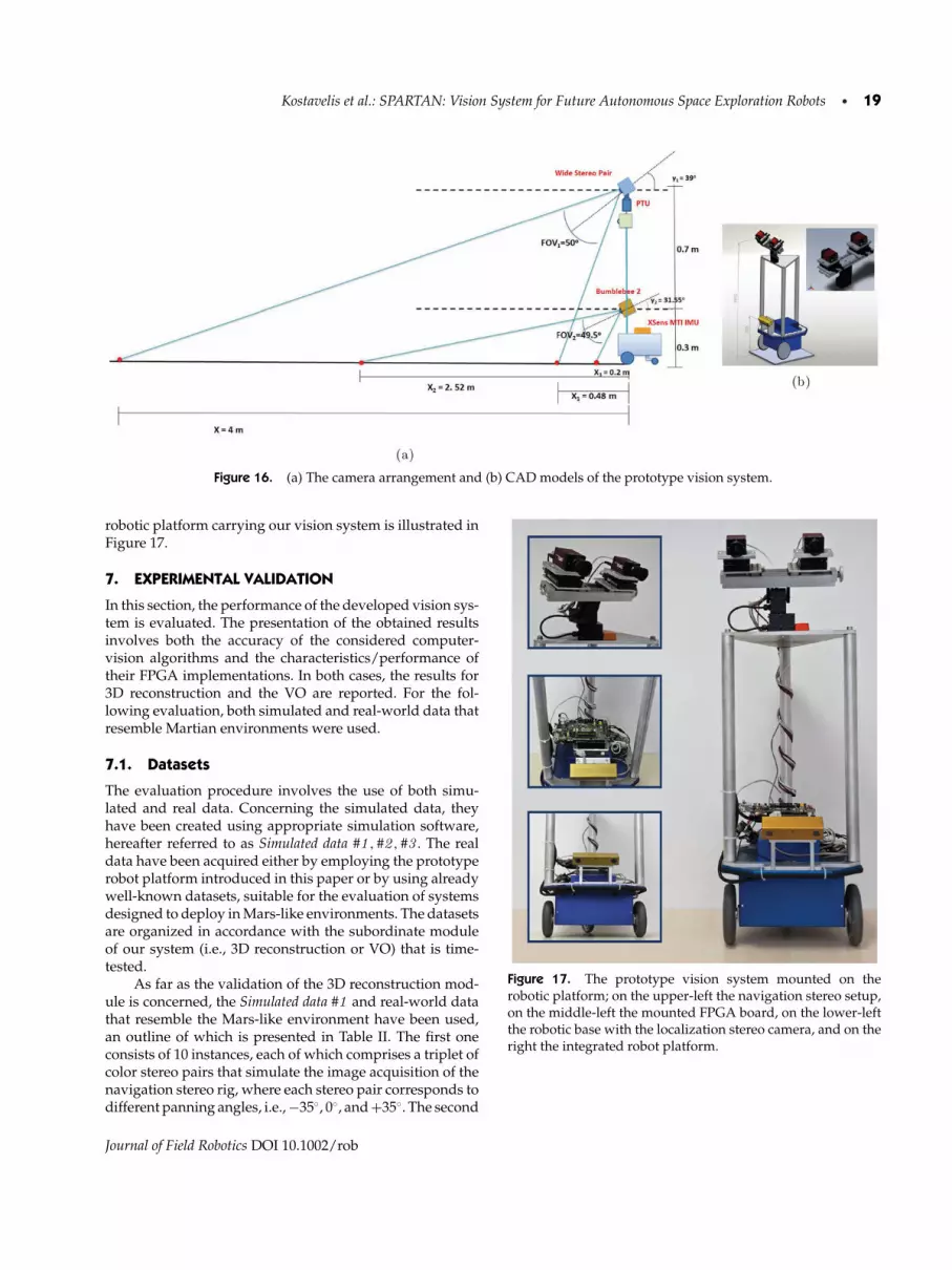
Kostavelis et al.: SPARTAN: Vision System for Future Autonomous Space Exploration Robots • 19
Figure 16. (a) The camera arrangement and (b) CAD models of the prototype vision system.
robotic platform carrying our vision system is illustrated inFigure 17.
7. EXPERIMENTAL VALIDATION
In this section, the performance of the developed vision sys-tem is evaluated. The presentation of the obtained resultsinvolves both the accuracy of the considered computer-vision algorithms and the characteristics/performance oftheir FPGA implementations. In both cases, the results for3D reconstruction and the VO are reported. For the fol-lowing evaluation, both simulated and real-world data thatresemble Martian environments were used.
7.1. Datasets
The evaluation procedure involves the use of both simu-lated and real data. Concerning the simulated data, theyhave been created using appropriate simulation software,hereafter referred to as Simulated data #1 , #2 , #3 . The realdata have been acquired either by employing the prototyperobot platform introduced in this paper or by using alreadywell-known datasets, suitable for the evaluation of systemsdesigned to deploy in Mars-like environments. The datasetsare organized in accordance with the subordinate moduleof our system (i.e., 3D reconstruction or VO) that is time-tested.
As far as the validation of the 3D reconstruction mod-ule is concerned, the Simulated data #1 and real-world datathat resemble the Mars-like environment have been used,an outline of which is presented in Table II. The first oneconsists of 10 instances, each of which comprises a triplet ofcolor stereo pairs that simulate the image acquisition of thenavigation stereo rig, where each stereo pair corresponds todifferent panning angles, i.e., −35◦, 0◦, and +35◦. The second
Figure 17. The prototype vision system mounted on therobotic platform; on the upper-left the navigation stereo setup,on the middle-left the mounted FPGA board, on the lower-leftthe robotic base with the localization stereo camera, and on theright the integrated robot platform.
Journal of Field Robotics DOI 10.1002/rob

20 • Journal of Field Robotics—2013
Table II. The datasets used for the evaluation of the 3D recon-struction component of the computer-vision algorithms.
Acquisition Number ofDataset Method Samples
Simulated data #1 Simulation 10DUTH Dataset (3D
Recon.)Prototype robot platform
(Navigation Stereo Camera)25
one, referred in Table II as the DUTH Dataset, has been ac-quired employing the navigation stereo rig of our deployedprototype robot. It consists of 25 instances, each one con-taining a triplet of color stereo pairs acquired by panningthe stereo rig accordingly. Figure 18 depicts various samplesof the aforementioned datasets.
Concerning the evaluation of the VO component of theproposed system, the Simulated data #2 , #3 , the dataset ac-quired by our deployed prototype robot (DUTH Dataset),the Devon Island Rover Navigation Dataset, and the AtacamaDesert Dataset have been utilized, a summary of which is pre-sented in Table III. Various samples of the utilized datasetsare depicted in Figure 19, indicating the variety of illumina-tion and camera geometry conditions that the experimentalprocedure has considered. In particular, the Simulated data#2 consists of 3,200 stereo pairs corresponding to a 100 mroute. In this dataset, the camera was placed 30 cm abovethe ground and titled by 31.55◦ as dictated by the require-ments for the localization camera. The relative translationbetween successive frames was approximately 3 cm. The
surface of the rendered images represents a rocky and un-even environment. This simulated route can be consideredas moderately challenging for a VO algorithm, as it mostlyinvolves straight paths with minor turns. Additionally, thedataset is accompanied by its ground-truth. The Simulateddata #3 consist of 1,836 stereo pairs corresponding to a 110 mroute. The geometry of the stereo camera in this dataset wasthe same as in the Simulated data #2 , however the samplingrate was more sparse and the relative displacement greater.In contrast to the previous route, the current one comprisesa greater challenge for a VO algorithm as it consists of aseries of successive turns, instead of straight segments. Thisdataset is also accompanied by its ground-truth both for therobot displacement and its orientation.
Furthermore, three sequences of real-world data thatclosely resemble Mars-like conditions have been consid-ered. The first one, which is shown in Table III, is calledthe DUTH Dataset and has been acquired employing thelocalization stereo rig (Bumblebee2) of our prototype robotwhen deployed in the field. It comprises a rocky and sandyenvironment near DUTH’s premises in Xanthi, Greece, andit has been acquired under low lighting conditions with alow elevation angle of the sun. The gathered images covera route of 11 m with relative translation among successiveframes being approximately 0.10 m. This dataset is accom-panied by ground-truth data acquired with a differentialglobal positioning system (DGPS), i.e., the Promark 500Magellan DGPS. The second image sequence is a third-partydataset, which has been gathered on Devon Island, knownas the Devon Island Rover Navigation Dataset. The camera ar-rangement of the robot used to acquire this dataset does not
Figure 18. Central (0◦) image of various triplets used for the evaluation of the 3D reconstruction component of the proposedvision system: (a) the Simulated data #1 and (b) real-world data that resemble the Mars environment.
Journal of Field Robotics DOI 10.1002/rob

Kostavelis et al.: SPARTAN: Vision System for Future Autonomous Space Exploration Robots • 21
Table III. The datasets used for the evaluation of the VO component of the computer-vision algorithms.
Number of CoveredDataset Acquisition Method/Platform Samples Distance (m)
Simulated data #2 Simulation 3,200 100Simulated data #3 Simulation 1,836 110DUTH Dataset (VO) Prototype robot platform (Localization Stereo
Camera)116 11
Devon Island Rover Navigation Dataset Third-party robot platform 4,488 1,000Atacama Desert Dataset Seeker prototype robot 1,530 96.5
comply with the one defined in the SPARTAN system, how-ever it employs the Bumblebee2 stereo camera by PointGreyResearch and, therefore, has been utilized for evaluation ofthe localization algorithms. This dataset was also used toprove that the accuracy of the developed algorithms doesnot depend on the type of data utilized. It comprises a collec-tion of images gathered at a Mars/Moon analog site on De-von Island, Nunavut and it is generally suitable for roboticsresearch (Furgale et al., 2012). Ground-truth position infor-mation from a DGPS is also provided, collected over a 10 kmtraverse. However, the proposed localization algorithm hasbeen evaluated in a subset of these data that correspondto 1 km, which was considered sufficient since our systemrequirements involved only 100 m routes. The third im-age sequence also comprises a third-party dataset, whichhas been acquired in the Atacama Desert in Chile (Wetter-green et al., 2005) and includes data from a 6 km route ofhighly representative Mars terrain (Woods et al., 2012). Thisdataset is accompanied by sparse DGPS ground-truth mea-surements. A subset of this dataset (approximately 96.5 mwith 6 cm between succesive frames) was selected, wherethe DGPS data were dense enough to be used in this work.
In summary, the utilized datasets for the evaluation ofthe VO accuracy have been selected in order to resemble asclosely as possible the Martian environment. In particular,the Devon Island Rover Navigation Dataset possesses surfacetexture and lighting conditions similar to those of Mars in-volving also a low elevation angle of the sun (Furgale et al.,2012). Additionally, the Atacama Desert Island Dataset wasfound to be appropriate for the experimentations of sim-ilar systems (Pedersen et al., 2003; Woods et al., 2012). Inaccordance with the acquisition practices of the aforemen-tioned datasets, the DUTH Dataset has been acquired by ourrobot prototype and specific characteristics such as elimi-nated lighting in rocky and sandy environment have beenretained.
7.2. Software Evaluation
7.2.1. 3D Reconstruction
The 3D reconstruction module has been tested both on theSimulated data #1 and on the dataset acquired from the navi-
gation stereo system of our prototype robotic platform. Con-cerning the Simulated data #1 , the accuracy of the 3D recon-struction module was better than 2 cm in the 4 m range,which indicates that the system can sufficiently meet the re-quirements. The performance of our system has been eval-uated by spotting objects (e.g., rocks and objects of knowndimensions) placed 4 m from the camera. After the 3D re-construction procedure, the same objects were identified inthe point cloud and their calculated distance was comparedto the real one. This procedure has been repeated for allthe triplets of stereo images. An example of the 3D recon-structed area that corresponds to 120◦ FOV, as a result of themerging of three stereo images with specific panning angles,is presented in Figure 20. The area is depicted as a texturedpoint cloud and the erroneous estimations are diminishedas the mismatches in the disparity computation module arerare. However, it should be mentioned that for the simu-lated data, the performance of the 3D reconstruction algo-rithm was expected and also found to be better than theperformance on real data, due to the fact that the renderedimages are fully textured and the stereo pairs are productsof a “perfect” virtual stereo camera. Given the availabilityof ground-truth for the simulated data, the performance ofthe algorithm has been evaluated for a reconstructed sim-ulated scene. Therefore, for the middle reference image ofFigure 20, the 3D reconstructions of the scene, using our al-gorithm [Figure 21(a)] and the ground-truth values [Figure21(b)], have been compared. Note that in Figure 21(a), thereconstructed area is sparser than in the ground-truth as aresult of the bidirectional consistency check in the computa-tion of the disparity map. The Euclidean distances betweencorresponding points in both reconstructions have beencomputed and the reconstruction accuracy for the scene hasbeen obtained. Figure 21(c) presents the 3D reconstructedarea using the developed algorithm, however the intensityvalues of the points indicate the Euclidean distance betweentheir reconstructed and their ground-truth values. Note thatthe accuracy for the entire scene remains within the 2 cmrequirements apart from only a few erroneously estimatedpoints that are scattered in the scene.
The 3D reconstruction algorithm was also tested ondata gathered during the field deployment of our developed
Journal of Field Robotics DOI 10.1002/rob

22 • Journal of Field Robotics—2013
Figure 19. Instances from datasets used for the evaluation of the VO component of the proposed vision system: (a) Simulated data#2 , (b) Simulated data #3 , (c) DUTH Dataset acquired by the prototype robot platform (Localization Stereo Camera), (d) the DevonIsland Rover Navigation Dataset, and (e) the Atacama Desert Dataset.
prototype robot (DUTH Dataset). The performance evalua-tion of the algorithm on the real-world data followed thesame experimental procedure as with the simulated data.An example of a 3D reconstructed area that corresponds to120◦ FOV, as a result of the merging of three stereo images
with specific panning angles, is presented in Figure 22. Thearea is depicted as a textured point cloud. In this case, theerroneous estimations are more than those found in the sim-ulated scenario, as a result of mismatches during the stereocorrespondence procedure.
Journal of Field Robotics DOI 10.1002/rob

Kostavelis et al.: SPARTAN: Vision System for Future Autonomous Space Exploration Robots • 23
Figure 20. In the first row, the left reference images of the three stereo pair samples with different panning angles are depictedfrom the Simulated data #1 ; in the second row, the respective 3D reconstructed area that covers 120◦ FOV is shown.
The accuracy of the 3D reconstruction module wasbetter than 2 cm in the 4 m range, which sufficientlymeets the system requirements. For instance, Figure 23 il-lustrates the results of a conducted experiment. A “cali-bration chessboard” of known dimensions (0.94 m longand 1.21 m wide) was placed around 4 m in front of therobot. Then, the 3D reconstruction of the scene was per-formed by our system and the width of the “chessboard”was measured again on the resulting point cloud. To pre-cisely evaluate the accuracy of this module, multiple mea-surements of the width were obtained on the point cloudalong the length of the “chessboard,” i.e., in the range of (3.7,4.6) m in front of the robot. Figure 23(b) depicts the mea-sured width of the “chessboard” for the respective distancerange, returning values ranging between (1.179, 1.238) m.In particular, at a 4 m distance the width of the “chess-board” was found to be 1.204 m, revealing that the 3Dreconstruction module retains accuracy better than 2 cmin 4 m. Note that measurements that took place beyond4 m are less accurate, as depicted in Figure 23(b). Specifi-cally, at 4.6 m the width of the chessboard was found to be1.238 m. These results have a twofold significance; on theone hand, the developed 3D reconstruction algorithm isaccurate and produces dense and consistent reconstructedareas, while on the other hand the construction and cal-ibration of the navigation stereo rig has been performedsuccessfully. Considering that the disparity computation al-gorithm described in Section 4.2.1 is based on line scanning,the alignment of cameras of the navigation stereo setupwas successful, retaining accurate alignment of the twocameras.
7.2.2. Visual Odometry
The evaluation of the VO algorithm has been performedon simulated data (Simulated data #2 and #3 ), on two well-known datasets that resemble Mars-like environments (De-von Island Dataset and Atacama Desert Dataset), as wellas on real-world data acquired by our prototype robot(DUTH Dataset). To quantify the accuracy of the VO al-gorithm, its output regarding the position of the robot isdirectly compared with the respective ground-truth data bymeans of the Euclidean distance as described later in thissection.
First, the accuracy of the algorithm has been exam-ined on the Simulated data #2 . The VO algorithm has beenevaluated on 3,200 successive frames and the total posi-tioning accuracy of the proposed algorithm is 0.62 m ona 100 m route. These results provided us with reasonableconfidence that the proposed method might meet the re-quirements of the system to retain accuracy better than2% on the 100 m route. Figure 24(a) depicts the 3D po-sition estimates against the ground-truth representing thedisplacements of the stereo camera. Moreover, the accu-racy of the proposed method can be further analyzed byexamining rotation estimations among all the successiveframes as presented in Figure 24(b). Figure 24(b) depictsthe instantaneous rotation estimations for all the framesof the route against the ground-truth values. A full ex-amination of the real potential of a VO algorithm alsorequires the examination of the continuous deviation ofthe algorithm from the ground-truth. Figure 24(c) presentsthe deviation in terms of 3D Euclidean distance of thecompared VO algorithm against the ground-truth along the
Journal of Field Robotics DOI 10.1002/rob

24 • Journal of Field Robotics—2013
Figure 21. (a) The 3D reconstructed area for the middle stereo pair of Figure 20 as generated by the developed algorithm, (b) theground-truth 3D reconstructed area of the same scene, and (c) the obtained reconstruction accuracy of the scene. Note that in (c)the intensity values of the points correspond to the Euclidean distance between their reconstructed and their ground-truth values.
entire route. It is shown that the used method exhibits con-stantly less than a 1.3 m deviation from the ground-truth.
The accuracy of the used algorithms has also been ex-amined on the Simulated data #3 . The VO algorithm hasbeen evaluated on 1,836 successive frames and the total po-sitioning accuracy of the proposed algorithm was foundto be better than 0.49 m for an 110 m route. It is worthnoting that the accuracy in the Simulated data #3 is betterthan in the Simulated data #2, which have smaller imagespacing. The explanation for this is that there exists a lowerlimit of the image spacing, below which no additional in-formation about the robot motion can be retrieved. How-
ever, in each cycle of VO calculation a systematic error isintroduced and a very small image spacing results in morecalculation cycles. These systematic errors accumulate overtime so avoiding unnecessarily frequent calculation cyclescan actually improve the results, apart from limiting thecomputational load. Thus, there is an optimum frame spac-ing. However, even if this optimum frame spacing existsfor each image sequence, it is difficult to determine it ina way other than experimentally. This is mainly due to itsdependence on factors such as the actual translational andangular speed of the robot, the characteristics of the usedalgorithms, the accuracy of the performed computations,
Journal of Field Robotics DOI 10.1002/rob

Kostavelis et al.: SPARTAN: Vision System for Future Autonomous Space Exploration Robots • 25
Figure 22. In the first row, the left reference images of the three stereo pair samples with different panning angles are depictedfrom the DUTH Dataset captured with the navigation stereo rig; in the second row, the respective 3D reconstructed area that covers120◦ FOV is shown.
and last but not least the characteristics of the scene, suchas texture and illumination. Figure 25(a) depicts the 3D po-sition estimates against the ground-truth representing thedisplacements of the stereo camera. Moreover, the accuracyof the proposed method can be further analyzed by exam-ining rotation estimations among all the successive framesas presented in Figure 25(b). Figure 25(b) depicts the instan-taneous rotation estimations for all the frames of the routeagainst the ground-truth values. A full examination of thereal potential of a VO algorithm also requires the examina-tion of the continuous deviation of the estimated trajectoryfrom the ground-truth one. Figure 25(c) presents the devia-tion in terms of 3D Euclidean distance of the compared VOalgorithm against the ground-truth along the entire route. Itis shown that the proposed method constantly retains lessthan a 1.2 m deviation from the ground-truth. It should alsobe noted that the VO exhibited remarkable accuracy on thetwo different simulated datasets. This means that the per-formance of the algorithm is not influenced by the shapeof the robot’s trajectory. Considering all the results on sim-ulated data, it can be expected that the VO algorithm canmeet the expected performance also on real-world data.
Furthermore, the accuracy of the VO algorithm hasbeen examined in real-world data and, specifically, in a11 m sequence acquired during the field deployment ofour prototype robot platform (DUTH Dataset), using thelocalization stereo camera. The algorithm has been evalu-ated on 116 successive image pairs and the total positioningaccuracy has been found to be 0.2 cm in the 11 m route(i.e., better than 2%), ensuring that the proposed method
complies with the requirements of the SPARTAN system.Although this dataset is not accompanied by orientationground-truth, it is clearly depicted in Figure 26(a) that therobot’s estimated trajectory follows precisely the displace-ment ground-truth derived from the DGPS data. Moreover,the continuous deviation, expressed as 3D Euclidean dis-tance from the ground-truth for each estimated position,is also depicted in Figure 26(b), revealing that the utilizedmethod constantly retains a deviation less than 2 cm.
Another dataset acquired in real-world conditions, onwhich the accuracy of the algorithm has also been exam-ined, is the Devon Island Rover Navigation Dataset. The VOalgorithm has been evaluated on 4,488 successive framesand the total positioning accuracy of the proposed algo-rithm is better than 15 m for a 1 km route, which means thatit is better than 2% and within the given requirements. Theevaluation of the proposed VO algorithm in this dataset isa challenging task as the traveled route is on uneven ter-rain with a lot of rolling between the successive frames.Figure 27(a) depicts the 3D position estimates against theDGPS ground-truth representing the displacements of thestereo camera. Once again, the accuracy of the proposedmethod is further analyzed by examining rotation esti-mations among all the successive frames as presented inFigure 27(b). Figure 27(b) depicts the instantaneous rota-tion estimations for all the frames of the route against theground-truth values. A full examination of the real poten-tial of a VO algorithm also requires the examination of thecontinuous deviation of the algorithm from the ground-truth. Figure 27(c) presents the deviation in terms of 3D
Journal of Field Robotics DOI 10.1002/rob

26 • Journal of Field Robotics—2013
Figure 23. (a) The left reference image of the navigation stereo camera, (b) width measurements of the “chessboard” for differentdistances from the robot, and (c) the reconstructed area.
Euclidean distance of the considered VO algorithm againstthe ground-truth along the entire route. It is seen that theproposed method retains constantly less than 15 m devia-tion from the ground-truth.
The last dataset on which the localization vision systemhas been tested is the Atacama Desert Dataset. In particular,we have evaluated our system on the part of this datasetthat is accompanied with consistent ground-truth data. Theconsidered subset consists of 1530 frames correspondingto a 96.5 m route. Although the robot motion is calculatedfor every frame, the accuracy could be computed only onthose frames for which DGPS measurements were available.
Figure 28(a) shows that the estimated 3D trajectory closelyfollows the DGPS ground-truth. The positioning accuracy ismeasured as Euclidean distances from the available DPGSmeasurements, as shown in Figure 28(b). The system ex-hibited better that 1% accuracy, retaining small positioningerrors.
The outcome of all the previous experiments in a va-riety of different datasets is that the accuracy of the pro-posed VO algorithm is consistently better that 2% irre-spective of the evaluation data. The latter means that theproposed localization system operates competently un-der different illumination conditions and camera geome-
Journal of Field Robotics DOI 10.1002/rob

Kostavelis et al.: SPARTAN: Vision System for Future Autonomous Space Exploration Robots • 27
Figure 24. Experimental validation with Simulated data #2 : (a) 3D trajectory estimation of the proposed VO algorithm superim-posed on ground-truth; (b) rotation estimations of all successive frames for the proposed method compared with the ground-truth;and (c) deviations in 3D Euclidean distance from the ground-truth for every frame of the examined method.
try, proving that the selected and implemented algorithmfulfills the initial requirements regarding the accuracy asposed by ESA.
7.3. Hardware Evaluation
The hardware implementations of critical kernels involvedin the 3D reconstruction and the VO components were de-veloped using parametric VHDL and implemented on aXilinx XC6VLX240T FPGA. This section presents the evalu-ation results for those hardware kernels.
7.3.1. 3D Reconstruction
The disparity kernel was synthesized for image sizes of1,120×1,120 pixels, which is the size of the images obtainedby the navigation camera. We performed design space ex-ploration to determine the optimal band height for the parti-tioning of the input images (as mentioned in Section 5.3.1).Selecting 28 rows per band minimizes the total executiontime due to the fact that it leads to high operation frequency
circuits and, at the same time, it reduces the overhead of suc-cessively reloading the input pixels to the pipeline (Lentariset al., 2012). Additionally, the size of the 28-row band op-timizes the utilization of the fixed-size memory blocks re-served within the FPGA for data storage. The communica-tion time for the three stereo pair images was 0.243 s due topipelined operation, and the processing time for the produc-tion of the three disparity maps, considering 224 disparitylevels, was 5.61 s. The overall resource utilization of the dis-parity implementation was 998 slices, which corresponds to2.6% of the entire FPGA and 101 block RAMs, which is 22%of the total available block RAMs.
The developed module achieves the accuracy specifiedby ESA within the available time window of 20 s. Comparedto other stereo-vision HW designs in the literature, ourESA compliant design consumes significantly fewer HWresources to examine more disparity levels. For example,compared to Jin et al. (2010), who examined 64 disparitylevels in 4 ms (too fast for the current ESA specifications),the proposed design consumes 20 times less FPGA LUTs,
Journal of Field Robotics DOI 10.1002/rob

28 • Journal of Field Robotics—2013
Figure 25. Experimental validation with Simulated data #3 : (a) 3D trajectory estimation of the proposed VO algorithm superim-posed on ground-truth; (b) rotation estimations of all successive frames for the proposed method compared with the ground-truth;and (c) deviations in 3D Euclidean distance from the ground-truth for every frame of the examined method.
Figure 26. Experimental validation with the DUTH Dataset: (a) the 3D trajectory estimation of the proposed VO algorithmsuperimposed on ground-truth; and (b) deviations in 3D Euclidean distance from the ground-truth for each frame of the examinedmethod.
Journal of Field Robotics DOI 10.1002/rob

Kostavelis et al.: SPARTAN: Vision System for Future Autonomous Space Exploration Robots • 29
Figure 27. Experimental validation with the Devon Island Rover Navigation Dataset: (a) 3D trajectory estimation of the proposedVO algorithm superimposed on ground-truth; (b) rotation estimations of all successive frames for the proposed method comparedwith the ground-truth; and (c) deviations in 3D Euclidean distance from the ground-truth for every single frame of the examinedmethod.
zero DSP blocks instead of 12, as well as only 1/3 of the mem-ory blocks. Such resource reduction can be proved criticalin space applications with devices of limited computationalpower.
7.3.2. Visual Odometry
The disparity kernel was synthesized for image sizes of512×384 pixels, which is the size of the images obtained bythe localization camera. After a design space exploration,a band of 64 image rows was selected for the partitioningof each image. This choice provides a good compromisebetween the execution time and the hardware cost. Thecommunication time for the stereo pair images was 0.035 s.Moreover, the processing time for the production of the dis-parity map, considering 100 disparity levels, was 0.141 s.The overall resource utilization of the disparity implemen-tation was 1227 slices (3%) and 98 block RAMs (22%).
Regarding the hardware acceleration of the SURF algo-rithm, the Coarse Detection kernel produces approximately99% of the same interest points as the software SURF im-plementation and can process the entire image in 0.008 s.
The hardware implementation of the kernel requires 777slices (2%), 4 DSP blocks (0.5%), and 54 block RAMs (13%).The description of the interest points based on the Box De-scription kernel produces approximately 92% of the samematches as the original SURF implementation while it canprocess 200 interest points in 0.005 s. The hardware imple-mentation of the kernel requires 2468 slices (6%), 13 DSPblocks (1%), and 137 block RAMs (32%). The complete ex-ecution of the SURF, taking into consideration the softwarepart, the communication, and the hardware part, is ana-lyzed after the complete system integration in the followingsubsection.
Compared to other SURF detection implementations inthe literature, our design achieves faster execution time withfewer HW resources. For example, when comparing ourCoarse Detector and Integral Image to Bouris et al. (2010),who also performed interpolation on FPGA, we use approx-imately six times less FPGA LUTs, memory blocks, and DSPblocks, while strictly for coarse detection functions, we useapproximately three times less LUTs. Moreover, our frameprocessing rate on the FPGA is two times faster than thework described in Bouris et al. (2010). On the other hand,
Journal of Field Robotics DOI 10.1002/rob

30 • Journal of Field Robotics—2013
Figure 28. Experimental validation on the Atacama Desert Dataset gathered by a prototype robot: (a) the 3D trajectory estimationof the proposed VO algorithm superimposed on ground-truth, and (b) deviations in Euclidean distance from the ground-truth foreach frame of the examined method.
regarding the SURF Description, this is the first implemen-tation on FPGA, to the best of our knowledge.
7.3.3. Entire System Time Execution
To conclude the evaluation of our system, we measure theexecution time of the entire HW/SW system, which we in-tegrate on a dual-core processor (3 GHz, 4 GB memory) andon the Virtex-6 FPGA. ESA has specified that the centralprocessing resources shall assume total utilization of a 150MIPS processor. As a result, we estimate the execution timeof our system deployed on such a 150 MIPS CPU. The es-timation involves scaling of the SW time by a factor of 18.4(based on performance comparison of the two CPUs accord-ing to the Whetstone, Dhrystone, and Linpack benchmarks,plus a 20% error margin).
Overall, the system requires 12.3 s to complete one stepof the 3D reconstruction, i.e., to process three image pairs of1,120×1,120 pixels each and construct their 3D map. Specif-ically, 11.3 s are consumed by the FPGA for the Disparitycomputation (operating at 172 MHz), while 1 s is consumedby the 150 MIPS CPU for Imaging and 3D point cloud merg-ing. Concerning the VO algorithm, our system requires 1 sto complete the processing of one 512×384 image pair with300 detected features on each. On average, SURF consumes775 ms out of which 67 ms correspond to the FPGA pro-cess (including communication) and 708 ms correspond tothe 150 MIPS CPU. Note that the Disparity requires 297 ms,which, however, are masked by the 775 ms of SURF, due tothe fact that these two modules are executed in parallel. Theremaining time is consumed by Imaging (37 ms), LandmarkMatching (136 ms), Motion Estimation (26 ms), and otherauxiliary functions of the system.
The aforementioned results exhibit that the developedsystem will meet the ESA specifications (20 s for the 3D re-construction utilizing the navigation stereo camera and 1 sfor the VO utilizing the localization stereo camera), evenwhen deployed on low computational power platforms,e.g., such as the one available on ExoMars. To further quan-tify the benefits of the proposed architecture, we evaluate itsspeed-up by comparing to the all-software solution, both ona high-end CPU and on the 150 MIPS CPU. In the 3D recon-struction, the Disparity would require approximately 80 sto be completed on the high-end CPU and 24.5 min to becompleted on the 150 MIPS CPU. Therefore, for the entire3D reconstruction, the proposed HW/SW solution leads toa speed-up of 7 when compared to the high-end CPU andto a speed-up of 116 when compared to the 150 MIPS CPU.Considering the VO algorithm, the all-software sequentialsolution would consume 2.2 s on a high-end CPU and 40s on the 150 MIPS CPU. Therefore, the proposed architec-ture achieves an approximate speed-up of 2 and 40 times,respectively. Specifically for SURF, when compared to thehigh-end CPU, we achieve a speed-up varying from 1.06to 1.35 depending on the number of features on the image(we measure an increased HW time due to the Ethernetcommunication bottleneck, which accounts for more than45 ms per image; in a project targeting the minimizationof this overhead, the speed-up would increase up to 2).When compared to the 150 MIPS CPU, i.e., within the ac-tual context of the proposed HW/SW solution, the achievedspeed-up of SURF execution is 3.5 times, which is exactly theboost required to meet the strict 1 s requirement imposedby ESA. Overall, the reported speed-up factors verify thatthe proposed HW/SW codesign improves significantly theexecution time, and moreover that it can be used beyond
Journal of Field Robotics DOI 10.1002/rob

Kostavelis et al.: SPARTAN: Vision System for Future Autonomous Space Exploration Robots • 31
the scope of this project to support high-end processors ex-ecuting computer vision algorithms.
8. LESSONS LEARNED
During the design, development and testing phases of thissystem we faced a series of practical issues that are worthmentioning. Furthermore, we were able to verify the advan-tages of our choices, both regarding the used algorithms andtheir FPGA-based implementation.
One of the first choices, when designing a vision sys-tem, is the algorithms that will be employed. Benchmark-ing of vision and robot localization algorithms is still anopen issue, as the characteristics and demands may signif-icantly vary from system to system. Making things evenmore complicated, we had to take into consideration alsohardware implementability and computational complexityfactors when choosing algorithms for our system. The se-lected algorithms should achieve the required accuracy ofresults and execution speed, when implemented on hard-ware. There is little literature on how to choose algorithmsfor hardware implementation. A general rule of thumb isthat the algorithms lacking repetitive structures are goodcandidates. However, small adjustments and tradeoffs wereoften required during the transition from software to hard-ware. As a result, we chose to develop our own algorithmsand then have them implemented on hardware, so that wecould make any required changes, while being confidentabout the consequences and the accuracy of the final re-sults.
When using vision sensors, the accuracy of the results(in our case 3D reconstruction and localization) is stronglydependent on factors such as the texture of the scene underobservation and the lighting of the environment. We definedthe geometry of the vision system and the characteristicsof the underlying algorithms keeping in mind these facts.The construction of a custom stereo rig, such as the navi-gation stereo camera of our system, is a tedious procedurethat requires multiple fine adjustments and calibrations toobtain accurate alignment between the cameras. This pro-cedure is very important due to the fact that the quality ofthe 3D reconstructed area is highly dependent both on theprecision of the camera arrangement and the implementedstereo-vision algorithm. Therefore, we have tried to set thebar of the theoretical accuracy high enough so as to ensureproper operation also in realistic situations. Multiple testsunder a variety of conditions have indicated that our sys-tem achieves the required accuracy during its operation, butmost importantly presents a coherent and reliable behavior.Having all the aforementioned limitations in mind, nobodycan rule out the possibility that under certain circumstancesthe accuracy will deteriorate below the desirable levels. In-deed, during our tests we have experienced cases in whichour system failed to respect the set requirements. The 3Dreconstruction accuracy is strongly dependent on the tex-
ture of the scene, due to the block-matching nature of theused stereo correspondence algorithm. Also, lighting wasfound to be a crucial factor that had an impact on the recon-struction accuracy. More specifically, the elevation angle ofthe sun and the surface albedo were observed to affect theresults significantly. On the other hand, the VO results werefound to be affected not only by the previous situations, butalso by the robot velocity and angular rate. As an example,extreme angular rates or increases of the speed affect im-age spacing with negative consequences for VO. As alreadydiscussed, we found out that extremely small velocities, oreven worse, a complete motion halt, again deteriorate thelocalization accuracy due to the accumulation of systematicerrors. Finally, our VO algorithm has been found to be un-able to recover from previously accumulated localizationerror. Consequently, a succesful test demanded that noneof the aforementioned factors should be experienced dur-ing the whole operation period. However, this problem ismeant to be treated within the larger robotic system, whereSPARTAN belongs. There, the host robot employs a redun-dancy of sensors and fusion of the information under awider localization framework to produce reliable results inthe long run.
Many challenges have been faced during the field de-ployment of our system. The data acquisition and the exe-cution of the proposed system, including the FPGA process-ing, have been performed online, however the evaluation ofboth the 3D reconstruction and the VO have been performedin an offline evaluation process. In particular, the validationof the 3D reconstruction has been performed by measur-ing the dimensions of various objects in the obtained pointclouds and comparing them to their actual values. Further-more, the estimated trajectory is evaluated in a post processstep by comparing the DGPS data and the computed mo-tion estimations. Thus, better insight for the performanceof the HW implementations was obtained both in termsof accuracy and execution timing. Moreover, the synchro-nization and the pairing of the DGPS measurements withthe rest of the captured data is a difficult and error-proneprocedure. Another difficulty was determining the initialpose of the robot. Typically, the solution to this issue isderived by using external nonvision sensors such as incli-nometers, compasses, etc. However, these sensors also in-troduce noise, making the validation procedure even morecomplicated.
To achieve the set requirements, a tight integration ofsoftware and hardware components was required. Makingthings even more complicated, our system is only part of abigger robotic system architecture that will need to seam-lessly interface and cooperate with ours. ROS provided thecommon substrate for the layered architecture of our sys-tem. It made the coordination between the sensors, the soft-ware, and the FPGA straightforward. Furthermore, it allowsfor future extensions and easy integration to the host roboticsystem.
Journal of Field Robotics DOI 10.1002/rob

32 • Journal of Field Robotics—2013
Regarding HW/SW codesign, SPARTAN has verifiedthe importance of profiling and careful partitioning of theinitial algorithms. Implementing mainly those computa-tionally intensive kernels based on integer arithmetic canlead to significant speed-up of the system with low costand negligible loss of accuracy when compared to the ini-tial CPU implementation. In this direction, developing andexperimenting with a fixed-point model on SW, prior tothe actual FPGA implementation, can greatly benefit thecodesign process. Additionally, the fixed-point model as-sists the designer in performing word-length optimization,i.e., in determining the minimum width of the internalHW datapaths in order to provide results for the requiredaccuracy.
Studying the system on an algorithmic level can leadto significant modifications and optimizations regardingmemory reuse and/or time complexity. Such optimizationsare crucial in FPGA implementations utilizing devices oflimited resources, especially when targeting space appli-cations. Moreover, it will allow for more precise partition-ing of the algorithm by taking into consideration memoryand communication requirements in addition to time. Inparticular, the communication between the CPU and theFPGA becomes a serious bottleneck in data-intensive ap-plications such as computer vision. Hence, it is crucial toidentify kernels with low communication requirements andpartition the system accordingly. Note that pipelining com-munication and processing steps prove to be a very usefulworkaround for the above bottleneck; the proposed dispar-ity design followed this pipelining approach and effectivelyeliminated the transfer delays.
9. CONCLUSIONS
This work described the development of a vision system forplanetary exploration rovers within the ESA project “SPAR-TAN.” The goal of the system was to allow efficient au-tonomous vision-based navigation of planetary rovers. Thefuture space exploration rovers need to cover longer dis-tances during their operation. The way to achieve this is byminimizing the time they spend statically processing datawith their limited computational capacity. As a result, theprocessing time needs to be reduced, while at the same timethe sensing accuracy should be improved in order for theresults to remain reasonably accurate over the longer cov-ered distances. The improved accuracy of the vision systemwas achieved by carefully designing the arrangement of thecameras and developing the required algorithms, includ-ing custom solutions where needed. On the other hand, toreduce the execution time we took advantage of the pos-sibility, inherent in many computer-vision algorithms, tobe parallelized and implemented using custom-designedvectorial processing, by means of FPGAs. As an indicationof the continued interest in FPGA-based robot vision solu-
tions, it is worth mentioning that ESA has recently called fora follow-on project of SPARTAN, i.e., the “Spartan Exten-sion Activity - Not Tendered” (SEXTANT) project, furtherinvestigating this direction.
Our vision system consists of two stereo cameras, a nav-igation and a localization one. A high-resolution custom-made stereo camera, placed on a mast 1 m above the ground,gathers navigation data used for 3D reconstruction of thescene. A lower-resolution commercial Bumblebee2 cameraby PointGrey Research, placed 30 cm above the ground, in-spects the region in front of the robot gathering localizationdata. The development of the system was described, cover-ing in detail the arrangement of the cameras, the character-istics of the used algorithms, as well as their implementationin hardware. A prototype of the complete vision system wasdeveloped and mounted on a mobile robot platform sim-ulating basic characteristics of the considered space rover.This robot platform hosted all the components of the devel-oped vision system, and was used to simulate rover fieldoperations and gather outdoor test data that exhibit similarcharacteristics to Martian environment. The ability of oursystem in 3D reconstruction and VO tasks was assessed ina variety of datasets, acquired both by our prototype robotplatform and by third-party ones. The resulting accuracyand the operation speed were found to satisfy the systemrequirements, as posed by ESA. More precisely, the use ofFPGA achieved a speed-up of the 3D reconstruction by afactor of 7 when compared to a high-end CPU and by a fac-tor of 116 when compared to a 150 MIPS CPU. Furthermore,the computation of VO was accelerated 2 and 40 times, re-spectively. However, in the long term the sole use of VOfor localization purposes is expected to lead to error accu-mulation, making the results unreliable. However, the sys-tem architecture, even if it does not explicitly include them,foresees the existence of external nonvisual sensors. Theseadditional sensors will contribute input to the localizationmodule, thus improving the accuracy and reliability of itsresults over long distances. The vision system was imple-mented in a modular manner, but also bearing in mind thatit will comprise one part of a bigger system, i.e., of the fullyequipped robotic platform. As such, interfaces with othermodules are foreseen, in accordance with the design andstandards defined by ESA.
ACKNOWLEDGMENTS
This work has been supported by the European SpaceAgency (ESA) project “SPAring Robotics Technologies forAutonomous Navigation (SPARTAN).” The authors wouldlike to thank Gianfranco Visentin for his valuable insightsand resources that he provided to our team during theSPARTAN project.
Journal of Field Robotics DOI 10.1002/rob

Kostavelis et al.: SPARTAN: Vision System for Future Autonomous Space Exploration Robots • 33
REFERENCES
Bajracharya, M., Maimone, M. W., & Helmick, D. (2008). Auton-omy for mars rovers: Past, present, and future. Computer,41(12), 44–50.
Bay, H., Ess, A., Tuytelaars, T., & Van Gool, L. (2008). Speeded-up robust features (SURF). Computer Vision and ImageUnderstanding, 110(3), 346–359.
Bianchi, R., & Reali-Costa, A. (2002). Implementing computervision algorithms in hardware: An fpga/vhdl-based visionsystem for a mobile robot. RoboCup 2001: Robot SoccerWorld Cup V (pp. 167–220).
Bouris, D., Nikitakis, A., & Papaefstathiou, I. (2010). Fast and ef-ficient fpga-based feature detection employing the surf al-gorithm. In Field-Programmable Custom Computing Ma-chines (FCCM), 2010 18th IEEE Annual International Sym-posium (pp. 3–10). IEEE.
Bowman, J., & Mihelich, P. (2013). Stereo Calibration. http://www.ros.org/wiki/camera_calibration/Unsynchronized_Stereo.
Cabay, S., & Jackson, L. (1976). A polynomial extrapolationmethod for finding limits and antilimits of vector se-quences. SIAM Journal on Numerical Analysis, 13(5), 734–752.
Cyganek, B., & Siebert, J. P. (2009). An introduction to 3Dcomputer vision techniques and algorithms. John Wiley& Sons.
Diamantopoulos, D., Siozios, K., Lentaris, G., Soudris, D., & Ro-drigalvarez, M. (2012). Spartan project: On profiling com-puter vision algorithms for rover navigation. In AdaptiveHardware and Systems (AHS), 2012 NASA/ESA Confer-ence (pp. 174–181). IEEE.
Esposito, F., Giuranna, M., Maturilli, A., Palomba, E., Colangeli,L., & Formisano, V. (2007). Albedo and photometric studyof Mars with the Planetary Fourier Spectrometer on-boardthe Mars Express mission. Icarus, 186, 527–546.
European Space Agency (2010). Statement of work: SPAr-ing Robotics Technologies for Autonomous Navigation(SPARTAN).
Evans, C. (2009). Notes on the opensurf library. University ofBristol, Tech. Rep. CSTR-09-001, January.
Fraundorfer, F., & Scaramuzza, D. (2012). Visual odometry: PartII: Matching, robustness, optimization, and applications.IEEE Robotics & Automation Magazine, 19(2), 78–90.
Furgale, P., & Barfoot, T. (2010a). Stereo mapping and local-ization for long-range path following on rough terrain. InIEEE International Conference on Robotics and Automa-tion (ICRA) (pp. 4410–4416).
Furgale, P., & Barfoot, T. D. (2010b). Visual teach and repeatfor long-range rover autonomy. Journal of Field Robotics,27(5), 534–560.
Furgale, P., Carle, P., Enright, J., & Barfoot, T. (2012). The devonisland rover navigation dataset. The International Journalof Robotics Research, 31(6), 707–713.
Giralt, G.& Boissier, L. (1992). The french planetary rover vap:Concept and current developments. In lEEE/RSJ Inter-national Conference on Intelligent Robots and Systems(IROS) (vol. 2, pp. 1391–1398).
Govender, N. (2009). Evaluation of feature detection algorithmsfor structure from motion. Council for Scientific and Indus-trial Research, Pretoria, Technical Report.
Grant, J., Westall, F., Beaty, D., Cady, S., Carr, M., Ciarletti,V., Coradini, A., Elfving, A., Glavin, D., Goesmann, F.,Hurowitz, J., Ori, G., Phillips, R., Salvo, C., Sephton, M.,Syvertson, M., & Vago, J. (2010). ExoMars and MAX-C:Planning for potential cooperative science using 2 rovermission to mars. In European Planetary Science Congress(vol. 5).
Griffiths, A., Coates, A., Jaumann, R., Michaelis, H., Paar, G.,Barnes, D., Josset, J., et al. (2006). Context for the esa exo-mars rover: The panoramic camera (pancam) instrument.International Journal of Astrobiology, 5(3), 269.
Guest, A. N., Cunio, P. M., Hofstetter, W. K., Hong, S., & Hoff-man, J. A. (2008). Development of the PISCES analog siteto support planetary exploration architecting and opera-tions: Final report. Technical report, Pacific InternationalSpace Center for Exploration Systems.
Harris, C., & Stephens, M. (1988). A combined corner and edgedetector. In Alvey vision conference (vol. 15, p. 50). Manch-ester, UK.
Hartley, R., & Zisserman, A. (2000). Multiple view geometry incomputer vision (vol. 2). Cambridge University Press.
Helmick, D., Roumeliotis, S., Cheng, Y., Clouse, D., Bajracharya,M., & Matthies, L. (2006). Slip-compensated path follow-ing for planetary exploration rovers. Advanced Robotics,20(11), 1257–1280.
Herbert, M., Caillas, C., Krotkov, E. P., Kweon, I. S., & Kanade, T.(1989). Terrain mapping for a roving planetary explorer. InIEEE International Conference on Robotics and Automa-tion (ICRA) (pp. 997–1002).
Ishigami, G., Nagatani, K., & Yoshida, K. (2011). Path planningand evaluation for planetary rovers based on dynamic mo-bility index. In IEEE/RSJ International Conference on In-telligent Robots and Systems (IROS) (pp. 601–606).
Jin, S., Cho, J., Dai Pham, X., Lee, K. M., Park, S.-K., Kim, M.,& Jeon, J. W. (2010). Fpga design and implementation ofa real-time stereo vision system. Circuits and Systems forVideo Technology, IEEE Transactions, 20(1), 15–26.
Johnson, A., Goldberg, S., Yang, C., & Matthies, L. (2008). Ro-bust and efficient stereo feature tracking for visual odom-etry. In IEEE International Conference on Robotics andAutomation (ICRA) (pp. 39–46).
Kaess, M., Ni, K., & Dellaert, F. (2009). Flow separation for fastand robust stereo odometry. In IEEE International Confer-ence on Robotics and Automation (ICRA) (pp. 3539–3544).
Kang, S., Webb, J., Zitnick, C., & Kanade, T. (1995). A multibase-line stereo system with active illumination and real-timeimage acquisition. In IEEE International Conference onComputer Vision (pp. 88–93).
Klippenstein, J., & Zhang, H. (2007). Quantitative evaluationof feature extractors for visual SLAM. In Fourth CanadianConference on Computer and Robot Vision (pp. 157–164).IEEE.
Konolige, K. (1997). Small vision systems: Hardware and im-plementation. In International Symposium on Robotics Re-search (pp. 111–116).
Journal of Field Robotics DOI 10.1002/rob
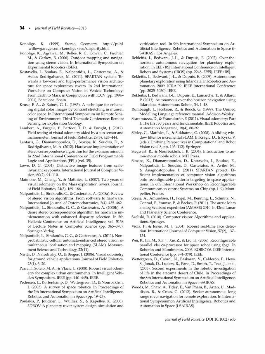
34 • Journal of Field Robotics—2013
Konolige, K. (1999). Stereo Geometry. http://pub1.willowgarage.com/konolige/svs/disparity.htm.
Konolige, K., Agrawal, M., Bolles, R. C., Cowan, C., Fischler,M., & Gerkey, B. (2006). Outdoor mapping and naviga-tion using stereo vision. In International Symposium onExperimental Robotics (ISER).
Kostavelis, I., Boukas, E., Nalpantidis, L., Gasteratos, A., &Aviles Rodrigalvarez, M. (2011). SPARTAN system: To-wards a low-cost and high-performance vision architec-ture for space exploratory rovers. In 2nd InternationalWorkshop on Computer Vision in Vehicle Technology:From Earth to Mars, in Conjunction with ICCV (pp. 1994–2001), Barcelona, Spain.
Kruse, F. A., & Raines, G. L. (1985). A technique for enhanc-ing digital color images by contrast stretching in munsellcolor space. In International Symposium on Remote Sens-ing of Environment, Third Thematic Conference: RemoteSensing for Exploration Geology.
Lambert, A., Furgale, P., Barfoot, T. D., & Enright, J. (2012).Field testing of visual odometry aided by a sun sensor andinclinometer. Journal of Field Robotics, 29(3), 426–444.
Lentaris, G., Diamantopoulos, D., Siozios, K., Soudris, D., &Rodrigalvarez, M. A. (2012). Hardware implementation ofstereo correspondence algorithm for the exomars mission.In 22nd International Conference on Field ProgrammableLogic and Applications (FPL) (vol. 35).
Lowe, D. G. (2004). Distinctive image features from scale-invariant keypoints. International Journal of Computer Vi-sion, 60(2), 91–110.
Maimone, M., Cheng, Y., & Matthies, L. (2007). Two years ofvisual odometry on the Mars exploration rovers. Journalof Field Robotics, 24(3), 169–186.
Nalpantidis, L., Sirakoulis, G., & Gasteratos, A. (2008a). Reviewof stereo vision algorithms: From software to hardware.International Journal of Optomechatronics, 2(4), 435–462.
Nalpantidis, L., Sirakoulis, G. C., & Gasteratos, A. (2008b). Adense stereo correspondence algorithm for hardware im-plementation with enhanced disparity selection. In 5thHellenic Conference on Artificial Intelligence, vol. 5138of Lecture Notes in Computer Science (pp. 365–370).Springer-Verlag.
Nalpantidis, L., Sirakoulis, G. C., & Gasteratos, A. (2011). Non-probabilistic cellular automata-enhanced stereo vision si-multaneous localisation and mapping (SLAM). Measure-ment Science and Technology, 22(11).
Nister, D., Naroditsky, O., & Bergen, J. (2006). Visual odometryfor ground vehicle applications. Journal of Field Robotics,23(1), 3–20.
Parra, I., Sotelo, M. A., & Vlacic, L. (2008). Robust visual odom-etry for complex urban environments. In Intelligent Vehi-cles Symposium, IEEE (pp. 440–445). IEEE.
Pedersen, L., Kortenkamp, D., Wettergreen, D., & Nourbakhsh,I. (2003). A survey of space robotics. In Proceedings ofthe 7th International Symposium on Artificial Intelligence,Robotics and Automation in Space (pp. 19–23).
Poulakis, P., Joudrier, L., Wailliez, S., & Kapellos, K. (2008).3DROV: A planetary rover system design, simulation and
verification tool. In 9th International Symposium on Ar-tificial Intelligence, Robotics and Automation in Space (i-SAIRAS), Los Angeles.
Rekleitis, I., Bedwani, J.-L., & Dupuis, E. (2007). Over-the-horizon, autonomous navigation for planetary explo-ration. In EEE/RSJ International Conference on IntelligentRobots and Systems (IROS) (pp. 2248–2255). IEEE/RSJ.
Rekleitis, I., Bedwani, J.-L., & Dupuis, E. (2009). Autonomousplanetary exploration using lidar data. In Robotics and Au-tomation, 2009. ICRA’09. IEEE International Conference(pp. 3025–3030). IEEE.
Rekleitis, I., Bedwani, J.-L., Dupuis, E., Lamarche, T., & Allard,P. (2013). Autonomous over-the-horizon navigation usinglidar data. Autonomous Robots, 34, 1–18.
Rumbaugh, J., Jacobson, R., & Booch, G. (1999). The UnifiedModelling Language reference manual. Addison-Wesley.
Scaramuzza, D., & Fraundorfer, F. (2011). Visual odometry: PartI: The first 30 years and fundamentals. IEEE Robotics andAutomation Magazine, 18(4), 80–92.
Sibley, G., Matthies, L., & Sukhatme, G. (2008). A sliding win-dow filter for incremental SLAM. In Kragic, D., & Kyrki, V.(eds.), Unifying Perspectives in Computational and RobotVision (vol. 8, pp. 103–112). Springer.
Siegwart, R., & Nourbakhsh, I. R. (2004). Introduction to au-tonomous mobile robots. MIT Press.
Siozios, K., Diamantopoulos, D., Kostavelis, I., Boukas, E.,Nalpantidis, L., Soudris, D., Gasteratos, A., Aviles, M.,& Anagnostopoulos, I. (2011). SPARTAN project: Ef-ficient implementation of computer vision algorithmsonto reconfigurable platform targeting to space applica-tions. In 6th International Workshop on ReconfigurableCommunication-centric Systems-on-Chip (pp. 1–9), Mont-pellier, France.
Steele, A., Amundsen, H., Fogel, M., Benning, L., Schmitz, N.,Conrad, P., Younse, P., & Backes, P. (2011). The arctic Marsanalog Svalbard expedition (AMASE) 2010. In 42nd Lunarand Planetary Science Conference.
Szeliski, R. (2010). Computer vision: Algorithms and applica-tions. Springer.
Viola, P., & Jones, M. J. (2004). Robust real-time face detec-tion. International Journal of Computer Vision, 57(2), 137–154.
Wei, R., Jin, M., Xia, J., Xie, Z., & Liu, H. (2006). Reconfigurableparallel vlsi co-processor for space robot using fpga. InRobotics and Biomimetics, 2006. ROBIO’06. IEEE Interna-tional Conference (pp. 374–379). IEEE.
Wettergreen, D., Cabrol, N., Baskaran, V., Calderon, F., Heys,S., Jonak, D., Luders, R., Pane, D., Smith, T., Teza, J., et al.(2005). Second experiments in the robotic investigationof life in the atacama desert of Chile. In Proceedings ofthe 8th International Symposium on Artificial Intelligence,Robotics and Automation in Space i-SAIRAS.
Woods, M., Shaw, A., Tidey, E., Van Pham, B., Artan, U., Mad-dison, B., & Cross, G. (2012). Seeker-autonomous longrange rover navigation for remote exploration. In Interna-tional Symposiumon Artificial Intelligence, Robotics andAutomation in Space (i-SAIRAS).
Journal of Field Robotics DOI 10.1002/rob


