Embed Size (px)
Citation preview
lable at ScienceDirect
Geotextiles and Geomembranes xxx (2011) 1e8
Contents lists avai
Geotextiles and Geomembranes
journal homepage: www.elsevier .com/locate/geotexmem
Soft ground improvement via vertical drains and vacuum assisted preloading
B. Indraratna a,*, C. Rujikiatkamjorn a, A.S. Balasubramaniamb, G. McIntosh c
aCentre for Geomechanics and Railway Engineering, School of Civil, Mining and Environmental Engineering, University of Wollongong, Wollongong City, NSW 2522, AustraliabGriffith University, Gold Coast, Queensland, AustraliacDouglas Partners Pty Ltd, Unanderra, NSW, Australia
a r t i c l e i n f o
Article history:Received 19 May 2010Accepted 19 December 2010Available online xxx
Keywords:Case historiesNumerical analysisVacuum consolidationVertical drains
* Corresponding author.E-mail address: [email protected] (B. Indraratna)
0266-1144/$ e see front matter Crown Copyright � 2doi:10.1016/j.geotexmem.2011.01.004
Please cite this article in press as: Indraratnaand Geomembranes (2011), doi:10.1016/j.ge
a b s t r a c t
Application of vacuum assisted preloading is an imperative method when a considerable load is requiredto meet the desired rate of settlement and an increase in the undrained shear strength upon consoli-dation. Moreover, where lateral displacements at the edge of a coastal embankment need to becontrolled, application of vacuum pressure with a cut off offers the optimum solution. To facilitatevacuum propagation, vertical drains are usually employed in conjunction. The installation of verticaldrains using a steel mandrel creates significant remoulding of the subsoil surrounding the drains thereby,reducing soil permeability and adversely affecting the soil consolidation process. In this paper, thesimulation of vacuum assisted consolidation using the spectral method and finite element analysis iscarried out. Subsequently, the 2D and 3D numerical multi-drain analyses are conducted to predict theexcess pore pressures, lateral and vertical displacements. The performance of two selected case historiesat the sites of Suvarnabhumi Airport, Thailand and Tianjin Port, China are discussed and analysed. Thenumerical predictions are then compared with the available field data. Finally, a procedure for the designof vertical drains is presented with a worked-out example.
Crown Copyright � 2011 Published by Elsevier Ltd. All rights reserved.
1. Introduction
Soft clay deposits possess a low bearing capacity and highcompressibility characteristics. Therefore, it is imperative to applyground improvement techniques to the existing soft soils prior toconstruction, in order to prevent unacceptable differential settle-ment. The application of prefabricated vertical drains (PVDs) andpreloading (surcharge and vacuum load) has become one of themost viable soil improvement techniques. Vertical drains provideconsiderably shortened horizontal drainage paths for pore waterflow, thereby accelerating the soil consolidation (Hansbo, 1981;Indraratna and Redana, 2000; Bergado et al., 2002; Indraratnaet al., 2004; Chai et al., 2010). In order to control the risk ofembankment failure, surcharge embankments with vacuumapplication are usually employed to accelerate the rate of settle-ment without increasing the excess pore pressure (Qian et al., 1992;Shang et al., 1998; Chu et al., 2000, Saowapakpiboon et al., 2010).This practice has been employed for land reclamation and portprojects as a high surcharge embankment over the soft dredged fills
.
011 Published by Elsevier Ltd. All
, B., et al., Soft ground improvotexmem.2011.01.004
cannot be raised due to various stability issues (Chu and Yan, 2005).The PVD system facilitates the vacuum pressure distribution todeep subsoil layers in the absence of the surcharge load influence,thereby increasing the consolidation rate (Chu et al., 2006; Leonget al., 2000). The vacuum system enhances the stability of anyraised embankment by minimizing the excess pore pressure at itsbase, and increasing the shear strength of the sand platform.Vacuum consolidation with PVDs is a sustainable option as it doesnot leave any chemical residue in the soil or groundwater, and hasno unacceptable noise levels compared to driven piles. Moreover,vacuum consolidation is isotropic, thereby minimizing the exces-sive lateral displacement due to high surcharge.
In this paper, modified radial consolidation theory using thespectral method capturing the variation of soil permeability withdepth is proposed. The equivalent (transformed) plane strainconversion employing the modified Cam-clay theory wascompared with the actual three-dimensional finite element anal-ysis. It has been shown that 2D plane strain finite element analysisis often adequate to predict settlements, pore pressures and lateraldisplacements if the conversion from axissymmetry to plane strainensures the same time consolidation response. Two case historiesare discussed and analysed, including the Suvarnabhumi Airport(Thailand) and Tianjin Port in China. The predictions are comparedwith the available field data.
rights reserved.
ement via vertical drains and vacuum assisted preloading, Geotextiles
de/2CL
ks
kh
ds/2
kh
ks
a
b
Smear zone
dw/2
ks
kh
c
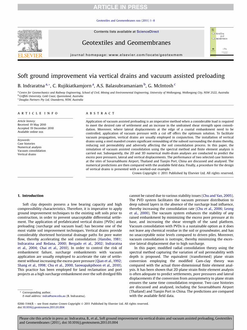
Fig. 2. Permeability distribution in smear zone (a) constant (b) linear and (c) parabolic.
B. Indraratna et al. / Geotextiles and Geomembranes xxx (2011) 1e82
2. Theoretical modelling for soft ground consolidation viavertical drains and vacuum preloading: a single drain analysis
The vacuum consolidation theory for radial drainagewith smeareffect was proposed by Mohamedelhassan and Shang (2002) andIndraratna et al. (2005a). Recently, Rujikiatkamjorn and Indraratna(2009) a proposed comprehensive solution to vacuum assistedconsolidation with both vertical and horizontal drainage includingthe smear effect, applicable to a single layer soil. Walker andIndraratna (2009) proposed a rigorous solution via spectralmethod for multi-layer soil improved by vacuum and surchargepreloading via PVDs.
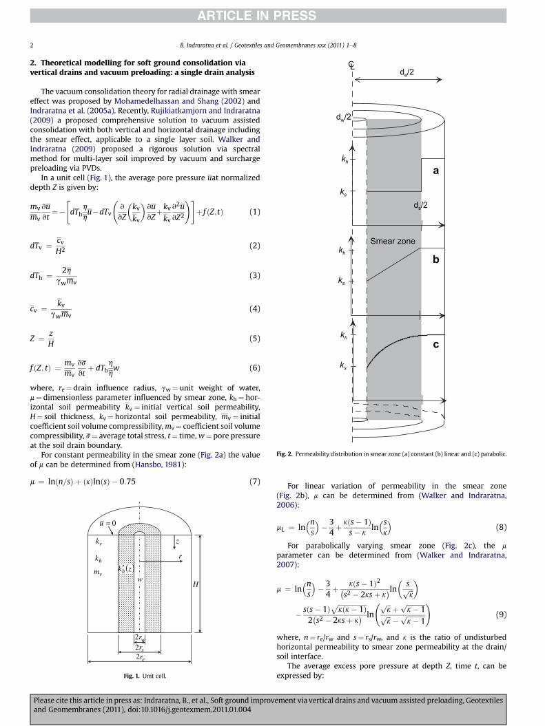
In a unit cell (Fig. 1), the average pore pressure uat normalizeddepth Z is given by:
mv
mv
vuvt
¼�"dTh
h
hu�dTv
v
vZ
�kvkv
�vuvZ
þkvkv
v2uvZ2
!#þ f ðZ;tÞ (1)
dTv ¼ cvH2 (2)
dTh ¼ 2hgwmv
(3)
cv ¼ kvgwmv
(4)
Z ¼ zH
(5)
f ðZ; tÞ ¼ mv
mv
vs
vtþ dTh
h
hw (6)
where, re¼ drain influence radius, gw¼ unit weight of water,m¼ dimensionless parameter influenced by smear zone, kh¼ hor-izontal soil permeability kv ¼ initial vertical soil permeability,H¼ soil thickness, kv¼ horizontal soil permeability, mv ¼ initialcoefficient soil volume compressibility,mv¼ coefficient soil volumecompressibility, s¼ average total stress, t¼ time,w¼ pore pressureat the soil drain boundary.
For constant permeability in the smear zone (Fig. 2a) the valueof m can be determined from (Hansbo, 1981):
m ¼ lnðn=sÞ þ ðkÞlnðsÞ � 0:75 (7)
0=u
w
vk
hk
vm ( )zkh′
wr2
sr2
er2
z
r
H
Fig. 1. Unit cell.
Please cite this article in press as: Indraratna, B., et al., Soft ground improvand Geomembranes (2011), doi:10.1016/j.geotexmem.2011.01.004
For linear variation of permeability in the smear zone(Fig. 2b), m can be determined from (Walker and Indraratna,2006):
mL ¼ ln�ns
�� 34þ kðs� 1Þ
s� kln�sk
�(8)
For parabolically varying smear zone (Fig. 2c), the m
parameter can be determined from (Walker and Indraratna,2007):
m ¼ ln�ns
�� 34þ kðs� 1Þ2�
s2 � 2ksþ k�ln� sffiffiffi
kp�
� sðs� 1Þ ffiffiffiffiffiffiffiffiffiffiffiffiffiffiffiffiffikðk� 1Þp
2�s2 � 2ksþ k
� ln
ffiffiffik
p þffiffiffiffiffiffiffiffiffiffiffik� 1
pffiffiffik
p �ffiffiffiffiffiffiffiffiffiffiffik� 1
p!
(9)
where, n¼ re/rw and s¼ rs/rw, and k is the ratio of undisturbedhorizontal permeability to smear zone permeability at the drain/soil interface.
The average excess pore pressure at depth Z, time t, can beexpressed by:
ement via vertical drains and vacuum assisted preloading, Geotextiles
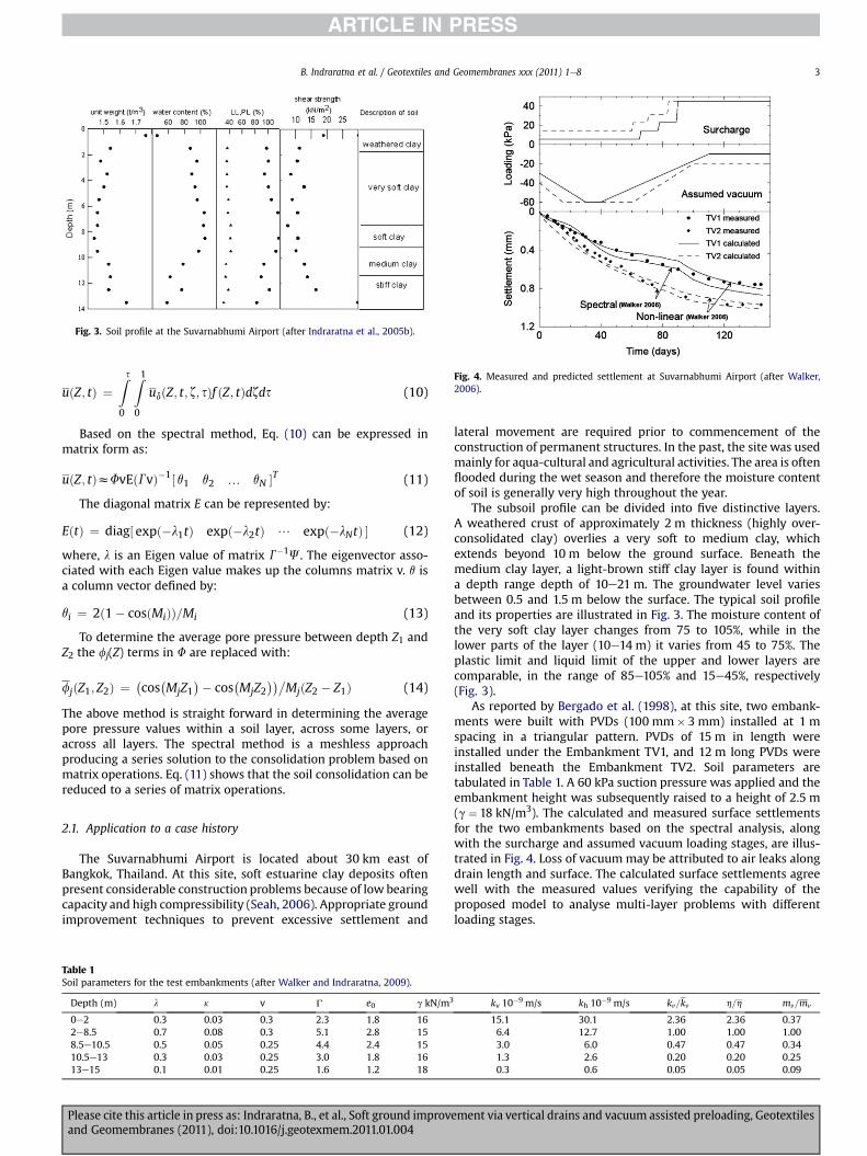
Fig. 3. Soil profile at the Suvarnabhumi Airport (after Indraratna et al., 2005b).
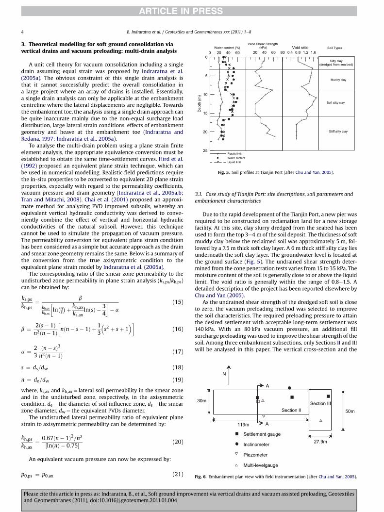
Fig. 4. Measured and predicted settlement at Suvarnabhumi Airport (after Walker,2006).
B. Indraratna et al. / Geotextiles and Geomembranes xxx (2011) 1e8 3
uðZ; tÞ ¼Zs0
Z10
udðZ; t; z; sÞf ðZ; tÞdzds (10)
Based on the spectral method, Eq. (10) can be expressed inmatrix form as:
uðZ; tÞzFvEðGvÞ�1½ q1 q2 . qN �T (11)
The diagonal matrix E can be represented by:
EðtÞ ¼ diag½ expð�l1tÞ expð�l2tÞ / expð�lNtÞ � (12)
where, l is an Eigen value of matrix G�1J. The eigenvector asso-ciated with each Eigen value makes up the columns matrix v. q isa column vector defined by:
qi ¼ 2ð1� cosðMiÞÞ=Mi (13)
To determine the average pore pressure between depth Z1 andZ2 the fj(Z) terms in F are replaced with:
fjðZ1; Z2Þ ¼ �cos�MjZ1
�� cos�MjZ2
��MjðZ2 � Z1Þ (14)
The above method is straight forward in determining the averagepore pressure values within a soil layer, across some layers, oracross all layers. The spectral method is a meshless approachproducing a series solution to the consolidation problem based onmatrix operations. Eq. (11) shows that the soil consolidation can bereduced to a series of matrix operations.
2.1. Application to a case history
The Suvarnabhumi Airport is located about 30 km east ofBangkok, Thailand. At this site, soft estuarine clay deposits oftenpresent considerable construction problems because of low bearingcapacity and high compressibility (Seah, 2006). Appropriate groundimprovement techniques to prevent excessive settlement and
Table 1Soil parameters for the test embankments (after Walker and Indraratna, 2009).
Depth (m) l k v G e0 g kN/m3
0e2 0.3 0.03 0.3 2.3 1.8 162e8.5 0.7 0.08 0.3 5.1 2.8 158.5e10.5 0.5 0.05 0.25 4.4 2.4 1510.5e13 0.3 0.03 0.25 3.0 1.8 1613e15 0.1 0.01 0.25 1.6 1.2 18
Please cite this article in press as: Indraratna, B., et al., Soft ground improvand Geomembranes (2011), doi:10.1016/j.geotexmem.2011.01.004
lateral movement are required prior to commencement of theconstruction of permanent structures. In the past, the site was usedmainly for aqua-cultural and agricultural activities. The area is oftenflooded during the wet season and therefore the moisture contentof soil is generally very high throughout the year.
The subsoil profile can be divided into five distinctive layers.A weathered crust of approximately 2 m thickness (highly over-consolidated clay) overlies a very soft to medium clay, whichextends beyond 10 m below the ground surface. Beneath themedium clay layer, a light-brown stiff clay layer is found withina depth range depth of 10e21 m. The groundwater level variesbetween 0.5 and 1.5 m below the surface. The typical soil profileand its properties are illustrated in Fig. 3. The moisture content ofthe very soft clay layer changes from 75 to 105%, while in thelower parts of the layer (10e14 m) it varies from 45 to 75%. Theplastic limit and liquid limit of the upper and lower layers arecomparable, in the range of 85e105% and 15e45%, respectively(Fig. 3).
As reported by Bergado et al. (1998), at this site, two embank-ments were built with PVDs (100 mm� 3 mm) installed at 1 mspacing in a triangular pattern. PVDs of 15 m in length wereinstalled under the Embankment TV1, and 12 m long PVDs wereinstalled beneath the Embankment TV2. Soil parameters aretabulated in Table 1. A 60 kPa suction pressure was applied and theembankment height was subsequently raised to a height of 2.5 m(g¼ 18 kN/m3). The calculated and measured surface settlementsfor the two embankments based on the spectral analysis, alongwith the surcharge and assumed vacuum loading stages, are illus-trated in Fig. 4. Loss of vacuum may be attributed to air leaks alongdrain length and surface. The calculated surface settlements agreewell with the measured values verifying the capability of theproposed model to analyse multi-layer problems with differentloading stages.
kv 10�9 m/s kh 10�9 m/s kv=kv h=h mv=mv
15.1 30.1 2.36 2.36 0.376.4 12.7 1.00 1.00 1.003.0 6.0 0.47 0.47 0.341.3 2.6 0.20 0.20 0.250.3 0.6 0.05 0.05 0.09
ement via vertical drains and vacuum assisted preloading, Geotextiles
0 20 40 60Water content (%)
25
20
15
10
5
0
Dep
th (m
)
Plastic limitWater contentLiquid limit
20 40 60 80
Vane Shear Strength (kPa)
0.4 0.8 1.2 1.6Void ratio Soil Types
Silty clay(dredged from sea bed)
Muddy clay
Soft silty clay
Stiff silty clay
Fig. 5. Soil profiles at Tianjin Port (after Chu and Yan, 2005).
N
30m
119m
Settlement gauge
Inclinometer
Piezometer
Multi-levelgauge
Section II
A
A
Section III50m
27.9m
Fig. 6. Embankment plan view with field instrumentation (after Chu and Yan, 2005).
B. Indraratna et al. / Geotextiles and Geomembranes xxx (2011) 1e84
3. Theoretical modelling for soft ground consolidation viavertical drains and vacuum preloading: multi-drain analysis
A unit cell theory for vacuum consolidation including a singledrain assuming equal strain was proposed by Indraratna et al.(2005a). The obvious constraint of this single drain analysis isthat it cannot successfully predict the overall consolidation ina large project where an array of drains is installed. Essentially,a single drain analysis can only be applicable at the embankmentcentreline where the lateral displacements are negligible. Towardsthe embankment toe, the analysis using a single drain approach canbe quite inaccurate mainly due to the non-equal surcharge loaddistribution, large lateral strain conditions, effects of embankmentgeometry and heave at the embankment toe (Indraratna andRedana, 1997; Indraratna et al., 2005a).
To analyse the multi-drain problem using a plane strain finiteelement analysis, the appropriate equivalence conversion must beestablished to obtain the same time-settlement curves. Hird et al.(1992) proposed an equivalent plane strain technique, which canbe used in numerical modelling. Realistic field predictions requirethe in-situ properties to be converted to equivalent 2D plane strainproperties, especially with regard to the permeability coefficients,vacuum pressure and drain geometry (Indraratna et al., 2005a,b;Tran and Mitachi, 2008). Chai et al. (2001) proposed an approxi-mate method for analyzing PVD improved subsoils, whereby anequivalent vertical hydraulic conductivity was derived to conve-niently combine the effect of vertical and horizontal hydraulicconductivities of the natural subsoil. However, this techniquecannot be used to simulate the propagation of vacuum pressure.The permeability conversion for equivalent plane strain conditionhas been considered as a simple but accurate approach as the drainand smear zone geometry remains the same. Below is a summary ofthe conversion from the true axisymmetric condition to theequivalent plane strain model by Indraratna et al. (2005a).
The corresponding ratio of the smear zone permeability to theundisturbed zone permeability in plane strain analysis (ks,ps/kh,ps)can be obtained by:
ks;pskh;ps
¼ b
kh;pskh;ax
ln�ns
�þ kh;axks;ax
lnðsÞ � 34
�� a
(15)
b ¼ 2ðs� 1Þn2ðn� 1Þ
nðn� s� 1Þ þ 1
3
�s2 þ sþ 1
��(16)
a ¼ 23
ðn� sÞ3n2ðn� 1Þ (17)
s ¼ ds=dw (18)
n ¼ de=dw (19)
where, ks,ax and kh,ax¼ lateral soil permeability in the smear zoneand in the undisturbed zone, respectively, in the axisymmetriccondition. de¼ the diameter of soil influence zone, ds¼ the smearzone diameter, dw¼ the equivalent PVDs diameter.
The undisturbed lateral permeability ratio of equivalent planestrain to axisymmetric permeability can be determined by:
kh;pskh;ax
¼ 0:67ðn� 1Þ2=n2½lnðnÞ � 0:75� (20)
An equivalent vacuum pressure can now be expressed by:
p0;ps ¼ p0;ax (21)
Please cite this article in press as: Indraratna, B., et al., Soft ground improvand Geomembranes (2011), doi:10.1016/j.geotexmem.2011.01.004
3.1. Case study of Tianjin Port: site descriptions, soil parameters andembankment characteristics
Due to the rapid development of the Tianjin Port, a new pier wasrequired to be constructed on reclamation land for a new storagefacility. At this site, clay slurry dredged from the seabed has beenused to form the top 3e4 m of the soil deposit. The thickness of softmuddy clay below the reclaimed soil was approximately 5 m, fol-lowed by a 7.5 m thick soft clay layer. A 6 m thick stiff silty clay liesunderneath the soft clay layer. The groundwater level is located atthe ground surface (Fig. 5). The undrained shear strength deter-mined from the cone penetration tests varies from 15 to 35 kPa. Themoisture content of the soil is generally close to or above the liquidlimit. The void ratio is generally within the range of 0.8e1.5. Adetailed description of the project has been reported elsewhere byChu and Yan (2005).
As the undrained shear strength of the dredged soft soil is closeto zero, the vacuum preloading method was selected to improvethe soil characteristics. The required preloading pressure to attainthe desired settlement with acceptable long-term settlement was140 kPa. With an 80 kPa vacuum pressure, an additional fillsurcharge preloading was used to improve the shear strength of thesoil. Among three embankment subsections, only Sections II and IIIwill be analysed in this paper. The vertical cross-section and the
ement via vertical drains and vacuum assisted preloading, Geotextiles
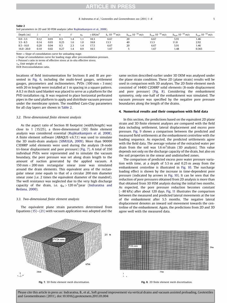
Table 2Soil parameters in 2D and 3D FEM analysis (after Rujikiatkamjorn et al., 2008).
Depth (m) l k v G e0 g kN/m3 kv 10�10 m/s kh,ax 10�10 m/s ks,ax 10�10 m/s kh,ps 10�10 m/s ks,ps 10�10 m/s
0.0e3.5 0.12 0.03 0.3 1.4 1.1 18.3 6.67 20 6.67 5.91 1.463.5e8.5 0.14 0.03 0.25 1.6 1.0 18.8 13.3 40 13.3 11.8 2.928.5e16.0 0.20 0.04 0.3 2.3 1.4 17.5 6.67 20 6.67 5.91 1.4616.0e20.0 0.10 0.02 0.27 1.4 0.9 18.5 1.67 5 1.67 1.48 0.365
Note: k Slope of consolidation curve for unloading stage.l Slope of consolidation curve for loading stage after preconsolidation pressure.v Poisson’s ratio in terms of effective stress at in-situ effective stress.gw Unit weight of soil.OCR Overconsolidation ratio.
B. Indraratna et al. / Geotextiles and Geomembranes xxx (2011) 1e8 5
locations of field instrumentation for Sections II and III are pre-sented in Fig. 6, including the multi-level gauges, settlementgauges, piezometers and inclinometers. PVDs (100 mm� 3 mm)with 20 m length were installed at 1 m spacing in a square pattern.A 0.3 m thick sand blanket was placed to serve as a platform for thePVD installation rig. It was required to place horizontal perforatedpipes in the sand platform to apply and distribute vacuum pressureunder the membrane system. The modified Cam-Clay parametersfor all clay layers are shown in Table 2.
3.2. Three-dimensional finite element analysis
As the aspect ratio of Section III footprint (width/length) wasclose to 1 (15/25), a three-dimensional (3D) finite elementanalysis was considered essential (Rujikiatkamjorn et al. 2008).A finite element software (ABAQUS v.6.7.1) was used to simulatethe 3D multi-drain analysis (SIMULIA, 2009). More than 90000C3D8RP solid elements were used during the analysis (8-nodetri-linear displacement and pore pressure) (Fig. 7). A total of 350individual PVDs were represented and to simulate the vacuumboundary, the pore pressure was set along drain length to theamount of suction generated by the applied vacuum. A150 mm� 200 mm rectangular smear zone was simulatedaround the drain elements. This equivalent area of the rectan-gular smear zone equals to that of a circular 200 mm diametersmear zone (i.e. 2 times the equivalent diameter of the mandrel).The well resistance was neglected due to the very high dischargecapacity of the drain, i.e. qw> 120 m3/year (Indraratna andRedana, 2000).
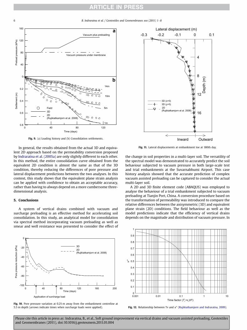
3.3. Two-dimensional finite element analysis
The equivalent plane strain parameters determined fromEquations (15)e(21) with vacuum application was adopted and the
Fig. 7. 3D finite element mesh discretisation.
Please cite this article in press as: Indraratna, B., et al., Soft ground improvand Geomembranes (2011), doi:10.1016/j.geotexmem.2011.01.004
same section described earlier under 3D DEM was analysed underthe plane strain condition. These 2D (plane strain) results will beused in comparison with 3D analyses. The 2D finite element meshconsisted of 14400 C2D8RP solid elements (8-node displacementand pore pressure) (Fig. 8). Considering the embankmentsymmetry, only one-half of the embankment was simulated. Thevacuum pressure was specified by the negative pore pressureboundaries along the length of the drains.
4. Numerical results and their comparison with field data
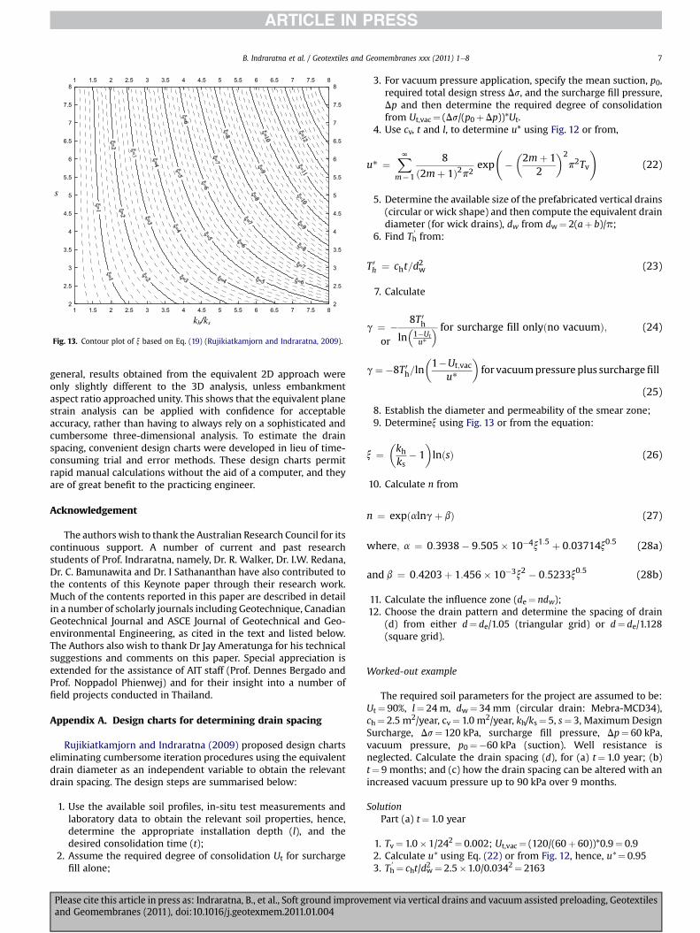
In this section, the predictions based on the equivalent 2D planestrain and 3D finite element analyses are compared with the fielddata including settlement, lateral displacement and excess porepressure. Fig. 9 shows a comparison between the predicted andmeasured field settlements at the embankment centreline with theloading sequence. As expected, the predicted settlements agreewith the field data. The average volume of the extracted water perdrain from the soil was 1.6 m3/drain (3D analysis). This valuedepends not only on the discharge capacity of the drain, but also onthe soil properties in the smear and undisturbed zones.
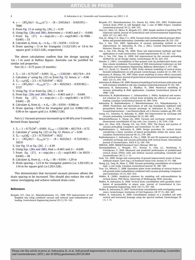
The comparison of predicted excess pore water pressure varia-tion with time, at a depth of 5.5 m and 0.25 m away from theembankment centreline is illustrated in Fig. 10. The surchargeloading effect is shown by the increase in time-dependent porepressure (indicated by arrows in Fig. 10). It can be seen that thereduction of pore pressures obtained from 2D analysis is more thanthat obtained from 3D FEM analysis during the initial two months.As expected, the pore pressure reduction becomes constant(�80 kPa) after about 120 days. Fig. 11 illustrates the comparisonbetween the measured and predicted lateral movements at the toeof the embankment after 5.5 months. The negative lateraldisplacement denotes an inward soil movement towards the cen-treline of the embankment. Again, the predictions from 2D and 3Dagree well with the measured data.
Fig. 8. 2D finite element mesh discretisation.
ement via vertical drains and vacuum assisted preloading, Geotextiles
0 40 80 120Time (days)
0.8
0.6
0.4
0.2
Settl
emen
t (m
)
0
40
80
120
160
Prel
oad
pres
sure
(kPa
)
Field3D2D (Rujikiatkamjorn et al. 2008)
1m
5m
10m
14m
Vacuum pressure under membrane
Vacuum plus preloadinga
b
Fig. 9. (a) Loading history and (b) Consolidation settlements.
-0.3 -0.2 -0.1 0 0.1Lateral displacement (m)
16
12
8
4
Dep
th (m
)
3D (x=0)3D (y=0)2D (Rujikiatkamjorn et al. 2008)
Inward Outward
Fig. 11. Lateral displacements at embankment toe at 180th day.
B. Indraratna et al. / Geotextiles and Geomembranes xxx (2011) 1e86
In general, the results obtained from the actual 3D and equiva-lent 2D approach based on the permeability conversion proposedby Indraratna et al. (2005a) are only slightly different to each other.In this method, the entire consolidation curve obtained from theequivalent 2D condition is almost the same as that of the 3Dcondition, thereby reducing the differences of pore pressure andlateral displacement predictions between the two analyses. In thiscontext, this study shows that the equivalent plane strain analysiscan be applied with confidence to obtain an acceptable accuracy,rather than having to always depend on amore cumbersome three-dimensional analysis.
5. Conclusions
A system of vertical drains combined with vacuum andsurcharge preloading is an effective method for accelerating soilconsolidation. In this study, an analytical model for consolidationvia spectral method incorporating vacuum preloading as well assmear and well resistance was presented to consider the effect of
0 40 80 120 160 200Time (days)
-100
-80
-60
-40
-20
0
Pore
pre
ssur
ere
duct
ion
(kPa
) 3D2D (Rujikiatkamjorn et al. 2008)
Application of surcharge load
Fig. 10. Pore pressure variation at 0.25 m away from the embankment centreline at5.5 m depth (arrows indicate times when surcharge loads were applied).
Please cite this article in press as: Indraratna, B., et al., Soft ground improvand Geomembranes (2011), doi:10.1016/j.geotexmem.2011.01.004
the change in soil properties in a multi-layer soil. The versatility ofthe spectral model was demonstrated to accurately predict the soilbehaviour subjected to vacuum pressure in both large-scale testand trial embankments at the Suvarnabhumi Airport. This casehistory analysis showed that the accurate prediction of complexvacuum assisted preloading can be captured to consider the actualmulti-layer soil.
A 2D and 3D finite element code (ABAQUS) was employed toanalyse the behaviour of a trial embankment subjected to vacuumpreloading at Tianjin Port, China. A conversion procedure based onthe transformation of permeability was introduced to compare therelative differences between the axisymmetric (3D) and equivalentplane strain (2D) conditions. The field behaviour as well as themodel predictions indicate that the efficiency of vertical drainsdepends on the magnitude and distribution of vacuum pressure. In
0.001 0.01 0.1 1 10Time factor (T =c t/l )
0
0.1
0.2
0.3
0.4
0.5
0.6
0.7
0.8
0.9
1
u*
Fig. 12. Relationship between Tv and u* (Rujikiatkamjorn and Indraratna, 2009).
ement via vertical drains and vacuum assisted preloading, Geotextiles
1 1.5 2 2.5 3 3.5 4 4.5 5 5.5 6 6.5 7 7.5 8
1 1.5 2 2.5 3 3.5 4 4.5 5 5.5 6 6.5 7 7.5 8
2
2.5
3
3.5
4
4.5
5
5.5
6
6.5
7
7.5
8
2
2.5
3
3.5
4
4.5
5
5.5
6
6.5
7
7.5
8
s
kh/ks
Fig. 13. Contour plot of x based on Eq. (19) (Rujikiatkamjorn and Indraratna, 2009).
B. Indraratna et al. / Geotextiles and Geomembranes xxx (2011) 1e8 7
general, results obtained from the equivalent 2D approach wereonly slightly different to the 3D analysis, unless embankmentaspect ratio approached unity. This shows that the equivalent planestrain analysis can be applied with confidence for acceptableaccuracy, rather than having to always rely on a sophisticated andcumbersome three-dimensional analysis. To estimate the drainspacing, convenient design charts were developed in lieu of time-consuming trial and error methods. These design charts permitrapid manual calculations without the aid of a computer, and theyare of great benefit to the practicing engineer.
Acknowledgement
The authors wish to thank the Australian Research Council for itscontinuous support. A number of current and past researchstudents of Prof. Indraratna, namely, Dr. R. Walker, Dr. I.W. Redana,Dr. C. Bamunawita and Dr. I Sathananthan have also contributed tothe contents of this Keynote paper through their research work.Much of the contents reported in this paper are described in detailin a number of scholarly journals including Geotechnique, CanadianGeotechnical Journal and ASCE Journal of Geotechnical and Geo-environmental Engineering, as cited in the text and listed below.The Authors also wish to thank Dr Jay Ameratunga for his technicalsuggestions and comments on this paper. Special appreciation isextended for the assistance of AIT staff (Prof. Dennes Bergado andProf. Noppadol Phienwej) and for their insight into a number offield projects conducted in Thailand.
Appendix A. Design charts for determining drain spacing
Rujikiatkamjorn and Indraratna (2009) proposed design chartseliminating cumbersome iteration procedures using the equivalentdrain diameter as an independent variable to obtain the relevantdrain spacing. The design steps are summarised below:
1. Use the available soil profiles, in-situ test measurements andlaboratory data to obtain the relevant soil properties, hence,determine the appropriate installation depth (l), and thedesired consolidation time (t);
2. Assume the required degree of consolidation Ut for surchargefill alone;
Please cite this article in press as: Indraratna, B., et al., Soft ground improvand Geomembranes (2011), doi:10.1016/j.geotexmem.2011.01.004
3. For vacuum pressure application, specify the mean suction, p0,required total design stress Ds, and the surcharge fill pressure,Dp and then determine the required degree of consolidationfrom Ut,vac¼ (Ds/(p0þDp))*Ut.
4. Use cv, t and l, to determine u* using Fig. 12 or from,
u* ¼XN 8
ð2mþ 1Þ2p2exp
��2mþ 1
2
�2p2Tv
!(22)
m¼1
5. Determine the available size of the prefabricated vertical drains(circular or wick shape) and then compute the equivalent draindiameter (for wick drains), dw from dw¼ 2(aþ b)/p;
6. Find Th0from:
T 0h ¼ cht=d2w (23)
7. Calculate
g ¼ � 8T 0h�1�Ut
� for surcharge fill onlyðno vacuumÞ; (24)
ln u*org¼�8T 0h=ln�1�Ut;vac
u*
�for vacuumpressure plus surcharge fill
(25)
8. Establish the diameter and permeability of the smear zone;9. Determinex using Fig. 13 or from the equation:
x ¼�khks
� 1�lnðsÞ (26)
10. Calculate n from
n ¼ expðalngþ bÞ (27)
where; a ¼ 0:3938� 9:505� 10�4x1:5 þ 0:03714x0:5 (28a)
and b ¼ 0:4203þ 1:456� 10�3x2 � 0:5233x0:5 (28b)
11. Calculate the influence zone (de¼ ndw);12. Choose the drain pattern and determine the spacing of drain
(d) from either d¼ de/1.05 (triangular grid) or d¼ de/1.128(square grid).
Worked-out example
The required soil parameters for the project are assumed to be:Ut¼ 90%, l¼ 24 m, dw¼ 34 mm (circular drain: Mebra-MCD34),ch¼ 2.5 m2/year, cv¼ 1.0 m2/year, kh/ks¼ 5, s¼ 3, Maximum DesignSurcharge, Ds¼ 120 kPa, surcharge fill pressure, Dp¼ 60 kPa,vacuum pressure, p0¼�60 kPa (suction). Well resistance isneglected. Calculate the drain spacing (d), for (a) t¼ 1.0 year; (b)t¼ 9 months; and (c) how the drain spacing can be altered with anincreased vacuum pressure up to 90 kPa over 9 months.
SolutionPart (a) t¼ 1.0 year
1. Tv¼ 1.0�1/242¼ 0.002; Ut,vac¼ (120/(60þ 60))*0.9¼ 0.92. Calculate u* using Eq. (22) or from Fig. 12, hence, u*¼ 0.953. Th
0 ¼ cht/dw2 ¼ 2.5�1.0/0.0342¼ 2163
ement via vertical drains and vacuum assisted preloading, Geotextiles
B. Indraratna et al. / Geotextiles and Geomembranes xxx (2011) 1e88
4. g¼�(8Th0/ln(1�Ut,vac/u*))¼�(8� 2163/ln(1�0.9/0.95))¼
76865. From Fig. 13 or using Eq. (26), x¼ 4.396. Using Eqs. (28a and 28b), determine a¼ 0.463 and b¼�0.649.7. From Eq. (27), n¼ exp(aln gþ b)¼ exp(0.463� ln 7686�
0.649)¼ 338. Calculate de from, de¼ n dw¼ 33� 0.034¼1.122 m9. Drain spacing¼ 1.1 m for triangular (1.122/1.05) or 1.0 m for
square grid (1.122/1.128), respectively.
The above calculations confirm that the design spacing of1m� 1 m used at Ballina Bypass. Australia can be justified forsimilar soil properties.
Part (b) t¼ 0.75 years (9 months)
1. Tv¼ 1.0� 0.75/242¼ 0.001; Ut,vac¼ (120/(60þ 60))*0.9¼ 0.92. Calculate u* using Eq. (22) or from Fig. 12; hence, u*¼ 0.963. Th
0 ¼ cht/dw2 ¼ 2.5� 0.75/0.0342¼16224. g¼�(8Th
0/ln(1�Ut,vac/u*))¼�(8� 1622/ln(1�0.9/0.96))¼
57375. Using Fig. 13 or from Eq. (26), x¼ 4.396. From Eqs. (28a and 28b), find a¼ 0.463 and b¼�0.649.7. From Eq. (27), n¼ exp(aln gþ b)¼ exp(0.463� ln 5737�
0.649)¼ 298. Calculate de from de¼ n dw¼ 29� 0.034¼ 0.986 m9. Drain spacing¼ 0.95 m for triangular grid (i.e. 0.986/1.05) or
0.90 m for square grid (i.e. 0.986/1.128).
Part (c): Vacuum pressure increased up to 90 kPa over 9months.Revised Drain Spacing?
1. Tv¼ 1�0.75/242¼ 0.001; Ut,vac¼ (120/(90þ 60))*0.9¼ 0.722. Calculate u* using Eq. (22) or Fig. 12, Hence, u*¼ 0.963. Th
0 ¼ cht/dw2 ¼ 2.5� 0.75/0.0342¼16224. g¼�(8Th
0/ln(1�Ut,vac/u*))¼�(8� 1622/ln(1�0.72/0.96))¼
105315. Use Fig. 13 or Eq. (26) , x¼ 4.396. Using Eqs. (28a and 28b), find a¼0.463 and b¼�0.649.7. From Eq. (27), n¼ exp(aln gþ b)¼ exp(0.463� ln 10531�
0.649)¼ 388. Calculate de from de¼ n dw¼ 38� 0.034¼1.29 m9. Drain spacing¼ 1.23 m for triangular pattern (i.e. 1.29/1.05) or
1.14 m for square grid (i.e.1.29/1.128).
This demonstrates that increased vacuum pressure allows thedrain spacing to be increased. This should also reduce the risk ofsmear overlapping and achieve reduced drain costs.
References
Bergado, D.T., Chai, J.C., Balasubramaniam, A.S., 1998. PVD improvement of softBangkok clay using combined vacuum and reduced sand embankment pre-loading. Geotechnical Engineering Journal 29 (1), 95e122.
Please cite this article in press as: Indraratna, B., et al., Soft ground improvand Geomembranes (2011), doi:10.1016/j.geotexmem.2011.01.004
Bergado, D.T., Balasubramanian, A.S., Fannin, R.J., Holtz, R.D., 2002. Prefabricatedvertical drain (PVD) in soft Bangkok clay: a case of NBIA Project. CanadianGeotechnical Journal 39 (2), 304e315.
Chai, J.C., Shen, S.L., Miura, N., Bergado, D.T., 2001. Simple method of modeling PVDimproved subsoil. Journal of Geotechnical and Geoenvironmental Engineering,ASCE 127 (11), 965e972.
Chai, J.C., Hong, Z.-S., Shen, S.-L., 2010. Vacuum-drain method induced pressure distri-bution and ground deformation. Geotextiles and Geomemberanes 28, 525e535.
Chu, J., Yan, S.W., 2005. Application of vacuum preloading method in soilimprovement. In: Indraratna, B., Chu, J. (Eds.), Ground Improvement-CaseHistories. Elsevier, pp. 91e118.
Chu, J., Yan, S.W., Zheng, Y.R., 2006. Three soil improvement methods and theirapplications to road construction. Ground Improvement 10 (3), 103e112.
Chu, J., Yan, S.W., Yang, H., 2000. Soil improvement by the vacuum preloadingmethod for an oil storage station. Geotechnique 50 (6), 625e632.
Hansbo, S. (1981). Consolidation of fine-grained soils by prefabricated drains andlime column installation. Proceedings of 10th International Conference on SoilMechanics and Foundation Engineering, Balkema (Rotterdam) 3: 677e682.
Hird, C.C., Pyrah, I.C., Russell, D., 1992. Finite element modelling of vertical drainsbeneath embankments on soft ground. Geotechnique, London 42 (3), 499e511.
Indraratna, B., Redana, I.W., 1997. Plane strain modeling of smear effects associatedwith vertical drains. Journal of geotechnical and geoenvironmental engineering,ASCE 123 (5), 474e478.
Indraratna, B., Redana, I.W., 2000.Numericalmodelingofvertical drainswithsmearandwell resistance installed in soft clay. Canadian Geotechnical Journal 37, 133e145.
Indraratna, B., Bamunawita, C., Khabbaz, H., 2004. Numerical modelling ofvacuum preloading & field applications. Canadian Geotechnical Journal 41,1098e1110.
Indraratna, B., Rujikiatkamjorn, C., Sathananthan, I., 2005a. Analytical and numer-ical solutions for a single vertical drain including the effects of vacuum pre-loading. Canadian Geotechinical Journal 42, 994e1014.
Indraratna, B., Rujikiatkamjorn, C., Balasubramaniam, A.S., Wijeyakulasuriya, V.,2005b. Predictions and observations of soft clay foundations stabilized withgeosynthetic drains and vacuum surcharge. In: Indraratna, B., Chu, J. (Eds.),Ground Improvemente CaseHistories Book, vol. 3. Elsevier, London, pp.199e230.
Leong, E.C., Soemitro, R., Rahardjo, H., 2000. Soil Improvement by surcharge andvacuum preloading. Geotechnique 50 (5), 601e605.
Mohamedelhassan, E., Shang, J.Q., 2002. Vacuum and surcharge combined one-dimensional consolidation of clay soils. Can. Geotech. J. 39, 1126e1138.
Qian, J.H., Zhao, W.B., Cheung, Y.K., Lee, P.K.K., 1992. The theory and practice ofvacuum preloading. Computers and Geotechnics 13, 103e118.
Rujikiatkamjorn, C., Indraratna, B., 2009. Design procedure for vertical drainsconsidering a linear variation of lateral permeability within the smear zone.Canadian Geotechnical Journal 46 (3), 270e280.
Rujikiatkamjorn, C., Indraratna, B., Chu, J., 2008. 2D and 3D numerical modeling ofcombined surcharge and vacuum preloading with vertical drains. InternationalJournal of Geomechanics, ASCE 8 (2), 144e156.
SIMULIA, 2009. ABAQUS/Standard User’s Manual. HKS Inc.Saowapakpiboon, J., Bergado, D.T., Youwai, S., Chai, J.C., Wanthong, P.,
Voottipruex, P., 2010. Measured and predicted performance of prefabricatedvertical drains (PVDs) with and without vacuum preloading. Geotextile andGeomembranes 28 (1), 1e11.
Seah, T.H., 2006. Design and construction of ground improvement works at Suvar-nabhumi airport. Geot. Eng, J. of Southeast Asian Geot. Society 37, 171e188.
Shang, J.Q., Tang, M., Miao, Z., 1998. Vacuum preloading consolidation of reclaimedland: a case study. Canadian Geotechnical Journal 35, 740e749.
Tran, T.A., Mitachi, T., 2008. Equivalent plane strain modeling of vertical drains insoft ground under embankment combined with vacuum preloading. Computersand Geotechnics 35 (5), 655e672.
Walker, R. (2006). Analytical solutions for modeling soft soilconsolidation byvertical drains. PhD thesis, University of Wollongong, NSW, Australia.
Walker, R., Indraratna, B., 2006. Vertical drain consolidation with parabolic distri-bution of permeability in smear zone. Journal of Geotechnical & Geo-environmental Engineering, ASCE 132 (7), 937e941.
Walker, R., Indraratna, B., 2007. Vertical drain consolidation with overlapping smearzones. Geotechnique, Institution of Civil Engineers, UK 57 (5), 463e467.
Walker, R., Indraratna, B., 2009. Consolidation analysis of a stratified soil withvertical and horizontal drainage using the spectral method. Géotechnique 59(1), 1e11.
ement via vertical drains and vacuum assisted preloading, Geotextiles


