Embed Size (px)
Citation preview
SNA and TCP/IP Integration
Jerzy Buczak, Karl Wozabal, Antonio Luca Castrichella, Heikki Lehikoinen,Maria Cristina Madureira, Tsutomu Masaoka
International Technical Support Organization
SG24-5291-00
http://www.redbooks.ibm.com


International Technical Support Organization SG24-5291-00
SNA and TCP/IP Integration
April 1999
© Copyright International Business Machines Corporation 1999. All rights reserved.Note to U.S Government Users - Documentation related to restricted rights - Use, duplication or disclosure is subject to restrictionsset forth in GSA ADP Schedule Contract with IBM Corp.
First Edition (April 1999 )
This edition applies to the following products:
• OS/390 eNetwork Communications Server, Version 2 Release 7• eNetwork Communications Server for OS/2, Version 5• eNetwork Communications Server for Windows NT, Version 6• 2216 Multiprotocol Access Services, Version 3 Release 2, together with equivalent releases of software on other
members of the 221X router family
Comments may be addressed to:IBM Corporation, International Technical Support OrganizationDept. HZ8 Building 678P.O. Box 12195Research Triangle Park, NC 27709-2195
When you send information to IBM, you grant IBM a non-exclusive right to use or distribute the information in anyway it believes appropriate without incurring any obligation to you.
Before using this information and the product it supports, be sure to read the general information in Appendix A,“Special Notices” on page 235.
Take Note!
Contents
Figures . . . . . . . . . . . . . . . . . . . . . . . . . . . . . . . . . . . . . . . . . . . . . . . . . . . . . . vii
Preface . . . . . . . . . . . . . . . . . . . . . . . . . . . . . . . . . . . . . . . . . . . . . . . . . . . . . xiiiThe Team That Wrote This Redbook . . . . . . . . . . . . . . . . . . . . . . . . . . . . . . . . . . . xiiiComments Welcome . . . . . . . . . . . . . . . . . . . . . . . . . . . . . . . . . . . . . . . . . . . . . . . xiv
Chapter 1. Integrating SNA and TCP/IP . . . . . . . . . . . . . . . . . . . . . . . . . . . . .11.1 Summary of Conclusions . . . . . . . . . . . . . . . . . . . . . . . . . . . . . . . . . . . . . .31.2 Options for Integration . . . . . . . . . . . . . . . . . . . . . . . . . . . . . . . . . . . . . . . .51.3 Data Link Switching . . . . . . . . . . . . . . . . . . . . . . . . . . . . . . . . . . . . . . . . . .51.4 AnyNet and MPTN . . . . . . . . . . . . . . . . . . . . . . . . . . . . . . . . . . . . . . . . . . .8
1.4.1 AnyNet/MPTN Node Types . . . . . . . . . . . . . . . . . . . . . . . . . . . . . . . . .91.4.2 AnyNet Products for TCP/IP and SNA/APPN. . . . . . . . . . . . . . . . . . .121.4.3 AnyNet in Summary . . . . . . . . . . . . . . . . . . . . . . . . . . . . . . . . . . . . .13
1.5 Enterprise Extender . . . . . . . . . . . . . . . . . . . . . . . . . . . . . . . . . . . . . . . . .131.5.1 Enterprise Extender Implementations . . . . . . . . . . . . . . . . . . . . . . . .15
1.6 Telnet/3270. . . . . . . . . . . . . . . . . . . . . . . . . . . . . . . . . . . . . . . . . . . . . . . .151.6.1 TN3270E Server Implementations. . . . . . . . . . . . . . . . . . . . . . . . . . .16
1.7 Host On-Demand . . . . . . . . . . . . . . . . . . . . . . . . . . . . . . . . . . . . . . . . . . .161.7.1 Host On-Demand Summary . . . . . . . . . . . . . . . . . . . . . . . . . . . . . . .17
Chapter 2. Enterprise Extender . . . . . . . . . . . . . . . . . . . . . . . . . . . . . . . . . .192.1 Benefits of Enterprise Extender . . . . . . . . . . . . . . . . . . . . . . . . . . . . . . . . .19
2.1.1 Failure Protection . . . . . . . . . . . . . . . . . . . . . . . . . . . . . . . . . . . . . . .192.1.2 Class of Service . . . . . . . . . . . . . . . . . . . . . . . . . . . . . . . . . . . . . . . .192.1.3 Flow and Congestion Control . . . . . . . . . . . . . . . . . . . . . . . . . . . . . .202.1.4 Usability and Cost Effectiveness . . . . . . . . . . . . . . . . . . . . . . . . . . . .20
2.2 HPR Overview . . . . . . . . . . . . . . . . . . . . . . . . . . . . . . . . . . . . . . . . . . . . .212.2.1 Automatic Network Routing . . . . . . . . . . . . . . . . . . . . . . . . . . . . . . . .222.2.2 Rapid Transport Protocol . . . . . . . . . . . . . . . . . . . . . . . . . . . . . . . . .23
2.3 Enterprise Extender Description . . . . . . . . . . . . . . . . . . . . . . . . . . . . . . . .252.3.1 TCP/IP Protocol Summary . . . . . . . . . . . . . . . . . . . . . . . . . . . . . . . .252.3.2 Enterprise Extender TCP/IP Protocol Usage . . . . . . . . . . . . . . . . . . .262.3.3 Enterprise Extender Implementation . . . . . . . . . . . . . . . . . . . . . . . . .272.3.4 A Restriction to Be Aware Of . . . . . . . . . . . . . . . . . . . . . . . . . . . . . . .282.3.5 Responsive Mode Adaptive Rate-Based Flow Control . . . . . . . . . . . .30
2.4 Enterprise Extender Implementation . . . . . . . . . . . . . . . . . . . . . . . . . . . . .302.4.1 SecureWay Communications Server for OS/390 . . . . . . . . . . . . . . . .302.4.2 Communications Server for Windows NT . . . . . . . . . . . . . . . . . . . . .332.4.3 The 221X Router Family . . . . . . . . . . . . . . . . . . . . . . . . . . . . . . . . . .33
2.5 Enterprise Extender between CS for OS/390 and CS/NT via 3172 . . . . . .332.5.1 MVS TCP/IP Definitions . . . . . . . . . . . . . . . . . . . . . . . . . . . . . . . . . .352.5.2 VTAM Definitions . . . . . . . . . . . . . . . . . . . . . . . . . . . . . . . . . . . . . . .372.5.3 CS/NT Configuration . . . . . . . . . . . . . . . . . . . . . . . . . . . . . . . . . . . . .392.5.4 Displays . . . . . . . . . . . . . . . . . . . . . . . . . . . . . . . . . . . . . . . . . . . . . .49
2.6 Enterprise Extender between CS for OS/390 and CS/NT via 2216 . . . . . .522.6.1 VTAM and IOCP Definitions . . . . . . . . . . . . . . . . . . . . . . . . . . . . . . .522.6.2 TCP/IP Definitions. . . . . . . . . . . . . . . . . . . . . . . . . . . . . . . . . . . . . . .542.6.3 2216 Definitions . . . . . . . . . . . . . . . . . . . . . . . . . . . . . . . . . . . . . . . .552.6.4 Displays . . . . . . . . . . . . . . . . . . . . . . . . . . . . . . . . . . . . . . . . . . . . . .57
2.7 Enterprise Extender and Native APPN in Parallel . . . . . . . . . . . . . . . . . . .57
© Copyright IBM Corp. 1999 iii

2.7.1 VTAM Definitions . . . . . . . . . . . . . . . . . . . . . . . . . . . . . . . . . . . . . . . 582.7.2 2216 Configuration . . . . . . . . . . . . . . . . . . . . . . . . . . . . . . . . . . . . . 592.7.3 CS/NT Configuration . . . . . . . . . . . . . . . . . . . . . . . . . . . . . . . . . . . . 632.7.4 Displays. . . . . . . . . . . . . . . . . . . . . . . . . . . . . . . . . . . . . . . . . . . . . . 64
Chapter 3. AnyNet Sockets over SNA . . . . . . . . . . . . . . . . . . . . . . . . . . . . 693.1 Sockets over SNA Overview . . . . . . . . . . . . . . . . . . . . . . . . . . . . . . . . . . 693.2 Sockets over SNA in SecureWay Communications Server for OS/390. . . 71
3.2.1 Definitions and Setup. . . . . . . . . . . . . . . . . . . . . . . . . . . . . . . . . . . . 733.2.2 Checking Connectivity . . . . . . . . . . . . . . . . . . . . . . . . . . . . . . . . . . . 75
3.3 AnyNet Sockets over SNA for CS/NT Access Node . . . . . . . . . . . . . . . . . 773.3.1 Configuration and Definition. . . . . . . . . . . . . . . . . . . . . . . . . . . . . . . 773.3.2 Node Operation . . . . . . . . . . . . . . . . . . . . . . . . . . . . . . . . . . . . . . . . 85
3.4 AnyNet Sockets over SNA CS/NT Gateway . . . . . . . . . . . . . . . . . . . . . . . 863.4.1 Configuration and Definition. . . . . . . . . . . . . . . . . . . . . . . . . . . . . . . 86
3.5 AnyNet Sockets over SNA CS/2 Access Node . . . . . . . . . . . . . . . . . . . . . 883.5.1 Configuration and Definition. . . . . . . . . . . . . . . . . . . . . . . . . . . . . . . 88
3.6 AnyNet Sockets over SNA CS/2 Gateway . . . . . . . . . . . . . . . . . . . . . . . . 973.7 Working Scenarios . . . . . . . . . . . . . . . . . . . . . . . . . . . . . . . . . . . . . . . . 100
3.7.1 Sockets over SNA between OS/390 Hosts . . . . . . . . . . . . . . . . . . . 1013.7.2 Sockets over SNA between OS/390 and CS/NT. . . . . . . . . . . . . . . 1083.7.3 Sockets over SNA, CS/NT to CS/2. . . . . . . . . . . . . . . . . . . . . . . . . 1133.7.4 Sockets over SNA, CS/NT to Native TCP/IP via Gateway . . . . . . . 1163.7.5 Connecting Two SNA Networks Using CS/NT and CS/2 Gateways 1203.7.6 Connecting Two IP Networks Using CS/2 and CS/NT Gateways . . 123
Chapter 4. AnyNet SNA over IP . . . . . . . . . . . . . . . . . . . . . . . . . . . . . . . . 1294.1 AnyNet SNA over IP Overview. . . . . . . . . . . . . . . . . . . . . . . . . . . . . . . . 1304.2 SNA over IP in SecureWay Communications Server for OS/390 . . . . . . 131
4.2.1 Definitions and Setup. . . . . . . . . . . . . . . . . . . . . . . . . . . . . . . . . . . 1324.2.2 Address Mapping . . . . . . . . . . . . . . . . . . . . . . . . . . . . . . . . . . . . . . 1354.2.3 Gateway Considerations . . . . . . . . . . . . . . . . . . . . . . . . . . . . . . . . 136
4.3 AnyNet SNA over IP for CS/2 . . . . . . . . . . . . . . . . . . . . . . . . . . . . . . . . 1364.3.1 Dependent LU Support . . . . . . . . . . . . . . . . . . . . . . . . . . . . . . . . . 1364.3.2 Configuration and Definitions . . . . . . . . . . . . . . . . . . . . . . . . . . . . . 137
4.4 AnyNet SNA over IP for CS/NT . . . . . . . . . . . . . . . . . . . . . . . . . . . . . . . 1424.4.1 Configuration and Definitions . . . . . . . . . . . . . . . . . . . . . . . . . . . . . 143
4.5 Working Scenarios . . . . . . . . . . . . . . . . . . . . . . . . . . . . . . . . . . . . . . . . 1474.5.1 SNA over IP between OS/390 Hosts . . . . . . . . . . . . . . . . . . . . . . . 1484.5.2 SNA over IP between OS/390 Hosts through a Gateway . . . . . . . . 1514.5.3 SNA over IP between Hosts through a Pair of Gateways . . . . . . . . 1524.5.4 SNA over IP between Workstation and OS/390 . . . . . . . . . . . . . . . 1544.5.5 SNA over IP between Workstation and OS/390 through a Gateway 1564.5.6 SNA over IP between Two Workstations . . . . . . . . . . . . . . . . . . . . 1574.5.7 SNA over IP Using Dependent LU Requester . . . . . . . . . . . . . . . . 158
Chapter 5. Data Link Switching . . . . . . . . . . . . . . . . . . . . . . . . . . . . . . . . 1635.1 Data Link Switching Description . . . . . . . . . . . . . . . . . . . . . . . . . . . . . . 163
5.1.1 How Data Link Switching Works . . . . . . . . . . . . . . . . . . . . . . . . . . 1645.1.2 Circuit Establishment . . . . . . . . . . . . . . . . . . . . . . . . . . . . . . . . . . . 167
5.2 Data Link Switching in the 221X Router Family . . . . . . . . . . . . . . . . . . . 1685.2.1 DLSw Configuration . . . . . . . . . . . . . . . . . . . . . . . . . . . . . . . . . . . . 1695.2.2 DLSw Operator Commands . . . . . . . . . . . . . . . . . . . . . . . . . . . . . . 170
5.3 Working Scenarios . . . . . . . . . . . . . . . . . . . . . . . . . . . . . . . . . . . . . . . . 170
iv SNA and TCP/IP Integration
5.3.1 Remote SDLC and Token-Ring over PPP to SDLC Host . . . . . . . . .1705.3.2 Remote Ethernet over PPP to Token-Ring Host . . . . . . . . . . . . . . .1845.3.3 Data Link Switching over a Frame Relay Connection . . . . . . . . . . .193
Chapter 6. Telnet/3270 . . . . . . . . . . . . . . . . . . . . . . . . . . . . . . . . . . . . . . . .1996.1 TN3270 Description . . . . . . . . . . . . . . . . . . . . . . . . . . . . . . . . . . . . . . . .199
6.1.1 TN3270 Enhancements . . . . . . . . . . . . . . . . . . . . . . . . . . . . . . . . . .2006.1.2 Positioning the TN3270E Server . . . . . . . . . . . . . . . . . . . . . . . . . . .201
6.2 TN3270E in SecureWay Communications Server for OS/390 . . . . . . . . .2026.2.1 Configuration and Definition . . . . . . . . . . . . . . . . . . . . . . . . . . . . . .2036.2.2 TN3270E Displays. . . . . . . . . . . . . . . . . . . . . . . . . . . . . . . . . . . . . .208
6.3 TN3270E in Communications Server for OS/2 . . . . . . . . . . . . . . . . . . . .2116.3.1 Configuration and Definition . . . . . . . . . . . . . . . . . . . . . . . . . . . . . .2116.3.2 Operation . . . . . . . . . . . . . . . . . . . . . . . . . . . . . . . . . . . . . . . . . . . .215
6.4 TN3270E in Communications Server for Windows NT. . . . . . . . . . . . . . .2166.4.1 Configuration and Definitions . . . . . . . . . . . . . . . . . . . . . . . . . . . . .2176.4.2 Operation . . . . . . . . . . . . . . . . . . . . . . . . . . . . . . . . . . . . . . . . . . . .221
6.5 TN3270E in the 221X Router Family . . . . . . . . . . . . . . . . . . . . . . . . . . . .2236.5.1 Configuration of TN3270E . . . . . . . . . . . . . . . . . . . . . . . . . . . . . . . .2246.5.2 Operation of TN3270E . . . . . . . . . . . . . . . . . . . . . . . . . . . . . . . . . .229
6.6 Host On-Demand . . . . . . . . . . . . . . . . . . . . . . . . . . . . . . . . . . . . . . . . . .2306.6.1 Host On-Demand Implementations . . . . . . . . . . . . . . . . . . . . . . . . .231
6.7 Host Publisher . . . . . . . . . . . . . . . . . . . . . . . . . . . . . . . . . . . . . . . . . . . .232
Appendix A. Special Notices . . . . . . . . . . . . . . . . . . . . . . . . . . . . . . . . . . . . . 235
Appendix B. Related Publications . . . . . . . . . . . . . . . . . . . . . . . . . . . . . . . . . 237B.1 International Technical Support Organization Publications. . . . . . . . . . . . . . 237B.2 Redbooks on CD-ROMs . . . . . . . . . . . . . . . . . . . . . . . . . . . . . . . . . . . . . . . . 238B.3 Other Publications. . . . . . . . . . . . . . . . . . . . . . . . . . . . . . . . . . . . . . . . . . . . . 238
How to Get ITSO Redbooks . . . . . . . . . . . . . . . . . . . . . . . . . . . . . . . . . . . . .239IBM Redbook Fax Order Form . . . . . . . . . . . . . . . . . . . . . . . . . . . . . . . . . . . . . . . 240
List of Abbreviations . . . . . . . . . . . . . . . . . . . . . . . . . . . . . . . . . . . . . . . . . .241
Index . . . . . . . . . . . . . . . . . . . . . . . . . . . . . . . . . . . . . . . . . . . . . . . . . . . . . . .245
ITSO Redbook Evaluation . . . . . . . . . . . . . . . . . . . . . . . . . . . . . . . . . . . . . .249
v

vi SNA and TCP/IP Integration
Figures
1. SNA over IP Using Data Link Switching. . . . . . . . . . . . . . . . . . . . . . . . . . . . . . . 62. AnyNet Access Node Structure . . . . . . . . . . . . . . . . . . . . . . . . . . . . . . . . . . . . . 93. AnyNet/MPTN Node Types . . . . . . . . . . . . . . . . . . . . . . . . . . . . . . . . . . . . . . . 104. IBM Networking Blueprint with CTS and MPTN. . . . . . . . . . . . . . . . . . . . . . . . 115. Enterprise Extender Operation. . . . . . . . . . . . . . . . . . . . . . . . . . . . . . . . . . . . . 146. RTP Connection and Use of ANR Labels . . . . . . . . . . . . . . . . . . . . . . . . . . . . 237. Enterprise Extender Operation. . . . . . . . . . . . . . . . . . . . . . . . . . . . . . . . . . . . . 278. HPR-to-Subarea Restriction. . . . . . . . . . . . . . . . . . . . . . . . . . . . . . . . . . . . . . . 299. Switched Connection Definition . . . . . . . . . . . . . . . . . . . . . . . . . . . . . . . . . . . . 3110. Connection Network Definitions . . . . . . . . . . . . . . . . . . . . . . . . . . . . . . . . . . . . 3211. Enterprise Extender between OS/390 and CS/NT. . . . . . . . . . . . . . . . . . . . . . 3512. MVS TCP/IP Definitions . . . . . . . . . . . . . . . . . . . . . . . . . . . . . . . . . . . . . . . . . . 3613. VTAM Start Options . . . . . . . . . . . . . . . . . . . . . . . . . . . . . . . . . . . . . . . . . . . . . 3714. XCA Major Node for Enterprise Extender . . . . . . . . . . . . . . . . . . . . . . . . . . . . 3815. Configuration Scenario Choice . . . . . . . . . . . . . . . . . . . . . . . . . . . . . . . . . . . . 3916. CS/NT Configuration Main Panel . . . . . . . . . . . . . . . . . . . . . . . . . . . . . . . . . . . 4017. Basic Node Definition. . . . . . . . . . . . . . . . . . . . . . . . . . . . . . . . . . . . . . . . . . . . 4118. DLU Requester Default Parameters . . . . . . . . . . . . . . . . . . . . . . . . . . . . . . . . 4219. Device (Port) Choices . . . . . . . . . . . . . . . . . . . . . . . . . . . . . . . . . . . . . . . . . . . 4220. Enterprise Extender DLC Configuration. . . . . . . . . . . . . . . . . . . . . . . . . . . . . . 4321. Link Station Type for Enterprise Extender . . . . . . . . . . . . . . . . . . . . . . . . . . . 4422. Link Station Definition (Basic Tab) . . . . . . . . . . . . . . . . . . . . . . . . . . . . . . . . . . 4523. Link Station Configuration (Advanced Tab) . . . . . . . . . . . . . . . . . . . . . . . . . . . 4624. Link Station Definition (EEDLC Connection Tab). . . . . . . . . . . . . . . . . . . . . . . 4725. DLUR PU Definition . . . . . . . . . . . . . . . . . . . . . . . . . . . . . . . . . . . . . . . . . . . . . 4826. Host LU Definition Panel . . . . . . . . . . . . . . . . . . . . . . . . . . . . . . . . . . . . . . . . . 4927. Node Display on CS/NT . . . . . . . . . . . . . . . . . . . . . . . . . . . . . . . . . . . . . . . . . . 5028. XCA Major Node Display . . . . . . . . . . . . . . . . . . . . . . . . . . . . . . . . . . . . . . . . . 5029. Enterprise Extender Logical Line Display . . . . . . . . . . . . . . . . . . . . . . . . . . . . 5130. Enterprise Extender Link Station Display. . . . . . . . . . . . . . . . . . . . . . . . . . . . . 5131. Enterprise Extender Connection via 2216 . . . . . . . . . . . . . . . . . . . . . . . . . . . . 5232. TRLE Definitions for MPC Connection. . . . . . . . . . . . . . . . . . . . . . . . . . . . . . . 5333. IOCP Definitions for MPC Connection . . . . . . . . . . . . . . . . . . . . . . . . . . . . . . . 5334. TCP/IP Profile with 2216 MPC . . . . . . . . . . . . . . . . . . . . . . . . . . . . . . . . . . . . . 5535. Adding ESCON Device to 2216 . . . . . . . . . . . . . . . . . . . . . . . . . . . . . . . . . . . . 5636. Configuring ESCON MPC Interface . . . . . . . . . . . . . . . . . . . . . . . . . . . . . . . . . 5637. IP Address Assignment . . . . . . . . . . . . . . . . . . . . . . . . . . . . . . . . . . . . . . . . . . 5738. TCP/IP MPC Initialization . . . . . . . . . . . . . . . . . . . . . . . . . . . . . . . . . . . . . . . . . 5739. VTAM MPC TRLE Display . . . . . . . . . . . . . . . . . . . . . . . . . . . . . . . . . . . . . . . . 5740. Native APPN and Enterprise Extender Backup . . . . . . . . . . . . . . . . . . . . . . . . 5841. Switched Major Node for Enterprise Extender . . . . . . . . . . . . . . . . . . . . . . . . . 5942. 2216 APPN Node Configuration . . . . . . . . . . . . . . . . . . . . . . . . . . . . . . . . . . . 5943. 2216 Token-Ring Port Configuration . . . . . . . . . . . . . . . . . . . . . . . . . . . . . . . . 6044. Token-Ring Link Station Definition . . . . . . . . . . . . . . . . . . . . . . . . . . . . . . . . . . 6045. 2216 Enterprise Extender Port Definition. . . . . . . . . . . . . . . . . . . . . . . . . . . . . 6146. Enterprise Extender Link Station on 2216 . . . . . . . . . . . . . . . . . . . . . . . . . . . . 6247. 2216 Internal IP Address . . . . . . . . . . . . . . . . . . . . . . . . . . . . . . . . . . . . . . . . . 6248. 2216 Configuration Display . . . . . . . . . . . . . . . . . . . . . . . . . . . . . . . . . . . . . . . 6349. Ethernet Port Selection on CS/NT . . . . . . . . . . . . . . . . . . . . . . . . . . . . . . . . . . 6450. Link Station for 2216 Enterprise Extender . . . . . . . . . . . . . . . . . . . . . . . . . . . . 65
© Copyright IBM Corp. 1999 vii

51. APPN Topology from RA39M . . . . . . . . . . . . . . . . . . . . . . . . . . . . . . . . . . . . . .6552. RTP Connection for DLUR/S Sessions. . . . . . . . . . . . . . . . . . . . . . . . . . . . . . .6653. Path Switch for DLUR/S Pipe . . . . . . . . . . . . . . . . . . . . . . . . . . . . . . . . . . . . . .6654. RTP Connection Display from CS/NT . . . . . . . . . . . . . . . . . . . . . . . . . . . . . . . .6755. AnyNet Sockets over SNA in OS/390 . . . . . . . . . . . . . . . . . . . . . . . . . . . . . . . .7256. BPXPRM03 Member of PARMLIB . . . . . . . . . . . . . . . . . . . . . . . . . . . . . . . . . .7357. Application Major Node for Sockets over SNA . . . . . . . . . . . . . . . . . . . . . . . . .7458. UNIX Systems Services Menu Screen . . . . . . . . . . . . . . . . . . . . . . . . . . . . . . .7559. UNIX Systems Services Command Input . . . . . . . . . . . . . . . . . . . . . . . . . . . . .7560. OPING Command Output . . . . . . . . . . . . . . . . . . . . . . . . . . . . . . . . . . . . . . . . .7661. OPING Failed . . . . . . . . . . . . . . . . . . . . . . . . . . . . . . . . . . . . . . . . . . . . . . . . . .7662. VTAM Display of OPING Sessions . . . . . . . . . . . . . . . . . . . . . . . . . . . . . . . . . .7763. Configuration Selection: AnyNet Sockets over SNA on CS/NT . . . . . . . . . . . .7864. Communications Server SNA Node Configuration . . . . . . . . . . . . . . . . . . . . . .7865. CS/NT Node Definition . . . . . . . . . . . . . . . . . . . . . . . . . . . . . . . . . . . . . . . . . . .7966. Device Type Selection . . . . . . . . . . . . . . . . . . . . . . . . . . . . . . . . . . . . . . . . . . .8067. Define a LAN Connection (Basic and Advanced) . . . . . . . . . . . . . . . . . . . . . . .8068. Define a LAN Connection (Adjacent Node and Reactivation). . . . . . . . . . . . . .8169. AnyNet Local Configuration Panel . . . . . . . . . . . . . . . . . . . . . . . . . . . . . . . . . .8170. sna0 Interface Configuration . . . . . . . . . . . . . . . . . . . . . . . . . . . . . . . . . . . . . . .8271. AnyNet Local Configuration (Again) . . . . . . . . . . . . . . . . . . . . . . . . . . . . . . . . .8372. IP Address to LU Mapping Panel . . . . . . . . . . . . . . . . . . . . . . . . . . . . . . . . . . .8373. AnyNet Sockets over SNA - LUs. . . . . . . . . . . . . . . . . . . . . . . . . . . . . . . . . . . .8474. AnyNet Sockets over SNA - Modes . . . . . . . . . . . . . . . . . . . . . . . . . . . . . . . . .8575. Node Operations Panel. . . . . . . . . . . . . . . . . . . . . . . . . . . . . . . . . . . . . . . . . . .8676. AnyNet Sockets over SNA - Route Part . . . . . . . . . . . . . . . . . . . . . . . . . . . . . .8777. AnyNet Sockets over SNA - Routes . . . . . . . . . . . . . . . . . . . . . . . . . . . . . . . . .8878. Communications Manager Setup Initial Screen . . . . . . . . . . . . . . . . . . . . . . . .8979. Open Configuration Panel. . . . . . . . . . . . . . . . . . . . . . . . . . . . . . . . . . . . . . . . .8980. Communications Manager Configuration Definition . . . . . . . . . . . . . . . . . . . . .9081. CS/2 Configuration List . . . . . . . . . . . . . . . . . . . . . . . . . . . . . . . . . . . . . . . . . . .9182. Local SNA Node Definition . . . . . . . . . . . . . . . . . . . . . . . . . . . . . . . . . . . . . . . .9283. Token-Ring DLC Definition . . . . . . . . . . . . . . . . . . . . . . . . . . . . . . . . . . . . . . . .9384. SNA Connections List Panel . . . . . . . . . . . . . . . . . . . . . . . . . . . . . . . . . . . . . . .9385. SNA Features Panel . . . . . . . . . . . . . . . . . . . . . . . . . . . . . . . . . . . . . . . . . . . . .9486. Sockets over SNA Local Parameters . . . . . . . . . . . . . . . . . . . . . . . . . . . . . . . .9587. Sockets over SNA IP Address to LU Mapping Panel . . . . . . . . . . . . . . . . . . . .9588. Address Mapping Details Panel . . . . . . . . . . . . . . . . . . . . . . . . . . . . . . . . . . . .9689. Sockets over SNA Modes . . . . . . . . . . . . . . . . . . . . . . . . . . . . . . . . . . . . . . . . .9790. Sockets over SNA Routes Panel . . . . . . . . . . . . . . . . . . . . . . . . . . . . . . . . . . .9891. Sockets over SNA Routes Parameters . . . . . . . . . . . . . . . . . . . . . . . . . . . . . . .9892. Routing and Parallel Gateways. . . . . . . . . . . . . . . . . . . . . . . . . . . . . . . . . . . . .9993. Sockets over SNA - Test Environment . . . . . . . . . . . . . . . . . . . . . . . . . . . . . .10194. OS/390-to-OS/390 Configuration . . . . . . . . . . . . . . . . . . . . . . . . . . . . . . . . . .10295. BPXPRM03 Definitions . . . . . . . . . . . . . . . . . . . . . . . . . . . . . . . . . . . . . . . . . .10296. Application Definition for Sockets over SNA on RA28M . . . . . . . . . . . . . . . . .10397. JCL to Start Sockets over SNA . . . . . . . . . . . . . . . . . . . . . . . . . . . . . . . . . . .10398. JCL for Address Mapping Program. . . . . . . . . . . . . . . . . . . . . . . . . . . . . . . . .10499. JCL for Interface Mapping Program . . . . . . . . . . . . . . . . . . . . . . . . . . . . . . . .104100.OPING between RA03 and RA28 . . . . . . . . . . . . . . . . . . . . . . . . . . . . . . . . .105101.Sockets over SNA Major Node Display . . . . . . . . . . . . . . . . . . . . . . . . . . . . .105102.Display of Sockets over SNA Application . . . . . . . . . . . . . . . . . . . . . . . . . . . .106103.Session Details Display for Sockets over SNA. . . . . . . . . . . . . . . . . . . . . . . .107
viii SNA and TCP/IP Integration

104.ISTSKNST JCL . . . . . . . . . . . . . . . . . . . . . . . . . . . . . . . . . . . . . . . . . . . . . . . 108105.CS/NT to OS/390 Access Nodes. . . . . . . . . . . . . . . . . . . . . . . . . . . . . . . . . . 109106.CS/NT Logical Links . . . . . . . . . . . . . . . . . . . . . . . . . . . . . . . . . . . . . . . . . . . 111107.LU 6.2 Sessions on CS/NT . . . . . . . . . . . . . . . . . . . . . . . . . . . . . . . . . . . . . . 112108.PING Transaction on CS/NT . . . . . . . . . . . . . . . . . . . . . . . . . . . . . . . . . . . . . 113109.Sessions between CS/2 and CS/NT . . . . . . . . . . . . . . . . . . . . . . . . . . . . . . . 114110.Windows NT IP Configuration . . . . . . . . . . . . . . . . . . . . . . . . . . . . . . . . . . . . 115111.PING from OS/2 Sockets over SNA . . . . . . . . . . . . . . . . . . . . . . . . . . . . . . . 115112.IP Interfaces on OS/2 . . . . . . . . . . . . . . . . . . . . . . . . . . . . . . . . . . . . . . . . . . 116113.Single Sockets over SNA Gateway . . . . . . . . . . . . . . . . . . . . . . . . . . . . . . . . 117114.Multiple Sockets over SNA Gateways with IP Between . . . . . . . . . . . . . . . . 120115.Multiple Sockets over SNA Gateways with SNA Between . . . . . . . . . . . . . . 124116.Sockets over SNA Routes Display . . . . . . . . . . . . . . . . . . . . . . . . . . . . . . . . 126117.LU Mapping Table Display. . . . . . . . . . . . . . . . . . . . . . . . . . . . . . . . . . . . . . . 127118.SNA Sessions between Gateways . . . . . . . . . . . . . . . . . . . . . . . . . . . . . . . . 128119.Structure of AnyNet/MVS SNA over IP . . . . . . . . . . . . . . . . . . . . . . . . . . . . . 131120.TCP/IP Major Node . . . . . . . . . . . . . . . . . . . . . . . . . . . . . . . . . . . . . . . . . . . . 132121.Independent LU Definition for AnyNet SNA over IP . . . . . . . . . . . . . . . . . . . 134122.Switched Major Node for DLUR LUs with AnyNet SNA over IP . . . . . . . . . . 135123.CS/2 Configuration List . . . . . . . . . . . . . . . . . . . . . . . . . . . . . . . . . . . . . . . . . 138124.AnyNet Base Parameters . . . . . . . . . . . . . . . . . . . . . . . . . . . . . . . . . . . . . . . 139125.AnyNet Connections Panel . . . . . . . . . . . . . . . . . . . . . . . . . . . . . . . . . . . . . . 140126.AnyNet Connection Details . . . . . . . . . . . . . . . . . . . . . . . . . . . . . . . . . . . . . . 141127.AnyNet Downstream Connection. . . . . . . . . . . . . . . . . . . . . . . . . . . . . . . . . . 141128.Partner LU Definitions . . . . . . . . . . . . . . . . . . . . . . . . . . . . . . . . . . . . . . . . . . 142129.CS/2 and CS/NT AnyNet Difference . . . . . . . . . . . . . . . . . . . . . . . . . . . . . . . 143130.Selection of Device for AnyNet SNA/IP . . . . . . . . . . . . . . . . . . . . . . . . . . . . . 144131.AnyNet SNA over IP Basic Configuration . . . . . . . . . . . . . . . . . . . . . . . . . . . 144132.Routing Preferences Panel . . . . . . . . . . . . . . . . . . . . . . . . . . . . . . . . . . . . . . 145133.Downstream Connection - Creation. . . . . . . . . . . . . . . . . . . . . . . . . . . . . . . . 146134.Downstream Connection - Basic . . . . . . . . . . . . . . . . . . . . . . . . . . . . . . . . . . 147135.OS/390-to-OS/390 Configuration. . . . . . . . . . . . . . . . . . . . . . . . . . . . . . . . . . 148136.TCP/IP Major Node for RAB . . . . . . . . . . . . . . . . . . . . . . . . . . . . . . . . . . . . . 148137.CDRSC Major Node on RAB . . . . . . . . . . . . . . . . . . . . . . . . . . . . . . . . . . . . . 149138.Remote SNA over IP LU Display . . . . . . . . . . . . . . . . . . . . . . . . . . . . . . . . . . 150139.TCP/IP Link Station Display. . . . . . . . . . . . . . . . . . . . . . . . . . . . . . . . . . . . . . 150140.AnyNet MVS-to-MVS through a Gateway . . . . . . . . . . . . . . . . . . . . . . . . . . . 151141.CDRSC Major Node on RAI . . . . . . . . . . . . . . . . . . . . . . . . . . . . . . . . . . . . . 151142.AnyNet MVS-to-MVS with Two Gateways. . . . . . . . . . . . . . . . . . . . . . . . . . . 153143.Display of Remote Partner across Two Gateways . . . . . . . . . . . . . . . . . . . . 154144.Workstation to OS/390 Access Nodes. . . . . . . . . . . . . . . . . . . . . . . . . . . . . . 155145.Workstation to OS/390 via Gateway . . . . . . . . . . . . . . . . . . . . . . . . . . . . . . . 156146.AnyNet SNA over IP between Workstations . . . . . . . . . . . . . . . . . . . . . . . . . 157147.Sockets Display from OS/2 . . . . . . . . . . . . . . . . . . . . . . . . . . . . . . . . . . . . . . 158148.Dependent LU Sessions with SNA over IP . . . . . . . . . . . . . . . . . . . . . . . . . . 159149.Switched Major Node for DLUR. . . . . . . . . . . . . . . . . . . . . . . . . . . . . . . . . . . 160150.Display of DLUR on AnyNet Link . . . . . . . . . . . . . . . . . . . . . . . . . . . . . . . . . 162151.TCP/IP Logical Link Station with Dependent LU Session . . . . . . . . . . . . . . . 162152.LLC and TCP Connections Using DLSw . . . . . . . . . . . . . . . . . . . . . . . . . . . . 165153.Physical DLSw Configuration . . . . . . . . . . . . . . . . . . . . . . . . . . . . . . . . . . . . 166154.Virtual Ring in DLSw Configuration . . . . . . . . . . . . . . . . . . . . . . . . . . . . . . . . 166155.DLSw Connection via PPP to SDLC Host . . . . . . . . . . . . . . . . . . . . . . . . . . . 171156.Downstream SDLC Port on 2210 B . . . . . . . . . . . . . . . . . . . . . . . . . . . . . . . . 173
ix

157.IP Configuration for Remote Router . . . . . . . . . . . . . . . . . . . . . . . . . . . . . . . .174158.OSPF Configuration on Remote Router . . . . . . . . . . . . . . . . . . . . . . . . . . . . .175159.Bridging Configuration on Remote Router . . . . . . . . . . . . . . . . . . . . . . . . . . .176160.DLSw Configuration . . . . . . . . . . . . . . . . . . . . . . . . . . . . . . . . . . . . . . . . . . . .177161.DLSw Configuration Display . . . . . . . . . . . . . . . . . . . . . . . . . . . . . . . . . . . . . .179162.SDLC Configuration for Local Router . . . . . . . . . . . . . . . . . . . . . . . . . . . . . . .180163.Link and Station Display for Local Router . . . . . . . . . . . . . . . . . . . . . . . . . . .181164.IP Configuration for Local Router . . . . . . . . . . . . . . . . . . . . . . . . . . . . . . . . . .181165.Bridge Configuration for Local Router . . . . . . . . . . . . . . . . . . . . . . . . . . . . . .182166.DLSw Configuration for Local Router . . . . . . . . . . . . . . . . . . . . . . . . . . . . . . .182167.DLSw Display from Remote Router . . . . . . . . . . . . . . . . . . . . . . . . . . . . . . . .183168.DLSw Display from Local Router . . . . . . . . . . . . . . . . . . . . . . . . . . . . . . . . . .184169.DLSw via PPP to LAN-attached Host . . . . . . . . . . . . . . . . . . . . . . . . . . . . . . .185170.Local Router Physical Interface Configuration . . . . . . . . . . . . . . . . . . . . . . . .186171.IP and OSPF Configuration . . . . . . . . . . . . . . . . . . . . . . . . . . . . . . . . . . . . . .187172.Bridge Configuration for Local 2210 . . . . . . . . . . . . . . . . . . . . . . . . . . . . . . . .188173.DLSw Configuration for Local 2210 . . . . . . . . . . . . . . . . . . . . . . . . . . . . . . . .188174.Ethernet Port Configuration . . . . . . . . . . . . . . . . . . . . . . . . . . . . . . . . . . . . . .189175.Bridge Definition for Ethernet 2210 . . . . . . . . . . . . . . . . . . . . . . . . . . . . . . . .190176.DLSw Configuration for Local 2210 . . . . . . . . . . . . . . . . . . . . . . . . . . . . . . . .191177.Display from Local LAN-attached 2210 . . . . . . . . . . . . . . . . . . . . . . . . . . . . .192178.DLSw Display on Remote 2210 . . . . . . . . . . . . . . . . . . . . . . . . . . . . . . . . . . .193179.DLSw over Frame Relay . . . . . . . . . . . . . . . . . . . . . . . . . . . . . . . . . . . . . . . .194180.Frame Relay Router Configuration. . . . . . . . . . . . . . . . . . . . . . . . . . . . . . . . .195181.IP Configuration . . . . . . . . . . . . . . . . . . . . . . . . . . . . . . . . . . . . . . . . . . . . . . .196182.DLSw Configuration . . . . . . . . . . . . . . . . . . . . . . . . . . . . . . . . . . . . . . . . . . . .197183.DLSw Display for Frame Relay Router. . . . . . . . . . . . . . . . . . . . . . . . . . . . . .198184.VTAM Definitions for TN3270E Server. . . . . . . . . . . . . . . . . . . . . . . . . . . . . .203185.Telnet Definitions in TCP/IP . . . . . . . . . . . . . . . . . . . . . . . . . . . . . . . . . . . . . .204186.BEGINVTAM Statements for TN3270E (Part 1). . . . . . . . . . . . . . . . . . . . . . .205187.BEGINVTAM Statements for TN3270E (Part 2). . . . . . . . . . . . . . . . . . . . . . .206188.Telnet Connections Summary . . . . . . . . . . . . . . . . . . . . . . . . . . . . . . . . . . . .208189.TN3270E Connection Details . . . . . . . . . . . . . . . . . . . . . . . . . . . . . . . . . . . . .209190.TN3270E Application Major Node Display . . . . . . . . . . . . . . . . . . . . . . . . . . .209191.TN3270E LU Details . . . . . . . . . . . . . . . . . . . . . . . . . . . . . . . . . . . . . . . . . . . .210192.Display LU Details from IP Address . . . . . . . . . . . . . . . . . . . . . . . . . . . . . . . .210193.CS/2 Profile List for TN3270E . . . . . . . . . . . . . . . . . . . . . . . . . . . . . . . . . . . .212194.TN3270 Server Parameters . . . . . . . . . . . . . . . . . . . . . . . . . . . . . . . . . . . . . .212195.TN3270 Additional Class Definitions . . . . . . . . . . . . . . . . . . . . . . . . . . . . . . .213196.LU Creation Panel . . . . . . . . . . . . . . . . . . . . . . . . . . . . . . . . . . . . . . . . . . . . .214197.TN3270 Server Options . . . . . . . . . . . . . . . . . . . . . . . . . . . . . . . . . . . . . . . . .214198.Subsystem Management Panel with TN3270E . . . . . . . . . . . . . . . . . . . . . . .215199.TN3270E Session Summary . . . . . . . . . . . . . . . . . . . . . . . . . . . . . . . . . . . . .215200.TN3270E Server Session Details . . . . . . . . . . . . . . . . . . . . . . . . . . . . . . . . . .216201.CS/NT Configuration with TN3270E Option . . . . . . . . . . . . . . . . . . . . . . . . . .217202.TN3270E Server Main Panel . . . . . . . . . . . . . . . . . . . . . . . . . . . . . . . . . . . . .218203.TN3270E LU Assignments . . . . . . . . . . . . . . . . . . . . . . . . . . . . . . . . . . . . . . .219204.TN3270E Options Panel. . . . . . . . . . . . . . . . . . . . . . . . . . . . . . . . . . . . . . . . .220205.TN3270E Filters . . . . . . . . . . . . . . . . . . . . . . . . . . . . . . . . . . . . . . . . . . . . . . .221206.TN3270E Summary Display . . . . . . . . . . . . . . . . . . . . . . . . . . . . . . . . . . . . . .222207.TN3270E Sessions Panel. . . . . . . . . . . . . . . . . . . . . . . . . . . . . . . . . . . . . . . .222208.TN3270E Session Details. . . . . . . . . . . . . . . . . . . . . . . . . . . . . . . . . . . . . . . .223209.APPN Host Link Configuration . . . . . . . . . . . . . . . . . . . . . . . . . . . . . . . . . . . .225
x SNA and TCP/IP Integration

210.TN3270 Server Configuration . . . . . . . . . . . . . . . . . . . . . . . . . . . . . . . . . . . . 226211.Explicit LU Definition . . . . . . . . . . . . . . . . . . . . . . . . . . . . . . . . . . . . . . . . . . . 228212.TN3270E Configuration Display . . . . . . . . . . . . . . . . . . . . . . . . . . . . . . . . . . 229213.TN3270E Connection Display . . . . . . . . . . . . . . . . . . . . . . . . . . . . . . . . . . . . 230214.Host On-Demand. . . . . . . . . . . . . . . . . . . . . . . . . . . . . . . . . . . . . . . . . . . . . . 231
xi

xii SNA and TCP/IP Integration
Preface
This redbook addresses the major networking issue facing many largeenterprises today: how to integrate their present SNA network with tomorrow’sTCP/IP and Web-based communication requirements.
There are many techniques available for carrying multiple protocols in the samebackbone network, but they fall into two major categories:
• Multiplexing or switching, in which all protocols are carried independently overa common transport facility. Such a facility could be asynchronous transfermode (ATM), frame relay, X.25 or a bridged LAN. Multiprotocol routing alsofalls into this category.
• Routing, which uses the network/routing layer of one protocol to carry all theothers. Generally (but not always), the backbone routing protocol chosen isIP.
In this book we concentrate on the routing techniques. In the first chapter weoffer an overview of each of them, and contrast their benefits and drawbacks. Inlater chapters we illustrate each routing technique with practical examplesconducted at our laboratory in the Raleigh ITSO Center.
Many of the SNA/IP integration techniques have already been documented inother redbooks, but never have they been brought together in one volume. Thisbook will help you to decide which method (or methods!) of SNA/IP integration ismost relevant to your needs, and to render assistance in implementing thatmethod.
The Team That Wrote This Redbook
This redbook was produced by a team of specialists from around the worldworking at the International Technical Support Organization, Raleigh Center.
Jerzy Buczak is an IT Consultant at the International Technical SupportOrganization, Raleigh Center. He writes extensively and teaches IBM classesworldwide on VTAM and APPN. Before joining the ITSO in 1996, Jerzy workedfor Networking Systems in the UK. He has 17 years’ experience in SNAnetworking, network management, and a wide variety of productimplementations. Jerzy holds an M.A. degree in mathematics from CambridgeUniversity, England.
Karl Wozabal is a Senior Networking Specialist at the International TechnicalSupport Organization, Raleigh Center. He writes extensively and teaches IBMclasses worldwide in all areas of TCP/IP. Before joining the ITSO, Karl worked inIBM Austria as a Networking Support Specialist.
Antonio Luca Castrichella is an IT specialist in IBM Italy. He has six years’experience in professional networking services with a variety of large customers.Luca is skilled in the installation and customization of TCP/IP in the MVS, UNIXSystems Services, AIX and Windows NT environments.
Heikki Lehikoinen is a networking specialist in IBM Finland. He has 26 years’experience in a wide variety of networking environments. His areas of particular
© Copyright IBM Corp. 1999 xiii

expertise include SNA/APPN architecture and products, network design, tuning,analysis and problem determination.
Maria Cristina Madureira is a Networking Support Specialist with IBM Brazil.Her particular area of expertise lies in implementing and maintaining TCP/IP onboth IBM and non-IBM routers. She also has experience in implementing bothSNA and TCP/IP on the CS for OS/390 platform.
Tsutomu Masaoka is an IT specialist in IBM Japan, and the leader of thenetworking team on a large banking account. His extensive knowledge includesdesigning large SNA networks, implementing a wide variety of networkingproducts, and organizing network management procedures. Masaoka-san has16 years’ experience in both SNA and TCP/IP with large customers.
Thanks to the following people for their invaluable contributions to this project.Some have reviewed the material and made corrections and additions. Othershave kindly allowed their redbook material to be used as a basis for parts of thisbook:
Roy BrabsonCS for OS/390 Development, Research Triangle Park
Nancy GatesAdvanced Technical Support, Washington Systems Center
John ParkerIBM United Kingdom
Wolfgang SingerIBM Austria
Jonathan FollowsBob HaimowitzTim KearbyJulian OverJuan RodriguezCarla SadtlerInternational Technical Support Organization, Raleigh Center
Comments Welcome
Your comments are important to us!
We want our redbooks to be as helpful as possible. Please send us yourcomments about this or other redbooks in one of the following ways:
• Fax the evaluation form found in “ITSO Redbook Evaluation” on page 249 tothe fax number shown on the form.
• Use the online evaluation form found at http://www.redbooks.ibm.com.
• Send your comments in an Internet note to [email protected].
xiv SNA and TCP/IP Integration
Chapter 1. Integrating SNA and TCP/IP
There was a time long ago when a typical enterprise installation used only onenetworking protocol to access the applications running on its computers. Exactlywhich protocol was used depended almost entirely on which manufacturer’shardware and operating system were installed. Most IBM installations used SNA,most DEC installations used DECNet, most UNIX installations used TCP/IP andso on.
In recent years the direction has changed; the networking protocols have, moreand more, been determined by the applications that the installation has chosen toinstall. This has led inevitably to a proliferation of networking protocols, followedby a drive to rationalize them because of the costs involved in running manyprotocols within a single network. This rationalization process will probably neverend, but great progress has been made and most large enterprises now have, atmost, two or three networking protocols in serious use. For installations usingIBM mainframes or mid-range systems these will include SNA and TCP/IP, withperhaps NetBIOS or IPX running on the site LANs. Since LAN protocols(NetBIOS in particular) do not take kindly to being run over the wide area,customers will often use either SNA or TCP/IP to carry these (where needed)between sites. Thus the major issue facing large installations today is how tocarry both SNA and TCP/IP traffic across the enterprise network most efficiently.
It is important to realize that both these protocols will remain in widespread usefor a very long time. To convert completely to one or the other would involve atotal rewrite or replacement of all the applications that use the less desirable one.There is no protocol conversion technique available today (and none visible in thefuture) that will provide a complete translation between all the features used bySNA applications and all the features used by TCP/IP applications. At theapplication programming interface, therefore, both SNA and TCP/IP must beprovided.
Fortunately this is not true at the lower layers of the networking (OSI) referencemodel. SNA and TCP/IP are almost completely independent of the physical anddata link layers of the architecture, and their differences at the next (network)layer are manageable. Only in the upper layers are SNA and TCP/IP sufficientlydifferent to make it virtually impossible to translate fully between them.Therefore, it is possible to combine SNA and TCP/IP at a transport level withoutaffecting the upper layers. There are three practical choices:
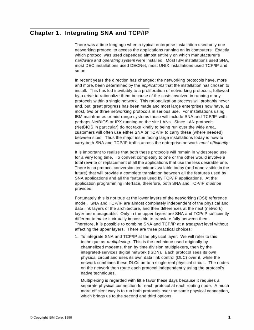
1. To integrate SNA and TCP/IP at the physical layer. We will refer to thistechnique as multiplexing. This is the technique used originally bychannelized modems, then by time division multiplexers, then by theintegrated-services digital network (ISDN). Each protocol sees its ownphysical circuit and uses its own data link control (DLC) over it, while thenetwork combines these DLCs on to a single real physical circuit. The nodeson the network then route each protocol independently using the protocol’snative techniques.
Multiplexing is regarded with little favor these days because it requires aseparate physical connection for each protocol at each routing node. A muchmore efficient way is to run both protocols over the same physical connection,which brings us to the second and third options.
© Copyright IBM Corp. 1999 1
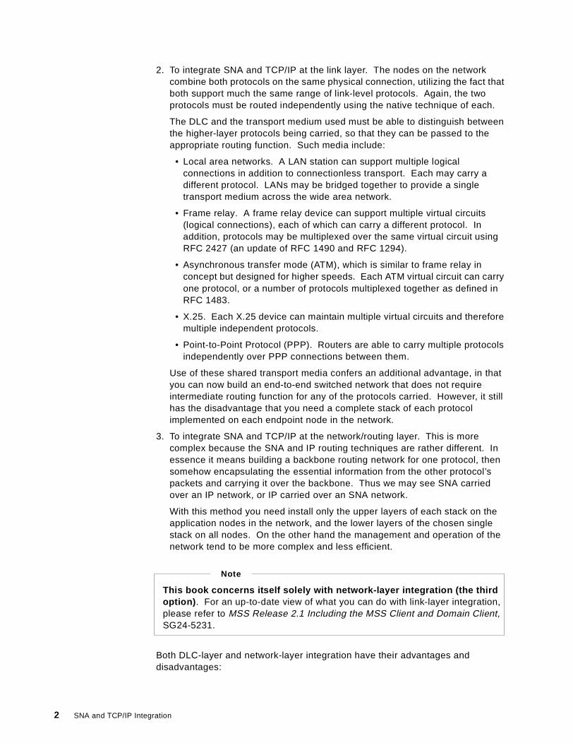
2. To integrate SNA and TCP/IP at the link layer. The nodes on the networkcombine both protocols on the same physical connection, utilizing the fact thatboth support much the same range of link-level protocols. Again, the twoprotocols must be routed independently using the native technique of each.
The DLC and the transport medium used must be able to distinguish betweenthe higher-layer protocols being carried, so that they can be passed to theappropriate routing function. Such media include:
• Local area networks. A LAN station can support multiple logicalconnections in addition to connectionless transport. Each may carry adifferent protocol. LANs may be bridged together to provide a singletransport medium across the wide area network.
• Frame relay. A frame relay device can support multiple virtual circuits(logical connections), each of which can carry a different protocol. Inaddition, protocols may be multiplexed over the same virtual circuit usingRFC 2427 (an update of RFC 1490 and RFC 1294).
• Asynchronous transfer mode (ATM), which is similar to frame relay inconcept but designed for higher speeds. Each ATM virtual circuit can carryone protocol, or a number of protocols multiplexed together as defined inRFC 1483.
• X.25. Each X.25 device can maintain multiple virtual circuits and thereforemultiple independent protocols.
• Point-to-Point Protocol (PPP). Routers are able to carry multiple protocolsindependently over PPP connections between them.
Use of these shared transport media confers an additional advantage, in thatyou can now build an end-to-end switched network that does not requireintermediate routing function for any of the protocols carried. However, it stillhas the disadvantage that you need a complete stack of each protocolimplemented on each endpoint node in the network.
3. To integrate SNA and TCP/IP at the network/routing layer. This is morecomplex because the SNA and IP routing techniques are rather different. Inessence it means building a backbone routing network for one protocol, thensomehow encapsulating the essential information from the other protocol’spackets and carrying it over the backbone. Thus we may see SNA carriedover an IP network, or IP carried over an SNA network.
With this method you need install only the upper layers of each stack on theapplication nodes in the network, and the lower layers of the chosen singlestack on all nodes. On the other hand the management and operation of thenetwork tend to be more complex and less efficient.
Both DLC-layer and network-layer integration have their advantages anddisadvantages:
This book concerns itself solely with network-layer integration (the thirdoption) . For an up-to-date view of what you can do with link-layer integration,please refer to MSS Release 2.1 Including the MSS Client and Domain Client,SG24-5231.
Note
2 SNA and TCP/IP Integration
• With DLC-layer integration, the endpoints and routing nodes of theconnections require multiple complete protocol stacks. While this is notusually a problem on large servers or routers, and less of a problem in anend-to-end switched environment, it can make a significant difference to theconfiguration and the management of user workstations and branch routers.Network-layer integration normally requires only one complete stack at eachnode, plus multiple partial stacks at the endpoints.
• Network-layer integration techniques tend to be more complex, and it is moredifficult to ensure that all the functions of the carried protocol are availablewhen the underlying carrying protocol is different in philosophy.
• The optimum level of service could be provided by either technique,depending on the mix of protocols needed and the service levels required foreach one.
One solution might be to use network-layer integration at the periphery of thenetwork but link-layer integration in the backbone. Thus user workstations wouldcontain a single protocol stack, but their gateways into the backbone routingnetwork would have both. Typically this would mean an IP stack on theworkstations (because it is easier and cheaper to provide legacy 3270 applicationaccess from an IP workstation than to provide Web access from an SNAworkstation). The gateway routers would then provide TN3270 conversion forSNA applications but leave the IP traffic alone. This solution, however, is not soeasy if the SNA applications are more recent types such as advancedprogram-to-program communication (APPC); dual stacks may still be neededthroughout.
It is important to understand that the choice between link-layer and network-layerintegration is one of finding the most cost-effective way of running a multiprotocolnetwork, and not one of interoperability. An application written to (for example)an SNA programming interface will always require a partner SNA application,regardless of what kind of network is used to transport the data; it will never talkto a (TCP/IP) Sockets application without some form of protocol conversion. Theintegration techniques we describe here provide protocol coexistence, notconversion.
In an ideal world the decision between link-layer and network-layer integrationwould be taken after extensive design studies, based on future projections forapplication requirements and technology trends. In practice, however, it oftendepends on the existing infrastructure at the time of the decision, as well as(often enough) prevailing fashion. Our book, therefore, does not attempt to giveadvice on this particular choice beyond some general observations.
1.1 Summary of Conclusions
As stated above, it is beyond the scope of this book to give detailed advice on thechoice between link-layer integration (running SNA and TCP/IP in parallel over ashared transport medium) and network-layer integration (running both protocolson top of the routing functions of one). In principle:
• With link-layer integration the more complex functions tend to be at the edgesof the network, whereas with network-layer integration they tend to bedistributed throughout the network. This is especially true in the case of a
Integrating SNA and TCP/IP 3

switched multiprotocol network, where there is no routing at all in thebackbone, merely switching.
• If your need is for a high-speed network with a high level of service, youshould consider link-layer integration, and in particular a switched backbone.The combination of simple switching in the backbone, plus native routingwhere it is needed, gives (all other things being equal) better performancethan routing throughout, especially considering possible inefficiencies due tonon-native routing for one protocol.
Switched backbone technologies for this case start with ATM as the clearwinner, because it was designed to carry very high traffic rates and give thecorrect service to such diverse traffic types as video, voice and data. Secondchoice must be frame relay or X.25; X.25 is old technology, but frame relaydoes not have mature switched virtual circuit standards. If your backbonecosts are based on connection time you need switched virtual circuits.Bridged LANs are not recommended across a wide area network because ofthe difficulty of limiting broadcast traffic (but ATM LAN emulation may be asolution).
• In a link-layer integration solution the costs of installing (or upgrading) thenetwork are biased towards the end stations and the edges of the network,whereas with network-layer integration they are more biased towards thebackbone routers.
• If one protocol predominates in your network, then you should considernetwork-layer integration. You have the choice of whether to route or to switchon the backbone, and the dominant protocol can be carried with maximumefficiency while minimizing the costs of carrying the other(s).
• On the other hand, if the two protocols are both of major importance, you maynot wish to introduce inefficiencies in one of them by making it use anon-native routing protocol. However, there is an inherent bias towardsTCP/IP in this because the technologies for carrying IP over SNA are lessnumerous and less advanced than those for carrying SNA over IP.
If you decide, or have decided, to implement network-layer integration then wefeel we can offer some more specific advice:
1. The backbone should be IP unless the overwhelming majority of your traffic is,and will remain, SNA. Methods of running IP over SNA are not as mature asmethods of running SNA over IP, so a network whose traffic is fairly evenlybalanced between SNA and IP is likely to benefit from the choice of IP.
2. If you have decided to use IP over SNA, then AnyNet is the only practicablechoice. Sockets APIs are supported on all current IBM platforms.
3. If you have decided to use SNA over IP, the SNA boundary should be placedas far out in the network as possible. With Enterprise Extender this isperfectly possible even if the backbone is totally IP. While SNA over IP iscurrently unable to provide the same level of service as native SNA (becauseof IP’s unpredictable connectionless transport), the use of end-to-end SNAprotocols should maximize the level of availability and performance to theirusers.
This is where Telnet/3270 comes into its own, if your SNA traffic is almost all3270-type traffic. With TN3270 you can minimize the costs of upgrading yourworkstations (since an IP stack tends to be cheaper to implement than an SNA
4 SNA and TCP/IP Integration
stack), while at the same time positioning your TN3270 Server (and thereforeyour SNA boundary) close to the workstation.
4. With SNA over IP, there are three main choices of technique: data linkswitching, AnyNet and Enterprise Extender. We strongly recommend that youchoose Enterprise Extender because:
• It provides end-to-end SNA priority and the high availability ofhigh-performance routing (HPR), even if there is not a single native SNAlink in your entire network.
• It is not susceptible to the failure of an SNA-to-IP boundary node in the waythat data link switching and AnyNet are susceptible.
• It provides the full dynamics of Advanced Peer-to-Peer Networking(APPN), unlike AnyNet.
• Its use of HPR routing minimizes the overhead on intermediate routers thatprovide Enterprise Extender-to-native SNA boundary functions.
• It is the only technique that gives you end-to-end nondisruptive sessionrecovery, again through its use of HPR.
1.2 Options for Integration
There are several different ways of running mixed protocol communication oversingle protocol transport networks. IBM provides the following solutions tointermix SNA and TCP/IP:
• Data link switching (DLSw). SNA traffic is encapsulated in TCP packets.
• AnyNet Sockets over SNA. TCP/IP traffic is carried across the SNA networkusing LU 6.2 sessions.
• AnyNet SNA over IP. SNA LU 6.2 and dependent LU traffic is carried overTCP connections.
• Telnet/3270 (TN3270). 3270 data streams are carried over TCP connectionsto a server which replaces the TCP transport with SNA transport.
• Host On-Demand (HOD). This is a TN3270 client implemented as a Javaapplet downloaded from a Web server.
• Enterprise Extender. SNA (HPR) packets are carried as User DatagramProtocol (UDP) packets over an IP network.
Most of these provide the ability to run SNA traffic over an IP network. Only one,Sockets over SNA, provides the ability to run TCP/IP Sockets applications overan SNA network.
Two of the methods, TN3270 and HOD, provide IBM 3270 terminal access toSNA applications from workstations having only a TCP/IP or Internet connection.
Each of these multiprotocol solutions is briefly described below. More detaileddescriptions with practical examples are in the subsequent chapters.
1.3 Data Link Switching
Data link switching (DLSw) is an IBM-architected extension to source routebridging that allows SNA and NetBIOS frames to be routed through an
Integrating SNA and TCP/IP 5
intervening IP network. It is implemented as an extra feature in IP routerproducts, such as the IBM 2210, 2212, 2216 and 3746 MAE.
There are two types of DLSw: local and remote. Here we concentrate on remoteDLSw for SNA, as it uses the IP transport network while local DLSw does not.Local data link switching enables communication between a LAN-attached SNAdevice and an SDLC station that is link-attached to the same DLSw router. TheSDLC station is assigned a MAC address so that it appears to other networkdevices to be on a LAN, and SDLC frames are converted to IEEE 802.2 logicallink control (LLC) type 2 frames.
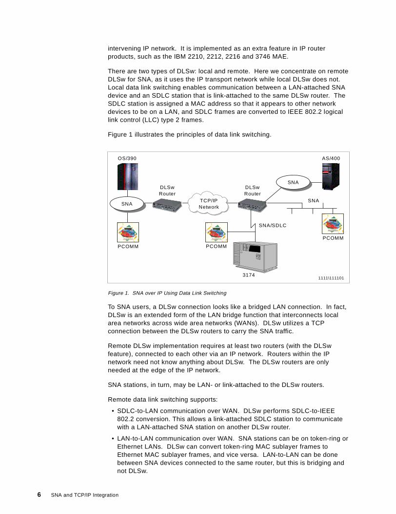
Figure 1 illustrates the principles of data link switching.
Figure 1. SNA over IP Using Data Link Switching
To SNA users, a DLSw connection looks like a bridged LAN connection. In fact,DLSw is an extended form of the LAN bridge function that interconnects localarea networks across wide area networks (WANs). DLSw utilizes a TCPconnection between the DLSw routers to carry the SNA traffic.
Remote DLSw implementation requires at least two routers (with the DLSwfeature), connected to each other via an IP network. Routers within the IPnetwork need not know anything about DLSw. The DLSw routers are onlyneeded at the edge of the IP network.
SNA stations, in turn, may be LAN- or link-attached to the DLSw routers.
Remote data link switching supports:
• SDLC-to-LAN communication over WAN. DLSw performs SDLC-to-IEEE802.2 conversion. This allows a link-attached SDLC station to communicatewith a LAN-attached SNA station on another DLSw router.
• LAN-to-LAN communication over WAN. SNA stations can be on token-ring orEthernet LANs. DLSw can convert token-ring MAC sublayer frames toEthernet MAC sublayer frames, and vice versa. LAN-to-LAN can be donebetween SNA devices connected to the same router, but this is bridging andnot DLSw.
OS/390
SNA
PCOMM
SNA/SDLC
3174
DLSwRouter
TCP/IPNetwork
DLSwRouter
SNA
SNA
AS/400
PCOMM
PCOMM
1111\111101
6 SNA and TCP/IP Integration
LAN-attached SNA devices use LLC type 2, which is the connection-orientedversion of Logical Link Control and requires timely responses between stations.With DLSw, the LLC 2 connections are terminated at the DLSw routers, whichacknowledge the frames locally instead of transmitting the acknowledgementsacross the WAN. This practice is called spoofing, and it can reduce the WANtraffic drastically. Also, it eliminates possible LLC timeouts across the WAN.
WAN traffic is reduced in similar fashion for SDLC-attached devices. Polling isdone locally by the DLSw station, and only productive polling results in datatransmission over the IP network.
DLSw-attached stations, even if they are on a leased SDLC link, are alwaysdefined as LAN-attached, and are thus considered by an SNA host as switchedresources. To VTAM they are defined in switched major nodes.
DLSw supports subarea (intermediate network node) as well as peripheral(boundary network node) communications. However, performance tests indicatethat, for INN traffic, DLSw can increase NCP CCU utilization as compared withplain bridging; spoofing can actually be counter-productive in this situation. If youplan to use DLSw for INN traffic you might want to evaluate plain bridging as analternative.
Data link switching is fairly commonly used, as it was the first SNA over IPsolution that became available. It has some attractive features such as spoofing,and it is easy to understand and configure. DLSw, like any other TCP connection,utilizes the dynamism and rerouting capabilities of the IP network.
DLSw has, however, some disadvantages:
• It may require additional routers on each side of the TCP/IP network ifperformance and availability requirements are to be met.
• Heavy workload demands may be placed on central (concentration point)routers implementing DLSw.
• While DLSw is an industry standard, many vendors have proprietaryextensions that work only with their products.
• DLSw as implemented in IBM products does not support HPR. DLSw is basedon the use of LLC2 connections using MAC and SAP addresses exchangedon TEST and XID frames. HPR does not require LLC2 connections, andnormally uses a SAP other than the one seen in the XID frames. However,some vendors’ extensions to DLSw support HPR connections in certaincircumstances.
• When a DLSw router fails, session outages occur, even if backup routers arein place.
• There are no SNA-like class of service or management functions within the IPpart of the network, although it is often possible to distinguish between SNAand other types of IP traffic.
You can find more information on data link switching in the following publications:
• 3746 Nways Controller Models 900 and 950: Multiaccess Enclosure Primer,SG24-5238
• MSS Release 2.1, Including the MSS Client and Domain Client, SG24-5231
Integrating SNA and TCP/IP 7

• IBM 2210 Nways Multiprotocol Router and IBM 2216 Nways MultiaccessConnector Description and Configuration Scenarios - Volume II, SG24-4956
• 3746, 2210, 2216, and 2220 Interconnectivity: Frame Relay and RelatedFunctions, SG24-2146
• 6611 Network Processor Introduction and Planning Guide Version 1 Release4, GK2T-0334 (contains an excellent description of DLSw functions)
• RFCs 1795 and 2166, which can be found on the IETF Web sitewww.ietf.org/rfc/ .
• The APPN Implementers’ Workshop home page atwww.networking.ibm.com/app/aiwhome.htm .
1.4 AnyNet and MPTN
AnyNet products implement the IBM Multiprotocol Transport Networking (MPTN)architecture, which supports mixed protocol networking. With AnyNet,application programs that were designed to operate over one transportnetworking protocol, such as SNA, OSI or TCP/IP, can run over a differenttransport network.
MPTN architecture also supports network interconnection, which meansconnecting transport networks of different types in a serial fashion to provide amultinetwork path for communicating partners.
In the context of MPTN, application programs or other end users are defined astransport users and each network using a protocol of its own is defined as atransport provider.
To build this type of multiprotocol network, some of the functions needed are:
• Address mapping, by which network addresses are changed from one networkprotocol format to another. In SNA networks, addresses are expressed intextual format, consisting of a NETWORK_NAME.LU_NAME pair. In IPnetworks addresses are expressed as four-byte binary numbers, usuallypresented in dotted decimal format, such as 155.130.96.29. (This four-byteaddressing of TCP/IP will be replaced by a larger address space, in theso-called IPNG or IPv6).
• Function compensations to provide required functions to the transport user butwhich are not available natively in the transport provider network. MPTNprovides a standard set of compensations for missing functions, which can beused by any protocols. An example of compensation is connectionestablishment and termination. This is needed when running SNA (connectionoriented) over IP (which is connectionless in nature).
• Network interconnection. MPTN transport gateways are used to interconnectdifferent transport providers when the end users are connected to differenttransport providers (one to its native transport and the other to a non-nativeone).
• Network management. Management of an MPTN network requires correlationbetween different native management protocols in the transport networks.
8 SNA and TCP/IP Integration

1.4.1 AnyNet/MPTN Node TypesAn access node contains MPTN functions that allow applications to run overnon-native transport providers. The access node function is used in systems thatonly need access to a transport network in order to reach their communicationspartners. The node is typically an endpoint of a connection. An access nodemay contain one or multiple transport providers, and multiple transport users.
Figure 2 on page 9 shows the structure of an MPTN access node. In thisexample the access node is a Sockets over SNA node. It contains two transportusers (an SNA CPI-C application and a Sockets application) and a singletransport provider (the SNA network). Two such nodes connected by an SNAnetwork can allow Sockets applications to communicate with each other withoutthe presence of an IP network.
Figure 2. AnyNet Access Node Structure
The end-to-end connection is always between matching transport users, forexample SNA transport user to SNA transport user, but not SNA transport user toTCP/IP transport user.
Figure 3 on page 10 shows how protocol users of the same type (shown as X)can communicate with each other when using AnyNet. On the left there are twosystems with MPTN access node capabilities. This allows their type X transportusers to communicate over a type Y transport provider. The type X transportusers in the two nodes on the right can communicate natively over the type Xtransport providers.
CPI-CCPI-C
ApplicationSockets
Application
APPC SocketsAPI
AnyNet MPTN Function
S N A
Integrating SNA and TCP/IP 9
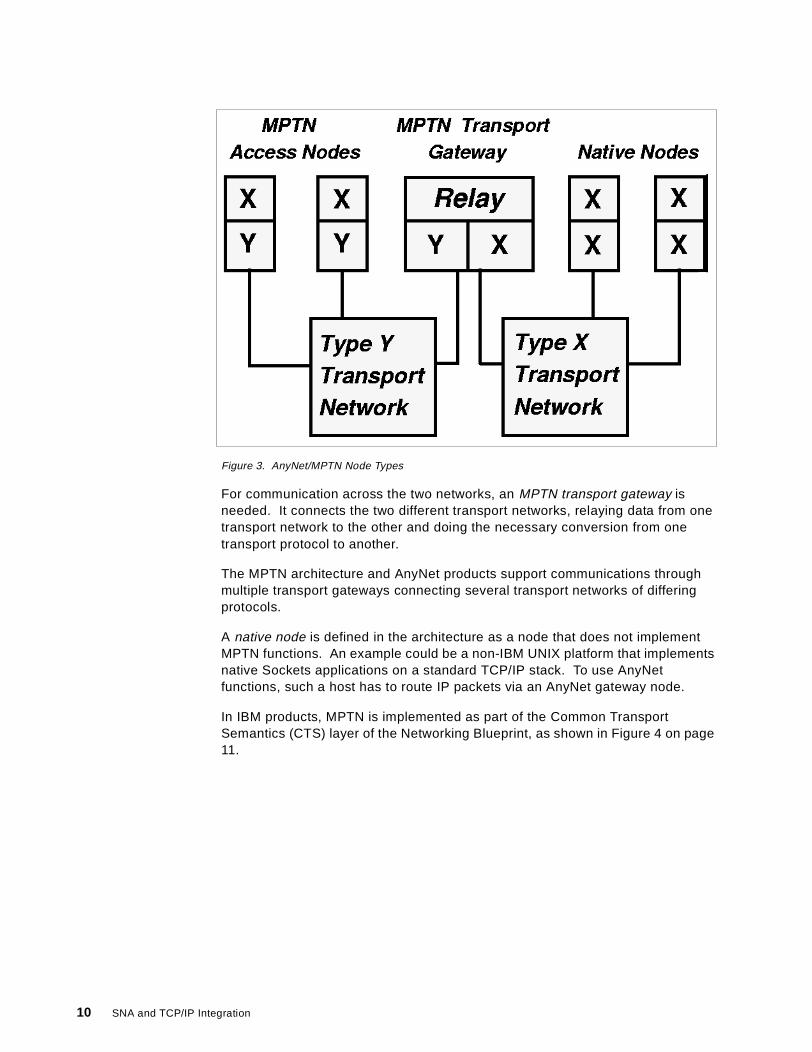
Figure 3. AnyNet/MPTN Node Types
For communication across the two networks, an MPTN transport gateway isneeded. It connects the two different transport networks, relaying data from onetransport network to the other and doing the necessary conversion from onetransport protocol to another.
The MPTN architecture and AnyNet products support communications throughmultiple transport gateways connecting several transport networks of differingprotocols.
A native node is defined in the architecture as a node that does not implementMPTN functions. An example could be a non-IBM UNIX platform that implementsnative Sockets applications on a standard TCP/IP stack. To use AnyNetfunctions, such a host has to route IP packets via an AnyNet gateway node.
In IBM products, MPTN is implemented as part of the Common TransportSemantics (CTS) layer of the Networking Blueprint, as shown in Figure 4 on page11.
10 SNA and TCP/IP Integration

Figure 4. IBM Networking Blueprint with CTS and MPTN
Common Transport Semantics (CTS) provides a common boundary between theapplication support layer and the transport network layer, separating the transportuser and the transport network from each other.
CTS includes all of the functions in the underlying transport providers. If requiredfunctions are missing from any of the transport providers, CTS itself providesthose functions via compensations. CTS function is delivered in different waysdepending on the situation:
1. Same protocol: CTS includes the case where the transport user protocolmatches the transport provider protocol. The connection or datagram isnative, and no changes are made to the protocol flows.
2. Mixed protocol includes two situations:
• Standards: CTS function can be delivered in specific situations by acceptedindustry standards, such as RFC 1006 for OSI over TCP/IP or RFCs 1001 and1002 for NetBIOS over TCP/IP.
• MPTN: This part of CTS was introduced by IBM. MPTN is typically used whenSNA is one of protocols being used.
The architecture is described in detail in the following manuals:
• Multiprotocol Transport Networking (MPTN) Architecture: Technical Overview,GC31-7073
• Multiprotocol Transport Networking (MPTN) Architecture: Formats,GC31-7074
Common Transport Semantics
sameprotocol
mixed protocol
standards MPTN
Integrating SNA and TCP/IP 11
AnyNet implementations of the MPTN architecture in different platforms include:
• SNA over IPX• SNA over TCP/IP• Sockets over IPX• Sockets over NetBIOS• Sockets over SNA• IPX over TCP/IP• IPX over SNA• NetBIOS over TCP/IP• NetBIOS over SNA
1.4.2 AnyNet Products for TCP/IP and SNA/APPNFor the purposes of this redbook, the AnyNet protocols that concern us areSockets over SNA and SNA over TCP/IP.
Sockets over SNA utilizes independent LU 6.2 sessions to carry TCP/IP trafficacross an SNA (subarea or APPN) network. The following current IBM productsprovide various options of Sockets over SNA:
1. Access node and gateway functions:
• SecureWay Communications Server for Windows/NT, Version 5 and above• SecureWay Communications Server for OS/2 Warp, Version 4.1 and above• SecureWay Communications Server for AIX, Version 4 Release 2 and
above
2. Sockets over SNA access node only:
• SecureWay Communications Server for OS/390 SNA (formerly known asVTAM), from VTAM Version 3 Release 4.2
• Operating System/400 (OS/400) Version 3.7 and above• SecureWay Personal Communications for Windows NT, Version 4 and
above• SecureWay Personal Communications for OS/2, Version 4 and above
AnyNet SNA over TCP/IP utilizes TCP connections to carry dependent andindependent LU sessions across an IP network. All implementations supportindependent LUs, but CS for OS/390 requires that dependent LUs utilize thedependent LU requester/server (DLUR/S) function. This is the only case wherethe DLUR/S control sessions do not require an APPN path. The following currentIBM products provide various options of SNA over TCP/IP:
1. Access node and gateway functions:
• SecureWay Communications Server for OS/390, from VTAM Version 3Release 4.2 (dependent LU sessions require VTAM V4R2 or above)
• SecureWay Communications Server for Windows NT, Version 5 and above• SecureWay Communications Server for OS/2 Warp, Version 4.1 and above• SecureWay Communications Server for AIX, Version 4 Release 2 and
above
2. Access node only:
• Operating System/400 (OS/400) Version 3.7 and above• Personal Communications for Windows NT, Version 4 and above• Personal Communications for OS/2, Version 4 and above
12 SNA and TCP/IP Integration
In addition to these current AnyNet products, there are earlier implementations,such as AnyNet/2 for OS/2. They are compatible with, and can still be usedtogether with, the newer products.
Note: The SecureWay Communications Server family of products was previouslyknown as the eNetwork Communications Server family.
1.4.3 AnyNet in SummaryThe AnyNet product family provides a convenient way to run SNA over TCP/IPand Sockets programs over SNA, as well as some additional protocolcombinations.
AnyNet Sockets over SNA is the only solution that we have for Socketsapplications to utilize SNA transport.
AnyNet has the following benefits:
• It is a software only solution. Generally no additional hardware is needed.
• It is based on a solid architecture, MPTN, covering most protocolrequirements.
• AnyNet has been available for several years; the products are mature andstable.
• AnyNet capability is available as a built-in feature in all CommunicationsServer products for most IBM platforms, and in two Personal Communicationsproducts (OS/2 and Windows).
1.5 Enterprise Extender
The Enterprise Extender technology is a simple set of extensions to the existing,open high-performance routing (HPR) technology. Its purpose is to carry SNAtraffic over an IP network while maintaining the SNA class of service to themaximum possible extent. Enterprise Extender is an up-to-date replacement fordata link switching.
To the HPR network, the IP backbone is a logical link; to the IP network, the SNAtraffic comprises UDP datagrams that are routed without hardware or softwarechanges to the IP backbone. There is no protocol transformation, as UDP/IP isseen as just another type of SNA DLC. Nor is there the overhead of additionaltransport functions, since TCP is not used.
Since Enterprise Extender is HPR, it provides the benefits of HPR all the wayfrom the mainframe to the furthest SNA-capable node in the network, such as aremote TN3270 Server. It does this regardless of whether the underlying routingnetwork is SNA, IP or a combination. Thus, for example, sessions using an SNAbackbone can be rerouted nondisruptively to a path over an IP backbone (or eventhe Internet) should a critical SNA component fail. No other technology canprovide this; data link switching is susceptible to failure of the DLSw routers at theedges of the IP network.
The other major benefit of Enterprise Extender is the ability to maintain the SNAclass of service across and within the IP network. Routers typically use either theprecedence bits in the IP header, or the UDP port number, to prioritize traffic.Enterprise Extender can use one or both of these to indicate the APPN
Integrating SNA and TCP/IP 13
14
transmission priority to the network. Once again, this feature is unique toEnterprise Extender.
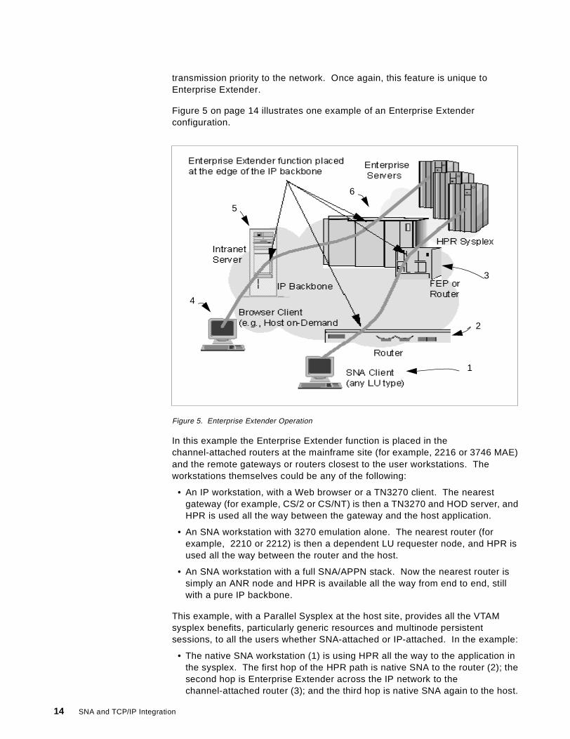
Figure 5 on page 14 illustrates one example of an Enterprise Extenderconfiguration.
Figure 5. Enterprise Extender Operation
In this example the Enterprise Extender function is placed in thechannel-attached routers at the mainframe site (for example, 2216 or 3746 MAE)and the remote gateways or routers closest to the user workstations. Theworkstations themselves could be any of the following:
• An IP workstation, with a Web browser or a TN3270 client. The nearestgateway (for example, CS/2 or CS/NT) is then a TN3270 and HOD server, andHPR is used all the way between the gateway and the host application.
• An SNA workstation with 3270 emulation alone. The nearest router (forexample, 2210 or 2212) is then a dependent LU requester node, and HPR isused all the way between the router and the host.
• An SNA workstation with a full SNA/APPN stack. Now the nearest router issimply an ANR node and HPR is available all the way from end to end, stillwith a pure IP backbone.
This example, with a Parallel Sysplex at the host site, provides all the VTAMsysplex benefits, particularly generic resources and multinode persistentsessions, to all the users whether SNA-attached or IP-attached. In the example:
• The native SNA workstation (1) is using HPR all the way to the application inthe sysplex. The first hop of the HPR path is native SNA to the router (2); thesecond hop is Enterprise Extender across the IP network to thechannel-attached router (3); and the third hop is native SNA again to the host.
1
2
3
4
5
6
SNA and TCP/IP Integration
• The Web browser workstation (4) is using TN3270 over native IP to theIntranet server (5). This server runs the HOD server as well as the TN3270EServer. The connection from there on is a two-hop HPR path carrying theSNA LU 2 session: one hop using Enterprise Extender to thechannel-attached router (6) and the second hop native SNA to the host.
An even better solution might be to run Enterprise Extender on the OS/390 hostitself. In that case, the channel-attached routers run only IP; eliminating theDLSw function can provide a very large increase in throughput of such routers.Again all the benefits of HPR are realized. A TN3270E Server at each remotelocation, coupled with Enterprise Extender on CS for OS/390, provides all theSNA/HPR capabilities even though the whole network is IP.
1.5.1 Enterprise Extender ImplementationsEnterprise Extender is available on the following products from IBM:
• SecureWay Communications Server for OS/390, Release 6 (with APAROW36113) and above
• 2216 Multiprotocol Access Services, Version 2 Release 2 and above
• 2212 Access Integration Services
• 2210 Multiprotocol Routing Services, Version 2 Release 2 and above
• 3746 Multiaccess Enclosure with Feature Code 5805
• Network Utility
• SecureWay Communications Server for Windows/NT, Version 6 and above
1.6 Telnet/3270
TN3270 is a protocol by which a workstation user can get access to IBM 3270applications running on an SNA host.
TN3270 requires a client function on the workstation and a TN3270 Serversomewhere in the network (sometimes even at the host). TCP/IP must berunning in both the client and the server system. The TN3270 Server translatesthe TCP/IP protocol to SNA 3270 (LU type 2), and maintains SNA sessions withthe desired host application(s).
The TN3270 client program runs typically in a PC workstation, using the installedTCP/IP stack for transport. No other protocols need to be installed in theworkstation. TN3270 is a popular method for integrating SNA and IP forworkstations that use SNA only for 3270 sessions, because the TCP/IP stack istypically installed in most workstations anyway.
The old TN3270 had certain limitations such as lack of printer support. For sometime, an updated version of the protocol called TN3270E (E stands for Extended)has been available. The old TN3270 clients can be used to access an extendedserver, since the two protocols are compatible. Note that TN3270E is notrequired for the use of the 3270 extended data stream; basic TN3270 supportsthis.
Integrating SNA and TCP/IP 15
A TN3270 Server in today’s IBM routers will normally use APPN and DLUR toaccess the host applications, but subarea protocols can also be used if the routeris adjacent to a VTAM or NCP node.
By moving the TN3270 Server out from the mainframe, one can achieve thefollowing benefits:
• Reduction in processor load, as the protocol conversion is done elsewhere.
• Better service level to users, in the form of constant response times and betteravailability. The further out in the network the TN3270 Server is placed, thegreater the level of service. This is due to the fact that SNA and APPN aremore deterministic by nature than IP, and use the class of service for routingand prioritization.
• Use of HPR with its dynamic route switching capability, giving even greateravailability. In addition, the presence of at least one HPR-capable SNA hop inthe network allows you to exploit multinode persistent sessions in a ParallelSysplex.
• A TCP/IP stack is not required in the OS/390 host unless needed for otherpurposes.
However, if all your 3270 applications are concentrated in the same place thenplacing the TN3270 Server on the host can be the most economical solution. Asa general principle, we believe that the TN3270 Server function should be asclose as possible to either the workstation or the host. Having it somewhere inbetween can introduce a potential disruptive failure point at the SNA/IP boundary.
1.6.1 TN3270E Server ImplementationsThe TN3270E Server function is available on the following current platforms:
• SecureWay Communications Server for OS/390
• OS/400
• SecureWay Communications Server for OS/2
• SecureWay Communications Server for AIX
• SecureWay Communications Server for Windows/NT
• 2216, 2212, 2210, 3746 MAE and Network Utility
1.7 Host On-Demand
Host On-Demand (HOD) is a means by which 3270 applications can be accessedfrom an Internet browser. It is based on Java, and thus requires a Java-capablebrowser. Nothing else is needed in the client workstation, except for a connectionto the Internet or other TCP/IP network.
HOD is actually a TN3270 (or other Telnet) client implemented in Java. To useHOD, a Web server is needed somewhere in the network for users to connect to.The TN3270 (or TN5250, or other Telnet) Java applet is downloaded from thisserver to the workstation. This Web server may also be running the TN3270Server function, through which the applications in the SNA hosts are accessed.
16 SNA and TCP/IP Integration
The HOD Web server and/or the TN3270 Server can be in the application hostitself. Alternatively, they could be on completely different platform(s), somewherein the SNA network.
The Host On-Demand server function is available for the following environments:
• OS/390• OS/400• OS/2• AIX, Sun Solaris and HP-UX• Novell Netware• Windows/NT
The latest release, Host On-Demand Version 3, supports TN3270, TN5250,VT52, VT100, VT220 and CICS Java Gateway displays.
HOD is an excellent solution for temporary access to 3270 applications from aWeb browser. It can be used, for example, to provide safe external access toyour enterprise data to the public or to selected customers. Your normal IPfirewall, together with your existing SNA security measures, should preventunauthorized access.
Host On-Demand supports end-to-end Secure Sockets Layer (SSL) encryptionbetween the client and the HOD server. In addition, HOD server profile access isprotected by user ID and password, and authentication is performed by the serversending an X.509 certificate.
Host On-Demand presents the Web user with the traditional green screen as aninterface. By using a product such as Host Publisher, you can instead present aWeb-like GUI interface to users not familiar with the 3270 green screen (such asthe public).
1.7.1 Host On-Demand SummaryHost On-Demand allows Web users to access host programs without installing aterminal emulator on their computer. A Java-capable Web browser is all theyneed. In our opinion, however, it cannot be recommended for constantprofessional use because of the additional overhead of running Java and abrowser as well as the 3270 protocol. Native SNA or TN3270E are bettersolutions for heavy use.
With HOD you have these benefits:
• Multiple concurrent sessions with one or more hosts.
• No end-user installation or configuration required to establish a session.
• User's browser remains available for concurrent Web use.
• Cost-effective distribution of emulator software updates with Java.
• Print screen, file transfer, cut and paste, and keyboard remapping.
• Host On-Demand is Java-based, so users in different operating environments(whether they are using network computers, traditional personal computers, oradvanced workstations) get the same look and feel.
• A Java-based application programming interface (API) for applicationdevelopment is available to customize desktops.
Integrating SNA and TCP/IP 17

• National language support is available, including support for double-bytecharacter sets.
Additional information on HOD can be found on the Host On-Demand home pageat URL:
http://www.software.ibm.com/network/hostondemand/
18 SNA and TCP/IP Integration
Chapter 2. Enterprise Extender
The Enterprise Extender technology was implemented on most of IBM’snetworking platforms during 1998. Its main objective is to provide SNA-over-IPintegration that is significantly superior to its predecessors such as data linkswitching and AnyNet.
2.1 Benefits of Enterprise Extender
Enterprise Extender combines features of SNA and IP to offer the best of bothworlds when running SNA traffic over an IP backbone. Its advantages are in thethree major areas of availability, performance and usability.
2.1.1 Failure ProtectionTCP/IP has always had the ability to reroute packets around failing components,without disrupting the connection, by means of its connectionless IP transport.More recently SNA has implemented the same function, albeit in a rather differentfashion. The high-performance routing (HPR) extension to SNA is connection-oriented as SNA has always been, but when it detects a failure it will move anexisting connection around a failing component. The use of HPR transport overan IP backbone provides four benefits, only one of which is available to trafficusing native TCP/IP:
1. Non-disruptive rerouting upon a failure could be accomplished using either IPor HPR methods, depending on the location of the failure.
2. HPR retains the connection-oriented nature of SNA, making it morepredictable and easier to manage.
3. The use of HPR allows both the above benefits to be realized in a combinednetwork which uses both SNA and IP routing in different portions. EnterpriseExtender provides seamless integration, in that the IP network is seen as anadditional hop in an SNA connection path.
4. Adaptive rate-based flow control provides a fair allocation of bandwidth amongSNA sessions and IP traffic while maintaining the SNA class of service.
By contrast, data link switching provides non-disruptive rerouting across the IPnetwork alone, and is susceptible to failures of the DLSw routers at the edge ofthe network. Since it does not support HPR, it cannot provide full end-to-endnon-disruptive rerouting in a combined SNA/IP network.
Enterprise Extender is particularly suited for customers wishing to exploit themultinode persistent sessions (MNPS) function in a Parallel Sysplex. MNPSallows an application to move between MVS images in a sysplex after a failure,without disrupting existing sessions. Since MNPS utilizes HPR to achieve this,Enterprise Extender is a perfect complement to MNPS even in the situationwhere there is no SNA backbone network whatsoever. The only requirement is aremote partner node capable of Enterprise Extender (and therefore HPR).
2.1.2 Class of ServiceOne of the biggest issues facing those who wish to transport SNA over an IPbackbone is the question of maintaining SNA’s class of service. In native SNA
© Copyright IBM Corp. 1999 19

the class of service specified for a particular session is used to determine boththe route taken by the session and the transmission priority allotted to it.
With an IP backbone the route is essentially unpredictable because of IP’sconnectionless transport. However, IP provides for a transmission priority usingthe precedence bits in the IP header. Many routers now support the use of thesebits, but in the past they have tended to use the TCP or UDP port number as ameans of assigning priorities to packets.
Enterprise Extender supports the use of both the precedence bits and the portnumbers to inform the IP network of the transmission priority. Use of theprecedence bits is recommended because the UDP or TCP port numbers arecarried inside the IP datagram, whereas the precedence bits are in the IP header.Thus encrypted packets have unreadable port numbers and fragmented packetshave no port numbers after the first fragment; therefore, intermediate routerscannot determine the priority in these cases.
2.1.3 Flow and Congestion ControlTCP/IP and HPR both provide their own unique, network-specific mechanisms forflow and congestion control. TCP uses a windowed technique, whereas HPRuses a technique based on data rate. Enterprise Extender introduced a newvariant of the HPR flow control method known as responsive mode adaptive rate-based (ARB) flow control. Responsive mode ARB, like basic mode ARB, isdesigned to prevent network congestion; however, it also ensures a fair divisionof network capacity between the four SNA priorities and the native IP traffic.
2.1.4 Usability and Cost EffectivenessEnterprise Extender technology can reduce the demands on the data centerrouting platforms such as routers and front-end processors and thus provide amore cost-effective solution than other integration technologies. The boundarynodes between the SNA and IP backbones have less work to do than, forexample, DLSw routers which must maintain TCP connections with theirattendant flow control and error recovery requirements. Enterprise Extenderdoes all that at the HPR endpoints wherever they may be located.
Enterprise Extender has been designed to run over existing IP networks withoutrequiring any change to applications or to IP routers. SNA applications see thesame network interface as before, whereas IP routers see the same IP (UDP)packets as before. Only the HPR nodes at the edges of the IP network need tobe aware of Enterprise Extender.
In conjunction with the branch extender technology, which was introduced in1997, Enterprise Extender permits the implementation of extremely largenetworks that provide SNA application access using any combination of SNA andIP networks and clients.
Together, these technologies can dramatically reduce the overhead in buildingthe real-world networks that integrate the SNA and IP network and applicationassets.
20 SNA and TCP/IP Integration
2.2 HPR Overview
Enterprise Extender is a new DLC type used by the SNA high-performancerouting architecture, so before describing Enterprise Extender itself we offer abrief overview of HPR. Further details on HPR can be found in Subarea to APPNMigration: HPR and DLUR Implementation, SG24-5204, and in Inside APPN -The Essential Guide to the Next-Generation SNA, SG24-3669.
HPR is a set of enhancements for APPN whose main objectives are:
• To improve APPN data routing
With faster, more reliable communication lines it is neither necessary nordesirable to perform error recovery, flow control and complicated routingfunctions at intermediate nodes in a network. HPR takes full advantage ofmodern technology to eliminate these functions, by ensuring that they areperformed only at the endpoints of a session path. With HPR, eachintermediate node has only a minimal switching function to perform.
• To improve APPN reliability
Customers have always wanted the network to recover from errors, and to findan alternate path without requiring the end user to take action. HPR switchessession routes to bypass link and node failures if an acceptable alternate pathis available. This occurs transparently to the sessions; in other words, thesession is not disrupted.
• Compatibility and easy migration
HPR implements many functions in exactly the same way as base APPN. Thesame topology, the same directory, the same search methods, and the sameroute calculations are used. Priority queueing, connection networks, DLUR/S,VR-TG and cross-network sessions are all supported by HPR. The samemanagement data is carried on the same sessions in the same ways. HPRfunctions are invoked only at session initiation time, when the first HPR-capable node on the session path discovers the new session request.
In HPR, sessions are grouped together on logical connections called rapidtransport protocol (RTP) connections. Sessions traversing the same route andusing the same class of service will normally share an RTP connection. Dataflowing on RTP connections flows as network layer packets (NLPs). Figure 6 onpage 23 illustrates an RTP connection.
The intermediate nodes in an HPR network have only one function, to route dataquickly and efficiently from one link to another. This technique is known asautomatic network routing (ANR). A node performing ANR is aware of neither thesessions nor the RTP connections passing through it. If there is no awarenessthere is no need for cleanup or restoration after a failure, so the ANR techniqueallows easy switching of session paths. Aside from the routing information, ANRnodes are aware of the transmission priority so that this can be maintainedthroughout the session path. Please refer to 2.2.1, “Automatic Network Routing”on page 22 for more details.
All the rest of the HPR function is implemented in the endpoints of a connection.The major part of this function is called rapid transport protocol (RTP). A nodecapable of RTP must be able to:
• Establish and maintain an RTP connection with a partner node
Enterprise Extender 21
• Recover from the loss or corruption of packets• Resequence packets arriving out of order• Perform adaptive rate-based (ARB) flow control for the RTP connection• Act as the boundary between base APPN and HPR portions of a network• Perform a nondisruptive path switch if a permanent failure occurs and an
alternative path is available
Please see 2.2.2, “Rapid Transport Protocol” on page 23 for more details on RTP.
The ability to understand ANR is part of the HPR base function, which is aprerequisite for RTP. The HPR base function includes:
• The ability to exchange HPR capabilities via XID exchange
• The ability to exchange HPR-related topology information on CP-CP sessions
• For a network node, the ability to calculate HPR-only routes, which arerequired for a successful path switch
There is one further HPR option that is particularly relevant to EnterpriseExtender, and that is called control flows over RTP. If a node implements theHPR base and RTP options alone, then the CP-CP sessions and the route setupmessages (which are used to establish the RTP connection, much as a BINDestablishes a session) flow as base APPN (FID-2) packets. If the connectiondoes not permit base APPN flows (in other words, the connection is HPR-only)then the CP-CP and route setup traffic must itself flow on RTP connections. Thecontrol flows over RTP option permits exactly this. RTP support is a prerequisiteto the control flows option. Since Enterprise Extender is an HPR-onlyconnection, the nodes at either end of such a connection must support the controlflows option.
2.2.1 Automatic Network RoutingAutomatic network routing (ANR) is a low-level routing mechanism that minimizesprocessing cycles and storage requirements for routing packets throughintermediate nodes.
ANR is a source-routing protocol; the routing information (ANR label) for everynode on the path is contained in the packet header. Furthermore, the ANR labelrepresents the onward link for each node, not the session as with base APPNrouting. There is no session awareness in a node performing ANR routing. All ithas to do is inspect the first ANR label in the packet header, strip it off, andforward the packet to the correct outbound link.
This label stripping technique is much more efficient than the label swappingtechnique (intermediate session routing) used by base APPN nodes. ISRrequires that the node inspects the session identifier in the incoming packet, usesit to look up a session table, swaps it to the outbound session identifier, andforwards the packet.
Figure 6 on page 23 illustrates the way ANR labels are used.
1. Node A sends an NLP to node B with ANR labels 21 / 33 / 65 / FF in theNLP header as shown.
2. Node B looks in the header for the first ANR label. This is 21, so node Bremoves it from the header and transfers the truncated NLP to the link itknows as 21.
22 SNA and TCP/IP Integration
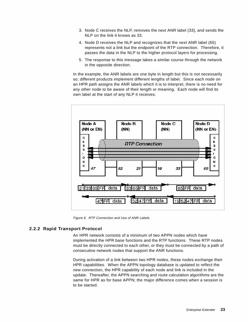
3. Node C receives the NLP, removes the next ANR label (33), and sends theNLP on the link it knows as 33.
4. Node D receives the NLP and recognizes that the next ANR label (65)represents not a link but the endpoint of the RTP connection. Therefore, itpasses the data in the NLP to the higher protocol layers for processing.
5. The response to this message takes a similar course through the networkin the opposite direction.
In the example, the ANR labels are one byte in length but this is not necessarilyso; different products implement different lengths of label. Since each node onan HPR path assigns the ANR labels which it is to interpret, there is no need forany other node to be aware of their length or meaning. Each node will find itsown label at the start of any NLP it receives.
Figure 6. RTP Connection and Use of ANR Labels
2.2.2 Rapid Transport ProtocolAn HPR network consists of a minimum of two APPN nodes which haveimplemented the HPR base functions and the RTP functions. These RTP nodesmust be directly connected to each other, or they must be connected by a path ofconsecutive network nodes that support the ANR functions.
During activation of a link between two HPR nodes, these nodes exchange theirHPR capabilities. When the APPN topology database is updated to reflect thenew connection, the HPR capability of each node and link is included in theupdate. Thereafter, the APPN searching and route calculation algorithms are thesame for HPR as for base APPN; the major difference comes when a session isto be started.
Enterprise Extender 23
At session initiation time, the node that contains the primary LU receives a routeselection control vector (RSCV) from its network node server, which representsthe route that the session is to take. Base APPN processing requires that theRSCV is appended to the BIND, which then flows through the networkestablishing the session path. With HPR, however, the first RTP-capable node onthe path must establish an RTP connection, if possible, over which the BIND mayflow as an NLP. This RTP-capable node, therefore, examines the RSCV (whichcontains the HPR information from the topology database) to see if such aconnection exists or can be set up.
The RTP-capable node determines the furthest RTP-capable partner on thesession path that is linked to it by a contiguous chain of ANR-capable nodes. Ifan RTP connection already exists over the same route and for the same class ofservice, the BIND (and therefore the new session) flows over that connection. Ifsuch a connection does not exist, one is established by means of the route setupmessage and its response. The route setup carries that portion of the RSCV thatrepresents the HPR part of the session route, and finds its own way through thenetwork exactly as a BIND would. The route setup exchange allows eachintermediate node to assign ANR labels to the links on the path, and to makethose labels known to the RTP endpoints that will use them to route NLPs. Theroute setup exchange also determines (among other things) the performancecharacteristics of the RTP connection, so that the ARB flow control algorithm canbe initialized with reasonable values.
2.2.2.1 End-to-End Error RecoveryOn an RTP connection it is the responsibility of the endpoint nodes to recoverfrom errors such as lost packets or packets arriving out of order. NLPsthemselves are subject to CRC checking as they pass through the network, butany error detected at an intermediate (ANR) node may result simply in the packetbeing discarded.
RTP nodes count the data bytes sent on each RTP connection, and include abyte sequence number in the header of each NLP. This is similar to the way TCPdetects lost data. Any discrepancy between the number of bytes received andthe sequence number received results in a request for retransmission. RTPnodes have the ability to request selective retransmission, so that only themissing packets need to be resent. This is clearly more efficient than resendingall the data since the first erroneous packet.
2.2.2.2 Non-Disruptive Path SwitchA path switch can be triggered by a timeout on an RTP connection, or bydetection of an error on a link adjacent to one of the RTP endpoints. It can alsobe initiated deliberately to move a session path in a planned fashion. When thishappens, one or both of the RTP endpoints request a new route (RSCV), whichmust be calculated by the appropriate network node(s). If an HPR-only path isavailable that satisfies the class of service required, a route setup is sent torestore the RTP connection and to establish the new set of ANR labels. As soonas this is done the NLPs continue to flow without disruption to the sessions usingthe RTP connection. If no HPR-only path is available, the RTP connection isterminated, together with all the sessions using it.
24 SNA and TCP/IP Integration
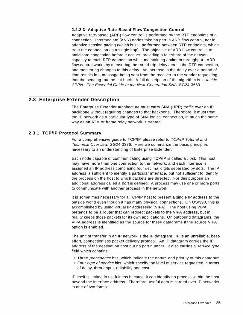
2.2.2.3 Adaptive Rate-Based Flow/Congestion ControlAdaptive rate-based (ARB) flow control is performed by the RTP endpoints of aconnection. Intermediate (ANR) nodes take no part in ARB flow control, nor inadaptive session pacing (which is still performed between RTP endpoints, whichtreat the connection as a single hop). The objective of ARB flow control is toanticipate congestion before it occurs, providing a fair share of the networkcapacity to each RTP connection while maintaining optimum throughput. ARBflow control works by measuring the round-trip delay across the RTP connection,and monitoring changes to this delay. An increase in the delay over a period oftime results in a message being sent from the receiver to the sender requestingthat the sending rate be cut back. A full description of the algorithm is in InsideAPPN - The Essential Guide to the Next-Generation SNA, SG24-3669.
2.3 Enterprise Extender Description
The Enterprise Extender architecture must carry SNA (HPR) traffic over an IPbackbone without requiring changes to that backbone. Therefore, it must treatthe IP network as a particular type of SNA logical connection, in much the sameway as an ATM or frame relay network is treated.
2.3.1 TCP/IP Protocol SummaryFor a comprehensive guide to TCP/IP, please refer to TCP/IP Tutorial andTechnical Overview, GG24-3376. Here we summarize the basic principlesnecessary to an understanding of Enterprise Extender.
Each node capable of communicating using TCP/IP is called a host. This hostmay have more than one connection to the network, and each interface isassigned an IP address comprising four decimal digits separated by dots. The IPaddress is sufficient to identify a particular interface, but not sufficient to identifythe process on the host to which packets are directed. For this purpose anadditional address called a port is defined. A process may use one or more portsto communicate with another process in the network.
It is sometimes necessary for a TCP/IP host to present a single IP address to theoutside world even though it has many physical connections. On OS/390, this isaccomplished by using virtual IP addressing (VIPA). The host using VIPApretends to be a router that can redirect packets to the VIPA address, but inreality keeps those packets for its own applications. On outbound datagrams, theVIPA address is identified as the source for these datagrams if the source VIPAoption is enabled.
The unit of transfer in an IP network is the IP datagram. IP is an unreliable, best-effort, connectionless packet delivery protocol. An IP datagram carries the IPaddress of the destination host but no port number. It also carries a service typefield which contains:
• Three precedence bits, which indicate the nature and priority of this datagram• Four type of service bits, which specify the level of service requested in terms
of delay, throughput, reliability and cost
IP itself is limited in usefulness because it can identify no process within the hostbeyond the interface address. Therefore, useful data is carried over IP networksin one of two forms:
Enterprise Extender 25

1. User datagram protocol (UDP) adds multiplexing to IP by carrying a portnumber in its header. It adds nothing by way of reliability, flow control or errorrecovery. It can detect corrupted packets but its only choice is to discard suchpackets.
2. Transmission control protocol (TCP) provides a reliable, multiplexed (again viaport numbers), connection-oriented transport whose basic principles are akinto those of SNA.
2.3.2 Enterprise Extender TCP/IP Protocol UsageThe designers of Enterprise Extender, therefore, had three choices as to themethod of transporting NLPs:
1. Raw IP datagrams. Datagrams are completely compatible with the HPRprinciples, as they flow through the network with minimal overhead andprovide no error recovery of any sort. However, raw IP provides no means ofmultiplexing; it would be impossible to distinguish between HPR over IP andother IP traffic to the same node, let alone between various types of HPR overIP packets. Although raw IP allows priority and type of service to be specified,in practice not all networks or routers are (or can be) configured to supportthis.
2. UDP packets provide the multiplexing required because they contain portnumbers. This allows Enterprise Extender packets to be distinguished fromother IP packets. It also permits a priority scheme to be implementedindependent of the type of service bits, since many routers are able toprioritize traffic based on the received port number. UDP, in addition, has lowoverhead since it does not concern itself with error recovery or flow control.
3. A TCP connection also provides multiplexing by means of port numbers, but itincurs a significantly higher overhead than raw IP or UDP. A TCP connectionhandles error recovery, retransmission and flow control; none of these isrequired for an HPR connection because the RTP endpoints are responsiblefor all of them. Moreover, if the Enterprise Extender connection is only part ofthe HPR path then one end or the other will be an ANR node; the additionalburden of a TCP connection is unacceptable for an ANR node which should doas little SNA processing as possible.
UDP was therefore the method chosen for Enterprise Extender, as Figure 7 onpage 27 illustrates.
26 SNA and TCP/IP Integration
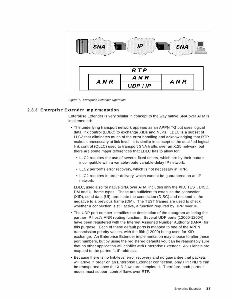
Figure 7. Enterprise Extender Operation
2.3.3 Enterprise Extender ImplementationEnterprise Extender is very similar in concept to the way native SNA over ATM isimplemented:
• The underlying transport network appears as an APPN TG but uses logicaldata link control (LDLC) to exchange XIDs and NLPs. LDLC is a subset ofLLC2 that eliminates much of the error handling and acknowledging that RTPmakes unnecessary at link level. It is similar in concept to the qualified logicallink control (QLLC) used to transport SNA traffic over an X.25 network, butthere are some major differences that LDLC has to allow for:
• LLC2 requires the use of several fixed timers, which are by their natureincompatible with a variable-route variable-delay IP network.
• LLC2 performs error recovery, which is not necessary in HPR.
• LLC2 requires in-order delivery, which cannot be guaranteed on an IPnetwork.
LDLC, used also for native SNA over ATM, includes only the XID, TEST, DISC,DM and UI frame types. These are sufficient to establish the connection(XID), send data (UI), terminate the connection (DISC) and respond in thenegative to a previous frame (DM). The TEST frames are used to checkwhether a connection is still active, a function required by HPR over IP.
• The UDP port number identifies the destination of the datagram as being thepartner IP host’s ANR routing function. Several UDP ports (12000-12004)have been registered with the Internet Assigned Number Authority (IANA) forthis purpose. Each of these default ports is mapped to one of the APPNtransmission priority values, with the fifth (12000) being used for XIDexchange. An Enterprise Extender implementation may choose to alter theseport numbers, but by using the registered defaults you can be reasonably surethat no other application will conflict with Enterprise Extender. ANR labels aremapped to the partner’s IP address.
• Because there is no link-level error recovery and no guarantee that packetswill arrive in order on an Enterprise Extender connection, only HPR NLPs canbe transported once the XID flows are completed. Therefore, both partnernodes must support control flows over RTP.
Enterprise Extender 27
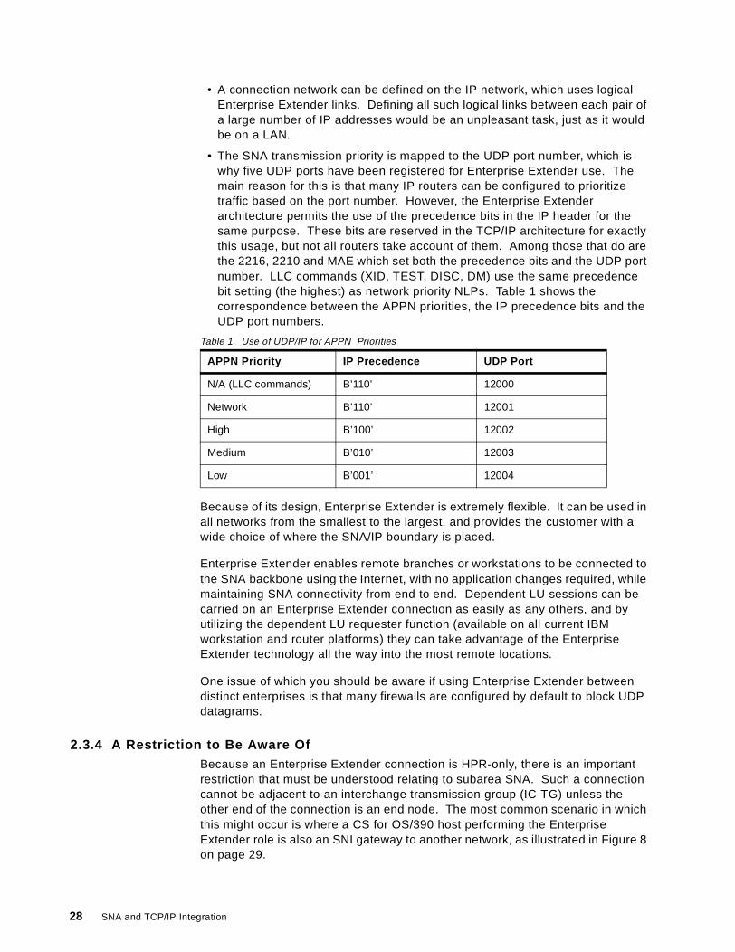
• A connection network can be defined on the IP network, which uses logicalEnterprise Extender links. Defining all such logical links between each pair ofa large number of IP addresses would be an unpleasant task, just as it wouldbe on a LAN.
• The SNA transmission priority is mapped to the UDP port number, which iswhy five UDP ports have been registered for Enterprise Extender use. Themain reason for this is that many IP routers can be configured to prioritizetraffic based on the port number. However, the Enterprise Extenderarchitecture permits the use of the precedence bits in the IP header for thesame purpose. These bits are reserved in the TCP/IP architecture for exactlythis usage, but not all routers take account of them. Among those that do arethe 2216, 2210 and MAE which set both the precedence bits and the UDP portnumber. LLC commands (XID, TEST, DISC, DM) use the same precedencebit setting (the highest) as network priority NLPs. Table 1 shows thecorrespondence between the APPN priorities, the IP precedence bits and theUDP port numbers.
Table 1. Use of UDP/IP for APPN Priorities
Because of its design, Enterprise Extender is extremely flexible. It can be used inall networks from the smallest to the largest, and provides the customer with awide choice of where the SNA/IP boundary is placed.
Enterprise Extender enables remote branches or workstations to be connected tothe SNA backbone using the Internet, with no application changes required, whilemaintaining SNA connectivity from end to end. Dependent LU sessions can becarried on an Enterprise Extender connection as easily as any others, and byutilizing the dependent LU requester function (available on all current IBMworkstation and router platforms) they can take advantage of the EnterpriseExtender technology all the way into the most remote locations.
One issue of which you should be aware if using Enterprise Extender betweendistinct enterprises is that many firewalls are configured by default to block UDPdatagrams.
2.3.4 A Restriction to Be Aware OfBecause an Enterprise Extender connection is HPR-only, there is an importantrestriction that must be understood relating to subarea SNA. Such a connectioncannot be adjacent to an interchange transmission group (IC-TG) unless theother end of the connection is an end node. The most common scenario in whichthis might occur is where a CS for OS/390 host performing the EnterpriseExtender role is also an SNI gateway to another network, as illustrated in Figure 8on page 29.
APPN Priority IP Precedence UDP Port
N/A (LLC commands) B’110’ 12000
Network B’110’ 12001
High B’100’ 12002
Medium B’010’ 12003
Low B’001’ 12004
28 SNA and TCP/IP Integration
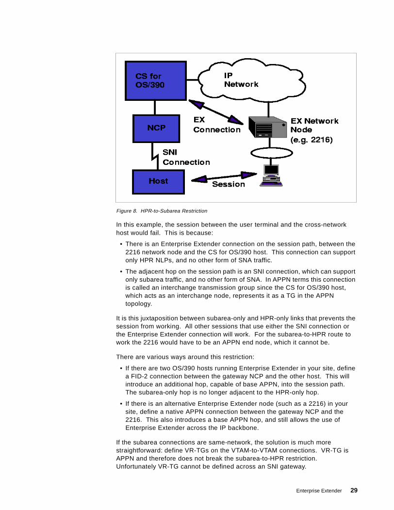
Figure 8. HPR-to-Subarea Restriction
In this example, the session between the user terminal and the cross-networkhost would fail. This is because:
• There is an Enterprise Extender connection on the session path, between the2216 network node and the CS for OS/390 host. This connection can supportonly HPR NLPs, and no other form of SNA traffic.
• The adjacent hop on the session path is an SNI connection, which can supportonly subarea traffic, and no other form of SNA. In APPN terms this connectionis called an interchange transmission group since the CS for OS/390 host,which acts as an interchange node, represents it as a TG in the APPNtopology.
It is this juxtaposition between subarea-only and HPR-only links that prevents thesession from working. All other sessions that use either the SNI connection orthe Enterprise Extender connection will work. For the subarea-to-HPR route towork the 2216 would have to be an APPN end node, which it cannot be.
There are various ways around this restriction:
• If there are two OS/390 hosts running Enterprise Extender in your site, definea FID-2 connection between the gateway NCP and the other host. This willintroduce an additional hop, capable of base APPN, into the session path.The subarea-only hop is no longer adjacent to the HPR-only hop.
• If there is an alternative Enterprise Extender node (such as a 2216) in yoursite, define a native APPN connection between the gateway NCP and the2216. This also introduces a base APPN hop, and still allows the use ofEnterprise Extender across the IP backbone.
If the subarea connections are same-network, the solution is much morestraightforward: define VR-TGs on the VTAM-to-VTAM connections. VR-TG isAPPN and therefore does not break the subarea-to-HPR restriction.Unfortunately VR-TG cannot be defined across an SNI gateway.
Enterprise Extender 29
2.3.5 Responsive Mode Adaptive Rate-Based Flow ControlThe original ARB algorithm introduced with HPR works very well with SNA trafficalone, but is less efficient in the Enterprise Extender environment when SNA andIP traffic must coexist. Upon detection of a lost packet (a common occurrence inIP networks), ARB would immediately reduce its sending rate by a significantamount, thus impacting performance.
An enhanced algorithm known as Responsive Mode ARB, or ARB-2, wasintroduced with Enterprise Extender, and is now an option for RTP nodes whetheror not their HPR connection includes an Enterprise Extender link. Nodes thatsupport Responsive Mode ARB can negotiate their level of ARB support duringroute setup exchange, and fall back to the original ARB if their partner does notsupport Responsive Mode. Thus each individual RTP connection can choosewhich option to use. Responsive Mode ARB provides the following features:
• It competes fairly with TCP congestion control. Therefore, reservation ofbandwidth for SNA traffic is no longer necessary (as it often is with DLSw).
• It can be tuned to tolerate a certain level of lost data.
• It gives priority to short transmissions.
• It allocates a fair bandwidth to sustained transmissions, independent ofpropagation delays.
• It can ramp up its transmission rate faster at startup.
2.4 Enterprise Extender Implementation
At the time this redbook is being written, there are eight products whichimplement, or plan to implement, Enterprise Extender:
• The 221X router family, which comprises the 2216, 2212, 2210, Network Utilityand 3746 Multiaccess Enclosure. The minimum software level required isVersion 2, Release 2 of Multiprotocol Access Services or its equivalent on theappropriate platform.
• SecureWay Communications Server for OS/390, Release 6 (with APAROW36113) or later.
• Communications Server for Windows NT, Version 6 or later.
• Communications Server for OS/2, the version planned for availability in Spring1999.
2.4.1 SecureWay Communications Server for OS/390Enterprise Extender on the OS/390 platform requires CS for OS/390 Release 6 orabove. The function was not present in the initial shipment of Release 6, but wasenabled by a subsequent PTF for APAR OW36113. It requires no additionalnetworking hardware or software beyond this release of OS/390.
CS for OS/390 allows multiple TCP/IP stacks to run concurrently with a singleVTAM, but the Enterprise Extender function can utilize only one of these at atime. VTAM can change its allegiance from one TCP/IP stack to another, but onlywhen all Enterprise Extender connections have been terminated. A VTAM startoption, TCPNAME, allows you to specify which of several stacks VTAM is to use.
30 SNA and TCP/IP Integration
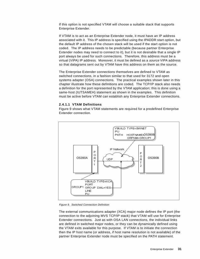
If this option is not specified VTAM will choose a suitable stack that supportsEnterprise Extender.
If VTAM is to act as an Enterprise Extender node, it must have an IP addressassociated with it. This IP address is specified using the IPADDR start option, butthe default IP address of the chosen stack will be used if the start option is notcoded. The IP address needs to be predictable (because partner EnterpriseExtender nodes may need to connect to it), but it is not desirable that a single IPport always be used for such connections. Therefore, this address must be avirtual (VIPA) IP address. Moreover, it must be defined as a source VIPA addressso that datagrams sent out by VTAM have this address on them as the source.
The Enterprise Extender connections themselves are defined to VTAM asswitched connections, in a fashion similar to that used for 3172 and opensystems adapter (OSA) connections. The practical examples shown later in thischapter illustrate how these definitions are coded. The TCP/IP stack also needsa definition for the port represented by the VTAM application; this is done using asame-host (IUTSAMEH) statement as shown in the examples. This definitionmust be active before VTAM can establish any Enterprise Extender connections.
2.4.1.1 VTAM DefinitionsFigure 9 shows what VTAM statements are required for a predefined EnterpriseExtender connection.
Figure 9. Switched Connection Definition
The external communications adapter (XCA) major node defines the IP port (theconnection to the adjoining MVS TCP/IP stack) that VTAM will use for EnterpriseExtender connections. Just as with OSA LAN connections, the individual linksare defined in switched major nodes, or they can be dynamically defined usingthe VTAM exits available for this purpose. If VTAM is to initiate the connectionthen the IP host name (or address, if host name resolution is not available) of thepartner Enterprise Extender node must be specified on the PATH statement.
OS390BOS390A
OS390B
Enterprise Extender 31
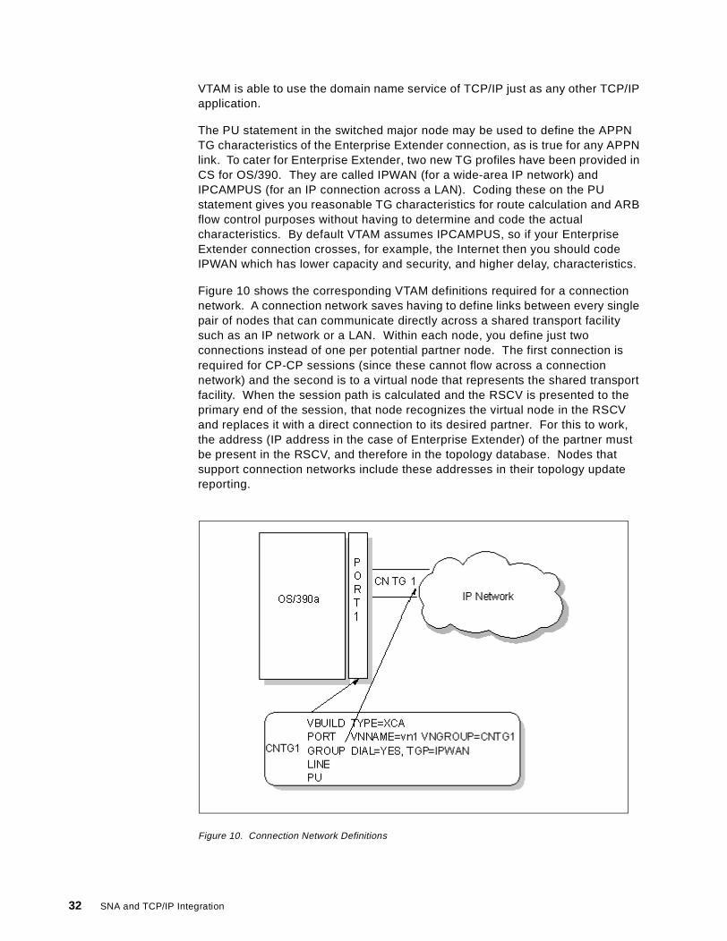
VTAM is able to use the domain name service of TCP/IP just as any other TCP/IPapplication.
The PU statement in the switched major node may be used to define the APPNTG characteristics of the Enterprise Extender connection, as is true for any APPNlink. To cater for Enterprise Extender, two new TG profiles have been provided inCS for OS/390. They are called IPWAN (for a wide-area IP network) andIPCAMPUS (for an IP connection across a LAN). Coding these on the PUstatement gives you reasonable TG characteristics for route calculation and ARBflow control purposes without having to determine and code the actualcharacteristics. By default VTAM assumes IPCAMPUS, so if your EnterpriseExtender connection crosses, for example, the Internet then you should codeIPWAN which has lower capacity and security, and higher delay, characteristics.
Figure 10 shows the corresponding VTAM definitions required for a connectionnetwork. A connection network saves having to define links between every singlepair of nodes that can communicate directly across a shared transport facilitysuch as an IP network or a LAN. Within each node, you define just twoconnections instead of one per potential partner node. The first connection isrequired for CP-CP sessions (since these cannot flow across a connectionnetwork) and the second is to a virtual node that represents the shared transportfacility. When the session path is calculated and the RSCV is presented to theprimary end of the session, that node recognizes the virtual node in the RSCVand replaces it with a direct connection to its desired partner. For this to work,the address (IP address in the case of Enterprise Extender) of the partner mustbe present in the RSCV, and therefore in the topology database. Nodes thatsupport connection networks include these addresses in their topology updatereporting.
Figure 10. Connection Network Definitions
32 SNA and TCP/IP Integration
Again, the familiar XCA major node is used. This time the VNNAME keywordspecifies the name of the virtual node representing the connection network, andVNGROUP points to the group of switched line definitions that will be used for thedynamically defined connections (PUs).
2.4.2 Communications Server for Windows NTEnterprise Extender was implemented in Version 6 of Communications Server forWindows NT. There is only one TCP/IP stack in Windows NT, and only oneEnterprise Extender port can be defined to CS/NT, so the process of defining anEnterprise Extender connection is somewhat simpler than that used in CS for OS/390.
The process consists essentially of defining an SNA connection on a new devicetype of IBM-EEDLC. This creates the link between CS/NT and the TCP/IP stack.After that you can create a link station for each predefined connection to a remotedevice, supplying the IP address of the remote partner where a LAN connectionwould require a MAC address. As with a LAN port, you can allow incoming callsto create link stations dynamically.
CS/NT does not support a connection network over IP in this release. This isplanned for late 1999.
2.4.3 The 221X Router FamilyEnterprise Extender has been implemented in the following releases of the 221Xrouter family products:
• 3746 Multiaccess Enclosure Extended Functions Part 2, feature code 5805• 2216 Multiprotocol Access Services, Version 2 Release 2 and above• 2210 Multiprotocol Routing Services, Version 2 Release 2 and above• 2212 Access Integration Services• Network Utility, models TN1 and TX1
In each of these products, Enterprise Extender capability is defined by means ofa new APPN port type, IP. Only one such port (logical interface) can be defined,and all Enterprise Extender connections are associated with this “virtual” port. Aswith all shareable APPN ports, link stations can be defined dynamically forincoming calls, or explicitly for all calls. For explicit definitions the configurationprocess asks for the remote IP address. The assignment of UDP port numberscan be changed from the default, and the 221X family allows you to specifywhether the IP precedence bits will be used for APPN priority in addition to theUDP port numbers.
2.5 Enterprise Extender between CS for OS/390 and CS/NT via 3172
Figure 11 on page 35 shows the network configuration that we used in our firsttesting scenario. We established an Enterprise Extender connection between anOS/390 host and a PC running Communications Server for Windows NT. Wethen used dependent LU requester to establish sessions between our terminalemulator (PComm/NT) and TSO on the host.
The essential features of the configuration are:
Enterprise Extender 33
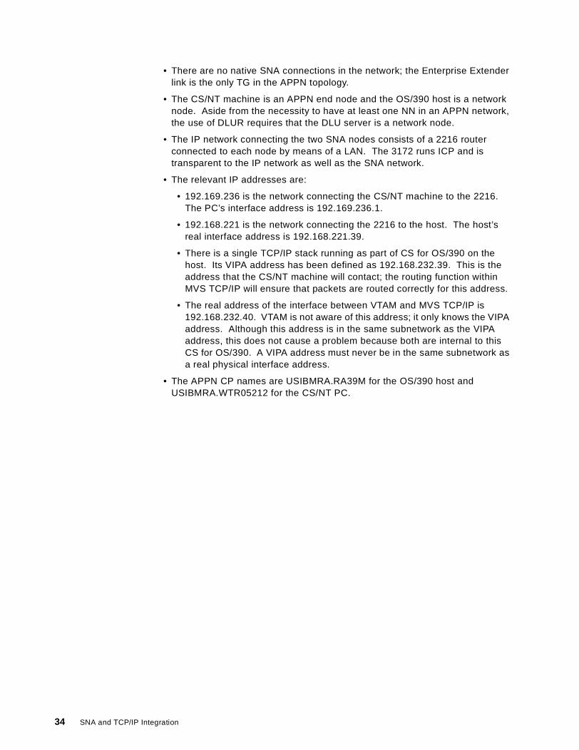
• There are no native SNA connections in the network; the Enterprise Extenderlink is the only TG in the APPN topology.
• The CS/NT machine is an APPN end node and the OS/390 host is a networknode. Aside from the necessity to have at least one NN in an APPN network,the use of DLUR requires that the DLU server is a network node.
• The IP network connecting the two SNA nodes consists of a 2216 routerconnected to each node by means of a LAN. The 3172 runs ICP and istransparent to the IP network as well as the SNA network.
• The relevant IP addresses are:
• 192.169.236 is the network connecting the CS/NT machine to the 2216.The PC’s interface address is 192.169.236.1.
• 192.168.221 is the network connecting the 2216 to the host. The host’sreal interface address is 192.168.221.39.
• There is a single TCP/IP stack running as part of CS for OS/390 on thehost. Its VIPA address has been defined as 192.168.232.39. This is theaddress that the CS/NT machine will contact; the routing function withinMVS TCP/IP will ensure that packets are routed correctly for this address.
• The real address of the interface between VTAM and MVS TCP/IP is192.168.232.40. VTAM is not aware of this address; it only knows the VIPAaddress. Although this address is in the same subnetwork as the VIPAaddress, this does not cause a problem because both are internal to thisCS for OS/390. A VIPA address must never be in the same subnetwork asa real physical interface address.
• The APPN CP names are USIBMRA.RA39M for the OS/390 host andUSIBMRA.WTR05212 for the CS/NT PC.
34 SNA and TCP/IP Integration
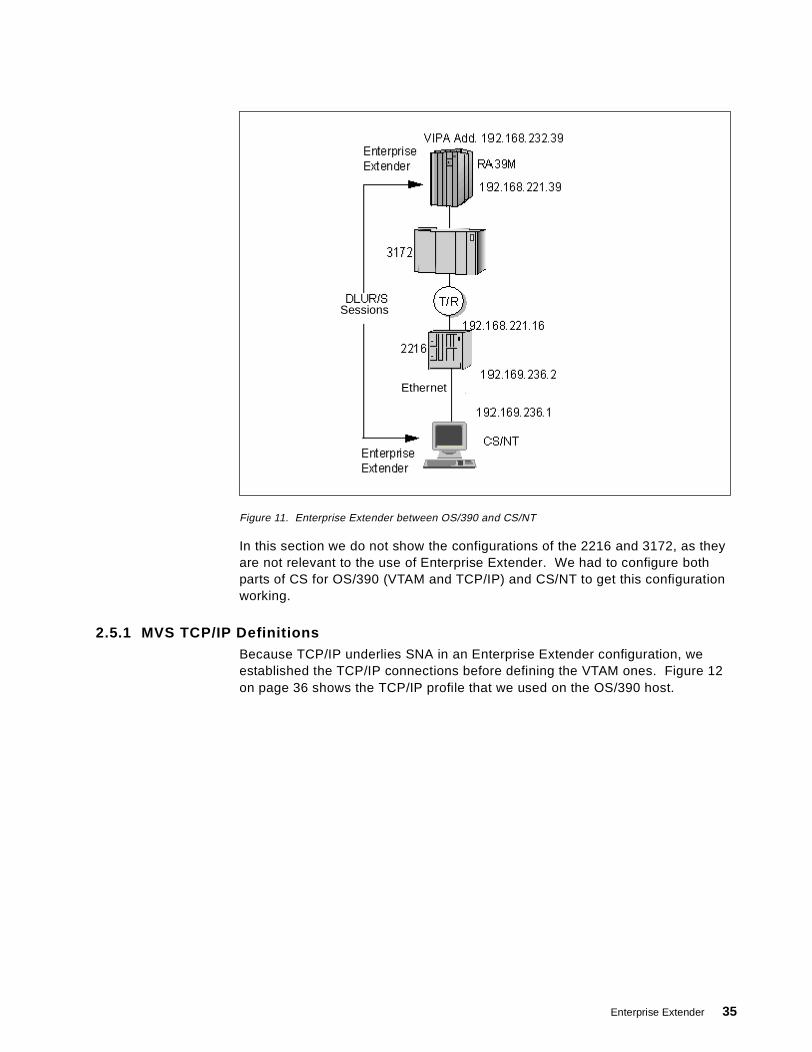
Figure 11. Enterprise Extender between OS/390 and CS/NT
In this section we do not show the configurations of the 2216 and 3172, as theyare not relevant to the use of Enterprise Extender. We had to configure bothparts of CS for OS/390 (VTAM and TCP/IP) and CS/NT to get this configurationworking.
2.5.1 MVS TCP/IP DefinitionsBecause TCP/IP underlies SNA in an Enterprise Extender configuration, weestablished the TCP/IP connections before defining the VTAM ones. Figure 12on page 36 shows the TCP/IP profile that we used on the OS/390 host.
Sessions
Ethernet
Enterprise Extender 35

Figure 12. MVS TCP/IP Definitions
In the TCP/IP profile we coded the following parameters:
1. SOURCEVIPA tells TCP/IP to return the VIPA address as the source addresson all outbound datagrams. It also means that a client program on this MVSimage (in our case, VTAM is that client) will use the VIPA address as its localaddress. This provides for maximum resilience against the failure of any onephysical interface. SOURCEVIPA is mandatory for Enterprise Extenderconnections.
;**********************************SOURCEVIPA
;**********************************;VIPA Definition (For V2R5);*********************************
DEVICE VIPA39A VIRTUAL 0LINK VIPA39A VIRTUAL 0
;*********************************;LCS Definition;*********************************DEVICE ICP1 LCS 342 AUTORESTARTLINK ICP1 IBMTR 0 ICP1
;*********************************;Enterprise extender definition;*********************************DEVICE IUTSAMEH MPCPTPLINK IUTSAMEH MPCPTP IUTSAMEH
; HOME Internet (IP) addresses of each link in the host.HOME
192.168.232.39 VIPA39A ; VIPA192.168.221.39 ICP1 ; 3172192.168.232.40 IUTSAMEH ; EE
;**************************************************************; Orouted Routing Information;**************************************************************; Link Maxmtu Metric Subnet Mask Dest Addr
BSDROUTINGPARMS falseVIPA39A DEFAULTSIZE 0 255.255.255.0 0IUTSAMEH DEFAULTSIZE 0 255.255.255.0 0ICP1 4000 0 255.255.255.0 0
ENDBSDROUTINGPARMS;********************************; Start all the defined devices;********************************
START ICP1 ; 3172START IUTSAMEH ; EExtender
1
2
3
4
5
36 SNA and TCP/IP Integration
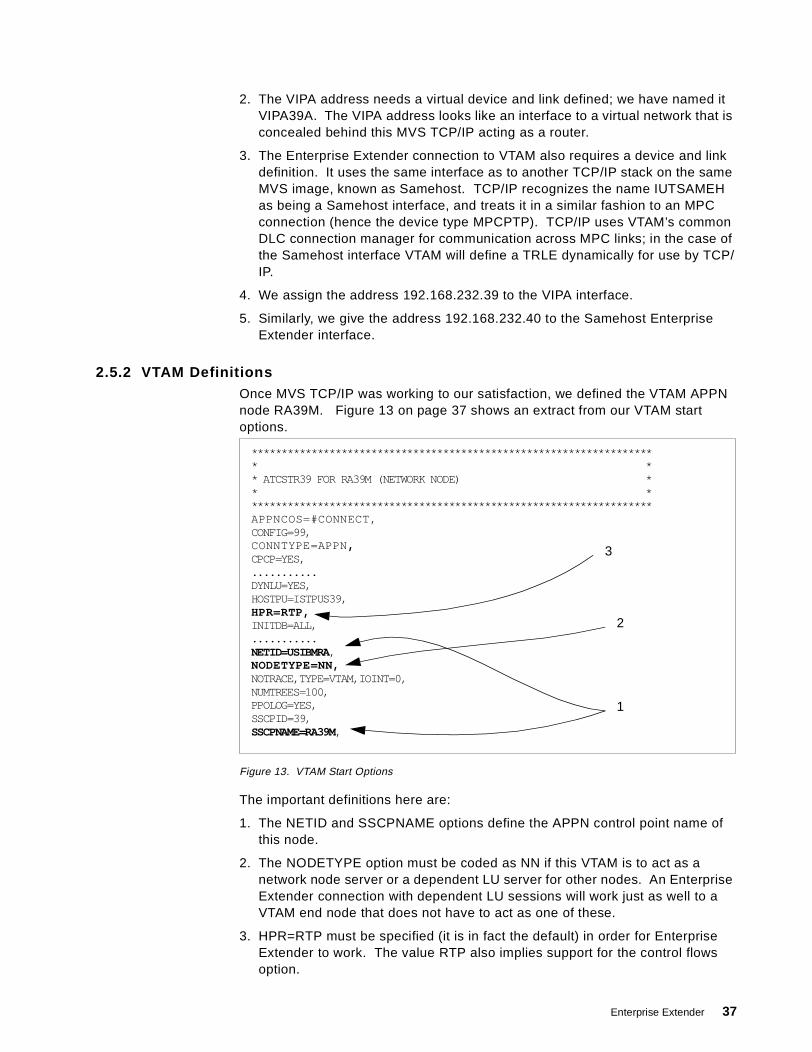
2. The VIPA address needs a virtual device and link defined; we have named itVIPA39A. The VIPA address looks like an interface to a virtual network that isconcealed behind this MVS TCP/IP acting as a router.
3. The Enterprise Extender connection to VTAM also requires a device and linkdefinition. It uses the same interface as to another TCP/IP stack on the sameMVS image, known as Samehost. TCP/IP recognizes the name IUTSAMEHas being a Samehost interface, and treats it in a similar fashion to an MPCconnection (hence the device type MPCPTP). TCP/IP uses VTAM’s commonDLC connection manager for communication across MPC links; in the case ofthe Samehost interface VTAM will define a TRLE dynamically for use by TCP/IP.
4. We assign the address 192.168.232.39 to the VIPA interface.
5. Similarly, we give the address 192.168.232.40 to the Samehost EnterpriseExtender interface.
2.5.2 VTAM DefinitionsOnce MVS TCP/IP was working to our satisfaction, we defined the VTAM APPNnode RA39M. Figure 13 on page 37 shows an extract from our VTAM startoptions.
Figure 13. VTAM Start Options
The important definitions here are:
1. The NETID and SSCPNAME options define the APPN control point name ofthis node.
2. The NODETYPE option must be coded as NN if this VTAM is to act as anetwork node server or a dependent LU server for other nodes. An EnterpriseExtender connection with dependent LU sessions will work just as well to aVTAM end node that does not have to act as one of these.
3. HPR=RTP must be specified (it is in fact the default) in order for EnterpriseExtender to work. The value RTP also implies support for the control flowsoption.
******************************************************************** ** ATCSTR39 FOR RA39M (NETWORK NODE) ** ********************************************************************APPNCOS=#CONNECT,CONFIG=99,CONNTYPE=APPN,CPCP=YES,...........DYNLU=YES,HOSTPU=ISTPUS39,HPR=RTP,INITDB=ALL,...........NETID=USIBMRA,NODETYPE=NN,NOTRACE,TYPE=VTAM,IOINT=0,NUMTREES=100,PPOLOG=YES,SSCPID=39,SSCPNAME=RA39M,
2
1
3
Enterprise Extender 37
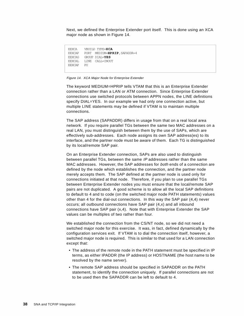
Next, we defined the Enterprise Extender port itself. This is done using an XCAmajor node as shown in Figure 14.
Figure 14. XCA Major Node for Enterprise Extender
The keyword MEDIUM=HPRIP tells VTAM that this is an Enterprise Extenderconnection rather than a LAN or ATM connection. Since Enterprise Extenderconnections use switched protocols between APPN nodes, the LINE definitionsspecify DIAL=YES. In our example we had only one connection active, butmultiple LINE statements may be defined if VTAM is to maintain multipleconnections.
The SAP address (SAPADDR) differs in usage from that on a real local areanetwork. If you require parallel TGs between the same two MAC addresses on areal LAN, you must distinguish between them by the use of SAPs, which areeffectively sub-addresses. Each node assigns its own SAP address(es) to itsinterface, and the partner node must be aware of them. Each TG is distinguishedby its local/remote SAP pair.
On an Enterprise Extender connection, SAPs are also used to distinguishbetween parallel TGs, between the same IP addresses rather than the sameMAC addresses. However, the SAP addresses for both ends of a connection aredefined by the node which establishes the connection, and the partner nodemerely accepts them. The SAP defined at the partner node is used only forconnections initiated at that node. Therefore, if you plan to use parallel TGsbetween Enterprise Extender nodes you must ensure that the local/remote SAPpairs are not duplicated. A good scheme is to allow all the local SAP definitionsto default to 4 and to code (on the switched major node PATH statements) valuesother than 4 for the dial-out connections. In this way the SAP pair (4,4) neveroccurs; all outbound connections have SAP pair (4,x) and all inboundconnections have SAP pair (x,4). Note that with Enterprise Extender the SAPvalues can be multiples of two rather than four.
We established the connection from the CS/NT node, so we did not need aswitched major node for this exercise. It was, in fact, defined dynamically by theconfiguration services exit. If VTAM is to dial the connection itself, however, aswitched major node is required. This is similar to that used for a LAN connectionexcept that:
• The address of the remote node in the PATH statement must be specified in IPterms, as either IPADDR (the IP address) or HOSTNAME (the host name to beresolved by the name server).
• The remote SAP address should be specified in SAPADDR on the PATHstatement, to identify the connection uniquely. If parallel connections are notto be used then the SAPADDR can be left to default to 4.
EEXCA VBUILD TYPE=XCAEEXCAP PORT MEDIUM=HPRIP,SAPADDR=4EEXCAG GROUP DIAL=YESEEXCAL LINE CALL=INOUTEEXCAP PU
38 SNA and TCP/IP Integration
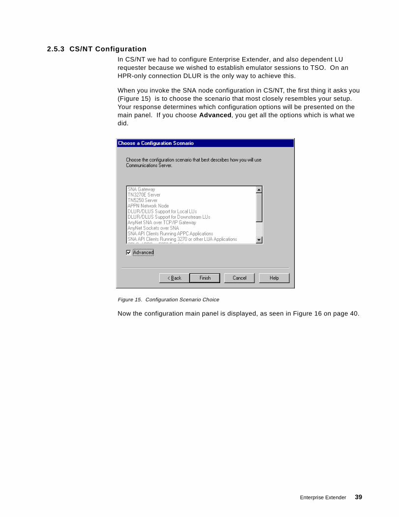
2.5.3 CS/NT ConfigurationIn CS/NT we had to configure Enterprise Extender, and also dependent LUrequester because we wished to establish emulator sessions to TSO. On anHPR-only connection DLUR is the only way to achieve this.
When you invoke the SNA node configuration in CS/NT, the first thing it asks you(Figure 15) is to choose the scenario that most closely resembles your setup.Your response determines which configuration options will be presented on themain panel. If you choose Advanced , you get all the options which is what wedid.
Figure 15. Configuration Scenario Choice
Now the configuration main panel is displayed, as seen in Figure 16 on page 40.
Enterprise Extender 39
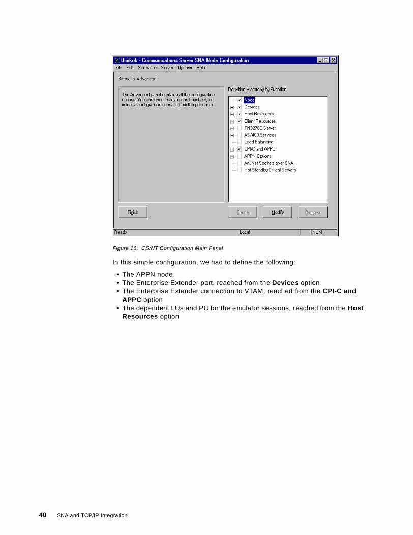
Figure 16. CS/NT Configuration Main Panel
In this simple configuration, we had to define the following:
• The APPN node• The Enterprise Extender port, reached from the Devices option• The Enterprise Extender connection to VTAM, reached from the CPI-C and
APPC option• The dependent LUs and PU for the emulator sessions, reached from the Host
Resources option
40 SNA and TCP/IP Integration
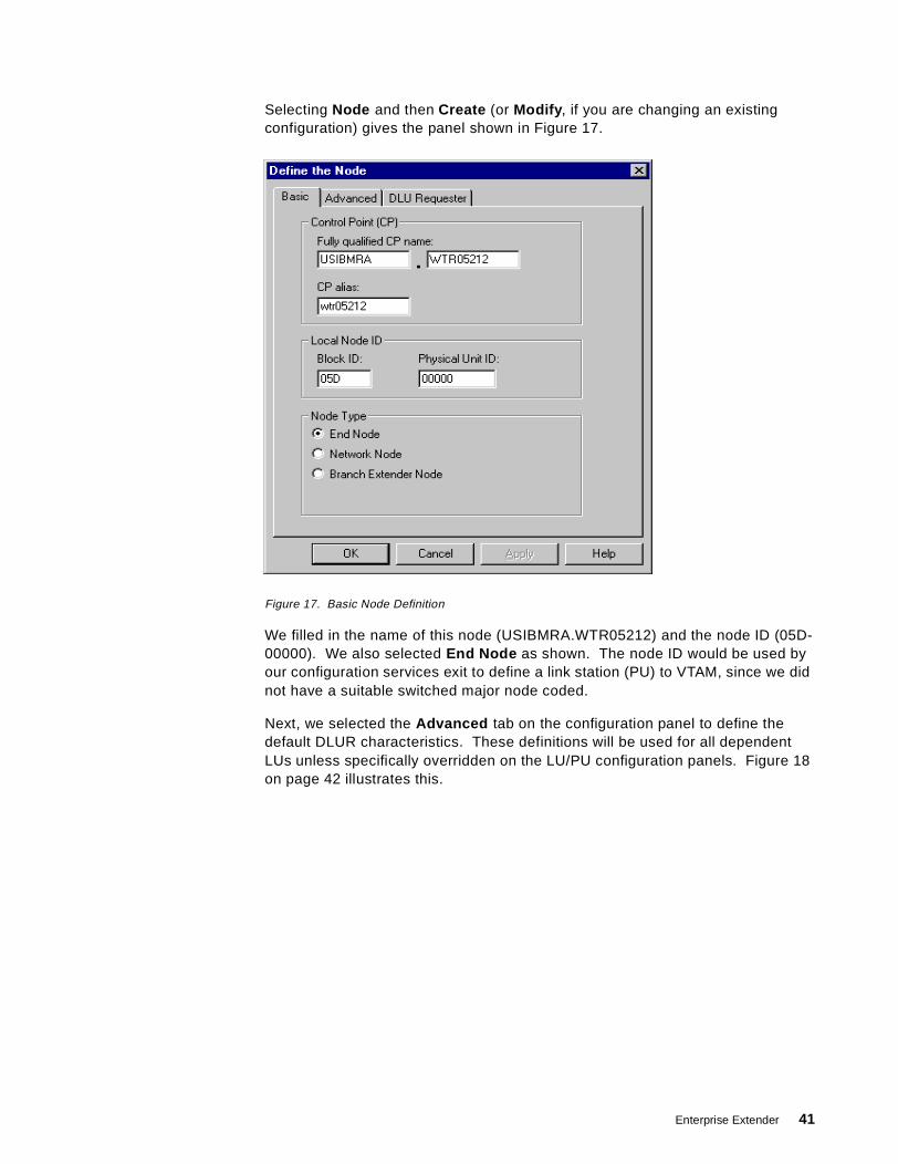
Selecting Node and then Create (or Modify , if you are changing an existingconfiguration) gives the panel shown in Figure 17.
Figure 17. Basic Node Definition
We filled in the name of this node (USIBMRA.WTR05212) and the node ID (05D-00000). We also selected End Node as shown. The node ID would be used byour configuration services exit to define a link station (PU) to VTAM, since we didnot have a suitable switched major node coded.
Next, we selected the Advanced tab on the configuration panel to define thedefault DLUR characteristics. These definitions will be used for all dependentLUs unless specifically overridden on the LU/PU configuration panels. Figure 18on page 42 illustrates this.
Enterprise Extender 41
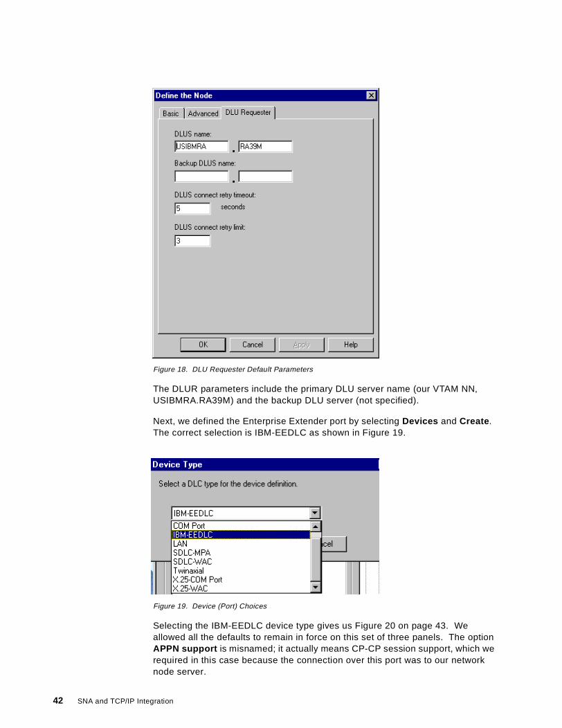
Figure 18. DLU Requester Default Parameters
The DLUR parameters include the primary DLU server name (our VTAM NN,USIBMRA.RA39M) and the backup DLU server (not specified).
Next, we defined the Enterprise Extender port by selecting Devices and Create .The correct selection is IBM-EEDLC as shown in Figure 19.
Figure 19. Device (Port) Choices
Selecting the IBM-EEDLC device type gives us Figure 20 on page 43. Weallowed all the defaults to remain in force on this set of three panels. The optionAPPN support is misnamed; it actually means CP-CP session support, which werequired in this case because the connection over this port was to our networknode server.
42 SNA and TCP/IP Integration
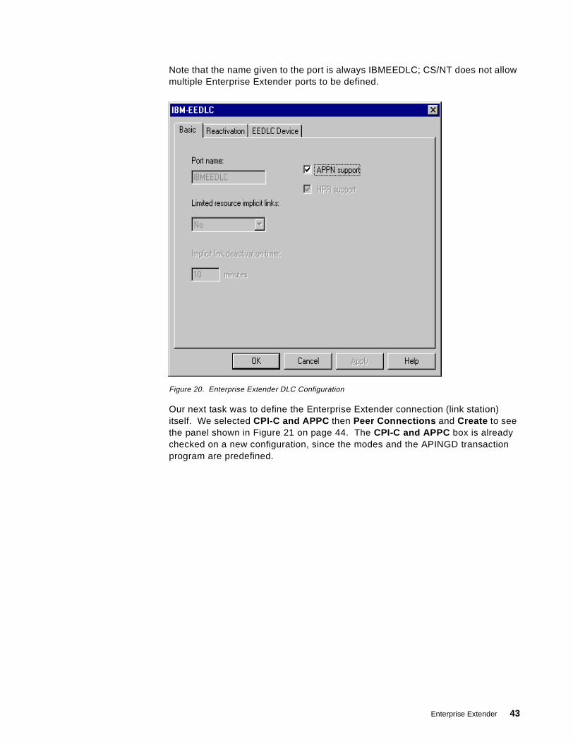
Note that the name given to the port is always IBMEEDLC; CS/NT does not allowmultiple Enterprise Extender ports to be defined.
Figure 20. Enterprise Extender DLC Configuration
Our next task was to define the Enterprise Extender connection (link station)itself. We selected CPI-C and APPC then Peer Connections and Create to seethe panel shown in Figure 21 on page 44. The CPI-C and APPC box is alreadychecked on a new configuration, since the modes and the APINGD transactionprogram are predefined.
Enterprise Extender 43
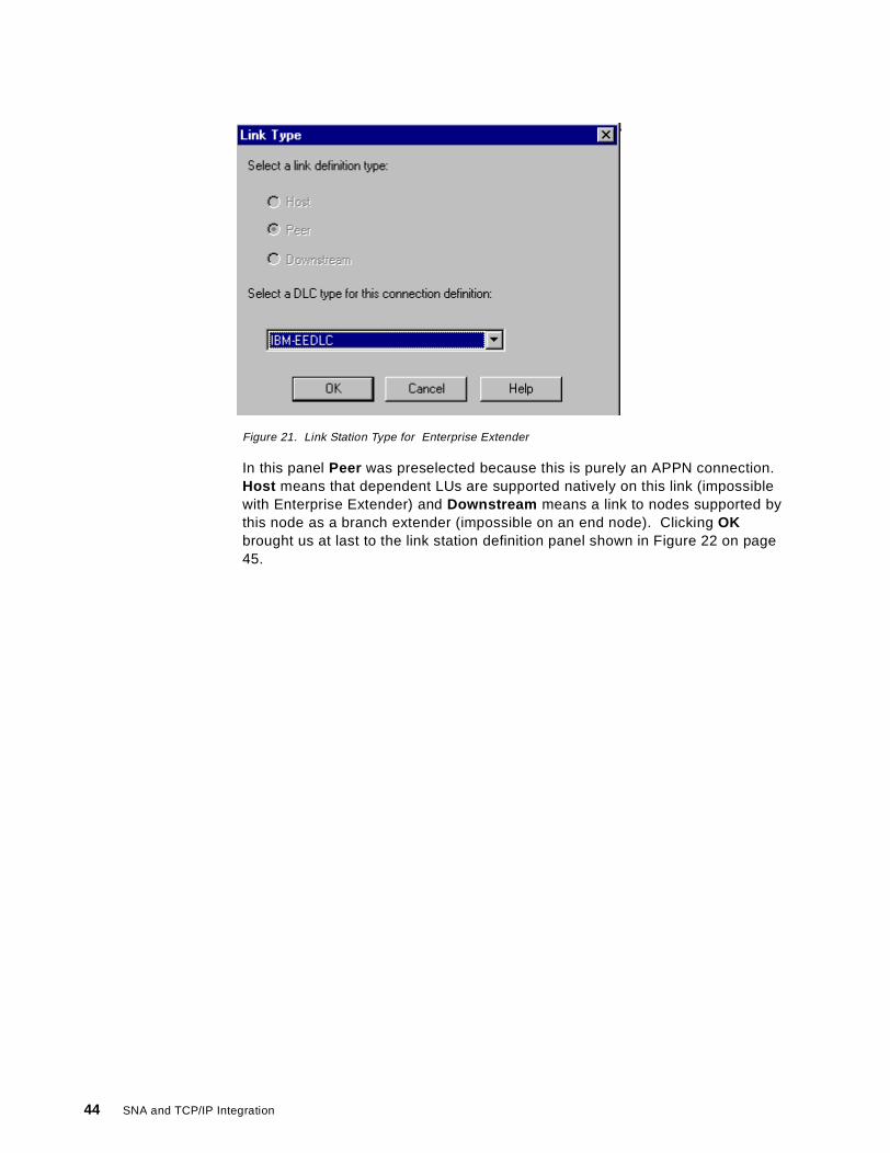
Figure 21. Link Station Type for Enterprise Extender
In this panel Peer was preselected because this is purely an APPN connection.Host means that dependent LUs are supported natively on this link (impossiblewith Enterprise Extender) and Downstream means a link to nodes supported bythis node as a branch extender (impossible on an end node). Clicking OKbrought us at last to the link station definition panel shown in Figure 22 on page45.
44 SNA and TCP/IP Integration

Figure 22. Link Station Definition (Basic Tab)
The Basic , Advanced (Figure 23 on page 46) and Reactivation tabs were leftalone to default. The Local Node ID on the Basic tab is used by VTAM to identifythe link station; in this case the configuration services exit would dynamicallydefine a PU name of W00000 from this information. The Advanced tab can beused to override some of the port definitions (such as CP-CP session support) aswell as to control what kind of partner node you will allow on this connection. Wewere happy for CS/NT to learn about its partner dynamically.
Enterprise Extender 45
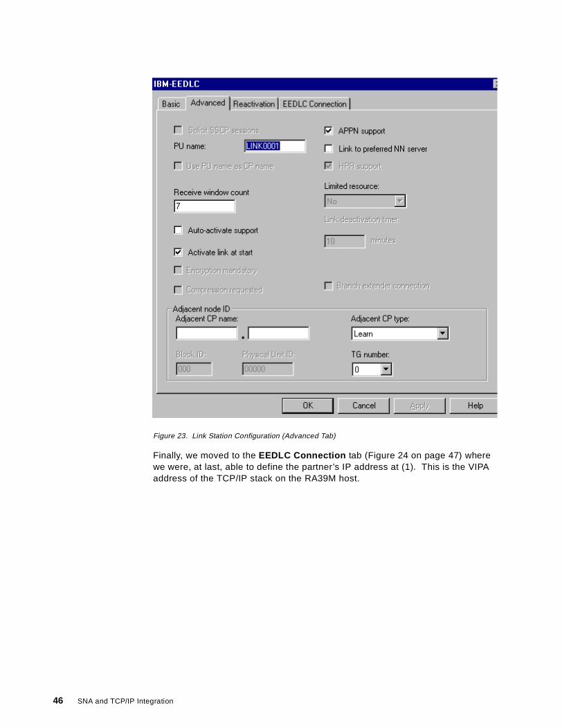
Figure 23. Link Station Configuration (Advanced Tab)
Finally, we moved to the EEDLC Connection tab (Figure 24 on page 47) wherewe were, at last, able to define the partner’s IP address at (1). This is the VIPAaddress of the TCP/IP stack on the RA39M host.
46 SNA and TCP/IP Integration
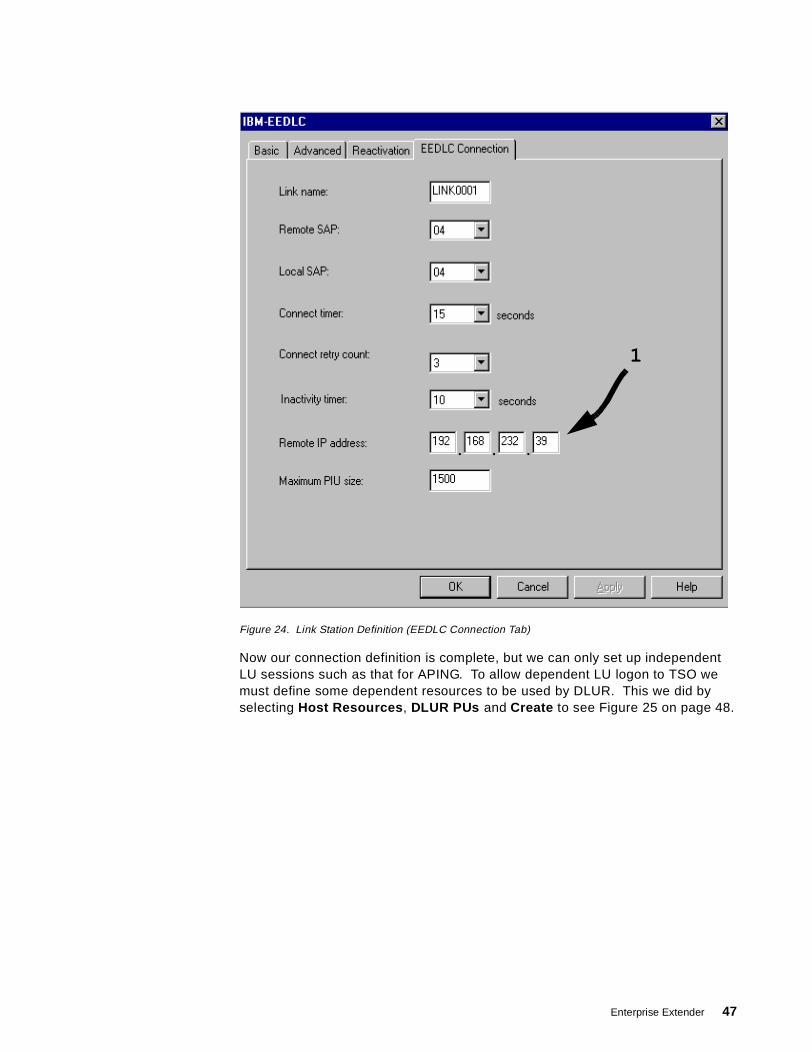
Figure 24. Link Station Definition (EEDLC Connection Tab)
Now our connection definition is complete, but we can only set up independentLU sessions such as that for APING. To allow dependent LU logon to TSO wemust define some dependent resources to be used by DLUR. This we did byselecting Host Resources , DLUR PUs and Create to see Figure 25 on page 48.
1
Enterprise Extender 47
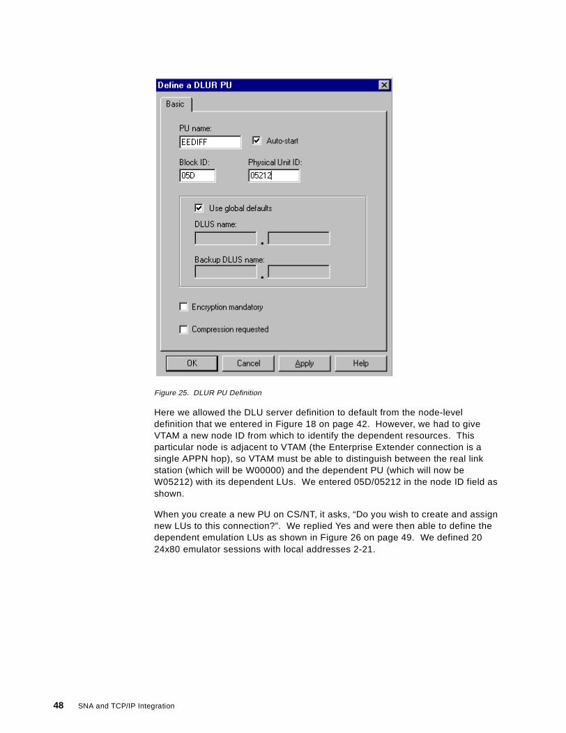
Figure 25. DLUR PU Definition
Here we allowed the DLU server definition to default from the node-leveldefinition that we entered in Figure 18 on page 42. However, we had to giveVTAM a new node ID from which to identify the dependent resources. Thisparticular node is adjacent to VTAM (the Enterprise Extender connection is asingle APPN hop), so VTAM must be able to distinguish between the real linkstation (which will be W00000) and the dependent PU (which will now beW05212) with its dependent LUs. We entered 05D/05212 in the node ID field asshown.
When you create a new PU on CS/NT, it asks, “Do you wish to create and assignnew LUs to this connection?”. We replied Yes and were then able to define thedependent emulation LUs as shown in Figure 26 on page 49. We defined 2024x80 emulator sessions with local addresses 2-21.
48 SNA and TCP/IP Integration
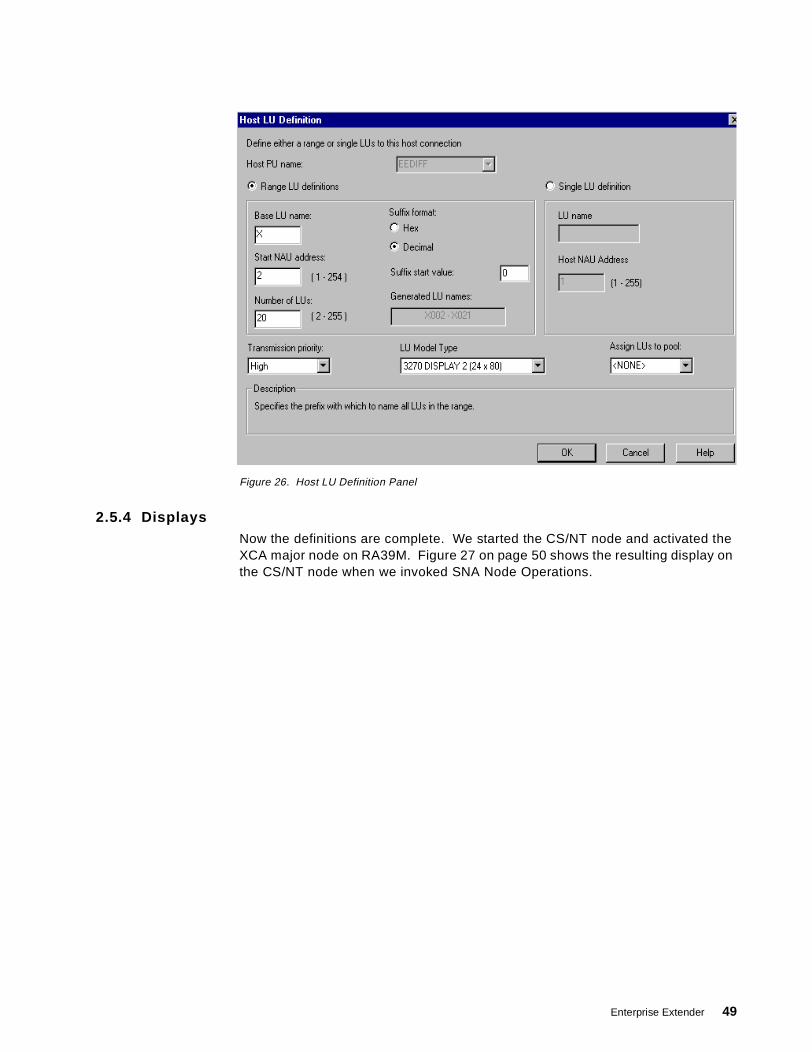
Figure 26. Host LU Definition Panel
2.5.4 DisplaysNow the definitions are complete. We started the CS/NT node and activated theXCA major node on RA39M. Figure 27 on page 50 shows the resulting display onthe CS/NT node when we invoked SNA Node Operations.
Enterprise Extender 49

Figure 27. Node Display on CS/NT
Note that:
1. There are 20 dependent LUs with SSCP-LU sessions, in other words theyhave been activated by VTAM.
2. The single independent LU is the control point USIBMRA.WTR05212.
3. The four LU 6.2 sessions are the two CP-CP sessions and the two DLUR/Ssessions, all between WTR05212 and RA39M.
Now we were able to log on to TSO (or, indeed, any application in the SNAnetwork) and do some useful work.
We displayed some of the new Enterprise Extender-related resources from VTAMRA39M. Figure 28 shows VTAM’s view of the XCA major node.
Figure 28. XCA Major Node Display
Information unique to Enterprise Extender here comprises:
1
3
2
D NET,E,ID=RA39AXCAIST097I DISPLAY ACCEPTEDIST075I NAME = RA39AXCA, TYPE = XCA MAJOR NODE 024IST486I STATUS= ACTIV, DESIRED STATE= ACTIVIST1679I MEDIUM = HPRIPIST1685I TCP/IP JOB NAME = T39ATCPIST1680I LOCAL IP ADDRESS 192.168.232.39IST654I I/O TRACE = OFF, BUFFER TRACE = OFFIST1656I VTAMTOPO = REPORT, NODE REPORTED - YESIST170I LINES:IST232I EEXCAL ACTIVIST314I END
1
2
3
50 SNA and TCP/IP Integration
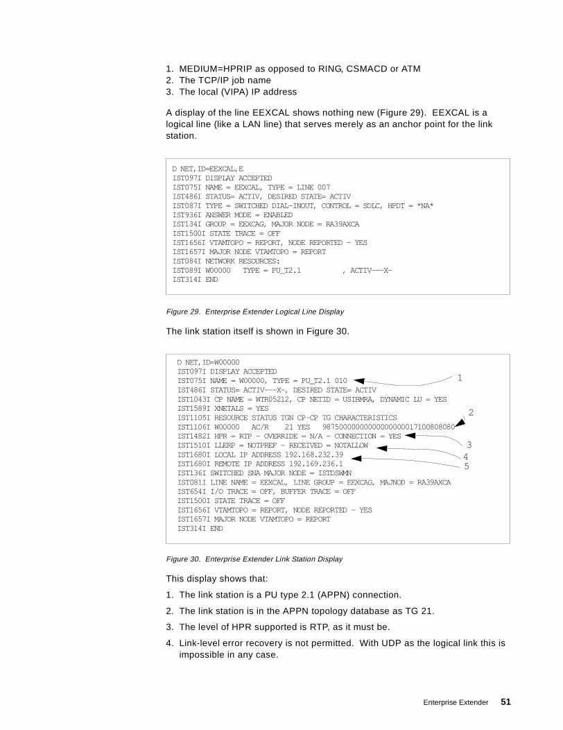
1. MEDIUM=HPRIP as opposed to RING, CSMACD or ATM2. The TCP/IP job name3. The local (VIPA) IP address
A display of the line EEXCAL shows nothing new (Figure 29). EEXCAL is alogical line (like a LAN line) that serves merely as an anchor point for the linkstation.
Figure 29. Enterprise Extender Logical Line Display
The link station itself is shown in Figure 30.
Figure 30. Enterprise Extender Link Station Display
This display shows that:
1. The link station is a PU type 2.1 (APPN) connection.
2. The link station is in the APPN topology database as TG 21.
3. The level of HPR supported is RTP, as it must be.
4. Link-level error recovery is not permitted. With UDP as the logical link this isimpossible in any case.
D NET,ID=EEXCAL,EIST097I DISPLAY ACCEPTEDIST075I NAME = EEXCAL, TYPE = LINE 007IST486I STATUS= ACTIV, DESIRED STATE= ACTIVIST087I TYPE = SWITCHED DIAL-INOUT, CONTROL = SDLC, HPDT = *NA*IST936I ANSWER MODE = ENABLEDIST134I GROUP = EEXCAG, MAJOR NODE = RA39AXCAIST1500I STATE TRACE = OFFIST1656I VTAMTOPO = REPORT, NODE REPORTED - YESIST1657I MAJOR NODE VTAMTOPO = REPORTIST084I NETWORK RESOURCES:IST089I W00000 TYPE = PU_T2.1 , ACTIV---X-IST314I END
D NET,ID=W00000IST097I DISPLAY ACCEPTEDIST075I NAME = W00000, TYPE = PU_T2.1 010IST486I STATUS= ACTIV---X-, DESIRED STATE= ACTIVIST1043I CP NAME = WTR05212, CP NETID = USIBMRA, DYNAMIC LU = YESIST1589I XNETALS = YESIST1105I RESOURCE STATUS TGN CP-CP TG CHARACTERISTICSIST1106I W00000 AC/R 21 YES 98750000000000000000017100808080IST1482I HPR = RTP - OVERRIDE = N/A - CONNECTION = YESIST1510I LLERP = NOTPREF - RECEIVED = NOTALLOWIST1680I LOCAL IP ADDRESS 192.168.232.39IST1680I REMOTE IP ADDRESS 192.169.236.1IST136I SWITCHED SNA MAJOR NODE = ISTDSWMNIST081I LINE NAME = EEXCAL, LINE GROUP = EEXCAG, MAJNOD = RA39AXCAIST654I I/O TRACE = OFF, BUFFER TRACE = OFFIST1500I STATE TRACE = OFFIST1656I VTAMTOPO = REPORT, NODE REPORTED - YESIST1657I MAJOR NODE VTAMTOPO = REPORTIST314I END
1
2
345
Enterprise Extender 51
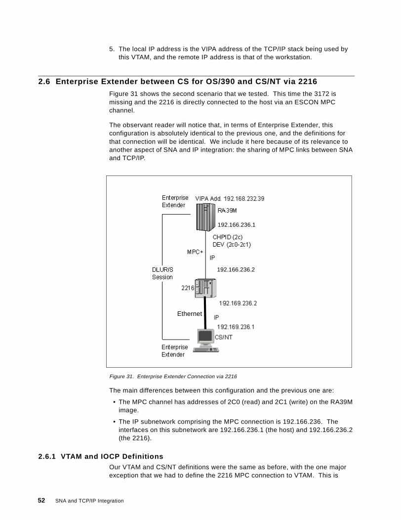
5. The local IP address is the VIPA address of the TCP/IP stack being used bythis VTAM, and the remote IP address is that of the workstation.
2.6 Enterprise Extender between CS for OS/390 and CS/NT via 2216
Figure 31 shows the second scenario that we tested. This time the 3172 ismissing and the 2216 is directly connected to the host via an ESCON MPCchannel.
The observant reader will notice that, in terms of Enterprise Extender, thisconfiguration is absolutely identical to the previous one, and the definitions forthat connection will be identical. We include it here because of its relevance toanother aspect of SNA and IP integration: the sharing of MPC links between SNAand TCP/IP.
Figure 31. Enterprise Extender Connection via 2216
The main differences between this configuration and the previous one are:
• The MPC channel has addresses of 2C0 (read) and 2C1 (write) on the RA39Mimage.
• The IP subnetwork comprising the MPC connection is 192.166.236. Theinterfaces on this subnetwork are 192.166.236.1 (the host) and 192.166.236.2(the 2216).
2.6.1 VTAM and IOCP DefinitionsOur VTAM and CS/NT definitions were the same as before, with the one majorexception that we had to define the 2216 MPC connection to VTAM. This is
1 192.1111111111111
192.166.236.1
192.166.236.2
Ethernet
52 SNA and TCP/IP Integration
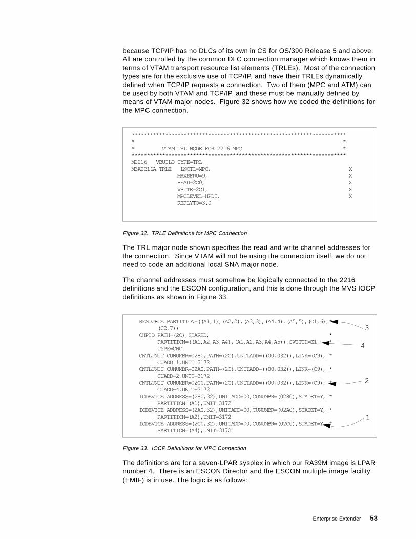
because TCP/IP has no DLCs of its own in CS for OS/390 Release 5 and above.All are controlled by the common DLC connection manager which knows them interms of VTAM transport resource list elements (TRLEs). Most of the connectiontypes are for the exclusive use of TCP/IP, and have their TRLEs dynamicallydefined when TCP/IP requests a connection. Two of them (MPC and ATM) canbe used by both VTAM and TCP/IP, and these must be manually defined bymeans of VTAM major nodes. Figure 32 shows how we coded the definitions forthe MPC connection.
Figure 32. TRLE Definitions for MPC Connection
The TRL major node shown specifies the read and write channel addresses forthe connection. Since VTAM will not be using the connection itself, we do notneed to code an additional local SNA major node.
The channel addresses must somehow be logically connected to the 2216definitions and the ESCON configuration, and this is done through the MVS IOCPdefinitions as shown in Figure 33.
Figure 33. IOCP Definitions for MPC Connection
The definitions are for a seven-LPAR sysplex in which our RA39M image is LPARnumber 4. There is an ESCON Director and the ESCON multiple image facility(EMIF) is in use. The logic is as follows:
*********************************************************************** ** VTAM TRL NODE FOR 2216 MPC ***********************************************************************M2216 VBUILD TYPE=TRLM3A2216A TRLE LNCTL=MPC, X
MAXBFRU=9, XREAD=2C0, XWRITE=2C1, XMPCLEVEL=HPDT, XREPLYTO=3.0
RESOURCE PARTITION=((A1,1),(A2,2),(A3,3),(A4,4),(A5,5),(C1,6),*(C2,7))
CHPID PATH=(2C),SHARED, *PARTITION=((A1,A2,A3,A4),(A1,A2,A3,A4,A5)),SWITCH=E1, *TYPE=CNC
CNTLUNIT CUNUMBR=0280,PATH=(2C),UNITADD=((00,032)),LINK=(C9), *CUADD=1,UNIT=3172
CNTLUNIT CUNUMBR=02A0,PATH=(2C),UNITADD=((00,032)),LINK=(C9), *CUADD=2,UNIT=3172
CNTLUNIT CUNUMBR=02C0,PATH=(2C),UNITADD=((00,032)),LINK=(C9), *CUADD=4,UNIT=3172
IODEVICE ADDRESS=(280,32),UNITADD=00,CUNUMBR=(0280),STADET=Y, *PARTITION=(A1),UNIT=3172
IODEVICE ADDRESS=(2A0,32),UNITADD=00,CUNUMBR=(02A0),STADET=Y, *PARTITION=(A2),UNIT=3172
IODEVICE ADDRESS=(2C0,32),UNITADD=00,CUNUMBR=(02C0),STADET=Y, *PARTITION=(A4),UNIT=3172
1
2
3
4
Enterprise Extender 53
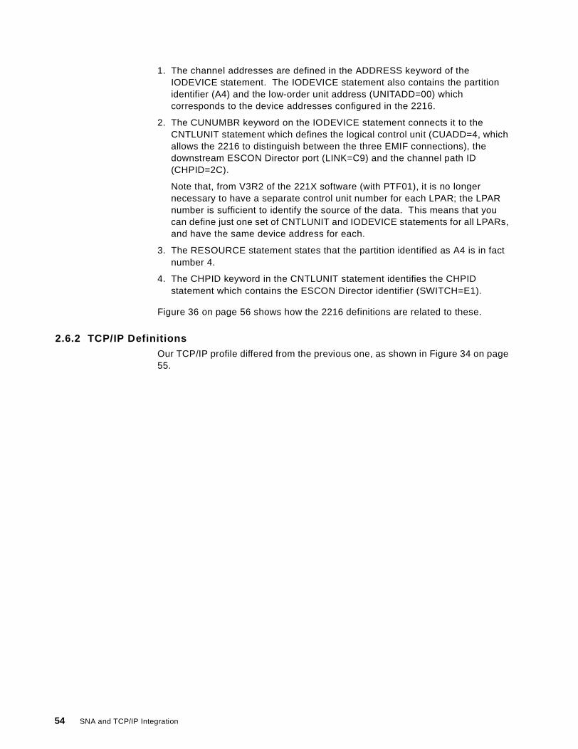
1. The channel addresses are defined in the ADDRESS keyword of theIODEVICE statement. The IODEVICE statement also contains the partitionidentifier (A4) and the low-order unit address (UNITADD=00) whichcorresponds to the device addresses configured in the 2216.
2. The CUNUMBR keyword on the IODEVICE statement connects it to theCNTLUNIT statement which defines the logical control unit (CUADD=4, whichallows the 2216 to distinguish between the three EMIF connections), thedownstream ESCON Director port (LINK=C9) and the channel path ID(CHPID=2C).
Note that, from V3R2 of the 221X software (with PTF01), it is no longernecessary to have a separate control unit number for each LPAR; the LPARnumber is sufficient to identify the source of the data. This means that youcan define just one set of CNTLUNIT and IODEVICE statements for all LPARs,and have the same device address for each.
3. The RESOURCE statement states that the partition identified as A4 is in factnumber 4.
4. The CHPID keyword in the CNTLUNIT statement identifies the CHPIDstatement which contains the ESCON Director identifier (SWITCH=E1).
Figure 36 on page 56 shows how the 2216 definitions are related to these.
2.6.2 TCP/IP DefinitionsOur TCP/IP profile differed from the previous one, as shown in Figure 34 on page55.
54 SNA and TCP/IP Integration
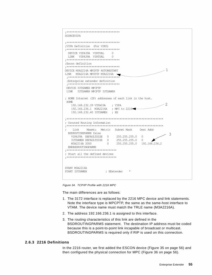
Figure 34. TCP/IP Profile with 2216 MPC
The main differences are as follows:
1. The 3172 interface is replaced by the 2216 MPC device and link statements.Note the interface type is MPCPTP, the same as the same-host interface toVTAM. The device name must match the TRLE name (M3A2216A).
2. The address 192.166.236.1 is assigned to this interface.
3. The routing characteristics of this link are defined in theBSDROUTINGPARMS statement. The destination IP address must be codedbecause this is a point-to-point link incapable of broadcast or multicast.BSDROUTINGPARMS is required only if RIP is used on this connection.
2.6.3 2216 DefinitionsIn the 2216 router, we first added the ESCON device (Figure 35 on page 56) andthen configured the physical connection for MPC (Figure 36 on page 56).
;**********************************SOURCEVIPA
;**********************************;VIPA Definition (For V2R5);**********************************
DEVICE VIPA39A VIRTUAL 0LINK VIPA39A VIRTUAL 0
;**********************************;Escon definition;**********************************DEVICE M3A2216A MPCPTP AUTORESTARTLINK M3A2216A MPCPTP M3A2216A
;*********************************;Enterprise extender definition;*********************************DEVICE IUTSAMEH MPCPTPLINK IUTSAMEH MPCPTP IUTSAMEH
; HOME Internet (IP) addresses of each link in the host.HOME
192.168.232.39 VIPA03A ; VIPA192.166.236.1 M3A2216A ; MPC to 2216192.168.232.40 IUTSAMEH ; EE
;**************************************************************; Orouted Routing Information;**************************************************************; Link Maxmtu Metric Subnet Mask Dest Addr
BSDROUTINGPARMS falseVIPA39A DEFAULTSIZE 0 255.255.255.0 0IUTSAMEH DEFAULTSIZE 0 255.255.255.0 0M3A2216A 2000 0 255.255.255.0 192.166.236.2
ENDBSDROUTINGPARMS;********************************; Start all the defined devices;********************************
START M3A2216ASTART IUTSAMEH ; EExtender *
2
3
1
Enterprise Extender 55
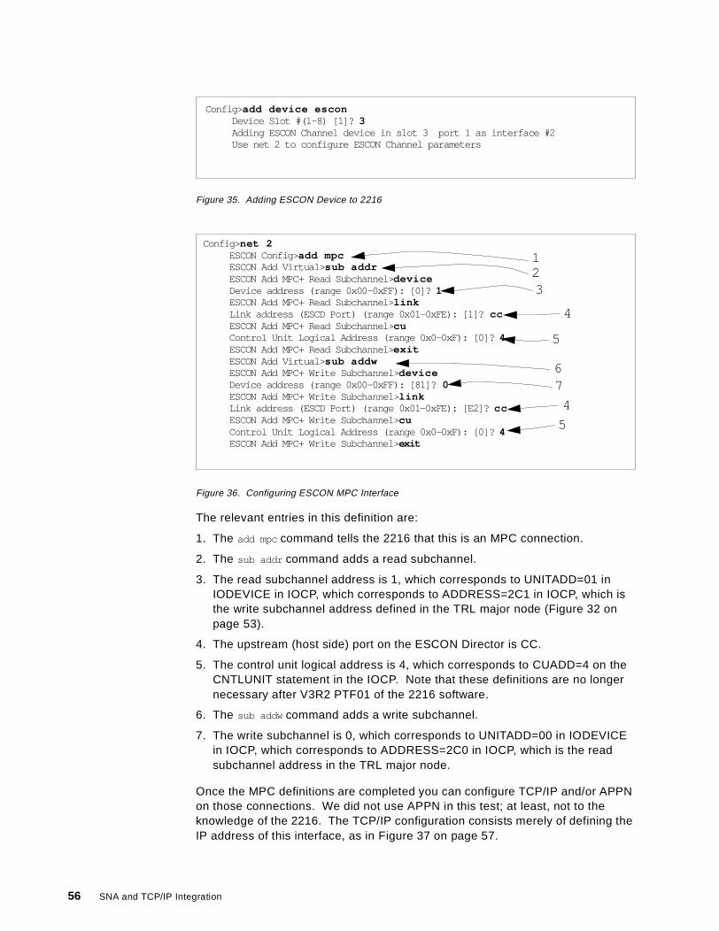
Figure 35. Adding ESCON Device to 2216
Figure 36. Configuring ESCON MPC Interface
The relevant entries in this definition are:
1. The add mpc command tells the 2216 that this is an MPC connection.
2. The sub addr command adds a read subchannel.
3. The read subchannel address is 1, which corresponds to UNITADD=01 inIODEVICE in IOCP, which corresponds to ADDRESS=2C1 in IOCP, which isthe write subchannel address defined in the TRL major node (Figure 32 onpage 53).
4. The upstream (host side) port on the ESCON Director is CC.
5. The control unit logical address is 4, which corresponds to CUADD=4 on theCNTLUNIT statement in the IOCP. Note that these definitions are no longernecessary after V3R2 PTF01 of the 2216 software.
6. The sub addw command adds a write subchannel.
7. The write subchannel is 0, which corresponds to UNITADD=00 in IODEVICEin IOCP, which corresponds to ADDRESS=2C0 in IOCP, which is the readsubchannel address in the TRL major node.
Once the MPC definitions are completed you can configure TCP/IP and/or APPNon those connections. We did not use APPN in this test; at least, not to theknowledge of the 2216. The TCP/IP configuration consists merely of defining theIP address of this interface, as in Figure 37 on page 57.
Config> add device esconDevice Slot #(1-8) [1]? 3Adding ESCON Channel device in slot 3 port 1 as interface #2Use net 2 to configure ESCON Channel parameters
Config> net 2ESCON Config>add mpcESCON Add Virtual> sub addrESCON Add MPC+ Read Subchannel>deviceDevice address (range 0x00-0xFF): [0]? 1ESCON Add MPC+ Read Subchannel>linkLink address (ESCD Port) (range 0x01-0xFE): [1]? ccESCON Add MPC+ Read Subchannel>cuControl Unit Logical Address (range 0x0-0xF): [0]? 4ESCON Add MPC+ Read Subchannel>exitESCON Add Virtual> sub addwESCON Add MPC+ Write Subchannel> deviceDevice address (range 0x00-0xFF): [81]? 0ESCON Add MPC+ Write Subchannel> linkLink address (ESCD Port) (range 0x01-0xFE): [E2]? ccESCON Add MPC+ Write Subchannel> cuControl Unit Logical Address (range 0x0-0xF): [0]? 4ESCON Add MPC+ Write Subchannel> exit
123
4
5
67
4
5
56 SNA and TCP/IP Integration
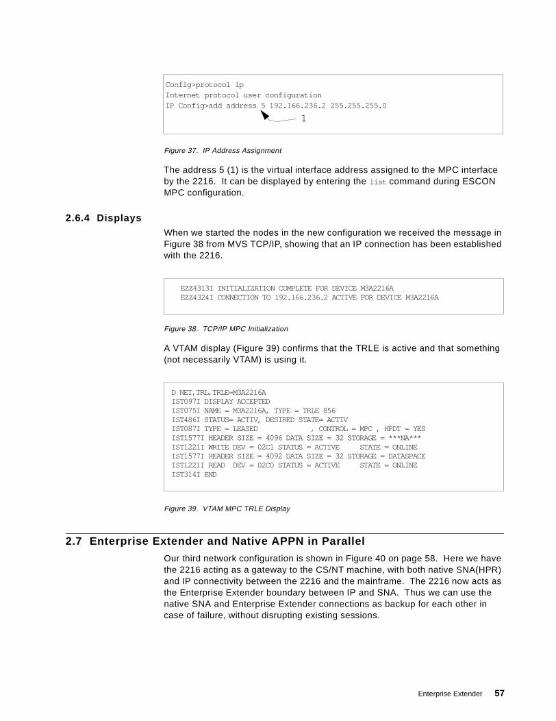
Figure 37. IP Address Assignment
The address 5 (1) is the virtual interface address assigned to the MPC interfaceby the 2216. It can be displayed by entering the list command during ESCONMPC configuration.
2.6.4 DisplaysWhen we started the nodes in the new configuration we received the message inFigure 38 from MVS TCP/IP, showing that an IP connection has been establishedwith the 2216.
Figure 38. TCP/IP MPC Initialization
A VTAM display (Figure 39) confirms that the TRLE is active and that something(not necessarily VTAM) is using it.
Figure 39. VTAM MPC TRLE Display
2.7 Enterprise Extender and Native APPN in Parallel
Our third network configuration is shown in Figure 40 on page 58. Here we havethe 2216 acting as a gateway to the CS/NT machine, with both native SNA(HPR)and IP connectivity between the 2216 and the mainframe. The 2216 now acts asthe Enterprise Extender boundary between IP and SNA. Thus we can use thenative SNA and Enterprise Extender connections as backup for each other incase of failure, without disrupting existing sessions.
Config>protocol ipInternet protocol user configurationIP Config>add address 5 192.166.236.2 255.255.255.0
1
EZZ4313I INITIALIZATION COMPLETE FOR DEVICE M3A2216AEZZ4324I CONNECTION TO 192.166.236.2 ACTIVE FOR DEVICE M3A2216A
D NET,TRL,TRLE=M3A2216AIST097I DISPLAY ACCEPTEDIST075I NAME = M3A2216A, TYPE = TRLE 856IST486I STATUS= ACTIV, DESIRED STATE= ACTIVIST087I TYPE = LEASED , CONTROL = MPC , HPDT = YESIST1577I HEADER SIZE = 4096 DATA SIZE = 32 STORAGE = ***NA***IST1221I WRITE DEV = 02C1 STATUS = ACTIVE STATE = ONLINEIST1577I HEADER SIZE = 4092 DATA SIZE = 32 STORAGE = DATASPACEIST1221I READ DEV = 02C0 STATUS = ACTIVE STATE = ONLINEIST314I END
Enterprise Extender 57
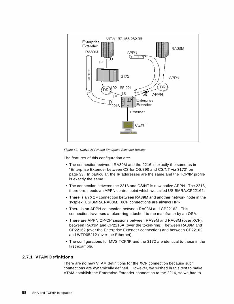
Figure 40. Native APPN and Enterprise Extender Backup
The features of this configuration are:
• The connection between RA39M and the 2216 is exactly the same as in“Enterprise Extender between CS for OS/390 and CS/NT via 3172” onpage 33. In particular, the IP addresses are the same and the TCP/IP profileis exactly the same.
• The connection between the 2216 and CS/NT is now native APPN. The 2216,therefore, needs an APPN control point which we called USIBMRA.CP22162.
• There is an XCF connection between RA39M and another network node in thesysplex, USIBMRA.RA03M. XCF connections are always HPR.
• There is an APPN connection between RA03M and CP22162. Thisconnection traverses a token-ring attached to the mainframe by an OSA.
• There are APPN CP-CP sessions between RA39M and RA03M (over XCF),between RA03M and CP2216A (over the token-ring), between RA39M andCP22162 (over the Enterprise Extender connection) and between CP22162and WTR05212 (over the Ethernet).
• The configurations for MVS TCP/IP and the 3172 are identical to those in thefirst example.
2.7.1 VTAM DefinitionsThere are no new VTAM definitions for the XCF connection because suchconnections are dynamically defined. However, we wished in this test to makeVTAM establish the Enterprise Extender connection to the 2216, so we had to
Ethernet
58 SNA and TCP/IP Integration

code a switched major node as shown in Figure 41. The XCA major node wasthe same as in the previous examples.
Figure 41. Switched Major Node for Enterprise Extender
Note that we specified the IP address of the 2216, namely 192.168.221.16.Ideally, we should have used an IP host name (on the HOSTNAME keyword) ifsuch a name had been registered to the domain name server.
2.7.2 2216 ConfigurationThe TCP/IP configuration for the 2216 was the same as in “Enterprise Extenderbetween CS for OS/390 and CS/NT via 3172” on page 33, but we now had to addAPPN and Enterprise Extender definitions. For APPN, we needed to define:
1. The node
2. The LAN port connecting the 2216 to the OSA and thus to RA03M
3. The LAN port connecting the 2216 to the CS/NT node (which was on adifferent LAN)
4. The link station from the 2216 to RA03M, as the 2216 was to initiate thisconnection
5. The Enterprise Extender port
6. The Enterprise Extender link station to connect with RA39M. Even thoughRA39M has this link station defined, we also defined it on the 2216 to showhow it was done.
The APPN node definition is shown in Figure 42.
Figure 42. 2216 APPN Node Configuration
The node definition is performed by entering talk 6 from the base (*) prompt.The main thing that has to be defined here is the CP name (1).
Next, we defined the token-ring port as shown in Figure 43 on page 60.
EESWJ VBUILD TYPE=SWNETEEPU PU ISTATUS=ACTIVE,PUTYPE=2,CPNAME=CP22162EESW PATH IPADDR=192.168.221.16,GRPNM=EEXCAG
Config> p appnAPPN user configurationAPPN config> set nodeEnable APPN (Y)es (N)o [Y]? yNetwork ID (Max 8 characters) [ ]? usibmraControl point name (Max 8 characters) [ ]? cp22162Route addition resistance(0-255) [128]? 128XID ID number for subarea connection (5 hex digits) [00000]? 00000Write this record? [Y]? YThe record has been written.APPN config> exit
1
Enterprise Extender 59
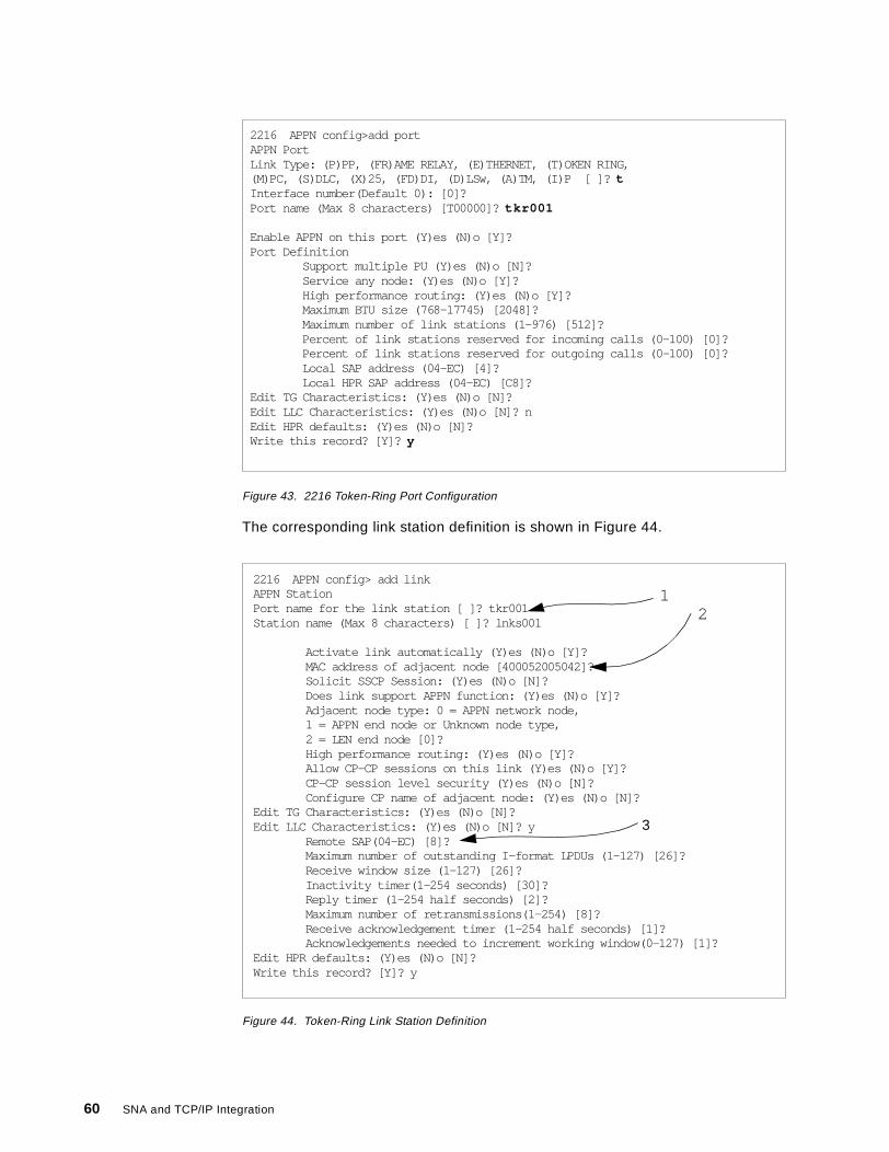
Figure 43. 2216 Token-Ring Port Configuration
The corresponding link station definition is shown in Figure 44.
Figure 44. Token-Ring Link Station Definition
2216 APPN config>add portAPPN PortLink Type: (P)PP, (FR)AME RELAY, (E)THERNET, (T)OKEN RING,(M)PC, (S)DLC, (X)25, (FD)DI, (D)LSw, (A)TM, (I)P [ ]? tInterface number(Default 0): [0]?Port name (Max 8 characters) [T00000]? tkr001
Enable APPN on this port (Y)es (N)o [Y]?Port Definition
Support multiple PU (Y)es (N)o [N]?Service any node: (Y)es (N)o [Y]?High performance routing: (Y)es (N)o [Y]?Maximum BTU size (768-17745) [2048]?Maximum number of link stations (1-976) [512]?Percent of link stations reserved for incoming calls (0-100) [0]?Percent of link stations reserved for outgoing calls (0-100) [0]?Local SAP address (04-EC) [4]?Local HPR SAP address (04-EC) [C8]?
Edit TG Characteristics: (Y)es (N)o [N]?Edit LLC Characteristics: (Y)es (N)o [N]? nEdit HPR defaults: (Y)es (N)o [N]?Write this record? [Y]? y
2216 APPN config> add linkAPPN StationPort name for the link station [ ]? tkr001Station name (Max 8 characters) [ ]? lnks001
Activate link automatically (Y)es (N)o [Y]?MAC address of adjacent node [400052005042]?Solicit SSCP Session: (Y)es (N)o [N]?Does link support APPN function: (Y)es (N)o [Y]?Adjacent node type: 0 = APPN network node,1 = APPN end node or Unknown node type,2 = LEN end node [0]?High performance routing: (Y)es (N)o [Y]?Allow CP-CP sessions on this link (Y)es (N)o [Y]?CP-CP session level security (Y)es (N)o [N]?Configure CP name of adjacent node: (Y)es (N)o [N]?
Edit TG Characteristics: (Y)es (N)o [N]?Edit LLC Characteristics: (Y)es (N)o [N]? y
Remote SAP(04-EC) [8]?Maximum number of outstanding I-format LPDUs (1-127) [26]?Receive window size (1-127) [26]?Inactivity timer(1-254 seconds) [30]?Reply timer (1-254 half seconds) [2]?Maximum number of retransmissions(1-254) [8]?Receive acknowledgement timer (1-254 half seconds) [1]?Acknowledgements needed to increment working window(0-127) [1]?
Edit HPR defaults: (Y)es (N)o [N]?Write this record? [Y]? y
21
3
60 SNA and TCP/IP Integration
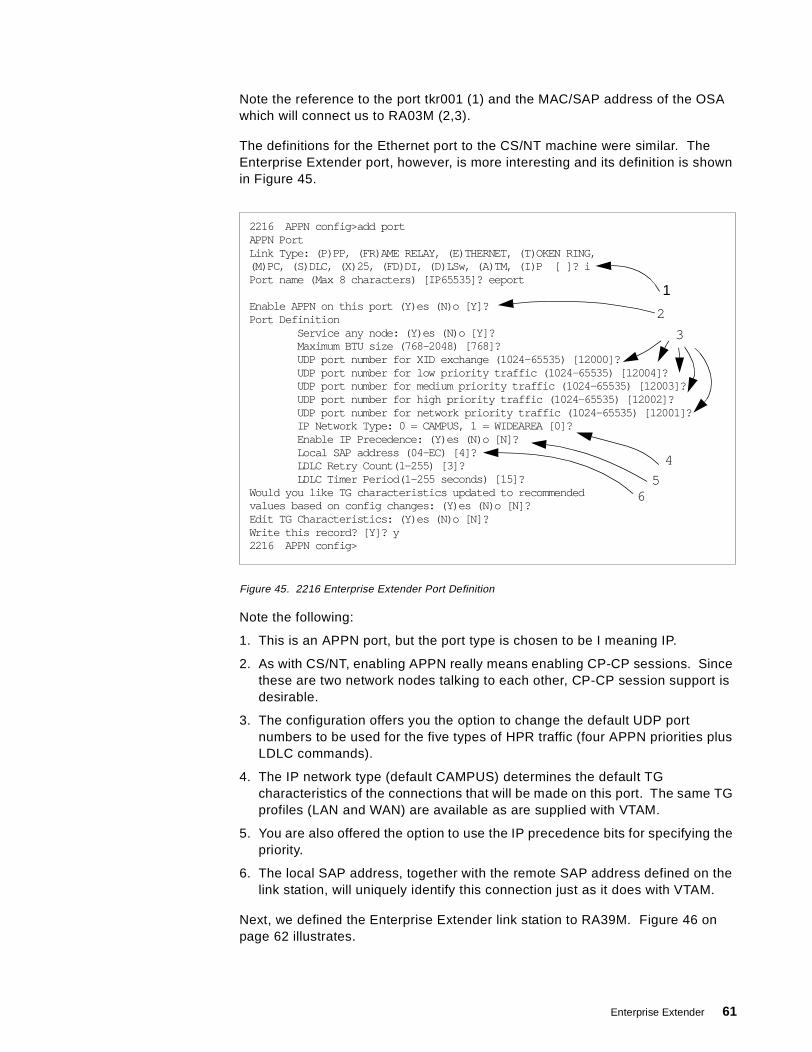
Note the reference to the port tkr001 (1) and the MAC/SAP address of the OSAwhich will connect us to RA03M (2,3).
The definitions for the Ethernet port to the CS/NT machine were similar. TheEnterprise Extender port, however, is more interesting and its definition is shownin Figure 45.
Figure 45. 2216 Enterprise Extender Port Definition
Note the following:
1. This is an APPN port, but the port type is chosen to be I meaning IP.
2. As with CS/NT, enabling APPN really means enabling CP-CP sessions. Sincethese are two network nodes talking to each other, CP-CP session support isdesirable.
3. The configuration offers you the option to change the default UDP portnumbers to be used for the five types of HPR traffic (four APPN priorities plusLDLC commands).
4. The IP network type (default CAMPUS) determines the default TGcharacteristics of the connections that will be made on this port. The same TGprofiles (LAN and WAN) are available as are supplied with VTAM.
5. You are also offered the option to use the IP precedence bits for specifying thepriority.
6. The local SAP address, together with the remote SAP address defined on thelink station, will uniquely identify this connection just as it does with VTAM.
Next, we defined the Enterprise Extender link station to RA39M. Figure 46 onpage 62 illustrates.
2216 APPN config>add portAPPN PortLink Type: (P)PP, (FR)AME RELAY, (E)THERNET, (T)OKEN RING,(M)PC, (S)DLC, (X)25, (FD)DI, (D)LSw, (A)TM, (I)P [ ]? iPort name (Max 8 characters) [IP65535]? eeport
Enable APPN on this port (Y)es (N)o [Y]?Port Definition
Service any node: (Y)es (N)o [Y]?Maximum BTU size (768-2048) [768]?UDP port number for XID exchange (1024-65535) [12000]?UDP port number for low priority traffic (1024-65535) [12004]?UDP port number for medium priority traffic (1024-65535) [12003]?UDP port number for high priority traffic (1024-65535) [12002]?UDP port number for network priority traffic (1024-65535) [12001]?IP Network Type: 0 = CAMPUS, 1 = WIDEAREA [0]?Enable IP Precedence: (Y)es (N)o [N]?Local SAP address (04-EC) [4]?LDLC Retry Count(1-255) [3]?LDLC Timer Period(1-255 seconds) [15]?
Would you like TG characteristics updated to recommendedvalues based on config changes: (Y)es (N)o [N]?Edit TG Characteristics: (Y)es (N)o [N]?Write this record? [Y]? y2216 APPN config>
1
2
3
4
56
Enterprise Extender 61
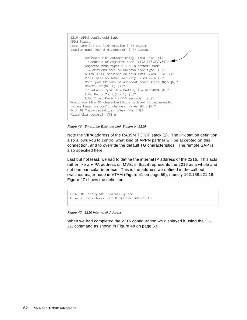
Figure 46. Enterprise Extender Link Station on 2216
Note the VIPA address of the RA39M TCP/IP stack (1). The link station definitionalso allows you to control what kind of APPN partner will be accepted on thisconnection, and to override the default TG characteristics. The remote SAP isalso specified here.
Last but not least, we had to define the internal IP address of the 2216. This actsrather like a VIPA address on MVS, in that it represents the 2216 as a whole andnot one particular interface. This is the address we defined in the call-outswitched major node in VTAM (Figure 41 on page 59), namely 192.168.221.16.Figure 47 shows the definition.
Figure 47. 2216 Internal IP Address
When we had completed the 2216 configuration we displayed it using the list
all command as shown in Figure 48 on page 63.
2216 APPN config>add linkAPPN StationPort name for the link station [ ]? eeportStation name (Max 8 characters) [ ]? eestat
Activate link automatically (Y)es (N)o [Y]?IP address of adjacent node [192.168.232.39]?Adjacent node type: 0 = APPN network node,1 = APPN end node or Unknown node type [0]?Allow CP-CP sessions on this link (Y)es (N)o [Y]?CP-CP session level security (Y)es (N)o [N]?Configure CP name of adjacent node: (Y)es (N)o [N]?Remote SAP(04-EC) [4]?IP Network Type: 0 = CAMPUS, 1 = WIDEAREA [0]?LDLC Retry Count(1-255) [3]?LDLC Timer Period(1-255 seconds) [15]?
Would you like TG characteristics updated to recommendedvalues based on config changes: (Y)es (N)o [N]?Edit TG Characteristics: (Y)es (N)o [N]?Write this record? [Y]? n
1
2216 IP config>set internal-ip-addInternal IP address [0.0.0.0]? 192.168.221.16
62 SNA and TCP/IP Integration
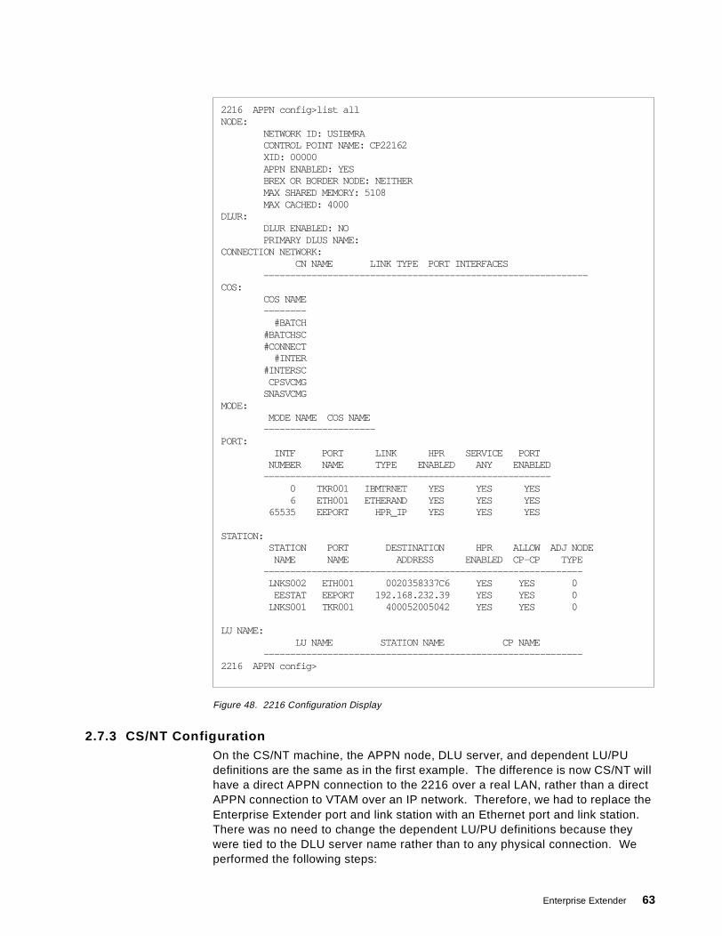
Figure 48. 2216 Configuration Display
2.7.3 CS/NT ConfigurationOn the CS/NT machine, the APPN node, DLU server, and dependent LU/PUdefinitions are the same as in the first example. The difference is now CS/NT willhave a direct APPN connection to the 2216 over a real LAN, rather than a directAPPN connection to VTAM over an IP network. Therefore, we had to replace theEnterprise Extender port and link station with an Ethernet port and link station.There was no need to change the dependent LU/PU definitions because theywere tied to the DLU server name rather than to any physical connection. Weperformed the following steps:
2216 APPN config>list allNODE:
NETWORK ID: USIBMRACONTROL POINT NAME: CP22162XID: 00000APPN ENABLED: YESBREX OR BORDER NODE: NEITHERMAX SHARED MEMORY: 5108MAX CACHED: 4000
DLUR:DLUR ENABLED: NOPRIMARY DLUS NAME:
CONNECTION NETWORK:CN NAME LINK TYPE PORT INTERFACES
-------------------------------------------------------------COS:
COS NAME--------
#BATCH#BATCHSC#CONNECT
#INTER#INTERSCCPSVCMG
SNASVCMGMODE:
MODE NAME COS NAME---------------------
PORT:INTF PORT LINK HPR SERVICE PORT
NUMBER NAME TYPE ENABLED ANY ENABLED------------------------------------------------------
0 TKR001 IBMTRNET YES YES YES6 ETH001 ETHERAND YES YES YES
65535 EEPORT HPR_IP YES YES YES
STATION:STATION PORT DESTINATION HPR ALLOW ADJ NODE
NAME NAME ADDRESS ENABLED CP-CP TYPE------------------------------------------------------------LNKS002 ETH001 0020358337C6 YES YES 0
EESTAT EEPORT 192.168.232.39 YES YES 0LNKS001 TKR001 400052005042 YES YES 0
LU NAME:LU NAME STATION NAME CP NAME
------------------------------------------------------------2216 APPN config>
Enterprise Extender 63
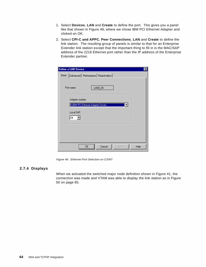
1. Select Devices , LAN and Create to define the port. This gives you a panellike that shown in Figure 49, where we chose IBM PCI Ethernet Adapter andclicked on OK.
2. Select CPI-C and APPC , Peer Connections , LAN and Create to define thelink station. The resulting group of panels is similar to that for an EnterpriseExtender link station except that the important thing to fill in is the MAC/SAPaddress of the 2216 Ethernet port rather than the IP address of the EnterpriseExtender partner.
Figure 49. Ethernet Port Selection on CS/NT
2.7.4 DisplaysWhen we activated the switched major node definition shown in Figure 41, theconnection was made and VTAM was able to display the link station as in Figure50 on page 65.
64 SNA and TCP/IP Integration
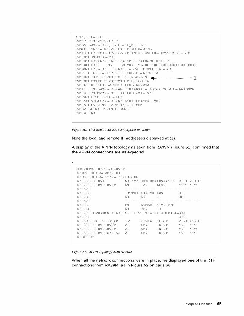
Figure 50. Link Station for 2216 Enterprise Extender
Note the local and remote IP addresses displayed at (1).
A display of the APPN topology as seen from RA39M (Figure 51) confirmed thatthe APPN connections are as expected.
.
Figure 51. APPN Topology from RA39M
When all the network connections were in place, we displayed one of the RTPconnections from RA39M, as in Figure 52 on page 66.
D NET,E,ID=EEPUIST097I DISPLAY ACCEPTEDIST075I NAME = EEPU, TYPE = PU_T2.1 049IST486I STATUS= ACTIV, DESIRED STATE= ACTIVIST1043I CP NAME = CP22162, CP NETID = USIBMRA, DYNAMIC LU = YESIST1589I XNETALS = YESIST1105I RESOURCE STATUS TGN CP-CP TG CHARACTERISTICSIST1106I EEPU AC/R 21 YES 98750000000000000000017100808080IST1482I HPR = RTP - OVERRIDE = N/A - CONNECTION = YESIST1510I LLERP = NOTPREF - RECEIVED = NOTALLOWIST1680I LOCAL IP ADDRESS 192.168.232.39IST1680I REMOTE IP ADDRESS 192.168.221.16IST136I SWITCHED SNA MAJOR NODE = RA39ASWJIST081I LINE NAME = EEXCAL, LINE GROUP = EEXCAG, MAJNOD = RA39AXCAIST654I I/O TRACE = OFF, BUFFER TRACE = OFFIST1500I STATE TRACE = OFFIST1656I VTAMTOPO = REPORT, NODE REPORTED - YESIST1657I MAJOR NODE VTAMTOPO = REPORTIST172I NO LOGICAL UNITS EXISTIST314I END
1
D NET,TOPO,LIST=ALL,ID=RA39MIST097I DISPLAY ACCEPTEDIST350I DISPLAY TYPE = TOPOLOGY 046IST1295I CP NAME NODETYPE ROUTERES CONGESTION CP-CP WEIGHTIST1296I USIBMRA.RA39M NN 128 NONE *NA* *NA*IST1579I ------------------------------------------IST1297I ICN/MDH CDSERVR RSN HPRIST1298I NO NO 2 RTPIST1579I ------------------------------------------IST1223I BN NATIVE TIME LEFTIST1224I NO YES 13IST1299I TRANSMISSION GROUPS ORIGINATING AT CP USIBMRA.RA39MIST1357I CPCPIST1300I DESTINATION CP TGN STATUS TGTYPE VALUE WEIGHTIST1301I USIBMRA.RA03M 21 OPER INTERM YES *NA*IST1301I USIBMRA.RA28M 21 OPER INTERM YES *NA*IST1301I USIBMRA.CP22162 21 OPER INTERM YES *NA*IST314I END
Enterprise Extender 65

Figure 52. RTP Connection for DLUR/S Sessions
This particular connection was the DLUR/S pipe carrying the LU 6.2 dependentLU requester sessions. The route taken (1) comprised the Enterprise Extenderconnection (TG 21) from RA39M to CP22162, followed by the Ethernetconnection (TG 21) from CP22162 to WTR05212. This path obviously had alower weight for the SNASVCMG class of service than the longer route viaRA03M, even though the longer route was all native APPN.
After we had established some independent and dependent LU sessions betweenWTR05212 and the VTAM hosts, we unplugged the 3172 connection to the token-ring. This had the effect of breaking the Enterprise Extender link, because therewas no other IP path between the 2216 and RA39M.
The sessions remained operational. To see why, we observed the console log onRA39M to see messages such as that in Figure 53. A non-disruptive path switchhad occurred.
Figure 53. Path Switch for DLUR/S Pipe
D NET,E,ID=CNR00010IST097I DISPLAY ACCEPTEDIST075I NAME = CNR00010, TYPE = PU_T2.1 094IST1392I DISCNTIM = 00010 DEFINED AT PU FOR DISCONNECTIST486I STATUS= ACTIV--LX-, DESIRED STATE= ACTIVIST1043I CP NAME = WTR05212, CP NETID = USIBMRA, DYNAMIC LU = YESIST1589I XNETALS = YESIST875I APPNCOS TOWARDS RTP = SNASVCMGIST1476I TCID X'065BA1CD00000044' - REMOTE TCID X'0000000002000000'IST1481I DESTINATION CP USIBMRA.WTR05212 - NCE X'80'IST1587I ORIGIN NCE X'D000000000000000'IST1477I ALLOWED DATA FLOW RATE = 400 KBITS/SECIST1516I INITIAL DATA FLOW RATE = 400 KBITS/SECIST1511I MAXIMUM NETWORK LAYER PACKET SIZE = 765 BYTESIST1478I NUMBER OF UNACKNOWLEDGED BUFFERS = 0IST1479I RTP CONNECTION STATE = CONNECTED - MNPS = NOIST1480I RTP END TO END ROUTE - PHYSICAL PATHIST1460I TGN CPNAME TG TYPE HPRIST1461I 21 USIBMRA.CP22162 APPN RTPIST1461I 21 USIBMRA.WTR05212 APPN RTPIST231I RTP MAJOR NODE = ISTRTPMNIST654I I/O TRACE = OFF, BUFFER TRACE = OFFIST1500I STATE TRACE = OFFIST355I LOGICAL UNITS:IST080I WTR05212 ACT/S----Y
1
IST1494I PATH SWITCH STARTED FOR RTP CNR00010IST1494I PATH SWITCH COMPLETED FOR RTP CNR00010 863IST1480I RTP END TO END ROUTE - PHYSICAL PATHIST1460I TGN CPNAME TG TYPE HPRIST1461I 21 USIBMRA.RA03M APPN RTPIST1461I 21 USIBMRA.CP22162 APPN RTPIST1461I 21 USIBMRA.WTR05212 APPN RTP
66 SNA and TCP/IP Integration
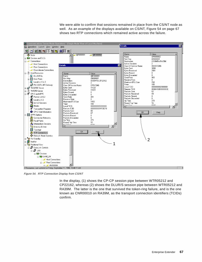
We were able to confirm that sessions remained in place from the CS/NT node aswell. As an example of the displays available on CS/NT, Figure 54 on page 67shows two RTP connections which remained active across the failure.
Figure 54. RTP Connection Display from CS/NT
In the display, (1) shows the CP-CP session pipe between WTR05212 andCP22162, whereas (2) shows the DLUR/S session pipe between WTR05212 andRA39M. The latter is the one that survived the token-ring failure, and is the oneknown as CNR00010 on RA39M, as the transport connection identifiers (TCIDs)confirm.
12
Enterprise Extender 67

68 SNA and TCP/IP Integration
Chapter 3. AnyNet Sockets over SNA
AnyNet Sockets over SNA is the only comprehensive technique available forrunning Sockets applications over an SNA transport network. It translates theSockets calls directly to SNA requests, so it does not require a TCP/IP stack onthe same node unless native IP transport is also needed.
AnyNet Sockets over SNA is currently implemented as part of theCommunications Server product family, comprising the following products:
• SecureWay Communications Server for OS/390 (access node only)
• OS/400 (access node only)
• Communications Server for AIX (access node and gateway)
• Communications Server for OS/2 (access node and gateway)
• Communications Server for Windows NT (access node and gateway)
In addition, AnyNet access node function only is available in PersonalCommunications for OS/2, Windows NT and Windows 95/98.
AnyNet functions have been available earlier for various platforms in differentpackages, such as AnyNet/2 for OS/2. These older versions are still compatiblewith the more current implementations.
The Sockets over SNA part of AnyNet has changed in OS/390 OpenEditionVersion 2 Release 5, as well as in Communications Server for Windows NTVersion 6. Therefore, we concentrated on these platforms for the examplesdescribed in this chapter.
3.1 Sockets over SNA Overview
AnyNet Sockets over SNA provides SNA transport to applications written to theSockets interface that would normally expect a TCP/IP network to satisfy theirtransport needs. You do not need to have native TCP/IP running in the samesystem, if all the transport needs are satisfied through the SNA network.
If you, however, run native TCP/IP and AnyNet Sockets over SNA at the sametime on a single system, you must give them separate IP subnetworks andtherefore different IP addresses. This is because the Sockets over SNAapplication looks like a new IP interface to the application; this new virtual IPinterface is normally known as sna0. As with all IP interfaces, sna0 must begiven an IP address and a subnet mask to allow communication over thatinterface (in other words, over the SNA network).
Sockets over SNA and native TCP/IP operate independently of one another andhave no awareness of each other's presence in an access node, where anycommunication between them must be done through an IP router. In a gatewaynode, they can route traffic to each other’s interfaces.
Because AnyNet Sockets over SNA must cause the SNA network to look like anIP network, it must map IP addresses to SNA logical unit names. Thus an IPpacket addressed to a given IP address can be assigned to the appropriate SNA
© Copyright IBM Corp. 1999 69
partner node, and an SNA session created if none exists. Address mapping canbe done in one of two ways:
• Explicitly. In the explicit method, you have to define each IP address and itscorresponding LU name manually. This has to be done in every AnyNet nodefor every IP address used as a destination address from that node. As thenetwork grows, this can become a tedious task.
• Algorithmically. The recommended method for address mapping is thealgorithmic one. Using this method, it is possible to code only one definitionand allow the provided address mapping program to do the rest. Dynamicdefinition of LUs in subarea networks, and especially in APPN, will allowcreation of new LUs automatically as they are needed, making network growtheasy for the systems programmer. Also, as the mapping is based on analgorithm, no memory or disk space is needed for large mapping tables. Thedrawback is that you need a reasonably consistent naming and addressingconvention in order to allow the algorithm to do its work.
The mapping algorithm is the same in all AnyNet products. This means that for aspecific IP address the same LU name will always be generated, provided thatthe seed values given to the algorithm are the same. The algorithm works asfollows:
• The IP address is logically divided into the two obvious portions: the networkaddress (that part defined by the 1 bits in the subnet mask) and the hostaddress (the rest). For example, the IP address 9.24.104.251 with the subnetmask 255.255.224.0 comprises a network address of 9.24.96.0 and a hostaddress of 8.251.
• The network address is used to look up a user-defined table which maps it toan SNA network ID together with an LU name prefix (typically SX). So, in ourexample, 9.24.96.0 might be mapped to USIBMRA.SX.
• Starting at the right-hand end, the host address is divided into groups of fivebits each. In our example above, the host address 8.251 (08FB inhexadecimal) becomes (00010,00111,11011) or (2,7,27).
• Each five-bit section now has 32 possible values, which are mapped to the 36alphanumeric characters with EIOU missing, as follows:
Value: 0 0 0 0 0 0 0 0 0 0 1 1 1 1 1 1 1 1 1 1 2 2 2 2 2 2 2 2 2 2 3 30 1 2 3 4 5 6 7 8 9 0 1 2 3 4 5 6 7 8 9 0 1 2 3 4 5 6 7 8 9 0 1
Mapped to: 0 1 2 3 4 5 6 7 8 9 A B C D F G H J K L M N P Q R S T V W X Y Z
In this way, our example of (2,7,27) becomes 27V.
• Finally, this result is padded with leading zeroes and appended to the networkID and the name prefix. In our case it produces USIBMRA.SX00027V.
You must ensure that the prefix is short enough to accommodate themaximum length of suffix that follows it. The default value SX of twocharacters is sufficient to cover any eventuality since a host address of morethan 30 bits is not possible in the IP architecture.
You can convert IP addresses to LU names the easy way by using the SXMAPcommand with the convert option on CS/2 or CS/NT.
From an IP topology point of view, the AnyNet Sockets over SNA section of thenetwork can be seen as a separate IP subnetwork. The Sockets over SNA
70 SNA and TCP/IP Integration
gateway nodes act as normal IP routers that route IP packets between twointerfaces: one standard TCP/IP interface and one AnyNet interface (sna0).
For data sent to the sna0 interface, Sockets over SNA maps the destination IPaddress to an SNA LU name and sends the data over LU 6.2 sessionsestablished between Sockets over SNA nodes. The LU 6.2 sessions can runover any SNA routing protocol (APPN, HPR, subarea) supported by the AnyNetnodes on the session path.
For Sockets applications of the stream type (where the local and remoteapplications establish a full-duplex byte-stream connection with each other),Sockets over SNA also needs full-duplex SNA communication. If both SNA LUssupport full-duplex LU 6.2, then only one session is established for the streamconnection. If either LU does not support full-duplex LU 6.2, two half-duplexsessions are set up (one contention winner for each end).
For IP datagrams (no stream connection), Sockets over SNA establishes one LU6.2 conversation for each destination, and thus one session whether full duplexor half duplex.
Although most of the nodes we used in our examples support full-duplex LU 6.2,the reader will notice that most of the displays show parallel LU 6.2 sessions inpairs. This is because we used PING extensively to test the connectivity. PINGuses a raw Sockets interface rather than a stream connection. Thus one LU 6.2session is set up by the node sending the PING (ICMP Echo datagram) and oneis set up by the node sending the PING response (ICMP Echo Reply datagram).
3.2 Sockets over SNA in SecureWay Communications Server for OS/390
The Sockets over SNA part of AnyNet was redesigned in OS/390 Version 2Release 5.
In previous versions of OS/390 and MVS, there were three Sockets applicationprogramming interfaces, all different:
1. The AnyNet Sockets API2. The MVS TCP/IP Sockets API3. The OpenEdition (now UNIX Systems Services) Sockets API.
Programs that required AnyNet had to be written to the AnyNet Sockets API,which meant in practice that most of the supplied TCP/IP application stackswould not work with AnyNet. From OS/390 Release 5 the only API supported byAnyNet Sockets over SNA is the UNIX Systems Services API. While this meansthat any user-written applications must be ported to the new API, it has the happyside effect that most of the supplied TCP/IP applications now do work. It alsomeans that native TCP/IP and/or AnyNet Sockets over SNA connections can beassigned dynamically to an application depending on the routing requirements tothe partner host. Figure 55 on page 72 shows how it fits together.
AnyNet Sockets over SNA 71
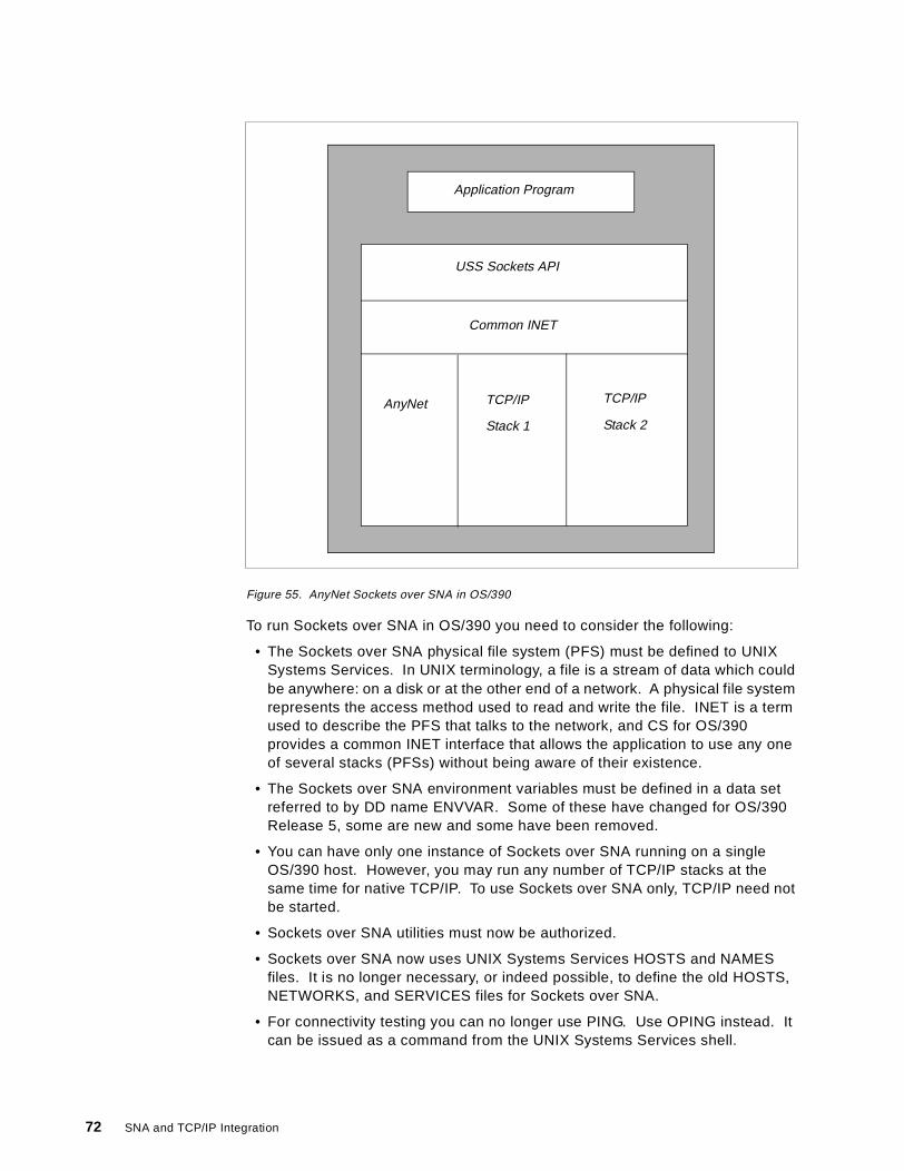
Figure 55. AnyNet Sockets over SNA in OS/390
To run Sockets over SNA in OS/390 you need to consider the following:
• The Sockets over SNA physical file system (PFS) must be defined to UNIXSystems Services. In UNIX terminology, a file is a stream of data which couldbe anywhere: on a disk or at the other end of a network. A physical file systemrepresents the access method used to read and write the file. INET is a termused to describe the PFS that talks to the network, and CS for OS/390provides a common INET interface that allows the application to use any oneof several stacks (PFSs) without being aware of their existence.
• The Sockets over SNA environment variables must be defined in a data setreferred to by DD name ENVVAR. Some of these have changed for OS/390Release 5, some are new and some have been removed.
• You can have only one instance of Sockets over SNA running on a singleOS/390 host. However, you may run any number of TCP/IP stacks at thesame time for native TCP/IP. To use Sockets over SNA only, TCP/IP need notbe started.
• Sockets over SNA utilities must now be authorized.
• Sockets over SNA now uses UNIX Systems Services HOSTS and NAMESfiles. It is no longer necessary, or indeed possible, to define the old HOSTS,NETWORKS, and SERVICES files for Sockets over SNA.
• For connectivity testing you can no longer use PING. Use OPING instead. Itcan be issued as a command from the UNIX Systems Services shell.
Application Program
USS Sockets API
AnyNet TCP/IP
Stack 1
TCP/IP
Stack 2
Common INET
72 SNA and TCP/IP Integration
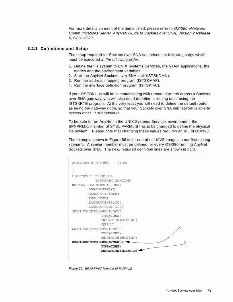
For more details on each of the items listed, please refer to OS/390 eNetworkCommunications Server, AnyNet: Guide to Sockets over SNA, Version 2 Release5, SC31-8577.
3.2.1 Definitions and SetupThe setup required for Sockets over SNA comprises the following steps whichmust be executed in the following order:
1. Define the file system to UNIX Systems Services, the VTAM applications, themodes and the environment variables.
2. Start the AnyNet Sockets over SNA task (ISTSKDMN).3. Run the address mapping program (ISTSKMAP).4. Run the interface definition program (ISTSKIFC).
If your OS/390 LUs will be communicating with remote partners across a Socketsover SNA gateway, you will also need to define a routing table using theISTSKRTE program. At the very least you will need to define the default routeras being the gateway node, so that your Sockets over SNA subnetwork is able toaccess other IP subnetworks.
To be able to run AnyNet in the UNIX Systems Services environment, theBPXPRMxx member of SYS1.PARMLIB has to be changed to define the physicalfile system. Please note that changing these values requires an IPL of OS/390.
The example shown in Figure 56 is for one of our MVS images in our first testingscenario. A similar member must be defined for every OS/390 running AnyNetSockets over SNA. The new, required definition lines are shown in bold.
Figure 56. BPXPRM03 Member of PARMLIB
SYS1.PARMLIB(BPXPRM03) - 01.08..FILESYSTYPE TYPE(CINET)
ENTRYPOINT(BPXTCINT)NETWORK DOMAINNAME(AF_INET)
DOMAINNUMBER(2)MAXSOCKETS(10000)TYPE(CINET)INADDRANYPORT(4000)INADDRANYCOUNT(2000)
SUBFILESYSTYPE NAME(T03ATCP)TYPE(CINET)ENTRYPOINT(EZBPFINI)DEFAULT
SUBFILESYSTYPE NAME(T03BTCP)TYPE(CINET)ENTRYPOINT(BPXTIINT)
SUBFILESYSTYPE NAME(ANYNET03)TYPE(CINET)ENTRYPOINT(ISTOEPIT)
1
2
AnyNet Sockets over SNA 73
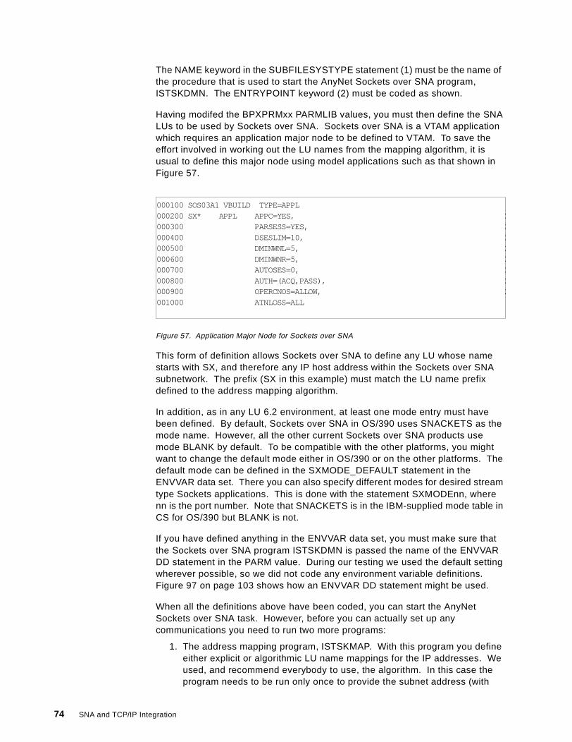
The NAME keyword in the SUBFILESYSTYPE statement (1) must be the name ofthe procedure that is used to start the AnyNet Sockets over SNA program,ISTSKDMN. The ENTRYPOINT keyword (2) must be coded as shown.
Having modifed the BPXPRMxx PARMLIB values, you must then define the SNALUs to be used by Sockets over SNA. Sockets over SNA is a VTAM applicationwhich requires an application major node to be defined to VTAM. To save theeffort involved in working out the LU names from the mapping algorithm, it isusual to define this major node using model applications such as that shown inFigure 57.
Figure 57. Application Major Node for Sockets over SNA
This form of definition allows Sockets over SNA to define any LU whose namestarts with SX, and therefore any IP host address within the Sockets over SNAsubnetwork. The prefix (SX in this example) must match the LU name prefixdefined to the address mapping algorithm.
In addition, as in any LU 6.2 environment, at least one mode entry must havebeen defined. By default, Sockets over SNA in OS/390 uses SNACKETS as themode name. However, all the other current Sockets over SNA products usemode BLANK by default. To be compatible with the other platforms, you mightwant to change the default mode either in OS/390 or on the other platforms. Thedefault mode can be defined in the SXMODE_DEFAULT statement in theENVVAR data set. There you can also specify different modes for desired streamtype Sockets applications. This is done with the statement SXMODEnn, wherenn is the port number. Note that SNACKETS is in the IBM-supplied mode table inCS for OS/390 but BLANK is not.
If you have defined anything in the ENVVAR data set, you must make sure thatthe Sockets over SNA program ISTSKDMN is passed the name of the ENVVARDD statement in the PARM value. During our testing we used the default settingwherever possible, so we did not code any environment variable definitions.Figure 97 on page 103 shows how an ENVVAR DD statement might be used.
When all the definitions above have been coded, you can start the AnyNetSockets over SNA task. However, before you can actually set up anycommunications you need to run two more programs:
1. The address mapping program, ISTSKMAP. With this program you defineeither explicit or algorithmic LU name mappings for the IP addresses. Weused, and recommend everybody to use, the algorithm. In this case theprogram needs to be run only once to provide the subnet address (with
000100 SOS03A1 VBUILD TYPE=APPL000200 SX* APPL APPC=YES, X000300 PARSESS=YES, X000400 DSESLIM=10, X000500 DMINWNL=5, X000600 DMINWNR=5, X000700 AUTOSES=0, X000800 AUTH=(ACQ,PASS), X000900 OPERCNOS=ALLOW, X001000 ATNLOSS=ALL
74 SNA and TCP/IP Integration
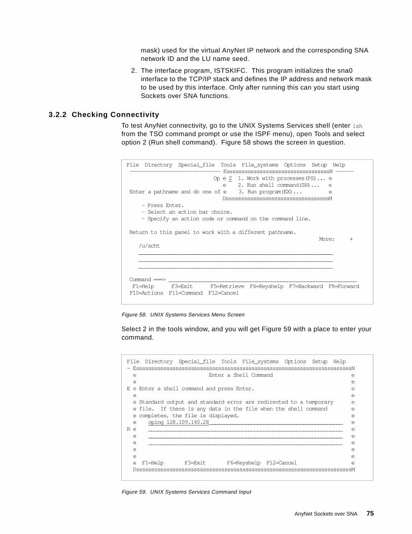
mask) used for the virtual AnyNet IP network and the corresponding SNAnetwork ID and the LU name seed.
2. The interface program, ISTSKIFC. This program initializes the sna0interface to the TCP/IP stack and defines the IP address and network maskto be used by this interface. Only after running this can you start usingSockets over SNA functions.
3.2.2 Checking ConnectivityTo test AnyNet connectivity, go to the UNIX Systems Services shell (enter ish
from the TSO command prompt or use the ISPF menu), open Tools and selectoption 2 (Run shell command). Figure 58 shows the screen in question.
Figure 58. UNIX Systems Services Menu Screen
Select 2 in the tools window, and you will get Figure 59 with a place to enter yourcommand.
Figure 59. UNIX Systems Services Command Input
File Directory Special_file Tools File_systems Options Setup Help------------------------------ EssssssssssssssssssssssssssssssssssN ------
Op e 2 1. Work with processes(PS)... ee 2. Run shell command(SH)... e
Enter a pathname and do one of e 3. Run program(EX)... eDssssssssssssssssssssssssssssssssssM
- Press Enter.- Select an action bar choice.- Specify an action code or command on the command line.
Return to this panel to work with a different pathname.More: +
/u/acht________________________________________________________________________________________________________________________________________________________________________________________________
Command ===> ______________________________________________________________F1=Help F3=Exit F5=Retrieve F6=Keyshelp F7=Backward F8=Forward
F10=Actions F11=Command F12=Cancel
File Directory Special_file Tools File_systems Options Setup Help- EsssssssssssssssssssssssssssssssssssssssssssssssssssssssssssssssssssssssN
e Enter a Shell Command ee e
E e Enter a shell command and press Enter. ee ee Standard output and standard error are redirected to a temporary ee file. If there is any data in the file when the shell command ee completes, the file is displayed. ee oping 128.109.140.28 ____________________________________________ e
R e ________________________________________________________________ ee ________________________________________________________________ ee ________________________________________________________________ ee ee ee F1=Help F3=Exit F6=Keyshelp F12=Cancel eDsssssssssssssssssssssssssssssssssssssssssssssssssssssssssssssssssssssssM
AnyNet Sockets over SNA 75

Because this version of AnyNet has changed the way it supports the SocketsAPIs, you can no longer use the PING command. PING is still available, but onlyfor native TCP/IP. With AnyNet, you have to use OPING, which runs under theUNIX Systems Services shell.
You enter the OPING command as shown, and after a short delay you will see theresult as in Figure 60.
Figure 60. OPING Command Output
If, on the other hand, you have not configured your network correctly, you aremore likely to see the display shown in Figure 61.
Figure 61. OPING Failed
When the OPING is issued (or, indeed, any remote IP host is contacted usingSockets over SNA) for the first time, it causes the following series of actions:
• Destination address mapping to an LU name.
• Session establishment to the remote LU. In fact there are three sessions: firstan SNASVCMG session between the LUs for the change number of sessions(CNOS) processing, and then two productive sessions, both in half duplexmode. OPING (like all PINGs) is an ICMP application which uses raw Socketsand not stream Sockets.
• Actual transfer of the IP data to the remote LU, and over to AnyNet and thecorresponding IP port.
For this reason, you can expect the first OPING to take a considerably longertime than subsequent OPINGs to the same destination.
The session status after the OPING is shown in the following VTAM display(Figure 62 on page 77).
BROWSE -- /tmp/HEIKKI.15:20:39.718892.ishell ------- Line 00000000 Col 001 040Command ===> Scroll ===> PAGE
********************************* Top of Data **********************************CS/390 V2R5: Pinging host 192.168.10.28Ping #1 response took 0.142 seconds.******************************** Bottom of Data ********************************
BROWSE -- /tmp/HEIKKI.14:23:31.885717.ishell ------- Line 00000000 Col 001 042Command ===> Scroll ===> PAGE
********************************* Top of Data **********************************sendto(): EDC8118I Network is unreachable.CS/390 V2R5: Pinging host 192.168.10.28******************************** Bottom of Data ********************************
76 SNA and TCP/IP Integration
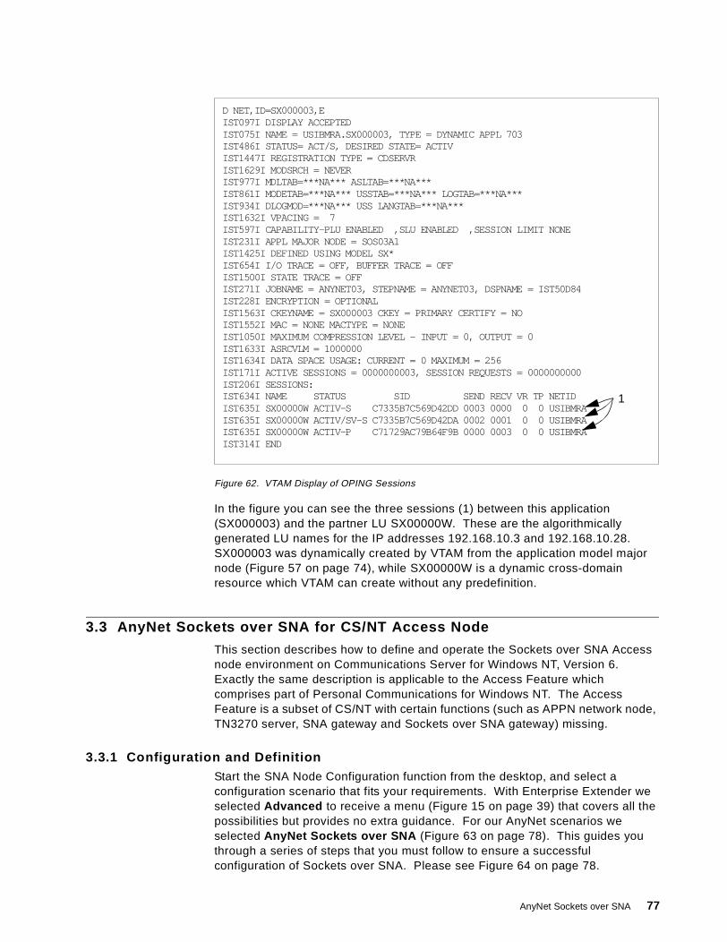
Figure 62. VTAM Display of OPING Sessions
In the figure you can see the three sessions (1) between this application(SX000003) and the partner LU SX00000W. These are the algorithmicallygenerated LU names for the IP addresses 192.168.10.3 and 192.168.10.28.SX000003 was dynamically created by VTAM from the application model majornode (Figure 57 on page 74), while SX00000W is a dynamic cross-domainresource which VTAM can create without any predefinition.
3.3 AnyNet Sockets over SNA for CS/NT Access Node
This section describes how to define and operate the Sockets over SNA Accessnode environment on Communications Server for Windows NT, Version 6.Exactly the same description is applicable to the Access Feature whichcomprises part of Personal Communications for Windows NT. The AccessFeature is a subset of CS/NT with certain functions (such as APPN network node,TN3270 server, SNA gateway and Sockets over SNA gateway) missing.
3.3.1 Configuration and DefinitionStart the SNA Node Configuration function from the desktop, and select aconfiguration scenario that fits your requirements. With Enterprise Extender weselected Advanced to receive a menu (Figure 15 on page 39) that covers all thepossibilities but provides no extra guidance. For our AnyNet scenarios weselected AnyNet Sockets over SNA (Figure 63 on page 78). This guides youthrough a series of steps that you must follow to ensure a successfulconfiguration of Sockets over SNA. Please see Figure 64 on page 78.
D NET,ID=SX000003,EIST097I DISPLAY ACCEPTEDIST075I NAME = USIBMRA.SX000003, TYPE = DYNAMIC APPL 703IST486I STATUS= ACT/S, DESIRED STATE= ACTIVIST1447I REGISTRATION TYPE = CDSERVRIST1629I MODSRCH = NEVERIST977I MDLTAB=***NA*** ASLTAB=***NA***IST861I MODETAB=***NA*** USSTAB=***NA*** LOGTAB=***NA***IST934I DLOGMOD=***NA*** USS LANGTAB=***NA***IST1632I VPACING = 7IST597I CAPABILITY-PLU ENABLED ,SLU ENABLED ,SESSION LIMIT NONEIST231I APPL MAJOR NODE = SOS03A1IST1425I DEFINED USING MODEL SX*IST654I I/O TRACE = OFF, BUFFER TRACE = OFFIST1500I STATE TRACE = OFFIST271I JOBNAME = ANYNET03, STEPNAME = ANYNET03, DSPNAME = IST50D84IST228I ENCRYPTION = OPTIONALIST1563I CKEYNAME = SX000003 CKEY = PRIMARY CERTIFY = NOIST1552I MAC = NONE MACTYPE = NONEIST1050I MAXIMUM COMPRESSION LEVEL - INPUT = 0, OUTPUT = 0IST1633I ASRCVLM = 1000000IST1634I DATA SPACE USAGE: CURRENT = 0 MAXIMUM = 256IST171I ACTIVE SESSIONS = 0000000003, SESSION REQUESTS = 0000000000IST206I SESSIONS:IST634I NAME STATUS SID SEND RECV VR TP NETIDIST635I SX00000W ACTIV-S C7335B7C569D42DD 0003 0000 0 0 USIBMRAIST635I SX00000W ACTIV/SV-S C7335B7C569D42DA 0002 0001 0 0 USIBMRAIST635I SX00000W ACTIV-P C71729AC79B64F9B 0000 0003 0 0 USIBMRAIST314I END
1
AnyNet Sockets over SNA 77

Figure 63. Configuration Selection: AnyNet Sockets over SNA on CS/NT
Figure 64. Communications Server SNA Node Configuration
Just as with Enterprise Extender, you have to configure the node, the devices(ports) and the link stations (connections) as a minimum. To this you must addthe AnyNet-specific definitions such as the mapping requirements. However, inthe guided path (as opposed to the advanced path) you invoke in sequence thesteps shown on the left-hand panel in Figure 64 rather than worry about which ofthe right-hand panel options you need to select.
First, you define the node itself (select Node Setup ), as in Figure 65.
78 SNA and TCP/IP Integration
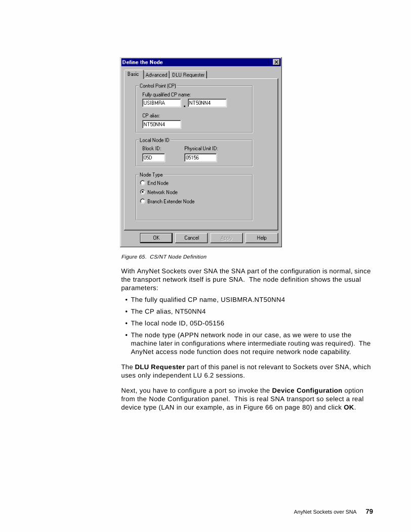
Figure 65. CS/NT Node Definition
With AnyNet Sockets over SNA the SNA part of the configuration is normal, sincethe transport network itself is pure SNA. The node definition shows the usualparameters:
• The fully qualified CP name, USIBMRA.NT50NN4
• The CP alias, NT50NN4
• The local node ID, 05D-05156
• The node type (APPN network node in our case, as we were to use themachine later in configurations where intermediate routing was required). TheAnyNet access node function does not require network node capability.
The DLU Requester part of this panel is not relevant to Sockets over SNA, whichuses only independent LU 6.2 sessions.
Next, you have to configure a port so invoke the Device Configuration optionfrom the Node Configuration panel. This is real SNA transport so select a realdevice type (LAN in our example, as in Figure 66 on page 80) and click OK .
AnyNet Sockets over SNA 79
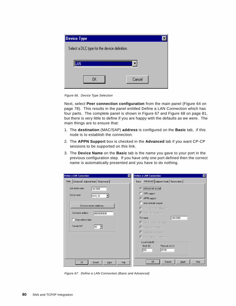
Figure 66. Device Type Selection
Next, select Peer connection configuration from the main panel (Figure 64 onpage 78). This results in the panel entitled Define a LAN Connection which hasfour parts. The complete panel is shown in Figure 67 and Figure 68 on page 81,but there is very little to define if you are happy with the defaults as we were. Themain things are to ensure that:
1. The destination (MAC/SAP) address is configured on the Basic tab, if thisnode is to establish the connection.
2. The APPN Support box is checked in the Advanced tab if you want CP-CPsessions to be supported on this link.
3. The Device Name on the Basic tab is the name you gave to your port in theprevious configuration step. If you have only one port defined then the correctname is automatically presented and you have to do nothing.
Figure 67. Define a LAN Connection (Basic and Advanced)
80 SNA and TCP/IP Integration
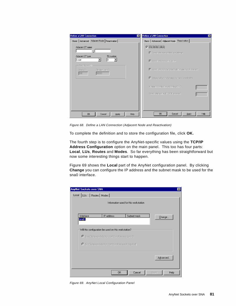
Figure 68. Define a LAN Connection (Adjacent Node and Reactivation)
To complete the definition and to store the configuration file, click OK.
The fourth step is to configure the AnyNet-specific values using the TCP/IPAddress Configuration option on the main panel. This too has four parts:Local , LUs , Routes and Modes . So far everything has been straightforward butnow some interesting things start to happen.
Figure 69 shows the Local part of the AnyNet configuration panel. By clickingChange you can configure the IP address and the subnet mask to be used for thesna0 interface.
Figure 69. AnyNet Local Configuration Panel
AnyNet Sockets over SNA 81
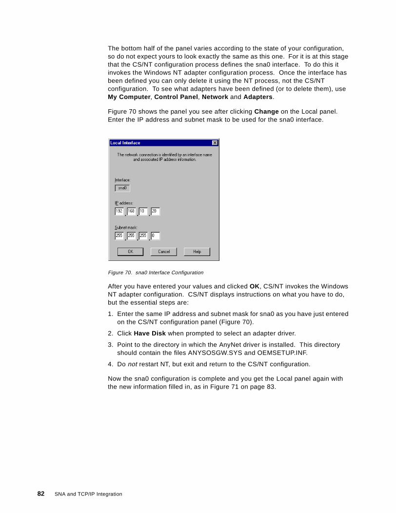
The bottom half of the panel varies according to the state of your configuration,so do not expect yours to look exactly the same as this one. For it is at this stagethat the CS/NT configuration process defines the sna0 interface. To do this itinvokes the Windows NT adapter configuration process. Once the interface hasbeen defined you can only delete it using the NT process, not the CS/NTconfiguration. To see what adapters have been defined (or to delete them), useMy Computer , Control Panel , Network and Adapters .
Figure 70 shows the panel you see after clicking Change on the Local panel.Enter the IP address and subnet mask to be used for the sna0 interface.
Figure 70. sna0 Interface Configuration
After you have entered your values and clicked OK , CS/NT invokes the WindowsNT adapter configuration. CS/NT displays instructions on what you have to do,but the essential steps are:
1. Enter the same IP address and subnet mask for sna0 as you have just enteredon the CS/NT configuration panel (Figure 70).
2. Click Have Disk when prompted to select an adapter driver.
3. Point to the directory in which the AnyNet driver is installed. This directoryshould contain the files ANYSOSGW.SYS and OEMSETUP.INF.
4. Do not restart NT, but exit and return to the CS/NT configuration.
Now the sna0 configuration is complete and you get the Local panel again withthe new information filled in, as in Figure 71 on page 83.
82 SNA and TCP/IP Integration
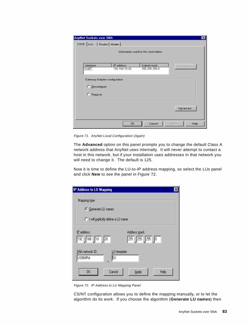
Figure 71. AnyNet Local Configuration (Again)
The Advanced option on this panel prompts you to change the default Class Anetwork address that AnyNet uses internally. It will never attempt to contact ahost in this network, but if your installation uses addresses in that network youwill need to change it. The default is 125.
Now it is time to define the LU-to-IP address mapping, so select the LUs paneland click New to see the panel in Figure 72.
Figure 72. IP Address to LU Mapping Panel
CS/NT configuration allows you to define the mapping manually, or to let thealgorithm do its work. If you choose the algorithm (Generate LU names ) then
AnyNet Sockets over SNA 83
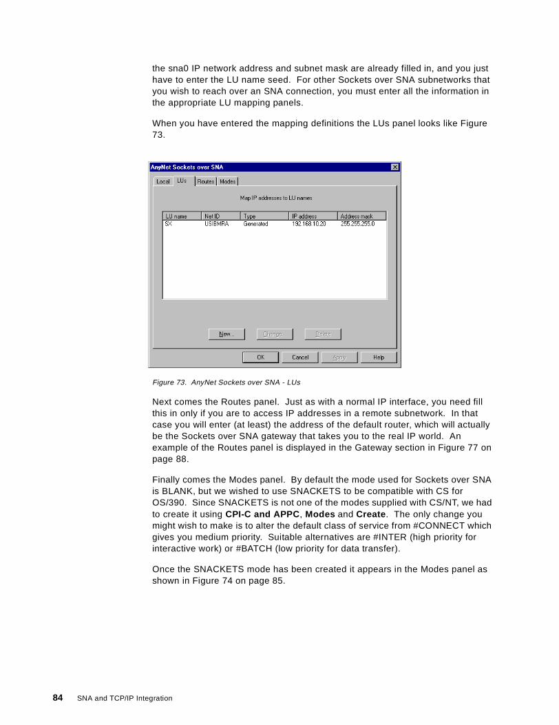
the sna0 IP network address and subnet mask are already filled in, and you justhave to enter the LU name seed. For other Sockets over SNA subnetworks thatyou wish to reach over an SNA connection, you must enter all the information inthe appropriate LU mapping panels.
When you have entered the mapping definitions the LUs panel looks like Figure73.
Figure 73. AnyNet Sockets over SNA - LUs
Next comes the Routes panel. Just as with a normal IP interface, you need fillthis in only if you are to access IP addresses in a remote subnetwork. In thatcase you will enter (at least) the address of the default router, which will actuallybe the Sockets over SNA gateway that takes you to the real IP world. Anexample of the Routes panel is displayed in the Gateway section in Figure 77 onpage 88.
Finally comes the Modes panel. By default the mode used for Sockets over SNAis BLANK, but we wished to use SNACKETS to be compatible with CS forOS/390. Since SNACKETS is not one of the modes supplied with CS/NT, we hadto create it using CPI-C and APPC , Modes and Create . The only change youmight wish to make is to alter the default class of service from #CONNECT whichgives you medium priority. Suitable alternatives are #INTER (high priority forinteractive work) or #BATCH (low priority for data transfer).
Once the SNACKETS mode has been created it appears in the Modes panel asshown in Figure 74 on page 85.
84 SNA and TCP/IP Integration
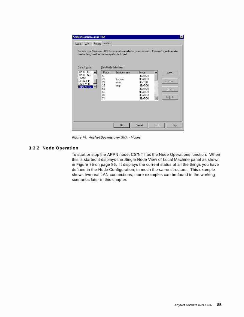
Figure 74. AnyNet Sockets over SNA - Modes
3.3.2 Node OperationTo start or stop the APPN node, CS/NT has the Node Operations function. Whenthis is started it displays the Single Node View of Local Machine panel as shownin Figure 75 on page 86. It displays the current status of all the things you havedefined in the Node Configuration, in much the same structure. This exampleshows two real LAN connections; more examples can be found in the workingscenarios later in this chapter.
AnyNet Sockets over SNA 85
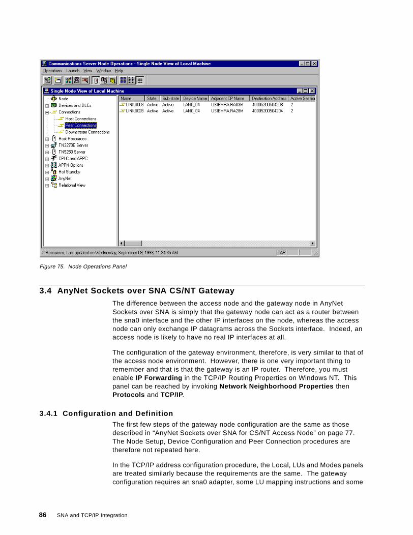
Figure 75. Node Operations Panel
3.4 AnyNet Sockets over SNA CS/NT Gateway
The difference between the access node and the gateway node in AnyNetSockets over SNA is simply that the gateway node can act as a router betweenthe sna0 interface and the other IP interfaces on the node, whereas the accessnode can only exchange IP datagrams across the Sockets interface. Indeed, anaccess node is likely to have no real IP interfaces at all.
The configuration of the gateway environment, therefore, is very similar to that ofthe access node environment. However, there is one very important thing toremember and that is that the gateway is an IP router. Therefore, you mustenable IP Forwarding in the TCP/IP Routing Properties on Windows NT. Thispanel can be reached by invoking Network Neighborhood Properties thenProtocols and TCP/IP.
3.4.1 Configuration and DefinitionThe first few steps of the gateway node configuration are the same as thosedescribed in “AnyNet Sockets over SNA for CS/NT Access Node” on page 77.The Node Setup, Device Configuration and Peer Connection procedures aretherefore not repeated here.
In the TCP/IP address configuration procedure, the Local, LUs and Modes panelsare treated similarly because the requirements are the same. The gatewayconfiguration requires an sna0 adapter, some LU mapping instructions and some
86 SNA and TCP/IP Integration
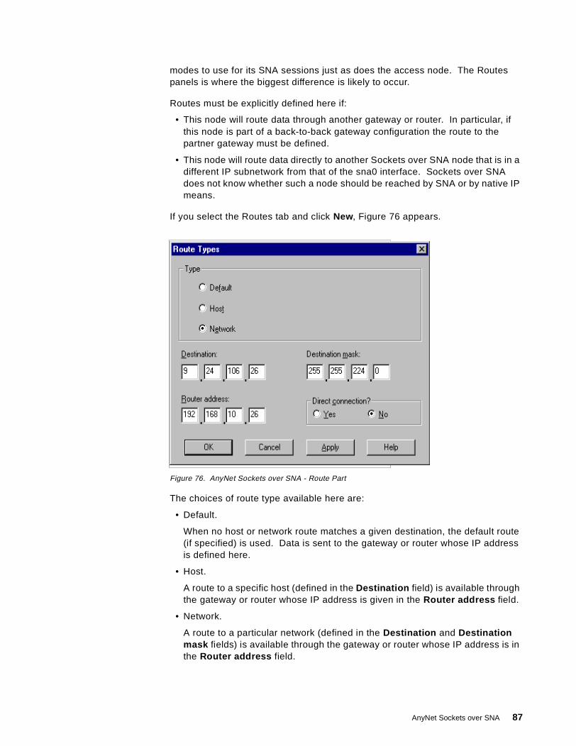
modes to use for its SNA sessions just as does the access node. The Routespanels is where the biggest difference is likely to occur.
Routes must be explicitly defined here if:
• This node will route data through another gateway or router. In particular, ifthis node is part of a back-to-back gateway configuration the route to thepartner gateway must be defined.
• This node will route data directly to another Sockets over SNA node that is in adifferent IP subnetwork from that of the sna0 interface. Sockets over SNAdoes not know whether such a node should be reached by SNA or by native IPmeans.
If you select the Routes tab and click New, Figure 76 appears.
Figure 76. AnyNet Sockets over SNA - Route Part
The choices of route type available here are:
• Default.
When no host or network route matches a given destination, the default route(if specified) is used. Data is sent to the gateway or router whose IP addressis defined here.
• Host.
A route to a specific host (defined in the Destination field) is available throughthe gateway or router whose IP address is given in the Router address field.
• Network.
A route to a particular network (defined in the Destination and Destinationmask fields) is available through the gateway or router whose IP address is inthe Router address field.
AnyNet Sockets over SNA 87
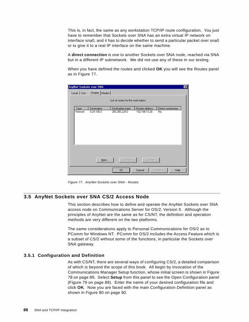
This is, in fact, the same as any workstation TCP/IP route configuration. You justhave to remember that Sockets over SNA has an extra virtual IP network oninterface sna0, and it has to decide whether to send a particular packet over sna0or to give it to a real IP interface on the same machine.
A direct connection is one to another Sockets over SNA node, reached via SNAbut in a different IP subnetwork. We did not use any of these in our testing.
When you have defined the routes and clicked OK you will see the Routes panelas in Figure 77.
Figure 77. AnyNet Sockets over SNA - Routes
3.5 AnyNet Sockets over SNA CS/2 Access Node
This section describes how to define and operate the AnyNet Sockets over SNAaccess node on Communications Server for OS/2, Version 5. Although theprinciples of AnyNet are the same as for CS/NT, the definition and operationmethods are very different on the two platforms.
The same considerations apply to Personal Communications for OS/2 as toPComm for Windows NT. PComm for OS/2 includes the Access Feature which isa subset of CS/2 without some of the functions, in particular the Sockets overSNA gateway.
3.5.1 Configuration and DefinitionAs with CS/NT, there are several ways of configuring CS/2, a detailed comparisonof which is beyond the scope of this book. All begin by invocation of theCommunications Manager Setup function, whose initial screen is shown in Figure78 on page 89. Select Setup from this panel to see the Open Configuration panel(Figure 79 on page 89). Enter the name of your desired configuration file andclick OK. Now you are faced with the main Configuration Definition panel asshown in Figure 80 on page 90.
88 SNA and TCP/IP Integration
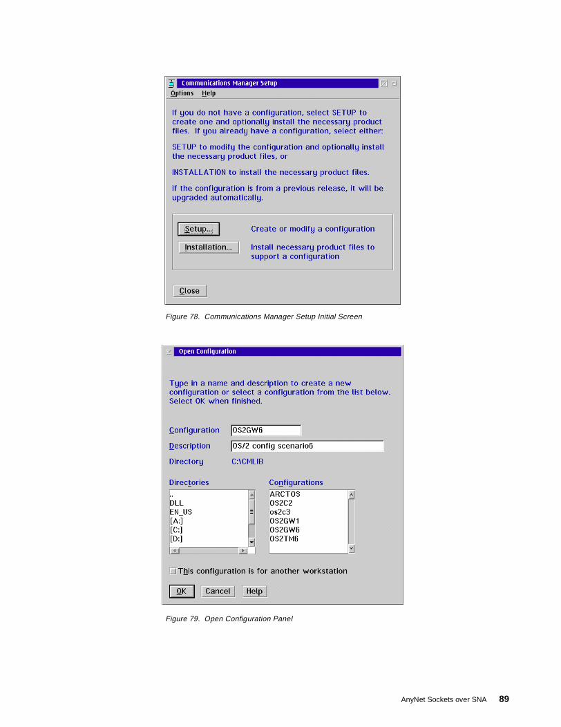
Figure 78. Communications Manager Setup Initial Screen
Figure 79. Open Configuration Panel
AnyNet Sockets over SNA 89
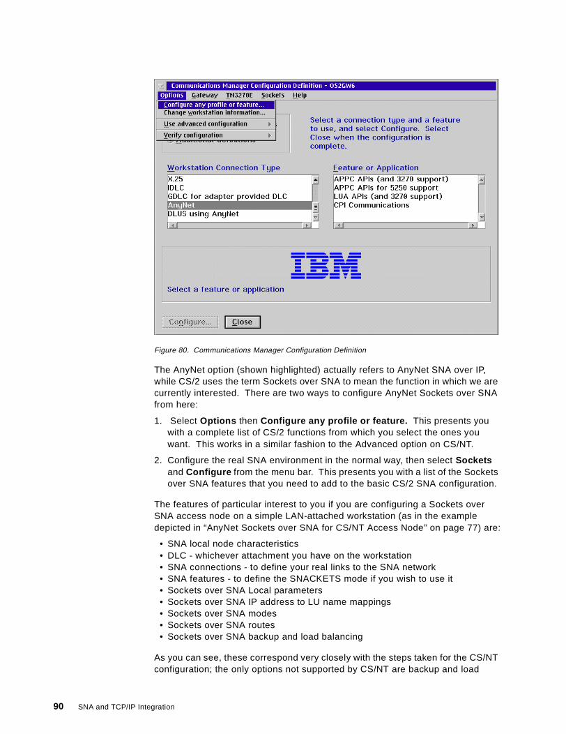
Figure 80. Communications Manager Configuration Definition
The AnyNet option (shown highlighted) actually refers to AnyNet SNA over IP,while CS/2 uses the term Sockets over SNA to mean the function in which we arecurrently interested. There are two ways to configure AnyNet Sockets over SNAfrom here:
1. Select Options then Configure any profile or feature. This presents youwith a complete list of CS/2 functions from which you select the ones youwant. This works in a similar fashion to the Advanced option on CS/NT.
2. Configure the real SNA environment in the normal way, then select Socketsand Configure from the menu bar. This presents you with a list of the Socketsover SNA features that you need to add to the basic CS/2 SNA configuration.
The features of particular interest to you if you are configuring a Sockets overSNA access node on a simple LAN-attached workstation (as in the exampledepicted in “AnyNet Sockets over SNA for CS/NT Access Node” on page 77) are:
• SNA local node characteristics• DLC - whichever attachment you have on the workstation• SNA connections - to define your real links to the SNA network• SNA features - to define the SNACKETS mode if you wish to use it• Sockets over SNA Local parameters• Sockets over SNA IP address to LU name mappings• Sockets over SNA modes• Sockets over SNA routes• Sockets over SNA backup and load balancing
As you can see, these correspond very closely with the steps taken for the CS/NTconfiguration; the only options not supported by CS/NT are backup and load
90 SNA and TCP/IP Integration
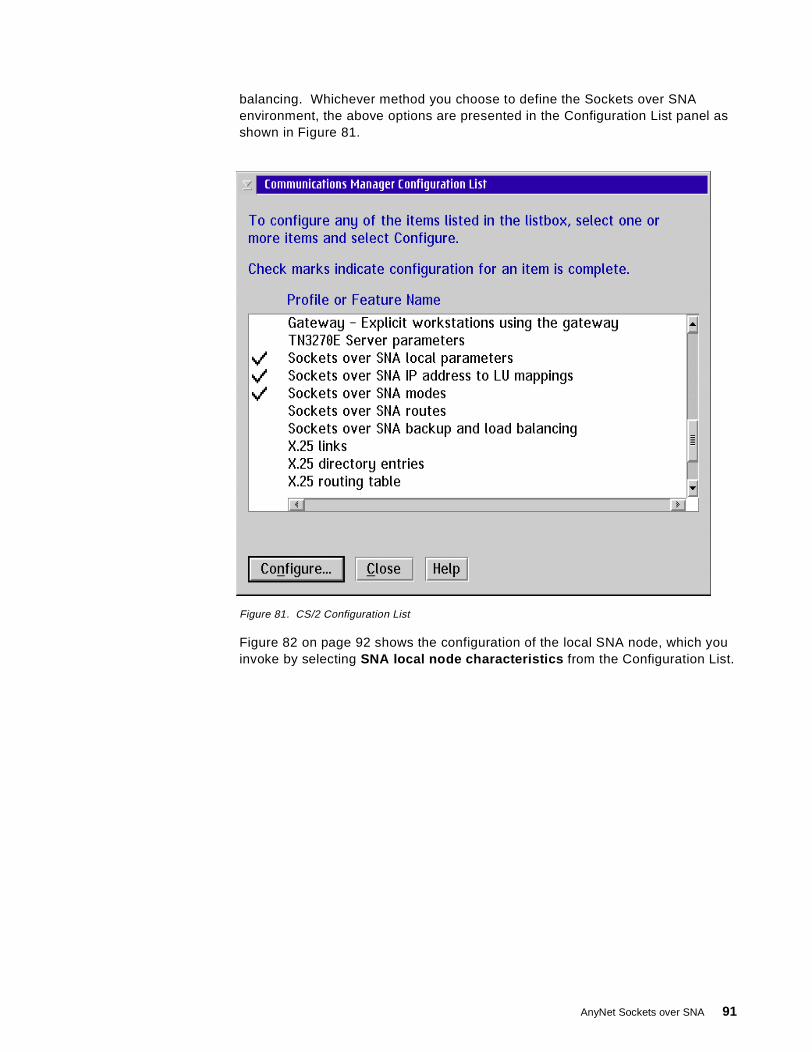
balancing. Whichever method you choose to define the Sockets over SNAenvironment, the above options are presented in the Configuration List panel asshown in Figure 81.
Figure 81. CS/2 Configuration List
Figure 82 on page 92 shows the configuration of the local SNA node, which youinvoke by selecting SNA local node characteristics from the Configuration List.
AnyNet Sockets over SNA 91
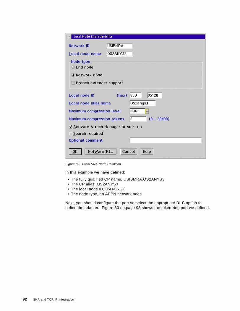
Figure 82. Local SNA Node Definition
In this example we have defined:
• The fully qualified CP name, USIBMRA.OS2ANYS3• The CP alias, OS2ANYS3• The local node ID, 05D-05128• The node type, an APPN network node
Next, you should configure the port so select the appropriate DLC option todefine the adapter. Figure 83 on page 93 shows the token-ring port we defined.
92 SNA and TCP/IP Integration
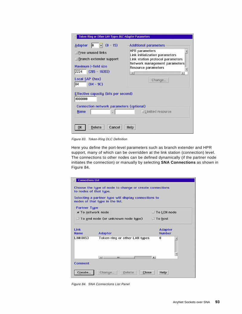
Figure 83. Token-Ring DLC Definition
Here you define the port-level parameters such as branch extender and HPRsupport, many of which can be overridden at the link station (connection) level.The connections to other nodes can be defined dynamically (if the partner nodeinitiates the connection) or manually by selecting SNA Connections as shown inFigure 84.
Figure 84. SNA Connections List Panel
AnyNet Sockets over SNA 93
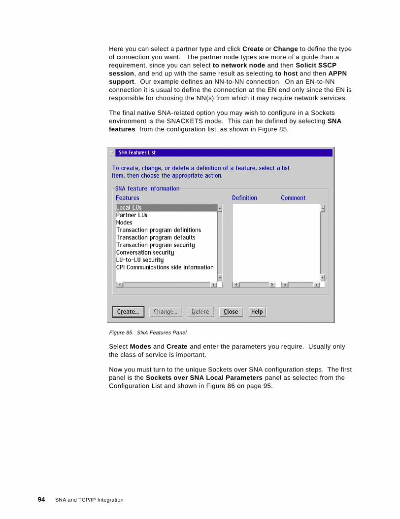
Here you can select a partner type and click Create or Change to define the typeof connection you want. The partner node types are more of a guide than arequirement, since you can select to network node and then Solicit SSCPsession , and end up with the same result as selecting to host and then APPNsupport . Our example defines an NN-to-NN connection. On an EN-to-NNconnection it is usual to define the connection at the EN end only since the EN isresponsible for choosing the NN(s) from which it may require network services.
The final native SNA-related option you may wish to configure in a Socketsenvironment is the SNACKETS mode. This can be defined by selecting SNAfeatures from the configuration list, as shown in Figure 85.
Figure 85. SNA Features Panel
Select Modes and Create and enter the parameters you require. Usually onlythe class of service is important.
Now you must turn to the unique Sockets over SNA configuration steps. The firstpanel is the Sockets over SNA Local Parameters panel as selected from theConfiguration List and shown in Figure 86 on page 95.
94 SNA and TCP/IP Integration
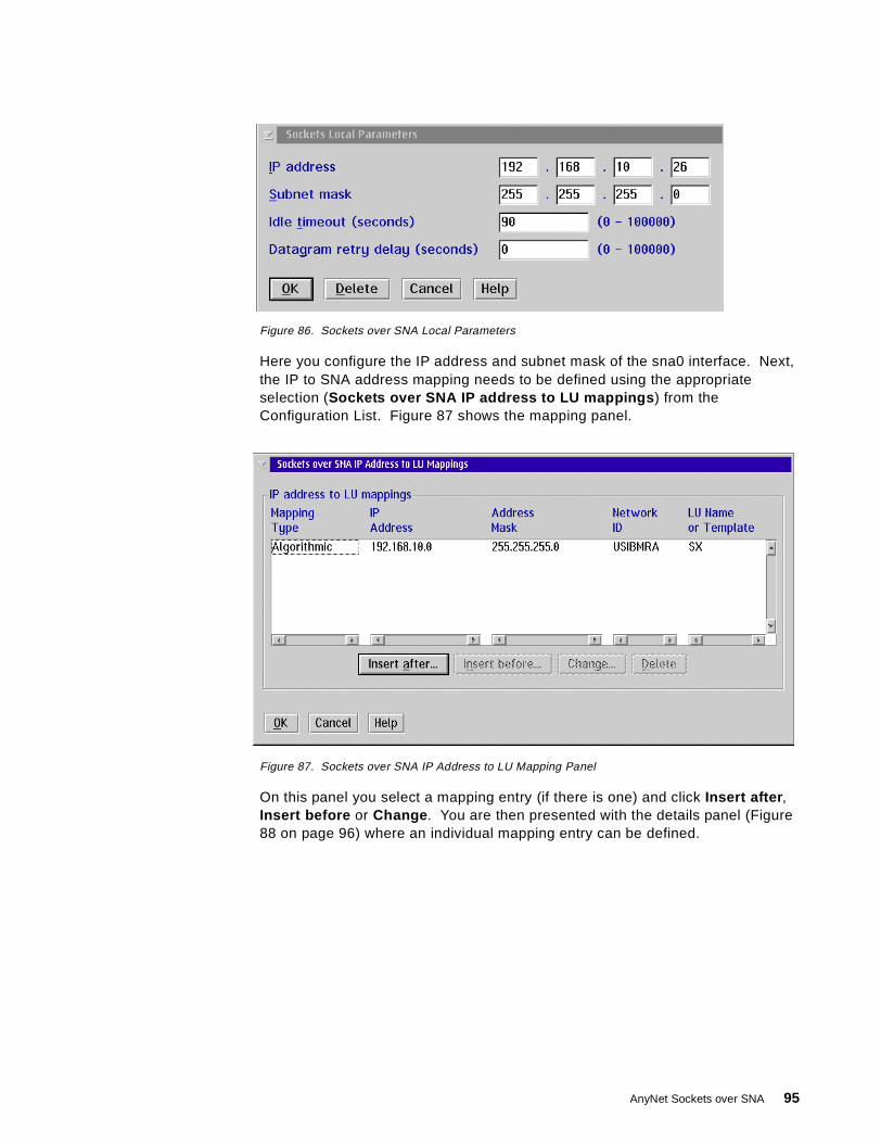
Figure 86. Sockets over SNA Local Parameters
Here you configure the IP address and subnet mask of the sna0 interface. Next,the IP to SNA address mapping needs to be defined using the appropriateselection (Sockets over SNA IP address to LU mappings ) from theConfiguration List. Figure 87 shows the mapping panel.
Figure 87. Sockets over SNA IP Address to LU Mapping Panel
On this panel you select a mapping entry (if there is one) and click Insert after ,Insert before or Change . You are then presented with the details panel (Figure88 on page 96) where an individual mapping entry can be defined.
AnyNet Sockets over SNA 95
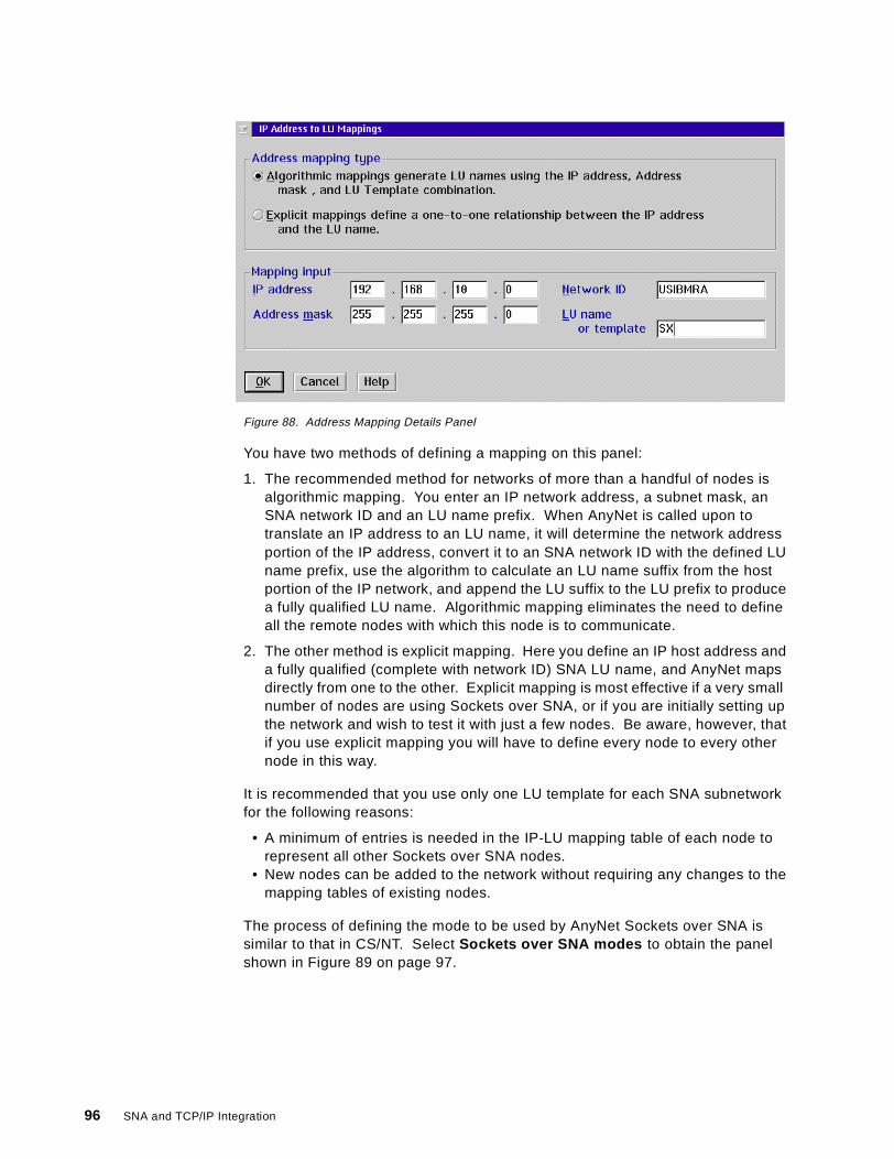
Figure 88. Address Mapping Details Panel
You have two methods of defining a mapping on this panel:
1. The recommended method for networks of more than a handful of nodes isalgorithmic mapping. You enter an IP network address, a subnet mask, anSNA network ID and an LU name prefix. When AnyNet is called upon totranslate an IP address to an LU name, it will determine the network addressportion of the IP address, convert it to an SNA network ID with the defined LUname prefix, use the algorithm to calculate an LU name suffix from the hostportion of the IP network, and append the LU suffix to the LU prefix to producea fully qualified LU name. Algorithmic mapping eliminates the need to defineall the remote nodes with which this node is to communicate.
2. The other method is explicit mapping. Here you define an IP host address anda fully qualified (complete with network ID) SNA LU name, and AnyNet mapsdirectly from one to the other. Explicit mapping is most effective if a very smallnumber of nodes are using Sockets over SNA, or if you are initially setting upthe network and wish to test it with just a few nodes. Be aware, however, thatif you use explicit mapping you will have to define every node to every othernode in this way.
It is recommended that you use only one LU template for each SNA subnetworkfor the following reasons:
• A minimum of entries is needed in the IP-LU mapping table of each node torepresent all other Sockets over SNA nodes.
• New nodes can be added to the network without requiring any changes to themapping tables of existing nodes.
The process of defining the mode to be used by AnyNet Sockets over SNA issimilar to that in CS/NT. Select Sockets over SNA modes to obtain the panelshown in Figure 89 on page 97.
96 SNA and TCP/IP Integration
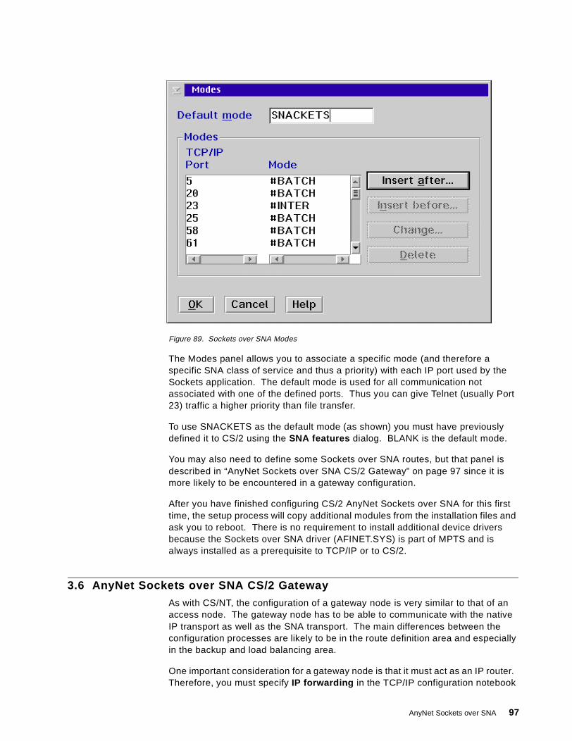
Figure 89. Sockets over SNA Modes
The Modes panel allows you to associate a specific mode (and therefore aspecific SNA class of service and thus a priority) with each IP port used by theSockets application. The default mode is used for all communication notassociated with one of the defined ports. Thus you can give Telnet (usually Port23) traffic a higher priority than file transfer.
To use SNACKETS as the default mode (as shown) you must have previouslydefined it to CS/2 using the SNA features dialog. BLANK is the default mode.
You may also need to define some Sockets over SNA routes, but that panel isdescribed in “AnyNet Sockets over SNA CS/2 Gateway” on page 97 since it ismore likely to be encountered in a gateway configuration.
After you have finished configuring CS/2 AnyNet Sockets over SNA for this firsttime, the setup process will copy additional modules from the installation files andask you to reboot. There is no requirement to install additional device driversbecause the Sockets over SNA driver (AFINET.SYS) is part of MPTS and isalways installed as a prerequisite to TCP/IP or to CS/2.
3.6 AnyNet Sockets over SNA CS/2 Gateway
As with CS/NT, the configuration of a gateway node is very similar to that of anaccess node. The gateway node has to be able to communicate with the nativeIP transport as well as the SNA transport. The main differences between theconfiguration processes are likely to be in the route definition area and especiallyin the backup and load balancing area.
One important consideration for a gateway node is that it must act as an IP router.Therefore, you must specify IP forwarding in the TCP/IP configuration notebook
AnyNet Sockets over SNA 97

for your OS/2 machine. In TCP/IP Version 4 Release 1 this is a check box on theRouting tab in the notebook.
Figure 90 shows the Routes panel that you get when you select Sockets overSNA routes from the Configuration List.
Figure 90. Sockets over SNA Routes Panel
If you select one of the Insert options or Change an existing route, you get theroute parameters panel as in Figure 91.
Figure 91. Sockets over SNA Routes Parameters
On this panel you have the option of defining one of four types of route (default,net, subnet or host) with appropriate destination addresses, router addresses andsubnet masks. The route types are:
98 SNA and TCP/IP Integration
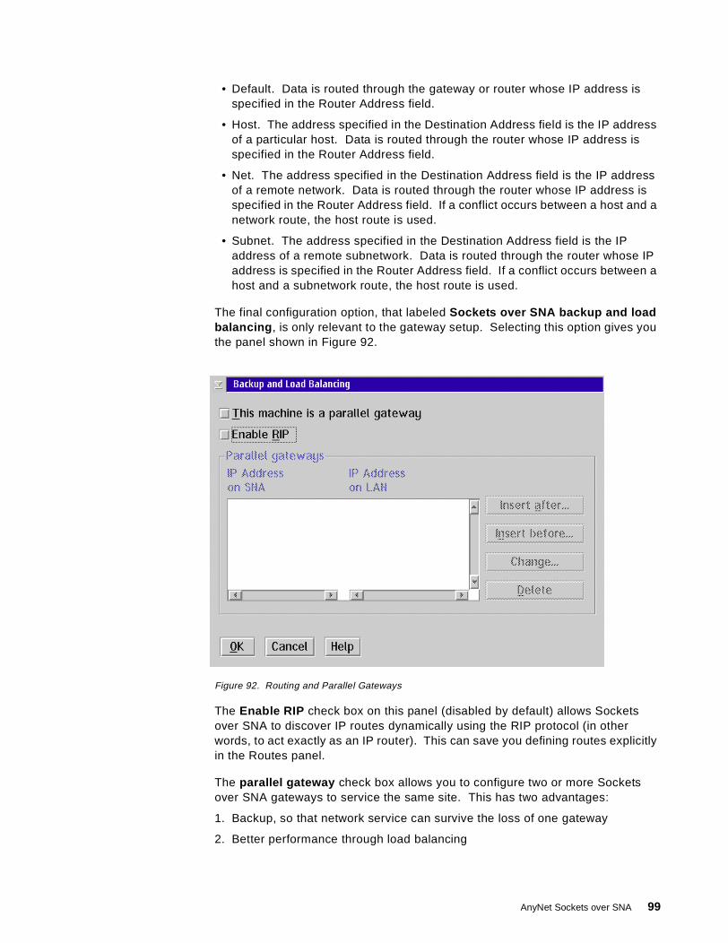
• Default. Data is routed through the gateway or router whose IP address isspecified in the Router Address field.
• Host. The address specified in the Destination Address field is the IP addressof a particular host. Data is routed through the router whose IP address isspecified in the Router Address field.
• Net. The address specified in the Destination Address field is the IP addressof a remote network. Data is routed through the router whose IP address isspecified in the Router Address field. If a conflict occurs between a host and anetwork route, the host route is used.
• Subnet. The address specified in the Destination Address field is the IPaddress of a remote subnetwork. Data is routed through the router whose IPaddress is specified in the Router Address field. If a conflict occurs between ahost and a subnetwork route, the host route is used.
The final configuration option, that labeled Sockets over SNA backup and loadbalancing , is only relevant to the gateway setup. Selecting this option gives youthe panel shown in Figure 92.
Figure 92. Routing and Parallel Gateways
The Enable RIP check box on this panel (disabled by default) allows Socketsover SNA to discover IP routes dynamically using the RIP protocol (in otherwords, to act exactly as an IP router). This can save you defining routes explicitlyin the Routes panel.
The parallel gateway check box allows you to configure two or more Socketsover SNA gateways to service the same site. This has two advantages:
1. Backup, so that network service can survive the loss of one gateway
2. Better performance through load balancing
AnyNet Sockets over SNA 99
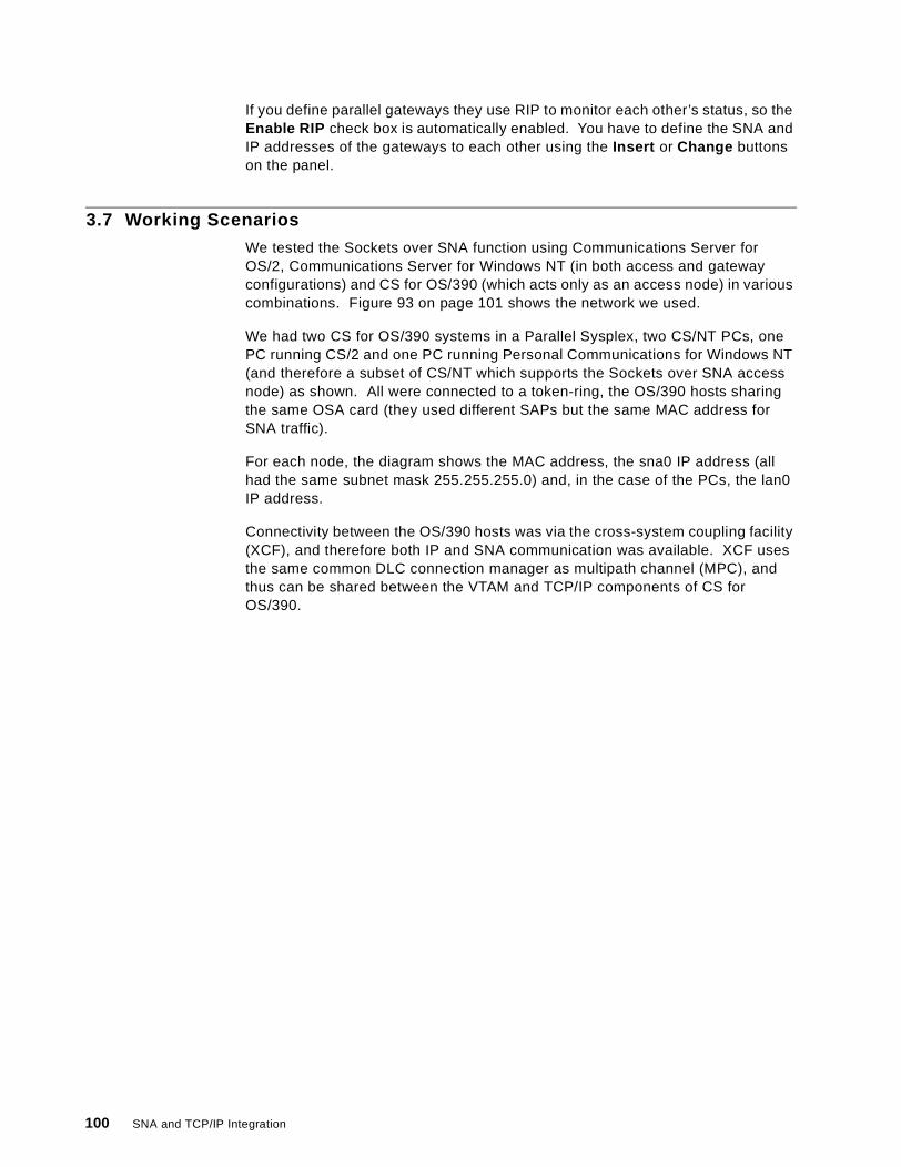
If you define parallel gateways they use RIP to monitor each other’s status, so theEnable RIP check box is automatically enabled. You have to define the SNA andIP addresses of the gateways to each other using the Insert or Change buttonson the panel.
3.7 Working Scenarios
We tested the Sockets over SNA function using Communications Server forOS/2, Communications Server for Windows NT (in both access and gatewayconfigurations) and CS for OS/390 (which acts only as an access node) in variouscombinations. Figure 93 on page 101 shows the network we used.
We had two CS for OS/390 systems in a Parallel Sysplex, two CS/NT PCs, onePC running CS/2 and one PC running Personal Communications for Windows NT(and therefore a subset of CS/NT which supports the Sockets over SNA accessnode) as shown. All were connected to a token-ring, the OS/390 hosts sharingthe same OSA card (they used different SAPs but the same MAC address forSNA traffic).
For each node, the diagram shows the MAC address, the sna0 IP address (allhad the same subnet mask 255.255.255.0) and, in the case of the PCs, the lan0IP address.
Connectivity between the OS/390 hosts was via the cross-system coupling facility(XCF), and therefore both IP and SNA communication was available. XCF usesthe same common DLC connection manager as multipath channel (MPC), andthus can be shared between the VTAM and TCP/IP components of CS forOS/390.
100 SNA and TCP/IP Integration
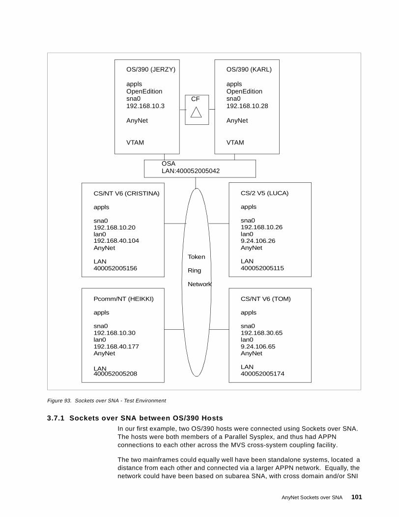
Figure 93. Sockets over SNA - Test Environment
3.7.1 Sockets over SNA between OS/390 HostsIn our first example, two OS/390 hosts were connected using Sockets over SNA.The hosts were both members of a Parallel Sysplex, and thus had APPNconnections to each other across the MVS cross-system coupling facility.
The two mainframes could equally well have been standalone systems, located adistance from each other and connected via a larger APPN network. Equally, thenetwork could have been based on subarea SNA, with cross domain and/or SNI
OS/390 (KARL)
appls
sna0192.168.10.28
AnyNet
VTAM
OS/390 (JERZY)
appls
sna0192.168.10.3
AnyNet
VTAM
CF
OSALAN:400052005042
CS/NT V6 (CRISTINA)
OpenEdition OpenEdition
appls
sna0192.168.10.20lan0
AnyNet
LAN400052005156
Pcomm/NT (HEIKKI)
appls
sna0192.168.10.30
AnyNet
400052005208
CS/NT V6 (TOM)
appls
sna0192.168.30.65
AnyNet
LAN400052005174
CS/2 V5 (LUCA)
appls
sna0192.168.10.26lan0
AnyNet
LAN400052005115
lan0
Token
Ring
Network
192.168.40.104 9.24.106.26
192.168.40.177lan09.24.106.65
LAN
AnyNet Sockets over SNA 101
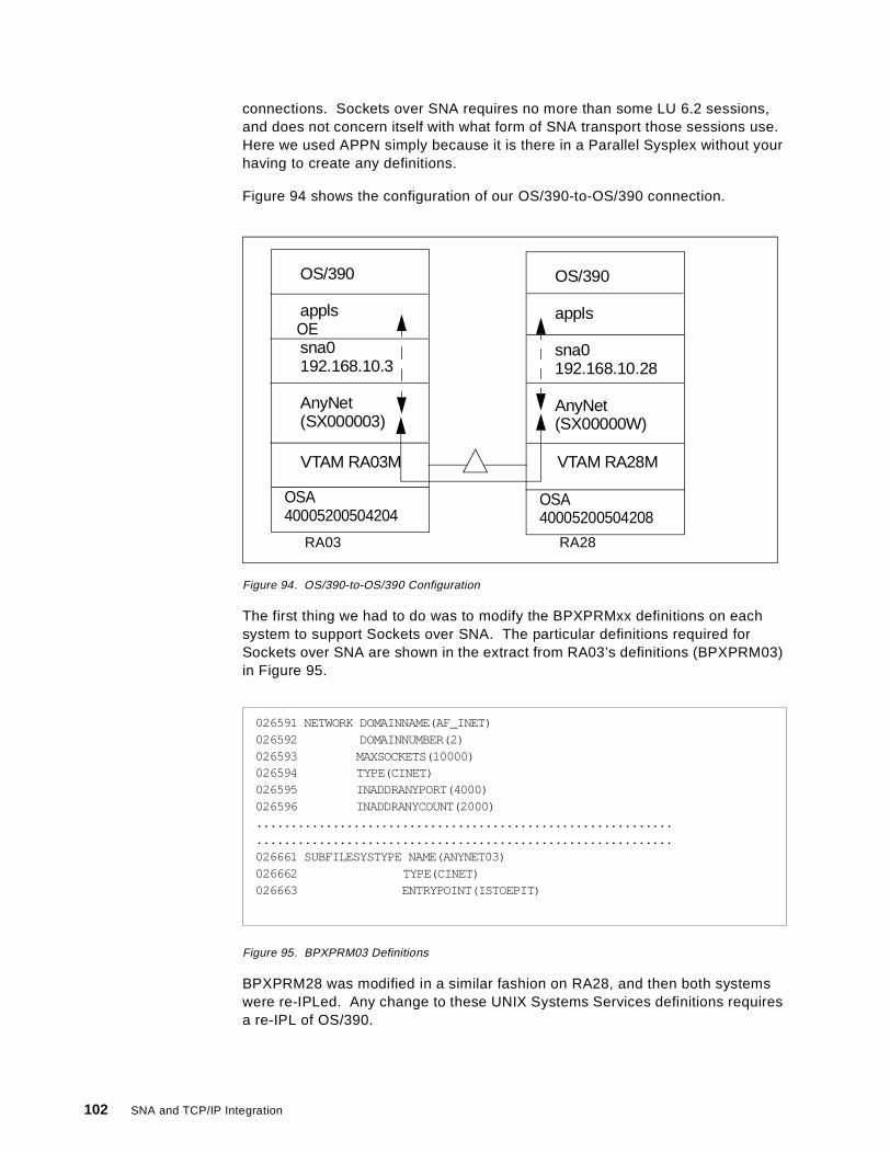
connections. Sockets over SNA requires no more than some LU 6.2 sessions,and does not concern itself with what form of SNA transport those sessions use.Here we used APPN simply because it is there in a Parallel Sysplex without yourhaving to create any definitions.
Figure 94 shows the configuration of our OS/390-to-OS/390 connection.
Figure 94. OS/390-to-OS/390 Configuration
The first thing we had to do was to modify the BPXPRMxx definitions on eachsystem to support Sockets over SNA. The particular definitions required forSockets over SNA are shown in the extract from RA03’s definitions (BPXPRM03)in Figure 95.
Figure 95. BPXPRM03 Definitions
BPXPRM28 was modified in a similar fashion on RA28, and then both systemswere re-IPLed. Any change to these UNIX Systems Services definitions requiresa re-IPL of OS/390.
OS/390 (JERZY)
appls
sna0192.168.10.3
AnyNet(SX000003)
OSA40005200504204
OE
OS/390 (KARL)
appls
sna0192.168.10.28
AnyNet(SX00000W)
OSA40005200504208
VTAM RA03M VTAM RA28M
RA03 RA28
026591 NETWORK DOMAINNAME(AF_INET)026592 DOMAINNUMBER(2)026593 MAXSOCKETS(10000)026594 TYPE(CINET)026595 INADDRANYPORT(4000)026596 INADDRANYCOUNT(2000)........................................................................................................................026661 SUBFILESYSTYPE NAME(ANYNET03)026662 TYPE(CINET)026663 ENTRYPOINT(ISTOEPIT)
102 SNA and TCP/IP Integration

Next we defined application major nodes for VTAM to recognize the Sockets overSNA application LUs (SX000003 and SX00000W in this example). Figure 96illustrates the one on RA28M.
Figure 96. Application Definition for Sockets over SNA on RA28M
On both systems we used model application definitions to save having to thinkabout the LU names that the AnyNet algorithm would generate. We knew thatour LU name prefix would be SX so we simply defined SX* as the applicationname.
The application major node caters for the local Sockets over SNA application; wedid not define the remote application (on the other host) because VTAM isperfectly capable of finding that dynamically. If we enter an IP address themapping algorithm will devise an LU name and then VTAM will search thenetwork to discover the location of the named LU.
Next we activated the application major nodes on each host, then started theSockets over SNA applications themselves. Figure 97 shows the JCL we usedon RA28.
Figure 97. JCL to Start Sockets over SNA
The JCL itself is straightforward, but please note the following:
1. The procedure name (ANYNET28 on RA28) must match the name defined inthe NAME keyword in the SUBFILESYSTEM statement in the BPXPRM28member of PARMLIB. Figure 95 on page 102 is the equivalent RA03 membershowing ANYNET03 as the procedure name.
2. If you code AnyNet environment variables (we did not) you can specify toOS/390 where to look for them on the PARM keyword. This points to the
000100 SOS28A1 VBUILD TYPE=APPL000200 SX* APPL APPC=YES, X000300 PARSESS=YES, X000400 DSESLIM=10, X000500 DMINWNL=5, X000600 DMINWNR=5, X000700 AUTOSES=0, X000800 AUTH=(ACQ,PASS), X000900 OPERCNOS=ALLOW, X001000 ATNLOSS=ALL
000100 //ANYNET28 PROC000200 //*000300 //ANYNET28 EXEC PGM=ISTSKDMN,REGION=0M,TIME=1440000400 //* PARM='ENVAR(_CEE_ENVFILE=DD:ENVVAR)'000500 //*000600 //STEPLIB DD DSN=SYS1.VTAMLIB,DISP=SHR000700 // DD DSN=CEE.SCEERUN,DISP=SHR000800 //SYSPRINT DD SYSOUT=*000900 //CEEDUMP DD DUMMY001000 //*ENVVAR DD DSN=ANYNET.CFG(ENVVAR),DISP=SHR
1
2
AnyNet Sockets over SNA 103
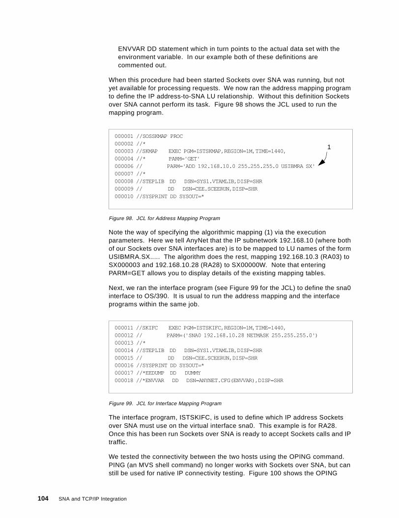
ENVVAR DD statement which in turn points to the actual data set with theenvironment variable. In our example both of these definitions arecommented out.
When this procedure had been started Sockets over SNA was running, but notyet available for processing requests. We now ran the address mapping programto define the IP address-to-SNA LU relationship. Without this definition Socketsover SNA cannot perform its task. Figure 98 shows the JCL used to run themapping program.
Figure 98. JCL for Address Mapping Program
Note the way of specifying the algorithmic mapping (1) via the executionparameters. Here we tell AnyNet that the IP subnetwork 192.168.10 (where bothof our Sockets over SNA interfaces are) is to be mapped to LU names of the formUSIBMRA.SX..... The algorithm does the rest, mapping 192.168.10.3 (RA03) toSX000003 and 192.168.10.28 (RA28) to SX00000W. Note that enteringPARM=GET allows you to display details of the existing mapping tables.
Next, we ran the interface program (see Figure 99 for the JCL) to define the sna0interface to OS/390. It is usual to run the address mapping and the interfaceprograms within the same job.
Figure 99. JCL for Interface Mapping Program
The interface program, ISTSKIFC, is used to define which IP address Socketsover SNA must use on the virtual interface sna0. This example is for RA28.Once this has been run Sockets over SNA is ready to accept Sockets calls and IPtraffic.
We tested the connectivity between the two hosts using the OPING command.PING (an MVS shell command) no longer works with Sockets over SNA, but canstill be used for native IP connectivity testing. Figure 100 shows the OPING
000001 //SOSSKMAP PROC000002 //*000003 //SKMAP EXEC PGM=ISTSKMAP,REGION=1M,TIME=1440,000004 //* PARM='GET'000006 // PARM='ADD 192.168.10.0 255.255.255.0 USIBMRA SX'000007 //*000008 //STEPLIB DD DSN=SYS1.VTAMLIB,DISP=SHR000009 // DD DSN=CEE.SCEERUN,DISP=SHR000010 //SYSPRINT DD SYSOUT=*
1
000011 //SKIFC EXEC PGM=ISTSKIFC,REGION=1M,TIME=1440,000012 // PARM=('SNA0 192.168.10.28 NETMASK 255.255.255.0')000013 //*000014 //STEPLIB DD DSN=SYS1.VTAMLIB,DISP=SHR000015 // DD DSN=CEE.SCEERUN,DISP=SHR000016 //SYSPRINT DD SYSOUT=*000017 //*EEDUMP DD DUMMY000018 //*ENVVAR DD DSN=ANYNET.CFG(ENVVAR),DISP=SHR
104 SNA and TCP/IP Integration
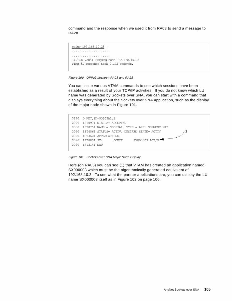
command and the response when we used it from RA03 to send a message toRA28.
Figure 100. OPING between RA03 and RA28
You can issue various VTAM commands to see which sessions have beenestablished as a result of your TCP/IP activities. If you do not know which LUname was generated by Sockets over SNA, you can start with a command thatdisplays everything about the Sockets over SNA application, such as the displayof the major node shown in Figure 101.
Figure 101. Sockets over SNA Major Node Display
Here (on RA03) you can see (1) that VTAM has created an application namedSX000003 which must be the algorithmically generated equivalent of192.168.10.3. To see what the partner applications are, you can display the LUname SX000003 itself as in Figure 102 on page 106.
oping 192.168.10.28 __..........................................CS/390 V2R5: Pinging host 192.168.10.28Ping #1 response took 0.142 seconds.
0290 D NET,ID=SOS03A1,E0090 IST097I DISPLAY ACCEPTED0090 IST075I NAME = SOS03A1, TYPE = APPL SEGMENT 2870090 IST486I STATUS= ACTIV, DESIRED STATE= ACTIV0090 IST360I APPLICATIONS:0090 IST080I SX* CONCT SX000003 ACT/S0090 IST314I END
1
AnyNet Sockets over SNA 105
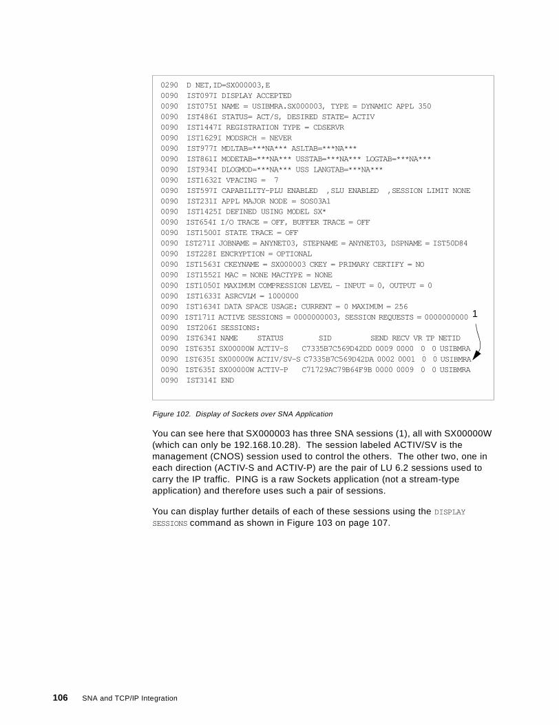
Figure 102. Display of Sockets over SNA Application
You can see here that SX000003 has three SNA sessions (1), all with SX00000W(which can only be 192.168.10.28). The session labeled ACTIV/SV is themanagement (CNOS) session used to control the others. The other two, one ineach direction (ACTIV-S and ACTIV-P) are the pair of LU 6.2 sessions used tocarry the IP traffic. PING is a raw Sockets application (not a stream-typeapplication) and therefore uses such a pair of sessions.
You can display further details of each of these sessions using the DISPLAY
SESSIONScommand as shown in Figure 103 on page 107.
0290 D NET,ID=SX000003,E0090 IST097I DISPLAY ACCEPTED0090 IST075I NAME = USIBMRA.SX000003, TYPE = DYNAMIC APPL 3500090 IST486I STATUS= ACT/S, DESIRED STATE= ACTIV0090 IST1447I REGISTRATION TYPE = CDSERVR0090 IST1629I MODSRCH = NEVER0090 IST977I MDLTAB=***NA*** ASLTAB=***NA***0090 IST861I MODETAB=***NA*** USSTAB=***NA*** LOGTAB=***NA***0090 IST934I DLOGMOD=***NA*** USS LANGTAB=***NA***0090 IST1632I VPACING = 70090 IST597I CAPABILITY-PLU ENABLED ,SLU ENABLED ,SESSION LIMIT NONE0090 IST231I APPL MAJOR NODE = SOS03A10090 IST1425I DEFINED USING MODEL SX*0090 IST654I I/O TRACE = OFF, BUFFER TRACE = OFF0090 IST1500I STATE TRACE = OFF0090 IST271I JOBNAME = ANYNET03, STEPNAME = ANYNET03, DSPNAME = IST50D840090 IST228I ENCRYPTION = OPTIONAL0090 IST1563I CKEYNAME = SX000003 CKEY = PRIMARY CERTIFY = NO0090 IST1552I MAC = NONE MACTYPE = NONE0090 IST1050I MAXIMUM COMPRESSION LEVEL - INPUT = 0, OUTPUT = 00090 IST1633I ASRCVLM = 10000000090 IST1634I DATA SPACE USAGE: CURRENT = 0 MAXIMUM = 2560090 IST171I ACTIVE SESSIONS = 0000000003, SESSION REQUESTS = 00000000000090 IST206I SESSIONS:0090 IST634I NAME STATUS SID SEND RECV VR TP NETID0090 IST635I SX00000W ACTIV-S C7335B7C569D42DD 0009 0000 0 0 USIBMRA0090 IST635I SX00000W ACTIV/SV-S C7335B7C569D42DA 0002 0001 0 0 USIBMRA0090 IST635I SX00000W ACTIV-P C71729AC79B64F9B 0000 0009 0 0 USIBMRA0090 IST314I END
1
106 SNA and TCP/IP Integration
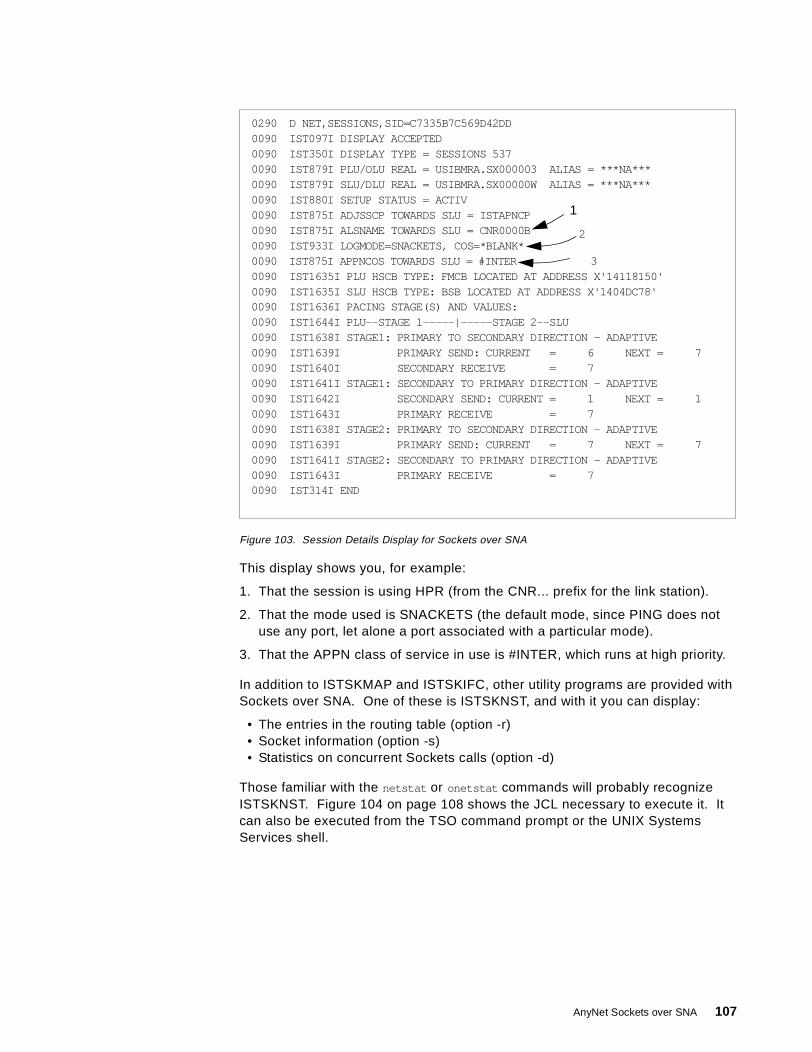
Figure 103. Session Details Display for Sockets over SNA
This display shows you, for example:
1. That the session is using HPR (from the CNR... prefix for the link station).
2. That the mode used is SNACKETS (the default mode, since PING does notuse any port, let alone a port associated with a particular mode).
3. That the APPN class of service in use is #INTER, which runs at high priority.
In addition to ISTSKMAP and ISTSKIFC, other utility programs are provided withSockets over SNA. One of these is ISTSKNST, and with it you can display:
• The entries in the routing table (option -r)• Socket information (option -s)• Statistics on concurrent Sockets calls (option -d)
Those familiar with the netstat or onetstat commands will probably recognizeISTSKNST. Figure 104 on page 108 shows the JCL necessary to execute it. Itcan also be executed from the TSO command prompt or the UNIX SystemsServices shell.
0290 D NET,SESSIONS,SID=C7335B7C569D42DD0090 IST097I DISPLAY ACCEPTED0090 IST350I DISPLAY TYPE = SESSIONS 5370090 IST879I PLU/OLU REAL = USIBMRA.SX000003 ALIAS = ***NA***0090 IST879I SLU/DLU REAL = USIBMRA.SX00000W ALIAS = ***NA***0090 IST880I SETUP STATUS = ACTIV0090 IST875I ADJSSCP TOWARDS SLU = ISTAPNCP0090 IST875I ALSNAME TOWARDS SLU = CNR0000B0090 IST933I LOGMODE=SNACKETS, COS=*BLANK*0090 IST875I APPNCOS TOWARDS SLU = #INTER 30090 IST1635I PLU HSCB TYPE: FMCB LOCATED AT ADDRESS X'14118150'0090 IST1635I SLU HSCB TYPE: BSB LOCATED AT ADDRESS X'1404DC78'0090 IST1636I PACING STAGE(S) AND VALUES:0090 IST1644I PLU--STAGE 1-----|-----STAGE 2--SLU0090 IST1638I STAGE1: PRIMARY TO SECONDARY DIRECTION - ADAPTIVE0090 IST1639I PRIMARY SEND: CURRENT = 6 NEXT = 70090 IST1640I SECONDARY RECEIVE = 70090 IST1641I STAGE1: SECONDARY TO PRIMARY DIRECTION - ADAPTIVE0090 IST1642I SECONDARY SEND: CURRENT = 1 NEXT = 10090 IST1643I PRIMARY RECEIVE = 70090 IST1638I STAGE2: PRIMARY TO SECONDARY DIRECTION - ADAPTIVE0090 IST1639I PRIMARY SEND: CURRENT = 7 NEXT = 70090 IST1641I STAGE2: SECONDARY TO PRIMARY DIRECTION - ADAPTIVE0090 IST1643I PRIMARY RECEIVE = 70090 IST314I END
1
2
AnyNet Sockets over SNA 107
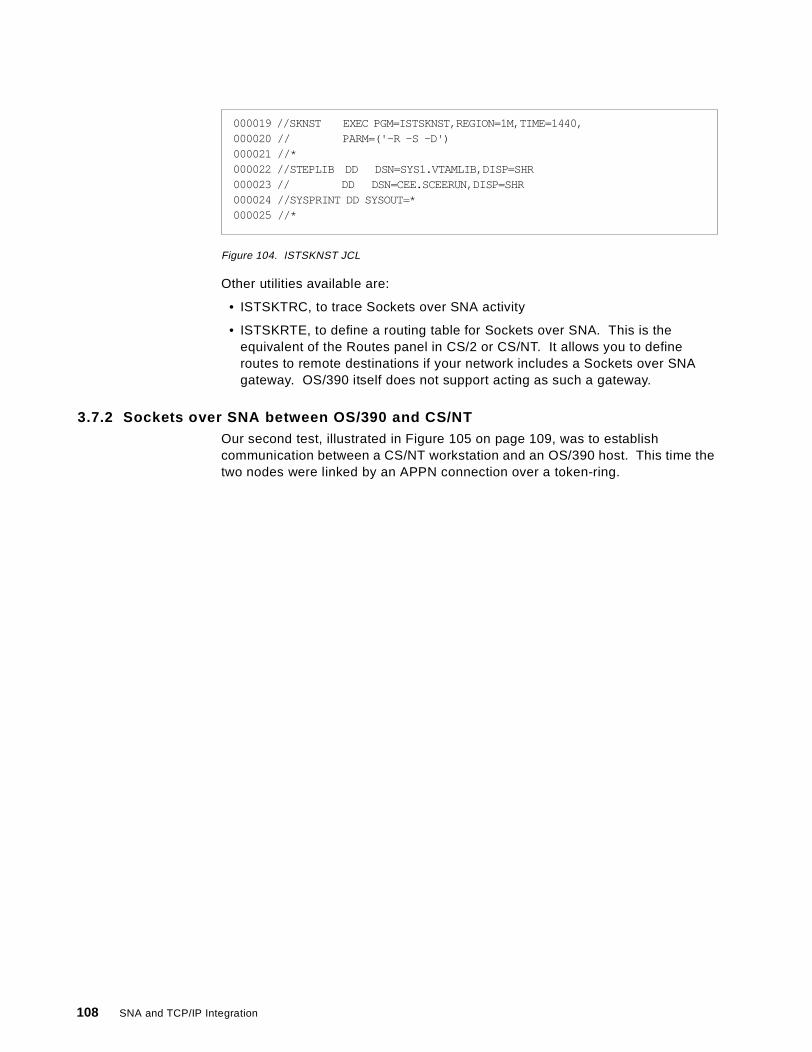
Figure 104. ISTSKNST JCL
Other utilities available are:
• ISTSKTRC, to trace Sockets over SNA activity
• ISTSKRTE, to define a routing table for Sockets over SNA. This is theequivalent of the Routes panel in CS/2 or CS/NT. It allows you to defineroutes to remote destinations if your network includes a Sockets over SNAgateway. OS/390 itself does not support acting as such a gateway.
3.7.2 Sockets over SNA between OS/390 and CS/NTOur second test, illustrated in Figure 105 on page 109, was to establishcommunication between a CS/NT workstation and an OS/390 host. This time thetwo nodes were linked by an APPN connection over a token-ring.
000019 //SKNST EXEC PGM=ISTSKNST,REGION=1M,TIME=1440,000020 // PARM=('-R -S -D')000021 //*000022 //STEPLIB DD DSN=SYS1.VTAMLIB,DISP=SHR000023 // DD DSN=CEE.SCEERUN,DISP=SHR000024 //SYSPRINT DD SYSOUT=*000025 //*
108 SNA and TCP/IP Integration
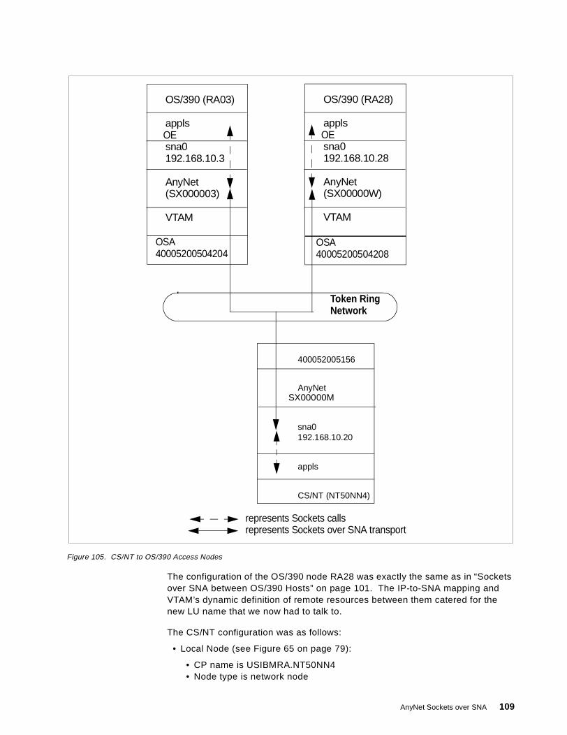
Figure 105. CS/NT to OS/390 Access Nodes
The configuration of the OS/390 node RA28 was exactly the same as in “Socketsover SNA between OS/390 Hosts” on page 101. The IP-to-SNA mapping andVTAM’s dynamic definition of remote resources between them catered for thenew LU name that we now had to talk to.
The CS/NT configuration was as follows:
• Local Node (see Figure 65 on page 79):
• CP name is USIBMRA.NT50NN4• Node type is network node
OS/390 (RA03)
appls
sna0192.168.10.3
AnyNet(SX000003)
VTAM
400052005156
AnyNet
sna0192.168.10.20
OSA40005200504204
OE
CS/NT (NT50NN4)
appls
represents Sockets callsrepresents Sockets over SNA transport
Token RingNetwork
OS/390 (RA28)
appls
sna0192.168.10.28
AnyNet(SX00000W)
VTAM
OSA40005200504208
OE
SX00000M
AnyNet Sockets over SNA 109
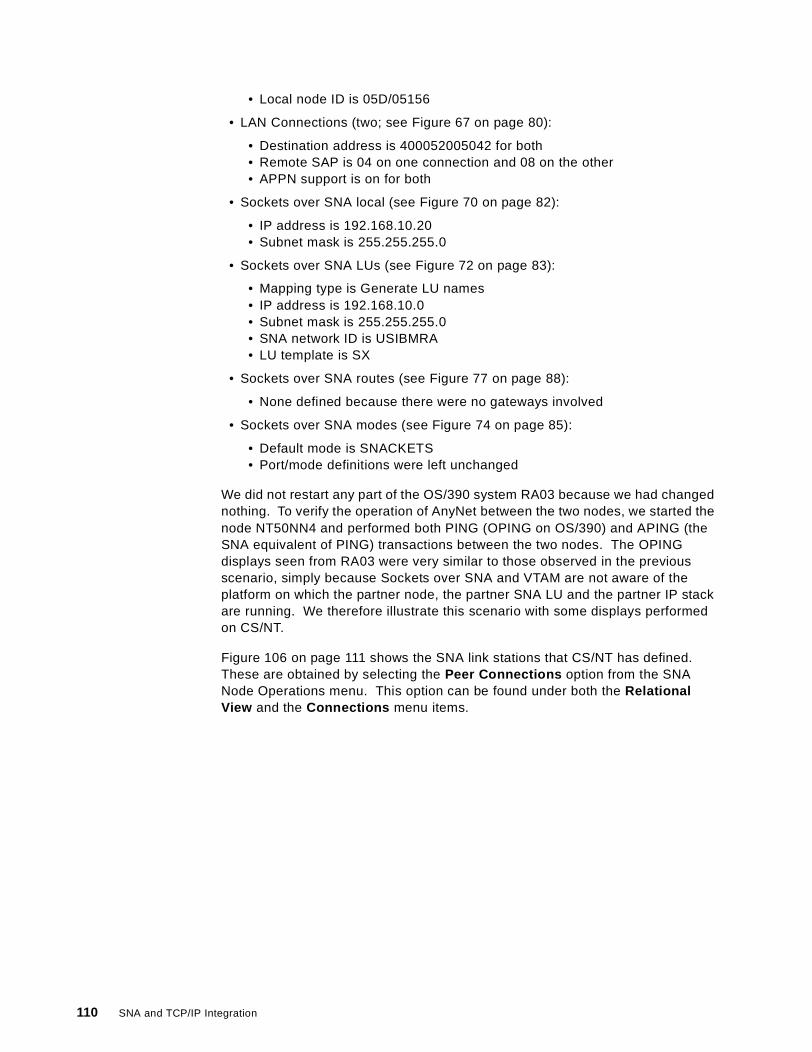
• Local node ID is 05D/05156
• LAN Connections (two; see Figure 67 on page 80):
• Destination address is 400052005042 for both• Remote SAP is 04 on one connection and 08 on the other• APPN support is on for both
• Sockets over SNA local (see Figure 70 on page 82):
• IP address is 192.168.10.20• Subnet mask is 255.255.255.0
• Sockets over SNA LUs (see Figure 72 on page 83):
• Mapping type is Generate LU names• IP address is 192.168.10.0• Subnet mask is 255.255.255.0• SNA network ID is USIBMRA• LU template is SX
• Sockets over SNA routes (see Figure 77 on page 88):
• None defined because there were no gateways involved
• Sockets over SNA modes (see Figure 74 on page 85):
• Default mode is SNACKETS• Port/mode definitions were left unchanged
We did not restart any part of the OS/390 system RA03 because we had changednothing. To verify the operation of AnyNet between the two nodes, we started thenode NT50NN4 and performed both PING (OPING on OS/390) and APING (theSNA equivalent of PING) transactions between the two nodes. The OPINGdisplays seen from RA03 were very similar to those observed in the previousscenario, simply because Sockets over SNA and VTAM are not aware of theplatform on which the partner node, the partner SNA LU and the partner IP stackare running. We therefore illustrate this scenario with some displays performedon CS/NT.
Figure 106 on page 111 shows the SNA link stations that CS/NT has defined.These are obtained by selecting the Peer Connections option from the SNANode Operations menu. This option can be found under both the RelationalView and the Connections menu items.
110 SNA and TCP/IP Integration
Figure 106. CS/NT Logical Links
The two connections are the token-ring links to RA03 and RA28 respectively; onlythe second of these was used in this test.
Figure 107 on page 112 shows the LU 6.2 sessions that were established as aresult of our activity.
AnyNet Sockets over SNA 111
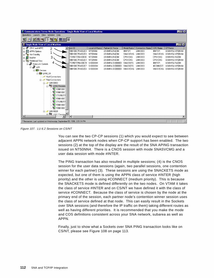
Figure 107. LU 6.2 Sessions on CS/NT
You can see the two CP-CP sessions (1) which you would expect to see betweenadjacent APPN network nodes when CP-CP support has been enabled. The twosessions (2) at the top of the display are the result of the SNA APING transactionissued on NT50NN4. There is a CNOS session with mode SNASVCMG and auser data session with mode #INTER.
The PING transaction has also resulted in multiple sessions; (4) is the CNOSsession for the user data sessions (again, two parallel sessions, one contentionwinner for each partner) (3). These sessions are using the SNACKETS mode asexpected, but one of them is using the APPN class of service #INTER (highpriority) and the other is using #CONNECT (medium priority). This is becausethe SNACKETS mode is defined differently on the two nodes. On VTAM it takesthe class of service #INTER and on CS/NT we have defined it with the class ofservice #CONNECT. Because the class of service is chosen by the node at theprimary end of the session, each partner node’s contention winner session usesthe class of service defined at that node. This can easily result in the Socketsover SNA sessions (and therefore the IP traffic on them) taking different routes aswell as having different priorities. It is recommended that you make the modeand COS definitions consistent across your SNA network, subarea as well asAPPN.
Finally, just to show what a Sockets over SNA PING transaction looks like onCS/NT, please see Figure 108 on page 113.
213
4
112 SNA and TCP/IP Integration
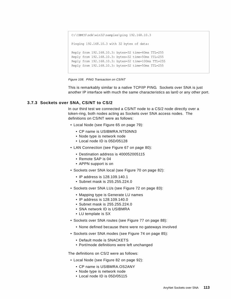
Figure 108. PING Transaction on CS/NT
This is remarkably similar to a native TCP/IP PING. Sockets over SNA is justanother IP interface with much the same characteristics as lan0 or any other port.
3.7.3 Sockets over SNA, CS/NT to CS/2In our third test we connected a CS/NT node to a CS/2 node directly over atoken-ring, both nodes acting as Sockets over SNA access nodes. Thedefinitions on CS/NT were as follows:
• Local Node (see Figure 65 on page 79):
• CP name is USIBMRA.NT50NN3• Node type is network node• Local node ID is 05D/05128
• LAN Connection (see Figure 67 on page 80):
• Destination address is 400052005115• Remote SAP is 04• APPN support is on
• Sockets over SNA local (see Figure 70 on page 82):
• IP address is 128.109.140.1• Subnet mask is 255.255.224.0
• Sockets over SNA LUs (see Figure 72 on page 83):
• Mapping type is Generate LU names• IP address is 128.109.140.0• Subnet mask is 255.255.224.0• SNA network ID is USIBMRA• LU template is SX
• Sockets over SNA routes (see Figure 77 on page 88):
• None defined because there were no gateways involved
• Sockets over SNA modes (see Figure 74 on page 85):
• Default mode is SNACKETS• Port/mode definitions were left unchanged
The definitions on CS/2 were as follows:
• Local Node (see Figure 82 on page 92):
• CP name is USIBMRA.OS2ANY• Node type is network node• Local node ID is 05D/05115
C:\IBMCS\sdk\win32\samples\ping 192.168.10.3
Pinging 192.168.10.3 with 32 bytes of data:
Reply from 192.168.10.3: bytes=32 time=60ms TTL=255Reply from 192.168.10.3: bytes=32 time=50ms TTL=255Reply from 192.168.10.3: bytes=32 time=100ms TTL=255Reply from 192.168.10.3: bytes=32 time=50ms TTL=255
AnyNet Sockets over SNA 113
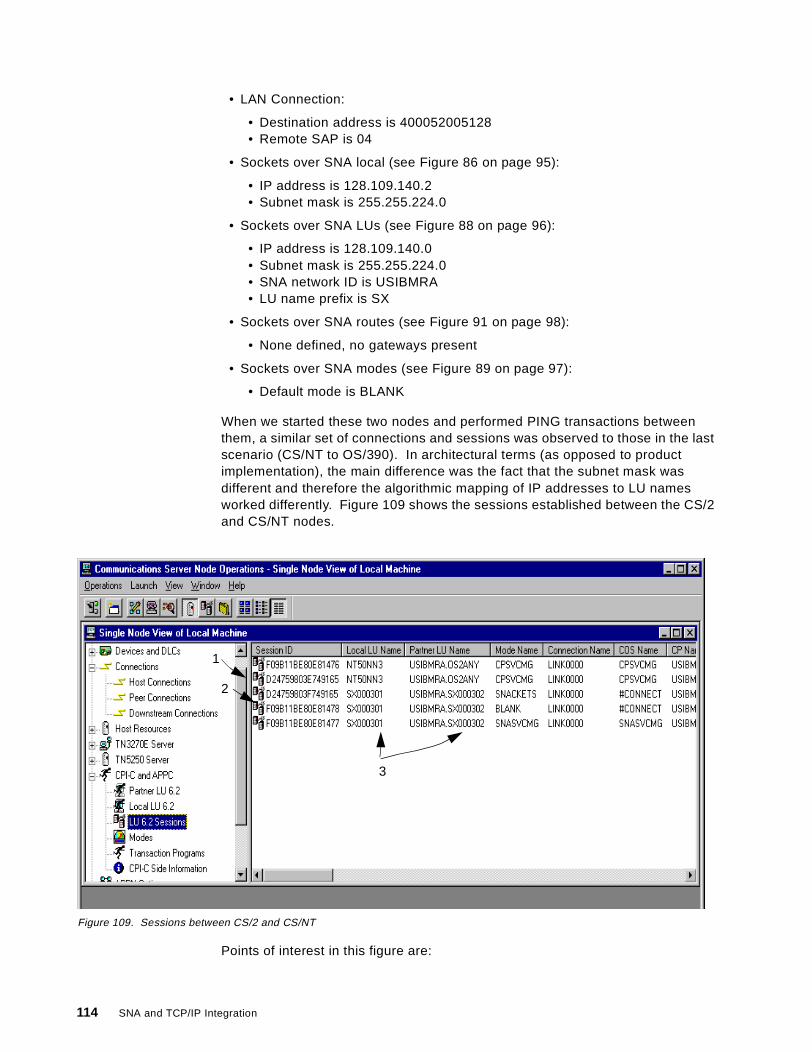
• LAN Connection:
• Destination address is 400052005128• Remote SAP is 04
• Sockets over SNA local (see Figure 86 on page 95):
• IP address is 128.109.140.2• Subnet mask is 255.255.224.0
• Sockets over SNA LUs (see Figure 88 on page 96):
• IP address is 128.109.140.0• Subnet mask is 255.255.224.0• SNA network ID is USIBMRA• LU name prefix is SX
• Sockets over SNA routes (see Figure 91 on page 98):
• None defined, no gateways present
• Sockets over SNA modes (see Figure 89 on page 97):
• Default mode is BLANK
When we started these two nodes and performed PING transactions betweenthem, a similar set of connections and sessions was observed to those in the lastscenario (CS/NT to OS/390). In architectural terms (as opposed to productimplementation), the main difference was the fact that the subnet mask wasdifferent and therefore the algorithmic mapping of IP addresses to LU namesworked differently. Figure 109 shows the sessions established between the CS/2and CS/NT nodes.
Figure 109. Sessions between CS/2 and CS/NT
Points of interest in this figure are:
1
2
3
114 SNA and TCP/IP Integration
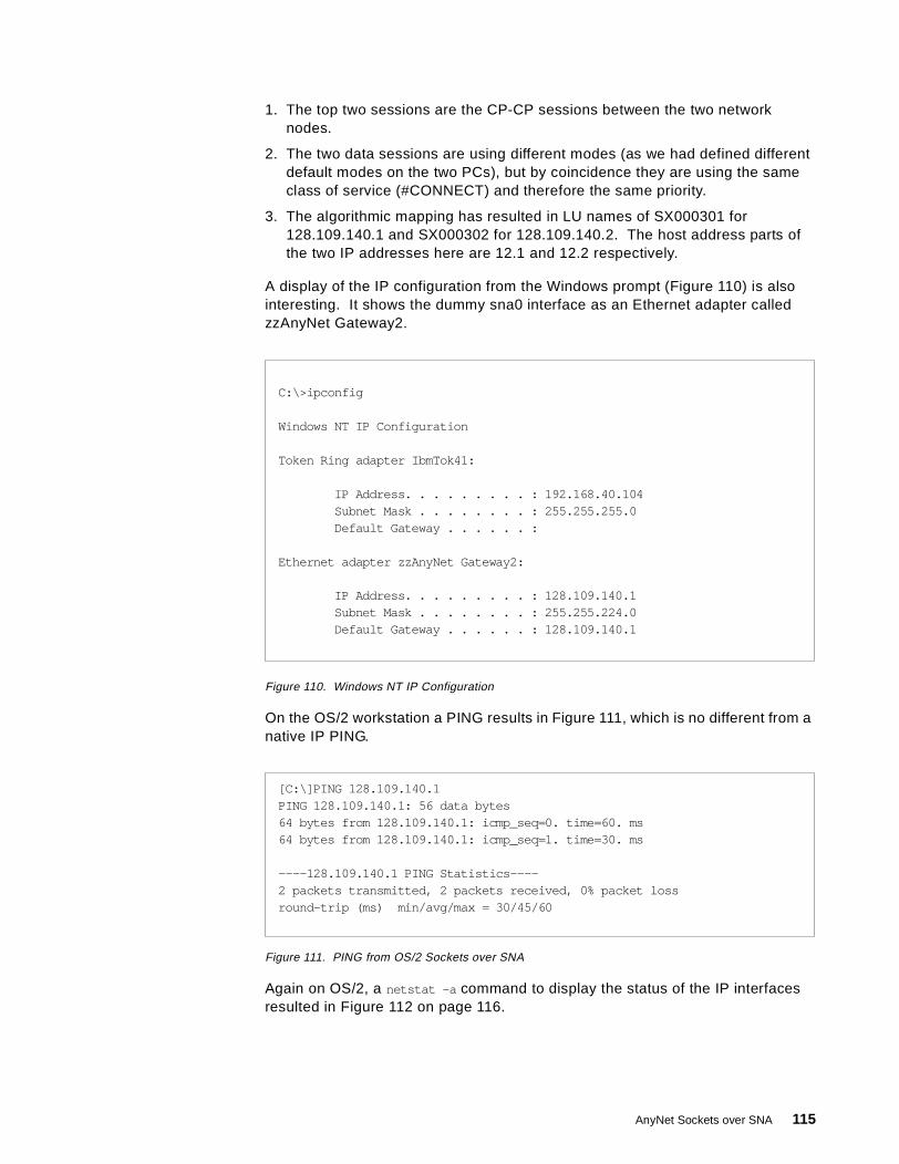
1. The top two sessions are the CP-CP sessions between the two networknodes.
2. The two data sessions are using different modes (as we had defined differentdefault modes on the two PCs), but by coincidence they are using the sameclass of service (#CONNECT) and therefore the same priority.
3. The algorithmic mapping has resulted in LU names of SX000301 for128.109.140.1 and SX000302 for 128.109.140.2. The host address parts ofthe two IP addresses here are 12.1 and 12.2 respectively.
A display of the IP configuration from the Windows prompt (Figure 110) is alsointeresting. It shows the dummy sna0 interface as an Ethernet adapter calledzzAnyNet Gateway2.
Figure 110. Windows NT IP Configuration
On the OS/2 workstation a PING results in Figure 111, which is no different from anative IP PING.
Figure 111. PING from OS/2 Sockets over SNA
Again on OS/2, a netstat -a command to display the status of the IP interfacesresulted in Figure 112 on page 116.
C:\>ipconfig
Windows NT IP Configuration
Token Ring adapter IbmTok41:
IP Address . . . . . . . . . : 192.168.40.104Subnet Mas k . . . . . . . . : 255.255.255.0Default Gateway . . . . . . :
Ethernet adapter zzAnyNet Gateway2:
IP Address . . . . . . . . . : 128.109.140.1Subnet Mas k . . . . . . . . : 255.255.224.0Default Gateway . . . . . . : 128.109.140.1
[C:\]PING 128.109.140.1PING 128.109.140.1: 56 data bytes64 bytes from 128.109.140.1: icmp_seq=0. time=60. ms64 bytes from 128.109.140.1: icmp_seq=1. time=30. ms
----128.109.140.1 PING Statistics----2 packets transmitted, 2 packets received, 0% packet lossround-trip (ms) min/avg/max = 30/45/60
AnyNet Sockets over SNA 115
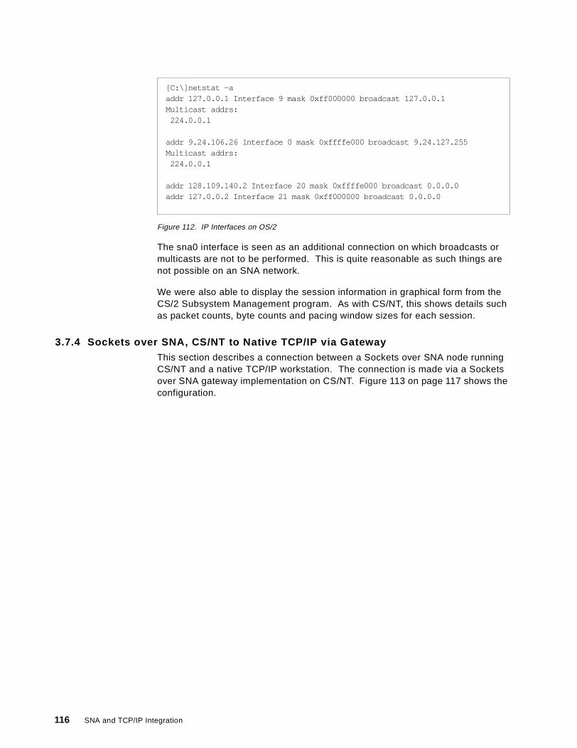
Figure 112. IP Interfaces on OS/2
The sna0 interface is seen as an additional connection on which broadcasts ormulticasts are not to be performed. This is quite reasonable as such things arenot possible on an SNA network.
We were also able to display the session information in graphical form from theCS/2 Subsystem Management program. As with CS/NT, this shows details suchas packet counts, byte counts and pacing window sizes for each session.
3.7.4 Sockets over SNA, CS/NT to Native TCP/IP via GatewayThis section describes a connection between a Sockets over SNA node runningCS/NT and a native TCP/IP workstation. The connection is made via a Socketsover SNA gateway implementation on CS/NT. Figure 113 on page 117 shows theconfiguration.
[C:\]netstat -aaddr 127.0.0.1 Interface 9 mask 0xff000000 broadcast 127.0.0.1Multicast addrs:
224.0.0.1
addr 9.24.106.26 Interface 0 mask 0xffffe000 broadcast 9.24.127.255Multicast addrs:
224.0.0.1
addr 128.109.140.2 Interface 20 mask 0xffffe000 broadcast 0.0.0.0addr 127.0.0.2 Interface 21 mask 0xff000000 broadcast 0.0.0.0
116 SNA and TCP/IP Integration
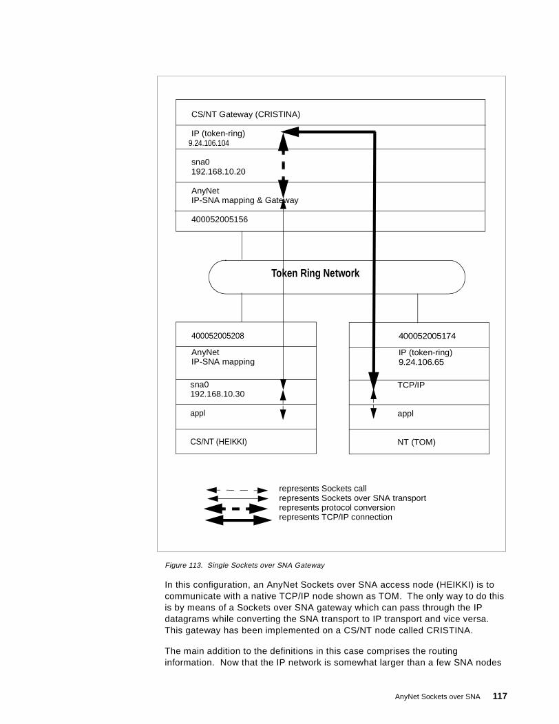
Figure 113. Single Sockets over SNA Gateway
In this configuration, an AnyNet Sockets over SNA access node (HEIKKI) is tocommunicate with a native TCP/IP node shown as TOM. The only way to do thisis by means of a Sockets over SNA gateway which can pass through the IPdatagrams while converting the SNA transport to IP transport and vice versa.This gateway has been implemented on a CS/NT node called CRISTINA.
The main addition to the definitions in this case comprises the routinginformation. Now that the IP network is somewhat larger than a few SNA nodes
CS/NT Gateway (CRISTINA)
IP (token-ring)
sna0192.168.10.20
AnyNet
400052005156
appl
CS/NT (HEIKKI)
400052005208
192.168.10.30
AnyNetIP-SNA mapping
sna0
appl
NT (TOM)
400052005174
IP (token-ring)9.24.106.65
TCP/IP
9.24.106.104
Token Ring Network
IP-SNA mapping & Gateway
represents Sockets callrepresents Sockets over SNA transportrepresents protocol conversionrepresents TCP/IP connection
AnyNet Sockets over SNA 117
talking to each other, we must do more than simply translate IP addresses to LUnames.
The configuration for the Sockets over SNA access node HEIKKI is as follows(we have omitted the SNA-only definitions to concentrate on the AnyNetparameters):
• Sockets over SNA local (see Figure 70 on page 82):
• IP address is 192.168.10.30• Subnet mask is 255.255.255.0
• Sockets over SNA LUs (see Figure 72 on page 83):
• Mapping type is Generate LU names• IP address is 192.168.10.0• Subnet mask is 255.255.255.0• SNA network ID is USIBMRA• LU template is SX
• Sockets over SNA routes (see Figure 77 on page 88):
• Type is Default• Router address is 192.168.10.20• Direct connection is No
The access node HEIKKI must be able to communicate with IP addressesoutside its native subnetwork 192.168.10.0. However, it has no IP-to-LUmapping information for such addresses, simply because those addresses areoutside the Sockets over SNA subnetwork. It needs to be told that theseaddresses must be reached via the gateway node CRISTINA which acts asthe IP router for the 192.168.10.0 subnetwork.
The router address is given as 192.168.10.20, which is in the Sockets overSNA subnetwork and can be contacted by SNA sessions after addresstranslation.
The destination address and subnet mask fields are not available for a defaultroute; by its very nature a default route is used for all addresses not definedelsewhere.
• Sockets over SNA modes (see Figure 74 on page 85):
• Default mode is SNACKETS• Port/mode definitions were left unchanged
The configuration of the native TCP/IP workstation TOM was as follows:
• TCP/IP Configuration
• IP address of token-ring interface is 9.24.106.65• Subnet mask is 255.255.224.0• Gateway (default router) address is 9.24.106.1
This is a mirror image of the Sockets over SNA definition on HEIKKI, exceptthat it points to the native IP interface on its default router. This router shouldbe able to find a route to the 192.168.10 subnetwork (in other words, to thegateway CRISTINA) by the usual IP means, namely RIP.
The configuration for the gateway node CRISTINA is as follows:
• TCP/IP Configuration
118 SNA and TCP/IP Integration
• IP address of token-ring interface is 9.24.106.104• Subnet mask is 255.255.224.0• Gateway (default router) address is 9.24.106.1• IP Forwarding is enabled
• Sockets over SNA local (see Figure 70 on page 82):
• IP address is 192.168.10.20• Subnet mask is 255.255.255.0
• Sockets over SNA LUs (see Figure 72 on page 83):
• Mapping type is Generate LU names• IP address is 192.168.10.0• Subnet mask is 255.255.255.0• SNA network ID is USIBMRA• LU template is SX
• Sockets over SNA routes (see Figure 77 on page 88):
• None required
All IP addresses can be reached directly from this node, and all are in thesame subnet as one or the other of the two interfaces. Addresses in the192.168.10 subnetwork can be reached by SNA sessions, whereas addressesin the 9.24.96 subnetwork can be reached by a direct LAN connection.
• Sockets over SNA modes (see Figure 74 on page 85):
• Default mode is BLANK• Port/mode definitions were left unchanged
We configured the three nodes as above, restarted them, and performed PINGtransactions between HEIKKI and TOM. After a successful connectivity test, weobserved the usual set of SNA LU 6.2 sessions between HEIKKI and CRISTINA:
• Two CP-CP sessions between the control point LUs• One CNOS session between the Sockets over SNA LUs• Two data sessions between the Sockets over SNA LUs
Some displays relating to the gateway environment are shown in the last sectionof this chapter, “Connecting Two IP Networks Using CS/2 and CS/NT Gateways”on page 123.
AnyNet Sockets over SNA 119

3.7.5 Connecting Two SNA Networks Using CS/NT and CS/2 GatewaysNext, we implemented back-to-back Sockets over SNA gateways to connect twoSNA (APPN) networks together using an IP network in the middle. Figure 114shows this configuration.
Figure 114. Multiple Sockets over SNA Gateways with IP Between
Here there are two Sockets over SNA access nodes, HEIKKI and TOM. Althoughphysically they share the same token-ring, we have logically separated them sothat only a native IP connection is available between their two subnetworks. Toallow the IP traffic that starts out as Sockets over SNA datagrams to traverse anative IP transport network we need two gateway nodes (CRISTINA and LUCA)as shown. In this scenario we have implemented CRISTINA on CS/NT and LUCA
CS/NT GW (CRISTINA)
TCP/IP
sna0192.168.10.20
AnyNet
400052005156
appl
NT (HEIKKI)
CS/2 GW (LUCA)
TCP/IP192.168.30.26
sna0192.168.20.26
AnyNetIP-SNA mapping
400052005115
400052005208
192.168.10.30
AnyNetIP-SNA mapping
sna0
appl
NT (TOM)
400052005174
192.168.20.65
AnyNetIP-SNA mapping
sna0
192.168.30.104
IP-SNA mapping
Token Ring Network
represents sockets callrepresents Sockets over SNA transportrepresents protocol conversionrepresents TCP/IP connection
120 SNA and TCP/IP Integration
on CS/2. In the configuration summaries that follow, we have again omitted thenative SNA connections for clarity.
Note that we cannot put all the Sockets over SNA nodes in the same IPsubnetwork here, as the SNA networks are disjoint. An attempt to contact an IPaddress in the other half of the Sockets over SNA network would result inIP-to-LU address translation and a fruitless search for an SNA LU that exists onlyin an unreachable SNA subnetwork. We therefore have three subnetworks:
• 192.168.10 for the network containing HEIKKI• 192.168.20 for the network containing TOM• 192.168.30 for the native IP network
The algorithmic address mapping, however, is the same in each disjoint SNAnetwork. There is no danger of duplicate LU names in the same SNA network.
The configuration for the access node HEIKKI is as follows:
• Sockets over SNA local (see Figure 70 on page 82):
• IP address is 192.168.10.30• Subnet mask is 255.255.255.0
• Sockets over SNA LUs (see Figure 72 on page 83):
• Mapping type is Generate LU names• IP address is 192.168.10.0• Subnet mask is 255.255.255.0• SNA network ID is USIBMRA• LU template is SX
• Sockets over SNA routes (see Figure 77 on page 88):
• Type is Default• Router address is 192.168.10.20• Direct connection is No
As with the previous scenario, the access node HEIKKI needs at least thisdefinition to communicate with IP addresses outside its native subnetwork192.168.10.0. Such addresses now include those in the 192.168.20subnetwork.
• Sockets over SNA modes (see Figure 74 on page 85):
• Default mode is SNACKETS• Port/mode definitions were left unchanged
The configuration for the access node TOM, which is a mirror image of HEIKKI, isas follows:
• Sockets over SNA local (see Figure 70 on page 82):
• IP address is 192.168.20.65• Subnet mask is 255.255.255.0
• Sockets over SNA LUs (see Figure 72 on page 83):
• Mapping type is Generate LU names• IP address is 192.168.20.0• Subnet mask is 255.255.255.0• SNA network ID is USIBMRA• LU template is SX
AnyNet Sockets over SNA 121

• Sockets over SNA routes (see Figure 77 on page 88):
• Type is Default• Router address is 192.168.20.26• Direct connection is No
• Sockets over SNA modes (see Figure 74 on page 85):
• Default mode is BLANK• Port/mode definitions were left unchanged
The configuration of the gateway CS/NT node CRISTINA is:
• TCP/IP Configuration
• IP address of token-ring interface is 192.168.30.104• Subnet mask is 255.255.255.0• IP Forwarding is enabled
• Sockets over SNA local (see Figure 70 on page 82):
• IP address is 192.168.10.20• Subnet mask is 255.255.255.0
• Sockets over SNA LUs (see Figure 72 on page 83):
• Mapping type is Generate LU names• IP address is 192.168.10.0• Subnet mask is 255.255.255.0• SNA network ID is USIBMRA• LU template is SX
• Sockets over SNA routes (see Figure 77 on page 88):
• Type is Network• Destination address is 192.168.20.0• Destination mask is 255.255.255.0• Router address is 192.168.30.26• Direct connection is No
Here we need routes to three separate subnetworks. Two of them(192.168.10 and 192.168.30) can be reached through the local interfaces(AnyNet and native IP respectively). The third one, 192.168.20, can only bereached through the partner gateway node LUCA whose address is192.168.30.26.
• Sockets over SNA modes (see Figure 74 on page 85):
• Default mode is BLANK• Port/mode definitions were left unchanged
The configuration of the gateway CS/2 node LUCA is:
• TCP/IP Configuration
• IP address of token-ring interface is 192.168.30.26• Subnet mask is 255.255.255.0• IP Forwarding is enabled
• Sockets over SNA local (see Figure 86 on page 95):
• IP address is 192.168.20.26• Subnet mask is 255.255.255.0
• Sockets over SNA LUs (see Figure 88 on page 96):
122 SNA and TCP/IP Integration
• IP address is 192.168.20.0• Subnet mask is 255.255.255.0• SNA network ID is USIBMRA• LU name prefix is SX
• Sockets over SNA routes (see Figure 91 on page 98):
• Type is Net• Destination address is 192.168.10.0• Destination mask is 255.255.255.0• Router address is 192.168.30.104• Metric is 2
In CS/2 you do not define a direct connection explicitly. A direct route (one toanother Sockets over SNA node in a different IP subnet) is defined by a metricof 0 and the address of the local interface. In our case we have an indirectroute (to a subnetwork reachable only via a remote router) so we input theaddress of that router and a metric (number of hops to the destination) of 2.
• Sockets over SNA modes (see Figure 89 on page 97):
• Default mode is BLANK
Again, we restarted all the nodes after reconfiguration and successfullyestablished communication between all the IP subnetworks; in particular betweenHEIKKI and LUCA.
3.7.6 Connecting Two IP Networks Using CS/2 and CS/NT GatewaysFor our final scenario, we implemented the opposite situation to that in“Connecting Two SNA Networks Using CS/NT and CS/2 Gateways” on page 120.Now we have (Figure 115 on page 124) two islands of IP connected via an SNAbackbone. The Sockets over SNA function is now purely a gateway one, andthere are no access nodes in the network.
AnyNet Sockets over SNA 123
Figure 115. Multiple Sockets over SNA Gateways with SNA Between
The physical setup is exactly the same as before, but now the workstationsHEIKKI and TOM are pure native TCP/IP and the connection between thegateways is SNA.
The configuration for the Windows NT workstation HEIKKI is as follows:
• TCP/IP Configuration
• IP address of token-ring interface is 192.168.40.177• Subnet mask is 255.255.255.0• Route to 192.168.10.0 (subnet mask 255.255.255.0) is via 192.168.40.104
CS/NT GW (NT50NN6)
AnyNet IP-SNA
sna0192.168.10.20
TCP/IP
40052005156
appl
NT (HEIKKI)
CS/NT GW (OS2NN6)
AnyNetIP-SNA mapping & Gateway
sna0192.168.10.26
TCP/IP9.24.106.26
40052005115
400052005208
IP192.168.40.177
TCP/IP
appl
NT (TOM)
400052005174
IP9.24.106.65
TCP/IP
mapping & Gateway
192.168.40.104
Token Ring Network
represents sockets callrepresents Sockets over SNA transportrepresents protocol conversionrepresents TCP/IP connection
124 SNA and TCP/IP Integration

• Route to 9.24.96.0 (subnet mask 255.255.224.0) is via 192.168.40.104
We used network routes in this scenario, rather than defining default routes to192.168.40.104 which would have had the same effect.
The configuration for the workstation TOM is as follows:
• TCP/IP Configuration
• IP address of token-ring interface is 9.24.106.65• Subnet mask is 255.255.224.0• Route to 192.168.40.0 (subnet mask 255.255.255.0) is via 9.24.106.26• Route to 192.168.10.0 (subnet mask 255.255.255.0) is via 9.24.106.26
The configuration for the CS/NT gateway NT50NN6 is:
• TCP/IP Configuration
• IP address of token-ring interface is 192.168.40.104• Subnet mask is 255.255.255.0• IP Forwarding is enabled
• Sockets over SNA local (see Figure 70 on page 82):
• IP address is 192.168.10.20• Subnet mask is 255.255.255.0
• Sockets over SNA LUs (see Figure 72 on page 83):
• Mapping type is Generate LU names• IP address is 192.168.10.0• Subnet mask is 255.255.255.0• SNA network ID is USIBMRA• LU template is SX
• Sockets over SNA routes (see Figure 77 on page 88):
• Type is Network• Destination address is 9.24.96.0• Destination mask is 255.255.224.0• Router address is 192.168.10.26• Direct connection is No
This gateway has no direct connections via Sockets over SNA to nodes in adifferent IP subnetwork. It has, however, an indirect route to the IP network9.24.96.0 (which contains the 9.24.106 addresses), reachable via its Socketsover SNA partner 192.168.10.26.
• Sockets over SNA modes (see Figure 74 on page 85):
• Default mode is SNACKETS• Port/mode definitions were left unchanged
Finally, the configuration of the CS/2 gateway OS2NN6 was:
• TCP/IP Configuration
• IP address of token-ring interface is 9.24.106.26• Subnet mask is 255.255.224.0• IP Forwarding is enabled
• Sockets over SNA local (see Figure 86 on page 95):
• IP address is 192.168.10.26
AnyNet Sockets over SNA 125
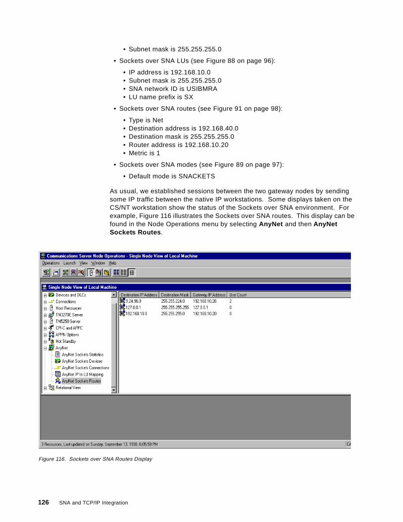
• Subnet mask is 255.255.255.0
• Sockets over SNA LUs (see Figure 88 on page 96):
• IP address is 192.168.10.0• Subnet mask is 255.255.255.0• SNA network ID is USIBMRA• LU name prefix is SX
• Sockets over SNA routes (see Figure 91 on page 98):
• Type is Net• Destination address is 192.168.40.0• Destination mask is 255.255.255.0• Router address is 192.168.10.20• Metric is 1
• Sockets over SNA modes (see Figure 89 on page 97):
• Default mode is SNACKETS
As usual, we established sessions between the two gateway nodes by sendingsome IP traffic between the native IP workstations. Some displays taken on theCS/NT workstation show the status of the Sockets over SNA environment. Forexample, Figure 116 illustrates the Sockets over SNA routes. This display can befound in the Node Operations menu by selecting AnyNet and then AnyNetSockets Routes .
Figure 116. Sockets over SNA Routes Display
126 SNA and TCP/IP Integration
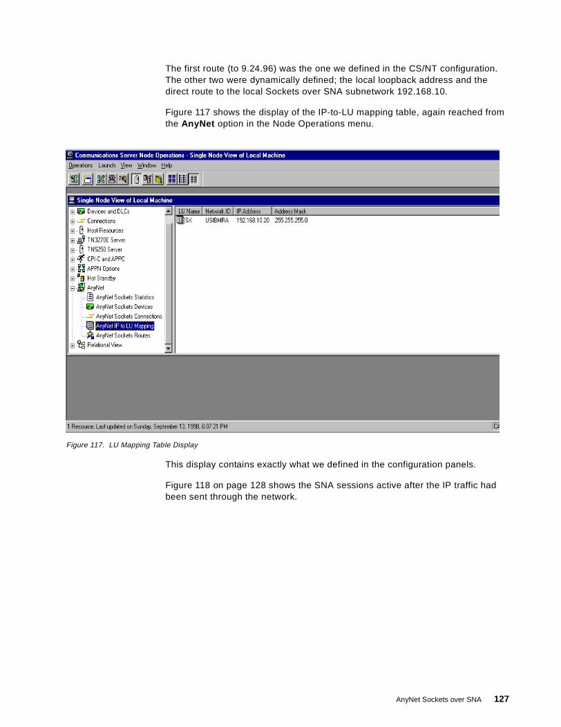
The first route (to 9.24.96) was the one we defined in the CS/NT configuration.The other two were dynamically defined; the local loopback address and thedirect route to the local Sockets over SNA subnetwork 192.168.10.
Figure 117 shows the display of the IP-to-LU mapping table, again reached fromthe AnyNet option in the Node Operations menu.
Figure 117. LU Mapping Table Display
This display contains exactly what we defined in the configuration panels.
Figure 118 on page 128 shows the SNA sessions active after the IP traffic hadbeen sent through the network.
AnyNet Sockets over SNA 127
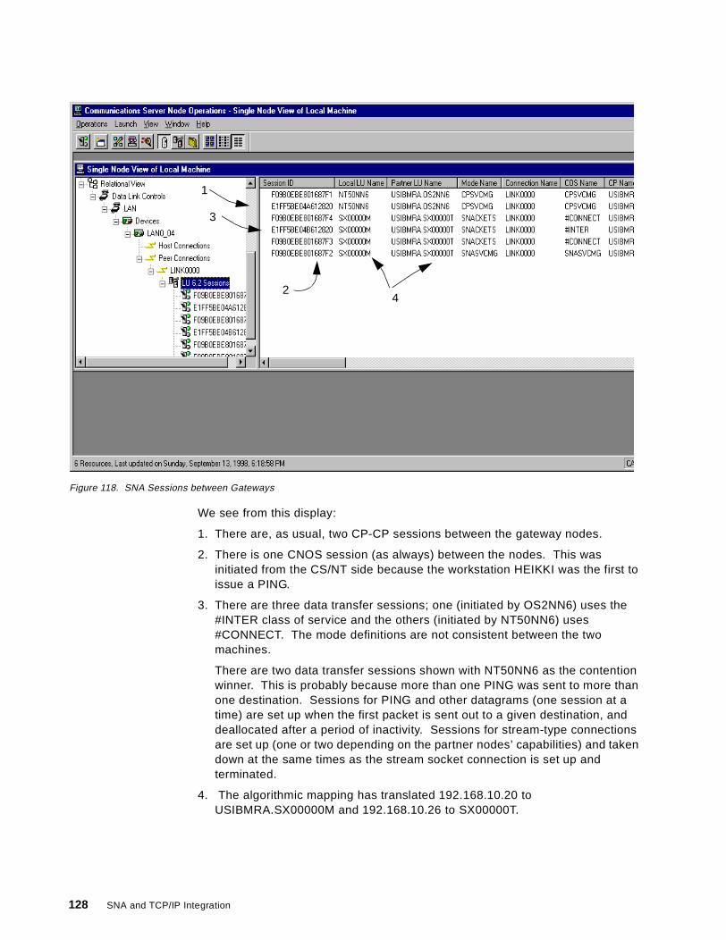
Figure 118. SNA Sessions between Gateways
We see from this display:
1. There are, as usual, two CP-CP sessions between the gateway nodes.
2. There is one CNOS session (as always) between the nodes. This wasinitiated from the CS/NT side because the workstation HEIKKI was the first toissue a PING.
3. There are three data transfer sessions; one (initiated by OS2NN6) uses the#INTER class of service and the others (initiated by NT50NN6) uses#CONNECT. The mode definitions are not consistent between the twomachines.
There are two data transfer sessions shown with NT50NN6 as the contentionwinner. This is probably because more than one PING was sent to more thanone destination. Sessions for PING and other datagrams (one session at atime) are set up when the first packet is sent out to a given destination, anddeallocated after a period of inactivity. Sessions for stream-type connectionsare set up (one or two depending on the partner nodes’ capabilities) and takendown at the same times as the stream socket connection is set up andterminated.
4. The algorithmic mapping has translated 192.168.10.20 toUSIBMRA.SX00000M and 192.168.10.26 to SX00000T.
1
2
3
4
128 SNA and TCP/IP Integration
Chapter 4. AnyNet SNA over IP
AnyNet SNA over IP fully meets the requirement of transporting any SNA sessionacross a TCP/IP network. It does not rely on the API to follow certain standardsas does Sockets over SNA. This is because SNA over IP implementations usethe native IP stack as a transport mechanism and the native SNA stack for theAPI, whereas Sockets over SNA implementations use their own Socketsinterfaces and do not require an IP stack except in the gateway configuration.
However, SNA over IP has one major drawback, in that the SNA logicalconnection cannot be APPN or subarea INN. It can be one of two things:
1. A low entry networking (LEN) connection, which is supported in both subareaand APPN environments but permits no control sessions and therefore nonetwork dynamics.
2. A peripheral subarea connection between a workstation and an SNA gateway.
Therefore, a certain amount of predefinition is always required in the SNA over IPenvironment:
• No search requests can be sent and thus partner LU locations must bepredefined at the originating node. Although an LU name can be translatedinto a partner IP address and that address can be discovered dynamically, thenode must first be told how to distinguish between native SNA partner LUsand AnyNet SNA over IP LUs.
• Dependent LU sessions between workstation and gateway require some extrapredefinition, since the LU name (and therefore the IP address) is not knownat either of these nodes; only the host VTAM knows this.
• Dependent LU sessions between workstation (or gateway) and host requirethe use of DLUR (this is the only case in which DLUR is supported withoutrequiring an APPN path between DLUR and DLUS).
• Dependent LU sessions must always take the same path as the DLUR/S pipe(the SNA over IP logical link), because there is no way of identifying the DLURnode’s network connections to the session partner.
Also, HPR is not supported across the IP portion of the path because route setupcannot flow across a LEN link or a peripheral subarea link.
AnyNet SNA over IP is therefore a suitable solution only where the SNA traffic islimited and the above factors are not major issues. Enterprise Extender is amuch better solution in most environments.
AnyNet SNA over IP is currently implemented as part of the CommunicationsServer product family which comprises:
• SecureWay Communications Server for OS/390 (access node and gateway)
• OS/400 (access node only)
• Communications Server for AIX (access node only)
• Communications Server for OS/2 (access node and gateway)
• Communications Server for Windows NT (access node and gateway)
© Copyright IBM Corp. 1999 129
In addition, AnyNet access node function is available with PersonalCommunications for OS/2 and Windows. As with Sockets over SNA, olderproducts have been available packaged in various ways over the years.
4.1 AnyNet SNA over IP Overview
AnyNet SNA over TCP/IP provides IP transport to applications written to variousSNA interfaces. Using SNA over TCP/IP, an application program designed to usean SNA API can communicate with another SNA application program over aTCP/IP transport network by mapping an LU-LU session to a TCP connection.
Using MPTN terminology, a native SNA transport user is able to use the non-native TCP/IP transport provider.
All SNA over TCP/IP implementations use the installed TCP/IP application as thebase. Thus SNA over TCP/IP supports all attachments supported by theunderlying TCP/IP stack. When using SNA over TCP/IP, SNA applicationprograms can access an IP network without modification.
Each SNA over IP implementation works in the same way: it takes SNA requestunits destined for the partner LU and sends them over the logical connection thatrepresents the IP network. Therefore, the same LU communication types aresupported over AnyNet SNA over IP as are supported over LEN or peripheralconnections, with the addition of the special case of dependent LU requester.This special case is necessary to allow dependent LU sessions, without which theapplication of SNA over IP would be very limited.
Because SNA over IP must cause the IP network to look like an SNA connection,it must translate SNA LU names to IP addresses. Thus a session request for agiven LU results in:
1. Mapping the partner LU to an IP address
2. Setting up a TCP connection (if one does not already exist) between this nodeand the partner node
3. Treating the TCP connection as an adjacent link station over which thesession data flows.
The configuration information that you need to define for AnyNet SNA over IPcomprises:
• Whether to route the data using SNA transport or using TCP/IP transport
• How to determine the IP address from the fully qualified LU name
On the TCP/IP side of the process, you have to designate a special port (TCPand UDP) for use by AnyNet SNA over IP. This enables the TCP/IP stack to routeSNA over IP packets to AnyNet while native IP packets are sent to their properdestination. The port number normally used is 397, the well-known port for SNAover IP. Both TCP and UDP are required because AnyNet uses UDP datagramsfor expedited SNA data even if the normal data is flowing on a TCP connection.
The translation process for LU names to IP addresses can be done in one of twoways:
• Explicitly. You define the name of each LU with which this node will establisha session, and the IP address that corresponds to the LU.
130 SNA and TCP/IP Integration
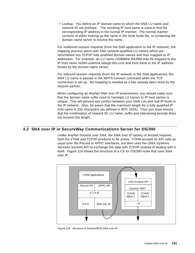
• Lookup. You define an IP domain name to which the SNA LU name andnetwork ID are prefixed. The resulting IP host name is used to find thecorresponding IP address in the normal IP manner. The normal mannerconsists of either looking up the name in the local hosts file, or contacting thedomain name server to resolve the name.
For outbound session requests (from the SNA application to the IP network), themapping process starts with SNA network-qualified LU names which arereformatted into TCP/IP fully qualified domain names and then mapped to IPaddresses. For example, an LU name USIBMRA.RA39M may be mapped to theIP host name ra39m.usibmra.raleigh.ibm.com and from there to the IP addressknown by the domain name server.
For inbound session requests (from the IP network to the SNA application), theSNA LU name is passed in the MPTN connect command when the TCPconnection is set up. No mapping is needed as it has already been done by thesession partner.
When configuring an AnyNet SNA over IP environment, you should make surethat the domain name suffix used to translate LU names to IP host names isunique. This will prevent any conflict between your SNA LUs and real IP hosts inthe IP network. Also, be aware that the maximum length for a fully qualified IPhost name is 255 characters (as defined in RFC 1034). Thus you must ensurethat the combination of network ID, LU name, suffix and intervening periods doesnot exceed this length.
4.2 SNA over IP in SecureWay Communications Server for OS/390
Unlike AnyNet Sockets over SNA, the SNA over IP variety of AnyNet requiresboth the VTAM and TCP/IP products to be active. VTAM accepts its API calls asusual over the Record or APPC interfaces, but then uses the UNIX SystemsServices Sockets API to exchange the data with TCP/IP instead of dealing with ititself. Figure 119 shows the structure of a CS for OS/390 node that uses SNAover IP.
Figure 119. Structure of AnyNet/MVS SNA over IP
VTAM Applications
V T A M
Record API APPC API
S N A SNA over IP I P
USS Sockets API
Common INET
TCP/IPStack 1
TCP/IPStack 2
AnyNet SNA over IP 131
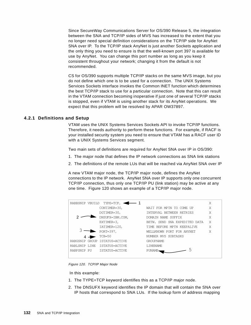
Since SecureWay Communications Server for OS/390 Release 5, the integrationbetween the SNA and TCP/IP sides of MVS has increased to the extent that youno longer need special definition considerations on the TCP/IP side for AnyNetSNA over IP. To the TCP/IP stack AnyNet is just another Sockets application andthe only thing you need to ensure is that the well-known port 397 is available foruse by AnyNet. You can change this port number as long as you keep itconsistent throughout your network; changing it from the default is notrecommended.
CS for OS/390 supports multiple TCP/IP stacks on the same MVS image, but youdo not define which one is to be used for a connection. The UNIX SystemsServices Sockets interface invokes the Common INET function which determinesthe best TCP/IP stack to use for a particular connection. Note that this can resultin the VTAM connection becoming inoperative if just one of several TCP/IP stacksis stopped, even if VTAM is using another stack for its AnyNet operations. Weexpect that this problem will be resolved by APAR OW37897.
4.2.1 Definitions and SetupVTAM uses the UNIX Systems Services Sockets API to invoke TCP/IP functions.Therefore, it needs authority to perform these functions. For example, if RACF isyour installed security system you need to ensure that VTAM has a RACF user IDwith a UNIX Systems Services segment.
Two main sets of definitions are required for AnyNet SNA over IP in OS/390:
1. The major node that defines the IP network connections as SNA link stations
2. The definitions of the remote LUs that will be reached via AnyNet SNA over IP
A new VTAM major node, the TCP/IP major node, defines the AnyNetconnections to the IP network. AnyNet SNA over IP supports only one concurrentTCP/IP connection, thus only one TCP/IP PU (link station) may be active at anyone time. Figure 120 shows an example of a TCP/IP major node.
Figure 120. TCP/IP Major Node
In this example:
1. The TYPE=TCP keyword identifies this as a TCP/IP major node.
2. The DNSUFX keyword identifies the IP domain that will contain the SNA overIP hosts that correspond to SNA LUs. If the lookup form of address mapping
RABBSNIP VBUILD TYPE=TCP, XCONTIMER=30, WAIT FOR MPTN TO COME UP XDGTIMER=30, INTERVAL BETWEEN RETRIES XDNSUFX=IBM.COM, DOMAIN NAME SUFFIX XEXTIMER=3, BETW. SEND SNA EXPEDITED DATA XIATIMER=120, TIME BEFORE MPTN KEEPALIVE XPORT=397, WELLKNOWN PORT FOR ANYNET XTCB=50 NUMBER MVS SUBTASKS
RABGSNIP GROUP ISTATUS=ACTIVE GROUPNAMERABLSNIP LINE ISTATUS=ACTIVE LINENAMERABPSNIP PU ISTATUS=ACTIVE PUNAME
2
1
3
4
5
132 SNA and TCP/IP Integration
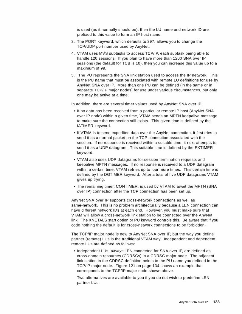
is used (as it normally should be), then the LU name and network ID areprefixed to this value to form an IP host name.
3. The PORT keyword, which defaults to 397, allows you to change theTCP/UDP port number used by AnyNet.
4. VTAM uses MVS subtasks to access TCP/IP, each subtask being able tohandle 120 sessions. If you plan to have more than 1200 SNA over IPsessions (the default for TCB is 10), then you can increase this value up to amaximum of 99.
5. The PU represents the SNA link station used to access the IP network. Thisis the PU name that must be associated with remote LU definitions for use byAnyNet SNA over IP. More than one PU can be defined (in the same or inseparate TCP/IP major nodes) for use under various circumstances, but onlyone may be active at a time.
In addition, there are several timer values used by AnyNet SNA over IP:
• If no data has been received from a particular remote IP host (AnyNet SNAover IP node) within a given time, VTAM sends an MPTN keepalive messageto make sure the connection still exists. This given time is defined by theIATIMER keyword.
• If VTAM is to send expedited data over the AnyNet connection, it first tries tosend it as a normal packet on the TCP connection associated with thesession. If no response is received within a suitable time, it next attempts tosend it as a UDP datagram. This suitable time is defined by the EXTIMERkeyword.
• VTAM also uses UDP datagrams for session termination requests andkeepalive MPTN messages. If no response is received to a UDP datagramwithin a certain time, VTAM retries up to four more times. This certain time isdefined by the DGTIMER keyword. After a total of five UDP datagrams VTAMgives up trying.
• The remaining timer, CONTIMER, is used by VTAM to await the MPTN (SNAover IP) connection after the TCP connection has been set up.
AnyNet SNA over IP supports cross-network connections as well assame-network. This is no problem architecturally because a LEN connection canhave different network IDs at each end. However, you must make sure thatVTAM will allow a cross-network link station to be connected over the AnyNetlink. The XNETALS start option or PU keyword controls this. Be aware that if youcode nothing the default is for cross-network connections to be forbidden.
The TCP/IP major node is new to AnyNet SNA over IP, but the way you definepartner (remote) LUs is the traditional VTAM way. Independent and dependentremote LUs are defined as follows:
• Independent LUs, always LEN connected for SNA over IP, are defined ascross-domain resources (CDRSCs) in a CDRSC major node. The adjacentlink station in the CDRSC definition points to the PU name you defined in theTCP/IP major node. Figure 121 on page 134 shows an example thatcorresponds to the TCP/IP major node shown above.
Two alternatives are available to you if you do not wish to predefine LENpartner LUs:
AnyNet SNA over IP 133

• If the remote LU will always initiate the session, VTAM can dynamicallycreate a CDRSC for it provided that the dynamic LU (DYNLU) option hasbeen set to YES for the AnyNet PU. DYNLU can be coded as a VTAM startoption or on the PU statement.
• The VTAM session management exit can be used to associate a linkstation name with a target LU. If your naming convention is reasonablyconsistent you can identify the AnyNet SNA over IP LUs in the exit andassociate the TCP/IP PU with them.
• Dependent LUs, always DLUR resources for SNA over IP in CS for OS/390,are defined in switched major nodes, or by the use of the dynamic definitionexits ISTEXCCS and/or ISTEXCSD. There is no special consideration forthese because they are reached via AnyNet. As with normal DLUR resourcesyou identify them by node ID, and if you want VTAM to establish theconnection you need to identify the DLUR control point name as well. TheDLUR CP itself is an independent LU and must be defined as in Figure 121.Figure 122 on page 135 shows a definition of a switched major node for usewith AnyNet SNA over IP.
Figure 121. Independent LU Definition for AnyNet SNA over IP
In this CDRSC major node we define three remote LUs all of which are to bereached via SNA over IP. The ALSLIST keyword points to the PU name in theTCP/IP major node (Figure 120 on page 132) in each case.
Note that the LUs (CDRSCs) defined here need not, themselves, be capable ofLEN or AnyNet. What matters is that they can be reached by means of the SNAover IP LEN connection. If the connection partner is an AnyNet SNA over IPgateway, a remote LU reachable through that gateway must be defined as above.In that case you must ensure that the remote LU is resolved to the same IPaddress as the partner gateway; the TCP connection will then be set up to thegateway node and the session request will be forwarded by the gateway into theSNA network.
The ALSREQ keywords are not strictly necessary, but will help to reduceunnecessary searching if your VTAM has APPN as well as LEN capability. VTAMwill always search the APPN network for a target resource before looking at aLEN connection, unless ALSREQ=YES is coded. If you know that AnyNetresources are reachable only via IP, coding ALSREQ=YES on their definitions willeliminate the fruitless APPN search.
*********************************************************************VBUILD TYPE=CDRSC
*********************************************************************WTR05221 CDRSC ALSLIST=RABPSNIP,ALSREQ=YESRAIAC CDRSC ALSLIST=RABPSNIP,ALSREQ=YESRAPAC CDRSC ALSLIST=RABPSNIP,ALSREQ=YES*********************************************************************
134 SNA and TCP/IP Integration
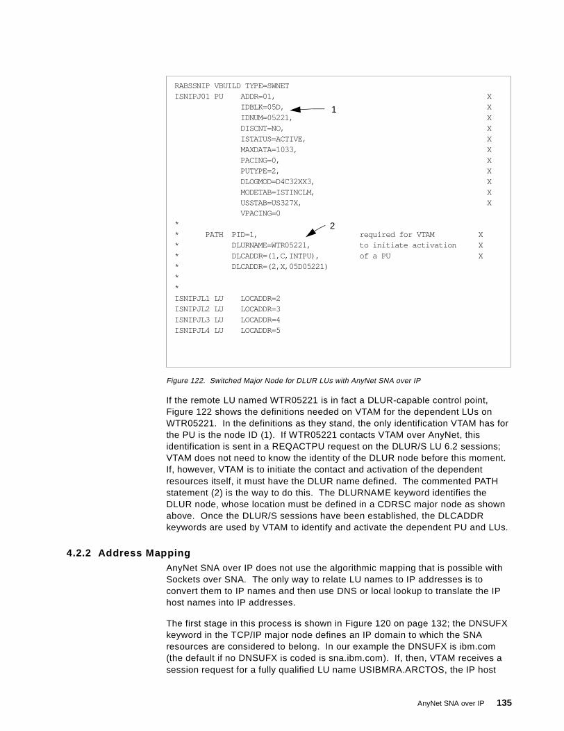
Figure 122. Switched Major Node for DLUR LUs with AnyNet SNA over IP
If the remote LU named WTR05221 is in fact a DLUR-capable control point,Figure 122 shows the definitions needed on VTAM for the dependent LUs onWTR05221. In the definitions as they stand, the only identification VTAM has forthe PU is the node ID (1). If WTR05221 contacts VTAM over AnyNet, thisidentification is sent in a REQACTPU request on the DLUR/S LU 6.2 sessions;VTAM does not need to know the identity of the DLUR node before this moment.If, however, VTAM is to initiate the contact and activation of the dependentresources itself, it must have the DLUR name defined. The commented PATHstatement (2) is the way to do this. The DLURNAME keyword identifies theDLUR node, whose location must be defined in a CDRSC major node as shownabove. Once the DLUR/S sessions have been established, the DLCADDRkeywords are used by VTAM to identify and activate the dependent PU and LUs.
4.2.2 Address MappingAnyNet SNA over IP does not use the algorithmic mapping that is possible withSockets over SNA. The only way to relate LU names to IP addresses is toconvert them to IP names and then use DNS or local lookup to translate the IPhost names into IP addresses.
The first stage in this process is shown in Figure 120 on page 132; the DNSUFXkeyword in the TCP/IP major node defines an IP domain to which the SNAresources are considered to belong. In our example the DNSUFX is ibm.com(the default if no DNSUFX is coded is sna.ibm.com). If, then, VTAM receives asession request for a fully qualified LU name USIBMRA.ARCTOS, the IP host
RABSSNIP VBUILD TYPE=SWNETISNIPJ01 PU ADDR=01, X
IDBLK=05D, XIDNUM=05221, XDISCNT=NO, XISTATUS=ACTIVE, XMAXDATA=1033, XPACING=0, XPUTYPE=2, XDLOGMOD=D4C32XX3, XMODETAB=ISTINCLM, XUSSTAB=US327X, XVPACING=0
** PATH PID=1, required for VTAM X* DLURNAME=WTR05221, to initiate activation X* DLCADDR=(1,C,INTPU), of a PU X* DLCADDR=(2,X,05D05221)**ISNIPJL1 LU LOCADDR=2ISNIPJL2 LU LOCADDR=3ISNIPJL3 LU LOCADDR=4ISNIPJL4 LU LOCADDR=5
1
2
AnyNet SNA over IP 135
name generated will be arctos.usibmra.ibm.com. If no network ID is suppliedVTAM will use its own (native) network ID unless XNETALS=YES and you havecoded a NETID keyword on the TCP/IP major node. In this case the codedNETID is used for the address resolution.
The second stage of address mapping is to translate the host name to an IPaddress. VTAM issues a gethostbyname() call to the Sockets API to obtain the IPaddress. TCP/IP then tries to resolve the name using DNS, and looks in theHOSTS.LOCAL file if DNS cannot resolve the name.
4.2.3 Gateway ConsiderationsBecause of the structure of an AnyNet SNA over IP node, the gatewayconfiguration does not require special treatment or definition. Any VTAM iscapable of passing data through from one interface to another, and SNA over IPis just one particular link station over which sessions may flow. Since the SNAover IP connection is LEN, VTAM regards resources on that connection as ownedby itself. Therefore, sessions passing through the gateway do not treat it as anintermediate routing node and the gateway may be an APPN end node.
If there are multiple SNA over IP gateways between an SNA network and an IPnetwork, they have no knowledge of each other as gateways. The choice ofrouting a session to one gateway or another follows the normal route selectionmechanisms in the originating network.
4.3 AnyNet SNA over IP for CS/2
The structure of an AnyNet SNA over IP node running CS/2 is essentially thesame as that of a CS for OS/390 node (Figure 119 on page 131). The SNA stackhas an additional logical connection available to it in addition to the real SNAlinks; this connection comprises a Sockets API to the adjacent TCP/IP stackwhich looks after the TCP/IP transport.
SNA over IP supports the same APIs as native SNA: the Communications ServerAPPC and CPI-C APIs (for LU 6.2 sessions) and the LU Application (LUA) API fordependent LU sessions. LUA is used by PComm/2; thus PComm sessions cantake advantage of AnyNet SNA over IP.
The gateway configuration is similar to the access node configuration except thatadditional SNA over IP links may need definition under some circumstances. Touse the gateway configuration you need to be running the full CommunicationsServer product, not the Access Feature subset. A gateway must be configuredas an APPN network node, because it is to route sessions as an intermediatenode. This does not apply to VTAM because VTAM acts as the resource owneron behalf of LEN-attached resources, whereas CS/2 acts as the network nodeserver on behalf of such resources.
4.3.1 Dependent LU SupportAnyNet for CS/2 supports dependent LU communication to an SNA host using thedependent LU requester function. The DLUR/S sessions (LU 6.2 over a LENconnection) are set up in the same manner as any other LU 6.2 sessions, and thedependent LU activation flows are encapsulated within these sessions. When asession request is received for a dependent LU, CS/2 knows very little about it
136 SNA and TCP/IP Integration
until a BIND appears on the LEN (SNA over IP) connection. All the logon,network searching, route selection and session parameter choosing are done byVTAM.
CS/2 can also act as an SNA gateway (this is not the same as an SNA over IPgateway) on behalf of other nodes with dependent LUs. In this case CS/2maintains LUs on behalf of the downstream nodes, and the upstream connectionto VTAM can be either native SNA (DLUR or more traditional forms), or SNA overIP (DLUR only).
If a downstream node is connected via AnyNet SNA over IP, CS/2 can beconfigured as:
• An SNA gateway and AnyNet access node on behalf of the dependent LUs onthe downstream node.
• An AnyNet gateway on behalf of the dependent or independent LUs on thedownstream node. For the dependent LUs, this provides the same function asthe case above.
If CS/2 is communicating with downstream dependent LUs over an IP network,the LU name to IP address mapping is useless because the LU names are notknown; a dependent LU is named by its owning SSCP and identifies itself only byits local address. Therefore, AnyNet nodes on each side of such a connectionmust have the SNA over IP link predefined. They exchange resource activationprotocols using UDP datagrams before embarking on real sessions.
4.3.2 Configuration and DefinitionsDefining an SNA over IP configuration is the same as defining a normal CS/2configuration, with the addition of one (and sometimes two) extra options. Theseare the AnyNet base parameters and the AnyNet connections options. Theywill be found in the Configuration List (Figure 123 on page 138) if you selectOptions and Configure any profile or feature .
If you are configuring an access node that has only IP connectivity to the network,you will not need to invoke the SNA connections option since the only externalconnection is via the IP network.
AnyNet SNA over IP 137
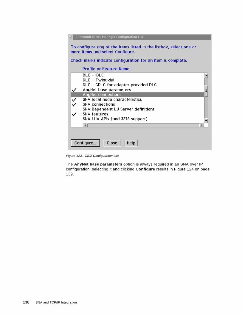
Figure 123. CS/2 Configuration List
The AnyNet base parameters option is always required in an SNA over IPconfiguration; selecting it and clicking Configure results in Figure 124 on page139.
138 SNA and TCP/IP Integration
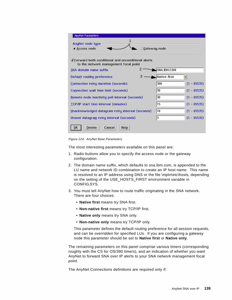
Figure 124. AnyNet Base Parameters
The most interesting parameters available on this panel are:
1. Radio buttons allow you to specify the access node or the gatewayconfiguration.
2. The domain name suffix, which defaults to sna.ibm.com, is appended to theLU name and network ID combination to create an IP host name. This nameis resolved to an IP address using DNS or the file \mptn\etc\hosts, dependingon the setting of the USE_HOSTS_FIRST environment variable inCONFIG.SYS.
3. You must tell AnyNet how to route traffic originating in the SNA network.There are four choices:
• Native first means try SNA first.
• Non-native first means try TCP/IP first.
• Native only means try SNA only.
• Non-native only means try TCP/IP only.
This parameter defines the default routing preference for all session requests,and can be overridden for specified LUs. If you are configuring a gatewaynode this parameter should be set to Native first or Native only .
The remaining parameters on this panel comprise various timers (correspondingroughly with the CS for OS/390 timers), and an indication of whether you wantAnyNet to forward SNA over IP alerts to your SNA network management focalpoint.
The AnyNet Connections definitions are required only if:
1
2
3
AnyNet SNA over IP 139
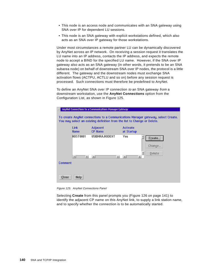
• This node is an access node and communicates with an SNA gateway usingSNA over IP for dependent LU sessions.
• This node is an SNA gateway with explicit workstations defined, which alsoacts as an SNA over IP gateway for those workstations.
Under most circumstances a remote partner LU can be dynamically discoveredby AnyNet across an IP network. On receiving a session request it translates theLU name into an IP address, contacts the IP address, and expects the remotenode to accept a BIND for the specified LU name. However, if the SNA over IPgateway also acts as an SNA gateway (in other words, it pretends to be an SNAsubarea node) on behalf of downstream SNA over IP nodes, the protocol is a littledifferent. The gateway and the downstream nodes must exchange SNAactivation flows (ACTPU, ACTLU and so on) before any session request isprocessed. Such connections must therefore be predefined to AnyNet.
To define an AnyNet SNA over IP connection to an SNA gateway from adownstream workstation, use the AnyNet Connections option from theConfiguration List, as shown in Figure 125.
Figure 125. AnyNet Connections Panel
Selecting Create from this panel prompts you (Figure 126 on page 141) toidentify the adjacent CP name on this AnyNet link, to supply a link station name,and to specify whether the connection is to be automatically started.
140 SNA and TCP/IP Integration

Figure 126. AnyNet Connection Details
To define an AnyNet SNA over IP connection from an SNA gateway to aworkstation, use instead the Gateway options from the Configuration List. Thereare three of these:
• Gateway - Hosts and host LU pools lets you define upstream connectionsand LU pools. In fact, this is an alternative way of defining AnyNet upstreamconnections if you simply select the AnyNet DLC.
• Gateway - Implicit workstations lets you define a template for use by LUsusing the pools you defined in the Gateway-Hosts option.
• Gateway - Explicit workstations lets you define individual connections todownstream nodes.
For example, if you select Explicit Workstations you will see a panel listing theavailable links and the number of LUs defined on each. Initially these do notinclude the AnyNet SNA over IP connection, so select Links and select theAnyNet DLC type from the scroll bar on the subsequent panel. Now if you clickCreate you will see the panel shown in Figure 127.
Figure 127. AnyNet Downstream Connection
Here you can identify the adjacent node by its CP name (which will result in itsbeing located using AnyNet address mapping and then DNS lookup), or by itsnode ID (if the partner is a type 2 node and does not have a CP name). If you usenode ID then the IP host name generated by AnyNet comprises the numeric nodeID followed by the domain suffix (for example, 05D05282.sna.ibm.com). Note
AnyNet SNA over IP 141
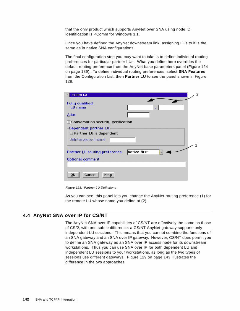
that the only product which supports AnyNet over SNA using node IDidentification is PComm for Windows 3.1.
Once you have defined the AnyNet downstream link, assigning LUs to it is thesame as in native SNA configurations.
The final configuration step you may want to take is to define individual routingpreferences for particular partner LUs. What you define here overrides thedefault routing preference from the AnyNet base parameters panel (Figure 124on page 139). To define individual routing preferences, select SNA Featuresfrom the Configuration List, then Partner LU to see the panel shown in Figure128.
Figure 128. Partner LU Definitions
As you can see, this panel lets you change the AnyNet routing preference (1) forthe remote LU whose name you define at (2).
4.4 AnyNet SNA over IP for CS/NT
The AnyNet SNA over IP capabilities of CS/NT are effectively the same as thoseof CS/2, with one subtle difference: a CS/NT AnyNet gateway supports onlyindependent LU sessions. This means that you cannot combine the functions ofan SNA gateway and an SNA over IP gateway. However, CS/NT does permit youto define an SNA gateway as an SNA over IP access node for its downstreamworkstations. Thus you can use SNA over IP for both dependent LU andindependent LU sessions to your workstations, as long as the two types ofsessions use different gateways. Figure 129 on page 143 illustrates thedifference in the two approaches.
1
2
142 SNA and TCP/IP Integration
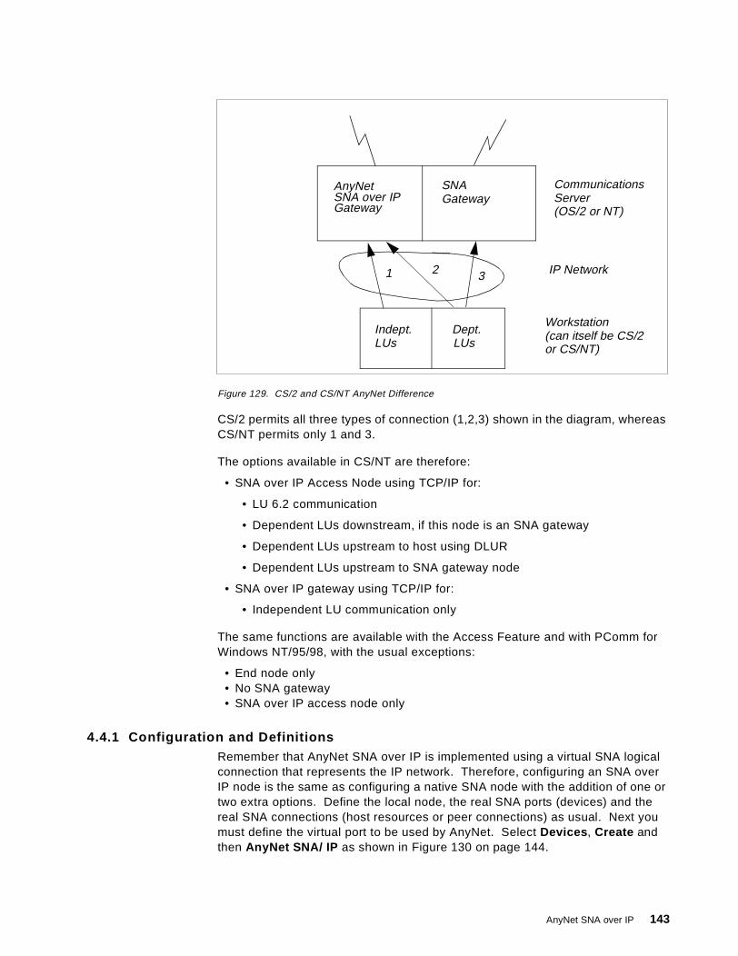
Figure 129. CS/2 and CS/NT AnyNet Difference
CS/2 permits all three types of connection (1,2,3) shown in the diagram, whereasCS/NT permits only 1 and 3.
The options available in CS/NT are therefore:
• SNA over IP Access Node using TCP/IP for:
• LU 6.2 communication
• Dependent LUs downstream, if this node is an SNA gateway
• Dependent LUs upstream to host using DLUR
• Dependent LUs upstream to SNA gateway node
• SNA over IP gateway using TCP/IP for:
• Independent LU communication only
The same functions are available with the Access Feature and with PComm forWindows NT/95/98, with the usual exceptions:
• End node only• No SNA gateway• SNA over IP access node only
4.4.1 Configuration and DefinitionsRemember that AnyNet SNA over IP is implemented using a virtual SNA logicalconnection that represents the IP network. Therefore, configuring an SNA overIP node is the same as configuring a native SNA node with the addition of one ortwo extra options. Define the local node, the real SNA ports (devices) and thereal SNA connections (host resources or peer connections) as usual. Next youmust define the virtual port to be used by AnyNet. Select Devices , Create andthen AnyNet SNA/ IP as shown in Figure 130 on page 144.
AnyNetSNA over IPGateway
SNAGateway
Indept. Dept.LUs LUs
CommunicationsServer(OS/2 or NT)
Workstation
IP Network1 2 3
(can itself be CS/2or CS/NT)
AnyNet SNA over IP 143
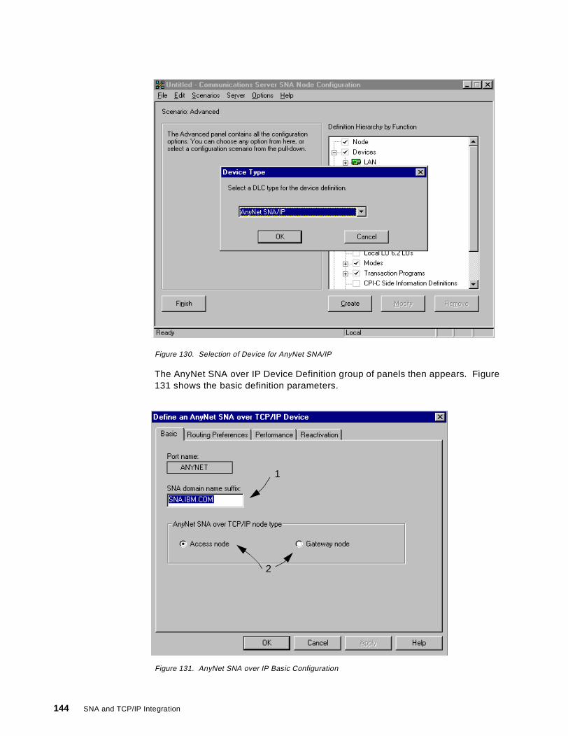
Figure 130. Selection of Device for AnyNet SNA/IP
The AnyNet SNA over IP Device Definition group of panels then appears. Figure131 shows the basic definition parameters.
Figure 131. AnyNet SNA over IP Basic Configuration
1
2
144 SNA and TCP/IP Integration
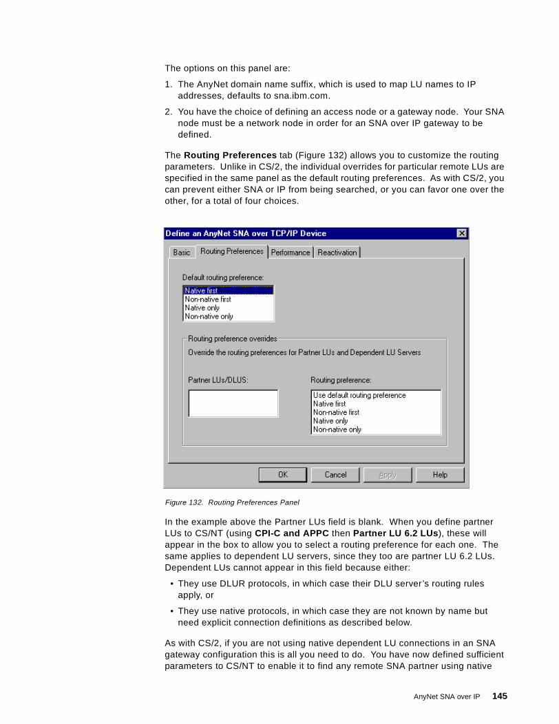
The options on this panel are:
1. The AnyNet domain name suffix, which is used to map LU names to IPaddresses, defaults to sna.ibm.com.
2. You have the choice of defining an access node or a gateway node. Your SNAnode must be a network node in order for an SNA over IP gateway to bedefined.
The Routing Preferences tab (Figure 132) allows you to customize the routingparameters. Unlike in CS/2, the individual overrides for particular remote LUs arespecified in the same panel as the default routing preferences. As with CS/2, youcan prevent either SNA or IP from being searched, or you can favor one over theother, for a total of four choices.
Figure 132. Routing Preferences Panel
In the example above the Partner LUs field is blank. When you define partnerLUs to CS/NT (using CPI-C and APPC then Partner LU 6.2 LUs ), these willappear in the box to allow you to select a routing preference for each one. Thesame applies to dependent LU servers, since they too are partner LU 6.2 LUs.Dependent LUs cannot appear in this field because either:
• They use DLUR protocols, in which case their DLU server’s routing rulesapply, or
• They use native protocols, in which case they are not known by name butneed explicit connection definitions as described below.
As with CS/2, if you are not using native dependent LU connections in an SNAgateway configuration this is all you need to do. You have now defined sufficientparameters to CS/NT to enable it to find any remote SNA partner using native
AnyNet SNA over IP 145
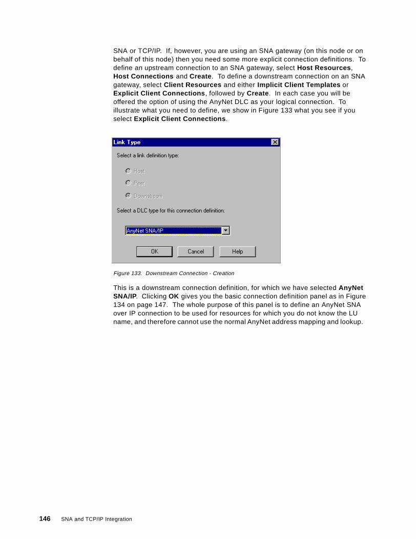
SNA or TCP/IP. If, however, you are using an SNA gateway (on this node or onbehalf of this node) then you need some more explicit connection definitions. Todefine an upstream connection to an SNA gateway, select Host Resources ,Host Connections and Create . To define a downstream connection on an SNAgateway, select Client Resources and either Implicit Client Templates orExplicit Client Connections , followed by Create . In each case you will beoffered the option of using the AnyNet DLC as your logical connection. Toillustrate what you need to define, we show in Figure 133 what you see if youselect Explicit Client Connections .
Figure 133. Downstream Connection - Creation
This is a downstream connection definition, for which we have selected AnyNetSNA/IP. Clicking OK gives you the basic connection definition panel as in Figure134 on page 147. The whole purpose of this panel is to define an AnyNet SNAover IP connection to be used for resources for which you do not know the LUname, and therefore cannot use the normal AnyNet address mapping and lookup.
146 SNA and TCP/IP Integration

Figure 134. Downstream Connection - Basic
The downstream node could be a type 2 or a type 2.1 node, and could beidentified by its CP name or by its node ID; therefore you are given the option (1)of which identification you wish to use. The default is by CP name, in which casethe AnyNet name translation will be used, the partner node will be contactedusing UDP, and MPTN protocols will then be used to activate the dependentresources. If you use the node ID (for PComm for Windows 3.1 workstationsonly), the mapping uses the full node ID as the unqualified host name, just as inCS/2.
Once you have defined a CP name or a node ID, you can assign a DLUS (ifrequired) and dependent LUs to this connection just as in a native SNAconfiguration.
4.5 Working Scenarios
The working scenarios presented in this section are taken from the redbookAnyNet: SNA over TCP/IP Installation and Interoperability, GG24-4395. At thetime that book was written there was no AnyNet support on any Windowsplatform except Windows 3.1, so the scenarios include OS/2 and MVSconfigurations only. The results described (and the figures we show) remain validto this day, but we present the configurations by referring to the earlier sectionsof this chapter rather than by repeating the actual definitions used. In this way wehope to give you up-to-date information which you can use to match your ownscenario to the ones we implemented.
1
AnyNet SNA over IP 147

All the workstations and OS/390 hosts we used were connected to a token-ringnetwork over which only TCP/IP communication was used. To show theoperation of an AnyNet SNA over IP gateway we had additional OS/390 hostslinked to the token-ring-attached ones by subarea or APPN SNA connections.We exercised both independent LU 6.2 and dependent DLUR LU communicationusing SNA over IP.
The SNA network ID used throughout the tests was USIBMRA.
4.5.1 SNA over IP between OS/390 HostsFigure 135 shows our first setup in which two OS/390 SNA over IP access nodescommunicate with each other.
Figure 135. OS/390-to-OS/390 Configuration
We established LU 6.2 communication between two CICS systems, RAIAC andRABAC. They run on VTAMs RAI and RAB respectively; the companion TCP/IPstacks are called T18ATCP and T11ATCP. The TCP/IP stacks are in the samesubnetwork and talk to each other via two 3172s as shown.
We first defined a TCP/IP major node on each VTAM system; the one on RAB isshown in Figure 136, the one on RAI being identical except for the resourcenames where I was substituted for B.
Figure 136. TCP/IP Major Node for RAB
3172 3172
9.67.38.3 9.67.38.11
Appl RAIAC Appl RABAC
VTAM RAI VTAM RAB
TCP/IPT18ATCP
TCP/IPT11ATCP
is SNA API calls
is SNA over IP transport
RABBSNIP VBUILD TYPE=TCP, XCONTIMER=30, WAIT FOR MPTN TO COME UP XDGTIMER=30, INTERVAL BETWEEN RETRIES XDNSUFX=IBM.COM, DOMAIN NAME SUFFIX XEXTIMER=3, BETW. SEND SNA EXPEDITED DATA XIATIMER=120, TIME BEFORE MPTN KEEPALIVE XPORT=397, WELLKNOWN PORT FOR ANYNET XTCB=50 NUMBER MVS SUBTASKS
RABGSNIP GROUP ISTATUS=ACTIVE GROUPNAMERABLSNIP LINE ISTATUS=ACTIVE LINENAMERABPSNIP PU ISTATUS=ACTIVE PUNAME
148 SNA and TCP/IP Integration
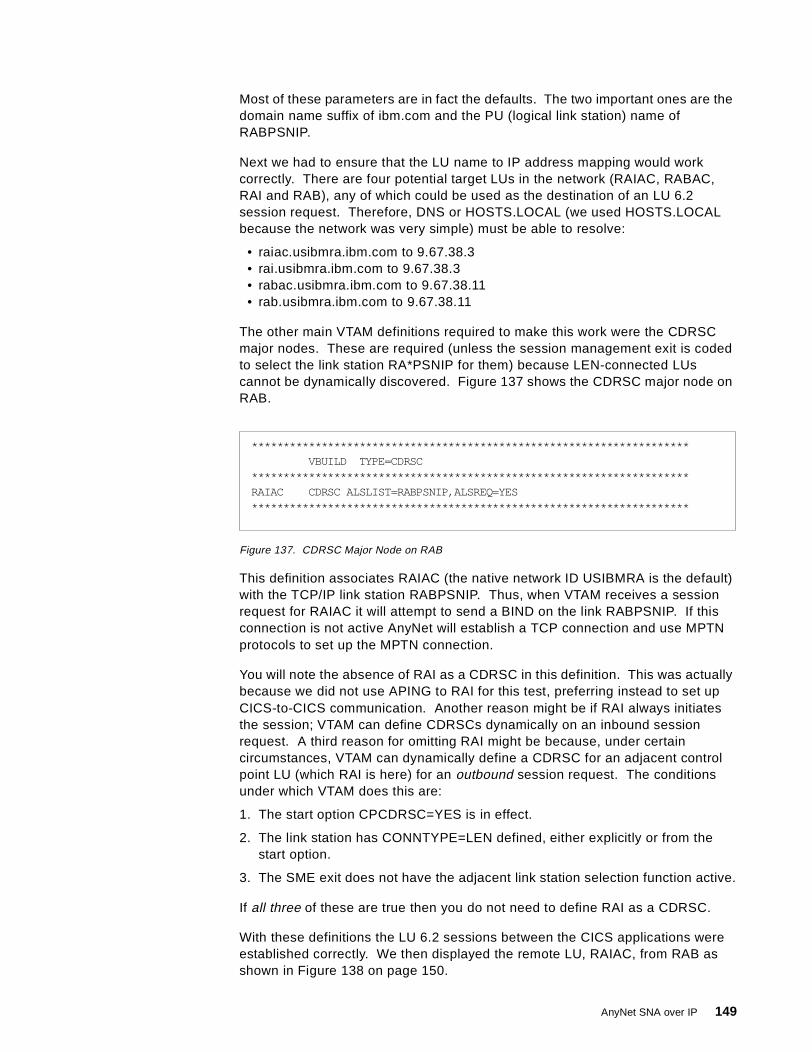
Most of these parameters are in fact the defaults. The two important ones are thedomain name suffix of ibm.com and the PU (logical link station) name ofRABPSNIP.
Next we had to ensure that the LU name to IP address mapping would workcorrectly. There are four potential target LUs in the network (RAIAC, RABAC,RAI and RAB), any of which could be used as the destination of an LU 6.2session request. Therefore, DNS or HOSTS.LOCAL (we used HOSTS.LOCALbecause the network was very simple) must be able to resolve:
• raiac.usibmra.ibm.com to 9.67.38.3• rai.usibmra.ibm.com to 9.67.38.3• rabac.usibmra.ibm.com to 9.67.38.11• rab.usibmra.ibm.com to 9.67.38.11
The other main VTAM definitions required to make this work were the CDRSCmajor nodes. These are required (unless the session management exit is codedto select the link station RA*PSNIP for them) because LEN-connected LUscannot be dynamically discovered. Figure 137 shows the CDRSC major node onRAB.
Figure 137. CDRSC Major Node on RAB
This definition associates RAIAC (the native network ID USIBMRA is the default)with the TCP/IP link station RABPSNIP. Thus, when VTAM receives a sessionrequest for RAIAC it will attempt to send a BIND on the link RABPSNIP. If thisconnection is not active AnyNet will establish a TCP connection and use MPTNprotocols to set up the MPTN connection.
You will note the absence of RAI as a CDRSC in this definition. This was actuallybecause we did not use APING to RAI for this test, preferring instead to set upCICS-to-CICS communication. Another reason might be if RAI always initiatesthe session; VTAM can define CDRSCs dynamically on an inbound sessionrequest. A third reason for omitting RAI might be because, under certaincircumstances, VTAM can dynamically define a CDRSC for an adjacent controlpoint LU (which RAI is here) for an outbound session request. The conditionsunder which VTAM does this are:
1. The start option CPCDRSC=YES is in effect.
2. The link station has CONNTYPE=LEN defined, either explicitly or from thestart option.
3. The SME exit does not have the adjacent link station selection function active.
If all three of these are true then you do not need to define RAI as a CDRSC.
With these definitions the LU 6.2 sessions between the CICS applications wereestablished correctly. We then displayed the remote LU, RAIAC, from RAB asshown in Figure 138 on page 150.
*********************************************************************VBUILD TYPE=CDRSC
*********************************************************************RAIAC CDRSC ALSLIST=RABPSNIP,ALSREQ=YES*********************************************************************
AnyNet SNA over IP 149

Figure 138. Remote SNA over IP LU Display
Seen from RAB, RAIAC is an independent LU and a CDRSC (1), as we canexpect from a LEN-connected resource. It can be reached via the link stationRABPSNIP (2) which is the name of the PU defined in the TCP/IP major node(Figure 136 on page 148). All four sessions between RABAC and RAIAC areusing this link station (3) as their path out of RAB to RAI.
We also displayed the status of the TCP/IP logical link station, as shown in Figure139.
Figure 139. TCP/IP Link Station Display
This is the same as any LEN connection, with nothing to indicate that TCP/IP isbeing used to transport the sessions.
D NET,ID=RAIAC,SCOPE=ALLIST097I DISPLAY ACCEPTEDIST075I NAME = USIBMRA.RAIAC, TYPE = CDRSCIST486I STATUS= ACT/S, DESIRED STATE= ACTIVIST977I MDLTAB=***NA*** ASLTAB=***NA***IST1333I ADJLIST = ***NA***IST861I MODETAB=***NA*** USSTAB=***NA*** LOGTAB=***NA***IST934I DLOGMOD=***NA*** USS LANGTAB=***NA***IST597I CAPABILITY-PLU ENABLED ,SLU ENABLED ,SESSION LIMIT NONEIST231I CDRSC MAJOR NODE = RABRSNIPIST1184I CPNAME = USIBMRA.RAB - NETSRVR = ***NA***IST1044I ALSLIST = RABPSNIPIST082I DEVTYPE = INDEPENDENT LU / CDRSCIST654I I/O TRACE = OFF, BUFFER TRACE = OFFIST171I ACTIVE SESSIONS = 0000000004, SESSION REQUESTS = 0000000000IST206I SESSIONS:IST1081I ADJACENT LINK STATION = RABPSNIPIST634I NAME STATUS SID SEND RECV VR TP NETIDIST635I RABAC ACTIV-S F86FE164BF5D0777 0004 0003 USIBMRAIST635I RABAC ACTIV-P F7EFD164B8D7DB2D 0000 0001 USIBMRAIST635I RABAC ACTIV-P F7EFD164B8D7DB2C 0000 0001 USIBMRAIST635I RABAC ACTIV-P F7EFD164B8D7DB2B 0002 0003 USIBMRAIST314I END
1
2
3
D NET,ID=RABPSNIP,SCOPE=ALLIST097I DISPLAY ACCEPTEDIST075I NAME = RABPSNIP, TYPE = PU_T2.1IST486I STATUS= ACTIV--L--, DESIRED STATE= ACTIVIST1043I CP NAME = ***NA***, CP NETID = USIBMRA, DYNAMIC LU = YESIST081I LINE NAME = RABLSNIP, LINE GROUP = RABGSNIP, MAJNOD = RABBSNIPIST654I I/O TRACE = OFF, BUFFER TRACE = OFFIST355I LOGICAL UNITS:IST080I RAIAC ACT/SIST314I END
150 SNA and TCP/IP Integration
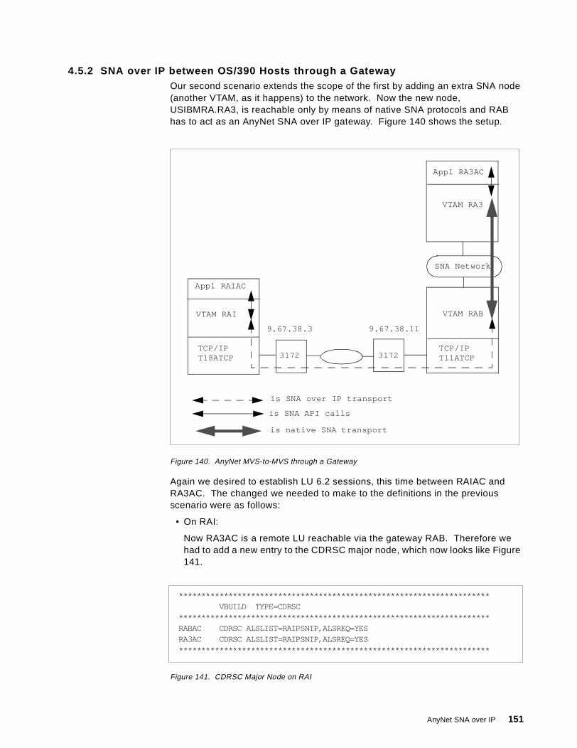
4.5.2 SNA over IP between OS/390 Hosts through a GatewayOur second scenario extends the scope of the first by adding an extra SNA node(another VTAM, as it happens) to the network. Now the new node,USIBMRA.RA3, is reachable only by means of native SNA protocols and RABhas to act as an AnyNet SNA over IP gateway. Figure 140 shows the setup.
Figure 140. AnyNet MVS-to-MVS through a Gateway
Again we desired to establish LU 6.2 sessions, this time between RAIAC andRA3AC. The changed we needed to make to the definitions in the previousscenario were as follows:
• On RAI:
Now RA3AC is a remote LU reachable via the gateway RAB. Therefore wehad to add a new entry to the CDRSC major node, which now looks like Figure141.
Figure 141. CDRSC Major Node on RAI
3172 3172
9.67.38.3 9.67.38.11
Appl RAIAC
VTAM RAI VTAM RAB
TCP/IPT18ATCP
TCP/IPT11ATCP
is SNA API calls
is SNA over IP transport
is native SNA transport
VTAM RA3
SNA Network
Appl RA3AC
*********************************************************************VBUILD TYPE=CDRSC
*********************************************************************RABAC CDRSC ALSLIST=RAIPSNIP,ALSREQ=YESRA3AC CDRSC ALSLIST=RAIPSNIP,ALSREQ=YES*********************************************************************
AnyNet SNA over IP 151
RABAC and RA3AC are reached in the same way, namely across the IPnetwork.
• On RAB:
The connection between RAB and RA3 is native SNA, so the definition (if any)of RA3AC is not dependent on AnyNet. RA3AC is always a CDRSC to RAB,but it may be defined explicitly or dynamically depending on the configurationand the installation’s policies.
• On RA3:
The partner LU RAIAC is seen by RA3 as being owned by RAB, since it isactually LEN attached to RAB. Therefore, it is defined (if at all) to RA3 as aCDRSC on RAB.
• In the IP network:
The only new circumstance that may impact the IP network is if RAI requests asession with RA3 or (as in our case) RA3AC. Since RAI now understands thatRA3AC can be reached through the IP network (Figure 141 on page 151), theIP network must be configured so that ra3ac.usibmra.ibm.com is resolved(along with rabac) to RAB’s IP address 9.67.38.11. Accordingly, we addedprecisely that entry to our HOSTS.LOCAL file on T18ATCP.
After making these changes we successfully established the LU 6.2 sessionsbetween RAIAC and RA3AC. Displays of the partner LU (RA3AC) and theTCP/IP link station (RAIPSNIP) from RAI showed similar results to those seen inFigure 138 on page 150 and Figure 139 on page 150 respectively. To RAI:
• RA3AC is an independent LU and CDRSC reachable via the link stationRAIPSNIP, which carries all the sessions between RAIAC and RA3AC.
• RAIPSNIP is a PU type 2.1 with RA3AC as a logical unit reachable through it.
4.5.3 SNA over IP between Hosts through a Pair of GatewaysNext, we extended our SNA network on the RAI side by adding a second VTAMnode, RAP, and connecting it to RAI by means of an SNA connection. Figure 142on page 153 shows the new configuration.
152 SNA and TCP/IP Integration

Figure 142. AnyNet MVS-to-MVS with Two Gateways
Now, to establish sessions between RAPAC (another CICS application on RAP)and the rest of the CICS systems we need to make the following changes:
• On RAP and RA3:
No definitions are required if these VTAM nodes are able to locate partnerresources dynamically, which is normally the case both in subarea and APPNenvironments. If you wish to define RAPAC and RA3AC to each other theyare both seen as CDRSCs owned by RAI (as far as RAP is concerned) and byRAB (as seen by RA3). Between RAI and RAB the connection is LEN and thetwo parts of the SNA network (whether subarea or APPN) are unknown toeach other.
• On RAI:
RAPAC is defined (if at all) as a CDRSC owned by RAP. RA3AC is alreadydefined from the previous scenario.
• On RAB:
RAPAC must be defined as a CDRSC reachable via the TCP/IP link stationRABPSNIP.
• In the IP network:
The IP host rapac.usibmra.ibm.com must be associated with RAI’s IP address,that is 9.67.38.3. We therefore added this entry to the HOSTS.LOCAL file onT11ATCP.
3172 3172
9.67.38.3 9.67.38.11
VTAM RAI VTAM RAB
TCP/IPT18ATCP
TCP/IPT11ATCP
is SNA API calls
is SNA over IP transport
is native SNA transport
VTAM RA3
SNA Network
Appl RA3AC
SNA Network
VTAM RAP
Appl RAPAC
AnyNet SNA over IP 153
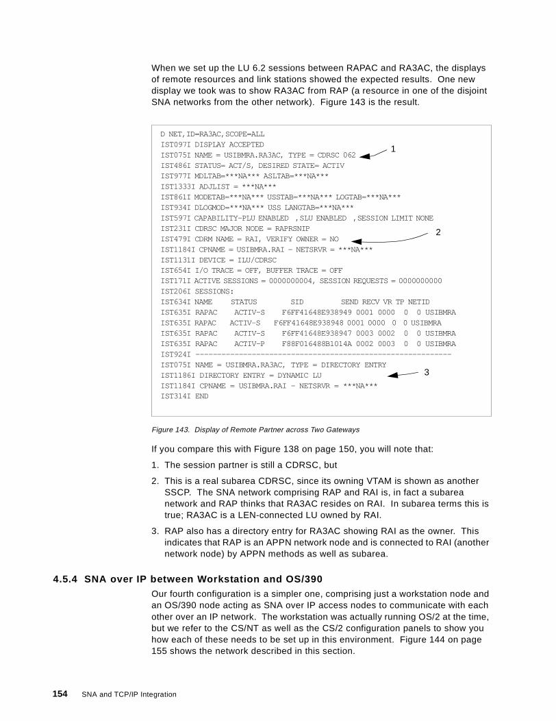
When we set up the LU 6.2 sessions between RAPAC and RA3AC, the displaysof remote resources and link stations showed the expected results. One newdisplay we took was to show RA3AC from RAP (a resource in one of the disjointSNA networks from the other network). Figure 143 is the result.
Figure 143. Display of Remote Partner across Two Gateways
If you compare this with Figure 138 on page 150, you will note that:
1. The session partner is still a CDRSC, but
2. This is a real subarea CDRSC, since its owning VTAM is shown as anotherSSCP. The SNA network comprising RAP and RAI is, in fact a subareanetwork and RAP thinks that RA3AC resides on RAI. In subarea terms this istrue; RA3AC is a LEN-connected LU owned by RAI.
3. RAP also has a directory entry for RA3AC showing RAI as the owner. Thisindicates that RAP is an APPN network node and is connected to RAI (anothernetwork node) by APPN methods as well as subarea.
4.5.4 SNA over IP between Workstation and OS/390Our fourth configuration is a simpler one, comprising just a workstation node andan OS/390 node acting as SNA over IP access nodes to communicate with eachother over an IP network. The workstation was actually running OS/2 at the time,but we refer to the CS/NT as well as the CS/2 configuration panels to show youhow each of these needs to be set up in this environment. Figure 144 on page155 shows the network described in this section.
D NET,ID=RA3AC,SCOPE=ALLIST097I DISPLAY ACCEPTEDIST075I NAME = USIBMRA.RA3AC, TYPE = CDRSC 062IST486I STATUS= ACT/S, DESIRED STATE= ACTIVIST977I MDLTAB=***NA*** ASLTAB=***NA***IST1333I ADJLIST = ***NA***IST861I MODETAB=***NA*** USSTAB=***NA*** LOGTAB=***NA***IST934I DLOGMOD=***NA*** USS LANGTAB=***NA***IST597I CAPABILITY-PLU ENABLED ,SLU ENABLED ,SESSION LIMIT NONEIST231I CDRSC MAJOR NODE = RAPRSNIPIST479I CDRM NAME = RAI, VERIFY OWNER = NOIST1184I CPNAME = USIBMRA.RAI - NETSRVR = ***NA***IST1131I DEVICE = ILU/CDRSCIST654I I/O TRACE = OFF, BUFFER TRACE = OFFIST171I ACTIVE SESSIONS = 0000000004, SESSION REQUESTS = 0000000000IST206I SESSIONS:IST634I NAME STATUS SID SEND RECV VR TP NETIDIST635I RAPAC ACTIV-S F6FF41648E938949 0001 0000 0 0 USIBMRAIST635I RAPAC ACTIV-S F6FF41648E938948 0001 0000 0 0 USIBMRAIST635I RAPAC ACTIV-S F6FF41648E938947 0003 0002 0 0 USIBMRAIST635I RAPAC ACTIV-P F88F016488B1014A 0002 0003 0 0 USIBMRAIST924I -----------------------------------------------------------IST075I NAME = USIBMRA.RA3AC, TYPE = DIRECTORY ENTRYIST1186I DIRECTORY ENTRY = DYNAMIC LUIST1184I CPNAME = USIBMRA.RAI - NETSRVR = ***NA***IST314I END
1
2
3
154 SNA and TCP/IP Integration
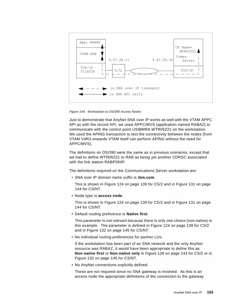
Figure 144. Workstation to OS/390 Access Nodes
Just to demonstrate that AnyNet SNA over IP works as well with the VTAM APPCAPI as with the record API, we used APPC/MVS (application named RABAZ) tocommunicate with the control point USIBMRA.WTR05221 on the workstation.We used the APING transaction to test the connectivity between the nodes (fromVTAM V4R3 onwards VTAM itself can perform APING without the need forAPPC/MVS).
The definitions on OS/390 were the same as in previous scenarios, except thatwe had to define WTR05221 to RAB as being yet another CDRSC associatedwith the link station RABPSNIP.
The definitions required on the Communications Server workstation are:
• SNA over IP domain name suffix is ibm.com .
This is shown in Figure 124 on page 139 for CS/2 and in Figure 131 on page144 for CS/NT.
• Node type is access node .
This is shown in Figure 124 on page 139 for CS/2 and in Figure 131 on page144 for CS/NT.
• Default routing preference is Native first .
This parameter is not relevant because there is only one choice (non-native) inthis example. The parameter is defined in Figure 124 on page 139 for CS/2and in Figure 132 on page 145 for CS/NT.
• No individual routing preferences for partner LUs.
If the workstation has been part of an SNA network and the only AnyNetresource was RABAZ, it would have been appropriate to define this asNon-native first or Non-native only in Figure 128 on page 142 for CS/2 or inFigure 132 on page 145 for CS/NT.
• No AnyNet connections explicitly defined.
These are not required since no SNA gateway is involved. As this is anaccess node the appropriate definitions of the connection to the gateway
3172
9.67.38.11 9.67.38.36
Appl RABAZ
VTAM RAB
TCP/IPT11ATCP
is SNA API calls
is SNA over IP transport
CP Name=WTR05221
TCP/IP
CommsServer
AnyNet SNA over IP 155
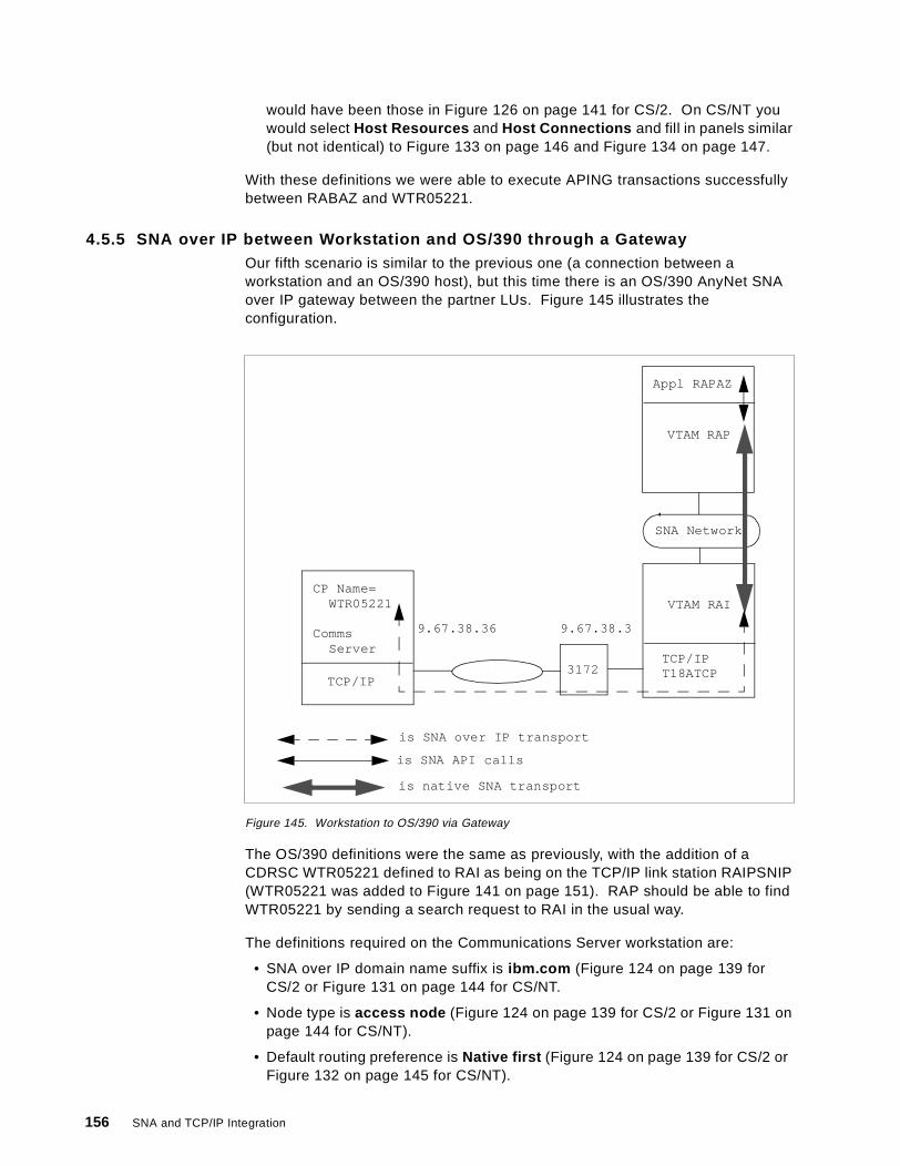
would have been those in Figure 126 on page 141 for CS/2. On CS/NT youwould select Host Resources and Host Connections and fill in panels similar(but not identical) to Figure 133 on page 146 and Figure 134 on page 147.
With these definitions we were able to execute APING transactions successfullybetween RABAZ and WTR05221.
4.5.5 SNA over IP between Workstation and OS/390 through a GatewayOur fifth scenario is similar to the previous one (a connection between aworkstation and an OS/390 host), but this time there is an OS/390 AnyNet SNAover IP gateway between the partner LUs. Figure 145 illustrates theconfiguration.
Figure 145. Workstation to OS/390 via Gateway
The OS/390 definitions were the same as previously, with the addition of aCDRSC WTR05221 defined to RAI as being on the TCP/IP link station RAIPSNIP(WTR05221 was added to Figure 141 on page 151). RAP should be able to findWTR05221 by sending a search request to RAI in the usual way.
The definitions required on the Communications Server workstation are:
• SNA over IP domain name suffix is ibm.com (Figure 124 on page 139 forCS/2 or Figure 131 on page 144 for CS/NT.
• Node type is access node (Figure 124 on page 139 for CS/2 or Figure 131 onpage 144 for CS/NT).
• Default routing preference is Native first (Figure 124 on page 139 for CS/2 orFigure 132 on page 145 for CS/NT).
3172
9.67.38.36 9.67.38.3
VTAM RAI
TCP/IPT18ATCP
is SNA API calls
is SNA over IP transport
is native SNA transport
VTAM RAP
SNA Network
Appl RAPAZ
TCP/IP
CP Name=WTR05221
CommsServer
156 SNA and TCP/IP Integration
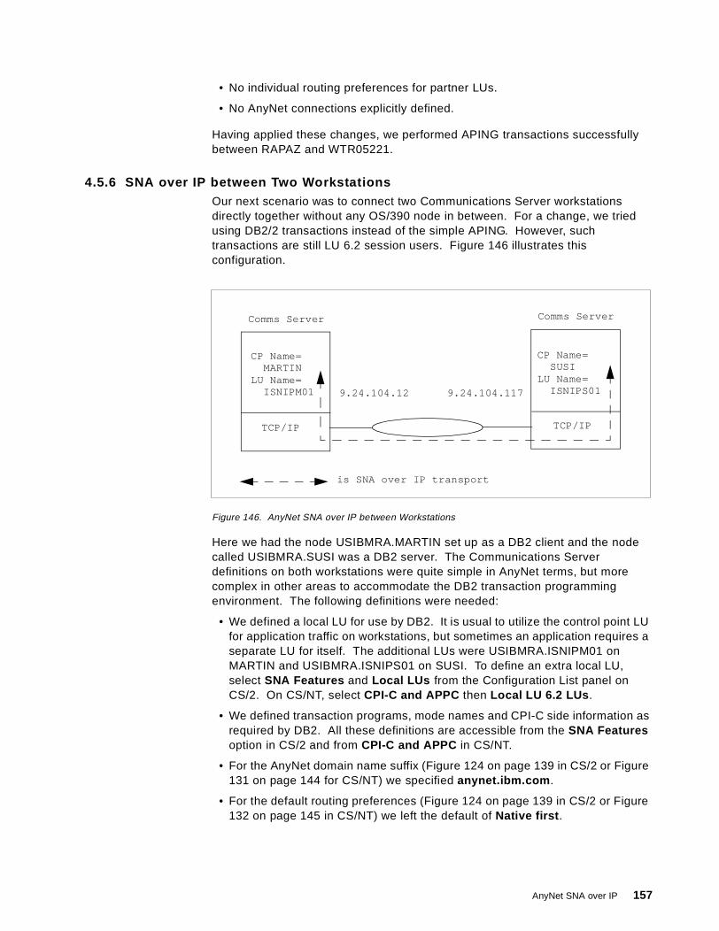
• No individual routing preferences for partner LUs.
• No AnyNet connections explicitly defined.
Having applied these changes, we performed APING transactions successfullybetween RAPAZ and WTR05221.
4.5.6 SNA over IP between Two WorkstationsOur next scenario was to connect two Communications Server workstationsdirectly together without any OS/390 node in between. For a change, we triedusing DB2/2 transactions instead of the simple APING. However, suchtransactions are still LU 6.2 session users. Figure 146 illustrates thisconfiguration.
Figure 146. AnyNet SNA over IP between Workstations
Here we had the node USIBMRA.MARTIN set up as a DB2 client and the nodecalled USIBMRA.SUSI was a DB2 server. The Communications Serverdefinitions on both workstations were quite simple in AnyNet terms, but morecomplex in other areas to accommodate the DB2 transaction programmingenvironment. The following definitions were needed:
• We defined a local LU for use by DB2. It is usual to utilize the control point LUfor application traffic on workstations, but sometimes an application requires aseparate LU for itself. The additional LUs were USIBMRA.ISNIPM01 onMARTIN and USIBMRA.ISNIPS01 on SUSI. To define an extra local LU,select SNA Features and Local LUs from the Configuration List panel onCS/2. On CS/NT, select CPI-C and APPC then Local LU 6.2 LUs .
• We defined transaction programs, mode names and CPI-C side information asrequired by DB2. All these definitions are accessible from the SNA Featuresoption in CS/2 and from CPI-C and APPC in CS/NT.
• For the AnyNet domain name suffix (Figure 124 on page 139 in CS/2 or Figure131 on page 144 for CS/NT) we specified anynet.ibm.com .
• For the default routing preferences (Figure 124 on page 139 in CS/2 or Figure132 on page 145 in CS/NT) we left the default of Native first .
9.24.104.12 9.24.104.117
is SNA over IP transport
CP Name=SUSI
TCP/IP
CP Name=MARTIN
LU Name=ISNIPM01
LU Name=ISNIPS01
Comms Server Comms Server
TCP/IP
AnyNet SNA over IP 157
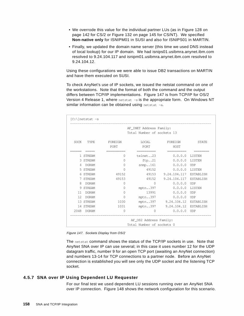
• We overrode this value for the individual partner LUs (as in Figure 128 onpage 142 for CS/2 or Figure 132 on page 145 for CS/NT). We specifiedNon-native only for ISNIPM01 in SUSI and also for ISNIPS01 in MARTIN.
• Finally, we updated the domain name server (this time we used DNS insteadof local lookup) for our IP domain. We had isnips01.usibmra.anynet.ibm.comresolved to 9.24.104.117 and isnipm01.usibmra.anynet.ibm.com resolved to9.24.104.12.
Using these configurations we were able to issue DB2 transactions on MARTINand have them executed on SUSI.
To check AnyNet’s use of IP sockets, we issued the netstat command on one ofthe workstations. Note that the format of both the command and the outputdiffers between TCP/IP implementations. Figure 147 is from TCP/IP for OS/2Version 4 Release 1, where netstat -s is the appropriate form. On Windows NTsimilar information can be obtained using netstat -a .
Figure 147. Sockets Display from OS/2
The netstat command shows the status of the TCP/IP sockets in use. Note thatAnyNet SNA over IP can use several; in this case it uses number 12 for the UDPdatagram traffic, number 9 for an open TCP port (awaiting an AnyNet connection)and numbers 13-14 for TCP connections to a partner node. Before an AnyNetconnection is established you will see only the UDP socket and the listening TCPsocket.
4.5.7 SNA over IP Using Dependent LU RequesterFor our final test we used dependent LU sessions running over an AnyNet SNAover IP connection. Figure 148 shows the network configuration for this scenario.
[C:\]netstat -s--------------------------------------------------------------------------
AF_INET Address Family:Total Number of sockets 13
SOCK TYPE FOREIGN LOCAL FOREIGN STATEPORT PORT HOST
====== ===== ========== ========== ========== ========1 STREAM 0 telnet..23 0.0.0.0 LISTEN3 STREAM 0 ftp..21 0.0.0.0 LISTEN4 DGRAM 0 snmp..161 0.0.0.0 UDP5 STREAM 0 49152 0.0.0.0 LISTEN6 STREAM 49152 49153 9.24.104.117 ESTABLISH7 STREAM 49153 49152 9.24.104.117 ESTABLISH8 DGRAM 0 0 0.0.0.0 UDP9 STREAM 0 mptn..397 0.0.0.0 LISTEN
11 DGRAM 0 13991 0.0.0.0 UDP12 DGRAM 0 mptn..397 0.0.0.0 UDP13 STREAM 1030 mptn..397 9.24.104.12 ESTABLISH14 STREAM 1031 mptn..397 9.24.104.12 ESTABLISH
2048 DGRAM 0 0 0.0.0.0 UDP--------------------------------------------------------------------------
AF_OS2 Address Family:Total Number of sockets 0
158 SNA and TCP/IP Integration

Figure 148. Dependent LU Sessions with SNA over IP
Here we have a dependent LU requester function defined on the workstationWTR05221, which will use VTAM RAB as its DLU server. We have fourdependent LUs defined on the workstation which must be able to log on to anapplication in the SNA network. To demonstrate dependent LU sessions over anIP network we used the TSO application RABAT running on RAB.
There are two logical steps to this setup: configuration of the DLUR/S pipe (a pairof LU 6.2 sessions) and configuration of the dependent resources that will usethat pipe. Exactly what you have to define to VTAM depends on which node(s)will initiate the DLUR/S pipe and the SSCP sessions for the dependentresources. In every case, however, VTAM needs to be an APPN network node toallow it to act as a dependent LU server.
The definitions required for this configuration are as follows:
• On the OS/390 host:
If the workstation initiates the DLUR/S pipe, VTAM requires no definitions forthis part of the setup. VTAM receives a BIND across the TCP/IP logical linkwhose origin LU is WTR05221 and whose mode is CPSVRMGR. This BIND isfor WTR05221’s contention winner LU 6.2 session. The mode name tellsVTAM that this is a DLUR/S request, and the incoming CP name tells VTAMthat an LU called USIBMRA.WTR05221 is reachable via the link stationRABPSNIP (which is where the BIND came from). Therefore VTAM can sendout a BIND over the IP network to establish its own contention winner sessionfor the DLUR/S pipe.
If VTAM is to initiate the DLUR/S connection, it needs to be told two things: thename of the DLUR node and how to find it. Normally just the name of theDLUR node is sufficient, but in the AnyNet SNA over IP case the DLUR/Sconnection is LEN and therefore VTAM must be told how to locate WTR05221.Thus you need two definitions: a CDRSC definition and a switched link stationdefinition. The former is accomplished by adding WTR05221 to a CDRSCmajor node such as that in Figure 141 on page 151, associating the CP LUname with the TCP/IP link station RABPSNIP. The switched link definition that
3172
9.67.38.36 9.67.38.11
VTAM RAB
TCP/IPT11ATCP
TCP/IP
CP Name=WTR05221
CommsServer
DLUR
DLUS
TSORABAT
Dependent LUs
is SNA over IP transport
is SNA API calls
AnyNet SNA over IP 159
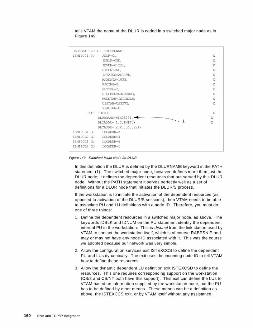
tells VTAM the name of the DLUR is coded in a switched major node as inFigure 149.
Figure 149. Switched Major Node for DLUR
In this definition the DLUR is defined by the DLURNAME keyword in the PATHstatement (1). The switched major node, however, defines more than just theDLUR node; it defines the dependent resources that are served by this DLURnode. Without the PATH statement it serves perfectly well as a set ofdefinitions for a DLUR node that initiates the DLUR/S process.
If the workstation is to initiate the activation of the dependent resources (asopposed to activation of the DLUR/S sessions), then VTAM needs to be ableto associate PU and LU definitions with a node ID. Therefore, you must doone of three things:
1. Define the dependent resources in a switched major node, as above. Thekeywords IDBLK and IDNUM on the PU statement identify the dependentinternal PU in the workstation. This is distinct from the link station used byVTAM to contact the workstation itself, which is of course RABPSNIP andmay or may not have any node ID associated with it. This was the coursewe adopted because our network was very simple.
2. Allow the configuration services exit ISTEXCCS to define the dependentPU and LUs dynamically. The exit uses the incoming node ID to tell VTAMhow to define these resources.
3. Allow the dynamic dependent LU definition exit ISTEXCSD to define theresources. This one requires corresponding support on the workstation(CS/2 and CS/NT both have this support). This exit can define the LUs toVTAM based on information supplied by the workstation node, but the PUhas to be defined by other means. These means can be a definition asabove, the ISTEXCCS exit, or by VTAM itself without any assistance.
RABSSNIP VBUILD TYPE=SWNETISNIPJ01 PU ADDR=01, X
IDBLK=05D, XIDNUM=05221, XDISCNT=NO, XISTATUS=ACTIVE, XMAXDATA=1033, XPACING=0, XPUTYPE=2, XDLOGMOD=D4C32XX3, XMODETAB=ISTINCLM, XUSSTAB=US327X, XVPACING=0
PATH PID=1, XDLURNAME=WTR05221, XDLCADDR=(1,C,INTPU), XDLCADDR=(2,X,05D05221)
ISNIPJL1 LU LOCADDR=2ISNIPJL2 LU LOCADDR=3ISNIPJL3 LU LOCADDR=4ISNIPJL4 LU LOCADDR=5
1
160 SNA and TCP/IP Integration
Note that the dependent PU and LUs can identify themselves by CP nameinstead of by node ID. This works properly only if the dependent resourcesare on a separate node attached downstream of the DLUR node.
If VTAM is to initiate the activation of the dependent PU and LUs, a switchedmajor node is always required, and the PATH statement as in Figure 149 onpage 160 is required within it. Note, however, that in this case the PU isidentified not by the IDBLK and IDNUM keywords on the PU statement but bythe DLCADDR keywords on the PATH statement.
In summary, the only strictly AnyNet-related consideration here is to makesure that the DLUR is reachable via the TCP/IP link station. Even that is notnormally required because the workstation usually initiates the DLUR/Sprocess.
• On the workstation:
Once again, the only AnyNet-specific requirements are to ensure that theDLUS can be located correctly. From the previous setup, WTR05221 will tryto locate USIBMRA.RAB using native (SNA) protocols first (and fail), followedby non-native (TCP/IP) protocols. The domain name suffix is already set toibm.com so WTR05221 will look for rab.usibmra.ibm.com to set up its DLUR/Ssessions.
The dependent LUs are defined (both on CS/2 and CS/NT) just as are nativedependent LUs, except that they are associated with a DLUS host nameinstead of with a real link station to a VTAM or an NCP. No additionalconfiguration is required if the DLUS happens to be reached via AnyNetinstead of via native APPN.
• In the IP network:
If TCP/IP is to succeed we must ensure that the DNS (or the local HOSTS file)can map rab.usibmra.ibm.com to 9.67.38.11 and wtr05221.usibmra.ibm.comto 9.67.38.36. This must be done in both directions because each node willestablish a TCP connection to the other.
No AnyNet definitions or address mappings are required for the dependent LUsor the OS/390 applications. A session request from a dependent LU travels overthe DLUR/S pipe (on an LU 6.2 session) to VTAM, which searches the SNAnetwork for the target application (TSO in our case). TSO sends a BIND to VTAMwhich forwards it across the AnyNet connection to the DLUR, where it knows thedependent LU resides. In the other direction, a session request from anapplication is handled by the DLUS VTAM and forwarded to the DLUR. Unlikethe case of native APPN, all flows relating to the dependent LUs are across theone LEN link, and both DLUR and DLUS understand this. Once they know eachother’s location they send all DLUR/S traffic to each other.
We configured the DLUR/S definitions on the workstation and on the host, andadded the minimal extra requirements for AnyNet. We were then able to log on toTSO from dependent LUs using the 3270 emulator on the workstations. We tookseveral displays of the dependent resources and their sessions, but there washardly anything in them to give away the fact that they were using an IP networkas their transport. As an example, please see Figure 150 on page 162 which is adisplay of the DLUR node from RAB.
AnyNet SNA over IP 161
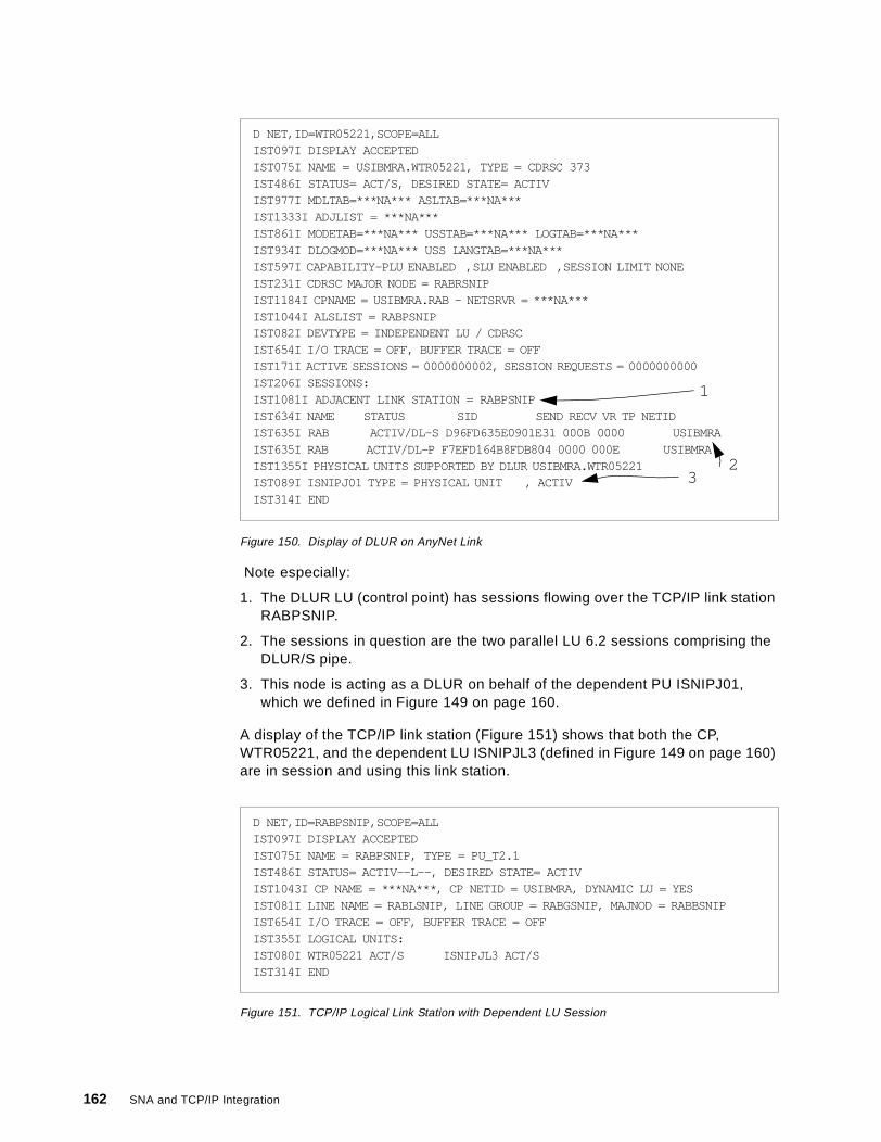
Figure 150. Display of DLUR on AnyNet Link
Note especially:
1. The DLUR LU (control point) has sessions flowing over the TCP/IP link stationRABPSNIP.
2. The sessions in question are the two parallel LU 6.2 sessions comprising theDLUR/S pipe.
3. This node is acting as a DLUR on behalf of the dependent PU ISNIPJ01,which we defined in Figure 149 on page 160.
A display of the TCP/IP link station (Figure 151) shows that both the CP,WTR05221, and the dependent LU ISNIPJL3 (defined in Figure 149 on page 160)are in session and using this link station.
Figure 151. TCP/IP Logical Link Station with Dependent LU Session
D NET,ID=WTR05221,SCOPE=ALLIST097I DISPLAY ACCEPTEDIST075I NAME = USIBMRA.WTR05221, TYPE = CDRSC 373IST486I STATUS= ACT/S, DESIRED STATE= ACTIVIST977I MDLTAB=***NA*** ASLTAB=***NA***IST1333I ADJLIST = ***NA***IST861I MODETAB=***NA*** USSTAB=***NA*** LOGTAB=***NA***IST934I DLOGMOD=***NA*** USS LANGTAB=***NA***IST597I CAPABILITY-PLU ENABLED ,SLU ENABLED ,SESSION LIMIT NONEIST231I CDRSC MAJOR NODE = RABRSNIPIST1184I CPNAME = USIBMRA.RAB - NETSRVR = ***NA***IST1044I ALSLIST = RABPSNIPIST082I DEVTYPE = INDEPENDENT LU / CDRSCIST654I I/O TRACE = OFF, BUFFER TRACE = OFFIST171I ACTIVE SESSIONS = 0000000002, SESSION REQUESTS = 0000000000IST206I SESSIONS:IST1081I ADJACENT LINK STATION = RABPSNIPIST634I NAME STATUS SID SEND RECV VR TP NETIDIST635I RAB ACTIV/DL-S D96FD635E0901E31 000B 0000 USIBMRAIST635I RAB ACTIV/DL-P F7EFD164B8FDB804 0000 000E USIBMRAIST1355I PHYSICAL UNITS SUPPORTED BY DLUR USIBMRA.WTR05221IST089I ISNIPJ01 TYPE = PHYSICAL UNIT , ACTIVIST314I END
1
32
D NET,ID=RABPSNIP,SCOPE=ALLIST097I DISPLAY ACCEPTEDIST075I NAME = RABPSNIP, TYPE = PU_T2.1IST486I STATUS= ACTIV--L--, DESIRED STATE= ACTIVIST1043I CP NAME = ***NA***, CP NETID = USIBMRA, DYNAMIC LU = YESIST081I LINE NAME = RABLSNIP, LINE GROUP = RABGSNIP, MAJNOD = RABBSNIPIST654I I/O TRACE = OFF, BUFFER TRACE = OFFIST355I LOGICAL UNITS:IST080I WTR05221 ACT/S ISNIPJL3 ACT/SIST314I END
162 SNA and TCP/IP Integration
Chapter 5. Data Link Switching
Data link switching is different in essence from Enterprise Extender and AnyNetSNA over IP. Data link switching maps SNA transport to IP transport, while theother technologies can effectively map an SNA API to IP transport. In fact, DLSwsimply maps LLC2 transport to IP transport for particular SAPs, and the presenceof SNA is merely incidental. Data link switching is something that happens in IProuters with an SNA connection outboard, whereas Enterprise Extender andAnyNet can be implemented at the endpoints of an SNA session. For thisreason, a DLSw solution is never end-to-end and cannot provide the same highlevel of service as an end-to-end connection using the same technologythroughout. In particular, each DLSw router constitutes a single point of failurewhose loss can disrupt SNA sessions.
5.1 Data Link Switching Description
Data link switching is a widely-accepted standard and is described in RFCs 1434and 1795 (Version 1) and RFC 2166 (Version 2). It is designed for both local andremote operation, and for carrying both NetBIOS and SNA traffic over an IPbackbone. NetBIOS does not concern us here, so we concentrate on SNA.Moreover, local DLSw is essentially SDLC-to-LLC2 translation and does not useIP transport. Therefore, we will not consider local DLSw further and the rest ofthis chapter assumes remote DLSw for SNA over IP.
DLSw is supported by the current IBM router family which comprises the 2216,2210, 2212, Network Utility, and 3746 MultiAccess Enclosure. We refer to thesegenerically as 221X.
An SNA node attached to a 221X uses remote DLSw to communicate withanother SNA node attached to another 221X. SNA stations may be link-attachedor LAN-attached to the 221Xs. The 221Xs, referred to as DLSw partners, mustboth be configured for DLSw. The partners communicate with each other acrossan IP network.
The essence of DLSw is to give a pair of IP routers at the edges of an IP networkthe appearance of a simple bridge. Thus SNA nodes connected to LANs at eitherside of the network can communicate with each other as if they were on the sameLAN. Even if the SNA stations are link-attached, they are assigned an internalMAC address and this is used in all communications, being mapped to the correctDLC address at the appropriate points.
Remote DLSw supports the following SNA protocols:
• Peripheral subarea (type 2.0 to type 4/5 nodes)• APPN or LEN (type 2.1 to type 2.1 nodes, including VTAM/NCP acting as type
2.1)• INN subarea (type 4/5 to type 4/5 nodes)
DLSw can communicate with SNA stations across the following DLCs:
• IEEE 802.2 over token-ring, Ethernet or FDDI LANs, frame relay (RFC1490/2427 bridged format), or ATM (LAN emulation or RFC 1483 bridgedformat)
• SDLC as primary, secondary or negotiable
© Copyright IBM Corp. 1999 163
• QLLC (X.25 PVC or SVC)• ESCON or parallel channel using LSA
The LLC connections are terminated at the 221Xs. Spoofing is used to eliminatethe transport of LLC acknowledgments across the WAN. This improves WANutilization and prevents link-level timeouts due to delays in the WAN. Each SNAstation receives acknowledgments from its locally-attached 221X, and not from itstrue SNA partner.
Since DLSw emulates a bridged LAN, LAN-attached SNA partner stations use thenormal source routing information, including the hop counts, in the LLC2 framesto exchange data across a token-ring. However, the DLSw partners alsoterminate the hop counts locally. Thus the source station may be up to sevenhops from the first 221X in the path and the receiving station may be up to sevenhops from the last 221X in the path. On a native token-ring connection there maybe a total of seven hops between the SNA partners.
For transport between the DLSw partners, the SNA frames are encapsulated inTCP packets and sent over a TCP connection. The route between two partnerscan contain IP routers that are not DLSw-capable.
5.1.1 How Data Link Switching WorksLike source route bridging, DLSw uses information in the data link layer header todetermine the route for a packet. The DLSw function examines the destinationMAC address and the destination service access point (DSAP) in the LLC2header. SNA frames (on a token-ring or an Ethernet) always contain DSAPs thatare multiples of 4 in the range X'04' to X'EC'. When you configure a 221X forDLSw, you must indicate which of the SNA SAPs you want DLSw to process.
Figure 152 on page 165 shows how SNA stations communicate with each otheronce a DLSw connection has been established. Device D1 on Ring 1 iscommunicating with station D2 on Ring 2. Both 221Xs are configured for DLSw,source route bridging, and IP. DLSw provides an LLC type 2 connection betweenD1 and the 221X on Ring 1 and an LLC type 2 connection between D2 and the221X on Ring 2. The SNA frames are encapsulated in IP datagrams and sentacross the IP network using a TCP connection. The path through the IP networkmay include intermediate routers, which do not have to support DLSw.
164 SNA and TCP/IP Integration
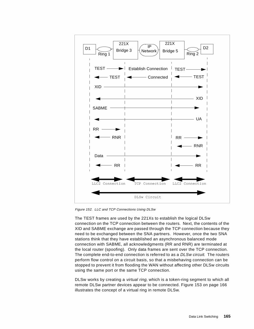
Figure 152. LLC and TCP Connections Using DLSw
The TEST frames are used by the 221Xs to establish the logical DLSwconnection on the TCP connection between the routers. Next, the contents of theXID and SABME exchange are passed through the TCP connection because theyneed to be exchanged between the SNA partners. However, once the two SNAstations think that they have established an asynchronous balanced modeconnection with SABME, all acknowledgments (RR and RNR) are terminated atthe local router (spoofing). Only data frames are sent over the TCP connection.The complete end-to-end connection is referred to as a DLSw circuit. The routersperform flow control on a circuit basis, so that a misbehaving connection can bestopped to prevent it from flooding the WAN without affecting other DLSw circuitsusing the same port or the same TCP connection.
DLSw works by creating a virtual ring, which is a token-ring segment to which allremote DLSw partner devices appear to be connected. Figure 153 on page 166illustrates the concept of a virtual ring in remote DLSw.
IPNetwork
D2D1Ring 1 Ring 2
221X
Bridge 3
221X
Bridge 5
TEST Establish Connection TEST
TESTConnectedTEST
XID
XID
SABME
UA
RR
RNR RR
RNR
Data
RRRR
LLC2 Connection TCP Connection LLC2 Connection
DLSw Circuit
Data Link Switching 165
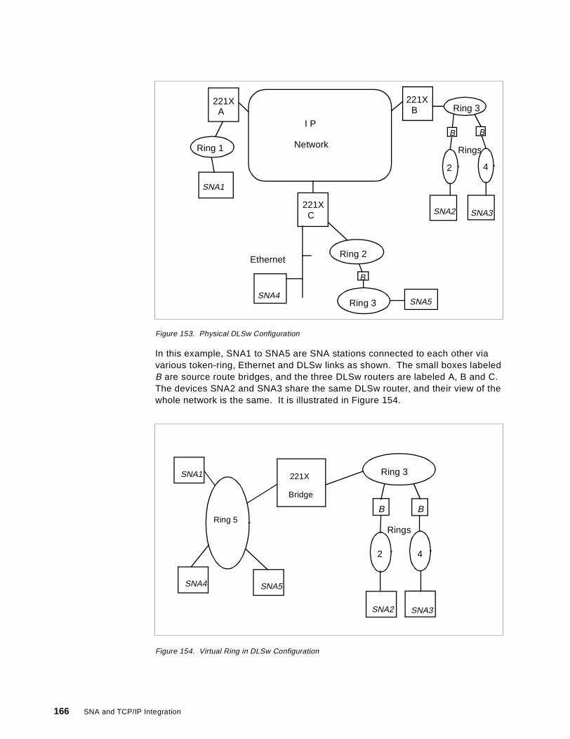
Figure 153. Physical DLSw Configuration
In this example, SNA1 to SNA5 are SNA stations connected to each other viavarious token-ring, Ethernet and DLSw links as shown. The small boxes labeledB are source route bridges, and the three DLSw routers are labeled A, B and C.The devices SNA2 and SNA3 share the same DLSw router, and their view of thewhole network is the same. It is illustrated in Figure 154.
Figure 154. Virtual Ring in DLSw Configuration
I P
Network
221XB
221XA
221XC
Ring 1
Ring 3
2 4
Rings
Ring 2
Ring 3
Ethernet
B B
B
SNA1
SNA2 SNA3
SNA4SNA5
Ring 3
Rings
2 4
B B
SNA2 SNA3
221X
Bridge
Ring 5
SNA1
SNA4 SNA5
166 SNA and TCP/IP Integration
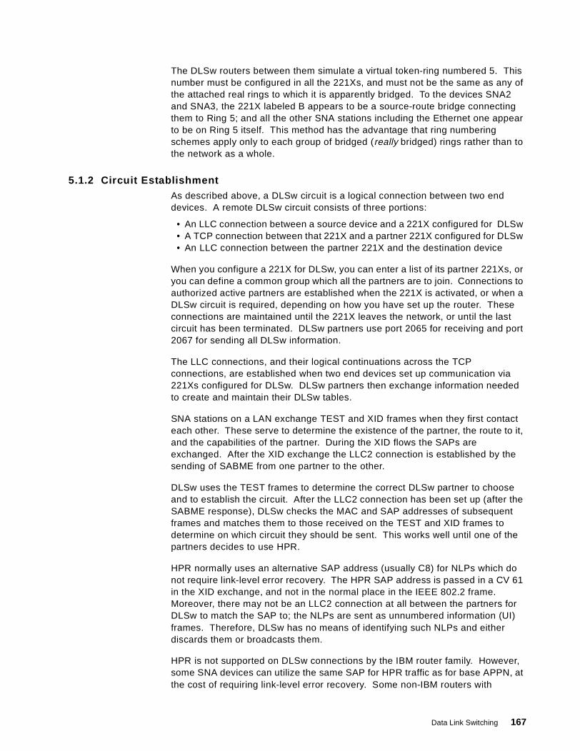
The DLSw routers between them simulate a virtual token-ring numbered 5. Thisnumber must be configured in all the 221Xs, and must not be the same as any ofthe attached real rings to which it is apparently bridged. To the devices SNA2and SNA3, the 221X labeled B appears to be a source-route bridge connectingthem to Ring 5; and all the other SNA stations including the Ethernet one appearto be on Ring 5 itself. This method has the advantage that ring numberingschemes apply only to each group of bridged (really bridged) rings rather than tothe network as a whole.
5.1.2 Circuit EstablishmentAs described above, a DLSw circuit is a logical connection between two enddevices. A remote DLSw circuit consists of three portions:
• An LLC connection between a source device and a 221X configured for DLSw• A TCP connection between that 221X and a partner 221X configured for DLSw• An LLC connection between the partner 221X and the destination device
When you configure a 221X for DLSw, you can enter a list of its partner 221Xs, oryou can define a common group which all the partners are to join. Connections toauthorized active partners are established when the 221X is activated, or when aDLSw circuit is required, depending on how you have set up the router. Theseconnections are maintained until the 221X leaves the network, or until the lastcircuit has been terminated. DLSw partners use port 2065 for receiving and port2067 for sending all DLSw information.
The LLC connections, and their logical continuations across the TCPconnections, are established when two end devices set up communication via221Xs configured for DLSw. DLSw partners then exchange information neededto create and maintain their DLSw tables.
SNA stations on a LAN exchange TEST and XID frames when they first contacteach other. These serve to determine the existence of the partner, the route to it,and the capabilities of the partner. During the XID flows the SAPs areexchanged. After the XID exchange the LLC2 connection is established by thesending of SABME from one partner to the other.
DLSw uses the TEST frames to determine the correct DLSw partner to chooseand to establish the circuit. After the LLC2 connection has been set up (after theSABME response), DLSw checks the MAC and SAP addresses of subsequentframes and matches them to those received on the TEST and XID frames todetermine on which circuit they should be sent. This works well until one of thepartners decides to use HPR.
HPR normally uses an alternative SAP address (usually C8) for NLPs which donot require link-level error recovery. The HPR SAP address is passed in a CV 61in the XID exchange, and not in the normal place in the IEEE 802.2 frame.Moreover, there may not be an LLC2 connection at all between the partners forDLSw to match the SAP to; the NLPs are sent as unnumbered information (UI)frames. Therefore, DLSw has no means of identifying such NLPs and eitherdiscards them or broadcasts them.
HPR is not supported on DLSw connections by the IBM router family. However,some SNA devices can utilize the same SAP for HPR traffic as for base APPN, atthe cost of requiring link-level error recovery. Some non-IBM routers with
Data Link Switching 167
vendor-specific extensions to DLSw can support HPR over DLSw circuits for suchdevices.
This is what happens when two SNA stations (let us call them A and B) contacteach other across a DLSw connection. If A and B are connected to 221A and221B respectively as DLSw partners:
1. Station A sends a TEST frame to find the destination device B. The TESTframe contains the addresses of both A (the source) and B (the destination).
2. 221A sees the TEST frame sent by A. If its DLSw routing table does notcontain information about how to reach B, 221A sends a CANUREACH frame(a type of DLSw packet) to all its authorized partners (including 221B). TheCANUREACH frame contains the information in the TEST frame and thesource address of 221A.
3. When the DLSw partners receive the CANUREACH frame, they broadcast theTEST frame to all devices on their directly attached LANs.
4. B receives the TEST frame from 221B, and sends a response back to 221B. Itmay receive multiple copies of this frame if it happens to be connected tomore than one DLSw router, in which case it will send a TEST response toeach one.
5. When 221B receives the TEST response frame from B, it sends anICANREACH frame (another type of DLSw-architected packet) to 221A. 221Balso records in its DLSw table that the source address in the TEST frame (thatof A) can be reached through 221A.
6. 221A receives the ICANREACH frame in response to its CANUREACH frame,and updates its DLSw table to identify 221B as being a way to reach the MACaddress of B. It may have received more than one such response, in whichcase it registers all the responders in its DLSw table as being capable ofreaching B. However, the first response received identifies the preferred routeand will be used in the future unless something goes wrong.
The next time 221A receives a TEST frame that contains B's destination address,it uses the information in its DLSw table to send the CANUREACH frame directlyto 221B. This eliminates the broadcast traffic required to send a CANUREACH toall of 221A's partners. Then, 221B broadcasts the TEST frame to B.Broadcasting this frame ensures that the LLC connection is established over thefastest path. Such broadcasts are contained within the LAN and do not generateWAN traffic.
If 221A receives multiple TEST frames containing a destination address that isnot in its DLSw table, it will send only one CANUREACH frame for thatdestination address to all of its partners. 221A will wait two minutes before timingout a CANUREACH request. When the first ICANREACH response returns,221A directs all the received frames to the router identified in the response frame.
5.2 Data Link Switching in the 221X Router Family
In this section we give a description of how the DLSw environment is configuredin the 221X routers. They all contain basically the same code, so that even if themethod of configuration differs (which it does in some cases) the principles arevalid for all these routers. The routers all support remote DLSw over IPconnections.
168 SNA and TCP/IP Integration
The configuration examples we give are based on the command-line interfaceavailable via the service port on the routers. The 3746 MAE, in particular, doesnot have such an interface and configuration is perfomed using the serviceprocessor console. The stand-alone routers (2216, 2212, 2210, Network Utility)can also be configured remotely using Telnet, or by using a GUI on a PC anddownloading the result using SNMP.
5.2.1 DLSw ConfigurationThe DLSw function itself is defined using the protocol dls command which givesyou a comprehensive range of options. However, certain prerequisites have tobe met if you are going to configure DLSw successfully; not all of these areobvious:
• You have to define the physical machine configuration, including the SNAports and the WAN ports over which DLSw will take place.
• You need to define link stations for both upstream and downstream SDLCconnections. Downstream you define the stations that the router will poll, andupstream you define the stations that the router will pretend to be.
• You need to enable IP (no, this is not automatic) on the ports that will use it.
• Because DLSw emulates a bridge, you need to enable bridging on all LANports that will be used by stations communicating over DLSw circuits. Bydefault the 221Xs enable transparent bridging, so you will have to turn this offand enable source-route bridging for token-ring ports. You will also have toenable DLSw on the LAN bridge ports. The 221Xs treats LAN bridge ports asdistinct from the LAN interfaces associated with them.
If you are planning to do real bridging as well as DLSw on the same port, youmust ensure that frames destined for DLSw are not bridged. You do this bysetting the protocol filters on all the non-DLSw bridge ports to reject framesdestined for SAP 4 (and any other SAPs used by DLSw).
• If you want the DLSw partners to find each other automatically instead ofhaving to be predefined, you can do this. If not all partner routers supportautomatic recognition, you can define some and leave others to contact eachother dynamically. To use this function, you have to enable OSPF and thenOSPF multicast on each router in a dynamic definition group.
Having set up the router to your requirements, you enter protocol dls and nowhave the opportunity to:
• Enable data link switching
• Set the source-route bridging virtual LAN segment number
• Define the group of dynamically recognized DLSw partners to which this routerwill belong, if appropriate
• Define DLSw partner IP addresses, if appropriate
• Define which SAPs DLSw is to recognize on received LAN frames
• Map the SDLC link stations (if there are any) to LAN MAC addresses and (ifnecessary) node IDs. SDLC-attached stations are bridged to the virtualtoken-ring in the same way as stations on a real LAN. If the SDLC-attachedstation is a type 2 node that does not supply its node ID on XID exchange, itmust be given a node ID for use with the LLC2 protocol.
Data Link Switching 169
5.2.2 DLSw Operator CommandsWhen the 221X router is running, a wide variety of commands is available todisplay the status of its functions. To enter operator console mode, type talk 5 atthe basic prompt; then to access the DLSw functions type protocol dls . Now youwill have the Data Link Switching Console available and you can enter commandssuch as these:
• list tcp sessions displays details of the TCP connections to partner DLSwrouters.
• list dls sessions displays details of SNA connections (the 221X calls themsessions, but they are sessions only in the DLSw sense, not in the SNAsense). Source and destination MAC addresses (or SDLC station addresses)and partner DLSw router addresses are shown. Additional statistics on eachSNA connection can be found by issuing the list dls sessions detail form ofthe command.
• list sdlc sessions shows details of the SDLC stations defined, the status oftheir connections, and their equivalent MAC addresses.
5.3 Working Scenarios
In our examples of DLSw configurations we have used 2210 routers throughout.As we stated above, the code in the 221X router family is the same in each box;therefore, the information you have to enter is the same even though it may beentered in different ways. We have also endeavored to produce a wide variety ofconnections in the examples: PPP or frame relay between routers, and Ethernet,token-ring and SDLC connections to the SNA nodes.
Note that the exact sequence of the configuration questions differs from releaseto release of the 221X code. The examples shown below may not correspond toyour own environment.
5.3.1 Remote SDLC and Token-Ring over PPP to SDLC HostFigure 155 on page 171 shows the configuration in this example.
170 SNA and TCP/IP Integration
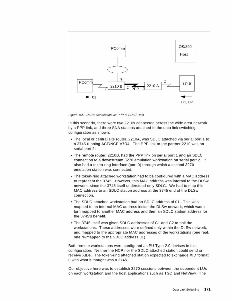
Figure 155. DLSw Connection via PPP to SDLC Host
In this scenario, there were two 2210s connected across the wide area networkby a PPP link, and three SNA stations attached to the data link switchingconfiguration as shown:
• The local or central site router, 2210A, was SDLC attached via serial port 1 toa 3745 running ACF/NCP V7R4. The PPP link to the partner 2210 was onserial port 2.
• The remote router, 2210B, had the PPP link on serial port 1 and an SDLCconnection to a downstream 3270 emulation workstation on serial port 2. Italso had a token-ring interface (port 0) through which a second 3270emulation station was connected.
• The token-ring attached workstation had to be configured with a MAC addressto represent the 3745. However, this MAC address was internal to the DLSwnetwork, since the 3745 itself understood only SDLC. We had to map thisMAC address to an SDLC station address at the 3745 end of the DLSwconnection.
• The SDLC-attached workstation had an SDLC address of 01. This wasmapped to an internal MAC address inside the DLSw network, which was inturn mapped to another MAC address and then an SDLC station address forthe 3745’s benefit.
• The 3745 itself was given SDLC addresses of C1 and C2 to poll theworkstations. These addresses were defined only within the DLSw network,and mapped to the appropriate MAC addresses of the workstations (one real,one re-mapped to the SDLC address 01).
Both remote workstations were configured as PU Type 2.0 devices in thisconfiguration. Neither the NCP nor the SDLC-attached station could send orreceive XIDs. The token-ring attached station expected to exchange XID format0 with what it thought was a 3745.
Our objective here was to establish 3270 sessions between the dependent LUson each workstation and the host applications such as TSO and NetView. The
OS/390
Host
37452210 A2210 B
PPP
PComm
PComm
01C1, C2
0
2
1
12
Data Link Switching 171
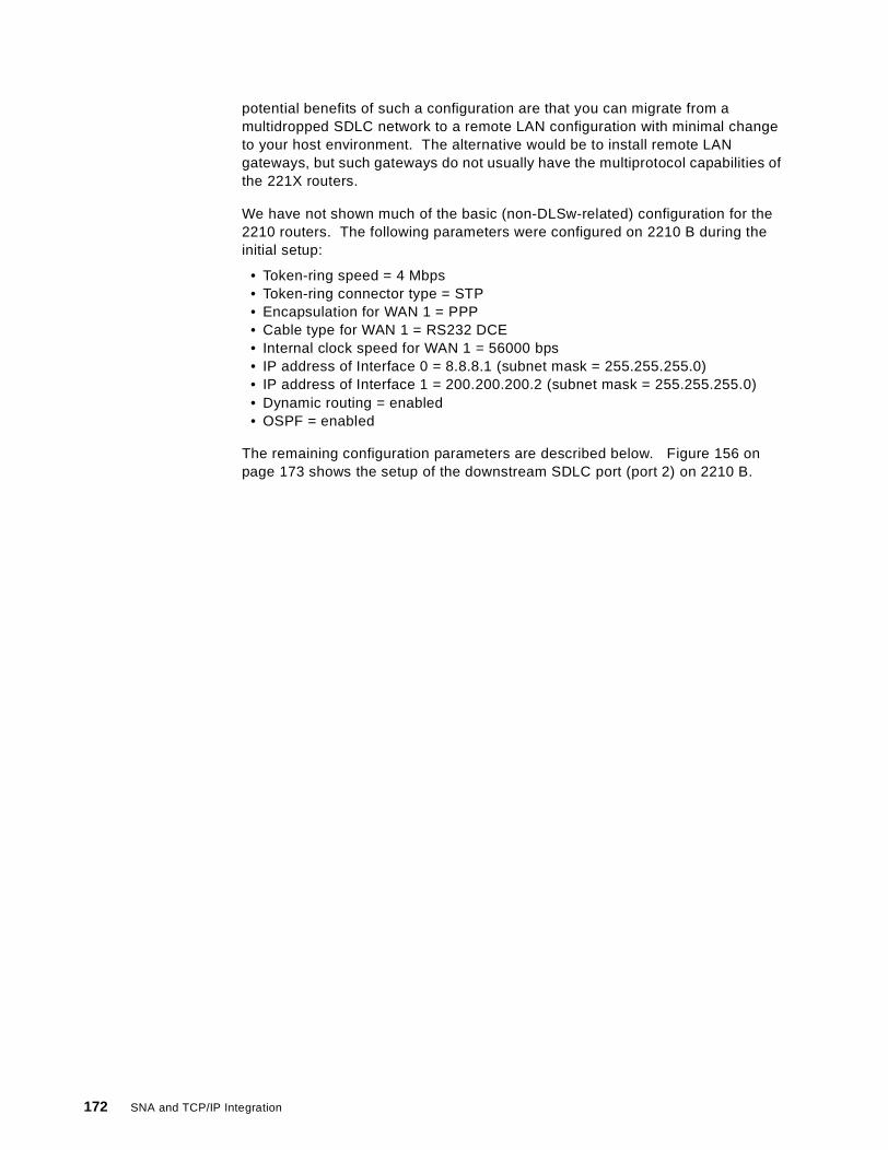
potential benefits of such a configuration are that you can migrate from amultidropped SDLC network to a remote LAN configuration with minimal changeto your host environment. The alternative would be to install remote LANgateways, but such gateways do not usually have the multiprotocol capabilities ofthe 221X routers.
We have not shown much of the basic (non-DLSw-related) configuration for the2210 routers. The following parameters were configured on 2210 B during theinitial setup:
• Token-ring speed = 4 Mbps• Token-ring connector type = STP• Encapsulation for WAN 1 = PPP• Cable type for WAN 1 = RS232 DCE• Internal clock speed for WAN 1 = 56000 bps• IP address of Interface 0 = 8.8.8.1 (subnet mask = 255.255.255.0)• IP address of Interface 1 = 200.200.200.2 (subnet mask = 255.255.255.0)• Dynamic routing = enabled• OSPF = enabled
The remaining configuration parameters are described below. Figure 156 onpage 173 shows the setup of the downstream SDLC port (port 2) on 2210 B.
172 SNA and TCP/IP Integration
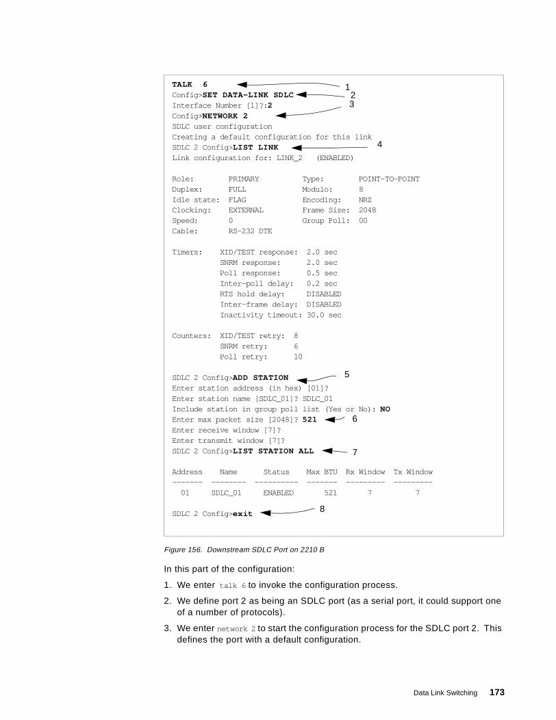
Figure 156. Downstream SDLC Port on 2210 B
In this part of the configuration:
1. We enter talk 6 to invoke the configuration process.
2. We define port 2 as being an SDLC port (as a serial port, it could support oneof a number of protocols).
3. We enter network 2 to start the configuration process for the SDLC port 2. Thisdefines the port with a default configuration.
TALK 6Config> SET DATA-LINK SDLCInterface Number [1]?: 2Config> NETWORK 2SDLC user configurationCreating a default configuration for this linkSDLC 2 Config> LIST LINKLink configuration for: LINK_2 (ENABLED)
Role: PRIMARY Type: POINT-TO-POINTDuplex: FULL Modulo: 8Idle state: FLAG Encoding: NRZClocking: EXTERNAL Frame Size: 2048Speed: 0 Group Poll: 00Cable: RS-232 DTE
Timers: XID/TEST response: 2.0 secSNRM response: 2.0 secPoll response: 0.5 secInter-poll delay: 0.2 secRTS hold delay: DISABLEDInter-frame delay: DISABLEDInactivity timeout: 30.0 sec
Counters: XID/TEST retry: 8SNRM retry: 6Poll retry: 10
SDLC 2 Config> ADD STATIONEnter station address (in hex) [01]?Enter station name [SDLC_01]? SDLC_01Include station in group poll list (Yes or No): NOEnter max packet size [2048]? 521Enter receive window [7]?Enter transmit window [7]?SDLC 2 Config> LIST STATION ALL
Address Name Status Max BTU Rx Window Tx Window------- -------- ---------- ------- --------- ---------
01 SDLC_01 ENABLED 521 7 7
SDLC 2 Config> exit
123
4
5
6
7
8
Data Link Switching 173
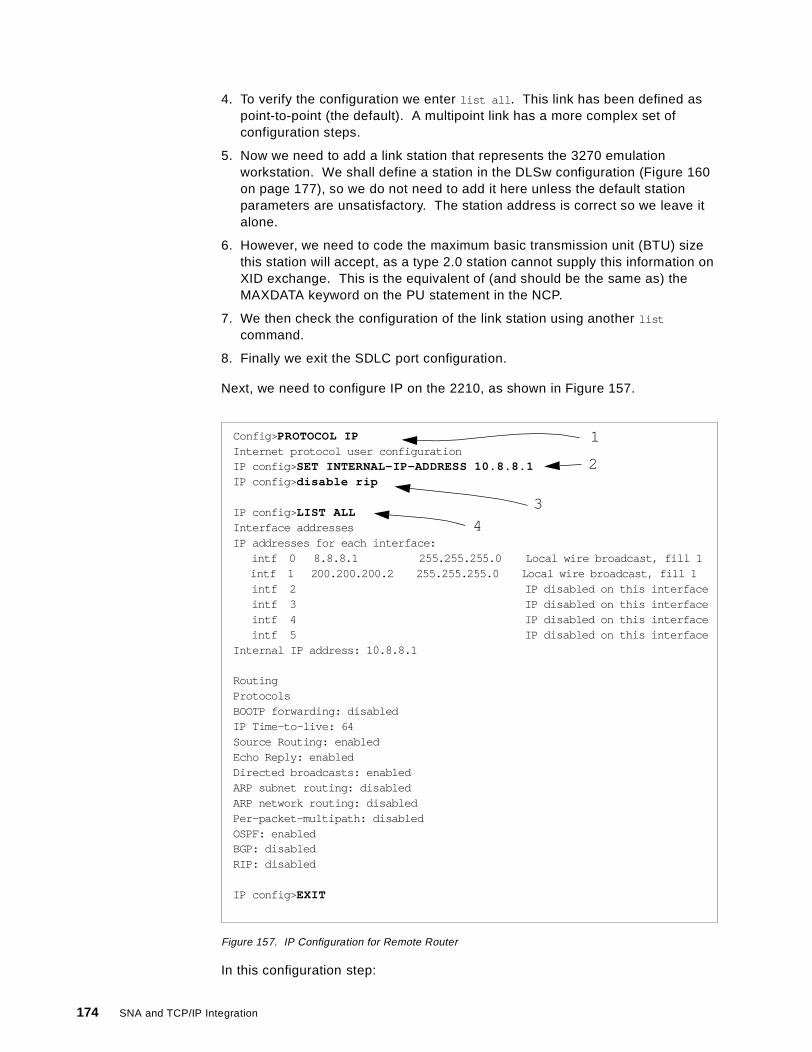
4. To verify the configuration we enter list all . This link has been defined aspoint-to-point (the default). A multipoint link has a more complex set ofconfiguration steps.
5. Now we need to add a link station that represents the 3270 emulationworkstation. We shall define a station in the DLSw configuration (Figure 160on page 177), so we do not need to add it here unless the default stationparameters are unsatisfactory. The station address is correct so we leave italone.
6. However, we need to code the maximum basic transmission unit (BTU) sizethis station will accept, as a type 2.0 station cannot supply this information onXID exchange. This is the equivalent of (and should be the same as) theMAXDATA keyword on the PU statement in the NCP.
7. We then check the configuration of the link station using another list
command.
8. Finally we exit the SDLC port configuration.
Next, we need to configure IP on the 2210, as shown in Figure 157.
Figure 157. IP Configuration for Remote Router
In this configuration step:
Config> PROTOCOL IPInternet protocol user configurationIP config> SET INTERNAL-IP-ADDRESS 10.8.8.1IP config> disable rip
IP config> LIST ALLInterface addressesIP addresses for each interface:
intf 0 8.8.8.1 255.255.255.0 Local wire broadcast, fill 1intf 1 200.200.200.2 255.255.255.0 Local wire broadcast, fill 1intf 2 IP disabled on this interfaceintf 3 IP disabled on this interfaceintf 4 IP disabled on this interfaceintf 5 IP disabled on this interface
Internal IP address: 10.8.8.1
RoutingProtocolsBOOTP forwarding: disabledIP Time-to-live: 64Source Routing: enabledEcho Reply: enabledDirected broadcasts: enabledARP subnet routing: disabledARP network routing: disabledPer-packet-multipath: disabledOSPF: enabledBGP: disabledRIP: disabled
IP config> EXIT
2
3
1
4
174 SNA and TCP/IP Integration
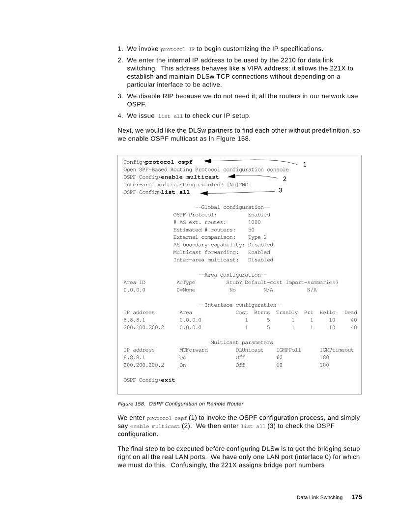
1. We invoke protocol IP to begin customizing the IP specifications.
2. We enter the internal IP address to be used by the 2210 for data linkswitching. This address behaves like a VIPA address; it allows the 221X toestablish and maintain DLSw TCP connections without depending on aparticular interface to be active.
3. We disable RIP because we do not need it; all the routers in our network useOSPF.
4. We issue list all to check our IP setup.
Next, we would like the DLSw partners to find each other without predefinition, sowe enable OSPF multicast as in Figure 158.
Figure 158. OSPF Configuration on Remote Router
We enter protocol ospf (1) to invoke the OSPF configuration process, and simplysay enable multicast (2). We then enter list all (3) to check the OSPFconfiguration.
The final step to be executed before configuring DLSw is to get the bridging setupright on all the real LAN ports. We have only one LAN port (interface 0) for whichwe must do this. Confusingly, the 221X assigns bridge port numbers
Config> protocol ospfOpen SPF-Based Routing Protocol configuration consoleOSPF Config> enable multicastInter-area multicasting enabled? [No]?NOOSPF Config> list all
--Global configuration--OSPF Protocol: Enabled# AS ext. routes: 1000Estimated # routers: 50External comparison: Type 2AS boundary capability: DisabledMulticast forwarding: EnabledInter-area multicast: Disabled
--Area configuration--Area ID AuType Stub? Default-cost Import-summaries?0.0.0.0 0=None No N/A N/A
--Interface configuration--IP address Area Cost Rtrns TrnsDly Pri Hello Dead8.8.8.1 0.0.0.0 1 5 1 1 10 40200.200.200.2 0.0.0.0 1 5 1 1 10 40
Multicast parametersIP address MCForward DLUnicast IGMPPoll IGMPtimeout8.8.8.1 On Off 60 180200.200.200.2 On Off 60 180
OSPF Config> exit
1
2
3
Data Link Switching 175

independently from LAN interface numbers, so in this configuration interface 0 isknown as bridge port 1. Please see Figure 159.
Figure 159. Bridging Configuration on Remote Router
This example shows that:
1. We enter protocol asrt to invoke the bridge configuration process.
Config> PROTOCOL ASRTAdaptive Source Routing Transparent Bridge user configurationASRT config> enable bridgeASRT config> disable transparentPort Number [1]ASRT config> enable source-routing 1 ffb 2ASRT config> enable dlsASRT config> list bridge
Source Routing Transparent Bridge Configuration===============================================
Bridge: Enabled Bridge Behavior: SRB+----------------------------+
-------------------| SOURCE ROUTING INFORMATION |-------------------------+----------------------------+
Bridge Number: 02 Segments: 1Max ARE Hop Cnt: 14 Max STE Hop cnt: 141: SRB: Not Active Internal Segment: 0x000LF-bit interpret: Extended
+-------------------+-------------------| SR-TB INFORMATION |----------------------------------
+-------------------+SR-TB Conversion: DisabledTB-Virtual Segment: 0x000 MTU of TB-Domain: 0
+------------------------------------+-------------------| SPANNING TREE PROTOCOL INFORMATION |-----------------
+------------------------------------+Bridge Address: Default Bridge Priority:32768/0x8000STP Participation: IBM-SRB proprietary
+-------------------------+-------------------| TRANSLATION INFORMATION |----------------------------
+-------------------------+FA<=>GA Conversion: Enabled UB-Encapsulation: DisabledDLS for the bridge: Enabled
+------------------+-------------------| PORT INFORMATION |-----------------------------------
+------------------+Number of ports added: 1Port: 1 Interface: 0 Behavior: SRB Only STP: Enabled
ASRT config> exit
1
23
45
6
7
176 SNA and TCP/IP Integration
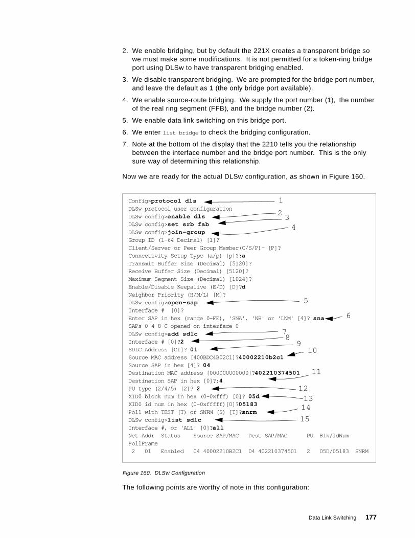
2. We enable bridging, but by default the 221X creates a transparent bridge sowe must make some modifications. It is not permitted for a token-ring bridgeport using DLSw to have transparent bridging enabled.
3. We disable transparent bridging. We are prompted for the bridge port number,and leave the default as 1 (the only bridge port available).
4. We enable source-route bridging. We supply the port number (1), the numberof the real ring segment (FFB), and the bridge number (2).
5. We enable data link switching on this bridge port.
6. We enter list bridge to check the bridging configuration.
7. Note at the bottom of the display that the 2210 tells you the relationshipbetween the interface number and the bridge port number. This is the onlysure way of determining this relationship.
Now we are ready for the actual DLSw configuration, as shown in Figure 160.
Figure 160. DLSw Configuration
The following points are worthy of note in this configuration:
Config> protocol dlsDLSw protocol user configurationDLSw config> enable dlsDLSw config> set srb fabDLSw config> join-groupGroup ID (1-64 Decimal) [1]?Client/Server or Peer Group Member(C/S/P)- [P]?Connectivity Setup Type (a/p) [p]?: aTransmit Buffer Size (Decimal) [5120]?Receive Buffer Size (Decimal) [5120]?Maximum Segment Size (Decimal) [1024]?Enable/Disable Keepalive (E/D) [D]? dNeighbor Priority (H/M/L) [M]?DLSw config> open-sapInterface # [0]?Enter SAP in hex (range 0-FE), 'SNA', 'NB' or 'LNM' [4]? snaSAPs 0 4 8 C opened on interface 0DLSw config> add sdlcInterface # [0]? 2SDLC Address [C1]? 01Source MAC address [400BDC4B02C1]? 40002210b2c1Source SAP in hex [4]? 04Destination MAC address [000000000000]? 402210374501Destination SAP in hex [0]?: 4PU type (2/4/5) [2]? 2XID0 block num in hex (0-0xfff) [0]? 05dXID0 id num in hex (0-0xfffff)[0]? 05183Poll with TEST (T) or SNRM (S) [T]? snrmDLSw config> list sdlcInterface #, or 'ALL' [0]? allNet Addr Status Source SAP/MAC Dest SAP/MAC PU Blk/IdNumPollFrame
2 01 Enabled 04 40002210B2C1 04 402210374501 2 05D/05183 SNRM
1
23
4
5
6
78
910
11
1213
14
15
Data Link Switching 177
1. We enter protocol dls to begin DLSw configuration.
2. We enable data link switching on the 2210.
3. We set the number of the virtual ring segment to FAB. This is the segment towhich all LAN-attached SNA stations will appear to be bridged whenestablishing a connection over the DLSw network. It must be the same for all221Xs in this DLSw group.
4. We tell the 2210 to join a group of DLSw partners. The group is identified bythe number 1, and OSPF multicast will be used by the members to locate eachother. The 221X can act in a client, a server or a peer capacity, and can takean active or a passive role in establishing the TCP connection with a partner.
If the routers are configured for dynamic partner discovery, those configuredas client will attempt to contact those configured as server, and vice versa.Those configured as peer will attempt to contact each other. An active routerattempts to contact its partners at startup time and at intervals thereafter; apassive router does so only when a connection is required for a DLSw circuit.Here we define a peer group (of two routers) in which this station will be anactive partner.
5. Next, we specify to which SAPs the DLSw function will respond on the LANinterfaces (0, the token-ring, in this example).
6. SNA normally uses SAP 04; the generic response sna to the question aboutSAPs results in 0, 4, 8 and C being placed in the list of SAPs supported.
7. Now we add the SDLC station to the DLSw support.
8. Interface 2 is the downstream serial port.
9. SDLC address 01 is the real polling address of the station we wish to define.
10.Next we define the MAC and SAP address to which this SDLC station will bemapped. If another SNA station on a LAN wishes to contact it this is the MACaddress it must search for.
11.The remote MAC/SAP address is the partner SNA station to which this station(01) will talk. This is the virtual MAC address that represents the 3745 at theother end of the DLSw circuit. If the 3745 was LAN-attached this would be thereal MAC address. It is not necessary to define this address for a type 2.0SDLC station as the partner node will always set up the connection.
12.This is a PU type 2.
13.A type 2.0 node on a leased connection does not send a node ID to identifyitself, so we must create one for it in case a LAN-attached partner wishes tocontact it.
14.Similarly, a type 2.0 node expects SNRM as the first DLC frame to be sent toit.
15.When we have finished the SDLC configuration we enter list sdlc to checkthe definitions.
When the DLSw configuration has been defined to our satisfaction, we display itusing the list dls command as shown in Figure 161 on page 179.
178 SNA and TCP/IP Integration
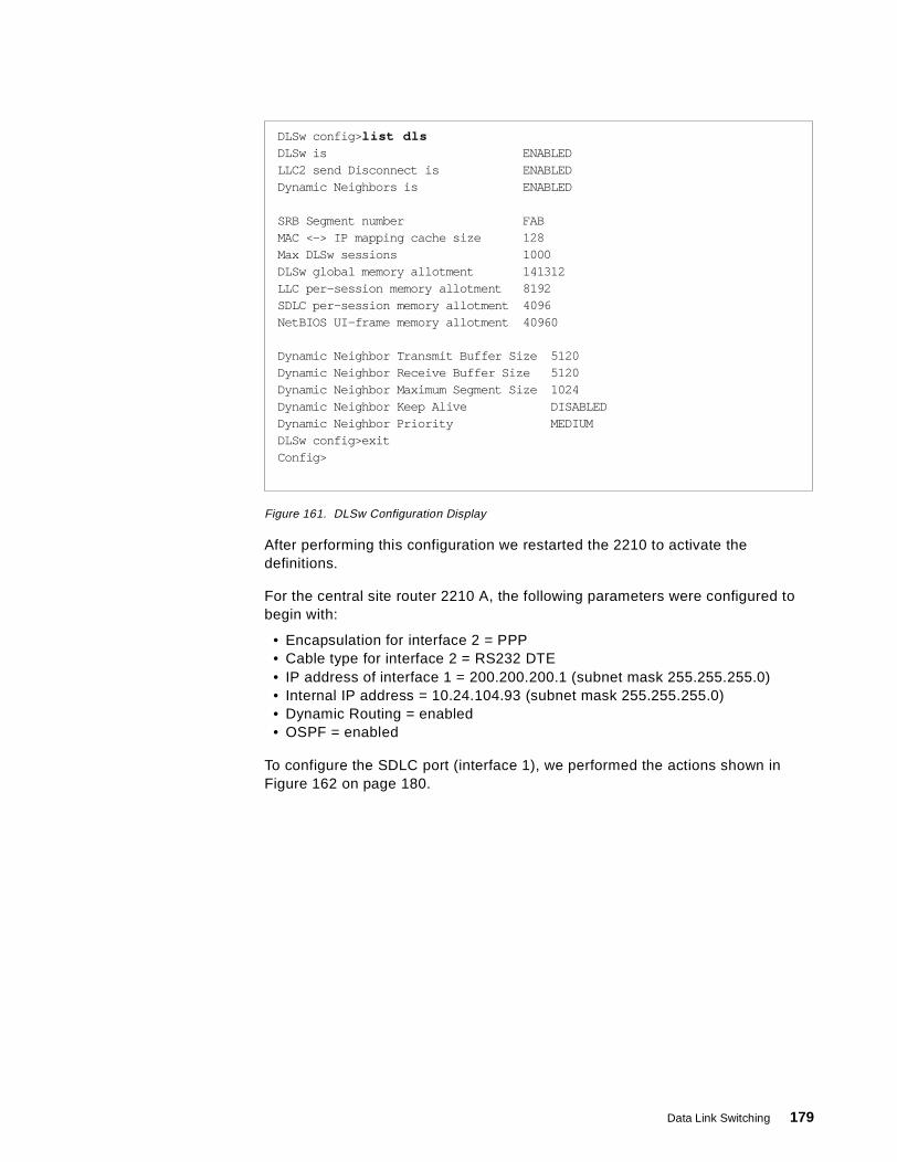
Figure 161. DLSw Configuration Display
After performing this configuration we restarted the 2210 to activate thedefinitions.
For the central site router 2210 A, the following parameters were configured tobegin with:
• Encapsulation for interface 2 = PPP• Cable type for interface 2 = RS232 DTE• IP address of interface 1 = 200.200.200.1 (subnet mask 255.255.255.0)• Internal IP address = 10.24.104.93 (subnet mask 255.255.255.0)• Dynamic Routing = enabled• OSPF = enabled
To configure the SDLC port (interface 1), we performed the actions shown inFigure 162 on page 180.
DLSw config> list dlsDLSw is ENABLEDLLC2 send Disconnect is ENABLEDDynamic Neighbors is ENABLED
SRB Segment number FABMAC <-> IP mapping cache size 128Max DLSw sessions 1000DLSw global memory allotment 141312LLC per-session memory allotment 8192SDLC per-session memory allotment 4096NetBIOS UI-frame memory allotment 40960
Dynamic Neighbor Transmit Buffer Size 5120Dynamic Neighbor Receive Buffer Size 5120Dynamic Neighbor Maximum Segment Size 1024Dynamic Neighbor Keep Alive DISABLEDDynamic Neighbor Priority MEDIUMDLSw config>exitConfig>
Data Link Switching 179
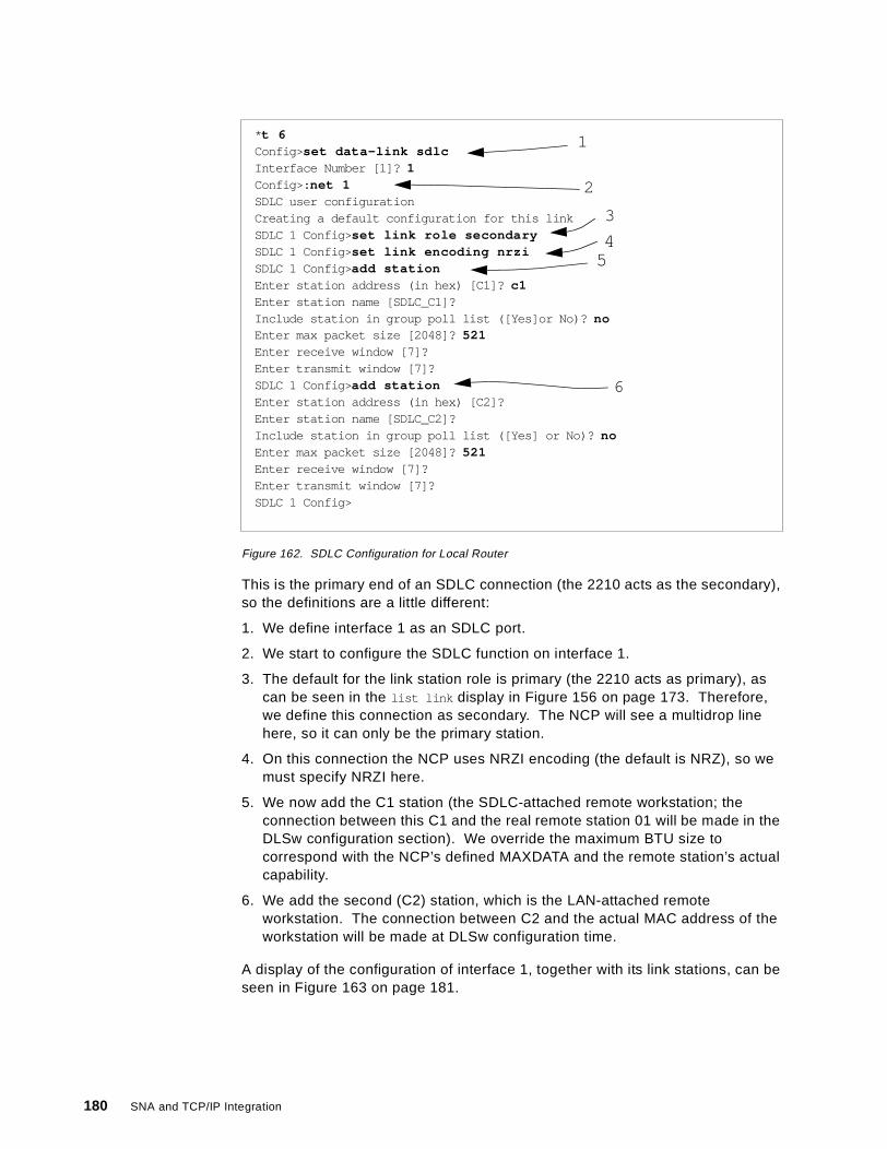
Figure 162. SDLC Configuration for Local Router
This is the primary end of an SDLC connection (the 2210 acts as the secondary),so the definitions are a little different:
1. We define interface 1 as an SDLC port.
2. We start to configure the SDLC function on interface 1.
3. The default for the link station role is primary (the 2210 acts as primary), ascan be seen in the list link display in Figure 156 on page 173. Therefore,we define this connection as secondary. The NCP will see a multidrop linehere, so it can only be the primary station.
4. On this connection the NCP uses NRZI encoding (the default is NRZ), so wemust specify NRZI here.
5. We now add the C1 station (the SDLC-attached remote workstation; theconnection between this C1 and the real remote station 01 will be made in theDLSw configuration section). We override the maximum BTU size tocorrespond with the NCP’s defined MAXDATA and the remote station’s actualcapability.
6. We add the second (C2) station, which is the LAN-attached remoteworkstation. The connection between C2 and the actual MAC address of theworkstation will be made at DLSw configuration time.
A display of the configuration of interface 1, together with its link stations, can beseen in Figure 163 on page 181.
* t 6Config> set data-link sdlcInterface Number [1]? 1Config>: net 1SDLC user configurationCreating a default configuration for this linkSDLC 1 Config> set link role secondarySDLC 1 Config> set link encoding nrziSDLC 1 Config> add stationEnter station address (in hex) [C1]? c1Enter station name [SDLC_C1]?Include station in group poll list ([Yes]or No)? noEnter max packet size [2048]? 521Enter receive window [7]?Enter transmit window [7]?SDLC 1 Config> add stationEnter station address (in hex) [C2]?Enter station name [SDLC_C2]?Include station in group poll list ([Yes] or No)? noEnter max packet size [2048]? 521Enter receive window [7]?Enter transmit window [7]?SDLC 1 Config>
2
4
6
3
5
1
180 SNA and TCP/IP Integration
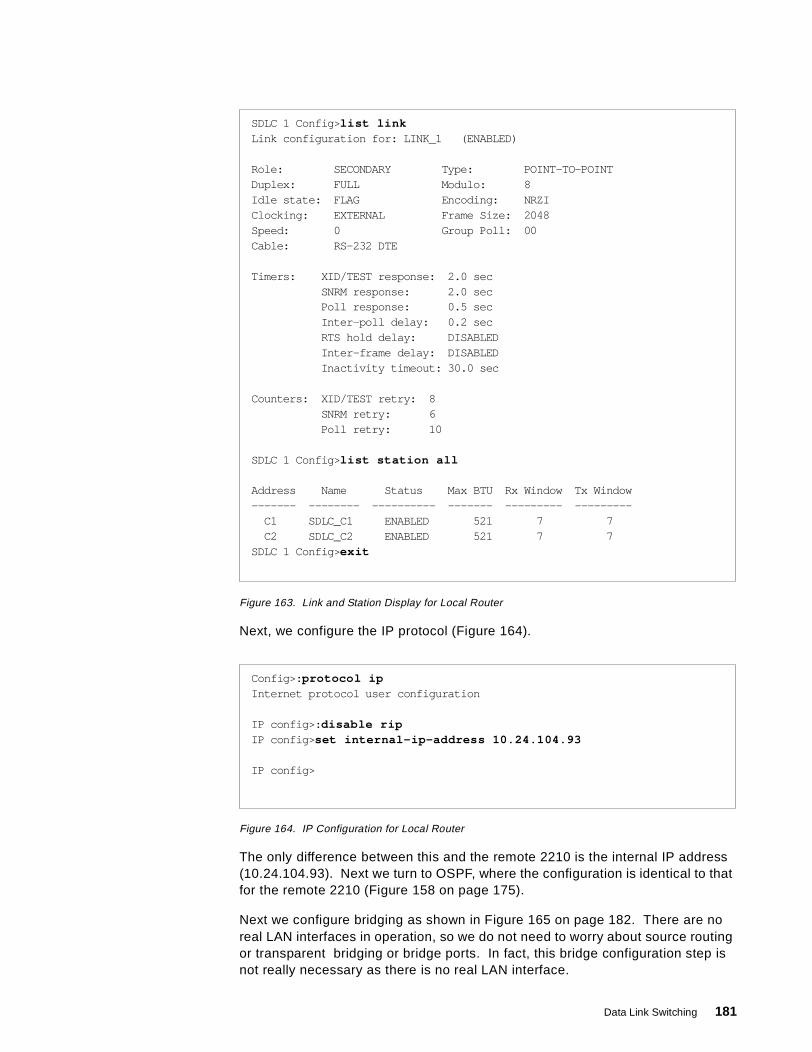
Figure 163. Link and Station Display for Local Router
Next, we configure the IP protocol (Figure 164).
Figure 164. IP Configuration for Local Router
The only difference between this and the remote 2210 is the internal IP address(10.24.104.93). Next we turn to OSPF, where the configuration is identical to thatfor the remote 2210 (Figure 158 on page 175).
Next we configure bridging as shown in Figure 165 on page 182. There are noreal LAN interfaces in operation, so we do not need to worry about source routingor transparent bridging or bridge ports. In fact, this bridge configuration step isnot really necessary as there is no real LAN interface.
SDLC 1 Config> list linkLink configuration for: LINK_1 (ENABLED)
Role: SECONDARY Type: POINT-TO-POINTDuplex: FULL Modulo: 8Idle state: FLAG Encoding: NRZIClocking: EXTERNAL Frame Size: 2048Speed: 0 Group Poll: 00Cable: RS-232 DTE
Timers: XID/TEST response: 2.0 secSNRM response: 2.0 secPoll response: 0.5 secInter-poll delay: 0.2 secRTS hold delay: DISABLEDInter-frame delay: DISABLEDInactivity timeout: 30.0 sec
Counters: XID/TEST retry: 8SNRM retry: 6Poll retry: 10
SDLC 1 Config> list station all
Address Name Status Max BTU Rx Window Tx Window------- -------- ---------- ------- --------- ---------
C1 SDLC_C1 ENABLED 521 7 7C2 SDLC_C2 ENABLED 521 7 7
SDLC 1 Config> exit
Config>: protocol ipInternet protocol user configuration
IP config>: disable ripIP config> set internal-ip-address 10.24.104.93
IP config>
Data Link Switching 181
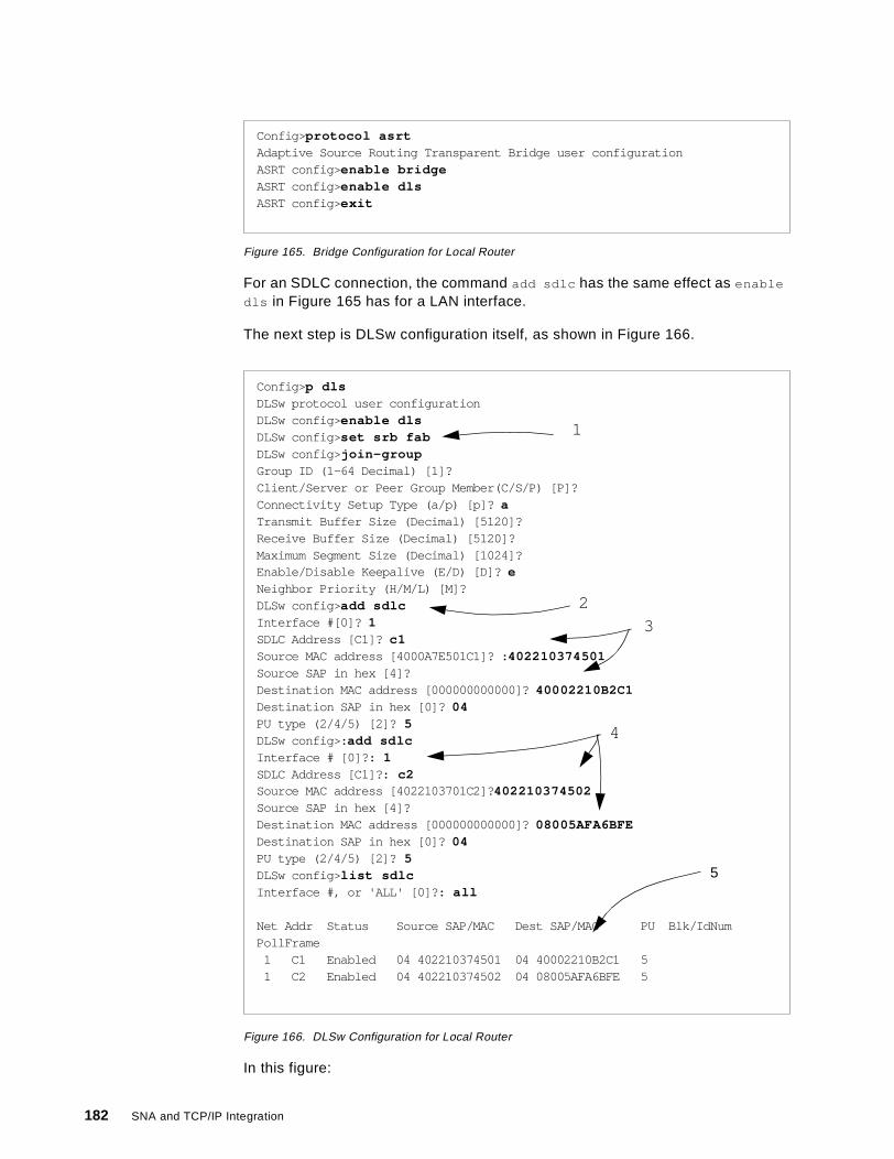
Figure 165. Bridge Configuration for Local Router
For an SDLC connection, the command add sdlc has the same effect as enable
dls in Figure 165 has for a LAN interface.
The next step is DLSw configuration itself, as shown in Figure 166.
Figure 166. DLSw Configuration for Local Router
In this figure:
Config> protocol asrtAdaptive Source Routing Transparent Bridge user configurationASRT config> enable bridgeASRT config> enable dlsASRT config> exit
Config> p dlsDLSw protocol user configurationDLSw config> enable dlsDLSw config> set srb fabDLSw config> join-groupGroup ID (1-64 Decimal) [1]?Client/Server or Peer Group Member(C/S/P) [P]?Connectivity Setup Type (a/p) [p]? aTransmit Buffer Size (Decimal) [5120]?Receive Buffer Size (Decimal) [5120]?Maximum Segment Size (Decimal) [1024]?Enable/Disable Keepalive (E/D) [D]? eNeighbor Priority (H/M/L) [M]?DLSw config> add sdlcInterface #[0]? 1SDLC Address [C1]? c1Source MAC address [4000A7E501C1]? : 402210374501Source SAP in hex [4]?Destination MAC address [000000000000]? 40002210B2C1Destination SAP in hex [0]? 04PU type (2/4/5) [2]? 5DLSw config>: add sdlcInterface # [0]?: 1SDLC Address [C1]?: c2Source MAC address [4022103701C2]? 402210374502Source SAP in hex [4]?Destination MAC address [000000000000]? 08005AFA6BFEDestination SAP in hex [0]? 04PU type (2/4/5) [2]? 5DLSw config> list sdlcInterface #, or 'ALL' [0]?: all
Net Addr Status Source SAP/MAC Dest SAP/MAC PU Blk/IdNumPollFrame
1 C1 Enabled 04 402210374501 04 40002210B2C1 51 C2 Enabled 04 402210374502 04 08005AFA6BFE 5
1
2
3
4
5
182 SNA and TCP/IP Integration
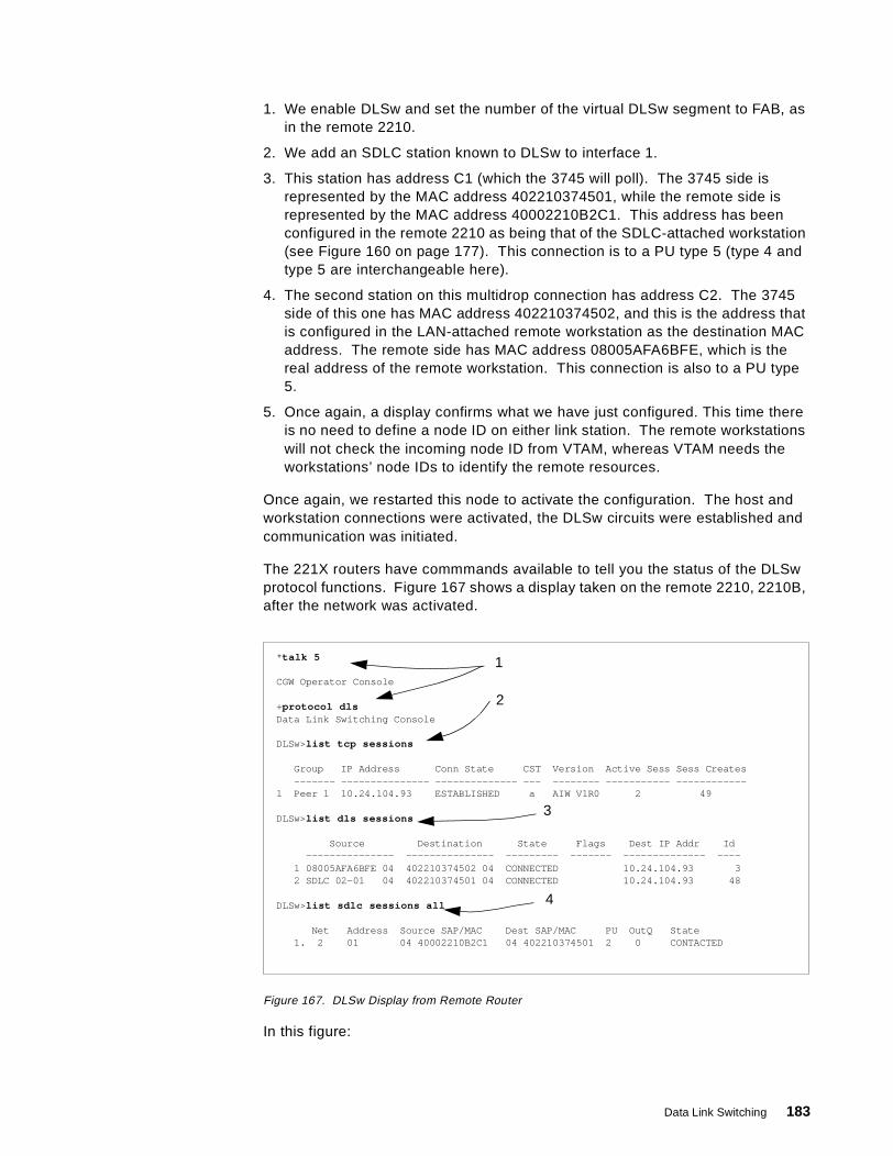
1. We enable DLSw and set the number of the virtual DLSw segment to FAB, asin the remote 2210.
2. We add an SDLC station known to DLSw to interface 1.
3. This station has address C1 (which the 3745 will poll). The 3745 side isrepresented by the MAC address 402210374501, while the remote side isrepresented by the MAC address 40002210B2C1. This address has beenconfigured in the remote 2210 as being that of the SDLC-attached workstation(see Figure 160 on page 177). This connection is to a PU type 5 (type 4 andtype 5 are interchangeable here).
4. The second station on this multidrop connection has address C2. The 3745side of this one has MAC address 402210374502, and this is the address thatis configured in the LAN-attached remote workstation as the destination MACaddress. The remote side has MAC address 08005AFA6BFE, which is thereal address of the remote workstation. This connection is also to a PU type5.
5. Once again, a display confirms what we have just configured. This time thereis no need to define a node ID on either link station. The remote workstationswill not check the incoming node ID from VTAM, whereas VTAM needs theworkstations’ node IDs to identify the remote resources.
Once again, we restarted this node to activate the configuration. The host andworkstation connections were activated, the DLSw circuits were established andcommunication was initiated.
The 221X routers have commmands available to tell you the status of the DLSwprotocol functions. Figure 167 shows a display taken on the remote 2210, 2210B,after the network was activated.
Figure 167. DLSw Display from Remote Router
In this figure:
* talk 5
CGW Operator Console
+protocol dlsData Link Switching Console
DLSw>list tcp sessions
Group IP Address Conn State CST Version Active Sess Sess Creates------- --------------- -------------- --- -------- ----------- ------------
1 Peer 1 10.24.104.93 ESTABLISHED a AIW V1R0 2 49
DLSw>list dls sessions
Source Destination State Flags Dest IP Addr Id--------------- --------------- --------- ------- -------------- ----
1 08005AFA6BFE 04 402210374502 04 CONNECTED 10.24.104.93 32 SDLC 02-01 04 402210374501 04 CONNECTED 10.24.104.93 48
DLSw>list sdlc sessions all
Net Address Source SAP/MAC Dest SAP/MAC PU OutQ State1. 2 01 04 40002210B2C1 04 402210374501 2 0 CONTACTED
1
2
3
4
Data Link Switching 183

1. Entering talk 5 and p dls from the basic prompt gives you the DLSw consolefunction.
2. The list tcp sessions command shows you the TCP connections to the DLSwpartners. Here there is only one, to 2210A whose internal IP address is shownas the connection partner.
3. The list dls sessions command tells you the DLSw circuits that are activefrom this router. As expected, there is one between the SDLC-attachedstation and the 3745, and one between the LAN-attached workstation and the3745. Both have the same DLSw partner.
4. The list sdlc sessions command gives details of the SNA connections on allattached SDLC interfaces.
Figure 168 shows the corresponding display on the local router taken at the sametime.
Figure 168. DLSw Display from Local Router
5.3.2 Remote Ethernet over PPP to Token-Ring HostIn the next scenario (Figure 169 on page 185), we show a DLSw configurationlinking an Ethernet-attached workstation to a host, but this time the host isconnected to the local router by means of a token-ring.
* t 5
CGW Operator Console
+protocol dlsw
DLSw>list tcp sessions
Group IP Address Conn State CST Version Active Sess Sess Creates------- --------------- -------------- --- -------- ----------- ------------
1 Peer 1 10.8.8.1 ESTABLISHED a AIW V1R0 2 49
DLSw>list dls sessions all
Source Destination State Flags Dest IP Addr Id--------------- --------------- --------- ------- -------------- ----
1 SDLC 01-C1 04 40002210B2C1 04 CONNECTED 10.8.8.1 482 SDLC 01-C2 04 08005AFA6BFE 04 CONNECTED 10.8.8.1 52
DLSw>list sdlc sessions
Net Address Source SAP/MAC Dest SAP/MAC PU OutQ State1. 1 C1 04 402210374501 04 40002210B2C1 5 0 CONTACTED2. 1 C2 04 402210374502 04 08005AFA6BFE 5 0 CONTACTED
184 SNA and TCP/IP Integration
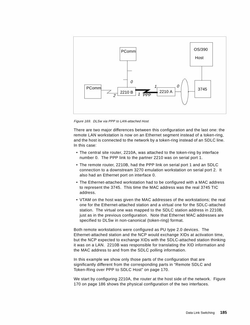
Figure 169. DLSw via PPP to LAN-attached Host
There are two major differences between this configuration and the last one: theremote LAN workstation is now on an Ethernet segment instead of a token-ring,and the host is connected to the network by a token-ring instead of an SDLC line.In this case:
• The central site router, 2210A, was attached to the token-ring by interfacenumber 0. The PPP link to the partner 2210 was on serial port 1.
• The remote router, 2210B, had the PPP link on serial port 1 and an SDLCconnection to a downstream 3270 emulation workstation on serial port 2. Italso had an Ethernet port on interface 0.
• The Ethernet-attached workstation had to be configured with a MAC addressto represent the 3745. This time the MAC address was the real 3745 TICaddress.
• VTAM on the host was given the MAC addresses of the workstations; the realone for the Ethernet-attached station and a virtual one for the SDLC-attachedstation. The virtual one was mapped to the SDLC station address in 2210B,just as in the previous configuration. Note that Ethernet MAC addresses arespecified to DLSw in non-canonical (token-ring) format.
Both remote workstations were configured as PU type 2.0 devices. TheEthernet-attached station and the NCP would exchange XIDs at activation time,but the NCP expected to exchange XIDs with the SDLC-attached station thinkingit was on a LAN. 2210B was responsible for translating the XID information andthe MAC address to and from the SDLC polling information.
In this example we show only those parts of the configuration that aresignificantly different from the corresponding parts in “Remote SDLC andToken-Ring over PPP to SDLC Host” on page 170.
We start by configuring 2210A, the router at the host side of the network. Figure170 on page 186 shows the physical configuration of the two interfaces.
OS/390
Host
37452210 A2210 B
PPP
PComm
PComm
0
12
1 0
Data Link Switching 185
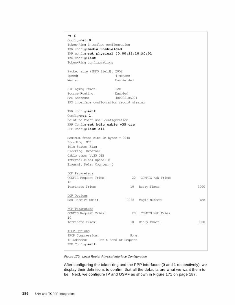
Figure 170. Local Router Physical Interface Configuration
After configuring the token-ring and the PPP interfaces (0 and 1 respectively), wedisplay their definitions to confirm that all the defaults are what we want them tobe. Next, we configure IP and OSPF as shown in Figure 171 on page 187.
* t 6Config> net 0Token-Ring interface configurationTKR config> media unshieldedTKR config> set physical 40:00:22:10:A0:01TKR config> listToken-Ring configuration:
Packet size (INFO field): 2052Speed: 4 Mb/secMedia: Unshielded
RIF Aging Timer: 120Source Routing: EnabledMAC Address: 40002210A001IPX interface configuration record missing
TKR config> exitConfig> net 1Point-to-Point user configurationPPP Config> set hdlc cable v35 dtePPP Config> list all
Maximum frame size in bytes = 2048Encoding: NRZIdle State: FlagClocking: ExternalCable type: V.35 DTEInternal Clock Speed: 0Transmit Delay Counter: 0
LCP ParametersCONFIG Request Tries: 20 CONFIG Nak Tries:10Terminate Tries: 10 Retry Timer: 3000
LCP OptionsMax Receive Unit: 2048 Magic Number: Yes
NCP ParametersCONFIG Request Tries: 20 CONFIG Nak Tries:10Terminate Tries: 10 Retry Timer: 3000
IPCP OptionsIPCP Compression: NoneIP Address: Don't Send or RequestPPP Config> exit
186 SNA and TCP/IP Integration
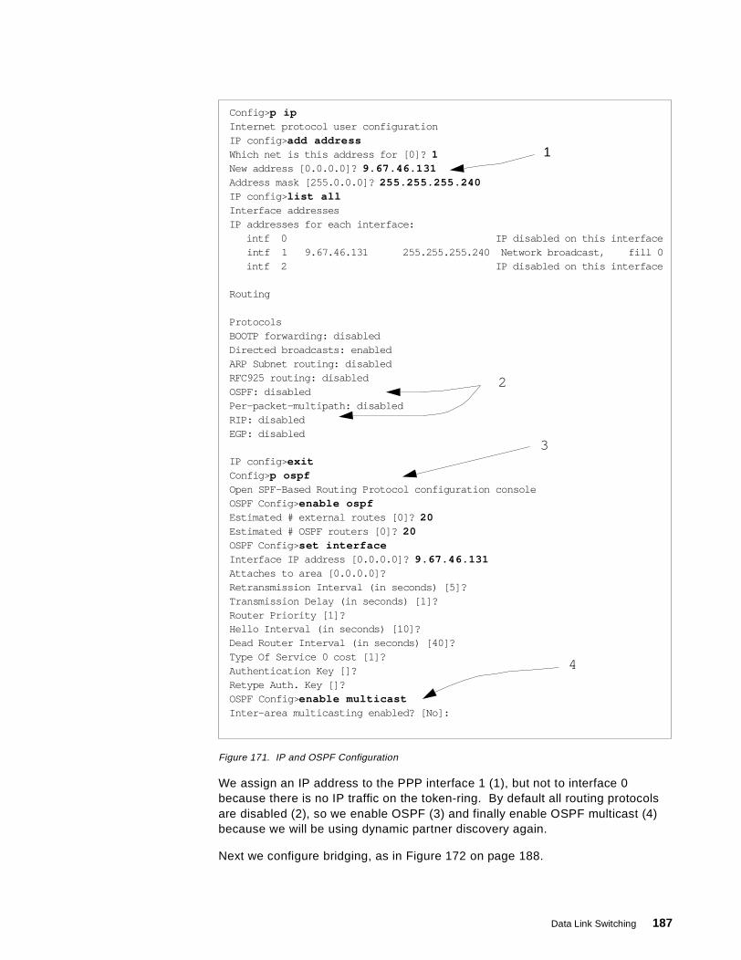
Figure 171. IP and OSPF Configuration
We assign an IP address to the PPP interface 1 (1), but not to interface 0because there is no IP traffic on the token-ring. By default all routing protocolsare disabled (2), so we enable OSPF (3) and finally enable OSPF multicast (4)because we will be using dynamic partner discovery again.
Next we configure bridging, as in Figure 172 on page 188.
Config> p ipInternet protocol user configurationIP config> add addressWhich net is this address for [0]? 1New address [0.0.0.0]? 9.67.46.131Address mask [255.0.0.0]? 255.255.255.240IP config> list allInterface addressesIP addresses for each interface:
intf 0 IP disabled on this interfaceintf 1 9.67.46.131 255.255.255.240 Network broadcast, fill 0intf 2 IP disabled on this interface
Routing
ProtocolsBOOTP forwarding: disabledDirected broadcasts: enabledARP Subnet routing: disabledRFC925 routing: disabledOSPF: disabledPer-packet-multipath: disabledRIP: disabledEGP: disabled
IP config> exitConfig> p ospfOpen SPF-Based Routing Protocol configuration consoleOSPF Config> enable ospfEstimated # external routes [0]? 20Estimated # OSPF routers [0]? 20OSPF Config> set interfaceInterface IP address [0.0.0.0]? 9.67.46.131Attaches to area [0.0.0.0]?Retransmission Interval (in seconds) [5]?Transmission Delay (in seconds) [1]?Router Priority [1]?Hello Interval (in seconds) [10]?Dead Router Interval (in seconds) [40]?Type Of Service 0 cost [1]?Authentication Key []?Retype Auth. Key []?OSPF Config> enable multicastInter-area multicasting enabled? [No]:
1
2
3
4
Data Link Switching 187

Figure 172. Bridge Configuration for Local 2210
We must enable bridging (1), disable transparent bridging (2) because this is atoken-ring, and enable source-route bridging (3). The interface to be bridged isport 1 (interface 0, as the display at 4 confirms), the bridge number is 1 and thesegment number of the token-ring is FFB. Finally we enable DLSw for thisinterface (5).
Now we turn to the DLSw configuration; see Figure 173.
Figure 173. DLSw Configuration for Local 2210
Config> protocol asrtAdaptive Source Routing Transparent Bridge user configurationASRT config> enable bridgeASRT config> disable transparentASRT config> enable source-routing 1 ffb 1ASRT config> enable dlsASRT config> list bridge
Source Routing Transparent Bridge Configuration===============================================
Bridge: ENABLED Bridge Behaviour: UnknownBridge Address: Not Specified By User Bridge Priority:(dec) 32768, (hex):8000Source Routing Bridge Number: 1 No. of Source routing segments: 1SRB: Max ARE Hop cnt: 14 Max STE Hop cnt: 14SR-TB Conversion: DISABLED TB-Virtual Segment:0x0 MTU for TB-Domain: 01&colon.N Source Routing: NOT ACTIVE Internal-VirtualSegment:0x0SRB LF-bit interpretation: EXTENDED FA <=> GA Conversion: ENABLEDSpanning Tree Protocol Participation: IEEE802.1dDLS for the bridge: ENABLEDNumber of ports added: 1Port Number: 1 Interface Number: 0 Port Behaviour: SRB Only
ASRT config> exit
12
3
4
5
Config> p dlsDLSw protocol user configurationDLSw config> enable dlsDLSw config> set srb aaaDLSw config> join-groupGroup ID (1-64 Decimal) [1]?Client/Server or Peer Group Member(C/S/P)- [C]: sTransmit Buffer Size (Decimal) [5120]?Maximum Segment Size (Decimal) [1024]?Enable/Disable Keepalive?(E/D)- [D]? eDLSw config> open-sap 0 00DLSw config> open-sap 0 04DLSw config> exit
1
2
188 SNA and TCP/IP Integration
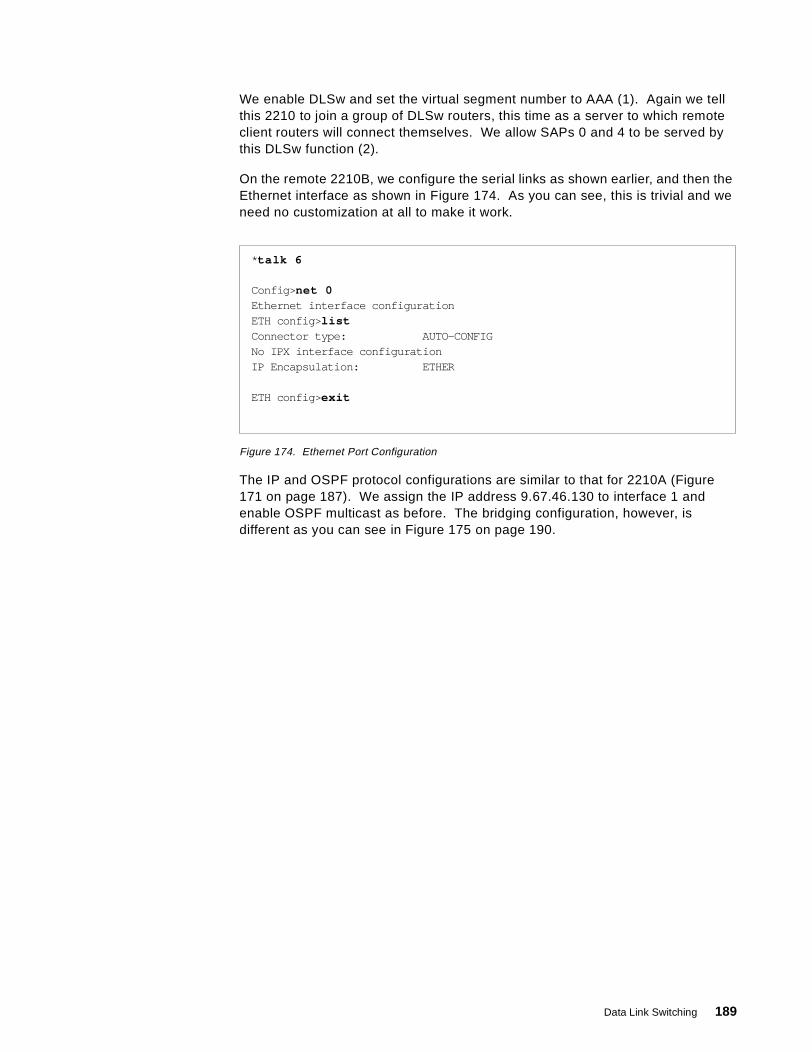
We enable DLSw and set the virtual segment number to AAA (1). Again we tellthis 2210 to join a group of DLSw routers, this time as a server to which remoteclient routers will connect themselves. We allow SAPs 0 and 4 to be served bythis DLSw function (2).
On the remote 2210B, we configure the serial links as shown earlier, and then theEthernet interface as shown in Figure 174. As you can see, this is trivial and weneed no customization at all to make it work.
Figure 174. Ethernet Port Configuration
The IP and OSPF protocol configurations are similar to that for 2210A (Figure171 on page 187). We assign the IP address 9.67.46.130 to interface 1 andenable OSPF multicast as before. The bridging configuration, however, isdifferent as you can see in Figure 175 on page 190.
* talk 6
Config> net 0Ethernet interface configurationETH config> listConnector type: AUTO-CONFIGNo IPX interface configurationIP Encapsulation: ETHER
ETH config> exit
Data Link Switching 189
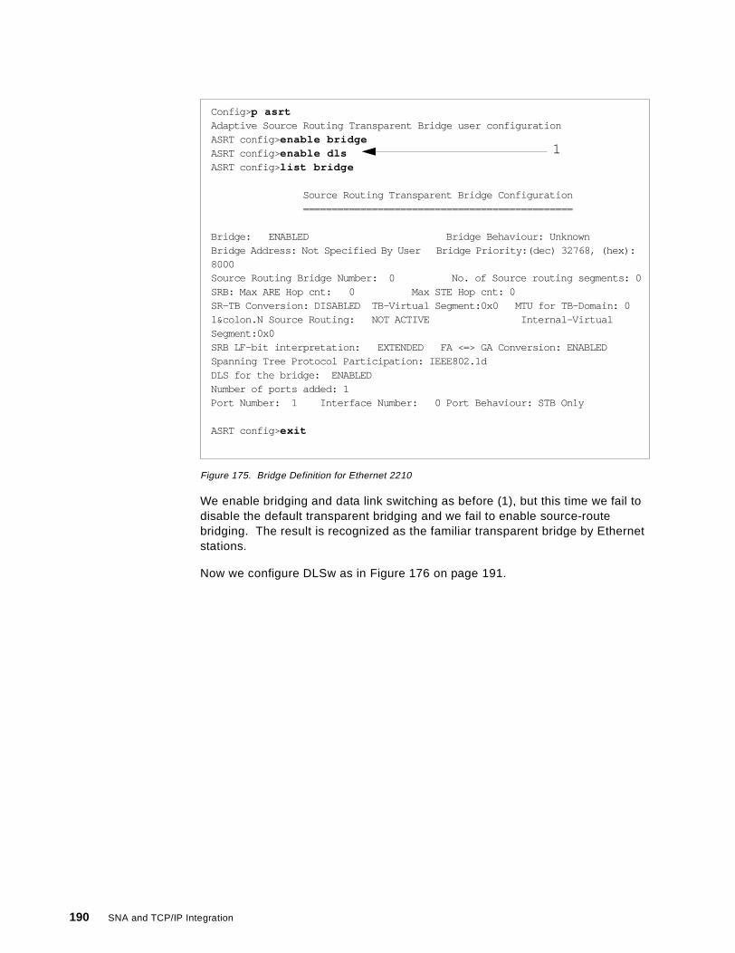
Figure 175. Bridge Definition for Ethernet 2210
We enable bridging and data link switching as before (1), but this time we fail todisable the default transparent bridging and we fail to enable source-routebridging. The result is recognized as the familiar transparent bridge by Ethernetstations.
Now we configure DLSw as in Figure 176 on page 191.
Config> p asrtAdaptive Source Routing Transparent Bridge user configurationASRT config> enable bridgeASRT config> enable dlsASRT config> list bridge
Source Routing Transparent Bridge Configuration===============================================
Bridge: ENABLED Bridge Behaviour: UnknownBridge Address: Not Specified By User Bridge Priority:(dec) 32768, (hex):8000Source Routing Bridge Number: 0 No. of Source routing segments: 0SRB: Max ARE Hop cnt: 0 Max STE Hop cnt: 0SR-TB Conversion: DISABLED TB-Virtual Segment:0x0 MTU for TB-Domain: 01&colon.N Source Routing: NOT ACTIVE Internal-VirtualSegment:0x0SRB LF-bit interpretation: EXTENDED FA <=> GA Conversion: ENABLEDSpanning Tree Protocol Participation: IEEE802.1dDLS for the bridge: ENABLEDNumber of ports added: 1Port Number: 1 Interface Number: 0 Port Behaviour: STB Only
ASRT config> exit
1
190 SNA and TCP/IP Integration
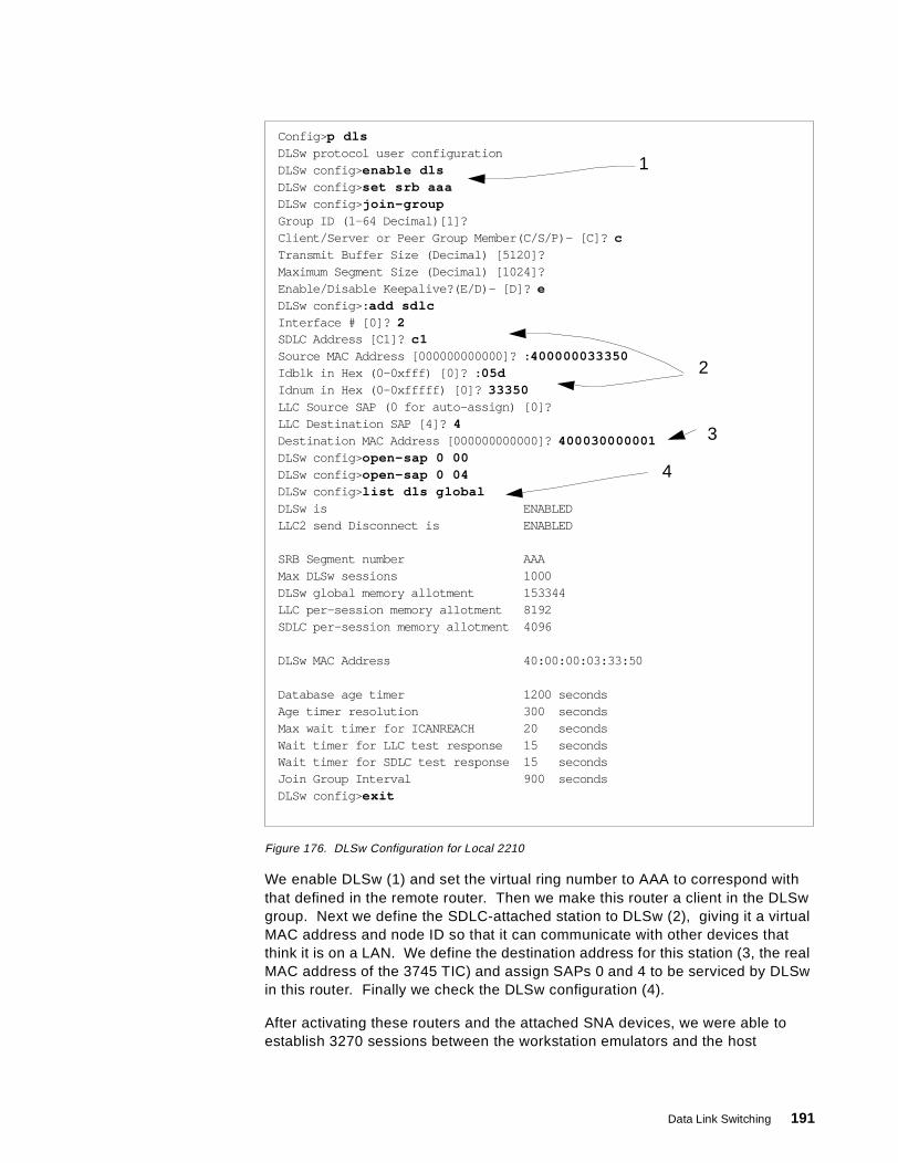
Figure 176. DLSw Configuration for Local 2210
We enable DLSw (1) and set the virtual ring number to AAA to correspond withthat defined in the remote router. Then we make this router a client in the DLSwgroup. Next we define the SDLC-attached station to DLSw (2), giving it a virtualMAC address and node ID so that it can communicate with other devices thatthink it is on a LAN. We define the destination address for this station (3, the realMAC address of the 3745 TIC) and assign SAPs 0 and 4 to be serviced by DLSwin this router. Finally we check the DLSw configuration (4).
After activating these routers and the attached SNA devices, we were able toestablish 3270 sessions between the workstation emulators and the host
Config> p dlsDLSw protocol user configurationDLSw config> enable dlsDLSw config> set srb aaaDLSw config> join-groupGroup ID (1-64 Decimal)[1]?Client/Server or Peer Group Member(C/S/P)- [C]? cTransmit Buffer Size (Decimal) [5120]?Maximum Segment Size (Decimal) [1024]?Enable/Disable Keepalive?(E/D)- [D]? eDLSw config>: add sdlcInterface # [0]? 2SDLC Address [C1]? c1Source MAC Address [000000000000]? : 400000033350Idblk in Hex (0-0xfff) [0]? : 05dIdnum in Hex (0-0xfffff) [0]? 33350LLC Source SAP (0 for auto-assign) [0]?LLC Destination SAP [4]? 4Destination MAC Address [000000000000]? 400030000001DLSw config> open-sap 0 00DLSw config> open-sap 0 04DLSw config> list dls globalDLSw is ENABLEDLLC2 send Disconnect is ENABLED
SRB Segment number AAAMax DLSw sessions 1000DLSw global memory allotment 153344LLC per-session memory allotment 8192SDLC per-session memory allotment 4096
DLSw MAC Address 40:00:00:03:33:50
Database age timer 1200 secondsAge timer resolution 300 secondsMax wait timer for ICANREACH 20 secondsWait timer for LLC test response 15 secondsWait timer for SDLC test response 15 secondsJoin Group Interval 900 secondsDLSw config> exit
1
2
3
4
Data Link Switching 191
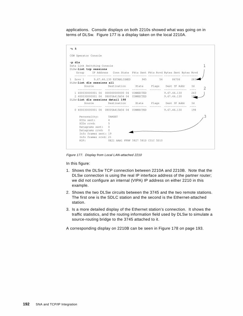
applications. Console displays on both 2210s showed what was going on interms of DLSw. Figure 177 is a display taken on the local 2210A.
Figure 177. Display from Local LAN-attached 2210
In this figure:
1. Shows the DLSw TCP connection between 2210A and 2210B. Note that theDLSw connection is using the real IP interface address of the partner router;we did not configure an internal (VIPA) IP address on either 2210 in thisexample.
2. Shows the two DLSw circuits between the 3745 and the two remote stations.The first one is the SDLC station and the second is the Ethernet-attachedstation.
3. Is a more detailed display of the Ethernet station’s connection. It shows thetraffic statistics, and the routing information field used by DLSw to simulate asource-routing bridge to the 3745 attached to it.
A corresponding display on 2210B can be seen in Figure 178 on page 193.
* t 5
CGW Operator Console
+p dlsData Link Switching ConsoleDLSw>list tcp sessions
Group IP Address Conn State Pkts Sent Pkts Rcvd Bytes Sent Bytes Rcvd------- --------------- ----------- --------- --------- ---------- ----------
1 Srvr 1 9.67.46.130 ESTABLISHED 945 54 86706 2836DLSw>list dls sessions all
Source Destination State Flags Dest IP Addr Id--------------- --------------- --------- ------- -------------- ----
1 400030000001 04 000000000000 04 CONNECTED 9.67.46.130 2432 400030000001 04 08005A415A56 04 CONNECTED 9.67.46.130 198
DLSw>list dls sessions detail 198Source Destination State Flags Dest IP Addr Id
--------------- --------------- --------- ------- -------------- ----0 400030000001 04 08005A415A56 04 CONNECTED 9.67.46.130 198
Personality: TARGETXIDs sent: 4XIDs rcvd: 5Datagrams sent: 0Datagrams rcvd: 0Info frames sent: 19Info frames rcvd: 21RIF: 0E21 AAA1 FFBF 5827 581D C31C 5D10
1
2
3
192 SNA and TCP/IP Integration

Figure 178. DLSw Display on Remote 2210
This figure shows the detailed display of the SDLC station’s circuit. There is norouting information field because there is no token-ring. Also, we show the SDLCsession display for this station.
5.3.3 Data Link Switching over a Frame Relay ConnectionIn our third example we show DLSw in use where there are three routers in theDLSw group connected via a frame relay wide area network. Figure 179 on page194 shows the configuration.
* t 5
+p dlsData Link Switching ConsoleDLSw>list tcp sessions
Group IP Address Conn State Pkts Sent Pkts Rcvd Bytes Sent Bytes Rcvd------- --------------- ----------- --------- --------- ---------- ----------
1 Clnt 1 9.67.46.131 ESTABLISHED 50 486 2772 47528DLSw>list dls sessions
Source Destination State Flags Dest IP Addr Id--------------- --------------- --------- ------- -------------- ----
1 000000000000 04 400030000001 04 CONNECTED 9.67.46.131 182 08005A415A56 04 400030000001 04 CONNECTED 9.67.46.131 347
DLSw>list dls sessions detail 18Source Destination State Flags Dest IP Addr Id
--------------- --------------- --------- ------- -------------- ----0 000000000000 04 400030000001 04 CONNECTED 9.67.46.131 18
Personality: ORIGINATORXIDs sent: 2XIDs rcvd: 1Datagrams sent: 0Datagrams rcvd: 0Info frames sent: 18Info frames rcvd: 16RIF:
DLSw>list sdlc sessionsNet Addr Src Sap Dst Sap Dest MAC OutQ State
1. 2 C1 04 04 40:00:30:00:00:01 00 CONTACTED
Data Link Switching 193
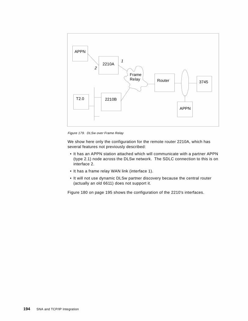
Figure 179. DLSw over Frame Relay
We show here only the configuration for the remote router 2210A, which hasseveral features not previously described:
• It has an APPN station attached which will communicate with a partner APPN(type 2.1) node across the DLSw network. The SDLC connection to this is oninterface 2.
• It has a frame relay WAN link (interface 1).
• It will not use dynamic DLSw partner discovery because the central router(actually an old 6611) does not support it.
Figure 180 on page 195 shows the configuration of the 2210’s interfaces.
FrameRelay
2210A
2210BT2.0
APPN
APPN
3745Router
1
2
194 SNA and TCP/IP Integration
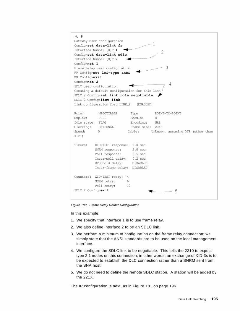
Figure 180. Frame Relay Router Configuration
In this example:
1. We specify that interface 1 is to use frame relay.
2. We also define interface 2 to be an SDLC link.
3. We perform a minimum of configuration on the frame relay connection; wesimply state that the ANSI standards are to be used on the local managementinterface.
4. We configure the SDLC link to be negotiable. This tells the 2210 to expecttype 2.1 nodes on this connection; in other words, an exchange of XID-3s is tobe expected to establish the DLC connection rather than a SNRM sent fromthe SNA host.
5. We do not need to define the remote SDLC station. A station will be added bythe 221X.
The IP configuration is next, as in Figure 181 on page 196.
* t 6Gateway user configurationConfig> set data-link frInterface Number [0]? 1Config> set data-link sdlcInterface Number [0]? 2Config> net 1Frame Relay user configurationFR Config> set lmi-type ansiFR Config> exitConfig> net 2SDLC user configurationCreating a default configuration for this linkSDLC 2 Config> set link role negotiableSDLC 2 Config> list linkLink configuration for: LINK_2 (ENABLED)
Role: NEGOTIABLE Type: POINT-TO-POINTDuplex: FULL Modulo: 8Idle state: FLAG Encoding: NRZClocking: EXTERNAL Frame Size: 2048Speed: 0 Cable: Unknown, assuming DTE (other thanX.21)
Timers: XID/TEST response: 2.0 secSNRM response: 2.0 secPoll response: 0.5 secInter-poll delay: 0.2 secRTS hold delay: DISABLEDInter-frame delay: DISABLED
Counters: XID/TEST retry: 4SNRM retry: 6Poll retry: 10
SDLC 2 Config> exit
1
2
3
4
5
Data Link Switching 195
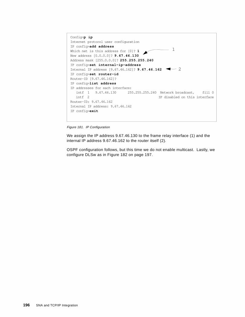
Figure 181. IP Configuration
We assign the IP address 9.67.46.130 to the frame relay interface (1) and theinternal IP address 9.67.46.162 to the router itself (2).
OSPF configuration follows, but this time we do not enable multicast. Lastly, weconfigure DLSw as in Figure 182 on page 197.
Config> p ipInternet protocol user configurationIP config> add addressWhich net is this address for [0]? 1New address [0.0.0.0]? 9.67.46.130Address mask [255.0.0.0]? 255.255.255.240IP config> set internal-ip-addressInternal IP address [9.67.46.162]? 9.67.46.162IP config> set router-idRouter-ID [9.67.46.162]?IP config> list addressIP addresses for each interface:
intf 1 9.67.46.130 255.255.255.240 Network broadcast, fill 0intf 2 IP disabled on this interface
Router-ID: 9.67.46.162Internal IP address: 9.67.46.162IP config> exit
1
2
196 SNA and TCP/IP Integration
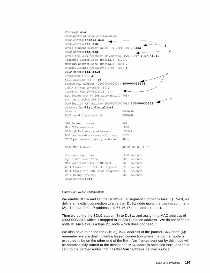
Figure 182. DLSw Configuration
We enable DLSw and set the DLSw virtual segment number to AAA (1). Next, wedefine an explicit connection to a partner DLSw node using the add tcp command(2). The partner’s IP address is 9.67.46.17 (the central router).
Then we define the SDLC station (3) to DLSw, and assign it a MAC address of400000033316 which is mapped to its SDLC station address. We do not define anode ID since this is a type 2.1 node which does not need it.
We also have to define the (virtual) MAC address of the partner SNA node (4);remember we are dealing with a leased connection where the partner node isexpected to be on the other end of the link. Any frames sent out by this node willbe automatically routed to the destination MAC address specified here, and thussent to the partner router that has this MAC address defined as local.
Config> p dlsDLSw protocol user configurationDLSw config> enable dlsDLSw config> set srbEnter segment number in hex (1-FFF)- [0]? : aaaDLSw config> add tcpEnter the DLSw neighbor IP Address [0.0.0.0]? 9.67.46.17Transmit Buffer Size (Decimal) [5120]?Maximum Segment Size (Decimal) [1024]?Enable/Disable Keepalive?(E/D)- [D]? eDLSw config> add sdlcInterface #[0]? 2SDLC Address [C1]? : c1Source MAC Address [000000000000]? 400000033316Idblk in Hex (0-0xfff) [0]?Idnum in Hex (0-0xfffff) [0]?LLC Source SAP (0 for auto-assign) [0]?LLC Destination SAP [4]?Destination MAC Address [000000000000]? 400000033338DLSw config> list dls globalDLSw is ENABLEDLLC2 send Disconnect is ENABLED
SRB Segment number AAAMax DLSw sessions 1000DLSw global memory allotment 153344LLC per-session memory allotment 8192SDLC per-session memory allotment 4096
DLSw MAC Address 40:00:00:03:33:16
Database age timer 1200 secondsAge timer resolution 300 secondsMax wait timer for ICANREACH 20 secondsWait timer for LLC test response 15 secondsWait timer for SDLC test response 15 secondsJoin Group Interval 900 secondsDLSw config> exit
1
2
3
4
Data Link Switching 197
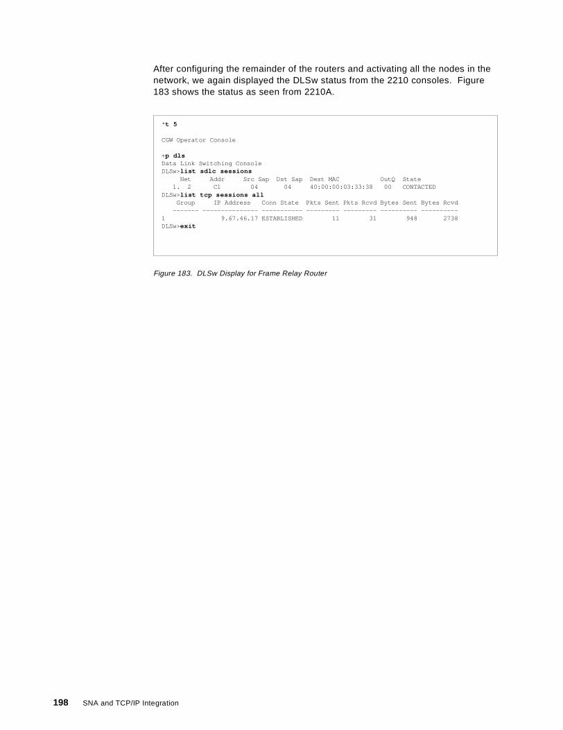
After configuring the remainder of the routers and activating all the nodes in thenetwork, we again displayed the DLSw status from the 2210 consoles. Figure183 shows the status as seen from 2210A.
Figure 183. DLSw Display for Frame Relay Router
* t 5
CGW Operator Console
+p dlsData Link Switching ConsoleDLSw>list sdlc sessions
Net Addr Src Sap Dst Sap Dest MAC OutQ State1. 2 C1 04 04 40:00:00:03:33:38 00 CONTACTED
DLSw>list tcp sessions allGroup IP Address Conn State Pkts Sent Pkts Rcvd Bytes Sent Bytes Rcvd
------- --------------- ----------- --------- --------- ---------- ----------1 9.67.46.17 ESTABLISHED 11 31 948 2738DLSw>exit
198 SNA and TCP/IP Integration
Chapter 6. Telnet/3270
Strictly speaking, Telnet/3270 (TN3270) and its offshoots (Host On-Demand andHost Publisher) are not network-layer integration techniques. They take theprotocol mapping a layer or two higher, going part of the way to full protocolconversion. However, they are by no means equivalent to full conversion sincethe Telnet/3270 clients must still have a comprehensive knowledge of parts of theSNA protocol.
By implementing Telnet/3270 you save some of the SNA protocol stack on theworkstation, but you pay for it in loss of flexibility: TN3270 supports only oneparticular kind of SNA communication, that associated with 3270 dependent LUs(LU types 1, 2 and 3). LU types 0, 6.2 and others must still use other integrationtechniques. However, the 3270 protocol is the most common throughout the SNAworld and TN3270 has significant benefits in the situation where you are trying tominimize the resources required on the workstations but to maximize the 3270features available to those workstations.
TN3270 has a sister protocol, TN5250, which corresponds to the 5250 protocolused in the AS/400 world. The principles are much the same; here we discussonly the 3270 option.
6.1 TN3270 Description
Telnet/3270 is a development of the old Telnet protocol, which is described inRFCs 854 and 855. A Telnet client uses this protocol to access the resources ona Telnet server as if the client was directly attached to the server. TN3270 itself isdescribed in RFCs 1041, 1576, 1646 and others. The TN3270 client has aTCP/IP stack with the TN3270 protocol. The TN3270 server acts as an SNA LUand translates the TCP/IP transport protocols to and from SNA protocols whileleaving the data stream largely unchanged. Thus the data flows over a nativeSNA 3270 session between the TN3270 server and the application host.
The Telnet protocol is based on three principles:
• The Network Virtual Terminal (NVT) concept. An NVT is an imaginary devicehaving a basic structure common to a wide range of real terminals. Each hostmaps its own terminal characteristics to those of an NVT, and assumes thatevery other host will do the same.
• A symmetric view of terminals and processes.
• Negotiation of terminal options. The principle of negotiated options is used bythe Telnet protocol, because many hosts wish to provide additional servicesbeyond those available with the NVT. The NVT has only a basic set offunctions because it must cater for all hosts.
Various options may be negotiated. Server and client use a set of conventionsto establish the operational characteristics of their Telnet connection.
The two hosts begin by verifying their mutual understanding; once this initialnegotiation is complete, they are capable of working at the minimum levelimplemented by the NVT. After this minimum understanding is achieved, theycan negotiate additional options to extend the capabilities of the NVT to reflectmore accurately the capabilities of the real hardware and the real applications in
© Copyright IBM Corp. 1999 199
use. Because of the symmetric model used by Telnet, both the host and theclient may propose additional options to be used.
The NVT has a printer (or display) and a keyboard, uses ASCII code, andemulates a simple half-duplex device operating in line-by-line mode. 3270devices, however, behave rather differently from the old ASCII screens or printersand thus a TN3270 client and server must negotiate certain additional options ifthey are to succeed in communication. The most important of these are:
• Binary Transmission. 3270 uses EBCDIC data streams which are full ofunprintable control characters, so TN3270 must allow any code to betransmitted.
• End of Record. 3270 data streams are block-oriented rather thanline-oriented, so TN3270 must recognize the end of a block.
• Terminal Type. The client and server must negotiate not only the fact that theywill exchange 3270 data streams, but also what model of 3270 screen they willemulate. Different models have different screen formats.
Once the basics have been negotiated there are still other things to get right, inparticular the character translation. 3270 functions such as ATTN or SYSREQmust be mapped to particular combinations of keys on the client’s keyboard.
6.1.1 TN3270 EnhancementsThe basic TN3270 functions still leave some features of real 3270 SNAcommunication unsupported. These include:
• TN3270 does not support 328x printers.
• TN3270 cannot handle SNA BIND information. The BIND on a 3270 sessionincludes information about screen formats and the ability to recognize themore advanced forms of the data stream.
• There is no support for the SNA positive/negative response process. Thismeans, among other things, that end-to-end (TN3270 client to hostapplication) response times cannot be measured.
• The 3270 ATTN and SYSREQ keys are not supported by all implementations.
• TN3270 cannot relate Telnet sessions to SNA LU names. This can make itdifficult to manage a TN3270 environment.
To allow TN3270 devices to make use of all these advanced features of native3270 communication, additions to the protocol were implemented. Theseadditions are called TN3270 Enhancements (TN3270E), and are described inRFCs 1647 and 2355.
In order to use TN3270E, both the client and server must negotiate the TN3270option when they are establishing their TN3270 connection. Once this has beenagreed they then negotiate the TN3270E options which include:
• Device type (screen or printer, fixed or dynamic screen sizes, ability to supportextended attributes)
• Printer data stream type (DSC or SCS)
• Device status information
• The passing of BIND information from server to client
200 SNA and TCP/IP Integration

• Positive/negative response exchanges (definite or exception responses, or noresponses)
• Device name (and therefore the ability to influence the choice of SNA LU)
Because only TN3270E provides anything approaching the full capabilities ofnative SNA 3270 devices, we consider only TN3270E communication throughoutthe remainder of this chapter. The current IBM products that support TN3270Eare as follows:
• TN3270E Client:
• Personal Communications/3270 for OS/2• Personal Communications/3270 for Windows• Communications Server for AIX
• TN3270E Server:
• SecureWay Communications Server for OS/390, Release 5 and above• Communications Server for OS/2, Version 4 Release 1 and above• Communications Server for Windows NT, Version 5 and above• The 221X router family (2216, 2212, 2210, 3746 MAE, Network Utility)
6.1.2 Positioning the TN3270E ServerThe TN3270E server function has been implemented on a variety of platforms,and can be positioned almost anywhere in your network:
• On the OS/390 host, in CS for OS/390• At the remote location, in CS/2 or CS/NT or a 2210/2212• Somewhere in between, typically on a channel-attached 221X
The location of the server is the subject of much debate. In an ideal world theanswer would depend on the distribution of your SNA applications, the relativecosts of implementing TN3270E in various places, and the resilience of eachoption. We simply make the following observations:
• We assume that if you are implementing TN3270E then most of yourworkstations require access to 3270-type applications only.
• If all your 3270 applications are in the same place (same host or same ParallelSysplex) then it probably makes sense to implement TN3270E in CS forOS/390. It can handle tens of thousands of connections, and you can achieveresilience by the judicious use of the Workload Manager and DNS-basedfunctions of CS for OS/390. There is no requirement for SNA in the remotelocations or in the backbone.
• If your 3270 applications are in the same location but not quite as closelycoupled as in the first case, then TN3270E in a 2216 (or MAE, or the NetworkUtility which was designed for exactly this situation) may be the best solution.Optimum routing can be achieved because the traffic does not pass throughintermediate hosts, and the Network Dispatcher can guarantee a measure ofhigh availability.
• If your 3270 applications are scattered throughout your network, and evenmore so if there are non-3270 sessions, then it makes sense to implementTN3270E as near to the users’ workstations as possible. That way optimum(now SNA) routing can be achieved, with SNA class of service betweenremote location and host application. If your backbone network is IP, thenEnterprise Extender provides the perfect solution; any SNA traffic can be
Telnet/3270 201
carried, and the SNA routing can be as direct as you wish because ofEnterprise Extender’s support for connection networks.
6.2 TN3270E in SecureWay Communications Server for OS/390
The Telnet server in CS for OS/390 supports line mode and basic TN3270 modeoperation as well as TN3270E. It was completely rewritten in Release 5 ofOS/390, and now takes full advantage of MVS multitasking capabilities. It usesthe UNIX Systems Services Sockets API.
TN3270E in CS for OS/390 provides:
• Secure Sockets Support
CS for OS/390 Release 6 introduced supports for the Secure Sockets Layer(SSL) standards. SSL provides secure data transmission between theTN3270 Server and an SSL-capable client. In an SSL session, any data on asecure port is encrypted using the SSL protocol before it is sent to the client.Data received from the client is decrypted before the data is sent to otherprocesses (with TN3270, these other processes mean VTAM).
• Multiple Ports Support
CS for OS/390 Release 6 also introduced the ability for the TN3270E Server tolisten on multiple ports. This means you can define different security levels(basic or secure) or different configuration parameters, or both, for each port.Up to 255 ports are allowed.
• LU 0, 1, 2 and 3 Support
LU type 0 represents a local non-SNA 3270 terminal and is often found onOS/390 hosts in its native form. Support for SNA printers means that noseparate product and no separate operational considerations are required toprint SNA data over the IP network.
• Unformatted System Services (USS) Support
This provides the ability to display the VTAM USS messages on the TN3270Eclient. The actual USS table to be used can be selected via the configurationfiles. The TN3270E client can issue the VTAM logon commands in the sameway as on a native SNA terminal.
• IP Address to LU Name Mapping (IP Filtering)
This function provides the ability to select both an LU name and an applicationname for incoming TN3270E sessions. The selection may be made on thebasis of a specific IP address, a group of IP addresses, a subnet, or the linkname used to connect to the OS/390 host. The function makes the LU nameand the application name predictable and controllable. In addition, CS forOS/390 Release 7 supports selection based on IP host name, or group ofnames, as well as IP address. With the increasing use of dynamic IP (where agiven client is not tied to a specific IP address) this can be very beneficial inmaintaining control over the mapping.
You can also associate printer devices with display devices in the server, sothe server knows where to direct a printer session that has been requested onbehalf of a given client.
• Operator Console Commands.
202 SNA and TCP/IP Integration
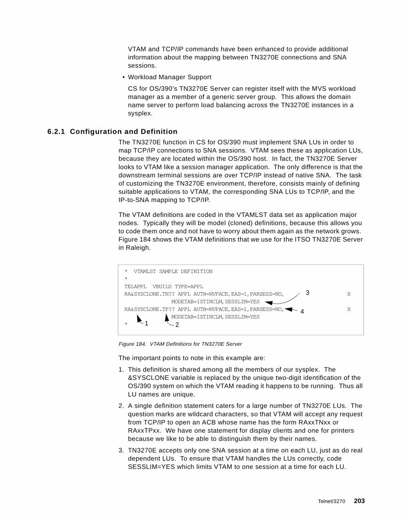
VTAM and TCP/IP commands have been enhanced to provide additionalinformation about the mapping between TN3270E connections and SNAsessions.
• Workload Manager Support
CS for OS/390’s TN3270E Server can register itself with the MVS workloadmanager as a member of a generic server group. This allows the domainname server to perform load balancing across the TN3270E instances in asysplex.
6.2.1 Configuration and DefinitionThe TN3270E function in CS for OS/390 must implement SNA LUs in order tomap TCP/IP connections to SNA sessions. VTAM sees these as application LUs,because they are located within the OS/390 host. In fact, the TN3270E Serverlooks to VTAM like a session manager application. The only difference is that thedownstream terminal sessions are over TCP/IP instead of native SNA. The taskof customizing the TN3270E environment, therefore, consists mainly of definingsuitable applications to VTAM, the corresponding SNA LUs to TCP/IP, and theIP-to-SNA mapping to TCP/IP.
The VTAM definitions are coded in the VTAMLST data set as application majornodes. Typically they will be model (cloned) definitions, because this allows youto code them once and not have to worry about them again as the network grows.Figure 184 shows the VTAM definitions that we use for the ITSO TN3270E Serverin Raleigh.
Figure 184. VTAM Definitions for TN3270E Server
The important points to note in this example are:
1. This definition is shared among all the members of our sysplex. The&SYSCLONE variable is replaced by the unique two-digit identification of theOS/390 system on which the VTAM reading it happens to be running. Thus allLU names are unique.
2. A single definition statement caters for a large number of TN3270E LUs. Thequestion marks are wildcard characters, so that VTAM will accept any requestfrom TCP/IP to open an ACB whose name has the form RAxxTNxx orRAxxTPxx. We have one statement for display clients and one for printersbecause we like to be able to distinguish them by their names.
3. TN3270E accepts only one SNA session at a time on each LU, just as do realdependent LUs. To ensure that VTAM handles the LUs correctly, codeSESSLIM=YES which limits VTAM to one session at a time for each LU.
* VTAMLST SAMPLE DEFINITION*TELAPPL VBUILD TYPE=APPLRA&SYSCLONE.TN?? APPL AUTH=NVPACE,EAS=1,PARSESS=NO, X
MODETAB=ISTINCLM,SESSLIM=YESRA&SYSCLONE.TP?? APPL AUTH=NVPACE,EAS=1,PARSESS=NO, X
MODETAB=ISTINCLM,SESSLIM=YES*
3
4
21
Telnet/3270 203
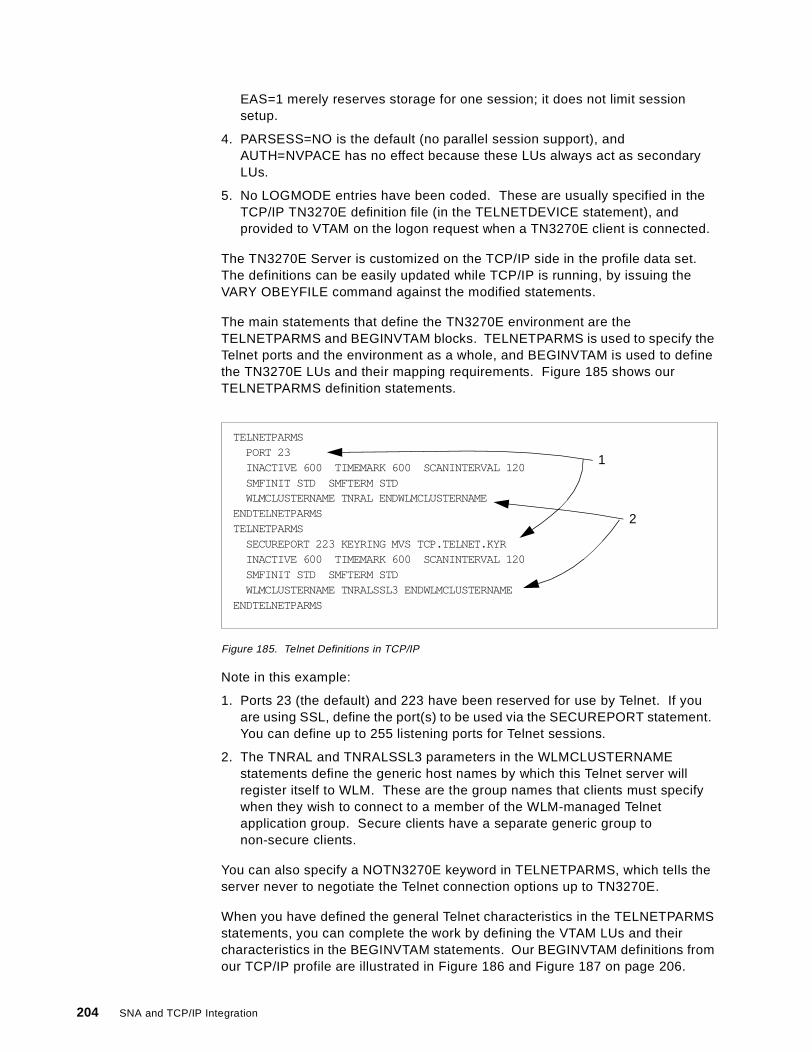
EAS=1 merely reserves storage for one session; it does not limit sessionsetup.
4. PARSESS=NO is the default (no parallel session support), andAUTH=NVPACE has no effect because these LUs always act as secondaryLUs.
5. No LOGMODE entries have been coded. These are usually specified in theTCP/IP TN3270E definition file (in the TELNETDEVICE statement), andprovided to VTAM on the logon request when a TN3270E client is connected.
The TN3270E Server is customized on the TCP/IP side in the profile data set.The definitions can be easily updated while TCP/IP is running, by issuing theVARY OBEYFILE command against the modified statements.
The main statements that define the TN3270E environment are theTELNETPARMS and BEGINVTAM blocks. TELNETPARMS is used to specify theTelnet ports and the environment as a whole, and BEGINVTAM is used to definethe TN3270E LUs and their mapping requirements. Figure 185 shows ourTELNETPARMS definition statements.
Figure 185. Telnet Definitions in TCP/IP
Note in this example:
1. Ports 23 (the default) and 223 have been reserved for use by Telnet. If youare using SSL, define the port(s) to be used via the SECUREPORT statement.You can define up to 255 listening ports for Telnet sessions.
2. The TNRAL and TNRALSSL3 parameters in the WLMCLUSTERNAMEstatements define the generic host names by which this Telnet server willregister itself to WLM. These are the group names that clients must specifywhen they wish to connect to a member of the WLM-managed Telnetapplication group. Secure clients have a separate generic group tonon-secure clients.
You can also specify a NOTN3270E keyword in TELNETPARMS, which tells theserver never to negotiate the Telnet connection options up to TN3270E.
When you have defined the general Telnet characteristics in the TELNETPARMSstatements, you can complete the work by defining the VTAM LUs and theircharacteristics in the BEGINVTAM statements. Our BEGINVTAM definitions fromour TCP/IP profile are illustrated in Figure 186 and Figure 187 on page 206.
TELNETPARMSPORT 23INACTIVE 600 TIMEMARK 600 SCANINTERVAL 120SMFINIT STD SMFTERM STDWLMCLUSTERNAME TNRAL ENDWLMCLUSTERNAME
ENDTELNETPARMSTELNETPARMS
SECUREPORT 223 KEYRING MVS TCP.TELNET.KYRINACTIVE 600 TIMEMARK 600 SCANINTERVAL 120SMFINIT STD SMFTERM STDWLMCLUSTERNAME TNRALSSL3 ENDWLMCLUSTERNAME
ENDTELNETPARMS
1
2
204 SNA and TCP/IP Integration

Figure 186. BEGINVTAM Statements for TN3270E (Part 1)
BEGINVTAMPORT 23 223
DEFAULTLUSRA&SYSCLONE.TN01..RA&SYSCLONE.TN50
ENDDEFAULTLUS
LUGROUP SPECLURA&SYSCLONE.TN91..RA&SYSCLONE.TN99
ENDLUGROUPLUMAP SPECLU 9.24.104.201
IPGROUP SPECIP9.24.104.191 9.24.104.192 9.24.104.193 9.24.104.194 9.24.104.1959.24.104.196 9.24.104.197 9.24.104.198 9.24.104.199
ENDIPGROUP
LUGROUP SPECLXRA&SYSCLONE.TN71..RA&SYSCLONE.TN75
ENDLUGROUPPRTGROUP PRINTERS
RA&SYSCLONE.TPR1..RA&SYSCLONE.TPR5ENDPRTGROUP ; printers for specific mapping and
; printer to LU associationLUMAP SPECLX SPECIP SPECIFIC PRINTERS
PRTGROUP PRINTERGRA&SYSCLONE.TPR6..RA&SYSCLONE.TPR9
ENDPRTGROUPPRTMAP PRINTERG SPECIP
LUGROUP RISCLUGRA&SYSCLONE.TN82 RA&SYSCLONE.TN83 RA&SYSCLONE.TN84RA&SYSCLONE.TN85 RA&SYSCLONE.TN86
ENDLUGROUPLUMAP RISCLUG 9.24.104.28
1
2
3
4
5
6
7
8
Telnet/3270 205
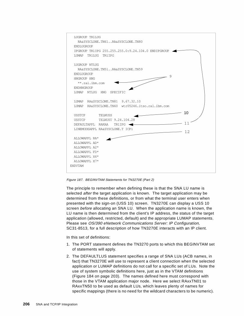
Figure 187. BEGINVTAM Statements for TN3270E (Part 2)
The principle to remember when defining these is that the SNA LU name isselected after the target application is known. The target application may bedetermined from these definitions, or from what the terminal user enters whenpresented with the sign-on (USS 10) screen. TN3270E can display a USS 10screen before allocating an SNA LU. When the application name is known, theLU name is then determined from the client’s IP address, the status of the targetapplication (allowed, restricted, default) and the appropriate LUMAP statements.Please see OS/390 eNetwork Communications Server: IP Configuration,SC31-8513, for a full description of how TN3270E interacts with an IP client.
In this set of definitions:
1. The PORT statement defines the TN3270 ports to which this BEGINVTAM setof statements will apply.
2. The DEFAULTLUS statement specifies a range of SNA LUs (ACB names, infact) that TN3270E will use to represent a client connection when the selectedapplication or LUMAP definitions do not call for a specific set of LUs. Note theuse of system symbolic definitions here, just as in the VTAM definitions(Figure 184 on page 203). The names defined here must correspond withthose in the VTAM application major node. Here we select RAxxTN01 toRAxxTN50 to be used as default LUs, which leaves plenty of names forspecific mappings (there is no need for the wildcard characters to be numeric).
LUGROUP TR1LUGRA&SYSCLONE.TN61..RA&SYSCLONE.TN80
ENDLUGROUPIPGROUP TR1IPG 255.255.255.0:9.24.104.0 ENDIPGROUPLUMAP TR1LUG TR1IPG
LUGROUP NTLUGRA&SYSCLONE.TN51..RA&SYSCLONE.TN59
ENDLUGROUPHNGROUP HNG
**.ral.ibm.comENDHNGROUPLUMAP NTLUG HNG SPECIFIC
LUMAP RA&SYSCLONE.TN81 9.67.32.10LUMAP RA&SYSCLONE.TN60 wtr05246.itso.ral.ibm.com
USSTCP TELNUSSUSSTCP TELNUST 9.24.104.28DEFAULTAPPL RAKAA TR1IPGLINEMODEAPPL RA&SYSCLONE.T ICP1
ALLOWAPPL RA*ALLOWAPPL AD*ALLOWAPPL A2*ALLOWAPPL FD*ALLOWAPPL X6*ALLOWAPPL X7*
ENDVTAM
9
10
11
12
206 SNA and TCP/IP Integration
3. Next, we define a pool of LUs called SPECLU. SPECLU now comprises theLUs named RAxxTN91 to RAxxTN99. We associate the IP host 9.24.104.201with this LU pool. When this IP host connects to the server as a TN3270Eclient it will be assigned to one of the LUs in this pool, provided that theapplication selected is permitted to this client.
4. We define a group of IP clients called SPECIP, which comprises nine IPaddresses as shown.
5. We define another pool of five LUs called SPECLX.
6. We define a pool of printer LUs called PRINTERS which contains the LUsnames RAxxTPR1 to RAxxTPR5.
7. Then we tie the last three definitions together with another LUMAP. Weassociate the group of IP clients SPECIP with the pool of LUs SPECLX, sothat if one of these clients requests a TN3270 connection it will be assigned aVTAM LU in this pool. This is a SPECIFIC mapping definition, so it is usedwhen the client requests a specific device name. If this fails, an equivalentGENERIC (the default value) mapping definition is used if available.
The same statement also maps the printer pool to the terminal pool.
8. A printer client group can also be assigned to a printer LU pool without anyassociation with displays. Here we define a printer LU pool called PRINTERGand map SPECIP to it. When a printer in the SPECIP group connects toTN3270E without requesting a specific LU name it will be assigned to one ofthe LUs in PRINTERG.
9. You can also define a group of clients by IP host name. Here we create agroup called HNG which comprises all hosts in the domain ral.ibm.com. Weassociate it with the LU pool NTLUG, provided the client specifies the LUname it wants.
10. The USSTCP statement associates a TN3270-specific USS message tablewith some or all of your TN3270E clients. Here, any client that does not havea default target application defined will be presented with the USS screen fromthe TELNUSS table. The exception is 9.24.104.28, which will receive thescreen from the TELNUST table.
11.Clients in the group TR1IPG will not receive any USS messages, but will belogged straight on to the application RAKAA. Note the definition of TR1IPG,where we select the whole of the 9.24.104 subnetwork by prefixing its addresswith its subnet mask.
12. Finally, we define which SNA applications will be permitted access from theTN3270E clients. Once again, wildcards are used to specify a range ofapplications. The ALLOWAPPL and RESTRICTAPPL statements are used tocontrol which users are allowed to log on to which applications using whichLUs. Restricted applications are associated with a list of authorized userswho must identify themselves by passwords.
Not present in our definitions, but of some interest, is the TELNETDEVICEstatement. This associates an SNA mode name with a device type (as defined inthe TN3270 standards). The default is for TN3270E to use LU type 0 (non-SNA)modes.
Telnet/3270 207
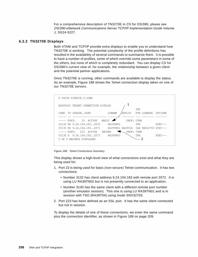
For a comprehensive description of TN3270E in CS for OS/390, please seeOS/390 eNetwork Communications Server TCP/IP Implementation Guide Volume1, SG24-5227.
6.2.2 TN3270E DisplaysBoth VTAM and TCP/IP provide extra displays to enable you to understand howTN3270E is working. The potential complexity of the profile definitions hasresulted in the availability of several commands to summarize them. It is possibleto have a number of profiles, some of which override some parameters in some ofthe others, but none of which is completely redundant. You can display CS forOS/390’s current view of, for example, the relationship between a given clientand the potential partner applications.
Once TN3270E is running, other commands are available to display the status.As an example, Figure 188 shows the Telnet connection display taken on one ofour TN3270E servers.
Figure 188. Telnet Connections Summary
This display shows a high-level view of what connections exist and what they arebeing used for:
1. Port 23 is being used for basic (non-secure) Telnet communication. It has twoconnections:
• Number 3132 has client address 9.24.104.183 with remote port 2072. It isusing LU RA39TN02 but is not presently connected to an application.
• Number 3130 has the same client with a different remote port number(another emulator session). This one is using LU RA39TN01 and is insession with TSO (RA39T04) using mode SNX32703.
2. Port 223 has been defined as an SSL port. It has the same client connectedbut not in session.
To display the details of one of these connections, we enter the same commandplus the connection identifier, as shown in Figure 189 on page 209.
D TCPIP,T39ATCP,T,CONN
EZZ6064I TELNET CONNECTION DISPLAYTSP
CONN TY IPADDR..PORT LUNAME APPLID PTR LOGMODE OPTIONS----- -- ---------------------- -------- -------- --- -------- ------------ PORT: 23 ACTIVE BASIC PROF: CURR03132 NS 9.24.104.183..2072 RA39TN02 TPE ETET---03130 NS 9.24.104.183..2071 RA39TN01 RA39T04 TAE SNX32703 ETET-------- PORT: 223 ACTIVE SECURE PROF: CURR03136 S 9.24.104.183..2073 RA39TN03 TPE ETET---5 OF 5 RECORDS DISPLAYED
1
2
208 SNA and TCP/IP Integration
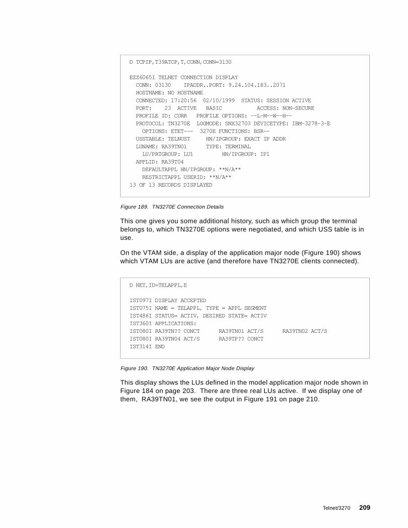
Figure 189. TN3270E Connection Details
This one gives you some additional history, such as which group the terminalbelongs to, which TN3270E options were negotiated, and which USS table is inuse.
On the VTAM side, a display of the application major node (Figure 190) showswhich VTAM LUs are active (and therefore have TN3270E clients connected).
Figure 190. TN3270E Application Major Node Display
This display shows the LUs defined in the model application major node shown inFigure 184 on page 203. There are three real LUs active. If we display one ofthem, RA39TN01, we see the output in Figure 191 on page 210.
D TCPIP,T39ATCP,T,CONN,CONN=3130
EZZ6065I TELNET CONNECTION DISPLAYCONN: 03130 IPADDR..PORT: 9.24.104.183..2071HOSTNAME: NO HOSTNAMECONNECTED: 17:20:56 02/10/1999 STATUS: SESSION ACTIVEPORT: 23 ACTIVE BASIC ACCESS: NON-SECUREPROFILE ID: CURR PROFILE OPTIONS: --L-M--W--H--PROTOCOL: TN3270E LOGMODE: SNX32703 DEVICETYPE: IBM-3278-3-E
OPTIONS: ETET--- 3270E FUNCTIONS: BSR--USSTABLE: TELNUST HN/IPGROUP: EXACT IP ADDRLUNAME: RA39TN01 TYPE: TERMINAL
LU/PRTGROUP: LU1 HN/IPGROUP: IP1APPLID: RA39T04
DEFAULTAPPL HN/IPGROUP: **N/A**RESTRICTAPPL USERID: **N/A**
13 OF 13 RECORDS DISPLAYED
D NET,ID=TELAPPL,E
IST097I DISPLAY ACCEPTEDIST075I NAME = TELAPPL, TYPE = APPL SEGMENTIST486I STATUS= ACTIV, DESIRED STATE= ACTIVIST360I APPLICATIONS:IST080I RA39TN?? CONCT RA39TN01 ACT/S RA39TN02 ACT/SIST080I RA39TN04 ACT/S RA39TP?? CONCTIST314I END
Telnet/3270 209
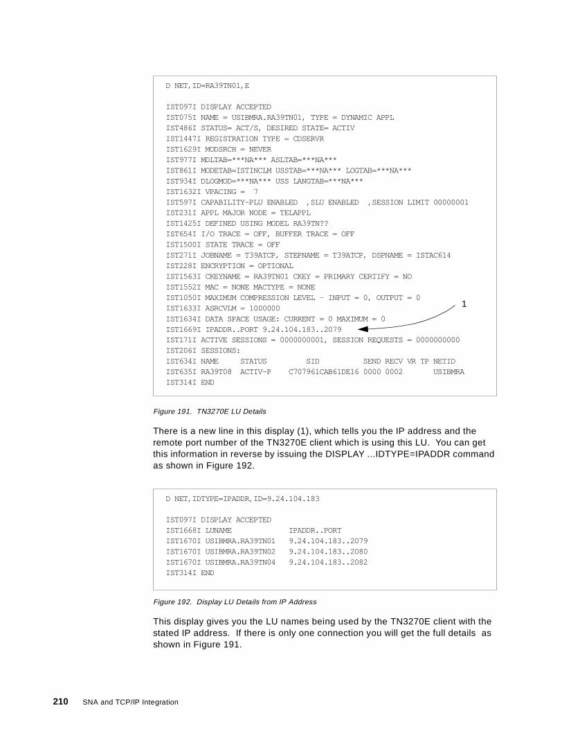
Figure 191. TN3270E LU Details
There is a new line in this display (1), which tells you the IP address and theremote port number of the TN3270E client which is using this LU. You can getthis information in reverse by issuing the DISPLAY ...IDTYPE=IPADDR commandas shown in Figure 192.
Figure 192. Display LU Details from IP Address
This display gives you the LU names being used by the TN3270E client with thestated IP address. If there is only one connection you will get the full details asshown in Figure 191.
D NET,ID=RA39TN01,E
IST097I DISPLAY ACCEPTEDIST075I NAME = USIBMRA.RA39TN01, TYPE = DYNAMIC APPLIST486I STATUS= ACT/S, DESIRED STATE= ACTIVIST1447I REGISTRATION TYPE = CDSERVRIST1629I MODSRCH = NEVERIST977I MDLTAB=***NA*** ASLTAB=***NA***IST861I MODETAB=ISTINCLM USSTAB=***NA*** LOGTAB=***NA***IST934I DLOGMOD=***NA*** USS LANGTAB=***NA***IST1632I VPACING = 7IST597I CAPABILITY-PLU ENABLED ,SLU ENABLED ,SESSION LIMIT 00000001IST231I APPL MAJOR NODE = TELAPPLIST1425I DEFINED USING MODEL RA39TN??IST654I I/O TRACE = OFF, BUFFER TRACE = OFFIST1500I STATE TRACE = OFFIST271I JOBNAME = T39ATCP, STEPNAME = T39ATCP, DSPNAME = ISTAC614IST228I ENCRYPTION = OPTIONALIST1563I CKEYNAME = RA39TN01 CKEY = PRIMARY CERTIFY = NOIST1552I MAC = NONE MACTYPE = NONEIST1050I MAXIMUM COMPRESSION LEVEL - INPUT = 0, OUTPUT = 0IST1633I ASRCVLM = 1000000IST1634I DATA SPACE USAGE: CURRENT = 0 MAXIMUM = 0IST1669I IPADDR..PORT 9.24.104.183..2079IST171I ACTIVE SESSIONS = 0000000001, SESSION REQUESTS = 0000000000IST206I SESSIONS:IST634I NAME STATUS SID SEND RECV VR TP NETIDIST635I RA39T08 ACTIV-P C707961CAB61DE16 0000 0002 USIBMRAIST314I END
1
D NET,IDTYPE=IPADDR,ID=9.24.104.183
IST097I DISPLAY ACCEPTEDIST1668I LUNAME IPADDR..PORTIST1670I USIBMRA.RA39TN01 9.24.104.183..2079IST1670I USIBMRA.RA39TN02 9.24.104.183..2080IST1670I USIBMRA.RA39TN04 9.24.104.183..2082IST314I END
210 SNA and TCP/IP Integration

6.3 TN3270E in Communications Server for OS/2
The TN3270E server function is available on Communications Server for OS/2itself, but not on the Access Feature that is a subset of CS/2.
Since CS/2 supports only LU type 2 displays (not LU 0), the TN3270Eimplementation does the same. Major functions in TN3270 on CS/2 are:
• LU types 1, 2 and 3 using the RFC 1647 standards.
• SNA positive and negative responses.
• Handling of attention and system request keys.
• Grouping of LUs into classes, which simplifies user access and managementof users. Both printer and display LUs can be defined as implicit (clients areallocated to any available LU in the pool) or explicit (clients require a specificdevice name).
• Association of printer LUs with display LUs.
TN3270E communication using SSL is not supported, nor is filtering (theassociation of particular clients to particular LUs). Both of these options areplanned for implementation in the next release due in Spring 1999.
Setting up the TN3270E Server is less complex than on CS for OS/390. Theowning VTAM is not in the same machine as the TN3270E server function, andthe filtering and SSL options are (for now) absent.
6.3.1 Configuration and DefinitionOnce you have configured your CS/2 machine for native SNA operation, theadditional work required for TN3270E is not great. In essence you have to selectone or more host links for TN3270E to use, define some LUs on those links, andallocate the LUs to TN3270E sessions. The host links used by TN3270E can benative or DLUR connections; the requirement is that SSCP sessions aresupported over those connections.
There are two ways to invoke the TN3270E configuration from theCommunications Manager Configuration Definition panel:
1. Click TN3270E and Configure .
2. Click Options and Configure any profile or feature .
In either case, the item on the Profile List you are looking for is called TN3270EServer parameters. Figure 193 on page 212 shows the Profile List when weselected the TN3270E/Configure option.
Telnet/3270 211
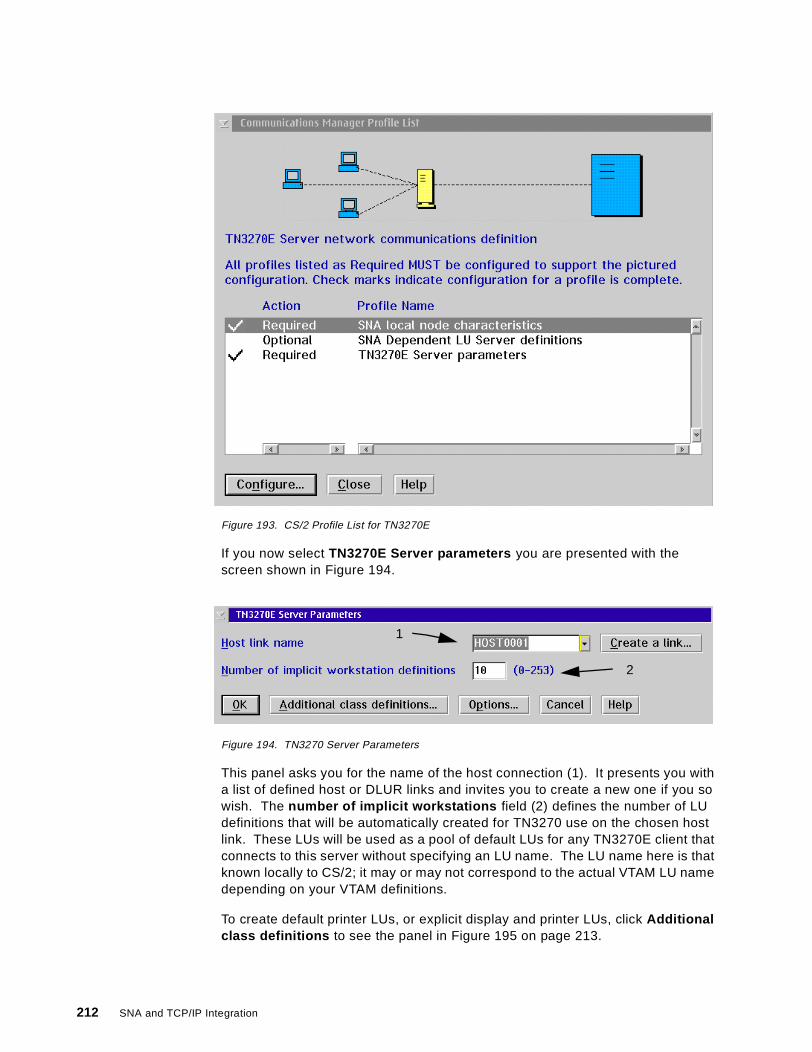
Figure 193. CS/2 Profile List for TN3270E
If you now select TN3270E Server parameters you are presented with thescreen shown in Figure 194.
Figure 194. TN3270 Server Parameters
This panel asks you for the name of the host connection (1). It presents you witha list of defined host or DLUR links and invites you to create a new one if you sowish. The number of implicit workstations field (2) defines the number of LUdefinitions that will be automatically created for TN3270 use on the chosen hostlink. These LUs will be used as a pool of default LUs for any TN3270E client thatconnects to this server without specifying an LU name. The LU name here is thatknown locally to CS/2; it may or may not correspond to the actual VTAM LU namedepending on your VTAM definitions.
To create default printer LUs, or explicit display and printer LUs, click Additionalclass definitions to see the panel in Figure 195 on page 213.
1
2
212 SNA and TCP/IP Integration
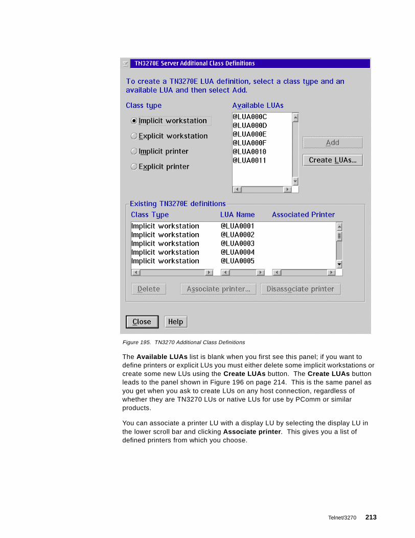
Figure 195. TN3270 Additional Class Definitions
The Available LUAs list is blank when you first see this panel; if you want todefine printers or explicit LUs you must either delete some implicit workstations orcreate some new LUs using the Create LUAs button. The Create LUAs buttonleads to the panel shown in Figure 196 on page 214. This is the same panel asyou get when you ask to create LUs on any host connection, regardless ofwhether they are TN3270 LUs or native LUs for use by PComm or similarproducts.
You can associate a printer LU with a display LU by selecting the display LU inthe lower scroll bar and clicking Associate printer . This gives you a list ofdefined printers from which you choose.
Telnet/3270 213

Figure 196. LU Creation Panel
The only other options to consider when defining TN3270E are those availablefrom the Options button on the Server Parameters panel (Figure 194 on page212). Figure 197 is displayed when you select Options .
Figure 197. TN3270 Server Options
Here you can define the Telnet port number (default 23, the well-known port forTelnet) and how long the server is to wait with no traffic on a connection beforeterminating the connection. You can also ask the server to send regularkeepalive messages to the client to check whether the connection is still up.
214 SNA and TCP/IP Integration
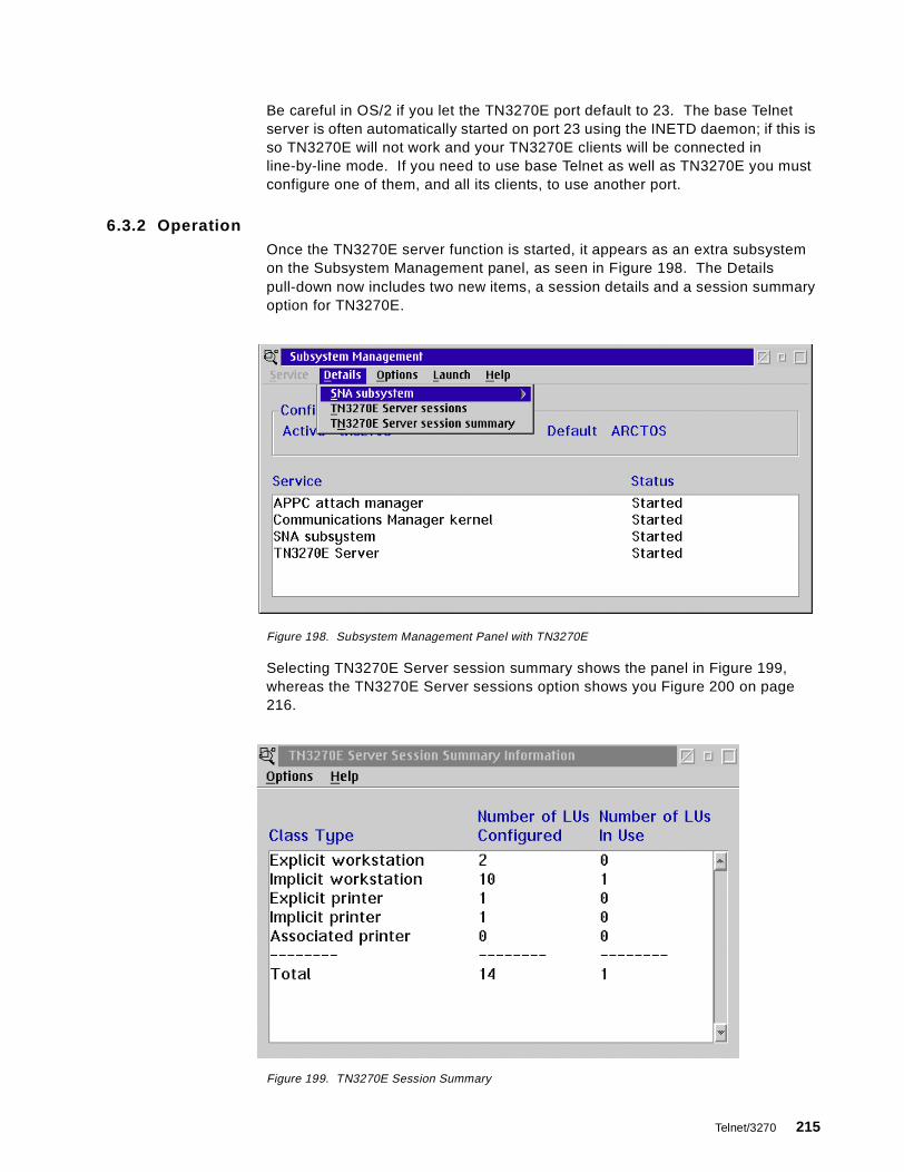
Be careful in OS/2 if you let the TN3270E port default to 23. The base Telnetserver is often automatically started on port 23 using the INETD daemon; if this isso TN3270E will not work and your TN3270E clients will be connected inline-by-line mode. If you need to use base Telnet as well as TN3270E you mustconfigure one of them, and all its clients, to use another port.
6.3.2 OperationOnce the TN3270E server function is started, it appears as an extra subsystemon the Subsystem Management panel, as seen in Figure 198. The Detailspull-down now includes two new items, a session details and a session summaryoption for TN3270E.
Figure 198. Subsystem Management Panel with TN3270E
Selecting TN3270E Server session summary shows the panel in Figure 199,whereas the TN3270E Server sessions option shows you Figure 200 on page216.
Figure 199. TN3270E Session Summary
Telnet/3270 215

Figure 200. TN3270E Server Session Details
This panel demonstrates that the client 9.24.104.251 (actually PComm/2 Version4 Release 2) is connected to the LU with a local name of @LUA0001. It is insession with a host application; if it were not the connection status would beSSCP-LU.
6.4 TN3270E in Communications Server for Windows NT
CS/NT supports the following options in its TN3270E function:
• LU types 1, 2 and 3 using the RFC 1647 standards.
• SNA positive and negative responses.
• Handling of attention and system request keys.
• Categorization of LUs into classes, as with CS/2.
• Association of printer LUs with display LUs.
• Secure Sockets Layer support.
• IP filtering, that is the control of access to host LUs depending on the client IPaddresses or host names.
• Server load balancing. This requires corresponding support in the clientworkstations, and allows TN3270E connections to be spread over multipleservers. PComm Version 4 Release 3 is an example of a client that supportsthis function.
The upstream host connection can be any suitable connection that supportsdependent LUs with their SSCP sessions (native or DLUR).
For a comprehensive guide to the TN3270E functions in CS/NT, please refer toIBM Communications Server for Windows NT Version 5.0, SG24-2099, and IBMeNetwork Communications Server for Windows NT Version 6.0 Enhancements,SG24-5232.
216 SNA and TCP/IP Integration
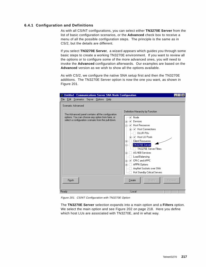
6.4.1 Configuration and DefinitionsAs with all CS/NT configurations, you can select either TN3270E Server from thelist of basic configuration scenarios, or the Advanced check box to receive amenu of all the possible configuration steps. The principle is the same as inCS/2, but the details are different.
If you select TN3270E Server , a wizard appears which guides you through somebasic steps to create a working TN3270E environment. If you want to review allthe options or to configure some of the more advanced ones, you will need toinvoke the Advanced configuration afterwards. Our examples are based on theAdvanced version as we wish to show all the options available.
As with CS/2, we configure the native SNA setup first and then the TN3270Eadditions. The TN3270E Server option is now the one you want, as shown inFigure 201.
Figure 201. CS/NT Configuration with TN3270E Option
The TN3270E Server selection expands into a main option and a Filters option.We select the main option and see Figure 202 on page 218. Here you definewhich host LUs are associated with TN3270E, and in what way.
Telnet/3270 217
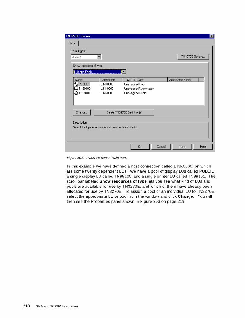
Figure 202. TN3270E Server Main Panel
In this example we have defined a host connection called LINK0000, on whichare some twenty dependent LUs. We have a pool of display LUs called PUBLIC,a single display LU called TN99100, and a single printer LU called TN99101. Thescroll bar labeled Show resources of type lets you see what kind of LUs andpools are available for use by TN3270E, and which of them have already beenallocated for use by TN3270E. To assign a pool or an individual LU to TN3270E,select the appropriate LU or pool from the window and click Change . You willthen see the Properties panel shown in Figure 203 on page 219.
218 SNA and TCP/IP Integration
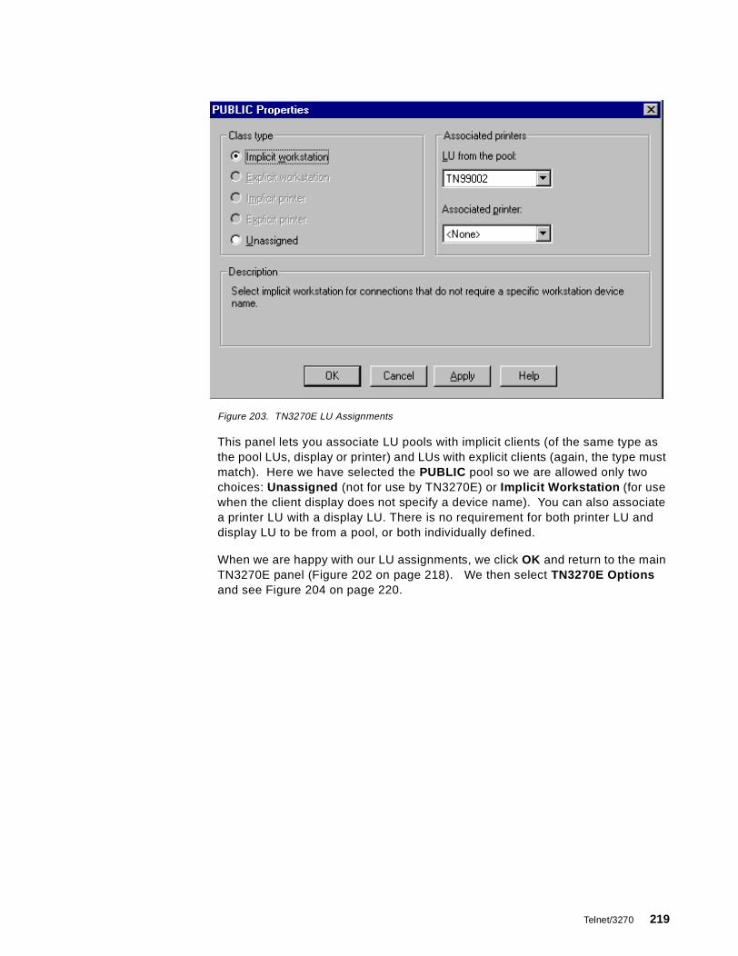
Figure 203. TN3270E LU Assignments
This panel lets you associate LU pools with implicit clients (of the same type asthe pool LUs, display or printer) and LUs with explicit clients (again, the type mustmatch). Here we have selected the PUBLIC pool so we are allowed only twochoices: Unassigned (not for use by TN3270E) or Implicit Workstation (for usewhen the client display does not specify a device name). You can also associatea printer LU with a display LU. There is no requirement for both printer LU anddisplay LU to be from a pool, or both individually defined.
When we are happy with our LU assignments, we click OK and return to the mainTN3270E panel (Figure 202 on page 218). We then select TN3270E Optionsand see Figure 204 on page 220.
Telnet/3270 219

Figure 204. TN3270E Options Panel
The definitions available on this panel are:
1. The IP port number to be used for non-SSL TN3270 communication. Asalways, it defaults to 23 and you must ensure that it is not also in use forline-mode Telnet connections.
2. The IP port number to be used for SSL connections.
3. Whether to send regular keepalive packets to the client.
4. Whether to terminate the session automatically if there has been no activity onit for a certain time.
5. Whether to enable filtering, and if so whether the client’s IP address or hostname should be checked first to determine what filtering to perform.
The filtering scheme itself is invoked from the main menu (Figure 201 on page217) by selecting TN3270E Server Filters and Create . Figure 205 on page 221is the result.
1 2
34
5
220 SNA and TCP/IP Integration

Figure 205. TN3270E Filters
The idea here is that you define a group of IP clients, select a group of LUs, andlink them together to ensure that clients from the selected group are assignedonly to LUs of the selected group.
LUs may be selected in three ways:
• By group.
• By individual LU.
• As the default pool (this option can be seen at the top of the Available LUs andPools window). The default pool is that defined as such on the main TN3270EServer panel (Figure 202 on page 218). It allows you to change the defaultpool without having to redefine the filters.
Clients may also be selected in three ways:
• By IP address. You can specify an individual client address or (by defining asuitable subnet mask) a group of clients in the same logical subnetwork.
• By host name.
• By domain name, thus selecting a whole domain’s worth of clients.
Be sure not to enable filtering on the Options panel, then forget to define anyfilters on the Filters panel. This will result in connections being denied with noobvious cause.
6.4.2 OperationThe Node Operations function of CS/NT contains some additional displays tomonitor the operation of TN3270E. On its main panel, there is a TN3270E Server
Telnet/3270 221
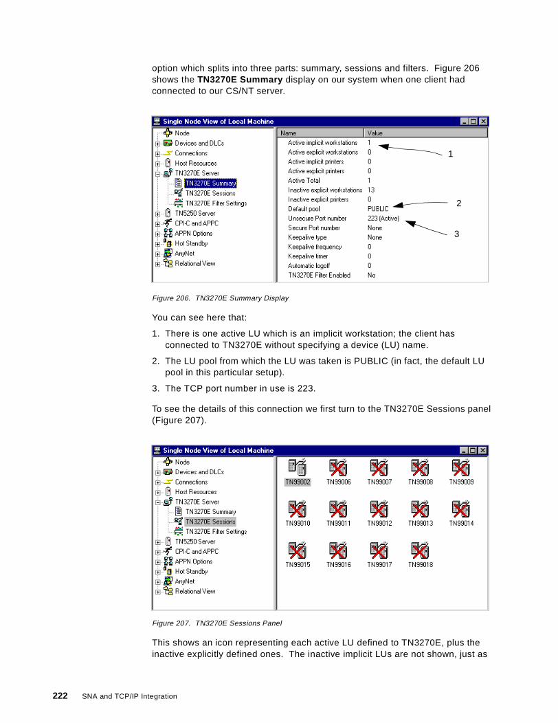
option which splits into three parts: summary, sessions and filters. Figure 206shows the TN3270E Summary display on our system when one client hadconnected to our CS/NT server.
Figure 206. TN3270E Summary Display
You can see here that:
1. There is one active LU which is an implicit workstation; the client hasconnected to TN3270E without specifying a device (LU) name.
2. The LU pool from which the LU was taken is PUBLIC (in fact, the default LUpool in this particular setup).
3. The TCP port number in use is 223.
To see the details of this connection we first turn to the TN3270E Sessions panel(Figure 207).
Figure 207. TN3270E Sessions Panel
This shows an icon representing each active LU defined to TN3270E, plus theinactive explicitly defined ones. The inactive implicit LUs are not shown, just as
1
2
3
222 SNA and TCP/IP Integration
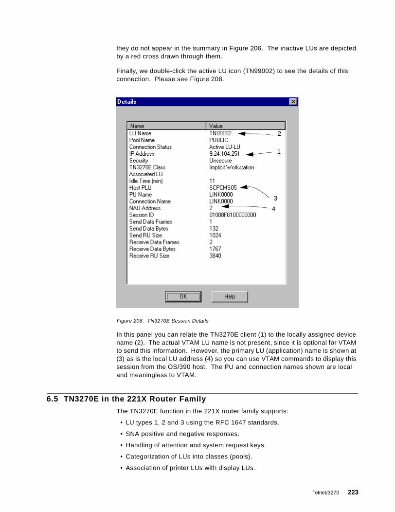
they do not appear in the summary in Figure 206. The inactive LUs are depictedby a red cross drawn through them.
Finally, we double-click the active LU icon (TN99002) to see the details of thisconnection. Please see Figure 208.
Figure 208. TN3270E Session Details
In this panel you can relate the TN3270E client (1) to the locally assigned devicename (2). The actual VTAM LU name is not present, since it is optional for VTAMto send this information. However, the primary LU (application) name is shown at(3) as is the local LU address (4) so you can use VTAM commands to display thissession from the OS/390 host. The PU and connection names shown are localand meaningless to VTAM.
6.5 TN3270E in the 221X Router Family
The TN3270E function in the 221X router family supports:
• LU types 1, 2 and 3 using the RFC 1647 standards.
• SNA positive and negative responses.
• Handling of attention and system request keys.
• Categorization of LUs into classes (pools).
• Association of printer LUs with display LUs.
1
2
3
4
Telnet/3270 223
• IP filtering, that is the mapping of clients to host LUs in order to controlaccess.
• Multiple ports for use by TN3270E. Each port can be associated with its ownset of LUs and pools, so that the client can access a different set of hostsessions by connecting to a different port.
• Host access via native subarea connections or DLUR connections. Subareaconnections are supported on token-ring, Ethernet, frame relay or ESCONconnections as applicable to the router in question. DLUR connections aresupported on any APPN link including DLSw, PPP and ATM.
There is always a line-mode Telnet server in a 221X (the remote console), so youneed to be careful about the use of port numbers for TN3270E use.
The TN3270E code, together with the prerequisite APPN code, is notautomatically loaded into the 221X unless you are using the ConfigurationProgram (the remote configuration tool which generates a configuration file to bedownloaded). If you are using Telnet or an ASCII emulator on the service port,you need to enter the following commands to get the right code loaded into thebox:
load add package appnload add package tn3270e
Unless you do both of these you will not be able to configure a subarea link, letalone the TN3270E Server.
6.5.1 Configuration of TN3270EWhether you will be using subarea or APPN/DLUR connectivity to the SNA host,you need to configure APPN on the 221X. Then, to define a host connection, youneed to do one of the following:
• For subarea connection, you configure a link station (add link in the APPNConfiguration process) and make sure that you answer yes to SolicitSSCP-PU session .
• For DLUR connection, you configure a local PU (add loc in the APPNConfiguration process) and give it the network name of the DLUS VTAM.
Having done this, you tell the TN3270E configuration process the name of thislink station or PU to identify the host connection to be used. The TN3270Econfiguration process itself is invoked by typing TN3270 from the APPNConfiguration prompt.
Figure 209 on page 225 shows the APPN configuration relevant to TN3270E inour test environment. The physical interfaces, the APPN node and the real APPNconnections have been defined, and we need to add some host links as the firststage of the definition. We shall add a subarea link on a token-ring port and aDLUR link.
To reach the APPN Configuration prompt, enter t 6 followed by p appn from thebase (asterisk) prompt.
224 SNA and TCP/IP Integration
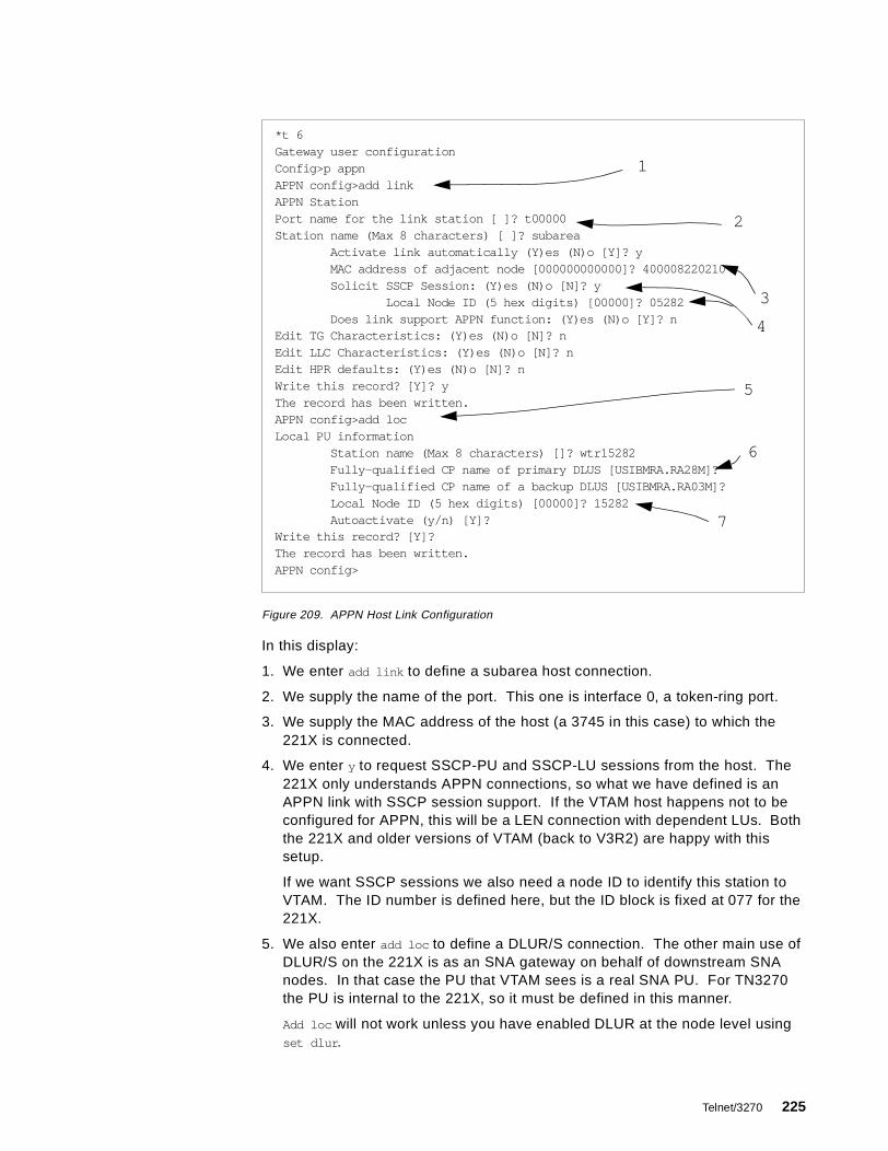
Figure 209. APPN Host Link Configuration
In this display:
1. We enter add link to define a subarea host connection.
2. We supply the name of the port. This one is interface 0, a token-ring port.
3. We supply the MAC address of the host (a 3745 in this case) to which the221X is connected.
4. We enter y to request SSCP-PU and SSCP-LU sessions from the host. The221X only understands APPN connections, so what we have defined is anAPPN link with SSCP session support. If the VTAM host happens not to beconfigured for APPN, this will be a LEN connection with dependent LUs. Boththe 221X and older versions of VTAM (back to V3R2) are happy with thissetup.
If we want SSCP sessions we also need a node ID to identify this station toVTAM. The ID number is defined here, but the ID block is fixed at 077 for the221X.
5. We also enter add loc to define a DLUR/S connection. The other main use ofDLUR/S on the 221X is as an SNA gateway on behalf of downstream SNAnodes. In that case the PU that VTAM sees is a real SNA PU. For TN3270the PU is internal to the 221X, so it must be defined in this manner.
Add loc will not work unless you have enabled DLUR at the node level usingset dlur .
*t 6Gateway user configurationConfig>p appnAPPN config>add linkAPPN StationPort name for the link station [ ]? t00000Station name (Max 8 characters) [ ]? subarea
Activate link automatically (Y)es (N)o [Y]? yMAC address of adjacent node [000000000000]? 400008220210Solicit SSCP Session: (Y)es (N)o [N]? y
Local Node ID (5 hex digits) [00000]? 05282Does link support APPN function: (Y)es (N)o [Y]? n
Edit TG Characteristics: (Y)es (N)o [N]? nEdit LLC Characteristics: (Y)es (N)o [N]? nEdit HPR defaults: (Y)es (N)o [N]? nWrite this record? [Y]? yThe record has been written.APPN config>add locLocal PU information
Station name (Max 8 characters) []? wtr15282Fully-qualified CP name of primary DLUS [USIBMRA.RA28M]?Fully-qualified CP name of a backup DLUS [USIBMRA.RA03M]?Local Node ID (5 hex digits) [00000]? 15282Autoactivate (y/n) [Y]?
Write this record? [Y]?The record has been written.APPN config>
1
2
3
5
4
6
7
Telnet/3270 225
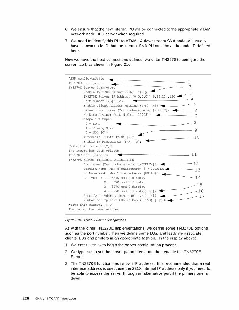
6. We ensure that the new internal PU will be connected to the appropriate VTAMnetwork node DLU server when required.
7. We need to identify this PU to VTAM. A downstream SNA node will usuallyhave its own node ID, but the internal SNA PU must have the node ID definedhere.
Now we have the host connections defined, we enter TN3270 to configure theserver itself, as shown in Figure 210.
Figure 210. TN3270 Server Configuration
As with the other TN3270E implementations, we define some TN3270E optionssuch as the port number, then we define some LUs, and lastly we associateclients, LUs and printers in an appropriate fashion. In the display above:
1. We enter tn3270e to begin the server configuration process.
2. We type set to set the server parameters, and then enable the TN3270EServer.
3. The TN3270E function has its own IP address. It is recommended that a realinterface address is used; use the 221X internal IP address only if you need tobe able to access the server through an alternative port if the primary one isdown.
APPN config>tn3270eTN3270E config>setTN3270E Server Parameters
Enable TN3270E Server (Y/N) [Y]? yTN3270E Server IP Address [0.0.0.0]? 9.24.104.120Port Number [23]? 123Enable Client Address Mapping (Y/N) [N]?Default Pool name (Max 8 characters) [PUBLIC]?NetDisp Advisor Port Number [10008]?Keepalive type:
0 = none,1 = Timing Mark,2 = NOP [0]?
Automatic Logoff (Y/N) [N]?Enable IP Precedence (Y/N) [N]?
Write this record? [Y]?The record has been written.TN3270E config>add imTN3270E Server Implicit Definitions
Pool name (Max 8 characters) [<DEFLT>]?Station name (Max 8 characters) []? SUBAREALU Name Mask (Max 5 characters) [@01LU]?LU Type ( 1 - 3270 mod 2 display
2 - 3270 mod 3 display3 - 3270 mod 4 display4 - 3270 mod 5 display) [1]?
Specify LU Address Ranges(s) (y/n) [N]?Number of Implicit LUs in Pool(1-253) [1]? 6
Write this record? [Y]?The record has been written.
12
345
67
8
9
10
11
12
13
14
15
1617
226 SNA and TCP/IP Integration
4. We change the TN3270E port number to 123 to avoid clashes with theline-mode Telnet server. We actually used Telnet to configure this particularmachine, a 2216. If you wish to define additional TN3270E ports, use the add
port command from the TN3270E prompt.
5. The default is not to filter IP clients. If you want to define filters, use the add
map command from the TN3270E prompt.
6. The default LU pool works the same way as in CS/NT. When you specify adefault pool here, you can change its name via the set command here withoutneeding to redefine all your implicit and explicit LUs.
7. The 221X can interoperate with a network dispatcher to provide loadbalancing over multiple TN3270E Servers. The advisor function is theprocess that communicates server status to the network dispatcher, and herewe can change the port number used by the advisor.
8. The sending of keepalive messages to the client is an option.
9. As with CS/2 and CS/NT, automatic termination of host sessions after a periodof inactivity can be defined.
10.The 221X allows you to set the priority on TN3270E packets by using theprecedence bits in the IP header.
11.When we have defined the basic TN3270E parameters, we must define somehost LUs for the clients to use. The simplest way is to define an implicit LUpool via the add im command.
12.We let the LUs we are about to define be in the default pool. The set processhas already given the pool a name of PUBLIC.
13.We must associate a host link (a PU, in other words) with these LUs. For thispool we choose the subarea connection previously defined in Figure 209 onpage 225. Our alternative would be the DLUR PU called WTR15282 that wasdefined in the same panel.
14.We give the pool of LUs some locally-known LU names.
15.These LUs are to be 24x80 display screens. The answer to this questionaffects what the 221X sends to VTAM as the device type for use by theself-defining dependent LU exit (ISTEXCSD). The device types sent are3270002 to 3270005 for displays and SCSP or 3270P for SCS or DSC printersrespectively.
16.We let the 221X decide what local (NAU) addresses to give the LUs. Bydefault it starts at 2 and goes upwards.
17.We define six LUs in the pool.
This is enough for a client to be able to connect to the subarea host, but we alsodefine some explicit LUs as in Figure 211 on page 228.
Telnet/3270 227
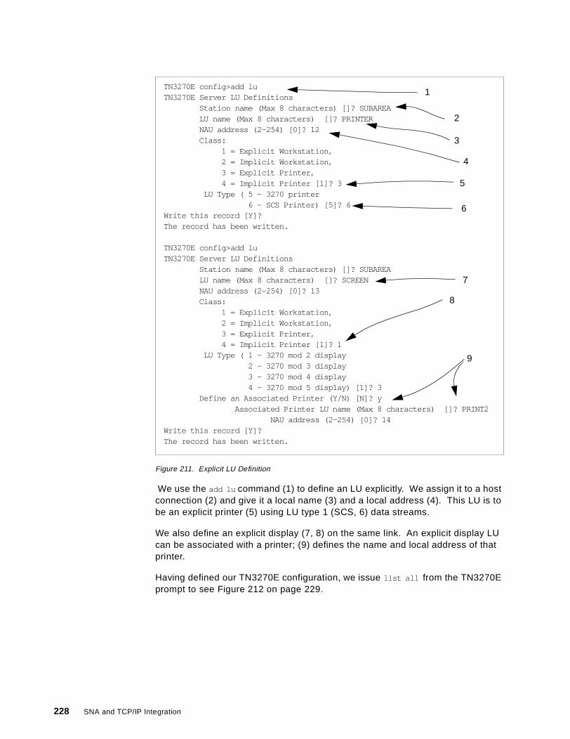
Figure 211. Explicit LU Definition
We use the add lu command (1) to define an LU explicitly. We assign it to a hostconnection (2) and give it a local name (3) and a local address (4). This LU is tobe an explicit printer (5) using LU type 1 (SCS, 6) data streams.
We also define an explicit display (7, 8) on the same link. An explicit display LUcan be associated with a printer; (9) defines the name and local address of thatprinter.
Having defined our TN3270E configuration, we issue list all from the TN3270Eprompt to see Figure 212 on page 229.
TN3270E config>add luTN3270E Server LU Definitions
Station name (Max 8 characters) []? SUBAREALU name (Max 8 characters) []? PRINTERNAU address (2-254) [0]? 12Class:
1 = Explicit Workstation,2 = Implicit Workstation,3 = Explicit Printer,4 = Implicit Printer [1]? 3
LU Type ( 5 - 3270 printer6 - SCS Printer) [5]? 6
Write this record [Y]?The record has been written.
TN3270E config>add luTN3270E Server LU Definitions
Station name (Max 8 characters) []? SUBAREALU name (Max 8 characters) []? SCREENNAU address (2-254) [0]? 13Class:
1 = Explicit Workstation,2 = Implicit Workstation,3 = Explicit Printer,4 = Implicit Printer [1]? 1
LU Type ( 1 - 3270 mod 2 display2 - 3270 mod 3 display3 - 3270 mod 4 display4 - 3270 mod 5 display) [1]? 3
Define an Associated Printer (Y/N) [N]? yAssociated Printer LU name (Max 8 characters) []? PRINT2
NAU address (2-254) [0]? 14Write this record [Y]?The record has been written.
1
2
3
4
5
6
7
8
9
228 SNA and TCP/IP Integration
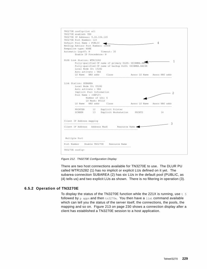
Figure 212. TN3270E Configuration Display
There are two host connections available for TN3270E to use. The DLUR PUcalled WTR15282 (1) has no implicit or explicit LUs defined on it yet. Thesubarea connection SUBAREA (2) has six LUs in the default pool (PUBLIC, as(4) tells us) and two explicit LUs as shown. There is no filtering in operation (3).
6.5.2 Operation of TN3270ETo display the status of the TN3270E function while the 221X is running, use t 5
followed by p appn and then tn3270e . You then have a list command availablewhich can tell you the status of the server itself, the connections, the pools, themapping and so on. Figure 213 on page 230 shows a connection display after aclient has established a TN3270E session to a host application.
TN3270E config>list allTN3270E enabled: YESTN3270E IP Address: 9.24.104.120TN3270E Port Number: 123Default Pool Name : PUBLICNetDisp Advisor Port Number: 10008Keepalive type: NONEAutomatic Logoff: N Timeout: 30
Enable IP Precedence: N
DLUS Link Station: WTR15282Fully-qualified CP name of primary DLUS: USIBMRA.RA28MFully-qualified CP name of backup DLUS: USIBMRA.RA03MLocal Node ID: 15282Auto activate : YESLU Name NAU addr Class Assoc LU Name Assoc NAU addr-----------------------------------------------------------------------
Link Station: SUBAREALocal Node ID: 05282Auto activate : YESImplicit Pool InformationPool Name : <DEFLT>
Number of LUs: 6LU Mask: @01LU
LU Name NAU addr Class Assoc LU Name Assoc NAU addr-----------------------------------------------------------------------PRINTER 12 Explicit PrinterSCREEN 13 Explicit Workstation PRINT2 14
Client IP Address mapping--------------------------Client IP Address Address Mask Resource Name------------------------------------------------------
Multiple Port------------------------------Port Number Enable TN3270E Resource Name-------------------------------------------------TN3270E config>
1
2
3
4
Telnet/3270 229
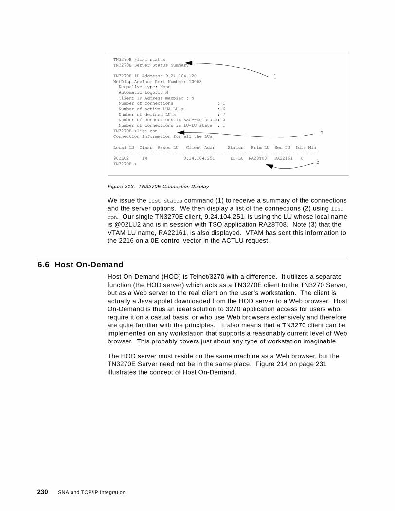
Figure 213. TN3270E Connection Display
We issue the list status command (1) to receive a summary of the connectionsand the server options. We then display a list of the connections (2) using list
con . Our single TN3270E client, 9.24.104.251, is using the LU whose local nameis @02LU2 and is in session with TSO application RA28T08. Note (3) that theVTAM LU name, RA22161, is also displayed. VTAM has sent this information tothe 2216 on a 0E control vector in the ACTLU request.
6.6 Host On-Demand
Host On-Demand (HOD) is Telnet/3270 with a difference. It utilizes a separatefunction (the HOD server) which acts as a TN3270E client to the TN3270 Server,but as a Web server to the real client on the user’s workstation. The client isactually a Java applet downloaded from the HOD server to a Web browser. HostOn-Demand is thus an ideal solution to 3270 application access for users whorequire it on a casual basis, or who use Web browsers extensively and thereforeare quite familiar with the principles. It also means that a TN3270 client can beimplemented on any workstation that supports a reasonably current level of Webbrowser. This probably covers just about any type of workstation imaginable.
The HOD server must reside on the same machine as a Web browser, but theTN3270E Server need not be in the same place. Figure 214 on page 231illustrates the concept of Host On-Demand.
TN3270E >list statusTN3270E Server Status Summary
TN3270E IP Address: 9.24.104.120NetDisp Advisor Port Number: 10008
Keepalive type: NoneAutomatic Logoff: NClient IP Address mapping : NNumber of connections : 1Number of active LUA LU's : 6Number of defined LU's : 7Number of connections in SSCP-LU state: 0Number of connections in LU-LU state : 1
TN3270E >list conConnection information for all the LUs
Local LU Class Assoc LU Client Addr Status Prim LU Sec LU Idle Min------------------------------------------------------------------------------@02LU2 IW 9.24.104.251 LU-LU RA28T08 RA22161 0TN3270E >
1
2
3
230 SNA and TCP/IP Integration
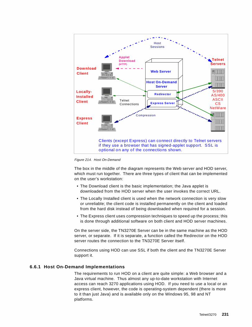
Figure 214. Host On-Demand
The box in the middle of the diagram represents the Web server and HOD server,which must run together. There are three types of client that can be implementedon the user’s workstation:
• The Download client is the basic implementation; the Java applet isdownloaded from the HOD server when the user invokes the correct URL.
• The Locally Installed client is used when the network connection is very slowor unreliable; the client code is installed permanently on the client and loadedfrom the hard disk instead of being downloaded when required for a session.
• The Express client uses compression techniques to speed up the process; thisis done through additional software on both client and HOD server machines.
On the server side, the TN3270E Server can be in the same machine as the HODserver, or separate. If it is separate, a function called the Redirector on the HODserver routes the connection to the TN3270E Server itself.
Connections using HOD can use SSL if both the client and the TN3270E Serversupport it.
6.6.1 Host On-Demand ImplementationsThe requirements to run HOD on a client are quite simple: a Web browser and aJava virtual machine. Thus almost any up-to-date workstation with Internetaccess can reach 3270 applications using HOD. If you need to use a local or anexpress client, however, the code is operating-system dependent (there is moreto it than just Java) and is available only on the Windows 95, 98 and NTplatforms.
Clients (except Express) can connect directly to Telnet serversif they use a bro wser that has signed-applet support. SSL iso ptional o n any o f the connectio ns shown.
TelnetServers
Dow nloadClient
Locally-InstalledClient
ExpressClient
AppletDownload(HTTP)
Host On-DemandServer
Web Server
Redirector
Express Server
S/390AS/400ASCII
CSNetWare
TelnetConnections
Compression
HostSessions
Telnet/3270 231
For full TN3270E support, Version 3 of the HOD server is required. This isimplemented on the following IBM platforms:
• OS/390 UNIX Systems Services• OS/400, Version 4 Release 2 or later• OS/2 Warp and Warp Server, Version 4 or later• AIX, Version 4 Release 2 or later• Sun Solaris• HP-UX• Windows NT, Version 4 with SP3 or later• Novell Netware, Version 4
The HOD server also requires Java, which comes with the HOD server code forWindows NT but is obtainable separately for the other platforms.
HOD server Version 3 supports the following major functions:
• TN3270, TN5250 and VT emulation as well as TN3270E• Session security through the Secure Sockets Layer (SSL) protocol• Server-based management of user configurations• Support for up to 26 concurrent sessions• Telnet redirection• LU and LU pool definition (explicit and implicit classes)• Support for attention and system request functions• 3270 host printing• Bookmarking of sessions in several ways• Macro record/play, with prompts and waits, just as PComm
6.7 Host Publisher
To the user with Web access and occasional requirements for 3270-basedapplications, HOD is an ideal solution except for one thing: the screenpresentation is that of a 3270 emulator, in other words a green screen with a rowof indicators on the bottom line and (most of the time) text-only presentation.Many Web users prefer their applications to provide scroll bars, check boxes, andlittle pictures by way of illustration; in other words a more natural GUI rather thanthe traditional 3270 interface.
Host Publisher addresses this requirement. In principle it works the same way asHOD except that it translates the 3270 data streams to Web-familiar presentationinstead of native 3270 presentation. The current Host Publisher technology ismore general than just 3270-to-Web-via-Java, and both the technology and theproducts which implement it are still under development. Therefore, we presentonly a brief summary of its operation.
The components of a Host Publisher server, which need not be together on thesame machine, are:
• A Web server, which talks to the client browser
• A component which recognizes certain strings in the URL and directs requeststo a page server
• Page servers, which deliver the Web-friendly pages to the Web server
• Integration components, which connect the page servers to the applicationsacting as the true servers (in our case, 3270 applications)
232 SNA and TCP/IP Integration

We expect to see a new generation of Host Publisher implementations later in1999.
Telnet/3270 233

234 SNA and TCP/IP Integration

Appendix A. Special Notices
This publication is intended to help networking profesionals understand andimplement the various ways of integrating SNA and TCP/IP communication. Theinformation in this publication is not intended as the specification of anyprogramming interfaces that are provided by the eNetwork CommunicationsServer family of products. See the PUBLICATIONS section of the IBMProgramming Announcement for those products for more information about whatpublications are considered to be product documentation.
References in this publication to IBM products, programs or services do not implythat IBM intends to make these available in all countries in which IBM operates.Any reference to an IBM product, program, or service is not intended to state orimply that only IBM's product, program, or service may be used. Any functionallyequivalent program that does not infringe any of IBM's intellectual property rightsmay be used instead of the IBM product, program or service.
Information in this book was developed in conjunction with use of the equipmentspecified, and is limited in application to those specific hardware and softwareproducts and levels.
IBM may have patents or pending patent applications covering subject matter inthis document. The furnishing of this document does not give you any license tothese patents. You can send license inquiries, in writing, to the IBM Director ofLicensing, IBM Corporation, 500 Columbus Avenue, Thornwood, NY 10594 USA.
Licensees of this program who wish to have information about it for the purposeof enabling: (i) the exchange of information between independently createdprograms and other programs (including this one) and (ii) the mutual use of theinformation which has been exchanged, should contact IBM Corporation, Dept.600A, Mail Drop 1329, Somers, NY 10589 USA.
Such information may be available, subject to appropriate terms and conditions,including in some cases, payment of a fee.
The information contained in this document has not been submitted to any formalIBM test and is distributed AS IS. The information about non-IBM ("vendor")products in this manual has been supplied by the vendor and IBM assumes noresponsibility for its accuracy or completeness. The use of this information or theimplementation of any of these techniques is a customer responsibility anddepends on the customer's ability to evaluate and integrate them into thecustomer's operational environment. While each item may have been reviewedby IBM for accuracy in a specific situation, there is no guarantee that the same orsimilar results will be obtained elsewhere. Customers attempting to adapt thesetechniques to their own environments do so at their own risk.
Any pointers in this publication to external Web sites are provided forconvenience only and do not in any manner serve as an endorsement of theseWeb sites.
Any performance data contained in this document was determined in a controlledenvironment, and therefore, the results that may be obtained in other operatingenvironments may vary significantly. Users of this document should verify theapplicable data for their specific environment.
© Copyright IBM Corp. 1999 235

Reference to PTF numbers that have not been released through the normaldistribution process does not imply general availability. The purpose of includingthese reference numbers is to alert IBM customers to specific information relativeto the implementation of the PTF when it becomes available to each customeraccording to the normal IBM PTF distribution process.
The following terms are trademarks of the International Business MachinesCorporation in the United States and/or other countries:
The following terms are trademarks of other companies:
C-bus is a trademark of Corollary, Inc.
Java and HotJava are trademarks of Sun Microsystems, Incorporated.
Microsoft, Windows, Windows NT, and the Windows 95 logo are trademarksor registered trademarks of Microsoft Corporation.
PC Direct is a trademark of Ziff Communications Company and is usedby IBM Corporation under license.
Pentium, MMX, ProShare, LANDesk, and ActionMedia are trademarks orregistered trademarks of Intel Corporation in the U.S. and othercountries.
UNIX is a registered trademark in the United States and othercountries licensed exclusively through X/Open Company Limited.
Other company, product, and service names may be trademarks orservice marks of others.
ACF/VTAM Advanced Peer-to-Peer NetworkingAIX AnyNetAPPN CICSDB2 ESCONIBM OpenEditionOS/2 OS/390OS/400 Parallel SysplexRACF SecureWaySystem/390 VTAM
236 SNA and TCP/IP Integration
Appendix B. Related Publications
The publications listed in this section are considered particularly suitable for amore detailed discussion of the topics covered in this redbook. Note that,whereas current versions of Communications Server publications use the brandname eNetwork, future ones will use the name SecureWay. We have usedeNetwork throughout this appendix to reflect the current set of publications.
B.1 International Technical Support Organization Publications
For information on ordering these ITSO publications see “How to Get ITSORedbooks” on page 239.
• 3746, 2210, 2216, and 2220 Interconnectivity: Frame Relay and RelatedFunctions, SG24-2146
• IBM 2210 Nways Multiprotocol Router and IBM 2216 Nways MultiaccessConnector Description and Configuration Scenarios - Volume II, SG24-4956
• IBM 2210 Nways Multiprotocol Router Description and ConfigurationScenarios, Volume I, SG24-4446
• MSS Release 2.1, Including the MSS Client and Domain Client, SG24-5231
• 3746 Nways Controller Models 900 and 950: Multiaccess Enclosure Primer,SG24-5238
• IBM 2216/Network Utility Host Channel Connections, SG24-5303
• Converging TCP/IP and SNA Networks: Web Access over SNA, SG24-2101
• OS/390 eNetwork Communications Server TCP/IP Implementation GuideVolume 1: Configuration and Routing, SG24-5227
• IBM Communications Server for Windows NT Version 5.0, SG24-2099
• IBM eNetwork Communications Server for Windows NT Version 6.0Enhancements, SG24-5232
• IBM Communications Server for OS/2 Warp Version 4.0 Enhancements,SG24-4587
• IBM Communications Server for OS/2 Warp Version 4.1 Enhancements,SG24-4916
• IBM eNetwork Communications Server for OS/2 Warp Version 5.0Enhancements, SG24-2147
• IBM Network Utility Description and Configuration Scenarios, SG24-5289
• Subarea to APPN Migration: HPR and DLUR Implementation, SG24-5204
• Inside APPN - The Essential Guide to the Next-Generation SNA, SG24-3669
• TCP/IP Tutorial and Technical Overview, GG24-3376
• AnyNet: SNA over TCP/IP Installation and Interoperability, GG24-4395 (nosoftcopy available)
© Copyright IBM Corp. 1999 237
B.2 Redbooks on CD-ROMs
Redbooks are also available on CD-ROMs. Order a subscription and receiveupdates 2-4 times a year.
B.3 Other Publications
These publications are also relevant as further information sources:
• 6611 Network Processor Introduction and Planning Guide, Version 1 Release4, GK2T-0334
• Multiprotocol Transport Networking (MPTN) Architecture: Technical Overview,GC31-7073
• Multiprotocol Transport Networking (MPTN) Architecture: Formats,GC31-7074
• OS/390 eNetwork Communications Server IP Configuration, SC31-8513
• OS/390 eNetwork Communications Server SNA Resource DefinitionReference, SC31-8565
• OS/390 eNetwork Communications Server SNA Network ImplementationGuide, SC31-8563
• OS/390 eNetwork Communications Server AnyNet: Guide to SNA over IP,SC31-8578 (available in softcopy only, on CD-ROM SK2T-6012)
• OS/390 eNetwork Communications Server AnyNet: Guide to Sockets overSNA, SC31-8577 (available in softcopy only, on CD-ROM SK2T-6012)
CD-ROM Title SubscriptionNumber
Collection KitNumber
System/390 Redbooks Collection SBOF-7201 SK2T-2177Networking and Systems Management Redbooks Collection SBOF-7370 SK2T-6022Transaction Processing and Data Management Redbook SBOF-7240 SK2T-8038Lotus Redbooks Collection SBOF-6899 SK2T-8039Tivoli Redbooks Collection SBOF-6898 SK2T-8044AS/400 Redbooks Collection SBOF-7270 SK2T-2849RS/6000 Redbooks Collection (HTML, BkMgr) SBOF-7230 SK2T-8040RS/6000 Redbooks Collection (PostScript) SBOF-7205 SK2T-8041RS/6000 Redbooks Collection (PDF Format) SBOF-8700 SK2T-8043Application Development Redbooks Collection SBOF-7290 SK2T-8037
238 SNA and TCP/IP Integration
How to Get ITSO Redbooks
This section explains how both customers and IBM employees can find out about ITSO redbooks, redpieces, andCD-ROMs. A form for ordering books and CD-ROMs by fax or e-mail is also provided.
• Redbooks Web Site http://www.redbooks.ibm.com/
Search for, view, download or order hardcopy/CD-ROM redbooks from the redbooks web site. Also readredpieces and download additional materials (code samples or diskette/CD-ROM images) from this redbookssite.
Redpieces are redbooks in progress; not all redbooks become redpieces and sometimes just a few chapters willbe published this way. The intent is to get the information out much quicker than the formal publishing processallows.
• E-mail Orders
Send orders via e-mail including information from the redbooks fax order form to:
• Telephone Orders
• Fax Orders
This information was current at the time of publication, but is continually subject to change. The latest information forcustomer may be found at http://www.redbooks.ibm.com/ and for IBM employees at http://w3.itso.ibm.com/ .
In United StatesOutside North America
e-mail [email protected] information is in the “How to Order” section at this site:http://www.elink.ibmlink.ibm.com/pbl/pbl/
United States (toll free)Canada (toll free)Outside North America
1-800-879-27551-800-IBM-4YOUCountry coordinator phone number is in the “How to Order” section atthis site:http://www.elink.ibmlink.ibm.com/pbl/pbl/
United States (toll free)CanadaOutside North America
1-800-445-92691-403-267-4455Fax phone number is in the “How to Order” section at this site:http://www.elink.ibmlink.ibm.com/pbl/pbl/
IBM employees may register for information on workshops, residencies, and redbooks by accessing the IBMIntranet Web site at http://w3.itso.ibm.com / and clicking the ITSO Mailing List button. Look in the Materialsrepository for workshops, presentations, papers, and Web pages developed and written by the ITSO technicalprofessionals; click the Additional Materials button. Employees may also view redbook. residency, and workshopannouncements at http://inews.ibm.com /.
IBM Intranet for Employees
© Copyright IBM Corp. 1999 239

IBM Redbook Fax Order FormPlease send me the following:
We accept American Express, Diners, Eurocard, Master Card, and Visa. Payment by credit card notavailable in all countries. Signature mandatory for credit card payment.
Title Order Number Quantity
First name Last name
Company
Address
City Postal code
Telephone number Telefax number VAT number
Invoice to customer number
Country
Credit card number
Credit card expiration date SignatureCard issued to
240 SNA and TCP/IP Integration

List of Abbreviations
ACB Access method Control Block
AIX Advanced InteractiveeXecutive
ANR Automatic Network Routing
ANSI American National StandardsInstitute
APAR Authorized Program AnalysisReport
API Application Program Interface
APPC AdvancedProgram-to-ProgramCommunication
APPN Advanced Peer-to-PeerNetworking
ARB Adaptive Rate-Based
ASCII American Standard Code forInformation Interchange
ATM Asynchronous Transfer Mode
BTU Basic Transmission Unit
CCU Central Control Unit
CDRSC Cross-Domain ReSourCe
CICS Customer Information ControlSystem
CNOS Change Number Of Sessions
COS Class Of Service
CP Control Point
CPI-C Common ProgrammingInterface for Communications
CRC Cyclic Redundancy Check
CS for OS/390 SecureWay CommunicationsServer for OS/390
CS/2 SecureWay CommunicationsServer for OS/2
CS/NT SecureWay CommunicationsServer for Windows NT
CTS Common TransportSemantics
DCE Data Circuit-terminatingEquipment
DLC Data Link Control
DLSw Data Link Switching
DLUR Dependent LU Requester
DLUR/S Dependent LURequester/Server
© Copyright IBM Corp. 1999
DLUS Dependent LU Server
DM Disconnected Mode
DNS Domain Name Server
DSAP Destination Service AccessPoint
DSC Display Screen Compatibility
DTE Data Terminal Equipment
EBCDIC Extended Binary CodedDecimal Interchange Code
EMIF ESCON Multiple ImageFacility
EN End Node
ESCON Enterprise SystemsCONnection
FDDI Fiber Distributed DataInterface
FID Format Identification
GUI Graphical User Interface
HOD Host On-Demand
HPR High-Performance Routing
IANA Internet Assigned NumberAuthority
IBM International BusinessMachines Corporation
IC-TG Interchange TransmissionGroup
ICMP Internet Control MessageProtocol
ICP Interconnect ControllerProgram
IEEE Institute of Electrical andElectronics Engineers
INN Intermediate Network Node
IOCP Input/Output ConfigurationProgram
IP Internet Protocol
IPX Internetwork PacketeXchange
ISDN Integrated-Services DigitalNetwork
ISPF Interactive SystemProductivity Facility
ISR Intermediate Session Routing
241
ITSO International TechnicalSupport Organization
JCL Job Control Language
LAN Local Area Network
LDLC Logical Data Link Control
LEN Low Entry Networking
LLC Logical Link Control
LPAR Logical PARtition
LSA Link Services Architecture
LU Logical Unit
LUA Logical Unit Application
MAC Medium Access Control
MAE MultiAccess Enclosure
MNPS Multinode Persistent Sessions
MPC MultiPath Channel
MPTN MultiProtocol TransportNetworking
MPTS MultiProtocol TransportServices
MSS Multiprotocol SwitchedServices
MVS Multiple Virtual Storage
NAU Network Accessible Unit
NCP Network Control Program
NLP Network Layer Packet
NN Network Node
NRZ Non-Return-to-Zero
NRZI Non-Return-to-Zero Inverted
NVT Network Virtual Terminal
OS/2 Operating System/2
OS/390 Operating System/390
OS/400 Operating System/400
OSA Open Systems Adapter
OSI Open SystemsInterconnection
OSPF Open Shortest Path First
PC Personal Computer
PComm Personal Communications
PFS Physical File System
PPP Point-to-Point Protocol
PU Physical Unit
PVC Permanent Virtual Circuit
QLLC Qualified Logical Link Control
RACF Resource Access ControlFacility
RFC Request For Comments
RIP Routing Information Protocol
RNR Request Not Ready
RR Request Ready
RSCV Route Selection ControlVector
RTP Rapid Transport Protocol
SABME Set Asynchronous BalancedMode Extended
SAP Service Access Point
SCS SNA Character String
SDLC Synchronous Data LinkControl
SME Session Management Exit
SNA Systems Network Architecture
SNI SNA Network Interconnect
SNMP Simple Network ManagementProtocol
SNRM Set Normal Response Mode
SSCP System Services ControlPoint
SSL Secure Sockets Layer
SVC Switched Virtual Circuit
TCID Transport ConnectionIdentifier
TCP Transmission Control Protocol
TG Transmission Group
TN3270 Telnet/3270
TN3270E Telnet/3270 Extended
TN5250 Telnet/5250
TRL Transport Resource List
TRLE Transport Resource ListElement
TSO Time Sharing Option
UDP User Datagram Protocol
UI Unnumbered Information
URL Uniform Resource Locator
USS Unformatted System Services
VIPA Virtual Internet ProtocolAddress(ing)
VR-TG Virtual Route-basedTransmission Group
242 SNA and TCP/IP Integration

VTAM Virtual TelecommunicationsAccess Method
WAN Wide Area Network
WLM Workload Manager
XCA eXternal CommunicationsAdapter
XCF Cross-System CouplingFacility
XID eXchange IDentifier
243

244 SNA and TCP/IP Integration

Index
Numerics221X routers
commands 170configuration display 63, 179, 181configuration for APPN 225configuration for bridging 176, 181, 188, 190configuration for DLSw 169, 177, 182, 188, 191, 197configuration for IP 174, 181, 187, 196configuration for OSPF 175, 187configuration for PPP and token-ring 186configuration for SDLC 180, 195configuration for SDLC port 173DLSw 163DLSw status display 183, 184, 192, 193, 198Enterprise Extender configuration 59MPC configuration 56MPC connection 52TN3270E configuration 224, 226TN3270E configuration display 229TN3270E status display 230
AANR 21, 22AnyNet 5, 8
product implementations 12SNA over IP 5, 12, 129Sockets over SNA 5, 12, 69
APING 155ARB flow control 25, 30asynchronous transfer mode 2, 4ATM 2, 4automatic network routing 21, 22
CCANUREACH 168common INET 72, 132Common Transport Semantics 10control flows over RTP 22CS/2
configuration 88configuration for SNA over IP 137, 155, 157, 161configuration for TN3270E 211DLUR and SNA over IP 159SNA over IP 136Sockets over SNA 88, 113Sockets over SNA gateway 97TN3270E displays 215TN3270E Server 211
CS/NTconfiguration 63, 77, 86configuration for Enterprise Extender 39configuration for TN3270E 217displays 50, 67, 85, 111, 126SNA over IP 142Sockets over SNA 77, 110, 116TN3270E display 222
© Copyright IBM Corp. 1999
TN3270E Server 216
Ddata link switching see DLSwDLSw 5, 7
221X routers 168and HPR 167circuit 165, 167configuration 177, 182, 188, 191, 197configuration of 221X 169connection establishment 168description 163local 6, 163on Ethernet 185on frame relay 193on SDLC port 171on token-ring port 171over PPP 171remote 6, 163spoofing 164TCP port 167virtual ring 166
EeNetwork Communications Server 13Enterprise Extender 5, 13
221X configuration 59221X routers 33, 57and TN3270E 201benefits 19connection network 28, 32CS for OS/390 30, 52, 57CS/NT 33, 39description 25, 27HPR only 27IP precedence bits 28parallel TGs 38path switch 66port numbers 27product implementations 15, 30restriction with subarea connections 28transmission priority 28UDP port usage 28use of SAPs 38
ENVVAR data set 74
Fframe relay 2
HHost On-Demand 5, 16
description 230product implementations 231
Host Publisher 232HPR
245

and DLSw 167error recovery 24flow control 25overview 21path switch 24restriction with adjacent subarea connection 29SAP 167
IICANREACH 168IOCP definitions for MPC 53IPCAMPUS TG profile 32IPWAN TG profile 32IUTSAMEH 31, 37
LLDLC 27link layer integration 3
MMPTN 8
access node 9address mapping 8function compensation 8gateway 10transport gateway 8
multiplexing 1MVS TCP/IP definitions
Enterprise Extender 35, 55TN3270E 204, 205
MVS TCP/IP displaysTN3270E Server 208, 209
Nnetstat command 107, 115, 158network dispatcher 201, 227network layer integration 3network virtual terminal 199NLP 21, 23
Oonetstat command 107OPING 72, 76OSPF 175, 178, 187
PParallel Sysplex 14physical file system 72, 73PING 72, 76, 115point-to-point protocol 2, 171, 185
RResponsive Mode ARB 30RFC 1034 131RFC 1041 199RFC 1294 2
RFC 1434 163RFC 1483 2RFC 1490 2RFC 1576 199RFC 1646 199RFC 1755 163RFC 2166 163RFC 2427 2RFC 854 199RFC 855 199RSCV 24RTP 21, 23
SSABME 165Samehost interface 37SAP 164, 167, 178Secure Sockets Layer 202, 216, 232SNA over IP
address mapping 130, 135, 149CS for OS/390 131, 148, 151, 156CS/2 136, 154, 156, 157CS/2 configuration 137CS/2 definitions 155CS/NT 142CS/NT definitions 143dependent LU support 129, 136dependent LUs 134, 145, 158description 130DLUR 158DNS lookup 131dual gateways 152gateway 151, 156IP domain 132, 139, 145, 155low entry networking 129product implementations 129routes 142, 145, 155TCP port 130UDP port 130VTAM definitions 132, 135, 148, 152VTAM display 150VTAM display with DLUR 162
sna0 69, 81, 95, 104SNACKETS 74SNRM 178Sockets over SNA
address mapping 70, 83, 95, 104backup in CS/2 99CS for OS/390 71, 101CS/2 88CS/2 gateway 120CS/NT 77, 109CS/NT gateway 116dual gateways 120, 123gateway 97, 123gateway configuration 86ISTSKIFC 73, 74, 104ISTSKMAP 73, 74, 104ISTSKNST 107ISTSKRTE 73
246 SNA and TCP/IP Integration

JCL for OS/390 103load balancing in CS/2 99mapping algorithm 70modes 74, 84, 96MVS application support 71OS/390 definitions 74product implementations 69routes 84, 87, 98, 118, 121sessions 71, 112, 114UNIX Systems Services definitions 102VTAM definitions 74, 103VTAM display 77Windows NT adapter configuration 82
source VIPA 31, 36
TTCP 26TCP/IP
addresses 25datagram 25datagrams 26host 25introduction 25IP precedence 25port 27
Telnet/3270 4, 5, 15and Enterprise Extender 202description 199enhancements (TN3270E) 200options 199TN3270E product implementations 201
TEST frame 165, 167TN3270E 15, 200, 232
221X configuration 224221X routers 223address mapping 202, 207and workload manager 203, 204CS for OS/390 202CS/2 configuration 211CS/NT 216CS/NT configuration 217CS/NT display 222IP filtering 207, 216, 220, 224load balancing 216MVS TCP/IP definitions 204, 205server implementations 16, 201server positioning 201subarea connections 224TCP port 215, 227VTAM definitions 203
TN5250 199, 232
UUDP 26UNIX Systems Services 73, 75, 102, 132UNIX Systems Services API 71
VVIPA 25, 31, 34, 36, 46, 62virtual ring 178VTAM definitions
2216 MPC 52Enterprise Extender 31, 37, 58SNA over IP 132, 135, 148, 159Sockets over SNA 74, 103TN3270E 203
VTAM displaysDLUR with SNA over IP 162Enterprise Extender 50, 65RTP pipe for Enterprise Extender 66SNA over IP 150, 154Sockets over SNA 77, 105TN3270E Server 209, 210
VTAM start optionsHPR 37IPADDR 31NETID 37NODETYPE 37SSCPNAME 37TCPNAME 30
XX.25 2XID frame 165, 167, 185
247

248 SNA and TCP/IP Integration

© Copyright IBM Corp. 1999 249
ITSO Redbook Evaluation
SNA and TCP/IP IntegrationSG24-5291-00
Your feedback is very important to help us maintain the quality of ITSO redbooks. Please complete thisquestionnaire and return it using one of the following methods:
• Use the online evaluation form found at http://www.redbooks.ibm.com• Fax this form to: USA International Access Code + 1 914 432 8264• Send your comments in an Internet note to [email protected]
Which of the following best describes you?_ Customer _ Business Partner _ Solution Developer _ IBM employee_ None of the above
Please rate your overall satisfaction with this book using the scale:(1 = very good, 2 = good, 3 = average, 4 = poor, 5 = very poor)
Overall Satisfaction __________
Please answer the following questions:
Was this redbook published in time for your needs? Yes___ No___
If no, please explain:
What other redbooks would you like to see published?
Comments/Suggestions: (THANK YOU FOR YOUR FEEDBACK!)

SG24-5291-00
Printed in the U.S.A.
SN
Aand
TC
P/IP
IntegrationS
G2
4-5
29
1-0
0