Embed Size (px)
Citation preview
3rd International Engineering Conference (IEC 2019)
Federal University of Technology, Minna, Nigeria
Smart Protection of Vehicle using Multifactor Authentication (MFA)
Technique *S. Aliyu, Umar Abdullahi, Majeedat Pomam, Mustapha Hafiz, Adeiza Sanusi , and Sodiq Akanmu
Department of Telecommunication Engineering, Federal University of Technology , PMB 65 Minna
Niger State, Nigeria
*Corresponding author email: [email protected], +2347039335074
ABSTRACT
In typical third world country like Nigeria, the incessant increase in car theft has called for provision of an
immediate solution. Occurrence of car theft is not limited to public places such as market, and bank arena, several
car thefts have occurred on gun-point. There is no doubt that modern cars have some level of pre-installed anti-
theft device by the manufacturers, however, poor user authentication has led to its inability to solve the problem
of car theft. Therefore, this paper proposed a multiple factor authentication approach to provide reliable car user
authentication. The proposed approach is capable of preventing unauthorized user from accessing the car, thus
securing the it from theft. Traditional approach of unlocking/locking cars involve the use of two buttons, one for
locking and the other for unlocking. This approach lacks user authentication, consequently, it is prone to
unauthorized access. To solve this problem, a password authentication approach was introduced. After unlocking
the car, user biometric, fingerprint, is required as a second means of authentication before the car ignition can be
activated. In the event of theft, a user authentication request pops up at a random time to authenticate the current
user. In the absence of genuine user, the car is deactivated and an SMS containing the current car location is sent
to the genuine user as well as security personnel. This is made possible through the use of GSM/GPS
communication module. The proposed system herewith is simple to use and can be used by any model of vehicle
and it is very reliable and efficient.
Keywords: Biometric; Fingerprint; GPS; GSM; Atmega16 Microcontroller; Multifactor Authentication .
INTRODUCTION
Vehicles (automobiles generally) are stolen everyday
yet people keep purchasing them; this is so because they
serve as means of easily transporting oneself from one
place to the other. In Nigeria today, vehicle theft has
become so ubiquitous such that car owners are conscious
of where and how they park their cars. Car theft is an illegal
act of possessing vehicles. In consensus with the National
Insurance Crime Bureau (NICB), Nationwide in 2010, one
million, two hundred thousand motor vehicle thefts were
estimated, i.e. about 416.7 cars were stolen per 100,000
residents (All, Ijeh-Ogbo, & Gbadamosi, 2005; Modi &
Sukhadia, 2017).
The alarming rate at which vehicles are stolen has
brought about the need for vehicle anti-theft systems –
which are systems designated to thwart the illegal
possession of valuable items such as automobiles. Anti-
theft systems have been in existence since stealing became
human’s source of livelihood. However, most previously
proposed systems fell short of proper user authentication,
therefore, the proposed system has been designed such that
vehicle driver can be well authenticated, and can easily be
shut down and tracked in the event of theft. To achieve user
or driver authentication, it was designed with a multi-level
authentication; failure to provide an appropriate means of
identification at either level restrains the user from gaining
complete access into the vehicle.
RELATED WORKS
Several systems have been proposed in the literature for
car security. Xiao & Feng, (2009), proposed a low-cost
extendable framework for embedded smart vehicle security
system. It consists of a FDS, a GPS module, a GSM module
and a control platform. The FDS is based on Adaboost
algorithm which can detect people’s faces in the vehicle
when nobody ought to be in the car, and either alarms
loudly or soundlessly. Other modules aid in the
transmission of the important data to car owners and, it
helps to watch guard vehicles at all the time, even when the
car is lost. Alarm is sent to the control center of the system
whenever intrusion is detected. Whenever the vehicle is on
silent mode, no alarm is made, but some modules function
to inform the owner and law enforcement agency about the
exact location of the car. This system is not expensive,
efficient and can be used to track vehicles.
Hasan et al., (2009), presented an arrangement that
permits an owner to remotely locate the vehicle. The
present position of the car is read by the system using the
GPS while it sends data through GPRS (General Packet
Radio Service) service to a web server utilizing the POST
mechanism of the HTTP protocol. The vehicle’s location is
then stored in the database for live and previous tracking.
701
3rd International Engineering Conference (IEC 2019)
Federal University of Technology, Minna, Nigeria
It is useful for the parents to watch over their children’s
safety, but it lacks unauthorized access denial and it
requires one to log into the website before tracking can be
done.
Hameed et al., (2010), presented a vehicle monitoring
and tracking system with an enhancement in mobility and
database facilities. This system can send SMS and MMS to
an authorized user for speedy response most especially if
the car is in close range. The images of the unauthorized
users are transmitted to the user and/or police through local
GSM/GPRS service provider. Whenever there is a hijack,
local security agent and owner can track down the car using
GPS which can be linked to Google Earth Map for ease of
location. The system makes use of microcontroller, GPRS
modem, and a PC. This system is cost-effective, has a real
life application, but it cannot prevent unauthorized access
into the car.
Wankhade & Dahad, (2011), proposed a system that
deals with the design and development of a theft control
system for an automobile, used to prevent vehicle theft. The
system makes use of an embedded system based on GSM
technology. A cell phone is interfaced with the
microcontroller, which in turn, is connected to the engine.
Information in the form of SMS is sent to the central
insurance system. The microcontroller unit reads the SMS
and, using the triangulation method, it extracts the exact
location (latitude and longitude) of the vehicle and sends it
to the user’s mobile. STATUS can be sent to the GSM
module by the user. This module verifies the authenticity
of the message before replying with an SMS that contains
the location (latitude and longitude) the vehicle. This
system lacks the ability to prevent unauthorized persons
from getting into the car.
Rashidi, Ariff, & Ibrahim, (2011), proposed a car
monitoring system using Bluetooth. Once an alarm is
triggered, a message is transmitted to the owner’s phone via
Bluetooth informing him/her of an intrusion. A PIR sensor
is used to monitor movements around the car. Alert
messages are sent to the user, if the microcontroller keeps
on receiving signal from the PIR sensor for seven minutes.
This system is restrained to the distance covered by the
Bluetooth; however, the owner can only receive alerts if
within the range of the Bluetooth.
Almomani, Alkhalil, Ahmad, & Jodeh, (2011),
developed a GPS car tracking and management system
which is aimed at making vehicle tracking easier and
available for any user and fleet companies. It provides
mobile software that enables ubiquitous tracking services
and web-based tracking software. It enables users to
remotely track and control the speed of their vehicles. It
makes use of GPS tracker, a GSM modem and a PC.
Bagavathy, Dhaya, & Devakumar, (2011), proposed an
emergency response system for smart cars to prevent theft
using ARM (Advanced RISC Machine) processor. This
system has an FDS which detects the face of the person
trying to gain access into the vehicle during the time
nobody should be in the car. FDS obtains images in a tiny
digital camera. Principal Component Algorithm (PCA) –
Linear Discriminant Analysis (LDA) is used to provide the
face authentication in the security system. A camera
module is used for downloading images from the system. It
recognizes the input after the image has been captured. The
result is processed as a character signal (authentic or not).
The microcontroller executes some actions based on the
result of the character signal. Though this system can deny
access to unauthorized users, it cannot be used to track
vehicles.
Kamble, (2012), wrote a paper on a smart vehicle
tracking system. The proposed system is a tracking system
useful in the determination of the geographical location of
a vehicle. Also, it can be used to transmit the information
remotely to a server. The system incorporates the use of
GPS, GSM and microcontroller to achieve the predefined
goals. To find the location of the vehicle, a user request is
sent to the number at the modem, which instantly replies to
that mobile showing the vehicle’s position. The proposed
system is limited to vehicle tracking only, i.e. it cannot
deny access to unauthorized users.
Sehgal, Singhal, Mangla, Singh, & Kulshrestha, (2012),
proposed an embedded interface for GSM based car
security system. It makes use of an 8-bits AT89S52
interfaced with a GSM module. Its control mechanism is
based on Dual Tone Multi-access Frequency tones
generated when the number keys are pressed. The system
has real life application and it is marketable due to its cost-
effectiveness, but it cannot be used to track vehicles in
event of theft.
Padmapriya & Kalajames, (2012), developed a real
time smart car lock security system using an improved face
detection and recognition technique based on skin color
information. The face is detected by Adaboost algorithm;
in addition, it employs the use of PCA algorithm to
recognize a specific face which compares the faces in the
database with the newly captured ones. A webcam is placed
in the car door, which records video frames. When an
unauthorized user tries to open the door, the owner is
alerted, else, the door will open and access will be gained
into the car. This system is efficient, cost-effective and can
be utilized for tracking vehicles using GPS. However, the
technique used for authentication is quite slow.
Khan & Mishra, (2012), described a system that can
provide tele-monitoring system for commercial vehicles. It
comprises of GPS, GSM and an AMR microcontroller. If a
password-like SMS is received from the owner, the vehicle
is stopped automatically. This system is applicable in
traffic surveillance. It can be used to remotely monitor a
vehicle but, it does not prevent unauthorized access. The
components used are; GPS, GSM, satellite and ARM
LPC2138 microcontroller.
Katta & Sudharsan, (2012), introduced an integrated
system to provide and assist the travelers, transport courier
companies, cars, and bike users obtain a real-time dynamic
vehicle tracking and traveled route information with the
time stamps. It is an integration of Geographical
702
3rd International Engineering Conference (IEC 2019)
Federal University of Technology, Minna, Nigeria
Information and Communication Technology (Geo-ICT)
and Sensor Network (SN) was used to develop a real time
monitoring system and take necessary decision in delivery
of information. It gathers information automatically using
sensors, and transmitting through Xbee enabled devices
and GPS for locating vehicles.
Ramani et al., (2013), made use of GPS and GSM
technology for a tracking and locking systems. The
components used includes; GSM, GPS, and a
microcontroller. The system was designed in two modes:
sleep mode when the owner is the operator and active mode
when there is an intruder, where the IR sensor senses the
signals and SMS is sent to the microcontroller. The
controller sends signals containing the vehicle’s location.
Depending on the command received, the vehicle’s speed
is gradually decreased and finally come to a stop. In
addition, all the doors are locked. To open the door or
restart the engine, authorized person needs to enter the
passwords. With this system, vehicles can be easily tracked
without the escape of the criminal, but it can only detect
intrusion if there is an interruption in any door of the car.
Pethakar, Srivastava, & Suryawanshi, (2013),
developed a GPS and GSM based vehicle tracking and
worker security system, which enables a company to track
the vehicle’s location. The system utilizes GPS, GSM,
RFID and a microcontroller. The proposed system consists
of three units – the vehicle unit, emergency button and
company unit. The vehicle unit is placed inside the car.
Whenever the car picks up the worker, he/she needs to
swipe the RF card number, with its database records; it
sends the worker’s id, cab id and the cab position co-
ordinates to the company unit via GSM module. The
emergency button is a part of the vehicle unit; there are
three to four emergency buttons in the car. These buttons
are placed such that workers can easily access them. If
worker finds himself/herself in a problem, he/she will press
the button; microcontroller will detect the action and send
a signal to the GSM which will communicate with the
company unit and police. Microcontroller will also send a
signal to the relay which turns off the vehicle ignition and
stops the vehicle. Company unit consist of GSM modem,
RS232 cable and computer. The GSM modem will receive
the message through the GSM. This message will be
transferred to the computer through the serial port. The
worker name, id and cab position coordinates get displayed
on the computer. Its use is limited to the use of the RF
cards.
Kotte & Yanamadala, (2013), described a tracking
system capable of continuous monitoring a vehicle on PC
via Google Earth Application. The main components used
in constructing this system is; GPS, GSM and MCU; it
comprises of two major design units which includes: In-
vehicle unit (the core part, installed in the vehicle) and the
tracking monitoring station. All the information sent by the
in-vehicle unit is stored in the database, maintained by the
tracking server. The in-vehicle unit has a tracking server
which it uses to transmit the vehicle’s location to its owner.
It is not cost-effective and it is mainly proposed for tracking
vehicles.
Verma & Bhatia, (2013), described a monitoring
system that informs the owner of the location and the route
traveled by the vehicle. It has a web application that
provides the user with the exact vehicle’s location. This
system comprises of GPS, GSM, AT mega microcontroller
MAX232, 16x2 LCD and software interfaced with all the
required modules and a web application. The GPS module
is used for getting the co-ordinates of the vehicle while the
GSM module is used for transmitting received data. The
microcontroller is the central unit which controls every
other component of the system; the LCD is used to display
location of vehicle. This system can calculate the distance
traveled by the vehicle, however, monitoring is via internet.
Oladimeji, Oshevire, Omitola, & Adedokun, (2013),
described a system that can be used to proffer a lasting
solution to the endemic act of vehicle theft. The
components used in realizing this system include; GSM,
GPRS modem module, HyperTerminal software and PC.
This module supervises the entire system communication
with one or more remote disabling receivers, which act as
the interface circuitry between the controller and the motor
vehicle subsystem.
Monisha, Leo, & Sakthi, (2014), described a system
that uses microcontroller (PIC16F877A), with regulated
power supply, GPS receiver for location of information,
GSM modem/mobile phone for remote communication and
LED indicators. This system consists of three modules; the
SMS ignition module: which is user defined, when the car
starts, it sends SMS to the car owner, the user is only able
to start the vehicle if there is a reply. The malfunction mode
helps to send message to the service center, whenever the
vehicle develops a fault. The accident alert module sends
SMS to a hospital or to the next of kin whenever an
accident occurs. The GSM is used to send the text message
containing the vehicle’s co-ordinates gotten from the GPS.
The GSM and GPS modules communicate with the
microcontroller with the aid of a serial device. The
proposed system has the capability to deny an unauthorized
person to access the vehicle; however, authentication takes
time because without a reply from the authorized user, the
vehicle cannot be started.
Sehgal, Singhal, Mangla, Singh, & Kulshrestha, (2012),
described a system that makes use of GSM and GPS for
controlling and securing vehicles. Whenever there’s an
intrusion, the user can send a predefined text to the system
via an SMS in order to automatically switching off the car’s
ignition system. The proposed system cannot detect
intrusion, it lacks access denial ability to unauthorized
users and it requires internet connection.
Prakash & Sirisha, (2014), developed a system that
utilizes GSM technology with CAN bus along with RFID
system for vehicle theft control. Once the car is ignited, an
SMS containing the vehicle’s co-ordinates are sent to the
owner’s number. On receiving this message, the owner
sends a reply to either stop the vehicle or allow the vehicle
703
3rd International Engineering Conference (IEC 2019)
Federal University of Technology, Minna, Nigeria
to run through a keypad. On receiving the locking code, the
speed of the car will be decreased. Similarly, whenever
there’s an intrusion, an alarm is sounded. The speed of the
vehicle can be remotely controlled. The system requires
RFID to be placed on every road; which makes the system
practically unrealistic.
All, Ijeh-Ogbo, & Gbadamosi, (2015), proposed a
system that can be used to protect vehicle theft via GSM
network. Commands are sent to and fro the system via a
GSM module. SMS messages are sent from GSM/GPRS
modem module to the user’s mobile phone whenever an
alarm situation occurs. Time snapshots of the vehicle’s
driver can be taken using DM642 media processor. Any
phone could be used to send out commands and remotely
demobilize the vehicle but no unauthorized access denial
and no authentication is required.
B. Bhatt, P. Kalani, N. Parmar, (2015), developed a
smart vehicle security system using GSM and GPS. The
component used in the system includes; GSM modern,
GPS receiver, 8051 microcontrollers, relay, interrupt
switch, vibration sensor etc. If the interrupt switch is
pressed, and the vehicle is started then controller will not
give any alert, because only the owner knows where it is.
If the vehicle is started without pressing the interrupt
switch, then an intrusion is defected, thus the
microcontroller sends an alert to the owner with the
location of the vehicle through SMS via GSM. Then the
owner can stop the engine by sending “stop” to the
controller through GSM to the microcontroller and relay
engine will stop. If accident occurs at that time, information
about the accident is sent simultaneously with the location
of the vehicle via SMS to the stored number.
Singh, Sethi, Biswal, & Pattanayak, (2015), developed
a smart anti-theft system that uses GPS and GSM system to
prevent theft and to determine the exact location of vehicle.
The system contains GPS module, GSM modem, infrared
sensors, Dual Tone Multi Frequency decoder IC
MT8870DE, 8051 microcontrollers, relay switch, vibration
sensor, paint spray and high voltage mesh. The circuit is
subdivided into two; one is for detecting the motion of the
thief using infrared sensors, and the other is for DTMF tone
detecting – for switching on/off the relay. When the thief
tries to unlock the car, the infrared sensors placed near the
car door will sense the motion or movement and will send
the signal to 8051 microcontrollers which sends the
triggering signal to relay; simultaneously, the
microcontroller sends the triggering signal thrice, to the
GSM mobile thereof, calling the user to inform him/her of
the intruder. The user then sends the DTMF tone to the
system placed in the car. The DTMF tone is decoded using
IC MT8870DE which controls the relays to activate the
security. It provides real time information such as location,
speed and expected arrival time of the user.
In a nutshell, after carrying out several reviews on
previous work relating to this project, it became apparent
that these developed systems lacked, majorly, user
authentication; thus traditional car security systems cannot
deny access to unauthorized users and cannot detect
intrusion in the case of hijack/theft. However, the proposed
system herewith is aimed at solving some of the limitations
of previous systems by incorporating the use of various
smart devices in order for it to be track able and to be able
to deny access to unauthorized users, and detect intrusion
in case of hijack.
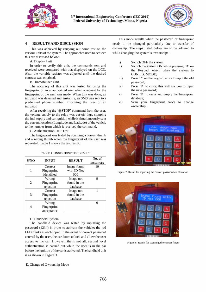
METHODOLOGY
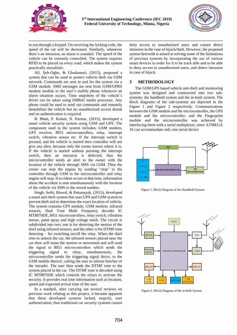
The GSM/GPS based vehicle anti-theft and monitoring
system was designed and constructed into two sub-
systems: the handheld system and the in-built system. The
block diagrams of the sub-systems are depicted in the
Figure 1 and Figure 2 respectively. Communications
between the GSM module and the microcontroller, the GPS
module and the microcontroller, and the Fingerprint
module and the microcontroller was achieved by
interfacing them with a serial multiplexer, since ATMEGA
16 can accommodate only one serial device
P.S.U
MICROCONTROLLER
RF RX
FINGER
RELAY
CAR
FUEL
GPS
GSM
RELAY
LCD KEYPAD CAR
IGNITION
Figure 2. Block Diagram of the in-built System
MICROCONTROLLER
Figure 1. Block Diagram of the Handheld System
704
3rd International Engineering Conference (IEC 2019)
Federal University of Technology, Minna, Nigeria
3.1 THE COMMUNICATION UNIT
This unit comprises of a GSM module, which sends and
receives messages (SMS) to and fro the vehicle’s owner.
The microcontroller works based on the reply the GSM
module receives; and a GPS module, which aids in tracking
and monitoring the vehicle at any particular point in time.
With the aid of this module, the location (longitude and
latitude) of the vehicle can be determined.
3.2 THE AUTHENTICATION UNIT
This unit is made up of a fingerprint module. Its purpose
in this system is to scan the finger of the person driving the
vehicle at any point in time. It serves as a means of easily
sensing intrusion through verification of the current user.
3.3 THE IMMOBILIZING UNIT AND RELAY
PARAMETERS
This unit is made up of two relays interconnected with
the ignition engine of the vehicle and its fuel pump. As we
all know, a relay is a switching device so was it employed
in this design to switch ON the ignition of the vehicle while
simultaneously permitting the flow of fuel into the
combustion engine and vice-versa. Since a relay requires
12V to operate, a transistor was used to amplify the voltage
being supplied by the microcontroller to the relay. The
calculations behind the values chosen is as follows:
𝑅𝐵 =𝑉𝐵𝐵−𝑉𝐵𝐸
𝐼𝐵 (1)
𝐼𝐶 = 𝛽𝐼𝐵 (2)
𝑉𝐶𝐸 = 𝑉𝐵𝐵 − 𝐼𝐶𝑅𝐶 (3)
𝑅𝑒𝑙𝑎𝑦 = 1000Ω
𝑉𝑅𝐸𝐿𝐴𝑌 = 12𝑉
𝑅𝑒𝑙𝑎𝑦 =𝑉𝑅𝐸𝐿𝐴𝑌
𝑅𝑅𝐸𝐿𝐴𝑌=
12
1000= 0.012𝐴
𝑉𝐵𝐸 = 0.7𝑉 𝑎𝑛𝑑 𝑉𝐵𝐵 = 12𝑉
𝐼𝐶 = 𝐼𝑅𝐸𝐿𝐴𝑌 = 0.012𝐴
∴ 𝑅𝐵 =12 − 0.7
0.012= 941.67Ω
3.4 DISPLAY UNIT
An LM016L, 16-character-by-2-line, dot matrix
Alphanumeric Liquid Crystal Display (LCD) was used in
this project as the display unit. An LM016L has 11 data
lines is required. The control lines include: RW, RS, and
EN. The Read/Write RW, control line reads data from the
LCD when it is 1 while data is written when it is 0. The
Register Select RS, Line treats data as an instruction when
it is ZERO and, it displays data on the screen when it is
ONE. The Enable Line is used to inform the LCD that data
has been sent to it. To send data to the LCD, EN is set to
LOW, while simultaneously setting the RW and the RS
lines appropriately. Pin 3 of the LCD is interfaced with a
variable resistor which is connected to the power supply.
This variable resistor is used to adjust the contrast of the
LCD.
3.5 CONTROL UNIT
ATmega16 is an 8-bit, high performance Atmel AVR
family with low power consumption. It is a 40pin
microcontroller with 16KB programmable flash memory,
1024bytes RAM and 512bytes EEPROM that allows both
temporary and permanent storage of data. The Atmel AVR
processor’s memory is a modified form of Harvard
Architecture, in which the program and data memory uses
separate buses for ease of access and increased capacity.
An Atmel AVR microcontroller has four categories of
memories: data memory, registers, I/O registers, and
SRAM program flash memory, each with a distinct
address.
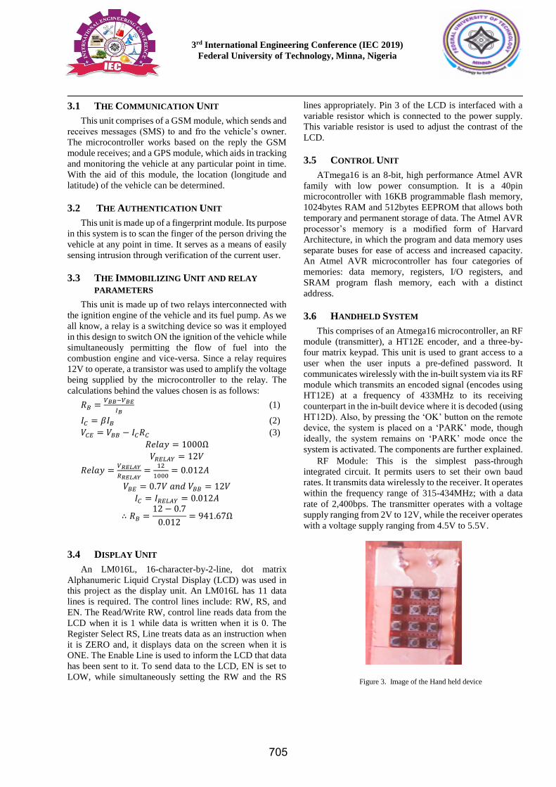
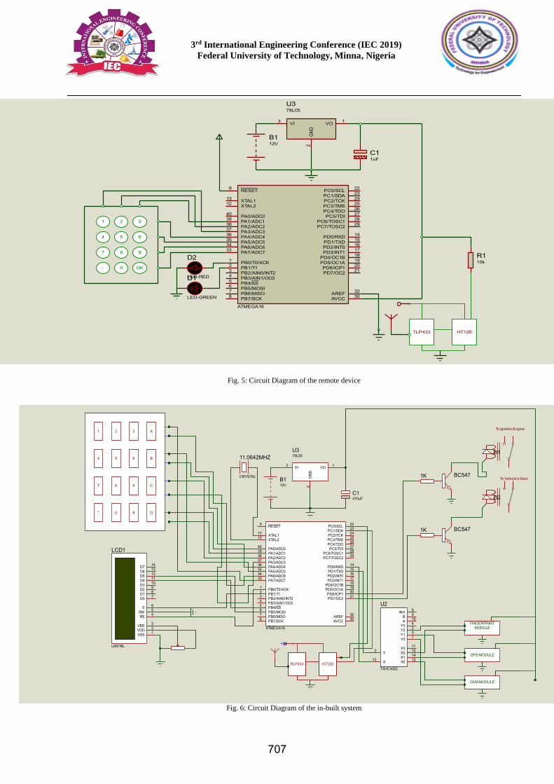
3.6 HANDHELD SYSTEM
This comprises of an Atmega16 microcontroller, an RF
module (transmitter), a HT12E encoder, and a three-by-
four matrix keypad. This unit is used to grant access to a
user when the user inputs a pre-defined password. It
communicates wirelessly with the in-built system via its RF
module which transmits an encoded signal (encodes using
HT12E) at a frequency of 433MHz to its receiving
counterpart in the in-built device where it is decoded (using
HT12D). Also, by pressing the ‘OK’ button on the remote
device, the system is placed on a ‘PARK’ mode, though
ideally, the system remains on ‘PARK’ mode once the
system is activated. The components are further explained.
RF Module: This is the simplest pass-through
integrated circuit. It permits users to set their own baud
rates. It transmits data wirelessly to the receiver. It operates
within the frequency range of 315-434MHz; with a data
rate of 2,400bps. The transmitter operates with a voltage
supply ranging from 2V to 12V, while the receiver operates
with a voltage supply ranging from 4.5V to 5.5V.
Figure 3. Image of the Hand held device
705
3rd International Engineering Conference (IEC 2019)
Federal University of Technology, Minna, Nigeria
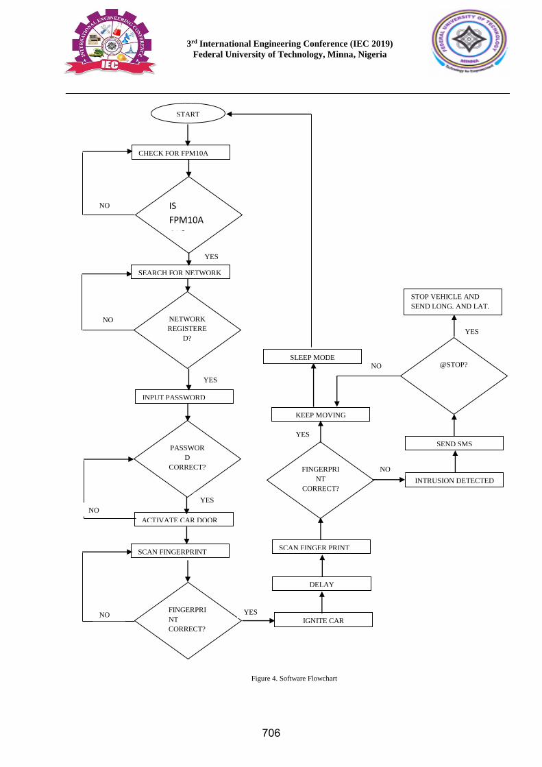
Figure 4. Software Flowchart
@STOP?
START
CHECK FOR FPM10A
INTRUSION DETECTED
SEARCH FOR NETWORK
NETWORK
REGISTERE
D?
INPUT PASSWORD
PASSWOR
D
CORRECT?
ACTIVATE CAR DOOR
SCAN FINGERPRINT
FINGERPRI
NT
CORRECT?
IGNITE CAR
SCAN FINGER PRINT
FINGERPRI
NT
CORRECT?
KEEP MOVING
SEND SMS
STOP VEHICLE AND
SEND LONG. AND LAT.
IS
FPM10A
OK?
YES
NO
YES
NO
YES
NO
YES NO
NO
YES
NO
YES
DELAY
SLEEP MODE
706
3rd International Engineering Conference (IEC 2019)
Federal University of Technology, Minna, Nigeria
Fig. 5: Circuit Diagram of the remote device
Fig. 6: Circuit Diagram of the in-built system
PB0/T0/XCK1
PB1/T12
PB2/AIN0/INT23
PB3/AIN1/OC04
PB4/SS5
PB5/MOSI6
PB6/MISO7
PB7/SCK8
RESET9
XTAL212 XTAL113
PD0/RXD 14
PD1/TXD 15
PD2/INT0 16
PD3/INT1 17
PD4/OC1B 18
PD5/OC1A 19
PD6/ICP1 20
PD7/OC2 21
PC0/SCL 22
PC1/SDA 23
PC2/TCK 24
PC3/TMS 25
PC4/TDO 26
PC5/TDI 27
PC6/TOSC1 28
PC7/TOSC2 29
PA7/ADC733 PA6/ADC634 PA5/ADC535 PA4/ADC436 PA3/ADC337 PA2/ADC238 PA1/ADC139 PA0/ADC040
AREF 32
AVCC 30
ATMEGA16
B112V
VI3 VO 1
GND
2
U378L05
C11uF
1 2 3
4 5 6
7 8 9
0- OK
D1
LED-GREEN
D2
LED-RED
TLP433 HT12E
R110k
PB0/T0/XCK1
PB1/T12
PB2/AIN0/INT23
PB3/AIN1/OC04
PB4/SS5
PB5/MOSI6
PB6/MISO7
PB7/SCK8
RESET9
XTAL212 XTAL113
PD0/RXD 14
PD1/TXD 15
PD2/INT0 16
PD3/INT1 17
PD4/OC1B 18
PD5/OC1A 19
PD6/ICP1 20
PD7/OC2 21
PC0/SCL 22
PC1/SDA 23
PC2/TCK 24
PC3/TMS 25
PC4/TDO 26
PC5/TDI 27
PC6/TOSC1 28
PC7/TOSC2 29
PA7/ADC733 PA6/ADC634 PA5/ADC535 PA4/ADC436 PA3/ADC337 PA2/ADC238 PA1/ADC139 PA0/ADC040
AREF 32
AVCC 30
ATMEGA16
D7 14
D6 13
D5 12
D4 11
D3 10
D2 9
D1 8
D0 7
E 6
RW 5
RS 4
VSS 1VDD 2VEE 3
LCD1
LM016L
1K
1K
BC547
BC547
D1
D2
To Ignition Engine
To Vehicle's Door
X0 12X1 14X2 15X3 11
Y0 1Y1 5Y2 2Y3 4A 10B 9INH 6
X13
Y3
U2
74HC4052
FINGERPRINTMODULE
GPS MODULE
GSM MODULE
B112V
VI3 VO 1
GN
D2
U378L05
C1470uF
1 A2 3
4 5
67
8
9
0* #
B
C
D
RLP433 HT12D
11.0642MHZ
CRYSTAL
+5V
707
3rd International Engineering Conference (IEC 2019)
Federal University of Technology, Minna, Nigeria
RESULTS AND DISCUSSION
This was achieved by carrying out some test on the
various units of the system. The approaches used to achieve
this are discussed below:
A. Display Unit
In order to verify this unit, the commands sent and
received were compared with that displayed on the LCD.
Also, the variable resistor was adjusted until the desired
contrast was obtained.
B. Immobilizer Unit
The accuracy of this unit was tested by using the
fingerprint of an unauthorized user when a request for the
fingerprint of the user was made. When this was done, an
intrusion was detected and, instantly, an SMS was sent to a
predefined phone number, informing the user of an
intrusion
After receiving the ‘@STOP’ command from the user,
the voltage supply to the relay was cut-off thus, stopping
the fuel supply and car ignition while it simultaneously sent
the current location (Longitude and Latitude) of the vehicle
to the number from which it received the command.
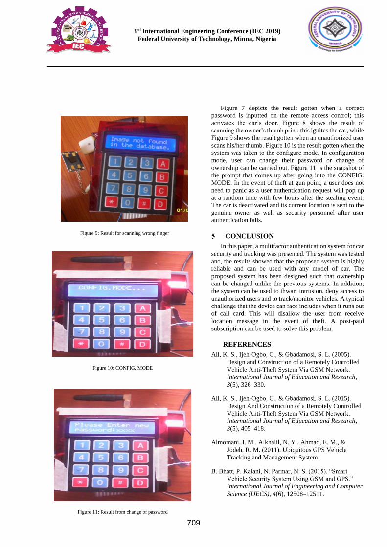
C. Authentication Unit Test
The fingerprint was tested by scanning a correct thumb
and a wrong thumb when the fingerprint of the user was
requested. Table 1 shows the test result;
TABLE 1: FINGERPRINT TEST RESULT
S/NO INPUT RESULT No. of
instances
1
Correct
Fingerprint
identified
Image found
with ID No:
000
10
2
Wrong
Fingerprint
rejection
Image not
found in the
database
9
3
Correct
Fingerprint
rejection
Image not
found in the
database
1
4
Wrong
Fingerprint
acceptance
0
D. Handheld System
The handheld device was tested by inputting the
password (1234) in order to activate the vehicle; the red
LED blinks at each input. In the event of correct password
entered by the user, the car doors unlock and allow the user
access to the car. However, that’s not all, second level
authentication is carried out while the user is in the car
before the ignition of the car is activated. The handheld unit
is as shown in Figure 3.
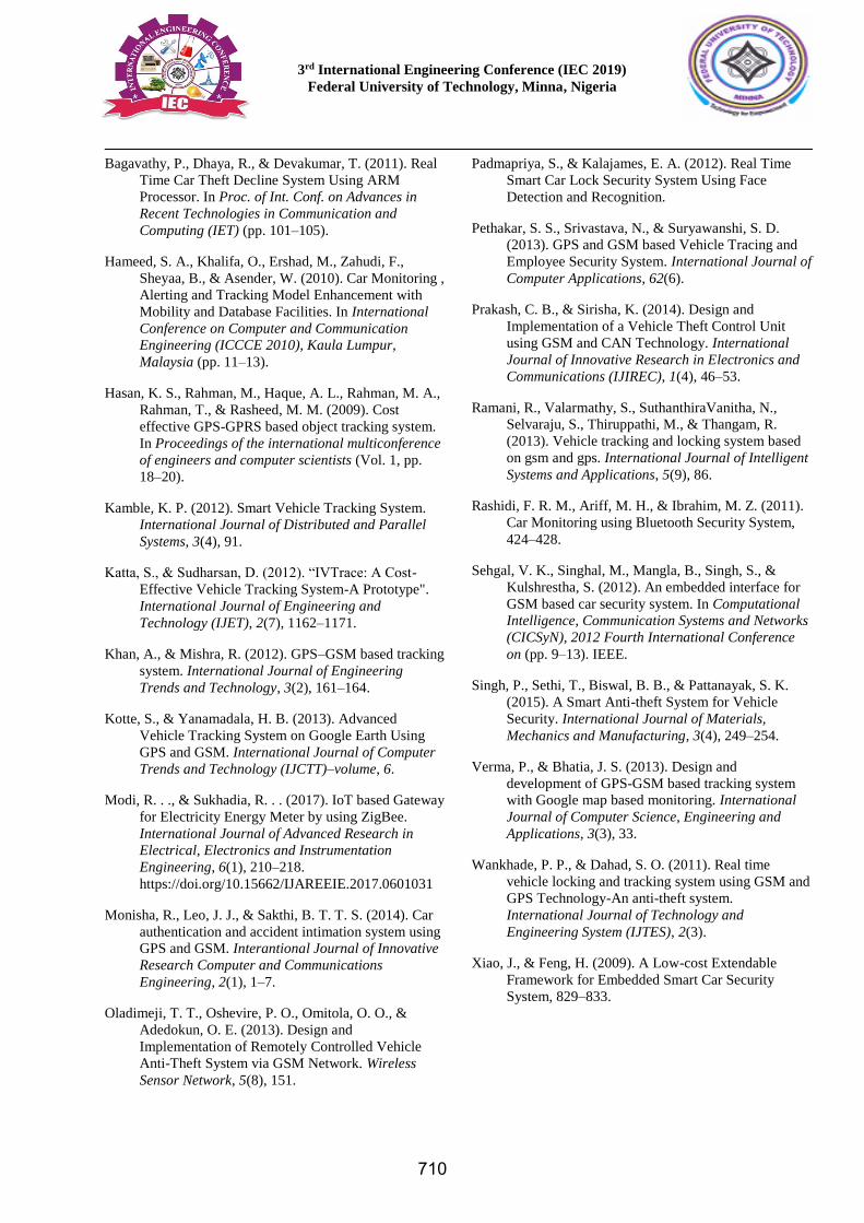
E. Change of Ownership Mode
This mode results when the password or fingerprint
needs to be changed particularly due to transfer of
ownership. The steps listed below are to be adhered to
while changing the system’s ownership: -
i) Switch OFF the system;
ii) Switch the system ON while pressing ‘D’ on
the Keypad, which takes the system to
CONFIG. MODE;
iii) Press ‘*’ on the keypad, so as to input the old
password;
iv) Press ‘D’ to enter; this will ask you to input
the new password;
v) Press ‘D’ to enter and empty the fingerprint
database;
vi) Scan your fingerprint twice to change
ownership.
Figure 7: Result for inputting the correct password combination
Figure 8: Result for scanning the correct finger
708
3rd International Engineering Conference (IEC 2019)
Federal University of Technology, Minna, Nigeria
Figure 7 depicts the result gotten when a correct
password is inputted on the remote access control; this
activates the car’s door. Figure 8 shows the result of
scanning the owner’s thumb print; this ignites the car, while
Figure 9 shows the result gotten when an unauthorized user
scans his/her thumb. Figure 10 is the result gotten when the
system was taken to the configure mode. In configuration
mode, user can change their password or change of
ownership can be carried out. Figure 11 is the snapshot of
the prompt that comes up after going into the CONFIG.
MODE. In the event of theft at gun point, a user does not
need to panic as a user authentication request will pop up
at a random time with few hours after the stealing event.
The car is deactivated and its current location is sent to the
genuine owner as well as security personnel after user
authentication fails.
CONCLUSION
In this paper, a multifactor authentication system for car
security and tracking was presented. The system was tested
and, the results showed that the proposed system is highly
reliable and can be used with any model of car. The
proposed system has been designed such that ownership
can be changed unlike the previous systems. In addition,
the system can be used to thwart intrusion, deny access to
unauthorized users and to track/monitor vehicles. A typical
challenge that the device can face includes when it runs out
of call card. This will disallow the user from receive
location message in the event of theft. A post-paid
subscription can be used to solve this problem.
REFERENCES
All, K. S., Ijeh-Ogbo, C., & Gbadamosi, S. L. (2005).
Design and Construction of a Remotely Controlled
Vehicle Anti-Theft System Via GSM Network.
International Journal of Education and Research,
3(5), 326–330.
All, K. S., Ijeh-Ogbo, C., & Gbadamosi, S. L. (2015).
Design And Construction of a Remotely Controlled
Vehicle Anti-Theft System Via GSM Network.
International Journal of Education and Research,
3(5), 405–418.
Almomani, I. M., Alkhalil, N. Y., Ahmad, E. M., &
Jodeh, R. M. (2011). Ubiquitous GPS Vehicle
Tracking and Management System.
B. Bhatt, P. Kalani, N. Parmar, N. S. (2015). “Smart
Vehicle Security System Using GSM and GPS.”
International Journal of Engineering and Computer
Science (IJECS), 4(6), 12508–12511.
Figure 9: Result for scanning wrong finger
Figure 10: CONFIG. MODE
Figure 11: Result from change of password
709
3rd International Engineering Conference (IEC 2019)
Federal University of Technology, Minna, Nigeria
Bagavathy, P., Dhaya, R., & Devakumar, T. (2011). Real
Time Car Theft Decline System Using ARM
Processor. In Proc. of Int. Conf. on Advances in
Recent Technologies in Communication and
Computing (IET) (pp. 101–105).
Hameed, S. A., Khalifa, O., Ershad, M., Zahudi, F.,
Sheyaa, B., & Asender, W. (2010). Car Monitoring ,
Alerting and Tracking Model Enhancement with
Mobility and Database Facilities. In International
Conference on Computer and Communication
Engineering (ICCCE 2010), Kaula Lumpur,
Malaysia (pp. 11–13).
Hasan, K. S., Rahman, M., Haque, A. L., Rahman, M. A.,
Rahman, T., & Rasheed, M. M. (2009). Cost
effective GPS-GPRS based object tracking system.
In Proceedings of the international multiconference
of engineers and computer scientists (Vol. 1, pp.
18–20).
Kamble, K. P. (2012). Smart Vehicle Tracking System.
International Journal of Distributed and Parallel
Systems, 3(4), 91.
Katta, S., & Sudharsan, D. (2012). “IVTrace: A Cost-
Effective Vehicle Tracking System-A Prototype".
International Journal of Engineering and
Technology (IJET), 2(7), 1162–1171.
Khan, A., & Mishra, R. (2012). GPS–GSM based tracking
system. International Journal of Engineering
Trends and Technology, 3(2), 161–164.
Kotte, S., & Yanamadala, H. B. (2013). Advanced
Vehicle Tracking System on Google Earth Using
GPS and GSM. International Journal of Computer
Trends and Technology (IJCTT)–volume, 6.
Modi, R. . ., & Sukhadia, R. . . (2017). IoT based Gateway
for Electricity Energy Meter by using ZigBee.
International Journal of Advanced Research in
Electrical, Electronics and Instrumentation
Engineering, 6(1), 210–218.
https://doi.org/10.15662/IJAREEIE.2017.0601031
Monisha, R., Leo, J. J., & Sakthi, B. T. T. S. (2014). Car
authentication and accident intimation system using
GPS and GSM. Interantional Journal of Innovative
Research Computer and Communications
Engineering, 2(1), 1–7.
Oladimeji, T. T., Oshevire, P. O., Omitola, O. O., &
Adedokun, O. E. (2013). Design and
Implementation of Remotely Controlled Vehicle
Anti-Theft System via GSM Network. Wireless
Sensor Network, 5(8), 151.
Padmapriya, S., & Kalajames, E. A. (2012). Real Time
Smart Car Lock Security System Using Face
Detection and Recognition.
Pethakar, S. S., Srivastava, N., & Suryawanshi, S. D.
(2013). GPS and GSM based Vehicle Tracing and
Employee Security System. International Journal of
Computer Applications, 62(6).
Prakash, C. B., & Sirisha, K. (2014). Design and
Implementation of a Vehicle Theft Control Unit
using GSM and CAN Technology. International
Journal of Innovative Research in Electronics and
Communications (IJIREC), 1(4), 46–53.
Ramani, R., Valarmathy, S., SuthanthiraVanitha, N.,
Selvaraju, S., Thiruppathi, M., & Thangam, R.
(2013). Vehicle tracking and locking system based
on gsm and gps. International Journal of Intelligent
Systems and Applications, 5(9), 86.
Rashidi, F. R. M., Ariff, M. H., & Ibrahim, M. Z. (2011).
Car Monitoring using Bluetooth Security System,
424–428.
Sehgal, V. K., Singhal, M., Mangla, B., Singh, S., &
Kulshrestha, S. (2012). An embedded interface for
GSM based car security system. In Computational
Intelligence, Communication Systems and Networks
(CICSyN), 2012 Fourth International Conference
on (pp. 9–13). IEEE.
Singh, P., Sethi, T., Biswal, B. B., & Pattanayak, S. K.
(2015). A Smart Anti-theft System for Vehicle
Security. International Journal of Materials,
Mechanics and Manufacturing, 3(4), 249–254.
Verma, P., & Bhatia, J. S. (2013). Design and
development of GPS-GSM based tracking system
with Google map based monitoring. International
Journal of Computer Science, Engineering and
Applications, 3(3), 33.
Wankhade, P. P., & Dahad, S. O. (2011). Real time
vehicle locking and tracking system using GSM and
GPS Technology-An anti-theft system.
International Journal of Technology and
Engineering System (IJTES), 2(3).
Xiao, J., & Feng, H. (2009). A Low-cost Extendable
Framework for Embedded Smart Car Security
System, 829–833.
710


