Embed Size (px)
Citation preview

30 June 2000. Appears in ESORICS, Springer LNCS. 1
Authentication and Confidentiality via IPsec⋆
Joshua D. Guttman, Amy L. Herzog, and F. Javier Thayer
The MITRE Corporationguttman, althomas, [email protected]
Abstract. The IP security protocols (IPsec) may be used via securitygateways that apply cryptographic operations to provide security ser-vices to datagrams, and this mode of use is supported by an increasingnumber of commercial products. In this paper, we formalize the types ofauthentication and confidentiality goal that IPsec is capable of achiev-ing, and we provide criteria that entail that a network with particularIPsec processing achieves its security goals.
This requires us to formalize the structure of networks using IPsec, andthe state of packets relevant to IPsec processing. We can then proveconfidentiality goals as invariants of the formalized systems. Authentica-tion goals are formalized in the manner of [9], and a simple proof methodusing “unwinding sets” is introduced. We end the paper by explainingthe network threats that are prevented by correct IPsec processing.
1 Introduction
The IP security protocols [7, 5, 6] (see also [8, 4]), collectively termed IPsec,are an important set of security protocols currently making their way into thecommercial world. The IPsec standards include protocols for ensuring confiden-tiality, integrity, and authentication of data communications in an IP network.The standards are very flexible, and this flexibility has led to great commer-cial interest; many IPsec products are now available. The same flexibility alsomeans that the protocol set is complex [2]. Hence, naıvely configured IPsec
products will often be set up wrong, making it hard to know what security goalshave actually been achieved. Our rigorous treatment suggests an approach toconstructing IPsec configuration tools, and suggests specific checks by which asystem administrator can ensure his goals are met, even without a tool.
IPsec can be used in two different ways. It can be used end-to-end, in whichcase the source and destination hosts for a datagram are responsible for allcryptographic processing. It can also be used via gateways, in which case asystem near the source host is responsible for applying cryptographic operationson behalf of the source, while a system near the destination is responsible forchecking and decryption. A flow of packets in which at least one endpoint is anIPsec gateway is called a tunnel .
⋆ This work was supported by the National Security Agency through US Army CE-COM contract DAAB07-99-C-C201.
The IPsec protocols work by prefixing special IP headers (or infixing specialheader fields). These headers contain an index (the Security Protection Index) bywhich the system applying the cryptographic operations specifies algorithms andkeys to be used. The cryptographic operations are intended to provide authen-tication and integrity1 for packets, or else confidentiality for packets. A singleIPsec header may provide both authentication and confidentiality, and indeedit is sound practice not to provide confidentiality without authentication [1]. Au-thentication is provided by means of keyed hashes, confidentiality by symmetricencryption. Hence, in both cases secrets must be shared between the systems ap-plying and removing the cryptography. Manual key placement or cryptographickey exchange methods [4, 8] may be used to create these shared secrets.
We will always regard the action of an IPsec gateway as a matter of manip-ulating headers. To apply cryptography, a source host or a gateway wraps thedatagram (including its non-IPsec header information) in a new header. If thisheader offers authentication then it can be applied only by a system sharing thesymmetric key. Moreover, the payload is protected from alteration in the sensethat alteration can be detected, and will prevent delivery of the (damaged) pay-load. If the new header offers confidentiality, then it can be removed only by asystem sharing the symmetric key. Headers are applied at one end of a tunneland checked and removed at the other. We abstract from operations on the pay-load itself, namely encrypting it or calculating a hash over it, although of coursethese operations are necessary for IPsec to be useful.
When IPsec is used via gateways, the hosts (or the organizations operatingthem) delegate a degree of trust to certain gateways. The purpose of this paper isto study the logic of that trust. We will formalize exactly what assumptions areneeded for the two types of goal, authentication and confidentiality, and explainhow the trust assumptions depend on network topology. We regard this paper asan extension of a research program, begun in [3], which aims to analyze the localprocessing required to enforce network-wide security policies. In [3], we studiedthe local packet filtering behavior routers must be trusted to perform, in orderto enforce network-wide firewall-like security goals.
In the next section, we formalize the security goals one can achieve via IPsec,and introduce the notion of a trust set, which is central to our analysis. Wethen formalize the structure of networks using IPsec (Section 3.1), the stateof packets relevant to IPsec processing (Section 3.2), and the properties ofcryptographic operations (Section 3.3). We detail our behavior requirements,and prove that they are sufficient to ensure goal achievability (Section 4). Weillustrate specific attacks that our approach prevents in Section 5. We end bysummarizing, and discussing potential future work.
1 For our purposes, integrity and authentication belong together. Jointly, they ensurethat the packet has originated at a known system, and has remained unchanged since,except for such header manipulations required by IP routing and delivery mecha-nisms. We will speak henceforth only of authentication; it should be understood thatintegrity is also included.
2

2 Achievable Security Goals
We focus on authentication and confidentiality as security goals in our analysis.Concrete security goals select certain packets that should receive protection [7];selection criteria may use source or destination addresses, protocol, and otherheader components such as the ports, in case the protocol is TCP or UDP.
2.1 Authentication Goals
The essence of authentication is that it allows the recipient to—so to speak—take a packet at face value. Thus, for a packet p selected for protection by aauthentication goal,
If A is the value in the source header field of p as received by B, thenp actually originated at A in the past, and the payload has not beenaltered since.
We do not regard a packet as being (properly) received unless the cryptographichash it contains matches the value computed from a shared secret and the packetcontents. It will not be delivered up the stack otherwise, nor forwarded to anothersystem after IPsec processing.
2.2 Confidentiality Goals
We assume that confidentiality headers (as in the Encapsulating Security Pay-load (ESP) protocol [6]) provide authentication, and add encryption. We havetwo reasons for doing so. First, the IPsec specification allows both authenti-cation and confidentiality to be used with the ESP header; it is inadvisable torequest only confidentiality when authentication can also be had at the sametime, and at modest additional processing cost. Second, it seems hard to stateprecisely what data is kept confidential, if that data might change as the packettraverses the network. It is thus hard to say what protection has been achieved [1,2]. When using confidentiality headers, we are therefore attempting to achievean authentication goal as well as a confidentiality goal.
A confidentiality goal for a packet with source field A, requiring protectionfrom disclosure in some network location C, stipulates:
If a packet originates at A, and later reaches the location C, then whileit is at C it has a header providing confidentiality.
The cryptographic protection may refer to the ESP header more specifically,stipulating certain parameters (key length, algorithm, etc). The proviso that thepacket was once at A is necessary, because in most cases we cannot preventsomeone at C from creating a spoofed packet with given header fields. However,a spoofed packet cannot compromise the confidentiality of A’s data if it has nocausal connection to A.
3
2.3 Example Goals
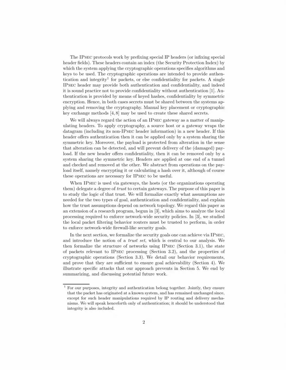
Consider the network in Figure 1. Given this example network, a potential au-thentication goal could be that packets traveling from EngineeringA to Engi-
neeringB should be authenticated, meaning that any packet with source fieldclaiming to be from EngineeringA that reaches EngineeringB should in facthave originated in EngineeringA. An example confidentiality goal is that pack-ets traveling from FinanceA to FinanceB should be encrypted whenever outsidethose areas. This means that if a packet has source field in FinanceA, and actu-ally originated there, then if it reaches any other area R, it has an ESP headerproviding encryption while at R.
Internet
PerimeterB
PerimeterA
EngineeringB
FinanceB
EngineeringA
FinanceA
SG 3
?SG 2
?@@
SG 1
?
@@
SG 4
?host3dbA-
COMPANY A COMPANY B
Fig. 1. Sample IPsec Network Representation
One advantage to this form of expression is that it is semantically precise.Another is that policies expressed in this form appear to be intrinsically compos-able, in the sense that separate goals can always be satisfied together. Moreover,this form of expression often suggests placement of trust sets, in a sense we willnow introduce.
2.4 Trust Sets
Once a packet enters an appropriate cryptographic tunnel, achieving a securitygoal does not depend on what happens until it exits. Thus, the set of locationsin the network topology that are accessible to the packet from the source (beforeentering the tunnel) or accessible from the exit of the tunnel (before reaching thedestination) are the only ones of real importance. We will call these locations atrust set for a particular security goal. A trust set is goal-specific; different goalsmay have different trust sets. For instance, an engineering group working on asensitive project could easily have much more restrictive security goals than itsparent corporation (in terms of trust).
Typically, a trust set is not a connected portion of the network. In many ofthe examples we will describe later, the trust set consists of two large connectedportions, with a large public ‘Internet’ network between them. In some cases
4
the trust set may consist of several islands, and the tunnels may not connectall of them directly. In this case, a packet may need to traverse several tunnelssuccessively in order to get from one island of the trust set to a distant one.
The choice of trust set for a particular security goal is a matter of balance.Clearly, the source must belong to the same island of the trust set as the tunnelentrance, and the tunnel exit must belong to the same island as the destination(or the entrance to the next tunnel). This encourages creating trust sets as largeas possible, since then a few tunnels may serve for many endpoints. However,the scope of a trust set must generally be limited to a set of networks on which itis possible to monitor traffic and check configurations. This encourages makingthe trust sets as small as possible. The art of using IPsec effectively consistspartly in balancing these two contrasting tendencies.
Boundaries Of special importance are those systems inside a trust set with adirect connection to systems outside the trust set. We term these systems theboundary of the trust set. We assume that every device on the boundary ofa trust set is capable of filtering packets. This may be a portion of its IPsec
functionality [7]. Alternatively, the device may not be IPsec-enabled, but insteadbe a filtering router or packet-filtering firewall. We regard such devices as adegenerate case of an IPsec-enabled device, one which happens never to beconfigured to apply any cryptographic operations.
3 Network Modeling
We begin talking about systems by viewing them as composed of networks anddevices capable of IPsec operations or packet filtering. A device has interfaceson one or more networks. Any machine (such as a switch or host) that performsno IPsec operations or filtering we may simply ignore. We may also ignore amachine that can perform IPsec operations, if it is not a member of the trustset for any security goal we would like to enforce. For instance, IPsec-enabledmachines elsewhere on the Internet can be ignored.
We regard a system as a graph with two kinds of nodes, representing thenetworks and the devices respectively. In the example shown in Figure 1, net-works appear as ovals and devices appear as black squares. An edge representsthe interfaces between a device and the network to which it is connected. We willnever connect two networks directly via an edge; this would not give a securityenforcement point to control the flow of packets between them. Instead, we willcoagulate any two networks that are connected by a device that provides nosecurity enforcement, representing them by the same oval. Figure 1 is a simplepicture: for any two nodes, deletion of a single edge causes them to become dis-connected. In other cases, there may be many disjoint paths between a pair oflocations.
5
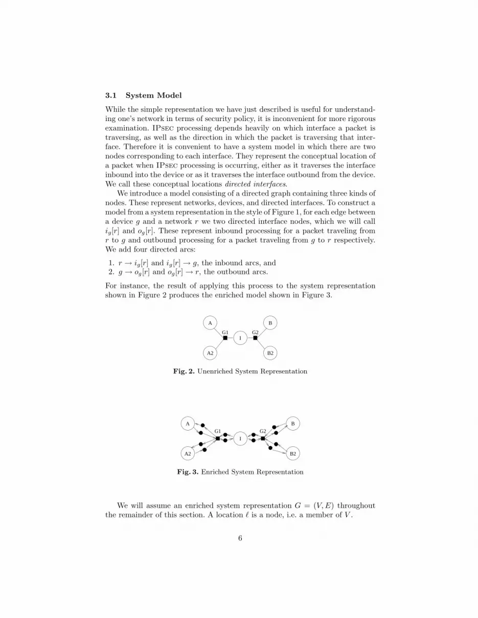
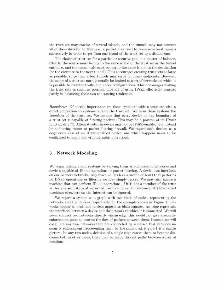
3.1 System Model
While the simple representation we have just described is useful for understand-ing one’s network in terms of security policy, it is inconvenient for more rigorousexamination. IPsec processing depends heavily on which interface a packet istraversing, as well as the direction in which the packet is traversing that inter-face. Therefore it is convenient to have a system model in which there are twonodes corresponding to each interface. They represent the conceptual location ofa packet when IPsec processing is occurring, either as it traverses the interfaceinbound into the device or as it traverses the interface outbound from the device.We call these conceptual locations directed interfaces.
We introduce a model consisting of a directed graph containing three kinds ofnodes. These represent networks, devices, and directed interfaces. To construct amodel from a system representation in the style of Figure 1, for each edge betweena device g and a network r we two directed interface nodes, which we will callig[r] and og[r]. These represent inbound processing for a packet traveling fromr to g and outbound processing for a packet traveling from g to r respectively.We add four directed arcs:
1. r → ig[r] and ig[r] → g, the inbound arcs, and2. g → og[r] and og[r] → r, the outbound arcs.
For instance, the result of applying this process to the system representationshown in Figure 2 produces the enriched model shown in Figure 3.
A2
A B
I
B2
G1 G2
Fig. 2. Unenriched System Representation
A2
A
B2
B
G2G1
I
Fig. 3. Enriched System Representation
We will assume an enriched system representation G = (V, E) throughoutthe remainder of this section. A location ℓ is a node, i.e. a member of V .
6
3.2 Packet States
Let P be a set of values we call protocol data. We may think of its values as theelements of IP headers other than source and destination. For instance, an IPheader may specify that the protocol is TCP, and the embedded TCP headermay specify a particular source port and destination port; this combination ofprotocol and port information may be taken as a typical member of P .
Let A ⊂ P be a set we call authenticated protocol data; it represents thoseheaders that provide IPsec authentication services. Let C ⊂ A be a set wecall confidentiality protocol data; it represents those headers that provide IPsec
confidentiality services. The assumption C ⊂ A codifies our decision not toconsider ESP headers that provide only confidentiality (cf. Section 2.2).
A header is a member of the set H = V × V × P , consisting of a sourcelocation, a destination location, and a protocol data value. Packet states aremembers of H∗, that is, possibly empty sequences 〈h1, . . . , hn〉. We use · asprefixing operator: h · 〈h1, . . . , hn〉 = 〈h, h1, . . . , hn〉.
Let K be a set of “processing states,” with a distinguished element ready ∈K. Intuitively, when an interface has taken all of the processing steps in theSecurity Association (SA, see [7]) for a packet p, then it enters the processingstate ready, indicating that the packet is now ready to move across the arc fromthat interface. If this is an outbound interface, it means that the packet maynow go out onto the attached network; if it is an inbound interface it means thatthe packet may now enter the device, typically to be routed to some outboundinterface or for local delivery. Other members of K are used to keep track ofcomplex IPsec processing, when several header layers must be added or removedbefore processing is complete at a particular interface. These clusters of behaviorrepresent IPsec Security Association bundles.
We regard the travels of a packet through a system as the evolution of astate machine. The packet may not yet have started to travel; this is the startstate. The packet may no longer be travelling; this is the finished state. Everyother state is a triple of a node ℓ ∈ V , indicating where the packet currently issituated; a processing state κ ∈ K, indicating whether the packet is ready tomove, or how much additional processing remains; and a packet state θ ∈ H∗,indicating the sequence of headers nested around the payload of the packet.
Definition 1. Ω(G, K, P, A, C) is the set of network states over the graph G =(V, E), the processing states K, and the protocol data P with C ⊂ A ⊂ P .Ω(G, K, P, A, C) is the disjoint union of
1. start,2. stop, and3. the triples (ℓ, κ, θ), for ℓ ∈ V , κ ∈ K, and θ ∈ H∗.
The transition relation of a network state machine is a union of the followingparameterized partial functions. We define what the resulting state is, assumingthat the function is defined for the state given. We also constrain when some ofthese functions may be defined; different IPsec security postures are determined
7

by different choices of domain for each of these partial functions (subject to theconstraints given).
Definition 2. A network operation is any partial function of one of the followingforms:
1. Packet creation operators createℓ,h(start) = (ℓ, ready, 〈h〉), when defined, for(ℓ, h) ∈ V ×H . createℓ,h is not defined unless its argument is the state start.
2. The packet discard operator discard(ℓ, κ, θ) = stop, when defined. discard isundefined for start.
3. Packet movement operators movee,κ(ℓ, ready, θ) = (ℓ′, κ, θ), when e ∈ E,
ℓe→ ℓ′ and κ 6= ready. movee,κ is undefined for all other network states.
4. Header prefixing operators prefixh,κ(ℓ, κ′, θ) = (ℓ, κ, h · θ) when defined. Thefunction prefixh,κ is nowhere defined when h 6∈ A.
5. Header pop operators popκ(ℓ, κ′, h · θ) = (ℓ, κ, θ) when defined.6. Null operators nullκ(ℓ, κ′, θ) = (ℓ, κ, θ) when defined.
A transition relation → ⊂ (Ω(G, K, P, A, C) × Ω(G, K, P, A, C)) is a union ofoperators create, discard, move, prefix, pop, and null.
The assumption that prefixh,κ is nowhere defined when h 6∈ A means that theonly nested headers we consider are IPsec headers.
We call the assumption that movee,κ(ℓ, κ′, θ) = (ℓ′, κ, θ) is not defined whenκ′ 6= ready the motion restriction. We call the assumption that it is not definedwhen κ = ready the inbound motion restriction. The motion restrictioncodifies the assumption that a device will not move a packet until it is ready.The inbound motion restriction codifies the assumption that there will alwaysbe a chance to process a packet when it arrives at a location, if needed, beforeit is declared ready to move to the next location.
Given a packet p, we call the address in the source header field of its topmostheader src(p). We call the address in the destination header field of the topmostheader dst(p). We also call a packet p an IPsec packet if its outermost header isan AH or ESP header; an ESP packet if its outermost header is an ESP header;and an AH packet if its outermost header is an AH header.
Definition 3. A trust set S for G = (V, E) consists of a set R ⊂ V of networks,together with all devices g adjacent to networks in R and all interfaces ig[∗] andog[∗].
The inbound boundary of S, written ∂inS is the set of all interfaces ig[r] orig[g
′] where g ∈ S and r, g′ 6∈ S.The outbound boundary of S, written ∂outS is the set of all interfaces og[r]
or og[g′] where g ∈ S and r, g′ 6∈ S.
In the remainder of this section, fix a trust set S and locations a, b ∈ S. Wewill use the following notation: Suppose x = (ℓ, κ, θ) is a network state wherex 6= start, stop.
– ℓ(x) = ℓ,
8

– κ(x) = κ,– θ(x) = θ.
A transition x → y is header non-augmenting iff it is of the form (ℓ, κ, θθ′) →(ℓ, κ′, θ′), where θ′ is a final segment of the concatenation θθ′.
3.3 Cryptographic Assumptions
We will make two assumptions about the IPsec cryptographic headers. First,we assume that cryptographic headers cannot be spoofed; in other words, thatif we receive a message with an authenticating header from a source “known tous,”2 then the entity named in the source field of the header is the entity thatapplied the header, and the payload cannot have been changed without detection.Second, confidentiality headers have the property that packets protected withthem can be decrypted only by the intended recipient, i.e. the device named inthe ESP header destination field. More formally, using a dash for any field thatmay take any value, we stipulate that for any transition:
(ℓ, κ, 〈[s′, d′,−], . . . 〉)
(ℓ, κ′, 〈[s, d, α], [s′, d′,−], . . . 〉)?
α ∈ A and s ∈ S implies ℓ = s. Moreover, for any transition:
(ℓ, κ′, 〈[s, d, γ], [s′, d′,−], . . . 〉)
(ℓ, κ, 〈[s′, d′,−], . . . 〉)?
γ ∈ C and s ∈ S implies ℓ = d.These properties axiomatize what is relevant to our analysis in the assump-
tion that key material is secret. If keys are compromised then security goalsdependent on them are unenforceable.
4 Security Goal Enforcement
Given an environment in which one can rigorously reason about packet states,and precise specifications of security goals, how does one ensure the goals areenforced? This section focuses on answering that question, by detailing formalbehavior requirements for systems and then proving they guarantee enforceabil-ity.
In our reasoning, we will assume that security goals are stated in the formgiven in Section 2.3.
2 Presumably as certified by some public key infrastructure, and certainly assumed toinclude those devices which are shown as nodes in the system model.
9
4.1 Authentication
Our authentication problem can be stated in the following way. Suppose a andb are network nodes. What processing conditions can we impose such that anauthentication goal holds?
To make this precise, let us say an authenticated state is one having the form(a, κ, 〈[a,−,−]〉) and an acceptor state is one of the form (b, ready, 〈[a,−,−]〉).The symbol authentic denotes the set of authenticated states, accept denotes theset of acceptor states. Our question can be stated thus: exhibit a set of processingrestrictions which ensure the following:
For any path start −→∗ ω where ω ∈ accept there is an intermediatestate ω′ so
start −→∗ ω′ −→∗ ω
where ω′ ∈ authentic.
Thus, whenever an acceptor state is reached, an authenticated state must haveoccurred earlier in the state history. In this sense, the prior occurrence of anauthenticated state is guaranteed when an acceptor state is observed. This useof “authenticated” for the states ω′ ∈ authentic follows Schneider [9].
Achieving authentication requires two types of behavior restrictions on trustednodes, depending on whether the system in question is in the boundary or not.We list behavior restrictions for each.
First we list a constraint that is required for the proofs, but is vacuous inIPsec [7], where inbound processing can only remove packet headers (but neveradd them).
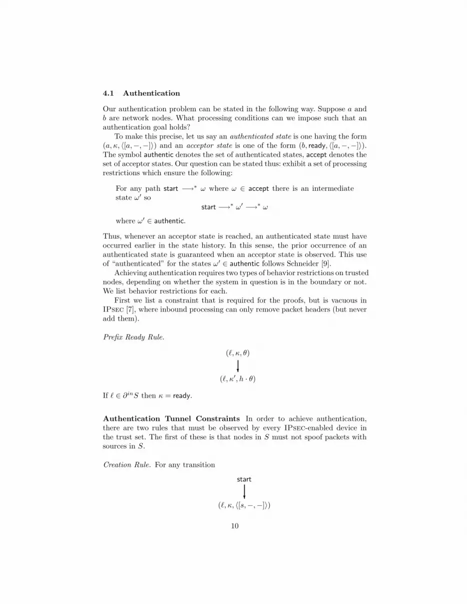
Prefix Ready Rule.
(ℓ, κ, θ)
(ℓ, κ′, h · θ)?
If ℓ ∈ ∂inS then κ = ready.
Authentication Tunnel Constraints In order to achieve authentication,there are two rules that must be observed by every IPsec-enabled device inthe trust set. The first of these is that nodes in S must not spoof packets withsources in S.
Creation Rule. For any transition
start
(ℓ, κ, 〈[s,−,−]〉)?
10
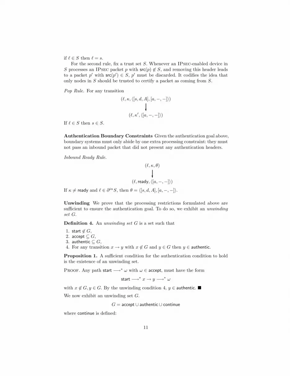
if ℓ ∈ S then ℓ = s.For the second rule, fix a trust set S. Whenever an IPsec-enabled device in
S processes an IPsec packet p with src(p) 6∈ S, and removing this header leadsto a packet p′ with src(p′) ∈ S, p′ must be discarded. It codifies the idea thatonly nodes in S should be trusted to certify a packet as coming from S.
Pop Rule. For any transition
(ℓ, κ, 〈[s, d, A], [a,−,−]〉)
(ℓ, κ′, 〈[a,−,−]〉)?
If ℓ ∈ S then s ∈ S.
Authentication Boundary Constraints Given the authentication goal above,boundary systems must only abide by one extra processing constraint: they mustnot pass an inbound packet that did not present any authentication headers.
Inbound Ready Rule.
(ℓ, κ, θ)
(ℓ, ready, 〈[a,−,−]〉)?
If κ 6= ready and ℓ ∈ ∂inS, then θ = 〈[s, d, A], [a,−,−]〉.
Unwinding We prove that the processing restrictions formulated above aresufficient to ensure the authentication goal. To do so, we exhibit an unwinding
set G.
Definition 4. An unwinding set G is a set such that
1. start 6∈ G,2. accept ⊆ G,3. authentic ⊆ G,4. For any transition x → y with x 6∈ G and y ∈ G then y ∈ authentic.
Proposition 1. A sufficient condition for the authentication condition to holdis the existence of an unwinding set.
Proof. Any path start −→∗ ω with ω ∈ accept, must have the form
start −→∗ x → y −→∗ ω
with x 6∈ G, y ∈ G. By the unwinding condition 4, y ∈ authentic. We now exhibit an unwinding set G.
G = accept ∪ authentic ∪ continue
where continue is defined:
11

Definition 5. (Continuing States) A state is a continuing state if it belongsto one of the three disjoint classes below:
C1 (ℓ, ready, 〈[a,−,−]〉) for ℓ ∈ ∂inS;C2 (ℓ, κ, 〈[a,−,−]〉) for ℓ ∈ S \ ∂inS,
i.e. for locations in the portion of S other than the inbound boundary;C3 (ℓ, κ, 〈· · · [s, d, A], [a,−,−]〉) for s ∈ S and any ℓ.
Proposition 2. G is an unwinding set.
Proof. Suppose x → y with x 6∈ G, y ∈ G. The proof is a completely mechanicalenumeration of cases. In each case, we show either that either it cannot reallyoccur or that y ∈ authentic.
Case I: y ∈ accept. By definition of accept, y is of the form (b, ready, 〈[a,−,−]〉).
1. b ∈ ∂inS.(a) x → y is a motion. The inbound motion restriction excludes this
case.(b) x → y is non-augmenting. By the inbound ready rule, x is of the form
(b, κ, 〈. . . , [s, d, A], [a,−,−]〉)
with s ∈ S. This implies x ∈ C3 ⊆ continue ⊆ G.(c) x = start. In this case, by the creation rule b = a. Thus y ∈ authentic.
2. b ∈ S \ ∂inS.(a) If x → y is a motion, then x must be of the form (ℓ, ready, 〈[a,−,−]〉) By
definition of network boundary of S, ℓ ∈ S. This implies x ∈ C1∪C2 ⊆G. This case is thus excluded.
(b) Otherwise x must be of one the formsi. (b, κ, 〈[s, d, A], [a,−,−]〉) with s ∈ S, so x ∈ C2 ⊆ G, which excludes
this case also.ii. start. In this case, by the creation rule y is of the form (b, κ, 〈[s,−,−]〉)
with b = s = a. Thus y ∈ authentic.
Case II: y ∈ C1. Thus y = (ℓ, ready, 〈[a,−,−]〉) for ℓ ∈ ∂inS.
1. x = (ℓ′, κ, θ). The inbound motion rule excludes this case.2. x = (ℓ, κ, θ). By the inbound ready rule, the transition x → y must be a
pop. In this case, by the pop rule x must be of the form (ℓ, κ′, 〈[s, d, A], [a,−,−]〉)for s ∈ S, so x ∈ C3 ⊆ G, which excludes this case also.
3. x = start. In this case, the creation rule implies ℓ = a, so y ∈ authentic.
Case III: y ∈ C2. In this case y is of the form (ℓ, κ, 〈[a,−,−]〉) for ℓ ∈ S \ ∂inS.
1. x = (ℓ′, κ′, θ) with ℓ′ 6= ℓ. In this case, the transition x → y must be a locationchange. By definition of border, ℓ′ ∈ S and by the motion ready restriction,κ′ = ready. In this case x ∈ C1 or x ∈ C2 depending on wehether ℓ′ ∈ ∂inS
or ℓ′ ∈ S \ ∂inS. Thus this case is excluded.2. x = (ℓ, κ′, θ). In this case, the transition x → y must be a pop. By the
pop rule x must be of the form (ℓ, κ′, 〈[s, d, A], [a,−,−]〉) for s ∈ S, sox ∈ C3 ⊆ G, which excludes this case also.
3. x = start. In this case, the creation rule implies ℓ = a, so y ∈ authentic.
12

Case IV: y ∈ C3. y is of the form (ℓ, κ, 〈· · · [s, d, A], [a,−,−]〉) for s ∈ S.
1. If x → y is a motion, then x ∈ C32. If x → y is a non-augmenting header transition, then x must also be of the
form C3.3. If x → y is a push, then either x ∈ C3 or x is of the form (ℓ, κ′, 〈[a,−,−]〉).
By cryptographic restriction, ℓ = s ∈ S. In this case x ∈ C1 or x ∈ C2depending on wehether ℓ ∈ ∂inS or ℓ ∈ S \ ∂inS. Thus this case is excluded.
4.2 Confidentiality
We will consider the following confidentiality problem: Suppose a and b arenetwork nodes. What conditions can we impose on the enclave nodes’ processingto ensure that packets travelling from a to b are encrypted whenever they arenot in the trust set S? More formally,given some set of processing restrictions,
If we start with a packet of the form (a, ready, 〈[a, b, p]〉), where a, b ∈ S,then it will never be the case that (ℓ, κ, 〈[a, b, p]〉) if ℓ 6∈ S.
Achieving confidentiality is even simpler than authentication. There are twosimple constraints, one on all devices in the trust set, and an additional constraintfor boundary members.
Confidentiality Tunnel Constraints Fix a trust set S. The constraint on alltrust set members requires them not to “tunnel” packets requiring protection outto a dangerous area. Our constraint will ensure that whenever a system insideS adds a confidentiality header to a packet which would require protection, thesource and destination of the added header are also in S.
Destination Prefix Rule. For any transition
(ℓ, κ, 〈[s1, d1, p1] · · · [a, b, p]〉)
(ℓ, κ′, 〈[s2, d2, p2][s1, d1, p1] · · · [a, b, p]〉)?
if ℓ ∈ S, s1, d1 ∈ S, and p1 6∈ C, then s2, d2 ∈ S. We include the case where〈[s1, d1, p1] · · · [a, b, p]〉 = 〈[a, b, p]〉.
Confidentiality Boundary Constraints As with authentication, we imposeone constraint on boundary members. If a packet p is traversing an outboundinterface on the boundary of S, and p could contain a packet p0 ∈ P with noconfidentiality header, discard p.
One way to safely implement this is to pass a packet p only if its topmostlayer is a confidentiality header, or else it has no IPsec headers and p 6∈ P .
13

Outbound Ready Rule. For any transition
(ℓ, κ, θ)
(ℓ, ready, θ′)?
if ℓ ∈ ∂outS, then either θ′ = 〈[s, d, C], . . . [a, b, p]〉 for s, d ∈ S, or else θ′ =〈[s′, d′,−], . . .〉 where either s′ or d′ not in S.
Invariant. We will prove that the processing restrictions formulated above aresufficient to ensure the confidentiality goal using an invariant of our state ma-chine. We will first show that the invariant holds, then prove that given theinvariant, our confidentiality goal holds as well.
Proposition 3. Suppose that Σ is a state machine satisfying the outboundready rule and the destination prefix rule, and suppose that (ℓ, κ, θ) is the stateresulting from a sequence of actions beginning with createa,[a,b,p], where a, b ∈ S.
1. If ℓ ∈ S, then either
(a) whenever [s1, d1, p1] is any layer of θ, then s1, d1 ∈ S and p1 6∈ C, or
(b) there is a final segment of θ of the form 〈[sk, dk, C] · · · [si, di, pi] · · ·〉 wheresk, dk ∈ S and for each i < k, si, di ∈ S and pi 6∈ C.
2. If ℓ 6∈ S, then there is a final segment of θ of the form 〈[sk, dk, C] · · · [si, di, pi] · · ·〉where sk, dk ∈ S and for each i < k, si, di ∈ S and pi 6∈ C.
Proof. We will examine each of the possible state transitions in turn, showingfor each that they cannot violate the invariant.
Case 1: create and discard In the case of the create operator, we know that thefirst transition in our state machine is the following (which does not violate theinvariant):
start
(a, ready, 〈[a, b, p]〉)?
The invariant imposes no constraints on the finish state, thus the discard transi-tion is irrelevant.
Case 2: pop Assume that we are at location ℓ. The state transition we are in-terested in is popκ(ℓ, κ′, h ·θ) = (ℓ, κ, θ). Our cryptographic assumptions preventany location from removing an encryption layer not destined for them. Thus,no location can remove the necessary confidentiality protection (provided it wasapplied), and the invariant is not violated.
14
Case 3: prefix Assume once again we are at location ℓ. The transition isprefixh,κ(ℓ, κ′, θ) = (ℓ, κ, h · θ). The only case which has bearing on the invariantis that where ℓ ∈ S, and there is no encryption layer in θ. By the DestinationPrefix rule, src(h), dst(h) ∈ S as well. If h is a confidentiality header, the packetnow satisfies the second invariant condition for locations in S. If h is not a con-fidentiality header, the packet satisfies the first invariant condition for locationsin S.
Case 4: null The invariant imposes no constraints on κ.
Case 5: move Again, assume we are at location ℓ. The transition is
movee,κ(ℓ, ready, θ) = (ℓ′, κ, θ)
Since this involves no change of state, the only case which could violate theinvariant is that where ℓ ∈ ∂oS and ℓ′ 6∈ S. The Outbound Ready rule ensuresthat the top layer of θ is either [s, d, C] with s, d ∈ S or [s′, d′,−] with s′, d′ 6∈ S.The Destination Prefix rule ensures that below the bottom-most confidentialitylayer, all layers have source and destination in S. So, regardless of which portionof the Outbound Ready rule is appropriate, the invariant is not violated.
Thus, the given invariant holds for our state machine. We now must show itimplies enforecement of the confidentiality goal.
The confidentiality goal is ensured if it is never the case that (ℓ, κ, 〈[a, b, p]〉)if ℓ 6∈ S. Condition 2 of the invariant provides this: suppose that we’re at ℓ 6∈ S.Then there is at least one layer [s, d, C] with s, d ∈ S, and no layers with externalsources ‘beneath’ that layer.
5 What Can Go Wrong
We have seen that the restrictions of Sections 4.1 and 4.2 suffice to ensure thatauthentication and confidentiality goals are achieved. In this section, we argueless formally that they are necessary. We illustrate the problems that can oth-erwise arise, by presenting example attacks, focusing first on authentication. Inall examples, we use the example network described in Figure 1.
5.1 Failures of Authentication
Corresponding to our three authentication constraints, there are three ways thatIPsec (incorrectly configured) may fail to achieve authentication goals.
Spoofing near source or destination The first of these problems arise iflocations within a trust set spoof packet addresses.
Consider the following security goal: packets traveling from EngineeringA toEngineeringB should be authenticated. If, in this case, one host in EngineeringA
creates a packet claiming to come from another, the security gateway applying
15

the cryptographic headers (either SG1 or SG2, here) would be unable to deter-mine that the packet was not legitimate. A similar situation could arise if a hostin EngineeringB created packets with source header field of an EngineeringA
system.
Tunneling packets to a point near source or destination The secondattack becomes possible if machines inside the source region do not ensure thatremoved layers correspond to an acceptable authentication tunnel.
Suppose again that the security goal is to authenticate packets traveling fromEngineeringA to EngineeringB. Further suppose that the device which performsoutbound cryptographic processing for Company A is SG1 .
Consider, then, the following case: a machine in the region Internet createsa packet with an forged source of a host in EngineeringA, and a destination inEngineeringB, and then adds a tunnel mode authentication header destined forthe host dbA, which performs IPsec processing.
The packet goes via SG2, which routes it through PerimeterA, and past SG1 .When it reaches the destination dbA, that host removes the tunnel-mode AHheader and successfully checks the cryptographic checksum against the payloadand tunneled header. The result of removing the tunnel-mode header is a non-IPsec packet with source header field in EngineeringA and destination headerfield in EngineeringB. The normal routing mechanism causes it to pass back toSG1 , which adds the “appropriate” authentication header. As a consequence itreaches Company B with a cryptographic header purporting to guarantee thatit originated in EngineeringA.
The same effect is obtained if the machine in the region Internet createsthe same packet initially, and then adds a tunnel mode authentication headerdestined for the host host3 . Clearly, the IPsec-enabled devices dbA and host3
must be configured to compare the source address on the IPsec header, namelythe Internet machine, against the source address on the inner, non-IPsec header(which claims to be in EngineeringA). The Pop Rule ensures that they willdiscard the forged packet when it emerges from the authentication tunnel withsource outside the trust set S.
Entry of packets near source or destination The third problem arises ifsystems on the boundary of the trust set S allow incoming packets to enter, evenif the packets claim to have originated inside.
Again consider the security goal that all traffic between EngineeringA andEngineeringB must be authenticated. Suppose further that SG1 and SG4 are theendpoints of the authentication tunnel. Then, if SG1 does not perform inboundfiltering on packets arriving from Perimeter A to check that they do not havesource header field from any system in EngineeringA, a machine in the regionInternet could create a packet with source in EngineeringA, use source routing(or another routing attack) to send it into EngineeringA, where it would thenbe sent to EngineeringB.
16

5.2 Failures of Confidentiality
Again corresponding to our behavior constraints, there are two types of attacksthat IPsec, configured incorrectly, cannot protect against. Assume that the cor-porations Company A and B wish to protect the confidentiality of traffic flowingfrom EngineeringA to EngineeringB, by ensuring that it is always encryptedwhile in the public Internet.
Tunneling to a point distant from source and destination The tunnelendpoints are SG2 and SG3 in this example. If SG4 is misconfigured, it mayinsert the packets decrypted by SG3 into another tunnel, intended for a differentsort of traffic. The exit from that tunnel may be on the public Internet, say inCompany C, with which Company B has some commercial relation, but which isa competitor of Company A. This would be a failure of confidentiality. CompanyC might even have been surprisingly helpful when the system administrators inCompany B designed their IPsec configuration.
Our Destination Prefix Rule (Section 4.2) prevents this sort of occurrence.
Escape to a point distant from source and destination In this example,the tunnel endpoints are SG1 and SG4. If SG4 or SG3 is not set up to preventback-flow of packets with source header field in EngineeringA and destinationheader field in EngineeringB, then these packets could be re-routed out past SG4
and SG3 after having traversed SG4, the point at which the ESP header wasremoved. The risk that this may be a reasonable routing strategy (or a feasibleattack on routing in Engineering B) increases if Engineering B consists of a largecollection of networks, and if it is more richly connected to the outside worldthan in our sample diagram.
Hence, systems on the boundary of the trust set must inspect packets beforepassing them on; this sort of attack is not possible if the Outbound Ready Rule
(Section 4.2) is in effect.
6 Conclusion
In this paper, we formalized the main security goals IPsec is suited to achieve,and we formalized IPsec-relevant aspects of networks. We then provided criteriaentailing that a network with particular IPsec processing achieves its securitygoals. Achieving these security goals requires identification of a trust set for eachgoal.
Our approach has several benefits.
– It is rigorous: provided the behavior restrictions are enforced, the securitygoals are formally guaranteed.
– It explains clearly exactly which systems must be trusted, and in exactlywhat ways.
17

– Its security management discipline can largely be enforced by software thatchecks the configurations of nodes within the trust set.
Future work will include the development of such a software tool. In addition,it seems likely that other related security protocol sets (for example, PPTP)could be analyzed in the same way; additional security goal types—such astraffic flow confidentiality or firewall-like restrictions on types of traffic, in themanner of [3]—could also be added.
References
1. Steven Bellovin. Problem areas for the IP security protocols. In Proceed-ings of the Sixth USENIX UNIX Security Symposium, July 1996. Also atftp://ftp.research.att.com/dist/smb/badesp.ps.
2. Niels Ferguson and Bruce Schneier. A cryptographic evaluation of ipsec. Counter-pane Internet Security, Inc., available at http://www.counterpane.com/ipsec.html,1999.
3. Joshua D. Guttman. Filtering postures: Local enforcement for global policies. InProceedings, 1997 IEEE Symposium on Security and Privacy, pages 120–29. IEEEComputer Society Press, May 1997.
4. D. Harkins and D. Carrel. The Internet Key Exchange (IKE). IETF NetworkWorking Group RFC 2409, November 1998.
5. S. Kent and R. Atkinson. IP Authentication Header. IETF Network Working GroupRFC 2402, November 1998.
6. S. Kent and R. Atkinson. IP Encapsulating Security Payload. IETF Network Work-ing Group RFC 2406, November 1998.
7. S. Kent and R. Atkinson. Security Architecture for the Internet Protocol. IETFNetwork Working Group RFC 2401, November 1998.
8. D. Maughan, M. Schertler, M. Schneider, and J. Turner. Internet Security Associ-ation and Key Management Protocol (ISAKMP). IETF Network Working GroupRFC 2408, November 1998.
9. Steve Schneider. Security properties and CSP. In Proceedings, 1996 IEEE Sympo-sium on Security and Privacy, pages 174–87. IEEE Computer Society Press, May1996.
18


