Embed Size (px)
Citation preview
Gibson Island STP ST32 Sludge Treatment (Belt Filter Press Vendor Manuals - Sludge Feed Pump) Vendor Manual
Q-Pulse Id: VM168 05/06/2013 1 of 253
1
AL-SALEEM Musaab
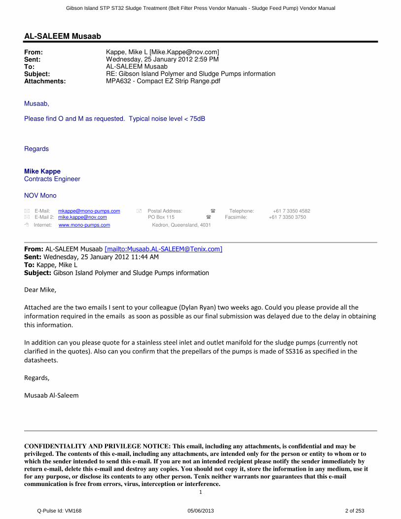
From: Kappe, Mike L [[email protected]]Sent: Wednesday, 25 January 2012 2:59 PMTo: AL-SALEEM MusaabSubject: RE: Gibson Island Polymer and Sludge Pumps informationAttachments: MPA632 - Compact EZ Strip Range.pdf
Musaab, Please find O and M as requested. Typical noise level < 75dB Regards Mike Kappe Contracts Engineer NOV Mono
� E-Mail: [email protected] � Postal Address: � Telephone: +61 7 3350 4582 � E-Mail 2: [email protected] PO Box 115 � Facsimile: +61 7 3350 3750
� Internet: www.mono-pumps.com Kedron, Queensland, 4031
From: AL-SALEEM Musaab [mailto:[email protected]] Sent: Wednesday, 25 January 2012 11:44 AM
To: Kappe, Mike L
Subject: Gibson Island Polymer and Sludge Pumps information
Dear Mike,
Attached are the two emails I sent to your colleague (Dylan Ryan) two weeks ago. Could you please provide all the
information required in the emails as soon as possible as our final submission was delayed due to the delay in obtaining
this information.
In addition can you please quote for a stainless steel inlet and outlet manifold for the sludge pumps (currently not
clarified in the quotes). Also can you confirm that the prepellars of the pumps is made of SS316 as specified in the
datasheets.
Regards,
Musaab Al-Saleem
CONFIDENTIALITY AND PRIVILEGE NOTICE: This email, including any attachments, is confidential and may be
privileged. The contents of this e-mail, including any attachments, are intended only for the person or entity to whom or to
which the sender intended to send this e-mail. If you are not an intended recipient please notify the sender immediately by
return e-mail, delete this e-mail and destroy any copies. You should not copy it, store the information in any medium, use it
for any purpose, or disclose its contents to any other person. Tenix neither warrants nor guarantees that this e-mail
communication is free from errors, virus, interception or interference.
Gibson Island STP ST32 Sludge Treatment (Belt Filter Press Vendor Manuals - Sludge Feed Pump) Vendor Manual
Q-Pulse Id: VM168 05/06/2013 2 of 253

2
Gibson Island STP ST32 Sludge Treatment (Belt Filter Press Vendor Manuals - Sludge Feed Pump) Vendor Manual
Q-Pulse Id: VM168 05/06/2013 3 of 253
Installation, Operation and Maintenance Instructions
Compact EZ Strip Range
MPA632
English
Gibson Island STP ST32 Sludge Treatment (Belt Filter Press Vendor Manuals - Sludge Feed Pump) Vendor Manual
Q-Pulse Id: VM168 05/06/2013 4 of 253

Mono UK Spares +44 (0)161 214 2380 (direct line 8.15 am – 5.00 pm)
E-mail [email protected]
Service +44 (0)161 214 2390 (direct line 8.15 am – 5.00 pm)
E-mail [email protected]
Service +44 (0)161 339 9000 (24 hrs)
Mono Australia Telephone Facsimile
Melbourne (03) 9580 5211 (03) 9580 9036
Sydney (02) 9521 5611 (02) 9542 3649
Brisbane (07) 3350 4582 (07) 3350 3750
Adelaide (08) 8447 8333 (08) 8447 8373
Perth (08) 9479 0444 (08) 9479 0400
Darwin (08) 8984 3099 (08) 8947 0540
Tasmania 0417 345 814 (03) 6330 2051
E-mail [email protected]
Mono New Zealand Spares & Service +64 (0)9 829 0333
E-mail [email protected]
Monoflo USA Spares & Service +1 713 466 7999
E-mail [email protected]
Mono China Telephone Facsimile
Beijing +86 (0) 10 6461 1115 +86 (0) 10 8486 8481
Shanghai +86 (0) 21 5915 7168 +86 (0) 21 5915 6863
E-mail [email protected]
Spares & ServiceIssued – April 2008
Spares & Service Contact Details
Monoflo South America Spares & Service +54 4296 8997 +54 4284 0323
E-mail [email protected]
Gibson Island STP ST32 Sludge Treatment (Belt Filter Press Vendor Manuals - Sludge Feed Pump) Vendor Manual
Q-Pulse Id: VM168 05/06/2013 5 of 253
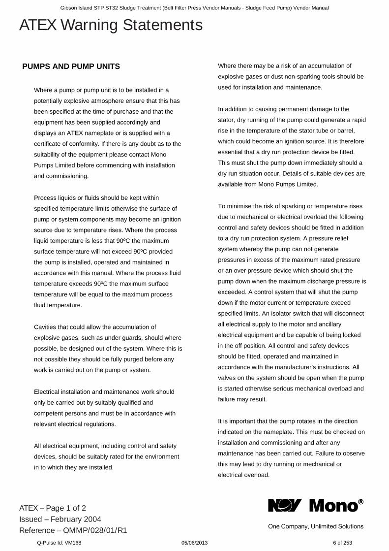
PUMPS AND PUMP UNITS
Where a pump or pump unit is to be installed in a
potentially explosive atmosphere ensure that this has
been specified at the time of purchase and that the
equipment has been supplied accordingly and
displays an ATEX nameplate or is supplied with a
certificate of conformity. If there is any doubt as to the
suitability of the equipment please contact Mono
Pumps Limited before commencing with installation
and commissioning.
Process liquids or fluids should be kept within
specified temperature limits otherwise the surface of
pump or system components may become an ignition
source due to temperature rises. Where the process
liquid temperature is less that 90ºC the maximum
surface temperature will not exceed 90ºC provided
the pump is installed, operated and maintained in
accordance with this manual. Where the process fluid
temperature exceeds 90ºC the maximum surface
temperature will be equal to the maximum process
fluid temperature.
Cavities that could allow the accumulation of
explosive gases, such as under guards, should where
possible, be designed out of the system. Where this is
not possible they should be fully purged before any
work is carried out on the pump or system.
Electrical installation and maintenance work should
only be carried out by suitably qualified and
competent persons and must be in accordance with
relevant electrical regulations.
All electrical equipment, including control and safety
devices, should be suitably rated for the environment
in to which they are installed.
Where there may be a risk of an accumulation of
explosive gases or dust non-sparking tools should be
used for installation and maintenance.
In addition to causing permanent damage to the
stator, dry running of the pump could generate a rapid
rise in the temperature of the stator tube or barrel,
which could become an ignition source. It is therefore
essential that a dry run protection device be fitted.
This must shut the pump down immediately should a
dry run situation occur. Details of suitable devices are
available from Mono Pumps Limited.
To minimise the risk of sparking or temperature rises
due to mechanical or electrical overload the following
control and safety devices should be fitted in addition
to a dry run protection system. A pressure relief
system whereby the pump can not generate
pressures in excess of the maximum rated pressure
or an over pressure device which should shut the
pump down when the maximum discharge pressure is
exceeded. A control system that will shut the pump
down if the motor current or temperature exceed
specified limits. An isolator switch that will disconnect
all electrical supply to the motor and ancillary
electrical equipment and be capable of being locked
in the off position. All control and safety devices
should be fitted, operated and maintained in
accordance with the manufacturer’s instructions. All
valves on the system should be open when the pump
is started otherwise serious mechanical overload and
failure may result.
It is important that the pump rotates in the direction
indicated on the nameplate. This must be checked on
installation and commissioning and after any
maintenance has been carried out. Failure to observe
this may lead to dry running or mechanical or
electrical overload.
ATEX – Page 1 of 2Issued – February 2004Reference – OMMP/028/01/R1
ATEX Warning StatementsGibson Island STP ST32 Sludge Treatment (Belt Filter Press Vendor Manuals - Sludge Feed Pump) Vendor Manual
Q-Pulse Id: VM168 05/06/2013 6 of 253
When fitting drives, couplings, belts, pulleys and
guards to a pump or pump unit it is essential that
these are correctly fitted, aligned and adjusted in
accordance with the manufacturer’s instructions.
Failure to do so may result in sparking due to
unintended mechanical contact or temperature rises
due to mechanical or electrical overload or slipping of
drive belts. Regular inspection of these parts must be
carried out to ensure they are in good condition and
replacement of any suspect part must be carried out
immediately.
Mechanical seals should be suitably rated for the
environment. The seal and any associated
equipment, such as a flushing system, must be
installed, operated and maintained in accordance with
the manufacturer’s instructions.
Where a packed gland seal is fitted this must be
correctly fitted and adjusted. This type of seal relies
on the process liquid to cool the shaft and packing
rings so a constant drip of liquid from the gland
section is required. Where this is undesirable an
alternative seal type should be fitted.
Failure to operate or maintain the pump and ancillary
equipment in line with the manufacturer’s instructions
may lead to premature and potentially dangerous
failure of components. Regular inspection, and where
necessary replacement, of bearings and lubrication is
essential.
The pump and its components have been designed to
ensure safe operation within the guidelines covered
by legislation. Accordingly Mono Pumps Limited have
declared the machine safe to use for the duty
specified as defined by the Declaration of
Incorporation or Conformity that is issued with this
instruction manual.
The use of replacement parts that are not
manufactured by or approved by Mono Pumps Limited
may affect the safe operation of the pump and it may
therefore become a safety hazard to both operators
and other equipment. In these circumstances the
Declaration provided will become invalid. The
guarantee referenced on the Terms and Conditions of
Sale will also be invalidated.
ATEX – Page 2 of 2Issued – February 2004Reference – OMMP/028/01/R1
ATEX Warning StatementsGibson Island STP ST32 Sludge Treatment (Belt Filter Press Vendor Manuals - Sludge Feed Pump) Vendor Manual
Q-Pulse Id: VM168 05/06/2013 7 of 253
SECTION 1 INSTALLATION
START-UP PROCEDURE
ASSEMBLY AND DISMANTLING ADVICE
SECTION 2 FAULT FINDING
SECTION 3 DRAWING REFERENCE NUMBERS
PUMP CODING SHEET
SECTION 4 DISMANTLING AND ASSEMBLY DIAGRAMS
EXPLODED VIEWS
SECTION 5 TORQUE TIGHTENING FIGURES
Index
EC Declaration of Incorporation
This declaration is only valid when partly completed machinery has been supplied.
In this case, the machinery meets the requirements of the said directive and is intended for incorporation into other machinery or for assembly with other machinery in order to constitute relevant machinery as defined by the said directive including any amendments, which are valid at the time of supply.
IMPORTANTThis machinery must not be put into service until the relevant machinery into which it is to be incorporated has been declared in conformity to the said directive.
This declaration is only valid when the machinery has been installed, operated and maintained in accordance with these instructions and safety guidelines contained within as well as instructions supplied for equipment assembled with or intended for use with this equipment.
The following harmonised standards are applicable: BS EN 809, BS EN ISO 12100 Parts 1 & 2
EC Declaration of Conformity
This declaration is not valid for partly completed machinery has been supplied.
In this case the machinery meets the requirements of the said directive including any amendments which are valid at the time of supply.
We further declare that, where applicable, said machinery also meets the requirements of:
The EMC Directive 2004/108/EC The Low Voltage Directive 2006 /95/E The Pressure Equipment Directive 97/23/EC The Outdoor Noise Directive 2005/88/EC The Drinking Water Directive 99/83/EC
IMPORTANTThis declaration is only valid when the machinery has been installed, operated and maintained in accordance with these instructions and safety guidelines contained within as well as instructions supplied for equipment assembled with or intended for use with this equipment.
Mr C. Q. Griffiths - Engineering Services Manager.for Mono Pumps Limited, Martin Street, Audenshaw, Manchester England, M34 5JA
IndexIssued – December 2009
EC Declaration as defined by Machinery Directive 2006/42/EC.
Gibson Island STP ST32 Sludge Treatment (Belt Filter Press Vendor Manuals - Sludge Feed Pump) Vendor Manual
Q-Pulse Id: VM168 05/06/2013 8 of 253
INSTALLATION
1.1 INSTALLATION AND SAFETYRECOMMENDATIONS
In common with other items of process plant a pumpmust be installed correctly to ensure satisfactory andsafe operation. The pump must also be maintainedto a suitable standard. Following theserecommendations will ensure that the safety ofpersonnel and satisfactory operation of the pump isachieved.
1.2.1. GENERAL
When handling harmful or objectionable materials,adequate ventilation must be provided in order todisperse dangerous concentrations of vapours. It isrecommended that wherever possible, Mono pumpsshould be installed with provision for adequatelighting, thus ensuring that effective maintenancecan be carried out in satisfactory conditions. Withcertain product materials, a hosing down facility withadequate draining will simplify maintenance andprolong the life of pump components.
1.2.2. SYSTEM DESIGN & INSTALLATION
At the system design stage, consideration must begiven to provision of filler plugs, and the installationof non-return and/or isolating valves. Pumps cannotbe reliably used as non-return valves. Pumps inparallel and those with high static discharge headmust be fitted with non-return valves.
The pumps must also be protected by suitabledevices against over pressure and dry running.
i. HORIZONTAL MOUNTING
All ranges excluding P Range Mono pumps arenormally installed in a horizontal position withbaseplates mounted on a flat surface, grouted inand bolted, thus ensuring firm fixing and a reductionin noise and vibration.
The unit should be checked after bolting down toensure that the alignment of the pump to its primemover is correct.
ii. VERTICAL MOUNTING
P Range Pumps Only
The P range pumps are intended for verticalinstallation. Care must be taken when lifting thepump into the vertical position.
Normally 'P' range pumps will be designed with asole plate that will be bolted to the customersframework.
If the pump is to be mounted in any way other thandescribed above, confirmation of the installationmust be agreed with Mono Pumps Limited. All thepipework should be independently supported.
1.3.1 HANDLING
During installation and maintenance, attention mustbe paid to the safe handling of all items. Where apump or its components weigh in excess of 20 kg(45lb) it is recommended that suitable lifting tackleshould be used to ensure that personal injury ordamage to components does not occur.
For safe handling of both bareshaft pumps andpump units (pump/ gearbox/motor etc.) slings shouldbe used. The position of the slings will depend uponthe specific pump/unit construction and should becarried out by personnel with the relevantexperience to ensure that the pump is not damagedand injury to personnel does not occur.
If eyebolts do exist then these should only be usedfor lifting the individual components for which theyare supplied.
1.3.2 STORAGE AND INFREQUENT OPERATION
The situation where a pump is used infrequently isalso covered by the instructions in this section.
SHORT TERM STORAGE
Where a pump has to be stored for 6 months orless then the following steps are advised:-
1. Store pump inside wherever possible or if this is notfeasible then provide protective covering. Do notallow moisture to collect around the pump.
2. Remove the drain plug, if fitted. Any inspectionplates fitted should also be removed to ensure thatthe suction housing can drain and dry completely.
3. Loosen the packed gland and inject sufficient greaseinto the stuffing box. Tighten the gland nut handtight. If a water flush system is to be used do notgrease, a small amount of light oil is recommendedfor these.
4. See Manufacturers Instructions formotor/gearbox/drive instructions for storageprocedures.
Section 1, Page 1Issued – October 2009
Installation, Operation & Maintenance Instructions
Pumps operating on high temperature dutiesshould be allowed to cool sufficiently before anymaintenance is carried out.
Gibson Island STP ST32 Sludge Treatment (Belt Filter Press Vendor Manuals - Sludge Feed Pump) Vendor Manual
Q-Pulse Id: VM168 05/06/2013 9 of 253
LONG TERM STORAGE
If the pump is to be kept in storage for more thansix months then in addition to the above thefollowing procedures should be carried outregularly (every 2 - 3 weeks if possible):
1. If practicable rotate the pump at least three quartersof one revolution to avoid the rotor setting in thestator.
2. Note, however, that the pump is not to be rotated formore than two revolutions each time becausedamage could be caused to the rotor/ statorelements.
IMMEDIATELY PRIOR TO INSTALLATION ANDSTARTING
Before installing the pump please ensure that allplugs and inspection plates are replaced andthat excess grease/oil is removed from thestuffing box.
1.4 ELECTRICAL
Electrical connection should only be made usingequipment suitable for both rating and environment.Where any doubts exist regarding the suitability ofequipment, Mono Pumps Limited, should beconsulted before proceeding. Normally the Monopump should be installed with starting equipmentarranged to give direct on line starting.
Earthing points will be provided on electric drives (ifsupplied) and it is essential that these are correctlyconnected. When the motor is being wired andchecked for rotation, the start/stop sequence mustbe instantaneous to prevent dry running (see 2) orpressurising upstream equipment. (Check directionarrow on pump nameplate). The electricalinstallation should include appropriate isolatingequipment to ensure that the pump unit is safe towork on.
1.5 PRESSURE RELIEF VALVES AND NON-RETURNVALVES
1. It is recommended that a suitable safety device isinstalled on the discharge side of the pump toprevent over-pressurisation of the system.
2. It is also recommended that a non-return valve isinstalled on the discharge side of the pump toprevent reverse flow through the system.
When both are installed it is advised that the reliefvalve is positioned closer to the pump than the non-return valve.
IMPORTANT
The pump must never run against a closed inletor outlet valve, as this could result inmechanical failure.
1.6 GENERAL SAFETY
GREAT CARE MUST BE TAKEN TO PROTECTALL ELECTRICAL EQUIPMENT FROMSPLASHING WHEN HOSING DOWN. WHEREMONO PUMPS LIMITED HAVE SUPPLIED ABARESHAFT PUMP THE ONUS IS ON THE USERTO FIT ADEQUATE GUARDS IN COMPLIANCEWITH THE REQUIREMENTS OF THE RELEVANTREGULATIONS.
All nuts and bolts, securing flanges and basemounting fixtures must be checked for tightnessbefore operation. To eliminate vibration, the pumpmust be correctly aligned with the drive unit, and allguards must be securely fixed in position. Whencommissioning the plant, all joints in the systemmust be checked thoroughly for leakage.
If, when starting, the pump does not appear tooperate correctly (see 2), the plant must be shutdown immediately and the cause of the malfunctionestablished before operations are recommenced. Itis recommended that depending upon plant systemoperation, either a combined vacuum and pressuregauge, or a vacuum gauge only be fitted to thepump inlet port, and a pressure gauge fitted to theoutlet port, these will then continuously monitor thepump operating conditions. May contain substances from the ECHA SVHC Candidates List (REACH - Regulation (EC) No. 1907/2006)
1.7 DUTY CONDITIONS
Pumps should only be installed on duties for whichMono Pumps Limited have specified the materials ofconstruction, flow rates, pressure, temperature, speed etc. Where dangerous materials are to be
pumped, consideration must be given to the safedischarge from relief valves, gland drains etc.IF THE DUTY SHOULD BE CHANGED, MONOPUMPS LIMITED SHOULD BE CONTACTED ANDTHEIR RECOMMENDATIONS SOUGHT IN THEINTEREST OF APPLICATION, SAFETY OFPLANT, EFFICIENCY AND PUMP LIFE.
Section 1, Page 2Issued – September 2009
Installation, Operation & Maintenance InstructionsGibson Island STP ST32 Sludge Treatment (Belt Filter Press Vendor Manuals - Sludge Feed Pump) Vendor Manual
Q-Pulse Id: VM168 05/06/2013 10 of 253
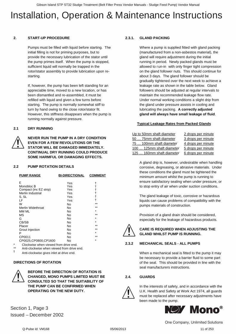
2. START-UP PROCEDURE
Pumps must be filled with liquid before starting. Theinitial filling is not for priming purposes, but toprovide the necessary lubrication of the stator untilthe pump primes itself. When the pump is stopped,sufficient liquid will normally be trapped in therotor/stator assembly to provide lubrication upon re-starting.
If, however, the pump has been left standing for anappreciable time, moved to a new location, or hasbeen dismantled and re-assembled, it must berefilled with liquid and given a few turns beforestarting. The pump is normally somewhat stiff toturn by hand owing to the close rotor/stator fit.However, this stiffness disappears when the pump isrunning normally against pressure.
2.1 DRY RUNNING
NEVER RUN THE PUMP IN A DRY CONDITIONEVEN FOR A FEW REVOLUTIONS OR THESTATOR WILL BE DAMAGED IMMEDIATELY.CONTINUAL DRY RUNNING COULD PRODUCESOME HARMFUL OR DAMAGING EFFECTS.
2.2 PUMP ROTATION DETAILS
PUMP RANGE BI-DIRECTIONAL COMMENT
EMonobloc B Yes
Yes
Merlin Industrial YesseYLS,SseYFL
**WMerlin Widethroat No
No
No
***oNLMMM**oNSM
*G*oNBS/BC**oNrecalP
Grout Injection No **oNP
**oN1100PCCP0025,CP0800,CP1600 No *
*
* Clockwise when viewed from drive end.** Anti-clockwise when viewed from drive end.
Anti-clockwise gives inlet at drive end.
DIRECTIONS OF ROTATION
BEFORE THE DIRECTION OF ROTATION ISCHANGED, MONO PUMPS LIMITED MUST BECONSULTED SO THAT THE SUITABILITY OFTHE PUMP CAN BE CONFIRMED WHENOPERATING ON THE NEW DUTY.
2.3.1. GLAND PACKING
Where a pump is supplied fitted with gland packing(manufactured from a non-asbestos material), thegland will require adjustment during the initialrunning in period. Newly packed glands must beallowed to run-in with only finger tight compressionon the gland follower nuts. This should continue forabout 3 days. The gland follower should begradually tightened over the next week to achieve aleakage rate as shown in the table below. Glandfollowers should be adjusted at regular intervals tomaintain the recommended leakage flow rate.Under normal working conditions a slight drip fromthe gland under pressure assists in cooling andlubricating the packing. A correctly adjustedgland will always have small leakage of fluid.
Typical Leakage Rates from Packed Glands
Up to 50mm shaft diameter 2 drops per minute50 … 75mm shaft diameter 3 drops per minute75 … 100mm shaft diameter 4 drops per minute100 … 125mm shaft diameter 5 drops per minute125 … 160mm shaft diameter 6 drops per minute
A gland drip is, however, undesirable when handlingcorrosive, degreasing, or abrasive materials. Underthese conditions the gland must be tightened theminimum amount whilst the pump is running toensure satisfactory sealing when under pressure, orto stop entry of air when under suction conditions.
The gland leakage of toxic, corrosive or hazardousliquids can cause problems of compatibility with thepumps materials of construction.
Provision of a gland drain should be considered,especially for the leakage of hazardous products.
CARE IS REQUIRED WHEN ADJUSTING THEGLAND WHILST PUMP IS RUNNING.
2.3.2 MECHANICAL SEALS - ALL PUMPS
When a mechanical seal is fitted to the pump it maybe necessary to provide a barrier fluid to some partof the seal. This should be provided in line with theseal manufacturers instructions.
2.4. GUARDS
In the interests of safety, and in accordance with theU.K. Health and Safety at Work Act 1974, all guardsmust be replaced after necessary adjustments havebeen made to the pump.
†
†
††
†seYt (inc EZ strip)capmoC †
†
Section 1, Page 3Issued – December 2002
Installation, Operation & Maintenance InstructionsGibson Island STP ST32 Sludge Treatment (Belt Filter Press Vendor Manuals - Sludge Feed Pump) Vendor Manual
Q-Pulse Id: VM168 05/06/2013 11 of 253
2.5 WARNING/CONTROL DEVICE
Prior to operating the pump, if any warning or controldevices are fitted these must be set in accordancewith their specific instructions.
2.6 PUMP OPERATING TEMPERATURE
The range of temperatures the pump surfaces willdevelop is dependent upon factors such as producttemperature and ambient temperature of theinstallation. There may be instances where theexternal pump surface can exceed 50oC.
In these instances, personnel must be made awareof this and suitable warnings/guarding used.
2.7 NOISE LEVELS
2.8 LUBRICATION
Pumps fitted with bearings should be inspectedperiodically to see if grease replenishment isnecessary, and if so, grease should be added untilthe chambers at the ends of the bearing spacer areapproximately one third full.
Periodic bearing inspection is necessary to maintainoptimum bearing performance. The most expedienttime to inspect is during periods of regularscheduled equipment downtime - for routinemaintenance or for any other reason.
Under tropical or other arduous conditions, however,a more frequent examination may be necessary. Itis therefore advisable to establish a correctmaintenance schedule or periodic inspection.
BP LC2 / Mobilgrease XHP 222 or their equivalentmust be used for replenishment.
2.9 PUMP UNITS
Where a pump unit is dismantled and re-assembled,consideration must be given to ensure that whereappropriate the following steps are covered.
1. Correct alignment of pump/gearbox2. Use of appropriate couplings & bushes3. Use of appropriate belts & pulleys correctly
tensioned.
2.10 CLEANING PRIOR TO OPERATION
i. Non Food Use
During the commissioning of a new pump orrecommissioning of an overhauled pump, it isadvisable to clean the pump prior to the initialoperation of the pump in the process.
ii. Food Use
When a pump has been supplied for a foodapplication, it is important to ensure that the pump isclean prior to initial operation of the pump.
Therefore, it is important that a clean-in-placetreatment is executed on the pump at the followingtimes:-
1. When the pump is first commissioned for use.
2. When any spare components are fitted into thewetted area of the pump.
A recommended CIP procedure is as follows:
This procedure should not be used on the CPPump Range. Please consult our applicationengineers for a suitable procedure.
Caustic WashLQ94 ex Lever Diversey or equivalent2% concentration
Acid WashP3 Horolith 617 ex HenkelEcolab or equivalent 1% concentration
Procedure
1. Caustic wash @ 75°C for 20 mins2. Water rinse @ 80°C for 20 mins
Section 1, Page 4Issued – August 2009
Installation, Operation & Maintenance Instructions
1. The sound pressure level should not exceed 85dB at one metre distance from the pump.
2. This is based on a typical installation and does not necessarily include noise from other sources or any contribution from building reverberation or installation pipework
3. It is recommended the actual pump unit noise levels are ascertained once the unit is installed and running at duty conditions
Gibson Island STP ST32 Sludge Treatment (Belt Filter Press Vendor Manuals - Sludge Feed Pump) Vendor Manual
Q-Pulse Id: VM168 05/06/2013 12 of 253
3. Acid wash @ 50°C for 20 mins4. Water rinse @ 80°C for 20 mins
CIP flow rates (hence pump speeds) should bemaximised to achieve highest level of cleanability.
A C.I.P. liquid velocity of 1.5 to 2.0 m/s is requiredfor removal of solids and soiling.
Pumps fitted with CIP by pass ports will permithigher flow rates without the need to increase pumpspeed.
The use of neat active causticand acid chemicals is notrecommended. Proprietary cleaningagents should be used in line with manufacturersinstructions.
All seals and gaskets should bereplaced with new if disturbedduring maintenance.
Pump internals should be regularly inspected toensure hygienic integrity is maintained, especiallywith respect to elastomeric components and seals,and replaced if necessary.
The four stages constitute one cycle and werecommend that this cycle is used to clean the pumpbefore use on food.
Once the pump has been commissioned, thecleaning process will depend upon the application.The user must therefore ensure that their cleaningprocedures are suitable for the duty for which thepump has been purchased.
2.11 WIDETHROAT PUMPS
Specific pumps may have auger feed screws, withor without a bridge breaker system to feed thepumping element. If the pump installation requiresthat these cannot be enclosed, care must be takento ensure personnel cannot gain access whilst thepump is operating. If this is not possible anemergency stop device must be fitted nearby.
2.12 EXPLOSIVE PRODUCTS/ HAZARDOUSATMOSPHERES
In certain instances the product being pumped maywell be of a hazardous nature.
In these installations consideration must be given toprovide suitable protection and appropriate warningsto safeguard personnel and plant.
2.13 ACCESS PORTS
Where access ports are fitted then the followingsteps must be followed prior to removal:
1. Pump must be shut down and the electrical supplyisolated.
2. Protective clothing should be worn, especially if thepumped product is obnoxious.
3. Remove access plate with care utilising wherepossible drip trays to collect product leakage.
Access ports are included to assist in removingblockages and to allow a visual check on thecomponents within the suction chamber.
It is not to be considered as an additional method indismantling the pump.
Re-assembly of the plate should be completed usingnew gaskets prior to the pump being switched on.
2.14 ADJUSTABLE STATORS
If adjustable stators are fitted then the followingsteps must be followed for adjusting the clampingdevices.
The adjustable stator assembly is designed to givean even compression around the statorcircumference. It is designed to be used whenpump performance reduces through wear to anunacceptable level, to restore the required flow rate.
The stator compression is increased using thefollowing steps:-
1. Release the six locking screws half a turn.
2. Tighten the eight clamp screws until adjustmentallowed by releasing the lock screws has been takenup.
3. Repeat steps 1 and 2 until the pump performancehas been restored to its former level.
NOTE
It is imperative that when adjusting the stator thatonly sufficient pressure is placed on the stator toenable the capacity of the pump to be reinstated.
Over tightening of the stator could easily result indamage to the driver by overload and so extremecare must be taken when carrying out theseadjustments.
Section 1, Page 5Issued – December 2002
Installation, Operation & Maintenance InstructionsGibson Island STP ST32 Sludge Treatment (Belt Filter Press Vendor Manuals - Sludge Feed Pump) Vendor Manual
Q-Pulse Id: VM168 05/06/2013 13 of 253
It is therefore advisable to make the adjustmentwhile the pump is running and power readings canbe monitored.
REMOVAL OF ADJUSTABLE STATOR
The procedure for removal of an adjustable stator isthe same as that of a standard one, except it isnecessary to remove the clamp plates before thestator can be twisted off the rotor.
This can be done by undoing the clamp screws;then releasing the clamp plate by using the lockingscrews as jacking screws to remove the clampplates.
Re-assembly will be done using the reverseprocedure.
2.15 MAINTENANCE OF WEARING COMPONENTS
2.15.1 ROTOR AND STATOR
The wear rate on these components is dependenton many factors, such as product abrasivity, speed,pressure etc.
When pump performance has reduced to anunacceptable level one or possibly both items willneed replacing.
2.15.2 DRIVE SHAFT - PACKED GLAND
The wear rate of the gland area is dependent onmany factors such as product abrasivity and speed.Regular gland maintenance will maximise the life ofthe shaft. Replacement of both the gland packingand shaft will be necessary when shaft sealingbecomes difficult to achieve.
2.15.3 COUPLING ROD JOINTS
Regular maintenance and lubrication will maximiselife of the joints.
Replacement of one or both joint assemblies andpossibly the coupling rod may be necessary whenwear is apparent.
It is essential to replace all the joint items withgenuine Mono parts to ensure maximum life.
2.15.4 FLEXISHAFT DRIVE PUMPS
With this design there are no wearing items toreplace in the drive train, however, if during routineinspection the shaft is visibly damaged / distorted or the protective coating is damaged, then this itemshould be replaced to avoid unexpectedbreakdowns.
2.16 MECHANICAL SPEED VARIATORS
Refer to the manufacturers instructions.
These machines require regular maintenance, whichtypically includes weekly adjustment through the fullspeed range.
3.0 ASSEMBLY AND DISMANTLING
Section 4 contains the steps to dismantle andre-assemble the pump. All fastenings must betightened securely and when identified theappropriate torque figures should be used.
3.1 USE OF ITEMS NOT APPROVED ORMANUFACTURED BY MONO PUMPS LIMITED
The pump and its components have been designedto ensure that the pump will operate safely within theguidelines covered by the legislation.
As a consequence Mono Pumps Limited have declared the machine safe to use for the dutyspecified as defined by the Declaration ofIncorporation or Conformity that is issued with thisInstruction Manual.
The use of replacement items that are not approvedby or manufactured by Mono Pumps Limited mayaffect the safe operation of the pump and it maytherefore become a safety hazard to both operatorsand other equipment. In these instances theDeclaration provided will therefore become invalid.The guarantee referenced in the Terms andConditions of Sale will also be invalidated ifreplacement items are used that are not approved ormanufactured by Mono Pumps Limited.
DISPOSAL OF WORN COMPONENTS
When replacing wearing parts, please ensuredisposal of used parts is carried out in compliancewith local environmental legislation. Particular careshould be taken when disposing of lubricants.
Section 1, Page 6Issued – December 2002
Installation, Operation & Maintenance InstructionsGibson Island STP ST32 Sludge Treatment (Belt Filter Press Vendor Manuals - Sludge Feed Pump) Vendor Manual
Q-Pulse Id: VM168 05/06/2013 14 of 253
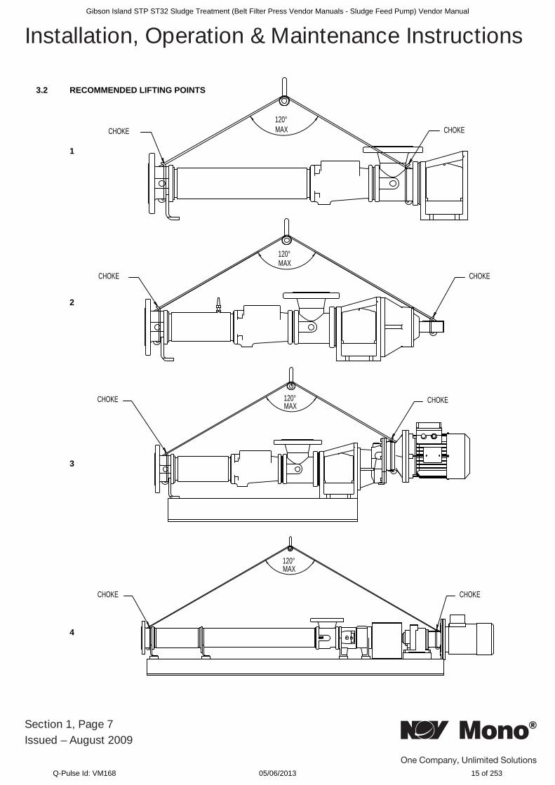
3.2 RECOMMENDED LIFTING POINTS
1
2
3
4
Section 1, Page 7Issued – August 2009
Installation, Operation & Maintenance Instructions
120°MAX CHOKECHOKE
120°MAX
CHOKECHOKE
120°MAX
CHOKECHOKE
120°MAX
CHOKECHOKE
Gibson Island STP ST32 Sludge Treatment (Belt Filter Press Vendor Manuals - Sludge Feed Pump) Vendor Manual
Q-Pulse Id: VM168 05/06/2013 15 of 253
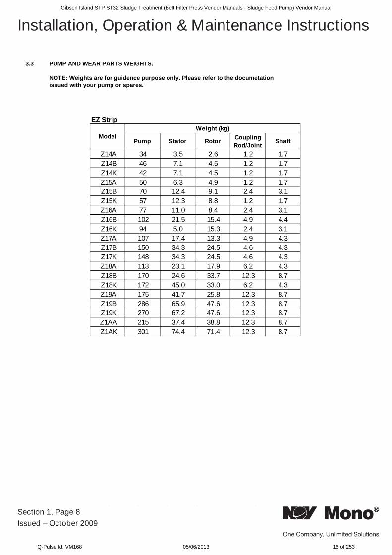
3.3 PUMP AND WEAR PARTS WEIGHTS.
NOTE: Weights are for guidence purpose only. Please refer to the documetation issued with your pump or spares.
Section 1, Page 8Issued – October 2009
Installation, Operation & Maintenance Instructions
EZ Strip
Pump Stator Rotor Coupling Rod/Joint Shaft
Z14A 34 3.5 2.6 1.2 1.7Z14B 46 7.1 4.5 1.2 1.7Z14K 42 7.1 4.5 1.2 1.7Z15A 50 6.3 4.9 1.2 1.7Z15B 70 12.4 9.1 2.4 3.1Z15K 57 12.3 8.8 1.2 1.7Z16A 77 11.0 8.4 2.4 3.1Z16B 102 21.5 15.4 4.9 4.4Z16K 94 5.0 15.3 2.4 3.1Z17A 107 17.4 13.3 4.9 4.3Z17B 150 34.3 24.5 4.6 4.3Z17K 148 34.3 24.5 4.6 4.3Z18A 113 23.1 17.9 6.2 4.3Z18B 170 24.6 33.7 12.3 8.7Z18K 172 45.0 33.0 6.2 4.3Z19A 175 41.7 25.8 12.3 8.7Z19B 286 65.9 47.6 12.3 8.7Z19K 270 67.2 47.6 12.3 8.7Z1AA 215 37.4 38.8 12.3 8.7Z1AK 301 74.4 71.4 12.3 8.7
ModelWeight (kg)
Gibson Island STP ST32 Sludge Treatment (Belt Filter Press Vendor Manuals - Sludge Feed Pump) Vendor Manual
Q-Pulse Id: VM168 05/06/2013 16 of 253
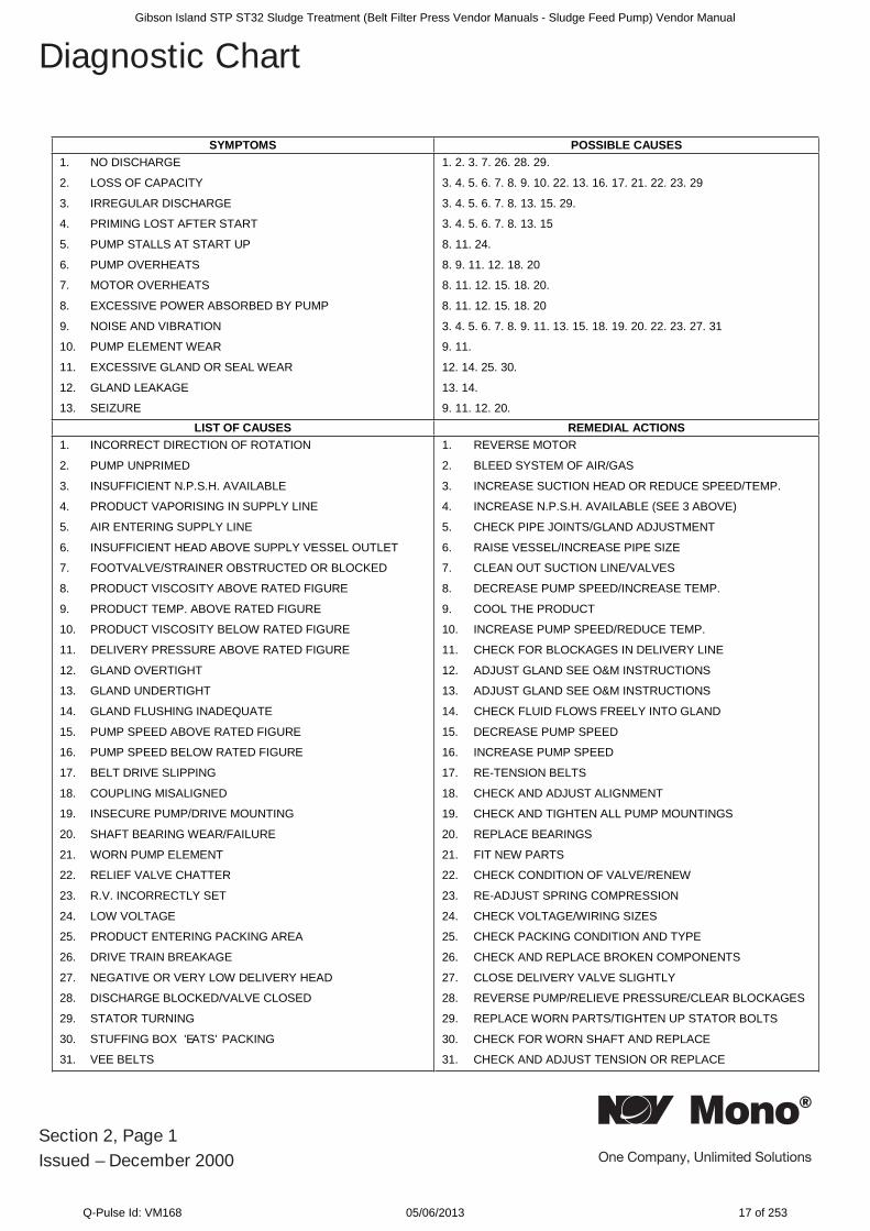
SESUACELBISSOPSMOTPMYS1. NO DISCHARGE
2. LOSS OF CAPACITY
3. IRREGULAR DISCHARGE
4. PRIMING LOST AFTER START
5. PUMP STALLS AT START UP
6. PUMP OVERHEATS
7. MOTOR OVERHEATS
8. EXCESSIVE POWER ABSORBED BY PUMP
9. NOISE AND VIBRATION
10. PUMP ELEMENT WEAR
11. EXCESSIVE GLAND OR SEAL WEAR
12. GLAND LEAKAGE
13. SEIZURE
1. 2. 3. 7. 26. 28. 29.
3. 4. 5. 6. 7. 8. 9. 10. 22. 13. 16. 17. 21. 22. 23. 29
3. 4. 5. 6. 7. 8. 13. 15. 29.
3. 4. 5. 6. 7. 8. 13. 15
8. 11. 24.
8. 9. 11. 12. 18. 20
8. 11. 12. 15. 18. 20.
8. 11. 12. 15. 18. 20
3. 4. 5. 6. 7. 8. 9. 11. 13. 15. 18. 19. 20. 22. 23. 27. 31
9. 11.
12. 14. 25. 30.
13. 14.
9. 11. 12. 20.
SNOITCALAIDEMERSESUACFOTSIL1. INCORRECT DIRECTION OF ROTATION
2. PUMP UNPRIMED
3. INSUFFICIENT N.P.S.H. AVAILABLE
4. PRODUCT VAPORISING IN SUPPLY LINE
5. AIR ENTERING SUPPLY LINE
6. INSUFFICIENT HEAD ABOVE SUPPLY VESSEL OUTLET
7. FOOTVALVE/STRAINER OBSTRUCTED OR BLOCKED
8. PRODUCT VISCOSITY ABOVE RATED FIGURE
9. PRODUCT TEMP. ABOVE RATED FIGURE
10. PRODUCT VISCOSITY BELOW RATED FIGURE
11. DELIVERY PRESSURE ABOVE RATED FIGURE
12. GLAND OVERTIGHT
13. GLAND UNDERTIGHT
14. GLAND FLUSHING INADEQUATE
15. PUMP SPEED ABOVE RATED FIGURE
16. PUMP SPEED BELOW RATED FIGURE
17. BELT DRIVE SLIPPING
18. COUPLING MISALIGNED
19. INSECURE PUMP/DRIVE MOUNTING
20. SHAFT BEARING WEAR/FAILURE
21. WORN PUMP ELEMENT
22. RELIEF VALVE CHATTER
23. R.V. INCORRECTLY SET
24. LOW VOLTAGE
25. PRODUCT ENTERING PACKING AREA
26. DRIVE TRAIN BREAKAGE
27. NEGATIVE OR VERY LOW DELIVERY HEAD
28. DISCHARGE BLOCKED/VALVE CLOSED
29. STATOR TURNING
30. STUFFING BOX 'EATS' PACKING
31. VEE BELTS
1. REVERSE MOTOR
2. BLEED SYSTEM OF AIR/GAS
3. INCREASE SUCTION HEAD OR REDUCE SPEED/TEMP.
4. INCREASE N.P.S.H. AVAILABLE (SEE 3 ABOVE)
5. CHECK PIPE JOINTS/GLAND ADJUSTMENT
6. RAISE VESSEL/INCREASE PIPE SIZE
7. CLEAN OUT SUCTION LINE/VALVES
8. DECREASE PUMP SPEED/INCREASE TEMP.
9. COOL THE PRODUCT
10. INCREASE PUMP SPEED/REDUCE TEMP.
11. CHECK FOR BLOCKAGES IN DELIVERY LINE
12. ADJUST GLAND SEE O&M INSTRUCTIONS
13. ADJUST GLAND SEE O&M INSTRUCTIONS
14. CHECK FLUID FLOWS FREELY INTO GLAND
15. DECREASE PUMP SPEED
16. INCREASE PUMP SPEED
17. RE-TENSION BELTS
18. CHECK AND ADJUST ALIGNMENT
19. CHECK AND TIGHTEN ALL PUMP MOUNTINGS
20. REPLACE BEARINGS
21. FIT NEW PARTS
22. CHECK CONDITION OF VALVE/RENEW
23. RE-ADJUST SPRING COMPRESSION
24. CHECK VOLTAGE/WIRING SIZES
25. CHECK PACKING CONDITION AND TYPE
26. CHECK AND REPLACE BROKEN COMPONENTS
27. CLOSE DELIVERY VALVE SLIGHTLY
28. REVERSE PUMP/RELIEVE PRESSURE/CLEAR BLOCKAGES
29. REPLACE WORN PARTS/TIGHTEN UP STATOR BOLTS
30. CHECK FOR WORN SHAFT AND REPLACE
31. CHECK AND ADJUST TENSION OR REPLACE
Section 2, Page 1Issued – December 2000
Diagnostic ChartGibson Island STP ST32 Sludge Treatment (Belt Filter Press Vendor Manuals - Sludge Feed Pump) Vendor Manual
Q-Pulse Id: VM168 05/06/2013 17 of 253
DRG.REF
DESCRIPTION DRG. REF
DESCRIPTION
IMPORTANT NOTE
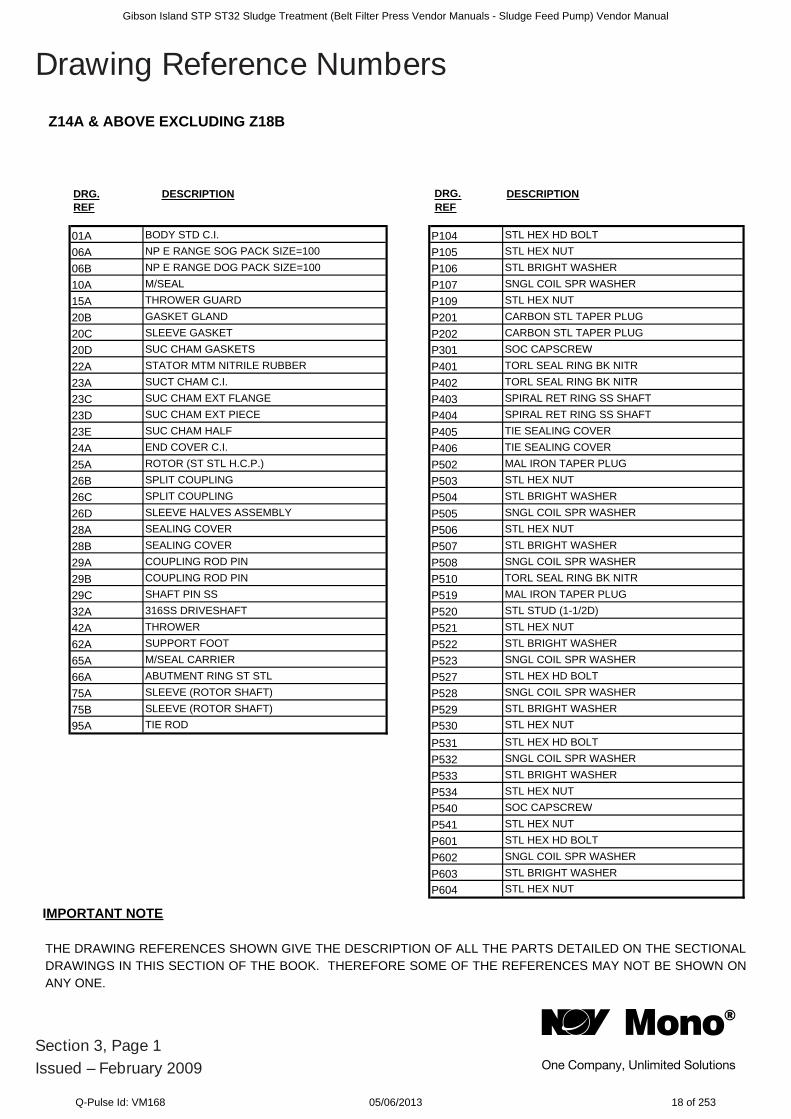
Z14A & ABOVE EXCLUDING Z18B
THE DRAWING REFERENCES SHOWN GIVE THE DESCRIPTION OF ALL THE PARTS DETAILED ON THE SECTIONAL DRAWINGS IN THIS SECTION OF THE BOOK. THEREFORE SOME OF THE REFERENCES MAY NOT BE SHOWN ON ANY ONE.
Section 3, Page 1Issued – February 2009
Drawing Reference Numbers
01A BODY STD C.I. P104 STL HEX HD BOLT06A NP E RANGE SOG PACK SIZE=100 P105 STL HEX NUT06B NP E RANGE DOG PACK SIZE=100 P106 STL BRIGHT WASHER10A M/SEAL P107 SNGL COIL SPR WASHER15A THROWER GUARD P109 STL HEX NUT20B GASKET GLAND P201 CARBON STL TAPER PLUG20C SLEEVE GASKET P202 CARBON STL TAPER PLUG20D SUC CHAM GASKETS P301 SOC CAPSCREW22A STATOR MTM NITRILE RUBBER P401 TORL SEAL RING BK NITR23A SUCT CHAM C.I. P402 TORL SEAL RING BK NITR23C SUC CHAM EXT FLANGE P403 SPIRAL RET RING SS SHAFT23D SUC CHAM EXT PIECE P404 SPIRAL RET RING SS SHAFT23E SUC CHAM HALF P405 TIE SEALING COVER24A END COVER C.I. P406 TIE SEALING COVER25A ROTOR (ST STL H.C.P.) P502 MAL IRON TAPER PLUG26B SPLIT COUPLING P503 STL HEX NUT26C SPLIT COUPLING P504 STL BRIGHT WASHER26D SLEEVE HALVES ASSEMBLY P505 SNGL COIL SPR WASHER28A SEALING COVER P506 STL HEX NUT28B SEALING COVER P507 STL BRIGHT WASHER29A COUPLING ROD PIN P508 SNGL COIL SPR WASHER29B COUPLING ROD PIN P510 TORL SEAL RING BK NITR29C SHAFT PIN SS P519 MAL IRON TAPER PLUG32A 316SS DRIVESHAFT P520 STL STUD (1-1/2D)42A THROWER P521 STL HEX NUT62A SUPPORT FOOT P522 STL BRIGHT WASHER65A M/SEAL CARRIER P523 SNGL COIL SPR WASHER66A ABUTMENT RING ST STL P527 STL HEX HD BOLT75A SLEEVE (ROTOR SHAFT) P528 SNGL COIL SPR WASHER75B SLEEVE (ROTOR SHAFT) P529 STL BRIGHT WASHER95A TIE ROD P530 STL HEX NUT
P531 STL HEX HD BOLTP532 SNGL COIL SPR WASHERP533 STL BRIGHT WASHERP534 STL HEX NUTP540 SOC CAPSCREWP541 STL HEX NUTP601 STL HEX HD BOLTP602 SNGL COIL SPR WASHERP603 STL BRIGHT WASHERP604 STL HEX NUT
Gibson Island STP ST32 Sludge Treatment (Belt Filter Press Vendor Manuals - Sludge Feed Pump) Vendor Manual
Q-Pulse Id: VM168 05/06/2013 18 of 253
DRG.REF.
DRG.REF.DESCRIPTION DESCRIPTION
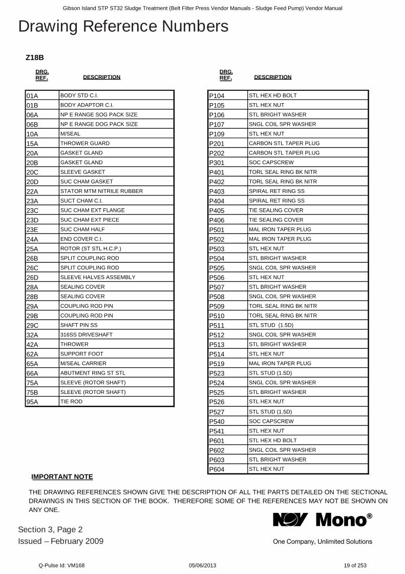
Z18B
IMPORTANT NOTE
THE DRAWING REFERENCES SHOWN GIVE THE DESCRIPTION OF ALL THE PARTS DETAILED ON THE SECTIONAL DRAWINGS IN THIS SECTION OF THE BOOK. THEREFORE SOME OF THE REFERENCES MAY NOT BE SHOWN ON ANY ONE.
Section 3, Page 2Issued – February 2009
Drawing Reference Numbers
01A BODY STD C.I. P104 STL HEX HD BOLT
01B BODY ADAPTOR C.I. P105 STL HEX NUT
06A NP E RANGE SOG PACK SIZE P106 STL BRIGHT WASHER
06B NP E RANGE DOG PACK SIZE P107 SNGL COIL SPR WASHER
10A M/SEAL P109 STL HEX NUT
15A THROWER GUARD P201 CARBON STL TAPER PLUG
20A GASKET GLAND P202 CARBON STL TAPER PLUG
20B GASKET GLAND P301 SOC CAPSCREW
20C SLEEVE GASKET P401 TORL SEAL RING BK NITR
20D SUC CHAM GASKET P402 TORL SEAL RING BK NITR
22A STATOR MTM NITRILE RUBBER P403 SPIRAL RET RING SS
23A SUCT CHAM C.I. P404 SPIRAL RET RING SS
23C SUC CHAM EXT FLANGE P405 TIE SEALING COVER
23D SUC CHAM EXT PIECE P406 TIE SEALING COVER
23E SUC CHAM HALF P501 MAL IRON TAPER PLUG
24A END COVER C.I. P502 MAL IRON TAPER PLUG
25A ROTOR (ST STL H.C.P.) P503 STL HEX NUT
26B SPLIT COUPLING ROD P504 STL BRIGHT WASHER
26C SPLIT COUPLING ROD P505 SNGL COIL SPR WASHER
26D SLEEVE HALVES ASSEMBLY P506 STL HEX NUT
28A SEALING COVER P507 STL BRIGHT WASHER
28B SEALING COVER P508 SNGL COIL SPR WASHER
29A COUPLING ROD PIN P509 TORL SEAL RING BK NITR
29B COUPLING ROD PIN P510 TORL SEAL RING BK NITR
29C SHAFT PIN SS P511 STL STUD (1.5D)
32A 316SS DRIVESHAFT P512 SNGL COIL SPR WASHER
42A THROWER P513 STL BRIGHT WASHER
62A SUPPORT FOOT P514 STL HEX NUT
65A M/SEAL CARRIER P519 MAL IRON TAPER PLUG
66A ABUTMENT RING ST STL P523 STL STUD (1.5D)
75A SLEEVE (ROTOR SHAFT) P524 SNGL COIL SPR WASHER
75B SLEEVE (ROTOR SHAFT) P525 STL BRIGHT WASHER
95A TIE ROD P526 STL HEX NUT
P527 STL STUD (1.5D)
P540 SOC CAPSCREW
P541 STL HEX NUT
P601 STL HEX HD BOLT
P602 SNGL COIL SPR WASHER
P603 STL BRIGHT WASHER
P604 STL HEX NUTIMPORTANT NOTE
Gibson Island STP ST32 Sludge Treatment (Belt Filter Press Vendor Manuals - Sludge Feed Pump) Vendor Manual
Q-Pulse Id: VM168 05/06/2013 19 of 253
Section 3, Page 3Issued – August 2009
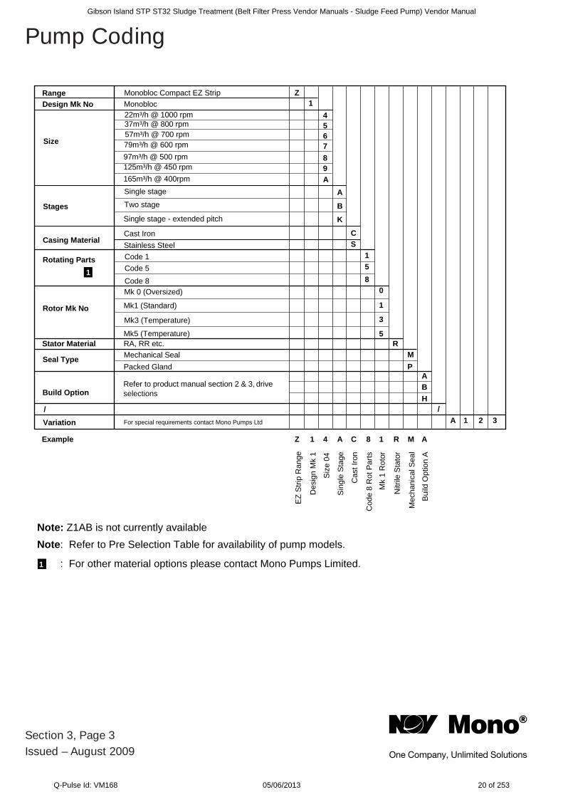
Pump Coding
Note: Refer to Pre Selection Table for availability of pump models.
: For other material options please contact Mono Pumps Limited. 1
AMR18CA41ZelpmaxE
Note: Z1AB is not currently available
EZ S
trip
Ran
ge
Des
ign
Mk
1
Siz
e 04
Sing
le S
tage
Cas
t Iro
n
Cod
e 8
Rot
Par
ts
Mk
1 R
otor
Nitr
ile S
tato
r
Mec
hani
cal S
eal
Bui
ld O
ptio
n A
Range Monobloc Compact EZ Strip Z1
456789A
A
B
K
CS
158
0
1
3
5
MR
PA
A 1 2 3
BH
Monobloc22m³/h @ 1000 rpm37m³/h @ 800 rpm57m³/h @ 700 rpm79m³/h @ 600 rpm97m³/h @ 500 rpm125m³/h @ 450 rpm165m³/h @ 400rpmSingle stage
Two stage
Single stage - extended pitch
Cast IronStainless SteelCode 1Code 5Code 8Mk 0 (Oversized)
Mk1 (Standard)
Mk3 (Temperature)
Mk5 (Temperature)Stator Material RA, RR etc.
Mechanical SealPacked Gland
/ /
Variation For special requirements contact Mono Pumps Ltd
Build Option
Seal Type
Refer to product manual section 2 & 3, drive selections
Casing Material
Size
Stages
Rotating Parts
Rotor Mk No
Design Mk No
1
Gibson Island STP ST32 Sludge Treatment (Belt Filter Press Vendor Manuals - Sludge Feed Pump) Vendor Manual
Q-Pulse Id: VM168 05/06/2013 20 of 253
RO
TOR
& S
TATO
R C
HA
NG
ED
ISM
AN
TLIN
G
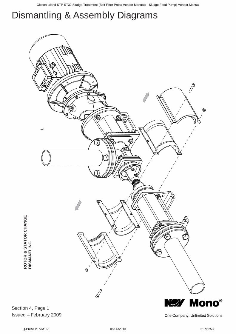
Section 4, Page 1Issued – February 2009
Dismantling & Assembly Diagrams
1
Gibson Island STP ST32 Sludge Treatment (Belt Filter Press Vendor Manuals - Sludge Feed Pump) Vendor Manual
Q-Pulse Id: VM168 05/06/2013 21 of 253

Section 4, Page 2Issued – December 2008
Dismantling & Assembly DiagramsR
OTO
R &
STA
TOR
CH
AN
GE
DIS
MA
NTL
ING
2
Gibson Island STP ST32 Sludge Treatment (Belt Filter Press Vendor Manuals - Sludge Feed Pump) Vendor Manual
Q-Pulse Id: VM168 05/06/2013 22 of 253
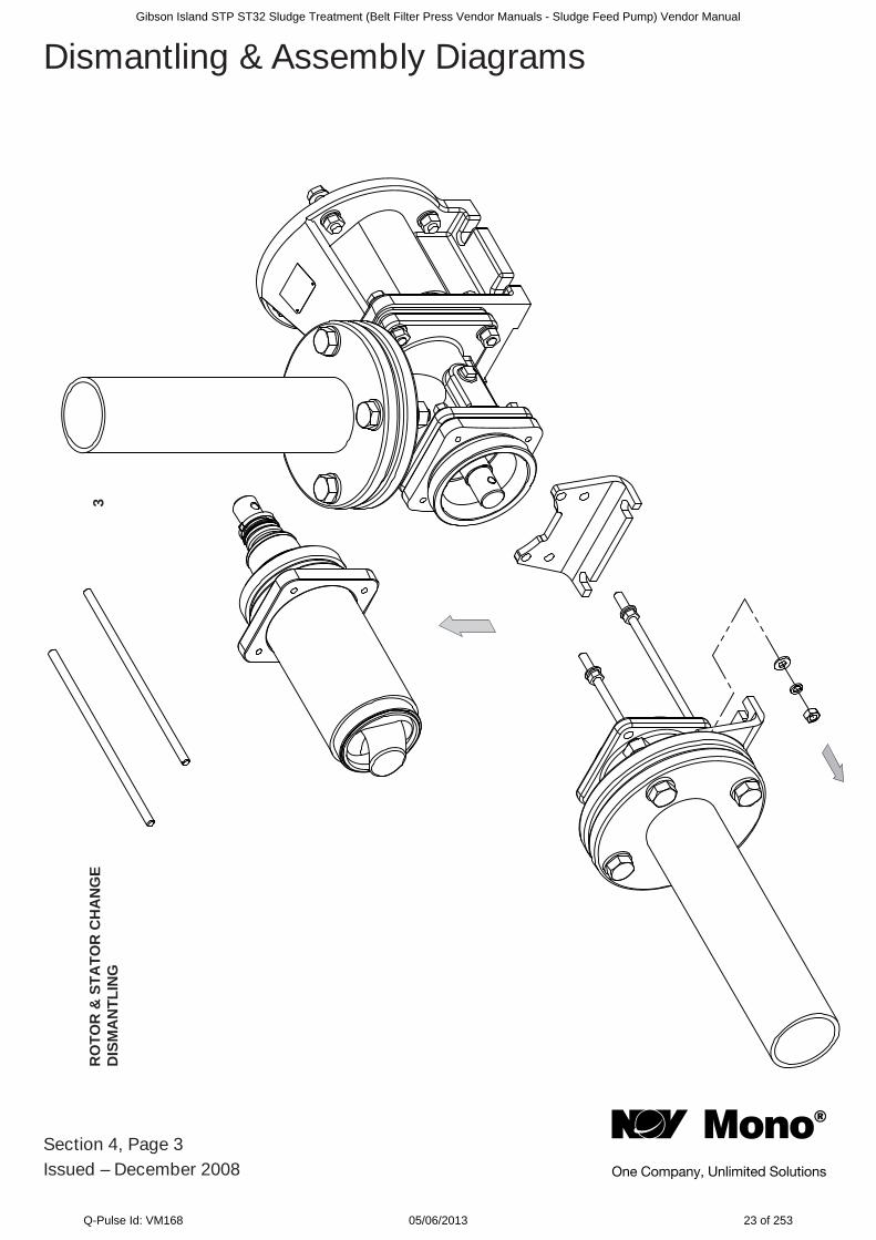
Section 4, Page 3Issued – December 2008
Dismantling & Assembly DiagramsR
OTO
R &
STA
TOR
CH
AN
GE
DIS
MA
NTL
ING
3
Gibson Island STP ST32 Sludge Treatment (Belt Filter Press Vendor Manuals - Sludge Feed Pump) Vendor Manual
Q-Pulse Id: VM168 05/06/2013 23 of 253

Section 4, Page 4Issued – December 2008
Dismantling & Assembly DiagramsR
OTO
R &
STA
TOR
CH
AN
GE
DIS
MA
NTL
ING
4
Gibson Island STP ST32 Sludge Treatment (Belt Filter Press Vendor Manuals - Sludge Feed Pump) Vendor Manual
Q-Pulse Id: VM168 05/06/2013 24 of 253
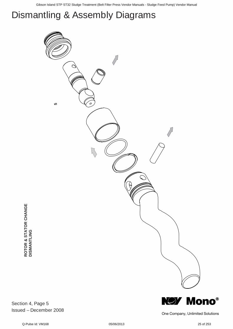
Section 4, Page 5Issued – December 2008
Dismantling & Assembly DiagramsR
OTO
R &
STA
TOR
CH
AN
GE
DIS
MA
NTL
ING
5
Gibson Island STP ST32 Sludge Treatment (Belt Filter Press Vendor Manuals - Sludge Feed Pump) Vendor Manual
Q-Pulse Id: VM168 05/06/2013 25 of 253
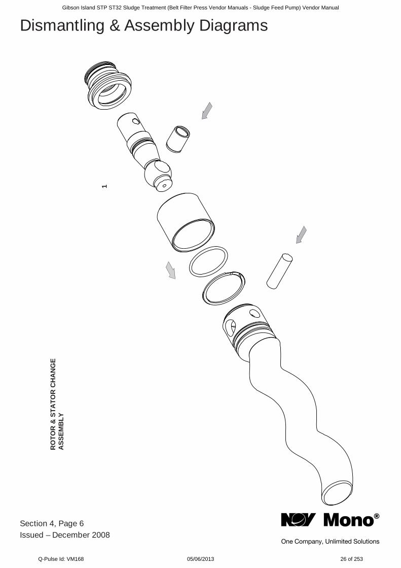
Section 4, Page 6Issued – December 2008
Dismantling & Assembly DiagramsR
OTO
R &
STA
TOR
CH
AN
GE
ASS
EMB
LY
1
Gibson Island STP ST32 Sludge Treatment (Belt Filter Press Vendor Manuals - Sludge Feed Pump) Vendor Manual
Q-Pulse Id: VM168 05/06/2013 26 of 253
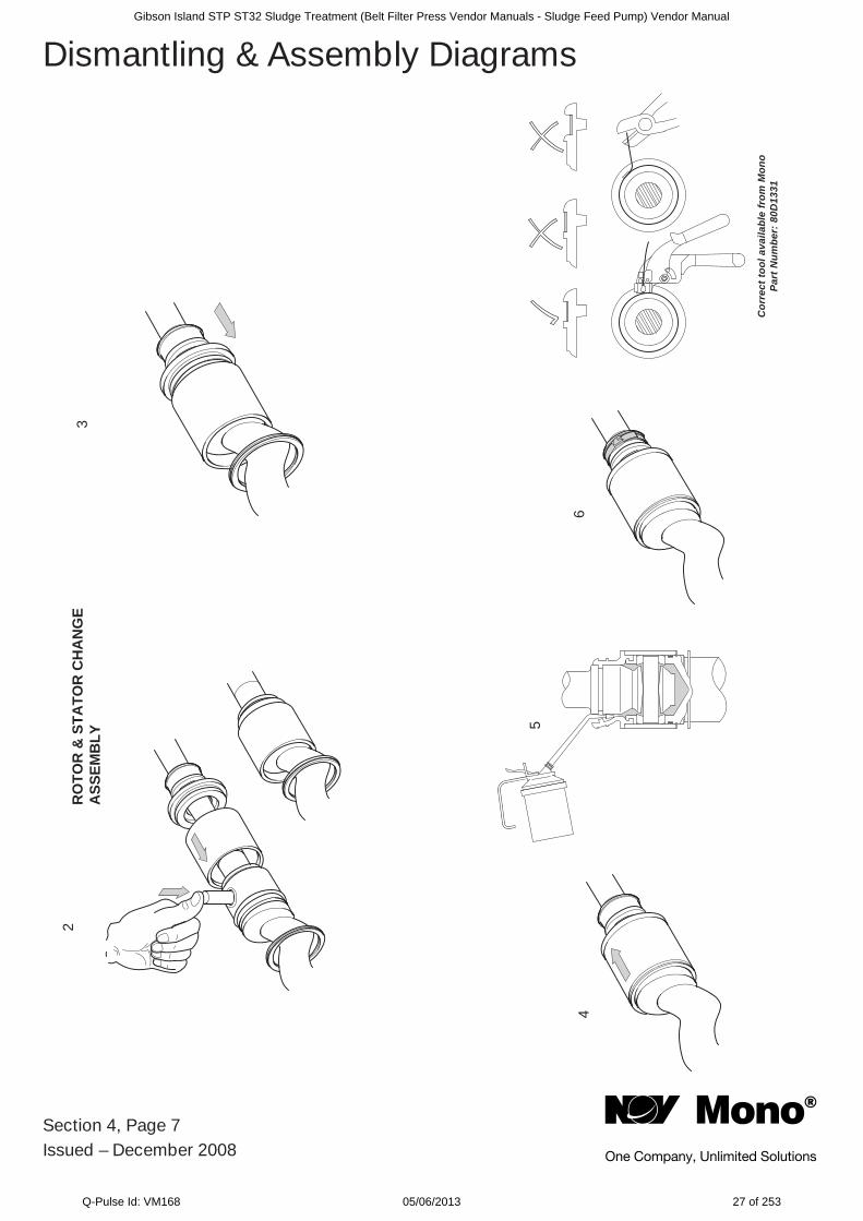
Section 4, Page 7Issued – December 2008
Dismantling & Assembly Diagrams2
3
4
5
6
Cor
rect
tool
ava
ilabl
e fr
om M
ono
Part
Num
ber:
80D
1331
RO
TOR
& S
TATO
R C
HA
NG
EA
SSEM
BLY
Gibson Island STP ST32 Sludge Treatment (Belt Filter Press Vendor Manuals - Sludge Feed Pump) Vendor Manual
Q-Pulse Id: VM168 05/06/2013 27 of 253
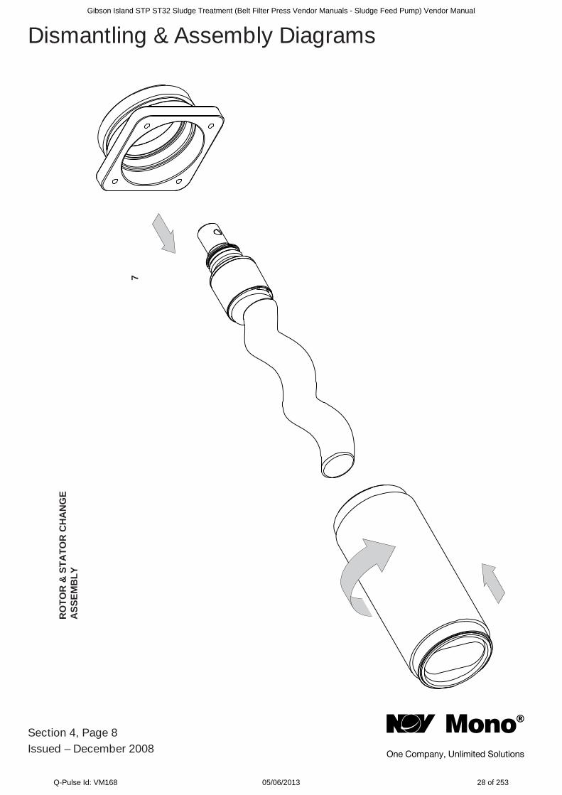
Section 4, Page 8Issued – December 2008
Dismantling & Assembly DiagramsR
OTO
R &
STA
TOR
CH
AN
GE
ASS
EMB
LY
7
Gibson Island STP ST32 Sludge Treatment (Belt Filter Press Vendor Manuals - Sludge Feed Pump) Vendor Manual
Q-Pulse Id: VM168 05/06/2013 28 of 253
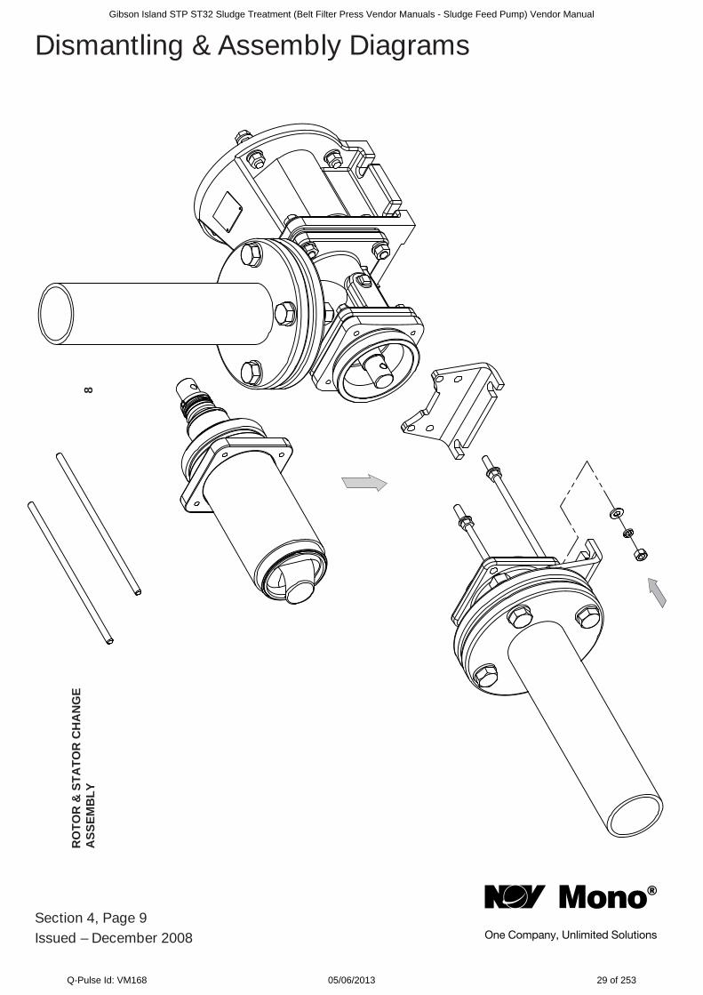
Section 4, Page 9Issued – December 2008
Dismantling & Assembly DiagramsR
OTO
R &
STA
TOR
CH
AN
GE
ASS
EMB
LY8
Gibson Island STP ST32 Sludge Treatment (Belt Filter Press Vendor Manuals - Sludge Feed Pump) Vendor Manual
Q-Pulse Id: VM168 05/06/2013 29 of 253
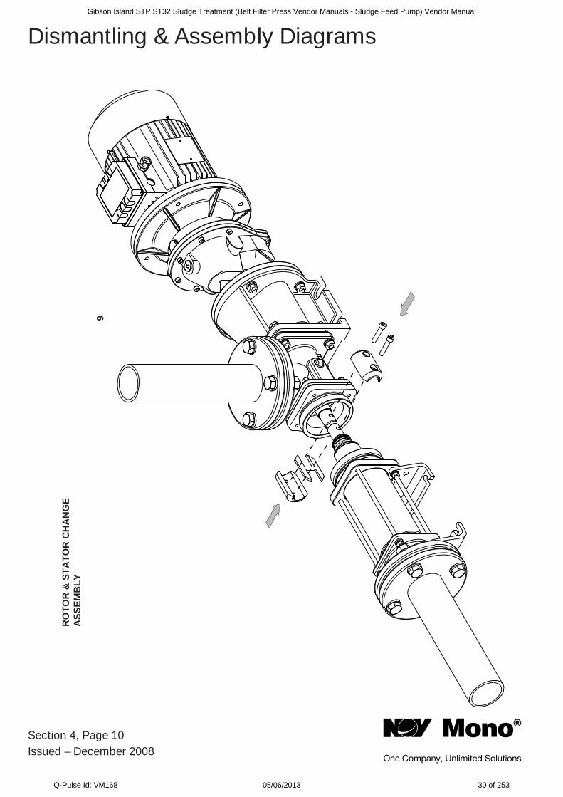
Section 4, Page 10Issued – December 2008
Dismantling & Assembly DiagramsR
OTO
R &
STA
TOR
CH
AN
GE
ASS
EMB
LY
9
Gibson Island STP ST32 Sludge Treatment (Belt Filter Press Vendor Manuals - Sludge Feed Pump) Vendor Manual
Q-Pulse Id: VM168 05/06/2013 30 of 253
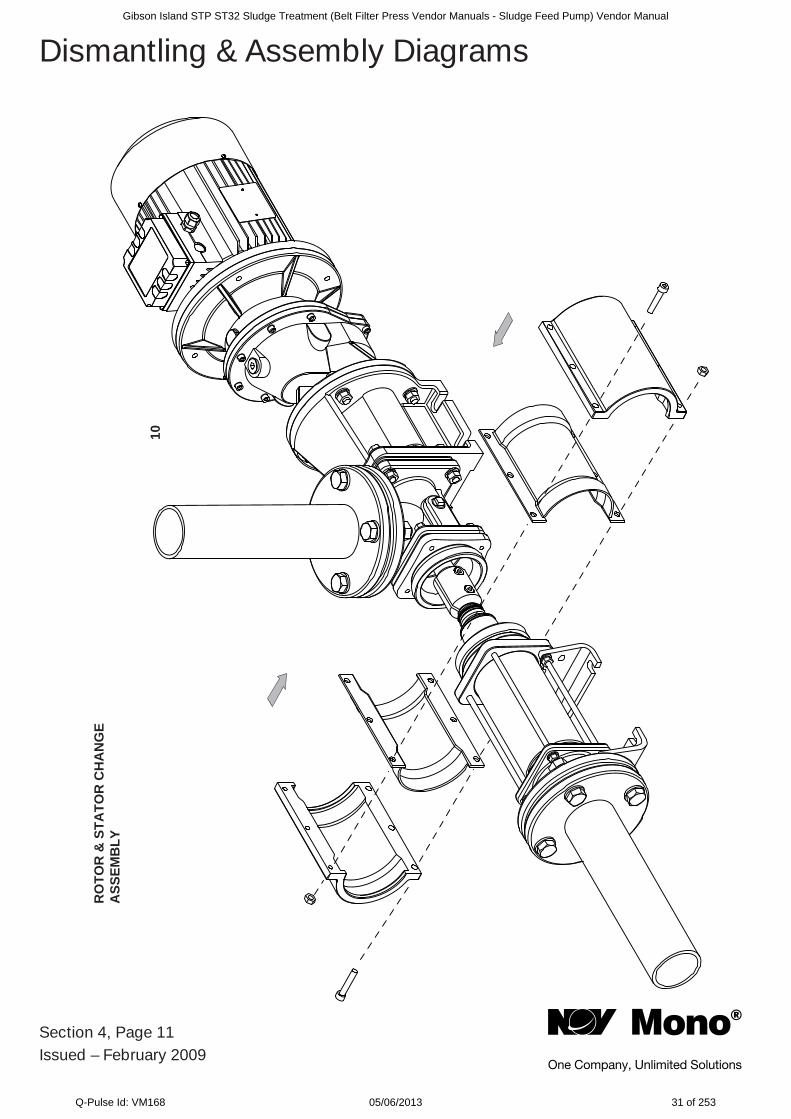
Section 4, Page 11Issued – February 2009
Dismantling & Assembly DiagramsR
OTO
R &
STA
TOR
CH
AN
GE
ASS
EMB
LY
10
Gibson Island STP ST32 Sludge Treatment (Belt Filter Press Vendor Manuals - Sludge Feed Pump) Vendor Manual
Q-Pulse Id: VM168 05/06/2013 31 of 253
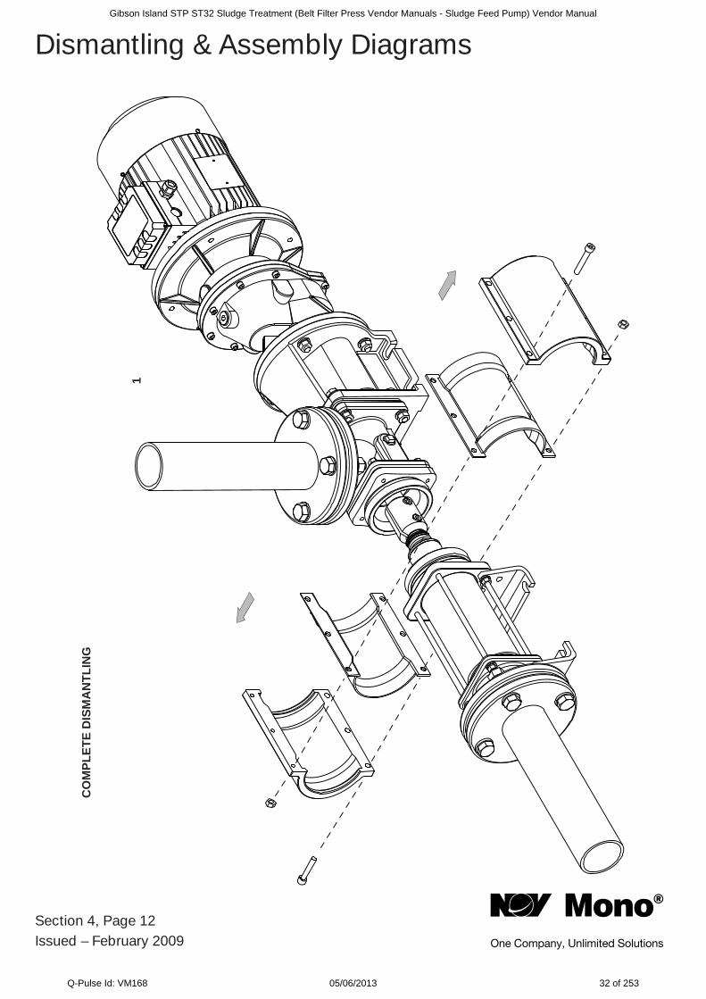
Section 4, Page 12Issued – February 2009
Dismantling & Assembly DiagramsC
OM
PLET
E D
ISM
AN
TLIN
G
1
Gibson Island STP ST32 Sludge Treatment (Belt Filter Press Vendor Manuals - Sludge Feed Pump) Vendor Manual
Q-Pulse Id: VM168 05/06/2013 32 of 253
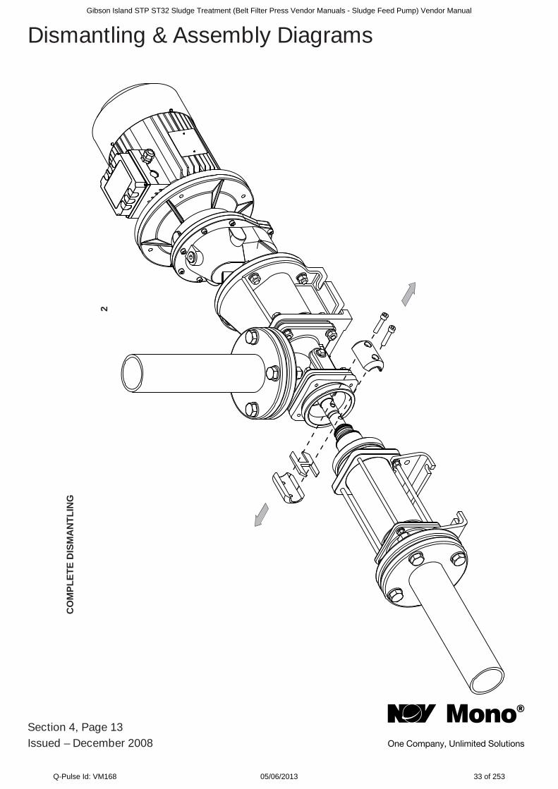
Section 4, Page 13Issued – December 2008
Dismantling & Assembly DiagramsC
OM
PLET
E D
ISM
AN
TLIN
G
2
Gibson Island STP ST32 Sludge Treatment (Belt Filter Press Vendor Manuals - Sludge Feed Pump) Vendor Manual
Q-Pulse Id: VM168 05/06/2013 33 of 253
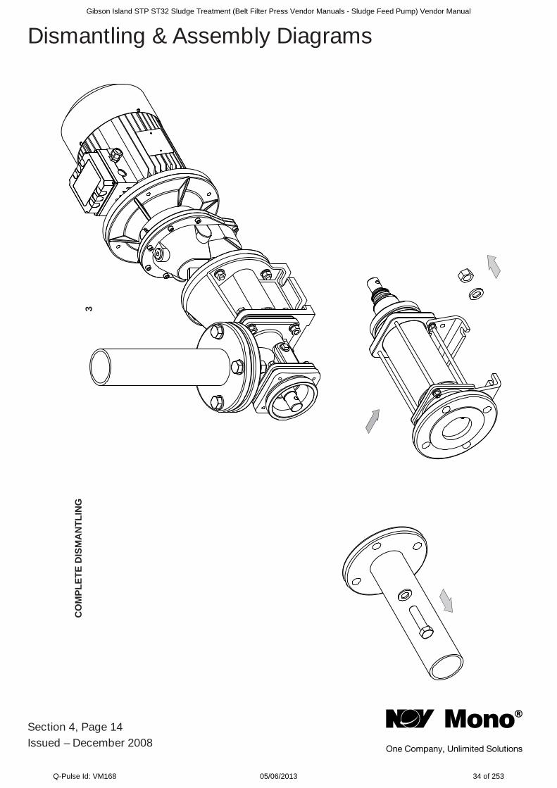
Section 4, Page 14Issued – December 2008
Dismantling & Assembly Diagrams
CO
MPL
ETE
DIS
MA
NTL
ING
3
Gibson Island STP ST32 Sludge Treatment (Belt Filter Press Vendor Manuals - Sludge Feed Pump) Vendor Manual
Q-Pulse Id: VM168 05/06/2013 34 of 253
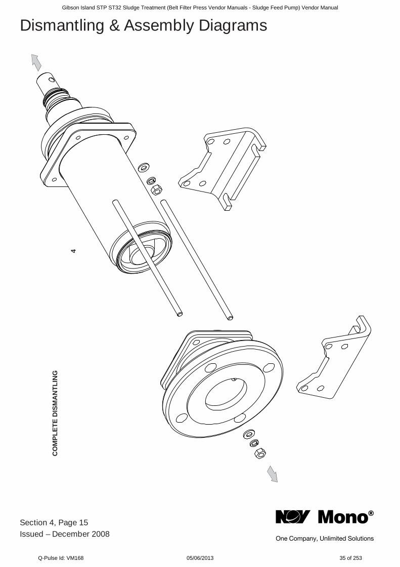
Section 4, Page 15Issued – December 2008
Dismantling & Assembly Diagrams
CO
MPL
ETE
DIS
MA
NTL
ING
4
Gibson Island STP ST32 Sludge Treatment (Belt Filter Press Vendor Manuals - Sludge Feed Pump) Vendor Manual
Q-Pulse Id: VM168 05/06/2013 35 of 253
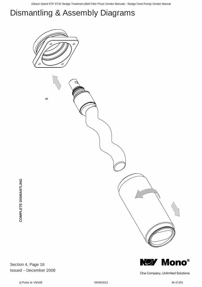
Section 4, Page 16Issued – December 2008
Dismantling & Assembly DiagramsC
OM
PLET
E D
ISM
AN
TLIN
G
5
Gibson Island STP ST32 Sludge Treatment (Belt Filter Press Vendor Manuals - Sludge Feed Pump) Vendor Manual
Q-Pulse Id: VM168 05/06/2013 36 of 253
Section 4, Page 17Issued – December 2008
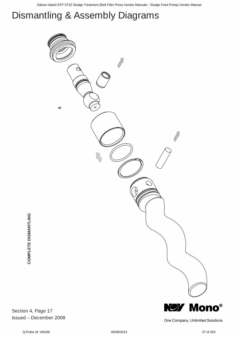
Dismantling & Assembly DiagramsC
OM
PLET
E D
ISM
AN
TLIN
G
6
Gibson Island STP ST32 Sludge Treatment (Belt Filter Press Vendor Manuals - Sludge Feed Pump) Vendor Manual
Q-Pulse Id: VM168 05/06/2013 37 of 253
Section 4, Page 18Issued – December 2008
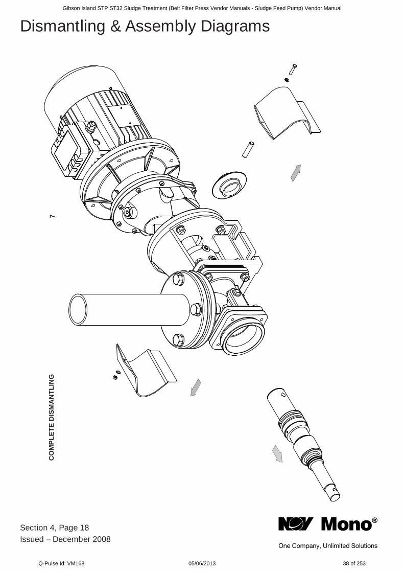
Dismantling & Assembly DiagramsC
OM
PLET
E D
ISM
AN
TLIN
G7
Gibson Island STP ST32 Sludge Treatment (Belt Filter Press Vendor Manuals - Sludge Feed Pump) Vendor Manual
Q-Pulse Id: VM168 05/06/2013 38 of 253
Section 4, Page 19Issued – December 2008
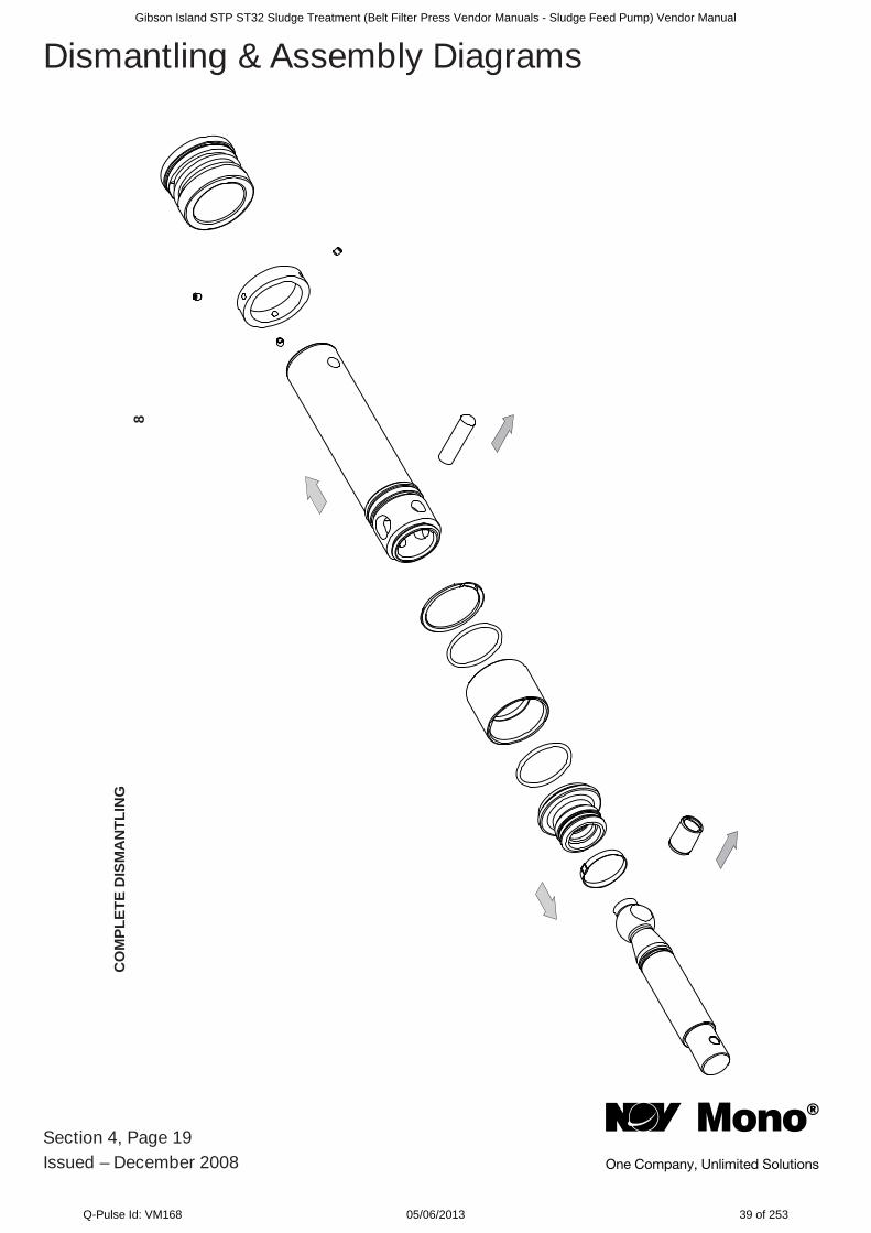
Dismantling & Assembly Diagrams
CO
MPL
ETE
DIS
MA
NTL
ING
8
Gibson Island STP ST32 Sludge Treatment (Belt Filter Press Vendor Manuals - Sludge Feed Pump) Vendor Manual
Q-Pulse Id: VM168 05/06/2013 39 of 253
Section 4, Page 20Issued – December 2008
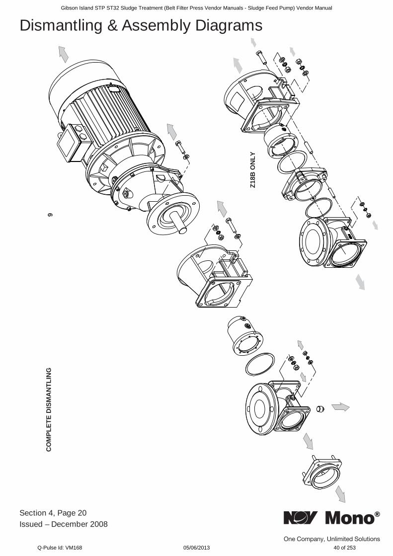
Dismantling & Assembly DiagramsC
OM
PLET
E D
ISM
AN
TLIN
G
Z18B
ON
LY
9
Gibson Island STP ST32 Sludge Treatment (Belt Filter Press Vendor Manuals - Sludge Feed Pump) Vendor Manual
Q-Pulse Id: VM168 05/06/2013 40 of 253
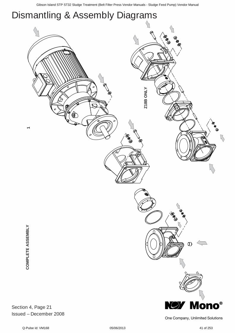
Section 4, Page 21Issued – December 2008
Dismantling & Assembly DiagramsC
OM
PLET
E A
SSEM
BLY
Z18B
ON
LY
1
Gibson Island STP ST32 Sludge Treatment (Belt Filter Press Vendor Manuals - Sludge Feed Pump) Vendor Manual
Q-Pulse Id: VM168 05/06/2013 41 of 253
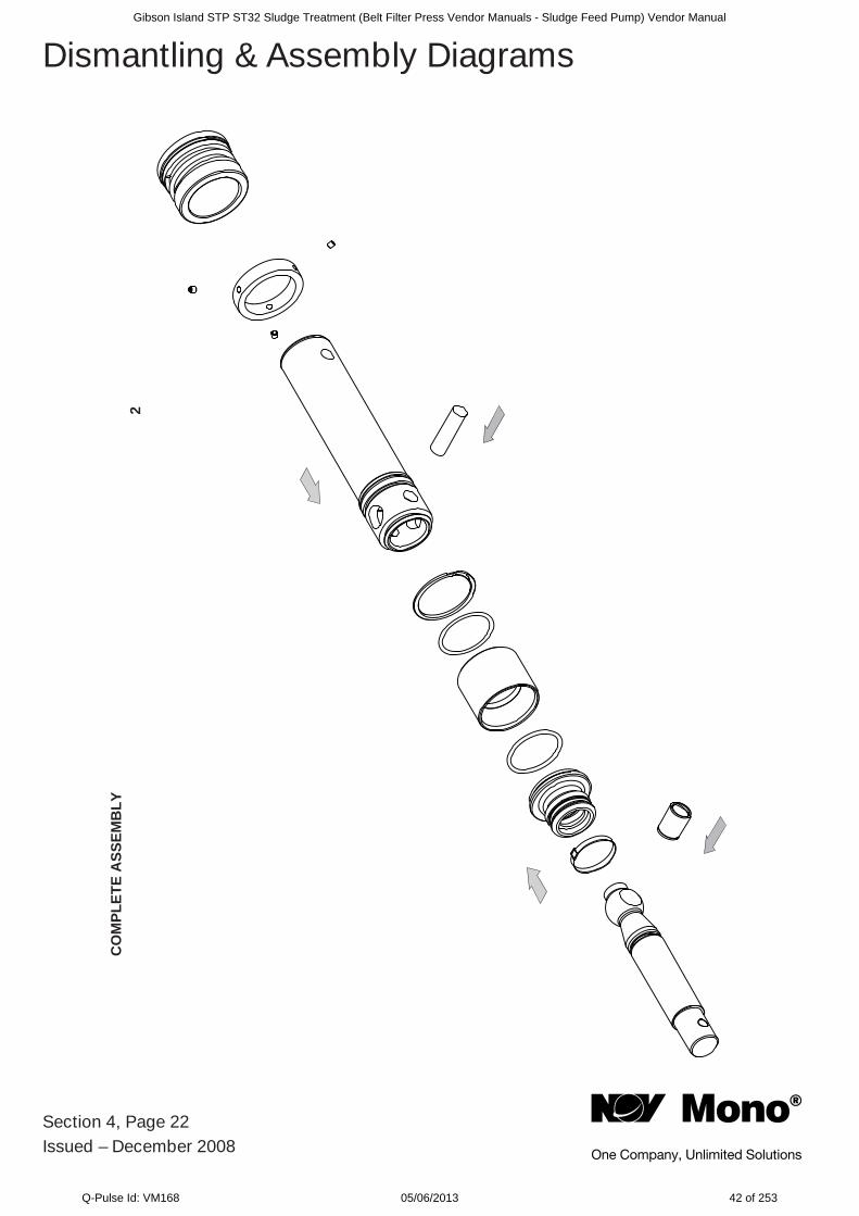
Section 4, Page 22Issued – December 2008
Dismantling & Assembly Diagrams
CO
MPL
ETE
ASS
EMB
LY2
Gibson Island STP ST32 Sludge Treatment (Belt Filter Press Vendor Manuals - Sludge Feed Pump) Vendor Manual
Q-Pulse Id: VM168 05/06/2013 42 of 253
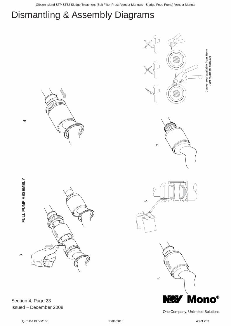
Section 4, Page 23Issued – December 2008
Dismantling & Assembly Diagrams3
4
5
6
7
Cor
rect
tool
ava
ilabl
e fr
om M
ono
Part
Num
ber:
80D
1331
FULL
PU
MP
ASS
EMB
LY
Gibson Island STP ST32 Sludge Treatment (Belt Filter Press Vendor Manuals - Sludge Feed Pump) Vendor Manual
Q-Pulse Id: VM168 05/06/2013 43 of 253
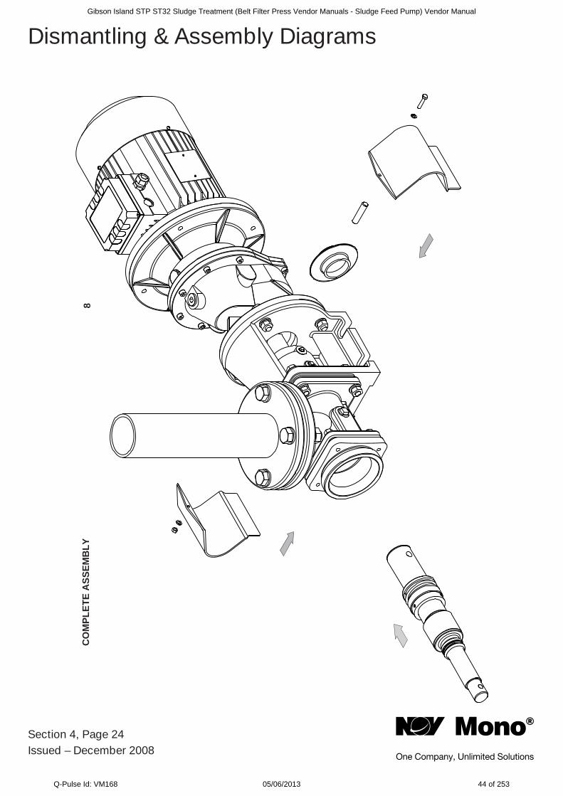
Section 4, Page 24Issued – December 2008
Dismantling & Assembly Diagrams
CO
MPL
ETE
ASS
EMB
LY8
Gibson Island STP ST32 Sludge Treatment (Belt Filter Press Vendor Manuals - Sludge Feed Pump) Vendor Manual
Q-Pulse Id: VM168 05/06/2013 44 of 253
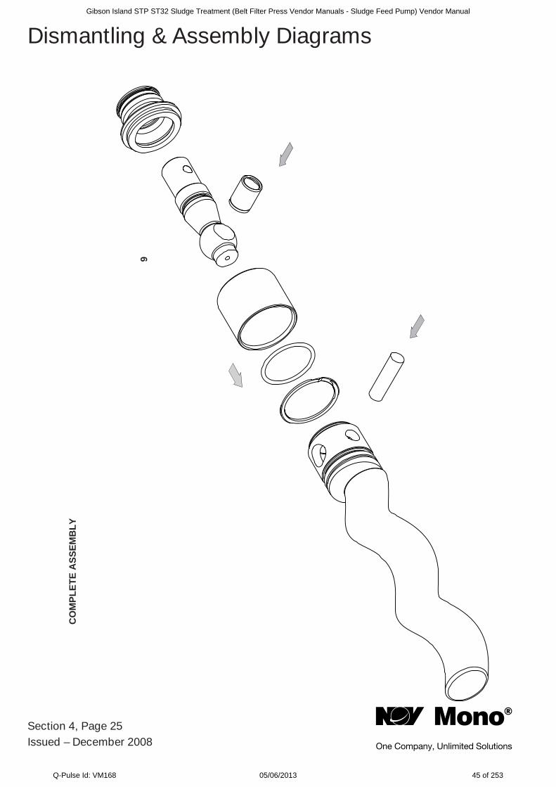
Section 4, Page 25Issued – December 2008
Dismantling & Assembly DiagramsC
OM
PLET
E A
SSEM
BLY
9
Gibson Island STP ST32 Sludge Treatment (Belt Filter Press Vendor Manuals - Sludge Feed Pump) Vendor Manual
Q-Pulse Id: VM168 05/06/2013 45 of 253
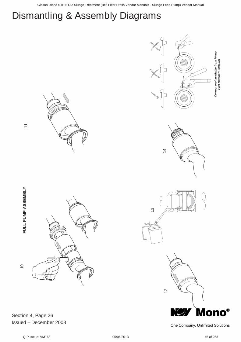
Section 4, Page 26Issued – December 2008
Dismantling & Assembly Diagrams10
11
12
13
14
Cor
rect
tool
ava
ilabl
e fr
om M
ono
Part
Num
ber:
80D
1331
FULL
PU
MP
ASS
EMB
LY
Gibson Island STP ST32 Sludge Treatment (Belt Filter Press Vendor Manuals - Sludge Feed Pump) Vendor Manual
Q-Pulse Id: VM168 05/06/2013 46 of 253
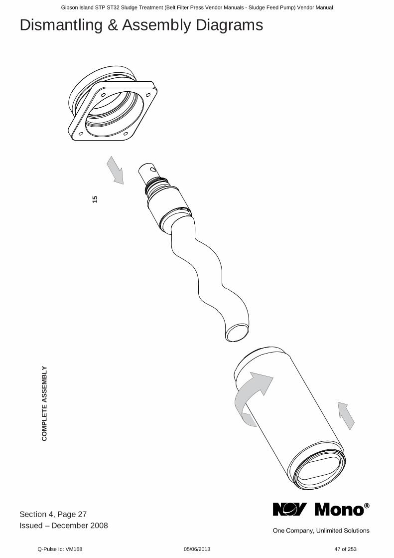
Section 4, Page 27Issued – December 2008
Dismantling & Assembly DiagramsC
OM
PLET
E A
SSEM
BLY
15
Gibson Island STP ST32 Sludge Treatment (Belt Filter Press Vendor Manuals - Sludge Feed Pump) Vendor Manual
Q-Pulse Id: VM168 05/06/2013 47 of 253
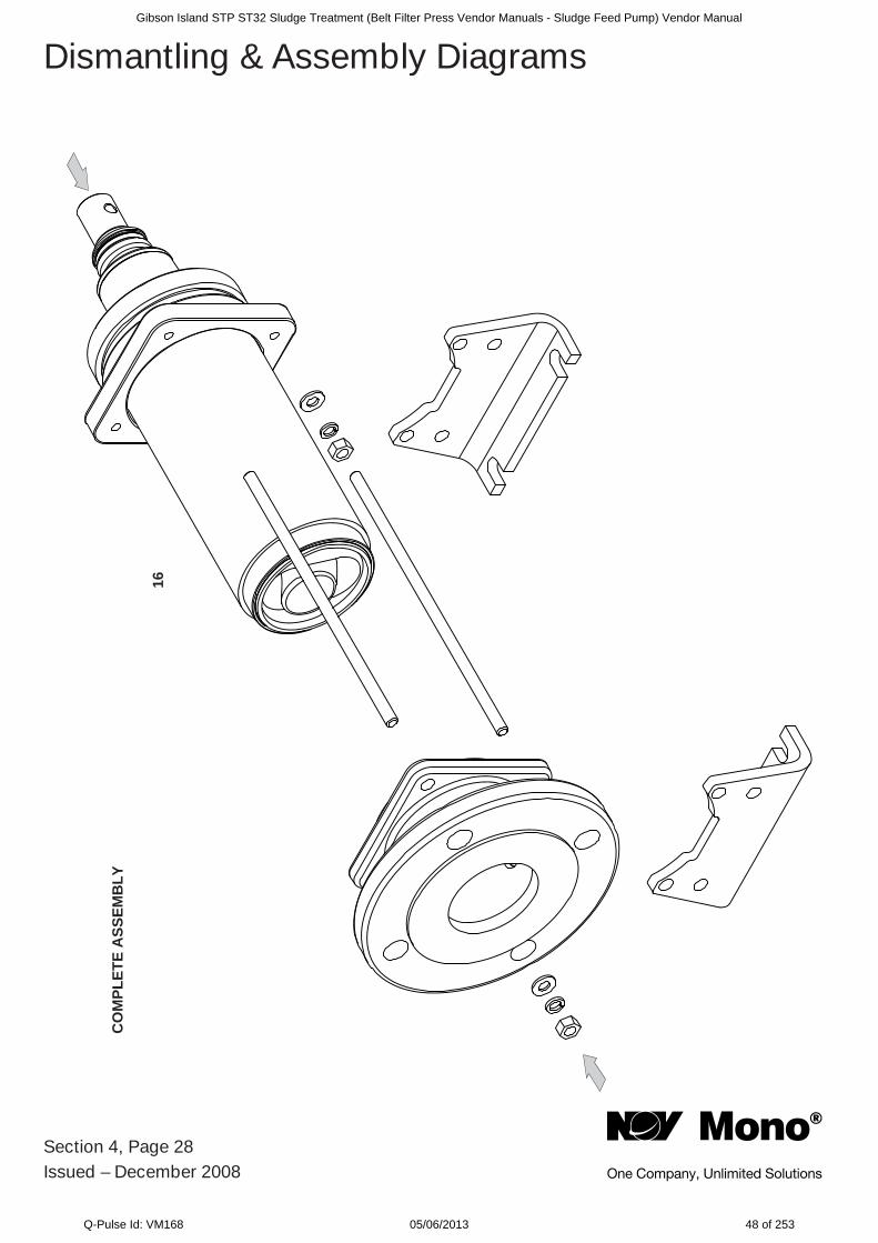
Section 4, Page 28Issued – December 2008
Dismantling & Assembly Diagrams
CO
MPL
ETE
ASS
EMB
LY
16
Gibson Island STP ST32 Sludge Treatment (Belt Filter Press Vendor Manuals - Sludge Feed Pump) Vendor Manual
Q-Pulse Id: VM168 05/06/2013 48 of 253
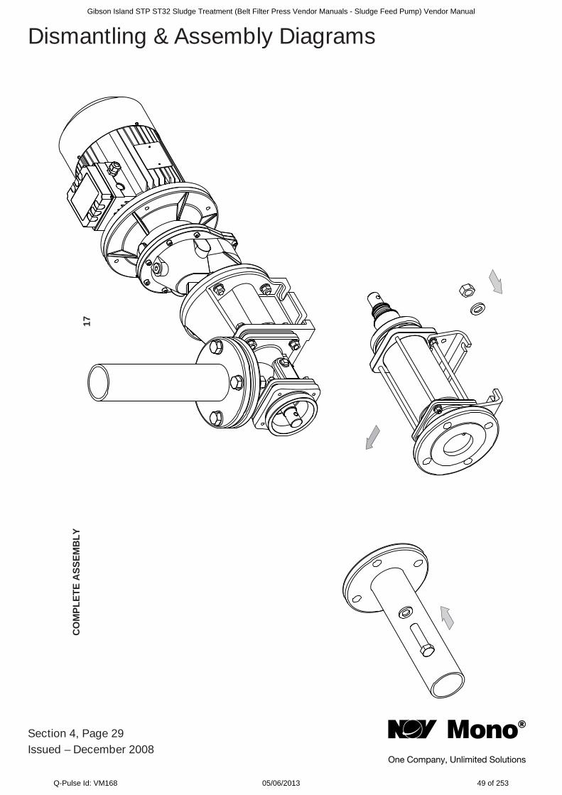
Section 4, Page 29Issued – December 2008
Dismantling & Assembly Diagrams
CO
MPL
ETE
ASS
EMB
LY17
Gibson Island STP ST32 Sludge Treatment (Belt Filter Press Vendor Manuals - Sludge Feed Pump) Vendor Manual
Q-Pulse Id: VM168 05/06/2013 49 of 253
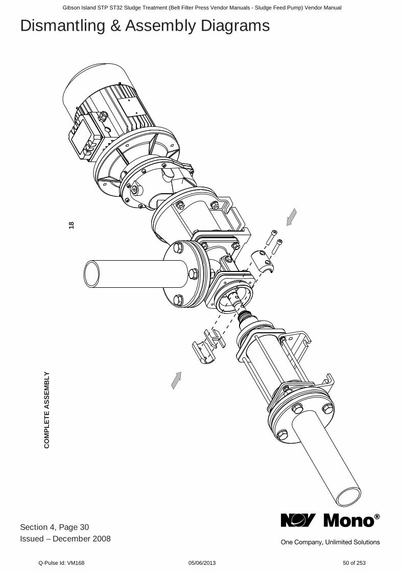
Section 4, Page 30Issued – December 2008
Dismantling & Assembly DiagramsC
OM
PLET
E A
SSEM
BLY
18
Gibson Island STP ST32 Sludge Treatment (Belt Filter Press Vendor Manuals - Sludge Feed Pump) Vendor Manual
Q-Pulse Id: VM168 05/06/2013 50 of 253

Section 4, Page 31Issued – February 2009
Dismantling & Assembly DiagramsC
OM
PLET
E A
SSEM
BLY
19
Gibson Island STP ST32 Sludge Treatment (Belt Filter Press Vendor Manuals - Sludge Feed Pump) Vendor Manual
Q-Pulse Id: VM168 05/06/2013 51 of 253
Section 4, Page 32Issued – April 2009
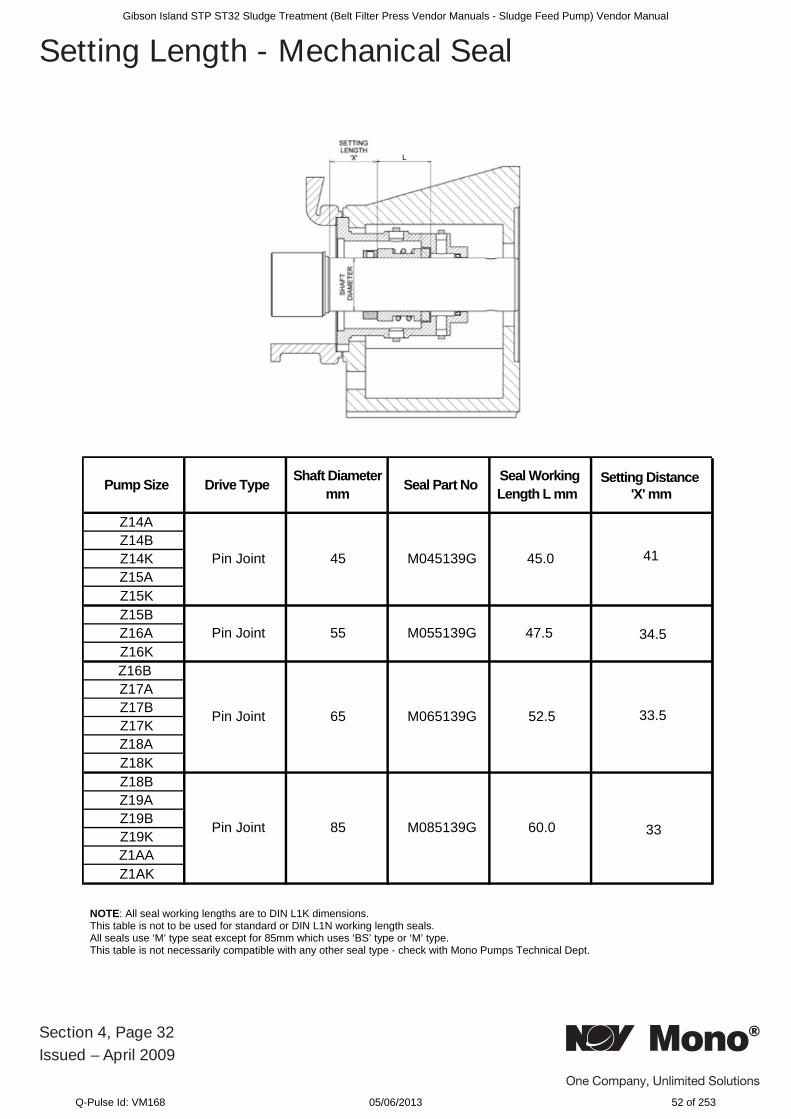
Setting Length - Mechanical Seal
Pump Size Drive Type Shaft Diameter mm Seal Part No Seal Working
Length L mm
Z14AZ14BZ14KZ15AZ15KZ15BZ16AZ16KZ16B Z17AZ17BZ17KZ18AZ18KZ18BZ19AZ19BZ19KZ1AAZ1AK
Pin Joint
Pin Joint
Pin Joint
Pin Joint
45
65
45.0
55 M055139G 47.5
M045139G
52.5
85 M085139G 60.0
M065139G
NOTE: All seal working lengths are to DIN L1K dimensions. This table is not to be used for standard or DIN L1N working length seals. All seals use ‘M’ type seat except for 85mm which uses ‘BS’ type or ‘M’ type. This table is not necessarily compatible with any other seal type - check with Mono Pumps Technical Dept.
Setting Distance 'X' mm
41
34.5
33.5
33
L
Gibson Island STP ST32 Sludge Treatment (Belt Filter Press Vendor Manuals - Sludge Feed Pump) Vendor Manual
Q-Pulse Id: VM168 05/06/2013 52 of 253
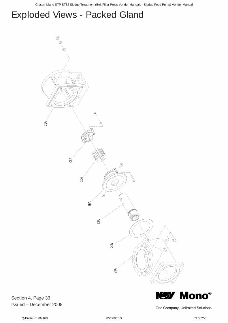
23A
20B
32A
08A
10A
65A
01A
Section 4, Page 33Issued – December 2008
Exploded Views - Packed GlandGibson Island STP ST32 Sludge Treatment (Belt Filter Press Vendor Manuals - Sludge Feed Pump) Vendor Manual
Q-Pulse Id: VM168 05/06/2013 53 of 253
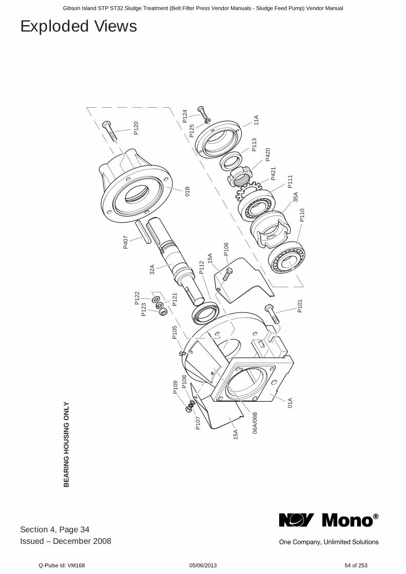
BEA
RIN
G H
OU
SIN
G O
NLY
P12
4
15A
P10
7
P10
8
01A
01B
P10
9
15A
P10
6
P12
2
P12
1
32A
P40
7
P11
2
P11
3
P11
0
P11
135
A
P42
1P
420
11A
P10
1
P12
5
P12
0
06A
/06B
P12
3
P10
5
Section 4, Page 34Issued – December 2008
Exploded ViewsGibson Island STP ST32 Sludge Treatment (Belt Filter Press Vendor Manuals - Sludge Feed Pump) Vendor Manual
Q-Pulse Id: VM168 05/06/2013 54 of 253
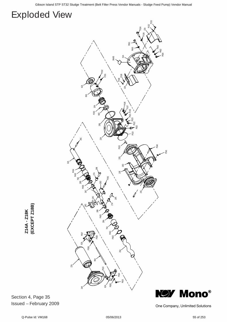
Section 4, Page 35Issued – February 2009
Exploded View
22A
24A 62
A
62A
P519
P504
P505
P503
95A
P507
P508
P506
25A
P403
P401
75A
28A
P405
26B
26C
P406
28B
75B
P402
P404
32A
26D
20C
26D
27A
27A
29B
29A
P301
29C
15A
15A
01A
P601
P603
P104
P106
P604
P602
P603
P109
P108
P102
P101
P202
P201
23A
20B
66AP203
10A
65A
42A
P520
P510
23D
23E
20D
P541
P540
23C
P522
P523
P521
P105
P107
P106
P502
06A/B
Z14A
- Z1
8K(E
XCEP
T Z1
8B)
Gibson Island STP ST32 Sludge Treatment (Belt Filter Press Vendor Manuals - Sludge Feed Pump) Vendor Manual
Q-Pulse Id: VM168 05/06/2013 55 of 253
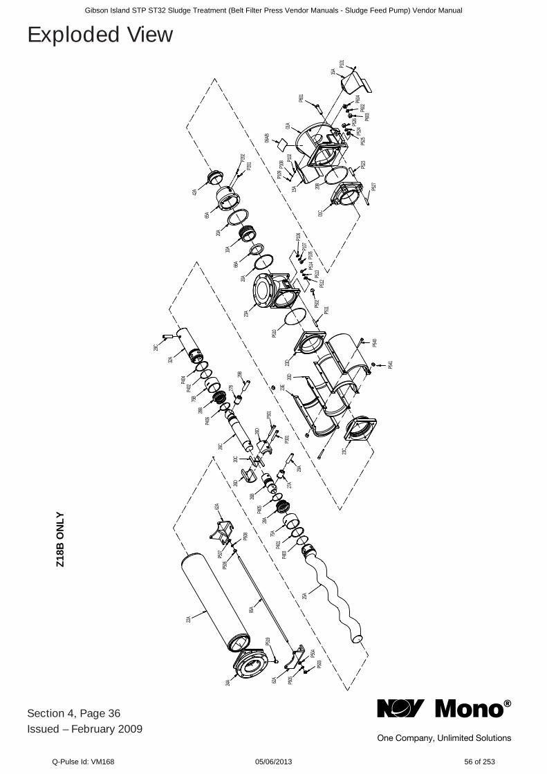
Section 4, Page 36Issued – February 2009
Exploded ViewZ1
8B O
NLY
24A
22A
P519
P503
P504
P50562A
95A
P506
P507
P508
62A
25A
P403
P401
75A
28A
P405
26B
26D
20C
26D
P301
P301
29A
27A
27B
29B
26C
P406
28B
75B
P402
P404
32A
29C
23C
P541
P540
20D
23E
23D
P511
P510
23A
P502
P512
P513
P514
P105
P107
P106
20A
66A
10A
20A
65A
42A
P201
P202
01C
15A 20
B
15A
P601
P604
P602
P603
P525
P524
P526
P523
P527
P102
P108
P109
06A/B
01A
P101
Gibson Island STP ST32 Sludge Treatment (Belt Filter Press Vendor Manuals - Sludge Feed Pump) Vendor Manual
Q-Pulse Id: VM168 05/06/2013 56 of 253
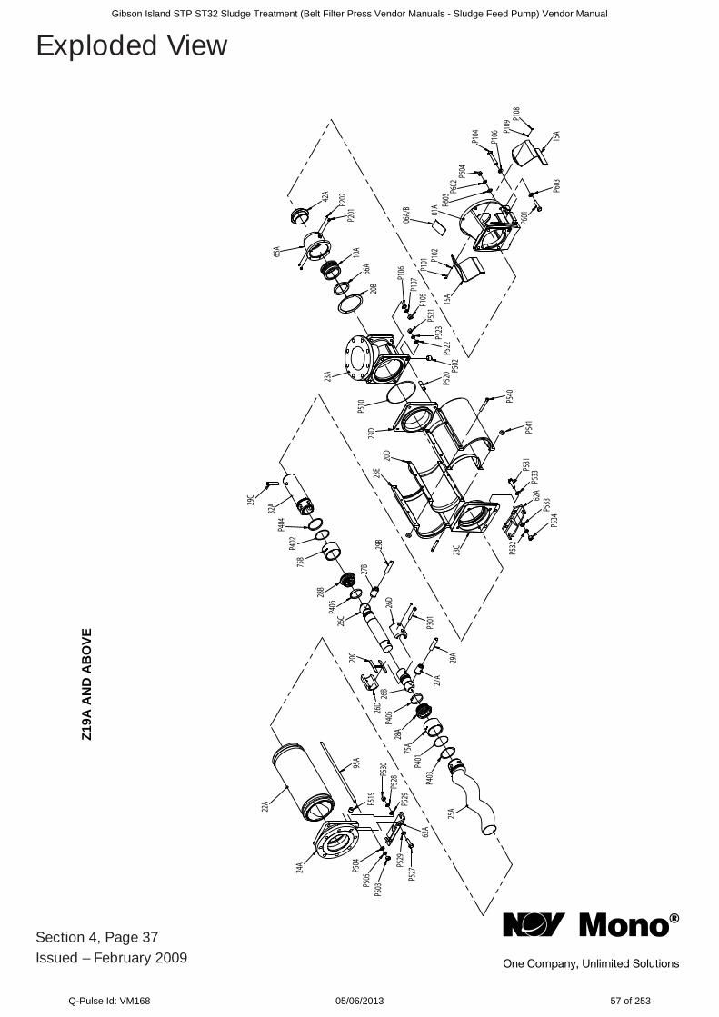
Section 4, Page 37Issued – February 2009
Exploded ViewZ1
9A A
ND
AB
OVE
24A
22A
P504
P505
P503
P527
P529
95A
P519
P530
P528
P529
62A
26D
20C
26C
26B
P406
28B
75B
P404
P402
32A29
C
29A
27A
26D
P301
29B
27B
23C
23E
20D
P531
P533
62A
P533
P532
P534
P520
23D
P510
P522
P523
P521
P105
P107P1
06
23A
P201
P202
20B
66A
10A
42A
65A
06A/
B
P101 P1
0215
A01
A P603
P602
P604
P104
P106 15AP1
09P1
08
P603
P601
P540
P541
25A
P403
P401
75A
28A
P405
P502
Gibson Island STP ST32 Sludge Treatment (Belt Filter Press Vendor Manuals - Sludge Feed Pump) Vendor Manual
Q-Pulse Id: VM168 05/06/2013 57 of 253
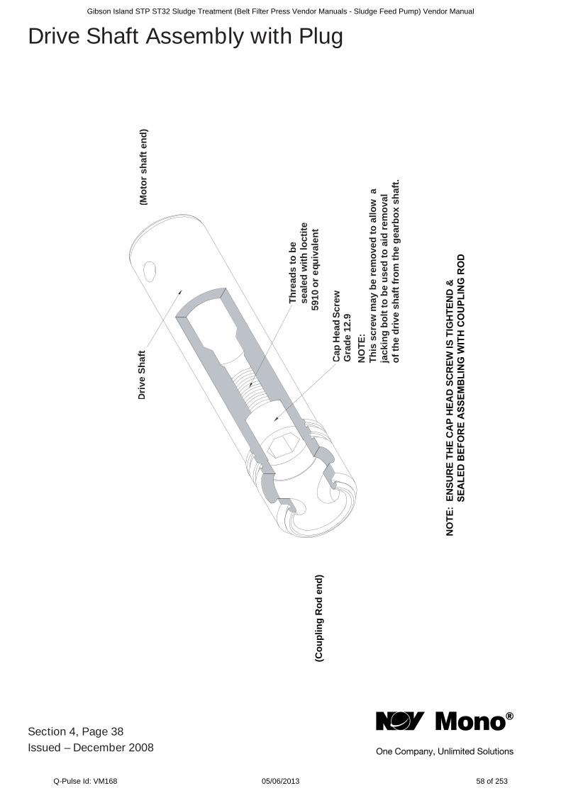
Thre
ads
to b
ese
aled
with
loct
ite o
r equ
ival
ent
Cap
Hea
d Sc
rew
Driv
e Sh
aft
(Mot
or s
haft
end)
(Cou
plin
g R
od e
nd)
NO
TE:
ENSU
RE
THE
CA
P H
EAD
SC
REW
IS T
IGH
TEN
D &
5910
Gra
de 1
2.9
Section 4, Page 38Issued – December 2008
Drive Shaft Assembly with Plug
NO
TE:
This
scr
ew m
ay b
e re
mov
ed to
allo
w a
ja
ckin
g bo
lt to
be
used
to a
id re
mov
alof
the
driv
e sh
aft f
rom
the
gear
box
shaf
t.
Gibson Island STP ST32 Sludge Treatment (Belt Filter Press Vendor Manuals - Sludge Feed Pump) Vendor Manual
Q-Pulse Id: VM168 05/06/2013 58 of 253
Section 5, Page 1Issued – June 2009
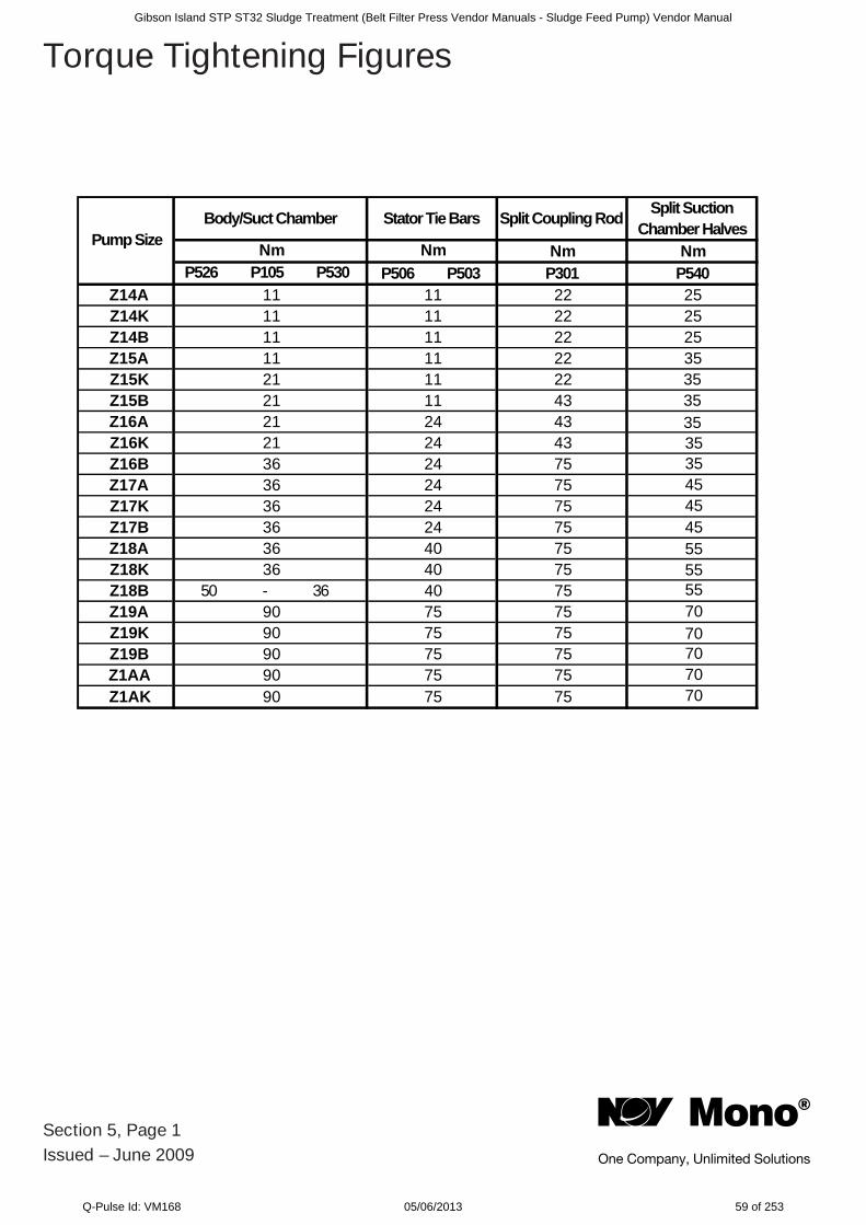
Torque Tightening Figures
Body/Suct Chamber Stator Tie Bars Split Coupling Rod Split Suction Chamber Halves
Nm Nm Nm NmP526 P105 P530 P506 P503 P301 P540
Z14A 11 11 22 25Z14K 11 11 22 25Z14B 11 11 22 25Z15A 11 11 22 35Z15K 21 11 22Z15B 21 11 43Z16A 21 24 43Z16K 21 24 43Z16B 36 24 75Z17A 36 24 75Z17K 36 24 75Z17B 36 24 75Z18A 36 40 75Z18K 36 40 75Z18B 50 - 36 40 75Z19A 90 75 75Z19K 90 75 75Z19B 90 75 75Z1AA 90 75 75Z1AK 90 75 75
Pump Size
35353535354545455555557070707070
Gibson Island STP ST32 Sludge Treatment (Belt Filter Press Vendor Manuals - Sludge Feed Pump) Vendor Manual
Q-Pulse Id: VM168 05/06/2013 59 of 253
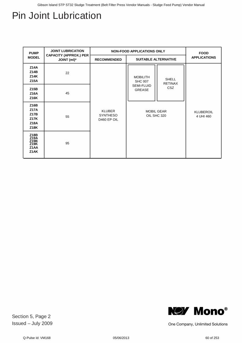
RECOMMENDED
Z14AZ14BZ14KZ15A
Z15BZ16AZ16K
Z16BZ17AZ17BZ17KZ18AZ18K
Z18BZ19A
Z19KZ1AAZ1AK
KLUBERSYNTHESOD460 EP OIL
22
45
55
95
PUMP MODEL
JOINT LUBRICATION CAPACITY (APPROX.) PER
JOINT (ml)*
FOODAPPLICATIONSSUITABLE ALTERNATIVE
NON-FOOD APPLICATIONS ONLY
KLUBEROIL 4 UHI 460
MOBILITHSHC 007
SEMI-FLUID GREASE
SHELLRETINAX
CSZ
MOBIL GEAROIL SHC 320
Section 5, Page 2Issued – July 2009
Pin Joint Lubrication
Z19B
Gibson Island STP ST32 Sludge Treatment (Belt Filter Press Vendor Manuals - Sludge Feed Pump) Vendor Manual
Q-Pulse Id: VM168 05/06/2013 60 of 253
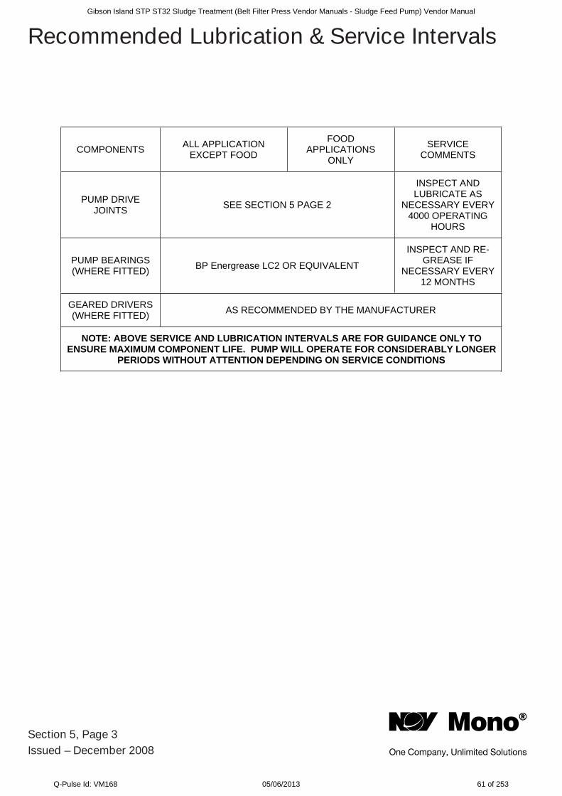
COMPONENTS ALL APPLICATION EXCEPT FOOD
FOODAPPLICATIONS
ONLY
SERVICECOMMENTS
PUMP DRIVE JOINTS SEE SECTION 5 PAGE 2
INSPECT AND LUBRICATE AS
NECESSARY EVERY 4000 OPERATING
HOURS
PUMP BEARINGS (WHERE FITTED) BP Energrease LC2 OR EQUIVALENT
INSPECT AND RE-GREASE IF
NECESSARY EVERY 12 MONTHS
GEARED DRIVERS (WHERE FITTED) AS RECOMMENDED BY THE MANUFACTURER
NOTE: ABOVE SERVICE AND LUBRICATION INTERVALS ARE FOR GUIDANCE ONLY TO ENSURE MAXIMUM COMPONENT LIFE. PUMP WILL OPERATE FOR CONSIDERABLY LONGER
PERIODS WITHOUT ATTENTION DEPENDING ON SERVICE CONDITIONS
Section 5, Page 3Issued – December 2008
Recommended Lubrication & Service IntervalsGibson Island STP ST32 Sludge Treatment (Belt Filter Press Vendor Manuals - Sludge Feed Pump) Vendor Manual
Q-Pulse Id: VM168 05/06/2013 61 of 253
Produced on recycled paper
© Mono Pumps Limited May 2011 Literature reference: MPA632. Published information other than that marked CERTIFIED does not extend any warranty or representation, expressed or implied, regarding these products. Any such warranties or other terms and conditions of sales and products shall be in accordance with Mono Pumps Limited standard terms and conditions of sale, available on request.
Mono® is a registered trademark of Mono Pumps Ltd.
Registered in England No 300721
Europe
Mono Pumps Ltd, Martin Street, Audenshaw Manchester, M34 5JA, England
T. +44 161 339 9000 E. [email protected]
D.M.I EST, 56, rue du Pont88300 Rebeuville, France
T. +33 3 29 94 26 88 E. [email protected]
Americas
Monofl o Inc., 10529 Fisher Road Houston, Texas 77041, USA
T. +1 713 980 8400 E. monofl [email protected]
Monofl o S.A., Ing Huergo 2239(1842) Monte Grande
Pcia. de Buenos Aires, ArgentinaT. +54 11 4290 9940/50
E. info.monofl [email protected]
Monofl o Canada, 6010 – 53rd AveAlberta, Lloydminster
T9V2T2, CanadaT: + 1 780 875 5584
E: info.monofl [email protected]
Asia
Mono Pumps Ltd, Building 5,Madong Industrial Park, 1250 Sicheng Rd
Malu Town, Jiading District, Shanghai 201801T. +86 21 3990 4588
Australasia
Mono Pumps (Australia) Pty Ltd 75 Frankston Garden Drive
Carrum Downs, Victoria 3201, AustraliaT. 1800 333 138
Mono Pumps (New Zealand) Ltd 35-41 Fremlin Place, Avondale Auckland, 1026, New Zealand
T. +64 9 829 0333E. [email protected]
Melbourne T. 03 9580 5211 F. 03 9580 6659 Sydney T. 02 8536 0900 F. 02 9542 3649 Brisbane T. 07 3350 4582 F. 07 3350 3750 Adelaide T. 08 8447 8333 F. 08 8447 8373 Perth T. 08 9303 0444 F. 08 9303 0400 Darwin T. 08 8931 3300 F. 08 8931 3200 Kalgoorlie T. 08 9022 4880 F. 08 9022 3660 Christchurch NZ T. +64 3 341 8379 F. +64 3 341 8486
www.monopumps.com.au
Gibson Island STP ST32 Sludge Treatment (Belt Filter Press Vendor Manuals - Sludge Feed Pump) Vendor Manual
Q-Pulse Id: VM168 05/06/2013 62 of 253
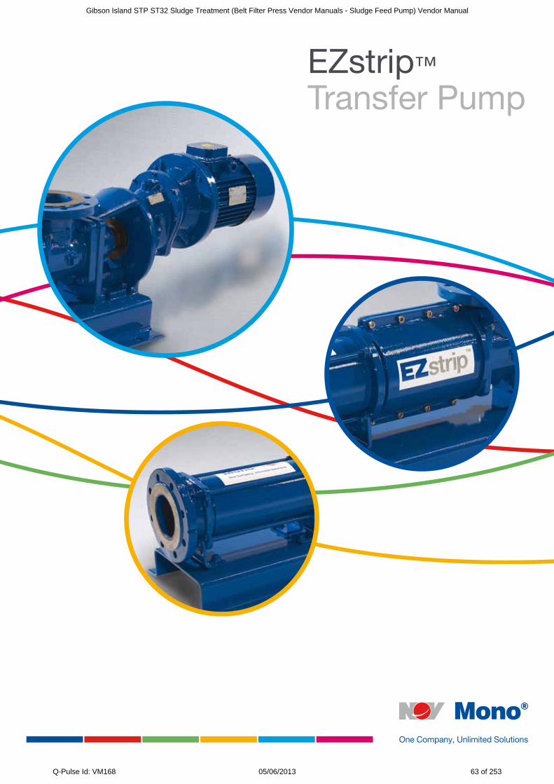
EZstrip™ Transfer Pump
Gibson Island STP ST32 Sludge Treatment (Belt Filter Press Vendor Manuals - Sludge Feed Pump) Vendor Manual
Q-Pulse Id: VM168 05/06/2013 63 of 253
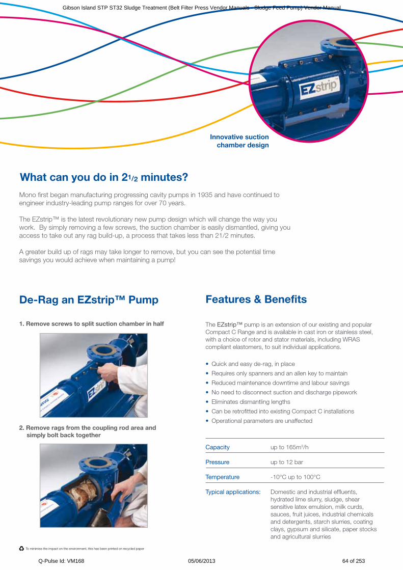
Features & Benefits The EZstrip™ pump is an extension of our existing and popular Compact C Range and is available in cast iron or stainless steel, with a choice of rotor and stator materials, including WRAS compliant elastomers, to suit individual applications.
• Quick and easy de-rag, in place
• Requires only spanners and an allen key to maintain
• Reduced maintenance downtime and labour savings
• No need to disconnect suction and discharge pipework
• Eliminates dismantling lengths
• Can be retrofitted into existing Compact C installations
• Operational parameters are unaffected
Capacity up to 165m3/h Pressure up to 12 bar Temperature -10°C up to 100°C Typical applications: Domestic and industrial effluents, hydrated lime slurry, sludge, shear sensitive latex emulsion, milk curds, sauces, fruit juices, industrial chemicals and detergents, starch slurries, coating clays, gypsum and silicate, paper stocks and agricultural slurries
To minimise the impact on the environment, this has been printed on recycled paper
What can you do in 21/2 minutes?
Mono first began manufacturing progressing cavity pumps in 1935 and have continued to engineer industry-leading pump ranges for over 70 years.
The EZstrip™ is the latest revolutionary new pump design which will change the way you work. By simply removing a few screws, the suction chamber is easily dismantled, giving you access to take out any rag build-up, a process that takes less than 21/2 minutes.
A greater build up of rags may take longer to remove, but you can see the potential time savings you would achieve when maintaining a pump!
De-Rag an EZstrip™ Pump
1. Remove screws to split suction chamber in half
2. Remove rags from the coupling rod area and simply bolt back together
Innovative suction chamber design
Gibson Island STP ST32 Sludge Treatment (Belt Filter Press Vendor Manuals - Sludge Feed Pump) Vendor Manual
Q-Pulse Id: VM168 05/06/2013 64 of 253
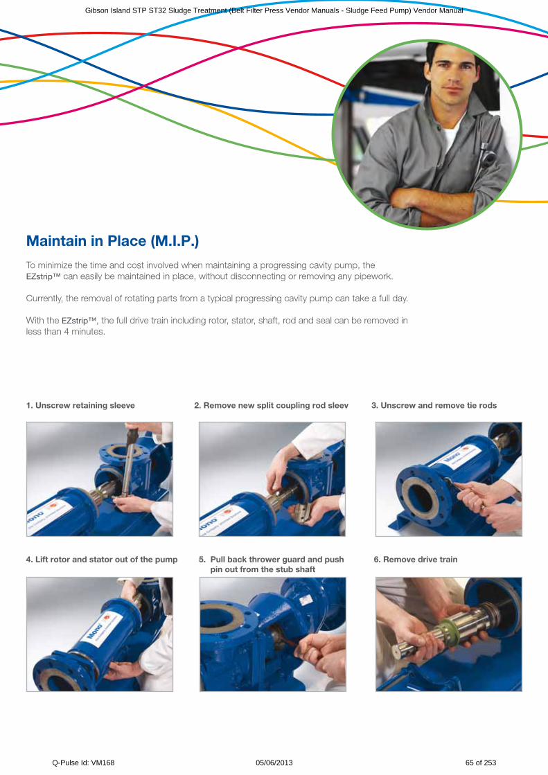
Maintain in Place (M.I.P.)
To minimize the time and cost involved when maintaining a progressing cavity pump, the EZstrip™ can easily be maintained in place, without disconnecting or removing any pipework. Currently, the removal of rotating parts from a typical progressing cavity pump can take a full day. With the EZstrip™, the full drive train including rotor, stator, shaft, rod and seal can be removed in less than 4 minutes.
1. Unscrew retaining sleeve 2. Remove new split coupling rod sleev 3. Unscrew and remove tie rods
4. Lift rotor and stator out of the pump 5. Pull back thrower guard and push 6. Remove drive train pin out from the stub shaft
Gibson Island STP ST32 Sludge Treatment (Belt Filter Press Vendor Manuals - Sludge Feed Pump) Vendor Manual
Q-Pulse Id: VM168 05/06/2013 65 of 253
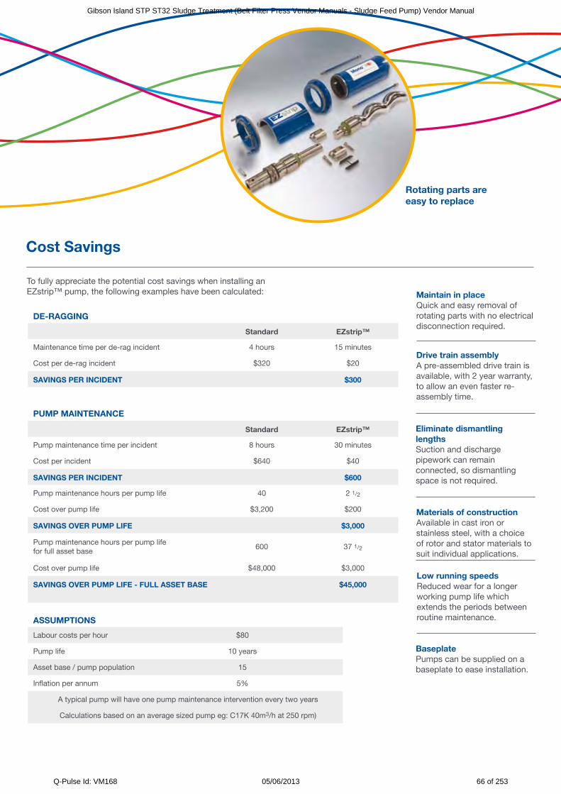
Cost Savings
Drive train assembly A pre-assembled drive train is available, with 2 year warranty, to allow an even faster re-assembly time.
Maintain in place Quick and easy removal of rotating parts with no electrical disconnection required.
To fully appreciate the potential cost savings when installing an EZstrip™ pump, the following examples have been calculated:
DE-RAGGING
Standard EZstrip™
Maintenance time per de-rag incident 4 hours 15 minutes
Cost per de-rag incident $320 $20
SAVINGS PER INCIDENT $300
PUMP MAINTENANCE
Standard EZstrip™
Pump maintenance time per incident 8 hours 30 minutes
Cost per incident $640 $40
SAVINGS PER INCIDENT $600
Pump maintenance hours per pump life 40 2 1/2
Cost over pump life $3,200 $200
SAVINGS OVER PUMP LIFE $3,000
Pump maintenance hours per pump life for full asset base
600 37 1/2
Cost over pump life $48,000 $3,000
SAVINGS OVER PUMP LIFE - FULL ASSET BASE $45,000Low running speeds Reduced wear for a longer working pump life which extends the periods between routine maintenance.
Materials of construction Available in cast iron or stainless steel, with a choice of rotor and stator materials to suit individual applications.
Eliminate dismantling lengths Suction and discharge pipework can remain connected, so dismantling space is not required.
Baseplate Pumps can be supplied on a baseplate to ease installation.
ASSUMPTIONS
Labour costs per hour $80
Pump life 10 years
Asset base / pump population 15
Inflation per annum 5%
A typical pump will have one pump maintenance intervention every two years
Calculations based on an average sized pump eg: C17K 40m3/h at 250 rpm)
Rotating parts are easy to replace
Gibson Island STP ST32 Sludge Treatment (Belt Filter Press Vendor Manuals - Sludge Feed Pump) Vendor Manual
Q-Pulse Id: VM168 05/06/2013 66 of 253
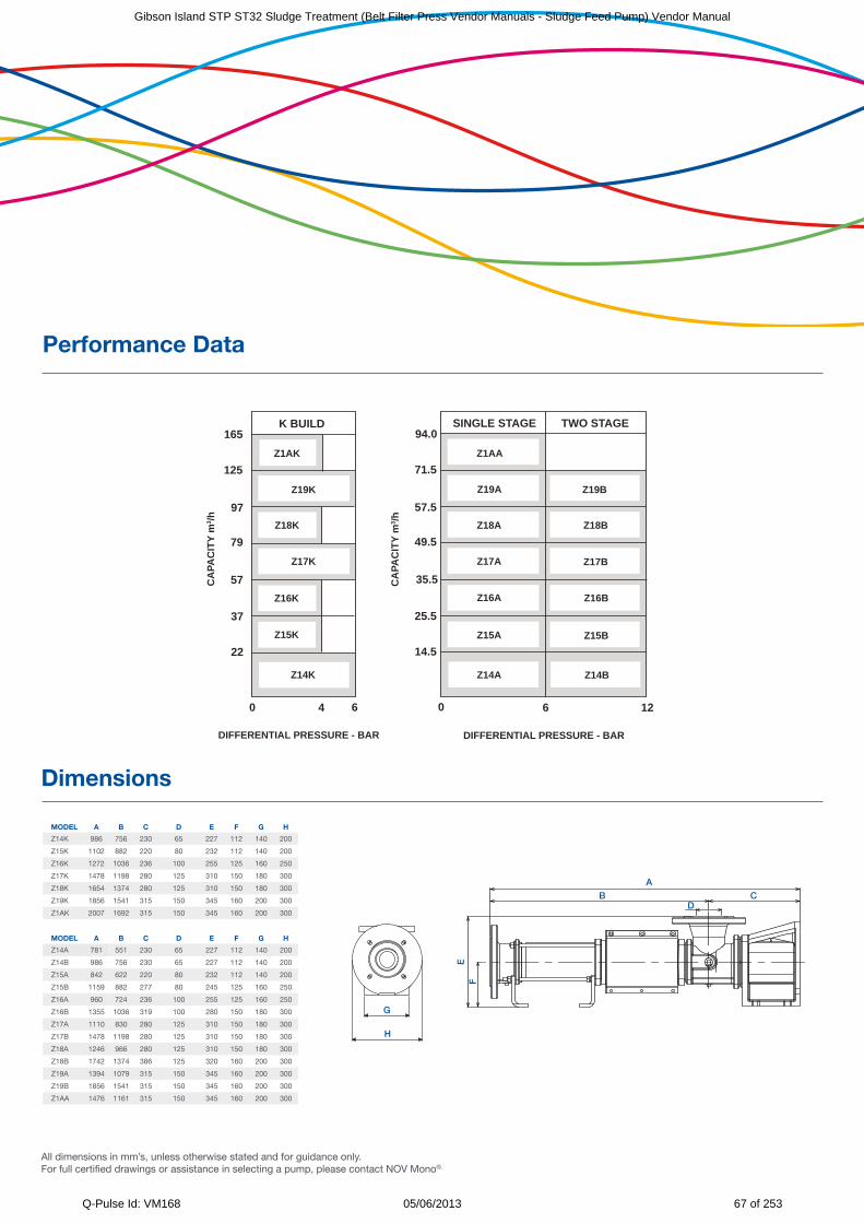
Performance Data
SINGLE STAGE TWO STAGEK BUILD
DIFFERENTIAL PRESSURE - BAR
04 6 12
14.5
25.5
35.5
49.5
57.5
71.5
94.0Z1AA
Z19A
Z15B
Z16B
Z17B
Z18B
Z19B
Z18A
Z17A
Z16A
Z15A
CA
PAC
ITY
m3 /h
Z14A Z14B
Z1AK
Z17K
Z14K
Z18K
Z16K
Z15K
Z19K
DIFFERENTIAL PRESSURE - BAR
0 6
22
37
57
79
97
125
165
CA
PAC
ITY
m3 /h
All dimensions in mm’s, unless otherwise stated and for guidance only. For full certified drawings or assistance in selecting a pump, please contact NOV Mono®.
MODEL A B C D E F G H
Z14K 986 756 230 65 227 112 140 200
Z15K 1102 882 220 80 232 112 140 200
Z16K 1272 1036 236 100 255 125 160 250
Z17K 1478 1198 280 125 310 150 180 300
Z18K 1654 1374 280 125 310 150 180 300
Z19K 1856 1541 315 150 345 160 200 300
Z1AK 2007 1692 315 150 345 160 200 300
MODEL A B C D E F G H
Z14A 781 551 230 65 227 112 140 200
Z14B 986 756 230 65 227 112 140 200
Z15A 842 622 220 80 232 112 140 200
Z15B 1159 882 277 80 245 125 160 250
Z16A 960 724 236 100 255 125 160 250
Z16B 1355 1036 319 100 280 150 180 300
Z17A 1110 830 280 125 310 150 180 300
Z17B 1478 1198 280 125 310 150 180 300
Z18A 1246 966 280 125 310 150 180 300
Z18B 1742 1374 386 125 320 160 200 300
Z19A 1394 1079 315 150 345 160 200 300
Z19B 1856 1541 315 150 345 160 200 300
Z1AA 1476 1161 315 150 345 160 200 300
H
G
A
DB C
EF
Dimensions
Gibson Island STP ST32 Sludge Treatment (Belt Filter Press Vendor Manuals - Sludge Feed Pump) Vendor Manual
Q-Pulse Id: VM168 05/06/2013 67 of 253
Produced on recycled paper
© Mono Pumps Limited June 2011 Literature reference: ART76/2
Published information other than that marked CERTIFIED does not extend any warranty or representation, expressed or implied, regarding these products. Any such warranties or other terms and conditions of sales and products shall be in accordance with Mono Pumps Limited standard terms and conditions of sale, available on request.
Mono® is a registered trademark of Mono Pumps Ltd.
Registered in England No 300721
Europe
Mono Pumps Ltd, Martin Street, Audenshaw Manchester, M34 5JA, England
T. +44 161 339 9000 E. [email protected]
D.M.I EST, 56, rue du Pont 88300 Rebeuville, France
T. +33 3 29 94 26 88 E. [email protected]
Americas
Monoflo Inc., 10529 Fisher Road Houston, Texas 77041, USA
T. +1 713 980 8400 E. [email protected]
Monoflo S.A., Ing Huergo 2239 (1842) Monte Grande
Pcia. de Buenos Aires, Argentina T. +54 11 4290 9940/50
Monoflo Canada, 6010 – 53rd Ave Alberta, Lloydminster
T9V2T2, Canada T: + 1 780 875 5584
Asia
Mono Pumps Ltd, Building 5, Madong Industrial Park, 1250 Sicheng Rd
Malu Town, Jiading District, Shanghai 201801 T. +86 21 3990 4588
Australasia
Mono Pumps (Australia) Pty Ltd 75 Frankston Gardens Drive
Carrum Downs, Victoria 3201, Australia T. 1800 333 138
Mono Pumps (New Zealand) Ltd 35-41 Fremlin Place, Avondale Auckland, 1026, New Zealand
T. +64 9 829 0333 E. [email protected]
Melbourne T. 03 9773 7777 F. 03 9773 7400 Sydney T. 02 8536 0900 F. 02 9542 3649 Brisbane T. 07 3350 4582 F. 07 3350 3750 Adelaide T. 08 8447 8333 F. 08 8447 8373 Perth T. 08 9303 0444 F. 08 9303 0400 Darwin T. 08 8931 3300 F. 08 8931 3200 Kalgoorlie T. 08 9022 4880 F. 08 9022 3660
www.monopumps.com.au
Gibson Island STP ST32 Sludge Treatment (Belt Filter Press Vendor Manuals - Sludge Feed Pump) Vendor Manual
Q-Pulse Id: VM168 05/06/2013 68 of 253
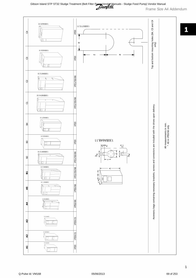
A1
A2
A3
A4
A5
B1
B2B3
B4C1
C2C3
C4
IP20
IP20
/21
IP20
/21
IP55
/66
IP55
/66
IP21
/55/
66IP
21/5
5/66
IP20
IP20
IP21
/55/
66IP
21/5
5/66
IP20
IP20
Acce
ssor
y ba
gs c
onta
inin
g ne
cess
ary
brac
kets
, scr
ews
and
conn
ecto
rs a
re in
clud
ed w
ith t
he d
rives
upo
n de
liver
y.To
p an
d bo
ttom
mou
ntin
g ho
les
(B4,
C3
and
C4on
ly)
All m
easu
rem
ents
in m
m.
* A5
in I
P55/
66 o
nly
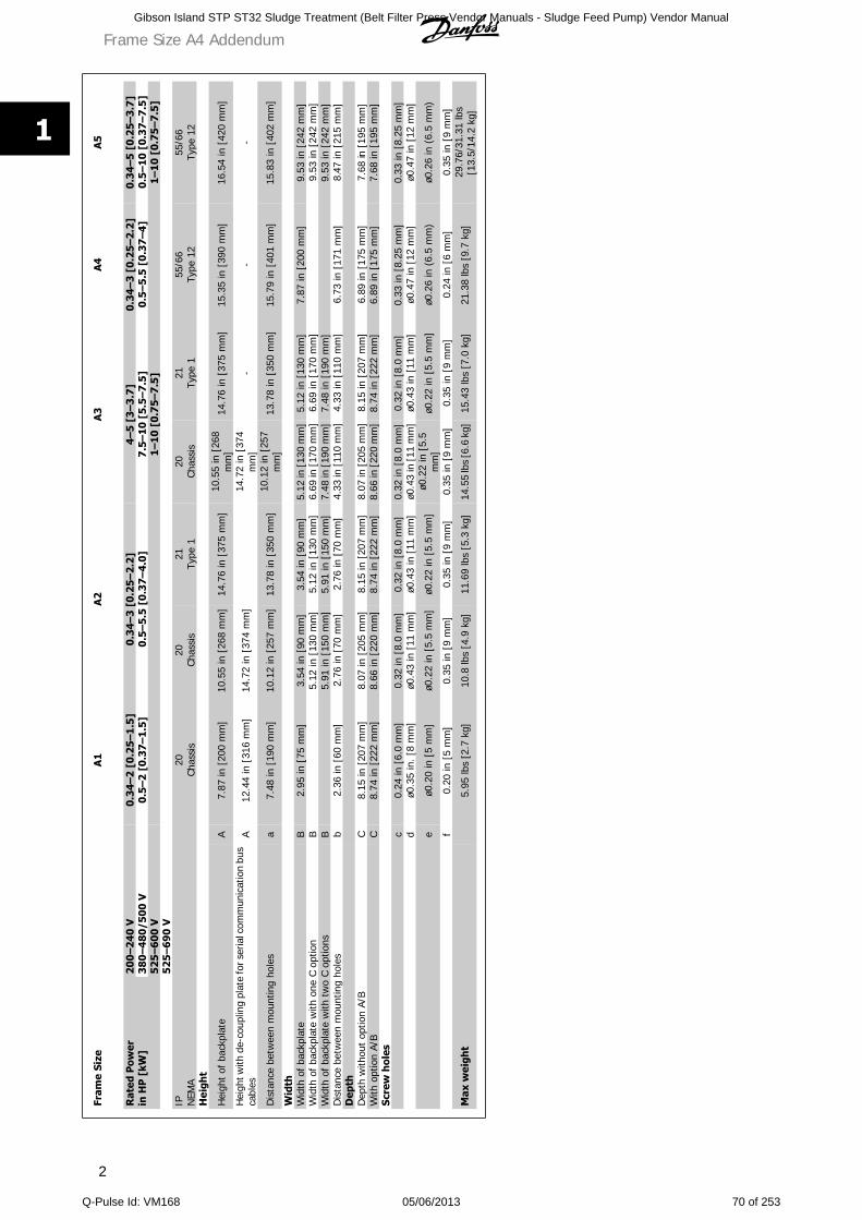
Frame Size A4 Addendum
1
1
Gibson Island STP ST32 Sludge Treatment (Belt Filter Press Vendor Manuals - Sludge Feed Pump) Vendor Manual
Q-Pulse Id: VM168 05/06/2013 69 of 253
Fram
e Si
zeA
1A
2A
3A
4A
5
Rat
ed P
ower
in H
P [
kW]
200
–240
V0.
34–2
[0
.25–
1.5
]0
.34–
3 [
0.2
5–2.
2]4–
5 [3
–3.7
]0.
34–3
[0.
25–2
.2]
0.34
–5 [
0.2
5–3.
7]
380
–480
/500
V0.
5–2
[0.3
7–1.
5]0.
5–5.
5 [
0.3
7–4.
0]7
.5–1
0 [
5.5–
7.5
]0
.5–5
.5 [
0.3
7–4]
0.5–
10 [
0.3
7–7.
5]
525
–600
V1–
10 [
0.7
5–7.
5]
1–10
[0.
75–
7.5]
525
–690
VIP N
EMA
20Ch
assi
s20
Chas
sis
21Ty
pe 1
20Ch
assi
s21
Type
155
/66
Type
12
55/6
6Ty
pe 1
2H
eigh
t
Hei
ght
of b
ackp
late
A7.
87 in
[20
0 m
m]
10.5
5 in
[26
8 m
m]
14.7
6 in
[37
5 m
m]
10.5
5 in
[26
8m
m]
14.7
6 in
[37
5 m
m]
15.3
5 in
[39
0 m
m]
16.5
4 in
[42
0 m
m]
Hei
ght w
ith d
e-co
uplin
g pl
ate
for s
eria
l com
mun
icat
ion
bus
cabl
esA
12.4
4 in
[31
6 m
m]
14.7
2 in
[37
4 m
m]
14.7
2 in
[37
4m
m]
--
-
Dis
tanc
e be
twee
n m
ount
ing
hole
sa
7.48
in [
190
mm
]10
.12
in [
257
mm
]13
.78
in [
350
mm
]10
.12
in [
257
mm
]13
.78
in [
350
mm
]15
.79
in [
401
mm
]15
.83
in [
402
mm
]
Wid
thW
idth
of
back
plat
eB
2.95
in [
75 m
m]
3.54
in [
90 m
m]
3.54
in [
90 m
m]
5.12
in [
130
mm
]5.
12 in
[13
0 m
m]
7.87
in [
200
mm
]9.
53 in
[24
2 m
m]
Wid
th o
f ba
ckpl
ate
with
one
C o
ptio
nB
5.12
in [
130
mm
]5.
12 in
[13
0 m
m]
6.69
in [
170
mm
]6.
69 in
[17
0 m
m]
9.53
in [
242
mm
]W
idth
of
back
plat
e w
ith t
wo
C op
tions
B5.
91 in
[15
0 m
m]
5.91
in [
150
mm
]7.
48 in
[19
0 m
m]
7.48
in [
190
mm
]9.
53 in
[24
2 m
m]
Dis
tanc
e be
twee
n m
ount
ing
hole
sb
2.36
in [
60 m
m]
2.76
in [
70 m
m]
2.76
in [
70 m
m]
4.33
in [
110
mm
]4.
33 in
[11
0 m
m]
6.73
in [
171
mm
]8.
47 in
[21
5 m
m]
Dep
thD
epth
with
out
optio
n A/
BC
8.15
in [
207
mm
]8.
07 in
[20
5 m
m]
8.15
in [
207
mm
]8.
07 in
[20
5 m
m]
8.15
in [
207
mm
]6.
89 in
[17
5 m
m]
7.68
in [
195
mm
]W
ith o
ptio
n A/
BC
8.74
in [
222
mm
]8.
66 in
[22
0 m
m]
8.74
in [
222
mm
]8.
66 in
[22
0 m
m]
8.74
in [
222
mm
]6.
89 in
[17
5 m
m]
7.68
in [
195
mm
]Sc
rew
hol
esc
0.24
in [
6.0
mm
]0.
32 in
[8.
0 m
m]
0.32
in [
8.0
mm
]0.
32 in
[8.
0 m
m]
0.32
in [
8.0
mm
]0.
33 in
[8.
25 m
m]
0.33
in [
8.25
mm
]d
ø0.3
5 in
. [8
mm
]ø0
.43
in [
11 m
m]
ø0.4
3 in
[11
mm
]ø0
.43
in [
11 m
m]
ø0.4
3 in
[11
mm
]ø0
.47
in [
12 m
m]
ø0.4
7 in
[12
mm
]
eø0
.20
in [
5 m
m]
ø0.2
2 in
[5.
5 m
m]
ø0.2
2 in
[5.
5 m
m]
ø0.2
2 in
[5.
5m
m]
ø0.2
2 in
[5.
5 m
m]
ø0.2
6 in
(6.
5 m
m)
ø0.2
6 in
(6.
5 m
m)
f0.
20 in
[5
mm
]0.
35 in
[9
mm
]0.
35 in
[9
mm
]0.
35 in
[9
mm
]0.
35 in
[9
mm
]0.
24 in
[6
mm
]0.
35 in
[9
mm
]
Max
wei
ght
5.95
lbs
[2.7
kg]
10.8
lbs
[4.9
kg]
11.6
9 lb
s [5
.3 k
g]14
.55
lbs
[6.6
kg]
15.4
3 lb
s [7
.0 k
g]21
.38
lbs
[9.7
kg]
29.7
6/31
.31
lbs
[13.
5/14
.2 k
g]
Frame Size A4 Addendum
2
1
Gibson Island STP ST32 Sludge Treatment (Belt Filter Press Vendor Manuals - Sludge Feed Pump) Vendor Manual
Q-Pulse Id: VM168 05/06/2013 70 of 253
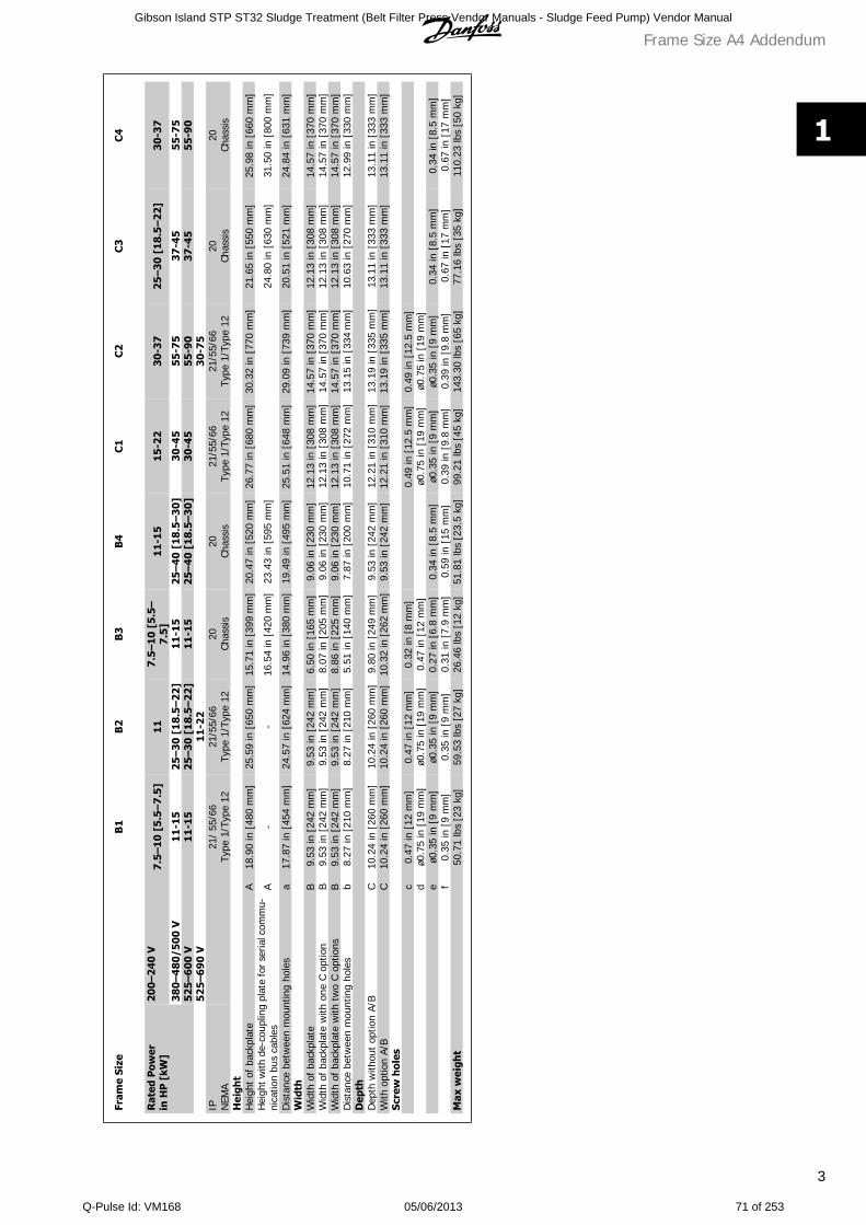
Fram
e Si
zeB
1B
2B
3B
4C
1C
2C
3C
4
Rat
ed P
ower
in H
P [
kW]
200–
240
V7.
5–10
[5.
5–7.
5]11
7.5–
10 [
5.5–
7.5]
11-1
515
-22
30-3
725
–30
[18.
5–2
2]30
-37
380–
480
/500
V1
1-15
25–3
0 [1
8.5–
22]
11-1
525
–40
[18
.5–3
0]30
-45
55-7
537
-45
55-7
552
5–6
00 V
11-
1525
–30
[18.
5–22
]11
-15
25–
40 [
18.5
–30]
30-4
555
-90
37-4
555
-90
525–
690
V11
-22
30-7
5IP N
EMA
21/
55/6
6Ty
pe 1
/Typ
e 12
21/5
5/66
Type
1/T
ype
1220
Chas
sis
20Ch
assi
s21
/55/
66Ty
pe 1
/Typ
e 12
21/5
5/66
Type
1/T
ype
1220
Chas
sis
20Ch
assi
sH
eigh
tH
eigh
t of
bac
kpla
teA
18.9
0 in
[48
0 m
m]
25.5
9 in
[65
0 m
m]
15.7
1 in
[39
9 m
m]
20.4
7 in
[52
0 m
m]
26.7
7 in
[68
0 m
m]
30.3
2 in
[77
0 m
m]
21.6
5 in
[55
0 m
m]
25.9
8 in
[66
0 m
m]
Hei
ght w
ith d
e-co
uplin
g pl
ate
for
seria
l com
mu-
nica
tion
bus
cabl
esA
--
16.5
4 in
[42
0 m
m]
23.4
3 in
[59
5 m
m]
24.8
0 in
[63
0 m
m]
31.5
0 in
[80
0 m
m]
Dis
tanc
e be
twee
n m
ount
ing
hole
sa
17.8
7 in
[45
4 m
m]
24.5
7 in
[62
4 m
m]
14.9
6 in
[38
0 m
m]
19.4
9 in
[49
5 m
m]
25.5
1 in
[64
8 m
m]
29.0
9 in
[73
9 m
m]
20.5
1 in
[52
1 m
m]
24.8
4 in
[63
1 m
m]
Wid
thW
idth
of
back
plat
eB
9.53
in [
242
mm
]9.
53 in
[24
2 m
m]
6.50
in [
165
mm
]9.
06 in
[23
0 m
m]
12.1
3 in
[30
8 m
m]
14.5
7 in
[37
0 m
m]
12.1
3 in
[30
8 m
m]
14.5
7 in
[37
0 m
m]
Wid
th o
f ba
ckpl
ate
with
one
C o
ptio
nB
9.53
in [
242
mm
]9.
53 in
[24
2 m
m]
8.07
in [
205
mm
]9.
06 in
[23
0 m
m]
12.1
3 in
[30
8 m
m]
14.5
7 in
[37
0 m
m]
12.1
3 in
[30
8 m
m]
14.5
7 in
[37
0 m
m]
Wid
th o
f ba
ckpl
ate
with
tw
o C
optio
nsB
9.53
in [
242
mm
]9.
53 in
[24
2 m
m]
8.86
in [
225
mm
]9.
06 in
[23
0 m
m]
12.1
3 in
[30
8 m
m]
14.5
7 in
[37
0 m
m]
12.1
3 in
[30
8 m
m]
14.5
7 in
[37
0 m
m]
Dis
tanc
e be
twee
n m
ount
ing
hole
sb
8.27
in [
210
mm
]8.
27 in
[21
0 m
m]
5.51
in [
140
mm
]7.
87 in
[20
0 m
m]
10.7
1 in
[27
2 m
m]
13.1
5 in
[33
4 m
m]
10.6
3 in
[27
0 m
m]
12.9
9 in
[33
0 m
m]
Dep
thD
epth
with
out
optio
n A/
BC
10.2
4 in
[26
0 m
m]
10.2
4 in
[26
0 m
m]
9.80
in [
249
mm
]9.
53 in
[24
2 m
m]
12.2
1 in
[31
0 m
m]
13.1
9 in
[33
5 m
m]
13.1
1 in
[33
3 m
m]
13.1
1 in
[33
3 m
m]
With
opt
ion
A/B
C10
.24
in [
260
mm
]10
.24
in [
260
mm
]10
.32
in [
262
mm
]9.
53 in
[24
2 m
m]
12.2
1 in
[31
0 m
m]
13.1
9 in
[33
5 m
m]
13.1
1 in
[33
3 m
m]
13.1
1 in
[33
3 m
m]
Scre
w h
oles
c0.
47 in
[12
mm
]0.
47 in
[12
mm
]0.
32 in
[8
mm
]0.
49 in
[12
.5 m
m]
0.49
in [
12.5
mm
]d
ø0.7
5 in
[19
mm
]ø0
.75
in [
19 m
m]
0.47
in [
12 m
m]
ø0.7
5 in
[19
mm
]ø0
.75
in [
19 m
m]
eø0
.35
in [
9 m
m]
ø0.3
5 in
[9
mm
]0.
27 in
[6.
8 m
m]
0.34
in [
8.5
mm
]ø0
.35
in [
9 m
m]
ø0.3
5 in
[9
mm
]0.
34 in
[8.
5 m
m]
0.34
in [
8.5
mm
]f
0.35
in [
9 m
m]
0.35
in [
9 m
m]
0.31
in [
7.9
mm
]0.
59 in
[15
mm
]0.
39 in
[9.
8 m
m]
0.39
in [
9.8
mm
]0.
67 in
[17
mm
]0.
67 in
[17
mm
]M
ax w
eigh
t50
.71
lbs
[23
kg]
59.5
3 lb
s [2
7 kg
]26
.46
lbs
[12
kg]
51.8
1 lb
s [2
3.5
kg]
99.2
1 lb
s [4
5 kg
]14
3.30
lbs
[65
kg]
77.1
6 lb
s [3
5 kg
]11
0.23
lbs
[50
kg]
Frame Size A4 Addendum
3
1
Gibson Island STP ST32 Sludge Treatment (Belt Filter Press Vendor Manuals - Sludge Feed Pump) Vendor Manual
Q-Pulse Id: VM168 05/06/2013 71 of 253
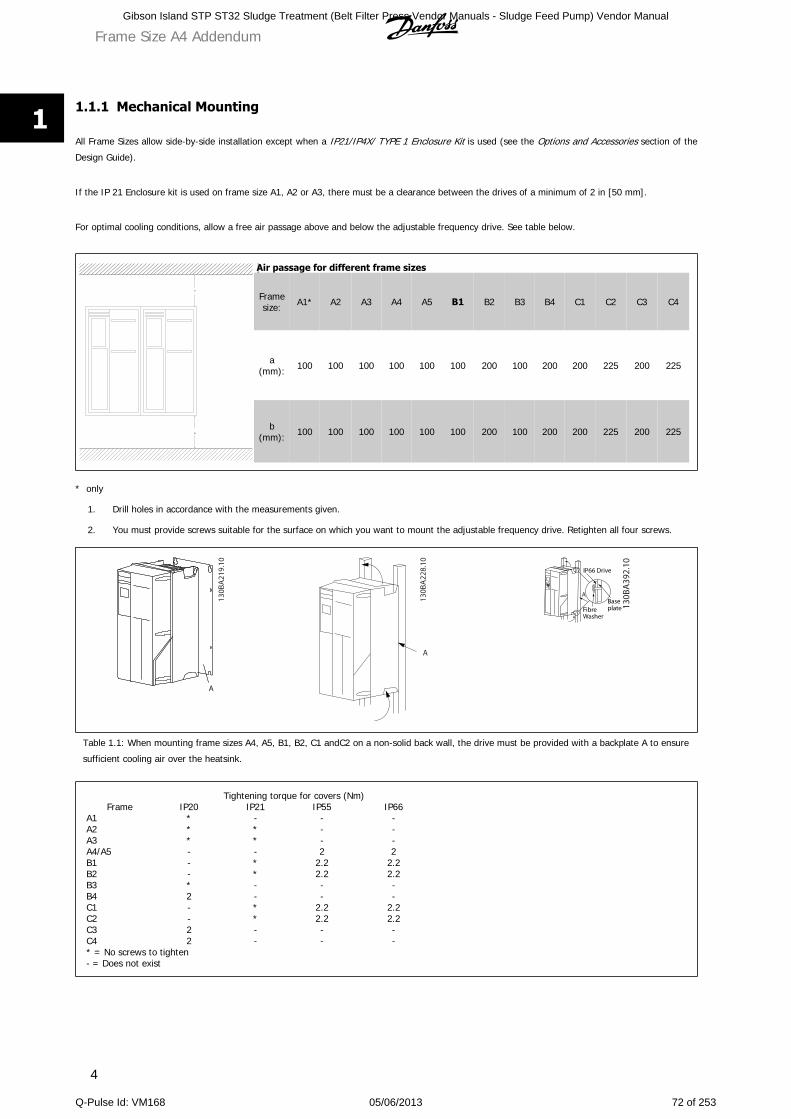
1.1.1 Mechanical Mounting
All Frame Sizes allow side-by-side installation except when a IP21/IP4X/ TYPE 1 Enclosure Kit is used (see the Options and Accessories section of the
Design Guide).
If the IP 21 Enclosure kit is used on frame size A1, A2 or A3, there must be a clearance between the drives of a minimum of 2 in [50 mm].
For optimal cooling conditions, allow a free air passage above and below the adjustable frequency drive. See table below.
Air passage for different frame sizes
Framesize: A1* A2 A3 A4 A5 B1 B2 B3 B4 C1 C2 C3 C4
a(mm): 100 100 100 100 100 100 200 100 200 200 225 200 225
b(mm): 100 100 100 100 100 100 200 100 200 200 225 200 225
* only
1. Drill holes in accordance with the measurements given.
2. You must provide screws suitable for the surface on which you want to mount the adjustable frequency drive. Retighten all four screws.
Table 1.1: When mounting frame sizes A4, A5, B1, B2, C1 andC2 on a non-solid back wall, the drive must be provided with a backplate A to ensure
sufficient cooling air over the heatsink.
FrameTightening torque for covers (Nm)
IP20 IP21 IP55 IP66A1 * - - -A2 * * - -A3 * * - -A4/A5 - - 2 2B1 - * 2.2 2.2B2 - * 2.2 2.2B3 * - - -B4 2 - - -C1 - * 2.2 2.2C2 - * 2.2 2.2C3 2 - - -C4 2 - - -* = No screws to tighten- = Does not exist
Frame Size A4 Addendum
4
1
Gibson Island STP ST32 Sludge Treatment (Belt Filter Press Vendor Manuals - Sludge Feed Pump) Vendor Manual
Q-Pulse Id: VM168 05/06/2013 72 of 253
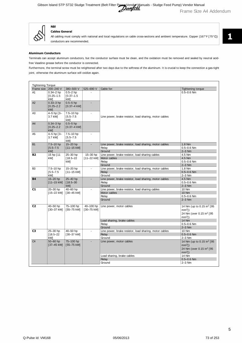
NB!
Cables General
All cabling must comply with national and local regulations on cable cross-sections and ambient temperature. Copper (167°F [75°C])
conductors are recommended.
Aluminum Conductors
Terminals can accept aluminum conductors, but the conductor surface must be clean, and the oxidation must be removed and sealed by neutral acid-
free Vaseline grease before the conductor is connected.
Furthermore, the terminal screw must be retightened after two days due to the softness of the aluminum. It is crucial to keep the connection a gas-tight
joint, otherwise the aluminum surface will oxidize again.
Tightening TorqueFrame size 200–240 V 380–500 V 525–690 V Cable for: Tightening torqueA1 0.34–2 hp
[0.25–1.5kW]
0.5–2 hp[0.37–1.5kW]
-
Line power, brake resistor, load sharing, motor cables
0.5–0.6 Nm
A2 0.33–3 hp[0.25–2.2kW]
0.5–5 hp[0.37–4 kW]
-
A3 4–5 hp [3–3.7 kW]
7.5–10 hp[5.5–7.5kW]
-
A4 0.34–3 hp[0.25–2.2kW]
0.5–5 hp[0.37–4 kW]
A5 4–5 hp [3–3.7 kW]
7.5–10 hp[5.5–7.5kW]
-
B1 7.5–10 hp[5.5–7.5kW]
15–20 hp[11–15 kW]
- Line power, brake resistor, load sharing, motor cables 1.8 NmRelay 0.5–0.6 NmGround 2–3 Nm
B2 15 hp [11kW]
25–30 hp[18.5–22kW]
15–30 hp[11–22 kW]
Line power, brake resistor, load sharing cables 4.5 NmMotor cables 4.5 NmRelay 0.5–0.6 NmGround 2–3 Nm
B3 7.5–10 hp[5.5–7.5kW]
15–20 hp[11–15 kW]
- Line power, brake resistor, load sharing, motor cables 1.8 NmRelay 0.5–0.6 NmGround 2–3 Nm
B4 15–20 hp[11–15 kW]
25–40 hp[18.5–30kW]
- Line power, brake resistor, load sharing, motor cables 4.5 NmRelay 0.5–0.6 NmGround 2–3 Nm
C1 20–30 hp[15–22 kW]
40–60 hp[30–45 kW]
- Line power, brake resistor, load sharing cables 10 NmMotor cables 10 NmRelay 0.5–0.6 NmGround 2–3 Nm
C2 40–50 hp[30–37 kW]
75–100 hp[55–75 kW]
40–100 hp[30–75 kW]
Line power, motor cables 14 Nm (up to 0.15 in2 [95mm2])24 Nm (over 0.15 in2 [95mm2])
Load sharing, brake cables 14 NmRelay 0.5–0.6 NmGround 2–3 Nm
C3 25–30 hp[18.5–22kW]
40–50 hp[30–37 kW]
- Line power, brake resistor, load sharing, motor cables 10 NmRelay 0.5–0.6 NmGround 2–3 Nm
C4 50–60 hp[37–45 kW]
75–100 hp[55–75 kW]
- Line power, motor cables 14 Nm (up to 0.15 in2 [95mm2])24 Nm (over 0.15 in2 [95mm2])
Load sharing, brake cables 14 NmRelay 0.5–0.6 NmGround 2–3 Nm
Frame Size A4 Addendum
5
1
Gibson Island STP ST32 Sludge Treatment (Belt Filter Press Vendor Manuals - Sludge Feed Pump) Vendor Manual
Q-Pulse Id: VM168 05/06/2013 73 of 253
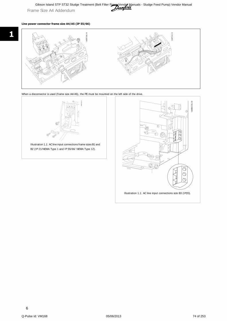
Line power connector frame size A4/A5 (IP 55/66)
When a disconnector is used (frame size A4/A5), the PE must be mounted on the left side of the drive.
Illustration 1.1: AC line input connections frame sizes B1 and
B2 (IP 21/NEMA Type 1 and IP 55/66/ NEMA Type 12).
Illustration 1.1: AC line input connections size B3 (IP20).
Frame Size A4 Addendum
6
1
Gibson Island STP ST32 Sludge Treatment (Belt Filter Press Vendor Manuals - Sludge Feed Pump) Vendor Manual
Q-Pulse Id: VM168 05/06/2013 74 of 253
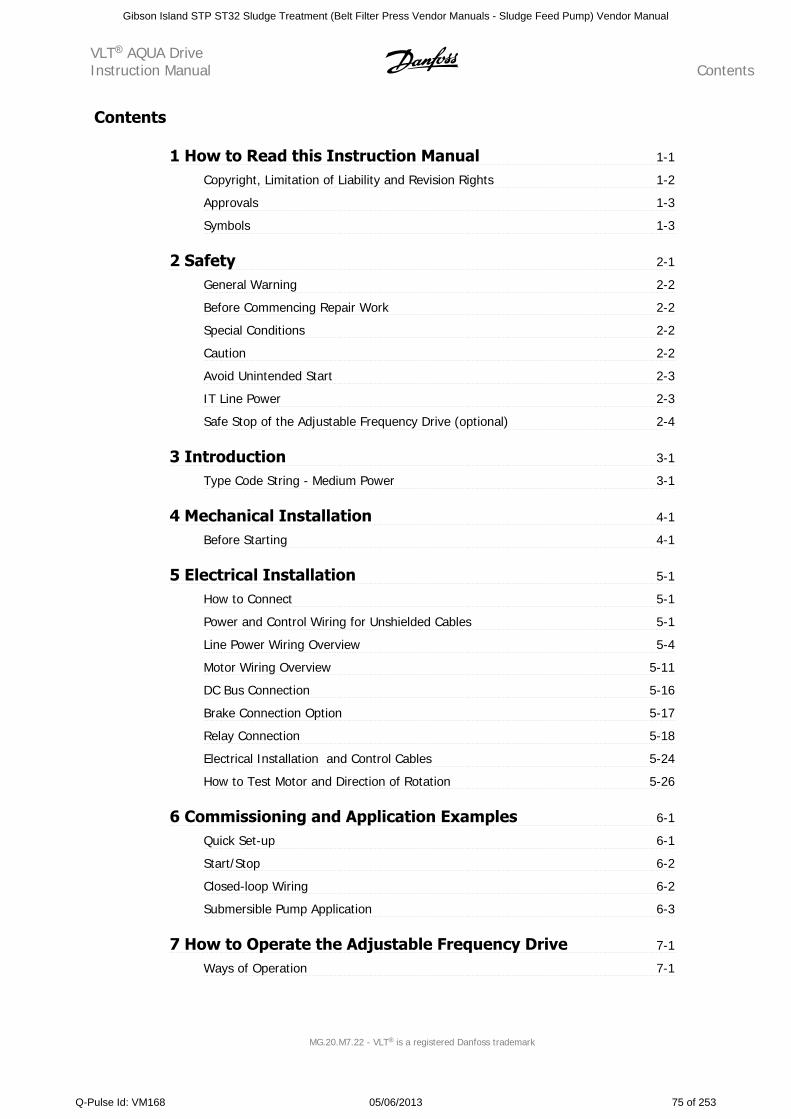
Contents
1 How to Read this Instruction Manual 1-1
Copyright, Limitation of Liability and Revision Rights 1-2
Approvals 1-3
Symbols 1-3
2 Safety 2-1
General Warning 2-2
Before Commencing Repair Work 2-2
Special Conditions 2-2
Caution 2-2
Avoid Unintended Start 2-3
IT Line Power 2-3
Safe Stop of the Adjustable Frequency Drive (optional) 2-4
3 Introduction 3-1
Type Code String - Medium Power 3-1
4 Mechanical Installation 4-1
Before Starting 4-1
5 Electrical Installation 5-1
How to Connect 5-1
Power and Control Wiring for Unshielded Cables 5-1
Line Power Wiring Overview 5-4
Motor Wiring Overview 5-11
DC Bus Connection 5-16
Brake Connection Option 5-17
Relay Connection 5-18
Electrical Installation and Control Cables 5-24
How to Test Motor and Direction of Rotation 5-26
6 Commissioning and Application Examples 6-1
Quick Set-up 6-1
Start/Stop 6-2
Closed-loop Wiring 6-2
Submersible Pump Application 6-3
7 How to Operate the Adjustable Frequency Drive 7-1
Ways of Operation 7-1
VLT AQUA DriveInstruction Manual Contents
MG.20.M7.22 - VLT is a registered Danfoss trademark
Gibson Island STP ST32 Sludge Treatment (Belt Filter Press Vendor Manuals - Sludge Feed Pump) Vendor Manual
Q-Pulse Id: VM168 05/06/2013 75 of 253
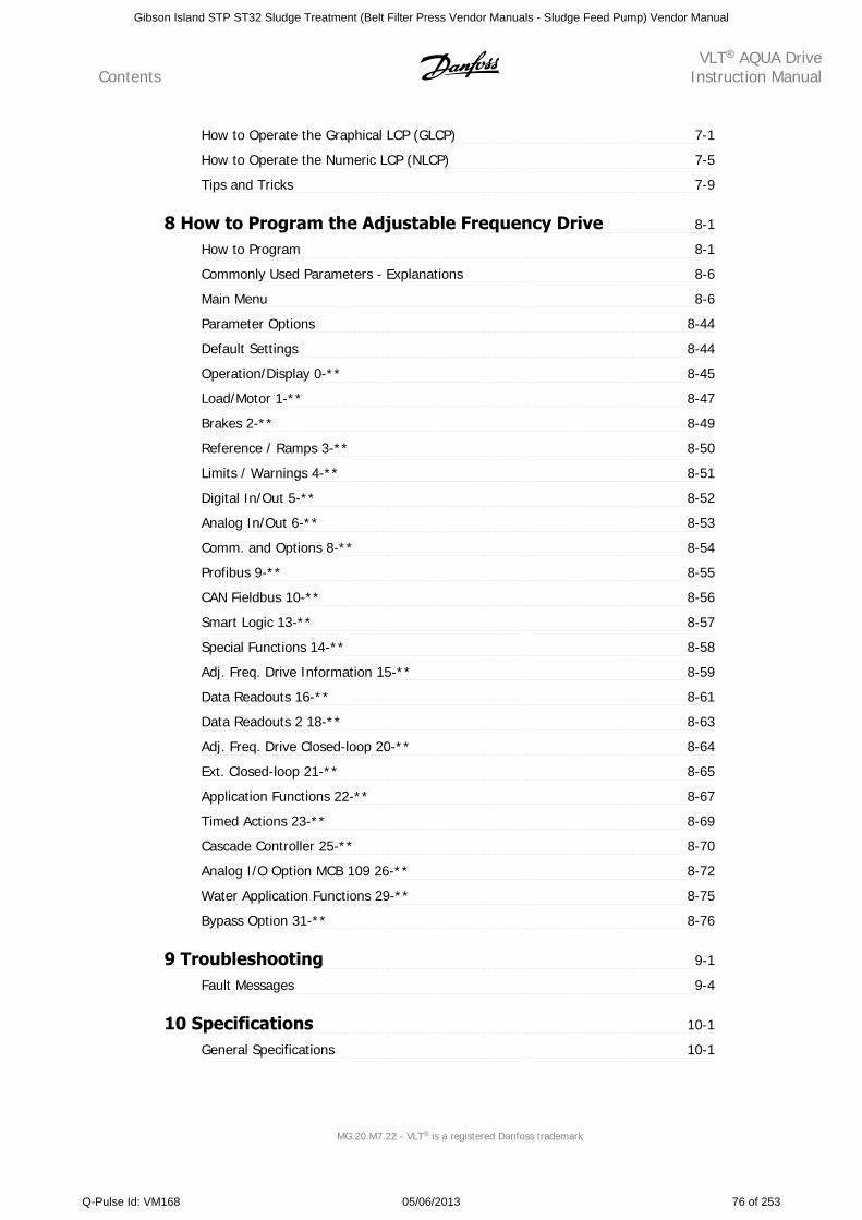
How to Operate the Graphical LCP (GLCP) 7-1
How to Operate the Numeric LCP (NLCP) 7-5
Tips and Tricks 7-9
8 How to Program the Adjustable Frequency Drive 8-1
How to Program 8-1
Commonly Used Parameters - Explanations 8-6
Main Menu 8-6
Parameter Options 8-44
Default Settings 8-44
Operation/Display 0-** 8-45
Load/Motor 1-** 8-47
Brakes 2-** 8-49
Reference / Ramps 3-** 8-50
Limits / Warnings 4-** 8-51
Digital In/Out 5-** 8-52
Analog In/Out 6-** 8-53
Comm. and Options 8-** 8-54
Profibus 9-** 8-55
CAN Fieldbus 10-** 8-56
Smart Logic 13-** 8-57
Special Functions 14-** 8-58
Adj. Freq. Drive Information 15-** 8-59
Data Readouts 16-** 8-61
Data Readouts 2 18-** 8-63
Adj. Freq. Drive Closed-loop 20-** 8-64
Ext. Closed-loop 21-** 8-65
Application Functions 22-** 8-67
Timed Actions 23-** 8-69
Cascade Controller 25-** 8-70
Analog I/O Option MCB 109 26-** 8-72
Water Application Functions 29-** 8-75
Bypass Option 31-** 8-76
9 Troubleshooting 9-1
Fault Messages 9-4
10 Specifications 10-1
General Specifications 10-1
ContentsVLT AQUA Drive
Instruction Manual
MG.20.M7.22 - VLT is a registered Danfoss trademark
Gibson Island STP ST32 Sludge Treatment (Belt Filter Press Vendor Manuals - Sludge Feed Pump) Vendor Manual
Q-Pulse Id: VM168 05/06/2013 76 of 253
Special Conditions 10-17
11 Index 11-1
VLT AQUA DriveInstruction Manual Contents
MG.20.M7.22 - VLT is a registered Danfoss trademark
Gibson Island STP ST32 Sludge Treatment (Belt Filter Press Vendor Manuals - Sludge Feed Pump) Vendor Manual
Q-Pulse Id: VM168 05/06/2013 77 of 253
ContentsVLT AQUA Drive
Instruction Manual
MG.20.M7.22 - VLT is a registered Danfoss trademark
Gibson Island STP ST32 Sludge Treatment (Belt Filter Press Vendor Manuals - Sludge Feed Pump) Vendor Manual
Q-Pulse Id: VM168 05/06/2013 78 of 253
1 How to Read this Instruction Manual
VLT AQUA DriveFC 200 Series
Software version: 1.33
This guide can be used with all FC 200 adjustable frequency driveswith software version 1.33 or later.
The current software version number can be read frompar. 15-43 Software Version.
VLT AQUA DriveInstruction Manual 1 How to Read this Instruction Manual
MG.20.M7.22 - VLT is a registered Danfoss trademark 1-1
1
Gibson Island STP ST32 Sludge Treatment (Belt Filter Press Vendor Manuals - Sludge Feed Pump) Vendor Manual
Q-Pulse Id: VM168 05/06/2013 79 of 253
1.1.1 Copyright, Limitation of Liability and Revision Rights
This publication contains information proprietary to Danfoss. By accepting and using this manual, the user agrees that the information contained herein
will be used solely for operating equipment from Danfoss or equipment from other vendors provided that such equipment is intended for communication
with Danfoss equipment over a serial communication link. This publication is protected under the copyright laws of Denmark and most other countries.
Danfoss does not warrant that a software program produced according to the guidelines provided in this manual will function properly in every physical,
hardware or software environment.
Although Danfoss has tested and reviewed the documentation within this manual, Danfoss makes no warranty or representation, neither expressed nor
implied, with respect to this documentation, including its quality, performance, or fitness for a particular purpose.
In no event shall Danfoss be liable for direct, indirect, special, incidental, or consequential damages arising out of the use, or the inability to use information
contained in this manual, even if advised of the possibility of such damages. In particular, Danfoss is not responsible for any costs, including but not
limited to those incurred as a result of lost profits or revenue, loss or damage of equipment, loss of computer programs, loss of data, the costs to substitute
these, or any claims by third parties.
Danfoss reserves the right to revise this publication at any time and to make changes to its contents without prior notice or any obligation to notify former
or present users of such revisions or changes.
1.1.2 Available Literature for VLT® AQUA DriveFC 200
- VLT® AQUA Drive Instruction Manual MG.20.Mx.yy provides the neccessary information for getting the drive up and running.
- VLT® AQUA Drive High Power Instruction Manual MG.20.Px.yy provides the neccessary information for getting the HP drive up and running.
- VLT® AQUA Drive Design Guide MG.20.Nx.yy contains all the technical information about the drive and customer design and applications.
- VLT® AQUA Drive Programming Guide MN.20.Ox.yy provides information on how to program and includes complete parameter descriptions.
- VLT® AQUA Drive FC 200 Profibus MG.33.Cx.yy
- VLT® AQUA Drive FC 200 DeviceNet MG.33.Dx.yy
- Output Filters Design Guide MG.90.Nx.yy
- VLT® AQUA Drive FC 200 Cascade Controller MI.38.Cx.yy
- Application Note MN20A102: Submersible Pump Application
- Application Note MN20B102: Master/Follower Operation Application
- Application Note MN20F102: Drive Closed-loop and Sleep Mode
- Instruction MI.38.Bx.yy: Installation Instruction for Mounting Brackets Enclosure type A5, B1, B2, C1 and C2 IP21, IP55 or IP66
- Instruction MI.90.Lx.yy: Analog I/O Option MCB109
- Instruction MI.33.Hx.yy: Panel through mount kit
x = Revision number
yy = Language code
Danfoss technical literature is also available online at
www.danfoss.com/BusinessAreas/DrivesSolutions/Documentations/Technical+Documentation.htm.
1 How to Read this Instruction ManualVLT AQUA Drive
Instruction Manual
1-2 MG.20.M7.22 - VLT is a registered Danfoss trademark
1
Gibson Island STP ST32 Sludge Treatment (Belt Filter Press Vendor Manuals - Sludge Feed Pump) Vendor Manual
Q-Pulse Id: VM168 05/06/2013 80 of 253
1.1.3 Approvals
1.1.4 Symbols
Symbols used in this Instruction Manual.
NOTE!
Indicates something to be noted by the reader.
Indicates a general warning.
Indicates a high-voltage warning.
Indicates a default setting
VLT AQUA DriveInstruction Manual 1 How to Read this Instruction Manual
MG.20.M7.22 - VLT is a registered Danfoss trademark 1-3
1
Gibson Island STP ST32 Sludge Treatment (Belt Filter Press Vendor Manuals - Sludge Feed Pump) Vendor Manual
Q-Pulse Id: VM168 05/06/2013 81 of 253
1 How to Read this Instruction ManualVLT AQUA Drive
Instruction Manual
1-4 MG.20.M7.22 - VLT is a registered Danfoss trademark
1
Gibson Island STP ST32 Sludge Treatment (Belt Filter Press Vendor Manuals - Sludge Feed Pump) Vendor Manual
Q-Pulse Id: VM168 05/06/2013 82 of 253
2 Safety
2.1.1 Safety Note
The voltage of the adjustable frequency drive is dangerous whenever connected to line power. Incorrect installation of the motor,
adjustable frequency drive or serial communication bus may cause damage to the equipment, serious personal injury or death. Con-
sequently, the instructions in this manual, as well as national and local rules and safety regulations, must be complied with.
Safety Regulations
1. The adjustable frequency drive must be disconnected from line power if repair work is to be carried out. Make sure that the line power supply
has been disconnected and that the necessary time has passed before removing motor and line power plugs.
2. The [STOP/RESET] key on the control panel of the adjustable frequency drive does not disconnect the equipment from line power and is thus
not to be used as a safety switch.
3. Correct protective grounding of the equipment must be established, the user must be protected against supply voltage, and the motor must be
protected against overload in accordance with applicable national and local regulations.
4. The ground leakage currents are higher than 3.5 mA.
5. Protection against motor overload is set by par. 1-90 Motor Thermal Protection. If this function is desired, set par. 1-90 to data value [ETR trip]
(default value) or data value [ETR warning]. Note: The function is initialized at 1.16 x rated motor current and rated motor frequency. For the
North American market: The ETR functions provide class 20 motor overload protection in accordance with NEC.
6. Do not remove the plugs for the motor and line power supply while the adjustable frequency drive is connected to line power. Make sure that
the line power supply has been disconnected and that the necessary time has passed before removing motor and line power plugs.
7. Please note that the adjustable frequency drive has more voltage inputs than L1, L2 and L3 when load sharing (linking of the DC intermediate
circuit) and external 24 V DC have been installed. Make sure that all voltage inputs have been disconnected and that the necessary time has
passed before commencing repair work.
Installation at High Altitudes
Installation at high altitude:
380–480 V: At altitudes above 10,000 ft [3 km], please contact Danfoss Drives regarding PELV.
525–690 V: At altitudes above 6,600 ft [2 km], please contact Danfoss Drives regarding PELV.
Warning against Unintended Start
1. The motor can be brought to a stop by means of digital commands, bus commands, references or a local stop, while the adjustable frequency drive
is connected to line power. If personal safety considerations make it necessary to ensure that no unintended start occurs, these stop functions are not
sufficient. 2. While parameters are being changed, the motor may start. Consequently, the stop key [RESET] must always be activated; following which
data can be modified. 3. A motor that has been stopped may start if faults occur in the electronics of the adjustable frequency drive, or if a temporary
overload or a fault in the supply line power or the motor connection ceases.
Warning:
Touching the electrical parts may be fatal - even after the equipment has been disconnected from line power.
Also make sure that other voltage inputs have been disconnected, such as external 24 V DC, load sharing (linkage of DC intermediate circuit), as well as
the motor connection for kinetic backup.
VLT AQUA DriveInstruction Manual 2 Safety
MG.20.M7.22 - VLT is a registered Danfoss trademark 2-1
2
Gibson Island STP ST32 Sludge Treatment (Belt Filter Press Vendor Manuals - Sludge Feed Pump) Vendor Manual
Q-Pulse Id: VM168 05/06/2013 83 of 253
2.1.2 General Warning
Leakage Current
The ground leakage current from the VLT AQUA Drive FC 200 exceeds 3.5 mA. According to IEC 61800-5-1, a reinforced protective
ground connection must be ensured by means of: a min. 0.016 in² [10 mm²] Cu or 0.025 in² [16 mm²] Al PE-wire, or an additional
PE wire - with the same cable cross-section as the line power wiring - must be terminated separately.
Residual Current Device
This product can cause DC current in the protective conductor. Where a residual current device (RCD) is used for extra protection, only
an RCD of Type B (time delayed) shall be used on the supply side of this product. See also RCD Application Note MN.90.GX.02.
Protective grounding of the VLT AQUA Drive FC 200 and the use of RCDs must always follow national and local regulations.
2.1.3 Before Commencing Repair Work
1. Disconnect the adjustable frequency drive from line power.
2. Disconnect DC bus terminals 88 and 89
3. Wait at least the time mentioned above in the section General Warning.
4. Remove motor cable
2.1.4 Special Conditions
Electrical Ratings:
The rating indicated on the nameplate of the adjustable frequency drive is based on a typical 3-phase line power supply within the specified voltage,
current and temperature ranges, which are expected to be used in most applications.
The adjustable frequency drives also support other special applications, which affect the electrical ratings of the adjustable frequency
drive. Special conditions that affect the electrical ratings might be:
• Single phase applications.
• High temperature applications which require derating of the electrical ratings
• Marine applications with more severe environmental conditions.
Consult the relevant clauses in these instructions and in the VLT AQUA Drive Design Guide for information about the electrical ratings.
Installation requirements:
The overall electrical safety of the adjustable frequency drive requires special installation considerations regarding:
• Fuses and circuit breakers for overcurrent and short-circuit protection
• Selection of power cables (line power, motor, brake, load sharing and relay)
• Grid configuration (IT,TN, grounded leg, etc.)
• Safety of low-voltage ports (PELV conditions).
Consult the relevant clauses in these instructions and in the VLT AQUA Drive Design Guide for information about the installation requirements.
2.1.5 Caution
The adjustable frequency drive DC link capacitors remain charged after power has been disconnected. To avoid an electrical shock
hazard, disconnect the adjustable frequency drive from line power before carrying out maintenance. Wait at least as follows before
doing service on the adjustable frequency drive:
2 SafetyVLT AQUA Drive
Instruction Manual
2-2 MG.20.M7.22 - VLT is a registered Danfoss trademark
2
Gibson Island STP ST32 Sludge Treatment (Belt Filter Press Vendor Manuals - Sludge Feed Pump) Vendor Manual
Q-Pulse Id: VM168 05/06/2013 84 of 253
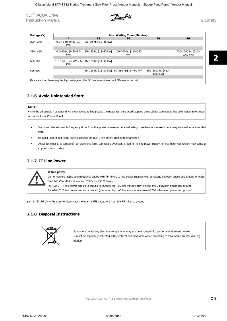
Voltage (V) Min. Waiting Time (Minutes)4 15 20 30 40
200 - 240 0.34–5 hp [0.25–3.7kW]
7.5–60 hp [5.5–45 kW]
380 - 480 0.5–10 hp [0.37–7.5
kW]15–125 hp [11–90 kW] 150–350 hp [110–250
kW] 450–1350 hp [315–
1000 kW]
525-600 1–10 hp [0.75 kW–7.5kW]
15–125 hp [11–90 kW]
525-690 15–125 hp [11–90 kW] 60–550 hp [45–400 kW] 600–1600 hp [450–
1200 kW]
Be aware that there may be high voltage on the DC link even when the LEDs are turned off.
2.1.6 Avoid Unintended Start
NOTE!
While the adjustable frequency drive is connected to line power, the motor can be started/stopped using digital commands, bus commands, references
or via the Local Control Panel.
• Disconnect the adjustable frequency drive from line power whenever personal safety considerations make it necessary to avoid an unintended
start.
• To avoid unintended start, always activate the [OFF] key before changing parameters.
• Unless terminal 37 is turned off, an electronic fault, temporary overload, a fault in the line power supply, or lost motor connection may cause a
stopped motor to start.
2.1.7 IT Line Power
IT line power
Do not connect adjustable frequency drives with RFI filters to line power supplies with a voltage between phase and ground of more
than 440 V for 400 V drives and 760 V for 690 V drives.
For 400 VT IT line power and delta ground (grounded leg), AC line voltage may exceed 440 V between phase and ground.
For 690 VT IT line power and delta ground (grounded leg), AC line voltage may exceed 760 V between phase and ground.
par. 14-50 RFI 1 can be used to disconnect the internal RFI capacitors from the RFI filter to ground.
2.1.8 Disposal Instructions
Equipment containing electrical components may not be disposed of together with domestic waste.
It must be separately collected with electrical and electronic waste according to local and currently valid leg-
islation.
VLT AQUA DriveInstruction Manual 2 Safety
MG.20.M7.22 - VLT is a registered Danfoss trademark 2-3
2
Gibson Island STP ST32 Sludge Treatment (Belt Filter Press Vendor Manuals - Sludge Feed Pump) Vendor Manual
Q-Pulse Id: VM168 05/06/2013 85 of 253
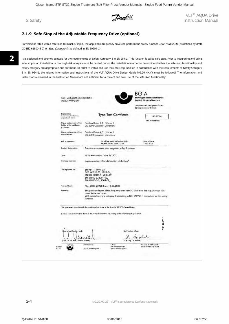
2.1.9 Safe Stop of the Adjustable Frequency Drive (optional)
For versions fitted with a safe stop terminal 37 input, the adjustable frequency drive can perform the safety function Safe Torque Off (As defined by draft
CD IEC 61800-5-2) or Stop Category 0 (as defined in EN 60204-1).
It is designed and deemed suitable for the requirements of Safety Category 3 in EN 954-1. This function is called safe stop. Prior to integrating and using
safe stop in an installation, a thorough risk analysis must be carried out on the installation in order to determine whether the safe stop functionality and
safety category are appropriate and sufficient. In order to install and use the Safe Stop function in accordance with the requirements of Safety Category
3 in EN 954-1, the related information and instructions of the VLT AQUA Drive Design Guide MG.20.NX.YY must be followed! The information and
instructions contained in the Instruction Manual are not sufficient for a correct and safe use of the safe stop functionality!
2 SafetyVLT AQUA Drive
Instruction Manual
2-4 MG.20.M7.22 - VLT is a registered Danfoss trademark
2
Gibson Island STP ST32 Sludge Treatment (Belt Filter Press Vendor Manuals - Sludge Feed Pump) Vendor Manual
Q-Pulse Id: VM168 05/06/2013 86 of 253
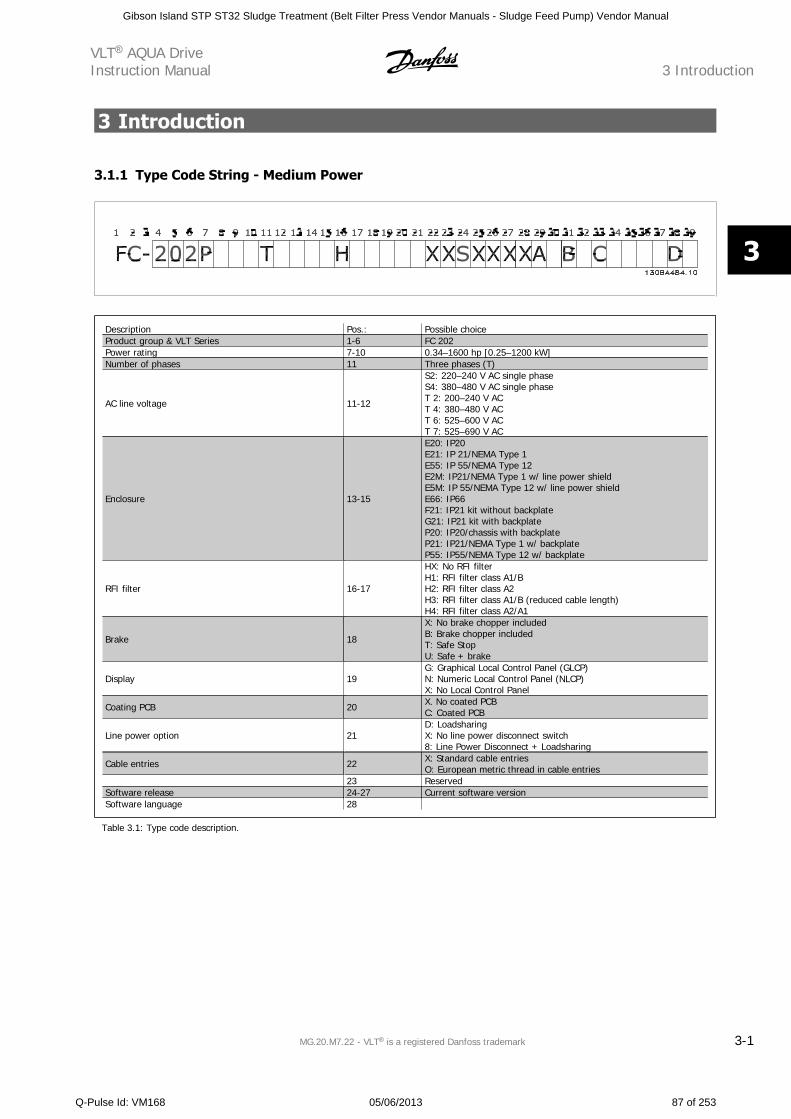
3 Introduction
3.1.1 Type Code String - Medium Power
Description Pos.: Possible choiceProduct group & VLT Series 1-6 FC 202Power rating 7-10 0.34–1600 hp [0.25–1200 kW]Number of phases 11 Three phases (T)
AC line voltage 11-12
S2: 220–240 V AC single phaseS4: 380–480 V AC single phaseT 2: 200–240 V ACT 4: 380–480 V ACT 6: 525–600 V ACT 7: 525–690 V AC
Enclosure 13-15
E20: IP20E21: IP 21/NEMA Type 1E55: IP 55/NEMA Type 12E2M: IP21/NEMA Type 1 w/ line power shieldE5M: IP 55/NEMA Type 12 w/ line power shieldE66: IP66F21: IP21 kit without backplateG21: IP21 kit with backplateP20: IP20/chassis with backplateP21: IP21/NEMA Type 1 w/ backplateP55: IP55/NEMA Type 12 w/ backplate
RFI filter 16-17
HX: No RFI filterH1: RFI filter class A1/BH2: RFI filter class A2H3: RFI filter class A1/B (reduced cable length)H4: RFI filter class A2/A1
Brake 18
X: No brake chopper includedB: Brake chopper includedT: Safe StopU: Safe + brake
Display 19G: Graphical Local Control Panel (GLCP)N: Numeric Local Control Panel (NLCP)X: No Local Control Panel
Coating PCB 20 X. No coated PCBC: Coated PCB
Line power option 21D: LoadsharingX: No line power disconnect switch8: Line Power Disconnect + Loadsharing
Cable entries 22 X: Standard cable entriesO: European metric thread in cable entries
23 ReservedSoftware release 24-27 Current software versionSoftware language 28
Table 3.1: Type code description.
VLT AQUA DriveInstruction Manual 3 Introduction
MG.20.M7.22 - VLT is a registered Danfoss trademark 3-1
3
Gibson Island STP ST32 Sludge Treatment (Belt Filter Press Vendor Manuals - Sludge Feed Pump) Vendor Manual
Q-Pulse Id: VM168 05/06/2013 87 of 253
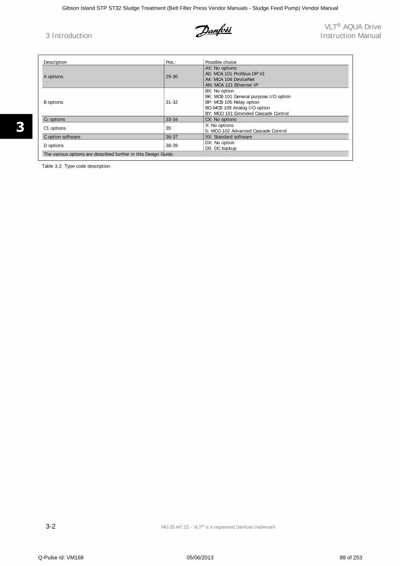
Description Pos.: Possible choice
A options 29-30
AX: No optionsA0: MCA 101 Profibus DP V1A4: MCA 104 DeviceNetAN: MCA 121 Ethernet IP
B options 31-32
BX: No optionBK: MCB 101 General purpose I/O optionBP: MCB 105 Relay optionBO:MCB 109 Analog I/O optionBY: MCO 101 Extended Cascade Control
C0 options 33-34 CX: No options
C1 options 35 X: No options5: MCO 102 Advanced Cascade Control
C option software 36-37 XX: Standard software
D options 38-39 DX: No optionD0: DC backup
The various options are described further in this Design Guide.
Table 3.2: Type code description.
3 IntroductionVLT AQUA Drive
Instruction Manual
3-2 MG.20.M7.22 - VLT is a registered Danfoss trademark
3
Gibson Island STP ST32 Sludge Treatment (Belt Filter Press Vendor Manuals - Sludge Feed Pump) Vendor Manual
Q-Pulse Id: VM168 05/06/2013 88 of 253
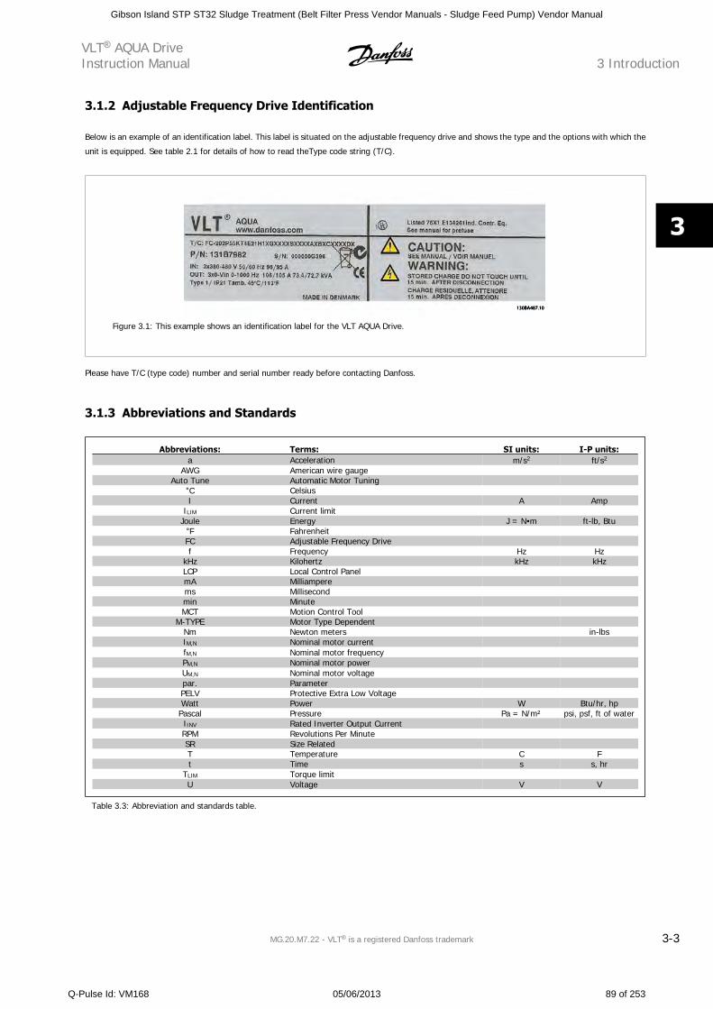
3.1.2 Adjustable Frequency Drive Identification
Below is an example of an identification label. This label is situated on the adjustable frequency drive and shows the type and the options with which the
unit is equipped. See table 2.1 for details of how to read theType code string (T/C).
Figure 3.1: This example shows an identification label for the VLT AQUA Drive.
Please have T/C (type code) number and serial number ready before contacting Danfoss.
3.1.3 Abbreviations and Standards
Abbreviations: Terms: SI units: I-P units:a Acceleration m/s2 ft/s2
AWG American wire gauge Auto Tune Automatic Motor Tuning
C Celsius I Current A Amp
ILIM Current limit Joule Energy J = N m ft-lb, Btu
F Fahrenheit FC Adjustable Frequency Drive f Frequency Hz Hz
kHz Kilohertz kHz kHzLCP Local Control Panel mA Milliampere ms Millisecond min Minute MCT Motion Control Tool
M-TYPE Motor Type Dependent Nm Newton meters in-lbsIM,N Nominal motor current fM,N Nominal motor frequency PM,N Nominal motor power UM,N Nominal motor voltage par. Parameter PELV Protective Extra Low Voltage Watt Power W Btu/hr, hp
Pascal Pressure Pa = N/m² psi, psf, ft of waterIINV Rated Inverter Output Current RPM Revolutions Per Minute SR Size Related T Temperature C Ft Time s s, hr
TLIM Torque limit U Voltage V V
Table 3.3: Abbreviation and standards table.
VLT AQUA DriveInstruction Manual 3 Introduction
MG.20.M7.22 - VLT is a registered Danfoss trademark 3-3
3
Gibson Island STP ST32 Sludge Treatment (Belt Filter Press Vendor Manuals - Sludge Feed Pump) Vendor Manual
Q-Pulse Id: VM168 05/06/2013 89 of 253
3 IntroductionVLT AQUA Drive
Instruction Manual
3-4 MG.20.M7.22 - VLT is a registered Danfoss trademark
3
Gibson Island STP ST32 Sludge Treatment (Belt Filter Press Vendor Manuals - Sludge Feed Pump) Vendor Manual
Q-Pulse Id: VM168 05/06/2013 90 of 253
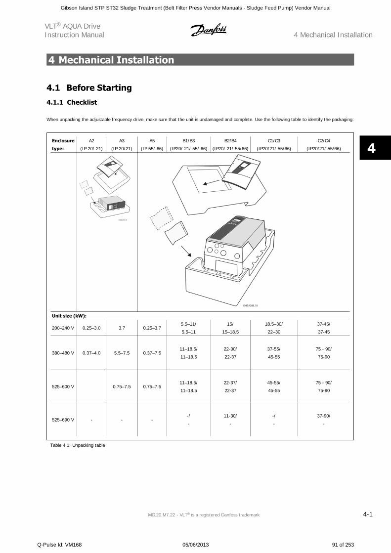
4 Mechanical Installation
4.1 Before Starting
4.1.1 Checklist
When unpacking the adjustable frequency drive, make sure that the unit is undamaged and complete. Use the following table to identify the packaging:
Enclosure
type:
A2
(IP 20/ 21)
A3
(IP 20/21)
A5
(IP 55/ 66)
B1/B3
(IP20/ 21/ 55/ 66)
B2/B4
(IP20/ 21/ 55/66)
C1/C3
(IP20/21/ 55/66)
C2/C4
(IP20/21/ 55/66)
Unit size (kW):
200–240 V 0.25–3.0 3.7 0.25–3.75.5–11/
5.5–11
15/
15–18.5
18.5–30/
22–30
37-45/
37-45
380–480 V 0.37–4.0 5.5–7.5 0.37–7.511–18.5/
11–18.5
22-30/
22-37
37-55/
45-55
75 - 90/
75-90
525–600 V 0.75–7.5 0.75–7.511–18.5/
11–18.5
22-37/
22-37
45-55/
45-55
75 - 90/
75-90
525–690 V - - --/
-
11-30/
-
-/
-
37-90/
-
Table 4.1: Unpacking table
VLT AQUA DriveInstruction Manual 4 Mechanical Installation
MG.20.M7.22 - VLT is a registered Danfoss trademark 4-1
4
Gibson Island STP ST32 Sludge Treatment (Belt Filter Press Vendor Manuals - Sludge Feed Pump) Vendor Manual
Q-Pulse Id: VM168 05/06/2013 91 of 253
Please note that a selection of screwdrivers (phillips or cross-thread screwdriver and torx), a side-cutter, drill and knife is also recommended to have
handy for unpacking and mounting the adjustable frequency drive. The packaging for these enclosures contains, as shown: accessory bag(s), documen-
tation and the unit. Depending on options fitted, there may be one or two bags and one or more booklets.
4 Mechanical InstallationVLT AQUA Drive
Instruction Manual
4-2 MG.20.M7.22 - VLT is a registered Danfoss trademark
4
Gibson Island STP ST32 Sludge Treatment (Belt Filter Press Vendor Manuals - Sludge Feed Pump) Vendor Manual
Q-Pulse Id: VM168 05/06/2013 92 of 253
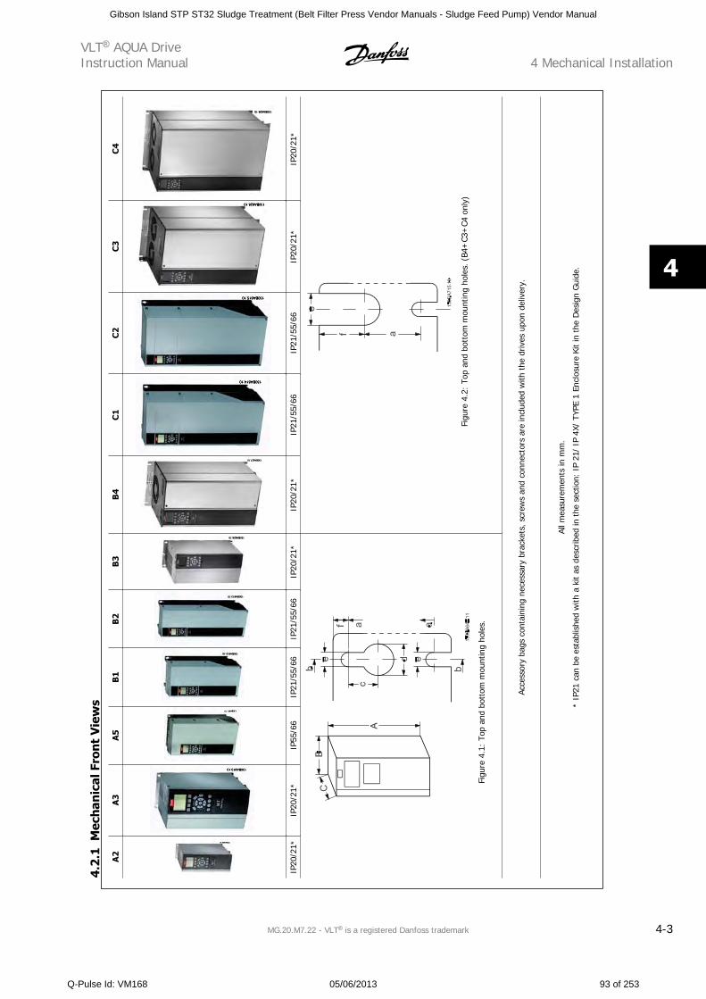
A2
A3
A5
B1
B2
B3
B4
C1
C2
C3
C4
IP20
/21*
IP20
/21*
IP55
/66
IP21
/55/
66IP
21/5
5/66
IP20
/21*
IP20
/21*
IP21
/55/
66IP
21/5
5/66
IP20
/21*
IP20
/21*
Figu
re 4
.1:
Top
and
bott
om m
ount
ing
hole
s.
Figu
re 4
.2:
Top
and
bott
om m
ount
ing
hole
s. (
B4+
C3+
C4 o
nly)
Acce
ssor
y ba
gs c
onta
inin
g ne
cess
ary
brac
kets
, scr
ews
and
conn
ecto
rs a
re in
clud
ed w
ith t
he d
rives
upo
n de
liver
y.
All m
easu
rem
ents
in m
m.
* IP
21 c
an b
e es
tabl
ishe
d w
ith a
kit
as d
escr
ibed
in t
he s
ectio
n: I
P 21
/ IP
4X/
TYP
E 1
Encl
osur
e Ki
t in
the
Des
ign
Gui
de.
4.2
.1M
ech
anic
al F
ron
t V
iew
s
VLT AQUA DriveInstruction Manual 4 Mechanical Installation
MG.20.M7.22 - VLT is a registered Danfoss trademark 4-3
4
Gibson Island STP ST32 Sludge Treatment (Belt Filter Press Vendor Manuals - Sludge Feed Pump) Vendor Manual
Q-Pulse Id: VM168 05/06/2013 93 of 253
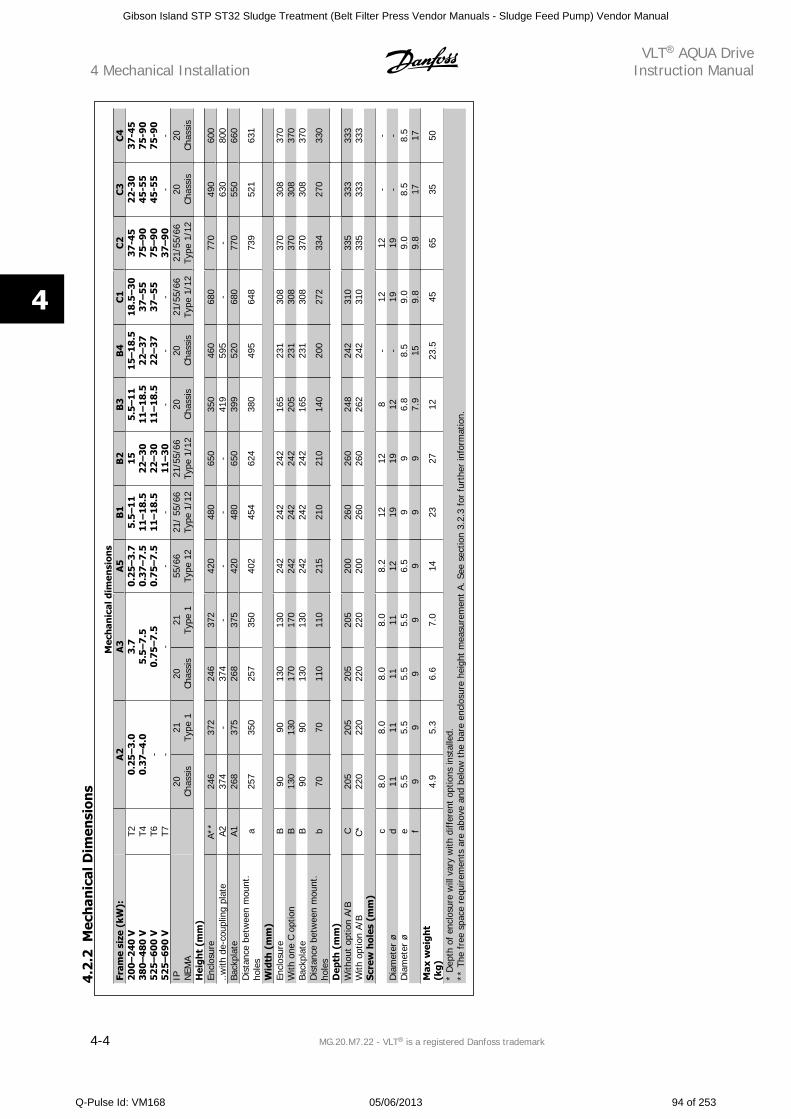
Mec
han
ical
dim
ensi
ons
Fram
e si
ze (
kW):
A2
A3
A5
B1
B2
B3
B4
C1
C2
C3
C4
200–
240
V38
0–48
0 V
525–
600
V52
5–69
0 V
T2 T4 T6 T7
0.25
–3.0
0.37
–4.0
- -
3.7
5.5
–7.5
0.7
5–7
.5-
0.2
5–3
.70.
37–
7.5
0.7
5–7
.5-
5.5
–11
11–
18.5
11–
18.5
-
1522
–30
22–
3011
–30
5.5–
11
11–
18.5
11–
18.5
-
15–
18.
522
–37
22–3
7-
18.5
–30
37–
55
37–
55
-
37-4
57
5–9
07
5–9
03
7–9
0
22-3
045
-55
45-5
5-
37-
457
5-90
75-
90 -IP N
EMA
20Ch
assi
s21
Type
120
Chas
sis
21Ty
pe 1
55/6
6Ty
pe 1
221
/ 55
/66
Type
1/1
221
/55/
66Ty
pe 1
/12
20Ch
assi
s20
Chas
sis
21/5
5/66
Type
1/1
221
/55/
66Ty
pe 1
/12
20Ch
assi
s20
Chas
sis
Hei
ght
(mm
)En
clos
ure
A**
246
372
246
372
420
480
650
350
460
680
770
490
600
..with
de-
coup
ling
plat
eA2
374
-37
4-
--
-41
959
5-
-63
080
0Ba
ckpl
ate
A126
837
526
837
542
048
065
039
952
068
077
055
066
0D
ista
nce
betw
een
mou
nt.
hole
sa
257
350
257
350
402
454
624
380
495
648
739
521
631
Wid
th (
mm
)En
clos
ure
B90
9013
013
024
224
224
216
523
130
837
030
837
0W
ith o
ne C
opt
ion
B13
013
017
017
024
224
224
220
523
130
837
030
837
0Ba
ckpl
ate
B90
9013
013
024
224
224
216
523
130
837
030
837
0D
ista
nce
betw
een
mou
nt.
hole
sb
7070
110
110
215
210
210
140
200
272
334
270
330
Dep
th (
mm
)W
ithou
t op
tion
A/B
C20
520
520
520
520
026
026
024
824
231
033
533
333
3W
ith o
ptio
n A/
BC*
220
220
220
220
200
260
260
262
242
310
335
333
333
Scre
w h
oles
(m
m)
c8.
08.
08.
08.
08.
212
128
-12
12-
-D
iam
eter
ød
1111
1111
1219
1912
-19
19-
-D
iam
eter
øe
5.5
5.5
5.5
5.5
6.5
99
6.8
8.5
9.0
9.0
8.5
8.5
f9
99
99
99
7.9
159.
89.
817
17M
ax w
eigh
t(k
g)4.
95.
36.
67.
014
2327
1223
.545
6535
50
* D
epth
of
encl
osur
e w
ill v
ary
with
diff
eren
t op
tions
inst
alle
d.**
The
fre
e sp
ace
requ
irem
ents
are
abo
ve a
nd b
elow
the
bar
e en
clos
ure
heig
ht m
easu
rem
ent
A. S
ee s
ectio
n 3.
2.3
for
furt
her
info
rmat
ion.
4.2
.2M
ech
anic
al D
imen
sion
s4 Mechanical Installation
VLT AQUA DriveInstruction Manual
4-4 MG.20.M7.22 - VLT is a registered Danfoss trademark
4
Gibson Island STP ST32 Sludge Treatment (Belt Filter Press Vendor Manuals - Sludge Feed Pump) Vendor Manual
Q-Pulse Id: VM168 05/06/2013 94 of 253
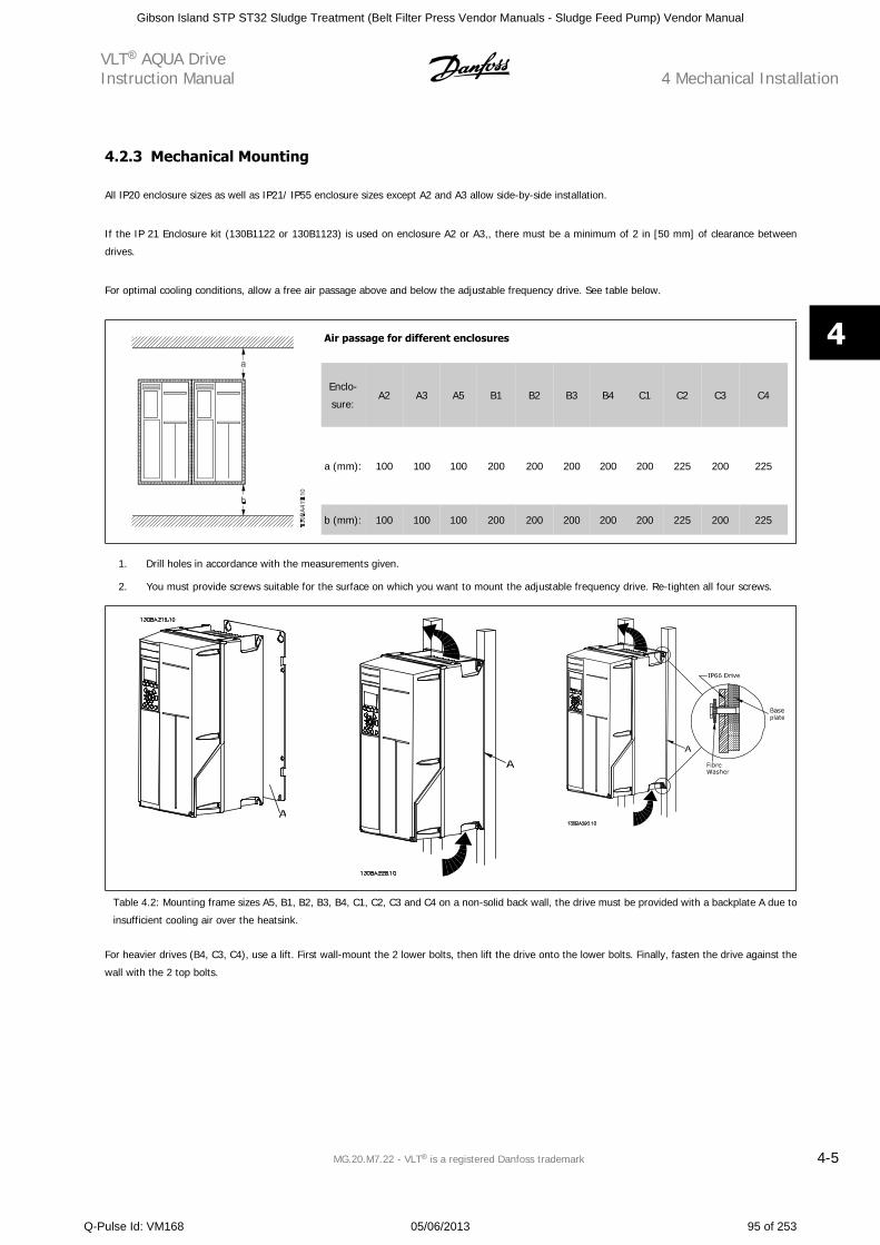
4.2.3 Mechanical Mounting
All IP20 enclosure sizes as well as IP21/ IP55 enclosure sizes except A2 and A3 allow side-by-side installation.
If the IP 21 Enclosure kit (130B1122 or 130B1123) is used on enclosure A2 or A3,, there must be a minimum of 2 in [50 mm] of clearance between
drives.
For optimal cooling conditions, allow a free air passage above and below the adjustable frequency drive. See table below.
Air passage for different enclosures
Enclo-
sure:A2 A3 A5 B1 B2 B3 B4 C1 C2 C3 C4
a (mm): 100 100 100 200 200 200 200 200 225 200 225
b (mm): 100 100 100 200 200 200 200 200 225 200 225
1. Drill holes in accordance with the measurements given.
2. You must provide screws suitable for the surface on which you want to mount the adjustable frequency drive. Re-tighten all four screws.
Table 4.2: Mounting frame sizes A5, B1, B2, B3, B4, C1, C2, C3 and C4 on a non-solid back wall, the drive must be provided with a backplate A due to
insufficient cooling air over the heatsink.
For heavier drives (B4, C3, C4), use a lift. First wall-mount the 2 lower bolts, then lift the drive onto the lower bolts. Finally, fasten the drive against the
wall with the 2 top bolts.
VLT AQUA DriveInstruction Manual 4 Mechanical Installation
MG.20.M7.22 - VLT is a registered Danfoss trademark 4-5
4
Gibson Island STP ST32 Sludge Treatment (Belt Filter Press Vendor Manuals - Sludge Feed Pump) Vendor Manual
Q-Pulse Id: VM168 05/06/2013 95 of 253
4.2.4 Safety Requirements for Mechanical Installation
Pay attention to the requirements that apply to integration and the field mounting kit. Follow the information in the list to avoid serious
damage or injury, especially when installing large units.
The adjustable frequency drive is cooled by air circulation.
To protect the unit from overheating, it must be ensured that the ambient temperature does not exceed the maximum temperature stated for the
adjustable frequency drive, and that the 24-hour average temperature is not exceeded. Locate the maximum temperature and 24-hour average in the
paragraph Derating for Ambient Temperature.
If the ambient temperature is in the range of 113°–131°F [45°–55°C], derating of the adjustable frequency drive will become relevant, see Derating for
Ambient Temperature.
The service life of the adjustable frequency drive is reduced if derating for ambient temperature is not taken into account.
4.2.5 Field Mounting
For field mounting the IP 21/IP 4X top/,TYPE 1 kits or IP 54/55 units are recommended.
4.2.6 Panel Through Mounting
A Panel Through Mount Kit is available for adjustable frequency drive series , VLT Aqua Drive and.
In order to increase heatsink cooling and reduce panel depth, the adjustable frequency drive may be mounted in a through panel. Furthermore, the built-
in fan can then be removed.
The kit is available for enclosures A5 through C2.
NOTE!
This kit cannot be used with cast front covers. No cover or IP21 plastic cover must be used instead.
Information on ordering numbers is found in the Design Guide, section Ordering Numbers.
More detailed information is available in the Panel Through Mount Kit instruction, MI.33.H1.YY, where yy=language code.
4 Mechanical InstallationVLT AQUA Drive
Instruction Manual
4-6 MG.20.M7.22 - VLT is a registered Danfoss trademark
4
Gibson Island STP ST32 Sludge Treatment (Belt Filter Press Vendor Manuals - Sludge Feed Pump) Vendor Manual
Q-Pulse Id: VM168 05/06/2013 96 of 253
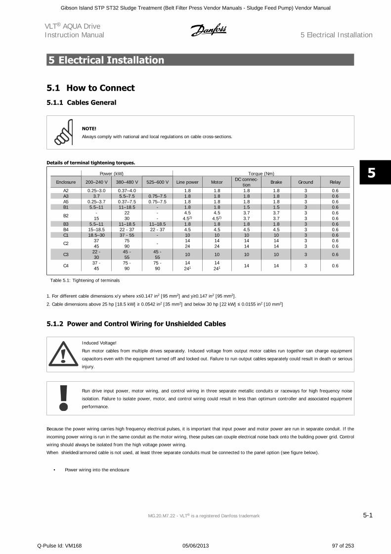
5 Electrical Installation
5.1 How to Connect
5.1.1 Cables General
NOTE!
Always comply with national and local regulations on cable cross-sections.
Details of terminal tightening torques.
Power (kW) Torque (Nm)
Enclosure 200–240 V 380–480 V 525–600 V Line power Motor DC connec-tion Brake Ground Relay
A2 0.25–3.0 0.37–4.0 1.8 1.8 1.8 1.8 3 0.6A3 3.7 5.5–7.5 0.75–7.5 1.8 1.8 1.8 1.8 3 0.6A5 0.25–3.7 0.37–7.5 0.75–7.5 1.8 1.8 1.8 1.8 3 0.6B1 5.5–11 11–18.5 - 1.8 1.8 1.5 1.5 3 0.6
B2 -15
2230
--
4.54.52)
4.54.52)
3.73.7
3.73.7
33
0.60.6
B3 5.5–11 11–18.5 11–18.5 1.8 1.8 1.8 1.8 3 0.6B4 15–18.5 22 - 37 22 - 37 4.5 4.5 4.5 4.5 3 0.6C1 18.5–30 37 - 55 - 10 10 10 10 3 0.6
C2 3745
7590 - 14
241424
1414
1414
33
0.60.6
C3 22 -30
45 -55
45 -55 10 10 10 10 3 0.6
C4 37 -45
75 -90
75 -90
14241
14241 14 14 3 0.6
Table 5.1: Tightening of terminals
1. For different cable dimensions x/y where x 0.147 in2 [95 mm2] and y 0.147 in2 [95 mm2].
2. Cable dimensions above 25 hp [18.5 kW] 0.0542 in2 [35 mm2] and below 30 hp [22 kW] 0.0155 in2 [10 mm2]
5.1.2 Power and Control Wiring for Unshielded Cables
Induced Voltage!
Run motor cables from multiple drives separately. Induced voltage from output motor cables run together can charge equipment
capacitors even with the equipment turned off and locked out. Failure to run output cables separately could result in death or serious
injury.
Run drive input power, motor wiring, and control wiring in three separate metallic conduits or raceways for high frequency noise
isolation. Failure to isolate power, motor, and control wiring could result in less than optimum controller and associated equipment
performance.
Because the power wiring carries high frequency electrical pulses, it is important that input power and motor power are run in separate conduit. If the
incoming power wiring is run in the same conduit as the motor wiring, these pulses can couple electrical noise back onto the building power grid. Control
wiring should always be isolated from the high voltage power wiring.
When shielded/armored cable is not used, at least three separate conduits must be connected to the panel option (see figure below).
• Power wiring into the enclosure
VLT AQUA DriveInstruction Manual 5 Electrical Installation
MG.20.M7.22 - VLT is a registered Danfoss trademark 5-1
5
Gibson Island STP ST32 Sludge Treatment (Belt Filter Press Vendor Manuals - Sludge Feed Pump) Vendor Manual
Q-Pulse Id: VM168 05/06/2013 97 of 253
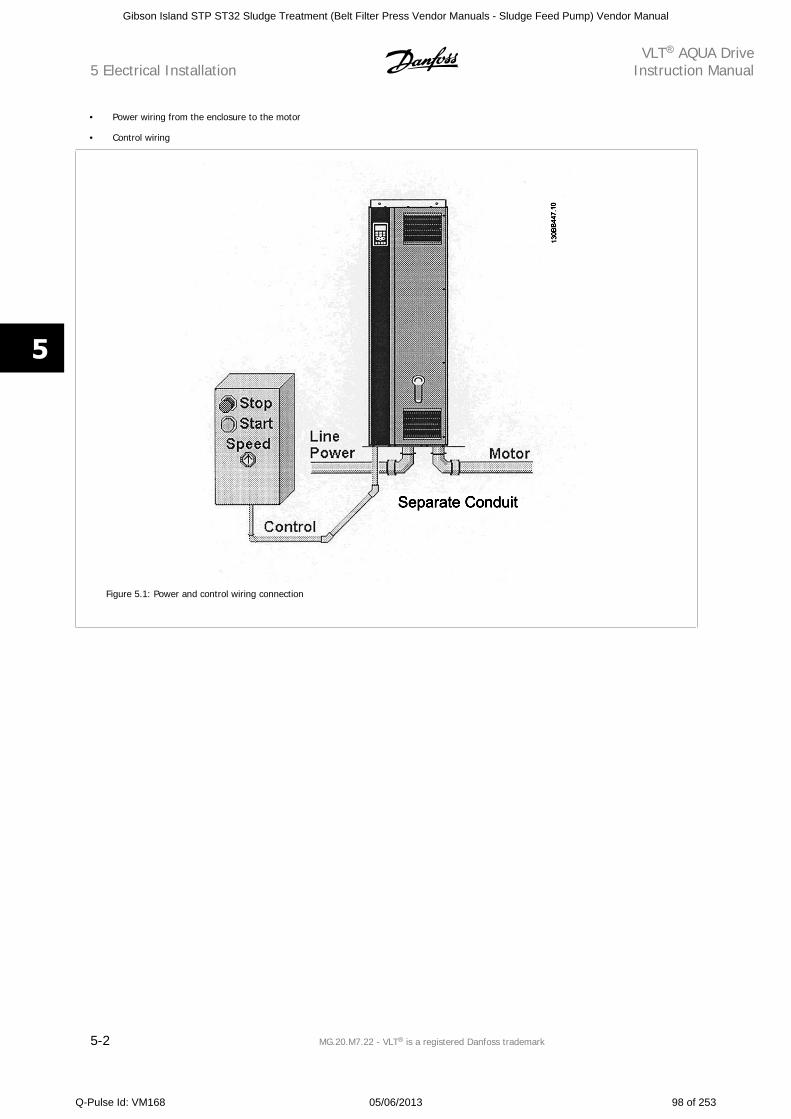
• Power wiring from the enclosure to the motor
• Control wiring
Figure 5.1: Power and control wiring connection
5 Electrical InstallationVLT AQUA Drive
Instruction Manual
5-2 MG.20.M7.22 - VLT is a registered Danfoss trademark
5
Gibson Island STP ST32 Sludge Treatment (Belt Filter Press Vendor Manuals - Sludge Feed Pump) Vendor Manual
Q-Pulse Id: VM168 05/06/2013 98 of 253
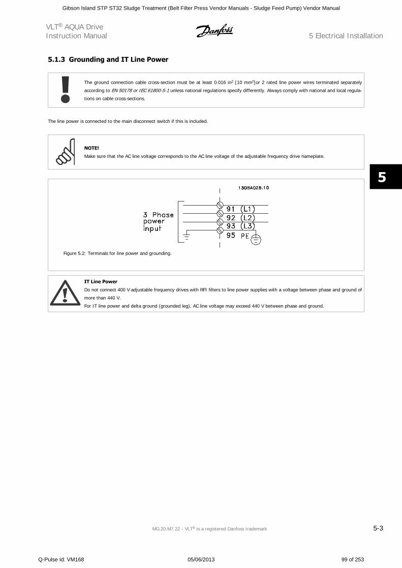
5.1.3 Grounding and IT Line Power
The ground connection cable cross-section must be at least 0.016 in2 [10 mm2]or 2 rated line power wires terminated separately
according to EN 50178 or IEC 61800-5-1 unless national regulations specify differently. Always comply with national and local regula-
tions on cable cross-sections.
The line power is connected to the main disconnect switch if this is included.
NOTE!
Make sure that the AC line voltage corresponds to the AC line voltage of the adjustable frequency drive nameplate.
Figure 5.2: Terminals for line power and grounding.
IT Line Power
Do not connect 400 V adjustable frequency drives with RFI filters to line power supplies with a voltage between phase and ground of
more than 440 V.
For IT line power and delta ground (grounded leg), AC line voltage may exceed 440 V between phase and ground.
VLT AQUA DriveInstruction Manual 5 Electrical Installation
MG.20.M7.22 - VLT is a registered Danfoss trademark 5-3
5
Gibson Island STP ST32 Sludge Treatment (Belt Filter Press Vendor Manuals - Sludge Feed Pump) Vendor Manual
Q-Pulse Id: VM168 05/06/2013 99 of 253
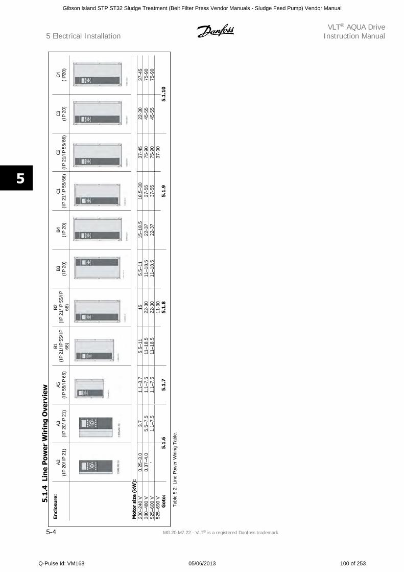
Encl
osu
re:
A2(I
P 20
/IP
21)
A3(I
P 20
/IP
21)
A5(I
P 55
/IP
66)
B1(I
P 21
/IP
55/I
P66
)
B2(I
P 21
/IP
55/I
P66
)
B3(I
P 20
)B4
(IP
20)
C1(I
P 21
/IP
55/6
6)C2
(IP
21/I
P 55
/66)
C3(I
P 20
)C4
(IP2
0)
130BA768.1
0
Mot
or s
ize
(kW
):20
0–24
0 V
0.25
–3.0
3.7
1.1–
3.7
5.5–
1115
5.5–
1115
–18.
518
.5–3
037
-45
22-3
037
-45
380–
480
V0.
37–4
.05.
5–7.
51.
1–7.
511
–18.
522
-30
11–1
8.5
22-3
737
-55
75-9
045
-55
75-9
052
5–60
0 V
'1.
1–7.
51.
1–7.
511
–18.
522
-30
11–1
8.5
22-3
737
-55
75-9
045
-55
75-9
052
5–69
0 V
11-3
0
37-9
0
G
oto:
5.1.
65.
1.7
5.1.
85
.1.9
5.1.
10
Tabl
e 5.
2: L
ine
Pow
er W
iring
Tab
le.
5.1
.4Li
ne
Pow
er W
irin
g O
verv
iew
5 Electrical InstallationVLT AQUA Drive
Instruction Manual
5-4 MG.20.M7.22 - VLT is a registered Danfoss trademark
5
Gibson Island STP ST32 Sludge Treatment (Belt Filter Press Vendor Manuals - Sludge Feed Pump) Vendor Manual
Q-Pulse Id: VM168 05/06/2013 100 of 253
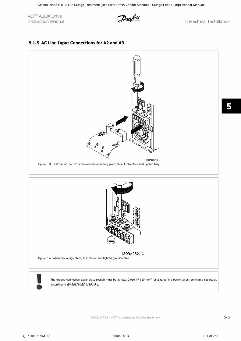
5.1.5 AC Line Input Connections for A2 and A3
Figure 5.3: First mount the two screws on the mounting plate, slide it into place and tighten fully.
Figure 5.4: When mounting cables, first mount and tighten ground cable.
The ground connection cable cross-section must be at least 0.016 in2 [10 mm2] or 2 rated line power wires terminated separately
according to EN 50178/IEC 61800-5-1.
VLT AQUA DriveInstruction Manual 5 Electrical Installation
MG.20.M7.22 - VLT is a registered Danfoss trademark 5-5
5
Gibson Island STP ST32 Sludge Treatment (Belt Filter Press Vendor Manuals - Sludge Feed Pump) Vendor Manual
Q-Pulse Id: VM168 05/06/2013 101 of 253
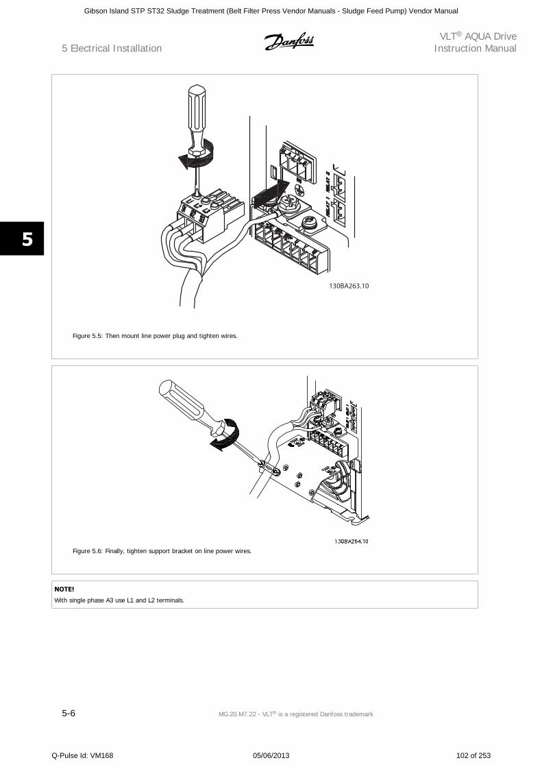
Figure 5.5: Then mount line power plug and tighten wires.
Figure 5.6: Finally, tighten support bracket on line power wires.
NOTE!
With single phase A3 use L1 and L2 terminals.
5 Electrical InstallationVLT AQUA Drive
Instruction Manual
5-6 MG.20.M7.22 - VLT is a registered Danfoss trademark
5
Gibson Island STP ST32 Sludge Treatment (Belt Filter Press Vendor Manuals - Sludge Feed Pump) Vendor Manual
Q-Pulse Id: VM168 05/06/2013 102 of 253
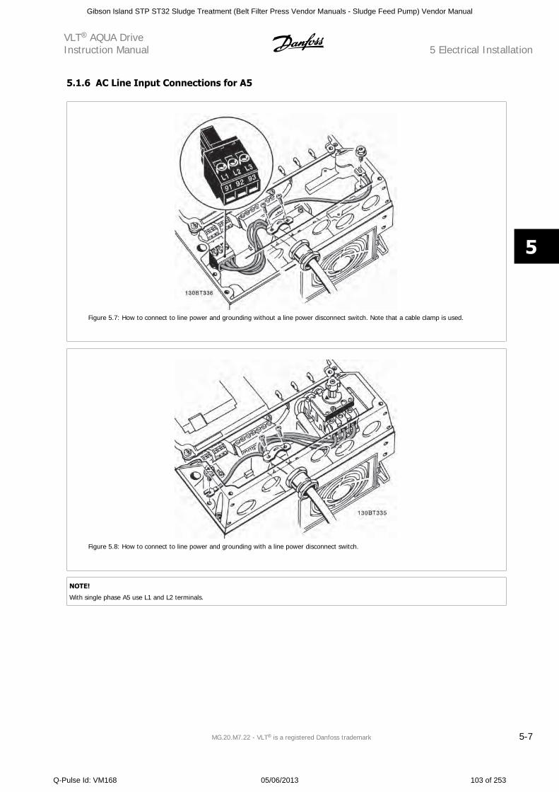
5.1.6 AC Line Input Connections for A5
Figure 5.7: How to connect to line power and grounding without a line power disconnect switch. Note that a cable clamp is used.
Figure 5.8: How to connect to line power and grounding with a line power disconnect switch.
NOTE!
With single phase A5 use L1 and L2 terminals.
VLT AQUA DriveInstruction Manual 5 Electrical Installation
MG.20.M7.22 - VLT is a registered Danfoss trademark 5-7
5
Gibson Island STP ST32 Sludge Treatment (Belt Filter Press Vendor Manuals - Sludge Feed Pump) Vendor Manual
Q-Pulse Id: VM168 05/06/2013 103 of 253
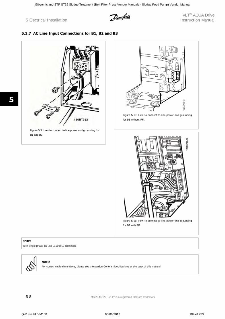
5.1.7 AC Line Input Connections for B1, B2 and B3
Figure 5.9: How to connect to line power and grounding for
B1 and B2
Figure 5.10: How to connect to line power and grounding
for B3 without RFI.
Figure 5.11: How to connect to line power and grounding
for B3 with RFI.
NOTE!
With single phase B1 use L1 and L2 terminals.
NOTE!
For correct cable dimensions, please see the section General Specifications at the back of this manual.
5 Electrical InstallationVLT AQUA Drive
Instruction Manual
5-8 MG.20.M7.22 - VLT is a registered Danfoss trademark
5
Gibson Island STP ST32 Sludge Treatment (Belt Filter Press Vendor Manuals - Sludge Feed Pump) Vendor Manual
Q-Pulse Id: VM168 05/06/2013 104 of 253
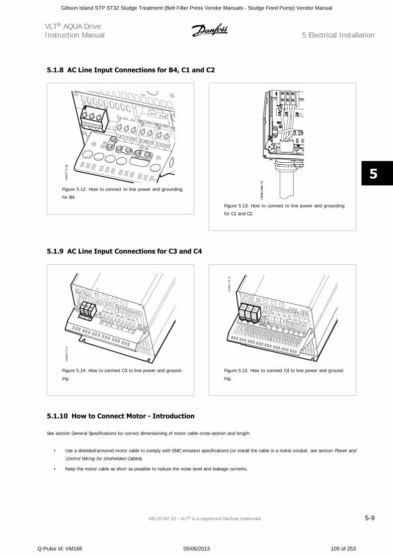
5.1.8 AC Line Input Connections for B4, C1 and C2
Figure 5.12: How to connect to line power and grounding
for B4.
Figure 5.13: How to connect to line power and grounding
for C1 and C2.
5.1.9 AC Line Input Connections for C3 and C4
Figure 5.14: How to connect C3 to line power and ground-
ing.
Figure 5.15: How to connect C4 to line power and ground-
ing.
5.1.10 How to Connect Motor - Introduction
See section General Specifications for correct dimensioning of motor cable cross-section and length.
• Use a shielded/armored motor cable to comply with EMC emission specifications (or install the cable in a metal conduit, see section Power and
Control Wiring for Unshielded Cables).
• Keep the motor cable as short as possible to reduce the noise level and leakage currents.
VLT AQUA DriveInstruction Manual 5 Electrical Installation
MG.20.M7.22 - VLT is a registered Danfoss trademark 5-9
5
Gibson Island STP ST32 Sludge Treatment (Belt Filter Press Vendor Manuals - Sludge Feed Pump) Vendor Manual
Q-Pulse Id: VM168 05/06/2013 105 of 253
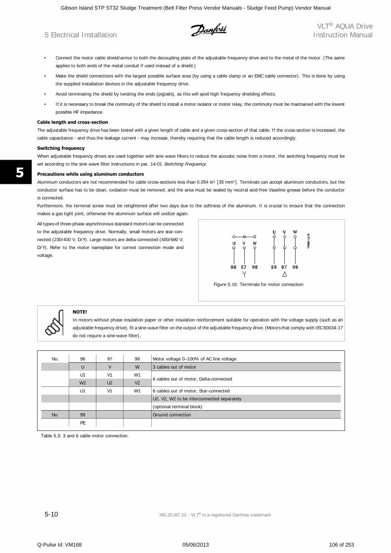
• Connect the motor cable shield/armor to both the decoupling plate of the adjustable frequency drive and to the metal of the motor. (The same
applies to both ends of the metal conduit if used instead of a shield.)
• Make the shield connections with the largest possible surface area (by using a cable clamp or an EMC cable connector). This is done by using
the supplied installation devices in the adjustable frequency drive.
• Avoid terminating the shield by twisting the ends (pigtails), as this will spoil high frequency shielding effects.
• If it is necessary to break the continuity of the shield to install a motor isolator or motor relay, the continuity must be maintained with the lowest
possible HF impedance.
Cable length and cross-section
The adjustable frequency drive has been tested with a given length of cable and a given cross-section of that cable. If the cross-section is increased, the
cable capacitance - and thus the leakage current - may increase, thereby requiring that the cable length is reduced accordingly.
Switching frequency
When adjustable frequency drives are used together with sine wave filters to reduce the acoustic noise from a motor, the switching frequency must be
set according to the sine wave filter instructions in par. 14-01 Switching Frequency.
Precautions while using aluminum conductors
Aluminum conductors are not recommended for cable cross-sections less than 0.054 in² [35 mm²]. Terminals can accept aluminum conductors, but the
conductor surface has to be clean, oxidation must be removed, and the area must be sealed by neutral acid-free Vaseline grease before the conductor
is connected.
Furthermore, the terminal screw must be retightened after two days due to the softness of the aluminum. It is crucial to ensure that the connection
makes a gas tight joint, otherwise the aluminum surface will oxidize again.
All types of three-phase asynchronous standard motors can be connected
to the adjustable frequency drive. Normally, small motors are star-con-
nected (230/400 V, D/Y). Large motors are delta-connected (400/690 V,
D/Y). Refer to the motor nameplate for correct connection mode and
voltage.
Figure 5.16: Terminals for motor connection
NOTE!
In motors without phase insulation paper or other insulation reinforcement suitable for operation with the voltage supply (such as an
adjustable frequency drive), fit a sine-wave filter on the output of the adjustable frequency drive. (Motors that comply with IEC 60034-17
do not require a sine-wave filter).
No. 96 97 98 Motor voltage 0–100% of AC line voltage.
U V W 3 cables out of motor
U1 V1 W16 cables out of motor, Delta-connected
W2 U2 V2
U1 V1 W1 6 cables out of motor, Star-connected
U2, V2, W2 to be interconnected separately
(optional terminal block)
No. 99 Ground connection
PE
Table 5.3: 3 and 6 cable motor connection.
5 Electrical InstallationVLT AQUA Drive
Instruction Manual
5-10 MG.20.M7.22 - VLT is a registered Danfoss trademark
5
Gibson Island STP ST32 Sludge Treatment (Belt Filter Press Vendor Manuals - Sludge Feed Pump) Vendor Manual
Q-Pulse Id: VM168 05/06/2013 106 of 253
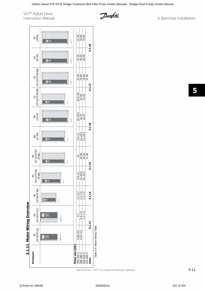
Encl
osur
e:A2
(IP
20/I
P 21
)A3
(IP
20/I
P 21
)A5
(IP
55/I
P 66
)
B1(I
P 21
/IP
55/
IP 6
6)
B2(I
P 21
/IP
55/
IP 6
6)
B3(I
P 20
)B4
(IP
20)
C1(I
P 21
/IP
55/6
6)C2
(IP
21/I
P 55
/66)
C3(I
P 20
)C4
(IP2
0)
Mot
or s
ize
(kW
):20
0–24
0 V
0.25
–3.0
3.7
1.1–
3.7
5.5–
1115
5.5–
1115
–18.
518
.5–3
037
-45
22-3
037
-45
380–
480
V0.
37–4
.05.
5–7.
51.
1–7.
511
–18.
522
-30
11–1
8.5
22-3
737
-55
75-9
045
-55
75-9
052
5–60
0 V
1.
1–7.
51.
1–7.
511
–18.
522
-30
11–1
8.5
22-3
737
-55
75-9
045
-55
75-9
052
5–69
0 V
11-3
0
37-9
0
G
oto:
5.1.
13
5.1
.14
5.1.
155.
1.1
65.
1.1
75.
1.18
Tabl
e 5.
4: M
otor
Wiri
ng T
able
.
5.1
.11
Mot
or W
irin
g O
verv
iew
VLT AQUA DriveInstruction Manual 5 Electrical Installation
MG.20.M7.22 - VLT is a registered Danfoss trademark 5-11
5
Gibson Island STP ST32 Sludge Treatment (Belt Filter Press Vendor Manuals - Sludge Feed Pump) Vendor Manual
Q-Pulse Id: VM168 05/06/2013 107 of 253
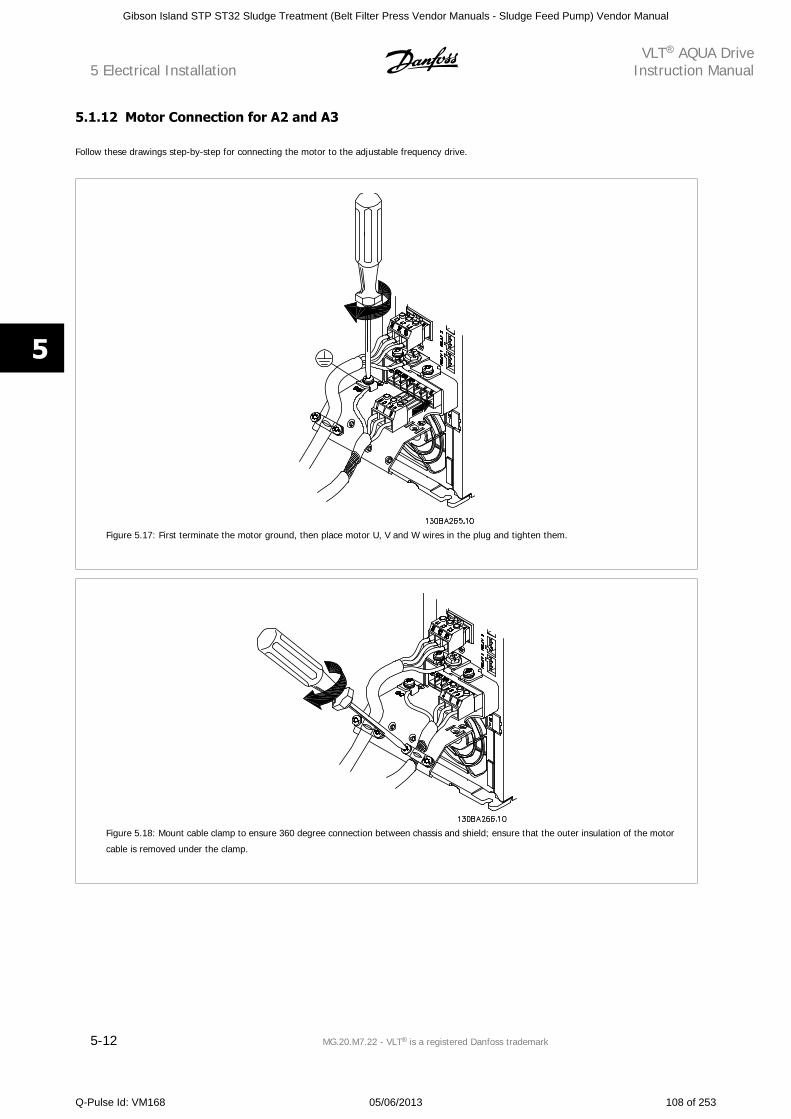
5.1.12 Motor Connection for A2 and A3
Follow these drawings step-by-step for connecting the motor to the adjustable frequency drive.
Figure 5.17: First terminate the motor ground, then place motor U, V and W wires in the plug and tighten them.
Figure 5.18: Mount cable clamp to ensure 360 degree connection between chassis and shield; ensure that the outer insulation of the motor
cable is removed under the clamp.
5 Electrical InstallationVLT AQUA Drive
Instruction Manual
5-12 MG.20.M7.22 - VLT is a registered Danfoss trademark
5
Gibson Island STP ST32 Sludge Treatment (Belt Filter Press Vendor Manuals - Sludge Feed Pump) Vendor Manual
Q-Pulse Id: VM168 05/06/2013 108 of 253
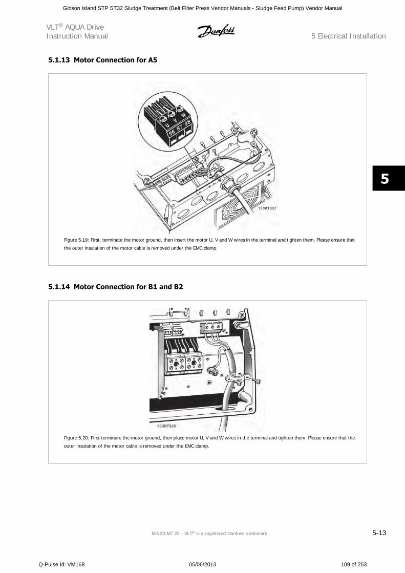
5.1.13 Motor Connection for A5
Figure 5.19: First, terminate the motor ground, then insert the motor U, V and W wires in the terminal and tighten them. Please ensure that
the outer insulation of the motor cable is removed under the EMC clamp.
5.1.14 Motor Connection for B1 and B2
Figure 5.20: First terminate the motor ground, then place motor U, V and W wires in the terminal and tighten them. Please ensure that the
outer insulation of the motor cable is removed under the EMC clamp.
VLT AQUA DriveInstruction Manual 5 Electrical Installation
MG.20.M7.22 - VLT is a registered Danfoss trademark 5-13
5
Gibson Island STP ST32 Sludge Treatment (Belt Filter Press Vendor Manuals - Sludge Feed Pump) Vendor Manual
Q-Pulse Id: VM168 05/06/2013 109 of 253
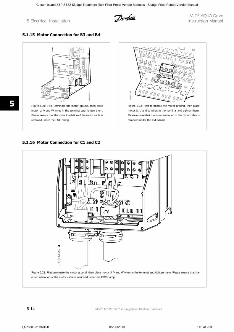
5.1.15 Motor Connection for B3 and B4
Figure 5.21: First terminate the motor ground, then place
motor U, V and W wires in the terminal and tighten them.
Please ensure that the outer insulation of the motor cable is
removed under the EMC clamp.
Figure 5.22: First terminate the motor ground, then place
motor U, V and W wires in the terminal and tighten them.
Please ensure that the outer insulation of the motor cable is
removed under the EMC clamp.
5.1.16 Motor Connection for C1 and C2
Figure 5.23: First terminate the motor ground, then place motor U, V and W wires in the terminal and tighten them. Please ensure that the
outer insulation of the motor cable is removed under the EMC clamp.
5 Electrical InstallationVLT AQUA Drive
Instruction Manual
5-14 MG.20.M7.22 - VLT is a registered Danfoss trademark
5
Gibson Island STP ST32 Sludge Treatment (Belt Filter Press Vendor Manuals - Sludge Feed Pump) Vendor Manual
Q-Pulse Id: VM168 05/06/2013 110 of 253
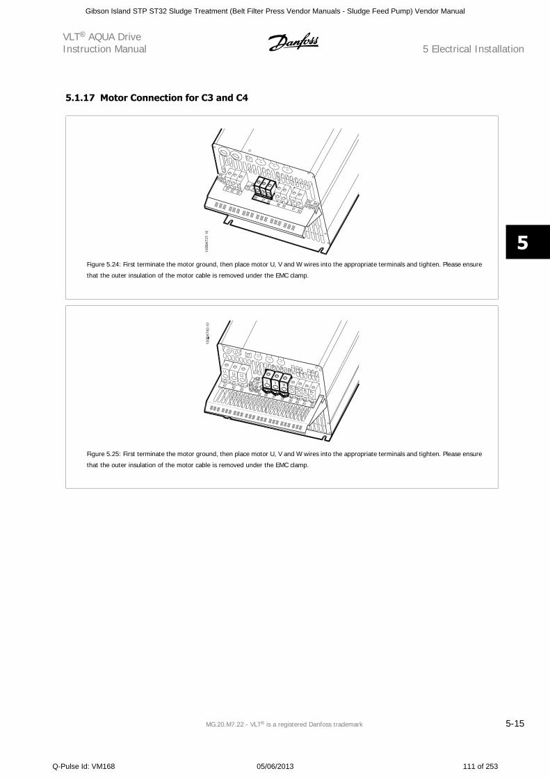
5.1.17 Motor Connection for C3 and C4
Figure 5.24: First terminate the motor ground, then place motor U, V and W wires into the appropriate terminals and tighten. Please ensure
that the outer insulation of the motor cable is removed under the EMC clamp.
Figure 5.25: First terminate the motor ground, then place motor U, V and W wires into the appropriate terminals and tighten. Please ensure
that the outer insulation of the motor cable is removed under the EMC clamp.
VLT AQUA DriveInstruction Manual 5 Electrical Installation
MG.20.M7.22 - VLT is a registered Danfoss trademark 5-15
5
Gibson Island STP ST32 Sludge Treatment (Belt Filter Press Vendor Manuals - Sludge Feed Pump) Vendor Manual
Q-Pulse Id: VM168 05/06/2013 111 of 253
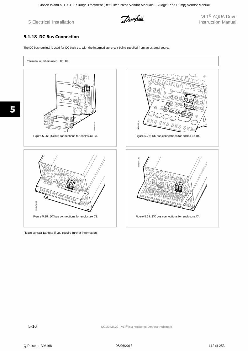
5.1.18 DC Bus Connection
The DC bus terminal is used for DC back-up, with the intermediate circuit being supplied from an external source.
Terminal numbers used: 88, 89
Figure 5.26: DC bus connections for enclosure B3. Figure 5.27: DC bus connections for enclosure B4.
Figure 5.28: DC bus connections for enclosure C3. Figure 5.29: DC bus connections for enclosure C4.
Please contact Danfoss if you require further information.
5 Electrical InstallationVLT AQUA Drive
Instruction Manual
5-16 MG.20.M7.22 - VLT is a registered Danfoss trademark
5
Gibson Island STP ST32 Sludge Treatment (Belt Filter Press Vendor Manuals - Sludge Feed Pump) Vendor Manual
Q-Pulse Id: VM168 05/06/2013 112 of 253
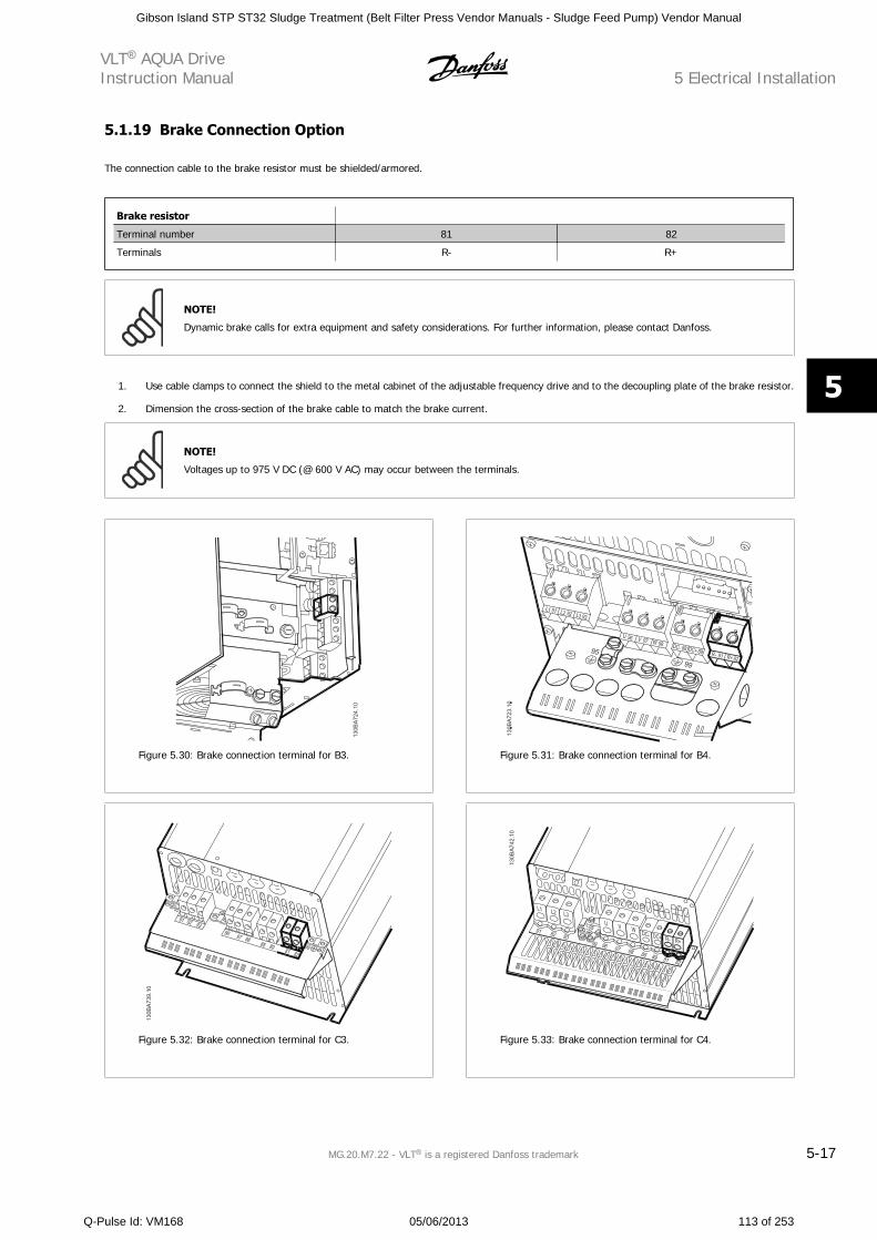
5.1.19 Brake Connection Option
The connection cable to the brake resistor must be shielded/armored.
Brake resistor
Terminal number 81 82
Terminals R- R+
NOTE!
Dynamic brake calls for extra equipment and safety considerations. For further information, please contact Danfoss.
1. Use cable clamps to connect the shield to the metal cabinet of the adjustable frequency drive and to the decoupling plate of the brake resistor.
2. Dimension the cross-section of the brake cable to match the brake current.
NOTE!
Voltages up to 975 V DC (@ 600 V AC) may occur between the terminals.
Figure 5.30: Brake connection terminal for B3. Figure 5.31: Brake connection terminal for B4.
Figure 5.32: Brake connection terminal for C3. Figure 5.33: Brake connection terminal for C4.
VLT AQUA DriveInstruction Manual 5 Electrical Installation
MG.20.M7.22 - VLT is a registered Danfoss trademark 5-17
5
Gibson Island STP ST32 Sludge Treatment (Belt Filter Press Vendor Manuals - Sludge Feed Pump) Vendor Manual
Q-Pulse Id: VM168 05/06/2013 113 of 253
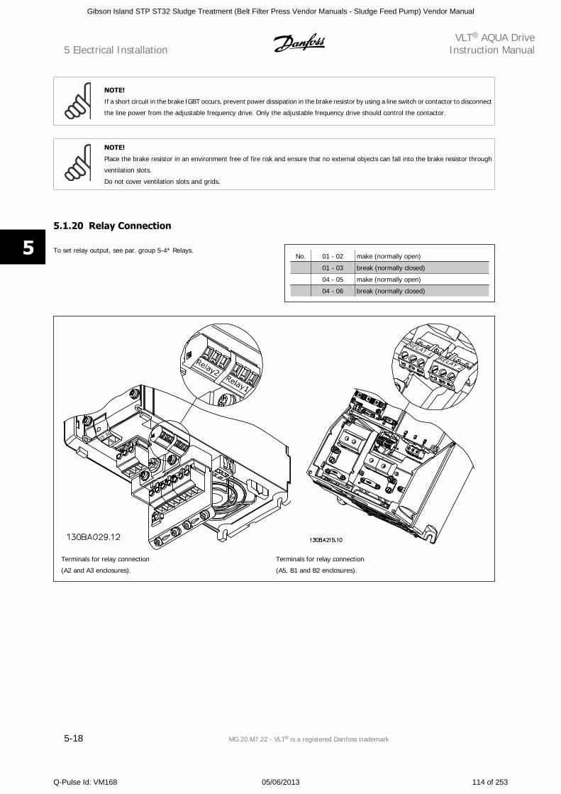
NOTE!
If a short circuit in the brake IGBT occurs, prevent power dissipation in the brake resistor by using a line switch or contactor to disconnect
the line power from the adjustable frequency drive. Only the adjustable frequency drive should control the contactor.
NOTE!
Place the brake resistor in an environment free of fire risk and ensure that no external objects can fall into the brake resistor through
ventilation slots.
Do not cover ventilation slots and grids.
5.1.20 Relay Connection
To set relay output, see par. group 5-4* Relays.No. 01 - 02 make (normally open)
01 - 03 break (normally closed)
04 - 05 make (normally open)
04 - 06 break (normally closed)
Terminals for relay connection
(A2 and A3 enclosures).
Terminals for relay connection
(A5, B1 and B2 enclosures).
5 Electrical InstallationVLT AQUA Drive
Instruction Manual
5-18 MG.20.M7.22 - VLT is a registered Danfoss trademark
5
Gibson Island STP ST32 Sludge Treatment (Belt Filter Press Vendor Manuals - Sludge Feed Pump) Vendor Manual
Q-Pulse Id: VM168 05/06/2013 114 of 253
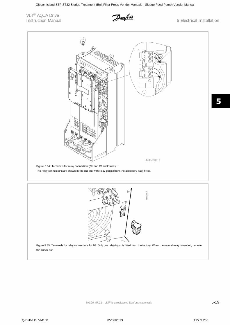
Figure 5.34: Terminals for relay connection (C1 and C2 enclosures).
The relay connections are shown in the cut-out with relay plugs (from the accessory bag) fitted.
Figure 5.35: Terminals for relay connections for B3. Only one relay input is fitted from the factory. When the second relay is needed, remove
the knock-out.
VLT AQUA DriveInstruction Manual 5 Electrical Installation
MG.20.M7.22 - VLT is a registered Danfoss trademark 5-19
5
Gibson Island STP ST32 Sludge Treatment (Belt Filter Press Vendor Manuals - Sludge Feed Pump) Vendor Manual
Q-Pulse Id: VM168 05/06/2013 115 of 253
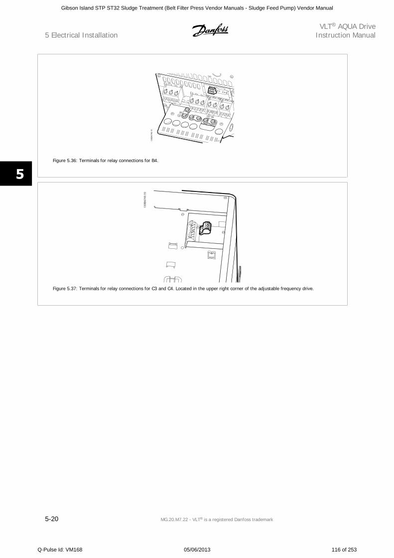
Figure 5.36: Terminals for relay connections for B4.
Figure 5.37: Terminals for relay connections for C3 and C4. Located in the upper right corner of the adjustable frequency drive.
5 Electrical InstallationVLT AQUA Drive
Instruction Manual
5-20 MG.20.M7.22 - VLT is a registered Danfoss trademark
5
Gibson Island STP ST32 Sludge Treatment (Belt Filter Press Vendor Manuals - Sludge Feed Pump) Vendor Manual
Q-Pulse Id: VM168 05/06/2013 116 of 253
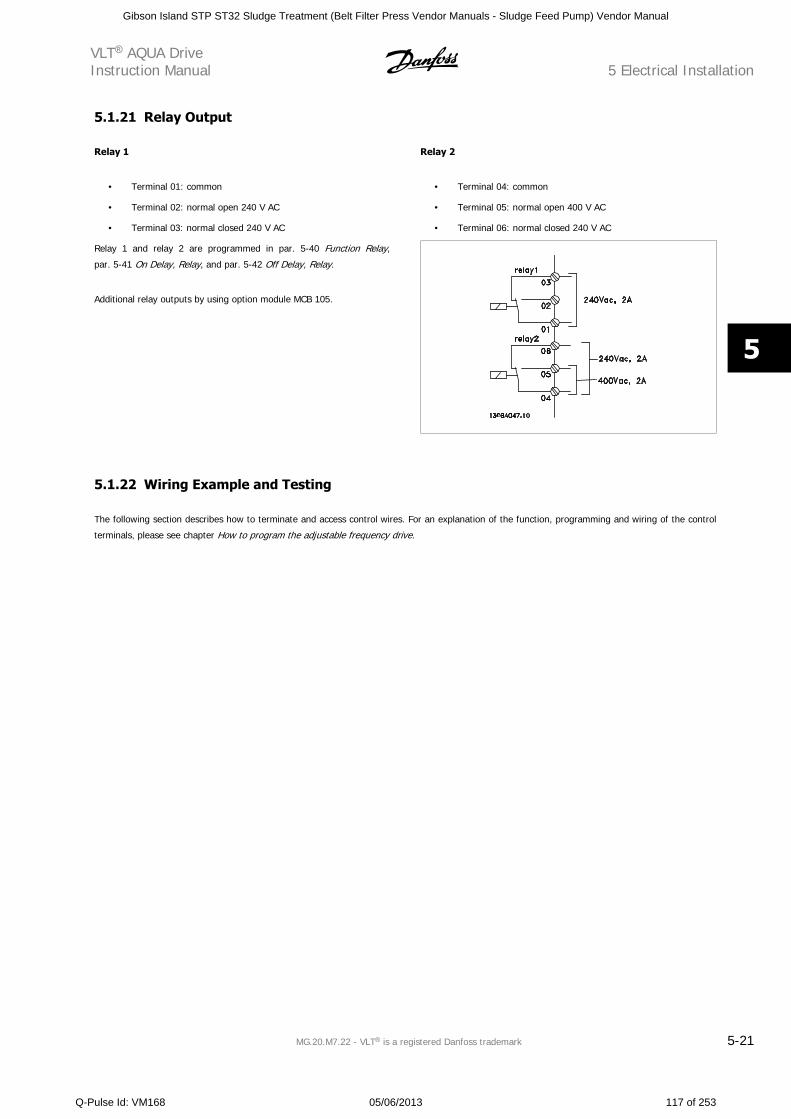
5.1.21 Relay Output
Relay 1
• Terminal 01: common
• Terminal 02: normal open 240 V AC
• Terminal 03: normal closed 240 V AC
Relay 2
• Terminal 04: common
• Terminal 05: normal open 400 V AC
• Terminal 06: normal closed 240 V AC
Relay 1 and relay 2 are programmed in par. 5-40 Function Relay,
par. 5-41 On Delay, Relay, and par. 5-42 Off Delay, Relay.
Additional relay outputs by using option module MCB 105.
5.1.22 Wiring Example and Testing
The following section describes how to terminate and access control wires. For an explanation of the function, programming and wiring of the control
terminals, please see chapter How to program the adjustable frequency drive.
VLT AQUA DriveInstruction Manual 5 Electrical Installation
MG.20.M7.22 - VLT is a registered Danfoss trademark 5-21
5
Gibson Island STP ST32 Sludge Treatment (Belt Filter Press Vendor Manuals - Sludge Feed Pump) Vendor Manual
Q-Pulse Id: VM168 05/06/2013 117 of 253
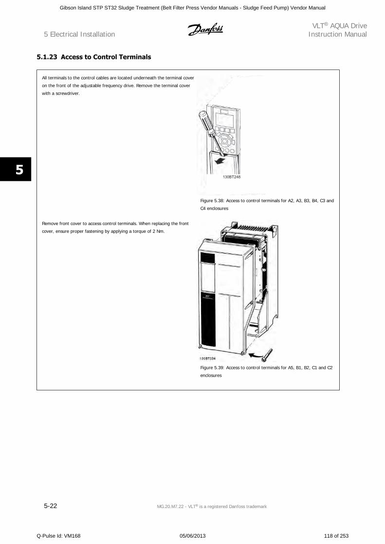
5.1.23 Access to Control Terminals
All terminals to the control cables are located underneath the terminal cover
on the front of the adjustable frequency drive. Remove the terminal cover
with a screwdriver.
130BT248
Figure 5.38: Access to control terminals for A2, A3, B3, B4, C3 and
C4 enclosures
Remove front cover to access control terminals. When replacing the front
cover, ensure proper fastening by applying a torque of 2 Nm.
Figure 5.39: Access to control terminals for A5, B1, B2, C1 and C2
enclosures
5 Electrical InstallationVLT AQUA Drive
Instruction Manual
5-22 MG.20.M7.22 - VLT is a registered Danfoss trademark
5
Gibson Island STP ST32 Sludge Treatment (Belt Filter Press Vendor Manuals - Sludge Feed Pump) Vendor Manual
Q-Pulse Id: VM168 05/06/2013 118 of 253
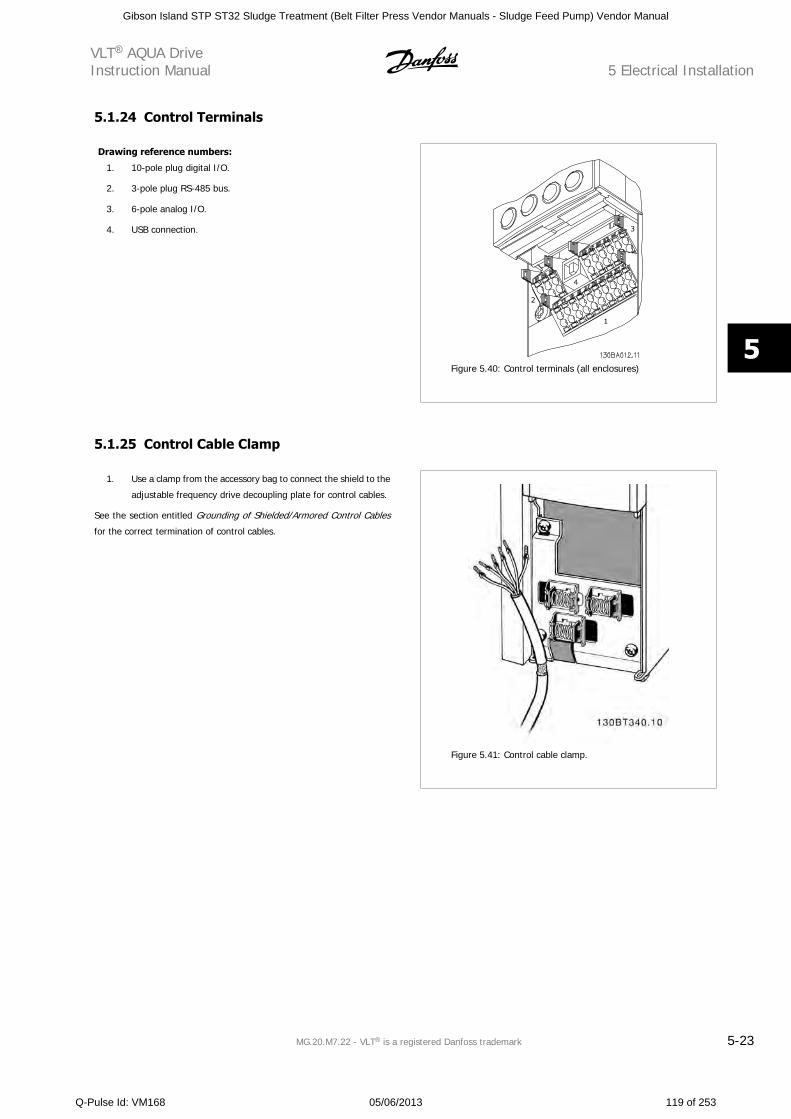
5.1.24 Control Terminals
Drawing reference numbers:
1. 10-pole plug digital I/O.
2. 3-pole plug RS-485 bus.
3. 6-pole analog I/O.
4. USB connection.
Figure 5.40: Control terminals (all enclosures)
5.1.25 Control Cable Clamp
1. Use a clamp from the accessory bag to connect the shield to the
adjustable frequency drive decoupling plate for control cables.
See the section entitled Grounding of Shielded/Armored Control Cables
for the correct termination of control cables.
Figure 5.41: Control cable clamp.
VLT AQUA DriveInstruction Manual 5 Electrical Installation
MG.20.M7.22 - VLT is a registered Danfoss trademark 5-23
5
Gibson Island STP ST32 Sludge Treatment (Belt Filter Press Vendor Manuals - Sludge Feed Pump) Vendor Manual
Q-Pulse Id: VM168 05/06/2013 119 of 253
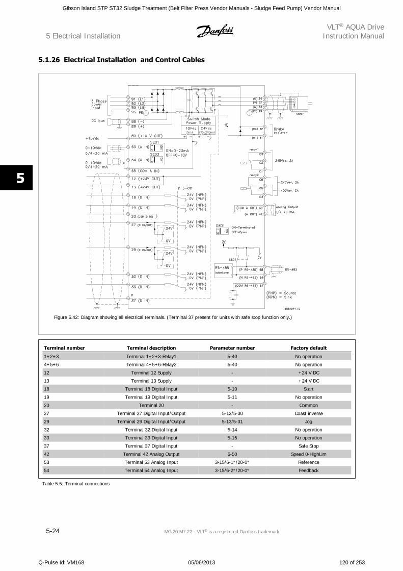
5.1.26 Electrical Installation and Control Cables
Figure 5.42: Diagram showing all electrical terminals. (Terminal 37 present for units with safe stop function only.)
Terminal number Terminal description Parameter number Factory default
1+2+3 Terminal 1+2+3-Relay1 5-40 No operation
4+5+6 Terminal 4+5+6-Relay2 5-40 No operation
12 Terminal 12 Supply - +24 V DC
13 Terminal 13 Supply - +24 V DC
18 Terminal 18 Digital Input 5-10 Start
19 Terminal 19 Digital Input 5-11 No operation
20 Terminal 20 - Common
27 Terminal 27 Digital Input/Output 5-12/5-30 Coast inverse
29 Terminal 29 Digital Input/Output 5-13/5-31 Jog
32 Terminal 32 Digital Input 5-14 No operation
33 Terminal 33 Digital Input 5-15 No operation
37 Terminal 37 Digital Input - Safe Stop
42 Terminal 42 Analog Output 6-50 Speed 0-HighLim
53 Terminal 53 Analog Input 3-15/6-1*/20-0* Reference
54 Terminal 54 Analog Input 3-15/6-2*/20-0* Feedback
Table 5.5: Terminal connections
5 Electrical InstallationVLT AQUA Drive
Instruction Manual
5-24 MG.20.M7.22 - VLT is a registered Danfoss trademark
5
Gibson Island STP ST32 Sludge Treatment (Belt Filter Press Vendor Manuals - Sludge Feed Pump) Vendor Manual
Q-Pulse Id: VM168 05/06/2013 120 of 253
Very long control cables and analog signals may, in rare cases and depending on the installation, result in 50/60 Hz ground loops due to noise from line
power supply cables.
If this occurs, break the shield or insert a 100 nF capacitor between shield and chassis.
NOTE!
The common of digital / analog inputs and outputs should be connected to separate common terminals 20, 39, and 55. This will prevent
ground current interference among groups. For example, it prevents switching on digital inputs from disturbing analog inputs.
NOTE!
To comply with EMC emission specifications, shielded/armored cables are recommended. If an unshielded/unarmored cable is used,
see section Power and Control Wiring for Unshielded Cables.. For more information, see EMC Test Results in the Design Guide.
VLT AQUA DriveInstruction Manual 5 Electrical Installation
MG.20.M7.22 - VLT is a registered Danfoss trademark 5-25
5
Gibson Island STP ST32 Sludge Treatment (Belt Filter Press Vendor Manuals - Sludge Feed Pump) Vendor Manual
Q-Pulse Id: VM168 05/06/2013 121 of 253
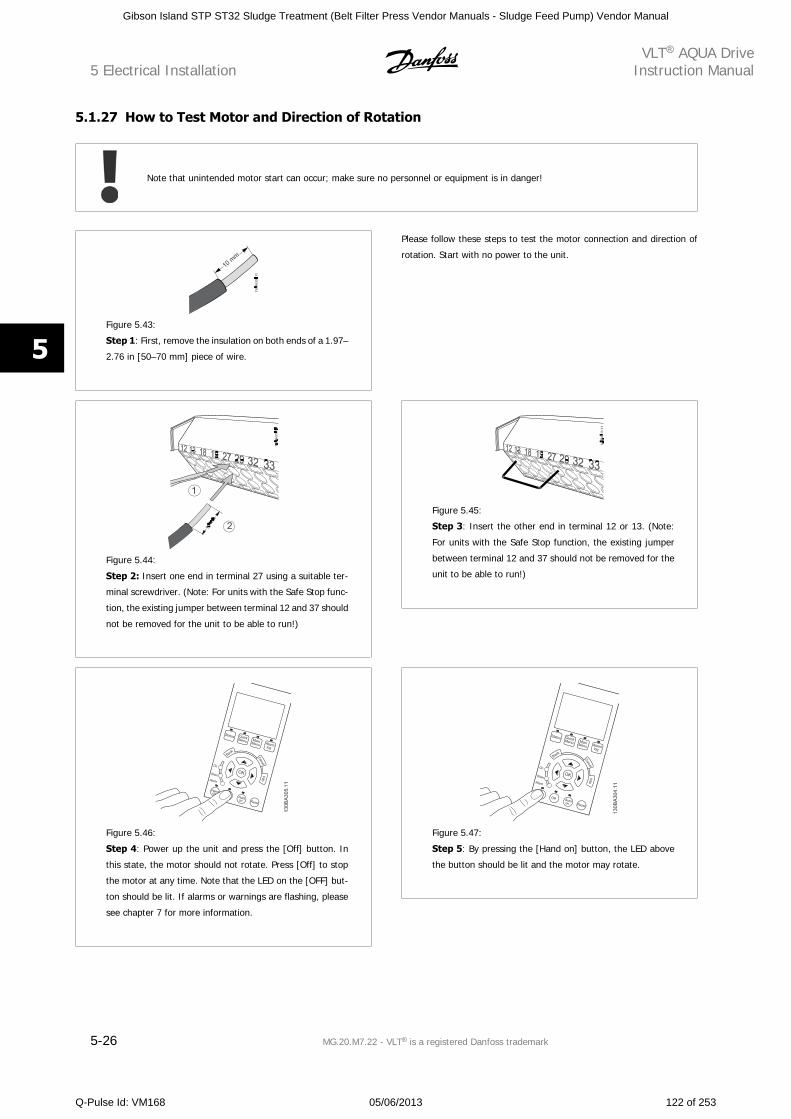
5.1.27 How to Test Motor and Direction of Rotation
Note that unintended motor start can occur; make sure no personnel or equipment is in danger!
Figure 5.43:
Step 1: First, remove the insulation on both ends of a 1.97–
2.76 in [50–70 mm] piece of wire.
Please follow these steps to test the motor connection and direction of
rotation. Start with no power to the unit.
Figure 5.44:
Step 2: Insert one end in terminal 27 using a suitable ter-
minal screwdriver. (Note: For units with the Safe Stop func-
tion, the existing jumper between terminal 12 and 37 should
not be removed for the unit to be able to run!)
Figure 5.45:
Step 3: Insert the other end in terminal 12 or 13. (Note:
For units with the Safe Stop function, the existing jumper
between terminal 12 and 37 should not be removed for the
unit to be able to run!)
Figure 5.46:
Step 4: Power up the unit and press the [Off] button. In
this state, the motor should not rotate. Press [Off] to stop
the motor at any time. Note that the LED on the [OFF] but-
ton should be lit. If alarms or warnings are flashing, please
see chapter 7 for more information.
Figure 5.47:
Step 5: By pressing the [Hand on] button, the LED above
the button should be lit and the motor may rotate.
5 Electrical InstallationVLT AQUA Drive
Instruction Manual
5-26 MG.20.M7.22 - VLT is a registered Danfoss trademark
5
Gibson Island STP ST32 Sludge Treatment (Belt Filter Press Vendor Manuals - Sludge Feed Pump) Vendor Manual
Q-Pulse Id: VM168 05/06/2013 122 of 253
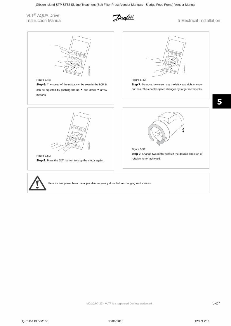
Figure 5.48:
Step 6: The speed of the motor can be seen in the LCP. It
can be adjusted by pushing the up and down arrow
buttons.
Figure 5.49:
Step 7: To move the cursor, use the left and right arrow
buttons. This enables speed changes by larger increments.
Figure 5.50:
Step 8: Press the [Off] button to stop the motor again.
Figure 5.51:
Step 9: Change two motor wires if the desired direction of
rotation is not achieved.
Remove line power from the adjustable frequency drive before changing motor wires.
VLT AQUA DriveInstruction Manual 5 Electrical Installation
MG.20.M7.22 - VLT is a registered Danfoss trademark 5-27
5
Gibson Island STP ST32 Sludge Treatment (Belt Filter Press Vendor Manuals - Sludge Feed Pump) Vendor Manual
Q-Pulse Id: VM168 05/06/2013 123 of 253
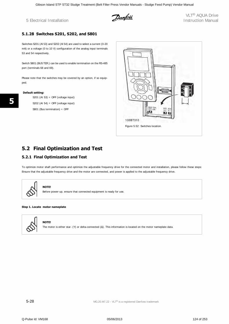
5.1.28 Switches S201, S202, and S801
Switches S201 (Al 53) and S202 (Al 54) are used to select a current (0-20
mA) or a voltage (0 to 10 V) configuration of the analog input terminals
53 and 54 respectively.
Switch S801 (BUS TER.) can be used to enable termination on the RS-485
port (terminals 68 and 69).
Please note that the switches may be covered by an option, if so equip-
ped.
Default setting:
S201 (AI 53) = OFF (voltage input)
S202 (AI 54) = OFF (voltage input)
S801 (Bus termination) = OFF
Figure 5.52: Switches location.
5.2 Final Optimization and Test
5.2.1 Final Optimization and Test
To optimize motor shaft performance and optimize the adjustable frequency drive for the connected motor and installation, please follow these steps:
Ensure that the adjustable frequency drive and the motor are connected, and power is applied to the adjustable frequency drive.
NOTE!
Before power-up, ensure that connected equipment is ready for use.
Step 1. Locate motor nameplate
NOTE!
The motor is either star- (Y) or delta-connected ( ). This information is located on the motor nameplate data.
5 Electrical InstallationVLT AQUA Drive
Instruction Manual
5-28 MG.20.M7.22 - VLT is a registered Danfoss trademark
5
Gibson Island STP ST32 Sludge Treatment (Belt Filter Press Vendor Manuals - Sludge Feed Pump) Vendor Manual
Q-Pulse Id: VM168 05/06/2013 124 of 253
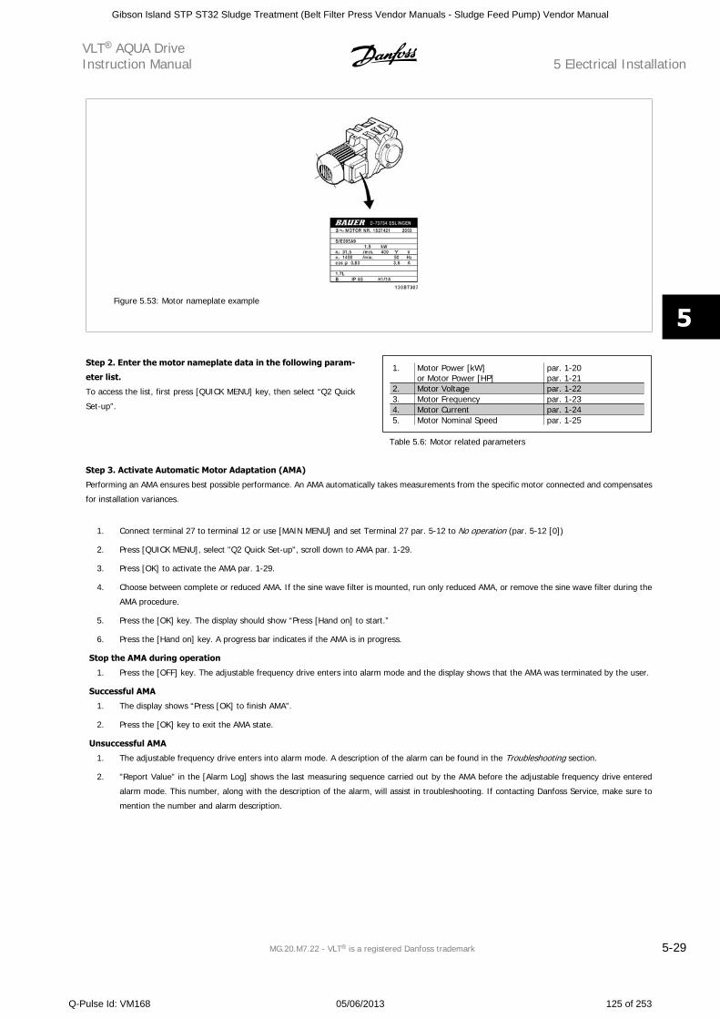
Figure 5.53: Motor nameplate example
Step 2. Enter the motor nameplate data in the following param-
eter list.
To access the list, first press [QUICK MENU] key, then select “Q2 Quick
Set-up”.
1. Motor Power [kW]or Motor Power [HP]
par. 1-20par. 1-21
2. Motor Voltage par. 1-223. Motor Frequency par. 1-234. Motor Current par. 1-245. Motor Nominal Speed par. 1-25
Table 5.6: Motor related parameters
Step 3. Activate Automatic Motor Adaptation (AMA)
Performing an AMA ensures best possible performance. An AMA automatically takes measurements from the specific motor connected and compensates
for installation variances.
1. Connect terminal 27 to terminal 12 or use [MAIN MENU] and set Terminal 27 par. 5-12 to No operation (par. 5-12 [0])
2. Press [QUICK MENU], select "Q2 Quick Set-up", scroll down to AMA par. 1-29.
3. Press [OK] to activate the AMA par. 1-29.
4. Choose between complete or reduced AMA. If the sine wave filter is mounted, run only reduced AMA, or remove the sine wave filter during the
AMA procedure.
5. Press the [OK] key. The display should show “Press [Hand on] to start.”
6. Press the [Hand on] key. A progress bar indicates if the AMA is in progress.
Stop the AMA during operation
1. Press the [OFF] key. The adjustable frequency drive enters into alarm mode and the display shows that the AMA was terminated by the user.
Successful AMA
1. The display shows “Press [OK] to finish AMA”.
2. Press the [OK] key to exit the AMA state.
Unsuccessful AMA
1. The adjustable frequency drive enters into alarm mode. A description of the alarm can be found in the Troubleshooting section.
2. "Report Value” in the [Alarm Log] shows the last measuring sequence carried out by the AMA before the adjustable frequency drive entered
alarm mode. This number, along with the description of the alarm, will assist in troubleshooting. If contacting Danfoss Service, make sure to
mention the number and alarm description.
VLT AQUA DriveInstruction Manual 5 Electrical Installation
MG.20.M7.22 - VLT is a registered Danfoss trademark 5-29
5
Gibson Island STP ST32 Sludge Treatment (Belt Filter Press Vendor Manuals - Sludge Feed Pump) Vendor Manual
Q-Pulse Id: VM168 05/06/2013 125 of 253
NOTE!
An unsuccessful AMA is often caused by incorrectly entered motor nameplate data or too big of a difference between the motor and
the adjustable frequency drive power sizes.
Step 4. Set speed limit and ramp time
Set up the desired limits for speed and ramp time.
Minimum Reference par. 3-02Maximum Reference par. 3-03
Motor Speed Low Limit par. 4-11 or 4-12Motor Speed High Limit par. 4-13 or 4-14
Ramp 1 Ramp-up Time [s] par. 3-41Ramp 1 Ramp-down Time 1 [s] par. 3-42
5 Electrical InstallationVLT AQUA Drive
Instruction Manual
5-30 MG.20.M7.22 - VLT is a registered Danfoss trademark
5
Gibson Island STP ST32 Sludge Treatment (Belt Filter Press Vendor Manuals - Sludge Feed Pump) Vendor Manual
Q-Pulse Id: VM168 05/06/2013 126 of 253
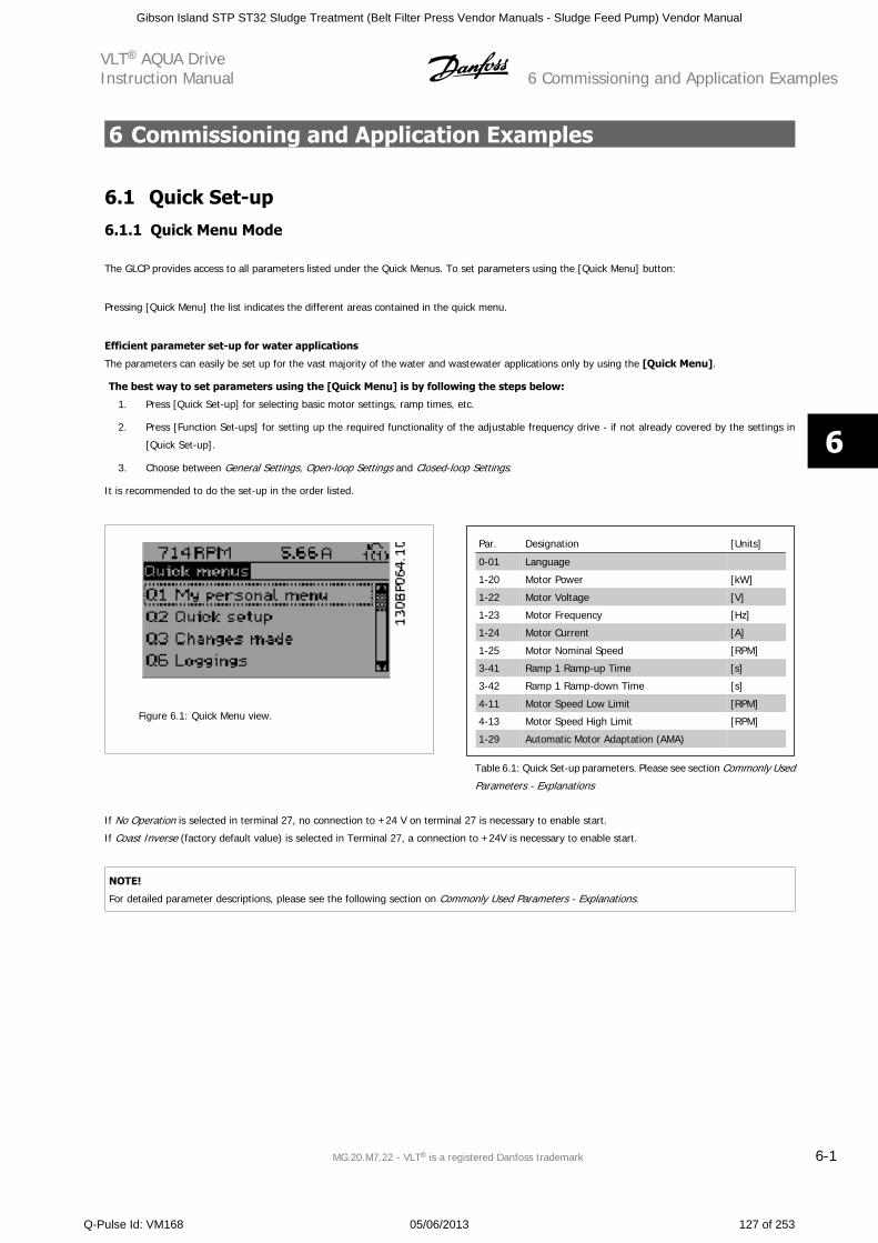
6 Commissioning and Application Examples
6.1 Quick Set-up
6.1.1 Quick Menu Mode
The GLCP provides access to all parameters listed under the Quick Menus. To set parameters using the [Quick Menu] button:
Pressing [Quick Menu] the list indicates the different areas contained in the quick menu.
Efficient parameter set-up for water applications
The parameters can easily be set up for the vast majority of the water and wastewater applications only by using the [Quick Menu].
The best way to set parameters using the [Quick Menu] is by following the steps below:
1. Press [Quick Set-up] for selecting basic motor settings, ramp times, etc.
2. Press [Function Set-ups] for setting up the required functionality of the adjustable frequency drive - if not already covered by the settings in
[Quick Set-up].
3. Choose between General Settings, Open-loop Settings and Closed-loop Settings.
It is recommended to do the set-up in the order listed.
Figure 6.1: Quick Menu view.
Par. Designation [Units]
0-01 Language
1-20 Motor Power [kW]
1-22 Motor Voltage [V]
1-23 Motor Frequency [Hz]
1-24 Motor Current [A]
1-25 Motor Nominal Speed [RPM]
3-41 Ramp 1 Ramp-up Time [s]
3-42 Ramp 1 Ramp-down Time [s]
4-11 Motor Speed Low Limit [RPM]
4-13 Motor Speed High Limit [RPM]
1-29 Automatic Motor Adaptation (AMA)
Table 6.1: Quick Set-up parameters. Please see section Commonly Used
Parameters - Explanations
If No Operation is selected in terminal 27, no connection to +24 V on terminal 27 is necessary to enable start.
If Coast Inverse (factory default value) is selected in Terminal 27, a connection to +24V is necessary to enable start.
NOTE!
For detailed parameter descriptions, please see the following section on Commonly Used Parameters - Explanations.
VLT AQUA DriveInstruction Manual 6 Commissioning and Application Examples
MG.20.M7.22 - VLT is a registered Danfoss trademark 6-1
6
Gibson Island STP ST32 Sludge Treatment (Belt Filter Press Vendor Manuals - Sludge Feed Pump) Vendor Manual
Q-Pulse Id: VM168 05/06/2013 127 of 253
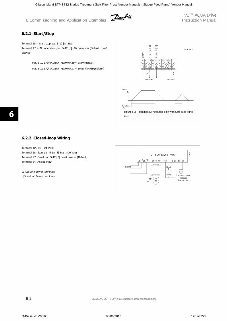
6.2.1 Start/Stop
Terminal 18 = start/stop par. 5-10 [8] Start
Terminal 27 = No operation par. 5-12 [0] No operation (Default coast
inverse
Par. 5-10 Digital Input, Terminal 18 = Start (default)
Par. 5-12 Digital Input, Terminal 27 = coast inverse (default)
Figure 6.2: Terminal 37: Available only with Safe Stop Func-
tion!
6.2.2 Closed-loop Wiring
Terminal 12 /13: +24 V DC
Terminal 18: Start par. 5-18 [8] Start (Default)
Terminal 27: Coast par. 5-12 [2] coast inverse (Default)
Terminal 54: Analog input
L1-L3: Line power terminals
U,V and W: Motor terminals
6 Commissioning and Application ExamplesVLT AQUA Drive
Instruction Manual
6-2 MG.20.M7.22 - VLT is a registered Danfoss trademark
6
Gibson Island STP ST32 Sludge Treatment (Belt Filter Press Vendor Manuals - Sludge Feed Pump) Vendor Manual
Q-Pulse Id: VM168 05/06/2013 128 of 253
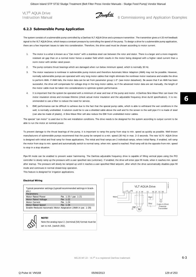
6.2.3 Submersible Pump Application
The system consists of a submersible pump controlled by a Danfoss VLT AQUA Drive and a pressure transmitter. The transmitter gives a 4-20 mA feedback
signal to the VLT AQUA Drive, which keeps a constant pressure by controlling the speed of the pump. To design a drive for a submersible pump application,
there are a few important issues to take into consideration. Therefore, the drive used must be chosen according to motor current.
1. The motor is a what is known as a “Can motor” with a stainless steel can between the rotor and stator. There is a larger and a more magnetic
resistant air-gap than on a normal motor hence a weaker field which results in the motor being designed with a higher rated current than a
norm motor with similar rated power.
2. The pump contains thrust bearings which are damaged when run below minimum speed, which is normally 30 Hz.
3. The motor reactance is nonlinear in submersible pump motors and therefore Automatic Motor Adaption (AMA) may not be possible. However,
normally submersible pumps are operated with very long motor cables that might eliminate the nonlinear motor reactance and enable the drive
to perform AMA. If AMA fails, the motor data can be set from parameter group 1-3* (see motor datasheet). Be aware that if an AMA has been
successful, the drive will compensate for voltage drop in the long motor cables, so if the advanced motor data are set manually, the length of
the motor cable must be taken into considerations to optimize system performance.
4. It is important that the system be operated with a minimum of wear and tear of the pump and motor. A Danfoss Sine-Wave filter can lower the
motor insulation stress and increase lifetime (check actual motor insulation and the adjustable frequency drive du/dt specification). It is rec-
ommended to use a filter to reduce the need for service.
5. EMC performance can be difficult to achieve due to the fact that the special pump cable, which is able to withstand the wet conditions in the
well, is normally unshielded. A solution could be to use a shielded cable above the well and fix the screen to the well pipe if it is made of steel
(can also be made of plastic). A Sine-Wave filter will also reduce the EMI from unshielded motor cables.
The special “can motor” is used due to the wet installation conditions. The drive needs to be designed for the system according to output current to be
able to run the motor at nominal power.
To prevent damage to the thrust bearings of the pump, it is important to ramp the pump from stop to min. speed as quickly as possible. Well-known
manufacturers of submersible pumps recommend that the pump be ramped to a min. speed (30 Hz) in max. 2–3 seconds. The new VLT© AQUA Drive
is designed with initial and final ramp for these applications. The initial and final ramps are 2 individual ramps, where Initial Ramp, if enabled, will ramp
the motor from stop to min. speed and automatically switch to normal ramp, when min. speed is reached. Final ramp will do the opposite from min. speed
to stop in a stop situation.
Pipe-fill mode can be enabled to prevent water hammering. The Danfoss adjustable frequency drive is capable of filling vertical pipes using the PID
controller to slowly ramp up the pressure with a user specified rate (units/sec). If enabled, the drive will enter pipe fill mode, when it reaches min. speed
after startup. The pressure will slowly be ramped up until it reaches a user-specified filled setpoint, after which the drive automatically disables pipe fill
mode and continues in normal closed-loop operation.
This feature is designed for irrigation applications.
Electrical Wiring
Typical parameter settings (typical/recommended settings in brack-ets.)Parameters: Motor Rated Power Par. 1-20 / par. 1-21Motor Rated Voltage Par. 1-22Motor Current Par. 1-24Motor Rated Speed Par. 1-28Enable Reduced Automatic Motor Adaptation (AMA in par. 1-29)
NOTE!
Note the analog input 2, (terminal (54) format must be
set to mA. (switch 202).
VLT AQUA DriveInstruction Manual 6 Commissioning and Application Examples
MG.20.M7.22 - VLT is a registered Danfoss trademark 6-3
6
Gibson Island STP ST32 Sludge Treatment (Belt Filter Press Vendor Manuals - Sludge Feed Pump) Vendor Manual
Q-Pulse Id: VM168 05/06/2013 129 of 253
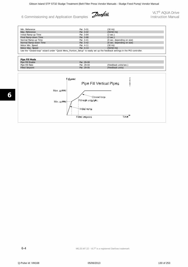
Min. Reference Par. 3-01 (30 Hz)Max. Reference Par. 3-02 (50/60 Hz)Initial Ramp-up Time Par. 3-84 (2 sec.)Final Ramp-down Time Par. 3-88 (2 sec.)Normal Ramp-up Time Par. 3-41 (8 sec. depending on size)Normal Ramp-down Time Par. 3-42 (8 sec. depending on size)Motor Min. Speed Par. 4-11 (30 Hz)Motor Max. Speed Par. 4-13 (50/60 Hz)Use the “Closed-loop” wizard under “Quick Menu_Funtion_Setup” to easily set up the feedback settings in the PID controller.
Pipe Fill ModePipe Fill Enable Par. 29-00 Pipe Fill Rate Par. 29-04 (Feedback units/sec.)Filled Setpoint Par. 29-05 (Feedback units)
6 Commissioning and Application ExamplesVLT AQUA Drive
Instruction Manual
6-4 MG.20.M7.22 - VLT is a registered Danfoss trademark
6
Gibson Island STP ST32 Sludge Treatment (Belt Filter Press Vendor Manuals - Sludge Feed Pump) Vendor Manual
Q-Pulse Id: VM168 05/06/2013 130 of 253
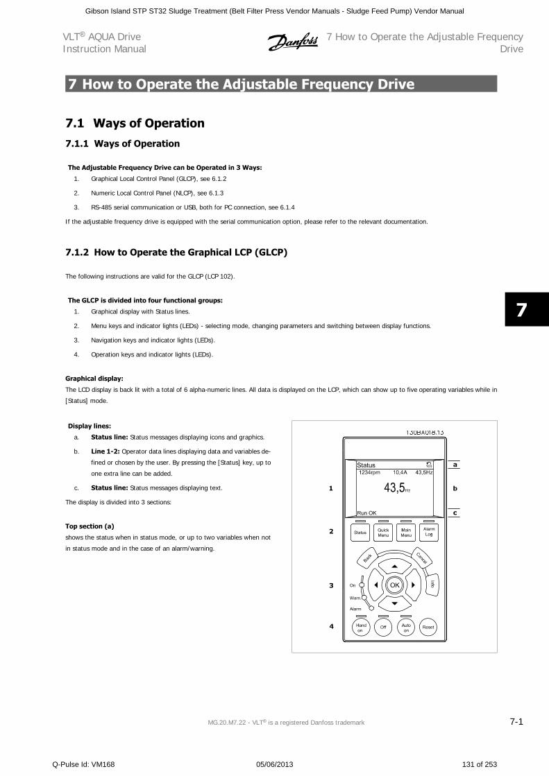
7 How to Operate the Adjustable Frequency Drive
7.1 Ways of Operation
7.1.1 Ways of Operation
The Adjustable Frequency Drive can be Operated in 3 Ways:
1. Graphical Local Control Panel (GLCP), see 6.1.2
2. Numeric Local Control Panel (NLCP), see 6.1.3
3. RS-485 serial communication or USB, both for PC connection, see 6.1.4
If the adjustable frequency drive is equipped with the serial communication option, please refer to the relevant documentation.
7.1.2 How to Operate the Graphical LCP (GLCP)
The following instructions are valid for the GLCP (LCP 102).
The GLCP is divided into four functional groups:
1. Graphical display with Status lines.
2. Menu keys and indicator lights (LEDs) - selecting mode, changing parameters and switching between display functions.
3. Navigation keys and indicator lights (LEDs).
4. Operation keys and indicator lights (LEDs).
Graphical display:
The LCD display is back lit with a total of 6 alpha-numeric lines. All data is displayed on the LCP, which can show up to five operating variables while in
[Status] mode.
Display lines:
a. Status line: Status messages displaying icons and graphics.
b. Line 1-2: Operator data lines displaying data and variables de-
fined or chosen by the user. By pressing the [Status] key, up to
one extra line can be added.
c. Status line: Status messages displaying text.
The display is divided into 3 sections:
Top section (a)
shows the status when in status mode, or up to two variables when not
in status mode and in the case of an alarm/warning.
VLT AQUA DriveInstruction Manual
7 How to Operate the Adjustable FrequencyDrive
MG.20.M7.22 - VLT is a registered Danfoss trademark 7-1
7
Gibson Island STP ST32 Sludge Treatment (Belt Filter Press Vendor Manuals - Sludge Feed Pump) Vendor Manual
Q-Pulse Id: VM168 05/06/2013 131 of 253
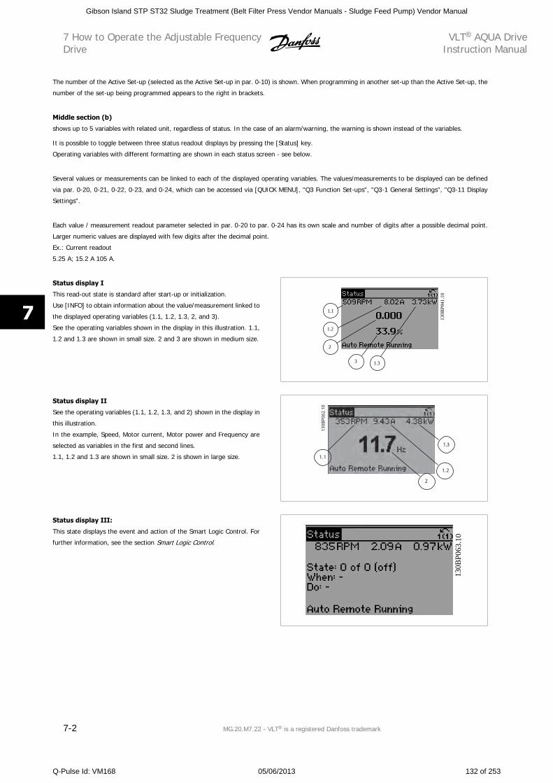
The number of the Active Set-up (selected as the Active Set-up in par. 0-10) is shown. When programming in another set-up than the Active Set-up, the
number of the set-up being programmed appears to the right in brackets.
Middle section (b)
shows up to 5 variables with related unit, regardless of status. In the case of an alarm/warning, the warning is shown instead of the variables.
It is possible to toggle between three status readout displays by pressing the [Status] key.
Operating variables with different formatting are shown in each status screen - see below.
Several values or measurements can be linked to each of the displayed operating variables. The values/measurements to be displayed can be defined
via par. 0-20, 0-21, 0-22, 0-23, and 0-24, which can be accessed via [QUICK MENU], "Q3 Function Set-ups", "Q3-1 General Settings", "Q3-11 Display
Settings".
Each value / measurement readout parameter selected in par. 0-20 to par. 0-24 has its own scale and number of digits after a possible decimal point.
Larger numeric values are displayed with few digits after the decimal point.
Ex.: Current readout
5.25 A; 15.2 A 105 A.
Status display I
This read-out state is standard after start-up or initialization.
Use [INFO] to obtain information about the value/measurement linked to
the displayed operating variables (1.1, 1.2, 1.3, 2, and 3).
See the operating variables shown in the display in this illustration. 1.1,
1.2 and 1.3 are shown in small size. 2 and 3 are shown in medium size.
130 B
P041
. 10
1.1
1.3
2
1.2
3
Status display II
See the operating variables (1.1, 1.2, 1.3, and 2) shown in the display in
this illustration.
In the example, Speed, Motor current, Motor power and Frequency are
selected as variables in the first and second lines.
1.1, 1.2 and 1.3 are shown in small size. 2 is shown in large size. 1.1
1.3
1.2
2
Status display III:
This state displays the event and action of the Smart Logic Control. For
further information, see the section Smart Logic Control.
130B
P 06 3
. 10
7 How to Operate the Adjustable FrequencyDrive
VLT AQUA DriveInstruction Manual
7-2 MG.20.M7.22 - VLT is a registered Danfoss trademark
7
Gibson Island STP ST32 Sludge Treatment (Belt Filter Press Vendor Manuals - Sludge Feed Pump) Vendor Manual
Q-Pulse Id: VM168 05/06/2013 132 of 253
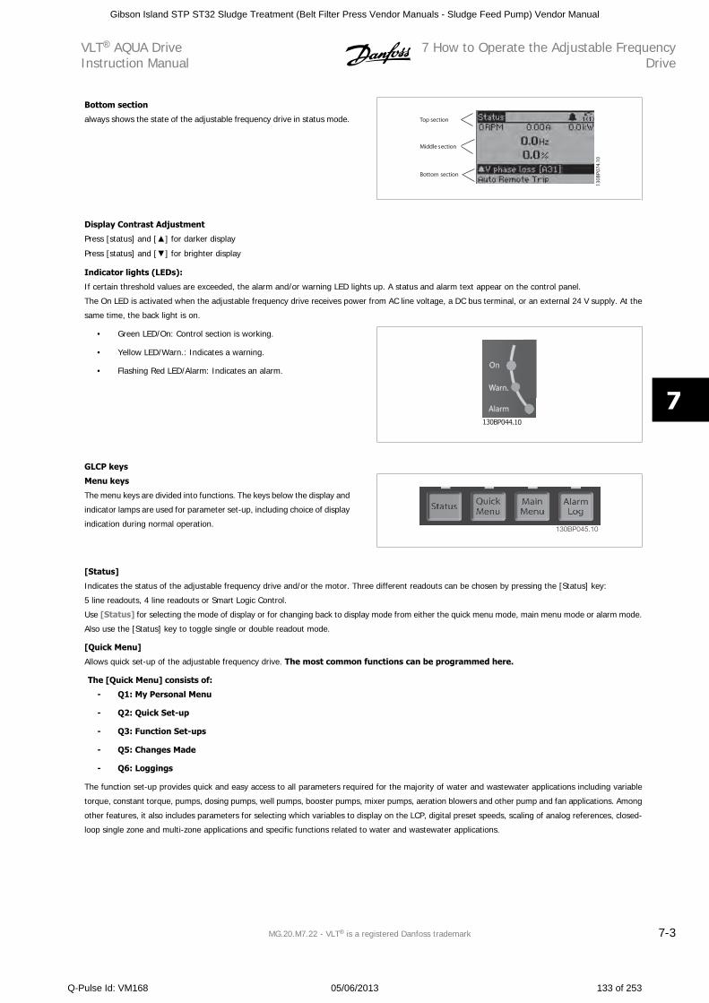
Bottom section
always shows the state of the adjustable frequency drive in status mode. Top section
Middle section
Bottom section
Display Contrast Adjustment
Press [status] and [ ] for darker display
Press [status] and [ ] for brighter display
Indicator lights (LEDs):
If certain threshold values are exceeded, the alarm and/or warning LED lights up. A status and alarm text appear on the control panel.
The On LED is activated when the adjustable frequency drive receives power from AC line voltage, a DC bus terminal, or an external 24 V supply. At the
same time, the back light is on.
• Green LED/On: Control section is working.
• Yellow LED/Warn.: Indicates a warning.
• Flashing Red LED/Alarm: Indicates an alarm.
GLCP keys
Menu keys
The menu keys are divided into functions. The keys below the display and
indicator lamps are used for parameter set-up, including choice of display
indication during normal operation.130BP045.10
[Status]
Indicates the status of the adjustable frequency drive and/or the motor. Three different readouts can be chosen by pressing the [Status] key:
5 line readouts, 4 line readouts or Smart Logic Control.
Use [Status] for selecting the mode of display or for changing back to display mode from either the quick menu mode, main menu mode or alarm mode.
Also use the [Status] key to toggle single or double readout mode.
[Quick Menu]
Allows quick set-up of the adjustable frequency drive. The most common functions can be programmed here.
The [Quick Menu] consists of:
- Q1: My Personal Menu
- Q2: Quick Set-up
- Q3: Function Set-ups
- Q5: Changes Made
- Q6: Loggings
The function set-up provides quick and easy access to all parameters required for the majority of water and wastewater applications including variable
torque, constant torque, pumps, dosing pumps, well pumps, booster pumps, mixer pumps, aeration blowers and other pump and fan applications. Among
other features, it also includes parameters for selecting which variables to display on the LCP, digital preset speeds, scaling of analog references, closed-
loop single zone and multi-zone applications and specific functions related to water and wastewater applications.
VLT AQUA DriveInstruction Manual
7 How to Operate the Adjustable FrequencyDrive
MG.20.M7.22 - VLT is a registered Danfoss trademark 7-3
7
Gibson Island STP ST32 Sludge Treatment (Belt Filter Press Vendor Manuals - Sludge Feed Pump) Vendor Manual
Q-Pulse Id: VM168 05/06/2013 133 of 253
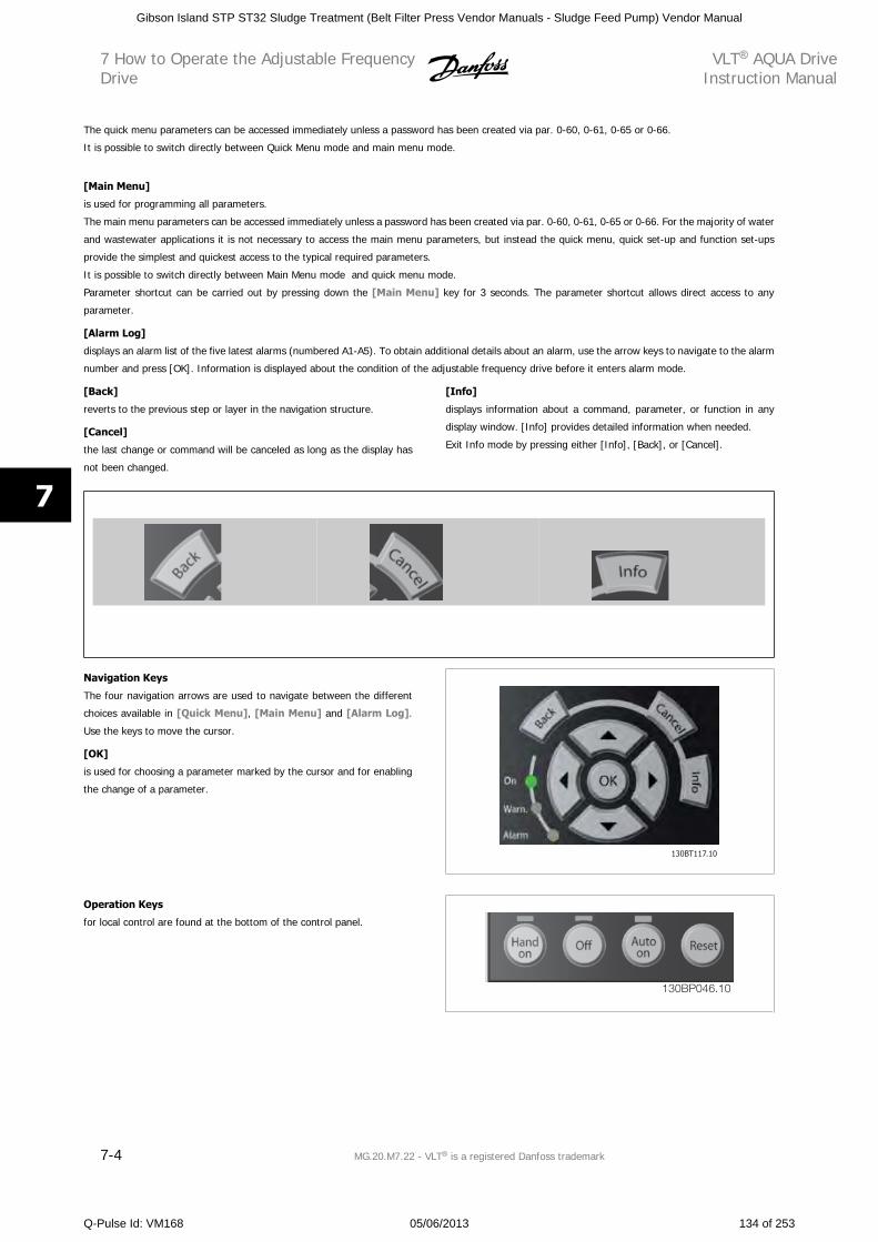
The quick menu parameters can be accessed immediately unless a password has been created via par. 0-60, 0-61, 0-65 or 0-66.
It is possible to switch directly between Quick Menu mode and main menu mode.
[Main Menu]
is used for programming all parameters.
The main menu parameters can be accessed immediately unless a password has been created via par. 0-60, 0-61, 0-65 or 0-66. For the majority of water
and wastewater applications it is not necessary to access the main menu parameters, but instead the quick menu, quick set-up and function set-ups
provide the simplest and quickest access to the typical required parameters.
It is possible to switch directly between Main Menu mode and quick menu mode.
Parameter shortcut can be carried out by pressing down the [Main Menu] key for 3 seconds. The parameter shortcut allows direct access to any
parameter.
[Alarm Log]
displays an alarm list of the five latest alarms (numbered A1-A5). To obtain additional details about an alarm, use the arrow keys to navigate to the alarm
number and press [OK]. Information is displayed about the condition of the adjustable frequency drive before it enters alarm mode.
[Back]
reverts to the previous step or layer in the navigation structure.
[Cancel]
the last change or command will be canceled as long as the display has
not been changed.
[Info]
displays information about a command, parameter, or function in any
display window. [Info] provides detailed information when needed.
Exit Info mode by pressing either [Info], [Back], or [Cancel].
Navigation Keys
The four navigation arrows are used to navigate between the different
choices available in [Quick Menu], [Main Menu] and [Alarm Log].
Use the keys to move the cursor.
[OK]
is used for choosing a parameter marked by the cursor and for enabling
the change of a parameter.
Operation Keys
for local control are found at the bottom of the control panel.
130BP046.10
7 How to Operate the Adjustable FrequencyDrive
VLT AQUA DriveInstruction Manual
7-4 MG.20.M7.22 - VLT is a registered Danfoss trademark
7
Gibson Island STP ST32 Sludge Treatment (Belt Filter Press Vendor Manuals - Sludge Feed Pump) Vendor Manual
Q-Pulse Id: VM168 05/06/2013 134 of 253
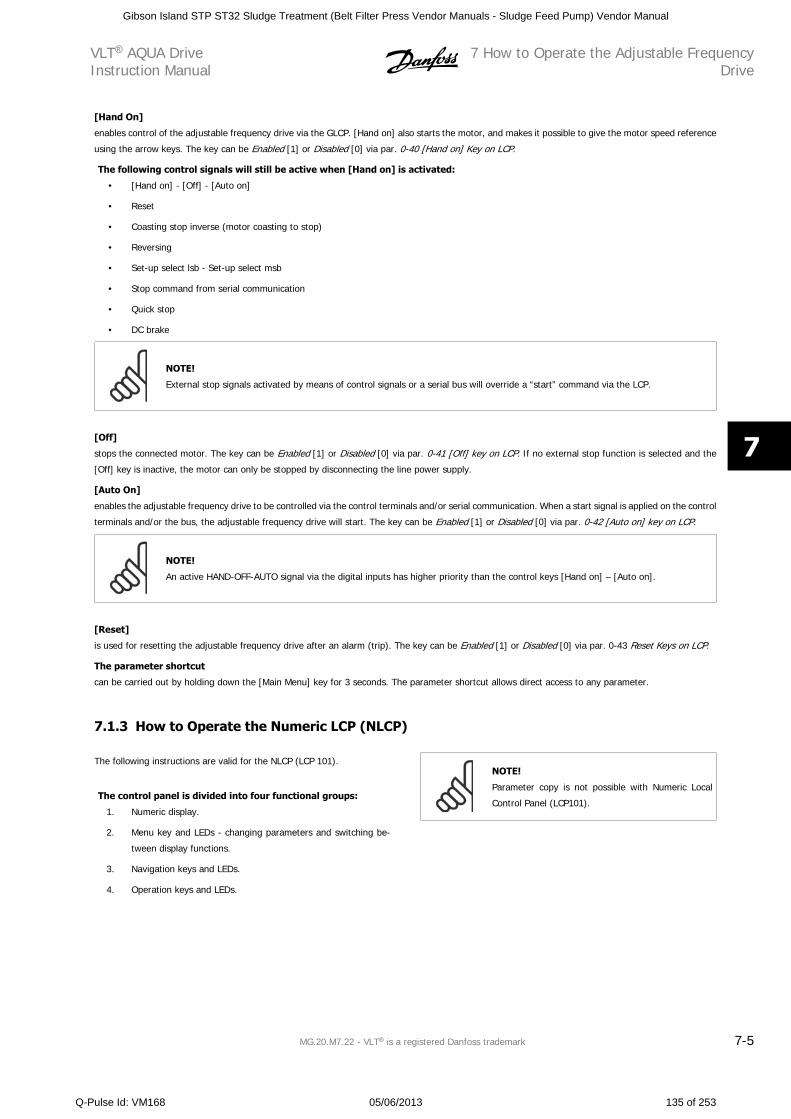
[Hand On]
enables control of the adjustable frequency drive via the GLCP. [Hand on] also starts the motor, and makes it possible to give the motor speed reference
using the arrow keys. The key can be Enabled [1] or Disabled [0] via par. 0-40 [Hand on] Key on LCP.
The following control signals will still be active when [Hand on] is activated:
• [Hand on] - [Off] - [Auto on]
• Reset
• Coasting stop inverse (motor coasting to stop)
• Reversing
• Set-up select lsb - Set-up select msb
• Stop command from serial communication
• Quick stop
• DC brake
NOTE!
External stop signals activated by means of control signals or a serial bus will override a “start” command via the LCP.
[Off]
stops the connected motor. The key can be Enabled [1] or Disabled [0] via par. 0-41 [Off] key on LCP. If no external stop function is selected and the
[Off] key is inactive, the motor can only be stopped by disconnecting the line power supply.
[Auto On]
enables the adjustable frequency drive to be controlled via the control terminals and/or serial communication. When a start signal is applied on the control
terminals and/or the bus, the adjustable frequency drive will start. The key can be Enabled [1] or Disabled [0] via par. 0-42 [Auto on] key on LCP.
NOTE!
An active HAND-OFF-AUTO signal via the digital inputs has higher priority than the control keys [Hand on] – [Auto on].
[Reset]
is used for resetting the adjustable frequency drive after an alarm (trip). The key can be Enabled [1] or Disabled [0] via par. 0-43 Reset Keys on LCP.
The parameter shortcut
can be carried out by holding down the [Main Menu] key for 3 seconds. The parameter shortcut allows direct access to any parameter.
7.1.3 How to Operate the Numeric LCP (NLCP)
The following instructions are valid for the NLCP (LCP 101).
The control panel is divided into four functional groups:
1. Numeric display.
2. Menu key and LEDs - changing parameters and switching be-
tween display functions.
3. Navigation keys and LEDs.
4. Operation keys and LEDs.
NOTE!
Parameter copy is not possible with Numeric Local
Control Panel (LCP101).
VLT AQUA DriveInstruction Manual
7 How to Operate the Adjustable FrequencyDrive
MG.20.M7.22 - VLT is a registered Danfoss trademark 7-5
7
Gibson Island STP ST32 Sludge Treatment (Belt Filter Press Vendor Manuals - Sludge Feed Pump) Vendor Manual
Q-Pulse Id: VM168 05/06/2013 135 of 253
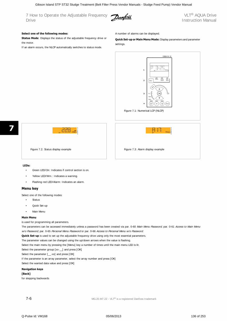
Select one of the following modes:
Status Mode: Displays the status of the adjustable frequency drive or
the motor.
If an alarm occurs, the NLCP automatically switches to status mode.
A number of alarms can be displayed.
Quick Set-up or Main Menu Mode: Display parameters and parameter
settings.
Figure 7.1: Numerical LCP (NLCP)
130B
P077
.10
Figure 7.2: Status display example
130B
P078
.10
Figure 7.3: Alarm display example
LEDs:
• Green LED/On: Indicates if control section is on.
• Yellow LED/Wrn.: Indicates a warning.
• Flashing red LED/Alarm: Indicates an alarm.
Menu key
Select one of the following modes:
• Status
• Quick Set-up
• Main Menu
Main Menu
is used for programming all parameters.
The parameters can be accessed immediately unless a password has been created via par. 0-60 Main Menu Password, par. 0-61 Access to Main Menu
w/o Password, par. 0-65 Personal Menu Password or par. 0-66 Access to Personal Menu w/o Password.
Quick Set-up is used to set up the adjustable frequency drive using only the most essential parameters.
The parameter values can be changed using the up/down arrows when the value is flashing.
Select the main menu by pressing the [Menu] key a number of times until the main menu LED is lit.
Select the parameter group [xx-__] and press [OK]
Select the parameter [__-xx] and press [OK]
If the parameter is an array parameter, select the array number and press [OK]
Select the wanted data value and press [OK]
Navigation keys
[Back]
for stepping backwards
7 How to Operate the Adjustable FrequencyDrive
VLT AQUA DriveInstruction Manual
7-6 MG.20.M7.22 - VLT is a registered Danfoss trademark
7
Gibson Island STP ST32 Sludge Treatment (Belt Filter Press Vendor Manuals - Sludge Feed Pump) Vendor Manual
Q-Pulse Id: VM168 05/06/2013 136 of 253
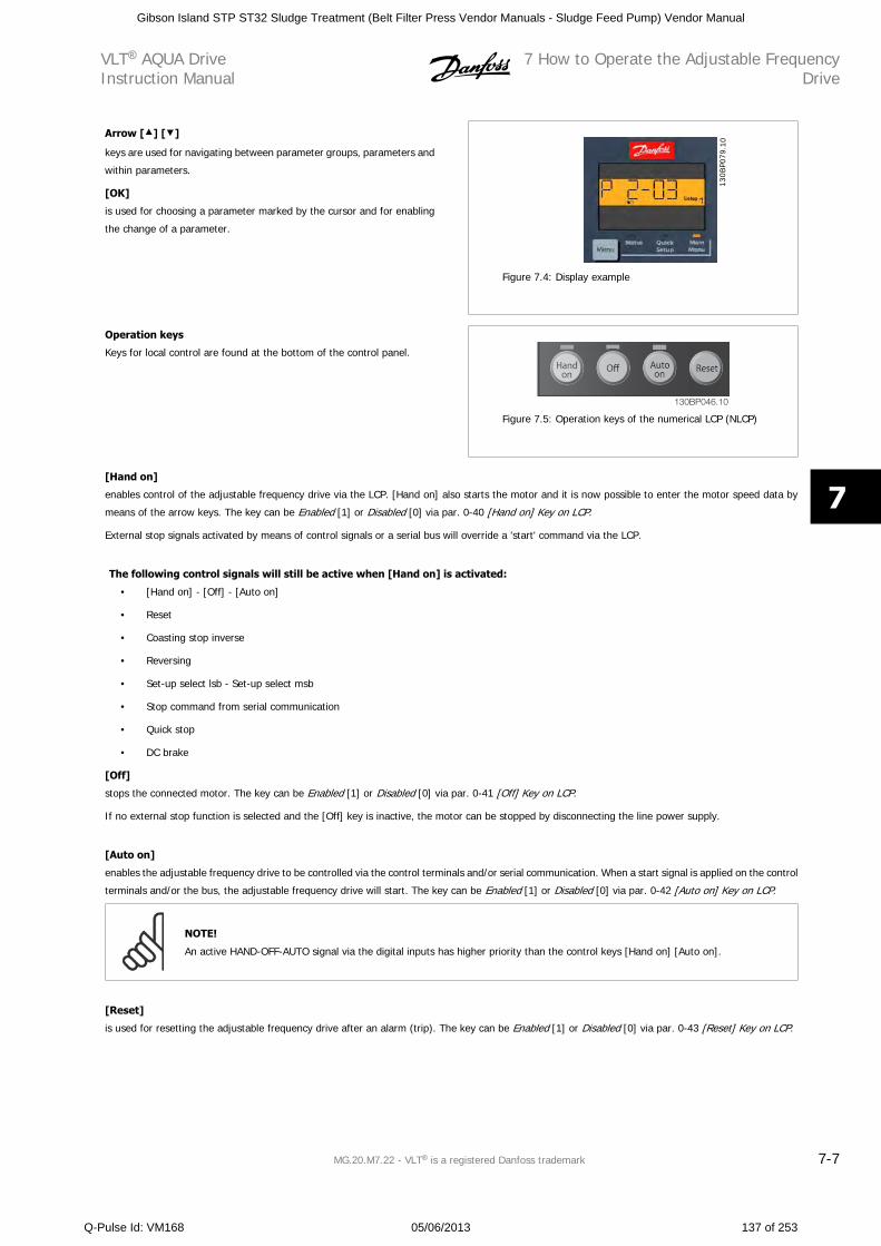
Arrow [ ] [ ]
keys are used for navigating between parameter groups, parameters and
within parameters.
[OK]
is used for choosing a parameter marked by the cursor and for enabling
the change of a parameter.
130B
P079
.10
Figure 7.4: Display example
Operation keys
Keys for local control are found at the bottom of the control panel.
130BP046.10
Figure 7.5: Operation keys of the numerical LCP (NLCP)
[Hand on]
enables control of the adjustable frequency drive via the LCP. [Hand on] also starts the motor and it is now possible to enter the motor speed data by
means of the arrow keys. The key can be Enabled [1] or Disabled [0] via par. 0-40 [Hand on] Key on LCP.
External stop signals activated by means of control signals or a serial bus will override a 'start' command via the LCP.
The following control signals will still be active when [Hand on] is activated:
• [Hand on] - [Off] - [Auto on]
• Reset
• Coasting stop inverse
• Reversing
• Set-up select lsb - Set-up select msb
• Stop command from serial communication
• Quick stop
• DC brake
[Off]
stops the connected motor. The key can be Enabled [1] or Disabled [0] via par. 0-41 [Off] Key on LCP.
If no external stop function is selected and the [Off] key is inactive, the motor can be stopped by disconnecting the line power supply.
[Auto on]
enables the adjustable frequency drive to be controlled via the control terminals and/or serial communication. When a start signal is applied on the control
terminals and/or the bus, the adjustable frequency drive will start. The key can be Enabled [1] or Disabled [0] via par. 0-42 [Auto on] Key on LCP.
NOTE!
An active HAND-OFF-AUTO signal via the digital inputs has higher priority than the control keys [Hand on] [Auto on].
[Reset]
is used for resetting the adjustable frequency drive after an alarm (trip). The key can be Enabled [1] or Disabled [0] via par. 0-43 [Reset] Key on LCP.
VLT AQUA DriveInstruction Manual
7 How to Operate the Adjustable FrequencyDrive
MG.20.M7.22 - VLT is a registered Danfoss trademark 7-7
7
Gibson Island STP ST32 Sludge Treatment (Belt Filter Press Vendor Manuals - Sludge Feed Pump) Vendor Manual
Q-Pulse Id: VM168 05/06/2013 137 of 253
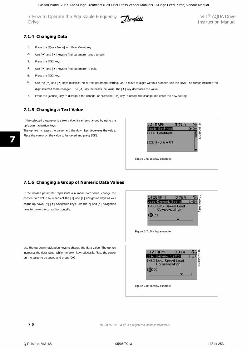
7.1.4 Changing Data
1. Press the [Quick Menu] or [Main Menu] key.
2. Use [ ] and [ ] keys to find parameter group to edit.
3. Press the [OK] key.
4. Use [ ] and [ ] keys to find parameter to edit.
5. Press the [OK] key.
6. Use the [ ] and [ ] keys to select the correct parameter setting. Or, to move to digits within a number, use the keys. The cursor indicates the
digit selected to be changed. The [ ] key increases the value, the [ ] key decreases the value.
7. Press the [Cancel] key to disregard the change, or press the [OK] key to accept the change and enter the new setting.
7.1.5 Changing a Text Value
If the selected parameter is a text value, it can be changed by using the
up/down navigation keys.
The up key increases the value, and the down key decreases the value.
Place the cursor on the value to be saved and press [OK].
Figure 7.6: Display example.
7.1.6 Changing a Group of Numeric Data Values
If the chosen parameter represents a numeric data value, change the
chosen data value by means of the [ ] and [ ] navigation keys as well
as the up/down [ ] [ ] navigation keys. Use the ] and [ ] navigation
keys to move the cursor horizontally.
Figure 7.7: Display example.
Use the up/down navigation keys to change the data value. The up key
increases the data value, while the down key reduces it. Place the cursor
on the value to be saved and press [OK].
Figure 7.8: Display example.
7 How to Operate the Adjustable FrequencyDrive
VLT AQUA DriveInstruction Manual
7-8 MG.20.M7.22 - VLT is a registered Danfoss trademark
7
Gibson Island STP ST32 Sludge Treatment (Belt Filter Press Vendor Manuals - Sludge Feed Pump) Vendor Manual
Q-Pulse Id: VM168 05/06/2013 138 of 253
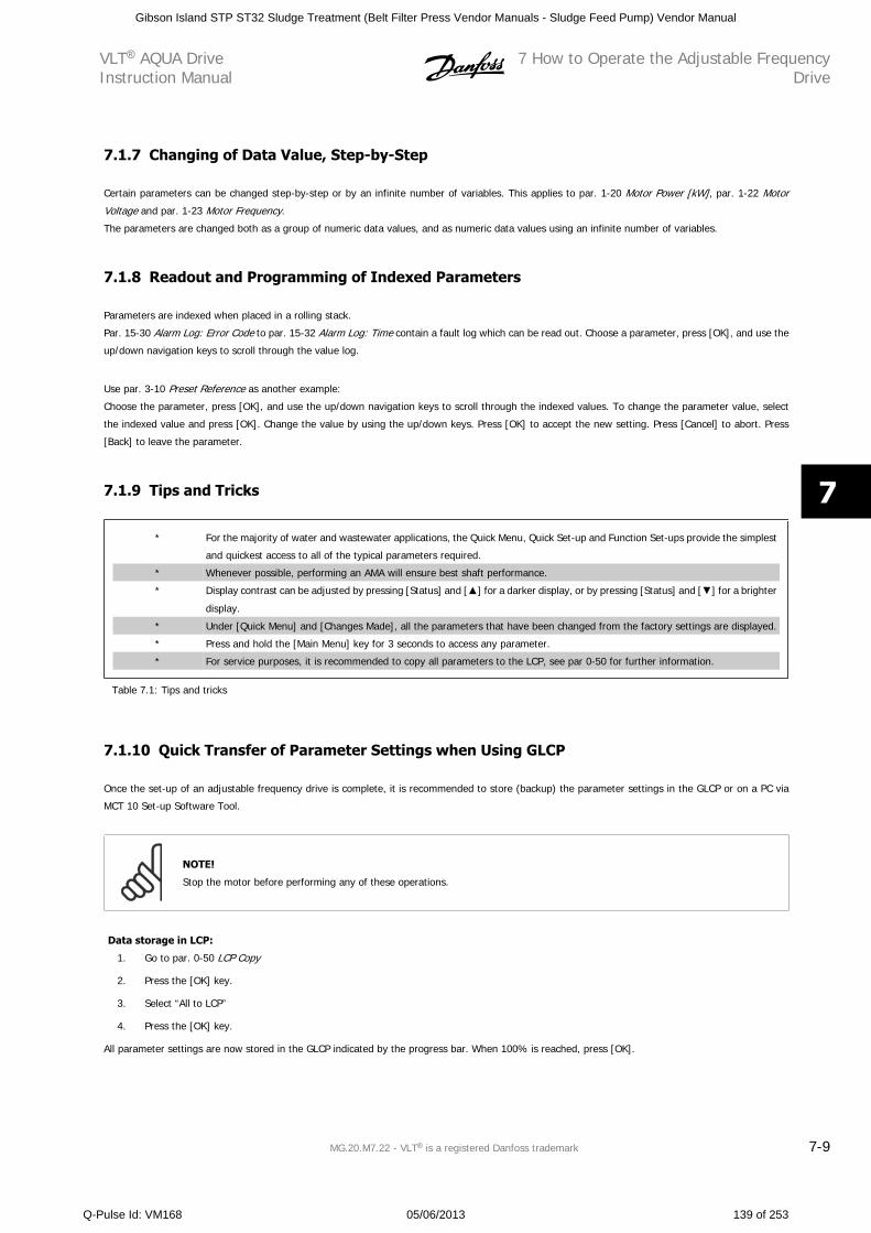
7.1.7 Changing of Data Value, Step-by-Step
Certain parameters can be changed step-by-step or by an infinite number of variables. This applies to par. 1-20 Motor Power [kW], par. 1-22 Motor
Voltage and par. 1-23 Motor Frequency.
The parameters are changed both as a group of numeric data values, and as numeric data values using an infinite number of variables.
7.1.8 Readout and Programming of Indexed Parameters
Parameters are indexed when placed in a rolling stack.
Par. 15-30 Alarm Log: Error Code to par. 15-32 Alarm Log: Time contain a fault log which can be read out. Choose a parameter, press [OK], and use the
up/down navigation keys to scroll through the value log.
Use par. 3-10 Preset Reference as another example:
Choose the parameter, press [OK], and use the up/down navigation keys to scroll through the indexed values. To change the parameter value, select
the indexed value and press [OK]. Change the value by using the up/down keys. Press [OK] to accept the new setting. Press [Cancel] to abort. Press
[Back] to leave the parameter.
7.1.9 Tips and Tricks
* For the majority of water and wastewater applications, the Quick Menu, Quick Set-up and Function Set-ups provide the simplest
and quickest access to all of the typical parameters required.
* Whenever possible, performing an AMA will ensure best shaft performance.
* Display contrast can be adjusted by pressing [Status] and [ ] for a darker display, or by pressing [Status] and [ ] for a brighter
display.
* Under [Quick Menu] and [Changes Made], all the parameters that have been changed from the factory settings are displayed.
* Press and hold the [Main Menu] key for 3 seconds to access any parameter.
* For service purposes, it is recommended to copy all parameters to the LCP, see par 0-50 for further information.
Table 7.1: Tips and tricks
7.1.10 Quick Transfer of Parameter Settings when Using GLCP
Once the set-up of an adjustable frequency drive is complete, it is recommended to store (backup) the parameter settings in the GLCP or on a PC via
MCT 10 Set-up Software Tool.
NOTE!
Stop the motor before performing any of these operations.
Data storage in LCP:
1. Go to par. 0-50 LCP Copy
2. Press the [OK] key.
3. Select “All to LCP”
4. Press the [OK] key.
All parameter settings are now stored in the GLCP indicated by the progress bar. When 100% is reached, press [OK].
VLT AQUA DriveInstruction Manual
7 How to Operate the Adjustable FrequencyDrive
MG.20.M7.22 - VLT is a registered Danfoss trademark 7-9
7
Gibson Island STP ST32 Sludge Treatment (Belt Filter Press Vendor Manuals - Sludge Feed Pump) Vendor Manual
Q-Pulse Id: VM168 05/06/2013 139 of 253
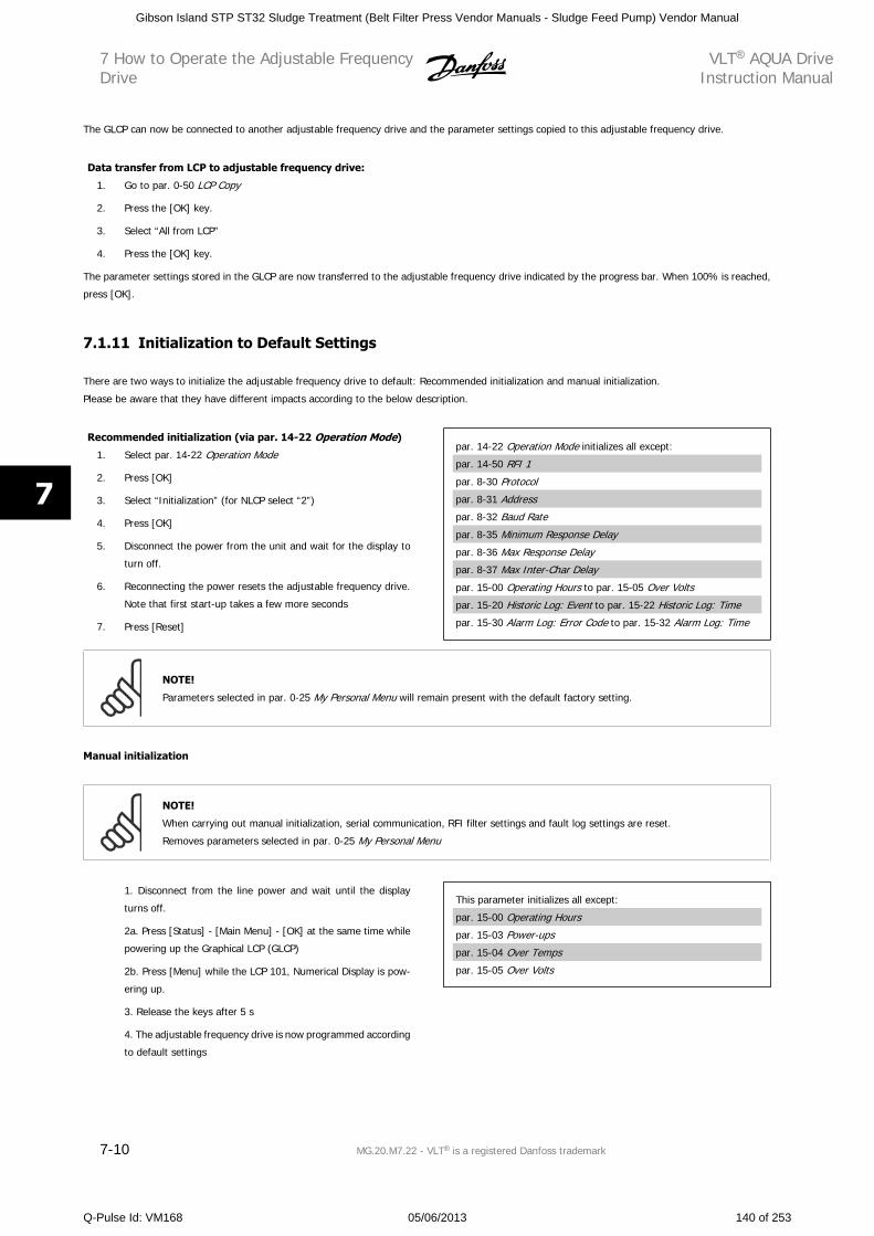
The GLCP can now be connected to another adjustable frequency drive and the parameter settings copied to this adjustable frequency drive.
Data transfer from LCP to adjustable frequency drive:
1. Go to par. 0-50 LCP Copy
2. Press the [OK] key.
3. Select “All from LCP”
4. Press the [OK] key.
The parameter settings stored in the GLCP are now transferred to the adjustable frequency drive indicated by the progress bar. When 100% is reached,
press [OK].
7.1.11 Initialization to Default Settings
There are two ways to initialize the adjustable frequency drive to default: Recommended initialization and manual initialization.
Please be aware that they have different impacts according to the below description.
Recommended initialization (via par. 14-22 Operation Mode)
1. Select par. 14-22 Operation Mode
2. Press [OK]
3. Select “Initialization” (for NLCP select “2”)
4. Press [OK]
5. Disconnect the power from the unit and wait for the display to
turn off.
6. Reconnecting the power resets the adjustable frequency drive.
Note that first start-up takes a few more seconds
7. Press [Reset]
par. 14-22 Operation Mode initializes all except:
par. 14-50 RFI 1
par. 8-30 Protocol
par. 8-31 Address
par. 8-32 Baud Rate
par. 8-35 Minimum Response Delay
par. 8-36 Max Response Delay
par. 8-37 Max Inter-Char Delay
par. 15-00 Operating Hours to par. 15-05 Over Volts
par. 15-20 Historic Log: Event to par. 15-22 Historic Log: Time
par. 15-30 Alarm Log: Error Code to par. 15-32 Alarm Log: Time
NOTE!
Parameters selected in par. 0-25 My Personal Menu will remain present with the default factory setting.
Manual initialization
NOTE!
When carrying out manual initialization, serial communication, RFI filter settings and fault log settings are reset.
Removes parameters selected in par. 0-25 My Personal Menu
1. Disconnect from the line power and wait until the display
turns off.
2a. Press [Status] - [Main Menu] - [OK] at the same time while
powering up the Graphical LCP (GLCP)
2b. Press [Menu] while the LCP 101, Numerical Display is pow-
ering up.
3. Release the keys after 5 s
4. The adjustable frequency drive is now programmed according
to default settings
This parameter initializes all except:
par. 15-00 Operating Hours
par. 15-03 Power-ups
par. 15-04 Over Temps
par. 15-05 Over Volts
7 How to Operate the Adjustable FrequencyDrive
VLT AQUA DriveInstruction Manual
7-10 MG.20.M7.22 - VLT is a registered Danfoss trademark
7
Gibson Island STP ST32 Sludge Treatment (Belt Filter Press Vendor Manuals - Sludge Feed Pump) Vendor Manual
Q-Pulse Id: VM168 05/06/2013 140 of 253
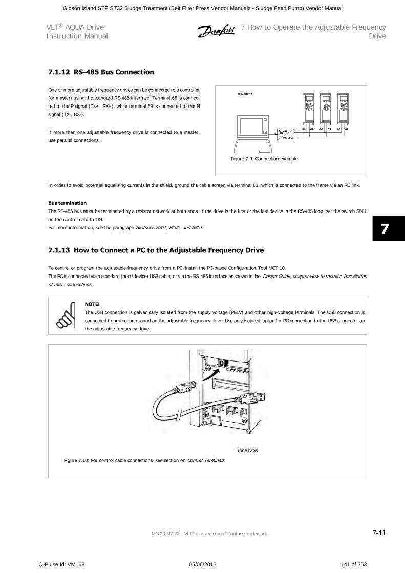
7.1.12 RS-485 Bus Connection
One or more adjustable frequency drives can be connected to a controller
(or master) using the standard RS-485 interface. Terminal 68 is connec-
ted to the P signal (TX+, RX+), while terminal 69 is connected to the N
signal (TX-, RX-).
If more than one adjustable frequency drive is connected to a master,
use parallel connections.
Figure 7.9: Connection example.
In order to avoid potential equalizing currents in the shield, ground the cable screen via terminal 61, which is connected to the frame via an RC link.
Bus termination
The RS-485 bus must be terminated by a resistor network at both ends. If the drive is the first or the last device in the RS-485 loop, set the switch S801
on the control card to ON.
For more information, see the paragraph Switches S201, S202, and S801.
7.1.13 How to Connect a PC to the Adjustable Frequency Drive
To control or program the adjustable frequency drive from a PC, install the PC-based Configuration Tool MCT 10.
The PC is connected via a standard (host/device) USB cable, or via the RS-485 interface as shown in the Design Guide, chapter How to Install > Installation
of misc. connections.
NOTE!
The USB connection is galvanically isolated from the supply voltage (PELV) and other high-voltage terminals. The USB connection is
connected to protection ground on the adjustable frequency drive. Use only isolated laptop for PC connection to the USB connector on
the adjustable frequency drive.
Figure 7.10: For control cable connections, see section on Control Terminals.
VLT AQUA DriveInstruction Manual
7 How to Operate the Adjustable FrequencyDrive
MG.20.M7.22 - VLT is a registered Danfoss trademark 7-11
7
Gibson Island STP ST32 Sludge Treatment (Belt Filter Press Vendor Manuals - Sludge Feed Pump) Vendor Manual
Q-Pulse Id: VM168 05/06/2013 141 of 253
7.1.14 PC Software Tools
PC-based Configuration Tool MCT 10
All adjustable frequency drives are equipped with a serial communication port. Danfoss provides a PC tool for communication between PC and adjustable
frequency drive, PC-based Configuration Tool MCT 10. Please check the section on Available Literature for detailed information on this tool.
MCT 10 set-up software
MCT 10 has been designed as an easy to use interactive tool for setting parameters in our adjustable frequency drives. The software can be downloaded
from the Danfoss internet site http://www.Danfoss.com/BusinessAreas/DrivesSolutions/Softwaredownload/DDPC+Software+Program.htm.
The MCT 10 set-up software will be useful for:
• Planning a communication network off-line. MCT 10 contains a complete adjustable frequency drive database
• Commissioning adjustable frequency drives on-line.
• Saving settings for all adjustable frequency drives.
• Replacing an adjustable frequency drive in a network.
• Simple and accurate documentation of adjustable frequency drive settings after commissioning.
• Expanding an existing network.
• Adjustable frequency drives developed in the future will be fully supported.
MCT 10 set-up software supports Profibus DP-V1 via a master class 2 connection. This makes it possible to access on-line read/write parameters in an
adjustable frequency drive via the Profibus network. This will eliminate the need for an extra communication network.
Save adjustable frequency drive settings:
1. Connect a PC to the unit via the USB COM port. (Note: Use a PC that is isolated from the line power, in conjunction with the USB port. Failure
to do so may damage equipment.)
2. Open MCT 10 Set-up Software
3. Choose “Read from drive”
4. Choose “Save as”
All parameters are now stored on the PC.
Load adjustable frequency drive settings:
1. Connect a PC to the adjustable frequency drive via the USB com port
2. Open MCT 10 Set-up software
3. Choose “Open”– stored files will be shown.
4. Open the appropriate file
5. Choose “Write to drive”
All parameter settings are now transferred to the adjustable frequency drive.
A separate manual for MCT 10 Set-up Software is available: MG.10.Rx.yy.
7 How to Operate the Adjustable FrequencyDrive
VLT AQUA DriveInstruction Manual
7-12 MG.20.M7.22 - VLT is a registered Danfoss trademark
7
Gibson Island STP ST32 Sludge Treatment (Belt Filter Press Vendor Manuals - Sludge Feed Pump) Vendor Manual
Q-Pulse Id: VM168 05/06/2013 142 of 253
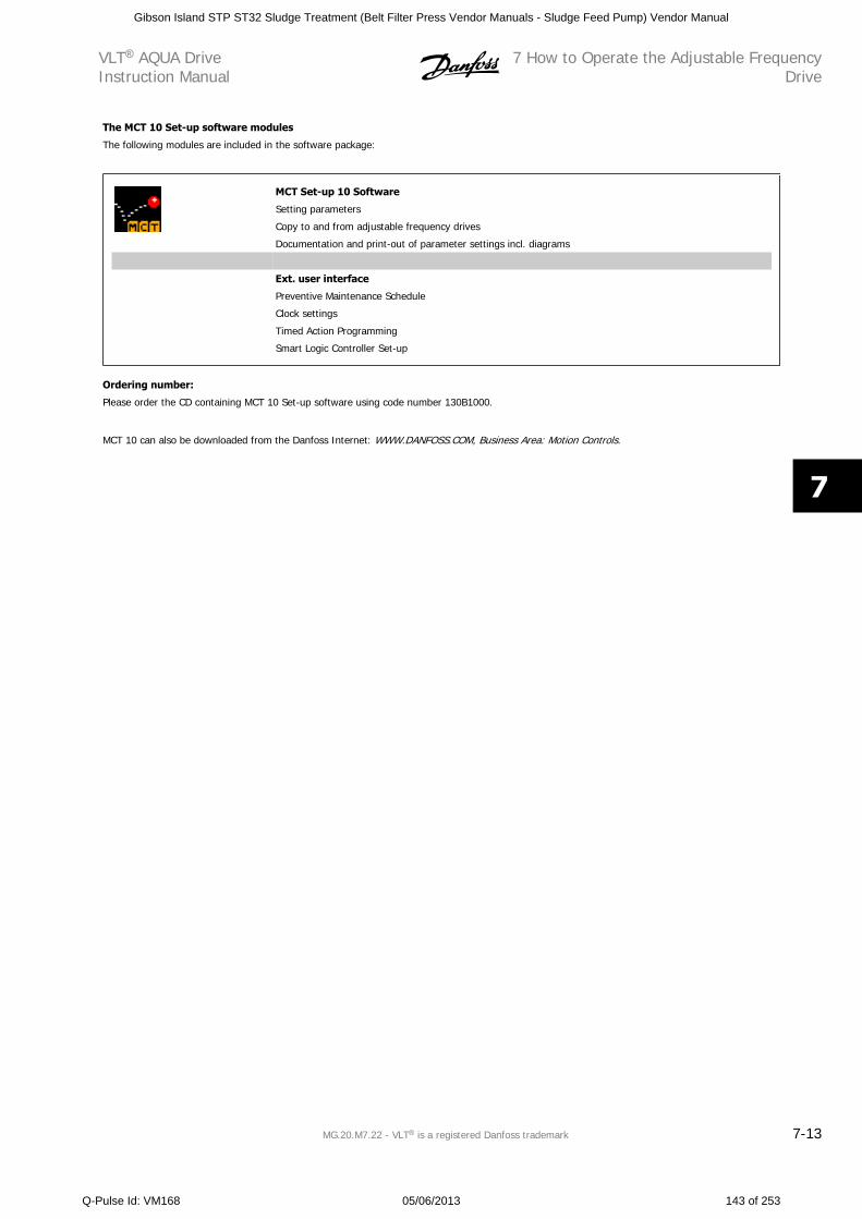
The MCT 10 Set-up software modules
The following modules are included in the software package:
MCT Set-up 10 Software
Setting parameters
Copy to and from adjustable frequency drives
Documentation and print-out of parameter settings incl. diagrams
Ext. user interface
Preventive Maintenance Schedule
Clock settings
Timed Action Programming
Smart Logic Controller Set-up
Ordering number:
Please order the CD containing MCT 10 Set-up software using code number 130B1000.
MCT 10 can also be downloaded from the Danfoss Internet: WWW.DANFOSS.COM, Business Area: Motion Controls.
VLT AQUA DriveInstruction Manual
7 How to Operate the Adjustable FrequencyDrive
MG.20.M7.22 - VLT is a registered Danfoss trademark 7-13
7
Gibson Island STP ST32 Sludge Treatment (Belt Filter Press Vendor Manuals - Sludge Feed Pump) Vendor Manual
Q-Pulse Id: VM168 05/06/2013 143 of 253
7 How to Operate the Adjustable FrequencyDrive
VLT AQUA DriveInstruction Manual
7-14 MG.20.M7.22 - VLT is a registered Danfoss trademark
7
Gibson Island STP ST32 Sludge Treatment (Belt Filter Press Vendor Manuals - Sludge Feed Pump) Vendor Manual
Q-Pulse Id: VM168 05/06/2013 144 of 253
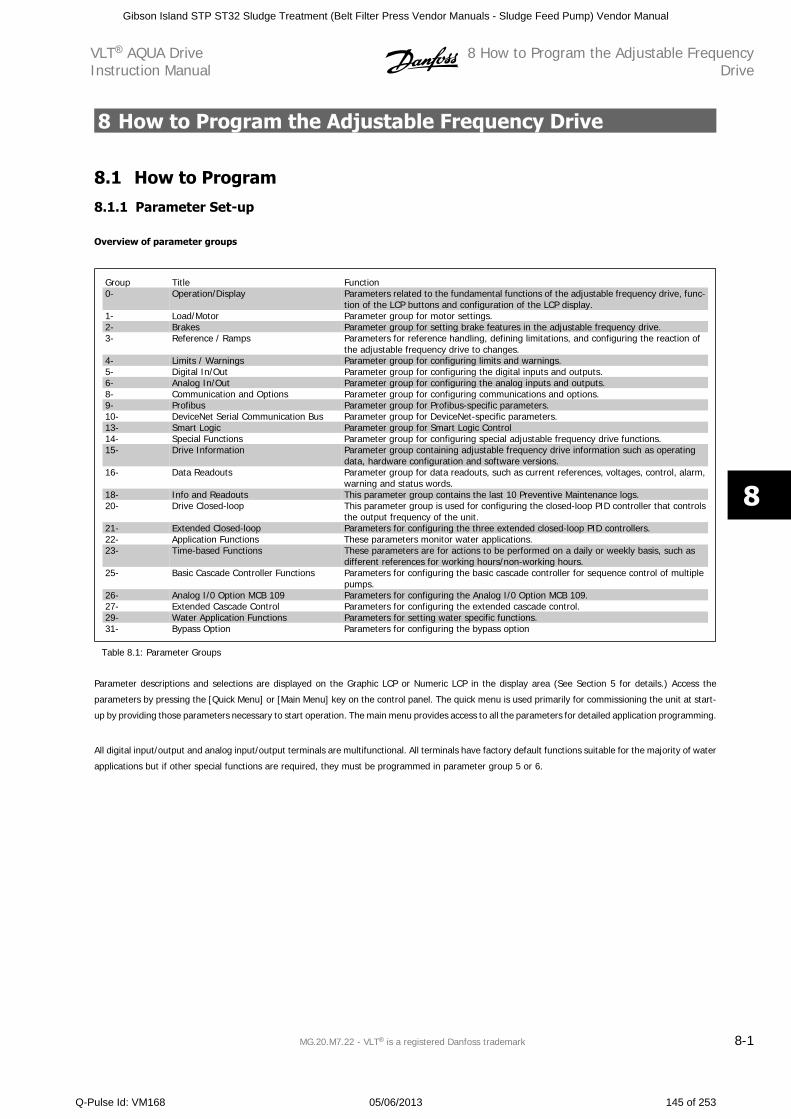
8 How to Program the Adjustable Frequency Drive
8.1 How to Program
8.1.1 Parameter Set-up
Overview of parameter groups
Group Title Function0- Operation/Display Parameters related to the fundamental functions of the adjustable frequency drive, func-
tion of the LCP buttons and configuration of the LCP display.1- Load/Motor Parameter group for motor settings.2- Brakes Parameter group for setting brake features in the adjustable frequency drive.3- Reference / Ramps Parameters for reference handling, defining limitations, and configuring the reaction of
the adjustable frequency drive to changes.4- Limits / Warnings Parameter group for configuring limits and warnings.5- Digital In/Out Parameter group for configuring the digital inputs and outputs.6- Analog In/Out Parameter group for configuring the analog inputs and outputs.8- Communication and Options Parameter group for configuring communications and options.9- Profibus Parameter group for Profibus-specific parameters.10- DeviceNet Serial Communication Bus Parameter group for DeviceNet-specific parameters.13- Smart Logic Parameter group for Smart Logic Control14- Special Functions Parameter group for configuring special adjustable frequency drive functions.15- Drive Information Parameter group containing adjustable frequency drive information such as operating
data, hardware configuration and software versions.16- Data Readouts Parameter group for data readouts, such as current references, voltages, control, alarm,
warning and status words.18- Info and Readouts This parameter group contains the last 10 Preventive Maintenance logs.20- Drive Closed-loop This parameter group is used for configuring the closed-loop PID controller that controls
the output frequency of the unit.21- Extended Closed-loop Parameters for configuring the three extended closed-loop PID controllers.22- Application Functions These parameters monitor water applications.23- Time-based Functions These parameters are for actions to be performed on a daily or weekly basis, such as
different references for working hours/non-working hours.25- Basic Cascade Controller Functions Parameters for configuring the basic cascade controller for sequence control of multiple
pumps.26- Analog I/0 Option MCB 109 Parameters for configuring the Analog I/0 Option MCB 109.27- Extended Cascade Control Parameters for configuring the extended cascade control.29- Water Application Functions Parameters for setting water specific functions.31- Bypass Option Parameters for configuring the bypass option
Table 8.1: Parameter Groups
Parameter descriptions and selections are displayed on the Graphic LCP or Numeric LCP in the display area (See Section 5 for details.) Access the
parameters by pressing the [Quick Menu] or [Main Menu] key on the control panel. The quick menu is used primarily for commissioning the unit at start-
up by providing those parameters necessary to start operation. The main menu provides access to all the parameters for detailed application programming.
All digital input/output and analog input/output terminals are multifunctional. All terminals have factory default functions suitable for the majority of water
applications but if other special functions are required, they must be programmed in parameter group 5 or 6.
VLT AQUA DriveInstruction Manual
8 How to Program the Adjustable FrequencyDrive
MG.20.M7.22 - VLT is a registered Danfoss trademark 8-1
8
Gibson Island STP ST32 Sludge Treatment (Belt Filter Press Vendor Manuals - Sludge Feed Pump) Vendor Manual
Q-Pulse Id: VM168 05/06/2013 145 of 253
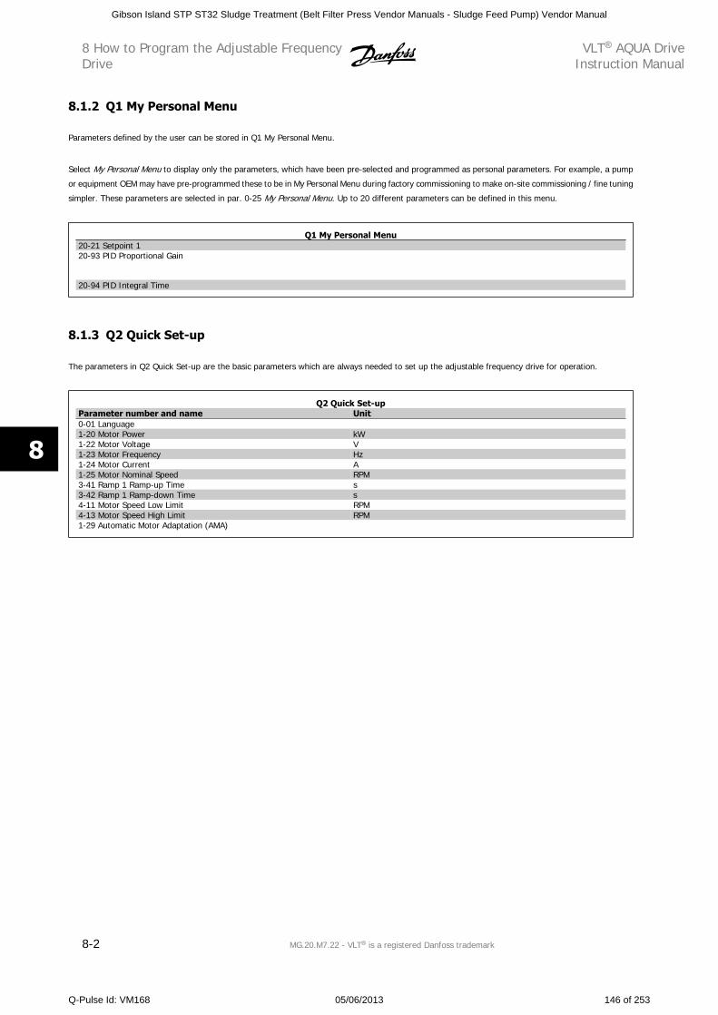
8.1.2 Q1 My Personal Menu
Parameters defined by the user can be stored in Q1 My Personal Menu.
Select My Personal Menu to display only the parameters, which have been pre-selected and programmed as personal parameters. For example, a pump
or equipment OEM may have pre-programmed these to be in My Personal Menu during factory commissioning to make on-site commissioning / fine tuning
simpler. These parameters are selected in par. 0-25 My Personal Menu. Up to 20 different parameters can be defined in this menu.
Q1 My Personal Menu20-21 Setpoint 120-93 PID Proportional Gain
20-94 PID Integral Time
8.1.3 Q2 Quick Set-up
The parameters in Q2 Quick Set-up are the basic parameters which are always needed to set up the adjustable frequency drive for operation.
Q2 Quick Set-upParameter number and name Unit0-01 Language1-20 Motor Power kW1-22 Motor Voltage V1-23 Motor Frequency Hz1-24 Motor Current A1-25 Motor Nominal Speed RPM3-41 Ramp 1 Ramp-up Time s3-42 Ramp 1 Ramp-down Time s4-11 Motor Speed Low Limit RPM4-13 Motor Speed High Limit RPM1-29 Automatic Motor Adaptation (AMA)
8 How to Program the Adjustable FrequencyDrive
VLT AQUA DriveInstruction Manual
8-2 MG.20.M7.22 - VLT is a registered Danfoss trademark
8
Gibson Island STP ST32 Sludge Treatment (Belt Filter Press Vendor Manuals - Sludge Feed Pump) Vendor Manual
Q-Pulse Id: VM168 05/06/2013 146 of 253
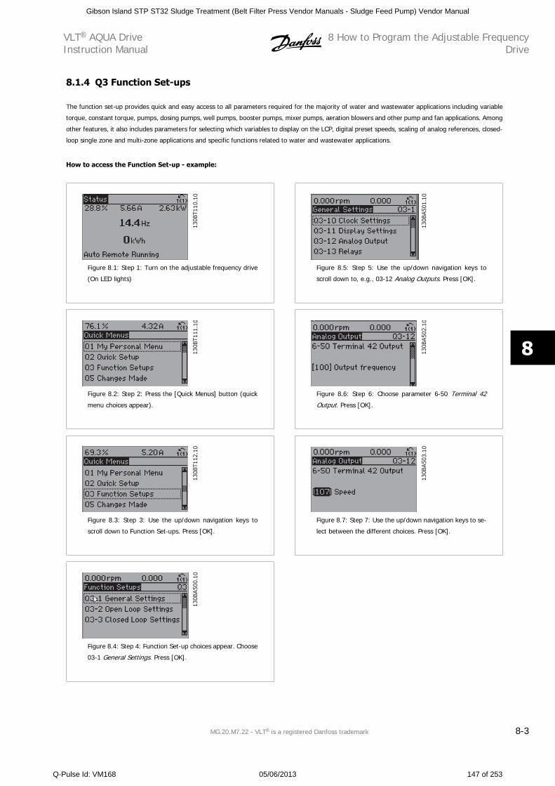
8.1.4 Q3 Function Set-ups
The function set-up provides quick and easy access to all parameters required for the majority of water and wastewater applications including variable
torque, constant torque, pumps, dosing pumps, well pumps, booster pumps, mixer pumps, aeration blowers and other pump and fan applications. Among
other features, it also includes parameters for selecting which variables to display on the LCP, digital preset speeds, scaling of analog references, closed-
loop single zone and multi-zone applications and specific functions related to water and wastewater applications.
How to access the Function Set-up - example:
130BT110.10
Figure 8.1: Step 1: Turn on the adjustable frequency drive
(On LED lights)
130BT111.10
Figure 8.2: Step 2: Press the [Quick Menus] button (quick
menu choices appear).
130BT112.10
Figure 8.3: Step 3: Use the up/down navigation keys to
scroll down to Function Set-ups. Press [OK].
130BA500.10
Figure 8.4: Step 4: Function Set-up choices appear. Choose
03-1 General Settings. Press [OK].
130BA501.10
Figure 8.5: Step 5: Use the up/down navigation keys to
scroll down to, e.g., 03-12 Analog Outputs. Press [OK].
130BA502.10
Figure 8.6: Step 6: Choose parameter 6-50 Terminal 42
Output. Press [OK].
130BA503.10
Figure 8.7: Step 7: Use the up/down navigation keys to se-
lect between the different choices. Press [OK].
VLT AQUA DriveInstruction Manual
8 How to Program the Adjustable FrequencyDrive
MG.20.M7.22 - VLT is a registered Danfoss trademark 8-3
8
Gibson Island STP ST32 Sludge Treatment (Belt Filter Press Vendor Manuals - Sludge Feed Pump) Vendor Manual
Q-Pulse Id: VM168 05/06/2013 147 of 253
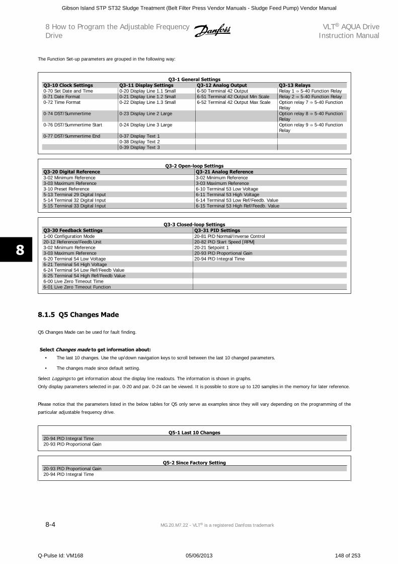
The Function Set-up parameters are grouped in the following way:
Q3-1 General SettingsQ3-10 Clock Settings Q3-11 Display Settings Q3-12 Analog Output Q3-13 Relays0-70 Set Date and Time 0-20 Display Line 1.1 Small 6-50 Terminal 42 Output Relay 1 5-40 Function Relay0-71 Date Format 0-21 Display Line 1.2 Small 6-51 Terminal 42 Output Min Scale Relay 2 5-40 Function Relay0-72 Time Format 0-22 Display Line 1.3 Small 6-52 Terminal 42 Output Max Scale Option relay 7 5-40 Function
Relay0-74 DST/Summertime 0-23 Display Line 2 Large Option relay 8 5-40 Function
Relay0-76 DST/Summertime Start 0-24 Display Line 3 Large Option relay 9 5-40 Function
Relay0-77 DST/Summertime End 0-37 Display Text 1
0-38 Display Text 20-39 Display Text 3
Q3-2 Open-loop SettingsQ3-20 Digital Reference Q3-21 Analog Reference3-02 Minimum Reference 3-02 Minimum Reference3-03 Maximum Reference 3-03 Maximum Reference3-10 Preset Reference 6-10 Terminal 53 Low Voltage5-13 Terminal 29 Digital Input 6-11 Terminal 53 High Voltage5-14 Terminal 32 Digital Input 6-14 Terminal 53 Low Ref/Feedb. Value5-15 Terminal 33 Digital Input 6-15 Terminal 53 High Ref/Feedb. Value
Q3-3 Closed-loop SettingsQ3-30 Feedback Settings Q3-31 PID Settings1-00 Configuration Mode 20-81 PID Normal/Inverse Control20-12 Reference/Feedb.Unit 20-82 PID Start Speed [RPM]3-02 Minimum Reference 20-21 Setpoint 13-03 Maximum Reference 20-93 PID Proportional Gain6-20 Terminal 54 Low Voltage 20-94 PID Integral Time6-21 Terminal 54 High Voltage6-24 Terminal 54 Low Ref/Feedb Value6-25 Terminal 54 High Ref/Feedb Value6-00 Live Zero Timeout Time6-01 Live Zero Timeout Function
8.1.5 Q5 Changes Made
Q5 Changes Made can be used for fault finding.
Select Changes made to get information about:
• The last 10 changes. Use the up/down navigation keys to scroll between the last 10 changed parameters.
• The changes made since default setting.
Select Loggings to get information about the display line readouts. The information is shown in graphs.
Only display parameters selected in par. 0-20 and par. 0-24 can be viewed. It is possible to store up to 120 samples in the memory for later reference.
Please notice that the parameters listed in the below tables for Q5 only serve as examples since they will vary depending on the programming of the
particular adjustable frequency drive.
Q5-1 Last 10 Changes20-94 PID Integral Time20-93 PID Proportional Gain
Q5-2 Since Factory Setting20-93 PID Proportional Gain20-94 PID Integral Time
8 How to Program the Adjustable FrequencyDrive
VLT AQUA DriveInstruction Manual
8-4 MG.20.M7.22 - VLT is a registered Danfoss trademark
8
Gibson Island STP ST32 Sludge Treatment (Belt Filter Press Vendor Manuals - Sludge Feed Pump) Vendor Manual
Q-Pulse Id: VM168 05/06/2013 148 of 253
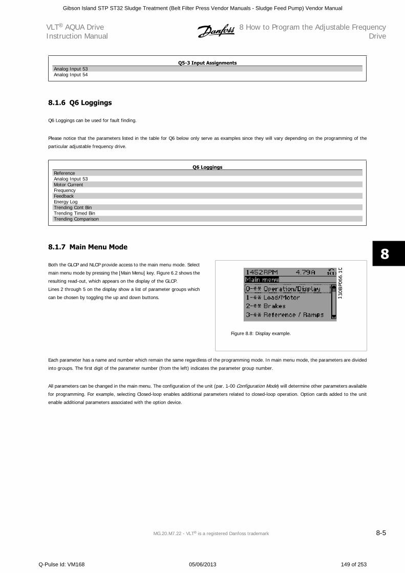
Q5-3 Input AssignmentsAnalog Input 53Analog Input 54
8.1.6 Q6 Loggings
Q6 Loggings can be used for fault finding.
Please notice that the parameters listed in the table for Q6 below only serve as examples since they will vary depending on the programming of the
particular adjustable frequency drive.
Q6 LoggingsReferenceAnalog Input 53Motor CurrentFrequencyFeedbackEnergy LogTrending Cont BinTrending Timed BinTrending Comparison
8.1.7 Main Menu Mode
Both the GLCP and NLCP provide access to the main menu mode. Select
main menu mode by pressing the [Main Menu] key. Figure 6.2 shows the
resulting read-out, which appears on the display of the GLCP.
Lines 2 through 5 on the display show a list of parameter groups which
can be chosen by toggling the up and down buttons.
Figure 8.8: Display example.
Each parameter has a name and number which remain the same regardless of the programming mode. In main menu mode, the parameters are divided
into groups. The first digit of the parameter number (from the left) indicates the parameter group number.
All parameters can be changed in the main menu. The configuration of the unit (par. 1-00 Configuration Mode) will determine other parameters available
for programming. For example, selecting Closed-loop enables additional parameters related to closed-loop operation. Option cards added to the unit
enable additional parameters associated with the option device.
VLT AQUA DriveInstruction Manual
8 How to Program the Adjustable FrequencyDrive
MG.20.M7.22 - VLT is a registered Danfoss trademark 8-5
8
Gibson Island STP ST32 Sludge Treatment (Belt Filter Press Vendor Manuals - Sludge Feed Pump) Vendor Manual
Q-Pulse Id: VM168 05/06/2013 149 of 253
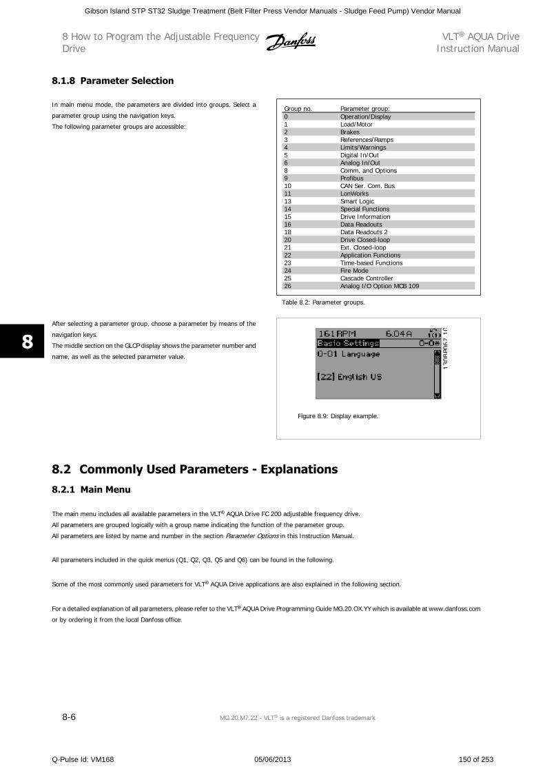
8.1.8 Parameter Selection
In main menu mode, the parameters are divided into groups. Select a
parameter group using the navigation keys.
The following parameter groups are accessible:
Group no. Parameter group:0 Operation/Display1 Load/Motor2 Brakes3 References/Ramps4 Limits/Warnings5 Digital In/Out6 Analog In/Out8 Comm. and Options9 Profibus10 CAN Ser. Com. Bus11 LonWorks13 Smart Logic14 Special Functions15 Drive Information16 Data Readouts18 Data Readouts 220 Drive Closed-loop21 Ext. Closed-loop22 Application Functions23 Time-based Functions24 Fire Mode25 Cascade Controller26 Analog I/O Option MCB 109
Table 8.2: Parameter groups.
After selecting a parameter group, choose a parameter by means of the
navigation keys.
The middle section on the GLCP display shows the parameter number and
name, as well as the selected parameter value.
Figure 8.9: Display example.
8.2 Commonly Used Parameters - Explanations
8.2.1 Main Menu
The main menu includes all available parameters in the VLT AQUA Drive FC 200 adjustable frequency drive.
All parameters are grouped logically with a group name indicating the function of the parameter group.
All parameters are listed by name and number in the section Parameter Options in this Instruction Manual.
All parameters included in the quick menus (Q1, Q2, Q3, Q5 and Q6) can be found in the following.
Some of the most commonly used parameters for VLT AQUA Drive applications are also explained in the following section.
For a detailed explanation of all parameters, please refer to the VLT AQUA Drive Programming Guide MG.20.OX.YY which is available at www.danfoss.com
or by ordering it from the local Danfoss office.
8 How to Program the Adjustable FrequencyDrive
VLT AQUA DriveInstruction Manual
8-6 MG.20.M7.22 - VLT is a registered Danfoss trademark
8
Gibson Island STP ST32 Sludge Treatment (Belt Filter Press Vendor Manuals - Sludge Feed Pump) Vendor Manual
Q-Pulse Id: VM168 05/06/2013 150 of 253
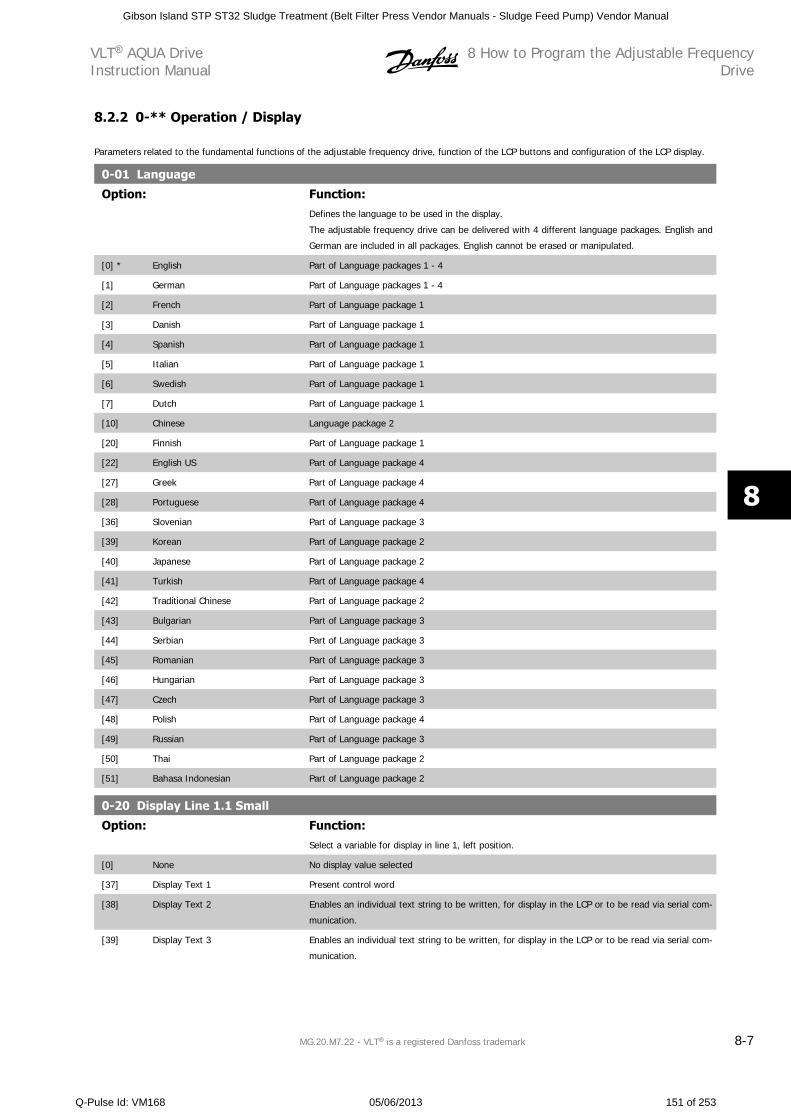
8.2.2 0-** Operation / Display
Parameters related to the fundamental functions of the adjustable frequency drive, function of the LCP buttons and configuration of the LCP display.
0-01 Language
Option: Function:Defines the language to be used in the display.
The adjustable frequency drive can be delivered with 4 different language packages. English and
German are included in all packages. English cannot be erased or manipulated.
[0] * English Part of Language packages 1 - 4
[1] German Part of Language packages 1 - 4
[2] French Part of Language package 1
[3] Danish Part of Language package 1
[4] Spanish Part of Language package 1
[5] Italian Part of Language package 1
[6] Swedish Part of Language package 1
[7] Dutch Part of Language package 1
[10] Chinese Language package 2
[20] Finnish Part of Language package 1
[22] English US Part of Language package 4
[27] Greek Part of Language package 4
[28] Portuguese Part of Language package 4
[36] Slovenian Part of Language package 3
[39] Korean Part of Language package 2
[40] Japanese Part of Language package 2
[41] Turkish Part of Language package 4
[42] Traditional Chinese Part of Language package 2
[43] Bulgarian Part of Language package 3
[44] Serbian Part of Language package 3
[45] Romanian Part of Language package 3
[46] Hungarian Part of Language package 3
[47] Czech Part of Language package 3
[48] Polish Part of Language package 4
[49] Russian Part of Language package 3
[50] Thai Part of Language package 2
[51] Bahasa Indonesian Part of Language package 2
0-20 Display Line 1.1 Small
Option: Function:Select a variable for display in line 1, left position.
[0] None No display value selected
[37] Display Text 1 Present control word
[38] Display Text 2 Enables an individual text string to be written, for display in the LCP or to be read via serial com-
munication.
[39] Display Text 3 Enables an individual text string to be written, for display in the LCP or to be read via serial com-
munication.
VLT AQUA DriveInstruction Manual
8 How to Program the Adjustable FrequencyDrive
MG.20.M7.22 - VLT is a registered Danfoss trademark 8-7
8
Gibson Island STP ST32 Sludge Treatment (Belt Filter Press Vendor Manuals - Sludge Feed Pump) Vendor Manual
Q-Pulse Id: VM168 05/06/2013 151 of 253
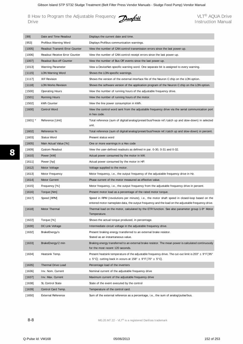
[89] Date and Time Readout Displays the current date and time.
[953] Profibus Warning Word Displays Profibus communication warnings.
[1005] Readout Transmit Error Counter View the number of CAN control transmission errors since the last power-up.
[1006] Readout Receive Error Counter View the number of CAN control receipt errors since the last power-up.
[1007] Readout Bus-off Counter View the number of Bus Off events since the last power-up.
[1013] Warning Parameter View a DeviceNet-specific warning word. One separate bit is assigned to every warning.
[1115] LON Warning Word Shows the LON-specific warnings.
[1117] XIF Revision Shows the version of the external interface file of the Neuron C chip on the LON option.
[1118] LON Works Revision Shows the software version of the application program of the Neuron C chip on the LON option.
[1500] Operating Hours View the number of running hours of the adjustable frequency drive.
[1501] Running Hours View the number of running hours of the motor.
[1502] kWh Counter View the line power consumption in kWh.
[1600] Control Word View the control word sent from the adjustable frequency drive via the serial communication port
in hex code.
[1601] * Reference [Unit] Total reference (sum of digital/analog/preset/bus/freeze ref./catch up and slow-down) in selected
unit.
[1602] Reference % Total reference (sum of digital/analog/preset/bus/freeze ref./catch up and slow-down) in percent.
[1603] Status Word Present status word
[1605] Main Actual Value [%] One or more warnings in a Hex code
[1609] Custom Readout View the user-defined readouts as defined in par. 0-30, 0-31 and 0-32.
[1610] Power [kW] Actual power consumed by the motor in kW.
[1611] Power [hp] Actual power consumed by the motor in HP.
[1612] Motor Voltage Voltage supplied to the motor.
[1613] Motor Frequency Motor frequency, i.e., the output frequency of the adjustable frequency drive in Hz.
[1614] Motor Current Phase current of the motor measured as effective value.
[1615] Frequency [%] Motor frequency, i.e., the output frequency from the adjustable frequency drive in percent.
[1616] Torque [Nm] Present motor load as a percentage of the rated motor torque.
[1617] Speed [RPM] Speed in RPM (revolutions per minute), i.e., the motor shaft speed in closed-loop based on the
entered motor nameplate data, the output frequency and the load on the adjustable frequency drive.
[1618] Motor Thermal Thermal load on the motor, calculated by the ETR function. See also parameter group 1-9* Motor
Temperature.
[1622] Torque [%] Shows the actual torque produced, in percentage.
[1630] DC Link Voltage Intermediate circuit voltage in the adjustable frequency drive.
[1632] BrakeEnergy/s Present braking energy transferred to an external brake resistor.
Stated as an instantaneous value.
[1633] BrakeEnergy/2 min Braking energy transferred to an external brake resistor. The mean power is calculated continuously
for the most recent 120 seconds.
[1634] Heatsink Temp. Present heatsink temperature of the adjustable frequency drive. The cut-out limit is 203° ± 9°F [95°
± 5°C]; cutting back in occurs at 158° ± 9°F [70° ± 5°C].
[1635] Thermal Drive Load Percentage load of the inverters
[1636] Inv. Nom. Current Nominal current of the adjustable frequency drive
[1637] Inv. Max. Current Maximum current of the adjustable frequency drive
[1638] SL Control State State of the event executed by the control
[1639] Control Card Temp. Temperature of the control card.
[1650] External Reference Sum of the external reference as a percentage, i.e., the sum of analog/pulse/bus.
8 How to Program the Adjustable FrequencyDrive
VLT AQUA DriveInstruction Manual
8-8 MG.20.M7.22 - VLT is a registered Danfoss trademark
8
Gibson Island STP ST32 Sludge Treatment (Belt Filter Press Vendor Manuals - Sludge Feed Pump) Vendor Manual
Q-Pulse Id: VM168 05/06/2013 152 of 253
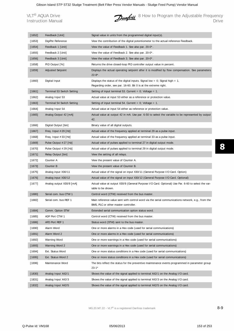
[1652] Feedback [Unit] Signal value in units from the programmed digital input(s).
[1653] DigiPot Reference View the contribution of the digital potentiometer to the actual reference Feedback.
[1654] Feedback 1 [Unit] View the value of Feedback 1. See also par. 20-0*.
[1655] Feedback 2 [Unit] View the value of Feedback 2. See also par. 20-0*.
[1656] Feedback 3 [Unit] View the value of Feedback 3. See also par. 20-0*.
[1658] PID Output [%] Returns the drive closed-loop PID controller output value in percent.
[1659] Adjusted Setpoint Displays the actual operating setpoint after it is modified by flow compensation. See parameters
22-8*.
[1660] Digital Input Displays the status of the digital inputs. Signal low = 0; Signal high = 1.
Regarding order, see par. 16-60. Bit 0 is at the extreme right.
[1661] Terminal 53 Switch Setting Setting of input terminal 53. Current = 0; Voltage = 1.
[1662] Analog Input 53 Actual value at input 53 either as a reference or protection value.
[1663] Terminal 54 Switch Setting Setting of input terminal 54. Current = 0; Voltage = 1.
[1664] Analog Input 54 Actual value at input 54 either as reference or protection value.
[1665] Analog Output 42 [mA] Actual value at output 42 in mA. Use par. 6-50 to select the variable to be represented by output
42.
[1666] Digital Output [bin] Binary value of all digital outputs.
[1667] Freq. Input #29 [Hz] Actual value of the frequency applied at terminal 29 as a pulse input.
[1668] Freq. Input #33 [Hz] Actual value of the frequency applied at terminal 33 as a pulse input.
[1669] Pulse Output #27 [Hz] Actual value of pulses applied to terminal 27 in digital output mode.
[1670] Pulse Output #29 [Hz] Actual value of pulses applied to terminal 29 in digital output mode.
[1671] Relay Output [bin] View the setting of all relays.
[1672] Counter A View the present value of Counter A.
[1673] Counter B View the present value of Counter B.
[1675] Analog input X30/11 Actual value of the signal on input X30/11 (General Purpose I/O Card. Option)
[1676] Analog input X30/12 Actual value of the signal on input X30/12 (General Purpose I/O Card. Optional)
[1677] Analog output X30/8 [mA] Actual value at output X30/8 (General Purpose I/O Card. Optional) Use Par. 6-60 to select the var-
iable to be shown.
[1680] Serial com. bus CTW 1 Control word (CTW) received from the bus master.
[1682] Serial com. bus REF 1 Main reference value sent with control word via the serial communications network, e.g., from the
BMS, PLC or other master controller.
[1684] Comm. Option STW Extended serial communication option status word.
[1685] ADF Port CTW 1 Control word (CTW) received from the bus master.
[1686] AFD Port REF 1 Status word (STW) sent to the bus master.
[1690] Alarm Word One or more alarms in a Hex code (used for serial communications)
[1691] Alarm Word 2 One or more alarms in a Hex code (used for serial communications)
[1692] Warning Word One or more warnings in a Hex code (used for serial communications)
[1693] Warning Word 2 One or more warnings in a Hex code (used for serial communications)
[1694] Ext. Status Word One or more status conditions in a Hex code (used for serial communications)
[1695] Ext. Status Word 2 One or more status conditions in a Hex code (used for serial communications)
[1696] Maintenance Word The bits reflect the status for the preventive maintenance events programmed in parameter group
23-1*
[1830] Analog Input X42/1 Shows the value of the signal applied to terminal X42/1 on the Analog I/O card.
[1831] Analog Input X42/3 Shows the value of the signal applied to terminal X42/3 on the Analog I/O card.
[1832] Analog Input X42/5 Shows the value of the signal applied to terminal X42/5 on the Analog I/O card.
VLT AQUA DriveInstruction Manual
8 How to Program the Adjustable FrequencyDrive
MG.20.M7.22 - VLT is a registered Danfoss trademark 8-9
8
Gibson Island STP ST32 Sludge Treatment (Belt Filter Press Vendor Manuals - Sludge Feed Pump) Vendor Manual
Q-Pulse Id: VM168 05/06/2013 153 of 253
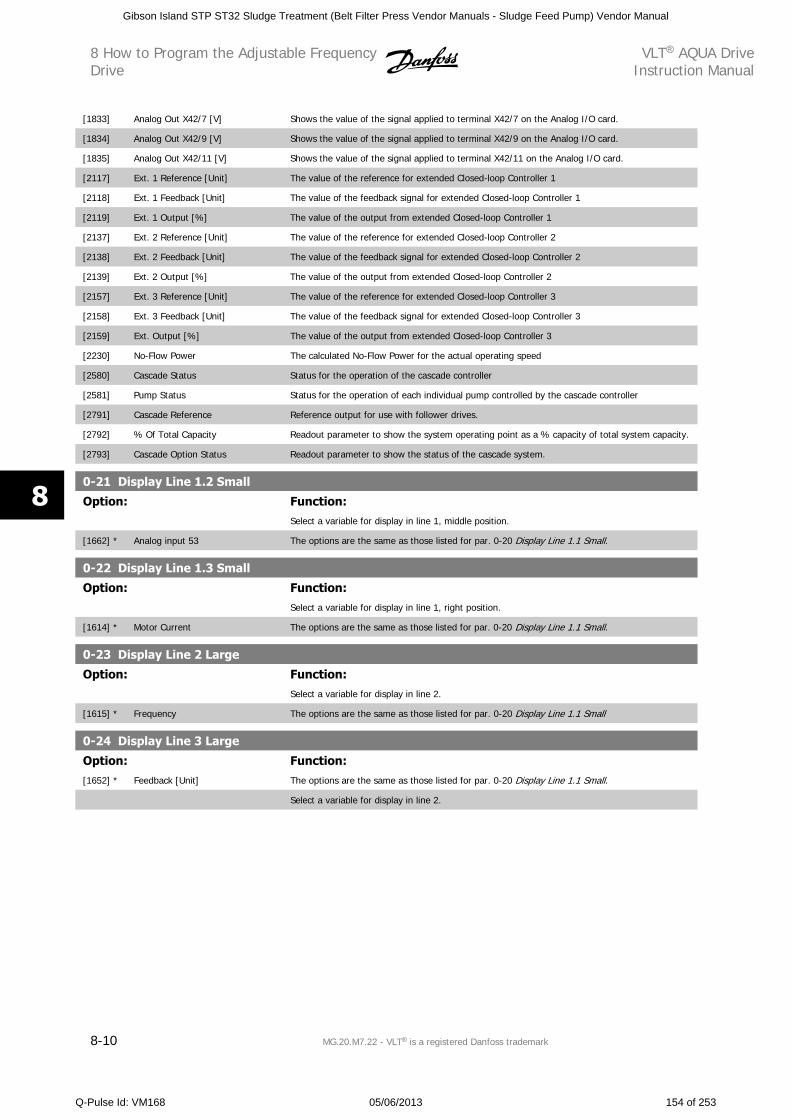
[1833] Analog Out X42/7 [V] Shows the value of the signal applied to terminal X42/7 on the Analog I/O card.
[1834] Analog Out X42/9 [V] Shows the value of the signal applied to terminal X42/9 on the Analog I/O card.
[1835] Analog Out X42/11 [V] Shows the value of the signal applied to terminal X42/11 on the Analog I/O card.
[2117] Ext. 1 Reference [Unit] The value of the reference for extended Closed-loop Controller 1
[2118] Ext. 1 Feedback [Unit] The value of the feedback signal for extended Closed-loop Controller 1
[2119] Ext. 1 Output [%] The value of the output from extended Closed-loop Controller 1
[2137] Ext. 2 Reference [Unit] The value of the reference for extended Closed-loop Controller 2
[2138] Ext. 2 Feedback [Unit] The value of the feedback signal for extended Closed-loop Controller 2
[2139] Ext. 2 Output [%] The value of the output from extended Closed-loop Controller 2
[2157] Ext. 3 Reference [Unit] The value of the reference for extended Closed-loop Controller 3
[2158] Ext. 3 Feedback [Unit] The value of the feedback signal for extended Closed-loop Controller 3
[2159] Ext. Output [%] The value of the output from extended Closed-loop Controller 3
[2230] No-Flow Power The calculated No-Flow Power for the actual operating speed
[2580] Cascade Status Status for the operation of the cascade controller
[2581] Pump Status Status for the operation of each individual pump controlled by the cascade controller
[2791] Cascade Reference Reference output for use with follower drives.
[2792] % Of Total Capacity Readout parameter to show the system operating point as a % capacity of total system capacity.
[2793] Cascade Option Status Readout parameter to show the status of the cascade system.
0-21 Display Line 1.2 Small
Option: Function:Select a variable for display in line 1, middle position.
[1662] * Analog input 53 The options are the same as those listed for par. 0-20 Display Line 1.1 Small.
0-22 Display Line 1.3 Small
Option: Function:Select a variable for display in line 1, right position.
[1614] * Motor Current The options are the same as those listed for par. 0-20 Display Line 1.1 Small.
0-23 Display Line 2 Large
Option: Function:Select a variable for display in line 2.
[1615] * Frequency The options are the same as those listed for par. 0-20 Display Line 1.1 Small
0-24 Display Line 3 Large
Option: Function:[1652] * Feedback [Unit] The options are the same as those listed for par. 0-20 Display Line 1.1 Small.
Select a variable for display in line 2.
8 How to Program the Adjustable FrequencyDrive
VLT AQUA DriveInstruction Manual
8-10 MG.20.M7.22 - VLT is a registered Danfoss trademark
8
Gibson Island STP ST32 Sludge Treatment (Belt Filter Press Vendor Manuals - Sludge Feed Pump) Vendor Manual
Q-Pulse Id: VM168 05/06/2013 154 of 253
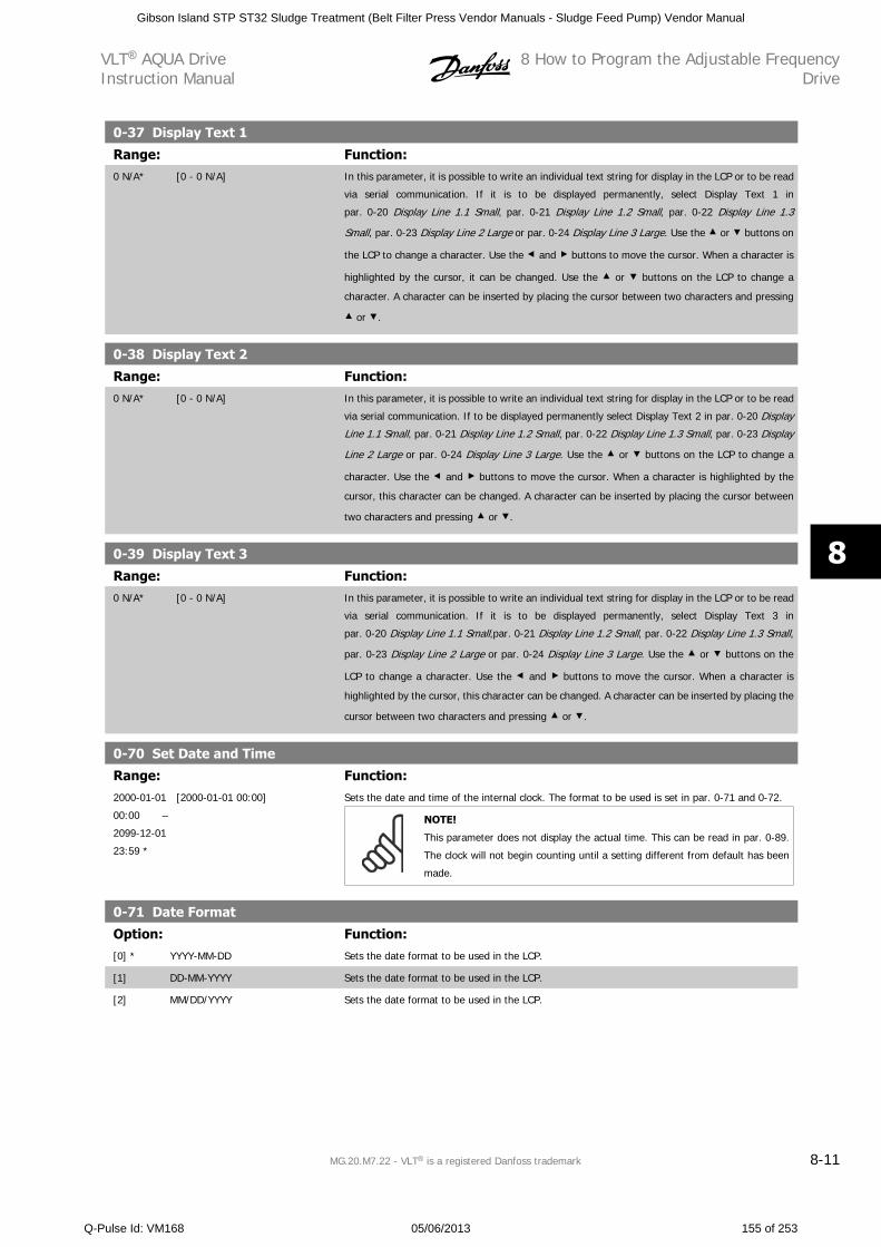
0-37 Display Text 1
Range: Function:0 N/A* [0 - 0 N/A] In this parameter, it is possible to write an individual text string for display in the LCP or to be read
via serial communication. If it is to be displayed permanently, select Display Text 1 in
par. 0-20 Display Line 1.1 Small, par. 0-21 Display Line 1.2 Small, par. 0-22 Display Line 1.3
Small, par. 0-23 Display Line 2 Large or par. 0-24 Display Line 3 Large. Use the or buttons on
the LCP to change a character. Use the and buttons to move the cursor. When a character is
highlighted by the cursor, it can be changed. Use the or buttons on the LCP to change a
character. A character can be inserted by placing the cursor between two characters and pressing
or .
0-38 Display Text 2
Range: Function:0 N/A* [0 - 0 N/A] In this parameter, it is possible to write an individual text string for display in the LCP or to be read
via serial communication. If to be displayed permanently select Display Text 2 in par. 0-20 Display
Line 1.1 Small, par. 0-21 Display Line 1.2 Small, par. 0-22 Display Line 1.3 Small, par. 0-23 Display
Line 2 Large or par. 0-24 Display Line 3 Large. Use the or buttons on the LCP to change a
character. Use the and buttons to move the cursor. When a character is highlighted by the
cursor, this character can be changed. A character can be inserted by placing the cursor between
two characters and pressing or .
0-39 Display Text 3
Range: Function:0 N/A* [0 - 0 N/A] In this parameter, it is possible to write an individual text string for display in the LCP or to be read
via serial communication. If it is to be displayed permanently, select Display Text 3 in
par. 0-20 Display Line 1.1 Small,par. 0-21 Display Line 1.2 Small, par. 0-22 Display Line 1.3 Small,
par. 0-23 Display Line 2 Large or par. 0-24 Display Line 3 Large. Use the or buttons on the
LCP to change a character. Use the and buttons to move the cursor. When a character is
highlighted by the cursor, this character can be changed. A character can be inserted by placing the
cursor between two characters and pressing or .
0-70 Set Date and Time
Range: Function:2000-01-01
00:00 –
2099-12-01
23:59 *
[2000-01-01 00:00] Sets the date and time of the internal clock. The format to be used is set in par. 0-71 and 0-72.
NOTE!
This parameter does not display the actual time. This can be read in par. 0-89.
The clock will not begin counting until a setting different from default has been
made.
0-71 Date Format
Option: Function:[0] * YYYY-MM-DD Sets the date format to be used in the LCP.
[1] DD-MM-YYYY Sets the date format to be used in the LCP.
[2] MM/DD/YYYY Sets the date format to be used in the LCP.
VLT AQUA DriveInstruction Manual
8 How to Program the Adjustable FrequencyDrive
MG.20.M7.22 - VLT is a registered Danfoss trademark 8-11
8
Gibson Island STP ST32 Sludge Treatment (Belt Filter Press Vendor Manuals - Sludge Feed Pump) Vendor Manual
Q-Pulse Id: VM168 05/06/2013 155 of 253
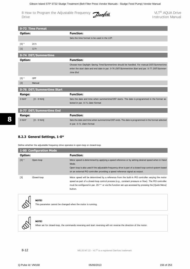
0-72 Time Format
Option: Function:Sets the time format to be used in the LCP.
[0] * 24 h
[1] 12 h
0-74 DST/Summertime
Option: Function:Choose how Daylight Saving Time/Summertime should be handled. For manual DST/Summertime
enter the start date and end date in par. 0-76 DST/Summertime Start and par. 0-77 DST/Summer-
time End.
[0] * OFF
[2] Manual
0-76 DST/Summertime Start
Range: Function:0 N/A* [0 - 0 N/A] Sets the date and time when summertime/DST starts. The date is programmed in the format se-
lected in par. 0-71 Date Format.
0-77 DST/Summertime End
Range: Function:0 N/A* [0 - 0 N/A] Sets the date and time when summertime/DST ends. The date is programmed in the format selected
in par. 0-71 Date Format.
8.2.3 General Settings, 1-0*
Define whether the adjustable frequency drive operates in open-loop or closed-loop.
1-00 Configuration Mode
Option: Function:[0] * Open-loop Motor speed is determined by applying a speed reference or by setting desired speed when in Hand
Mode.
Open-loop is also used if the adjustable frequency drive is part of a closed-loop control system based
on an external PID controller providing a speed reference signal as output.
[3] Closed-loop Motor speed will be determined by a reference from the built-in PID controller varying the motor
speed as part of a closed-loop control process (e.g., constant pressure or flow). The PID controller
must be configured in par. 20-** or via the function set-ups accessed by pressing the [Quick Menu]
button.
NOTE!
This parameter cannot be changed when the motor is running.
NOTE!
When set for closed-loop, the commands reversing and start reversing will not reverse the direction of the motor.
8 How to Program the Adjustable FrequencyDrive
VLT AQUA DriveInstruction Manual
8-12 MG.20.M7.22 - VLT is a registered Danfoss trademark
8
Gibson Island STP ST32 Sludge Treatment (Belt Filter Press Vendor Manuals - Sludge Feed Pump) Vendor Manual
Q-Pulse Id: VM168 05/06/2013 156 of 253
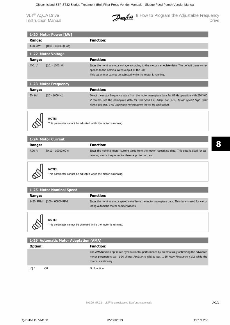
1-20 Motor Power [kW]
Range: Function:4.00 kW* [0.09 - 3000.00 kW]
1-22 Motor Voltage
Range: Function:400. V* [10. - 1000. V] Enter the nominal motor voltage according to the motor nameplate data. The default value corre-
sponds to the nominal rated output of the unit.
This parameter cannot be adjusted while the motor is running.
1-23 Motor Frequency
Range: Function:50. Hz* [20 - 1000 Hz] Select the motor frequency value from the motor nameplate data.For 87 Hz operation with 230/400
V motors, set the nameplate data for 230 V/50 Hz. Adapt par. 4-13 Motor Speed High Limit
[RPM] and par. 3-03 Maximum Reference to the 87 Hz application.
NOTE!
This parameter cannot be adjusted while the motor is running.
1-24 Motor Current
Range: Function:7.20 A* [0.10 - 10000.00 A] Enter the nominal motor current value from the motor nameplate data. This data is used for cal-
culating motor torque, motor thermal protection, etc.
NOTE!
This parameter cannot be adjusted while the motor is running.
1-25 Motor Nominal Speed
Range: Function:1420. RPM* [100 - 60000 RPM] Enter the nominal motor speed value from the motor nameplate data. This data is used for calcu-
lating automatic motor compensations.
NOTE!
This parameter cannot be changed while the motor is running.
1-29 Automatic Motor Adaptation (AMA)
Option: Function:The AMA function optimizes dynamic motor performance by automatically optimizing the advanced
motor parameters par. 1-30 Stator Resistance (Rs) to par. 1-35 Main Reactance (Xh)) while the
motor is stationary.
[0] * Off No function
VLT AQUA DriveInstruction Manual
8 How to Program the Adjustable FrequencyDrive
MG.20.M7.22 - VLT is a registered Danfoss trademark 8-13
8
Gibson Island STP ST32 Sludge Treatment (Belt Filter Press Vendor Manuals - Sludge Feed Pump) Vendor Manual
Q-Pulse Id: VM168 05/06/2013 157 of 253
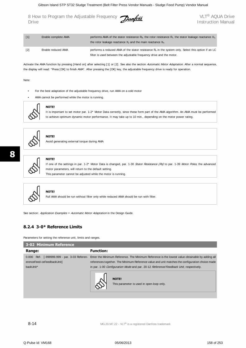
[1] Enable complete AMA performs AMA of the stator resistance RS, the rotor resistance Rr, the stator leakage reactance X1,
the rotor leakage reactance X2 and the main reactance Xh.
[2] Enable reduced AMA performs a reduced AMA of the stator resistance Rs in the system only. Select this option if an LC
filter is used between the adjustable frequency drive and the motor.
Activate the AMA function by pressing [Hand on] after selecting [1] or [2]. See also the section Automatic Motor Adaptation. After a normal sequence,
the display will read: “Press [OK] to finish AMA”. After pressing the [OK] key, the adjustable frequency drive is ready for operation.
Note:
• For the best adaptation of the adjustable frequency drive, run AMA on a cold motor
• AMA cannot be performed while the motor is running.
NOTE!
It is important to set motor par. 1-2* Motor Data correctly, since these form part of the AMA algorithm. An AMA must be performed
to achieve optimum dynamic motor performance. It may take up to 10 min., depending on the motor power rating.
NOTE!
Avoid generating external torque during AMA
NOTE!
If one of the settings in par. 1-2* Motor Data is changed, par. 1-30 Stator Resistance (Rs) to par. 1-39 Motor Poles, the advanced
motor parameters, will return to the default setting.
This parameter cannot be adjusted while the motor is running.
NOTE!
Full AMA should be run without filter only while reduced AMA should be run with filter.
See section: Application Examples > Automatic Motor Adaptation in the Design Guide.
8.2.4 3-0* Reference Limits
Parameters for setting the reference unit, limits and ranges.
3-02 Minimum Reference
Range: Function:0.000 Ref-
erenceFeed-
backUnit*
[-999999.999 - par. 3-03 Referen-
ceFeedbackUnit]
Enter the Minimum Reference. The Minimum Reference is the lowest value obtainable by adding all
references together. The Minimum Reference value and unit matches the configuration choice made
in par. 1-00 Configuration Mode and par. 20-12 Reference/Feedback Unit, respectively.
NOTE!
This parameter is used in open-loop only.
8 How to Program the Adjustable FrequencyDrive
VLT AQUA DriveInstruction Manual
8-14 MG.20.M7.22 - VLT is a registered Danfoss trademark
8
Gibson Island STP ST32 Sludge Treatment (Belt Filter Press Vendor Manuals - Sludge Feed Pump) Vendor Manual
Q-Pulse Id: VM168 05/06/2013 158 of 253
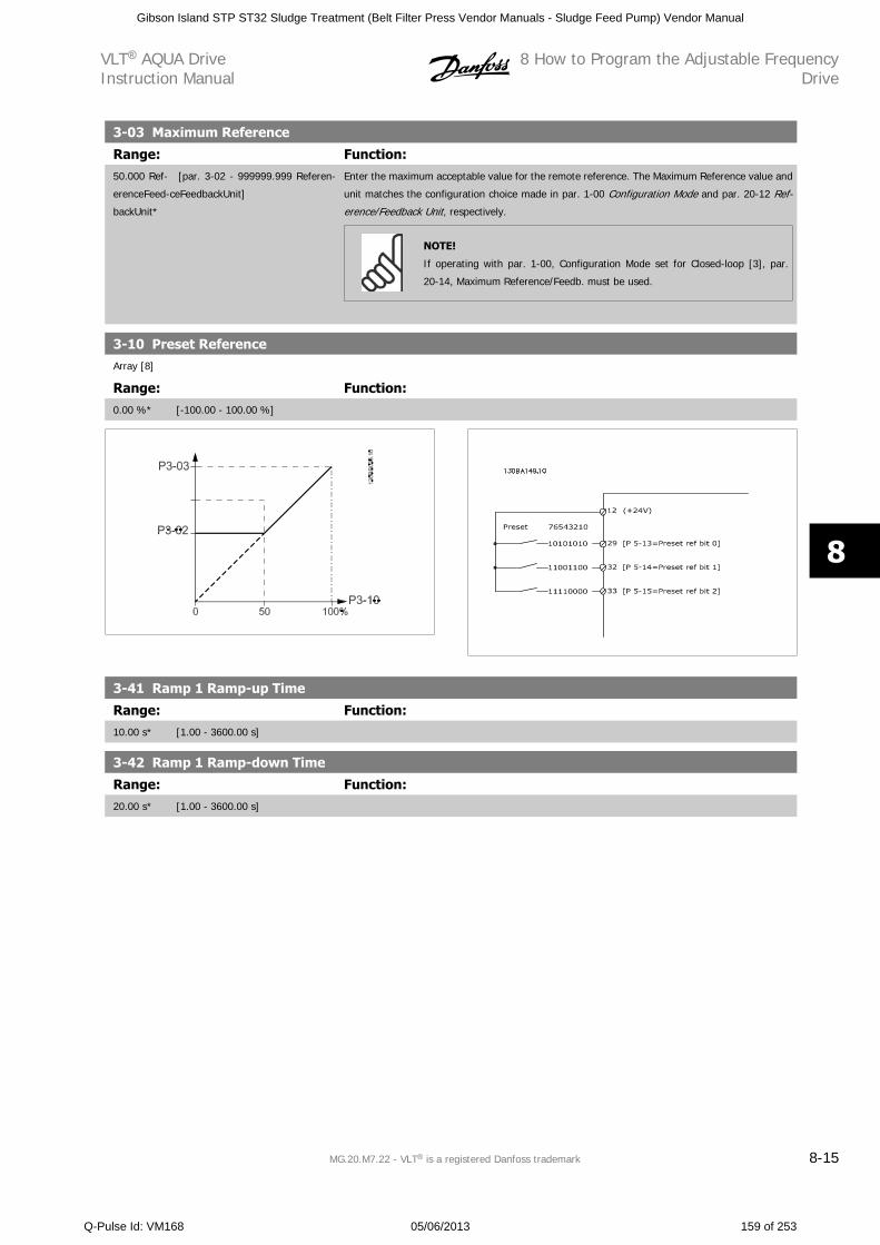
3-03 Maximum Reference
Range: Function:50.000 Ref-
erenceFeed-
backUnit*
[par. 3-02 - 999999.999 Referen-
ceFeedbackUnit]
Enter the maximum acceptable value for the remote reference. The Maximum Reference value and
unit matches the configuration choice made in par. 1-00 Configuration Mode and par. 20-12 Ref-
erence/Feedback Unit, respectively.
NOTE!
If operating with par. 1-00, Configuration Mode set for Closed-loop [3], par.
20-14, Maximum Reference/Feedb. must be used.
3-10 Preset ReferenceArray [8]
Range: Function:0.00 %* [-100.00 - 100.00 %]
3-41 Ramp 1 Ramp-up Time
Range: Function:10.00 s* [1.00 - 3600.00 s]
3-42 Ramp 1 Ramp-down Time
Range: Function:20.00 s* [1.00 - 3600.00 s]
VLT AQUA DriveInstruction Manual
8 How to Program the Adjustable FrequencyDrive
MG.20.M7.22 - VLT is a registered Danfoss trademark 8-15
8
Gibson Island STP ST32 Sludge Treatment (Belt Filter Press Vendor Manuals - Sludge Feed Pump) Vendor Manual
Q-Pulse Id: VM168 05/06/2013 159 of 253
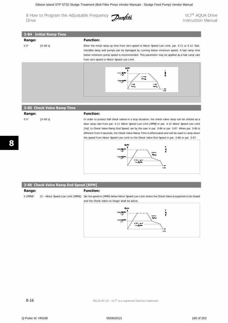
3-84 Initial Ramp Time
Range: Function:0 s* [0–60 s] Enter the initial ramp-up time from zero speed to Motor Speed Low Limit, par. 4-11 or 4-12. Sub-
mersible deep well pumps can be damaged by running below minimum speed. A fast ramp time
below minimum pump speed is recommended. This parameter may be applied as a fast ramp rate
from zero speed to Motor Speed Low Limit.
3-85 Check Valve Ramp Time
Range: Function:0 s* [0–60 s] In order to protect ball check valves in a stop situation, the check valve ramp can be utilized as a
slow ramp rate from par. 4-11 Motor Speed Low Limit [RPM] or par. 4-12 Motor Speed Low Limit
[Hz], to Check Valve Ramp End Speed, set by the user in par. 3-86 or par. 3-87. When par. 3-85 is
different from 0 seconds, the Check Valve Ramp Time is effectuated and will be used to ramp down
the speed from Motor Speed Low Limit to the Check Valve End Speed in par. 3-86 or par. 3-87.
3-86 Check Valve Ramp End Speed [RPM]
Range: Function:0 [RPM]* [0 – Motor Speed Low Limit [RPM]] Set the speed in [RPM] below Motor Speed Low Limit where the Check Valve is expected to be closed
and the Check Valve no longer shall be active.
8 How to Program the Adjustable FrequencyDrive
VLT AQUA DriveInstruction Manual
8-16 MG.20.M7.22 - VLT is a registered Danfoss trademark
8
Gibson Island STP ST32 Sludge Treatment (Belt Filter Press Vendor Manuals - Sludge Feed Pump) Vendor Manual
Q-Pulse Id: VM168 05/06/2013 160 of 253
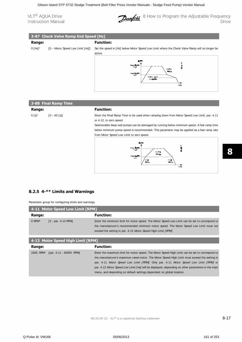
3-87 Check Valve Ramp End Speed [Hz]
Range: Function:0 [Hz]* [0 – Motor Speed Low Limit [Hz]] Set the speed in [Hz] below Motor Speed Low Limit where the Check Valve Ramp will no longer be
active.
3-88 Final Ramp Time
Range: Function:0 [s]* [0 – 60 [s]] Enter the Final Ramp Time to be used when ramping down from Motor Speed Low Limit, par. 4-11
or 4-12, to zero speed.
Submersible deep well pumps can be damaged by running below minimum speed. A fast ramp time
below minimum pump speed is recommended. This parameter may be applied as a fast ramp rate
from Motor Speed Low Limit to zero speed.
8.2.5 4-** Limits and Warnings
Parameter group for configuring limits and warnings.
4-11 Motor Speed Low Limit [RPM]
Range: Function:0 RPM* [0 - par. 4-13 RPM] Enter the minimum limit for motor speed. The Motor Speed Low Limit can be set to correspond to
the manufacturer’s recommended minimum motor speed. The Motor Speed Low Limit must not
exceed the setting in par. 4-13 Motor Speed High Limit [RPM].
4-13 Motor Speed High Limit [RPM]
Range: Function:1500. RPM* [par. 4-11 - 60000. RPM] Enter the maximum limit for motor speed. The Motor Speed High Limit can be set to correspond to
the manufacturer’s maximum rated motor. The Motor Speed High Limit must exceed the setting in
par. 4-11 Motor Speed Low Limit [RPM]. Only par. 4-11 Motor Speed Low Limit [RPM] or
par. 4-12 Motor Speed Low Limit [Hz] will be displayed, depending on other parameters in the main
menu, and depending on default settings dependant on global location.
VLT AQUA DriveInstruction Manual
8 How to Program the Adjustable FrequencyDrive
MG.20.M7.22 - VLT is a registered Danfoss trademark 8-17
8
Gibson Island STP ST32 Sludge Treatment (Belt Filter Press Vendor Manuals - Sludge Feed Pump) Vendor Manual
Q-Pulse Id: VM168 05/06/2013 161 of 253
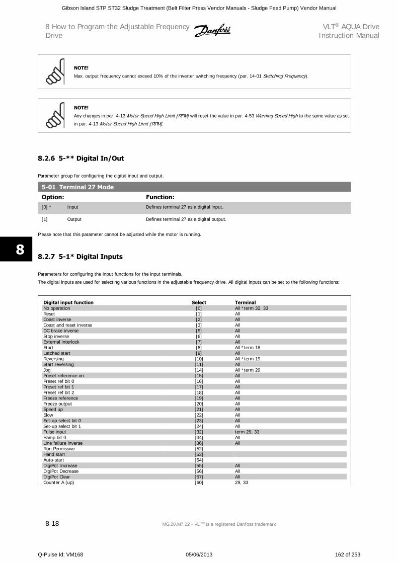
NOTE!
Max. output frequency cannot exceed 10% of the inverter switching frequency (par. 14-01 Switching Frequency).
NOTE!
Any changes in par. 4-13 Motor Speed High Limit [RPM] will reset the value in par. 4-53 Warning Speed High to the same value as set
in par. 4-13 Motor Speed High Limit [RPM].
8.2.6 5-** Digital In/Out
Parameter group for configuring the digital input and output.
5-01 Terminal 27 Mode
Option: Function:[0] * Input Defines terminal 27 as a digital input.
[1] Output Defines terminal 27 as a digital output.
Please note that this parameter cannot be adjusted while the motor is running.
8.2.7 5-1* Digital Inputs
Parameters for configuring the input functions for the input terminals.
The digital inputs are used for selecting various functions in the adjustable frequency drive. All digital inputs can be set to the following functions:
Digital input function Select TerminalNo operation [0] All *term 32, 33Reset [1] AllCoast inverse [2] AllCoast and reset inverse [3] AllDC brake inverse [5] AllStop inverse [6] AllExternal interlock [7] AllStart [8] All *term 18Latched start [9] AllReversing [10] All *term 19Start reversing [11] AllJog [14] All *term 29Preset reference on [15] AllPreset ref bit 0 [16] AllPreset ref bit 1 [17] AllPreset ref bit 2 [18] AllFreeze reference [19] AllFreeze output [20] AllSpeed up [21] AllSlow [22] AllSet-up select bit 0 [23] AllSet-up select bit 1 [24] AllPulse input [32] term 29, 33Ramp bit 0 [34] AllLine failure inverse [36] AllRun Permissive [52]Hand start [53] Auto-start [54]DigiPot Increase [55] AllDigiPot Decrease [56] AllDigiPot Clear [57] AllCounter A (up) [60] 29, 33
8 How to Program the Adjustable FrequencyDrive
VLT AQUA DriveInstruction Manual
8-18 MG.20.M7.22 - VLT is a registered Danfoss trademark
8
Gibson Island STP ST32 Sludge Treatment (Belt Filter Press Vendor Manuals - Sludge Feed Pump) Vendor Manual
Q-Pulse Id: VM168 05/06/2013 162 of 253
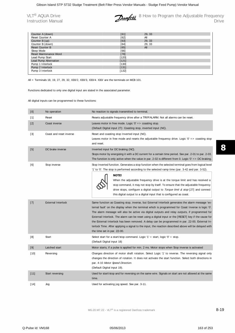
Counter A (down) [61] 29, 33Reset Counter A [62] AllCounter B (up) [63] 29, 33Counter B (down) [64] 29, 33Reset Counter B [65] AllSleep Mode [66] Reset Maintenance Word [78] Lead Pump Start [120] Lead Pump Alternation [121] Pump 1 Interlock [130] Pump 2 Interlock [131] Pump 3 Interlock [132]
All = Terminals 18, 19, 27, 29, 32, X30/2, X30/3, X30/4. X30/ are the terminals on MCB 101.
Functions dedicated to only one digital input are stated in the associated parameter.
All digital inputs can be programmed to these functions:
[0] No operation No reaction to signals transmitted to terminal.
[1] Reset Resets adjustable frequency drive after a TRIP/ALARM. Not all alarms can be reset.
[2] Coast inverse Leaves motor in free mode. Logic ‘0’ => coasting stop.
(Default Digital input 27): Coasting stop, inverted input (NC).
[3] Coast and reset inverse Reset and coasting stop Inverted input (NC).
Leaves motor in free mode and resets the adjustable frequency drive. Logic ‘0’ => coasting stop
and reset.
[5] DC brake inverse Inverted input for DC braking (NC).
Stops motor by energizing it with a DC current for a certain time period. See par. 2-01 to par. 2-03.
The function is only active when the value in par. 2-02 is different from 0. Logic ’0’ => DC braking.
[6] Stop inverse Stop Inverted function. Generates a stop function when the selected terminal goes from logical level
‘1’ to ‘0’. The stop is performed according to the selected ramp time (par. 3-42 and par. 3-52).
NOTE!
When the adjustable frequency drive is at the torque limit and has received a
stop command, it may not stop by itself. To ensure that the adjustable frequency
drive stops, configure a digital output to Torque limit & stop [27] and connect
this digital output to a digital input that is configured as coast.
[7] External Interlock Same function as Coasting stop, inverse, but External Interlock generates the alarm message ’ex-
ternal fault’ on the display when the terminal which is programmed for Coast Inverse is logic ‘0’.
The alarm message will also be active via digital outputs and relay outputs, if programmed for
External Interlock. The alarm can be reset using a digital input or the [RESET] key if the cause for
the External Interlock has been removed. A delay can be programmed in par. 22-00, External In-
terlock Time. After applying a signal to the input, the reaction described above will be delayed with
the time set in par. 22-00.
[8] Start Select start for a start/stop command. Logic ‘1’ = start, logic ‘0’ = stop.
(Default Digital input 18)
[9] Latched start Motor starts, if a pulse is applied for min. 2 ms. Motor stops when Stop inverse is activated
[10] Reversing Changes direction of motor shaft rotation. Select Logic ‘1’ to reverse. The reversing signal only
changes the direction of rotation. It does not activate the start function. Select both directions in
par. 4-10 Motor Speed Direction.
(Default Digital input 19).
[11] Start reversing Used for start/stop and for reversing on the same wire. Signals on start are not allowed at the same
time.
[14] Jog Used for activating jog speed. See par. 3-11.
VLT AQUA DriveInstruction Manual
8 How to Program the Adjustable FrequencyDrive
MG.20.M7.22 - VLT is a registered Danfoss trademark 8-19
8
Gibson Island STP ST32 Sludge Treatment (Belt Filter Press Vendor Manuals - Sludge Feed Pump) Vendor Manual
Q-Pulse Id: VM168 05/06/2013 163 of 253
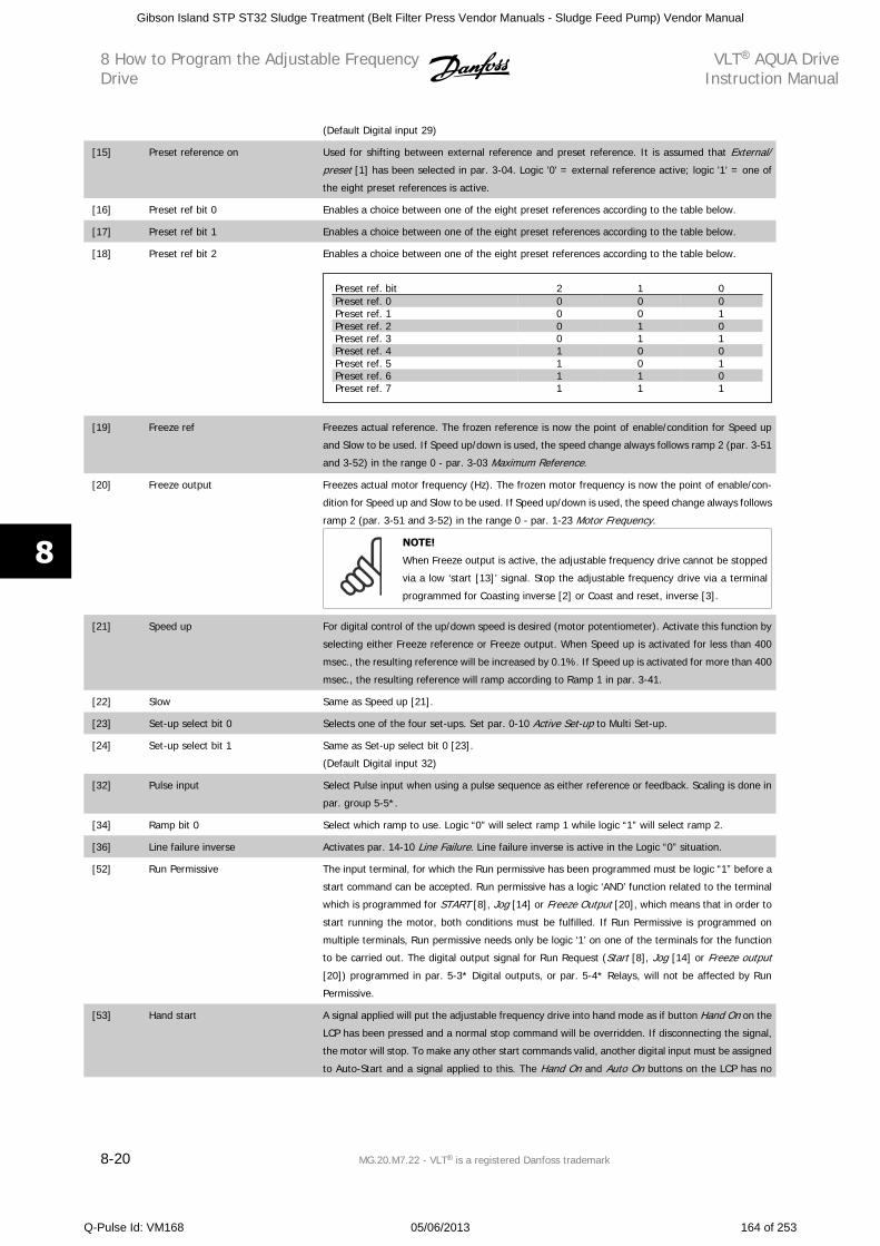
(Default Digital input 29)
[15] Preset reference on Used for shifting between external reference and preset reference. It is assumed that External/
preset [1] has been selected in par. 3-04. Logic '0' = external reference active; logic '1' = one of
the eight preset references is active.
[16] Preset ref bit 0 Enables a choice between one of the eight preset references according to the table below.
[17] Preset ref bit 1 Enables a choice between one of the eight preset references according to the table below.
[18] Preset ref bit 2 Enables a choice between one of the eight preset references according to the table below.
Preset ref. bit 2 1 0Preset ref. 0 0 0 0Preset ref. 1 0 0 1Preset ref. 2 0 1 0Preset ref. 3 0 1 1Preset ref. 4 1 0 0Preset ref. 5 1 0 1Preset ref. 6 1 1 0Preset ref. 7 1 1 1
[19] Freeze ref Freezes actual reference. The frozen reference is now the point of enable/condition for Speed up
and Slow to be used. If Speed up/down is used, the speed change always follows ramp 2 (par. 3-51
and 3-52) in the range 0 - par. 3-03 Maximum Reference.
[20] Freeze output Freezes actual motor frequency (Hz). The frozen motor frequency is now the point of enable/con-
dition for Speed up and Slow to be used. If Speed up/down is used, the speed change always follows
ramp 2 (par. 3-51 and 3-52) in the range 0 - par. 1-23 Motor Frequency.
NOTE!
When Freeze output is active, the adjustable frequency drive cannot be stopped
via a low ‘start [13]’ signal. Stop the adjustable frequency drive via a terminal
programmed for Coasting inverse [2] or Coast and reset, inverse [3].
[21] Speed up For digital control of the up/down speed is desired (motor potentiometer). Activate this function by
selecting either Freeze reference or Freeze output. When Speed up is activated for less than 400
msec., the resulting reference will be increased by 0.1%. If Speed up is activated for more than 400
msec., the resulting reference will ramp according to Ramp 1 in par. 3-41.
[22] Slow Same as Speed up [21].
[23] Set-up select bit 0 Selects one of the four set-ups. Set par. 0-10 Active Set-up to Multi Set-up.
[24] Set-up select bit 1 Same as Set-up select bit 0 [23].
(Default Digital input 32)
[32] Pulse input Select Pulse input when using a pulse sequence as either reference or feedback. Scaling is done in
par. group 5-5*.
[34] Ramp bit 0 Select which ramp to use. Logic “0” will select ramp 1 while logic “1” will select ramp 2.
[36] Line failure inverse Activates par. 14-10 Line Failure. Line failure inverse is active in the Logic “0” situation.
[52] Run Permissive The input terminal, for which the Run permissive has been programmed must be logic “1” before a
start command can be accepted. Run permissive has a logic ‘AND’ function related to the terminal
which is programmed for START [8], Jog [14] or Freeze Output [20], which means that in order to
start running the motor, both conditions must be fulfilled. If Run Permissive is programmed on
multiple terminals, Run permissive needs only be logic ‘1’ on one of the terminals for the function
to be carried out. The digital output signal for Run Request (Start [8], Jog [14] or Freeze output
[20]) programmed in par. 5-3* Digital outputs, or par. 5-4* Relays, will not be affected by Run
Permissive.
[53] Hand start A signal applied will put the adjustable frequency drive into hand mode as if button Hand On on the
LCP has been pressed and a normal stop command will be overridden. If disconnecting the signal,
the motor will stop. To make any other start commands valid, another digital input must be assigned
to Auto-Start and a signal applied to this. The Hand On and Auto On buttons on the LCP has no
8 How to Program the Adjustable FrequencyDrive
VLT AQUA DriveInstruction Manual
8-20 MG.20.M7.22 - VLT is a registered Danfoss trademark
8
Gibson Island STP ST32 Sludge Treatment (Belt Filter Press Vendor Manuals - Sludge Feed Pump) Vendor Manual
Q-Pulse Id: VM168 05/06/2013 164 of 253
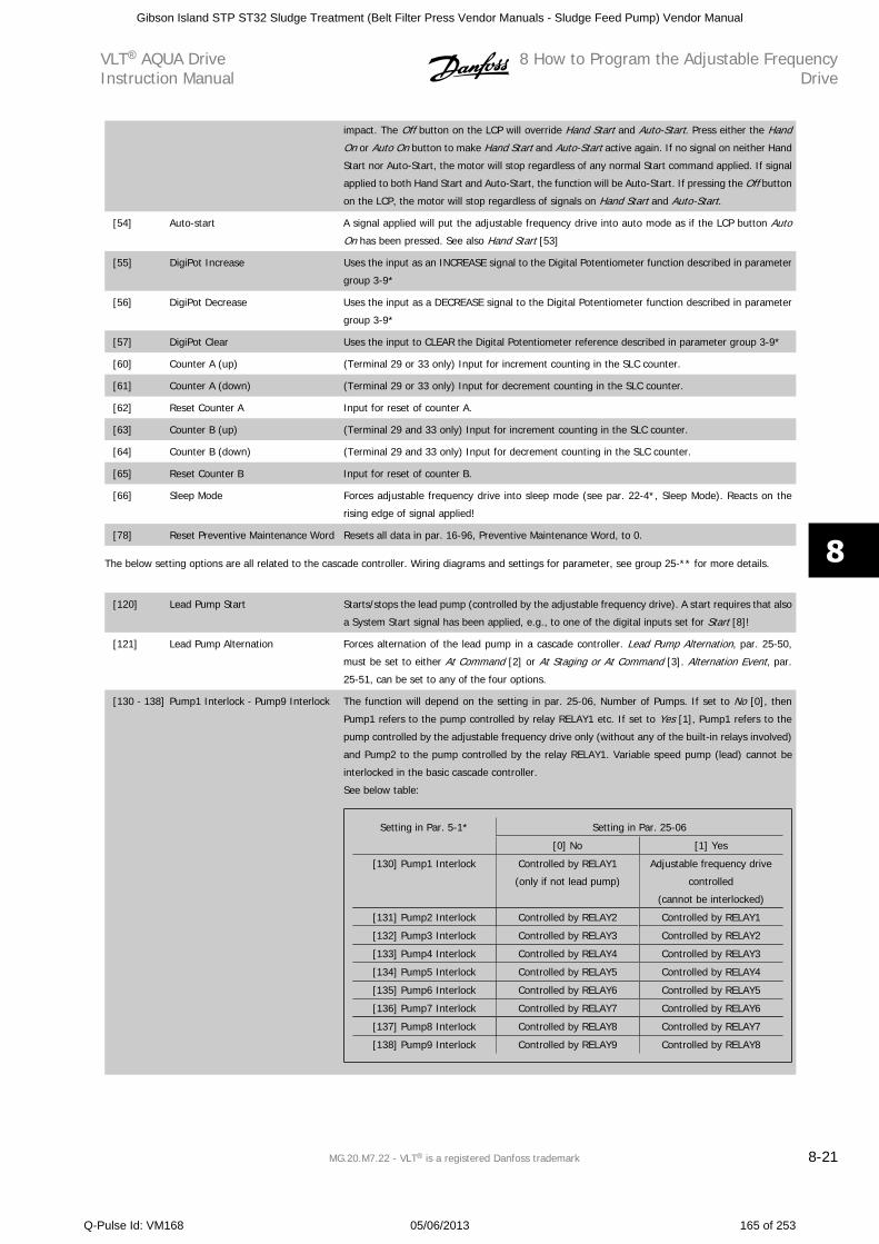
impact. The Off button on the LCP will override Hand Start and Auto-Start. Press either the Hand
On or Auto On button to make Hand Start and Auto-Start active again. If no signal on neither Hand
Start nor Auto-Start, the motor will stop regardless of any normal Start command applied. If signal
applied to both Hand Start and Auto-Start, the function will be Auto-Start. If pressing the Off button
on the LCP, the motor will stop regardless of signals on Hand Start and Auto-Start.
[54] Auto-start A signal applied will put the adjustable frequency drive into auto mode as if the LCP button Auto
On has been pressed. See also Hand Start [53]
[55] DigiPot Increase Uses the input as an INCREASE signal to the Digital Potentiometer function described in parameter
group 3-9*
[56] DigiPot Decrease Uses the input as a DECREASE signal to the Digital Potentiometer function described in parameter
group 3-9*
[57] DigiPot Clear Uses the input to CLEAR the Digital Potentiometer reference described in parameter group 3-9*
[60] Counter A (up) (Terminal 29 or 33 only) Input for increment counting in the SLC counter.
[61] Counter A (down) (Terminal 29 or 33 only) Input for decrement counting in the SLC counter.
[62] Reset Counter A Input for reset of counter A.
[63] Counter B (up) (Terminal 29 and 33 only) Input for increment counting in the SLC counter.
[64] Counter B (down) (Terminal 29 and 33 only) Input for decrement counting in the SLC counter.
[65] Reset Counter B Input for reset of counter B.
[66] Sleep Mode Forces adjustable frequency drive into sleep mode (see par. 22-4*, Sleep Mode). Reacts on the
rising edge of signal applied!
[78] Reset Preventive Maintenance Word Resets all data in par. 16-96, Preventive Maintenance Word, to 0.
The below setting options are all related to the cascade controller. Wiring diagrams and settings for parameter, see group 25-** for more details.
[120] Lead Pump Start Starts/stops the lead pump (controlled by the adjustable frequency drive). A start requires that also
a System Start signal has been applied, e.g., to one of the digital inputs set for Start [8]!
[121] Lead Pump Alternation Forces alternation of the lead pump in a cascade controller. Lead Pump Alternation, par. 25-50,
must be set to either At Command [2] or At Staging or At Command [3]. Alternation Event, par.
25-51, can be set to any of the four options.
[130 - 138] Pump1 Interlock - Pump9 Interlock The function will depend on the setting in par. 25-06, Number of Pumps. If set to No [0], then
Pump1 refers to the pump controlled by relay RELAY1 etc. If set to Yes [1], Pump1 refers to the
pump controlled by the adjustable frequency drive only (without any of the built-in relays involved)
and Pump2 to the pump controlled by the relay RELAY1. Variable speed pump (lead) cannot be
interlocked in the basic cascade controller.
See below table:
Setting in Par. 5-1* Setting in Par. 25-06
[0] No [1] Yes
[130] Pump1 Interlock Controlled by RELAY1
(only if not lead pump)
Adjustable frequency drive
controlled
(cannot be interlocked)
[131] Pump2 Interlock Controlled by RELAY2 Controlled by RELAY1
[132] Pump3 Interlock Controlled by RELAY3 Controlled by RELAY2
[133] Pump4 Interlock Controlled by RELAY4 Controlled by RELAY3
[134] Pump5 Interlock Controlled by RELAY5 Controlled by RELAY4
[135] Pump6 Interlock Controlled by RELAY6 Controlled by RELAY5
[136] Pump7 Interlock Controlled by RELAY7 Controlled by RELAY6
[137] Pump8 Interlock Controlled by RELAY8 Controlled by RELAY7
[138] Pump9 Interlock Controlled by RELAY9 Controlled by RELAY8
VLT AQUA DriveInstruction Manual
8 How to Program the Adjustable FrequencyDrive
MG.20.M7.22 - VLT is a registered Danfoss trademark 8-21
8
Gibson Island STP ST32 Sludge Treatment (Belt Filter Press Vendor Manuals - Sludge Feed Pump) Vendor Manual
Q-Pulse Id: VM168 05/06/2013 165 of 253
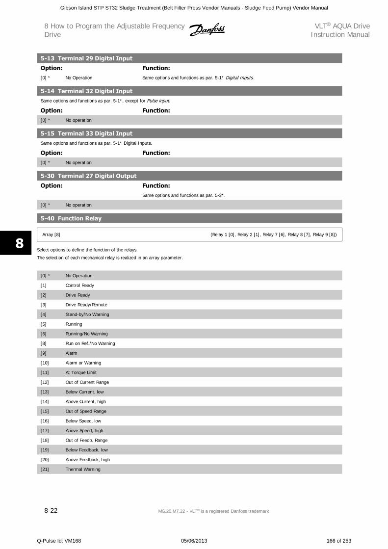
5-13 Terminal 29 Digital Input
Option: Function:[0] * No Operation Same options and functions as par. 5-1* Digital Inputs.
5-14 Terminal 32 Digital InputSame options and functions as par. 5-1*, except for Pulse input.
Option: Function:[0] * No operation
5-15 Terminal 33 Digital InputSame options and functions as par. 5-1* Digital Inputs.
Option: Function:[0] * No operation
5-30 Terminal 27 Digital Output
Option: Function:Same options and functions as par. 5-3*.
[0] * No operation
5-40 Function Relay
Array [8] (Relay 1 [0], Relay 2 [1], Relay 7 [6], Relay 8 [7], Relay 9 [8])
Select options to define the function of the relays.
The selection of each mechanical relay is realized in an array parameter.
[0] * No Operation
[1] Control Ready
[2] Drive Ready
[3] Drive Ready/Remote
[4] Stand-by/No Warning
[5] Running
[6] Running/No Warning
[8] Run on Ref./No Warning
[9] Alarm
[10] Alarm or Warning
[11] At Torque Limit
[12] Out of Current Range
[13] Below Current, low
[14] Above Current, high
[15] Out of Speed Range
[16] Below Speed, low
[17] Above Speed, high
[18] Out of Feedb. Range
[19] Below Feedback, low
[20] Above Feedback, high
[21] Thermal Warning
8 How to Program the Adjustable FrequencyDrive
VLT AQUA DriveInstruction Manual
8-22 MG.20.M7.22 - VLT is a registered Danfoss trademark
8
Gibson Island STP ST32 Sludge Treatment (Belt Filter Press Vendor Manuals - Sludge Feed Pump) Vendor Manual
Q-Pulse Id: VM168 05/06/2013 166 of 253
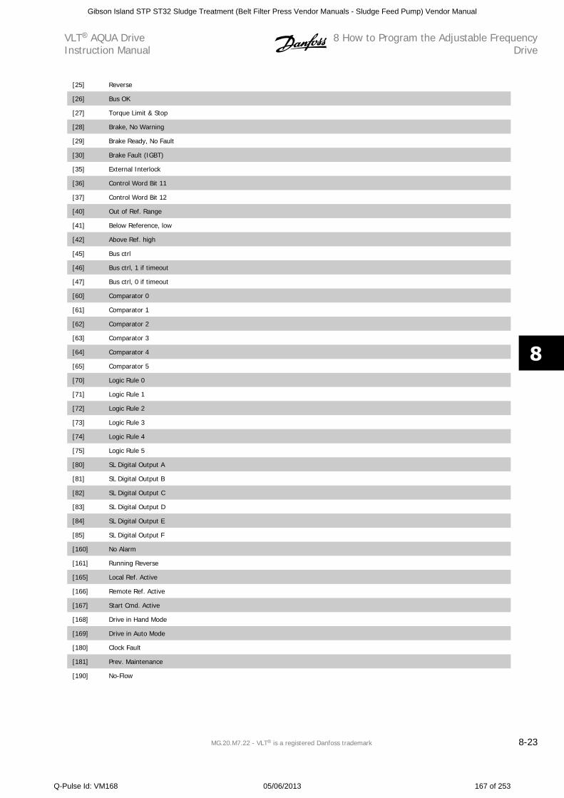
[25] Reverse
[26] Bus OK
[27] Torque Limit & Stop
[28] Brake, No Warning
[29] Brake Ready, No Fault
[30] Brake Fault (IGBT)
[35] External Interlock
[36] Control Word Bit 11
[37] Control Word Bit 12
[40] Out of Ref. Range
[41] Below Reference, low
[42] Above Ref. high
[45] Bus ctrl
[46] Bus ctrl, 1 if timeout
[47] Bus ctrl, 0 if timeout
[60] Comparator 0
[61] Comparator 1
[62] Comparator 2
[63] Comparator 3
[64] Comparator 4
[65] Comparator 5
[70] Logic Rule 0
[71] Logic Rule 1
[72] Logic Rule 2
[73] Logic Rule 3
[74] Logic Rule 4
[75] Logic Rule 5
[80] SL Digital Output A
[81] SL Digital Output B
[82] SL Digital Output C
[83] SL Digital Output D
[84] SL Digital Output E
[85] SL Digital Output F
[160] No Alarm
[161] Running Reverse
[165] Local Ref. Active
[166] Remote Ref. Active
[167] Start Cmd. Active
[168] Drive in Hand Mode
[169] Drive in Auto Mode
[180] Clock Fault
[181] Prev. Maintenance
[190] No-Flow
VLT AQUA DriveInstruction Manual
8 How to Program the Adjustable FrequencyDrive
MG.20.M7.22 - VLT is a registered Danfoss trademark 8-23
8
Gibson Island STP ST32 Sludge Treatment (Belt Filter Press Vendor Manuals - Sludge Feed Pump) Vendor Manual
Q-Pulse Id: VM168 05/06/2013 167 of 253
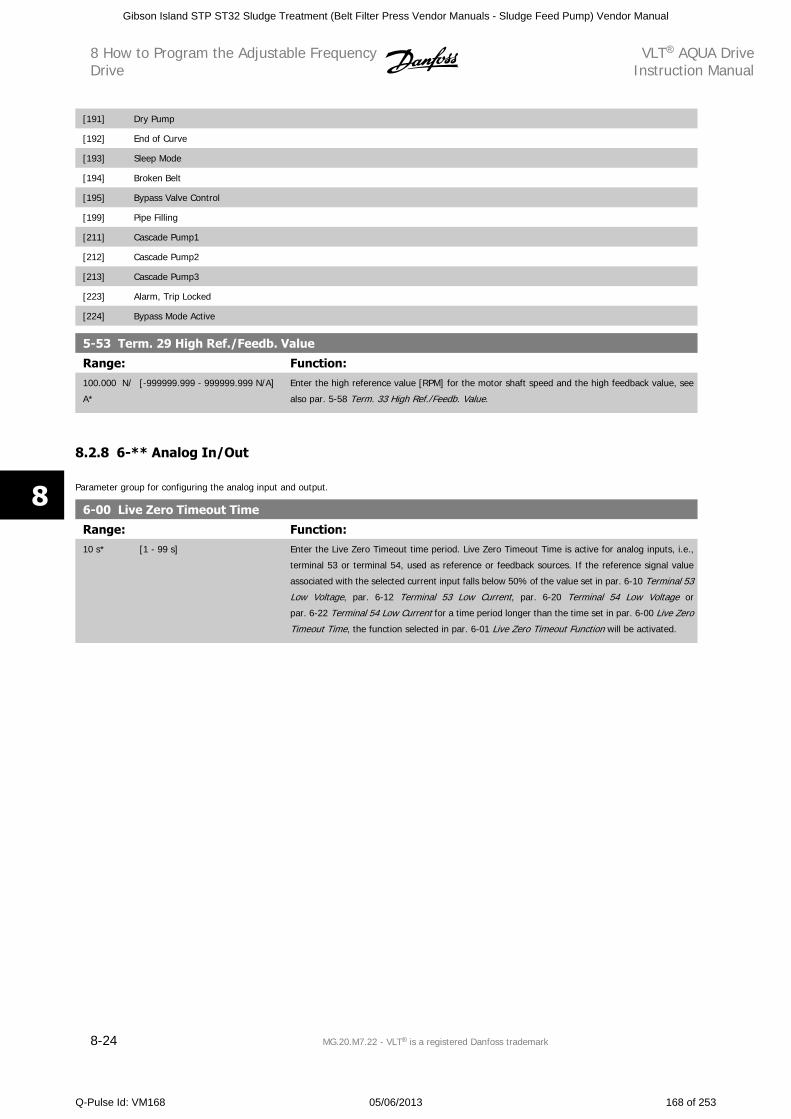
[191] Dry Pump
[192] End of Curve
[193] Sleep Mode
[194] Broken Belt
[195] Bypass Valve Control
[199] Pipe Filling
[211] Cascade Pump1
[212] Cascade Pump2
[213] Cascade Pump3
[223] Alarm, Trip Locked
[224] Bypass Mode Active
5-53 Term. 29 High Ref./Feedb. Value
Range: Function:100.000 N/
A*
[-999999.999 - 999999.999 N/A] Enter the high reference value [RPM] for the motor shaft speed and the high feedback value, see
also par. 5-58 Term. 33 High Ref./Feedb. Value.
8.2.8 6-** Analog In/Out
Parameter group for configuring the analog input and output.
6-00 Live Zero Timeout Time
Range: Function:10 s* [1 - 99 s] Enter the Live Zero Timeout time period. Live Zero Timeout Time is active for analog inputs, i.e.,
terminal 53 or terminal 54, used as reference or feedback sources. If the reference signal value
associated with the selected current input falls below 50% of the value set in par. 6-10 Terminal 53
Low Voltage, par. 6-12 Terminal 53 Low Current, par. 6-20 Terminal 54 Low Voltage or
par. 6-22 Terminal 54 Low Current for a time period longer than the time set in par. 6-00 Live Zero
Timeout Time, the function selected in par. 6-01 Live Zero Timeout Function will be activated.
8 How to Program the Adjustable FrequencyDrive
VLT AQUA DriveInstruction Manual
8-24 MG.20.M7.22 - VLT is a registered Danfoss trademark
8
Gibson Island STP ST32 Sludge Treatment (Belt Filter Press Vendor Manuals - Sludge Feed Pump) Vendor Manual
Q-Pulse Id: VM168 05/06/2013 168 of 253
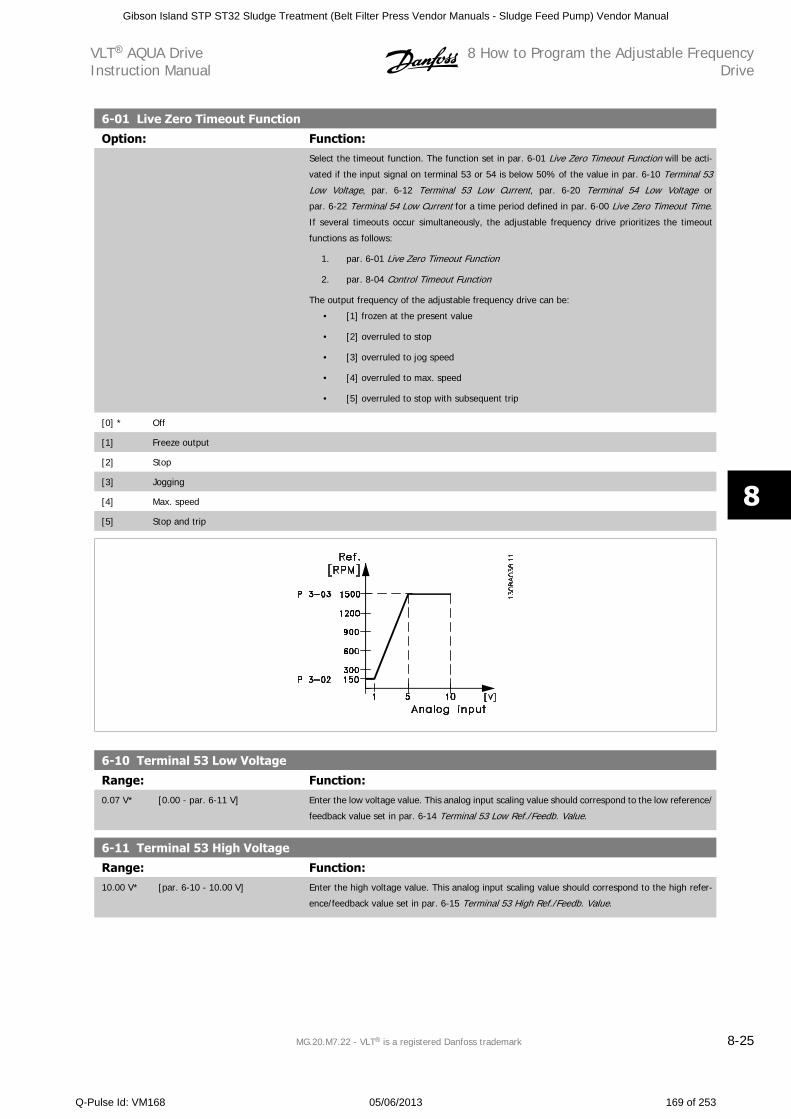
6-01 Live Zero Timeout Function
Option: Function:Select the timeout function. The function set in par. 6-01 Live Zero Timeout Function will be acti-
vated if the input signal on terminal 53 or 54 is below 50% of the value in par. 6-10 Terminal 53
Low Voltage, par. 6-12 Terminal 53 Low Current, par. 6-20 Terminal 54 Low Voltage or
par. 6-22 Terminal 54 Low Current for a time period defined in par. 6-00 Live Zero Timeout Time.
If several timeouts occur simultaneously, the adjustable frequency drive prioritizes the timeout
functions as follows:
1. par. 6-01 Live Zero Timeout Function
2. par. 8-04 Control Timeout Function
The output frequency of the adjustable frequency drive can be:
• [1] frozen at the present value
• [2] overruled to stop
• [3] overruled to jog speed
• [4] overruled to max. speed
• [5] overruled to stop with subsequent trip
[0] * Off
[1] Freeze output
[2] Stop
[3] Jogging
[4] Max. speed
[5] Stop and trip
6-10 Terminal 53 Low Voltage
Range: Function:0.07 V* [0.00 - par. 6-11 V] Enter the low voltage value. This analog input scaling value should correspond to the low reference/
feedback value set in par. 6-14 Terminal 53 Low Ref./Feedb. Value.
6-11 Terminal 53 High Voltage
Range: Function:10.00 V* [par. 6-10 - 10.00 V] Enter the high voltage value. This analog input scaling value should correspond to the high refer-
ence/feedback value set in par. 6-15 Terminal 53 High Ref./Feedb. Value.
VLT AQUA DriveInstruction Manual
8 How to Program the Adjustable FrequencyDrive
MG.20.M7.22 - VLT is a registered Danfoss trademark 8-25
8
Gibson Island STP ST32 Sludge Treatment (Belt Filter Press Vendor Manuals - Sludge Feed Pump) Vendor Manual
Q-Pulse Id: VM168 05/06/2013 169 of 253
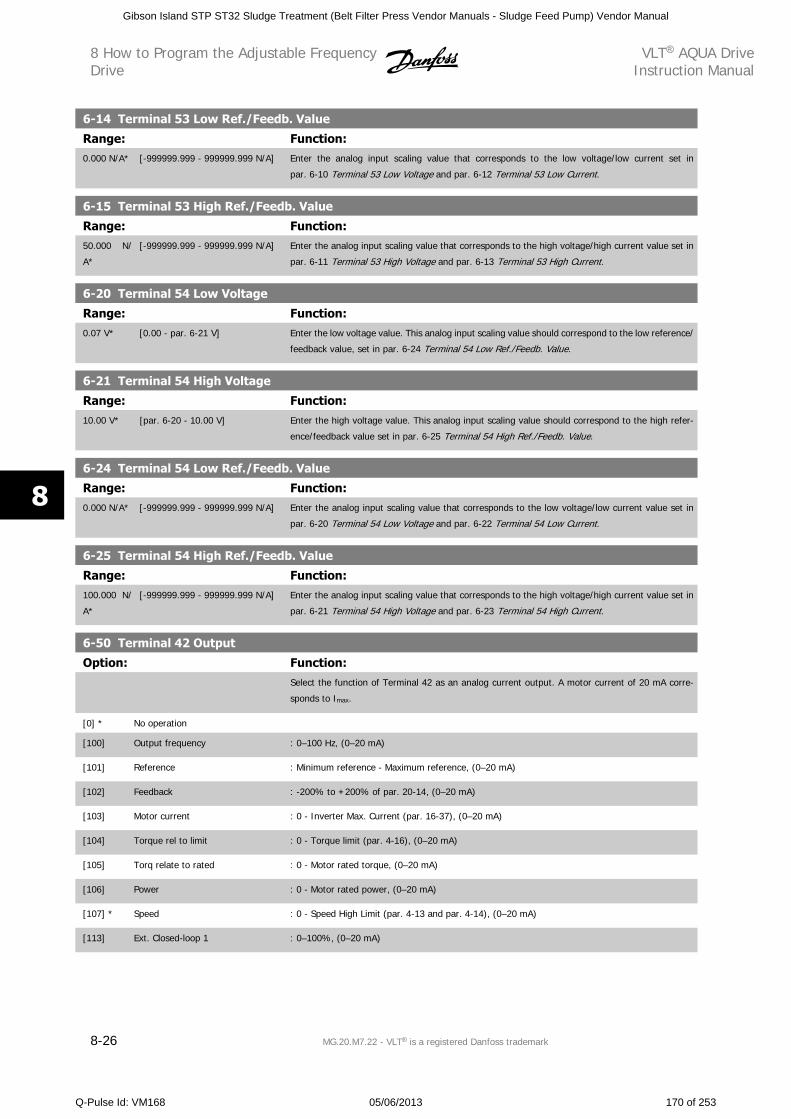
6-14 Terminal 53 Low Ref./Feedb. Value
Range: Function:0.000 N/A* [-999999.999 - 999999.999 N/A] Enter the analog input scaling value that corresponds to the low voltage/low current set in
par. 6-10 Terminal 53 Low Voltage and par. 6-12 Terminal 53 Low Current.
6-15 Terminal 53 High Ref./Feedb. Value
Range: Function:50.000 N/
A*
[-999999.999 - 999999.999 N/A] Enter the analog input scaling value that corresponds to the high voltage/high current value set in
par. 6-11 Terminal 53 High Voltage and par. 6-13 Terminal 53 High Current.
6-20 Terminal 54 Low Voltage
Range: Function:0.07 V* [0.00 - par. 6-21 V] Enter the low voltage value. This analog input scaling value should correspond to the low reference/
feedback value, set in par. 6-24 Terminal 54 Low Ref./Feedb. Value.
6-21 Terminal 54 High Voltage
Range: Function:10.00 V* [par. 6-20 - 10.00 V] Enter the high voltage value. This analog input scaling value should correspond to the high refer-
ence/feedback value set in par. 6-25 Terminal 54 High Ref./Feedb. Value.
6-24 Terminal 54 Low Ref./Feedb. Value
Range: Function:0.000 N/A* [-999999.999 - 999999.999 N/A] Enter the analog input scaling value that corresponds to the low voltage/low current value set in
par. 6-20 Terminal 54 Low Voltage and par. 6-22 Terminal 54 Low Current.
6-25 Terminal 54 High Ref./Feedb. Value
Range: Function:100.000 N/
A*
[-999999.999 - 999999.999 N/A] Enter the analog input scaling value that corresponds to the high voltage/high current value set in
par. 6-21 Terminal 54 High Voltage and par. 6-23 Terminal 54 High Current.
6-50 Terminal 42 Output
Option: Function:Select the function of Terminal 42 as an analog current output. A motor current of 20 mA corre-
sponds to Imax.
[0] * No operation
[100] Output frequency : 0–100 Hz, (0–20 mA)
[101] Reference : Minimum reference - Maximum reference, (0–20 mA)
[102] Feedback : -200% to +200% of par. 20-14, (0–20 mA)
[103] Motor current : 0 - Inverter Max. Current (par. 16-37), (0–20 mA)
[104] Torque rel to limit : 0 - Torque limit (par. 4-16), (0–20 mA)
[105] Torq relate to rated : 0 - Motor rated torque, (0–20 mA)
[106] Power : 0 - Motor rated power, (0–20 mA)
[107] * Speed : 0 - Speed High Limit (par. 4-13 and par. 4-14), (0–20 mA)
[113] Ext. Closed-loop 1 : 0–100%, (0–20 mA)
8 How to Program the Adjustable FrequencyDrive
VLT AQUA DriveInstruction Manual
8-26 MG.20.M7.22 - VLT is a registered Danfoss trademark
8
Gibson Island STP ST32 Sludge Treatment (Belt Filter Press Vendor Manuals - Sludge Feed Pump) Vendor Manual
Q-Pulse Id: VM168 05/06/2013 170 of 253
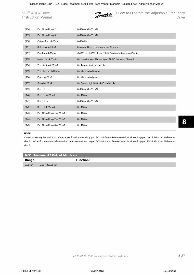
[114] Ext. Closed-loop 2 : 0–100%, (0–20 mA)
[115] Ext. Closed-loop 3 : 0–100%, (0–20 mA)
[130] Output freq. 4-20mA : 0–100 Hz
[131] Reference 4-20mA : Minimum Reference - Maximum Reference
[132] Feedback 4-20mA : -200% to +200% of par. 20-14 Maximum Reference/Feedb.
[133] Motor cur. 4-20mA : 0 - Inverter Max. Current (par. 16-37 Inv. Max. Current)
[134] Torq.% lim 4-20 mA : 0 - Torque limit (par. 4-16)
[135] Torq.% nom 4-20 mA : 0 - Motor rated torque
[136] Power 4-20mA : 0 - Motor rated power
[137] Speed 4-20mA : 0 - Speed High Limit (4-13 and 4-14)
[139] Bus ctrl. : 0–100%, (0–20 mA)
[140] Bus ctrl. 4-20 mA : 0 - 100%
[141] Bus ctrl t.o. : 0–100%, (0–20 mA)
[142] Bus ctrl 4-20mA t.o. : 0 - 100%
[143] Ext. Closed-loop 1 4-20 mA : 0 - 100%
[144] Ext. Closed-loop 2 4-20 mA : 0 - 100%
[145] Ext. Closed-loop 3 4-20 mA : 0 - 100%
NOTE!
Values for setting the minimum reference are found in open-loop par. 3-02 Minimum Reference and for closed-loop par. 20-13 Minimum Reference/
Feedb. - values for maximum reference for open-loop are found in par. 3-03 Maximum Reference and for closed-loop par. 20-14 Maximum Reference/
Feedb..
6-51 Terminal 42 Output Min Scale
Range: Function:0.00 %* [0.00 - 200.00 %]
VLT AQUA DriveInstruction Manual
8 How to Program the Adjustable FrequencyDrive
MG.20.M7.22 - VLT is a registered Danfoss trademark 8-27
8
Gibson Island STP ST32 Sludge Treatment (Belt Filter Press Vendor Manuals - Sludge Feed Pump) Vendor Manual
Q-Pulse Id: VM168 05/06/2013 171 of 253
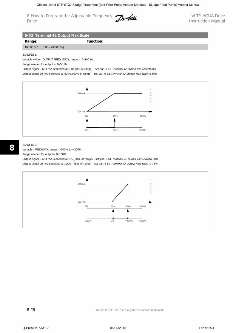
6-52 Terminal 42 Output Max Scale
Range: Function:100.00 %* [0.00 - 200.00 %]
EXAMPLE 1:
Variable value= OUTPUT FREQUENCY, range = 0–100 Hz
Range needed for output = 0–50 Hz
Output signal 0 or 4 mA is needed at 0 Hz (0% of range) - set par. 6-51 Terminal 42 Output Min Scale to 0%
Output signal 20 mA is needed at 50 Hz (50% of range) - set par. 6-52 Terminal 42 Output Max Scale to 50%
�����������
EXAMPLE 2:
Variable= FEEDBACK, range= -200% to +200%
Range needed for output= 0–100%
Output signal 0 or 4 mA is needed at 0% (50% of range) - set par. 6-51 Terminal 42 Output Min Scale to 50%
Output signal 20 mA is needed at 100% (75% of range) - set par. 6-52 Terminal 42 Output Max Scale to 75%
����������
8 How to Program the Adjustable FrequencyDrive
VLT AQUA DriveInstruction Manual
8-28 MG.20.M7.22 - VLT is a registered Danfoss trademark
8
Gibson Island STP ST32 Sludge Treatment (Belt Filter Press Vendor Manuals - Sludge Feed Pump) Vendor Manual
Q-Pulse Id: VM168 05/06/2013 172 of 253
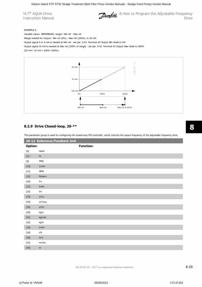
EXAMPLE 3:
Variable value= REFERENCE, range= Min ref - Max ref
Range needed for output= Min ref (0%) - Max ref (100%), 0–10 mA
Output signal 0 or 4 mA is needed at Min ref - set par. 6-51 Terminal 42 Output Min Scale to 0%
Output signal 10 mA is needed at Max ref (100% of range) - set par. 6-52 Terminal 42 Output Max Scale to 200%
(20 mA / 10 mA x 100%=200%).
����������
8.2.9 Drive Closed-loop, 20-**
This parameter group is used for configuring the closed-loop PID controller, which controls the output frequency of the adjustable frequency drive.
20-12 Reference/Feedback Unit
Option: Function:[0] None
[1] * %
[5] PPM
[10] 1/min
[11] RPM
[12] Pulse/s
[20] l/s
[21] l/min
[22] l/h
[23] m3/s
[24] m3/min
[25] m3/h
[30] kg/s
[31] kg/min
[32] kg/h
[33] t/min
[34] t/h
[40] m/s
[41] m/min
[45] m
VLT AQUA DriveInstruction Manual
8 How to Program the Adjustable FrequencyDrive
MG.20.M7.22 - VLT is a registered Danfoss trademark 8-29
8
Gibson Island STP ST32 Sludge Treatment (Belt Filter Press Vendor Manuals - Sludge Feed Pump) Vendor Manual
Q-Pulse Id: VM168 05/06/2013 173 of 253
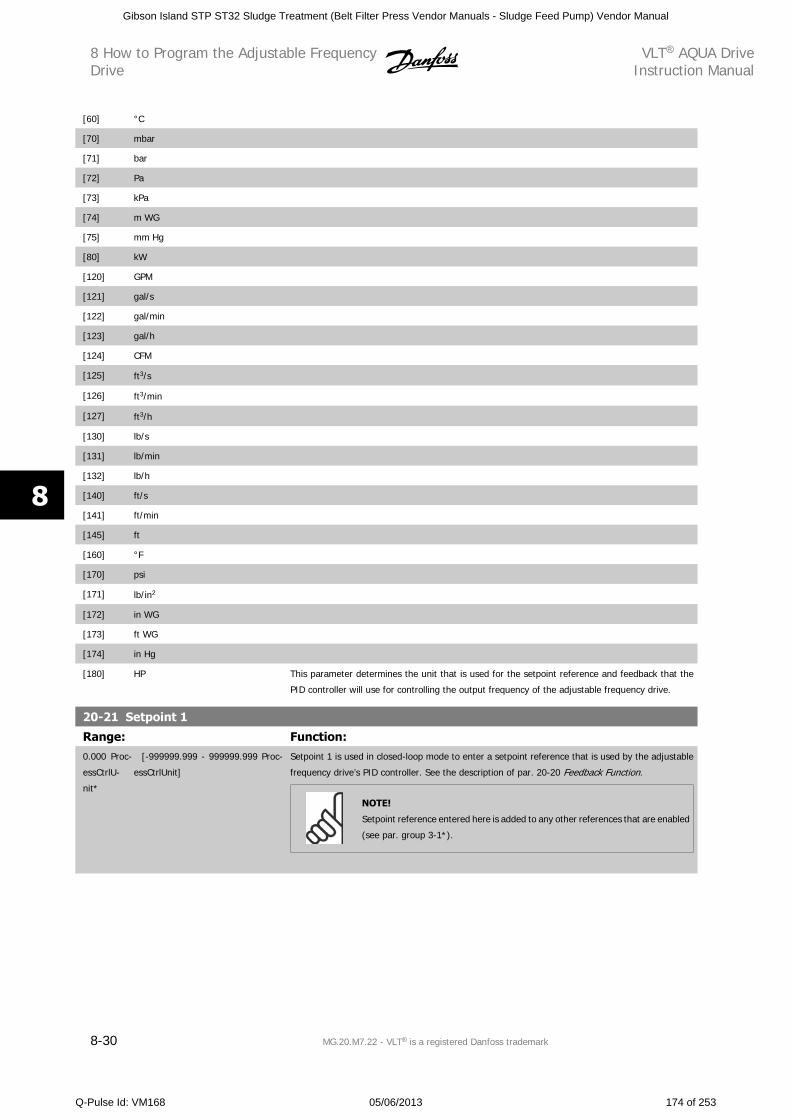
[60] °C
[70] mbar
[71] bar
[72] Pa
[73] kPa
[74] m WG
[75] mm Hg
[80] kW
[120] GPM
[121] gal/s
[122] gal/min
[123] gal/h
[124] CFM
[125] ft3/s
[126] ft3/min
[127] ft3/h
[130] lb/s
[131] lb/min
[132] lb/h
[140] ft/s
[141] ft/min
[145] ft
[160] °F
[170] psi
[171] lb/in2
[172] in WG
[173] ft WG
[174] in Hg
[180] HP This parameter determines the unit that is used for the setpoint reference and feedback that the
PID controller will use for controlling the output frequency of the adjustable frequency drive.
20-21 Setpoint 1
Range: Function:0.000 Proc-
essCtrlU-
nit*
[-999999.999 - 999999.999 Proc-
essCtrlUnit]
Setpoint 1 is used in closed-loop mode to enter a setpoint reference that is used by the adjustable
frequency drive’s PID controller. See the description of par. 20-20 Feedback Function.
NOTE!
Setpoint reference entered here is added to any other references that are enabled
(see par. group 3-1*).
8 How to Program the Adjustable FrequencyDrive
VLT AQUA DriveInstruction Manual
8-30 MG.20.M7.22 - VLT is a registered Danfoss trademark
8
Gibson Island STP ST32 Sludge Treatment (Belt Filter Press Vendor Manuals - Sludge Feed Pump) Vendor Manual
Q-Pulse Id: VM168 05/06/2013 174 of 253
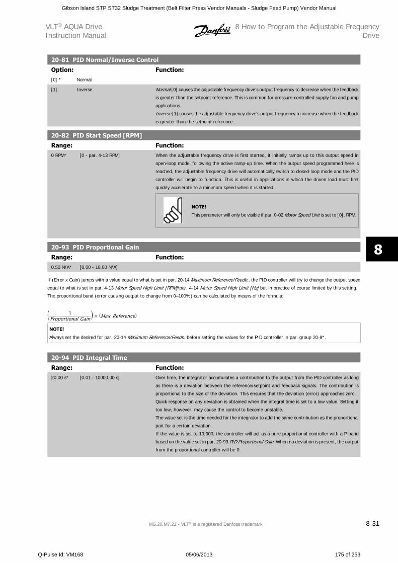
20-81 PID Normal/Inverse Control
Option: Function:[0] * Normal
[1] Inverse Normal [0] causes the adjustable frequency drive’s output frequency to decrease when the feedback
is greater than the setpoint reference. This is common for pressure-controlled supply fan and pump
applications.
Inverse [1] causes the adjustable frequency drive’s output frequency to increase when the feedback
is greater than the setpoint reference.
20-82 PID Start Speed [RPM]
Range: Function:0 RPM* [0 - par. 4-13 RPM] When the adjustable frequency drive is first started, it initially ramps up to this output speed in
open-loop mode, following the active ramp-up time. When the output speed programmed here is
reached, the adjustable frequency drive will automatically switch to closed-loop mode and the PID
controller will begin to function. This is useful in applications in which the driven load must first
quickly accelerate to a minimum speed when it is started.
NOTE!
This parameter will only be visible if par. 0-02 Motor Speed Unit is set to [0], RPM.
20-93 PID Proportional Gain
Range: Function:0.50 N/A* [0.00 - 10.00 N/A]
If (Error x Gain) jumps with a value equal to what is set in par. 20-14 Maximum Reference/Feedb., the PID controller will try to change the output speed
equal to what is set in par. 4-13 Motor Speed High Limit [RPM]/par. 4-14 Motor Speed High Limit [Hz] but in practice of course limited by this setting.
The proportional band (error causing output to change from 0–100%) can be calculated by means of the formula:
( 1Proportional Gain ) × (Max Reference)
NOTE!
Always set the desired for par. 20-14 Maximum Reference/Feedb. before setting the values for the PID controller in par. group 20-9*.
20-94 PID Integral Time
Range: Function:20.00 s* [0.01 - 10000.00 s] Over time, the integrator accumulates a contribution to the output from the PID controller as long
as there is a deviation between the reference/setpoint and feedback signals. The contribution is
proportional to the size of the deviation. This ensures that the deviation (error) approaches zero.
Quick response on any deviation is obtained when the integral time is set to a low value. Setting it
too low, however, may cause the control to become unstable.
The value set is the time needed for the integrator to add the same contribution as the proportional
part for a certain deviation.
If the value is set to 10,000, the controller will act as a pure proportional controller with a P-band
based on the value set in par. 20-93 PID Proportional Gain. When no deviation is present, the output
from the proportional controller will be 0.
VLT AQUA DriveInstruction Manual
8 How to Program the Adjustable FrequencyDrive
MG.20.M7.22 - VLT is a registered Danfoss trademark 8-31
8
Gibson Island STP ST32 Sludge Treatment (Belt Filter Press Vendor Manuals - Sludge Feed Pump) Vendor Manual
Q-Pulse Id: VM168 05/06/2013 175 of 253
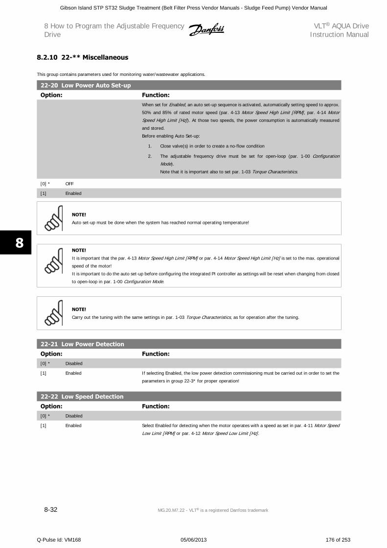
8.2.10 22-** Miscellaneous
This group contains parameters used for monitoring water/wastewater applications.
22-20 Low Power Auto Set-up
Option: Function:When set for Enabled, an auto set-up sequence is activated, automatically setting speed to approx.
50% and 85% of rated motor speed (par. 4-13 Motor Speed High Limit [RPM], par. 4-14 Motor
Speed High Limit [Hz]). At those two speeds, the power consumption is automatically measured
and stored.
Before enabling Auto Set-up:
1. Close valve(s) in order to create a no-flow condition
2. The adjustable frequency drive must be set for open-loop (par. 1-00 Configuration
Mode).
Note that it is important also to set par. 1-03 Torque Characteristics.
[0] * OFF
[1] Enabled
NOTE!
Auto set-up must be done when the system has reached normal operating temperature!
NOTE!
It is important that the par. 4-13 Motor Speed High Limit [RPM] or par. 4-14 Motor Speed High Limit [Hz] is set to the max. operational
speed of the motor!
It is important to do the auto set-up before configuring the integrated PI controller as settings will be reset when changing from closed
to open-loop in par. 1-00 Configuration Mode.
NOTE!
Carry out the tuning with the same settings in par. 1-03 Torque Characteristics, as for operation after the tuning.
22-21 Low Power Detection
Option: Function:[0] * Disabled
[1] Enabled If selecting Enabled, the low power detection commissioning must be carried out in order to set the
parameters in group 22-3* for proper operation!
22-22 Low Speed Detection
Option: Function:[0] * Disabled
[1] Enabled Select Enabled for detecting when the motor operates with a speed as set in par. 4-11 Motor Speed
Low Limit [RPM] or par. 4-12 Motor Speed Low Limit [Hz].
8 How to Program the Adjustable FrequencyDrive
VLT AQUA DriveInstruction Manual
8-32 MG.20.M7.22 - VLT is a registered Danfoss trademark
8
Gibson Island STP ST32 Sludge Treatment (Belt Filter Press Vendor Manuals - Sludge Feed Pump) Vendor Manual
Q-Pulse Id: VM168 05/06/2013 176 of 253
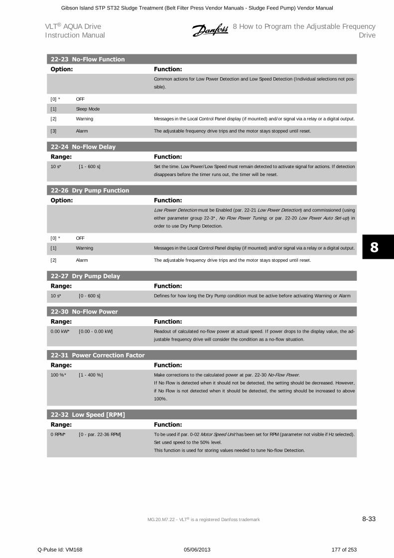
22-23 No-Flow Function
Option: Function:Common actions for Low Power Detection and Low Speed Detection (Individual selections not pos-
sible).
[0] * OFF
[1] Sleep Mode
[2] Warning Messages in the Local Control Panel display (if mounted) and/or signal via a relay or a digital output.
[3] Alarm The adjustable frequency drive trips and the motor stays stopped until reset.
22-24 No-Flow Delay
Range: Function:10 s* [1 - 600 s] Set the time. Low Power/Low Speed must remain detected to activate signal for actions. If detection
disappears before the timer runs out, the timer will be reset.
22-26 Dry Pump Function
Option: Function:Low Power Detection must be Enabled (par. 22-21 Low Power Detection) and commissioned (using
either parameter group 22-3*, No Flow Power Tuning, or par. 22-20 Low Power Auto Set-up) in
order to use Dry Pump Detection.
[0] * OFF
[1] Warning Messages in the Local Control Panel display (if mounted) and/or signal via a relay or a digital output.
[2] Alarm The adjustable frequency drive trips and the motor stays stopped until reset.
22-27 Dry Pump Delay
Range: Function:10 s* [0 - 600 s] Defines for how long the Dry Pump condition must be active before activating Warning or Alarm
22-30 No-Flow Power
Range: Function:0.00 kW* [0.00 - 0.00 kW] Readout of calculated no-flow power at actual speed. If power drops to the display value, the ad-
justable frequency drive will consider the condition as a no-flow situation.
22-31 Power Correction Factor
Range: Function:100 %* [1 - 400 %] Make corrections to the calculated power at par. 22-30 No-Flow Power.
If No Flow is detected when it should not be detected, the setting should be decreased. However,
if No Flow is not detected when it should be detected, the setting should be increased to above
100%.
22-32 Low Speed [RPM]
Range: Function:0 RPM* [0 - par. 22-36 RPM] To be used if par. 0-02 Motor Speed Unit has been set for RPM (parameter not visible if Hz selected).
Set used speed to the 50% level.
This function is used for storing values needed to tune No-flow Detection.
VLT AQUA DriveInstruction Manual
8 How to Program the Adjustable FrequencyDrive
MG.20.M7.22 - VLT is a registered Danfoss trademark 8-33
8
Gibson Island STP ST32 Sludge Treatment (Belt Filter Press Vendor Manuals - Sludge Feed Pump) Vendor Manual
Q-Pulse Id: VM168 05/06/2013 177 of 253
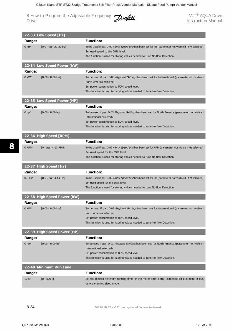
22-33 Low Speed [Hz]
Range: Function:0 Hz* [0.0 - par. 22-37 Hz] To be used if par. 0-02 Motor Speed Unit has been set for Hz (parameter not visible if RPM selected).
Set used speed to the 50% level.
The function is used for storing values needed to tune No-flow Detection.
22-34 Low Speed Power [kW]
Range: Function:0 kW* [0.00 - 0.00 kW] To be used if par. 0-03 Regional Settings has been set for International (parameter not visible if
North America selected).
Set power consumption to 50% speed level.
This function is used for storing values needed to tune No-flow Detection.
22-35 Low Speed Power [HP]
Range: Function:0 hp* [0.00 - 0.00 hp] To be used if par. 0-03 Regional Settings has been set for North America (parameter not visible if
International selected).
Set power consumption to 50% speed level.
This function is used for storing values needed to tune No-flow Detection.
22-36 High Speed [RPM]
Range: Function:0 RPM* [0 - par. 4-13 RPM] To be used if par. 0-02 Motor Speed Unit has been set for RPM (parameter not visible if Hz selected).
Set used speed for the 85% level.
The function is used for storing values needed to tune No-flow Detection.
22-37 High Speed [Hz]
Range: Function:0.0 Hz* [0.0 - par. 4-14 Hz] To be used if par. 0-02 Motor Speed Unit has been set for Hz (parameter not visible if RPM selected).
Set used speed for the 85% level.
The function is used for storing values needed to tune No-flow Detection.
22-38 High Speed Power [kW]
Range: Function:0 kW* [0.00 - 0.00 kW] To be used if par. 0-03 Regional Settings has been set for International (parameter not visible if
North America selected).
Set power consumption to 85% speed level.
This function is used for storing values needed to tune No-flow Detection.
22-39 High Speed Power [HP]
Range: Function:0 hp* [0.00 - 0.00 hp] To be used if par. 0-03 Regional Settings has been set for North America (parameter not visible if
International selected).
Set power consumption to 85% speed level.
This function is used for storing values needed to tune No-flow Detection.
22-40 Minimum Run Time
Range: Function:10 s* [0 - 600 s] Set the desired minimum running time for the motor after a start command (digital input or bus)
before entering sleep mode.
8 How to Program the Adjustable FrequencyDrive
VLT AQUA DriveInstruction Manual
8-34 MG.20.M7.22 - VLT is a registered Danfoss trademark
8
Gibson Island STP ST32 Sludge Treatment (Belt Filter Press Vendor Manuals - Sludge Feed Pump) Vendor Manual
Q-Pulse Id: VM168 05/06/2013 178 of 253
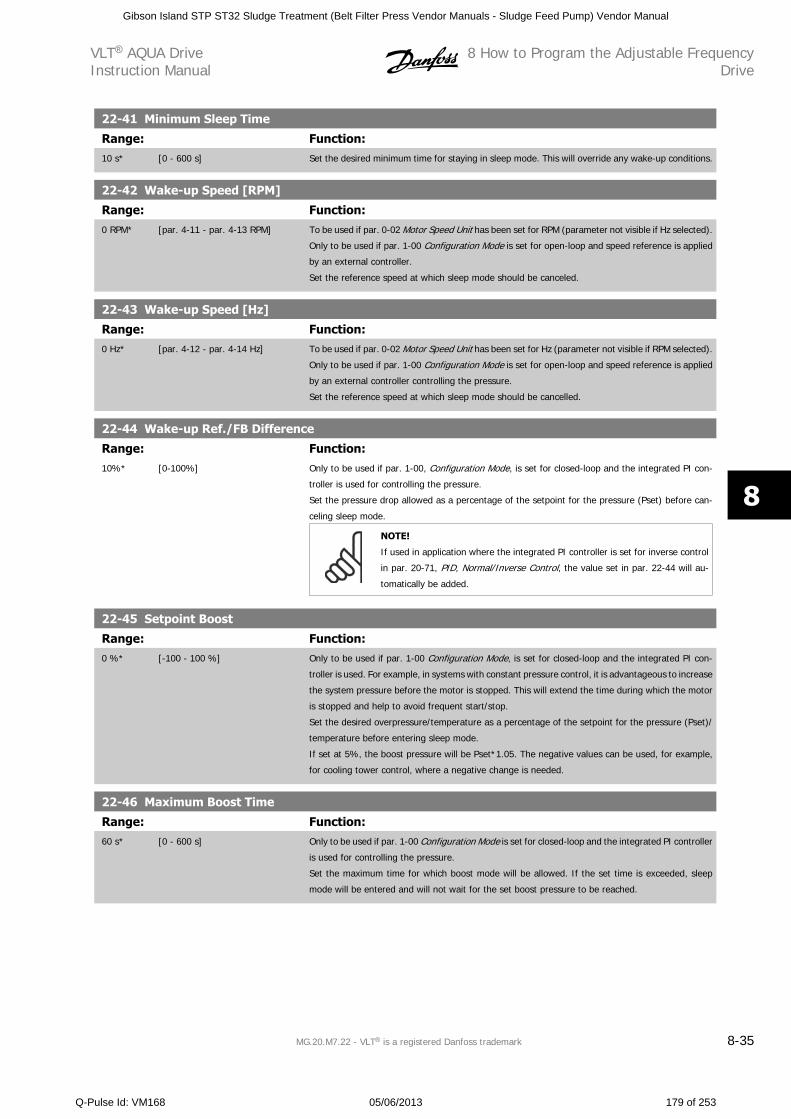
22-41 Minimum Sleep Time
Range: Function:10 s* [0 - 600 s] Set the desired minimum time for staying in sleep mode. This will override any wake-up conditions.
22-42 Wake-up Speed [RPM]
Range: Function:0 RPM* [par. 4-11 - par. 4-13 RPM] To be used if par. 0-02 Motor Speed Unit has been set for RPM (parameter not visible if Hz selected).
Only to be used if par. 1-00 Configuration Mode is set for open-loop and speed reference is applied
by an external controller.
Set the reference speed at which sleep mode should be canceled.
22-43 Wake-up Speed [Hz]
Range: Function:0 Hz* [par. 4-12 - par. 4-14 Hz] To be used if par. 0-02 Motor Speed Unit has been set for Hz (parameter not visible if RPM selected).
Only to be used if par. 1-00 Configuration Mode is set for open-loop and speed reference is applied
by an external controller controlling the pressure.
Set the reference speed at which sleep mode should be cancelled.
22-44 Wake-up Ref./FB Difference
Range: Function:10%* [0-100%] Only to be used if par. 1-00, Configuration Mode, is set for closed-loop and the integrated PI con-
troller is used for controlling the pressure.
Set the pressure drop allowed as a percentage of the setpoint for the pressure (Pset) before can-
celing sleep mode.
NOTE!
If used in application where the integrated PI controller is set for inverse control
in par. 20-71, PID, Normal/Inverse Control, the value set in par. 22-44 will au-
tomatically be added.
22-45 Setpoint Boost
Range: Function:0 %* [-100 - 100 %] Only to be used if par. 1-00 Configuration Mode, is set for closed-loop and the integrated PI con-
troller is used. For example, in systems with constant pressure control, it is advantageous to increase
the system pressure before the motor is stopped. This will extend the time during which the motor
is stopped and help to avoid frequent start/stop.
Set the desired overpressure/temperature as a percentage of the setpoint for the pressure (Pset)/
temperature before entering sleep mode.
If set at 5%, the boost pressure will be Pset*1.05. The negative values can be used, for example,
for cooling tower control, where a negative change is needed.
22-46 Maximum Boost Time
Range: Function:60 s* [0 - 600 s] Only to be used if par. 1-00 Configuration Mode is set for closed-loop and the integrated PI controller
is used for controlling the pressure.
Set the maximum time for which boost mode will be allowed. If the set time is exceeded, sleep
mode will be entered and will not wait for the set boost pressure to be reached.
VLT AQUA DriveInstruction Manual
8 How to Program the Adjustable FrequencyDrive
MG.20.M7.22 - VLT is a registered Danfoss trademark 8-35
8
Gibson Island STP ST32 Sludge Treatment (Belt Filter Press Vendor Manuals - Sludge Feed Pump) Vendor Manual
Q-Pulse Id: VM168 05/06/2013 179 of 253
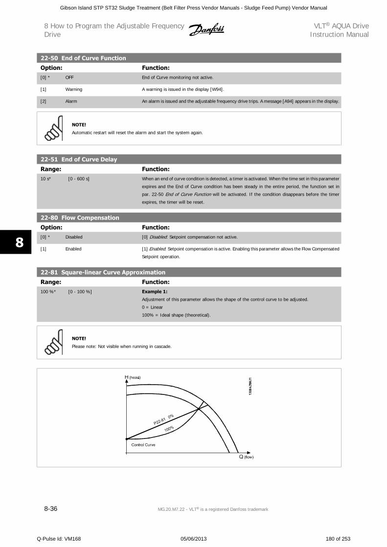
22-50 End of Curve Function
Option: Function:[0] * OFF End of Curve monitoring not active.
[1] Warning A warning is issued in the display [W94].
[2] Alarm An alarm is issued and the adjustable frequency drive trips. A message [A94] appears in the display.
NOTE!
Automatic restart will reset the alarm and start the system again.
22-51 End of Curve Delay
Range: Function:10 s* [0 - 600 s] When an end of curve condition is detected, a timer is activated. When the time set in this parameter
expires and the End of Curve condition has been steady in the entire period, the function set in
par. 22-50 End of Curve Function will be activated. If the condition disappears before the timer
expires, the timer will be reset.
22-80 Flow Compensation
Option: Function:[0] * Disabled [0] Disabled: Setpoint compensation not active.
[1] Enabled [1] Enabled: Setpoint compensation is active. Enabling this parameter allows the Flow Compensated
Setpoint operation.
22-81 Square-linear Curve Approximation
Range: Function:100 %* [0 - 100 %] Example 1:
Adjustment of this parameter allows the shape of the control curve to be adjusted.
0 = Linear
100% = Ideal shape (theoretical).
NOTE!
Please note: Not visible when running in cascade.
8 How to Program the Adjustable FrequencyDrive
VLT AQUA DriveInstruction Manual
8-36 MG.20.M7.22 - VLT is a registered Danfoss trademark
8
Gibson Island STP ST32 Sludge Treatment (Belt Filter Press Vendor Manuals - Sludge Feed Pump) Vendor Manual
Q-Pulse Id: VM168 05/06/2013 180 of 253
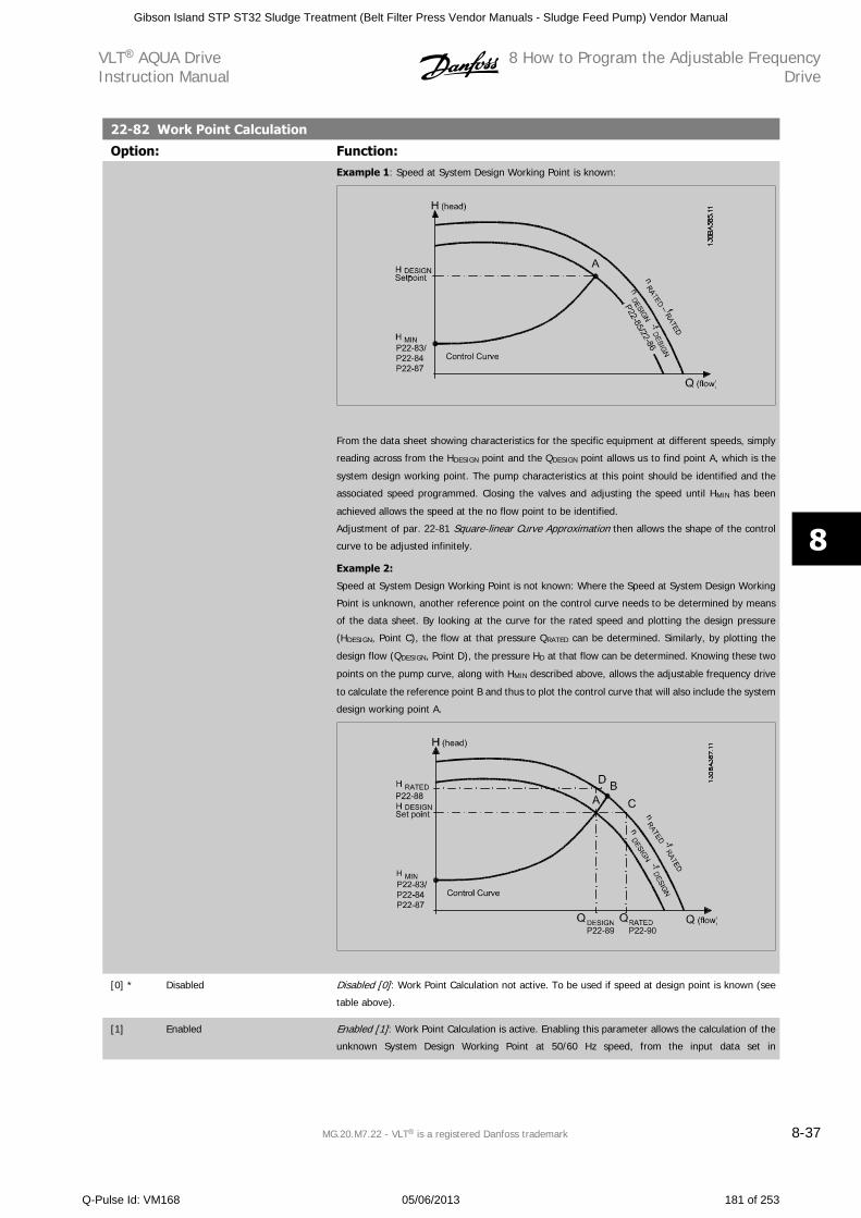
22-82 Work Point Calculation
Option: Function:Example 1: Speed at System Design Working Point is known:
From the data sheet showing characteristics for the specific equipment at different speeds, simply
reading across from the HDESIGN point and the QDESIGN point allows us to find point A, which is the
system design working point. The pump characteristics at this point should be identified and the
associated speed programmed. Closing the valves and adjusting the speed until HMIN has been
achieved allows the speed at the no flow point to be identified.
Adjustment of par. 22-81 Square-linear Curve Approximation then allows the shape of the control
curve to be adjusted infinitely.
Example 2:
Speed at System Design Working Point is not known: Where the Speed at System Design Working
Point is unknown, another reference point on the control curve needs to be determined by means
of the data sheet. By looking at the curve for the rated speed and plotting the design pressure
(HDESIGN, Point C), the flow at that pressure QRATED can be determined. Similarly, by plotting the
design flow (QDESIGN, Point D), the pressure HD at that flow can be determined. Knowing these two
points on the pump curve, along with HMIN described above, allows the adjustable frequency drive
to calculate the reference point B and thus to plot the control curve that will also include the system
design working point A.
[0] * Disabled Disabled [0]: Work Point Calculation not active. To be used if speed at design point is known (see
table above).
[1] Enabled Enabled [1]: Work Point Calculation is active. Enabling this parameter allows the calculation of the
unknown System Design Working Point at 50/60 Hz speed, from the input data set in
VLT AQUA DriveInstruction Manual
8 How to Program the Adjustable FrequencyDrive
MG.20.M7.22 - VLT is a registered Danfoss trademark 8-37
8
Gibson Island STP ST32 Sludge Treatment (Belt Filter Press Vendor Manuals - Sludge Feed Pump) Vendor Manual
Q-Pulse Id: VM168 05/06/2013 181 of 253
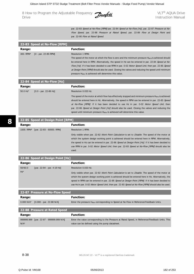
par. 22-83 Speed at No-Flow [RPM] par. 22-84 Speed at No-Flow [Hz], par. 22-87 Pressure at No-
Flow Speed, par. 22-88 Pressure at Rated Speed, par. 22-89 Flow at Design Point and
par. 22-90 Flow at Rated Speed.
22-83 Speed at No-Flow [RPM]
Range: Function:300. RPM* [0 - par. 22-85 RPM] Resolution 1 RPM.
The speed of the motor at which the flow is zero and the minimum pressure HMIN is achieved should
be entered here in RPM. Alternatively, the speed in Hz can be entered in par. 22-84 Speed at No-
Flow [Hz]. If it has been decided to use RPM in par. 0-02 Motor Speed Unit, then par. 22-85 Speed
at Design Point [RPM] should also be used. Closing the valves and reducing the speed until minimum
pressure HMIN is achieved will determine this value.
22-84 Speed at No-Flow [Hz]
Range: Function:50.0 Hz* [0.0 - par. 22-86 Hz] Resolution 0.033 Hz.
The speed of the motor at which flow has effectively stopped and minimum pressure HMIN is achieved
should be entered here in Hz. Alternatively, the speed in RPM can be entered in par. 22-83 Speed
at No-Flow [RPM]. If it has been decided to use Hz in par. 0-02 Motor Speed Unit, then
par. 22-86 Speed at Design Point [Hz] should also be used. Closing the valves and reducing the
speed until minimum pressure HMIN is achieved will determine this value.
22-85 Speed at Design Point [RPM]
Range: Function:1500. RPM* [par. 22-83 - 60000. RPM] Resolution 1 RPM.
Only visible when par. 22-82 Work Point Calculation is set to Disable. The speed of the motor at
which the system design working point is achieved should be entered here in RPM. Alternatively,
the speed in Hz can be entered in par. 22-86 Speed at Design Point [Hz]. If it has been decided to
use RPM in par. 0-02 Motor Speed Unit, then par. 22-83 Speed at No-Flow [RPM] should also be
used.
22-86 Speed at Design Point [Hz]
Range: Function:50/60.0
Hz*
[par. 22-84 - par. 4-19 Hz] Resolution 0.033 Hz.
Only visible when par. 22-82 Work Point Calculation is set to Disable. The speed of the motor at
which the system design working point is achieved should be entered here in Hz. Alternatively, the
speed in RPM can be entered in par. 22-85 Speed at Design Point [RPM]. If it has been decided to
use Hz in par. 0-02 Motor Speed Unit, then par. 22-83 Speed at No-Flow [RPM] should also be used.
22-87 Pressure at No-Flow Speed
Range: Function:0.000 N/A* [0.000 - par. 22-88 N/A] Enter the pressure HMIN corresponding to Speed at No Flow in Reference/Feedback Units.
22-88 Pressure at Rated Speed
Range: Function:999999.999
N/A*
[par. 22-87 - 999999.999 N/A] Enter the value corresponding to the Pressure at Rated Speed, in Reference/Feedback Units. This
value can be defined using the pump datasheet.
8 How to Program the Adjustable FrequencyDrive
VLT AQUA DriveInstruction Manual
8-38 MG.20.M7.22 - VLT is a registered Danfoss trademark
8
Gibson Island STP ST32 Sludge Treatment (Belt Filter Press Vendor Manuals - Sludge Feed Pump) Vendor Manual
Q-Pulse Id: VM168 05/06/2013 182 of 253
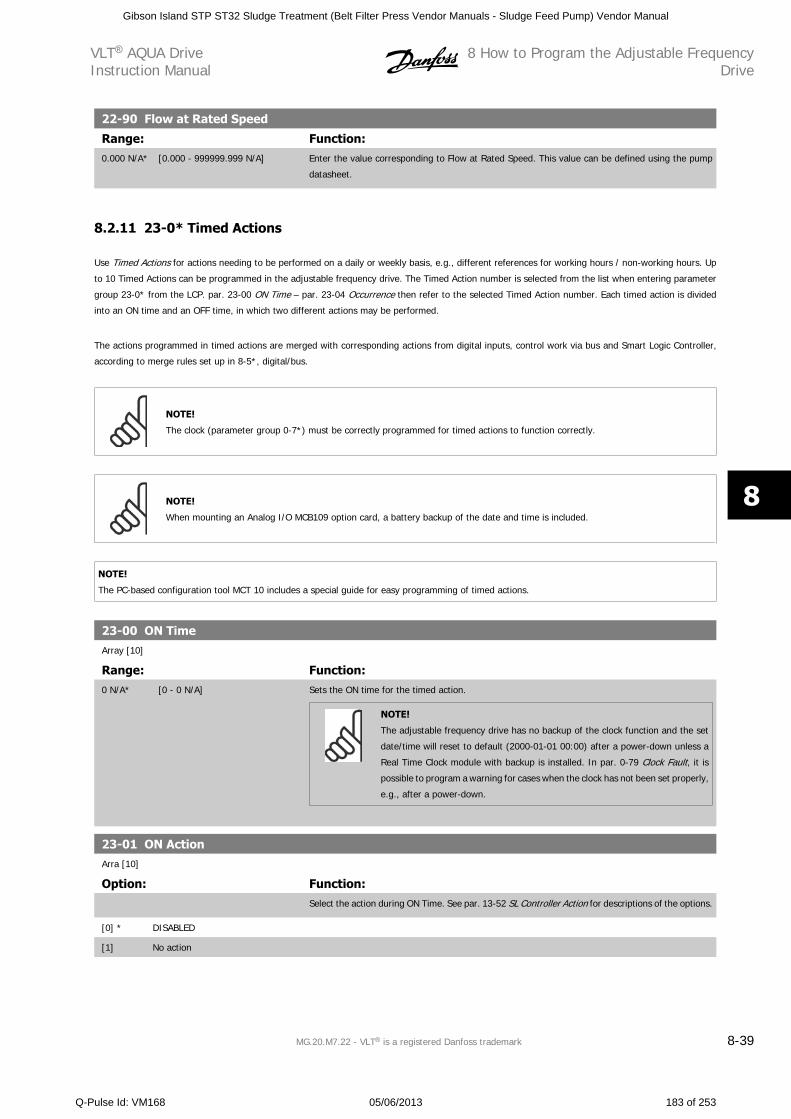
22-90 Flow at Rated Speed
Range: Function:0.000 N/A* [0.000 - 999999.999 N/A] Enter the value corresponding to Flow at Rated Speed. This value can be defined using the pump
datasheet.
8.2.11 23-0* Timed Actions
Use Timed Actions for actions needing to be performed on a daily or weekly basis, e.g., different references for working hours / non-working hours. Up
to 10 Timed Actions can be programmed in the adjustable frequency drive. The Timed Action number is selected from the list when entering parameter
group 23-0* from the LCP. par. 23-00 ON Time – par. 23-04 Occurrence then refer to the selected Timed Action number. Each timed action is divided
into an ON time and an OFF time, in which two different actions may be performed.
The actions programmed in timed actions are merged with corresponding actions from digital inputs, control work via bus and Smart Logic Controller,
according to merge rules set up in 8-5*, digital/bus.
NOTE!
The clock (parameter group 0-7*) must be correctly programmed for timed actions to function correctly.
NOTE!
When mounting an Analog I/O MCB109 option card, a battery backup of the date and time is included.
NOTE!
The PC-based configuration tool MCT 10 includes a special guide for easy programming of timed actions.
23-00 ON TimeArray [10]
Range: Function:0 N/A* [0 - 0 N/A] Sets the ON time for the timed action.
NOTE!
The adjustable frequency drive has no backup of the clock function and the set
date/time will reset to default (2000-01-01 00:00) after a power-down unless a
Real Time Clock module with backup is installed. In par. 0-79 Clock Fault, it is
possible to program a warning for cases when the clock has not been set properly,
e.g., after a power-down.
23-01 ON ActionArra [10]
Option: Function:Select the action during ON Time. See par. 13-52 SL Controller Action for descriptions of the options.
[0] * DISABLED
[1] No action
VLT AQUA DriveInstruction Manual
8 How to Program the Adjustable FrequencyDrive
MG.20.M7.22 - VLT is a registered Danfoss trademark 8-39
8
Gibson Island STP ST32 Sludge Treatment (Belt Filter Press Vendor Manuals - Sludge Feed Pump) Vendor Manual
Q-Pulse Id: VM168 05/06/2013 183 of 253
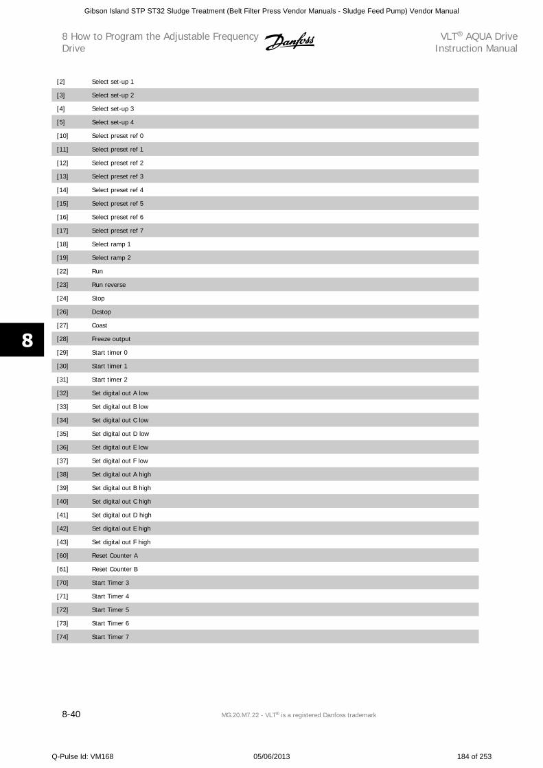
[2] Select set-up 1
[3] Select set-up 2
[4] Select set-up 3
[5] Select set-up 4
[10] Select preset ref 0
[11] Select preset ref 1
[12] Select preset ref 2
[13] Select preset ref 3
[14] Select preset ref 4
[15] Select preset ref 5
[16] Select preset ref 6
[17] Select preset ref 7
[18] Select ramp 1
[19] Select ramp 2
[22] Run
[23] Run reverse
[24] Stop
[26] Dcstop
[27] Coast
[28] Freeze output
[29] Start timer 0
[30] Start timer 1
[31] Start timer 2
[32] Set digital out A low
[33] Set digital out B low
[34] Set digital out C low
[35] Set digital out D low
[36] Set digital out E low
[37] Set digital out F low
[38] Set digital out A high
[39] Set digital out B high
[40] Set digital out C high
[41] Set digital out D high
[42] Set digital out E high
[43] Set digital out F high
[60] Reset Counter A
[61] Reset Counter B
[70] Start Timer 3
[71] Start Timer 4
[72] Start Timer 5
[73] Start Timer 6
[74] Start Timer 7
8 How to Program the Adjustable FrequencyDrive
VLT AQUA DriveInstruction Manual
8-40 MG.20.M7.22 - VLT is a registered Danfoss trademark
8
Gibson Island STP ST32 Sludge Treatment (Belt Filter Press Vendor Manuals - Sludge Feed Pump) Vendor Manual
Q-Pulse Id: VM168 05/06/2013 184 of 253
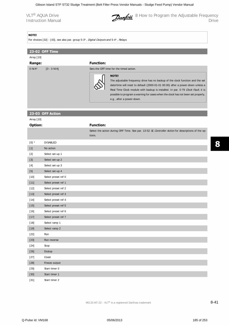
NOTE!
For choices [32] - [43], see also par. group 5-3*, Digital Outputs and 5-4*, Relays.
23-02 OFF TimeArray [10]
Range: Function:0 N/A* [0 - 0 N/A] Sets the OFF time for the timed action.
NOTE!
The adjustable frequency drive has no backup of the clock function and the set
date/time will reset to default (2000-01-01 00:00) after a power-down unless a
Real Time Clock module with backup is installed. In par. 0-79 Clock Fault, it is
possible to program a warning for cases when the clock has not been set properly,
e.g., after a power-down.
23-03 OFF ActionArray [10]
Option: Function:Select the action during OFF Time. See par. 13-52 SL Controller Action for descriptions of the op-
tions.
[0] * DISABLED
[1] No action
[2] Select set-up 1
[3] Select set-up 2
[4] Select set-up 3
[5] Select set-up 4
[10] Select preset ref 0
[11] Select preset ref 1
[12] Select preset ref 2
[13] Select preset ref 3
[14] Select preset ref 4
[15] Select preset ref 5
[16] Select preset ref 6
[17] Select preset ref 7
[18] Select ramp 1
[19] Select ramp 2
[22] Run
[23] Run reverse
[24] Stop
[26] Dcstop
[27] Coast
[28] Freeze output
[29] Start timer 0
[30] Start timer 1
[31] Start timer 2
VLT AQUA DriveInstruction Manual
8 How to Program the Adjustable FrequencyDrive
MG.20.M7.22 - VLT is a registered Danfoss trademark 8-41
8
Gibson Island STP ST32 Sludge Treatment (Belt Filter Press Vendor Manuals - Sludge Feed Pump) Vendor Manual
Q-Pulse Id: VM168 05/06/2013 185 of 253
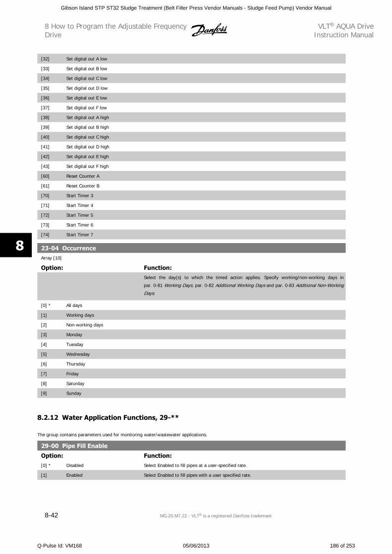
[32] Set digital out A low
[33] Set digital out B low
[34] Set digital out C low
[35] Set digital out D low
[36] Set digital out E low
[37] Set digital out F low
[38] Set digital out A high
[39] Set digital out B high
[40] Set digital out C high
[41] Set digital out D high
[42] Set digital out E high
[43] Set digital out F high
[60] Reset Counter A
[61] Reset Counter B
[70] Start Timer 3
[71] Start Timer 4
[72] Start Timer 5
[73] Start Timer 6
[74] Start Timer 7
23-04 OccurrenceArray [10]
Option: Function:Select the day(s) to which the timed action applies. Specify working/non-working days in
par. 0-81 Working Days, par. 0-82 Additional Working Days and par. 0-83 Additional Non-Working
Days.
[0] * All days
[1] Working days
[2] Non-working days
[3] Monday
[4] Tuesday
[5] Wednesday
[6] Thursday
[7] Friday
[8] Saturday
[9] Sunday
8.2.12 Water Application Functions, 29-**
The group contains parameters used for monitoring water/wastewater applications.
29-00 Pipe Fill Enable
Option: Function:[0] * Disabled Select Enabled to fill pipes at a user-specified rate.
[1] Enabled Select Enabled to fill pipes with a user specified rate.
8 How to Program the Adjustable FrequencyDrive
VLT AQUA DriveInstruction Manual
8-42 MG.20.M7.22 - VLT is a registered Danfoss trademark
8
Gibson Island STP ST32 Sludge Treatment (Belt Filter Press Vendor Manuals - Sludge Feed Pump) Vendor Manual
Q-Pulse Id: VM168 05/06/2013 186 of 253
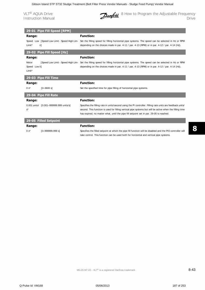
29-01 Pipe Fill Speed [RPM]
Range: Function:Speed Low
Limit*
[Speed Low Limit - Speed High Lim-
it]
Set the filling speed for filling horizontal pipe systems. The speed can be selected in Hz or RPM
depending on the choices made in par. 4-11 / par. 4-13 (RPM) or in par. 4-12 / par. 4-14 (Hz).
29-02 Pipe Fill Speed [Hz]
Range: Function:Motor
Speed Low
Limit*
[Speed Low Limit - Speed High Lim-
it]
Set the filling speed for filling horizontal pipe systems. The speed can be selected in Hz or RPM
depending on the choices made in par. 4-11 / par. 4-13 (RPM) or in par. 4-12 / par. 4-14 (Hz).
29-03 Pipe Fill Time
Range: Function:0 s* [0–3600 s] Set the specified time for pipe filling of horizontal pipe systems.
29-04 Pipe Fill Rate
Range: Function:0.001 units/
s*
[0.001–999999.999 units/s] Specifies the filling rate in units/second using the PI controller. Filling rate units are feedback units/
second. This function is used for filling vertical pipe systems but will be active when the filling time
has expired, no matter what, until the pipe fill setpoint set in par. 29-05 is reached.
29-05 Filled Setpoint
Range: Function:0 s* [0–999999,999 s] Specifies the filled setpoint at which the pipe fill function will be disabled and the PID controller will
take control. This function can be used both for horizontal and vertical pipe systems.
VLT AQUA DriveInstruction Manual
8 How to Program the Adjustable FrequencyDrive
MG.20.M7.22 - VLT is a registered Danfoss trademark 8-43
8
Gibson Island STP ST32 Sludge Treatment (Belt Filter Press Vendor Manuals - Sludge Feed Pump) Vendor Manual
Q-Pulse Id: VM168 05/06/2013 187 of 253
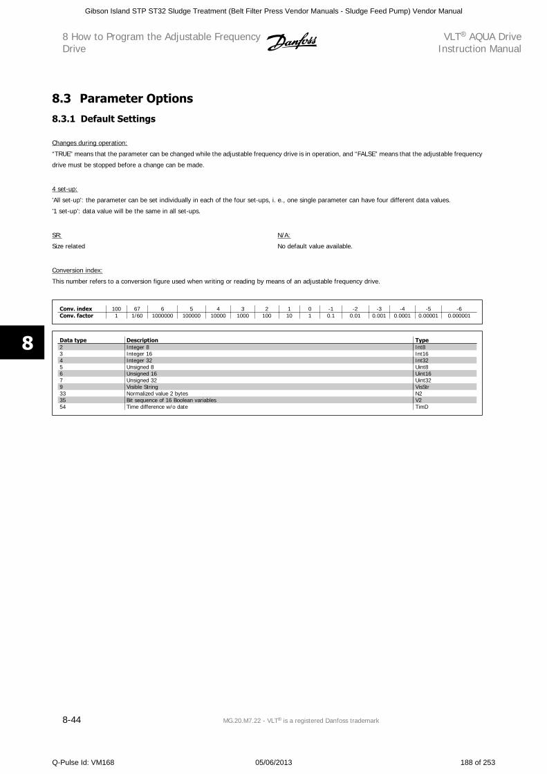
8.3 Parameter Options
8.3.1 Default Settings
Changes during operation:
“TRUE” means that the parameter can be changed while the adjustable frequency drive is in operation, and “FALSE” means that the adjustable frequency
drive must be stopped before a change can be made.
4 set-up:
'All set-up': the parameter can be set individually in each of the four set-ups, i. e., one single parameter can have four different data values.
’1 set-up’: data value will be the same in all set-ups.
SR:
Size related
N/A:
No default value available.
Conversion index:
This number refers to a conversion figure used when writing or reading by means of an adjustable frequency drive.
Conv. index 100 67 6 5 4 3 2 1 0 -1 -2 -3 -4 -5 -6Conv. factor 1 1/60 1000000 100000 10000 1000 100 10 1 0.1 0.01 0.001 0.0001 0.00001 0.000001
Data type Description Type2 Integer 8 Int83 Integer 16 Int164 Integer 32 Int325 Unsigned 8 Uint86 Unsigned 16 Uint167 Unsigned 32 Uint329 Visible String VisStr33 Normalized value 2 bytes N235 Bit sequence of 16 Boolean variables V254 Time difference w/o date TimD
8 How to Program the Adjustable FrequencyDrive
VLT AQUA DriveInstruction Manual
8-44 MG.20.M7.22 - VLT is a registered Danfoss trademark
8
Gibson Island STP ST32 Sludge Treatment (Belt Filter Press Vendor Manuals - Sludge Feed Pump) Vendor Manual
Q-Pulse Id: VM168 05/06/2013 188 of 253
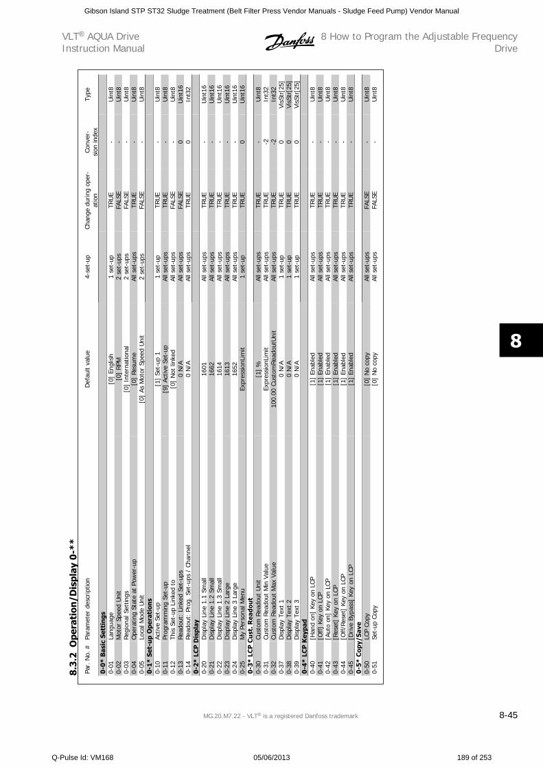
Par.
No.
#Pa
ram
eter
des
crip
tion
Def
ault
valu
e4-
set-
upCh
ange
dur
ing
oper
-at
ion
Conv
er-
sion
inde
xTy
pe
0-0*
Bas
ic S
etti
ngs
0-01
Lang
uage
[0]
Engl
ish
1 se
t-up
TRU
E-
Uin
t80-
02M
otor
Spe
ed U
nit
[0]
RPM
2 se
t-up
sFA
LSE
-U
int8
0-03
Reg
iona
l Set
tings
[0]
Inte
rnat
iona
l2
set-
ups
FALS
E-
Uin
t80-
04O
pera
ting
Stat
e at
Pow
er-u
p[0
] Re
sum
eAl
l set
-ups
TRU
E-
Uin
t80-
05Lo
cal M
ode
Uni
t[0
] As
Mot
or S
peed
Uni
t2
set-
ups
FALS
E-
Uin
t80-
1* S
et-u
p O
pera
tion
s0-
10Ac
tive
Set-
up[1
] Se
t-up
11
set-
upTR
UE
-U
int8
0-11
Prog
ram
min
g Se
t-up
[9]
Activ
e Se
t-up
All s
et-u
psTR
UE
-U
int8
0-12
This
Set
-up
Link
ed t
o[0
] N
ot li
nked
All s
et-u
psFA
LSE
-U
int8
0-13
Read
out:
Lin
ked
Set-
ups
0 N
/AAl
l set
-ups
FALS
E0
Uin
t16
0-14
Read
out:
Pro
g. S
et-u
ps /
Cha
nnel
0 N
/AAl
l set
-ups
TRU
E0
Int3
20-
2* L
CP
Dis
play
0-20
Dis
play
Lin
e 1.
1 Sm
all
1601
All s
et-u
psTR
UE
-U
int1
60-
21D
ispl
ay L
ine
1.2
Smal
l16
62Al
l set
-ups
TRU
E-
Uin
t16
0-22
Dis
play
Lin
e 1.
3 Sm
all
1614
All s
et-u
psTR
UE
-U
int1
60-
23D
ispl
ay L
ine
2 La
rge
1613
All s
et-u
psTR
UE
-U
int1
60-
24D
ispl
ay L
ine
3 La
rge
1652
All s
et-u
psTR
UE
-U
int1
60-
25M
y Pe
rson
al M
enu
Expr
essi
onLi
mit
1 se
t-up
TRU
E0
Uin
t16
0-3*
LC
P C
ust
. Rea
dou
t0-
30Cu
stom
Rea
dout
Uni
t[1
] %
All s
et-u
psTR
UE
-U
int8
0-31
Cust
om R
eado
ut M
in V
alue
Expr
essi
onLi
mit
All s
et-u
psTR
UE
-2In
t32
0-32
Cust
om R
eado
ut M
ax V
alue
100.
00 C
usto
mRea
dout
Uni
tAl
l set
-ups
TRU
E-2
Int3
20-
37D
ispl
ay T
ext
10
N/A
1 se
t-up
TRU
E0
VisS
tr[2
5]0-
38D
ispl
ay T
ext
20
N/A
1 se
t-up
TRU
E0
VisS
tr[2
5]0-
39D
ispl
ay T
ext
30
N/A
1 se
t-up
TRU
E0
VisS
tr[2
5]0-
4* L
CP
Key
pad
0-40
[Han
d on
] Ke
y on
LCP
[1]
Enab
led
All s
et-u
psTR
UE
-U
int8
0-41
[Off
] Ke
y on
LCP
[1]
Enab
led
All s
et-u
psTR
UE
-U
int8
0-42
[Aut
o on
] Ke
y on
LCP
[1]
Enab
led
All s
et-u
psTR
UE
-U
int8
0-43
[Res
et]
Key
on L
CP[1
] En
able
dAl
l set
-ups
TRU
E-
Uin
t80-
44[O
ff/R
eset
] Ke
y on
LCP
[1]
Enab
led
All s
et-u
psTR
UE
-U
int8
0-45
[Driv
e By
pass
] Ke
y on
LCP
[1]
Enab
led
All s
et-u
psTR
UE
-U
int8
0-5*
Cop
y/Sa
ve0-
50LC
P Co
py[0
] N
o co
pyAl
l set
-ups
FALS
E-
Uin
t80-
51Se
t-up
Cop
y[0
] N
o co
pyAl
l set
-ups
FALS
E-
Uin
t8
8.3
.2O
pera
tion
/Dis
play
0-*
*
VLT AQUA DriveInstruction Manual
8 How to Program the Adjustable FrequencyDrive
MG.20.M7.22 - VLT is a registered Danfoss trademark 8-45
8
Gibson Island STP ST32 Sludge Treatment (Belt Filter Press Vendor Manuals - Sludge Feed Pump) Vendor Manual
Q-Pulse Id: VM168 05/06/2013 189 of 253
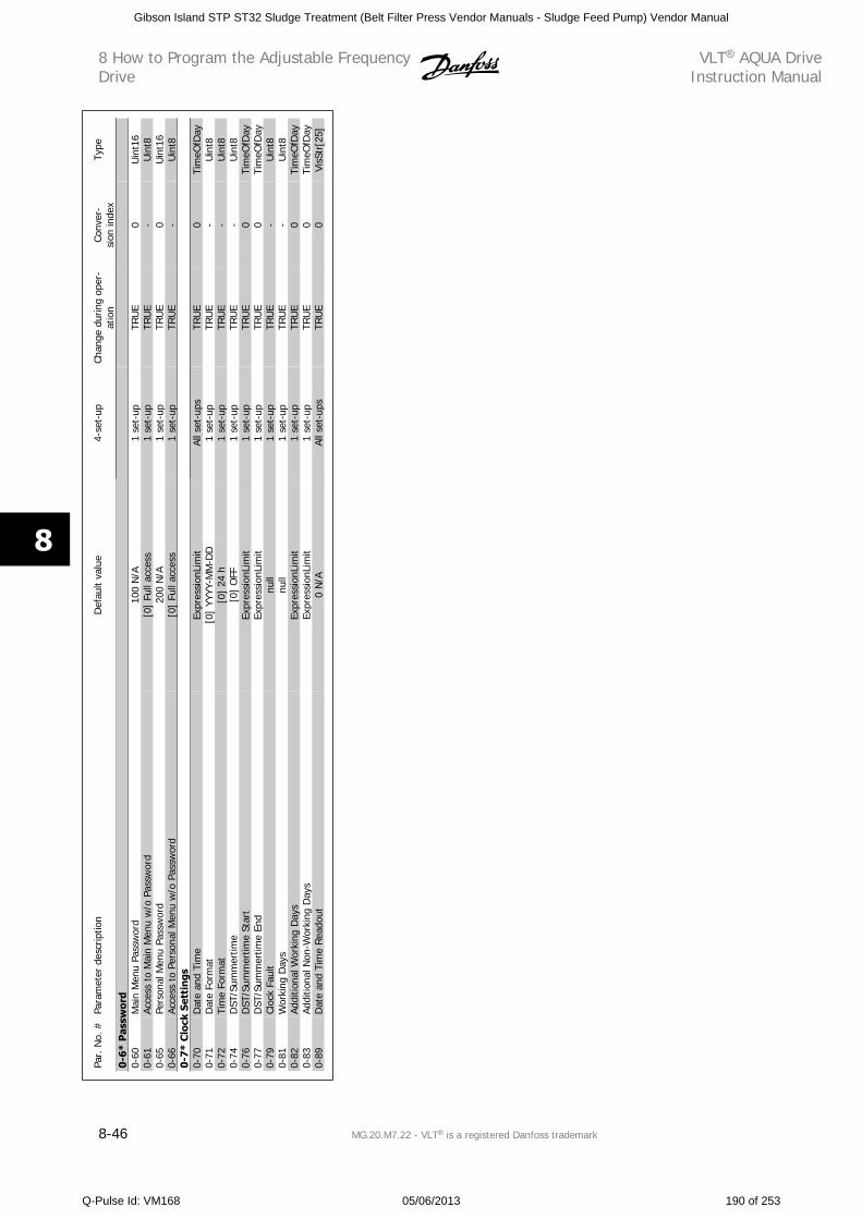
Par.
No.
#Pa
ram
eter
des
crip
tion
Def
ault
valu
e4-
set-
upCh
ange
dur
ing
oper
-at
ion
Conv
er-
sion
inde
xTy
pe
0-6*
Pas
swor
d0-
60M
ain
Men
u Pa
ssw
ord
100
N/A
1 se
t-up
TRU
E0
Uin
t16
0-61
Acce
ss t
o M
ain
Men
u w
/o P
assw
ord
[0]
Full
acce
ss1
set-
upTR
UE
-U
int8
0-65
Pers
onal
Men
u Pa
ssw
ord
200
N/A
1 se
t-up
TRU
E0
Uin
t16
0-66
Acce
ss t
o Pe
rson
al M
enu
w/o
Pas
swor
d[0
] Fu
ll ac
cess
1 se
t-up
TRU
E-
Uin
t80-
7* C
lock
Set
tin
gs0-
70D
ate
and
Tim
eEx
pres
sion
Lim
itAl
l set
-ups
TRU
E0
Tim
eOfD
ay0-
71D
ate
Form
at[0
] YY
YY-M
M-D
D1
set-
upTR
UE
-U
int8
0-72
Tim
e Fo
rmat
[0]
24 h
1 se
t-up
TRU
E-
Uin
t80-
74D
ST/S
umm
ertim
e[0
] O
FF1
set-
upTR
UE
-U
int8
0-76
DST
/Sum
mer
time
Star
tEx
pres
sion
Lim
it1
set-
upTR
UE
0Ti
meO
fDay
0-77
DST
/Sum
mer
time
End
Expr
essi
onLi
mit
1 se
t-up
TRU
E0
Tim
eOfD
ay0-
79Cl
ock
Faul
tnu
ll1
set-
upTR
UE
-U
int8
0-81
Wor
king
Day
snu
ll1
set-
upTR
UE
-U
int8
0-82
Addi
tiona
l Wor
king
Day
sEx
pres
sion
Lim
it1
set-
upTR
UE
0Ti
meO
fDay
0-83
Addi
tiona
l Non
-Wor
king
Day
sEx
pres
sion
Lim
it1
set-
upTR
UE
0Ti
meO
fDay
0-89
Dat
e an
d Ti
me
Read
out
0 N
/AAl
l set
-ups
TRU
E0
VisS
tr[2
5]
8 How to Program the Adjustable FrequencyDrive
VLT AQUA DriveInstruction Manual
8-46 MG.20.M7.22 - VLT is a registered Danfoss trademark
8
Gibson Island STP ST32 Sludge Treatment (Belt Filter Press Vendor Manuals - Sludge Feed Pump) Vendor Manual
Q-Pulse Id: VM168 05/06/2013 190 of 253
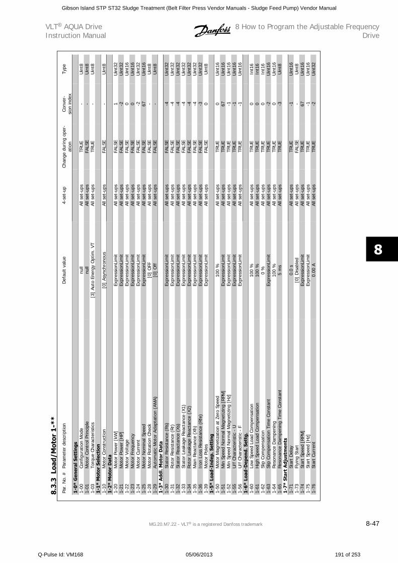
Par.
No.
#Pa
ram
eter
des
crip
tion
Def
ault
valu
e4-
set-
upCh
ange
dur
ing
oper
-at
ion
Conv
er-
sion
inde
xTy
pe
1-0*
Gen
eral
Set
tin
gs1-
00Co
nfig
urat
ion
Mod
enu
llAl
l set
-ups
TRU
E-
Uin
t81-
01M
otor
Con
trol
Prin
cipl
enu
llAl
l set
-ups
FALS
E-
Uin
t81-
03To
rque
Cha
ract
eris
tics
[3]
Auto
Ene
rgy
Opt
im. V
TAl
l set
-ups
TRU
E-
Uin
t81-
1* M
otor
Sel
ecti
on1-
10M
otor
Con
stru
ctio
n[0
] As
ynch
rono
usAl
l set
-ups
FALS
E-
Uin
t81-
2* M
otor
Dat
a1-
20M
otor
Pow
er [
kW]
Expr
essi
onLi
mit
All s
et-u
psFA
LSE
1U
int3
21-
21M
otor
Pow
er [
HP]
Expr
essi
onLi
mit
All s
et-u
psFA
LSE
-2U
int3
21-
22M
otor
Vol
tage
Expr
essi
onLi
mit
All s
et-u
psFA
LSE
0U
int1
61-
23M
otor
Fre
quen
cyEx
pres
sion
Lim
itAl
l set
-ups
FALS
E0
Uin
t16
1-24
Mot
or C
urre
ntEx
pres
sion
Lim
itAl
l set
-ups
FALS
E-2
Uin
t32
1-25
Mot
or N
omin
al S
peed
Expr
essi
onLi
mit
All s
et-u
psFA
LSE
67U
int1
61-
28M
otor
Rot
atio
n Ch
eck
[0]
OFF
All s
et-u
psFA
LSE
-U
int8
1-29
Auto
mat
ic M
otor
Ada
ptat
ion
(AM
A)[0
] O
ffAl
l set
-ups
FALS
E-
Uin
t81-
3* A
ddl.
Mot
or D
ata
1-30
Stat
or R
esis
tanc
e (R
s)Ex
pres
sion
Lim
itAl
l set
-ups
FALS
E-4
Uin
t32
1-31
Roto
r Re
sist
ance
(Rr
)Ex
pres
sion
Lim
itAl
l set
-ups
FALS
E-4
Uin
t32
1-32
Stat
or R
eact
ance
(Xs
)Ex
pres
sion
Lim
itAl
l set
-ups
FALS
E-4
Uin
t32
1-33
Stat
or L
eaka
ge R
eact
ance
(X1
)Ex
pres
sion
Lim
itAl
l set
-ups
FALS
E-4
Uin
t32
1-34
Roto
r Le
akag
e Re
acta
nce
(X2)
Expr
essi
onLi
mit
All s
et-u
psFA
LSE
-4U
int3
21-
35M
ain
Reac
tanc
e (X
h)Ex
pres
sion
Lim
itAl
l set
-ups
FALS
E-4
Uin
t32
1-36
Iron
Los
s R
esis
tanc
e (R
fe)
Expr
essi
onLi
mit
All s
et-u
psFA
LSE
-3U
int3
21-
39M
otor
Pol
esEx
pres
sion
Lim
itAl
l set
-ups
FALS
E0
Uin
t81-
5* L
oad-
Inde
p. S
etti
ng1-
50M
otor
Mag
netiz
atio
n at
Zer
o Sp
eed
100
%Al
l set
-ups
TRU
E0
Uin
t16
1-51
Min
Spe
ed N
orm
al M
agne
tizin
g [R
PM]
Expr
essi
onLi
mit
All s
et-u
psTR
UE
67U
int1
61-
52M
in S
peed
Nor
mal
Mag
netiz
ing
[Hz]
Expr
essi
onLi
mit
All s
et-u
psTR
UE
-1U
int1
61-
55U
/f C
hara
cter
istic
- U
Expr
essi
onLi
mit
All s
et-u
psTR
UE
-1U
int1
61-
56U
/f C
hara
cter
istic
- F
Expr
essi
onLi
mit
All s
et-u
psTR
UE
-1U
int1
61-
6* L
oad-
Dep
end.
Set
tg.
1-60
Low
Spe
ed L
oad
Com
pens
atio
n10
0 %
All s
et-u
psTR
UE
0In
t16
1-61
Hig
h Sp
eed
Load
Com
pens
atio
n10
0 %
All s
et-u
psTR
UE
0In
t16
1-62
Slip
Com
pens
atio
n0
%Al
l set
-ups
TRU
E0
Int1
61-
63Sl
ip C
ompe
nsat
ion
Tim
e Co
nsta
ntEx
pres
sion
Lim
itAl
l set
-ups
TRU
E-2
Uin
t16
1-64
Res
onan
ce D
ampe
ning
100
%Al
l set
-ups
TRU
E0
Uin
t16
1-65
Reso
nanc
e D
ampe
ning
Tim
e Co
nsta
nt5
ms
All s
et-u
psTR
UE
-3U
int8
1-7*
Sta
rt A
dju
stm
ents
1-71
Star
t D
elay
0.0
sAl
l set
-ups
TRU
E-1
Uin
t16
1-73
Flyi
ng S
tart
[0]
Dis
able
dAl
l set
-ups
FALS
E-
Uin
t81-
74St
art
Spee
d [R
PM]
Expr
essi
onLi
mit
All s
et-u
psTR
UE
67U
int1
61-
75St
art
Spee
d [H
z]Ex
pres
sion
Lim
itAl
l set
-ups
TRU
E-1
Uin
t16
1-76
Star
t Cu
rren
t0.
00 A
All s
et-u
psTR
UE
-2U
int3
2
8.3
.3Lo
ad/M
otor
1-*
*
VLT AQUA DriveInstruction Manual
8 How to Program the Adjustable FrequencyDrive
MG.20.M7.22 - VLT is a registered Danfoss trademark 8-47
8
Gibson Island STP ST32 Sludge Treatment (Belt Filter Press Vendor Manuals - Sludge Feed Pump) Vendor Manual
Q-Pulse Id: VM168 05/06/2013 191 of 253
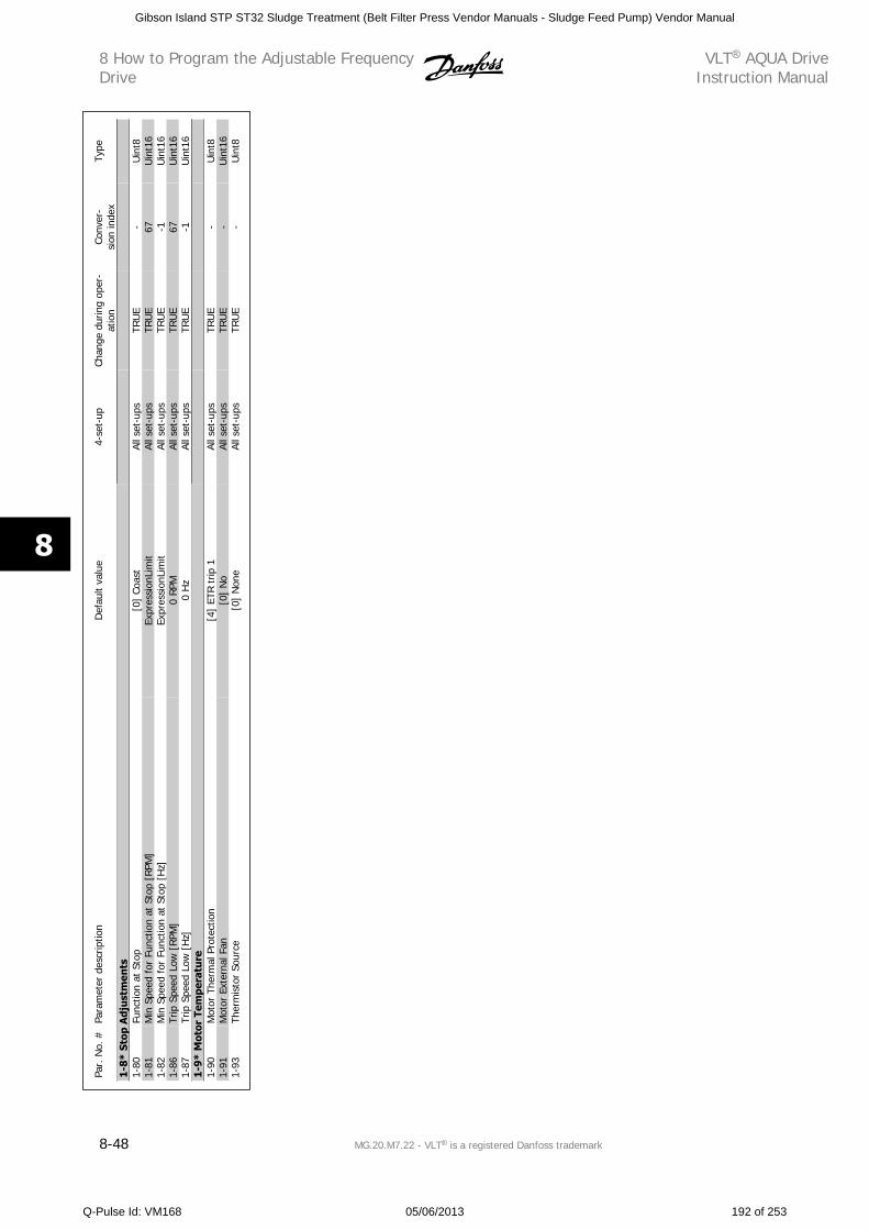
Par.
No.
#Pa
ram
eter
des
crip
tion
Def
ault
valu
e4-
set-
upCh
ange
dur
ing
oper
-at
ion
Conv
er-
sion
inde
xTy
pe
1-8*
Sto
p A
djus
tmen
ts1-
80Fu
nctio
n at
Sto
p[0
] Co
ast
All s
et-u
psTR
UE
-U
int8
1-81
Min
Spe
ed f
or F
unct
ion
at S
top
[RPM
]Ex
pres
sion
Lim
itAl
l set
-ups
TRU
E67
Uin
t16
1-82
Min
Spe
ed f
or F
unct
ion
at S
top
[Hz]
Expr
essi
onLi
mit
All s
et-u
psTR
UE
-1U
int1
61-
86Tr
ip S
peed
Low
[RPM
]0
RPM
All s
et-u
psTR
UE
67U
int1
61-
87Tr
ip S
peed
Low
[H
z]0
Hz
All s
et-u
psTR
UE
-1U
int1
61-
9* M
otor
Tem
pera
ture
1-90
Mot
or T
herm
al P
rote
ctio
n[4
] ET
R tr
ip 1
All s
et-u
psTR
UE
-U
int8
1-91
Mot
or E
xter
nal F
an[0
] N
oAl
l set
-ups
TRU
E-
Uin
t16
1-93
Ther
mis
tor
Sour
ce[0
] N
one
All s
et-u
psTR
UE
-U
int8
8 How to Program the Adjustable FrequencyDrive
VLT AQUA DriveInstruction Manual
8-48 MG.20.M7.22 - VLT is a registered Danfoss trademark
8
Gibson Island STP ST32 Sludge Treatment (Belt Filter Press Vendor Manuals - Sludge Feed Pump) Vendor Manual
Q-Pulse Id: VM168 05/06/2013 192 of 253
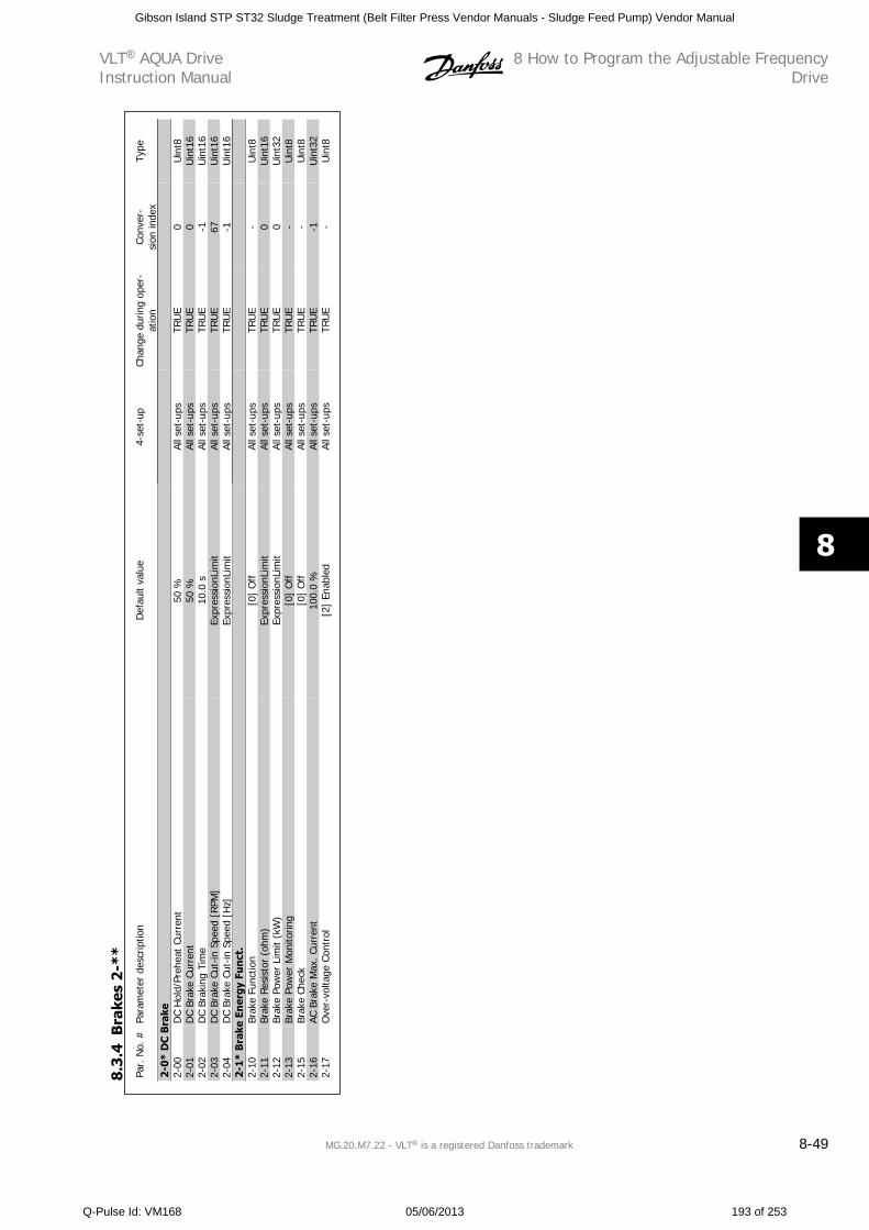
Par.
No.
#Pa
ram
eter
des
crip
tion
Def
ault
valu
e4-
set-
upCh
ange
dur
ing
oper
-at
ion
Conv
er-
sion
inde
xTy
pe
2-0*
DC
Bra
ke2-
00D
C H
old/
Preh
eat
Curr
ent
50 %
All s
et-u
psTR
UE
0U
int8
2-01
DC
Brak
e Cu
rren
t50
%Al
l set
-ups
TRU
E0
Uin
t16
2-02
DC
Brak
ing
Tim
e10
.0 s
All s
et-u
psTR
UE
-1U
int1
62-
03D
C Br
ake
Cut-
in S
peed
[R
PM]
Expr
essi
onLi
mit
All s
et-u
psTR
UE
67U
int1
62-
04D
C Br
ake
Cut-
in S
peed
[H
z]Ex
pres
sion
Lim
itAl
l set
-ups
TRU
E-1
Uin
t16
2-1*
Bra
ke E
ner
gy F
un
ct.
2-10
Brak
e Fu
nctio
n[0
] O
ffAl
l set
-ups
TRU
E-
Uin
t82-
11Br
ake
Resi
stor
(oh
m)
Expr
essi
onLi
mit
All s
et-u
psTR
UE
0U
int1
62-
12Br
ake
Pow
er L
imit
(kW
)Ex
pres
sion
Lim
itAl
l set
-ups
TRU
E0
Uin
t32
2-13
Brak
e Po
wer
Mon
itorin
g[0
] O
ffAl
l set
-ups
TRU
E-
Uin
t82-
15Br
ake
Chec
k[0
] O
ffAl
l set
-ups
TRU
E-
Uin
t82-
16AC
Bra
ke M
ax. C
urre
nt10
0.0
%Al
l set
-ups
TRU
E-1
Uin
t32
2-17
Ove
r-vo
ltage
Con
trol
[2]
Enab
led
All s
et-u
psTR
UE
-U
int8
8.3
.4B
rake
s 2
-**
VLT AQUA DriveInstruction Manual
8 How to Program the Adjustable FrequencyDrive
MG.20.M7.22 - VLT is a registered Danfoss trademark 8-49
8
Gibson Island STP ST32 Sludge Treatment (Belt Filter Press Vendor Manuals - Sludge Feed Pump) Vendor Manual
Q-Pulse Id: VM168 05/06/2013 193 of 253
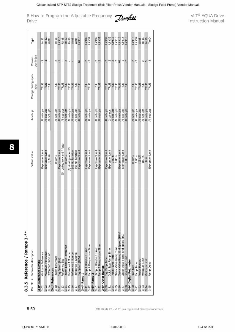
Par.
No.
#Pa
ram
eter
des
crip
tion
Def
ault
valu
e4-
set-
upCh
ange
dur
ing
oper
-at
ion
Conv
er-
sion
inde
xTy
pe
3-0*
Ref
eren
ce L
imit
s3-
02M
inim
um R
efer
ence
Expr
essi
onLi
mit
All s
et-u
psTR
UE
-3In
t32
3-03
Max
imum
Ref
eren
ceEx
pres
sion
Lim
itAl
l set
-ups
TRU
E-3
Int3
23-
04Re
fere
nce
Func
tion
[0]
Sum
All s
et-u
psTR
UE
-U
int8
3-1*
Ref
eren
ces
3-10
Pres
et R
efer
ence
0.00
%Al
l set
-ups
TRU
E-2
Int1
63-
11Jo
g Sp
eed
[Hz]
Expr
essi
onLi
mit
All s
et-u
psTR
UE
-1U
int1
63-
13Ref
eren
ce S
ite[0
] Li
nked
to
Han
d /
Auto
All s
et-u
psTR
UE
-U
int8
3-14
Pres
et R
elat
ive
Refe
renc
e0.
00 %
All s
et-u
psTR
UE
-2In
t32
3-15
Ref
eren
ce 1
Sou
rce
[1]
Anal
og in
put
53Al
l set
-ups
TRU
E-
Uin
t83-
16Re
fere
nce
2 So
urce
[0]
No
func
tion
All s
et-u
psTR
UE
-U
int8
3-17
Ref
eren
ce 3
Sou
rce
[0]
No
func
tion
All s
et-u
psTR
UE
-U
int8
3-19
Jog
Spee
d [R
PM]
Expr
essi
onLi
mit
All s
et-u
psTR
UE
67U
int1
63-
4* R
amp
13-
41Ra
mp
1 Ra
mp-
up T
ime
Expr
essi
onLi
mit
All s
et-u
psTR
UE
-2U
int3
23-
42Ram
p 1
Ram
p-do
wn
Tim
eEx
pres
sion
Lim
itAl
l set
-ups
TRU
E-2
Uin
t32
3-5*
Ram
p 2
3-51
Ram
p 2
Ram
p-up
Tim
eEx
pres
sion
Lim
itAl
l set
-ups
TRU
E-2
Uin
t32
3-52
Ram
p 2
Ram
p-do
wn
Tim
eEx
pres
sion
Lim
itAl
l set
-ups
TRU
E-2
Uin
t32
3-8*
Oth
er R
amps
3-80
Jog
Ram
p Ti
me
Expr
essi
onLi
mit
All s
et-u
psTR
UE
-2U
int3
23-
81Q
uick
Sto
p Ram
p Ti
me
Expr
essi
onLi
mit
2 se
t-up
sTR
UE
-2U
int3
23-
84In
itial
Ram
p Ti
me
0.00
sAl
l set
-ups
TRU
E-2
Uin
t16
3-85
Chec
k Va
lve
Ram
p Ti
me
0.00
sAl
l set
-ups
TRU
E-2
Uin
t16
3-86
Chec
k Va
lve
Ram
p En
d Sp
eed
[RPM
]Ex
pres
sion
Lim
itAl
l set
-ups
TRU
E67
Uin
t16
3-87
Chec
k Va
lve
Ram
p En
d Sp
eed
[HZ]
Expr
essi
onLi
mit
All s
et-u
psTR
UE
-1U
int1
63-
88Fi
nal R
amp
Tim
e0.
00 s
All s
et-u
psTR
UE
-2U
int1
63-
9* D
igit
al P
ot. m
eter
3-90
Step
Siz
e0.
10 %
All s
et-u
psTR
UE
-2U
int1
63-
91Ram
p Ti
me
1.00
sAl
l set
-ups
TRU
E-2
Uin
t32
3-92
Pow
er R
esto
re[0
] O
ffAl
l set
-ups
TRU
E-
Uin
t83-
93M
axim
um L
imit
100
%Al
l set
-ups
TRU
E0
Int1
63-
94M
inim
um L
imit
0 %
All s
et-u
psTR
UE
0In
t16
3-95
Ram
p D
elay
Expr
essi
onLi
mit
All s
et-u
psTR
UE
-3Ti
mD
8.3
.5R
efer
ence
/ R
amps
3-*
*
8 How to Program the Adjustable FrequencyDrive
VLT AQUA DriveInstruction Manual
8-50 MG.20.M7.22 - VLT is a registered Danfoss trademark
8
Gibson Island STP ST32 Sludge Treatment (Belt Filter Press Vendor Manuals - Sludge Feed Pump) Vendor Manual
Q-Pulse Id: VM168 05/06/2013 194 of 253
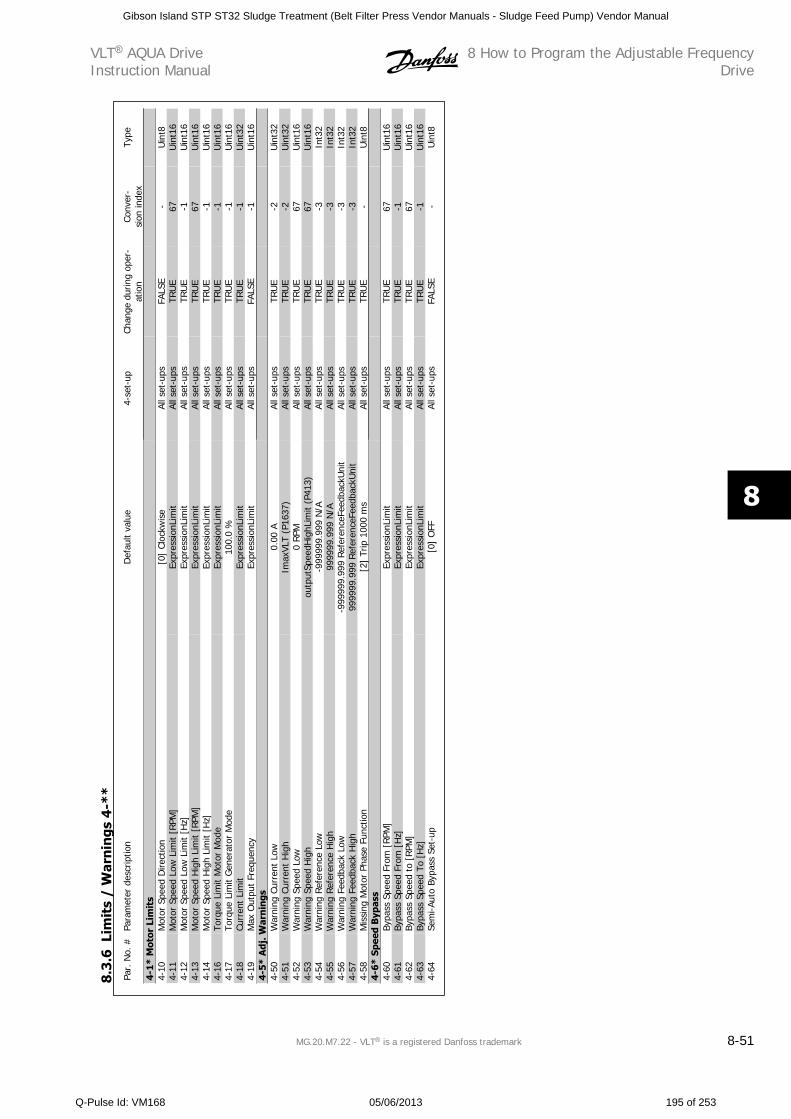
Par.
No.
#Pa
ram
eter
des
crip
tion
Def
ault
valu
e4-
set-
upCh
ange
dur
ing
oper
-at
ion
Conv
er-
sion
inde
xTy
pe
4-1*
Mot
or L
imit
s4-
10M
otor
Spe
ed D
irect
ion
[0]
Cloc
kwis
eAl
l set
-ups
FALS
E-
Uin
t84-
11M
otor
Spe
ed L
ow L
imit
[RPM
]Ex
pres
sion
Lim
itAl
l set
-ups
TRU
E67
Uin
t16
4-12
Mot
or S
peed
Low
Lim
it [H
z]Ex
pres
sion
Lim
itAl
l set
-ups
TRU
E-1
Uin
t16
4-13
Mot
or S
peed
Hig
h Li
mit
[RPM
]Ex
pres
sion
Lim
itAl
l set
-ups
TRU
E67
Uin
t16
4-14
Mot
or S
peed
Hig
h Li
mit
[Hz]
Expr
essi
onLi
mit
All s
et-u
psTR
UE
-1U
int1
64-
16To
rque
Lim
it M
otor
Mod
eEx
pres
sion
Lim
itAl
l set
-ups
TRU
E-1
Uin
t16
4-17
Torq
ue L
imit
Gen
erat
or M
ode
100.
0 %
All s
et-u
psTR
UE
-1U
int1
64-
18Cu
rren
t Li
mit
Expr
essi
onLi
mit
All s
et-u
psTR
UE
-1U
int3
24-
19M
ax O
utpu
t Fr
eque
ncy
Expr
essi
onLi
mit
All s
et-u
psFA
LSE
-1U
int1
64-
5* A
dj. W
arn
ings
4-50
War
ning
Cur
rent
Low
0.00
AAl
l set
-ups
TRU
E-2
Uin
t32
4-51
War
ning
Cur
rent
Hig
hIm
axVL
T (P
1637
)Al
l set
-ups
TRU
E-2
Uin
t32
4-52
War
ning
Spe
ed L
ow0
RPM
All s
et-u
psTR
UE
67U
int1
64-
53W
arni
ng S
peed
Hig
hou
tput
Spee
dHig
hLim
it (P
413)
All s
et-u
psTR
UE
67U
int1
64-
54W
arni
ng R
efer
ence
Low
-999
999.
999
N/A
All s
et-u
psTR
UE
-3In
t32
4-55
War
ning
Ref
eren
ce H
igh
9999
99.9
99 N
/AAl
l set
-ups
TRU
E-3
Int3
24-
56W
arni
ng F
eedb
ack
Low
-999
999.
999
Ref
eren
ceFe
edba
ckU
nit
All s
et-u
psTR
UE
-3In
t32
4-57
War
ning
Fee
dbac
k H
igh
9999
99.9
99 R
efer
ence
Feed
back
Uni
tAl
l set
-ups
TRU
E-3
Int3
24-
58M
issi
ng M
otor
Pha
se F
unct
ion
[2]
Trip
100
0 m
sAl
l set
-ups
TRU
E-
Uin
t84-
6* S
peed
Byp
ass
4-60
Bypa
ss S
peed
Fro
m [
RPM
]Ex
pres
sion
Lim
itAl
l set
-ups
TRU
E67
Uin
t16
4-61
Bypa
ss S
peed
Fro
m [
Hz]
Expr
essi
onLi
mit
All s
et-u
psTR
UE
-1U
int1
64-
62By
pass
Spe
ed t
o [R
PM]
Expr
essi
onLi
mit
All s
et-u
psTR
UE
67U
int1
64-
63By
pass
Spe
ed T
o [H
z]Ex
pres
sion
Lim
itAl
l set
-ups
TRU
E-1
Uin
t16
4-64
Sem
i-Aut
o By
pass
Set
-up
[0]
OFF
All s
et-u
psFA
LSE
-U
int8
8.3
.6Li
mit
s /
War
nin
gs 4
-**
VLT AQUA DriveInstruction Manual
8 How to Program the Adjustable FrequencyDrive
MG.20.M7.22 - VLT is a registered Danfoss trademark 8-51
8
Gibson Island STP ST32 Sludge Treatment (Belt Filter Press Vendor Manuals - Sludge Feed Pump) Vendor Manual
Q-Pulse Id: VM168 05/06/2013 195 of 253
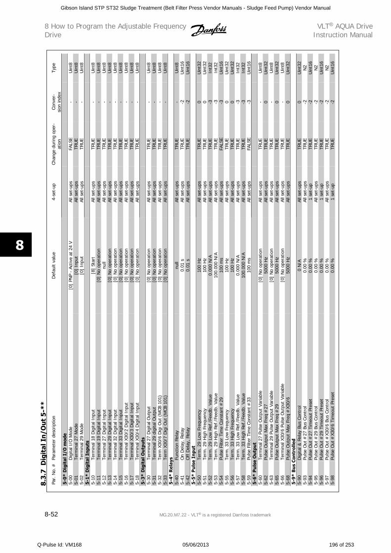
Par.
No.
#Pa
ram
eter
des
crip
tion
Def
ault
valu
e4-
set-
upCh
ange
dur
ing
oper
-at
ion
Conv
er-
sion
inde
xTy
pe
5-0*
Dig
ital
I/O
mod
e5-
00D
igita
l I/O
Mod
e[0
] PN
P -
Activ
e at
24
VAl
l set
-ups
FALS
E-
Uin
t85-
01Te
rmin
al 2
7 M
ode
[0]
Inpu
tAl
l set
-ups
TRU
E-
Uin
t85-
02Te
rmin
al 2
9 M
ode
[0]
Inpu
tAl
l set
-ups
TRU
E-
Uin
t85-
1* D
igit
al I
npu
ts5-
10Te
rmin
al 1
8 D
igita
l Inp
ut[8
] St
art
All s
et-u
psTR
UE
-U
int8
5-11
Term
inal
19
Dig
ital I
nput
[0]
No
oper
atio
nAl
l set
-ups
TRU
E-
Uin
t85-
12Te
rmin
al 2
7 D
igita
l Inp
utnu
llAl
l set
-ups
TRU
E-
Uin
t85-
13Te
rmin
al 2
9 D
igita
l Inp
ut[0
] N
o op
erat
ion
All s
et-u
psTR
UE
-U
int8
5-14
Term
inal
32
Dig
ital I
nput
[0]
No
oper
atio
nAl
l set
-ups
TRU
E-
Uin
t85-
15Te
rmin
al 3
3 D
igita
l Inp
ut[0
] N
o op
erat
ion
All s
et-u
psTR
UE
-U
int8
5-16
Term
inal
X30
/2 D
igita
l Inp
ut[0
] N
o op
erat
ion
All s
et-u
psTR
UE
-U
int8
5-17
Term
inal
X30
/3 D
igita
l Inp
ut[0
] N
o op
erat
ion
All s
et-u
psTR
UE
-U
int8
5-18
Term
inal
X30
/4 D
igita
l Inp
ut[0
] N
o op
erat
ion
All s
et-u
psTR
UE
-U
int8
5-3*
Dig
ital
Ou
tpu
ts5-
30Te
rmin
al 2
7 D
igita
l Out
put
[0]
No
oper
atio
nAl
l set
-ups
TRU
E-
Uin
t85-
31Te
rmin
al 2
9 di
gita
l Out
put
[0]
No
oper
atio
nAl
l set
-ups
TRU
E-
Uin
t85-
32Te
rm X
30/6
Dig
i Out
(M
CB 1
01)
[0]
No
oper
atio
nAl
l set
-ups
TRU
E-
Uin
t85-
33Te
rm X
30/7
Dig
i Out
(M
CB 1
01)
[0]
No
oper
atio
nAl
l set
-ups
TRU
E-
Uin
t85-
4* R
elay
s5-
40Fu
nctio
n R
elay
null
All s
et-u
psTR
UE
-U
int8
5-41
On
Del
ay, R
elay
0.01
sAl
l set
-ups
TRU
E-2
Uin
t16
5-42
Off
Del
ay, R
elay
0.01
sAl
l set
-ups
TRU
E-2
Uin
t16
5-5*
Pu
lse
Inpu
t5-
50Te
rm. 2
9 Lo
w F
requ
ency
100
Hz
All s
et-u
psTR
UE
0U
int3
25-
51Te
rm. 2
9 H
igh
Freq
uenc
y10
0 H
zAl
l set
-ups
TRU
E0
Uin
t32
5-52
Term
. 29
Low
Ref
./Fe
edb.
Val
ue0.
000
N/A
All s
et-u
psTR
UE
-3In
t32
5-53
Term
. 29
Hig
h Re
f./F
eedb
. Val
ue10
0.00
0 N
/AAl
l set
-ups
TRU
E-3
Int3
25-
54Pu
lse
Filte
r Ti
me
Cons
tant
#29
100
ms
All s
et-u
psFA
LSE
-3U
int1
65-
55Te
rm. 3
3 Lo
w F
requ
ency
100
Hz
All s
et-u
psTR
UE
0U
int3
25-
56Te
rm. 3
3 H
igh
Freq
uenc
y10
0 H
zAl
l set
-ups
TRU
E0
Uin
t32
5-57
Term
. 33
Low
Ref
./Fe
edb.
Val
ue0.
000
N/A
All s
et-u
psTR
UE
-3In
t32
5-58
Term
. 33
Hig
h Re
f./Fe
edb.
Val
ue10
0.00
0 N
/AAl
l set
-ups
TRU
E-3
Int3
25-
59Pu
lse
Filte
r Ti
me
Cons
tant
#33
100
ms
All s
et-u
psFA
LSE
-3U
int1
65-
6* P
uls
e O
utp
ut
5-60
Term
inal
27
Puls
e O
utpu
t Va
riabl
e[0
] N
o op
erat
ion
All s
et-u
psTR
UE
-U
int8
5-62
Puls
e O
utpu
t M
ax F
req
#27
5000
Hz
All s
et-u
psTR
UE
0U
int3
25-
63Te
rmin
al 2
9 Pu
lse
Out
put
Varia
ble
[0]
No
oper
atio
nAl
l set
-ups
TRU
E-
Uin
t85-
65Pu
lse
Out
put
Max
Fre
q #
2950
00 H
zAl
l set
-ups
TRU
E0
Uin
t32
5-66
Term
inal
X30
/6 P
ulse
Out
put
Varia
ble
[0]
No
oper
atio
nAl
l set
-ups
TRU
E-
Uin
t85-
68Pu
lse
Out
put
Max
Fre
q #
X30/
650
00 H
zAl
l set
-ups
TRU
E0
Uin
t32
5-9*
Bu
s C
ontr
olle
d5-
90D
igita
l & R
elay
Bus
Con
trol
0 N
/AAl
l set
-ups
TRU
E0
Uin
t32
5-93
Puls
e O
ut #
27 B
us C
ontr
ol0.
00 %
All s
et-u
psTR
UE
-2N
25-
94Pu
lse
Out
#27
Tim
eout
Pre
set
0.00
%1
set-
upTR
UE
-2U
int1
65-
95Pu
lse
Out
#29
Bus
Con
trol
0.00
%Al
l set
-ups
TRU
E-2
N2
5-96
Puls
e O
ut #
29 T
imeo
ut P
rese
t0.
00 %
1 se
t-up
TRU
E-2
Uin
t16
5-97
Puls
e O
ut #
X30/
6 Bu
s Co
ntro
l0.
00 %
All s
et-u
psTR
UE
-2N
25-
98Pu
lse
Out
#X3
0/6
Tim
eout
Pre
set
0.00
%1
set-
upTR
UE
-2U
int1
6
8.3
.7D
igit
al I
n/O
ut
5-*
*
8 How to Program the Adjustable FrequencyDrive
VLT AQUA DriveInstruction Manual
8-52 MG.20.M7.22 - VLT is a registered Danfoss trademark
8
Gibson Island STP ST32 Sludge Treatment (Belt Filter Press Vendor Manuals - Sludge Feed Pump) Vendor Manual
Q-Pulse Id: VM168 05/06/2013 196 of 253
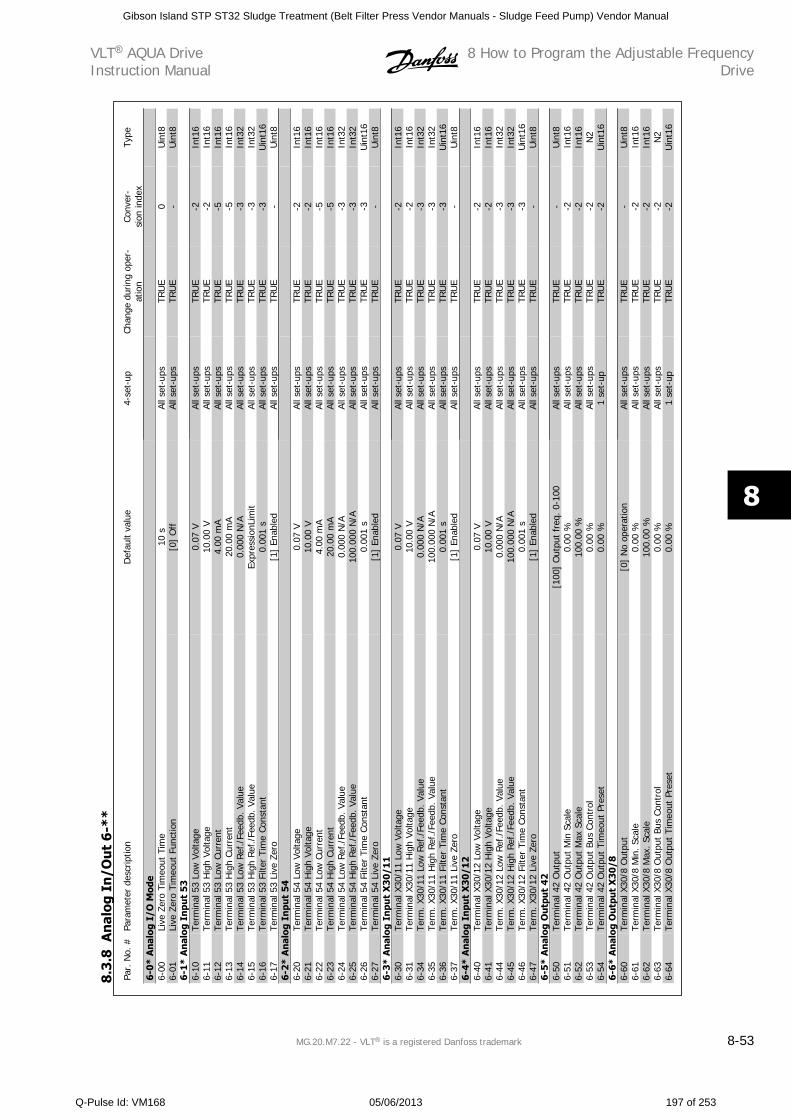
Par.
No.
#Pa
ram
eter
des
crip
tion
Def
ault
valu
e4-
set-
upCh
ange
dur
ing
oper
-at
ion
Conv
er-
sion
inde
xTy
pe
6-0*
An
alog
I/O
Mod
e6-
00Li
ve Z
ero
Tim
eout
Tim
e10
sAl
l set
-ups
TRU
E0
Uin
t86-
01Li
ve Z
ero
Tim
eout
Fun
ctio
n[0
] O
ffAl
l set
-ups
TRU
E-
Uin
t86-
1* A
nal
og I
npu
t 53
6-10
Term
inal
53
Low
Vol
tage
0.07
VAl
l set
-ups
TRU
E-2
Int1
66-
11Te
rmin
al 5
3 H
igh
Volta
ge10
.00
VAl
l set
-ups
TRU
E-2
Int1
66-
12Te
rmin
al 5
3 Lo
w C
urre
nt4.
00 m
AAl
l set
-ups
TRU
E-5
Int1
66-
13Te
rmin
al 5
3 H
igh
Curr
ent
20.0
0 m
AAl
l set
-ups
TRU
E-5
Int1
66-
14Te
rmin
al 5
3 Lo
w R
ef./
Feed
b. V
alue
0.00
0 N
/AAl
l set
-ups
TRU
E-3
Int3
26-
15Te
rmin
al 5
3 H
igh
Ref
./Fe
edb.
Val
ueEx
pres
sion
Lim
itAl
l set
-ups
TRU
E-3
Int3
26-
16Te
rmin
al 5
3 Fi
lter
Tim
e Co
nsta
nt0.
001
sAl
l set
-ups
TRU
E-3
Uin
t16
6-17
Term
inal
53
Live
Zer
o[1
] En
able
dAl
l set
-ups
TRU
E-
Uin
t86-
2* A
nal
og I
npu
t 54
6-20
Term
inal
54
Low
Vol
tage
0.07
VAl
l set
-ups
TRU
E-2
Int1
66-
21Te
rmin
al 5
4 H
igh
Volta
ge10
.00
VAl
l set
-ups
TRU
E-2
Int1
66-
22Te
rmin
al 5
4 Lo
w C
urre
nt4.
00 m
AAl
l set
-ups
TRU
E-5
Int1
66-
23Te
rmin
al 5
4 H
igh
Curr
ent
20.0
0 m
AAl
l set
-ups
TRU
E-5
Int1
66-
24Te
rmin
al 5
4 Lo
w R
ef./
Feed
b. V
alue
0.00
0 N
/AAl
l set
-ups
TRU
E-3
Int3
26-
25Te
rmin
al 5
4 H
igh
Ref./
Feed
b. V
alue
100.
000
N/A
All s
et-u
psTR
UE
-3In
t32
6-26
Term
inal
54
Filte
r Ti
me
Cons
tant
0.00
1 s
All s
et-u
psTR
UE
-3U
int1
66-
27Te
rmin
al 5
4 Li
ve Z
ero
[1]
Enab
led
All s
et-u
psTR
UE
-U
int8
6-3*
An
alog
In
put
X30
/11
6-30
Term
inal
X30
/11
Low
Vol
tage
0.07
VAl
l set
-ups
TRU
E-2
Int1
66-
31Te
rmin
al X
30/1
1 H
igh
Volta
ge10
.00
VAl
l set
-ups
TRU
E-2
Int1
66-
34Te
rm. X
30/1
1 Lo
w R
ef./
Feed
b. V
alue
0.00
0 N
/AAl
l set
-ups
TRU
E-3
Int3
26-
35Te
rm. X
30/1
1 H
igh
Ref
./Fe
edb.
Val
ue10
0.00
0 N
/AAl
l set
-ups
TRU
E-3
Int3
26-
36Te
rm. X
30/1
1 Fi
lter
Tim
e Co
nsta
nt0.
001
sAl
l set
-ups
TRU
E-3
Uin
t16
6-37
Term
. X30
/11
Live
Zer
o[1
] En
able
dAl
l set
-ups
TRU
E-
Uin
t86-
4* A
nal
og I
npu
t X
30/1
26-
40Te
rmin
al X
30/1
2 Lo
w V
olta
ge0.
07 V
All s
et-u
psTR
UE
-2In
t16
6-41
Term
inal
X30
/12
Hig
h Vo
ltage
10.0
0 V
All s
et-u
psTR
UE
-2In
t16
6-44
Term
. X30
/12
Low
Ref
./Fe
edb.
Val
ue0.
000
N/A
All s
et-u
psTR
UE
-3In
t32
6-45
Term
. X30
/12
Hig
h R
ef./
Feed
b. V
alue
100.
000
N/A
All s
et-u
psTR
UE
-3In
t32
6-46
Term
. X30
/12
Filte
r Ti
me
Cons
tant
0.00
1 s
All s
et-u
psTR
UE
-3U
int1
66-
47Te
rm. X
30/1
2 Li
ve Z
ero
[1]
Enab
led
All s
et-u
psTR
UE
-U
int8
6-5*
An
alog
Ou
tpu
t 42
6-50
Term
inal
42
Out
put
[100
] O
utpu
t fr
eq. 0
-100
All s
et-u
psTR
UE
-U
int8
6-51
Term
inal
42
Out
put
Min
Sca
le0.
00 %
All s
et-u
psTR
UE
-2In
t16
6-52
Term
inal
42
Out
put
Max
Sca
le10
0.00
%Al
l set
-ups
TRU
E-2
Int1
66-
53Te
rmin
al 4
2 O
utpu
t Bu
s Co
ntro
l0.
00 %
All s
et-u
psTR
UE
-2N
26-
54Te
rmin
al 4
2 O
utpu
t Ti
meo
ut P
rese
t0.
00 %
1 se
t-up
TRU
E-2
Uin
t16
6-6*
An
alog
Ou
tpu
t X
30/8
6-60
Term
inal
X30
/8 O
utpu
t[0
] N
o op
erat
ion
All s
et-u
psTR
UE
-U
int8
6-61
Term
inal
X30
/8 M
in. Sc
ale
0.00
%Al
l set
-ups
TRU
E-2
Int1
66-
62Te
rmin
al X
30/8
Max
. Sca
le10
0.00
%Al
l set
-ups
TRU
E-2
Int1
66-
63Te
rmin
al X
30/8
Out
put
Bus
Cont
rol
0.00
%Al
l set
-ups
TRU
E-2
N2
6-64
Term
inal
X30
/8 O
utpu
t Ti
meo
ut P
rese
t0.
00 %
1 se
t-up
TRU
E-2
Uin
t16
8.3
.8A
nal
og I
n/O
ut
6-*
*
VLT AQUA DriveInstruction Manual
8 How to Program the Adjustable FrequencyDrive
MG.20.M7.22 - VLT is a registered Danfoss trademark 8-53
8
Gibson Island STP ST32 Sludge Treatment (Belt Filter Press Vendor Manuals - Sludge Feed Pump) Vendor Manual
Q-Pulse Id: VM168 05/06/2013 197 of 253
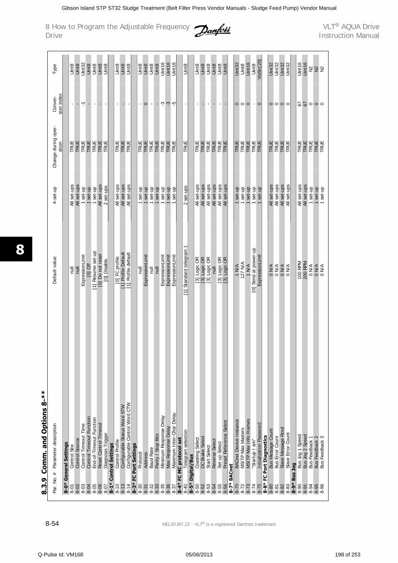
Par.
No.
#Pa
ram
eter
des
crip
tion
Def
ault
valu
e4-
set-
upCh
ange
dur
ing
oper
-at
ion
Conv
er-
sion
inde
xTy
pe
8-0*
Gen
eral
Set
tin
gs8-
01Co
ntro
l Site
null
All s
et-u
psTR
UE
-U
int8
8-02
Cont
rol S
ourc
enu
llAl
l set
-ups
TRU
E-
Uin
t88-
03Co
ntro
l Tim
eout
Tim
eEx
pres
sion
Lim
it1
set-
upTR
UE
-1U
int3
28-
04Co
ntro
l Tim
eout
Fun
ctio
n[0
] O
ff1
set-
upTR
UE
-U
int8
8-05
End-
of-T
imeo
ut F
unct
ion
[1]
Resu
me
set-
up1
set-
upTR
UE
-U
int8
8-06
Rese
t Co
ntro
l Tim
eout
[0]
Do
not
rese
tAl
l set
-ups
TRU
E-
Uin
t88-
07D
iagn
osis
Trig
ger
[0]
Dis
able
2 se
t-up
sTR
UE
-U
int8
8-1*
Con
trol
Set
tin
gs8-
10Co
ntro
l Pro
file
[0]
FC p
rofil
eAl
l set
-ups
TRU
E-
Uin
t88-
13Co
nfig
urab
le S
tatu
s W
ord
STW
[1]
Prof
ile D
efau
ltAl
l set
-ups
TRU
E-
Uin
t88-
14Co
nfig
urab
le C
ontr
ol W
ord
CTW
[1]
Prof
ile d
efau
ltAl
l set
-ups
TRU
E-
Uin
t88-
3* F
C P
ort
Sett
ings
8-30
Prot
ocol
null
1 se
t-up
TRU
E-
Uin
t88-
31Ad
dres
sEx
pres
sion
Lim
it1
set-
upTR
UE
0U
int8
8-32
Baud
Rat
enu
ll1
set-
upTR
UE
-U
int8
8-33
Parit
y /
Stop
Bits
null
1 se
t-up
TRU
E-
Uin
t88-
35M
inim
um R
espo
nse
Del
ayEx
pres
sion
Lim
it1
set-
upTR
UE
-3U
int1
68-
36M
ax R
espo
nse
Del
ayEx
pres
sion
Lim
it1
set-
upTR
UE
-3U
int1
68-
37M
axim
um I
nter
-Cha
r D
elay
Expr
essi
onLi
mit
1 se
t-up
TRU
E-5
Uin
t16
8-4*
FC
MC
pro
toco
l set
8-40
Tele
gram
sel
ectio
n[1
] St
anda
rd t
eleg
ram
12
set-
ups
TRU
E-
Uin
t88-
5* D
igit
al/B
us
8-50
Coas
ting
Sele
ct[3
] Lo
gic
OR
All s
et-u
psTR
UE
-U
int8
8-52
DC
Brak
e Se
lect
[3]
Logi
c O
RAl
l set
-ups
TRU
E-
Uin
t88-
53St
art
Sele
ct[3
] Lo
gic
OR
All s
et-u
psTR
UE
-U
int8
8-54
Reve
rse
Sele
ctnu
llAl
l set
-ups
TRU
E-
Uin
t88-
55Se
t-up
Sel
ect
[3]
Logi
c O
RAl
l set
-ups
TRU
E-
Uin
t88-
56Pr
eset
Ref
eren
ce S
elec
t[3
] Lo
gic
OR
All s
et-u
psTR
UE
-U
int8
8-7
* B
AC
net
8-70
BACn
et D
evic
e In
stan
ce1
N/A
1 se
t-up
TRU
E0
Uin
t32
8-72
MS/
TP M
ax M
aste
rs12
7 N
/A1
set-
upTR
UE
0U
int8
8-73
MS/
TP M
ax I
nfo
Fram
es1
N/A
1 se
t-up
TRU
E0
Uin
t16
8-74
"Sta
rtup
I a
m"
[0]
Send
at
pow
er-u
p1
set-
upTR
UE
-U
int8
8-75
Initi
aliz
atio
n Pa
ssw
ord
Expr
essi
onLi
mit
1 se
t-up
TRU
E0
VisS
tr[2
0]8-
8* F
C P
ort
Dia
gnos
tics
8-80
Bus
Mes
sage
Cou
nt0
N/A
All s
et-u
psTR
UE
0U
int3
28-
81Bu
s Er
ror
Coun
t0
N/A
All s
et-u
psTR
UE
0U
int3
28-
82Sl
ave
Mes
sage
Rcv
d0
N/A
All s
et-u
psTR
UE
0U
int3
28-
83Sl
ave
Erro
r Co
unt
0 N
/AAl
l set
-ups
TRU
E0
Uin
t32
8-9*
Bu
s Jo
g8-
90Bu
s Jo
g 1
Spee
d10
0 RP
MAl
l set
-ups
TRU
E67
Uin
t16
8-91
Bus
Jog
2 Sp
eed
200
RPM
All s
et-u
psTR
UE
67U
int1
68-
94Bu
s Fe
edba
ck 1
0 N
/A1
set-
upTR
UE
0N
28-
95Bu
s Fe
edba
ck 2
0 N
/A1
set-
upTR
UE
0N
28-
96Bu
s Fe
edba
ck 3
0 N
/A1
set-
upTR
UE
0N
2
8.3
.9C
omm
. an
d O
ptio
ns
8-*
*
8 How to Program the Adjustable FrequencyDrive
VLT AQUA DriveInstruction Manual
8-54 MG.20.M7.22 - VLT is a registered Danfoss trademark
8
Gibson Island STP ST32 Sludge Treatment (Belt Filter Press Vendor Manuals - Sludge Feed Pump) Vendor Manual
Q-Pulse Id: VM168 05/06/2013 198 of 253
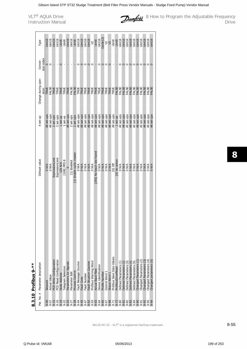
Par.
No.
#Pa
ram
eter
des
crip
tion
Def
ault
valu
e4-
set-
upCh
ange
dur
ing
oper
-at
ion
Conv
er-
sion
inde
xTy
pe
9-00
Setp
oint
0 N
/AAl
l set
-ups
TRU
E0
Uin
t16
9-07
Actu
al V
alue
0 N
/AAl
l set
-ups
FALS
E0
Uin
t16
9-15
PCD
Writ
e Co
nfig
urat
ion
Expr
essi
onLi
mit
2 se
t-up
sTR
UE
-U
int1
69-
16PC
D R
ead
Conf
igur
atio
nEx
pres
sion
Lim
it2
set-
ups
TRU
E-
Uin
t16
9-18
Nod
e Ad
dres
s12
6 N
/A1
set-
upTR
UE
0U
int8
9-22
Tele
gram
Sel
ectio
n[1
08]
PPO
81
set-
upTR
UE
-U
int8
9-23
Para
met
ers
for
Sign
als
0Al
l set
-ups
TRU
E-
Uin
t16
9-27
Para
met
er E
dit
[1]
Enab
led
2 se
t-up
sFA
LSE
-U
int1
69-
28Pr
oces
s Co
ntro
l[1
] En
able
cyc
lic m
aste
r2
set-
ups
FALS
E-
Uin
t89-
44Fa
ult
Mes
sage
Cou
nter
0 N
/AAl
l set
-ups
TRU
E0
Uin
t16
9-45
Faul
t Co
de0
N/A
All s
et-u
psTR
UE
0U
int1
69-
47Fa
ult
Num
ber
0 N
/AAl
l set
-ups
TRU
E0
Uin
t16
9-52
Faul
t Si
tuat
ion
Coun
ter
0 N
/AAl
l set
-ups
TRU
E0
Uin
t16
9-53
Prof
ibus
War
ning
Wor
d0
N/A
All s
et-u
psTR
UE
0V2
9-63
Actu
al B
aud
Rat
e[2
55]
No
baud
rat
e fo
und
All s
et-u
psTR
UE
-U
int8
9-64
Dev
ice
Iden
tific
atio
n0
N/A
All s
et-u
psTR
UE
0U
int1
69-
65Pr
ofile
Num
ber
0 N
/AAl
l set
-ups
TRU
E0
Oct
Str[
2]9-
67Co
ntro
l Wor
d 1
0 N
/AAl
l set
-ups
TRU
E0
V29-
68St
atus
Wor
d 1
0 N
/AAl
l set
-ups
TRU
E0
V29-
71Pr
ofib
us S
ave
Dat
a Va
lues
[0]
Off
All s
et-u
psTR
UE
-U
int8
9-72
Prof
ibus
Driv
eRes
et[0
] N
o ac
tion
1 se
t-up
FALS
E-
Uin
t89-
80D
efin
ed P
aram
eter
s (1
)0
N/A
All s
et-u
psFA
LSE
0U
int1
69-
81D
efin
ed P
aram
eter
s (2
)0
N/A
All s
et-u
psFA
LSE
0U
int1
69-
82D
efin
ed P
aram
eter
s (3
)0
N/A
All s
et-u
psFA
LSE
0U
int1
69-
83D
efin
ed P
aram
eter
s (4
)0
N/A
All s
et-u
psFA
LSE
0U
int1
69-
84D
efin
ed P
aram
eter
s (5
)0
N/A
All s
et-u
psFA
LSE
0U
int1
69-
90Ch
ange
d Pa
ram
eter
s (1
)0
N/A
All s
et-u
psFA
LSE
0U
int1
69-
91Ch
ange
d Pa
ram
eter
s (2
)0
N/A
All s
et-u
psFA
LSE
0U
int1
69-
92Ch
ange
d Pa
ram
eter
s (3
)0
N/A
All s
et-u
psFA
LSE
0U
int1
69-
93Ch
ange
d Pa
ram
eter
s (4
)0
N/A
All s
et-u
psFA
LSE
0U
int1
69-
94Ch
ange
d pa
ram
eter
s (5
)0
N/A
All s
et-u
psFA
LSE
0U
int1
6
8.3.
10
Pro
fibu
s 9-
**
VLT AQUA DriveInstruction Manual
8 How to Program the Adjustable FrequencyDrive
MG.20.M7.22 - VLT is a registered Danfoss trademark 8-55
8
Gibson Island STP ST32 Sludge Treatment (Belt Filter Press Vendor Manuals - Sludge Feed Pump) Vendor Manual
Q-Pulse Id: VM168 05/06/2013 199 of 253
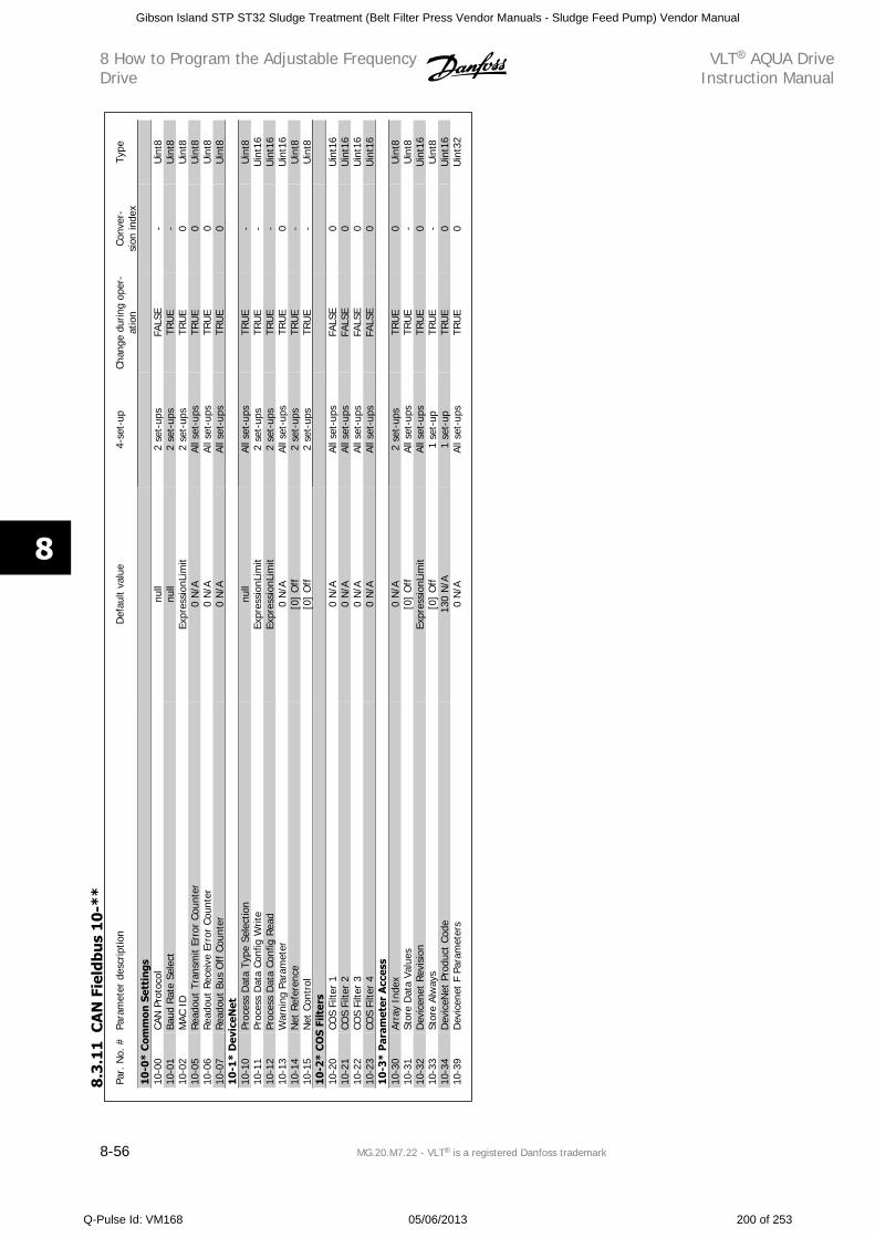
Par.
No.
#Pa
ram
eter
des
crip
tion
Def
ault
valu
e4-
set-
upCh
ange
dur
ing
oper
-at
ion
Conv
er-
sion
inde
xTy
pe
10-0
* C
omm
on S
etti
ngs
10-0
0CA
N P
roto
col
null
2 se
t-up
sFA
LSE
-U
int8
10-0
1Ba
ud R
ate
Sele
ctnu
ll2
set-
ups
TRU
E-
Uin
t810
-02
MAC
ID
Expr
essi
onLi
mit
2 se
t-up
sTR
UE
0U
int8
10-0
5Re
adou
t Tr
ansm
it Er
ror
Coun
ter
0 N
/AAl
l set
-ups
TRU
E0
Uin
t810
-06
Read
out
Rece
ive
Erro
r Co
unte
r0
N/A
All s
et-u
psTR
UE
0U
int8
10-0
7Re
adou
t Bu
s O
ff C
ount
er0
N/A
All s
et-u
psTR
UE
0U
int8
10-1
* D
evic
eNet
10-1
0Pr
oces
s D
ata
Type
Sel
ectio
nnu
llAl
l set
-ups
TRU
E-
Uin
t810
-11
Proc
ess
Dat
a Co
nfig
Writ
eEx
pres
sion
Lim
it2
set-
ups
TRU
E-
Uin
t16
10-1
2Pr
oces
s D
ata
Conf
ig R
ead
Expr
essi
onLi
mit
2 se
t-up
sTR
UE
-U
int1
610
-13
War
ning
Par
amet
er0
N/A
All s
et-u
psTR
UE
0U
int1
610
-14
Net
Ref
eren
ce[0
] O
ff2
set-
ups
TRU
E-
Uin
t810
-15
Net
Con
trol
[0]
Off
2 se
t-up
sTR
UE
-U
int8
10-2
* C
OS
Filt
ers
10-2
0CO
S Fi
lter
10
N/A
All s
et-u
psFA
LSE
0U
int1
610
-21
COS
Filte
r 2
0 N
/AAl
l set
-ups
FALS
E0
Uin
t16
10-2
2CO
S Fi
lter
30
N/A
All s
et-u
psFA
LSE
0U
int1
610
-23
COS
Filte
r 4
0 N
/AAl
l set
-ups
FALS
E0
Uin
t16
10-3
* P
aram
eter
Acc
ess
10-3
0Ar
ray
Inde
x0
N/A
2 se
t-up
sTR
UE
0U
int8
10-3
1St
ore
Dat
a Va
lues
[0]
Off
All s
et-u
psTR
UE
-U
int8
10-3
2D
evic
enet
Rev
isio
nEx
pres
sion
Lim
itAl
l set
-ups
TRU
E0
Uin
t16
10-3
3St
ore
Alw
ays
[0]
Off
1 se
t-up
TRU
E-
Uin
t810
-34
Dev
iceN
et P
rodu
ct C
ode
130
N/A
1 se
t-up
TRU
E0
Uin
t16
10-3
9D
evic
enet
F P
aram
eter
s0
N/A
All s
et-u
psTR
UE
0U
int3
2
8.3
.11
CA
N F
ield
bus
10
-**
8 How to Program the Adjustable FrequencyDrive
VLT AQUA DriveInstruction Manual
8-56 MG.20.M7.22 - VLT is a registered Danfoss trademark
8
Gibson Island STP ST32 Sludge Treatment (Belt Filter Press Vendor Manuals - Sludge Feed Pump) Vendor Manual
Q-Pulse Id: VM168 05/06/2013 200 of 253
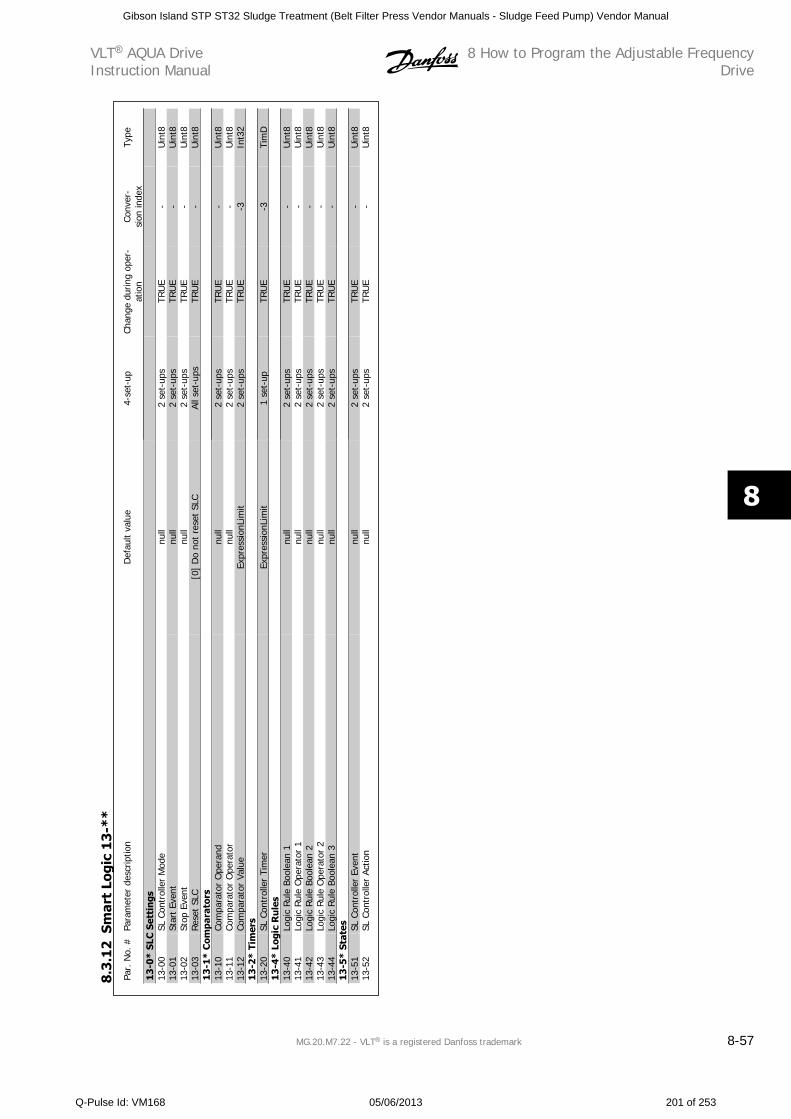
Par.
No.
#Pa
ram
eter
des
crip
tion
Def
ault
valu
e4-
set-
upCh
ange
dur
ing
oper
-at
ion
Conv
er-
sion
inde
xTy
pe
13-0
* SL
C S
etti
ngs
13-0
0SL
Con
trol
ler
Mod
enu
ll2
set-
ups
TRU
E-
Uin
t813
-01
Star
t Ev
ent
null
2 se
t-up
sTR
UE
-U
int8
13-0
2St
op E
vent
null
2 se
t-up
sTR
UE
-U
int8
13-0
3Re
set
SLC
[0]
Do
not
rese
t SL
CAl
l set
-ups
TRU
E-
Uin
t813
-1*
Com
para
tors
13-1
0Co
mpa
rato
r O
pera
ndnu
ll2
set-
ups
TRU
E-
Uin
t813
-11
Com
para
tor
Ope
rato
rnu
ll2
set-
ups
TRU
E-
Uin
t813
-12
Com
para
tor
Valu
eEx
pres
sion
Lim
it2
set-
ups
TRU
E-3
Int3
213
-2*
Tim
ers
13-2
0SL
Con
trol
ler
Tim
erEx
pres
sion
Lim
it1
set-
upTR
UE
-3Ti
mD
13-4
* Lo
gic
Ru
les
13-4
0Lo
gic
Rule
Boo
lean
1nu
ll2
set-
ups
TRU
E-
Uin
t813
-41
Logi
c Rul
e O
pera
tor
1nu
ll2
set-
ups
TRU
E-
Uin
t813
-42
Logi
c Ru
le B
oole
an 2
null
2 se
t-up
sTR
UE
-U
int8
13-4
3Lo
gic
Rule
Ope
rato
r 2
null
2 se
t-up
sTR
UE
-U
int8
13-4
4Lo
gic
Rule
Boo
lean
3nu
ll2
set-
ups
TRU
E-
Uin
t813
-5*
Stat
es13
-51
SL C
ontr
olle
r Ev
ent
null
2 se
t-up
sTR
UE
-U
int8
13-5
2SL
Con
trol
ler
Actio
nnu
ll2
set-
ups
TRU
E-
Uin
t8
8.3
.12
Smar
t Lo
gic
13
-**
VLT AQUA DriveInstruction Manual
8 How to Program the Adjustable FrequencyDrive
MG.20.M7.22 - VLT is a registered Danfoss trademark 8-57
8
Gibson Island STP ST32 Sludge Treatment (Belt Filter Press Vendor Manuals - Sludge Feed Pump) Vendor Manual
Q-Pulse Id: VM168 05/06/2013 201 of 253
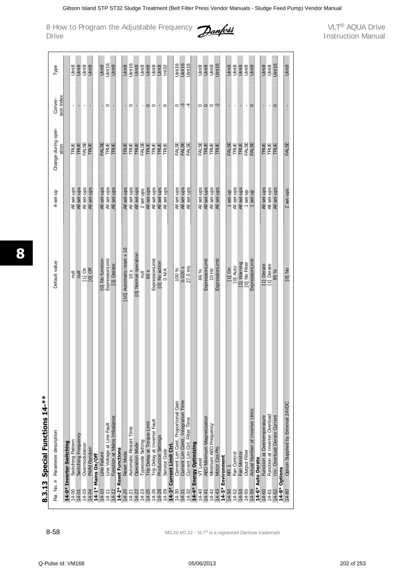
Par.
No.
#Pa
ram
eter
des
crip
tion
Def
ault
valu
e4-
set-
upCh
ange
dur
ing
oper
-at
ion
Conv
er-
sion
inde
xTy
pe
14-0
* In
vert
er S
wit
chin
g14
-00
Switc
hing
Pat
tern
null
All s
et-u
psTR
UE
-U
int8
14-0
1Sw
itchi
ng F
requ
ency
null
All s
et-u
psTR
UE
-U
int8
14-0
3O
verm
odul
atio
n[1
] O
nAl
l set
-ups
FALS
E-
Uin
t814
-04
PWM
Ran
dom
[0]
Off
All s
et-u
psTR
UE
-U
int8
14
-1*
Mai
ns
On
/Off
14-1
0Li
ne F
ailu
re[0
] N
o fu
nctio
nAl
l set
-ups
FALS
E-
Uin
t814
-11
Line
Vol
tage
at
Line
Fau
ltEx
pres
sion
Lim
itAl
l set
-ups
TRU
E0
Uin
t16
14-1
2Fu
nctio
n at
Mai
ns I
mba
lanc
e[3
] D
erat
eAl
l set
-ups
TRU
E-
Uin
t814
-2*
Res
et F
un
ctio
ns
14-2
0Re
set
Mod
e[1
0] A
utom
atic
res
et x
10
All s
et-u
psTR
UE
-U
int8
14-2
1Au
tom
atic
Res
tart
Tim
e10
sAl
l set
-ups
TRU
E0
Uin
t16
14-2
2O
pera
tion
Mod
e[0
] N
orm
al o
pera
tion
All s
et-u
psTR
UE
-U
int8
14-2
3Ty
peco
de S
ettin
gnu
ll2
set-
ups
FALS
E-
Uin
t814
-25
Trip
Del
ay a
t To
rque
Lim
it60
sAl
l set
-ups
TRU
E0
Uin
t814
-26
Trip
Del
ay a
t In
vert
er F
ault
Expr
essi
onLi
mit
All s
et-u
psTR
UE
0U
int8
14-2
8Pr
oduc
tion
Sett
ings
[0]
No
actio
nAl
l set
-ups
TRU
E-
Uin
t814
-29
Serv
ice
Code
0 N
/AAl
l set
-ups
TRU
E0
Int3
214
-3*
Cu
rren
t Li
mit
Ctr
l.14
-30
Curr
ent
Lim
Con
t, P
ropo
rtio
nal G
ain
100
%Al
l set
-ups
FALS
E0
Uin
t16
14-3
1Cu
rren
t Li
m C
ontr
, Int
egra
tion
Tim
e0.
020
sAl
l set
-ups
FALS
E-3
Uin
t16
14-3
2Cu
rren
t Li
m C
trl,
Filte
r Ti
me
27.0
ms
All s
et-u
psFA
LSE
-4U
int1
614
-4*
Ener
gy O
ptim
izin
g14
-40
VT L
evel
66 %
All s
et-u
psFA
LSE
0U
int8
14-4
1AE
O M
inim
um M
agne
tizat
ion
Expr
essi
onLi
mit
All s
et-u
psTR
UE
0U
int8
14-4
2M
inim
um A
EO F
requ
ency
10 H
zAl
l set
-ups
TRU
E0
Uin
t814
-43
Mot
or C
os-P
hiEx
pres
sion
Lim
itAl
l set
-ups
TRU
E-2
Uin
t16
14-5
* En
viro
nm
ent
14-5
0RFI
1[1
] O
n1
set-
upFA
LSE
-U
int8
14-5
2Fa
n Co
ntro
l[0
] Au
toAl
l set
-ups
TRU
E-
Uin
t814
-53
Fan
Mon
itor
[1]
War
ning
All s
et-u
psTR
UE
-U
int8
14-5
5O
utpu
t Fi
lter
[0]
No
Filte
r1
set-
upFA
LSE
-U
int8
14-5
9Ac
tual
Num
ber
of I
nver
ter
Uni
tsEx
pres
sion
Lim
it1
set-
upFA
LSE
0U
int8
14-6
* A
uto
Der
ate
14-6
0Fu
nctio
n at
Ove
rtem
pera
ture
[1]
Der
ate
All s
et-u
psTR
UE
-U
int8
14-6
1Fu
nctio
n at
Inv
erte
r O
verlo
ad[1
] D
erat
eAl
l set
-ups
TRU
E-
Uin
t814
-62
Inv.
Ove
rload
Der
ate
Curr
ent
95 %
All s
et-u
psTR
UE
0U
int1
614
-8*
Opt
ion
s14
-80
Opt
ion
Supp
lied
by E
xter
nal 2
4VD
C[0
] N
o2
set-
ups
FALS
E-
Uin
t8
8.3
.13
Spec
ial F
un
ctio
ns
14
-**
8 How to Program the Adjustable FrequencyDrive
VLT AQUA DriveInstruction Manual
8-58 MG.20.M7.22 - VLT is a registered Danfoss trademark
8
Gibson Island STP ST32 Sludge Treatment (Belt Filter Press Vendor Manuals - Sludge Feed Pump) Vendor Manual
Q-Pulse Id: VM168 05/06/2013 202 of 253
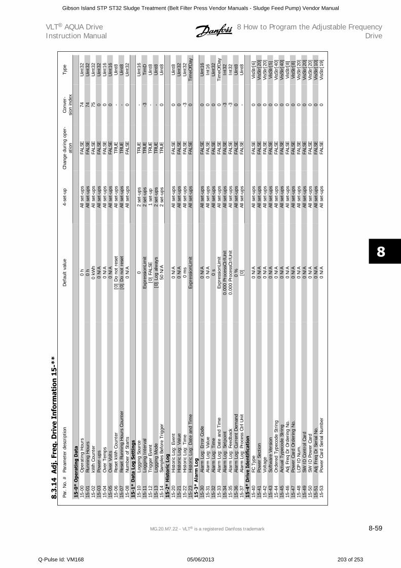
Par.
No.
#Pa
ram
eter
des
crip
tion
Def
ault
valu
e4-
set-
upCh
ange
dur
ing
oper
-at
ion
Conv
er-
sion
inde
xTy
pe
15-0
* O
pera
tin
g D
ata
15-0
0O
pera
ting
Hou
rs0
hAl
l set
-ups
FALS
E74
Uin
t32
15-0
1Ru
nnin
g H
ours
0 h
All s
et-u
psFA
LSE
74U
int3
215
-02
kWh
Coun
ter
0 kW
hAl
l set
-ups
FALS
E75
Uin
t32
15-0
3Po
wer
-ups
0 N
/AAl
l set
-ups
FALS
E0
Uin
t32
15-0
4O
ver
Tem
ps0
N/A
All s
et-u
psFA
LSE
0U
int1
615
-05
Ove
r Vo
lts0
N/A
All s
et-u
psFA
LSE
0U
int1
615
-06
Res
et k
Wh
Coun
ter
[0]
Do
not
rese
tAl
l set
-ups
TRU
E-
Uin
t815
-07
Rese
t Ru
nnin
g H
ours
Cou
nter
[0]
Do
not
rese
tAl
l set
-ups
TRU
E-
Uin
t815
-08
Num
ber
of S
tart
s0
N/A
All s
et-u
psFA
LSE
0U
int3
215
-1*
Dat
a Lo
g Se
ttin
gs15
-10
Logg
ing
Sour
ce0
2 se
t-up
sTR
UE
-U
int1
615
-11
Logg
ing
Inte
rval
Expr
essi
onLi
mit
2 se
t-up
sTR
UE
-3Ti
mD
15-1
2Tr
igge
r Ev
ent
[0]
FALS
E1
set-
upTR
UE
-U
int8
15-1
3Lo
ggin
g M
ode
[0]
Log
alw
ays
2 se
t-up
sTR
UE
-U
int8
15-1
4Sa
mpl
es B
efor
e Tr
igge
r50
N/A
2 se
t-up
sTR
UE
0U
int8
15-2
* H
isto
ric
Log
15-2
0H
isto
ric L
og:
Even
t0
N/A
All s
et-u
psFA
LSE
0U
int8
15-2
1H
isto
ric L
og:
Valu
e0
N/A
All s
et-u
psFA
LSE
0U
int3
215
-22
His
toric
Log
: Ti
me
0 m
sAl
l set
-ups
FALS
E-3
Uin
t32
15-2
3H
isto
ric L
og:
Dat
e an
d Ti
me
Expr
essi
onLi
mit
All s
et-u
psFA
LSE
0Ti
meO
fDay
15-3
* A
larm
Log
15-3
0Al
arm
Log
: Er
ror
Code
0 N
/AAl
l set
-ups
FALS
E0
Uin
t16
15-3
1Al
arm
Log
: Va
lue
0 N
/AAl
l set
-ups
FALS
E0
Int1
615
-32
Alar
m L
og:
Tim
e0
sAl
l set
-ups
FALS
E0
Uin
t32
15-3
3Al
arm
Log
: D
ate
and
Tim
eEx
pres
sion
Lim
itAl
l set
-ups
FALS
E0
Tim
eOfD
ay15
-34
Alar
m L
og:
Setp
oint
0.00
0 Pr
oces
sCtr
lUni
tAl
l set
-ups
FALS
E-3
Int3
215
-35
Alar
m L
og:
Feed
back
0.00
0 Pr
oces
sCtr
lUni
tAl
l set
-ups
FALS
E-3
Int3
215
-36
Alar
m L
og:
Curr
ent
Dem
and
0 %
All s
et-u
psFA
LSE
0U
int8
15-3
7Al
arm
Log
: Pr
oces
s Ct
rl U
nit
[0]
All s
et-u
psFA
LSE
-U
int8
15-4
* D
rive
Ide
nti
fica
tion
15-4
0FC
Typ
e0
N/A
All s
et-u
psFA
LSE
0Vi
sStr
[6]
15-4
1Po
wer
Sec
tion
0 N
/AAl
l set
-ups
FALS
E0
VisS
tr[2
0]15
-42
Volta
ge0
N/A
All s
et-u
psFA
LSE
0Vi
sStr
[20]
15-4
3So
ftw
are
Vers
ion
0 N
/AAl
l set
-ups
FALS
E0
VisS
tr[5
]15
-44
Ord
ered
Typ
ecod
e St
ring
0 N
/AAl
l set
-ups
FALS
E0
VisS
tr[4
0]15
-45
Actu
al T
ypec
ode
Strin
g0
N/A
All s
et-u
psFA
LSE
0Vi
sStr
[40]
15-4
6Ad
j Fre
q D
r O
rder
ing
No.
0 N
/AAl
l set
-ups
FALS
E0
VisS
tr[8
]15
-47
Pow
er C
ard
Ord
erin
g N
o.0
N/A
All s
et-u
psFA
LSE
0Vi
sStr
[8]
15-4
8LC
P ID
Num
.0
N/A
All s
et-u
psFA
LSE
0Vi
sStr
[20]
15-4
9SW
ID
Con
trol
Car
d0
N/A
All s
et-u
psFA
LSE
0Vi
sStr
[20]
15-5
0SW
ID
Pow
er C
ard
0 N
/AAl
l set
-ups
FALS
E0
VisS
tr[2
0]15
-51
Adj F
req
Dr
Seria
l No.
0 N
/AAl
l set
-ups
FALS
E0
VisS
tr[1
0]15
-53
Pow
er C
ard
Seria
l Num
ber
0 N
/AAl
l set
-ups
FALS
E0
VisS
tr[1
9]
8.3
.14
Adj
. Fre
q. D
rive
In
form
atio
n 1
5-*
*
VLT AQUA DriveInstruction Manual
8 How to Program the Adjustable FrequencyDrive
MG.20.M7.22 - VLT is a registered Danfoss trademark 8-59
8
Gibson Island STP ST32 Sludge Treatment (Belt Filter Press Vendor Manuals - Sludge Feed Pump) Vendor Manual
Q-Pulse Id: VM168 05/06/2013 203 of 253
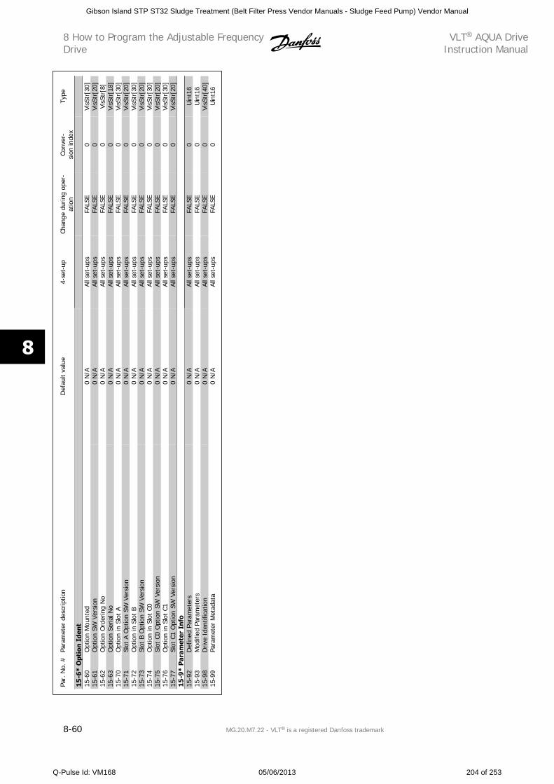
Par.
No.
#Pa
ram
eter
des
crip
tion
Def
ault
valu
e4-
set-
upCh
ange
dur
ing
oper
-at
ion
Conv
er-
sion
inde
xTy
pe
15-6
* O
ptio
n I
den
t15
-60
Opt
ion
Mou
nted
0 N
/AAl
l set
-ups
FALS
E0
VisS
tr[3
0]15
-61
Opt
ion
SW V
ersi
on0
N/A
All s
et-u
psFA
LSE
0Vi
sStr
[20]
15-6
2O
ptio
n O
rder
ing
No
0 N
/AAl
l set
-ups
FALS
E0
VisS
tr[8
]15
-63
Opt
ion
Seria
l No
0 N
/AAl
l set
-ups
FALS
E0
VisS
tr[1
8]15
-70
Opt
ion
in S
lot
A0
N/A
All s
et-u
psFA
LSE
0Vi
sStr
[30]
15-7
1Sl
ot A
Opt
ion
SW V
ersi
on0
N/A
All s
et-u
psFA
LSE
0Vi
sStr
[20]
15-7
2O
ptio
n in
Slo
t B
0 N
/AAl
l set
-ups
FALS
E0
VisS
tr[3
0]15
-73
Slot
B O
ptio
n SW
Ver
sion
0 N
/AAl
l set
-ups
FALS
E0
VisS
tr[2
0]15
-74
Opt
ion
in S
lot
C00
N/A
All s
et-u
psFA
LSE
0Vi
sStr
[30]
15-7
5Sl
ot C
0 O
ptio
n SW
Ver
sion
0 N
/AAl
l set
-ups
FALS
E0
VisS
tr[2
0]15
-76
Opt
ion
in S
lot
C10
N/A
All s
et-u
psFA
LSE
0Vi
sStr
[30]
15-7
7Sl
ot C
1 O
ptio
n SW
Ver
sion
0 N
/AAl
l set
-ups
FALS
E0
VisS
tr[2
0]15
-9*
Par
amet
er I
nfo
15-9
2D
efin
ed P
aram
eter
s0
N/A
All s
et-u
psFA
LSE
0U
int1
615
-93
Mod
ified
Par
amet
ers
0 N
/AAl
l set
-ups
FALS
E0
Uin
t16
15-9
8D
rive
Iden
tific
atio
n0
N/A
All s
et-u
psFA
LSE
0Vi
sStr
[40]
15-9
9Pa
ram
eter
Met
adat
a0
N/A
All s
et-u
psFA
LSE
0U
int1
6
8 How to Program the Adjustable FrequencyDrive
VLT AQUA DriveInstruction Manual
8-60 MG.20.M7.22 - VLT is a registered Danfoss trademark
8
Gibson Island STP ST32 Sludge Treatment (Belt Filter Press Vendor Manuals - Sludge Feed Pump) Vendor Manual
Q-Pulse Id: VM168 05/06/2013 204 of 253
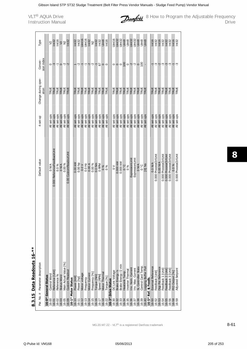
Par.
No.
#Pa
ram
eter
des
crip
tion
Def
ault
valu
e4-
set-
upCh
ange
dur
ing
oper
-at
ion
Conv
er-
sion
inde
xTy
pe
16
-0*
Gen
eral
Sta
tus
16-0
0Co
ntro
l Wor
d0
N/A
All s
et-u
psTR
UE
0V2
16-0
1Re
fere
nce
[Uni
t]0.
000
Ref
eren
ceFe
edba
ckU
nit
All s
et-u
psTR
UE
-3In
t32
16-0
2Ref
eren
ce %
0.0
%Al
l set
-ups
TRU
E-1
Int1
616
-03
Stat
us W
ord
0 N
/AAl
l set
-ups
TRU
E0
V216
-05
Mai
n Ac
tual
Val
ue [
%]
0.00
%Al
l set
-ups
TRU
E-2
N2
16-0
9Cu
stom
Rea
dout
0.00
Cus
tom
Rea
dout
Uni
tAl
l set
-ups
TRU
E-2
Int3
216
-1*
Mot
or S
tatu
s16
-10
Pow
er [
kW]
0.00
kW
All s
et-u
psTR
UE
1In
t32
16-1
1Po
wer
[hp
]0.
00 h
pAl
l set
-ups
TRU
E-2
Int3
216
-12
Mot
or v
olta
ge0.
0 V
All s
et-u
psTR
UE
-1U
int1
616
-13
Freq
uenc
y0.
0 H
zAl
l set
-ups
TRU
E-1
Uin
t16
16-1
4M
otor
Cur
rent
0.00
AAl
l set
-ups
TRU
E-2
Int3
216
-15
Freq
uenc
y [%
]0.
00 %
All s
et-u
psTR
UE
-2N
216
-16
Torq
ue [
Nm
]0.
0 N
mAl
l set
-ups
TRU
E-1
Int3
216
-17
Spee
d [R
PM]
0 RP
MAl
l set
-ups
TRU
E67
Int3
216
-18
Mot
or T
herm
al0
%Al
l set
-ups
TRU
E0
Uin
t816
-22
Torq
ue [
%]
0 %
All s
et-u
psTR
UE
0In
t16
16-3
* D
rive
Sta
tus
16-3
0D
C Li
nk V
olta
ge0
VAl
l set
-ups
TRU
E0
Uin
t16
16-3
2Br
ake
Ener
gy /
s0.
000
kWAl
l set
-ups
TRU
E0
Uin
t32
16-3
3Br
ake
Ener
gy /
2 m
in0.
000
kWAl
l set
-ups
TRU
E0
Uin
t32
16-3
4H
eats
ink
Tem
p.0
°CAl
l set
-ups
TRU
E10
0U
int8
16-3
5In
vert
er T
herm
al0
%Al
l set
-ups
TRU
E0
Uin
t816
-36
Inv.
Nom
. Cur
rent
Expr
essi
onLi
mit
All s
et-u
psTR
UE
-2U
int3
216
-37
Inv.
Max
. Cur
rent
Expr
essi
onLi
mit
All s
et-u
psTR
UE
-2U
int3
216
-38
SL C
ontr
olle
r St
ate
0 N
/AAl
l set
-ups
TRU
E0
Uin
t816
-39
Cont
rol C
ard
Tem
p.0
°CAl
l set
-ups
TRU
E10
0U
int8
16-4
0Lo
ggin
g Bu
ffer
Ful
l[0
] N
oAl
l set
-ups
TRU
E-
Uin
t816
-5*
Ref
. & F
eedb
.16
-50
Exte
rnal
Ref
eren
ce0.
0 N
/AAl
l set
-ups
TRU
E-1
Int1
616
-52
Feed
back
[U
nit]
0.00
0 Pr
oces
sCtr
lUni
tAl
l set
-ups
TRU
E-3
Int3
216
-53
Dig
i Pot
Ref
eren
ce0.
00 N
/AAl
l set
-ups
TRU
E-2
Int1
616
-54
Feed
back
1 [
Uni
t]0.
000
Proc
essC
trlU
nit
All s
et-u
psTR
UE
-3In
t32
16-5
5Fe
edba
ck 2
[U
nit]
0.00
0 Pr
oces
sCtr
lUni
tAl
l set
-ups
TRU
E-3
Int3
216
-56
Feed
back
3 [
Uni
t]0.
000
Proc
essC
trlU
nit
All s
et-u
psTR
UE
-3In
t32
16-5
8PI
D O
utpu
t [%
]0.
0 %
All s
et-u
psTR
UE
-1In
t16
16-5
9Ad
just
ed S
etpo
int
0.00
0 Pr
oces
sCtr
lUni
tAl
l set
-ups
TRU
E-3
Int3
2
8.3
.15
Dat
a R
eado
uts
16
-**
VLT AQUA DriveInstruction Manual
8 How to Program the Adjustable FrequencyDrive
MG.20.M7.22 - VLT is a registered Danfoss trademark 8-61
8
Gibson Island STP ST32 Sludge Treatment (Belt Filter Press Vendor Manuals - Sludge Feed Pump) Vendor Manual
Q-Pulse Id: VM168 05/06/2013 205 of 253
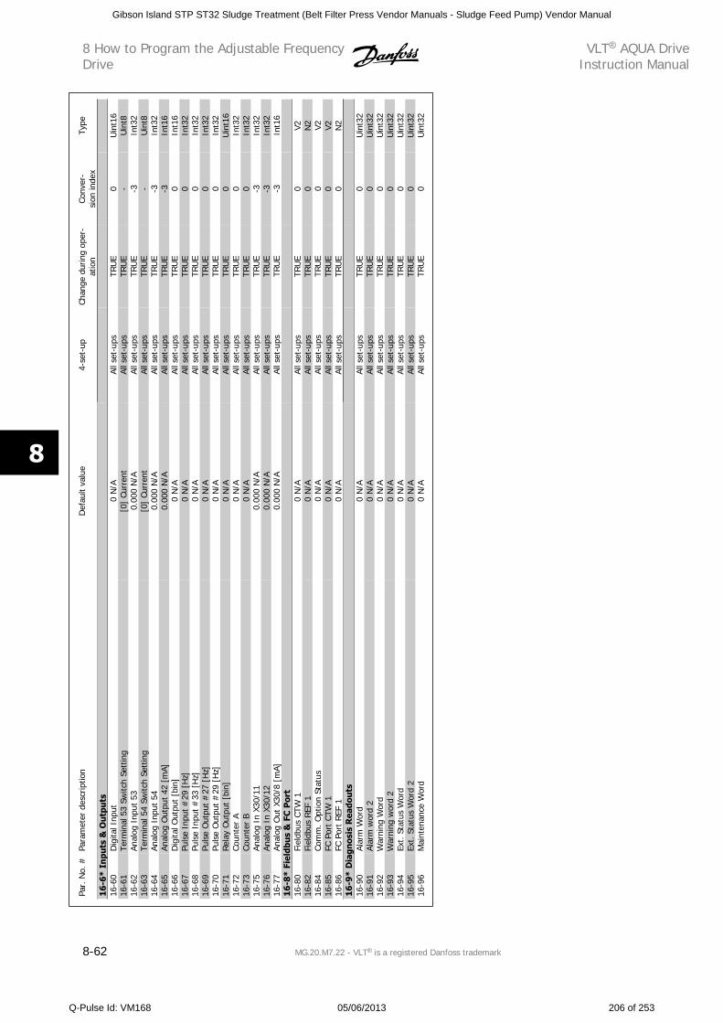
Par.
No.
#Pa
ram
eter
des
crip
tion
Def
ault
valu
e4-
set-
upCh
ange
dur
ing
oper
-at
ion
Conv
er-
sion
inde
xTy
pe
16-6
* In
puts
& O
utp
uts
16-6
0D
igita
l Inp
ut0
N/A
All s
et-u
psTR
UE
0U
int1
616
-61
Term
inal
53
Switc
h Se
ttin
g[0
] Cu
rren
tAl
l set
-ups
TRU
E-
Uin
t816
-62
Anal
og I
nput
53
0.00
0 N
/AAl
l set
-ups
TRU
E-3
Int3
216
-63
Term
inal
54
Switc
h Se
ttin
g[0
] Cu
rren
tAl
l set
-ups
TRU
E-
Uin
t816
-64
Anal
og I
nput
54
0.00
0 N
/AAl
l set
-ups
TRU
E-3
Int3
216
-65
Anal
og O
utpu
t 42
[m
A]0.
000
N/A
All s
et-u
psTR
UE
-3In
t16
16-6
6D
igita
l Out
put
[bin
]0
N/A
All s
et-u
psTR
UE
0In
t16
16-6
7Pu
lse
Inpu
t #
29 [
Hz]
0 N
/AAl
l set
-ups
TRU
E0
Int3
216
-68
Puls
e In
put
#33
[H
z]0
N/A
All s
et-u
psTR
UE
0In
t32
16-6
9Pu
lse
Out
put
#27
[H
z]0
N/A
All s
et-u
psTR
UE
0In
t32
16-7
0Pu
lse
Out
put
#29
[H
z]0
N/A
All s
et-u
psTR
UE
0In
t32
16-7
1Re
lay
Out
put
[bin
]0
N/A
All s
et-u
psTR
UE
0U
int1
616
-72
Coun
ter
A0
N/A
All s
et-u
psTR
UE
0In
t32
16-7
3Co
unte
r B
0 N
/AAl
l set
-ups
TRU
E0
Int3
216
-75
Anal
og I
n X3
0/11
0.00
0 N
/AAl
l set
-ups
TRU
E-3
Int3
216
-76
Anal
og I
n X3
0/12
0.00
0 N
/AAl
l set
-ups
TRU
E-3
Int3
216
-77
Anal
og O
ut X
30/8
[m
A]0.
000
N/A
All s
et-u
psTR
UE
-3In
t16
16-8
* Fi
eldb
us
& F
C P
ort
16-8
0Fi
eldb
us C
TW 1
0 N
/AAl
l set
-ups
TRU
E0
V216
-82
Fiel
dbus
REF
10
N/A
All s
et-u
psTR
UE
0N
216
-84
Com
m. O
ptio
n St
atus
0 N
/AAl
l set
-ups
TRU
E0
V216
-85
FC P
ort
CTW
10
N/A
All s
et-u
psTR
UE
0V2
16-8
6FC
Por
t REF
10
N/A
All s
et-u
psTR
UE
0N
216
-9*
Dia
gnos
is R
eado
uts
16-9
0Al
arm
Wor
d0
N/A
All s
et-u
psTR
UE
0U
int3
216
-91
Alar
m w
ord
20
N/A
All s
et-u
psTR
UE
0U
int3
216
-92
War
ning
Wor
d0
N/A
All s
et-u
psTR
UE
0U
int3
216
-93
War
ning
wor
d 2
0 N
/AAl
l set
-ups
TRU
E0
Uin
t32
16-9
4Ex
t. S
tatu
s W
ord
0 N
/AAl
l set
-ups
TRU
E0
Uin
t32
16-9
5Ex
t. S
tatu
s W
ord
20
N/A
All s
et-u
psTR
UE
0U
int3
216
-96
Mai
nten
ance
Wor
d0
N/A
All s
et-u
psTR
UE
0U
int3
2
8 How to Program the Adjustable FrequencyDrive
VLT AQUA DriveInstruction Manual
8-62 MG.20.M7.22 - VLT is a registered Danfoss trademark
8
Gibson Island STP ST32 Sludge Treatment (Belt Filter Press Vendor Manuals - Sludge Feed Pump) Vendor Manual
Q-Pulse Id: VM168 05/06/2013 206 of 253
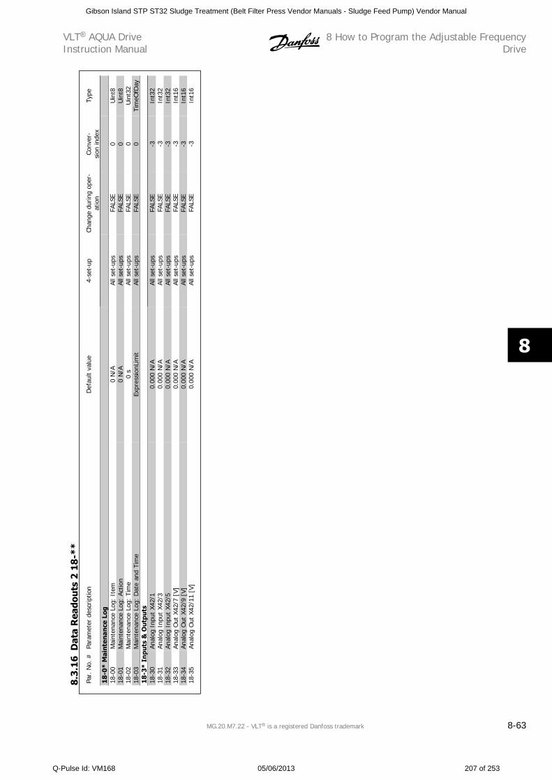
Par.
No.
#Pa
ram
eter
des
crip
tion
Def
ault
valu
e4-
set-
upCh
ange
dur
ing
oper
-at
ion
Conv
er-
sion
inde
xTy
pe
18-0
* M
aint
enan
ce L
og18
-00
Mai
nten
ance
Log
: It
em0
N/A
All s
et-u
psFA
LSE
0U
int8
18-0
1M
aint
enan
ce L
og:
Actio
n0
N/A
All s
et-u
psFA
LSE
0U
int8
18-0
2M
aint
enan
ce L
og:
Tim
e0
sAl
l set
-ups
FALS
E0
Uin
t32
18-0
3M
aint
enan
ce L
og:
Dat
e an
d Ti
me
Expr
essi
onLi
mit
All s
et-u
psFA
LSE
0Ti
meO
fDay
18-3
* In
puts
& O
utp
uts
18-3
0An
alog
Inp
ut X
42/1
0.00
0 N
/AAl
l set
-ups
FALS
E-3
Int3
218
-31
Anal
og I
nput
X42
/30.
000
N/A
All s
et-u
psFA
LSE
-3In
t32
18-3
2An
alog
Inp
ut X
42/5
0.00
0 N
/AAl
l set
-ups
FALS
E-3
Int3
218
-33
Anal
og O
ut X
42/7
[V]
0.00
0 N
/AAl
l set
-ups
FALS
E-3
Int1
618
-34
Anal
og O
ut X
42/9
[V]
0.00
0 N
/AAl
l set
-ups
FALS
E-3
Int1
618
-35
Anal
og O
ut X
42/1
1 [V
]0.
000
N/A
All s
et-u
psFA
LSE
-3In
t16
8.3
.16
Dat
a R
eado
uts
2 1
8-*
*
VLT AQUA DriveInstruction Manual
8 How to Program the Adjustable FrequencyDrive
MG.20.M7.22 - VLT is a registered Danfoss trademark 8-63
8
Gibson Island STP ST32 Sludge Treatment (Belt Filter Press Vendor Manuals - Sludge Feed Pump) Vendor Manual
Q-Pulse Id: VM168 05/06/2013 207 of 253
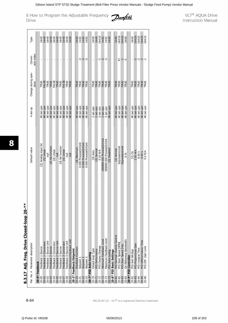
Par.
No.
#Pa
ram
eter
des
crip
tion
Def
ault
valu
e4-
set-
upCh
ange
dur
ing
oper
-at
ion
Conv
er-
sion
inde
xTy
pe
20-0
* Fe
edba
ck20
-00
Feed
back
1 S
ourc
e[2
] An
alog
inpu
t 54
All s
et-u
psTR
UE
-U
int8
20-0
1Fe
edba
ck 1
Con
vers
ion
[0]
Line
arAl
l set
-ups
FALS
E-
Uin
t820
-02
Feed
back
1 S
ourc
e U
nit
null
All s
et-u
psTR
UE
-U
int8
20-0
3Fe
edba
ck 2
Sou
rce
[0]
No
func
tion
All s
et-u
psTR
UE
-U
int8
20-0
4Fe
edba
ck 2
Con
vers
ion
[0]
Line
arAl
l set
-ups
FALS
E-
Uin
t820
-05
Feed
back
2 S
ourc
e U
nit
null
All s
et-u
psTR
UE
-U
int8
20-0
6Fe
edba
ck 3
Sou
rce
[0]
No
func
tion
All s
et-u
psTR
UE
-U
int8
20-0
7Fe
edba
ck 3
Con
vers
ion
[0]
Line
arAl
l set
-ups
FALS
E-
Uin
t820
-08
Feed
back
3 S
ourc
e U
nit
null
All s
et-u
psTR
UE
-U
int8
20-1
2Ref
eren
ce/F
eedb
ack
Uni
tnu
llAl
l set
-ups
TRU
E-
Uin
t820
-2*
Feed
back
/Set
poin
t20
-20
Feed
back
Fun
ctio
n[4
] M
axim
umAl
l set
-ups
TRU
E-
Uin
t820
-21
Setp
oint
10.
000
Proc
essC
trlU
nit
All s
et-u
psTR
UE
-3In
t32
20-2
2Se
tpoi
nt 2
0.00
0 Pr
oces
sCtr
lUni
tAl
l set
-ups
TRU
E-3
Int3
220
-23
Setp
oint
30.
000
Proc
essC
trlU
nit
All s
et-u
psTR
UE
-3In
t32
20-7
* P
ID A
uto
-tu
nin
g20
-70
Clos
ed-lo
op T
ype
[0]
Auto
2 se
t-up
sTR
UE
-U
int8
20-7
1PI
D P
erfo
rman
ce[0
] N
orm
al2
set-
ups
TRU
E-
Uin
t820
-72
PID
Out
put
Chan
ge0.
10 N
/A2
set-
ups
TRU
E-2
Uin
t16
20-7
3M
inim
um F
eedb
ack
Leve
l-9
9999
9.00
0 Pr
oces
sCtr
lUni
t2
set-
ups
TRU
E-3
Int3
220
-74
Max
imum
Fee
dbac
k Le
vel
9999
99.0
00 P
roce
ssCt
rlUni
t2
set-
ups
TRU
E-3
Int3
220
-79
PID
Aut
o-tu
ning
[0]
Dis
able
dAl
l set
-ups
TRU
E-
Uin
t820
-8*
PID
Bas
ic S
etti
ngs
20-8
1PI
D N
orm
al/
Inve
rse
Cont
rol
[0]
Nor
mal
All s
et-u
psTR
UE
-U
int8
20-8
2PI
D S
tart
Spe
ed [
RPM
]Ex
pres
sion
Lim
itAl
l set
-ups
TRU
E67
Uin
t16
20-8
3PI
D S
tart
Spe
ed [
Hz]
Expr
essi
onLi
mit
All s
et-u
psTR
UE
-1U
int1
620
-84
On
Ref
eren
ce B
andw
idth
5 %
All s
et-u
psTR
UE
0U
int8
20-9
* P
ID C
ontr
olle
r20
-91
PID
Ant
i Win
dup
[1]
On
All s
et-u
psTR
UE
-U
int8
20-9
3PI
D P
ropo
rtio
nal G
ain
2.00
N/A
All s
et-u
psTR
UE
-2U
int1
620
-94
PID
Int
egra
l Tim
e8.
00 s
All s
et-u
psTR
UE
-2U
int3
220
-95
PID
Diff
eren
tiatio
n Ti
me
0.00
sAl
l set
-ups
TRU
E-2
Uin
t16
20-9
6PI
D D
iff. G
ain
Lim
it5.
0 N
/AAl
l set
-ups
TRU
E-1
Uin
t16
8.3.
17
Adj
. Fre
q. D
rive
Clo
sed-
loop
20-
**
8 How to Program the Adjustable FrequencyDrive
VLT AQUA DriveInstruction Manual
8-64 MG.20.M7.22 - VLT is a registered Danfoss trademark
8
Gibson Island STP ST32 Sludge Treatment (Belt Filter Press Vendor Manuals - Sludge Feed Pump) Vendor Manual
Q-Pulse Id: VM168 05/06/2013 208 of 253
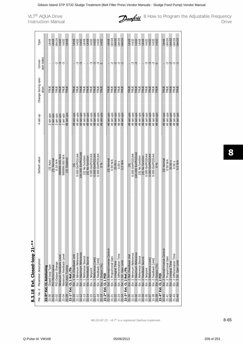
Par.
No.
#Pa
ram
eter
des
crip
tion
Def
ault
valu
e4-
set-
upCh
ange
dur
ing
oper
-at
ion
Conv
er-
sion
inde
xTy
pe
21-0
* Ex
t. C
L A
uto
tun
ing
21-0
0Cl
osed
-loop
Typ
e[0
] Au
to2
set-
ups
TRU
E-
Uin
t821
-01
PID
Per
form
ance
[0]
Nor
mal
2 se
t-up
sTR
UE
-U
int8
21-0
2PI
D O
utpu
t Ch
ange
0.10
N/A
2 se
t-up
sTR
UE
-2U
int1
621
-03
Min
imum
Fee
dbac
k Le
vel
-999
999.
000
N/A
2 se
t-up
sTR
UE
-3In
t32
21-0
4M
axim
um F
eedb
ack
Leve
l99
9999
.000
N/A
2 se
t-up
sTR
UE
-3In
t32
21-0
9PI
D A
uto
Tuni
ng[0
] D
isab
led
All s
et-u
psTR
UE
-U
int8
21-1
* Ex
t. C
L 1
Ref
./Fb
.21
-10
Ext.
1 R
ef./
Feed
back
Uni
t[0
]Al
l set
-ups
TRU
E-
Uin
t821
-11
Ext.
1 M
inim
um R
efer
ence
0.00
0 Ex
tPID
1Uni
tAl
l set
-ups
TRU
E-3
Int3
221
-12
Ext.
1 M
axim
um R
efer
ence
100.
000
ExtP
ID1U
nit
All s
et-u
psTR
UE
-3In
t32
21-1
3Ex
t. 1
Ref
eren
ce S
ourc
e[0
] N
o fu
nctio
nAl
l set
-ups
TRU
E-
Uin
t821
-14
Ext.
1 F
eedb
ack
Sour
ce[0
] N
o fu
nctio
nAl
l set
-ups
TRU
E-
Uin
t821
-15
Ext.
1 S
etpo
int
0.00
0 Ex
tPID
1Uni
tAl
l set
-ups
TRU
E-3
Int3
221
-17
Ext.
1 R
efer
ence
[U
nit]
0.00
0 Ex
tPID
1Uni
tAl
l set
-ups
TRU
E-3
Int3
221
-18
Ext.
1 F
eedb
ack
[Uni
t]0.
000
ExtP
ID1U
nit
All s
et-u
psTR
UE
-3In
t32
21-1
9Ex
t. 1
Out
put
[%]
0 %
All s
et-u
psTR
UE
0In
t32
21-2
* Ex
t. C
L 1
PID
21-2
0Ex
t. 1
Nor
mal
/Inv
erse
Con
trol
[0]
Nor
mal
All s
et-u
psTR
UE
-U
int8
21-2
1Ex
t. 1
Pro
port
iona
l Gai
n0.
50 N
/AAl
l set
-ups
TRU
E-2
Uin
t16
21-2
2Ex
t. 1
Int
egra
l Tim
e20
.00
sAl
l set
-ups
TRU
E-2
Uin
t32
21-2
3Ex
t. 1
Diff
eren
tatio
n Ti
me
0.00
sAl
l set
-ups
TRU
E-2
Uin
t16
21-2
4Ex
t. 1
Dif.
Gai
n Li
mit
5.0
N/A
All s
et-u
psTR
UE
-1U
int1
621
-3*
Ext.
CL
2 R
ef./
Fb.
21-3
0Ex
t. 2
Ref
./Fe
edba
ck U
nit
[0]
All s
et-u
psTR
UE
-U
int8
21-3
1Ex
t. 2
Min
imum
Ref
eren
ce0.
000
ExtP
ID2U
nit
All s
et-u
psTR
UE
-3In
t32
21-3
2Ex
t. 2
Max
imum
Ref
eren
ce10
0.00
0 Ex
tPID
2Uni
tAl
l set
-ups
TRU
E-3
Int3
221
-33
Ext.
2 R
efer
ence
Sou
rce
[0]
No
func
tion
All s
et-u
psTR
UE
-U
int8
21-3
4Ex
t. 2
Fee
dbac
k So
urce
[0]
No
func
tion
All s
et-u
psTR
UE
-U
int8
21-3
5Ex
t. 2
Set
poin
t0.
000
ExtP
ID2U
nit
All s
et-u
psTR
UE
-3In
t32
21-3
7Ex
t. 2
Ref
eren
ce [
Uni
t]0.
000
ExtP
ID2U
nit
All s
et-u
psTR
UE
-3In
t32
21-3
8Ex
t. 2
Fee
dbac
k [U
nit]
0.00
0 Ex
tPID
2Uni
tAl
l set
-ups
TRU
E-3
Int3
221
-39
Ext.
2 O
utpu
t [%
]0
%Al
l set
-ups
TRU
E0
Int3
221
-4*
Ext.
CL
2 P
ID21
-40
Ext.
2 N
orm
al/I
nver
se C
ontr
ol[0
] N
orm
alAl
l set
-ups
TRU
E-
Uin
t821
-41
Ext.
2 P
ropo
rtio
nal G
ain
0.50
N/A
All s
et-u
psTR
UE
-2U
int1
621
-42
Ext.
2 I
nteg
ral T
ime
20.0
0 s
All s
et-u
psTR
UE
-2U
int3
221
-43
Ext.
2 D
iffer
enta
tion
Tim
e0.
00 s
All s
et-u
psTR
UE
-2U
int1
621
-44
Ext.
2 D
if. G
ain
Lim
it5.
0 N
/AAl
l set
-ups
TRU
E-1
Uin
t16
8.3
.18
Ext.
Clo
sed-
loop
21
-**
VLT AQUA DriveInstruction Manual
8 How to Program the Adjustable FrequencyDrive
MG.20.M7.22 - VLT is a registered Danfoss trademark 8-65
8
Gibson Island STP ST32 Sludge Treatment (Belt Filter Press Vendor Manuals - Sludge Feed Pump) Vendor Manual
Q-Pulse Id: VM168 05/06/2013 209 of 253
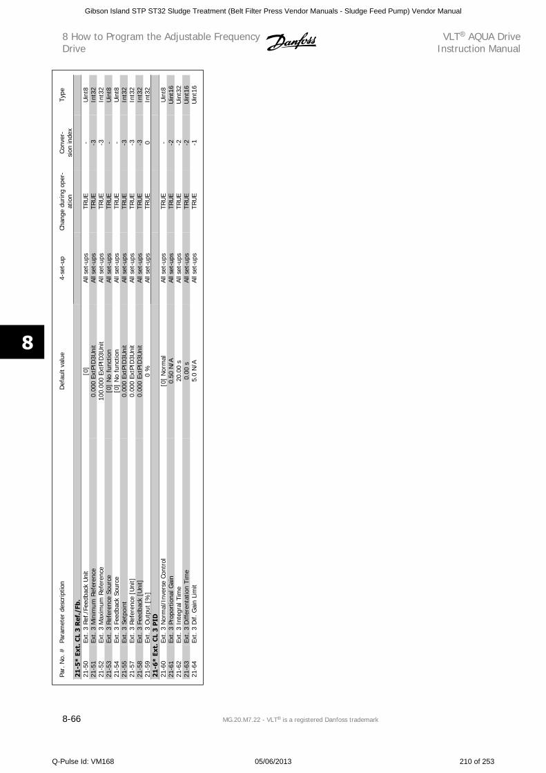
Par.
No.
#Pa
ram
eter
des
crip
tion
Def
ault
valu
e4-
set-
upCh
ange
dur
ing
oper
-at
ion
Conv
er-
sion
inde
xTy
pe
21-5
* Ex
t. C
L 3
Ref
./Fb
.21
-50
Ext.
3 R
ef./
Feed
back
Uni
t[0
]Al
l set
-ups
TRU
E-
Uin
t821
-51
Ext.
3 M
inim
um R
efer
ence
0.00
0 Ex
tPID
3Uni
tAl
l set
-ups
TRU
E-3
Int3
221
-52
Ext.
3 M
axim
um R
efer
ence
100.
000
ExtP
ID3U
nit
All s
et-u
psTR
UE
-3In
t32
21-5
3Ex
t. 3
Ref
eren
ce S
ourc
e[0
] N
o fu
nctio
nAl
l set
-ups
TRU
E-
Uin
t821
-54
Ext.
3 F
eedb
ack
Sour
ce[0
] N
o fu
nctio
nAl
l set
-ups
TRU
E-
Uin
t821
-55
Ext.
3 S
etpo
int
0.00
0 Ex
tPID
3Uni
tAl
l set
-ups
TRU
E-3
Int3
221
-57
Ext.
3 R
efer
ence
[U
nit]
0.00
0 Ex
tPID
3Uni
tAl
l set
-ups
TRU
E-3
Int3
221
-58
Ext.
3 F
eedb
ack
[Uni
t]0.
000
ExtP
ID3U
nit
All s
et-u
psTR
UE
-3In
t32
21-5
9Ex
t. 3
Out
put
[%]
0 %
All s
et-u
psTR
UE
0In
t32
21-6
* Ex
t. C
L 3
PID
21-6
0Ex
t. 3
Nor
mal
/Inv
erse
Con
trol
[0]
Nor
mal
All s
et-u
psTR
UE
-U
int8
21-6
1Ex
t. 3
Pro
port
iona
l Gai
n0.
50 N
/AAl
l set
-ups
TRU
E-2
Uin
t16
21-6
2Ex
t. 3
Int
egra
l Tim
e20
.00
sAl
l set
-ups
TRU
E-2
Uin
t32
21-6
3Ex
t. 3
Diff
eren
tatio
n Ti
me
0.00
sAl
l set
-ups
TRU
E-2
Uin
t16
21-6
4Ex
t. 3
Dif.
Gai
n Li
mit
5.0
N/A
All s
et-u
psTR
UE
-1U
int1
6
8 How to Program the Adjustable FrequencyDrive
VLT AQUA DriveInstruction Manual
8-66 MG.20.M7.22 - VLT is a registered Danfoss trademark
8
Gibson Island STP ST32 Sludge Treatment (Belt Filter Press Vendor Manuals - Sludge Feed Pump) Vendor Manual
Q-Pulse Id: VM168 05/06/2013 210 of 253
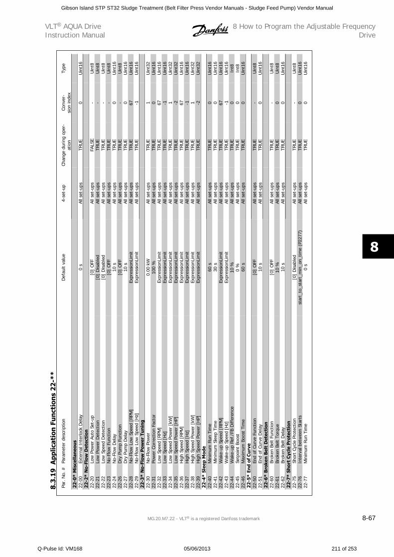
Par.
No.
#Pa
ram
eter
des
crip
tion
Def
ault
valu
e4-
set-
upCh
ange
dur
ing
oper
-at
ion
Conv
er-
sion
inde
xTy
pe
22-0
* M
isce
llan
eou
s22
-00
Exte
rnal
Int
erlo
ck D
elay
0 s
All s
et-u
psTR
UE
0U
int1
622
-2*
No-
Flow
Det
ecti
on22
-20
Low
Pow
er A
uto
Set-
up[0
] O
FFAl
l set
-ups
FALS
E-
Uin
t822
-21
Low
Pow
er D
etec
tion
[0]
Dis
able
dAl
l set
-ups
TRU
E-
Uin
t822
-22
Low
Spe
ed D
etec
tion
[0]
Dis
able
dAl
l set
-ups
TRU
E-
Uin
t822
-23
No-
Flow
Fun
ctio
n[0
] O
FFAl
l set
-ups
TRU
E-
Uin
t822
-24
No-
Flow
Del
ay10
sAl
l set
-ups
TRU
E0
Uin
t16
22-2
6D
ry P
ump
Func
tion
[0]
OFF
All s
et-u
psTR
UE
-U
int8
22-2
7D
ry P
ump
Del
ay10
sAl
l set
-ups
TRU
E0
Uin
t16
22-2
8N
o-Fl
ow L
ow S
peed
[RP
M]
Expr
essi
onLi
mit
All s
et-u
psTR
UE
67U
int1
622
-29
No-
Flow
Low
Spe
ed [
Hz]
Expr
essi
onLi
mit
All s
et-u
psTR
UE
-1U
int1
622
-3*
No-
Flow
Pow
er T
un
ing
22-3
0N
o-Fl
ow P
ower
0.00
kW
All s
et-u
psTR
UE
1U
int3
222
-31
Pow
er C
orre
ctio
n Fa
ctor
100
%Al
l set
-ups
TRU
E0
Uin
t16
22-3
2Lo
w S
peed
[RPM
]Ex
pres
sion
Lim
itAl
l set
-ups
TRU
E67
Uin
t16
22-3
3Lo
w S
peed
[H
z]Ex
pres
sion
Lim
itAl
l set
-ups
TRU
E-1
Uin
t16
22-3
4Lo
w S
peed
Pow
er [
kW]
Expr
essi
onLi
mit
All s
et-u
psTR
UE
1U
int3
222
-35
Low
Spe
ed P
ower
[H
P]Ex
pres
sion
Lim
itAl
l set
-ups
TRU
E-2
Uin
t32
22-3
6H
igh
Spee
d [R
PM]
Expr
essi
onLi
mit
All s
et-u
psTR
UE
67U
int1
622
-37
Hig
h Sp
eed
[Hz]
Expr
essi
onLi
mit
All s
et-u
psTR
UE
-1U
int1
622
-38
Hig
h Sp
eed
Pow
er [
kW]
Expr
essi
onLi
mit
All s
et-u
psTR
UE
1U
int3
222
-39
Hig
h Sp
eed
Pow
er [
HP]
Expr
essi
onLi
mit
All s
et-u
psTR
UE
-2U
int3
222
-4*
Slee
p M
ode
22-4
0M
inim
um R
un T
ime
60 s
All s
et-u
psTR
UE
0U
int1
622
-41
Min
imum
Sle
ep T
ime
30 s
All s
et-u
psTR
UE
0U
int1
622
-42
Wak
e-up
Spe
ed [
RPM
]Ex
pres
sion
Lim
itAl
l set
-ups
TRU
E67
Uin
t16
22-4
3W
ake-
up S
peed
[H
z]Ex
pres
sion
Lim
itAl
l set
-ups
TRU
E-1
Uin
t16
22-4
4W
ake-
up R
ef./
FB D
iffer
ence
10 %
All s
et-u
psTR
UE
0In
t822
-45
Setp
oint
Boo
st0
%Al
l set
-ups
TRU
E0
Int8
22-4
6M
axim
um B
oost
Tim
e60
sAl
l set
-ups
TRU
E0
Uin
t16
22-5
* En
d of
Cu
rve
22-5
0En
d of
Cur
ve F
unct
ion
[0]
OFF
All s
et-u
psTR
UE
-U
int8
22-5
1En
d of
Cur
ve D
elay
10 s
All s
et-u
psTR
UE
0U
int1
622
-6*
Bro
ken
Bel
t D
etec
tion
22-6
0Br
oken
Bel
t Fu
nctio
n[0
] O
FFAl
l set
-ups
TRU
E-
Uin
t822
-61
Brok
en B
elt
Torq
ue10
%Al
l set
-ups
TRU
E0
Uin
t822
-62
Brok
en B
elt
Del
ay10
sAl
l set
-ups
TRU
E0
Uin
t16
22-7
* Sh
ort
Cyc
le P
rote
ctio
n22
-75
Shor
t Cy
cle
Prot
ectio
n[0
] D
isab
led
All s
et-u
psTR
UE
-U
int8
22-7
6In
terv
al b
etw
een
Star
tsst
art_
to_s
tart
_min
_on_
time
(P22
77)
All s
et-u
psTR
UE
0U
int1
622
-77
Min
imum
Run
Tim
e0
sAl
l set
-ups
TRU
E0
Uin
t16
8.3
.19
App
licat
ion
Fu
nct
ion
s 2
2-*
*
VLT AQUA DriveInstruction Manual
8 How to Program the Adjustable FrequencyDrive
MG.20.M7.22 - VLT is a registered Danfoss trademark 8-67
8
Gibson Island STP ST32 Sludge Treatment (Belt Filter Press Vendor Manuals - Sludge Feed Pump) Vendor Manual
Q-Pulse Id: VM168 05/06/2013 211 of 253
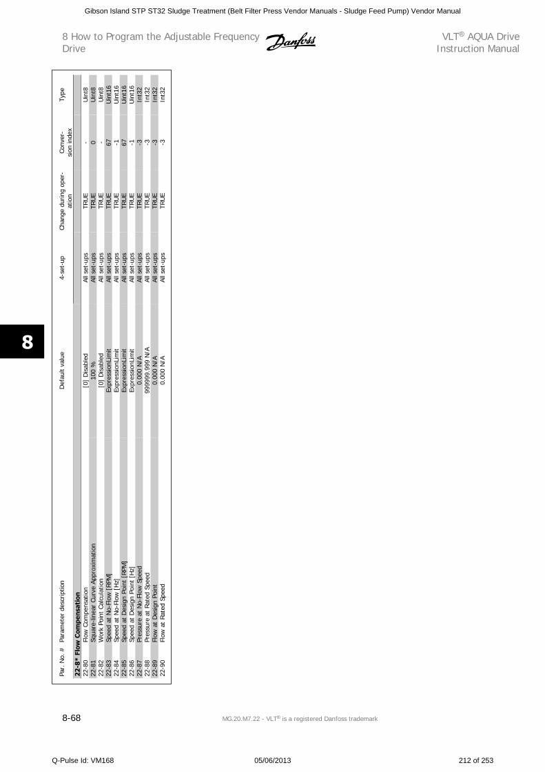
Par.
No.
#Pa
ram
eter
des
crip
tion
Def
ault
valu
e4-
set-
upCh
ange
dur
ing
oper
-at
ion
Conv
er-
sion
inde
xTy
pe
22-8
* Fl
ow C
ompe
nsat
ion
22-8
0Fl
ow C
ompe
nsat
ion
[0]
Dis
able
dAl
l set
-ups
TRU
E-
Uin
t822
-81
Squa
re-li
near
Cur
ve A
ppro
xim
atio
n10
0 %
All s
et-u
psTR
UE
0U
int8
22-8
2W
ork
Poin
t Ca
lcul
atio
n[0
] D
isab
led
All s
et-u
psTR
UE
-U
int8
22-8
3Sp
eed
at N
o-Fl
ow [
RPM
]Ex
pres
sion
Lim
itAl
l set
-ups
TRU
E67
Uin
t16
22-8
4Sp
eed
at N
o-Fl
ow [
Hz]
Expr
essi
onLi
mit
All s
et-u
psTR
UE
-1U
int1
622
-85
Spee
d at
Des
ign
Poin
t [R
PM]
Expr
essi
onLi
mit
All s
et-u
psTR
UE
67U
int1
622
-86
Spee
d at
Des
ign
Poin
t [H
z]Ex
pres
sion
Lim
itAl
l set
-ups
TRU
E-1
Uin
t16
22-8
7Pr
essu
re a
t N
o-Fl
ow S
peed
0.00
0 N
/AAl
l set
-ups
TRU
E-3
Int3
222
-88
Pres
sure
at
Rate
d Sp
eed
9999
99.9
99 N
/AAl
l set
-ups
TRU
E-3
Int3
222
-89
Flow
at
Des
ign
Poin
t0.
000
N/A
All s
et-u
psTR
UE
-3In
t32
22-9
0Fl
ow a
t Ra
ted
Spee
d0.
000
N/A
All s
et-u
psTR
UE
-3In
t32
8 How to Program the Adjustable FrequencyDrive
VLT AQUA DriveInstruction Manual
8-68 MG.20.M7.22 - VLT is a registered Danfoss trademark
8
Gibson Island STP ST32 Sludge Treatment (Belt Filter Press Vendor Manuals - Sludge Feed Pump) Vendor Manual
Q-Pulse Id: VM168 05/06/2013 212 of 253
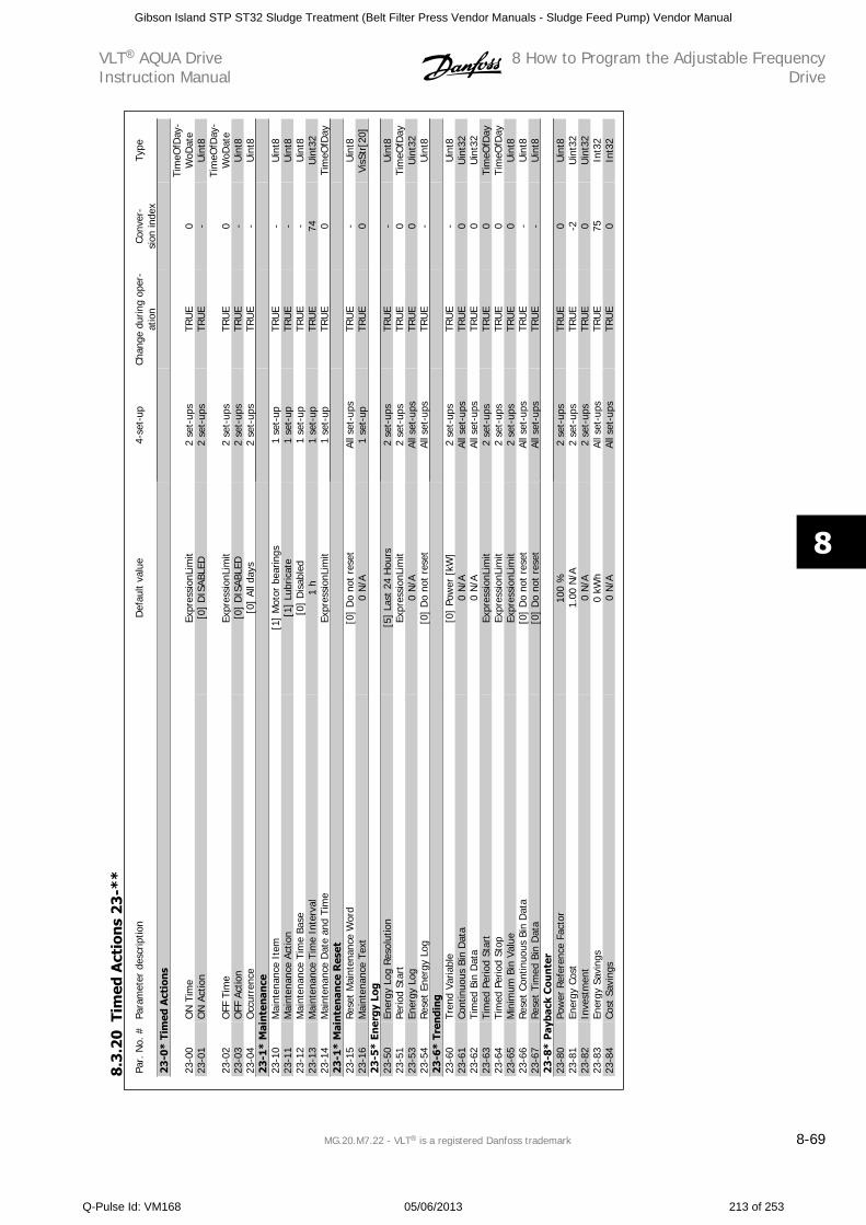
Par.
No.
#Pa
ram
eter
des
crip
tion
Def
ault
valu
e4-
set-
upCh
ange
dur
ing
oper
-at
ion
Conv
er-
sion
inde
xTy
pe
23-0
* Ti
med
Act
ion
s
23-0
0O
N T
ime
Expr
essi
onLi
mit
2 se
t-up
sTR
UE
0Ti
meO
fDay
-W
oDat
e23
-01
ON
Act
ion
[0]
DIS
ABLE
D2
set-
ups
TRU
E-
Uin
t8
23-0
2O
FF T
ime
Expr
essi
onLi
mit
2 se
t-up
sTR
UE
0Ti
meO
fDay
-W
oDat
e23
-03
OFF
Act
ion
[0]
DIS
ABLE
D2
set-
ups
TRU
E-
Uin
t823
-04
Occ
urre
nce
[0]
All d
ays
2 se
t-up
sTR
UE
-U
int8
23-1
* M
aint
enan
ce23
-10
Mai
nten
ance
Ite
m[1
] M
otor
bea
rings
1 se
t-up
TRU
E-
Uin
t823
-11
Mai
nten
ance
Act
ion
[1]
Lubr
icat
e1
set-
upTR
UE
-U
int8
23-1
2M
aint
enan
ce T
ime
Base
[0]
Dis
able
d1
set-
upTR
UE
-U
int8
23-1
3M
aint
enan
ce T
ime
Inte
rval
1 h
1 se
t-up
TRU
E74
Uin
t32
23-1
4M
aint
enan
ce D
ate
and
Tim
eEx
pres
sion
Lim
it1
set-
upTR
UE
0Ti
meO
fDay
23-1
* M
aint
enan
ce R
eset
23-1
5Re
set
Mai
nten
ance
Wor
d[0
] D
o no
t re
set
All s
et-u
psTR
UE
-U
int8
23-1
6M
aint
enan
ce T
ext
0 N
/A1
set-
upTR
UE
0Vi
sStr
[20]
23-5
* En
ergy
Log
23-5
0En
ergy
Log
Res
olut
ion
[5]
Last
24
Hou
rs2
set-
ups
TRU
E-
Uin
t823
-51
Perio
d St
art
Expr
essi
onLi
mit
2 se
t-up
sTR
UE
0Ti
meO
fDay
23-5
3En
ergy
Log
0 N
/AAl
l set
-ups
TRU
E0
Uin
t32
23-5
4Re
set
Ener
gy L
og[0
] D
o no
t re
set
All s
et-u
psTR
UE
-U
int8
23-6
* Tr
endi
ng
23-6
0Tr
end
Varia
ble
[0]
Pow
er [
kW]
2 se
t-up
sTR
UE
-U
int8
23-6
1Co
ntin
uous
Bin
Dat
a0
N/A
All s
et-u
psTR
UE
0U
int3
223
-62
Tim
ed B
in D
ata
0 N
/AAl
l set
-ups
TRU
E0
Uin
t32
23-6
3Ti
med
Per
iod
Star
tEx
pres
sion
Lim
it2
set-
ups
TRU
E0
Tim
eOfD
ay23
-64
Tim
ed P
erio
d St
opEx
pres
sion
Lim
it2
set-
ups
TRU
E0
Tim
eOfD
ay23
-65
Min
imum
Bin
Val
ueEx
pres
sion
Lim
it2
set-
ups
TRU
E0
Uin
t823
-66
Res
et C
ontin
uous
Bin
Dat
a[0
] D
o no
t re
set
All s
et-u
psTR
UE
-U
int8
23-6
7Re
set
Tim
ed B
in D
ata
[0]
Do
not
rese
tAl
l set
-ups
TRU
E-
Uin
t823
-8*
Pay
back
Cou
nte
r23
-80
Pow
er R
efer
ence
Fac
tor
100
%2
set-
ups
TRU
E0
Uin
t823
-81
Ener
gy C
ost
1.00
N/A
2 se
t-up
sTR
UE
-2U
int3
223
-82
Inve
stm
ent
0 N
/A2
set-
ups
TRU
E0
Uin
t32
23-8
3En
ergy
Sav
ings
0 kW
hAl
l set
-ups
TRU
E75
Int3
223
-84
Cost
Sav
ings
0 N
/AAl
l set
-ups
TRU
E0
Int3
2
8.3
.20
Tim
ed A
ctio
ns
23
-**
VLT AQUA DriveInstruction Manual
8 How to Program the Adjustable FrequencyDrive
MG.20.M7.22 - VLT is a registered Danfoss trademark 8-69
8
Gibson Island STP ST32 Sludge Treatment (Belt Filter Press Vendor Manuals - Sludge Feed Pump) Vendor Manual
Q-Pulse Id: VM168 05/06/2013 213 of 253
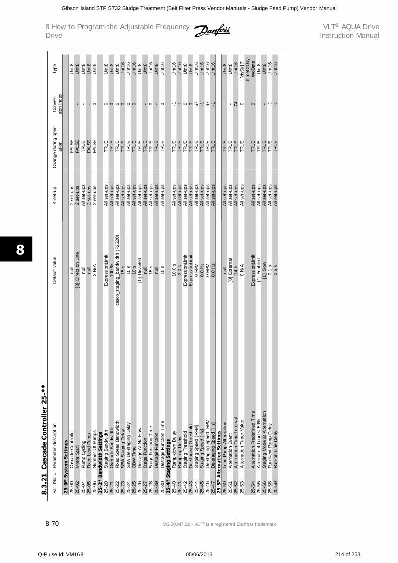
Par.
No.
#Pa
ram
eter
des
crip
tion
Def
ault
valu
e4-
set-
upCh
ange
dur
ing
oper
-at
ion
Conv
er-
sion
inde
xTy
pe
25-0
* Sy
stem
Set
tin
gs25
-00
Casc
ade
Cont
rolle
rnu
ll2
set-
ups
FALS
E-
Uin
t825
-02
Mot
or S
tart
[0]
Dire
ct o
n Li
ne2
set-
ups
FALS
E-
Uin
t825
-04
Pum
p Cy
clin
gnu
llAl
l set
-ups
TRU
E-
Uin
t825
-05
Fixe
d Le
ad P
ump
null
2 se
t-up
sFA
LSE
-U
int8
25-0
6N
umbe
r O
f Pu
mps
2 N
/A2
set-
ups
FALS
E0
Uin
t825
-2*
Ban
dwid
th S
etti
ngs
25-2
0St
agin
g Ba
ndw
idth
Expr
essi
onLi
mit
All s
et-u
psTR
UE
0U
int8
25-2
1O
verr
ide
Band
wid
th10
0 %
All s
et-u
psTR
UE
0U
int8
25-2
2Fi
xed
Spee
d Ba
ndw
idth
casc
o_st
agin
g_ba
ndw
idth
(P2
520)
All s
et-u
psTR
UE
0U
int8
25-2
3SB
W S
tagi
ng D
elay
15 s
All s
et-u
psTR
UE
0U
int1
625
-24
SBW
De-
stag
ing
Del
ay15
sAl
l set
-ups
TRU
E0
Uin
t16
25-2
5O
BW T
ime
10 s
All s
et-u
psTR
UE
0U
int1
625
-26
Des
tage
At
No-
Flow
[0]
Dis
able
dAl
l set
-ups
TRU
E-
Uin
t825
-27
Stag
e Fu
nctio
nnu
llAl
l set
-ups
TRU
E-
Uin
t825
-28
Stag
e Fu
nctio
n Ti
me
15 s
All s
et-u
psTR
UE
0U
int1
625
-29
Des
tage
Fun
ctio
nnu
llAl
l set
-ups
TRU
E-
Uin
t825
-30
Des
tage
Fun
ctio
n Ti
me
15 s
All s
et-u
psTR
UE
0U
int1
625
-4*
Stag
ing
Sett
ings
25-4
0Ra
mp-
dow
n D
elay
10.0
sAl
l set
-ups
TRU
E-1
Uin
t16
25-4
1Ra
mp-
up D
elay
2.0
sAl
l set
-ups
TRU
E-1
Uin
t16
25-4
2St
agin
g Th
resh
old
Expr
essi
onLi
mit
All s
et-u
psTR
UE
0U
int8
25-4
3D
e-st
agin
g Th
resh
old
Expr
essi
onLi
mit
All s
et-u
psTR
UE
0U
int8
25-4
4St
agin
g Sp
eed
[RPM
]0
RPM
All s
et-u
psTR
UE
67U
int1
625
-45
Stag
ing
Spee
d [H
z]0.
0 H
zAl
l set
-ups
TRU
E-1
Uin
t16
25-4
6D
e-st
agin
g Sp
eed
[RPM
]0
RPM
All s
et-u
psTR
UE
67U
int1
625
-47
De-
stag
ing
Spee
d [H
z]0.
0 H
zAl
l set
-ups
TRU
E-1
Uin
t16
25-5
* A
lter
nat
ion
Set
tin
gs25
-50
Lead
Pum
p Al
tern
atio
nnu
llAl
l set
-ups
TRU
E-
Uin
t825
-51
Alte
rnat
ion
Even
t[0
] Ex
tern
alAl
l set
-ups
TRU
E-
Uin
t825
-52
Alte
rnat
ion
Tim
e In
terv
al24
hAl
l set
-ups
TRU
E74
Uin
t16
25-5
3Al
tern
atio
n Ti
mer
Val
ue0
N/A
All s
et-u
psTR
UE
0Vi
sStr
[7]
25-5
4Al
tern
atio
n Pr
edef
ined
Tim
eEx
pres
sion
Lim
itAl
l set
-ups
TRU
E0
Tim
eOfD
ay-
WoD
ate
25-5
5Al
tern
ate
if Lo
ad <
50%
[1]
Enab
led
All s
et-u
psTR
UE
-U
int8
25-5
6St
agin
g M
ode
at A
ltern
atio
n[0
] Sl
owAl
l set
-ups
TRU
E-
Uin
t825
-58
Run
Nex
t Pu
mp
Del
ay0.
1 s
All s
et-u
psTR
UE
-1U
int1
625
-59
Run-
on L
ine
Del
ay0.
5 s
All s
et-u
psTR
UE
-1U
int1
6
8.3
.21
Cas
cade
Con
trol
ler
25
-**
8 How to Program the Adjustable FrequencyDrive
VLT AQUA DriveInstruction Manual
8-70 MG.20.M7.22 - VLT is a registered Danfoss trademark
8
Gibson Island STP ST32 Sludge Treatment (Belt Filter Press Vendor Manuals - Sludge Feed Pump) Vendor Manual
Q-Pulse Id: VM168 05/06/2013 214 of 253
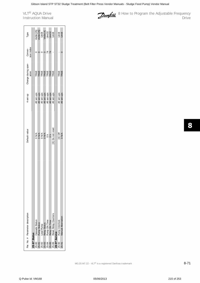
Par.
No.
#Pa
ram
eter
des
crip
tion
Def
ault
valu
e4-
set-
upCh
ange
dur
ing
oper
-at
ion
Conv
er-
sion
inde
xTy
pe
25-8
* St
atu
s25
-80
Casc
ade
Stat
us0
N/A
All s
et-u
psTR
UE
0Vi
sStr
[25]
25-8
1Pu
mp
Stat
us0
N/A
All s
et-u
psTR
UE
0Vi
sStr
[25]
25-8
2Le
ad P
ump
0 N
/AAl
l set
-ups
TRU
E0
Uin
t825
-83
Rela
y St
atus
0 N
/AAl
l set
-ups
TRU
E0
VisS
tr[4
]25
-84
Pum
p O
N T
ime
0 h
All s
et-u
psTR
UE
74U
int3
225
-85
Rela
y O
N T
ime
0 h
All s
et-u
psTR
UE
74U
int3
225
-86
Rese
t Re
lay
Coun
ters
[0]
Do
not
rese
tAl
l set
-ups
TRU
E-
Uin
t825
-9*
Serv
ice
25-9
0Pu
mp
Inte
rlock
[0]
Off
All s
et-u
psTR
UE
-U
int8
25-9
1M
anua
l Alte
rnat
ion
0 N
/AAl
l set
-ups
TRU
E0
Uin
t8
VLT AQUA DriveInstruction Manual
8 How to Program the Adjustable FrequencyDrive
MG.20.M7.22 - VLT is a registered Danfoss trademark 8-71
8
Gibson Island STP ST32 Sludge Treatment (Belt Filter Press Vendor Manuals - Sludge Feed Pump) Vendor Manual
Q-Pulse Id: VM168 05/06/2013 215 of 253
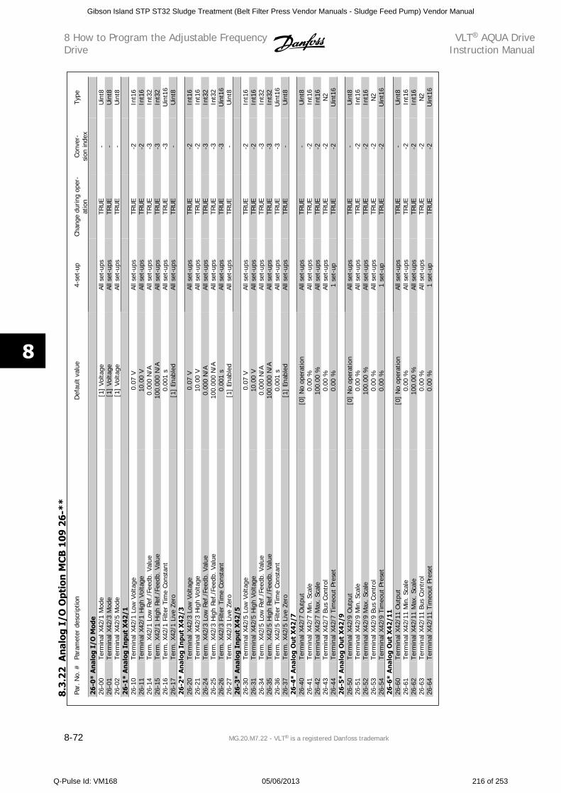
Par.
No.
#Pa
ram
eter
des
crip
tion
Def
ault
valu
e4-
set-
upCh
ange
dur
ing
oper
-at
ion
Conv
er-
sion
inde
xTy
pe
26-0
* A
nal
og I
/O M
ode
26-0
0Te
rmin
al X
42/1
Mod
e[1
] Vo
ltage
All s
et-u
psTR
UE
-U
int8
26-0
1Te
rmin
al X
42/3
Mod
e[1
] Vo
ltage
All s
et-u
psTR
UE
-U
int8
26-0
2Te
rmin
al X
42/5
Mod
e[1
] Vo
ltage
All s
et-u
psTR
UE
-U
int8
26-1
* A
nal
og I
npu
t X
42/1
26-1
0Te
rmin
al X
42/1
Low
Vol
tage
0.07
VAl
l set
-ups
TRU
E-2
Int1
626
-11
Term
inal
X42
/1 H
igh
Volta
ge10
.00
VAl
l set
-ups
TRU
E-2
Int1
626
-14
Term
. X42
/1 L
ow R
ef./
Feed
b. V
alue
0.00
0 N
/AAl
l set
-ups
TRU
E-3
Int3
226
-15
Term
. X42
/1 H
igh
Ref./F
eedb
. Val
ue10
0.00
0 N
/AAl
l set
-ups
TRU
E-3
Int3
226
-16
Term
. X42
/1 F
ilter
Tim
e Co
nsta
nt0.
001
sAl
l set
-ups
TRU
E-3
Uin
t16
26-1
7Te
rm. X
42/1
Liv
e Ze
ro[1
] En
able
dAl
l set
-ups
TRU
E-
Uin
t826
-2*
An
alog
In
put
X42
/326
-20
Term
inal
X42
/3 L
ow V
olta
ge0.
07 V
All s
et-u
psTR
UE
-2In
t16
26-2
1Te
rmin
al X
42/3
Hig
h Vo
ltage
10.0
0 V
All s
et-u
psTR
UE
-2In
t16
26-2
4Te
rm. X
42/3
Low
Ref
./Fe
edb.
Val
ue0.
000
N/A
All s
et-u
psTR
UE
-3In
t32
26-2
5Te
rm. X
42/3
Hig
h Re
f./F
eedb
. Va
lue
100.
000
N/A
All s
et-u
psTR
UE
-3In
t32
26-2
6Te
rm. X
42/3
Filt
er T
ime
Cons
tant
0.00
1 s
All s
et-u
psTR
UE
-3U
int1
626
-27
Term
. X42
/3 L
ive
Zero
[1]
Enab
led
All s
et-u
psTR
UE
-U
int8
26-3
* A
nal
og I
npu
t X
42/5
26-3
0Te
rmin
al X
42/5
Low
Vol
tage
0.07
VAl
l set
-ups
TRU
E-2
Int1
626
-31
Term
inal
X42
/5 H
igh
Volta
ge10
.00
VAl
l set
-ups
TRU
E-2
Int1
626
-34
Term
. X42
/5 L
ow R
ef./
Feed
b. V
alue
0.00
0 N
/AAl
l set
-ups
TRU
E-3
Int3
226
-35
Term
. X42
/5 H
igh
Ref./F
eedb
. Val
ue10
0.00
0 N
/AAl
l set
-ups
TRU
E-3
Int3
226
-36
Term
. X42
/5 F
ilter
Tim
e Co
nsta
nt0.
001
sAl
l set
-ups
TRU
E-3
Uin
t16
26-3
7Te
rm. X
42/5
Liv
e Ze
ro[1
] En
able
dAl
l set
-ups
TRU
E-
Uin
t826
-4*
An
alog
Ou
t X
42/7
26-4
0Te
rmin
al X
42/7
Out
put
[0]
No
oper
atio
nAl
l set
-ups
TRU
E-
Uin
t826
-41
Term
inal
X42
/7 M
in. Sc
ale
0.00
%Al
l set
-ups
TRU
E-2
Int1
626
-42
Term
inal
X42
/7 M
ax. S
cale
100.
00 %
All s
et-u
psTR
UE
-2In
t16
26-4
3Te
rmin
al X
42/7
Bus
Con
trol
0.00
%Al
l set
-ups
TRU
E-2
N2
26-4
4Te
rmin
al X
42/7
Tim
eout
Pre
set
0.00
%1
set-
upTR
UE
-2U
int1
626
-5*
An
alog
Ou
t X
42/9
26-5
0Te
rmin
al X
42/9
Out
put
[0]
No
oper
atio
nAl
l set
-ups
TRU
E-
Uin
t826
-51
Term
inal
X42
/9 M
in. Sc
ale
0.00
%Al
l set
-ups
TRU
E-2
Int1
626
-52
Term
inal
X42
/9 M
ax. S
cale
100.
00 %
All s
et-u
psTR
UE
-2In
t16
26-5
3Te
rmin
al X
42/9
Bus
Con
trol
0.00
%Al
l set
-ups
TRU
E-2
N2
26-5
4Te
rmin
al X
42/9
Tim
eout
Pre
set
0.00
%1
set-
upTR
UE
-2U
int1
626
-6*
An
alog
Ou
t X
42/1
126
-60
Term
inal
X42
/11
Out
put
[0]
No
oper
atio
nAl
l set
-ups
TRU
E-
Uin
t826
-61
Term
inal
X42
/11
Min
. Sc
ale
0.00
%Al
l set
-ups
TRU
E-2
Int1
626
-62
Term
inal
X42
/11
Max
. Sc
ale
100.
00 %
All s
et-u
psTR
UE
-2In
t16
26-6
3Te
rmin
al X
42/1
1 Bu
s Co
ntro
l0.
00 %
All s
et-u
psTR
UE
-2N
226
-64
Term
inal
X42
/11
Tim
eout
Pre
set
0.00
%1
set-
upTR
UE
-2U
int1
6
8.3
.22
An
alog
I/O
Opt
ion
MC
B 1
09
26
-**
8 How to Program the Adjustable FrequencyDrive
VLT AQUA DriveInstruction Manual
8-72 MG.20.M7.22 - VLT is a registered Danfoss trademark
8
Gibson Island STP ST32 Sludge Treatment (Belt Filter Press Vendor Manuals - Sludge Feed Pump) Vendor Manual
Q-Pulse Id: VM168 05/06/2013 216 of 253
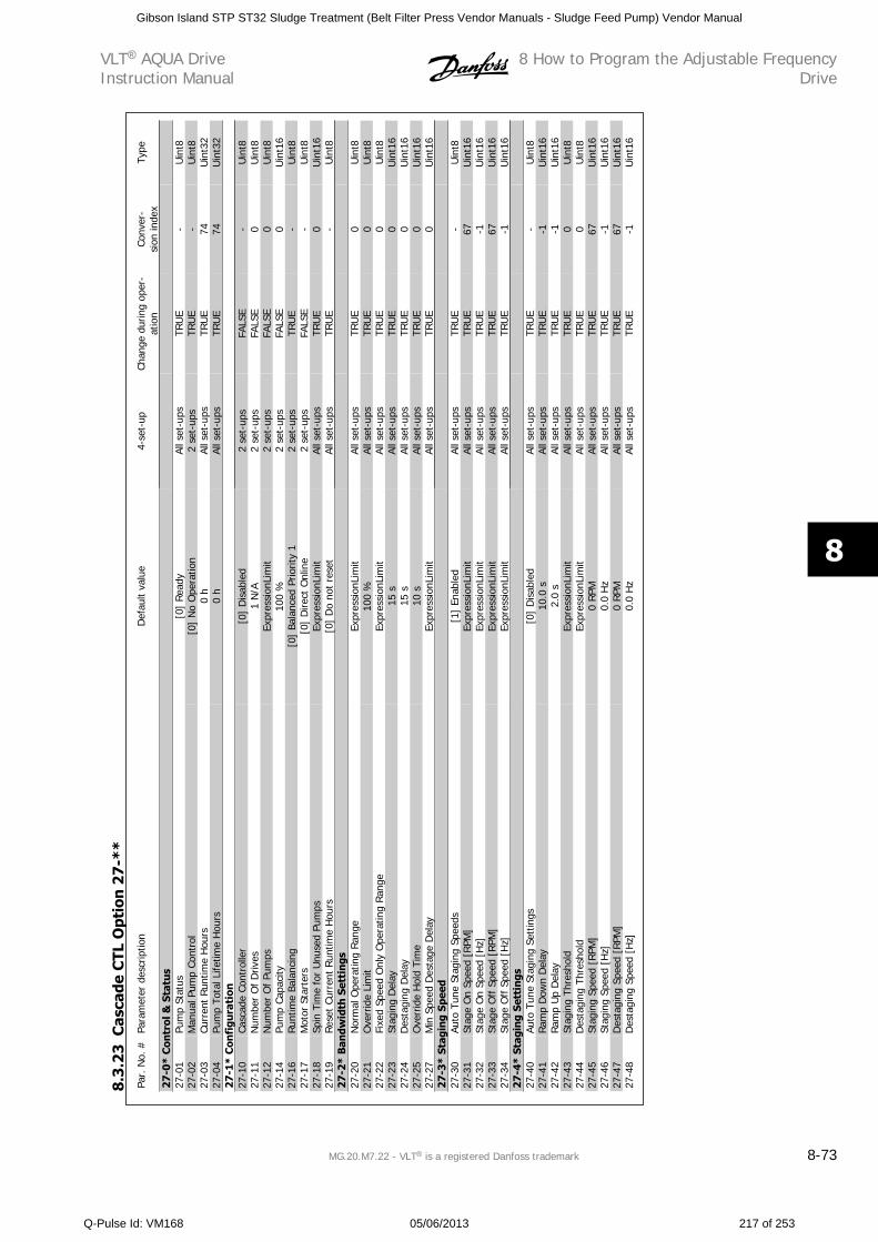
Par.
No.
#Pa
ram
eter
des
crip
tion
Def
ault
valu
e4-
set-
upCh
ange
dur
ing
oper
-at
ion
Conv
er-
sion
inde
xTy
pe
27-0
* C
ontr
ol &
Sta
tus
27-0
1Pu
mp
Stat
us[0
] Rea
dyAl
l set
-ups
TRU
E-
Uin
t827
-02
Man
ual P
ump
Cont
rol
[0]
No
Ope
ratio
n2
set-
ups
TRU
E-
Uin
t827
-03
Curr
ent
Run
time
Hou
rs0
hAl
l set
-ups
TRU
E74
Uin
t32
27-0
4Pu
mp
Tota
l Life
time
Hou
rs0
hAl
l set
-ups
TRU
E74
Uin
t32
27-1
* C
onfi
gura
tion
27-1
0Ca
scad
e Co
ntro
ller
[0]
Dis
able
d2
set-
ups
FALS
E-
Uin
t827
-11
Num
ber
Of
Driv
es1
N/A
2 se
t-up
sFA
LSE
0U
int8
27-1
2N
umbe
r O
f Pu
mps
Expr
essi
onLi
mit
2 se
t-up
sFA
LSE
0U
int8
27-1
4Pu
mp
Capa
city
100
%2
set-
ups
FALS
E0
Uin
t16
27-1
6Ru
ntim
e Ba
lanc
ing
[0]
Bala
nced
Prio
rity
12
set-
ups
TRU
E-
Uin
t827
-17
Mot
or S
tart
ers
[0]
Dire
ct O
nlin
e2
set-
ups
FALS
E-
Uin
t827
-18
Spin
Tim
e fo
r U
nuse
d Pu
mps
Expr
essi
onLi
mit
All s
et-u
psTR
UE
0U
int1
627
-19
Rese
t Cu
rren
t Run
time
Hou
rs[0
] D
o no
t re
set
All s
et-u
psTR
UE
-U
int8
27-2
* B
andw
idth
Set
tin
gs27
-20
Nor
mal
Ope
ratin
g Ran
geEx
pres
sion
Lim
itAl
l set
-ups
TRU
E0
Uin
t827
-21
Ove
rrid
e Li
mit
100
%Al
l set
-ups
TRU
E0
Uin
t827
-22
Fixe
d Sp
eed
Onl
y O
pera
ting
Ran
geEx
pres
sion
Lim
itAl
l set
-ups
TRU
E0
Uin
t827
-23
Stag
ing
Del
ay15
sAl
l set
-ups
TRU
E0
Uin
t16
27-2
4D
esta
ging
Del
ay15
sAl
l set
-ups
TRU
E0
Uin
t16
27-2
5O
verr
ide
Hol
d Ti
me
10 s
All s
et-u
psTR
UE
0U
int1
627
-27
Min
Spe
ed D
esta
ge D
elay
Expr
essi
onLi
mit
All s
et-u
psTR
UE
0U
int1
627
-3*
Stag
ing
Spee
d27
-30
Auto
Tun
e St
agin
g Sp
eeds
[1]
Enab
led
All s
et-u
psTR
UE
-U
int8
27-3
1St
age
On
Spee
d [R
PM]
Expr
essi
onLi
mit
All s
et-u
psTR
UE
67U
int1
627
-32
Stag
e O
n Sp
eed
[Hz]
Expr
essi
onLi
mit
All s
et-u
psTR
UE
-1U
int1
627
-33
Stag
e O
ff S
peed
[RP
M]
Expr
essi
onLi
mit
All s
et-u
psTR
UE
67U
int1
627
-34
Stag
e O
ff S
peed
[H
z]Ex
pres
sion
Lim
itAl
l set
-ups
TRU
E-1
Uin
t16
27-4
* St
agin
g Se
ttin
gs27
-40
Auto
Tun
e St
agin
g Se
ttin
gs[0
] D
isab
led
All s
et-u
psTR
UE
-U
int8
27-4
1Ra
mp
Dow
n D
elay
10.0
sAl
l set
-ups
TRU
E-1
Uin
t16
27-4
2Ra
mp
Up
Del
ay2.
0 s
All s
et-u
psTR
UE
-1U
int1
627
-43
Stag
ing
Thre
shol
dEx
pres
sion
Lim
itAl
l set
-ups
TRU
E0
Uin
t827
-44
Des
tagi
ng T
hres
hold
Expr
essi
onLi
mit
All s
et-u
psTR
UE
0U
int8
27-4
5St
agin
g Sp
eed
[RPM
]0
RPM
All s
et-u
psTR
UE
67U
int1
627
-46
Stag
ing
Spee
d [H
z]0.
0 H
zAl
l set
-ups
TRU
E-1
Uin
t16
27-4
7D
esta
ging
Spe
ed [
RPM
]0
RPM
All s
et-u
psTR
UE
67U
int1
627
-48
Des
tagi
ng S
peed
[H
z]0.
0 H
zAl
l set
-ups
TRU
E-1
Uin
t16
8.3
.23
Cas
cade
CTL
Opt
ion
27
-**
VLT AQUA DriveInstruction Manual
8 How to Program the Adjustable FrequencyDrive
MG.20.M7.22 - VLT is a registered Danfoss trademark 8-73
8
Gibson Island STP ST32 Sludge Treatment (Belt Filter Press Vendor Manuals - Sludge Feed Pump) Vendor Manual
Q-Pulse Id: VM168 05/06/2013 217 of 253
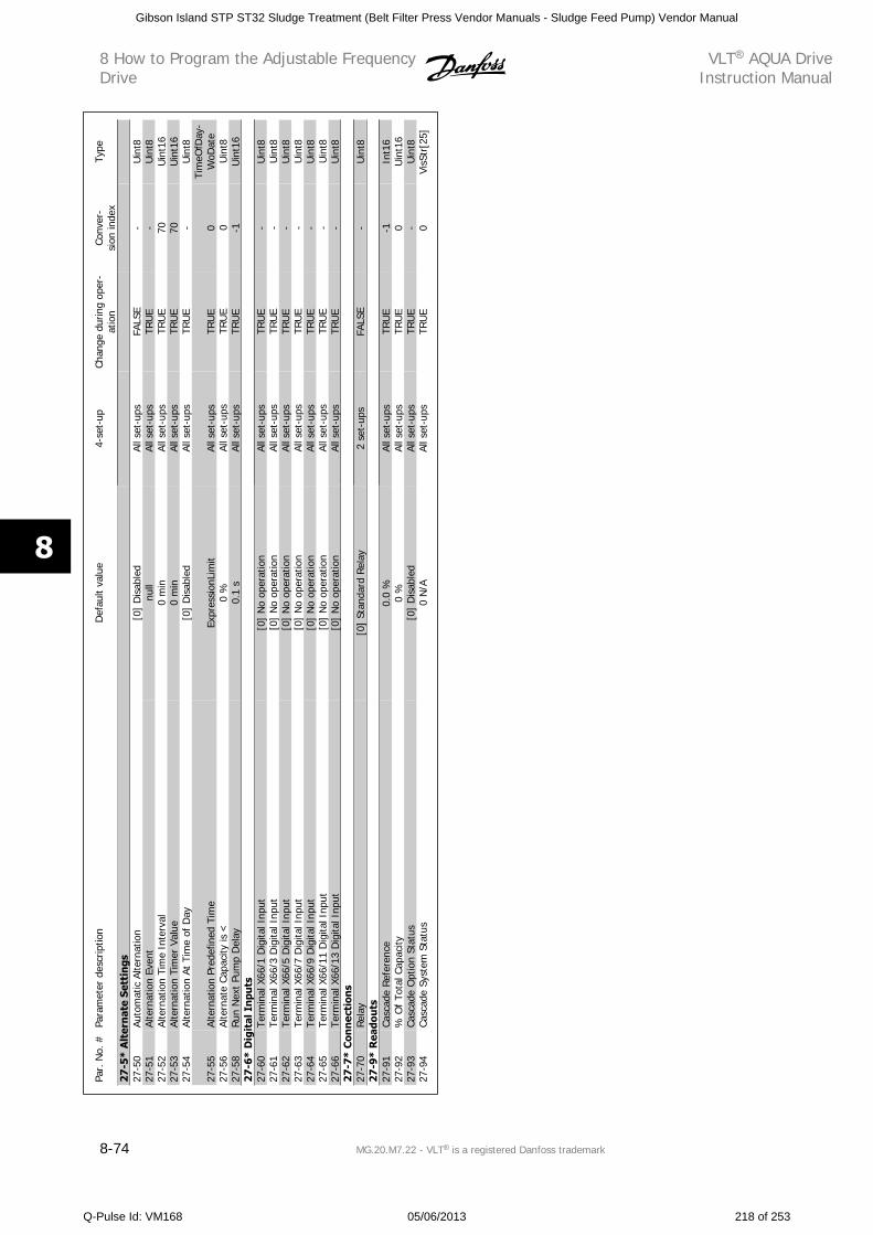
Par.
No.
#Pa
ram
eter
des
crip
tion
Def
ault
valu
e4-
set-
upCh
ange
dur
ing
oper
-at
ion
Conv
er-
sion
inde
xTy
pe
27-5
* A
lter
nat
e Se
ttin
gs27
-50
Auto
mat
ic A
ltern
atio
n[0
] D
isab
led
All s
et-u
psFA
LSE
-U
int8
27-5
1Al
tern
atio
n Ev
ent
null
All s
et-u
psTR
UE
-U
int8
27-5
2Al
tern
atio
n Ti
me
Inte
rval
0 m
inAl
l set
-ups
TRU
E70
Uin
t16
27-5
3Al
tern
atio
n Ti
mer
Val
ue0
min
All s
et-u
psTR
UE
70U
int1
627
-54
Alte
rnat
ion
At T
ime
of D
ay[0
] D
isab
led
All s
et-u
psTR
UE
-U
int8
27-5
5Al
tern
atio
n Pr
edef
ined
Tim
eEx
pres
sion
Lim
itAl
l set
-ups
TRU
E0
Tim
eOfD
ay-
WoD
ate
27-5
6Al
tern
ate
Capa
city
is <
0 %
All s
et-u
psTR
UE
0U
int8
27-5
8Run
Nex
t Pu
mp
Del
ay0.
1 s
All s
et-u
psTR
UE
-1U
int1
627
-6*
Dig
ital
In
puts
27-6
0Te
rmin
al X
66/1
Dig
ital I
nput
[0]
No
oper
atio
nAl
l set
-ups
TRU
E-
Uin
t827
-61
Term
inal
X66
/3 D
igita
l Inp
ut[0
] N
o op
erat
ion
All s
et-u
psTR
UE
-U
int8
27-6
2Te
rmin
al X
66/5
Dig
ital I
nput
[0]
No
oper
atio
nAl
l set
-ups
TRU
E-
Uin
t827
-63
Term
inal
X66
/7 D
igita
l Inp
ut[0
] N
o op
erat
ion
All s
et-u
psTR
UE
-U
int8
27-6
4Te
rmin
al X
66/9
Dig
ital I
nput
[0]
No
oper
atio
nAl
l set
-ups
TRU
E-
Uin
t827
-65
Term
inal
X66
/11
Dig
ital I
nput
[0]
No
oper
atio
nAl
l set
-ups
TRU
E-
Uin
t827
-66
Term
inal
X66
/13
Dig
ital I
nput
[0]
No
oper
atio
nAl
l set
-ups
TRU
E-
Uin
t827
-7*
Con
nec
tion
s27
-70
Rela
y[0
] St
anda
rd R
elay
2 se
t-up
sFA
LSE
-U
int8
27-9
* R
eado
uts
27-9
1Ca
scad
e Re
fere
nce
0.0
%Al
l set
-ups
TRU
E-1
Int1
627
-92
% O
f To
tal C
apac
ity0
%Al
l set
-ups
TRU
E0
Uin
t16
27-9
3Ca
scad
e O
ptio
n St
atus
[0]
Dis
able
dAl
l set
-ups
TRU
E-
Uin
t827
-94
Casc
ade
Syst
em S
tatu
s0
N/A
All s
et-u
psTR
UE
0Vi
sStr
[25]
8 How to Program the Adjustable FrequencyDrive
VLT AQUA DriveInstruction Manual
8-74 MG.20.M7.22 - VLT is a registered Danfoss trademark
8
Gibson Island STP ST32 Sludge Treatment (Belt Filter Press Vendor Manuals - Sludge Feed Pump) Vendor Manual
Q-Pulse Id: VM168 05/06/2013 218 of 253
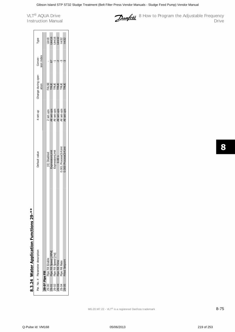
Par.
No.
#Pa
ram
eter
des
crip
tion
Def
ault
valu
e4-
set-
upCh
ange
dur
ing
oper
-at
ion
Conv
er-
sion
inde
xTy
pe
29-0
* P
ipe
Fill
29-0
0Pi
pe F
ill E
nabl
e[0
] D
isab
led
2 se
t-up
sFA
LSE
-U
int8
29-0
1Pi
pe F
ill S
peed
[RP
M]
Expr
essi
onLi
mit
All s
et-u
psTR
UE
67U
int1
629
-02
Pipe
Fill
Spe
ed [
Hz]
Expr
essi
onLi
mit
All s
et-u
psTR
UE
-1U
int1
629
-03
Pipe
Fill
Tim
e0.
00 s
All s
et-u
psTR
UE
-2U
int3
229
-04
Pipe
Fill
Rat
e0.
001
Proc
essC
trlU
nit
All s
et-u
psTR
UE
-3In
t32
29-0
5Fi
lled
Setp
oint
0.00
0 Pr
oces
sCtr
lUni
tAl
l set
-ups
TRU
E-3
Int3
2
8.3
.24
Wat
er A
pplic
atio
n F
un
ctio
ns
29
-**
VLT AQUA DriveInstruction Manual
8 How to Program the Adjustable FrequencyDrive
MG.20.M7.22 - VLT is a registered Danfoss trademark 8-75
8
Gibson Island STP ST32 Sludge Treatment (Belt Filter Press Vendor Manuals - Sludge Feed Pump) Vendor Manual
Q-Pulse Id: VM168 05/06/2013 219 of 253
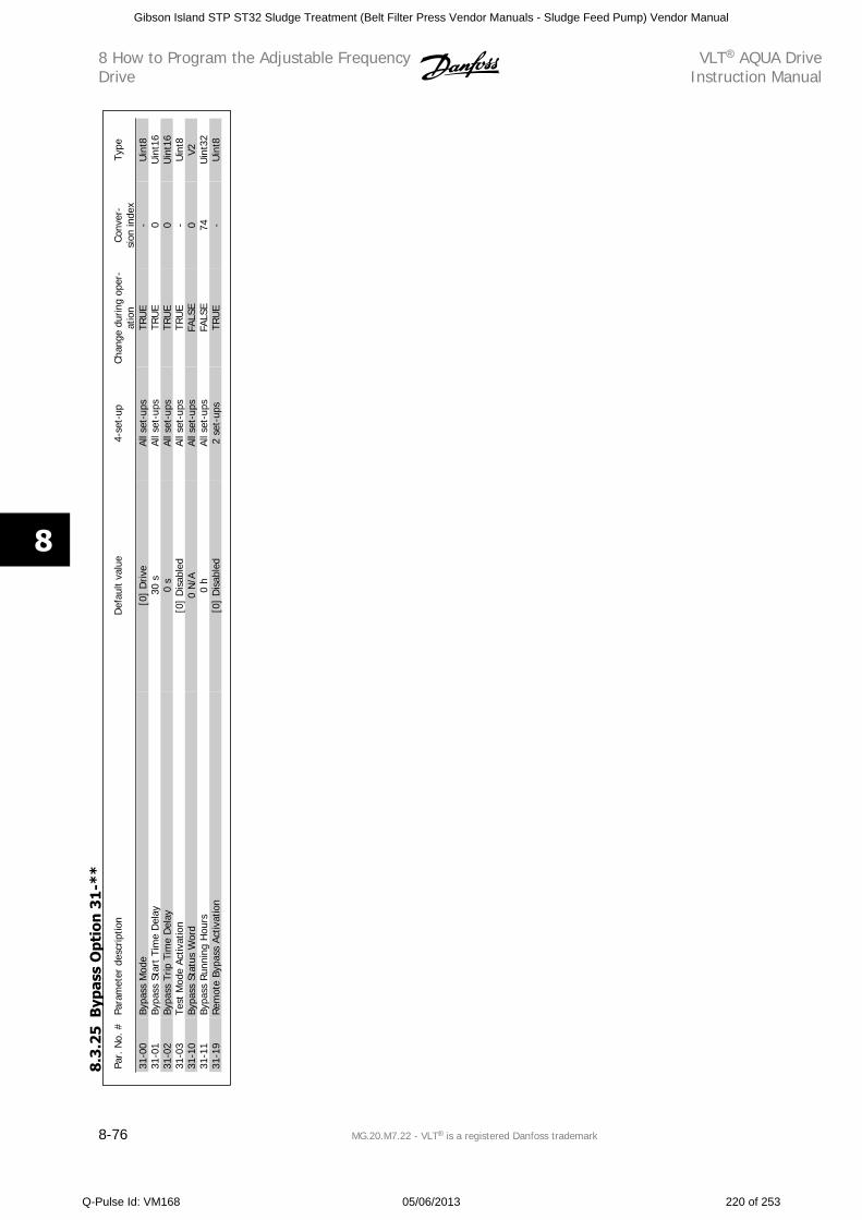
Par.
No.
#Pa
ram
eter
des
crip
tion
Def
ault
valu
e4-
set-
upCh
ange
dur
ing
oper
-at
ion
Conv
er-
sion
inde
xTy
pe
31-0
0By
pass
Mod
e[0
] D
rive
All s
et-u
psTR
UE
-U
int8
31-0
1By
pass
Sta
rt T
ime
Del
ay30
sAl
l set
-ups
TRU
E0
Uin
t16
31-0
2By
pass
Trip
Tim
e D
elay
0 s
All s
et-u
psTR
UE
0U
int1
631
-03
Test
Mod
e Ac
tivat
ion
[0]
Dis
able
dAl
l set
-ups
TRU
E-
Uin
t831
-10
Bypa
ss S
tatu
s W
ord
0 N
/AAl
l set
-ups
FALS
E0
V231
-11
Bypa
ss R
unni
ng H
ours
0 h
All s
et-u
psFA
LSE
74U
int3
231
-19
Rem
ote
Bypa
ss A
ctiv
atio
n[0
] D
isab
led
2 se
t-up
sTR
UE
-U
int8
8.3
.25
Byp
ass
Opt
ion
31
-**
8 How to Program the Adjustable FrequencyDrive
VLT AQUA DriveInstruction Manual
8-76 MG.20.M7.22 - VLT is a registered Danfoss trademark
8
Gibson Island STP ST32 Sludge Treatment (Belt Filter Press Vendor Manuals - Sludge Feed Pump) Vendor Manual
Q-Pulse Id: VM168 05/06/2013 220 of 253
9 Troubleshooting
9.1 Alarms and WarningsA warning or an alarm is signaled by the relevant LED on the front of the adjustable frequency drive and indicated by a code on the display.
A warning remains active until its cause is no longer present. Under certain circumstances operation of the motor may still be continued. Warning messages
may be critical, but are not necessarily so.
In the event of an alarm, the adjustable frequency drive will have tripped. Alarms must be reset to restart operation once their cause has been rectified.
This may be done in four ways:
1. By using the [RESET] control button on the LCP control panel.
2. Via a digital input with the “Reset” function.
3. Via serial communication/optional serial communication bus.
4. By resetting automatically using the [Auto Reset] function, which is a default setting for VLT AQUA Drive, see par. 14-20 Reset Mode in VLT
AQUA Drive Programming Guide
NOTE!
After a manual reset using the [RESET] button on the LCP, the [AUTO ON] or [HAND ON] button must be pressed to restart the motor.
If an alarm cannot be reset, the reason may be that its cause has not been rectified, or the alarm is trip-locked (see also table on following page).
Alarms that are trip-locked offer additional protection, means that the line power supply must be switched off before the alarm can be reset. After being
switched back on, the adjustable frequency drive is no longer blocked and may be reset as described above, once the cause has been rectified.
Alarms that are not trip-locked can also be reset using the automatic reset function in par. 14-20 Reset Mode (Warning: automatic wake-up is possible!)
If a warning and alarm is marked against a code in the table on the following page, this means that either a warning occurs before an alarm, or it can
be specified whether it is a warning or an alarm that is to be displayed for a given fault.
This is possible, for instance, in par. 1-90 Motor Thermal Protection. After an alarm or trip, the motor carries on coasting, and the alarm and warning
flash on the adjustable frequency drive. Once the problem has been rectified, only the alarm continues flashing.
VLT AQUA DriveInstruction Manual 9 Troubleshooting
MG.20.M7.22 - VLT is a registered Danfoss trademark 9-1
9
Gibson Island STP ST32 Sludge Treatment (Belt Filter Press Vendor Manuals - Sludge Feed Pump) Vendor Manual
Q-Pulse Id: VM168 05/06/2013 221 of 253
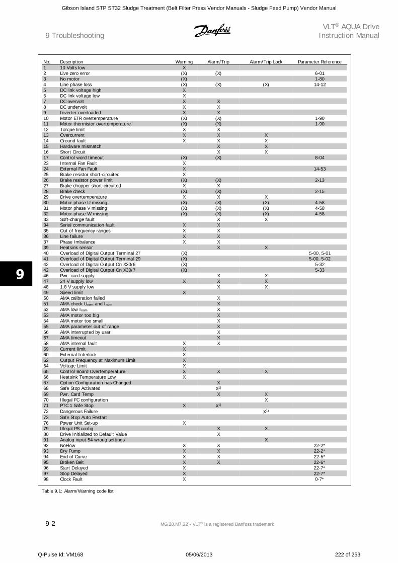
No. Description Warning Alarm/Trip Alarm/Trip Lock Parameter Reference1 10 Volts low X 2 Live zero error (X) (X) 6-013 No motor (X) 1-804 Line phase loss (X) (X) (X) 14-125 DC link voltage high X 6 DC link voltage low X 7 DC overvolt X X 8 DC undervolt X X 9 Inverter overloaded X X 10 Motor ETR overtemperature (X) (X) 1-9011 Motor thermistor overtemperature (X) (X) 1-9012 Torque limit X X 13 Overcurrent X X X 14 Ground fault X X X 15 Hardware mismatch X X 16 Short Circuit X X 17 Control word timeout (X) (X) 8-0423 Internal Fan Fault X 24 External Fan Fault X 14-5325 Brake resistor short-circuited X 26 Brake resistor power limit (X) (X) 2-1327 Brake chopper short-circuited X X 28 Brake check (X) (X) 2-1529 Drive overtemperature X X X 30 Motor phase U missing (X) (X) (X) 4-5831 Motor phase V missing (X) (X) (X) 4-5832 Motor phase W missing (X) (X) (X) 4-5833 Soft-charge fault X X 34 Serial communication fault X X 35 Out of frequency ranges X X 36 Line failure X X 37 Phase Imbalance X X 39 Heatsink sensor X X 40 Overload of Digital Output Terminal 27 (X) 5-00, 5-0141 Overload of Digital Output Terminal 29 (X) 5-00, 5-0242 Overload of Digital Output On X30/6 (X) 5-3242 Overload of Digital Output On X30/7 (X) 5-3346 Pwr. card supply X X 47 24 V supply low X X X 48 1.8 V supply low X X 49 Speed limit X 50 AMA calibration failed X 51 AMA check Unom and Inom X 52 AMA low Inom X 53 AMA motor too big X 54 AMA motor too small X 55 AMA parameter out of range X 56 AMA interrupted by user X 57 AMA timeout X 58 AMA internal fault X X 59 Current limit X 60 External Interlock X 62 Output Frequency at Maximum Limit X 64 Voltage Limit X 65 Control Board Overtemperature X X X 66 Heatsink Temperature Low X 67 Option Configuration has Changed X 68 Safe Stop Activated X1) 69 Pwr. Card Temp X X 70 Illegal FC configuration X 71 PTC 1 Safe Stop X X1) 72 Dangerous Failure X1) 73 Safe Stop Auto Restart 76 Power Unit Set-up X 79 Illegal PS config X X 80 Drive Initialized to Default Value X 91 Analog input 54 wrong settings X 92 NoFlow X X 22-2*93 Dry Pump X X 22-2*94 End of Curve X X 22-5*95 Broken Belt X X 22-6*96 Start Delayed X 22-7*97 Stop Delayed X 22-7*98 Clock Fault X 0-7*
Table 9.1: Alarm/Warning code list
9 TroubleshootingVLT AQUA Drive
Instruction Manual
9-2 MG.20.M7.22 - VLT is a registered Danfoss trademark
9
Gibson Island STP ST32 Sludge Treatment (Belt Filter Press Vendor Manuals - Sludge Feed Pump) Vendor Manual
Q-Pulse Id: VM168 05/06/2013 222 of 253
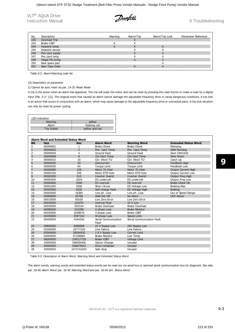
No. Description Warning Alarm/Trip Alarm/Trip Lock Parameter Reference220 Overload Trip X 243 Brake IGBT X X 244 Heatsink temp X X X 245 Heatsink sensor X X 246 Pwr.card supply X X 247 Pwr.card temp X X 248 Illegal PS config X X 250 New spare part X 251 New Type Code X X
Table 9.2: Alarm/Warning code list
(X) Dependent on parameter
1) Cannot be auto reset via par. 14-20 Reset Mode
A trip is the action when an alarm has appeared. The trip will coast the motor and can be reset by pressing the reset button or make a reset by a digital
input (Par. 5-1* [1]). The original event that caused an alarm cannot damage the adjustable frequency drive or cause dangerous conditions. A trip lock
is an action that occurs in conjunction with an alarm, which may cause damage to the adjustable frequency drive or connected parts. A trip lock situation
can only be reset by power cycling.
LED indicationWarning yellowAlarm flashing red
Trip locked yellow and red
Alarm Word and Extended Status WordBit Hex Dec Alarm Word Warning Word Extended Status Word0 00000001 1 Brake Check Brake Check Ramping1 00000002 2 Pwr. Card Temp Pwr. Card Temp AMA Running2 00000004 4 Ground Fault Ground Fault Start CW/CCW3 00000008 8 Ctrl.Card Temp Ctrl.Card Temp Slow Down4 00000010 16 Ctrl. Word TO Ctrl. Word TO Catch Up5 00000020 32 Overcurrent Overcurrent Feedback High6 00000040 64 Torque Limit Torque Limit Feedback Low7 00000080 128 Motor Th Over Motor Th Over Output Current High8 00000100 256 Motor ETR Over Motor ETR Over Output Current Low9 00000200 512 Inverter Overld. Inverter Overld. Output Freq High10 00000400 1024 DC undervolt DC undervolt Output Freq Low11 00000800 2048 DC overvolt DC overvolt Brake Check OK12 00001000 4096 Short Circuit DC Voltage Low Braking Max13 00002000 8192 Soft-charge Fault DC Voltage High Braking14 00004000 16384 Line ph. Loss Line ph. Loss Out of Speed Range15 00008000 32768 AMA Not OK No Motor OVC Active16 00010000 65536 Live Zero Error Live Zero Error 17 00020000 131072 Internal Fault 10 V Low 18 00040000 262144 Brake Overload Brake Overload 19 00080000 524288 U phase Loss Brake Resistor 20 00100000 1048576 V phase Loss Brake IGBT 21 00200000 2097152 W phase Loss Speed Limit 22 00400000 4194304 Serial Communication
FaultSerial Communication Fault
23 00800000 8388608 24 V Supply Low 24V Supply Low 24 01000000 16777216 Line Failure Line Failure 25 02000000 33554432 1.8 V Supply Low Current Limit 26 04000000 67108864 Brake Resistor Low Temp 27 08000000 134217728 Brake IGBT Voltage Limit 28 10000000 268435456 Option Change Unused 29 20000000 536870912 Drive Initialized Unused 30 40000000 1073741824 Safe Stop Unused
Table 9.3: Description of Alarm Word, Warning Word and Extended Status Word
The alarm words, warning words and extended status words can be read out via serial bus or optional serial communication bus for diagnosis. See also
par. 16-90 Alarm Word, par. 16-92 Warning Word and par. 16-94 Ext. Status Word.
VLT AQUA DriveInstruction Manual 9 Troubleshooting
MG.20.M7.22 - VLT is a registered Danfoss trademark 9-3
9
Gibson Island STP ST32 Sludge Treatment (Belt Filter Press Vendor Manuals - Sludge Feed Pump) Vendor Manual
Q-Pulse Id: VM168 05/06/2013 223 of 253
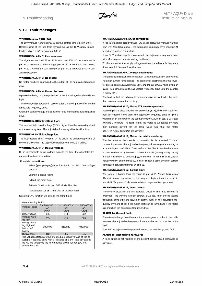
9.1.1 Fault Messages
WARNING 1, 10 Volts low:
The 10 V voltage from terminal 50 on the control card is below 10 V.
Remove some of the load from terminal 50, as the 10 V supply is over-
loaded. Max. 15 mA or minimum 590 .
WARNING/ALARM 2, Live zero error:
The signal on terminal 53 or 54 is less than 50% of the value set in
par. 6-10 Terminal 53 Low Voltage, par. 6-12 Terminal 53 Low Current,
par. 6-20 Terminal 54 Low Voltage, or par. 6-22 Terminal 54 Low Cur-
rent respectively.
WARNING/ALARM 3, No motor:
No motor has been connected to the output of the adjustable frequency
drive.
WARNING/ALARM 4, Mains phs. loss:
A phase is missing on the supply side, or the line voltage imbalance is too
high.
This message also appears in case of a fault in the input rectifier on the
adjustable frequency drive.
Check the supply voltage and supply currents to the adjustable frequency
drive.
WARNING 5, DC link voltage high:
The intermediate circuit voltage (DC) is higher than the overvoltage limit
of the control system. The adjustable frequency drive is still active.
WARNING 6, DC link voltage low:
The intermediate circuit voltage (DC) is below the undervoltage limit of
the control system. The adjustable frequency drive is still active.
WARNING/ALARM 7, DC overvoltage:
If the intermediate circuit voltage exceeds the limit, the adjustable fre-
quency drive trips after a time.
Possible corrections:
Select Over Voltage Control function in par. 2-17 Over-voltage
Control
Connect a brake resistor
Extend the ramp time
Activate functions in par. 2-10 Brake Function
Increase par. 14-26 Trip Delay at Inverter Fault
Selecting OVC function will extend the ramp times.
Alarm/warning limits:
Voltage Range 3 x 200–240 VAC
3 x 380–500 VAC
3 x 550–600 VAC
[VDC] [VDC] [VDC]Undervoltage 185 373 532Voltage warn-ing low 205 410 585
Voltage warn-ing high (w/obrake - w/brake)
390/405 810/840 943/965
Overvoltage 410 855 975The voltages stated are the intermediate circuit voltage of the ad-justable frequency drive with a tolerance of ± 5%. The correspond-ing AC line voltage is the intermediate circuit voltage (DC link)divided by 1.35.
WARNING/ALARM 8, DC undervoltage:
If the intermediate circuit voltage (DC) drops below the “voltage warning
low” limit (see table above), the adjustable frequency drive checks if 24
V backup supply is connected.
If no 24 V backup supply is connected, the adjustable frequency drive
trips after a given time depending on the unit.
To check whether the supply voltage matches the adjustable frequency
drive, see 3.1 General Specifications.
WARNING/ALARM 9, Inverter overloaded:
The adjustable frequency drive is about to cut out because of an overload
(too high current for too long). The counter for electronic, thermal inver-
ter protection gives a warning at 98% and trips at 100%, while giving an
alarm. You cannot reset the adjustable frequency drive until the counter
is below 90%.
The fault is that the adjustable frequency drive is overloaded by more
than nominal current for too long.
WARNING/ALARM 10, Motor ETR overtemperature:
According to the electronic thermal protection (ETR), the motor is too hot.
You can choose if you want the adjustable frequency drive to give a
warning or an alarm when the counter reaches 100% in par. 1-90 Motor
Thermal Protection. The fault is that the motor is overloaded by more
than nominal current for too long. Make sure that the motor
par. 1-24 Motor Current is set correctly.
WARNING/ALARM 11, Motor thermistor overtemp:
The thermistor or the thermistor connection is disconnected. You can
choose if you want the adjustable frequency drive to give a warning or
an alarm in par. 1-90 Motor Thermal Protection. Check that the thermistor
is connected correctly between terminal 53 or 54 (analog voltage input)
and terminal 50 (+ 10 Volts supply), or between terminal 18 or 19 (digital
input PNP only) and terminal 50. If a KTY sensor is used, check for correct
connection between terminal 54 and 55.
WARNING/ALARM 12, Torque limit:
The torque is higher than the value in par. 4-16 Torque Limit Motor
Mode (in motor operation) or the torque is higher than the value in
par. 4-17 Torque Limit Generator Mode (in regenerative operation).
WARNING/ALARM 13, Overcurrent:
The inverter peak current limit (approx. 200% of the rated current) is
exceeded. The warning will last approx. 8-12 sec., then the adjustable
frequency drive trips and issues an alarm. Turn off the adjustable fre-
quency drive and check if the motor shaft can be turned and if the motor
size matches the adjustable frequency drive.
ALARM 14, Ground fault:
There is a discharge from the output phases to ground, either in the cable
between the adjustable frequency drive and the motor or in the motor
itself.
Turn off the adjustable frequency drive and remove the ground fault.
ALARM 15, Incomplete hardware:
A fitted option is not handled by the present control board (hardware or
software).
9 TroubleshootingVLT AQUA Drive
Instruction Manual
9-4 MG.20.M7.22 - VLT is a registered Danfoss trademark
9
Gibson Island STP ST32 Sludge Treatment (Belt Filter Press Vendor Manuals - Sludge Feed Pump) Vendor Manual
Q-Pulse Id: VM168 05/06/2013 224 of 253
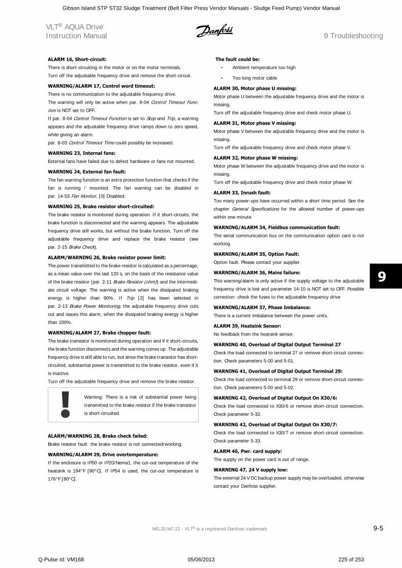
ALARM 16, Short-circuit:
There is short-circuiting in the motor or on the motor terminals.
Turn off the adjustable frequency drive and remove the short-circuit.
WARNING/ALARM 17, Control word timeout:
There is no communication to the adjustable frequency drive.
The warning will only be active when par. 8-04 Control Timeout Func-
tion is NOT set to OFF.
If par. 8-04 Control Timeout Function is set to Stop and Trip, a warning
appears and the adjustable frequency drive ramps down to zero speed,
while giving an alarm.
par. 8-03 Control Timeout Time could possibly be increased.
WARNING 23, Internal fans:
External fans have failed due to defect hardware or fans not mounted.
WARNING 24, External fan fault:
The fan warning function is an extra protection function that checks if the
fan is running / mounted. The fan warning can be disabled in
par. 14-53 Fan Monitor, [0] Disabled.
WARNING 25, Brake resistor short-circuited:
The brake resistor is monitored during operation. If it short-circuits, the
brake function is disconnected and the warning appears. The adjustable
frequency drive still works, but without the brake function. Turn off the
adjustable frequency drive and replace the brake resistor (see
par. 2-15 Brake Check).
ALARM/WARNING 26, Brake resistor power limit:
The power transmitted to the brake resistor is calculated as a percentage,
as a mean value over the last 120 s, on the basis of the resistance value
of the brake resistor (par. 2-11 Brake Resistor (ohm)) and the intermedi-
ate circuit voltage. The warning is active when the dissipated braking
energy is higher than 90%. If Trip [2] has been selected in
par. 2-13 Brake Power Monitoring, the adjustable frequency drive cuts
out and issues this alarm, when the dissipated braking energy is higher
than 100%.
WARNING/ALARM 27, Brake chopper fault:
The brake transistor is monitored during operation and if it short-circuits,
the brake function disconnects and the warning comes up. The adjustable
frequency drive is still able to run, but since the brake transistor has short-
circuited, substantial power is transmitted to the brake resistor, even if it
is inactive.
Turn off the adjustable frequency drive and remove the brake resistor.
Warning: There is a risk of substantial power being
transmitted to the brake resistor if the brake transistor
is short-circuited.
ALARM/WARNING 28, Brake check failed:
Brake resistor fault: the brake resistor is not connected/working.
WARNING/ALARM 29, Drive overtemperature:
If the enclosure is IP00 or IP20/Nema1, the cut-out temperature of the
heatsink is 194°F [90°C]. If IP54 is used, the cut-out temperature is
176°F [80°C].
The fault could be:
- Ambient temperature too high
- Too long motor cable
ALARM 30, Motor phase U missing:
Motor phase U between the adjustable frequency drive and the motor is
missing.
Turn off the adjustable frequency drive and check motor phase U.
ALARM 31, Motor phase V missing:
Motor phase V between the adjustable frequency drive and the motor is
missing.
Turn off the adjustable frequency drive and check motor phase V.
ALARM 32, Motor phase W missing:
Motor phase W between the adjustable frequency drive and the motor is
missing.
Turn off the adjustable frequency drive and check motor phase W.
ALARM 33, Inrush fault:
Too many power-ups have occurred within a short time period. See the
chapter General Specifications for the allowed number of power-ups
within one minute.
WARNING/ALARM 34, Fieldbus communication fault:
The serial communication bus on the communication option card is not
working.
WARNING/ALARM 35, Option Fault:
Option fault. Please contact your supplier.
WARNING/ALARM 36, Mains failure:
This warning/alarm is only active if the supply voltage to the adjustable
frequency drive is lost and parameter 14-10 is NOT set to OFF. Possible
correction: check the fuses to the adjustable frequency drive
WARNING/ALARM 37, Phase Imbalance:
There is a current imbalance between the power units.
ALARM 39, Heatsink Sensor:
No feedback from the heatsink sensor.
WARNING 40, Overload of Digital Output Terminal 27
Check the load connected to terminal 27 or remove short-circuit connec-
tion. Check parameters 5-00 and 5-01.
WARNING 41, Overload of Digital Output Terminal 29:
Check the load connected to terminal 29 or remove short-circuit connec-
tion. Check parameters 5-00 and 5-02.
WARNING 42, Overload of Digital Output On X30/6:
Check the load connected to X30/6 or remove short-circuit connection.
Check parameter 5-32.
WARNING 42, Overload of Digital Output On X30/7:
Check the load connected to X30/7 or remove short-circuit connection.
Check parameter 5-33.
ALARM 46, Pwr. card supply:
The supply on the power card is out of range.
WARNING 47, 24 V supply low:
The external 24 V DC backup power supply may be overloaded, otherwise
contact your Danfoss supplier.
VLT AQUA DriveInstruction Manual 9 Troubleshooting
MG.20.M7.22 - VLT is a registered Danfoss trademark 9-5
9
Gibson Island STP ST32 Sludge Treatment (Belt Filter Press Vendor Manuals - Sludge Feed Pump) Vendor Manual
Q-Pulse Id: VM168 05/06/2013 225 of 253
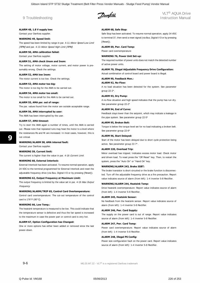
ALARM 48, 1.8 V supply low:
Contact your Danfoss supplier.
WARNING 49, Speed limit:
The speed has been limited by range in par. 4-11 Motor Speed Low Limit
[RPM] and par. 4-13 Motor Speed High Limit [RPM].
ALARM 50, AMA calibration failed:
Contact your Danfoss supplier.
ALARM 51, AMA check Unom and Inom:
The setting of motor voltage, motor current, and motor power is pre-
sumably wrong. Check the settings.
ALARM 52, AMA low Inom:
The motor current is too low. Check the settings.
ALARM 53, AMA motor too big:
The motor is too big for the AMA to be carried out.
ALARM 54, AMA motor too small:
The motor is too small for the AMA to be carried out.
ALARM 55, AMA par. out of range:
The par. values found from the motor are outside acceptable range.
ALARM 56, AMA interrupted by user:
The AMA has been interrupted by the user.
ALARM 57, AMA timeout:
Try to start the AMA again a number of times, until the AMA is carried
out. Please note that repeated runs may heat the motor to a level where
the resistances Rs and Rr are increased. In most cases, however, this is
not critical.
WARNING/ALARM 58, AMA internal fault:
Contact your Danfoss supplier.
WARNING 59, Current limit:
The current is higher than the value in par. 4-18 Current Limit.
WARNING 60, External Interlock:
External Interlock has been activated. To resume normal operation, apply
24 VDC to the terminal programmed for External Interlock and reset the
adjustable frequency drive (via Bus, Digital I/O or by pressing [Reset]).
WARNING 62, Output Frequency at Maximum Limit:
The output frequency is limited by the value set in par. 4-19 Max Output
Frequency
WARNING/ALARM/TRIP 65, Control Card Overtemperature:
Control card overtemperature: The cut-out temperature of the control
card is 176°F (80°C).
WARNING 66, Low Temp.:
The heatsink temperature is measured to be low. This could indicate that
the temperature sensor is defective and thus the fan speed is increased
to the maximum in case the power part or control card is very hot.
ALARM 67, Option Configuration has Changed:
One or more options has either been added or removed since the last
power-down.
ALARM 68, Safe Stop:
Safe Stop has been activated. To resume normal operation, apply 24 VDC
to terminal 37, then send a reset signal (via Bus, Digital I/O or by pressing
[Reset]).
ALARM 69, Pwr. Card Temp:
Power card overtemperature
WARNING 76, Power Unit Set-up:
The required number of power units does not match the detected number
of active power units.
ALARM 70, Illegal Adjustable Frequency Drive Configuration:
Actual combination of control board and power board is illegal.
ALARM 90, Feedback Mon.:
ALARM 92, No-Flow:
A no load situation has been detected for the system. See parameter
group 22-2*.
ALARM 93, Dry Pump:
A no-flow situation and high speed indicates that the pump has run dry.
See parameter group 22-2*
ALARM 94, End of Curve:
Feedback stays lower than the setpoint, which may indicate a leakage in
the pipe system. See parameter group 22-5*
ALARM 95, Broken Belt:
Torque is below the torque level set for no load indicating a broken belt.
See parameter group 22-6*
ALARM 96, Start Delayed:
Start of the motor has been delayed due to short cycle protection being
active. See parameter group 22-7*.
ALARM 220, Overload Trip:
Motor overload has tripped. Indicates excess motor load. Check motor
and driven load. To reset press the "Off Reset" key. Then, to restart the
system, press the "Auto On" or "Hand On" key.
WARNING/ALARM 243, Brake IGBT:
The brake transistor is short-circuited or the brake function is disconnec-
ted. Turn off the adjustable frequency drive as a fire precaution. Report
value indicates source of alarm (from left): 1-4 Inverter 5-8 Rectifier.
WARNING/ALARM 244, Heatsink Temp:
Drive heatsink overtemperature: Report value indicates source of alarm
(from left): 1-4 Inverter 5-8 Rectifier.
ALARM 245, Heatsink Sensor:
No feedback from the heatsink sensor. Report value indicates source of
alarm (from left): 1-4 Inverter 5-8 Rectifier.
ALARM 246, Pwr. Card Supply:
The supply on the power card is out of range. Report value indicates
source of alarm (from left): 1-4 Inverter 5-8 Rectifier.
ALARM 247, Pwr. Card Temp:
Power card overtemperature. Report value indicates source of alarm
(from left): 1-4 Inverter 5-8 Rectifier.
ALARM 248, Illegal PS Config:
Power size configuration fault on the power card. Report value indicates
source of alarm (from left): 1-4 Inverter 5-8 Rectifier.
9 TroubleshootingVLT AQUA Drive
Instruction Manual
9-6 MG.20.M7.22 - VLT is a registered Danfoss trademark
9
Gibson Island STP ST32 Sludge Treatment (Belt Filter Press Vendor Manuals - Sludge Feed Pump) Vendor Manual
Q-Pulse Id: VM168 05/06/2013 226 of 253
ALARM 250, New Spare Part:
The power or switch mode power supply has been exchanged. The ad-
justable frequency drive type code must be restored in the EEPROM.
Select the correct type code in Par 14-23 according to the label on unit.
Remember to select ‘Save to EEPROM’ to complete.
ALARM 251, New Type Code:
The adjustable frequency drive has a new type code.
VLT AQUA DriveInstruction Manual 9 Troubleshooting
MG.20.M7.22 - VLT is a registered Danfoss trademark 9-7
9
Gibson Island STP ST32 Sludge Treatment (Belt Filter Press Vendor Manuals - Sludge Feed Pump) Vendor Manual
Q-Pulse Id: VM168 05/06/2013 227 of 253
9 TroubleshootingVLT AQUA Drive
Instruction Manual
9-8 MG.20.M7.22 - VLT is a registered Danfoss trademark
9
Gibson Island STP ST32 Sludge Treatment (Belt Filter Press Vendor Manuals - Sludge Feed Pump) Vendor Manual
Q-Pulse Id: VM168 05/06/2013 228 of 253
10 Specifications
10.1 General Specifications
VLT AQUA DriveInstruction Manual 10 Specifications
MG.20.M7.22 - VLT is a registered Danfoss trademark 10-1
10
Gibson Island STP ST32 Sludge Treatment (Belt Filter Press Vendor Manuals - Sludge Feed Pump) Vendor Manual
Q-Pulse Id: VM168 05/06/2013 229 of 253
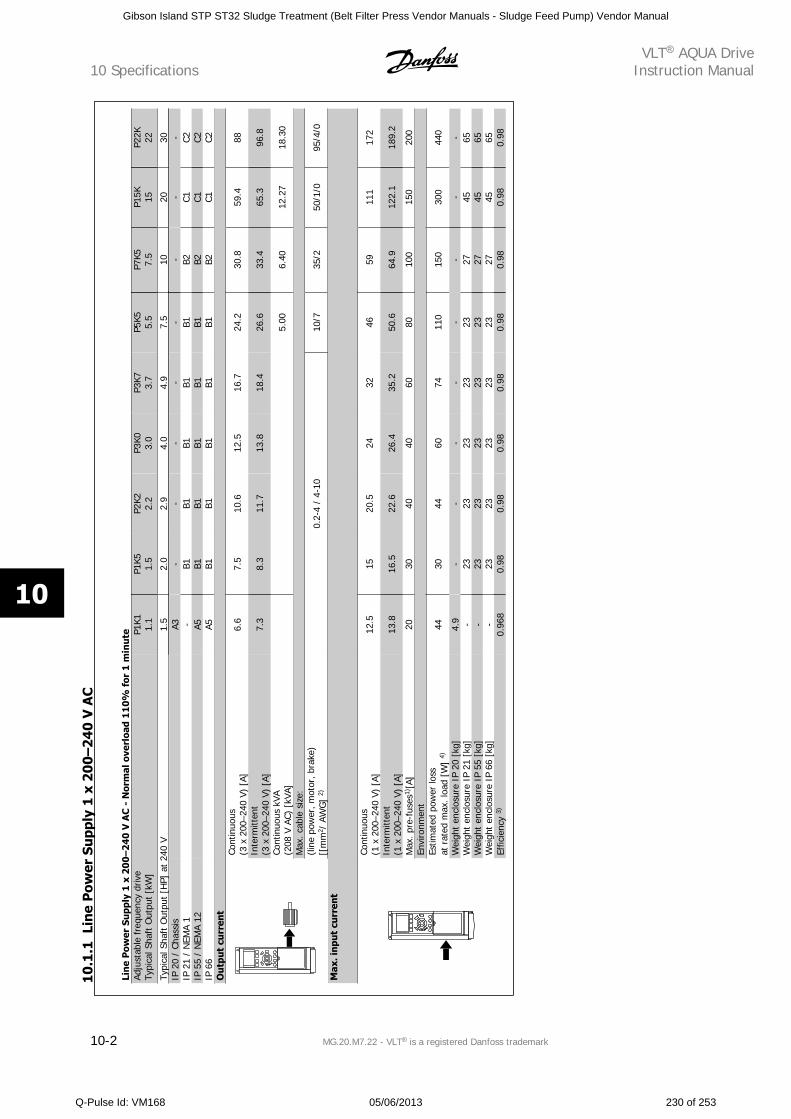
Lin
e P
ower
Su
pply
1 x
20
0–
24
0 V
AC
- N
orm
al o
verl
oad
11
0%
for
1 m
inu
teAd
just
able
fre
quen
cy d
rive
Typi
cal S
haft
Out
put
[kW
]P1
K11.
1P1
K51.
5P2
K22.
2P3
K03.
0P3
K73.
7P5
K55.
5P7
K57.
5P1
5K 15P2
2K 22
Typi
cal S
haft
Out
put
[HP]
at
240
V1.
52.
02.
94.
04.
97.
510
2030
IP 2
0 /
Chas
sis
A3
--
--
--
--
IP 2
1 /
NEM
A 1
-
B1B1
B1B1
B1B2
C1C2
IP 5
5 /
NEM
A 12
A5
B1B1
B1B1
B1B2
C1C2
IP 6
6
A5B1
B1B1
B1B1
B2C1
C2O
utp
ut c
urr
ent
Cont
inuo
us(3
x 2
00–2
40 V
) [A
]6.
67.
510
.612
.516
.724
.230
.859
.488
Inte
rmitt
ent
(3 x
200
–240
V)
[A]
7.3
8.3
11.7
13.8
18.4
26.6
33.4
65.3
96.8
Cont
inuo
us k
VA(2
08 V
AC)
[kV
A]
5.00
6.40
12.2
718
.30
Max
. cab
le s
ize:
(line
pow
er, m
otor
, bra
ke)
[[m
m2 /
AW
G]
2)0.
2-4
/ 4-
1010
/735
/250
/1/0
95/4
/0
Max
. inp
ut c
urr
ent
Cont
inuo
us(1
x 2
00–2
40 V
) [A
]12
.515
20.5
2432
4659
111
172
Inte
rmitt
ent
(1 x
200
–240
V)
[A]
13.8
16.5
22.6
26.4
35.2
50.6
64.9
122.
118
9.2
Max
. pre
-fus
es1)
[A]
2030
4040
6080
100
150
200
Envi
ronm
ent
Estim
ated
pow
er lo
ssat
rat
ed m
ax. l
oad
[W]
4)44
3044
6074
110
150
300
440
Wei
ght
encl
osur
e IP
20
[kg]
4.9
--
--
--
--
Wei
ght
encl
osur
e IP
21
[kg]
-23
2323
2323
2745
65W
eigh
t en
clos
ure
IP 5
5 [k
g]-
2323
2323
2327
4565
Wei
ght
encl
osur
e IP
66
[kg]
-23
2323
2323
2745
65Ef
ficie
ncy
3)0.
968
0.98
0.98
0.98
0.98
0.98
0.98
0.98
0.98
10.1
.1Li
ne
Pow
er S
upp
ly 1
x 2
00–
240
V A
C10 Specifications
VLT AQUA DriveInstruction Manual
10-2 MG.20.M7.22 - VLT is a registered Danfoss trademark
10
Gibson Island STP ST32 Sludge Treatment (Belt Filter Press Vendor Manuals - Sludge Feed Pump) Vendor Manual
Q-Pulse Id: VM168 05/06/2013 230 of 253
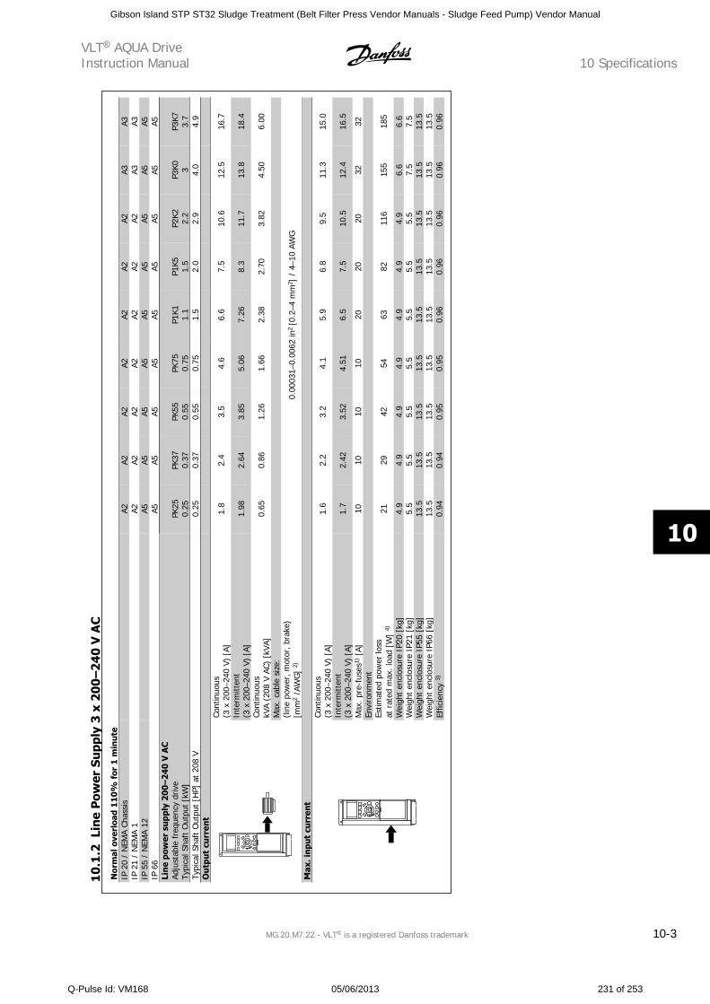
Nor
mal
ove
rloa
d 11
0%
for
1 m
inu
teIP
20
/ N
EMA
Chas
sis
A2
A2A2
A2A2
A2A2
A3A3
IP 2
1 /
NEM
A 1
A2
A2A2
A2A2
A2A2
A3A3
IP 5
5 /
NEM
A 12
A5
A5A5
A5A5
A5A5
A5A5
IP 6
6
A5A5
A5A5
A5A5
A5A5
A5Li
ne
pow
er s
upp
ly 2
00–2
40
V A
CAd
just
able
fre
quen
cy d
rive
Typi
cal S
haft
Out
put
[kW
]PK
250.
25PK
370.
37PK
550.
55PK
750.
75P1
K11.
1P1
K51.
5P2
K22.
2P3
K0 3P3
K73.
7Ty
pica
l Sha
ft O
utpu
t [H
P] a
t 20
8 V
0.25
0.37
0.55
0.75
1.5
2.0
2.9
4.0
4.9
Ou
tput
cu
rren
t
Cont
inuo
us(3
x 2
00–2
40 V
) [A
]1.
82.
43.
54.
66.
67.
510
.612
.516
.7
Inte
rmitt
ent
(3 x
200
–240
V)
[A]
1.98
2.64
3.85
5.06
7.26
8.3
11.7
13.8
18.4
Cont
inuo
uskV
A (2
08 V
AC)
[kV
A]0.
650.
861.
261.
662.
382.
703.
824.
506.
00
Max
. cab
le s
ize:
(line
pow
er, m
otor
, bra
ke)
[mm
2 /A
WG
] 2)
0.00
031–
0.00
62 in
2 [0
.2–4
mm
2 ] /
4–1
0 AW
G
Max
. inp
ut c
urr
ent
Cont
inuo
us(3
x 2
00–2
40 V
) [A
]1.
62.
23.
24.
15.
96.
89.
511
.315
.0
Inte
rmitt
ent
(3 x
200
–240
V)
[A]
1.7
2.42
3.52
4.51
6.5
7.5
10.5
12.4
16.5
Max
. pr
e-fu
ses1
) [A]
1010
1010
2020
2032
32En
viro
nmen
tEs
timat
ed p
ower
loss
at r
ated
max
. loa
d [W
] 4)
2129
4254
6382
116
155
185
Wei
ght
encl
osur
e IP
20 [
kg]
4.9
4.9
4.9
4.9
4.9
4.9
4.9
6.6
6.6
Wei
ght
encl
osur
e IP
21 [
kg]
5.5
5.5
5.5
5.5
5.5
5.5
5.5
7.5
7.5
Wei
ght
encl
osur
e IP
55 [
kg]
13.5
13.5
13.5
13.5
13.5
13.5
13.5
13.5
13.5
Wei
ght
encl
osur
e IP
66 [
kg]
13.5
13.5
13.5
13.5
13.5
13.5
13.5
13.5
13.5
Effic
ienc
y 3)
0.94
0.94
0.95
0.95
0.96
0.96
0.96
0.96
0.96
10
.1.2
Lin
e P
ower
Su
pply
3 x
20
0–
24
0 V
AC
VLT AQUA DriveInstruction Manual 10 Specifications
MG.20.M7.22 - VLT is a registered Danfoss trademark 10-3
10
Gibson Island STP ST32 Sludge Treatment (Belt Filter Press Vendor Manuals - Sludge Feed Pump) Vendor Manual
Q-Pulse Id: VM168 05/06/2013 231 of 253
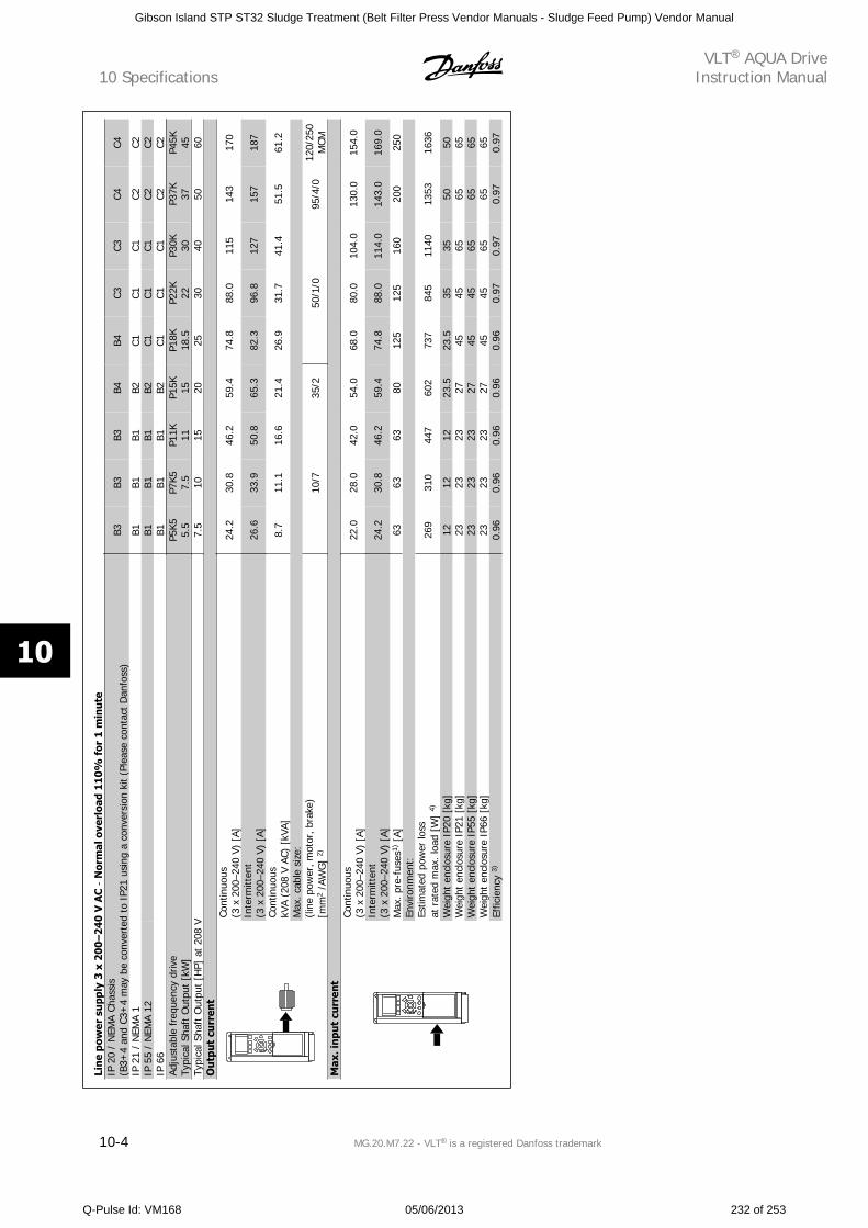
Lin
e po
wer
su
pply
3 x
20
0–
24
0 V
AC
- N
orm
al o
verl
oad
110
% f
or 1
min
ute
IP 2
0 /
NEM
A Ch
assi
s(B
3+4
and
C3+
4 m
ay b
e co
nver
ted
to I
P21
usin
g a
conv
ersi
on k
it (P
leas
e co
ntac
t D
anfo
ss)
B3B3
B3B4
B4C3
C3C4
C4
IP 2
1 /
NEM
A 1
B1
B1B1
B2C1
C1C1
C2C2
IP 5
5 /
NEM
A 12
B1
B1B1
B2C1
C1C1
C2C2
IP 6
6
B1B1
B1B2
C1C1
C1C2
C2Ad
just
able
fre
quen
cy d
rive
Typi
cal S
haft
Out
put
[kW
]P5
K55.
5P7
K57.
5P1
1K 11P1
5K 15P1
8K18
.5P2
2K 22P3
0K 30P3
7K 37P4
5K 45Ty
pica
l Sha
ft O
utpu
t [H
P] a
t 20
8 V
7.5
1015
2025
3040
5060
Ou
tput
cu
rren
tCo
ntin
uous
(3 x
200
–240
V)
[A]
24.2
30.8
46.2
59.4
74.8
88.0
115
143
170
Inte
rmitt
ent
(3 x
200
–240
V)
[A]
26.6
33.9
50.8
65.3
82.3
96.8
127
157
187
Cont
inuo
uskV
A (2
08 V
AC)
[kV
A]8.
711
.116
.621
.426
.931
.741
.451
.561
.2
Max
. cab
le s
ize:
(line
pow
er, m
otor
, bra
ke)
[mm
2 /A
WG
] 2)
10/7
35/2
50/1
/095
/4/0
120/
250
MCM
Max
. inp
ut c
urr
ent
Cont
inuo
us(3
x 2
00–2
40 V
) [A
]22
.028
.042
.054
.068
.080
.010
4.0
130.
015
4.0
Inte
rmitt
ent
(3 x
200
–240
V)
[A]
24.2
30.8
46.2
59.4
74.8
88.0
114.
014
3.0
169.
0
Max
. pre
-fus
es1)
[A]
6363
6380
125
125
160
200
250
Envi
ronm
ent:
Estim
ated
pow
er lo
ssat
rat
ed m
ax. l
oad
[W]
4)26
931
044
760
273
784
511
4013
5316
36
Wei
ght
encl
osur
e IP
20 [
kg]
1212
1223
.523
.535
3550
50W
eigh
t en
clos
ure
IP21
[kg
]23
2323
2745
4565
6565
Wei
ght
encl
osur
e IP
55 [
kg]
2323
2327
4545
6565
65W
eigh
t en
clos
ure
IP66
[kg
]23
2323
2745
4565
6565
Effic
ienc
y 3)
0.96
0.96
0.96
0.96
0.96
0.97
0.97
0.97
0.97
10 SpecificationsVLT AQUA Drive
Instruction Manual
10-4 MG.20.M7.22 - VLT is a registered Danfoss trademark
10
Gibson Island STP ST32 Sludge Treatment (Belt Filter Press Vendor Manuals - Sludge Feed Pump) Vendor Manual
Q-Pulse Id: VM168 05/06/2013 232 of 253
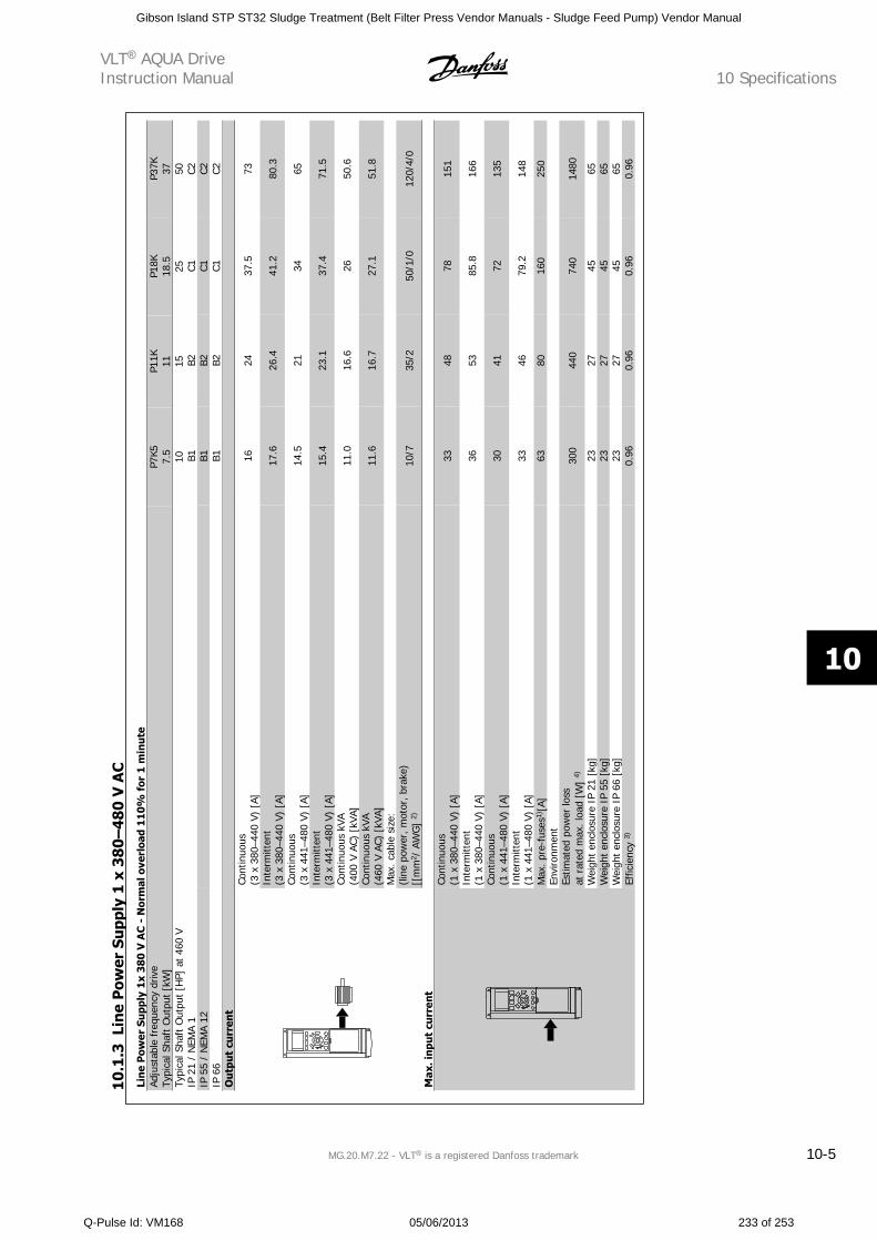
Lin
e P
ower
Su
pply
1x
380
V A
C -
Nor
mal
ove
rloa
d 11
0% f
or 1
min
ute
Adju
stab
le f
requ
ency
driv
eTy
pica
l Sha
ft O
utpu
t [k
W]
P7K5
7.5
P11K 11
P18K
18.5
P37K 37
Typi
cal S
haft
Out
put
[HP]
at
460
V10
1525
50IP
21
/ N
EMA
1
B1B2
C1C2
IP 5
5 /
NEM
A 12
B1
B2C1
C2IP
66
B1
B2C1
C2O
utp
ut c
urr
ent
Cont
inuo
us(3
x 3
80–4
40 V
) [A
]16
2437
.573
Inte
rmitt
ent
(3 x
380
–440
V)
[A]
17.6
26.4
41.2
80.3
Cont
inuo
us(3
x 4
41–4
80 V
) [A
]14
.521
3465
Inte
rmitt
ent
(3 x
441
–480
V)
[A]
15.4
23.1
37.4
71.5
Cont
inuo
us k
VA(4
00 V
AC)
[kV
A]11
.016
.626
50.6
Cont
inuo
us k
VA(4
60 V
AC)
[kV
A]11
.616
.727
.151
.8
Max
. cab
le s
ize:
(line
pow
er, m
otor
, bra
ke)
[[m
m2 /
AW
G]
2)10
/735
/250
/1/0
120/
4/0
Max
. inp
ut c
urr
ent
Cont
inuo
us(1
x 3
80–4
40 V
) [A
]33
4878
151
Inte
rmitt
ent
(1 x
380
–440
V)
[A]
3653
85.8
166
Cont
inuo
us(1
x 4
41–4
80 V
) [A
]30
4172
135
Inte
rmitt
ent
(1 x
441
–480
V)
[A]
3346
79.2
148
Max
. pr
e-fu
ses1
) [A]
6380
160
250
Envi
ronm
ent
Estim
ated
pow
er lo
ssat
rat
ed m
ax. l
oad
[W]
4)30
044
074
014
80
Wei
ght
encl
osur
e IP
21
[kg]
2327
4565
Wei
ght
encl
osur
e IP
55
[kg]
2327
4565
Wei
ght
encl
osur
e IP
66
[kg]
2327
4565
Effic
ienc
y 3)
0.96
0.96
0.96
0.96
10.1
.3Li
ne
Pow
er S
upp
ly 1
x 3
80–
480
V A
C
VLT AQUA DriveInstruction Manual 10 Specifications
MG.20.M7.22 - VLT is a registered Danfoss trademark 10-5
10
Gibson Island STP ST32 Sludge Treatment (Belt Filter Press Vendor Manuals - Sludge Feed Pump) Vendor Manual
Q-Pulse Id: VM168 05/06/2013 233 of 253
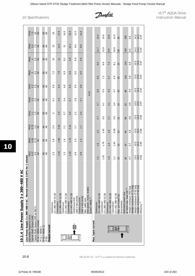
Lin
e P
ower
Su
pply
3 x
38
0–
48
0 V
AC
- N
orm
al o
verl
oad
11
0%
for
1 m
inu
teAd
just
able
fre
quen
cy d
rive
Typi
cal S
haft
Out
put
[kW
]PK
370.
37PK
550.
55PK
750.
75P1
K11.
1P1
K51.
5P2
K22.
2P3
K0 3P4
K0 4P5
K55.
5P7
K57.
5Ty
pica
l Sha
ft O
utpu
t [H
P] a
t 46
0 V
0.5
0.75
1.0
1.5
2.0
2.9
4.0
5.3
7.5
10IP
20
/ N
EMA
Chas
sis
A2A2
A2A2
A2A2
A2A2
A3A3
IP 2
1 /
NEM
A 1
IP
55
/ N
EMA
12
A5A5
A5A5
A5A5
A5A5
A5A5
IP 6
6
A5A5
A5A5
A5A5
A5A5
AAA5
Ou
tput
cu
rren
tCo
ntin
uous
(3 x
380
–440
V)
[A]
1.3
1.8
2.4
34.
15.
67.
210
1316
Inte
rmitt
ent
(3 x
380
–440
V)
[A]
1.43
1.98
2.64
3.3
4.5
6.2
7.9
1114
.317
.6
Cont
inuo
us(3
x 4
41–4
80 V
) [A
]1.
21.
62.
12.
73.
44.
86.
38.
211
14.5
Inte
rmitt
ent
(3 x
441
–480
V)
[A]
1.32
1.76
2.31
3.0
3.7
5.3
6.9
9.0
12.1
15.4
Cont
inuo
us k
VA(4
00 V
AC)
[kV
A]0.
91.
31.
72.
12.
83.
95.
06.
99.
011
.0
Cont
inuo
us k
VA(4
60 V
AC)
[kV
A]0.
91.
31.
72.
42.
73.
85.
06.
58.
811
.6
Max
. cab
le s
ize:
(line
pow
er, m
otor
, br
ake)
[[m
m2 /
AW
G]
2)4/
10
Max
. inp
ut c
urr
ent
Cont
inuo
us(3
x 3
80–4
40 V
) [A
]1.
21.
62.
22.
73.
75.
06.
59.
011
.714
.4
Inte
rmitt
ent
(3 x
380
–440
V)
[A]
1.32
1.76
2.42
3.0
4.1
5.5
7.2
9.9
12.9
15.8
Cont
inuo
us(3
x 4
41–4
80 V
) [A
]1.
01.
41.
92.
73.
14.
35.
77.
49.
913
.0
Inte
rmitt
ent
(3 x
441
–480
V)
[A]
1.1
1.54
2.09
3.0
3.4
4.7
6.3
8.1
10.9
14.3
Max
. pre
-fus
es1)
[A]
1010
1010
1020
2020
3030
Envi
ronm
ent
Estim
ated
pow
er lo
ssat
rat
ed m
ax. l
oad
[W]
4)35
4246
5862
8811
612
418
725
5
Wei
ght
encl
osur
e IP
20 [
kg]
4.7
4.7
4.8
4.8
4.9
4.9
4.9
4.9
6.6
6.6
Wei
ght
encl
osur
e IP
21
[kg]
Wei
ght
encl
osur
e IP
55
[kg]
13.5
13.5
13.5
13.5
13.5
13.5
13.5
13.5
14.2
14.2
Wei
ght
encl
osur
e IP
66
[kg]
13.5
13.5
13.5
13.5
13.5
13.5
13.5
13.5
14.2
14.2
Effic
ienc
y 3)
0.93
0.95
0.96
0.96
0.97
0.97
0.97
0.97
0.97
0.97
10.1
.4Li
ne
Pow
er S
upp
ly 3
x 3
80–
480
V A
C
10 SpecificationsVLT AQUA Drive
Instruction Manual
10-6 MG.20.M7.22 - VLT is a registered Danfoss trademark
10
Gibson Island STP ST32 Sludge Treatment (Belt Filter Press Vendor Manuals - Sludge Feed Pump) Vendor Manual
Q-Pulse Id: VM168 05/06/2013 234 of 253
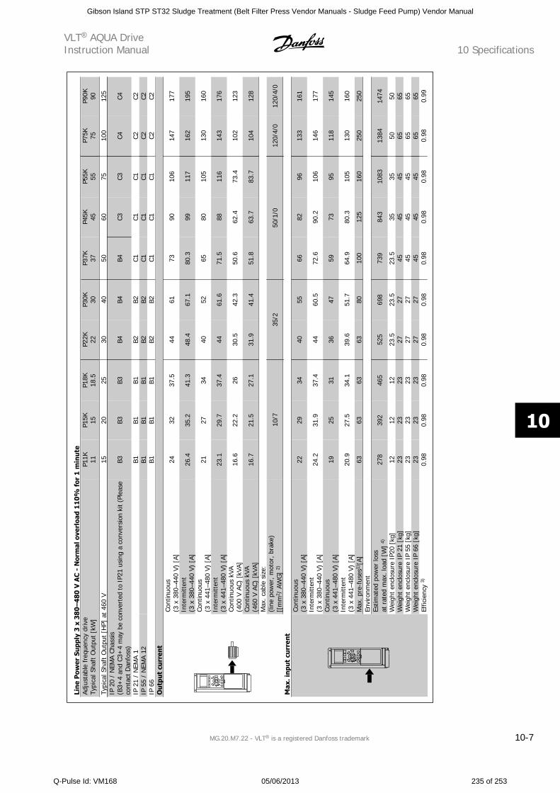
Lin
e P
ower
Su
pply
3 x
38
0–
48
0 V
AC
- N
orm
al o
verl
oad
11
0%
for
1 m
inu
teAd
just
able
fre
quen
cy d
rive
Typi
cal S
haft
Out
put
[kW
]P1
1K 11P1
5K 15P1
8K18
.5P2
2K 22P3
0K 30P3
7K 37P4
5K 45P5
5K 55P7
5K 75P9
0K 90
Typi
cal S
haft
Out
put
[HP]
at
460
V15
2025
3040
5060
7510
012
5IP
20
/ N
EMA
Chas
sis
(B3+
4 an
d C3
+4
may
be
conv
erte
d to
IP2
1 us
ing
a co
nver
sion
kit
(Ple
ase
cont
act
Dan
foss
)B3
B3B3
B4B4
B4C3
C3C4
C4
IP 2
1 /
NEM
A 1
B1
B1B1
B2B2
C1C1
C1C2
C2IP
55
/ N
EMA
12
B1B1
B1B2
B2C1
C1C1
C2C2
IP 6
6
B1B1
B1B2
B2C1
C1C1
C2C2
Ou
tput
cu
rren
tCo
ntin
uous
(3 x
380
–440
V)
[A]
2432
37.5
4461
7390
106
147
177
Inte
rmitt
ent
(3 x
380
–440
V)
[A]
26.4
35.2
41.3
48.4
67.1
80.3
9911
716
219
5
Cont
inuo
us(3
x 4
41–4
80 V
) [A
]21
2734
4052
6580
105
130
160
Inte
rmitt
ent
(3 x
441
–480
V)
[A]
23.1
29.7
37.4
4461
.671
.588
116
143
176
Cont
inuo
us k
VA(4
00 V
AC)
[kV
A]16
.622
.226
30.5
42.3
50.6
62.4
73.4
102
123
Cont
inuo
us k
VA(4
60 V
AC)
[kV
A]16
.721
.527
.131
.941
.451
.863
.783
.710
412
8
Max
. ca
ble
size
:(li
ne p
ower
, mot
or, b
rake
)[[
mm
2 / A
WG
] 2)
10/7
35/2
50/1
/012
0/4/
012
0/4/
0
Max
. inp
ut c
urr
ent
Cont
inuo
us(3
x 3
80–4
40 V
) [A
]22
2934
4055
6682
9613
316
1
Inte
rmitt
ent
(3 x
380
–440
V)
[A]
24.2
31.9
37.4
4460
.572
.690
.210
614
617
7
Cont
inuo
us(3
x 4
41–4
80 V
) [A
]19
2531
3647
5973
9511
814
5
Inte
rmitt
ent
(3 x
441
–480
V)
[A]
20.9
27.5
34.1
39.6
51.7
64.9
80.3
105
130
160
Max
. pr
e-fu
ses1
) [A]
6363
6363
8010
012
516
025
025
0En
viro
nmen
tEs
timat
ed p
ower
loss
at r
ated
max
. loa
d [W
] 4)
278
392
465
525
698
739
843
1083
1384
1474
Wei
ght
encl
osur
e IP
20 [
kg]
1212
1223
.523
.523
.535
3550
50W
eigh
t en
clos
ure
IP 2
1 [k
g]23
2323
2727
4545
4565
65W
eigh
t en
clos
ure
IP 5
5 [k
g]23
2323
2727
4545
4565
65W
eigh
t en
clos
ure
IP 6
6 [k
g]23
2323
2727
4545
4565
65Ef
ficie
ncy
3)0.
980.
980.
980.
980.
980.
980.
980.
980.
980.
99
VLT AQUA DriveInstruction Manual 10 Specifications
MG.20.M7.22 - VLT is a registered Danfoss trademark 10-7
10
Gibson Island STP ST32 Sludge Treatment (Belt Filter Press Vendor Manuals - Sludge Feed Pump) Vendor Manual
Q-Pulse Id: VM168 05/06/2013 235 of 253
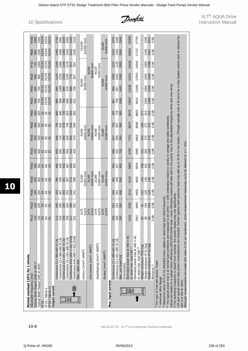
Nor
mal
ove
rloa
d 11
0%
for
1 m
inu
teAd
just
able
fre
quen
cy d
rive
Typi
cal S
haft
Out
put
[kW
] at
400
VP1
1011
0P1
3213
2P1
6016
0P2
0020
0P2
5025
0P3
1531
5P3
5535
5P4
0040
0P4
5045
0P5
0050
0P5
6056
0P6
3063
0P7
1071
0P8
0080
0P1
M0
1000
Typi
cal S
haft
Out
put
[HP]
at
460V
150
200
250
300
350
450
500
550
600
700
750
900
1000
1200
1350
IP 0
0
D3
D3
D4
D4
D4
E2E2
E2E2
F1/F
3F1
/F3
F1/F
3F1
/F3
F2/F
4F2
/F4
IP 2
1 /
Nem
a 1
D
1D
1D
2D
2D
2E1
E1E1
E1F1
/F3
F1/F
3F1
/F3
F1/F
3F2
/F4
F2/F
4IP
54
/ N
ema
12
D1
D1
D2
D2
D2
E1E1
E1E1
F1/F
3F1
/F3
F1/F
3F1
/F3
F2/F
4F2
/F4
Ou
tput
cu
rren
tCo
ntin
uous
(3
x 38
0-44
0 V)
[A]
212
260
315
395
480
600
658
745
800
880
990
1120
1260
1460
1720
Inte
rmitt
ent
(3 x
380
-440
V)
[A]
233
286
347
435
528
660
724
820
880
968
1089
1232
1386
1606
1892
Cont
inuo
us (
3 x
441–
480
V) [
A]19
024
030
236
144
354
059
067
873
078
089
010
5011
6013
8015
30In
term
itten
t (3
x 4
41–4
80 V
) [A
]20
926
433
239
748
759
464
974
680
385
897
911
5512
7615
1816
83Co
ntin
uous
kVA
(40
0 V
AC)
[kVA
]14
718
021
827
433
341
645
651
655
461
068
677
687
310
1211
92Co
ntin
uous
kVA
(46
0 V
AC)
[kVA
]15
119
124
128
835
343
047
054
058
262
170
983
792
411
0012
19M
ax. c
able
siz
e:
(mot
or,)
[m
m2 /
AW
G2)
]2x
702x
2/0
2x18
52x
300
mcm
4x24
04x
500
mcm
8x15
08x
300
mcm
12x1
5012
x300
mcm
(li
ne p
ower
) [m
m2 /
AW
G2)
]2x
702x
2/0
2x18
52x
300
mcm
4x24
04x
500
mcm
8x24
08x
500
mcm
(lo
adsh
arin
g) [
mm
2 / A
WG
2)]
2x70
2x2/
02x
185
2x30
0 m
cm4x
240
4x50
0 m
cm4x
120
4x25
0 m
cm
(b
rake
) [m
m2 /
AW
G2)
]2x
702x
2/0
2x18
52x
300
mcm
2x18
52x
350
mcm
4x18
54x
350
mcm
6x18
56x
350
mcm
Max
. inp
ut c
urr
ent
Cont
inuo
us (
3 x
380-
440
V) [
A]20
425
130
438
146
359
064
773
378
785
796
410
9012
2714
2216
75Co
ntin
uous
(3
x 44
1–48
0 V)
[A]
183
231
291
348
427
531
580
667
718
759
867
1022
1129
1344
1490
Max
. pr
e-fu
ses1
) [A]
300
350
400
500
630
700
900
900
900
1600
1600
2000
2000
2500
2500
Envi
ronm
ent:
Estim
ated
pow
er lo
ss a
t 40
0 V
ACat
rat
ed m
ax. l
oad
[W]
4)32
3437
8242
1351
1958
9367
9077
0188
7996
7010
647
1233
813
201
1543
618
084
2035
8
Estim
ated
pow
er lo
ss a
t 46
0 V
ACat
rat
ed m
ax. l
oad
[W]
4)29
4736
6540
6346
5256
3460
8269
5380
8988
0394
1411
006
1235
314
041
1713
717
752
Wei
ght
encl
osur
e IP
00 [
kg]
8291
112
123
138
221
234
236
277
--
--
--
Wei
ght
encl
osur
e IP
21
[kg]
9610
412
513
615
126
327
027
231
310
0410
0410
0410
0412
4612
46W
eigh
t en
clos
ure
IP 5
4 [k
g]96
104
125
136
151
263
270
272
313
1299
1299
1299
1299
1541
1541
Effic
ienc
y 3)
0.98
0.98
0.98
0.98
0.98
0.98
0.98
0.98
0.98
0.98
0.98
0.98
0.98
0.98
0.98
1) F
or t
ype
of f
use
see
sect
ion
Fuse
s2)
Am
eric
an W
ire G
auge
3) M
easu
red
usin
g 16
ft
[5 m
] sh
ield
ed m
otor
cab
les
at r
ated
load
and
rat
ed f
requ
ency
4) T
he t
ypic
al p
ower
loss
is a
t no
rmal
load
con
ditio
ns a
nd e
xpec
ted
to b
e w
ithin
+/-
15%
(to
lera
nce
rela
tes
to v
arie
ty in
vol
tage
and
cab
le c
ondi
tions
).Va
lues
are
bas
ed o
n a
typi
cal m
otor
eff
icie
ncy
(eff
2/ef
f3 b
orde
r lin
e). L
ower
eff
icie
ncy
mot
ors
will
als
o ad
d to
the
pow
er lo
ss in
the
adj
usta
ble
freq
uenc
y dr
ive
and
vice
ver
sa.
If t
he s
witc
hing
fre
quen
cy is
rai
sed
from
nom
inal
, the
pow
er lo
sses
may
ris
e si
gnifi
cant
ly.
LCP
and
typi
cal c
ontr
ol c
ard
pow
er c
onsu
mpt
ions
are
incl
uded
. Fur
ther
opt
ions
and
cus
tom
er lo
ad m
ay a
dd u
p to
30
W t
o th
e lo
sses
. (Th
ough
typ
ical
ly o
nly
4 W
ext
ra f
or a
ful
ly lo
aded
con
trol
car
d or
opt
ions
for
slot
A o
r sl
ot B
, eac
h).
Alth
ough
mea
sure
men
ts a
re m
ade
with
sta
te o
f th
e ar
t eq
uipm
ent,
som
e m
easu
rem
ent
inac
cura
cy m
ust
be a
llow
ed f
or (
+/-
5%
).
10 SpecificationsVLT AQUA Drive
Instruction Manual
10-8 MG.20.M7.22 - VLT is a registered Danfoss trademark
10
Gibson Island STP ST32 Sludge Treatment (Belt Filter Press Vendor Manuals - Sludge Feed Pump) Vendor Manual
Q-Pulse Id: VM168 05/06/2013 236 of 253
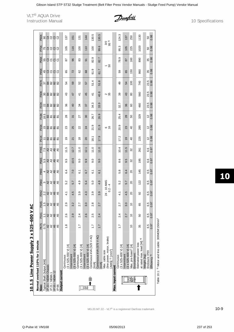
Nor
mal
ove
rloa
d 11
0%
for
1 m
inu
teSi
ze:
PK75
P1K1
P1K5
P2K2
P3K0
P4K0
P5K5
P7K5
P11K
P15K
P18K
P22K
P30K
P37K
P45K
P55K
P75K
P90K
Typi
cal S
haft
Out
put
[kW
]0.
751.
11.
52.
23
45.
57.
511
1518
.522
3037
4555
7590
IP 2
0 /
NEM
A Ch
assi
sA2
A2A2
A2A2
A2A3
A3B3
B3B3
B4B4
B4C3
C3C4
C4IP
21
/ N
EMA
1A2
A2A2
A2A2
A2A3
A3B1
B1B1
B2B2
B2C1
C1C2
C2IP
55
/ N
EMA
12A5
A5A5
A5A5
A5A5
A5B1
B1B1
B2B2
B2C1
C1C2
C2IP
66
A5A5
A5A5
A5A5
A5A5
B1B1
B1B2
B2B2
C1C1
C2C2
Ou
tput
cu
rren
tCo
ntin
uous
(3 x
525
–550
V)
[A]
1.8
2.6
2.9
4.1
5.2
6.4
9.5
11.5
1923
2836
4354
6587
105
137
Inte
rmitt
ent
(3 x
525
–550
V)
[A]
2.9
3.2
4.5
5.7
7.0
10.5
12.7
2125
3140
4759
7296
116
151
Cont
inuo
us(3
x 5
25–6
00 V
) [A
]1.
72.
42.
73.
94.
96.
19.
011
.018
2227
3441
5262
8310
013
1
Inte
rmitt
ent
(3 x
525
–600
V)
[A]
2.6
3.0
4.3
5.4
6.7
9.9
12.1
2024
3037
4557
6891
110
144
Cont
inuo
us k
VA (
525
V AC
)[k
VA]
1.7
2.5
2.8
3.9
5.0
6.1
9.0
11.0
18.1
21.9
26.7
34.3
4151
.461
.982
.910
013
0.5
Cont
inuo
us k
VA (
575
V AC
)[k
VA]
1.7
2.4
2.7
3.9
4.9
6.1
9.0
11.0
17.9
21.9
26.9
33.9
40.8
51.8
61.7
82.7
99.6
130.
5
Max
. cab
le s
ize
(line
pow
er, m
otor
, bra
ke)
[AW
G]
2) [
mm
2 ]
24 -
10
AWG
0.2
- 4
6 162 35
1 503/
095
5)
Max
. inp
ut c
urr
ent
Cont
inuo
us(3
x 5
25–6
00 V
) [A
]1.
72.
42.
74.
15.
25.
88.
610
.417
.220
.925
.432
.739
4959
78.9
95.3
124.
3
Inte
rmitt
ent
(3 x
525
–600
V)
[A]
2.7
3.0
4.5
5.7
6.4
9.5
11.5
1923
2836
4354
6587
105
137
Max
. pr
e-fu
ses1
) [A]
1010
1020
2020
3232
4040
5060
8010
015
016
022
525
0En
viro
nmen
t:Es
timat
ed p
ower
loss
at r
ated
max
. loa
d [W
] 4)
3550
6592
122
145
195
261
225
285
329
460
560
740
860
890
1020
1130
Wei
ght
[kg]
:En
clos
ure
IP20
6.5
6.5
6.5
6.5
6.5
6.5
6.6
6.6
1212
1223
.523
.523
.535
3550
50Ef
ficie
ncy
4)0.
970.
970.
970.
970.
970.
970.
970.
970.
980.
980.
980.
980.
980.
980.
980.
980.
980.
98
Tabl
e 10
.1:
5) M
otor
and
line
cab
le:
300M
CM/1
50m
m2
10
.1.5
Lin
e P
ower
Su
pply
3 x
52
5–
60
0 V
AC
VLT AQUA DriveInstruction Manual 10 Specifications
MG.20.M7.22 - VLT is a registered Danfoss trademark 10-9
10
Gibson Island STP ST32 Sludge Treatment (Belt Filter Press Vendor Manuals - Sludge Feed Pump) Vendor Manual
Q-Pulse Id: VM168 05/06/2013 237 of 253
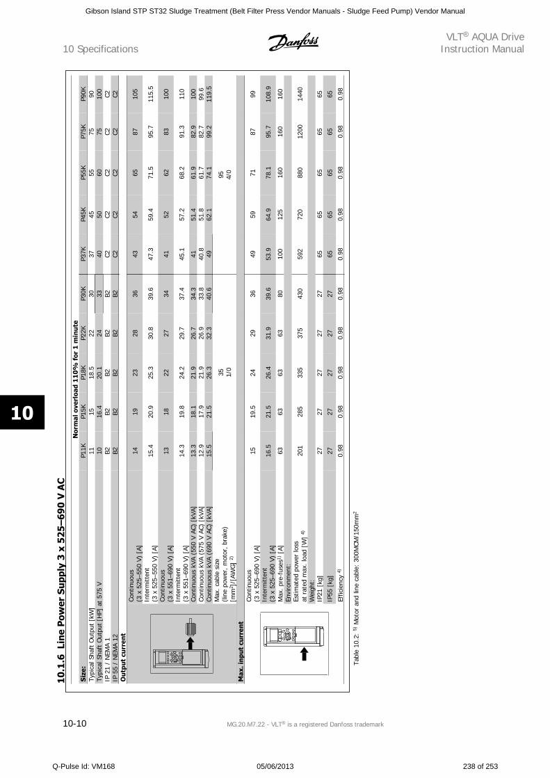
Nor
mal
ove
rloa
d 1
10
% f
or 1
min
ute
Size
:P1
1KP1
5KP1
8KP2
2KP3
0KP3
7KP4
5KP5
5KP7
5KP9
0KTy
pica
l Sha
ft O
utpu
t [k
W]
1115
18.5
2230
3745
5575
90Ty
pica
l Sha
ft O
utpu
t [H
P] a
t 57
5 V
1016
.420
.124
3340
5060
7510
0IP
21
/ N
EMA
1B2
B2B2
B2B2
C2C2
C2C2
C2IP
55
/ N
EMA
12B2
B2B2
B2B2
C2C2
C2C2
C2O
utp
ut c
urr
ent
Cont
inuo
us(3
x 5
25–5
50 V
) [A
]14
1923
2836
4354
6587
105
Inte
rmitt
ent
(3 x
525
–550
V)
[A]
15.4
20.9
25.3
30.8
39.6
47.3
59.4
71.5
95.7
115.
5
Cont
inuo
us(3
x 5
51–6
90 V
) [A
]13
1822
2734
4152
6283
100
Inte
rmitt
ent
(3 x
551
–690
V)
[A]
14.3
19.8
24.2
29.7
37.4
45.1
57.2
68.2
91.3
110
Cont
inuo
us k
VA (
550
V AC
) [k
VA]
13.3
18.1
21.9
26.7
34.3
4151
.461
.982
.910
0Co
ntin
uous
kVA
(57
5 V
AC)
[kVA
]12
.917
.921
.926
.933
.840
.851
.861
.782
.799
.6Co
ntin
uous
kVA
(69
0 V
AC)
[kVA
]15
.521
.526
.332
.340
.649
62.1
74.1
99.2
119.
5M
ax. c
able
siz
e(li
ne p
ower
, mot
or, b
rake
)[m
m2 ]
/[AW
G]
2)
35 1/0
95 4/0
Max
. inp
ut c
urr
ent
Cont
inuo
us(3
x 5
25–6
90 V
) [A
]15
19.5
2429
3649
5971
8799
Inte
rmitt
ent
(3 x
525
–690
V)
[A]
16.5
21.5
26.4
31.9
39.6
53.9
64.9
78.1
95.7
108.
9
Max
. pr
e-fu
ses1
) [A]
6363
6363
8010
012
516
016
016
0En
viro
nmen
t:Es
timat
ed p
ower
loss
at r
ated
max
. loa
d [W
] 4)
201
285
335
375
430
592
720
880
1200
1440
Wei
ght:
IP21
[kg
]27
2727
2727
6565
6565
65
IP55
[kg
]27
2727
2727
6565
6565
65
Effic
ienc
y 4)
0.98
0.98
0.98
0.98
0.98
0.98
0.98
0.98
0.98
0.98
Tabl
e 10
.2:
5) M
otor
and
line
cab
le:
300M
CM/1
50m
m2
10
.1.6
Lin
e P
ower
Su
pply
3 x
52
5–
69
0 V
AC
10 SpecificationsVLT AQUA Drive
Instruction Manual
10-10 MG.20.M7.22 - VLT is a registered Danfoss trademark
10
Gibson Island STP ST32 Sludge Treatment (Belt Filter Press Vendor Manuals - Sludge Feed Pump) Vendor Manual
Q-Pulse Id: VM168 05/06/2013 238 of 253
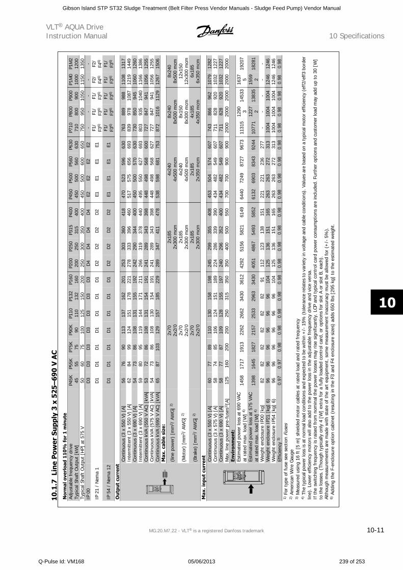
Nor
mal
ove
rloa
d 11
0%
for
1 m
inu
teAd
just
able
fre
quen
cy d
rive
Typi
cal S
haft
Out
put
[kW
]P4
5K 45P5
5K 55P7
5K 75P9
0K 90P1
1011
0P1
3213
2P1
6016
0P2
0020
0P2
5025
0P3
1531
5P4
0040
0P4
5045
0P5
0050
0P5
6056
0P6
3063
0P7
1071
0P8
0080
0P9
0090
0P1
M0
1000
P1M
212
00Ty
pica
l Sha
ft O
utpu
t [H
P] a
t 57
5 V
5060
7510
012
515
020
025
030
035
040
045
050
060
065
075
095
010
5011
5013
50IP
00
D
3D
3D
3D
3D
3D
3D
3D
4D
4D
4D
4E2
E2E2
E2-
--
--
IP 2
1 /
Nem
a 1
D
1D
1D
1D
1D
1D
1D
1D
2D
2D
2D
2E1
E1E1
E1F1
/F3
6)F1
/F3
6)F1
/F3
6)F2
/F4
6)F2
/F4
6)
IP 5
4 /
Nem
a 12
D
1D
1D
1D
1D
1D
1D
1D
2D
2D
2D
2E1
E1E1
E1F1
/F3
6)F1
/F3
6)F1
/F3
6)F1
/F3
6)F1
/F3
6)
Ou
tput
cu
rren
tCo
ntin
uous
(3
x 55
0 V)
[A]
5676
9011
313
716
220
125
330
336
041
847
052
359
663
076
388
998
811
0813
17In
term
itten
t (3
x 5
50 V
) [A
]62
8499
124
151
178
221
278
333
396
460
517
575
656
693
839
978
1087
1219
1449
Cont
inuo
us (
3 x
690
V) [
A]54
7386
108
131
155
192
242
290
344
400
450
500
570
630
730
850
945
1060
1260
Inte
rmitt
ent
(3 x
690
V)
[A]
5980
9511
914
417
121
126
631
937
844
049
555
062
769
380
393
510
4011
6613
86Co
ntin
uous
kVA
(55
0 V
AC)
[kVA
]53
7286
108
131
154
191
241
289
343
398
448
498
568
600
727
847
941
1056
1255
Cont
inuo
us k
VA (
575
V AC
) [k
VA]
5473
8610
813
015
419
124
128
934
339
844
849
856
862
772
784
794
110
5612
55Co
ntin
uous
kVA
(69
0 V
AC)
[kVA
]65
8710
312
915
718
522
928
934
741
147
853
859
868
175
387
210
1611
2912
6715
06M
ax. c
able
siz
e:
(line
pow
er)
[mm
2 / A
WG
] 2)
2x70
2x2/
02x
185
2x30
0 m
cm4x
240
4x50
0 m
cm8x
240
8x50
0 m
cm8x
240
8x50
0 m
cm
(Mot
or)
[mm
2 / A
WG
] 2)
2x70
2x2/
02x
185
2x30
0 m
cm4x
240
4x50
0 m
cm8x
150
8x30
0 m
cm12
x150
12x3
00 m
cm
(Bra
ke)
[mm
2 / A
WG
] 2)
2x70
2x2/
02x
185
2x30
0 m
cm2x
185
2x35
0 m
cm4x
185
4x35
0 m
cm6x
185
6x35
0 m
cmM
ax. i
nput
cu
rren
tCo
ntin
uous
(3
x 55
0 V)
[A]
6077
8911
013
015
819
824
529
935
540
845
350
457
460
774
386
696
210
7912
82Co
ntin
uous
(3
x 57
5 V)
[A]
5874
8510
612
415
118
922
428
633
939
043
448
254
960
771
182
892
010
3212
27Co
ntin
uous
(3
x 69
0 V)
[A]
5877
8710
912
815
519
724
029
635
240
043
448
254
960
771
182
892
010
3212
27M
ax. l
ine
pow
er p
re-f
uses
1)[A
]12
516
020
020
025
031
535
035
040
050
055
070
070
090
090
020
0020
0020
0020
0020
00En
viro
nmen
t:Es
timat
ed p
ower
loss
at
690
VAC
at r
ated
max
. loa
d [W
] 4)
1458
1717
1913
2262
2662
3430
3612
4292
5156
5821
6149
6440
7249
8727
9673
1131
512
90 314
533
1637 5
1920
7
Estim
ated
pow
er lo
ss a
t 57
5 VA
Cat
rat
ed m
ax. l
oad
[W]
4)13
9816
4518
2721
5725
3329
6334
3040
5148
6754
9358
5261
3269
0383
4392
4410
771
1227 2
1383
515
59 218
281
Wei
ght
encl
osur
e IP
00 [
kg]
8282
8282
8282
9111
212
313
815
122
122
123
627
7-
--
--
Wei
ght
encl
osur
e IP
21 [
kg]
6)96
9696
9696
9610
412
513
615
116
526
326
327
231
310
0410
0410
0412
4612
46W
eigh
t en
clos
ure
IP54
[kg
] 6)
9696
9696
9696
104
125
136
151
165
263
263
272
313
1004
1004
1004
1246
1246
Effic
ienc
y 3)
0.97
0.97
0.98
0.98
0.98
0.98
0.98
0.98
0.98
0.98
0.98
0.98
0.98
0.98
0.98
0.98
0.98
0.98
0.98
0.98
1) F
or t
ype
of f
use
see
sect
ion
Fuse
s2)
Am
eric
an W
ire G
auge
3) M
easu
red
usin
g 16
ft
[5 m
] sh
ield
ed m
otor
cab
les
at r
ated
load
and
rat
ed f
requ
ency
4) T
he ty
pica
l pow
er lo
ss is
at n
orm
al lo
ad c
ondi
tions
and
exp
ecte
d to
be
with
in +
/- 1
5% (
tole
ranc
e re
late
s to
var
iety
in v
olta
ge a
nd c
able
con
ditio
ns).
Val
ues
are
base
d on
a ty
pica
l mot
or e
ffic
ienc
y (e
ff2/
eff3
bor
der
line)
. Low
er e
ffic
ienc
y m
otor
s w
ill a
lso
add
to t
he p
ower
loss
in t
he a
djus
tabl
e fr
eque
ncy
driv
e an
d vi
ce v
ersa
.If
the
sw
itchi
ng fre
quen
cy is
rai
sed
from
nom
inal
the
pow
er lo
sses
may
ris
e si
gnifi
cant
ly.
LCP
and
typi
cal c
ontr
ol c
ard
pow
er c
onsu
mpt
ions
are
incl
uded
. Fur
ther
opt
ions
and
cus
tom
er lo
ad m
ay a
dd u
p to
30
[W]
to t
he lo
sses
. (Th
ough
typ
ical
ly o
nly
4 [W
] ex
tra
for
a fu
lly lo
aded
con
trol
car
d, o
r op
tions
for
slo
t A
or s
lot
B, e
ach)
.Al
thou
gh m
easu
rem
ents
are
mad
e w
ith s
tate
of th
e ar
t eq
uipm
ent,
som
e m
easu
rem
ent
inac
cura
cy m
ust
be a
llow
ed f
or (
+/-
5%
).6)
Add
ing
the
F-en
clos
ure
optio
n ca
bine
t (r
esul
ting
in t
he F
3 an
d F4
enc
losu
re s
izes
) ad
ds 6
50 lb
s [2
95 k
g] t
o th
e es
timat
ed w
eigh
t.
10.1
.7Li
ne
Pow
er S
upp
ly 3
x 5
25–
690
V A
C
VLT AQUA DriveInstruction Manual 10 Specifications
MG.20.M7.22 - VLT is a registered Danfoss trademark 10-11
10
Gibson Island STP ST32 Sludge Treatment (Belt Filter Press Vendor Manuals - Sludge Feed Pump) Vendor Manual
Q-Pulse Id: VM168 05/06/2013 239 of 253
Protection and Features:
• Electronic thermal motor protection against overload.
• Temperature monitoring of the heatsink ensures that the adjustable frequency drive trips if the temperature reaches 203°F ± 41°F [95°C ±
5°C]. An overload temperature cannot be reset until the temperature of the heatsink is below 158°F ± 9°F [70°C ± 5°C] (Guideline - these
temperatures may vary for different power sizes, enclosures etc.). VLT AQUA Drive has an auto derating function to avoid it's heatsink reaching
203°F [95°C].
• The adjustable frequency drive is protected against short-circuits on motor terminals U, V, W.
• If a line phase is missing, the adjustable frequency drive trips or issues a warning (depending on the load).
• Monitoring of the intermediate circuit voltage ensures that the adjustable frequency drive trips if the intermediate circuit voltage is too low or
too high.
• The adjustable frequency drive is protected against ground faults on motor terminals U, V, W.
Line power supply (L1, L2, L3):
Supply voltage 200–240 V ±10%
Supply voltage 380–480 V ±10%
Supply voltage 525–600 V ±10%
Supply voltage 525–690 V ±10%
AC line voltage low / line drop-out:
During low AC line voltage or a line drop-out, the adjustable frequency drive continues until the intermediate circuit voltage drops below the minimum
stop level, which corresponds typically to 15% below the adjustable frequency drive's lowest rated supply voltage. Power-up and full torque cannot be
expected at AC line voltage lower than 10% below the adjustable frequency drive's lowest rated supply voltage.
Supply frequency 50/60 Hz +4/-6%
The adjustable frequency drive power supply is tested in accordance with IEC61000-4-28, 50 Hz +4/-6%.
Max. imbalance temporary between line phases 3.0% of rated supply voltage
True Power Factor ( ) 0.9 nominal at rated load
Displacement Power Factor (cos ) near unity (> 0.98)
Switching on input supply L1, L2, L3 (power-ups) enclosure type A maximum 2 times/min.
Switching on input supply L1, L2, L3 (power-ups) enclosure type B, C maximum 1 time/min.
Switching on input supply L1, L2, L3 (power-ups) enclosure type D, E, F maximum 1 time/2 min.
Environment according to EN60664-1 overvoltage category III/pollution degree 2
The unit is suitable for use on a circuit capable of delivering not more than 100.000 RMS symmetrical Amperes, 240/480 V maximum.
Motor output (U, V, W):
Output voltage 0–100% of supply voltage
Output frequency 0–1000 Hz*
Switching on output Unlimited
Ramp times 1–3600 sec.
* Dependent on power size.
Torque characteristics:
Starting torque (Constant torque) maximum 110% for 1 min.*
Starting torque maximum 135% up to 0.5 sec.*
Overload torque (Constant torque) maximum 110% for 1 min.*
*Percentage relates to VLT AQUA Drive's nominal torque.
Cable lengths and cross-sections:
Max. motor cable length, shielded/armored VLT AQUA Drive: 492 ft [150 m]
Max. motor cable length, unshielded/unarmored VLT AQUA Drive: 984 ft [300 m]
Max. cross-section to motor, line power, load sharing and brake *
Maximum cross-section to control terminals, rigid wire 0.0023 in2 [1.5 mm2]/16 AWG (2 x 0.001122 in [0.75 mm2])
Maximum cross-section to control terminals, flexible cable 0.0016 in2 [1 mm2]/18 AWG
Maximum cross-section to control terminals, cable with enclosed core 0.0008 in2 [0.5 mm2]/20 AWG
10 SpecificationsVLT AQUA Drive
Instruction Manual
10-12 MG.20.M7.22 - VLT is a registered Danfoss trademark
10
Gibson Island STP ST32 Sludge Treatment (Belt Filter Press Vendor Manuals - Sludge Feed Pump) Vendor Manual
Q-Pulse Id: VM168 05/06/2013 240 of 253
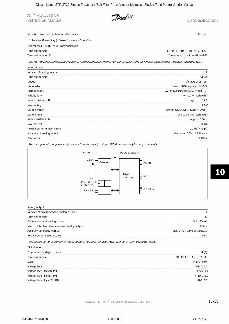
Minimum cross-section to control terminals 0.25 mm2
* See Line Power Supply tables for more information!
Control card, RS-485 serial communication:
Terminal number 68 (P,TX+, RX+), 69 (N,TX-, RX-)
Terminal number 61 Common for terminals 68 and 69
The RS-485 serial communication circuit is functionally seated from other central circuits and galvanically isolated from the supply voltage (PELV).
Analog inputs:
Number of analog inputs 2
Terminal number 53, 54
Modes Voltage or current
Mode select Switch S201 and switch S202
Voltage mode Switch S201/switch S202 = OFF (U)
Voltage level : 0–+10 V (scaleable)
Input resistance, Ri approx. 10 k
Max. voltage ± 20 V
Current mode Switch S201/switch S202 = ON (I)
Current level 0/4 to 20 mA (scaleable)
Input resistance, Ri approx. 200
Max. current 30 mA
Resolution for analog inputs 10 bit (+ sign)
Accuracy of analog inputs Max. error 0.5% of full scale
Bandwidth : 200 Hz
The analog inputs are galvanically isolated from the supply voltage (PELV) and other high-voltage terminals.
Analog output:
Number of programmable analog outputs 1
Terminal number 42
Current range at analog output 0/4 - 20 mA
Max. resistor load to common at analog output 500
Accuracy on analog output Max. error: 0.8% of full scale
Resolution on analog output 8 bit
The analog output is galvanically isolated from the supply voltage (PELV) and other high-voltage terminals.
Digital inputs:
Programmable digital inputs 4 (6)
Terminal number 18, 19, 27 1), 29 1), 32, 33,
Logic PNP or NPN
Voltage level 0–24 V DC
Voltage level, logic'0' PNP < 5 V DC
Voltage level, logic'1' PNP > 10 V DC
Voltage level, logic '0' NPN > 19 V DC
VLT AQUA DriveInstruction Manual 10 Specifications
MG.20.M7.22 - VLT is a registered Danfoss trademark 10-13
10
Gibson Island STP ST32 Sludge Treatment (Belt Filter Press Vendor Manuals - Sludge Feed Pump) Vendor Manual
Q-Pulse Id: VM168 05/06/2013 241 of 253
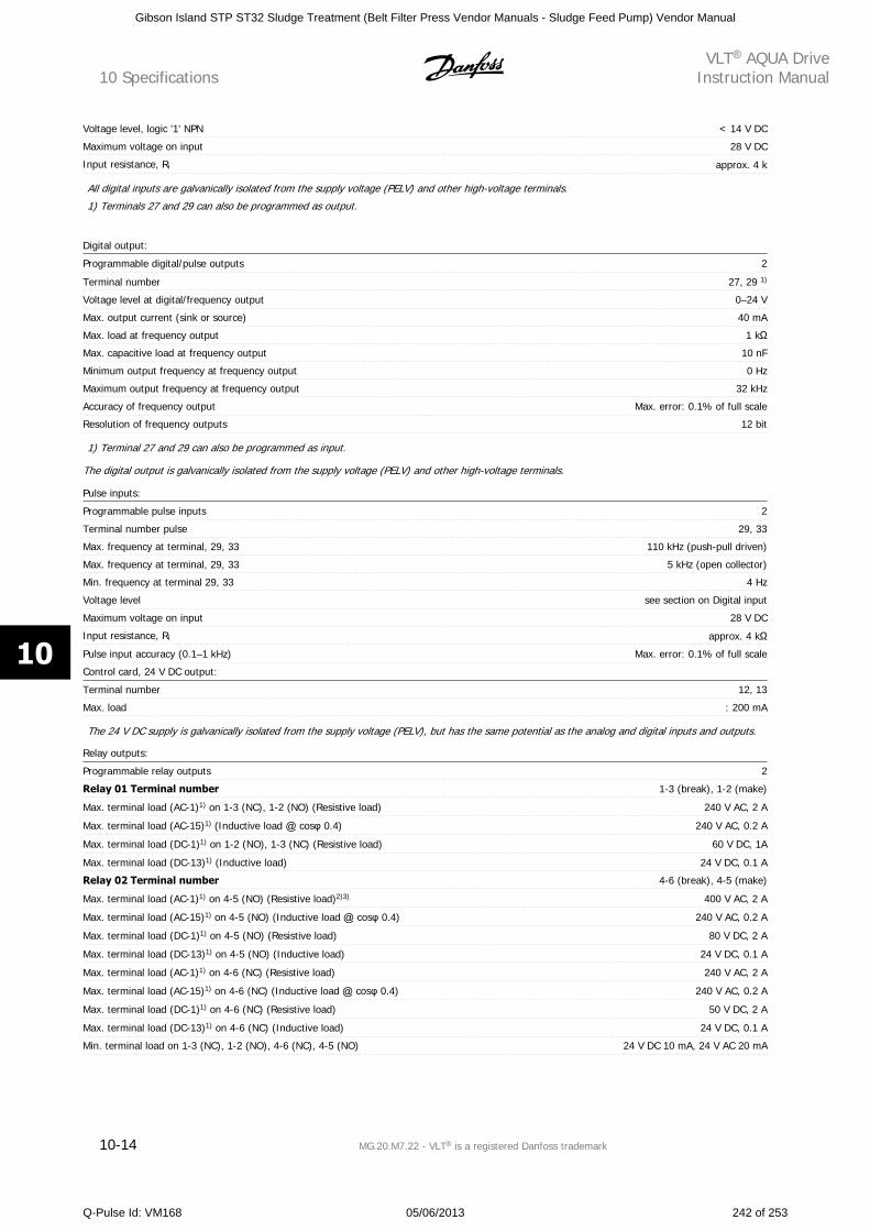
Voltage level, logic '1' NPN < 14 V DC
Maximum voltage on input 28 V DC
Input resistance, Ri approx. 4 k
All digital inputs are galvanically isolated from the supply voltage (PELV) and other high-voltage terminals.
1) Terminals 27 and 29 can also be programmed as output.
Digital output:
Programmable digital/pulse outputs 2
Terminal number 27, 29 1)
Voltage level at digital/frequency output 0–24 V
Max. output current (sink or source) 40 mA
Max. load at frequency output 1 k
Max. capacitive load at frequency output 10 nF
Minimum output frequency at frequency output 0 Hz
Maximum output frequency at frequency output 32 kHz
Accuracy of frequency output Max. error: 0.1% of full scale
Resolution of frequency outputs 12 bit
1) Terminal 27 and 29 can also be programmed as input.
The digital output is galvanically isolated from the supply voltage (PELV) and other high-voltage terminals.
Pulse inputs:
Programmable pulse inputs 2
Terminal number pulse 29, 33
Max. frequency at terminal, 29, 33 110 kHz (push-pull driven)
Max. frequency at terminal, 29, 33 5 kHz (open collector)
Min. frequency at terminal 29, 33 4 Hz
Voltage level see section on Digital input
Maximum voltage on input 28 V DC
Input resistance, Ri approx. 4 k
Pulse input accuracy (0.1–1 kHz) Max. error: 0.1% of full scale
Control card, 24 V DC output:
Terminal number 12, 13
Max. load : 200 mA
The 24 V DC supply is galvanically isolated from the supply voltage (PELV), but has the same potential as the analog and digital inputs and outputs.
Relay outputs:
Programmable relay outputs 2
Relay 01 Terminal number 1-3 (break), 1-2 (make)
Max. terminal load (AC-1)1) on 1-3 (NC), 1-2 (NO) (Resistive load) 240 V AC, 2 A
Max. terminal load (AC-15)1) (Inductive load cos 0.4) 240 V AC, 0.2 A
Max. terminal load (DC-1)1) on 1-2 (NO), 1-3 (NC) (Resistive load) 60 V DC, 1A
Max. terminal load (DC-13)1) (Inductive load) 24 V DC, 0.1 A
Relay 02 Terminal number 4-6 (break), 4-5 (make)
Max. terminal load (AC-1)1) on 4-5 (NO) (Resistive load)2)3) 400 V AC, 2 A
Max. terminal load (AC-15)1) on 4-5 (NO) (Inductive load cos 0.4) 240 V AC, 0.2 A
Max. terminal load (DC-1)1) on 4-5 (NO) (Resistive load) 80 V DC, 2 A
Max. terminal load (DC-13)1) on 4-5 (NO) (Inductive load) 24 V DC, 0.1 A
Max. terminal load (AC-1)1) on 4-6 (NC) (Resistive load) 240 V AC, 2 A
Max. terminal load (AC-15)1) on 4-6 (NC) (Inductive load cos 0.4) 240 V AC, 0.2 A
Max. terminal load (DC-1)1) on 4-6 (NC) (Resistive load) 50 V DC, 2 A
Max. terminal load (DC-13)1) on 4-6 (NC) (Inductive load) 24 V DC, 0.1 A
Min. terminal load on 1-3 (NC), 1-2 (NO), 4-6 (NC), 4-5 (NO) 24 V DC 10 mA, 24 V AC 20 mA
10 SpecificationsVLT AQUA Drive
Instruction Manual
10-14 MG.20.M7.22 - VLT is a registered Danfoss trademark
10
Gibson Island STP ST32 Sludge Treatment (Belt Filter Press Vendor Manuals - Sludge Feed Pump) Vendor Manual
Q-Pulse Id: VM168 05/06/2013 242 of 253
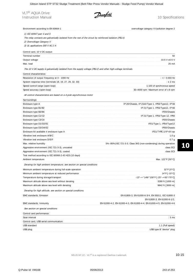
Environment according to EN 60664-1 overvoltage category III/pollution degree 2
1) IEC 60947 part 4 and 5
The relay contacts are galvanically isolated from the rest of the circuit by reinforced isolation (PELV).
2) Overvoltage Category II
3) UL applications 300 V AC 2 A
Control card, 10 V DC output:
Terminal number 50
Output voltage 10.5 V 0.5 V
Max. load 25 mA
The 10 V DC supply is galvanically isolated from the supply voltage (PELV) and other high-voltage terminals.
Control characteristics:
Resolution of output frequency at 0 - 1000 Hz : +/- 0.003 Hz
System response time (terminals 18, 19, 27, 29, 32, 33) : 2 ms
Speed control range (open-loop) 1:100 of synchronous speed
Speed accuracy (open-loop) 30–4000 rpm: Maximum error of ±8 rpm
All control characteristics are based on a 4-pole asynchronous motor
Surroundings:
Enclosure type A IP 20/Chassis, IP 21kit/Type 1, IP55/Type12, IP 66
Enclosure type B1/B2 IP 21/Type 1, IP55/Type12, IP 66
Enclosure type B3/B4 IP20/Chassis
Enclosure type C1/C2 IP 21/Type 1, IP55/Type 12, IP66
Enclosure type C3/C4 IP20/Chassis
Enclosure type D1/D2/E1 IP21/Type 1, IP54/Type12
Enclosure type D3/D4/E2 IP00/Chassis
Enclosure kit available enclosure type A IP21/TYPE 1/IP 4X top
Vibration test enclosure A/B/C 1.0 g
Vibration test enclosure D/E/F 0.7 g
Max. relative humidity 5%–95%(IEC 721-3-3; Class 3K3 (non-condensing) during operation
Aggressive environment (IEC 721-3-3), uncoated class 3C2
Aggressive environment (IEC 721-3-3), coated class 3C3
Test method according to IEC 60068-2-43 H2S (10 days)
Ambient temperature Max. 122°F [50°C]
Derating for high ambient temperature, see section on special conditions
Minimum ambient temperature during full-scale operation 32°F [0°C]
Minimum ambient temperature at reduced performance 14°F [-10°C]
Temperature during storage/transport -13°–+°149/°158°F [-25°–+65°/70°C]
Maximum altitude above sea level without derating 3280 ft [1000 m]
Maximum altitude above sea level with derating 9842 ft [3000 m]
Derating for high altitude, see section on special conditions.
EMC standards, Emission EN 61800-3, EN 61000-6-3/4, EN 55011, IEC 61800-3
EMC standards, Immunity
EN 61800-3, EN 61000-6-1/2,
EN 61000-4-2, EN 61000-4-3, EN 61000-4-4, EN 61000-4-5, EN 61000-4-6
See section on special conditions
Control card performance:
Scan interval : 5 ms
Control card, USB serial communication:
USB standard 1.1 (Full speed)
USB plug USB type B “device” plug
VLT AQUA DriveInstruction Manual 10 Specifications
MG.20.M7.22 - VLT is a registered Danfoss trademark 10-15
10
Gibson Island STP ST32 Sludge Treatment (Belt Filter Press Vendor Manuals - Sludge Feed Pump) Vendor Manual
Q-Pulse Id: VM168 05/06/2013 243 of 253
Connection to PC is carried out via a standard host/device USB cable.
The USB connection is galvanically isolated from the supply voltage (PELV) and other high-voltage terminals.
The USB connection is not galvanically isolated from protection ground. Only use an isolated laptop/PC as the connection to the USB
connector on an VLT AQUA Drive or an isolated USB cable/drive.
10 SpecificationsVLT AQUA Drive
Instruction Manual
10-16 MG.20.M7.22 - VLT is a registered Danfoss trademark
10
Gibson Island STP ST32 Sludge Treatment (Belt Filter Press Vendor Manuals - Sludge Feed Pump) Vendor Manual
Q-Pulse Id: VM168 05/06/2013 244 of 253
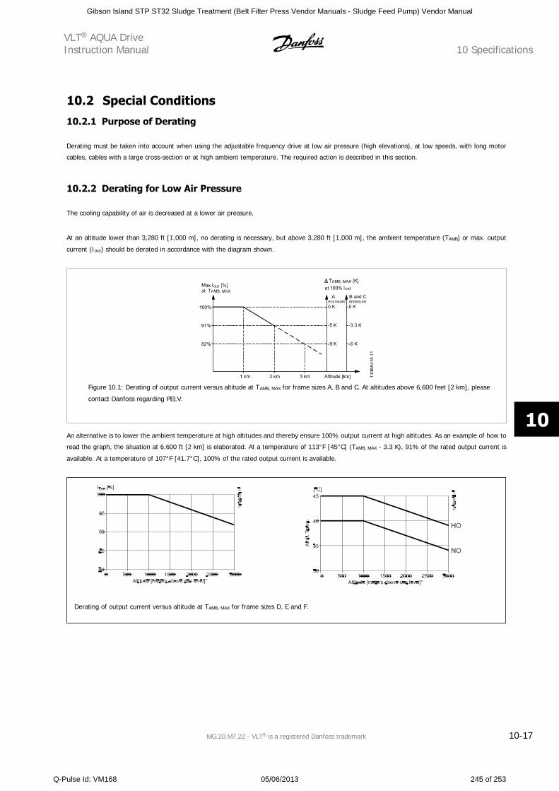
10.2 Special Conditions
10.2.1 Purpose of Derating
Derating must be taken into account when using the adjustable frequency drive at low air pressure (high elevations), at low speeds, with long motor
cables, cables with a large cross-section or at high ambient temperature. The required action is described in this section.
10.2.2 Derating for Low Air Pressure
The cooling capability of air is decreased at a lower air pressure.
At an altitude lower than 3,280 ft [1,000 m], no derating is necessary, but above 3,280 ft [1,000 m], the ambient temperature (TAMB) or max. output
current (Iout) should be derated in accordance with the diagram shown.
Figure 10.1: Derating of output current versus altitude at TAMB, MAX for frame sizes A, B and C. At altitudes above 6,600 feet [2 km], please
contact Danfoss regarding PELV.
An alternative is to lower the ambient temperature at high altitudes and thereby ensure 100% output current at high altitudes. As an example of how to
read the graph, the situation at 6,600 ft [2 km] is elaborated. At a temperature of 113°F [45°C] (TAMB, MAX - 3.3 K), 91% of the rated output current is
available. At a temperature of 107°F [41.7°C], 100% of the rated output current is available.
Derating of output current versus altitude at TAMB, MAX for frame sizes D, E and F.
VLT AQUA DriveInstruction Manual 10 Specifications
MG.20.M7.22 - VLT is a registered Danfoss trademark 10-17
10
Gibson Island STP ST32 Sludge Treatment (Belt Filter Press Vendor Manuals - Sludge Feed Pump) Vendor Manual
Q-Pulse Id: VM168 05/06/2013 245 of 253
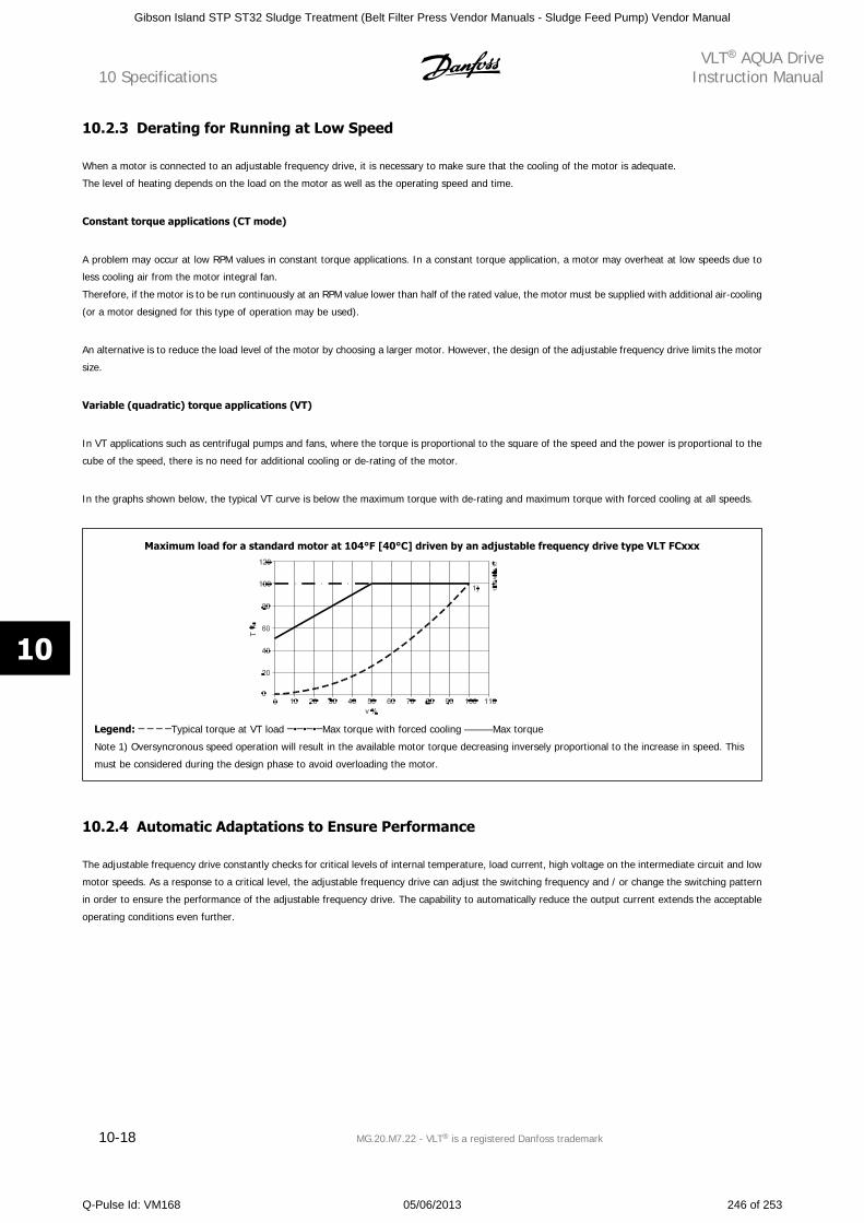
10.2.3 Derating for Running at Low Speed
When a motor is connected to an adjustable frequency drive, it is necessary to make sure that the cooling of the motor is adequate.
The level of heating depends on the load on the motor as well as the operating speed and time.
Constant torque applications (CT mode)
A problem may occur at low RPM values in constant torque applications. In a constant torque application, a motor may overheat at low speeds due to
less cooling air from the motor integral fan.
Therefore, if the motor is to be run continuously at an RPM value lower than half of the rated value, the motor must be supplied with additional air-cooling
(or a motor designed for this type of operation may be used).
An alternative is to reduce the load level of the motor by choosing a larger motor. However, the design of the adjustable frequency drive limits the motor
size.
Variable (quadratic) torque applications (VT)
In VT applications such as centrifugal pumps and fans, where the torque is proportional to the square of the speed and the power is proportional to the
cube of the speed, there is no need for additional cooling or de-rating of the motor.
In the graphs shown below, the typical VT curve is below the maximum torque with de-rating and maximum torque with forced cooling at all speeds.
Maximum load for a standard motor at 104°F [40°C] driven by an adjustable frequency drive type VLT FCxxx
Legend: Typical torque at VT load Max torque with forced cooling Max torque
Note 1) Oversyncronous speed operation will result in the available motor torque decreasing inversely proportional to the increase in speed. This
must be considered during the design phase to avoid overloading the motor.
10.2.4 Automatic Adaptations to Ensure Performance
The adjustable frequency drive constantly checks for critical levels of internal temperature, load current, high voltage on the intermediate circuit and low
motor speeds. As a response to a critical level, the adjustable frequency drive can adjust the switching frequency and / or change the switching pattern
in order to ensure the performance of the adjustable frequency drive. The capability to automatically reduce the output current extends the acceptable
operating conditions even further.
10 SpecificationsVLT AQUA Drive
Instruction Manual
10-18 MG.20.M7.22 - VLT is a registered Danfoss trademark
10
Gibson Island STP ST32 Sludge Treatment (Belt Filter Press Vendor Manuals - Sludge Feed Pump) Vendor Manual
Q-Pulse Id: VM168 05/06/2013 246 of 253
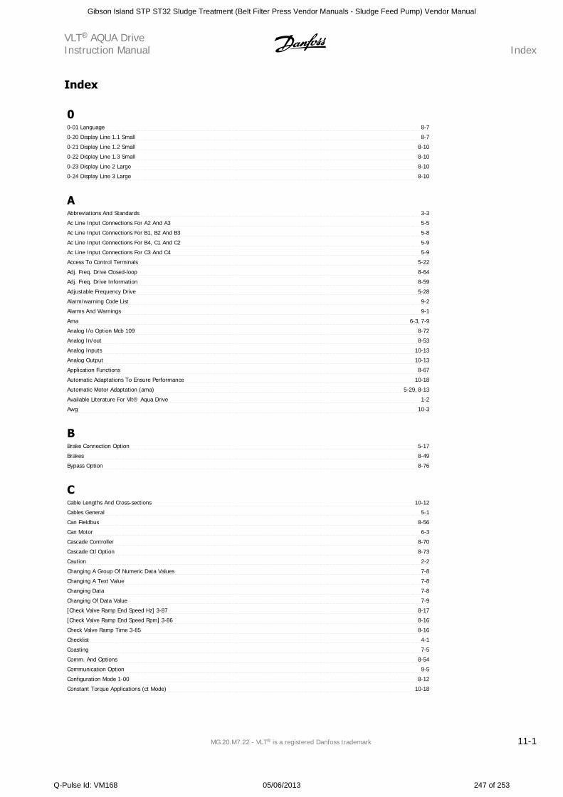
Index
00-01 Language 8-7
0-20 Display Line 1.1 Small 8-7
0-21 Display Line 1.2 Small 8-10
0-22 Display Line 1.3 Small 8-10
0-23 Display Line 2 Large 8-10
0-24 Display Line 3 Large 8-10
AAbbreviations And Standards 3-3
Ac Line Input Connections For A2 And A3 5-5
Ac Line Input Connections For B1, B2 And B3 5-8
Ac Line Input Connections For B4, C1 And C2 5-9
Ac Line Input Connections For C3 And C4 5-9
Access To Control Terminals 5-22
Adj. Freq. Drive Closed-loop 8-64
Adj. Freq. Drive Information 8-59
Adjustable Frequency Drive 5-28
Alarm/warning Code List 9-2
Alarms And Warnings 9-1
Ama 6-3, 7-9
Analog I/o Option Mcb 109 8-72
Analog In/out 8-53
Analog Inputs 10-13
Analog Output 10-13
Application Functions 8-67
Automatic Adaptations To Ensure Performance 10-18
Automatic Motor Adaptation (ama) 5-29, 8-13
Available Literature For Vlt® Aqua Drive 1-2
Awg 10-3
BBrake Connection Option 5-17
Brakes 8-49
Bypass Option 8-76
CCable Lengths And Cross-sections 10-12
Cables General 5-1
Can Fieldbus 8-56
Can Motor 6-3
Cascade Controller 8-70
Cascade Ctl Option 8-73
Caution 2-2
Changing A Group Of Numeric Data Values 7-8
Changing A Text Value 7-8
Changing Data 7-8
Changing Of Data Value 7-9
[Check Valve Ramp End Speed Hz] 3-87 8-17
[Check Valve Ramp End Speed Rpm] 3-86 8-16
Check Valve Ramp Time 3-85 8-16
Checklist 4-1
Coasting 7-5
Comm. And Options 8-54
Communication Option 9-5
Configuration Mode 1-00 8-12
Constant Torque Applications (ct Mode) 10-18
VLT AQUA DriveInstruction Manual Index
MG.20.M7.22 - VLT is a registered Danfoss trademark 11-1
Gibson Island STP ST32 Sludge Treatment (Belt Filter Press Vendor Manuals - Sludge Feed Pump) Vendor Manual
Q-Pulse Id: VM168 05/06/2013 247 of 253
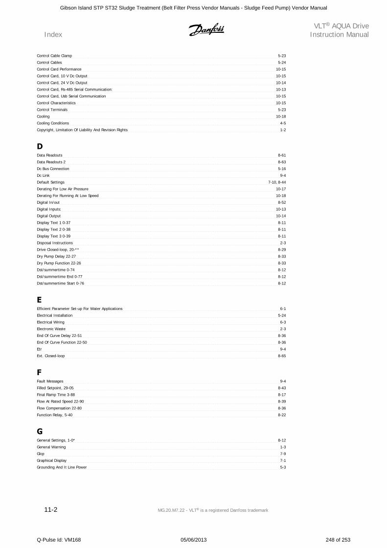
Control Cable Clamp 5-23
Control Cables 5-24
Control Card Performance 10-15
Control Card, 10 V Dc Output 10-15
Control Card, 24 V Dc Output 10-14
Control Card, Rs-485 Serial Communication: 10-13
Control Card, Usb Serial Communication 10-15
Control Characteristics 10-15
Control Terminals 5-23
Cooling 10-18
Cooling Conditions 4-5
Copyright, Limitation Of Liability And Revision Rights 1-2
DData Readouts 8-61
Data Readouts 2 8-63
Dc Bus Connection 5-16
Dc Link 9-4
Default Settings 7-10, 8-44
Derating For Low Air Pressure 10-17
Derating For Running At Low Speed 10-18
Digital In/out 8-52
Digital Inputs: 10-13
Digital Output 10-14
Display Text 1 0-37 8-11
Display Text 2 0-38 8-11
Display Text 3 0-39 8-11
Disposal Instructions 2-3
Drive Closed-loop, 20-** 8-29
Dry Pump Delay 22-27 8-33
Dry Pump Function 22-26 8-33
Dst/summertime 0-74 8-12
Dst/summertime End 0-77 8-12
Dst/summertime Start 0-76 8-12
EEfficient Parameter Set-up For Water Applications 6-1
Electrical Installation 5-24
Electrical Wiring 6-3
Electronic Waste 2-3
End Of Curve Delay 22-51 8-36
End Of Curve Function 22-50 8-36
Etr 9-4
Ext. Closed-loop 8-65
FFault Messages 9-4
Filled Setpoint, 29-05 8-43
Final Ramp Time 3-88 8-17
Flow At Rated Speed 22-90 8-39
Flow Compensation 22-80 8-36
Function Relay, 5-40 8-22
GGeneral Settings, 1-0* 8-12
General Warning 1-3
Glcp 7-9
Graphical Display 7-1
Grounding And It Line Power 5-3
IndexVLT AQUA Drive
Instruction Manual
11-2 MG.20.M7.22 - VLT is a registered Danfoss trademark
Gibson Island STP ST32 Sludge Treatment (Belt Filter Press Vendor Manuals - Sludge Feed Pump) Vendor Manual
Q-Pulse Id: VM168 05/06/2013 248 of 253
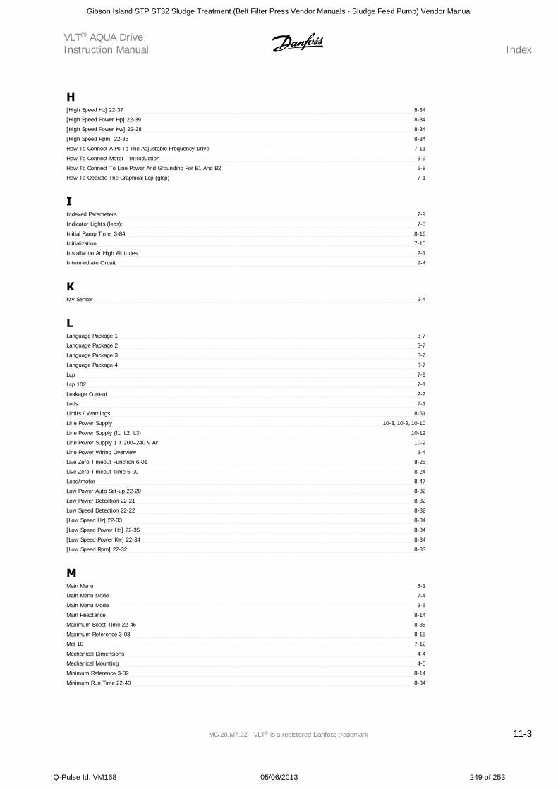
H[High Speed Hz] 22-37 8-34
[High Speed Power Hp] 22-39 8-34
[High Speed Power Kw] 22-38 8-34
[High Speed Rpm] 22-36 8-34
How To Connect A Pc To The Adjustable Frequency Drive 7-11
How To Connect Motor - Introduction 5-9
How To Connect To Line Power And Grounding For B1 And B2 5-8
How To Operate The Graphical Lcp (glcp) 7-1
IIndexed Parameters 7-9
Indicator Lights (leds): 7-3
Initial Ramp Time, 3-84 8-16
Initialization 7-10
Installation At High Altitudes 2-1
Intermediate Circuit 9-4
KKty Sensor 9-4
LLanguage Package 1 8-7
Language Package 2 8-7
Language Package 3 8-7
Language Package 4 8-7
Lcp 7-9
Lcp 102 7-1
Leakage Current 2-2
Leds 7-1
Limits / Warnings 8-51
Line Power Supply 10-3, 10-9, 10-10
Line Power Supply (l1, L2, L3) 10-12
Line Power Supply 1 X 200–240 V Ac 10-2
Line Power Wiring Overview 5-4
Live Zero Timeout Function 6-01 8-25
Live Zero Timeout Time 6-00 8-24
Load/motor 8-47
Low Power Auto Set-up 22-20 8-32
Low Power Detection 22-21 8-32
Low Speed Detection 22-22 8-32
[Low Speed Hz] 22-33 8-34
[Low Speed Power Hp] 22-35 8-34
[Low Speed Power Kw] 22-34 8-34
[Low Speed Rpm] 22-32 8-33
MMain Menu 8-1
Main Menu Mode 7-4
Main Menu Mode 8-5
Main Reactance 8-14
Maximum Boost Time 22-46 8-35
Maximum Reference 3-03 8-15
Mct 10 7-12
Mechanical Dimensions 4-4
Mechanical Mounting 4-5
Minimum Reference 3-02 8-14
Minimum Run Time 22-40 8-34
VLT AQUA DriveInstruction Manual Index
MG.20.M7.22 - VLT is a registered Danfoss trademark 11-3
Gibson Island STP ST32 Sludge Treatment (Belt Filter Press Vendor Manuals - Sludge Feed Pump) Vendor Manual
Q-Pulse Id: VM168 05/06/2013 249 of 253
Minimum Sleep Time 22-41 8-35
Motor Connection For C3 And C4 5-15
Motor Current 1-24 8-13
Motor Frequency 1-23 8-13
Motor Nameplate 5-28
Motor Nominal Speed 1-25 8-13
Motor Output 10-12
[Motor Power Kw] 1-20 8-13
Motor Protection 10-12
[Motor Speed High Limit Rpm] 4-13 8-17
[Motor Speed Low Limit Rpm] 4-11 8-17
Motor Voltage 1-22 8-13
Motor Wiring Overview 5-11
NNameplate Data 5-29
Nameplate Data. 5-28
Nlcp 7-5
No-flow Delay 22-24 8-33
No-flow Function 22-23 8-33
No-flow Power 22-30 8-33
OOccurrence 23-04 8-42
Off Action 23-03 8-41
Off Time 23-02 8-41
On Action 23-01 8-39
On Time 23-00 8-39
Operation/display 8-45
Output Performance (u, V, W) 10-12
PPanel Through Mounting 4-6
Parameter Options 8-44
Parameter Selection 8-6
Parameter Set-up 8-1
Pc Software Tools 7-12
Pid Integral Time 20-94 8-31
Pid Normal/inverse Control, 20-81 8-31
Pid Proportional Gain 20-93 8-31
[Pid Start Speed Rpm] 20-82 8-31
Pipe Fill Enable, 29-00 8-42
Pipe Fill Rate, 29-04 8-43
[Pipe Fill Speed Hz], 29-02 8-43
[Pipe Fill Speed Rpm], 29-01 8-42
Pipe Fill Time, 29-03 8-43
Power Correction Factor 22-31 8-33
Preset Reference 3-10 8-15
Pressure At No-flow Speed 22-87 8-38
Pressure At Rated Speed 22-88 8-38
Profibus 8-55
Profibus Dp-v1 7-12
Protection And Features 10-11
Pulse Inputs 10-14
QQ1 My Personal Menu 8-2
Q2 Quick Set-up 8-2
Q3 Function Set-ups 8-3
Q5 Changes Made 8-4
IndexVLT AQUA Drive
Instruction Manual
11-4 MG.20.M7.22 - VLT is a registered Danfoss trademark
Gibson Island STP ST32 Sludge Treatment (Belt Filter Press Vendor Manuals - Sludge Feed Pump) Vendor Manual
Q-Pulse Id: VM168 05/06/2013 250 of 253
Q6 Loggings 8-5
Quick Menu 6-1, 7-3, 8-1
Quick Menu Mode 7-4
Quick Transfer Of Parameter Settings When Using Glcp 7-9
RRamp 1 Ramp-down Time 3-42 8-15
Ramp 1 Ramp-up Time 3-41 8-15
Reference / Ramps 8-50
Reference/feedback Unit, 20-12 8-29
Relay Connection 5-18
Relay Output 5-21
Relay Outputs 10-14
Reset 7-5
Residual Current Device 2-2
Rs-485 Bus Connection 7-11
SSafety Note 2-1
Safety Requirements For Mechanical Installation 4-6
Serial Communication 10-15
Set Date And Time, 0-70 8-11
Setpoint 1 20-21 8-30
Setpoint Boost 22-45 8-35
Shielded/armored 5-1, 5-25
Side-by-side Installation 4-5
Sine-wave Filter 5-10
Sine-wave Filter 6-3
Smart Logic 8-57
Software Version 1-1
Special Functions 8-58
[Speed At Design Point Hz] 22-86 8-38
[Speed At Design Point Rpm] 22-85 8-38
[Speed At No-flow Hz] 22-84 8-38
[Speed At No-flow Rpm] 22-83 8-38
Square-linear Curve Approximation 22-81 8-36
Start/stop 6-2
Stator Leakage Reactance 8-14
Status 7-3
Status Messages 7-1
Step-by-step 7-9
Submersible Pump 6-3
Surroundings 10-15
Switches S201, S202, And S801 5-28
TTerm. 29 High Ref./feedb. Value 5-53 8-24
Terminal 27 Mode 5-01 8-18
Terminal 42 Output 6-50 8-26
Terminal 42 Output Max Scale 6-52 8-28
Terminal 42 Output Min Scale 6-51 8-27
Terminal 53 High Ref./feedb. Value 6-15 8-26
Terminal 53 High Voltage 6-11 8-25
Terminal 53 Low Ref./feedb. Value 6-14 8-26
Terminal 53 Low Voltage 6-10 8-25
Terminal 54 High Ref./feedb. Value 6-25 8-26
Terminal 54 High Voltage 6-21 8-26
Terminal 54 Low Ref./feedb. Value 6-24 8-26
Terminal 54 Low Voltage 6-20 8-26
Tightening Of Terminals 5-1
Time Format 0-72 8-12
VLT AQUA DriveInstruction Manual Index
MG.20.M7.22 - VLT is a registered Danfoss trademark 11-5
Gibson Island STP ST32 Sludge Treatment (Belt Filter Press Vendor Manuals - Sludge Feed Pump) Vendor Manual
Q-Pulse Id: VM168 05/06/2013 251 of 253
Timed Actions 8-39, 8-69
Torque Characteristics 10-12
Type Code String - Medium Power 3-1
Type Code String (t/c). 3-3
UUnpacking Table 4-1
Usb Connection. 5-23
VVariable (quadratic) Torque Applications (vt) 10-18
Voltage Level 10-13
WWake-up Ref./fb Difference 22-44 8-35
[Wake-up Speed Hz] 22-43 8-35
[Wake-up Speed Rpm] 22-42 8-35
Warning Against Unintended Start 2-1
Water Application Functions 8-75
Water Application Functions, 29-** 8-42
Wiring Example And Testing 5-21
Work Point Calculation 22-82 8-37
IndexVLT AQUA Drive
Instruction Manual
11-6 MG.20.M7.22 - VLT is a registered Danfoss trademark
Gibson Island STP ST32 Sludge Treatment (Belt Filter Press Vendor Manuals - Sludge Feed Pump) Vendor Manual
Q-Pulse Id: VM168 05/06/2013 252 of 253
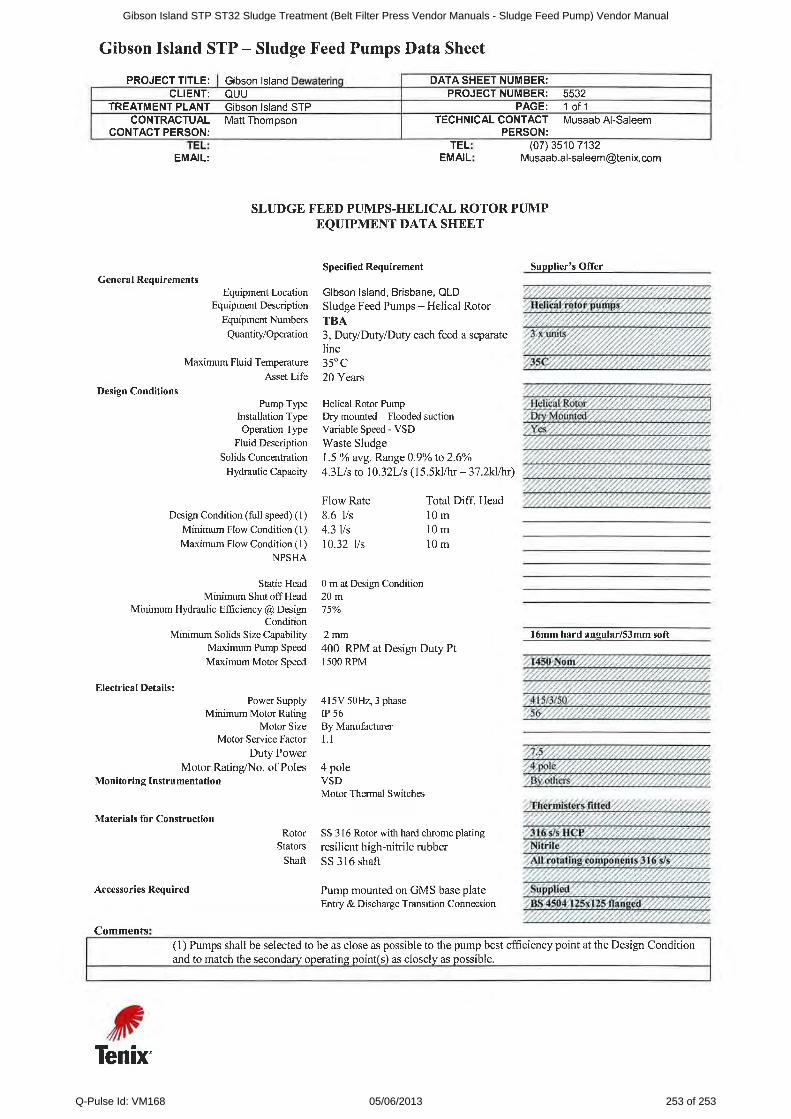
Gibson Island STP ST32 Sludge Treatment (Belt Filter Press Vendor Manuals - Sludge Feed Pump) Vendor Manual
Q-Pulse Id: VM168 05/06/2013 253 of 253


