Embed Size (px)
Citation preview

Accepted Manuscript
Simulation of nitrogen diffusion in Ni vis-à-vis Fe – Identification of betterstructural material for neutron detectors
T.N. Prasanthi, C. Sudha, S. Saroja, M. Vijayalakshmi
PII: S2211-3797(14)00027-8DOI: http://dx.doi.org/10.1016/j.rinp.2014.07.002Reference: RINP 116
To appear in: Results in Physics
Received Date: 15 May 2014Accepted Date: 1 July 2014
Please cite this article as: Prasanthi, T.N., Sudha, C., Saroja, S., Vijayalakshmi, M., Simulation of nitrogen diffusionin Ni vis-à-vis Fe – Identification of better structural material for neutron detectors, Results in Physics (2014), doi:http://dx.doi.org/10.1016/j.rinp.2014.07.002
This is a PDF file of an unedited manuscript that has been accepted for publication. As a service to our customerswe are providing this early version of the manuscript. The manuscript will undergo copyediting, typesetting, andreview of the resulting proof before it is published in its final form. Please note that during the production processerrors may be discovered which could affect the content, and all legal disclaimers that apply to the journal pertain.
1
Simulation of nitrogen diffusion in Ni vis-à-vis Fe – Identification of better
structural material for neutron detectors
T.N. Prasanthi, C. Sudha*, S. Saroja, M. Vijayalakshmi
Physical Metallurgy Group, Metallurgy and Materials Group
Indira Gandhi Centre for Atomic Research, Kalpakkam-603102, Tamilnadu, India
ABSTRACT
Inconel 600, a Ni-based alloy was considered as a possible replacement for austenitic
stainless steels for service at high temperature in nitrogen containing atmosphere of the
neutron detector. To obtain a fundamental understanding of the differences in the diffusivity
of nitrogen in pure Fe and Ni lattices, molecular dynamics simulations were carried out.
Based on the simulation of nitrogen trajectories in the temperature range of 1200-1400 K,
pre-exponential factor, activation energy and jumping frequency were calculated and
compared for fcc Ni and Fe. MD simulations confirmed that rate of diffusion of nitrogen is
lower in Ni when compared to Fe, suggesting the replacement of austenitic steel with Inconel
600 for better performance of the detectors.
Keywords:
Inconel 600, Austenitic stainless steel, Nitrogen diffusion, Molecular dynamics simulations
* Corresponding author. Tel.: 91 44 27480306; fax: 91 44 27480202.
E-mail address: [email protected] (C. Sudha).
2
1. Introduction
Fission chambers with high sensitivity, capable of providing sustained service in hostile
environments like high temperature, neutron and gamma fluxes are designed for both in-core
and out-of-core applications [1]. Structural materials for the electrodes of the neutron detector
(Fig. 1) are chosen such that they satisfy demands from radiological, thermal and mechanical
property considerations [2]. For detectors operating upto 523 K, high purity aluminium was
used as the structural material whereas austenitic stainless steel was preferred for higher
operating temperatures (523-873 K). In addition, if there is liquid sodium environment, 300
series austenitic stainless steels were preferred due to their compatibility with liquid sodium
and high temperature mechanical property [3]. In fission chambers which work on the
principle of ionization detectors, argon was often used as the filling gas due to its chemical
inertness, low thermal neutron cross section and good ionization properties [4]. When ‘fast
response detectors’ (with collection time ≤ 120 ns) were developed argon was replaced with a
mixture of argon + (3-5%) N2 [5,6] which necessitated a reevaluation of the structural
material. At a high operating temperature (>723 K), if austenitic stainless steel is exposed to
the filling gas containing nitrogen there is an increased probability of it getting nitrided
forming Fe and Cr rich nitrides on the exposed surface [7,8]. As a consequence nitrogen used
as the ‘quenching gas’ in the detector is consumed thereby increasing the dead time of the
detector compromising its efficiency as a ‘fast response’ chamber. Hence Inconel 600, a Ni-
based alloy was considered as a possible replacement for stainless steel with the objective of
enhancing the performance of the detector.
Although Inconel 600 with similar (a) crystal structure and (b) concentration of the major
nitride forming element (Cr) [9] as that of austenitic stainless steel may exhibit similar
nitriding behaviour, the difficulty in nitriding Ni could also make it more resistant to
nitriding. This has been established through detailed experimental study of Inconel 600

3
followed by microstructural characterization, nitrogen profile simulation and microstructure
prediction [10,11]. This study established that under the same conditions of nitriding, growth
kinetics of the nitride layer in Inconel 600 is four times slower than in an austenitic stainless
steel. This behaviour was attributed to the differences in the diffusivity of nitrogen in Ni and
Fe based substrates. No direct experimental data is available on nitrogen diffusion in pure Ni
except the work carried out by R. Lappalainen and A. Anttila [12] on nitrogen ion
implantation. Hence, to obtain a fundamental understanding of the diffusion of nitrogen in
pure Fe and Ni lattices detailed work has been carried out to estimate the diffusion
parameters of nitrogen in fcc Fe and Ni based on simulations within the frame work of
molecular dynamics, the results of which are presented in this paper.
Among the various simulation techniques available in literature like the molecular statics
[13], Monte Carlo [14] and first principle based ab-initio calculations [15], molecular
dynamics (MD) was found to be ideal for estimation of transport coefficients and time
dependant response of a system to external perturbations [16,17]. MD simulations have been
also used extensively for studying the interaction of substitutional and interstitial elements in
selected systems [18,19].
MD simulation to study interstitial diffusivity of carbon using various interatomic
potentials is reported in literature [20-23]. Compared to the information available for carbon,
study on nitrogen diffusivity in Fe is scarce. Johnsons et al. [24] studied the transport
properties of carbon and nitrogen atoms in Fe and V considering the similarities in their
behaviour in Fe lattice. Grujicic et al. [25] developed EAM potentials to derive physical
properties for Fe-N system and later used it to analyse the thermally activated movement of
dislocations in Fe-Cr-Ni-C alloys [26]. MEAM potentials are also available for Fe-C and Fe-
N systems [27]. However, to the best of our knowledge MEAM potentials are not available
4
for Ni-N system. Hence, in the present investigation EAM potentials developed by Grujicic et
al. [25,26] for Fe-N and Ni-N systems have been used.
2. Computational Details
In molecular dynamic simulation the time dependent position and velocity coordinates of
atoms are determined by solving Newton’s classical laws of motion and the force acting
between any two atoms is obtained from the interatomic potential as shown below:
( )[ ])()( rUr
rF∂
∂−= (1)
where U(r) is the total potential energy function which can be further split into 1-body, 2-
body and many body interaction terms. In EAM formalism each atom is considered as an
impurity atom embedded in a cloud of other atoms and the mathematical expression for the
total potential energy function is given as
∑ ∑≠
−
+=i ij
ijijiiRFE ])(
2
1)([
)(
φρ (2)
where ( )ij
ii rρρ Σ=
→
is the electron density of an atom j at the position of atom i, )(→
iiF ρ is
the embedding energy function which depends on the electron density distribution at site ‘i’
due to all other neighboring atoms, )( ijij Rφ is the pair potential term between the atoms
separated by a distance Rij and the summation is taken over all the atoms. Depending on the
system under consideration it is essential to select appropriate interatomic potential and
validate it prior to the simulations. In general, validation of the interatomic potentials is
carried out by calculating certain physical properties of the system such as bulk modulus,
cohesive energy, elastic constants and thermal expansion coefficients.
In the present work EAM potentials were validated by calculating the cohesive energy,
bulk modulus and elastic constants. For both fcc Fe and Ni lattices size of the super cell was

5
considered as 10*10*10 consisting of 4000 atoms each. For validation of the potentials, fcc
Fe/Ni –N lattices were equilibrated assuming the number of atoms, volume and pressure to be
a constant (4000 atoms at NPT). Periodic boundary conditions were applied along x, y and z
directions of the unit cell. For fcc Fe and Ni lattices, equilibrium values for lattice constants
were assumed as 3.59 and 3.52 A0
respectively. The lattice constant for Fe and Ni lattices
were varied from 3.58 and 3.51 A0 to 3.60 and 3.53 A
0 respectively in steps of 0.0001 A
0.
Variation in potential energy was monitored as a function of lattice constant for every 50 ps
till the total time of simulation. From the plot of potential energy (E) vs lattice constant (a)
cohesive energy and bulk modulus were estimated using the procedure available in literature
[28]. Following expression was involved in estimating the bulk modulus.
2
22
0
4 a
E
v
aB
∂
∂= (3)
where ‘ 0a ’ and ‘a’ are lattice constants at equilibrium and after dilation respectively. ‘E’
represents the total energy of the atom and ‘v’ is the volume per atom. Cohesive energy, the
minimum energy or the energy per atom at equilibrium separation was obtained as 4.95 and
5.24 eV for Fe and Ni lattices respectively. Bulk modulus was calculated as 0.8 and 1.12 eV/
A03
for Fe and Ni lattices respectively. Elastic constants were obtained by applying strain on
the lattices in x, y and z directions of the unit cell. Relative change in the length of the unit
cell in comparison to equilibrium values was a measure of the elastic constants.
Table 1 is a comparison of the calculated and reported [25,26] values for cohesive energy,
bulk modulus and elastic constants. Compared to the values reported by Grujicic et al.
[25,26], ∼24% error was observed for Fe-N system and ∼27% error for Ni-N system. Even
though the authors have used the same EAM potential parameters as that of Grujicic et al.
discrepancy in the estimated properties of the materials could be probably due to difference in
the actual procedure adopted for MD simulations. For further validation, eqn. 4 was used to
6
calculate bulk modulus from the elastic constants and compare with the value obtained using
the simulations. Elastic constants and bulk modulus are related as:
3
)*2( 1211 CCB
+= (4)
where C11 and C12 are the elastic constants. Values of bulk modulus calculated using eqn. 4
were 0.706 and 1.06 eV/A03
for Fe and Ni lattices respectively which varied by <10% from
the values obtained from the simulation. Thus in the present study EAM potentials of
Grujicic et al. [25,26] were used and the system was equilibrated in a canonical (NPT)
ensemble followed by NVE integration of the atoms to ensure conservation of the system.
A typical MD system consists of 103 to 10
5 atoms for a time step of few tens of nano
seconds (ns). Considering the extremely limited solubility of nitrogen in Ni (0.0012 wt% at
1823 K under 1 bar of nitrogen partial pressure) [9] only a dilute system of one nitrogen atom
in 4000 Ni or Fe atoms was considered for the actual simulations. In both the lattices
preferred site occupancy for nitrogen atoms was considered as interstitial octahedral sites to
minimize the free energy of the system. Initial coordinate of the nitrogen atom was assumed
as one of the octahedral position in the lattice at (1/4,3/4, 3/4). Total time of simulation was
fixed as 4 ns at an interval of 1E-7 s. After equilibrating the system using CLAMP method,
velocities were assigned to each atom at a specified temperature. Further, a canonical
ensemble (NPT) was considered at a specified temperature at an interval of 100 K and at a
time step of 0.0001 fs. This method eliminated any deviation in the lattice constants due to
the diffusion of the atoms. Finally MD simulations were carried out using a microcanonical
ensemble in which a constant NVE integration was done in order to maintain the N atom
trajectory consistent with constant number of atoms and simulation super cell. Periodic
boundary conditions were applied to the simulation box so that whenever an atom leaves the
box, vacancy created is filled by another atom from the preceding cell and the total number of

7
atoms in the super cell is maintained constant. Diffusion process was initiated by giving
initial velocities according to Maxwell distribution at a particular temperature and force
calculations were applied to the imaginary simulation box or super cell. MD simulations were
carried out on XMD platform at various temperatures in the range of 1200 to 1400 K with an
interval of 50 K.
For solving the force integral equations finite difference method was used. Out of various
logical algorithms available for this purpose Velocity Verlet algorithm was used to calculate
the atomic positions from the previous and current time steps. Simulations were carried out
until the system reached equilibrium state at zero pressure. Chosen time of simulation was
found to be long enough to obtain a linear dependence of mean square displacement with
time. Atomic trajectories were traced from the time of evolution of atomic positions and
velocity coordinates. Using these trajectories transport properties such as diffusion
coefficients and activation energies were estimated as described in the subsequent sections.
3. Results and Discussion
Fig. 2(a and b) show the nitrogen trajectories in fcc Fe and Ni lattices respectively at a
temperature of 1200 K. At any given temperature nitrogen atom was observed to travel over
larger lattice spacings in Fe as compared to that in Ni. At each temperature the mean square
displacement (MSD) was calculated from the total diffusing distance using the following Eq.
(5) [28]
∑=
=><N
i
iRN
tR1
22 1)( (5)
where N is the total number of atoms considered for simulation. Plot of MSD vs time of
simulation for Fe-N and Ni-N systems are given as Fig. 3(a and b) respectively.
From the MSD obtained at each temperature, the diffusion coefficient for nitrogen ‘DN’
was calculated using the following Eq. (6)
8
t
RDN
6
2 ><= (6)
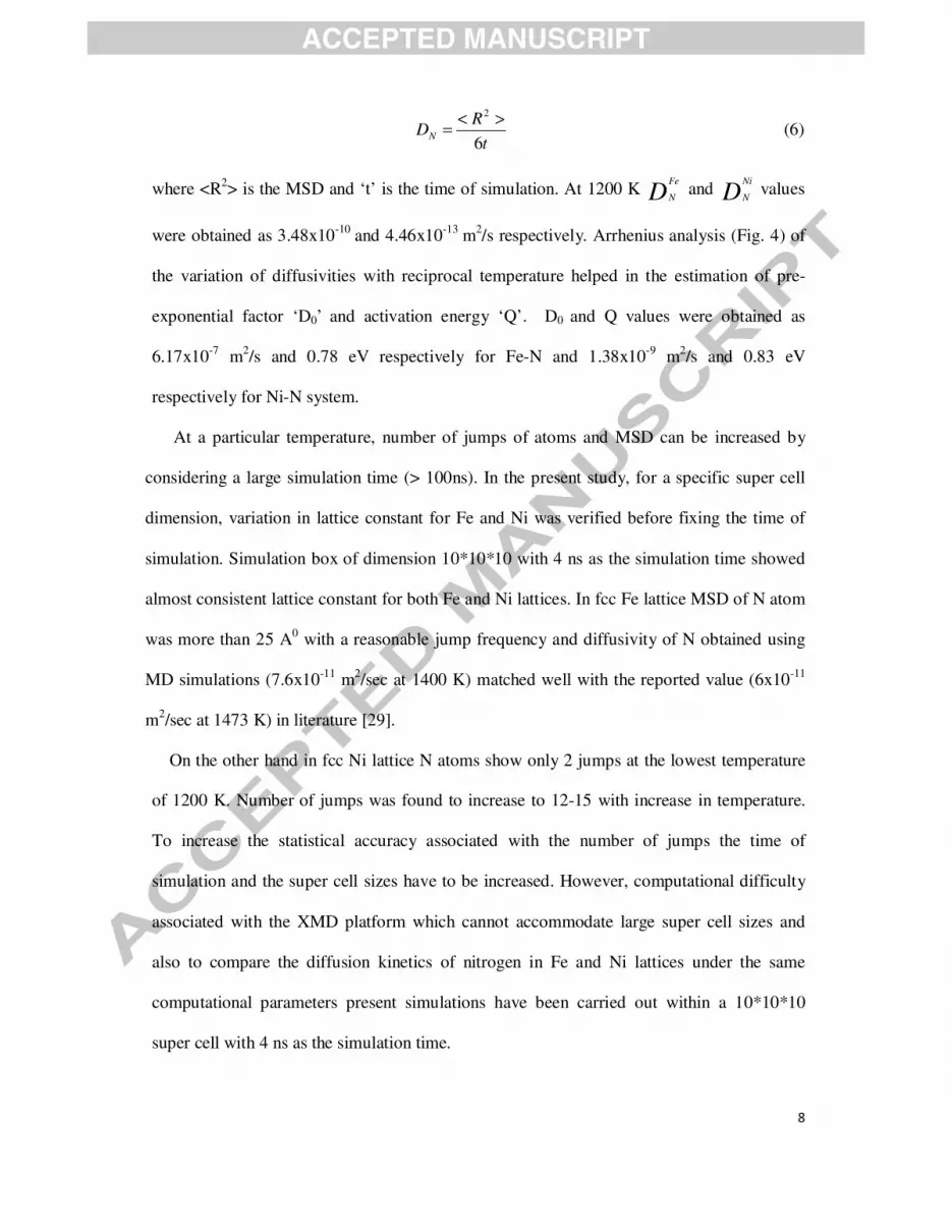
where <R2> is the MSD and ‘t’ is the time of simulation. At 1200 K D
Fe
N and D
Ni
N values
were obtained as 3.48x10⁻¹⁰
and 4.46x10⁻¹³
m2/s respectively. Arrhenius analysis (Fig. 4) of
the variation of diffusivities with reciprocal temperature helped in the estimation of pre-
exponential factor ‘D0’ and activation energy ‘Q’. D0 and Q values were obtained as
6.17x10⁻⁷
m2/s and 0.78 eV respectively for Fe-N and 1.38x10
-9 m
2/s and 0.83 eV
respectively for Ni-N system.
At a particular temperature, number of jumps of atoms and MSD can be increased by
considering a large simulation time (> 100ns). In the present study, for a specific super cell
dimension, variation in lattice constant for Fe and Ni was verified before fixing the time of
simulation. Simulation box of dimension 10*10*10 with 4 ns as the simulation time showed
almost consistent lattice constant for both Fe and Ni lattices. In fcc Fe lattice MSD of N atom
was more than 25 A0 with a reasonable jump frequency and diffusivity of N obtained using
MD simulations (7.6x10⁻¹¹
m2/sec at 1400 K) matched well with the reported value (6x10
-11
m2/sec at 1473 K) in literature [29].
On the other hand in fcc Ni lattice N atoms show only 2 jumps at the lowest temperature
of 1200 K. Number of jumps was found to increase to 12-15 with increase in temperature.
To increase the statistical accuracy associated with the number of jumps the time of
simulation and the super cell sizes have to be increased. However, computational difficulty
associated with the XMD platform which cannot accommodate large super cell sizes and
also to compare the diffusion kinetics of nitrogen in Fe and Ni lattices under the same
computational parameters present simulations have been carried out within a 10*10*10
super cell with 4 ns as the simulation time.
9
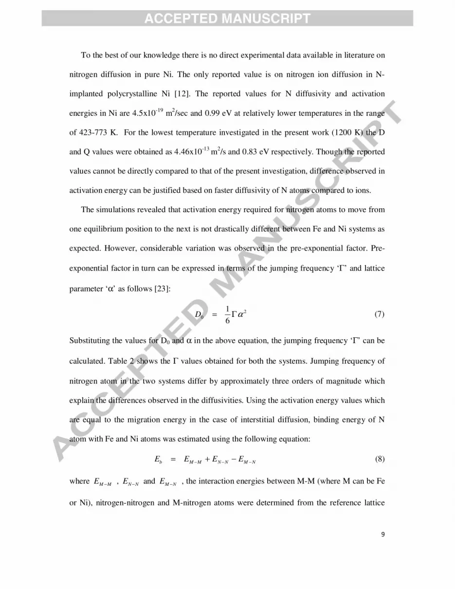
To the best of our knowledge there is no direct experimental data available in literature on
nitrogen diffusion in pure Ni. The only reported value is on nitrogen ion diffusion in N-
implanted polycrystalline Ni [12]. The reported values for N diffusivity and activation
energies in Ni are 4.5x10⁻¹⁹
m2/sec and 0.99 eV at relatively lower temperatures in the range
of 423-773 K. For the lowest temperature investigated in the present work (1200 K) the D
and Q values were obtained as 4.46x10⁻¹³
m2/s and 0.83 eV respectively. Though the reported
values cannot be directly compared to that of the present investigation, difference observed in
activation energy can be justified based on faster diffusivity of N atoms compared to ions.
The simulations revealed that activation energy required for nitrogen atoms to move from
one equilibrium position to the next is not drastically different between Fe and Ni systems as
expected. However, considerable variation was observed in the pre-exponential factor. Pre-
exponential factor in turn can be expressed in terms of the jumping frequency ‘Γ’ and lattice
parameter ‘α’ as follows [23]:
2
06
1αΓ=D (7)
Substituting the values for D0 and α in the above equation, the jumping frequency ‘Γ’ can be
calculated. Table 2 shows the Γ values obtained for both the systems. Jumping frequency of
nitrogen atom in the two systems differ by approximately three orders of magnitude which
explain the differences observed in the diffusivities. Using the activation energy values which
are equal to the migration energy in the case of interstitial diffusion, binding energy of N
atom with Fe and Ni atoms was estimated using the following equation:
NMNNMMb EEEE −−− −+= (8)
where MME − , NNE − and NME − , the interaction energies between M-M (where M can be Fe
or Ni), nitrogen-nitrogen and M-nitrogen atoms were determined from the reference lattice

10
structures and substituted back into Eq. (8) to obtain Eb. The values were obtained as 0.34
and 0.47 eV for Fe-N and Ni-N respectively.
Information available in literature [29-31] is with respect to study of nitrogen diffusion
based on growth kinetics of the nitrided layers in Ni-based alloys of varying composition.
Wide variation observed in the diffusivity and activation energy values for nitrogen in these
alloys were justified based on the differences in the (a) concentration of nitride forming
elements (like Cr and Fe) and (b) experimental conditions used for nitriding. In this context
present work enabled direct comparison of nitrogen diffusivities in pure Fe and Ni lattices.
4. Conclusion
MD simulations revealed sluggish diffusivity for nitrogen in Ni when compared to that in
Fe confirming that Ni-based alloys are better structural materials than austenitic stainless
steels for nitrogen containing atmospheres as in fission chambers.
Acknowledgements
The authors thank Dr. P.R. Vasudeva Rao, Director IGCAR and Dr. T. Jayakumar, Director,
MMG for their encouragement and support throughout the period of this project. The authors
also thank Dr. R. Anand, M/s Sandvik Asia, Pune for helping in understanding MD
simulations.

11
References
1. J.P. Trapp, E. Bacconnet, T. Domenech in: High temperature and sensitivity fission
chambers for LMFBRs neutronic control, NEACRP Specialists meeting on in core
instrumentation and reactor core assessment, Pittsburg, USA. October 1991
2. J.F. Mech, Nuclear Power Reactor Instrumentation Systems handbook, Vol. 1, (ed) J.M.
Harrer and J.G. Beckerley, NTIS, Springfield 1974
3. L.C. Wimpee in: State of the art review for LMFBR source range fission counter, Report
No. GEAP-10611, U.S. Atomic Energy Commission, 1972
4. K.R. Prasad, S.P. Chaganty, V. Balagi, E. Unnikrishnan, K. Venkateswara Rao, Nuclear
Instruments and Methods in Physics Research Section A 418 (1998) 420
5. Product specification of neutron detector – CFUC06 of M/s Photonis.
http://www.photonis.com/en/pdf_download/cfuc06.pdf
6. Product specification of neutron detector – CFUC07 of M/s Photonis.
http://www.photonis.com/en/pdf_download/cfuc07.pdf
7. D. Sundararaman, P. Kuppusami, V.S. Raghunathan, Surface and Coatings Technology
30 (1987) 343.
8. M.F. Chung, Y.K. Lim, Scripta Metallurgica 20 (1986) 807
9. C. Kowanda, M.O. Speidel, Scripta Materialia 48 (2003) 1073
10. C. Sudha Study of mass transport across microstructural and microchemical gradients in
Fe, Ni and Ti based alloys, Ph.D. Thesis, University of Madras (2012) 67.
11. C. Sudha, R. Anand, V. Thomas Paul, S. Saroja, M. Vijayalakshmi, Surface and Coatings
Technology 226 (2013) 92.
12. R. Lappalainen, A. Anttila, Applied Physics A 42 (1987) 263.
13. Yu.N. Osetsky, Defects and Diffusion Forum 188-190 (2001) 71
12
14. C. Domain, C.S. Becquart, J. Foct, Physical Review B 69 (2004) 144112.
15. D.E. Jiang, Emily A. Carter, Physical Review B 67 (2003) 214103.
16. K. Tapasa, A.V. Barashev, D.J. Bacon, Yu.N. Osetsky, Acta Materialia 55 (2007) 1.
17. C.S. Becquart, J.M. Raulot, G. Bencteux, C. Domain, M. Perez, S. Garruchet, H. Nguyen,
Computational Material Science 40 (2007) 119.
18. E.V. Levchenko, A.V. Evteev, I.V. Belova, G.E. Murch, Acta Materialia 57 (2009) 846.
19. M.S. Daw, M.I. Baskes, Physical Review B 29 (1984) 6443.
20. Q. Jiansheng, L. Yongli, H. Yina, X. Xin, W. Farong, Nuclear Instruments and Methods
in Physics Research Section B 267 (2009) 3179.
21. M. Ruda, D. Farkas, G. Garcia, Computational Material Science 45 (2009) 550.
22. B.J. Lee, W.S. Ko, H.K. Kim, E.Ha. Kim, CALPHAD 34 (2010) 510.
23. H.K. Kim, W.S. Jung, B.J. Lee, Acta Materialia 57 (2009) 3140.
24. R.A. Johnson, G.J. Dienes, C. Damask, Acta Metallurgica 12 (1964) 1215.
25. M. Grujicic, Materials Science and Engineering A 177 (1994) 233.
26. M. Grujicic, X.W. Zhou, Materials Science and Engineering A 190 (1995) 87.
27. B.J. Lee, T.H. Lee, S.J. Kim, Acta Materialia 54 (2006) 4597.
28. W. Cia, J. Li, S. Yip, Molecular Dynamics. In: Konings R.J.M (ed.), Comprehensive
Nuclear Materials, Vol. 1, Amsterdam 2012.
29. D.L. Williamson, O. Ozturk, R. Wei, P.J. Wilbur, Surface and Coatings Technology 65
(1994) 15.
30. A.A. Kodentsov, M.J.H. Van Dal, C. Cserhati, L. Daroczi, F.J.J. Van Loo, Acta
Materialia 47(11) (1999) 3169.
31. Y. Sun, Journal of Alloys and Compounds 351 (2003) 241.

13
Figures
Fig. 1. Schematic of the fission chamber
Fig. 2. Trajectory of nitrogen atom in (a) fcc Fe and (b) fcc Ni at a temperature of 1200 K
a b

14
Fig. 3. Mean square displacement (MSD) vs time of simulation for (a) Fe-N and (b) Ni-N
systems
1.0 1.5 2.0 2.5 3.0 3.5 4.0
0
5
10
15
20
25
1200K 1250K 1300K 1350K 1400KM
SD
(A
0)2
Time (ns)
1.0 1.5 2.0 2.5 3.0 3.5 4.0
0.5
1.0
1.5
2.0
2.5
3.0
3.5
4.0
1200K 1250K 1300K 1350K 1400K
MS
D (
A0)2
Time (ns)
a b

15
Fig. 4.Variation of ln ND vs 1/T for Ni-N and Fe-N systems
0.70 0.72 0.74 0.76 0.78 0.80 0.82 0.84
-32
-28
-24
-20
ln(D
N)
1/T*103(K
-1)
Fe-N
Ni-N

16
Table 1
Comparison of calculated and reported [25,26] physical properties using EAM potentials
Table 2
Comparison of pre exponential factor and jumping frequency ‘Γ’ of nitrogen atoms
System Cohesive Energy
(eV)
Elastic constants
C11 C12
Bulk Modulus
(eV/0
A3)
Present
Study
Reported Present
study
Reported Present
study
Reported Present
study
Reported
Fe-N 4.95 3.989 0.99 0.883 0.564 0.627 0.8 0.713
Ni-N 5.24 4.124 1.46 1.541 0.856 0.921 1.12 1.128
System D0 (m2/s) Γ (/s)
Fe-N 6.17E-07 3.14E-07
Ni-N 2.28E-09 1.60E-10
17
Figure Captions:
Fig. 1. Schematic of the fission chamber
Fig. 2(a). Trajectory of nitrogen atom in fcc Fe lattice at a temperature of 1200K
Fig. 2(b). Trajectory of nitrogen atom in fcc Ni lattice at a temperature of 1200K
Fig. 3(a). Mean square displacement (MSD) vs time of simulation for Fe-N system
Fig. 3(b). Mean square displacement (MSD) vs time of simulation for Ni-N system
Fig. 4. Variation of ln ND vs 1/T for Ni-N and Fe-N systems


