Embed Size (px)
Citation preview

SIMULATION OF HELICOPTER VIBRATIONS BY SIMULINK DYNAMIC MODEL OF FULLY ARTICULATED ROTOR
Shevtsov, S.N.1, Oganesyan, P.A.1, Zhilyaev, I.V.1, Wu, P.-C.2, Cheng, V.-T.2, Chang, S.-H.2
1South Center of Russian Academy, 2National Kaohsiung Marine University 1Tchekhov str., 41, Rostov on Don, Russia, 2No.142, Haijhuan Rd., Nanzi Dist., Kaohsiung, Taiwan R.O.C.
[email protected] SUMMARY: The modern aircraft must meet the strong requirements to limits for emitted noise caused by intensive structural vibrations. The helicopter vibrations are mainly excited by periodic forces generated by the main rotor and transferred through the rotor head and the gearbox into the fuselage. Most intensive vibrations are generated at forward flight. So, the development of the means for the helicopters vibration control is very attractive area of scientific and engineering efforts. The recent tendency in aircraft design is the virtual testing of structures to diminish the full-scale testing cost, and total investigation time. The mandatory part of such virtual testing of the helicopter is a dynamic model of the rotor. This model should represent the actual physical rotor behavior as accurately as possible when subjected to a wide range of operating conditions scenarios. The purpose of the presented model is the testing and development of methods for the identification of the helicopter rotor dynamic state on the different modes of flight with the possible ability to control the vibrations levels, the forces and moments in arbitrary points of the structure. The model was developed for the full scale five-bladed fully articulated rotor, where each blade is considered as the solid body, and runs in the Simulink / SimMechanics / MATLAB environment with normal and high-speed simulation. The model takes into account geometrical dimensions, mass and inertia tensor of blades, hub, brackets, housings of the feathering hinge, calculated from the CAD model; the presence and orientation of flapping, lead-lag and feathering hinges. The presented simulation results show that the helicopter rotor dynamic model describes correctly all principal phenomena which arise at the helicopter hover and forward flight, and how the conventional rotor control affect on the vibration forces and torques in the different points of the helicopter structure. KEYWORDS: Helicopter rotor vibrations, Dynamics modeling, Vibration control 1. INTRODUCTION The modern helicopters have made a significant progress in performance, reliability, handling qualities, and efficiency, but still have the drawbacks as noise and high vibrations generated by the main rotor due to blade vortex interaction (BVI), high Mach numbers at the advancing blade, etc. Due to these troubles the field of active control of helicopter rotor blades has raised a consequent interest in the last 30 years, and most attempts to solve the problem of noise and vibrations reduction associated with active control of the rotor blades. The first theoretical studies for the rotor vibration reduction have been implemented by higher harmonic control (HHC) which is based on actuators located below the swashplate, to enforcing oscillations of fixed frame with frequencies bNkk ..1, , where is the rotor angular frequency, and bN is the total number of blades [1, 2]. The other solution than HHC is Individual Blade Control (IBC), which is based on actuators in the rotating frame, where actuators change the aerodynamic properties of each blade in the real time [3-5]. The typical control loop includes an accelerometer sensing the vibration level on a rotated or fixed frame, controller’s gain and integrator, then block summing a pitch command with controller’s signal, and, finally, a blade pitch actuator which changes the pitch angle of the blade. The aerodynamic properties of the blades can be changed in real time not only by the pitch angle, but also by the small active flaps placed on the blade and actuated using smart
materials. The effectiveness of the active flap control on noise and vibration as well as on the control power, rotor smoothing, and performance was conclusively demonstrated [4, 5]. Automatic active flap control complements the generic helicopter control means such as rotor rotation frequency, collective, longitudinal and lateral pitch control, which are operated by the pilot. Different concepts and architectures for the active rotor control have been investigated and tested. These are traditional proportional-integral-derivative (PID) controllers [6-9], PID controllers with adaptively modified positive position feedback [10], PID controllers with varied actuator delay [11], PID controllers designed on the basis H∞ criterion [12, 13]. An integrated part of the automatic controller, or a necessary tool to configure it, is a dynamic model of the rotor. These models can be discrete with small number of degree of freedom [6, 7] or distributed finite element (FE) models [8-10, 12], where the rotor blade is considered as a beam with bending and torsional compliance. Due to complexity of the full rotor dynamics the task of the controller synthesis is usually simplified by linearization, “decoupling” of some degree of freedom, or by other reduction techniques [6, 7]. For example, in the paper [7] the helicopter rotor is represented by a simple linear quasi-static frequency-domain model, relating the response vector Z (harmonics) to the multicylic pitch vector (harmonics) through a transfer functionT . The response vector consists of sine and cosine components of stress and the vibration level, in either the rotating or the fixed frame. The transfer function and uncontrolled response depend on the forward speed, rotor lift, and propulsive force. The helicopter rotor multicyclic characteristics are identified, using a succession of input and output measurements and a least-squared-error method. In modern works (see e.g. [14]) the virtual testing of aircraft structures are developed to diminishes the full-scale testing cost, and total investigation time. Virtual testing is the simulation of structure using advanced methods of dynamic analysis. It will involve the combination of analysis software, methods, people skills and experience to predict the actual aircraft structural strength, noise and vibration intensity with a high level of confidence. This is achieved through the creation and execution of a detailed dynamic model of an aircraft structure, which represents the actual physical behaviour accurately as possible when subjected to a wide range of operating conditions scenarios. New tools proposed by MATLAB for the dynamic systems design and simulation allow to construct a much more complete model of the plant, providing visibility, and traceability of the process parameters (forces, moments, linear and angular displacement, velocities, accelerations, power, etc.) over simulation time in arbitrary points in the system, as well as a convenient means of increasing the number of properties and components. Full compatibility of such software with the identification, optimization algorithms and many other toolboxes can effectively solve the problem of control synthesis before manufacturing of real world devices [14]. The purpose of approach and simulation model presented below is the testing and development of methods for the identification of the helicopter rotor dynamic state on the different modes of flight with the ability to control the vibrations levels, the forces and moments at various points of the structure at changes the parameters of the command signals supplied to the cyclic blades pitch. The model was developed for the five-bladed fully articulated rotor, where each blade is considered as the solid body, and runs in the Simulink / SimMechanics / MATLAB environment with normal and high-speed simulation (after compiling the model). In fact, the model simulates a whirl tower setup with full scale main rotor tested in wind tunnel. We present some results of numerical simulation of the proposed model at the different “wind tunnel testing modes”, next compare them to the experimental data and known phenomena. 2. DYNAMIC MODEL OF FULLY ARTICULATED HELICOPTER ROTOR: REQUIREMENTS AND LIMITATIONS Contrary to the many analytical [1, 15, 16] and numerical [6, 17] helicopter rotor dynamic models the proposed model does not requires the very limiting assumptions. In order to be useful to the controller synthesis for real-world active rotor its dynamic model should take into account: - Geometrical dimensions, mass and inertia tensor of all 5bN blades, hub, brackets, housings of the feathering hinge, calculated from the CAD model; - The presence and orientation of flapping, lead-lag and feathering hinges; - A range of rotor revolution speed Ω - up to 4.32 rad/sec; - The ability to change independently the collective θ0, and cyclic, both longitudinal θ1s and lateral θ1c blade pitch during the simulation with a restriction on the range of the pitch angle θ (simulated swashplate): 1.0 – 14.5 deg; - Range of the blades movement ζ around the axis of lead-lag hinge in its plane of rotation is -11 deg (back) ...+13 deg (forth); - The presence of the blades overhangs constraints and drag dampers withstanding to the blade turns about lead-lag hinges;
- The pitch-flap coupling pK , which change the pitch angles according to pK (positive for flap up,
pitch down); - Take-off weight of helicopter W is about 10 ton; - In order to simulate a forward flight a possibility of changing the air speed V in the range 0 ... 250 km / h at time of the simulation process (approximately through the vector sum of the peripheral speed r of the blade and the projection of the flow velocity sinV in the direction of motion of the blade points) sinVrU ,
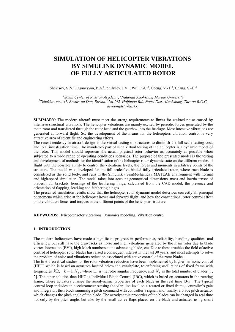
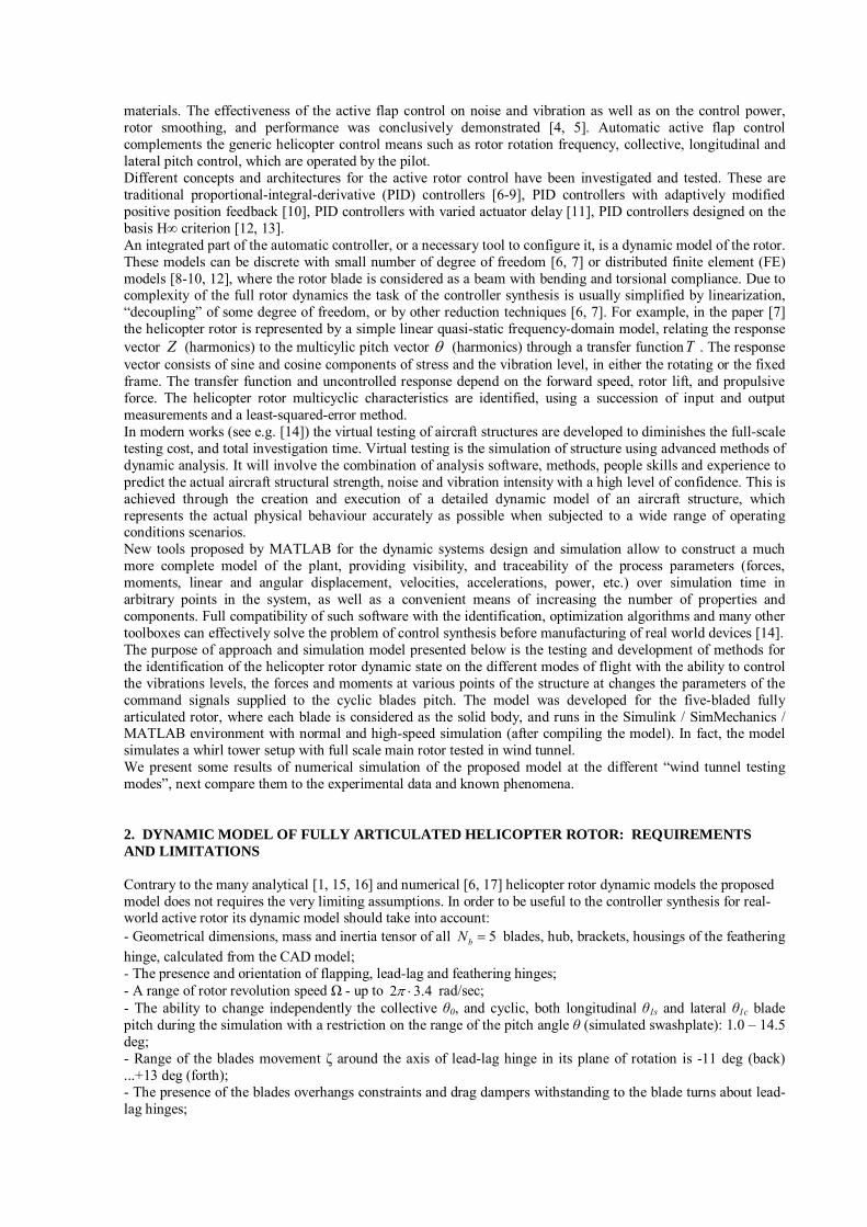
where is the blade azimuth position, and r is the blade element distance from the rotor axis; - The model is three-dimensional; air flow is homogeneous, arbitrarily directed with time dependent intensity; - All forces of mechanical nature, acting on the rotor structural elements, including gravity, centrifugal and Coriolis forces, reaction in the adjoints, torques are automatically calculated due to abilities of SimMechanics Toolbox solver for the stiff dynamic systems; - Precision of the blades set balancing, that can be broken by a small changing of some components of the inertia tensors, mass or location of the centers of gravity; - The possibility of introducing the desired harmonics in the pitch angle or in the aerodynamic properties of each blade; - The model should allow saving a video motion of the rotor structures and all diagrams of the time histories. These requirements can be satisfied automatically by the model that was correctly built in the SimMechanics MATLAB environment. All dimensions, mass and inertial properties for the structural elements were adopted for the prototype five-bladed helicopter. In fact, the constructed model simulates the helicopter wind tunnel testing. Geometry of the helicopter rotor model and enlarged view of the hub are showed on the Figs. 1 - 2.
Figure 1 – The general view of the five-bladed fully articulated helicopter rotor
a) b)
Figure 2 – The schematic [1] (a) and enlarged 3D model’s (b) views on the hub equipped by the flapping, vertical and feathering hinges. Position of the parts corresponds to the rotor acceleration – blades are slightly turned in the vertical hinges
The control input at a presence of the pitch – flap coupling consist of just the mean and first harmonics
01010 sincos scpK , (1)
where is the blade azimuthal position and 0 is the advance angle control. The mean angle 0 is the
collective pitch, and the 1/rev harmonics sc 11 , are the cyclic pitch angles formed by the tilting of the
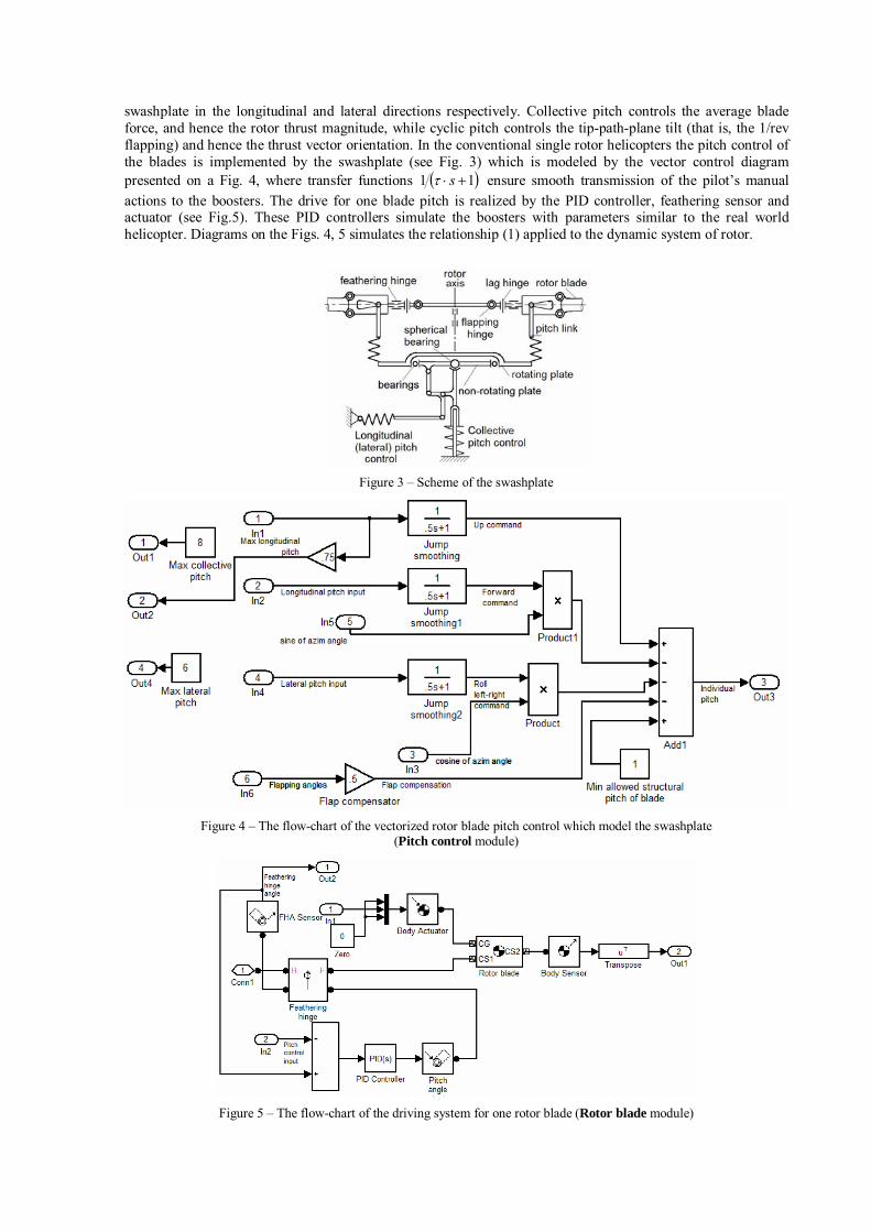
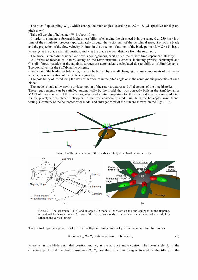
swashplate in the longitudinal and lateral directions respectively. Collective pitch controls the average blade force, and hence the rotor thrust magnitude, while cyclic pitch controls the tip-path-plane tilt (that is, the 1/rev flapping) and hence the thrust vector orientation. In the conventional single rotor helicopters the pitch control of the blades is implemented by the swashplate (see Fig. 3) which is modeled by the vector control diagram presented on a Fig. 4, where transfer functions 11 s ensure smooth transmission of the pilot’s manual actions to the boosters. The drive for one blade pitch is realized by the PID controller, feathering sensor and actuator (see Fig.5). These PID controllers simulate the boosters with parameters similar to the real world helicopter. Diagrams on the Figs. 4, 5 simulates the relationship (1) applied to the dynamic system of rotor.
Figure 3 – Scheme of the swashplate
Figure 4 – The flow-chart of the vectorized rotor blade pitch control which model the swashplate (Pitch control module)
Figure 5 – The flow-chart of the driving system for one rotor blade (Rotor blade module)
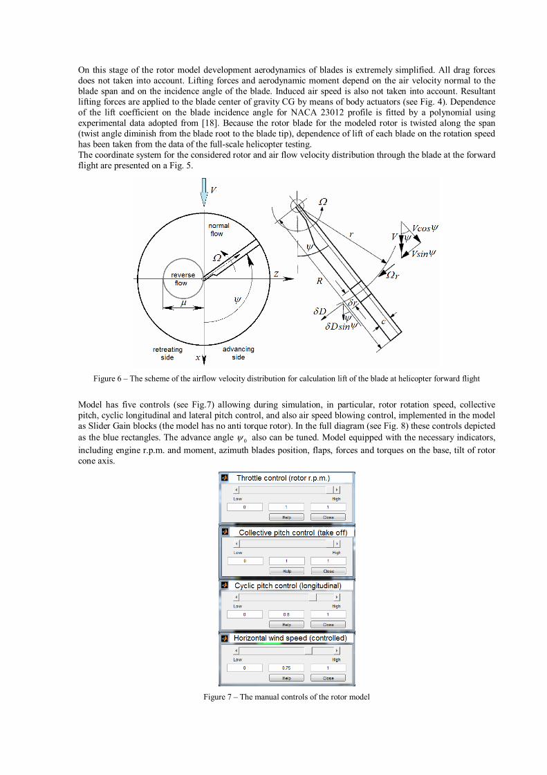
On this stage of the rotor model development aerodynamics of blades is extremely simplified. All drag forces does not taken into account. Lifting forces and aerodynamic moment depend on the air velocity normal to the blade span and on the incidence angle of the blade. Induced air speed is also not taken into account. Resultant lifting forces are applied to the blade center of gravity CG by means of body actuators (see Fig. 4). Dependence of the lift coefficient on the blade incidence angle for NACA 23012 profile is fitted by a polynomial using experimental data adopted from [18]. Because the rotor blade for the modeled rotor is twisted along the span (twist angle diminish from the blade root to the blade tip), dependence of lift of each blade on the rotation speed has been taken from the data of the full-scale helicopter testing. The coordinate system for the considered rotor and air flow velocity distribution through the blade at the forward flight are presented on a Fig. 5.
Figure 6 – The scheme of the airflow velocity distribution for calculation lift of the blade at helicopter forward flight
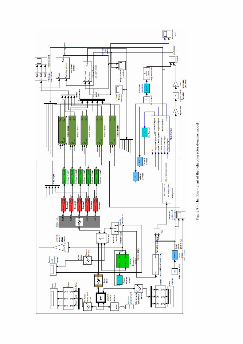
Model has five controls (see Fig.7) allowing during simulation, in particular, rotor rotation speed, collective pitch, cyclic longitudinal and lateral pitch control, and also air speed blowing control, implemented in the model as Slider Gain blocks (the model has no anti torque rotor). In the full diagram (see Fig. 8) these controls depicted as the blue rectangles. The advance angle 0 also can be tuned. Model equipped with the necessary indicators, including engine r.p.m. and moment, azimuth blades position, flaps, forces and torques on the base, tilt of rotor cone axis.
Figure 7 – The manual controls of the rotor model
Fig
ure
8 –
The
flo
w –
cha
rt o
f th
e he
licop
ter
roto
r dy
nam
ic m
odel
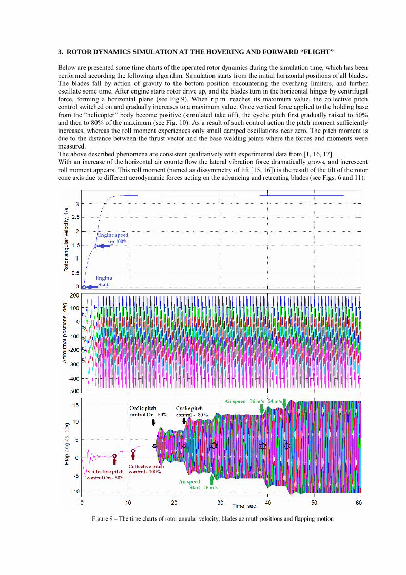
3. ROTOR DYNAMICS SIMULATION AT THE HOVERING AND FORWARD “FLIGHT” Below are presented some time charts of the operated rotor dynamics during the simulation time, which has been performed according the following algorithm. Simulation starts from the initial horizontal positions of all blades. The blades fall by action of gravity to the bottom position encountering the overhang limiters, and further oscillate some time. After engine starts rotor drive up, and the blades turn in the horizontal hinges by centrifugal force, forming a horizontal plane (see Fig.9). When r.p.m. reaches its maximum value, the collective pitch control switched on and gradually increases to a maximum value. Once vertical force applied to the holding base from the “helicopter” body become positive (simulated take off), the cyclic pitch first gradually raised to 50% and then to 80% of the maximum (see Fig. 10). As a result of such control action the pitch moment sufficiently increases, whereas the roll moment experiences only small damped oscillations near zero. The pitch moment is due to the distance between the thrust vector and the base welding joints where the forces and moments were measured. The above described phenomena are consistent qualitatively with experimental data from [1, 16, 17]. With an increase of the horizontal air counterflow the lateral vibration force dramatically grows, and increscent roll moment appears. This roll moment (named as dissymmetry of lift [15, 16]) is the result of the tilt of the rotor cone axis due to different aerodynamic forces acting on the advancing and retreating blades (see Figs. 6 and 11).
Figure 9 – The time charts of rotor angular velocity, blades azimuth positions and flapping motion
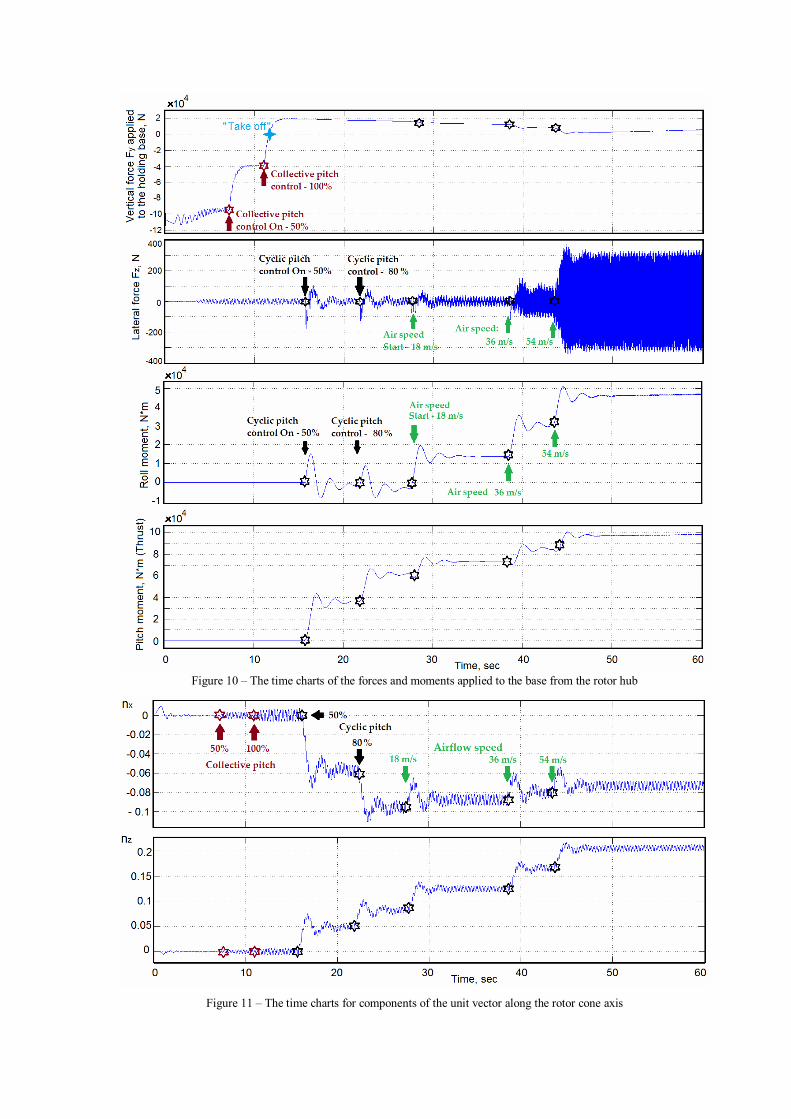
Figure 10 – The time charts of the forces and moments applied to the base from the rotor hub
Figure 11 – The time charts for components of the unit vector along the rotor cone axis
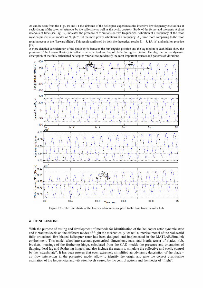
As can be seen from the Figs. 10 and 11 the airframe of the helicopter experiences the intensive low frequency excitations at each change of the rotor adjustments by the collective as well as the cyclic controls. Study of the forces and moments at short intervals of time (see Fig. 12) indicates the presence of vibrations on two frequencies. Vibration at a frequency of the rotor rotation present at all modes of "flight." But the most power vibrations at a frequency bN time more comparing to the rotor
rotation occur at the "forward flight". This result confirmed by both the theoretical results [1 – 3, 15, 16] and aviation practice [19]. A more detailed consideration of the phase shifts between the hub angular position and the lag motion of each blade show the presence of the known Hooks joint effect - periodic lead and lag of blade during its rotation. Hereby, the correct dynamic description of the fully articulated helicopter rotor allows to identify the most important sources and patterns of vibrations.
Figure 12 – The time charts of the forces and moments applied to the base from the rotor hub
4. CONCLUSIONS With the purpose of testing and development of methods for identification of the helicopter rotor dynamic state and vibrations levels on the different modes of flight the mechanically “exact” numerical model of the real-world fully articulated five bladed helicopter rotor has been designed and implemented in the MATLAB/Simulink environment. This model takes into account geometrical dimensions, mass and inertia tensor of blades, hub, brackets, housings of the feathering hinge, calculated from the CAD model; the presence and orientation of flapping, lead-lag and feathering hinges, and also include the means to simulate the collective and cyclic control by the “swashplate”. It has been proven that even extremely simplified aerodynamic description of the blade – air flow interaction in the presented model allow to identify the origin and give the correct quantitative estimation of the frequencies and vibration levels caused by the control actions and the modes of “flight”.
ACKNOWLEDGEMENTS The authors wish to acknowledge the financial and technical support from the group of companies “Russian helicopters” and Union of Russian aircraft manufacturers. 5. REFERENCES [1] Bramwell, A.R.S., Done, J., Balmford, D., “Bramwell’s helicopter dynamics”, Reed Educational and Professional Publ. Ltd, 2001, 373 p. [2] Straub, F.K., Anand, V.R., Birchette, T.S., and Lau, B.H., “SMART Rotor Development and Wind Tunnel Test”, Proceedings of 35th European Rotorcraft Forum, Hamburg, Germany, 2009, p. 23. [3] Kessler, Ch. “Active Rotor Control for Helicopters: Individual Blade Control and Swashplateless Rotor Designs”, CEAS Aeronautical J. 1, 2011, pp. 23–-54. [4] Liu, L., Friedmann, P.P., Kim, I. and Bernstein, D.S., “Rotor Performance Enhancement and Vibration Reduction in Presence of Dynamic Stall Using Actively Controlled Flaps”, Proceedings of AHS 62nd Annual Forum, 2006, pp.1—55. [5] Viswamurthy, S.R., and Ganguli, R., “Using the Complete Authority of Multiple Active Trailing-Edge Flaps for Helicopter Vibration Control”, J. of Vibration and Control, 14, 2008, pp.1175-1199. [6] Chopra, I., McCloud III, J.L., “A Numerical Simulation Study of Open-Loop, Closed-Loop and Adaptive Multicyclic Control Systems”, Proceedings of AHS Northeast Region Meeting on Helicopter Vibration, Hartford, Conn., 1981, pp. 63—77. [7] Johnson, W., “Self-Tuning Regulators for Multicyclic Control of Helicopter Vibration”, Ames Research Center, NASA, Washington, D.C., 1982. [8] Nandi, A., Neogy, S. and Irretier, H., “Vibration Control of a Structure and a Rotor Using One-Sided Magnetic Actuator and a Digital Proportional-Derivative Control”, J. of Vibration and Control, 15, 2009, pp.163—181. [9] Shevtsov, S., Tsahalis, D., Flek, M., Samochenko, I., “Comparison of Active and Passive Modes of Piezoelectric Patch Actuators for Scaled Helicopter Rotor Blade Vibration Suppression”, Proceedings of Int. Conf. on Noise and Vibration Engineering ISMA2010, Leuven, Belgium, 2010, pp. 441--456. [10] Mahmoodi, S.N., Ahmadian, M. and Inman, D.J., “Adaptive Modified Positive Position Feedback for Active Vibration Control of Structures”, J. of Intelligent Material Systems and Structures”, 21, 2010, pp.571-580. [11] Du, H, and Zhang, N., “Active Vibration Control of Structures Subject to Parameter Uncertainties and Actuator Delay”, J. of Vibration and Control, 14, 2008, pp.689—709. [12] Rao, A.K., Natesan, K., Seetharama, M., and Ganguli, R., “Experimental Demonstration of H∞ Control Based Active Vibration Suppression in Composite Fin-Tip of Aircraft Using Optimally Placed Piezoelectric Patch Actuators”, J. of Intelligent Material Systems and Structures, 19, 2008, pp.651—669. [13] Sivriouglu, S., “H∞ Control for Suppressing Acoustic Modes of a Distributed Structure Using Cluster Sensing and Actuation”, J. of Vibration and Control, 16, 2010, pp.439-453. [14] Ostergaard, M.G., Ibbotson, A.R., Le Roux, O., and Prior, A.M., “Virtual Testing of Aircraft Structures”, CEAS Aeronautical J., 1, 2011, pp.83–103. [15] Seddon, J., “Basics Helicopter Aerodynamics”, Blackwell Scientific Publ. Ltd., 1998, 136 p. [16] Johnson, W., “Helicopter Theory”, Dover Publ. Inc., N.-Y., 1994, 1089 p. [17] Theodore, C.R., “Helicopter Flight Dynamics Simulation with Refined Aerodynamic Modeling”, PhD thesis, University of Maryland, 2000, 501 p. [18] Abbot, I.H., Doenhoff, A.E., “Theory of Wing Section”, Dover Publ. Inc., N.-Y., 2004, 693 p. [19] Wagtendonk, W.J., “Principles of Helicopter Flight”, Aviation Supplies & Academic, Inc., 1995, 275 p.


