Embed Size (px)
Citation preview

© 2015 Pow erShield Ltd.
Sentinel Installation Manualm-Senzor
Sentinel Installation Manual m-Senzor
2
© 2015 PowerShield Ltd.
Contents
Table of Contents1 Introduction 4
2 Definitions for this Manual 5
3 Installation QuickGuide 6
4 The SENTINEL Battery Monitoring System 9................................................................................................................................... 10Installation - Preliminaries
.......................................................................................................................................................... 10Sentinel Monitor
.......................................................................................................................................................... 10Pow er Supply
.......................................................................................................................................................... 10Faceplate
.......................................................................................................................................................... 11System Capacity
.......................................................................................................................................................... 11Sentinel Communications
.......................................................................................................................................................... 12m-Senzor
.......................................................................................................................................................... 13BBus
................................................................................................................................... 13Installation
.......................................................................................................................................................... 13Step 1 - Monoblocks/Jars
.......................................................................................................................................................... 14Step 2 - Sentinel
......................................................................................................................................................... 14Set the Sentinel ID
......................................................................................................................................................... 14Mount and Pow er Up the Sentinel
.......................................................................................................................................................... 15Step 3 – Mounting Rail for m-Senzors
.......................................................................................................................................................... 15Step 4 – m-Senzor Pow er Leads
.......................................................................................................................................................... 16Step 5 – Connect m-Senzors
.......................................................................................................................................................... 17Step 6 – Connect the BBus
.......................................................................................................................................................... 18Step 7 – Connecting the Current Transducer
.......................................................................................................................................................... 19Step 8 – Connecting the Temperature Probe
.......................................................................................................................................................... 19Step 9 – Communications
.......................................................................................................................................................... 20Step 10 – Confirmation
5 Appendix 1 - LED Behaviour 21................................................................................................................................... 21Sentinel................................................................................................................................... 22m-Senzor
6 Appendix 2 – Sentinel Rear Panel 23
7 Appendix 3 - Communications 24................................................................................................................................... 24Service Port................................................................................................................................... 24Port 1................................................................................................................................... 25Port 2................................................................................................................................... 26Port 3
8 Appendix 4 - Relay Outputs and Auxillary Inputs 27................................................................................................................................... 27Alarm Output Relays................................................................................................................................... 27Auxillary Inputs
9 Appendix 5 - m-Senzor Connections 28................................................................................................................................... 28Dual m-Senzor Power Lead Connection Detail................................................................................................................................... 28Single m-Senzor Power Lead Connection Detail
10 Appendix 6 - Installation Forms 29................................................................................................................................... 29Site Identification Form (SIF)
3Contents
Sentinel Installation Manual m-Senzor © 2015 PowerShield Ltd.
................................................................................................................................... 30String Configuration Form (SCF)
................................................................................................................................... 31Monoblock Mapping Form (MMF)
11 Appendix 7 - Monitor & m-Senzor Replacement 32................................................................................................................................... 32Replace a Monitor................................................................................................................................... 32Replace an m-Senzor
12 Appendix 8 - Models and Part Numbers 34................................................................................................................................... 34Sentinels................................................................................................................................... 35m-Senzors................................................................................................................................... 36m-Senzor Leads
13 Appendix 9 - Specifications 37................................................................................................................................... 37Sentinel
Sentinel Installation Manual m-Senzor
4
© 2015 PowerShield Ltd.
Introduction
1 Introduction
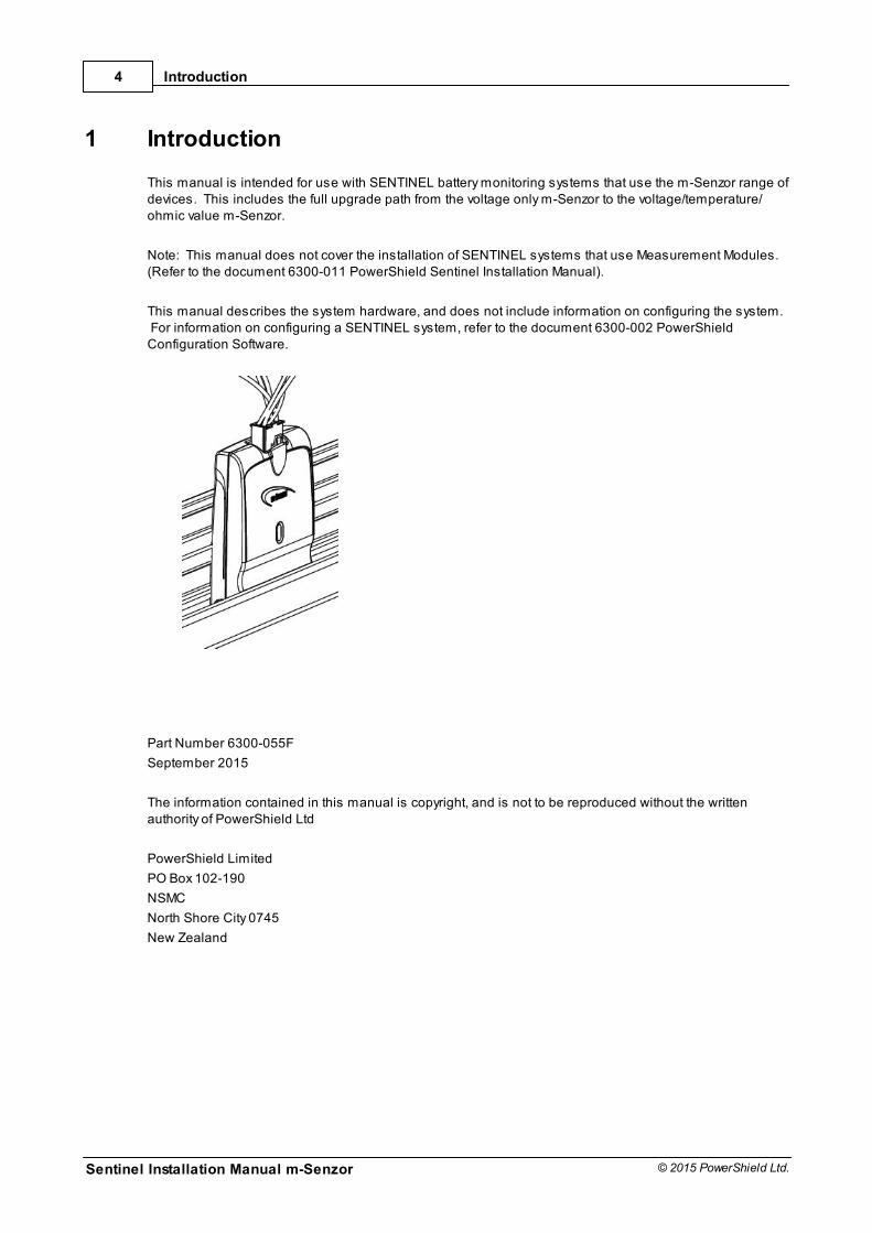
This manual is intended for use with SENTINEL battery monitoring systems that use the m-Senzor range ofdevices. This includes the full upgrade path from the voltage only m-Senzor to the voltage/temperature/ohmic value m-Senzor.
Note: This manual does not cover the installation of SENTINEL systems that use Measurement Modules. (Refer to the document 6300-011 PowerShield Sentinel Installation Manual).
This manual describes the system hardware, and does not include information on configuring the system. For information on configuring a SENTINEL system, refer to the document 6300-002 PowerShieldConfiguration Software.
Part Number 6300-055F
September 2015
The information contained in this manual is copyright, and is not to be reproduced without the writtenauthority of PowerShield Ltd
PowerShield Limited
PO Box 102-190
NSMC
North Shore City 0745
New Zealand
Definitions for this Manual
Sentinel Installation Manual m-Senzor
5
© 2015 PowerShield Ltd.
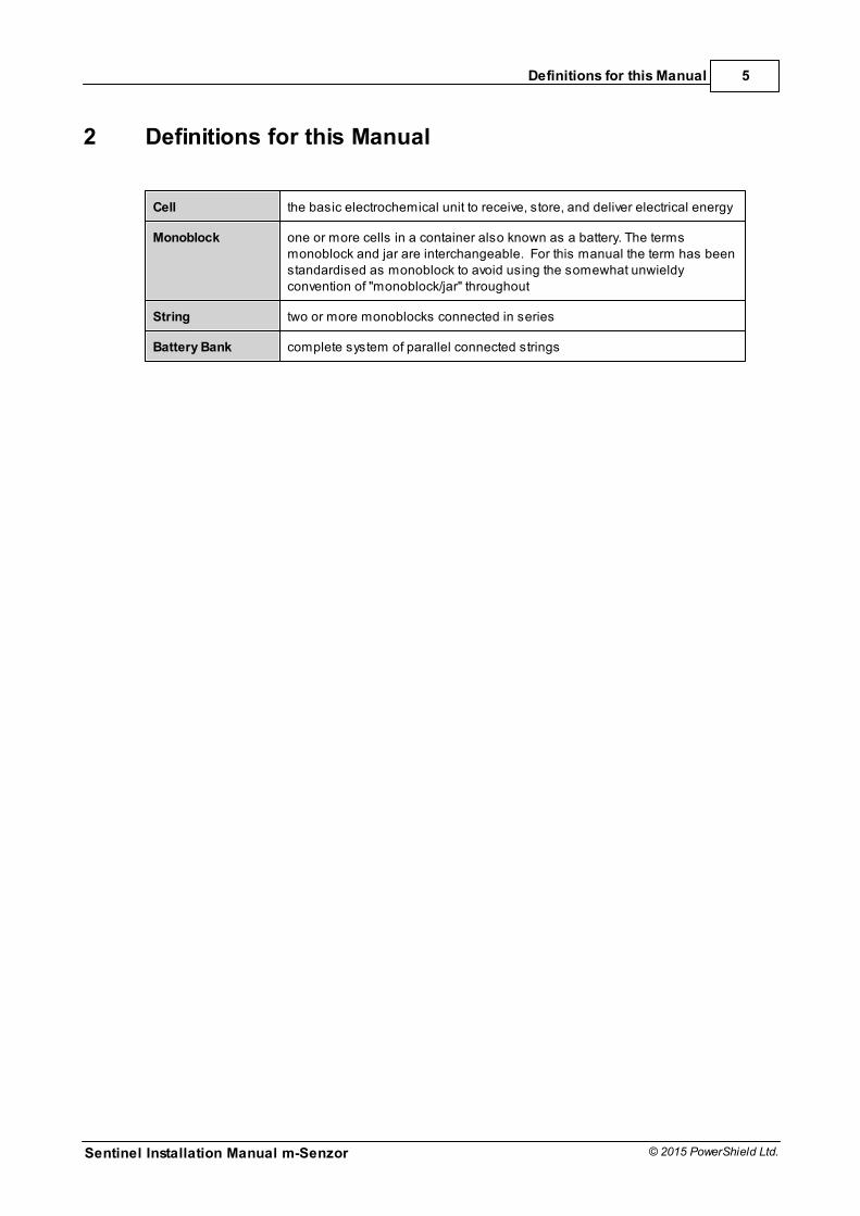
2 Definitions for this Manual
Cell the basic electrochemical unit to receive, store, and deliver electrical energy
Monoblock one or more cells in a container also known as a battery. The termsmonoblock and jar are interchangeable. For this manual the term has beenstandardised as monoblock to avoid using the somewhat unwieldyconvention of "monoblock/jar" throughout
String two or more monoblocks connected in series
Battery Bank complete system of parallel connected strings
Sentinel Installation Manual m-Senzor
6
© 2015 PowerShield Ltd.
Installation QuickGuide
3 Installation QuickGuide
Installation QuickGuide
Sentinel Installation Manual m-Senzor
7
© 2015 PowerShield Ltd.
Sentinel Installation Manual m-Senzor
8
© 2015 PowerShield Ltd.
Installation QuickGuide
The SENTINEL Battery Monitoring System
Sentinel Installation Manual m-Senzor
9
© 2015 PowerShield Ltd.
4 The SENTINEL Battery Monitoring System
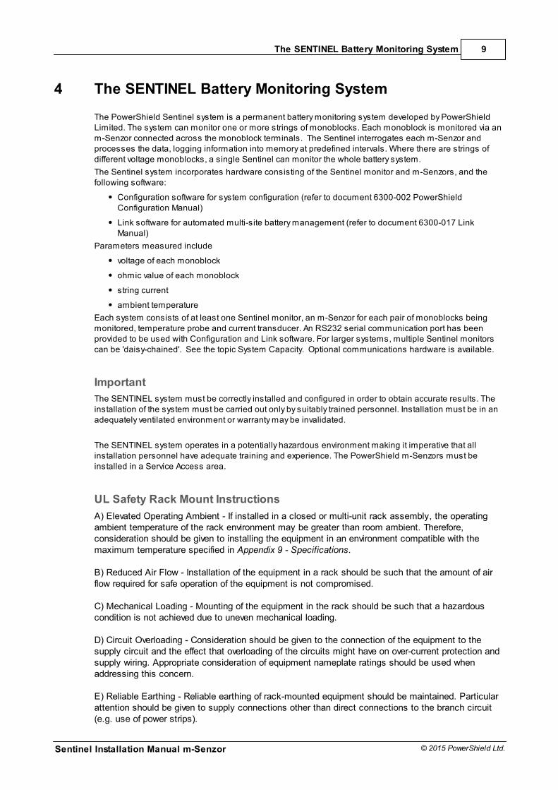
The PowerShield Sentinel system is a permanent battery monitoring system developed by PowerShieldLimited. The system can monitor one or more strings of monoblocks. Each monoblock is monitored via anm-Senzor connected across the monoblock terminals. The Sentinel interrogates each m-Senzor andprocesses the data, logging information into memory at predefined intervals. Where there are strings ofdifferent voltage monoblocks, a single Sentinel can monitor the whole battery system.
The Sentinel system incorporates hardware consisting of the Sentinel monitor and m-Senzors, and thefollowing software:
Configuration software for system configuration (refer to document 6300-002 PowerShieldConfiguration Manual)
Link software for automated multi-site battery management (refer to document 6300-017 LinkManual)
Parameters measured include
voltage of each monoblock
ohmic value of each monoblock
string current
ambient temperature
Each system consists of at least one Sentinel monitor, an m-Senzor for each pair of monoblocks beingmonitored, temperature probe and current transducer. An RS232 serial communication port has beenprovided to be used with Configuration and Link software. For larger systems, multiple Sentinel monitorscan be 'daisy-chained'. See the topic System Capacity. Optional communications hardware is available.
Important
The SENTINEL system must be correctly installed and configured in order to obtain accurate results. Theinstallation of the system must be carried out only by suitably trained personnel. Installation must be in anadequately ventilated environment or warranty may be invalidated.
The SENTINEL system operates in a potentially hazardous environment making it imperative that allinstallation personnel have adequate training and experience. The PowerShield m-Senzors must beinstalled in a Service Access area.
UL Safety Rack Mount Instructions
A) Elevated Operating Ambient - If installed in a closed or multi-unit rack assembly, the operatingambient temperature of the rack environment may be greater than room ambient. Therefore,consideration should be given to installing the equipment in an environment compatible with themaximum temperature specified in Appendix 9 - Specifications.
B) Reduced Air Flow - Installation of the equipment in a rack should be such that the amount of airflow required for safe operation of the equipment is not compromised.
C) Mechanical Loading - Mounting of the equipment in the rack should be such that a hazardouscondition is not achieved due to uneven mechanical loading.
D) Circuit Overloading - Consideration should be given to the connection of the equipment to thesupply circuit and the effect that overloading of the circuits might have on over-current protection andsupply wiring. Appropriate consideration of equipment nameplate ratings should be used whenaddressing this concern.
E) Reliable Earthing - Reliable earthing of rack-mounted equipment should be maintained. Particularattention should be given to supply connections other than direct connections to the branch circuit(e.g. use of power strips).

Sentinel Installation Manual m-Senzor
10
© 2015 PowerShield Ltd.
The SENTINEL Battery Monitoring System
4.1 Installation - Preliminaries
4.1.1 Sentinel Monitor
Width: 430mm / 17 inches (19” rack compatible)
Depth: 270mm / 10.6 inches
Height: 45mm / 1.8 inches (1U)
4.1.2 Power Supply
The Sentinel is available in the following power supply models:
48V DC Model: Range of input voltage is 20V-65VDC, max 0.4A per Sentinel.
72V DC Model: Range of input voltage is 55V-140VDC, max 0.40A per Sentinel.
Input connector is a 3 way plug and screw terminal block.
The power supply must be fused.
Must be installed in a service access area.
AC Model: Range of input voltage is 110V-240V AC (50/60Hz), max 0.15A per Sentinel.
Input connector is a male IEC input. IEC mains cable is supplied.
Note that the DC units cannot be powered with AC voltage and that the AC units cannot be powered withDC voltage.
Ensure that the correct power supply for Sentinel units is being used prior to applying power.
Both AC and DC models must be installed by a service person and connected to a socket outlet orfixed wiring with a protective earthing conductor or connector.
A readily available disconnect device shall be incorporated in the building wiring or the socket outlet,near the Sentinel, and be readily accessible.
To ensure that the system operates during a power failure, it is recommended that the monitor ispowered by a battery backed supply rather than from a mains adaptor.
4.1.3 Faceplate
The faceplate, label and LED arrangement of the Sentinel is shown below. Refer to Appendix 1 for a fulldescription of LED behaviour.
The SENTINEL Battery Monitoring System
Sentinel Installation Manual m-Senzor
11
© 2015 PowerShield Ltd.
4.1.4 System Capacity
Every system must have a Sentinel master unit, and additional Sentinel units may be added as slaves toincrease capacity of the overall system. The Sentinel master unit has 8 Bbus ports, with each portsupporting up to 10 m-senzors (20 monoblocks). Therefore, if there are more than 160 monoblocks in asystem, additional Sentinel units are required. Similarly, if there are more than 5 battery strings in a system,additional Sentinel units are required. A maximum of 16 units, including the master, can be connected.
The position of the rotary switch at the rear of the Sentinel determines the identification number of the unit. The Master must be set to 0, Slaves may be 1-9 or A-F, ensuring that each figure is used only once in thesystem. Each unit is identified by the switch setting.
Refer to Appendix 2 for a diagram of the Sentinel rear panel.
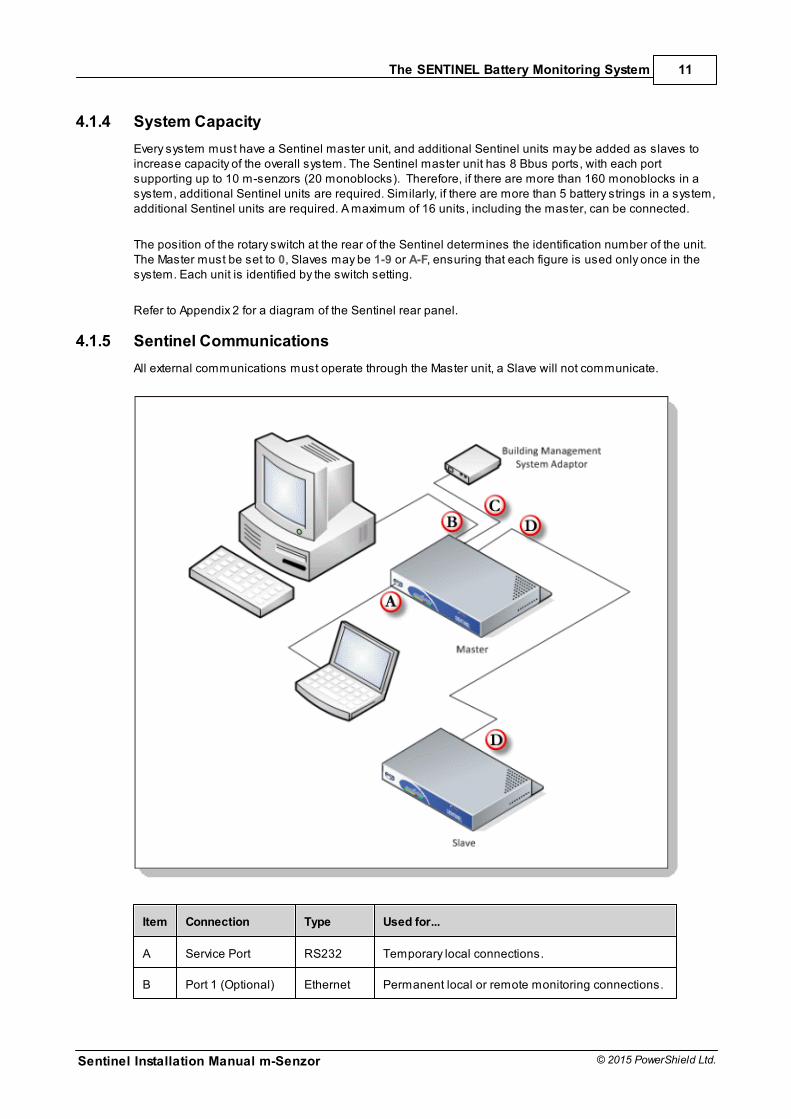
4.1.5 Sentinel Communications
All external communications must operate through the Master unit, a Slave will not communicate.
Item Connection Type Used for...
A Service Port RS232 Temporary local connections.
B Port 1 (Optional) Ethernet Permanent local or remote monitoring connections.
Sentinel Installation Manual m-Senzor
12
© 2015 PowerShield Ltd.
The SENTINEL Battery Monitoring System
Item Connection Type Used for...
C Port 2 (Optional) RS485 orRS232
Permanent connection to third party systems.
D Port 3 Sentinel system communications. Master to Slaveand Slave to Slave.
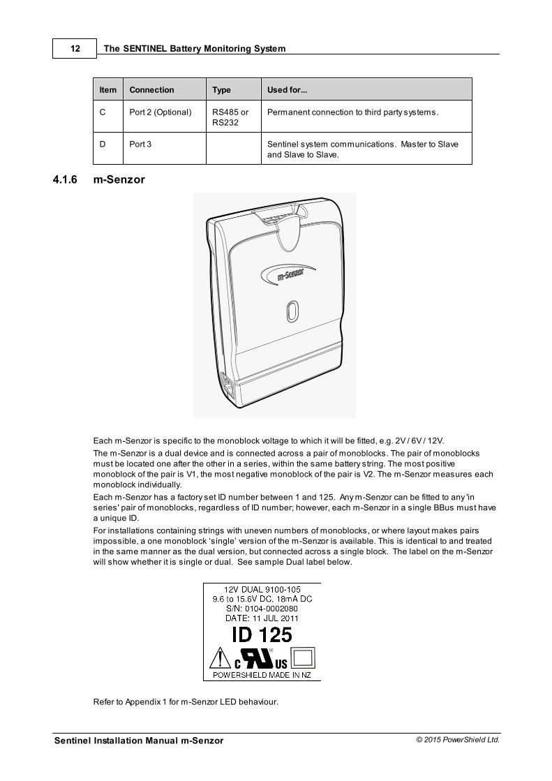
4.1.6 m-Senzor
Each m-Senzor is specific to the monoblock voltage to which it will be fitted, e.g. 2V / 6V / 12V.
The m-Senzor is a dual device and is connected across a pair of monoblocks. The pair of monoblocksmust be located one after the other in a series, within the same battery string. The most positivemonoblock of the pair is V1, the most negative monoblock of the pair is V2. The m-Senzor measures eachmonoblock individually.
Each m-Senzor has a factory set ID number between 1 and 125. Any m-Senzor can be fitted to any 'inseries' pair of monoblocks, regardless of ID number; however, each m-Senzor in a single BBus must havea unique ID.
For installations containing strings with uneven numbers of monoblocks, or where layout makes pairsimpossible, a one monoblock ‘single’ version of the m-Senzor is available. This is identical to and treatedin the same manner as the dual version, but connected across a single block. The label on the m-Senzorwill show whether it is single or dual. See sample Dual label below.
Refer to Appendix 1 for m-Senzor LED behaviour.
The SENTINEL Battery Monitoring System
Sentinel Installation Manual m-Senzor
13
© 2015 PowerShield Ltd.
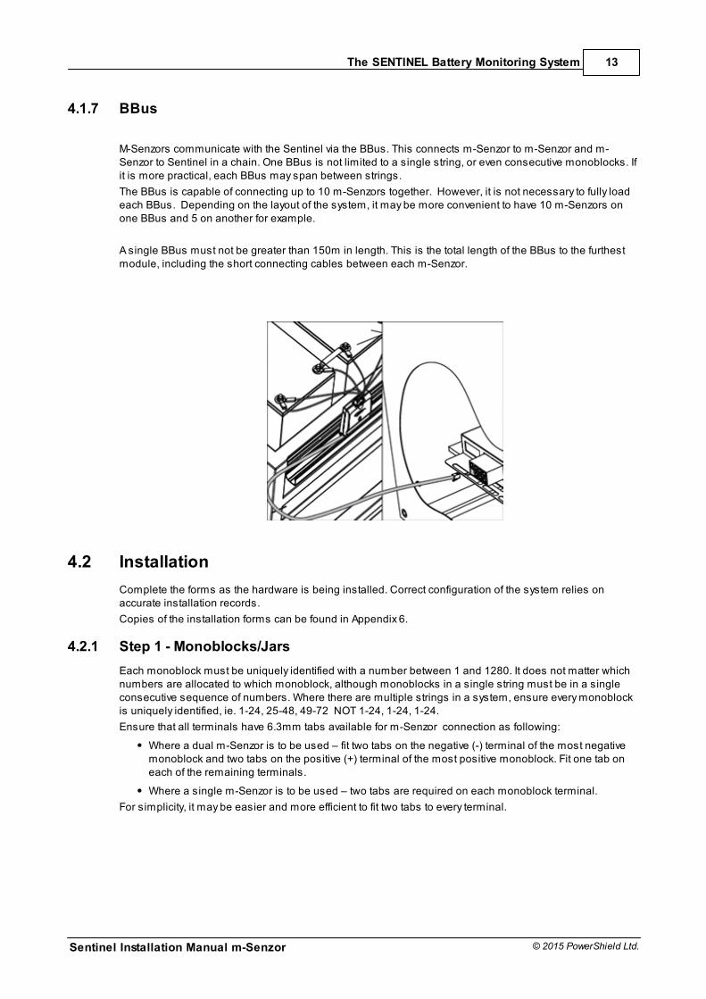
4.1.7 BBus
M-Senzors communicate with the Sentinel via the BBus. This connects m-Senzor to m-Senzor and m-Senzor to Sentinel in a chain. One BBus is not limited to a single string, or even consecutive monoblocks. Ifit is more practical, each BBus may span between strings.
The BBus is capable of connecting up to 10 m-Senzors together. However, it is not necessary to fully loadeach BBus. Depending on the layout of the system, it may be more convenient to have 10 m-Senzors onone BBus and 5 on another for example.
A single BBus must not be greater than 150m in length. This is the total length of the BBus to the furthestmodule, including the short connecting cables between each m-Senzor.
4.2 Installation
Complete the forms as the hardware is being installed. Correct configuration of the system relies onaccurate installation records.
Copies of the installation forms can be found in Appendix 6.
4.2.1 Step 1 - Monoblocks/Jars
Each monoblock must be uniquely identified with a number between 1 and 1280. It does not matter whichnumbers are allocated to which monoblock, although monoblocks in a single string must be in a singleconsecutive sequence of numbers. Where there are multiple strings in a system, ensure every monoblockis uniquely identified, ie. 1-24, 25-48, 49-72 NOT 1-24, 1-24, 1-24.
Ensure that all terminals have 6.3mm tabs available for m-Senzor connection as following:
Where a dual m-Senzor is to be used – fit two tabs on the negative (-) terminal of the most negativemonoblock and two tabs on the positive (+) terminal of the most positive monoblock. Fit one tab oneach of the remaining terminals.
Where a single m-Senzor is to be used – two tabs are required on each monoblock terminal.
For simplicity, it may be easier and more efficient to fit two tabs to every terminal.
Sentinel Installation Manual m-Senzor
14
© 2015 PowerShield Ltd.
The SENTINEL Battery Monitoring System
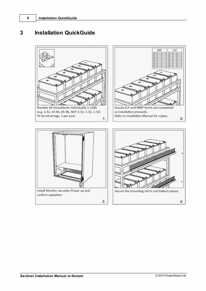
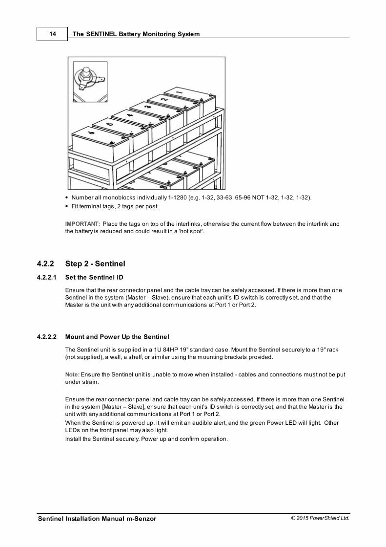
Number all monoblocks individually 1-1280 (e.g. 1-32, 33-63, 65-96 NOT 1-32, 1-32, 1-32).
Fit terminal tags, 2 tags per post.
IMPORTANT: Place the tags on top of the interlinks, otherwise the current flow between the interlink andthe battery is reduced and could result in a 'hot spot'.
4.2.2 Step 2 - Sentinel
4.2.2.1 Set the Sentinel ID
Ensure that the rear connector panel and the cable tray can be safely accessed. If there is more than oneSentinel in the system (Master – Slave), ensure that each unit’s ID switch is correctly set, and that theMaster is the unit with any additional communications at Port 1 or Port 2.
4.2.2.2 Mount and Power Up the Sentinel
The Sentinel unit is supplied in a 1U 84HP 19" standard case. Mount the Sentinel securely to a 19" rack(not supplied), a wall, a shelf, or similar using the mounting brackets provided.
Note: Ensure the Sentinel unit is unable to move when installed - cables and connections must not be putunder strain.
Ensure the rear connector panel and cable tray can be safely accessed. If there is more than one Sentinelin the system [Master – Slave], ensure that each unit’s ID switch is correctly set, and that the Master is theunit with any additional communications at Port 1 or Port 2.
When the Sentinel is powered up, it will emit an audible alert, and the green Power LED will light. OtherLEDs on the front panel may also light.
Install the Sentinel securely. Power up and confirm operation.
The SENTINEL Battery Monitoring System
Sentinel Installation Manual m-Senzor
15
© 2015 PowerShield Ltd.
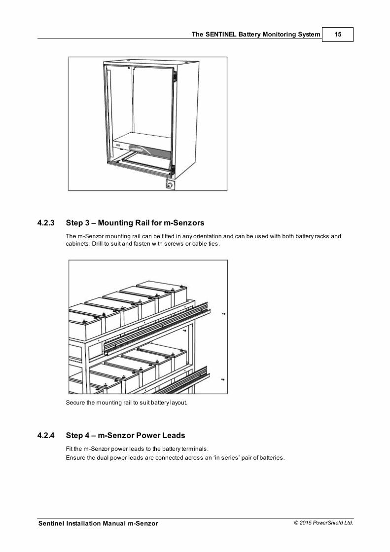
4.2.3 Step 3 – Mounting Rail for m-Senzors
The m-Senzor mounting rail can be fitted in any orientation and can be used with both battery racks andcabinets. Drill to suit and fasten with screws or cable ties.
Secure the mounting rail to suit battery layout.
4.2.4 Step 4 – m-Senzor Power Leads
Fit the m-Senzor power leads to the battery terminals.
Ensure the dual power leads are connected across an ‘in series’ pair of batteries.
Sentinel Installation Manual m-Senzor
16
© 2015 PowerShield Ltd.
The SENTINEL Battery Monitoring System
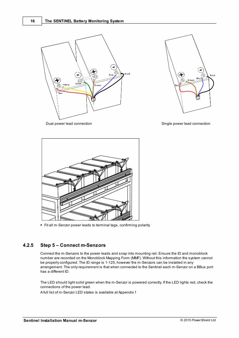
Dual power lead connection Single power lead connection
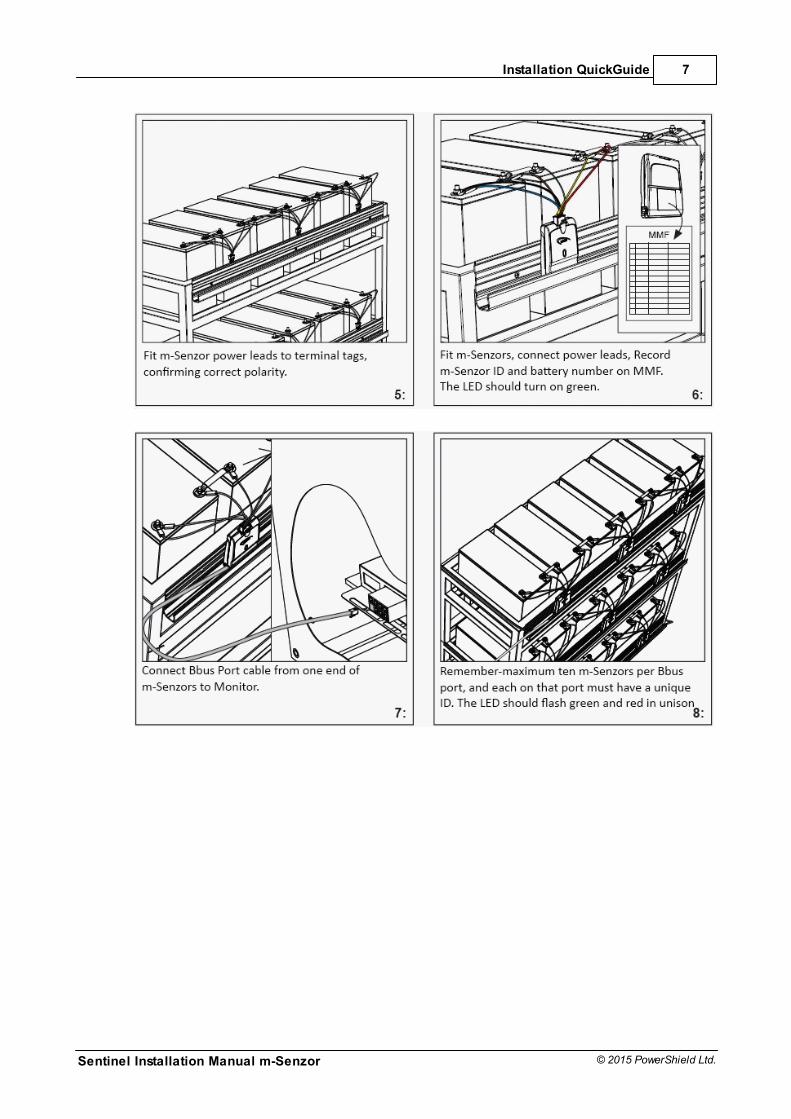
Fit all m-Senzor power leads to terminal tags, confirming polarity
4.2.5 Step 5 – Connect m-Senzors
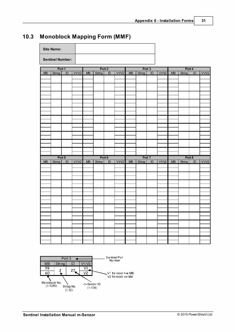
Connect the m-Senzors to the power leads and snap into mounting rail. Ensure the ID and monoblocknumber are recorded on the Monoblock Mapping Form (MMF). Without this information the system cannotbe properly configured. The ID range is 1-125, however the m-Senzors can be installed in anyarrangement. The only requirement is that when connected to the Sentinel each m-Senzor on a BBus porthas a different ID.
The LED should light solid green when the m-Senzor is powered correctly. If the LED lights red, check theconnections of the power lead.
A full list of m-Senzor LED states is available at Appendix 1
The SENTINEL Battery Monitoring System
Sentinel Installation Manual m-Senzor
17
© 2015 PowerShield Ltd.
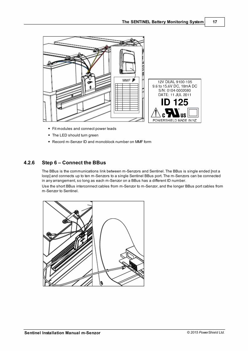
Fit modules and connect power leads
The LED should turn green
Record m-Senzor ID and monoblock number on MMF form
4.2.6 Step 6 – Connect the BBus
The BBus is the communications link between m-Senzors and Sentinel. The BBus is single ended [not aloop] and connects up to ten m-Senzors to a single Sentinel BBus port. The m-Senzors can be connectedin any arrangement, so long as each m-Senzor on a BBus has a different ID number.
Use the short BBus interconnect cables from m-Senzor to m-Senzor, and the longer BBus port cables fromm-Senzor to Sentinel.
Sentinel Installation Manual m-Senzor
18
© 2015 PowerShield Ltd.
The SENTINEL Battery Monitoring System
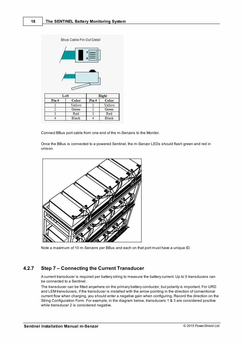
Connect BBus port cable from one end of the m-Senzors to the Monitor.
Once the BBus is connected to a powered Sentinel, the m-Senzor LEDs should flash green and red inunison.
Note a maximum of 10 m-Senzors per BBus and each on that port must have a unique ID.
4.2.7 Step 7 – Connecting the Current Transducer
A current transducer is required per battery string to measure the battery current. Up to 5 transducers canbe connected to a Sentinel.
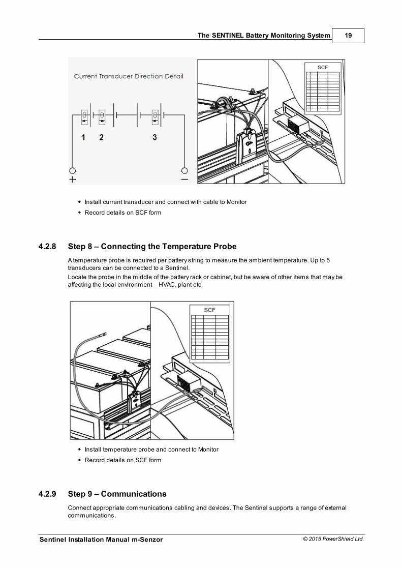
The transducer can be fitted anywhere on the primary battery conductor, but polarity is important. For URDand LEM transducers, if the transducer is installed with the arrow pointing in the direction of conventionalcurrent flow when charging, you should enter a negative gain when configuring. Record the direction on theString Configuration Form. For example, in the diagram below, transducers 1 & 3 are considered positivewhile transducer 2 is considered negative.
The SENTINEL Battery Monitoring System
Sentinel Installation Manual m-Senzor
19
© 2015 PowerShield Ltd.
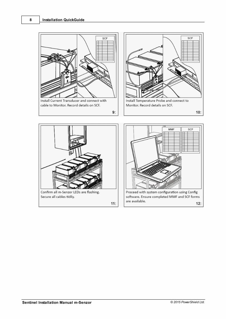
Install current transducer and connect with cable to Monitor
Record details on SCF form
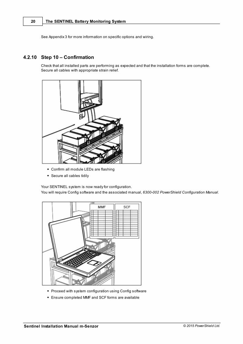
4.2.8 Step 8 – Connecting the Temperature Probe
A temperature probe is required per battery string to measure the ambient temperature. Up to 5transducers can be connected to a Sentinel.
Locate the probe in the middle of the battery rack or cabinet, but be aware of other items that may beaffecting the local environment – HVAC, plant etc.
Install temperature probe and connect to Monitor
Record details on SCF form
4.2.9 Step 9 – Communications
Connect appropriate communications cabling and devices. The Sentinel supports a range of externalcommunications.
Sentinel Installation Manual m-Senzor
20
© 2015 PowerShield Ltd.
The SENTINEL Battery Monitoring System
See Appendix 3 for more information on specific options and wiring.
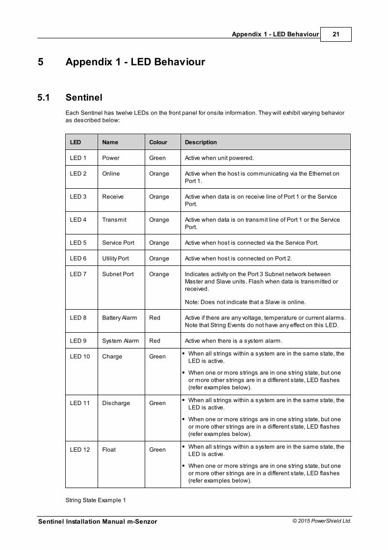
4.2.10 Step 10 – Confirmation
Check that all installed parts are performing as expected and that the installation forms are complete.Secure all cables with appropriate strain relief.
Confirm all module LEDs are flashing
Secure all cables tidily
Your SENTINEL system is now ready for configuration.
You will require Config software and the associated manual, 6300-002 PowerShield Configuration Manual.
Proceed with system configuration using Config software
Ensure completed MMF and SCF forms are available
Appendix 1 - LED Behaviour
Sentinel Installation Manual m-Senzor
21
© 2015 PowerShield Ltd.
5 Appendix 1 - LED Behaviour
5.1 Sentinel
Each Sentinel has twelve LEDs on the front panel for onsite information. They will exhibit varying behavioras described below:
LED Name Colour Description
LED 1 Power Green Active when unit powered.
LED 2 Online Orange Active when the host is communicating via the Ethernet onPort 1.
LED 3 Receive Orange Active when data is on receive line of Port 1 or the ServicePort.
LED 4 Transmit Orange Active when data is on transmit line of Port 1 or the ServicePort.
LED 5 Service Port Orange Active when host is connected via the Service Port.
LED 6 Utility Port Orange Active when host is connected on Port 2.
LED 7 Subnet Port Orange Indicates activity on the Port 3 Subnet network betweenMaster and Slave units. Flash when data is transmitted orreceived.
Note: Does not indicate that a Slave is online.
LED 8 Battery Alarm Red Active if there are any voltage, temperature or current alarms.Note that String Events do not have any effect on this LED.
LED 9 System Alarm Red Active when there is a system alarm.
LED 10 Charge Green When all strings within a system are in the same state, theLED is active.
When one or more strings are in one string state, but oneor more other strings are in a different state, LED flashes(refer examples below).
LED 11 Discharge Green When all strings within a system are in the same state, theLED is active.
When one or more strings are in one string state, but oneor more other strings are in a different state, LED flashes(refer examples below).
LED 12 Float Green When all strings within a system are in the same state, theLED is active.
When one or more strings are in one string state, but oneor more other strings are in a different state, LED flashes(refer examples below).
String State Example 1
Sentinel Installation Manual m-Senzor
22
© 2015 PowerShield Ltd.
Appendix 1 - LED Behaviour
2 String system: String 1 is in Float and String 2 is in Discharge
=> Float and Discharge LEDs flash
String State Example 2
4 String system: All Strings are in Float
=> Float LED is active
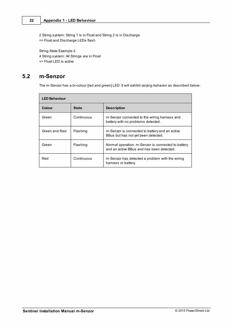
5.2 m-Senzor
The m-Senzor has a bi-colour [red and green] LED. It will exhibit varying behavior as described below:
LED Behaviour
Colour State Description
Green Continuous m-Senzor connected to the wiring harness andbattery with no problems detected.
Green and Red Flashing m-Senzor is connected to battery and an activeBBus but has not yet been detected.
Green Flashing Normal operation. m-Senzor is connected to batteryand an active BBus and has been detected.
Red Continuous m-Senzor has detected a problem with the wiringharness or battery.
Appendix 2 – Sentinel Rear Panel
Sentinel Installation Manual m-Senzor
23
© 2015 PowerShield Ltd.
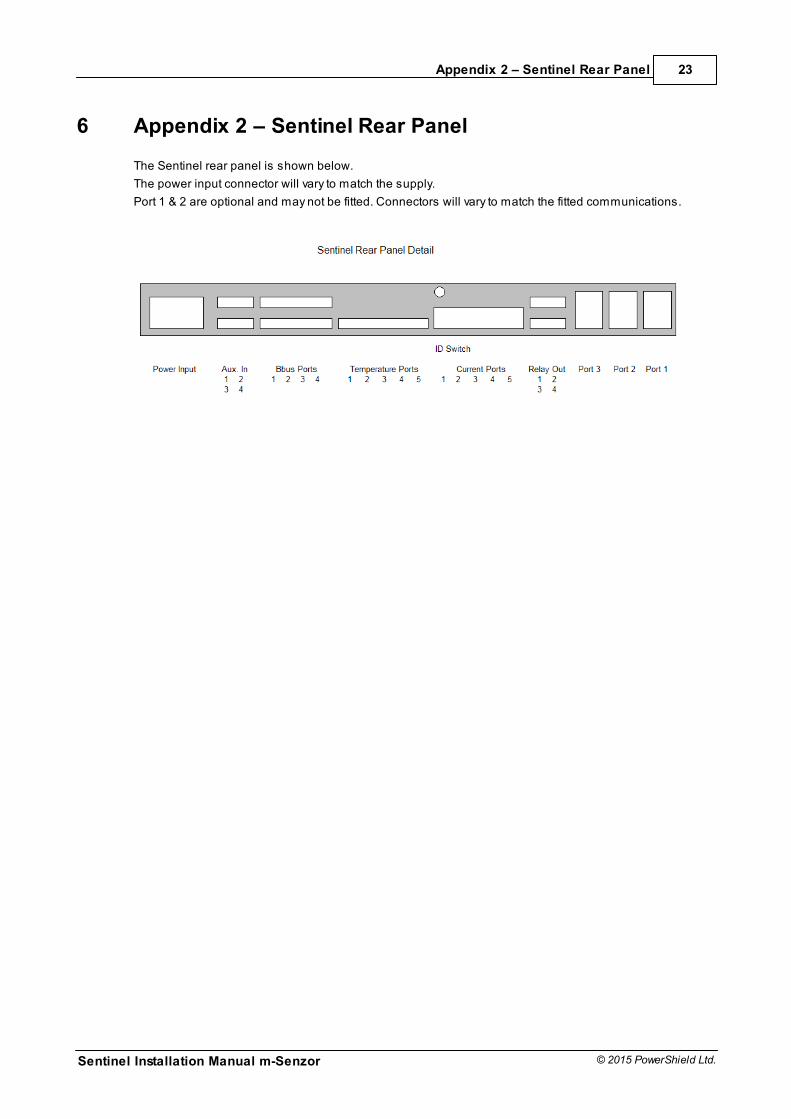
6 Appendix 2 – Sentinel Rear Panel
The Sentinel rear panel is shown below.
The power input connector will vary to match the supply.
Port 1 & 2 are optional and may not be fitted. Connectors will vary to match the fitted communications.
Sentinel Installation Manual m-Senzor
24
© 2015 PowerShield Ltd.
Appendix 3 - Communications
7 Appendix 3 - Communications
7.1 Service Port
The Service Port is located at the front of the Sentinel. The Service Port is intended as a temporaryconnection whereas Port 1 [see below] is intended as the primary permanent communication port, with thecommunication cable to remain connected. Communication via the Service Port will overridecommunications at Port 1.
Connection to the Service Port is RS232 serial communication via a DB9 Male connector. Connect using afull null modem cable with handshaking.
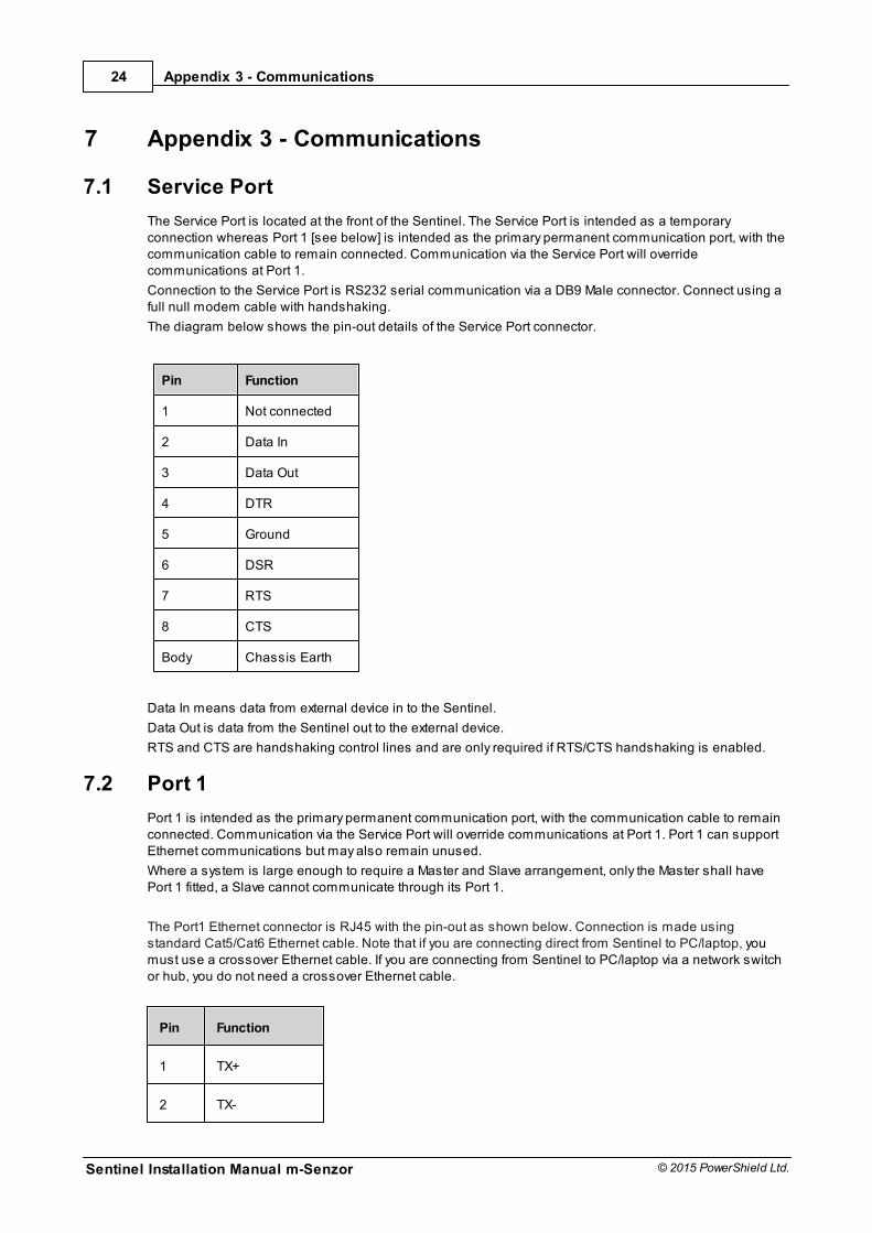
The diagram below shows the pin-out details of the Service Port connector.
Pin Function
1 Not connected
2 Data In
3 Data Out
4 DTR
5 Ground
6 DSR
7 RTS
8 CTS
Body Chassis Earth
Data In means data from external device in to the Sentinel.
Data Out is data from the Sentinel out to the external device.
RTS and CTS are handshaking control lines and are only required if RTS/CTS handshaking is enabled.
7.2 Port 1
Port 1 is intended as the primary permanent communication port, with the communication cable to remainconnected. Communication via the Service Port will override communications at Port 1. Port 1 can supportEthernet communications but may also remain unused.
Where a system is large enough to require a Master and Slave arrangement, only the Master shall havePort 1 fitted, a Slave cannot communicate through its Port 1.
The Port1 Ethernet connector is RJ45 with the pin-out as shown below. Connection is made usingstandard Cat5/Cat6 Ethernet cable. Note that if you are connecting direct from Sentinel to PC/laptop, youmust use a crossover Ethernet cable. If you are connecting from Sentinel to PC/laptop via a network switchor hub, you do not need a crossover Ethernet cable.
Pin Function
1 TX+
2 TX-
Appendix 3 - Communications
Sentinel Installation Manual m-Senzor
25
© 2015 PowerShield Ltd.
3 RX+
4 RX-
5 nc
6 nc
7 nc
8 nc
The Ethernet option has two LEDs that show the following states:
Link LED (left side) Activity LED (right side)
Colour State Colour State
Off No link Off No activity
Amber 10Mbps Amber Half duplex
Green 100Mbps Green Full duplex
7.3 Port 2
Port 2 is intended as a secondary communication port to allow integration with third party systems. It islocated on the rear of the Sentinel, adjacent to Port 1. It can support two different communication options –RS485 or RS232. These are factory fitted options and must be specified at time of purchase. Only one ofthe two options can be fitted to a Sentinel at a time. Note that Port 2 may also remain unused.
Where a system is large enough to require a Master and Slave arrangement, only the Master shall havePort 2 fitted, a Slave cannot communicate through its Port 2.
Port 2 is intended primarily for integration with third party ModBus systems. For more information onintegrating a Sentinel system with ModBus, see the separate manual 6300-049 Sentinel Modbus Port 2Interface and its associated document 6300-050 Sentinel Modbus Port 2 Interface Register List.
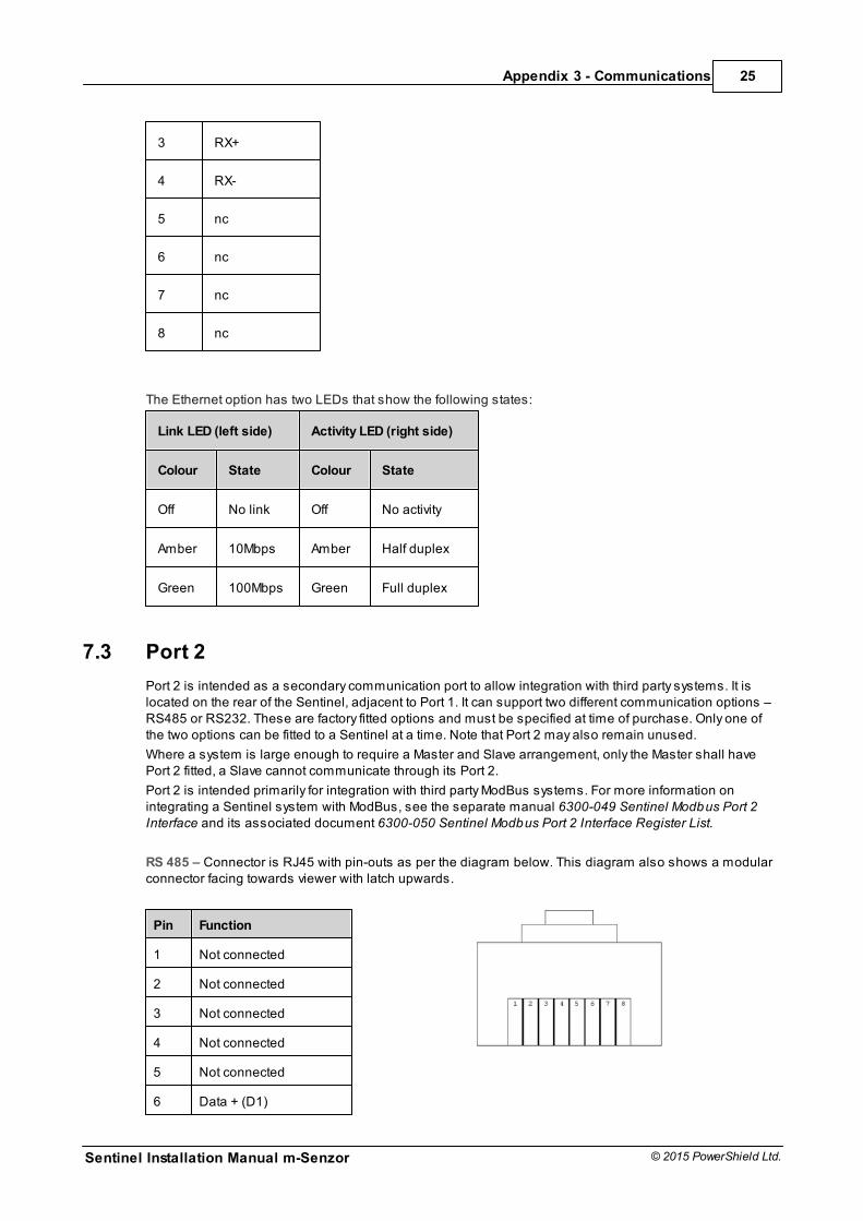
RS 485 – Connector is RJ45 with pin-outs as per the diagram below. This diagram also shows a modularconnector facing towards viewer with latch upwards.
Pin Function
1 Not connected
2 Not connected
3 Not connected
4 Not connected
5 Not connected
6 Data + (D1)
Sentinel Installation Manual m-Senzor
26
© 2015 PowerShield Ltd.
Appendix 3 - Communications
7 Data - (D0)
8 Not connected
RS232 – Connector is DB9 Female. Pin-outs are as per diagram below.
Pin Function
1 Not connected
2 Data In
3 Data Out
4 Not connected
5 Ground
6 RTS
7 CTS
8 Not connected
Con. Body Chassis Earth
Data In means data from external device in to the Sentinel.
Data Out is data from the Sentinel out to the external device.
RTS and CTS are handshaking control lines and are only required if RTS/CTS handshaking is enabled.
7.4 Port 3
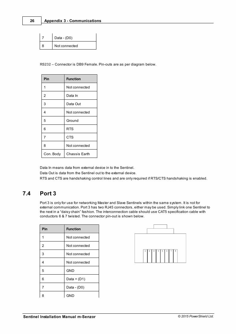
Port 3 is only for use for networking Master and Slave Sentinels within the same system. It is not forexternal communication. Port 3 has two RJ45 connectors, either may be used. Simply link one Sentinel tothe next in a “daisy chain” fashion. The interconnection cable should use CAT5 specification cable withconductors 6 & 7 twisted. The connector pin-out is shown below.
Pin Function
1 Not connected
2 Not connected
3 Not connected
4 Not connected
5 GND
6 Data + (D1)
7 Data - (D0)
8 GND
Appendix 4 - Relay Outputs and Auxillary Inputs
Sentinel Installation Manual m-Senzor
27
© 2015 PowerShield Ltd.
8 Appendix 4 - Relay Outputs and Auxillary Inputs
8.1 Alarm Output Relays
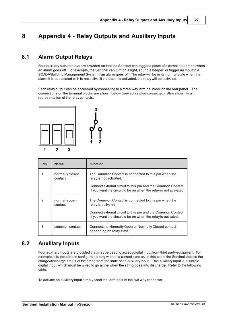
Four auxiliary output relays are provided so that the Sentinel can trigger a piece of external equipment whenan alarm goes off. For example, the Sentinel can turn on a light, sound a beeper, or trigger an input to aSCADA/Building Management System if an alarm goes off. The relay will be in its normal state when thealarm it is associated with is not active. If the alarm is activated, the relay will be activated.
Each relay output can be accessed by connecting to a three way terminal block on the rear panel. Theconnections on the terminal blocks are shown below (viewed as plug connected). Also shown is arepresentation of the relay contacts.
Pin Name Function
1 normally closedcontact
The Common Contact is connected to this pin when therelay is not activated.
Connect external circuit to this pin and the Common Contact if you want the circuit to be on when the relay is not activated.
2 normally opencontact
The Common Contact is connected to this pin when therelay is activated.
Connect external circuit to this pin and the Common Contact if you want the circuit to be on when the relay is activated.
3 common contact Connects to Normally Open or Normally Closed contactdepending on relay state.
8.2 Auxillary Inputs
Four auxiliary inputs are provided that may be used to accept digital input from third party equipment. Forexample, it is possible to configure a string without a current sensor. In this case, the Sentinel detects thecharge/discharge status of the string from the state of an Auxiliary input. This auxiliary input is a simpledigital input, which must be wired to go active when the string goes into discharge. Refer to the followingtable:
To activate an auxiliary input simply short the terminals of the two way connector.
Sentinel Installation Manual m-Senzor
28
© 2015 PowerShield Ltd.
Appendix 5 - m-Senzor Connections
9 Appendix 5 - m-Senzor Connections
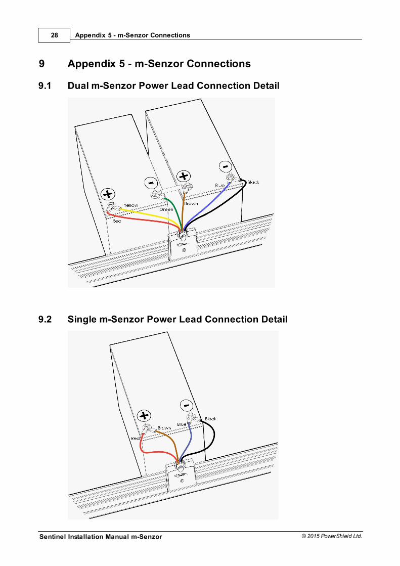
9.1 Dual m-Senzor Power Lead Connection Detail
9.2 Single m-Senzor Power Lead Connection Detail
Appendix 6 - Installation Forms
Sentinel Installation Manual m-Senzor
29
© 2015 PowerShield Ltd.
10 Appendix 6 - Installation Forms
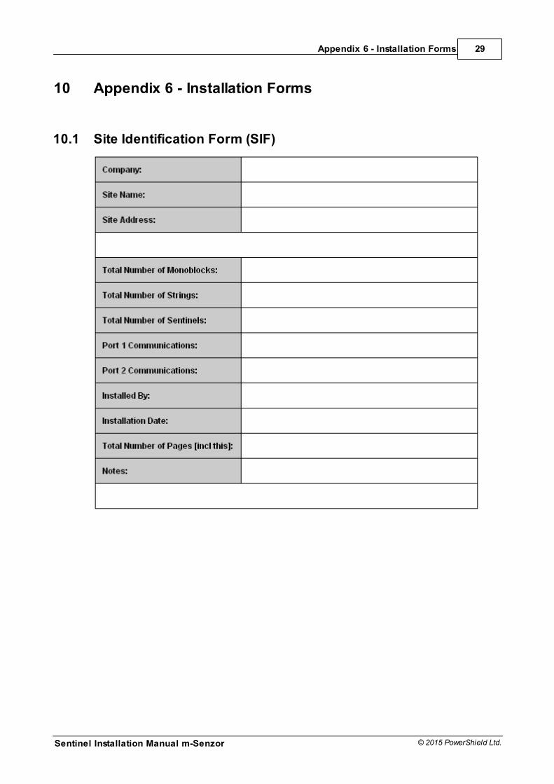
10.1 Site Identification Form (SIF)
Sentinel Installation Manual m-Senzor
30
© 2015 PowerShield Ltd.
Appendix 6 - Installation Forms
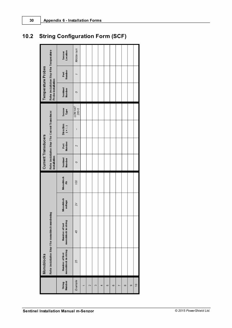
10.2 String Configuration Form (SCF)
Appendix 6 - Installation Forms
Sentinel Installation Manual m-Senzor
31
© 2015 PowerShield Ltd.
10.3 Monoblock Mapping Form (MMF)
Site Name:
Sentinel Number:
Sentinel Installation Manual m-Senzor
32
© 2015 PowerShield Ltd.
Appendix 7 - Monitor & m-Senzor Replacement
11 Appendix 7 - Monitor & m-Senzor Replacement
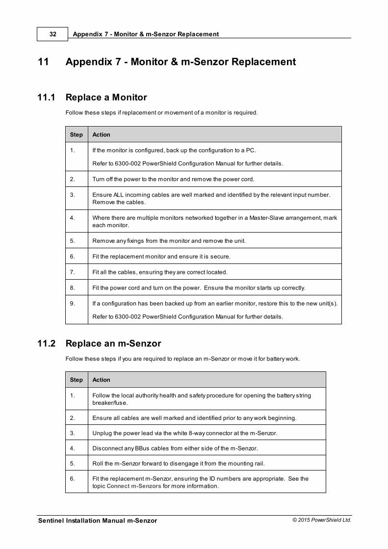
11.1 Replace a Monitor
Follow these steps if replacement or movement of a monitor is required.
Step Action
1. If the monitor is configured, back up the configuration to a PC.
Refer to 6300-002 PowerShield Configuration Manual for further details.
2. Turn off the power to the monitor and remove the power cord.
3. Ensure ALL incoming cables are well marked and identified by the relevant input number. Remove the cables.
4. Where there are multiple monitors networked together in a Master-Slave arrangement, markeach monitor.
5. Remove any fixings from the monitor and remove the unit.
6. Fit the replacement monitor and ensure it is secure.
7. Fit all the cables, ensuring they are correct located.
8. Fit the power cord and turn on the power. Ensure the monitor starts up correctly.
9. If a configuration has been backed up from an earlier monitor, restore this to the new unit(s).
Refer to 6300-002 PowerShield Configuration Manual for further details.
11.2 Replace an m-Senzor
Follow these steps if you are required to replace an m-Senzor or move it for battery work.
Step Action
1. Follow the local authority health and safety procedure for opening the battery stringbreaker/fuse.
2. Ensure all cables are well marked and identified prior to any work beginning.
3. Unplug the power lead via the white 8-way connector at the m-Senzor.
4. Disconnect any BBus cables from either side of the m-Senzor.
5. Roll the m-Senzor forward to disengage it from the mounting rail.
6. Fit the replacement m-Senzor, ensuring the ID numbers are appropriate. See thetopic Connect m-Senzors for more information.

Appendix 7 - Monitor & m-Senzor Replacement
Sentinel Installation Manual m-Senzor
33
© 2015 PowerShield Ltd.
Step Action
7. Fit the BBus cables and connect the power lead via the white 8-way connector at them-Senzor.
8. The green LED should illuminate within 4 seconds. If it does not, DO NOT proceed toStep 9. Check the connections to the battery.
9. Follow the local authority health and safety procedure for closing the battery stringbreaker/fuse.
Sentinel Installation Manual m-Senzor
34
© 2015 PowerShield Ltd.
Appendix 8 - Models and Part Numbers
12 Appendix 8 - Models and Part Numbers
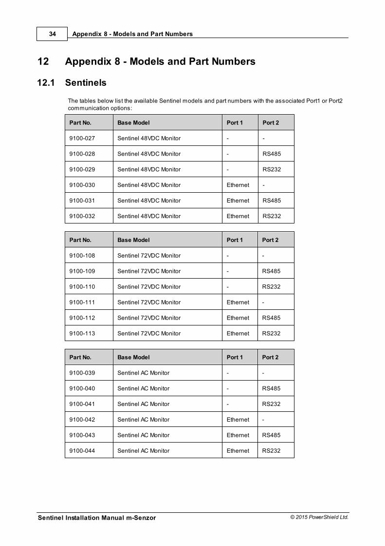
12.1 Sentinels
The tables below list the available Sentinel models and part numbers with the associated Port1 or Port2communication options:
Part No. Base Model Port 1 Port 2
9100-027 Sentinel 48VDC Monitor - -
9100-028 Sentinel 48VDC Monitor - RS485
9100-029 Sentinel 48VDC Monitor - RS232
9100-030 Sentinel 48VDC Monitor Ethernet -
9100-031 Sentinel 48VDC Monitor Ethernet RS485
9100-032 Sentinel 48VDC Monitor Ethernet RS232
Part No. Base Model Port 1 Port 2
9100-108 Sentinel 72VDC Monitor - -
9100-109 Sentinel 72VDC Monitor - RS485
9100-110 Sentinel 72VDC Monitor - RS232
9100-111 Sentinel 72VDC Monitor Ethernet -
9100-112 Sentinel 72VDC Monitor Ethernet RS485
9100-113 Sentinel 72VDC Monitor Ethernet RS232
Part No. Base Model Port 1 Port 2
9100-039 Sentinel AC Monitor - -
9100-040 Sentinel AC Monitor - RS485
9100-041 Sentinel AC Monitor - RS232
9100-042 Sentinel AC Monitor Ethernet -
9100-043 Sentinel AC Monitor Ethernet RS485
9100-044 Sentinel AC Monitor Ethernet RS232
Appendix 8 - Models and Part Numbers
Sentinel Installation Manual m-Senzor
35
© 2015 PowerShield Ltd.
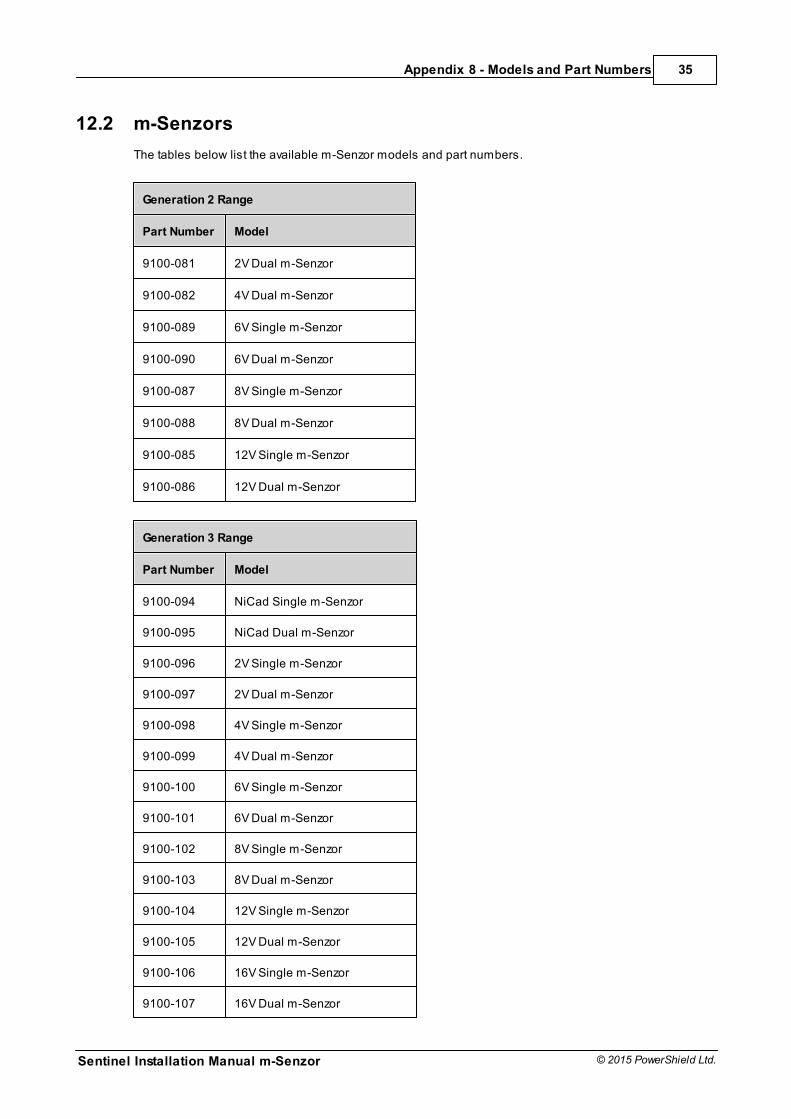
12.2 m-Senzors
The tables below list the available m-Senzor models and part numbers.
Generation 2 Range
Part Number Model
9100-081 2V Dual m-Senzor
9100-082 4V Dual m-Senzor
9100-089 6V Single m-Senzor
9100-090 6V Dual m-Senzor
9100-087 8V Single m-Senzor
9100-088 8V Dual m-Senzor
9100-085 12V Single m-Senzor
9100-086 12V Dual m-Senzor
Generation 3 Range
Part Number Model
9100-094 NiCad Single m-Senzor
9100-095 NiCad Dual m-Senzor
9100-096 2V Single m-Senzor
9100-097 2V Dual m-Senzor
9100-098 4V Single m-Senzor
9100-099 4V Dual m-Senzor
9100-100 6V Single m-Senzor
9100-101 6V Dual m-Senzor
9100-102 8V Single m-Senzor
9100-103 8V Dual m-Senzor
9100-104 12V Single m-Senzor
9100-105 12V Dual m-Senzor
9100-106 16V Single m-Senzor
9100-107 16V Dual m-Senzor
Sentinel Installation Manual m-Senzor
36
© 2015 PowerShield Ltd.
Appendix 8 - Models and Part Numbers
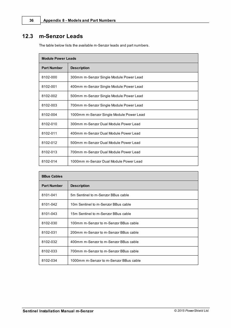
12.3 m-Senzor Leads
The table below lists the available m-Senzor leads and part numbers.
Module Power Leads
Part Number Description
8102-000 300mm m-Senzor Single Module Power Lead
8102-001 400mm m-Senzor Single Module Power Lead
8102-002 500mm m-Senzor Single Module Power Lead
8102-003 700mm m-Senzor Single Module Power Lead
8102-004 1000mm m-Senzor Single Module Power Lead
8102-010 300mm m-Senzor Dual Module Power Lead
8102-011 400mm m-Senzor Dual Module Power Lead
8102-012 500mm m-Senzor Dual Module Power Lead
8102-013 700mm m-Senzor Dual Module Power Lead
8102-014 1000mm m-Senzor Dual Module Power Lead
BBus Cables
Part Number Description
8101-041 5m Sentinel to m-Senzor BBus cable
8101-042 10m Sentinel to m-Senzor BBus cable
8101-043 15m Sentinel to m-Senzor BBus cable
8102-030 100mm m-Senzor to m-Senzor BBus cable
8102-031 200mm m-Senzor to m-Senzor BBus cable
8102-032 400mm m-Senzor to m-Senzor BBus cable
8102-033 700mm m-Senzor to m-Senzor BBus cable
8102-034 1000mm m-Senzor to m-Senzor BBus cable
Appendix 9 - Specifications
Sentinel Installation Manual m-Senzor
37
© 2015 PowerShield Ltd.
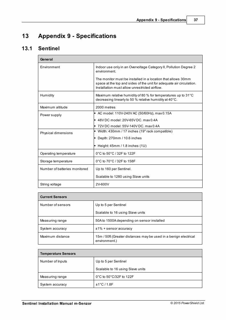
13 Appendix 9 - Specifications
13.1 Sentinel
General
Environment Indoor use only in an Overvoltage Category II, Pollution Degree 2environment.
The monitor must be installed in a location that allows 30mmspace at the top and sides of the unit for adequate air circulation. Installation must allow unrestricted airflow.
Humidity Maximum relative humidity of 80 % for temperatures up to 31°Cdecreasing linearly to 50 % relative humidity at 40°C.
Maximum altitude 2000 metres
Power supply AC model: 110V-240V AC (50/60Hz), max 0.15A
48V DC model: 20V-65V DC. max 0.4A
72V DC model: 55V-140V DC. max 0.4A
Physical dimensions Width: 430mm / 17 inches (19" rack compatible)
Depth: 270mm / 10.6 inches
Height: 45mm / 1.8 inches (1U)
Operating temperature 0°C to 50°C / 32F to 122F
Storage temperature 0°C to 70°C / 32F to 158F
Number of batteries monitored Up to 160 per Sentinel.
Scalable to 1280 using Slave units
String voltage 2V-600V
Current Sensors
Number of sensors Up to 5 per Sentinel
Scalable to 16 using Slave units
Measuring range 50A to 1500A depending on sensor installed
System accuracy ±1% + sensor accuracy
Maximum distance 15m / 50ft (Greater distances may be used in a benign electricalenvironment.)
Temperature Sensors
Number of Inputs Up to 5 per Sentinel
Scalable to 16 using Slave units
Measuring range 0°C to 50°C/32F to 122F
System accuracy ±1°C / 1.8F
Sentinel Installation Manual m-Senzor
38
© 2015 PowerShield Ltd.
Appendix 9 - Specifications
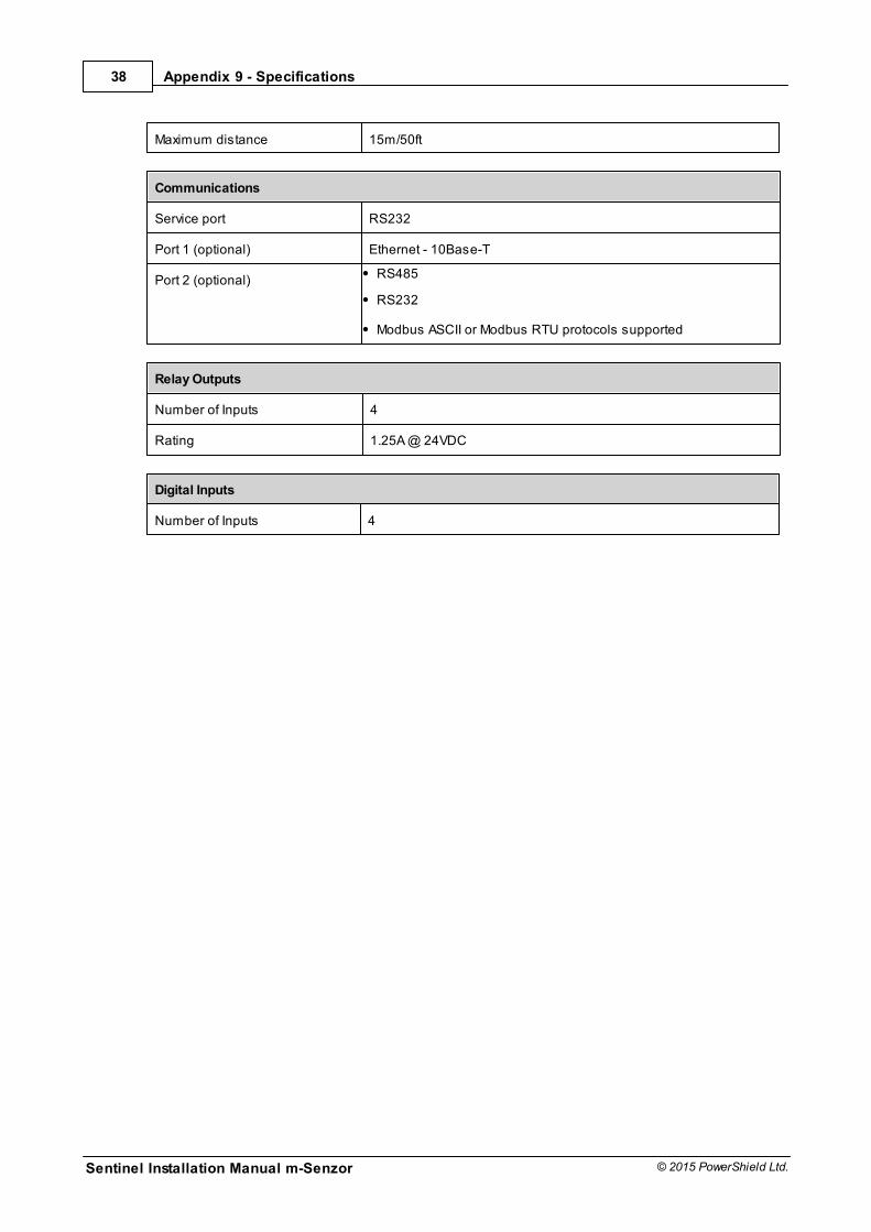
Maximum distance 15m/50ft
Communications
Service port RS232
Port 1 (optional) Ethernet - 10Base-T
Port 2 (optional) RS485
RS232
Modbus ASCII or Modbus RTU protocols supported
Relay Outputs
Number of Inputs 4
Rating 1.25A @ 24VDC
Digital Inputs
Number of Inputs 4