Embed Size (px)
Citation preview
STR-1015-1
3rd International Structural Specialty Conference 3ièmeconférenceinternationalespécialiséesur le génie des structures
Edmonton, Alberta
June 6-9, 2012 /6 au 9 juin 2012
Seismic Performance Evaluation of Multi-column Bridge Bent Retrofitted with Composite Materials
A. H. M. MuntasirBillah, M Shahria Alam
School of Engineering, The University of British Columbia, Kelowna, BC, Canada
Abstract: Application of composite materials has gained popularity for strengthening deficient concrete structures. Different types of composite materials have been investigated in the past and proven to be an effective mean for retrofitting. The aim of this study is to investigate the possible use of high performance materials for seismic upgrading of bridge bents. This analytical study investigates the use of engineered cementitious composite (ECC) along with carbon fiber reinforced polymer (CFRP) for seismic retrofitting of a non-seismically designed multi-column bridge bent. A non-seismically designed pre 1965 bridge bent has been retrofitted using ECC and CFRP jacketing and their performance has been compared in terms of the base shear capacity demand ratio, ductility demand, residual drift and damage states under earthquake loading. Nonlinear Incremental Dynamic Analysis (IDA) has been carried out to predict the structural behavior of the retrofitted bridge bents subjected to ten selected ground motions. Comparisons of static pushover against dynamic time history analyses results have been performed, in terms of performance criteria such as the displacement and base shear at cracking, yielding and crushing. Statistical analysis shows the differences in results obtained from static and dynamic analysis in predicting structural behavior under seismic excitation. The results obtained from this study indicate that the bridge bent retrofitted with ECC jacket performs better in limiting the residual drift with adequate damage resistance under earthquake loading.
1. Introduction
Highway bridges play an important role to build a smooth and fast communication system in between cities and across country. Recent collapses of several bridges in North America highlight the vulnerability of the existing bridges, which may be inadequate during seismic loads as required by the current codes and guidelines (e.g. ATC-32, CSA-2010). Many bridges were designed without any earthquake resistance criterion since they were built prior to earthquake resistant design codes; others were designed to resist horizontal actions but without the principles of the capacity design or were built at a site in an area where the seismic hazard has been re-evaluated and increased (CSA-2010, ATC-32).Common deficiencies found in bridge bents built prior to 1965 include insufficient transverse reinforcement and inadequate lap splice length. In addition, poor detailing including poor anchorage of the transverse reinforcement, rare use of ties, and lap splices located in potential flexural hinge regions make older columns susceptible to failure. Possible failure modes of deficient columns are shear failure, pre-mature flexural failure and lap splice failure.

STR-1015-2
The replacement or demolition of these deficient bridges will be a costly undertaking. Alternatively,retrofitting of these bridges could be more convenient to meet the current seismic and traffic demand. Various rehabilitation techniques are available to upgrade the seismic performance of existing RC structures.
The major techniques for structural rehabilitation of RC bridges include encasing of columns and beam column joints with steel, Fiber Reinforced Polymer (FRP) or reinforced concrete (RC) jackets.In recent years, innovative technologies such as engineered cementitious composites (ECC) jacketing, prestressing wires, etc. along with traditional solutions have become available to the practitioners for structural retrofitting by either enhancing the seismic capacity or reducing the demand. These options may be significantly different with respect to various aspects such as costs, time, structural performances, architectural impact, occupancy disruption, etc. (FHWA-HRT-06-032, 2006).In the last two decades, FRP have attracted the attention of researchers and bridge owners as an alternative material for retrofitting reinforced concrete bridge elements. The use of ECC, a high performance high strength concrete with its special tensile properties is gradually gaining popularity among the practitioners in earthquake engineering. Because of its improved tensile and strength properties, ECC warrants its use in seismic retrofitting.
Many seismic design guidelines (FEMA-356 and Eurocode-8) recommend static pushover analysis(SPO) as an effective tool for design and assessment of structures under seismic action. Inelastic static pushover analysis is a simple yet effective technique for assessing seismic performance of structures (Saiidi and Sozen, 1981; Bracci et al. 1999). Being a monotonic analysis, static analysis does not require unloading and reloading models. Although these procedures are much simpler than their dynamic counterpart, such techniques are not able to take into account progressive structural stiffness degradation, change of modal characteristics and period elongation of the structure for increasing values of external action (Ferracuti et al. 2009). Incremental Dynamic Analysis (IDA) is capable of accurately predicting the seismic capacity and demand of structures from elastic to dynamic instability ranges, by using a series of non-linear ground motion time-histories of increasing intensity (Mwafy and Elnashai, 2001).
The objective of this study is to compare the performance of a pre-1965 designed multi column bridge bent retrofitted with different composite materials jacket, namely FRP jacketing and engineered cementitious composites (ECC) jacketing. Here, nonlinear finite element analysis has been implemented to conduct the study, which was first verified with the experimental results of each category of retrofitting. Moreover, the study aims to develop dynamic pushover envelopes from IDA for bridge bents retrofitted with different techniques.This study also investigates and compares the performance of the retrofitted bridge bents with different analysis techniques i.e. SPO and IDA. A statistical analysis of the results obtained from SPO and IDAreveals marked differences and range of variation in predicting the performance points (base share and displacement at yielding andcrushing) attained in the static and dynamic analyses.

STR-1015-3
2. Bridge Bent Details
To evaluate the performance of the retrofitted multi-column bridge bent, the northbound lanes of the South Temple Bridge is considered in this study (Pantelides and Gergely, 2002).The bridge was considered seismically deficient as it had inadequacy in the amount of reinforcement and seismic detailing. This bridge bent was retrofitted by Pantelides and Gergely(2002) using CFRP jacketing. They developed design equations for CFRP jacketing and performed both experimental study and analytical verification of their results. The bent consists of three columns and a bent cap, as shown in Figure 1. A concrete deck of 21.87 m span was supported by two bents and each bent supported eight steel girders. A gravity load of 240 kN was carried by each steel girder.Reinforcement details of the column, bent cap, and joints are also shown in Figure 1.The bent column had inadequate transverse reinforcement in the lap-splice region. Transverse hoops in the bent cap joints were absent, and columns had insufficient tie spacing in the plastic hinge regions, which is the most vulnerable portion of a column.The reinforcing steel in the bridge bent had yield strength of 275 MPa, while the compressive strength of the concrete was 21 MPa.
Figure 1: South Temple Bridge bent dimensions and reinforcement details (adapted from Pantelides and Gergely, 2002)
2.1 Details of Retrofitting Techniques
In order to design the two different retrofitting techniques,a response spectrum analysis wascarried out to determine the design base shear. As the bridge bent is located in Salt Lake City, Utah, USA,the design response spectrum for this location wasobtained (Swensen and Wong, 2011). Determining the time period and modal mass participation factors from eigenvalue analysis, the design base shear for each retrofitted bridge bent was calculated using the square root sum of square (SRSS) method.
In this study the CFRP composite jacket retrofitting technique was implemented from Pantelides and Gergely (2002), which has a tensile strength of 628 MPa, initial stiffness of 6.5x10⁴ MPa and ultimate axial strain of 10mm/m. The material is a carbon fiber/epoxy resin composite with 48,000 fibers per tow unidirectional carbon fibers. The number of tows per 25.4 mm of sheet (pitch) was 6.5, and the width of the carbon fiber sheets was 457 mm. The thickness of the CFRP jacketing was calculated to be 3.42 mm.
Due to its superior property over regular concrete, ECC jacketing was utilized as another retrofitting technique in this study. Because of the strain-hardening property of ECC, this ductile material behaves more like steel than traditional concrete. The jacket thickness calculated was 80 mm. For retrofitting with ECC jacket, no additional reinforcement was provided. The ECC used in this study has a compressive strength of 80 MPa and a tensile strength of 6.5 MPa.

STR-1015-4
3. Finite element modeling
The analytical model of the bridge bent is approximated as a continuous 2-D finite element frame using the SeismoStruct nonlinear analysis program (SeismoStruct, 2010). Nonlinear static pushover and incremental dynamic time-history analyses have been performed to determine the performances of the retrofitted bridge bents. 3-D inelastic beam elements have been used for modeling the beams and the columns. Here, fiber modeling approach has been employed to represent the distribution of material nonlinearity along the length and cross-sectional area of the member. The confinement effect of the concrete section is considered on the basis of reinforcement detailing. To develop the analytical model Menegotto-Pinto steel model (Menegotto and Pinto, 1973)with Filippou (Filippou et al.,1983) isotropic strain hardening property is used for reinforcing steel material.The yield strength, strain hardening parameter and modulus of elasticity of steel are considered as 275MPa, 0.5% and 2x10⁵ MPa, respectively.For concrete nonlinear variable confinement model of Madas and Elnashai (1992) with compressive strength of 21MPa and tensile strength of 1.7MPa has been used. CFRP confined concrete model developed by Ferracuti and Savoia (2005) has been implemented.In this model the confinement effect of the FRP wrapping follows the rules proposed by Spoelstra and Monti (1999).
The CFRP retrofitted bridge bent has been modeled in SeismoStruct(2010) with jacketed section. To develop the analytical model for bridge bent retrofitted with ECC jacket, another finite element software ZeusNL (2011) was employed. Similar concrete and steel model was used for modeling bridge bent where ECC jacket was modeled following the constitutive relationship developed by Han et al. (2003). Although this study used two different finite element software, both the software uses same modeling approach i.e. fiber modeling approach. Moreover, both software has similar constitutive models for concrete and steel and uses similar algorithm for static and dynamic analysis and these allowed producing comparable results.
3.1 Model validation with experimental results
In this section the numerical models of the two retrofitted bridge bents have been varified at the component level using experimental data from existing literature. Figure 2a illustrates the comparative study of pushover response curve for the previous experimental and analytical result(Pantelides and Gergely, 2002) on the South Temple Bridge bent along with the results obtained from the present numerical model. From Figure 2a it is evident that the present analytical result is very close to the previous analytical result.The present analytical result varied only 14% and 12% in predicting the stiffness and capacity compared to those of the experimental results, respectively.
Figure 2: Comparison of experimental and analytical results for (a) bridge bent retrofitted with CFRP (Pantelides and Gergely, 2002)and (b) ECC column(Gencturk and Elnashai ,2011)
-4
-3
-2
-1
0
1
2
3
4
-6 -4 -2 0 2 4 6
Load
(kN
)
Drift (%)
AnalyticalExperiment
(b)
0
400
800
1200
1600
2000
0 50 100 150 200 250 300
Bas
e S
hear
(kN
)
Displacement (mm)
Present Analytical ResultExperimental ResultPrevious Analytical Result
(a)

STR-1015-5
Gencturk and Elnashai (2011) reported the accuracy of ZeusNL in predicting the experimental results. In order to validatethe numerical simulation results of the present studywith experimental results (Gencturk and Elnashai, 2011), the load-drift (%) curve obtained from the cyclic tests and the numerical study are plotted in Figure 2b. From Figure 2b it is observed that the numerical model is capable of predicting the peak load and strength with reasonable accuracy with a little difference in predicting stiffness. The energy dissipation capacity predicted from the numerical analysis was 0.61 kN-m, whereas the energy dissipation obtained from experimental result was 0.57 kN-m, which is only 7% lower than the calculated result.
4. Nonlinear static Pushover analysis
Nonlinear static pushover analysis has been performed for each bridge bent. The girder load of 240 kN has been applied as a permanent load at each girder location and for the pushover analysis incremental load has beenapplied in the form of displacement up to a magnitude of 0.3m. The pushover response curves for the two retrofitting techniques and the original bridge bent are shown in Figure 3a.
From the pushover response curves it is observed that both retrofitting techniques increased the capacity of the bridge bent considerably. From the pushover analysis it is observed that in terms of capacity both retrofitting techniques showed similar performance, which shows that the retrofit designs are adequate and comparable. Figure 3b presents the ductility for bridge bent retrofitted with different retrofitting techniques. Ductility is defined as the ratio of the bent top displacement at maximum load to the bent top displacement at yield load. ECC jacketed bridge bent showed higher ductility which was 3.6% higher as compared to CFRP jacket.
Figure 3: (a)Pushover response curve and (b) Ductility forretrofitted bridge bents
The two composite materials considered in this study are compared in terms of different performance criteria. The performance criteria considered here are the displacements and base shear at the onset of concrete cracking, yielding of longitudinal steel and crushing of concrete.TheYielding of steel rebar was assumed to take place at a tensile strain of 0.0025 while the cracking strain of concrete was considered to be 0.00014. Paulay and Priestley (1992) suggested that the crushing strain of confined concrete ranges between 0.015 and 0.05. In the present analysis, crushing of confined concrete was assumed to take place at a concrete compressive strain of 0.035.Table 1shows the comparative performance of different retrofitting techniques.
0
400
800
1200
1600
2000
0 50 100 150 200 250 300
Bas
e S
hear
(kN
)
Displacement (mm)
CFRP
ECC
Original
(a)
0
0.5
1
1.5
2
2.5
3
3.5
4
Original CFRP ECC
Duc
tility
Cap
acity
Retrofitting Technique
(b)
STR-1015-6
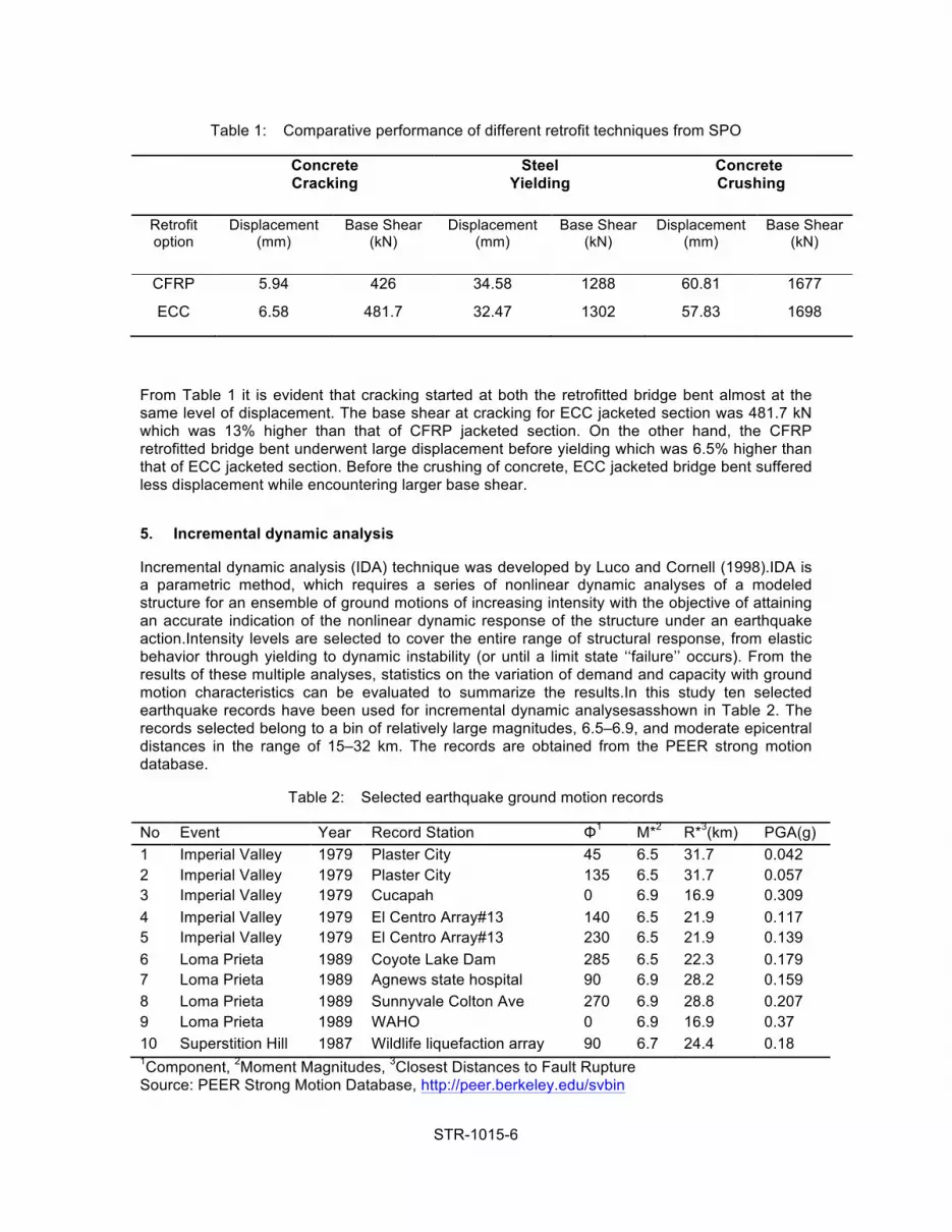
Table 1: Comparative performance of different retrofit techniques from SPO
Concrete Cracking
Steel Yielding
Concrete Crushing
Retrofit option
Displacement (mm)
Base Shear (kN)
Displacement (mm)
Base Shear (kN)
Displacement (mm)
Base Shear (kN)
CFRP 5.94 426 34.58 1288 60.81 1677
ECC 6.58 481.7 32.47 1302 57.83 1698
From Table 1 it is evident that cracking started at both the retrofitted bridge bent almost at the same level of displacement. The base shear at cracking for ECC jacketed section was 481.7 kN which was 13% higher than that of CFRP jacketed section. On the other hand, the CFRP retrofitted bridge bent underwent large displacement before yielding which was 6.5% higher than that of ECC jacketed section. Before the crushing of concrete, ECC jacketed bridge bent suffered less displacement while encountering larger base shear.
5. Incremental dynamic analysis
Incremental dynamic analysis (IDA) technique was developed by Luco and Cornell (1998).IDA is a parametric method, which requires a series of nonlinear dynamic analyses of a modeled structure for an ensemble of ground motions of increasing intensity with the objective of attaining an accurate indication of the nonlinear dynamic response of the structure under an earthquake action.Intensity levels are selected to cover the entire range of structural response, from elastic behavior through yielding to dynamic instability (or until a limit state ‘‘failure’’ occurs). From the results of these multiple analyses, statistics on the variation of demand and capacity with ground motion characteristics can be evaluated to summarize the results.In this study ten selected earthquake records have been used for incremental dynamic analysesasshown in Table 2. The records selected belong to a bin of relatively large magnitudes, 6.5–6.9, and moderate epicentral distances in the range of 15–32 km. The records are obtained from the PEER strong motion database.
Table 2: Selected earthquake ground motion records
No Event Year Record Station Φ1 M*2 R*3(km) PGA(g) 1 Imperial Valley 1979 Plaster City 45 6.5 31.7 0.042 2 Imperial Valley 1979 Plaster City 135 6.5 31.7 0.057 3 Imperial Valley 1979 Cucapah 0 6.9 16.9 0.309 4 Imperial Valley 1979 El Centro Array#13 140 6.5 21.9 0.117 5 Imperial Valley 1979 El Centro Array#13 230 6.5 21.9 0.139 6 Loma Prieta 1989 Coyote Lake Dam 285 6.5 22.3 0.179 7 Loma Prieta 1989 Agnews state hospital 90 6.9 28.2 0.159 8 Loma Prieta 1989 Sunnyvale Colton Ave 270 6.9 28.8 0.207 9 Loma Prieta 1989 WAHO 0 6.9 16.9 0.37 10 Superstition Hill 1987 Wildlife liquefaction array 90 6.7 24.4 0.18 1Component, 2Moment Magnitudes, 3Closest Distances to Fault Rupture Source: PEER Strong Motion Database, http://peer.berkeley.edu/svbin
STR-1015-7
5.1 Comparison of Different Retrofit Alternatives
Once the model is generated and the ground motion records are chosen, IDA is performed. Thus, anonlinear computational model of the prototype structural system was developed. To startthe analysis, the chosen earthquake records need to be scaled from a low intensity measure (IM)to several higher IMlevels until structural collapse occurs.This section presents the results of the dynamic responses of two retrofitted bridge bents under the Imperial valley earthquake (record no. 3 in Table 2).The performance of different retrofit alternatives are compared in terms of the base shear capacity demand ratio (Figure 4a), residual drift percent (Figure 4b), ductility demand (Figure 4c) and damage states to find out the most efficient retrofit option.
5.1.1 Base shear capacity/demand ratio
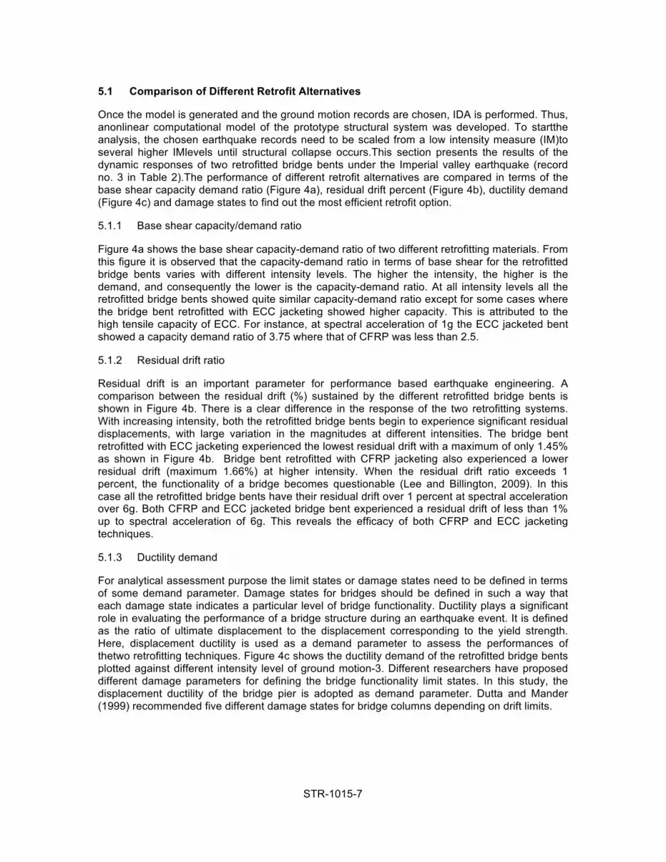
Figure 4a shows the base shear capacity-demand ratio of two different retrofitting materials. From this figure it is observed that the capacity-demand ratio in terms of base shear for the retrofitted bridge bents varies with different intensity levels. The higher the intensity, the higher is the demand, and consequently the lower is the capacity-demand ratio. At all intensity levels all the retrofitted bridge bents showed quite similar capacity-demand ratio except for some cases where the bridge bent retrofitted with ECC jacketing showed higher capacity. This is attributed to the high tensile capacity of ECC. For instance, at spectral acceleration of 1g the ECC jacketed bent showed a capacity demand ratio of 3.75 where that of CFRP was less than 2.5.
5.1.2 Residual drift ratio
Residual drift is an important parameter for performance based earthquake engineering. A comparison between the residual drift (%) sustained by the different retrofitted bridge bents is shown in Figure 4b. There is a clear difference in the response of the two retrofitting systems. With increasing intensity, both the retrofitted bridge bents begin to experience significant residual displacements, with large variation in the magnitudes at different intensities. The bridge bent retrofitted with ECC jacketing experienced the lowest residual drift with a maximum of only 1.45% as shown in Figure 4b. Bridge bent retrofitted with CFRP jacketing also experienced a lower residual drift (maximum 1.66%) at higher intensity. When the residual drift ratio exceeds 1 percent, the functionality of a bridge becomes questionable (Lee and Billington, 2009). In this case all the retrofitted bridge bents have their residual drift over 1 percent at spectral acceleration over 6g. Both CFRP and ECC jacketed bridge bent experienced a residual drift of less than 1% up to spectral acceleration of 6g. This reveals the efficacy of both CFRP and ECC jacketing techniques.
5.1.3 Ductility demand
For analytical assessment purpose the limit states or damage states need to be defined in terms of some demand parameter. Damage states for bridges should be defined in such a way that each damage state indicates a particular level of bridge functionality. Ductility plays a significant role in evaluating the performance of a bridge structure during an earthquake event. It is defined as the ratio of ultimate displacement to the displacement corresponding to the yield strength. Here, displacement ductility is used as a demand parameter to assess the performances of thetwo retrofitting techniques. Figure 4c shows the ductility demand of the retrofitted bridge bents plotted against different intensity level of ground motion-3. Different researchers have proposed different damage parameters for defining the bridge functionality limit states. In this study, the displacement ductility of the bridge pier is adopted as demand parameter. Dutta and Mander (1999) recommended five different damage states for bridge columns depending on drift limits.
STR-1015-8
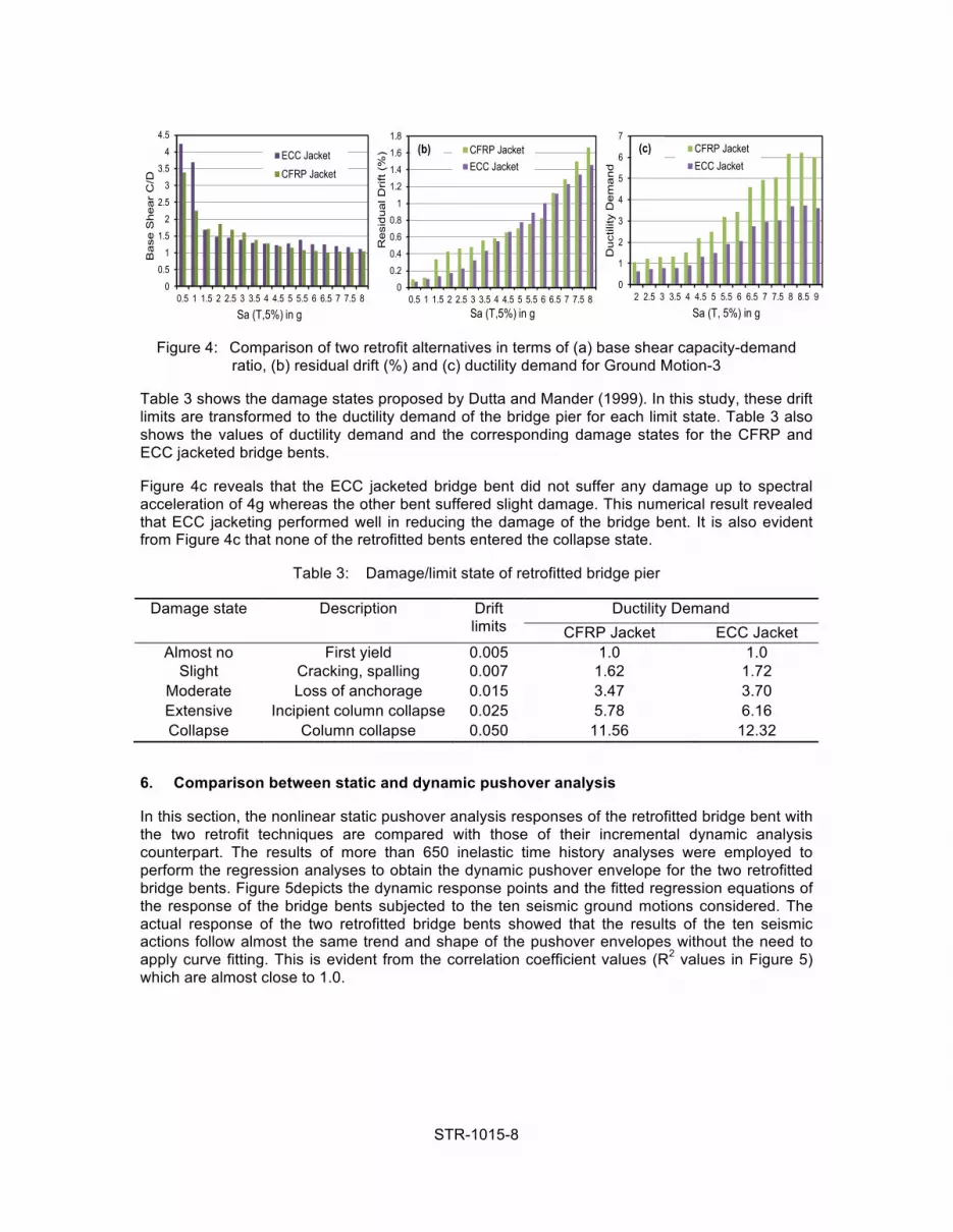
Figure 4: Comparison of two retrofit alternatives in terms of (a) base shear capacity-demand ratio, (b) residual drift (%) and (c) ductility demand for Ground Motion-3
Table 3 shows the damage states proposed by Dutta and Mander (1999). In this study, these drift limits are transformed to the ductility demand of the bridge pier for each limit state. Table 3 also shows the values of ductility demand and the corresponding damage states for the CFRP and ECC jacketed bridge bents.
Figure 4c reveals that the ECC jacketed bridge bent did not suffer any damage up to spectral acceleration of 4g whereas the other bent suffered slight damage. This numerical result revealed that ECC jacketing performed well in reducing the damage of the bridge bent. It is also evident from Figure 4c that none of the retrofitted bents entered the collapse state.
Table 3: Damage/limit state of retrofitted bridge pier
Damage state Description Drift limits
Ductility Demand CFRP Jacket ECC Jacket
Almost no First yield 0.005 1.0 1.0 Slight Cracking, spalling 0.007 1.62 1.72
Moderate Loss of anchorage 0.015 3.47 3.70 Extensive Incipient column collapse 0.025 5.78 6.16 Collapse Column collapse 0.050 11.56 12.32
6. Comparison between static and dynamic pushover analysis
In this section, the nonlinear static pushover analysis responses of the retrofitted bridge bent with the two retrofit techniques are compared with those of their incremental dynamic analysis counterpart. The results of more than 650 inelastic time history analyses were employed to perform the regression analyses to obtain the dynamic pushover envelope for the two retrofitted bridge bents. Figure 5depicts the dynamic response points and the fitted regression equations of the response of the bridge bents subjected to the ten seismic ground motions considered. The actual response of the two retrofitted bridge bents showed that the results of the ten seismic actions follow almost the same trend and shape of the pushover envelopes without the need to apply curve fitting. This is evident from the correlation coefficient values (R2 values in Figure 5) which are almost close to 1.0.
0
0.2
0.4
0.6
0.8
1
1.2
1.4
1.6
1.8
0.5 1 1.5 2 2.5 3 3.5 4 4.5 5 5.5 6 6.5 7 7.5 8
Re
sid
ua
l Drift
(%
)
Sa (T,5%) in g
CFRP JacketECC Jacket
(b)
0
1
2
3
4
5
6
7
2 2.5 3 3.5 4 4.5 5 5.5 6 6.5 7 7.5 8 8.5 9
Du
ctili
ty D
em
an
d
Sa (T, 5%) in g
CFRP JacketECC Jacket
(c)
0
0.5
1
1.5
2
2.5
3
3.5
4
4.5
0.5 1 1.5 2 2.5 3 3.5 4 4.5 5 5.5 6 6.5 7 7.5 8
Ba
se S
hea
r C
/D
Sa (T,5%) in g
ECC Jacket
CFRP Jacket
STR-1015-9
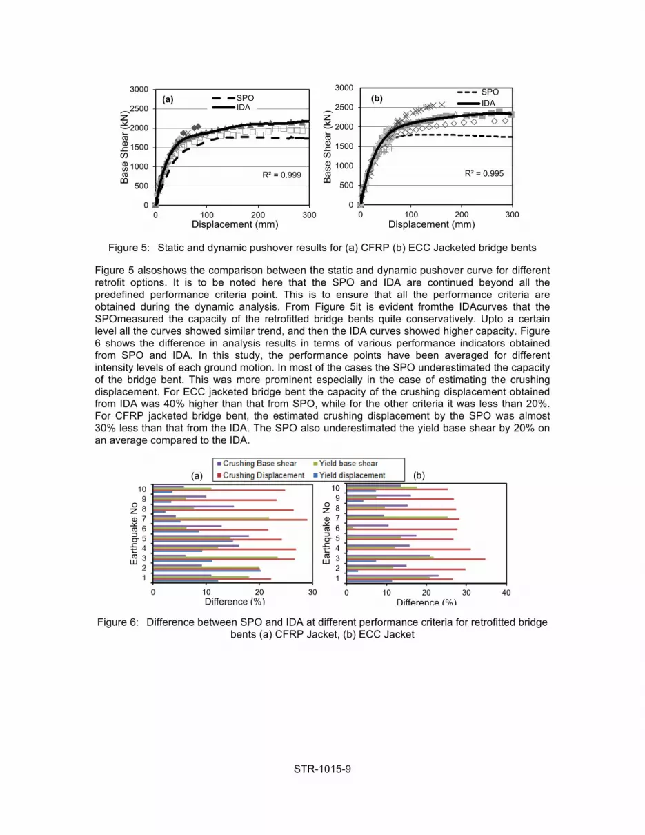
Figure 5: Static and dynamic pushover results for (a) CFRP (b) ECC Jacketed bridge bents
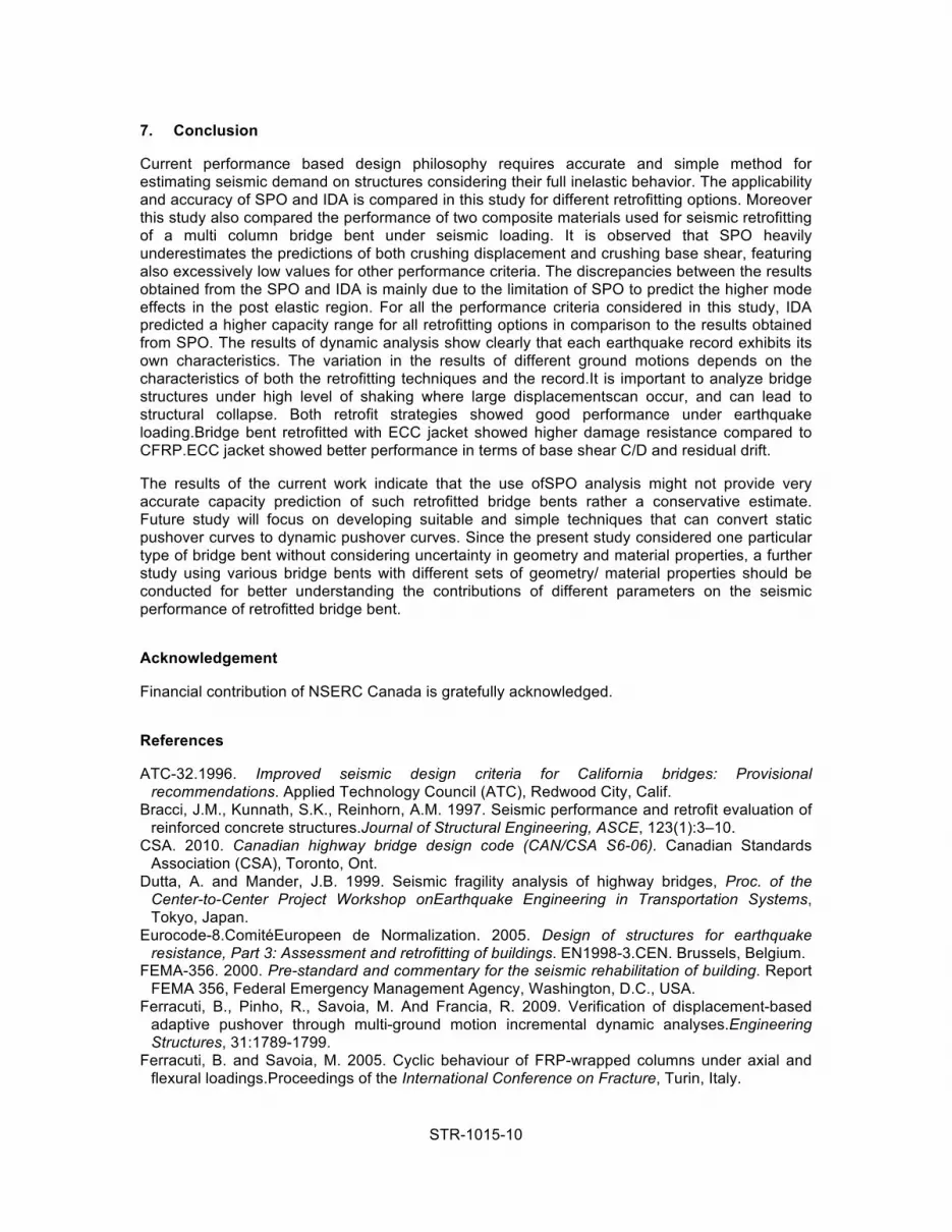
Figure 5 alsoshows the comparison between the static and dynamic pushover curve for different retrofit options. It is to be noted here that the SPO and IDA are continued beyond all the predefined performance criteria point. This is to ensure that all the performance criteria are obtained during the dynamic analysis. From Figure 5it is evident fromthe IDAcurves that the SPOmeasured the capacity of the retrofitted bridge bents quite conservatively. Upto a certain level all the curves showed similar trend, and then the IDA curves showed higher capacity. Figure 6 shows the difference in analysis results in terms of various performance indicators obtained from SPO and IDA. In this study, the performance points have been averaged for different intensity levels of each ground motion. In most of the cases the SPO underestimated the capacity of the bridge bent. This was more prominent especially in the case of estimating the crushing displacement. For ECC jacketed bridge bent the capacity of the crushing displacement obtained from IDA was 40% higher than that from SPO, while for the other criteria it was less than 20%. For CFRP jacketed bridge bent, the estimated crushing displacement by the SPO was almost 30% less than that from the IDA. The SPO also underestimated the yield base shear by 20% on an average compared to the IDA.
Figure 6: Difference between SPO and IDA at different performance criteria for retrofitted bridge bents (a) CFRP Jacket, (b) ECC Jacket
R² = 0.999
0
500
1000
1500
2000
2500
3000
0 100 200 300
Base
She
ar (k
N)
Displacement (mm)
SPOIDA
(a)
R² = 0.995
0
500
1000
1500
2000
2500
3000
0 100 200 300
Base
She
ar (k
N)
Displacement (mm)
SPOIDA(b)
0 10 20 30
123456789
10
Difference (%)
Ear
thqu
ake
No
(a)
0 10 20 30 40
123456789
10
Difference (%)
Ear
thqu
ake
No
(b)
STR-1015-10
7. Conclusion
Current performance based design philosophy requires accurate and simple method for estimating seismic demand on structures considering their full inelastic behavior. The applicability and accuracy of SPO and IDA is compared in this study for different retrofitting options. Moreover this study also compared the performance of two composite materials used for seismic retrofitting of a multi column bridge bent under seismic loading. It is observed that SPO heavily underestimates the predictions of both crushing displacement and crushing base shear, featuring also excessively low values for other performance criteria. The discrepancies between the results obtained from the SPO and IDA is mainly due to the limitation of SPO to predict the higher mode effects in the post elastic region. For all the performance criteria considered in this study, IDA predicted a higher capacity range for all retrofitting options in comparison to the results obtained from SPO. The results of dynamic analysis show clearly that each earthquake record exhibits its own characteristics. The variation in the results of different ground motions depends on the characteristics of both the retrofitting techniques and the record.It is important to analyze bridge structures under high level of shaking where large displacementscan occur, and can lead to structural collapse. Both retrofit strategies showed good performance under earthquake loading.Bridge bent retrofitted with ECC jacket showed higher damage resistance compared to CFRP.ECC jacket showed better performance in terms of base shear C/D and residual drift.
The results of the current work indicate that the use ofSPO analysis might not provide very accurate capacity prediction of such retrofitted bridge bents rather a conservative estimate. Future study will focus on developing suitable and simple techniques that can convert static pushover curves to dynamic pushover curves. Since the present study considered one particular type of bridge bent without considering uncertainty in geometry and material properties, a further study using various bridge bents with different sets of geometry/ material properties should be conducted for better understanding the contributions of different parameters on the seismic performance of retrofitted bridge bent.
Acknowledgement
Financial contribution of NSERC Canada is gratefully acknowledged.
References
ATC-32.1996. Improved seismic design criteria for California bridges: Provisional recommendations. Applied Technology Council (ATC), Redwood City, Calif.
Bracci, J.M., Kunnath, S.K., Reinhorn, A.M. 1997. Seismic performance and retrofit evaluation of reinforced concrete structures.Journal of Structural Engineering, ASCE, 123(1):3–10.
CSA. 2010. Canadian highway bridge design code (CAN/CSA S6-06). Canadian Standards Association (CSA), Toronto, Ont.
Dutta, A. and Mander, J.B. 1999. Seismic fragility analysis of highway bridges, Proc. of the Center-to-Center Project Workshop onEarthquake Engineering in Transportation Systems, Tokyo, Japan.
Eurocode-8.ComitéEuropeen de Normalization. 2005. Design of structures for earthquake resistance, Part 3: Assessment and retrofitting of buildings. EN1998-3.CEN. Brussels, Belgium.
FEMA-356. 2000. Pre-standard and commentary for the seismic rehabilitation of building. Report FEMA 356, Federal Emergency Management Agency, Washington, D.C., USA.
Ferracuti, B., Pinho, R., Savoia, M. And Francia, R. 2009. Verification of displacement-based adaptive pushover through multi-ground motion incremental dynamic analyses.Engineering Structures, 31:1789-1799.
Ferracuti, B. and Savoia, M. 2005. Cyclic behaviour of FRP-wrapped columns under axial and flexural loadings.Proceedings of the International Conference on Fracture, Turin, Italy.

STR-1015-11
FHWA-HRT-06-032. 2006. Seismic Retrofitting Manual for Highway Structures: Part 1 – Bridges. Research, Development, and Technology, Turner-Fairbank, Highway Research Center 6300, Georgetown Pike McLean, VA 22101-2296.
Filippou F.C., Popov E.P., Bertero V.V. 1983. Modelling of R/C joints under cyclic excitations.ASCE Journal of Structural Engineering,109(11),2666-2684.
Gencturk B and Elnashai AS. 2011. Multi-objective optimal seismic design of buildings using advanced engineering materials.MAE Center Report No. 11-01, Department of Civil and Environmental Engineering, University of Illinois at Urbana-Champaign, Urbana, Illinois.
Han, T.S., Feenstar, P.S. and Billington, S.L. 2003. Simulation of highly ductile fiber-reinforced cement-based composite components under cyclic loading. ACI Structural Journal, 100(6): 749-757.
Lee, W.K. and Billington, S. L. 2009. Simulation and performance-based earthquake engineering assessment of self-centering post-tensioned concrete bridge systems. PEER Report 2009/109, University of California, Berkeley, California.
Luco, N. and Cornell, C. A. 1998. Effects of random connection fractures on the demands and reliability for a three-story pre-Northridge (SMRP) structure.Proc. of the sixth U.S. National Conf. on Earthquake Eng., Earthquake Engineering Research Institute, Oakland, California.
Madas P. and Elnashai A.S. 1992. A new passive confinement model for transient analysis of reinforced concrete structures.Earthquake EngStruc, 21: 409-431.
MenegottoM.and Pinto P.E. 1973. Method of analysis for cyclically loaded R.C. plane frames including changes in geometry and non-elastic behaviour of elements under combined normal force and bending. Symposium on the Resistance and Ultimate Deformability of Structures Acted on by Well Defined Repeated Loads, IABSE, Zurich, Switzerland, pp. 15-22.
Mwafy, A.M. and Elnashai, A.S. 2001. Static pushover versus dynamic collapse analysis of RC buildings.Engineering Structures, 23: 407–424.
Pantelides,C.P. and Gergely, J. 2002. Carbon fiber reinforced polymer seismic retrofit of RC bridge bent: Design and In Situ Validation.Journal of Composites for Construction, 6 (1), 52-60.
Paulay, T. and Priestley, M.J.N. 1992. Seismic Design of Reinforced Concrete and Masonry Buildings, J. Wiley, New York, USA.
Saiidi, M. and Sozen, M.A. 1981.Simple nonlinear seismic analysis of R/C structures.Journal of the Structural Division, ASCE, 107(ST5):937–51.
Seismostruct V5.0.5 (2010) www.seismosoft.com Spoelstra M., Monti G. 1999. FRP-confined concrete model.Journal of Composites for
Construction, ASCE, 3, 143-150. Swensen S. and Wong K. 2011.Evaluation of peak structural responses based on consistent
elastic and inelastic design spectra. Struct. Design Tall Spec. Build. 20: 164–176. ZeusNL. 2011. A system for inelastic analysis of structure, V-1.8.9, Mid America Earthquake
Centre.


