Embed Size (px)
Citation preview


SecurView® DX/RT Breast Imaging Workstation
Installation and Service Manual For Software Version 10.4
Part Number MAN-06206 Revision 001 October 2019

© 2019 Hologic, Inc. Printed in the USA. This manual was originally written in English. Hologic, SecurView, Unifi, and associated logos are trademarks and/or registered trademarks of Hologic, Inc., and/or its subsidiaries in the United States and/or other countries. All other trademarks, registered trademarks, and product names are the property of their respective owners.
This product may be protected by one or more U.S. or foreign patents as identified at www.Hologic.com/patents.
Softcopy reading software © 2002–2019 MeVis Medical Solutions AG. All rights reserved. This product and related documentation are protected by copyright and are distributed under licenses restricting their use, copying, distribution, and decompilation. No part of this product or related documentation may be reproduced in any form by any means without prior written authorization of MeVis Medical Solutions AG and its licensors, if any. FlowBack, FlowNext, MammoNavigator, and ReportFlow are trademarks of MeVis BreastCare GmbH & Co. KG. This product may be protected by one or more of the following patents: 7,283,857, 6,891,920.
Libraries
Libtiff library © 1988-1997 Sam Leffler, 1991-1997 Silicon Graphics, Inc. OFFIS_DCMTK © 1994–2005, OFFIS MergeCOM-3 Advanced Integrator's Tool Kit – Version 4.8.0.0 PostgreSQL – Version 9.4.1 © 1996-2015, The PostgreSQL Global Development Group, 1994, The Regents of the University of California jpeglib © 1991-1998, Thomas G. Lane xerces © 1999-2010 The Apache Software Foundation 7-Zip © 1999-2009 Igor Pavlov Qt 4.8.6 © 2014 Digia Plc and/or its subsidiary(-ies), licensed under LGPL v2.1. This Qt library has been adapted by MeVis Medical Solutions AG. You may obtain the complete corresponding source code by sending an order to MeVis Medical Solutions AG, Support Department, Caroline-Herschel-Str. 1, 28359 Bremen, Germany.
Product Support USA: +1.877.371.4372 Europe: +32 2 711 4690 Asia: +852 37487700 Australia: +1 800 264 073 All Other: +1 781 999 7750 Email: [email protected]

SecurView DX/RT 10.4 Installation and Service Manual Table of Contents
MAN-06206 Revision 001 v
Table of Contents
List of Tables __________________________________________________________________ xi
1: Introduction __________________________________________________________________1 1.1 About This Guide ................................................................................................................................................... 1 1.2 Training .................................................................................................................................................................... 2 1.3 Document Conventions ......................................................................................................................................... 2 1.4 Terms and Definitions ............................................................................................................................................ 3
2: Workstation Description _______________________________________________________5 2.1 Workstation Overview ........................................................................................................................................... 5 2.2 SecurView DX Diagnostic Workstation ............................................................................................................... 7 2.3 SecurView RT Technologist Workstation ............................................................................................................ 8 2.4 SecurView Manager ............................................................................................................................................... 9 2.5 Multiworkstation Systems ................................................................................................................................... 10
3: Site Settings _________________________________________________________________11 3.1 Site Inspection ....................................................................................................................................................... 11 3.2 Required Materials ............................................................................................................................................... 11 3.3 Site Settings Table ................................................................................................................................................. 11
4: Installing the System _________________________________________________________15 4.1 Unpacking the SecurView System ...................................................................................................................... 15 4.2 Installing the SecurView Workstation ............................................................................................................... 16
4.2.1 Setting up the Workstation Computer ................................................................................................ 16 4.2.2 SecurView DX Display Connections (Barco High-Brightness Display) .......................................... 19 4.2.3 SecurView DX Display Connections (Barco Coronis Uniti 12MP Display).................................... 19 4.2.4 SecurView DX Display Connections (Barco Nio 5MP Displays) ..................................................... 21 4.2.5 SecurView RT Display Connections (Barco Nio 3MP Display) ....................................................... 22 4.2.6 SecurView Manager Display Connections .......................................................................................... 22
5: Configuring Windows Settings ________________________________________________25 5.1 System Startup and Shutdown ........................................................................................................................... 25
5.1.1 Workstation Startup ............................................................................................................................... 25 5.1.2 Workstation Shutdown .......................................................................................................................... 26 5.1.3 Manager Shutdown ................................................................................................................................ 26
5.2 Setting Up the Network Connections ................................................................................................................ 26 5.3 Setting the Network Card Properties ................................................................................................................. 27 5.4 Setting the Computer Name ................................................................................................................................ 27 5.5 Verifying the UPS Settings .................................................................................................................................. 28 5.6 Calibrating the High Resolution MG Displays ................................................................................................. 28 5.7 Customer and Windows Administrator Rights ................................................................................................ 29 5.8 Synchronizing System Time ................................................................................................................................ 29

SecurView DX/RT 10.4 Installation and Service Manual Table of Contents
vi MAN-06206 Revision 001
5.9 Configuring Remote Access (Manager) ............................................................................................................. 30 5.10 Increasing Security on the SCR User Account (Optional) ............................................................................... 30 5.11 Windows Domain Policy Settings (Optional) ................................................................................................... 32
5.11.1 Default Domain Policies ........................................................................................................................ 32 5.11.2 Domain Group Policy Settings ............................................................................................................. 32
5.12 Configuring Hologic Connect ............................................................................................................................. 33 5.12.1 Entering DNS Server Information ........................................................................................................ 33 5.12.2 Entering Hologic Connect Information ............................................................................................... 33
6: Configuring the SecurView Application ________________________________________35 6.1 Configuring a SecurView Workstation as a Client ........................................................................................... 35
6.1.1 Pre-Installation for Existing Standalone Workstations...................................................................... 35 6.1.2 Configuring a Workstation as a Client ................................................................................................ 36
6.2 Configuring DICOM Settings (Standalone, Manager) ..................................................................................... 37 6.2.1 DICOM > Setup Tab ............................................................................................................................... 37 6.2.2 DICOM > Printer Tab ............................................................................................................................. 40 6.2.3 DICOM > Destination Tab (SecurView DX) ........................................................................................ 48 6.2.4 DICOM > Destination Tab (SecurView RT) ........................................................................................ 50
6.3 Configuring the Settings Tab ............................................................................................................................... 51 6.3.1 Configuring Disk Space Monitoring and Auto-Deletion .................................................................. 52 6.3.2 Configuring Auto-Fetching / Auto-Completion (Standalone, Manager) ........................................ 52 6.3.3 Configuring Active Directory ............................................................................................................... 53 6.3.4 Configuring Study List Manager .......................................................................................................... 54 6.3.5 Configuring Application Event Logging ............................................................................................. 54 6.3.6 Configuring Manufacturer Settings ..................................................................................................... 55 6.3.7 Configuring Double Reading for Studies (SecurView DX) ............................................................... 57 6.3.8 Setting the Site Name and Address ...................................................................................................... 58 6.3.9 Configuring MG Secondary Capture Format (SecurView DX) ........................................................ 59
6.4 Configuring Licensing .......................................................................................................................................... 59 6.4.1 Verifying Licenses .................................................................................................................................. 59 6.4.2 Configuring Licenses.............................................................................................................................. 60
6.5 Configuring Routing ............................................................................................................................................ 61 6.5.1 Configuring Routing (Manager, Client) .............................................................................................. 61 6.5.2 Configuring Routing (Standalone) ....................................................................................................... 63
6.6 Configuring the Patient List for an Additional Monitor (Optional) .............................................................. 64 6.7 Configuring the Keypad (SecurView DX) ......................................................................................................... 65
6.7.1 Troubleshooting the Keypad (SecurView DX) ................................................................................... 65 6.8 Configuring the Barcode Scanner (Standalone, Client) ................................................................................... 66
6.8.1 Changing the Barcode Between Patient ID and Accession Number ............................................... 66 6.8.2 Control Studies Provided to Application Synchronization .............................................................. 67
6.9 Configuring SecurView/Unifi Workspace Integration .................................................................................... 68 6.10 Backing Up the System (Standalone, Manager) ................................................................................................ 68 6.11 Completing the Installation Report Form .......................................................................................................... 68

SecurView DX/RT 10.4 Installation and Service Manual Table of Contents
MAN-06206 Revision 001 vii
7: Maintenance _________________________________________________________________69 7.1 Backing Up and Restoring the Database ........................................................................................................... 70
7.1.1 Accessing the DBM Tool ........................................................................................................................ 70 7.1.2 Restoring from Backup and Synchronizing the Database ................................................................ 71 7.1.3 Restoring from Backup .......................................................................................................................... 74 7.1.4 Synchronizing Database with File System .......................................................................................... 75 7.1.5 Creating a Startup Database.................................................................................................................. 77 7.1.6 Creating a Backup of the Patient Database ......................................................................................... 79 7.1.7 Restoring Multimodality Viewer from Restore Point........................................................................ 80 7.1.8 Performing Database Maintenance ...................................................................................................... 80 7.1.9 Removing Auto-Fetching/Auto-Completion Jobs.............................................................................. 81 7.1.10 Exporting Users ...................................................................................................................................... 82 7.1.11 Importing Users ...................................................................................................................................... 83
7.2 Maintaining the Workstation Hardware (Standalone, Manager, Client) ...................................................... 84 7.2.1 Preventive Maintenance Checklist ....................................................................................................... 87
7.3 Importing Procedure Names Using DICOM Tags (Standalone, Manager) .................................................. 88 7.4 Configuring the User Interface Language ......................................................................................................... 90 7.5 Installing the SecurView Online Documentation (Outside US) ..................................................................... 90 7.6 Adding a SecurView User to the Site Domain .................................................................................................. 91 7.7 Reinstalling the SecurView Application ............................................................................................................ 93
7.7.1 Backing Up the SecurView System ...................................................................................................... 93 7.7.2 Uninstalling the SecurView Application ............................................................................................. 94 7.7.3 Installing the SecurView Application .................................................................................................. 94 7.7.4 Restoring the Application Settings and Database .............................................................................. 96 7.7.5 Deleting All Patient Data from SecurView (Standalone, Manager) ................................................ 97 7.7.6 Installing the SecurView Online Documentation............................................................................... 97
7.8 Recovering a Workstation ................................................................................................................................... 97 7.8.1 Restoring the System to SecurView Base Image ................................................................................ 98 7.8.2 Installing the Updates ............................................................................................................................ 99
7.9 Converting Standalone Workstations to Clients ............................................................................................ 101 7.9.1 Preparing Standalone for Conversion to Client ............................................................................... 102 7.9.2 Adding a Client to a Manager ............................................................................................................ 103
7.10 Substituting a Local Language Keyboard ....................................................................................................... 104 7.11 Configuring the Multi-Function Mouse (SecurView DX) ............................................................................. 104
7.11.1 Recommended Functions .................................................................................................................... 104 7.11.2 Recommended Mapping Configurations .......................................................................................... 105
7.12 Programming the Keypad ................................................................................................................................. 105 7.12.1 Known Issues ........................................................................................................................................ 106 7.12.2 USB Game Controller Keypad ............................................................................................................ 106 7.12.3 USB Keypad (Older Style) ................................................................................................................... 107 7.12.4 Keypad Commands .............................................................................................................................. 107 7.12.5 Configuring the Key Functions .......................................................................................................... 109 7.12.6 Key and Toolbar Functions ................................................................................................................. 110 7.12.7 Toggling between MG and Reconstructed Slices ............................................................................. 110

SecurView DX/RT 10.4 Installation and Service Manual Table of Contents
viii MAN-06206 Revision 001
7.12.8 Behavior of the USB Keypad ............................................................................................................... 111 7.12.9 Behavior of the USB Game Controller Keypad ................................................................................ 111
7.13 Keyboard Functions ............................................................................................................................................ 111 7.14 Reinstalling LCD Photometer Sensor ............................................................................................................... 117
7.14.1 Reconnecting the Photometer Sensor................................................................................................. 117 7.14.2 Reinstalling the Photometer Sensor Driver ....................................................................................... 118
7.15 Configure Colors Used by SecurView displays .............................................................................................. 118 7.15.1 Enable Color Support in SecurView .................................................................................................. 119 7.15.2 Enable the Toolbar Color ..................................................................................................................... 119
7.16 Configure Indicators for Prior and Current Images ....................................................................................... 120 7.16.1 Enable SecurView to Use Color Indicators for Prior and Current Images ................................... 120 7.16.2 Configure Optional Indicators for Prior and Current Images ........................................................ 121
7.17 Configuring Indicators for Smart Mapping .................................................................................................... 122 7.18 Configuring Maximum Speed for Cine ........................................................................................................... 122 7.19 Configuring Hanging Order .............................................................................................................................. 123
7.19.1 Editing the Configuration File ............................................................................................................ 124 7.19.2 Hanging Order Parameters ................................................................................................................. 124 7.19.3 MammoNavigator Sorting Order ....................................................................................................... 126
7.20 Improving Manager Performance with NIC Teaming .................................................................................. 126 7.20.1 Install and Configure NIC Teaming ................................................................................................... 127
8: Troubleshooting ____________________________________________________________131 8.1 Setting True Size Pixel Pitch on Displays ........................................................................................................ 131 8.2 Collecting Log Files ............................................................................................................................................ 132 8.3 Copying Scheduled Backup Files to an External Drive ................................................................................. 132 8.4 Configuring AutoMerge .................................................................................................................................... 133 8.5 Troubleshooting Multiworkstation Configurations ....................................................................................... 134
8.5.1 System Startup Issues ........................................................................................................................... 134 8.5.2 Incorrect IP Address Issues ................................................................................................................. 134 8.5.3 Client Cannot Reach Manager ............................................................................................................ 135 8.5.4 Manual Connection Succeeds ............................................................................................................. 135 8.5.5 Manager Loses Client Connection ...................................................................................................... 136
8.6 Printer Configuration Issues .............................................................................................................................. 136 8.7 Configuring Printer Timeouts ........................................................................................................................... 136 8.8 Auto-Fetching Issues .......................................................................................................................................... 137 8.9 Patient ID and Patient’s Birth Date Issues ....................................................................................................... 137 8.10 Contrast Enhanced Image Display Issues ....................................................................................................... 137 8.11 Mammography Image Display Issues ............................................................................................................. 138 8.12 PACS Issues with Default Manual Query Attributes .................................................................................... 143 8.13 Troubleshooting System Failures (Standalone, Manager) ............................................................................ 144 8.14 Troubleshooting the Updates Installation ....................................................................................................... 144 8.15 Configuring Enhanced Image Distribution ..................................................................................................... 145 8.16 Ports Used by SecurView ................................................................................................................................... 146

SecurView DX/RT 10.4 Installation and Service Manual Table of Contents
MAN-06206 Revision 001 ix
Appendix A Barco Video Cards _________________________________________________149
Appendix B Video Driver Installers _____________________________________________151
Index ________________________________________________________________________153

SecurView DX/RT 10.4 Installation and Service Manual Table of Contents
MAN-06206 Revision 001 xi
List of Tables Table 1: System Tasks ........................................................................................................................................................ 6 Table 2: Site Settings ........................................................................................................................................................ 13 Table 3: Default Parameters for Commonly Used Printers ....................................................................................... 44 Table 4: Keypad Configuration ................................................................................................................................... 107 Table 5: Keyboard Functions ....................................................................................................................................... 112 Table 6: Configuration of Timeouts for Printing in Lightbox.ini ............................................................................ 136 Table 7: Adjustable Settings in ManufacturerConfiguration.ini ............................................................................. 138 Table 8: Barco Video Cards .......................................................................................................................................... 149 Table 9: Video Driver Installer Locations ................................................................................................................... 151


SecurView DX/RT 10.4 Installation and Service Manual Chapter 1: Introduction
MAN-06206 Revision 001 Page 1
1: Introduction About This Guide on page 1
Training on page 2
Document Conventions on page 2
Terms and Definitions on page 3
1.1 About This Guide This guide provides installation, configuration, maintenance, and troubleshooting procedures for SecurView® workstations:
• SecurView DX Diagnostic Workstation • SecurView RT Technologist Workstation This guide is organized as follows:
• Introduction on page 1 provides background information on the system and the guides.
• Workstation Description on page 5 provides an overview of the SecurView workstations, including component descriptions.
• Site Settings on page 11 includes information on site inspection, required materials, and system settings.
• Installing the System on page 15 explains how to install the hardware: workstation computer, displays, and accessories.
• Configuring Windows Settings on page 25 provides procedures that must be performed in Windows before using the system: configuring the IP address, host name, UPS, Hologic Connect, and so on, and calibrating the displays.
• Configuring the SecurView Application on page 35 explains how to configure SecurView for use at the site: DICOM settings, hard drive space, licensing, routing,
• Maintenance on page 69 provides supplemental maintenance information and procedures.
• Troubleshooting on page 131 provides troubleshooting information and procedures. • Barco Video Cards on page 149 provides a list of Barco video cards used with
SecurView DX/RT systems. • Video Driver Installers on page 151 provides a list of video card installers
automatically copied to the local system during a system upgrade.
Chapter 1

SecurView DX/RT 10.4 Installation and Service Manual Chapter 1: Introduction
Page 2 MAN-06206 Revision 001
1.2 Training Hologic does not accept responsibility for injury or damage associated with improper or unsafe system operation.
Service engineers must ensure that they receive training on SecurView workstations with Hologic training programs before servicing the unit.
Refer to the user guides for procedures to use and configure SecurView workstations.
1.3 Document Conventions Type text written in monospaced font exactly as shown.
This guide uses the following conventions to provide technical and safety information of special interest.
Warning: An instruction that, if not followed, can result in a hazardous condition.
Caution An instruction that, if not followed, can result in damage to the system.
Important An instruction provided to ensure correct results and optimal performance, or to clarify limitations of the device.
Note Information provided to clarify a particular step or procedure.

SecurView DX/RT 10.4 Installation and Service Manual Chapter 1: Introduction
MAN-06206 Revision 001 Page 3
1.4 Terms and Definitions AE Application Entity. A DICOM term referring to an application
that performs DICOM services.
Auto-Fetching Automated retrieval of prior patient data from a PACS.
AWS Acquisition Workstation
CC, MLO Cranio-Caudal, Medio-Lateral Oblique (view positions for screening mammography).
Client A SecurView DX or SecurView RT workstation connected to a Manager.
DICOM Digital Imaging and Communications in Medicine – an international standard for the exchange of imaging and related information.
GSPS Grayscale Softcopy Presentation State. A DICOM object that when created by SecurView contains study state information, markings, and Annotations. GSPS objects can be sent to other SecurView workstations or to a PACS.
Image A set of modality-specific binary data and identifying attributes that represents the result of an imaging procedure performed on a patient. DICOM uniquely identifies image objects with a globally unique identifier (UID).
License Dongle An electronic device that plugs into a computer and serves as a security measure to enable the use of certain software.
LUT Look-Up Table. An image processing function that replaces one image pixel value with a specified image pixel value.
Manager A SecurView computer that manages communication and contains a central database within a multiworkstation configuration.
MQSA Mammography Quality Standards Act
Multiworkstation Two or more SecurView workstations that share a common database on the Manager.
PACS Picture Archiving Communications System. A device used for long-term storage of DICOM images.
SecurView DX/RT 10.4 Installation and Service Manual Chapter 1: Introduction
Page 4 MAN-06206 Revision 001
Pre-Fetch The retrieval of prior patient data in preparation for an upcoming exam. Many PACS can be configured to pull older images for a patient and forward them to the SecurView based on scheduling information that comes from a PACS Broker/HIS/RIS. Pre-fetching and routing are usually performed during off-hours when traffic is lower.
RIS Radiology Information System
SCP Service Class Provider
SCU Service Class User
Series A set of images that has been acquired for a single study with the same modality.
Standalone A single SecurView workstation that ‘stands alone’, (for example, one that does not require a Manager).
Study A specific instance of a procedure on the acquisition workstation, consisting of a set of images and/or series, that has been performed on a specific patient, and is usually identified in some locally unique way. DICOM identifies studies with a globally unique instance UID.
UID Unique Identifier. A string of characters that uniquely identifies a wide variety of items guaranteeing uniqueness across multiple countries, sites, vendors, and equipment. The string is composed of decimal digits (0–9) and decimal point and must not exceed 64 characters.
UPS Uninterruptible Power Supply
View A descriptor that indicates patient positioning during image acquisition.
SecurView DX/RT 10.4 Installation and Service Manual Chapter 2: Workstation Description
MAN-06206 Revision 001 Page 5
2: Workstation Description Workstation Overview on page 5
SecurView DX Diagnostic Workstation on page 7
SecurView RT Technologist Workstation on page 8
SecurView Manager on page 9
Multiworkstation Systems on page 10
2.1 Workstation Overview The four SecurView workstation configurations covered in this guide are:
• SecurView DX Diagnostic Workstation – Used primarily by radiologists to review medical images for screening and diagnostic mammography and digital breast tomosynthesis.
• SecurView RT Technologist Workstation – Used primarily by technologists to review images for reference purposes.
• SecurView DX Manager – Provides central database access and performs the image preparation for all connected SecurView DX Diagnostic Workstations.
• SecurView RT Manager – Provides central database access and performs the image preparation for all connected SecurView RT Technologist Workstations.
Chapter 2

SecurView DX/RT 10.4 Installation and Service Manual Chapter 2: Workstation Description
Page 6 MAN-06206 Revision 001
The following table lists principal tasks of the SecurView Manager, Client, and Standalone workstations.
Table 1: System Tasks SecurView DX or RT Manager Workstation
System administration and settings No image display and review Performs all DICOM transactions for cluster Central database with DICOM data, system settings, and user preferences Prepared pixel data Central preparation and authentication DX Manager requires the DWS-MANAGER license RT Manager requires the TWS-MANAGER license
SecurView DX or RT Client Workstation
Patient browser Workstation administration and user settings Diagnostic review (DX) Image display (RT) Query/Retrieve Receive prepared images from Manager for reviewing Accept and display Mammography CAD SRs DX Client requires the DWS-WORKSTATION license RT Client requires the TWS- WORKSTATION license
SecurView DX or RT Standalone Workstation
Patient browser Workstation administration and system settings Diagnostic review (DX) Image display (RT) Query/Retrieve Perform DICOM transactions Database with DICOM data, configurable system settings, and user preferences Prepared pixel data Store copies of all Mammography CAD SRs DX Standalone requires the DWS-WORKSTATION license RT Standalone requires the TWS-WORKSTATION license

SecurView DX/RT 10.4 Installation and Service Manual Chapter 2: Workstation Description
MAN-06206 Revision 001 Page 7
2.2 SecurView DX Diagnostic Workstation Physicians use SecurView DX diagnostic workstations to review medical images. A DX Standalone or Client workstation consists of:
• One high-resolution landscape display or two high-resolution portrait displays • One or two optional low-resolution displays for multimodality images, Patient
Manager, and/or external applications. Limit of two optional displays (for example, two multimodality monitors, two additional monitors, or one multimodality/one additional monitor).
• Computer with Microsoft Windows 10 • Keyboard • Multi-function mouse • Workflow keypad with trackball (optional) • Uninterruptible Power Supply (UPS) not shown (optional)
Note Options to display multimodality images enhance the softcopy reading environment of the SecurView DX workstation. Details can be found in the Advanced Multimodality Option User Guide, Advanced Multimodality Option Installation & Service Manual, MultiView Multimodality User Guide, and MultiView Multimodality Installation Guide. The additional monitor option can be used to display the Patient List or and/or an approved external application (with Application Synchronization installed).
Note If a workstation is licensed for the Advanced Multimodality Option or MultiView Multimodality, one of the available color displays must be set as the primary display.
SecurView DX Diagnostic Workstation

SecurView DX/RT 10.4 Installation and Service Manual Chapter 2: Workstation Description
Page 8 MAN-06206 Revision 001
2.3 SecurView RT Technologist Workstation Technologists use SecurView RT workstations to prepare patient studies for review. The workstation consists of:
• Landscape display • Computer with Microsoft Windows 10 • Keyboard and mouse • UPS (not shown)
SecurView RT Technologist Workstation

SecurView DX/RT 10.4 Installation and Service Manual Chapter 2: Workstation Description
MAN-06206 Revision 001 Page 9
2.4 SecurView Manager The SecurView DX Manager and SecurView RT Manager both provide central database access and perform the image preparation for all connected SecurView DX and SecurView RT Client workstations respectively.
The Manager consists of:
• Landscape display • Computer with Microsoft Windows Server 2016 • Keyboard and mouse • UPS (not shown)
SecurView DX / SecurView RT Manager
The Manager connects to all SecurView Clients through a network (100 Mbps or 1 Gbps Ethernet recommended). The computer has two built-in network cards; however only one (NIC1) is currently used.

SecurView DX/RT 10.4 Installation and Service Manual Chapter 2: Workstation Description
Page 10 MAN-06206 Revision 001
2.5 Multiworkstation Systems One SecurView Manager workstation can support multiple SecurView Client workstations as needed, depending on patient volume and workflow requirements. There are two multiworkstation configurations:
• SecurView DX Manager supports SecurView DX Client workstations • SecurView RT Manager supports SecurView RT Client workstations The Manager receives the mammography images from the acquisition workstation or PACS and provides a central database of current images for all connected Client workstations. Each Manager-Client system acts as a single DICOM entity.
SecurView Multiworkstation System

SecurView DX/RT 10.4 Installation and Service Manual Chapter 3: Site Settings
MAN-06206 Revision 001 Page 11
3: Site Settings Site Inspection on page 11
Required Materials on page 11
Site Settings Table on page 11
3.1 Site Inspection Before installation, a Field Engineer works with personnel at the customer site to collect information necessary for the installation. The information should include the facility’s shipping address, operating hours, lead personnel, contact information, and network/system configuration information. Be sure to review the configuration guidelines provided in the Site Settings Table on page 11.
3.2 Required Materials In addition to this guide and a standard hand tool set, you will need the Hologic passwords.
For passwords, log into the SFTP server (https://drftp.hologic.com) and navigate to the /shared software/Password folder, which contains the password file. Dealers can access the password file by logging into dicom@hologic on the https://drftp.hologic.com SFTP server. For further assistance, contact Hologic Technical Support.
3.3 Site Settings Table Before installation, discuss the following information with personnel at the customer site. Record all network settings using the Site Settings Table on page 11.
• SecurView allows the user to query/retrieve studies manually from DICOM-compatible PACS. You must obtain an AE title, IP address, and port number for the query/retrieve service on the PACS.
• SecurView prints to a DICOM-compatible printer. Obtain IP addresses, AE titles, and ports for the site’s DICOM printer(s).
• SecurView DX can be configured to send Notices to SecurView RT (Standalone(s) and/or Manager) and Hologic Acquisition Workstation/Advanced Workflow Manager. Conversely, the SecurView RT (Standalone(s) and/or Manager) can be configured to send Notices to SecurView DX. Record the AE title, IP address, and port number of each destination.
• Obtain an IP address and AE title for the Standalone or Manager from the PACS administrator.
• Obtain an IP address for each Client from the PACS administrator.
Chapter 3

SecurView DX/RT 10.4 Installation and Service Manual Chapter 3: Site Settings
Page 12 MAN-06206 Revision 001
• Install Hologic Connect to provide remote access to the system. The system must have access to the Internet for Hologic Connect to be activated. Contact the site IT administrator to obtain a DNS Server address.
• SecurView supports auto-fetching. This feature allows for automatic querying of the PACS upon arrival of new studies to determine if prior images exist that should be retrieved. This capability is important for sites that do not have an automated mechanism for pre-fetching and routing priors. Coordinate with the site to determine whether they want to enable this feature.
• SecurView is capable of recognizing when incoming studies are screening or diagnostic. The Selenia Dimensions Acquisition Workstation (or other vendor digital mammography acquisition system) procedure names must be entered through the service interface. Prior to installation, collect a list of these procedure names exactly as they have been entered on the Selenia Dimensions Acquisition Workstation or other digital mammography acquisition system.
The following information pertains to the SecurView DX diagnostic workstation only:
• SecurView DX can store Annotations, Tagged Tomo Slices, and study state information to a PACS as DICOM Grayscale Softcopy Presentation State (GSPS) objects, or Annotations and Tagged Tomo Slices as DICOM Secondary Capture images. Coordinate with the site to determine if they want to store this information on a PACS device.
• Find out which format the customer prefers if there is a choice. (For example, if the PACS supports the storage of GSPS, do the PACS devices also support displaying GSPS?) Obtain the AE title, IP address, and port number for the PACS store service.
The following information pertains to SecurView systems with MultiView Multimodality (MM):
• MultiView MM is run on SecurView Standalone/Client workstations. • MultiView MM has its own DICOM AE Title and Port, but shares its IP Address and
Computer Name with the SecurView Standalone/Client.

SecurView DX/RT 10.4 Installation and Service Manual Chapter 3: Site Settings
MAN-06206 Revision 001 Page 13
Table 2: Site Settings
Device AE Title IP Address Port Computer Name
Manager
Standalone MultiView MM
Client 1 MultiView MM
N/A
N/A
Client 2 MultiView MM
N/A
N/A
Client 3 MultiView MM
N/A
N/A
Printer
Printer
Printer
PACS for Storage
PACS for Storage
PACS for Query/Retrieve
PACS for Query/Retrieve
Notice Destination
Notice Destination
Notice Destination
Subnet Mask N/A N/A N/A
Default Gateway N/A N/A N/A
DNS Server IP N/A N/A N/A


SecurView DX/RT 10.4 Installation and Service Manual Chapter 4: Installing the System
MAN-06206 Revision 001 Page 15
4: Installing the System Unpacking the SecurView System on page 15
Installing the SecurView Workstation on page 16
4.1 Unpacking the SecurView System Before you open the shipping cartons, be sure to:
• Inspect each container for damage. • Note any damage on the shipping manifest. • Notify Hologic if any external shipping damage has occurred. During installation, as you set up the system, you will remove all components from their shipping cartons. If a component is missing or damaged, contact Hologic. Discard shipping materials unless directed otherwise by clinic staff.
The SecurView systems ship in several boxes as described below. Unpack all boxes and verify that all items are present. Retain all packaged items (software, removable media, manuals).
Warning: To prevent injury to personnel and/or damage to equipment, use caution when unpacking the equipment.
Caution: Do not install the SecurView system in a room with magnetic resonance imaging (MRI) equipment. MRI emissions can interfere with proper operation.
..
To unpack the system:
1. If applicable, cut the retaining straps that secure the boxes to the shock-mounted wooden pallet. Remove the boxes from the pallet.
2. Open all boxes and verify their contents against the packing list and sales order.
Note If there is a discrepancy between the contents and the sales order, contact Hologic immediately. If it is necessary to repack any items for installation at a later time, use the original packaging materials.
3. Carefully remove all shipping materials (foam padding, tie-downs, straps, and shipping wrap).
4. Inspect each item for damage. 5. Dispose of packaging material.
Chapter 4

SecurView DX/RT 10.4 Installation and Service Manual Chapter 4: Installing the System
Page 16 MAN-06206 Revision 001
Note If shipping damage is of a concealed nature, contact the carrier as soon as the damage is found and request a shipping damage inspection. Normally, any claims for shipping damage must be completed within 15 days of receiving the shipment.
4.2 Installing the SecurView Workstation Use the following procedures to install the workstation hardware. Set up any Client workstations and then modify them using the procedure in Configuring a SecurView Workstation as a Client on page 35.
Note For a multiworkstation configuration, complete the Manager installation first. This order of operations ensures that you can connect the Client workstations as you install them.
• Setting up the Workstation Computer on page 16 • SecurView DX Display Connections (Barco High-Brightness Display) on page 19 • SecurView DX Display Connections (Barco Coronis Uniti 12MP Display) on page 19 • SecurView DX Display Connections (Barco Nio 5MP Displays) on page 21 • SecurView RT Display Connections (Barco Nio 3MP Display) on page 22 • SecurView Manager Display Connections on page 22
4.2.1 Setting up the Workstation Computer
Warning: The system may weigh up to 100 pounds. To prevent personal injury, obtain assistance when moving the system.
1. If you are installing a SecurView Manager, perform the following steps. (For Standalone and Client workstations, go to step 2.)
a. Place the Manager computer on a flat work surface with the bottom of the computer overhanging the surface edge.
b. Align the foot tabs with the chassis cutouts on the bottom of the computer. Slide the tabs into the cutouts until they lock into place.
c. Repeat to install the other foot. See ‘Installing the Stabilizer Feet and/or the Optional Casters’ in your system Dell manual for more information.
2. Position the workstation in a secure area that is not in a zone with a lot of foot traffic. 3. Install the license dongle in a USB port on the back of the computer. If the dongle is
not in place, the application software will not run. 4. Connect the USB mouse and keyboard to available USB ports.

SecurView DX/RT 10.4 Installation and Service Manual Chapter 4: Installing the System
MAN-06206 Revision 001 Page 17
5. Connect and route all cables. Secure them neatly from point to point for your specific workstation configuration. Do not allow twists or kinks. See the following cabling connection diagrams for the SecurView Manager (Rack Mount).
Warning: Cables can pose a tripping hazard if not properly secured and neatly routed. Consider cord protectors or cord covers, especially when running loose cables near a walkway.
Note Connect the Ethernet cable after you set the IP address. See Setting Up the Network Connections on page 26.
SecurView Manager (Rack-Mount) Cable Connections (Front)
SecurView Manager (Rack-Mount) Cable Connections (Back)

SecurView DX/RT 10.4 Installation and Service Manual Chapter 4: Installing the System
Page 18 MAN-06206 Revision 001
6. Connect and configure the uninterruptible power supply (UPS) for your specific SecurView workstation configuration. (See the following figure.)
a. Plug in the battery connector.
b. Connect the supplied USB cable from the back of the UPS to a USB port on the back of the computer.
c. Plug the UPS into a two-pole, three-wire, grounded receptacle only. Avoid using extension cords.
d. Using the computer power cord, plug the computer into a power receptacle on the UPS.
UPS Connections
7. Connect and configure the display SecurView connections for your specific SecurView workstation configuration.

SecurView DX/RT 10.4 Installation and Service Manual Chapter 4: Installing the System
MAN-06206 Revision 001 Page 19
4.2.2 SecurView DX Display Connections (Barco High-Brightness Display) 1. Set the display in position.
Note Refer to the ‘Setup and installation’ section of the manufacturer User Manual (included with each display) for detailed instructions on setting up the display.
2. If the power and DisplayPort (DP) cables are not connected to the display, remove the protective covers from the top rear of the display.
3. Connect the power and DP cables to the display. 4. Connect USB 2.0 cable to the USB upstream connector on the display and then
connect the USB cable to a USB port in the back of the computer. 5. Reinstall the protective cover, carefully routing the cables through the back of the
display. 6. Connect the DP cables between the display and the computer. 7. Connect the display power cables from the display power connection to the back of
the UPS. 8. Write the Hologic system serial number on the Hologic Technical Support label. The
serial number appears on a Hologic label located on the system computer. 9. Place the label in a visible location that is suitable to the customer.
4.2.3 SecurView DX Display Connections (Barco Coronis Uniti 12MP Display)
Warning: Do not attempt to lift or move this display alone. This display weighs 75 pounds and requires more than one person to move it.
1. Set the display in position.
Note Refer to the ‘Setup and installation’ section of the manufacturer User Manual (included with each display) for detailed instructions on setting up the display.
2. If the power and Display Port (DP) cables are not connected to the display, remove the protective cover from the top rear of the display.
3. Connect the power and DP cables to the display. Refer to the following figure. 4. Connect USB 2.0 cable to the USB upstream connector on the display as shown in the
following figure and then connect the USB cable to a USB port in the back of the computer.

SecurView DX/RT 10.4 Installation and Service Manual Chapter 4: Installing the System
Page 20 MAN-06206 Revision 001
5. (Optional) If the customer will use the touchpad accessory that is included with the display, connect the USB cable that is supplied with the accessory to either of the open ports on the display and then connect the USB cable to the touchpad. For more details about the accessory and its features, see the documentation that is included with the display.
SecurView DX Barco Coronis Uniti 12MP Display Connections
6. Reinstall the protective cover, carefully routing the cables through the back of the display.
7. Connect the DP cables between the display and the computer. 8. Connect the display power cables from the display power connection to the back of
the UPS. 9. Write the Hologic system serial number on the Hologic Technical Support label. The
serial number appears on a Hologic label located on the system computer. 10. Place the label in a visible location that is suitable to the customer.

SecurView DX/RT 10.4 Installation and Service Manual Chapter 4: Installing the System
MAN-06206 Revision 001 Page 21
4.2.4 SecurView DX Display Connections (Barco Nio 5MP Displays) 1. Set the MG displays in position.
Note Refer to the ‘Setup and installation’ section of the manufacturer User Manual (included with the displays) for detailed instructions on setting up the displays.
2. If the power and Display Port (DP) cables are not connected to the displays, remove the protective covers from the top rear of the displays.
3. Connect the 24V power cable to each display. 4. Connect the DP cable to the DP connector of the display that is placed to the left. 5. Connect the DP cable to the DP connector of the display that is placed to the right. 6. Connect a USB 2.0 cable to the USB upstream connector of the display that is placed
to the right. 7. Connect a USB 2.0 cable to the USB upstream connector of the display that is placed
to the left. 8. Reinstall the protective covers, carefully routing the cables out through the ‘chute’ on
the covers. 9. Connect the DP cables between the displays and the computer. 10. Connect the USB 2.0 cables to USB 2.0 connectors on the back of the computer. 11. Connect the display power cables from the display power connection to the back of
the UPS. 12. Write the Hologic system serial number on the Hologic Technical Support label. The
serial number appears on a Hologic label located on the system computer. 13. Place the label in a visible location that is suitable to the customer.

SecurView DX/RT 10.4 Installation and Service Manual Chapter 4: Installing the System
Page 22 MAN-06206 Revision 001
4.2.5 SecurView RT Display Connections (Barco Nio 3MP Display) 1. Set the display in landscape position.
Note Refer to the ‘Setup and installation’ section of the manufacturer User Manual (included with each display) for detailed instructions on setting up the display.
2. If the power and Display Port (DP) cables are not connected to the workstation display, remove the protective cover from the rear of the display.
3. Connect the DP cable to the display. 4. Connect the 24V power cable to the display. 5. Connect the display power cable from the display power connection to the back of
the UPS. 6. Reinstall the protective cover (workstation), carefully routing the power and DP
cable out through the ‘chute’ on the cover. 7. Connect the DP cable to a Display Port connector on the computer. 8. Write the Hologic system serial number on the Hologic Technical Support label. The
serial number appears on a Hologic label located on the system computer. 9. Place the label in a visible location that is suitable to the customer.
4.2.6 SecurView Manager Display Connections 1. Set the display in landscape position.
Note Refer to the ‘Setup and installation’ section of the manufacturer User Manual (included with each display) for detailed instructions on setting up the display.
2. Connect the DVI cable to the display. 3. Connect the output of the 12 VDC power supply to the display.
Note The workstation power cable connection to the rear display uses an 8-pin DIN connector.
4. Connect the display power cables from the display power connection to the back of the UPS.
5. Connect the DVI cable to a video connector on the computer. 6. Write the Hologic system serial number on the Hologic Technical Support label. The
serial number appears on a Hologic label located on the system computer.

SecurView DX/RT 10.4 Installation and Service Manual Chapter 4: Installing the System
MAN-06206 Revision 001 Page 23
7. Place the label in a visible location that is suitable to the customer.
SecurView Manager Display Connections


SecurView DX/RT 10.4 Installation and Service Manual Chapter 5: Configuring Windows Settings
MAN-06206 Revision 001 Page 25
5: Configuring Windows Settings System Startup and Shutdown on page 25
Setting Up the Network Connections on page 26
Setting the Network Card Properties on page 27
Setting the Computer Name on page 27
Verifying the UPS Settings on page 28
Calibrating the High Resolution MG Displays on page 28
Customer and Windows Administrator Rights on page 29
Synchronizing System Time on page 29
Configuring Remote Access (Manager) on page 30
Increasing Security on the SCR User Account (Optional) on page 30
Windows Domain Policy Settings (Optional) on page 32
Configuring Hologic Connect on page 33
5.1 System Startup and Shutdown Use these procedures when it is necessary to start up or shut down the system.
• Workstation Startup on page 25 • Workstation Shutdown on page 26 • Manager Shutdown on page 26
5.1.1 Workstation Startup 1. Switch on the UPS. 2. Switch on the display(s). 3. Switch on the SecurView workstation computer. 4. For passwords, log into the SFTP server (https://drftp.hologic.com) and navigate to the
/shared software/Password folder, which contains the password file.
Note Dealers can access the password file by logging into dicom@hologic on the https://drftp.hologic.com SFTP server. For further assistance, contact Hologic Technical Support.
Chapter 5

SecurView DX/RT 10.4 Installation and Service Manual Chapter 5: Configuring Windows Settings
Page 26 MAN-06206 Revision 001
5.1.2 Workstation Shutdown You must shut down the system when you need to disassemble components or disconnect a cable.
1. Select Start > power icon > Shut down. 2. The operating system shuts down. 3. Switch off the display(s).
5.1.3 Manager Shutdown The Manager computer uses Windows Server 2016. The Windows Server operating system requires the user to select a reason for shut down.
1. Select Start > power icon > Shut down. A drop-down menu displays. 2. Select an appropriate reason from the list and select Continue. 3. The operating system shuts down.
5.2 Setting Up the Network Connections Use this procedure to set the IP address on the new system, which is necessary for connecting to the site’s Local Area Network.
1. Log into Windows as Administrator.
2. Press Windows + [X] and select Network Connections. The Network Connections window appears.
3. Select the appropriate link. For Windows 10: Select the Ethernet link. The Ethernet Status window appears. For Windows Server 2016: Select the NIC link. The NIC Status window appears.
4. Select Properties. For Windows 10: The Ethernet Properties window appears. For Windows Server 2016: The NIC Properties window appears.
5. In the ‘This connection uses the following items’ list, select Internet Protocol Version 4 (TCP/IPv4), then select Properties.
6. Select 'Use the following DNS server address'. Enter the network information recorded in the Site Settings Table on page 11. Select OK.
7. Connect an Ethernet cable from the local clinic network to the Ethernet port on the back of the workstation.

SecurView DX/RT 10.4 Installation and Service Manual Chapter 5: Configuring Windows Settings
MAN-06206 Revision 001 Page 27
5.3 Setting the Network Card Properties Use this procedure to set the network card Speed and Duplex properties on the new system, which may be necessary for connecting to the site’s Local Area Network
1. Return to the proper window. For Windows 10: Return to the Ethernet Properties window. For Windows Server 2016: Return to the NIC Properties window.
2. In the ‘Connect using’ area, select Configure. For Windows 10: The Network Connection Properties window appears. For Windows Server 2016: The Intel® I350 Gigabit Network Connection window appears.
3. Select the Advanced tab. 4. In the ‘Property’ area, select Speed & Duplex. 5. Set the speed and duplex type from the drop-down Value list as required by the site
and select OK. 6. Make sure that the computer can access the network. 7. Close all open windows
5.4 Setting the Computer Name Use this procedure to set the host name on the new system, which is necessary for connecting to the site’s Local Area Network.
1. From the Windows desktop, right-click This PC, then select Properties. 2. In the ‘Computer name, domain, and work group settings’ area, select Change
settings. The System Properties window appears. 3. Select Change. The Computer Name/Domain Changes dialog opens. 4. In the ‘Computer name’ field, enter the computer name recorded in the Site Settings
Table on page 11. 5. Select OK (twice). The system may prompt you to restart. 6. Close all open windows and restart the computer.
SecurView DX/RT 10.4 Installation and Service Manual Chapter 5: Configuring Windows Settings
Page 28 MAN-06206 Revision 001
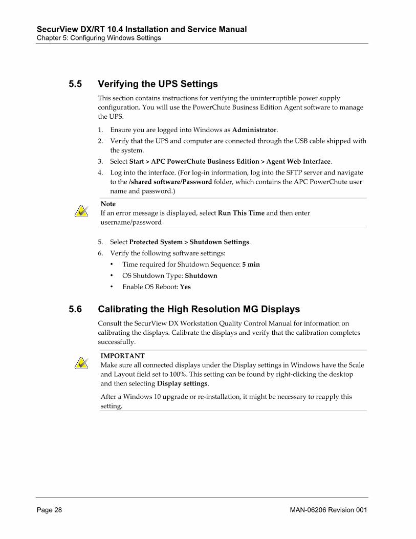
5.5 Verifying the UPS Settings This section contains instructions for verifying the uninterruptible power supply configuration. You will use the PowerChute Business Edition Agent software to manage the UPS.
1. Ensure you are logged into Windows as Administrator. 2. Verify that the UPS and computer are connected through the USB cable shipped with
the system. 3. Select Start > APC PowerChute Business Edition > Agent Web Interface. 4. Log into the interface. (For log-in information, log into the SFTP server and navigate
to the /shared software/Password folder, which contains the APC PowerChute user name and password.)
Note If an error message is displayed, select Run This Time and then enter username/password
5. Select Protected System > Shutdown Settings. 6. Verify the following software settings:
• Time required for Shutdown Sequence: 5 min • OS Shutdown Type: Shutdown • Enable OS Reboot: Yes
5.6 Calibrating the High Resolution MG Displays Consult the SecurView DX Workstation Quality Control Manual for information on calibrating the displays. Calibrate the displays and verify that the calibration completes successfully.
IMPORTANT Make sure all connected displays under the Display settings in Windows have the Scale and Layout field set to 100%. This setting can be found by right-clicking the desktop and then selecting Display settings.
After a Windows 10 upgrade or re-installation, it might be necessary to reapply this setting.

SecurView DX/RT 10.4 Installation and Service Manual Chapter 5: Configuring Windows Settings
MAN-06206 Revision 001 Page 29
5.7 Customer and Windows Administrator Rights There may be times when you need to grant Windows Administrator rights to a customer or third-party application technical support representative. These Administrator rights allow the user the proper permissions to install Hologic-approved software (for example, Hologic-approved dictation microphone and associated software used with Application Synchronization).
There is a Windows Customer account that grants these rights and permissions. Take great care when providing this user name and password, as this account allows the customer complete and unrestricted access to create, delete, and modify files, folders, permissions, and settings. Use this account only to help the customer or third-party application technical support representative install Hologic-approved software. You can find the Customer account password by logging into the SFTP server and navigating to the /shared software/Password folder, which contains the password file.
Note Dealers can access the password file by logging into dicom@hologic on the https://drftp.hologic.com SFTP server. For further assistance, contact Hologic Technical Support.
5.8 Synchronizing System Time Be sure to synchronize the system time for a Manager and its Clients. Errors can occur if system times differ. Use the Network Time Protocol to synchronize Manager and Client times.
Note Issues can also occur if the system time of any SecurView differs from the system time of any imaging modality that is sending images. Check that the system time is the same on all configurations that need to communicate: Selenia and/or Selenia Dimensions Acquisition Workstation, Cenova, SecurView DX/RT.

SecurView DX/RT 10.4 Installation and Service Manual Chapter 5: Configuring Windows Settings
Page 30 MAN-06206 Revision 001
5.9 Configuring Remote Access (Manager) Accessing a system remotely via Remote Desktop requires the remote user to enter a user name and password of a local user of the system. By default the SCR user account does not use a password. Use this procedure to set a password for the SCR user account and configure remote access to a SecurView Manager.
1. Log into Windows as SCR. 2. Press [Ctrl]+[Alt]+[Del] and select Change password. 3. Enter the new password and select OK. 4. Log off as SCR. 5. Log into Windows as Administrator. 6. Select Start. Type SystemPropertiesRemote.exe and press [Enter]. 7. In the ‘Remote Desktop’ area, select Allow users to connect remotely to this
computer. 8. Choose Select User. The Remote Desktop Users window appears. 9. Select Add. The Select Users window appears. 10. Enter a username (for example, SCR) and select OK.
5.10 Increasing Security on the SCR User Account (Optional) Some sites may request to enable a password on the Windows SCR user account to increase SecurView system security. This change provides convenience for the local user by automating the log-in process.
1. Log out of the SecurView application. 2. Log into Windows as Administrator. 3. Press Windows +[R]. 4. In the Run dialog, type control userpasswords2 and press [Enter]. The User
Accounts window appears. 5. Select the ‘Users must enter a user name and password to use this computer’ check
box, if not already selected. Select Apply. 6. Select the SCR user account in the User Accounts window and select Reset
Password. The Reset Password window appears. 7. Type in a new password, and then confirm the password. Choose a strong password
containing at least six characters. Write down this password and store it in a secure place accessible only by authorized personnel.
8. Select OK to return to the User Accounts window.

SecurView DX/RT 10.4 Installation and Service Manual Chapter 5: Configuring Windows Settings
MAN-06206 Revision 001 Page 31
9. In the User Accounts window, clear the ‘Users must enter a user name and password to use this computer’ check box.
10. Select OK. The Automatically Log On window appears:
11. Type the password chosen for the SCR user account and then confirm the password. Select OK.
12. Reboot the system. Going forward, each time the system is started Windows automatically logs on the SCR user with the password provided. This enhancement increases system security and hinders a remote attacker from accessing the system from a remote location. This setup also requires good physical security to protect the system, since anyone who uses the workstation will have access to the Windows desktop.

SecurView DX/RT 10.4 Installation and Service Manual Chapter 5: Configuring Windows Settings
Page 32 MAN-06206 Revision 001
5.11 Windows Domain Policy Settings (Optional) If SecurView is installed within a Windows domain, verify that the Microsoft Windows domain Group Policies Preferences are set according to the recommendations in this section to ensure that SecurView is installed and functions properly. For more details about Group Policies Preferences, see https://technet.microsoft.com.
5.11.1 Default Domain Policies The default group policies should allow:
• Windows error reporting to be disabled • Use of the CD/DVD-RW drive with no restrictions • Performance tracking • System shutdown • Visibility of desktop items • Windows applications to run, even if the applications are not specified
5.11.2 Domain Group Policy Settings Group Policy Name Recommendation Explanation
User Account Control: Only elevate executables that are signed and validated
Disable (default setting) If you disable this setting, an executable file required by SecurView is permitted to run. If enabled, the setting enforces public key infrastructure (PKI) signature checks for any interactive applications that request elevation of privilege.
Windows Firewall: Allow local program exceptions
Enable if firewall is used
Sets a firewall exception that allows administrators to define a local program exceptions list.
Select a special Powerplan: selected a buildin scheme
Do not use this customized Power Plan
A custom Power Plan can prevent configuration of the Power Plan policy proposed for use by SecurView.
Disable Windows Installer
Do not use Prevents Windows installers from running.

SecurView DX/RT 10.4 Installation and Service Manual Chapter 5: Configuring Windows Settings
MAN-06206 Revision 001 Page 33
5.12 Configuring Hologic Connect To activate Hologic Connect, you must enter a DNS Server in the TCP/IP Properties. Obtain this address from the Site Settings Table on page 11 you filled out.
5.12.1 Entering DNS Server Information Use this procedure to enter DNS Server information.
1. Log into Windows as Administrator.
2. Press Windows + [X] and select Network Connections. The Network Connections window appears.
3. Select the appropriate link: For Windows 10 (Standalone and Client): Select the Ethernet link. The Ethernet Status window appears. For Windows Server 2016 (Manager): Select the NIC link. The NIC Status window appears.
4. Select Properties. For Windows 10 (Standalone and Client): The Ethernet Properties window appears. For Windows Server 2016 (Manager): The NIC Properties window appears.
5. In the ‘This connection uses the following items’ list, select Internet Protocol Version 4 (TCP/IPv4), then select Properties.
6. Select Use the following DNS Server addresses. 7. Enter the DNS Server address that you recorded in the Site Settings Table on page 11
in the Preferred DNS Server field 8. Select OK to close any open windows.
5.12.2 Entering Hologic Connect Information 1. On the desktop, double-click the Hologic Connect Configuration Tool icon. The
Hologic Connect Control Panel appears. 2. Select the Site Details tab and then fill out all fields.
Note The information entered in the Customer Name field must be identical for all SecurView workstations and for any other Hologic products at the site. The information in the Location field must be unique for each workstation. It should identify the room or department where the workstation is located, followed by the Hologic system serial number. The serial number appears on a Hologic label located on the computer.
3. Select Apply. The Hologic Connect application may display ‘Please restart the following services: Hologic Connect’. You can wait to restart the service.
4. Select the Control tab. In the Model drop-down list, select SecurView.

SecurView DX/RT 10.4 Installation and Service Manual Chapter 5: Configuring Windows Settings
Page 34 MAN-06206 Revision 001
5. Record the SecurView serial number:____________________________. 6. Deselect the Use MAC Address check box. 7. Enter the serial number (see step 5) in the Hologic Connect Serial Number field. 8. If the site requires a proxy server for Internet access, you will need to configure a
proxy server for Hologic Connect. Work with the site’s IT administrator to determine the required proxy settings.
a. Select proxy type. Select the Type drop-down list and select None, HTTP, or SOCKS{4|5}.
• None – No proxy server. • HTTP – The session connects through a Hypertext Transfer Protocol (HTTP)
proxy server. HTTP is a communications protocol used to transfer information on intranets and the World Wide Web.
• SOCKS{4|5} – The session connects through a SOCKS version 4 or 5 proxy server. SOCKS is an abbreviation for SOCKetS, and is an Internet protocol that allows client-server applications to transparently use network firewall services.
b. Enter proxy server settings. Enter the appropriate IP Address, Port, User Name, and Password for the customer’s proxy server.
9. Select Apply. 10. Select Start to restart the Hologic Connect service, and then close the window. 11. Contact Hologic Customer Support at [email protected]. Include the
following information in your e-mail: • Subject – Hologic Connect Installation • Customer Name – Enter this information exactly as it appears in the Hologic
Connect Control Panel > Site Details tab. • Location – Enter this information exactly as it appears in the Hologic Connect
Control Panel > Site Details tab. • Hologic Connect Serial Number – Enter this information exactly as it appears in the
Hologic Connect Control Panel > Control tab. • SecurView Workstation Information – DX or RT • System Type – Standalone, Client, or Manager

SecurView DX/RT 10.4 Installation and Service Manual Chapter 6: Configuring the SecurView Application
MAN-06206 Revision 001 Page 35
6: Configuring the SecurView Application Configuring a SecurView Workstation as a Client on page 35
Configuring DICOM Settings (Standalone, Manager) on page 37
Configuring the Settings Tab on page 51
Configuring Licensing on page 59
Configuring Routing on page 61
Configuring the Patient List for an Additional Monitor (Optional) on page 64
Configuring the Keypad (SecurView DX) on page 65
Configuring the Barcode Scanner (Standalone, Client) on page 66
Configuring SecurView/Unifi Workspace Integration on page 68
Backing Up the System (Standalone, Manager) on page 68
Completing the Installation Report Form on page 68
6.1 Configuring a SecurView Workstation as a Client This section contains information on configuring a new multiworkstation installation and on configuring a workstation as a Client.
• Pre-Installation for Existing Standalone Workstations on page 35 • Configuring a Workstation as a Client on page 36
6.1.1 Pre-Installation for Existing Standalone Workstations When converting existing Standalone workstations into Clients:
1. Ensure that all workstations to be integrated in the multiworkstation configuration are at the same SecurView release level as the Manager. If this is not the case, then upgrade them using the appropriate assemblies.
2. To minimize installation time, delete as many patients as possible from each existing workstation as described below:
a. Ensure that users read as many patients as possible before converting the workstation.
b. Use the Case Administrator (delete) account and delete all Read patients from the system.
c. Ensure that you have an external USB drive with enough disk space, especially if it is necessary to transfer patient data from the workstation to be converted.
Chapter 6

SecurView DX/RT 10.4 Installation and Service Manual Chapter 6: Configuring the SecurView Application
Page 36 MAN-06206 Revision 001
3. Perform all operations in Converting Standalone Workstations to Clients on page 101 on the Standalone and Manager, then go to Configuring a Workstation as a Client on page 36.
Note Any SecurView configuration settings on an existing Standalone that apply to the Manager to which the Standalone will be connected as a Client must be migrated manually.
6.1.2 Configuring a Workstation as a Client Use these instructions for setting up a SecurView Client workstation.
To configure a workstation as a Client:
1. Log into the SecurView application as service. 2. Select the Exit to Windows tab and select OK to confirm. 3. Display File Explorer by pressing Windows + [E]. 4. Navigate to E:\SecurView. 5. Delete the workstationtype.dat and systemtype.dat files. 6. Close all open windows. 7. Launch the SecurView application. The system prompts to set the workstation type. 8. Select either the Diagnostic workstation or Technologist workstation option. 9. Select Multi-workstation Client, assigned to server and enter the IP address for the
Manager.
10. Select Test to confirm the workstation can communicate with the Manager. 11. Select OK. The system will synchronize with the Manager. This synchronization may
take several minutes depending on the number of patients imported.

SecurView DX/RT 10.4 Installation and Service Manual Chapter 6: Configuring the SecurView Application
MAN-06206 Revision 001 Page 37
6.2 Configuring DICOM Settings (Standalone, Manager) DICOM settings are accessible only to service users. The DICOM tab provides three tabs you can use to add DICOM devices and configure settings: Setup, Printer, and Destination.
• DICOM > Setup Tab on page 37 • DICOM > Printer Tab on page 40 • DICOM > Destination Tab (SecurView DX) on page 48 • DICOM > Destination Tab (SecurView RT) on page 50
6.2.1 DICOM > Setup Tab Use the DICOM > Setup tab to:
• Enter the AE title, IP address, and port for the SecurView workstation you are configuring.
• Add other DICOM devices (other SecurView workstations (Standalone or Manager), PACS devices, and DICOM printers).
The Setup tab has five sections used to connect to DICOM entities:
1 – This Workstation. These fields show the workstation you are configuring (SCR-System) and selected PACS and printer devices connected to the workstation.
Note For Auto-Fetching, the workstation uses the entity entered for PACS 1. You can edit this field only if Auto-Fetching/Auto-Completion (Settings tab) is set to Off. For more information, see Configuring Auto-Fetching / Auto-Completion (Standalone, Manager) on page 52.
2 – DICOM Entities. This section shows the connected DICOM entities and provides buttons to edit or delete a selected entity or send an echo to a selected entity. The SCR-System entity in the list is the SecurView workstation you are configuring.
3 – DICOM Setup. Use these fields to add a device to the DICOM Entities list.
• Use the SCR-System Entity Type for the workstation you are configuring. • Use the PACS/Station Entity Type to add PACS devices and other
SecurView DX/RT destinations. • Use the Printer Entity Type to add printer destinations.
4 – Printer Setup. The left window shows the printer types (models + film sizes) you can assign to a Printer entity. The right window shows the currently selected printer types you want to configure.
Note If the site’s printer is not listed, contact Technical Support. For information about adding printer types, see DICOM > Printer Tab on page 40.

SecurView DX/RT 10.4 Installation and Service Manual Chapter 6: Configuring the SecurView Application
Page 38 MAN-06206 Revision 001
5 – Additional PACS Settings. Use these fields to configure different AE titles and ports for storage, query/retrieve, and verification, if the PACS separates these application entities. The following example screen shows the five sections of the DICOM > Setup tab:
To set up DICOM devices:
1. Double-click the SecurView icon and log into the application as service. 2. Select Administration, then DICOM, then the Setup tab. 3. Identify the workstation you are configuring:
a. Select the SCR-System radio button in the Entity Type section.
b. Enter the AE title, IP address, and port for the SecurView workstation.
c. Select Save. The SCR-System should appear in the DICOM Entities list at left.

SecurView DX/RT 10.4 Installation and Service Manual Chapter 6: Configuring the SecurView Application
MAN-06206 Revision 001 Page 39
4. Add PACS devices and/or other SecurView workstations (Manager or Standalone):
Important Do not enter information for a Client workstation or Dimensions.
a. Select the PACS/Station radio button in the Entity Type section.
b. Enter the AE title, IP address, and port for the device.
c. Use the Additional PACS Settings fields to configure different AE titles and ports for storage, query/retrieve, and verification, if the PACS device separates these application entities.
Important Do not enter a value for the Query / Retrieve IM port, as no known PACS use it and it will lead to unpredictable behavior.
d. Select Save. The PACS device or workstation should appear in the DICOM Entities list at left.
e. Repeat steps b–d for any other PACS devices or SecurView workstations.
5. Add a printer for this workstation:
a. Select the Printer radio button in the Entity Type section.
b. Enter the AE title, IP address, and port for the printer.
c. In the Printer Setup list, select a printer type (model + film size) and then select the right arrow button. The printer type should appear in the list at right.
Note If the site’s printer is not listed, you may be able to add it to the list of printer types by using the Printer tab (see next section).
d. Repeat step c for each film size available for the printer. Be sure to include the ‘auto’ size entry.
Note If medium size "Auto" is included, at least one other medium size has to be added for the same printer.
e. Use the Default drop-down list to select the default printer type.
f. Select Save. The printer should appear in the DICOM Entities list at left.
Note The most common printers and film sizes are preloaded in the software. After setting up the printer, select the Printer tab to confirm the default printer parameters (see next section).

SecurView DX/RT 10.4 Installation and Service Manual Chapter 6: Configuring the SecurView Application
Page 40 MAN-06206 Revision 001
6. Set preferred DICOM devices: In the section marked ‘This workstation’, select the default PACS device(s) and printer to be used with the workstation.
Note For Auto-Fetching, the workstation uses the entity entered for PACS 1. You can edit this field only if Auto-Fetching/Auto-Completion (Settings tab) is set to Off. For more information, see Configuring Auto-Fetching / Auto-Completion (Standalone, Manager) on page 52.
6.2.2 DICOM > Printer Tab The Printer tab lets you review printer parameters and manually add, edit, and delete printer types. Use this window to set up printer configurations that are not included in the default printer types. The Printer tab has four major sections (see next page):
1 – Printer Type. This section lists printer types that you can assign to a Printer entity on the DICOM > Setup tab. When shipped, the SecurView application is preloaded with a default set of common printer types.
Note If the site’s printer is not listed, contact Technical Support.
Below the Printer Type list are fields that display attributes of the currently selected printer type. Use the buttons at the bottom to add, edit, or delete a printer type.
2 – Medium. This section includes two lists. At left are the medium types available for all printer types. At right are the currently assigned medium types for the selected printer type.
• Use the arrow buttons to assig n (or remove) a medium type to (or from) a selected printer type.
• Use the Default drop-down list to select the default medium type.
Note If you remove the default medium, SecurView automatically resets the default to another medium in the current assigned list. If necessary, select the appropriate default medium from the drop-down list.

SecurView DX/RT 10.4 Installation and Service Manual Chapter 6: Configuring the SecurView Application
MAN-06206 Revision 001 Page 41
3 – Medium Size. This section includes two lists. At left are the medium sizes available for all printer types. At right is the currently assigned medium size for the selected printer type. (You can assign only one at a time.)
• To change the medium size assigned to a selected printer type, select the medium size and then select the right arrow button.
• To add a new medium size to the available list, enter the value and select Add. • To delete a medium size from the available list, select it in the left list and select
Delete. (You can delete a medium size only if it is not assigned to any printer type.)
Note The predefined medium size "Auto" cannot be the only medium size defined for a printer. At least one other medium size must be configured for the printer.
4 – Additional Printer Settings. Configure printer settings to send images to the printer with or without a printer LUT.
• Use the Printer LUT drop-down to choose between predefined printer LUTs. • Use the Print Mode radio buttons to select either Standard Printing or
Presentation LUT Printing. If you select Presentation LUT Printing, you can edit the default Luminescence and Reflected ambient light values. The Presentation LUT Shape value for DICOM tag (2050,0020) must be selected. Contact Technical Support for assistance.
Note: • For standard printing in the USA, set Printer LUT to ‘P_to_LIN_at_5000’.
• For standard printing in Europe, set Printer LUT to ‘P_to_LIN_at_4000’.
• For Presentation LUT printing, set Printer LUT to ‘None’.

SecurView DX/RT 10.4 Installation and Service Manual Chapter 6: Configuring the SecurView Application
Page 42 MAN-06206 Revision 001
The following example shows the four sections of the DICOM > Printer tab:
To add a new printer type:
1. Double-click the SecurView icon and log into the application as service. 2. Select Administration, then DICOM, then the Printer tab. 3. In the Printer Type list, select on a printer type. If possible, select one that is similar to
the printer type you want to add.

SecurView DX/RT 10.4 Installation and Service Manual Chapter 6: Configuring the SecurView Application
MAN-06206 Revision 001 Page 43
4. Enter a name for the new printer type in the Printer name field.
5. Select Add. The new printer type should appear in the Printer Type list. 6. Edit the parameters for the new printer type as described below.
Note If a printer can handle two or more medium sizes, add the printer type several times with different names, for example, AGFA(8×10) and AGFA(10×12).
To edit a printer type:
1. In the Printer Type list, select the printer type you want to edit. The parameters for the printer type will appear.
2. Edit the parameters as needed (for example, Configuration Info, Dmin, Medium, Medium Size, Additional Printer Settings, and so on.) If necessary, consult the table Default Parameters for Commonly Used Printers on page 112.
3. Select Edit / Save to save the new parameters. (Note that you need to select Edit/Save only if you make changes to the parameters at the bottom of the screen, and not for the Medium and Medium Size lists.)
Note For information on printer timeouts, see Configuring Printer Timeouts on page 136.
To delete a printer type:
1. In the Printer Type list, select the printer type you want to delete. 2. Select Delete. SecurView prompts, ‘Do you want to delete this DICOM printer?’ 3. Select OK to delete the printer type.
Note A printer type can be deleted only if it is not assigned to a Printer entity in the DICOM > Setup tab.

SecurView DX/RT 10.4 Installation and Service Manual Chapter 6: Configuring the SecurView Application
Page 44 MAN-06206 Revision 001
The following table provides default parameters for printer types preloaded into SecurView. Note that pixel spacing entries are required to enable calculations for diagnostic printing.
Table 3: Default Parameters for Commonly Used Printers
Mfg. Model Printer Name
Film Size (inches) Dmin Dmax Medium Config. Info Matrix
Pixel Size (mm)
Agfa Drystar 4500M
AGFA DS4500 (8×10)
8 × 10 20 360 BF PERCEPTION _LUT=LINEAR
3828×4958 0.05
Drystar 4500M
AGFA DS4500 (Auto)
10 × 12 20 360 BF PERCEPTION _LUT=LINEAR
4892×5810 0.05
LR 5200 AGFA LR5200 (8×10)
8 × 10 20 360 BF PERCEPTION _LUT=LINEAR
4776×5944 0.034
Drystar 5500
AGFA DS5500 (8×10)
8 × 10 20 360 BF PERCEPTION _LUT=LINEAR
3828×4958 0.05
Drystar 5500
AGFA DS5500 (10×12)
10 × 12 20 360 BF PERCEPTION _LUT=LINEAR
4892×5810 0.05
Drystar 5500
AGFA DS5500 (11×14)
11 × 14 20 360 BF PERCEPTION _LUT=LINEAR
5376×6922 0.05
Drystar AXYS
AGFA DSAXYS (8×10)
8 × 10 20 360 BF PERCEPTION _LUT=LINEAR
3828×4958 0.05
Drystar AXYS
AGFA DSAXYS (10×12)
10 × 12 20 360 BF PERCEPTION _LUT=LINEAR
4892×5810 0.05
Drystar AXYS
AGFA DSAXYS (11×14)
11 × 14 20 360 BF PERCEPTION _LUT=LINEAR
5376×6922 0.05

SecurView DX/RT 10.4 Installation and Service Manual Chapter 6: Configuring the SecurView Application
MAN-06206 Revision 001 Page 45
Table 3: Default Parameters for Commonly Used Printers
Mfg. Model Printer Name
Film Size (inches) Dmin Dmax Medium Config. Info Matrix
Pixel Size (mm)
Fuji All Fuji (8×10) 8 × 10 20 360 BF CS100 P:3907×4819 L:4931×3795
0.05
All Fuji (10×12) 10 × 12 20 360 BF CS100 P:4919×5831 L:5943×4807
0.05
All Fuji (10×14) 10 × 14 20 360 BF CS100 P:5075×7043 L:7199×4919
0.05
All Fuji (14×14) 14 × 14 20 360 BF CS100 6819×6819 0.05
All Fuji (14×17) 14 × 17 20 360 BF CS100 P:6999×8339 L:8479×6883
0.05
Care- stream Health
DryView 5850
Carestream DV5850 (8×10)
8 × 10 20 360 MBF LUT=Linods. w87,1
3848×4864 0.05
DryView 5850
Carestream DV5850 (10×12)
10 × 12 20 360 MBF LUT=Linods. w87,1
4864×5880 0.05
DryView 5950
Carestream DV5950 (8×10)
8 × 10 20 360 MBF LUT=Linods. w87,1
3848×4864 0.05
DryView 5950
Carestream DV5950 (10×12)
10 × 12 20 360 MBF LUT=Linods. w87,1
4864×5880 0.05
DryView 6850
Carestream DV6850 (8 x 10)
8 x 10 20 360 MBF LUT=Linods. w87,1
4924×6224 .039
DryView 6850
Carestream DV6850 (10 x 12)
10 x 12 20 360 MBF LUT=Linods. w87,1
6224x7526 .039
DryView 6850
Carestream DV6850 (11 x 14)
11 x 14 20 360 MBF LUT=Linods. w87,1
6874x8824 .039

SecurView DX/RT 10.4 Installation and Service Manual Chapter 6: Configuring the SecurView Application
Page 46 MAN-06206 Revision 001
Table 3: Default Parameters for Commonly Used Printers
Mfg. Model Printer Name
Film Size (inches) Dmin Dmax Medium Config. Info Matrix
Pixel Size (mm)
Kodak DryView 6800
Kodak 6800 (8×10)
8 × 10 20 360 MBF LUT=Linods. w87,1
5056×6368 0.039
Kodak DryView 6800
Kodak 6800 (10×12)
10 × 12 20 360 MBF LUT=Linods. w87,1
6368×7656 0.039
Kodak DryView 6800
Kodak 6800 (11×14)
11 × 14 20 360 MBF LUT=Linods. w87,1
7028×8976 0.039
Kodak DryView 6800
Kodak 6800 (14×14)
14 × 14 20 360 BF CS000 8976×8976 0.039
Kodak DryView 6800
Kodak 6800 (14×17)
14 × 17 20 360 BF CS000 8976×10928 0.039
Kodak/ Care- stream Health
Kodak 8610
Kodak 8610 (8×10)
8 × 10 20 360 BF CS000 4800×6200 0.03875
Kodak DryView 8900
Kodak 8900 (8×10)
8 × 10 20 360 MBF CS000 5056×6368 0.039
Kodak DryView 8900
Kodak 8900 (10×12)
10 × 12 20 360 MBF CS000 6368×7656 0.039
Kodak DryView 8900
Kodak 8900 (11×14)
11 × 14 20 360 BF CS000 7028×8976 0.039
Kodak DryView 8900
Kodak 8900 (14×14)
14 × 14 20 360 BF CS000 8976×8976 0.039
Kodak DryView 8900
Kodak 8900 (14×17)
14 × 17 20 360 BF CS000 8976×10928 0.039

SecurView DX/RT 10.4 Installation and Service Manual Chapter 6: Configuring the SecurView Application
MAN-06206 Revision 001 Page 47
Table 3: Default Parameters for Commonly Used Printers
Mfg. Model Printer Name
Film Size (inches) Dmin Dmax Medium Config. Info Matrix
Pixel Size (mm)
Konica Drypro 793
Konica 793 (8×10)
8 × 10 20 360 DBF KC_LUT=1 4596×5674 0.04375
Drypro 793
Konica 793 (10×12)
10 × 12 20 360 DBF KC_LUT=1 5766×6826 0.04375
Drypro 793
Konica 793 (11×14)
11 × 14 20 360 DBF KC_LUT=1 6273×8079 0.04375
Drypro 793
Konica 793 (14×14)
14 × 14 20 360 DBF KC_LUT=1 8079×7988 0.04375
Drypro 793
Konica 793 (14×17)
14 × 17 20 360 DBF KC_LUT=1 8079×9725 0.04375
Drypro 873
Konica 873 pLUT (8x10)
8 × 10 20 360 DBF KC_LUT=1 4536×5612 0.04375
Drypro 873
Konica 873 pLUT (10x12)
10 × 12 20 360 DBF KC_LUT=1 5702×6778 0.04375
Sony Film- Station DF750
Sony DF750 (8x10)
8 × 10 20 360 MBF 128 4736×5856 0.042
Film- Station DF750
Sony DF750 (10x12)
10 × 12 20 360 MBF 128 5952×7040 0.042
DBF = DR BLUE FILM, BF = BLUE FILM, MBF = MAMMO BLUE FILM

SecurView DX/RT 10.4 Installation and Service Manual Chapter 6: Configuring the SecurView Application
Page 48 MAN-06206 Revision 001
6.2.3 DICOM > Destination Tab (SecurView DX) SecurView can automatically send the following objects to configured destinations:
• GSPS (Annotations, Tagged Tomo Slices, and Study State) • MG Secondary Captures (Annotations and Tagged Tomo Slices) • MM ScreenCaptures • Notices Use the Destination tab to configure the destinations. It is possible to configure SecurView to send GSPS Objects and Secondary Capture images containing Annotations and tagged tomosynthesis slices to different destinations when a study is marked as ‘Read’. This service setting is useful in situations where it is desirable to send Annotations to multiple destinations and one of the destinations is unable to accept GSPS objects.
All entities configured as PACS/Station can be assigned as destinations. For details, see Configuring Auto-Fetching / Auto-Completion (Standalone, Manager) on page 52.
The SecurView DX Destination tab provides four sections (see next page):
1 – Destinations for GSPS (Annotations, Tagged Tomo Slices, and Study State): Available and selected destinations to which GSPS objects can be sent automatically at close of study.
2 – Destinations for MG Secondary Captures (Annotations and Tagged Tomo Slices): Available and selected destinations to which Annotations and tagged tomo slices can be sent automatically at close of study.
Note Configure Secondary Capture destinations only for PACS or third-party workstations (not other SecurView workstations). Use this configuration option only if the destination PACS does not accept GSPS, or if the PACS cannot display GSPS and the customer wants to view Annotations on the PACS workstations.
3 – Destinations for MM ScreenCaptures: Available and selected destinations to which MM ScreenCaptures can be sent automatically at close of study.
4 – Destinations for Notices: Available and selected destinations to which Notices can be sent automatically at close of study or manually by the user (with the Send All Notices and Send Image Notice Pie menu options).
Note For Notice destinations, select SecurView DX or SecurView RT Standalone workstations and SecurView DX and SecurView RT Managers, or Selenia Dimensions AWM. SecurView always sends Notices as GSPS objects.

SecurView DX/RT 10.4 Installation and Service Manual Chapter 6: Configuring the SecurView Application
MAN-06206 Revision 001 Page 49
The following example shows the four sections of the SecurView DX Destination tab:

SecurView DX/RT 10.4 Installation and Service Manual Chapter 6: Configuring the SecurView Application
Page 50 MAN-06206 Revision 001
6.2.4 DICOM > Destination Tab (SecurView RT) The Destination tab lets you configure destinations for sending Notices. A Notice is a GSPS message from another Hologic workstation that contains all Annotations for one or more images, current window/level values, the user name, and the creation date and time.
You can also configure destinations for sending Notice Synchronization objects. Notice Synchronization objects are private DICOM objects to facilitate communication between Hologic systems (for example, notifying another workstation that a Notice has been marked as ‘Viewed’).
The SecurView RT Destination tab provides two sections:
1 – Destinations for Notices: Available and selected destinations to which Notices can be sent.
2 – Destinations for Notice Synchronization objects: Available and selected destinations to which Notice synchronization objects can be sent.
Note Notice synchronization allows sharing of Notice ‘Viewed’ status. In field 2, select only SecurView RT Standalones, or Managers, or Selenia Dimensions AWM. Do not select PACS or SecurView DX.

SecurView DX/RT 10.4 Installation and Service Manual Chapter 6: Configuring the SecurView Application
MAN-06206 Revision 001 Page 51
6.3 Configuring the Settings Tab Use the Settings tab for the procedures listed below. Note that these settings are also accessible to the site’s Administrator users.
• Configuring Disk Space Monitoring and Auto-Deletion on page 52 • Configuring Auto-Fetching / Auto-Completion (Standalone, Manager) on page 52 • Configuring Active Directory on page 53 • Configuring Study List Manager on page 54 • Configuring Application Event Logging on page 54 • Configuring Manufacturer Settings on page 55 • Configuring Double Reading for Studies (SecurView DX) on page 57 • Setting the Site Name and Address on page 58 • Configuring MG Secondary Capture Format (SecurView DX) on page 59

SecurView DX/RT 10.4 Installation and Service Manual Chapter 6: Configuring the SecurView Application
Page 52 MAN-06206 Revision 001
6.3.1 Configuring Disk Space Monitoring and Auto-Deletion For instructions on configuring local storage management for all systems, refer to the SecurView DX/RT Workstation User Guide. The user guide also provides information on automatic deletion of patients in a multiworkstation configuration.
On connected Clients, note the following:
• If a Client has less disk capacity than its Manager, set Automatic Deletion to On. • If a Client has at least the same disk capacity as its Manager, set Automatic
Deletion to Off.
6.3.2 Configuring Auto-Fetching / Auto-Completion (Standalone, Manager) The auto-fetching function automatically retrieves prior objects from an archive when SecurView receives new studies. The objects can be images, CAD SRs, study states with Annotations, and third-party GSPS objects in studies that meet the auto-fetching criteria.
The auto-completion function automatically retrieves all objects of the referenced study when SecurView receives a GSPS or CAD SR object.
To configure auto-fetching and auto-completion:
1. Select the Settings tab.
2. Select Configure in the Auto-Fetching/Auto-Completion section. Then select
options from the following dialog:

SecurView DX/RT 10.4 Installation and Service Manual Chapter 6: Configuring the SecurView Application
MAN-06206 Revision 001 Page 53
3. Mode: Select Auto-Fetching of prior images if SecurView is responsible for retrieving prior studies from the archive. • For SecurView DX, auto-completion is unnecessary
in most cases because it adds redundant network traffic.
• For SecurView RT, auto-completion may be appropriate (for example, SecurView RT may receive a Notice for which it does not have the images, depending on the site’s image routing and/or SecurView RT automatic deletion settings).
4. Auto-Fetching Limit: Select either a time interval (years back) or the number of most recent studies.
5. Retrieve Modalities: Select which modalities to retrieve. (The ‘MG’ setting retrieves prior digital mammography studies with associated GSPS Annotations and Mammography CAD SRs.)
6. DICOM Query/Retrieve Level: Select a level based on PACS 1 requirements. (Configure PACS 1 in the DICOM > Setup tab). • Series level is preferred if PACS 1 supports it. • Study level is also an acceptable setting. This level
requires that PACS 1 supports Modalities in Study (0008,0061) correctly in DICOM queries.
7. Auto-Fetching/Auto-Completion Execution: • For a multiworkstation system, the Manager uses
the All the time option. (Not logged in is not available.)
• For a Standalone system, select either setting. If you select Not logged in, the system performs auto-fetching only when no user is logged into the system.
8. Select OK to save the settings.
6.3.3 Configuring Active Directory Active Directory is a Microsoft Windows directory service used to help manage network security. When you add or edit a user profile, SecurView gives you the option to use Active Directory for user authentication. See Adding a SecurView User to the Site Domain on page 91.

SecurView DX/RT 10.4 Installation and Service Manual Chapter 6: Configuring the SecurView Application
Page 54 MAN-06206 Revision 001
6.3.4 Configuring Study List Manager SecurView can be configured to share patient list information with other image review applications. This allows the radiologist to drive the workflow from a single study list without moving from one workstation to another. Currently, only SecurView and Hologic MultiView support a shared patient list.
The recommended default location to install Study List Manager is a SecurView Manager or Standalone workstation. For complete Study List Manager installation and configuration instructions, see the Application Synchronization Installation Manual. Instructions for configuring the SecurView application to connect to a Study List Manager are found in the latest version of the SecurView DX/RT Workstation User Guide.
6.3.5 Configuring Application Event Logging SecurView can create a log file that captures key application level events. Customers may access these logs to monitor activity on the system or help demonstrate compliance with HIPAA or other patient privacy policies.
When the Application Event Logging feature is enabled, SecurView stores the Application Event Log file in the F:\ApplicationEventLog folder by default. Hologic recommends that the Application Event Log folder be maintained on a secure drive external to the SecurView workstation. Consult with the site’s IT administrator to determine the appropriate log path for the external drive.
To set the size of the Application Event Log file:
1. Navigate to E:\SecurView. 2. Open logger.ini using Notepad. 3. Scroll to the following entry: MaxSizeInKBytes 4. Set the desired size (in KBytes; default is 15000, representing 15 MB). 5. Save the file and close Notepad. The Application Event Log file is archived automatically each time it reaches maximum size. Archived Application Event Log files are not deleted.
For complete Application Event Logging configuration instructions, see the latest version of the SecurView DX/RT Workstation User Guide.

SecurView DX/RT 10.4 Installation and Service Manual Chapter 6: Configuring the SecurView Application
MAN-06206 Revision 001 Page 55
6.3.6 Configuring Manufacturer Settings You can customize tomosynthesis settings per manufacturer and model of digital breast tomosynthesis acquisition system.
1. Select Configure in the Manufacturer Settings area to open the Manufacturer Settings dialog box.
2. Select "+" to add a new blank setting. 3. Select the blank setting to enter or select a value for each field.
a. Manufacturer: Enter the manufacturer name exactly as it appears in (0008,0070) Manufacturer in DICOM image headers. Leave the field blank to apply the setting to all manufacturers.
b. Model: Enter the model name exactly as it appears in (0008,1090) Manufacturer’s Model Name in DICOM image headers. Leave the field blank to apply the setting to all models for a manufacturer.
c. Date From: Enter a start date to apply the setting to a subset of images according to the value of Study Date (0008,0020) in DICOM image headers. Enter a year (2 or 4 digits) or year and month. Leave the field blank to apply the setting to all images of the specified manufacturer or model.
d. Date To: Enter an end date to apply the setting to a subset of images according to the value of Study Date (0008,0020) in DICOM image headers. Enter a year (2 or 4 digits) or year and month. Leave the field blank to apply the setting to all images of the specified manufacturer or model.

SecurView DX/RT 10.4 Installation and Service Manual Chapter 6: Configuring the SecurView Application
Page 56 MAN-06206 Revision 001
e. Property: Select the property to apply to the setting
• Exclude from Combination Procedure Creation: For non-Hologic manufacturers only, enable to prevent combining images of the same study, laterality and view in the Tomosynthesis Navigation buttons (conventional 2D, synthesized 2D, tomosynthesis projections, reconstructions). Use only if combining these images causes a problem.
• Create Combination Procedure by View: For non-Hologic manufacturers only, enable to combine images of the same study, laterality and view in the Tomosynthesis Navigation buttons even if Frame of Reference UID is missing (conventional 2D, synthesized 2D, tomosynthesis projections, reconstructions). This property does not apply to spot compression, magnification, or specimen views. This property is ignored if Exclude from Combination Procedure Selection is enabled for the same manufacturer or model.
• Registered scaling for Combination Procedures: For non-Hologic manufacturers only, enable to scale the images in a combination procedure as if they are registered by the image height (conventional 2D, synthesized 2D, reconstructions). Enable this property only if the manufacturer (for example, Fuji) provides registered images. Otherwise, the display of images might lead to unexpected results. Unregistered scaling is based on pixel spacing.
• Sort synthesized 3D by number of slices: Set which reconstruction is displayed on top in the Tomosynthesis Navigation Reconstruction button when more than one reconstruction is available for a view (slices, slabs). This property applies only when the Sort Reconstruction On Top user preference is set to Vendor specific. Select the Value ascending to display the reconstruction with the least slices on top. Select the Value descending to display the reconstruction with the most slices on top.
• Reset Zoom and Panning when Switching in Combination Procedure: For non-Hologic manufacturers only with images that are not scaled by height (for example, GE and Siemens), enable to prevent synchronization of zoom and pan when switching between images of a combination procedure.
• Display 3D CAD Marks on Synthesized 2D: Enable projection of 3D CAD marks for reconstructed slices onto corresponding synthesized 2D images.
• Display 3D CAD Marks on Conventional 2D: Enable projection of 3D CAD marks for reconstructed slices onto corresponding conventional 2D images of a combination procedure.
• Display 3D CAD Marks on Synthesized 3D slabs: Enable projection of 3D CAD marks for reconstructed slices onto corresponding slabs.
f. Value: Select enabled, disabled, ascending or descending, as it applies to the selected property.

SecurView DX/RT 10.4 Installation and Service Manual Chapter 6: Configuring the SecurView Application
MAN-06206 Revision 001 Page 57
4. Select - to delete a setting. 5. Select OK to save changes. 6. Restart the SecurView application for the changes to take effect.
6.3.7 Configuring Double Reading for Studies (SecurView DX) In a double-reading scenario, a configuration option allows a GSPS object to be sent after each reader marks the study as ‘Read’. This setting allows for using the GSPS mechanism to synchronize reading states between multiple Standalone DX systems where double reading is used.
Use this procedure only if the site wants to set up double reading.
Note In earlier SecurView versions for systems configured for double reading, GSPS objects were sent only after the second reader marked a patient as ‘Read’.
To configure a site for double-reading:
1. Select the Settings tab. 2. In the Double Reading for Studies area, select the preferred double reading state for
each study type (Screening, Diagnostic, and Undefined).
Note A double reading occurs when two radiologists view one study and each marks it ‘Read’ without knowledge of the other’s findings or Annotations. Consult with site personnel before changing these settings from the single read defaults.
3. In the Send Annotations, Tagged Tomo, Study State area, select the preferred study state sending mode for double reading.
• after each single-read event: GSPS objects are sent after any reader marks the study as ‘Read’.
• after the double-read event only: GSPS objects are sent only after the second reader marks the study as ‘Read’.
4. Select OK and continue to the next section of the guide.

SecurView DX/RT 10.4 Installation and Service Manual Chapter 6: Configuring the SecurView Application
Page 58 MAN-06206 Revision 001
6.3.8 Setting the Site Name and Address Use the Settings tab to configure the institution name and address.
To set the site name and address:
1. Select the Settings tab. 2. In the Local Institution area, enter the institution name and address.
Note The institution information on the Settings tab applies to a Manager and all connected Clients. It is not possible to configure different institution settings for Clients connected to the same Manager.
3. In the Adoption of Institution Name and Address area, select the source of the information for GSPS objects, Secondary Capture, and ScreenCaptures.
• Select from Local Institution if the site wants to apply the local institution information to all SecurView-created GSPS, MG Secondary Captures, and MM ScreenCaptures.
• Select from the source image if the site wants to apply the institution information contained in the DICOM header of the image from which the GSPS, MG Secondary Capture, or MM ScreenCapture was created.
4. Select OK and continue to the next section of the guide.

SecurView DX/RT 10.4 Installation and Service Manual Chapter 6: Configuring the SecurView Application
MAN-06206 Revision 001 Page 59
6.3.9 Configuring MG Secondary Capture Format (SecurView DX) The Settings tab lets you configure the format of MG Secondary Capture images (only Annotations) that SecurView sends automatically at close of study. Change these settings only if the site requests something different from the defaults.
To set MG Secondary Capture image characteristics:
1. Select the Settings tab. 2. In the Secondary Capture area, select the Resolution drop-down list, and choose
Quadruple Tiling or Single Tiling according to the site preference.
3. In the Font Size field, enter a number or select one to set the Annotations font size. 4. Leave the DICOM Format field as ‘Secondary Capture Image’. 5. Select OK to save. 6. Restart the SecurView application on the Standalone system or Manager (plus all
connected Clients). You must restart the application for the saved configurations to take effect.
6.4 Configuring Licensing This section contains information on verifying, adding, and deleting licenses for your system.
A valid license must be installed to perform any action in the patient browser or to review medical images.
6.4.1 Verifying Licenses The licenses are loaded on each SecurView system during the manufacturing process and recorded on the License Key Delivery Note. You can find the License Key Delivery Note with the SecurView DX/RT Workstation User Guide. Verify that the licenses on the License Key Delivery Note are present for each system.
To verify licenses:
1. Record the ID (for example, 9-65EA736E) printed on the license dongle. The dongle should be present in a USB port on the back of the computer.
Note Before verifying licenses for a Manager, exit the SecurView application on all Clients.
2. Log into Windows as SCR. 3. Log into the SecurView application as service.

SecurView DX/RT 10.4 Installation and Service Manual Chapter 6: Configuring the SecurView Application
Page 60 MAN-06206 Revision 001
4. Select Administration and then the Licensing tab. 5. Verify that all licenses listed in the License Key Delivery Note appear in the
Licensing window.
Note The license generation number must match the SecurView version number. If a license is missing, email [email protected] with the SecurView serial number and dongle ID. Contact Technical Support for further assistance.
6. Select OK to close the Licensing window. 7. Select the Exit to Windows tab and OK to confirm.
Note You must restart the application after making changes to license settings.
6.4.2 Configuring Licenses Some sites may require further configuration of their pre-installed licenses. SecurView provides an interface for adding and deleting licenses.
To replace a licenses.dat file:
1. Log into the SecurView application as service. 2. Select Administration and then the Licensing tab. The Licensing window appears. 3. Select Open License File and browse to the licenses.dat file location. 4. Select the file and select Open. SecurView copies the licenses.dat file to the hard
drive and displays the licenses in the Licensing window. 5. Select OK to close the Licensing window. 6. To use the new licenses, exit and restart the SecurView application.
To add a single license:
1. In the Licensing window, enter the following information: • Feature – name of the specific license you wish to add • Generation – the license generation number must match the software version
number (for example, SecurView 10.1 requires generation 10.1 licenses) • License – license key, 20-character string
2. Select Check. The application checks whether the license is available for your system. If so, the license appears in the Licensing window.
3. To use the new license, exit and restart the SecurView application.
To delete a license:
1. In the Licensing window, select the license that you wish to delete. 2. Select Delete. 3. Select OK to close the Licensing window. 4. Exit and restart the SecurView application.

SecurView DX/RT 10.4 Installation and Service Manual Chapter 6: Configuring the SecurView Application
MAN-06206 Revision 001 Page 61
6.5 Configuring Routing After configuring the licenses, configure the routing as explained below.
• Configuring Routing (Manager, Client) on page 61 • Configuring Routing (Standalone) on page 63
6.5.1 Configuring Routing (Manager, Client) Use the following procedure to configure routing for a multiworkstation system:
1. On the Manager, double-click the SecurView icon. 2. Log into SecurView as service. 3. Select Administration. 4. Select the Routing tab. The Image Routing / Modality Acceptance window appears.
5. In the Image Routing field, select Manager, then select the following check boxes: MG, DX-MG, CR-MG, SC-MG, US, SC-US, SC.
Note Select the Tomo-Reconstruction check box if tomosynthesis reconstructed slices are being received as Hologic Secondary Capture Image, Breast Tomosynthesis Image or CT Image.
Note US, SC-US, and SC may not need to be selected on SecurView RT. Consult the customer to determine if they will be viewing these modalities on the technologist workstation.

SecurView DX/RT 10.4 Installation and Service Manual Chapter 6: Configuring the SecurView Application
Page 62 MAN-06206 Revision 001
6. For each Client workstation connected to this Manager:
a. Select Add client. The Add client window appears.
b. Enter the Client workstation IP address and select OK.
The added Client appears in the Image Routing field.
c. In the Image Routing field, select DWS-MG (or TWS-MG if you are configuring a Technologist workstation). Select check boxes as appropriate, either all or a subset of those checked in step 5.
Note Select the Tomo-Reconstruction check box if tomosynthesis reconstructed slices are being received as Hologic Secondary Capture Image, Breast Tomosynthesis Image or CT Image.
Note If the workstation includes a Multimodality license, refer to the SecurView Advanced Multimodality Option Installation Manual for configuration instructions.
7. Select Save. 8. Select OK (twice). 9. Select the Exit to Windows tab and select OK to confirm. 10. Double-click the SecurView icon.

SecurView DX/RT 10.4 Installation and Service Manual Chapter 6: Configuring the SecurView Application
MAN-06206 Revision 001 Page 63
6.5.2 Configuring Routing (Standalone) Use this procedure only to configure routing for Standalone workstations. (Use the Manager to configure Client routing.)
1. Select the Routing tab. The Image Routing / Modality Acceptance window appears.
2. In the Image Routing field, select Standalone Workstation, then select the following check boxes: MG, DX-MG, CR-MG, SC-MG, US, SC-US, SC.
Note Select the Tomo-Reconstruction check box if tomosynthesis reconstructed slices are being received as Hologic Secondary Capture Image, Breast Tomosynthesis Image or CT Image.
Note US, SC-US and SC may not need to be selected on the SecurView RT. Consult the customer to determine if they will be viewing these modalities on the technologist workstation.
3. In the Image Routing field, select DWS-MG (or TWS-MG if you are configuring a Technologist workstation). Select check boxes as appropriate, either all or a subset of those checked in step 2.
Note Select the Tomo-Reconstruction check box if tomosynthesis reconstructed slices are being received as Hologic Secondary Capture Image, Breast Tomosynthesis Image or CT Image.

SecurView DX/RT 10.4 Installation and Service Manual Chapter 6: Configuring the SecurView Application
Page 64 MAN-06206 Revision 001
Note If the workstation includes a Multimodality license, refer to the SecurView Advanced Multimodality Option Installation Manual for configuration instructions.
4. Select Save. 5. Select OK. 6. Select the Exit to Windows tab and select OK to confirm.
6.6 Configuring the Patient List for an Additional Monitor (Optional) Complete this section for Standalone and Client workstations with an additional monitor where the customer prefers the patient list to appear on that monitor rather than on the left high-resolution display.
1. Check the window number assigned to the additional monitor.
a. Right-click the desktop and select Display settings.
b. Select Detect to verify the window number assigned to the additional monitor.
2. Display File Explorer by pressing Windows + [E]. 3. Navigate to E:\SecurView. 4. Double-click lightbox.ini to open it with Notepad.
Note Log off and close the SecurView application if it is running before editing the file.
5. For Standalone or Client systems with an additional monitor, if the customer wishes to display the patient list on the additional monitor, then locate the following line: PatientManagerMonitor:0
6. Change the variable 0 so it matches the number of the window assigned to the additional monitor.
Note If necessary, remove the comment # sign from the beginning of the PatientManagerMonitor line in the lightbox.ini file.
7. Save the file and close Notepad.

SecurView DX/RT 10.4 Installation and Service Manual Chapter 6: Configuring the SecurView Application
MAN-06206 Revision 001 Page 65
6.7 Configuring the Keypad (SecurView DX) The current Hologic keypad is usually set to Game Controller mode. If necessary, use this procedure to set the keypad to the Game Controller mode.
This procedure applies only to the current keypads, which began shipping in March 2007. The current keypad has a scroll wheel above the trackball. The old keypad has no scroll wheel.
Current Keypad with Scroll Wheel
1. Disconnect the USB cable from the keypad. 2. Turn the keypad over. 3. Using a pen or small screwdriver, move the switch on the back of the keypad to the
top position for Game Controller mode. 4. Reconnect the USB cable. 5. Select Start > power icon > Shut down. Then restart the system. 6. Log into SecurView as review. 7. Select Administration. 8. Double-click a patient in the Patient List.
9. Confirm that the keypad functions by pressing the ReportFlow keys to step
forward and back through the ReportFlow.
6.7.1 Troubleshooting the Keypad (SecurView DX) 1. If the keypad is unresponsive to input, perform the following steps:
a. Log into SecurView as a user in the Administrator user group (for example, admin).
b. Disconnect the keypad from the computer.
c. Select the Exit to Windows tab and OK to confirm, and then wait 5-10 seconds.
d. Reconnect the keypad.
e. Double-click the SecurView icon and log into SecurView.
f. Confirm that the keypad functions.
SecurView DX/RT 10.4 Installation and Service Manual Chapter 6: Configuring the SecurView Application
Page 66 MAN-06206 Revision 001
2. If the keypad is still unresponsive, perform the following steps:
a. Log into SecurView as any user.
b. Disconnect the keypad from the computer.
c. Select the Shutdown tab and OK to confirm.
d. Reconnect the keypad.
e. Power on the computer.
f. Log into SecurView and confirm that the keypad functions.
6.8 Configuring the Barcode Scanner (Standalone, Client) The barcode scanner is a tool that lets you navigate quickly between patients that are currently in the patient list. The system supports the Symbol LS 1900 and LS2208 barcode scanners.
• LS 1900 series. Refer to the latest revision of the Synapse Smart Cable for USB Interface Guide or Product Reference Guide that matches the delivered scanner.
• LS2208. Refer to the LS2208 Series-Product Reference Guide, which includes the Synapse Smart Cable for USB Interface Guide.
You can program scanners to perform a variety of functions. For example, you can add three zeros to a field, trim the leftmost characters, and so on. Use 123 Scan, a tool available on the drftp server, to make such changes.
You can also use the configuration file BarCodeScanner.ini to configure the additional barcode scanner settings explained here:
• Changing the Barcode Between Patient ID and Accession Number on page 66 • Control Studies Provided to Application Synchronization on page 67
6.8.1 Changing the Barcode Between Patient ID and Accession Number SecurView uses one of these fields in a barcode:
• Patient ID (medical record number, or MRN) • Accession Number
Note When used with Application Synchronization, SecurView sends only the study of the barcoded accession number by default. For details, see Control Studies Provided to Application Synchronization on page 67.
If the site wants to use the Patient ID to identify patients, no further action is required.
To set the barcode scanner to use the Accession Number:
1. Display File Explorer by pressing Windows + [E]. 2. Navigate to E:\SecurView\BarCodeScanner.ini.

SecurView DX/RT 10.4 Installation and Service Manual Chapter 6: Configuring the SecurView Application
MAN-06206 Revision 001 Page 67
3. Open the BarCodeScanner.ini in Notepad and delete the # symbol from the second line and add it as a prefix to the first line, as shown here:
#MODE = PATIENT_ID # remove the first # of this line if Patient-IDs are to be used. MODE = ACCESSION_NUMBER # remove the first # of this line if Accession Numbers are to be used.
4. Save the file. 5. Exit Notepad. 6. Restart the computer.
6.8.2 Control Studies Provided to Application Synchronization When you use a barcode to open patients on SecurView, the list of studies that is provided in an open patient message to Application Synchronization is controlled by these settings:
• BarCodeScanner.ini mode is set to Patient ID: SecurView provides all studies in the open patient message
• BarCodeScanner.ini mode is set to Accession Number: By default SecurView provides only the study of the barcoded accession number in the open patient message. If the site instead wants to provide all studies, use this procedure to change the filter by accession number setting.
Change the Filter by Accession Number Setting
1. Set the barcode scanner to use the accession number:
a. Display File Explorer by pressing Windows + [E].
b. Navigate to E:\SecurView\BarCodeScanner.ini.
c. Open the BarCodeScanner.ini file in Notepad and delete the symbol # from the second line and add it as a prefix to the first, as shown here:
#MODE = PATIENT_ID # remove the first # of this line if Patient-IDs are to be used. MODE = ACCESSION_NUMBER # remove the first # of this line if Accession Numbers are to be used.
2. Set the value of XAPP_FILTER_BY_ACCESSION_NUMBER to 1 or 0 as shown here:
# 0 - all patient information is sent to XApp # 1 - default; studies in outgoing XApp messages are filtered by accession number XAPP_FILTER_BY_ACCESSION_NUMBER=1
3. Save the file. 4. Exit Notepad. 5. Restart the computer.

SecurView DX/RT 10.4 Installation and Service Manual Chapter 6: Configuring the SecurView Application
Page 68 MAN-06206 Revision 001
6.9 Configuring SecurView/Unifi Workspace Integration Refer to the Unifi Workspace Installation and Service Manual to configure a SecurView Standalone or Manager to synchronize patient states with Unifi™ Workspace.
6.10 Backing Up the System (Standalone, Manager) The SecurView system offers you various options to back up system files and databases.
• SaveSettingsAndDB.bat is a batch file that allows you to save the system configuration settings and back up the database.
• The DBM tool and the Maintenance tab in the SecurView application backup and restore only the database, and not changes made directly to configuration files. For more information on the DBM tool, see Backing Up and Restoring the Database on page 70.
To save all settings and back up the database:
1. Log into the SecurView application as service. 2. Select the Exit to Windows tab and select OK to confirm. 3. Log into Windows as Administrator. 4. Display File Explorer by pressing Windows + [E]. 5. Navigate to E:\SecurView\Hologic-Service. 6. Double-click SaveSettingsAndDB.bat. Follow the on-screen instructions. After the
script finishes, close the window. 7. Load an external removable media (USB drive, etc.). 8. Navigate to F:\ and copy/paste the Hologic-Service-Data\ folder onto the removable
media. 9. Close all open windows.
6.11 Completing the Installation Report Form Service Engineers who have access to the Hologic intranet (https://my.hologic.com) should complete this online report:
1. From MyHologic, select Divisions > Breast & Skeletal Health Solutions > BSH Customer Experience and Service > Imaging Field Service Team Site.
2. On the Imaging Field Service web page, locate and select the Installation Report button.
3. Fill out all required fields and select Submit.
Authorized dealers who have access to the Hologic extranet (The WIRE) should complete this online report:
1. Navigate to https://thewire.hologic.com/installation-form to access the installation report. 2. Fill out all required fields and select Submit.

SecurView DX/RT 10.4 Installation and Service Manual Chapter 7: Maintenance
MAN-06206 Revision 001 Page 69
7: Maintenance Backing Up and Restoring the Database on page 70
Maintaining the Workstation Hardware (Standalone, Manager, Client) on page 84
Importing Procedure Names Using DICOM Tags (Standalone, Manager) on page 88
Configuring the User Interface Language on page 90
Installing the SecurView Online Documentation (Outside US) on page 90
Adding a SecurView User to the Site Domain on page 91
Reinstalling the SecurView Application on page 93
Recovering a Workstation on page 97
Converting Standalone Workstations to Clients on page 101
Substituting a Local Language Keyboard on page 104
Configuring the Multi-Function Mouse (SecurView DX) on page 104
Programming the Keypad on page 105
Keyboard Functions on page 111
Reinstalling LCD Photometer Sensor on page 117
Configure Colors Used by SecurView displays on page 118
Configure Indicators for Prior and Current Images on page 120
Configuring Indicators for Smart Mapping on page 122
Configuring Maximum Speed for Cine on page 122
Configuring Hanging Order on page 123
Improving Manager Performance with NIC Teaming on page 126
Chapter 7

SecurView DX/RT 10.4 Installation and Service Manual Chapter 7: Maintenance
Page 70 MAN-06206 Revision 001
7.1 Backing Up and Restoring the Database These procedures use the DBM Tool to back up and restore only the database, and not changes made to configuration files. The ‘system settings’ mentioned are only those stored in the database (for example, set using the SecurView application user interface).
Keep the following points in mind when backing up and restoring SecurView.
• Back up and restore the database on the Standalone or Manager, not the Clients. (The backup and restore check boxes are disabled on the Clients.)
• For Client workstations, exported images and DICOM files can be stored on external removable media.
To perform a complete system backup, see Backing Up the System (Standalone, Manager) on page 68.
• Accessing the DBM Tool on page 70 • Restoring from Backup and Synchronizing the Database on page 71 • Restoring from Backup on page 74 • Synchronizing Database with File System on page 75 • Creating a Startup Database on page 77 • Creating a Backup of the Patient Database on page 79 • Restoring Multimodality Viewer from Restore Point on page 80 • Performing Database Maintenance on page 80 • Removing Auto-Fetching/Auto-Completion Jobs on page 81 • Exporting Users on page 82 • Importing Users on page 83
7.1.1 Accessing the DBM Tool The DbMaintenanceTool.bat (DBM Tool) opens a utility that provides various database maintenance functions.
1. Log into the application as service. 2. Select the Exit to Windows tab and select OK to confirm. 3. Display File Explorer by pressing Windows + [E]. 4. Navigate to E:\Securview\Hologic-Service. 5. Double-click DbMaintenanceTool.bat to run the DBM tool. The Database
Maintenance Tool sign in window appears.

SecurView DX/RT 10.4 Installation and Service Manual Chapter 7: Maintenance
MAN-06206 Revision 001 Page 71
6. Enter the following password: Pwd$4$Serv 7. Select OK. The main DBM Tool window offers several database maintenance functions.
7.1.2 Restoring from Backup and Synchronizing the Database The Restore from backup and synchronize database with file system DBM Tool option combines the functions of option 2 (Restore from Backup) and option 3 (Synchronize database with file system). After a successful restore, the wizard guides you through the synchronization process.
When using this option, the current database will be erased. All information that was present will be lost and replaced by the information in the database that is being imported.
Note If the database is large, do not use this option. Use the procedures described in Restoring from Backup on page 74 instead.
Note Non-local studies added through a Study List Manager connection are not restored.
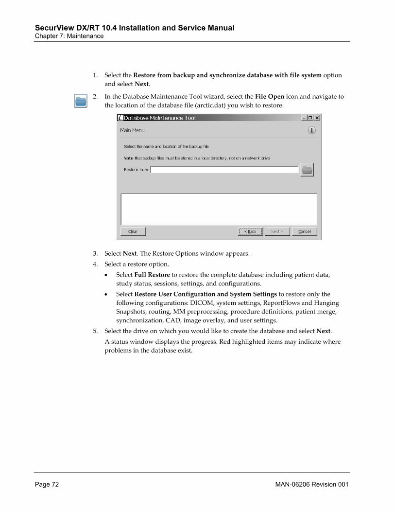
SecurView DX/RT 10.4 Installation and Service Manual Chapter 7: Maintenance
Page 72 MAN-06206 Revision 001
1. Select the Restore from backup and synchronize database with file system option and select Next.
2. In the Database Maintenance Tool wizard, select the File Open icon and navigate to
the location of the database file (arctic.dat) you wish to restore.
3. Select Next. The Restore Options window appears. 4. Select a restore option.
• Select Full Restore to restore the complete database including patient data, study status, sessions, settings, and configurations.
• Select Restore User Configuration and System Settings to restore only the following configurations: DICOM, system settings, ReportFlows and Hanging Snapshots, routing, MM preprocessing, procedure definitions, patient merge, synchronization, CAD, image overlay, and user settings.
5. Select the drive on which you would like to create the database and select Next. A status window displays the progress. Red highlighted items may indicate where problems in the database exist.

SecurView DX/RT 10.4 Installation and Service Manual Chapter 7: Maintenance
MAN-06206 Revision 001 Page 73
6. After the restoring process ends with success, select Next. The Synchronize database with file system window appears. The Synchronize database with file system step contains four fields:
1 – DICOM objects found in the database but missing on the hard disk 2 – DICOM objects missing in the database but found on the hard disk 3 – Object Option buttons 4 – Progress window
Note If DICOM objects are listed as missing on the hard disk in field 1, they will be deleted from the database in the next step.

SecurView DX/RT 10.4 Installation and Service Manual Chapter 7: Maintenance
Page 74 MAN-06206 Revision 001
7. Select the appropriate option. Two option buttons prompt for action regarding handling of DICOM objects found on the hard drive but not in the database during synchronization: • Select Remove from hard disk to delete the listed studies from the hard disk. • Select Re-Import into SecurView to import the listed studies from the database
into the import folder of the hard disk, which is scanned by the DICOM Import function at application startup.
8. Select Next. 9. Select Finish, and then Cancel to exit the program.
7.1.3 Restoring from Backup This DBM Tool option restores the database from an existing backup file.
Caution: If the SecurView system has been compromised by a computer virus, contact Technical Support before performing this procedure.
1. Select Restore from backup and select Next. 2. In the Restore from Backup wizard, select Open and navigate to the location of the
database file (arctic.dat) to be restored. 3. Select Next. The Restore Options window appears. 4. Select a restore option.
• Select Full Restore to restore the complete database including patient data, study status, sessions, settings, and configurations.
• Select Restore User Configuration and System Settings to restore only the following configurations: DICOM, system settings, ReportFlows and Hanging Snapshots, routing, MM preprocessing, procedure definitions, patient merge, synchronization, CAD, image overlay, and user settings.
5. Select the drive on which you would like to create the database and select Next. A status window displays the progress. Red highlighted items may indicate where problems in the database exist.
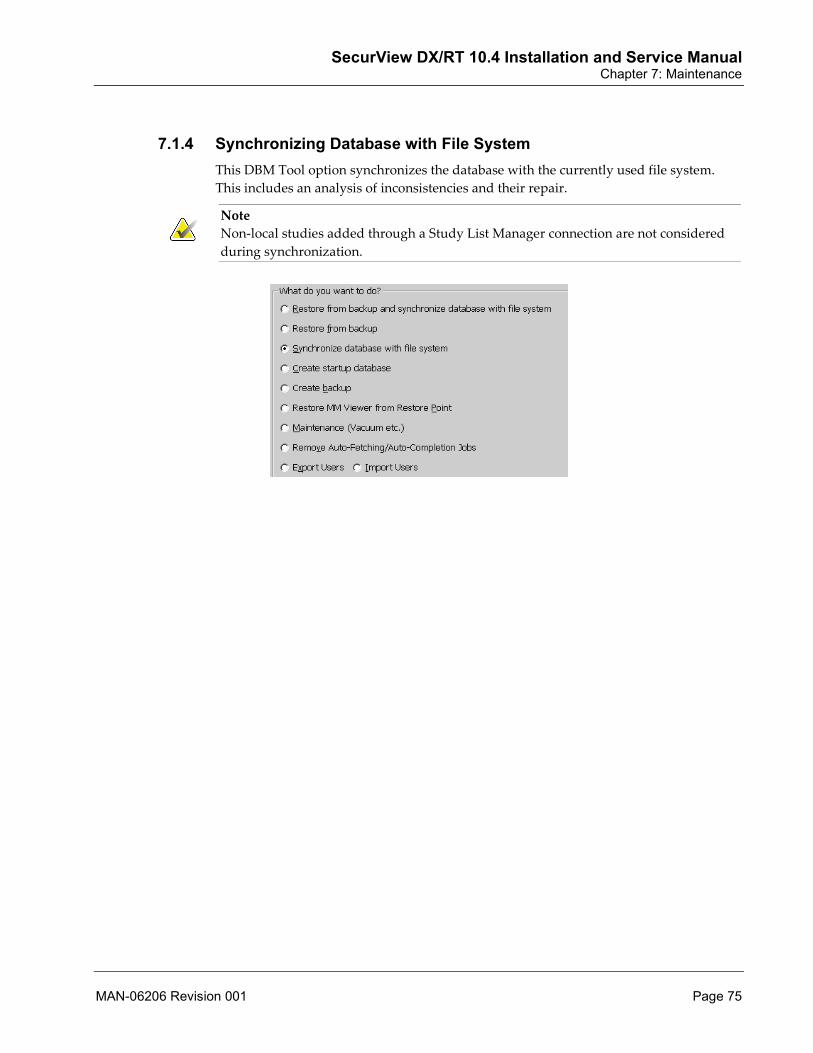
SecurView DX/RT 10.4 Installation and Service Manual Chapter 7: Maintenance
MAN-06206 Revision 001 Page 75
7.1.4 Synchronizing Database with File System This DBM Tool option synchronizes the database with the currently used file system. This includes an analysis of inconsistencies and their repair.
Note Non-local studies added through a Study List Manager connection are not considered during synchronization.

SecurView DX/RT 10.4 Installation and Service Manual Chapter 7: Maintenance
Page 76 MAN-06206 Revision 001
1. Select Synchronize database with file system and select Next. The Synchronize database window appears.
The Synchronize database with file system step contains four fields: 1 – DICOM objects found in the database but missing on the hard disk 2 – DICOM objects missing in the database but found on the hard disk 3 – Object Option buttons 4 – Progress window
Note If DICOM objects are listed as missing on the hard disk in section #1, they will be deleted from the database in the next step.

SecurView DX/RT 10.4 Installation and Service Manual Chapter 7: Maintenance
MAN-06206 Revision 001 Page 77
2. Select the appropriate options. Two option buttons prompt for action regarding handling of DICOM objects found on the hard drive but not in the database during synchronization: • Select Remove from hard disk to delete the listed studies from the hard disk. • Select Re-Import into SecurView to import the listed studies from the database
into the import folder of the hard disk, which is scanned by the DICOM Import function at application startup.
3. Select Next. 4. Select Finish, then Cancel to exit the program.
7.1.5 Creating a Startup Database This DBM Tool option will drop the current database and create a new startup database.
1. Select Create startup database and select Next. The Create New Database window appears.

SecurView DX/RT 10.4 Installation and Service Manual Chapter 7: Maintenance
Page 78 MAN-06206 Revision 001
2. Select the drive on which you would like to create the database and select Next. The status window appears and informs you of the progress.
The clearing process takes a few minutes. • When complete a Success message appears. • If this page ends with a red highlighted error message, you should record the
error. 3. Select Finish, then Cancel to exit the program.

SecurView DX/RT 10.4 Installation and Service Manual Chapter 7: Maintenance
MAN-06206 Revision 001 Page 79
7.1.6 Creating a Backup of the Patient Database This DBM Tool option creates a file containing a complete backup of the current database.
1. Select Create backup and select Next. The Backup window appears.
2. In the Backup window, select the File Open icon and navigate to the location of the
database file (arctic.dat) to be created.
Note Either keep the default name of the backup (backup.dat) or create a unique name for the file.
3. Select Save and then Next. 4. Select Finish, and then Cancel to exit the program.

SecurView DX/RT 10.4 Installation and Service Manual Chapter 7: Maintenance
Page 80 MAN-06206 Revision 001
7.1.7 Restoring Multimodality Viewer from Restore Point This DBM Tool option restores a Multimodality viewer from a restore point.
1. Select Restore MM Viewer from Restore Point and select Next. The Restore reset points from database window appears.
2. Follow the on-screen instructions to restore these reset points.
7.1.8 Performing Database Maintenance This DBM Tool option performs data-cleaning procedures on the database.
1. Select Maintenance (Vacuum etc.) and select Next. The clean-up process may take a few moments to complete.
2. Select Finish, then Cancel to exit the program.

SecurView DX/RT 10.4 Installation and Service Manual Chapter 7: Maintenance
MAN-06206 Revision 001 Page 81
7.1.9 Removing Auto-Fetching/Auto-Completion Jobs This DBM Tool option removes pending Auto-Fetching/Auto-Completion jobs from the database.
1. Select Remove Auto-Fetching/Auto-Completion Jobs and select Next. The Remove Auto-Fetching/Auto-Completion jobs window appears.
2. Select a removal option. • Select Remove All to remove all Auto-Fetching/Auto-Completion jobs. • Deselect Remove All to specify the number of days a job remains in the system.
3. Select Next. The status window displays progress.

SecurView DX/RT 10.4 Installation and Service Manual Chapter 7: Maintenance
Page 82 MAN-06206 Revision 001
7.1.10 Exporting Users This DBM Tool option exports SecurView user profile information to an .xml file.
1. Select Export Users and select Next. The Select file to export window appears.
2. In the Select file to export window, select the File Open icon and navigate to the
location of the export file to be created. 3. Select Save, then Next. The status window displays progress.

SecurView DX/RT 10.4 Installation and Service Manual Chapter 7: Maintenance
MAN-06206 Revision 001 Page 83
7.1.11 Importing Users This DBM Tool option imports SecurView user profile information from an exported user .xml file (see Exporting Users on page 82).
1. Select Import Users and select Next. The Select file to import window appears.
2. In the Select file to import window, select the File Open icon and navigate to the
location of the file you wish to import. 3. Select Next and Save. The status window displays progress.

SecurView DX/RT 10.4 Installation and Service Manual Chapter 7: Maintenance
Page 84 MAN-06206 Revision 001
7.2 Maintaining the Workstation Hardware (Standalone, Manager, Client) Perform periodic maintenance twice a year on the SecurView workstation. This section provides detailed instructions for maintaining the SecurView workstations. Before starting the maintenance procedure, make sure you have the following materials:
• Removable media • Lint-free cloth • Vacuum cleaner • Water-based cleaning solution for coated glass/plastic surfaces
1. Perform disk cleanup:
a. Exit the SecurView application.
b. Create a system backup on removable media (see Backing Up the System (Standalone, Manager) on page 68).
c. Press the Windows key, type Disk Cleanup in the search bar, and select the Disk Cleanup program from the search results. The Select Drive: window appears.
d. Choose the C:\ drive and select OK.
e. The Disk Cleanup for System (C:\) window appears. Choose the Recycle Bin and Temporary Files to delete. Select OK. The Disk Cleanup window displays the deletion progress.
f. After the process completes, shut down the system.
2. Clean the hardware:
a. Shut down the UPS.
b. Open the computer side access panel.
c. Carefully vacuum the fan air entry ports and heat sinks.
d. Replace the cover and close side access panel.
e. Vacuum the UPS case ventilation holes.
f. Apply water-based cleaning solution to a soft cloth and wipe the display(s), computer case exterior, keyboard, mouse, UPS case, and keypad.

SecurView DX/RT 10.4 Installation and Service Manual Chapter 7: Maintenance
MAN-06206 Revision 001 Page 85
3. Check the UPS battery:
Note APC recommends replacing the UPS battery approximately every four years.
a. Remove the UPS case front cover as shown in the following figure:
b. Slide the battery out of the UPS case as shown in the following figure:

SecurView DX/RT 10.4 Installation and Service Manual Chapter 7: Maintenance
Page 86 MAN-06206 Revision 001
c. Check the date stamp label located on top of the battery (see the following figure). If the date is four years old or older, replace the battery.
d. Slide the battery back into the UPS case.
e. Reattach the case front cover.
f. Start the UPS and run the self-test.
g. Switch on the SecurView workstation.
h. Refer to Verifying the UPS Settings on page 28 to ensure proper UPS functionality
4. Complete the SecurView Preventive Maintenance Checklist (see next page).

SecurView DX/RT 10.4 Installation and Service Manual Chapter 7: Maintenance
MAN-06206 Revision 001 Page 87
7.2.1 Preventive Maintenance Checklist Use the checklist below to verify that the preventive maintenance steps are complete.
Site Name: _____________________________________
Date: _____________________
Model #: __________________
Serial #: __________________
Done Preventive Maintenance Task
Create a system backup.
Perform disk cleanup and remove temporary files.
Vacuum the computer ventilation ports and heat sinks.
Wipe down computer case, keyboard, keypad, and display(s).
Vacuum UPS case ventilation holes.
Check UPS battery date code and replace, if necessary.
Run UPS self test.
Switch on the SecurView workstation.
Provide copies of the completed Service Report and Preventive Maintenance Checklist to the Site Technologist.
Return the completed Service Report and Preventive Maintenance Checklist to Hologic, Inc.

SecurView DX/RT 10.4 Installation and Service Manual Chapter 7: Maintenance
Page 88 MAN-06206 Revision 001
7.3 Importing Procedure Names Using DICOM Tags (Standalone, Manager) The procedure names contained in DICOM images allow the application to classify incoming studies as screening or diagnostic. They also can be used to determine which ReportFlows are selected for different procedures.
This section contains instructions for running a utility that extracts the procedure names from DICOM files on the system and imports them into the database.
To complete this section, patient studies must exist on the system that contains representative procedure names. For new installations, sample patient studies can be created at the AWS for each procedure name and sent to the SecurView system.
To import procedure names:
1. On each Standalone or Manager workstation, log into the SecurView application as service.
2. Select the Exit to Windows tab and OK to confirm. 3. Display File Explorer by pressing Windows + [E]. 4. Navigate to E:\SecurView\Hologic-Service\Utilities\Import_Procedurenames_Tool. 5. Double-click DCM_CSV.exe to launch the program. The DCM_CSV window
appears.

SecurView DX/RT 10.4 Installation and Service Manual Chapter 7: Maintenance
MAN-06206 Revision 001 Page 89
6. Leave the CSV output file and DICOM directory fields at their default locations:
a. CSV output file – E:\SecurView\Hologic-Service\Utilities\ Import_Procedurenames_Tool\ProcedureIdentification.csv
b. DICOM directory – F:\DICOM
7. In the Date Range field, enter a date range that spans the last three working days (for example, 01/9/2019 – 01/11/2019).
Note The DCM_CSV program will process DICOM files that have a date within a specified date range. Because it can take approximately 10 minutes to process 1000 files, Hologic recommends that the date range be limited to several days.
8. Select Generate CSV to extract the information from the DICOM files and generate the output file. This process will take some time depending on the number of files to be processed.
9. In the Table Generated window, select OK. 10. When the process has completed, select Import CSV to import the procedure names
into the database. 11. In the ProcedureIdentification Import window, select OK. Close the DCM_CSV
utility.
To confirm procedure names:
1. Start the SecurView application and log in as service. 2. Select Administration and then the ReportFlow tab. 3. Confirm that the procedure names appear as expected. The Examination Procedure
Identification list should contain all procedures that were entered at the Dimensions AWS in the procedure editor screen.
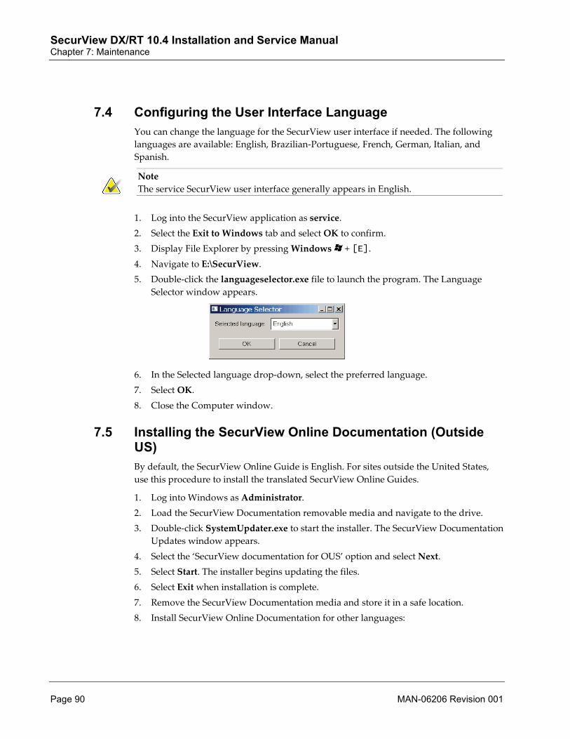
SecurView DX/RT 10.4 Installation and Service Manual Chapter 7: Maintenance
Page 90 MAN-06206 Revision 001
7.4 Configuring the User Interface Language You can change the language for the SecurView user interface if needed. The following languages are available: English, Brazilian-Portuguese, French, German, Italian, and Spanish.
Note The service SecurView user interface generally appears in English.
1. Log into the SecurView application as service. 2. Select the Exit to Windows tab and select OK to confirm. 3. Display File Explorer by pressing Windows + [E]. 4. Navigate to E:\SecurView. 5. Double-click the languageselector.exe file to launch the program. The Language
Selector window appears.
6. In the Selected language drop-down, select the preferred language. 7. Select OK. 8. Close the Computer window.
7.5 Installing the SecurView Online Documentation (Outside US) By default, the SecurView Online Guide is English. For sites outside the United States, use this procedure to install the translated SecurView Online Guides.
1. Log into Windows as Administrator. 2. Load the SecurView Documentation removable media and navigate to the drive. 3. Double-click SystemUpdater.exe to start the installer. The SecurView Documentation
Updates window appears. 4. Select the ‘SecurView documentation for OUS’ option and select Next. 5. Select Start. The installer begins updating the files. 6. Select Exit when installation is complete. 7. Remove the SecurView Documentation media and store it in a safe location. 8. Install SecurView Online Documentation for other languages:

SecurView DX/RT 10.4 Installation and Service Manual Chapter 7: Maintenance
MAN-06206 Revision 001 Page 91
Note This step is mandatory if you require languages other than English, Spanish, Italian, German, French, and Brazilian-Portuguese. If you do not need any additional languages, skip to step 9.
a. Navigate to E:\SecurView\Help\English and rename ‘SCR.pdf’ to ‘SCR-EN.pdf’.
b. Navigate to E:\Securview\Help and locate the folder for the language you wish to install.
c. Copy ‘SCR.pdf’ from that folder into E:\Securview\Help\English.
9. Verify the installation.
a. Double-click the SecurView icon and log in as admin.
b. Select the Administration tab to display the User Setup window.
c. Select Help. The Online Guide should appear.
7.6 Adding a SecurView User to the Site Domain Active Directory is a Microsoft Windows directory service used to help manage network security. When you add or edit a user profile, SecurView gives you the option to use Active Directory for user authentication. Use the following procedures to add a SecurView user with Active Directory credentials to the site domain.
1. Confirm that the SecurView workstation has been configured as part of the site domain, if desired. Consult with the site’s IT administrator to add the workstation to the site domain. Refer to Windows Domain Policy Settings (Optional) on page 32 before adding the workstation to the site domain.
2. Configure the Active Directory connection.
a. Log into the SecurView application as service.
b. Select Administration and then the Settings tab.
c. Select Configure… in the Active Directory Setup section. Then select options from the following dialog:
d. Enter the fully qualified host name of the Active Directory server.

SecurView DX/RT 10.4 Installation and Service Manual Chapter 7: Maintenance
Page 92 MAN-06206 Revision 001
e. Enter the port of the Active Directory server. The default setting is 389.
f. Select an authentication method:
• Kerberos – the default setting. • Digest – not usable in multiple domain scenarios, as different users with the
same username but in separate domains cannot be distinguished (one user will not be able to log in).
• Plaintext Password – not recommended, as passwords are transmitted without encryption.
g. As an option, enter the default domain to use if an Active Directory user does not specify a domain when logging in.
h. Select OK to save settings and log out as service.
3. Add the new user profile.
a. Log into the SecurView application as admin.
b. Select Administration and then the User Setup tab.
c. In the User Setup window, select Add to display the following dialog:
Note On SecurView RT, the ‘Rights’ options do not appear.
d. Enter the user name, last name, and first name.

SecurView DX/RT 10.4 Installation and Service Manual Chapter 7: Maintenance
MAN-06206 Revision 001 Page 93
e. Select ‘Use Active Directory’ to authenticate the user with Active Directory server.
• The user name must not contain a backslash (\) character. • The ‘@’ character should only be used in the form username@domain to
restrict the user to authenticate against a specific domain. This is useful when different users with the same name exist in different domains.
• There is no requirement to add the domain to the user name. If the domain is not specified, the user can be authenticated against any domain.
f. Assign the user to a group.
g. Assign user rights (for Administrators, Radiologists, and Technologists only on SecurView DX).
h. Select OK.
7.7 Reinstalling the SecurView Application Use the following procedures to reinstall the SecurView application:
• Backing Up the SecurView System on page 93 • Uninstalling the SecurView Application on page 94 • Installing the SecurView Application on page 94 • Restoring the Application Settings and Database on page 96 • Deleting All Patient Data from SecurView (Standalone, Manager) on page 97 • Installing the SecurView Online Documentation on page 97
7.7.1 Backing Up the SecurView System 1. Back up the SecurView system settings (see Backing Up the System (Standalone,
Manager) on page 68 for instructions). If the SecurView application is not accessible, locate the most recent backup file to use.
Note If manual changes were made to merge.ini, mergecom.app, and merge.pro files in E:\SecurView\Merge, you will need to back up these files prior to uninstalling the SecurView application.
2. You can download the system settings (from F:\Hologic-Service_Schedule_Backup) to a share drive, USB drive or burn the system settings to a DVD. Whatever you decide, you must ensure that the file or DVD is stored in a secure location and available when needed.

SecurView DX/RT 10.4 Installation and Service Manual Chapter 7: Maintenance
Page 94 MAN-06206 Revision 001
7.7.2 Uninstalling the SecurView Application
Note If you are uninstalling the application on a Manager computer, shut down each client prior to starting this procedure.
1. Log into Windows as Administrator. 2. Use the ‘Add or Remove Programs’ feature of the Windows Control Panel to display
the list of currently installed programs. Select Start, type add or remove, and select Add or remove programs from the search results.
Note The Uninstaller removes the F:\DICOM folder, which contains image data. If you wish to keep this folder, rename it (for example, ‘DICOM_old’).
3. Select the SecurView application and select Uninstall to start uninstalling the program. When the process is finished, you can review the output messages and proceed to the next step. Select Next to continue.
4. When the Uninstall finished window appears, select Close to exit the uninstaller. 5. Rename the E:\SecurView folder to ‘E:\SecurView_Backup’. 6. Rename all folders on the F:\ drive by appending ‘_old’ to each folder name. 7. Log out of Windows.
7.7.3 Installing the SecurView Application
Note Confirm that the version of the application you are installing is the same version that you uninstalled in Uninstalling the SecurView Application on page 94.
Note If the SecurView workstation has been configured as part of the site domain, the domain policies may prevent the SecurView application installation. Work with the site administrator to ensure that the policies are set as recommended in Windows Domain Policy Settings (Optional) on page 32.
Note SecurView will not install correctly if the administrator account used to run the installer is a domain user and an administrator account also exists as local user. For example, Administrator@yourDomain is the domain user, and the local user is Administrator. If you receive the message: "Unable to install Enterprise DB correctly", delete the local user.

SecurView DX/RT 10.4 Installation and Service Manual Chapter 7: Maintenance
MAN-06206 Revision 001 Page 95
1. Log into Windows as Administrator. 2. Load the SecurView Application Installation removable media. 3. Display File Explorer by pressing Windows + [E]. 4. Navigate to the drive and double-click SecurView x.x.x.x-Installer.exe to start the
SecurView installer.
Note Select Run if an "Open File – Security Warning" prompt appears.
5. The Welcome to SecurView installation wizard window opens. 6. Select Next. The Select Folders for SecurView window appears. 7. Use the default selection for folders E:\SecurView and F:\ and then select Next. The
Select Workstation Environment window appears. 8. Select the workstation type and then select the correct multi-workstation
environment. Select Next. 9. The Select Folders for Database window appears. Use the default folder and drive
partition. 10. Select Next. 11. If you are using a Standalone workstation or a client assigned to a manager, the
Select Display window appears.
a. Use the Select Display list to select a display model, based on the display used with the workstation or client.
b. Select Next. The Select Language window appears.
12. Select a language for SecurView users and then select Next. 13. Verify that you are satisfied with the contents of the Summary window and then
select Install. The SecurView installer begins installing the application. 14. To complete the installation, select Next in the Installation Finished window and
then select Close. 15. Remove the SecurView Application Installation media and store it in a safe location. 16. Close all open windows and reboot the system.

SecurView DX/RT 10.4 Installation and Service Manual Chapter 7: Maintenance
Page 96 MAN-06206 Revision 001
7.7.4 Restoring the Application Settings and Database You will need the removable media for the latest available backup performed using SaveSettingsAndDB.bat (see Backing Up the System (Standalone, Manager) on page 68 for instructions). Use this removable media in the following procedures to restore SecurView application settings and database.
Note If you previously backed up the merge.ini, mergecom.app, and mergecom.pro files in Backing Up the SecurView System on page 93, you will need to manually restore these files.
1. Log into Windows as Administrator. 2. Load the Backup removable media created in Backing Up the System (Standalone,
Manager) on page 68. 3. Carefully delete the following folder: F:\Hologic-Service-Data\ 4. Copy the entire \Hologic-Service-Data\ folder from the Backup removable media, to
the root of the F:\ drive. 5. After the folder is copied, right-click the folder and then select Properties. Clear the
Read-only box, then select OK. 6. Select OK again to accept the default and apply to all subfolders and files. 7. Display File Explorer by pressing Windows + [E]. 8. Navigate to E:\SecurView\Hologic-Service. 9. Double-click RestoreSettingsAndDB.bat and choose option A to restore the database
and all files.
Note Be sure that the database/settings backup removable media is the latest one available and that it matches the SecurView version to which you are restoring.
10. Press any key to close the command window. 11. Close all open windows. 12. Log out of the Windows Administrator account. 13. Remove the SecurView Application Backup removable media and store it in a safe
location.

SecurView DX/RT 10.4 Installation and Service Manual Chapter 7: Maintenance
MAN-06206 Revision 001 Page 97
7.7.5 Deleting All Patient Data from SecurView (Standalone, Manager) 1. Log into Windows as SCR. Log into the SecurView application as service. 2. Select the Administration tab. 3. Select Delete Patients. Highlight all patients and select Delete. 4. Confirm deletion of patients by selecting OK. 5. After all patients have been deleted, select Exit to close the Delete Patients window. 6. Select OK, then logoff.
Note At this point all patient data have been deleted. You must manually retrieve from PACS any patient data required by the customer.
7.7.6 Installing the SecurView Online Documentation 1. Log into Windows as Administrator. 2. Load the SecurView Documentation removable media and navigate to the drive. 3. Double-click SystemUpdater.exe to start the installer. The SecurView Documentation
Updates window appears. 4. Select either the ‘SecurView documentation for US’ or ‘SecurView documentation for
OUS’ option and select Next. You must select the ‘OUS’ option to install the translated user guides.
5. Select Start. The installer begins updating the files. 6. Select Exit when installation is complete. 7. Remove the SecurView Documentation media and store it in a safe location. 8. Verify the installation.
a. Double-click the SecurView icon and log in as admin.
b. Select the Administration tab to display the User Setup window.
c. Select Help. The Online Guide should appear.
7.8 Recovering a Workstation Use this procedure to recover the system from catastrophic hard disk failure or system corruption.
Note Always make sure that the UPS for your specific workstation configuration is connected and enabled before beginning the recovery process.
The procedures for recovering a SecurView workstation include the following major steps:
1. Back up the SecurView system (see Backing Up the SecurView System on page 93).

SecurView DX/RT 10.4 Installation and Service Manual Chapter 7: Maintenance
Page 98 MAN-06206 Revision 001
2. Reimage the system (see Restoring the System to SecurView Base Image on page 98). 3. Install the system updates (see Installing the Updates on page 99). 4. Install the application (see Installing the SecurView Application on page 94). 5. Restore the system settings and database (see Restoring the Application Settings and
Database on page 96). 6. Confirm that the SecurView configuration settings have been restored (see
Configuring the SecurView Application on page 35). 7. Delete all patient data (see Deleting All Patient Data from SecurView (Standalone,
Manager) on page 97). 8. Install the online documentation (see Installing the SecurView Online Documentation on
page 97). 9. Reinstall all other applications (for example, MultiView MM, Application
Synchronization, and approved third-party applications) that were previously installed on the computer.
7.8.1 Restoring the System to SecurView Base Image Restore the system to the SecurView base image using the SecurView System Base Image removable media for the appropriate operating system. You will restore the hardware configuration (system partition, check drive letters).
SecurView System Base Image Removable Media
T7910, T3620, or newer Windows 10
PE T630, R730, or newer Windows Server 2016
1. Load the Base Image removable media specific to your system.
Note If you encounter any PERC 6/i backup battery issues, contact Technical Support.
2. Restart the system. 3. During boot up, press the F12 key (Client) or the F11 key (Manager) to load the Boot
Manager. For SecurView Manager, select One-shot BIOS boot Menu. 4. From the available boot options, select the removable media containing the Windows
OS. The system will boot to the removable media and a Restore window appears. 5. In the Restore window, select Restore.
Note Do not press any keys during the rebooting process. This process can take up to 15 minutes.
6. Remove the removable media from the drive and store it in a safe location. 7. After the final reboot, the Set Up window appears. Enter the product key for the
version of Window you are restoring (affixed to the computer) and select Next. If Administrator password screen appears, leave password blank and select Finish.

SecurView DX/RT 10.4 Installation and Service Manual Chapter 7: Maintenance
MAN-06206 Revision 001 Page 99
8. Confirm the drive letters and labels are correct. Display File Explorer by pressing Windows + [E]. The drive letters and labels should appear as follows: • System C:\ • CD\DVD-ROM D:\ • Application E:\ • Data F:\
Note If a drive letter or label is incorrect, refer to appropriate AP for renaming instructions.
9. Rename the folders on the E:\ and F:\ drives by appending ‘_old’ to each folder name.
7.8.2 Installing the Updates To install the updates (Standalone or Client):
1. Log into Windows as Administrator. 2. Exit the Barco Conference CloneView application, if it is running on the system. 3. Load the SecurView System Updates removable media. 4. Remove any external USB drives that are connected to the computer 5. Navigate to the drive and double-click SystemUpdater.exe. The SecurView System
Updates window appears. 6. Select Install PowerChute Business Edition and select Next. 7. If the SecurView system uses a 12MP display, select Enable Barco VirtualView.
Otherwise, leave the default selection of Disable Barco VirtualView. 8. Select the calibration software that is appropriate for the display in use:
• Select Monitor Calibration Software - QA Web for SecurView DX workstations equipped with Barco LCD displays.
• Select None for SecurView RT workstations. 9. Select Next.

SecurView DX/RT 10.4 Installation and Service Manual Chapter 7: Maintenance
Page 100 MAN-06206 Revision 001
10. Select Start. The SecurView System Updates installer copies files to disk and configures users. During this process, which can take up to 30 minutes, the installer automatically reboots the system multiple times.
Note If during intermediate reboots, the Administrator password is rejected upon login, try to log in again and leave the password blank.
Note If you do not have a UPS connected to the system via USB, the system update stops and the PowerChute Business Edition pop-up screen appears in the background of the System Updates screen. To continue, plug the UPS into the computer’s USB port and select Run Auto Detect.
Note If the Updates installer unexpectedly stops or becomes unresponsive, see Troubleshooting the Updates Installation on page 144.
11. When prompted to restart Windows, select Yes.
Note If necessary, press [Ctrl] + [Alt] + [Delete] to display the Windows logon dialog.
Note If MultiView is installed and System Updates changes the Windows Theme to Windows Classic, reapply the MultiView Dark Theme by right-clicking the Desktop, selecting Personalize, selecting MultiViewDarkTheme, and selecting OK.
Note If System Updates changes the resolution of the Barco monitors, uninstall and then reinstall the Barco MXRT Display Driver by selecting Start, type add or remove, and select Add or remove programs from the search results.
12. Remove the SecurView System Updates media and store it in a safe location.
To install the system updates (Manager): 1. Log into Windows as Administrator. 2. Load the SecurView System Updates removable media. 3. Remove any external USB drives that are connected to the computer. 4. Navigate to the disk drive and double-click SystemUpdater.exe. The SecurView
System Updates window appears.

SecurView DX/RT 10.4 Installation and Service Manual Chapter 7: Maintenance
MAN-06206 Revision 001 Page 101
5. Select the PowerChute installation option and select Next. • Select Install PowerChute for systems equipped with an attached UPS. • Select None for systems without an attached UPS. The SecurView System Updates window appears.
6. Select Start. The SecurView System Updates installer copies files to disk and configures users. During this process, which can take up to 30 minutes, the installer automatically reboots the system multiple times.
Note If during intermediate reboots the Administrator password is rejected at login, try logging in again and leave the password blank.
Note If you do not have a UPS connected to the system via USB, the system update stops and the PowerChute Business Edition pop-up screen appears in the background of the System Updates screen. To continue, plug the UPS into the computer’s USB port and select Run Auto Detect.
Note If the Updates installer unexpectedly stops or becomes unresponsive, see Troubleshooting the Updates Installation on page 144.
7. When prompted to restart Windows, select Yes.
Note If necessary, press [Ctrl] + [Alt] + [Delete] to display the Windows logon dialog.
8. Remove the SecurView System Updates media and store it in a safe location.
7.9 Converting Standalone Workstations to Clients Use these procedures when converting an existing Standalone workstation to a Client workstation, and then connecting that Client to an existing Manager.
• Preparing Standalone for Conversion to Client on page 102 • Adding a Client to a Manager on page 103

SecurView DX/RT 10.4 Installation and Service Manual Chapter 7: Maintenance
Page 102 MAN-06206 Revision 001
7.9.1 Preparing Standalone for Conversion to Client A USB external hard disk drive is required when converting an existing Standalone containing patient and user data to a Client.
1. Back up the Standalone workstation and export ReportFlows:
a. Log into the SecurView application as service.
b. Select Administration.
c. Select the Maintenance tab.
d. Create a backup DVD by selecting Backup and inserting a blank DVD-R when prompted. Label the DVD with a description and today’s date (for example, SecurView Standalone Database Backup, 01.11.19).
2. Export ReportFlows:
a. Install the USB external hard drive in an open USB port on the back of the computer.
b. In the Hanging Snapshots and ReportFlows area, select Export.
c. Select the USB external hard drive as the destination for the exported ReportFlows.
d. When backup is completed, select OK.
3. Select the Exit to Windows tab and select OK to confirm. 4. Use the DBM Tool to export user profile information to the USB external hard drive
(see Exporting Users on page 82). 5. If it is necessary to move patient data to the Manager, copy the contents of the
following folders to a USB external hard drive: • F:\DICOM • F:\DICOM_SR • F:\DICOM_Annotation
6. Remove the USB external hard drive.
Note For information on configuring a SecurView workstation as a Client,see Configuring a Workstation as a Client on page 36.

SecurView DX/RT 10.4 Installation and Service Manual Chapter 7: Maintenance
MAN-06206 Revision 001 Page 103
7.9.2 Adding a Client to a Manager Use this procedure to back up the Manager, add Clients, then import users, ReportFlows, and images to the Manager.
1. Back up the SecurView Manager:
a. Shut down all Clients in the cluster.
b. On the Manager, log into SecurView as service.
c. Select Administration and then the Maintenance tab.
d. Create a backup DVD by selecting Backup and inserting a blank DVD-R when prompted.
e. Label the DVD as ‘SecurView Manager Database Backup’ with today’s date.
2. Add Clients to the Manager:
a. Install the USB external hard drive in an open USB port on the computer.
b. Select the Routing tab.
c. Select Add client and enter the IP address of the new Client.
d. Route modality types to the new Client’s MG and MM viewers as appropriate.
3. Close the Administration window. Select Exit to Windows and OK to confirm. 4. Use the DBM Tool to import users to the Manager (see Importing Users on page 83). 5. Restart SecurView on the Manager and log in as service. 6. Import ReportFlows to the SecurView Manager:
a. Select Administration and then the Maintenance tab.
b. In the Hanging Snapshots and ReportFlows field, select Import.
c. Navigate to the USB external hard drive as the location for the ReportFlows being imported, and select the file that was exported from the Standalone system.
d. Follow instructions to import all desired ReportFlows.
e. When import is completed, select OK.
7. Select the Exit to Windows tab and then OK to confirm. 8. Import images to the Manager:
a. Copy all image, SR, and Annotation files on the USB drive to the F:\DICOMImport folder on the Manager.
b. Double-click the SecurView icon. Images will begin to be imported. This import may take a few moments, depending on the number of images selected for re-import.
c. Remove the USB external hard drive.

SecurView DX/RT 10.4 Installation and Service Manual Chapter 7: Maintenance
Page 104 MAN-06206 Revision 001
7.10 Substituting a Local Language Keyboard This section describes how to use the Clock, Language, and Region in the Control Panel to substitute local language keyboards on your computer. The SecurView application supports only a subset of the languages included in ISO IR-100, Latin alphabet No. 1, such as Portuguese, French, German, Italian, and Spanish.
1. Log into Windows as Administrator. 2. Select Start > Settings > Time & Language > Region & Language. The Region &
language window appears. 3. Select Add a Language. The Add a Language window appears. 4. Select the desired language. The language is added to The Region & language
window. 5. Close the Settings window.
7.11 Configuring the Multi-Function Mouse (SecurView DX) The SecurView DX system includes a multi-function mouse that can be configured with SecurView functions. This section describes recommended SecurView functions that you can map to the multi-function mouse buttons.
Refer to the mouse manufacturer instructions for installing and configuring the mouse.
7.11.1 Recommended Functions Use keyboard shortcuts to program the multi-function mouse buttons. The following table provides several recommended functions that you can program using a standard keyboard.
Function Key
FlowNext [4] or Left Arrow ←
FlowBack [1] or [End]
CAD [/]
CC Current num [-]
MLO Current num [+]
Annotation Options
Arrow [F10]
Ellipse [F11]
Freehand [F12]
Measurement [2] or Down Arrow ↓
Cine Start/Stop1 [F6]
Toggle MG / Tomo1 [J]
1(requires a Tomosynthesis license)

SecurView DX/RT 10.4 Installation and Service Manual Chapter 7: Maintenance
MAN-06206 Revision 001 Page 105
Additional functions can be mapped to the multi-function mouse buttons. Refer to the latest SecurView DX/RT Workstation User Guide for the list of keyboard shortcuts for commonly used functions or see Keyboard Functions on page 111 for a complete list of functions.
7.11.2 Recommended Mapping Configurations Button placement varies between multi-function mouse models. If the mouse has buttons on both the left and right sides, use the following mapping configuration:
Left Mouse Buttons Right Mouse Buttons
CC
MLO
FlowNext
FlowBack
If the multi-function mouse has two center buttons, use the following mapping configuration:
• Top center button – Preferred annotation function (for example, ellipse, freehand, and so on.)
• Bottom center button – CAD
7.12 Programming the Keypad This section describes the functionality associated with the keypad. There are two versions of the special keypad: The USB Game Controller keypad and the USB keypad. The software automatically detects the keypad by the signals received and then detects the keypad mode.
Both keypads are custom-built controllers that provide the user with quick access to the most commonly used functions. The keypad is intended to be used in conjunction with the keyboard and mouse.
• Known Issues on page 106 • USB Game Controller Keypad on page 106 • USB Keypad (Older Style) on page 107 • Keypad Commands on page 107 • Configuring the Key Functions on page 109 • Key and Toolbar Functions on page 110 • Toggling between MG and Reconstructed Slices on page 110 • Behavior of the USB Keypad on page 111 • Behavior of the USB Game Controller Keypad on page 111

SecurView DX/RT 10.4 Installation and Service Manual Chapter 7: Maintenance
Page 106 MAN-06206 Revision 001
7.12.1 Known Issues The USB keypad simulates keyboard presses. Therefore, unexpected behavior may occur when using approved third-party applications on SecurView with Application Synchronization (for example, RIS or reporting system).
Hologic recommends that you use the USB Game Controller keypad when running Application Synchronization with an approved third-party application running on SecurView.
7.12.2 USB Game Controller Keypad The USB Game Controller keypad sends the following information to Windows through the USB port:
• Manufacturer: Hologic, Inc. • Model: SecurView Keypad • Mode: Keyboard or Gameport For full functionality, set the keypad to Game Controller mode (see Configuring the Keypad (SecurView DX) on page 65).
USB Game Controller Keypad (current style)

SecurView DX/RT 10.4 Installation and Service Manual Chapter 7: Maintenance
MAN-06206 Revision 001 Page 107
7.12.3 USB Keypad (Older Style) The following figure shows the older style keypad.
USB Keypad (older style)
7.12.4 Keypad Commands The following table corresponds to the figures in the previous sections. The table starts at zero (0) on the current style keypad figure and describes each toolbar button and configuration command.
Table 4: Keypad Configuration USB Game Controller #
USB Keypad # Description Toolbar Button Configuration Command
0 4116 MammoNavigator Toggle MammoNavigator On/Off
_CMD_TOGGLE_NAVIGATOR
1 4152 Window/Level Activate W/L mode _CMD_WINDOWLEVEL
2 65 Magnifier Activate Magnifier mode
_CMD_MAGNIFIER
3 4149 Cine Start/Stop Toggle Cine ON/OFF _CMD_CINEMODE
4 74 Toggle MG/Tomo Tomo Combo _CMD_TOMO_COMBO
11 4112 View Actual Pixels Left
View Actual Pixels left display
_CMD_VIEW_ACTUAL_PIXELS_ LEFT

SecurView DX/RT 10.4 Installation and Service Manual Chapter 7: Maintenance
Page 108 MAN-06206 Revision 001
Table 4: Keypad Configuration USB Game Controller #
USB Keypad # Description Toolbar Button Configuration Command
12 4118 View Actual Pixels Right
View Actual Pixels right display
_CMD_VIEW_ACTUAL_PIXELS_ RIGHT
13 71 Patient List Display Patient List _CMD_PATIENTLIST
19 4107 Close Study Close Study _CMD_REPORT
20 4119 Patient Information
Patient information overlay
_CMD_PRESSED_PATIENTINFO
21 78 Increase Gamma Gamma + _CMD_GAMMA_INCREASE
25 77 Decrease Gamma Gamma – _CMD_GAMMA_DECREASE
24 4101 Next Patient Next case _CMD_NEXT_CASE
10 43 MLO Current MLO (single tiling) – further clicks toggle between currents and all priors
_CMD_VIEW_MLO
18 4114 FlowNext Next step _CMD_NEXT_STEP
17 4113 FlowBack Previous step _CMD_PREV_STEP
9 45 CC Current CC (single tiling) – further clicks toggle between currents and all priors
_CMD_VIEW_CC
23 4103 Previous Patient Previous case _CMD_PREV_CASE
22 88 True Size True Size Display mode _CMD_TRUE_SIZE
15 47 CAD On/Off Toggle CAD display ON/OFF
_CMD_TOGGLE_CAD
14 89 Same Size Toggle between Same Size and RightSize display mode
_CMD_SAME_SIZE
16 4102 Overview Overview hanging (quadruple tiling)
_CMD_OVERVIEW
6 4148 Fit to Viewport Fit-to-Viewport display mode
_CMD_FIT_TO_SCREEN
7 4145 Reset Window/Level
Reset W/L (default LUT)
_CMD_DEFAULT_LUT
8 4151 Reset Reset all settings _CMD_RESET_DISPLAY
SecurView DX/RT 10.4 Installation and Service Manual Chapter 7: Maintenance
MAN-06206 Revision 001 Page 109
7.12.5 Configuring the Key Functions There are two .xml files that allow you to configure keypad key functions. These .xml files are located in the E:\Securview directory.
• Keypad{020304B4-0000-0000-0000-504944564944}.xml: Use to configure the USB Game Controller keypad functionality.
• Keyboard.xml: Use to configure the USB keypad functionality. You can edit these .xml files with any text editor; however, be sure to make a backup copy of the file before you make changes. Be careful when changing these settings!
If a radiologist wants to map a function to a different keypad button, follow the directions below. The example explains how to change a keypad button from Cine Start/Stop to Inverse Magnifier.
To change the keypad mapping from Cine Start/Stop to Inverse Magnifier:
1. Log into Windows as Administrator. 2. Display File Explorer by pressing Windows + [E]. 3. Navigate to E:\SecurView. 4. Make a backup copy of the .xml file you want to edit. 5. Open Keypad{020304B4-0000-0000-0000-504944564944}.xml using Notepad. 6. In the table Keypad Configurations on page 112, look up the Cine Start/Stop command
to determine its button number and command string. Then in the .xml file, scroll to the Start/Stop Cine entry:
- <Mapping> <Button Type="UInt">3</Button> <Command Type="String">_CMD_CINEMODE</Command> <Pressed Type="Bool">False</Pressed> </Mapping>
7. In the table Keyboard Functions on page 112, look up the Inverse Magnifier command to determine its command string. Then in the .xml file, change the <Command Type="String"> entry to: _CMD_INVERSE_MAGNIFIER.
Note To make the same change for the USB keypad, open the Keyboard.xml file, scroll to the 4149 keycode _CMD_CINEMODE entry, and perform the same procedure.
8. Save the file and close Notepad. 9. Restart the computer. 10. Log into Windows as SCR. Log into the SecurView application as review and select
Administration. 11. Double-click a patient in the Patient List and confirm that the keypad button triggers
the correct event.

SecurView DX/RT 10.4 Installation and Service Manual Chapter 7: Maintenance
Page 110 MAN-06206 Revision 001
7.12.6 Key and Toolbar Functions Each key on the special keypad corresponds to a button on the toolbar, and activates exactly the same function. (The correspondence is visualized through identical icons).
If the MG viewer has the focus, the MG viewer and not the Multimodality (MM) viewer will react on all special keypad keys, as defined in the table Keyboard Functions on page 112.
If the MM viewer has the focus:
• The MM viewer (and not the MG viewer) will react on a subset of special keypad keys, as defined in the table Keyboard Functions on page 112. The information is denoted as General or Viewer under the Application Context column. This subset includes keys that are meaningful in both viewers such as window level (W/L) or are viewer independent such as Next Patient or Previous Patient.
• If the MM viewer has no function associated with the respective key, this information is denoted as MG under the Application Context column in the table Keyboard Functions on page 112. The MG viewer is the only viewer that reacts on these keystrokes.
Note If neither the MG viewer nor the MM viewer has the focus, the reaction to keystrokes on the special keypad depends on special keypad version. See Behavior of the USB Keypad on page 111 and Behavior of the USB Game Controller Keypad on page 111.
Note While the radiologist is reviewing, the application in focus will be defined by the mouse pointer position (for example, if the mouse is moved from the MM to the MG viewer, the MG viewer retrieves the focus and vice versa).
The system will not react on a keystroke of the special keypad button with an assigned function if the corresponding toolbar button is disabled (for example, CAD display, Close Study).
While a modal dialog other than Close Study is opened or the Text Annotation Mode in the MM Viewer is active, special keypad commands are not executed. If the USB keypad version is used, pressing a button on the keypad may be interpreted in a different way, (for example, if text annotation mode is active and the user presses the MLO CC button, a ‘b’ will be added into the text field).
The next case button will also submit an opened Close Study dialog with OK, even if the current session is a view now session with one patient only.
7.12.7 Toggling between MG and Reconstructed Slices Toggling between conventional MG and reconstruction slices will be applied only for the tiling where the mouse pointer is positioned.
The mouse is not affected if the mouse pointer is not positioned on a tiling that contains a combo view.

SecurView DX/RT 10.4 Installation and Service Manual Chapter 7: Maintenance
MAN-06206 Revision 001 Page 111
7.12.8 Behavior of the USB Keypad Keypad behavior is not affected by the computer keyboard NumLock, Caps Lock, or Shift keys. If you press any other keys such as Ctrl, Alt, or the Windows , the keypad does not function, as these keys can be used by MM keyboard shortcuts.
If neither the MG viewer nor the MM viewer has the focus, the system reaction depends on how the window that has the focus reacts on the corresponding key code.
The USB keypad does not support a press and hold mode. The functionality of the BreastDensity button and the Clear All mode for the Patient information overlay button is not available with this keypad.
7.12.9 Behavior of the USB Game Controller Keypad If neither the MG viewer nor the MM viewer has the focus and the MG viewer is open, then the MG viewer will react on the keypad keys. This information is denoted as General and MG under the Application Context column in the table Keyboard Functions on page 112.
7.13 Keyboard Functions The following table lists all functions and assigned keypad and keyboard keys. The availability of the function depends on the device being used (USB Game Controller keypad, USB keypad, or keyboard).
The rows with no keypad or keyboard assignment (for example, View Actual Pixels display mode) still lists the configuration command. These commands are listed in the event you want to program that command to another key.
There are three application contexts:
• General. The function will be executed independent of which viewer (MG or MM) has the focus (for example, Next Patient).
• MG. The function applies only to MG (for example, Toggle MammoNavigator on/off). The function will be executed in the MG viewer independent of which viewer has the focus.
• Viewer. The function will be executed in the viewer that has the focus (for example, FlowNext or Toggle Cine on/off).

SecurView DX/RT 10.4 Installation and Service Manual Chapter 7: Maintenance
Page 112 MAN-06206 Revision 001
Table 5: Keyboard Functions
Function Application Context Configuration Command Keypad Keyboard
Next Patient General _CMD_NEXT_CASE [Enter]
Previous Patient General _CMD_PREV_CASE [Delete]
FlowNext Viewer _CMD_NEXT_STEP
[4] or Left Arrow ←
FlowBack Viewer _CMD_PREV_STEP [1] or [End]
Open Close Study dialog
Viewer (Dialog opens on active viewer)
_CMD_REPORT [5]
Toggle MammoNavigator on/off
MG _CMD_TOGGLE_NAVIGATOR
[6] or Right Arrow →
Toggle Annotation User Filter on/off
MG _CMD_ANNOTATION_USER_FILTER
Display Patient List General _CMD_PATIENTLIST
[G]
MG Viewer DICOM Print
MG _CMD_DICOM_PRINT
Close General _CMD_QUIT [Q]
Activate Magnifier Mode
Viewer _CMD_MAGNIFIER
[A]
Activate Inverse Magnifier Mode
Viewer (applies to MG only)
_CMD_INVERSE_MAGNIFIER
Activate W/L mode
Viewer _CMD_WINDOWLEVEL
[F9]
Toggle Inversion on/off
Viewer _CMD_TOGGLE_INVERSION
[I]

SecurView DX/RT 10.4 Installation and Service Manual Chapter 7: Maintenance
MAN-06206 Revision 001 Page 113
Table 5: Keyboard Functions
Function Application Context Configuration Command Keypad Keyboard
Reset W/L (default LUT)
Viewer _CMD_DEFAULT_LUT
[F2]
Gamma + MG _CMD_GAMMA_INCREASE
[F3] or [N]
Gamma - MG _CMD_GAMMA_DECREASE
[F1] or [M]
Toggle Patient information overlay
Viewer _CMD_TOGGLE_PATIENTHISTORY
[3] or [PageDown]
Toggle Patient information overlay (Press and hold mode)
Viewer _CMD_PRESSED_PATIENTINFO
[3] or [PageDown]
and Hold
Reset all settings Viewer _CMD_RESET_DISPLAY
[F8]
Overview hanging (quadruple tiling)
MG _CMD_OVERVIEW
[O] or [Insert]
CC (single tiling) Further clicks toggle between currents and all priors.
MG _CMD_VIEW_CC
num [-]
MLO (single tiling) Further clicks toggle between currents and all priors.
MG _CMD_VIEW_MLO
num [+]
Fit to Viewport display mode
MG _CMD_FIT_TO_SCREEN
[F5]
View Actual Pixels display mode
MG _CMD_VIEW_ACTUAL_PIXELS

SecurView DX/RT 10.4 Installation and Service Manual Chapter 7: Maintenance
Page 114 MAN-06206 Revision 001
Table 5: Keyboard Functions
Function Application Context Configuration Command Keypad Keyboard
View Actual Pixels right display
MG _CMD_VIEW_ACTUAL_PIXELS_RIGHT
[F], [PageUp], [9], or [8]
View Actual Pixels left display
MG _CMD_VIEW_ACTUAL_PIXELS_LEFT
[D], [Home], [7], or Up Arrow ↑
True Size display mode
MG _CMD_TRUE_SIZE
[X]
Toggle between Same Size and Right Size display mode
MG _CMD_SAME_SIZE [Y]
Intelligent Roaming on both displays
MG _CMD_STRUCTURED_ROAMING
Intelligent Roaming Step Forward
MG _CMD_ROAMING_NEXT_STEP
Intelligent Roaming Step Backward
MG _CMD_ROAMING_PREVIOUS_STEP
Arrow Marking Mode
Viewer _CMD_DRAW_ARROW
[F10]
Ellipse Marking Mode
Viewer _CMD_DRAW_ELLIPSE
[F11]
Freehand Marking Mode
Viewer _CMD_DRAW_FREEHAND
[F12]
Delete selected marking
Viewer _CMD_DELETE
[Backspace]
Undo deletion of selected marking
MG _CMD_UNDO
[Z]
Measurement Mode Viewer _CMD_DRAW_RULER [2] or Down
Arrow ↓

SecurView DX/RT 10.4 Installation and Service Manual Chapter 7: Maintenance
MAN-06206 Revision 001 Page 115
Table 5: Keyboard Functions
Function Application Context Configuration Command Keypad Keyboard
Toggle CAD display on/off
MG _CMD_TOGGLE_CAD
[/]
Toggle R2 PeerView/RightOn
MG _CMD_TOGGLE_PEERVIEW_RIGHTON
BreastDensity on/off "press and hold" mode
MG _CMD_BREAST_DENSITY
Toggle between conventional and MG and reconstructed slices.
MG _CMD_TOMO_COMBO [J]
Toggle Cine on/off Viewer _CMD_CINEMODE [F6]
Toggle tagging for Tomo Print on/off
MG _CMD_TOGGLE_TOMO_PRINT
[Spacebar]
Toggle display of Tomo CAD outlines on/off
MG _CMD_TOGGLE_CAD_OUTLINES
[B]
Toggle display of Tomo CAD calcification spot marks on/off
MG _CMD_TOGGLE_CAD_SPOTMARKS
[C]
Tomo CAD: step to next result (cluster)
Viewer (applies only to MG)
_CMD_TOMO_CAD_NEXTRESULT
[W]
Tomo CAD: step to previous result (cluster)
Viewer (applies only to MG)
_CMD_TOMO_CAD_PREVIOUSRESULT
[S]
Toggle menu bar on/off
Viewer _CMD_TOGGLE_MENU
[*]
Flip Left/Right Viewer _CMD_FLIP_LEFTRIGHT

SecurView DX/RT 10.4 Installation and Service Manual Chapter 7: Maintenance
Page 116 MAN-06206 Revision 001
Table 5: Keyboard Functions
Function Application Context Configuration Command Keypad Keyboard
Flip Up/Down Viewer (applies only to MG)
_CMD_FLIP_UPDOWN
Export (TIFF/DICOM)
MG _CMD_EXPORT
[E]
Display Help window General _CMD_HELP
[?]
Synchronize (send Open Patient message to external application)
General _CMD_UPDATE_RIS
[R]
Show current mouse position
MG _CMD_SHOW_MOUSE_POSITION
[F4]
Dump image DICOM header
MG _CMD_DUMP_DICOM
[H]
Continuous Zoom MG _CMD_CONT_ZOOM
[F7]
Reset Continuous Zoom
MG _CMD_RESET_CONT_ZOOM
[F7]
SmartMapping MG _CMD_TOGGLE_SMARTMAP
[V]
Temporary Smart SmartMapping
MG _CMD_CTRL_KEY_PRESS/RELEASE
[Ctrl]
SecurView DX/RT 10.4 Installation and Service Manual Chapter 7: Maintenance
MAN-06206 Revision 001 Page 117
7.14 Reinstalling LCD Photometer Sensor The Barco photometer sensor is USB-port-specific and does not function if inserted into a different USB port than the one originally used for installation. After the initial installation, there should be no need to remove the sensor from the original USB port. If you need to reconnect the photometer or reinstall the Barco LCD sensor driver, use the procedures in this section.
7.14.1 Reconnecting the Photometer Sensor Log into Windows as Administrator.
1. Plug the Barco photometer sensor into an open USB port. • Press the Windows key and enter ‘devmgmt.msc’. If there is a question mark
(?) and/or an exclamation mark (!) next to Calibrator, see the following Reinstalling the Photometer Sensor Driver on page 118.
• If a log-in prompt asks you to log into an account that is part of the Administrators group, select Cancel and try a different USB port. When you plug into the correctly configured port, Windows will not prompt you to log into another account.
• If you see Found New Hardware Wizard after connecting the photometer sensor, select Cancel and try a different USB port. When you plug into the correctly configured port, Found New Hardware Wizard should not appear.
2. If you cannot find the correct USB port, see the following Reinstalling the Photometer Sensor Driver on page 118.

SecurView DX/RT 10.4 Installation and Service Manual Chapter 7: Maintenance
Page 118 MAN-06206 Revision 001
7.14.2 Reinstalling the Photometer Sensor Driver 1. Log into Windows as Administrator. 2. Connect the Barco photometer sensor to an available USB port on the computer.
Perform the following steps if the driver has not already been installed.
a. At the ‘Found New Hardware Wizard’ prompt, select No, not at this time to avoid connecting to Windows Update and select Next.
Note If the wizard does not start automatically, follow these instructions.
1. Press Windows + [R].
2. In the Run dialog, enter the following information: ‘devmgmt.msc’.
3. If there is a question mark (?) and/or an exclamation mark (!) next to Calibrator, right-click Calibrator and then select Update Driver. The Hardware Update Wizard appears.
b. Select Install from a list or specific location (Advanced). Select Next.
c. Select Search for the best driver in these locations.
d. Uncheck ‘Search removable media (floppy, DVD-ROM…)’.
e. Select the Include this location in the search check box.
f. Select Browse and navigate to C:\SysUpdate\Barco\QAWeb\XP64.
g. Select OK, then Next to install the drivers.
h. If prompted, select the Barco LCD Calibration Device and select Next.
3. Select Finish.
7.15 Configure Colors Used by SecurView displays Configure color display options when a customer wants you to:
• Set up a color display with a new SecurView system • Upgrade SecurView and install a high-resolution color display In these cases, edit the lightbox.ini file to:
• Enable Color Support in SecurView on page 119 • Enable the Toolbar Color on page 119
SecurView DX/RT 10.4 Installation and Service Manual Chapter 7: Maintenance
MAN-06206 Revision 001 Page 119
7.15.1 Enable Color Support in SecurView You must enable color display features when you add a color display during a SecurView upgrade, or if you set up a color display for an existing SecurView system. In these cases, color support is not enabled for any feature until you complete this procedure.
Note This procedure is not required when you install SecurView for the first time on a system with a high resolution color display.
1. Open the lightbox.ini configuration file.
Note Log off and close the SecurView application if it is running before editing the file.
2. Look for the parameter: UseColorOnHighResDisplays
3. Remove the # at the front of this line, if necessary. 4. Set the value to 1 as follows:
UseColorOnHighResDisplays:1 5. Save the file.
7.15.2 Enable the Toolbar Color
Important This setting will show the default color of the SecurView toolbar. Do not change the value of this setting.
1. Open the lightbox.ini configuration file.
Note Log off and close the SecurView application if it is running before editing the file.
2. Look for the parameter: LightboxToolBarColorRGB:7DB5DD
3. Remove the # at the front of this line, if necessary. 4. Save the file.
SecurView DX/RT 10.4 Installation and Service Manual Chapter 7: Maintenance
Page 120 MAN-06206 Revision 001
7.16 Configure Indicators for Prior and Current Images SecurView provides the ability to provide more prominent distinction between prior and current images on displays that are either:
• color, if color support is activated, or • grayscale values if color support is not activated. Current and prior images can be differentiated by highlighting various combinations of:
• description (study date) (default) • digital markers • stack indicators Before you can use these features for a color display, complete the steps in Enable Color Support in SecurView on page 119.
Then, use these procedures to configure additional features:
• Enable SecurView to Use Color Indicators for Prior and Current Images on page 120 • Configure Optional Indicators for Prior and Current Images on page 121
7.16.1 Enable SecurView to Use Color Indicators for Prior and Current Images 1. Open the lightbox.ini configuration file and look for the parameters:
• CurrentImageIndicationColorRGB:FFE744;D9D9D9 • PriorImageIndicationColorRGB:306090;717171
Note The bolded 6-digit values that are preceded by ColorRGB are for use with color indicators.The unbolded 6-digit values that immediately follow are for use with grayscale indicators.
Note Log off and close the SecurView application if it is running before editing the file.
2. Remove the # at the front of each of these lines, if necessary. 3. Save the file.

SecurView DX/RT 10.4 Installation and Service Manual Chapter 7: Maintenance
MAN-06206 Revision 001 Page 121
7.16.2 Configure Optional Indicators for Prior and Current Images Radiologists may prefer more prominent visual distinctions between current and prior images. SecurView provides this feature with a combination of study dates, digital markers and stack indicators. Use this procedure to configure the items that will be highlighted.
1. Open the lightbox.ini configuration file and look from the list in Configure Indicators for Prior and Current Images on page 120 for the parameter: CurrentPriorImageIndication: description
Note Log off and close the SecurView application if it is running before editing the file.
2. Remove the # at the front of the line for the parameter that activates the chosen feature or features.
3. Save the file.
Configuration Options for Prior and Current Images Parameter Description
CurrentPriorImageIndication: digital marker
Only the digital marker is used as indication.
CurrentPriorImageIndication: stack indicator
Only the stack indicator is used as indication.
CurrentPriorImageIndication: description, digital marker
The description and the digital marker are used as indications.
CurrentPriorImageIndication: description, stack indicator
The description and the stack indicator are used as indications.
CurrentPriorImageIndication: digital marker, stack indicator
The digital marker and the stack indicator are used as indications.
CurrentPriorImageIndication: description, digital marker, stack indicator
The description, the digital marker and the stack indicator are used as indications.

SecurView DX/RT 10.4 Installation and Service Manual Chapter 7: Maintenance
Page 122 MAN-06206 Revision 001
7.17 Configuring Indicators for Smart Mapping You can configure viewports used for Smart Mapping to have a highlighted frame.
1. Open the lightbox.ini configuration file and look for the parameters: • DrawSmartMapFrame:1 • DrawSmartMapFrameWidthInMM:1 • DrawSmartMapColor:22496b • DrawSmartMapGray:888888
2. Set the value of DrawSmartMapFrame to 1 to show a highlighted frame, or 0 to disable the highlighted frame.
3. Set the value of DrawSmartMapFrameWidthInMM to 1 or 2. 4. Set the value of DrawSmartMapColor to the hexadecimal value for the desired color
for the highlighted frame for color displays. 5. Set the value of DrawSmartMapGray to the hexadecimal values for the desired
grayscale color for the highlighted frame for grayscale displays. 6. Save the file.
7.18 Configuring Maximum Speed for Cine The MaximumCineSpeedInFramesPerSecond setting in lightbox.ini controls the maximum limit for cine mode.
1. Open the lightbox.ini configuration file and look for the parameter: • MaximumCineSpeedInFramesPerSecond:30
2. Edit the value. 3. Save the file.

SecurView DX/RT 10.4 Installation and Service Manual Chapter 7: Maintenance
MAN-06206 Revision 001 Page 123
7.19 Configuring Hanging Order The HangingOrder.ini file controls the order in which the images appear in the MG Viewer, MammoNavigator, and Consecutive Hanging snapshot.
• Editing the Configuration File on page 124 • Hanging Order Parameters on page 124 • MammoNavigator Sorting Order on page 126
Example of HangingOrder.ini File (partial)

SecurView DX/RT 10.4 Installation and Service Manual Chapter 7: Maintenance
Page 124 MAN-06206 Revision 001
7.19.1 Editing the Configuration File You must configure the HangingOrder.ini file separately on each Standalone and Client workstation.
1. Create a backup of the Standalone or Manager system (see Backing Up the System (Standalone, Manager) on page 68).
2. Display File Explorer by pressing Windows + [E]. 3. Navigate to E:\SecurView. 4. Right-click HangingOrder.ini, select Open with, then Notepad. 5. Edit the file as necessary using the information in Hanging Order Parameters on page
124. 6. Save changes and close all open windows.
7.19.2 Hanging Order Parameters This section describes the properties of the hanging order parameters.
Sortorder The Sortorder parameter applies only to the Consecutive Hanging snapshot, which displays additional images not covered by the current ReportFlow. It defines the hierarchical sorting order of the four criteria listed below. All four Sortorder criteria must be present in the Sortorder parameter, but the order may be changed:
• Sortorder:Modality,Studydate,View,Laterality The behavior of the Consecutive Hanging snapshot is also affected by the configuration of the Modality, Studydate, View, and Modifier parameters as explained below.
Modality The Modality parameter defines the sorting order of modalities for all image presentations (MG Viewer, Consecutive Hanging mode, and MammoNavigator). All Modality criteria must be present, but the order may be changed:
• Modality:MG,US,DX,CR,PT,OT
Studydate The Studydate parameter defines whether SecurView displays images of newer or older studies first for all image presentations. The value may be either newer|older or older|newer. If there is more than one study on the same date, SecurView sorts based on study time.
Laterality The Laterality parameter applies only to image sorting within a stack in a Hanging Snapshot tile that contains images of different lateralities. The value may be left|right or right|left. The system places images with a different value for laterality and images with unknown laterality at the bottom of the stack.

SecurView DX/RT 10.4 Installation and Service Manual Chapter 7: Maintenance
MAN-06206 Revision 001 Page 125
Note Laterality has no effect on sorting in the MammoNavigator or Consecutive Hanging mode. The Laterality order and orientation of MammoNavigator thumbnails within a modality group are determined by the Laterality Positioning user preference.
View and Modifier The View and Modifier parameters define the sorting order of image views and view modifiers. SecurView always sorts with respect to views before sorting with respect to view modifiers. SecurView divides the images into two groups and displays them in the following order:
1. Images with no view modifier or with an Implant Displaced (ID) modifier. 2. Images with one or more of the view modifiers shown below. Within the first group, you can define an order by rearranging the values listed for the View parameter. All view labels listed must be present, but the order may be changed.
• View:CC,CC-ID,MLO,MLO-ID,ML,ML-ID,LMO,LMO-ID,LM,LM-ID,XCC,XCC-ID,XCCM,XCCM-ID,XCCL,XCCL-ID,FB,FB-ID,SIO,SIO-ID,ISO,ISO-ID,SPEC
Within the second group, you can define an order by rearranging the values listed for the Modifier parameter. All modifier values must be present, but the order may be changed.
• Modifier:M,S,CV,AT,RL,RM,RI,RS,TAN,ID,NP,AC,IMF,AX
Tomo/ConventionalMG SecurView uses this parameter only for sorting in the MammoNavigator. If a study contains both MG images that are part of a Tomosynthesis Combination Procedure (‘Tomo’) and conventional MG images that are not part of a combination procedure (‘Conv’), this setting defines which ones the MammoNavigator displays first. The value may either Tomo|Conv or Conv|Tomo.
TomoCombo SecurView uses this parameter only for sorting in the MammoNavigator. The TomoCombo parameter defines the MammoNavigator sort order for incomplete Tomo combination procedures inside the group of Tomo images. The sort order can be any combination of the three values: ComboConv|Recon|Proj.
‘ComboConv’ stands for all combination procedures consisting of one or more conventional MG (including complete combination procedures). ‘Recon’ stands for all combination procedures with reconstructed slices but no conventional MG. ‘Proj’ stands for combination procedures with only projection images.
Acquisition Date/Time The Acquisition Date/Time parameter defines the order in which SecurView displays images of the same modality with the same laterality and view (or no view). The value may be either newer|older or older|newer.

SecurView DX/RT 10.4 Installation and Service Manual Chapter 7: Maintenance
Page 126 MAN-06206 Revision 001
Weighting parameters for algorithm of automatic selection of ReportFlow based on image content SecurView uses these weighting parameters to calculate a final quality parameter:
• W1:1 W2:1 W3:0.5 W4:0 The system sorts ReportFlows based on these quality parameters. Leave these numbers at the default settings shown above.
7.19.3 MammoNavigator Sorting Order SecurView manages the hierarchical sorting order within the MammoNavigator as explained below.
• The top level is study. Studies are listed chronologically (older|newer) or reverse chronologically (newer|older), based on the value of the Studydate parameter.
• Within each study, if there is more than one modality (rarely occurs), SecurView groups thumbnails by modality according to the order specified by the Modality parameter.
• Within each modality group, the MammoNavigator lists thumbnails according to the order specified by the View parameter, followed by the View Modifier parameter. The MammoNavigator displays thumbnails of images without view information at the end of each modality group. (This sorting applies primarily to the MG modality.)
• The Laterality order and orientation of thumbnails within a modality group are determined by the Laterality Positioning user preference.
• If there is more than one image of the same laterality and view (or no view) within a modality group, the MammoNavigator orders the thumbnails as specified by Acquisition Date/Time parameter.
• The MammoNavigator also sorts images based on the Tomo/ConventionalMG and TomoCombo parameters as discussed in the previous section.
7.20 Improving Manager Performance with NIC Teaming Use the Server Manager application to configure NIC teaming on the server. NIC teaming allows multiple network adapters to be placed on one team (bandwidth aggregation), which increases performance on the SecurView Manager.
Prior to starting this procedure, consult with the site IT administrator about the following:
• Availability of an additional LAN connection located near the Manager. • Access to an extra Ethernet cable to connect the NIC to the LAN. • Using the original IP address for the newly created NIC team is recommended.
However, confirm this with the site IT administrator. • Connecting to SecurView Manager from the console with keyboard, mouse, and
monitor, rather than remotely. Connecting remotely resets the IP address and severs the connection.
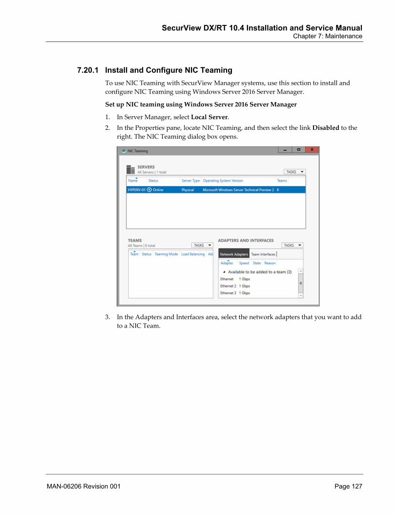
SecurView DX/RT 10.4 Installation and Service Manual Chapter 7: Maintenance
MAN-06206 Revision 001 Page 127
7.20.1 Install and Configure NIC Teaming
To use NIC Teaming with SecurView Manager systems, use this section to install and
configure NIC Teaming using Windows Server 2016 Server Manager.
Set up NIC teaming using Windows Server 2016 Server Manager
1. In Server Manager, select Local Server.
2. In the Properties pane, locate NIC Teaming, and then select the link Disabled to the
right. The NIC Teaming dialog box opens.
3. In the Adapters and Interfaces area, select the network adapters that you want to add
to a NIC Team.

SecurView DX/RT 10.4 Installation and Service Manual Chapter 7: Maintenance
Page 128 MAN-06206 Revision 001
4. Select TASKS, and then select Add to New Team.
5. The New team dialog box opens and displays network adapters and team members. In Team name, type a name for the new NIC Team (for example, SV_Teaming).

SecurView DX/RT 10.4 Installation and Service Manual Chapter 7: Maintenance
MAN-06206 Revision 001 Page 129
6. In the Additional properties area, select values for Teaming mode, Load balancing mode, and Standby adapter as needed. In most cases, the highest-performing load balancing mode is Dynamic (default configuration).
7. Select OK. 8. Reboot the system.
Note If the site IT administrator provided a new IP address, update the DICOM Setup configuration for this workstation. For multiworkstation systems, first update the DICOM Setup configuration for the Manager, then update these settings on each connected Client. Refer to DICOM > Setup Tab on page 37 for complete instructions.


SecurView DX/RT 10.4 Installation and Service Manual Chapter 8: Troubleshooting
MAN-06206 Revision 001 Page 131
8: Troubleshooting Setting True Size Pixel Pitch on Displays on page 131
Collecting Log Files on page 132
Copying Scheduled Backup Files to an External Drive on page 132
Configuring AutoMerge on page 133
Troubleshooting Multiworkstation Configurations on page 134
Printer Configuration Issues on page 136
Configuring Printer Timeouts on page 136
Auto-Fetching Issues on page 137
Patient ID and Patient’s Birth Date Issues on page 137
Contrast Enhanced Image Display Issues on page 137
Mammography Image Display Issues on page 138
PACS Issues with Default Manual Query Attributes on page 143
Troubleshooting System Failures (Standalone, Manager) on page 144
Troubleshooting the Updates Installation on page 144
Configuring Enhanced Image Distribution on page 145
PACS Issues for Rejection of BPO "For Processing" Images on page 146
Changed Windows Settings After Windows OS Upgrade on page 146
Ports Used by SecurView on page 146
8.1 Setting True Size Pixel Pitch on Displays Run the Set-Display-Config.bat script when you suspect that the mammography images are not being displayed correctly when operating in True Size mode, or if you replace the system mammography monitors.
1. Exit to Windows from SecurView. 2. Display File Explorer by pressing Windows + [E]. 3. Navigate to E:\Securview\Hologic-Service. 4. Double-click Set-Display-Config.bat to run the program. 5. Select the number that corresponds to the Manufacturer of the mammography
display type. For example, Barco. 6. Select the number that corresponds to the specific Model of the mammography
displays connected to the system.
Chapter 8

SecurView DX/RT 10.4 Installation and Service Manual Chapter 8: Troubleshooting
Page 132 MAN-06206 Revision 001
Note The model of the display is usually located on the lower rear of the display.
7. You should see a message confirming that one file was copied and the configuration is complete.
8. Press any key to close the command window as shown on-screen. 9. Close any open windows. 10. Start SecurView.
8.2 Collecting Log Files Run the getlogs.bat script when you want to collect the SecurView log files.
1. Display File Explorer by pressing Windows + [E]. 2. Navigate to E:\Securview\Hologic-Service. 3. Double-click getlogs.bat to run the program. 4. Type the number that corresponds to the type of files you want to collect.
1 – Full set of log files and system files only. 2 – Database files only. 3 – Database and full set of log files and system files. 4 – Log files and system files (excluding archived SYSINFO logs). 5 – Log files and system files (excluding all archived logs). 6 – Database, log files, and system files (excluding archived SYSINFO logs). 7 – Database, log files, and system files (excluding all archived logs).
5. Press [Enter]. The system collects the log files. 6. You can find the collected log files in the E:\SecurView\Hologic-Service\Logs folder. 7. Close all open windows.
8.3 Copying Scheduled Backup Files to an External Drive The ScheduledBackup.dat file automatically backs up the configuration and database files to F:\Hologic_Service_Scheduled-Backup\[date] on the local data drive. In addition to storing the backup files on the F:\ drive, you can copy these backup files to a secure drive external to the SecurView workstation. Storing the backup files on a secure external drive is useful in the event of a catastrophic hard disk failure. Use this procedure to configure the OffSystemBackup.bat file to back up the configuration and database files to a secure drive.
Note Do not manually run the OffSystemBackup.bat file. The ScheduledBackup.dat file uses this file during the automatic back up process.

SecurView DX/RT 10.4 Installation and Service Manual Chapter 8: Troubleshooting
MAN-06206 Revision 001 Page 133
1. Display File Explorer by pressing Windows + [E]. 2. Navigate to E:\SecurView\Hologic-Service. 3. Open the OffSystemBackup.bat file and locate the following line:
rem xcopy /e /y %1\*.* G:\Hologic-Service-Scheduled-Backup\!c_date!_%:date~0,-11%\
4. Remove the ‘rem’ from the line to enable the external drive backup. 5. Select a location to store the backup file. Replace the letter ‘G:\’ with either a
mapped network drive letter or USB drive letter. 6. Save the file. 7. Close all open windows.
8.4 Configuring AutoMerge The SecurView AutoMerge feature may be useful for multi-site enterprises with independent Radiology Information Systems (RIS) that may or may not use the same MRN (Patient ID) schema, and a centrally located SecurView workstation that receives images from multiple sites. Patients may move from one site to another for imaging (for example, have screening at one site and follow-up diagnostic at another) and are assigned different local MRNs at each site. If the enterprise also has a separate corporate-wide patient identifier that can be provided to the modality (for example, Selenia Dimensions) with Modality Worklist, the AutoMerge feature places those received patient images with different local MRNs into the same patient folder, based on the corporate-wide patient identifier.
The SecurView AutoMerge feature may also be useful if a customer changes from one RIS to another and the new RIS has a different MRN schema. If there is a unique corporate-wide or PIX (patient ID cross-referencing) identifier available in the DICOM image headers for all archived prior studies and new studies, then prior and new studies with different MRNs for a patient can be merged automatically into one patient folder on SecurView.
Configuring SecurView automatic merging of patients using enterprise-wide patient ID:
• Requires Modality Worklist Provider to return local patient ID in (0010,0020) plus an additional enterprise-wide unique patient ID in an attribute that can be mapped to, for example, Other Patient IDs (0010,1000) in Selenia Dimensions-created DICOM image objects.
• In SecurView lightbox.ini, set AutoMergeDICOM:gggg,eeee-n (for example, AutoMergeDICOM:0010,1000-1). (Available in SecurView 6-0-0 and later.)
• When SecurView receives a DICOM object, if no patient folder match is found using Patient ID (0010, 0020), coupled with Patient’s Birth Date (0010,0030) in SecurView 6-0-5 and later, the configured AutoMergeDICOM attribute value is checked for a match in the database. If found, the received object is merged automatically with the matching patient.

SecurView DX/RT 10.4 Installation and Service Manual Chapter 8: Troubleshooting
Page 134 MAN-06206 Revision 001
8.5 Troubleshooting Multiworkstation Configurations Network problems may occur on the Client side and the Manager side of a multiworkstation configuration.
• System Startup Issues on page 134 • Incorrect IP Address Issues on page 134 • Client Cannot Reach Manager on page 135 • Manual Connection Succeeds on page 135 • Manager Loses Client Connection on page 136
8.5.1 System Startup Issues If a network error occurs during system startup, the Client cannot connect to the multiworkstation Manager.
A startup window appears, which allows you to either shut down the system or log the SCR user off from the operating system.
Every five seconds the system tries to reach the multiworkstation Manager until either the Manager reconnects, or you select Shutdown or Log off from Operating System in the system startup window.
8.5.2 Incorrect IP Address Issues If the Manager IP address is incorrectly configured on the Client side, a network error can occur. In this case, perform the following steps:
1. Log into Windows as Administrator. 2. Display File Explorer by pressing Windows + [E]. 3. Navigate to E:\SecurView.

SecurView DX/RT 10.4 Installation and Service Manual Chapter 8: Troubleshooting
MAN-06206 Revision 001 Page 135
4. Double-click the SetWorkstationType.exe file to launch the program.
5. Reconfigure the system type and set the Manager IP address.
8.5.3 Client Cannot Reach Manager If network problems occur and a Client cannot reach the Manager, this Client will be inoperable for as long as the network problem persists. In this case, perform the following steps on the Client:
1. Try to re-establish a connection to the Manager after the given timeout has expired. 2. Display File Explorer by pressing Windows + [E]. 3. Navigate to E:\SecurView. 4. Double-click lightbox.ini to open it with Notepad.
Note Log off and close the SecurView application if it is running before editing the file.
5. Locate the following lines and configure the timeout and number of retries: MWS_RetryTimeOut (default: 1) MWS_RetryCount (default: 2)
If the Client cannot re-establish the connection, the system displays an error message and manual retry button to re-establish the connection to the Manager.
8.5.4 Manual Connection Succeeds If the user manually tries to re-establish the Manager connection and the network problem is resolved, two cases must be considered:
• The Manager has not yet cleaned up the sessions and locks of the Client. In this case, the user can continue to work.
• The Manager has cleaned up the sessions and locks for this Client. In this case, the user is logged out of the Client, and all work on the current patient is lost.
If you confirm the error message, or if the auto-logout time has expired, you will be logged out of the Client. If the network problem still exists, the log in will fail with a message that states the problem.
In all cases where you are logged out automatically due to network problems, a message appears informing you about the loss of work on the current patient.

SecurView DX/RT 10.4 Installation and Service Manual Chapter 8: Troubleshooting
Page 136 MAN-06206 Revision 001
8.5.5 Manager Loses Client Connection If the Manager encounters a network problem concerning a Client, the Manager takes the following measures in this order:
1. The Manager tries to re-establish a Client connection until the allotted timeout has expired. This timeout can be configured using the lightbox.ini file on the Manager.
2. After the timeout has expired, the Manager closes all sessions and releases all locks for the Client. This action results in all work for the current patient being lost for the user of that Client.
8.6 Printer Configuration Issues If the preloaded printer types are destroyed or lost, they can be reloaded by running ImportDefaultPrinters.bat. This file is located in the E:\SecurView\SQLScripts directory.
Running ImportDefaultPrinters.bat will erase any existing printer configurations.
8.7 Configuring Printer Timeouts The default PrintPreparer_MaxErrorsFromSCU, SCU_SleepTimeAfterPrintJob, and DICOMReadMessageTimeout values in the lightbox.ini file are fine under most circumstances. These timeouts can be configured by reviewing the settings in the following table and then editing the lightbox.ini file.
If the setting is not specified in the lightbox.ini file, the default value is used.
Table 6: Configuration of Timeouts for Printing in Lightbox.ini
Setting Default Comment
PrintPreparer_MaxErrorsFromSCU 5 The number of failed attempts after which the print job is stopped and the system continues with the next film to print.
SCU_SleepTimeAfterPrintJob 5 The number of seconds for the sleep time between print-jobs.
DICOMPrintReadMessageTimeout 30 The number of seconds of the timeout for a response from the DICOM printer.
DICOMPrintReadMessageTimeoutRetries 30 The number of retries to wait for a response from the DICOM printer in the event that the printer does not respond in the configured number of seconds.

SecurView DX/RT 10.4 Installation and Service Manual Chapter 8: Troubleshooting
MAN-06206 Revision 001 Page 137
8.8 Auto-Fetching Issues The default AutoFetcher_CMoveIPCTimeout and DICOM_QueryRetrieveTimeout values in the lightbox.ini are acceptable under most circumstances.
However, if the PACS has a long-term archive and short-term archive, and images must be moved from long-term archive to short-term archive before they can be sent to SecurView in response to an Auto-Fetch C-MOVE request, expect delays of several minutes for the final C-MOVE response.
The AutoFetcher_CMoveIPCTimeout and DICOM_QueryRetrieveTimeout must then be adjusted accordingly in the lightbox.ini file.
8.9 Patient ID and Patient’s Birth Date Issues SecurView uses both the Patient ID and Patient’s Birth Date DICOM attribute values to determine patient uniqueness. In some images, the Patient’s Birth Date attribute is empty, and it is desirable to consider patient ID only in those circumstances. This issue has been observed in prior images digitized from film for certain manufacturers.
You can use the PatientIdentification_SpecialDOBHandling configuration option in the lightbox.ini file to merge incoming patients with matching Patient IDs even if the Patient’s Birth Date attribute is empty by setting the flag to 1 (true). This setting ensures that all of the studies that have the same Patient ID and either a matching Patient’s Birth Date or empty Patient’s Birth Date will appear in the same patient folder.
The default value for this setting is 0 (false).
Patient ID Special DOB Handling
8.10 Contrast Enhanced Image Display Issues The ContrastImageTypeMap.ini file contains the values of Image Type (0008,0008) value 4 in DICOM image headers that the SecurView application uses to identify contrast enhanced mammography images for labeling MammoNavigator thumbnails and applying Hanging Snapshot settings within ReportFlows.
The following lines must be added to ContrastImageTypeMap.ini (for example, located in E:\SecurView) to identify GE contrast enhanced mammography images correctly as low energy or subtraction.
LOW_ENERGY : Low-Energy RECOMBINED : Subtraction

SecurView DX/RT 10.4 Installation and Service Manual Chapter 8: Troubleshooting
Page 138 MAN-06206 Revision 001
8.11 Mammography Image Display Issues The ManufacturerConfiguration.ini file contains manufacturer specific settings and preferences that are used to override the default SecurView behavior for mammography image display based on DICOM image header information.
You can edit this .ini file with any text editor; however, it is important to make a backup copy of the file before you attempt to make any changes. Take great care when changing these settings as they influence the display of mammography images.
This particular .ini file allows you to configure the manufacturer and model names from which to accept digital mammography For Processing images. You can also change settings that affect the grayscale transformations applied to specific manufacturer mammography images prior to display (for example modality LUT, VOI LUT, pixel padding).
Changes to ManufacturerConfiguration.ini may be helpful if a customer reports that mammography images from a specific manufacturer (and possibly model) are not displaying well on SecurView. Hologic has tried to set the default values based on current configuration knowledge. Thus, changes to these settings in the field will be rare. The default ManufacturerConfiguration.ini is shown at the end of this section. The default file is for reference only.
Table 7: Adjustable Settings in ManufacturerConfiguration.ini Setting Comment
DisableDigitalMarker If an image has a laterality/view label (for example, R CC) embedded in the stored pixel data, some customers do not want SecurView to display its digital marker also (a similar label) on those images.
DiscardGSPS Disables the display of a specific manufacturer or model GSPS if there is a problem with the SecurView interpretation/display of the GSPS content.
DiscardBreastTomosynthesisReconstruction Disables the display of a specific manufacturer or model Breast Tomosynthesis Image (BTO) if there is a problem with SecurView display of the images.
DiscardBreastTomosynthesisProjection Disables the display of a specific manufacturer or model Breast Projection X-Ray Image (BPO) if there is a problem with SecurView display of the images.
UseNthVoiLutAsDefault=n Selects the specific VOI LUT setting to use as the image display default when more than one Window Width/Window Center value pair or VOI LUT Sequence item is included in the DICOM image header in a consistent, predictable order for a specific manufacturer/model (for example, normal, harder, softer).

SecurView DX/RT 10.4 Installation and Service Manual Chapter 8: Troubleshooting
MAN-06206 Revision 001 Page 139
Table 7: Adjustable Settings in ManufacturerConfiguration.ini Setting Comment
PreferVOILUTSequence Selects VOI LUT Sequence instead of Window Width/Window Center to use as the image display default when both are present. May be used in conjunction with UseNthVoiLutAsDefault. If this setting is absent, the nth Window Width/Window Center pair will be the default. If this setting is present, the nth VOI LUT Sequence item will be the default.
CorrectVOILUTSequenceBits If a customer has 15-bit or 16-bit digital mammography images (for example, Agfa CR) and the DICOM image header includes VOI LUT Sequence items, use this setting to override the LUT Descriptor 3rd value if necessary so the VOI LUT is applied correctly.
ApplyClaheProcessing Primarily intended for use with Siemens digital mammography images, but could be applied to any manufacturer or model digital mammography images upon customer request.
ApplyClaheProcessing=[offset] Applies CLAHE processing with modified strength (value range = -10 to 10; default is 0) +n means more CLAHE enhancement and –n means less CLAHE enhancement.
DiscardDICOM6000Overlays Disables the display of a specific manufacturer or model DICOM 6000 Overlay if there is a problem with the SecurView interpretation/display of the DICOM 6000 Overlay content. To discard DICOM 6000 Overlays for all manufacturers, replace the default line that contains *:-:-:DICOM6000Overlay_Enhancement... with a line that contains *:-:-:DiscardDICOM6000Overlays.
SkipSecondaryCaptureCreationForDICOM6000 For use only when SecurView is guaranteed to receive two SOP Instances for each digital mammography image – the original image and a copy of the image that contains the DICOM 6000 Overlay. Then SecurView presents just the original image and an image with the DICOM 6000 Overlay burned in stacked for display. See the Note after this table.
DICOM6000Overlay_Enhancement, default=1 Adjusts the thickness in pixels of lines and text in the DICOM6000 Overlay to improve visibility.
DICOM6000Overlay_OutlineWidth, default=2 Adjusts the black outline width in pixels around lines and text in the DICOM6000 Overlay to improve visibility.
SecurView DX/RT 10.4 Installation and Service Manual Chapter 8: Troubleshooting
Page 140 MAN-06206 Revision 001
Table 7: Adjustable Settings in ManufacturerConfiguration.ini Setting Comment
SkipMPEForPresentation For sites using Mammography Prior Enhancement (MPE), if the customer is not satisfied with the appearance of GE For Presentation digital mammography prior images that are processed using the MPE license, add the SkipMPEForPresentation setting to the GE MEDICAL SYSTEMS line. This allows GE For Processing images to continue to be MPE processed.
ERMF Overrides the DICOM header value of Estimated Radiographic Magnification Factor (0018,1114) used for image sizing for 2D/3D comparison and measurement length calculation when the value is 1.0. Conventional 2D images such as Hologic Selenia have ERMF=1.0 in the DICOM header instead of the actual value of 1.069 or 1.073.
Note The default SecurView behavior when an image is received that contains a DICOM 6000 Overlay is to present the image without the DICOM 6000 Overlay and also create an internal "secondary capture" image that contains the DICOM 6000 Overlay burned in. The two images are stacked for display. If SecurView in addition receives the SOP Instance containing the original image without the DICOM 6000 Overlay, then there will be three images stacked for display that represent the same acquired image.
Note If the MPE feature is licensed and the customer wants MPE applied to prior GE For Processing images, follow the instructions in the file to enable the GE MEDICAL SYSTEMS line that includes AcceptForProcessing, and disable the GE MEDICAL SYSTEMS line that does not include it. Previously in SecurView 8.1 and 8.2, the default GE MEDICAL SYSTEMS line included AcceptForProcessing, anticipating that customers with GE digital mammography images would add the MPE license, but the majority have not.
Note For sites using MPE, if the customer is not satisfied with the appearance of any GE digital mammography prior images that are MPE processed, disable the MPE license, delete the affected patients, then resend the GE digital mammography images.

SecurView DX/RT 10.4 Installation and Service Manual Chapter 8: Troubleshooting
MAN-06206 Revision 001 Page 141
Caution Overriding the DICOM header ERMF value can result in incorrect diagnoses in these cases:
• The ERMF override value is not configured correctly and the results are incorrect image sizing and incorrect measurement lengths.
• An ERMF override value is configured when the DICOM header ERMF value is correct and the results are incorrect image sizing and incorrect measurement lengths.
To avoid incorrect diagnoses, ensure that an ERMF override value is both: • Configured only for images that are known to use an incorrect ERMF value
in the DICOM header • Corresponds to the correct ERMF value for the images.
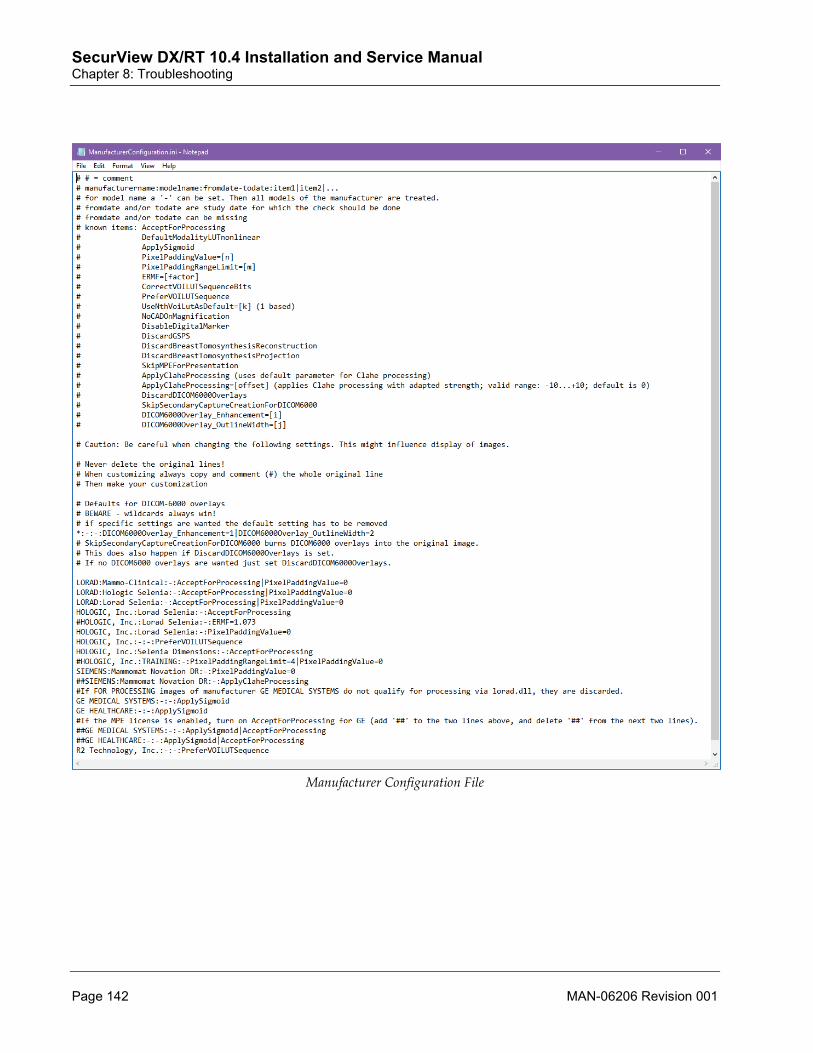
SecurView DX/RT 10.4 Installation and Service Manual Chapter 8: Troubleshooting
Page 142 MAN-06206 Revision 001
Manufacturer Configuration File

SecurView DX/RT 10.4 Installation and Service Manual Chapter 8: Troubleshooting
MAN-06206 Revision 001 Page 143
8.12 PACS Issues with Default Manual Query Attributes The OptionalQRTags.ini file contains optional DICOM attributes included in a Search on PACS manual query on the following levels: study, series, image. An attribute will be included in the query if its flag is set to 1 (true). You can exclude an attribute by setting its flag to 0 (false). Do not add attributes to or delete attributes from this file.
Study, series, or image level querying for manual query only is controlled by QR_Search_Level in the lightbox.ini file. The default is Series. Whether or not to include any optional study, series, or image level attributes in the query is controlled by SendOptionalStudyLevelTags, SendOptionalSeriesLevelTags and SendOptionalImageLevelTags in the lightbox.ini file. The default value for each of these is 1 (true).
Changes to OptionalQRTags.ini may be helpful if you determine that a PACS has a problem with the default manual query attributes (for example, Query/Retrieve may be slower on some GE PACS). Always make a backup copy of the file before you attempt to make any changes. The default values in the OptionalQRTags.ini are shown below.
Optional QR Tags File

SecurView DX/RT 10.4 Installation and Service Manual Chapter 8: Troubleshooting
Page 144 MAN-06206 Revision 001
8.13 Troubleshooting System Failures (Standalone, Manager) Depending on the status of the SecurView Windows operating system and the SecurView application, there are various actions you can take.
• If the SecurView is in a state where Windows is running correctly but the SecurView application does not start due to database issues, see Restoring from Backup on page 74.
Caution If the SecurView system has been compromised by a computer virus, contact Technical Support before performing the steps in Restoring from Backup on page 74.
• If the SecurView is in a state where Windows fails to load due to a computer virus or corrupt files on the system partition, see Recovering a Workstation on page 97.
• If the SecurView Manager is in a state where Windows is not loading and/or the system does not boot due to a catastrophic hardware failure, see Recovering a Workstation on page 97.
• If the SecurView is in a state where the database is corrupted and the DBM Tool is unavailable, see Reinstalling the SecurView Application on page 93.
8.14 Troubleshooting the Updates Installation This section provides troubleshooting procedures if, during a disaster recovery (see Recovering a Workstation on page 97), the SecurView System or Hologic OS Updates installer unexpectedly stops or becomes unresponsive during installation.
1. Resume the Updates installation. The ‘Would you like to resume the previous installation?’ message appears.
a. Select Yes. The Updates installer window appears.
b. Select Start to restart the Updates installation.
c. Confirm the Updates installer has resumed the installation.
If this does not resolve the problem, go to the next step. 2. Restart the Updates installer.
a. In the Updates installer window, select Exit.
b. Navigate to the drive and double-click SystemUpdater.exe. The ‘Would you like to resume the previous installation?’ message appears.
c. Select Yes. The Updates installer window appears.
d. Select Start to restart the Updates installation.
e. Confirm the Updates installer has resumed the installation.
If this does not resolve the problem, go to the next step.

SecurView DX/RT 10.4 Installation and Service Manual Chapter 8: Troubleshooting
MAN-06206 Revision 001 Page 145
3. Reboot the SecurView workstation and restart the Updates installer.
a. In the Updates installer window, select Exit.
b. Reboot the SecurView workstation.
c. Log into Windows as Administrator.
Note If the Administrator password is rejected at login, try logging in again and leave the password blank.
d. Navigate to the drive and double-click SystemUpdater.exe. The ‘Would you like to resume the previous installation?’ message appears.
e. Select Yes. The Updates installer window appears.
f. Select Start to restart the Updates installation.
g. Confirm the Updates installer has resumed the installation.
If this does not resolve the problem, go to the next step. 4. Check the Updates log.
a. Locate the System-Updates.log file in the following directory:
C:\ProgramData\Hologic\SystemUpdates
b. Open and review the file. Note any error messages and address any issue that is preventing the Updates installation.
c. Restart the Updates installer (see step 2).
Note After reviewing the log file, if you are unable to address the issue that is preventing the Updates installation, send the log file to Hologic Technical Support. Contact the Hologic Technical Support team at [email protected]. Include the following information in your e-mail:
• Subject – SecurView System Updates Installation Failure • Body – Site name, SecurView serial number, and dongle ID • Attachment – System-Updates.log
8.15 Configuring Enhanced Image Distribution By default, SecurView is configured to use enhanced image distribution, such that the manager and clients distribute images within the cluster. If a client has an insufficient network connection, image distribution to other clients may slow down. To avoid this situation the bandwidth is monitored by the manager automatically, and only clients with sufficient bandwidth will take part in distribution to other clients.

SecurView DX/RT 10.4 Installation and Service Manual Chapter 8: Troubleshooting
Page 146 MAN-06206 Revision 001
If needed, use the following steps to exclude a client manually from image distribution.
1. Shut down the SecurView application on the affected client. 2. Open lightbox.ini in a text editor such as Notepad. 3. Search for ‘DisableClientImageDistribution’
a. If the parameter exists, set the value to ‘1’
b. If the parameter does not exist, add it and set the value to ‘1’
4. Save changes to lightbox.ini and close the text editor. 5. Restart SecurView.
Note To re-enable distribution, reverse the above steps by setting the ‘DisableClientImageDistribution’ parameter to a value of 0, or by deleting the parameter from lightbox.ini.
If needed, use the following steps to completely disable client image distribution.
1. Shut down the SecurView application on all clients and the manager. 2. Open lightbox.ini in a text editor such as Notepad. 3. Search for ‘DisableClientImageDistribution’
a. If the parameter exists, set the value to ‘1’
b. If the parameter does not exist, add it and set the value to ‘1’
4. Save changes to lightbox.ini and close the text editor. 5. Restart SecurView on the manager and all clients.
Note To re-enable client image distribution, reverse the above steps by setting ‘DisableClientImageDistribution’ parameter to a value of 0, or by deleting the parameter from lightbox.ini on the manager
8.16 Ports Used by SecurView Default ports used by SecurView during communication with external applications are:
• 4697, 4698 and 4699 are used by the Study List Manager for patient list synchronization with MultiView MM.
• 4700 and 4702 are used by SecurView as listening ports when communicating with Application Synchronization.
• 5100 is used by Application Synchronization as a listening port, if running on the SecurView system.
• Above 4702 and below 5200 can be used for Application Synchronization, if running on the SecurView system.
• 104 is used for DICOM nodes.

SecurView DX/RT 10.4 Installation and Service Manual Chapter 8: Troubleshooting
MAN-06206 Revision 001 Page 147
The dynamic port range for TCP/IP is start=5200 and end=64999 (num=59800).
The range from Port 65000 to 65500 should be completely reserved for SecurView. SecurView processes are using the following Ports:
Port Process
65000 PostgreSQL
65019-65024 SCHEDULER
65025-65030 DICOM_SCU
65031-65036 DICOM_SCP
65037-65042 DBSTARTUP
65043-65048 DATABASE
65049-65054 APPLICATIONSELECTOR
65055-65060 LIGHTBOX
65061-65066 WATCHDOG
65067-65072 PRINTPREPROCESSOR
65073-65078 LICENSESERVER
65085-65090 IPCMONITOR
65091-65096 WATERMARKCONTROLLER
65097-65102 IPCKILLER
65103-65108 AUTOFETCHER
65109-65114 SYSTEMREADY
65115-65120 DISTRIBUTOR
65121-65126 SYNCHRONIZER
65127-65132 DICOMSERVICE
65139-65144 BARCODESCANNER
65163-65168 MODAL_CONTROLLER
65169-65174 XAPPINTERFACE
65175-65180 BACKGROUNDSCREEN
65187-65192 SERVICELOGGER
65193-65198 LOGARCHIVER
65199-65204 SYSINFOLOGGER

SecurView DX/RT 10.4 Installation and Service Manual Chapter 8: Troubleshooting
Page 148 MAN-06206 Revision 001
Port Process
65000 PostgreSQL
65205-65210 PREPARATION_CONTROL
65211-65216 PREPARATION_MG
65217-65222 PREPARATION_TOMO0
65223-65228 PREPARATION_TOMO1
65229-65234 PREPARATION_TOMO2
65235-65240 PREPARATION_TOMO3
65241-65246 PREPARATION_TOMO4
65247-65252 PREPARATION_TOMO5
65253-65258 PREPARATION_TOMO6
65259-65264 PREPARATION_TOMO7
65265-65270 PREPARATION_MAP0
65271-65276 PREPARATION_MAP1
65277-65282 PREPARATION_MAP2
65283-65288 PREPARATION_MAP3
65289 MEVISAPGATEWAY
65307 MAPWORKSPACESYNCHRONIZER
65343 SLMPROXY
65402 MM_IMAGEDATASERVER
65408 MM_WORKSPACESERVER
65500 GATEWAY
65503 PRIMACONNECTOR

SecurView DX/RT 10.4 Installation and Service Manual Appendix A: Barco Video Cards
MAN-06206 Revision 001 Page 149
Appendix A Barco Video Cards The following table lists the Barco video cards used with SecurView DX/RT systems:
Table 8: Barco Video Cards Version OS MG Card Multimodality Card Additional Monitor Card
SecurView DX with Barco Nio 5MP Displays
10.4 or later Windows 10 MXRT-2600 (WDDM driver)
NA Onboard display port
SecurView DX with Barco Coronis 5MP Displays
10.4 or later Windows 10 MXRT-7600 (WDDM driver)
MXRT-7600 MXRT-7600
SecurView DX with Barco High-Brightness, Coronis 10MP Fusion Display(s)
10.4 or later Windows 10 MXRT-7600 (WDDM driver)
MXRT-7600 MXRT-7600
SecurView DX with Barco Coronis Uniti 12MP Display
10.4 or later Windows 10 MXRT-7600 (WDDM driver)
MXRT-7600 MXRT-7600
SecurView RT with Barco Nio 3MP Display
10.4 or later Windows 10 MXRT-2600 (WDDM driver)
NA NA
Appendix A


SecurView DX/RT 10.4 Installation and Service Manual Appendix B: Video Driver Installers
MAN-06206 Revision 001 Page 151
Appendix B Video Driver Installers During a system upgrade, the System Updates Installer automatically copies video driver installers to your local system. Refer to the following table for the video driver installer locations:
Table 9: Video Driver Installer Locations
Video Card OS Driver Installer Location
MXRT-2600/7600 Windows 10 C:\SysUpdate\Video_Drivers\Barco\K5408051.21\ Barco\setup.exe
Onboard Display- System with MXRT-2600 requiring additional display.
Windows 10 C:\SysUpdate\Video_Drivers\Intel… Intel-HD-Graphics-510-530-630-Driver_5C3P0_WIN_23.20.16.4973_A06
Onboard Video Windows Server 2016
The Servers use the Windows Generic Display Driver
Appendix B


SecurView DX/RT 10.4 Installation and Service Manual Index
MAN-06206 Revision 001 Page 153
Index A Adding a SecurView User to Site Domain • 91 address, institution • 57 administrator rights • 29 Annotations, configuring • 48 Application Event Logging • 53 auto-completion • 51 auto-fetching • 11, 51
issues • 137 Automerge, configuring • 133
B backing up
database • 70 system (complete) • 67
barcode scanner • 65 birth date, troubleshooting • 137
C cables, configuring • 16 Client workstations
configuring • 35 defined • 3 in multiworkstation configurations • 10
Configuring Automerge • 133 Configuring Hologic Connect • 33 Configuring the multi-function mouse • 104
D DBM tool • 70 DICOM
printer settings • 11 settings • 37
disk space monitoring • 51 document conventions • 2 double-reading settings • 56
F file deletion, automatic • 51
G GSPS, configuring • 48
H Hanging order, configuring • 123 Hologic Connect, configuring • 33
I institution name and address • 57
K key functions, configuring • 109 keypad
programming • 105
L language, user interface • 90 LCD photometer sensor, reinstalling • 117 licenses, configuring • 58 log files, collecting • 132
M Maintaining workstation hardware • 84 Manager workstations
defined • 3 description • 10
materials required for installation • 11 MG Secondary Capture images
configuring • 48 setting format for • 58
MM screen captures, configuring • 48 multi-function mouse
configuring • 104 multiworkstations
description • 10 troubleshooting • 134
N Notices, configuring • 11, 48
O online documentation
installing • 97

SecurView DX/RT 10.4 Installation and Service Manual Index
Page 154 MAN-06206 Revision 001
installing for sites outside the US • 90
P PACS
adding and configuring • 37 issues with default manual query attributes •
143 patient ID troubleshooting issues • 137 Preventive Maintenance Checklist • 87 printer
adding, editing, deleting • 40 configuration issues • 136 setting up • 40 timeouts for • 136
printers adding • 37 default parameters for commonly used • 40
procedure names, importing • 88
Q query/retrieve • 11
R recovering a workstation • 97 restoring the database • 70 routing, configuring • 60
S scheduled backup files
copying to an external drive • 132 scr user account • 30 SecurView application
installing • 94 uninstalling • 94
SecurView DX in multiworkstation • 10
SecurView Manager in multiworkstation • 10
SecurView RT Destination tab • 49 in multiworkstation • 10
site inspection • 11 name and address • 57
settings • 11 Standalone workstations
defined • 3 starting up the system • 25 Study List Manager • 53 system
startup • 25 troubleshooting failures • 144 unpacking • 15
system time, synchronizing • 29
T terms and definitionsTerms • 3 training • 2 troubleshooting
auto-fetching • 137 collecting log files • 132 copying schedule backup files to an external
drive • 132 multiworkstation configurations • 134 PACS issues • 143 patient ID and birthdate issues • 137 printer configuration • 136 printer timeouts • 136 setting True Size pixel pitch • 131 system failures • 144
True Size pixel pitch setting • 131
U unpacking the system • 15 UPS
connecting and configuring • 16 user interface language • 90
W workstations
description of • 5 installing • 16 models • 5 recovering • 97


