Embed Size (px)
Citation preview
12-01-12
SECTION 26 29 21 ENCLOSED SWITCHES AND CIRCUIT BREAKERS
SPEC WRITE NOTE: Delete between //___// if not applicable to project. Also delete any other item or paragraph not applicable to the section and renumber the paragraphs.
PART 1 - GENERAL
1.1 DESCRIPTION
A. This section specifies the furnishing, installation, and connection of
fused and unfused disconnect switches (indicated as switches in this
section), and separately-enclosed circuit breakers for use in
electrical systems rated 600 V and below.
1.2 RELATED WORK
//A. Section 13 05 41, SEISMIC RESTRAINT REQUIREMENTS FOR NON-STRUCTURAL
COMPONENTS: Requirements for seismic restraint of non-structural
components.//
B. Section 26 05 11, REQUIREMENTS FOR ELECTRICAL INSTALLATIONS:
Requirements that apply to all sections of Division 26.
C. Section 26 05 19, LOW-VOLTAGE ELECTRICAL POWER CONDUCTORS AND CABLES:
Low-voltage conductors.
D. Section 26 05 26, GROUNDING AND BONDING FOR ELECTRICAL SYSTEMS:
Requirements for personnel safety and to provide a low impedance path
for possible ground faults.
E. Section 26 05 33, RACEWAY AND BOXES FOR ELECTRICAL SYSTEMS: Conduits.
F. Section 26 24 16, PANELBOARDS: Molded-case circuit breakers.
1.3 QUALITY ASSURANCE
A. Refer to Paragraph, QUALIFICATIONS (PRODUCTS AND SERVICES), in Section
26 05 11, REQUIREMENTS FOR ELECTRICAL INSTALLATIONS.
1.4 SUBMITTALS
A. Submit six copies of the following in accordance with Section 26 05 11,
REQUIREMENTS FOR ELECTRICAL INSTALLATIONS.
1. Shop Drawings:
a. Submit sufficient information to demonstrate compliance with
drawings and specifications.
b. Submit the following data for approval:
1) Electrical ratings, dimensions, mounting details, materials,
required clearances, terminations, weight, fuses, circuit
26 29 21 - 1

12-01-12
breakers, wiring and connection diagrams, accessories, and
device nameplate data.
SPEC WRITER NOTE: Include the following paragraph for projects in seismic areas of moderate-high, high and very high seismicities as listed in Table 4 of VA Handbook H-18-8, Seismic Design Requirements. Coordinate with the structural engineer.
//c. Certification from the manufacturer that representative enclosed
switches and circuit breakers have been seismically tested to
International Building Code requirements. Certification shall be
based upon simulated seismic forces on a shake table or by
analytical methods, but not by experience data or other
methods.//
2. Manuals:
a. Submit complete maintenance and operating manuals including
technical data sheets, wiring diagrams, and information for
ordering fuses, circuit breakers, and replacement parts.
1) Include schematic diagrams, with all terminals identified,
matching terminal identification in the enclosed switches and
circuit breakers.
2) Include information for testing, repair, troubleshooting,
assembly, and disassembly.
b. If changes have been made to the maintenance and operating
manuals originally submitted, submit updated maintenance and
operating manuals two weeks prior to the final inspection.
3. Certifications: Two weeks prior to final inspection, submit the
following.
a. Certification by the manufacturer that the enclosed switches and
circuit breakers conform to the requirements of the drawings and
specifications.
b. Certification by the Contractor that the enclosed switches and
circuit breakers have been properly installed, adjusted, and
tested.
1.5 APPLICABLE PUBLICATIONS
A. Publications listed below (including amendments, addenda, revisions,
supplements, and errata) form a part of this specification to the
26 29 21 - 2
12-01-12
extent referenced. Publications are referenced in the text by
designation only.
B. International Code Council (ICC):
IBC-12..................International Building Code
C. National Electrical Manufacturers Association (NEMA):
FU l-07.................Low Voltage Cartridge Fuses
KS l-06.................Enclosed and Miscellaneous Distribution
Equipment Switches (600 Volts Maximum)
D. National Fire Protection Association (NFPA):
70-11...................National Electrical Code (NEC)
E. Underwriters Laboratories, Inc. (UL):
98-07...................Enclosed and Dead-Front Switches
248-00..................Low Voltage Fuses
489-09..................Molded Case Circuit Breakers and Circuit
Breaker Enclosures
SPEC WRITER NOTE: Delete between // ---- // if not applicable to project. Also delete any other item or paragraph not applicable to the section and renumber the paragraphs.
PART 2 - PRODUCTS
2.1 FUSED SWITCHES RATED 600 AMPERES AND LESS
A. Switches shall be in accordance with NEMA, NEC, UL, as specified, and
as shown on the drawings.
B. Shall be NEMA classified General Duty (GD) for 240 V switches, and NEMA
classified Heavy Duty (HD) for 480 V switches.
C. Shall be horsepower (HP) rated.
D. Shall have the following features:
1. Switch mechanism shall be the quick-make, quick-break type.
2. Copper blades, visible in the open position.
3. An arc chute for each pole.
4. External operating handle shall indicate open and closed positions,
and have lock-open padlocking provisions.
5. Mechanical interlock shall permit opening of the door only when the
switch is in the open position, defeatable to permit inspection.
6. Fuse holders for the sizes and types of fuses specified.
7. Solid neutral for each switch being installed in a circuit which
includes a neutral conductor.
8. Ground lugs for each ground conductor.
26 29 21 - 3
12-01-12
9. Enclosures:
a. Shall be the NEMA types shown on the drawings.
b. Where the types of switch enclosures are not shown, they shall be
the NEMA types most suitable for the ambient environmental
conditions.
c. Shall be finished with manufacturer’s standard gray baked enamel
paint over pretreated steel.
//10. Electrically operated switches shall only be installed where shown
on the drawings.//
2.2 UNFUSED SWITCHES RATED 600 AMPERES AND LESS
A. Shall be the same as fused switches, but without provisions for fuses.
2.3 FUSED SWITCHES RATED OVER 600 AMPERES TO 1200 AMPERES
A. Shall be the same as fused switches, and shall be NEMA classified Heavy
Duty (HD).
2.4 MOTOR RATED TOGGLE SWITCHES
A. Type 1, general purpose for single-phase motors rated up to 1
horsepower.
B. Quick-make, quick-break toggle switch with external reset button and
thermal overload protection matched to nameplate full-load current of
actual protected motor.
2.5 CARTRIDGE FUSES
SPEC WRITE NOTE: Edit the paragraph below to conform to project requirements.
A. Shall be in accordance with NEMA FU 1.
B. Service Entrance: //Class L, fast acting// //Class L, time delay//
//Class RK1, fast acting// //Class RK1, time delay// //Class J, fast
acting// //Class J, time delay// //Class T, fast acting//.
C. Feeders: //Class L, fast acting// //Class L, time delay// //Class RK1,
fast acting// //Class RK1, time delay// //Class RK5, fast acting//
//Class RK5, time delay// //Class J, fast acting// //Class J, time
delay//.
D. Motor Branch Circuits: //Class RK1// //Class RK5//, time delay.
E. Other Branch Circuits: //Class RK1, time delay// //Class RK5, time
delay// //Class J, fast acting// //Class J, time delay//.
F. Control Circuits: Class CC, //fast acting// //time delay//.
2.6 SEPARATELY-ENCLOSED CIRCUIT BREAKERS
A. Provide circuit breakers in accordance with the applicable requirements
in Section 26 24 16, PANELBOARDS.
26 29 21 - 4
12-01-12
B. Enclosures shall be the NEMA types shown on the drawings. Where the
types are not shown, they shall be the NEMA type most suitable for the
ambient environmental conditions.
SPEC WRITER NOTE: Delete between // ---- // if not applicable to project. Also delete any other item or paragraph not applicable to the section and renumber the paragraphs.
PART 3 - EXECUTION
3.1 INSTALLATION
A. Installation shall be in accordance with the manufacturer’s
instructions, the NEC, as shown on the drawings, and as specified.
//B. In seismic areas, enclosed switches and circuit breakers shall be
adequately anchored and braced per details on structural contract
drawings to withstand the seismic forces at the location where
installed.//
C. Fused switches shall be furnished complete with fuses. Arrange fuses
such that rating information is readable without removing the fuses.
3.2 ACCEPTANCE CHECKS AND TESTS
A. Perform in accordance with the manufacturer's recommendations. In
addition, include the following:
1. Visual Inspection and Tests:
a. Compare equipment nameplate data with specifications and approved
shop drawings.
b. Inspect physical, electrical, and mechanical condition.
c. Verify tightness of accessible bolted electrical connections by
calibrated torque-wrench method.
d. Vacuum-clean enclosure interior. Clean enclosure exterior.
3.3 SPARE PARTS
A. Two weeks prior to the final inspection, furnish one complete set of
spare fuses for each fused disconnect switch installed on the project.
Deliver the spare fuses to the //Resident Engineer// //COTR//.
---END---
26 29 21 - 5
11-09
SECTION 27 05 11 REQUIREMENTS FOR COMMUNICATIONS INSTALLATIONS
PART 1 - GENERAL
1.01 DESCRIPTION
A. This Section, Requirements for Communications Installations, applies to all sections of Division 27.
B. Furnish and install communications cabling, systems, equipment, and accessories in accordance with the specifications and drawings. Capacities and ratings of transformers, cable, and other items and arrangements for the specified items are shown on drawings.
1.02 MINIMUM REQUIREMENTS
A. References to industry and trade association standards and codes are minimum installation requirement standards.
B. Drawings and other specification sections shall govern in those instances where requirements are greater than those specified in the above standards.
1.03 QUALIFICATIONS (PRODUCTS AND SERVICES)
A. Manufacturers Qualifications: The manufacturer shall regularly and presently produce, as one of the manufacturer's principal products, the equipment and material specified for this project, and shall have manufactured the item for at least three years.
B. Product Qualification: 1. Manufacturer's product shall have been in satisfactory operation,
on three installations of similar size and type as this project, for approximately three years.
2. The Government reserves the right to require the Contractor to submit a list of installations where the products have been in operation before approval.
C. Service Qualifications: There shall be a permanent service organization maintained or trained by the manufacturer which will render satisfactory service to this installation within four hours of receipt of notification that service is needed. Submit name and address of service organizations.
1.04 MANUFACTURED PRODUCTS
A. Materials and equipment furnished shall be of current production by manufacturers regularly engaged in the manufacture of such items, for which replacement parts shall be available.
B. When more than one unit of the same class of equipment is required, such units shall be the product of a single manufacturer.
C. Equipment Assemblies and Components: 1. Components of an assembled unit need not be products of the same
manufacturer.
27 05 11 - 1
11-09
2. Manufacturers of equipment assemblies, which include components made by others, shall assume complete responsibility for the final assembled unit.
3. Components shall be compatible with each other and with the total assembly for the intended service.
4. Constituent parts which are similar shall be the product of a single manufacturer.
D. Factory wiring shall be identified on the equipment being furnished and on all wiring diagrams.
E. When Factory Testing Is Specified: 1. The Government shall have the option of witnessing factory tests.
The contractor shall notify the VA through the Resident Engineer a minimum of 15 working days prior to the manufacturers making the factory tests.
2. Four copies of certified test reports containing all test data shall be furnished to the Resident Engineer prior to final inspection and not more than 90 days after completion of the tests.
3. When equipment fails to meet factory test and re-inspection is required, the contractor shall be liable for all additional expenses, including expenses of the Government.
1.05 EQUIPMENT REQUIREMENTS
A. Where variations from the contract requirements are requested in accordance with the GENERAL CONDITIONS and Section 01 33 23, SHOP DRAWINGS, PRODUCT DATA, AND SAMPLES, the connecting work and related components shall include, but not be limited to additions or changes to branch circuits, circuit protective devices, conduits, wire, feeders, controls, panels and installation methods.
1.06 EQUIPMENT PROTECTION
A. Equipment and materials shall be protected during shipment and storage against physical damage, dirt, moisture, cold and rain: 1. During installation, enclosures, equipment, controls, controllers,
circuit protective devices, and other like items, shall be protected against entry of foreign matter; and be vacuum cleaned both inside and outside before testing and operating and repainting if required.
2. Damaged equipment shall be, as determined by the Resident Engineer, placed in first class operating condition or be returned to the source of supply for repair or replacement.
3. Painted surfaces shall be protected with factory installed removable heavy kraft paper, sheet vinyl or equal.
4. Damaged paint on equipment and materials shall be refinished with the same quality of paint and workmanship as used by the manufacturer so repaired areas are not obvious.
1.07 WORK PERFORMANCE
A. Job site safety and worker safety is the responsibility of the contractor.
B. For work on existing stations, arrange, phase and perform work to assure communications service for other buildings at all times. Refer to Article OPERATIONS AND STORAGE AREAS under Section 01 00 00, GENERAL REQUIREMENTS.
27 05 11 - 2
11-09
C. New work shall be installed and connected to existing work neatly and carefully. Disturbed or damaged work shall be replaced or repaired to its prior conditions, as required by Section 01 00 00, GENERAL REQUIREMENTS.
D. Coordinate location of equipment and pathways with other trades to minimize interferences. See the GENERAL CONDITIONS.
1.08 EQUIPMENT INSTALLATION AND REQUIREMENTS
A. Equipment location shall be as close as practical to locations shown on the drawings.
B. Inaccessible Equipment: 1. Where the Government determines that the Contractor has installed
equipment not conveniently accessible for operation and maintenance, the equipment shall be removed and reinstalled as directed at no additional cost to the Government.
2. "Conveniently accessible" is defined as being capable of being reached without the use of ladders, or without climbing or crawling under or over obstacles such as, but not limited to, motors, pumps, belt guards, transformers, piping, ductwork, conduit and raceways.
1.09 EQUIPMENT IDENTIFICATION
A. Install an identification sign which clearly indicates information required for use and maintenance of equipment.
B. Nameplates shall be laminated black phenolic resin with a white core with engraved lettering, a minimum of 6 mm (1/4 inch) high. Secure nameplates with screws. Nameplates that are furnished by manufacturer as a standard catalog item, or where other method of identification is herein specified, are exceptions.
1.10 SUBMITTALS
A. Submit in accordance with Section 01 33 23, SHOP DRAWINGS, PRODUCT DATA, AND SAMPLES.
B. The Government's approval shall be obtained for all equipment and material before delivery to the job site. Delivery, storage, or installation of equipment or material which has not had prior approval will not be permitted at the job site.
C. All submittals shall include adequate descriptive literature, catalog cuts, shop drawings, and other data necessary for the Government to ascertain that the proposed equipment and materials comply with specification requirements. Catalog cuts submitted for approval shall be legible and clearly identify equipment being submitted.
D. Submittals for individual systems and equipment assemblies which consist of more than one item or component shall be made for the system or assembly as a whole. Partial submittals will not be considered for approval. 1. Mark the submittals, "SUBMITTED UNDER SECTION__________________". 2. Submittals shall be marked to show specification reference
including the section and paragraph numbers. 3. Submit each section separately.
27 05 11 - 3
11-09
E. The submittals shall include the following: 1. Information that confirms compliance with contract requirements.
Include the manufacturer's name, model or catalog numbers, catalog information, technical data sheets, shop drawings, pictures, nameplate data and test reports as required.
2. Submittals are required for all equipment anchors and supports. Submittals shall include weights, dimensions, center of gravity, standard connections, manufacturer's recommendations and behavior problems (e.g., vibration, thermal expansion,) associated with equipment or piping so that the proposed installation can be properly reviewed.
3. Elementary and interconnection wiring diagrams for communication and signal systems, control system and equipment assemblies. All terminal points and wiring shall be identified on wiring diagrams.
4. Parts list which shall include those replacement parts recommended by the equipment manufacturer, quantity of parts, current price and availability of each part.
F. Manuals: Submit in accordance with Section 01 00 00, GENERAL REQUIREMENTS. 1. Maintenance and Operation Manuals: Submit as required for systems
and equipment specified in the technical sections. Furnish four copies, bound in hardback binders, (manufacturer's standard binders) or an approved equivalent. Furnish one complete manual as specified in the technical section but in no case later than prior to performance of systems or equipment test, and furnish the remaining manuals prior to contract completion.
2. Inscribe the following identification on the cover: the words "MAINTENANCE AND OPERATION MANUAL," the name and location of the system, equipment, building, name of Contractor, and contract number. Include in the manual the names, addresses, and telephone numbers of each subcontractor installing the system or equipment and the local representatives for the system or equipment.
3. Provide a "Table of Contents" and assemble the manual to conform to the table of contents, with tab sheets placed before instructions covering the subject. The instructions shall be legible and easily read, with large sheets of drawings folded in.
4. The manuals shall include: a. Internal and interconnecting wiring and control diagrams
with data to explain detailed operation and control of the equipment.
b. A control sequence describing start-up, operation, and shutdown.
c. Description of the function of each principal item of equipment.
d. Installation and maintenance instructions. e. Safety precautions. f. Diagrams and illustrations. g. Testing methods. h. Performance data. i. Pictorial "exploded" parts list with part numbers. Emphasis
shall be placed on the use of special tools and instruments. The list shall indicate sources of supply, recommended spare parts, and name of servicing organization.
j. Appendix; list qualified permanent servicing organizations for support of the equipment, including addresses and certified qualifications.
G. Approvals will be based on complete submission of manuals together with shop drawings.
27 05 11 - 4

11-09
H. After approval and prior to installation, furnish the Resident Engineer with one sample of each of the following: 1. A 300 mm (12 inch) length of each type and size of wire and cable
along with the tag from the coils of reels from which the samples were taken.
2. Each type of conduit and pathway coupling, bushing and termination fitting.
3. Raceway and pathway hangers, clamps and supports. 4. Duct sealing compound.
I. In addition to the requirement of SUBMITTALS, the VA reserves the right to request the manufacturer to arrange for a VA representative to see typical active systems in operation, when there has been no prior experience with the manufacturer or the type of equipment being submitted.
1.11 SINGULAR NUMBER
A. Where any device or part of equipment is referred to in these specifications in the singular number (e.g., "the switch"), this reference shall be deemed to apply to as many such devices as are required to complete the installation as shown on the drawings.
1.12 TRAINING
A. Training shall be provided in accordance with Article, INSTRUCTIONS, of Section 01 00 00, GENERAL REQUIREMENTS.
B. Training shall be provided for the particular equipment or system as required in each associated specification.
C. A training schedule shall be developed and submitted by the contractor and approved by the Resident Engineer at least 30 days prior to the planned training.
END OF SECTION
27 05 11 - 5
06-01-13
SECTION 27 08 00
COMMISSIONING OF COMMUNICATIONS SYSTEMS
PART 1 - GENERAL
1.1 DESCRIPTION
A. The requirements of this Section apply to all sections of Division 27.
B. This project will have selected building systems commissioned. The
complete list of equipment and systems to be commissioned is specified
in Section 01 91 00 GENERAL COMMISSIONING REQUIREMENTS. The
commissioning process, which the Contractor is responsible to execute,
is defined in Section 01 91 00 GENERAL COMMISSIONING REQUIRMENTS. A
Commissioning Agent (CxA) appointed by the VA will manage the
commissioning process.
1.2 RELATED WORK
A. Section 01 00 00 GENERAL REQUIREMENTS.
B. Section 01 91 00 GENERAL COMMISSIONING REQUIREMENTS.
C. Section 01 33 23 SHOP DRAWINGS, PRODUCT DATA, AND SAMPLES.
1.3 SUMMARY
A. This Section includes requirements for commissioning the Facility
communications systems, related subsystems and related equipment. This
Section supplements the general requirements specified in Section 01 91
00 General Commissioning Requirements.
B. Refer to Section 01 91 00 GENERAL COMMISSIONING REQUIREMENTS for more
details regarding processes and procedures as well as roles and
responsibilities for all Commissioning Team members.
1.4 DEFINITIONS
A. Refer to Section 01 91 00 GENERAL COMMISSIONING REQUIREMENTS for
definitions.
1.5COMMISSIONED SYSTEMS
A. Commissioning of a system or systems specified in Division 27 is part
of the construction process. Documentation and testing of these
systems, as well as training of the VA’s Operation and Maintenance
personnel in accordance with the requirements of Section 01 91 00 and
of Division 27, is required in cooperation with the VA and the
Commissioning Agent.
B. The Facility exterior closure systems commissioning will include the
systems listed in Section 01 19 00 General Commissioning Requirements:
27 08 00 - 1
06-01-13
1.6 SUBMITTALS
A. The commissioning process requires review of selected Submittals that
pertain to the systems to be commissioned. The Commissioning Agent
will provide a list of submittals that will be reviewed by the
Commissioning Agent. This list will be reviewed and approved by the VA
prior to forwarding to the Contractor. Refer to Section 01 33 23 SHOP
DRAWINGS, PRODUCT DATA, and SAMPLES for further details.
B. The commissioning process requires Submittal review simultaneously with
engineering review. Specific submittal requirements related to the
commissioning process are specified in Section 01 91 00 GENERAL
COMMISSIONING REQUIREMENTS.
PART 2 - PRODUCTS (NOT USED)
PART 3 - EXECUTION
3.1 CONSTRUCTION INSPECTIONS
A. Commissioning of Communications systems will require inspection of
individual elements of the communications system construction
throughout the construction period. The Contractor shall coordinate
with the Commissioning Agent in accordance with Section 01 19 00 and
the Commissioning plan to schedule communications systems inspections
as required to support the Commissioning Process.
3.2 PRE-FUNCTIONAL CHECKLISTS
A. The Contractor shall complete Pre-Functional Checklists to verify
systems, subsystems, and equipment installation is complete and systems
are ready for Systems Functional Performance Testing. The
Commissioning Agent will prepare Pre-Functional Checklists to be used
to document equipment installation. The Contractor shall complete the
checklists. Completed checklists shall be submitted to the VA and to
the Commissioning Agent for review. The Commissioning Agent may spot
check a sample of completed checklists. If the Commissioning Agent
determines that the information provided on the checklist is not
accurate, the Commissioning Agent will return the marked-up checklist
to the Contractor for correction and resubmission. If the
Commissioning Agent determines that a significant number of completed
checklists for similar equipment are not accurate, the Commissioning
Agent will select a broader sample of checklists for review. If the
Commissioning Agent determines that a significant number of the broader
sample of checklists is also inaccurate, all the checklists for the
type of equipment will be returned to the Contractor for correction and
27 08 00 - 2
06-01-13
resubmission. Refer to SECTION 01 91 00 GENERAL COMMISSIONING
REQUIREMENTS for submittal requirements for Pre-Functional Checklists,
Equipment Startup Reports, and other commissioning documents.
3.3 CONTRACTORS TESTS
A. Contractor tests as required by other sections of Division 27 shall be
scheduled and documented in accordance with Section 01 00 00 GENERAL
REQUIREMENTS. All testing shall be incorporated into the project
schedule. Contractor shall provide no less than 7 calendar days’
notice of testing. The Commissioning Agent will witness selected
Contractor tests at the sole discretion of the Commissioning Agent.
Contractor tests shall be completed prior to scheduling Systems
Functional Performance Testing.
3.4 SYSTEMS FUNCTIONAL PERFORMANCE TESTING:
A. The Commissioning Process includes Systems Functional Performance
Testing that is intended to test systems functional performance under
steady state conditions, to test system reaction to changes in
operating conditions, and system performance under emergency
conditions. The Commissioning Agent will prepare detailed Systems
Functional Performance Test procedures for review and approval by the
Resident Engineer. The Contractor shall review and comment on the
tests prior to approval. The Contractor shall provide the required
labor, materials, and test equipment identified in the test procedure
to perform the tests. The Commissioning Agent will witness and
document the testing. The Contractor shall sign the test reports to
verify tests were performed. See Section 01 91 00 GENERAL
COMMISSIONING REQUIREMENTS, for additional details.
3.5 TRAINING OF VA PERSONNEL
A. Training of the VA operation and maintenance personnel is required in
cooperation with the Resident Engineer and Commissioning Agent.
Provide competent, factory authorized personnel to provide instruction
to operation and maintenance personnel concerning the location,
operation, and troubleshooting of the installed systems. Contractor
shall submit training agendas and trainer resumes in accordance with
the requirements of Section 01 19 00. The instruction shall be
scheduled in coordination with the VA Resident Engineer after
submission and approval of formal training plans. Refer to Section 01
91 00 GENERAL COMMISSIONING REQUIREMENTS and Division 27 Sections for
additional Contractor training requirements.
27 08 00 - 3

06-01-13
----- END -----
27 08 00 - 4
12-05M
SECTION 27 10 00 STRUCTURED CABLING
PART 1 - GENERAL
1.01 DESCRIPTION
A. This section specifies the furnishing, installation, and connection of the structured cabling system to provide a comprehensive telecommunications infrastructure.
1.02 RELATED WORK
A. Excavation and backfill for cables that are installed in conduit: Section 31 20 00, EARTH MOVING.
B. Sealing around penetrations to maintain the integrity of time rated construction: Section 07 84 00, FIRESTOPPING.
C. General electrical requirements that are common to more than one section in Division 27: Section 27 05 11, REQUIREMENTS FOR COMMUNICATIONS INSTALLATIONS.
D. Conduits for cables and wiring: Section 27 05 33, RACEWAYS AND BOXES FOR COMMUNICATIONS SYSTEMS.
E. Requirements for personnel safety and to provide a low impedance path for possible ground fault currents: Section 27 05 26, GROUNDING AND BONDING FOR COMMUNICATIONS SYSTEMS.
1.03 SUBMITTALS
A. In accordance with Section 01 33 23, SHOP DRAWINGS, PRODUCT DATA, AND SAMPLES, furnish the following: 1. Manufacturer's Literature and Data: Showing each cable type and
rating. 2. Certificates: Two weeks prior to final inspection, deliver to the
VA Project Manager four copies of the certification that the material is in accordance with the drawings and specifications and has been properly installed.
1.04 APPLICABLE PUBLICATIONS
A. Publications listed below (including amendments, addenda, revisions, supplements and errata) form a part of this specification to the extent referenced. Publications are reference in the text by the basic designation only.
B. American Society of Testing Material (ASTM): D2301-04................Standard Specification for Vinyl Chloride
Plastic Pressure Sensitive Electrical Insulating Tape
C. Federal Specifications (Fed. Spec.): A-A-59544-00............Cable and Wire, Electrical (Power, Fixed
Installation)
D. National Fire Protection Association (NFPA): 70-05...................National Electrical Code (NEC)
27 10 00 - 1
12-05M
E. Underwriters Laboratories, Inc. (UL): 44-02...................Thermoset-Insulated Wires and Cables 83-03...................Thermoplastic-Insulated Wires and Cables 467-01..................Electrical Grounding and Bonding Equipment 486A-01.................Wire Connectors and Soldering Lugs for Use with
Copper Conductors 486C-02.................Splicing Wire Connectors 486D-02.................Insulated Wire Connector Systems for Underground
Use or in Damp or Wet Locations 486E-00.................Equipment Wiring Terminals for Use with Aluminum
and/or Copper Conductors 493-01..................Thermoplastic-Insulated Underground Feeder and
Branch Circuit Cable 514B-02.................Fittings for Cable and Conduit 1479-03.................Fire Tests of Through-Penetration Fire Stops
PART 2 - PRODUCTS
2.01 CONTROL WIRING
A. Unless otherwise specified in other sections of these specifications, control wiring shall be as specified for power and lighting wiring, except the minimum size shall be not less than No. 14 AWG.
B. Control wiring shall be large enough so that the voltage drop under inrush conditions does not adversely affect operation of the controls.
2.02 COMMUNICATION AND SIGNAL WIRING
A. Shall conform to the recommendations of the manufacturers of the communication and signal systems; however, not less than what is shown.
B. Wiring shown is for typical systems. Provide wiring as required for the systems being furnished.
C. Multi-conductor cables shall have the conductors color coded.
2.03 WIRE LUBRICATING COMPOUND
A. Suitable for the wire insulation and conduit it is used with, and shall not harden or become adhesive.
B. Shall not be used on wire for isolated type electrical power systems.
2.04 FIREPROOFING TAPE
A. The tape shall consist of a flexible, conformable fabric of organic composition coated one side with flame-retardant elastomer.
B. The tape shall be self-extinguishing and shall not support combustion. It shall be arc-proof and fireproof.
C. The tape shall not deteriorate when subjected to water, gases, salt water, sewage, or fungus and be resistant to sunlight and ultraviolet light.
D. The finished application shall withstand a 200-ampere arc for not less than 30 seconds.
27 10 00 - 2
12-05M
E. Securing tape: Glass cloth electrical tape not less than 0.18 mm (7 mils) thick, and 19 mm (3/4 inch) wide.
PART 3 - EXECUTION
3.01 INSTALLATION, GENERAL
A. Install all wiring in raceway systems.
B. Wire Pulling: 1. Provide installation equipment that will prevent the cutting or
abrasion of insulation during pulling of cables. 2. Use ropes made of nonmetallic material for pulling feeders. 3. Attach pulling lines for feeders by means of either woven basket
grips or pulling eyes attached directly to the conductors, as approved by the Resident Engineer.
4. Pull in multiple cables together in a single conduit.
3.02 CONTROL, COMMUNICATION AND SIGNAL WIRING INSTALLATION
A. Unless otherwise specified in other sections, install wiring and connect to equipment/devices to perform the required functions as shown and specified.
B. Except where otherwise required, install a separate power supply circuit for each system so that malfunctions in any system will not affect other systems.
C. Where separate power supply circuits are not shown, connect the systems to the nearest panelboards of suitable voltages, which are intended to supply such systems and have suitable spare circuit breakers or space for installation.
D. Install a red warning indicator on the handle of the branch circuit breaker for the power supply circuit for each system to prevent accidental de-energizing of the systems.
E. System voltages shall be 120 volts or lower where shown on the drawings or as required by the NEC.
3.03 CONTROL, COMMUNICATION AND SIGNAL SYSTEM IDENTIFICATION
A. Install a permanent wire marker on each wire at each termination.
B. Identifying numbers and letters on the wire markers shall correspond to those on the wiring diagrams used for installing the systems.
C. Wire markers shall retain their markings after cleaning.
3.04 EXISTING WIRING
A. Unless specifically indicated on the plans, existing wiring shall not be reused for the new installation. Only wiring that conforms to the specifications and applicable codes may be reused. If existing wiring does not meet these requirements, existing wiring may not be reused and new wires shall be installed.
27 10 00 - 3

12-05M
END OF SECTION
27 10 00 - 4
06-01-13
SECTION 27 51 23 INTERCOMMUNICATIONS AND PROGRAM SYSTEMS
SPEC WRITER NOTES: 1. Edit between //-----// Delete if not
applicable to project. Defer to VA TVE (005OP3B – see Paragraph 1.3.D for specific contact info) for technical assistance.
2. Included throughout this specification are references to the system’s interface capability and various related features. The system designer shall verify availability of this system and coordinate associated requirements and subsequent interface(s).
PART 1 - GENERAL
1.1 SECTION SUMMARY
A. Work covered by this document includes design, engineering, labor,
material, products, guaranty, training and services for, and incidental
to, the complete installation of a new and fully operating National
Fire Protection Association (NFPA) Listed Emergency/Public Safety
Public Address and Mass Notification communication (PA) system as
detailed herein.
B. Work shall be complete, tested, labeled, certified and ready for
operation
1.2 RELATED SECTIONS
A. Section 01 33 23, SHOP DRAWINGS, PRODUCT DATA AND SAMPLES
B. Section 26 05 21, LOW-VOLTAGE ELECTRICAL POWER CONDUCTORS AND CABLES
(600 Volts and Below)
C. Section 26 41 00, FACILITY LIGHTNING PROTECTION
D. Section 27 05 26, GROUNDING AND BONDING FOR COMMUNCATIONS SYSTEMS
E. Section 27 05 11, REQUIREMENTS FOR COMMUNCATIONS INSTALLATIONS
F. Section 27 10 00, STRUCTURED CABLING
G. Section 27 15 00, COMMUNICATIONS HORIZONTAL CABLING
H. Section 27 05 33, RACEWAYS AND BOXES FOR COMMUNICATIONS SYSTEMS
1.3 DEFINITIONS
A. Provide: Design, engineer, furnish, install, connect complete, test,
certify and warranty.
B. Work: Materials furnished and completely installed.
C. Review of contract drawings: A service by the engineer to reduce the
possibility of materials being ordered which do not comply with
27 51 23 - 1
06-01-13
contract documents. The engineer's review shall not relieve the
Contractor of responsibility for dimensions or compliance with the
contract documents. The reviewer's failure to detect an error does not
constitute permission for the Contractor to proceed in error.
D. Headquarters Technical Review, for National/VA communications and
security, codes, frequency licensing, standards, guidelines compliance:
Office of Telecommunications
Special Communications Team (005OP2B)
1335 East West Highway – 3rd Floor
Silver Spring, Maryland 20910
(O) 301-734-0350, (F) 301-734-0360
E. Engineer: //XXXXXXX//
//XXXXXXX//
//XXXXXXX//
//XXXXXXX//
//XXXXXXX//
F. Owner: //XXXXXXX//
G. General Contractor (GC): //XXXXXXX//
H. Contractor: Radio Contractor; you; successful bidder.
1.4 REFERENCES
A. The installation shall comply fully with all governing authorities,
laws and ordinances, regulations, codes and standards, including, but
not limited to:
1. United States Federal Law and Codes:
a. Departments of:
1) CFR, Title 15 – Department of Commerce, Under the Information
Technology Management Reform Act (Public Law 104-106), the
Secretary of Commerce approves standards and guidelines that
are developed by the:
a) Chapter II, National Institute of Standards Technology
(NIST – formerly the National Bureau of Standards). Under
Section 5131 of the Information Technology Management
Reform Act of 1996 and the Federal Information Security
Management Act of 2002 (Public Law 107-347), NIST develops
– Federal Information Processing Standards Publication
(FIPS) 140-2—Security Requirements for Cryptographic
Modules.
27 51 23 - 2
06-01-13
b) Chapter XXIII, National Telecommunications and Information
Administration (NTIA – aka ‘Red Book’) Chapter 7.8/9
Federal communications Commission (FCC) Title 47 (CFR),
Part 15, Radio Frequency Restriction of Use and Compliance
in “Safety of Life” Functions and Locations.
2) CFR, Title 29, Department of Labor, Chapter XVII -
Occupational Safety and Health Administration (OSHA), Part
1910 – Occupational Safety and Health Standard:
a) Subpart 7 - Definition and requirements for a National
Recognized Testing Laboratory (NRTL – 15 Laboratory’s, for
complete list, contact
http://www.osha.gov/dts/otpca/nrtl/faq_nrtl.html)
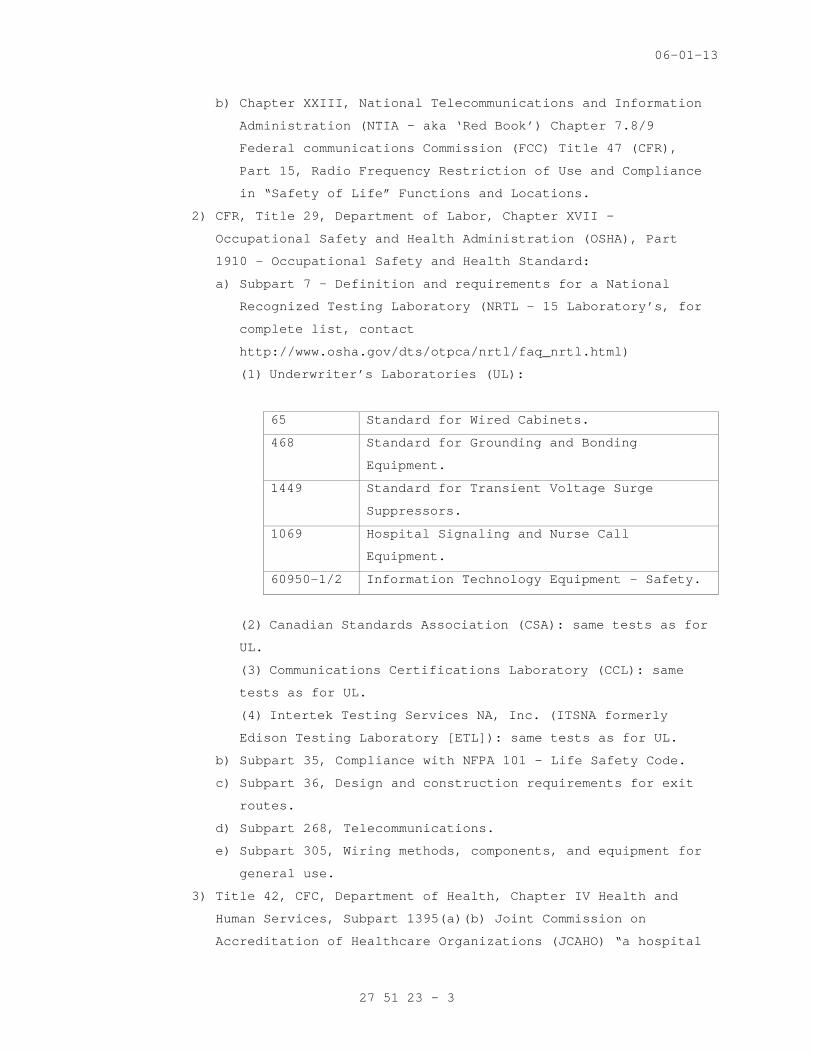
(1) Underwriter’s Laboratories (UL):
65 Standard for Wired Cabinets.
468 Standard for Grounding and Bonding
Equipment.
1449 Standard for Transient Voltage Surge
Suppressors.
1069 Hospital Signaling and Nurse Call
Equipment.
60950-1/2 Information Technology Equipment – Safety.
(2) Canadian Standards Association (CSA): same tests as for
UL.
(3) Communications Certifications Laboratory (CCL): same
tests as for UL.
(4) Intertek Testing Services NA, Inc. (ITSNA formerly
Edison Testing Laboratory [ETL]): same tests as for UL.
b) Subpart 35, Compliance with NFPA 101 – Life Safety Code.
c) Subpart 36, Design and construction requirements for exit
routes.
d) Subpart 268, Telecommunications.
e) Subpart 305, Wiring methods, components, and equipment for
general use.
3) Title 42, CFC, Department of Health, Chapter IV Health and
Human Services, Subpart 1395(a)(b) Joint Commission on
Accreditation of Healthcare Organizations (JCAHO) “a hospital
27 51 23 - 3
06-01-13
that meets JCAHO accreditation is deemed to meet the Medicare
conditions of Participation by meeting Federal Directives:”
All guidelines for Life, Personal and Public Safety; and,
Essential and Emergency Communications.
4) All guidelines for Life, Personal and Public Safety; and,
Essential and Emergency Communications.
5) CFR, Title 47, Telecommunications, FCC: Part 15 – Restrictions
of use for Part 15 listed Radio Equipment in Safety of
Life/Emergency Functions/Equipment/Locations (also see CFR,
Title 15, Department of Commerce, Chapter XXIII – NTIA).
6) Public Law No. 100-527, Department of Veterans Affairs:
a) Office of Telecommunications:
(1) Handbook 6100, Telecommunications.
b) Office of Cyber and Information Security (OCIS):
(1) Handbook 6500, Information Security Program.
(2) Wireless and Handheld Device Security Guideline Version
3.2, August 15, 2005.
c) Spectrum Management FCC and NTIA Radio Frequency Compliance
and Licensing Program.
2. National Codes:
a. American Institute of Architects (AIA): Guidelines for Healthcare
Facilities.
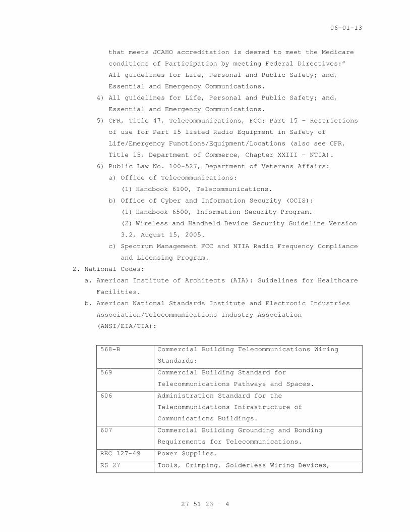
b. American National Standards Institute and Electronic Industries
Association/Telecommunications Industry Association
(ANSI/EIA/TIA):
568-B Commercial Building Telecommunications Wiring
Standards:
569 Commercial Building Standard for
Telecommunications Pathways and Spaces.
606 Administration Standard for the
Telecommunications Infrastructure of
Communications Buildings.
607 Commercial Building Grounding and Bonding
Requirements for Telecommunications.
REC 127-49 Power Supplies.
RS 27 Tools, Crimping, Solderless Wiring Devices,
27 51 23 - 4
06-01-13
Recommended Procedures for User Certification.
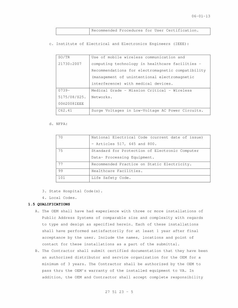
c. Institute of Electrical and Electronics Engineers (IEEE):
SO/TR
21730:2007
Use of mobile wireless communication and
computing technology in healthcare facilities -
Recommendations for electromagnetic compatibility
(management of unintentional electromagnetic
interference) with medical devices.
0739-
5175/08/$25.
00©2008IEEE
Medical Grade – Mission Critical – Wireless
Networks.
C62.41 Surge Voltages in Low-Voltage AC Power Circuits.
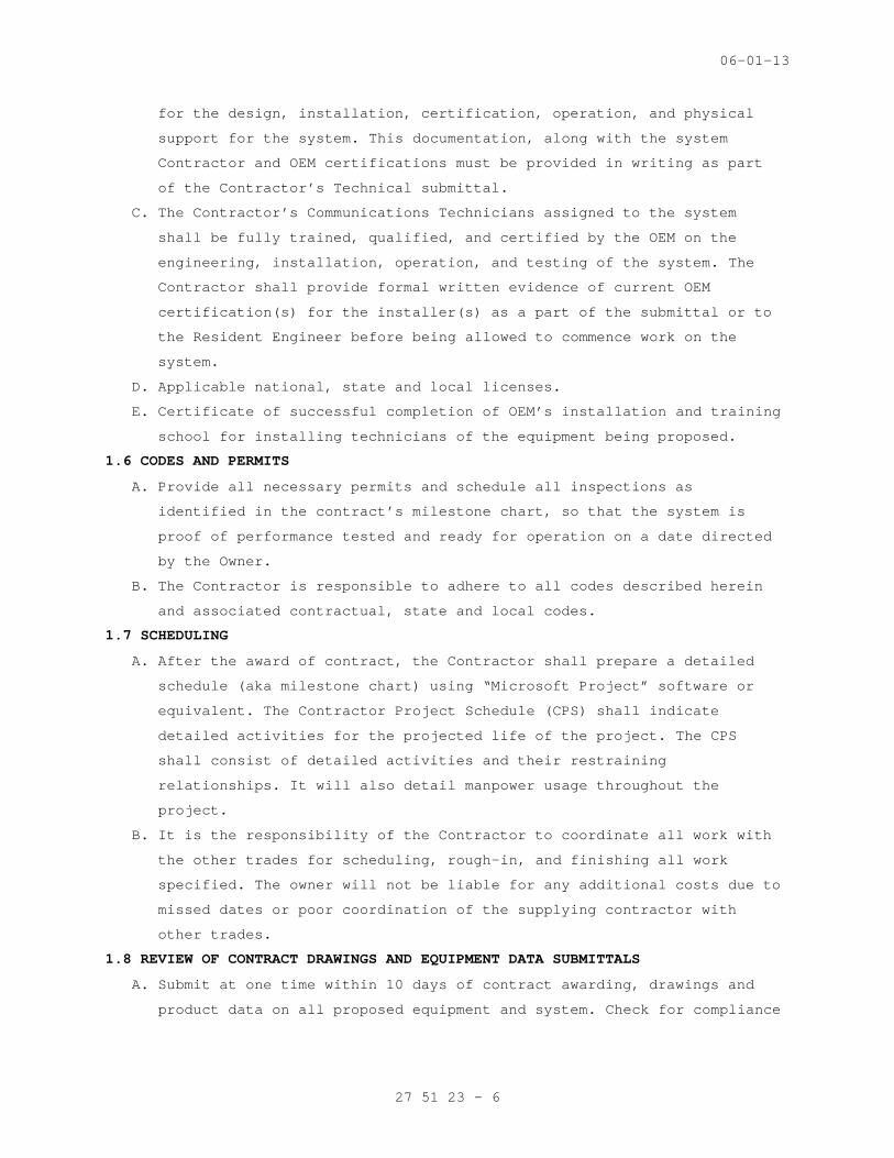
d. NFPA:
70 National Electrical Code (current date of issue)
– Articles 517, 645 and 800.
75 Standard for Protection of Electronic Computer
Data- Processing Equipment.
77 Recommended Practice on Static Electricity.
99 Healthcare Facilities.
101 Life Safety Code.
3. State Hospital Code(s).
4. Local Codes.
1.5 QUALIFICATIONS
A. The OEM shall have had experience with three or more installations of
Public Address Systems of comparable size and complexity with regards
to type and design as specified herein. Each of these installations
shall have performed satisfactorily for at least 1 year after final
acceptance by the user. Include the names, locations and point of
contact for these installations as a part of the submittal.
B. The Contractor shall submit certified documentation that they have been
an authorized distributor and service organization for the OEM for a
minimum of 3 years. The Contractor shall be authorized by the OEM to
pass thru the OEM’s warranty of the installed equipment to VA. In
addition, the OEM and Contractor shall accept complete responsibility
27 51 23 - 5
06-01-13
for the design, installation, certification, operation, and physical
support for the system. This documentation, along with the system
Contractor and OEM certifications must be provided in writing as part
of the Contractor’s Technical submittal.
C. The Contractor’s Communications Technicians assigned to the system
shall be fully trained, qualified, and certified by the OEM on the
engineering, installation, operation, and testing of the system. The
Contractor shall provide formal written evidence of current OEM
certification(s) for the installer(s) as a part of the submittal or to
the Resident Engineer before being allowed to commence work on the
system.
D. Applicable national, state and local licenses.
E. Certificate of successful completion of OEM’s installation and training
school for installing technicians of the equipment being proposed.
1.6 CODES AND PERMITS
A. Provide all necessary permits and schedule all inspections as
identified in the contract’s milestone chart, so that the system is
proof of performance tested and ready for operation on a date directed
by the Owner.
B. The Contractor is responsible to adhere to all codes described herein
and associated contractual, state and local codes.
1.7 SCHEDULING
A. After the award of contract, the Contractor shall prepare a detailed
schedule (aka milestone chart) using “Microsoft Project” software or
equivalent. The Contractor Project Schedule (CPS) shall indicate
detailed activities for the projected life of the project. The CPS
shall consist of detailed activities and their restraining
relationships. It will also detail manpower usage throughout the
project.
B. It is the responsibility of the Contractor to coordinate all work with
the other trades for scheduling, rough-in, and finishing all work
specified. The owner will not be liable for any additional costs due to
missed dates or poor coordination of the supplying contractor with
other trades.
1.8 REVIEW OF CONTRACT DRAWINGS AND EQUIPMENT DATA SUBMITTALS
A. Submit at one time within 10 days of contract awarding, drawings and
product data on all proposed equipment and system. Check for compliance
27 51 23 - 6

06-01-13
with contract documents and certify compliance with Contractor's
"APPROVED" stamp and signature.
B. Support all submittals with descriptive materials, i.e., catalog
sheets, product data sheets, diagrams, and charts published by the
manufacturer. These materials shall show conformance to specification
and drawing requirements.
C. Where multiple products are listed on a single cut-sheet, circle or
highlight the one that you propose to use. Provide a complete and
through equipment list of equipment expected to be installed in the
system, with spares, as a part of the submittal. Special Communications
(005OP3B – herein after referred to as 005OP3B) will not review any
submittal that does not have this list.
D. Provide four copies to the PM for technical review. The PM will provide
a copy to the offices identified in Paragraph 1.3.C and D, at a minimum
for compliance review as described herein where each responsible
individual(s) shall respond to the PM within 10 days of receipt of
their acceptance or rejection of the submittal(s).
1.9 PROJECT RECORD DOCUMENTS (AS BUILTS)
A. Throughout progress of the work, maintain an accurate record of changes
in Contract Documents. Upon completion of Work, transfer recorded
changes to a set of Project Record Documents.
B. The floor plans shall be marked in pen to include the following:
1. All device locations with labels.
2. Conduit locations.
3. Head-end equipment and specific location.
4. Wiring diagram.
5. Labeling and administration documentation.
6. Warranty certificate.
7. System test results.
1.10 WARRANTIES AND GUARANTY
A. The Contractor shall warrant the installation to be free from defect in
material and workmanship for a period of 1 year from the date of
acceptance of the project by the owner. The Contractor shall agree to
remedy covered defects within 8 hours of notification of major failures
or within twenty-four (24) hours of notification for individual station
related problems.
B. Refer to Part 4 for applicable Warranty requirements.
27 51 23 - 7
06-01-13
1.11 USE OF THE SITE
A. Use of the site shall be at the GC’s direction.
B. Coordinate with the GC for lay-down areas for product storage and
administration areas.
C. Coordinate work with the GC and their sub-contractors.
D. Access to buildings wherein the work is performed shall be directed by
the GC.
1.12 DELIVERY, STORAGE, AND HANDLING
A. Deliver, store, and handle products using means and methods that will
prevent damage, deterioration, and loss, including theft.
B. Store products in original containers.
C. Coordinate with the GC for product storage. There may be little or no
storage space available on site. Plan to potentially store materials
off site.
D. Do not install damaged products. Remove damaged products from the site
and replaced with new product at no cost to the Owner.
1.13 PROJECT CLOSE-OUT
A. Prior to final inspection and acceptance of the work, remove all
debris, rubbish, waste material, tools, construction equipment,
machinery and surplus materials from the project site and thoroughly
clean your work area.
B. Before the project closeout date, the Contractor shall submit:
1. Warranty certificate.
2. Evidence of compliance with requirements of governing authorities
such as the Low Voltage Certificate of Inspection.
3. Project record documents.
4. Instruction manuals and software that is a part of the system.
C. Contractor shall submit written notice that:
1. Contract Documents have been reviewed.
2. Project has been inspected for compliance with contract.
3. Work has been completed in accordance with the contract
PART 2 – PRODUCTS AND FUNCTIONAL REQUIREMENTS
2.1 GENERAL REQUIREMENTS FOR EQUIPMENT AND MATERIALS
A. Coordinate features and select components to form an integrated system.
Match components and interconnections for optimum performance of
specified functions.
27 51 23 - 8
06-01-13
B. Expansion Capability: Increase number of stations in the future by 25
percent above those indicated without adding any internal or external
components or main trunk cable conductors.
C. Equipment: Modular type using solid-state components, fully rated for
continuous duty unless otherwise indicated. Select equipment for normal
operation on input power usually supplied at 110 to 130 V, 60 Hz.
D. Weather-Resistant Equipment: Listed and labeled by an OSHA certified
National Recognized Testing Laboratory (NRTL – i.e. UL) for duty
outdoors or in damp locations.
2.2 SYSTEM DESCRIPTION
A. The intercom system shall allow voice communication between wall-
mounted intercom stations and a desktop (or wall-mounted) master
station.
B. All necessary equipment required to meet the intent of these
specifications, whether or not enumerated within these specifications,
shall be supplied and installed to provide a complete and operating
nurse and patient communications network.
C. Systems firmware shall be the product of a reputable firmware OEM of
record with a proven history of product reliability and sole control
over all source code. Manufacturer shall provide, free of charge,
product firmware and software upgrades for a period of twos year from
date of acceptance by VA for any product feature enhancements. System
configuration programming changes shall not require any exchange of
parts and shall be capable of being executed remotely via a modem
connection (when specifically approved by 005OP3B).
D. The Intercom System (IC) equipment shall be located in room // _____
//. The IC shall connect rooms(s) // _____ //. The IC shall provide
zoned, one-way voice paging through distributed, wall-mounted units.
Voice input into the IC shall be by zone from the main console at the
// _____ //.
E. When the IC system is approved to connect to a separate communications
system (i.e. LAN, WAN, Telephone, Nurse Call, radio raging, wireless
systems, etc) the connection point shall meet the following minimum
requirements for each hard wired connection (note each wireless system
connection MUST BE APPROVED PRIOR TO CONTRACT BID BY VA HEADQUARTERS
005OP3B AND 005OP2B):
1. UL 60950-1/2.
2. FIPS 142.
27 51 23 - 9
06-01-13
3. FCC Part 15 Listed Radio Equipment is not allowed.
F. Contractor is responsible for pricing all accessories and miscellaneous
equipment required to form a complete and operating system. Unless
otherwise noted in this Part, equipment quantities shall be as
indicated on the drawings.
2.3 MANUFACTURERS
A. The products specified shall be new, UL Listed, and produced by OEM
manufacturer of record.
B. The following equipment items are the salient requirements of VA to
provide an acceptable system described herein.
2.4 FUNCTIONAL DESCRIPTION OF SWITCHED SYSTEMS
A. Manually Switched:
1. Master Station:
a. Communicating selectively with other master and speaker-
microphone stations by actuating selector switches.
b. Communicating simultaneously with all other stations by actuating
a single all-call switch.
c. Communicating with individual stations in privacy.
d. Including other master-station connections in a multiple-station
conference call.
e. Overriding any conversation by a designated master station.
2. Room Speaker-Microphone Station:
a. Having privacy from remote monitoring without a warning tone
signal at monitored station. Designated speaker-microphone
stations have a privacy switch to prevent another station from
listening and to permit incoming calls.
b. Communicating hands free.
c. Calling master station by actuating call switch.
d. Returning a busy signal to indicate that station is already in
use.
e. Being free of noise and distortion during operation and when in
standby mode.
3. Speakers: Free of noise and distortion during operation and when in
standby mode.
27 51 23 - 10
06-01-13
B. Microprocessor-Switched:
1. Master Station:
a. Communicating selectively with other master and speaker-
microphone stations by dialing station's number on a 12-digit
keypad.
b. Communicating simultaneously with all other stations by dialing a
designated number on a 12-digit key-pad.
c. Communicating with individual stations in privacy.
d. Including other master-station connections in a multiple-station
conference call.
e. Accessing separate paging speakers or groups of paging speakers
by dialing designated numbers on a 12-digit keypad.
f. Overriding any conversation by a designated master station.
g. Displaying selected station.
h. Volume Control: Regulates incoming-call volume.
i. Identifies calling stations and stations in use. LED remains on
until call is answered.
j. Momentary audible tone signal announces incoming calls.
k. Handset with Hook Switch: Telephone type with 18-inch- long,
permanently coiled cord. Arrange to disconnect speaker when
handset is lifted.
l. Reset Control: Cancels call and resets system for next call.
m. Equipment Cabinet: Comply with TIA/EIA-310-D. Lockable,
ventilated metal cabinet houses terminal strips, power supplies,
amplifiers, system volume control, and other switching and
control devices required for conversation channels and control
functions
n. Vertical Equipment Rack:
1) 28” (16RU) rack space. Welded Steel construction. Minimum 78”
usable depth. Adjustable front mounting rails.
2) Install the following products in rack provided by same
manufacturer or as specified:
a) Security screws w/ nylon isolation bushings.
b) Textured blank panels.
c) Custom mounts for components without rack mount kits.
d) Security covers.
e) Copper Bus Bar.
27 51 23 - 11
06-01-13
f) Power Sequencer- rack-mounted power conditioner and
(provide as-needed) delayed sequencer(s) with (2)
unswitched outlets each and contact closure control inputs.
2. Room Speaker-Microphone Station:
a. Having privacy from remote monitoring without a warning tone
signal at monitored station. Designated speaker-microphone
stations have a privacy switch to prevent another station from
listening and to permit incoming calls.
b. Communicating hands free.
c. Calling master station by actuating call switch.
d. Returning a busy signal to indicate that station is already in
use.
e. Being free of noise and distortion during operation and when in
standby mode.
C. Wireless:
1. Radio Paging Equipment and Systems:
a. The IC system shall have the ability to interface ONLY with VA
Certified and Licensed radio paging system (FCC Part 15 listed
pagers and transmitters are not allowed for “Safety of Life”
functions or installed in those specific areas. VA Headquarters
TVE - 005OPB2 and SM - 005OPB2 are the ONLY approving authorities
for this function) and must have the following minimum system
features:
1) Ability to pass-through location information (such as a room
number) and call-type as well as other text messages
simultaneously to shift supervisor identified staff members
2) System shall allow the operator to select staff members by
name and pager number and to select a message consisting of a
room number and a condition code (aka priority level).
Operator may also choose to type in a unique alpha-numeric
text message (the text message shall meet or exceed all HIPA
and VA OCIS Communications Security Guidelines for the
transmission of Patient or Staff Specific information [aka
PII] – VA Headquarters TVE - 005OP2B is the approving
authority for this function) into the system to be read by the
holder of the pager unit.
3) While a patient station is connected to the nurse’s master
station, the system shall allow the operator to automatically
27 51 23 - 12

06-01-13
page the staff member assigned to that room. An alternate
staff member may be selected for paging purposes in place of
the primary staff member. The system must allow an alternate
staff member to be paged when the primary staff member is
unable to respond to patient’s needs within a specified period
of time. The system must have the ability to assign any bed to
any pager or pager group, and to assign an unlimited amount of
pagers to any patient bed.
4) System shall have the ability to send all code blue calls to
staff members by predetermined group (as required)
automatically by simply pressing one “Code Blue” button. Pager
shall indicate room number of code call, and state “Code Blue”
in plain English format on pagers (FCC Part 15 listed pagers
are not allowed to be use as “Safety of Life” functions or
those specific locations. VA Headquarters TVE - 005OP2B is the
approving authority for this requirement).
2. Personal Wireless Communicator:
a. The IC system will only be allowed to connect to the personal
wireless communications system, pass text data and provide a 2-
way communication between the Telephone Interface and the
personal wireless communicator as long as it is not a FCC Part 15
listed device(s), meets or exceeds UL 60950-1/2, meets OCIS Guide
Lines for FIPS 140-2 certification and the using staff shows an
extensive training program along with recertification(s)
according to the Facility Emergency Plan concerning HIPA
requirements.
b. VA Headquarters TVE - 005OP3B and SM - 005OP2B are the approving
authority for this requirement.
3. Other Wireless Equipment/Systems:
a. Each proposed wireless system and/or equipment to be connected to
or be a part of the IC system, each shall meet the minimum
requirements outlines in Paragraph 2.7.A.
b. Contact TVE - 005OP3B and SM – 005OP2B for specific required pre-
approvals (full or conditional) as described herein.
2.5 HEAD-END EQUIPMENT
A. Provide all required power supplies, communications hubs, network
switches, intelligent controllers and other devices necessary to form a
27 51 23 - 13
06-01-13
complete system. Head-end components may be rack mounted or wall
mounted in a metal enclosure.
B. Provide the head-end equipment in the closed telecommunications closet
where the IC system is installed to include at a minimum the equipment
listed in Paragraph 2.3.
C. Provide minimum of 15 minute battery back-up to system components.
D. Equipment Cabinet: Comply with TIA/EIA-310-D. Lockable, ventilated
metal cabinet houses terminal strips, power supplies, amplifiers,
system volume control, and other switching and control devices required
for conversation channels and control functions
E. Vertical Equipment Rack, Wall Mounted (to be included inside of the
Equipment Cabinet):
1. 28” (16RU) rack space. Welded Steel construction. Minimum 20” usable
depth. Adjustable front mounting rails.
2. Install the following products in rack provided by same manufacturer
or as specified:
a. Security screws w/ nylon isolation bushings.
b. Textured blank panels.
c. Custom mounts for components without rack mount kits.
d. Security covers.
e. Copper Bus Bar.
f. Power Sequencer- rack-mounted power conditioner and (provide as-
needed) delayed sequencer(s) with (2) unswitched outlets each and
contact closure control inputs.
2.6 SYSTEM CABLES
A. Refer to OFM approved Master Construction Specification, SECTION 27 10
00, STRUCTURED CABLING for specific installation and testing
requirements.
B. Conductors: Jacketed, twisted pair and twisted multipair, untinned
solid copper. Sizes as recommended by system manufacturer, but no
smaller than No. 22 AWG.
C. Insulation: Thermoplastic, not less than 1/32 inch thick.
D. Shielding: For speaker-microphone leads and elsewhere where recommended
by manufacturer; No. 34 AWG, tinned, soft-copper strands formed into a
braid or equivalent foil.
E. Minimum Shielding Coverage on Conductors: 60 percent.
F. All cabling shall be // plenum // // riser // rated.
27 51 23 - 14
06-01-13
G. Provide one spare 1,000 foot roll of approved system (not microphone)
cable only.
2.7 RACEWAYS
A. Intercommunication and Program System Raceways and Boxes: Comply with
requirements in Division 26, Section 26 05 33, RACEWAY AND BOXES FOR
ELECTRICAL SYSTEMS.
B. Each raceway that is open top, shall be: UL certified for
telecommunications systems, partitioned with metal partitions in order
to comply with NEC Parts 517 and 800 to “mechanically separate
telecommunications systems of different service, protect the installed
cables from falling out when vertically mounted and allow junction
boxes to be attached to the side to interface “drop” type conduit cable
feeds.
C. Intercommunication System Cable Infrastructure: EMT or in J-hooks above
accessible ceilings, 24 inches on center.
D. Junction boxes shall be not less than 2-1/2 inches deep and 6 inches
wide by 6 inches long.
E. Flexible metal conduit is prohibited unless specifically approved by
005OP3B.
F. Install manufactured conduit sweeps and long-radius elbows whenever
possible
2.8 SYSTEM CONDUIT
A. The nurse call/code blue system is NFPA listed as Emergency/Public
Safety Communication System that requires the entire system to be
installed in a separate conduit system.
B. The use of centralized mechanically partitioned wireways may be used to
augment main distribution conduit on a case by case basis when
specifically approved by VA Headquarters (005OP3B).
2.9 CONDUIT SLEEVES
A. The Engineer has made a good effort to identify where conduit sleeves
through full-height and fire rated walls on the drawings, and has
instructed the electrician to provide the sleeves as shown on the
drawings.
B. While the sleeves shown on the drawings will be provided by others, the
contractor is responsible for installing conduit sleeves and fire-
proofing where necessary. It is often the case, that due to field
conditions, the nurse-call cable may have to be installed through an
alternate route. Any conduit sleeves required due to field conditions
27 51 23 - 15
06-01-13
or those omitted by the engineer shall be provided by the cabling
contractor.
2.10 DEVICE BACKBOXES
A. Furnish to the electrical contractor all backboxes required for the PAS
devices.
B. The electrical contractor shall install the backboxes as well as the
system conduit. Coordinate the delivery of the backboxes with the
construction schedule.
2.11 UNINTERRUPTIBLE POWER SUPPLY (UPS)
A. Provide a backup battery or a UPS for the system to allow normal
operation and function (as if there was no AC power failure) in the
event of an AC power failure or during input power fluctuations for a
minimum of 15 minutes.
B. As an alternate solution, the telephone system UPS may be utilized to
meet this requirement at the head-end location, as long as this
function is specifically approved by the Telephone Contractor and the
RE.
C. The PA Contractor shall not make any attachments or connection to the
telephone system until specifically directed to do so, in writing, by
the RE.
D. Provide UPS for all active system components including but not limited
to:
1. System Amplifiers.
2. Microphone Consoles.
3. System Interface Units.
4. Head-end Equipment Rack(s).
PART 3 - EXECUTION
3.1 PROJECT MANAGEMENT
A. Assign a single project manager to this project who will serve as the
point of contact for the Owner, the General Contractor, and the
Engineer.
B. The Contractor shall be proactive in scheduling work at the hospital,
specifically the Contractor will initiate and maintain discussion with
the general contractor regarding the schedule for ceiling cover up and
install cables to meet that schedule.
C. Contact the Office of Telecommunications, Special Communications Team
(005OP3B) at (301) 734-0350 to have a VA Certified Telecommunications
COTR assigned to the project for telecommunications review, equipment
27 51 23 - 16
06-01-13
and system approval and co-ordination with VA’s Spectrum Management and
OCIS Teams.
3.2 COORDINATION WITH OTHER TRADES
A. Coordinate with the cabling contractor the location of intercom
equipment in the Telecommunications Closets.
B. Before beginning work, verify the location, quantity, size and access
for the following:
1. Isolated ground AC power circuits provided for systems.
2. Junction boxes, wall boxes, wire troughs, conduit stubs and other
related infrastructure for the systems.
3. System components installed by others.
4. Overhead supports and rigging hardware installed by others.
C. Immediately notify the Owner, General Contractor and Consultant in
writing of any discrepancies.
3.3 NEEDS ASSESSMENT
Provide a one-on-one meeting with the particular nursing manager of
each unit affected by the installation of the new nurse call/code blue
system. Review the floor plan drawing, educate the nursing manager with
the functions of the equipment that is being provided and gather
details specific to the individual units; coverage and priorities of
calls; staffing patterns; and other pertinent details that will affect
system programming and training
3.4 INSTALLATION
A. General:
1. Execute work in accordance with National, State and local codes,
regulations and ordinances.
2. Install work neatly, plumb and square and in a manner consistent
with standard industry practice. Carefully protect work from dust,
paint and moisture as dictated by site conditions. The Contractor
will be fully responsible for protection of his work during the
construction phase up until final acceptance by the Owner.
3. Install equipment according to OEM’s recommendations. Provide any
hardware, adaptors, brackets, rack mount kits or other accessories
recommended by OEM for correct assembly and installation.
27 51 23 - 17
06-01-13
4. Secure equipment firmly in place, including receptacles, speakers,
equipment racks, system cables, etc.:
a. All supports, mounts, fasteners, attachments and attachment
points shall support their loads with a safety factor of at least
5:1.
b. Do not impose the weight of equipment or fixtures on supports
provided for other trades or systems.
c. Any suspended equipment or associated hardware must be certified
by the OEM for overhead suspension.
d. The Contractor is responsible for means and methods in the
design, fabrication, installation and certification of any
supports, mounts, fasteners and attachments.
5. Finishes for any exposed work such as plates, racks, panels,
speakers, etc. shall be approved by the Architect, Owner and
005OP3B.
6. Coordinate cover plates with field conditions. Size and install
cover plates as necessary to hide joints between back boxes and
surrounding wall. Where cover plates are not fitted with connectors,
provide grommeted holes in size and quantity required. Do not allow
cable to leave or enter boxes without cover plates installed.
B. Equipment Racks:
1. Fill unused equipment mounting spaces with blank panels or vent
panels. Match color to equipment racks.
2. Provide security covers for all devices not requiring routine
operator control.
3. Provide vent panels and cooling fans as required for the operation
of equipment within the OEM' specified temperature limits. Provide
adequate ventilation space between equipment for cooling. Follow
manufacturer’s recommendations regarding ventilation space between
amplifiers.
4. Provide insulated connections of the electrical raceway to equipment
racks.
5. Provide continuous raceway/conduit with no more than 40 percent fill
between wire troughs and equipment racks for all non-plenum-rated
cable. Ensure each system is mechanically separated from each other
in the wireway.
C. Wiring Practice: In addition to the mandatory infrastructure
requirements outlined in VA Construction Specification, Section 27 10
27 51 23 - 18
06-01-13
00, STRUCTURED CABLING, the following additional practices shall be
adhered to:
1. Comply with requirements for raceways and boxes specified in
Division 26, Section 27 05 33, RACEWAY AND BOXES FOR ELECTRICAL
SYSTEMS.
2. Execute all wiring in strict adherence to the National Electrical
Code, applicable local building codes and standard industry
practices.
3. Where raceway is to be EMT (conduit), wiring of differing
classifications shall be run in separate conduit. Where raceway is
to be an enclosure (rack, tray, wire trough, utility box) wiring of
differing classifications which share the same enclosure shall be
mechanically partitioned and separated by at least 4 inches. Where
Wiring of differing classifications must cross, they shall cross
perpendicular to one another.
4. Do not splice wiring anywhere along the entire length of the run.
Make sure cables are fully insulated and shielded from each other
and from the raceway for the entire length of the run.
5. Do not pull wire through any enclosure where a change of raceway
alignment or direction occurs. Do not bend wires to less than radius
recommended by manufacturer.
6. Replace the entire length of the run of any wire or cable that is
damaged or abraided during installation. There are no acceptable
methods of repairing damaged or abraided wiring.
7. Use wire pulling lubricants and pulling tensions as recommended by
the OEM.
8. Use grommets around cut-outs and knock-outs where conduit or chase
nipples are not installed.
9. Do not use tape-based or glue-based cable anchors.
10. Ground shields and drain wires as indicated by the drawings.
11. Field wiring entering equipment racks shall be terminated as
follows:
a. Provide ample service loops at harness break-outs and at plates,
panels and equipment. Loops should be sufficient to allow plates,
panels and equipment to be removed for service and inspection.
b. Line level and speaker level wiring may be terminated inside the
equipment rack using specified terminal blocks (see “Products.”)
27 51 23 - 19
06-01-13
Provide 15 percent spare terminals inside each rack. Microphone
level wiring may only be terminated at the equipment served.
c. If specified terminal blocks are not designed for rack mounting,
utilize 3/4 inch plywood or 1/8 inch thick aluminum plates/blank
panels as a mounting surface. Do not mount on the bottom of the
rack.
d. Employ permanent strain relief for any cable with an outside
diameter of 1 inch or greater.
12. Use only balanced audio circuits unless noted otherwise
13. Make all connections as follows:
a. Make all connections using rosin-core solder or mechanical
connectors appropriate to the application.
b. For crimp-type connections, use only tools that are specified by
the manufacturer for the application.
c. Use only insulated spade lugs on screw terminals. Spade lugs
shall be sized to fit the wire gauge. Do not exceed two lugs per
terminal.
d. Wire nuts, electrical tape or “Scotch Lock” connections are not
acceptable for any application.
D. Cable Installation - In addition to the mandatory infrastructure
requirements outlined in VA Master Construction Specification, Section
27 10 00, STRUCTURED CABLING, the following additional practices shall
be adhered to:
1. Support cable on maximum 4’-0” centers. Acceptable means of cable
support are cable tray, j-hooks, and bridal rings. Velcro wrap cable
bundles loosely to the means of support with plenum rated Velcro
straps. Plastic tie wraps are not acceptable as a means to bundle
cables.
2. Run cables parallel to walls.
3. Install maximum of 10 cables in a single row of J-hooks. Provide
necessary rows of J-hooks as required by the number of cables.
4. Do not lay cables on top of light fixtures, ceiling tiles,
mechanical equipment, or ductwork. Maintain at least 2’-0” clearance
from all shielded electrical apparatus.
5. All cables shall be tested after the total installation is fully
complete. All test results are to be documented. All cables shall
pass acceptable test requirements and levels. Contractor shall
remedy any cabling problems or defects in order to pass or comply
27 51 23 - 20
06-01-13
with testing. This includes the re-pull of new cable as required at
no additional cost to the Owner.
6. Ends of cables shall be properly terminated on both ends per
industry and OEM’s recommendations.
7. Provide proper temporary protection of cable after pulling is
complete before final dressing and terminations are complete. Do not
leave cable lying on floor. Bundle and tie wrap up off of the floor
until you are ready to terminate.
8. Cover the end of the overall jacket with a 1 inch (minimum) length
of transparent heat-shrink tubing. Cut unused insulated conductors 2
inches (minimum) past the heat-shrink, fold back over jacket and
secure with cable-tie. Cut unused shield/drain wires 2 inches
(minimum) past the Heat-shrink and serve as indicated below.
9. Cover shield/drain wires with heat-shrink tubing extending back to
the overall jacket. Extend tubing 1/4 inch past the end of unused
wires, fold back over jacket and secure with cable tie.
10. For each solder-type connection, cover the bare wire and solder
connection with heat-shrink tubing.
11. Terminate conductors; no cable shall contain unterminated elements.
Make terminations only at outlets and terminals.
12. Splices, Taps, and Terminations: Arrange on numbered terminal strips
in junction, pull, and outlet boxes; terminal cabinets; and
equipment enclosures. Cables may not be spliced.
13. Bundle, lace, and train conductors to terminal points without
exceeding OEM's limitations on bending radii. Install lacing bars
and distribution spools.
14. Cold-Weather Installation: Bring cable to room temperature before
dereeling. Heat lamps shall not be used.
15. Cable shall not be run through structural members or be in contact
with pipes, ducts, or other potentially damaging items.
16. Separation of Wires: (Refer to Raceway Installation) Separate
speaker-microphone, line-level, speaker-level, and power wiring
runs. Install in separate raceways or, where exposed or in same
enclosure, separate conductors at least 12 inches apart for speaker
microphones and adjacent parallel power and telephone wiring.
Separate other intercommunication equipment conductors as
recommended by equipment manufacturer.
27 51 23 - 21
06-01-13
17. Serve all cables as follows:
a. Cover the end of the overall jacket with a 1 inch (minimum)
length of transparent heat-shrink tubing. Cut unused insulated
conductors 2 inches (minimum) past the heat-shrink, fold back
over jacket and secure with cable-tie. Cut unused shield/drain
wires 2 inches (minimum) past the Heat-shrink and serve as
indicated below.
b. Cover shield/drain wires with heat-shrink tubing extending back
to the overall jacket. Extend tubing 1/4 inch past the end of
unused wires, fold back over jacket and secure with cable tie.
c. For each solder-type connection, cover the bare wire and solder
connection with heat-shrink tubing.
E. Labeling:
1. Clearly, consistently, logically and permanently mark switches,
connectors, jacks, relays, receptacles and electronic and other
equipment.
2. Engrave and paint fill all receptacle panels using 1/8” (minimum)
high lettering and contrasting paint.
3. For rack-mounted equipment, use engraved Lamacoid labels with white
1/8 inch (minimum) high lettering on black background. Label the
front and back of all rack-mounted equipment
4. Where multiple pieces of equipment reside in the same rack group,
clearly and logically label each indicating to which room, channel,
receptacle location, etc. they correspond.
5. Permanently label cables at each end, including intra-rack
connections. Labels shall be covered by the same, transparent heat-
shrink tubing covering the end of the overall jacket. Alternatively,
computer generated labels of the type which include a clear
protective wrap may be used.
6. Contractor’s name shall appear no more than once on each continuous
set of racks. The Contractor’s name shall not appear on wall plates
or portable equipment.
7. Ensure each OEM supplied equipment has appropriate UL Labels/Marks
for the service the equipment is performed permanently attached and
marked. Equipment installed not bearing these UL marks will not be
allowed to be a part of the PAS System. The Contractor shall bear
all costs required to provide replacement equipment with approved UL
marks.
27 51 23 - 22
06-01-13
3.5 PROTECTION OF NETWORK DEVICES
Contractor shall protect network devices during unpacking and
installation by wearing manufacturer approved electrostatic discharge
(ESD) wrist straps tied to chassis ground. The wrist strap shall meet
OSHA requirements for prevention of electrical shock, should technician
come in contact with high voltage.
3.6 CUTTING AND PATCHING
A. It shall be the responsibility of the contractor to keep their work
area clear of debris and clean area daily at completion of work.
B. It shall be the responsibility of the contractor to patch and paint any
wall or surface that has been disturbed by the execution of this work.
C. The Contractor shall be responsible for providing any additional
cutting, drilling, fitting or patching required that is not indicated
as provided by others to complete the Work or to make its parts fit
together properly.
D. The Contractor shall not damage or endanger a portion of the work or
fully or partially completed construction of the Owner or separate
contractors by cutting, patching or otherwise altering such
construction, or by excavation. The Contractor shall not cut or
otherwise alter such construction by the Owner or a separate contractor
except with written consent of the Owner and of such separate
contractor; such consent shall not be unreasonably withheld. The
Contractor shall not unreasonably withhold from the Owner or a separate
Contractor the Contractor’s consent to cutting or otherwise altering
the work.
E. Where coring of existing (previously installed) concrete is specified
or required, including coring indicated under unit prices, the location
of such coring shall be clearly identified in the field and the
location shall be approved by the Project Manager prior to commencement
of coring work.
3.7 FIREPROOFING
A. Where nurse-call cables penetrate fire rated walls, floors and
ceilings, fireproof the opening.
B. Provide conduit sleeves (if not already provided by electrical
contractor) for cables that penetrate fire rated walls. After the
cabling installation is complete, install fire proofing material in and
around all conduit sleeves and openings. Install fire proofing material
thoroughly and neatly. Seal all floor and ceiling penetrations.
27 51 23 - 23
06-01-13
C. Use only materials and methods that preserve the integrity of the fire
stopping system and its rating.
3.8 GROUNDING
A. Ground cable shields and equipment to eliminate shock hazard and to
minimize ground loops, commonmode returns, noise pickup, cross talk,
and other impairments.
B. Signal Ground Terminal: Locate at main equipment cabinet. Isolate from
power system and equipment grounding.
C. Install grounding electrodes as specified in Division 26 Section
"Grounding and Bonding for Electrical Systems."
D. Do not use “3rd or 4th” wire internal electrical system conductors for
ground.
E. Do not connect system ground to the building’s external lightning
protection system.
F. Do not “mix grounds” of different systems.
PART 4 – TESTING, GUARANTY AND TRAINING
4.1 PROOF OF PERFORMANCE TESTING
A. Acceptance Test:
1. The Contractor shall schedule an acceptance test date and give the
RE 30 days written notice prior to the date the acceptance test is
expected to begin. The system shall be tested in the presence of a
Government Representative and an OEM certified representative. The
system shall be tested utilizing the approved test equipment to
certify proof of performance and Emergency compliance. The test
shall verify that the total system meets all the requirements of
this specification. The notification of the acceptance test shall
include the expected length (in time) of the test.
B. Acceptance Test Procedure:
1. Physical and Mechanical Inspection:
a. The Government Representative will tour all areas where the
system and all sub-systems are completely and properly installed
to insure they are operationally ready for proof of performance
testing. A system inventory including available spare parts will
be taken at this time. Each item of installed equipment shall be
checked to ensure appropriate UL certification labels are
affixed.
27 51 23 - 24
06-01-13
b. The system diagrams, record drawings, equipment manuals, Auto CAD
Disks, intermediate, and pretest results shall be formally
inventoried and reviewed.
c. Failure of the system to meet the installation requirements of
this specification shall be grounds for terminating all testing.
2. Operational Test:
a. The Contractor shall demonstrate the full functionality of the
system including:
1. Station to master calls
2. Station to station calls
3. Broadcast calls
4. Location identification of stations at the intercom master
station
3. Test Conclusion:
a. At the conclusion of the Acceptance Test, using the generated
punch list (or discrepancy list) the VA and the Contractor shall
jointly agree to the results of the test, and reschedule testing
on deficiencies and shortages with the RE. Any retesting to
comply with these specifications will be done at the Contractor's
expense.
b. If the system is declared unacceptable without conditions, all
rescheduled testing expenses will be born by the Contractor.
4.2 WARRANTY
A. Comply with FAR 52.246-21, except that warranty shall be as follows:
B. Contractor’s Responsibility:
1. The Contractor shall warranty that all provided material and
equipment will be free from defects, workmanship and will remain so
for a period of one year from date of final acceptance of the system
by the VA. The Contractor shall provide OEM’s equipment warranty
documents, to the RE (or Facility Contracting Officer if the
Facility has taken procession of the building), that certifies each
item of equipment installed conforms to OEM published
specifications.
2. The Contractor's maintenance personnel shall have the ability to
contact the Contractor and OEM for emergency maintenance and
logistic assistance, remote diagnostic testing, and assistance in
resolving technical problems at any time. This contact capability
27 51 23 - 25
06-01-13
shall be provided by the Contractor and OEM at no additional cost to
the VA.
3. All Contractor maintenance and supervisor personnel shall be fully
qualified by the OEM and must provide two copies of current and
qualified OEM training certificates and OEM certification upon
request.
4. Additionally, the Contractor shall accomplish the following minimum
requirements during the two year guaranty period:
a. Response Time during the Two Year Guaranty Period:
1) The RE (or Facility Contracting Officer if the system has been
turned over to the Facility) is the Contractor’s ONLY OFFICIAL
reporting and contact official for nurse call system trouble
calls, during the guaranty period.
2) A standard work week is considered 8:00 A.M. to 5:00 P.M. or
as designated by the RE (or Facility Contracting Officer),
Monday through Friday exclusive of Federal Holidays.
3) The Contractor shall respond and correct on-site trouble
calls, during the standard work week to:
a) A routine trouble call within 1 working day of its report.
A routine trouble is considered a trouble which causes a
pillow speaker or cordset, one master IC control station,
room station or emergency station to be inoperable.
b) Routine trouble calls in critical emergency health care
facilities (i.e., cardiac arrest, intensive care units,
etc.) shall also be deemed as an emergency trouble call.
The RE (or Facility Contracting Officer) shall notify the
Contractor of this type of trouble call.
c) An emergency trouble call within 4 hours of its report. An
emergency trouble is considered a trouble which causes a
sub-system (ward), distribution point, terminal cabinet, or
all call system to be inoperable at anytime.
4) If a IC component failure cannot be corrected within 4 hours
(exclusive of the standard work time limits), the Contractor
shall be responsible for providing alternate IC equipment. The
alternate equipment/system shall be operational within a
maximum of 20 hours after the 4 hour trouble shooting time and
restore the effected location operation to meet the system
performance standards. If any sub-system or major system
27 51 23 - 26

06-01-13
trouble cannot be corrected within one working day, the
Contractor shall furnish and install compatible substitute
equipment returning the system or sub-system to full
operational capability, as described herein, until repairs are
complete.
b. Required On-Site Visits during the Two Year Guaranty Period
1) The Contractor shall visit, on-site, for a minimum of 8 hours,
once every 12 weeks, during the guaranty period, to perform
system preventive maintenance, equipment cleaning, and
operational adjustments to maintain the system according the
descriptions identified in this document.
2) The Contractor shall arrange all Facility visits with the RE
(or Facility Contracting Officer) prior to performing the
required maintenance visits.
3) Preventive maintenance shall be performed by the Contractor in
accordance with the OEM's recommended practice and service
intervals during non-busy time agreed to by the RE (or
Facility Contracting Officer) and Contractor.
4) The preventive maintenance schedule, functions and reports
shall be provided to and approved by the RE (or Facility
Contracting Officer).
5) The Contractor shall provide the RE (or Facility Contracting
Officer) a type written report itemizing each deficiency found
and the corrective action performed during each required visit
or official reported trouble call. The Contractor shall
provide the RE with sample copies of these reports for review
and approval at the beginning of the Acceptance Test. The
following reports are the minimum required:
a) The Contractor shall provide a monthly summary all
equipment and sub-systems serviced during this warranty
period to RE (or Facility Contracting Officer) by the fifth
(5th) working day after the end of each month. The report
shall clearly and concisely describe the services rendered,
parts replaced and repairs performed. The report shall
prescribe anticipated future needs of the equipment and
systems for preventive and predictive maintenance.
b) The Contractor shall maintain a separate log entry for each
item of equipment and each sub-system of the system. The
27 51 23 - 27
06-01-13
log shall list dates and times of all scheduled, routine,
and emergency calls. Each emergency call shall be described
with details of the nature and causes of emergency steps
taken to rectify the situation and specific recommendations
to avoid such conditions in the future.
6) The RE (or Facility Contracting Officer) shall convey to the
Facility Engineering Officer, 2 copies of actual reports for
evaluation.
a) The RE (or Facility Contracting Officer) shall ensure a
copy of these reports is entered into the system’s official
acquisition documents.
b) The Facility Chief Engineer shall ensure a copy of these
reports is entered into the system’s official technical
record documents.
C. Work Not Included:
Maintenance and repair service shall not include the performance of any
work due to improper use; accidents; other vendor, contractor, or owner
tampering or negligence, for which the Contractor is not directly
responsible and does not control. The Contractor shall immediately
notify the RE or Facility Contracting Officer in writing upon the
discovery of these incidents. The RE or Facility Contracting Officer
will investigate all reported incidents and render
4.3 TRAINING
A. Provide thorough training of the owner’s engineering and maintenance
staff.
B. Provide the following minimum training times and durations:
1. // 24 // hours prior to opening
2. // 24 // hours during the opening week
3. // 24 // hours for supervisors and system administrators
- - - E N D - - -
27 51 23 - 28
06-01-13
SECTION 27 52 31 SECURITY EMERGENCY CALL, DURESS ALARM, AND TELECOMMUNICATIONS
SPEC WRITER NOTES: 1. Edit between //-----// Delete if not
applicable to project. Defer to VA TVE (005OP3B – see Paragraph 1.3.D for specific contact info) for technical assistance.
2. Included throughout this specification are references to the system’s interface capability and various related features. The system designer shall verify availability of this system and coordinate associated requirements and subsequent interface(s).
PART 1 - GENERAL
1.1 SECTION SUMMARY
A. Work covered by this document includes design, engineering, labor,
material, products, guaranty, training and services for, and incidental
to, the complete installation of a new and fully operating National
Fire Protection Association (NFPA) Listed Critical Service Nurse-Call
and Life Safety Code Blue communication system as detailed herein.
B. Work shall be complete, tested, labeled, certified and ready for
operation.
1.2 RELATED SECTIONS
A. Section 01 33 23, SHOP DRAWINGS, PRODUCT DATA AND SAMPLES.
B. Section 26 05 21, LOW-VOLTAGE ELECTRICAL POWER CONDUCTORS AND CABLES
(600 Volts and Below).
C. Section 26 41 00, FACILITY LIGHTNING PROTECTION.
D. Section 27 05 26, GROUNDING AND BONDING FOR COMMUNCATIONS SYSTEMS.
E. Section 27 05 11, REQUIREMENTS FOR COMMUNCATIONS INSTALLATIONS.
F. Section 27 10 00, STRUCTURED CABLING.
G. Section 27 15 00, COMMUNICATIONS HORIZONTAL CABLING.
H. Section 27 05 33, RACEWAYS AND BOXES FOR COMMUNICATIONS SYSTEMS.
I. Section 10 25 13, PATIENT BED SERVICE WALLS.
1.3 DEFINITIONS
A. Provide: Design, engineer, furnish, install, connect complete, test,
certify and warranty.
B. Work: Materials furnished and completely installed.
C. Review of contract drawings: A service by the engineer to reduce the
possibility of materials being ordered which do not comply with
27 52 31 - 1

06-01-13
contract documents. The engineer's review shall not relieve the
Contractor of responsibility for dimensions or compliance with the
contract documents. The reviewer's failure to detect an error does not
constitute permission for the Contractor to proceed in error.
D. Headquarters (aka VACO) Technical Review, for National and VA
Communications and Security, Codes, Frequency Licensing Standards,
Guidelines and Compliance:
Office of Telecommunications
Special Communications Team (005OP3B)
1335 East West Highway – 3rd Floor
Silver Spring, Maryland 20910,
(O) 301-734-0350, (F) 301-734-0360
E. Engineer: //XXXXXXX//
//XXXXXXX//
//XXXXXXX//
//XXXXXXX//
//XXXXXXX//
F. Owner: //XXXXXXX//
G. General Contractor (GC): //XXXXXXX//
H. Contractor: Systems Contractor; you; successful bidder
1.4 REFERENCES
A. The installation shall comply fully with all governing authorities,
laws and ordinances, regulations, codes and standards, including, but
not limited to:
1. United States:
a. Department of Commerce:
1) National Telecommunications and Information Administration
(NTIA), Red Book, Chapter 7.8/9 Radio Frequency Restriction of
Use and Compliance.
2) National Institute of Standards Technology (NIST), Federal
Information Processing Standards Publication (FIPS) 140-2,
Security Requirements for Cryptographic Modules.
b. Department of Labor, Occupational Safety and Health
Administration (OSHA): All standards for personnel physical and
life safety.
c. Department of Veterans Affairs, Office of Cyber and Information
Security (OCIS):
1) Handbook 6500, Information Security Program.
27 52 31 - 2
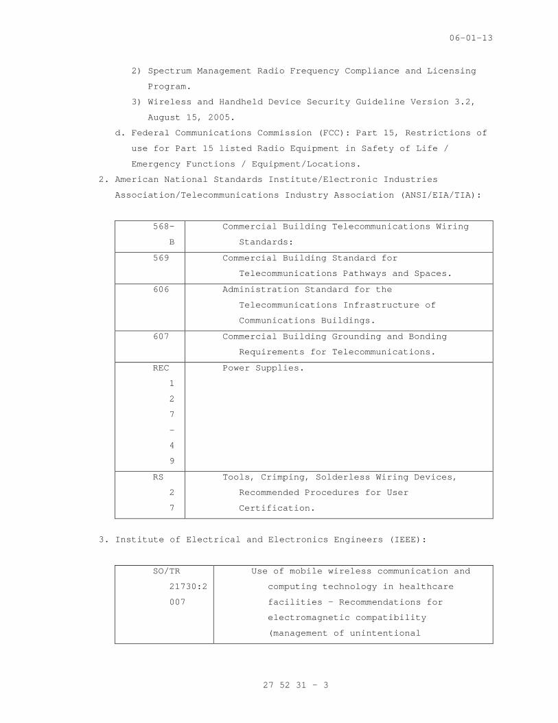
06-01-13
2) Spectrum Management Radio Frequency Compliance and Licensing
Program.
3) Wireless and Handheld Device Security Guideline Version 3.2,
August 15, 2005.
d. Federal Communications Commission (FCC): Part 15, Restrictions of
use for Part 15 listed Radio Equipment in Safety of Life /
Emergency Functions / Equipment/Locations.
2. American National Standards Institute/Electronic Industries
Association/Telecommunications Industry Association (ANSI/EIA/TIA):
568-
B
Commercial Building Telecommunications Wiring
Standards:
569 Commercial Building Standard for
Telecommunications Pathways and Spaces.
606 Administration Standard for the
Telecommunications Infrastructure of
Communications Buildings.
607 Commercial Building Grounding and Bonding
Requirements for Telecommunications.
REC
1
2
7
-
4
9
Power Supplies.
RS
2
7
Tools, Crimping, Solderless Wiring Devices,
Recommended Procedures for User
Certification.
3. Institute of Electrical and Electronics Engineers (IEEE):
SO/TR
21730:2
007
Use of mobile wireless communication and
computing technology in healthcare
facilities - Recommendations for
electromagnetic compatibility
(management of unintentional
27 52 31 - 3
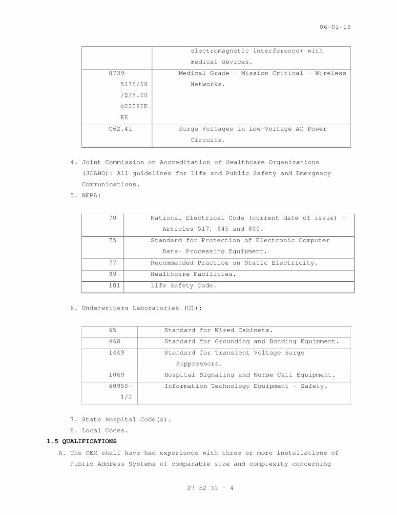
06-01-13
electromagnetic interference) with
medical devices.
0739-
5175/08
/$25.00
©2008IE
EE
Medical Grade – Mission Critical – Wireless
Networks.
C62.41 Surge Voltages in Low-Voltage AC Power
Circuits.
4. Joint Commission on Accreditation of Healthcare Organizations
(JCAHO): All guidelines for Life and Public Safety and Emergency
Communications.
5. NFPA:
70 National Electrical Code (current date of issue) –
Articles 517, 645 and 800.
75 Standard for Protection of Electronic Computer
Data- Processing Equipment.
77 Recommended Practice on Static Electricity.
99 Healthcare Facilities.
101 Life Safety Code.
6. Underwriters Laboratories (UL):
65 Standard for Wired Cabinets.
468 Standard for Grounding and Bonding Equipment.
1449 Standard for Transient Voltage Surge
Suppressors.
1069 Hospital Signaling and Nurse Call Equipment.
60950-
1/2
Information Technology Equipment – Safety.
7. State Hospital Code(s).
8. Local Codes.
1.5 QUALIFICATIONS
A. The OEM shall have had experience with three or more installations of
Public Address Systems of comparable size and complexity concerning
27 52 31 - 4

06-01-13
type and design as specified herein. Each of these installations shall
have performed satisfactorily for at least 1 year after final
acceptance by the user. Include the names, locations and point of
contact for these installations as a part of the submittal.
B. The Contractor shall submit certified documentation that they have been
an authorized distributor and service organization for the OEM for a
minimum of 3 years. The Contractor shall be authorized by the OEM to
pass thru the OEM’s warranty of the installed equipment to VA. In
addition, the OEM and Contractor shall accept complete responsibility
for the design, installation, certification, operation, and physical
support for the system. This documentation, along with the system
Contractor and OEM certifications must be provided in writing as part
of the Contractor’s Technical submittal.
C. The Contractor’s Communications Technicians assigned to the system
shall be fully trained, qualified, and certified by the OEM on the
engineering, installation, operation, and testing of the system. The
Contractor shall provide formal written evidence of current OEM
certification(s) for the installer(s) as a part of the submittal or to
the Resident Engineer before being allowed to commence work on the
system.
D. Applicable national, state and local licenses.
E. Certificate of successful completion of OEM’s installation/training
school for installing technicians of the equipment being proposed.
1.6 CODES AND PERMITS
Provide all necessary permits and schedule all inspections as
identified in the contract’s milestone chart, so that the system is
proof of performance tested and ready for operation on a date directed
by the Owner.
1.7 SCHEDULING
A. After the award of contract, the Contractor shall prepare a detailed
schedule (aka milestone chart) using “Microsoft Project” software or
equivalent. The Contractor Project Schedule (CPS) shall indicate
detailed activities for the projected life of the project. The CPS
shall consist of detailed activities and their restraining
relationships. It will also detail manpower usage throughout the
project.
B. It is the responsibility of the Contractor to coordinate all work with
the other trades for scheduling, rough-in, and finishing all work
27 52 31 - 5
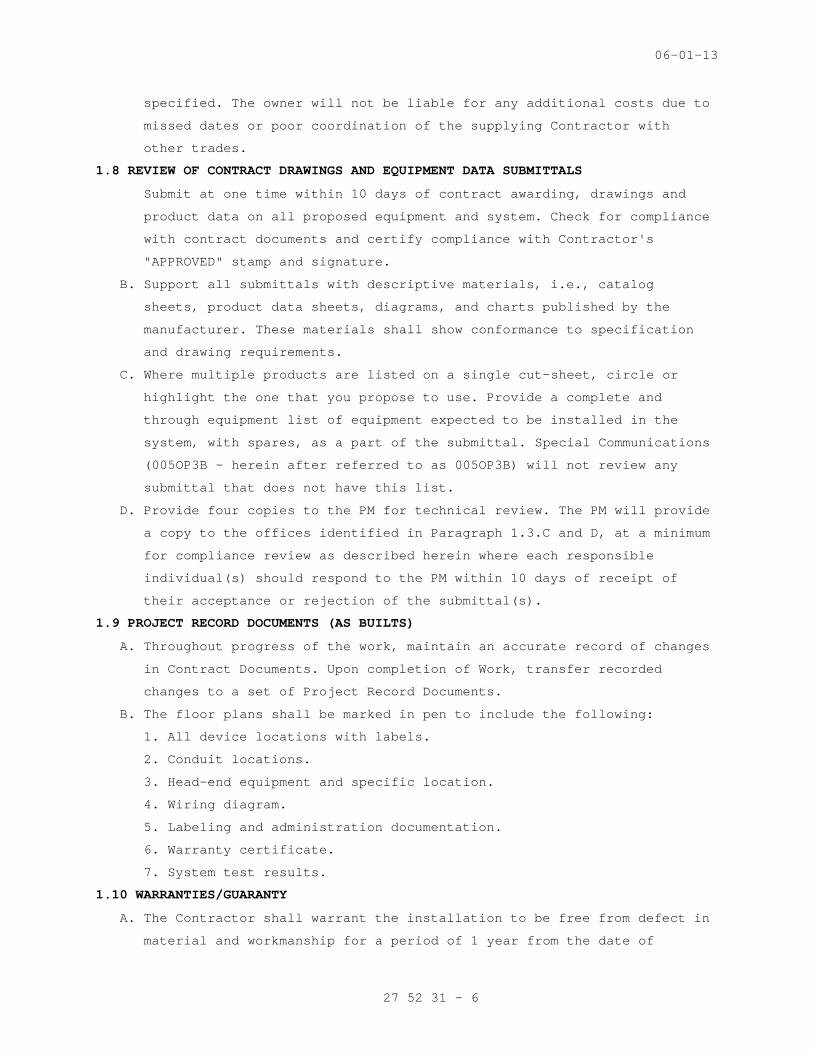
06-01-13
specified. The owner will not be liable for any additional costs due to
missed dates or poor coordination of the supplying Contractor with
other trades.
1.8 REVIEW OF CONTRACT DRAWINGS AND EQUIPMENT DATA SUBMITTALS
Submit at one time within 10 days of contract awarding, drawings and
product data on all proposed equipment and system. Check for compliance
with contract documents and certify compliance with Contractor's
"APPROVED" stamp and signature.
B. Support all submittals with descriptive materials, i.e., catalog
sheets, product data sheets, diagrams, and charts published by the
manufacturer. These materials shall show conformance to specification
and drawing requirements.
C. Where multiple products are listed on a single cut-sheet, circle or
highlight the one that you propose to use. Provide a complete and
through equipment list of equipment expected to be installed in the
system, with spares, as a part of the submittal. Special Communications
(005OP3B – herein after referred to as 005OP3B) will not review any
submittal that does not have this list.
D. Provide four copies to the PM for technical review. The PM will provide
a copy to the offices identified in Paragraph 1.3.C and D, at a minimum
for compliance review as described herein where each responsible
individual(s) should respond to the PM within 10 days of receipt of
their acceptance or rejection of the submittal(s).
1.9 PROJECT RECORD DOCUMENTS (AS BUILTS)
A. Throughout progress of the work, maintain an accurate record of changes
in Contract Documents. Upon completion of Work, transfer recorded
changes to a set of Project Record Documents.
B. The floor plans shall be marked in pen to include the following:
1. All device locations with labels.
2. Conduit locations.
3. Head-end equipment and specific location.
4. Wiring diagram.
5. Labeling and administration documentation.
6. Warranty certificate.
7. System test results.
1.10 WARRANTIES/GUARANTY
A. The Contractor shall warrant the installation to be free from defect in
material and workmanship for a period of 1 year from the date of
27 52 31 - 6
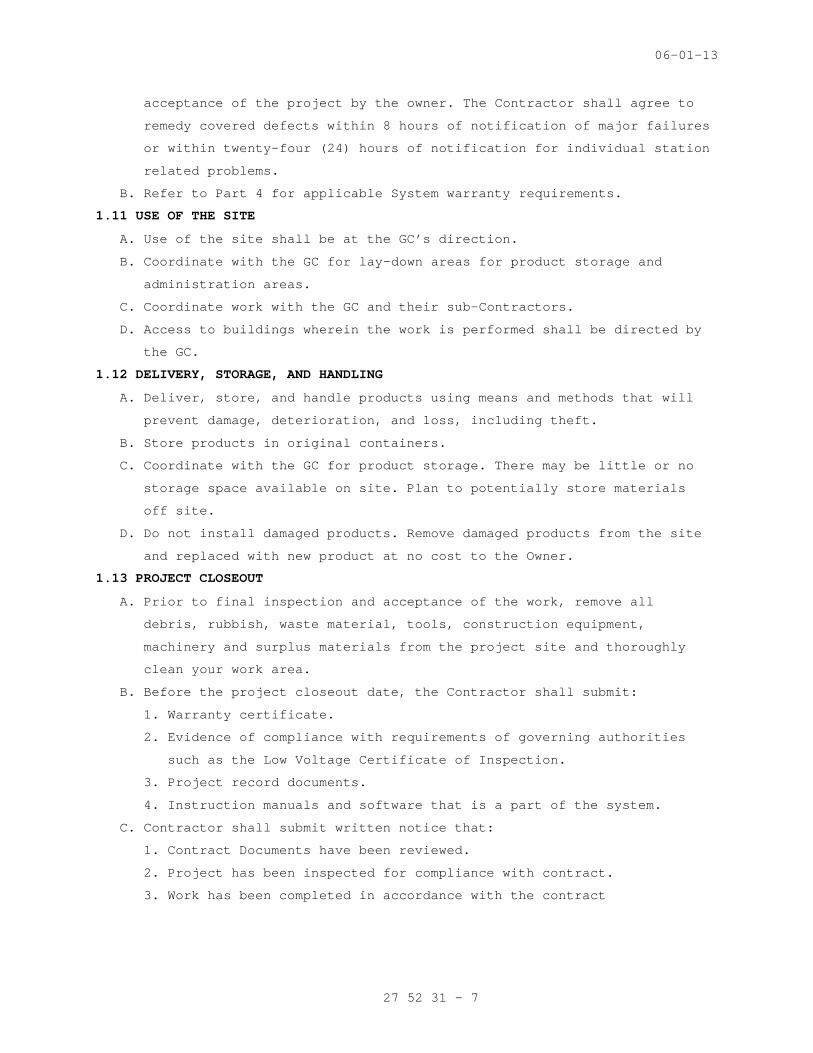
06-01-13
acceptance of the project by the owner. The Contractor shall agree to
remedy covered defects within 8 hours of notification of major failures
or within twenty-four (24) hours of notification for individual station
related problems.
B. Refer to Part 4 for applicable System warranty requirements.
1.11 USE OF THE SITE
A. Use of the site shall be at the GC’s direction.
B. Coordinate with the GC for lay-down areas for product storage and
administration areas.
C. Coordinate work with the GC and their sub-Contractors.
D. Access to buildings wherein the work is performed shall be directed by
the GC.
1.12 DELIVERY, STORAGE, AND HANDLING
A. Deliver, store, and handle products using means and methods that will
prevent damage, deterioration, and loss, including theft.
B. Store products in original containers.
C. Coordinate with the GC for product storage. There may be little or no
storage space available on site. Plan to potentially store materials
off site.
D. Do not install damaged products. Remove damaged products from the site
and replaced with new product at no cost to the Owner.
1.13 PROJECT CLOSEOUT
A. Prior to final inspection and acceptance of the work, remove all
debris, rubbish, waste material, tools, construction equipment,
machinery and surplus materials from the project site and thoroughly
clean your work area.
B. Before the project closeout date, the Contractor shall submit:
1. Warranty certificate.
2. Evidence of compliance with requirements of governing authorities
such as the Low Voltage Certificate of Inspection.
3. Project record documents.
4. Instruction manuals and software that is a part of the system.
C. Contractor shall submit written notice that:
1. Contract Documents have been reviewed.
2. Project has been inspected for compliance with contract.
3. Work has been completed in accordance with the contract
27 52 31 - 7
06-01-13
PART 2 - PRODUCTS AND FUNCTIONAL REQUIREMENTS
2.1 GENERAL REQUIREMENTS FOR EQUIPMENT AND MATERIALS
A. Coordinate features and select components to form an integrated system.
Match components and interconnections for optimum performance of
specified functions.
B. Expansion Capability: Increase number of stations in the future by 25
percent above those indicated without adding any internal or external
components or main trunk cable conductors.
C. Equipment: Modular type using solid-state components, fully rated for
continuous duty unless otherwise indicated. Select equipment for normal
operation on input power usually supplied at 110 to 130 V, 60 Hz.
D. Weather-Resistant Equipment: Listed and labeled by an OSHA certified
National Recognized Testing Laboratory (NRTL – i.e. UL) for duty
outdoors or in damp locations.
2.2 SYSTEM DESCRIPTION
A. System hardware shall consist of an indoor or outdoor enclosures,
poles, strobe lights, intercom system, intercom stations, intercom
master stations, and power supplies. All necessary equipment required
to meet the intent of these specifications, whether or not enumerated
within these specifications, shall be supplied and installed to provide
a complete and operating nurse and patient communications network.
B. Systems firmware shall be the product of a reputable firmware OEM of
record with a proven history of product reliability and sole control
over all source code. Manufacturer shall provide, free of charge,
product firmware/software upgrades for a period of two year from date
of acceptance by VA for any product feature enhancements. System
configuration programming changes shall not require any exchange of
parts and shall be capable of being executed remotely via a modem
connection (when specifically approved by 005OP2B).
2.3 EMERGENCY CALL STATIONS
A. The emergency call station shall be a dual button emergency phone. The
unit shall be an ADA compliant, multi-function, high strength, vandal
resistant security unit. The unit shall include a high quality, vandal
resistant, hands free communications device, a powerful (1 million
candlepower) strobe light and a vivid blue area light, which serves to
identify the unit from great distances. The unit shall include an
integrated wall mount enclosure assembly and an emergency phone
station.
27 52 31 - 8

06-01-13
B. The unit shall have an integrated blue light and strobe encased in
Lexan. The blue light shall be always lit, calling attention to the
location of the emergency communication unit. When the emergency phone
is activated, the strobe shall flash at 1 million candlepower and 60
fpm. The strobe shall flash until either actively terminated by the
personnel receiving the call or automatically upon termination of the
call itself.
C. The wall mount enclosure shall be made of a vandal resistant, 12-gauge
No.4 vertical brushed stainless steel. It shall be designed to
withstand prolonged exposure to harsh environments. The unit shall have
a blue light/strobe located at the top of the unit, housed in a vandal
resistant, blue polycarbonate refractor housing. This blue light and
strobe shall be further enclosed in a clear polycarbonate security
enclosure. The wall mount shall measure 12 1/8 inches w x 32 1/4 inches
h x 7 9/16 inches d and weigh approximately 75 lbs. The ADA-compliant,
hands-free emergency phone shall be flush mounted into the wall mount
enclosure. Emergency phone station faceplate shall be 12-gauge No.4
brushed stainless steel or as otherwise approved.
D. The housing for pole mount unit shall be a concentric steel cylinder
(bollard) with an 8.75 inch diameter, a .25 inch wall thickness and a
height of 84 inches. The unit shall have a blue light and strode
located at the top of the unit. A deep blue polycarbonate prismatic
refractor that distributes the light in a horizontal pattern, making
the flash bright and visible even at great distances, shall cover the
strobe. The ADA-compliant, hands-free emergency phone shall be flush
mounted into the pole mount housing. The unit weight approximately 275
lbs.
E. The blue light and strobe shall be controlled via the emergency phone,
and connect to an auxiliary output of the emergency phone. The
emergency phone shall connect via its RJ-11 connector to a standard
phone line or PBX extension. The emergency phone should not require
connection to any power source other than the telephone line. The blue
light, strobe, and faceplate light require 24VAC, 60Hz power.
F. The unit shall have the following features:
1. Interface with Owner’s PBX or regular phone line.
2. Vandal resistant stainless steel faceplate and metal button(s).
3. Phone line powered; no power supply or battery backup required.
4. LED indicator for hearing impaired.
27 52 31 - 9

06-01-13
5. Cast metal raised letter and Braille signage for ADA compliance.
6. Auto-answer that allows security to monitor and initiate calls with
Owner provided phone.
7. Auxiliary input and outputs programmable to integrate with CCTV and
security systems.
G. Tamper resistant fasteners shall be used. It shall not be possible to
enter the unit or remove any component without a special computer
designed bit-wrench designed for the purpose. These bit-wrenches are
available only from the manufacturer of the unit. All other types of
fasteners shall not be acceptable due to the abundance of non-
proprietary tools available for their removal.
H. The entire unit shall be water and insect resistant when fully
assembled.
I. The system shall immediately and automatically dial the security desk
when activated. In addition, activation shall simultaneously cause the
blue strobe light to flash at no less than 60 times per minute and
where indicated activate CCTV camera switching via an interface to the
CCTV system and the access control system.
J. Mounting:
1. Wall mount security call stations shall be attached to the wall with
anchors bolts as recommended by the manufacturer or otherwise
indicated herein.
2. Security call station poles shall be secured as shown on the
drawings.
K. Electrical:
1. All electrical components shall have quick-disconnect terminals with
plug and receptacle attachments for easy service or removal. All
wiring shall be concealed within the unit and shall not be visible
from the outside.
2. The unit shall require 24 VAC under normal operation. The entire
unit shall be surge protected.
L. Strobe Lights:
1. The strobe light shall generate approximately 1,000,000 candlepower,
and have a flash rate of no less than 60 flashes per minute. It
shall be covered by a deep blue polycarbonate, prismatic refractor
that distributes the light in a horizontal pattern, making the flash
bright and visible even at great distances. The strobe light shall
27 52 31 - 10
06-01-13
be situated within the housing, inaccessible to vandals and weather
resistant.
2. The strobe shall be automatically activated when the "Emergency"
button is touched, and shall flash until the receiving party of the
call deactivates it. The strobe cannot be deactivated at the unit
itself.
M. Communications:
1. Each unit shall have a high quality, vandal resistant and ADA
compliant communications device.
2. The speakerphone shall have the following standard features:
a. Three number dialing capability.
b. Programmable from a remote location.
c. Two input relays.
d. Two output relays.
e. Remote speaker volume adjustment.
f. Capable of playing up to two digitally stored voice messages.
g. Programmable passwords.
h. Capable of using interchangeable faceplates.
i. Silent dial out.
j. Output sound level >80 dB at 1 meter for normal conversation.
k. Waterproof speaker.
l. Waterproof microphone.
m. Auto answer and auto shut-off.
n. Operating temperatures of -40°F to +150°F (-40° to +65°C).
o. Speakerphone electronics are conformal coated to withstand harsh
environments.
N. Graphics:
1. The graphics shall be cut from an engineering grade reflective vinyl
for high visibility and legibility, with a seven-year durability.
2. The standard graphics text shall be “Emergency”. Standard colors
shall be reflective white, reflective blue and reflective black.
O. Finish:
1. For wall mounted unit, the finish shall be stainless steel. The
finish shall be uniform and free of visible defects.
2. For pole mounted unit, the unit shall be finished with a coating
process known to be highly graffiti resistant and UV resistant.
27 52 31 - 11
06-01-13
P. Security Call Station Power Supply:
1. Security Call Station power supply shall power multiple call
stations.
2. Power supply shall include the following:
a. Steel, NEMA 1 rated enclosure.
b. AC power indicator with power On/Off switch.
c. 120 or 230 VAC selectable input.
d. 24VAC output or 28VAC output for longer runs.
e. Main fused input.
f. 10A current capacity.
g. 8 fused outputs.
h. Input wire size 12-16 gauge.
i. Output wire size 12-22 gauge solid or stranded wire.
Q. Security Call Station Cable
1. Call Station communication cable shall meet manufacturers’
requirement.
2. Call Station power cable shall be minimum 14 awg wire or as
otherwise approved. Power cable for each call station shall be home
run from the power supply to the respective call station unit.
3. Cables installed underground or in underground conduits must be
rated for direct burial installation.
4. Cables used inside a building must be labeled for indoor use as
described in NFPA 70, the National Electric Code. Cables shall be
plenum rated if used in a plenum space and riser rated in all other
areas.
2.4 UNINTERRUPTIBLE POWER SUPPLY (UPS)
A. Provide a backup battery or a UPS for the system to allow normal
operation and function (as if there was no AC power failure) in the
event of an AC power failure or during input power fluctuations for a
minimum of 15 minutes.
B. As an alternate solution, the telephone system UPS may be utilized to
meet this requirement at the head-end location, as long as this
function is specifically approved by the Telephone Contractor and the
Resident Engineer.
C. The Contractor shall not make any attachments or connection to the
telephone system until specifically directed to do so, in writing, by
the Resident Engineer.
27 52 31 - 12
06-01-13
D. Provide UPS for all active system components including but not limited
to:
1. Intercom head-end
2. Master intercom stations
3. Remoted intercom stations
PART 3 - EXECUTION
3.1 PROJECT MANAGEMENT
A. Assign a single project manager to this project who will serve as the
point of contact for the Owner, the General Contractor, and the
Engineer.
B. The Contractor shall be proactive in scheduling work at the hospital,
specifically the Contractor will initiate and maintain discussion with
the General Contractor regarding the schedule for ceiling cover up and
install cables to meet that schedule.
C. Contact the Office of Telecommunications, Special Communications Team
(005OP3B) at (301) 734-0350 to have a VA Certified Telecommunications
COTR assigned to the project for telecommunications review, equipment
and system approval and co-ordination with VA’s Spectrum Management and
OCIS Teams.
3.2 COORDINATION WITH OTHER TRADES
A. Coordinate with the cabling contractor the location of security
emergency call and duress alarm equipment in the Telecommunications
Closets.
B. Before beginning work, verify the location, quantity, size and access
for the following:
1. Isolated ground AC power circuits provided for systems.
2. Junction boxes, wall boxes, wire troughs, conduit stubs and other
related infrastructure for the systems.
3. System components installed by others.
4. Overhead supports and rigging hardware installed by others.
C. Immediately notify the Owner, General Contractor and Engineer in
writing of any discrepancies.
3.3 INSTALLATION
A. General:
1. Execute work in accordance with National, State and local codes,
regulations and ordinances.
2. Install work neatly, plumb and square and in a manner consistent
with standard industry practice. Carefully protect work from dust,
27 52 31 - 13

06-01-13
paint and moisture as dictated by site conditions. The Contractor
will be fully responsible for protection of his work during the
construction phase up until final acceptance by the Owner.
3. Install equipment according to OEM’s recommendations. Provide any
hardware, adaptors, brackets, rack mount kits or other accessories
recommended by OEM for correct assembly and installation.
4. Secure equipment firmly in place, including intercom stations,
equipment racks, system cables, etc.
a. All supports, mounts, fasteners, attachments and attachment
points shall support their loads with a safety factor of at least
5:1.
b. Do not impose the weight of equipment or fixtures on supports
provided for other trades or systems.
c. Any suspended equipment or associated hardware must be certified
by the OEM for overhead suspension.
d. The Contractor is responsible for means and methods in the
design, fabrication, installation and certification of any
supports, mounts, fasteners and attachments.
5. Finishes for any exposed work such as plates, racks, panels, towers,
enclosures, intercom stations, etc. shall be approved by the
Architect, Owner and 005OP3B.
6. Coordinate cover plates with field conditions. Size and install
cover plates as necessary to hide joints between back boxes and
surrounding wall. Where cover plates are not fitted with connectors,
provide grommeted holes in size and quantity required. Do not allow
cable to leave or enter boxes without cover plates installed.
B. Equipment Racks:
1. Fill unused equipment mounting spaces with blank panels or vent
panels. Match color to equipment racks.
2. Provide security covers for all devices not requiring routine
operator control.
3. Provide vent panels and cooling fans as required for the operation
of equipment within the OEM' specified temperature limits. Provide
adequate ventilation space between equipment for cooling. Follow
manufacturer’s recommendations regarding ventilation space between
amplifiers.
4. Provide insulated connections of the electrical raceway to equipment
racks.
27 52 31 - 14

06-01-13
5. Provide continuous raceway and conduit with no more than 40 percent
fill between wire troughs and equipment racks for all non-plenum-
rated cable. Ensure each system is mechanically separated from each
other in the wireway.
C. Wiring Practice:
1. Comply with requirements for raceways and boxes specified in
Division 26, Section 26 05 33 RACEWAY AND BOXES FOR ELECTRICAL
SYSTEMS.
2. Execute all wiring in strict adherence to the National Electrical
Code, applicable local building codes and standard industry
practices.
3. Wiring shall be classified according to the following low voltage
signal types:
a. Voice audio
b. Low voltage DC control or power (less than 48VDC).
4. Where raceway is to be EMT (conduit), wiring of differing
classifications shall be run in separate conduit. Where raceway is
to be an enclosure (rack, tray, wire trough, utility box) wiring of
differing classifications which share the same enclosure shall be
mechanically partitioned and separated by at least four (4) inches.
Where Wiring of differing classifications must cross, they shall
cross perpendicular to one another.
5. Do not splice wiring anywhere along the entire length of the run.
Make sure cables are fully insulated and shielded from each other
and from the raceway for the entire length of the run.
6. Do not pull wire through any enclosure where a change of raceway
alignment or direction occurs. Do not bend wires to less than radius
recommended by manufacturer.
7. Replace the entire length of the run of any wire or cable that is
damaged or abraded during installation. There are no acceptable
methods of repairing damaged or abraded wiring.
8. Use wire pulling lubricants and pulling tensions as recommended by
the OEM.
9. Use grommets around cut-outs and knock-outs where conduit or chase
nipples are not installed.
10. Do not use tape-based or glue-based cable anchors.
11. Ground shields and drain wires as indicated by the drawings or
recommended by the OEM.
27 52 31 - 15
06-01-13
12. Field wiring entering equipment racks shall be terminated as
follows:
a. Provide ample service loops at harness break-outs and at plates,
panels and equipment. Loops should be sufficient to allow plates,
panels and equipment to be removed for service and inspection.
b. If specified terminal blocks are not designed for rack mounting,
utilize 3/4 inch plywood or 1/8 inch thick aluminum plates/blank
panels as a mounting surface. Do not mount on the bottom of the
rack.
c. Employ permanent strain relief for any cable with an outside
diameter of 1 inch or greater.
13. Make all connections as follows:
a. Make all connections using rosin-core solder or mechanical
connectors appropriate to the application.
b. For crimp-type connections, use only tools that are specified by
the manufacturer for the application.
c. Use only insulated spade lugs on screw terminals. Spade lugs
shall be sized to fit the wire gauge. Do not exceed two lugs per
terminal.
d. Wire nuts, electrical tape or “Scotch Lock” connections are not
acceptable for any application.
D. Cable Installation - In addition to the mandatory infrastructure
requirements outlined in VA Construction Specification, Section 27 10
00, STRUCTURED CABLING, the following additional practices shall be
adhered to:
1. Support cable on maximum 2’-0” centers. Acceptable means of cable
support are cable tray, j-hooks, and bridal rings. Velcro wrap cable
bundles loosely to the means of support with plenum rated Velcro
straps. Plastic tie wraps are not acceptable as a means to bundle
cables.
2. Run cables parallel to walls.
3. Install maximum of 10 cables in a single row of J-hooks. Provide
necessary rows of J-hooks as required by the number of cables.
4. Do not lay cables on top of light fixtures, ceiling tiles,
mechanical equipment, or ductwork. Maintain at least 2’-0” clearance
from all shielded electrical apparatus.
5. All cables shall be tested after the total installation is fully
complete. All test results are to be documented. All cables shall
27 52 31 - 16

06-01-13
pass acceptable test requirements and levels. Contractor shall
remedy any cabling problems or defects in order to pass or comply
with testing. This includes the re-pull of new cable as required at
no additional cost to the Owner.
6. Ends of cables shall be properly terminated on both ends per
industry and OEM’s recommendations.
7. Provide proper temporary protection of cable after pulling is
complete before final dressing and terminations are complete. Do not
leave cable lying on floor. Bundle and tie wrap up off the floor
until you are ready to terminate.
8. Cover the end of the overall jacket with a 1 inch (minimum) length
of transparent heat-shrink tubing. Cut unused insulated conductors 2
inches (minimum) past the heat-shrink, fold back over jacket and
secure with cable-tie. Cut unused shield/drain wires 2 inches
(minimum) past the Heat-shrink and serve as indicated below.
9. Cover shield/drain wires with heat-shrink tubing extending back to
the overall jacket. Extend tubing 1/4 inch past the end of unused
wires, fold back over jacket and secure with cable tie.
10. For each solder-type connection, cover the bare wire and solder
connection with heat-shrink tubing.
11.Terminate conductors; no cable shall contain unterminated elements.
Make terminations only at outlets and terminals.
12. Splices, Taps, and Terminations: Arrange on numbered terminal strips
in junction, pull, and outlet boxes; terminal cabinets; and
equipment enclosures. Cables may not be spliced.
13. Bundle, lace, and train conductors to terminal points without
exceeding OEM's limitations on bending radii. Install lacing bars
and distribution spools.
14. Cold-Weather Installation: Bring cable to room temperature before
dereeling. Heat lamps shall not be used.
15. Cable shall not be run through structural members or be in contact
with pipes, ducts, or other potentially damaging items.
16. Separation of Wires: (Refer to Raceway Installation) Separate
speaker-microphone, line-level, speaker-level, and power wiring
runs. Install in separate raceways or, where exposed or in same
enclosure, separate conductors at least 12 inches apart for speaker
microphones and adjacent parallel power and telephone wiring.
27 52 31 - 17
06-01-13
Separate other intercommunication equipment conductors as
recommended by equipment manufacturer.
17. Serve all cables as follows:
a. Cover the end of the overall jacket with a 1 inch (minimum)
length of transparent heat-shrink tubing. Cut unused insulated
conductors 2 inches (minimum) past the heat-shrink, fold back
over jacket and secure with cable-tie. Cut unused shield/drain
wires 2 inches (minimum) past the heat-shrink and serve as
indicated below.
b. Cover shield/drain wires with heat-shrink tubing extending back
to the overall jacket. Extend tubing 1/4 inch past the end of
unused wires, fold back over jacket and secure with cable tie.
c. For each solder-type connection, cover the bare wire and solder
connection with heat-shrink tubing.
F. Labeling:
1. Clearly, consistently, logically and permanently mark switches,
connectors, jacks, relays, receptacles and electronic and other
equipment.
2. Engrave and paint fill all receptacle panels using 1/8” (minimum)
high lettering and contrasting paint.
3. For rack-mounted equipment, use engraved Lamacoid labels with white
1/8” (minimum) high lettering on black background. Label the front
and back of all rack-mounted equipment.
4. Where multiple pieces of equipment reside in the same rack group,
clearly and logically label each indicating to which room, channel,
receptacle location, etc. they correspond.
5. Permanently label cables at each end, including intra-rack
connections. Labels shall be covered by the same, transparent heat-
shrink tubing covering the end of the overall jacket. Alternatively,
computer generated labels of the type which include a clear
protective wrap may be used.
6. Contractor’s name shall appear no more than once on each continuous
set of racks. The Contractor’s name shall not appear on wall plates
or portable equipment.
7. Provide printed labels at both ends of the cable.
8. Ensure each OEM supplied equipment has appropriate UL Labels/Marks
for the service the equipment is performed permanently
attached/marked. Equipment installed not bearing these UL marks will
27 52 31 - 18
06-01-13
not be allowed to be part of the system. The Contractor shall bear
all costs required to provide replacement equipment with approved UL
marks.
3.4 SYSTEM PROGRAMMING
Provide all programming required for a complete and operational system.
Coordinate programming parameters with Owner and Engineer.
3.5 PROTECTION OF NETWORK DEVICES
Contractor shall protect network devices during unpacking and
installation by wearing manufacturer approved electrostatic discharge
(ESD) wrist straps tied to chassis ground. The wrist strap shall meet
OSHA requirements for prevention of electrical shock, should technician
come in contact with high voltage.
3.6 CLEANING AND PATCHING
A. It shall be the responsibility of the contractor to keep their work
area clear of debris and clean area daily at completion of work.
B. It shall be the responsibility of the contractor to patch and paint any
wall or surface that has been disturbed by the execution of this work.
C. The Contractor shall be responsible for providing any additional
cutting, drilling, fitting or patching required that is not indicated
as provided by others to complete the Work or to make its parts fit
together properly.
D. The Contractor shall not damage or endanger a portion of the Work or
fully or partially completed construction of the Owner or separate
contractors by cutting, patching or otherwise altering such
construction, or by excavation. The Contractor shall not cut or
otherwise alter such construction by the Owner or a separate contractor
except with written consent of the Owner and of such separate
contractor; such consent shall not be unreasonably withheld. The
Contractor shall not unreasonably withhold from the Owner or a separate
Contractor the Contractor’s consent to cutting or otherwise altering
the Work.
E. Where coring of existing (previously installed) concrete is specified
or required, including coring indicated under unit prices, the location
of such coring shall be clearly identified in the field and the
location shall be approved by the Project Manager prior to commencement
of coring work.
27 52 31 - 19
06-01-13
3.7 FIREPROOFING
A. Where cables penetrate fire rated walls, floors and ceilings, fireproof
the opening.
B. Provide conduit sleeves (if not already provided by electrical
contractor) for cables that penetrate fire rated walls. After the
cabling installation is complete, install fireproofing material in and
around all conduit sleeves and openings. Install fire proofing material
thoroughly and neatly. Seal all floor and ceiling penetrations.
C. Use only materials and methods that preserve the integrity of the fire
stopping system and its rating.
3.8 GROUNDING
A. Ground cable shields and equipment to eliminate shock hazard and to
minimize ground loops, commonmode returns, noise pickup, cross talk,
and other impairments.
B. Signal Ground Terminal: Locate at main equipment cabinet. Isolate from
power system and equipment grounding.
C. Install grounding electrodes as specified in Division 26, Section 26 05
26, GROUNDING AND BONDING FOR ELECTRICAL SYSTEMS.
D. Do not use “3rd or 4th” wire internal electrical system conductors for
ground.
E. Do not connect system ground to the building’s external lightning
protection system.
F. Do not “mix grounds” of different systems
PART 4 -TESTING/GUARANTY/TRAINING
4.1 PROOF OF PERFORMANCE TESTING
A. Intermediate Testing:
1. After completion of 25 – 30 percent of the installation of a head
end cabinet(s) and equipment, one IC master station, local and
remote intercom stations, and prior to any further work, this
portion of the system must be pretested, inspected, and certified.
Each item of installed equipment shall be checked to ensure
appropriate UL certification labels are affixed, NFPA, Life Safety,
and JCAHCO guidelines are followed, and proper installation
practices are followed. The intermediate test shall include a full
operational test.
2. The inspection and test will be conducted by a factory-certified
representative and witnessed by a Government Representative. The
results of the inspection will be officially recorded by the
27 52 31 - 20

06-01-13
Government Representative and maintained on file by the Resident
Engineer (RE), until completion of the entire project. The results
will be compared to the Acceptance Test results. An identical
inspection may be conducted between the 65 - 75 percent of the
system construction phase, at the direction of the Resident
Engineer.
B. Pretesting:
1. Upon completing installation of the system, the Contractor shall
align, balance, and completely pretest the entire system under full
operating conditions.
2. Pretesting Procedure:
a. During the system pretest the Contractor shall verify (utilizing
approved test equipment) that the system is fully operational and
meets all the system performance requirements of this standard.
b. The Contractor shall pretest and verify that all system functions
and specification requirements are met and operational, no
unwanted aural effects, such as signal distortion, noise pulses,
glitches, audio hum, poling noise, etc. are present. At a
minimum, each of the following locations shall be fully
pretested:
1) Central Control Cabinets.
2) All Networked locations.
3) System trouble reporting.
4) System electrical supervision.
5) UPS operation.
3. The Contractor shall provide four (4) copies of the recorded system
pretest measurements and the written certification that the system
is ready for the formal acceptance test shall be submitted to the
Resident Engineer.
C. Acceptance Test:
1. After the system has been pretested and the Contractor has submitted
the pretest results and certification to the Resident Engineer, then
the Contractor shall schedule an acceptance test date and give the
Resident Engineer 30 days written notice prior to the date the
acceptance test is expected to begin. The system shall be tested in
the presence of a Government Representative and an OEM certified
representative. The system shall be tested utilizing the approved
test equipment to certify proof of performance. The test shall
27 52 31 - 21

06-01-13
verify that the total system meets all the requirements of this
specification. The notification of the acceptance test shall include
the expected length (in time) of the test.
2. The acceptance test shall be performed on a "go-no-go" basis. Only
those operator adjustments required to show proof of performance
shall be allowed. The test shall demonstrate and verify that the
installed system does comply with all requirements of this
specification under operating conditions. The system shall be rated
as either acceptable or unacceptable at the conclusion of the test.
Failure of any part of the system that precludes completion of
system testing, and which cannot be repaired in four (4) hours,
shall be cause for terminating the acceptance test of the system.
Repeated failures that result in a cumulative time of eight (8)
hours to affect repairs shall cause the entire system to be declared
unacceptable. Retesting of the entire system shall be rescheduled at
the convenience of the Government.
D. Acceptance Test Procedure:
1. Physical and Mechanical Inspection:
a. The Government Representative will tour all major areas where the
system is and all sub-systems are completely and properly
installed to insure they are operationally ready for proof of
performance testing. A system inventory including available spare
parts will be taken at this time. Each item of installed
equipment shall be checked to ensure appropriate UL certification
labels are affixed.
b. The system diagrams, record drawings, equipment manuals, Auto CAD
Disks, intermediate, and pretest results shall be formally
inventoried and reviewed.
c. Failure of the system to meet the installation requirements of
this specification shall be grounds for terminating all testing.
2. Operational Test:
a. After the Physical and Mechanical Inspection, the central
terminating and nurse call master control equipment shall be
checked to verify that it meets all performance requirements
outlined herein. A spectrum analyzer and sound level meter may be
utilized to accomplish this requirement.
b. Individual Item Test: The Government Representative will select
individual items of equipment for detailed proof of performance
27 52 31 - 22
06-01-13
testing until 100 percent of the system has been tested and found
to meet the contents of this specification. Each item shall meet
or exceed the minimum requirements of this document.
3. Test Conclusion:
a. At the conclusion of the Acceptance Test, using the generated
punch list (or discrepancy list) the VA and the Contractor shall
jointly agree to the results of the test, and reschedule testing
on deficiencies and shortages with the Resident Engineer. Any
retesting to comply with these specifications will be done at the
Contractor's expense.
b. If the system is declared unacceptable without conditions, all
rescheduled testing expenses will be born by the Contractor.
E. Acceptable Test Equipment:
1. The test equipment shall furnished by the Contractor shall have a
calibration tag of an acceptable calibration service dated not more
than 12 months prior to the test. As part of the submittal, a test
equipment list shall be furnished that includes the make and model
number of the following type of equipment as a minimum:
2. Spectrum Analyzer.
3. Signal Level Meter.
4. Volt-Ohm Meter.
5. Sound Pressure Level (SPL) Meter.
6. Oscilloscope.
4.2 WARRANTY
A. Comply with FAR clause 52.246-21, except that warranty shall be as
follows:
B. Contractor’s Responsibility:
1. The Contractor shall warranty that all provided material and
equipment will be free from defects, workmanship and will remain so
for a period of one year from date of final acceptance of the system
by the VA. The Contractor shall provide OEM’s equipment warranty
documents, to the Resident Engineer (or Facility Contracting Officer
if the Facility has taken procession of the building), that
certifies each item of equipment installed conforms to OEM published
specifications.
2. The Contractor's maintenance personnel shall have the ability to
contact the Contractor and OEM for emergency maintenance and
logistic assistance, remote diagnostic testing, and assistance in
27 52 31 - 23
06-01-13
resolving technical problems at any time. This contact capability
shall be provided by the Contractor and OEM at no additional cost to
the VA.
3. All Contractor maintenance and supervisor personnel shall be fully
qualified by the OEM and must provide two (2) copies of current and
qualified OEM training certificates and OEM certification upon
request.
4. Additionally, the Contractor shall accomplish the following minimum
requirements during the two year guaranty period:
a. Response Time During the Two Year Guaranty Period:
1) The Resident Engineer (or Facility Contracting Officer if the
system has been turned over to the Facility) is the
Contractor’s ONLY OFFICIAL reporting and contact official for
Security Emergency Call and Duress Alarm system trouble calls,
during the guaranty period.
2) A standard work week is considered 8:00 A.M. to 5:00 P.M. or
as designated by the Resident Engineer (or Facility
Contracting Officer), Monday through Friday exclusive of
Federal Holidays.
3) The Contractor shall respond and correct on-site trouble
calls, during the standard work week to:
a) A routine trouble call within one (1) working day of its
report. A routine trouble is considered a trouble which
causes a single intercom station inoperable.
b) An emergency trouble call within four hours of its report.
An emergency trouble is considered a trouble which causes a
sub-system (ward), distribution point, terminal cabinet, to
be inoperable at anytime.
b. Required On-Site Visits During the Two Year Guaranty Period
1) The Contractor shall visit, on-site, for a minimum of eight
(8) hours, once every 12 weeks, during the guaranty period, to
perform system preventive maintenance, equipment cleaning, and
operational adjustments to maintain the system according the
descriptions identified in this document.
2) The Contractor shall arrange all Facility visits with the
Resident Engineer (or Facility Contracting Officer) prior to
performing the required maintenance visits.
27 52 31 - 24

06-01-13
3) Preventive maintenance shall be performed by the Contractor in
accordance with the OEM's recommended practice and service
intervals during non-busy time agreed to by the Resident
Engineer (or Facility Contracting Officer) and Contractor.
4) The preventive maintenance schedule, functions and reports
shall be provided to and approved by the Resident Engineer (or
Facility Contracting Officer).
5) The Contractor shall provide the Resident Engineer (or
Facility Contracting Officer) a type written report itemizing
each deficiency found and the corrective action performed
during each required visit or official reported trouble call.
The Contractor shall provide the Resident Engineer with sample
copies of these reports for review and approval at the
beginning of the Acceptance Test. The following reports are
the minimum required:
a) The Contractor shall provide a monthly summary all
equipment and sub-systems serviced during this warranty
period to Resident Engineer (or Facility Contracting
Officer) by the fifth (5th) working day after the end of
each month. The report shall clearly and concisely describe
the services rendered, parts replaced and repairs
performed. The report shall prescribe anticipated future
needs of the equipment and systems for preventive and
predictive maintenance.
b) The Contractor shall maintain a separate log entry for each
item of equipment and each sub-system of the system. The
log shall list dates and times of all scheduled, routine,
and emergency calls. Each emergency call shall be described
with details of the nature and causes of emergency steps
taken to rectify the situation and specific recommendations
to avoid such conditions in the future.
6) The Resident Engineer (or Facility Contracting Officer) shall
convey to the Facility Engineering Officer, two (2) copies of
actual reports for evaluation.
a) The Resident Engineer (or Facility Contracting Officer)
shall ensure a copy of these reports is entered into the
system’s official acquisition documents.
27 52 31 - 25
06-01-13
b) The Facility Chief Engineer shall ensure a copy of these
reports is entered into the system’s official technical
record documents.
C. Work Not Included: Maintenance and repair service shall not include the
performance of any work due to improper use; accidents; other vendor,
contractor, or owner tampering or negligence, for which the Contractor
is not directly responsible and does not control. The Contractor shall
immediately notify the Resident Engineer or Facility Contracting
Officer in writing upon the discovery of these incidents. The Resident
Engineer or Facility Contracting Officer will investigate all reported
incidents and render
4.3 TRAINING
A. Provide thorough training of all nursing staff assigned to those
nursing units receiving new networked nurse/patient communications
equipment. This training shall be developed and implemented to address
two different types of staff. Floor nurses/staff shall receive training
from their perspective, and likewise, unit secretaries (or any person
whose specific responsibilities include answering patient calls and
dispatching staff) shall receive operational training from their
perspective. A separate training room will be set up that allows this
type of individualized training utilizing in-service training unit,
prior to cut over of the new system.
B. Provide the following minimum training times and durations:
1. //32// hours during the opening week for security staff – both day
and night shifts.
2. //24// hours for supervisors and system administrators.
- - - E N D - - -
27 52 31 - 26
9-11
SECTION 28 05 00 COMMON WORK RESULTS FOR ELECTRONIC SAFETY AND SECURITY
PART 1 - GENERAL
1.01 DESCRIPTION
A. This Section, Common Work Results for Electronic Safety and Security (ESS), applies to all sections of Division 28.
B. Furnish and install fully functional electronic safety and security cabling system(s), equipment and approved accessories in accordance with the specification section(s), drawing(s), and referenced publications. Capacities and ratings of cable and other items and arrangements for the specified items are shown on each system’s required Bill of Materials (BOM) and verified on the approved system drawing(s). If there is a conflict between contract’s specification(s) and drawings(s), the contract’s specification requirements shall prevail.
C. The Contractor shall provide a fully functional and operating ESS, programmed, configured, documented, and tested as required herein and the respective Safety and Security System Specification(s). The Contractor shall provide calculations and analysis to support design and engineering decisions as specified in submittals. The Contractor shall provide and pay all labor, materials, and equipment, sales and gross receipts and other taxes. The Contractor shall secure and pay for plan check fees, permits, other fees, and licenses necessary for the execution of work as applicable for the project. Give required notices; the Contractor will comply with codes, ordinances, regulations, and other legal requirements of public authorities, which bear on the performance of work.
D. The Contractor shall provide an ESS, installed, programmed, configured, documented, and tested. The security system shall include but not limited to: physical access control, intrusion detection, duress alarms, elevator control interface, video assessment and surveillance, video recording and storage, delayed egress, personal protection system, intercommunication system, fire alarm interface, equipment cabinetry, dedicated photo badging system and associated live camera, report printer, photo badge printer, and uninterruptible power supplies (UPS) interface. Operator training shall not be required as part of the Security Contractors scope and shall be provided by the Owner. The Security Contractor shall still be required to provide necessary maintenance and troubleshooting manuals as well as submittals as identified herein. The work shall include the procurement and installation of electrical wire and cables, the installation and testing of all system components. Inspection, testing, demonstration, and acceptance of equipment, software, materials, installation, documentation, and workmanship, shall be as specified herein. The Contractor shall provide all associated installation support, including the provision of primary electrical input power circuits.
E. Repair Service Replacement Parts On-site service during the warranty period shall be provided as specified under “Emergency Service”. The Contractor shall guarantee all parts and labor for a term of one (1) year, unless dictated otherwise in this specification from the acceptance date of the system as described in Part 5 of this Specification. The Contractor shall be responsible for all equipment, software, shipping, transportation charges, and expenses associated with the service of the system for one (1) year. The Contractor shall
28 05 00 - 1
9-11
provide 24-hour telephone support for the software program at no additional charge to the owner. Software support shall include all software updates that occur during the warranty period.
F. Section Includes: 1. Description of Work for Electronic Security Systems, 2. Electronic security equipment coordination with relating
Divisions, 3. Submittal Requirements for Electronic Security, 4. Miscellaneous Supporting equipment and materials for Electronic
Security, 5. Electronic security installation requirements.
1.02 RELATED WORK
A. Section 01 00 00 - GENERAL REQUIREMENTS. For General Requirements.
B. Section 07 84 00 - FIRESTOPPING. Requirements for firestopping application and use.
C. Section 08 71 00 - DOOR HARDWARE. Requirements for door installation.
D. Section 26 05 11 - REQUIREMENTS FOR ELECTRICAL INSTALLATIONS. Requirements for connection of high voltage.
E. Section 26 05 21 - LOW VOLTAGE ELECTRICAL POWER CONDUCTORS AND CABLES (600 VOLTS AND BELOW). Requirements for power cables.
F. Section 26 05 33 – RACEWAY AND BOXES FOR ELECTRICAL SYSTEMS. Requirements for infrastructure.
G. Section 28 05 13 - CONDUCTORS AND CABLES FOR ELECTRONIC SAFETY AND SECURITY. Requirements for conductors and cables.
H. Section 28 05 26 - GROUNDING AND BONDING FOR ELECTRONIC SAFETY AND SECURITY. Requirements for grounding of equipment.
I. Section 28 05 28.33 - CONDUITS AND BOXES FOR ELECTRONIC SAFETY AND SECURITY. Requirements for infrastructure.
J. Section 28 08 00 - COMMISIONING OF ELECTRONIC SAFETY AND SECURITY SYSTEMS. Requirements for Commissioning.
K. Section 28 13 00 - PHYSICAL ACCESS CONTROL SYSTEMS (PACS). For physical access control integration.
L. Section 28 23 00 - VIDEO SURVEILLANCE. Requirements for security camera systems.
1.03 DEFINITIONS
A. AGC: Automatic Gain Control.
B. Basket Cable Tray: A fabricated structure consisting of wire mesh bottom and side rails.
C. BICSI: Building Industry Consulting Service International.
28 05 00 - 2
9-11
D. CCD: Charge-coupled device.
E. Central Station: A PC with software designated as the main controlling PC of the security access system. Where this term is presented with initial capital letters, this definition applies.
F. Channel Cable Tray: A fabricated structure consisting of a one-piece, ventilated-bottom or solid-bottom channel section.
G. Controller: An intelligent peripheral control unit that uses a computer for controlling its operation. Where this term is presented with an initial capital letter, this definition applies.
H. CPU: Central processing unit.
I. Credential: Data assigned to an entity and used to identify that entity.
J. DGP: Data Gathering Panel – component of the Physical Access Control System capable to communicate, store and process information received from readers, reader modules, input modules, output modules, and Security Management System.
K. DTS: Digital Termination Service: A microwave-based, line-of-sight communications provided directly to the end user.
L. EMI: Electromagnetic interference.
M. EMT: Electric Metallic Tubing.
N. ESS: Electronic Security System.
O. File Server: A PC in a network that stores the programs and data files shared by users.
P. GFI: Ground fault interrupter.
Q. IDC: Insulation displacement connector.
R. Identifier: A credential card, keypad personal identification number or code, biometric characteristic, or other unique identification entered as data into the entry-control database for the purpose of identifying an individual. Where this term is presented with an initial capital letter, this definition applies.
S. I/O: Input/Output.
T. Intrusion Zone: A space or area for which an intrusion must be detected and uniquely identified, the sensor or group of sensors assigned to perform the detection, and any interface equipment between sensors and communication link to central-station control unit.
U. Ladder Cable Tray: A fabricated structure consisting of two longitudinal side rails connected by individual transverse members (rungs).
V. LAN: Local area network.
28 05 00 - 3
9-11
W. LCD: Liquid-crystal display.
X. LED: Light-emitting diode.
Y. Location: A Location on the network having a PC-to-Controller communications link, with additional Controllers at the Location connected to the PC-to-Controller link with RS-485 communications loop. Where this term is presented with an initial capital letter, this definition applies.
Z. Low Voltage: As defined in NFPA 70 for circuits and equipment operating at less than 50 V or for remote-control and signaling power-limited circuits.
AA. M-JPEG: Motion – Joint Photographic Experts Group.
BB. MPEG: Moving picture experts group.
CC. NEC: National Electric Code
DD. NEMA: National Electrical Manufacturers Association
EE. NFPA: National Fire Protection Association
FF. NTSC: National Television System Committee.
GG. NRTL: Nationally Recognized Testing Laboratory.
HH. Open Cabling: Passing telecommunications cabling through open space (e.g., between the studs of a wall cavity).
II. PACS: Physical Access Control System; A system comprised of cards, readers, door controllers, servers and software to control the physical ingress and egress of people within a given space
JJ. PC: Personal computer. This acronym applies to the Central Station, workstations, and file servers.
KK. PCI Bus: Peripheral component interconnect; a peripheral bus providing a high-speed data path between the CPU and peripheral devices (such as monitor, disk drive, or network).
LL. PDF: (Portable Document Format.) The file format used by the Acrobat document exchange system software from Adobe.
MM. RCDD: Registered Communications Distribution Designer.
NN. RFI: Radio-frequency interference.
OO. RIGID: Rigid conduit is galvanized steel tubing, with a tubing wall that is thick enough to allow it to be threaded.
PP. RS-232: An TIA/EIA standard for asynchronous serial data communications between terminal devices. This standard defines a 25-pin connector and certain signal characteristics for interfacing computer equipment.
QQ. RS-485: An TIA/EIA standard for multipoint communications.
28 05 00 - 4
9-11
RR. Solid-Bottom or Non-ventilated Cable Tray: A fabricated structure consisting of integral or separate longitudinal side rails, and a bottom without ventilation openings.
SS. SMS: Security Management System – A SMS is software that incorporates multiple security subsystems (e.g., physical access control, intrusion detection, closed circuit television, intercom) into a single platform and graphical user interface.
TT. TCP/IP: Transport control protocol/Internet protocol incorporated into Microsoft Windows.
UU. Trough or Ventilated Cable Tray: A fabricated structure consisting of integral or separate longitudinal rails and a bottom having openings sufficient for the passage of air and using 75 percent or less of the plan area of the surface to support cables.
VV. UPS: Uninterruptible Power Supply
WW. UTP: Unshielded Twisted Pair
XX. Workstation: A PC with software that is configured for specific limited security system functions.
1.04 QUALITY ASSURANCE
A. Manufacturers Qualifications: The manufacturer shall regularly and presently produce, as one of the manufacturer's principal products, the equipment and material specified for this project, and shall have manufactured the item for at least three years.
B. Product Qualification: 1. Manufacturer's product shall have been in satisfactory operation,
on three installations of similar size and type as this project, for approximately three years.
2. The Government reserves the right to require the Contractor to submit a list of installations where the products have been in operation before approval.
C. Contractor Qualification: 1. The Contractor or security sub-contractor shall be a licensed
security Contractor with a minimum of five (5) years experience installing and servicing systems of similar scope and complexity. The Contractor shall be an authorized regional representative of the Security Management System’s (PACS) manufacturer. The Contractor shall provide four (4) current references from clients with systems of similar scope and complexity which became operational in the past three (3) years. At least three (3) of the references shall be utilizing the same system components, in a similar configuration as the proposed system. The references must include a current point of contact, company or agency name, address, telephone number, complete system description, date of completion, and approximate cost of the project. The owner reserves the option to visit the reference sites, with the site owner’s permission and representative, to verify the quality of installation and the references’ level of satisfaction with the system. The Contractor shall provide copies of system manufacturer certification for all technicians. The Contractor shall only utilize factory-trained technicians to install, program, and service the PACS. The Contractor shall only utilize
28 05 00 - 5
9-11
factory-trained technicians to install, terminate and service controller/field panels and reader modules. The technicians shall have a minimum of five (5) continuous years of technical experience in electronic security systems. The Contractor shall have a local service facility. The facility shall be located within [60] <insert number> miles of the project site. The local facility shall include sufficient spare parts inventory to support the service requirements associated with this contract. The facility shall also include appropriate diagnostic equipment to perform diagnostic procedures. The Resident Engineer reserves the option of surveying the company’s facility to verify the service inventory and presence of a local service organization.
2. The Contractor shall provide proof project superintendent with BICSI Certified Commercial Installer Level 1, Level 2, or Technician to provide oversight of the project.
3. Cable installer must have on staff a Registered Communication Distribution Designer (RCDD) certified by Building Industry Consulting Service International. The staff member shall provide consistent oversight of the project cabling throughout design, layout, installation, termination and testing.
D. Service Qualifications: There shall be a permanent service organization maintained or trained by the manufacturer which will render satisfactory service to this installation within four hours of receipt of notification that service is needed. Submit name and address of service organizations.
1.05 GENERAL ARANGEMENT OF CONTRACT DOCUMENTS
A. The Contract Documents supplement to this specification indicates approximate locations of equipment. The installation and/or locations of the equipment and devices shall be governed by the intent of the design; specification and Contract Documents, with due regard to actual site conditions, recommendations, ambient factors affecting the equipment and operations in the vicinity. The Contract Documents are diagrammatic and do not reveal all offsets, bends, elbows, components, materials, and other specific elements that may be required for proper installation. If any departure from the contract documents is deemed necessary, or in the event of conflicts, the Contractor shall submit details of such departures or conflicts in writing to the owner or owner’s representative for his or her comment and/or approval before initiating work.
B. Anything called for by one of the Contract Documents and not called for by the others shall be of like effect as if required or called by all, except if a provision clearly designed to negate or alter a provision contained in one or more of the other Contract Documents shall have the intended effect. In the event of conflicts among the Contract Documents, the Contract Documents shall take precedence in the following order: the Form of Agreement; the Supplemental General Conditions; the Special Conditions; the Specifications with attachments; and the drawings.
1.06 SUBMITTALS
A. Submit in accordance with Section 01 33 23, SHOP DRAWINGS, PRODUCT DATA, AND SAMPLES.
B. The Government's approval shall be obtained for all equipment and material before delivery to the job site. Delivery, storage or
28 05 00 - 6
9-11
installation of equipment or material which has not had prior approval will not be permitted at the job site.
C. Submittals for individual systems and equipment assemblies which consist of more than one item or component shall be made for the system or assembly as a whole. Partial submittals will not be considered for approval. 1. Mark the submittals, "SUBMITTED UNDER SECTION__________________". 2. Submittals shall be marked to show specification reference
including the section and paragraph numbers. 3. Submit each section separately.
D. The submittals shall include the following: 1. Information that confirms compliance with contract requirements.
Include the manufacturer's name, model or catalog numbers, catalog information, technical data sheets, shop drawings, pictures, nameplate data and test reports as required.
2. Submittals are required for all equipment anchors and supports. Submittals shall include weights, dimensions, center of gravity, standard connections, manufacturer's recommendations and behavior problems (e.g., vibration, thermal expansion,) associated with equipment or piping so that the proposed installation can be properly reviewed.
3. Parts list which shall include those replacement parts recommended by the equipment manufacturer, quantity of parts, current price and availability of each part.
E. Submittals shall be in full compliance of the Contract Documents. All submittals shall be provided in accordance with this section. Submittals lacking the breath or depth these requirements will be considered incomplete and rejected. Submissions are considered multidisciplinary and shall require coordination with applicable divisions to provide a complete and comprehensive submission package. All submittals shall include adequate descriptive literature, catalog cuts, shop drawings and other data necessary for the Government to ascertain that the proposed equipment and materials comply with specification requirements. Catalog cuts submitted for approval shall be legible and clearly identify equipment being submitted. Additional general provisions are as follows: 1. The Contractor shall schedule submittals in order to maintain the
project schedule. For coordination drawings refer to Specification Section 01 33 10 - Design Submittal Procedures, which outline basic submittal requirements and coordination. Section 01 33 10 shall be used in conjunction with this section.
2. The Contractor shall identify variations from requirements of Contract Documents and state product and system limitations, which may be detrimental to successful performance of the completed work or system.
3. Each package shall be submitted at one (1) time for each review and include components from applicable disciplines (e.g., electrical work, architectural finishes, door hardware, etc.) which are required to produce an accurate and detailed depiction of the project.
4. Manufacturer’s information used for submittal shall have pages with items for approval tagged, items on pages shall be identified, and capacities and performance parameters for review shall be clearly marked through use of an arrow or highlighting. Provide space for Resident Engineer and Contractor review stamps.
28 05 00 - 7
9-11
5. Technical Data Drawings shall be in the latest version of AutoCAD®, drawn accurately, and in accordance with VA CAD Standards CAD Standard Application Guide, and VA BIM Guide. FREEHAND SKETCHES OR COPIED VERSIONS OF THE CONSTRUCTION DOCUMENTS WILL NOT BE ACCEPTED. The Contractor shall not reproduce Contract Documents or copy standard information as the basis of the Technical Data Drawings. If departures from the technical data drawings are subsequently deemed necessary by the Contractor, details of such departures and the reasons thereof shall be submitted in writing to the Resident Engineer for approval before the initiation of work.
6. Packaging: The Contractor shall organize the submissions according to the following packaging requirements. a. Binders: For each manual, provide heavy duty, commercial
quality, durable three (3) ring vinyl covered loose leaf binders, sized to receive 8.5 x 11 in paper, and appropriate capacity to accommodate the contents. Provide a clear plastic sleeve on the spine to hold labels describing the contents. Provide pockets in the covers to receive folded sheets. 1) Where two (2) or more binders are necessary to
accommodate data; correlate data in each binder into related groupings according to the Project Manual table of contents. Cross-referencing other binders where necessary to provide essential information for communication of proper operation and/or maintenance of the component or system.
2) Identify each binder on the front and spine with printed binder title, Project title or name, and subject matter covered. Indicate the volume number if applicable.
b. Dividers: Provide heavy paper dividers with celluloid tabs for each Section. Mark each tab to indicate contents.
c. Protective Plastic Jackets: Provide protective transparent plastic jackets designed to enclose diagnostic software for computerized electronic equipment.
d. Text Material: Where written material is required as part of the manual use the manufacturer's standard printed material, or if not available, specially prepared data, neatly typewritten on 8.5 inches by 11 inches 20 pound white bond paper.
e. Drawings: Where drawings and/or diagrams are required as part of the manual, provide reinforced punched binder tabs on the drawings and bind them with the text. 1) Where oversized drawings are necessary, fold the
drawings to the same size as the text pages and use as a foldout.
2) If drawings are too large to be used practically as a foldout, place the drawing, neatly folded, in the front or rear pocket of the binder. Insert a type written page indicating the drawing title, description of contents and drawing location at the appropriate location of the manual.
3) Drawings shall be sized to ensure details and text is of legible size. Text shall be no less than 1/16” tall.
f. Manual Content: Submit in accordance with Section 01 00 00, GENERAL REQUIREMENTS. 1) Maintenance and Operation Manuals: Submit as required
for systems and equipment specified in the technical sections. Furnish four copies, bound in hardback
28 05 00 - 8
9-11
binders, (manufacturer's standard binders) or an approved equivalent. Furnish one complete manual as specified in the technical section but in no case later than prior to performance of systems or equipment test, and furnish the remaining manuals prior to contract completion.
2) Inscribe the following identification on the cover: the words "MAINTENANCE AND OPERATION MANUAL," the name and location of the system, equipment, building, name of Contractor, and contract number. Include in the manual the names, addresses, and telephone numbers of each subcontractor installing the system or equipment and the local representatives for the system or equipment.
3) The manuals shall include: a) Internal and interconnecting wiring and control
diagrams with data to explain detailed operation and control of the equipment.
b) A control sequence describing start-up, operation, and shutdown.
c) Description of the function of each principal item of equipment.
d) Installation and maintenance instructions. e) Safety precautions. f) Diagrams and illustrations. g) Testing methods. h) Performance data. i) Pictorial "exploded" parts list with part
numbers. Emphasis shall be placed on the use of special tools and instruments. The list shall indicate sources of supply, recommended spare parts, and name of servicing organization.
j) Appendix; list qualified permanent servicing organizations for support of the equipment, including addresses and certified qualifications.
g. Binder Organization: Organize each manual into separate sections for each piece of related equipment. At a minimum, each manual shall contain a title page, table of contents, copies of Product Data supplemented by drawings and written text, and copies of each warranty, bond, certifications, and service Contract issued. Refer to Group I through V Technical Data Package Submittal requirements for required section content.
h. Title Page: Provide a title page as the first sheet of each manual to include the following information; project name and address, subject matter covered by the manual, name and address of the Project, date of the submittal, name, address, and telephone number of the Contractor, and cross references to related systems in other operating and/or maintenance manuals.
i. Table of Contents: After the title page, include a type written table of contents for each volume, arranged systematically according to the Project Manual format. Provide a list of each product included, identified by product name or other appropriate identifying symbols and indexed to the content of the volume. Where more than one (1) volume is required to hold data for a particular system, provide a comprehensive table of contents for all volumes in each volume of the set.
28 05 00 - 9
9-11
j. General Information Section: Provide a general information section immediately following the table of contents, listing each product included in the manual, identified by product name. Under each product, list the name, address, and telephone number of the installer and maintenance Contractor. In addition, list a local source for replacement parts and equipment.
k. Drawings: Provide specially prepared drawings where necessary to supplement the manufacturers printed data to illustrate the relationship between components of equipment or systems, or provide control or flow diagrams. Coordinate these drawings with information contained in Project Record Drawings to assure correct illustration of the completed installation.
l. Manufacturer’s Data: Where manufacturer's standard printed data is included in the manuals, include only those sheets that are pertinent to the part or product installed. Mark each sheet to identify each part or product included in the installation. Where more than one (1) item in tabular format is included, identify each item, using appropriate references from the Contract Documents. Identify data that is applicable to the installation and delete references to information which is not applicable.
m. Where manufacturer's standard printed data is not available and the information is necessary for proper operation and maintenance of equipment or systems, or it is necessary to provide additional information to supplement the data included in the manual, prepare written text to provide the necessary information. Organize the text in a consistent format under a separate heading for different procedures. Where necessary, provide a logical sequence of instruction for each operating or maintenance procedure. Where similar or more than one product is listed on the submittal the Contractor shall differentiate by highlighting the specific product to be utilized.
n. Calculations: Provide a section for circuit and panel calculations.
o. Loading Sheets: Provide a section for DGP Loading Sheets. p. Certifications: Provide section for Contractor’s
manufacturer certifications. 7. Contractor Review: Review submittals prior to transmittal.
Determine and verify field measurements and field construction criteria. Verify manufacturer’s catalog numbers and conformance of submittal with requirements of contract documents. Return non-conforming or incomplete submittals with requirements of the work and contract documents. Apply Contractor’s stamp with signature certifying the review and verification of products occurred, and the field dimensions, adjacent construction, and coordination of information is in accordance with the requirements of the contract documents.
8. Resubmission: Revise and resubmit submittals as required within 15 calendar days of return of submittal. Make resubmissions under procedures specified for initial submittals. Identify all changes made since previous submittal.
9. Product Data: Within 15 calendar days after execution of the contract, the Contractor shall submit for approval a complete list of all of major products proposed for use. The data shall include name of manufacturer, trade name, model number, the associated contract document section number, paragraph number, and the referenced standards for each listed product.
28 05 00 - 10
9-11
F. Group 1 Technical Data Package: Group I Technical Data Package shall be one submittal consisting of the following content and organization. Refer to VA Special Conditions Document for drawing format and content requirements. The data package shall include the following: 1. Section I - Drawings:
a. General – Drawings shall conform to VA CAD Standards Guide. All text associated with security details shall be 1/8” tall and meet VA text standard for AutoCAD™ drawings.
b. Cover Sheet – Cover sheet shall consist of Project Title and Address, Project Number, Area and Vicinity Maps.
c. General Information Sheets – General Information Sheets shall consist of General Notes, Abbreviations, Symbols, Wire and Cable Schedule, Project Phasing, and Sheet Index.
d. Floor Plans – Floor plans shall be produced from the Architectural backgrounds issued in the Construction Documents. The contractor shall receive floor plans from the prime A/E to develop these drawing sets. Security devices shall be placed on drawings in scale. All text associated with security details shall be 1/8” tall and meet VA text standard for AutoCAD™ drawings. Floor plans shall identify the following: 1) Security devices by symbol, 2) The associated device point number (derived from the
loading sheets), 3) Wire & cable types and counts 4) Conduit sizing and routing 5) Conduit riser systems 6) Device and area detail call outs
e. Architectural details – Architectural details shall be produced for each device mounting type (door details for EECS and IDS, Intrusion Detection system (motion sensor, vibration, microwave Motion Sensor and Camera mounting,
f. Riser Diagrams – Contractor shall provide a riser diagram indicating riser architecture and distribution of the SMS throughout the facility (or area in scope).
g. Block Diagrams – Contractor shall provide a block diagram for the entire system architecture and interconnections with SMS subsystems. Block diagram shall identify SMS subsystem (e.g., electronic entry control, intrusion detection, closed circuit television, intercom, and other associated subsystems) integration; and data transmission and media conversion methodologies.
h. Interconnection Diagrams – Contractor shall provide interconnection diagram for each sensor, and device component. Interconnection diagram shall identify termination locations, standard wire detail to include termination schedule. Diagram shall also identify interfaces to other systems such as elevator control, fire alarm systems, and security management systems.
i. Security Details: 1) Panel Assembly Detail – For each panel assembly, a
panel assembly details shall be provided identifying individual panel component size and content.
2) Panel Details – Provide security panel details identify general arrangement of the security system components, backboard size, wire through size and location, and power circuit requirements.
3) Device Mounting Details – Provide mounting detailed drawing for each security device (physical access control system, intrusion detection, video surveillance and assessment, and intercom systems) for
28 05 00 - 11
9-11
each type of wall and ceiling configuration in project. Device details shall include device, mounting detail, wiring and conduit routing.
4) Details of connections to power supplies and grounding 5) Details of surge protection device installation 6) Sensor detection patterns – Each system sensor shall
have associated detection patterns. 7) Equipment Rack Detail – For each equipment rack,
provide a scaled detail of the equipment rack location and rack space utilization. Use of BISCI wire management standards shall be employed to identify wire management methodology. Transitions between equipment racks shall be shown to include use vertical and horizontal latter rack system.
8) Security Control Room – The contractor shall provide a layout plan for the Security Control Room. The layout plan shall identify all equipment and details associated with the installation.
9) Operator Console – The contractor shall provide a layout plan for the Operator Console. The layout plan shall identify all equipment and details associated with the installation. Equipment room - the contractor shall provide a layout plan for the equipment room. The layout plan shall identify all equipment and details associated with the installation.
10) Equipment Room – Equipment room details shall provide architectural, electrical, mechanical, plumbing, IT/Data and associated equipment and device placements both vertical and horizontally.
j. Electrical Panel Schedule – Electrical Panel Details shall be provided for all SMS systems electrical power circuits. Panel details shall be provided identifying panel type (Standard, Emergency Power, Emergency/Uninterrupted Power Source, and Uninterrupted Power Source Only), panel location, circuit number, and circuit amperage rating.
k. Door Schedule – A door schedule shall be developed for each door equipped with electronic security components. At a minimum, the door schedule shall be coordinated with Division 08 work and include the following information: 1) Item Number 2) Door Number (Derived from A/E Drawings) 3) Floor Plan Sheet Number 4) Standard Detail Number 5) Door Description (Derived from Loading Sheets) 6) Data Gathering Panel Input Number 7) Door Position or Monitoring Device Type & Model Number 8) Lock Type, Model Number & Power Input/Draw
(standby/active) 9) Card Reader Type & Model Number 10) Shunting Device Type & Model Number 11) Sounder Type & Model Number 12) Manufacturer 13) Misc. devices as required
a) Delayed Egress Type & Model Number b) Intercom c) Camera d) Electric Transfer Hinge e) Electric Pass-through device
14) Remarks column indicating special notes or door configurations
28 05 00 - 12
9-11
2. Camera Schedule - A camera schedule shall be developed for each camera. Contractors shall coordinate with the Resident Engineer to determine camera starting numbers and naming conventions. All drawings shall identify wire and cable standardization methodology. Color coding of all wiring conductors and jackets is required and shall be communicated consistently throughout the drawings package submittal. At a minimum, the camera schedule shall include the following information: a. Item Number b. Camera Number c. Naming Conventions d. Description of Camera Coverage e. Camera Location f. Floor Plan Sheet Number g. Camera Type h. Mounting Type i. Standard Detail Reference j. Power Input & Draw k. Power Panel Location l. Remarks Column for Camera
3. Section II – Data Gathering Panel Documentation Package a. Contractor shall provide Data Gathering Panel (DGP) input
and output documentation packages for review at the Shop Drawing submittal stage and also with the as-built documentation package. The documentation packages shall be provided in both printed and magnetic form at both review stages.
b. The Contractor shall provide loading sheet documentation package for the associated DGP, including input and output boards for all field panels associated with the project. Documentation shall be provided in current version Microsoft Excel spreadsheets following the format currently utilized by VA. A separate spreadsheet file shall be generated for each DGP and associated field panels.
c. The spreadsheet names shall follow a sequence that shall display the spreadsheets in numerical order according to the DGP system number. The spreadsheet shall include the prefix in the file name that uniquely identifies the project site. The spreadsheet shall detail all connected items such as card readers, alarm inputs, and relay output connections. The spreadsheet shall include an individual section (row) for each panel input, output and card reader. The spreadsheet shall automatically calculate the system numbers for card readers, inputs, and outputs based upon data entered in initialization fields.
d. All entries must be verified against the field devices. Copies of the floor plans shall be forwarded under separate cover.
e. The DGP spreadsheet shall include an entry section for the following information: 1) DGP number 2) First Reader Number 3) First Monitor Point Number 4) First Relay Number 5) DGP, input or output Location 6) DGP Chain Number 7) DGP Cabinet Tamper Input Number 8) DGP Power Fail Input Number 9) Number of Monitor Points Reserved For Expansion Boards
28 05 00 - 13
9-11
10) Number of Control Points (Relays) Reserved For Expansion Boards
f. The DGP, input module and output module spreadsheets shall automatically calculate the following information based upon the associated entries in the above fields: 1) System Numbers for Card Readers 2) System Numbers for Monitor Point Inputs 3) System Numbers for Control Points (Relays) 4) Next DGP or input module First Monitor Point Number 5) Next DGP or output module First Control Point Number
g. The DGP spreadsheet shall provide the following information for each card reader: 1) DGP Reader Number 2) System Reader Number 3) Cable ID Number 4) Description Field (Room Number) 5) Description Field (Device Type i.e.: In Reader, Out
Reader, etc.) 6) Description Field 7) DGP Input Location 8) Date Test 9) Date Passed 10) Cable Type 11) Camera Numbers (of cameras viewing the reader
location) h. The DGP and input module spreadsheet shall provide the
following information for each monitor point (alarm input). 1) DGP Monitor Point Input Number 2) System Monitor Point Number 3) Cable ID Number 4) Description Field (Room Number) 5) Description Field (Device Type i.e.: Door Contact,
Motion Detector, etc.) 6) DGP or input module Input Location 7) Date Test 8) Date Passed 9) Cable Type 10) Camera Numbers (of associated alarm event preset call-
ups) i. The DGP and output module spreadsheet shall provide the
following information for each control point (output relay). 1) DGP Control Point (Relay) Number 2) System (Control Point) Number 3) Cable ID Number 4) Description Field (Room Number) 5) Description Field (Device: Lock Control, Local
Sounder, etc.) 6) Description Field 7) DGP or OUTPUT MODULE Output Location 8) Date Test 9) Date Passed Cable Type 10) Camera Number (of associated alarm event preset call-
ups) j. The DGP, input module and output module spreadsheet shall
include the following information or directions in the header and footer: 1) Header
a) DGP Input and Output Worksheet
28 05 00 - 14
9-11
b) Enter Beginning Reader, Input, and Output Starting Numbers and Sheet Will Automatically Calculate the Remaining System Numbers.
2) Footer a) File Name b) Date Printed c) Page Number
4. Section III - Construction Mock-up: In areas with exposed EMT/Conduit Raceways, contractor shall conceal raceway as much as practical and unobtrusively. In addition, historic significance must be considered to determine installation means and methods for approval by the owner.
5. Section IV - Manufacturers’ Data: The data package shall include manufacturers’ data for all materials and equipment, including sensors, local processors and console equipment provided under this specification.
6. Section V - System Description and Analysis: The data package shall include system descriptions, analysis, and calculations used in sizing equipment required by these specifications. Descriptions and calculations shall show how the equipment will operate as a system to meet the performance requirements of this specification. The data package shall include the following: a. Central processor memory size; communication speed and
protocol description; rigid disk system size and configuration; flexible disk system size and configuration; back-up media size and configuration; alarm response time calculations; command response time calculations; start-up operations; expansion capability and method of implementation; sample copy of each report specified; and color photographs representative of typical graphics.
b. Software Data: The data package shall consist of descriptions of the operation and capability of the system, and application software as specified.
c. Overall System Reliability Calculations: The data package shall include all manufacturers’ reliability data and calculations required to show compliance with the specified reliability.
7. Section VI – Certifications & References: All specified manufacturer’s certifications shall be included with the data package. Contractor shall provide Project references as outlined in Paragraph 1.4 “Quality Assurance”.
G. Group II Technical Data Package 1. The Contractor shall prepare a report of “Current Site Conditions”
and submit a report to the Resident Engineer documenting changes to the site, particularly those conditions that affect performance of the system to be installed. The Contractor shall provide specification sheets, or written functional requirements to support the findings, and a cost estimate to correct those site changes or conditions which affect the installation of the system or its performance. The Contractor shall not correct any deficiency without written permission from the COTR.
2. System Configuration and Functionality: The contractor shall provide the results of the meeting with VA to develop system requirements and functionality including but not limited to: a. Baseline configuration b. Access levels c. Schedules (intrusion detection, physical access control,
holidays, etc.) d. Badge database
28 05 00 - 15
9-11
e. System monitoring and reporting (unit level and central control)
f. Naming conventions and descriptors
H. Group III Technical Data Package 1. Development of Test Procedures: The Contractor will prepare
performance test procedures for the system testing. The test procedures shall follow the format of the VA Testing procedures and be customized to the contract requirements. The Contractor will deliver the test procedures to the Resident Engineer for approval at least 60 calendar days prior to the requested test date.
I. Group IV Technical Data Package 1. Performance Verification Test
a. Based on the successful completion of the pre-delivery test, the Contractor shall finalize the test procedures and report forms for the performance verification test (PVT) and the endurance test. The PVT shall follow the format, layout and content of the pre-delivery test. The Contractor shall deliver the PVT and endurance test procedures to the Resident Engineer for approval. The Contractor may schedule the PVT after receiving written approval of the test procedures. The Contractor shall deliver the final PVT and endurance test reports within 14 calendar days from completion of the tests. Refer to Part 3 of this section for System Testing and Acceptance requirements.
2. Training Documentation a. New Facilities and Major Renovations: Familiarization
training shall be provided for new equipment or systems. Training can include site familiarization training for VA technicians and administrative personnel. Training shall include general information on new system layout including closet locations, turnover of the completed system including all documentation, including manuals, software, key systems, and full system administration rights. Lesson plans and training manuals training shall be oriented to type of training to be provided.
b. New Unit Control Room: 1) Provide the security personnel with training in the
use, operation, and maintenance of the entire control room system (Unit Control and Equipment Rooms). The training documentation must include the operation and maintenance. The first of the training sessions shall take place prior to system turnover and the second immediately after turnover. Coordinate the training sessions with the Owner. Completed classroom sessions will be witnessed and documented by the Architect/Engineer, and approved by the Resident Engineer. Instruction is not to begin until the system is operational as designed.
2) The training documents will cover the operation and the maintenance manuals and the control console operators’ manuals and service manuals in detail, stressing all important operational and service diagnostic information necessary for the maintenance and operations personnel to efficiently use and maintain all systems.
3) Provide an illustrated control console operator's manual and service manual. The operator's manual shall be written in laymen's language and printed so as to
28 05 00 - 16
9-11
become a permanent reference document for the operators, describing all control panel switch operations, graphic symbol definitions and all indicating functions and a complete explanation of all software.
4) The service manual shall be written in laymen's language and printed so as to become a permanent reference document for maintenance personnel, describing how to run internal self diagnostic software programs, troubleshoot head end hardware and field devices with a complete scenario simulation of all possible system malfunctions and the appropriate corrective measures.
5) Provide a professional color DVD instructional recording of all the operational procedures described in the operator's manual. All charts used in the training session shall be clearly presented on the video. Any DVD found to be inferior in recording or material content shall be reproduced at no cost until an acceptable DVD is submitted. Provide four copies of the training DVD, one to the architect/engineer and three to the owner.
3. System Configuration and Data Entry: a. The contractor is responsible for providing all system
configuration and data entry for the SMS and subsystems (e.g., video matrix switch, intercom, digital video recorders, network video recorders). All data entry shall be performed per VA standards & guidelines. The Contractor is responsible for participating in all meetings with the client to compile the information needed for data entry. These meetings shall be established at the beginning of the project and incorporated in to the project schedule as a milestone task. The contractor shall be responsible for all data collection, data entry, and system configuration. The contractor shall collect, enter, & program and/or configure the following components: 1) Physical Access control system components, 2) All intrusion detection system components, 3) Video surveillance, control and recording systems, 4) Intercom systems components, 5) All other security subsystems shown in the contract
documents. b. The Contractor is responsible for compiling the card access
database for the VA employees, including programming reader configurations, access shifts, schedules, exceptions, card classes and card enrollment databases.
c. Refer to Part 3 for system programming requirements and planning guidelines.
4. Graphics: Based on CAD as-built drawings developed for the construction project, create all map sets showing locations of all alarms and field devices. Graphical maps of all alarm points installed under this contract including perimeter and exterior alarm points shall be delivered with the system. The Contractor shall create and install all graphics needed to make the system operational. The Contractor shall utilize data from the contract documents, Contractor’s field surveys, and all other pertinent information in the Contractor’s possession to complete the graphics. The Contractor shall identify and request from the COTR, any additional data needed to provide a complete graphics package. Graphics shall have sufficient level of detail for the system operator to assess the alarm. The Contractor shall supply hard
28 05 00 - 17
9-11
copy, color examples at least 203.2 x 254 mm (8 x 10 in) of each type of graphic to be used for the completed Security system. The graphics examples shall be delivered to the Resident Engineer for review and approval at least 90 calendar days prior to the scheduled date the Contractor requires them.
J. Group V Technical Data Package: Final copies of the manuals shall be delivered to the Resident Engineer as part of the acceptance test. The draft copy used during site testing shall be updated with any changes required prior to final delivery of the manuals. Each manual’s contents shall be identified on the cover. The manual shall include names, addresses, and telephone numbers of each sub-contractor installing equipment or systems, as well as the nearest service representatives for each item of equipment for each system. The manuals shall include a table of contents and tab sheets. Tab sheets shall be placed at the beginning of each chapter or section and at the beginning of each appendix. The final copies delivered after completion of the endurance test shall include all modifications made during installation, checkout, and acceptance. Six (6) hard-copies and one (1) soft copy on CD of each item listed below shall be delivered as a part of final systems acceptance. 1. Functional Design Manual: The functional design manual shall
identify the operational requirements for the entire system and explain the theory of operation, design philosophy, and specific functions. A description of hardware and software functions, interfaces, and requirements shall be included for all system operating modes. Manufacturer developed literature may be used; however, shall be produced to match the project requirements.
2. Equipment Manual: A manual describing all equipment furnished including: a. General description and specifications; installation and
checkout procedures; equipment electrical schematics and layout drawings; system schematics and layout drawings; alignment and calibration procedures; manufacturer’s repair list indicating sources of supply; and interface definition.
3. Software Manual: The software manual shall describe the functions of all software and include all other information necessary to enable proper loading, testing, and operation. The manual shall include: a. Definition of terms and functions; use of system and
applications software; procedures for system initialization, start-up, and shutdown; alarm reports; reports generation, database format and data entry requirements; directory of all disk files; and description of all communications protocols including data formats, command characters, and a sample of each type of data transfer.
4. Operator’s Manual: The operator’s manual shall fully explain all procedures and instructions for the operation of the system, including: a. Computers and peripherals; system start-up and shutdown
procedures; use of system, command, and applications software; recovery and restart procedures; graphic alarm presentation; use of report generator and generation of reports; data entry; operator commands’ alarm messages, and printing formats; and system access requirements.
5. Maintenance Manual: The maintenance manual shall include descriptions of maintenance for all equipment including inspection, recommend schedules, periodic preventive maintenance, fault diagnosis, and repair or replacement of defective components.
28 05 00 - 18
9-11
6. Spare Parts & Components Data: At the conclusion of the Contractor's work, the Contractor shall submit to the Resident Engineer a complete list of the manufacturer's recommended spare parts and components required to satisfactorily maintain and service the systems, as well as unit pricing for those parts and components.
7. Operation, Maintenance & Service Manuals: The Contractor shall provide two (2) complete sets of operating and maintenance manuals in the form of an instructional manual for use by the VA Security Guard Force personnel. The manuals shall be organized into suitable sets of manageable size. Where possible, assemble instructions for similar equipment into a single binder. If multiple volumes are required, each volume shall be fully indexed and coordinated.
8. Equipment and Systems Maintenance Manual: The Contractor shall provide the following descriptive information for each piece of equipment, operating system, and electronic system: a. Equipment and/or system function. b. Operating characteristics. c. Limiting conditions. d. Performance curves. e. Engineering data and test. f. Complete nomenclature and number of replacement parts. g. Provide operating and maintenance instructions including
assembly drawings and diagrams required for maintenance and a list of items recommended to stock as spare parts.
h. Provide information detailing essential maintenance procedures including the following: routine operations, trouble shooting guide, disassembly, repair and re-assembly, alignment, adjusting, and checking.
i. Provide information on equipment and system operating procedures, including the following; start-up procedures, routine and normal operating instructions, regulation and control procedures, instructions on stopping, shut-down and emergency instructions, required sequences for electric and electronic systems, and special operating instructions.
j. Manufacturer equipment and systems maintenance manuals are permissible.
9. Project Redlines: During construction, the Contractor shall maintain an up-to-date set of construction redlines detailing current location and configuration of the project components. The redline documents shall be marked with the words ‘Master Redlines’ on the cover sheet and be maintained by the Contractor in the project office. The Contractor will provide access to redline documents anytime during the project for review and inspection by the Resident Engineer or authorized Office of Protection Services representative. Master redlines shall be neatly maintained throughout the project and secured under lock and key in the contractor’s onsite project office. Any project component or assembly that is not installed in strict accordance with the drawings shall be so noted on the drawings. Prior to producing Record Construction Documents, the contractor will submit the Master Redline document to the Resident Engineer for review and approval of all changes or modifications to the documents. Each sheet shall have Resident Engineer initials indicating authorization to produce “As Built” documents. Field drawings shall be used for data gathering & field changes. These changes shall be made to the master redline documents daily. Field drawings shall not be considered “master redlines”.
10. Record Specifications: The Contractor shall maintain one (1) copy of the Project Specifications, including addenda and modifications
28 05 00 - 19
9-11
issued, for Project Record Documents. The Contractor shall mark the Specifications to indicate the actual installation where the installation varies substantially from that indicated in the Contract Specifications and modifications issued. (Note related Project Record Drawing information where applicable). The Contractor shall pay particular attention to substitutions, selection of product options, and information on concealed installations that would be difficult to identify or measure and record later. Upon completion of the mark ups, the Contractor shall submit record Specifications to the COTR. As with master relines, Contractor shall maintain record specifications for Resident Engineer review and inspection at anytime.
11. Record Product Data: The Contractor shall maintain one (1) copy of each Product Data submittal for Project Record Document purposes. The Data shall be marked to indicate the actual product installed where the installation varies substantially from that indicated in the Product Data submitted. Significant changes in the product delivered to the site and changes in manufacturer's instructions and recommendations for installation shall be included. Particular attention will be given to information on concealed products and installations that cannot be readily identified or recorded later. Note related Change Orders and mark up of Record Construction Documents, where applicable. Upon completion of mark up, submit a complete set of Record Product Data to the COTR.
12. Miscellaneous Records: The Contractor shall maintain one (1) copy of miscellaneous records for Project Record Document purposes. Refer to other Specifications for miscellaneous record-keeping requirements and submittals concerning various construction activities. Before substantial completion, complete miscellaneous records and place in good order, properly identified and bound or filed, ready for use and reference. Categories of requirements resulting in miscellaneous records include a minimum of the following: a. Certificates received instead of labels on bulk products. b. Testing and qualification of tradesmen. (“Contractor’s
Qualifications”) c. Documented qualification of installation firms. d. Load and performance testing. e. Inspections and certifications. f. Final inspection and correction procedures. g. Project schedule
13. Record Construction Documents (Record As-Built) a. Upon project completion, the contractor shall submit the
project master redlines to the Resident Engineer prior to development of Record construction documents. The Resident Engineer shall be given a minimum of a thirty (30) day review period to determine the adequacy of the master redlines. If the master redlines are found suitable by the Resident Engineer, the Resident Engineer will initial and date each sheet and turn redlines over to the contractor for as built development.
b. The Contractor shall provide the Resident Engineer a complete set of "as-built" drawings and original master redlined marked "as-built" blue-line in the latest version of AutoCAD drawings unlocked on CD or DVD. The as-built drawing shall include security device number, security closet connection location, data gathering panel number, and input or output number as applicable. All corrective notations made by the Contractor shall be legible when submitted to the COTR. If, in the opinion of the COTR, any
28 05 00 - 20
9-11
redlined notation is not legible, it shall be returned to the Contractor for re-submission at no extra cost to the Owner. The Contractor shall organize the Record Drawing sheets into manageable sets bound with durable paper cover sheets with suitable titles, dates, and other identifications printed on the cover. The submitted as built shall be in editable formats and the ownership of the drawings shall be fully relinquished to the owner.
c. Where feasible, the individual or entity that obtained record data, whether the individual or entity is the installer, sub-contractor, or similar entity, is required to prepare the mark up on Record Drawings. Accurately record the information in a comprehensive drawing technique. Record the data when possible after it has been obtained. For concealed installations, record and check the mark up before concealment. At the time of substantial completion, submit the Record Construction Documents to the COTR. The Contractor shall organize into bound and labeled sets for the COTR's continued usage. Provide device, conduit, and cable lengths on the conduit drawings. Exact in-field conduit placement/routings shall be shown. All conduits shall be illustrated in their entire length from termination in security closets; no arrowed conduit runs shall be shown. Pull box and junction box sizes are to be shown if larger than 100mm (4 inch).
K. FIPS 201 Compliance Certificates 1. Provide Certificates for all software components and device types
utilizing credential verification. Provide certificates for: a. Fingerprint Capture Station b. Card Readers c. Facial Image Capturing Camera d. PIV Middelware e. Template Matcher f. Electromagnetically Opaque Sleeve g. Certificate Management
1) CAK Authentication System 2) PIV Authentication System 3) Certificate Validator 4) Cryptographic Module
h. <list devices and software>
L. Approvals will be based on complete submission of manuals together with shop drawings.
M. After approval and prior to installation, furnish the Resident Engineer with one sample of each of the following: 1. A 300 mm (12 inch) length of each type and size of wire and cable
along with the tag from the coils of reels from which the samples were taken.
2. Each type of conduit and pathway coupling, bushing and termination fitting.
3. Conduit hangers, clamps and supports. 4. Duct sealing compound.
N. Completed System Readiness Checklists provided by the Commissioning Agent and completed by the contractor, signed by a qualified technician and dated on the date of completion, in accordance with the requirements of Section 28 08 00 COMMISSIONING OF ELECTRONIC SAFETY AND SECURITY SYSTEMS.
28 05 00 - 21
9-11
O. In addition to the requirement of SUBMITTALS, the VA reserves the right to request the manufacturer to arrange for a VA representative to see typical active systems in operation, when there has been no prior experience with the manufacturer or the type of equipment being submitted.
1.07 APPLICABLE PUBLICATIONS
A. The publications listed below (including amendments, addenda, revisions, supplement, and errata) form a part of this specification to the extent referenced. The publications are referenced in the text by the basic designation only.
B. American National Standards Institute (ANSI)/ International Code Council (ICC): A117.1..................Standard on Accessible and Usable Buildings and
Facilities
C. American National Standards Institute (ANSI)/ Security Industry Association (SIA): AC-03...................Access Control: Access Control Guideline Dye
Sublimation Printing Practices for PVC Access Control Cards
CP-01-00................Control Panel Standard-Features for False Alarm Reduction
PIR-01-00...............Passive Infrared Motion Detector Standard - Features for Enhancing False Alarm Immunity
TVAC-01.................CCTV to Access Control Standard - Message Set for System Integration
D. American National Standards Institute (ANSI)/Electronic Industries Alliance (EIA): 330-09..................Electrical Performance Standards for CCTV
Cameras 375A-76.................Electrical Performance Standards for CCTV
Monitors
E. American National Standards Institute (ANSI): ANSI S3.2-99............Method for measuring the Intelligibility of
Speech over Communications Systems
F. American Society for Testing and Materials (ASTM) B1-07...................Standard Specification for Hard-Drawn Copper
Wire B3-07...................Standard Specification for Soft or Annealed
Copper Wire B8-04...................Standard Specification for Concentric-Lay-
Stranded Copper Conductors, Hard, Medium-Hard, or Soft
C1238-97 (R03)..........Standard Guide for Installation of Walk-Through Metal Detectors
D2301-04................Standard Specification for Vinyl Chloride Plastic Pressure Sensitive Electrical Insulating Tape
G. Architectural Barriers Act (ABA), 1968
H. Department of Justice: American Disability Act (ADA) 28 CFR Part 36-2010 ADA Standards for Accessible Design
28 05 00 - 22
9-11
I. Department of Veterans Affairs: VHA National CAD Standard Application Guide, 2006
VA BIM Guide, V1.0 10
J. Federal Communications Commission (FCC): (47 CFR 15) Part 15 Limitations on the Use of Wireless
Equipment/Systems
K. Federal Information Processing Standards (FIPS): FIPS-201-1..............Personal Identity Verification (PIV) of Federal
Employees and Contractors
L. Federal Specifications (Fed. Spec.): A-A-59544-08............Cable and Wire, Electrical (Power, Fixed
Installation)
M. Government Accountability Office (GAO): GAO-03-8-02.............Security Responsibilities for Federally Owned
and Leased Facilities
N. Homeland Security Presidential Directive (HSPD): HSPD-12.................Policy for a Common Identification Standard for
Federal Employees and Contractors
O. Institute of Electrical and Electronics Engineers (IEEE): 81-1983.................IEEE Guide for Measuring Earth Resistivity,
Ground Impedance, and Earth Surface Potentials of a Ground System
802.3af-08..............Power over Ethernet Standard 802.3at-09 .............Power over Ethernet (PoE) Plus Standard C2-07...................National Electrical Safety Code C62.41-02...............IEEE Recommended Practice on Surge Voltages in
Low-Voltage AC Power Circuits C95.1-05................Standards for Safety Levels with Respect to
Human Exposure in Radio Frequency Electromagnetic Fields
P. International Organization for Standardization (ISO): 7810....................Identification cards – Physical characteristics 7811....................Physical Characteristics for Magnetic Stripe
Cards 7816-1..................Identification cards - Integrated circuit(s)
cards with contacts - Part 1: Physical characteristics
7816-2..................Identification cards - Integrated circuit cards - Part 2: Cards with contacts -Dimensions and location of the contacts
7816-3..................Identification cards - Integrated circuit cards - Part 3: Cards with contacts - Electrical interface and transmission protocols
7816-4..................Identification cards - Integrated circuit cards - Part 11: Personal verification through biometric methods
7816-10.................Identification cards - Integrated circuit cards - Part 4: Organization, security and commands for interchange
14443...................Identification cards - Contactless integrated circuit cards; Contactless Proximity Cards
28 05 00 - 23
9-11
Operating at 13.56 MHz in up to 5 inches distance
15693...................Identification cards -- Contactless integrated circuit cards - Vicinity cards; Contactless Vicinity Cards Operating at 13.56 MHz in up to 50 inches distance
19794...................Information technology - Biometric data interchange formats
Q. National Electrical Contractors Association 303-2005................Installing Closed Circuit Television (CCTV)
Systems
R. National Electrical Manufactures Association (NEMA): 250-08..................Enclosures for Electrical Equipment (1000 Volts
Maximum) TC-3-04.................PVC Fittings for Use with Rigid PVC Conduit and
Tubing FB1-07..................Fittings, Cast Metal Boxes and Conduit Bodies
for Conduit, Electrical Metallic Tubing and Cable
S. National Fire Protection Association (NFPA): 70-11................... National Electrical Code (NEC) 731-08..................Standards for the Installation of Electric
Premises Security Systems 99-2005.................Health Care Facilities
T. National Institute of Justice (NIJ) 0601.02-03..............Standards for Walk-Through Metal Detectors for
use in Weapons Detection 0602.02-03..............Hand-Held Metal Detectors for Use in Concealed
Weapon and Contraband Detection
U. National Institute of Standards and Technology (NIST): IR 6887 V2.1............Government Smart Card Interoperability
Specification (GSC-IS) Special Pub 800-37......Guide for Applying the Risk Management Framework
to Federal Information Systems Special Pub 800-63......Electronic Authentication Guideline Special Pub 800-73-3....Interfaces for Personal Identity Verification (4
Parts) ........................Pt. 1- End Point PIV Card Application Namespace,
Data Model & Representation ........................Pt. 2- PIV Card Application Card Command
Interface ........................Pt. 3- PIV Client Application Programming
Interface ........................Pt. 4- The PIV Transitional Interfaces & Data
Model Specification Special Pub 800-76-1....Biometric Data Specification for Personal
Identity Verification Special Pub 800-78-2....Cryptographic Algorithms and Key Sizes for
Personal Identity Verification Special Pub 800-79-1....Guidelines for the Accreditation of Personal
Identity Verification Card Issuers Special Pub 800-85B-1...DRAFTPIV Data Model Test Guidelines Special Pub 800-85A-2...PIV Card Application and Middleware Interface
Test Guidelines (SP 800-73-3 compliance) Special Pub 800-96......PIV Card Reader Interoperability Guidelines
28 05 00 - 24
9-11
Special Pub 800-104A....Scheme for PIV Visual Card Topography
V. Occupational and Safety Health Administration (OSHA): 29 CFR 1910.97..........Nonionizing radiation
W. Section 508 of the Rehabilitation Act of 1973
X. Security Industry Association (SIA): AG-01 ..................Security CAD Symbols Standards
Y. Underwriters Laboratories, Inc. (UL): 1-05....................Flexible Metal Conduit 5-04....................Surface Metal Raceway and Fittings 6-07....................Rigid Metal Conduit 44-05...................Thermoset-Insulated Wires and Cables 50-07...................Enclosures for Electrical Equipment 83-08...................Thermoplastic-Insulated Wires and Cables 294-99..................The Standard of Safety for Access Control System
Units 305-08..................Standard for Panic Hardware 360-09..................Liquid-Tight Flexible Steel Conduit 444-08..................Safety Communications Cables 464-09..................Audible Signal Appliances 467-07..................Electrical Grounding and Bonding Equipment 486A-03.................Wire Connectors and Soldering Lugs for Use with
Copper Conductors 486C-04.................Splicing Wire Connectors 486D-05.................Insulated Wire Connector Systems for Underground
Use or in Damp or Wet Locations 486E-00.................Equipment Wiring Terminals for Use with Aluminum
and/or Copper Conductors 493-07..................Thermoplastic-Insulated Underground Feeder and
Branch Circuit Cable 514A-04.................Metallic Outlet Boxes 514B-04.................Fittings for Cable and Conduit 51-05...................Schedule 40 and 80 Rigid PVC Conduit 609-96..................Local Burglar Alarm Units and Systems 634-07..................Standards for Connectors with Burglar-Alarm
Systems 636-01..................Standard for Holdup Alarm Units and Systems 639-97..................Standard for Intrusion-Detection Units 651-05..................Schedule 40 and 80 Rigid PVC Conduit 651A-07.................Type EB and A Rigid PVC Conduit and HDPE Conduit 752-05..................Standard for Bullet-Resisting Equipment 797-07..................Electrical Metallic Tubing 827-08..................Central Station Alarm Services 1037-09.................Standard for Anti-theft Alarms and Devices 1635-10.................Digital Alarm Communicator System Units 1076-95.................Standards for Proprietary Burglar Alarm Units
and Systems 1242-06.................Intermediate Metal Conduit 1479-03.................Fire Tests of Through-Penetration Fire Stops 1981-03.................Central Station Automation System 2058-05.................High Security Electronic Locks 60950...................Safety of Information Technology Equipment 60950-1.................Information Technology Equipment - Safety - Part
1: General Requirements
Z. Uniform Federal Accessibility Standards (UFAS) 1984
28 05 00 - 25
9-11
AA. United States Department of Commerce: Special Pub 500-101 ....Care and Handling of Computer Magnetic Storage
Media
1.08 COORDINATION
A. Coordinate arrangement, mounting, and support of electronic safety and security equipment: 1. To allow maximum possible headroom unless specific mounting
heights that reduce headroom are indicated. 2. To provide for ease of disconnecting the equipment with minimum
interference to other installations. 3. To allow right of way for piping and conduit installed at required
slope. 4. So connecting raceways, cables, wireways, cable trays, and busways
will be clear of obstructions and of the working and access space of other equipment.
B. Coordinate installation of required supporting devices and set sleeves in cast-in-place concrete, masonry walls, and other structural components as they are constructed.
C. Coordinate location of access panels and doors for electronic safety and security items that are behind finished surfaces or otherwise concealed.
1.09 MAINTENANCE & SERVICE
A. General Requirements 1. The Contractor shall provide all services required and equipment
necessary to maintain the entire integrated electronic security system in an operational state as specified for a period of one (1) year after formal written acceptance of the system. The Contractor shall provide all necessary material required for performing scheduled adjustments or other non-scheduled work. Impacts on facility operations shall be minimized when performing scheduled adjustments or other non-scheduled work. See also General Project Requirements.
B. Description of Work 1. The adjustment and repair of the security system includes all
software updates, panel firmware, and the following new items computers equipment, communications transmission equipment and data transmission media (DTM), local processors, security system sensors, physical access control equipment, facility interface, signal transmission equipment, and video equipment.
C. Personnel 1. Service personnel shall be certified in the maintenance and repair
of the selected type of equipment and qualified to accomplish all work promptly and satisfactorily. The Resident Engineer shall be advised in writing of the name of the designated service representative, and of any change in personnel. The Resident Engineer shall be provided copies of system manufacturer certification for the designated service representative.
D. Schedule of Work 1. The work shall be performed during regular working hours, Monday
through Friday, excluding federal holidays.
E. System Inspections
28 05 00 - 26
9-11
1. These inspections shall include: a. The Contractor shall perform two (2) minor inspections at
six (6) month intervals or more if required by the manufacturer, and two (2) major inspections offset equally between the minor inspections to effect quarterly inspection of alternating magnitude. 1) Minor Inspections shall include visual checks and
operational tests of all console equipment, peripheral equipment, local processors, sensors, electrical and mechanical controls, and adjustments on printers.
2) Major Inspections shall include all work described for Minor Inspections and the following: clean all system equipment and local processors including interior and exterior surfaces; perform diagnostics on all equipment; operational tests of the CPU, switcher, peripheral equipment, recording devices, monitors, picture quality from each camera; check, walk test, and calibrate each sensor; run all system software diagnostics and correct all problems; and resolve any previous outstanding problems.
F. Emergency Service 1. The owner shall initiate service calls whenever the system is not
functioning properly. The Contractor shall provide the Owner with an emergency service center telephone number. The emergency service center shall be staffed 24 hours a day 365 days a year. The Owner shall have sole authority for determining catastrophic and non-catastrophic system failures within parameters stated in General Project Requirements. a. For catastrophic system failures, the Contractor shall
provide same day four (4) hour service response with a defect correction time not to exceed eight (8) hours from [notification] [arrival on site]. Catastrophic system failures are defined as any system failure that the Owner determines will place the facility(s) at increased risk.
b. For non-catastrophic failures, the Contractor within eight (8) hours with a defect correction time not to exceed 24 hours from notification.
G. Operation 1. Performance of scheduled adjustments and repair shall verify
operation of the system as demonstrated by the applicable portions of the performance verification test.
H. Records & Logs 1. The Contractor shall maintain records and logs of each task and
organize cumulative records for each component and for the complete system chronologically. A continuous log shall be submitted for all devices. The log shall contain all initial settings, calibration, repair, and programming data. Complete logs shall be maintained and available for inspection on site, demonstrating planned and systematic adjustments and repairs have been accomplished for the system.
I. Work Request 1. The Contractor shall separately record each service call request,
as received. The record shall include the serial number identifying the component involved, its location, date and time the call was received, specific nature of trouble, names of service personnel assigned to the task, instructions describing
28 05 00 - 27
9-11
the action taken, the amount and nature of the materials used, and the date and time of commencement and completion. The Contractor shall deliver a record of the work performed within five (5) working days after the work was completed.
J. System Modifications 1. The Contractor shall make any recommendations for system
modification in writing to the Resident Engineer. No system modifications, including operating parameters and control settings, shall be made without prior written approval from the Resident Engineer. Any modifications made to the system shall be incorporated into the operation and maintenance manuals and other documentation affected.
K. Software 1. The Contractor shall provide all software updates when approved by
the Owner from the manufacturer during the installation and 12-month warranty period and verify operation of the system. These updates shall be accomplished in a timely manner, fully coordinated with the system operators, and incorporated into the operations and maintenance manuals and software documentation. There shall be at least one (1) scheduled update near the end of the first year’s warranty period, at which time the Contractor shall install and validate the latest released version of the Manufacturer’s software. All software changes shall be recorded in a log maintained in the unit control room. An electronic copy of the software update shall be maintained within the log. At a minimum, the contractor shall provide a description of the modification, when the modification occurred, and name and contact information of the individual performing the modification. The log shall be maintained in a white 3 ring binder and the cover marked “SOFTWARE CHANGE LOG”.
1.10 MINIMUM REQUIREMENTS
A. References to industry and trade association standards and codes are minimum installation requirement standards.
B. Drawings and other specification sections shall govern in those instances where requirements are greater than those specified in the above standards.
1.11 DELIVERY, STORAGE, & HANDLING
A. Equipment and materials shall be protected during shipment and storage against physical damage, dirt, moisture, cold and rain: 1. During installation, enclosures, equipment, controls, controllers,
circuit protective devices, and other like items, shall be protected against entry of foreign matter; and be vacuum cleaned both inside and outside before testing and operating and repainting if required.
2. Damaged equipment shall be, as determined by the Resident Engineer, placed in first class operating condition or be returned to the source of supply for repair or replacement.
3. Painted surfaces shall be protected with factory installed removable heavy craft paper, sheet vinyl or equal.
4. Damaged paint on equipment and materials shall be refinished with the same quality of paint and workmanship as used by the manufacturer so repaired areas are not obvious.
28 05 00 - 28
9-11
B. Central Station, Workstations, and Controllers: 1. Store in temperature and humidity controlled environment in
original manufacturer's sealed containers. Maintain ambient temperature between 10 to 30 deg C (50 to 85 deg F), and not more than 80 percent relative humidity, non-condensing.
2. Open each container; verify contents against packing list, and file copy of packing list, complete with container identification for inclusion in operation and maintenance data.
3. Mark packing list with designations which have been assigned to materials and equipment for recording in the system labeling schedules generated by cable and asset management system.
4. Save original manufacturer's containers and packing materials and deliver as directed under provisions covering extra materials.
1.12 PROJECT CONDITIONS
A. Environmental Conditions: System shall be capable of withstanding the following environmental conditions without mechanical or electrical damage or degradation of operating capability: 1. Interior, Controlled Environment: System components, except
central-station control unit, installed in temperature-controlled interior environments shall be rated for continuous operation in ambient conditions of 2 to 50 deg C (36 to 122 deg F) dry bulb and 20 to 90 percent relative humidity, non-condensing. NEMA 250, Type 1 enclosure.
2. Interior, Uncontrolled Environment: System components installed in non-temperature-controlled interior environments shall be rated for continuous operation in ambient conditions of -18 to 50 deg C (0 to 122 deg F) dry bulb and 20 to 90 percent relative humidity, non-condensing. NEMA 250, Type 4X enclosures.
3. Exterior Environment: System components installed in locations exposed to weather shall be rated for continuous operation in ambient conditions of -34 to 50 deg C (-30 to 122 deg F) dry bulb and 20 to 90 percent relative humidity, condensing. Rate for continuous operation where exposed to rain as specified in NEMA 250, winds up to 137 km/h (85 mph) and snow cover up to 610 mm (24 in) thick. NEMA 250, Type 4X enclosures.
4. Hazardous Environment: System components located in areas where fire or explosion hazards may exist because of flammable gases or vapors, flammable liquids, combustible dust, or ignitable fibers shall be rated, listed, and installed according to NFPA 70.
5. Corrosive Environment: For system components subjected to corrosive fumes, vapors, and wind-driven salt spray in coastal zones, provide NEMA 250, Type 4X enclosures.
B. Security Environment: Use vandal resistant enclosures in high-risk areas where equipment may be subject to damage.
C. Console: All console equipment shall, unless noted otherwise, be rated for continuous operation under ambient environmental conditions of 15.6 to 29.4 deg C (60 to 85 deg F) and a relative humidity of 20 to 80 percent.
1.13 EQUIPMENT AND MATERIALS
A. Materials and equipment furnished shall be of current production by manufacturers regularly engaged in the manufacture of such items, for which replacement parts shall be available.
28 05 00 - 29
9-11
B. When more than one unit of the same class of equipment is required, such units shall be the product of a single manufacturer.
C. Equipment Assemblies and Components: 1. Components of an assembled unit need not be products of the same
manufacturer. 2. Manufacturers of equipment assemblies, which include components
made by others, shall assume complete responsibility for the final assembled unit.
3. Components shall be compatible with each other and with the total assembly for the intended service.
4. Constituent parts which are similar shall be the product of a single manufacturer.
D. Factory wiring shall be identified on the equipment being furnished and on all wiring diagrams.
E. When Factory Testing Is Specified: 1. The Government shall have the option of witnessing factory tests.
The contractor shall notify the VA through the Resident Engineer a minimum of 15 working days prior to the manufacturers making the factory tests.
2. Four copies of certified test reports containing all test data shall be furnished to the Resident Engineer prior to final inspection and not more than 90 days after completion of the tests.
3. When equipment fails to meet factory test and re-inspection is required, the contractor shall be liable for all additional expenses, including expenses of the Government.
1.14 ELECTRICAL POWER
A. Electrical power of 120 Volts Alternating Current (VAC) shall be indicated on the Division 26 drawings. Additional locations requiring primary power required by the security system shall be shown as part of these contract documents. Primary power for the security system shall be configured to switch to emergency backup sources automatically if interrupted without degradation of any critical system function. Alarms shall not be generated as a result of power switching, however, an indication of power switching on (on-line source) shall be provided to the alarm monitor. The Security Contractor shall provide an interface (dry contact closure) between the PACS and the Uninterruptible Power Supply (UPS) system so the UPS trouble signals and main power fail appear on the PACS operator terminal as alarms.
B. Failure of any on-line battery shall be detected and reported as a fault condition. Battery backed-up power supplies shall be provided sized for [8] <insert hours> hours of operation at actual connected load. Requirements for additional power or locations shall be included with the contract to support equipment and systems offered. The following minimum requirements shall be provided for power sources and equipment. 1. Emergency Generator
a. Report Printers: Unit Control Room b. Video Monitors: Unit Control Room c. Intercom Stations d. Radio System e. Lights: Unit Control Room, Equipment Rooms, & Security
Offices f. Outlets: Security Outlets dedicated to security equipment
racks or security enclosure assemblies.
28 05 00 - 30
9-11
g. Security Device Power Supplies (DGP, VASS, Card Access, Lock Power, etc.) powered from the security closets or remotely: various locations
h. Telephone/Radio Recording Equipment: Unit Control Room. i. VASS Camera Power Supplies: Security Closets j. VASS Pan/Tilt Units: Various Locations k. VASS Outdoor Housing Heaters and Blowers: Various Sites l. Intercom Master Control System m. Fiber Optic Receivers/Transmitters n. Security office Weapons Storage o. Outlets that charge handheld radios
2. Uninterruptible Power Supply (UPS) on Emergency Power a. The following 120VAC circuits shall be provided by others.
The Security Contractor shall coordinate exact locations with the Electrical Contractor: 1) Security System Monitors and Keyboards: Control Room 2) CPU: Control Equipment Room 3) Communications equipment: Control Equipment Room and
various sites. 4) VASS Matrix Switcher: Control Equipment Room 5) VASS: Control Equipment Room 6) Digital Video Recorders, encoders & decoders: Control
Room 7) All equipment Room racked equipment. 8) Network switches
1.15 TRANSIENT VOLTAGE SUPPRESSION, POWER SURGE SUPPLESION, & GROUNDING
A. Transient Voltage Surge Suppression: All cables and conductors extending beyond building façade, except fiber optic cables, which serve as communication, control, or signal lines shall be protected against Transient Voltage surges and have Transient Voltage Surge Suppression (TVSS) protection. The TVSS device shall be UL listed in accordance with Standard TIA 497B installed at each end. Lighting and surge suppression shall be a multi-strike variety and include a fault indicator. Protection shall be furnished at the equipment and additional triple solid state surge protectors rated for the application on each wire line circuit shall be installed within 914.4 mm (3 ft) of the building cable entrance. Fuses shall not be used for surge protection. The inputs and outputs shall be tested in both normal mode and common mode to verify there is no interference. 1. A 10-microsecond rise time by 1000 microsecond pulse width
waveform with a peak voltage of 1500 volts and a peak current of 60 amperes.
2. An 8-microsecond rise time by 20-microsecond pulse width waveform with a peak voltage of 1000 volts and a peak current of 500 amperes.
3. Maximum series current: 2 AMPS. Provide units manufactured by Advanced Protection Technologies, model # TE/FA 10B or TE/FA 20B.
4. Operating Temperature and Humidity: -40 to 85 deg C (-40 to 185 deg F), 0 to 95 percent relative humidity.
B. Grounding and Surge Suppression 1. The Security Contractor shall provide grounding and surge
suppression to stabilize the voltage under normal operating conditions. To ensure the operation of over current devices, such as fuses, circuit breakers, and relays, under ground-fault conditions.
28 05 00 - 31
9-11
2. Security Contractor shall engineer and provide proper grounding and surge suppression as required by local jurisdiction and prevailing codes and standards referenced in this document.
3. Principal grounding components and features. Include main grounding buses and grounding and bonding connections to service equipment.
4. Details of interconnection with other grounding systems. The lightning protection system shall be provided by the Security Contractor.
5. Locations and sizes of grounding conductors and grounding buses in electrical, data, and communication equipment rooms and closets.
6. AC power receptacles are not to be used as a ground reference point.
7. Any cable that is shielded shall require a ground in accordance with the best practices of the trade and manufactures installation instructions.
8. Protection should be provided at both ends of cabling.
1.16 COMPONENT ENCLOSURES
A. Construction of Enclosures 1. Consoles, power supply enclosures, detector control and terminal
cabinets, control units, wiring gutters, and other component housings, collectively referred to as enclosures, shall be so formed and assembled as to be sturdy and rigid.
2. Thickness of metal in-cast and sheet metal enclosures of all types shall not be less than those in Tables I and II, UL 611. Sheet steel used in fabrication of enclosures shall be not less than 14 gauge. Consoles shall be 16-gauge.
3. Doors and covers shall be flanged. Enclosures shall not have pre-punched knockouts. Where doors are mounted on hinges with exposed pins, the hinges shall be of the tight pin type or the ends of hinge pins shall be tack welded to prevent removal. Doors having a latch edge length of less than 609.6 mm (24 in) shall be provided with a single construction core. Where the latch edge of a hinged door is more than 609.6 mm (24 in) or more in length, the door shall be provided with a three-point latching device with construction core; or alternatively with two, one located near each end.
4. Any ventilator openings in enclosures and cabinets shall conform to the requirements of UL 611. Unless otherwise indicated, sheet metal enclosures shall be designed for wall mounting with tip holes slotted. Mounting holes shall be in positions that remain accessible when all major operating components are in place and the door is open, but shall be in accessible when the door is closed.
5. Covers of pull and junction boxes provided to facilitate initial installation of the system shall be held in place by tamper proof Torx Center post security screws. Stenciled or painted labels shall be affixed to such boxes indicating they contain no connections. These labels shall not indicate the box is part of the Electronic Security System (ESS).
B. Consoles & Equipment Racks: All consoles and vertical equipment racks shall include a forced air-cooling system to be provided by others. 1. Vertical Equipment Racks:
a. The forced air blowers shall be installed in the vented top of each cabinet and shall not reduce usable rack space.
b. The forced air fan shall consist of one fan rated at 105 CFM per rack bay and noise level shall not exceed 55 decibels.
28 05 00 - 32
9-11
c. Vertical equipment racks are to be provided with full sized clear plastic locking doors and vented top panels as shown on contract drawings.
2. Console racks: a. Forced air fans shall be installed in the top rear of each
console bay. The forced air fan shall consist of one fan rated at 105 CFM mounted to a 133mm vented blank panel the noise level of each fan shall not exceed 55 decibels. The fans shall be installed so air is pulled from the bottom of the rack or cabinet and exhausted out the top.
b. Console racks are to be provided with flush mounted hinged rear doors with recessed locking latch on the bottom and middle sections of the consoles. Provide code access to support wiring for devices located on the work surfaces.
C. Tamper Provisions and Tamper Switches: 1. Enclosures, cabinets, housings, boxes and fittings or every
product description having hinged doors or removable covers and which contain circuits, or the integrated security system and its power supplies shall be provided with cover operated, corrosion-resistant tamper switches.
2. Tamper switches shall be arranged to initiate an alarm signal that will report to the monitoring station when the door or cover is moved. Tamper switches shall be mechanically mounted to maximize the defeat time when enclosure covers are opened or removed. It shall take longer than 1 second to depress or defeat the tamper switch after opening or removing the cover. The enclosure and tamper switch shall function together in such a manner as to prohibit direct line of sign to any internal component before the switch activates.
3. Tamper switches shall be inaccessible until the switch is activated. Have mounting hardware concealed so the location of the switch cannot be observed from the exterior of the enclosure. Be connected to circuits which are under electrical supervision at all times, irrespective of the protection mode in which the circuit is operating. Be spring-loaded and held in the closed position by the door or cover and be wired so they break the circuit when the door cover is disturbed. Tamper circuits shall be adjustable type screw sets and shall be adjusted by the contractor to eliminate nuisance alarms associated with incorrectly mounted tamper device shall annunciate prior to the enclosure door opening (within 1/4 “ tolerance. The tamper device or its components shall not be visible or accessing with common tools to bypass when the enclosure is in the secured mode.
4. The single gang junction boxes for the portrait alarming and pull boxes with less than 102 square mm will not require tamper switches.
5. All enclosures over 305 square mm shall be hinged with an enclosure lock.
6. Control Enclosures: Maintenance/Safety switches on control enclosures, which must be opened to make routing maintenance adjustments to the system and to service the power supplies, shall be push/pull-set automatic reset type.
7. Provide one (1) enclosure tamper switch for each 609 linear mm of enclosure lock side opening evenly spaced.
8. All security screws shall be Torx-Post Security Screws. 9. The contractor shall provide the owner with two (2) torx-post
screwdrivers.
28 05 00 - 33
9-11
1.17 ELECTRONIC COMPONENTS
A. All electronic components of the system shall be of the solid-state type, mounted on printed circuit boards conforming to UL 796. Boards shall be plug-in, quick-disconnect type. Circuitry shall not be so densely placed as to impede maintenance. All power-dissipating components shall incorporate safety margins of not less than 25 percent with respect to dissipation ratings, maximum voltages, and current-carrying capacity.
1.18 SUBSTITUTE MATERIALS & EQUIPMENT
A. Where variations from the contract requirements are requested in accordance with the GENERAL CONDITIONS and Section 01 33 23, SHOP DRAWINGS, PRODUCT DATA, AND SAMPLES, the connecting work and related components shall include, but not be limited to additions or changes to branch circuits, circuit protective devices, conduits, wire, feeders, controls, panels and installation methods.
B. In addition to this Section the Security Contractor shall also reference Section II, Products and associated divisions. The Resident Engineer shall have final authority on the authorization or refusal of substitutions. If there are no proposed substitutions, a statement in writing from the Contractor shall be submitted to the Resident Engineer stating same. In the preparation of a list of substitutions, the following information shall be included, as a minimum: 1. Identity of the material or devices specified for which there is a
proposed substitution. 2. Description of the segment of the specification where the material
or devices are referenced. 3. Identity of the proposed substitute by manufacturer, brand name,
catalog or model number and the manufacturer’s product name. 4. A technical statement of all operational characteristic expressing
equivalence to items to be substituted and comparison, feature-by-feature, between specification requirements and the material or devices called for in the specification; and Price differential.
C. Materials Not Listed: Furnish all necessary hardware, software, programming materials, and supporting equipment required to place the specified major subsystems in full operation. Note that some supporting equipment, materials, and hardware may not be described herein. Depending on the manufacturers selected by the COTR, some equipment, materials and hardware may not be contained in either the Contract Documents or these written specifications, but are required by the manufacturer for complete operation according to the intent of the design and these specifications. In such cases, the Resident Engineer shall be given the opportunity to approve the additional equipment, hardware and materials that shall be fully identified in the bid and in the equipment list submittal. The Resident Engineer shall be consulted in the event there is any question about which supporting equipment, materials, or hardware is intended to be included.
D. Response to Specification: The Contractor shall submit a point-by-point statement of compliance with each paragraph of the security specification. The statement of compliance shall list each paragraph by number and indicate “COMPLY” opposite the number for each paragraph where the Contractor fully complies with the specification. Where the proposed system cannot meet the requirements of the paragraph, and does not offer an equivalent solution, the offers shall indicate “DOES NOT COMPLY” opposite the paragraph number. Where the proposed system does
28 05 00 - 34
9-11
not comply with the paragraph as written, but the bidder feels it will accomplish the intent of the paragraph in a manner different from that described, the offers shall indicate “COMPARABLE”. The offers shall include a statement fully describing the “comparable” method of satisfying the requirement. Where a full and concise description is not provided, the offered system shall be considered as not complying with the specification. Any submission that does not include a point-by-point statement of compliance, as described above, shall be disqualified. Submittals for products shall be in precise order with the product section of the specification. Submittals not in proper sequence will be rejected.
1.19 LIKE ITEMS
A. Where two or more items of equipment performing the same function are required, they shall be exact duplicates produced by one manufacturer. All equipment provided shall be complete, new, and free of any defects.
1.20 WARRANTY
A. The Contractor shall, as a condition precedent to the final payment, execute a written guarantee (warranty) to the COTR certifying all contract requirements have been completed according to the final specifications. Contract drawings and the warranty of all materials and equipment furnished under this contract are to remain in satisfactory operating condition (ordinary wear and tear, abuse and causes beyond his control for this work accepted) for one (1) year from the date the Contactor received written notification of final acceptance from the COTR. Demonstration and training shall be performed prior to system acceptance. All defects or damages due to faulty materials or workmanship shall be repaired or replaced without delay, to the COTR's satisfaction, and at the Contractor's expense. The Contractor shall provide quarterly inspections during the warranty period. The contractor shall provide written documentation to the COTR on conditions and findings of the system and device(s). In addition, the contractor shall provide written documentation of test results and stating what was done to correct any deficiencies. The first inspection shall occur 90 calendar days after the acceptance date. The last inspection shall occur 30 calendar days prior to the end of the warranty. The warranty period shall be extended until the last inspection and associated corrective actions are complete. When equipment and labor covered by the Contractor's warranty, or by a manufacturer's warranty, have been replaced or restored because of it’s failure during the warranty period, the warranty period for the replaced or repaired equipment or restored work shall be reinstated for a period equal to the original warranty period, and commencing with the date of completion of the replacement or restoration work. In the event any manufacturer customarily provides a warranty period greater than one (1) year, the Contractor's warranty shall be for the same duration for that component.
1.21 SINGULAR NUMBER
A. Where any device or part of equipment is referred to in these specifications in the singular number (e.g., "the switch"), this reference shall be deemed to apply to as many such devices as are required to complete the installation as shown on the drawings.
28 05 00 - 35
9-11
PART 2 - PRODUCTS
2.01 EQUIPMENT AND MATERIALS
A. All equipment associated within the Security Control Room, Security Console and Security Equipment Room shall be UL 827, UL 1981, and UL 60950 compliant and rated for continuous operation. Environmental conditions (i.e. temperature, humidity, wind, and seismic activity) shall be taken under consideration at each facility and site location prior to installation of the equipment.
B. All equipment shall operate on a 120 or 240 volts alternating current (VAC); 50 Hz or 60 Hz AC power system unless documented otherwise in subsequent sections listed within this specification. All equipment shall have a back-up source of power that will provide a minimum of [8] <insert hours> hours of run time in the event of a loss of primary power to the facility.
C. The system shall be designed, installed, and programmed in a manner that will allow for ease of operation, programming, servicing, maintenance, testing, and upgrading of the system.
D. All equipment and materials for the system will be compatible to ensure correct operation.
2.02 EQUIPMENT ITEMS
A. The Security Management System shall provide full interface with all components of the security subsystem as follows: 1. Shall allow for communication between the Physical Access Control
System and Database Management and all subordinate work and monitoring stations, enrollment centers for badging and biometric devices as part of the PACS, local annunciation centers, the electronic Security Management System (SMS), and all other VA redundant or backup command center or other workstations locations.
2. Shall provide automatic continuous communication with all systems that are monitored by the SMS, and shall automatically annunciate any communication failures or system alarms to the SMS operator providing identification of the system, nature of the alarm, and location of the alarm.
3. Controlling devices shall be utilized to interface the SMS with all field devices.
4. The Security control room and security console will be supported by an uninterrupted power supply (UPS) or dedicated backup generator power circuit.
5. The Security Equipment room, Security Control Room, and Security Operator Console shall house the following equipment i.e. refer to individual master specifications for each security subsystem’s specific requirements: a. Security Console Bays and Equipment Racks b. Security Network Server and Workstation c. CCTV Monitoring, Controlling, and Recording Equipment d. PACS Monitoring and Controlling Equipment e. IDS Monitoring and Controlling Equipment f. Security Access Detection Monitoring Equipment g. EPPS Monitoring and Controlling Equipment h. Main Panels for all Security Systems i. Power Supply Units (PSU) for all field devices j. Life safety and power monitoring equipment
28 05 00 - 36
9-11
k. All other building systems deemed necessary by the VA to include, but not limited to, heating, ventilation and air conditioning (HVAC), elevator control, portable radio, fire alarm monitoring, and other potential systems.
l. Police two-way radio control consoles/units.
B. Security Console Bays - shall be EIA 310D compliant and: 1. Utilize stand-up, sit-down, and vertical equipment racks in any
combination to monitor and control the security subsystems. 2. Shall be wide enough for equipment that requires a minimum 19 inch
(47.5 cm) mounting area. 3. Shall be made of metal, furnished with wire ways, a power strip, a
thermostatic controlled bottom or top mounted fan units, a hinge mounted rear door, a hinge mounted front door made of Plexiglas, and a louvered top. When possible, pre-fabricated (standard off-the-shelf) security console equipment shall be used in place of customized designed consoles.
4. A wire management system shall be designed and installed so that all cables are mounted in a manner that they do not interfere with day-to-day operations, are labeled for quick identification, and so that high voltage power cables do not cause signal interference with low voltage and data carrying cables.
5. Shall be mounted on lockable casters. 6. Shall be ergonomically designed so that all devices requiring
repetitive interaction with by the operator can be easily accessed, observed, and accomplished.
7. Controls and displays shall be located so that they are not obscured during normal operation. Control and display units installed with a work bench shall be a minimum of 3 in. (7.5 cm) from all edges of the work bench area.
8. All security subsystem controls shall be installed within the same operating console bay of their associated equipment.
9. Video monitors shall be mounted above all controls within a console bay and positioned in a manner that minimum strain is placed on the operator viewing them at the console.
10. At least one workbench for every three (3) console bays shall be provided free of control equipment to allow for appropriate operator workspace.
11. All console devices shall be labeled and marked with a minimum of quarter inch bold print.
12. All non-security related equipment that is required to be monitored shall be installed in a console bay separate from the security subsystem equipment and clearing be identified as such.
13. Console bays and related equipment shall be arranged in priority order and sequenced based upon their pre-defined security subsystem operations criticality established by the Contracting Officer.
14. The following minimum console technical characteristics shall be taken into consideration when designing for and installing the security console and equipment racks:
Stand-Up Sit-Down Vertical Equipment Rack
Workstation Height No Greater than 84 in. (210 cm)
No greater than 72 in. (150 cm)
No greater than 96 in. (240 cm)
Bench board Slope 21 in. (52.5 cm)
25 in. (62.5 cm)
N/A
Bench board Angle 15 degrees 15 degrees N/A
28 05 00 - 37
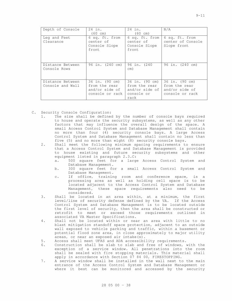
9-11
Depth of Console 24 in. (60 cm)
24 in. (60 cm)
N/A
Leg and Feet Clearance
6 sq. ft. from center of Console Slope front
6 sq. ft. from center of Console Slope front
6 sq. ft. from center of Console Slope front
Distance Between Console Rows
96 in. (240 cm) 96 in. (240 cm)
96 in. (240 cm)
Distance Between Console and Wall
36 in. (90 cm) from the rear and/or side of console or rack
36 in. (90 cm) from the rear and/or side of console or rack
36 in. (90 cm) from the rear and/or side of console or rack
C. Security Console Configuration: 1. The size shall be defined by the number of console bays required
to house and operate the security subsystems, as well as any other factors that may influence the overall design of the space. A small Access Control System and Database Management shall contain no more than four (4) security console bays. A large Access Control System and Database Management shall contain no less than five (5) and no more than eight (8) security console bays.
2. Shall meet the following minimum spacing requirements to ensure that a Access Control System and Database Management is provided to house existing and future security subsystems and other equipment listed in paragraph 2.3.C: a. 500 square feet for a large Access Control System and
Database Management. b. 300 square feet for a small Access Control System and
Database Management. c. If office, training room and conference space, is a
processing area as well as holding cell space is to be located adjacent to the Access Control System and Database Management, these space requirements also need to be considered.
3. Shall be located in an area within, at a minimum, the first level/line of security defense defined by the VA. If the Access Control System and Database Management is to be located outside the first level of security, then the area shall be constructed or retrofit to meet or exceed those requirements outlined in associated VA Master Specifications.
4. Shall not be located within or near an area with little to no blast mitigation standoff space protection, adjacent to an outside wall exposed to vehicle parking and traffic, within a basement or potential flood zone area, in close approximately to major utility areas, or near an exposed air intake(s).
5. Access shall meet UFAS and ADA accessibility requirements. 6. Construction shall be slab to slab and free of windows, with the
exception of a service window. All penetrations into the room shall be sealed with fire stopping materials. This material shall apply in accordance with Section 07 84 00, FIRESTOPPING.
7. A service window shall be installed in the wall next to the main entrance of the Access Control System and Database Management or where it best can be monitored and accessed by the security
28 05 00 - 38
9-11
console operator. The window shall meet all requirements set forth in UL 752, to include at a minimum, Class III ballistic level protection. The windows shall be set in a minimum or four (4) inches (100 mm) solid concrete units to ceiling height with either masonry or gypsum wall board to the underside of the slab above. It shall also contain a service tray constructed in a manner that only objects no larger than 3 inches (7.5 cm) in width may pass through it.
8. The walls making up or surrounding the Access Control System and Database Management shall be made of materials that at a minimum offer Class III ballistic level protection for the security console operator(s).
9. There will be a main power cut-off button/switch located inside the Access Control System and Database Management in the event of an electrical fire or related event occurs.
10. Shall have a fire alarm detection unit that is tied into the main building fire alarm system and have at least two fire extinguishers located within it.
11. Shall utilize a fire suppression system similar to that used by the VA’s computer and telecommunications room operating areas.
12. The floor shall be raised a minimum of 4 inches (10 cm) from the concrete floor base. Wire ways shall be utilized under the raised floor for separation of signal and power wires and cables.
13. Access shall be monitored and controlled by the PACS via card reader and fixed camera that utilizes a wide angle lens. A 1 in. (2.5 cm) deadbolt shall be utilized as a mechanical override for the door in the event of electrical failure of the PACS, card reader, or locking mechanism.
14. There shall only be one point of ingress and egress to and from the Security Control Room. The door shall be made of solid core wood or better. If a window is required for the door, then the window shall be ballistic resistant with a Millar covering.
15. A two-way intercom shall be placed at the point of entry into the Security Control Room for access-communication control purposes.
16. A remote push-button door unlocking device shall not be installed for the electronic PACS locking mechanism providing access control into the Security Control Room.
17. All controlling equipment and power supplies that must be wall mounted shall be mounted in a manner that maximizes usability of the Security Control Room wall space. All equipment shall be mounted to three quarter inch fire retardant plywood. The plywood shall be fastened to the wall from slab to slab and fixed to the existing walls supports.
D. Security Control Room Ventilation 1. Shall meet or exceed all requirements laid out in VA Master
Specification listed in Division 23, HEATING, VENTILATION, AND AIR CONDITIONING.
2. Controls shall be via a separate air handling system that provides an isolated supply and return system. The Security Control Room shall have a dedicated thermostat control unit and cut-off switch to be able to shut off ventilation to the control room in the event of a chemical, biological, or radiological (CBR) event or other related emergency.
3. There shall be a louver installed in the control room door to assist with ventilation of the room. The louver shall be exactly 12 x 12 inches (30 x 30 cm) and closeable.
E. Security Control Room and Security Console Lighting: 1. The following factors shall be taken into consideration for
lighting of the Security Control Room and console area:
28 05 00 - 39
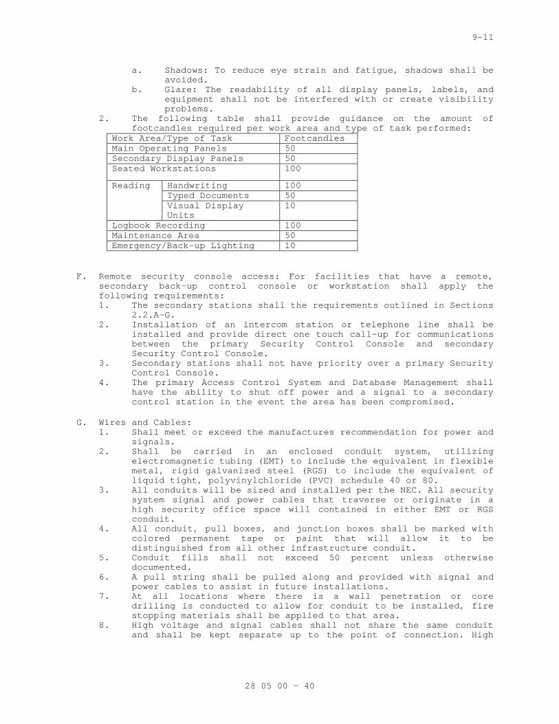
9-11
a. Shadows: To reduce eye strain and fatigue, shadows shall be avoided.
b. Glare: The readability of all display panels, labels, and equipment shall not be interfered with or create visibility problems.
2. The following table shall provide guidance on the amount of footcandles required per work area and type of task performed:
Work Area/Type of Task Footcandles Main Operating Panels 50 Secondary Display Panels 50 Seated Workstations 100
Reading Handwriting 100 Typed Documents 50 Visual Display Units
10
Logbook Recording 100 Maintenance Area 50 Emergency/Back-up Lighting 10
F. Remote security console access: For facilities that have a remote, secondary back-up control console or workstation shall apply the following requirements: 1. The secondary stations shall the requirements outlined in Sections
2.2.A-G. 2. Installation of an intercom station or telephone line shall be
installed and provide direct one touch call-up for communications between the primary Security Control Console and secondary Security Control Console.
3. Secondary stations shall not have priority over a primary Security Control Console.
4. The primary Access Control System and Database Management shall have the ability to shut off power and a signal to a secondary control station in the event the area has been compromised.
G. Wires and Cables: 1. Shall meet or exceed the manufactures recommendation for power and
signals. 2. Shall be carried in an enclosed conduit system, utilizing
electromagnetic tubing (EMT) to include the equivalent in flexible metal, rigid galvanized steel (RGS) to include the equivalent of liquid tight, polyvinylchloride (PVC) schedule 40 or 80.
3. All conduits will be sized and installed per the NEC. All security system signal and power cables that traverse or originate in a high security office space will contained in either EMT or RGS conduit.
4. All conduit, pull boxes, and junction boxes shall be marked with colored permanent tape or paint that will allow it to be distinguished from all other infrastructure conduit.
5. Conduit fills shall not exceed 50 percent unless otherwise documented.
6. A pull string shall be pulled along and provided with signal and power cables to assist in future installations.
7. At all locations where there is a wall penetration or core drilling is conducted to allow for conduit to be installed, fire stopping materials shall be applied to that area.
8. High voltage and signal cables shall not share the same conduit and shall be kept separate up to the point of connection. High
28 05 00 - 40
9-11
voltage for the security subsystems shall be any cable or sets of cables carrying 30 VDC/VAC or higher.
9. For all equipment that is carrying digital data between the Security Control Room, Security Equipment Room, Security Console, or at a remote monitoring station, it shall not be less that 20 AWG and stranded copper wire for each conductor. The cable or each individual conductor within the cable shall have a shield that provides 100% coverage. Cables with a single overall shield shall have a tinned copper shield drain wire.
2.03 FIBER OPTIC EQUIPMENT
A. 8 Channel Fiber Optic Transcievers (Video&PTZ Control) 1. The field-located and central-located fiber optic transceivers
shall utilize wave division multiplexing to transmit and receive video and data pan-tilt-zoom control signals over two standard 62.5/125 multimode fibers.
2. The units shall be capable of operating over a range of 2 km. 3. The units shall be NTSC color compatible. 4. The units shall support data rates up to 64 Kbps. 5. The units shall be surface or rack mountable. 6. The units shall be UL listed. 7. The units shall meet or exceed the following specifications:
a. Video 1) Input/Output: 1 volt pk-pk (75 ohms) 2) Input/Output Channels: 8 3) Bandwidth: 10 Hz - 6.5 MHZ per channel 4) Differential Gain: <2% 5) Differential Phase: <0.7° 6) Tilt: <1% 7) Signal to Noise Ratio: 60 dB
b. Data (Control) 1) Data Channels: 2 2) Data Format: RS-232, RS-422, 2 wire or 4 wire RS-
485 with Tri-State Manchester Bi-Phase and Sensornet 3) Data Rate: DC - 100 kbps (NRZ) 4) Bit Error Rate: < 1 in 10-9 @ Maximum Optical Loss
Budget 5) Operating Mode: Simplex or Full-Duplex 6) Wavelength: 1310/1550 nm, Multimode or Singlemode 7) Optical Emitter: Laser Diode 8) Number of Fibers: 1
c. Connectors 1) Optical: ST 2) Power and Data: Terminal Block with Screw Clamps 3) Video: BNC (Gold Plated Center-Pin)
d. Electrical and Mechanical 1) Power: 12 VDC @ 500 mA (stand-alone) 2) Current Protection: Automatic Resettable Solid-
State Current Limiters e. Environmental
1) MTBF: > 100,000 hours 2) Operating Temp: -40 to 74 deg C (-40 to 165 deg F) 3) Storage Temp: -40 to 85 deg C (-40 to 185 deg F) 4) Relative Humidity: 0% to 95% (non-condensing)
B. Fiber Optic Transmitters: The central-located fiber optic transmitters shall utilize wave division multiplexing to transmit video and signals over standard 62.5/125 multimode fibers. 1. The units shall be capable of operating over a range of 4.8 km.
28 05 00 - 41
9-11
2. The units shall be NTSC color compatible. 3. The units shall support data rates up to 64 Kbps. 4. The units shall be surface or rack mountable. 5. The units shall be UL listed. 6. The units shall meet or exceed the following specifications:
a. Video 1) Input: 1 volt pk-pk (75 ohms) 2) Bandwidth: 5H2 - 10 MHZ 3) Differential Gain: <5% 4) Tilt: <1% 5) Signal-Noise: 60db 6) Wavelength: 850nm 7) Number of Fibers: 1 8) Operating Temp: -20 to 70 deg C (-4 to 158 deg F) 9) Connectors:
a) Power: Female plug with screw clamps b) Video: BNC c) Optical: ST
10) Power: 12 VDC
C. Fiber Optic Receivers: The field-located fiber optic receivers shall utilize wave division multiplexing to receive video signals over standard 62.5/125 multimode fiber. 1. The units shall be capable of operating over a range of 4.8 km. 2. The units shall be NTSC color compatible. 3. 3. The units shall support data rates up to 64 Kbps. 4. 4. The units shall be surface or rack mountable. 5. 5. The units shall be UL listed. 6. 6. The units shall meet or exceed the following specifications:
a. Video 1) Output: 1 volt pk-pk (75 ohms) 2) Bandwidth: 5H2 - 10 MHZ 3) Differential Gain: <5% 4) Tilt: <1% 5) Signal-Noise: 60dB 6) Wavelength: 850nm 7) Number of Fibers: 1 8) Surface Mount: 106.7 x 88.9 x 25.4 mm (4.2 x 3.5 x
1 in) 9) Operating Temp: -20 to 70 deg C (-4 to 158 deg F) 10) Connectors: 11) Power: Female plug block with screw clamps 12) Video: BNC 13) Optical: ST 14) Power: 12 VAC8 Channel Fiber Optic Transcievers
(Video&PTZ Control)
D. Fiber Optic Sub Rack with Power Supply 1. The Card Cage Rack shall provide high-density racking for fiber-
optic modules. The unit shall be designed to mount in standard 483 mm (19 in) instrument racks and to accommodate the equivalent of 15 1-inch modules. a. Specifications
1) Card Orientation: Vertical 2) Construction: Aluminum 3) Current Consumption: 0.99 A 4) Humidity: 95.0 % RH 5) Input Power: 100-240 VAC, 60/50 Hz 6) Mounting: Mounts in standard 483 mm (19 in) rack
using four (4) screws (optional wall brackets purchased separately)
28 05 00 - 42
9-11
7) Number of Outputs: 1.0 8) Number of Slots 15.0 9) Operating Temperature: -40 to +75 deg C (-40.0 to
167.0 deg F) 10) Ouput Voltage: 13.5 V 11) Output Current 6.0 A 12) Power Dissipation: 28.0 W 13) Power Factor: 48.0 14) Power Supply: (built-in) 15) Rack Units: 3RU 16) Redundant Capability: Yes 17) Weight: 2.43 kg (5.35 lb) 18) Width: 483 mm (19.0 in)
2.04 TRANSIENT VOLTAGE SURGE SUPPRESSION DEVICES (TVSS) AND SURGE SUPPRESION
A. Transient Voltage Surge Suppression 1. All cables and conductors extending beyond building perimeter,
except fiber optic cables, which serve as communication, control, or signal lines shall be protected against Transient Voltage surges and have Transient Voltage surge suppression protection (TVSS) UL listed in accordance with Standard 497B installed at each end. Lighting and surge suppression shall be a multi-strike variety and include a fault indicator. Protection shall be furnished at the equipment and additional triple solid state surge protectors rated for the application on each wire line circuit shall be installed within 915 mm (36 in) of the building cable entrance. Fuses shall not be used for surge protection. The inputs and outputs shall be tested in both normal mode and common mode using the following waveforms: a. A 10-microsecond rise time by 1000 microsecond pulse width
waveform with a peak voltage of 1500 volts and a peak current of 60 amperes.
b. An 8-microsecond rise time by 20-microsecond pulse width waveform with a peak voltage of 1000 volts and a peak current of 500 amperes.
c. Maximum series current: 2 AMPS. Provide units manufactured by Advanced Protection Technologies, model # TE/FA 10B or TE/FA 20B or approved equivalent.
d. Operating Temperature and Humidity: -40 to + 85 deg C (-40 to 185 deg F), and 0 to 95 percent relative humidity, non-condensing.
B. Physical Access Control Systems 1. Suppressors shall be installed on AC power at the point of service
and shall meet the following criteria: a. UL1449 2nd Edition, 2007, listed b. UL1449 S.V.R. of 400 Volts or lower c. Status Indicator Light(s) d. Minimum Surge Current Capacity: 40,000 Amps (8 x 20 µsec) e. Maximum Continuous Current: 15 Amps f. MCOV: 125 VAC g. Service Voltage: 110-120 VAC
2. Suppressors shall be installed on the Low Voltage circuit at both the point of entrance and exit of the building. Suppressors shall meet the following criteria: a. UL 497B b. Minimum Surge Current Capacity: 2,000 Amps per pair c. Maximum Continuous Current: 5 Amps d. MCOV: 33 Volts
28 05 00 - 43
9-11
e. Service Voltage: 24Volts 3. Suppressors shall be installed on the communication circuit
between the access controller and card reader at both the entrance and exit of the building. Suppressors shall meet the following criteria: a. Conforms with UL497B standards (where applicable) b. Clamp level for 12 and 24V power: 18VDC / 38VDC c. Clamp level for Data/LED: 6.8VDC d. Service Voltage for Power: 12VDC/24VDC e. Service Voltage for Data/LED: <5VDC f. Clamp level – PoE Access Power: 72V g. Clamp level – PoE Access Data: 7.9V h. Service Voltage – PoE Access: 48VAC – 54VAC i. Service Voltage – PoE Data: <5VDC
C. Intercom Systems 1. Suppressors shall be installed on the AC power at the point of
service and shall meet the following criteria: a. UL 1449 Listed b. UL 1449 S.V.R. of 400 Volts or lower c. Diagnostic Indicator Light(s) d. Integrated ground terminating post (where case/chassis
ground exists) e. Minimum Surge Current Capacity of 13,000 Amps (8 x 20 µSec)
2. Suppressors shall be installed on incoming central office lines and shall meet the following criteria: a. UL 497A Listed b. Multi Stage protection design c. Auto-reset current protection not to exceed 2 Amps per pair d. Minimum Surge Current of 500 Amps per pair (8 x 20 µSec)
3. Suppressors shall be installed on all telephone/intercom circuits that enter or leave separate buildings and shall meet the following criteria: a. UL 497A Listed (where applicable) b. UL 497B Listed (horns, strobes, speakers or communication
circuits over 300 feet) c. Multi Stage protection design d. Auto-reset over-current protection not to exceed 5 Amps per
pair e. Minimum Surge Current of 1000 Amps per pair (8 x 20 µSec)
D. Intrusion Detection Systems 1. Suppressors shall be installed on AC at the point of service and
shall meet the following criteria: a. UL 1449, 2nd Edition 2007, listed b. UL 1449 S.V.R. of 400 Volts or lower c. Status Indicator Lights d. Center screw for terminating Class II transformers e. Minimum Surge Current Capacity of 32,000 Amps (8 x 20 µSec)
2. Suppressors shall be installed on all Telephone Communication Interface circuits and shall meet the following criteria: a. UL 497A Listed b. Multi Stage protection design c. Surge Current Capacity: 9,000 Amps (8x20 µSec) d. Clamp Voltage: 130Vrms e. Auto reset current protection not to exceed 150 milliAmps
3. Suppressors shall be installed on all burglar alarm initiating and signaling loops and addressable circuits which enter or leave separate buildings. The following criteria shall be met: a. UL 497B for data communications or annunciation
(powered loops)
28 05 00 - 44
9-11
b. Fail-short/fail-safe mode. c. Surge Current Capacity: 9,000 Amps (8x20 µSec) d. Clamp Voltage: 15 Vrms e. Joule Rating: 76 Joules per pair (10x1000 µSec) f. Auto-reset current protection not to exceed 150 milliAmps
for UL 497A devices.
E. Video Surveillance System 1. Protectors shall be installed on coaxial cable systems on points
of entry and exit from separate buildings. Suppressors shall be installed at each exterior camera location and include protection for 12 and/or 24 volt power, data signal and motor controls (for Pan, Tilt and Zoom systems). SPDs shall protect all modes herein mentioned and contain all modes in a single unit system. Protection for all systems mentioned above shall be incorporated at the head end equipment. Additionally a minimum 450VA battery back up shall be used to protect the DVR or VCR and monitor. Protectors shall meet the following criteria: a. Head-End Power
1) UL 1778, cUL (Battery Back Up) 2) Minimum Surge Current Capacity: 65,000 Amps
(8x20µsec) 3) Minimum of two (2) NEMA 5-15R Receptacles (one (1) AC
power only, one (1) with UPS) 4) All modes protected (L-N, L-G, N-G) 5) EMI/RFI Filtering 6) Maximum Continuous Current: 12 Amps
b. Camera Power 1) Minimum Surge Current Capacity: 1,000 Amps
(8X20µsec); 240 Amps for IP Video/PoE cameras 2) Screw Terminal Connection 3) All protection modes L-G (all Lines) 4) MCOV <40VAC
c. Video And Data 1) Surge Current Capacity 1,000 Amps per conductor 2) “BNC” Connection (Coax) 3) Protection modes: L-G (Data), Center Pin-G, Shield-G
(Coax) 4) Band Pass 0-2GHz 5) Insertion Loss <0.3dB
F. Grounding and Surge Suppression 1. The Security Contractor shall provide grounding and surge
suppression to stabilize the voltage under normal operating conditions. This is to ensure the operation of over current devices, such as fuses, circuit breakers, and relays, underground-fault conditions.
2. The Contractor shall engineer, provide, ad install proper grounding and surge suppression as required by local jurisdiction and prevailing codes and standards, referenced in this document.
3. Principal grounding components and features shall include: main grounding buses, grounding, and bonding connections to service equipment.
4. The Contractor shall provide detail drawings of interconnection with other grounding systems including lightning protection systems.
5. The Contractor shall provide details of locations and sizes of grounding conductors and grounding buses in electrical, data, and communication equipment rooms and closets.
6. AC power receptacles are not to be used as a ground reference point.
28 05 00 - 45
9-11
7. Any cable that is shielded shall require a ground in accordance with applicable codes, the best practices of the trade, and all manufactures’ installation instructions.
G. 120 VAC Surge Suppression 1. Continuous Current: Unlimited (parallel connection) 2. Max Surge Current: 13,500 Amps 3. Protection Modes: L - N, L - G, N - G 4. Warranty: Ten Year Limited Warranty 5. Dimension: 73.7 x 41.1 x 52.1 mm (2.90 x 1.62 x 2.05 in) 6. Weight: 2.88 g (0.18 lbs) 7. Housing: ABS
2.05 INSTALLATION KIT
A. General: 1. The kit shall be provided that, at a minimum, includes all
connectors and terminals, labeling systems, audio spade lugs, barrier strips, punch blocks or wire wrap terminals, heat shrink tubing, cable ties, solder, hangers, clamps, bolts, conduit, cable duct, and/or cable tray, etc., required to accomplish a neat and secure installation. All wires shall terminate in a spade lug and barrier strip, wire wrap terminal or punch block. Unfinished or unlabeled wire connections shall not be allowed. All unused and partially opened installation kit boxes, coaxial, fiber-optic, and twisted pair cable reels, conduit, cable tray, and/or cable duct bundles, wire rolls, physical installation hardware shall be turned over to the Contracting Officer. The following sections outline the minimum required installation sub-kits to be used:
2. System Grounding: a. The grounding kit shall include all cable and installation
hardware required. All head end equipment and power supplies shall be connected to earth ground via internal building wiring, according to the NEC.
b. This includes, but is not limited to: 1) Coaxial Cable Shields 2) Control Cable Shields 3) Data Cable Shields 4) Equipment Racks 5) Equipment Cabinets 6) Conduits 7) Cable Duct blocks 8) Cable Trays 9) Power Panels 10) Grounding 11) Connector Panels
3. Coaxial Cable: The coaxial cable kit shall include all coaxial connectors, cable tying straps, heat shrink tabbing, hangers, clamps, etc., required to accomplish a neat and secure installation.
4. Wire and Cable: The wire and cable kit shall include all connectors and terminals, audio spade lugs, barrier straps, punch blocks, wire wrap strips, heat shrink tubing, tie wraps, solder, hangers, clamps, labels etc., required to accomplish a neat and orderly installation.
5. Conduit, Cable Duct, and Cable Tray: The kit shall include all conduit, duct, trays, junction boxes, back boxes, cover plates, feed through nipples, hangers, clamps, other hardware required to accomplish a neat and secure conduit, cable duct, and/or cable tray installation in accordance with the NEC and this document.
28 05 00 - 46

9-11
6. Equipment Interface: The equipment kit shall include any item or quantity of equipment, cable, mounting hardware and materials needed to interface the systems with the identified sub-system(s) according to the OEM requirements and this document.
7. Labels: The labeling kit shall include any item or quantity of labels, tools, stencils, and materials needed to label each subsystem according to the OEM requirements, as-installed drawings, and this document.
8. Documentation: The documentation kit shall include any item or quantity of items, computer discs, as installed drawings, equipment, maintenance, and operation manuals, and OEM materials needed to provide the system documentation as required by this document and explained herein.
PART 3 - EXECUTION
3.01 COMMON REQUIREMENTS FOR ELECTRONIC SAFETY AND SECURITY INSTALLATION
A. Comply with NECA 1.
B. Measure indicated mounting heights to bottom of unit for suspended items and to center of unit for wall-mounting items.
C. Headroom Maintenance: If mounting heights or other location criteria are not indicated, arrange and install components and equipment to provide maximum possible headroom consistent with these requirements.
D. Equipment: Install to facilitate service, maintenance, and repair or replacement of components of both electronic safety and security equipment and other nearby installations. Connect in such a way as to facilitate future disconnecting with minimum interference with other items in the vicinity.
E. Right of Way: Give to piping systems installed at a required slope.
F. Equipment location shall be as close as practical to locations shown on the drawings.
G. Inaccessible Equipment: 1. Where the Government determines that the Contractor has installed
equipment not conveniently accessible for operation and maintenance, the equipment shall be removed and reinstalled as directed at no additional cost to the Government.
2. "Conveniently accessible" is defined as being capable of being reached without the use of ladders, or without climbing or crawling under or over obstacles such as, but not limited to, motors, pumps, belt guards, transformers, piping, ductwork, conduit and raceways.
3.02 FIRESTOPPING
A. Apply firestopping to penetrations of fire-rated floor and wall assemblies for electronic safety and security installations to restore original fire-resistance rating of assembly. Firestopping materials and installation requirements are specified in Division 07 Section 07 84 00 "Firestopping."
28 05 00 - 47
9-11
3.03 COMMISIONING
A. Provide commissioning documentation in accordance with the requirements of Section 28 08 00 – COMMISIONIN OF ELECTRONIC SAFETY AND SECURITY SYSTEMS for all inspection, start up, and contractor testing required above and required by the System Readiness Checklist provided by the Commissioning Agent.
B. Components provided under this section of the specification will be tested as part of a larger system. Refer to section 28 08 00 – COMMISIONING OF ELECTRONIC SAFETY AND SECURITY SYSTEMS and related sections for contractor responsibilities for system commissioning.
3.04 DEMONSTRATION AND TRAINING
A. Training shall be provided in accordance with Article, INSTRUCTIONS, of Section 01 00 00, GENERAL REQUIREMENTS.
B. Training shall be provided for the particular equipment or system as required in each associated specification.
C. A training schedule shall be developed and submitted by the contractor and approved by the Resident Engineer at least 30 days prior to the planned training.
D. Provide services of manufacturer’s technical representative for <insert hours> hours to instruct VA personnel in operation and maintenance of units.
E. Submit training plans and instructor qualifications in accordance with the requirements of Section 28 08 00 – COMMISIONING OF ELECTRONIC SAFETY AND SECURITY SYSTEMS.
3.05 WORK PERFORMANCE
A. Job site safety and worker safety is the responsibility of the contractor.
B. For work on existing stations, arrange, phase and perform work to assure electronic safety and security service for other buildings at all times. Refer to Article OPERATIONS AND STORAGE AREAS under Section 01 00 00, GENERAL REQUIREMENTS.
C. New work shall be installed and connected to existing work neatly and carefully. Disturbed or damaged work shall be replaced or repaired to its prior conditions, as required by Section 01 00 00, GENERAL REQUIREMENTS.
D. Coordinate location of equipment and conduit with other trades to minimize interferences. See the GENERAL CONDITIONS.
3.06 SYSTEM PROGRAMMING
A. General Programming Requirements 1. This following section shall be used by the contractor to identify
the anticipated level of effort (LOE) required setup, program, and configure the Electronic Security System (ESS). The contractor shall be responsible for providing all setup, configuration, and programming to include data entry for the Security Management
28 05 00 - 48
9-11
System (SMS) and subsystems [(e.g., video matrix switch, intercoms, digital video recorders, intrusion devices, including integration of subsystems to the SMS (e.g., camera call up, time synchronization, intercoms)]. System programming for existing or new SMS servers shall not be conducted at the project site.
B. Level of Effort for Programming 1. The Contractor shall perform and complete system programming
(including all data entry) at an offsite location using the Contractor’s own copy of the SMS software. The Contractor’s copy of the SMS software shall be of the Owners current version. Once system programming has been completed, the Contractor shall deliver the data to the Resident Engineer on data entry forms and an approved electronic medium, utilizing data from the contract documents. The completed forms shall be delivered to the Resident Engineer for review and approval at least 90 calendar days prior to the scheduled date the Contractor requires it. The Contractor shall not upload system programming until the Resident Engineer has provided written approval. The Contractor is responsible for backing up the system prior to uploading new programming data. Additional programming requirements are provided as follows: a. Programming for New SMS Server: The contractor shall
provide all other system related programming. The contractor will be responsible for uploading personnel information (e.g., ID Cards backgrounds, names, access privileges, personnel photos, access schedules, personnel groupings) along with coordinating with Resident Engineer for device configurations, standards, and groupings. VA shall provide database to support Contractor’s data entry tasks. The contractor shall anticipate a weekly coordination meeting and working with Resident Engineer to ensure data uploading is performed without incident of loss of function or data loss.
b. Programming for Existing SMS Servers: The contractor shall perform all related system programming except for personnel data as noted. The contractor will not be responsible for uploading personnel information (e.g., ID Cards backgrounds, names, access privileges, access schedules, personnel groupings). The contractor shall anticipate a weekly coordination meeting and working alongside of Resident Engineer to ensure data uploading is performed without incident of loss of function or data loss. System programming for SMS servers shall be performed by using the Contractor’s own server and software. These servers shall not be connected to existing devices or systems at any time.
2. The Contractor shall identify and request from the Resident Engineer, any additional data needed to provide a complete and operational system as described in the contract documents.
3. Contractor and Resident Engineer coordination on programming requires a high level of coordination to ensure programming is performed in accordance with VA requirements and programming uploads do not disrupt existing systems functionality. The contractor shall anticipate a minimum a weekly coordination meeting. Contractor shall ensure data uploading is performed without incident of loss of function or data loss. The following Level of Effort Chart is provided to communicate the expected level of effort required by contractors on VA ESS projects. Calculations to determine actual levels of effort shall be confirmed by the contractor before project award.
28 05 00 - 49
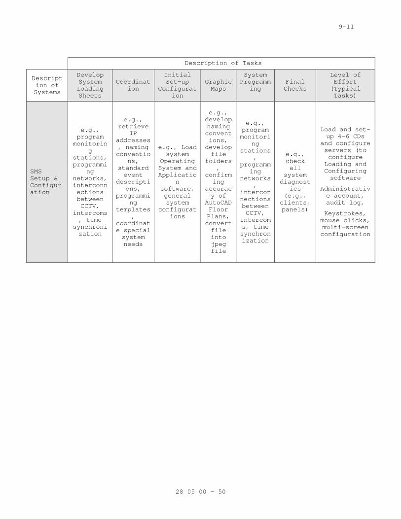
9-11
Description of Tasks
Description of Systems
Develop System Loading Sheets
Coordination
Initial Set-up
Configuration
Graphic Maps
System Programm
ing Final Checks
Level of Effort (Typical Tasks)
SMS Setup & Configuration
e.g., program monitorin
g stations, programmi
ng networks, interconnections between CCTV,
intercoms, time
synchronization
e.g., retrieve
IP addresses, naming conventio
ns, standard event
descriptions,
programming
templates,
coordinate special system needs
e.g., Load system
Operating System and Applicatio
n software, general system
configurations
e.g., develop naming conventions, develop file
folders,
confirming
accuracy of
AutoCAD Floor Plans, convert file into jpeg file
e.g., program monitori
ng stations
, programm
ing networks
, interconnections between CCTV,
intercoms, time synchronization
e.g., check all
system diagnost
ics (e.g., clients, panels)
Load and set-up 4-6 CDs
and configure servers (to configure Loading and Configuring software
Administrative account, audit log,
Keystrokes, mouse clicks, multi-screen configuration
28 05 00 - 50
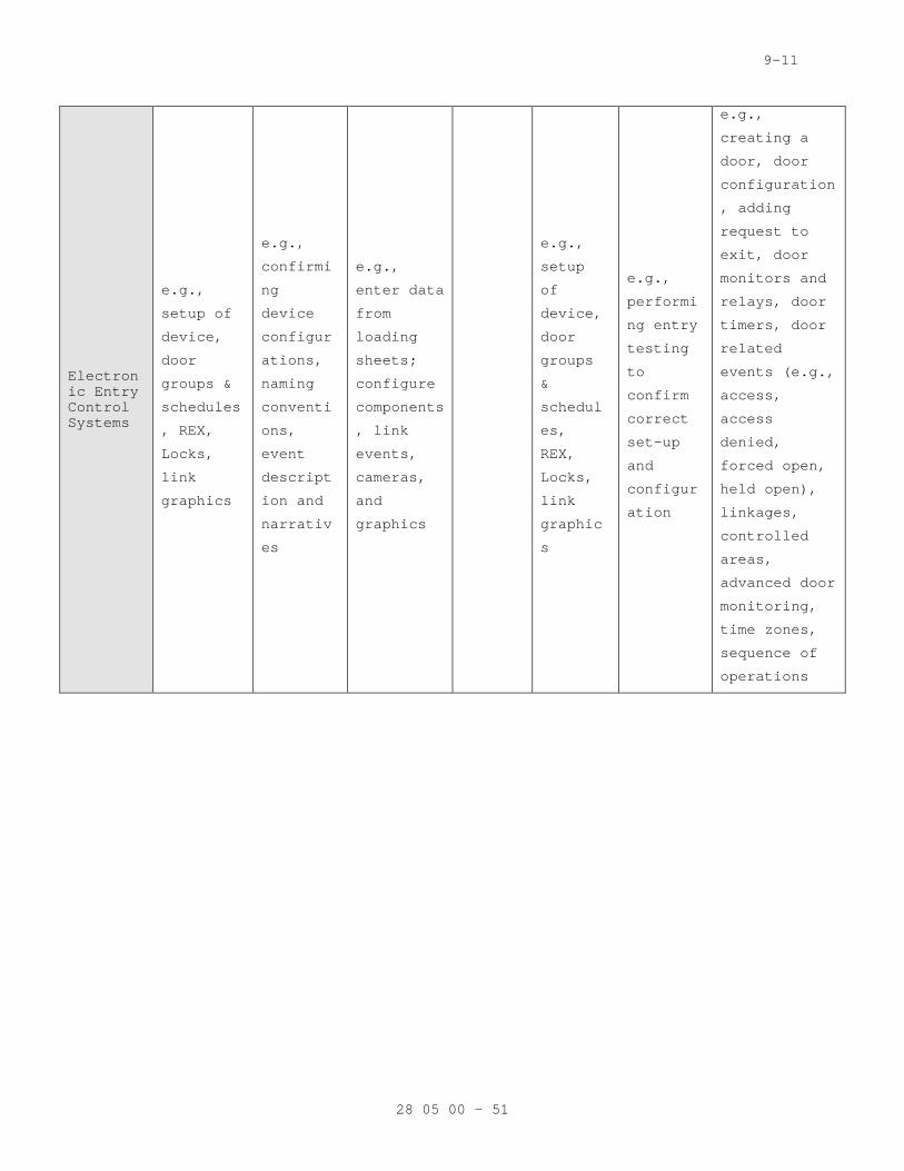
9-11
Electronic Entry Control Systems
e.g.,
setup of
device,
door
groups &
schedules
, REX,
Locks,
link
graphics
e.g.,
confirmi
ng
device
configur
ations,
naming
conventi
ons,
event
descript
ion and
narrativ
es
e.g.,
enter data
from
loading
sheets;
configure
components
, link
events,
cameras,
and
graphics
e.g.,
setup
of
device,
door
groups
&
schedul
es,
REX,
Locks,
link
graphic
s
e.g.,
performi
ng entry
testing
to
confirm
correct
set-up
and
configur
ation
e.g.,
creating a
door, door
configuration
, adding
request to
exit, door
monitors and
relays, door
timers, door
related
events (e.g.,
access,
access
denied,
forced open,
held open),
linkages,
controlled
areas,
advanced door
monitoring,
time zones,
sequence of
operations
28 05 00 - 51
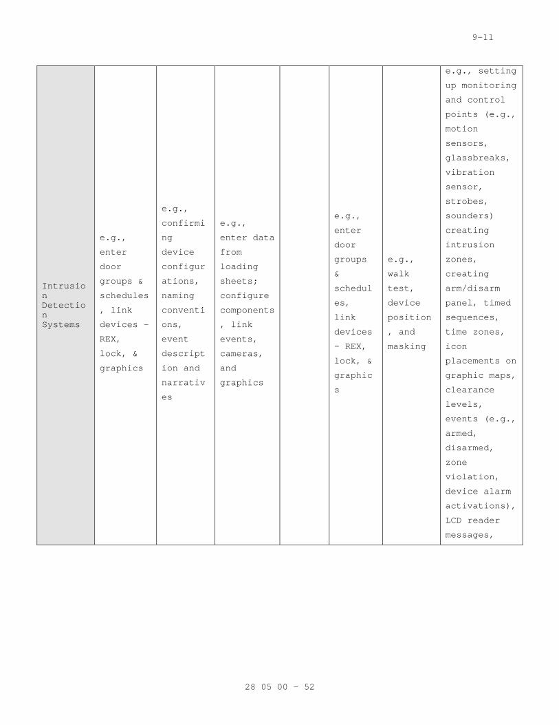
9-11
Intrusion Detection Systems
e.g.,
enter
door
groups &
schedules
, link
devices -
REX,
lock, &
graphics
e.g.,
confirmi
ng
device
configur
ations,
naming
conventi
ons,
event
descript
ion and
narrativ
es
e.g.,
enter data
from
loading
sheets;
configure
components
, link
events,
cameras,
and
graphics
e.g.,
enter
door
groups
&
schedul
es,
link
devices
- REX,
lock, &
graphic
s
e.g.,
walk
test,
device
position
, and
masking
e.g., setting
up monitoring
and control
points (e.g.,
motion
sensors,
glassbreaks,
vibration
sensor,
strobes,
sounders)
creating
intrusion
zones,
creating
arm/disarm
panel, timed
sequences,
time zones,
icon
placements on
graphic maps,
clearance
levels,
events (e.g.,
armed,
disarmed,
zone
violation,
device alarm
activations),
LCD reader
messages,
28 05 00 - 52
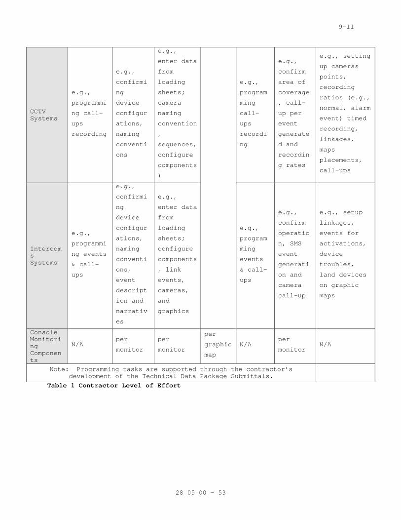
9-11
CCTV Systems
e.g.,
programmi
ng call-
ups
recording
e.g.,
confirmi
ng
device
configur
ations,
naming
conventi
ons
e.g.,
enter data
from
loading
sheets;
camera
naming
convention
,
sequences,
configure
components
)
e.g.,
program
ming
call-
ups
recordi
ng
e.g.,
confirm
area of
coverage
, call-
up per
event
generate
d and
recordin
g rates
e.g., setting
up cameras
points,
recording
ratios (e.g.,
normal, alarm
event) timed
recording,
linkages,
maps
placements,
call-ups
Intercoms Systems
e.g.,
programmi
ng events
& call-
ups
e.g.,
confirmi
ng
device
configur
ations,
naming
conventi
ons,
event
descript
ion and
narrativ
es
e.g.,
enter data
from
loading
sheets;
configure
components
, link
events,
cameras,
and
graphics
e.g.,
program
ming
events
& call-
ups
e.g.,
confirm
operatio
n, SMS
event
generati
on and
camera
call-up
e.g., setup
linkages,
events for
activations,
device
troubles,
land devices
on graphic
maps
Console Monitoring Components
N/A per
monitor
per
monitor
per
graphic
map
N/A per
monitor N/A
Note: Programming tasks are supported through the contractor’s development of the Technical Data Package Submittals.
Table 1 Contractor Level of Effort
28 05 00 - 53
9-11
3.07 TESTING AND ACCEPTANCE
A. Performance Requirements 1. General:
a. The Contractor shall perform contract field, performance verification, and endurance testing and make adjustments of the completed security system when permitted. The Contractor shall provide all personnel, equipment, instrumentation, and supplies necessary to perform all testing. Written notification of planned testing shall be given to the Resident Engineer at least 60 calendar days prior to the test and after the Contractor has received written approval of the specific test procedures.
b. The COTR shall witness all testing and system adjustments during testing. Written permission shall be obtained from the Resident Engineer before proceeding with the next phase of testing. Original copies of all data produced during performance verification and endurance testing shall be turned over to the Resident Engineer at the conclusion of each phase of testing and prior to Resident Engineer approval of the test.
2. Test Procedures and Reports: The test procedures, compliant w/ VA standard test procedures, shall explain in detail, step-by-step actions and expected results demonstrating compliance with the requirements of the specification. The test reports shall be used to document results of the tests. The reports shall be delivered to the Resident Engineer within seven (7) calendar days after completion of each test.
B. Pre-Delivery Testing 1. The purpose of the pre-delivery test is to establish that a system
is suitable for installation. As such, pre-delivery test shall be a mock-up of the system as planned in the contract documents. The Contractor shall assemble the Security Test System at the Contractors local project within 50-miles of the project site, and perform tests to demonstrate the performance of the system complies with the contract requirements in accordance with the approved pre-delivery test procedures. The tests shall take place during regular daytime working hours on weekdays. Model numbers of equipment tested shall be identical to those to be delivered to the site. Original copies of all data produced during pre-delivery testing, including results of each test procedure, shall be documented and delivered to the Resident Engineer at the conclusion of pre-delivery testing and prior to Resident Engineer’s approval of the test. The test report shall be arranged so all commands, stimuli, and responses are correlated to allow logical interpretation. For Existing System modifications, the contractor shall provide their own server with loaded applicable software to support PDT.
2. Test Setup: The pre-delivery test setup shall include the following: a. All console equipment.
1) At least one of each type of data transmission media (DTM) and associated equipment to provide a fully integrated PACS.
2) The number of local processors shall equal the amount required by the site design.
28 05 00 - 54
9-11
3) Enough sensor simulators to provide alarm signal inputs to the system equal to the number of sensors required by the design. The alarm signals shall be manually or software generated.
4) Contractor to prove to owner all systems are appropriately sized and configured as sized.
5) Integration of VASS, intercom systems, other subsystems.
3. During the bidding process the contractor shall submit a request for information to the Owner to determine if a pre-delivery test will be required. If a pre-delivery test is not required, the contractor shall provide a written notification that the Pre-delivery Test is not required in their shop drawings submission.
C. Intermediate Testing 1. After completion of 30-50 percent of the installation of ESS
cabinet(s) and equipment, one local and remote control stations and prior to any further work, this portion of the system must be pretested, inspected, and certified. Each item of installed equipment shall be checked to ensure appropriate FCC listing & UL certification labels are affixed, NFPA, Emergency, Safety, and JCAHCO guidelines are followed, and proper installation practices are followed. The intermediate test shall include a full operational test.
D. The inspection and test will be conducted by a factory-certified contractor representative and witnessed by a Government Representative. The results of the inspection will be officially recorded by a designated Government Representative and maintained on file by the Resident Engineer (RE), until completion of the entire project. The results will be compared to the Acceptance Test results.
E. Contractor’s Field Testing (CFT) 1. The Contractor shall calibrate and test all equipment, verify DTM
operation, place the integrated system in service, and test the integrated system. Ground rods installed by this Contractor within the base of camera poles shall be tested as specified in IEEE STD 142. The Contractor shall test all security systems and equipment, and provide written proof of a 100% operational system before a date is established for the system acceptance test. Documentation package for CFT shall include completed (fully annotated details of test details) for each device and system tested, and annotated loading sheets documenting complete testing to Resident Engineer approval. CFT test documentation package shall conform to submittal requirements outlined in this Section. The Contractor’s field testing procedures shall be identical to the Resident Engineer’s acceptance testing procedures. The Contractor shall provide the Resident Engineer with a written listing of all equipment and software indicating all equipment and components have been tested and passed. The Contractor shall deliver a written report to the VA Project Manager stating the installed complete system has been calibrated, tested, and is ready to begin performance verification testing; describing the results of the functional tests, diagnostics, and calibrations; and the report shall also include a copy of the approved acceptance test procedure. Performance verification testing shall not take place until written notice by contractor is received certifying that a contractors field test was successful.
F. Performance Verification Test (PVT)
28 05 00 - 55
9-11
1. Test team: a. After the system has been pretested and the Contractor has
submitted the pretest results and certification to the Resident Engineer, then the Contractor shall schedule an acceptance test to date and give the Resident Engineer written, notice as described herein, prior to the date the acceptance test is expected to begin. The system shall be tested in the presence of a Government Representative, an OEM certified representative, representative of the Contractor and other approved by the Resident Engineer. The system shall be tested utilizing the approved test equipment to certify proof of performance, FCC, UL and Emergency Service compliance. The test shall verify that the total system meets all the requirements of this specification. The notification of the acceptance test shall include the expected length (in time) of the test.
2. The Contractor shall demonstrate the completed Physical Access Control System PACS complies with the contract requirements. In addition, the Contractor shall provide written certification that the system is 100% operational prior to establishing a date for starting PVT. Using approved test procedures, all physical and functional requirements of the project shall be demonstrated and shown. The PVT will be stopped and aborted as soon as 10 technical deficiencies are found requiring correction. The Contractor shall be responsible for all travel and lodging expenses incurred for out-of-town personnel required to be present for resumption of the PVT. If the acceptance test is aborted, the re-test will commence from the beginning with a retest of components previously tested and accepted.
3. The PVT, as specified, shall not begin until receipt of written certification that the Contractors Field Testing was successful. This shall include certification of successful completion of testing as specified in paragraph “Contractor’s Field Testing”, and upon successful completion of testing at any time when the system fails to perform as specified. Upon termination of testing by the Resident Engineer or Contractor, the Contractor shall commence an assessment period as described for Endurance Testing Phase II.
4. Upon successful completion of the acceptance test, the Contractor shall deliver test reports and other documentation, as specified, to the Resident Engineer prior to commencing the endurance test.
5. Additional Components of the PVT shall include: a. System Inventory
1) All Device equipment 2) All Software 3) All Logon and Passwords 4) All Cabling System Matrices 5) All Cable Testing Documents 6) All System and Cabinet Keys
b. Inspection 1) Contractor shall record an inspection punch list
noting all system deficiencies. The contractor shall prepare an inspection punch list format for Resident Engineers approval.
2) As a minimum the punch list shall include a listing of punch list items, punch list item location, description of item problem, date noted, date corrected, and details of how item was corrected.
6. Partial PVT - At the discretion of Resident engineer, the Performance Verification Test may be performed in part should a 100% compliant CFT be performed. In the event that a partial PVT
28 05 00 - 56
9-11
will be performed instead of a complete PVT; the partial PVT shall be performed by testing 10% of the system. The contractor shall perform a test of each procedure on select devices or equipment.
G. Endurance Test 1. The Contractor shall demonstrate the specified probability of
detection and false alarm rate requirements of the completed system. The endurance test shall be conducted in phases as specified below. The endurance test shall not be started until the Resident Engineer notifies the Contractor, in writing, that the performance verification test is satisfactorily completed, training as specified has been completed, and correction of all outstanding deficiencies has been satisfactorily completed. VA shall operate the system 24 hours per day, including weekends and holidays, during Phase I and Phase III endurance testing. VA will maintain a log of all system deficiencies. The Resident Engineer may terminate testing at any time the system fails to perform as specified. Upon termination of testing, the Contractor shall commence an assessment period as described for Phase II. During the last day of the test, the Contractor shall verify the appropriate operation of the system. Upon successful completion of the endurance test, the Contractor shall deliver test reports and other documentation as specified to the Resident Engineer prior to acceptance of the system.
2. Phase I (Testing): The test shall be conducted 24 hours per day for 15 consecutive calendar days, including holidays, and the system shall operate as specified. The Contractor shall make no repairs during this phase of testing unless authorized in writing by the Resident Engineer. If the system experiences no failures, the Contractor may proceed directly to Phase III testing after receiving written permission from the Resident Engineer.
3. Phase II (Assessment): a. After the conclusion of Phase I, the Contractor shall
identify all failures, determine causes of all failures, repair all failures, and deliver a written report to the Resident Engineer. The report shall explain in detail the nature of each failure, corrective action taken, results of tests performed, and recommend the point at which testing should be resumed.
b. After delivering the written report, the Contractor shall convene a test review meeting at the job site to present the results and recommendations to the Resident Engineer. The meeting shall not be scheduled earlier than five (5) business days after the Resident Engineer receives the report. As part of this test review meeting, the Contractor shall demonstrate all failures have been corrected by performing appropriate portions of the performance verification test. Based on the Contractor’s report and the test review meeting, the Resident Engineer will provide a written determine of either the restart date or require Phase I be repeated.
4. Phase III (Testing): The test shall be conducted 24 hours per day for 15 consecutive calendar days, including holidays, and the system shall operate as specified. The Contractor shall make no repairs during this phase of testing unless authorized in writing by the COTR.
5. Phase IV (Assessment): a. After the conclusion of Phase III, the Contractor shall
identify all failures, determine causes of all failures, repair all failures, and deliver a written report to the COTR. The report shall explain in detail the nature of each
28 05 00 - 57
9-11
failure, corrective action taken, results of tests performed, and recommend the point at which testing should be resumed.
b. After delivering the written report, the Contractor shall convene a test review meeting at the job site to present the results and recommendations to the COTR. The meeting shall not be scheduled earlier than five (5) business days after receipt of the report by the COTR. As a part of this test review meeting, the Contractor shall demonstrate that all failures have been corrected by repeating appropriate portions for the performance verification test. Based on the review meeting the test should not be scheduled earlier than five (5) business days after the Resident Engineer receives the report. As a part of this test review meeting, the Contractor shall demonstrate all failures have been corrected by repeating appropriate portions of the performance verification test. Based on the Contractor’s report and the test review meeting, the Resident Engineer will provide a written determine of either the restart date or require Phase III be repeated. After the conclusion of any re-testing which the Resident Engineer may require, the Phase IV assessment shall be repeated as if Phase III had just been completed.
H. Exclusions 1. The Contractor will not be held responsible for failures in system
performance resulting from the following: a. An outage of the main power in excess of the capability of
any backup power source provided the automatic initiation of all backup sources was accomplished and that automatic shutdown and restart of the PACS performed as specified.
b. Failure of an Owner furnished equipment or communications link, provided the failure was not due to Contractor furnished equipment, installation, or software.
c. Failure of existing Owner owned equipment, provided the failure was not due to Contractor furnished equipment, installation, or software.
END OF SECTION
28 05 00 - 58

09-11
SECTION 28 05 13 CONDUCTORS AND CABLES FOR ELECTRONIC SAFETY AND SECURITY
PART 1 - GENERAL
1.01 DESCRIPTION
A. This section specifies the finishing, installation, connection, testing and certification the conductors and cables required for a fully functional for electronic safety and security (ESS) system.
1.02 RELATED WORK
A. Section 01 00 00 - GENERAL REQUIREMENTS. For General Requirements.
B. Section 07 84 00 - FIRESTOPPING. Requirements for firestopping application and use.
C. Section 28 05 00 – COMMON WORK RESULTS FOR ELECTRONIC SAFETY AND SECURITY. Requirements for general requirements that are common to more than one section in Division 28.
D. Section 28 05 26 - GROUNDING AND BONDING FOR ELECTRONIC SAFETY AND SECURITY. Requirements for personnel safety and to provide a low impedance path for possible ground fault currents.
E. Section 28 05 28.33 - CONDUITS AND BOXES FOR ELECTRONIC SECURITY AND SAFETY. Requirements for infrastructure.
1.03 DEFINITIONS
A. BICSI: Building Industry Consulting Service International.
B. EMI: Electromagnetic interference.
C. IDC: Insulation displacement connector.
D. Ladder Cable Tray: A fabricated structure consisting of two longitudinal side rails connected by individual transverse members (rungs).
E. Low Voltage: As defined in NFPA 70 for circuits and equipment operating at less than 50 V or for remote-control and signaling power-limited circuits.
F. Open Cabling: Passing telecommunications cabling through open space (e.g., between the studs of a wall cavity).
G. RCDD: Registered Communications Distribution Designer.
H. UTP: Unshielded twisted pair.
1.04 QUALITY ASSURANCE
A. See section 28 05 00, Paragraph 1.4.
28 05 13 - 1
09-11
1.05 SUBMITTALS
A. In accordance with Section 01 33 23, SHOP DRAWINGS, PRODUCT DATA, AND SAMPLES, furnish the following: 1. Manufacturer's Literature and Data: Showing each cable type and
rating. 2. Certificates: Two weeks prior to final inspection, deliver to the
Resident Engineer four copies of the certification that the material is in accordance with the drawings and specifications and diagrams for cable management system.
3. Wiring Diagrams. Show typical wiring schematics including the following: a. Workstation outlets, jacks, and jack assemblies. b. Patch cords. c. Patch panels.
4. Cable Administration Drawings: As specified in Part 3 "Identification" Article.
5. Project planning documents as specified in Part 3. 6. Maintenance Data: For wire and cable to include in maintenance
manuals.
1.06 APPLICABLE PUBLICATIONS
A. Publications listed below (including amendments, addenda, revisions, supplements and errata) form a part of this specification to the extent referenced. Publications are reference in the text by the basic designation only.
B. American Society of Testing Material (ASTM): D2301-04................Standard Specification for Vinyl Chloride
Plastic Pressure Sensitive Electrical Insulating Tape
C. Federal Specifications (Fed. Spec.): A-A-59544-08............Cable and Wire, Electrical (Power, Fixed
Installation)
D. National Fire Protection Association (NFPA): 70-11...................National Electrical Code (NEC)
E. Underwriters Laboratories, Inc. (UL): 44-05...................Thermoset-Insulated Wires and Cables 83-08...................Thermoplastic-Insulated Wires and Cables 467-07..................Electrical Grounding and Bonding Equipment 486A-03.................Wire Connectors and Soldering Lugs for Use with
Copper Conductors 486C-04.................Splicing Wire Connectors 486D-05.................Insulated Wire Connector Systems for Underground
Use or in Damp or Wet Locations 486E-00.................Equipment Wiring Terminals for Use with Aluminum
and/or Copper Conductors 493-07..................Thermoplastic-Insulated Underground Feeder and
Branch Circuit Cable 514B-04.................Fittings for Cable and Conduit 1479-03.................Fire Tests of Through-Penetration Fire Stops
1.07 DELIVERY, STORAGE, AND HANDLING
A. Test cables upon receipt at Project site.
28 05 13 - 2
09-11
1. Test optical fiber cable to determine the continuity of the strand end to end. Use optical-fiber flashlight or optical loss test set.
2. Test optical fiber cable on reels. Use an optical time domain reflectometer to verify the cable length and locate cable defects, splices, and connector; include the loss value of each. Retain test data and include the record in maintenance data.
3. Test each pair of UTP cable for open and short circuits.
1.08 PROJECT CONDITIONS
A. Environmental Limitations: Do not deliver or install UTP, optical fiber, and coaxial cables and connecting materials until wet work in spaces is complete and dry, and temporary HVAC system is operating and maintaining ambient temperature and humidity conditions at occupancy levels during the remainder of the construction period.
PART 2 - PRODUCTS
2.01 GENERAL
A. General: All cabling locations shall be in conduit systems as outlined in Division 28 unless a waiver is granted in writing or an exception is noted on the construction drawings.
B. Support of Open Cabling: NRTL labeled for support of Category 6 cabling, designed to prevent degradation of cable performance and pinch points that could damage cable. 1. Support brackets with cable tie slots for fastening cable ties to
brackets. 2. Lacing bars, spools, J-hooks, and D-rings. 3. Straps and other devices.
2.02 UTP CABLE
A. Description: 100-ohm, 4-pair UTP, formed into 25-pair binder groups covered with a blue thermoplastic jacket. 1. Comply with ICEA S-90-661 for mechanical properties. 2. Comply with TIA/EIA-568-B.1 for performance specifications. 3. Comply with TIA/EIA-568-B.2, Category 6. 4. Listed and labeled by an NRTL acceptable to authorities having
jurisdiction as complying with UL 444 and NFPA 70 for the following types: a. Communications, General Purpose: Type CM or CMG. b. Communications, Plenum Rated: Type CMP, complying with NFPA
262. c. Communications, Riser Rated: Type CMR, complying with UL
1666. d. Communications, Limited Purpose: Type CMX. e. Multipurpose: Type MP or MPG. f. Multipurpose, Plenum Rated: Type MPP, complying with NFPA
262. g. Multipurpose, Riser Rated: Type MPR, complying with UL
1666.
2.03 UTP CABLE HARDWARE
A. UTP Cable Connecting Hardware: IDC type, using modules designed for punch-down caps or tools. Cables shall be terminated with connecting hardware of the same category or higher.
28 05 13 - 3
09-11
B. Connecting Blocks: 110-style for Category 6. Provide blocks for the number of cables terminated on the block, plus 25 percent spare. Integral with connector bodies, including plugs and jacks where indicated.
2.04 OPTICAL FIBER CABLE
A. Description: Multimode, 50/125 -micrometer, 24-fiber, non-conductive tight buffer, optical fiber cable. 1. Comply with ICEA S-83-596 for mechanical properties. 2. Comply with TIA/EIA-568-B.3 for performance specifications. 3. Comply with TIA/EIA-492AAAA-B for detailed specifications. 4. Listed and labeled by an NRTL acceptable to authorities having
jurisdiction as complying with UL 444, UL 1651, and NFPA 70 for the following types: a. General Purpose, Nonconductive: Type OFN or OFNG [, or
OFNR, OFNP]. b. Plenum Rated, Nonconductive: Type OFNP, complying with NFPA
262. c. Riser Rated, Nonconductive: Type OFNR, complying with UL
1666. d. General Purpose, Conductive: Type OFC or OFCG. e. Plenum Rated, Conductive: Type OFCP, complying with NFPA
262. f. Riser Rated, Conductive: Type OFCR, complying with UL 1666.
5. Conductive cable shall be [steel] [aluminum] armored type. 6. Maximum Attenuation: 3.50 dB/km at 850 nm; 1.5 dB/km at 1300 nm. 7. Minimum Modal Bandwidth: 160 MHz-km at 850 nm; 500 MHz-km at 1300
nm.
B. Jacket: 1. Jacket Color: Aqua for 50/125-micrometer cable 2. Cable cordage jacket, fiber, unit, and group color shall be
according to TIA/EIA-598-B. 3. Imprinted with fiber count, fiber type, and aggregate length at
regular intervals not to exceed 40 inches (1000 mm).
2.05 OPTICAL FIBER CABLE HARDWARE
A. Cable Connecting Hardware: Meet the Optical Fiber Connector Intermateability Standards (FOCIS) specifications of TIA/EIA-604-2, TIA/EIA-604-3-A, and TIA/EIA-604-12. Comply with TIA/EIA-568-B.3. 1. Quick-connect, simplex and duplex, Type SC connectors. Insertion
loss shall be not more than 0.75 dB. 2. Type SFF connectors may be used in termination racks, panels, and
equipment packages.
2.06 COAXIAL CABLE
A. General Coaxial Cable Requirements: Broadband type, recommended by cable manufacturer specifically for broadband data transmission applications. Coaxial cable and accessories shall have 75-ohm nominal impedance with a return loss of 20 dB maximum from 7 to 806 MHz.
B. RG-11/U: NFPA 70, Type CATV. 1. No. 14 AWG, solid, copper-covered steel conductor. 2. Gas-injected, foam-PE insulation. 3. Double shielded with 100 percent aluminum polyester tape and 60
percent aluminum braid. 4. Jacketed with sunlight-resistant, black PVC or PE.
28 05 13 - 4
09-11
5. Suitable for outdoor installations in ambient temperatures ranging from minus 40 to plus 85 deg C.
C. RG59/U: NFPA 70, Type CATVR. 1. No. 20 AWG, solid, silver-plated, copper-covered steel conductor. 2. Gas-injected, foam-PE insulation. 3. Triple shielded with 100 percent aluminum polyester tape and 95
percent aluminum braid; covered by aluminum foil with grounding strip.
4. Color-coded PVC jacket.
D. RG-6/U: NFPA 70, Type CATV or CM. 1. No. 16 AWG, solid, copper-covered steel conductor; gas-injected,
foam-PE insulation. 2. Double shielded with 100 percent aluminum-foil shield and 60
percent aluminum braid. 3. Jacketed with black PVC or PE. 4. Suitable for indoor installations.
E. RG59/U: NFPA 70, Type CATV. 1. No. 20 AWG, solid, copper-covered steel conductor; gas-injected,
foam-PE insulation. 2. Double shielded with 100 percent aluminum polyester tape and 40
percent aluminum braid. 3. PVC jacket.
F. RG59/U (Plenum Rated): NFPA 70, Type CMP. 1. No. 20 AWG, solid, copper-covered steel conductor; foam
fluorinated ethylene propylene insulation. 2. Double shielded with 100 percent aluminum-foil shield and 65
percent aluminum braid. 3. Copolymer jacket.
2.07 COAXIAL CABLE HARDWARE
A. Coaxial-Cable Connectors: Type BNC, 75 ohms.
2.08 RS-232 CABLE
A. Standard Cable: NFPA 70, Type CM. 1. Paired, 2 pairs, No. 22 AWG, stranded (7x30) tinned copper
conductors. 2. Polypropylene insulation. 3. Individual aluminum foil-polyester tape shielded pairs with 100
percent shield coverage. 4. PVC jacket. 5. Pairs are cabled on common axis with No. 24 AWG, stranded (7x32)
tinned copper drain wire. 6. Flame Resistance: Comply with UL 1581.
B. Plenum-Rated Cable: NFPA 70, Type CMP. 1. Paired, 2 pairs, No. 22 AWG, stranded (7x30) tinned copper
conductors. 2. Plastic insulation. 3. Individual aluminum foil-polyester tape shielded pairs with 100
percent shield coverage. 4. Plastic jacket. 5. Pairs are cabled on common axis with No. 24 AWG, stranded (7x32)
tinned copper drain wire. 6. Flame Resistance: Comply with NFPA 262.
28 05 13 - 5
09-11
2.09 RS-485 CABLE
A. Standard Cable: NFPA 70, Type CM. 1. Paired, 2 pairs, twisted, No. 22 AWG, stranded (7x30) tinned
copper conductors. 2. PVC insulation. 3. Unshielded. 4. PVC jacket. 5. Flame Resistance: Comply with UL 1581.
B. Plenum-Rated Cable: NFPA 70, Type CMP. 1. Paired, 2 pairs, No. 22 AWG, stranded (7x30) tinned copper
conductors. 2. Fluorinated ethylene propylene insulation. 3. Unshielded. 4. Fluorinated ethylene propylene jacket. 5. Flame Resistance: NFPA 262, Flame Test.
2.10 LOW-VOLTAGE CONTROL CABLE
A. Paired Lock Cable: NFPA 70, Type CMG. 1. 1 pair, twisted, No. 16 AWG, stranded (19x29) tinned copper
conductors. 2. PVC insulation. 3. Unshielded. 4. PVC jacket. 5. Flame Resistance: Comply with UL 1581.
B. Plenum-Rated, Paired Lock Cable: NFPA 70, Type CMP. 1. 1 pair, twisted, No. 16 AWG, stranded (19x29) tinned copper
conductors. 2. PVC insulation. 3. Unshielded. 4. PVC jacket. 5. Flame Resistance: Comply with NFPA 262.
C. Paired Lock Cable: NFPA 70, Type CMG. 1. 1 pair, twisted, No. 18 AWG, stranded (19x30) tinned copper
conductors. 2. PVC insulation. 3. Unshielded. 4. PVC jacket. 5. Flame Resistance: Comply with UL 1581.
D. Plenum-Rated, Paired Lock Cable: NFPA 70, Type CMP. 1. 1 pair, twisted, No. 18 AWG, stranded (19x30) tinned copper
conductors. 2. Fluorinated ethylene propylene insulation. 3. Unshielded. 4. Plastic jacket. 5. Flame Resistance: NFPA 262, Flame Test.
2.11 CONTROL-CIRCUIT CONDUCTORS
A. Class 1 Control Circuits: Stranded copper, Type THHN-THWN, in raceway complying with UL 83.
B. Class 2 Control Circuits: Stranded copper, Type THHN-THWN, in raceway complying with UL 83.
28 05 13 - 6
09-11
C. Class 3 Remote-Control and Signal Circuits: Stranded copper, Type TW or TF, complying with UL 83.
2.12 FIRE ALARM WIRE AND CABLE
A. General Wire and Cable Requirements: NRTL listed and labeled as complying with NFPA 70, Article 760.
B. Signaling Line Circuits: Twisted, shielded pair, not less than size as recommended by system manufacturer]. 1. Circuit Integrity Cable: Twisted shielded pair, NFPA 70, Article
760, Classification CI, for power-limited fire alarm signal service Type FPL. NRTL listed and labeled as complying with UL 1424 and UL 2196 for a 2-hour rating.
C. Non-Power-Limited Circuits: Solid-copper conductors with 600-V rated, 75 deg C, color-coded insulation. 1. Low-Voltage Circuits: No. 16 AWG, minimum. 2. Line-Voltage Circuits: No. 12 AWG, minimum. 3. Multiconductor Armored Cable: NFPA 70, Type MC, copper
conductors, Type TFN/THHN conductor insulation, copper drain wire, copper armor[ with outer jacket] with red identifier stripe, NTRL listed for fire alarm and cable tray installation, plenum rated, and complying with requirements in UL 2196 for a 2-hour rating.
2.13 IDENTIFICATION PRODUCTS
A. Comply with UL 969 for a system of labeling materials, including label stocks, laminating adhesives, and inks used by label printers.
2.14 SOURCE QUALITY CONTROL
A. Testing Agency: Engage a qualified testing agency to evaluate cables.
B. Factory test UTP and optical fiber cables on reels according to TIA/EIA-568-B.1.
C. Factory test UTP cables according to TIA/EIA-568-B.2.
D. Factory test multimode optical fiber cables according to TIA/EIA-526-14-A and TIA/EIA-568-B.3.
E. Factory sweep test coaxial cables at frequencies from 5 MHz to 1 GHz. Sweep test shall test the frequency response, or attenuation over frequency, of a cable by generating a voltage whose frequency is varied through the specified frequency range and graphing the results.
F. Cable will be considered defective if it does not pass tests and inspections.
G. Prepare test and inspection reports.
2.15 WIRE LUBRICATING COMPOUND
A. Suitable for the wire insulation and conduit it is used with, and shall not harden or become adhesive.
B. Shall not be used on wire for isolated type electrical power systems.
28 05 13 - 7
09-11
2.16 FIREPROOFING TAPE
A. The tape shall consist of a flexible, conformable fabric of organic composition coated one side with flame-retardant elastomer.
B. The tape shall be self-extinguishing and shall not support combustion. It shall be arc-proof and fireproof.
C. The tape shall not deteriorate when subjected to water, gases, salt water, sewage, or fungus and be resistant to sunlight and ultraviolet light.
D. The finished application shall withstand a 200-ampere arc for not less than 30 seconds.
E. Securing tape: Glass cloth electrical tape not less than 0.18 mm (7 mils) thick, and 19 mm (3/4 inch) wide.
PART 3 - EXECUTION
3.01 INSTALLATION OF CONDUCTORS AND CABLES
A. Comply with NECA 1.
B. General Requirements for Cabling: 1. Comply with TIA/EIA-568-B.1. 2. Comply with BICSI ITSIM, Ch. 6, "Cable Termination Practices." 3. Install 110-style IDC termination hardware unless otherwise
indicated. 4. Terminate all conductors; no cable shall contain un-terminated
elements. Make terminations only at indicated outlets, terminals, and cross-connect and patch panels.
5. Cables may not be spliced. Secure and support cables at intervals not exceeding 30 inches (760 mm) and not more than 6 inches (150 mm) from cabinets, boxes, fittings, outlets, racks, frames, and terminals.
6. Bundle, lace, and train conductors to terminal points without exceeding manufacturer's limitations on bending radii, but not less than radii specified in BICSI ITSIM, "Cabling Termination Practices" Chapter. Install lacing bars and distribution spools.
7. Do not install bruised, kinked, scored, deformed, or abraded cable. Do not splice cable between termination, tap, or junction points. Remove and discard cable if damaged during installation and replace it with new cable.
8. Cold-Weather Installation: Bring cable to room temperature before dereeling. Heat lamps shall not be used for heating.
9. Pulling Cable: a. Comply with BICSI ITSIM, Ch. 4, "Pulling Cable." Monitor
cable pull tensions. b. Provide installation equipment that will prevent the cutting
or abrasion of insulation during pulling of cables. c. Use ropes made of nonmetallic material for pulling feeders. d. Attach pulling lines for feeders by means of either woven
basket grips or pulling eyes attached directly to the conductors, as approved by the Resident Engineer/COTR.
e. Pull in multiple cables together in a single conduit.
C. Splice cables and wires where necessary only in outlet boxes, junction boxes, or pull boxes.
28 05 13 - 8
09-11
1. Splices and terminations shall be mechanically and electrically secure.
2. Where the Government determines that unsatisfactory splices or terminations have been installed, remove the devices and install approved devices at no additional cost to the Government.
D. Seal cable and wire entering a building from underground, between the wire and conduit where the cable exits the conduit, with a non-hardening approved compound.
E. Unless otherwise specified in other sections install wiring and connect to equipment/devices to perform the required functions as shown and specified.
F. Except where otherwise required, install a separate power supply circuit for each system so that malfunctions in any system will not affect other systems.
G. Where separate power supply circuits are not shown, connect the systems to the nearest panel boards of suitable voltages, which are intended to supply such systems and have suitable spare circuit breakers or space for installation.
H. Install a red warning indicator on the handle of the branch circuit breaker for the power supply circuit for each system to prevent accidental de-energizing of the systems.
I. System voltages shall be 120 volts or lower where shown on the drawings or as required by the NEC.
J. UTP Cable Installation: 1. Comply with TIA/EIA-568-B.2. 2. Do not untwist UTP cables more than 1/2 inch (12 mm) from the
point of termination to maintain cable geometry.
K. Optical Fiber Cable Installation: 1. Comply with TIA/EIA-568-B.3. 2. Cable shall be terminated on connecting hardware that is rack or
cabinet mounted.
L. Open-Cable Installation: 1. Install cabling with horizontal and vertical cable guides in
telecommunications spaces with terminating hardware and interconnection equipment.
2. Suspend copper cable not in a wireway or pathway a minimum of 8 inches (200 mm) above ceilings by cable supports not more than [60 inches (1525 mm)] <Insert dimension> apart.
3. Cable shall not be run through structural members or in contact with pipes, ducts, or other potentially damaging items.
M. Installation of Cable Routed Exposed under Raised Floors: 1. Install plenum-rated cable only. 2. Install cabling after the flooring system has been installed in
raised floor areas. 3. Coil cable [72 inches (1830 mm)] <Insert size> long shall be
neatly coiled not less than [12 inches (300 mm)] <Insert size> in diameter below each feed point.
N. Outdoor Coaxial Cable Installation:
28 05 13 - 9
09-11
1. Install outdoor connections in enclosures complying with NEMA 250, Type 4X. Install corrosion-resistant connectors with properly designed O-rings to keep out moisture.
2. Attach antenna lead-in cable to support structure at intervals not exceeding 36 inches (915 mm).
O. Separation from EMI Sources: 1. Comply with BICSI TDMM and TIA/EIA-569-A recommendations for
separating unshielded copper voice and data communication cable from potential EMI sources, including electrical power lines and equipment.
2. Separation between open communications cables or cables in nonmetallic raceways and unshielded power conductors and electrical equipment shall be as follows: a. Electrical Equipment Rating Less Than 2 kVA: A minimum of 5
inches (127 mm). b. Electrical Equipment Rating between 2 and 5 kVA: A minimum
of 12 inches (300 mm). c. Electrical Equipment Rating More Than 5 kVA: A minimum of
24 inches (600 mm). 3. Separation between communications cables in grounded metallic
raceways and unshielded power lines or electrical equipment shall be as follows: a. Electrical Equipment Rating Less Than 2 kVA: A minimum of
2-1/2 inches (64 mm). b. Electrical Equipment Rating between 2 and 5 kVA: A minimum
of 6 inches (150 mm). c. Electrical Equipment Rating More Than 5 kVA: A minimum of
12 inches (300 mm). 4. Separation between communications cables in grounded metallic
raceways and power lines and electrical equipment located in grounded metallic conduits or enclosures shall be as follows: a. Electrical Equipment Rating Less Than 2 kVA: No
requirement. b. Electrical Equipment Rating between 2 and 5 kVA: A minimum
of 3 inches (75 mm). c. Electrical Equipment Rating More Than 5 kVA: A minimum of 6
inches (150 mm). 5. Separation between Cables and Electrical Motors and Transformers,
5 kVA or HP and Larger: A minimum of 48 inches (1200 mm). 6. Separation between Cables and Fluorescent Fixtures: A minimum of
5 inches (127 mm).
3.02 FIRE ALARM WIRING INSTALLATION
A. Comply with NECA 1 and NFPA 72.
B. Wiring Method: Install wiring in metal raceway according to Division 28 Section CONDUITS AND BACKBOXES FOR ELECTRICAL SYSTEMS." 1. Install plenum cable in environmental air spaces, including plenum
ceilings. 2. Fire alarm circuits and equipment control wiring associated with
the fire alarm system shall be installed in a dedicated raceway system. This system shall not be used for any other wire or cable.
C. Wiring Method: 1. Cables and raceways used for fire alarm circuits, and equipment
control wiring associated with the fire alarm system, may not contain any other wire or cable.
28 05 13 - 10
09-11
2. Fire-Rated Cables: Use of 2-hour, fire-rated fire alarm cables, NFPA 70, Types MI and CI, is not permitted.
3. Signaling Line Circuits: Power-limited fire alarm cables shall not be installed in the same cable or raceway as signaling line circuits.
D. Wiring within Enclosures: Separate power-limited and non-power-limited conductors as recommended by manufacturer. Install conductors parallel with or at right angles to sides and back of the enclosure. Bundle, lace, and train conductors to terminal points with no excess. Connect conductors that are terminated, spliced, or interrupted in any enclosure associated with the fire alarm system to terminal blocks. Mark each terminal according to the system's wiring diagrams. Make all connections with approved crimp-on terminal spade lugs, pressure-type terminal blocks, or plug connectors.
E. Cable Taps: Use numbered terminal strips in junction, pull, and outlet boxes, cabinets, or equipment enclosures where circuit connections are made.
F. Color-Coding: Color-code fire alarm conductors differently from the normal building power wiring. Use one color-code for alarm circuit wiring and another for supervisory circuits. Color-code audible alarm-indicating circuits differently from alarm-initiating circuits. Use different colors for visible alarm-indicating devices. Paint fire alarm system junction boxes and covers red.
G. Wiring to Remote Alarm Transmitting Device: 1-inch (25-mm) conduit between the fire alarm control panel and the transmitter. Install number of conductors and electrical supervision for connecting wiring as needed to suit monitoring function.
3.03 CONTROL CIRCUIT CONDUCTORS
A. Minimum Conductor Sizes: 1. Class 1 remote-control and signal circuits, No. 14 AWG. 2. Class 2 low-energy, remote-control and signal circuits, No. 16
AWG. 3. Class 3 low-energy, remote-control, alarm and signal circuits, No.
12 AWG.
3.04 CONNECTIONS
A. Comply with requirements in Division 28 Section, PHYSICAL ACCESS CONTROL for connecting, terminating, and identifying wires and cables.
B. Comply with requirements in Division 28 Section "VIDEO SURVEILLANCE" for connecting, terminating, and identifying wires and cables.
C. Comply with requirements in Division 28 Section "ELECTRONIC PERSONAL PROTECTION SYSTEMS" for connecting, terminating, and identifying wires and cables.
D. Comply with requirements in Division 28 Section "FIRE DETECTION AND ALARM" for connecting, terminating, and identifying wires and cables.
28 05 13 - 11
09-11
3.05 FIRESTOPPING
A. Comply with requirements in Division 07 Section "PENETRATION FIRESTOPPING."
B. Comply with TIA/EIA-569-A, "Firestopping" Annex A.
C. Comply with BICSI TDMM, "Firestopping Systems" Article.
3.06 GROUNDING
A. For communications wiring, comply with ANSI-J-STD-607-A and with BICSI TDMM, "Grounding, Bonding, and Electrical Protection" Chapter.
B. For low-voltage wiring and cabling, comply with requirements in Division 28 Section "GROUNDING AND BONDING FOR ELECTRONIC SAFETY AND SECURITY."
3.07 IDENTIFICATION
A. Identify system components, wiring, and cabling complying with TIA/EIA-606-A.
B. Install a permanent wire marker on each wire at each termination.
C. Identifying numbers and letters on the wire markers shall correspond to those on the wiring diagrams used for installing the systems.
D. Wire markers shall retain their markings after cleaning.
E. In each handhole, install embossed brass tags to identify the system served and function.
3.08 FIELD QUALITY CONTROL
A. Testing Agency: Engage a qualified testing agency to perform tests and inspections.
B. Perform tests and inspections.
C. Tests and Inspections: 1. Visually inspect UTP and optical fiber cable jacket materials for
UL or third-party certification markings. Inspect cabling terminations to confirm color-coding for pin assignments, and inspect cabling connections to confirm compliance with TIA/EIA-568-B.1.
2. Visually inspect cable placement, cable termination, grounding and bonding, equipment and patch cords, and labeling of all components.
3. Test UTP cabling for DC loop resistance, shorts, opens, intermittent faults, and polarity between conductors. Test operation of shorting bars in connection blocks. Test cables after termination but not cross connection. a. Test instruments shall meet or exceed applicable
requirements in TIA/EIA-568-B.2. Perform tests with a tester that complies with performance requirements in "Test Instruments (Normative)" Annex, complying with measurement accuracy specified in "Measurement Accuracy (Informative)" Annex. Use only test cords and adapters that are qualified
28 05 13 - 12
09-11
by test equipment manufacturer for channel or link test configuration.
4. Optical Fiber Cable Tests: a. Test instruments shall meet or exceed applicable
requirements in TIA/EIA-568-B.1. Use only test cords and adapters that are qualified by test equipment manufacturer for channel or link test configuration.
b. Link End-to-End Attenuation Tests: 1) Multimode Link Measurements: Test at 850 or 1300 nm
in 1 direction according to TIA/EIA-526-14-A, Method B, One Reference Jumper.
2) Attenuation test results for links shall be less than 2.0 dB. Attenuation test results shall be less than that calculated according to equation in TIA/EIA-568-B.1.
D. Document data for each measurement. Print data for submittals in a summary report that is formatted using Table 10.1 in BICSI TDMM as a guide, or transfer the data from the instrument to the computer, save as text files, print, and submit.
E. End-to-end cabling will be considered defective if it does not pass tests and inspections.
F. Prepare test and inspection reports.
3.09 EXISITNG WIRING
A. Unless specifically indicated on the plans, existing wiring shall not be reused for the new installation. Only wiring that conforms to the specifications and applicable codes may be reused. If existing wiring does not meet these requirements, existing wiring may not be reused and new wires shall be installed.
END OF SECTION
28 05 13 - 13
06-01-13
SECTION 28 08 00 COMMISSIONING OF ELECTRONIC SAFETY AND SECURITY SYSTEMS
PART 1 - GENERAL
1.1 DESCRIPTION
A. The requirements of this Section apply to all sections of Division 28.
B. This project will have selected building systems commissioned. The
complete list of equipment and systems to be commissioned is specified
in Section 01 91 00 GENERAL COMMISSIONING REQUIREMENTS. The
commissioning process, which the Contractor is responsible to execute,
is defined in Section 01 91 00 GENERAL COMMISSIONING REQUIRMENTS. A
Commissioning Agent (CxA) appointed by the VA will manage the
commissioning process.
1.2 RELATED WORK
A. Section 01 00 00 GENERAL REQUIREMENTS.
B. Section 01 91 00 GENERAL COMMISSIONING REQUIREMENTS.
C. Section 01 33 23 SHOP DRAWINGS, PRODUCT DATA, AND SAMPLES.
1.3 SUMMARY
A. This Section includes requirements for commissioning the Facility
electronic safety and security systems, related subsystems and related
equipment. This Section supplements the general requirements specified
in Section 01 91 00 General Commissioning Requirements.
B. Refer to Section 01 91 00 GENERAL COMMISSIONING REQUIREMENTS for more
details regarding processes and procedures as well as roles and
responsibilities for all Commissioning Team members.
1.4 DEFINITIONS
A. Refer to Section 01 91 00 GENERAL COMMISSIONING REQUIREMENTS for
definitions.
1.5 COMMISSIONED SYSTEMS
A. Commissioning of a system or systems specified in Division 28 is part
of the construction process. Documentation and testing of these
systems, as well as training of the VA’s Operation and Maintenance
personnel in accordance with the requirements of Section 01 91 00 and
of Division 28, is required in cooperation with the VA and the
Commissioning Agent.
B. The Facility exterior closure systems commissioning will include the
systems listed in Section 01 19 00 General Commissioning Requirements:
28 08 00 - 1
06-01-13
1.6 SUBMITTALS
A. The commissioning process requires review of selected Submittals that
pertain to the systems to be commissioned. The Commissioning Agent
will provide a list of submittals that will be reviewed by the
Commissioning Agent. This list will be reviewed and approved by the VA
prior to forwarding to the Contractor. Refer to Section 01 33 23 SHOP
DRAWINGS, PRODUCT DATA, and SAMPLES for further details.
B. The commissioning process requires Submittal review simultaneously with
engineering review. Specific submittal requirements related to the
commissioning process are specified in Section 01 91 00 GENERAL
COMMISSIONING REQUIREMENTS.
PART 2 - PRODUCTS (NOT USED)
PART 3 - EXECUTION
3.1 CONSTRUCTION INSPECTIONS
A. Commissioning of Electronic Safety and Security systems will require
inspection of individual elements of the electronic safety and security
systems throughout the construction period. The Contractor shall
coordinate with the Commissioning Agent in accordance with Section 01
19 00 and the Commissioning plan to schedule electronic safety and
security systems inspections as required to support the Commissioning
Process.
3.2 PRE-FUNCTIONAL CHECKLISTS
A. The Contractor shall complete Pre-Functional Checklists to verify
systems, subsystems, and equipment installation is complete and systems
are ready for Systems Functional Performance Testing. The
Commissioning Agent will prepare Pre-Functional Checklists to be used
to document equipment installation. The Contractor shall complete the
checklists. Completed checklists shall be submitted to the VA and to
the Commissioning Agent for review. The Commissioning Agent may spot
check a sample of completed checklists. If the Commissioning Agent
determines that the information provided on the checklist is not
accurate, the Commissioning Agent will return the marked-up checklist
to the Contractor for correction and resubmission. If the
Commissioning Agent determines that a significant number of completed
checklists for similar equipment are not accurate, the Commissioning
Agent will select a broader sample of checklists for review. If the
Commissioning Agent determines that a significant number of the broader
sample of checklists is also inaccurate, all the checklists for the
28 08 00 - 2
06-01-13
type of equipment will be returned to the Contractor for correction and
resubmission. Refer to SECTION 01 91 00 GENERAL COMMISSIONING
REQUIREMENTS for submittal requirements for Pre-Functional Checklists,
Equipment Startup Reports, and other commissioning documents.
3.3 CONTRACTORS TESTS
A. Contractor tests as required by other sections of Division 28 shall be
scheduled and documented in accordance with Section 01 00 00 GENERAL
REQUIREMENTS. All testing shall be incorporated into the project
schedule. Contractor shall provide no less than 7 calendar days’
notice of testing. The Commissioning Agent will witness selected
Contractor tests at the sole discretion of the Commissioning Agent.
Contractor tests shall be completed prior to scheduling Systems
Functional Performance Testing.
3.4 SYSTEMS FUNCTIONAL PERFORMANCE TESTING
A. The Commissioning Process includes Systems Functional Performance
Testing that is intended to test systems functional performance under
steady state conditions, to test system reaction to changes in
operating conditions, and system performance under emergency
conditions. The Commissioning Agent will prepare detailed Systems
Functional Performance Test procedures for review and approval by the
Resident Engineer. The Contractor shall review and comment on the
tests prior to approval. The Contractor shall provide the required
labor, materials, and test equipment identified in the test procedure
to perform the tests. The Commissioning Agent will witness and
document the testing. The Contractor shall sign the test reports to
verify tests were performed. See Section 01 91 00 GENERAL
COMMISSIONING REQUIREMENTS, for additional details.
3.5 TRAINING OF VA PERSONNEL
A. Training of the VA operation and maintenance personnel is required in
cooperation with the Resident Engineer and Commissioning Agent.
Provide competent, factory authorized personnel to provide instruction
to operation and maintenance personnel concerning the location,
operation, and troubleshooting of the installed systems. Contractor
shall submit training agendas and trainer resumes in accordance with
the requirements of Section 01 19 00. The instruction shall be
scheduled in coordination with the VA Resident Engineer after
submission and approval of formal training plans. Refer to Section 01
28 08 00 - 3

06-01-13
91 00 GENERAL COMMISSIONING REQUIREMENTS and Division 28 Sections for
additional Contractor training requirements.
----- END -----
28 08 00 - 4

10-07M
SECTION 28 13 11 PHYSICAL ACCESS CONTROL SYSTEM (PACS)
PART 1 – GENERAL
1.1 DESCRIPTION
A. Provide a complete and operable expansion of the existing Physical Access Control system at VA San Diego Medical Center. System expansion includes, but is not limited to, scramble pads, panic buttons and related accessories.
B. Scope of work includes all programming required to integrate the new system devices into the existing system.
1.2 RELATED WORK
A. For firestopping application and use, Section 07 84 00, FIRESTOPPING.
B. For labeling and signs, Section 10 14 00, SIGNAGE.
C. For connection of high voltage, Section 26 05 11, REQUIREMENTS FOR
ELECTRICAL INSTALLATIONS.
D. For power cables, Section 26 05 21, LOW-VOLTAGE ELECTRICAL POWER
CONDUCTORS AND CABLES (600 VOLTS AND BELOW).
E. For grounding of equipment, Section 26 05 26, GROUNDING AND BONDING FOR
ELECTRICAL SYSTEMS.
F. For infrastructure, Section 26 05 33, RACEWAYS AND BOXES FOR ELECTRICAL
SYSTEMS.
J. For alarm systems, Section 28 16 11, INTRUSION DETECTION SYSTEM (IDS).
K. For control and operation of all security systems, Section 28 13 16,
ACCESS CONTROL SYSTEM AND DATABASE MANAGEMENT.
L. For security camera systems, Section 28 23 00 VIDEO SURVEILLANCE.
N. For Warranty of Construction, Section 00 72 00, GENERAL CONDITIONS.
O. For General Requirements, Section 01 00 00, GENERAL REQUIREMENTS.
1.3 QUALITY ASSURANCE
A. The Contractor shall be responsible for providing, installing, and the
operation of the PACS as shown. The Contractor shall also provide
certification as required.
B. The existing security system will be tested to ensure new and existing
components are fully compatible as a system and can be integrated with
all associated security subsystems, whether the security system is
stand-alone or a part of a complete Information Technology (IT)
computer network.
28 13 11 - 1
10-07M
C. The Contractor or security sub-contractor shall be a licensed security
Contractor as required within the state or jurisdiction of where the
installation work is being conducted.
D. Manufacturer of the PACS (Physical Access Control System) must
specialize in intrusion detection and access control systems with a
minimum of 10 years experience.
E. Manufacturer must be able to provide direct to the end user telephone
technical support for normal business hours for the customer’s factory
trained personnel to the end user on all standard products.
F. Manufacturer must offer emergency after hours telephone support to the
factory trained end end-user operator and administrator.
G. The PACS Installation Contractor must be a company specializing in
intrusion detection and access control systems with a minimum of “Five”
years experience on systems of similar size and scope. Company must be
an authorized service provider from the Manufacturer of the PACS
System.
H. The PACS Installation Contractor Requirements:
a. Technicians working on project must have been certified on the
hardware and software used for this project. Training
Certificates from the Manufacturer shall be required as part of
the submittal. Training must be current within 2 years on the
PACS Software and Distributed hardware.
b. Must be a “current” (which also extends into the future for at
least such time as will cover the project including the guarantee
period) and “direct” authorized re-seller and installer of the
PACS. Letter of proof of shall be required from the PACS
Manufacturer.
c. Technicians and/or installers who will work on the VA facility
must show proof of Training on PACS Software and Hardware.
28 13 11 - 2

10-07M
Training Certificates on these courses must be within 2 years
timeframe for installation at Veterans Administration.
The Installer must also be representative from a company
specializing in intrusion detection and access control systems
with a minimum of five years experience on systems of similar
size and scope.
d. Have manufactured, supplied or installed at least 5 other systems
of similar size, complexity, and general operation as the systems
described in these specifications. Furnish written proof of
compliance with this paragraph at time of bid.
e. Hold all legally required licenses necessary to accomplish the
installation and activation of the described system at the
facilities indicated. Submit copies of licenses.
f. Hold all legally required registrations.
g. Have a local office within 50 miles of the project site, staffed
with factory-trained technicians with experience on systems of
similar complexity and function as described in these
specifications. The factory-trained technicians shall be fully
capable of system engineering support, installation supervision,
system start-up, and providing Owner with training and service on
both hardware and software for the systems specified. Submit
copies of the factory certifications.
h. All persons engaged in selling, altering, installing,
maintaining, moving, repairing, replacing, servicing, responding
or monitoring alarm systems and persons who manage or supervise
persons employed by an alarm company shall possess a valid Alarm
Agent Permit, pursuant to the Alarm Company Act. The Card Access
System/Alarm Security Contractor shall make available to the
Owner copies of current Alarm Agent Permits upon request.
i. Insurance Certificates: Provide copy of Card Access/Alarm
Contractor's current liability insurance certificate with bid.
j. Service Capability: Submit with Bid documentation that the Card
Access/Alarm Contractor has competent design, installation,
service and maintenance personnel and facilities with reasonable
stock of service parts within fifty (50) air miles of the job
site.
28 13 11 - 3
10-07M
1.4 SUBMITTALS
A. Submit below items in conjunction with Master Specification Sections 01
33 23, SHOP DRAWINGS, PRODUCT DATA, and SAMPLES, and Section 02 41 00,
DEMOLITION.
B. Provide certificates of compliance with Section 1.3, Quality Assurance.
C. Provide a complete and thorough pre-installation and as-built design
package in both electronic format and on paper, minimum size 48 x 48
inches (1220 x 1220 millimeters); drawing submittals shall be per the
established project schedule.
D. Pre-installation design and as-built packages shall include, but not be
limited to:
1. Index Sheet that shall:
a. Define each page of the design package to include facility name,
building name, floor, and sheet number.
b. Provide a complete list of all security abbreviations and
symbols.
c. Reference all general notes that are utilized within the design
package.
d. Specification and scope of work pages for all individual security
systems that are applicable to the design package that will:
1) Outline all general and job specific work required within the
design package.
2) Provide a detailed device identification table outlining
device Identification (ID) and use for all security systems
equipment utilized in the design package.
2. Drawing sheets that will be plotted on the individual floor plan
shall:
a. Include a title block as defined above.
b. Clearly define the drawings scale in both standard and metric
measurements.
c. Provide device identification and location.
d. Address all signal and power conduit runs and sizes that are
associated with the design of the electronic security system and
other security elements (e.g., barriers, etc.).
e. Identify all pull box and conduit locations, sizes, and fill
capacities.
28 13 11 - 4
10-07M
f. Address all general and drawing specific notes for a particular
drawing sheet.
3. A detailed riser drawing for each applicable security subsystem
shall:
a. Indicate the sequence of operation.
b. Relationship of integrated components on one diagram.
c. Include the number, size, identification, and maximum lengths of
interconnecting wires.
d. Wire/cable types shall be defined by a wire and cable schedule.
The schedule shall utilize a lettering system that will
correspond to the wire/cable it represents (example: A = 18 AWG/1
Pair Twisted, Unshielded). This schedule shall also provide the
manufacturer’s name and part number for the wire/cable being
installed.
4. A detailed system drawing for each applicable security system
shall:
a. Clearly identify how all equipment within the system, from main
panel to device, shall be laid out and connected.
b. Provide full detail of all system components wiring from point-
to-point.
c. Identify wire types utilized for connection, interconnection with
associate security subsystems.
d. Show device locations that correspond to the floor plans.
e. All general and drawing specific notes shall be included with the
system drawings.
5. A detailed schedule for all of the applicable security subsystems
shall be included. All schedules shall provide the following
information:
a. Device ID.
b. Device Location (e.g. site, building, floor, room number,
location, and description).
c. Mounting type (e.g. flush, wall, surface, etc.).
d. Power supply or circuit breaker and power panel number.
e. In addition, for the PACS, provide the door ID, door type (e.g.
wood or metal), locking mechanism (e.g. strike or electromagnetic
lock) and control device (e.g. card reader or biometrics).
6. Detail and elevation drawings for all devices that define how they
were installed and mounted.
28 13 11 - 5
10-07M
E. Pre-installation design packages shall go through a full review process
conducted by the Contractor along with a VA representative to ensure
all work has been clearly defined and completed. All reviews shall be
conducted in accordance with the project schedule. There shall be four
(4) stages to the review process:
1. 35 percent
2. 65 percent
3. 90 percent
4. 100 percent
F. Provide manufacturer security system product cut-sheets. Submit for
approval at least 30 days prior to commencement of formal testing, a
Security System Operational Test Plan. Include procedures for
operational testing of each component and security subsystem, to
include performance of an integrated system test.
G. Submit manufacture’s certification of Underwriters Laboratories, Inc.
(UL) listing as specified. Provide all maintenance and operating
manuals per Section 01 00 00, GENERAL REQUIREMENTS.
1.5 APPLICABLE PUBLICATIONS
A. The publications listed below (including amendments, addenda,
revisions, supplement, and errata) form a part of this specification to
the extent referenced. The publications are referenced in the text by
the basic designation only.
B. American National Standards Institute (ANSI)/ Security Industry
Association (SIA):
AC-01...................Access Control: Wiegand Card Reader Interface
Standard
AC-03...................Access Control: Badging Techniques
C. American National Standards Institute (ANSI)/ International Code
Council (ICC):
A117.1..................Standard on Accessible and Usable Buildings and
Facilities
D. Department of Justice American Disability Act (ADA)
28 CFR Part 36-90.......ADA Standards for Accessible Design
E. Government Accountability Office (GAO):
GAO-03-8-02.............Security Responsibilities for Federally Owned
and Leased Facilities
F. National Electrical Contractors Association
28 13 11 - 6
10-07M
303-2005................Installing Closed Circuit Television (CCTV)
Systems
G. National Electrical Manufactures Association (NEMA):
250-03..................Enclosures for Electrical Equipment (1000 Volts
Maximum)
H. National Fire Protection Association (NFPA):
70-05................... Article 780-National Electrical Code
I. Underwriters Laboratories, Inc. (UL):
294-99..................Standard for Access Control
305-97..................Standard for Panic Hardware
639-97..................Standard for Intrusion-Detection Units
752-05..................Standard for Bullet-Resisting Equipment
827-96..................Central Station Alarm Services
1076-95.................Standards for Proprietary Burglar Alarm Units
and Systems
1981-03.................Central Station Automation System
2058-05.................High Security Electronic Locks
J. Homeland Security Presidential Directive (HSPD):
HSPD-12.................Policy for a Common Identification Standard for
Federal Employees and Contractors
K. Federal Information Processing Standards (FIPS):
FIPS-201................Personal Identity Verification (PIV) of Federal
Employees and Contractors
L. National Institute of Standards and Technology (NIST):
IR 6887 V2.1............Government Smart Card Interoperability
Specification (GSC-IS)
Special Pub 800-96......PIV Card Reader Interoperability Guidelines
M. Institute of Electrical and Electronics Engineers (IEEE):
C62.41..................IEEE Recommended Practice on Surge Voltages in
Low-Voltage AC Power Circuits
N. International Organization for Standardization (ISO):
7810....................Physical Characteristics of Credit Card Size
Document
7811....................Physical Characteristics for Magnetic Stripe
Cards
7816-1..................Physical Characteristics of the Card
7816-2..................Dimensions and Contact Position of the card
7816-3..................Electrical Signals and Transmission Protocols
28 13 11 - 7
10-07M
7816-4..................Inter-Industry Command for Interchange
14443...................RFID cards; Contactless Proximity Cards
Operating at 13.56 MHz in up to 5 inches
distance
15693...................RFID cards; Contactless Vicinity Cards
Operating at 13.56 MHz in up to 50 inches
distance
O. Uniform Federal Accessibility Standards (UFAS) 1984
P. ADA Standards for Accessible Design 1994
1.6 WARRANTY OF CONSTRUCTION.
Warrant PACS work subject to the Article “Warranty of Construction” of
Section 00 72 00, GENERAL CONDITIONS.
PART 2 – PRODUCTS
2.1 EQUIPMENT AND MATERIALS
A. All equipment associated within the PACS shall be UL 294 compliant and
rated for continuous operation. Environmental conditions (i.e.
temperature, humidity, wind, and seismic activity) shall be taken under
consideration at each facility and site location prior to installation
of the equipment.
B. All equipment shall operate on a 120 or 240 volts alternating current
(VAC); 50 Hz or 60 Hz AC power system unless documented otherwise in
subsequent sections listed within this specification. All equipment
shall have a back-up source of power that will provide a minimum of 96
hours of run time in the event of a loss of primary power to the
facility.
C. The system shall be designed, installed, and programmed in a manner
that will allow for easy of operation, programming, servicing,
maintenance, testing, and upgrading of the system.
D. E. All equipment and materials for the system will be compatible to
ensure correct operation as outlined in FIPS 201, March 2006 and HSPD-
12.
2.2 EQUIPMENT ITEMS
A. The security system characteristics listed in this section will serve
as a guide in selection of equipment and materials for the PACS. If
updated or more suitable versions are available then the Contracting
Officer will approve the acceptance of prior to an installation.
B. PACS equipment shall meet or exceed all requirements listed below.
28 13 11 - 8

10-07M
C. A PACS shall be comprised of, but not limited to, the following
components:
1. Card Reader/Keypad Reader and Credential Cards
2. Wires and Cables
D. Card Readers and Credential Cards:
1. Shall be utilized for controlling the locking hardware on a door and
allows for reporting back to the main control panel with the
time/date the door was accessed, the name of the person accessing
the point of entry, and its location.
2. Will be fully programmable and addressable, locally and remotely,
and hardwired to the system.
3. Shall be individually home run to the main panel.
4. Shall be installed in a manner that they comply with:
a. The Uniform Federal Accessibility Standards (UFAS)
b. The Americans with Disabilities Act (ADA)
c. The ADA Standards for Accessible Design
5. Shall support a variety of card readers that must encompass a wide
functional range. The PACS may combine any of the card readers
described below for installations requiring multiple types of card
reader capability (i.e., card only, card and/or PIN, card and/or
biometrics, card and/or pin and/or biometrics, supervised inputs,
etc.). These card readers shall be available in the approved
technology to meet FIPS 201 and is ISO 14443 A or B compliant. The
reader output can be Wiegand, RS-22, 485 or TCP/IP.
6. Are to be housed in an aluminum bezel with a wide lead-in for easy
card entry.
7. Shall contain read head electronics, and a sender to encode digital
door control signals.
8. LED’s shall be utilized to indicate card reader status and access
status.
9. Shall be able to support a user defined downloadable off-line mode
of operation (e.g. locked, unlocked, or facility code), which will
go in effect during loss of communication with the main control
panel.
10. Shall provide audible feedback to indicate access granted/denied
decisions. Upon a card swipe, two audible tones or beeps shall
indicate access granted and three tones or beeps shall indicate
28 13 11 - 9

10-07M
access denied. All keypad buttons shall provide (tactile?? What does
this mean) audible feedback.
11. Shall have a minimum of two programmable inputs and two programmable
outputs.
12. All card readers that utilize keypad controls along with a reader
and shall meet the following specifications:
a. Entry control keypads shall use a unique combination of
alphanumeric and other symbols as an identifier. Keypads shall
contain an integral alphanumeric/special symbols keyboard with
symbols arranged in ascending ASCII code ordinal sequence.
Communications protocol shall be compatible with the local
processor.
b. Shall include a Light Emitting Diode (LED) or other type of
visual indicator display and provide visual or visual and audible
status indications and user prompts. The display shall indicate
power on/off, and whether user passage requests have been
accepted or rejected. The design of the keypad display or keypad
enclosure shall limit the maximum horizontal and vertical viewing
angles of the keypad. The maximum horizontal viewing angle shall
be plus and minus five (5) degrees or less off a vertical plane
perpendicular to the plane of the face of the keypad display. The
maximum vertical viewing angle shall be plus and minus 15 degrees
or less off a horizontal plane perpendicular to the plane of the
face of the keypad display.
c. Shall respond to passage requests by generating a signal to the
local processor. The response time shall be 800 milliseconds or
less from the time the last alphanumeric symbol is entered until
a response signal is generated.
d. Shall be powered from the source as designed and shall not
dissipate more than 150 Watts.
e. Shall be suitable for surface, semi-flush, pedestal, or
weatherproof mounting as required.
f. Shall provide a means for users to indicate a duress situation by
entering a special code.
13. Card readers shall come in the following formats:
a. Magnetic Stripe Card Reader
28 13 11 - 10
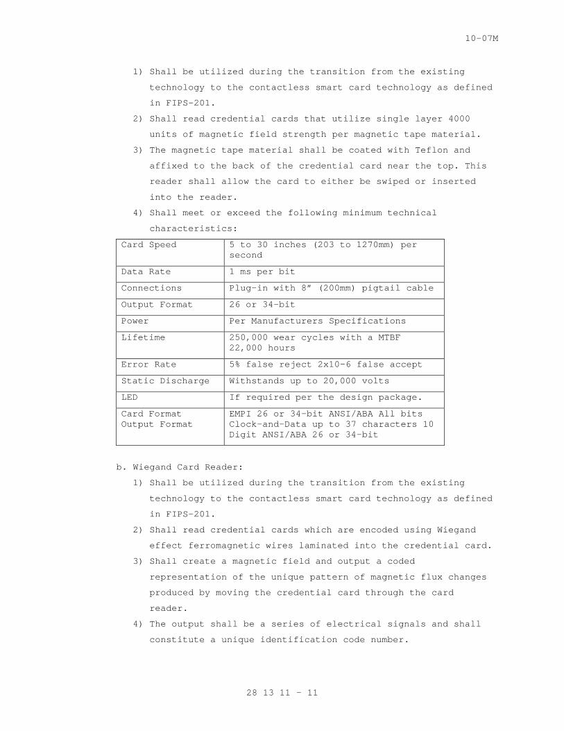
10-07M
1) Shall be utilized during the transition from the existing
technology to the contactless smart card technology as defined
in FIPS-201.
2) Shall read credential cards that utilize single layer 4000
units of magnetic field strength per magnetic tape material.
3) The magnetic tape material shall be coated with Teflon and
affixed to the back of the credential card near the top. This
reader shall allow the card to either be swiped or inserted
into the reader.
4) Shall meet or exceed the following minimum technical
characteristics:
Card Speed 5 to 30 inches (203 to 1270mm) per second
Data Rate 1 ms per bit
Connections Plug-in with 8” (200mm) pigtail cable
Output Format 26 or 34-bit
Power Per Manufacturers Specifications
Lifetime 250,000 wear cycles with a MTBF 22,000 hours
Error Rate 5% false reject 2x10⁻⁶ false accept
Static Discharge Withstands up to 20,000 volts
LED If required per the design package.
Card Format Output Format
EMPI 26 or 34-bit ANSI/ABA All bits Clock-and-Data up to 37 characters 10 Digit ANSI/ABA 26 or 34-bit
b. Wiegand Card Reader:
1) Shall be utilized during the transition from the existing
technology to the contactless smart card technology as defined
in FIPS-201.
2) Shall read credential cards which are encoded using Wiegand
effect ferromagnetic wires laminated into the credential card.
3) Shall create a magnetic field and output a coded
representation of the unique pattern of magnetic flux changes
produced by moving the credential card through the card
reader.
4) The output shall be a series of electrical signals and shall
constitute a unique identification code number.
28 13 11 - 11
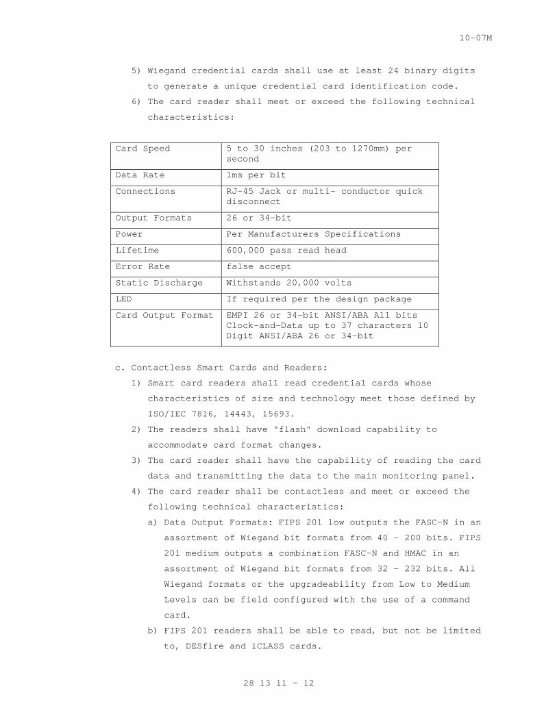
10-07M
5) Wiegand credential cards shall use at least 24 binary digits
to generate a unique credential card identification code.
6) The card reader shall meet or exceed the following technical
characteristics:
Card Speed 5 to 30 inches (203 to 1270mm) per second
Data Rate 1ms per bit
Connections RJ-45 Jack or multi- conductor quick disconnect
Output Formats 26 or 34-bit
Power Per Manufacturers Specifications
Lifetime 600,000 pass read head
Error Rate false accept
Static Discharge Withstands 20,000 volts
LED If required per the design package
Card Output Format EMPI 26 or 34-bit ANSI/ABA All bits Clock-and-Data up to 37 characters 10 Digit ANSI/ABA 26 or 34-bit
c. Contactless Smart Cards and Readers:
1) Smart card readers shall read credential cards whose
characteristics of size and technology meet those defined by
ISO/IEC 7816, 14443, 15693.
2) The readers shall have "flash" download capability to
accommodate card format changes.
3) The card reader shall have the capability of reading the card
data and transmitting the data to the main monitoring panel.
4) The card reader shall be contactless and meet or exceed the
following technical characteristics:
a) Data Output Formats: FIPS 201 low outputs the FASC-N in an
assortment of Wiegand bit formats from 40 – 200 bits. FIPS
201 medium outputs a combination FASC-N and HMAC in an
assortment of Wiegand bit formats from 32 – 232 bits. All
Wiegand formats or the upgradeability from Low to Medium
Levels can be field configured with the use of a command
card.
b) FIPS 201 readers shall be able to read, but not be limited
to, DESfire and iCLASS cards.
28 13 11 - 12
10-07M
Reader range shall comply with ISO standards 7816, 14443, and
15693, and also take into consideration conditions, are at
a minimum 1” to 2” (2.5 – 5 cm).
d. Proximity (PROX) Card Reader:
1) Shall be utilized during the transition from the existing
technology to the contactless smart card technology as defined
in FIPS-201.
2) Shall use active/passive proximity detection and shall not
require contact with the proximity credential card for
operation.
a) Active detection proximity card readers shall provide power
to compatible credential cards through magnetic induction
and receive and decode a unique identification code number
transmitted from the credential card.
b) Passive detection proximity card readers shall use a swept-
frequency, radio frequency field generator to read the
resonant frequencies of tuned circuits laminated into
compatible credential cards. The resonant frequencies read
shall constitute a unique identification code number.
3) Shall read proximity cards in a range from 0 to at least six
(6) inches (0 to at least 15 cm) from the reader. The
credential card design shall allow for a minimum of 32,000
unique identification codes per facility.
4) Shall be able to read cards from two (2) inches (5cm) to 6
inches (15cm).
5) For exterior parking lots or garages shall be 16 inches (40
cm).
6) The operating frequency shall be determined by the type of
access control system being utilized.
e. Credential Cards: Shall be in accordance with FIPS 201 and
controlled by the PIV enrollment and issuance system.
G. Portal Control Devices:
1. Shall be used to assist the PACS.
2. Such devices shall:
a. Provide a means of monitoring the doors status.
b. Allow for exiting a space via either a push button, request to
exit, or panic/crash bar.
28 13 11 - 13
10-07M
c. Provide a means of override to the PACS via a keypad or key
bypass.
d. Assist door operations utilizing automatic openers and closures.
e. Provide a secondary means of access to a space via a keypad.
3. Shall be connected to and monitored by the main PACS panel.
4. Shall be installed in a manner that they comply with:
a. The Uniform Federal Accessibility Standards (UFAS)
b. The Americans with Disabilities Act (ADA)
c. The ADA Standards for Accessible Design
5. Shall provide a secondary means of access control within a secure
area.
6. Keypads: Refer to Section 2.2.F.12 for keypad requirements.
7. Push-Button Switches:
a. Shall be momentary contact, back lighted push buttons, and
stainless steel switch enclosures for each push button as shown.
Buttons are to be utilized for secondary means of releasing a
locking mechanism.
b. In an area where a push button is being utilized for remote
access of the locking device then no more than two (2) buttons
shall operate one door from within one secure space. Buttons will
not be wired in series with one other.
C. In an area where locally stationed guards control entry to
multiple secure points via remote switches. An interface board
shall be designed and constructed for only the amount of buttons
it shall house. These buttons shall be flush mounted and clearly
labeled for ease of use. All buttons shall be connected to the
PACS and SMS system for monitoring purposes.
d. Shall have double-break silver contacts that will make 720 VA at
60 amperes and break 720 VA at 10 amperes.
8. Crash Bar:
a. Emergency Exit with Alarm (Panic):
1. Entry control portals shall include panic bar emergency exit
hardware as designed.
2. Panic bar emergency exit hardware shall provide an alarm shunt
signal to the PACS and SMS.
3. The panic bar shall include a conspicuous warning sign with
one (1) inch (2.5 cm) high, red lettering notifying personnel
28 13 11 - 14
10-07M
that an alarm will be annunciated if the panic bar is
operated.
4. Operation of the panic bar hardware shall generate an
intrusion alarm that reports to both the SMS and Intrusion
Detection System. The use of a micro switch installed within
the panic bar shall be utilized for this.
5. The panic bar shall a fully mechanical connection only and
shall not depend upon electric power for operation.
6. The panic bar shall be compatible with mortise or rim mount
door hardware and shall operate by retracting the bolt
manually by either pressing the panic bar or with a key by-
pass. Refer to Section 2.2.I.9 for key-bypass specifications.
b. Normal Exit:
1) Entry control portals shall include panic bar non-emergency
exit hardware as designed.
2) Panic bar non-emergency exit hardware shall be monitored by
and report to the SMS.
3) Operation of the panic bar hardware shall not generate a
locally audible or an intrusion alarm within the IDS.
4) When exiting, the panic bar shall depend upon a mechanical
connection only. The exterior, non-secure side of the door
shall be provided with an electrified thumb latch or lever to
provide access after the credential I.D. authentication by the
SMS.
5) The panic bar shall be compatible with mortise or rim mount
door hardware and shall operate by retracting the bolt
manually by either pressing the panic bar or with a key by-
pass. Refer to Section 2.2.I.9 for key-bypass specifications.
The strikes/bolts shall include a micro switch to indicate to
the system when the bolt is not engaged or the strike
mechanism is unlocked. The signal switches shall report a
forced entry to the system in the event the door is left open
or accessed without the identification credentials.
9. Key Bypass:
a. Shall be utilized for all doors that have a mortise or rim
mounted door hardware.
b. Each door shall be individually keyed with one master key per
secured area.
28 13 11 - 15
10-07M
c. Cylinders shall be six (6)-pin and made of brass or equivalent.
Keys for the cylinders shall be constructed of solid material and
produced and cut by the same distributor. Keys shall not be
purchased, cut, and supplied by multiple dealers.
d. All keys shall have a serial number cut into the key. No two
serial numbers shall be the same.
e. All keys and cylinders shall be stored in a secure area that is
monitored by the Intrusion Detection System.
10. Automatic Door Opener and Closer:
a. Shall be low energy operators.
b. Door closing force shall be adjustable to ensure adequate closing
control.
c. Shall have an adjustable back-check feature to cushion the door
opening speed if opened violently.
d. Motor assist shall be adjustable from 0 to 30 seconds in five (5)
second increments. Motor assist shall restart the time cycle with
each new activation of the initiating device.
e. Unit shall have a three-position selector mode switch that shall
permit unit to be switched “ON” to monitor for function
activation, switched to “H/O” for indefinite hold open function
or switched to “OFF,” which shall deactivate all control
functions but will allow standard door operation by means of the
internal mechanical closer.
f. Door control shall be adjustable to provide compliance with the
requirements of the Americans with Disabilities Act (ADA) and
ANSI standards A117.1.
g. All automatic door openers and closers shall:
1) Meet UL standards.
2) Be fire rated.
3) Have push and go function to activate power operator or power
assist function.
4) Have push button controls for setting door close and door open
positions.
5) Have open obstruction detection and close obstruction
detection built into the unit.
6) Have door closer assembly with adjustable spring size, back-
check valve, sweep valve, latch valve, speed control valve and
pressure adjustment valve to control door closing.
28 13 11 - 16
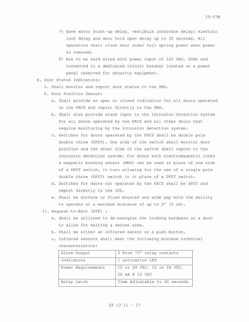
10-07M
7) Have motor start-up delay, vestibule interface delay; electric
lock delay and door hold open delay up to 30 seconds. All
operators shall close door under full spring power when power
is removed.
8) Are to be hard wired with power input of 120 VAC, 60Hz and
connected to a dedicated circuit breaker located on a power
panel reserved for security equipment.
H. Door Status Indicators:
1. Shall monitor and report door status to the SMS.
2. Door Position Sensor:
a. Shall provide an open or closed indication for all doors operated
on the PACS and report directly to the SMS.
b. Shall also provide alarm input to the Intrusion Detection System
for all doors operated by the PACS and all other doors that
require monitoring by the intrusion detection system.
c. Switches for doors operated by the PACS shall be double pole
double throw (DPDT). One side of the switch shall monitor door
position and the other side if the switch shall report to the
intrusion detection system. For doors with electromagnetic locks
a magnetic bonding sensor (MBS) can be used in place of one side
of a DPDT switch, in turn allowing for the use of a single pole
double throw (SPDT) switch in it place of a DPDT switch.
d. Switches for doors not operated by the PACS shall be SPDT and
report directly to the IDS.
e. Shall be surface or flush mounted and wide gap with the ability
to operate at a maximum distance of up to 2” (5 cm).
11. Request-to-Exit (RTE) :
a. Shall be utilized to de-energize the locking hardware on a door
to allow for exiting a secure area.
b. Shall be either an infrared sensor or a push button.
c. Infrared sensors shall meet the following minimum technical
characteristics:
Alarm Output 2 Form "C" relay contacts
Indicators 1 activation LED
Power Requirements 12 or 24 VAC, 12 or 24 VDC,
26 mA @ 12 VDC
Relay Latch Time Adjustable to 60 seconds
28 13 11 - 17
10-07M
I. Entry Control Devices:
1. Shall be hardwired to the PACS main control panel and operated by
either a card reader or a biometric device via a relay on the main
control panel.
2. Shall be fail-safe in the event of power failure to the PACS system.
3. Shall operate at 24 VCD, with the exception of turnstiles and be
powered by a separate power supply dedicated to the door control
system. Each power supply shall be rated to operate a minimum of two
doors simultaneously without error to the system or overload the
power supply unit.
4. Shall have a diode or metal-oxide veristor (MOV) to protect the
controller and power supply from reverse current surges or back-
check.
5. Electric Strikes/Bolts: Shall be:
a. Made of heavy-duty construction and tamper resistant design.
b. Tested to over one million cycles.
c. Rated for a minimum of 1000 lbs. holding strength.
d. Utilize an actuating solenoid for the strike/bolt. The solenoid
shall move from fully open to fully closed position and back in
not more than 500 milliseconds and be rated for continuous duty.
e. Utilize a signal switch that will indicate to the system if the
strike/bolt is not engaged or is unlocked when it should be
secured.
f. Flush mounted within the door frame.
6. Electric Mortise Locks: Shall be installed within the door and an
electric transfer hinge shall be utilized to allow the wires to be
transferred from the door frame to the lock. If utilized with a
double door then the lock shall be installed inside the active leaf.
7. Electromagnetic Locks:
a. These locks shall be without mechanical linkage utilizing no
moving parts, and securing the door to its frame solely on
electromagnetic force.
b. Shall be comprised of two pieces, the mag-lock and the door
plate. The mag-lock shall be surface mounted to the door frame
and the door plate shall be surface mounted to the door.
c. Ensure a diode or MOV is installed in line with the DC voltage
supplying power to the unit in order to prevent back-check on the
system when the mag-lock is powered.
28 13 11 - 18
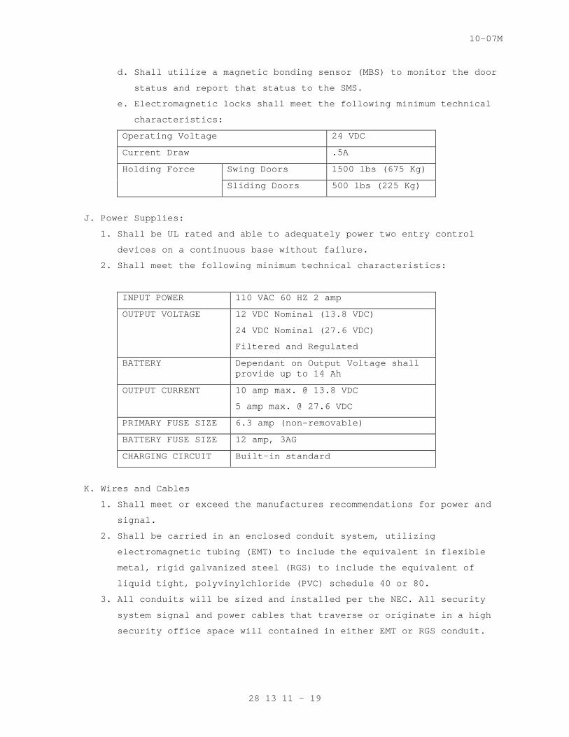
10-07M
d. Shall utilize a magnetic bonding sensor (MBS) to monitor the door
status and report that status to the SMS.
e. Electromagnetic locks shall meet the following minimum technical
characteristics:
Operating Voltage 24 VDC
Current Draw .5A
Holding Force Swing Doors 1500 lbs (675 Kg)
Sliding Doors 500 lbs (225 Kg)
J. Power Supplies:
1. Shall be UL rated and able to adequately power two entry control
devices on a continuous base without failure.
2. Shall meet the following minimum technical characteristics:
INPUT POWER 110 VAC 60 HZ 2 amp
OUTPUT VOLTAGE 12 VDC Nominal (13.8 VDC)
24 VDC Nominal (27.6 VDC)
Filtered and Regulated
BATTERY Dependant on Output Voltage shall provide up to 14 Ah
OUTPUT CURRENT 10 amp max. @ 13.8 VDC
5 amp max. @ 27.6 VDC
PRIMARY FUSE SIZE 6.3 amp (non-removable)
BATTERY FUSE SIZE 12 amp, 3AG
CHARGING CIRCUIT Built-in standard
K. Wires and Cables
1. Shall meet or exceed the manufactures recommendations for power and
signal.
2. Shall be carried in an enclosed conduit system, utilizing
electromagnetic tubing (EMT) to include the equivalent in flexible
metal, rigid galvanized steel (RGS) to include the equivalent of
liquid tight, polyvinylchloride (PVC) schedule 40 or 80.
3. All conduits will be sized and installed per the NEC. All security
system signal and power cables that traverse or originate in a high
security office space will contained in either EMT or RGS conduit.
28 13 11 - 19
10-07M
4. All conduit, pull boxes, and junction boxes shall be clearly marked
every with colored permanent tape or paint that will allow it to be
distinguished from all other conduit and infrastructure.
5. Conduit fills shall not exceed 50 percent unless otherwise
documented.
6. A pull rope shall be pulled along with signal and power cables to
assist in future work.
7. At all locations where core drilling is conducted to allow for
conduit to be installed, then fire stopping shall be applied to that
area.
8. High power and signal cables shall not share the same conduit and
shall be kept separate up to the point of connection. High power for
the security system shall be defined as any cable or sets of cables
carrying 30 VDC/VAC or higher.
9. Signal Cables:
a. Shall meet or exceed all specifications and requirements called
out by the manufactures.
b. Shall be twisted pairs.
c. All cables and conductors, except fiber optic cables, that act as
a control, communication, or signal lines shall include surge
protection. Surge protection shall be furnished at the equipment
end and additional triple electrode gas surge protectors rated
for the application on each wire line circuit shall be installed
within 3 feet, (1 meter) of the building cable entrance. The
inputs and outputs shall be tested in both normal and common mode
using the following wave forms:
1) A 10 microsecond rise time by 1000 microsecond pulse width
waveform with a peak voltage of 1500 volts and peak current of
60 amperes.
2) An 8 microsecond rise time by 20 microsecond pulse width wave
form with a peak voltage of 1000 volts and peak current of 500
amperes.
10. Power Cables:
a. Shall be rated for either 110 or 220 VAC, 50 or 60 Hz, and shall
comply with VA Master Spec 26 05 21 Low Voltage Electrical Power
Conductors and Cables (600 Volts and Below).
b. Shall be sized according and comply with the NEC. High voltage
power cables will be a minimum of three conductors, 14 AWG,
28 13 11 - 20
10-07M
stranded, and coated with a non-conductive polyvinylchloride
(PVC) jacket.
c. Low Voltage Power Cables:
1) All cables shall be a minimum of 18 AWG, Stranded and have a
polyvinylchloride outer jacket.
2) Specific cable size shall determined using a basic voltage
over distance calculation and shall comply with the NEC’s
requirements for low voltage cables.
d. All equipment connected to AC power shall be protected from
surges. Equipment protection shall withstand surge test waveforms
described in IEEE C62.41. Fuses shall not be used as a means of
surge protection.
2.3 INSTALLATION KIT
A. General: The kit shall be provided that at, a minimum includes all
connectors and terminals, labeling systems, audio spade lugs, barrier
strips, punch blocks or wire wrap terminals, heat shrink tubing, cable
ties, solder, hangers, clamps, bolts, conduit, cable duct, and/or cable
tray, etc., required to accomplish a neat and secure installation. All
wires shall terminate in a spade lug and barrier strip, wire wrap
terminal or punch block. Unfinished or unlabeled wire connections
shall not be allowed. All unused and partially opened installation kit
boxes, coaxial, fiber-optic, and twisted pair cable reels, conduit,
cable tray, and/or cable duct bundles, wire rolls, physical
installation hardware shall be turned over to the Contracting Officer.
The following sections outlined are the minimum required installation
sub-kits:
1. System Grounding:
a. The grounding kit shall include all cable and installation
hardware required. All head end equipment and power supplies
shall be connected to earth ground via internal building wiring,
according to the NEC.
b. This includes, but is not limited to:
1) Coaxial Cable Shields
2) Control Cable Shields
3) Data Cable Shields
4) Equipment Racks
5) Equipment Cabinets
6) Conduits
28 13 11 - 21
10-07M
7) Cable Duct blocks
8) Cable Trays
9) Power Panels
10) Grounding
11) Connector Panels
2. Coaxial Cable: The coaxial cable kit shall include all coaxial
connectors, cable tying straps, heat shrink tabbing, hangers,
clamps, etc., required to accomplish a neat and secure installation.
3. Wire and Cable: The wire and cable kit shall include all connectors
and terminals, audio spade lugs, barrier straps, punch blocks, wire
wrap strips, heat shrink tubing, tie wraps, solder, hangers, clamps,
labels etc., required to accomplish a neat and orderly installation.
4. Conduit, Cable Duct, and Cable Tray: The kit shall include all
conduit, duct, trays, junction boxes, back boxes, cover plates, feed
through nipples, hangers, clamps, other hardware required to
accomplish a neat and secure conduit, cable duct, and/or cable tray
installation in accordance with the NEC and this document.
5. Equipment Interface: The equipment kit shall include any item or
quantity of equipment, cable, mounting hardware and materials needed
to interface the systems with the identified sub-system(s) according
to the OEM requirements and this document.
6. Labels: The labeling kit shall include any item or quantity of
labels, tools, stencils, and materials needed to label each
subsystem according to the OEM requirements, as-installed drawings,
and this document.
7. Documentation: The documentation kit shall include any item or
quantity of items, computer discs, as installed drawings, equipment,
maintenance, and operation manuals, and OEM materials needed to
provide the system documentation as required by this document and
explained herein.
PART 3
3.1 INSTALLATION
A. System installation shall be in accordance with UL 294, manufacturer
and related documents and references, for each type of security
subsystem designed, engineered and installed.
B. Components shall be configured with appropriate “service points” to
pinpoint system trouble in less than 30 minutes.
28 13 11 - 22
10-07M
C. The Contractor shall install all system components including Government
furnished equipment, and appurtenances in accordance with the
manufacturer's instructions, documentation listed in Sections 1.4 and
1.5 of this document, and shall furnish all necessary connectors,
terminators, interconnections, services, and adjustments required for a
operable system.
D. The PACS will be designed, engineered, installed, and tested to ensure
all components are fully compatible as a system and can be integrated
with all associated security subsystems, whether the system is a stand
alone or a network.
E. For integration purposes, the PACS shall be integrated where
appropriate with the following associated security subsystems:
1. CCTV:
a. Provide 24 hour coverage of all entry points to the perimeter and
agency buildings. As well as all emergency exits utilizing a
fixed color camera.
b. Be able to monitor, control and record cameras on a 24 hours
basis.
c. Be programmed automatically call up a camera when an access point
is but into an alarm state.
d. For additional PACS system requirements as they relate to the
CCTV, refer to Section 28 23 00, VIDEO SURVEILLANCE.
2. IDS:
a. Be able monitor door control sensors.
b. Be able to monitor and control the IDS on a 24 hours basis.
c. Be programmed to go into an alarm state when an IDS device is put
into an alarm state, and notify the operator via an audible
alarm.
d. For additional PACS system requirements as they relate to the
IDS, refer to Section 28 16 11, INTRUSION DETECTION SYSTEM.
3. Security Access Detection:
a. Be able to monitor all objects that have been screened with an x-
ray machine and be able to monitor all data acquired by the bomb
detection unit.
b. For additional PACS system requirements as they relate to the
Security Access Detection, refer to Section 28 13 53, SECURITY
ACCESS DETECTION.
4. EPPS:
28 13 11 - 23

10-07M
a. Be programmed to go into an alarm state when an emergency call
box or duress alarm/panic device is activated, and notify the
Access Control System and Database Management of an alarm event.
b. For additional PACS requirements as they relate to the EPPS,
refer to Section 28 26 00, ELECTRONIC PERSONAL PROTECTION SYSTEM.
E. Integration with these security subsystems shall be achieved by
computer programming or the direct hardwiring of the systems.
F. For programming purposes refer to the manufacturers requirements for
correct system operations. Ensure computers being utilized for system
integration meet or exceed the minimum system requirements outlined on
the systems software packages.
G. The Contractor shall visit the site and verify that site conditions are
in agreement with the design package. The Contractor shall report all
changes to the site or conditions that will affect performance of the
system. The Contractor shall not take any corrective action without
written permission from the Government.
H. The Contractor shall visit the site and verify that site conditions are
in agreement/compliance with the design package. The Contractor shall
report all changes to the site or conditions that will affect
performance of the system to the Contracting Officer in the form of a
report. The Contractor shall not take any corrective action without
written permission received from the Contracting Officer.
I. Existing Equipment:
1. The Contractor shall connect to and utilize existing door equipment,
control signal transmission lines, and devices as outlined in the
design package. Door equipment and signal lines that are usable in
their original configuration without modification may be reused with
Contracting Officer approval.
2. The Contractor shall perform a field survey, including testing and
inspection of all existing door equipment and signal lines intended
to be incorporated into the PACS, and furnish a report to the
Contracting Officer as part of the site survey report. For those
items considered nonfunctioning, provide (with the report)
specification sheets, or written functional requirements to support
the findings and the estimated cost to correct the deficiency. As
part of the report, the Contractor shall include a schedule for
connection to all existing equipment.
28 13 11 - 24

10-07M
3. The Contractor shall make written requests and obtain approval prior
to disconnecting any signal lines and equipment, and creating
equipment downtime. Such work shall proceed only after receiving
Contracting Officer approval of these requests. If any device fails
after the Contractor has commenced work on that device, signal or
control line, the Contractor shall diagnose the failure and perform
any necessary corrections to the equipment.
4. The Contractor shall be held responsible for repair costs due to
Contractor negligence, abuse, or improper installation of equipment.
5. The Contracting Officer shall be provided a full list of all
equipment that is to be removed or replaced by the Contractor, to
include description and serial/manufacturer numbers where possible.
The Contractor shall dispose of all equipment that has been removed
or replaced based upon approval of the Contracting Officer after
reviewing the equipment removal list. In all areas where equipment
is removed or replaced the Contractor shall repair those areas to
match the current existing conditions.
J. Enclosure Penetrations: All enclosure penetrations shall be from the
bottom of the enclosure unless the system design requires penetrations
from other directions. Penetrations of interior enclosures involving
transitions of conduit from interior to exterior, and all penetrations
on exterior enclosures shall be sealed with rubber silicone sealant to
preclude the entry of water and will comply with VA Master
Specification 07 84 00, Firestopping. The conduit riser shall terminate
in a hot-dipped galvanized metal cable terminator. The terminator shall
be filled with an approved sealant as recommended by the cable
manufacturer and in such a manner that the cable is not damaged.
K. Cold Galvanizing: All field welds and brazing on factory galvanized
boxes, enclosures, and conduits shall be coated with a cold galvanized
paint containing at least 95 percent zinc by weight.
L. Control Panels:
1. Connect power and signal lines to the controller.
2. Program the panel as outlined by the design and per the
manufacturer’s programming guidelines.
M. SMS:
1. Coordinate with the VA agency’s IT personnel to place the computer
on the local LAN or Intranet and provide the security system
28 13 11 - 25

10-07M
protection levels required to insure only authorized VA personnel
have access to the system.
2. Program and set-up the SMS to ensure it is in fully operation.
N. Card Readers:
1. Connect all signal inputs and outputs as shown and specified.
2. Terminate input signals as required.
3. Program and address the reader as per the design package.
4. Readers shall be surface or flushed mounted and all appropriate
hardware shall be provided to ensure the unit is installed in an
enclosed conduit system.
O. Portal Control Devices:
1. Install all signal input and output cables as well as all power
cables.
2. Devices shall be surface or flush mounted as per the design package.
3. Program all devices and ensure they are working.
P. Door Status Indicators:
1. Install all signal input and output cables as well as all power
cables.
2. RTE’s shall be surface mounted and angled in a manner that they
cannot be compromised from the non-secure side of a windowed door,
or allow for easy release of the locking device from a distance no
greater than 6 feet from the base of the door.
3. Door position sensors shall be surface or flush mounted and wide gap
with the ability to operate at a maximum distance of up to 2” (5
cm).
Q. Entry Control Devices:
1. Install all signal input and power cables.
2. Strikes and bolts shall be mounted within the door frame.
3. Mortise locks shall be mounted within the door and an electric
transfer hinge shall be utilized to transfer the wire from within
the door frame to the mortise lock inside the door.
4. Electromagnetic locks shall be installed with the mag-lock mounted
to the door frame and the metal plate mounted to the door.
R. System Start-Up:
1. The Contractor shall not apply power to the PACS until the following
items have been completed:
a. PACS equipment items and have been set up in accordance with
manufacturer's instructions.
28 13 11 - 26
10-07M
b. A visual inspection of the PACS has been conducted to ensure that
defective equipment items have not been installed and that there
are no loose connections.
c. System wiring has been tested and verified as correctly connected
as indicated.
d. All system grounding and transient protection systems have been
verified as installed and connected as indicated.
e. Power supplies to be connected to the PACS have been verified as
the correct voltage, phasing, and frequency as indicated.
2. Satisfaction of the above requirements shall not relieve the
Contractor of responsibility for incorrect installation, defective
equipment items, or collateral damage as a result of Contractor work
efforts.
S. Supplemental Contractor Quality Control:
1. The Contractor shall provide the services of technical
representatives who are familiar with all components and
installation procedures of the installed PACS; and are approved by
the Contracting Officer.
2. The Contractor will be present on the job site during the
preparatory and initial phases of quality control to provide
technical assistance.
3. The Contractor shall also be available on an as needed basis to
provide assistance with follow-up phases of quality control.
4. The Contractor shall participate in the testing and validation of
the system and shall provide certification that the system installed
is fully operational as all construction document requirements have
been fulfilled.
3.2 TESTING AND TRAINING
A. Training at the factory and/or offer pre-scheduled training at the site
location for a fee. Manufacturer shall be required to have a network
of qualified installers and/or dealers as referred to by Hirsch
Electronics Corporation.
B. Veterans Administration shall be able to choose from a minimum of 3
dealers (Electronic Security Installation providers) from the
manufacturer to provide service and installation support on all Hirsch
products.
28 13 11 - 27

10-07M
All testing and training shall be compliant with the VA General
Requirements, Section 01 00 00, GENERAL REQUIREMENTS.
-----END----
28 13 11 - 28
9-11
SECTION 28 13 16 PHYSICAL ACCESS CONTROL SYSTEM AND DATABASE MANAGEMENT
SPEC WRITER NOTE: Delete between //___//if not applicable to project. Also delete any other item or paragraph not applicable in the section and renumber the paragraphs.
PART 1 – GENERAL
1.1 DESCRIPTION
A. This section specifies the finishing, installation, connection,
testing and certification of a complete and fully operation
Physical Access Control Database Management System, hereinafter
referred to as the PACMS.
B. This Section includes a Physical Security Access System Database
Management consisting of database management software.
Requirements for hardware supporting database management are
described in Section 28 13 00 PHYSICAL ACCESS CONTROL, Part 2.
1.2 RELATED WORK
SPEC WRITER NOTE: Delete any item or paragraph not applicable in the section and renumber the paragraphs.
A. Section 01 00 00 - GENERAL REQUIREMENTS. For General
Requirements.
B. Section 28 05 00 – COMMON WORK RESULTS FOR ELECTRONIC SAFETY AND
SECURITY. Requirements for general requirements that are common
to more than one section in Division 28.
C. Section 28 05 13 - CONDUCTORS AND CABLES FOR ELECTRONIC SAFETY
AND SECURITY. Requirements for conductors and cables.
D. Section 28 05 26 - GROUNDING AND BONDING FOR ELECTRONIC SAFETY
AND SECURITY. Requirements for grounding and bonding.
E. Section 28 05 28.33 - CONDUITS AND BOXES FOR ELECTRONIC SAFETY
AND SECURITY. Requirements for infrastructure.
F. Section 28 08 00 - COMMISIONING OF ELECTRONIC SAFETY AND SECURITY
SYSTEMS. For requirements for commissioning and systems readiness
checklists.
G. Section 28 13 00 - PHYSICAL ACCESS CONTROL SYSTEM. Requirements
for physical access control system.
28 13 16 - 1
9-11
H. Section 28 13 53 - SECURITY ACCESS DETECTION. Requirements for
screening of personnel and shipments.
I. Section 28 16 00 - INTRUSION DETECTION SYSTEM (IDS). Requirements
for alarm systems.
J. Section 28 23 00 - VIDEO SURVEILLANCE. Requirements for security
camera systems.
K. Section 28 26 00 - ELECTRONIC PERSONAL PROTECTION SYSTEM (EPPS).
Requirements for emergency and interior communications.
1.3 QUALITY ASSURANCE
A. The Contractor shall be responsible for providing, installing,
and the operation of the Access Control System and Database
Management as shown. The Contractor shall also provide
certification as required.
B. The security system shall be installed and tested to ensure all
components are fully compatible as a system and can be integrated
with all associated security subsystems, whether the security
system is stand-alone or a part of a Information Technology (IT)
computer network.
C. The Contractor or security sub-contractor shall be a licensed
security Contractor as required within the state or jurisdiction
of where the installation work is being conducted.
D. The manufacturers of all hardware and software components
employed in the SMS shall be established vendors to the access
control/security monitoring industry for no less than five (5)
years and shall have successfully implemented at least 5 systems
of similar size and complexity.
E. Contractor / Integrator Qualifications
1. The security system integrator shall have been regularly
engaged in the installation and maintenance of integrated
access control systems and have a proven track record with
similar systems of the same size, scope, and complexity.
2. The security system integrator shall supply information
attesting to the fact that their firm is an authorized product
integrator certified with the SMS. A minimum of one technician
shall be a installer certified by the SMS manufacturer.
3. The security system integrator shall supply information
attesting to the fact that their installation and service
technicians are competent factory trained and certified
28 13 16 - 2
9-11
personnel capable of maintaining the system and providing
reasonable service time.
4. The security system integrator shall provide a minimum of
three (3) references whose systems are of similar complexity
and have been installed and maintained by the security system
integrator in the last five (5) years.
5. There shall be a local representative and factory authorized
local service organization that shall carry a complete stock
of parts and provide maintenance for these systems.
F. Service Qualifications: There shall be a permanent service
organization maintained or trained by the manufacturer which will
render satisfactory service to this installation within // four
// // eight // hours of receipt of notification that service is
needed. Submit name and address of service organizations.
1.4 SUBMITTALS
SPEC WRITER NOTE: Delete and/or amend all paragraphs and sub-paragraphs and information as needed to ensure that only the documentation required is requested per the Request for Proposal (RFP).
A. Submit below items in conjunction with Master Specification
Sections 01 33 23, SHOP DRAWINGS, PRODUCT DATA, AND SAMPLES, and
Section 02 41 00, DEMOLITION.
B. Provide certificates of compliance with Section 1.3, Quality
Assurance.
C. Provide a pre-installation and as-built design package in both
electronic format and on paper, minimum size 48 x 48 inches
(1220mm x 1220mm); drawing submittals shall be per the
established project schedule.
D. Pre-installation design and as-built packages shall include, but
not be limited to:
1. Index Sheet that shall:
a. Define each page of the design package to include facility
name, building name, floor, and sheet number.
b. Provide a list of all security abbreviations and symbols.
c. Reference all general notes that are utilized within the
design package.
28 13 16 - 3

9-11
d. Specification and scope of work pages for all security
systems that are applicable to the design package that
will:
1) Outline all general and job specific work required
within the design package.
2) Provide a device identification table outlining device
Identification (ID) and use for all security systems
equipment utilized in the design package.
2. Drawing sheets that will be plotted on the individual floor
plans or site plans shall:
a. Include a title block as defined above.
b. Define the drawings scale in both standard and metric
measurements.
c. Provide device identification and location.
d. Address all signal and power conduit runs and sizes that
are associated with the design of the electronic security
system and other security elements (e.g., barriers, etc.).
e. Identify all pull box and conduit locations, sizes, and
fill capacities.
f. Address all general and drawing specific notes for a
particular drawing sheet.
3. A riser drawing for each applicable security subsystem shall:
a. Indicate the sequence of operation.
b. Relationship of integrated components on one diagram.
c. Include the number, size, identification, and maximum
lengths of interconnecting wires.
d. Wire/cable types shall be defined by a wire and cable
schedule. The schedule shall utilize a lettering system
that will correspond to the wire/cable it represents
(example: A = 18 AWG/1 Pair Twisted, Unshielded). This
schedule shall also provide the manufacturer’s name and
part number for the wire/cable being installed.
4. A system drawing for each applicable security system shall:
a. Identify how all equipment within the system, from main
panel to device, shall be laid out and connected.
b. Provide full detail of all system components wiring from
point-to-point.
28 13 16 - 4
9-11
c. Identify wire types utilized for connection,
interconnection with associate security subsystems.
d. Show device locations that correspond to the floor plans.
e. All general and drawing specific notes shall be included
with the system drawings.
5. A schedule for all of the applicable security subsystems shall
be included. All schedules shall provide the following
information:
a. Device ID.
b. Device Location (e.g. site, building, floor, room number,
location, and description).
c. Mounting type (e.g. flush, wall, surface, etc.).
d. Power supply or circuit breaker and power panel number.
e. In addition, for the CCTV Systems, provide the camera ID,
camera type (e.g. fixed or pan/tilt/zoom (P/T/Z), lens type
(e.g. for fixed cameras only) and housing model number.
6. Detail and elevation drawings for all devices that define how
they were installed and mounted.
E. Pre-installation design packages shall be reviewed by the
Contractor along with a VA representative to ensure all work has
been completed. All reviews shall be conducted in accordance with
the project schedule. There shall be four (4) stages to the
review process:
1. 35 percent
2. 65 percent
3. 90 percent
4. 100 percent
F. Provide manufacturer security system product cut-sheets. Submit
for approval at least 30 days prior to commencement of formal
testing, a Security System Operational Test Plan. Include
procedures for operational testing of each component and security
subsystem, to include performance of an integrated system test.
G. Submit manufacture’s certification of Underwriters Laboratories,
Inc. (UL) listing as specified. Provide all maintenance and
operating manuals per Section 01 00 00, GENERAL REQUIREMENTS.
28 13 16 - 5
9-11
1.5 APPLICABLE PUBLICATIONS
SPEC WRITER NOTE: Delete first paragraph below if stand alone specs. Delete rest of the subparagraphs if section 280500 is provided with the project.
//A. Refer to 25 05 00 COMMON WORK RESULTS FOR ELECTRONIC SAFETY AND
SECURITY, Part 1//
A. The publications listed below (including amendments, addenda,
revisions, supplement, and errata) form a part of this
specification to the extent referenced. The publications are
referenced in the text by the basic designation only.
B. American National Standards Institute (ANSI)/ Security Industry
Association (SIA):
AC-03...................Access Control: Access Control Guideline
Dye Sublimation Printing Practices for
PVC Access Control Cards
TVAC-01.................CCTV to Access Control Standard - Message
Set for System Integration
C. American National Standards Institute (ANSI)/ International Code
Council (ICC):
A117.1..................Standard on Accessible and Usable
Buildings and Facilities
D. Department of Justice American Disability Act (ADA)
28 CFR Part 36..........2010 ADA Standards for Accessible Design
E. Federal Communications Commission (FCC):
(47 CFR 15) Part 15.....Limitations on the Use of Wireless
Equipment/Systems
F. Government Accountability Office (GAO):
GAO-03-8-02Security.....Responsibilities for Federally Owned and
Leased Facilities
G. National Electrical Contractors Association
303-2005................Installing Closed Circuit Television
(CCTV) Systems
H. National Electrical Manufactures Association (NEMA):
250-08..................Enclosures for Electrical Equipment (1000
Volts Maximum)
I. National Fire Protection Association (NFPA):
28 13 16 - 6
9-11
70-11................... National Electrical Code
J. Underwriters Laboratories, Inc. (UL):
294-99..................The Standard of Safety for Access Control
System Units
305-08..................Standard for Panic Hardware
639-97..................Standard for Intrusion-Detection Units
752-05..................Standard for Bullet-Resisting Equipment
827-08..................Central Station Alarm Services
1076-95.................Standards for Proprietary Burglar Alarm
Units and Systems
1981-03.................Central Station Automation System
2058-05.................High Security Electronic Locks
K. Homeland Security Presidential Directive (HSPD):
HSPD-12.................Policy for a Common Identification
Standard for Federal Employees and
Contractors
L. Federal Information Processing Standards (FIPS):
FIPS-201-1..............Personal Identity Verification (PIV) of
Federal Employees and Contractors
M. National Institute of Standards and Technology (NIST):
IR 6887 V2.1............Government Smart Card Interoperability
Specification (GSC-IS)
Special Pub 800-37......Guide for Applying the Risk Management
Framework to Federal Information Systems
Special Pub 800-63......Electronic Authentication Guideline
Special Pub 800-73-3....Interfaces for Personal Identity
Verification (4 Parts)
........................Pt. 1- End Point PIV Card Application
Namespace, Data Model & Representation
........................Pt. 2- PIV Card Application Card Command
Interface
........................Pt. 3- PIV Client Application Programming
Interface
........................Pt. 4- The PIV Transitional Interfaces &
Data Model Specification
Special Pub 800-76-1....Biometric Data Specification for Personal
Identity Verification
28 13 16 - 7

9-11
Special Pub 800-78-2....Cryptographic Algorithms and Key Sizes
for Personal Identity Verification
Special Pub 800-79-1....Guidelines for the Accreditation of
Personal Identity Verification Card
Issuers
Special Pub 800-85B-1...DRAFTPIV Data Model Test Guidelines
Special Pub 800-85A-2...PIV Card Application and Middleware
Interface Test Guidelines (SP 800-73-3
compliance)
Special Pub 800-96......PIV Card Reader Interoperability
Guidelines
Special Pub 800-104A....Scheme for PIV Visual Card Topography
Special Pub 800-116.....Recommendation for the Use of PIV
Credentials in Physical Access Control
Systems (PACS)
N. International Organization for Standardization (ISO):
7810....................Identification cards – Physical
characteristics
7811....................Physical Characteristics for Magnetic
Stripe Cards
7816-1..................Identification cards - Integrated
circuit(s) cards with contacts - Part 1:
Physical characteristics
7816-2..................Identification cards - Integrated circuit
cards - Part 2: Cards with contacts -
Dimensions and location of the contacts
7816-3..................Identification cards - Integrated circuit
cards - Part 3: Cards with contacts -
Electrical interface and transmission
protocols
7816-4..................Identification cards - Integrated circuit
cards - Part 11: Personal verification
through biometric methods
7816-10.................Identification cards - Integrated circuit
cards - Part 4: Organization, security
and commands for interchange
14443...................Identification cards - Contactless
integrated circuit cards; Contactless
28 13 16 - 8
9-11
Proximity Cards Operating at 13.56 MHz in
up to 5 inches distance
15693...................Identification cards -- Contactless
integrated circuit cards - Vicinity
cards; Contactless Vicinity Cards
Operating at 13.56 MHz in up to 50 inches
distance
19794...................Information technology - Biometric data
interchange formats
O. Uniform Federal Accessibility Standards (UFAS) 1984
P. Section 508 of the Rehabilitation Act of 1973
1.6 WARRANTY OF CONSTRUCTION.
A. Warrant PACMS work subject to the Article “Warranty of
Construction” of FAR clause 52.246-21 and Section 280500.
B. Demonstration and training shall be performed prior to system
acceptance.
PART 2 – PRODUCTS
Spec Note: Delete or amend all paragraphs and sub-paragraphs as needed to ensure that only the equipment required per the Request for Proposal (RFP) is provided.
2.1 SYSTEM DATABASE
A. Database and database management software shall be HSPD-12 and
FIPS compliant. Database and database management software shall
define and modify each point in database using operator commands.
Definition shall include parameters and constraints associated
with each system device.
B. Database Operations:
1. System data management shall be in a hierarchical menu tree
format, with navigation through expandable menu branches and
manipulated with use of menus and icons in a main menu and
system toolbar.
2. Navigational Aids:
a. Toolbar icons for add, delete, copy, print, capture image,
activate, deactivate, and muster report.
b. Point and click feature to facilitate data manipulation.
28 13 16 - 9

9-11
c. Next and previous command buttons visible when editing
database fields to facilitate navigation from one record to
the next.
d. Copy command and copy tool in the toolbar to copy data from
one record to create a new similar record.
3. All data entry shall be automatically checked for duplicate
and illegal data and shall verify that data are in a valid
format.
4. Provide a memo or note field for each item that is stored in
database, allowing the storing of information about any
defining characteristics of the item. Memo field is used for
noting the purpose the item was entered for, reasons for
changes that were made, and the like.
C. File Management:
1. Provide database backup and restoration system, allowing
selection of storage media, including hard discs, optical
media, flash drives, and designated network resources.
2. Provide manual and automatic mode of backup operations. The
number of automatic sequential backups before the oldest
backup becomes overwritten; FIFO mode shall be operator
selectable.
3. Backup program shall provide manual operation from any PC on
the LAN and shall operate while system remains operational.
D. Database Segmentation:
1. The System shall employ advanced database segmentation
functionality. Each segment shall be allowed to have its own
unique set of cardholders, hardware, and system parameters
including access control field hardware, timezones, access
levels, etc., which shall allow System Administrators to
expand upon current hardware constraints. As such, only
credentials that are assigned access levels to card readers in
a segment need to be downloaded to the Data Gathering Panels
in that segment.
2. Cardholders shall be allowed to belong to one segment, many
segments, or all segments.
3. The database segmentation functionality shall also provide a
capability to object records in the system, where segment
System Administrators and Operators can only view, add,
28 13 16 - 10
9-11
modify, delete, and manipulate cardholders, system parameters
and access control field hardware that belong to their
respective segments.
4. System Administrators and System Operators shall be assigned
the segments they are allowed to view and control. System
Administrators and System Operators may be assigned to more
than one segment and a segment may be assigned to more than
one System Administrator and System Operator. A one-to-many
relationship shall exist for System Administrators and System
Operators with respect to segments. The SYSTEM shall support a
minimum of [65,000] <insert number> segments.
E. Bi-Directional Data Exchange
1. The System shall support a real time, bi directional data
interface to external databases such as Human Resources, Time
and Attendance, Food Service Systems. The interface shall
allow data to be imported into or exported out of the SYSTEM
in real time or in a batch mode basis. Data used for import
shall be retrieved directly from an external database or
through an import file. Data provided for export shall be
applied directly to an external database or through an export
file. Any data shall be imported or exported including image
data. The file used for import or created by export shall have
the ability to be structured in a wide variety of ways, but
shall always be in ASCII text format.
2. The System shall also support a one step download and
distribution process of cardholder and security information
from the external database to the SYSTEM database, all the way
down to the Intelligent Field Controller (ISC) database. This
shall be a guaranteed process, even if the communication path
between the SYSTEM database server and the ISC is broken. If
the communication path is broken, the data shall be stored in
a temporary queue and shall be automatically downloaded once
the communication path is restored.
F. Database connectivity:
1. The SMS database shall support open direct database
connectivity for importing cardholder and card ID data from
external systems and/or database applications. The PACS SMS
28 13 16 - 11

9-11
shall facilitate interfacing by providing the following
capabilities:
a. Real time and batch processing of data via ODBC, JDBC or
OLE DB over a network connection.
b. Insert, update, and delete record information.
c. Automatic download of data to control panels (data
gathering panels) based on database changes.
d. Provide audit trail in the operator history/archive
database for all database changes initiated by the
interface.
G. Operator Passwords:
1. Software shall support up to [32,000] <insert number>
individual system operators, each with a unique password.
2. Operator Password: [One to eight alphanumeric characters]
<Insert password characteristic>.
3. Allow passwords to be case sensitive.
4. Allow use of Single sign-off (SSO) password.
5. Passwords shall not be displayed when entered.
6. Provide each password with a unique and customizable password
profile, and allow several operators to share a password
profile. Include the following features in the password
profile:
a. Allow for at least [32,000] <Insert number> operator
password profiles.
b. Predetermine the highest-level password profile for access
to all functions and areas of program.
c. Allow or disallow operator access to any program operation,
including the functions of View, Add, Edit, and Delete.
d. Restrict which doors an operator can assign access to.
7. Operators shall use a user name and password to log on to
system.
a. This user name and password is used to access database
areas and programs as determined by the associated profile.
8. Make provision to allow the operator to log off without fully
exiting program. User may be logged off but program will
remain running while displaying the login window for the next
operator.
28 13 16 - 12

9-11
SPEC WRITER NOTE: Edit between // as required by the project.
H. Access Card/Code Operation and Management: Access authorization
shall be by card /, by a manually entered code (PIN), by a
combination of both (card plus PIN), by a biometric, by
combination of PIN and biometric/.
1. Access authorization shall verify the card or card-and-PIN
validation, and the access level (time of day, day of week,
date), anti-passback status, and number of uses last.
2. Use data-entry windows to view, edit, and issue access levels.
Access authorization entry management system shall maintain
and coordinate all access levels to prevent duplication or the
incorrect creation of levels.
3. Allow assignment of multiple cards/codes to a cardholder.
4. Allow assignment of at least four access levels for each
Location to a cardholder. Each access level may contain any
combination of doors.
5. Each door may be assigned four time zones.
6. Access codes may be up to 11 digits in length.
SPEC WRITER NOTE: Feature in first subparagraph below helps speed data entry.
7. Software shall allow the grouping of locations so cardholder
data can be shared by all locations in the group.
8. Visitor Access: Issue a visitor badge, without assigning that
person a card or code, for data tracking or photo ID purposes.
9. Cardholder Tracing: Allow for selection of cardholder for
tracing. Make a special audible and visual annunciation at
control station when a selected card or code is used at a
designated code reader. Annunciation shall include an
automatic display of the cardholder image.
10. Allow option for each cardholder to be given either an
unlimited number of uses or a number from 1 to 9998 that
regulates the number of times the card can be used before it
is automatically deactivated.
11. Provide for cards and codes to be activated and deactivated
manually or automatically by date. Provide for multiple
deactivate dates to be preprogrammed.
I. Security Access Integration:
28 13 16 - 13
9-11
1. Photo ID badging and photo verification shall use same
database as the security access and may query data from
cardholder, group, and other personal information to build a
custom ID badge.
2. The SMS shall provide a means for manually importing and
exporting selected data in XML format. This mechanism shall
support the import and export of any and all classes or types
of data in the system. Specific data validation and logging
requirements shall be met.
3. The system shall also support importing from CSV files.
4. The SMS shall provide an automated import mechanism
(preferably XML-based). This mechanism shall support the
import of most classes or types of data into the system.
Specific data validation and logging requirements shall be
met.
5. The SMS shall provide a Data Mapping feature that provides
field mapping information using the XSLT file based on the
input data or an external XSLT file.
6. Automatic or manual image recall and manual access based on
photo verification shall also be a means of access
verification and entry.
7. System shall allow sorting of cardholders together by group or
other characteristic for a fast and efficient method of
reporting on, and enabling or disabling, cards or codes.
J. Key control and tracking shall be an integrated function of
cardholder data.
1. Provide the ability to store information about which
conventional metal keys are issued and to whom, along with key
construction information.
2. Reports shall be designed to list everyone that has possession
of a specified key.
K. Operator Comments:
1. With the press of one appropriate button on toolbar, the user
shall be permitted to make operator comments into history at
anytime.
2. Automatic prompting of operator comment shall occur before the
resolution of each alarm.
28 13 16 - 14

9-11
3. Operator comments shall be recorded by time, date, and
operator number.
4. Comments shall be sorted and viewed through reports and
history.
5. The operator may enter comments in two ways; either or both
may be used:
a. Manually entered through keyboard data entry (typed), up to
65,000 characters per each alarm.
b. Predefined and stored in database for retrieval on request.
6. System shall have a minimum of 999 predefined operator
comments with up to 30 characters per comment.
L. Group:
1. Group names may be used to sort cardholders into groups that
allow the operator to determine the tenant, vendor,
contractor, department, division, or any other designation of
a group to which the person belongs.
2. System software shall have the capacity to assign 1 of 32,000
group names to an access authorization.
3. Make provision in software to deactivate and reactivate all
access authorizations assigned to a particular group.
4. Allow sorting of history reports and code list printouts by
group name.
M. Time Zones:
1. Each zone consists of a start and stop time for 7 days of the
week and three holiday schedules. A time zone is assigned to
inputs, outputs, or access levels to determine when an input
shall automatically arm or disarm, when an output
automatically opens or secures, or when access authorization
assigned to an access level will be denied or granted.
2. Up to four time zones may be assigned to inputs and outputs to
allow up to four arm or disarm periods per day or four lock or
unlock periods per day; up to three holiday override schedules
may be assigned to a time zone.
3. Data-entry window shall display a dynamically linked bar graph
showing active and inactive times for each day and holiday, as
start and stop times are entered or edited.
4. System shall have the capacity for [2048] <Insert number> time
zones for each Location.
28 13 16 - 15

9-11
N. Holidays:
1. Three different holiday schedules may be assigned to a time
zone. Holiday schedule consists of date in format MM/DD/YYYY
and a description. When the holiday date matches the current
date of the time zone, the holiday schedule replaces the time
zone schedule for that 24-hour period.
2. System shall have the capacity for [32,000] <Insert number>
holidays.
3. Three separate holiday schedules may be applied to a time
zone.
4. Holidays have an option to be designated as occurring on the
designated date each year. These holidays remain in system
and will not be purged.
5. Holidays not designated to occur each year shall be
automatically purged from database after the date expires.
O. Access Levels:
1. System shall allow for the creation at least [32,000] <Insert
number> access levels.
2. System shall allow for access to be restricted to any area by
reader and by time. Access levels shall determine when and
where an Identifier is authorized.
3. System shall be able to create multiple door and time zone
combinations under same access level so that an Identifier may
be valid during different time periods at different readers
even if the readers are on the same Controller.
P. User-Defined Fields:
1. System shall provide a minimum of 99 user-defined fields, each
with up to 50 characters, for specific information about each
credential holder.
2. System shall accommodate a title for each field; field length
shall be 20 characters.
3. A "Required" option may be applied to each user-defined field
that, when selected, forces the operator to enter data in the
user-defined field before the credential can be saved.
4. A "Unique" option may be applied to each user-defined field
that, when selected, will not allow duplicate data from
different credential holders to be entered.
28 13 16 - 16
9-11
5. Data format option may be assigned to each user-defined field
that will require the data to be entered with certain
character types in specific spots in the field entry window.
6. A user-defined field, if selected, will define the field as a
deactivate date. The selection shall automatically cause the
data to be formatted with the windows MM/DD/YYYY date format.
The credential of the holder will be deactivated on that date.
7. A search function shall allow any one user-defined field or
combination of user-defined fields to be searched to find the
appropriate cardholder. The search function shall include
search for a character string.
8. System shall have the ability to print cardholders based on
and organized by the user-defined fields.
Q. Code Tracing:
1. System shall perform code tracing selectable by cardholder and
by reader.
2. Any code may be designated as a "traced code" with no limit to
how many codes can be traced.
3. Any reader may be designated as a "trace reader" with no limit
to which or how many readers can be used for code tracing.
4. When a traced code is used at a trace reader, the access-
granted message that usually appears on the monitor window of
the Central Station shall be highlighted with a different
color than regular messages. A short singular beep shall
occur at the same time the highlighted message is displayed on
the window.
5. The traced cardholder image (if image exists) shall appear on
workstations when used at a trace reader.
R. Database and File Replication:
1. The Security Management System shall be capable of supporting
database and file replication using [Microsoft SQL Server
Replication Services and Microsoft File Replication Services]
<insert database and file replication services> for providing
distributed database replication across multiple PACS
application servers allowing for system expansion and
delivering N tiers of server redundancy.
2. Database and file replication shall not require any
proprietary database or file replication software.
28 13 16 - 17
9-11
PART 3 - EXECUTION
3.1 INSTALLATION
SPEC WRITER NOTE: Delete and/or amend this all paragraphs and sub-paragraphs to apply to only the equipment and devices that are being installed.
A. System installation shall be in accordance with manufacturer and
related documents and references, for each type of security
subsystem designed, engineered and installed.
B. All software shall be installed per the design package and the
manufacturer’s installation specifications.
3.2 TESTING AND TRAINING
A. All testing and training shall be compliant with the VA General
Requirements, Section 01 00 00, GENERAL REQUIREMENTS.
B. Perform testing and system certification as outlined in section
28 05 00 COMMON WORK RESULTS FOR ELECTRONIC SAFETY AND SECURITY.
C. The software shall be entered into the SMS computer systems and
debugged. The Contractor shall be responsible for documenting and
entering the initial database into the system. The Contractor
shall provide the necessary blank forms with instructions to fill
in all the required data information that will make up the
database. The database shall then be reviewed by the Contractor
and entered into the system. Prior to full operation, a complete
demonstration of the computer real time functions shall be
performed. A printed validation log shall be provided as proof of
operation for each software application package. In addition, a
point utilization report shall be furnished listing each point,
the associated programs utilizing that point as an input or
output and the programs which that point initiates.
D. Upon satisfactory on line operation of the system software, the
entire installation including all subsystems shall be inspected.
The Contractor shall perform all tests, furnish all test
equipment and consumable supplies necessary and perform any work
as required to establish performance levels for the system in
accordance with the specifications. Each device shall be tested
as a working component of the completed system. All system
controls shall be inspected for proper operation and response.
28 13 16 - 18
9-11
E. Tests shall demonstrate the response time and display format of
each different type of input sensor and output control device.
Response time shall be measured with the system functioning at
full capacity. Computer operation shall be tested with the
complete data file.
F. The Contractor shall provide a competent trainer who has
extensive experience on the installed systems and in delivering
training to provide the instruction. As an alternative, the
Contractor may propose the use of factory training personnel and
coordinate the number of personnel to be trained.
3.3 MAINTENANCE
A. The Contractor shall offer a Support Agreement (SSA) in order for
Technical Support Specialists to reactively troubleshoot system
problems.
B. As part of the agreement, 5x9 telephone support (Standard and
Enhanced SSA) will be provided to the Contractor by Certified
Technicians. An option of 7x24 Standby telephone support
(Enhanced SSA) shall be offered.
C. As part of the agreement, Flashable and Non-Flashable (Chips)
firmware and documentation shall be provided.
D. As part of the agreement, access to Security Management System
(SMS)software patches and software release updates shall be
provided.
E. The Support Agreement shall cover the current version of the SMS
software release one full version back, and associated controller
hardware.
-----END----
28 13 16 - 19
09-11
SECTION 28 13 53 SECURITY ACCESS DETECTION
SPECS WRITER NOTE: Delete // ________ // if not applicable to project. Also delete any other item or paragraph not applicable in the section and renumber the paragraphs. Insert additional provisions as required for this project.
PART 1 – GENERAL
1.1 DESCRIPTION
A. Provide and install a complete Detection and Screening System,
hereinafter referred to as the Security Access Detection as specified
in this section.
1.2 RELATED WORK
SPECS WRITER NOTE: Delete any item or paragraph not applicable in the section and renumber the paragraphs.
A. Section 01 00 00 - GENERAL REQUIREMENTS. For General Requirements.
B. Section 07 84 00 - FIRESTOPPING. Requirements for firestopping
application and use.
C. Section 10 14 00 - SIGNAGE. Requirements for labeling and signs.
D. Section 28 05 00 - COMMON WORK RESULTS FOR ELECTRONIC SAFETY AND
SECURITY. For general requirements that are common to more than one
section in Division 28.
E. Section 28 05 13 - CONDUCTORS AND CABLES FOR ELECTRONIC SAFETY AND
SECURITY. Requirements for conductors and cables.
F. Section 28 05 26 - GROUNDING AND BONDING FOR ELECTRONIC SAFETY AND
SECURITY. Requirements for grounding of equipment.
G. Section 28 05 28.33 - CONDUITS AND BOXES FOR ELECTRONIC SAFETY AND
SECURITY. Requirements for infrastructure.
H. Section 28 08 00 - COMMISIONING OF ELECTRONIC SAFETY AND SECURITY
SYSTEMS. For commissioning requirements, systems readiness checklists,
and training.
I. Section 28 13 00 - PHYSICAL ACCESS CONTROL SYSTEMS (PACS). Requirements
for physical access control integration.
J. Section 28 13 16 - ACCESS CONTROL SYSTEM AND DATABASE MANAGEMENT.
Requirements for control and operation of all security systems.
K. Section 28 16 00 - INTRUSION DETECTION SYSTEM. Requirements for alarm
systems.
L. Section 28 23 00 - VIDEO SURVEILLANCE. Requirements for security camera
systems.
28 13 53-1

09-11
M. Section 28 26 00 - ELECTRONIC PERSONAL PROTECTION SYSTEM (EPPS).
Requirements for emergency and interior communications.
1.3 QUALITY ASSURANCE
//A. Refer to 28 05 00 COMMON WORK RESULTS FOR ELECTRONIC SAFETY AND
SECURITY, Part 1//
A. The Contractor shall be responsible for providing, installing, and the
operation of the Security Access Detection as shown. The Contractor
shall also provide certification as required.
B. The security system shall be installed and tested to ensure all
components are fully compatible as a system and can be integrated with
all associated security subsystems, whether the security system is
stand-alone or a part of a complete Information Technology (IT)
computer network.
C. The Contractor or security sub-contractor shall be a licensed security
Contractor as required within the state or jurisdiction of where the
installation work is being conducted.
D. Manufacturers Qualifications: The manufacturer shall regularly and
presently produce, as one of the manufacturer's principal products, the
equipment and material specified for this project, and shall have
manufactured the item for at least three years.
E. Product Qualification:
1. Manufacturer's product shall have been in satisfactory operation, on
three installations of similar size and type as this project, for
approximately three years.
2. The Government reserves the right to require the Contractor to
submit a list of installations where the products have been in
operation before approval.
F. Contractor Qualification:
1. The Contractor or security sub-contractor shall be a licensed
security Contractor with a minimum of five (5) years experience
installing and servicing systems of similar scope and complexity.
The Contractor shall be an authorized regional representative of the
Security Management System’s (PACS) manufacturer. The Contractor
shall provide four (4) current references from clients with systems
of similar scope and complexity which became operational in the past
three (3) years. At least three (3) of the references shall be
utilizing the same system components, in a similar configuration as
the proposed system. The references must include a current point of
28 13 53-2

09-11
contact, company or agency name, address, telephone number, complete
system description, date of completion, and approximate cost of the
project. The owner reserves the option to visit the reference
sites, with the site owner’s permission and representative, to
verify the quality of installation and the references’ level of
satisfaction with the system. The Contractor shall provide copies
of system manufacturer certification for all technicians. The
Contractor shall only utilize factory-trained technicians to
install, program, and service the PACS. The Contractor shall only
utilize factory-trained technicians to install, terminate and
service controller/field panels and reader modules. The technicians
shall have a minimum of five (5) continuous years of technical
experience in electronic security systems. The Contractor shall
have a local service facility. The facility shall be located within
60 miles of the project site. The local facility shall include
sufficient spare parts inventory to support the service requirements
associated with this contract. The facility shall also include
appropriate diagnostic equipment to perform diagnostic procedures.
The COTR reserves the option of surveying the company’s facility to
verify the service inventory and presence of a local service
organization.
2. The Contractor shall provide proof project superintendent with BICSI
Certified Commercial Installer Level 1, Level 2, or Technician to
provide oversight of the project.
3. Cable installer must have on staff a Registered Communication
Distribution Designer (RCDD) certified by Building Industry
Consulting Service International. The staff member shall provide
consistent oversight of the project cabling throughout design,
layout, installation, termination and testing.
SPEC WRITER NOTE: In the following paragraph use 4 hours for metropolitan areas and 8 hours for rural areas.
G. Service Qualifications: There shall be a permanent service organization
maintained or trained by the manufacturer which will render
satisfactory service to this installation within // four // eight //
hours of receipt of notification that service is needed. Submit name
and address of service organizations.
28 13 53-3

09-11
1.4 SUBMITTALS
SPECS WRITER NOTE: Delete and/or amend all paragraphs and sub-paragraphs and information as needed to ensure that only the documentation required is requested per the Request for Proposal (RFP).
A. Submit below items in conjunction with Master Specification Sections 01
33 23, SHOP DRAWINGS, PRODUCT DATA, AND SAMPLES, Section 02 41 00,
DEMOLITION, and Section 28 05 00, COMMON WORK RESULTS FOR ELECTRONIC
SAFETY AND SECURITY.
B. Provide certificates of compliance with Section 1.3, Quality Assurance.
C. Provide a complete and thorough pre-installation and as-built design
package in both electronic format and on paper, minimum size 48 x 48
inches (in.) (1220 x 1220 millimeters) (mm); drawing submittals shall
be per the established project schedule.
D. Pre-installation design and as-built packages shall include, but not be
limited to:
1. Index Sheet that shall:
a. Clearly define each page of the design package to include
facility name, building name, floor, and sheet number.
b. Provide a complete list of all security abbreviations and
symbols.
c. Reference all general notes that are utilized within the design
package.
d. Specification and scope of work pages for all individual security
systems that are applicable to the design package that will:
1) Outline all general and job specific work required within the
design package.
2) Provide a detailed device identification table outlining
device Identification (ID) and use for all security systems
equipment utilized in the design package.
2. Drawing sheets that will be plotted on the individual floor plans or
site plans shall:
a. Include a title block as defined above.
b. Clearly define the drawings scale in both standard and metric
measurements.
c. Provide device identification and location.
28 13 53-4
09-11
d. Address all signal and power conduit runs and sizes that are
associated with the design of the electronic security system and
other security elements.
e. Identify all pull box and conduit locations, sizes, and fill
capacities.
f. Address all general and drawing specific notes for a particular
drawing sheet.
3. A detailed riser drawing for each applicable security subsystem
shall:
a. Indicate the sequence of operation.
b. Relationship of integrated components on one (1) diagram.
c. Include the number, size, identification, and maximum lengths of
interconnecting wires.
d. Wire/cable types shall be defined by a wire and cable schedule.
The schedule shall utilize a lettering system that will
correspond to the wire/cable it represents (example: A = 18 AWG/1
Pair Twisted, Unshielded). This schedule shall also provide the
manufacturer’s name and part number for the wire/cable being
installed.
4. A detailed system drawing for each applicable security system shall:
a. Clearly identify how all equipment within the system, from main
panel to device, shall be laid out and connected.
b. Provide full detail of all system components wiring from point-
to-point.
c. Identify wire types utilized for connection, interconnection with
associate security subsystems.
d. Show device locations that correspond to the floor plans.
e. All general and drawing specific notes shall be included with the
system drawings.
5. A detailed schedule for all of the applicable security subsystems
shall be included. All schedules shall provide the following
information:
a. Device ID.
b. Device Location (e.g. site, building, floor, room number,
location, and description).
c. Mounting type (e.g. flush, wall, surface, etc.).
d. Power supply or circuit breaker and power panel number.
28 13 53-5
09-11
e. In addition, provide the Security Access Detection detector or
screening device ID, type (e.g. walk-through screener, X-ray,
explosive detector, etc.), type of technology used by system for
detection and model number.
6. Provide detail and elevation drawings for all devices that define
how they were installed and mounted.
E. The pre-installation design packages shall go through a full review
process conducted by the Contractor along with a VA representative to
ensure all work has been clearly defined and completed. All reviews
shall be conducted in accordance with the project schedule. There shall
be four (4) stages to the review process:
1. 35 percent
2. 65 percent
3. 90 percent
4. 100 percent
F. The Contractor shall provide manufacturer security system product cut-
sheets that clearly and completely indicate the description and
function of each component of the security systems they are associated
with. Also, indicate all termination points of devices and
interconnections required for operation of the system, and between
modules and devices.
G. The Contractor shall submit for approval at least 30 days prior to
commencement of formal testing, a Security System Operational Test
Plan. Include detailed procedures for operational testing of each
component and security subsystem, to include performance of an
integrated system test.
H. The Contractor shall submit manufacture’s certification of Underwriters
Laboratories, Inc. (UL) listing for all security system devices, power
sources, control panels, and monitoring equipment.
I. The Contractor shall provide complete maintenance and operating manuals
from the manufacturer that support as-builts and system design, to
include all technical product sheets and overall system schematics. Two
(2) weeks prior to the final inspection, four (4) copies of the
maintenance and operating manuals also need to be submitted to the RE.
J. Certifications: Two (2) weeks prior to final inspection, submit four
(4) copies of the following to the RE:
28 13 53-6
09-11
1. Complete maintenance and operating manuals from the manufacturer
that support as-built and systems design, to include all technical
data sheets and overall system schematics.
2. Certification by the Contractor that the materials submitted is in
accordance with the drawings and specifications.
3. Certification by the Contractor that a complete security system
installation has been installed, tested and adjusted.
K. Completed System Readiness Checklists provided by the Commissioning
Agent and completed by the contractor, signed by a qualified technician
and dated on the date of completion, in accordance with the
requirements of Section 28 08 00 COMMISSIONING OF ELECTRONIC SAFETY AND
SECURITY SYSTEMS.
1.5 APPLICABLE PUBLICATIONS
A. The publications listed below (including amendments, addenda,
revisions, supplement, and errata) form a part of this specification to
the extent referenced. The publications are referenced in the text by
the basic designation only.
B. American Society for Testing and Materials (ASTM)
C1238-97 (R03)..........Standard Guide for Installation of Walk-Through
Metal Detectors
C. Department of Justice American Disability Act (ADA)
28 CFR Part 36-94.......ADA Standards for Accessible Design
D. Department of Veterans Affairs
VHA National CAD Standard Application Guide, 2006
VA BIM Guide, V1.0 10
E. Federal Communications Commision (FCC):
(47 CFR 15) Part 15.....Limitations on the Use of Wireless
Equipment/Systems
F. Government Accountability Office (GAO):
GAO-03-8-02.............Security Responsibilities for Federally Owned
and Leased Facilities
G. Institute of Electrical and Electronics Engineers (IEEE):
C95.1-05................Standards for Safety Levels with Respect to
Human Exposure in Radio Frequency
Electromagnetic Fields
H. National Fire Protection Association (NFPA):
70-11................... Article 780-National Electrical Code
I. National Institute of Justice (NIJ)
28 13 53-7

09-11
0601.02-03..............Standards for Walk-Through Metal Detectors for
use in Weapons Detection
0602.02-03..............Hand-Held Metal Detectors for Use in Concealed
Weapon and Contraband Detection
J. National Electrical Manufactures Association (NEMA)
250-08..................Enclosures for Electrical Equipment (1000 Volts
Maximum)
K. Occupational and Safety Health Administration (OSHA):
29 CFR 1910.97..........Nonionizing radiation
L. Security Industry Association (SIA):
AG-01...................Security CAD Symbols Standards
M. Underwriters Laboratories, Inc. (UL):
187-98..................Standard for X-ray Equipment
464-03..................Audible Signal Appliances
N. United States Department of Commerce:
Special Pub 500-101 ....Care and Handling of Computer Magnetic Storage
Media
O. Uniform Federal Accessibility Standards (UFAS), 1984
P. Architectural Barriers Act (ABA), 1968
1.6 COORIDNATION
A. Coordinate arrangement, mounting, and support of security access
detection equipment:
1. To allow maximum possible headroom unless specific mounting heights
that reduce headroom are indicated.
2. To provide for ease of disconnecting the equipment with minimum
interference to other installations.
3. To allow right of way for piping and conduit installed at required
slope.
4. So connecting raceways, cables, wireways, cable trays, and busways
will be clear of obstructions and of the working and access space of
other equipment.
B. Coordinate installation of required supporting devices and set sleeves
in cast-in-place concrete, masonry walls, and other structural
components as they are constructed.
C. Coordinate location of access panels and doors for electronic safety
and security items that are behind finished surfaces or otherwise
concealed.
28 13 53-8
09-11
1.7 WARRANTY OF CONSTRUCTION.
A. Warrant Security Access Detection work subject to the Article “Warranty
of Construction” of FAR clause 52.246-21.
B. Demonstration and training shall be performed prior to system
acceptance.
PART 2 – PRODUCTS
SPEC WRITER NOTE: Delete or amend all paragraphs and sub-paragraphs as needed to ensure that only the equipment required per the Request for Proposal (RFP) is provided.\
2.1 GENERAL
A. All equipment shall operate on a 120 or 240 volts alternating current
(VAC); 50 hertz (Hz) or 60 Hz alternating current (AC) power system
unless documented otherwise in subsequent sections listed within this
spec. All equipment shall have a battery back-up source of power that
will provide 12 hours (hrs.) of run time in the event of a loss of
primary power to Security Access Detection systems until a backup
generator comes on-line.
B. Walk-through metal detectors and X-ray machines shall meet the National
Institute of Justice (NIJ) Standards and Safety requirements.
C. The Security Access Detection shall be designed, installed, and
programmed in a manner that will allow for easy of operation,
programming, servicing, maintenance, testing, and upgrading of the
system.
D. All Security Access Detection components located in designated
“HAZARDOUS ENVIRONMENT” areas where fire or explosion could occur due
to the presence of natural gases or vapors, flammable liquids,
combustible residue, or ignitable fibers or debris, shall be rated
Class II, Division I, Group F, and installed in accordance with NFPA
70, Chapter 5.
E. All Security Access Detection equipment and materials provided shall be
new, first grade, standard, current products of the manufacturer and
shall be suitable for the systems being installed and the intent of the
design.
F. All Security Access Detection equipment and materials shall be stored,
adequately protected and carefully handled to prevent damage before and
during installation and according to manufacture’s instructions.
28 13 53-9
09-11
G. All Security Access Detection equipment provided with a factory finish
shall be maintained free of dust, dirt and foreign matter. Dents,
marred finishes and other damage shall be repaired to its original
condition or shall be replaced, at no additional cost to the Owner.
H. The Contractor shall provide the RE with written verification, that the
type of wire/cable being provided is recommended and approved by the
OEM. Cabling shall meet the interconnecting wiring requirements of NFPA
70 (NEC). The Contractor is responsible for providing the correct
protection cable duct and/or conduit and wiring.
I. The Contractor is responsible for interfacing Security Access Detection
with other security subsystems. The Contractor shall utilize
interfacing methods that are approved by the OEM and RE. At a minimum,
an acceptable interfacing method requires not only a physical and
mechanical connection; but also a matching of signal, voltage, and
processing levels with regard to signal quality and impedance. The
interface point must adhere to all standards described herein.
J. The characteristics listed in this section will serve as a guide in
selection of equipment and materials for the Security Access Detection.
If updated or more suitable versions are available then the RE will
approve the acceptance of prior to an installation.
K. If any obsolete, incompatible, or damaged equipment is offered by the
Contractor at the time of installation, then the equipment will be
returned and replaced with equipment at no cost to the government.
2.2 EQUIPMENT ITEMS
A. General
1. All specifications listed within this section are the minimum
requirements to be met to ensure a working Security Access Detection
is in place.
2. Detection Sensor subsystems shall consist of sensors capable of:
a. Locating and identifying prohibited, threatening, contraband
materials and items the system is designed to detect and protect
against being brought into a facility.
b. Sensors shall be adjustable to maximize capabilities based on
environmental and security requirement changes.
3. Annunciation: Shall contain one (1) or more indicator lamps,
alphanumeric displays that provide status information about a
circuit or condition of the operating units. Walk-Through or
28 13 53-10
09-11
conveyer pass through units must provide a uniform two-digit error
code to identify different types of system failures.
4. Audible Signal Device: Shall consist of audible sound for alarms,
supervisory, and trouble signals and shall be distinctive.
5. Assessment: Shall consist of electronic devices required to visually
and audibly verify the validity and functionality of Security Access
Detection. Assessment also includes providing indication of
tampering, fail-safe, low battery, and power losses.
6. Alarm Reporting: Shall consist of electronic devices to annunciate
Security Access Detection information to at least two (2) separate
locations. The alarms shall maintain the capability to respond with
local and remote visible and audible signals upon activation of
detection sensors. The alarms should have the capability of a silent
mode only alerting personnel using the system.
7. Power Supply: Security Access Detection shall be capable of
continuous operation and include a battery backup module capable of
12 hrs. of backup use. All non-portable systems shall operate on
100-240 VAC. Hand-Held Security Access Detection (Metal and
Explosive Detectors) shall have the capability to operate on
rechargeable batteries.
2.3. WALK-THROUGH METAL DETECTORS:
A. Shall meet NIJ Standard 0601.02 and be able to detect and locate guns,
knives, and other flat and rod-shaped objects regardless of
orientation.
B. All electronics shall be modular in design for easy plug-in and
replacement. The Detector shall use multiple coil circuits with dual
alarm lights to indicate which side of the individual the detected item
is located.
C. Shall be capable of self-diagnostics and conduct self-test of all
systems to automatically identify failures or problems with components
as displayed on the control unit liquid crystal display (LCD). The
detection unit shall not require re-calibration each time the system is
turned off and back on.
D. Shall provide for full body coverage: coverage on the left, center,
right, front, and back of the body from head to floor, providing
uniform detection.
28 13 53-11
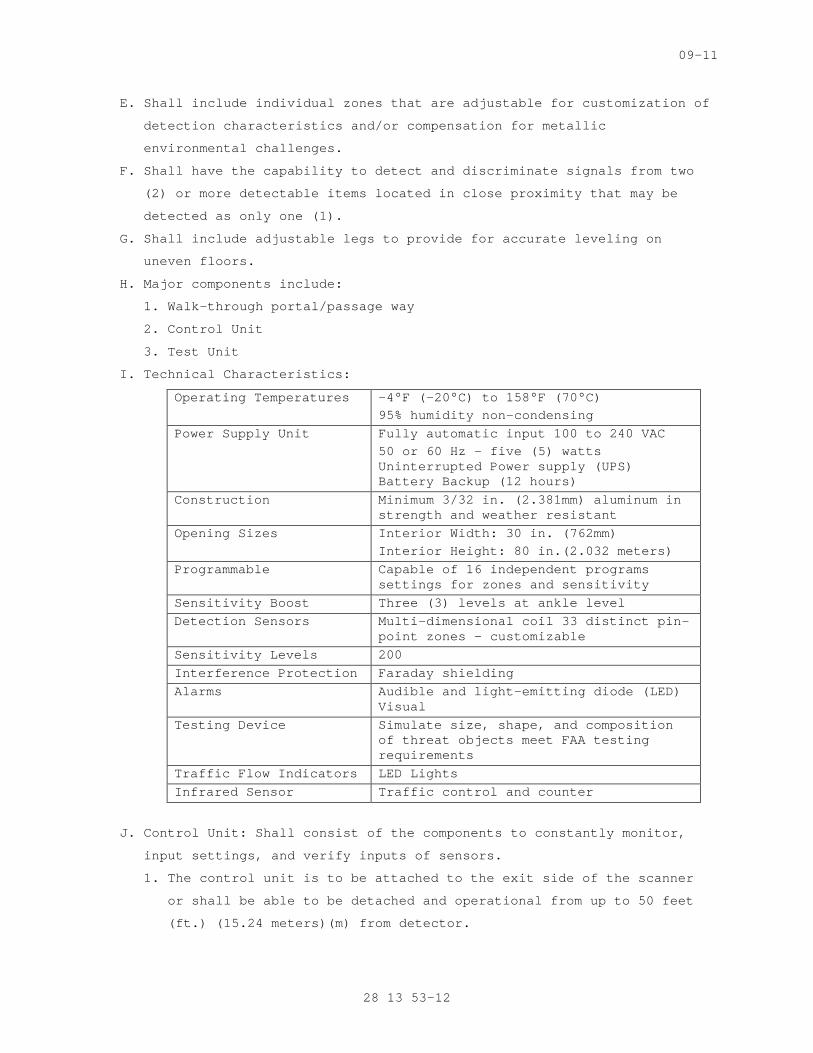
09-11
E. Shall include individual zones that are adjustable for customization of
detection characteristics and/or compensation for metallic
environmental challenges.
F. Shall have the capability to detect and discriminate signals from two
(2) or more detectable items located in close proximity that may be
detected as only one (1).
G. Shall include adjustable legs to provide for accurate leveling on
uneven floors.
H. Major components include:
1. Walk-through portal/passage way
2. Control Unit
3. Test Unit
I. Technical Characteristics:
Operating Temperatures -4°F (-20°C) to 158°F (70°C) 95% humidity non-condensing
Power Supply Unit Fully automatic input 100 to 240 VAC 50 or 60 Hz – five (5) watts Uninterrupted Power supply (UPS) Battery Backup (12 hours)
Construction Minimum 3/32 in. (2.381mm) aluminum in strength and weather resistant
Opening Sizes Interior Width: 30 in. (762mm) Interior Height: 80 in.(2.032 meters)
Programmable Capable of 16 independent programs settings for zones and sensitivity
Sensitivity Boost Three (3) levels at ankle level Detection Sensors Multi-dimensional coil 33 distinct pin-
point zones – customizable Sensitivity Levels 200 Interference Protection Faraday shielding Alarms Audible and light-emitting diode (LED)
Visual Testing Device Simulate size, shape, and composition
of threat objects meet FAA testing requirements
Traffic Flow Indicators LED Lights Infrared Sensor Traffic control and counter
J. Control Unit: Shall consist of the components to constantly monitor,
input settings, and verify inputs of sensors.
1. The control unit is to be attached to the exit side of the scanner
or shall be able to be detached and operational from up to 50 feet
(ft.) (15.24 meters)(m) from detector.
28 13 53-12
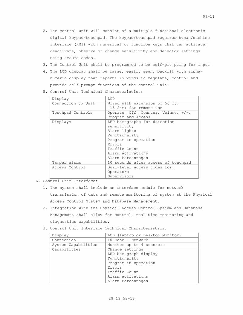
09-11
2. The control unit will consist of a multiple functional electronic
digital keypad/touchpad. The keypad/touchpad requires human/machine
interface (HMI) with numerical or function keys that can activate,
deactivate, observe or change sensitivity and detector settings
using secure codes.
3. The Control Unit shall be programmed to be self-prompting for input.
4. The LCD display shall be large, easily seen, backlit with alpha-
numeric display that reports in words to regulate, control and
provide self-prompt functions of the control unit.
5. Control Unit Technical Characteristics:
Display LCD Connection to Unit Wired with extension of 50 ft.
(15.24m) for remote use Touchpad Controls Operate, Off, Counter, Volume, +/-,
Program and Access Displays LED bar-graphs for detection
sensitivity Alarm lights Functionality Program in operation Errors Traffic Count Alarm activations Alarm Percentages
Tamper alarm 10 seconds after access of touchpad Access Control Dual-level access codes for:
Operators Supervisors
K. Control Unit Interface:
1. The system shall include an interface module for network
transmission of data and remote monitoring of system at the Physical
Access Control System and Database Management.
2. Integration with the Physical Access Control System and Database
Management shall allow for control, real time monitoring and
diagnostics capabilities.
3. Control Unit Interface Technical Characteristics:
Display LCD (laptop or Desktop Monitor) Connection 10-Base T Network System Capabilities Monitor up to 4 scanners Capabilities Change settings
LED bar-graph display Functionality Program in operation Errors Traffic Count Alarm activations Alarm Percentages
28 13 53-13
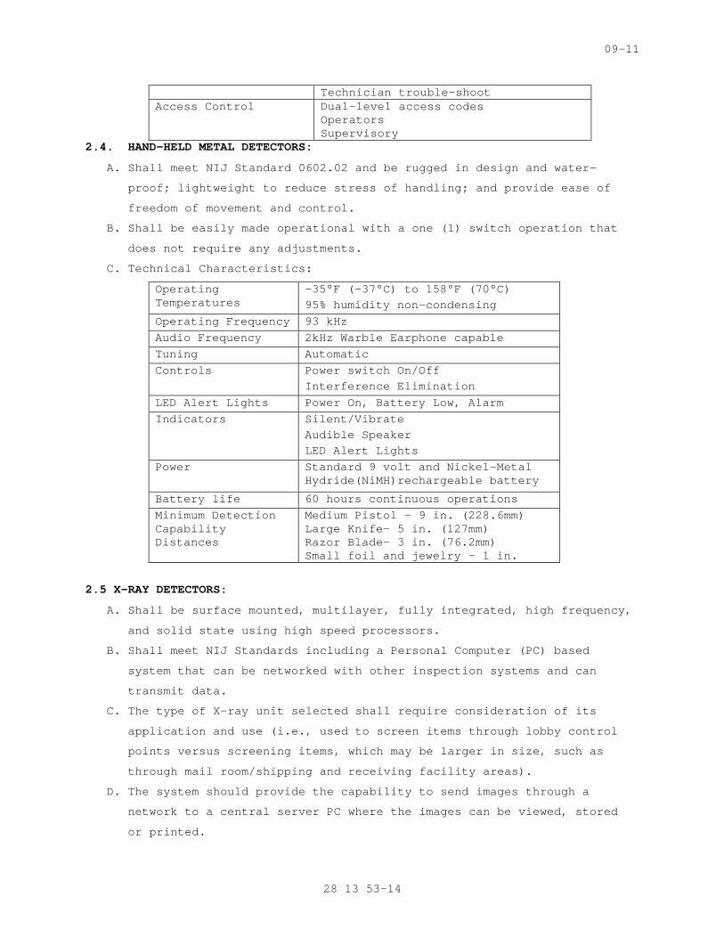
09-11
Technician trouble-shoot Access Control Dual-level access codes
Operators Supervisory
2.4. HAND-HELD METAL DETECTORS:
A. Shall meet NIJ Standard 0602.02 and be rugged in design and water-
proof; lightweight to reduce stress of handling; and provide ease of
freedom of movement and control.
B. Shall be easily made operational with a one (1) switch operation that
does not require any adjustments.
C. Technical Characteristics:
Operating Temperatures
-35°F (-37°C) to 158°F (70°C) 95% humidity non-condensing
Operating Frequency 93 kHz Audio Frequency 2kHz Warble Earphone capable Tuning Automatic Controls Power switch On/Off
Interference Elimination LED Alert Lights Power On, Battery Low, Alarm Indicators Silent/Vibrate
Audible Speaker LED Alert Lights
Power Standard 9 volt and Nickel-Metal Hydride(NiMH)rechargeable battery
Battery life 60 hours continuous operations Minimum Detection Capability Distances
Medium Pistol – 9 in. (228.6mm) Large Knife- 5 in. (127mm) Razor Blade- 3 in. (76.2mm) Small foil and jewelry – 1 in.
2.5 X-RAY DETECTORS:
A. Shall be surface mounted, multilayer, fully integrated, high frequency,
and solid state using high speed processors.
B. Shall meet NIJ Standards including a Personal Computer (PC) based
system that can be networked with other inspection systems and can
transmit data.
C. The type of X-ray unit selected shall require consideration of its
application and use (i.e., used to screen items through lobby control
points versus screening items, which may be larger in size, such as
through mail room/shipping and receiving facility areas).
D. The system should provide the capability to send images through a
network to a central server PC where the images can be viewed, stored
or printed.
28 13 53-14
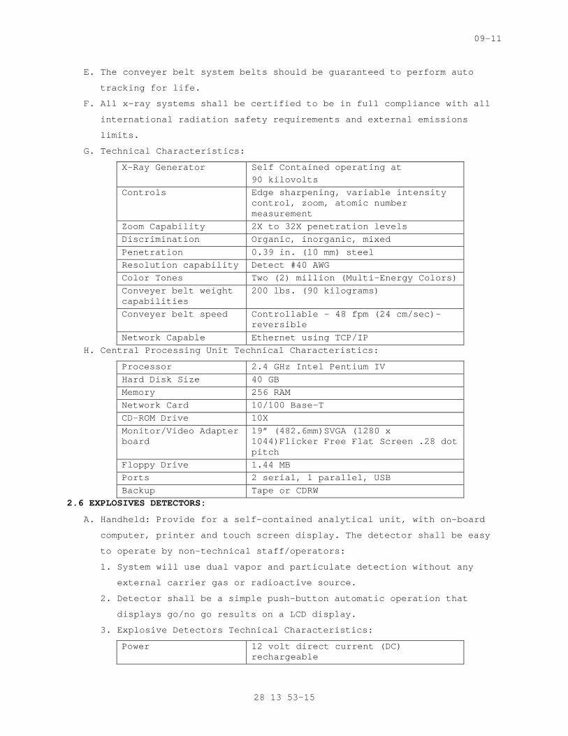
09-11
E. The conveyer belt system belts should be guaranteed to perform auto
tracking for life.
F. All x-ray systems shall be certified to be in full compliance with all
international radiation safety requirements and external emissions
limits.
G. Technical Characteristics:
X-Ray Generator Self Contained operating at 90 kilovolts
Controls Edge sharpening, variable intensity control, zoom, atomic number measurement
Zoom Capability 2X to 32X penetration levels Discrimination Organic, inorganic, mixed Penetration 0.39 in. (10 mm) steel Resolution capability Detect #40 AWG Color Tones Two (2) million (Multi-Energy Colors) Conveyer belt weight capabilities
200 lbs. (90 kilograms)
Conveyer belt speed Controllable – 48 fpm (24 cm/sec)- reversible
Network Capable Ethernet using TCP/IP H. Central Processing Unit Technical Characteristics:
Processor 2.4 GHz Intel Pentium IV Hard Disk Size 40 GB Memory 256 RAM Network Card 10/100 Base-T CD-ROM Drive 10X Monitor/Video Adapter board
19” (482.6mm)SVGA (1280 x 1044)Flicker Free Flat Screen .28 dot pitch
Floppy Drive 1.44 MB Ports 2 serial, 1 parallel, USB Backup Tape or CDRW
2.6 EXPLOSIVES DETECTORS:
A. Handheld: Provide for a self-contained analytical unit, with on-board
computer, printer and touch screen display. The detector shall be easy
to operate by non-technical staff/operators:
1. System will use dual vapor and particulate detection without any
external carrier gas or radioactive source.
2. Detector shall be a simple push-button automatic operation that
displays go/no go results on a LCD display.
3. Explosive Detectors Technical Characteristics:
Power 12 volt direct current (DC) rechargeable
28 13 53-15
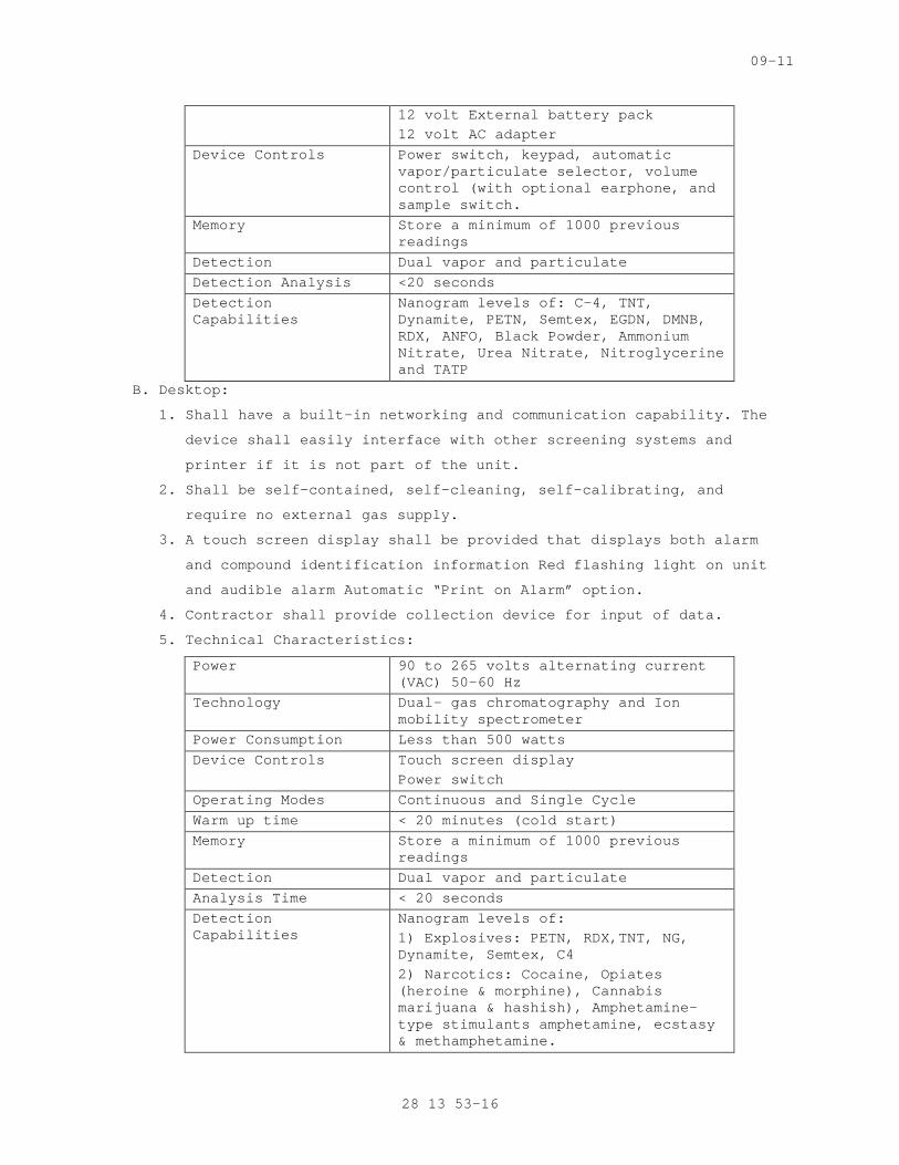
09-11
12 volt External battery pack 12 volt AC adapter
Device Controls Power switch, keypad, automatic vapor/particulate selector, volume control (with optional earphone, and sample switch.
Memory Store a minimum of 1000 previous readings
Detection Dual vapor and particulate Detection Analysis <20 seconds Detection Capabilities
Nanogram levels of: C-4, TNT, Dynamite, PETN, Semtex, EGDN, DMNB, RDX, ANFO, Black Powder, Ammonium Nitrate, Urea Nitrate, Nitroglycerine and TATP
B. Desktop:
1. Shall have a built-in networking and communication capability. The
device shall easily interface with other screening systems and
printer if it is not part of the unit.
2. Shall be self-contained, self-cleaning, self-calibrating, and
require no external gas supply.
3. A touch screen display shall be provided that displays both alarm
and compound identification information Red flashing light on unit
and audible alarm Automatic “Print on Alarm” option.
4. Contractor shall provide collection device for input of data.
5. Technical Characteristics:
Power 90 to 265 volts alternating current (VAC) 50-60 Hz
Technology Dual- gas chromatography and Ion mobility spectrometer
Power Consumption Less than 500 watts Device Controls Touch screen display
Power switch Operating Modes Continuous and Single Cycle Warm up time < 20 minutes (cold start) Memory Store a minimum of 1000 previous
readings Detection Dual vapor and particulate Analysis Time < 20 seconds Detection Capabilities
Nanogram levels of: 1) Explosives: PETN, RDX,TNT, NG, Dynamite, Semtex, C4 2) Narcotics: Cocaine, Opiates (heroine & morphine), Cannabis marijuana & hashish), Amphetamine-type stimulants amphetamine, ecstasy & methamphetamine.
28 13 53-16
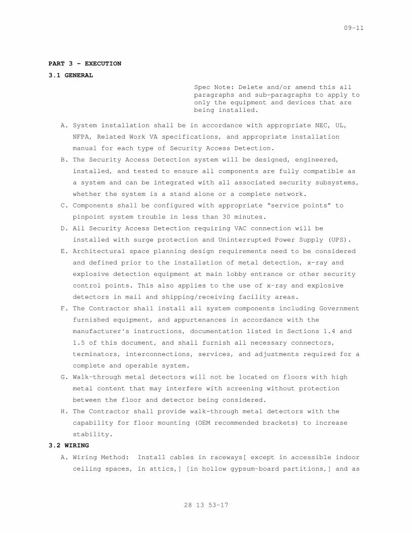
09-11
PART 3 - EXECUTION
3.1 GENERAL
Spec Note: Delete and/or amend this all paragraphs and sub-paragraphs to apply to only the equipment and devices that are being installed.
A. System installation shall be in accordance with appropriate NEC, UL,
NFPA, Related Work VA specifications, and appropriate installation
manual for each type of Security Access Detection.
B. The Security Access Detection system will be designed, engineered,
installed, and tested to ensure all components are fully compatible as
a system and can be integrated with all associated security subsystems,
whether the system is a stand alone or a complete network.
C. Components shall be configured with appropriate “service points” to
pinpoint system trouble in less than 30 minutes.
D. All Security Access Detection requiring VAC connection will be
installed with surge protection and Uninterrupted Power Supply (UPS).
E. Architectural space planning design requirements need to be considered
and defined prior to the installation of metal detection, x-ray and
explosive detection equipment at main lobby entrance or other security
control points. This also applies to the use of x-ray and explosive
detectors in mail and shipping/receiving facility areas.
F. The Contractor shall install all system components including Government
furnished equipment, and appurtenances in accordance with the
manufacturer's instructions, documentation listed in Sections 1.4 and
1.5 of this document, and shall furnish all necessary connectors,
terminators, interconnections, services, and adjustments required for a
complete and operable system.
G. Walk-through metal detectors will not be located on floors with high
metal content that may interfere with screening without protection
between the floor and detector being considered.
H. The Contractor shall provide walk-through metal detectors with the
capability for floor mounting (OEM recommended brackets) to increase
stability.
3.2 WIRING
A. Wiring Method: Install cables in raceways[ except in accessible indoor
ceiling spaces, in attics,] [in hollow gypsum-board partitions,] and as
28 13 53-17
09-11
otherwise indicated. Conceal raceways and wiring except in unfinished
spaces.
SPECS WRITER NOTE: Retain paragraph above or first paragraph below. Delete both if wiring method is indicated on Drawings.
B. Wiring Method: Install cables concealed in accessible ceilings, walls,
and floors where possible.
C. Wiring within Enclosures: Bundle, lace, and train conductors to
terminal points with no excess and without exceeding manufacturer's
limitations on bending radii. Provide and use lacing bars and
distribution spools.
D. Splices, Taps, and Terminations: For power and control wiring, use
numbered terminal strips in junction, pull, and outlet boxes; terminal
cabinets; and equipment enclosures. Tighten electrical connectors and
terminals according to manufacturer's published torque-tightening
values. If manufacturer's torque values are not indicated, use those
specified in UL 486A and UL 486B.
SPECS WRITER NOTE: Retain paragraph below only if required by manufacturer. Show independent-signal circuit-grounding methods and details on Drawings.
E. Grounding: Provide independent-signal circuit grounding recommended in
writing by manufacturer.
3.3 FIELD QUALITY CONTROL
A. Manufacturer's Field Service: Engage a factory-authorized service
representative to inspect field-assembled components and equipment
installation and supervise pretesting, testing, and adjusting of video
surveillance equipment.
B. Inspection: Verify that units and controls are properly installed,
connected, and labeled, and that interconnecting wires and terminals
are identified.
C. Test Schedule: Schedule tests after pretesting has been successfully
completed and system has been in normal functional operation for at
least 14 days. Provide a minimum of 10 days' notice of test schedule.
D. Operational Tests: Perform operational system tests to verify that
system complies with Specifications. Include all modes of system
operation. Test equipment for proper operation in all functional
modes.
E. Remove and replace malfunctioning items and retest as specified above.
F. Record test results for each piece of equipment.
28 13 53-18
09-11
G. Retest: Correct deficiencies identified by tests and observations and
retest until specified requirements are met.
3.4 ADJUSTING
A. Occupancy Adjustments: When requested within 12 months of date of
Substantial Completion, provide on-site assistance in adjusting system
to suit actual occupied conditions and to optimize performance of the
installed equipment. Tasks shall include, but are not limited to, the
following:
1. Check cable connections.
2. Check proper operation of detectors.
3. Recommend changes to walk trough detectors, X-ray machines, and
associated equipment to improve Owner' utilization of security
access detection system.
4. Provide a written report of adjustments and recommendations.
B. Adjustment/Alignment/Synchronization: Contractor shall prepare for
system activation by following manufacturer’s recommended procedures
for adjustment, alignment, programming, or synchronization. Prepare
each component in accordance with appropriate provisions of the
component’s installation, operations, and maintenance instructions.
3.5 CLEANING
A. Cleaning: Subsequent to installation, clean each system component of
dust, dirt, grease, or oil incurred during installation in accordance
to manufacture instructions.
3.6 INTEGRATION
A. For integration purposes, the Security Access Detection system shall be
integrated with the Physical Access Control System and Database
Management via CAT-V cables and where appropriate with CCTV and EPPS.
The CCTV Security System will:
1. Provide full coverage of all lobby entrance screening areas
utilizing a fixed color camera.
2. Record activity on a 24 hours basis.
3. The CCTV system should have facial recognition software to assist in
identifying individuals for current and future purposes.
4. For additional CCTV system requirements as they relate to the
Security Access Detection, refer to Section 28 13 53, SECURITY
ACCESS DETECTION.
B. Integration with CCTV and EPPS security subsystems shall be achieved by
computer programming or the direct hardwiring of the systems.
28 13 53-19
09-11
C. For programming purposes, refer to the manufacturers requirements for
correct system operations. Ensure computer hardware being utilized for
system integration meets or exceeds the minimum system requirements as
well as systems software requirements.
3.7 EXISTING CONDITIONS
A. The Contractor shall visit the site and verify that site conditions are
in agreement/compliance with the design package. The Contractor shall
report all changes to the site or conditions that will affect
performance of the system to the Contracting Officer in the form of a
report. The Contractor shall not take any corrective action without
written permission received from the Contracting Officer.
B. Existing Equipment
1. The Contractor shall connect to and utilize existing equipment, and
control signal transmission lines, and devices as outlined in the
design package. Equipment and signal lines that are usable in their
original configuration without modification may be reused with
Contracting Officer approval.
2. The Contractor shall perform a field survey, including testing and
inspection of all existing equipment, power outlets, and signal
lines intended to be used by the Security Access Detection, and
furnish a report to the Contracting Officer as part of the site
survey report. For those items considered nonfunctioning, provide
(with the report) specification sheets, or written functional
requirements to support the findings and the estimated cost to
correct the deficiency. As part of the report, the Contractor shall
include a schedule for connection to all existing equipment.
3. The Contractor shall make written requests and obtain approval prior
to disconnecting any signal lines and equipment, and creating
equipment downtime. Such work shall proceed only after receiving
Contracting Officer approval of these requests. If any device fails
after the Contractor has commenced work on that device, signal or
control line, the Contractor shall diagnose the failure and perform
any necessary corrections to the equipment.
4. The Contractor shall be held responsible for repair costs due to
Contractor negligence, abuse, or improper installation of equipment.
5. The Contracting Officer shall provide a full list of all equipment
that is to be removed or replaced by the Contractor. The Contractor
shall dispose of all equipment that has been removed or replaced. In
28 13 53-20
09-11
all areas where equipment is removed or replaced the Contractor
shall repair those areas to match the current existing conditions.
3.8 SYSTEM START-UP AND TESTING
A. System Start-Up
1. The Contractor shall not apply power to any installed Security
Access Detection until the following items have been completed:
a. Security Access Detection equipment items have been set up in
accordance with manufacturer's instructions.
b. A visual inspection of the Security Access Detection system has
been conducted to ensure that defective equipment items have not
been installed and that there are no loose connections.
c. System wiring has been tested and verified as correctly connected
as indicated.
d. All system grounding and transient protection systems have been
verified as installed and connected as indicated.
e. Power supplies to be connected to the Security Access Detection
system have been verified as the correct voltage, phasing, and
frequency as indicated by the manufacturer.
2. Satisfaction of the above requirements shall not relieve the
Contractor of responsibility for incorrect installation, defective
equipment items, or collateral damage as a result of Contractor work
efforts.
B. Supplemental Contractor Quality Control: The following requirements
supplement the Contractor quality control requirements specified
elsewhere in the contract:
1. The Contractor shall provide the services of technical
representatives who are familiar with all components and
installation procedures of any installed Security Access Detection;
and are approved by the Contracting Officer.
2. The Contractor will be present on the job site during the
preparatory and initial phases of quality control to provide
technical assistance.
3. The Contractor shall also be available on an as needed basis to
provide assistance with follow-up phases of quality control.
4. The Contractor shall participate in the testing and validation of
the system and shall provide certification that the system installed
is fully operational as all construction document requirements have
been fulfilled.
28 13 53-21

09-11
C. All testing and training shall be compliant with the VA General
Requirements, Section 01 00 00, GENERAL REQUIREMENTS.
D. The Commissioning Agent will observe startup and contractor testing of
selected equipment. Coordinate the startup and contractor testing
schedules with the Resident Engineer and Commissioning Agent. Provide
a minimum of 7 days prior notice.
3.9 COMMISSIONING
A. Provide commissioning documentation in accordance with the requirements
of Section 28 08 00 – COMMISSIONING OF ELECTRONIC SAFETY AND SECURITY
SYSTEMS for all inspection, start up, and contractor testing required
above and required by the System Readiness Checklist provided by the
Commissioning Agent.
B. Components provided under this section of the specification will be
tested as part of a larger system. Refer to Section 28 08 00 –
COMMISSIONING OF ELECTRONIC SAFETY AND SECURITY SYSTEMS and related
sections for contractor responsibilities for system commissioning.
-----END----
28 13 53-22
10-11
SECTION 28 16 00 INTRUSION DETECTION SYSTEM
SPECS WRITER NOTE: Delete // ________ // if not applicable to project. Also delete any other item or paragraph not applicable in the section and renumber the paragraphs. Insert additional provisions as required for this project.
PART 1 – GENERAL
1.1 DESCRIPTION
A. Provide and install a complete Intrusion Detection System, hereinafter
referred to as IDS, as specified in this section.
B. This Section includes the following:
1. Intrusion detection with [hard-wired] [multiplexed], modular,
microprocessor-based controls, intrusion sensors and detection
devices, and communication links to perform monitoring, alarm, and
control functions.
2. Responsibility for integrating electronic and electrical systems and
equipment is specified in the following Sections, with Work
specified in this Section:
a. Division 08 Section "DOOR HARDWARE".
b. Division 14 Section "ELECTRIC TRACTION ELEVATORS".
c. Division 27 Section "INTERCOMMUNICATIONS AND PROGRAM SYSTEMS".
d. Division 28 Section "PHYSICAL ACCESS CONTROL".
e. Division 28 Section "FIRE DETECTION AND ALARM".
f. Division 28 Section "VIDEO SURVEILLANCE".
g. Division 32 Section "CHAIN LINK FENCES AND GATES".
C. Related Sections include the following:
1. Division 28 Section "VIDEO SURVEILLANCE" for closed-circuit
television cameras that are used as devices for video motion
detection.
2. Division 28 Section "CONDUCTORS AND CABLES FOR ELECTRONIC SAFETY AND
SECURITY" for cabling between central-station control units and
field-mounted devices and controllers.
1.2 RELATED WORK
SPECS WRITER NOTE: Delete any item or paragraph not applicable in the section.
A. Section 01 00 00 - GENERAL REQUIREMENTS. For General Requirements.
B. Section 07 84 00 - FIRESTOPPING. Requirements for firestopping
application and use.
28 16 00-1
10-11
C. Section 14 21 00 - ELECTRIC TRACTION ELEVATORS. Requirements for
elevators.
D. Section 14 24 00 - HYDRAULIC ELEVATORS. Requirements for elevators.
E. Section 10 14 00 - SIGNAGE. Requirements for labeling and signs.
F. Section 26 05 11 - REQUIREMENTS FOR ELECTRICAL INSTALLATIONS.
Requirements for connection of high voltage.
G. Section 26 05 21 - LOW VOLTAGE ELECTRICAL POWER CONDUCTORS AND CABLES
(600 VOLTS AND BELOW). Requirements for power cables.
H. Section 28 05 00 – COMMON WORK RESULTS FOR ELECTRONIC SAFETY AND
SECURITY. Requirements for general requirements that are common to more
than one section in Division 28.
I. Section 28 05 13 - CONDUCTORS AND CABLES FOR ELECTRONIC SAFETY AND
SECURITY. Requirements for conductors and cables.
J. Section 28 05 26 - GROUNDING AND BONDING FOR ELECTRONIC SAFETY AND
SECURITY. Requirements for grounding of equipment.
K. Section 28 05 28.33 - CONDUITS AND BACKBOXES FOR ELECTRONIC SAFETY AND
SECURITY. Requirements for infrastructure.
L. Section 28 08 00 - COMMISIONING OF ELECTRONIC SAFETY AND SECURITY.
Requirements for commissioning - systems readiness checklists, and
training.
M. Section 28 13 00 - PHYSICAL ACCESS CONTROL SYSTEMS (PACS). Requirements
for physical access control integration.
N. Section 28 13 16 - ACCESS CONTROL SYSTEM AND DATABASE MANAGEMENT.
Requirements for control and operation of all security systems.
O. Section 28 23 00 - VIDEO SURVEILLANCE. Requirements for security camera
systems.
P. Section 28 26 00 - ELECTRONIC PERSONAL PROTECTION SYSTEM (EPPS).
Requirements for emergency and interior communications.
Q. Section 28 31 00 - FIRE DETECTION AND ALARM. Requirements for
integration with fire detection and alarm system.
1.3 QUALITY ASSURANCE
A. The Contractor shall be responsible for providing, installing, and the
operation of the IDS as shown. The Contractor shall also provide
certification as required.
B. The security system shall be installed and tested to ensure all
components are fully compatible as a system and can be integrated with
all associated security subsystems, whether the security system is
28 16 00-2
10-11
stand-alone or a part of a complete Information Technology (IT)
computer network.
C. The Contractor or security sub-contractor shall be a licensed security
Contractor as required within the state or jurisdiction of where the
installation work is being conducted.
1.4 DEFINITIONS
A. Controller: An intelligent peripheral control unit that uses a
computer for controlling its operation. Where this term is presented
with an initial capital letter, this definition applies.
B. I/O: Input/Output.
C. Intrusion Zone: A space or area for which an intrusion must be
detected and uniquely identified, the sensor or group of sensors
assigned to perform the detection, and any interface equipment between
sensors and communication link to central-station control unit.
D. LED: Light-emitting diode.
E. NEC: National Electric Code
F. NEMA: National Electrical Manufacturers Association
G. NFPA: National Fire Protection Association
H. NRTL: Nationally Recognized Testing Laboratory.
I. SMS: Security Management System – A SMS is software that incorporates
multiple security subsystems (e.g., physical access control, intrusion
detection, closed circuit television, intercom) into a single platform
and graphical user interface.
J. PIR: Passive infrared.
K. RF: Radio frequency.
L. Standard Intruder: A person who weighs 45 kg (100 lb.) or less and
whose height is 1525 mm (60 in) or less; dressed in a long-sleeved
shirt, slacks, and shoes.
M. Standard-Intruder Movement: Any movement, such as walking, running,
crawling, rolling, or jumping, of a "standard intruder" in a protected
zone.
N. TCP/IP: Transport control protocol/Internet protocol incorporated into
Microsoft Windows.
O. UPS: Uninterruptible Power Supply
P. UTP: Unshielded Twisted Pair
1.5 SUBMITTALS
SPEC WRITER NOTE: Delete and/or amend all paragraphs and sub-paragraphs and information as needed to ensure that only
28 16 00-3
10-11
the documentation required is requested per the Request for Proposal (RFP).
//A. Refer to Section 28 05 00, Part1//
A. Submit below items in conjunction with Master Specification Sections 01
33 23, SHOP DRAWINGS, PRODUCT DATA, AND SAMPLES, and Section 02 41 00,
DEMOLITION.
B. Provide certificates of compliance with Section 1.3, Quality Assurance.
C. Provide a shop drawing and as-built design package in both electronic
format and on paper, minimum size 1220 x 1220 millimeters (48 x 48
inches); drawing submittals shall be per the established project
schedule.
D. Shop drawing and as-built packages shall include, but not be limited
to:
1. Index Sheet that shall:
a. Define each page of the design package to include facility name,
building name, floor, and sheet number.
b. Provide a list of all security abbreviations and symbols.
c. Reference all general notes that are utilized within the design
package.
d. Specification and scope of work pages for all security systems
that are applicable to the design package that will:
1) Outline all general and job specific work required within the
design package.
2) Provide a device identification table outlining device
Identification (ID) and use for all security systems equipment
utilized in the design package.
2. Drawing sheets that will be plotted on the individual floor plans or
site plans shall:
a. Include a title block as defined above.
b. Define the drawings scale in both standard and metric
measurements.
c. Provide device identification and location.
d. Address all signal and power conduit runs and sizes that are
associated with the design of the electronic security system and
other security elements (e.g., barriers, etc.).
e. Identify all pull box and conduit locations, sizes, and fill
capacities.
f. Address all general and drawing specific notes for a particular
drawing sheet.
28 16 00-4
10-11
3. A riser drawing for each applicable security subsystem shall:
a. Indicate the sequence of operation.
b. Relationship of integrated components on one diagram.
c. Include the number, size, identification, and maximum lengths of
interconnecting wires.
d. Wire/cable types shall be defined by a wire and cable schedule.
The schedule shall utilize a lettering system that will
correspond to the wire/cable it represents (example: A = 18 AWG/1
Pair Twisted, Unshielded). This schedule shall also provide the
manufacturer’s name and part number for the wire/cable being
installed.
4. A system drawing for each applicable security system shall:
a. Identify how all equipment within the system, from main panel to
device, shall be laid out and connected.
b. Provide full detail of all system components wiring from point-
to-point.
c. Identify wire types utilized for connection, interconnection with
associate security subsystems.
d. Show device locations that correspond to the floor plans.
e. All general and drawing specific notes shall be included with the
system drawings.
5. A schedule for all of the applicable security subsystems shall be
included. All schedules shall provide the following information:
a. Device ID.
b. Device Location (e.g. site, building, floor, room number,
location, and description).
c. Mounting type (e.g. flush, wall, surface, etc.).
d. Power supply or circuit breaker and power panel number.
e. In addition, for the IDS, provide the sensor ID, sensor type and
housing model number.
6. Detail and elevation drawings for all devices that define how they
were installed and mounted.
E. Shop drawing packages shall be reviewed by the Contractor along with a
VA representative to ensure all work has been clearly defined and
completed. All reviews shall be conducted in accordance with the
project schedule. There shall be four (4) stages to the review process:
1. 35 percent
2. 65 percent
28 16 00-5
10-11
3. 90 percent
4. 100 percent
F. Provide manufacturer security system product cut-sheets. Submit for
approval at least 30 days prior to commencement of formal testing, a
Security System Operational Test Plan. Include procedures for
operational testing of each component and security subsystem, to
include performance of an integrated system test.
G. Submit manufacture’s certification of Underwriters Laboratories, Inc.
(UL) listing as specified. Provide all maintenance and operating
manuals per the VA General Requirements, Section 01 00 00, GENERAL
REQUIREMENTS.
H. Completed System Readiness Checklists provided by the Commissioning
Agent and completed by the contractor, signed by a qualified technician
and dated on the date of completion, in accordance with the
requirements of Section 28 08 00 COMMISSIONING OF ELECTRONIC SAFETY AND
SECURITY SYSTEMS.
1.6 APPLICABLE PUBLICATIONS
A. The publications listed below (including amendments, addenda,
revisions, supplement, and errata) form a part of this specification to
the extent referenced. The publications are referenced in the text by
the basic designation only.
B. American National Standards Institute (ANSI)/Security Industry
Association (SIA):
PIR-01-00...............Passive Infrared Motion Detector Standard -
Features for Enhancing False Alarm Immunity
CP-01-00................Control Panel Standard-Features for False Alarm
Reduction
C. Department of Justice American Disability Act (ADA)
28 CFR Part 36..........2010 ADA Standards for Accessible Design
D. Federal Communications Commission (FCC):
(47 CFR 15) Part 15.....Limitations on the Use of Wireless
Equipment/Systems
E. National Electrical Manufactures Association (NEMA):
250-08..................Enclosures for Electrical Equipment (1000 Volts
Maximum)
F. National Fire Protection Association (NFPA):
70-11...................National Electrical Code
28 16 00-6
10-11
731-08..................Standards for the Installation of Electric
Premises Security Systems
G. Underwriters Laboratories, Inc. (UL):
464-09..................Audible Signal Appliances
609-96..................Local Burglar Alarm Units and Systems
634-07..................Standards for Connectors with Burglar-Alarm
Systems
639-07..................Standards for Intrusion Detection Units
1037-09.................Standard for Anti-theft Alarms and Devices
1635-10.................Digital Alarm Communicator System Units
H. Uniform Federal Accessibility Standards (UFAS), 19841.
1.7 COORDINATION
A. Coordinate arrangement, mounting, and support of intrusion detection
system equipment:
1. To allow maximum possible headroom unless specific mounting heights
that reduce headroom are indicated.
2. To provide for ease of disconnecting the equipment with minimum
interference to other installations.
3. To allow right of way for piping and conduit installed at required
slope.
4. So connecting raceways, cables, wireways, cable trays, and busways
will be clear of obstructions and of the working and access space of
other equipment.
B. Coordinate installation of required supporting devices and set sleeves
in cast-in-place concrete, masonry walls, and other structural
components as they are constructed.
C. Coordinate location of access panels and doors for electronic safety
and security items that are behind finished surfaces or otherwise
concealed.
1.8 EQUIPMENT AND MATERIALS
A. General
1. All equipment associated within the IDS shall be rated for
continuous operation. Environmental conditions (i.e. temperature,
humidity, wind, and seismic activity) shall be taken under
consideration at each facility and site location prior to
installation of the equipment.
2. All equipment shall operate on a 120 or 240 volts alternating
current (VAC); 50 Hz or 60 Hz AC power system unless documented
28 16 00-7
10-11
otherwise in subsequent sections listed within this specification.
All equipment shall have a back-up source of power that will provide
a minimum of 96 hours of run time in the event of a loss of primary
power to the facility.
3. The system shall be designed, installed, and programmed in a manner
that will allow for ease of operation, programming, servicing,
maintenance, testing, and upgrading of the system.
4. All IDS components located in designated “HAZARDOUS ENVIRONMENT”
areas where fire or explosion could occur due to the presence of
natural gases or vapors, flammable liquids, combustible residue, or
ignitable fibers or debris, shall be rated Class II, Division I,
Group F, and installed in accordance with National Fire Protection
Association (NFPA) 70 National Electric Code, Chapter 5.
5. All equipment and materials for the system will be compatible to
ensure functional operation in accordance with requirements.
1.9 WARRANTY OF CONSTRUCTION.
A. Warrant IDS work subject to the Article “Warranty of Construction” of
FAR 52.246-21.
B. Demonstration and training shall be performed prior to system
acceptance.
PART 2 – PRODUCTS
SPEC WRITER NOTE: Delete or amend all paragraphs and sub-paragraphs as needed to ensure that only the equipment required per the Request for Proposal (RFP) is provided.
2.1 FUNCTIONAL DESCRIPTION OF SYSTEM
SPEC WRITER NOTE: Revise functional description to fit the project requirements.
A. Supervision: System components shall be continuously monitored for
normal, alarm, supervisory, and trouble conditions. Indicate
deviations from normal conditions at any location in system.
Indication includes identification of device or circuit in which
deviation has occurred and whether deviation is an alarm or
malfunction.
SPEC WRITER NOTE: Retain subparagraphs below if retaining option in paragraph above.
28 16 00-8
10-11
1. Alarm Signal: Display at central-station control unit and actuate
audible and visual alarm devices.
2. Trouble Condition Signal: Distinct from other signals, indicating
that system is not fully functional. Trouble signal shall indicate
system problems such as battery failure, open or shorted
transmission line conductors, or controller failure.
3. Supervisory Condition Signal: Distinct from other signals,
indicating an abnormal condition as specified for the particular
device or controller.
SPEC WRITER NOTE: Select one of the first two paragraphs below.
B. System Control: Central-station control unit shall directly monitor
intrusion detection units and connecting wiring.
C. System Control: Central-station control unit shall directly monitor
intrusion detection devices /, perimeter detection units,/ /,
controllers associated with perimeter detection units,/ and connecting
wiring in a multiplexed distributed control system or as part of a
network.
D. System shall automatically reboot program without error or loss of
status or alarm data after any system disturbance.
E. Operator Commands:
SPEC WRITER NOTE: Edit list below to suit Project. Coordinate with operator commands listed for "Central-Station Control Units" Article. Delete nonapplicable commands.
1. Help with System Operation: Display all commands available to
operator. Help command, followed by a specific command, shall
produce a short explanation of the purpose, use, and system reaction
to that command.
2. Acknowledge Alarm: To indicate that alarm message has been observed
by operator.
3. Place Protected Zone in Access: Disable all intrusion-alarm
circuits of a specific protected zone. Tamper circuits may not be
disabled by operator.
4. Place Protected Zone in Secure: Activate all intrusion-alarm
circuits of a protected zone.
5. Protected Zone Test: Initiate operational test of a specific
protected zone.
6. System Test: Initiate system-wide operational test.
28 16 00-9
10-11
7. Print Reports.
SPEC WRITER NOTE: Coordinate function in paragraph below with timing device specified in "Central-Station Control Units" Article.
F. Timed Control at Central-Station Control Unit: Allow automatically
timed "secure" and "access" functions of selected protected zones.
SPEC WRITER NOTE: Retain paragraph and subparagraphs below if alarm signals control lights, elevators, intercom, sound, or closed-circuit television components. Edit to suit Project design and systems integration specifications. Coordinate with Drawings.
G. Automatic Control of Related Systems: Alarm or supervisory signals
from certain intrusion detection devices control the following
functions in related systems:
1. Switch selected lights.
2. Shift elevator control to a different mode.
3. Open a signal path between certain intercommunication stations.
4. Shift sound system to "listening mode" and open a signal path to
certain system speakers.
5. Switch signal to selected monitor from closed-circuit television
camera in vicinity of sensor signaling an alarm.
SPEC WRITER NOTE: Delete paragraph below if no printer in system.
H. Printed Record of Events: Print a record of alarm, supervisory, and
trouble events on system printer. Sort and report by protected zone,
device, and function. When central-station control unit receives a
signal, print a report of alarm, supervisory, or trouble condition.
Report type of signal (alarm, supervisory, or trouble), protected zone
description, date, and time of occurrence. Differentiate alarm signals
from other indications. When system is reset, report reset event with
the same information concerning device, location, date, and time.
Commands shall initiate the reporting of a list of current alarm,
supervisory, and trouble conditions in system or a log of past events.
I. Response Time: 2 seconds between actuation of any alarm and its
indication at central-station control unit.
J. Circuit Supervision: Supervise all signal and data transmission lines,
links with other systems, and sensors from central-station control
unit. Indicate circuit and detection device faults with both protected
zone and trouble signals, sound a distinctive audible tone, and
28 16 00-10
10-11
illuminate an LED. Maximum permissible elapsed time between occurrence
of a trouble condition and indication at central-station control unit
is 20 seconds. Initiate an alarm in response to opening, closing,
shorting, or grounding of a signal or data transmission line.
SPEC WRITER NOTE: Delete paragraph below if not required for the Project. Coordinate with Drawings.
K. Programmed Secure-Access Control: System shall be programmable to
automatically change status of various combinations of protected zones
between secure and access conditions at scheduled times. Status
changes may be preset for repetitive, daily, and weekly; specially
scheduled operations may be preset up to a year in advance. Manual
secure-access control stations shall override programmed settings.
L. Manual Secure-Access Control: Coded entries at manual stations shall
change status of associated protected zone between secure and access
conditions.
2.2 SYSTEM COMPONENT REQUIREMENTS
SPEC WRITER NOTE: Retain first paragraph and subparagraph below if systems integration is required. If retaining, identify equipment and Section that specifies integrated system console.
A. Compatibility: Detection devices and their communication features,
connecting wiring, and central-station control unit shall be selected
and configured with accessories for full compatibility with the
following equipment:
1. Data Gathering Panel, Output Module, Input Module, 28 13 00 PHYSICAL
ACCESS CONTROL SYSTEM.
//2. List devices…//
B. Surge Protection: Protect components from voltage surges originating
external to equipment housing and entering through power,
communication, signal, control, or sensing leads. Include surge
protection for external wiring of each conductor entry connection to
components.
1. Minimum Protection for Power Lines 120 V and More: Auxiliary panel
suppressors complying with requirements in Division 26 Section
TRANSIENT-VOLTAGE SUPPRESSION FOR LOW-VOLTAGE ELECTRICAL POWER
CIRCUITS.
2. Minimum Protection for Communication, Signal, Control, and Low-
Voltage Power Lines: Comply with requirements in Division 26
Section TRANSIENT-VOLTAGE SUPPRESSION FOR LOW-VOLTAGE ELECTRICAL
28 16 00-11
10-11
POWER CIRCUITS as recommended by manufacturer for type of line being
protected.
C. Interference Protection: Components shall be unaffected by radiated
RFI and electrical induction of 15 V/m over a frequency range of 10 to
10,000 MHz and conducted interference signals up to 0.25-V RMS injected
into power supply lines at 10 to 10,000 MHz.
SPEC WRITER NOTE: Coordinate paragraph below with Drawings and detailed component Specifications.
D. Tamper Protection: Tamper switches on detection devices, controllers,
annunciators, pull boxes, junction boxes, cabinets, and other system
components shall initiate a tamper-alarm signal when unit is opened or
partially disassembled and when entering conductors are cut or
disconnected. Central-station control-unit alarm display shall
identify tamper alarms and indicate locations.
SPEC WRITER NOTES: Coordinate three paragraphs below with Drawings and with features listed in central-station control units and at central-station control unit. Delete items not in Project. Indicate features in a device schedule.
E. Self-Testing Devices: Automatically test themselves periodically, but
not less than once per hour, to verify normal device functioning and
alarm initiation capability. Devices transmit test failure to central-
station control unit.
F. Antimasking Devices: Automatically check operation continuously or at
intervals of a minute or less, and use signal-processing logic to
detect blocking, masking, jamming, tampering, or other operational
dysfunction. Devices transmit detection of operational dysfunction to
central-station control unit as an alarm signal.
G. Addressable Devices: Transmitter and receivers shall communicate
unique device identification and status reports to central-station
control unit.
SPEC WRITER NOTE: Delete paragraph below unless remotely adjustable detectors are used.
H. Remote-Controlled Devices: Individually and remotely adjustable for
sensitivity and individually monitored at central-station control unit
for calibration, sensitivity, and alarm condition.
28 16 00-12
10-11
2.3 ENCLOSURES
A. Interior Sensors: Enclosures that protect against dust, falling dirt,
and dripping noncorrosive liquids.
B. Interior Electronics: NEMA 250, Type 12.
C. Exterior Electronics: NEMA 250, Type 4X [fiberglass] [stainless
steel].
D. Corrosion Resistant: NEMA 250, Type 4X [PVC] [stainless steel].
E. Screw Covers: Where enclosures are accessible to inmates, secure with
security fasteners of type appropriate for enclosure.
2.5 EQUIPMENT ITEMS
A. General:
1. All requirements listed below are the minimum specifications that
need to be met in order to comply with the IDS.
2. All IDS sensors shall conform to UL 639, Intrusion Detection
Standard.
3. Ensure that IDS is fully integrated with other security subsystems
as required to include, but not limited to, the CCTV, PACS, EPPS,
and Physical Access Control System and Database Management. The IDS
provided shall not limit the expansion and growth capability to a
single manufacturer and shall allow modular expansion with minimal
equipment modifications.
B. IDS Components: The IDS shall consist of, but not be limited to, the
following components:
1. Control Panel
2. Exterior Detection Devices (Sensors)
3. Interior Detection Devices (Sensors)
4. Power Supply
5. Enclosures
2.6 CONTROL PANEL
A. The Control panel shall be the main point of programming, monitoring,
accessing, securing, and troubleshooting the IDS. Refer to American
National Standards Institute (ANSI) CP-01 Control Panel Standard-
Features for False Alarm Reduction.
B. The Control Panel shall provide a means of reporting alarms to an
Physical Access Control System and Database Management via a computer
interface or direct connection to an alarm control monitoring panel.
C. The Control panel shall utilize a Multifunctional Keypad, Input and
Output Modules for expansion of alarm zones, interfacing with
28 16 00-13
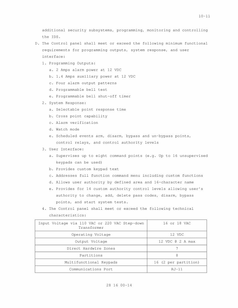
10-11
additional security subsystems, programming, monitoring and controlling
the IDS.
D. The Control panel shall meet or exceed the following minimum functional
requirements for programming outputs, system response, and user
interface:
1. Programming Outputs:
a. 2 Amps alarm power at 12 VDC
b. 1.4 Amps auxiliary power at 12 VDC
c. Four alarm output patterns
d. Programmable bell test
e. Programmable bell shut-off timer
2. System Response:
a. Selectable point response time
b. Cross point capability
c. Alarm verification
d. Watch mode
e. Scheduled events arm, disarm, bypass and un-bypass points,
control relays, and control authority levels
3. User Interface:
a. Supervises up to eight command points (e.g. Up to 16 unsupervised
keypads can be used)
b. Provides custom keypad text
c. Addresses full function command menu including custom functions
d. Allows user authority by defined area and 16-character name
e. Provides for 14 custom authority control levels allowing user’s
authority to change, add, delete pass codes, disarm, bypass
points, and start system tests.
4. The Control panel shall meet or exceed the following technical
characteristics:
Input Voltage via 110 VAC or 220 VAC Step-down Transformer
16 or 18 VAC
Operating Voltage 12 VDC
Output Voltage 12 VDC @ 2 A max
Direct Hardwire Zones 7
Partitions 8
Multifunctional Keypads 16 (2 per partition)
Communications Port RJ-11
28 16 00-14

10-11
E. A multifunctional keypad shall be utilized as a user interface for
arming, disarming, monitoring, troubleshooting, and programming the
alarm control panel.
F. Keypads shall have the following features:
1. Multiple function keypads suitable for remote mounting, no greater
than 1333 m (4000 ft), shall be provided from the control panel and
have a light emitting diode (LED) readout of alarm and trouble
conditions by zone.
2. An alphanumeric English language display, with keypad
programmability, and EE-PROM memory, shall also be provided.
3. Trouble alarm indicators shall be distinguishable from intrusion
alarms.
4. A minimum of four (4) zones selectable as entry and exit with
programmable time delay.
5. Complete system test activated capability at the keypad.
6. Capability for opening and closing reports to a remote monitoring
location.
7. Adjustable entry and exit delay times.
8. Capability for a minimum of two (2) multiple function keypads.
9. Capability to shunt or bypass selected interior zones while arming
perimeter protection and remaining interior zones.
10. Capability for a minimum of seven assignable pass-codes that are
keypad programmable from a suppressed master code.
11. The control panel shall have a communications port that will allow
for communications with a computer for programming, monitoring, and
troubleshooting purposes. The communications port will be, at a
minimum, and RJ-11 or better.
12. The control panel will have a systems success probability of 95% or
better, and shall include the following success considerations:
a. False Alarm: Shall not exceed one (1) false alarm per 30 days per
sensor zone.
b. Nuisance Alarm: Shall not exceed a rate of one (1) alarm per
seven (7) days per zone within the first 60 days after
installation and acceptance. Sensor adjustments will be made and
then shall not exceed one (1) alarm per 30 days.
13. The Control Panel will be able to detect either a line fault or
power loss for all supervised data cables.
28 16 00-15
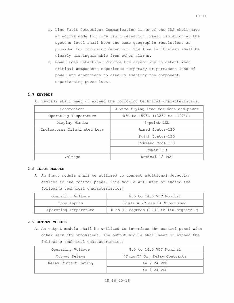
10-11
a. Line Fault Detection: Communication links of the IDS shall have
an active mode for line fault detection. Fault isolation at the
systems level shall have the same geographic resolutions as
provided for intrusion detection. The line fault alarm shall be
clearly distinguishable from other alarms.
b. Power Loss Detection: Provide the capability to detect when
critical components experience temporary or permanent loss of
power and annunciate to clearly identify the component
experiencing power loss.
2.7 KEYPADS
A. Keypads shall meet or exceed the following technical characteristics:
Connections 4-wire flying lead for data and power
Operating Temperature 0°C to +50°C (+32°F to +122°F)
Display Window 8-point LED
Indicators: Illuminated keys Armed Status-LED
Point Status-LED
Command Mode-LED
Power-LED
Voltage Nominal 12 VDC
2.8 INPUT MODULE
A. An input module shall be utilized to connect additional detection
devices to the control panel. This module will meet or exceed the
following technical characteristics:
Operating Voltage 8.5 to 14.5 VDC Nominal
Zone Inputs Style A (Class B) Supervised
Operating Temperature 0 to 40 degrees C (32 to 140 degrees F)
2.9 OUTPUT MODULE
A. An output module shall be utilized to interface the control panel with
other security subsystems. The output module shall meet or exceed the
following technical characteristics:
Operating Voltage 8.5 to 14.5 VDC Nominal
Output Relays “Form C” Dry Relay Contracts
Relay Contact Rating 4A @ 24 VDC
4A @ 24 VAC
28 16 00-16
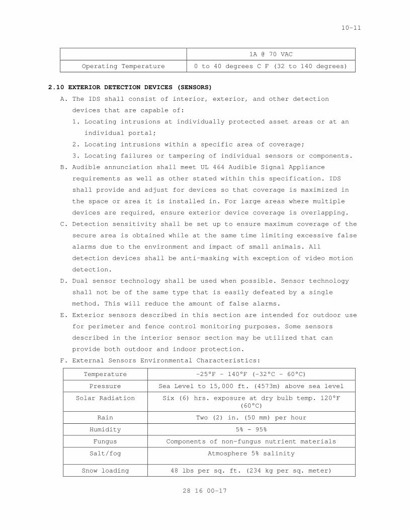
10-11
1A @ 70 VAC
Operating Temperature 0 to 40 degrees C F (32 to 140 degrees)
2.10 EXTERIOR DETECTION DEVICES (SENSORS)
A. The IDS shall consist of interior, exterior, and other detection
devices that are capable of:
1. Locating intrusions at individually protected asset areas or at an
individual portal;
2. Locating intrusions within a specific area of coverage;
3. Locating failures or tampering of individual sensors or components.
B. Audible annunciation shall meet UL 464 Audible Signal Appliance
requirements as well as other stated within this specification. IDS
shall provide and adjust for devices so that coverage is maximized in
the space or area it is installed in. For large areas where multiple
devices are required, ensure exterior device coverage is overlapping.
C. Detection sensitivity shall be set up to ensure maximum coverage of the
secure area is obtained while at the same time limiting excessive false
alarms due to the environment and impact of small animals. All
detection devices shall be anti-masking with exception of video motion
detection.
D. Dual sensor technology shall be used when possible. Sensor technology
shall not be of the same type that is easily defeated by a single
method. This will reduce the amount of false alarms.
E. Exterior sensors described in this section are intended for outdoor use
for perimeter and fence control monitoring purposes. Some sensors
described in the interior sensor section may be utilized that can
provide both outdoor and indoor protection.
F. External Sensors Environmental Characteristics:
Temperature -25°F - 140°F (-32°C - 60°C)
Pressure Sea Level to 15,000 ft. (4573m) above sea level
Solar Radiation Six (6) hrs. exposure at dry bulb temp. 120°F (60°C)
Rain Two (2) in. (50 mm) per hour
Humidity 5% - 95%
Fungus Components of non-fungus nutrient materials
Salt/fog Atmosphere 5% salinity
Snow loading 48 lbs per sq. ft. (234 kg per sq. meter)
28 16 00-17
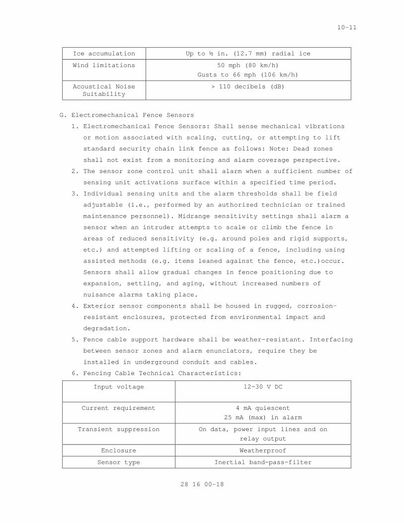
10-11
Ice accumulation Up to ½ in. (12.7 mm) radial ice
Wind limitations 50 mph (80 km/h)
Gusts to 66 mph (106 km/h)
Acoustical Noise Suitability
> 110 decibels (dB)
G. Electromechanical Fence Sensors
1. Electromechanical Fence Sensors: Shall sense mechanical vibrations
or motion associated with scaling, cutting, or attempting to lift
standard security chain link fence as follows: Note: Dead zones
shall not exist from a monitoring and alarm coverage perspective.
2. The sensor zone control unit shall alarm when a sufficient number of
sensing unit activations surface within a specified time period.
3. Individual sensing units and the alarm thresholds shall be field
adjustable (i.e., performed by an authorized technician or trained
maintenance personnel). Midrange sensitivity settings shall alarm a
sensor when an intruder attempts to scale or climb the fence in
areas of reduced sensitivity (e.g. around poles and rigid supports,
etc.) and attempted lifting or scaling of a fence, including using
assisted methods (e.g. items leaned against the fence, etc.)occur.
Sensors shall allow gradual changes in fence positioning due to
expansion, settling, and aging, without increased numbers of
nuisance alarms taking place.
4. Exterior sensor components shall be housed in rugged, corrosion-
resistant enclosures, protected from environmental impact and
degradation.
5. Fence cable support hardware shall be weather-resistant. Interfacing
between sensor zones and alarm enunciators, require they be
installed in underground conduit and cables.
6. Fencing Cable Technical Characteristics:
Input voltage 12-30 V DC
Current requirement 4 mA quiescent
25 mA (max) in alarm
Transient suppression On data, power input lines and on
relay output
Enclosure Weatherproof
Sensor type Inertial band-pass-filter
28 16 00-18
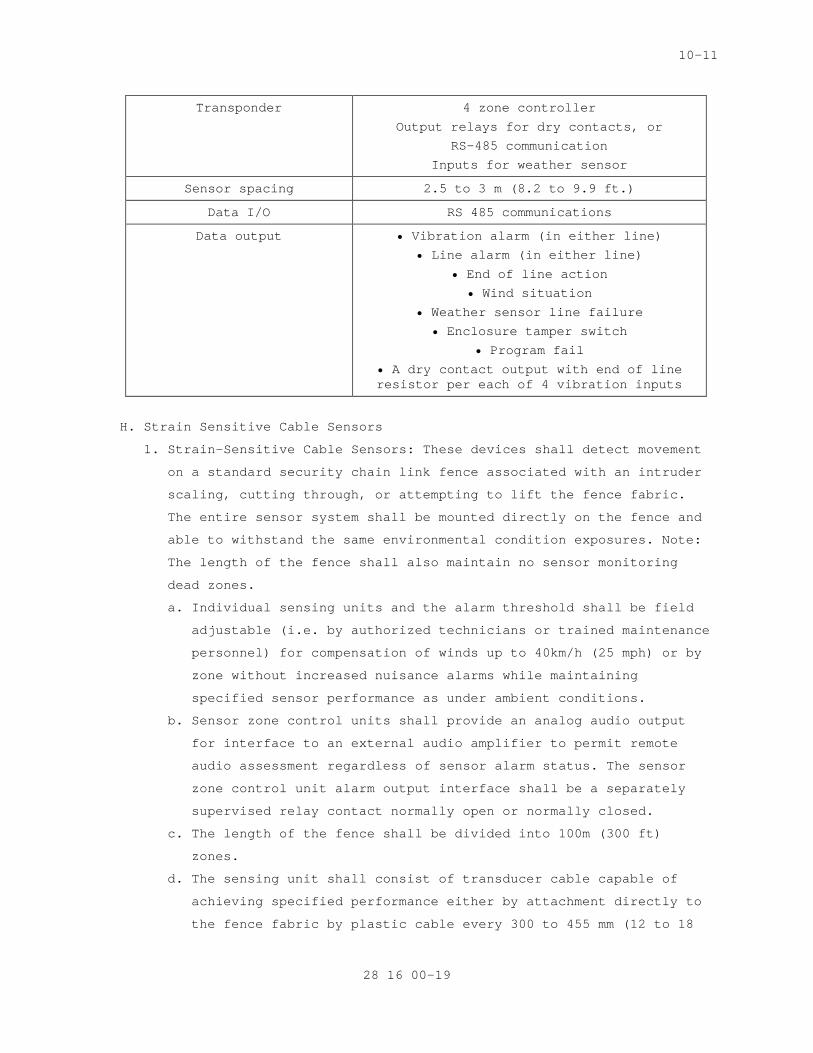
10-11
Transponder 4 zone controller
Output relays for dry contacts, or
RS-485 communication
Inputs for weather sensor
Sensor spacing 2.5 to 3 m (8.2 to 9.9 ft.)
Data I/O RS 485 communications
Data output • Vibration alarm (in either line)
• Line alarm (in either line)
• End of line action
• Wind situation
• Weather sensor line failure
• Enclosure tamper switch
• Program fail
• A dry contact output with end of line resistor per each of 4 vibration inputs
H. Strain Sensitive Cable Sensors
1. Strain-Sensitive Cable Sensors: These devices shall detect movement
on a standard security chain link fence associated with an intruder
scaling, cutting through, or attempting to lift the fence fabric.
The entire sensor system shall be mounted directly on the fence and
able to withstand the same environmental condition exposures. Note:
The length of the fence shall also maintain no sensor monitoring
dead zones.
a. Individual sensing units and the alarm threshold shall be field
adjustable (i.e. by authorized technicians or trained maintenance
personnel) for compensation of winds up to 40km/h (25 mph) or by
zone without increased nuisance alarms while maintaining
specified sensor performance as under ambient conditions.
b. Sensor zone control units shall provide an analog audio output
for interface to an external audio amplifier to permit remote
audio assessment regardless of sensor alarm status. The sensor
zone control unit alarm output interface shall be a separately
supervised relay contact normally open or normally closed.
c. The length of the fence shall be divided into 100m (300 ft)
zones.
d. The sensing unit shall consist of transducer cable capable of
achieving specified performance either by attachment directly to
the fence fabric by plastic cable every 300 to 455 mm (12 to 18
28 16 00-19
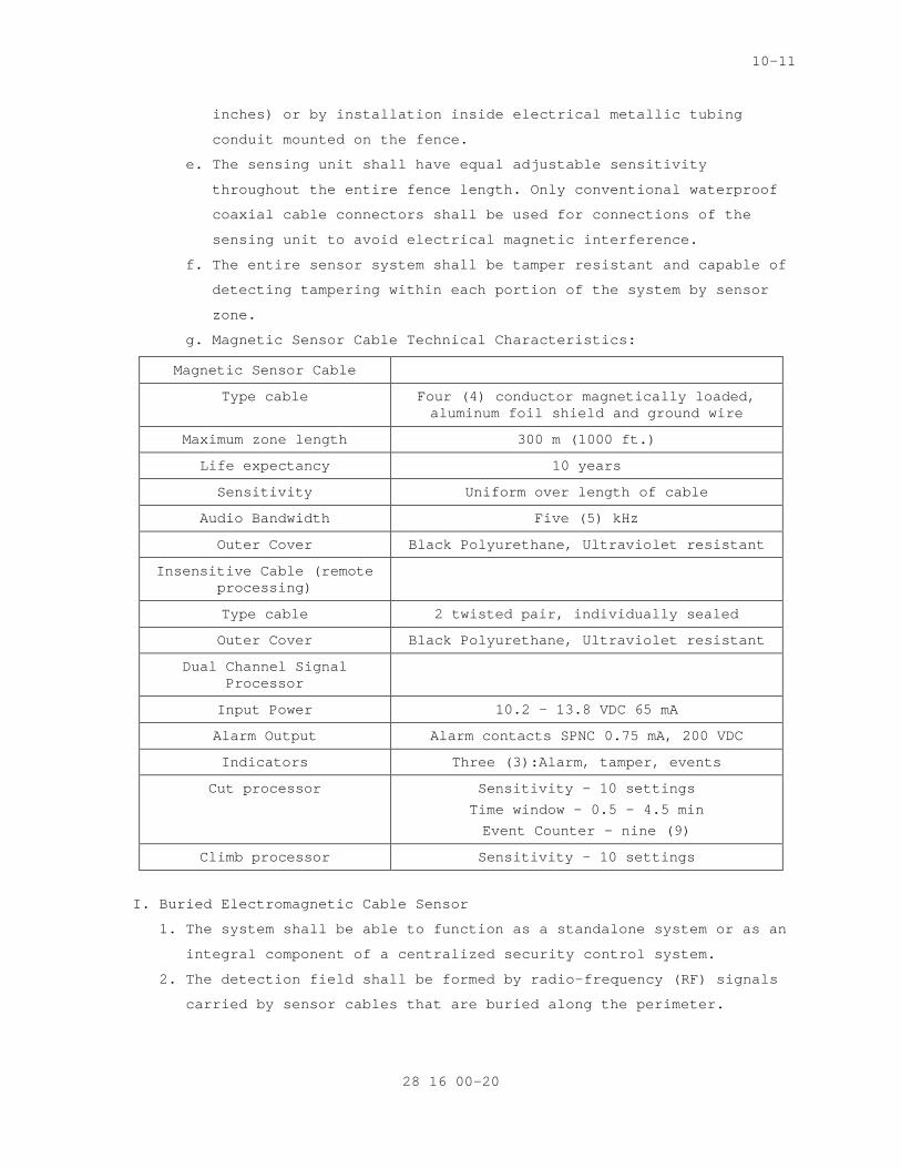
10-11
inches) or by installation inside electrical metallic tubing
conduit mounted on the fence.
e. The sensing unit shall have equal adjustable sensitivity
throughout the entire fence length. Only conventional waterproof
coaxial cable connectors shall be used for connections of the
sensing unit to avoid electrical magnetic interference.
f. The entire sensor system shall be tamper resistant and capable of
detecting tampering within each portion of the system by sensor
zone.
g. Magnetic Sensor Cable Technical Characteristics:
Magnetic Sensor Cable
Type cable Four (4) conductor magnetically loaded, aluminum foil shield and ground wire
Maximum zone length 300 m (1000 ft.)
Life expectancy 10 years
Sensitivity Uniform over length of cable
Audio Bandwidth Five (5) kHz
Outer Cover Black Polyurethane, Ultraviolet resistant
Insensitive Cable (remote processing)
Type cable 2 twisted pair, individually sealed
Outer Cover Black Polyurethane, Ultraviolet resistant
Dual Channel Signal Processor
Input Power 10.2 – 13.8 VDC 65 mA
Alarm Output Alarm contacts SPNC 0.75 mA, 200 VDC
Indicators Three (3):Alarm, tamper, events
Cut processor Sensitivity - 10 settings
Time window – 0.5 – 4.5 min
Event Counter – nine (9)
Climb processor Sensitivity – 10 settings
I. Buried Electromagnetic Cable Sensor
1. The system shall be able to function as a standalone system or as an
integral component of a centralized security control system.
2. The detection field shall be formed by radio-frequency (RF) signals
carried by sensor cables that are buried along the perimeter.
28 16 00-20
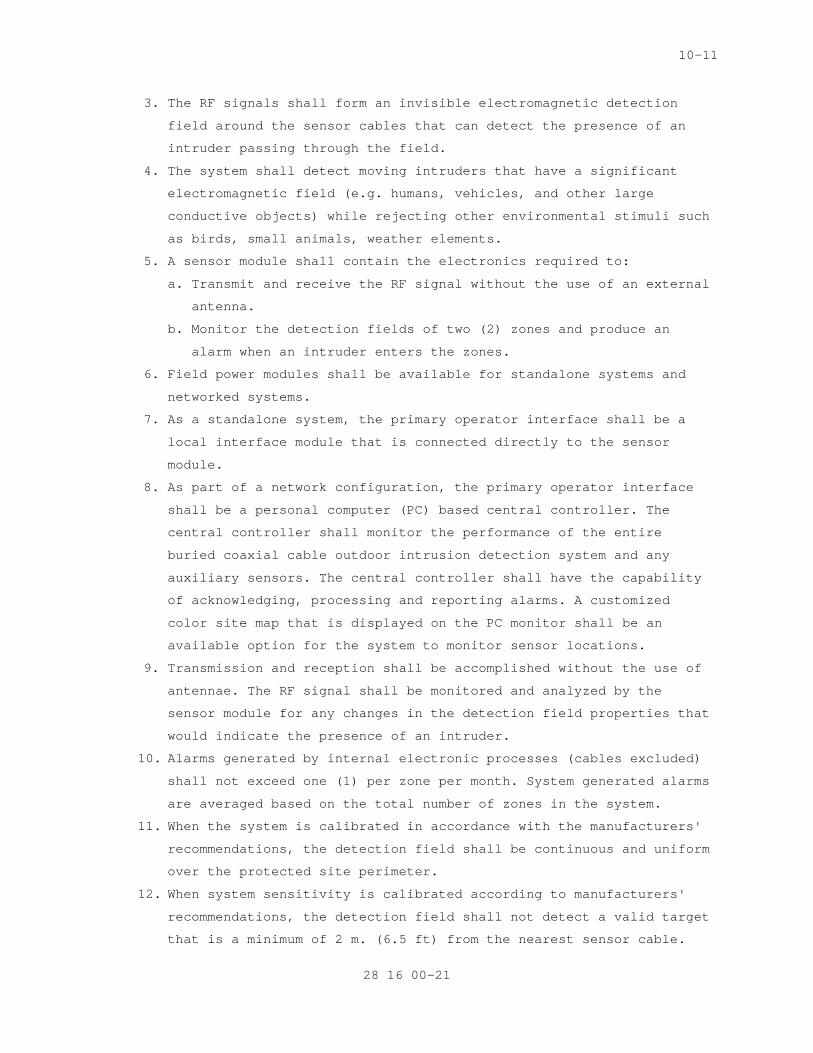
10-11
3. The RF signals shall form an invisible electromagnetic detection
field around the sensor cables that can detect the presence of an
intruder passing through the field.
4. The system shall detect moving intruders that have a significant
electromagnetic field (e.g. humans, vehicles, and other large
conductive objects) while rejecting other environmental stimuli such
as birds, small animals, weather elements.
5. A sensor module shall contain the electronics required to:
a. Transmit and receive the RF signal without the use of an external
antenna.
b. Monitor the detection fields of two (2) zones and produce an
alarm when an intruder enters the zones.
6. Field power modules shall be available for standalone systems and
networked systems.
7. As a standalone system, the primary operator interface shall be a
local interface module that is connected directly to the sensor
module.
8. As part of a network configuration, the primary operator interface
shall be a personal computer (PC) based central controller. The
central controller shall monitor the performance of the entire
buried coaxial cable outdoor intrusion detection system and any
auxiliary sensors. The central controller shall have the capability
of acknowledging, processing and reporting alarms. A customized
color site map that is displayed on the PC monitor shall be an
available option for the system to monitor sensor locations.
9. Transmission and reception shall be accomplished without the use of
antennae. The RF signal shall be monitored and analyzed by the
sensor module for any changes in the detection field properties that
would indicate the presence of an intruder.
10. Alarms generated by internal electronic processes (cables excluded)
shall not exceed one (1) per zone per month. System generated alarms
are averaged based on the total number of zones in the system.
11. When the system is calibrated in accordance with the manufacturers'
recommendations, the detection field shall be continuous and uniform
over the protected site perimeter.
12. When system sensitivity is calibrated according to manufacturers'
recommendations, the detection field shall not detect a valid target
that is a minimum of 2 m. (6.5 ft) from the nearest sensor cable.
28 16 00-21
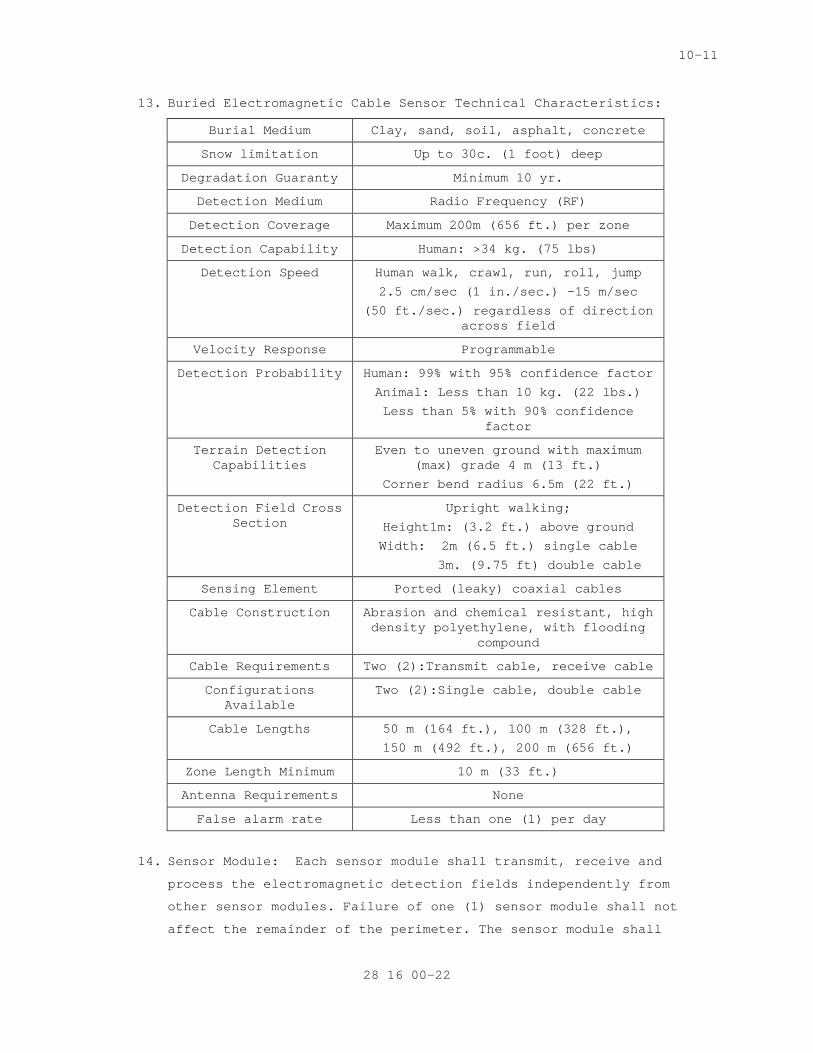
10-11
13. Buried Electromagnetic Cable Sensor Technical Characteristics:
Burial Medium Clay, sand, soil, asphalt, concrete
Snow limitation Up to 30c. (1 foot) deep
Degradation Guaranty Minimum 10 yr.
Detection Medium Radio Frequency (RF)
Detection Coverage Maximum 200m (656 ft.) per zone
Detection Capability Human: >34 kg. (75 lbs)
Detection Speed Human walk, crawl, run, roll, jump
2.5 cm/sec (1 in./sec.) –15 m/sec
(50 ft./sec.) regardless of direction across field
Velocity Response Programmable
Detection Probability Human: 99% with 95% confidence factor
Animal: Less than 10 kg. (22 lbs.)
Less than 5% with 90% confidence factor
Terrain Detection Capabilities
Even to uneven ground with maximum (max) grade 4 m (13 ft.)
Corner bend radius 6.5m (22 ft.)
Detection Field Cross Section
Upright walking;
Height1m: (3.2 ft.) above ground
Width: 2m (6.5 ft.) single cable
3m. (9.75 ft) double cable
Sensing Element Ported (leaky) coaxial cables
Cable Construction Abrasion and chemical resistant, high density polyethylene, with flooding
compound
Cable Requirements Two (2):Transmit cable, receive cable
Configurations Available
Two (2):Single cable, double cable
Cable Lengths 50 m (164 ft.), 100 m (328 ft.),
150 m (492 ft.), 200 m (656 ft.)
Zone Length Minimum 10 m (33 ft.)
Antenna Requirements None
False alarm rate Less than one (1) per day
14. Sensor Module: Each sensor module shall transmit, receive and
process the electromagnetic detection fields independently from
other sensor modules. Failure of one (1) sensor module shall not
affect the remainder of the perimeter. The sensor module shall
28 16 00-22
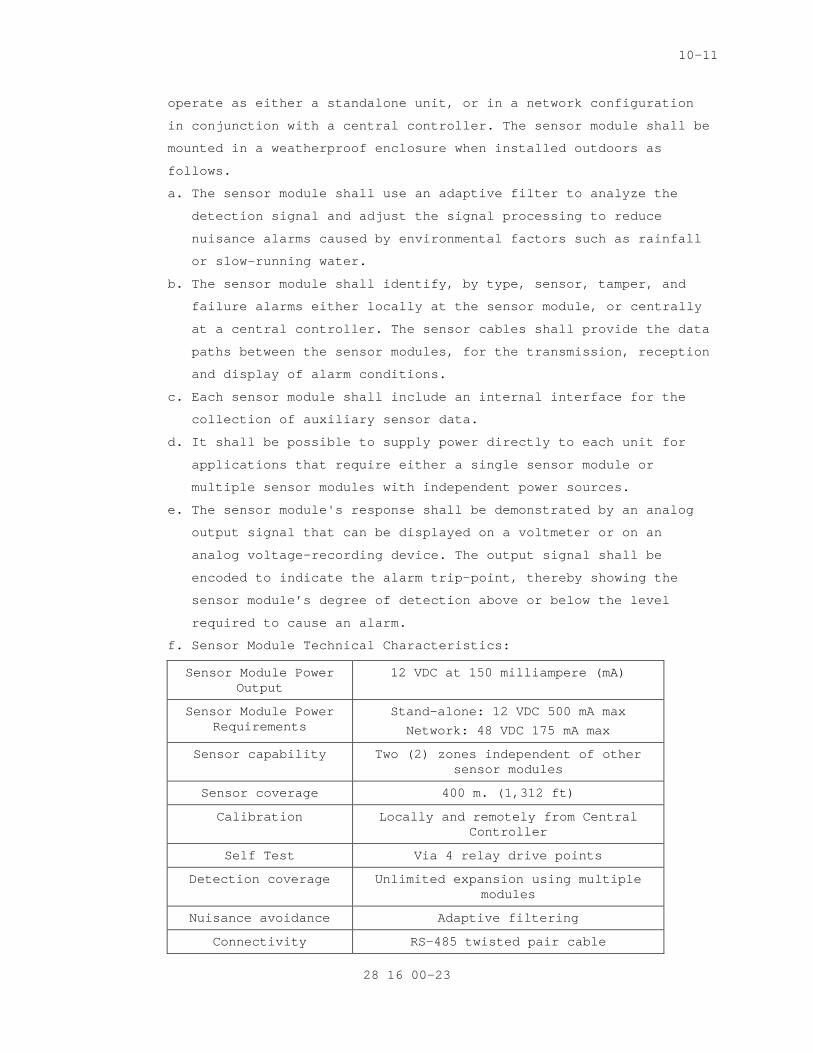
10-11
operate as either a standalone unit, or in a network configuration
in conjunction with a central controller. The sensor module shall be
mounted in a weatherproof enclosure when installed outdoors as
follows.
a. The sensor module shall use an adaptive filter to analyze the
detection signal and adjust the signal processing to reduce
nuisance alarms caused by environmental factors such as rainfall
or slow-running water.
b. The sensor module shall identify, by type, sensor, tamper, and
failure alarms either locally at the sensor module, or centrally
at a central controller. The sensor cables shall provide the data
paths between the sensor modules, for the transmission, reception
and display of alarm conditions.
c. Each sensor module shall include an internal interface for the
collection of auxiliary sensor data.
d. It shall be possible to supply power directly to each unit for
applications that require either a single sensor module or
multiple sensor modules with independent power sources.
e. The sensor module's response shall be demonstrated by an analog
output signal that can be displayed on a voltmeter or on an
analog voltage-recording device. The output signal shall be
encoded to indicate the alarm trip-point, thereby showing the
sensor module’s degree of detection above or below the level
required to cause an alarm.
f. Sensor Module Technical Characteristics:
Sensor Module Power Output
12 VDC at 150 milliampere (mA)
Sensor Module Power Requirements
Stand-alone: 12 VDC 500 mA max
Network: 48 VDC 175 mA max
Sensor capability Two (2) zones independent of other sensor modules
Sensor coverage 400 m. (1,312 ft)
Calibration Locally and remotely from Central Controller
Self Test Via 4 relay drive points
Detection coverage Unlimited expansion using multiple modules
Nuisance avoidance Adaptive filtering
Connectivity RS-485 twisted pair cable
28 16 00-23
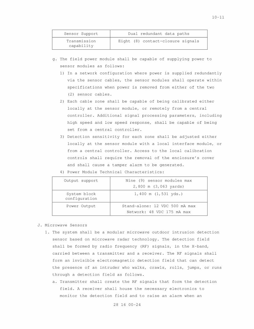
10-11
Sensor Support Dual redundant data paths
Transmission capability
Eight (8) contact-closure signals
g. The field power module shall be capable of supplying power to
sensor modules as follows:
1) In a network configuration where power is supplied redundantly
via the sensor cables, the sensor modules shall operate within
specifications when power is removed from either of the two
(2) sensor cables.
2) Each cable zone shall be capable of being calibrated either
locally at the sensor module, or remotely from a central
controller. Additional signal processing parameters, including
high speed and low speed response, shall be capable of being
set from a central controller.
3) Detection sensitivity for each zone shall be adjusted either
locally at the sensor module with a local interface module, or
from a central controller. Access to the local calibration
controls shall require the removal of the enclosure’s cover
and shall cause a tamper alarm to be generated.
4) Power Module Technical Characteristics:
Output support Nine (9) sensor modules max
2,800 m (3,063 yards)
System block configuration
1,400 m (1,531 yds.)
Power Output Stand-alone: 12 VDC 500 mA max
Network: 48 VDC 175 mA max
J. Microwave Sensors
1. The system shall be a modular microwave outdoor intrusion detection
sensor based on microwave radar technology. The detection field
shall be formed by radio frequency (RF) signals, in the X-band,
carried between a transmitter and a receiver. The RF signals shall
form an invisible electromagnetic detection field that can detect
the presence of an intruder who walks, crawls, rolls, jumps, or runs
through a detection field as follows.
a. Transmitter shall create the RF signals that form the detection
field. A receiver shall house the necessary electronics to
monitor the detection field and to raise an alarm when an
28 16 00-24
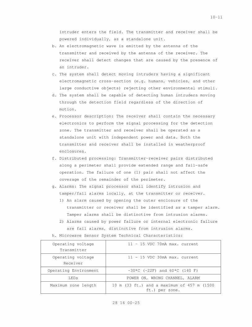
10-11
intruder enters the field. The transmitter and receiver shall be
powered individually, as a standalone unit.
b. An electromagnetic wave is emitted by the antenna of the
transmitter and received by the antenna of the receiver. The
receiver shall detect changes that are caused by the presence of
an intruder.
c. The system shall detect moving intruders having a significant
electromagnetic cross-section (e.g. humans, vehicles, and other
large conductive objects) rejecting other environmental stimuli.
d. The system shall be capable of detecting human intruders moving
through the detection field regardless of the direction of
motion.
e. Processor description: The receiver shall contain the necessary
electronics to perform the signal processing for the detection
zone. The transmitter and receiver shall be operated as a
standalone unit with independent power and data. Both the
transmitter and receiver shall be installed in weatherproof
enclosures.
f. Distributed processing: Transmitter-receiver pairs distributed
along a perimeter shall provide extended range and fail-safe
operation. The failure of one (1) pair shall not affect the
coverage of the remainder of the perimeter.
g. Alarms: The signal processor shall identify intrusion and
tamper/fail alarms locally, at the transmitter or receiver.
1) An alarm caused by opening the outer enclosure of the
transmitter or receiver shall be identified as a tamper alarm.
Tamper alarms shall be distinctive from intrusion alarms.
2) Alarms caused by power failure or internal electronic failure
are fail alarms, distinctive from intrusion alarms.
h. Microwave Sensor System Technical Characteristics:
Operating voltage
Transmitter
11 – 15 VDC 70mA max. current
Operating voltage
Receiver
11 – 15 VDC 30mA max. current
Operating Environment –30ºC (-22F) and 60ºC (140 F)
LEDs POWER ON, WRONG CHANNEL, ALARM
Maximum zone length 10 m (33 ft.) and a maximum of 457 m (1500 ft.) per zone.
28 16 00-25
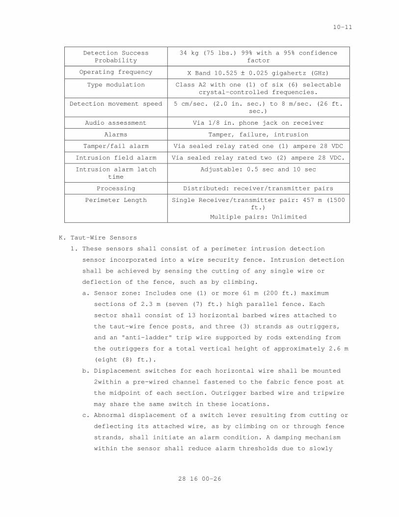
10-11
Detection Success Probability
34 kg (75 lbs.) 99% with a 95% confidence factor
Operating frequency X Band 10.525 ± 0.025 gigahertz (GHz)
Type modulation Class A2 with one (1) of six (6) selectable crystal-controlled frequencies.
Detection movement speed 5 cm/sec. (2.0 in. sec.) to 8 m/sec. (26 ft. sec.)
Audio assessment Via 1/8 in. phone jack on receiver
Alarms Tamper, failure, intrusion
Tamper/fail alarm Via sealed relay rated one (1) ampere 28 VDC
Intrusion field alarm Via sealed relay rated two (2) ampere 28 VDC.
Intrusion alarm latch time
Adjustable: 0.5 sec and 10 sec
Processing Distributed: receiver/transmitter pairs
Perimeter Length Single Receiver/transmitter pair: 457 m (1500 ft.)
Multiple pairs: Unlimited
K. Taut-Wire Sensors
1. These sensors shall consist of a perimeter intrusion detection
sensor incorporated into a wire security fence. Intrusion detection
shall be achieved by sensing the cutting of any single wire or
deflection of the fence, such as by climbing.
a. Sensor zone: Includes one (1) or more 61 m (200 ft.) maximum
sections of 2.3 m (seven (7) ft.) high parallel fence. Each
sector shall consist of 13 horizontal barbed wires attached to
the taut-wire fence posts, and three (3) strands as outriggers,
and an "anti-ladder" trip wire supported by rods extending from
the outriggers for a total vertical height of approximately 2.6 m
(eight (8) ft.).
b. Displacement switches for each horizontal wire shall be mounted
2within a pre-wired channel fastened to the fabric fence post at
the midpoint of each section. Outrigger barbed wire and tripwire
may share the same switch in these locations.
c. Abnormal displacement of a switch lever resulting from cutting or
deflecting its attached wire, as by climbing on or through fence
strands, shall initiate an alarm condition. A damping mechanism
within the sensor shall reduce alarm thresholds due to slowly
28 16 00-26
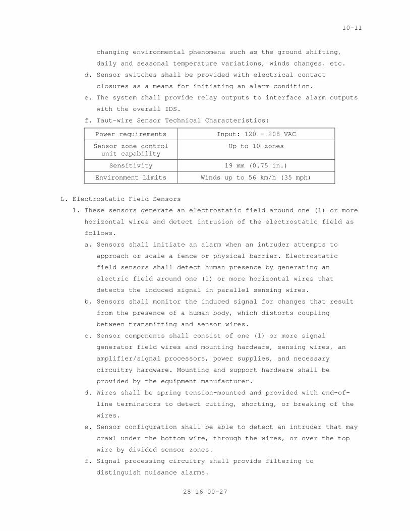
10-11
changing environmental phenomena such as the ground shifting,
daily and seasonal temperature variations, winds changes, etc.
d. Sensor switches shall be provided with electrical contact
closures as a means for initiating an alarm condition.
e. The system shall provide relay outputs to interface alarm outputs
with the overall IDS.
f. Taut-wire Sensor Technical Characteristics:
Power requirements Input: 120 – 208 VAC
Sensor zone control unit capability
Up to 10 zones
Sensitivity 19 mm (0.75 in.)
Environment Limits Winds up to 56 km/h (35 mph)
L. Electrostatic Field Sensors
1. These sensors generate an electrostatic field around one (1) or more
horizontal wires and detect intrusion of the electrostatic field as
follows.
a. Sensors shall initiate an alarm when an intruder attempts to
approach or scale a fence or physical barrier. Electrostatic
field sensors shall detect human presence by generating an
electric field around one (1) or more horizontal wires that
detects the induced signal in parallel sensing wires.
b. Sensors shall monitor the induced signal for changes that result
from the presence of a human body, which distorts coupling
between transmitting and sensor wires.
c. Sensor components shall consist of one (1) or more signal
generator field wires and mounting hardware, sensing wires, an
amplifier/signal processors, power supplies, and necessary
circuitry hardware. Mounting and support hardware shall be
provided by the equipment manufacturer.
d. Wires shall be spring tension-mounted and provided with end-of-
line terminators to detect cutting, shorting, or breaking of the
wires.
e. Sensor configuration shall be able to detect an intruder that may
crawl under the bottom wire, through the wires, or over the top
wire by divided sensor zones.
f. Signal processing circuitry shall provide filtering to
distinguish nuisance alarms.
28 16 00-27
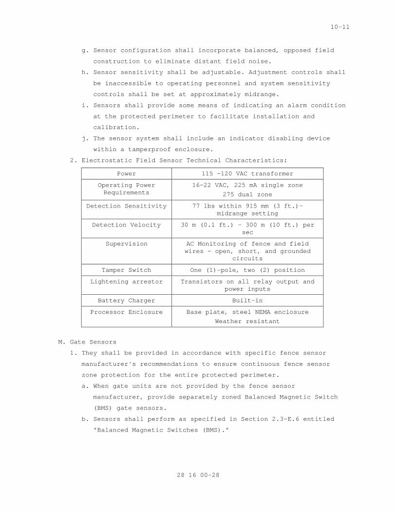
10-11
g. Sensor configuration shall incorporate balanced, opposed field
construction to eliminate distant field noise.
h. Sensor sensitivity shall be adjustable. Adjustment controls shall
be inaccessible to operating personnel and system sensitivity
controls shall be set at approximately midrange.
i. Sensors shall provide some means of indicating an alarm condition
at the protected perimeter to facilitate installation and
calibration.
j. The sensor system shall include an indicator disabling device
within a tamperproof enclosure.
2. Electrostatic Field Sensor Technical Characteristics:
Power 115 -120 VAC transformer
Operating Power Requirements
16-22 VAC, 225 mA single zone
275 dual zone
Detection Sensitivity 77 lbs within 915 mm (3 ft.)- midrange setting
Detection Velocity 30 m (0.1 ft.) - 300 m (10 ft.) per sec
Supervision AC Monitoring of fence and field wires – open, short, and grounded
circuits
Tamper Switch One (1)-pole, two (2) position
Lightening arrestor Transistors on all relay output and power inputs
Battery Charger Built-in
Processor Enclosure Base plate, steel NEMA enclosure
Weather resistant
M. Gate Sensors
1. They shall be provided in accordance with specific fence sensor
manufacturer's recommendations to ensure continuous fence sensor
zone protection for the entire protected perimeter.
a. When gate units are not provided by the fence sensor
manufacturer, provide separately zoned Balanced Magnetic Switch
(BMS) gate sensors.
b. Sensors shall perform as specified in Section 2.3-E.6 entitled
"Balanced Magnetic Switches (BMS)."
28 16 00-28
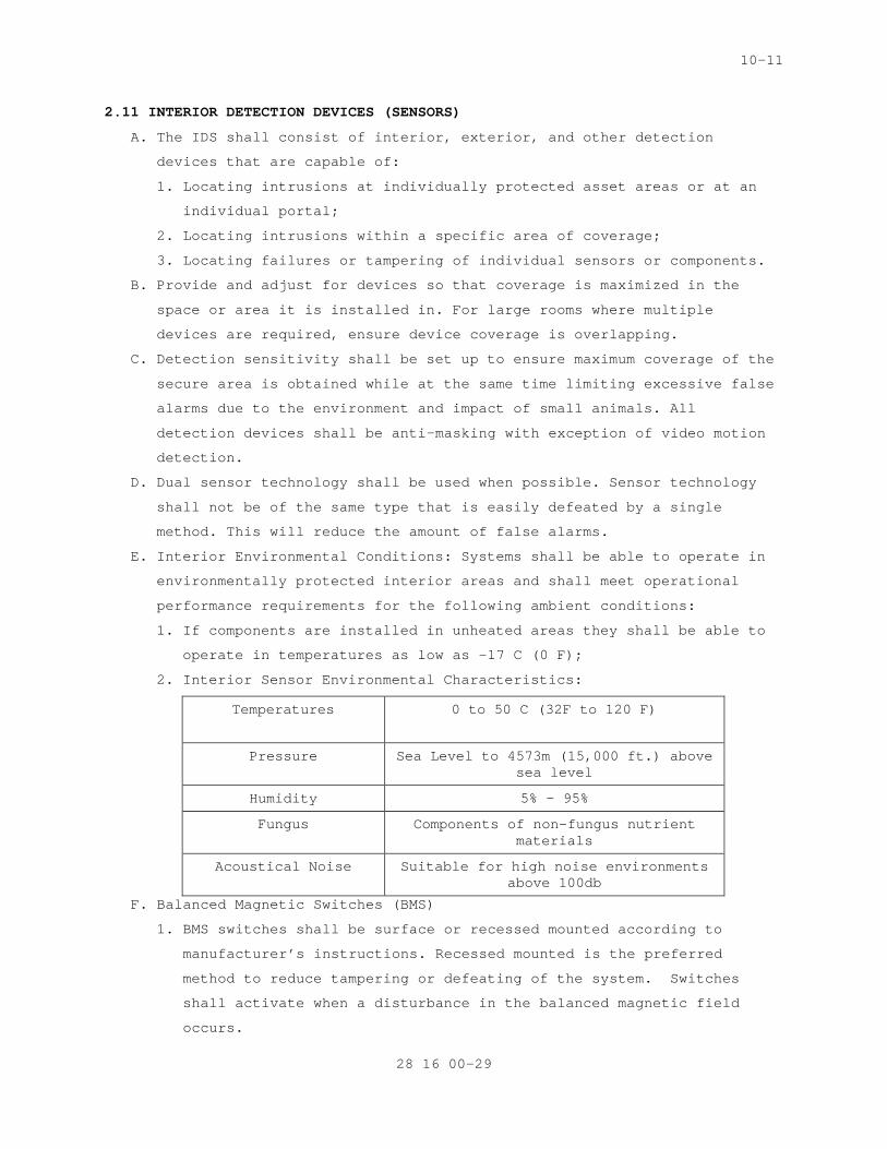
10-11
2.11 INTERIOR DETECTION DEVICES (SENSORS)
A. The IDS shall consist of interior, exterior, and other detection
devices that are capable of:
1. Locating intrusions at individually protected asset areas or at an
individual portal;
2. Locating intrusions within a specific area of coverage;
3. Locating failures or tampering of individual sensors or components.
B. Provide and adjust for devices so that coverage is maximized in the
space or area it is installed in. For large rooms where multiple
devices are required, ensure device coverage is overlapping.
C. Detection sensitivity shall be set up to ensure maximum coverage of the
secure area is obtained while at the same time limiting excessive false
alarms due to the environment and impact of small animals. All
detection devices shall be anti-masking with exception of video motion
detection.
D. Dual sensor technology shall be used when possible. Sensor technology
shall not be of the same type that is easily defeated by a single
method. This will reduce the amount of false alarms.
E. Interior Environmental Conditions: Systems shall be able to operate in
environmentally protected interior areas and shall meet operational
performance requirements for the following ambient conditions:
1. If components are installed in unheated areas they shall be able to
operate in temperatures as low as -17 C (0 F);
2. Interior Sensor Environmental Characteristics:
Temperatures 0 to 50 C (32F to 120 F)
Pressure Sea Level to 4573m (15,000 ft.) above sea level
Humidity 5% - 95%
Fungus Components of non-fungus nutrient materials
Acoustical Noise Suitable for high noise environments above 100db
F. Balanced Magnetic Switches (BMS)
1. BMS switches shall be surface or recessed mounted according to
manufacturer’s instructions. Recessed mounted is the preferred
method to reduce tampering or defeating of the system. Switches
shall activate when a disturbance in the balanced magnetic field
occurs.
28 16 00-29
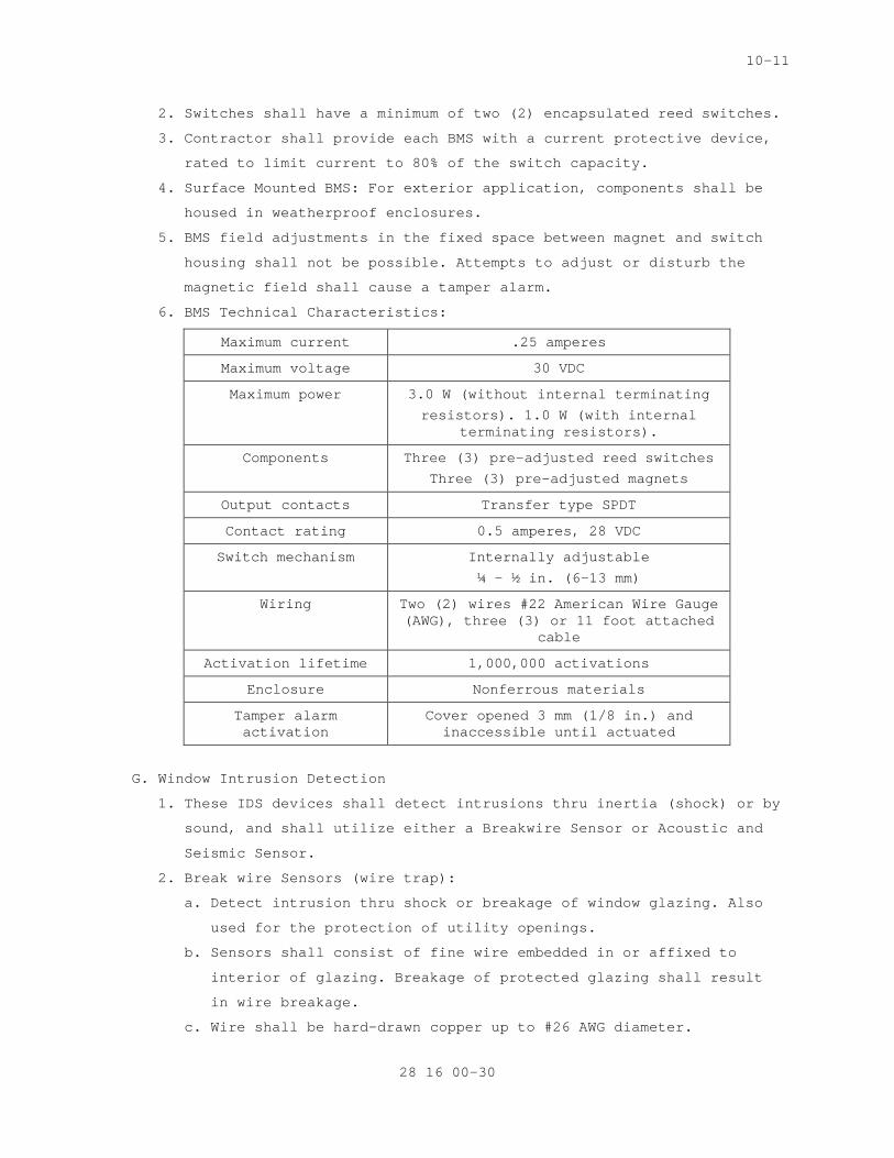
10-11
2. Switches shall have a minimum of two (2) encapsulated reed switches.
3. Contractor shall provide each BMS with a current protective device,
rated to limit current to 80% of the switch capacity.
4. Surface Mounted BMS: For exterior application, components shall be
housed in weatherproof enclosures.
5. BMS field adjustments in the fixed space between magnet and switch
housing shall not be possible. Attempts to adjust or disturb the
magnetic field shall cause a tamper alarm.
6. BMS Technical Characteristics:
Maximum current .25 amperes
Maximum voltage 30 VDC
Maximum power 3.0 W (without internal terminating
resistors). 1.0 W (with internal terminating resistors).
Components Three (3) pre-adjusted reed switches
Three (3) pre-adjusted magnets
Output contacts Transfer type SPDT
Contact rating 0.5 amperes, 28 VDC
Switch mechanism Internally adjustable
¼ - ½ in. (6-13 mm)
Wiring Two (2) wires #22 American Wire Gauge (AWG), three (3) or 11 foot attached
cable
Activation lifetime 1,000,000 activations
Enclosure Nonferrous materials
Tamper alarm activation
Cover opened 3 mm (1/8 in.) and inaccessible until actuated
G. Window Intrusion Detection
1. These IDS devices shall detect intrusions thru inertia (shock) or by
sound, and shall utilize either a Breakwire Sensor or Acoustic and
Seismic Sensor.
2. Break wire Sensors (wire trap):
a. Detect intrusion thru shock or breakage of window glazing. Also
used for the protection of utility openings.
b. Sensors shall consist of fine wire embedded in or affixed to
interior of glazing. Breakage of protected glazing shall result
in wire breakage.
c. Wire shall be hard-drawn copper up to #26 AWG diameter.
28 16 00-30
10-11
d. If sensors are affixed to glazing the sensor shall be protected
by a clear coating which shall not affect sensor functioning.
e. Sensor shall be terminated in insulated connectors which are
concealed and tamper resistant.
f. Protection of inlet openings:
1) Shall consist of up to 26 AWG hard-drawn copper wire with a
tensile strength of 17.8 N 4 pounds maximum.
2) Wire shall be interlaced throughout the opening such that no
opening between wires shall be larger than 100 mm (4 in.. on
center.
3) Sensors shall be terminated so that attempts to cut the wire
or otherwise enlarge openings between wires shall cause an
alarm.
4) Sensors shall be terminated in insulated connectors which are
concealed and tamper resistant.
H. Acoustic and Seismic Glass Break Detectors
1. Detects intrusion thru the use of audible sound and vibration
emitted from the breaking of glass using a tuned frequency range and
sound pattern recognition. This initiates an alarm when glass they
protect is broken or cracked.
2. Detectors shall be installed in strict conformance with
manufacture’s installation instructions.
3. The detector’s power circuit shall be switched via an output relay
on the control panel to provide latching alarm LED reset capability.
4. Sensors shall be contained in a fire-resistant ABS plastic housing
and must be mounted in contact with a window.
5. Sensing shall be accomplished through the use of a mechanical
filtered piezoelectric element.
6. Sensors shall have a sensitivity adjustment controlling output
voltage from the piezoelectric element which triggers a solid-state
latching device.
7. Sensors shall selectively filter input to minimize false alarms and
not initiate alarm in response to ambient seismic vibrations or
other ambient stimuli.
8. A manufacture’s test unit will be used to validate the sensor by
simulating glass breakage.
28 16 00-31
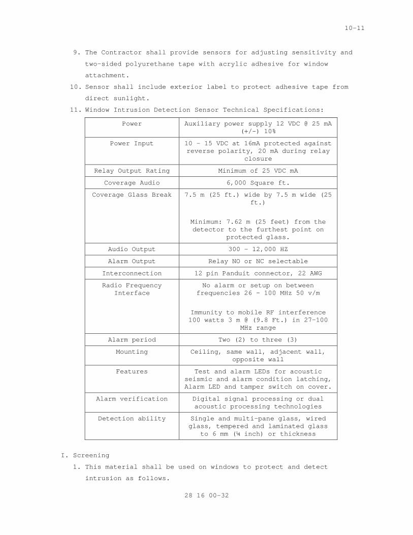
10-11
9. The Contractor shall provide sensors for adjusting sensitivity and
two-sided polyurethane tape with acrylic adhesive for window
attachment.
10. Sensor shall include exterior label to protect adhesive tape from
direct sunlight.
11. Window Intrusion Detection Sensor Technical Specifications:
Power Auxiliary power supply 12 VDC @ 25 mA (+/-) 10%
Power Input 10 – 15 VDC at 16mA protected against reverse polarity, 20 mA during relay
closure
Relay Output Rating Minimum of 25 VDC mA
Coverage Audio 6,000 Square ft.
Coverage Glass Break 7.5 m (25 ft.) wide by 7.5 m wide (25 ft.)
Minimum: 7.62 m (25 feet) from the detector to the furthest point on
protected glass.
Audio Output 300 – 12,000 HZ
Alarm Output Relay NO or NC selectable
Interconnection 12 pin Panduit connector, 22 AWG
Radio Frequency Interface
No alarm or setup on between frequencies 26 – 100 MHz 50 v/m
Immunity to mobile RF interference 100 watts 3 m @ (9.8 Ft.) in 27-100
MHz range
Alarm period Two (2) to three (3)
Mounting Ceiling, same wall, adjacent wall, opposite wall
Features Test and alarm LEDs for acoustic seismic and alarm condition latching, Alarm LED and tamper switch on cover.
Alarm verification Digital signal processing or dual acoustic processing technologies
Detection ability Single and multi-pane glass, wired glass, tempered and laminated glass
to 6 mm (¼ inch) or thickness
I. Screening
1. This material shall be used on windows to protect and detect
intrusion as follows.
28 16 00-32
10-11
a. Security screens shall be constructed from a maximum of 26 AWG
insulated hard-drawn copper.
b. Screens shall be connected to an alarm circuitry by means of
flexible armored cords. Security screen circuitry shall provide
end-of-line resistors in series or equivalent methods ensuring
alarm activation if short-circuiting of the screen is attempted.
c. If unable to install a break wire sensor (wire traps), then
tamper switches will be provided.
d. Contractor shall provide tamper switches in the frames as
required with not less than one (1) switch on each side if
dimensions are 610 mm two ((2) ft. square) or less, and two (2)
switches if dimensions exceed 610 mm (2 ft. square). Tamper
switches shall be corrosion-resistant, spring-operated, and shall
initiate an alarm with a movement of 50 mm (two (2) in.) or less
before access to the switch is possible.
e. Electrical characteristics of the switch shall match the alarm
system requirements.
J. Vibration Sensors
1. These sensors shall initiate alarms upon detecting drilling,
cutting, or blasting through walls, or other methods of forced entry
through a structure as follows.
2. Sensors shall detect and selectively amplify signals generated by
forced penetration of a protective structure.
3. Sensors shall be designed to give peak response to structurally
conveyed vibrations associated with forcible attack on the protected
surface.
4. Sensors will initiate an alarm if attempts are made to remove them
from the surface of the wall.
5. Sensors shall be enclosed in protective mountings.
6. Sensors shall include an adjustable alarm discriminator to prevent
incidental vibrations which may occur from triggering the alarm
circuit.
7. Sensors shall be provided with a tamper switch.
8. Sensor sensitivity shall be individually adjustable unless a sensor
is designed to accommodate vibration ranges of specific surface type
on which it will be mounted. Sensitivity adjustments shall not be
accessible without removing the sensor cover. Also, a sensor shall
not be responsive to airborne sound.
28 16 00-33
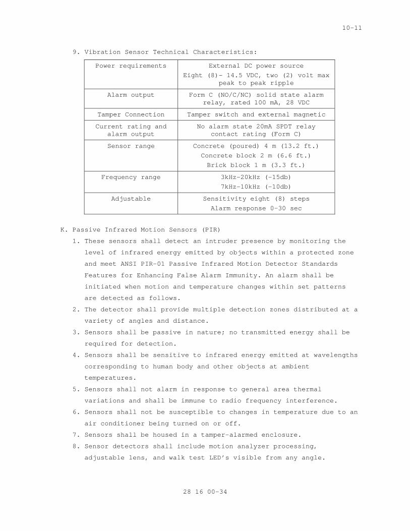
10-11
9. Vibration Sensor Technical Characteristics:
Power requirements External DC power source
Eight (8)- 14.5 VDC, two (2) volt max peak to peak ripple
Alarm output Form C (NO/C/NC) solid state alarm relay, rated 100 mA, 28 VDC
Tamper Connection Tamper switch and external magnetic
Current rating and alarm output
No alarm state 20mA SPDT relay contact rating (Form C)
Sensor range Concrete (poured) 4 m (13.2 ft.)
Concrete block 2 m (6.6 ft.)
Brick block 1 m (3.3 ft.)
Frequency range 3kHz-20kHz (-15db)
7kHz-10kHz (-10db)
Adjustable Sensitivity eight (8) steps
Alarm response 0-30 sec
K. Passive Infrared Motion Sensors (PIR)
1. These sensors shall detect an intruder presence by monitoring the
level of infrared energy emitted by objects within a protected zone
and meet ANSI PIR-01 Passive Infrared Motion Detector Standards
Features for Enhancing False Alarm Immunity. An alarm shall be
initiated when motion and temperature changes within set patterns
are detected as follows.
2. The detector shall provide multiple detection zones distributed at a
variety of angles and distance.
3. Sensors shall be passive in nature; no transmitted energy shall be
required for detection.
4. Sensors shall be sensitive to infrared energy emitted at wavelengths
corresponding to human body and other objects at ambient
temperatures.
5. Sensors shall not alarm in response to general area thermal
variations and shall be immune to radio frequency interference.
6. Sensors shall not be susceptible to changes in temperature due to an
air conditioner being turned on or off.
7. Sensors shall be housed in a tamper-alarmed enclosure.
8. Sensor detectors shall include motion analyzer processing,
adjustable lens, and walk test LED’s visible from any angle.
28 16 00-34
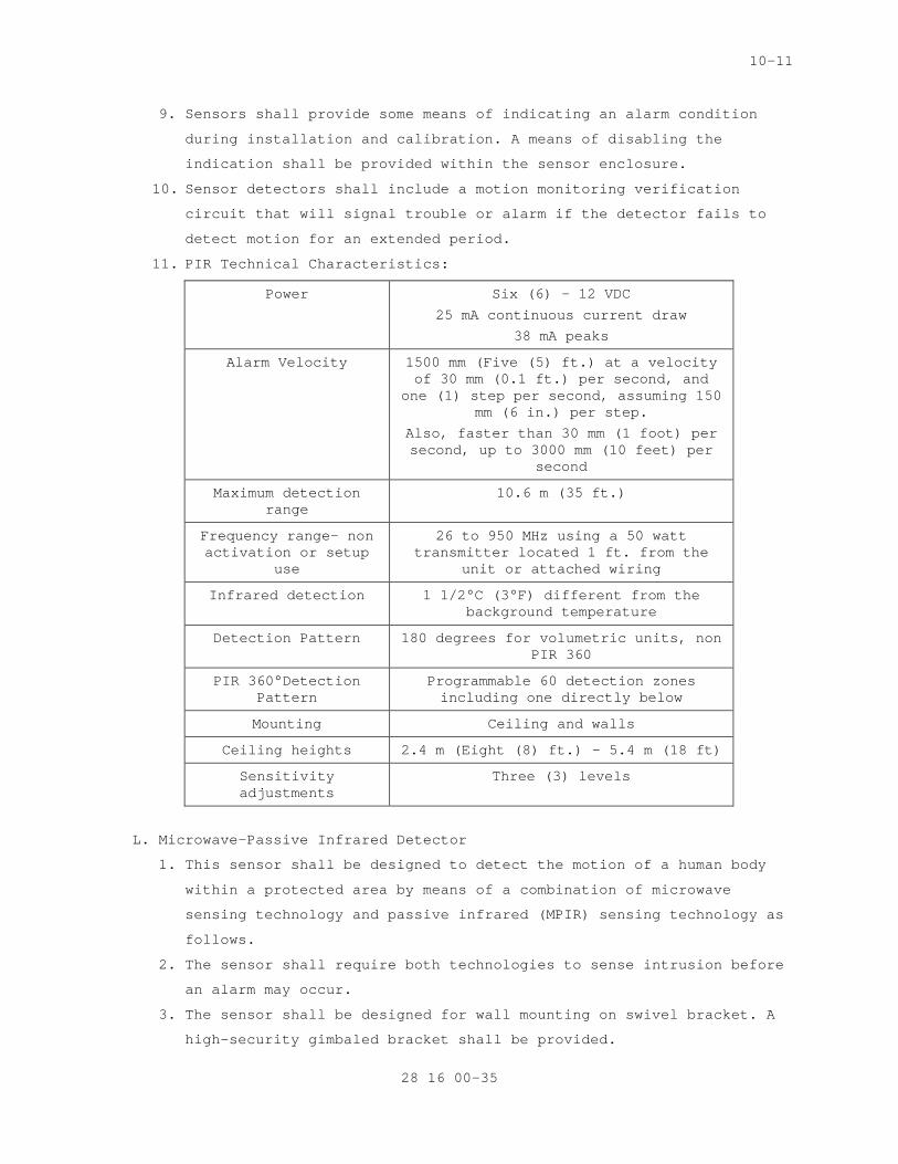
10-11
9. Sensors shall provide some means of indicating an alarm condition
during installation and calibration. A means of disabling the
indication shall be provided within the sensor enclosure.
10. Sensor detectors shall include a motion monitoring verification
circuit that will signal trouble or alarm if the detector fails to
detect motion for an extended period.
11. PIR Technical Characteristics:
Power Six (6) – 12 VDC
25 mA continuous current draw
38 mA peaks
Alarm Velocity 1500 mm (Five (5) ft.) at a velocity of 30 mm (0.1 ft.) per second, and
one (1) step per second, assuming 150 mm (6 in.) per step.
Also, faster than 30 mm (1 foot) per second, up to 3000 mm (10 feet) per
second
Maximum detection range
10.6 m (35 ft.)
Frequency range- non activation or setup
use
26 to 950 MHz using a 50 watt transmitter located 1 ft. from the
unit or attached wiring
Infrared detection 1 1/2°C (3°F) different from the background temperature
Detection Pattern 180 degrees for volumetric units, non PIR 360
PIR 360°Detection Pattern
Programmable 60 detection zones including one directly below
Mounting Ceiling and walls
Ceiling heights 2.4 m (Eight (8) ft.) – 5.4 m (18 ft)
Sensitivity adjustments
Three (3) levels
L. Microwave-Passive Infrared Detector
1. This sensor shall be designed to detect the motion of a human body
within a protected area by means of a combination of microwave
sensing technology and passive infrared (MPIR) sensing technology as
follows.
2. The sensor shall require both technologies to sense intrusion before
an alarm may occur.
3. The sensor shall be designed for wall mounting on swivel bracket. A
high-security gimbaled bracket shall be provided.
28 16 00-35
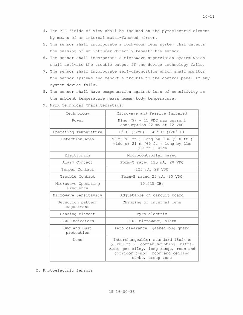
10-11
4. The PIR fields of view shall be focused on the pyroelectric element
by means of an internal multi-faceted mirror.
5. The sensor shall incorporate a look-down lens system that detects
the passing of an intruder directly beneath the sensor.
6. The sensor shall incorporate a microwave supervision system which
shall activate the trouble output if the device technology fails.
7. The sensor shall incorporate self-diagnostics which shall monitor
the sensor systems and report a trouble to the control panel if any
system device fails.
8. The sensor shall have compensation against loss of sensitivity as
the ambient temperature nears human body temperature.
9. MPIR Technical Characteristics:
Technology Microwave and Passive Infrared
Power Nine (9) – 15 VDC max current consumption 22 mA at 12 VDC
Operating Temperature 0° C (32°F) – 49° C (120° F)
Detection Area 30 m (98 ft.) long by 3 m (9.8 ft.) wide or 21 m (69 ft.) long by 21m
(69 ft.) wide
Electronics Microcontroller based
Alarm Contact Form-C rated 125 mA, 28 VDC
Tamper Contact 125 mA, 28 VDC
Trouble Contact Form-B rated 25 mA, 30 VDC
Microwave Operating Frequency
10.525 GHz
Microwave Sensitivity Adjustable on circuit board
Detection pattern adjustment
Changing of internal lens
Sensing element Pyro-electric
LED Indicators PIR, microwave, alarm
Bug and Dust protection
zero-clearance, gasket bug guard
Lens Interchangeable: standard 18x24 m (60x80 ft.), corner mounting, ultra-wide, pet alley, long range, room and
corridor combo, room and ceiling combo, creep zone
M. Photoelectric Sensors
28 16 00-36
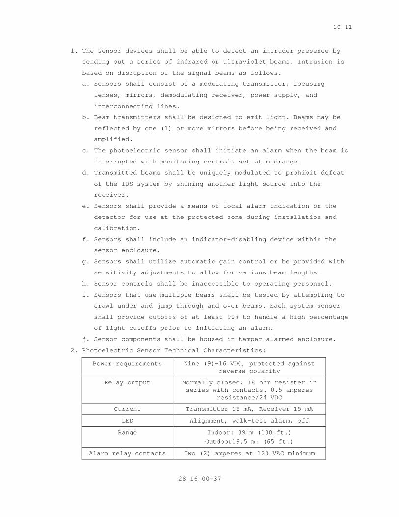
10-11
1. The sensor devices shall be able to detect an intruder presence by
sending out a series of infrared or ultraviolet beams. Intrusion is
based on disruption of the signal beams as follows.
a. Sensors shall consist of a modulating transmitter, focusing
lenses, mirrors, demodulating receiver, power supply, and
interconnecting lines.
b. Beam transmitters shall be designed to emit light. Beams may be
reflected by one (1) or more mirrors before being received and
amplified.
c. The photoelectric sensor shall initiate an alarm when the beam is
interrupted with monitoring controls set at midrange.
d. Transmitted beams shall be uniquely modulated to prohibit defeat
of the IDS system by shining another light source into the
receiver.
e. Sensors shall provide a means of local alarm indication on the
detector for use at the protected zone during installation and
calibration.
f. Sensors shall include an indicator-disabling device within the
sensor enclosure.
g. Sensors shall utilize automatic gain control or be provided with
sensitivity adjustments to allow for various beam lengths.
h. Sensor controls shall be inaccessible to operating personnel.
i. Sensors that use multiple beams shall be tested by attempting to
crawl under and jump through and over beams. Each system sensor
shall provide cutoffs of at least 90% to handle a high percentage
of light cutoffs prior to initiating an alarm.
j. Sensor components shall be housed in tamper-alarmed enclosure.
2. Photoelectric Sensor Technical Characteristics:
Power requirements Nine (9)-16 VDC, protected against reverse polarity
Relay output Normally closed. 18 ohm resister in series with contacts. 0.5 amperes
resistance/24 VDC
Current Transmitter 15 mA, Receiver 15 mA
LED Alignment, walk-test alarm, off
Range Indoor: 39 m (130 ft.)
Outdoor19.5 m: (65 ft.)
Alarm relay contacts Two (2) amperes at 120 VAC minimum
28 16 00-37
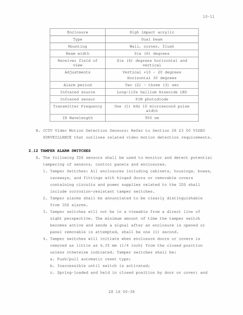
10-11
Enclosure High impact acrylic
Type Dual beam
Mounting Wall, corner, flush
Beam width Six (6) degrees
Receiver field of view
Six (6) degrees horizontal and vertical
Adjustments Vertical +10 – 20 degrees
Horizontal 30 degrees
Alarm period Two (2) – three (3) sec
Infrared source Long-life Gallium Arsenide LED
Infrared sensor PIN photodiode
Transmitter Frequency One (1) kHz 10 microsecond pulse width
IR Wavelength 950 nm
N. CCTV Video Motion Detection Sensors: Refer to Section 28 23 00 VIDEO
SURVEILLANCE that outlines related video motion detection requirements.
2.12 TAMPER ALARM SWITCHES
A. The following IDS sensors shall be used to monitor and detect potential
tampering of sensors, control panels and enclosures.
1. Tamper Switches: All enclosures including cabinets, housings, boxes,
raceways, and fittings with hinged doors or removable covers
containing circuits and power supplies related to the IDS shall
include corrosion-resistant tamper switches.
2. Tamper alarms shall be annunciated to be clearly distinguishable
from IDS alarms.
3. Tamper switches will not be in a viewable from a direct line of
sight perspective. The minimum amount of time the tamper switch
becomes active and sends a signal after an enclosure is opened or
panel removable is attempted, shall be one (1) second.
4. Tamper switches will initiate when enclosure doors or covers is
removed as little as 6.35 mm (1/4 inch) from the closed position
unless otherwise indicated. Tamper switches shall be:
a. Push/pull automatic reset type;
b. Inaccessible until switch is activated;
c. Spring-loaded and held in closed position by door or cover; and
28 16 00-38
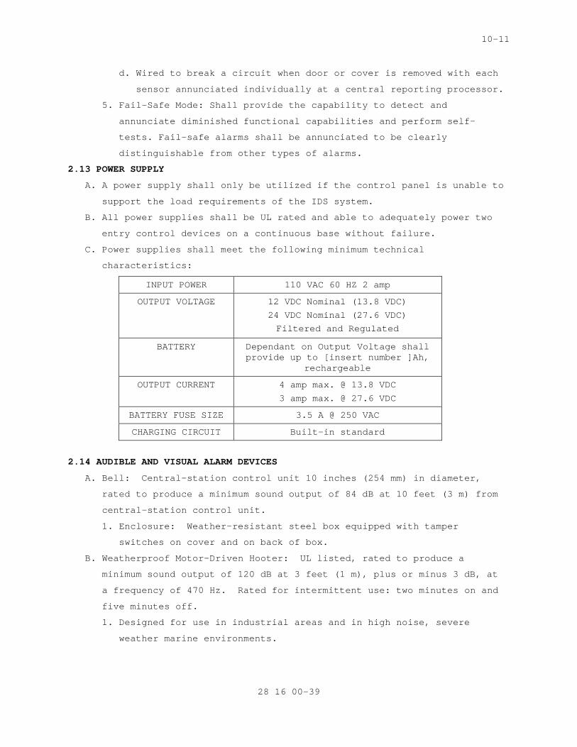
10-11
d. Wired to break a circuit when door or cover is removed with each
sensor annunciated individually at a central reporting processor.
5. Fail-Safe Mode: Shall provide the capability to detect and
annunciate diminished functional capabilities and perform self-
tests. Fail-safe alarms shall be annunciated to be clearly
distinguishable from other types of alarms.
2.13 POWER SUPPLY
A. A power supply shall only be utilized if the control panel is unable to
support the load requirements of the IDS system.
B. All power supplies shall be UL rated and able to adequately power two
entry control devices on a continuous base without failure.
C. Power supplies shall meet the following minimum technical
characteristics:
INPUT POWER 110 VAC 60 HZ 2 amp
OUTPUT VOLTAGE 12 VDC Nominal (13.8 VDC)
24 VDC Nominal (27.6 VDC)
Filtered and Regulated
BATTERY Dependant on Output Voltage shall provide up to [insert number ]Ah,
rechargeable
OUTPUT CURRENT 4 amp max. @ 13.8 VDC
3 amp max. @ 27.6 VDC
BATTERY FUSE SIZE 3.5 A @ 250 VAC
CHARGING CIRCUIT Built-in standard
2.14 AUDIBLE AND VISUAL ALARM DEVICES
A. Bell: Central-station control unit 10 inches (254 mm) in diameter,
rated to produce a minimum sound output of 84 dB at 10 feet (3 m) from
central-station control unit.
1. Enclosure: Weather-resistant steel box equipped with tamper
switches on cover and on back of box.
B. Weatherproof Motor-Driven Hooter: UL listed, rated to produce a
minimum sound output of 120 dB at 3 feet (1 m), plus or minus 3 dB, at
a frequency of 470 Hz. Rated for intermittent use: two minutes on and
five minutes off.
1. Designed for use in industrial areas and in high noise, severe
weather marine environments.
28 16 00-39
10-11
C. Siren: 30-W speaker with siren driver, rated to produce a minimum
sound output of 103 dB at 10 feet (3 m) from central-station control
unit.
1. Enclosure: Weather-resistant steel box with tamper switches on
cover and on back of box.
D. Strobe: Xenon light complying with UL 1638, with a clear polycarbonate
lens.
1. Light Output: 115 cd, minimum.
2. Flash Rate: 60 per minute.
2.15 SECURITY FASTENERS
A. Security fasteners shall be operable only by tools produced for use on
specific type of fastener by fastener manufacturer or other licensed
fabricator. Drive system type, head style, material, and protective
coating as required for assembly, installation, and strength.
SPEC WRITER NOTE: Insert additional types of security fasteners below with other drive systems and head styles if necessary or for special applications. Coordinate type of security fasteners retained in this Section with other Sections specifying security fasteners. See Evaluations.
B. Drive System Types: Pinned Torx or pinned hex (Allen).
C. Socket Flat Countersunk Head Fasteners:
1. Heat-treated alloy steel, ASTM F 835 (ASTM F 835M).
2. Stainless steel, ASTM F 879 (ASTM F 879M), Group 1 CW.
D. Socket Button Head Fasteners:
1. Heat-treated alloy steel, ASTM F 835 (ASTM F 835M).
2. Stainless steel, ASTM F 879 (ASTM F 879M), Group 1 CW.
E. Socket Head Cap Fasteners:
1. Heat-treated alloy steel, ASTM A 574 (ASTM A 574M).
2. Stainless steel, ASTM F 837 (ASTM F 837M), Group 1 CW.
F. Protective Coatings for Heat-Treated Alloy Steel:
1. Zinc chromate, ASTM F 1135, Grade 3 or 4; for exterior applications
and interior applications where indicated.
2. Zinc phosphate with oil, ASTM F 1137, Grade I, or black oxide.
PART 3 - EXECUTION
SPEC WRITER NOTE: Delete and/or amend this all paragraphs and sub-paragraphs to
28 16 00-40
10-11
apply to only the equipment and devices that are being installed.
3.1 INSTALLATION
A. IDS installation shall be in accordance with Underwriters Laboratories
(UL) 639 Standards for Intrusion Detection Units and UL 634 Standards
for Connectors with Burglar Alarm Systems, and appropriate
manufacture’s installation manuals for each type of IDS.
B. Components shall be configured with appropriate “service points” to
pinpoint system trouble in less than 30 minutes.
C. The Contractor shall install all system components including VA
furnished equipment, and appurtenances in accordance with the
manufacturer's instructions and shall furnish all necessary connectors,
terminators, interconnections, services, and adjustments required for a
complete and operable system.
D. The IDS will be designed, engineered, installed, and tested to ensure
all components are fully compatible as a system and can be integrated
with all associated security subsystems, whether the system is a stand
alone or designed as a computer network.
E. The IDS shall be able to be integrated with other security subsystems.
Integration with these security subsystems shall be achieved by
computer programming and the direct hardwiring of the systems.
Determination for methodology shall be outlined when the system(s)
is/are being designed and engineered. For installation purposes, the
IDS shall utilize an output module for integration with other security
subsystems. The Contractor will ensure all connections are per the OEM
and that any and all software upgrades required to integrate the
systems are installed prior to system start-up.
F. For programming purposes, the Contractor shall refer to the
manufacturer’s requirements and Contracting Officer instructions for
correct system operations. This includes ensuring computers being
utilized for system integration meet or exceeds the minimum system
requirements outlined in the IDS software packages.
G. Lightening and power surges to the central alarm reporting and display
unit shall be protected at both ends against excessive voltages. This
requirement shall apply for circuits that are routed both in
underground conduits and overhead runs.
H. At a minimum, the Contractor shall install primary detection devices,
such as three electrode gas-type surge arresters, and secondary
28 16 00-41
10-11
protectors to reduce dangerous voltages to levels that will cause no
damage. Fuses shall not be permitted as protection devices.
I. The Contractor shall provide fail-safe gas tube type surge arresters on
exposed IDS data circuits. In addition, transient protection shall
protect against spikes up to 1000 volts peak voltage with a one-
microsecond rise time and 100-microsecond decay time, without causing
false alarms. The protective device shall be automatic and self-
restoring. Also, circuits shall be designed or selected assuming a
maximum of 25 ohms to ground.
J. Product Delivery, Storage and Handling:
1. Delivery: Deliver materials to the job site in OEM's original
unopened containers, clearly labeled with the OEM's name, equipment
model and serial identification numbers, and UL logo. The
Contracting Officer may inventory the IDS equipment at the time of
delivery and reject items that do not conform to this requirement.
2. Storage and Handling: Store and protect equipment in a manner that
will preclude damage as directed by the Contracting Officer.
K. Cleaning and Adjustments:
1. Cleaning: Subsequent to installation, clean each system component of
dust, dirt, grease, or oil incurred during installation in
accordance to manufacture instructions.
2. Prepare for system activation by following manufacturer’s
recommended procedures for adjustment, alignment, or
synchronization. Prepare each component in accordance with
appropriate provisions of the component’s installation, operations,
and maintenance instructions.
L. Tamper Switches
1. Install tamper switches to initiate an alarm signal when a panel,
box, or component housing door or cover is moved as little as 6.35
mm (1/4 inch) from the normally closed position unless otherwise
specified.
2. Locate tamper switches within enclosures, cabinets, housings, boxes,
raceways, and fittings to prevent direct line of sight to any
internal components and to prevent tampering with switch or
circuitry.
3. Conceal tamper switch mounting hardware so that the location of the
switch within the enclosure cannot be determined from the exterior.
M. Unique IDS Installation Components:
28 16 00-42
10-11
1. BMS Surface Mounted:
a. Surface mounted BMS housing for the switch element shall have the
capability to receive threaded conduit. Housing covers for
surface mounted BMS, if made of cast aluminum, shall be secured
by stainless steel screws. Magnet housing cover shall not be
readily removable and BMS housings shall be protected from
unauthorized access by a cover operated, corrosion-resistant
tamper device.
b. Conductors running from a door to alarm circuits shall be
contained within a flexible armored cord constructed from
corrosion-resistant metal. Each end of the armored cord shall
terminate in a junction box or other enclosure. Armored cord ends
shall be mechanically secured to the junction boxes by clamps or
bushings. Conductors within the armored cord shall be provided
with lug terminals at each end. Conductors and the armored cord
shall experience no mechanical strain as the door is removed from
fully open to closed position. Switch circuits shall initiate an
alarm if a short circuit is applied to the door cord.
c. For exterior application on double gates, both BMS elements must
be mounted on the gate. Flexible armored cord constructed from
corrosion-resistant metal shall be used to provide electrical
connection.
2. BMS Recessed Mounted:
a. Ball bearing door trips shall be mounted within vault door
headers such that when the locking mechanism is secured, the door
bolt engages an actuator, mechanically closing the switch.
b. Door bolt locking mechanisms shall be fully engaged before the
ball bearing door trip is activated. Also, circuit jumpers from
the door shall be provided.
3. Vibration Sensors:
a. Mount vibration sensors directly contacting the surface to be
protected.
b. Provide at least one (1) sensor on each monolithic slab or wall
section, even though spacing closer than that required for
midrange sensitivity may result.
c. House sensors in protective mountings and fasten to surface with
concealed mounting screws or an epoxy.
28 16 00-43
10-11
d. Adjust discriminator on the job to precise needs of application.
Connect sensors to an electronic control unit by means of wiring
or fiber optics cable run in rigid steel conduit or electrical
metallic tubing (EMT).
4. Passive Infrared Detectors: (PIR)
a. The protective beam shall be focused in a straight line.
b. Installed beam distance from transmitter to receiver shall not
exceed 80% of the manufacturer's maximum recommended rating.
c. Mirrors may be used to extend the beam or to establish a network
of beams. Each mirror used shall not lower the rated maximum
system range by more than 50%.
d. Mirrors and photoelectric sources used in outdoor applications
shall have self-heating capability to eliminate condensation and
shall be housed in weatherproof enclosures.
5. Taut-Wire:
a. Housing for switch assembly shall be covered by a neoprene cap to
retain the center bolt (lever arm), which functions as a lever to
translate movement of the attached horizontal wire into contact
closure. When the neoprene cap is firmly seated on the cup-shaped
polycarbonate housing, it shall function as the fulcrum for the
lever (bolt).
b. Upper exposed end of the lever shall be threaded to accommodate
clamping to the horizontal wire. The lower end of the lever,
which is fashioned to serve as the movable electrical contact,
shall be held suspended in a small cup-shaped contact that floats
in a plastic putty material.
c. Plastic putty used shall retain a degree of elasticity under
varying temperature conditions and provide the sensor switch with
a self-adjusting property. This provides the switch with a built-
in compensating mechanism that ignores small, very slow changes
in lever alignment (i.e. which may result from environmental
changes such as extreme temperature variations and ground seepage
due to weather conditions) and to react to fast changes only, as
caused by manual deflection or cutting of the wires.
d. Contractor shall provide metal slider strips having slots through
which the barbed wires pass. Wires shall be prevented from
leaving the slots by rivets. A slider strip shall be used to
28 16 00-44

10-11
translate normal forces to the barbed wire and to the horizontal
displacement of the sensor.
e. Install one (1) slider strip pair, upper and lower, on every
fence post except where sensor posts or anchor strips are
installed.
f. Separation between slider elements along the fence shall be 3000
mm (10 feet).
g. Attach wires of sensor to existing, specially installed fence
posts, called anchor posts, located equidistant on both sides of
sensor posts and at ends of sensor zone run.
h. Anchor strip shall be a strip of steel plate on which fastening
plates are installed. Weld or otherwise attach the strip to
anchor post and ends of tensed barbed wires wrapped around the
fastening plates. Attempts to climb on fastening plates or on the
attached barbed wires shall cause plates to break off, creating
an alarm and making it impossible to defeat the system by
climbing at the anchor post.
i. The use of barbed wire as part of the IDS system shall be
suitable for installation under a preload tension of
approximately 392 N 88 pounds and be flexible enough for
convenient manipulation during tensioning. Double-strand 15 1/2-
gage barbed wire shall be the minimum acceptable.
6. Electromechanical Fence Sensors:
a. The fence length shall be divided into 100m (300 ft). or zones.
b. Sensors shall consist of individual electromechanical sensing
units mounted every three-thousand and 3045mm (10 ft). on the
fence fabric or posts and wired in series to a sensor zone
control unit and associated power supply.
7. Electrostatic Field Sensors:
a. Sensors shall be capable of following irregular contours and
barrier bends without degrading sensitivity below the specified
detection level.
b. In no case shall a single sensor zone exceed 100m (300 ft). or
be long enough to significantly degrade sensitivity.
c. Adjacent zones shall provide continuous coverage to avoid a dead
zone. Adjacent zones shall be designed to prevent crosstalk
interference.
28 16 00-45
10-11
d. Exterior components shall be housed in rugged corrosion-resistant
enclosures, protected from environmental degradation and include
tamper switches.
e. Interfacing between exterior units shall be carried in
underground cables.
f. Exterior support hardware shall be stainless or galvanized to
avoid tension degradation.
g. Sensor and field wires shall be stainless steel. Wire spacing for
various configurations shall be maintained constant throughout
each zone and shall be uniform with respect to the ground and
follow manufacturer's specifications.
h. Signal processing equipment shall be separately mounted such that
no desensitized zones are created within the zone of detection.
8. Microwave: Do not install microwave sensors where fluorescent lights
may pose a problem due to radiated ionization from lights.
3.2 WIRING INSTALLATION
SPECS WRITER NOTE: Coordinate this Article with Drawings. Select one of first three paragraphs below to specify wiring method. Retain/Delete first two paragraphs and retain and revise third paragraph to suit Project.
A. Wiring Method: Install wiring in metal raceways according to Section
28 05 28.33 "CONDUITS AND BOXES FOR ELECTRONIC SAFETY AND SECURITY."
Conceal raceway except in unfinished spaces and as indicated. Minimum
conduit size shall be 3/4 inch (20 mm). Control and data transmission
wiring shall not share conduit with other building wiring systems.
B. Wiring Method: Install wiring in raceways except in accessible indoor
ceiling spaces and in interior hollow gypsum board partitions where
cable may be used. Conceal raceways and wiring except in unfinished
spaces and as indicated. Minimum conduit size shall be 3/4 inch (20
mm). Control and data transmission wiring shall not share conduit with
other building wiring systems.
C. Wiring Method: Cable, concealed in accessible ceilings, walls, and
floors when possible.
D. Wiring within Enclosures: Bundle, lace, and train conductors to
terminal points. Use lacing bars and distribution spools. Separate
power-limited and non-power-limited conductors as recommended in
writing by manufacturer. Install conductors parallel with or at right
28 16 00-46
10-11
angles to sides and back of enclosure. Connect conductors that are
terminated, spliced, or interrupted in any enclosure associated with
intrusion system to terminal blocks. Mark each terminal according to
system's wiring diagrams. Make all connections with approved crimp-on
terminal spade lugs, pressure-type terminal blocks, or plug connectors.
E. Wires and Cables:
SPECS WRITER NOTE: Coordinate subparagraphs below with Drawings.
1. Conductors: Size as recommended in writing by system manufacturer,
unless otherwise indicated.
2. 120-V Power Wiring: Install according to Division 26 Section "LOW-
VOLTAGE ELECTRICAL POWER CONDUCTORS AND CABLES," unless otherwise
indicated.
3. Control and Signal Transmission Conductors: Install unshielded,
twisted-pair cable, unless otherwise indicated or if manufacturer
recommends shielded cable, according to Division 28 Section
"CONDUCTORS AND CABLES FOR ELECTRONIC SAFETY AND SECURITY."
4. Computer and Data-Processing Cables: Install according to Division
28 Section "CONDUCTORS AND CABLES FOR ELECTRONIC SAFETY AND
SECURITY."
5. Television Signal Transmission Cables: Install according to
Division 28 Section "CONDUCTORS AND CABLES FOR ELECTRONIC SAFETY AND
SECURITY."
F. Splices, Taps, and Terminations: Make connections only on numbered
terminal strips in junction, pull, and outlet boxes; terminal cabinets;
and equipment enclosures.
G. Install power supplies and other auxiliary components for detection
devices at controllers, unless otherwise indicated or required by
manufacturer. Do not install such items near devices they serve.
H. Identify components with engraved, laminated-plastic or metal nameplate
for central-station control unit and each terminal cabinet, mounted
with corrosion-resistant screws.
3.3 GROUNDING
A. Ground system components and conductor and cable shields to eliminate
shock hazard and to minimize ground loops, common-mode returns, noise
pickup, cross talk, and other impairments.
B. Signal Ground Terminal: Locate at main equipment rack or cabinet.
Isolate from power system and equipment grounding. Provide [5] <Insert
28 16 00-47
10-11
selected maximum value>-ohm ground. Measure, record, and report ground
resistance.
SPECS WRITER NOTE: Coordinate paragraph below with Drawings.
C. Install grounding electrodes of type, size, location, and quantity
indicated. Comply with installation requirements in Division 28
Section "GROUNDING AND BONDING FOR ELECTRONIC SAFETY AND SECURITY
SYSTEMS."
3.4 STARTUP AND TESTING
A. The Commissioning Agent will observe startup and contractor testing of
selected equipment. Coordinate the startup and contractor testing
schedules with the Resident Engineer and Commissioning Agent. Provide
a minimum of 7 days prior notice.
3.5 COMMISIONING
A. Provide commissioning documentation in accordance with the requirements
of Section 28 08 00 – COMMISSIONING OF ELECTRONIC SAFETY AND SECURITY
SYSTEMS for all inspection, start up, and contractor testing required
above and required by the System Readiness Checklist provided by the
Commissioning Agent.
B. Components provided under this section of the specification will be
tested as part of a larger system. Refer to Section 28 08 00 –
COMMISSIONING OF ELECTRONIC SAFETY AND SECURITY SYSTEMS and related
sections for contractor responsibilities for system commissioning.
3.6 TESTS AND TRAINING
SPECS WRITER NOTE: Edit text below per project requirements.
A. All testing and training shall be compliant with the VA General
Requirements, Section 01 00 00, GENERAL REQUIREMENTS.
B. Provide services of manufacturer’s technical representative for [insert
number] hours to instruct VA personnel in operation and maintenance of
units.
C. Submit training plans and instructor qualifications in accordance with
the requirements of Section 28 08 00 – COMMISSIONING OF ELECTRONIC
SAFETY AND SECURITY SYSTEMS.
-----END----
28 16 00-48
09-11
SECTION 28 23 00 VIDEO SURVEILLANCE
PART 1 – GENERAL
1.1 DESCRIPTION
A. Provide and install a complete and operable expansion of the existing
Video Surveillance System, which is identified as the Video Assessment
and Surveillance System hereinafter referred to as the VASS System as
specified in this section.
B. This Section includes video surveillance system consisting of cameras
and associated data transmission wiring.
C. Scope of work includes all programming required to integrate the new
system devices/equipment into the existing system.
1.2 RELATED WORK
A. Section 01 00 00 - GENERAL REQUIREMENTS. For General Requirements.
B. Section 07 84 00 - FIRESTOPPING. Requirements for firestopping
application and use.
F. Section 26 05 11 - REQUIREMENTS FOR ELECTRICAL INSTALLATIONS.
Requirements for connection of high voltage.
G. Section 26 05 21 - LOW VOLTAGE ELECTRICAL POWER CONDUCTORS AND CABLES
(600 VOLTS AND BELOW). Requirements for power cables.
J. Section 28 05 00 – COMMON WORK RESULTS FOR ELECTRONIC SAFETY AND
SECURITY. Requirements for general requirements that are common to more
than one section in Division 28.
K. Section 28 05 13 - CONDUCTORS AND CABLES FOR ELECTRONIC SAFETY AND
SECURITY. Requirements for conductors and cables.
L. Section 28 05 26 - GROUNDING AND BONDING FOR ELECTRONIC SAFETY AND
SECURITY. Requirements for grounding of equipment.
M. Section 28 05 28.33 - CONDUITS AND BACKBOXES FOR ELECTRONIC SAFETY AND
SECURITY. Requirements for infrastructure.
O. Section 28 13 00 - PHYSICAL ACCESS CONTROL SYSTEM. Requirements for
physical access control system integration.
1.3 DEFINITIONS
A. AGC: Automatic gain control.
B. B/W: Black and white.
C. CCD: Charge-coupled device.
D. CIF: Common Intermediate Format CIF images are 352 pixels wide and
88/240 (PAL/NTSC) pixels tall (352 x 288/240).
28 23 00 - 1
09-11
E. 4CIF: resolution is 704 pixels wide and 576/480 (PAL/NTSC) pixels tall
(704 x 576/480).
F. H.264 (also known as MPEG4 Part 10): a encoding format that compresses
video much more effectively than older (MPEG4) standards.
G. ips: Images per second.
H. MPEG: Moving picture experts group.
I. MPEG4: a video encoding and compression standard that uses inter-frame
encoding to significantly reduce the size of the video stream being
transmitted.
J. NTSC: National Television System Committee.
K. UPS: Uninterruptible power supply.
L. PTZ: refers to a movable camera that has the ability to pan left and
right, tilt up and down, and zoom or magnify a scene.
1.4 QUALITY ASSURANCE
A. The Contractor shall be responsible for providing, installing, and the
operation of the VASS System as shown. The Contractor shall also
provide certification as required.
B. The security system shall be installed and tested to ensure all
components are fully compatible as a system and can be integrated with
all associated security subsystems, whether the security system is
stand-alone or a part of a complete Information Technology (IT)
computer network.
C. The Contractor or security sub-contractor shall be a licensed security
Contractor as required within the state or jurisdiction of where the
installation work is being conducted.
D. Manufacturers Qualifications: The manufacturer shall regularly and
presently produce, as one of the manufacturer's principal products, the
equipment and material specified for this project, and shall have
manufactured the item for at least three years.
E. Product Qualification:
1. Manufacturer's product shall have been in satisfactory operation, on
three installations of similar size and type as this project, for
approximately three years.
2. The Government reserves the right to require the Contractor to
submit a list of installations where the products have been in
operation before approval.
F. Contractor Qualification:
28 23 00 - 2

09-11
1. The Contractor or security sub-contractor shall be a licensed
security Contractor with a minimum of five (5) years experience
installing and servicing systems of similar scope and complexity.
The Contractor shall be an authorized regional representative of the
Video Assessment and Surveillance System’s (VASS) manufacturer. The
Contractor shall provide four (4) current references from clients
with systems of similar scope and complexity which became
operational in the past three (3) years. At least three (3) of the
references shall be utilizing the same system components, in a
similar configuration as the proposed system. The references must
include a current point of contact, company or agency name, address,
telephone number, complete system description, date of completion,
and approximate cost of the project. The owner reserves the option
to visit the reference sites, with the site owner’s permission and
representative, to verify the quality of installation and the
references’ level of satisfaction with the system. The Contractor
shall provide copies of system manufacturer certification for all
technicians. The Contractor shall only utilize factory-trained
technicians to install, program, and service the VASS. The
Contractor shall only utilize factory-trained technicians to
install, terminate and service cameras, control, and recording
equipment. The technicians shall have a minimum of five (5)
continuous years of technical experience in electronic security
systems. The Contractor shall have a local service facility. The
facility shall be located within 60 miles of the project site. The
local facility shall include sufficient spare parts inventory to
support the service requirements associated with this contract. The
facility shall also include appropriate diagnostic equipment to
perform diagnostic procedures. The COTR reserves the option of
surveying the company’s facility to verify the service inventory and
presence of a local service organization.
2. The Contractor shall provide proof project superintendent with BICSI
Certified Commercial Installer Level 1, Level 2, or Technician to
provide oversight of the project.
3. Cable installer must have on staff a Registered Communication
Distribution Designer (RCDD) certified by Building Industry
Consulting Service International. The staff member shall provide
28 23 00 - 3
09-11
consistent oversight of the project cabling throughout design,
layout, installation, termination and testing.
G. Service Qualifications: There shall be a permanent service organization
maintained or trained by the manufacturer which will render
satisfactory service to this installation within four hours of receipt
of notification that service is needed. Submit name and address of
service organizations.
1.5 SUBMITTALS
A. Submit below items in conjunction with Master Specification Sections 01
33 23, Shop Drawings, Product Data, and Samples, and Section 02 41 00,
Demolition Drawings.
B. Provide certificates of compliance with Section 1.4, Quality Assurance.
C. Provide a pre-installation and as-built design package in both
electronic format and on paper, minimum size 1220 x 1220 millimeters
(48 x 48 inches); drawing submittals shall be per the established
project schedule.
D. Pre-installation design and as-built packages shall include, but not be
limited to:
1. Index Sheet that shall:
a. Define each page of the design package to include facility name,
building name, floor, and sheet number.
b. Provide a list of all security abbreviations and symbols.
c. Reference all general notes that are utilized within the design
package.
d. Specification and scope of work pages for all security systems
that are applicable to the design package that will:
1) Outline all general and job specific work required within the
design package.
2) Provide a device identification table outlining device
Identification (ID) and use for all security systems equipment
utilized in the design package.
2. Floor plans, site plans, and enlarged plans shall:
a. Include a title block as defined above.
b. Define the drawings scale in both standard and metric
measurements.
c. Provide device identification and location.
28 23 00 - 4

09-11
d. Address all signal and power conduit runs and sizes that are
associated with the design of the electronic security system and
other security elements (e.g., barriers, etc.).
e. Identify all pull box and conduit locations, sizes, and fill
capacities.
f. Address all general and drawing specific notes for a particular
drawing sheet.
3. A riser drawing for each applicable security subsystem shall:
a. Indicate the sequence of operation.
b. Relationship of integrated components on one diagram.
c. Include the number, size, identification, and maximum lengths of
interconnecting wires.
d. Wire/cable types shall be defined by a wire and cable schedule.
The schedule shall utilize a lettering system that will
correspond to the wire/cable it represents (example: A = 18 AWG/1
Pair Twisted, Unshielded). This schedule shall also provide the
manufacturer’s name and part number for the wire/cable being
installed.
4. A system drawing for each applicable security system shall:
a. Identify how all equipment within the system, from main panel to
device, shall be laid out and connected.
b. Provide full detail of all system components wiring from point-
to-point.
c. Identify wire types utilized for connection, interconnection with
associate security subsystems.
d. Show device locations that correspond to the floor plans.
e. All general and drawing specific notes shall be included with the
system drawings.
5. A schedule for all of the applicable security subsystems shall be
included. All schedules shall provide the following information:
a. Device ID.
b. Device Location (e.g. site, building, floor, room number,
location, and description).
c. Mounting type (e.g. flush, wall, surface, etc.).
d. Power supply or circuit breaker and power panel number.
e. In addition, for the VASS Systems, provide the camera ID, camera
type (e.g. fixed or pan/tilt/zoom (P/T/Z), lens type (e.g. for
fixed cameras only) and housing model number.
28 23 00 - 5
09-11
6. Detail and elevation drawings for all devices that define how they
were installed and mounted.
E. Pre-installation design packages shall be reviewed by the Contractor
along with a VA representative to ensure all work has been clearly
defined and completed. All reviews shall be conducted in accordance
with the project schedule. There shall be four (4) stages to the review
process:
1. 100 percent
F. Provide manufacturer security system product cut-sheets. Submit for
approval at least 30 days prior to commencement of formal testing, a
Security System Operational Test Plan. Include procedures for
operational testing of each component and security subsystem, to
include performance of an integrated system test.
G. Submit manufacture’s certification of Underwriters Laboratories, Inc.
(UL) listing as specified. Provide all maintenance and operating
manuals per the VA General Requirements, Section 01 00 00, GENERAL
REQUIREMENTS.
1.6 APPLICABLE PUBLICATIONS
A. The publications listed below (including amendments, addenda,
revisions, supplement, and errata) form a part of this specification to
the extent referenced. The publications are referenced in the text by
the basic designation only.
B. American National Standards Institute (ANSI)/Electronic Industries
Alliance (EIA):
330-09..................Electrical Performance Standards for CCTV
Cameras
375A-76.................Electrical Performance Standards for CCTV
Monitors
C. Institute of Electrical and Electronics Engineers (IEEE):
C62.41-02...............IEEE Recommended Practice on Surge Voltages in
Low-Voltage AC Power Circuits
802.3af-08..............Power over Ethernet Standard
D. Federal Communications Commission (FCC):
(47 CFR 15) Part 15 Limitations on the Use of Wireless Equipment/Systems
E. National Electrical Contractors Association (NECA):
303-2005................Installing Closed Circuit Television (CCTV)
Systems
28 23 00 - 6
09-11
F. National Fire Protection Association (NFPA):
70-08...................Article 780-National Electrical Code
G. Federal Information Processing Standard (FIPS):
140-2-02................Security Requirements for Cryptographic Modules
H. Underwriters Laboratories, Inc. (UL):
983-06..................Standard for Surveillance Camera Units
3044-01.................Standard for Surveillance Closed Circuit
Television Equipment
1.7 COORDINATION
A. Coordinate arrangement, mounting, and support of video surveillance
equipment:
1. To allow maximum possible headroom unless specific mounting heights
that reduce headroom are indicated.
2. To provide for ease of disconnecting the equipment with minimum
interference to other installations.
3. To allow right of way for piping and conduit installed at required
slope.
4. So connecting raceways, cables, wireways, cable trays, and busways
will be clear of obstructions and of the working and access space of
other equipment.
B. Coordinate installation of required supporting devices and set sleeves
in cast-in-place concrete, masonry walls, and other structural
components as they are constructed.
C. Coordinate location of access panels and doors for video surveillance
items that are behind finished surfaces or otherwise concealed.
1.8 WARRANTY OF CONSTRUCTION
A. Warrant VASS System work subject to the Article “Warranty of
Construction” of FAR clause 52.246-21.
B. Demonstration and training shall be performed prior to system
acceptance.
PART 2 – PRODUCTS
2.1 GENERAL
A. Video signal format shall comply with the NTSC standard composite
video, interlaced. Composite video signal termination shall be 75
ohms.
28 23 00 - 7
09-11
B. Surge Protection: Protect components from voltage surges originating
external to equipment housing and entering through power,
communication, signal, control, or sensing leads. Include surge
protection for external wiring of each conductor entry connection to
components.
C. Power Connections: Comply with requirements in Section 28 05 00 COMMON
WORK REQUIREMENTS FOR ELECTRONIC SAFETY AND SECURITY, Part 2, as
recommended by manufacturer for type of line being protected.
D. Tamper Protection: Tamper switches on enclosures, control units, pull
boxes, junction boxes, cabinets, and other system components shall
initiate a tamper-alarm signal when unit is opened or partially
disassembled. Control-station, control-unit alarm display shall
identify tamper alarms and indicate locations.
2.2 CAMERAS
A. All Cameras will be EIA 330 and UL 1.Minimum Protection for Power
Connections 120 V and more: Auxiliary panel suppressors shall comply
with requirements in Section 28 05 00 COMMON WORK REQUIREMENTS FOR
ELECTRONIC SAFETY AND SECURITY, Part 2.
B. Minimum Protection for Communication, Signal, Control, and Low-Voltage
983 compliant as well as:
1. Will be charge coupled device (CCD cameras and shall conform to
National Television System Committee (NTSC) formatting.
2. Fixed cameras shall be color and the primary choice for monitoring
following the activities described below. Pan/Tilt/Zoom (P/T/Z)
cameras shall be color and are to be utilized to complement the
fixed cameras.
4. Shall be powered over Ethernet. Network switches supporting PoE
cameras shall have a back-up power source to ensure cameras are
still operational in the event of loss of primary power to the VASS
System.
5. Shall be rated for continuous operation under the environmental
conditions listed in Part 1, Project Conditions.
7. Each function and activity shall be addressed within the system by a
unique user defined name, with minimum of twenty (20) characters.
The use of codes or mnemonics identifying the VASS action shall not
be accepted.
10. Will be fitted with AI/DC lenses to ensure the image quality under
different light conditions.
28 23 00 - 8
09-11
11. P/T/Z cameras shall be utilized in a manner that they complement
fixed cameras and shall not be used as a primary means of monitoring
activity.
12. Dummy or fake cameras will not be utilized at any time.
13. Appropriate signage shall be designed, provided, and posted that
notifies people that an area is under camera surveillance.
C. MATRIX SWITCHER
1. The matrix switcher shall meet the following minimum requirements:
a. Take multiple camera inputs and route them to multiple
monitoring stations.
b. Allow for centralized user management controlling
configurations.
c. Provide live viewing of all cameras.
d. Provide P/T/Z, focus, and iris control of all unitized
cameras.
e. Be expandable to allow for the addition of multiple cameras
and monitoring stations over the life of the system visual
identification system by utilizing input and output video and
controller cards.
f. Input cards shall allow for the addition of a minimum of four
(4) camera inputs per card.
g. Output cards shall allow for the addition of a minimum of
eight (8) outputs per card.
h. Have the ability to be programmed either locally or remotely.
i. Remotely operate multiple cameras from multiple stations.
j. Be able to fully interface with a digital video recorder (DVR)
for recording of all events.
k. Utilize RS-232 or fiber optic connections for integration with
the SMS computer station via a remote port on a network hub.
l. Shall have an alarm interface that is compatible with all
associated security subsystems. Alarm inputs shall be via
either a relay or an EIA ANSI/EIA/TIA-232-F interface. The
interface shall allow for a minimum of 24 alarm inputs and 12
alarm outputs.
m. The switcher response time to an alarm input shall not be less
than 200 milliseconds from the time an alarm is sensed until a
picture is displayed on a monitor.
28 23 00 - 9
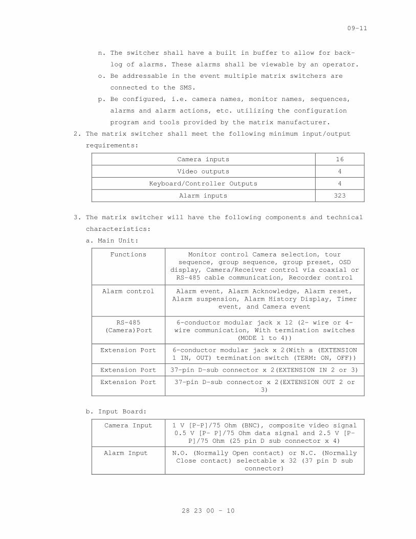
09-11
n. The switcher shall have a built in buffer to allow for back-
log of alarms. These alarms shall be viewable by an operator.
o. Be addressable in the event multiple matrix switchers are
connected to the SMS.
p. Be configured, i.e. camera names, monitor names, sequences,
alarms and alarm actions, etc. utilizing the configuration
program and tools provided by the matrix manufacturer.
2. The matrix switcher shall meet the following minimum input/output
requirements:
Camera inputs 16
Video outputs 4
Keyboard/Controller Outputs 4
Alarm inputs 323
3. The matrix switcher will have the following components and technical
characteristics:
a. Main Unit:
Functions
Monitor control Camera selection, tour sequence, group sequence, group preset, OSD
display, Camera/Receiver control via coaxial or RS-485 cable communication, Recorder control
Alarm control Alarm event, Alarm Acknowledge, Alarm reset, Alarm suspension, Alarm History Display, Timer
event, and Camera event
RS-485 (Camera)Port
6-conductor modular jack x 12 (2- wire or 4-wire communication, With termination switches
(MODE 1 to 4))
Extension Port 6-conductor modular jack x 2(With a (EXTENSION 1 IN, OUT) termination switch (TERM: ON, OFF))
Extension Port 37-pin D-sub connector x 2(EXTENSION IN 2 or 3)
Extension Port 37-pin D-sub connector x 2(EXTENSION OUT 2 or 3)
b. Input Board:
Camera Input
1 V [P-P]/75 Ohm (BNC), composite video signal 0.5 V [P- P]/75 Ohm data signal and 2.5 V [P-
P]/75 Ohm (25 pin D sub connector x 4)
Alarm Input
N.O. (Normally Open contact) or N.C. (Normally Close contact) selectable x 32 (37 pin D sub
connector)
28 23 00 - 10
09-11
c. Output Board:
Monitor Output 1 V [P-P]/75 Ohm (BNC)
Alarm Output Open collector output x 32, Max. 24 VDC, 100 mA
Extension Port 6-conductor modular jack x 2
Serial Port 9-pin D-sub connector x 2
D. IP Network Encoder
1. The units shall be used for video monitoring and surveillance over
IP networks. IP Network Encoder shall encode analog video to MPEG-4
digital video.
2. The encoder shall use MPEG-4 compression for distribution of images
over a network.
3. The encoder shall be [rack][surface] <erase one> mounted unit.
4. The encoder shall include, but not be limited to the following:
a. The encoder shall use “hybrid” technology in providing both
analog and network connections with the purpose of allowing users
to integrate existing equipment and digital IP products.
1) The encoder shall provide [one] <insert number of video
inputs> composite video input(s).
2) The encoder shall provide one Ethernet connection.
b. The encoder shall have the following digital resolution:
a) D1: 720x576 (NTSC); 720x480 (PAL)
b) CIF: 352 x 288 (NTSC); 352 x 240 (PAL)
c) QCIF: 160 x 144 (NTSC); 160 x 112 (PAL)
c. The encoder shall have a digital frame rate of up to 30 frames
per second (NTSC) at 720x480 resolution or 25 fps (PAL) at
720x586 resolution.
d. The encoder/decoder shall use the following protocols:
1) TCP/IP
2) UDP/IP
3) DHCP
4) Multicast
5) Data Throttle
6) Heart beat
e. The encoder shall have the following connectors:
1) Power connector: 3-pin male – for connecting the external
power supply
28 23 00 - 11
09-11
2) I/O connector: 16-pin male – for connecting alarm, audio, RS-
232, RS-485 input and output
3) Video I/O connector: SVHS style – for input and output
connection of two composite monitors
4) Ethernet port: RJ-45 – for connecting to a network
f. The encoder/decoder shall have the following indicators:
1) Power LED
2) Link – indicates activity on the Ethernet port
3) Tx activity
4) Rx activity
g. The encoder shall have the following additional specifications:
1) Video
a) Video signal input: 1 V p-p ±10% 75 ohms, autosensing
b) Input termination: 75 ohm
c) Video compression standard: MPEG-4
d) Audio compression standard: MPEG-1 Layer 2
2) Audio
a) Audio input: 315 mV, 40 kOhms, unbalanced
b) Audio output: 315 mV, 600 ohms, unbalanced
3) Electrical
a) External power supply: 100 to 240 VAC
b) Output voltage: 13.5 V, 1.33 A
c) Power consumption: 0.5 W maximum
2.3 VIDEO CAMERAS
A. The cameras shall be high-resolution color video cameras with wide
dynamic range capturing capability.
B. The camera shall meet or exceed the following specifications:
1. The image capturing device shall be a 1/3-inch image sensor designed
for capturing wide dynamic images.
a. The image capturing device shall have a separate analog-to-
digital converter for every pixel.
b. The image capturing device shall sample each pixel multiple times
per second.
c. The dynamic range shall be 95 dB typical and 120 dB maximum.
3. The camera shall optimize each pixel independently.
4. The camera shall have onscreen display menus for programming of the
camera’s settings.
5. The signal system shall be NTSC.
28 23 00 - 12
09-11
C. The camera shall have composite video output.
D. The camera shall come with a manual varifocal lens.
E. The video output shall be composite: 1.0 volts peak-to-peak at 75-ohm
load.
2.7 AUTOMATIC COLOR DOME CAMERA - ANALOG
A. The camera shall be a high-resolution color video camera with wide
dynamic range capturing capability.
B. Comply with UL 639.
C. Pickup Device: 1/3 CCD interline transfer.
D. Horizontal Resolution: 480 lines.
E. Signal-to-Noise Ratio: Not less than 50 dB, with the camera AGC off.
F. With AGC, manually selectable on or off.
G. Sensitivity: Camera shall provide usable images in low-light
conditions, delivering an image at a scene illumination of <Insert
light level> lux at <Insert f-stop of lens>[, with the camera AGC off].
H. Sensitivity: Camera shall deliver 1-V peak-to-peak video signal at the
minimum specified light level. The illumination for the test shall be
with lamps rated at approximately 2200-K color temperature, and with
the camera AGC off.
I. Manually selectable modes for backlight compensation or normal
lighting.
J. Pan and Tilt: Direct-drive motor, 360-degree rotation angle, and 180-
degree tilt angle. Pan-and-tilt speed shall be variable controlled by
operator. Movement from preset positions shall be not less than 300
degrees per second.
K. Preset positioning: 64 user-definable scenes. Controls shall include
the following:
1. In "sequence mode," camera shall continuously sequence through
preset positions, with dwell time and sequencing under operator
control.
2. Motion detection shall be available at each camera position.
L. Scanning Synchronization: Determined by external synch over the
coaxial cable. Camera shall revert to internally generated
synchronization on loss of external synch signal.
M. White Balance: Auto-tracing white balance, with manually settable
fixed balance option.
28 23 00 - 13
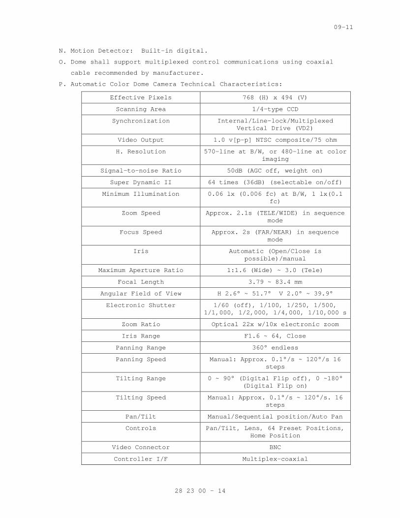
09-11
N. Motion Detector: Built-in digital.
O. Dome shall support multiplexed control communications using coaxial
cable recommended by manufacturer.
P. Automatic Color Dome Camera Technical Characteristics:
Effective Pixels 768 (H) x 494 (V)
Scanning Area 1/4-type CCD
Synchronization Internal/Line-lock/Multiplexed Vertical Drive (VD2)
Video Output 1.0 v[p-p] NTSC composite/75 ohm
H. Resolution 570-line at B/W, or 480-line at color imaging
Signal-to-noise Ratio 50dB (AGC off, weight on)
Super Dynamic II 64 times (36dB) (selectable on/off)
Minimum Illumination 0.06 lx (0.006 fc) at B/W, 1 lx(0.1 fc)
Zoom Speed Approx. 2.1s (TELE/WIDE) in sequence mode
Focus Speed Approx. 2s (FAR/NEAR) in sequence mode
Iris Automatic (Open/Close is possible)/manual
Maximum Aperture Ratio 1:1.6 (Wide) ~ 3.0 (Tele)
Focal Length 3.79 ~ 83.4 mm
Angular Field of View H 2.6° ~ 51.7° V 2.0° ~ 39.9°
Electronic Shutter 1/60 (off), 1/100, 1/250, 1/500, 1/1,000, 1/2,000, 1/4,000, 1/10,000 s
Zoom Ratio Optical 22x w/10x electronic zoom
Iris Range F1.6 ~ 64, Close
Panning Range 360° endless
Panning Speed Manual: Approx. 0.1°/s ~ 120°/s 16 steps
Tilting Range 0 ~ 90° (Digital Flip off), 0 ~180° (Digital Flip on)
Tilting Speed Manual: Approx. 0.1°/s ~ 120°/s. 16 steps
Pan/Tilt Manual/Sequential position/Auto Pan
Controls Pan/Tilt, Lens, 64 Preset Positions, Home Position
Video Connector BNC
Controller I/F Multiplex-coaxial
28 23 00 - 14
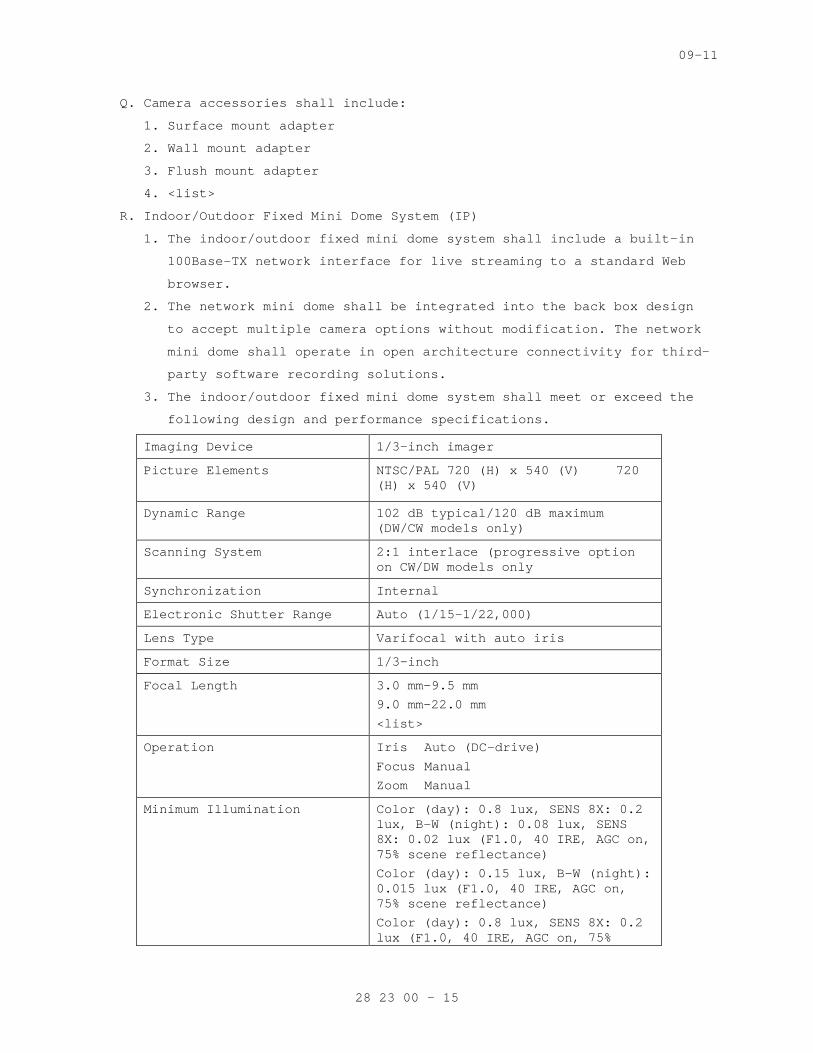
09-11
Q. Camera accessories shall include:
1. Surface mount adapter
2. Wall mount adapter
3. Flush mount adapter
4. <list>
R. Indoor/Outdoor Fixed Mini Dome System (IP)
1. The indoor/outdoor fixed mini dome system shall include a built-in
100Base-TX network interface for live streaming to a standard Web
browser.
2. The network mini dome shall be integrated into the back box design
to accept multiple camera options without modification. The network
mini dome shall operate in open architecture connectivity for third-
party software recording solutions.
3. The indoor/outdoor fixed mini dome system shall meet or exceed the
following design and performance specifications.
Imaging Device 1/3-inch imager
Picture Elements
NTSC/PAL 720 (H) x 540 (V) 720 (H) x 540 (V)
Dynamic Range 102 dB typical/120 dB maximum (DW/CW models only)
Scanning System 2:1 interlace (progressive option on CW/DW models only
Synchronization Internal
Electronic Shutter Range Auto (1/15–1/22,000)
Lens Type Varifocal with auto iris
Format Size 1/3-inch
Focal Length 3.0 mm–9.5 mm
9.0 mm–22.0 mm
<list>
Operation Iris Auto (DC-drive)
Focus Manual
Zoom Manual
Minimum Illumination Color (day): 0.8 lux, SENS 8X: 0.2 lux, B-W (night): 0.08 lux, SENS 8X: 0.02 lux (F1.0, 40 IRE, AGC on, 75% scene reflectance)
Color (day): 0.15 lux, B-W (night): 0.015 lux (F1.0, 40 IRE, AGC on, 75% scene reflectance)
Color (day): 0.8 lux, SENS 8X: 0.2 lux (F1.0, 40 IRE, AGC on, 75%
28 23 00 - 15
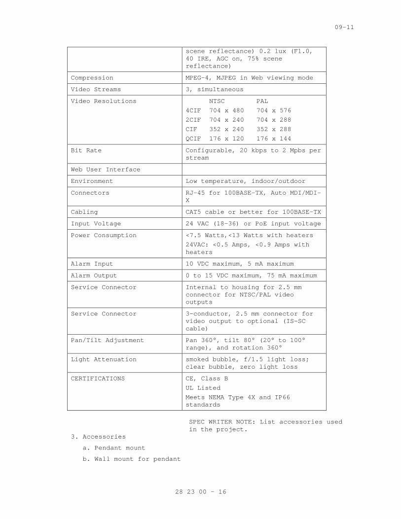
09-11
scene reflectance) 0.2 lux (F1.0, 40 IRE, AGC on, 75% scene reflectance)
Compression MPEG-4, MJPEG in Web viewing mode
Video Streams 3, simultaneous
Video Resolutions NTSC PAL
4CIF 704 x 480 704 x 576
2CIF 704 x 240 704 x 288
CIF 352 x 240 352 x 288
QCIF 176 x 120 176 x 144
Bit Rate Configurable, 20 kbps to 2 Mpbs per stream
Web User Interface
Environment Low temperature, indoor/outdoor
Connectors RJ-45 for 100BASE-TX, Auto MDI/MDI-X
Cabling CAT5 cable or better for 100BASE-TX
Input Voltage 24 VAC (18-36) or PoE input voltage
Power Consumption <7.5 Watts,<13 Watts with heaters
24VAC: <0.5 Amps, <0.9 Amps with heaters
Alarm Input 10 VDC maximum, 5 mA maximum
Alarm Output 0 to 15 VDC maximum, 75 mA maximum
Service Connector Internal to housing for 2.5 mm connector for NTSC/PAL video outputs
Service Connector 3-conductor, 2.5 mm connector for video output to optional (IS-SC cable)
Pan/Tilt Adjustment Pan 360°, tilt 80° (20° to 100° range), and rotation 360°
Light Attenuation smoked bubble, f/1.5 light loss; clear bubble, zero light loss
CERTIFICATIONS CE, Class B
UL Listed
Meets NEMA Type 4X and IP66 standards
SPEC WRITER NOTE: List accessories used in the project.
3. Accessories
a. Pendant mount
b. Wall mount for pendant
28 23 00 - 16
09-11
c. Corner adapter for wall mount
d. Pole adapter for wall mount
S. Megapixel High Definition Integrated Digital Network Camera
1. The network camera shall offer dual video streams with up to 3.1
megapixel resolution (2048 x 1536) in progressive scan format.
2. An alarm input and relay output shall be built in for integration
with hard wired external sensors.
3. The network camera shall be capable of firmware upgrades through a
network using a software-based device utility.
4. The network camera shall offer auto back focus (ABF) functionality
through a push button on the camera. ABF parameters shall also be
configurable through a standard Web browser interface.
5. The network camera shall offer a video output port providing an
NTSC/PAL analog video output signal for adjusting field of view and
focus at the camera.
6. The network camera shall provide advanced low-light capabilities for
color and day/night models with sensitivity down to 0.12 lux in
color and 0.03 lux in black-white (B-W).
7. The network camera shall have removable IR cut filter mechanism for
increased sensitivity in low-light installations. The sensitivity
of IR cut filter removal shall be configurable through a Web
browser.
8. The network camera shall support two simultaneous, configurable
video streams. H.264 and MJPEG compression formats shall be
available for primary and secondary streams with selectable unicast
and multicast protocols. The streams shall be configurable in a
variety of frame rates and bit rates.
9. The network camera shall support industry standard Power over
Ethernet (PoE)
10. IEEE 802.3af to supply power to the camera over the network. The
network camera shall also offer a 24 VAC power input for optional
use.
11. The network camera shall use a standard Web browser interface for
remote administration and configuration of camera parameters.
12. The network camera shall have a window blanking feature to conceal
user-defined privacy areas that cannot be viewed by an operator. The
network camera shall support up to four blanked windows. A blanked
area shall appear on the screen as a solid gray window.
28 23 00 - 17
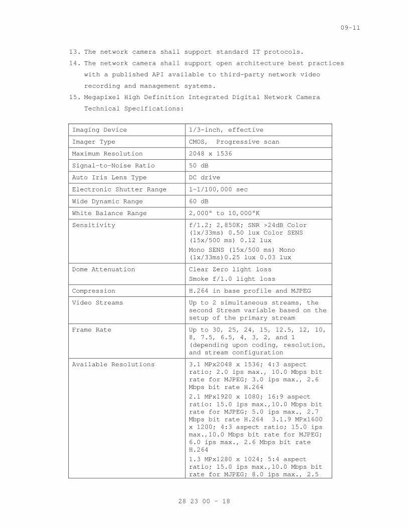
09-11
13. The network camera shall support standard IT protocols.
14. The network camera shall support open architecture best practices
with a published API available to third-party network video
recording and management systems.
15. Megapixel High Definition Integrated Digital Network Camera
Technical Specifications:
Imaging Device 1/3-inch, effective
Imager Type CMOS, Progressive scan
Maximum Resolution 2048 x 1536
Signal-to-Noise Ratio 50 dB
Auto Iris Lens Type DC drive
Electronic Shutter Range 1~1/100,000 sec
Wide Dynamic Range 60 dB
White Balance Range 2,000° to 10,000°K
Sensitivity f/1.2; 2,850K; SNR >24dB Color (1x/33ms) 0.50 lux Color SENS (15x/500 ms) 0.12 lux
Mono SENS (15x/500 ms) Mono (1x/33ms)0.25 lux 0.03 lux
Dome Attenuation Clear Zero light loss
Smoke f/1.0 light loss
Compression H.264 in base profile and MJPEG
Video Streams Up to 2 simultaneous streams, the second Stream variable based on the setup of the primary stream
Frame Rate Up to 30, 25, 24, 15, 12.5, 12, 10, 8, 7.5, 6.5, 4, 3, 2, and 1 (depending upon coding, resolution, and stream configuration
Available Resolutions 3.1 MPx2048 x 1536; 4:3 aspect ratio; 2.0 ips max., 10.0 Mbps bit rate for MJPEG; 3.0 ips max., 2.6 Mbps bit rate H.264
2.1 MPx1920 x 1080; 16:9 aspect ratio: 15.0 ips max.,10.0 Mbps bit rate for MJPEG; 5.0 ips max., 2.7 Mbps bit rate H.264 3.1.9 MPx1600 x 1200; 4:3 aspect ratio; 15.0 ips max.,10.0 Mbps bit rate for MJPEG; 6.0 ips max., 2.6 Mbps bit rate H.264
1.3 MPx1280 x 1024; 5:4 aspect ratio; 15.0 ips max.,10.0 Mbps bit rate for MJPEG; 8.0 ips max., 2.5
28 23 00 - 18
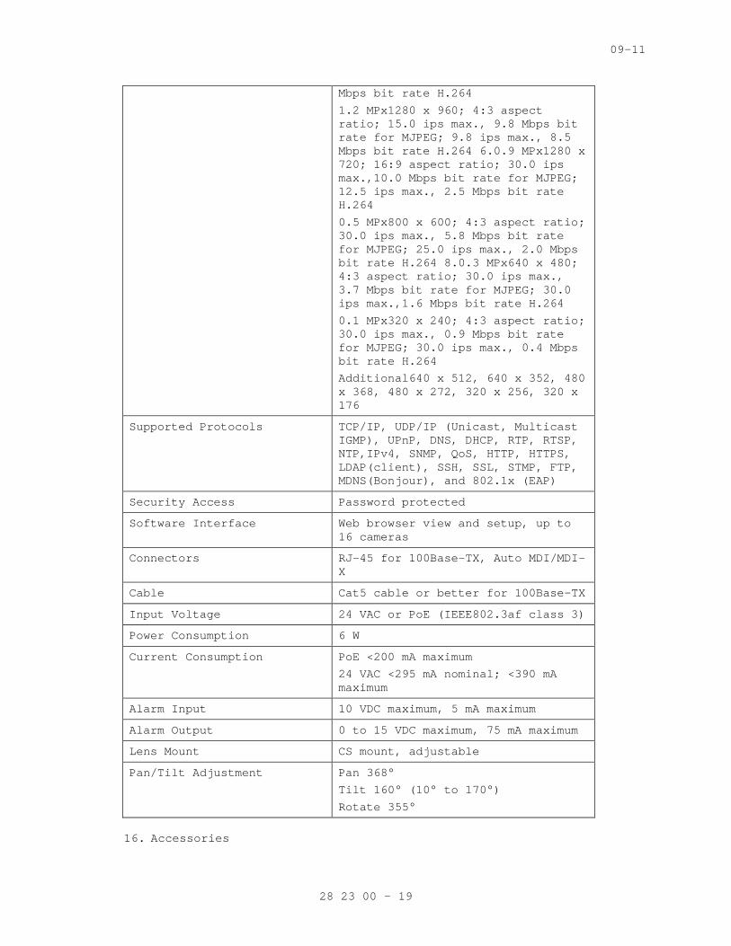
09-11
Mbps bit rate H.264
1.2 MPx1280 x 960; 4:3 aspect ratio; 15.0 ips max., 9.8 Mbps bit rate for MJPEG; 9.8 ips max., 8.5 Mbps bit rate H.264 6.0.9 MPx1280 x 720; 16:9 aspect ratio; 30.0 ips max.,10.0 Mbps bit rate for MJPEG; 12.5 ips max., 2.5 Mbps bit rate H.264
0.5 MPx800 x 600; 4:3 aspect ratio; 30.0 ips max., 5.8 Mbps bit rate for MJPEG; 25.0 ips max., 2.0 Mbps bit rate H.264 8.0.3 MPx640 x 480; 4:3 aspect ratio; 30.0 ips max., 3.7 Mbps bit rate for MJPEG; 30.0 ips max.,1.6 Mbps bit rate H.264
0.1 MPx320 x 240; 4:3 aspect ratio; 30.0 ips max., 0.9 Mbps bit rate for MJPEG; 30.0 ips max., 0.4 Mbps bit rate H.264 Additional640 x 512, 640 x 352, 480 x 368, 480 x 272, 320 x 256, 320 x 176
Supported Protocols TCP/IP, UDP/IP (Unicast, Multicast IGMP), UPnP, DNS, DHCP, RTP, RTSP, NTP,IPv4, SNMP, QoS, HTTP, HTTPS, LDAP(client), SSH, SSL, STMP, FTP, MDNS(Bonjour), and 802.1x (EAP)
Security Access Password protected
Software Interface Web browser view and setup, up to 16 cameras
Connectors RJ-45 for 100Base-TX, Auto MDI/MDI-X
Cable Cat5 cable or better for 100Base-TX
Input Voltage 24 VAC or PoE (IEEE802.3af class 3)
Power Consumption 6 W
Current Consumption PoE <200 mA maximum
24 VAC <295 mA nominal; <390 mA maximum
Alarm Input 10 VDC maximum, 5 mA maximum
Alarm Output 0 to 15 VDC maximum, 75 mA maximum
Lens Mount CS mount, adjustable
Pan/Tilt Adjustment Pan 368°
Tilt 160° (10° to 170°)
Rotate 355°
16. Accessories
28 23 00 - 19
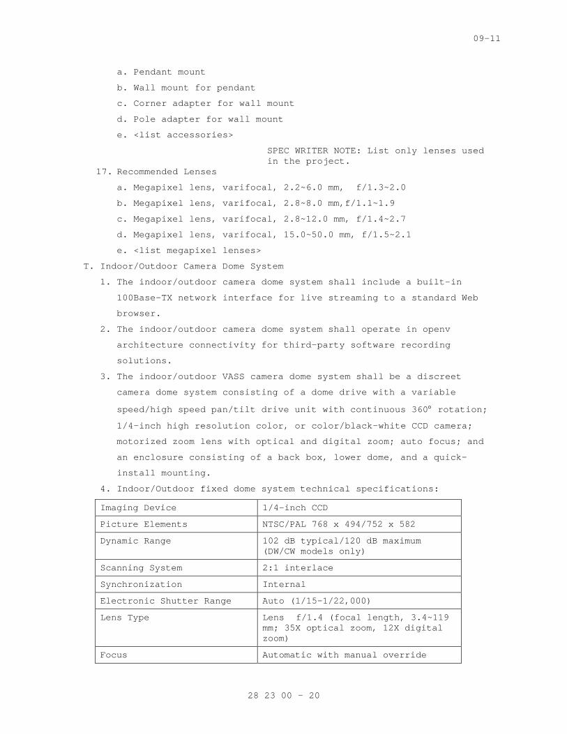
09-11
a. Pendant mount
b. Wall mount for pendant
c. Corner adapter for wall mount
d. Pole adapter for wall mount
e. <list accessories>
SPEC WRITER NOTE: List only lenses used in the project.
17. Recommended Lenses
a. Megapixel lens, varifocal, 2.2~6.0 mm, f/1.3~2.0
b. Megapixel lens, varifocal, 2.8~8.0 mm,f/1.1~1.9
c. Megapixel lens, varifocal, 2.8~12.0 mm, f/1.4~2.7
d. Megapixel lens, varifocal, 15.0~50.0 mm, f/1.5~2.1
e. <list megapixel lenses>
T. Indoor/Outdoor Camera Dome System
1. The indoor/outdoor camera dome system shall include a built-in
100Base-TX network interface for live streaming to a standard Web
browser.
2. The indoor/outdoor camera dome system shall operate in openv
architecture connectivity for third-party software recording
solutions.
3. The indoor/outdoor VASS camera dome system shall be a discreet
camera dome system consisting of a dome drive with a variable
speed/high speed pan/tilt drive unit with continuous 360° rotation;
1/4-inch high resolution color, or color/black-white CCD camera;
motorized zoom lens with optical and digital zoom; auto focus; and
an enclosure consisting of a back box, lower dome, and a quick-
install mounting.
4. Indoor/Outdoor fixed dome system technical specifications:
Imaging Device 1/4-inch CCD
Picture Elements NTSC/PAL 768 x 494/752 x 582
Dynamic Range 102 dB typical/120 dB maximum (DW/CW models only)
Scanning System 2:1 interlace
Synchronization Internal
Electronic Shutter Range Auto (1/15–1/22,000)
Lens Type Lens f/1.4 (focal length, 3.4~119 mm; 35X optical zoom, 12X digital zoom)
Focus Automatic with manual override
28 23 00 - 20
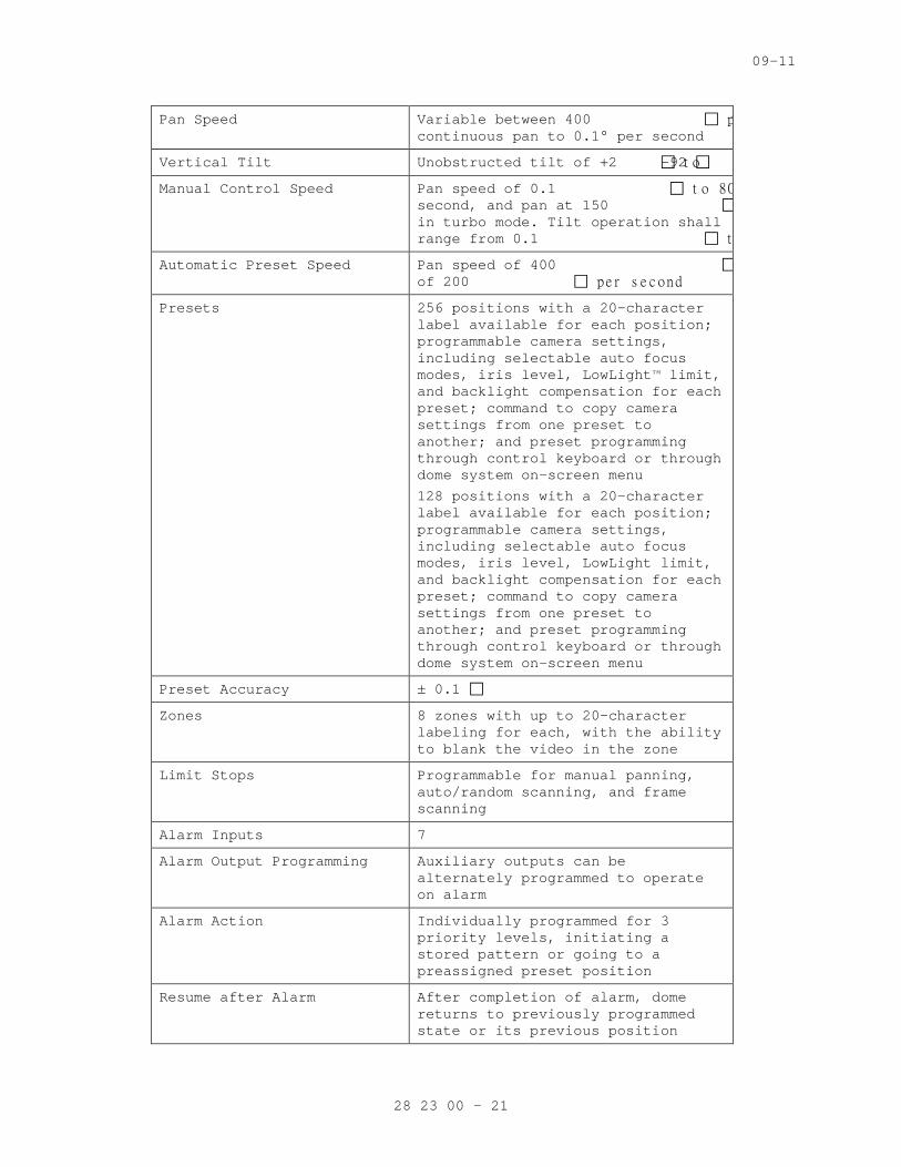
09-11
Pan Speed Variable between 400 p continuous pan to 0.1° per second
Vertical Tilt Unobstructed tilt of +2 t o -92
Manual Control Speed Pan speed of 0.1 t o 80 second, and pan at 150 in turbo mode. Tilt operation shall range from 0.1 t
Automatic Preset Speed Pan speed of 400 of 200 p e r s e c ond
Presets 256 positions with a 20-character label available for each position; programmable camera settings, including selectable auto focus modes, iris level, LowLight™ limit, and backlight compensation for each preset; command to copy camera settings from one preset to another; and preset programming through control keyboard or through dome system on-screen menu
128 positions with a 20-character label available for each position; programmable camera settings, including selectable auto focus modes, iris level, LowLight limit, and backlight compensation for each preset; command to copy camera settings from one preset to another; and preset programming through control keyboard or through dome system on-screen menu
Preset Accuracy ± 0.1
Zones 8 zones with up to 20-character labeling for each, with the ability to blank the video in the zone
Limit Stops Programmable for manual panning, auto/random scanning, and frame scanning
Alarm Inputs 7
Alarm Output Programming Auxiliary outputs can be alternately programmed to operate on alarm
Alarm Action Individually programmed for 3 priority levels, initiating a stored pattern or going to a preassigned preset position
Resume after Alarm After completion of alarm, dome returns to previously programmed state or its previous position
28 23 00 - 21
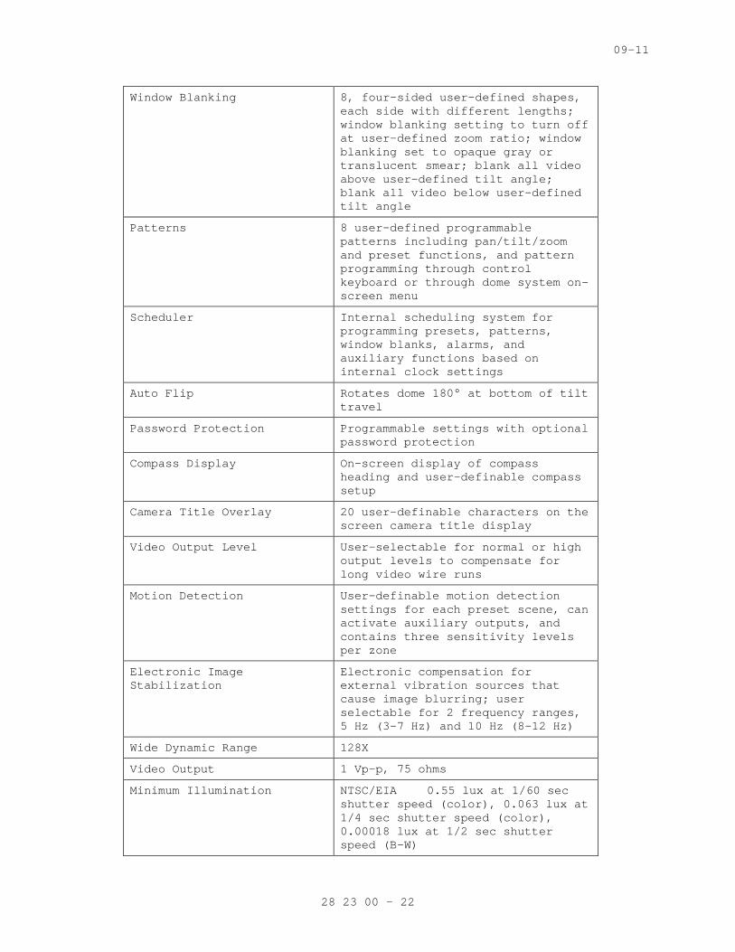
09-11
Window Blanking 8, four-sided user-defined shapes, each side with different lengths; window blanking setting to turn off at user-defined zoom ratio; window blanking set to opaque gray or translucent smear; blank all video above user-defined tilt angle; blank all video below user-defined tilt angle
Patterns 8 user-defined programmable patterns including pan/tilt/zoom and preset functions, and pattern programming through control keyboard or through dome system on-screen menu
Scheduler Internal scheduling system for programming presets, patterns, window blanks, alarms, and auxiliary functions based on internal clock settings
Auto Flip Rotates dome 180° at bottom of tilt travel
Password Protection Programmable settings with optional password protection
Compass Display On-screen display of compass heading and user-definable compass setup
Camera Title Overlay 20 user-definable characters on the screen camera title display
Video Output Level User-selectable for normal or high output levels to compensate for long video wire runs
Motion Detection User-definable motion detection settings for each preset scene, can activate auxiliary outputs, and contains three sensitivity levels per zone
Electronic Image Stabilization
Electronic compensation for external vibration sources that cause image blurring; user selectable for 2 frequency ranges, 5 Hz (3-7 Hz) and 10 Hz (8-12 Hz)
Wide Dynamic Range 128X
Video Output 1 Vp-p, 75 ohms
Minimum Illumination NTSC/EIA 0.55 lux at 1/60 sec shutter speed (color), 0.063 lux at 1/4 sec shutter speed (color), 0.00018 lux at 1/2 sec shutter speed (B-W)
28 23 00 - 22
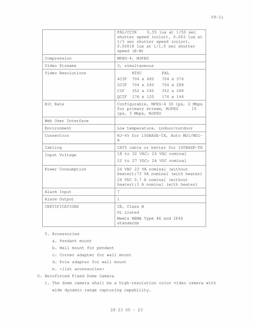
09-11
PAL/CCIR 0.55 lux at 1/50 sec shutter speed (color), 0.063 lux at 1/3 sec shutter speed (color), 0.00018 lux at 1/1.5 sec shutter speed (B-W)
Compression MPEG-4, MJPEG
Video Streams 3, simultaneous
Video Resolutions NTSC PAL
4CIF 704 x 480 704 x 576
2CIF 704 x 240 704 x 288
CIF 352 x 240 352 x 288
QCIF 176 x 120 176 x 144
Bit Rate Configurable, MPEG-4 30 ips, 2 Mbps for primary stream, MJPEG 15 ips, 3 Mbps, MJPEG
Web User Interface
Environment Low temperature, indoor/outdoor
Connectors RJ-45 for 100BASE-TX, Auto MDI/MDI-X
Cabling CAT5 cable or better for 100BASE-TX
Input Voltage 18 to 32 VAC; 24 VAC nominal
22 to 27 VDC; 24 VDC nominal
Power Consumption 24 VAC 23 VA nominal (without heater);73 VA nominal (with heater)
24 VDC 0.7 A nominal (without heater);3 A nominal (with heater)
Alarm Input 7
Alarm Output 1
CERTIFICATIONS CE, Class B
UL Listed
Meets NEMA Type 4X and IP66 standards
5. Accessories
a. Pendant mount
b. Wall mount for pendant
c. Corner adapter for wall mount
d. Pole adapter for wall mount
e. <list accessories>
U. Reinforced Fixed Dome Camera
1. The dome camera shall be a high-resolution color video camera with
wide dynamic range capturing capability.
28 23 00 - 23
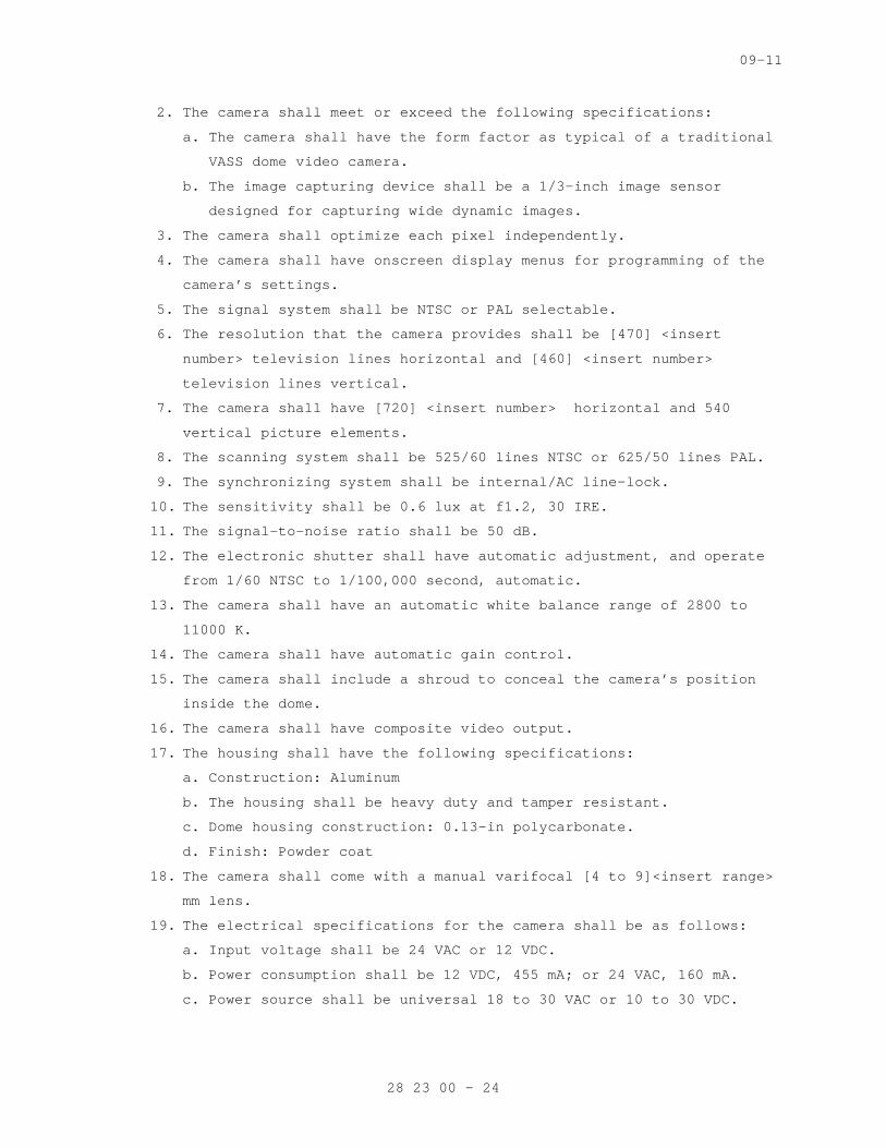
09-11
2. The camera shall meet or exceed the following specifications:
a. The camera shall have the form factor as typical of a traditional
VASS dome video camera.
b. The image capturing device shall be a 1/3-inch image sensor
designed for capturing wide dynamic images.
3. The camera shall optimize each pixel independently.
4. The camera shall have onscreen display menus for programming of the
camera’s settings.
5. The signal system shall be NTSC or PAL selectable.
6. The resolution that the camera provides shall be [470] <insert
number> television lines horizontal and [460] <insert number>
television lines vertical.
7. The camera shall have [720] <insert number> horizontal and 540
vertical picture elements.
8. The scanning system shall be 525/60 lines NTSC or 625/50 lines PAL.
9. The synchronizing system shall be internal/AC line-lock.
10. The sensitivity shall be 0.6 lux at f1.2, 30 IRE.
11. The signal-to-noise ratio shall be 50 dB.
12. The electronic shutter shall have automatic adjustment, and operate
from 1/60 NTSC to 1/100,000 second, automatic.
13. The camera shall have an automatic white balance range of 2800 to
11000 K.
14. The camera shall have automatic gain control.
15. The camera shall include a shroud to conceal the camera’s position
inside the dome.
16. The camera shall have composite video output.
17. The housing shall have the following specifications:
a. Construction: Aluminum
b. The housing shall be heavy duty and tamper resistant.
c. Dome housing construction: 0.13-in polycarbonate.
d. Finish: Powder coat
18. The camera shall come with a manual varifocal [4 to 9]<insert range>
mm lens.
19. The electrical specifications for the camera shall be as follows:
a. Input voltage shall be 24 VAC or 12 VDC.
b. Power consumption shall be 12 VDC, 455 mA; or 24 VAC, 160 mA.
c. Power source shall be universal 18 to 30 VAC or 10 to 30 VDC.
28 23 00 - 24
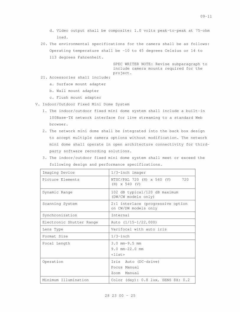
09-11
d. Video output shall be composite: 1.0 volts peak-to-peak at 75-ohm
load.
20. The environmental specifications for the camera shall be as follows:
Operating temperature shall be -10 to 45 degrees Celsius or 14 to
113 degrees Fahrenheit.
SPEC WRITER NOTE: Revise subparagraph to include camera mounts required for the project.
21. Accessories shall include:
a. Surface mount adapter
b. Wall mount adapter
c. Flush mount adapter
V. Indoor/Outdoor Fixed Mini Dome System
1. The indoor/outdoor fixed mini dome system shall include a built-in
100Base-TX network interface for live streaming to a standard Web
browser.
2. The network mini dome shall be integrated into the back box design
to accept multiple camera options without modification. The network
mini dome shall operate in open architecture connectivity for third-
party software recording solutions.
3. The indoor/outdoor fixed mini dome system shall meet or exceed the
following design and performance specifications.
Imaging Device 1/3-inch imager
Picture Elements
NTSC/PAL 720 (H) x 540 (V) 720 (H) x 540 (V)
Dynamic Range 102 dB typical/120 dB maximum (DW/CW models only)
Scanning System 2:1 interlace (progressive option on CW/DW models only
Synchronization Internal
Electronic Shutter Range Auto (1/15–1/22,000)
Lens Type Varifocal with auto iris
Format Size 1/3-inch
Focal Length 3.0 mm–9.5 mm
9.0 mm–22.0 mm
<list>
Operation Iris Auto (DC-drive)
Focus Manual
Zoom Manual
Minimum Illumination Color (day): 0.8 lux, SENS 8X: 0.2
28 23 00 - 25
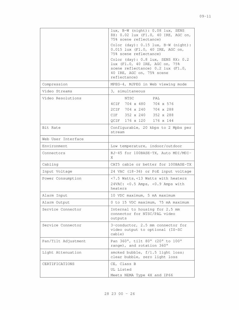
09-11
lux, B-W (night): 0.08 lux, SENS 8X: 0.02 lux (F1.0, 40 IRE, AGC on, 75% scene reflectance)
Color (day): 0.15 lux, B-W (night): 0.015 lux (F1.0, 40 IRE, AGC on, 75% scene reflectance)
Color (day): 0.8 lux, SENS 8X: 0.2 lux (F1.0, 40 IRE, AGC on, 75% scene reflectance) 0.2 lux (F1.0, 40 IRE, AGC on, 75% scene reflectance)
Compression MPEG-4, MJPEG in Web viewing mode
Video Streams 3, simultaneous
Video Resolutions NTSC PAL
4CIF 704 x 480 704 x 576
2CIF 704 x 240 704 x 288
CIF 352 x 240 352 x 288
QCIF 176 x 120 176 x 144
Bit Rate Configurable, 20 kbps to 2 Mpbs per stream
Web User Interface
Environment Low temperature, indoor/outdoor
Connectors RJ-45 for 100BASE-TX, Auto MDI/MDI-X
Cabling CAT5 cable or better for 100BASE-TX
Input Voltage 24 VAC (18-36) or PoE input voltage
Power Consumption <7.5 Watts,<13 Watts with heaters
24VAC: <0.5 Amps, <0.9 Amps with heaters
Alarm Input 10 VDC maximum, 5 mA maximum
Alarm Output 0 to 15 VDC maximum, 75 mA maximum
Service Connector Internal to housing for 2.5 mm connector for NTSC/PAL video outputs
Service Connector 3-conductor, 2.5 mm connector for video output to optional (IS-SC cable)
Pan/Tilt Adjustment Pan 360°, tilt 80° (20° to 100° range), and rotation 360°
Light Attenuation smoked bubble, f/1.5 light loss; clear bubble, zero light loss
CERTIFICATIONS CE, Class B
UL Listed
Meets NEMA Type 4X and IP66
28 23 00 - 26

09-11
standards
4. Accessories
a. Pendant mount
b. Wall mount for pendant
c. Corner adapter for wall mount
d. Pole adapter for wall mount
e. <list accessories>
W. Megapixel High Definition Integrated Digital Network Camera
1. The network camera shall offer dual video streams with up to 3.1
megapixel resolution (2048 x 1536) in progressive scan format.
2. An alarm input and relay output shall be built in for integration
with hard wired external sensors.
3. The network camera shall be capable of firmware upgrades through a
network using a software-based device utility.
4. The network camera shall offer auto back focus (ABF) functionality
through a push button on the camera. ABF parameters shall also be
configurable through a standard Web browser interface.
5. The network camera shall offer a video output port providing an
NTSC/PAL analog video output signal for adjusting field of view and
focus at the camera.
6. The network camera shall provide advanced low-light capabilities for
color and day/night models with sensitivity down to 0.12 lux in
color and 0.03 lux in black-white (B-W).
7. The network camera shall have removable IR cut filter mechanism for
increased sensitivity in low-light installations. The sensitivity
of IR cut filter removal shall be configurable through a Web
browser.
8. The network camera shall support two simultaneous, configurable
video streams. H.264 and MJPEG compression formats shall be
available for primary and secondary streams with selectable unicast
and multicast protocols. The streams shall be configurable in a
variety of frame rates and bit rates.
9. The network camera shall support industry standard Power over
Ethernet (PoE)
10. IEEE 802.3af to supply power to the camera over the network. The
network camera shall also offer a 24 VAC power input for optional
use.
28 23 00 - 27
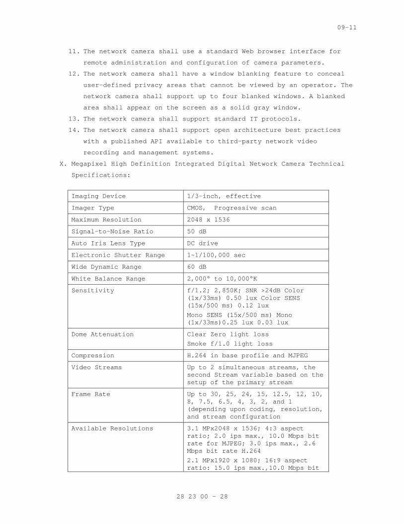
09-11
11. The network camera shall use a standard Web browser interface for
remote administration and configuration of camera parameters.
12. The network camera shall have a window blanking feature to conceal
user-defined privacy areas that cannot be viewed by an operator. The
network camera shall support up to four blanked windows. A blanked
area shall appear on the screen as a solid gray window.
13. The network camera shall support standard IT protocols.
14. The network camera shall support open architecture best practices
with a published API available to third-party network video
recording and management systems.
X. Megapixel High Definition Integrated Digital Network Camera Technical
Specifications:
Imaging Device 1/3-inch, effective
Imager Type CMOS, Progressive scan
Maximum Resolution 2048 x 1536
Signal-to-Noise Ratio 50 dB
Auto Iris Lens Type DC drive
Electronic Shutter Range 1~1/100,000 sec
Wide Dynamic Range 60 dB
White Balance Range 2,000° to 10,000°K
Sensitivity f/1.2; 2,850K; SNR >24dB Color (1x/33ms) 0.50 lux Color SENS (15x/500 ms) 0.12 lux
Mono SENS (15x/500 ms) Mono (1x/33ms)0.25 lux 0.03 lux
Dome Attenuation Clear Zero light loss
Smoke f/1.0 light loss
Compression H.264 in base profile and MJPEG
Video Streams Up to 2 simultaneous streams, the second Stream variable based on the setup of the primary stream
Frame Rate Up to 30, 25, 24, 15, 12.5, 12, 10, 8, 7.5, 6.5, 4, 3, 2, and 1 (depending upon coding, resolution, and stream configuration
Available Resolutions 3.1 MPx2048 x 1536; 4:3 aspect ratio; 2.0 ips max., 10.0 Mbps bit rate for MJPEG; 3.0 ips max., 2.6 Mbps bit rate H.264
2.1 MPx1920 x 1080; 16:9 aspect ratio: 15.0 ips max.,10.0 Mbps bit
28 23 00 - 28
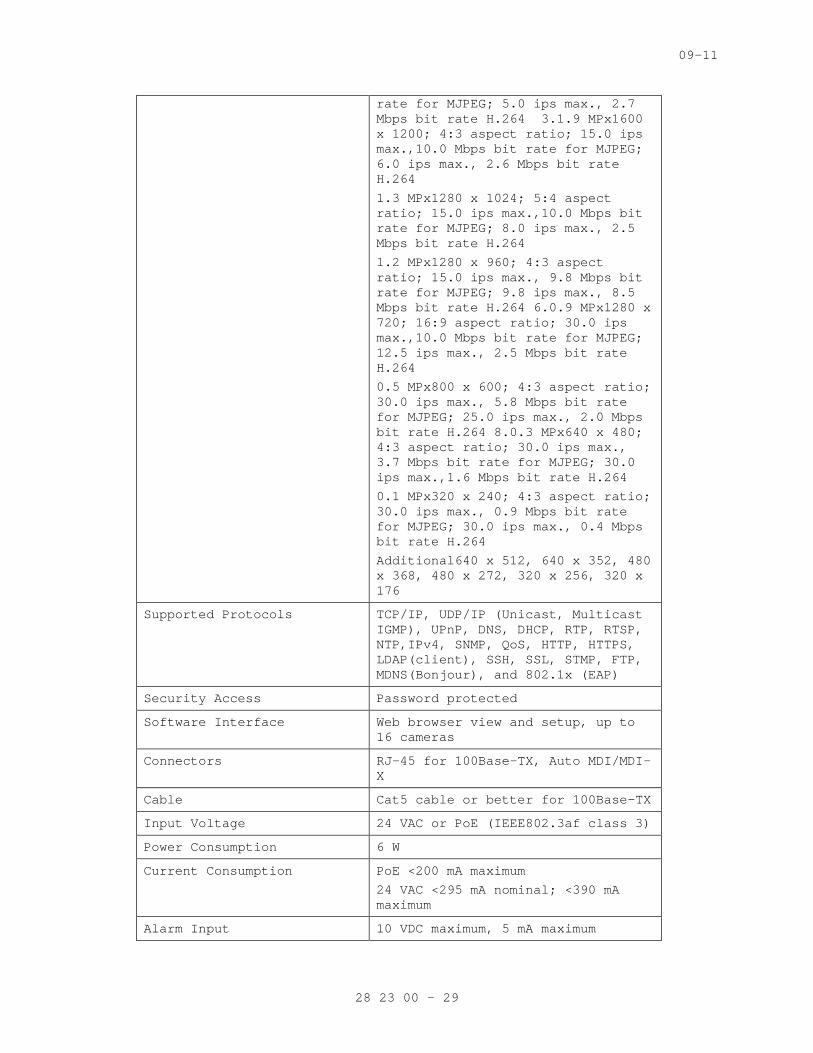
09-11
rate for MJPEG; 5.0 ips max., 2.7 Mbps bit rate H.264 3.1.9 MPx1600 x 1200; 4:3 aspect ratio; 15.0 ips max.,10.0 Mbps bit rate for MJPEG; 6.0 ips max., 2.6 Mbps bit rate H.264
1.3 MPx1280 x 1024; 5:4 aspect ratio; 15.0 ips max.,10.0 Mbps bit rate for MJPEG; 8.0 ips max., 2.5 Mbps bit rate H.264
1.2 MPx1280 x 960; 4:3 aspect ratio; 15.0 ips max., 9.8 Mbps bit rate for MJPEG; 9.8 ips max., 8.5 Mbps bit rate H.264 6.0.9 MPx1280 x 720; 16:9 aspect ratio; 30.0 ips max.,10.0 Mbps bit rate for MJPEG; 12.5 ips max., 2.5 Mbps bit rate H.264
0.5 MPx800 x 600; 4:3 aspect ratio; 30.0 ips max., 5.8 Mbps bit rate for MJPEG; 25.0 ips max., 2.0 Mbps bit rate H.264 8.0.3 MPx640 x 480; 4:3 aspect ratio; 30.0 ips max., 3.7 Mbps bit rate for MJPEG; 30.0 ips max.,1.6 Mbps bit rate H.264
0.1 MPx320 x 240; 4:3 aspect ratio; 30.0 ips max., 0.9 Mbps bit rate for MJPEG; 30.0 ips max., 0.4 Mbps bit rate H.264
Additional640 x 512, 640 x 352, 480 x 368, 480 x 272, 320 x 256, 320 x 176
Supported Protocols TCP/IP, UDP/IP (Unicast, Multicast IGMP), UPnP, DNS, DHCP, RTP, RTSP, NTP,IPv4, SNMP, QoS, HTTP, HTTPS, LDAP(client), SSH, SSL, STMP, FTP, MDNS(Bonjour), and 802.1x (EAP)
Security Access Password protected
Software Interface Web browser view and setup, up to 16 cameras
Connectors RJ-45 for 100Base-TX, Auto MDI/MDI-X
Cable Cat5 cable or better for 100Base-TX
Input Voltage 24 VAC or PoE (IEEE802.3af class 3)
Power Consumption 6 W
Current Consumption PoE <200 mA maximum
24 VAC <295 mA nominal; <390 mA maximum
Alarm Input 10 VDC maximum, 5 mA maximum
28 23 00 - 29
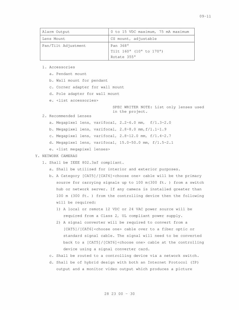
09-11
Alarm Output 0 to 15 VDC maximum, 75 mA maximum
Lens Mount CS mount, adjustable
Pan/Tilt Adjustment Pan 368°
Tilt 160° (10° to 170°)
Rotate 355°
1. Accessories
a. Pendant mount
b. Wall mount for pendant
c. Corner adapter for wall mount
d. Pole adapter for wall mount
e. <list accessories>
SPEC WRITER NOTE: List only lenses used in the project.
2. Recommended Lenses
a. Megapixel lens, varifocal, 2.2~6.0 mm, f/1.3~2.0
b. Megapixel lens, varifocal, 2.8~8.0 mm,f/1.1~1.9
c. Megapixel lens, varifocal, 2.8~12.0 mm, f/1.4~2.7
d. Megapixel lens, varifocal, 15.0~50.0 mm, f/1.5~2.1
e. <list megapixel lenses>
Y. NETWORK CAMERAS
1. Shall be IEEE 802.3af compliant.
a. Shall be utilized for interior and exterior purposes.
b. A Category [CAT5]/[CAT6]<choose one> cable will be the primary
source for carrying signals up to 100 m(300 ft. ) from a switch
hub or network server. If any camera is installed greater than
100 m (300 ft. ) from the controlling device then the following
will be required:
1) A local or remote 12 VDC or 24 VAC power source will be
required from a Class 2, UL compliant power supply.
2) A signal converter will be required to convert from a
[CAT5]/[CAT6]<choose one> cable over to a fiber optic or
standard signal cable. The signal will need to be converted
back to a [CAT5]/[CAT6]<choose one> cable at the controlling
device using a signal converter card.
c. Shall be routed to a controlling device via a network switch.
d. Shall be of hybrid design with both an Internet Protocol (IP)
output and a monitor video output which produces a picture
28 23 00 - 30
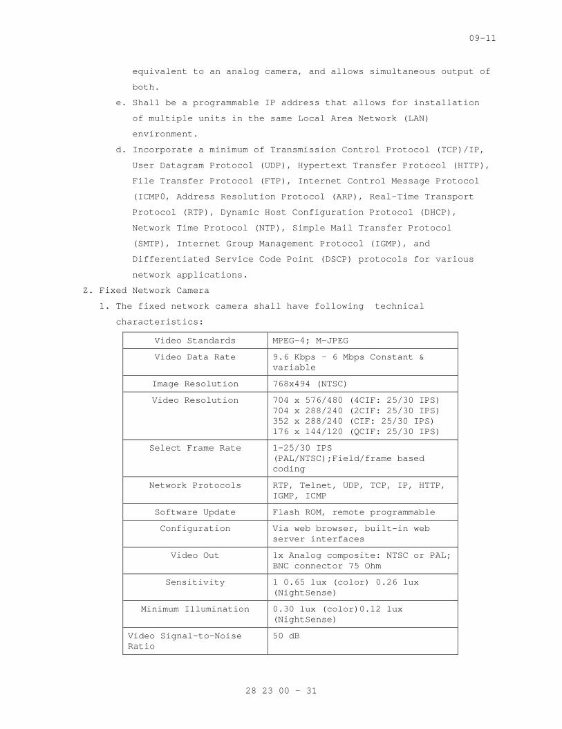
09-11
equivalent to an analog camera, and allows simultaneous output of
both.
e. Shall be a programmable IP address that allows for installation
of multiple units in the same Local Area Network (LAN)
environment.
d. Incorporate a minimum of Transmission Control Protocol (TCP)/IP,
User Datagram Protocol (UDP), Hypertext Transfer Protocol (HTTP),
File Transfer Protocol (FTP), Internet Control Message Protocol
(ICMP0, Address Resolution Protocol (ARP), Real-Time Transport
Protocol (RTP), Dynamic Host Configuration Protocol (DHCP),
Network Time Protocol (NTP), Simple Mail Transfer Protocol
(SMTP), Internet Group Management Protocol (IGMP), and
Differentiated Service Code Point (DSCP) protocols for various
network applications.
Z. Fixed Network Camera
1. The fixed network camera shall have following technical
characteristics:
Video Standards MPEG-4; M-JPEG
Video Data Rate 9.6 Kbps - 6 Mbps Constant & variable
Image Resolution 768x494 (NTSC)
Video Resolution 704 x 576/480 (4CIF: 25/30 IPS) 704 x 288/240 (2CIF: 25/30 IPS) 352 x 288/240 (CIF: 25/30 IPS) 176 x 144/120 (QCIF: 25/30 IPS)
Select Frame Rate 1-25/30 IPS (PAL/NTSC);Field/frame based coding
Network Protocols RTP, Telnet, UDP, TCP, IP, HTTP, IGMP, ICMP
Software Update Flash ROM, remote programmable
Configuration Via web browser, built-in web server interfaces
Video Out 1x Analog composite: NTSC or PAL; BNC connector 75 Ohm
Sensitivity 1 0.65 lux (color) 0.26 lux (NightSense)
Minimum Illumination 0.30 lux (color)0.12 lux (NightSense)
Video Signal-to-Noise Ratio
50 dB
28 23 00 - 31
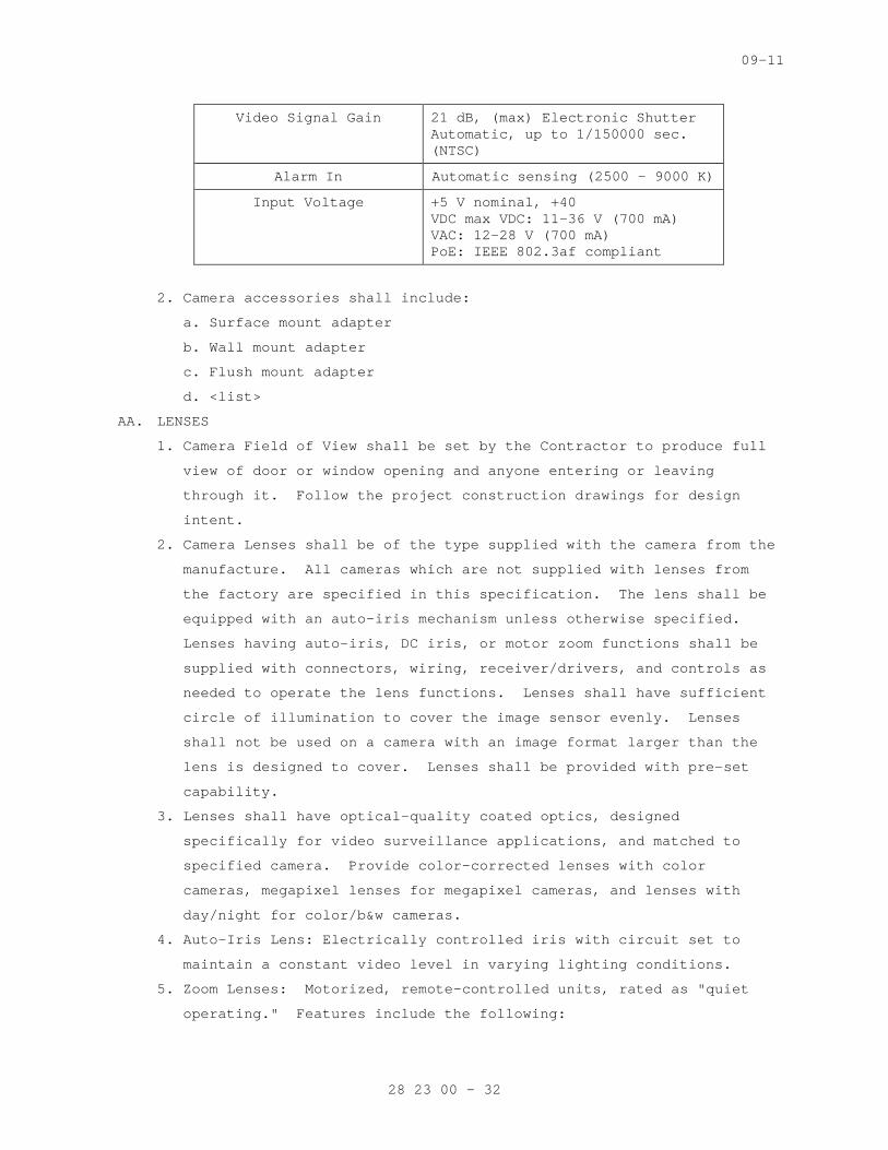
09-11
Video Signal Gain 21 dB, (max) Electronic Shutter Automatic, up to 1/150000 sec. (NTSC)
Alarm In Automatic sensing (2500 - 9000 K)
Input Voltage +5 V nominal, +40 VDC max VDC: 11-36 V (700 mA) VAC: 12-28 V (700 mA) PoE: IEEE 802.3af compliant
2. Camera accessories shall include:
a. Surface mount adapter
b. Wall mount adapter
c. Flush mount adapter
d. <list>
AA. LENSES
1. Camera Field of View shall be set by the Contractor to produce full
view of door or window opening and anyone entering or leaving
through it. Follow the project construction drawings for design
intent.
2. Camera Lenses shall be of the type supplied with the camera from the
manufacture. All cameras which are not supplied with lenses from
the factory are specified in this specification. The lens shall be
equipped with an auto-iris mechanism unless otherwise specified.
Lenses having auto-iris, DC iris, or motor zoom functions shall be
supplied with connectors, wiring, receiver/drivers, and controls as
needed to operate the lens functions. Lenses shall have sufficient
circle of illumination to cover the image sensor evenly. Lenses
shall not be used on a camera with an image format larger than the
lens is designed to cover. Lenses shall be provided with pre-set
capability.
3. Lenses shall have optical-quality coated optics, designed
specifically for video surveillance applications, and matched to
specified camera. Provide color-corrected lenses with color
cameras, megapixel lenses for megapixel cameras, and lenses with
day/night for color/b&w cameras.
4. Auto-Iris Lens: Electrically controlled iris with circuit set to
maintain a constant video level in varying lighting conditions.
5. Zoom Lenses: Motorized, remote-controlled units, rated as "quiet
operating." Features include the following:
28 23 00 - 32
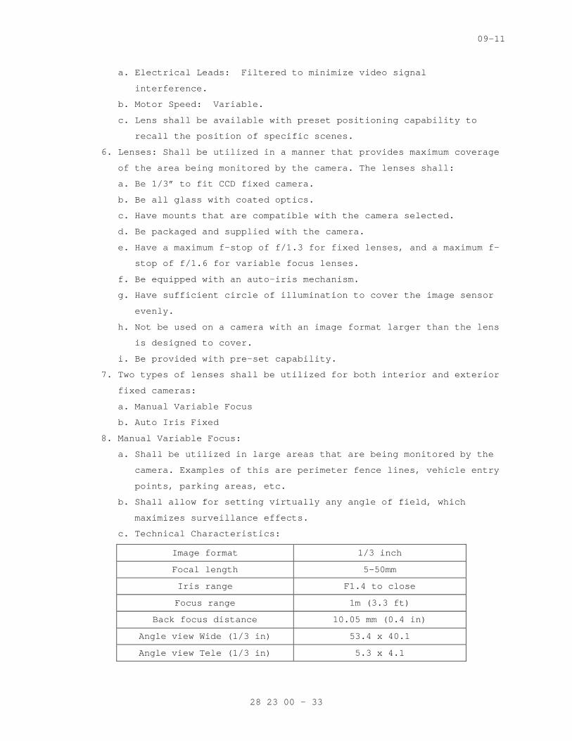
09-11
a. Electrical Leads: Filtered to minimize video signal
interference.
b. Motor Speed: Variable.
c. Lens shall be available with preset positioning capability to
recall the position of specific scenes.
6. Lenses: Shall be utilized in a manner that provides maximum coverage
of the area being monitored by the camera. The lenses shall:
a. Be 1/3” to fit CCD fixed camera.
b. Be all glass with coated optics.
c. Have mounts that are compatible with the camera selected.
d. Be packaged and supplied with the camera.
e. Have a maximum f-stop of f/1.3 for fixed lenses, and a maximum f-
stop of f/1.6 for variable focus lenses.
f. Be equipped with an auto-iris mechanism.
g. Have sufficient circle of illumination to cover the image sensor
evenly.
h. Not be used on a camera with an image format larger than the lens
is designed to cover.
i. Be provided with pre-set capability.
7. Two types of lenses shall be utilized for both interior and exterior
fixed cameras:
a. Manual Variable Focus
b. Auto Iris Fixed
8. Manual Variable Focus:
a. Shall be utilized in large areas that are being monitored by the
camera. Examples of this are perimeter fence lines, vehicle entry
points, parking areas, etc.
b. Shall allow for setting virtually any angle of field, which
maximizes surveillance effects.
c. Technical Characteristics:
Image format 1/3 inch
Focal length 5–50mm
Iris range F1.4 to close
Focus range 1m (3.3 ft)
Back focus distance 10.05 mm (0.4 in)
Angle view Wide (1/3 in) 53.4 x 40.1
Angle view Tele (1/3 in) 5.3 x 4.1
28 23 00 - 33
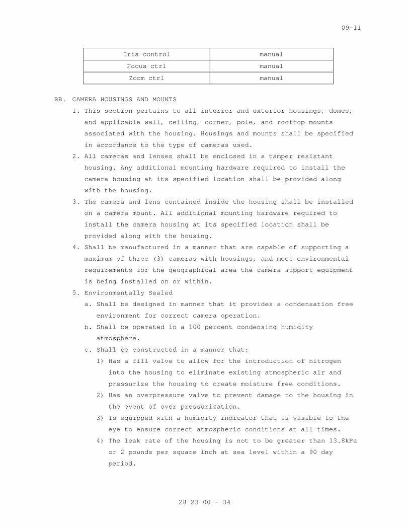
09-11
Iris control manual
Focus ctrl manual
Zoom ctrl manual
BB. CAMERA HOUSINGS AND MOUNTS
1. This section pertains to all interior and exterior housings, domes,
and applicable wall, ceiling, corner, pole, and rooftop mounts
associated with the housing. Housings and mounts shall be specified
in accordance to the type of cameras used.
2. All cameras and lenses shall be enclosed in a tamper resistant
housing. Any additional mounting hardware required to install the
camera housing at its specified location shall be provided along
with the housing.
3. The camera and lens contained inside the housing shall be installed
on a camera mount. All additional mounting hardware required to
install the camera housing at its specified location shall be
provided along with the housing.
4. Shall be manufactured in a manner that are capable of supporting a
maximum of three (3) cameras with housings, and meet environmental
requirements for the geographical area the camera support equipment
is being installed on or within.
5. Environmentally Sealed
a. Shall be designed in manner that it provides a condensation free
environment for correct camera operation.
b. Shall be operated in a 100 percent condensing humidity
atmosphere.
c. Shall be constructed in a manner that:
1) Has a fill valve to allow for the introduction of nitrogen
into the housing to eliminate existing atmospheric air and
pressurize the housing to create moisture free conditions.
2) Has an overpressure valve to prevent damage to the housing in
the event of over pressurization.
3) Is equipped with a humidity indicator that is visible to the
eye to ensure correct atmospheric conditions at all times.
4) The leak rate of the housing is not to be greater than 13.8kPa
or 2 pounds per square inch at sea level within a 90 day
period.
28 23 00 - 34

09-11
5) It shall contain camera mounts or supports as needed to allow
for correct positioning of the camera and lens.
6) The housing and sunshield are to be white in color.
6. All electrical and signal cables required for correct operations
shall be supplied in a hardened carrier system from the controller
to the camera.
7. The mounting bracket shall be adjustable to allow for the housing
weight of the camera and the housing unit it is placed in.
8. Accessibility to the camera and mounts shall be taken into
consideration for maintenance and service purposes.
CC. Indoor Mounts
1. Ceiling Mounts:
a. This enclosure and mount shall be installed in a finished or
suspended ceiling.
b. The enclosure and mount shall be fastened to the finished
ceiling, and shall not depend on the ceiling tile grid for
complete support.
c. Suspended ceiling mounts shall be low profile, and shall be
suitable for replacement of 610mm x 610mm (2 foot by 2 foot)
ceiling tiles.
2. Wall Mounts:
a. The enclosure shall be installed in manner that it matches the
existing décor and placed at a height that it will be
unobtrusive, unable to cause personal harm, and prevents
tampering and vandalism.
b. The mount shall contain a manual pan/tilt head that will provide
360 degrees of horizontal and vertical positioning from a
horizontal position, and has a locking bar or screw to maintain
its fixed position once it has been adjusted.
DD. Interior Domes
1. The interior dome shall be a pendant mount, pole mount, ceiling
mount, surface mount, or corner mounted equipment.
2. The lower portion of the dome that provides camera viewing shall be
made of black opaque acrylic and shall have a light attenuation
factor of no more that 1 f-stop.
3. The housing shall be equipped with integral pan/tilt capabilities
complete with wiring, wiring harness, connectors, receiver/driver,
pan/tilt control system, pre-position cards, or any other hardware
28 23 00 - 35
09-11
and equipment as needed to fully provide a fully functional pan/tilt
dome.
4. The pan/tilt mechanism shall be:
a. Constructed of heavy duty bearings and hardened steel gears.
b. Permanently lubricated to ensure smooth and consistent movement
of all parts throughout the life of the product.
c. Equipped with motors that are thermally or impedance protected
against overload damage.
d. Pan movements shall be 360 degrees and tilt movement shall no be
less than +/- 90 degrees.
e. Pan speed shall be a minimum of 10 degrees per second.
EE. Exterior Domes
1. The exterior dome shall meet all requirements outlined in the
interior dome paragraph above.
2. The housing shall be constructed to be dust and water tight, and
fully operational in 100 percent condensing humidity.
FF. Exterior Wall Mounts
1. Shall have an adjustable head for mounting the camera.
2. Shall be constructed of aluminum, stainless steel, or steel with a
corrosion-resistant finish.
3. The head shall be adjustable for not less than plus and minus 90
degrees of pan, and not less than plus and minus 45 degrees of tilt.
If the bracket is to be used in conjunction with a pan/tilt, the
bracket shall be supplied without the adjustable mounting head, and
shall have a bolt-hole pattern to match the pan/tilt base.
4. Shall be installed at a height that allows for maximum coverage of
the area being monitored.
2.8 POWER SUPPLIES
A. Power supplies shall be a low-voltage power supplies matched for
voltage and current requirements of cameras and accessories, type as
recommended by camera, infrared illuminator, and lens manufacturer.
B. Technical specifications:
1. Input: 115VAC, 50/60Hz, 2.7 amps
2. Outputs:
a. Number of outputs, 16
b. Fuse/PTC protected, power limited
c. Output voltage & power:
28 23 00 - 36
09-11
1) 24VAC @ 12.5 amps (300VA) or 28VAC @ 10 amp (280VA) supply
current
3. Illuminated power disconnect circuit breaker with manual reset
4. Surge suppression
5. Camera synchronization
6. Wall/Rack mount.
7. Enclosure: NEMA 250, Type 1.
2.9 INFRARED ILLUMINATORS
A. Lighting fixtures that emit light only in the infrared spectrum,
suitable for use with cameras indicated, for nighttime surveillance,
without emitting visible light.
1. Field-Selectable Beam Patterns: Narrow, medium, and wide.
2. Rated Lamp Life: More than 8000 hours
3. Power Supply: [12-VAC/DC] [120-VAC].
B. Area Coverage: Illumination to 50 m (150 feet) in a narrow beam
pattern.
C. Exterior housings shall be suitable for same environmental conditions
as associated camera.
2.10 NETWORK SERVER
A. Allow for the transmission of live video, data, and audio over either
an existing Ethernet network or a dedicated security system network,
requiring an IP address or Internet Explorer 5.5 or higher, or shall
work as an analog-to-Ethernet “bridge” controlling matrices,
multiplexers, and pan/tilt/zoom cameras. The network shall operate in a
box-to-box configuration allowing for encoded video to be decoded and
displayed on an analog monitor.
B. If a VASS System network is going to be utilized as the primary means
of monitoring, operating, and recording cameras then the following
equipment shall be required as part of the system:
1. System Server
2. Computer Workstation
3. Recording Device
4. Encoder/Decoder
5. Monitor
6. Hub/Switch
7. Router
8. Encryptor
28 23 00 - 37
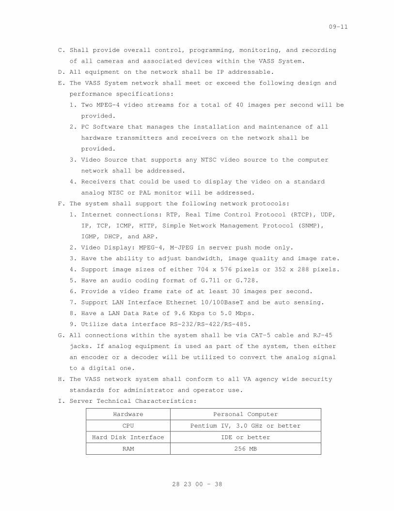
09-11
C. Shall provide overall control, programming, monitoring, and recording
of all cameras and associated devices within the VASS System.
D. All equipment on the network shall be IP addressable.
E. The VASS System network shall meet or exceed the following design and
performance specifications:
1. Two MPEG-4 video streams for a total of 40 images per second will be
provided.
2. PC Software that manages the installation and maintenance of all
hardware transmitters and receivers on the network shall be
provided.
3. Video Source that supports any NTSC video source to the computer
network shall be addressed.
4. Receivers that could be used to display the video on a standard
analog NTSC or PAL monitor will be addressed.
F. The system shall support the following network protocols:
1. Internet connections: RTP, Real Time Control Protocol (RTCP), UDP,
IP, TCP, ICMP, HTTP, Simple Network Management Protocol (SNMP),
IGMP, DHCP, and ARP.
2. Video Display: MPEG-4, M-JPEG in server push mode only.
3. Have the ability to adjust bandwidth, image quality and image rate.
4. Support image sizes of either 704 x 576 pixels or 352 x 288 pixels.
5. Have an audio coding format of G.711 or G.728.
6. Provide a video frame rate of at least 30 images per second.
7. Support LAN Interface Ethernet 10/100BaseT and be auto sensing.
8. Have a LAN Data Rate of 9.6 Kbps to 5.0 Mbps.
9. Utilize data interface RS-232/RS-422/RS-485.
G. All connections within the system shall be via CAT-5 cable and RJ-45
jacks. If analog equipment is used as part of the system, then either
an encoder or a decoder will be utilized to convert the analog signal
to a digital one.
H. The VASS network system shall conform to all VA agency wide security
standards for administrator and operator use.
I. Server Technical Characteristics:
Hardware Personal Computer
CPU Pentium IV, 3.0 GHz or better
Hard Disk Interface IDE or better
RAM 256 MB
28 23 00 - 38
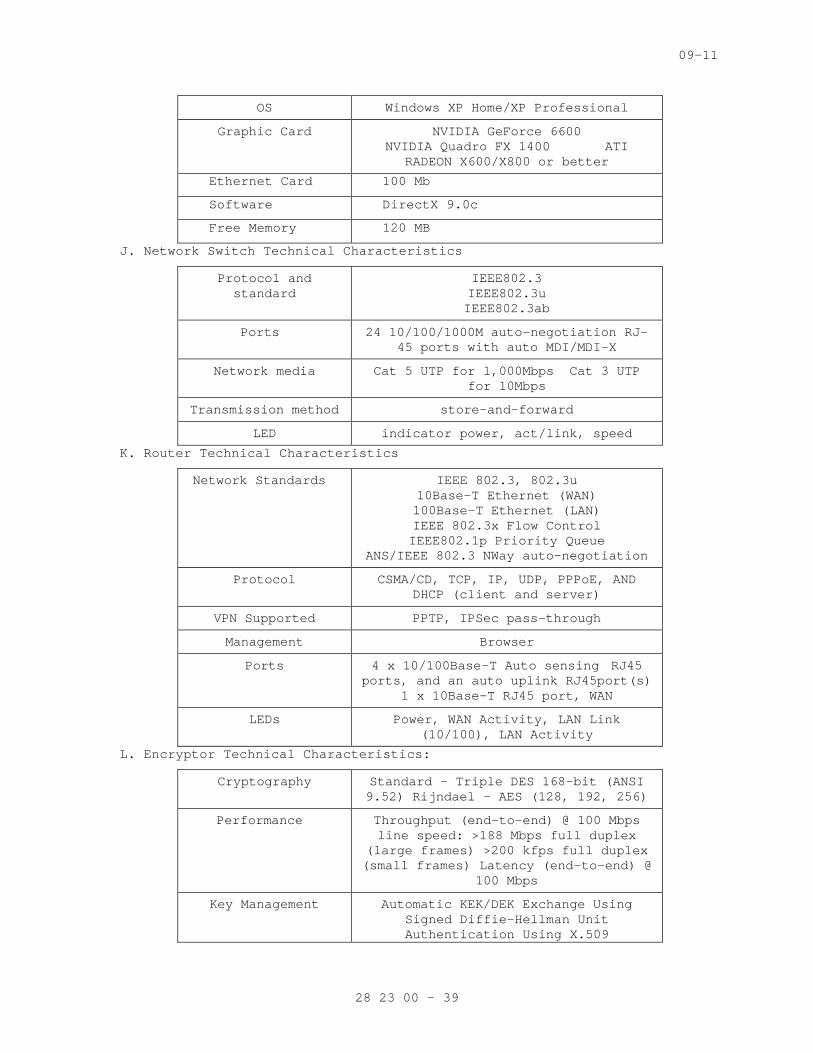
09-11
OS Windows XP Home/XP Professional
Graphic Card NVIDIA GeForce 6600 NVIDIA Quadro FX 1400 ATI
RADEON X600/X800 or better
Ethernet Card 100 Mb
Software DirectX 9.0c
Free Memory 120 MB
J. Network Switch Technical Characteristics
Protocol and standard
IEEE802.3 IEEE802.3u IEEE802.3ab
Ports 24 10/100/1000M auto-negotiation RJ-45 ports with auto MDI/MDI-X
Network media Cat 5 UTP for 1,000Mbps Cat 3 UTP for 10Mbps
Transmission method store-and-forward
LED indicator power, act/link, speed
K. Router Technical Characteristics
Network Standards IEEE 802.3, 802.3u 10Base-T Ethernet (WAN) 100Base-T Ethernet (LAN) IEEE 802.3x Flow Control IEEE802.1p Priority Queue
ANS/IEEE 802.3 NWay auto-negotiation
Protocol CSMA/CD, TCP, IP, UDP, PPPoE, AND DHCP (client and server)
VPN Supported PPTP, IPSec pass-through
Management Browser
Ports 4 x 10/100Base-T Auto sensing RJ45 ports, and an auto uplink RJ45port(s)
1 x 10Base-T RJ45 port, WAN
LEDs Power, WAN Activity, LAN Link (10/100), LAN Activity
L. Encryptor Technical Characteristics:
Cryptography Standard - Triple DES 168-bit (ANSI 9.52) Rijndael - AES (128, 192, 256)
Performance Throughput (end-to-end) @ 100 Mbps line speed: >188 Mbps full duplex
(large frames) >200 kfps full duplex (small frames) Latency (end-to-end) @
100 Mbps
Key Management Automatic KEK/DEK Exchange Using Signed Diffie-Hellman Unit Authentication Using X.509
28 23 00 - 39
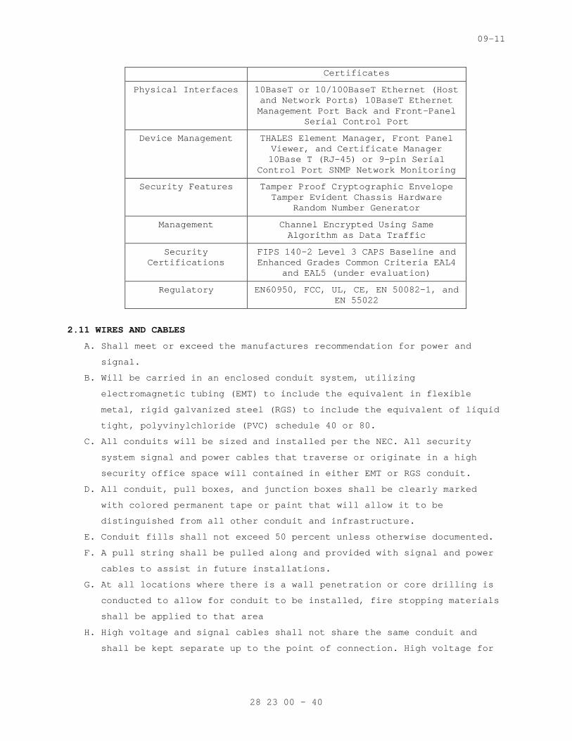
09-11
Certificates
Physical Interfaces 10BaseT or 10/100BaseT Ethernet (Host and Network Ports) 10BaseT Ethernet Management Port Back and Front-Panel
Serial Control Port
Device Management THALES Element Manager, Front Panel Viewer, and Certificate Manager 10Base T (RJ-45) or 9-pin Serial
Control Port SNMP Network Monitoring
Security Features Tamper Proof Cryptographic Envelope Tamper Evident Chassis Hardware
Random Number Generator
Management Channel Encrypted Using Same Algorithm as Data Traffic
Security Certifications
FIPS 140-2 Level 3 CAPS Baseline and Enhanced Grades Common Criteria EAL4
and EAL5 (under evaluation)
Regulatory EN60950, FCC, UL, CE, EN 50082-1, and EN 55022
2.11 WIRES AND CABLES
A. Shall meet or exceed the manufactures recommendation for power and
signal.
B. Will be carried in an enclosed conduit system, utilizing
electromagnetic tubing (EMT) to include the equivalent in flexible
metal, rigid galvanized steel (RGS) to include the equivalent of liquid
tight, polyvinylchloride (PVC) schedule 40 or 80.
C. All conduits will be sized and installed per the NEC. All security
system signal and power cables that traverse or originate in a high
security office space will contained in either EMT or RGS conduit.
D. All conduit, pull boxes, and junction boxes shall be clearly marked
with colored permanent tape or paint that will allow it to be
distinguished from all other conduit and infrastructure.
E. Conduit fills shall not exceed 50 percent unless otherwise documented.
F. A pull string shall be pulled along and provided with signal and power
cables to assist in future installations.
G. At all locations where there is a wall penetration or core drilling is
conducted to allow for conduit to be installed, fire stopping materials
shall be applied to that area
H. High voltage and signal cables shall not share the same conduit and
shall be kept separate up to the point of connection. High voltage for
28 23 00 - 40
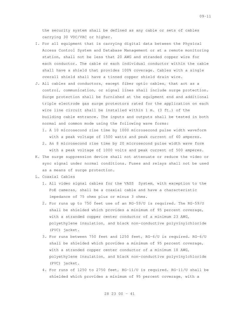
09-11
the security system shall be defined as any cable or sets of cables
carrying 30 VDC/VAC or higher.
I. For all equipment that is carrying digital data between the Physical
Access Control System and Database Management or at a remote monitoring
station, shall not be less that 20 AWG and stranded copper wire for
each conductor. The cable or each individual conductor within the cable
shall have a shield that provides 100% coverage. Cables with a single
overall shield shall have a tinned copper shield drain wire.
J. All cables and conductors, except fiber optic cables, that act as a
control, communication, or signal lines shall include surge protection.
Surge protection shall be furnished at the equipment end and additional
triple electrode gas surge protectors rated for the application on each
wire line circuit shall be installed within 1 m. (3 ft.) of the
building cable entrance. The inputs and outputs shall be tested in both
normal and common mode using the following wave forms:
1. A 10 microsecond rise time by 1000 microsecond pulse width waveform
with a peak voltage of 1500 watts and peak current of 60 amperes.
2. An 8 microsecond rise time by 20 microsecond pulse width wave form
with a peak voltage of 1000 volts and peak current of 500 amperes.
K. The surge suppression device shall not attenuate or reduce the video or
sync signal under normal conditions. Fuses and relays shall not be used
as a means of surge protection.
L. Coaxial Cables
1. All video signal cables for the VASS System, with exception to the
PoE cameras, shall be a coaxial cable and have a characteristic
impedance of 75 ohms plus or minus 3 ohms.
2. For runs up to 750 feet use of an RG-59/U is required. The RG-59/U
shall be shielded which provides a minimum of 95 percent coverage,
with a stranded copper center conductor of a minimum 23 AWG,
polyethylene insulation, and black non-conductive polyvinylchloride
(PVC) jacket.
3. For runs between 750 feet and 1250 feet, RG-6/U is required. RG-6/U
shall be shielded which provides a minimum of 95 percent coverage,
with a stranded copper center conductor of a minimum 18 AWG,
polyethylene insulation, and black non-conductive polyvinylchloride
(PVC) jacket.
4. For runs of 1250 to 2750 feet, RG-11/U is required. RG-11/U shall be
shielded which provides a minimum of 95 percent coverage, with a
28 23 00 - 41
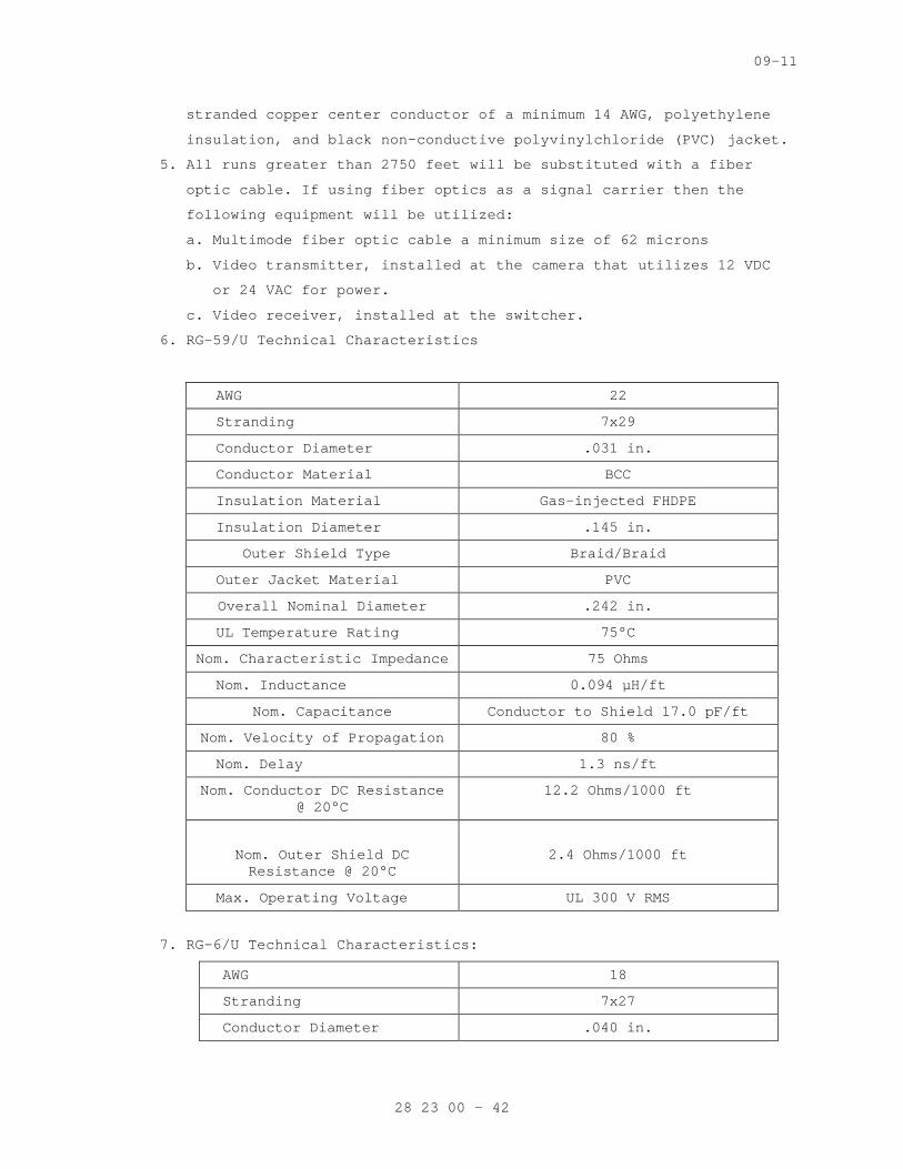
09-11
stranded copper center conductor of a minimum 14 AWG, polyethylene
insulation, and black non-conductive polyvinylchloride (PVC) jacket.
5. All runs greater than 2750 feet will be substituted with a fiber
optic cable. If using fiber optics as a signal carrier then the
following equipment will be utilized:
a. Multimode fiber optic cable a minimum size of 62 microns
b. Video transmitter, installed at the camera that utilizes 12 VDC
or 24 VAC for power.
c. Video receiver, installed at the switcher.
6. RG-59/U Technical Characteristics
AWG 22
Stranding 7x29
Conductor Diameter .031 in.
Conductor Material BCC
Insulation Material Gas-injected FHDPE
Insulation Diameter .145 in.
Outer Shield Type Braid/Braid
Outer Jacket Material PVC
Overall Nominal Diameter .242 in.
UL Temperature Rating 75°C
Nom. Characteristic Impedance 75 Ohms
Nom. Inductance 0.094 μH/ft
Nom. Capacitance Conductor to Shield 17.0 pF/ft
Nom. Velocity of Propagation 80 %
Nom. Delay 1.3 ns/ft
Nom. Conductor DC Resistance @ 20°C
12.2 Ohms/1000 ft
Nom. Outer Shield DC Resistance @ 20°C
2.4 Ohms/1000 ft
Max. Operating Voltage UL 300 V RMS
7. RG-6/U Technical Characteristics:
AWG 18
Stranding 7x27
Conductor Diameter .040 in.
28 23 00 - 42
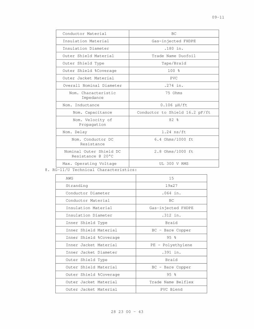
09-11
Conductor Material BC
Insulation Material Gas-injected FHDPE
Insulation Diameter .180 in.
Outer Shield Material Trade Name Duofoil
Outer Shield Type Tape/Braid
Outer Shield %Coverage 100 %
Outer Jacket Material PVC
Overall Nominal Diameter .274 in.
Nom. Characteristic Impedance
75 Ohms
Nom. Inductance 0.106 μH/ft
Nom. Capacitance Conductor to Shield 16.2 pF/ft
Nom. Velocity of Propagation
82 %
Nom. Delay 1.24 ns/ft
Nom. Conductor DC Resistance
6.4 Ohms/1000 ft
Nominal Outer Shield DC Resistance @ 20°C
2.8 Ohms/1000 ft
Max. Operating Voltage UL 300 V RMS
8. RG-11/U Technical Characteristics:
AWG 15
Stranding 19x27
Conductor Diameter .064 in.
Conductor Material BC
Insulation Material Gas-injected FHDPE
Insulation Diameter .312 in.
Inner Shield Type Braid
Inner Shield Material BC - Bare Copper
Inner Shield %Coverage 95 %
Inner Jacket Material PE – Polyethylene
Inner Jacket Diameter .391 in.
Outer Shield Type Braid
Outer Shield Material BC - Bare Copper
Outer Shield %Coverage 95 %
Outer Jacket Material Trade Name Belflex
Outer Jacket Material PVC Blend
28 23 00 - 43
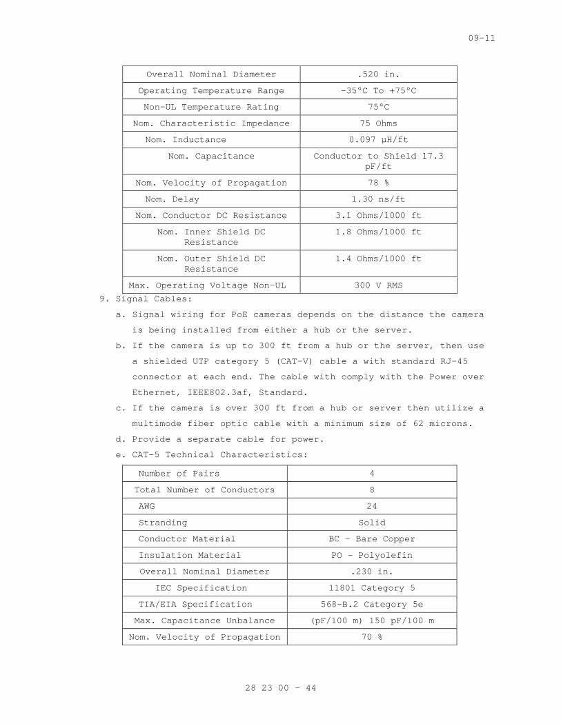
09-11
Overall Nominal Diameter .520 in.
Operating Temperature Range -35°C To +75°C
Non-UL Temperature Rating 75°C
Nom. Characteristic Impedance 75 Ohms
Nom. Inductance 0.097 μH/ft
Nom. Capacitance Conductor to Shield 17.3 pF/ft
Nom. Velocity of Propagation 78 %
Nom. Delay 1.30 ns/ft
Nom. Conductor DC Resistance 3.1 Ohms/1000 ft
Nom. Inner Shield DC Resistance
1.8 Ohms/1000 ft
Nom. Outer Shield DC Resistance
1.4 Ohms/1000 ft
Max. Operating Voltage Non-UL 300 V RMS
9. Signal Cables:
a. Signal wiring for PoE cameras depends on the distance the camera
is being installed from either a hub or the server.
b. If the camera is up to 300 ft from a hub or the server, then use
a shielded UTP category 5 (CAT-V) cable a with standard RJ-45
connector at each end. The cable with comply with the Power over
Ethernet, IEEE802.3af, Standard.
c. If the camera is over 300 ft from a hub or server then utilize a
multimode fiber optic cable with a minimum size of 62 microns.
d. Provide a separate cable for power.
e. CAT-5 Technical Characteristics:
Number of Pairs 4
Total Number of Conductors 8
AWG 24
Stranding Solid
Conductor Material BC - Bare Copper
Insulation Material PO – Polyolefin
Overall Nominal Diameter .230 in.
IEC Specification 11801 Category 5
TIA/EIA Specification 568-B.2 Category 5e
Max. Capacitance Unbalance (pF/100 m) 150 pF/100 m
Nom. Velocity of Propagation 70 %
28 23 00 - 44
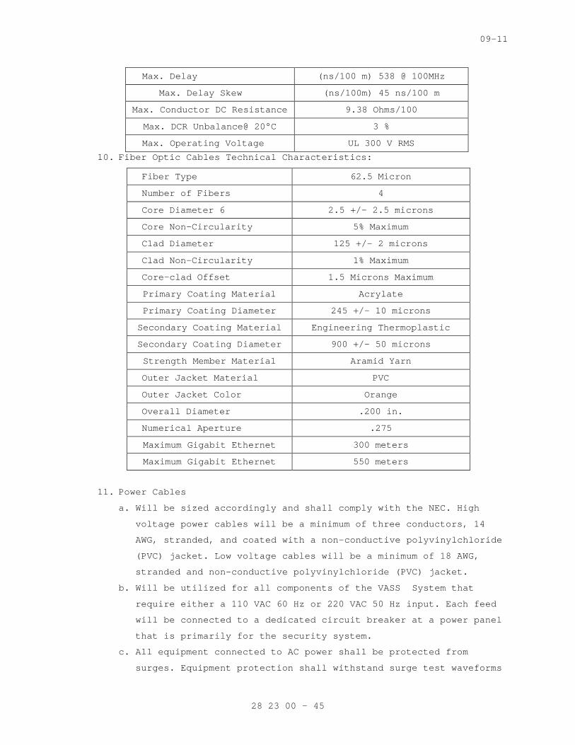
09-11
Max. Delay (ns/100 m) 538 @ 100MHz
Max. Delay Skew (ns/100m) 45 ns/100 m
Max. Conductor DC Resistance 9.38 Ohms/100
Max. DCR Unbalance@ 20°C 3 %
Max. Operating Voltage UL 300 V RMS
10. Fiber Optic Cables Technical Characteristics:
Fiber Type 62.5 Micron
Number of Fibers 4
Core Diameter 6 2.5 +/- 2.5 microns
Core Non-Circularity 5% Maximum
Clad Diameter 125 +/- 2 microns
Clad Non-Circularity 1% Maximum
Core-clad Offset 1.5 Microns Maximum
Primary Coating Material Acrylate
Primary Coating Diameter 245 +/- 10 microns
Secondary Coating Material Engineering Thermoplastic
Secondary Coating Diameter 900 +/- 50 microns
Strength Member Material Aramid Yarn
Outer Jacket Material PVC
Outer Jacket Color Orange
Overall Diameter .200 in.
Numerical Aperture .275
Maximum Gigabit Ethernet 300 meters
Maximum Gigabit Ethernet 550 meters
11. Power Cables
a. Will be sized accordingly and shall comply with the NEC. High
voltage power cables will be a minimum of three conductors, 14
AWG, stranded, and coated with a non-conductive polyvinylchloride
(PVC) jacket. Low voltage cables will be a minimum of 18 AWG,
stranded and non-conductive polyvinylchloride (PVC) jacket.
b. Will be utilized for all components of the VASS System that
require either a 110 VAC 60 Hz or 220 VAC 50 Hz input. Each feed
will be connected to a dedicated circuit breaker at a power panel
that is primarily for the security system.
c. All equipment connected to AC power shall be protected from
surges. Equipment protection shall withstand surge test waveforms
28 23 00 - 45
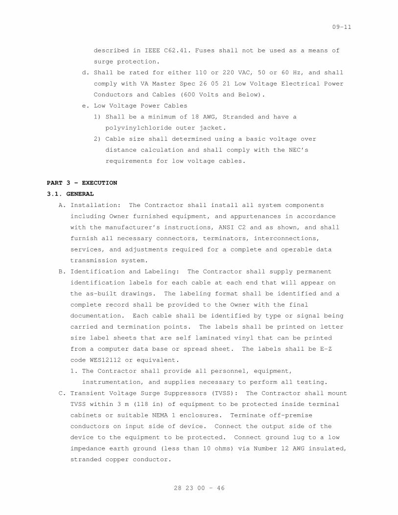
09-11
described in IEEE C62.41. Fuses shall not be used as a means of
surge protection.
d. Shall be rated for either 110 or 220 VAC, 50 or 60 Hz, and shall
comply with VA Master Spec 26 05 21 Low Voltage Electrical Power
Conductors and Cables (600 Volts and Below).
e. Low Voltage Power Cables
1) Shall be a minimum of 18 AWG, Stranded and have a
polyvinylchloride outer jacket.
2) Cable size shall determined using a basic voltage over
distance calculation and shall comply with the NEC’s
requirements for low voltage cables.
PART 3 - EXECUTION
3.1. GENERAL
A. Installation: The Contractor shall install all system components
including Owner furnished equipment, and appurtenances in accordance
with the manufacturer’s instructions, ANSI C2 and as shown, and shall
furnish all necessary connectors, terminators, interconnections,
services, and adjustments required for a complete and operable data
transmission system.
B. Identification and Labeling: The Contractor shall supply permanent
identification labels for each cable at each end that will appear on
the as-built drawings. The labeling format shall be identified and a
complete record shall be provided to the Owner with the final
documentation. Each cable shall be identified by type or signal being
carried and termination points. The labels shall be printed on letter
size label sheets that are self laminated vinyl that can be printed
from a computer data base or spread sheet. The labels shall be E-Z
code WES12112 or equivalent.
1. The Contractor shall provide all personnel, equipment,
instrumentation, and supplies necessary to perform all testing.
C. Transient Voltage Surge Suppressors (TVSS): The Contractor shall mount
TVSS within 3 m (118 in) of equipment to be protected inside terminal
cabinets or suitable NEMA 1 enclosures. Terminate off-premise
conductors on input side of device. Connect the output side of the
device to the equipment to be protected. Connect ground lug to a low
impedance earth ground (less than 10 ohms) via Number 12 AWG insulated,
stranded copper conductor.
28 23 00 - 46
09-11
D. Contractor’s Field Test: The Contractor shall verify the complete
operation of the data transmission system during the Contractor’s Field
Testing. Field test shall include a bit error rate test. The
Contractor shall perform the test by sending a minimum of 1,000,000
bits of data on each DTM circuit and measuring the bit error rate. The
bit error rate shall not be greater than one (1) bit out of each
100,000 bits sent for each dial-up DTM circuit, and one (1) bit out of
1,000,000 bits sent for each leased or private DTM circuit. The
Contractor shall submit a report containing results of the field test.
E. Acceptance Test and Endurance Test: The wire line data transmission
system shall be tested as a part of the completed IDS and EECS during
the Acceptance test and Endurance Test as specified.
F. Identification and Labeling: The Contractor shall supply
identification tags or labels for each cable. Cable shall be labeled
at both end points and at intermediate hand holes, manholes, and
junction boxes. The labeling format shall be identified and a complete
record shall be provided to the Owner with the final documentation.
Each cable shall be identified with type of signal being carried and
termination points.
3.2 INSTALLATION
A. System installation shall be in accordance with NECA 303, manufacturer
and related documents and references, for each type of security
subsystem designed, engineered and installed.
B. Components shall be configured with appropriate “service points” to
pinpoint system trouble in less than 30 minutes.
C. The Contractor shall install all system components including Government
furnished equipment, and appurtenances in accordance with the
manufacturer's instructions, documentation listed in Sections 1.5 of
this document, and shall furnish all necessary connectors, terminators,
interconnections, services, and adjustments required for a complete and
operable system.
D. The VASS System will be designed, engineered, installed, and tested to
ensure all components are fully compatible as a system and can be
integrated with all associated security subsystems, whether the system
is a stand alone or a complete network.
28 23 00 - 47
09-11
E. For integration purposes, the VASS System shall be integrated where
appropriate with the following associated security subsystems:
1. PACS:
a. Provide 24 hour coverage of all entry points to the perimeter and
agency buildings, as well as all emergency exits utilizing a
fixed color camera.
b. Record cameras on a 24 hours basis.
c. Be programmed go into an alarm state when an emergency exit is
opened, and notify the Physical Access Control System and
Database Management of an alarm event.
2. IDS:
a. Provide a recorded alarm event via a color camera that is
connected to the IDS system by either direct hardwire or a
security system computer network.
b. Record cameras on a 24 hours basis.
c. Be programmed to go into an alarm state when an IDS device is put
into an alarm state, and notify the PACS.
d. For additional VASS System requirements as they relate to the
IDS, refer to Section 28 16 00 “INTRUSION DETECTION”.
3. Security Access Detection:
a. Provide full coverage of all vehicle and lobby entrance screening
areas utilizing a fixed color camera.
b. Record cameras on a 24 hours basis.
c. The VASS System should have facial recognition software to assist
in identifying individuals for current and future purposes.
4. EPPS:
a. Provide a recorded alarm event via a color camera that is
connected to the EPPS system by either direct hardwire or a
security system computer network.
b. Record cameras on a 24 hours basis.
c. Be programmed to go into an alarm state when an emergency call
box or duress alarm/panic device is activated, and notify the
Physical Access Control System and Database Management of an
alarm event.
F. Integration with these security subsystems shall be achieved by
computer programming or the direct hardwiring of the systems.
G. For programming purposes refer to the manufacturers requirements for
correct system operations. Ensure computers being utilized for system
28 23 00 - 48
09-11
integration meet or exceed the minimum system requirements outlined on
the systems software packages.
H. A complete VASS System shall be comprised of, but not limited to, the
following components:
1. Cameras
2. Lenses
3. Video Display Equipment
4. Camera Housings and Mounts
5. Controlling Equipment
6. Recording Devices
7. Wiring and Cables
I. The Contractor shall visit the site and verify that site conditions are
in agreement/compliance with the design package. The Contractor shall
report all changes to the site or conditions that will affect
performance of the system to the Contracting Officer in the form of a
report. The Contractor shall not take any corrective action without
written permission received from the Contracting Officer.
J. Existing Equipment
1. The Contractor shall connect to and utilize existing video
equipment, video and control signal transmission lines, and devices
as outlined in the design package. Video equipment and signal lines
that are usable in their original configuration without modification
may be reused with Contracting Officer approval.
2. The Contractor shall perform a field survey, including testing and
inspection of all existing video equipment and signal lines intended
to be incorporated into the VASS System, and furnish a report to
the Contracting Officer as part of the site survey report. For those
items considered nonfunctioning, provide (with the report)
specification sheets, or written functional requirements to support
the findings and the estimated cost to correct the deficiency. As
part of the report, the Contractor shall include a schedule for
connection to all existing equipment.
3. The Contractor shall make written requests and obtain approval prior
to disconnecting any signal lines and equipment, and creating
equipment downtime. Such work shall proceed only after receiving
Contracting Officer approval of these requests. If any device fails
after the Contractor has commenced work on that device, signal or
28 23 00 - 49
09-11
control line, the Contractor shall diagnose the failure and perform
any necessary corrections to the equipment.
4. The Contractor shall be held responsible for repair costs due to
Contractor negligence, abuse, or incorrect installation of
equipment.
5. The Contracting Officer shall be provided a full list of all
equipment that is to be removed or replaced by the Contractor, to
include description and serial/manufacturer numbers where possible.
The Contractor shall dispose of all equipment that has been removed
or replaced based upon approval of the Contracting Officer after
reviewing the equipment removal list. In all areas where equipment
is removed or replaced the Contractor shall repair those areas to
match the current existing conditions.
K. Enclosure Penetrations: All enclosure penetrations shall be from the
bottom of the enclosure unless the system design requires penetrations
from other directions. Penetrations of interior enclosures involving
transitions of conduit from interior to exterior, and all penetrations
on exterior enclosures shall be sealed with rubber silicone sealant to
preclude the entry of water and will comply with VA Master
Specification 07 84 00, Firestopping. The conduit riser shall terminate
in a hot-dipped galvanized metal cable terminator. The terminator shall
be filled with an approved sealant as recommended by the cable
manufacturer and in such a manner that the cable is not damaged.
L. Cold Galvanizing: All field welds and brazing on factory galvanized
boxes, enclosures, and conduits shall be coated with a cold galvanized
paint containing at least 95 percent zinc by weight.
M. Interconnection of Console Video Equipment: The Contractor shall
connect signal paths between video equipment as specified by the OEM.
Cables shall be as short as practicable for each signal path without
causing strain at the connectors. Rack mounted equipment on slide
mounts shall have cables of sufficient length to allow full extension
of the slide rails from the rack.
N. Cameras:
1. Install the cameras with the focal length lens as indicated for each
zone.
2. Connect power and signal lines to the camera.
3. Aim camera to give field of view as needed to cover the alarm zone.
28 23 00 - 50

09-11
4. Aim fixed mounted cameras installed outdoors facing the rising or
setting sun sufficiently below the horizon to preclude the camera
looking directly at the sun.
5. Focus the lens to give a sharp picture (to include checking for day
and night focus and image quality) over the entire field of view
6. Synchronize all cameras so the picture does not roll on the monitor
when cameras are selected.
7. PTZ cameras shall have all preset positions and privacy areas
defined and programmed.
O. Switcher:
1. Install the switcher according to the OEM.
2. Connect all subassemblies as specified by the manufacturer and as
shown.
3. Connect video signal inputs and outputs as shown and specified;
terminate video inputs as required.
4. Connect alarm signal inputs and outputs as shown and specified;
connect control signal inputs and outputs for ancillary equipment or
secondary control/monitoring sites as specified by the manufacturer
and as shown.
5. Connect the switcher CPU and switcher subassemblies to AC power.
6. Load all software as specified and required for an operational VASS
System configured for the site and building requirements, including
data bases, operational parameters, and system, command, and
application programs.
7. Provide the original and 2 backup copies for all accepted software
upon successful completion of the endurance test.
8. Program the video annotation for each camera.
P. Video Encoder/Decoder
1. Install the Video Encoder/Decoder as specified by the OEM.
2. Connect analog camera inputs to video encoder.
3. Connect network camera to video decoder.
4. Connect video encoder to VASS network.
5. Connect video decoder to video matrix, DVR, monitor etc.
6. Connect unit to AC power (UPS).
7. Configure the video encoder/decoder per manufacturer’s
recommendation and project requirements.
Q. Video Server:
1. Install the video server specified by the OEM.
28 23 00 - 51

09-11
2. Connect video server to AC power (UPS).
3. Connect to VASS network.
4. Install operating system and Video Management Software.
5. Provide Video Management Software programming per VA guidance and
the requirements provided by the Owner. Programming shall include:
a. Camera names
b. Screen views
c. Camera recording schedules (continuous and event) driven
recording. Events include alarms from other systems (sensors),
manual input, and video motion detection.
d. Video detection zones for each camera requiring video motion
detection
e. Alarm interface
f. Alarm outputs
g. GUI maps, views, icons and actions
h. PTZ controls (presets, time schedules for privacy zones etc.)
i. Reports
R. Video Workstation:
1. Install the video workstation as specified by the OEM.
2. Connect video workstation to AC power (UPS).
3. Connect to VASS network.
4. Install operating system and application software.
5. Provide application software programming per VA guidance and the
requirements provided by the Owner. Programming shall include:
a. Screen views
b. Graphical User Interface (GUI) maps, views, icons and actions
c. Alarm outputs
d. Reports
S. Network Switch:
1. Install the network switch as specified by the OEM.
2. Connect network switch to AC power (UPS).
3. Connect network cameras to network switch.
4. Configure the network switch per manufacturer’s recommendation and
project requirements.
T. Network Recording Equipment
1. Install the NVR or video storage unit as specified by the OEM.
2. Connect recording device to AC power (UPS).
3. Connect recording device to network switch as shown and specified.
28 23 00 - 52

09-11
4. Configure network connections
5. Provide recording unit programming per VA guidance and the
requirements provided by the Owner. Programming shall include:
a. Camera names
b. Screen views
c. Camera recording schedules (continuous and event) driven
recording. Events include alarms from other systems (sensors),
manual input, and video motion detection.
d. Video detection zones for each camera requiring video motion
detection
e. Alarm interface
f. Alarm outputs
g. GUI maps, views, icons and actions
h. PTZ controls (presets, time schedules for privacy zones etc.)
i. Reports
U. Video Recording Equipment:
1. Install the video recording equipment as specified by the OEM.
2. Connect video signal inputs and outputs as shown and specified.
3. Connect alarm signal inputs and outputs as shown and specified.
4. Connect video recording equipment to AC power.
5. Program the video recording equipment;
a. Recording schedules
b. Camera caption
V. Video Signal Equipment:
1. Install the video signal equipment as specified by the OEM.
2. Connect video or signal inputs and outputs as shown and specified.
3. Terminate video inputs as required.
4. Connect alarm signal inputs and outputs as required.
5. Connect control signal inputs and outputs as required
6. Connect electrically powered equipment to AC power.
W. Camera Housings, Mounts, and Poles:
1. Install the camera housings and mounts as specified by the
manufacturer and as shown, provide mounting hardware sized
appropriately to secure each camera, housing and mount with maximum
wind and ice loading encountered at the site.
2. Provide a foundation for each camera pole as specified and shown.
28 23 00 - 53
09-11
3. Provide a ground rod for each camera pole and connect the camera
pole to the ground rod as specified in Division 26 of the VA Master
Specification and the VA Electrical Manual 730.
4. Provide electrical and signal transmission cabling to the mount
location via a hardened carrier system from the Physical Access
Control System and Database Management to the device.
5. Connect signal lines and AC power to the housing interfaces.
6. Connect pole wiring harness to camera.
3.3 SYSTEM START-UP
A. The Contractor shall not apply power to the VASS System until the
following items have been completed:
1. VASS System equipment items and have been set up in accordance with
manufacturer's instructions.
2. A visual inspection of the VASS System has been conducted to ensure
that defective equipment items have not been installed and that
there are no loose connections.
3. System wiring has been tested and verified as correctly connected as
indicated.
4. All system grounding and transient protection systems have been
verified as installed and connected as indicated.
5. Power supplies to be connected to the VASS System have been
verified as the correct voltage, phasing, and frequency as
indicated.
B. The Commissioning Agent will observe startup and contractor testing of
selected equipment. Coordinate the startup and contractor testing
schedules with the Resident Engineer and Commissioning Agent. Provide
a minimum of 7 days prior notice.
C. Satisfaction of the above requirements shall not relieve the Contractor
of responsibility for incorrect installation, defective equipment
items, or collateral damage as a result of Contractor work efforts.
3.4 SUPLEMENTAL CONTRACTOR QUIALITY CONTROL
A. The Contractor shall provide the services of technical representatives
who are familiar with all components and installation procedures of the
installed VASS System; and are approved by the Contracting Officer.
B. The Contractor will be present on the job site during the preparatory
and initial phases of quality control to provide technical assistance.
C. The Contractor shall also be available on an as needed basis to provide
assistance with follow-up phases of quality control.
28 23 00 - 54

09-11
D. The Contractor shall participate in the testing and validation of the
system and shall provide certification that the system installed is
fully operational as all construction document requirements have been
fulfilled.
-----END----
28 23 00 - 55
09-11
SECTION 28 26 00 ELECTRONIC PERSONAL PROTECTION SYSTEM
SPEC WRITER NOTE: Delete between //___//if not applicable to project. Also delete any other item or paragraph not applicable in the section and renumber the paragraphs.
PART 1 – GENERAL
1.1 DESCRIPTION
A. Provide and install complete Duress-Panic Alarms, Emergency Phones/
Call-Boxes, and Intercom Systems, data transmission wiring and a
control station with its associated equipment, hereafter referred to as
EPPS System.
SPEC WRITER NOTE: Retain paragraph below if Security Access Detection System will be integrated with one or more of other systems and integration requirements are specified in one of those system Sections. If retaining below, edit both paragraph above and paragraph below to coordinate with the scope of the Section that includes systems integration requirements.
B. EPPS shall be integrated with monitoring and control system specified
in Division 28 Section [VIDEO SURVEILLANCE SYSTEMS] [INTRUSION
DETECTION] [PHYSICAL ACCESS CONTROL SYSTEM] that specifies systems
integration.
1.2 RELATED WORK
SPEC WRITER NOTE: Delete any item or paragraph not applicable in the section.
A. Section 01 00 00 - GENERAL REQUIREMENTS. For General Requirements.
B. Section 07 84 00 - FIRESTOPPING. Requirements for firestopping
application and use.
C. Section 10 14 00 - SIGNAGE. Requirements for labeling and signs.
D. Section 14 21 00 - ELECTRIC TRACTION ELEVATORS. Requirements for
elevators.
E. Section 14 24 00 - HYDRAULIC ELEVATORS. Requirements for elevators.
F. Section 26 05 11 - REQUIREMENTS FOR ELECTRICAL INSTALLATIONS.
Requirements for connection of high voltage.
G. Section 26 05 21 - LOW VOLTAGE ELECTRICAL POWER CONDUCTORS AND CABLES
(600 VOLTS AND BELOW). Requirements for power cables.
28 26 00 - 1
09-11
H. Section 26 05 33 – RACEWAYS AND BOXES FOR ELECTRICAL SYSTEMS.
Requirements for infrastructure.
I. Section 28 05 00 - COMMON WORK RESULTS FOR ELECTRONIC SAFETY AND
SECURITY. Requirements for general requirements that are common to more
than one section in Division 28.
J. Section 28 05 13 - CONDUCTORS AND CABLES FOR ELECTRONIC SAFETY AND
SECURITY. Requirements for conductors and cables.
K. Section 28 05 26 - GROUNDING AND BONDING FOR ELECTRONIC SAFETY AND
SECURITY. Requirements for grounding of equipment.
L. Section 28 05 28.33 - CONDUITS AND BACK BOXES FOR ELECTRONIC SAFETY AND
SECURITY. Requirements for infrastructure.
M. Section 28 08 00 - COMMISIONING OF ELECTRONIC SAFETY AND SECURITY.
Requirements for requirements for commissioning - systems readiness
checklists, and training.
N. Section 28 13 00 - PHYSICAL ACCESS CONTROL SYSTEMS (PACS). Requirements
for physical access control integration.
O. Section 28 13 16 - ACCESS CONTROL SYSTEM AND DATABASE MANAGEMENT.
Requirements for control and operation of all security systems.
P. Section 28 16 00 - INTRUSION DETECTION SYSTEM. Requirements for
integration with intrusion detection system.
Q. Section 28 13 53 - SECURITY ACCESS DETECTION. Requirements for security
access detection.
R. Section 28 23 00 - VIDEO SURVEILLANCE. Requirements for security camera
systems.
1.3 QUALITY ASSURANCE
A. The Contractor shall be responsible for providing, installing, and the
operation of the EPPS System as shown. The Contractor shall also
provide certification as required.
B. The security system shall be installed and tested to ensure all
components are fully compatible as a system and can be integrated with
all associated security subsystems, whether the security system is
stand-alone or a part of a complete Information Technology (IT)
computer network.
C. The Contractor or security sub-contractor shall be a licensed security
Contractor as required within the state or jurisdiction of where the
installation work is being conducted.
D. Manufacturers Qualifications: The manufacturer shall regularly and
presently produce, as one of the manufacturer's principal products, the
28 26 00 - 2

09-11
equipment and material specified for this project, and shall have
manufactured the item for at least three years.
E. Product Qualification:
1. Manufacturer's product shall have been in satisfactory operation, on
three installations of similar size and type as this project, for
approximately three years.
2. The Government reserves the right to require the Contractor to
submit a list of installations where the products have been in
operation before approval.
F. Contractor Qualification:
1. The Contractor or security sub-contractor shall be a licensed
security Contractor with a minimum of five (5) years experience
installing and servicing systems of similar scope and complexity.
The Contractor shall be an authorized regional representative of the
Security Management System’s (PACS) manufacturer. The Contractor
shall provide four (4) current references from clients with systems
of similar scope and complexity which became operational in the past
three (3) years. At least three (3) of the references shall be
utilizing the same system components, in a similar configuration as
the proposed system. The references must include a current point of
contact, company or agency name, address, telephone number, complete
system description, date of completion, and approximate cost of the
project. The owner reserves the option to visit the reference
sites, with the site owner’s permission and representative, to
verify the quality of installation and the references’ level of
satisfaction with the system. The Contractor shall provide copies
of system manufacturer certification for all technicians. The
Contractor shall only utilize factory-trained technicians to
install, program, and service the PACS. The Contractor shall only
utilize factory-trained technicians to install, terminate and
service controller/field panels and reader modules. The technicians
shall have a minimum of five (5) continuous years of technical
experience in electronic security systems. The Contractor shall
have a local service facility. The facility shall be located within
60 miles of the project site. The local facility shall include
sufficient spare parts inventory to support the service requirements
associated with this contract. The facility shall also include
appropriate diagnostic equipment to perform diagnostic procedures.
28 26 00 - 3
09-11
The COTR reserves the option of surveying the company’s facility to
verify the service inventory and presence of a local service
organization.
2. The Contractor shall provide proof project superintendent with BICSI
Certified Commercial Installer Level 1, Level 2, or Technician to
provide oversight of the project.
3. Cable installer must have on staff a Registered Communication
Distribution Designer (RCDD) certified by Building Industry
Consulting Service International. The staff member shall provide
consistent oversight of the project cabling throughout design,
layout, installation, termination and testing.
SPEC WRITER NOTE: In the following paragraph use 4 hours for metropolitan areas and 8 hours for rural areas.
G. Service Qualifications: There shall be a permanent service organization
maintained or trained by the manufacturer which will render
satisfactory service to this installation within // four // eight //
hours of receipt of notification that service is needed. Submit name
and address of service organizations.
1.4 SUBMITALS
SPEC WRITER NOTE: Delete and/or amend all paragraphs and sub-paragraphs and information as needed to ensure that only the documentation required is requested per the Request for Proposal (RFP).
A. Submit below items in accordance with Section 28 05 00, COMMON WORK
RESULTS FOR ELECTRONIC SAFETY AND SECURITY and Master Specification
Sections 01 33 23, SHOP DRAWING, PRODUCT DATA, AND SAMPLES, and Section
02 41 00, DEMOLITION.
B. Provide certificates of compliance with Section 1.3, Quality Assurance.
C. Provide a pre-installation and as-built design package in both
electronic format and on paper, minimum size 48 x 48 inches (1220 x
1220 millimeters); drawing submittals shall be per the established
project schedule.
D. Shop drawings and as-built packages shall include, but not be limited
to:
1. Index Sheet that shall:
a. Define each page of the design package to include facility name,
building name, floor, and sheet number.
b. Provide a list of all security abbreviations and symbols.
28 26 00 - 4

09-11
c. Reference all general notes that are utilized within the design
package.
d. Specification and scope of work pages for all security systems
that are applicable to the design package that will:
1) Outline all general and job specific work required within the
design package.
2) Provide a device identification table outlining device
Identification (ID) and use for all security systems equipment
utilized in the design package.
2. Drawing sheets that will be plotted on the individual floor plans or
site plans shall:
a. Include a title block as defined above.
b. Define the drawings scale in both standard and metric
measurements.
c. Provide device identification and location.
d. Address all signal and power conduit runs and sizes that are
associated with the design of the electronic security system and
other security elements (e.g., barriers, etc.).
e. Identify all pull box and conduit locations, sizes, and fill
capacities.
f. Address all general and drawing specific notes for a particular
drawing sheet.
3. A riser drawing for each applicable security subsystem shall:
a. Indicate the sequence of operation.
b. Relationship of integrated components on one diagram.
c. Include the number, size, identification, and maximum lengths of
interconnecting wires.
d. Wire/cable types shall be defined by a wire and cable schedule.
The schedule shall utilize a lettering system that will
correspond to the wire/cable it represents (example: A = 18 AWG/1
Pair Twisted, Unshielded). This schedule shall also provide the
manufacturer’s name and part number for the wire/cable being
installed.
4. A system drawing for each applicable security system shall:
a. Identify how all equipment within the system, from main panel to
device, shall be laid out and connected.
b. Provide full detail of all system components wiring from point-
to-point.
28 26 00 - 5
09-11
c. Identify wire types utilized for connection, interconnection with
associate security subsystems.
d. Show device locations that correspond to the floor plans.
e. All general and drawing specific notes shall be included with the
system drawings.
5. A schedule for all of the applicable security subsystems shall be
included. All schedules shall provide the following information:
a. Device ID.
b. Device Location (e.g. site, building, floor, room number,
location, and description).
c. Mounting type (e.g. flush, wall, surface, etc.).
d. Power supply or circuit breaker and power panel number.
6. Detail and elevation drawings for all devices that define how they
were installed and mounted.
E. Pre-installation design packages shall be reviewed by the Contractor
along with a VA representative to ensure all work has been clearly
defined and completed. All reviews shall be conducted in accordance
with the project schedule. There shall be four (4) stages to the review
process:
1. 35 percent
2. 65 percent
3. 90 percent
4. 100 percent
F. Provide manufacturer security system product cut-sheets. Submit for
approval at least 30 days prior to commencement of formal testing, a
Security System Operational Test Plan. Include procedures for
operational testing of each component and security subsystem, to
include performance of an integrated system test.
G. Submit manufacture’s certification of Underwriters Laboratories, Inc.
(UL) listing as specified. Provide all maintenance and operating
manuals per the VA General Requirements, Section 01 00 00, GENERAL
REQUIREMENTS.
1.5 APPLICABLE PUBLICATIONS
A. The publications listed below (including amendments, addenda,
revisions, supplement, and errata) form a part of this specification to
the extent referenced. The publications are referenced in the text by
the basic designation only.
B. American National Standards Institute (ANSI):
28 26 00 - 6
09-11
ANSI S3.2-09............Method for measuring the Intelligibility of
Speech over Communications Systems
C. Department of Justice American Disability Act (ADA)
28 CFR Part 36..........2010 ADA Standards for Accessible Design
D. Federal Communications Commision (FCC):
(47 CFR 15) Part 15.....Limitations on the Use of Wireless
Equipment/Systems
E. National Fire Protection Association (NFPA):
70-11...................National Electrical Code
F. National Electrical Manufactures Association (NEMA)
250-08..................Enclosures for Electrical Equipment (1000 Volts
Maximum)
G. Underwriters Laboratories, Inc. (UL):
305-08..................Standard for Panic Hardware
444-08..................Safety Communications Cables
636-01..................Standard for Holdup Alarm Units and Systems
H. Uniform Federal Accessibility Standards (UFAS), 1984
1.6 COORDINATION
A. Coordinate arrangement, mounting, and support of electronic safety and
security equipment:
1. To allow maximum possible headroom unless specific mounting heights
that reduce headroom are indicated.
2. To provide for ease of disconnecting the equipment with minimum
interference to other installations.
3. To allow right of way for piping and conduit installed at required
slope.
4. So connecting raceways, cables, wireways, cable trays, and busways
will be clear of obstructions and of the working and access space of
other equipment.
B. Coordinate installation of required supporting devices and set sleeves
in cast-in-place concrete, masonry walls, and other structural
components as they are constructed.
C. Coordinate location of access panels and doors for electronic safety
and security items that are behind finished surfaces or otherwise
concealed.
1.7 MAINTENANCE & SERVICE
A. General Requirements
28 26 00 - 7

09-11
1. The Contractor shall provide all services required and equipment
necessary to maintain the entire integrated electronic security
system in an operational state as specified for a period of one (1)
year after formal written acceptance of the system. The Contractor
shall provide all necessary material required for performing
scheduled adjustments or other non-scheduled work. Impacts on
facility operations shall be minimized when performing scheduled
adjustments or other non-scheduled work. See also General Project
Requirements.
B. Description of Work
1. The adjustment and repair of the security system includes all
software updates, panel firmware, and the following new items
computers equipment, communications transmission equipment and data
transmission media (DTM), local processors, security system sensors,
facility interface, and signal transmission equipment.
C. Personnel
1. Service personnel shall be certified in the maintenance and repair
of the selected type of equipment and qualified to accomplish all
work promptly and satisfactorily. The COTR shall be advised in
writing of the name of the designated service representative, and of
any change in personnel. The COTR shall be provided copies of
system manufacturer certification for the designated service
representative.
D. Schedule of Work
1. The work shall be performed during regular working ours, Monday
through Friday, excluding federal holidays. These inspections shall
include:
a. The Contractor shall perform two (2) minor inspections at six (6)
month intervals or more if required by the manufacturer, and two
(2) major inspections offset equally between the minor
inspections to effect quarterly inspection of alternating
magnitude.
1) Minor Inspections shall include visual checks and operational
tests of all console equipment, peripheral equipment, local
processors, sensors, electrical and mechanical controls, and
adjustments on printers.
2) Major Inspections shall include all work described for Minor
Inspections and the following: clean all system equipment and
28 26 00 - 8

09-11
local processors including interior and exterior surfaces;
perform diagnostics on all equipment; operational tests of the
CPU, switcher, peripheral equipment, check and calibrate each
sensor; run all system software diagnostics and correct all
problems; and resolve any previous outstanding problems.
E. Emergency Service
1. The owner shall initiate service calls whenever the system is not
functioning properly. The Contractor shall provide the Owner with
an emergency service center telephone number. The emergency service
center shall be staffed 24 hours a day 365 days a year. The Owner
shall have sole authority for determining catastrophic and non-
catastrophic system failures within parameters stated in General
Project Requirements.
a. For catastrophic system failures, the Contractor shall provide
same day four (4) hour service response with a defect correction
time not to exceed eight (8) hours from [notification] [arrival
on site]. Catastrophic system failures are defined as any system
failure that the Owner determines will place the facility(s) at
increased risk.
b. For non-catastrophic failures, the Contractor within eight (8)
hours with a defect correction time not to exceed 24 hours from
notification.
F. Operation
1. Performance of scheduled adjustments and repair shall verify
operation of the system as demonstrated by the applicable portions
of the performance verification test.
G. Records & Logs
1. The Contractor shall maintain records and logs of each task and
organize cumulative records for each component and for the complete
system chronologically. A continuous log shall be submitted for all
devices. The log shall contain all initial settings, calibration,
repair, and programming data. Complete logs shall be maintained and
available for inspection on site, demonstrating planned and
systematic adjustments and repairs have been accomplished for the
system.
H. Work Request
1. The Contractor shall separately record each service call request, as
received. The record shall include the serial number identifying
28 26 00 - 9
09-11
the component involved, its location, date and time the call was
received, specific nature of trouble, names of service personnel
assigned to the task, instructions describing the action taken, the
amount and nature of the materials used, and the date and time of
commencement and completion. The Contractor shall deliver a record
of the work performed within five (5) working days after the work
was completed.
I. System Modifications
1. The Contractor shall make any recommendations for system
modification in writing to the COTR. No system modifications,
including operating parameters and control settings, shall be made
without prior written approval from the COTR. Any modifications
made to the system shall be incorporated into the operation and
maintenance manuals and other documentation affected.
J. Software
1. The Contractor shall provide all software updates when approved by
the Owner from the manufacturer during the installation and 12-month
warranty period and verify operation of the system. These updates
shall be accomplished in a timely manner, fully coordinated with the
system operators, and incorporated into the operations and
maintenance manuals and software documentation. There shall be at
least one (1) scheduled update near the end of the first year’s
warranty period, at which time the Contractor shall install and
validate the latest released version of the Manufacturer’s software.
All software changes shall be recorded in a log maintained in the
unit control room. An electronic copy of the software update shall
be maintained within the log. At a minimum, the contractor shall
provide a description of the modification, when the modification
occurred, and name and contact information of the individual
performing the modification. The log shall be maintained in a white
3 ring binder and the cover marked “SOFTWARE CHANGE LOG”.
1.8 WARRANTY OF CONSTRUCTION.
A. Warrant EPPS System work subject to the Article “Warranty of
Construction” of FAR clause 52.246-21.
B. Demonstration and training shall be performed prior to system
acceptance.
28 26 00 - 10
09-11
1.9 GENERAL REQUIREMENTS
A. For general requirements that are common to more than one section in
Division 28 refer to Section 28 05 00, COMMON WORK RESULTS FOR
ELECTRONIC SAFETY AND SECURITY.
B. General requirements applicable to this section include:
1. Performance Requirements,
2. Delivery, Handling and Storage,
3. Project Conditions,
4. Equipment and Materials,
5. Electrical Power,
6. Lightning, Power Surge Suppression, and Grounding,
7. Electronic Components,
8. Substitute Materials and Equipment, and
9. Like Items.
PART 2 – PRODUCTS
SPEC WRITER NOTE: Delete or amend all paragraphs and sub-paragraphs as needed to ensure that only the equipment required per the Request for Proposal (RFP) is provided.
2.1 EQUIPMENT AND MATERIALS
A. General:
1. All equipment shall be rated for continuous operation.
Environmental conditions (i.e. temperature, humidity, wind, and
seismic activity) shall be taken under consideration at each
facility and site location prior to installation of the equipment.
2. All equipment shall operate on a 120 or 240 volts alternating
current (VAC); 50 hertz (Hz) or 60 Hz Alternating Current (AC) power
system unless documented otherwise in subsequent sections listed
within this spec. All equipment shall have a battery back-up source
of power that will provide 12 hours (hrs.) of run time in the event
of a loss of primary power to the security systems until a backup
generator comes on-line.
3. The EPPS systems shall be designed, installed, and programmed in a
manner that will allow for easy of operation, programming,
servicing, maintenance, testing, and upgrading of the system.
4. All EPPS components located in designated “HAZARDOUS ENVIRONMENT”
areas where fire or explosion could occur due to the presence of
28 26 00 - 11

09-11
natural gases or vapors, flammable liquids, combustible residue, or
ignitable fibers or debris, shall be rated Class II, Division I,
Group F, and installed in accordance with National Fire Protection
Association (NFPA) 70, National Electrical Code Chapter 5.
5. The Contractor shall provide the Contracting Officer with written
verification, that the type of wire/cable being provided is
recommended and approved by the OEM. Cabling shall meet the
interconnecting wiring requirements of NFPA 70, National Electrical
Code. The Contractor is responsible for providing the correct
protection cable duct and/or conduit and wiring.
6. When interfacing with other communications or security subsystems
the Contractor shall utilize interfacing methods that are approved
by the Contracting Officer. At a minimum, an acceptable interfacing
method requires not only a physical and mechanical connection; but
also a matching of signal, voltage, and processing levels with
regard to signal quality and impedance. The interface point must
adhere to all standards described herein.
7. Systems shall be scaleable, not vendor specific, and allow expansion
as required.
8. Wireless systems shall use ultrasonic, infrared and radio frequency
waves to link distributed transmitters and receivers. Specific
characteristics of particular facility will determine best
application. Contractor is responsible for determining best system
using prediction program to determine where readable signals can be
obtained and identify “dead spots”.
9. All hardwired alarms, switches, and junction boxes shall be
protected from tampering and include line supervision.
10. The installation and placement of intercom units and emergency-call
boxes in strategic locations shall also require that signage be
posted near these devices. The signage, in accordance with Section
10 14 00, SIGNAGE shall communicate the location of the device and
its unique identification number, and brief instruction on how to
access/use the device. The signage may appear on the device, on a
pole or wall near the device location and shall be printed in a
manner that is easily read during daylight and hours of darkness.
2.2 EQUIPMENT ITEMS
A. All systems shall be designed to provide continuous electrical
supervision of the complete and entire system.
28 26 00 - 12

09-11
B. Noise filters and surge protectors shall be provided for all
intercommunications equipment to ensure protection from primary AC
power surges and to ensure noise interference is not induced into low
voltage data circuits.
C. All alarm and initiating and signaling circuits shall be supervised for
open circuits, short circuits, and system grounds. Main and
Uninterrupted Power Supply (UPS) power circuits shall be supervised for
any change in operating conditions (e.g. low battery, primary to back
up battery, and UPS online). When an open, short or ground occurs in
any system circuit, an audible and visual fault alarm signal shall be
initiated at the master control station and all remote locations.
D. Control Unit: Shall consist of the components to constantly monitor and
verify alarm activation; identify zone of activation and location of
activation.
E. Audible Signal Device for Duress-Panic: Provides alarm activation and
audible sound for alarms, as well as supervisory and trouble signals
that shall be distinctive.
F. Assessment: This capability shall consist of electronic devices
required to visually and audibly verify the validity of alarms.
Assessment also includes providing indication of tampering, fail-safe,
low battery, and power losses.
G. Alarm Monitoring and Reporting: Shall annunciate information to at
least two (2) separate locations. The alarms shall maintain the
capability to respond with local and remote visible and audible signals
upon activation of an alarm. The alarms shall have the capability of
operating in a silent mode, alerting personnel monitoring the system
that the device has been activated.
H. The intercom and emergency call-box systems shall be provided with
normally acceptable speech intelligibility, defined as a score of at
least 70% in accordance with ANSI S3.2
I. Master Stations for Emergency Call Box and Security Intercoms:
1. All master stations shall have a "call-in" switch to provide an
audible and visual indication of incoming calls from remote
stations. Individual visual indication shall identify the calling
station and status, and remain actuated until a call is answered by
a master station.
2. Master stations shall be equipped with a handset with a switch for
private conversations.
28 26 00 - 13

09-11
3. Intercom master stations shall also have an all-call feature, and
have the ability to receive video from a video intercom unit.
4. Master stations shall have the capability to selectively communicate
with any remote station by actuating assigned station number on a
keypad or select button for that station.
5. Master stations may be standalone or can be integrated with the
Physical Access Control System and Database Management. The
Contractor will be responsible for the integration of the Master
station with the Physical Access Control System and Database
Management in accordance with OEM instructions and Section 28 13 16,
PHYSICAL ACCESS CONTROL SYSTEM AND DATABASE MANAGEMENT.
J. Duress-Panic Alarms:
1. Housing shall be a rugged corrosion-resistant housing of stainless
steel or Acrylonitrile Butadiene Styrene (ABS) molded plastic or
similar material that is weather and dust proof.
2. Actuating device shall include a minimum of a plunger button whose
head is recessed from the face/front edge of the housing and be
designed to avoid accidental activation using switch guard or
multiple buttons (i.e., requires pressing two (2) buttons
simultaneously)
3. Wireless stationary devices will meet the same specifications as
Personal Duress/Panic Alarms.
4. Alarm switch/button shall lock-in upon activation until manually
reset with key or manufacture provided device.
5. The switch shall be a positive-acting, double-pole, and double-throw
switch.
6. Duress/Panic alarms shall meet UL 305 Standard for Panic Alarms. To
reduce the possibility of false alarms and ensure installation
functionality UL 636 Standard for Holdup Alarms standards shall be
met.
7. Alarms used for concealed application requires silent alarm
notification to a monitoring station. They shall annunciate at the
Physical Access Control System and Database Management, monitored by
a central station or direct connect to local police, depending on
local ordinance requirements.
8. Shall be capable of being mounted for hand or foot use in a manner
that is unable to be viewed by the public. Larger systems use a
computer that intercepts and processes alarms and displays them on a
28 26 00 - 14
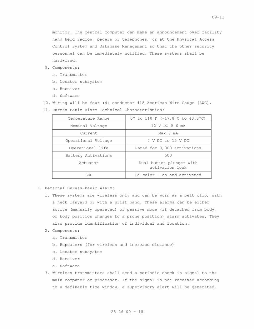
09-11
monitor. The central computer can make an announcement over facility
hand held radios, pagers or telephones, or at the Physical Access
Control System and Database Management so that the other security
personnel can be immediately notified. These systems shall be
hardwired.
9. Components:
a. Transmitter
b. Locator subsystem
c. Receiver
d. Software
10. Wiring will be four (4) conductor #18 American Wire Gauge (AWG).
11. Duress-Panic Alarm Technical Characteristics:
Temperature Range 0° to 110°F (-17.8°C to 43.3°C)
Nominal Voltage 12 V DC @ 6 mA
Current Max 8 mA
Operational Voltage 7 V DC to 15 V DC
Operational life Rated for 0,000 activations
Battery Activations 500
Actuator Dual button plunger with activation lock
LED Bi-color – on and activated
K. Personal Duress-Panic Alarm:
1. These systems are wireless only and can be worn as a belt clip, with
a neck lanyard or with a wrist band. These alarms can be either
active (manually operated) or passive mode (if detached from body,
or body position changes to a prone position) alarm activates. They
also provide identification of individual and location.
2. Components:
a. Transmitter
b. Repeaters (for wireless and increase distance)
c. Locator subsystem
d. Receiver
e. Software
3. Wireless transmitters shall send a periodic check in signal to the
main computer or processor. If the signal is not received according
to a definable time window, a supervisory alert will be generated.
28 26 00 - 15
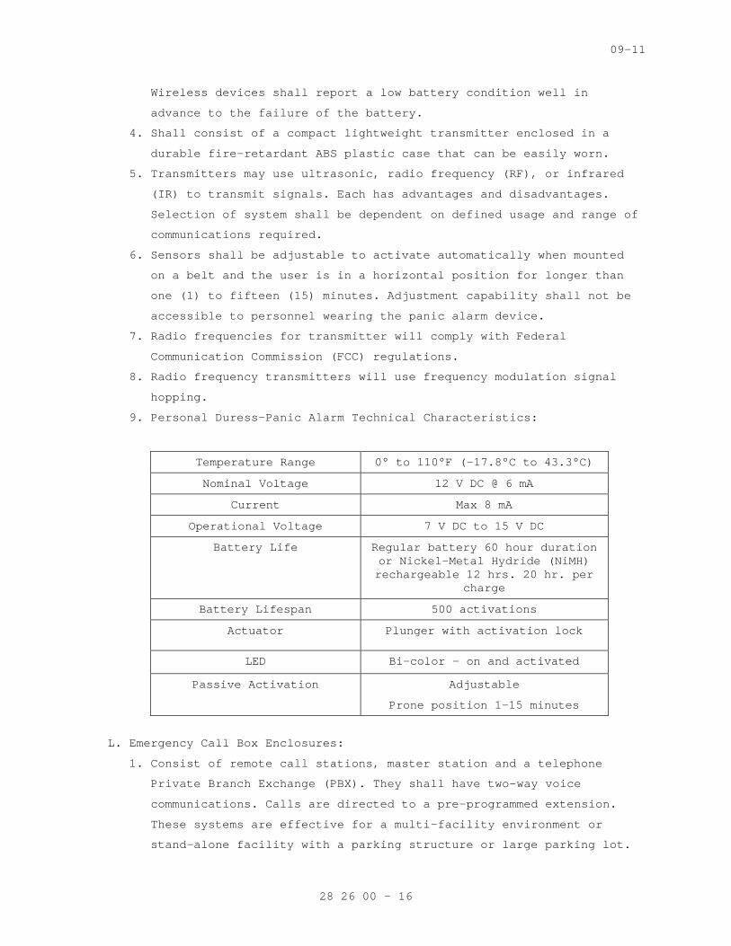
09-11
Wireless devices shall report a low battery condition well in
advance to the failure of the battery.
4. Shall consist of a compact lightweight transmitter enclosed in a
durable fire-retardant ABS plastic case that can be easily worn.
5. Transmitters may use ultrasonic, radio frequency (RF), or infrared
(IR) to transmit signals. Each has advantages and disadvantages.
Selection of system shall be dependent on defined usage and range of
communications required.
6. Sensors shall be adjustable to activate automatically when mounted
on a belt and the user is in a horizontal position for longer than
one (1) to fifteen (15) minutes. Adjustment capability shall not be
accessible to personnel wearing the panic alarm device.
7. Radio frequencies for transmitter will comply with Federal
Communication Commission (FCC) regulations.
8. Radio frequency transmitters will use frequency modulation signal
hopping.
9. Personal Duress-Panic Alarm Technical Characteristics:
Temperature Range 0° to 110°F (-17.8°C to 43.3°C)
Nominal Voltage 12 V DC @ 6 mA
Current Max 8 mA
Operational Voltage 7 V DC to 15 V DC
Battery Life Regular battery 60 hour duration or Nickel-Metal Hydride (NiMH) rechargeable 12 hrs. 20 hr. per
charge
Battery Lifespan 500 activations
Actuator Plunger with activation lock
LED Bi-color – on and activated
Passive Activation Adjustable
Prone position 1-15 minutes
L. Emergency Call Box Enclosures:
1. Consist of remote call stations, master station and a telephone
Private Branch Exchange (PBX). They shall have two-way voice
communications. Calls are directed to a pre-programmed extension.
These systems are effective for a multi-facility environment or
stand-alone facility with a parking structure or large parking lot.
28 26 00 - 16
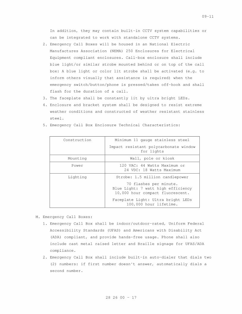
09-11
In addition, they may contain built-in CCTV system capabilities or
can be integrated to work with standalone CCTV systems.
2. Emergency Call Boxes will be housed in an National Electric
Manufactures Association (NEMA) 250 Enclosures for Electrical
Equipment compliant enclosures. Call-box enclosure shall include
blue light/or similar strobe mounted behind or on top of the call
box: A blue light or color lit strobe shall be activated (e.g. to
inform others visually that assistance is required) when the
emergency switch/button/phone is pressed/taken off-hook and shall
flash for the duration of a call.
3. The faceplate shall be constantly lit by ultra bright LEDs.
4. Enclosure and bracket system shall be designed to resist extreme
weather conditions and constructed of weather resistant stainless
steel.
5. Emergency Call Box Enclosure Technical Characteristics:
Construction Minimum 11 gauge stainless steel
Impact resistant polycarbonate window for lights
Mounting Wall, pole or kiosk
Power 120 VAC: 44 Watts Maximum or 24 VDC: 18 Watts Maximum
Lighting Strobe: 1.5 million candlepower
70 flashes per minute. Blue Light: 7 watt high efficiency 10,000 hour compact fluorescent.
Faceplate Light: Ultra bright LEDs 100,000 hour lifetime.
M. Emergency Call Boxes:
1. Emergency Call Box shall be indoor/outdoor-rated, Uniform Federal
Accessibility Standards (UFAS) and Americans with Disability Act
(ADA) compliant, and provide hands-free usage. Phone shall also
include cast metal raised letter and Braille signage for UFAS/ADA
compliance.
2. Emergency Call Box shall include built-in auto-dialer that dials two
(2) numbers: if first number doesn't answer, automatically dials a
second number.
28 26 00 - 17
09-11
3. The System shall include auto-answer to allow for monitoring and
initiating calls with an Emergency Phone.
4. Emergency Call Box shall use flush mount enclosure (FME,) shall
include two (2) piece housing construction with full front lip to
allow tight gasket seal between the speakerphone and enclosure.
Screws shall be tamper free.
5. When activated the Emergency Call Box shall automatically place a
call to the pre-programmed number(s). If the number is busy it
should automatically call a second number.
6. The electronics enclosure shall be capable of using interchangeable
faceplates: a single-button faceplate, a two-button faceplate, or a
two-button faceplate with keypad.
7. The system shall use a “plain old telephone service” (POTS) line or
analog PBX and shall be capable of integration with existing CCTV
and Physical Access Control System and Database Management via
software at the SMS head-end.
8. Depending on distance and existing phone line capabilities, RF or
use of wireless phone connections may be considered. The Contractor
and Contracting Officer shall select appropriate system based on
facility telecommunication system capabilities and desired system
requirements.
9. Monitoring/Diagnostic capability at control and monitoring stations
shall include the capability to automatically poll each Emergency
Call Box, report incoming calls, identify location, and keep
permanent records of all events with the use of a Windows based
compatible software package and shall also meet the requirements of
the Security Management System (SMS).
10. If speaker/handset stations are used, lifting the handset shall
automatically cut out the loudspeaker in the station and all
conversation shall be carried through the handset. Where noise does
not exceed 55 dB, hands-free operations may be performed from
distances up to 20 feet (ft.) (6.096 m). In higher noise
environments only a talk-listen switch shall be utilized.
11. If system is a hardware type master station it shall be capable of:
a. LED display of identification code for emergency phones;
b. Indicate whether call was initiated by pushing button or by an
auxiliary device;
28 26 00 - 18
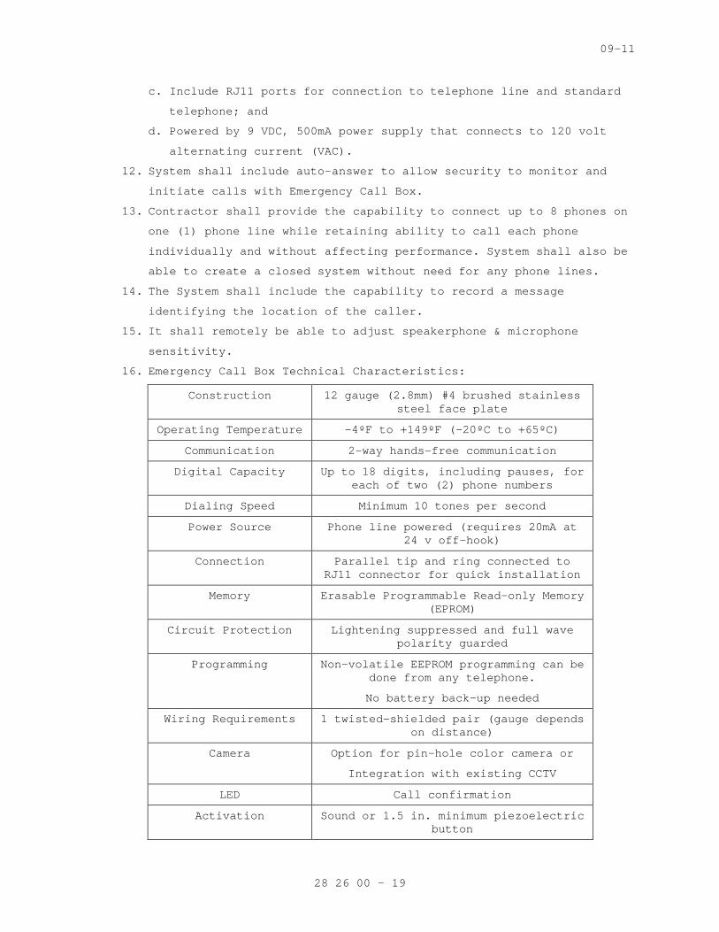
09-11
c. Include RJ11 ports for connection to telephone line and standard
telephone; and
d. Powered by 9 VDC, 500mA power supply that connects to 120 volt
alternating current (VAC).
12. System shall include auto-answer to allow security to monitor and
initiate calls with Emergency Call Box.
13. Contractor shall provide the capability to connect up to 8 phones on
one (1) phone line while retaining ability to call each phone
individually and without affecting performance. System shall also be
able to create a closed system without need for any phone lines.
14. The System shall include the capability to record a message
identifying the location of the caller.
15. It shall remotely be able to adjust speakerphone & microphone
sensitivity.
16. Emergency Call Box Technical Characteristics:
Construction 12 gauge (2.8mm) #4 brushed stainless steel face plate
Operating Temperature -4ºF to +149ºF (-20ºC to +65ºC)
Communication 2-way hands-free communication
Digital Capacity Up to 18 digits, including pauses, for each of two (2) phone numbers
Dialing Speed Minimum 10 tones per second
Power Source Phone line powered (requires 20mA at 24 v off-hook)
Connection Parallel tip and ring connected to RJ11 connector for quick installation
Memory Erasable Programmable Read-only Memory (EPROM)
Circuit Protection Lightening suppressed and full wave polarity guarded
Programming Non-volatile EEPROM programming can be done from any telephone.
No battery back-up needed
Wiring Requirements 1 twisted-shielded pair (gauge depends on distance)
Camera Option for pin-hole color camera or
Integration with existing CCTV
LED Call confirmation
Activation Sound or 1.5 in. minimum piezoelectric button
28 26 00 - 19
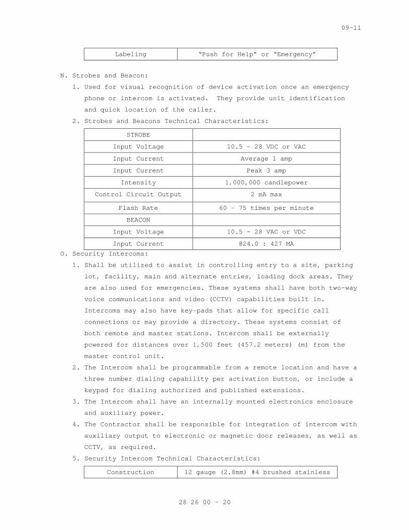
09-11
Labeling “Push for Help” or “Emergency”
N. Strobes and Beacon:
1. Used for visual recognition of device activation once an emergency
phone or intercom is activated. They provide unit identification
and quick location of the caller.
2. Strobes and Beacons Technical Characteristics:
STROBE
Input Voltage 10.5 – 28 VDC or VAC
Input Current Average 1 amp
Input Current Peak 3 amp
Intensity 1,000,000 candlepower
Control Circuit Output 2 mA max
Flash Rate 60 – 75 times per minute
BEACON
Input Voltage 10.5 - 28 VAC or VDC
Input Current @24.0 : 427 MA
O. Security Intercoms:
1. Shall be utilized to assist in controlling entry to a site, parking
lot, facility, main and alternate entries, loading dock areas. They
are also used for emergencies. These systems shall have both two-way
voice communications and video (CCTV) capabilities built in.
Intercoms may also have key-pads that allow for specific call
connections or may provide a directory. These systems consist of
both remote and master stations. Intercom shall be externally
powered for distances over 1,500 feet (457.2 meters) (m) from the
master control unit.
2. The Intercom shall be programmable from a remote location and have a
three number dialing capability per activation button, or include a
keypad for dialing authorized and published extensions.
3. The Intercom shall have an internally mounted electronics enclosure
and auxiliary power.
4. The Contractor shall be responsible for integration of intercom with
auxiliary output to electronic or magnetic door releases, as well as
CCTV, as required.
5. Security Intercom Technical Characteristics:
Construction 12 gauge (2.8mm) #4 brushed stainless
28 26 00 - 20
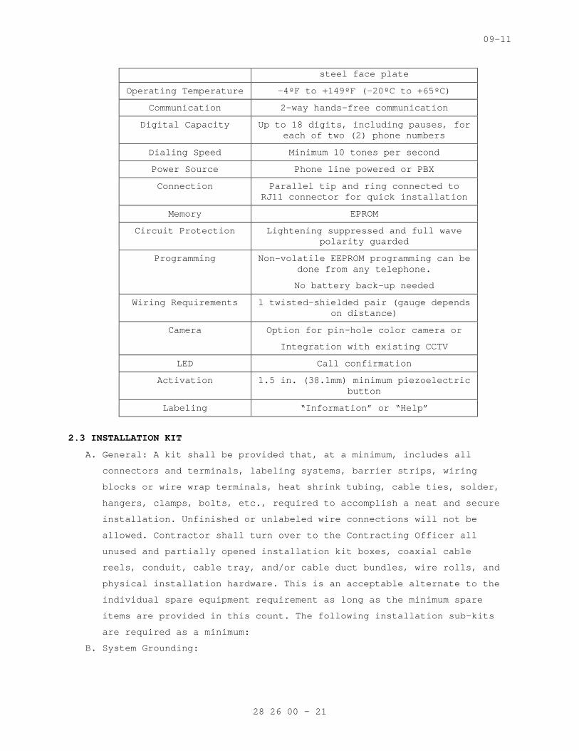
09-11
steel face plate
Operating Temperature -4ºF to +149ºF (-20ºC to +65ºC)
Communication 2-way hands-free communication
Digital Capacity Up to 18 digits, including pauses, for each of two (2) phone numbers
Dialing Speed Minimum 10 tones per second
Power Source Phone line powered or PBX
Connection Parallel tip and ring connected to RJ11 connector for quick installation
Memory EPROM
Circuit Protection Lightening suppressed and full wave polarity guarded
Programming Non-volatile EEPROM programming can be done from any telephone.
No battery back-up needed
Wiring Requirements 1 twisted-shielded pair (gauge depends on distance)
Camera Option for pin-hole color camera or
Integration with existing CCTV
LED Call confirmation
Activation 1.5 in. (38.1mm) minimum piezoelectric button
Labeling “Information” or “Help”
2.3 INSTALLATION KIT
A. General: A kit shall be provided that, at a minimum, includes all
connectors and terminals, labeling systems, barrier strips, wiring
blocks or wire wrap terminals, heat shrink tubing, cable ties, solder,
hangers, clamps, bolts, etc., required to accomplish a neat and secure
installation. Unfinished or unlabeled wire connections will not be
allowed. Contractor shall turn over to the Contracting Officer all
unused and partially opened installation kit boxes, coaxial cable
reels, conduit, cable tray, and/or cable duct bundles, wire rolls, and
physical installation hardware. This is an acceptable alternate to the
individual spare equipment requirement as long as the minimum spare
items are provided in this count. The following installation sub-kits
are required as a minimum:
B. System Grounding:
28 26 00 - 21
09-11
1. The grounding kit shall include all cable in accordance with UL 444
Communications Cables, and installation hardware required. All
grounding will be according to the NEC.
2. This includes, but is not limited to:
a. Coaxial Cable Shields
b. Control Cable Shields
c. Data Cable Shields
d. Conduits
e. Cable Duct
f. Cable Trays
g. Power Panels
h. Connector Panels
C. Coaxial Cable: The coaxial cable kit shall include all coaxial
connectors, cable tying straps, heat shrink tabbing, hangers, clamps,
etc., required to accomplish a neat and secure installation.
D. Wire And Cable: The wire and cable kit shall include all connectors and
terminals, barrier straps, wiring blocks, wire wrap strips, heat shrink
tubing, tie wraps, solder, hangers, clamps, labels etc., required to
accomplish a neat and orderly installation.
E. Equipment Interface: The equipment interface kit shall include any item
or quantity of equipment, cable, mounting hardware and materials needed
to interface Systems and Subsystems according to the OEM requirements
and this specification.
F. Labels: The labeling kit shall include any item or quantity of labels,
tools, stencils, and materials needed to label each subsystem according
to the OEM requirements, as-installed drawings, and this specification.
G. Documentation: The documentation kit shall include any item or quantity
of items, computer discs, as installed drawings, equipment,
maintenance, and operation manuals, and OEM materials needed to
correctly provide the system documentation as required by this document
and explained herein.
PART 3 – EXECUTION
SPEC WRITER NOTE: Delete and/or amend this all paragraphs and sub-paragraphs to apply to only the equipment and devices that are being installed.
28 26 00 - 22
09-11
3.1 INSTALLATION
A. System installation shall be installed in accordance with NFPA 731
Standards for the Installation of Electric Premises Security Systems
and appropriate installation manual for each type of subsystem
designed, engineered, and installed.
B. The location and type of duress, intercom, or call-box to be installed
will be in accordance with physical security requirements unique to
each VA facility.
C. For EPPS systems (i.e. use current panic/duress and emergency call
boxes) that can operate through existing VA facility telephone system
lines, software programming and hardware, refer to Section 27 51 23,
INTERCOMMUNICATIONS AND PROGRAM SYSTEMS to integrate additional EPPS
equipment.
D. Concealed duress/panic devices shall be mounted in such a way that
their location is only known by the person having knowledge of the
activating device location. No wiring shall be exposed to identify the
location of the activation device.
E. Floor mounted duress alarms shall be attached to millwork on floor.
When mounted under millwork, wiring shall be routed in millwork to
conduit system via flexible conduit.
F. Hard-wired switches shall be wired to individual alarm points within
the Advanced Processing Controller (apC).
G. Wall and post mounted stations shall be mounted to meet UFAS/ADA
requirements and use tamper proof bolts and screws. Testing will be
finished before installation of fasteners.
H. Cleaning: Subsequent to installation, clean each system component of
dust, dirt, grease, or oil incurred during installation in accordance
to manufacture instructions.
I. Provisions shall be made for systems in high-noise areas or areas with
electrical interference environments.
J. Adjustment/Alignment/Synchronization: Contractor shall prepare for
system activation by following manufacturer’s recommended procedures
for adjustment, alignment, or programming. Prepare each component in
accordance with appropriate provisions of the component’s installation,
operations, and maintenance instructions.
3.2 WIRELINE DATA TRANSMISSION
A. Installation: The Contractor shall install all system components
including Owner furnished equipment, and appurtenances in accordance
28 26 00 - 23

09-11
with the manufacturer’s instructions, ANSI C2 and as shown, and shall
furnish all necessary connectors, terminators, interconnections,
services, and adjustments required for a complete and operable data
transmission system.
B. Identification and Labeling: The Contractor shall supply permanent
identification labels for each cable at each end that will appear on
the as-built drawings. The labeling format shall be identified and a
complete record shall be provided to the Owner with the final
documentation. Each cable shall be identified by type or signal being
carried and termination points. The labels shall be printed on letter
size label sheets that are self laminated vinyl that can be printed
from a computer data base or spread sheet. The labels shall be E-Z
code WES12112 or equivalent.
C. The Contractor shall provide all personnel, equipment, instrumentation,
and supplies necessary to perform all testing.
D. Transient Voltage Surge Suppressors (TVSS): The Contractor shall mount
TVSS within 3 m (118 in) of equipment to be protected inside terminal
cabinets or suitable NEMA 1 enclosures. Terminate off-premise
conductors on input side of device. Connect the output side of the
device to the equipment to be protected. Connect ground lug to a low
impedance earth ground (less than 10 ohms) via Number 12 AWG insulated,
stranded copper conductor.
E. Contractor’s Field Test: The Contractor shall verify the complete
operation of the data transmission system during the Contractor’s Field
Testing. Field test shall include a bit error rate test. The
Contractor shall perform the test by sending a minimum of 1,000,000
bits of data on each DTM circuit and measuring the bit error rate. The
bit error rate shall not be greater than one (1) bit out of each
100,000 bits sent for each dial-up DTM circuit, and one (1) bit out of
1,000,000 bits sent for each leased or private DTM circuit. The
Contractor shall submit a report containing results of the field test.
F. Acceptance Test and Endurance Test: The wire line data transmission
system shall be tested as a part of the completed IDS and EECS during
the Acceptance test and Endurance Test as specified.
G. Identification and Labeling: The Contractor shall supply
identification tags or labels for each cable. Cable shall be labeled
at both end points and at intermediate hand holes, manholes, and
junction boxes. The labeling format shall be identified and a complete
28 26 00 - 24
09-11
record shall be provided to the Owner with the final documentation.
Each cable shall be identified with type of signal being carried and
termination points.
3.3 WIRING
A. Wiring Method: Install cables in raceways [except in accessible indoor
ceiling spaces, in attics,] [in hollow gypsum-board partitions,] and as
otherwise indicated. Conceal raceways and wiring except in unfinished
spaces.
SPEC WRITER NOTE: Retain paragraph above or first paragraph below. Delete both if wiring method is indicated on Drawings.
B. Wiring Method: Install cables concealed in accessible ceilings, walls,
and floors where possible.
C. Wiring within Enclosures: Bundle, lace, and train conductors to
terminal points with no excess and without exceeding manufacturer's
limitations on bending radii. Provide and use lacing bars and
distribution spools.
D. Splices, Taps, and Terminations: For power and control wiring, use
numbered terminal strips in junction, pull, and outlet boxes; terminal
cabinets; and equipment enclosures. Tighten electrical connectors and
terminals according to manufacturer's published torque-tightening
values. If manufacturer's torque values are not indicated, use those
specified in UL 486A and UL 486B.
SPEC WRITER NOTE: reetain paragraph below only if required by manufacturer. Show independent-signal circuit-grounding methods and details on Drawings.
E. Grounding: Provide independent-signal circuit grounding recommended in
writing by manufacturer.
3.4 FIELD QUALITY CONTROL
A. Manufacturer's Field Service: Engage a factory-authorized service
representative to inspect field-assembled components and equipment
installation and supervise pretesting, testing, and adjusting of video
surveillance equipment.
B. Inspection: Verify that units and controls are properly installed,
connected, and labeled, and that interconnecting wires and terminals
are identified.
C. Test Schedule: Schedule tests after pretesting has been successfully
completed and system has been in normal functional operation for at
least 14 days. Provide a minimum of 10 days' notice of test schedule.
28 26 00 - 25
09-11
D. Operational Tests: Perform operational system tests to verify that
system complies with Specifications. Include all modes of system
operation. Test equipment for proper operation in all functional
modes.
E. Remove and replace malfunctioning items and retest as specified above.
F. Record test results for each piece of equipment.
G. Retest: Correct deficiencies identified by tests and observations and
retest until specified requirements are met.
3.5 ADJUSTING
A. Occupancy Adjustments: When requested within 12 months of date of
Substantial Completion, provide on-site assistance in adjusting system
to suit actual occupied conditions and to optimize performance of the
installed equipment. Tasks shall include, but are not limited to, the
following:
1. Check cable connections.
2. Check proper operation of detectors.
3. Recommend changes to walk trough detectors, X-ray machines, and
associated equipment to improve Owner' utilization of security
access detection system.
4. Provide a written report of adjustments and recommendations.
3.6 CLEANING
A. Clean installed items using methods and materials recommended in
writing by manufacturer.
3.7 DEMONSTRATION
A. Engage a factory-authorized service representative to train Owner's
maintenance personnel to adjust, operate, and maintain electronic
personal protection system (EPSS) equipment.
1. Train Owner's maintenance personnel on procedures and schedules for
troubleshooting, servicing, and maintaining equipment.
2. Demonstrate methods of determining optimum alignment and adjustment
of components and settings for system controls.
3. Review equipment list and data in maintenance manuals.
4. Conduct a minimum of [four] <Insert number> hours' training.
3.8 COMMISIONING
A. Provide commissioning documentation in accordance with the requirements
of Section 28 08 00 – COMMISSIONING OF ELECTRONIC SAFETY AND SECURITY
SYSTEMS for all inspection, start up, and contractor testing required
28 26 00 - 26

09-11
above and required by the System Readiness Checklist provided by the
Commissioning Agent.
B. Components provided under this section of the specification will be
tested as part of a larger system. Refer to Section 28 08 00 –
COMMISSIONING OF ELECTRONIC SAFETY AND SECURITY SYSTEMS and related
sections for contractor responsibilities for system commissioning.
3.9 TESTS AND TRAINING
A. All testing and training shall be compliant with the VA General
Requirements, Section 01 00 00, GENERAL REQUIREMENTS and Section 28 05
00 COMMON WORK RESULTS FOR ELECTRONIC SAFETY AND SECURITY.
-----END----
28 26 00 - 27


