Embed Size (px)
Citation preview
Scalable VPN Routing via Relaying
Changhoon KimPrinceton University
Alexandre GerberAT&T Labs–Research
Carsten LundAT&T Labs–Research
Dan PeiAT&T Labs–Research
Subhabrata SenAT&T Labs–Research
ABSTRACTEnterprise customers are increasingly adopting MPLS (Multipro-tocol Label Switching) VPN (Virtual Private Network) service thatoffers direct any-to-any reachability among the customer sites viaa provider network. Unfortunately this direct reachability modelmakes the service provider’s routing tables grow very largeas thenumber of VPNs and the number of routes per customer increase.As a result, router memory in the provider’s network has become akey bottleneck in provisioning new customers. This paper proposesRelaying, a scalable VPN routing architecture that the provider canimplement simply by modifying the configuration of routers in theprovider network, without requiring changes to the router hardwareand software. Relaying substantially reduces the memory footprintof VPNs by choosing a small number of hub routers in each VPNthat maintain full reachability information, and by allowing non-hub routers to reach other routers through a hub. Deploying Relay-ing in practice, however, poses a challenging optimizationproblemthat involves minimizing router memory usage by having as fewhubs as possible, while limiting the additional latency dueto indi-rect delivery via a hub. We first investigate the fundamentaltensionbetween the two objectives and then develop algorithms to solvethe optimization problem by leveraging some unique properties ofVPNs, such as sparsity of traffic matrices and spatial locality ofcustomer sites. Extensive evaluations using real traffic matrices,routing configurations, and VPN topologies demonstrate that Re-laying is very promising and can reduce routing-table usageby upto 90%, while increasing the additional distances traversed by traf-fic by only a few hundred miles, and the backbone bandwidth usageby less than10%.
Categories and Subject DescriptorsC.2.3 [Computer-Communication Network]: Network Opera-tions; C.4 [Performance of Systems]: Design StudiesGeneral TermsManagement, Measurement, Performance, Reliability
KeywordsVPN, Routing, Optimization, Measurement
Permission to make digital or hard copies of all or part of this work forpersonal or classroom use is granted without fee provided that copies arenot made or distributed for profit or commercial advantage and that copiesbear this notice and the full citation on the first page. To copy otherwise, torepublish, to post on servers or to redistribute to lists, requires prior specificpermission and/or a fee.SIGMETRICS’08,June 2–6, 2008, Annapolis, Maryland, USA.Copyright 2008 ACM 978-1-60558-005-0/08/06 ...$5.00.
1. INTRODUCTIONVPN service allows for enterprise customers to interconnect
their sites via dedicated, secure tunnels that are established overa provider network. Among various VPN architectures, layer3MPLS VPN [14] offers direct any-to-any reachability among allsites of a customer, without requiring the customer to maintain full-mesh tunnels between each pair of sites. This any-to-any reacha-bility model makes each customer VPN highly scalable and cost-efficient, leading to the growth of the MPLS VPN service at anunprecedentedly rapid pace. According to the market researcherIDC, the MPLS VPN market was worth $16.4 billion in 2006 andis still growing fast [8]. By 2010, it is expected that nearlyallmedium-sized and large businesses in the United States willhaveMPLS VPNs in place.
The any-any reachability model of MPLS VPNs imposes a heavycost on the providers’ router memory resources. Each provideredge (PE) router in a VPNprovider network (see, e.g., Figure 1a)is connected to one or more different customer sites, and each cus-tomer edge (CE) router in a site announces its own address blocks(i.e., routes) to the PE router it is connected to. To enabledirectany-to-any reachability over the provider network, for each VPN,each PE router advertises all routes it received from the CE routersthat are directly connected to it, to all other PEs in the sameVPN.Then, the other PEs keep those routes in their VPN routing tablesfor later packet delivery. Thus, the VPN routing tables in PEroutersgrow very fast as the number of customers (i.e., VPNs) and thenumber of routes per customer increase. As a result, router mem-ory space required for storing VPN routing tables has becomea keybottleneck in provisioning new customers.
We give a simple example to illustrate how critical the memorymanagement problem is. Consider a PE with a network interfacecard with OC-12 (622 Mbps) bandwidth that can be channelizedinto 336 T1 (1.544 Mbps) ports - this is a very common interfacecard configuration for PEs. This interface can serve up to 336dif-ferent customer sites. It is not unusual that a large companyhashundreds or even thousands of sites. For instance, a large conve-nience store chain in the U.S. has 7,200 stores. Now, supposethePE in question serves one retail store of the chain via one of the T1ports. Since each of the 7,200 stores announces at least two routes(one for the site, and the other for the link connecting the site andthe backbone), that single PE has to maintain at least 14,400routesjust to maintain any-any connectivity to all sites in this customer’sVPN. On the other hand, a router’s network interface has a lim-ited amount of memory that is specifically designed for fast addresslook-up. Today’s state-of-the-art interface card can store at most 1million routes, and a mid-level interface card popularly used forPEs can hold at most200 to 300K routes. Obviously, using7.2%

(14, 400/200K) of the total memory for a single site that accountsfor only at most0.3% of the total capacity (1 out of 336 T1 ports)leads to very low utilization; having only14 customers that aresimilar to the convenience store can use up the entire interface cardmemory, while322 other ports are still available. Even if interfacecards with larger amounts of memory become available in the fu-ture, since the port-density of interfaces also grows, thisresourceutilization gap remains.
Fortunately, in reality, every customer site typically does notcommunicate with every other site in the VPN. This is driven bya number of factors includingi) most networking applications to-day are predominantly client-server applications, and theservers(e.g., database, mail, file servers, etc.) are located at a few centrallocations for a customer, andii ) enterprise communications typi-cally follow corporate structures and hierarchies. In fact, a mea-surement study based on traffic volumes in a large VPN provider’sbackbone shows that traffic matrices (i.e., matrices of traffic vol-umes between each pair of PEs) in VPNs are typically very sparse,and have a clear hub-and-spoke communication pattern [12, 11].We also observed similar patterns by analyzing our own flow-leveltraffic traces. Hence, PE routers nowadays install more routes thanthey actually need, perhaps much more than they frequently need.
This sparse communication behavior of VPNs motivates a routerinterface memory saving approach thatinstalls only a smaller num-ber of routesat a PE, while stillmaintains any-to-any connectivitybetween customer sites. In this paper, we proposeRelaying, a scal-able VPN routing architecture. Relaying substantially reduces thememory footprint of VPNs byselecting a small number of hub PEsthat maintain full reachability information, and by allowing non-hub PEs to reach other routers only through the hubs.To be usefulin practice, however, Relaying needs to satisfy the following re-quirements:
• Bounded penalty:The performance penalty associated withindirect delivery (i.e., detouring through a hub) should beproperly restricted, so that the service quality perceivedbycustomers does not get noticeably deteriorated and that theworkload posed on the provider’s network does not signifi-cantly increase either. Specifically, bothi) additional latencybetween communicating pairs of PEs, andii ) the increase ofload on the provider network should be insignificant on av-erage and be strictly bounded within the values specified inSLAs (Service Level Agreements) in the worst case.
• Deployability: The solution should be immediately deploy-able, work in the context of existing routing protocols, re-quire no changes to router hardware and software, and betransparent to customers.
To bound the performance penalty and to reduce the memoryfootprint of routing tables at the same time, we need to choosea small number of hub PEs out of all PEs, where the hub PEsoriginate or receivemosttraffic within the VPN. Specifically, weformulate this requirement as the following optimization problem.For each VPN whose traffic matrices, topology, and indirectionconstraints (e.g., maximum additional latency, or total latency) aregiven, select as small a number of hubs as possible, such that thetotal number of routes installed at all PEs is minimized, while theconstraints on indirect routing are not violated. Note that, unlikeconventional routing studies that typically limit overallstretch (i.e.,the ratio between the length of the actual path used for delivery andthe length of the shortest path), we instead bound the additional(or total) latency of eachindividual path. This is because an over-all stretch is often not quite useful in directly quantifying the per-formance impact on applications along each path, and hence hardto be derived from SLAs. Moreover, most applications are rather
tolerant to the small increase of latency, but the perceivedqualityof those applications drastically drops beyond a certain thresholdwhich can be very well specified by an absolute maximum latencyvalue, rather than a ratio (i.e., stretch).
To solve this optimization problem, we first explore the funda-mental trade-off relationship between the number of hubs and thecost due to the relayed delivery. Then, we propose algorithms thatcan strictly limit the increase of individual path lengths and can re-duce the number of hubs at the same time. Our algorithms exploitsome unique properties of VPNs, such as sparse traffic matricesand spatial locality of customer sites. We then perform extensiveevaluations using real traffic matrices, route advertisement configu-ration data, and network topologies of hundreds of VPNs at a largeprovider. The results show that Relaying can reduce routingtablesizes by up to90%. The cost for this large saving is the increase ofindividual communication’s unidirectional latency only by at most2 to3 ms (i.e., the increase of each path’s length by up to a few hun-dred miles ), and the increase of backbone resource utilization byless than10%. Moreover, even when we assume a full any-to-anyconversation pattern in each VPN, rather than the sparse patternsthat are monitored during a measurement period, our algorithmscan save more than60% of memory for moderate penalties.
This paper has four contributions:i) We propose Relaying, anew routing architecture for MPLS VPNs that substantially reducesmemory usage of routing tables;ii ) we formulate an optimizationproblem of determining a hub set, and assigning hubs to the re-maining PEs in a VPN;iii ) we develop practical algorithms to solvethe hub selection problem; andiv) we extensively evaluate the pro-posed architecture and algorithms with real traffic traces,routingconfiguration, and topologies from hundreds of operationalVPNs.
The rest of the paper is organized as follows. Section 2 explainsthe problem background and introduces desirable properties that asolution should have. Section 3 presents our measurement resultsthat motivate Relaying, and Section 4 describes our Relaying ap-proach. Section 5 investigates the solution space with a baselineRelaying scheme. Sections 6 and 7 formulate problems of findingpractical Relaying configuration, propose algorithms to solve theproblems, and evaluate the solutions. We discuss the implementa-tion and deployment issues in Section 8, followed by relatedworkin Section 9. Finally, we conclude the paper in Section 10.
2. BACKGROUNDIn this section, we first provide some background on MPLS VPN
and then introduce terms we use in later sections. We also describewhat properties a memory saving solution for VPNs should pos-sess. Finally we briefly justify our Relaying architecture.
2.1 How MPLS VPN worksLayer 3 MPLS VPN is a technology that creates virtual networks
on top of a shared MPLS backbone. As shown in Figure 1a, aPE can be connected to multiple Customer Edge (CE) routers ofdifferent customers. Isolating traffic among different customers isachieved by having distinct Virtual Routing and Forwarding(VRF)instances in PEs. Thus, one can conceptually view a VRF as a vir-tual PE that is specific to a VPN1. Given a VPN, each VRF locallypopulates its VPN routing table either with statically configuredroutes (i.e., subnets) pointing to incident CE routers, or with routesthat are learned from the incident CE routers via BGP [13]. Then,these local routes are propagated to other VRFs in the same VPNvia Multi-Protocol Border Gateway Protocol (MP-BGP) [1]. Once
1We also use “PE” to denote “VRF” when we specifically discussabout a single VPN.

(a) (b) (c)Figure 1: (a) MPLS VPN service with three PEs; two customer VPNs (X, Y ) exist, (b) Direct reachability, (c) Reachability under Relaying.
routes are disseminated correctly, each VRF learns all customerroutes of the VPN. Then, packets are directly forwarded fromasource to a destination VRF through a label-switched path (i.e., tun-nel). PEs in a region are physically located at a single POP (Pointof Presence) that houses all communication facilities in the region.
Figure 1b illustrates an example VPN provisioned over five PEs.Each PE’s routing table is shown as a box by the PE. We assumethat PEi is connected to CEi which announces prefixi. PEi ad-vertises prefixi to the other PEs via BGP, ensuring reachability toCEi. To offer the direct any-to-any reachability, each PE storesevery route advertised by the other PEs in its local VRF table. Inthis example, thus, each PE keeps five route entries, leadingto 25entries in total across all PEs. The arrows illustrate a traffic ma-trix. Black arrows represent active communications between pairsof PEs that are monitored during a measurement period, whereasgray ones denote inactive communications.
Specifically, our Relaying architecture aims to reduce the size ofa FIB (Forwarding Information Base), a data structure storing routeentries. A FIB is also called a forwarding table and is optimized forfast look-up for high speed packet forwarding. Due to performanceand scalability reasons, routers are usually built with several FIBseach of which is located in a very fast memory on a line card (i.e.,network interface card). Unfortunately, the size of a line-card mem-ory is limited, and increasing its size is usually very hard due to var-ious constraints, such as packet forwarding rate, power consump-tion, heat dissipation, spatial restriction, etc. For example, someline-card models use a special hardware, such as TCAM (TernaryContent Addressable Memory) or SRAM [3], which is much moreexpensive and hard to be built in a larger size than regular DRAMsare. Even if a larger line-card memory was available, upgrading allline cards in the network with the large memory may be extremelycostly. In MPLS VPN, a VRF is a virtual FIB specific to a VPNand resides in a line-card memory along with other VRFs config-ured on the same card. Beside the VRFs, line-card memory alsostores packet filtering rules, counters for measurement, and some-times the routes from the public Internet as well, which collectivelymake the FIB-size problem even more challenging.
2.2 Desirable properties of a solutionTo ensure usefulness, a router memory saving architecture for
VPNs should satisfy the following requirements.
1. Immediately deployable: Routing table growth is an im-minent problem to providers; a solution should make use ofrouter functions (either in software or hardware) and routingprotocols that are available today.
2. Simple to implement: A solution must be easy to designand implement. For management simplicity, configuring thesolution should be intuitive as well.
3. Transparent to customers: A solution should not requiremodifications to customer routers.
We deliberately choose Relaying as a solution because it satisfiesthese requirements. Relaying satisfies goal1 because the providercan implement Relaying only via router configuration changes (seeSection 8 for details). It also meets goal3 since a hub maintainsfull reachability, allowing spoke-to-spoke traffic to be directly han-dled at a hub without forwarding it to a customer site that is directlyconnected to the hub. Ensuring goal2, however, shapes some de-sign principles of Relaying which we will discuss in the followingsections. Here we briefly summarize those details and justify them.
Relaying classifies PEs into just two groups (hubs and spokes)and applies a simple “all-or-one” table construction policy to thegroups, where hubs maintain “all” routes in the VPN, and spokesstore only “one” default route to a hub (the details are in Section 4).Although we could save more memory by allowing each hub tostore a disjoint fraction of the entire route set, such an approach in-evitably increases complexity because the scheme requiresa con-sistency protocol among PEs.
For the same reason, we do not consider incorporating cache-based optimizations. When using route caching, each spoke PEcan store a small fraction of routes (in addition to the default route,or without the default route) that might be useful for futurepacketdelivery. Thus any conversation whose destination is foundin thecache does not take an indirect path. Despite this benefit, a routecaching scheme is very hard to implement because we have to mod-ify routers, violating goal1. Specifically, we need to design andimplementi) a resolution protocol to handle cache misses, andii )a caching architecture (e.g., route eviction mechanism) running inrouter interface cards. Apart from the implementation issues, theroute caching mechanism itself is generally much harder to cor-rectly configure than Relaying is, violating goal2. For example, toactually reduce memory usage, we need to fix a route cache’s size.However, a fixed-sized cache is vulnerable to a sudden increase ofthe number of popular routes due to the changes in the customerside or malicious attempts to poison a cache (e.g., scanning). Toavoid thrashing in these cases we have to either dynamicallyadjustcache size, or have to allow some slackness to buffer the churns;neither is satisfactory because the former introduces complexity,and the latter lowers memory saving effect.
Goal 2 also leads us to another important design decision,namely individual optimization of VPNs. That is, in our Relay-ing model, a set of Relaying configuration (i.e., the set of hubs)for a VPN does not depend on other VPNs. Thus, for example,we do not select a VRF in a PE as a hub at the expense of makingother VRFs in the same PE spokes, neither do we choose a VRFas a spoke to make other VRFs in the same PE hubs. This designdecision is critical because VPNs are dynamic. If we allowedthedependency among different VPNs, having a new VPN customeror deleting an existing customer might alter the Relaying configu-ration of other VPNs, leading to a large re-configuration overhead.Moreover, this independence condition also allows networkadmin-

0 10% 20% 30%Num. of active routes / Num. of total routes
0
0.2
0.4
0.6
0.8
1F
ract
ion
of V
RF
s
2007/May2007/May/13-192007/Jul2007/Jul/23-29
(a)
0 1000 2000 3000 4000 5000 6000Distance (in miles)
0
0.2
0.4
0.6
0.8
1
Fra
ctio
n of
PE
s
25th percentile50th75th95th100th
(b)
Figure 2: (a) CDFs of the proportion of active prefixes in a VRF, (b)CDFs of the distance to thei-th percentile closest VRF
istrators to customize each VPN differently by applying differentoptimization parameters to different VPNs.
3. UNDERSTANDING VPNSIn this section, we first briefly describes the data set used
throughout the paper. Then we present our measurement resultsfrom a large set of operational VPNs. By analyzing the results, weidentify key observations that motivate Relaying.
3.1 Data sourcesVPN configuration, VRF tables, and network topology:We useconfiguration and topology information of a large VPN serviceprovider in the U.S. which has, at least, hundreds of customers.VPNs vary in size and in geographical coverage; smaller onesareprovisioned over a few PEs, whereas larger ones span over hun-dreds of PEs. The largest VPN installs more than20, 000 routes ineach of its VRFs. Specifically, from this VPN configuration set, weobtain the list of PEs with which each VPN is provisioned, andthelist of prefixes each VRF advertises to other VRFs. We also obtainthe list of routes installed in each VRF under the existing routingconfiguration. From the topology, we obtain the location of eachPE and POP, the list of PEs in each POP, and inter-POP distances.
Traffic matrices: We use traffic matrices each of which describesPE-to-PE traffic volumes in a VPN. These matrices are generatedby analyzing real traffic traces captured in the provider backboneover a certain (usually longer than a week) period. The traffic tracesare obtained by monitoring the links of PEs facing the core routersin the backbone using Netflow [4]. Thus, the source PE of the flowis obvious, while the destination is also available from thetunnelend point information in flow records. Unless otherwise specified,the evaluation results shown in the following sections are based ona week-long traffic measurements obtained in May, 2007.
3.2 Properties enabling memory savingThrough the analysis of the measurement results, we make the
following observations about the MPLS VPNs. These propertiesallow us to employ Relaying to reduce routing tables.
Sparse traffic matrices: A significant fraction of VPNs exhibit“hub-and-spoke” traffic pattern, where a majority of PEs (i.e.,spokes) communicatemostlywith a small number of highly popu-lar PEs (i.e., hubs). Figure 2a shows the distributions of the numberof active prefixes (i.e., destination address blocks that are actuallyused during a measurement period) divided by the number of totalprefixes in a VRF. We measure the distributions during four differ-ent measurement periods, ranging from a week to a month. Thecurves show that, for most VRFs, the set of active prefixes is muchsmaller than the set of total prefixes. Across all measurement peri-ods, roughly80% (94%) of VRFs use only10% (20%) of the totalprefixes stored. The figure also confirms that the sets of active pre-fixes are stable over different measurement periods. By processing
these results, we found out that the actual amount of memory re-quired to store the active route set is only3.9% of the total amount.Thus, if there was an ideal memory saving scheme that preciselymaintain only those prefixes that are used during the measurementperiod, such a scheme would reduce memory usage by96.1%. Thisnumber sets a rough guideline for our Relaying mechanism.
Spatial locality of customer sites: Sites in the same VPN tendto be clustered geographically. Figure 2b shows the distributionsof the distance from a VRF to itsi-th percentile closest VRF. Forexample, the25th percentile curve shows that80% of VRFs have25% of the other VRFs in the same VPN within630 miles. Ac-cording to the50-th percentile curve, most (81%) VRFs have atleast half of the other VRFs in the same VPN within1, 000 miles.Thus, a single hub can serve a large number of nearby PEs, leadingto the decrease of additional distances due to Relaying.
PE’s Freedom to selectively install routes:A PE can choose notto store and advertise every specific route of a VPN to a CE as longas it maintains reachability to all the other sites (e.g. viaa defaultroute). Indeed, this does not affect a CE’s reachability to all othersites because a CE’s only way to reach other sites is via its adjacentPE(s) of the same (and sole) VPN backbone. Furthermore, thisCE does not have to propagate all the routes to other downstreamcustomers. However, a CE might still be connected to multiplePEs for load-balancing or backup purpose. In that case, the sameload-balancing or backup goals are still achieved if all theadjacentPEs are selected as hubs or all are selected as spokes at the sametime so that all the PEs announce the same set of routes to the CE.Note that this property does not hold for the routers participating inthe Internet routing, where it is common for customers to be multi-homed to multiple providers or to be transit providers themselves.
4. OVERVIEW OF RELAYINGThe key properties of VPN introduced in the previous section
collectively form a foundation for Relaying. In this section, wefirst define the Relaying architecture, and then introduce detailedvariations of the Relaying mechanism.
4.1 Relaying through hubsIn Relaying, PEs are categorized into two different groups:hubs
and spokes. A hub PE maintains full reachability information,whereas a spoke PE maintains the reachability for the customersites that are directly attached to it and asingle default routepoint-ing to one of the hub PEs. When a spoke needs to deliver packetsdestined to non-local sites, the spoke forwards the packetsto itshub. Since every hub maintains full reachability, the hub that re-ceived the relayed packets can then directly deliver them tocorrectdestinations. Multi-hop delivery across hubs is not required be-cause every hub maintains the same routing table.
This mechanism is illustrated in Figure 1c. Assuming the trafficpattern shown in Figure 1b is stable, one may choose PE1 and PE3as hubs. This leads to16, rather than25, route entries in total. Al-though the paths of most active communications remain unaffected(as denoted by solid edges), this Relaying configuration requiressome communications (dotted edges) be detoured through hubs,offering indirect reachability. This indirect delivery obviously in-flates some paths’ length, leading to the increase of latency, addi-tional resource consumption in the backbone, and larger fate shar-ing. Fortunately, reducing this side effect is possible when one canbuild a set of hubs that originates or receive most traffic within theVPN. Meanwhile, reducing the memory footprint of routing tablesrequires the hub set to be as small as possible. In the followingsections, we show that composing such a hub set is possible.

0 0.2 0.4 0.6 0.8 1Volume threshold (alpha)
0
0.2
0.4
0.6
0.8
1
Pro
port
ion
reduction in num. of prefixesvol relayed / vol totalvol*add_dist / vol*dir_dist
(a)
0 0.1 0.2 0.3 0.4 0.5 0.6Volume threshold (alpha)
0
0.1
0.2
0.3
Pro
port
ion
randomde factooptimal
(b)
0 1000 2000 3000 4000 5000 6000Additional distance (in miles)
0.6
0.7
0.8
0.9
1
Fra
ctio
n of
con
vers
atio
ns
optimalde factorandom
(c)Figure 3: (a) Gain and cost (de facto asgn.), (b) Sum of the products of volume and additional distance, (c) CDF of additional distances (α = 0.1)
4.2 Hub selection vs. hub assignmentRelaying is composed of two different sub-problems:hub selec-
tion andhub assignmentproblems. Given a VPN, ahub selectionproblem is a decision problem of selecting each PE in the VPN asa hub or a spoke. On the other hand, ahub assignmentproblem isa matter of deciding which hub a spoke PE should use as its de-fault route. A spoke must use a single hub consistently because,by definition, a PE cannot change its default route for each differ-ent destination. To implement Relaying, we let each hub advertisea default route (i.e.,0.0.0.0/0) to spoke PEs via BGP. Thus, inpractice, the BGP routing logic running at each PE autonomouslysolves the hub assignment problem. Since all updates for thede-fault route are to be equivalent for simplicity, each PE chooses theclosest hub in terms of IGP (Interior Gateway Protocol) distance.We call this model thede factohub assignment strategy.
In order to assess the effect of the de facto strategy on path infla-tion, we compare it with some other hub assignment schemes, in-cluding random, optimal, and algorithm-specific assignment. Therandomassignment model assigns a random hub for each non-localdestination. In theoptimal assignment scheme, we assume thateach PE chooses the best hub (i.e., the one minimizing the addi-tional distance) for each non-local destination. Note thatthis modelis impossible to realize because it requires global view on routing.Finally, thealgorithm-specificassignment is the assignment planthat our algorithm generates. This plan is realistic because it as-sumes a single hub per spoke, not per destination.
5. BASELINE PERFORMANCE OFRELAYING
To investigate fundamental trade-off relationship between thegain (i.e., memory saving) and cost (i.e., increase of path lengthsand the workload in the backbone due to detouring), we first ex-plore a simple, light-weight strategy to reduce routing tables. De-spite its simplicity, this strategy saves router memory substantiallywith only moderate penalties. Note that the Relaying schemes wepropose in later sections aim to outperform this baseline approach.
5.1 Selecting heavy sources or sinks as hubsThe key problem of Relaying is building a right set of hubs. For-
tunately, spatial locality of traffic matrices hints us thatforcing aspoke PE to communicate only through a hub might increase mem-ory saving significantly, without increasing the path lengths of mostconversations. Thus, we first investigate the following simple hubselection strategy, namelyaggregate volume-based hub selection,leveraging the sparsity of traffic matrices.
For a PEpi in VPNv, we measure the aggregate traffic volume toand from the PE. We denoteain
i to be the aggregated traffic volumereceived bypi from all customer sites directly connected topi, andaout
i to be the aggregated traffic volume sent bypi to all customersites directly attached topi. In VPN v, if ain
i ≥ αP
j ainj or
aouti ≥ α
P
jaout
j whereα is a tunable parameter between0 and1 inclusively, then we choosepi as a hub inv.
Although we could formulate this as an optimization problemto determine the optimal value ofα (for a certain VPN or for allVPNs) minimizing a multi-objective function (e.g., a weighted sumof routing table size and the amount of traffic volume relayedviahubs), this approach lead us to two problems. First, it is hard to de-termine a general, but practically meaningful multi-objective util-ity function especially when each of the objectives has a differentmeaning. Second, the objectives (e.g., memory saving) are not con-vex, making efficient search impossible. Instead, we perform nu-merical analysis with varying values ofα and show how table sizeand the amount of relayed traffic volume varies across differentαvalues. Since there are hundreds of VPNs available, exploring eachindividual VPN with varyingα values broadens the solution spaceimpractically large. Thus we apply a commonα value for all VPNs.
5.2 Performance of the hub selectionPerformance metrics: To assess Relaying performance, we mea-sure four quantities:metric-i) the number of routing table entriesreduced,metric-ii) the amount of traffic that is indirectly deliveredthrough hubs,metric-iii) the sum of the products of traffic volumeand additional distance by which the traffic has to be detoured, andmetric-iv) the additional distance of each conversation’s forwardingpath. For easier representation, we normalize the first three metrics.Metric-i is normalized by the total number of routing entries beforeRelaying,metric-ii is normalized by the amount of total traffic inthe VPN, andmetric-iii is normalized by the sum of the products oftraffic volume and direct (i.e., shortest) distance. We consistentlyuse these metrics throughout the rest of the paper.
The meanings of these metrics are as followings.Metric-i quan-tifies our scheme’sgain in memory saving, whereasmetric-ii, iiiand iv denote itscost. Specifically,ii and iii show the increase ofworkload on the backbone. On the other hand,iv shows the la-tency inflation of individual PE-to-PE communications. Note thatwe measure the latency increase in distance (i.e., miles) because, inthe backbone of a large tier-one network, propagation delaydom-inates a path latency. Due to the speed of light and attenuation,a mile in distance roughly corresponds to11.5 usec of latency intime. Thus, increasing a path length by1000 (or 435) miles lead tothe increase of unidirectional latency roughly by11.5 (5) msec.
Relaying results: Figure 3a shows the gain and cost of the ag-gregate volume-based hub selection scheme across different valuesof the volume thresholdα. As soon as we apply Relaying (i.e.,α > 0), all three quantities increase because the number of hubsdecreases asα increases. Note, however, that the memory savingincreases very fast, whereas the amount of relayed traffic and itsvolume-mile product increases modestly. If we assume a sampleutility function that is an equally weighted sum of the memory sav-ing and the relayed traffic volume, the utility value (i.e., the gapbetween the gain and the cost curves) is maximized whereα is

around0.1 to 0.2. Whenα passes0.23, however, the memory sav-ing begins to decrease fast because a large value ofα fails to selecthubs in some VPNs, making those VPNs revert to the direct reach-ability architecture between every pair of PEs. This also makes thecost values decrease as well.
Figure 3b shows how different hub assignment schemes affectthe cost (specifically, the increase of workload on the backbonemanifested by the sum of the products of volume and additional dis-tance). Note that we do not plot the gain curve because it remainsidentical regardless of which hub assignment scheme we use.First,the graph shows that the overall workload increased by Relayingwith either the de facto or the optimal assignment is generally low(less than14% for anyα). Second, the de facto assignment onlyslightly increases the workload on the backbone (around2%) inthe sweet spot (0.1 < α < 0.2), compared to the optimal (butimpractical) scheme. The increase happens because the de factoscheme forces a spoke to use the closest hub consistently, and thatclosest hub might not be the spoke’s popular communication peer.Nevertheless, this result indicates that choosing the closest hub iseffective in reducing the path inflation.
Although the sum of the volume-mile products is reasonablysmall, the increased path lengths can be particularly detrimentalto someindividual traffic flows. Figure 3c shows, for all commu-nicating pairs in all VPNs, how much additional distances the Re-laying scheme incurs. The figure shows latency distributions whenusing Relaying (withα = 0.1) for three different hub assignmentschemes: optimal, de facto, and random. For example, when us-ing Relaying with the de facto assignment scheme, roughly70%of the communicating pairs still take the shortest paths, whereasaround94% of the pairs experience additional distances of at most1000 miles (i.e., the increase of unidirectional latency by up to11.5msec). Unfortunately this means that some6% of the pairs sufferfrom more than1000 miles of additional distances, which can growin the worst case larger than5000 miles (i.e., additional60 msec ormore unidiretionally). To those communications, this basic Relay-ing scheme might be simply unacceptable, as some applications’quality may drastically drop. Unfortunately, the figure also showsthat even the optimal hub assignment scheme does not help much inreducing the particularly large additional path lengths.To removethe heavy tail, we need a better set of hubs.
6. LATENCY-CONSTRAINED RELAYINGRelaying requires spoke-to-spoke traffic to traverse an indirect
path, and therefore increases paths’ latency. However, many VPNapplications such as VoIP are particularly delay-sensitive and canonly tolerate a strictly-bounded end-to-end latency (e.g., up to250 ms for VoIP). SLAs routinely specify a tolerable maximumlatency for a VPN, and violations can lead to adverse business con-sequences, such as customers’ loss of revenue due to business dis-ruptions and corresponding penalties on the provider.
The simple baseline hub selection scheme introduced in Sec-tion 5 does not factor in the increase of path latencies due torelay-ing. Thus, we next formulate the following optimization problem,namely latency-constrained Relaying (LCR) problem, of whichgoal is to minimize the memory usage of VPN routing tables sub-ject to a constraint on the maximum additional latency of eachpath. Note that we deliberately bound individual paths’ additionallatency, rather than the overall stretch, because guaranteeing a cer-tain hard limit in latency is more important for applications. Forexample, increasing a path’s latency from30 msec (a typical coast-to-coast latency in the U.S.) to60 leads to the stretch of only2,whereas the additional30 msec can intolerably harm a VoIP call’squality. On the other hand, increasing a path’s latency from2 msec
Figure 4: A sample serve-use relationship
to 10 may be nearly unnoticeable to users, even though the stretchfactor in this case is5.
6.1 LCR Problem formulationWe first introduce the following notation. LetP denote the set of
PE routersP = {p1, p2, ..., pn} in VPN v. We define two matrices: i) Conversation matrixC = (ci,j) that captures the historicalcommunication between the routers inP , whereci,j = 1 if i 6= jandpi has transmitted traffic topj during the measurement period,andci,j = 0 otherwise; andii ) latency matrixL = (li,j) whereli,jis unidirectional communication latency (in terms of distance) frompi to pj . li,i = 0 by definition. LetH = {h1, ..., hm} (m ≤ n)be a subset ofP denoting the hub set. Finally, we define mappingM : P → H that determines a hubhj ∈ H for eachpi ∈ P .
LCR is an optimization problem of determining a smallestH(i.e., hub selection) and a corresponding mappingM (i.e., hub as-signment), such that in the resulting Relaying solution, every com-munications between a pair of VRFs adhere to the maximum al-lowable additional latency (in distance) thresholdθ. Formally,
min |H |s.t. ∀s, d whosecsd = 1,
ls,M(s) + lM(s),d − ls,d ≤ θ
Other variations of the above formulation include boundingei-ther the maximum total one-way distance, or both the additionaland the total distances. In this paper, we do not study these varia-tions due to the following reasons. First, bounding the additionaldistance is a stricter condition than bounding only the total dis-tance is. Thus, our results in the following sections provide lowerbounds of memory saving and upper bounds of indirection penal-ties. Second, when bounding total and additional distances, the to-tal distance threshold must be larger than the maximum direct dis-tance. However, this maximum direct distance often resultsfroma small number of outlier conversations (e.g., communication be-tween Honolulu and Boston in the case of the U.S.), making thetotal distance bound ineffective for most common conversations.
Considering the any-to-any reachability model of MPLS VPNs,we could accommodate the possibility that any PE can potentiallycommunicate with any other PEs in the VPN, even if they have notin the past. Thus, we can solve the LCR problem using afull-meshconversation matrixCfull = (cfull
i,j ), where∀i, j (i 6= j) cfulli,j =
1, cfulli,i = 0. There is trade-off between using the usage-based
matrices (C) and full-mesh matrices (Cfull). Using Cfull im-poses stricter constraints, potentially leading to lower memory sav-ing. The advantage of this approach, however, is that the hubselec-tion would be oblivious to the changes in communication patternsamong PEs, obviating periodical re-adjustment of the hub set.
Unfortunately, the LCR problem is NP-hard, and we provide thisproof in the extended version of this paper [10]. Hence, we proposean approximation algorithm explained in the following subsection.
6.2 Algorithm to solve LCRIn this section, we outline our solution to theLCRproblem. The
pseudo-code of this algorithm is also given in our extended ver-
0 200 400 600 800 1000Additional distance (in miles)
0.4
0.5
0.6
0.7
0.8
0.9
1
Fra
ctio
n of
con
vers
atio
ns
theta = 0 miletheta = 0 mi (de facto)theta = 200 mitheta = 200 mi (de facto)theta = 400 mitheta = 400 mi (de facto)theta = 800 mitheta = 800 mi (de facto)
(a)
0 400 800 1200 1600 2000Additional distance (in miles)
0.97
0.98
0.99
1
Fra
ctio
n of
con
vers
atio
ns
theta = 0 mile0 mi (de facto)200 mi200 mi (de facto)400 mi400 mi (de facto)800 mi800 mi (de facto)
(b)
0 200 400 600 800 1000Maximum additional distance, theta (in miles)
0
0.2
0.4
0.6
0.8
1
Pro
port
ion
reduction in num. of prefixesvol relayed / vol totalvol*add_dist / vol*dir_dist
(c)Figure 5: LCR performance with usage-basedC (a) CDF of additional distances, (b) CDF of additional distances (zoomed in), (c) Gain and cost
sion [10]. We solve a LCR problem through a two-staged approach.The first stage buildsserve-userelationships among PEs. Given apair of PEs(pi, pj) ∈ P , we say thatpi can servepj , or con-versely, thatpj can usepi, if all conversations inC from pj toother PEs in the VPN can be routed viapi as a hub without vio-lating the latency constraint. For each PEpi in P , we builds twosets:i) theservesetSi composed of PEs thatpi can serve as a hub,andii ) theusesetUi composed of PEs thatpi, as a spoke, can usefor relaying. The serve-use relationships among PEs can be rep-resented as a bipartite graph. Figure 4 shows a sample serve-userelationship graph of a VPN with five PEs. Each node on the leftbank representspi ∈ P in its role as a possible hub, and on theright bank, each node representspi in its role as a potential spoke.The existence of serve-use relationship between(pi, pj) ∈ P isrepresented by an edge betweenpi on the left bank andpj on theright bank.
Our original LCR problem now reduces to finding the smallestnumber of nodes on the left bank (i.e., hubs) that can serve everynode on the right bank. This is an instance of the set cover prob-lem, which is proven to be NP-complete [9], and we use a simplegreedy approximation strategy to solve this. At each step, the LCRalgorithm i) greedily selectspi from the left bank whose serve setSi is the largest,ii ) removepi from the left bank,iii ) remove allpj (j ∈ Si) from the right bank and update the mapping functionM to indicate thatpj ’s assigned hub ispi, andiv) revise the serve-use relationships for the remaining PEs in the graph. The abovestep is repeated until no PE remains on the right bank.
The LCR algorithm can be easily extended to solve the alter-native problems mentioned above (i.e., bounding total latency, orboth additional and total latency) only by re-defining the semanticsof “serve” and “use” relationship. Note also that the LCR algo-rithm assigns a single hub for each spoke PE, and each spoke PEis assumed to use the single hub consistently for all packets. Thus,the hub assignment plan generated by the LCR algorithm is imple-mentable, if not as simple as the de facto assignment scheme basedon BGP anycasting as described in Section 4. For example, a VPNprovisioning system can configure each spoke PE’s BGP process tochoose a specific route advertisement from a corresponding hub.
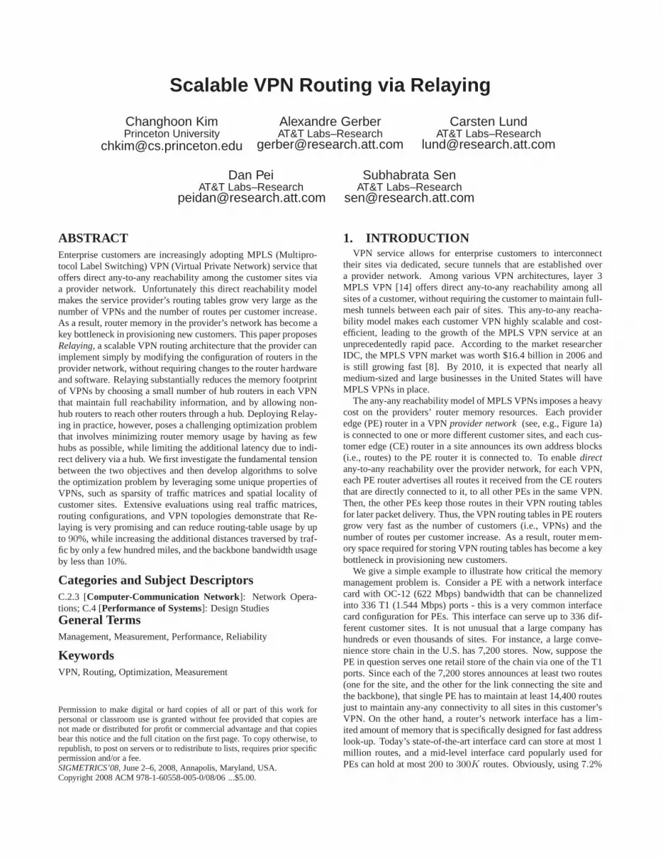
6.3 Solutions with usage-based matricesWe run the LCR algorithm individually for each VPN. The re-
sults shown in later sections are the aggregate of individual solu-tions across all VPNs.
Bounding additional distances:Figure 5a shows the CDFs of ad-ditional distances of all conversation pairs inC across all VPNs forvaryingθ values. Solid lines show the additional distance distribu-tions when using the algorithm-specific hub assignment decisions(i.e., assignment plans computed by the LCR algorithm), whereasthe dotted lines represent the distributions when spoke PEschoosethe closest hubs in terms of the IGP metric (i.e., the de factohub as-signment). Note, however, that for a givenθ, both solid and dotted
curves are generated with the same hub set. For some spoke PEs,the hub determined by the LCR algorithm might be different fromthe closest hub that the de facto assignment scheme would choose.Thus, when one uses the hub sets selected by the LCR algorithmaccompanied with the de facto hub assignment scheme, some pairsof PEs might experience additional distances larger thanθ. This iswhy solid lines always conform theθ values, whereas dotted lineshave tails extending beyond theta.
However, the fraction of PE pairs experiencing additional dis-tances larger thanθ is small. We re-scale Figure 5a to magnifythe tails and present it as Figure 5b. For a reasonable value of θ(e.g., additional400 miles, which are commensurate with5 msecincrease in latency), only1.3% of PE pairs experience additionaldistances larger thanθ. Meanwhile, the fraction of pairs exposed tounbearably larger additional distances (e.g.,1000+ miles, or morethan11.5 msec in latency) is only0.2%, which amounts to a fewtens of pairs. These results suggest that in practice, administratorscan use the simpler de facto assignment scheme in general andcanconfigure only those small number of exceptional PEs as per spe-cific assignment plans dictated by the LCR algorithm.
Memory saving: We next investigate the memory saving from ourlatency constrained hub selection. Figure 5c shows the gain(i.e.,memory saving) and cost (i.e., the increase of workload in the back-bone) under LCR for a range ofθ. Both the gain and cost curvesincrease withθ because a larger value ofθ makes it possible for asmaller number of hubs to serve all the spokes.
The results convey a number of promising messages. For exam-ple, to achieve roughly80% memory saving, a conversation (i.e.,VRF pairs) need to tolerate additional distance of only up to320miles, which corresponds to the increase of unidirectionallatencyby just3 ms. Moreover, when conversations can bear at most1000miles of path inflation, Relaying can reduce routing table memoryby roughly88%. Note that this amount of memory saving is only8% worse than that of the ideal memory saving scheme mentionedin Section 3.2, and is better than that of the aggregate volume-basedscheme (Figure 3a) with any choices of the volume thresholdα.
A surprising result is that, even if we do not allow any additionaldistance (i.e.,θ = 0), the relaying scheme can reduce routing ta-ble memory consumption by around a hefty54%. By specificallyanalyzing these penalty-free cases, we found out three reasons forthis huge, free-of-charge benefit. First, a significant number of PEscommunicate mostly with a hub PE. In the case of the traffic whosesource or destination is a hub, our relaying scheme does not intro-duce any additional distance penalty as long as the hubs are cor-rectly identified and assigned. This case accounts for roughly 45%of the entire penalty-free conversations. Second, a hub cansome-times be located on the shortest path from a source to a destination(38%). For example in the United States, relaying traffic betweenSan Diego and San Francisco through Los Angeles might not incurany detour in effect because physical connectivity betweenthe twocities might be already configured that way. Third, for availability
0 200 400 600 800 1000Maximum additional distance, theta (in miles)
0
0.2
0.4
0.6
0.8
1
Pro
port
ion
reduction in num. of prefixesvol relayed / vol totalvol*add_dist/ vol*dir_dist
(a)
0 200 400 600 800 1000Maximum additional distance, theta (in miles)
0
0.2
0.4
0.6
0.8
1
Pro
port
ion
vol_relayed / vol_total (test)vol*add_dist / vol*dir_dist (test)vol_relayed / vol_total (model)vol*add_dist / vol*dir_dist (model)
(b)
0 200 400 600 800 1000Additional distance (in miles)
0.4
0.5
0.6
0.7
0.8
0.9
1
Fra
ctio
n of
con
vers
atio
ns
theta = 0 mile0 mi (de facto)200 mi200 mi (de facto)400 mi 400 mi (de facto)800 mi800 mi (de facto)
(c)Figure 6: (a) LCR performance with Cfull, (b) Robustness results (costs), (c) Robustness results (CDF of additional distances withC)
purposes, a VPN is often provisioned over multiple PEs located atthe same POP (17%). Thus if one of the PEs in a POP is chosenas a hub, all the other PEs at the same POP can use the hub PE forrelaying and avoid any (practically meaningful) distance penalties.
Indirection penalty: Figure 5c shows that the latency-constrainedRelaying requires substantially more traffic to be relayed comparedto the base line relaying scheme shown in Figure 3a. (Note thatwe use the same metrics described in Section 5.2.) This is be-cause the LCR algorithm does not take into account the relativetraffic volumes associated with the different PE-to-PE conversa-tions while making either the hub selection or hub assignment de-cisions; the LCR algorithm selects a PE as a hub as long as thePE can relay the largest number of other PEs without violating thelatency constraint. However, Figure 5c also shows that the sumof the relayed volume and additional distance products is a rel-atively small compared to the corresponding sum of the volumeand direct distance products. This is because, even when relayingis needed, the algorithm limits the additional distances below thesmall θ values. Hence, thepractical impactof relaying (e.g., theincrease of resource usage in the provider network) is much lesssevere than it is suggested by the sheer amount of relayed traffic.Also, we confirmed that using the de facto hub assignment, ratherthan the LCR algorithm’s hub assignment plan, increases theag-gregate costs very little. This is because the LCR algorithmdoesnot necessarily choose heavy sources or sinks as hubs, leaving onlylittle room to improve/worsen the indirection penalties via differenthub assignments.
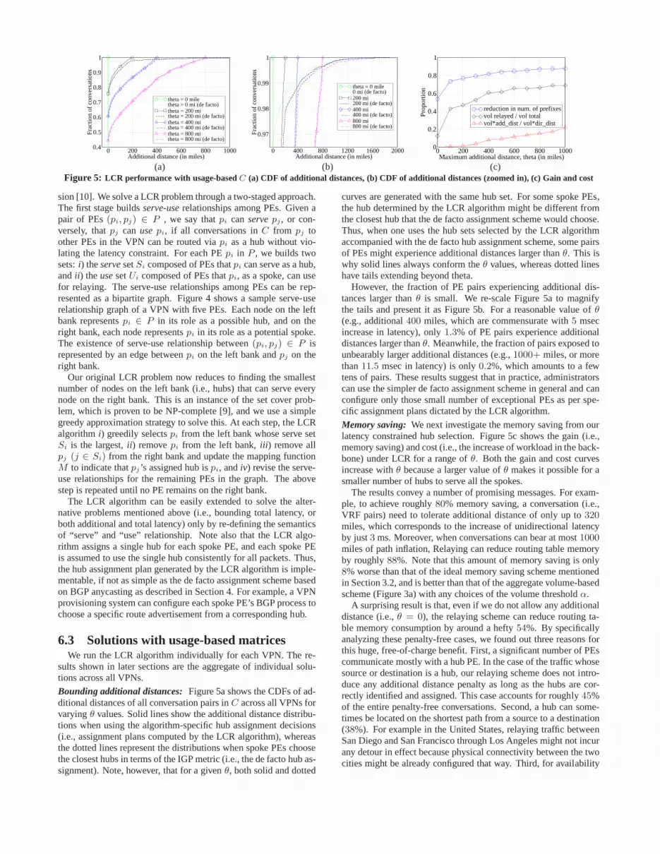
6.4 Solutions with full-mesh matricesWe next consider the performance of the LCR when using the
full-mesh conversation matrices. Figure 6a shows the gain and thecost curves. While we select the hubs based on the full-mesh ma-trices, to evaluate the penalties due to relaying we use the histori-cal PE-to-PE conversations (including volumes) that are monitoredduring the measurement period (May 13 - 19, 2007).
The results are encouraging, even though the conversation ma-trices are much denser in this case. At the expense of incurring ad-ditional distances of up to roughly480 miles (corresponding onlyto roughly5 ms in unidirectional latency), we can reduce the mem-ory consumption by nearly70%. Interestingly, we can still saveroughly 23% of memory even with no additional distance. Thisis is because, given a PE, it is sometimes possible to have a hublying on every shortest path from the PE to each other PE. For ex-ample, on a graph showing the physical connectivity of a VPN,ifa spoke PE has only one link connecting itself to its neighbor, andthe neighbor is the hub of the spoke PE, delivering traffic throughthe neighbor does not increase any paths’ lengths originating fromthe spoke PE. We also note that the aggregate costs (i.e., relayedtraffic volume and its volume-mile product) are slightly reducedcompared to the results derived from usage-based matrices.This isbecause hub sets for full-mesh matrices are bigger than those for
usage-based matrices. We also confirmed that the lengths of indi-vidual paths are correctly bounded withinθ for all cases.
For network administrators, these full-mesh results are particu-larly encouraging for the following reasons. First, even when cus-tomers’ networking patterns drastically change from todays hub-and-spoke style to a more peer-to-peer-like style (e.g., byperva-sively deploying VoIP or P2P-style data sharing applications), therelaying scheme can still save significant amount of memory.Sec-ond, it has the additional attraction that the relaying solution needsto be computed and implemented only once and for all. Therewould be no need to track the changing conversation matrices, un-like the usage-based case.
6.5 RobustnessWe next explore how our solution performs under traffic dynam-
ics. Figure 6b shows the results when we apply afixedsolution setderived from the traffic measurements in a particularmodelweek(May 13 - 19, 2007) to the traffic for8 different testweeks in Mayto August, 2007. We assume that VRFs added later on after themodel week maintains full reachability.
The solid curves in Figure 6b depict the aggregate cost during thetest weeks. We apply the usage-based solutions – both the hubse-lection and assignment results – from the model week to the trafficmatrices of the test weeks. Error bars represent the maximumandminimum cost across all8 weeks with each value ofθ, whereas thecurve connects the averages. For comparison, we also plot the costcurves for the model week using dotted lines. We do not plot thegain curves because we use the same hub set for all the weeks. Theresults are promising; the aggregate cost curves for the test weeksare close to those of the model week for all choices ofθ except0.The exception whenθ = 0 occurs because the strict latency con-dition leads to a solution set that is very sensitive to traffic patternchanges. The tight error bars show that the aggregate cost isstablewith little variance across the8 test weeks. We found similar re-sults with the full-mesh solution of the model week, and omitthegraphs in the interest of space.
Figure 6c shows the distribution of additional distances when weapply the usage-based solutions from the model week to one (July23 - 29, 2007) of the test weeks. The solid lines show the additionaldistances when we use both the hub selection and assignment plansof the model week. The dotted lines represent the distances whencombining the hub selection results with de facto hub assignment.The graph is similar to Figure 5a, meaning that the site-to-site la-tency distribution remains fairly stable over the test weeks. How-ever, the fraction of communication pairs whose additionaldistanceis larger than the specifiedθ increases by at most3%, leaving heav-ier tails. Note that, due to traffic dynamics, just using the hub as-signment results of the model week (i.e., solid curves) doesnotguarantee the conformance toθ in subsequent weeks because theconversation matrix changes. However, the fraction of suchcasesis small. In the case ofθ = 400, only less than2.5% of conver-sation pairs do not meet the latency constraint. We verified that

Figure 7: A sample serve-use relationship with penalties
these tails are removed when using the full-mesh solutions of thetest week. In conclusion, the latency-constrained hub selection andassignment scheme generates robust solutions.
7. LATENCY-CONSTRAINED,VOLUME-SENSITIVE RELAYING
In addition to bounding additional latency within a threshold, wealso want to reduce additional resource consumption in the back-bone required for Relaying. We view the sum of volume and ad-ditional distance products is one of the relevant metrics tomeasurethe load a backbone has to bear. This requirement motivates an-other optimization problem, namelylatency-constrained, volume-sensitive Relaying (LCVSR).
7.1 LCVSR Problem formulationTo formulate this problem, we define a volume matrixV =
(vi,j) of a VPN wherevi,j denotes the amount of traffic volumethatpi sends topj . Obviously,vi,j = 0 whenci,j = 0. Now weconsider the following problem:
min |H |,P
∀s,dvs,d · (ls,M(s) + lM(s),d − ls,d)
s.t. ∀s, d whosecs,d = 1,ls,M(s) + lM(s),d − ls,d ≤ θ
To provide robust solutions for the worst case, we can also uti-lize the full-mesh conversation matrixCfull. Note, however, thatwe still need to use the usage-based volume matrixV as well be-cause we cannot correctly assume the volumes of the conversationsthat have never taken place. Thus, a hub set generated by thisfor-mulation can serve traffic between any pairs of PEs without violat-ing the latency constraint, and keeps the amount of relayed volumerelatively small as long as the volume matrices considered are sim-ilar to the usage-based matrices. Hence, assuming that the futurecommunication between two PEs who have never spoken to eachother in the past generates relatively small amount of traffic, thisfull-mesh solution might still work effectively.
7.2 Algorithm to solve LCVSRWe outline our LCVSR algorithm in this section. The pseudo-
code is given in [10]. Minimizing|H | conflicts with minimizingP
∀s,dvs,d · (ls,M(s) + lM(s),d − ls,d), making the problem hard
to solve. For example, to reduce the additional resource consump-tion to zero, every PE should become a hub, leading to the maxi-mum value of|H |. Note, however, that this does not mean that theadditional resource consumption can be minimized only and if onlythe hub set is maximal. In fact, for someC, it is possible to mini-mize the additional resource consumption with a very small|H | –one trivial example is the case where there is only one popular PE,and all the other PEs communicate only with the popular PE. Al-though we cannot minimize both the objectives at the same time ingeneral, coming up with a unified objective function composed ofthe two objectives functions (e.g., a weighed sum of the two objec-tives) is not a good approach either because the two objectives carrytotally different meanings. Thus, we propose a simple heuristic tobuild a reasonably small hub set that reduces the relayed volume.
Our algorithm for LCVSR works similarly to the algorithmfor the LCR problem. Thus, the first stage of the algorithmbuilds the same serve-use relationships among PEs. However,during the process, the algorithm also computes apenaltyvaluefor each PE. The penaltyXi of PE pi is defined to be the sumof the volume and additional distance products of all conver-sations inC, assumingpi is a sole hub in the VPN. That is,Xi =
P
∀s,d vs,d · (ls,i + li,d − ls,d). Figure 7 illustrates a sam-ple serve-use relationship graph with five PEs, where each PEisannotated with its penalty value. With these serve-use relationshipsalong with penalties, the algorithm chooses hubs.
Due to the two conflicting objectives, at each run of the hub se-lection process, the algorithm has to make a decision that reduceseither one of the two objectives, but not necessarily both. We de-sign our algorithm to choose a PE from the server side (i.e., theleft bank) that hasthe smallest penalty value, rather than the largestserve set size. The intuition behind this design is that choosinga PE with the smallest penalty is often conducive to reducingbothobjectives, if not always. By definition, a penalty valueXi of PEpi
decreases when each product (i.e.,vs,d ·(ls,i +li,d−ls,d)) becomessmaller. Now suppose a PE that communicates with a large numberof other PEs; we call such a PE has a highspan. The penalty of thehigh-span PE is usually lower because the high-span PE is on theshortest path of many conversations, making many of the volume-distance products zero. Thus, our algorithm tends to choosePEswith higher spans. The key is that, fortunately, a PE with a higherspanalso has a large serve set (i.e.,Si) because it can serve as ahub a large number of PEs it communicates without violating theadditional distance constraint. The remaining part (removing thechosen PE, and revising the serve-use relationships) is identical tothe previous algorithm. We repeat the process until no PE remainson the user side.
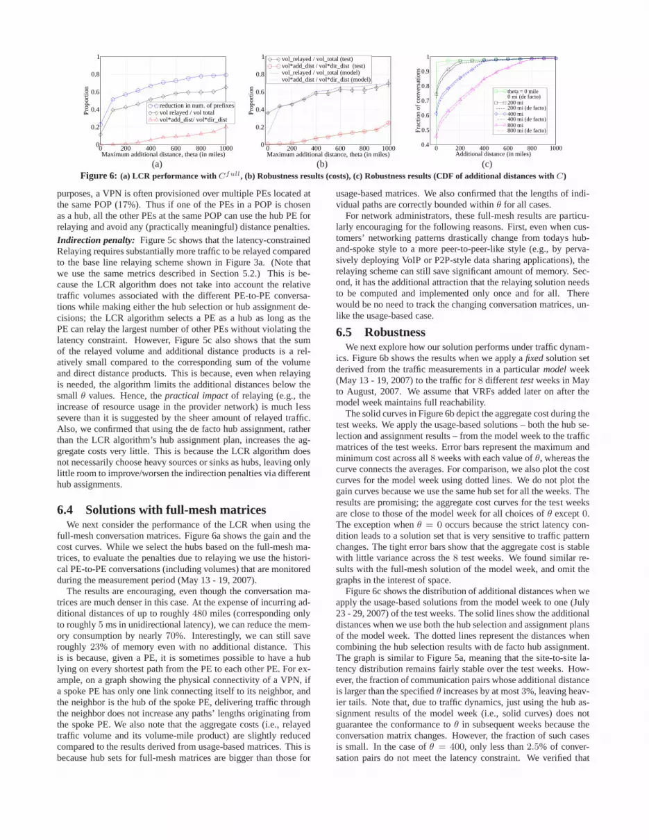
7.3 Solutions with usage-based matricesThe benefit of LCVSR over LCR is shown in Figure 8a. The
figure indicates that LCVSR algorithm significantly reducesindi-rection penalties compared to the LCR algorithm. The amountofrelayed traffic volume increases much more slowly than does it withthe LCR algorithm and never exceed40% of the total volume foranyθ below1000 miles. In comparison, in Figure 5c, the same costcurve lies above the40% line for almost allθ, reaching nearly70%whenθ = 1000. This decrease in relayed volume also reduces thesum of volume and additional distance products. For a reasonablechoice ofθ (e.g.,400 miles), the sum of the volume and additionalmile products is only1.2% of the corresponding total.
Figure 8a also shows the LCVSR can still substantially reducerouter memory usage, and also that the amount of memory savingis marginally lower than the results of LCR. Specifically, a compar-ison with Figure 5c reveals that the saving for eachθ is lower byonly 1 to 3%. While, the lower saving is somewhat expected giventhat LCVSR does not explicitly aim to minimize|H |, the small dif-ference in saving suggests that the LCVSR is still very effective inidentifying memory-efficient solutions.
In conclusion, the LCVSR scheme results in very modest in-crease of backbone workload, while enabling dramatic memorysaving. We also confirmed that combining the LCVSR with thesimpler-to-implement de facto assignment scheme, insteadof theassignment dictated by the algorithm, marginally affects the aggre-gate cost.
We also note that the distribution of path lengths is biased to-wards lower values for the LCVSR compared to the LCR, as evi-denced by comparing the each CDF curve in Figure 8b to the cor-responding curve in Figure 5a. In particular we note that forany
0 200 400 600 800 1000Maximum additional distance, theta (in miles)
0
0.2
0.4
0.6
0.8
1
Pro
port
ion reduction in num. of prefixes
vol relayed / vol totalvol*add_dist / vol*direct_dist
(a)
0 200 400 600 800 1000Additional distance (in miles)
0.4
0.5
0.6
0.7
0.8
0.9
1
Fra
ctio
n of
con
vers
atio
ns
theta = 0 mile0 mi (de facto)200 mi200 mi (de facto)400 mi 400 mi (de facto)800 mi800 mi (de facto)
(b)
0 200 400 600 800 1000Maximum additional distance, theta (in miles)
0
0.2
0.4
0.6
0.8
1
Pro
port
ion
reduction in num. of prefixesvol relayed / vol totalvol*add_dist / vol*direct_dist
(c)Figure 8: LCVSR performance (a) Gain and cost (withC), (b) CDF of additional distances (withC) (c) Gain and cost (withCfull)
givenθ, a significantly larger fraction of communications have nopath inflation. This reduced inflation is probably a consequence ofthe LCVSR algorithm tending to choose PEs with higher span val-ues, rather than those PEs whose locations are qualified to serve alarger number of other PEs, as hubs. Using the de facto assignmentscheme, however, also adversely impacts a few (e.g.,0.9% of thetotal communication pairs in the case ofθ = 400) individual pairs,leading to the increase of additional distances beyondθ.
7.4 Solutions with full-mesh matricesHere we compare LCVSR with LCR, both using full-mesh con-
versation matrices. Recall that a full-mesh conversation matrix ofa VPN factor in the latency for conversations between every PEpair. Hence, for a given PE, the number of hub PEs that can servethe given PE tends to be smaller than the corresponding numberwith the usage-based conversation matrix. This in turn suggeststhat hub sets are generally larger in the full-mesh case. This intu-ition is confirmed in Figure 8c which shows that the hub set sizeindeed increases. However, we can still save a substantial22 to75% of memory for reasonable values ofθ in the few hundredmiles range. This corresponds to marginally lower (about1 − 5%)memory saving compared to the LCR algorithm (see Figure 6a).On the other hand, the cost of Relaying reduces significantlyunderLCVSR (about50% in terms of the amount of relayed volume, and75 to 95% in terms of the sum of volume and additional distanceproducts) compared to LCR.
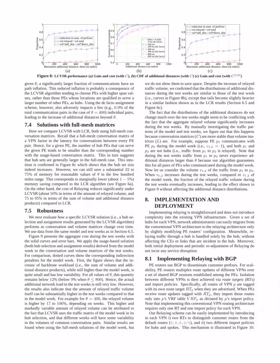
7.5 RobustnessWe next evaluate how a specific LCVSR solution (i.e., a hub se-
lection and assignment results generated by the LCVSR algorithm)performs as conversation and volume matrices change over time.We use data from the same model and test weeks as in Section 6.5.
Figure 9 presents the aggregate cost during the test weeks withthe solid curves and error bars. We apply the usage-based solution(both hub selection and assignment results) derived from the modelweek to the conversation and volume matrices of the test weeks.For comparison, dotted curves show the corresponding indirectionpenalties for the model week. First, the figure shows that thein-crease of backbone workload (i.e., the sum of volume and addi-tional distance products), while still higher than the model week, isquite small and has low variability. For all values ofθ, this quantityremains below12% (below9% whenθ ≤ 800). Hence, the actualadditional network load in the test weeks is still very low. However,the results also indicate that the amount of relayed traffic volumeitself can be substantially higher in the test weeks compared to thatin the model week. For example forθ = 400, the relayed volumeis higher by17 to 106%, depending on weeks. This higher andmarkedly variable amount of relayed volume can be attributed tothe fact that LCVSR uses the traffic matrix of the model week initshub selection, and that different weeks will have some variabilityin the volumes of common conversation pairs. Similar results arefound when using the full-mesh solutions of the model week, but
we do not show them to save space. Despite the increase of relayedtraffic volume, we confirmed that the distributions of additional dis-tances during the test weeks are similar to those of the test week(i.e., curves in Figure 8b), except that tails become slightly heavierin a similar fashion shown as in the LCR results (Section 6.5 andFigure 6c).
The fact that the distributions of the additional distancesdo notchange much over the test weeks might seem to be conflicting withthe fact that the aggregate relayed volume significantly increasesduring the test weeks. By manually investigating the trafficpat-terns of the model and test weeks, we figure out that this happensbecause conversation matrices (C) are more stable than volume ma-trices (L) are. For example, suppose PEp1 communicates withPE p2 during the model week (i.e.,c1,2 = 1), and bothp1 andp2 are not hubs (i.e., traffic fromp1 to p2 is relayed). Note thatduring the test weeks traffic fromp1 to p2 never experience ad-ditional distances larger thanθ because our algorithm guaranteesthis for all pairs of PEs who communicated during the model week.Now let us consider the volumev1,2 of the traffic fromp1 to p2.When v1,2 increases during the test weeks, compared tov1,2 ofthe model week, the fraction of the relayed traffic volume duringthe test weeks eventually increases, leading to the effect shown inFigure 9 without affecting the additional distance distributions.
8. IMPLEMENTATION ANDDEPLOYMENT
Implementing relaying is straightforward and does not introducecomplexity into the existing VPN infrastructure. Given a set ofhubs for each VPN, network administrators can easily migrate fromthe conventional VPN architecture to the relaying architecture onlyby slightly modifying PE routers’ configuration. Meanwhile, re-laying traffic through a hub is handled solely by the hub, withoutaffecting the CEs or links that are incident to the hub. Moreover,both initial deployment and periodic re-adjustment of Relaying donot incur any service disruption.
8.1 Implementing Relaying with BGPPE routers use BGP to disseminate customer prefixes. For scal-
ability, PE routers multiplex route updates of different VPNs overa set of shared BGP sessions established among the PEs. Isolationbetween different VPNs is then achieved viaroute targets(RTs)and import policies. Specifically, all routes of VPNp are taggedwith its own route targetRTp when they are advertised. When PEsreceive route updates tagged withRTp, they import those routesonly into p’s VRF tableV RFp as dictated byp’s import policy.Note that implementing this conventional VPN routing architecturerequires only one RT and one import policy for each VPN.
Our Relaying scheme can be easily implemented by introducingin each VPNi) two RTs to distinguish customer routes from thedefault routes (0.0.0.0/0), and ii ) two different import policiesfor hubs and spokes. This mechanism is illustrated in Figure10.
0 200 400 600 800 1000Maximum additional distance, theta (in miles)
0
0.2
0.4
0.6
0.8
1
Pro
port
ion
vol_relayed / vol_total (test)vol*add_dist / vol*dir_dist (test)vol_relayed / vol_total (model)vol*add_dist / vol*dir_dist (model)
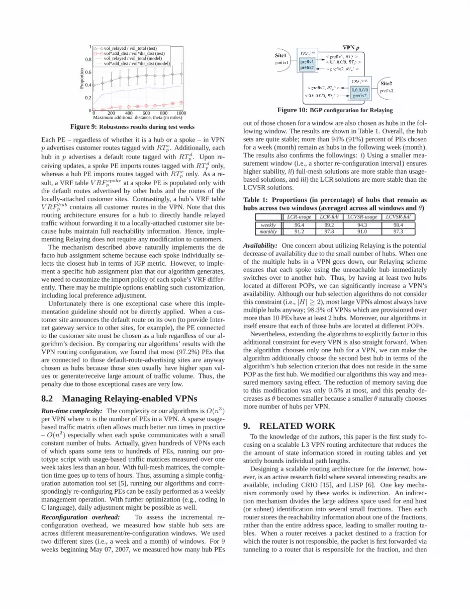
Figure 9: Robustness results during test weeks
Each PE – regardless of whether it is a hub or a spoke – in VPNp advertises customer routes tagged withRT c
p . Additionally, eachhub in p advertises a default route tagged withRT d
p . Upon re-ceiving updates, a spoke PE imports routes tagged withRT d
p only,whereas a hub PE imports routes tagged withRT c
p only. As a re-sult, a VRF tableV RF spoke
p at a spoke PE is populated only withthe default routes advertised by other hubs and the routes ofthelocally-attached customer sites. Contrastingly, a hub’s VRF tableV RF hub
p contains all customer routes in the VPN. Note that thisrouting architecture ensures for a hub to directly handle relayedtraffic without forwarding it to a locally-attached customer site be-cause hubs maintain full reachability information. Hence,imple-menting Relaying does not require any modification to customers.
The mechanism described above naturally implements the defacto hub assignment scheme because each spoke individually se-lects the closest hub in terms of IGP metric. However, to imple-ment a specific hub assignment plan that our algorithm generates,we need to customize the import policy of each spoke’s VRF differ-ently. There may be multiple options enabling such customization,including local preference adjustment.
Unfortunately there is one exceptional case where this imple-mentation guideline should not be directly applied. When a cus-tomer site announces the default route on its own (to provideInter-net gateway service to other sites, for example), the PE connectedto the customer site must be chosen as a hub regardless of our al-gorithm’s decision. By comparing our algorithms’ results with theVPN routing configuration, we found that most (97.2%) PEs thatare connected to those default-route-advertising sites are anywaychosen as hubs because those sites usually have higher span val-ues or generate/receive large amount of traffic volume. Thus, thepenalty due to those exceptional cases are very low.
8.2 Managing Relaying-enabled VPNsRun-time complexity: The complexity or our algorithms isO(n3)per VPN wheren is the number of PEs in a VPN. A sparse usage-based traffic matrix often allows much better run times in practice– O(n2) especially when each spoke communicates with a smallconstant number of hubs. Actually, given hundreds of VPNs eachof which spans some tens to hundreds of PEs, running our pro-totype script with usage-based traffic matrices measured over oneweek takes less than an hour. With full-mesh matrices, the comple-tion time goes up to tens of hours. Thus, assuming a simple config-uration automation tool set [5], running our algorithms andcorre-spondingly re-configuring PEs can be easily performed as a weeklymanagement operation. With further optimization (e.g., coding inC language), daily adjustment might be possible as well.
Reconfiguration overhead: To assess the incremental re-configuration overhead, we measured how stable hub sets areacross different measurement/re-configuration windows. We usedtwo different sizes (i.e., a week and a month) of windows. For9weeks beginning May 07, 2007, we measured how many hub PEs
Figure 10: BGP configuration for Relaying
out of those chosen for a window are also chosen as hubs in the fol-lowing window. The results are shown in Table 1. Overall, thehubsets are quite stable; more than94% (91%) percent of PEs chosenfor a week (month) remain as hubs in the following week (month).The results also confirms the followings:i) Using a smaller mea-surement window (i.e., a shorter re-configuration interval) ensureshigher stability,ii ) full-mesh solutions are more stable than usage-based solutions, andiii ) the LCR solutions are more stable than theLCVSR solutions.
Table 1: Proportions (in percentage) of hubs that remain ashubs across two windows (averaged across all windows andθ)
LCR-usage LCR-full LCVSR-usage LCVSR-full
weekly 96.4 99.2 94.3 98.4monthly 91.2 97.8 91.0 97.3
Availability: One concern about utilizing Relaying is the potentialdecrease of availability due to the small number of hubs. When oneof the multiple hubs in a VPN goes down, our Relaying schemeensures that each spoke using the unreachable hub immediatelyswitches over to another hub. Thus, by having at least two hubslocated at different POPs, we can significantly increase a VPN’savailability. Although our hub selection algorithms do notconsiderthis constraint (i.e.,|H | ≥ 2), most large VPNs almost always havemultiple hubs anyway;98.3% of VPNs which are provisioned overmore than10 PEs have at least2 hubs. Moreover, our algorithms initself ensure that each of those hubs are located at different POPs.
Nevertheless, extending the algorithms to explicitly factor in thisadditional constraint for every VPN is also straight forward. Whenthe algorithm chooses only one hub for a VPN, we can make thealgorithm additionally choose the second best hub in terms of thealgorithm’s hub selection criterion that does not reside inthe samePOP as the first hub. We modified our algorithms this way and mea-sured memory saving effect. The reduction of memory saving dueto this modification was only0.5% at most, and this penalty de-creases asθ becomes smaller because a smallerθ naturally choosesmore number of hubs per VPN.
9. RELATED WORKTo the knowledge of the authors, this paper is the first study fo-
cusing on a scalable L3 VPN routing architecture that reduces thethe amount of state information stored in routing tables andyetstrictly bounds individual path lengths.
Designing a scalable routing architecture forthe Internet, how-ever, is an active research field where several interesting results areavailable, including CRIO [15], and LISP [6]. One key mecha-nism commonly used by these works isindirection. An indirec-tion mechanism divides the large address space used for end host(or subnet) identification into several small fractions. Then eachrouter stores the reachability information about one of thefractions,rather than the entire address space, leading to smaller routing ta-bles. When a router receives a packet destined to a fraction forwhich the router is not responsible, the packet is first forwarded viatunneling to a router that is responsible for the fraction, and then

finally to the actual destination. Each architectural modelmen-tioned above suggests unique mechanisms to systematicallydividethe original address space into fractions, and to map a fraction to arouter. For example, CRIO uses large super-prefixes and BGP forthese purposes, whereas LISP encompasses several variations, in-cluding super-prefix-based, DNS-based, or ICMP-based mappingmodels. However, none of these models suggest specific algo-rithms that can generate complete indirection configuration satisfy-ing parameterized performance constraints. Also, all these modelspropose caching for reducing path inflation, whereas our approachavoids caching for simplicity and implementability.
Flat routing architectures, such as ROFL [2] and UIP [7], also re-duces the amount of state at the expense of increasing path stretch.These works leverage on DHTs (Distributed Hash Tables) to avoidstoring individual route entries for each destination. Unfortunately,these solutions are not immediately available and lacks simplicity.Also it is unclear how we can utilize these flat routing schemes in aVPN environment where names (i.e., prefixes) are not flat. Forex-ample, a router cannot determine which part of a given destinationaddress it should hash unless it knows the destination prefix. Apartfrom these, the flat routing schemes are not practically suitable forrealizing a constrained indirection architecture becausepath stretchin those architectures is unlimited in the worst case, and paths mayoften change as the set of destinations (i.e., prefixes) change.
Understanding the unique nature of VPNs and suggesting a bet-ter (e.g., more efficient or scalable) provisioning architecture lever-aging the unique nature of VPNs has been of interest to many re-searchers recently. A study on estimating PE-to-PE traffic matrixfrom aggregate volume data gathered at the edge [12] has iden-tified the strong “hub-and-spoke” traffic patterns. They used theestimation model to suggest a more efficient admission controlscheme [11]. Unfortunately, estimated traffic matrices arenot suit-able for making relaying decisions since hub selection is sensitiveto the conversation matrices, rather than the volumes matrices.
10. CONCLUSIONThe large memory footprint of L3 VPN services is a critical,
impending problem to network service providers. As a solution,this paper suggests Relaying, a highly scalable VPN routingar-chitecture. Relaying enables routers to reduce routing tables sig-nificantly by offering indirect any-to-any reachability among PEs.Despite this benefit, there are two practical requirements that mustbe considered. First, from customer sites’ point of view, end-to-endcommunication latency over a VPN should not increase noticeably.Second, for the service provider’s sake, Relaying should not signif-icantly increase the workload on the backbone.
Reflecting these requirements, we formulate two hub selectionand assignment problems and suggest practical algorithms to solvethe problems. Our evaluation using real traffic matrices, routingconfiguration, and VPN topologies draws the following conclu-sions: i) When one can allow the path lengths of common con-versations to increase by a few hundred miles (i.e., a few msec inunidirectional latency) at most, Relaying can reduce memory con-sumption by80 to 90%; ii ) even when enforcing the additional dis-tance limit to every conversation, rather than only common ones,Relaying can still save60 to 80% of memory with the increase ofunidirectional latency by around10 msec at most; andiii ) it is pos-sible, at the same time, to increase memory saving, reduce the in-crease of workload on the backbone, and bound additional latencyof individual conversations.
Our Relaying technique is readily deployable in today’s net-work, works in the context of existing routing protocols, requiresno changes to either router hardware and software, or to the cus-
tomer’s network. Network administrators can implement Relayingby modifying routing protocol configuration only. The entire pro-cess of Relaying configuration can be easily automated, and adjust-ing the configuration does not incur service disruption.
In this paper, we focused on techniques that did not requireany new capabilities or protocols. The space of alternatives in-creases if we relax this strict backwards-compatibility assumption.One interesting possibility involves combining caching with Re-laying, where Relaying is used as a resolution scheme to handlecache misses. Another revolves around having hubs keep smallernon-overlapping portions of the address space, rather thanthe en-tire space, and utilizing advanced resolution mechanisms such asDHTs. We are exploring these as part of ongoing work.
AcknowledgmentsWe would like to thank Jennifer Rexford for her role in formulat-ing this project and providing insightful feedback throughout theexecution of the project. We also thank Yung Yi, Matthew Cae-sar, Rui Zhang-Shen, Yaping Zhu, and Jiayue He for their valuablecomments on the earlier draft of this paper. Finally, we thank ourshepherd, Nick Feamster, and the anonymous reviewers for theirsuggestions on how to improve the presentation of the material.
11. REFERENCES[1] T. Bates, R. Chandra, D. Katz, and Y. Rekhter. Multiprotocol
Extensions for BGP-4. RFC 2283, 1998.[2] M. Caesar, T. Condie, J. Kannan, K. Lakshminarayanan, and
I. Stoica. ROFL: Routing on Flat Labels. InProc. ACM SIGCOMM,September 2006.
[3] Cisco. Cisco line cards, engine 0,1,2,3,4.http://www.cisco.com/en/US/products/hw/routers/ps167/products_tech_note09186a00801e1dbe.shtml.
[4] B. Claise. Cisco Systems NetFlow Services Export Version 9.Request for Comments 3954, October 2004.
[5] W. Enck, P. McDaniel, S. Sen, et al. Configuration Management at aMassive Scale: System Design and Experience. InProc. USENIXAnnual Technical Conference, 2007.
[6] D. Farinacci, V. Fuller, D. Oran, and D. Meyer. Locator/IDSeparation Protocol (LISP). Internet-Draft (work in progress),November 2007.
[7] B. Ford. Unmanaged Internet Protocol: taming the edge networkmanagement crisis. InACM Computer Communication Review,volume 34, pages 93–98, 2004.
[8] IDC. U.S. IP VPN services 2006-2010 forecast.http://www.idc.com/getdoc.jsp?containerId=201682.
[9] R. Karp. Reducibility among combinatorial problems. InComplexityof Computer Computations, pages 85–103, 1972.
[10] C. Kim, A. Gerber, C. Lund, D. Pei, and S. Sen. Scalable VPNRouting via Relaying. Technical Report, November 2007. AT&TTD-794M29.
[11] S. Raghunath, S. Kalyanaraman, and K. K. Ramakrishnan.Trade-offs in Resource Management for Virtual Private Networks. InProc. IEEE INFOCOM, March 2005.
[12] S. Raghunath, K. K. Ramakrishnan, S. Kalyanaraman, andC. Chase.Measurement Based Characterization and Provisioning of IPVPNs.In Proc. Internet Measurement Conference, October 2004.
[13] Y. Rekhter, T. Li, and S. Hares. A Border Gateway Protocol (BGP-4).RFC 4271, January 2006.
[14] E. Rosen and Y. Rekhter. BGP/MPLS IP Virtual Private Networks.RFC 4364, February 2006.
[15] X. Zhang, P. Francis, J. Wang, and K. Yoshida. Scaling IPRoutingwith the Core Router-Integrated Overlay. InProc. InternationalConference on Network Protocols, 2006.