Embed Size (px)
Citation preview

K14064
For many years, Protective Relaying: Principles and Applications has been the go-to text for gaining proficiency in the technological fundamentals of power system protection. Continuing in the bestsell-ing tradition of the previous editions by the late J. Lewis Blackburn, the Fourth Edition retains the core concepts at the heart of power system analysis. Featuring refinements and additions to accommodate recent technological progress, the text:
• Explores developments in the creation of smarter, more flexible protective systems based on advances in the computational power of digital devices and the capabilities of communication systems that can be applied within the power grid
• Examines the regulations related to power system protection and how they impact the way protective relaying systems are designed, applied, set, and monitored
• Considers the evaluation of protective systems during system disturbances and describes the tools available for analysis
• Addresses the benefits and problems associated with applying microprocessor-based devices in protection schemes
• Contains an expanded discussion of intertie protection require-ments at dispersed generation facilities
Providing information on a mixture of old and new equipment, Protective Relaying: Principles and Applications, Fourth Edition reflects the present state of power systems currently in operation, making it a handy reference for practicing protection engineers. And yet its challenging end-of-chapter problems, coverage of the basic mathematical requirements for fault analysis, and real-world examples ensure engineering students receive a practical, effective education on protective systems. Plus, with the inclusion of a solutions manual and figure slides with qualifying course adoption, the Fourth Edition is ready-made for classroom implementation.
Electrical Engineering
P R O T E C T I V E R E L A Y I N G P R I N C I P L E S A N D A P P L I C AT I O N S
F O U R T H E D I T I O N
PR I N C I P LE S AN D APPL I CAT I O N S
PROTECTIVER E L A Y I N G
F O U R T H E D I T I O N
PROTECTIVE RELAYING P
RIN
CIP
LES
AN
D A
PP
LICATIO
NS
FO
UR
TH
ED
ITIO
N

PR I N C I P LE S AN D APPL I CAT I O N SPR I N C I P LE S AN D APPL I CAT I O N S
PROTECTIVER E L A Y I N G
F O U R T H E D I T I O N


CRC Press is an imprint of theTaylor & Francis Group, an informa business
Boca Raton London New York
PR I N C I P LE S AN D APPL I CAT I O N SPR I N C I P LE S AN D APPL I CAT I O N S
PROTECTIVER E L A Y I N G
F O U R T H E D I T I O N

CRC PressTaylor & Francis Group6000 Broken Sound Parkway NW, Suite 300Boca Raton, FL 33487-2742
© 2014 by Taylor & Francis Group, LLCCRC Press is an imprint of Taylor & Francis Group, an Informa business
No claim to original U.S. Government worksVersion Date: 20131212
International Standard Book Number-13: 978-1-4398-8812-4 (eBook - PDF)
This book contains information obtained from authentic and highly regarded sources. Reasonable efforts have been made to publish reliable data and information, but the author and publisher cannot assume responsibility for the validity of all materials or the consequences of their use. The authors and publishers have attempted to trace the copyright holders of all material reproduced in this publication and apologize to copyright holders if permission to publish in this form has not been obtained. If any copyright material has not been acknowledged please write and let us know so we may rectify in any future reprint.
Except as permitted under U.S. Copyright Law, no part of this book may be reprinted, reproduced, transmitted, or utilized in any form by any electronic, mechanical, or other means, now known or hereafter invented, including photocopying, microfilming, and recording, or in any information stor-age or retrieval system, without written permission from the publishers.
For permission to photocopy or use material electronically from this work, please access www.copy-right.com (http://www.copyright.com/) or contact the Copyright Clearance Center, Inc. (CCC), 222 Rosewood Drive, Danvers, MA 01923, 978-750-8400. CCC is a not-for-profit organization that pro-vides licenses and registration for a variety of users. For organizations that have been granted a pho-tocopy license by the CCC, a separate system of payment has been arranged.
Trademark Notice: Product or corporate names may be trademarks or registered trademarks, and are used only for identification and explanation without intent to infringe.
Visit the Taylor & Francis Web site athttp://www.taylorandfrancis.com
and the CRC Press Web site athttp://www.crcpress.com

v
ContentsPreface to the Fourth Edition ..................................................................................xxiPreface to the Third Edition ................................................................................ xxiiiPreface to the Second Edition ................................................................................xxvPreface to the First Edition ..................................................................................xxviiAuthor ...................................................................................................................xxix
Chapter 1 Introduction and General Philosophies ................................................1
1.1 Introduction and Denitions ......................................................11.2 Typical Protective Relays and Relay Systems ...........................51.3 Typical Power Circuit Breakers .................................................81.4 Nomenclature and Device Numbers ........................................ 111.5 Typical Relay and Circuit Breaker Connections ..................... 161.6 Basic Objectives of System Protection .................................... 17
1.6.1 Reliability ................................................................... 191.6.2 Selectivity ...................................................................201.6.3 Speed ..........................................................................201.6.4 Simplicity ................................................................... 211.6.5 Economics .................................................................. 211.6.6 General Summary ......................................................22
1.7 Factors Affecting the Protection System .................................221.7.1 Economics ..................................................................221.7.2 Personality Factor .......................................................221.7.3 Location of Disconnecting and Input Devices ...........231.7.4 Available Fault Indicators...........................................23
1.8 Classication of Relays............................................................231.8.1 Protective Relays ........................................................231.8.2 Regulating Relays .......................................................241.8.3 Reclosing, Synchronism Check,
and Synchronizing Relays ..........................................241.8.4 Monitoring Relays ......................................................241.8.5 Auxiliary Relays .........................................................241.8.6 Other Relay Classications ........................................24
1.9 Protective Relay Performance .................................................251.9.1 Correct Operation .......................................................251.9.2 Incorrect Operation ....................................................251.9.3 No Conclusion ............................................................261.9.4 Tracking Relay Performance ......................................26
1.10 Principles of Relay Application ...............................................261.11 Information for Application.....................................................28
1.11.1 System Conguration .................................................28

vi Contents
1.11.2 Impedance and Connection of the Power Equipment, System Frequency, System Voltage, and System Phase Sequence .......................................29
1.11.3 Existing Protection and Problems ..............................291.11.4 Operating Procedures and Practices ..........................291.11.5 Importance of the System Equipment Being
Protected .....................................................................291.11.6 System Fault Study .....................................................291.11.7 Maximum Loads and System Swing Limits ..............301.11.8 Current and Voltage Transformer Locations,
Connections, and Ratios .............................................301.11.9 Future Expansion........................................................30
1.12 Structural Changes within the Electric Power Industry ..........301.13 Reliability and Protection Standards ....................................... 32
1.13.1 Regulatory Agencies .................................................. 33Bibliography .......................................................................................34
Chapter 2 Fundamental Units: Per-Unit and Percent Values .............................. 37
2.1 Introduction ............................................................................. 372.2 Per-Unit and Percent Denitions ............................................. 372.3 Advantages of Per Unit and Percent ........................................ 382.4 General Relations between Circuit Quantities ........................ 382.5 Base Quantities ........................................................................402.6 Per-Unit and Percent Impedance Relations ............................. 412.7 Per-Unit and Percent Impedances of Transformer Units ......... 42
2.7.1 Transformer Bank Example .......................................442.8 Per-Unit and Percent Impedances of Generators ..................... 452.9 Per-Unit and Percent Impedances of Overhead Lines .............462.10 Changing Per-Unit (Percent) Quantities to Different
Bases ..............................................................................462.10.1 Example: Base Conversion with Equation 2.34 ......... 472.10.2 Example: Base Conversion Requiring
Equation 2.33 ...........................................................48Bibliography ....................................................................................... 49
Chapter 3 Phasors and Polarity ........................................................................... 51
3.1 Introduction ............................................................................. 513.2 Phasors ..................................................................................... 51
3.2.1 Phasor Representation ................................................ 513.2.2 Phasor Diagrams for Sinusoidal Quantities ............... 533.2.3 Combining Phasors .................................................... 533.2.4 Phasor Diagrams Require a Circuit Diagram ............54

viiContents
3.2.5 Nomenclature for Current and Voltage ......................543.2.5.1 Current and Flux .........................................543.2.5.2 Voltage ........................................................ 55
3.2.6 Phasor Diagram .......................................................... 563.3 Circuit and Phasor Diagrams for a Balanced Three-Phase
Power System ........................................................................... 563.4 Phasor and Phase Rotation ...................................................... 583.5 Polarity .................................................................................... 58
3.5.1 Transformer Polarity .................................................. 583.5.2 Relay Polarity ............................................................. 61
3.6 Application of Polarity for Phase-Fault Directional Sensing ............................................................................. 633.6.1 90°–60° Connection for Phase-Fault Protection ........64
3.7 Directional Sensing for Ground Faults: Voltage Polarization ..........................................................................66
3.8 Directional Sensing for Ground Faults: Current Polarization ....................................................................... 67
3.9 Other Directional-Sensing Connections ..................................683.10 Application Aspects of Directional Relaying ..........................693.11 Summary ................................................................................. 70
Chapter 4 Symmetrical Components: A Review ................................................ 71
4.1 Introduction and Background .................................................. 714.2 Positive-Sequence Set .............................................................. 724.3 Nomenclature Convenience ..................................................... 734.4 Negative-Sequence Set ............................................................ 734.5 Zero-Sequence Set ................................................................... 744.6 General Equations ................................................................... 744.7 Sequence Independence .......................................................... 754.8 Positive-Sequence Sources ...................................................... 764.9 Sequence Networks ................................................................. 78
4.9.1 Positive-Sequence Network ........................................ 784.9.2 Negative-Sequence Network ......................................804.9.3 Zero-Sequence Network ............................................. 824.9.4 Sequence Network Reduction ....................................84
4.10 Shunt Unbalance Sequence Network Interconnections ...........854.10.1 Fault Impedance .........................................................854.10.2 Substation and Tower-Footing Impedance .................864.10.3 Sequence Interconnections for Three-Phase Faults ...... 864.10.4 Sequence Interconnections for Single-Phase-to-
Ground Faults .............................................................874.10.5 Sequence Interconnections for Phase-to-Phase
Faults ..........................................................................88

viii Contents
4.10.6 Sequence Interconnections for Double-Phase-to-Ground Faults ............................................................. 89
4.10.7 Other Sequence Interconnections for Shunt System Conditions ......................................................90
4.11 Example: Fault Calculations on a Typical System Shown in Figure 4.16 ........................................................................... 914.11.1 Three-Phase Fault at Bus G ........................................934.11.2 Single-Phase-to-Ground Fault at Bus G .....................94
4.12 Example: Fault Calculation for Autotransformers...................954.12.1 Single-Phase-to-Ground Fault at H Calculation ........97
4.13 Example: Open-Phase Conductor ............................................994.14 Example: Open-Phase Falling to Ground on One Side ...........994.15 Series and Simultaneous Unbalances .................................... 1024.16 Overview ............................................................................... 103
4.16.1 Voltage and Current Phasors for Shunt Faults ......... 1034.16.2 System Voltage Proles during Faults ..................... 1044.16.3 Unbalanced Currents in the Unfaulted Phases
for Phase-to-Ground Faults in Loop Systems .......... 1074.16.4 Voltage and Current Fault Phasors for
All Combinations of the Different Faults ................. 1084.17 Summary ............................................................................... 111Bibliography ..................................................................................... 112Appendix 4.1 Short-Circuit MVA and Equivalent Impedance ......... 113Appendix 4.2 Impedance and Sequence Connections for Transformer Banks ........................................................................... 115Appendix 4.3 Sequence Phase Shifts through Wye–Delta Transformer Banks ........................................................................... 122Appendix 4.4 Impedance of Overhead Lines ................................... 125Appendix 4.5 Zero-Sequence Impedance of Transformers .............. 141
Chapter 5 Relay Input Sources .......................................................................... 145
5.1 Introduction ........................................................................... 1455.2 Equivalent Circuits of Current and Voltage Transformers .... 1455.3 CTs for Protection Applications ............................................ 1505.4 CT Performance on a Symmetrical AC Component ............. 150
5.4.1 Performance by Classic Analysis ............................. 1515.4.2 Performance by CT Characteristic Curves .............. 1515.4.3 Performance by ANSI/IEEE Standard Accuracy
Classes ...................................................................... 1515.4.4 IEC Standard Accuracy Classes............................... 155
5.5 Secondary Burdens during Faults ......................................... 1555.6 CT Selection and Performance Evaluation for Phase Faults ....157
5.6.1 CT Ratio Selection for Phase-Connected Equipment ....1575.6.2 Select the Relay Tap for the Phase–Overcurrent
Relays ....................................................................... 157

ixContents
5.6.3 Determine the Total Connected Secondary Load (Burden) in Ohms ..................................................... 158
5.6.4 Determine the CT Performance Using the ANSI/IEEE Standard ............................................... 1585.6.4.1 When Using a Class T CT ........................ 1585.6.4.2 When Using a Class C CT and
Performance by the ANSI/IEEE Standard ....1595.6.4.3 When Using a Class C CT and
Performance with the CT Excitation Curves ....................................................... 160
5.7 Performance Evaluation for Ground Relays .......................... 1615.8 Effect of Unenergized CTs on Performance ......................... 1615.9 Flux Summation Current Transformer .................................. 1635.10 Current Transformer Performance on the DC Component ........ 1645.11 Summary: Current Transformer Performance Evaluation ..........165
5.11.1 Saturation on Symmetrical AC Current Input Resulting from the CT Characteristics and the Secondary Load ....................................................... 165
5.11.2 Saturation by the DC Offset of the Primary AC Current ............................................................... 166
5.12 Current Transformer Residual Flux and Subsidence Transients ............................................................................... 167
5.13 Auxiliary Current Transformers in CT Secondary Circuits .......1685.14 Voltage Transformers for Protective Applications ................ 1695.15 Optical Sensors ...................................................................... 170Bibliography ..................................................................................... 172
Chapter 6 Protection Fundamentals and Basic Design Principles .................... 173
6.1 Introduction ........................................................................... 1736.2 Differential Principle ............................................................. 1736.3 Overcurrent–Distance Protection and the Basic
Protection Problem ................................................................ 1766.3.1 Time Solution ........................................................... 1776.3.2 Communication Solution .......................................... 178
6.4 Backup Protection: Remote versus Local ............................. 1786.5 Basic Design Principles ......................................................... 179
6.5.1 Time–Overcurrent Relays ........................................ 1796.5.2 Instantaneous Current–Voltage Relays ..................... 1826.5.3 Directional-Sensing Power Relays ........................... 1846.5.4 Polar Unit ................................................................. 1846.5.5 Phase Distance Relays .............................................. 185
6.5.5.1 Balanced Beam Type: Impedance Characteristic ............................................ 185
6.5.6 R–X Diagram ............................................................ 1866.5.7 Mho Characteristic ................................................... 186

x Contents
6.5.8 Single-Phase Mho Units ........................................... 1896.5.9 Polyphase Mho Units ............................................... 190
6.5.9.1 Three-Phase Fault Units ........................... 1906.5.9.2 Phase-to-Phase Fault Units ....................... 192
6.5.10 Other Mho Units ...................................................... 1926.5.11 Reactance Units ........................................................ 194
6.6 Ground Distance Relays ........................................................ 1946.7 Solid-State Microprocessor Relays........................................ 1966.8 Summary ............................................................................... 198Bibliography ..................................................................................... 198
Chapter 7 System-Grounding Principles .......................................................... 199
7.1 Introduction ........................................................................... 1997.2 Ungrounded Systems ............................................................. 1997.3 Transient Overvoltages ..........................................................2037.4 Grounded-Detection Methods for Ungrounded Systems ......204
7.4.1 Three-Voltage Transformers .....................................2047.4.2 Single-Voltage Transformers ....................................206
7.5 High-Impedance Grounding Systems ...................................2087.5.1 Resonant Grounding .................................................2087.5.2 High-Resistance Grounding .....................................2097.5.3 Example: Typical High-Resistance Neutral
Grounding ................................................................ 2107.5.4 Example: Typical High-Resistance Grounding
with Three Distribution Transformers ..................... 2157.6 System Grounding for Mine or Other Hazardous-Type
Applications ........................................................................... 2187.7 Low-Impedance Grounding .................................................. 218
7.7.1 Example: Typical Low-Resistance Neutral Reactor Grounding ................................................... 221
7.7.2 Example: Typical Low-Resistance Neutral Resistance Grounding .............................................. 222
7.8 Solid (Effective) Grounding .................................................. 2237.8.1 Example: Solid Grounding ....................................... 2237.8.2 Ground Detection on Solid-Grounded Systems .......225
7.9 Ferroresonance in Three-Phase Power Systems ....................2257.9.1 General Summary for Ferroresonance for
Distribution Systems ................................................ 2297.9.2 Ferroresonance at High Voltages ............................. 229
7.10 Safety Grounding ..................................................................2307.11 Grounding Summary and Recommendations ....................... 231Bibliography ..................................................................................... 233

xiContents
Chapter 8 Generator Protection/Intertie Protection for Distributed Generation ........................................................................................ 235
8.1 Introduction ........................................................................... 2358.1.1 Historical Perspectives ............................................. 2358.1.2 Bulk Power Generators............................................. 2378.1.3 Distributed Generators ............................................. 2388.1.4 Potential Problems .................................................... 239
8.2 Generator Connections and Overview of Typical Protection ....................................................................... 240
8.3 Stator Phase-Fault Protection for All Size Generators ..........2428.3.1 Differential Protection (87) for Small kVA
(MVA) Generators ....................................................2428.3.2 Multi-CT Differential Protection (87) for All
Size Generators ........................................................ 2438.3.3 High-Impedance Voltage Differential Protection
for Generators ...........................................................2468.3.4 Direct-Connected Generator Current Differential
Example ....................................................................2468.3.5 Phase Protection for Small Generators That Do
Not Use Differentials................................................ 2478.3.6 Unit Generator Current Differential (87)
Example for Phase Protection ..................................2488.4 Unit Transformer Phase-Fault Differential
Protection (87TG) ..................................................................2508.5 Phase-Fault Backup Protection (51 V) or (21) ....................... 251
8.5.1 Voltage-Controlled or Voltage-Restraint Time–Overcurrent (51 V) Backup Protection .......... 251
8.5.2 Phase Distance (21) Backup Protection .................... 2528.6 Negative-Sequence Current Backup Protection .................... 2528.7 Stator Ground-Fault Protection ............................................. 253
8.7.1 Ground-Fault Protection for Single Medium or Small Wye-Connected Generators (Type 1a: See Figures 8.3 and 8.11)................................................. 253
8.7.2 Ground-Fault Protection of Multiple Medium or Small Wye- or Delta-Connected Generators (Type 2: See Figures 8.2 and 8.12) ...........................254
8.7.3 Ground-Fault Protection for Ungrounded Generators ................................................................ 255
8.7.4 Ground-Fault Protection for Very Small, Solidly Grounded Generators ...............................................256
8.7.5 Ground-Fault Protection for Unit-Connected Generators Using High-Impedance Neutral Grounding (Type 1b: See Figure 8.5) .......................256

xii Contents
8.7.6 Added Protection for 100% Generator Ground Protection with High-Resistance Grounding ........... 257
8.7.7 High-Voltage Ground-Fault Coupling Can Produce V0 in High-Impedance Grounding Systems .................. 259
8.7.8 Ground-Fault Protection for Multidirect-Connected Generators Using High-Resistance Grounding .............261
8.8 Multiple Generator Units Connected Directly to a Transformer: Grounding and Protection ........................ 261
8.9 Field Ground Protection (64) ................................................. 2628.10 Generator Off-Line Protection .............................................. 2628.11 Reduced or Lost Excitation Protection (40) .......................... 262
8.11.1 Loss of Excitation Protection with Distance (21) Relays ....................................................................... 262
8.11.2 Loss of Excitation Protection with a Var-Type Relay .........................................................................266
8.12 Generator Protection for System Disturbances and Operational Hazards .......................................................2668.12.1 Loss of Prime Mover: Generator Motoring (32) ...... 2678.12.2 Overexcitation: Volts per Hertz Protection (24) ....... 2678.12.3 Inadvertent Energization: Nonsynchronized
Connection (67) ........................................................2688.12.4 Breaker Pole Flashover (61) ......................................2688.12.5 Thermal Overload (49) .............................................2698.12.6 Off-Frequency Operation .........................................2698.12.7 Overvoltage .............................................................. 2708.12.8 Loss of Synchronism: Out-of-Step ........................... 2708.12.9 Subsynchronous Oscillations ................................... 271
8.13 Loss of Voltage Transformer Signal ...................................... 2728.14 Generator Breaker Failure ..................................................... 2738.15 Excitation System Protection and Limiters ........................... 273
8.15.1 Field Grounds ........................................................... 2748.15.2 Field Overexcitation ................................................. 2748.15.3 Field Underexcitation ............................................... 2758.15.4 Practical Considerations ........................................... 275
8.16 Synchronous Condenser Protection ....................................... 2768.17 Generator-Tripping Systems .................................................. 2768.18 Station Auxiliary Service System ......................................... 2768.19 Distributed Generator Intertie Protection .............................. 277
8.19.1 Power Quality Protection ......................................... 2788.19.2 Power System Fault Protection ................................. 2838.19.3 System Protection for Faults on Distributed
Generator Facilities ..................................................2848.19.4 Other Intertie Protection Considerations .................2858.19.5 Induction Generators/Static Inverters/Wind Farms ..... 285
8.19.5.1 Induction Generators ................................2858.19.5.2 Inverters ....................................................286

xiiiContents
8.19.5.3 Wind Farms ..............................................2888.19.6 Practical Considerations of Distributed Generation ..... 289
8.20 Protection Summary .............................................................. 291Bibliography .....................................................................................292
Chapter 9 Transformer, Reactor, and Shunt Capacitor Protection .................... 295
9.1 Transformers .......................................................................... 2959.2 Factors Affecting Differential Protection ..............................2979.3 False Differential Current ..................................................... 298
9.3.1 Magnetization Inrush ............................................... 2989.3.2 Overexcitation ..........................................................3009.3.3 Current Transformer Saturation ............................... 301
9.4 Transformer Differential Relay Characteristics .................... 3019.5 Application and Connection of Transformer
Differential Relays .................................................................3039.6 Example: Differential Protection Connections for a
Two-Winding Wye–Delta Transformer Bank .......................3049.6.1 First Step: Phasing ....................................................3049.6.2 Second Step: CT Ratio and Tap Selections ..............306
9.7 Load Tap-Changing Transformers ........................................3079.8 Example: Differential Protection Connections
for Multiwinding Transformer Bank .....................................3089.9 Application of Auxiliaries for Current Balancing ................. 3119.10 Paralleling CTs in Differential Circuits ................................ 3119.11 Special Connections for Transformer Differential Relays .... 3139.12 Differential Protection for Three-Phase Banks
of Single-Phase Transformer Units ....................................... 3159.13 Ground (Zero-Sequence) Differential Protection
for Transformers .................................................................... 3169.14 Equipment for Transfer Trip Systems .................................... 317
9.14.1 Fault Switch .............................................................. 3179.14.2 Communication Channel .......................................... 3189.14.3 Limited Fault-Interruption Device ........................... 318
9.15 Mechanical Fault Detection for Transformers....................... 3189.15.1 Gas Detection ........................................................... 3189.15.2 Sudden Pressure ....................................................... 319
9.16 Grounding Transformer Protection ....................................... 3199.17 Ground Differential Protection with Directional Relays ...... 3219.18 Protection of Regulating Transformers ................................. 3249.19 Transformer Overcurrent Protection ..................................... 3249.20 Transformer Overload-through-Fault-Withstand Standards ......3289.21 Examples: Transformer Overcurrent Protection ................... 330
9.21.1 Industrial Plant or Similar Facility Served by a 2500 kVA, 12 kV: 480 V Transformer with 5.75% Impedance ................................................................ 331

xiv Contents
9.21.2 Distribution or Similar Facility Served by a 7500 kVA, 115: 12 kV Transformer with 7.8% Impedance ................................................................335
9.21.3 Substation Served by a 12/16/20 MVA, 115: 12.5 kV Transformer with 10% Impedance ...... 337
9.22 Transformer Thermal Protection ........................................... 3399.23 Overvoltage on Transformers ................................................ 3399.24 Summary: Typical Protection for Transformers ....................340
9.24.1 Individual Transformer Units ...................................3409.24.2 Parallel Transformer Units ....................................... 3419.24.3 Redundancy Requirements for Bulk Power
Transformers ............................................................3449.25 Reactors ................................................................................. 345
9.25.1 Types of Reactors ..................................................... 3459.25.2 General Application of Shunt Reactors ....................3469.25.3 Reactor Protection ....................................................346
9.26 Capacitors .............................................................................. 3479.27 Power System Reactive Requirements .................................. 3479.28 Shunt Capacitor Applications ................................................3489.29 Capacitor Bank Designs ........................................................ 3499.30 Distribution Capacitors Bank Protection............................... 3509.31 Designs and Limitations of Large Capacitor Banks ............. 3519.32 Protection of Large Capacitor Banks .................................... 3549.33 Series Capacitor Bank Protection .......................................... 3599.34 Capacitor Bank Protection Application Issues ......................360Bibliography ..................................................................................... 361Appendix 9.1 Application of Digital Transformer Differential Relays ........................................................................... 362
Chapter 10 Bus Protection .................................................................................. 371
10.1 Introduction: Typical Bus Arrangements .............................. 37110.2 Single Breaker–Single Bus .................................................... 37310.3 Single Buses Connected with Bus Ties ................................. 37310.4 Main and Transfer Buses with Single Breakers .................... 37410.5 Single Breaker–Double Bus .................................................. 37710.6 Double Breaker–Double Bus ................................................. 37810.7 Ring Bus ................................................................................ 37810.8 Breaker-and-Half Bus ............................................................ 37810.9 Transformer–Bus Combination ............................................. 37910.10 General Summary of Buses ................................................... 37910.11 Differential Protection for Buses ........................................... 379
10.11.1 Multirestraint Current Differential .......................... 38110.11.2 High-Impedance Voltage Differential ...................... 38310.11.3 Air-Core Transformer Differential ...........................38410.11.4 Moderate High-Impedance Differential................... 385

xvContents
10.12 Other Bus Differential Systems ............................................. 38610.12.1 Time–Overcurrent Differential ................................ 38610.12.2 Directional Comparison Differential ....................... 38610.12.3 Partial Differential ................................................... 38610.12.4 Short Time-Delay Scheme: Instantaneous
Blocking ................................................................. 38810.13 Ground-Fault Bus .................................................................. 38910.14 Protection Summary .............................................................. 38910.15 Bus Protection: Practical Considerations .............................. 389Bibliography .....................................................................................390
Chapter 11 Motor Protection .............................................................................. 391
11.1 Introduction ........................................................................... 39111.2 Potential Motor Hazards ........................................................ 39111.3 Motor Characteristics Involved in Protection ....................... 39211.4 Induction Motor Equivalent Circuit ...................................... 39311.5 General Motor Protection ...................................................... 39511.6 Phase-Fault Protection ........................................................... 39511.7 Differential Protection ........................................................... 39711.8 Ground-Fault Protection ........................................................ 39811.9 Thermal and Locked-Rotor Protection .................................40011.10 Locked-Rotor Protection for Large Motors (21) ....................40211.11 System Unbalance and Motors ..............................................40311.12 Unbalance and Phase Rotation Protection ............................40811.13 Undervoltage Protection ........................................................40911.14 Bus Transfer and Reclosing ...................................................40911.15 Repetitive Starts and Jogging Protection .............................. 41011.16 Multifunction Microprocessor Motor Protection Units ........ 41011.17 Synchronous Motor Protection .............................................. 41111.18 Summary: Typical Protection for Motors .............................. 41111.19 Practical Considerations of Motor Protection ....................... 412Bibliography ..................................................................................... 413
Chapter 12 Line Protection ................................................................................. 415
12.1 Classications of Lines and Feeders ..................................... 41512.2 Line Classications for Protection ........................................ 418
12.2.1 Distribution Lines ..................................................... 41912.2.2 Transmission and Subtransmission Lines ................ 420
12.3 Techniques and Equipment for Line Protection .................... 42012.3.1 Fuses ......................................................................... 42112.3.2 Automatic Circuit Reclosers ..................................... 42112.3.3 Sectionalizers ........................................................... 42212.3.4 Coordinating Time Interval...................................... 422

xvi Contents
12.4 Coordination Fundamentals and General Setting Criteria ....42412.4.1 Phase Time–Overcurrent Relay Setting ................... 42512.4.2 Ground Time–Overcurrent Relay Setting ................ 42512.4.3 Phase and Ground Instantaneous Overcurrent
Relay Setting ............................................................ 42612.5 Distribution Feeder, Radial Line Protection,
and Coordination ................................................................... 42612.6 Example: Coordination for a Typical Distribution Feeder .... 429
12.6.1 Practical Distribution Coordination Considerations ...43212.7 Distributed Generators and Other Sources Connected
to Distribution Lines .............................................................. 43312.8 Example: Coordination for a Loop System ........................... 43412.9 Instantaneous Trip Application for a Loop System ...............44012.10 Short-Line Applications ........................................................ 44112.11 Network and Spot Network Systems .....................................44212.12 Distance Protection for Phase Faults .....................................44212.13 Distance Relay Applications for Tapped
and Multiterminal Lines ........................................................44512.14 Voltage Sources for Distance Relays .....................................44712.15 Distance Relay Applications in Systems Protected
by Inverse-Time–Overcurrent Relays ....................................44812.16 Ground-Fault Protection for Lines ........................................44812.17 Distance Protection for Ground Faults and Direction
Overcurrent Comparisons .....................................................44812.18 Fault Resistance and Relaying ............................................... 45012.19 Directional Sensing for Ground–Overcurrent Relays ........... 45212.20 Polarizing Problems with Autotransformers ......................... 45312.21 Voltage Polarization Limitations ........................................... 45612.22 Dual Polarization for Ground Relaying ................................. 45612.23 Ground Directional Sensing with Negative Sequence .......... 45712.24 Mutual Coupling and Ground Relaying ................................ 45712.25 Ground Distance Relaying with Mutual Induction ...............46312.26 Long EHV Series-Compensated Line Protection .................46412.27 Backup: Remote, Local, and Breaker Failure .......................46512.28 Summary: Typical Protection for Lines ................................46912.29 Practical Considerations of Line Protection .......................... 470Bibliography ..................................................................................... 470
Chapter 13 Pilot Protection ................................................................................. 473
13.1 Introduction ........................................................................... 47313.2 Pilot System Classications ................................................... 47313.3 Protection Channel Classications ........................................ 474

xviiContents
13.4 Directional Comparison Blocking Pilot Systems .................. 47513.5 Directional Comparison Unblocking Pilot System ............... 477
13.5.1 Normal-Operating Condition (No Faults) ................ 47813.5.2 Channel Failure ........................................................ 47913.5.3 External Fault on Bus G or in the System
to the Left ................................................................. 47913.5.4 Internal Faults in the Protected Zone ....................... 479
13.6 Directional Comparison Overreaching Transfer Trip Pilot Systems ......................................................................... 47913.6.1 External Fault on Bus G or in the System
to the Left .................................................................48113.6.2 Internal Faults in the Protected Zone ....................... 481
13.7 Directional Comparison Underreaching Transfer Trip Pilot Systems ......................................................................... 48113.7.1 Zone Acceleration .................................................... 483
13.8 Phase Comparison: Pilot Wire Relaying (Wire Line Channels) ............................................................................... 483
13.9 Phase Comparison: Audio Tone or Fiber-Optic Channels ........................................................................48613.9.1 External Fault on Bus H or in the System
to the Right ...............................................................48613.9.2 Internal Faults in the Protected Zone .......................487
13.10 Segregated Phase Comparison Pilot Systems .......................48813.11 Single-Pole–Selective-Pole Pilot Systems .............................48813.12 Directional Wave Comparison Systems ................................ 48913.13 Digital Current Differential ...................................................49013.14 Pilot Scheme Enhancements .................................................490
13.14.1 Transient Blocking ...................................................49013.14.2 Weak Infeed Logic .................................................. 49113.14.3 Breaker Open Keying .............................................. 491
13.15 Transfer Trip Systems ............................................................ 49113.16 Communication Channels for Protection .............................. 492
13.16.1 Power-Line Carrier: On–Off or Frequency Shift ................................................................ 492
13.16.2 Pilot Wires: Audio Tone Transmission .................... 49413.16.3 Pilot Wires: 50 or 60 Hz Transmission ................... 49413.16.4 Digital Channels ...................................................... 494
13.17 Digital Line Current Differential Systems ............................ 49613.17.1 Characteristics of Line Differential Schemes ......... 49613.17.2 Line Differential Issues ........................................... 497
13.17.2.1 Current Sample Alignment ..................... 49813.17.2.2 Current Transformer Saturation .............. 49913.17.2.3 Line Charging Current ............................500

xviii Contents
13.17.2.4 Sensitivity ................................................50013.17.3 Line Differential Design Enhancements .................502
13.17.3.1 Sensitivity Enhancement .........................50213.17.3.2 Maintaining Adequate Data Alignment ... 50313.17.3.3 Mitigating Impacts of Current
Transformer Saturation ............................ 50313.17.3.4 Accounting for Line Charging Current ...50413.17.3.5 Current-Ratio Differential Concept .........504
13.17.4 Line Differential Application ..................................50813.18 Pilot Relaying: Operating Experiences .................................50813.19 Summary ............................................................................... 510Bibliography ..................................................................................... 512Appendix 13.1 Protection of Wire Line Pilot Circuits ..................... 513
Chapter 14 Stability, Reclosing, Load Shedding, and Trip Circuit Design ........ 519
14.1 Introduction ........................................................................... 51914.2 Electric Power and Power Transmission ............................... 51914.3 Steady-State Operation and Stability .................................... 52114.4 Transient Operation and Stability .......................................... 52114.5 System Swings and Protection .............................................. 52414.6 Out-of-Step Detection by Distance Relays ............................ 52914.7 Automatic Line Reclosing ..................................................... 53114.8 Distribution Feeder Reclosing ............................................... 53214.9 Subtransmission and Transmission-Line Reclosing .............. 53314.10 Reclosing on Lines with Transformers or Reactors .............. 53514.11 Automatic Synchronizing ...................................................... 53514.12 Frequency Relaying for Load Shedding–Load Saving .......... 53514.13 Underfrequency Load-Shedding Design ............................... 537
14.13.1 Underfrequency Load-Shedding Criteria ................ 53714.13.2 Underfrequency Load-Shedding Scheme
Architecture ............................................................. 53814.13.3 Underfrequency Control Scheme Design ................ 539
14.14 Performance of Underfrequency Load-Shedding Schemes .....54114.15 Frequency Relaying for Industrial Systems ........................... 54114.16 Voltage Collapse .................................................................... 54214.17 Voltage Collapse Mitigating Techniques ............................... 54214.18 Protection and Control Trip Circuits ..................................... 54314.19 Substation DC Systems .........................................................54414.20 Trip Circuit Devices .............................................................. 545
14.20.1 Auxiliary Relays ...................................................... 54514.20.2 Targeting and Seal-In Devices ................................54614.20.3 Switches and Diodes ................................................54614.20.4 Trip Coils ................................................................. 547
14.21 Trip Circuit Design ................................................................54814.22 Trip Circuit Monitoring and Alarms .....................................548

xixContents
14.23 Special Protection Schemes................................................... 55014.24 Practical Considerations: Special Protection Schemes ......... 551Bibliography ..................................................................................... 552
Chapter 15 Microprocessor Applications and Substation Automation ............... 553
15.1 Introduction ........................................................................... 55315.2 Microprocessor-Based Relay Designs ................................... 55415.3 Programmable Logic Controllers .......................................... 55515.4 Application of Microprocessor Relays .................................. 55515.5 Programming of Microprocessor Relaying ........................... 556
15.5.1 Boolean Algebra ....................................................... 55615.5.2 Control Equation Elements ...................................... 56215.5.3 Binary Elements ....................................................... 56215.5.4 Analog Quantities ..................................................... 56215.5.5 Math Operators ........................................................ 56215.5.6 Settings ..................................................................... 562
15.6 Attributes of Microprocessor-Based Relays .......................... 56315.7 Protection Enhancements ...................................................... 563
15.7.1 Distribution Protection Systems ...............................56415.7.2 Transmission Protection Systems ............................. 567
15.8 Multifunctional Capability .................................................... 56815.9 Wiring Simplication ............................................................ 56915.10 Event Reports......................................................................... 569
15.10.1 Types of Event Reports............................................. 57015.11 Commissioning and Periodic Testing .................................... 57115.12 Setting Specications and Documentation ............................ 57315.13 Fault Location ........................................................................ 57415.14 Power System Automation ..................................................... 57615.15 Practical Observations: Microprocessor Relay Application .....578Bibliography ..................................................................................... 579
Chapter 16 Improving Protective System Performance...................................... 581
16.1 Performance Measurement Techniques ................................ 58216.2 Measuring Protective System Performance .......................... 58316.3 Analyzing Protective System Misoperations ........................ 583
16.3.1 Parameters for Measuring Protective System Performance ............................................................. 584
16.3.2 Regulatory Issues ..................................................... 58516.4 NERC Standard PRC-004 ..................................................... 58616.5 Procedures for Implementing PRC-004 ................................ 58716.6 Tools for Analyzing Power System Events ............................ 588
16.6.1 Fault Recorders ......................................................... 59016.6.2 Dynamic Disturbance Recorders ............................. 59216.6.3 Sequence-of-Events Recorders ................................. 594

xx Contents
16.7 Overview of Major Power Outages ....................................... 59616.7.1 Northeast Blackout (November 9, 1965) .................. 59616.7.2 West Coast Blackout (July 2, 1996) .......................... 59716.7.3 Northeast United States/Canadian Blackout
(August 14, 2003) ..................................................... 59816.7.4 Florida Blackout (February 26, 2008) ...................... 59816.7.5 Pacic Southwest Outage (September 8, 2011) ........ 59916.7.6 Summary .................................................................. 599
16.8 Relay Setting Loadability ......................................................60016.8.1 Three-Terminal Lines ...............................................60016.8.2 Remote Backup Protection .......................................602
16.9 NERC Standard PRC-023 .....................................................60416.9.1 Loadability of Distance Relays ................................60516.9.2 Requirements for Transformer Overload Settings ...60716.9.3 Loadability of Pilot Schemes ...................................607
16.9.3.1 Loadability of DCB Pilot Schemes ..........60816.9.3.2 Loadability of POTT Pilot Schemes ........609
16.9.4 Switch-On-to-Fault Loadability ...............................60916.10 Loadability Limits on Non-BES Lines.................................. 61016.11 Generator Trips during Disturbances .................................... 61216.12 Protection System Maintenance ............................................ 61316.13 Grid Automation: Protection Aspects ................................... 61416.14 Summary ............................................................................... 617Bibliography ..................................................................................... 617
Chapter 17 Problems ........................................................................................... 619

xxi
Preface to the Fourth EditionThe fourth edition of Protective Relaying adds a number of new topics that have recently evolved into higher signicance in power system protection. Regulations are playing an ever-increasing role in how protective relaying systems are designed, applied, set, and monitored. A discussion of those regulations that are related to power system protection, including their impacts on the work performed by protec-tion personnel, has been added in this edition. The task of analyzing the perfor-mance of protective systems during system disturbances has also been receiving an increasing amount of attention. Scrutiny of disturbance events is recognized as a valuable tool for promoting better designs, rectifying errors, identifying faulty equipment and location of faults, and the promotion of sound application practices. A discussion of this subject, along with the nature of the tools available to facilitate such analysis, has been added in the fourth edition.
The penetration of dispersed generation continues to increase within power sys-tem networks. Solar- and wind-powered plants make up a signicant portion of these installations. The nature of intertie facilities for generating stations that are run on solar and wind power differ from those that interface with synchronous machines. The coverage of intertie protection requirements at dispersed generation facilities has been expanded in this edition.
Advances in the computational power of digital devices and the capabilities of communication systems that can be applied within the power grid have created a host of opportunities for the development of smarter and more exible protective systems. A discussion of a number of such developments has been incorporated into the text.
A core value of this book lies in its presentation of the technological basics that need to be understood to become procient in the eld of power system protec-tion. Despite the dramatic technological advances that have occurred in recent years, the basic principles of power system analysis remain intact. These basics are maintained in the fourth edition with renements, additions, and more examples included. Technological advances, of course, have changed the nature of the equip-ment used to detect failures on the power system and the types and capabilities of the related communication facilities that are used within protective systems. Many power systems contain a mixture of older equipment and modern equipment. As such, expertise that spans an array of equipment vintages is needed to support pro-tection requirements for typical power systems currently in operation. The fourth edition maintains information on older types of devices while adding information on some of the newer types of devices and applications that have been developed in recent times.

xxii Preface to the Fourth Edition
I hope that this text will continue to serve as a useful tool for engineers working in the power system protection eld as well as for students with an interest in a career in electric power systems. In recent years, technological advances have certainly added a layer of excitement to this eld. It seems like there is always something new to learn, something new to investigate, and new challenges to confront. I am sure this trend will continue into the future.
Thomas J. Domin

xxiii
Preface to the Third EditionThe third edition of Protective Relaying incorporates information on new develop-ments and topics in protective relaying that has emerged since the second edition was published. This time span represents a dynamic period that involved signi-cant technological advances and revolutionary structural changes within the electric power industry. The format of this book remains similar to the previous editions and retains the full scope of fundamentals of protection that have been presented by Lewis Blackburn in a most elegant and understandable manner. I have taken on the task of updating and expanding Blackburn’s work with humility and honor.
From a technical standpoint, signicant advances in the development and applica-tion of digital processing devices in power system protection and control continue. A considerable amount of new material is presented on this subject along with the benets and problems associated with applying such microprocessor-based devices in protection schemes. Over recent years, structural changes within the electric utility industry have changed the manner in which segments of power systems are owned and networks are developed. The impacts of these changes with respect to the system protection function are discussed in this edition. In addition, structural and regulatory changes have promoted the installation of generators with a wide range of sizes at locations that are distributed throughout power transmission and distribution systems. A discussion of protection requirements at the interconnection location for such distributed generation has been added to the text. New material is also presented on the application of protective systems and limiters in generator excitation systems. Other areas that have been added or signicantly expanded include capacitor bank protection, underfrequency load-shedding scheme designs and performance, voltage collapse and mitigation, special protection schemes, fault and event recording, fault location techniques, and the latest advances in transformer protection. All existing material in the text has been reviewed and updated as appropriate.
An addition that I hope will be rewarding to the reader is the inclusion of my per-sonal insights on the practical application and performance aspects of power system protection and operations. These perspectives have been gained during my career, spanning over 40 years, as a protection engineer at a midsized electric utility and as a consultant to various electric power entities throughout the world. Through this experience, I believe that I have gained a peek into, and an appreciation of, many of the signicant issues that confront and challenge engineers attempting to develop a background and intuition in power system protection. The insights presented are personal and practical, more than theoretical, and are intended to add a real-life perspective to the text. It is hoped that this material will help put various protection practices into a clearer perspective and provide useful information to improve the effectiveness of engineers working in the highly challenging and rewarding eld of protective relaying.
Thomas J. Domin


xxv
Preface to the Second EditionThis new edition of Protective Relaying has been written to update and expand the treatment of many important topics in the rst edition, which was published in 1987. The structure is similar to that of the rst edition, but each chapter has been care-fully reviewed and changes have been made throughout to clarify material, present advances in relaying for the protection of power systems, and add additional exam-ples. The chapter on generator protection has been completely rewritten to reect current governmental rules and regulations. Many gures are now displayed in a more compact form, which makes them easier to refer to. As in the rst edition, additional problems are provided at the end of the book for further study. I have tried again to present the material in a straightforward style, focusing on what will be most useful to the reader. I hope that this volume will be as well received as the rst edition was.
J. Lewis Blackburn


xxvii
Preface to the First EditionProtective relaying is a vital part of any electric power system: quite unnecessary during normal operation but very important during trouble, faults, and abnormal disturbances. Properly applied protective relaying initiates the disconnection of the trouble area while operation and service in the rest of the system continue.
This book presents the fundamentals and basic technology of application of pro-tective relays in electric power systems and documents the protection practices in common use. The objective is to provide a useful reference for practicing engineers and technicians as well as a practical book for college-level courses in the power eld. Applications with examples are included for both utility and industrial–commercial systems generally operating above 480 V.
Protective relay designs vary with different manufacturers and are constantly changing, especially as solid-state technology impacts this area. However, protec-tive relaying applications remain the same, relatively independent of designs and their trends. As a result, design aspects are not emphasized in this book. This area is best covered by individual manufacturer’s information.
Protective relaying can be considered a vertical specialty with a horizontal van-tage point; thus, while specialized, it is involved with and requires knowledge of all of the equipment required in the generation, transmission, distribution, and uti-lization of electrical power. In addition, it requires an understanding of how the system performs normally as well as during faults and abnormal conditions. As a result, this subject provides an excellent background for specialized study in any of the individual areas and is especially important for system planning, operation, and management.
Fifty years of friends, associates, and students within Westinghouse, the IEEE, CIGRE, many utilities, and industrial companies around the world have directly or indirectly contributed to this book. Their contributions and support are gratefully acknowledged.
Special acknowledgment and thanks are extended to Rich Duncan for his enthu-siastic encouragement and support during the preparation of this manuscript and to W.A. Elmore, T.D. Estes, C.H. Grifn, R.E. Hart, C.J. Heffernan, and H.J. Li for photographic and additional technical help. In addition, I express my gratitude to Dr. Eileen Gardiner of Marcel Dekker, Inc., who most patiently encouraged and supported this effort.
J. Lewis Blackburn

xxix
AuthorThomas J. Domin is a registered professional engineer in the state of Pennsylvania, with extensive experience working with electrical power systems. His work back-ground includes over 40 years of experience in working for PPL, Inc., a mid-sized electric utility headquartered in Allentown, Pennsylvania.
A major portion of this experience has been in the area of protective relaying, with a major focus on the application and coordination of protective facilities on electrical power systems. The scope of his work covers electrical facilities, extend-ing from high-voltage transmission systems down through low-voltage distribution systems, and includes the development of protection requirements and analysis of protection performance for power system lines, transformers, generators, capacitors, power plant auxiliary equipment, and interties with nonutility facilities. His experi-ence includes the development of protection philosophies, standards, and practices; the specication of relaying and control logic requirements for protective systems; the development of specications for protective relay settings; and the analysis of disturbances in electric power systems. He has also studied and analyzed genera-tor excitation control systems, voltage control, load ow, system stability, and sys-tem operations and has worked on the development of expansion planning studies for electric utility systems. In addition to working on electrical systems within the United States, Domin has also worked on a variety of international projects involv-ing electrical protection and power system operations.


1
1 Introduction and General Philosophies
1.1 INTRODUCTION AND DEFINITIONS
What is a relay; more specically, what is a protective relay? The Institute of Electrical and Electronic Engineers (IEEE) denes a relay as “an electric device that is designed to respond to input conditions in a prescribed manner and, after specied conditions are met, to cause contact operation or similar abrupt change in associated electric control circuits.” A note adds: “Inputs are usually electric, but may be mechanical, thermal, or other quantities or a combination of quantities. Limit switches and similar simple devices are not relays” (IEEE C37.90, 1989).
Relays are used in all aspects of activity: home, communication, transporta-tion, commerce, and industry, to name a few. Wherever electricity is used, there is a high probability that relays are involved. They are used in heating, air condition-ing, stoves, dishwashers, clothes washers and dryers, elevators, telephone networks, trafc controls, transportation vehicles, automatic process systems, robotics, space activities, and many other applications.
In this book we focus on one of the more interesting and sophisticated applica-tions of relays, the protection of electric power systems. The IEEE denes a protec-tive relay as “a relay whose function is to detect defective lines or apparatus or other power system conditions of an abnormal or dangerous nature and to initiate appro-priate control circuit action” (IEEE 100, 2000).
Fuses are also used in protection. IEEE denes a fuse as “an over-current protec-tive device with a circuit-opening fusible part that is heated and severed by the pas-sage of the overcurrent through it” (IEEE 100, 2000).
Thus, protective relays and their associated equipment are compact units of ana-log, discrete solid-state components, operational ampliers, and digital microproces-sor networks connected to the power system to sense problems. These are frequently abbreviated simply as relays and relay systems. They are used in all parts of the power system, together with fuses, for the detection of intolerable conditions, most often faults.
Protective relaying, commonly abbreviated relaying, is a nonprot, nonrevenue-producing item that is not necessary in the normal operation of an electric power system until a fault—an abnormal, intolerable situation—occurs.
A primary objective of all power systems is to maintain a very high level of con-tinuity of service, and when intolerable conditions occur, to minimize the outage times. Loss of power, voltage dips, and overvoltages will occur, however, because it is impossible, as well as impractical, to avoid the consequences of natural events,

2 Protective Relaying: Principles and Applications
physical accidents, equipment failure, or misoperation owing to human error. Many of these result in faults: inadvertent, accidental connections and flashovers between the phase wires or from the phase wire(s) to the ground.
Natural events that can cause short circuits (faults) are lightning (induced volt-age or direct strikes), wind, ice, earthquake, re, explosions, falling trees, ying objects, physical contact by animals, and contamination. Accidents include faults resulting from vehicles hitting poles or contacting live equipment, unfortunate peo-ple contacting live equipment, digging into underground cables, and human errors. Considerable effort is made to minimize damage possibilities, but the elimination of all such problems is not yet achievable.
A dramatic illustration of the need and importance of power system protection is shown in Figure 1.1. This spectacular lightning strike occurred over Seattle dur-ing a storm on July 31, 1984, and in a region where lightning is infrequent. The isokeraunic charts for this area of the Pacic Northwest indicate that the probabil-ity of storm days when thunder is heard is ve or fewer per year (Westinghouse Electric Corp., 1964). Although some 12,000 homes lost power during this storm, neither major damage nor prolonged outages were experienced by the local utili-ties. Fortunately, lightning protection and many relays operated to minimize the problems.
Good maintenance practices serve as an important tool in preventing faults and related outages. In agricultural and coastal areas, contamination on insulators caused by materials such as dust, pesticide and fertilizer sprays, and salt can build to a point that ashover occurs. Once a ashover occurs across an insulator, the circuit must
FIGURE 1.1 Lightning over Seattle—a vivid illustration of the importance of power system protection. (Courtesy of Greg Gilbert/Seattle Times photo.)
3Introduction and General Philosophies
be tripped in order to de-energize the arc. Flashed insulators are often damaged resulting in a permanent outage to the associated circuit. In areas where insulation contamination is prevalent, periodic cleaning of the insulators serves as a method to remove the contamination before it reaches the point of causing the insulator to ash. In recent years, raptor droppings in some northwestern states have caused insulators to fail on several important high-voltage lines. Contamination caused by birds has also been a serious problem in Florida. Devices that discourage or prevent birds from roosting near or above insulators are available to mitigate this problem. A good tree-trimming program is also an important method of preventing tree-related faults. Broken branches and falling trees cause many outages to lines during wind, ice, and snow storms. Trees are especially problematic in distribution circuits that often run through areas that are densely populated with trees. For example, an early wet snowfall on October 30, 2011, caused many power outages in the northeastern part of the United States due to tree contacts. The heavy snow built up on branches that were still laden with leaves causing them to break and fall into distribution lines. In a 29-county area in eastern Pennsylvania, over 3000 cases of trouble with an average of ve problems per case were reported as a result of this storm. In this area, over 170 12.47 kV circuit breakers locked out. Outages to subtransmission lines also occurred as a result of entire trees falling into the lines from the edges of the right-of-way clearings. Many customers and even towns were out of power for up to a week as repair personnel attempted to reach the problem area over roads blocked by heavy snow and fallen trees. Trees also cause problems to higher-voltage transmission lines. Trees growing in the right-of-way under high-voltage lines are especially troublesome as they are most likely to fault the line during heavy load periods. During such operating conditions, the power system is highly dependent on its transmission facilities in order to maintain proper operation. During heavy load periods, transmission circuits often become heavily loaded, causing the wires to heat, expand, and consequently sag. The initial contact with a tree growing beneath the circuit is, therefore, most likely to occur when the power system can least afford the loss of a line. Such tree-related contacts played a large role in two large-scale out-ages that blacked out a large portion of the western United States in the late 1990s. Line outages caused by tree contacts also played a part in the blackout that occurred in the northeastern part of the country in August 2003. These outages are discussed in greater detail in Chapter 16.
Most faults in an electrical utility system with a network of overhead lines are single-phase-to-ground faults resulting primarily from lightning-induced transient high voltage and from falling trees and tree limbs. In the overhead distribution systems, momentary tree contact caused by wind is another major cause of faults. Ice, freezing snow, and wind during severe storms can cause many faults and much damage. These faults include the following, with very approximate percentages of occurrence:
Single phase to ground: 70%–80%Phase to phase to ground: 10%–17%Phase to phase: 8%–10%Three phase: 2%–3%

4 Protective Relaying: Principles and Applications
Series unbalances, such as a broken conductor or a blown fuse, are less common and are more prevalent on lower-voltage systems that use fuses in three-phase cir-cuits for protection. It is important for electrical equipment to be protected against the damaging effects of unbalanced and/or low voltage that can exist during such open-circuit conditions.
Fault occurrence can be quite variable, depending on the type of power sys-tem (e.g., overhead vs. underground lines) and the local environmental or weather conditions.
In many instances the ashover caused by such events does not result in perma-nent damage if the circuit is interrupted quickly. A common practice is to open the faulted circuit, permit the arc to extinguish naturally, and then close the circuit again. Usually, this enhances the continuity of services by causing only a momentary out-age and voltage dip. Typical outage times are in the order of a fraction of a second to one or two minutes, rather than many minutes and hours.
System faults usually, but not always, provide signicant changes in the system quantities, which can be used to distinguish between tolerable and intolerable system conditions. These changing quantities include overcurrent, over- or under-voltage power, power factor or phase angle, power or current direction, imped-ance, frequency, temperature, physical movements, pressure, and contamination of the insulating quantities. The most common fault indicator is a sudden and generally signicant increase in the current; consequently, overcurrent protection is widely used.
Protection is the science, skill, and art of applying and setting relays or fuses, or both, to provide maximum sensitivity to faults and undesirable conditions but to avoid their operation under all permissible or tolerable conditions. The basic approach throughout this book is to dene the tolerable and intolerable conditions that may exist and to look for dened differences (handles) that the relays or fuses can sense.
It is important to recognize that the time window of decision in power system pro-tection is very narrow, and when faults occur, a recheck for verication or a decision-making procedure that involves additional time is not desirable. It is vital (1) that a correct decision be made by the protective device as to whether the trouble is intoler-able and, thus, demands quick action, or whether it is a tolerable or transient situation that the system can absorb, and (2) that, if necessary, the protective device operates to isolate the trouble area quickly and with a minimum of system disturbance. This trouble time may be, and often is, associated with high extraneous noise, which must not fool the device or cause incorrect operation.
Both failure to operate and incorrect operation can result in major system upsets involving increased equipment damage, increased personnel hazards, and possible long interruption of service. These stringent requirements with serious potential con-sequences tend to make protection engineers somewhat conservative. One of the advantages of the modern digital relays is that they can check and monitor them-selves to minimize equipment problems as well as to provide a wealth of information on the events that resulted in triggering their operation.
Problems can and do occur in protective equipment; nothing is perfect. To minimize the potential catastrophic problems that can result in the power system

5Introduction and General Philosophies
from a protection failure, the practice is to use several relays or relay systems operating in parallel. These can be at the same location (primary backup), at the same station (local backup), or at various remote stations (remote backup). All three are used together in many applications. In higher-voltage power systems, this concept is extended by providing separate current- and voltage-measuring devices, separate trip coils on the circuit breakers, and separate tripping battery sources.
The various protective devices must be properly coordinated such that the relay systems assigned to operate at the rst sign of trouble in their assigned protective zone operate rst. Should they fail, various backup systems must be available and able to operate to clear the trouble. An adequate, high-protection redundancy capabil-ity is very important. Additional redundancy, however, does have a negative impact on security. As more systems are added to enhance dependability, an increased prob-ability of incorrect operations results. Good judgment must be utilized when apply-ing protective relaying in order to optimize the balance between dependability and security. The optimal balance will vary, depending on the characteristics and objec-tives of each specic application.
1.2 TYPICAL PROTECTIVE RELAYS AND RELAY SYSTEMS
A typical logic representation of an electric relay is shown in Figure 1.2. The com-ponents can be electromechanical, solid state, or digital. The logic functions are general in nature, so that in any particular unit, they may be combined or, on occa-sion, not required.
Specic designs and features vary widely with application requirements, different manufacturers, and the time period of the particular design. Originally, all protec-tive relays were of the electromechanical type. Electromechanical type relays are still in widespread use and continue to be manufactured and applied. Analog-type electronic relays using discreet electronic components were introduced in the 1970s. In recent years, microprocessor-based electronic relays have been developed and are being applied at an increasing rate. Microprocessor-based relays are sometimes referred to as numerical-type relays since the analog inputs are converted to digital numbers that are then processed within the relay. Even with this trend toward the utilization of microprocessor-based relays, however, it may be a long time before electromechanical devices are completely replaced.
With electronic relays, the protection principles and fundamentals are essen-tially unchanged as are the issues regarding protection reliability. Microprocessor-type relays do provide many benets such as higher accuracy, reduced space, lower equipment and installation costs, and wider application and setting capabilities, plus various other desirable supplemental features. These include control logic, remote
Single ormultipleinputs
Single ormultipleSensing Integration
timing, etc. Amplification Output
FIGURE 1.2 Logic representation of an electric relay.

6 Protective Relaying: Principles and Applications
(c)
(a)
(b)
(d) (e)
FIGURE 1.3 Typical solid-state microprocessor relays for power system protection: (a–c) Rack-type mounting: (a) three-phase and ground distance, (b) segregated-phase compari-son system, and (c) phase and ground distance with pilot capabilities. (d and e) “Flexitest”-type cases for panel mounting: (d) three-phase and ground overcurrent and (e) same as (c). (Courtesy of ABB Power T&D Company, Coral Springs, FL.)

7Introduction and General Philosophies
and peer-to-peer communications, data acquisition, event recording, fault location, remote setting, and self-monitoring and checking. The specics of these features will vary between different types of relays and relay manufacturers. Microprocessor-based relays will be discussed in greater detail in Chapter 15.
Various types of protective relays and relay assemblies are illustrated in Figures 1.3 through 1.6. Many modern microprocessor relays utilize a liquid crystal display (LCD) on the front panel. Such displays typically show setting, metering, and event and relay self-test status information. Relay settings can also be changed through the LCD interface without the need for a data terminal. Target information is typically displayed on microprocessor relays with the use of LEDs that identify the protec-tive functions that had operated to initiate tripping along with other information such as the type of fault that had been detected (i.e., a phase to ground) and recloser status. Terminal blocks are normally provided on the back of the relay for connect-ing the various inputs that are required and outputs that are provided by the relay. Communication ports are provided for transmitting digital data.
The fundamental characteristics of relay designs necessary to understand the applications are outlined in Chapter 6 and are augmented as required in subsequent chapters.
FIGURE 1.4 Typical relay protection for backup of two 500 kV transmission lines using electromechanical protective relays. (Courtesy of Georgia Power Company, Atlanta, GA.)

8 Protective Relaying: Principles and Applications
1.3 TYPICAL POWER CIRCUIT BREAKERS
Protective relays provide the brains to sense trouble, but as low-energy devices, they are not able to open and isolate the problem area of the power system. Circuit break-ers and various types of circuit interrupters, including motor contactors and motor controllers, are used for this and provide the muscle for fault isolation. Thus, protec-tive relays and circuit breaker-interrupting devices are a team; both are necessary for the prompt isolation of a trouble area or damaged equipment. A protective relay without a circuit breaker has no basic value except possibly for alarm. Similarly, a circuit breaker without relays has minimum value, that being for manually energiz-ing or de-energizing a circuit or equipment.
Typical circuit breakers used to isolate a faulted or damaged area are shown in Figures 1.7 and 1.8. Figure 1.7 shows a long row of three-phase 115 kV oil
FIGURE 1.5 Typical relay panel for the protection of a cogenerator intertie, using solid-state relays. (Courtesy of Harlo Corporation, Grandville, MI, Control Panel Division, and Basler Electric.)

9Introduction and General Philosophies
FIGURE 1.6 Typical microprocessor distance relays for single-pole tripping at 500 kV. (Courtesy of Schweitzer Engineering Laboratories, Inc., Pullman, WA.)
FIGURE 1.7 Row of typical three-phase 115 kV oil circuit breakers. The pneumatic operat-ing mechanism is visible within the open cabinet. (Courtesy of Puget Sound Power and Light Company, Bellevue, WA.)

10 Protective Relaying: Principles and Applications
circuit breakers with pneumatic controls in an outdoor substation. These are known as dead-tank breakers; the tank or breaker housing is at ground potential. Toroidal wound-bushing current transformers (CTs) are mounted in the pods just under the fluted porcelain insulators at the top of the tank. This general type is in wide use in many different designs and variations. The media employed for circuit interruption include air, air blast, compressed air, gas, and vacuum in addition to oil.
Figure 1.8 shows a 500 kV live-tank circuit breaker. Here, the interrupting mech-anisms and housing are at the high-voltage level and insulated from ground through the porcelain columns. The CTs are mounted on separate porcelain columns, as shown at the left of each phase breaker.
Dead-tank breakers, such as those illustrated in Figure 1.7, usually have a single trip coil that initiates simultaneous opening of all three-phase breaker poles. The live-tank types generally have a trip coil and mechanism for operating each pole or phase independently. This is evident in Figure 1.8. For these types, the relays must energize all three trip coils to open the three-phase power circuit. It is possible to connect the three trip coils in parallel or in series for tripping all three poles. Three trip coils in series are preferred. This arrangement permits easier monitoring of cir-cuit continuity and requires less trip current.
In the United States, the practice for many years has been to open all three phases for all types of faults, even though one or two of the phases may not be involved in the fault. Connecting the three independent trip coils in series for this purpose is known as independent pole tripping.
Any failure of the opening mechanism on single-trip-coil breakers would require the backup protection to isolate the trouble area by opening all other breakers
FIGURE 1.8 Typical 500 kV live-tank circuit breaker. Two interrupting mechanisms, oper-ated in series, are mounted on insulating columns, with the associated CT on its column at the left. These are single-phase units; three are shown for the three-phase system. (Courtesy of Georgia Power Company, Atlanta, GA.)

11Introduction and General Philosophies
feeding the fault. With independent pole tripping, there is a low probability that all three poles would fail to open by protective relay action; one hopes that at least one or two of the poles would open correctly. Should the fault be three phase, which is the most severe fault for a power system, the opening of at least one or two poles reduces this type of fault to one less severe from a system stability standpoint, either double phase or single phase.
Because most transmission-line faults are transient single-line-to-ground type, opening only the faulted phase would clear it. With a transient fault, such as that resulting from lightning-induced overvoltage, immediate reclosing of the open, faulted phase would restore the three-phase service. Known as single-pole trip-ping, this tends to reduce the shock on the power system. It is discussed further in Chapters 13 and 14.
As indicated earlier, at the lower voltages, the circuit breaker (interrupter) and relays frequently are combined into a single-operating unit. The circuit breaker switches commonly installed in the service entrance cabinet in modern residen-tial homes and commercial buildings are typical examples. In general, this type of arrangement is used up through 480–600 V. Primarily, the protection is overcurrent, although overvoltage may be included. The low accuracy and difculties of calibra-tion and testing have resulted in a wider application of solid-state technology in these designs. Because the relay units and breaker are together physically and the voltage exposure level is low, the problems of extraneous voltages and noise that affect solid-state designs are minimized.
1.4 NOMENCLATURE AND DEVICE NUMBERS
The nomenclature and abbreviations used generally follow common practice in the United States. The functions of various relays and equipment are identied by the ANSI/IEEE standardized device function numbers (IEEE C37.2, 2008). A brief review is in order.
The phase of the three-phase system are designated as A, B, C or a, b, c, rather than 1, 2, 3 (also used in the United States) or r, s, t (used in Europe). Also, 1, 2, 3 is avoided because 1 also designates positive sequence, and 2, negative sequence. Letters avoid possible confusion. Capital letters are used on one side of wye–delta transformer banks, with lowercase letters on the other side. Although normally not followed in practice, this emphasizes that there is a phase shift and voltage difference across the transformer bank.
Device numbers with sufx letter(s) provide convenient identication of the basic functions of electrical equipment, such as circuit breakers, relays, and switches. When several units of the same type of device are used in a circuit or system, a number preceding the device number is used to differentiate between them. Letters following the device number provide additional information on the application, use, or actuating quantities. Unfortunately, the same letter may be used with quite a different connotation or meaning. Normally, this will be clear from the use.

12 Protective Relaying: Principles and Applications
Letters and abbreviations frequently used include the following:
A Alarm
AC Alternating current
B Bus, battery, blower
BP Bypass
BT Bus tie
C Current, close, control, capacitor, compensator, case
CC Closing coil, coupling capacitor, carrier current
CS Control switch, contactor switch
CT Current transformer
CCVT Coupling capacitor voltage device
D Down, direct, discharge
DC Direct current
E Exciter, excitation
F Field, feeder, fan
Ga Ground, generator
GND, Gnd Ground
H Heater, housing
L Line, lower, level, liquid
M Motor, metering
MOC Mechanism-operated contact
MoD Metal oxide protective device
MOS Motor-operated switch
Na Neutral, network
NC Normally closed
NO Normally open
O Open
P Power, pressure
PB Push button
PF Power factor
R Raise, reactor
S Speed, secondary, synchronizing
T Transformer, trip
TC Trip coil
U Up, unit
V Voltage, vacuum
VAR Reactive power
VT Voltage transformer
W Watts, water
X, Y, Z Auxiliary relays
a N and G (or n and g) are used in circuits involving ground. A con-vention that is common but not standardized is the use of G when a relay is connected to a CT in the grounded neutral circuit, and N when connected in the neutral of three wye-connected CTs. Similar usage is applied to voltage.

13Introduction and General Philosophies
Device numbers that are frequently used are listed in the following. A complete list and denitions are given in Standard IEEE C37.2:
1. Master element: Normally used for hand-operated devices. A common use is the spring return-to-center control switch for circuit breakers, where the switch contacts are 101T (trip), 101c (close), and 101SC (closed when turned to close and remains closed when released; opens when turned to trip and remains open when released). When several breakers are involved, they are identied by 101, 201, 301, and so on.
2. Time-delay starting or closing relay: Except device functions 48, 62, and 79.
3. Checking or interlocking relay. 4. Master contactor. 5. Stopping device. 6. Starting circuit breaker. 7. Rate-of-rise relay. 8. Control power-disconnecting device. 9. Reversing device. 10. Unit sequence switch. 11. Multifunction device. 12. Overspeed device. 13. Synchronous-speed device. 14. Underspeed device. 15. Speed- or frequency-matching device. 16. Data communication device. 17. Shunting or discharge switch. 18. Accelerating or decelerating device. 19. Starting-to-running transition contactor. 20. Electrically operated valve. 21. Distance relay. 22. Equalizer circuit breaker. 23. Temperature control device. 24. Volts/hertz relay. 25. Synchronizing or synchronism-check device. 26. Apparatus thermal device. 27. Undervoltage relay. 28. Flame detector. 29. Isolating contactor. 30. Annunciator relay. 31. Separate excitation device. 32. Directional power relay. 33. Position switch. 34. Master sequence device. 35. Brush-operating or slip-ring short circuiting. 36. Polarity or polarizing voltage device. 37. Undercurrent or underpower relay.

14 Protective Relaying: Principles and Applications
38. Bearing protective device. 39. Mechanical condition monitor. 40. Field relay. 41. Field circuit breaker. 42. Running circuit breaker. 43. Manual transfer or selector device. 44. Unit sequence starting relay. 45. Atmospheric condition monitor. 46. Reverse-phase or phase-balance relay. 47. Phase-sequence or phase-balance voltage relay. 48. Incomplete-sequence relay. 49. Machine or transformer thermal relay. 50. Instantaneous overcurrent. 51. AC time–overcurrent relay. 52. AC circuit breaker. Mechanism-operated contacts are as follows: a. 52a, 52aa: Open when breaker contacts are open, closed when breaker
contacts are closed b. 52b, 52bb: Closed when breaker contacts are open, open when breaker
contacts are closed 52aa and 52bb operate just as mechanism motion starts; known as high-
speed contacts. 53. Exciter or DC generator relay. 54. Turning gear engaging device. 55. Power factor relay. 56. Field application relay. 57. Short-circuiting or grounding device. 58. Rectication failure relay. 59. Overvoltage relay. 60. Voltage or current balance relay. 61. Density switch or sensor. 62. Time-delay stopping or opening relay. 63. Pressure switch. 64. Ground detector relay. 65. Governor. 66. Notching or jogging device. 67. AC directional overcurrent relay. 68. Blocking relay. 69. Permissive control device. 70. Rheostat. 71. Level switch. 72. DC circuit breaker. 73. Load-resistor contactor. 74. Alarm relay. 75. Position changing mechanism. 76. DC overcurrent relay.

15Introduction and General Philosophies
77. Telemetering device. 78. Phase-angle measuring or out-of-step protective relay. 79. AC-reclosing relay. 80. Flow switch. 81. Frequency relay. 82. DC load-measuring reclosing relay. 83. Automatic selective control or transfer relay. 84. Operating mechanism. 85. Carrier or pilot-wire receiver relay. 86. Lockout relay. 87. Differential protective relay. 88. Auxiliary motor or motor generator. 89. Line switch. 90. Regulating device. 91. Voltage directional relay. 92. Voltage and power directional relay. 93. Field-changing contactor. 94. Tripping or trip-free relay. 95–99. For specic applications where other numbers are not suitable.
AFD — Arc ash detectorCLK — Clock or timing sourceDDR — Dynamic disturbance recorderDFR — Digital fault recorderENV — Environmental dataHIZ — High-impedance fault detectorHMI — Human–machine interfaceHST — HistorianLGC — Scheme logicMET — Substation meteringPDC — Phasor data concentratorPMU — Phasor measurement unitPQM — Power quality monitorRIO — Remote input/output deviceRTU — Remote terminal unit/data concentratorSER — Sequence of events recorderTCM — Trip circuit monitorSOTF — Switch on to fault
A sufx letter or number may be used with the device number. For example, sufx N is used if the device is connected to a neutral wire—59N is used to designate a relay used for protection against neutral displacement. Sufxes X, Y, and Z are used for auxiliary devices. A “G” sufx denotes a ground—50G represents an instantaneous overcurrent ground relay. Sufx numbers are used to denote multiple devices that are the same and used in a common protection system. 51-1 and 51-2 would be used to designate two time–overcurrent relays used in the same scheme.

16 Protective Relaying: Principles and Applications
For device number 16, sufx letters are used to further dene the device—a rst sufx letter “S” is used for “serial” or “E” for “Ethernet.” The subsequent letters are “C,” security processing function; “F,” rewall or message lter; “M,” network managed function; “R,” router; “S,” switch; and “T,” telephone component. Thus, a managed Ethernet switch would be 16ESM.
1.5 TYPICAL RELAY AND CIRCUIT BREAKER CONNECTIONS
Protective relays using electrical quantities are connected to the power system through CT or voltage transformer (VT). These input devices or instrument trans-formers provide insulation from the high-power system voltages and reduce the mag-nitudes to practical secondary levels for the relays. As an important element of the protection system, these units are discussed in Chapter 5. In circuit schematics and diagrams, they are represented as shown in Figure 1.9. This diagram shows a typical one-line AC schematic and a DC trip circuit schematic.
The protective relay system is connected to the AC power system through the CTs commonly associated with the circuit breaker and, if necessary, to the VTs. These are shown connected to the station AC bus, but often at the higher voltages, the volt-age devices are connected to the transmission line. The circuit breaker is designated as device 52 following the ANSI/IEEE device number system (IEEE C37.2, 2008).
In the DC schematic, the contacts are always shown in their de-energized posi-tion. Thus, when the circuit breaker is closed and in service, its 52a contact is closed. When a system fault operates the protective relay, its output contact closes to energize
AC bus Current transformers (CTs)
AC protected circuit
Circuit breaker
PositiveTrip
output
Protectiverelay or system
Voltagetransformer
(VT) (optional)
Protectiverelay
Circuitbreaker
Negative
CS
CS 52 T
52
Relay 52a
DC station battery
FIGURE 1.9 Typical single-line AC connections of a protective relay with its DC trip circuit. The CS seal in the unit is not required with solid-state units and lower-trip circuit currents with modern circuit breakers.

17Introduction and General Philosophies
the circuit breaker trip coil 52T, which functions to open the breaker main contacts and de-energize the connected power circuit.
The electromechanical relay contacts basically are not designed to interrupt the circuit breaker trip coil current, so an auxiliary DC-operated unit-designated contactor switch (CS) was used to seal in or bypass the protective relay contacts as shown. When the circuit breaker opens, the 52a switch will open to de-energize the trip coil 52T. The interruption of the fault by the circuit breaker will have opened the protective relay contacts before the 52a contact opens. This CS unit is not required with solid-state relays.
The various power-interrupting devices are operated either by the overcurrent that passes through them during a fault or by a DC-operated trip coil, such as that shown in Figure 1.9. The rst types are designated as series trip, direct acting, direct release, indirect release, and overcurrent release. Usually, these have built-in overcurrent relay units that determine the level of the AC current at and above which their contacts will open. All of these types are used at the lower-voltage level of the power system.
At the higher-power system voltages, each station at which circuit breakers are installed has a station battery to supply DC to the breaker trip coils, the control and protective relay circuits as required, emergency alarms and lighting, and so on. In the United States, this is generally 125 V DC; 250 V DC is used in some large power stations, and 48 V DC is often used for electronic and solid-state devices. This DC supply is another vital part of the protection system and requires careful attention and maintenance for high system and protection reliability.
Some protective relays are packaged as individual phase and ground units, so for complete phase- and ground-fault protection, four units are commonly used. Typical three-phase AC connections for a set of relays and their associated CTs and VTs are shown in Figure 1.10. Modern digital relays are often multifunctional in design with a variety of protective elements packaged into a single device. Design of control circuits are discussed in more detail in Chapter 15.
1.6 BASIC OBJECTIVES OF SYSTEM PROTECTION
The fundamental objective of system protection is to provide isolation of a problem area in the power system quickly, such that as much as possible of the rest of the power system is left to continue service. Within this context, there are ve basic facets of protective relay application.
Before discussing these, it should be noted that the use of the term protection does not indicate or imply that the protection equipment can prevent trouble, such as faults and equipment failures, or electric shocks due to inadvertent human contacts. It cannot anticipate trouble. The protective relays act only after an abnormal or intol-erable condition has occurred, with sufcient indication to permit their operation. Thus, protection does not mean prevention but rather minimizing the duration of the trouble and limiting the damage, outage time, and related problems that may result otherwise.

18 Protective Relaying: Principles and Applications
The ve basic facets are as follows:
1. Reliability: Assurance that the protection will perform correctly 2. Selectivity: Maximum continuity of service with minimum system
disconnection 3. Speed of operation: Minimum fault duration and consequent equipment
damage and system instability 4. Simplicity: Minimum protective equipment and associated circuitry to
achieve the protection objectives 5. Economics: Maximum protection at minimal total cost
Because these are the underlying foundations of all protection, further discussion is in order.
Primary bus Currenttransf.(CTs)
Voltagetransf.(VTs)
Circuitbreaker
52
Phase relays
Groundrelay
Voltage forground relays
when applicable
A
A
B
A relay
A
B
B relay
B
C
C
C relay
C
AuxiliaryVTsSecondary
voltages forphase relay
when required
FIGURE 1.10 Typical three-phase AC connections of a set of phase and ground relays for the protection of an AC power system. The relays may be separate, as shown, or combined together in one unit.

19Introduction and General Philosophies
1.6.1 RELIABILITY
Reliability has two aspects, dependability and security. Dependability is dened as “the degree of certainty that a relay or relay system will operate correctly” (IEEE C37.2, 2008). Security “relates to the degree of certainty that a relay or relay sys-tem will not operate incorrectly” (IEEE C37.2, 2008). In other words, dependability indicates the ability of the protection system to perform correctly when required, whereas security is its ability to avoid unnecessary operation during normal day-after-day operation and faults and problems outside the designated zone of operation. There is often a very ne line between the tolerable transients that the power system can operate through successfully, and those, such as light faults, may develop and result in a major problem if not quickly isolated. Thus, the protection must be secure (not operate on tolerable transients) yet dependable (operate on intolerable transients and permanent faults). It is these somewhat conicting requirements, together with the speculation of what trouble may occur, when, and where, that help make power system protection the most interesting technical science and art.
Dependability is easy to ascertain by testing the protection system to assure that it will operate as intended when the operating thresholds are exceeded. Security is more difcult to ascertain. There can be almost an innite variety of transients that might upset the protective system, and predetermination of all these possibilities is difcult or impossible.
Manufacturers often use elaborate power system simulations, computers, and sometimes staged fault tests on energized power systems to check both dependabil-ity and security. The practical and best answer to both security and dependability is the background experience of the designers, conrmed by eld experience. Thus, actual in-service installations provide the best and nal laboratory. This should only conrm the reliability and not be used basically for the development.
As a generality, enhancing security tends to decrease the dependability, and vice versa. As an illustration, the single relay trip contact shown in Figure 1.9 represents high dependability, but it has the potential of being accidentally closed by unantici-pated transients or human error resulting in an undesired operation. To minimize this potential problem, a second relay, such as a fault detector, can be used with its operating contact in series in the DC trip circuit. Now, both contacts must close to trip the circuit breaker, which should occur for intolerable conditions or faults. This has increased security, for it is less likely that extraneous transients or problems would cause both relays to operate simultaneously. However, the dependability has been decreased, for it now requires two relays to operate correctly. This arrangement is used, because the dependability is still quite high, together with improved security.
Security is thus very important (as is dependability), as relays are connected for their lifetime to the power system as silent sentinels, waiting for intolerable condi-tions and experiencing all the transients and external faults not in their operating zone. The hope always is that there will be no faults or intolerable conditions; hence, no occasion for the relays to operate. Fortunately, there are relatively few faults, on average, in a power system. It is estimated that, in general, the cumulative operat-ing time (the times the relay is sensing and operating for an internal fault) during a relay’s lifetime averages in the order of seconds to a few minutes, depending on the

20 Protective Relaying: Principles and Applications
speed of the particular relay type. This contrasts dramatically with a life of over 30 years for many electromechanical relays. Therefore, relays basically do not wear out from operations—indeed, more wear will occur from maintenance testing and similar use.
Similar experience occurs with electronic relays, except that because of the still rapidly changing technology, the lifetime of many of these relays will probably be much shorter.
In general, experiences in power systems, both large and small, utilities and indus-trial, indicate that their protective relay systems have greater than 99% reliability—a commendable tribute to the industry.
1.6.2 SELECTIVITY
Relays have an assigned area known as the primary protection zone, but they may properly operate in response to conditions outside this zone. In these instances, they provide backup protection for the area outside their primary zone. This is designated as the backup or overreached zone.
Selectivity (also known as relay coordination) is the process of applying and set-ting the protective relays that overreach other relays such that they operate as fast as possible within their primary zone but have delayed operation in their backup zone. This is necessary to permit the primary relays assigned to this backup or overreached area time to operate. Otherwise, both sets of relays may operate for faults in this overreached area, the assigned primary relays for the area and the backup relays. Operation of the backup protection is incorrect and undesirable unless the primary protection of that area fails to clear the fault. Consequently, selectivity or relay coordination is important to assure maximum service continu-ity with minimum system disconnection. This process is discussed in more detail in later chapters.
1.6.3 SPEED
Obviously, it is desirable that the protection isolates a trouble zone as rapidly as possible. In some applications, this is not difcult, but in others, particularly where selectivity is involved, faster operation can be accomplished by more complex and a higher-cost protection. Zero-time or very-high-speed protection, although inherently desirable, may result in an increased number of undesired operations. As a broad generality, the faster the operation, the higher the probability of incorrect operation. Time, generally a very small amount, remains as one of the best means of distin-guishing between tolerable and intolerable transients.
A high-speed relay is one that operates in less than 50 ms (three cycles on a 60 Hz basis) (IEEE 100, 2000). The term instantaneous is dened to indicate that no (time) delay is purposely introduced in the action of the device (IEEE 100, 2000). In prac-tice, the terms instantaneous and high-speed are used interchangeably to describe protective relays that operate in 50 ms or less.
Modern high-speed circuit breakers operate in the range of 17–50 ms (one to three cycles at 60 Hz); others operate at less than 83 ms (ve cycles at 60 Hz).

21Introduction and General Philosophies
Thus, the total clearing time (relays plus breaker) typically ranges from approxi-mately 35 to 130 ms (two to eight cycles at 60 Hz).
In the lower-voltage systems, in which time coordination is required between protective relays, relay-operating times generally will be slower, typically on the order of 0.2–1.5 s for the primary zone. Primary-zone relay times longer than 1.5–2.0 s are unusual for faults in this zone, but they are possible and do exist. Thus, speed is important, but it is not always absolutely required nor is it always practical to obtain high speed without additional cost and complexity, which may not be justied.
Relay speed is especially important when the protected facility exists in a stability-sensitive area of the power system network. Faster fault clearing reduces the amount that generators can accelerate during the fault and, therefore, improves stability margins. Early designs of microprocessor-type relays were more or less slower than electromechanical or solid-state analog designs. Modern microprocessor relay designs, however, incorporate processors and algorithms that provide operating speeds that are in the same range as that of other types of relays.
1.6.4 SIMPLICITY
A protective relay system should be kept as simple and straightforward as pos-sible while still accomplishing its intended goals. Each added unit or component, which may offer enhancement of the protection but is not necessarily basic to the protection requirements, should be considered very carefully. Each addi-tion provides a potential source of trouble and added maintenance. As has been emphasized, incorrect operation or unavailability of the protection can result in catastrophic problems in a power system. Problems in the protective system can greatly impinge on the system—in general, probably more than any other power system component.
The increasing use of solid-state and digital technologies in protective relay-ing provides many convenient possibilities for increased sophistication. Some will enhance the protection; others add components that are desirable to have. All adjuncts should be evaluated carefully to assure that they really, and signicantly, contribute to improve the system protection.
1.6.5 ECONOMICS
It is fundamental to obtain the maximum protection for the minimum cost, and cost is always a major factor. The lowest-priced, initial-cost-protective system may not be the most reliable one; furthermore, it may involve greater difculties in installation and in operation, as well as higher maintenance costs. Protection costs are considered high when considered alone, but they should be evaluated in the light of the much higher cost of the equipment they are protecting and the cost of an outage or loss of the protected equipment through improper protection. Saving to reduce the rst costs can result in spending many more times of this saving to repair or replace equipment damaged or lost because of inadequate or improper protection.

22 Protective Relaying: Principles and Applications
1.6.6 GENERAL SUMMARY
It would indeed be utopian if all ve basic objectives could be achieved to their maximum level. Real-life practical considerations require common sense and com-promise. Thus, the protection engineer must maximize these as a group for the pro-tection problem at hand and for the requirements of the system. This is an exciting challenge that will produce many different approaches and answers.
1.7 FACTORS AFFECTING THE PROTECTION SYSTEM
There are four major factors that inuence protective relaying:
1. Economics 2. Personality of the relay engineer and the characteristics of the power system 3. Location and availability of disconnecting and isolating devices (circuit
breakers, switches, and input devices [CTs and VTs]) 4. Available fault indicators (fault studies and such)
These are discussed in more detail in the following sections.
1.7.1 ECONOMICS
Economics has been discussed in Section 1.6.5 and is always important. Fortunately, faults and troubles are relatively infrequent, so it is easy to decide not to spend money on protection because there have not been any problems. Certainly, the protection engineer hopes that the protection will never be called on to operate, but when trou-ble does occur, protection is vital for the life of the system. A single fault during which the protection promptly and correctly isolates the trouble zone, thereby mini-mizing the outage time and reducing equipment damage, can more than pay for the protection required.
1.7.2 PERSONALITY FACTOR
What, when, and where an intolerable condition will occur in the power system is unpredictable. The number of possibilities that exist is innite. Consequently, the engineer must design the protective system for the most probable events, based on past experiences, anticipated possibilities that seem most likely to occur, and the equipment manufacturer’s recommendations, well seasoned by good practical judg-ment. This tends to make protection an art as well as a technical science. Because the personalities of protection engineers, as well as that of the power system as reected by management, operating considerations, and historical development, are differ-ent, so is the protection that results. Although there is much common technology, protection systems and practices are far from standardized. Accordingly, protection reects the personality of the engineers and the system, again making the art and practice of system protection most interesting.

23Introduction and General Philosophies
1.7.3 LOCATION OF DISCONNECTING AND INPUT DEVICES
Protection can be applied only where there are circuit breakers or similar devices to enable isolation of the trouble area and where CT and VT, when required, are available to provide information about faults and trouble in the power system. Close cooperation between system planners and protection engineers is important to facili-tate optimal performance and operation of the power system.
1.7.4 AVAILABLE FAULT INDICATORS
The troubles, faults, and intolerable conditions must provide a distinguishable dif-ference from the normal operating or tolerable conditions. Some signal or change in the quantities—handle—is necessary to cause relay operation or detection of the problem. Reiterating, common handles available are current, voltage, impedance, reactance, power, power factor, power or current direction, frequency, temperature, and pressure. Any signicant change in these may provide a means to detect abnor-mal conditions and so be employed for relay operation.
The key to the selection and application of protection is first to determine what measures (handles) exist to distinguish between tolerable and intolerable conditions. From this information, a relay or relay system can be found or designed if necessary to operate on detectable difference(s).
If a signicant difference does not exist between the normal and abnormal con-ditions, protection is limited at best, or it is not possible at all. An example of this exists in distribution systems, where accidents or storms may result in an energized line being near or on the ground. This is totally intolerable, but the fault current can be very small or zero, and all other system parameters such as voltage, power, and frequency, may remain within normal limits. Consequently, in these situations, no handle exists for any type of relay to detect and isolate the intolerable condition.
1.8 CLASSIFICATION OF RELAYS
Relays may be classied in several different ways, such as by function, input, perfor-mance characteristics, or operating principles. Classication by function is most common. There are ve basic functional types: (1) protective; (2) regulating; (3) reclosing, synchronism check, and synchronizing; (4) monitoring; and (5) auxiliary.
1.8.1 PROTECTIVE RELAYS
Protective relays and associated systems (and fuses) operate on the intolerable power system conditions and are the main thrust of this book. They are applied to all parts of the power system: generators, buses, transformers, transmission lines, distribution lines and feeders, motors and utilization loads, capacitor banks, and reactors. For the most part, the relays discussed are separate devices that are connected to the power system through CT and VTs from the highest system voltage (765 kV, at present) down to service levels of 480 V. In general, distribution equipment below 480 V is protected by fuses or protection devices that are integral with the equipment. Such devices are not discussed in depth here.

24 Protective Relaying: Principles and Applications
1.8.2 REGULATING RELAYS
Regulating relays are associated with tap changers on transformers and on governors of generating equipment to control the voltage levels with varying loads. Regulating relays are used during normal system operation and do not respond to system faults unless the faults are left on the system far too long. This is not normal. This book does not discuss this type of relay.
1.8.3 RECLOSING, SYNCHRONISM CHECK, AND SYNCHRONIZING RELAYS
Reclosing, synchronism-check, and synchronizing relays were formerly classed as programming, but because this term is now widely used in a different context as related to computers, a name change has been made. Relays of this type are used in energizing or restoring lines to service after an outage and in interconnecting preen-ergized parts of systems.
1.8.4 MONITORING RELAYS
Monitoring relays are used to verify conditions in the power system or in the pro-tective system. Examples in power systems are fault detectors, voltage check, or directional-sensing units that conrm power system conditions but do not directly sense the fault or trouble. In a protection system, they are used to monitor the con-tinuity of circuits, such as pilot wires and trip circuits. In general, alarm units serve as monitoring functions.
1.8.5 AUXILIARY RELAYS
Auxiliary units are used throughout a protective system for a variety of purposes. Generally, there are two categories: contact multiplication and circuit isolation. In relaying and control systems, there are frequent requirements for (1) more outputs for multiple tripping, alarms, and operating other equipment, such as recording and data acquisition and lockout; (2) contacts that will handle higher currents or voltages in the secondary systems; and (3) electrical and magnetic isolation of several second-ary circuits.
The seal-in (CS) relay of Figure 1.9 is an auxiliary relay application. The trip and closing relays used with circuit breakers are auxiliary relays.
1.8.6 OTHER RELAY CLASSIFICATIONS
Protective relays classied by input are known as current, voltage, power, fre-quency, and temperature relays. Those classied by operating principle include electromechanical, solid-state, digital, percentage differential, multirestraint, and product units. Those classied by performance characteristics are known as distance, reactance, directional overcurrent, inverse time, phase, ground, denite, high-speed, slow-speed, phase comparison, overcurrent, undervoltage, overvoltage, etc.

25Introduction and General Philosophies
1.9 PROTECTIVE RELAY PERFORMANCE
It is difcult to completely evaluate an individual protective relay’s performance, because many relays near the trouble area may begin to operate for any given fault. Good performance occurs only when the primary relays operate to isolate the trouble area. All other alerted relays will return to their normal quiescent mode.
Performance (relay operation) can be categorized as follows:
1. Correct, generally 95%–99% a. As planned b. Not as planned or expected 2. Incorrect, either failure to trip or false tripping a. Not as planned or wanted b. Acceptable for the particular situation 3. No conclusion
1.9.1 CORRECT OPERATION
Correct operation indicates that (1) at least one of the primary relays operated cor-rectly, (2) none of the backup relays operated to trip for the fault, and (3) the trouble area was properly isolated in the time expected. Over many years and today, close to 99% of all relay operations are corrected and wanted (i.e., operation is as planned and programmed). This is a tribute to the relay protection departments, their engi-neers, technicians, and all associated personnel.
The 1965 Northeast blackout was an excellent example of the correct, not as planned or expected, category. Of the many, many relays that operated during the event, all (as far as I remember) operated correctly. That is, the system quantities got into the operation zones or levels such that the relays operated correctly but were generally unwanted. At that time, no one had anticipated this most unusual system disturbance.
Recently, a utility engineer reported that a fault was cleared in his system by two incorrect operations. This was certainly not planned or anticipated.
1.9.2 INCORRECT OPERATION
Incorrect operations result from a failure, a malfunction, or an unanticipated or unplanned operation of the protective system. This can cause either incorrect isola-tion of a no-trouble area or a failure to isolate a trouble area. The reasons for incorrect operation can be one or a combination of (1) misapplication of relays, (2) incorrect setting, (3) personnel errors, and (4) equipment problems or failures (relays, breakers, CTs, VTs, station battery, wiring, pilot channel, auxiliaries, and so on).
It is practically impossible to anticipate and provide protection for the infinity of possible power system problems. With the best of planning and design, there will always be a potential situation that may not be protected or an error not detected. Occasionally, these are covered by an incorrect operation that can be classied as acceptable for the particular situation. Although these are very few, they have saved power systems and minimized embarrassments.

26 Protective Relaying: Principles and Applications
1.9.3 NO CONCLUSION
No conclusion refers to circumstances during which one or more relays have or appear to have operated, such as the circuit breaker tripping, but no cause can be found. No evidence of a power system fault or trouble, nor apparent failure of the equipment, can cause a frustrating situation. This can result in many hours of post-mortem investigations. Fortunately, modern microprocessor relays with data record-ing and oscillography can provide direct evidence or clues to the problem, as well as indicating potential issues that have not yet caused actual problems. It is suspected that many inconclusive events are the result of personnel involvement that is not reported or of intermittent troubles that do not become apparent during testing and investigation.
1.9.4 TRACKING RELAY PERFORMANCE
Tracking relay performance along with causes of misoperations can provide useful information on problematic trends or weak spots that are developing in the pro-tection applications or in design details. Comparing performance between utilities can also provide indicators that reect on best practices. Such comparisons must be made carefully since utilities may track performance differently. Also, the nature of the power system within specic utilities may vary such that each are faced with distinct and different challenges. Recent efforts have focused on developing a uni-form method for tracking relay performance in order to make comparisons more meaningful. Methods for measuring relay performance and reporting requirements for relay misoperations are discussed in Chapter 16.
1.10 PRINCIPLES OF RELAY APPLICATION
The power system is divided into protection zones dened by the equipment and the available circuit breakers. Six categories of protection zones are possible in each power system: (1) generators and generator–transformer units, (2) transformers, (3) buses, (4) lines (transmission, subtransmission, and distribution), (5) utilization equipment (motors, static loads, or other), and (6) capacitor or reactor banks (when separately protected).
Most of these zones are illustrated in Figure 1.11. Although the fundamentals of protection are quite similar, each of these six categories has protective relays, specically designed for primary protection, that are based on the characteristics of the equipment being protected. The protection of each zone normally includes relays that can provide backup for the relays protecting the adjacent equipment.
The protection in each zone should overlap that in the adjacent zone; otherwise, a primary protection void would occur between the protection zones. This overlap is accomplished by the location of the CTs—the key sources of power system informa-tion for the relays. This is shown in Figure 1.11 and, more specically, in Figure 1.12.
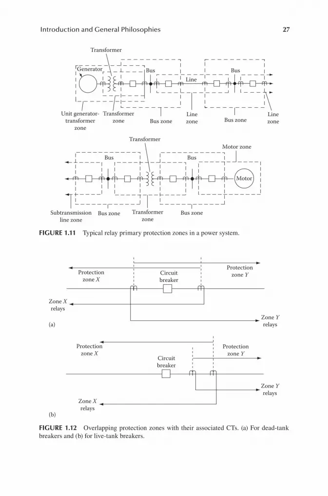
27Introduction and General Philosophies
Transformer
Generator
Transformer
Transformerzone
Unit generator-transformer
zone
Bus Bus
BusBus
Line
Linezone
LinezoneBus zone
Bus zoneBus zone
Bus zone
Motor zone
Motor
Subtransmissionline zone
Transformerzone
FIGURE 1.11 Typical relay primary protection zones in a power system.
Protectionzone X
Zone Xrelays
Zone Xrelays
Zone Yrelays
Zone Yrelays
(a)
Protectionzone X
Protectionzone Y
Protectionzone Y
Circuitbreaker
Circuitbreaker
(b)
FIGURE 1.12 Overlapping protection zones with their associated CTs. (a) For dead-tank breakers and (b) for live-tank breakers.
28 Protective Relaying: Principles and Applications
Faults between the two CTs (see Figure 1.12) result in both zone X and zone Y relays operating and both tripping the associated circuit breaker.
For case (a), this fault probably involves the circuit breaker itself and so may not be cleared until the remote breakers at either end are opened. For case (b), zone Y relays alone opening the circuit breaker would clear faults between the two CTs from the left fault source. The relays at the remote right source must also be opened for these faults. The operation of the zone X relays is not required, but it cannot be prevented.
Fortunately, the area of exposure is quite small, and the possibility of faults is low. Without this overlap, primary protection for the area between the CTs would not exist, so this overlap is standard practice in all applications.
1.11 INFORMATION FOR APPLICATION
One of the most difcult aspects of applying protection is often an accurate state-ment of the protection requirements or problem. This is valuable as an aid to a prac-tical efcient solution and is particularly important when assistance is desired from others who might be involved or might assist in the solution, such as consultants, manufacturers, and other engineers. The following checklist of required informa-tion has been developed from many years of assisting relay engineers with their protection problems. It outlines the information needed, some of which is invariably overlooked in the rst denition of the problem.
The required information should include the following:
1. Single-line diagram of the system or area involved 2. Impedance and connections of the power equipment, system frequency,
voltage, and phase sequence 3. Unless new, existing protection and problems 4. Operating procedures and practices affecting the protection 5. Importance of the protection; pilot, nonpilot, and so on 6. System fault study 7. Maximum load and system swing limits 8. CT and VT locations, connections, and ratios 9. Future expansions expected or anticipated
More detail on these follows.
1.11.1 SYSTEM CONFIGURATION
A single-line diagram for application considerations or a three-line diagram for complete connections and panel-wiring drawings documenting the area to be studied and of the surrounding system should be available. The location of the circuit breakers, CT and VT, generators, buses, and taps on lines should be shown. The transformer bank connections and system grounding are necessary when considering ground-fault protection. The grounding information is often missing on station drawings.

29Introduction and General Philosophies
1.11.2 IMPEDANCE AND CONNECTION OF THE POWER EQUIPMENT, SYSTEM FREQUENCY, SYSTEM VOLTAGE, AND SYSTEM PHASE SEQUENCE
Most of this information is usually included on the single-term diagram, but often omitted are the connections and grounding of the power transformer banks and the circuit impedance. Phase sequence is necessary when a three-line connection dia-gram is required.
1.11.3 EXISTING PROTECTION AND PROBLEMS
If installation is new, information on existing facilities is not applicable, however, facilities should be identied as new. If not new, such information about the exist-ing protection and any problems may assist updating or integration with the changes desired.
1.11.4 OPERATING PROCEDURES AND PRACTICES
Additions or changes should conform to the existing practices, procedures, and desires. When these affect the protection, they should be indicated. Often this can be accomplished by indicating that certain types of equipment or practices are unacceptable.
1.11.5 IMPORTANCE OF THE SYSTEM EQUIPMENT BEING PROTECTED
This is often apparent by the system voltage level and size. For example, high-voltage transmission lines are usually protected by high-speed pilot protection, and low-voltage systems by time–overcurrent protection. However, this should be clari-ed according to the desires of the protection engineers or the requirements of the system. In general, the more important the equipment that needs protection is to the power system and its ability to maintain service, the more important it becomes to provide full and adequate high-speed protection.
1.11.6 SYSTEM FAULT STUDY
A fault study is important for most protection applications. For phase-fault protec-tion, a three-phase fault study is required, whereas for ground-fault protection, a single-line-to-ground fault study is required. The latter should include the zero-sequence voltages and the negative-sequence currents and voltages, which can be useful if directional sensing of ground faults is involved.
On lines, information concerning a fault on the line side at an open breaker (known as a line-end fault) is frequently important. The currents recorded should be those that will ow through the relays or fuses, rather than the total fault current.
The fault study should indicate the units (in volts or amperes) at a specied volt-age base or in per unit with the base clearly specied. Experience has shown that quite often, the base of the quantities is not shown or is not clearly indicated.

30 Protective Relaying: Principles and Applications
1.11.7 MAXIMUM LOADS AND SYSTEM SWING LIMITS
The maximum load that will be permitted to pass through the equipment during short-time or emergency operation for which the protection must not operate should be specied. If known, the maximum system swing from which the power system can recover after a transient disturbance is important in some applications and should be specied.
1.11.8 CURRENT AND VOLTAGE TRANSFORMER LOCATIONS, CONNECTIONS, AND RATIOS
This information is often shown on the one-line drawing, but often the data are incomplete or are unclear. Where multiratio devices exist, the specic tap or ratio in use should be specied. The grounding of the VT or voltage devices should be clear.
1.11.9 FUTURE EXPANSION
The system growth or changes that are likely to occur within a reasonable time and are known or planned should be indicated.
Not all of the foregoing items necessarily apply to a specic problem or system requirement, but this checklist should assist in providing a better understanding of the protection problems and requirements. Usually, the fault study, together with related information, will provide information on the measurable quantities (handles) to which the protective relays can respond. When this is not apparent, the rst pri-ority for any application is to search for the handles that can be used to distinguish between tolerable and intolerable conditions.
1.12 STRUCTURAL CHANGES WITHIN THE ELECTRIC POWER INDUSTRY
The electric power industry has historically been structured with entities that are vertically integrated monopolies that are regulated by governmental agencies. These industry entities are mainly made up of investor-owned utilities and also consist of utilities that are owned by municipals or electric cooperatives. Under such structure, each utility owned all generation, transmission, and distribution facilities within its designated service territory. Each utility likewise owned the protection systems that existed within its territory, which included those at gen-erating plants, on the transmission and distribution system, down to the point of interface with customer facilities. The utility was solely responsible for the appli-cation, design, construction, settings, testing, and maintenance of all related pro-tection facilities.
In the 1990s, a movement was developed to restructure the US electric power industry to one that is more competitive in nature. Various legislations have been passed at both the federal and state levels to force such changes to be implemented.

31Introduction and General Philosophies
It was felt that competition would lead to greater efciencies within the industry and would ultimately benet consumers by providing lower-priced electric energy. This movement is still in an evolutionary state but has initiated signicant changes to the industry. Many of the laws that have been passed are state laws, so differences do exist among various areas of the country. The basic result, however, is a power system in which generation and supply are unregulated. Anyone can own generating facilities with the transmission system opened up to all qualied users. Likewise, anyone can offer to supply energy to customers. Transmission and distribution facili-ties typically remain regulated and are owned by the utility company. Propositions have been made, however, in which transmission facilities would be combined and owned by a regional transmission owner in a given area. Traditional utilities can still own generation facilities and can also offer to be a supplier. However, these func-tions must be operated as separate subsidiaries with adequate safeguards to prevent competitive advantage. The responsibility of maintaining a competitive wholesale energy market and assuring power system reliability, in many cases, has been del-egated to independent system operators.
The nal structure of the electric power industry has yet to evolve. Nevertheless, the direction has been set and participants need to adjust to function effectively within the new environment. Concern has been expressed that power system reliability may decline due to a deteriorating effect that competition may have on the cooperative atmosphere that had prevailed in the past. Credibility to this concern is supported by several severe blackouts, power shortages, and slow response to outages that have occurred in areas where competition has been implemented. Politicians need to be alert to this threat and consider any legislation necessary to assure that a level of reli-ability and customer service comparable to that which has prevailed and expected in this country is maintained.
Structural changes in the power industry do not change the technical and practi-cal aspect that relate to the application of power system protection. Such change, however, does have an impact on the manner in which the protection process is car-ried out. These changes present new challenges that require consideration be given to various protection issues:
1. The impact of economic constraints, which can develop in a competitive atmosphere, may result in pressures to decrease resources available to sup-port the protection function. Economic benet from application of protec-tion is sometimes difcult to quantify. Protection engineers need to develop skills required to economically justify proposed protection installations. Familiarity with concepts used in the power system planning process should be a priority.
2. The separation of the various entities within the structure of the power indus-try will require good documentation and a system for exchanging informa-tion in order to conduct protection studies and verify protection information.
3. With generators potentially located at a variety of locations throughout the delivery system, additional hazards to the supply system can be cre-ated. Such hazards must be identied and appropriate protection systems applied. This subject is discussed further in Chapter 8.

32 Protective Relaying: Principles and Applications
4. Application of special protection schemes may be required in order to accommodate a desired generator installation at a specic location. Such schemes are not protective schemes applied typically for fault protection but are applied to guard against undesired system operation conditions when the generator is operating. Special protection schemes are discussed in greater detail in Chapter 14.
5. Uniform protection design standards, application practices, and mainte-nance and testing requirements need to be documented and provided to all entities. An auditing and enforcement system to assure compliance to such standard is required.
1.13 RELIABILITY AND PROTECTION STANDARDS
With the signicant structural changes that have been evolving within the elec-tric power industry, it has been recognized that standards and procedures need to be developed in order to facilitate effective market operations and to ensure reli-able power system operations. Reliability standards have existed for planning and operating power systems for many years. Compliance with these standards has been open to interpretation and is voluntary in nature. With separation of owner-ship within the industry, reliance on such voluntary compliance is not considered practical to assure that reliability aspects of the power system are given the desired priority. It is also considered mandatory that technical requirements relating to the types of equipment being installed along with the manner in which it is con-nected, operated, and protected be documented so that all participants in the mar-ket are treated in a fair and similar manner. Considerable work has transpired in recent times to expand the scope and detail contained in such standards with a greater emphasis on mandatory compliance through the passing of new legislation, expanded oversight, and penalties for violations. Much of this work is being done by groups with oversight or regulatory authority over the industry. This includes reliability councils, state agencies, federal agencies, and regional transmission organizations.
In the protection area, a variety of ANSI/IEEE standards has been developed over the years and continue to be developed as conditions change. These standards cover various aspects of design requirements for protective equipment and the manner in which such equipment needs to be applied to protect specic electrical facilities. Protection requirements related to issues pertaining to power system reliability and safety applicable to power systems within specied jurisdictional areas are being developed as part of the aforementioned process being carried out within oversight and regulatory agencies. The main focus of these protection standards relate to facilities associated with bulk power systems since it is the health of the bulk power system that is critical to maintaining continual and safe operation of the nation’s power grid and in preventing large-scale disturbances and outages. Since portions of the power grid are built and owned by many separate entities, standards and related enforcement procedures are critical to the prevention of weak spots within this vast network. Standards for designs at lower-voltage levels are often developed

33Introduction and General Philosophies
by the utilities themselves in order to meet performance requirements mandated by regulatory agencies. Oversight of standards for lower-voltage-level facilities does exist in areas where multiple ownerships exist. Consequently, the major emphasis of protection standards that are currently being developed to promote reliability and a fair market pertains to protection requirements for bulk power facilities and for the intertie locations at which generation connects to the utility power system.
Generator intertie protection requirements are discussed further in Chapter 8. For bulk power facilities, the reliability standards are typically built around the important objectives of protective systems as described earlier, such as the following:
1. Preventing or minimizing equipment damage. While equipment damage can be costly to the owner, such outages also present challenges to the oper-ating reliability of the power system.
2. Minimizing the scope and area of an outage following a system fault. 3. Assuring that faults are detected and cleared in time frames such that the
power system remains stable. 4. Allowing power system facilities to be loaded to their full normal and emer-
gency ratings.
Standards have also been developed to assure that all operations of protective sys-tems on higher-voltage equipment are analyzed for correctness. All incorrect opera-tions must be reporting detailing cause and corrective actions taken.
Operation design of bulk power systems are such that, as a minimum, the system must remain operational upon the sudden, unexpected loss of any single facility on the system. System operators will alter the generation dispatch or the conguration of the system in order to remain within these operational criteria. To align with this single contingency concept, protection standards for bulk power facilities typically require that redundancy exists within the protection design. Redundancy is required to assure that the failure of any single protection component, such as an instrument transformer, relay, breaker, control circuit, or communication channel, will not result in the failure to be able to detect and isolate faults. The major objectives of the protective systems must remain intact for the failure of any device associated with a protective system. This constraint typically requires the use of two independent protection schemes for each protected facility on bulk power systems. This require-ment is discussed in subsequent chapters as protective schemes for various types of equipment are covered.
1.13.1 REGULATORY AGENCIES
The North American Electric Reliability Corporation (NERC) is a nongovern-ment organization that has statutory responsibility to regulate bulk power system users, owners, and operators through the adoption and enforcement of standards for fair, ethical, and efcient practices. As of June 18, 2007, the US Federal Energy Regulatory Commission (FERC) granted NERC the legal authority to enforce reliability standards for the bulk power systems in the United States and made

34 Protective Relaying: Principles and Applications
compliance with these standards mandatory and enforceable. NERC is a self-regulatory organization subject to oversight by FERC and governmental authori-ties in Canada.
NERC standards focus on the bulk power system since it is this system that is most signicant to the reliability of the electric grid. The current denition of the bulk electric system includes “all transmission elements operated at 100 kV or higher and real power and reactive power resources connected at 100 kV or higher. This does not include facilities used in the local distribution of electric energy.” The ele-ments included in this denition is modied by specic inclusions and exclusions provided by NERC.
Compliance to the standards is facilitated by a monitoring process by which NERC issues sanctions and ensures mitigation of conrmed violations of manda-tory reliability standards. Entities found in violation of any standard must submit a plan for mitigation of the violation for approval by NERC and, once approved, must execute the submitted plan.
NERC relies on regional entities to enforce the standards through approved del-egation agreements. The regional entities are responsible for monitoring compliance to the standards of all registered entities within their regional boundaries. A hear-ing process is available within the regions to resolve violations that are contested. Compliance with all approved standards is required by all bulk power system own-ers, operators, and users. At the present time, there are eight regional entities that cover all areas within the United States:
1. Florida Reliability Coordinating Council (FRCC) 2. Midwest Reliability Organization (MRO) 3. Northeast Power Coordinating Council (NPCC) 4. Reliability First Corporation (RFC) 5. SERC Reliability Council (SERC) 6. Southwest Power Pool (SPP) RE 7. Texas Reliability Entity (TRE) 8. Western Electricity Coordinating Council (WECC)
A number of NERC standards relate to power system protection and control. These regulations, along with their impact on protective relaying, are discussed in greater detail in Chapter 16.
BIBLIOGRAPHY
The following provides references for this chapter and general references applicable to all chapters.
The IEEE Power System Relaying Committee of the Power Engineering Society has documented a Bibliography of Relay Literature from 1927. In recent years,

35Introduction and General Philosophies
this is issued as a committee report every two years. These are in the AIEE and IEEE Transactions as follows:
Period Covered Transaction Reference
1927–1939 Vol. 60, 1941; pp. 1435–1447
1940–1943 Vol. 63, 1944; pp. 705–709
1944–1946 Vol. 67, pt. I, 1948; pp. 24–27
1947–1949 Vol. 70, pt. I, 1951; pp. 247–250
1950–1952 Vol. 74, pt. III, 1955; pp. 45–48
1953–1954 Vol. 76, pt. III, 1957; pp. 126–129
1955–1956 Vol. 78, pt. III, 1959; pp. 78–81
1957–1958 Vol. 79, pt. III, 1960; pp. 39–42
1959–1960 Vol. 81, pt. III, 1962; pp. 109–112
1961–1964 Vol. PAS-85, No. 10, 1966; pp. 1044–1053
1965–1966 Vol. PAS-88, No. 3, 1969; pp. 244–250
1967–1969 Vol. PAS-90, No. 5, 1971; pp. 1982–1988
1970–1971 Vol. PAS-92, No. 3, 1973; pp. 1132–1140
1972–1973 Vol. PAS-94, No. 6, 1975; pp. 2033–3041
1974–1975 Vol. PAS-97, No. 3, 1978; pp. 789–801
1976–1977 Vol. PAS-99, No. 1, 1980; pp. 99–107
1978–1979 Vol. PAS100, No. 5, 1981; pp. 2407–2415
1980–1981 Vol. PAS102, No. 4, 1983; pp. 1014–1024
1982–1983 Vol. PAS104, No. 5. 1985; pp. 1189–1197
1984–1985 Vol. PWRD-2, 2, 1987; pp. 349–358
1986–1987 Vol. PWRD-4, 3, 1989; pp. 1649–1658
1988–1989 Vol. PWRD-6, 4, 1991; pp. 1409–1422
1990 Vol. PWRD-7, 1, 1992; pp. 173–181
1991 Vol. PWRD-8, 3, 1993; pp. 955–961
1992 Vol. PWRD-10, 1, 1995; pp. 142–152
1993 Vol. PWRD-10, 2, 1995; pp. 684–696
1994–Paper # 95 SM 436-6
ANSI/IEEE Standard C37.010, Application Guide for AC High-Voltage Circuit Breakers Rated on a Symmetrical Current Basis, IEEE Service Center, Piscataway, NJ, 1979.
ANSI/IEEE Standard C37.2, Standard Electrical Power System Device Function Numbers, IEEE Service Center, Piscataway, NJ, 2008.
ANSI/IEEE Standard C37.90, Relays and Relay Systems Associated with Electric Power Apparatus, IEEE Service Center, Piscataway, NJ, 1989.
ANSI/IEEE Standard C37.100, Definitions for Power Switchgear, IEEE Service Center, Piscataway, NJ, 1992.
ANSI/IEEE Standard 100, IEEE Standard Dictionary of Electrical and Electronics Terms, IEEE Service Center, Piscataway, NJ, 2000.
ANSI/IEEE Standard 260, IEEE Standard Letter Symbols for Units of Measurement, IEEE Service Center, Piscataway, NJ, 1978.
ANSI/IEEE Standard 280, IEEE Standard Letter Symbols for Quantities Used in Electrical Science and Electrical Engineering, IEEE Service Center, Piscataway, NJ, 1985.

36 Protective Relaying: Principles and Applications
ANSI/IEEE Standard 945, IEEE Recommended Practice for Preferred Metric Units for Use in Electrical and Electronics Science and Technology, IEEE Service Center, Piscataway, NJ, 1984.
Beeman, D., Industrial Power Systems Handbook, McGraw-Hill, New York, 1955.Elmore, W.A. (ed.), Protective Relaying: Theory and Applications, ABB Power T&D
Company, Marcel Dekker, New York, 1994.Fink, D.G. and Beaty, H.W., Standard Handbook for Electrical Engineers, McGraw-Hill,
New York, 1968.Horowitz, S.H., Protective Relaying for Power Systems, IEEE Press, IEEE Service Center,
Piscataway, NJ, 1980.Horowitz, S.H. and Phadice, A.G., Power System Relaying, Research Studies Press, Chichester,
England, Distributed by John Wiley & Sons, 1996.IEEE Power System Relaying Committee Report, Review of recent practices and trends in
protective relaying, IEEE Trans. Power Appar. Syst., 1981, PAS 100(8), 4054–4064.IEEE Brown Book, Standard 399, Recommended Practice and Industrial and Commercial
Power System Analysis, IEEE Service Center, Piscataway, NJ, 1979.IEEE Buff Book, Standard 242, IEEE Recommended Practice for Protection and Coordination
of Industrial and Commercial Power Systems, IEEE Service Center, Piscataway, NJ, 1986.
IEEE Red Book, Standard 141, Recommended Practice for Electrical Power Distribution for Industrial Plants, IEEE Service Center, Piscataway, NJ, 1986.
Mason, C.R., The Art and Science of Protective Relaying, John Wiley & Sons, New York, 1956.
Van C. Washington, A.R., Protective Relays, Their Theory and Practice, Vol. I, John Wiley & Sons, New York, 1962, Vol. II, Chapman & Hall, London, U.K., 1974.
Washington Electric Corp., Applied Protective Relaying, Coral Springs, FL, 1982.Westinghouse Electric Corp., Electrical Transmission and Distribution Reference Book,
4th ed., East Pittsburgh, PA, 1964.Westinghouse Electric Corp., Electric Utility Engineering Reference Book, Vol. 3: Distribution
Systems, East Pittsburgh, PA, 1965.

References
1 Chapter 1: Introduction and GeneralPhilosophies
to all chapters. The IEEE Power System Relaying Committeeof the Power Engineering Society
this is issued as a committee report every two years. Theseare in the AIEE and IEEE
Transactions as follows: Period Covered TransactionReference 1927–1939 Vol. 60, 1941; pp. 1435–1447 1940–1943Vol. 63, 1944; pp. 705–709 1944–1946 Vol. 67, pt. I, 1948;pp. 24–27 1947–1949 Vol. 70, pt. I, 1951; pp. 247–2501950–1952 Vol. 74, pt. III, 1955; pp. 45–48 1953–1954 Vol.76, pt. III, 1957; pp. 126–129 1955–1956 Vol. 78, pt. III,1959; pp. 78–81 1957–1958 Vol. 79, pt. III, 1960; pp. 39–421959–1960 Vol. 81, pt. III, 1962; pp. 109–112 1961–1964Vol. PAS-85, No. 10, 1966; pp. 1044–1053 1965–1966 Vol.PAS-88, No. 3, 1969; pp. 244–250 1967–1969 Vol. PAS-90, No.5, 1971; pp. 1982–1988 1970–1971 Vol. PAS-92, No. 3, 1973;pp. 1132–1140 1972–1973 Vol. PAS-94, No. 6, 1975; pp.2033–3041 1974–1975 Vol. PAS-97, No. 3, 1978; pp. 789–8011976–1977 Vol. PAS-99, No. 1, 1980; pp. 99–107 1978–1979Vol. PAS100, No. 5, 1981; pp. 2407–2415 1980–1981 Vol.PAS102, No. 4, 1983; pp. 1014–1024 1982–1983 Vol. PAS104,No. 5. 1985; pp. 1189–1197 1984–1985 Vol. PWRD-2, 2, 1987;pp. 349–358 1986–1987 Vol. PWRD-4, 3, 1989; pp. 1649–16581988–1989 Vol. PWRD-6, 4, 1991; pp. 1409–1422 1990 Vol.PWRD-7, 1, 1992; pp. 173–181 1991 Vol. PWRD-8, 3, 1993; pp.955–961 1992 Vol. PWRD-10, 1, 1995; pp. 142–152 1993 Vol.PWRD-10, 2, 1995; pp. 684–696 1994–Paper # 95 SM 436-6
ANSI/IEEE Standard C37.010, Application Guide for ACHigh-Voltage Circuit Breakers Rated on a SymmetricalCurrent Basis, IEEE Service Center, Piscataway, NJ, 1979.
ANSI/IEEE Standard C37.2, Standard Electrical Power SystemDevice Function Numbers, IEEE Service Center, Piscataway,NJ, 2008.
ANSI/IEEE Standard C37.90, Relays and Relay SystemsAssociated with Electric Power Apparatus, IEEE ServiceCenter, Piscataway, NJ, 1989.
ANSI/IEEE Standard C37.100, Definitions for PowerSwitchgear, IEEE Service Center, Piscataway, NJ, 1992.
ANSI/IEEE Standard 100, IEEE Standard Dictionary of

Electrical and Electronics Terms, IEEE Service Center,Piscataway, NJ, 2000.
ANSI/IEEE Standard 260, IEEE Standard Letter Symbols forUnits of Measurement, IEEE Service Center, Piscataway, NJ,1978.
ANSI/IEEE Standard 280, IEEE Standard Letter Symbols forQuantities Used in Electrical Science and ElectricalEngineering, IEEE Service Center, Piscataway, NJ, 1985.
ANSI/IEEE Standard 945, IEEE Recommended Practice forPreferred Metric Units for Use in Electrical andElectronics Science and Technology, IEEE Service Center,Piscataway, NJ, 1984.
Beeman, D., Industrial Power Systems Handbook, McGraw-Hill,New York, 1955.
Elmore, W.A. (ed.), Protective Relaying: Theory andApplications, ABB Power T&D Company, Marcel Dekker, NewYork, 1994.
Fink, D.G. and Beaty, H.W., Standard Handbook forElectrical Engineers, McGraw-Hill, New York, 1968.
Horowitz, S.H., Protective Relaying for Power Systems, IEEEPress, IEEE Service Center, Piscataway, NJ, 1980.
Horowitz, S.H. and Phadice, A.G., Power System Relaying,Research Studies Press, Chichester, England, Distributedby John Wiley & Sons, 1996.
IEEE Power System Relaying Committee Report, Review ofrecent practices and trends in protective relaying, IEEETrans. Power Appar. Syst., 1981, PAS 100(8), 4054–4064.
IEEE Brown Book, Standard 399, Recommended Practice andIndustrial and Commercial Power System Analysis, IEEEService Center, Piscataway, NJ, 1979.
IEEE Buff Book, Standard 242, IEEE Recommended Practice forProtection and Coordination of Industrial and CommercialPower Systems, IEEE Service Center, Piscataway, NJ, 1986.
IEEE Red Book, Standard 141, Recommended Practice forElectrical Power Distribution for Industrial Plants, IEEEService Center, Piscataway, NJ, 1986.
Mason, C.R., The Art and Science of Protective Relaying,

John Wiley & Sons, New York, 1956.
Van C. Washington, A.R., Protective Relays, Their Theoryand Practice, Vol. I, John Wiley & Sons, New York, 1962,Vol. II, Chapman & Hall, London, U.K., 1974.
Washington Electric Corp., Applied Protective Relaying,Coral Springs, FL, 1982.
Westinghouse Electric Corp., Electrical Transmission andDistribution Reference Book, 4th ed., East Pittsburgh, PA,1964.
Westinghouse Electric Corp., Electric Utility EngineeringReference Book, Vol. 3: Distribution Systems, EastPittsburgh, PA, 1965.

2 Chapter 2: Fundamental Units: Per-Unitand Percent Values
Fitzgerald, A.E., Kingsley, C., and Umans, S.D., ElectricMachinery, McGraw-Hill, New York, 1983.
Grainger, J.J. and Stevenson, W.D., Power System Analysis,McGraw-Hill, New York, 1994.
Seidman, A.H., Mahrous, H., and Hicks, T.G., Handbook ofElectric Power Calculations, McGraw-Hill, New York, 1983.
Weedy, B.M., Electric Power Systems, 3rd ed., John Wiley &Sons, New York, 1979.

4 Chapter 4: Symmetrical Components: AReview
Anderson, P.M., Analysis of Faulted Power Systems, IowaState University Press, Ames, IA, 1973.
ANSI/IEEE Standard C37.5, Guide for Calculation of FaultCurrents for Application of AC High Voltage CircuitBreakers Rated on a Total Current Basis, IEEE ServiceCenter, Piscataway, NJ, 1979.
Blackburn, J.L., Symmetrical Components for Power SystemsEngineering, Marcel Dekker, New York, 1993.
Calabrese, G.O., Symmetrical Components Applied to ElectricPower Networks, Ronald Press, New York, 1959.
Clarke, E., Circuit Analysis of AC Power Systems, Vols. 1and 2, and General Electric, Schenectady, NY, 1943, 1950.
Harder, E.L., Sequence network connections for unbalancedload and fault conditions, Electr. J. Dec. 34, 1937,481–488.
Standard 141-1993, IEEE Recommended Practice for ElectricPower Distribution for Industrial Plants, IEEE ServiceCenter, Piscataway, NJ, 1993.
Wagner, C.F. and Evans, R.D., Symmetrical Components,McGraw-Hill, New York, 1933, (available in reprint fromR.E. Krieger Publishing, Melbourne, FL, 1982).
APPENDIX 4.1 SHORT-CIRCUIT MVA AND EQUIVALENT IMPEDANCE
Quite often short-circuit MVA data are supplied forthree-phase and single-phase
to-ground faults at various buses or interconnection pointsin a power system. The
derivation for this and conversion into system impedancesare as follows:
A.4.1-1 THREE-PHASE FAULTS φ= = φ3 I MVA 3fault-short-circuit MVA 3 kV 1000 SC (A4.1-1)
where I 3ϕ is the total three-phase fault current inamperes and kV is the system line
to-line voltage in kilovolts. From this, = φ I 1000 MVA 3

kV 3 SC (A4.1-2) = = = φ φ Ω Z V I I 1000 kV 3 kV MVA LN 33 2 SC (A4.1-3)
Substituting Equation 2.15, which is = Ω Z MVA Z KV pu B B2 (2.15)
the positive-sequence impedance to the fault location is =ZMVA MVA pu 1 base SC (A4.1-4)
Z 1 = Z 2 for all practical cases. Z 1 can be assumed tobe X 1 unless X/R data are pro
vided to determine an angle.
A.4.1-2 SINGLE-PHASE-TO-GROUND FAULTS φ= = 1000 φ φ I MVA Gfault short-circuit MVA 3 kV GSC G (A4.1-5)
where I ϕG is the total single-line-to-ground faultcurrent in amperes and kV is the
system line-to-line voltage in kilovolts: = φ φ I 1000 MVA3 kV G GSC (A4.1-6)
However, = + + = = φ I I I I V Z Z Z V Z 3 + + 3 G 1 2 0LN 1 2 0 LN g (A4.1-7)
where Z g = Z 1 + Z 2 + Z 0 . From Equations A4.1-3 andA4.1-7, = Ω φ 2 Z 3 kV MVA (in ) g GSC (A4.1-8) = φ Z 3 MVAMVA pu g base GSC (A4.1-9)
Therefore, Z 0 = Z g − Z 1 − Z 2 , or in most practicalcases, X 0 = X g − X 1 − X 2 because the
resistance is usually small in relation to the reactance.
Example
A short-circuit study indicates that at bus X in the 69 kVsystem, =MVA 594 MVA SC = φ MVA 631 MVA GSC
on a 100 MVA base.
Thus, the total reactance to the fault is = = =X X 100 5940.1684 pu 1 2 = =X 300 631 0.4754 pu g
X 0 = 0.4754 − 0.1684 − 0.1684 = 0.1386 pu, all values ona 100 MVA 69 kV base.
APPENDIX 4.2 IMPEDANCE AND SEQUENCE CONNECTIONS FORTRANSFORMER BANKS

A.4.2-1 TWO-WINDING TRANSFORMER BANKS
Typical banks are shown in Figure A4.2-1. H is thehigh-voltage winding and L the
low-voltage winding. These designations can be interchangedas required. Z T is the
transformer leakage impedance between the two windings. Itis normally designated
in per unit or percent by the manufacturer and stamped onthe transformer name
plate. Unless otherwise specied, this value is on theself-cooled kVA or MVA rating
at the rated voltages.
It can be measured by shorting one winding and applyingvoltage to the other wind
ing. This voltage should not cause the transformer tosaturate. From Figure A4.2-2, = = + + Z V I Z Z Z Z Z T H Le L e (A4.2-1)
Because unsaturated Z e is very large compared to Z L ,the term Z L Z e /Z L + Z e approaches
and is approximately equal to Z L , so that for practicalpurposes, = = +Z V I Z Z T H L (A4.2-2)
Z T is measured in practice by circulating rated current(I R ), through one winding
with the other shorted and measuring the voltage (V W )required to circulate this rated
current. Then, = ΩZ V I T W R (A4.2-3)
This test can be done for either winding or as convenient.On the measured side, the
base impedance will be = ΩZ V I B R R (A4.2-4)
where V R and I R are the rated voltage and current,respectively.
Then, the per-unit impedance from Equation 2.1 is = Ω Ω =

=Z Z Z V I I V V V ( ) ( ) pu T T B W R R R W R (A4.2-5)
For three-phase-type transformer units, the nameplateshould specify this Z T , usually
in percent, on the three-phase kVA (MVA) rating, and the kVline-to-line voltages. Transformer Bank Connection a b Z NZ NH Z NL c d e f g h H N 1 or N 2 No No No No No No No NoZ T Z T Z T Z T Z T Z T Z T Z T Z T 3Z N 3Z NH 3Z NL Z T ZT Z T Z T Z T Z T Z T N 1 or N 2 N 1 or N 2 N 1 or N 2 N1 or N 2 N 1 or N 2 N 1 or N 2 N 1 or N 2 H H H H L L LL L H L H H L L H L H L H L H L H L H L H L H L H L H L H HH H H L L L L Open Open Open Open Open Open L H L Positiveand Negative Sequence Connections Zero Sequence Connection
FIGURE A4.2-1 Sequence connections for typical two-windingtransformer banks.
When several kVA (MVA) ratings are specied, the normalrating, without fans,
pumps, and such (lowest) rating, should be used as one ofthe impedance bases.
For individual single-phase transformers, the transformerimpedance is normally
specied on a single-phase kVA (MVA) and the rated windingvoltages (kV) of the
transformer. When three such units are used in three-phasesystems, then the three
phase kVA (MVA) and line-to-line voltage (kV) bases arerequired, as outlined in
Chapter 2.
Thus, when three individual single-phase transformers areconnected in the
power system, the individual nameplate percent or per-unitimpedance will be the Z T
leakage impedance, but only on the three-phase kVA (MVA)base, and the system
line-to-line kV.
Example

Impedance of single-phase transformers in three-phase powersystems
Consider single-phase transformers, each with a nameplaterating of 20 MVA,
66.5 kV: 13.8 kV, X = 10%. Considering the individualtransformer alone, its leakage
reactance is = = X X 0.10 pu on 20 MVA, 66.5 kV or 0.10 puon 20 MVA, 13.8 kV T T (A4.2-6)
Converting these to actual ohms using Equation A4.2-5, V WH= 0.10 V RH = 0.10 ×
66,500 = 6,650 V on the high side, where I RH =20,000/66.5 = 300.75 A primary.
Then, we obtain from Equation A4.2-3 the following: = = ΩX6650 300.75 22.11 primary TH (A4.2-7)
or on the secondary side, V WL = 0.10 × 13,800 = 1,380 V,and I RL = 20,000/13.8 =
1449.28 A secondary: = = ΩX 1380 1449.28 0.952 secondaryTL (A4.2-8) Z H V I Z e Z L
FIGURE A4.2-2 Simplied equivalent diagram for atransformer: Z H and Z L are the compo
nents of the transformer leakage impedance and Z e is theexciting impedance. All values are
in per unit or primary H side ohms.
Check: × = Ω 66.5 13.8 0.952 22.11 primary 2
Now consider two possible applications of three of theseindividual transformers to a
power system. These are intended to demonstrate thefundamentals; do not consider
if the transformer windings are compatible or suitable forthe system voltages shown.
Case 1
Connect the high-voltage windings in wye to a 115 kV system

and the low-voltage
windings in delta to a 13.8 kV system. As indicatedpreviously, the leakage imped
ance of this transformer bank for this application is X X= 0.10 pu on 60 MVA, 115 kV = 0.10 pu on 60 MVA, 13.8 kV TT (A4.2-9)
Now to check this. From Equation 2.17, = × = Ω = × = Ω X X115 0.10 60 22.04 primary 13.8 0.10 60 0.317 secondary TH2 TL 2 (A4.2-10)
It will be noted that the individual transformer reactanceper Equation A4.2-8 is
0.952 Ω, but this is the reactance across the 13.8 kVbecause of the delta connection.
The equivalent wye impedance can be determined by theproduct of the two-delta
branches on either side of the desired wye branch dividedby the sum of the three
delta branches. Thus, the wye equivalent is = = Ω(0.952)0.952 (3)0.952 0.952 3 0.317 as before
Check: × = Ω 115 13.8 0.317 22.01 primary 2
Case 2
Connect the high-voltage windings in delta to a 66.5 kVsystem and the low-voltage
side in wye to a 24 kV system. Now the transformer bankimpedance for this system
application is = = X X 0.10 pu on 60 MVA, 66.5 kV or 0.10pu on 60 MVA, 24 kV T T (A4.2-11)
Now to check this by converting to ohms, using Equation2.17, × ΩX = 66.5 0.10 60 = 7.37 primary TH 2 (A4.2-12)
Now this primary winding of 22.11 Ω (Equation A4.2-7) isconnected across the 66.5 kV sys
tem because of the delta. Accordingly, the equivalent wyereactance is 22.11/3 = 7.37 Ω

line-to-neutral on the primary side.
On the secondary side, X TL = 24 2 × 0.10/60 = 0.96 Ω issecondary as Equation
A4.2-8.
Check: × = Ω 66.5 24 0.96 7.37 primary 2
The connections of two-winding transformers in the sequencenetworks are doc
umented in Figure A4.2-1. Note that the connections forpositive and negative
sequences are all the same and are independent of the bankconnections. This is not
true for the zero sequence with different connections foreach type of bank.
Neutral impedance is shown for several connections. If theblanks are solid
grounded, the neutral impedance is zero, and the valuesshown are shorted out in the
system and are zero-sequence diagrams.
A.4.2-2 THREE-WINDING AND AUTOTRANSFORMER BANKS
Typical banks are shown in Figure A4.2-3. H, M, and L arethe high-, medium-,
and low-voltage windings. These designations can beinterchanged as required.
Normally, the manufacturer provides the leakage impedancesbetween the wind
ings as Z HM , Z HL , and Z ML , usually on different kVAor MVA ratings and at the rated
winding voltages.
To use these impedances in the sequence networks, they mustbe converted to an
equivalent wye-type network, as shown. This conversion is =+ −Z Z Z Z 1 2 ( ) H HM HL ML (A4.2-13) = + −Z Z Z Z 1 2 (

) M HM ML HL (A4.2-14) = + −Z Z Z Z 1 2 ( ) L HL ML HM(A4.2-15)
It is easy to remember this conversion, for the equivalentwye value is always half
the sum of the leakage impedances involved, minus the onethat is not involved.
For example, Z H is half of Z HM and Z HL , bothinvolving H, minus Z ML that does not
involve H. Transformer Bank Connection Positive andNegative Sequence Connection Zero Sequence Connection a b cd H H H H H H H H H H H H M M M M M Open Open Open If solidgrounded If solid grounded Z N = 0 Z NH and/or Z NM = 0If solid grounded Z N = 0 M M M M M M M Z N Z H Z H Z H ZH Z H 3Z N 3Z N 3Z NM 3Z NM Z H Z H Z H Z M Z M Z M Z M Z MZ M Z M Z M Z L Z L Z L Z L Z L Z L Z L Z L N 1 N 0 N 0 N 0N 0 N 2 Z N Z NM Z NH L L L L L L L L L L L L or N 1 N 2 orN 1 N 2 or N 1 N 2 or
FIGURE A4.2-3 Sequence connections for typicalthree-winding and autotransformer banks.
After determining Z H , Z M , and Z L , a good check is tosee if they add up as Z H +
Z M = Z HM , … . If these values are not available, theycan be measured as described
for a two-winding transformer. For the three-winding orautotransformers, Z HM is the
impedance looking into H winding with M shorted, L open; ZHL is the impedance
looking into H winding, with L shorted, M open; Z ML isthe impedance looking into
M winding, with L shorted, H open.
This equivalent wye is a mathematical networkrepresentation valid for determin
ing currents and voltages at the transformer terminals orin the associated system.
The wye point has no physical meaning. Quite often, one ofthe values will be nega

tive and should be used as such in the network. It does notrepresent a capacitor.
The positive- and negative-sequence connections are all thesame and indepen
dent of the actual bank connections. However, theconnections for the zero-sequence
network are all different and depend on the transformerbank connections. If the
neutrals are solidly grounded, then the Z N and 3Z Ncomponents shown are shorted
out in the system and sequence circuits.
APPENDIX 4.3 SEQUENCE PHASE SHIFTS THROUGH WYE–DELTATRANSFORMER BANKS
As has been indicated, positive and negative sequences passthrough the transformer
bank, and in the sequence networks, the impedance is thesame, independent of the
bank connection. This is shown in Figures A4.2-1 andA4.2-3. In these networks, the
phase shift is ignored, but if currents and voltages aretransferred from one side of
the transformer bank to the other, these phase shifts mustbe taken into account. This
appendix will document these relations. For this thestandard ANSI connections are
shown in Figure A4.3-1.
From Figure A4.3-1a, all quantities are phase-to-neutralvalues and in amperes or
volts; for per unit, N = 1, =n 1/ 3: = − = −I n I I V n VV( ) and ( ) a c aA A B High side Low side Low sideHighside I a I b I c
a A A A Turns ratio n:1 Voltage ratio N:1 Turns ratio n:1Voltage ratio N:1 A a a a B B B B b b b c c c C C C C n n

nI a n n n I A I A I A I B I C I a I B I B I C I C I c I bnI b nI c 1 1
b
c n kV a kV A 3 N = = = kV a kV A N 3n n = kV a kV A 3 N= = kV a kV A N 3 n
(a) (b)
FIGURE A4.3-1 ANSI-connected wye–delta transformer banks:the high-voltage side
phase a leads the low-voltage side phase a for bothconnections illustrated: (a) wye (star) on
high side and (b) delta on high side.
For positive sequence (see Equation 4.2), = − = − = ∠ − ° =∠ − ° I n I aI n a I nI NI ( ) (1 ) 3 30 30 a a a a a A1 11 1 1 1 (A4.3-1) = − = − = ∠ + ° = ∠ + ° V n V a V n a V nVNV ( ) (1 ) 3 30 30 a1 A1 2 A1 2 A1 A1 A1 (A4.3-2)
For negative sequence (see Equation 4.3), = − = − = ∠ + ° =∠ + ° I n I a I n a I nI NI ( ) (1 ) 3 30 30 a a a a a A2 12 1 2 2 2 2 (A4.3-3) = − = −V n V aV n a V( ) (1 ) a2 A2 A2A2 (A4.3-4) = ∠ − ° = ∠ − ° 2 2 nV NV3 30 30 A A (A4.3-5)
Now consider the connections in Figure A4.3-1b. Again allvalues are in phase-to
neutral amperes or volts; for per unit, N = 1, =n 3 : = − =−I n I I V n V V 1 ( ) and 1 ( ) a A B A a c
For positive sequence (see Equation 4.2), = − = − = ∠ + ° =∠ + ° I n I a I n a I n I N I 1 ( ) 1 (1 ) 3 30 1 30 a A AA A A 1 1 2 1 2 1 1 1 (A4.3-6) = − = − = ∠ − ° = ∠ − ° V nV aV n a V n V N V 1 ( ) 1 (1 ) 3 30 1 30 A a a a a a 1 1 11 1 1 (A4.3-7)
For negative sequence (see Equation 4.3), = − = − = ∠ − ° =∠ − ° I n I aI n a I n I N I 1 ( ) 1 (1 ) 3 30 1 30 a A A AA A 2 2 2 2 2 2 (A4.3-8) = − = − = ∠ + ° = ∠ + ° V n V a Vn a V n V N V 1 ( ) 1 (1 ) 3 30 1 30 A a a a a a 2 2 2 2 22 2 2 (A4.3-9)
A.4.3-1 SUMMARY
An examination of the foregoing equations shows that forANSI standard connected

wye–delta transformer banks, (1) if both thepositive-sequence current and voltage
on one side lead the positive-sequence current and voltageon the other side by 30°,
the negative-sequence current and voltage correspondinglywill both lag by 30°; and
(2) similarly, if the positive-sequence quantities lag inpassing through the bank,
the negative-sequence quantities correspondingly will lead30°. This fundamental is
useful in transferring currents and voltages through thesebanks.
Zero sequence is not phase-shifted if it can pass throughand ow in the trans
former bank. The zero-sequence circuits for varioustransformer banks are shown in
Figures A4.2-1 and A4.2-3.
APPENDIX 4.4 IMPEDANCE OF OVERHEAD LINES
A large portion of power transmission and delivery systemsare made up of overhead
lines. The impedances of such lines have a signicantinuence on the magnitude
and distribution of currents that ow throughout the systemduring short-circuit con
ditions. Many relay settings relate directly to theseshort-circuit currents as well as
to the impedance values of the lines themselves.
It is not critical that protection engineers be capable ofderiving and utilizing the
related formulations to calculate the impedance of overheadlines. This process can be
rather complex and tedious. Computer programs have been

developed and are avail
able for performing this task. Protection engineers,however, should have an under
standing of the degree that factors inuence the impedancevalues such that, as factors
change, sound judgments regarding the need for relaysetting review can be made. As
such, it is not the intent of this appendix to explain andderive the various formulas
and methodologies used for calculating the impedance ofoverhead lines, but rather
to illustrate the factors that inuence the impedancevalues along with the relative
magnitude of inuence.
The impedance of overhead lines is made up of resistance,inductive reactance,
and capacitive reactance. For the purpose of short-circuitcalculations, line capaci
tance is typically neglected since its inuence on faultcurrent values are insignicant.
Common practice is to model a line in short-circuit studieswith a series-connected
resistance and inductive reactance value. It should benoted that the capacitive reac
tance value of lines can have signicant impact on systemvoltages and current ows
under normal system operating conditions and, as such, isrepresented in models for
other types of studies such as load ow analysis.
A.4.4-1 RESISTANCE OF OVERHEAD LINES
The resistance of overhead lines is dependent upon thematerial of which the con

ductor is made and its cross-sectional area. Skin effectdoes inuence the resis
tance of a conductor—inductive inuences between currentlaments within a
conductor cause current to be forced toward the outermostportion of the conduc
tor effectively reducing its cross-sectional area and thusincreasing its resistance.
Skin effect is frequency dependent becoming more pronouncedas frequency
increases. A similar factor called the proximity effect iscaused by the change
in current distribution within a conductor caused by theinductive inuence of
current in a nearby conductor. For overhead lines, attypical operating frequen
cies, changes to resistance values caused by skin effectare such that they need to
be included in the resistance determination. Conductorspacing is typically large
enough such that the proximity effect can be ignored exceptin the case of cable
circuits.
The temperature of the conductor will also cause itsresistance to change. The
conductor temperature will vary depending on the ambientair temperature, wind
speed, load the conductor is carrying, and the type ofinsulation being utilized.
As load current in a conductor increases, the conductortemperature will increase.
Resistance is temperature dependent and increases astemperature increases.

Resistance values for all types of conductors used foroverhead lines are readily
available in tables provided by the conductor manufacturer.The published resistance
values will include the impact of skin effect. Resistancevalues are published for dif
ferent temperatures and frequencies.
The following data illustrate the relative inuence offrequency and temperature
on conductor resistance:
1. 1000 MCM, 37 strand, copper conductor:
a. At 77°F –
i. D-C Resistance = 0.0585 Ω/mile
ii. At 25 Hz, resistance = 0.0594 Ω/mile
iii. At 50 Hz, resistance = 0.0620 Ω/mile
iv. At 60 Hz, resistance = 0.0634 Ω/mile
b. At 122°F –
i. D-C Resistance = 0.0640 Ω/mile
ii. At 25 Hz, resistance = 0.0648 Ω/mile
iii. At 50 Hz, resistance = 0.0672 Ω/mile
iv. At 60 Hz, resistance = 0.0685 Ω/mile
2. 500 MCM, 37 strand copper conductor:
a. At 77°F –
i. D-C Resistance = 0.1170 Ω/mile
ii. At 25 Hz, resistance = 0.1175 Ω/mile
iii. At 50 Hz, resistance = 0.1188 Ω/mile
iv. At 60 Hz, resistance = 0.1196 Ω/mile

b. At 122°F –
i. D-C Resistance = 0.1280 Ω/mile
ii. At 25 Hz, resistance = 0.1283 Ω/mile
iii. At 50 Hz, resistance = 0.1296 Ω/mile
iv. At 60 Hz, resistance = 0.1303 Ω/mile
3. 4/0, 19 strand, copper conductor:
a. At 77°F –
i. D-C Resistance = 0.276 Ω/mile
ii. At 25 Hz, resistance = 0.277 Ω/mile
iii. At 50 Hz, resistance = 0.277 Ω/mile
iv. At 60 Hz, resistance = 0.278 Ω/mile
b. At 122°F –
i. D-C Resistance = 0.302 Ω/mile
ii. At 25 Hz, resistance = 0.303 Ω/mile
iii. At 50 Hz, resistance = 0.303 Ω/mile
iv. At 60 Hz, resistance = 0.303 Ω/mile
As illustrated in the previous data, as the size of theconductor becomes smaller, the
impact of skin effect on the conductor resistancedecreases. The conductor resistance
increases about 9.6% for a temperature change from 77°F to122°F. The illustrated val
ues and percent changes will differ somewhat for conductorsmade of different material.
A.4.4-2 INDUCTIVE REACTANCE OF A SINGLE CONDUCTOR OVER EARTH
The inductive reactance of overhead lines is highlyinuenced by the characteristics
of the conductor and the spacing of the conductors. The

basic formula for a single
conductor over lossless earth is as follows: µ pi =L h r2ln 2 H/m aa (A4.4-1)
where
L aa is the self-inductance of conductor
μ is the permeability of medium pi= − 4 (10 ) 7 for air
h is the height of conductor above earth
r is the radius of conductor
(Note that h and r must be in the same terms.)
The previous formula only considers ux exterior to theconductor. An additional
term that is equal to µ pi=L 8 must be added to accountfor ux internal to the
conductor. For convenience, the actual physical radius ofthe conductor is modied
such that it will account for the internal ux and be ableto be used directly in the
L aa formula. This equivalent radius is referred to as theconductor geometric mean
radius (GMR) and is published for all types of conductors.
With X L = ωL, the basis inductance formula for a singleconductor over earth can
be modied to obtain inductive reactance in terms ofΩ/mile: = ΩX h r 0.1213 ln 2 /mile at 60 Hz Laae (A4.4-2) =r GMR e
(For solid conductor r e = 0.779 [radius].)
A.4.4-3 MUTUAL INDUCTIVE REACTANCE OF TWO CONDUCTORS OVEREARTH
The mutual inductance of two conductors (conductor a andconductor b) over lossless
earth L( ) ab is given by the following: µ pi = ′′ L D D2

ln H/m ab ab ab (A4.4-3)
The inductive reactance of two conductors over losslessearth X( ) Lab in ohms per
mile at 60 cycles/s is given by = Ω ′ X D D0.1213 ln /mile at 60 Hz Lab ab ab (A4.4-4)
where
D ab is the distance between conductors a and b in feet
D ab ′ is the distance between conductor a and the imageconductor of b
(With earth considered lossless, a conductor’s image islocated in the earth a distance
equal to 2 × (conductor height) from the conductor andvertically below the conductor.
See Figure A4.4-1.) a D ab b h D ab΄ 2h
FIGURE A4.4-1 Illustration of dimensions for two conductorsat equal heights over loss
less earth.
As an example, consider two conductors over lossless earth:
Height above earth (h) = 30 ft (height of each conductor)
Distance between conductors (D ab ) = 30 ft
GMR or R e = 1.0 in.
Frequency = 60 Hz
Calculate X Laa and X Lab in ohms per mile: = = = = Ω X h 0.1213 ln 2 GMR 0.1213 ln 2(30) 112 0.1213 (ln 720) 0.798 mile Laa = + = ′ D 30 60 67.08 ftab 2 2 = = = Ω X 0.1213 ln 67.08 30 0.1213 (ln2.236) 0.0976 mile Lab
In examining the expression for X Laa , it is possible toattribute a portion of the reac
tance to the characteristics of the conductor (GMR) and aportion to spacing (height).

Since = +x y x yln( / ) ln ln(1/ ) , = = +X h h0.1213 ln 2 GMR 0.1213 ln 1 GMR 0.1213 (ln 2 )Laa (A4.4-5)
The rst portion of the previous expression is attributableonly to GMR (conductor)
and the second portion is attributable only to the spacelocation of the conductor
above ground (height).
For example, for the conductor located 30 ft above groundwith a GMR = 1.0 in., = + = + = + = X 0.1213 ln1 1 12 0.1213 (ln 60) 0.1213 (2.48) 0.1213 (4.09) 0.3010.496 0.797 Laa
With total X Laa = 0.797 Ω/mile, 0.301 Ω/mile isattributable to GMR (conductor char
acteristics) and 0.496 Ω/mile is attributable to height(spacing).
Consider next that the previous two conductors areconnected to a single-phase,
60-Hz source at one end and connected together at the otherend to form a single
phase circuit. The inductive reactance of conductor a isequal to X Laa − X Lab . The
minus sign appears in this equation because in asingle-phase circuit currents in each
conductor ow in opposite directions—the induced voltage ineach conductor due
to the mutual impedance will have a polarity such that itwill increase current ow
in each conductor and thus reduce conductor inductivereactance. It should be noted
that X Lab = X Lba since the mutual parameters are thesame. The impedance of either
conductor in the single-phase circuit (assuming eachconductor is the same size) will

therefore be equal to = −X X X L L Lcond self mutual(A4.4-6)
Inserting appropriate equations for the self and mutualinductive reactances, = − ′ X h D D0.1213 ln 2 GMR 0.1213 ln L ab ab cond (A4.4-7) = − ′ X h D D 0.1213 ln 2 GMR ln L ab ab cond (A4.4-8) = ++ ′ X D h D 0.1213 ln 1 GMR ln ln 2 L ab abcond (A4.4-9)
Note that in the third term of the previous equation, 2hand D ab ′ will be generally
close in magnitude and, as such, ′ h D2 ab will be anumber close to 1.0. ′ h Dln(2 ) ab
will be a relatively small number—height above ground playsa minimal role in the
conductor’s inductive reactance. The rst term, ln(1 GMR), is the inductive reactance
due to the conductor characteristics out to 1 ft spacing.This term can be referred to
as X a . The second term, ln D ab , represents theinductive reactance that results due to
the spacing from 1 ft out to the other conductor. This termcan be referred to as X d .
These concepts will be further analyzed later in thisappendix when the impedance
of three-phase circuits is discussed.
A.4.4-4 IMPEDANCE OF THREE-PHASE OVERHEAD LINES
A.4.4-4.1 Three-Phase Overhead Line: No Ground Wires(Lossless Earth)
Previous analysis of the impedance of conductors over alossless earth can be
extended to the analysis of three-phase circuits. Theimpedance of a three-phase
circuit without ground wires over a lossless earth can bebest expressed as a phase

impedance matrix Z[ ] P of the following form: Ω Z Z Z Z Z Z Z Z Z /mile aa ab ac ba bb bc ca cbcc
where (with all conductors being of the same size) = = =R RR resistance of conductor in ohms/mile aa bb cc = = = = ==R R R R R R 0 (for a lossless earth) ab ac ba bc ca cb
And from Equations A4.4-2 and A4.4-4, = ΩX h r0.1213 ln 2 /mile Laa a e = = Ω ′ X X D D0.1213 ln /mile Lab Lba ab ab = = Ω ′ X X D D0.1213 ln /mile Lac Lca ac ac = = Ω ′ X X D D0.1213 ln /mile Lbc Lcb bc bc
For example, consider a three-phase overhead line overlossless earth with each con
ductor = ′′ R( 1.0 ) e located 30 ft above ground andspaced 20 ft apart as shown in
Figure A4.4-2:
2h = 60 ft (for all conductors) = = ′ D D 20 ab bc = ′ D 40ac = = = = + = ′ ′ ′ ′ ′ D D D D 60 20 63.24 ab ba bc cb 22 = = + = ′ ′ ′ D D 60 40 72.11 ac ca 2 2 = = = = ΩX X X 0.1213 ln 60 1 12 0.80 /mile Laa Lbb Lcc = = = = = = Ω ′ X X X X D D 0.1213 ln 0.1213ln 63.24 20 0.14 /mile ab ba bc cb ab ab = = = = Ω ′ X X D D 0.1213 ln 0.1213 ln 72.11 400.071 /mile ac ca ac ac
Neglecting resistance, the resultant matrix for the linewould appear as follows: = Z[ ] 0.800.14 0.071 0.14 0.80 0.14 0.071 0.14 0.80 P
Of signicance to note is that the impedance of athree-phase overhead line is best
represented by an associated impedance matrix. The previousillustration neglects
resistance and does not include the impact of ground wiresor resistivity of the earth.
With the presence of ground wires and earth resistance, theprevious impedance
matrix needs to be modied by developing an appropriatecorrection matrix and

earth correction factors. The impact of ground wires andresistivity of the earth on
the impedance of overhead lines will be discussed later inthis appendix.
While the impedance matrix for a three-phase overhead lineas previously illus
trated is useful, sequence impedances are the values usedin short-circuit studies and D ac h 2h D ac΄ D ab D ab ΄ Dbc
FIGURE A4.4-2 Illustration of dimensions for threeconductors at equal heights over
lossless earth.
are of interest to protection personnel. It can be shownthat the phase impedance
matrix, Z[ ], P can be converted to a sequence impedancematrix, Z[ ], S by utilizing the
following transformation formula: = − Z a Z a[ ] [ ] [ ][], S 1 P (A4.4-10)
where = Z Z Z Z Z Z Z Z Z Z [ ] aa abac ba bb bc ca cb cc P = a a a a a [ ]1 1 1 1 1 2 2 = − a a a a a [ ] 1 1 1 11 1 2 2 ε= ∠ = ° a 1 120 j120 = Z Z Z ZZ Z Z Z Z Z [ ] S 00 01 02 10 11 12 20 21 22
The diagonal values of the sequence impedance matrixrepresent the zero-sequence
self-impedance Z( ), 00 the positive-sequenceself-impedance Z( ) 11 , and the negative
sequence self-impedance Z( ) 22 of the overhead line. Theoff-diagonal values repre
sent the mutual impedances between the sequences.
Using Equation A4.4-10 (recognizing that = = =Z Z Z Z ZZand and ab ba ac ca bc cb )
and solving for the elements of the sequence impedancematrix result in the following: = = + + − + +Z Z Z Z Z Z ZZ 1 3 ( ) 1 3 ( ) aa bb cc ab bc ca11 22 (A4.4-11) = + + +

+ +Z Z Z Z Z Z Z 1 3 ( ) 2 3 ( ) aa bb cc ab bc ca00(A4.4-12) = + + + + +Z Z a Z aZ aZ Z a Z 1 3 ( ) 2 3 ( ) aabb cc ab bc ca12 2 2 (A4.4-13) = + + + + +Z Z aZ a Z a Z ZaZ 1 3 ( ) 2 3 ( ) aa bb cc ab bc ca21 2 2 (A4.4-14) + = ++ − + +Z Z Z aZ a Z a Z Z aZ 1 3 ( ) 1 3 ( ) aa bb cc ab bcca10 02 2 2 (A4.4-15) = = + + − + +Z Z Z a Z aZ aZ Z a Z 13 ( ) 1 3 ( ) aa bb cc ab bc ca01 20 2 2 (A4.4-16)
Equations A4.4-11 and A4.4-12 are of most practicalsignicance since they provide
the positive-, negative-, and zero-sequence line impedancesthat are used in typical
short-circuit studies. Equations A4.4-13 through A4.4-16provide the mutual imped
ances between the sequence networks. These mutualimpedances are relatively small
and are normally ignored in short-circuit calculations.
Considering a line that is fully transposed (each phaseconductor is in each physi
cal location on the tower for 1/3 of the line length):
Self-impedance values (diagonals in Z matrix—Z aa , Z bb ,and Z cc ) will be equal,
and thus, = + + = = =Z Z Z Z Z Z Z 1 3 ( ) aa bb cc aa bbccSELF (A4.4-17)
The off-diagonal values will be equal to = + + = = =Z Z Z ZZ Z Z 1 3 ( ) ab bc ca ab bc caMUTUAL (A4.4-18)
The positive-, negative-, and zero-sequence impedances,based on Equations A4.4-11
and A4.4-12, are equal to = = −Z Z Z Z 11 22 SELF MUTUAL(A4.4-19)
= +Z Z Z2 00 SELF MUTUAL (A4.4-20)
For the fully transposed line, the mutual impedancesbetween sequences will be
equal to zero.
From an intuitive standpoint, Equations A4.4-19 and A4.4-20

can be interpreted
as follows:
The sequence impedance of any phase of a three-phaseoverhead line will be equal
to its self-impedance and the mutual effect of currents inthe other two phases. With
positive- and negative-sequence voltages applied to thephase conductors, currents
in the adjacent conductors will be displaced by 120°. Thein-phase positions of each
of these currents will be 0.5I at minus 180°. Since thisin-phase portion of current
is at −180°, the mutual effect of the two adjacent phaseconductors will be to reduce
the impedance of each individual phase conductor by × − =−Z Z2 0.5 . MUTUAL MUTUAL
With zero-sequence voltages applied to all three phaseconductors, current in each
phase will be in-phase with the mutual effect adding to theself-impedance of each
individual phase conductor. Thus, zero-sequence impedanceof each phase is equal
to its self-impedance plus twice the mutual impedance.
A.4.4-5 GMR AND GMD CONCEPTS: THREE-PHASE OVERHEAD LINES
For typical three-phase line congurations, the mutualimpedances between sequences
are relatively small and usually neglected. Likewise, theimpact of ground wires and
earth resistivity on the positive-sequence impedance can beshown to also be relatively
small. On these bases, Equation A4.4-11 provides arelatively good value for the positive

sequence impedance of a three-phase overhead line. Thisequation can be expressed as = + + − − −Z Z Z Z Z Z Z 1 3 () aa bb cc ab bc ca1 (A4.4-21)
Referring back to the denitions of the Z quantities, ω= ++ + − − − ′ ′ ′ Z R j K h r h r h r d d d d d d1 3 ln 2 ln 2 ln 2 ln ln ln aa a bb b cc c ab ab bc bc caca 1 1 ω= + + + ′ ′ ′ Z R j K r r r d d d h h hd d d 1 3 ln 1 ln[ ] ln 2 2 2 a b c ab bc ca aa bb cc ab bcca 1 1 ω= + + + ′ ′ ′ Z R j K d d d h h h d d dln 1 GMR ln ln 2 2 2 ab bc ca aa bb cc ab bc ca 1 1 3 3(A4.4-22)
The third term of (A4.4-22) will be a very small numberand, for practical purposes,
insignicant. The value d d d3 ab bc ca is referred to as“GMD.” Thus, at 60 Hz, a good
approximation of the positive-sequence impedance of athree-phase overhead line is
given by = + + ΩZ R j0.1213 ln 1 GMR lnGMD/mile 1 (A4.4-23) = + +Z R j j0.1213ln 1 GMR 0.1213ln GMD 1(A4.4-24)
The term j0.1213 ln(1 GMR) is referred to as “X a ,”which represents the reac
tance of the conductor out to 1 ft spacing. It is inuencedby the characteristics of
the conductor. The term j0.1213 ln GMD is referred to as “Xd ,” which represents the
reactance resulting from the spacing of the conductor.Values of X a and X d can be
found in tables for various values of GMR and GMD.
An expression for zero-sequence impedance of a three-phaseoverhead line can
also be derived from the expression illustrated in EquationA4.4-12: = + + + + +Z Z Z Z Z Z Z 1 3 ( 2[ ]) aa bb cc abbc ca0 (A4.4-25)
At 60 Hz, = + − + ′ ′ ′ Z R h h h d d d0.1213ln 1 GMR lnGMD ln (2 )(2 )(2 )( )] aa bb cc ab bc ca0 2 2 3

(A4.4-26)
For the previous equation for zero-sequence impedance of athree-phase over
head line,
• All terms are signicant. Height of conductors aboveground will affect the zero-sequence impedance.
• The impedance matrix of the line includes modication bya correction matrix, which captures the inuence of anyexisting ground wires.
• Result must be modied by correction factors to capturethe inuence of earth resistivity since such inuence canhave signicance.
It should also be noted that
• Zero-sequence mutual impedance between overhead linesthat are located physically close to each other issignicant and must be included in study models.
• Zero-sequence calculations are rather complex and arenormally done by computer programs. The intent of theprevious information is to illustrate the factors thatinuence the zero-sequence impedance of overhead lines.
A.4.4-6 THREE-PHASE OVERHEAD LINE: IMPACT OF GROUND WIRESAND EARTH RESISTANCE
Ground wires are often used on three-phase overhead lines.On higher-voltage
transmission and subtransmission lines, the ground wiresare generally located
above the phase conductors. The ground wires provideshielding for the phase
conductors against lightning strikes along with a good pathfor ground current
to ow. On distribution lines, the ground wire is oftenlocated below the phase
conductors as a means to provide safety for personnelworking on the pole and for

convenience for grounding electrical facilities. Workerswho may be climbing or
working around the pole will rst encounter the ground wireif they inadvertently
extend into the vicinity of the power conductors.
The impedance of overhead lines is impacted by theexistence of ground wires.
A correction matrix, Z CORR , must be applied to theimpedance matrix to account for
ground wires: = ∆ ∆ ∆ ∆ ∆ ∆ ∆ ∆ ∆ Z Z ZZ Z Z Z Z Z Z aa ab ac ba bb bc ca cb cc CORR (A4.4-27)
The impedance elements of the correction matrix are derivedfrom the phase and ground
wire conductor characteristics and the physical location ofthese conductors. Formulas
for these elements can be found in textbooks providingin-depth coverage of this subject.
The previous impedance correction matrix is subtracted fromthe impedance
matrix to obtain an effective impedance matrix. Theeffective impedance matrix can
then be transformed to obtain the corrected positive-,negative-, and zero-sequence
impedance values by using Equations A4.4-11 and A4.4-12. Asan alternative, the
impedance correction matrix can be transformed into apositive-, negative-, and
zero-sequence correction value as follows: ( ) = = ∆ + ∆ +∆ − ∆ − ∆ − ∆Z Z Z Z Z Z Z Z 1 3 aa bb cc ab bc ca1(CORR)2(CORR) (A4.4-28) = ∆ + ∆ + ∆ + ∆ + ∆ + ∆Z Z Z Z Z Z Z 1 3[ 2( )] aa bb cc ab bc ca0(CORR) (A4.4-29)
The sequence impedances corrected for the impact of groundwires can then be
obtained by subtracting the correction value from the

uncorrected value: = −Z Z Z 1(WITH.GRD.WIRES) 1(UNCORR)1(CORR) (A4.4-30) = −Z Z Z 2(WITH.GRD.WIRES) 2(UNCORR)2(CORR) (A4.4-31) = −Z Z Z 0(WITH.GRD.WIRES) 0(UNCORR)0(CORR) (A4.4-32)
Important conclusions regarding the impact of ground wireson the sequence imped
ances are as follows:
1. Correction for ground wires affects both the resistanceand inductive reactance values of the respective sequenceimpedances.
2. The correction affect of ground wires on the positive-and negativesequence impedances is relatively small.
3. The correction affect of ground wires on thezero-sequence impedance is signicant.
An additional correction to the overhead line impedancecalculations must be
made to account for the fact that the earth is not aperfect conductor. Earth resis
tivity is measured in terms of meter-ohms, which is themeasure of the resistance
of a cubic meter of earth. Wet soil has relatively lowresistivity while dry soil
has high resistivity. The losses in the earth affect thedistribution of the currents
in the earth below the line. With lossless earth, theequivalent return conductor in
the earth was considered to be a mirror image of theconductor above earth. With
losses in the earth, the return conductor is effectivelydriven further down into the
earth. A method to account for earth losses that is widelyused was developed by
Carson and Campbell in the United States and by Rudenber,Mayr, and Pollaczed

in Europe in the 1920s. The correction factors were basedon experimentation and
tests on actual overhead lines.
Earth correction factors will only impact positive-sequenceline impedances very
slightly but will have a signicantly greater impact onzero-sequence impedance.
A higher earth resistivity causes the location of thereturn conductor to be driven
deeper into the earth. This causes zero-sequence reactanceto increase. A higher
earth resistivity will also cause the zero-sequenceresistance to increase.
The following examples demonstrate the impact of earthresistivity and ground
wires on the impedance of an overhead line.
Sample Line
Height above ground—30 ft
Spacing—horizontal with each conductor 20 ft apart
Conductor—556 ACSR (GMR = 0.37 in.)
Temperature—25°C
1. Earth resistance—100 m-Ω (average soil) = + ΩZ j0.1630.8146 /mile 1 = + ΩZ j0.442 2.535 /mile 0
2. Earth resistance—0.01 m-Ω (seawater) = + ΩZ j0.1650.8088 /mile 1 = + ΩZ j0.249 1.265 /mile 0
3. Earth resistance—1000 m-Ω (dry earth) = + ΩZ j0.1630.8146 /mile 1 = + ΩZ j0.446 2.950 /mile 0
4. Same as condition (1) with conductor height increased to130 ft = + ΩZ j0.163 0.8146 /mile 1 = + ΩZ j0.423 2.557/mile 0
5. Same as condition (1) with two ground wires located 10ft above the midpoint between conductors. Ground

conductors—3/8″ HS steel = + ΩZ j0.164 0.8144 /mile 1 = +ΩZ j0.691 2.330 /mile 0
6. Same as condition (5) with ground wires changes to 1/2″HS steel = + ΩZ j0.164 0.8139 /mile 1 = + ΩZ j0.755 2.120/mile 0
7. Same as condition (5) with ground wires changes tooptical GW 0.752″ = + ΩZ j0.165 0.8090 /mile 1 = + ΩZj0.408 1.440 /mile 0
8. Same as condition (5) with earth resistivity chancedfrom 100 to 0.01 m-Ω = + ΩZ j0.167 0.8080 /mile 1 = + ΩZj0.296 1.220 /mile 0
The previous calculations were performed using acommercially available computer
program.
A mutual impedance will exist between three-phase circuitsthat are in prox
imity with one another due to ux that links the associatedcircuits. Calculation
of the mutual impedance involves expanding the previous 3 ×3 matrix used for
a single circuit to a 6 × 6 matrix that containsinformation on the self-impedance
of each line along with the mutual impedance between thecircuits. Positive- and
negative-sequence mutual impedance is relatively small dueto the cancelling
effect of the associated phase uxes. Positive and negativemutual impedances are
normally less than 7% (in the order of 3%–5%) of therelated positive sequence.
Zero-sequence mutual impedance can be large with values fordouble-circuited
lines that may exceed 50% of the zero-sequenceself-impedance of the related

circuits.
Several observations that are of signicance to protectionpersonnel are as follows:
Positive-sequence impedance of overhead lines is mainly afunction of conduc
tor spacing. Factors such as ground wires, earthresistivity, and height of conduc
tors over earth have only a very small effect on thepositive-sequence impedance
values. As a result, positive-sequence impedancecalculations will have relatively
high accuracy.
Zero-sequence impedance of overhead lines is signicantlyaffected by the pres
ence and type of ground wires as well as by earthresistivity. Height of the circuit
over earth has but a small impact on zero-sequenceimpedance. Since earth resistiv
ity is variable with estimated values used in calculations,zero-sequence calculations
tend to be less accurate than positive-sequencecalculations.
Actual tests made on overhead lines revealed thatpositive-sequence calculated
values fall with around 2% of test values and zero-sequencecalculated values fall
within around 4% of calculated values. With zero-sequencehaving a greater vari
ance than that of positive-sequence values, relay settingsthat are based solely on
positive and negative line impedances can be set with lessmargin than those that are
based on values that include zero sequence line impedances.

The type of ground wire used does signicantly impactzero-sequence impedance
especially when steel wires are replaced with opticalwires. Such changeouts are
often made when utilities are in the process of expandingtheir communication facil
ities. When such changes are made, it is important thatprotection settings dependent
on zero-sequence impedance quantities be reviewed.
Positive- and negative-sequence mutual impedances are ofsmall enough magni
tudes such that they can be neglected in typicalshort-circuit studies. Zero-sequence
mutual impedances, however, are signicant and must beincluded in short-circuit
studies.
APPENDIX 4.5 ZERO-SEQUENCE IMPEDANCE OF TRANSFORMERS
In the past, lacking specic test data, zero-sequenceimpedance of three-phase trans
formers had been assumed to be equal to the positive- andnegative-sequence imped
ance. (The ux path for positive and negative-sequence uxis always the same.)
This is a good assumption provided that the magnetic pathfor zero-sequence ux is
similar to that for positive- and negative-sequence ux.
For three-phase transformers with shell-type construction,the magnetic path
for zero-sequence ux is basically the same as that for thepositive- and negative
sequence ux. The majority of three-phase transformers,however, are built with core

type construction. Smaller transformers are generally builtwith three-legged core
construction. For larger transformers of core construction,additional legs are added
to provide a return path for zero-sequence ux—ve-leggedcore construction is com
mon for large transformers. For transformers withthree-legged core-type construc
tion, a return path for zero-sequence ux does not exist.As a result, for three-legged
core-type transformers, zero-sequence ux must returnthrough the air and the trans
former casing. This path has a higher reluctance than thatof the iron core; thus, the
zero-sequence impedance becomes lower than the positive-and negative-sequence
impedance. A return path is not required for positive- ornegative-sequence ux since
cancellation takes place due to the 120° separation of theindividual phase uxes. As
an estimate, zero-sequence impedance for three phasethree-legged core-type trans
formers can be assumed to be about 85%–90% of the positive-and negative-sequence
impedance. For transformers of ve-legged coreconstruction, the zero-sequence
impedance ranges from 90% to 100% of the positive- andnegative-sequence imped
ance. If zero-sequence test data are available for thetransformer, the actual zero
sequence impedance can be determined.
Depending on the winding connections and type ofconstruction, short-circuit

models should take into consideration possible differencesbetween zero-sequence
impedance of a transformer and itspositive-/negative-sequence impedance.
Commercial short-circuit programs are available thatconvert the test data into an
equivalent model.
The following example illustrates a methodology forcalculating the zero
sequence impedances for an equivalent T-model of anautotransformer with
a delta tertiary using test data provided by thetransformer manufacturer. For
purposes of this example, the branch of the T-model to thetransformer high
side, low side, and tertiary is designated as Z 0(H) , Z0(L) , and Z 0(T ), respectively (see
Figure A4.5-1).
Transformer—75 MVA, 230 kV high side, 69 kV low side, 12.47kV tertiary
Test 1
Single-phase voltage applied to high-side windings (3high-side windings connected
in parallel) with low side open.
V = 2454 VI (at voltage source) = 30.1 A = = ΩZ Ph (3)2454V 30.1 244.58 / T 1
Test 2
Single-phase voltage applied to high-side windings (3high-side windings connected
in parallel) with low-side windings shorted.
V = 8050 V I (at voltage source) = 188.3 A = = ΩZ Ph

(3)8050V 188.3 128.25 / T 2
Test 3
Single-phase voltage applied to low-side windings (3low-side windings connected in
parallel) with high-side windings open.
V = 283 V I (at voltage source) = 100.4 A = = ΩZ Ph (3)283V100.4 8.46 / T 3
Test 4
Single-phase voltage applied to low-side windings (3low-side windings connected in
parallel) with high-side windings shorted.
V = 932 V I (at voltage source) = 628 A = = ΩZ Ph (3)932V628 4.45 / T 4
For each of the previous tests, the delta tertiary windingsare closed. Since in each of the
tests, the three-phase windings connected to the voltagesource are connected in paral
lel, the measured voltage must be multiplied by 3 in orderto obtain ohms per phase. High side Z 0(H) Z 0(T ) Z 0(L)Tertiary Low side
FIGURE A4.5-1 Diagram of the T-equivalent model for athree-winding transformer.
It should also be noted that even though the test data aretypically provided by the
manufacturer for the four conditions mentioned previously,only three of the tests
are required for determining the zero-sequence impedancessince, in theory, =Z Z Z Z( )( ) ( )( ). T T T T1 4 2 3
To obtain a solution to the test equations, the ohm valuesneed to be converted to
percent on a common base. Using 100 as base MVA, Z T1 is ameasure of the imped

ance of the high-side winding plus the tertiary winding: =Ω = = + Z Z Z% (248 ) (100 MVA)(100) 230 kV46.88% T H T1 2 0( ) 0( )
Z T2 is a measure of the impedance of the high-sidewinding plus the low-side wind
ing and tertiary in parallel: = Ω == + Z Z Z Z% 128.25 (100 MVA)(100) 230 kV 24.24% // T H LT2 2 0( ) 0( ) 0( )
Z T3 is a measure of the impedance of the low-side windingplus the tertiary winding: = Ω = =+ Z Z Z% 8.46 (100 MVA)(100) 69 kV 17.77% T L T3 2 0( ) 0()
Z T4 is a measure of the impedance of the low-side windingplus the high-side winding
and tertiary in parallel: = Ω = = +Z Z Z Z% 4.45 (100 MVA)(100) 69 kV 9.35% // T L H T4 2 0( )0( ) 0( )
Solutions for Z 0(H) , Z 0(L) , and Z 0(T) can be closelyapproximated as follows: = − + − Z Z Z Z Z Z Z Z Z 2 T T TT T T T T T 0( ) 1 3 4 1 1 3 3 2
= − + − =
Z (46.88%)(17.77%) (9.35%)(46.88%) (46.88%)(17.77%)(17.77%)(24.24% ) 2 19.92%
T0( ) = − = − =Z Z Z 46.88% 19.92% 26.96% H T T0( ) 1 0( )= − = − = −Z Z Z 17.77% 19.92% 2.15% L T T0( ) 3 0( )
The equivalent T-model for the previous example transformerwould be as shown in
Figure A4.5-2. High side (230 kV) Z 0(H ) = 26.96% Z 0(T) =19.92% Z 0(L) = – 2.15% Tertiary (12.47 kV) Low side (69kV)
FIGURE A4.5-2 T-equivalent for the example three-windingtransformer.

5 Chapter 5: Relay Input Sources
ANSI/IEEE Standard C37.13, Low-Voltage AC Power CircuitBreakers in Enclosures, IEEE Service Center, Piscataway,NJ, 1981.
ANSI/IEEE Standard C57.13, Requirements for InstrumentTransformers, IEEE Service Center, Piscataway, NJ, 1978.
ANSI/IEEE Standard C57.13.1, Guide for Field Testing ofRelaying Current Transformers, IEEE Service Center, 1981.
ANSI/IEEE Standard C57.13.2, Guide for Standard ConformanceTest Procedures for Instrument Transformers, IEEE ServiceCenter, 1986.
ANSI/IEEE Standard C57.13.3, Guide for the Grounding ofInstrument Transformer Secondary Circuits and Cases, IEEEService Center, 1983.
ANSI/IEEE Standard C57.13, Requirements for InstrumentTransformers, IEEE Service Center, 1978.
Connor, E.E., Wentz, E.C., and Allen, D.W., Methods forestimating transient performance of practical currenttransformers for relaying, IEEE Trans. Power Appar. Syst.,PAS 94, January 1975, 116–122.
IEEE Power System Relaying Committee Report 76-CH1130-4PWR, Transient response of current transformers, IEEESpecial Publication, A summary report and discussion, IEEETrans. Power Appar. Syst., PAS 96, November–December 1977,1809–1814.
IEEE Power System Relaying Committee Report, Transientresponse of coupling capacitor voltage transformers, IEEETrans. Power. Syst., PAS 100, December 1981, 4811–4814.
Iwanusiw, O.W., Remnant ux in current transformers,Ontario Hydro Res. Q., 1970, 18–21.
Linders, J.R. and Barnett, C.W., Chairman, relayperformance with low-ratio CTs and high fault currents,IEEE Trans. Ind. Appl., 31, 1995, 392–404.
Wentz, E.C. and Allen, D.W., Help for the relay engineer indealing with transient currents, IEEE Trans. Power Appar.Syst., PAS 101, March 1982, 517–525.

6 Chapter 6: Protection Fundamentals andBasic Design Principles
Lewis, W.A. and Tippett, L.S., Fundamental basis fordistance relaying on a three phase system, AIEE Trans.,66, 1947, 694–708. The original was presented, but notpublished, at an AIEE meeting in 1932.
Sonnemann, W.K., A study of directional elements for phaserelays, AIEE Trans., 69(II), 1950, 1438–1451.
Van, C. and Warrington, A.C., Application of ohm and mhoprinciple to protective relaying, AIEE Trans., 65, 1946,378–386, 490. jX Line Imp R (Restriction) R
FIGURE 6.20 Quadrilateral distance element set to enclosedesired area in which fault
restriction may exist.

7 Chapter 7: System-Grounding Principles
Cottrell, R.G. and Niebahn, W.D., An analysis of potentialferroresonance at 138 kV distribution substations,McGraw-Edison’s The Line, 80/2, 1980, 9–12, 17–18.
Forster, R.S. and Beard, L.R., Solving the ferroresonanceproblem, Trans. Dist., December 1984, 44, 46, 48.
Gleason, L.L., Neutral inversion of a single potentialtransformer connected to ground on an isolated deltasystem, AIEE Trans., 70(P. 1), 1951, 103–111.
Hopkinson, R.H., Ferroresonant overvoltage control based onTNA tests on three-phase wye– delta transformer banks, IEEETrans., PAS-87(2), February 1965, 352–361.
Hopkinson, R.H., Ferroresonant overvoltage control based onTNA tests on three-phase delta– wye transformer banks, IEEETrans., PAS-86(10), October 1967, 1258–1265.
IEEE Green Book, Standard 142-1982, Recommended Practicefor Grounding of Industrial and Commercial Power Systems,IEEE Service Center, Piscataway, NJ, 1982.
IEEE Standard 80, Guide for Safety in AC SubstationGrounding, IEEE Service Center, Piscataway, NJ, 1982.
Locke, P., Check your ferroresonance concepts at 34 kV,Trans. Dist., April 1978, 32–34, 39.
Price, E.D., Voltage transformer ferroresonance intransmission substations, 30th Annual Protection RelayEngineers Conference, Texas A&M University, CollegeStation, TX, April 25–27, 1977.
Rudenberg, R., Transient Performance of Electric PowerSystems, MIT Press, Cambridge, MA, 1969.
Smith, D.R., Swanson, S.R., and Bout, J.D., Overvoltageswith remotely-switched cable fed grounded wye–wyetransformer, IEEE Trans., PAS-75, September–October 1975,1843–1853.

8 Chapter 8: GeneratorProtection/Intertie Protection forDistributed Generation
ANSI/IEEE Standard C37.95, Guide for Protective Relaying ofUtility–Consumer Interconnections, IEEE Service Center,Piscataway, NJ, 1974.
ANSI/IEEE Standard C37.101, Generator Ground ProtectionGuide, IEEE Service Center, Piscataway, NJ, 1985.
ANSI/IEEE Standard C37.102, Guide for AC GeneratorProtection, IEEE Service Center, Piscataway, NJ, 1987.
ANSI/IEEE Standard C37.106, Guide for Abnormal FrequencyProtection of Power Generating Plants, IEEE ServiceCenter, Piscataway, NJ, 1987.
ANSI/IEEE Standard 1001.0, IEEE Guide for InterfacingDispersed Storage and Generation Facilities with ElectricUtility Systems, IEEE Service Center, Piscataway, NJ, 1989.
Ayoub, A.H., Coping with dispersed generation, Transm.Dist., January 1987, 40–46.
DePugh, K.S. and Apostolov, A.P., Nonutility generationinterconnection guidelines of the New York State Electric& Gas Corp., Pennsylvania Electric Association FallConference, Hershey, PA, September 21, 1993.
Ferro, W. and Gish, W., Overvoltages caused by DSGoperation: Synchronous and induction generators, IEEETrans., PWRD-1(1), January 1986, 258–264.
Grifn, C.H., Relay protection of generator station servicetransformers, IEEE Trans. Power Appar. Syst., PAS 101,1982, 2780–2789.
Grifn, C.H. and Pope, J.W., Generator ground faultprotection using overcurrent, overvoltage and undervoltagerelays, IEEE Trans. Power Appar. Syst., PAS 101, 1982,4490–4501.
Gross, E.T.B. and Gulachenski, E.M., Experience on the NewEngland system with generator protection by resonantneutral ground, IEEE Trans. Power Appar. Syst., PAS 92,1973, 1186–1194.
IEEE Application Guide for IEEE Std 1547, IEEE Standard forInterconnecting Distributed Resources with Electric Power

Systems, 15 April 2009, IEEE Service Center, New York.
IEEE Committee Report, A survey of generator back-upprotection practices, IEEE Trans. Power Deliv., 5(2),April 1990, 575–584.
IEEE Intertie Protection of Consumer-Owned Sources ofGeneration, 3 MVA or Less, 88th 0224-6-PWR, 5(2), April1990, 924–929.
IEEE Power System Relaying Committee, Potential transformerapplication on unit-connected generators, IEEE Trans.Power Appar. Syst., PAS 91, 1972, 24–28.
IEEE Power System Relaying Committee, Loss-of-eld relayoperation during system disturbances, IEEE Trans. PowerAppar. Syst., PAS 94, 1975, 1464–1472.
IEEE Power System Relaying Committee, Protective relayingfor pumped storage hydro units, IEEE Trans. Power Appar.Syst., PAS 94, 1975, 899–907.
IEEE Power System Relaying Committee, Out-of-step relayingfor generators, IEEE Trans. Power Appar. Syst., PAS 96,1977, 1556–1564.
ORNL, Cost/Risk Trade-offs of Alternate Protection Schemesfor Small Power Sources Connected to an ElectricDistribution System, Oak Ridge National Laboratory/MartinMarietta Energy Systems, Inc. for U.S. Department ofEnergy, Oak Ridge, TN, ORNL/ Sub/81-16957/1, January 1986.
Patton, J. and Curtice, D., Analysis of utility problemsassociated with small wind turbine interconnections, IEEETrans., PAS 101(10), October 1982, 3957–3966.
Pope, J.W., A comparison of 100% stator ground faultprotection schemes for generator stator windings, IEEETrans. Power Appar. Syst., PAS 103, 1984, 832–840.
Schlake, R.L., Buckley, G.W., and McPherson, G.,Performance of third harmonic ground fault protectionschemes for generator stator windings, IEEE Trans. PowerAppar. Syst., PAS 100, 1981, 3195–3202.
Wagner, C.L. et al., Relay performance in DSG islands, IEEETrans. Power Deliv., 4(1), January 1989, 122–131.

9 Chapter 9: Transformer, Reactor, andShunt Capacitor Protection
ANSI/IEEE Standard C37.91, Guide for Protective RelayingApplications to Power Transformers, IEEE Service Center,Piscataway, NJ, 1985.
ANSI/IEEE Standard C37.99, Guide for Protection of ShuntCapacitors, IEEE Service Center, Piscataway, NJ, 2000.
ANSI/IEEE Standard C37.109, Guide for the Protection ofShunt Reactors, IEEE Service Center, Piscataway, NJ, 1988.
ANSI/IEEE Standard C57.12, General Requirements forLiquid-Immersed Distribution, Power and RegulatingTransformers, IEEE Service Center, Piscataway, NJ, 2000.
ANSI/IEEE Standard C57.109, Transformer through FaultCurrent Duration Guide, IEEE Service Center, Piscataway,NJ, 1993.
Grifn, C.H., Development and application offault-withstand standards for power transformers, IEEETrans. Power Appar. Syst., PAS 104, 1985, 2177–2188.
IEEE Power System Relaying Committee, Shunt reactorprotection practices, IEEE Trans. Power Appar. Syst., PAS103, 1984, 1970–1976.
Sonnemann, W.K., Wagner, C.L., and Rockefeller, G.D.,Magnetizing inrush phenomenon in transformer banks, AIEETrans., 77(P. III), 1958, 884–892.
APPENDIX 9.1 APPLICATION OF DIGITAL TRANSFORMERDIFFERENTIAL RELAYS
The basic principles of transformer protection as outlinedin this chapter apply
regardless of the technology used in the design of therelated protective devices.
In the case of transformer differential relays, theprinciples include the following
requirements:
• The current magnitude measurements for each input currentmust be adjusted such that the differential currentmeasured for normal load conditions and for external fault

conditions is below the operating level of the relay.
• The phase angles of the currents used in the differentialcalculation must account for phase shifts that result fromthe connection of the transformer windings.
• The differential relay must be able to overcomechallenges created by transformer magnetizing inrushcurrents, currents caused by overexcitation, and distortedcurrent waveforms caused by CT saturation.
The techniques outlined in this chapter to accomplishedthese requirements focus
on the application of electromechanical-type relays. Thecomputing power of
microprocessor-based relays provides greater exibility inaccomplishing these
requirements in a highly effective manner.
A.9.1-1 CURRENT MAGNITUDE COMPENSATION
Prior to the development of digital transformerdifferential relays, current magnitude
adjustments were accomplished by selecting appropriatecurrent transformer ratios
and connections on each side of the transformer windings.Additional compensations
were provided by passing the currents throughautotransformers built into the relay
for each current input. The autotransformers had tapsavailable to further adjust the
currents used to determine the value of the differentialcurrent. To compensate for
circulating zero sequence current in delta paths internalto the transformer, CTs were
connected in delta on the sides of the transformer on whichthe winding connec
tion allowed for external zero sequence current ow. Thisprocedure is illustrated in

Figure 9.5. The delta-connected high-side windings of thetransformer do not allow
for zero sequence current ow external to the transformer,thus it is safe to connect
the high-side CTs in wye. The low-side windings are of awye-grounded connec
tion that allows for external zero sequence current ow.Thus, delta-connected CTs
are required on the transformer low side. Note that thedelta-connected CT is also
required to compensate for phase shifts in the currentswhich will be discussed later
in this appendix.
Use of microprocessor-based transformer differential relaysallows for more ex
ibility in selecting CT connections and ratios. The digitaldifferential relay just needs
to be provided information concerning the transformerratings and connections
(transformer voltage and capacity ratings, windingconnections, location of ground
ing connections) and the related CT ratios and connections.If ground connections
exist internal to the transformer, zero sequence currentsare ltered out of the cur
rent measurements to account for magnitude mismatch causedby zero sequence
currents that may circulate within the transformer. Withthis information, the digi
tal relay is designed to calculate an appropriate“Magnitude Compensation Factor,”
which is applied to the input currents to compensate forthe differences in current

magnitudes.
A.9.1-2 PHASE ANGLE COMPENSATION
The example in Section 9.6 illustrated CT connectionsrequired to provide proper
phase angle compensation for a delta-wye-connectedtransformer in which the low
side currents lag the high-side currents by 30°. Thisconnection corresponds to the
ANSI standard connection for such a transformer. Thehigh-side delta is of a “ D AB ”
connection. In a “ D AB ” delta connection, the windingwith polarity connected to “A”
phase is connected to the non-polarity side of the windingwhose polarity is con
nected to “B” phase as shown in Figure 9.5. With A-B-Crotation, this results in the
low-side currents lagging the high-side currents by 30°.
Many other connections of the three-phase transformer arepossible, result
ing in a variety of phase angle shifts that differ fromthat of the ANSI standard
mentioned earlier. Determining the phase angle shift thatoccurs for various trans
former connections along with the proper compensationrequired in connecting or
programming transformer differential relays has been achallenge for protection
engineers throughout the years. For example, if the deltaconnection of the trans
former shown in Figure 9.5 was “ D AC ,” as shown in FigureA9.1-1, I A is propor
tional to −I I a c and the low-side currents will lead

the high-side currents by 30°.
(For example, with a balanced set of phasors with A-B-Crotation and with I a at 0°, ( )
= ∠ − ∠ = ∠ −I I I n I n 0 120 Turns Ratio( ) 3 30 A a c ,thus I a leads I A by ∠30 .) In order to
properly match the angle of the currents, thedelta-connected low-side CTs would
need to be connected in a D AB connection.
Some utilities employ an A-C-B rotation rather than A-B-C.With an A-C-B rota
tion, for a two-winding transformer connected per the ANSIstandard as shown in
Figure 9.5, the low-side currents will lead the high-sidecurrents by 30°. (Since with
A-C-B rotation, with I a at 0°, I b will be at 120° andthe high-side “A” phase current,
I A , will be proportional to I I a b − , which will be aphasor at ∠ − 30 )
Other phase shifts are possible by switching the manner inwhich the phases are
connected to the bushings. In North America, standarddesignations for bushings
on two-winding transformers are H1, H2, and H3 forhigh-side bushings. Low-side
bushings are designated as X1, X2, and X3. H1 and X1windings share the same
core, with both having a common polarity. The same is truefor H2 and X2 and
for H3 and X3. Normally, in a two-winding, three-phasetransformer, “A” phase is
connected to the H1 and X1 bushings, “B” phase to the H2and X2 bushings, and
“C” phase to the H3 and X3 bushings. Consider, for example,

a two-winding, three
phase delta-connected transformer D( ) AB on the highside and wye-grounded on the
low-side, as shown in Figure A9.1-2.
On the low side, the phases are connected normally—“A”phase to X1, “B” phase
to X2, and “C” phase to X3. On the high side, however, “B”phase is connected
138 kV 69 kV I A = I a(p) – I c(p) I B = I b(p) – I a(p)I C = I c(p) – I b(p) A a H1 I a(p) I a(s) I b(s) I c(s) Ib(p) I c(p) B b H2 H3 X2 X3 X1 C c I (p) = I s n n= 138 69(3)
FIGURE A9.1-1 Three-phase, two-winding, delta–wyetransformer with delta-connected D (AC) . I B = I a(p) – Ib(p) I C = I b(p) – I c(p) I A = I c(p) – I a(p)
138 kV 69 kV B C A a b c I a(p) I b(p) I c(p) I a(s) I b(s)I c(s) X2 X3 X1 H1 H2 H3 I (p) = I s n n= 138 69( ) 3
FIGURE A9.1-2 Connections for a three-phase, two-winding,delta–wye transformer with
high-side phases connected in a nonconventional manner.
to H1, “C” phase to H2, and “A” phase to H3. For thisconnection, ∝ −I I I A c a ,
∝ −I I I B a b , and ∝ −I I I C b c . The low-sidecurrents consequently lag the high-side
currents by 150°: ( ) = ∠ − ∠ = ∠I I I n I n 120 0 3 150 Ac a
Note that the A,B,C terminology for phase designation andthe “H” and “X” designa
tion for transformer bushings reect those used in NorthAmerica. Internationally,
other designations are used. For example, phases can bedesignated as U, V, W and
bushings designated as 1U, 1V, 1W for high-side bushingsand 2U, 2V, 2W for low
side bushings.
With electromechanical relays, compensation for aconnection as shown in
Figure A9.1-2 would need to be accomplished by swappingaround the current con
nections that extend from either the high-side or low-sideCTs to the relay. If the
high-side CT connections were to be swapped, the “A” phaselead (lead from CT
connected to H3) would need to connect to the “C” phaserelay input connection,
the “B” phase lead (lead from CT connected to H1) wouldconnect to the “A” phase
input, and the “C” phase lead (lead from CT connected toH2) to the “B” phase
input. The secondary CTs would still need to be connectedin delta as shown in
Figure 9.5 in order to compensate for the normal 30° shiftcaused by the delta-wye
connection of the transformer. It can be shown that,through various connections, it
is possible to obtain phase shifts in “30°” increments from0° to 360°. While many
of these connections are uncommon, they may be applied inspecial circumstances.
In the industry, short-hand designations are often used toidentify the type of con
nection and the respective phase shift. For example, thestandard ANSI connection
for a delta-wye-grounded transformer in which the low sidelags the high side by 30°
is designated as “ D Y AB ”. The “D” indicates that thehigh side is connected in delta,

the “AB” indicates that the delta is of an “AB” typeconnection, and the “Y” indi
cates the low side is connected in wye. Another universalway of designating this
connection would be “Dy1”. The “D” designates the high-sideconnection as delta,
the “y” designates the low side as a wye connection, andthe “1” indicates that the
low side lags the high side by one “30° increment.”Likewise, the transformer con
nection shown in Figure A9.1-2 would be designated as “Dy5”(low side lags high
side by ve “ 30 increments”).
With the application of digital transformer differentialrelays, the burden of deter
mining proper CT connections to compensate for phase shiftscaused by the trans
former connection is removed. Calculations can be donewithin the relay to provide
for the required phase compensation. Many manufacturersprovide sets of equations
that provide a variety of phase shifts when applied to aset of positive sequence pha
sors. In setting the relay, the protection engineer mustdetermine the appropriate
set of equations to use for the specic relatedapplication. As such, the protection
engineer must still determine the phase shift that existsbetween the currents being
supplied to the relay. For example, consider thetransformer and related protection
illustrated in Figure 9.5 except that the CTs on the 69 kVside of the transformer are

connected in wye instead of delta. In analyzing theconnection, the engineer would
need to determine that the low-side currents will lag thehigh-side currents by 30°
under balanced conditions. A set of equations to providethe required phase shift
would then be programmed into the relay to be applied onthe currents supplied to
the relay from the low side of the transformer. A suitableset of equations would be
as follows: = − I I I 3 a(compensated) a b (A9.1-1) = − I II 3 b(compensated) b c (A9.1-2) = − I I I 3 c(compensated)c a (A9.1-3)
where
I I I, , a b c are the currents supplied to the relayinput terminals
I I I, , a(compensated) b(compensated) c(compensated) arethe related compensated currents that are calculated bythe relay
The above equations can be expressed in matrix form asfollows: I I I I I I I compensated : 1 3 1 1 0 0 1 1 1 0 1a(comp) b(comp) c(comp) a b c ( ) =− − − (A9.1-4)
Considering I I I, , a b c to have a magnitude of 1.0with ABC rotation, I 1 3 1 0 1 240 a comp ( ) = ∠ − ∠ ( ) Ij j 1 3 1 0 0.5 0.866 a comp ( ) ( ) = + − − − ( )I j 1 3 1.5 0.866 1 3 1.732 30 a comp ( ) ( ) = + = ∠ ( ) I1 30 a comp = ∠ ( )
As indicated above, the compensation matrix acts to shift“A” phase current 30°
in the counterclockwise direction. Calculations for Ib(comp) and I c(comp) would show a
similar 30° counterclockwise shift for “B” and “C” phasecurrents.
The compensation matrix of formula (A9.1-4) effectively

rotates a set of balanced
phasors of A, B, C 30° in the counterclockwise direction.Since 30° consists of one
“30° increment,” this matrix can be designated as a “1”compensation matrix. The
compensation matrix does not affect the magnitude of thephasors.
A complete listing of matrices that provide phase shifts in30° increments in the
counterclockwise direction are as follows:
0° shift (“0” compensation matrix) 1 0 0 0 1 0 0 0 1
30° shift (“1” compensation matrix) 1 3 1 1 0 0 1 1 1 0 1 −− −
60° shift (“2” compensation matrix) 1 3 1 2 1 1 1 2 2 1 1 −− −
90° shift (“3” compensation matrix) 1 3 0 1 1 1 0 1 1 1 0 −− −
120° shift (“4” compensation matrix) 1 3 1 1 2 2 1 1 1 2 1− − − − − −
150° shift (“5” compensation matrix) 1 3 1 0 1 1 1 0 0 1 1− − −
180° shift (“6” compensation matrix) 1 3 2 1 1 1 2 1 1 1 2− − −
210° shift (“7” compensation matrix) 1 3 1 1 0 0 1 1 1 0 1− − −
240° shift (“8” compensation matrix) 1 3 1 2 1 1 1 2 2 1 1− − − − − −
270° shift (“9” compensation matrix) 1 3 0 1 1 1 0 1 1 1 0− − −
300° shift (“10” compensation matrix) 1 3 1 1 2 2 1 1 1 2 1− − −
330° shift (“11” compensation matrix) 1 3 1 0 1 1 1 0 0 1 1

− − −
360° shift (“12” compensation matrix) 1 3 2 1 1 1 2 1 1 1 2− − − − − −
The above matrices will shift an uncompensated set ofbalanced phasors with A-B-C
rotation by the indicated degrees in the counterclockwisedirection. Conversely, with
A-C-B rotation, the indicated phase shift will be in theclockwise direction.
It should be noted that all of the compensation matrices,except for “0”, lter
zero sequence from the set of phasors to which they areapplied. The “0” matrix
and the “12” matrix both accomplish the same amount ofphase shift—0°. The “0”
matrix does not, however, lter zero sequence, while the“12” matrix does lter zero
sequence. For example, consider the following set ofphasors: I I I1 0 , 0, 0 a b c = ∠ = =
The zero sequence component of this set of phasors is I 1 31 0 0 0 0.333 0 o = ∠ + + = ∠
Applying compensation matrix “1” to the set of phasors: I II 1 0 0 0 1 0 0 0 1 1 0 0 0 a(comp) b(comp) c(comp) = ∠ I I I1 0 0 0 a(comp) b(comp) c(comp) = ∠ = =
The original set of phasors remain intact—zero sequence isnot ltered out.
Applying compensation matrix “12” to the set of phasors: II I 1 3 2 1 1 1 2 1 1 1 2 1 0 0 0 a(comp) b(comp) c(comp) = − − − − − − ∠ I I I 1 3 2 0 0.667 0 1 3 1 0 0.333 0 1 31 0 0.333 0 a(comp) b(comp) c(comp) ( ) ( ) ( ) = ∠ = ∠ = −∠ = − ∠ = − ∠ = − ∠
Zero sequence component of the compensated phasors ( I I II 1 3 ( ): 0 a b c = + + I 1 3 0.667 0 0.333 0 0.333 0 0o(comp) = ∠ − ∠ − ∠ =

Zero sequence does not exist in the set of compensatedphasors.
In applying a digital transformer differential relay, therelay engineer needs to
determine the phase shifts that exist between the currentinputs, select one current
as a reference, and program the relay such that theappropriate set of equations are
applied to the other input currents to bring all currentsback in phase. The more basic
and economical digital transformer differential relays mayonly provide those sets
of compensation equations that apply to transformerconnections that are typically
applied in practice.
As with electromechanical transformer differential relays,the current transform
ers associated with the differential connection should besized, to the extent possible,
to avoid saturation during high-current external faultconditions. Digital techniques,
however, are available to detect CT saturation and restrainoperation of differential
relays when conditions indicate that CT saturation hasoccurred.
A.9.1-3 OTHER FEATURES OF DIGITAL TRANSFORMER DIFFERENTIALRELAYS
Digital transformer differential relays provide otherenhanced features:
1. Wide exibility in selecting percentage slopes andbreakpoints.
2. The amount of second harmonic restraint can be variedover a wide range to suit the users need. Restraint on

second and fourth harmonic is used to prevent operation ontransformer inrush current.
3. The amount of fth harmonic restraint can also be variedover a wide range if such restraint is desired. The fthharmonic restraint is used to prevent operation on falsedifferential current that can exist during overexcitationconditions. This is mostly applicable on generator unittransformers.
4. Negative sequence differential elements are madeavailable in some designs. This element maintains highsensitivity for inter-turn faults during heavy loadconditions, during which the phase differential elementsbecome less sensitive due to the high restraint caused byload currents.
5. Flexible restricted earth-fault protection is providedin many digital designs.

10 Chapter 10: Bus Protection
ANSI/IEEE Standard C37.97, Guide for Protective RelayApplications to Power Buses, IEEE Service Center,Piscataway, NJ, 1979.
Udren, E.A., Cease, T.W., Johnston, P.M., and Faber, K.,Bus differential protection with a combination of CTs andmagneto-optic current transducers, 49th Protective RelayEngineers Conference, Georgia Institute of Technology,Atlanta, GA, May 3–5, 1995.

11 Chapter 11: Motor Protection
ANSI/IEEE Standard C37.96, Guide for AC Motor Protection,IEEE Service Center, Piscataway, NJ, 1988.
Brighton, R.J. Jr. and Ranade, P.N., Why overload relays donot always protect motors, IEEE Trans. Ind. Appl., IA 18,November–December 1982, 691–697.
Dunki-Jacobs, J.R. and Ker, R.H., A quantitative analysisof grouped single-phased induction motors, IEEE Trans.Ind. Appl., IA 17, March–April 1981, 125–132.
Gill, J.D., Transfer of motor loads between out-of-phasesources, IEEE Trans. Ind. Appl., IA 15, July–August 1979,376–381; discussion in IA 16, January–February 1980,161–162.
Lazar, I., Protective relaying for motors, Power Eng.,82(9), 1978, 66–69.
Linders, J.R., Effects of power supply variations on ACmotor characteristics, IEEE Trans. Ind. Appl., IA 8,July–August 1972, 383–400.
Regotti, A.A. and Russell, J.D. Jr., Thermal limit curvesfor large squirrel cage induction motors, IEEE Joint PowerGeneration Conference, Buffalo, NY, September 1976.
Shulman, J.M., Elmore, W.A., and Bailey, K.D., Motorstarting protection by impedance sensing, IEEE Trans. PowerSyst., PS 97, 1978, 1689–1695.
Woll, R.E., Effect of unbalanced voltage on the operationof polyphase induction motors, IEEE Trans. Ind. Appl., IA11 January–February 1975, 38–42.

12 Chapter 12: Line Protection
ANSI/IEEE Standard C37.95, Guide for Protective Relaying ofConsumer–Utility Interconnections, IEEE Service Center,Piscataway, NJ, 1973.
ANSI/IEEE Standard C37.103, Guide for Differential andPolarizing Relay Circuit Testing, IEEE Service Center,Piscataway, NJ, 1990.
ANSI/IEEE Standard C37.108, Guide for the Protection ofNetwork Transformers, IEEE Service Center, Piscataway, NJ,1989.
ANSI/IEEE Standard C92.2, Alternating-Current ElectricalSystems and Equipment Operating at Voltages above 230 kVNominal—Preferred Voltage Ratings, IEEE, New York, 1987.
ANSI/NEMA C84.1, Electric Power Systems andEquipment—Voltage Ratings, NEMA, Rosslyn, VA, 1977. SourceSource Line section HG
FIGURE 12.30 General summary and suggested protection forloop lines and circuits.
Protection at both terminals.
Blackburn, J.L., Voltage induction in paralleledtransmission circuits, AIEE Trans., 81, 1962, 921–929.
Bozoki, B., Benney, J.C., and Usas, W.V., Protectiverelaying for tapped high voltage transmission lines, IEEETrans. Power Appar. Syst., PAS 104, 1985, 865–872.
Burke, J.J. and Lawrence, D.J., Characteristics of faultcurrents on distribution systems, IEEE Trans. Power Appar.Syst., PAS 103, 1984, 1–6.
Curd, E. and Curtis, L.E., Procedure for an OvercurrentProtective Device Time–Current Coordination Study, Vol. 1,No. 1 Section 110, Square D Power Systems EngineeringData, Square D. Co., Middletown, OH, 1979.
Dugan, R.C. and Rizy, D.T., Electric distributionprotection problems associated the interconnection of malldispersed generation systems, IEEE Trans. Power Appar.Syst., PAS 103, 1984, 1121–1127.
Elmore, W.A. and Blackburn, J.L., Negative sequencedirectional ground relaying, AIEE Trans., 81, 1962,

913–921.
Grifn, C.H., Principles of ground relaying for highvoltage and extra high voltage transmission lines, IEEETrans. Power Appar. Syst., PAS 102, 1983, 420–432.
IEEE-PES, Protection Aspects of Multi-terminal Lines,IEEE-PES Special Publication 79TH0056-2-PWR, IEEE PESWinter Power Meeting, New York, NY, 1979.
IEEE Standard Dictionary, Glossary of Terms andDefinitions, IEEE, IEEE Service Center, Piscataway, NJ,1987.
IEEE Tutorial Course, Application and Coordination ofReclosers, Sectionalizers and Fuses, 80EHO157-8-PWR, IEEEService Center, Piscataway, NJ, 1980.
Lewis, W.A. and Tippett, L.S., Fundamental basis fordistance relaying on a three-phase system, AIEE Trans.,1947, 66, 694–708.
McGraw-Edison Co., Distribution System Protection Manual,Bulletin No. 71022, Canonsburg, PA.
de Mello, F.P., Feltes, J.W., Hannett, L.N., and White,J.C., Application of induction generators in power systems,IEEE Trans. Power Appar. Syst., 1982, PAS 101, 3385–3393.
Power System Relaying Committee, Local backup relayingprotection, IEEE Trans. Power Appar. Syst., PAS 89, 1970,1061–1068.
Power System Relaying Committee, EHV protection problems,IEEE Trans. Power Appar. Syst., PAS 100, 1981, 2399–2406.
Power System Relaying Committee, Distribution lineprotection practices, industry survey analysis, IEEETrans. Power Appar. Syst., PAS 102, 1983, 3279–287.
Rook, M.J., Goff, L.E., Potochnry, G.J., and Powell, L.J.,Application of protective relays on a largeindustrial–utility tie with industrial co-generation, IEEETrans. Power Appar. Syst., PAS 100, 1981, 2804–2812.
Wang, G.N., Moffatt, W.M., Vegh, L.J., and Veicht, F.J.,High-resistance grounding and selective ground faultprotection for a major industrial facility, IEEE Trans.Ind. Appl., IA20, July–August 1984, 978–985.

13 Chapter 13: Pilot Protection
Altuve, H.J., Benmouyal, G., Fischer, N., and Kasztenny,B., Tutorial on operating characteristics ofmicroprocessor-based multiterminal line currentdifferential relays. Schweitzer Engineering Laboratories,Inc., Pullman, WA, 2011.
ANSI/IEEE Standard C37.93, Guide for Protective RelayApplications of Audio Tones Over Telephone Channels, IEEEService Center, New York.
Bayless, R.S., Single phase switching scheme protects 500kV line, Trans. Distribut., 35 (1), 1983, 24–29, 47.
Bratton, R.E., Transfer trip relaying over a digitallymultiplexed ber optic link, IEEE Trans. Power Appar.Syst., PAS 103, 1984, 403–406.
Burger, J., Fischer, N., Kasztenny, B., and Miller, H.,Modern line current differential protection solutions,presented at the 2010 Texas A&M Conference for ProtectiveRelay Engineers, College Station, TX.
Carroll, D., Dorfner, J., Fodero, K., Huntley, C., and Lee,T., Resolving digital line current differential relaysecurity and dependability problems: A case history,presented before the 29th annual Western Protective RelayConference, Spokane, WA, October 22–24, 2002.
Chamia, M. and Liberman, S., Ultra high speed relay forEHV/UHV transmission lines— Development, design andapplication, IEEE Trans., PAS-97, 1978, 2104–2116.
Crossley, P.A. and McLaren, P.G., Distance protection basedon traveling waves, IEEE Trans., PAS-102, 1983, 2971–2982.
Edwards, L., Chadwick, J.W., Riesch, H.A., and Smith, L.E.,Single pole switching on TVA’s Paradise-Davidson 500 kVline—Design concepts and staged fault test results, IEEETrans. Power Appar. Syst., PAS 90, 1971, 2436–2450.
IEEE Standard 281, Service Conditions for Power SystemCommunications Apparatus, IEEE Service Center, Piscataway,NJ.
IEEE Standard 367, Guide for the Maximum Electric PowerStation Ground Potential Rise and Induced Voltage from aPower Fault, IEEE Service Center, Piscataway, NJ.

IEEE Standard 487, Guide for the Protection of Wire LineCommunication Facilities Serving Electric Power Stations,IEEE Service Center, Piscataway, NJ.
Shehab-Eldin, E.H. and McLaren, P.G., Travelling wavedistance protection, problem areas and solutions, IEEETrans. Power Deliv., 3, July 1988, 894–902.
Sun, S.C. and Ray, R.E., A current differential relaysystem using ber optics communication, IEEE Trans. PowerAppar. Syst., PAS 102, 1983, 410–419.
Van Zee, W.H. and Felton, R.J., 500-kV System Relaying,Design and Operating Experience, CIGRE, 1978, Paper 34-7.
APPENDIX 13.1 PROTECTION OF WIRE LINE PILOT CIRCUITS
Optic-ber channels eliminate the electrical hazards ofinduction, station ground
rise, and insulation, which have been the major problem inthe use of direct metallic
wires. Yet, these channels are in use and will probablycontinue to be in use. Thus, a
review of wire pilot-line protection is in order.
Surge arrestors can be used for equipment surge protectionas appropriate.
Insulation problems generally can be detected bysupervisory equipment together
with good maintenance and inspection procedures. Mutualinduction and station
ground rise voltages can be controlled by proper design.
The best pilot wire channel is one with adequate insulationand shielding to with
stand induced voltages or ground station rise if possible.Grounded metallic shields
with pilot cables or supporting messenger wires can provideabout 50% reduction in
induced voltage.

Mutual induction occurs when fault current, primarily the3I 0 component,
ows through the transmission line that is in parallel withthe pilot pair. An
example is shown in Figure A13.1-1a. A voltage equal to I FZ M (3I 0 Z 0M ) is induced
in the pilot pair between the wires and ground. If thepilot pair is not grounded,
this voltage exists across the pair as illustrated inFigure A13.1-1b. This assumes
uniform exposure along the line and that I F is for afault near or at either bus G
or bus H. If the gaps ash or the insulation breaks down atone terminal, such as
bus H, the full induced voltage will appear at the otherend, as shown in Figure
A13.1-1c.
If protective gaps at both ends break down, the inducedvoltage causes current to
circulate over the two pilot wires in parallel and groundand thus reduces the voltage
to a low level. Telephone gaps, carbon blocks, and gasdischarge tubes are used. With
3 mil gaps and gas tubes, the usual breakdown voltages are400–500 V; 6 mil gaps
have breakdown of about 850 V.
For protective relay applications, it is mandatory that amutual drainage reactor
be used with the gaps or tubes. The typical connections areillustrated in Figure
A13.1-1d. These reactors force simultaneous breakdown ofboth gaps. Otherwise, the
breakdown of one gap before the other will result in a

momentary voltage between
the pair and is sufcient to cause undesired and incorrectoperation of high-speed
relays. As indicated, twisted pairs are necessary to keepthis voltage difference
between pairs to a small value.
Station ground rise is illustrated in Figure A13.1-2. Thereturn path for a
ground fault is illustrated approximately in FigureA13.1-2a. If the fault is within
the area of the ground mat, most or all of the returncurrent will be through the
mat to the transformer bank neutral. For faults outside theground-mat area, a
great deal or all of the current will return through theresistance represented by R G
between the ground-mat and remote ground. R G is thesummation of many parallel
paths of contact between the station-grounding network anda nonuniform earth.
Station-ground-mat design and its grounding is a complexsubject with many vari
ables and assumptions. The objective is to keep both theimpedance across the
mat and to the remote earth as low as possible. Physicalmeasurement of R G is
quite difcult. (a) Bus G Bus H Transmission circuit Pilotpair I F Z M (b) I F Z M 2 I F Z M 2 Remote–average earthpotential plane * * * To relays Protective gaps Protectivegaps Mutual drainage reactor Mutual drainage reactor Torelays Twisted pilot pair *Ground to station ground mat ifstation ground rise is negligible. Otherwise ground toremote ground. Alternate protection circuit Mutual drainagereactor Gas discharge tube (c) I F Z M V = 0 Remote–averageearth potential plane (d)

FIGURE A13.1-1 Typical voltage induction in a paralleledpilot circuit: (a) a pilot pair par
alleling a transmission circuit; (b) mutual inductionvoltage prole for uniform induction and
pilot pairs ungrounded at both terminals; (c) mutualinduction voltage prole for uniform
induction and pilot pairs grounded at bus H terminal; (d)mutual induction voltage reduced
by circulation over the pilot pair and ground afterprotective gaps ash over.
During a ground fault, there will be a voltage differencebetween the ground-mat
and remote earth of kI G R G . This can be quite large,with high values of current or
ground resistance.
Equipment that enters the station from outside, such ascommunication cables,
can be subject to this voltage, as illustrated in FigureA13.1-2b. All grounded shield
circuits should be terminated outside the station if thereis the possibility of a signi
cant voltage difference during faults. The pilot pairs thatmust enter the station will
be subject to this voltage rise. Although the pair may notbe grounded to remote earth Station ground MAT Ground risegradient Remote–average earth potential plane Shield V R =Approximately KI G R G Pilot pair (S ) V R (a) Powertransformer Station ground MAT Ground fault I G I G R G kIG CT a b c Remote–average earth potential plane G (b)
FIGURE A13.1-2 Station-ground-mat voltage rise duringsystem ground faults: (a) phase
to-ground fault and the current return paths; (b) pilotcircuit entering station subject to the
ground rise voltage. (continued) Low-voltage area to remoteground High-voltage area to station ground Relay insulating

transformer Neutralizing reactor To relays Station groundLow-voltage area to station ground High-voltage area toremote ground Twisted pilot pair CI During ground faults
(c) Station ground MAT To relays Neutralizing transformerTwisted pilot pair Insulated from station ground andconnected to remote ground Low-voltage area to remoteground High-voltage area to station ground Low-voltage areato station ground High-voltage area to remote ground Duringground faults (d)
FIGURE A13.1-2 (continued) Station-ground-mat voltage riseduring system ground faults:
(c) three-winding neutralizing transformer application; (d)two-winding neutralizing trans
former application.
physically, it can be essentially at remote earth potentialdue to the distributed capac
itance of the pair to earth. Generally, the rise isexpressed as the maximum I G (3I 0 )
current for a fault immediately outside the station timesthe measured or calculated
ground resistance (R G ). This represents a maximum valuethat may not be realized
in actual practice. The insulation of the cable andassociated terminating equipment
must be able to withstand this rise, or neutralizingdevices must be applied.
The two types of neutralizing transformers generally usedare shown in Figure
A13.1-2c and d. In Figure A13.1-2c, the primary winding isconnected between the
station and remote earth to sense the station ground rise.This provides a neutral
izing voltage across the secondaries so that the stationterminals are at the station
ground-mat voltage, whereas the other end is at remote
ground. For multiple pilot
pairs, transformers with many multiple secondaries areavailable.
A two-winding neutralizing reactor applicable to a singlepilot pair, used for pro
tection, is shown in Figure A13.1-2d. Capacitor C1 withequivalent capacitance along
the pilot pair or at the remote end provides the excitingcurrent and, hence, the excit
ing voltage across the windings equivalent to the rise instation ground.
It is important to recognize that with these devicesnormally mounted in the sta
tion environment, one end will be at remote ground and thusshould be insulated and
isolated from personnel contact. This would also be true ofhigh-voltage cable entries
without neutralizing devices. Pilot wires are usuallylimited to short distances, on
the order of 15–20 miles or less.

14 Chapter 14: Stability, Reclosing, LoadShedding, and Trip Circuit Design
Berry, D.H., Brown, R.D., Redmond, J.J., and Watson, W.,Underfrequency Protection of the Ontario Hydro System,CIGRE, 1970, paper 32-14.
Dalziel, C.E. and Steinbach, E.W., Underfrequencyprotection of power systems for system relief, loadshedding system splitting, IEEE Trans. Power Appar. Syst.,PAS 78, 1959, 1227–1238.
IEEE Power System Relaying Committee, Automatic reclosingof transmission lines, IEEE Trans. Power Appar. Syst., PAS103, 1984, 234–245.
IEEE Power System Relaying Committee Working Group, Astatus report on methods used for system preservationduring underfrequency conditions, IEEE Trans. Power Appar.Syst., PAS 94, 1975, 360–366.
Lokay, H.E. and Burtnyk, V., Application of underfrequencyrelay, for automatic load shedding, IEEE Trans. PowerAppar. Syst., PAS 87, 1968, 776–783.
Power Systems Engineering Committee, Proposed terms anddenitions for power system stability, IEEE Trans. PowerAppar. Syst., PAS 101, 1982, 1894–1898.

15 Chapter 15: MicroprocessorApplications and Substation Automation
Costello, D., Understanding and Analyzing Event ReportInformation, Schweitzer Engineering Laboratories, Inc.,Pullman, WA, 2000.
Dolezilek, D.J., Power System Automation, SchweitzerEngineering Laboratories, Inc., Pullman, WA.
Elmore, W.A., Protective Relaying Theory and Applications,2nd ed., Revised and Expanded, Marcel Dekker, Inc., NewYork, 2004.
Escobedo, D.S., Ramirez, E.A., Villanueva, O.A.M., andFerrer, H.J.A., Multifunction Relays and Protection LogicProcessors in Distribution Substation Applications,Schweitzer Engineering Laboratories, Monterrey, Mexico,2005.
IEEE Tutorial Course, Advancements in Microprocessor BasedProtection and Communication, IEEE Operations Center,Piscataway, NJ, 1988.
Klaus-Peter, B., Lohmann, V., and Wimmer, W., SubstationAutomation Handbook, Utility Automation SonsultingLohmann, Bremgarten, Switzerland, 2003.
Kupholdt, T.R., Lessons in Electric Circuits, Vol. 4,Digital, January 18, 2006.
Mooney, J., Microprocessor Based Transmission Line RelayApplications, Schweitzer Engineering Laboratories, Inc.,Pullman, WA.
Young, M. and Horak, J., Commissioning Numerical Relays,Basler Electric Company, Highland, IL, 2003.
Zimmerman, K. and Costello, D., Impedance-Based FaultLocation Experience, Schweitzer Engineering Laboratories,Inc., Pullman, WA, 2004.

16 Chapter 16: Improving ProtectiveSystem Performance
Adamiak, M. and Hunt, R., Application of Phasor MeasurementUnits for Disturbance Recording, GE Multilin, Presented atthe Georgia Tech Fault & Disturbance Conference, Atlanta,GA, 2005.
Moxley, R., Analyze Relay Fault Data to Improve ServiceReliability, Schweitzer Engineering Laboratories, Inc.,Pullman, WA, 2010.
NERC Standard PRC-001-1, System Protection Coordination,NERC Reliability Standards, North American ReliabilityCorporation, Washington, DC, January 2007.
NERC Standard PRC-002-NPCC-01, Disturbance Monitoring, NERCReliability Standards, North American ReliabilityCorporation, Washington, DC, November 2010.
NERC Standard PRC-004-1, Analysis and Mitigation ofTransmission and Generator Protection SystemMisoperations, NERC Reliability Standards, North AmericanReliability Corporation, Washington, DC, September 2011.
NERC Standard PRC-023-2, Transmission Relay Loadability,NERC Reliability Standards, North American ReliabilityCorporation, Washington, DC, February 2008.
NERC Technical Reference Document, Power Plant andTransmission System Protection Coordination, NorthAmerican Reliability Corporation, Washington, DC, September2009.
Perez, J., A guide to digital fault recording eventanalysis, 2010 GA Tech Fault & Disturbance AnalysisConference, Atlanta, GA, May 3–4, 2010.
System Protection and Control Task Force of the NERCPlanning Committee, Determination and Application ofPractical Relaying Loadability Ratings Version 1, June2008.
Uluski, R., Creating smart distribution through automation,PAC World, Houston, TX, March 2012, pp. 18–25.


