Embed Size (px)
Citation preview
DEU
TSC
H
ENG
LISH
FR
AN
ÇA
IS
ESPA
ÑO
L I
TALI
AN
O
NED
ERLA
ND
S Č
ESK
Ý
POLS
KI
РУ
СС
КИ
Й
Assembly instructions
W I N D OW H A R DWA R E
D O O R H A R DWA R E
S L I D I N G D O O R H A R DWA R E
V E N T I L AT I O N T EC H N O LO GY
B U I L D I N G T EC H N O LO GY
D O O R H A R DWA R E
RS 1100.Multi-point service lock with comfort mushroom cams for timber, PVC and metal doors.

Assembly instructions for multi-point service lock RS 1100
Feedback on documentation
We welcome your comments and suggestions on how to improve our documentation.
Please send us your feedback by e-mail to [email protected].
Directory
10.2016
Directory
1 Introduction 51.1 Target group . . . . . . . . . . . . . . . . . . . . . . . . . . . . . . . . . . . . . . . . . . . . . . . . . . . . . . . . . . . .5
1.2 Correct use . . . . . . . . . . . . . . . . . . . . . . . . . . . . . . . . . . . . . . . . . . . . . . . . . . . . . . . . . . . . .5
1.3 Incorrect use . . . . . . . . . . . . . . . . . . . . . . . . . . . . . . . . . . . . . . . . . . . . . . . . . . . . . . . . . . . .5
1.4 Liability . . . . . . . . . . . . . . . . . . . . . . . . . . . . . . . . . . . . . . . . . . . . . . . . . . . . . . . . . . . . . .5
1.4.1 Intended use . . . . . . . . . . . . . . . . . . . . . . . . . . . . . . . . . . . . . . . . . . . . . . . . . . . . . . .5
1.4.2 Product liability . . . . . . . . . . . . . . . . . . . . . . . . . . . . . . . . . . . . . . . . . . . . . . . . . . . . . .5
1.4.3 Disclaimer of liability . . . . . . . . . . . . . . . . . . . . . . . . . . . . . . . . . . . . . . . . . . . . . . . . . . .5
1.5 Storage and transport . . . . . . . . . . . . . . . . . . . . . . . . . . . . . . . . . . . . . . . . . . . . . . . . . . . . . . .6
1.5.1 Storage . . . . . . . . . . . . . . . . . . . . . . . . . . . . . . . . . . . . . . . . . . . . . . . . . . . . . . . . . .6
1.5.2 Transport . . . . . . . . . . . . . . . . . . . . . . . . . . . . . . . . . . . . . . . . . . . . . . . . . . . . . . . . .6
1.6 Visual indicators . . . . . . . . . . . . . . . . . . . . . . . . . . . . . . . . . . . . . . . . . . . . . . . . . . . . . . . . . .6
1.6.1 Safety notices . . . . . . . . . . . . . . . . . . . . . . . . . . . . . . . . . . . . . . . . . . . . . . . . . . . . . . .6
1.6.2 Other types of indicators . . . . . . . . . . . . . . . . . . . . . . . . . . . . . . . . . . . . . . . . . . . . . . . . .6
2 Safety 72.1 Personal protective equipment . . . . . . . . . . . . . . . . . . . . . . . . . . . . . . . . . . . . . . . . . . . . . . . . . . .7
2.2 Safety notices . . . . . . . . . . . . . . . . . . . . . . . . . . . . . . . . . . . . . . . . . . . . . . . . . . . . . . . . . . .7
2.2.1 Heavy components . . . . . . . . . . . . . . . . . . . . . . . . . . . . . . . . . . . . . . . . . . . . . . . . . . . .7
2.2.2 Sharp edges . . . . . . . . . . . . . . . . . . . . . . . . . . . . . . . . . . . . . . . . . . . . . . . . . . . . . . .7
2.2.3 Swarf flying around rapidly. . . . . . . . . . . . . . . . . . . . . . . . . . . . . . . . . . . . . . . . . . . . . . . .7
2.3 Causes of damage . . . . . . . . . . . . . . . . . . . . . . . . . . . . . . . . . . . . . . . . . . . . . . . . . . . . . . . . .8
3 Scope of delivery 113.1 Faceplate set . . . . . . . . . . . . . . . . . . . . . . . . . . . . . . . . . . . . . . . . . . . . . . . . . . . . . . . . . . . 11
3.2 Main lock (to be ordered separately) . . . . . . . . . . . . . . . . . . . . . . . . . . . . . . . . . . . . . . . . . . . . . . 12
3.3 Accessories (optional) . . . . . . . . . . . . . . . . . . . . . . . . . . . . . . . . . . . . . . . . . . . . . . . . . . . . . . 13
4 Assembly 154.1 Assembly requirements . . . . . . . . . . . . . . . . . . . . . . . . . . . . . . . . . . . . . . . . . . . . . . . . . . . . . . 15
4.1.1 Risk of injury from crushing . . . . . . . . . . . . . . . . . . . . . . . . . . . . . . . . . . . . . . . . . . . . . . . 15
4.1.2 Risk of injury from saw burrs . . . . . . . . . . . . . . . . . . . . . . . . . . . . . . . . . . . . . . . . . . . . . . 15
4.1.3 Risk of injury from swarf flying around rapidly . . . . . . . . . . . . . . . . . . . . . . . . . . . . . . . . . . . . . 15
4.1.4 Comfort mushroom cams' path and direction of travel . . . . . . . . . . . . . . . . . . . . . . . . . . . . . . . . . 16
4.1.5 Preventing corrosion . . . . . . . . . . . . . . . . . . . . . . . . . . . . . . . . . . . . . . . . . . . . . . . . . . 16
4.1.6 Required tools . . . . . . . . . . . . . . . . . . . . . . . . . . . . . . . . . . . . . . . . . . . . . . . . . . . . . 16
4.1.7 Screws . . . . . . . . . . . . . . . . . . . . . . . . . . . . . . . . . . . . . . . . . . . . . . . . . . . . . . . . . 17
4.1.8 Frame parts for roller bolts . . . . . . . . . . . . . . . . . . . . . . . . . . . . . . . . . . . . . . . . . . . . . . . 17
4.1.9 Milling work . . . . . . . . . . . . . . . . . . . . . . . . . . . . . . . . . . . . . . . . . . . . . . . . . . . . . . 17
4.1.10 Unused recesses in the door . . . . . . . . . . . . . . . . . . . . . . . . . . . . . . . . . . . . . . . . . . . . . . 17
4.1.11 Aligning the frame parts and main lock in the door. . . . . . . . . . . . . . . . . . . . . . . . . . . . . . . . . . . 17
4.2 Removing the defective locking part . . . . . . . . . . . . . . . . . . . . . . . . . . . . . . . . . . . . . . . . . . . . . . . 18
4.2.1 Preparing for work . . . . . . . . . . . . . . . . . . . . . . . . . . . . . . . . . . . . . . . . . . . . . . . . . . . 18
4.2.2 Dismantling the defective multi-point lock . . . . . . . . . . . . . . . . . . . . . . . . . . . . . . . . . . . . . . . 18
4.3 Preparing the multi-point service lock . . . . . . . . . . . . . . . . . . . . . . . . . . . . . . . . . . . . . . . . . . . . . . 20
4.3.1 Checking the DIN orientation of the latch . . . . . . . . . . . . . . . . . . . . . . . . . . . . . . . . . . . . . . . 20
4.3.2 Connecting the main lock to the faceplate centre section . . . . . . . . . . . . . . . . . . . . . . . . . . . . . . . . 21
Directory
Assembly instructions for multi-point service lock RS 1100
4.4 Checking functionality for the first time . . . . . . . . . . . . . . . . . . . . . . . . . . . . . . . . . . . . . . . . . . . . . . 23
4.4.1 Checking functionality with the parts removed . . . . . . . . . . . . . . . . . . . . . . . . . . . . . . . . . . . . . 23
4.5 Arranging the components of the multi-point service lock . . . . . . . . . . . . . . . . . . . . . . . . . . . . . . . . . . . . 24
4.5.1 Determining the position of the gear box . . . . . . . . . . . . . . . . . . . . . . . . . . . . . . . . . . . . . . . . 24
4.5.2 Determining the position of the extension pieces . . . . . . . . . . . . . . . . . . . . . . . . . . . . . . . . . . . . 25
4.5.3 Cropping the components . . . . . . . . . . . . . . . . . . . . . . . . . . . . . . . . . . . . . . . . . . . . . . . 28
4.6 Installing the multi-point service lock . . . . . . . . . . . . . . . . . . . . . . . . . . . . . . . . . . . . . . . . . . . . . . . 29
4.6.1 Checking the groove depth on timber doors . . . . . . . . . . . . . . . . . . . . . . . . . . . . . . . . . . . . . . 29
4.6.2 Checking the routed pocket on timber doors . . . . . . . . . . . . . . . . . . . . . . . . . . . . . . . . . . . . . . 30
4.6.3 Installing the main lock . . . . . . . . . . . . . . . . . . . . . . . . . . . . . . . . . . . . . . . . . . . . . . . . . 31
4.6.4 Assembling the extension pieces . . . . . . . . . . . . . . . . . . . . . . . . . . . . . . . . . . . . . . . . . . . . 33
4.6.5 Observing the height of the comfort mushroom cams . . . . . . . . . . . . . . . . . . . . . . . . . . . . . . . . . 33
4.6.6 Checking functionality after each extension piece has been assembled . . . . . . . . . . . . . . . . . . . . . . . . 35
4.6.7 Assembling the blanking faceplate . . . . . . . . . . . . . . . . . . . . . . . . . . . . . . . . . . . . . . . . . . . 36
4.6.8 Securing the screens . . . . . . . . . . . . . . . . . . . . . . . . . . . . . . . . . . . . . . . . . . . . . . . . . . 38
4.6.9 Checking functionality for the final time . . . . . . . . . . . . . . . . . . . . . . . . . . . . . . . . . . . . . . . . . 38
4.7 Pressure control . . . . . . . . . . . . . . . . . . . . . . . . . . . . . . . . . . . . . . . . . . . . . . . . . . . . . . . . . 40
5 Appendix 415.1 Disposal . . . . . . . . . . . . . . . . . . . . . . . . . . . . . . . . . . . . . . . . . . . . . . . . . . . . . . . . . . . . . 41
5.1.1 Disposing of the packaging material . . . . . . . . . . . . . . . . . . . . . . . . . . . . . . . . . . . . . . . . . . 41
5.1.2 Disposing of the defective multi-point lock . . . . . . . . . . . . . . . . . . . . . . . . . . . . . . . . . . . . . . . 41
5.2 Accessories . . . . . . . . . . . . . . . . . . . . . . . . . . . . . . . . . . . . . . . . . . . . . . . . . . . . . . . . . . . 41
5.3 Main lock types, key-operated . . . . . . . . . . . . . . . . . . . . . . . . . . . . . . . . . . . . . . . . . . . . . . . . . . 42
5
Introduction
10.2016
1 Introduction
1.1 Target groupThis documentation is intended for use by specialists only. All procedures described here must be carried out only by experienced professionals.
1.2 Correct use – Replacing defective multi-point locks
– Installation exclusively as a complete set in timber, PVC and metal doors in fixed buildings
If the multi-point service lock is to be installed in doors where a multi-point lock with additional lock cases was previously installed, unused routed pockets must be sealed with suitable, pressure-resistant filler material prior to installation, in such a way that the fixing screws for the faceplate centre section and the extension pieces permanently maintain a sufficient grip. Longer fixing screws may be used here, depending on the properties of the door. In this case, it is important to ensure that the filler or glazing does not become damaged as a result of excessively long screws. If the multi-point service lock is to be installed in doors where a locking part with an offset latch was previously assembled, the offset soft-lock latch included in the scope of delivery must be assembled.
1.3 Incorrect useUnder no circumstances may the multi-point service lock be used in doors for escape or emergency routes.
1.4 Liability
1.4.1 Intended useAny use of this product that is not in accordance with its correct use, or any adaptation of or modification to the product and its asso-ciated components for which our express consent has not been obtained, is strictly prohibited. We accept no liability whatsoever for any material losses or injury to people caused by failure to comply with this stipulation.
1.4.2 Product liabilityOur products are guaranteed – subject to correct installation and proper use – for a period of one year from the date of receipt by a company (according to our general terms and conditions) or as otherwise agreed, and for a period of two years for end consumers, in accordance with statutory provisions. As part of our ongoing improvements, we reserve the right to replace individual compo-nents or entire products. Consequential losses resulting from defects are excluded from the warranty within the limits of the law. The warranty shall become void if modifications that are not authorised by us or have not been described in this documentation are performed on the product and/or individual components, or if the product and/or individual components is/are dismantled or partly dismantled, and the defect is due to the changes made.
1.4.3 Disclaimer of liabilityThe product and its components are subject to stringent quality controls.
The product functions reliably and safely when used correctly. Our liability for consequential losses and/or claims for damages is excluded, except in the case of wilful misconduct or gross negligence, or where we are responsible for injury to life, physical injury or damage to health.
Strict liability under the German Product Liability Act (Produkthaftungsgesetz) remains unaffected. Liability for the culpable violation of significant contractual obligations also remains unaffected; liability in this case is limited to losses that are specific to the contract and that could have been foreseen. The above regulations do not imply a change in the burden of proof to the detriment of the consumer.
6
Introduction
Assembly instructions for multi-point service lock RS 1100
1.5 Storage and transport
1.5.1 StorageUp to the point of installation, store the multi-point service lock in its packaging within sealed rooms at a temperature of 5 - 50°C and a humidity level of < 60%
1.5.2 TransportTransport the multi-point service lock in its packaging.
Make sure that the visible surfaces of the multi-point service lock are not damaged.
Do not press the components down onto a hard surface, as this could damage them (particularly the toothed shoes).
1.6 Visual indicators
1.6.1 Safety noticesThese assembly instructions use the following safety notices:
CAUTION!
This text indicates the type and source of a hazard.
This text indicates the consequences if the information is not observed. The level of severity of the consequences is equiva-lent to slight injuries.
– This text denotes measures for avoiding the hazard.
NOTE!
This text indicates the type and source of a hazard.
This text indicates the consequences if the information is not observed. The level of severity of the consequences is equiva-lent to damage to the product or the environment.
– This text denotes measures for avoiding the hazard.
1.6.2 Other types of indicatorsBelow is a list of symbols used in these assembly instructions and their meanings:
– Items of text following this marker are found in lists.
• Items of text with a bullet point in front of them are instructions that must be followed in the specified order.
„“„ Items of text in quotation marks are cross-references to other chapters or sections.
7
Safety
10.2016
2 Safety
Before starting the assembly work, read the following safety instructions carefully. They are designed to keep you safe and prevent hazards, injuries and material losses.
2.1 Personal protective equipmentYou will need the following protective equipment when assembling multi-point service locks:
– Safety shoes
– Protective gloves
– Protective goggles
2.2 Safety notices
2.2.1 Heavy componentsWhen working with multi-point locks, the door leaf will need to be lifted off in some cases.
This presents a risk of foot injuries.
– Always wear safety shoes.
2.2.2 Sharp edgesCropping metal components creates sharp edges.
This presents a risk of cutting injuries.
– Wear suitable protective gloves.
2.2.3 Swarf flying around rapidlyDuring milling work, there will be swarf flying around rapidly.
This presents a risk of eye injuries.
– Wear protective goggles.
8
Safety
Assembly instructions for multi-point service lock RS 1100
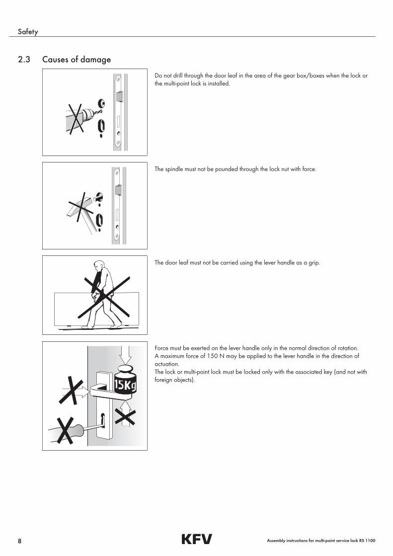
2.3 Causes of damage
Do not drill through the door leaf in the area of the gear box/boxes when the lock or the multi-point lock is installed.
The spindle must not be pounded through the lock nut with force.
The door leaf must not be carried using the lever handle as a grip.
Force must be exerted on the lever handle only in the normal direction of rotation.A maximum force of 150 N may be applied to the lever handle in the direction of actuation.The lock or multi-point lock must be locked only with the associated key (and not with foreign objects).
9
Safety
10.2016
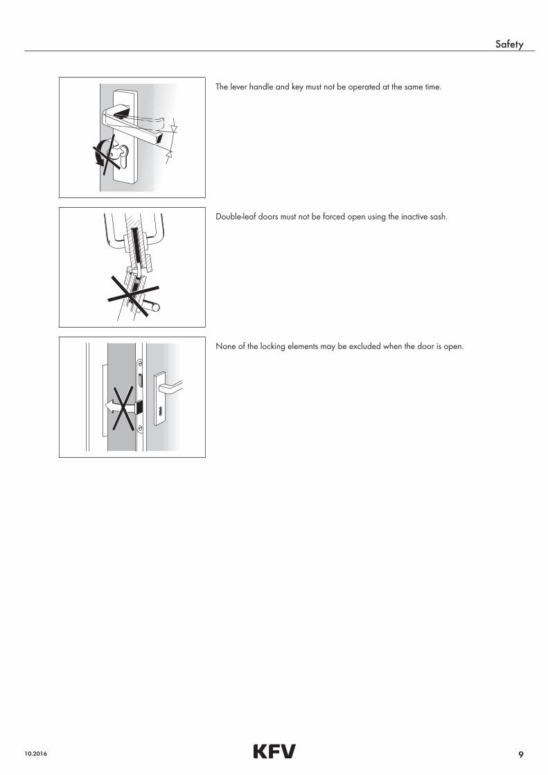
The lever handle and key must not be operated at the same time.
Double-leaf doors must not be forced open using the inactive sash.
None of the locking elements may be excluded when the door is open.

10
Scope of delivery
Assembly instructions for multi-point service lock RS 1100
11
Scope of delivery
10.2016
3 Scope of delivery
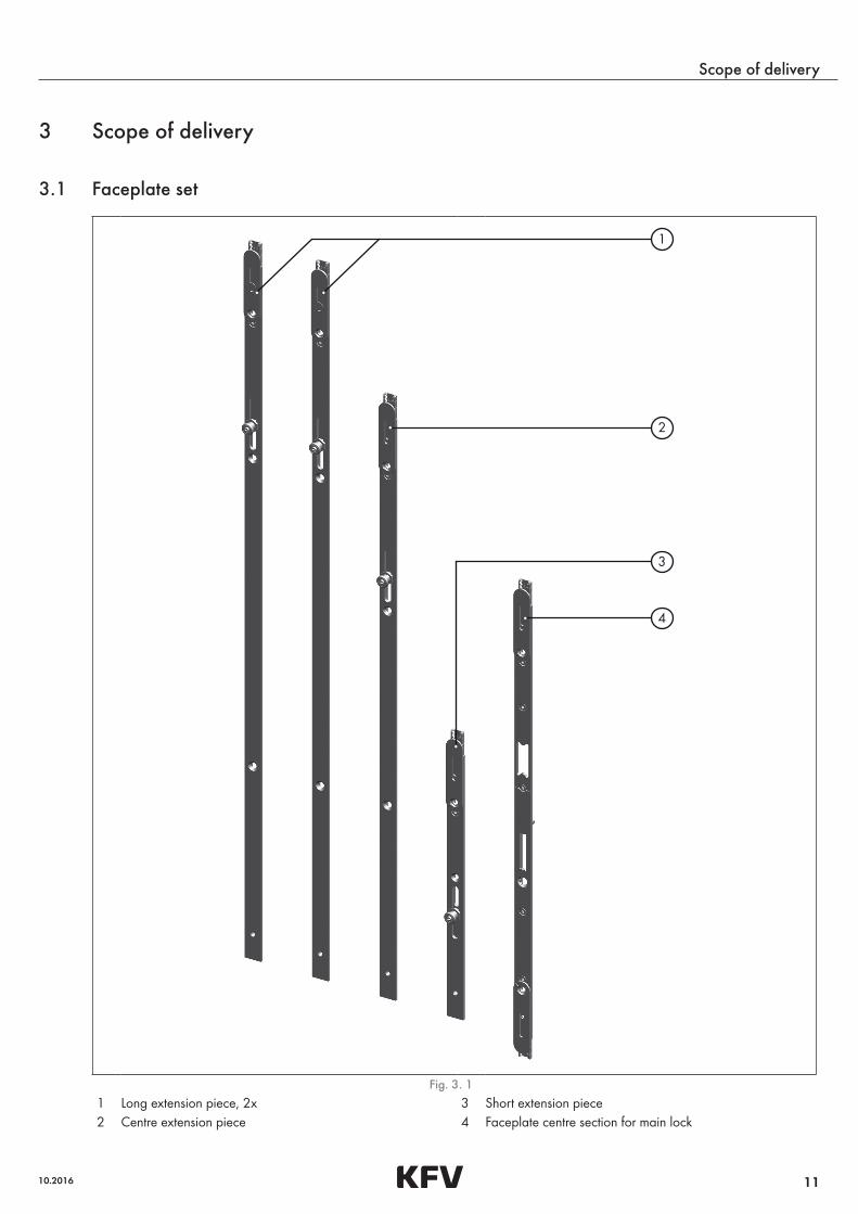
3.1 Faceplate set
1
2
3
4
Fig. 3. 1 1 Long extension piece, 2x 3 Short extension piece2 Centre extension piece 4 Faceplate centre section for main lock
12
Scope of delivery
Assembly instructions for multi-point service lock RS 1100
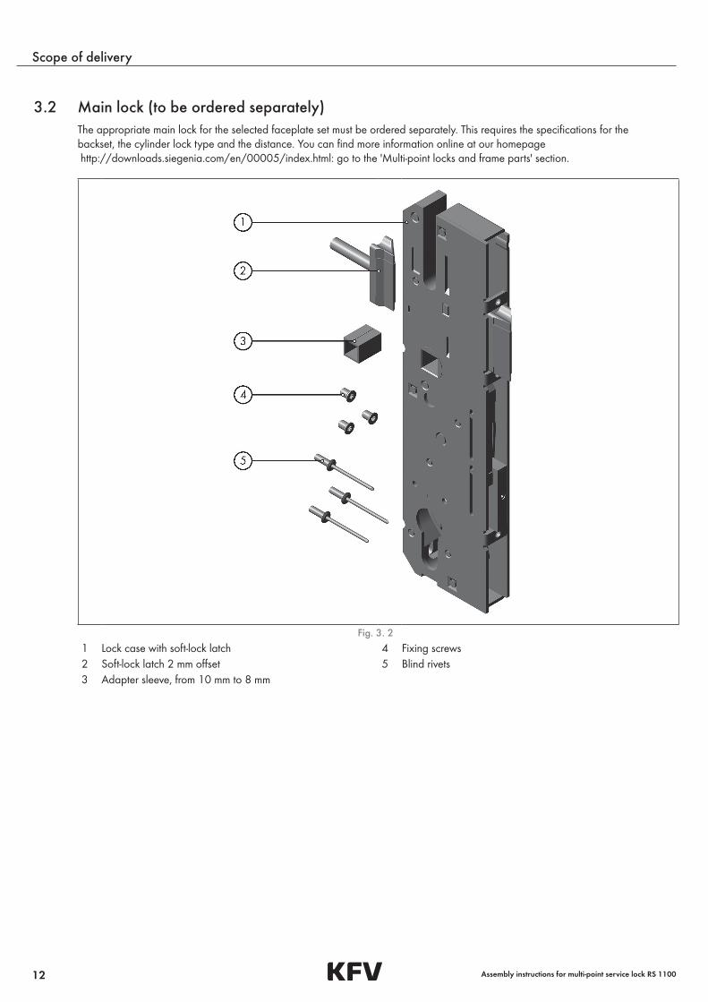
3.2 Main lock (to be ordered separately)The appropriate main lock for the selected faceplate set must be ordered separately. This requires the specifications for the backset, the cylinder lock type and the distance. You can find more information online at our homepage http://downloads.siegenia.com/en/00005/index.html: go to the 'Multi-point locks and frame parts' section.
Fig. 3. 2 1 Lock case with soft-lock latch 4 Fixing screws2 Soft-lock latch 2 mm offset 5 Blind rivets3 Adapter sleeve, from 10 mm to 8 mm
13
Scope of delivery
10.2016
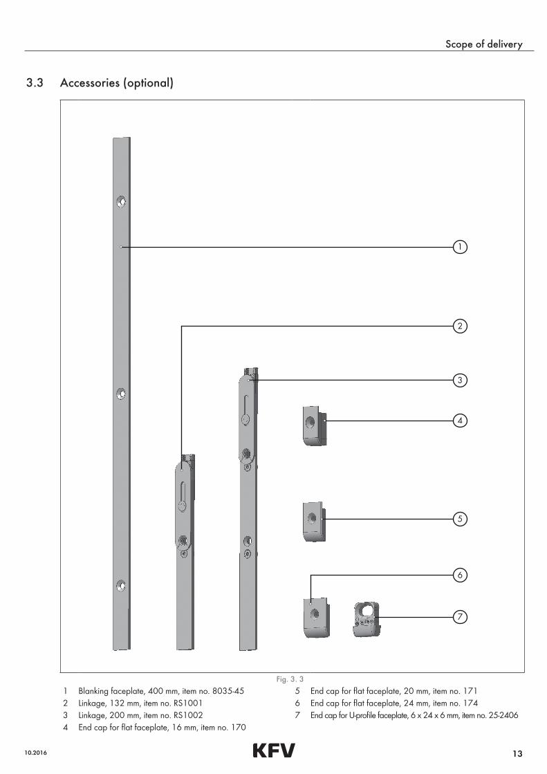
3.3 Accessories (optional)
1
2
3
4
7
5
6
Fig. 3. 3 1 Blanking faceplate, 400 mm, item no. 8035-45 5 End cap for flat faceplate, 20 mm, item no. 1712 Linkage, 132 mm, item no. RS1001 6 End cap for flat faceplate, 24 mm, item no. 1743 Linkage, 200 mm, item no. RS1002 7 End cap for U-profile faceplate, 6 x 24 x 6 mm, item no. 25-24064 End cap for flat faceplate, 16 mm, item no. 170

14
Scope of delivery
Assembly instructions for multi-point service lock RS 1100
15
Assembly
10.2016
4 Assembly
The multi-point service lock may only be assembled if all of the following requirements have been met.
4.1 Assembly requirements – Observe regional construction regulations and legislation.
– Make sure there is a sufficiently large surface available for measurement and processing.
– Install the multi-point service lock and accessory components in accordance with our assembly instructions only.
– Make sure that the dimensions and technical properties of the door and the multi-point service lock are compatible. In particular, pay attention to the multi-point lock's direction of travel.
– In the multi-point service lock, the comfort mushroom cams travel vertically from top to bottom. If the multi-point lock that is being used for replacement is different in this respect, the frame parts must be adjusted accordingly.
– All the dimensions in this documentation are specified in mm.
4.1.1 Risk of injury from crushing
CAUTION!
Risk of injury from crushing
If the multi-point service lock is installed without the door leaf being lifted off, there is a risk of fingers becoming trapped.
– Lift off the door leaf or secure it with a locking wedge.
4.1.2 Risk of injury from saw burrs
CAUTION!
Risk of injury from saw burrs
Cropping metal components creates saw burrs that can lead to cutting injuries. There is also the risk of the movable component functions becoming impaired.
– Wear protective gloves.
– Deburr the sawn edges of the components after cropping.
4.1.3 Risk of injury from swarf flying around rapidly
CAUTION!
Risk of injury from swarf flying around rapidly
During milling work, there will be swarf flying around at high speed. Without protective equipment, this swarf can cause injuries, especially to the eyes.
– Always wear protective goggles during milling work.
16
Assembly
Assembly instructions for multi-point service lock RS 1100
4.1.4 Comfort mushroom cams' path and direction of travel
NOTE!
Excessively short travel paths in the frame parts
If the multi-point service lock is assembled in this case, the comfort mushroom cams will not be able to lock fully in the end position. In the locked position, they will knock against the frame parts and press the door leaf upwards. This will result in damage and a loss of functionality.
– Measure the path of travel in the frame parts. If the path of travel is shorter than 20 mm, do not assemble the multi-point service lock until you have either:
– moved the frame parts or
– assembled appropriate frame parts.
4.1.5 Preventing corrosion
NOTE!
Acetic curing sealants
Using acetic curing sealants will lead to corrosion damage on components and/or the door.
– Use neutral curing sealants only.
NOTE!
Tools (such as metal saws and files) for non-stainless steel
Tools that have been used for work on non-stainless steel will cause corrosion when they come into contact with stainless steel.
– Only use tools that are exclusively suitable for work on stainless steel.
4.1.6 Required tools – Metal saw
– Metal file
– Cutter (timber), 16 mm
– Screwdriver, hexalobular, no. 10
– Screwdriver to fit cylinder lock fixing screw
– Open-end spanner 11
– Building key, if applicable
17
Assembly
10.2016
4.1.7 Screws
NOTE!
Non-stainless screws
Non-stainless screws will cause corrosion of stainless steel when they come into contact with stainless steel parts.
– Only use screws made of stainless steel.
1
2
3
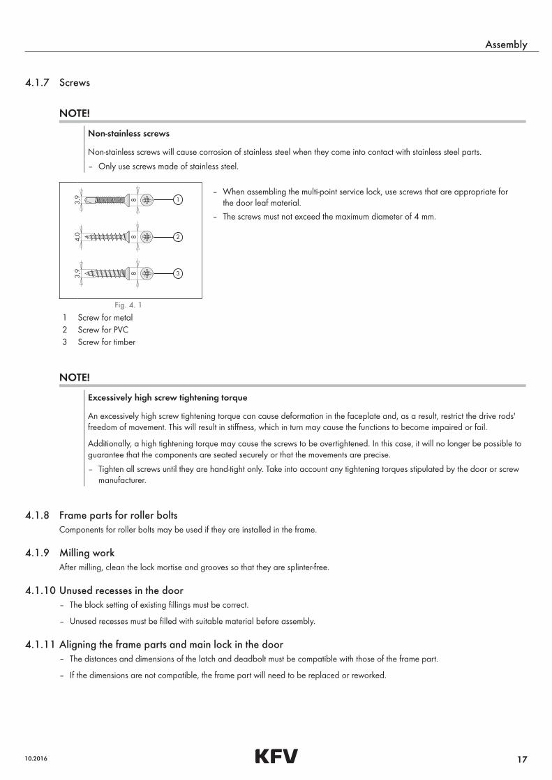
– When assembling the multi-point service lock, use screws that are appropriate for the door leaf material.
– The screws must not exceed the maximum diameter of 4 mm.
Fig. 4. 1
1 Screw for metal2 Screw for PVC3 Screw for timber
NOTE!
Excessively high screw tightening torque
An excessively high screw tightening torque can cause deformation in the faceplate and, as a result, restrict the drive rods' freedom of movement. This will result in stiffness, which in turn may cause the functions to become impaired or fail.
Additionally, a high tightening torque may cause the screws to be overtightened. In this case, it will no longer be possible to guarantee that the components are seated securely or that the movements are precise.
– Tighten all screws until they are hand-tight only. Take into account any tightening torques stipulated by the door or screw manufacturer.
4.1.8 Frame parts for roller boltsComponents for roller bolts may be used if they are installed in the frame.
4.1.9 Milling workAfter milling, clean the lock mortise and grooves so that they are splinter-free.
4.1.10 Unused recesses in the door – The block setting of existing fillings must be correct.
– Unused recesses must be filled with suitable material before assembly.
4.1.11 Aligning the frame parts and main lock in the door – The distances and dimensions of the latch and deadbolt must be compatible with those of the frame part.
– If the dimensions are not compatible, the frame part will need to be replaced or reworked.

18
Assembly
Assembly instructions for multi-point service lock RS 1100
4.2 Removing the defective locking part
4.2.1 Preparing for work
CAUTION!
Risk of injury from crushing
If the multi-point locks are removed and installed without the door leaf being lifted off, there is a risk of fingers becoming trapped.
– Lift off the door leaf or secure it with a locking wedge.
• Make sure there is a sufficiently large surface available for measurement and processing.
4.2.2 Dismantling the defective multi-point lock
• Move the lock into the open position.
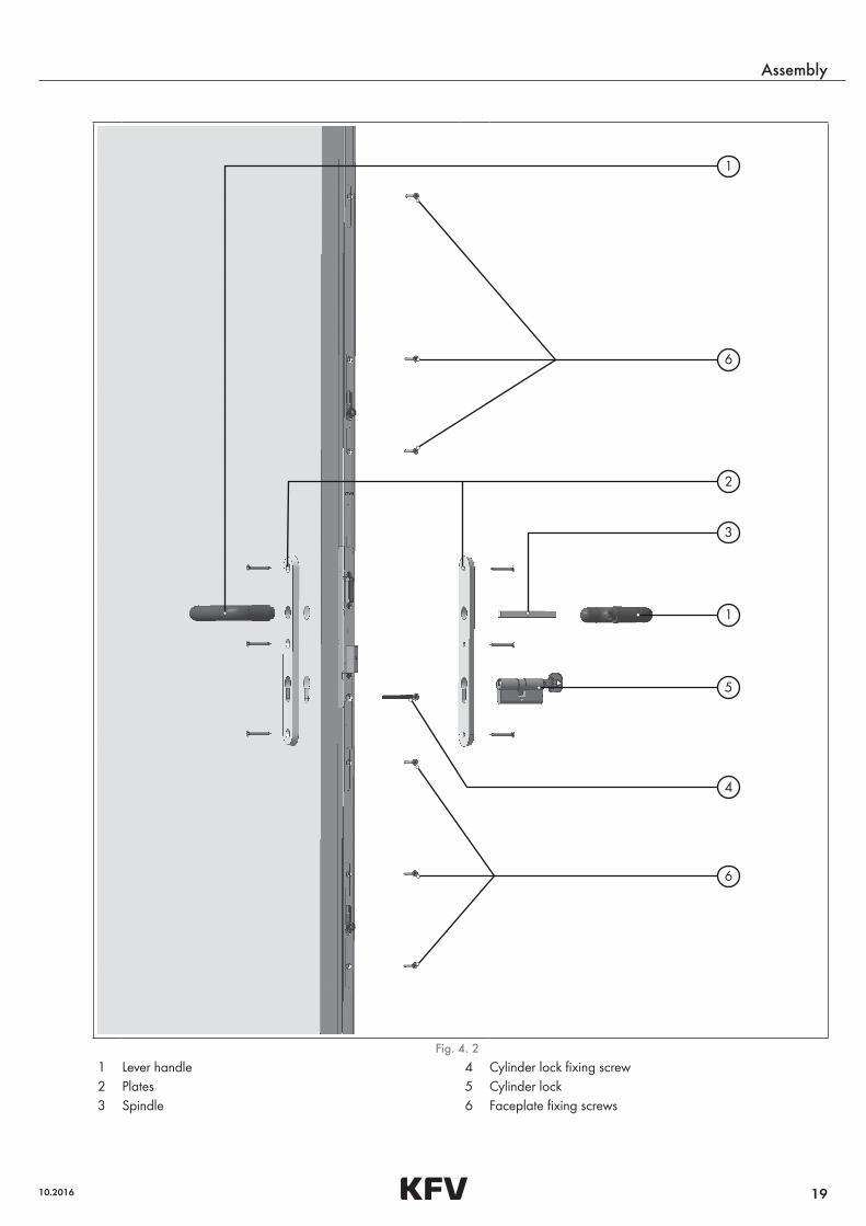
• Dismantle the lever handle (1).
• On both sides, dismantle the plates (2) or rosette fittings (illustration above).
• Slide the spindle (3) out of the spindle square.
• Unscrew the cylinder lock fixing screw (4).
• Slide the cylinder lock (5) out of the gear box.
• Working from bottom to top, loosen all the fixing screws (6) from the faceplate.
• Remove the defective multi-point lock.
• Place the multi-point lock on an even surface.
19
Assembly
10.2016
1
2
3
1
5
4
6
6
Fig. 4. 2 1 Lever handle 4 Cylinder lock fixing screw2 Plates 5 Cylinder lock3 Spindle 6 Faceplate fixing screws
20
Assembly
Assembly instructions for multi-point service lock RS 1100
4.3 Preparing the multi-point service lock
4.3.1 Checking the DIN orientation of the latch
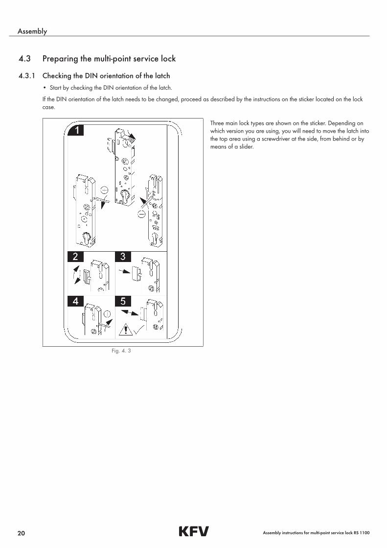
• Start by checking the DIN orientation of the latch.
If the DIN orientation of the latch needs to be changed, proceed as described by the instructions on the sticker located on the lock case.
Three main lock types are shown on the sticker. Depending on which version you are using, you will need to move the latch into the top area using a screwdriver at the side, from behind or by means of a slider.
Fig. 4. 3
21
Assembly
10.2016
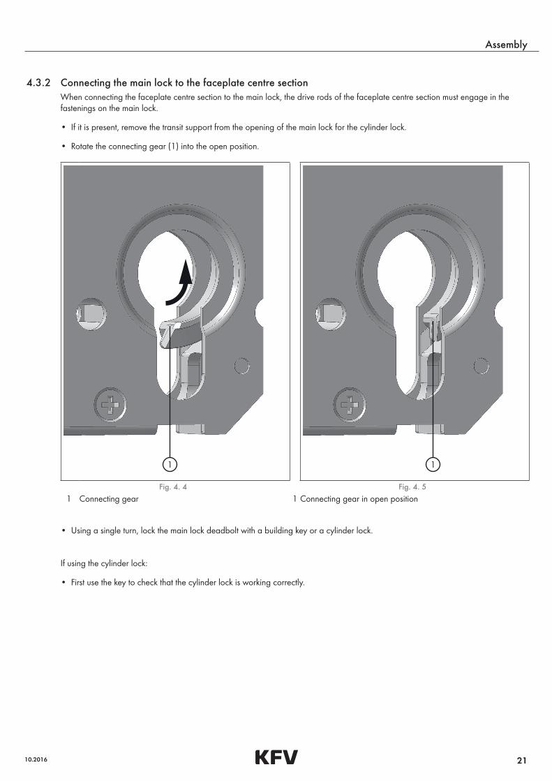
4.3.2 Connecting the main lock to the faceplate centre sectionWhen connecting the faceplate centre section to the main lock, the drive rods of the faceplate centre section must engage in the fastenings on the main lock.
• If it is present, remove the transit support from the opening of the main lock for the cylinder lock.
• Rotate the connecting gear (1) into the open position.
1 1
Fig. 4. 4 Fig. 4. 5 1 Connecting gear 1 Connecting gear in open position
• Using a single turn, lock the main lock deadbolt with a building key or a cylinder lock.
If using the cylinder lock:
• First use the key to check that the cylinder lock is working correctly.
22
Assembly
Assembly instructions for multi-point service lock RS 1100
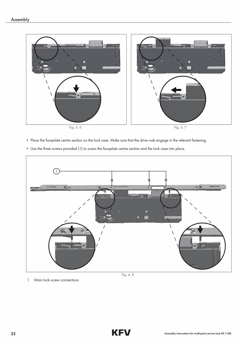
Fig. 4. 6 Fig. 4. 7
• Place the faceplate centre section on the lock case. Make sure that the drive rods engage in the relevant fastening.
• Use the three screws provided (1) to screw the faceplate centre section and the lock case into place.
1
Fig. 4. 8 1 Main lock screw connections
23
Assembly
10.2016
4.4 Checking functionality for the first time
4.4.1 Checking functionality with the parts removed
• Rotate the connecting gear into the open position. „page 21, Fig. 4. 4„“ and „page 21, Fig. 4. 5„“.
• Before installation, use the key to check that the cylinder lock is working correctly.
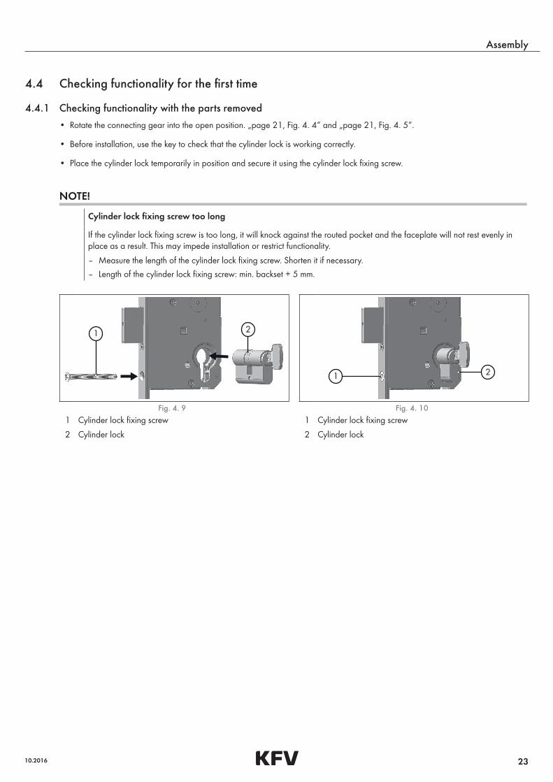
• Place the cylinder lock temporarily in position and secure it using the cylinder lock fixing screw.
NOTE!
Cylinder lock fixing screw too long
If the cylinder lock fixing screw is too long, it will knock against the routed pocket and the faceplate will not rest evenly in place as a result. This may impede installation or restrict functionality.
– Measure the length of the cylinder lock fixing screw. Shorten it if necessary.
– Length of the cylinder lock fixing screw: min. backset + 5 mm.
1 2
1 2
Fig. 4. 9 Fig. 4. 10 1 Cylinder lock fixing screw 1 Cylinder lock fixing screw
2 Cylinder lock 2 Cylinder lock
24
Assembly
Assembly instructions for multi-point service lock RS 1100
• Check the functionality of the main lock based on the points listed below.
Check Malfunction Action
Lock the deadbolt completely (double turn)
– It must be possible for the deadbolt to move easily.
– Deadbolt does not operate with ease. • Check that the drive rods are correctly seated in the fastenings.
If the problem is still not resolved:
• Replace the lock case.
Pull out the key with the deadbolt locked
– When the deadbolt is locked, it must be possible to pull out the key without resistance.
– Key cannot be pulled out. • Check the cylinder lock while it is removed.
If the cylinder lock is defective, replace it.
If the cylinder lock is not defective:
• Replace the lock case.
Turn and release the key in the unlocking direction with the deadbolt retracted
– The latch must be able to retract with ease.
– The latch may protrude from the face-plate by a maximum of 2 mm.
– The latch must be able to extend again with ease.
– The latch is unable to retract easily.
– The latch is unable to retract far enough.
– The latch runs with difficulty, does not extend completely, or does not extend at all.
• Replace the lock case.
Unlock and relock the main lock
– It must be possible for both drive rods to move with ease.
– The drive rods run with difficulty. • Loosen the three screws for the face-plate.
• Check that the drive rods are correctly seated in the fastenings.
• Remove any contamination from the running surfaces and drive rods.
• Remove the cylinder lock again.
4.5 Arranging the components of the multi-point service lock • Place the dismantled multi-point lock and the multi-point service lock on a level surface.
4.5.1 Determining the position of the gear box
• Move the lock components of both multi-point locks to the open position.
• Align the gear boxes with one another on the spindle square.
25
Assembly
10.2016
1
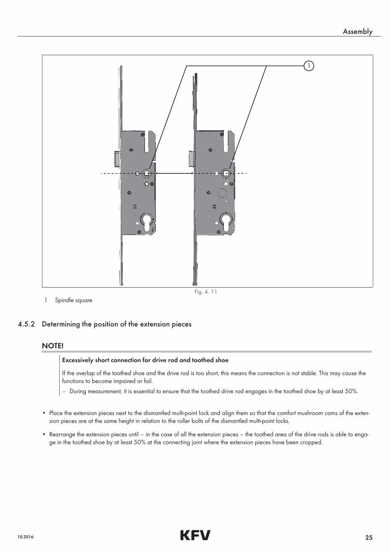
Fig. 4. 11 1 Spindle square
4.5.2 Determining the position of the extension pieces
NOTE!
Excessively short connection for drive rod and toothed shoe
If the overlap of the toothed shoe and the drive rod is too short, this means the connection is not stable. This may cause the functions to become impaired or fail.
– During measurement, it is essential to ensure that the toothed drive rod engages in the toothed shoe by at least 50%.
• Place the extension pieces next to the dismantled multi-point lock and align them so that the comfort mushroom cams of the exten-sion pieces are at the same height in relation to the roller bolts of the dismantled multi-point locks.
• Rearrange the extension pieces until – in the case of all the extension pieces – the toothed area of the drive rods is able to enga-ge in the toothed shoe by at least 50% at the connecting joint where the extension pieces have been cropped.
26
Assembly
Assembly instructions for multi-point service lock RS 1100
21 50 %
100 %
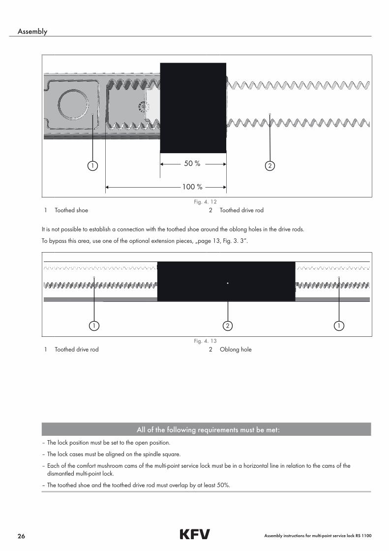
Fig. 4. 12 1 Toothed shoe 2 Toothed drive rod
It is not possible to establish a connection with the toothed shoe around the oblong holes in the drive rods.
To bypass this area, use one of the optional extension pieces, „page 13, Fig. 3. 3„“.
21 1
Fig. 4. 13 1 Toothed drive rod 2 Oblong hole
All of the following requirements must be met:
– The lock position must be set to the open position.
– The lock cases must be aligned on the spindle square.
– Each of the comfort mushroom cams of the multi-point service lock must be in a horizontal line in relation to the cams of the dismantled multi-point lock.
– The toothed shoe and the toothed drive rod must overlap by at least 50%.
27
Assembly
10.2016
2
21
1
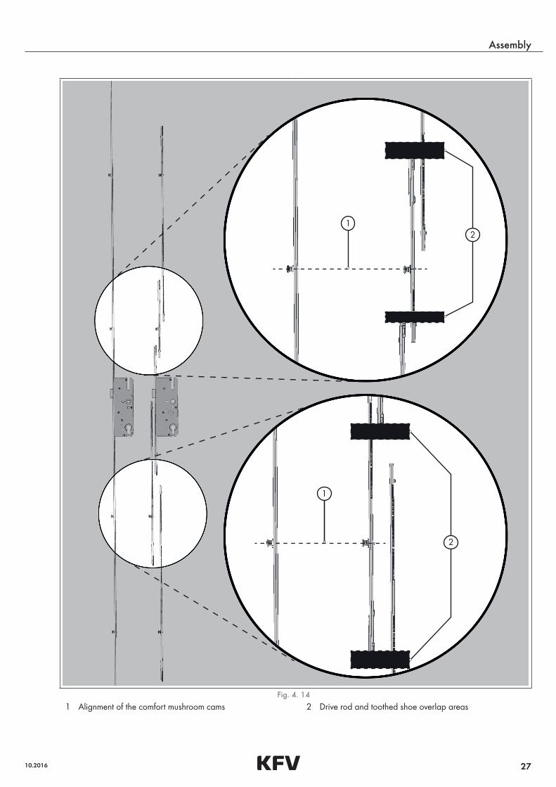
Fig. 4. 14 1 Alignment of the comfort mushroom cams 2 Drive rod and toothed shoe overlap areas

28
Assembly
Assembly instructions for multi-point service lock RS 1100
4.5.3 Cropping the components
CAUTION!
Sharp edges due to saw burrs
Cropping metal components creates saw burrs that can lead to cutting injuries. There is also the risk of the movable component functions becoming impaired.
– Wear protective gloves when cropping and deburring.
– Deburr the sawn edges of the components after cropping.
• Mark the positions of the saw cuts on the extension pieces of the multi-point service lock.
• Crop all the extension pieces at right angles to the positions you have marked.
NOTE!
Drive rods spreading
If the drive rods are cropped in the area of the oblong holes, there is a risk of them spreading. This may result in excessive wear in the groove and stiffness to the point of the functions failing.
– When cropping the drive rods, always ensure that the oblong holes remain closed.
• Crop the drive rods at the outer extension pieces behind the oblong hole of the guiding bolt by at least 20 mm, so that the drive rods do not protrude beyond the end of the extension piece when extended.
• Deburr the sawn edges.
3 12 4
min. 20 mm
Fig. 4. 15 1 Cropping area 3 Drive rod2 Guiding bolt 4 Toothed shoe
29
Assembly
10.2016
4.6 Installing the multi-point service lock
4.6.1 Checking the groove depth on timber doors
CAUTION!
Risk of injury from swarf flying around rapidly
During milling work, there will be swarf flying around at high speed. Without protective equipment, this swarf can cause injuries, especially to the eyes.
– Always wear protective goggles during milling work.
4 mm
2
1
3
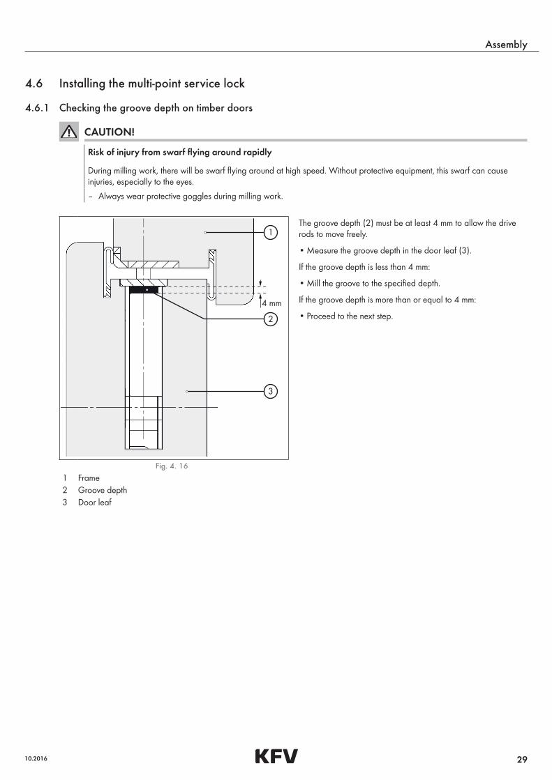
The groove depth (2) must be at least 4 mm to allow the drive rods to move freely.
• Measure the groove depth in the door leaf (3).
If the groove depth is less than 4 mm:
• Mill the groove to the specified depth.
If the groove depth is more than or equal to 4 mm:
• Proceed to the next step.
Fig. 4. 16 1 Frame2 Groove depth3 Door leaf
30
Assembly
Assembly instructions for multi-point service lock RS 1100
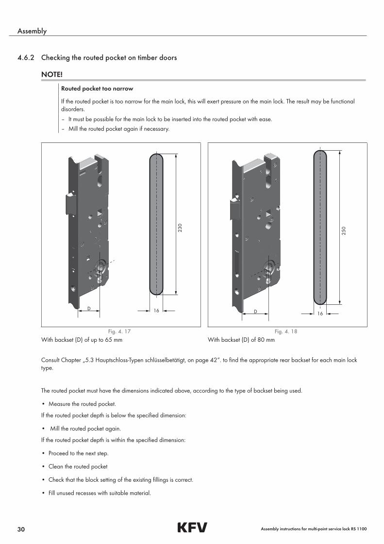
4.6.2 Checking the routed pocket on timber doors
NOTE!
Routed pocket too narrow
If the routed pocket is too narrow for the main lock, this will exert pressure on the main lock. The result may be functional disorders.
– It must be possible for the main lock to be inserted into the routed pocket with ease.
– Mill the routed pocket again if necessary.
D 16
230
D 16
250
Fig. 4. 17 Fig. 4. 18 With backset (D) of up to 65 mm With backset (D) of 80 mm
Consult Chapter „5.3 Hauptschloss-Typen schlüsselbetätigt, on page 42„“. to find the appropriate rear backset for each main lock type.
The routed pocket must have the dimensions indicated above, according to the type of backset being used.
• Measure the routed pocket.
If the routed pocket depth is below the specified dimension:
• Mill the routed pocket again.
If the routed pocket depth is within the specified dimension:
• Proceed to the next step.
• Clean the routed pocket
• Check that the block setting of the existing fillings is correct.
• Fill unused recesses with suitable material.
31
Assembly
10.2016
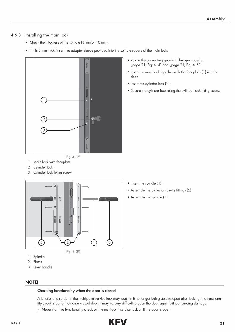
4.6.3 Installing the main lock
• Check the thickness of the spindle (8 mm or 10 mm).
• If it is 8 mm thick, insert the adapter sleeve provided into the spindle square of the main lock.
1
2
3
• Rotate the connecting gear into the open position „page 21, Fig. 4. 4„“ and „page 21, Fig. 4. 5„“.
• Insert the main lock together with the faceplate (1) into the door.
• Insert the cylinder lock (2).
• Secure the cylinder lock using the cylinder lock fixing screw.
Fig. 4. 19 1 Main lock with faceplate2 Cylinder lock3 Cylinder lock fixing screw
1 33 2
• Insert the spindle (1).
• Assemble the plates or rosette fittings (2).
• Assemble the spindle (3).
Fig. 4. 20 1 Spindle2 Plates3 Lever handle
NOTE!
Checking functionality when the door is closed
A functional disorder in the multi-point service lock may result in it no longer being able to open after locking. If a functiona-lity check is performed on a closed door, it may be very difficult to open the door again without causing damage.
– Never start the functionality check on the multi-point service lock until the door is open.
32
Assembly
Assembly instructions for multi-point service lock RS 1100
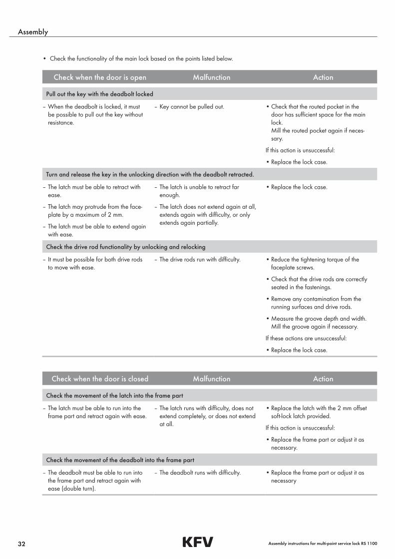
• Check the functionality of the main lock based on the points listed below.
Check when the door is open Malfunction Action
Pull out the key with the deadbolt locked
– When the deadbolt is locked, it must be possible to pull out the key without resistance.
– Key cannot be pulled out. • Check that the routed pocket in the door has sufficient space for the main lock. Mill the routed pocket again if neces-sary.
If this action is unsuccessful:
• Replace the lock case.
Turn and release the key in the unlocking direction with the deadbolt retracted.
– The latch must be able to retract with ease.
– The latch may protrude from the face-plate by a maximum of 2 mm.
– The latch must be able to extend again with ease.
– The latch is unable to retract far enough.
– The latch does not extend again at all, extends again with difficulty, or only extends again partially.
• Replace the lock case.
Check the drive rod functionality by unlocking and relocking
– It must be possible for both drive rods to move with ease.
– The drive rods run with difficulty. • Reduce the tightening torque of the faceplate screws.
• Check that the drive rods are correctly seated in the fastenings.
• Remove any contamination from the running surfaces and drive rods.
• Measure the groove depth and width. Mill the groove again if necessary.
If these actions are unsuccessful:
• Replace the lock case.
Check when the door is closed Malfunction Action
Check the movement of the latch into the frame part
– The latch must be able to run into the frame part and retract again with ease.
– The latch runs with difficulty, does not extend completely, or does not extend at all.
• Replace the latch with the 2 mm offset soft-lock latch provided.
If this action is unsuccessful:
• Replace the frame part or adjust it as necessary.
Check the movement of the deadbolt into the frame part
– The deadbolt must be able to run into the frame part and retract again with ease (double turn).
– The deadbolt runs with difficulty. • Replace the frame part or adjust it as necessary
33
Assembly
10.2016
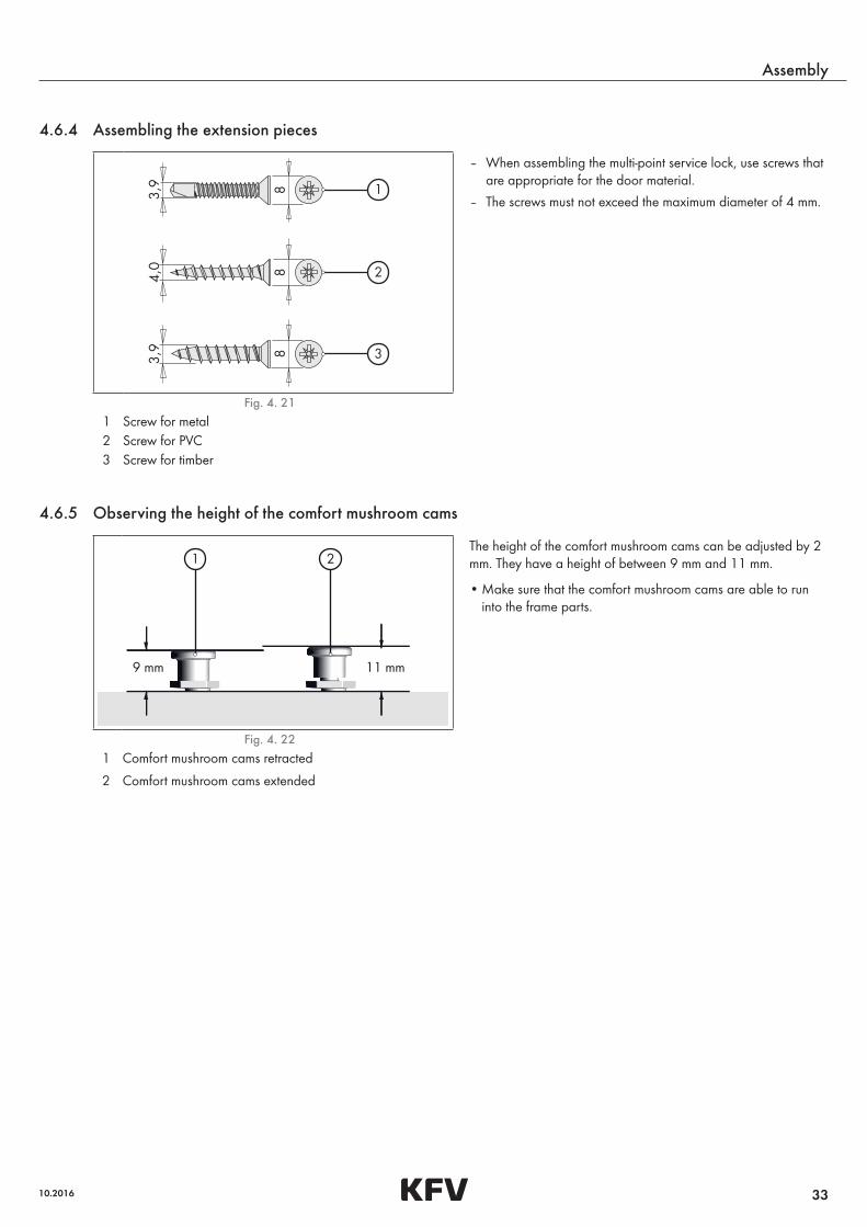
4.6.4 Assembling the extension pieces
1
2
3
– When assembling the multi-point service lock, use screws that are appropriate for the door material.
– The screws must not exceed the maximum diameter of 4 mm.
Fig. 4. 21 1 Screw for metal2 Screw for PVC3 Screw for timber
4.6.5 Observing the height of the comfort mushroom cams
9 mm 11 mm
1 2The height of the comfort mushroom cams can be adjusted by 2 mm. They have a height of between 9 mm and 11 mm.
• Make sure that the comfort mushroom cams are able to run into the frame parts.
Fig. 4. 22 1 Comfort mushroom cams retracted
2 Comfort mushroom cams extended
34
Assembly
Assembly instructions for multi-point service lock RS 1100
NOTE!
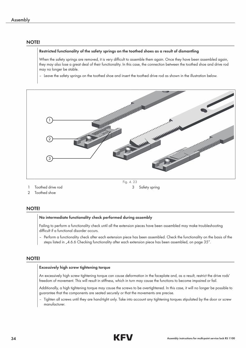
Restricted functionality of the safety springs on the toothed shoes as a result of dismantling
When the safety springs are removed, it is very difficult to assemble them again. Once they have been assembled again, they may also lose a great deal of their functionality. In this case, the connection between the toothed shoe and drive rod may no longer be stable.
– Leave the safety springs on the toothed shoe and insert the toothed drive rod as shown in the illustration below.
2
1
3
Fig. 4. 23 1 Toothed drive rod 3 Safety spring2 Toothed shoe
NOTE!
No intermediate functionality check performed during assembly
Failing to perform a functionality check until all the extension pieces have been assembled may make troubleshooting difficult if a functional disorder occurs.
– Perform a functionality check after each extension piece has been assembled. Check the functionality on the basis of the steps listed in „4.6.6 Checking functionality after each extension piece has been assembled, on page 35„“.
NOTE!
Excessively high screw tightening torque
An excessively high screw tightening torque can cause deformation in the faceplate and, as a result, restrict the drive rods' freedom of movement. This will result in stiffness, which in turn may cause the functions to become impaired or fail.
Additionally, a high tightening torque may cause the screws to be overtightened. In this case, it will no longer be possible to guarantee that the components are seated securely or that the movements are precise.
– Tighten all screws until they are hand-tight only. Take into account any tightening torques stipulated by the door or screw manufacturer.
35
Assembly
10.2016
NOTE!
Checking functionality when the door is closed
A functional disorder in the multi-point service lock may result in it no longer being able to open after locking. If a functiona-lity check is performed on a closed door, it may be very difficult to open the door again without causing damage.
– Never start the functionality check on the multi-point service lock until the door is open.
• Hook the first extension piece into the toothed shoe of the main lock drive rod. During this process, make sure that the safety springs on the toothed shoe are not overstretched.
• Screw the extension piece into the door leaf. Use only countersunk fastening holes for this purpose.
• Check the functionality on the basis of the steps listed in: „4.6.6 Checking functionality after each extension piece has been assembled, on page 35„“.
• Assemble all the extension pieces one after another. (Proceed as before).
4.6.6 Checking functionality after each extension piece has been assembled
• Check the functionality of the lock based on the points listed below.
Check when the door is open Malfunction Action
Lock the deadbolt with a double turn
– It must be possible to lock the main lock deadbolt completely and with ease.
– The comfort mushroom cams must be able to move with ease.
– The deadbolt runs with difficulty.
– The comfort mushroom cams move with difficulty.
• Check that the drive rods are correctly seated in the fastenings.
• Remove any contamination from the running surfaces and drive rods.
– If these actions are unsuccessful, replace the extension piece.
Check when the door is closed Malfunction Action
Check the comfort mushroom cams by locking with a double turn
– The comfort mushroom cams must be able to move with ease in the frame parts.
– The comfort mushroom cams must not descend all the way into the frame parts.
– The comfort mushroom cams run with difficulty.
– The comfort mushroom cams descend all the way into the frame parts.
• Adjust the seating of the door leaf on the hinges.
• Adjust the pressure of the comfort mushroom cams „4.7 Pressure control, on page 40„“.
If this action is unsuccessful:
• Assemble suitable frame parts or adjust them accordingly.
36
Assembly
Assembly instructions for multi-point service lock RS 1100
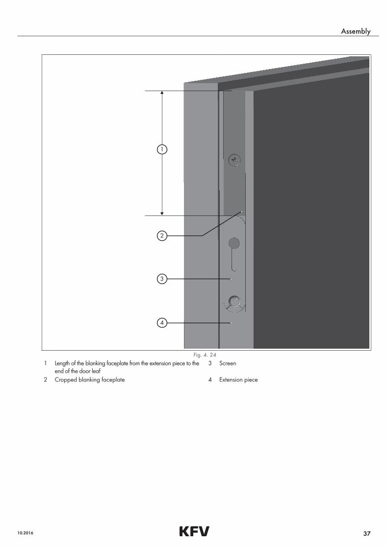
4.6.7 Assembling the blanking faceplateThere is the option of ordering a KFV blanking faceplate for the purpose of extending the multi-point service lock as far as the upper and lower edges of the door leaf.
Check when the door is open Malfunction Action
Check the cropping of the drive rods on the two outer extension pieces
– The lower drive rod must not protrude beyond the end of the extension piece (locked with a double turn).
– The upper drive rod must not protrude beyond the end of the extension piece (in open position).
Drive rods that are too long may knock against the edges of the blanking facepla-tes.
– Drive rods protrude beyond the extensi-on pieces.
• Remove the extension piece, crop the drive rod and deburr the sawn edge.
CAUTION!
Sharp edges due to saw burrs
Cropping metal components creates saw burrs that can lead to cutting injuries. There is also the risk of the movable component functions becoming impaired.
– Wear protective gloves.
– Deburr the sawn edges of the components after cropping.
• Measure the length required for each blanking faceplate, from the end of the extension piece to the end of the door leaf, and crop the sections.
• Deburr the sawn edges.
• Place the blanking faceplate all the way down onto the extension piece end and screw the blanking faceplate in place until it is hand-tight.
37
Assembly
10.2016
2
3
4
1
Fig. 4. 24 1 Length of the blanking faceplate from the extension piece to the
end of the door leaf3 Screen
2 Cropped blanking faceplate 4 Extension piece
38
Assembly
Assembly instructions for multi-point service lock RS 1100
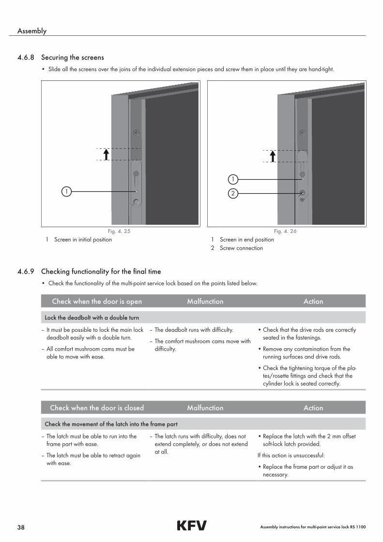
4.6.8 Securing the screens
• Slide all the screens over the joins of the individual extension pieces and screw them in place until they are hand-tight.
1 2
1
Fig. 4. 25 Fig. 4. 26 1 Screen in initial position 1 Screen in end position
2 Screw connection
4.6.9 Checking functionality for the final time
• Check the functionality of the multi-point service lock based on the points listed below.
Check when the door is open Malfunction Action
Lock the deadbolt with a double turn
– It must be possible to lock the main lock deadbolt easily with a double turn.
– All comfort mushroom cams must be able to move with ease.
– The deadbolt runs with difficulty.
– The comfort mushroom cams move with difficulty.
• Check that the drive rods are correctly seated in the fastenings.
• Remove any contamination from the running surfaces and drive rods.
• Check the tightening torque of the pla-tes/rosette fittings and check that the cylinder lock is seated correctly.
Check when the door is closed Malfunction Action
Check the movement of the latch into the frame part
– The latch must be able to run into the frame part with ease.
– The latch must be able to retract again with ease.
– The latch runs with difficulty, does not extend completely, or does not extend at all.
• Replace the latch with the 2 mm offset soft-lock latch provided.
If this action is unsuccessful:
• Replace the frame part or adjust it as necessary.
39
Assembly
10.2016
Check when the door is closed Malfunction Action
Check the functionality of the latch with the lever handle while the door is closed
– The latch must be able to retract with ease.
– The latch must not touch the frame part when the door is opened.
– The latch is unable to retract easily.
– The latch touches the frame part.
• Replace the latch with the 2 mm offset soft-lock latch provided.
• Adjust the seating of the door leaf on the hinges.
If these actions are unsuccessful:
• Replace the frame part or adjust it as necessary.
Turn and release the key in the unlocking direction with the deadbolt retracted
– The latch must be able to retract with ease.
– The latch may protrude from the face-plate by a maximum of 2 mm.
– The latch must be able to extend again with ease.
– The latch is unable to retract easily.
– The latch is unable to retract far enough.
– The latch runs with difficulty, does not extend completely, or does not extend at all.
• Check that the frame parts are correctly seated for the comfort mushroom cams and that the main lock deadbolt is able to be locked completely.
Check locking with a double turn
– The main lock deadbolt and the com-fort mushroom cams must be able to retract from and extend easily into the frame parts.
– The locking elements run with difficulty. • Adjust the seating of the door leaf on the hinges.
• Adjust the pressure of the comfort mushroom cams „4.7 Pressure control, on page 40„“.
• Replace the frame parts or adjust them as necessary.
40
Assembly
Assembly instructions for multi-point service lock RS 1100
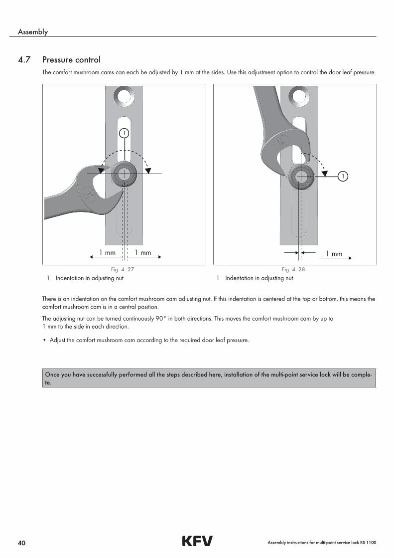
4.7 Pressure controlThe comfort mushroom cams can each be adjusted by 1 mm at the sides. Use this adjustment option to control the door leaf pressure.
1
1 mm1 mm
1
1 mm
Fig. 4. 27 Fig. 4. 28 1 Indentation in adjusting nut 1 Indentation in adjusting nut
There is an indentation on the comfort mushroom cam adjusting nut. If this indentation is centered at the top or bottom, this means the comfort mushroom cam is in a central position.
The adjusting nut can be turned continuously 90° in both directions. This moves the comfort mushroom cam by up to 1 mm to the side in each direction.
• Adjust the comfort mushroom cam according to the required door leaf pressure.
Once you have successfully performed all the steps described here, installation of the multi-point service lock will be comple-te.
41
Appendix
10.2016
5 Appendix
5.1 Disposal
5.1.1 Disposing of the packaging materialThe packaging provided by KFV Karl Fliether GmbH & Co. KG, 42551 Velbert, Germany, consists of recyclable materials and com-plies with the standards of INTERSEROH Dienstleistungs GmbH.
Please dispose of this packaging material separately by placing it in the appropriate recyclables containers.
– Cardboard/paper
– Plastics
5.1.2 Disposing of the defective multi-point lockUnder no circumstances may the multi-point lock be disposed of along with domestic waste. It contains lubricants that are harmful to the environment.
Dispose of the multi-point lock correctly along with other scrap metal.
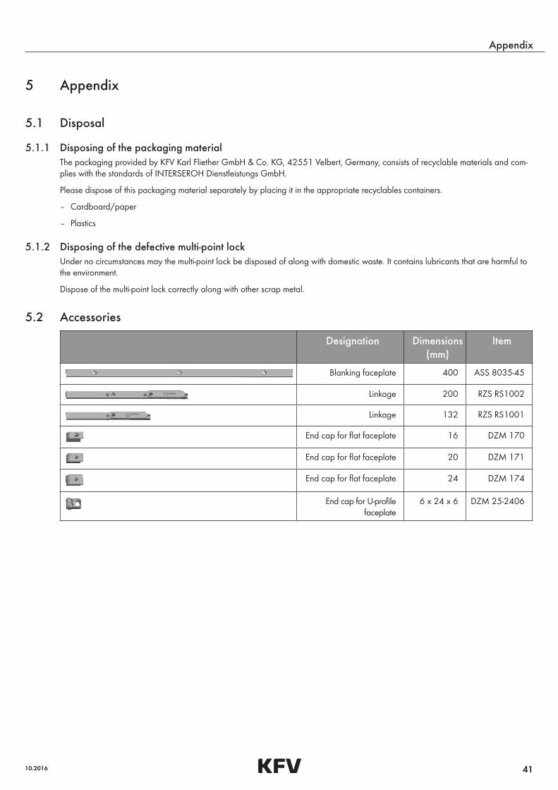
5.2 Accessories
Designation Dimensions (mm)
Item
Blanking faceplate 400 ASS 8035-45
Linkage 200 RZS RS1002
Linkage 132 RZS RS1001
End cap for flat faceplate 16 DZM 170
End cap for flat faceplate 20 DZM 171
End cap for flat faceplate 24 DZM 174
End cap for U-profile faceplate
6 x 24 x 6 DZM 25-2406
42
Appendix
Assembly instructions for multi-point service lock RS 1100
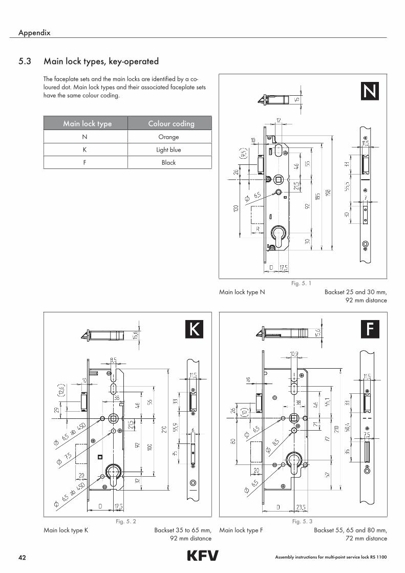
5.3 Main lock types, key-operated
The faceplate sets and the main locks are identified by a co-loured dot. Main lock types and their associated faceplate sets have the same colour coding.
Main lock type Colour coding
N Orange
K Light blue
F Black
Fig. 5. 1 Main lock type N Backset 25 and 30 mm, 92 mm distance
Fig. 5. 2 Fig. 5. 3Main lock type K Backset 35 to 65 mm, 92 mm distance
Main lock type F Backset 55, 65 and 80 mm, 72 mm distance

Assembly instructions for multi-point service lock RS 1100

H39
.MFV
RS00
1EN
/201
5-2/
0
A company of the SIEGENIA GROUP
Contact your dealer:
KFV Karl Fliether GmbH & Co. KG
Siemensstraße 10
42551 Velbert
GERMANY
Phone: +49 2051 278-0
Fax: +49 2051 278-167
www.kfv.de
SIEGENIA worldwide:
Austria Phone: +43 6225 8301
Belarus Phone: +375 17 3121168
Benelux Phone: +32 9 2811312
China Phone: +86 316 5998198
France Phone: +33 3 89618131
Germany Phone: +49 271 39310
Great Britain Phone: +44 2476 622000
Hungary Phone: +36 76 500810
Italy Phone: +39 02 9353601
Poland Phone: +48 77 4477700
Russia Phone: +7 495 7211762
South Korea Phone: +82 31 7985590
Switzerland Phone: +41 33 3461010
Turkey Phone: +90 216 5934151
Ukraine Phone: +380 44 4637979
You can fi nd address details for our
international sites at: www.siegenia.com


![2,2′-[(3a RS ,7a RS )-Perhydrobenzimidazole-1,3-diyl)bis(methylene)]diphenol](https://img.dokumen.tips/doc/110x75/63258a267fd2bfd0cb038430/22-3a-rs-7a-rs-perhydrobenzimidazole-13-diylbismethylenediphenol.jpg)


