Embed Size (px)
Citation preview

NEXCOM International Co., Ltd.
NEXCOM International Co., Ltd.Published March 2017
www.nexcom.com
Mobile Computing SolutionsVehicle Mount Computer VMC 1100User Manual
Copyright © 2014 NEXCOM International Co., Ltd. All rights reserved ii VMC 1100 User Manual
Contents
Contents
PrefaceCopyright .............................................................................................. vDisclaimer .............................................................................................. vAcknowledgements ............................................................................... vRegulatory Compliance Statements ........................................................ vDeclaration of Conformity ....................................................................... vRoHS Compliance .................................................................................. viWarranty and RMA ................................................................................viiSafety Information ...............................................................................viiiInstallation Recommendations ...............................................................viiiSafety Precautions .................................................................................. ixTechnical Support and Assistance ............................................................ xConventions Used in this Manual ............................................................ xGlobal Service Contact Information ........................................................ xi
Headquarters ...................................................................................... xiPackage Contents .................................................................................xiiiOrdering Information ............................................................................xiv
Chapter 1: Product IntroductionOverview ................................................................................................1
VMC 1100 Key Features ......................................................................1Hardware Specifications ..........................................................................3
VMC 1100 ..........................................................................................3Mechanical Dimensions ...........................................................................5
Getting to Know VMC 1100 ...................................................................6VMC 1100 Front & Side View ..............................................................6VMC 1100 Rear View ..........................................................................7
Chapter 2: Using the GPS FeatureSetup and Using GPS Information .........................................................12
Setup Window Screenshot ..............................................................14GPS Info Window Screenshot ..........................................................14GPS Information Instructions ...........................................................15
Chapter 3: Jumpers and ConnectorsBefore You Begin .................................................................................16Precautions ..........................................................................................16Jumper .................................................................................................17Locations of the Jumpers and Connectors .............................................18
Mainboard ........................................................................................18Internal Connectors and DIP Switch Settings .........................................19
VGA Connector ..............................................................................19Flash/Debug Connector ...................................................................19MCU Debug COM Header ..............................................................20MCU Flash Connector .....................................................................20EC Debug COM Connector .............................................................21Port 80 Debug Connector ...............................................................21Serial-ATA .......................................................................................22SATA DOM Power Connector ..........................................................22
Copyright © 2014 NEXCOM International Co., Ltd. All rights reserved iii VMC 1100 User Manual
Contents
ME/RTC Clear Switch ......................................................................23Input Voltage Control Switch ...........................................................23GPIO Pull High Switch .....................................................................24LED Indicators .................................................................................24VMC 1100 RS232 COM1 Power Jumper .........................................25
External Connectors ..............................................................................26RS232 Connector ............................................................................26VMC 1100 RS485/CAN Connector ..................................................26GPIO and Sensor Connector ............................................................27
Chapter 4: Function Key Code ConstantsVisual Basic Reference ...........................................................................28Extended ASCII Keyboard Codes ...........................................................29
Chapter 5: Touchscreen Driver InstallationInstalling PenMount Windows Universal Driver .................................30(For 2000/XP/XPT/XPE/2003/VISTA/7/WES7/2008/8) ...........................30Installing PenMount Mouse Driver in
Windows 2000/XP/XPT/XPE/2003/VISTA/7/WES7/2008/8 ....................32Installing PenMount Digitizer Driver in
Windows XP/Vista/7/WES7/2008/8.....................................................33Configuring Touchscreen in PenMount Mouse Driver .........................33PenMount Control Panel ...................................................................34PenMount Monitor Menu Icon ..........................................................38PenMount Rotating Function .............................................................38Touchscreen Configuration of PenMount ..........................................39Digitizer Driver ...................................................................................39
PenMount Control Panel .................................................................40Uninstalling PenMount Windows Universal Driver ..............................43Installing PenMount Linux X Window USB Driver ...............................44
Installing PenMount Linux X Window USB Driver .............................44
Calibration Utilities ..........................................................................44Installing PenMount WinCE Driver .....................................................44
Installing PenMount WinCE Driver ...................................................44Touchscreen Driver Software Functions..................................................45
Standard Calibration ..........................................................................47Advanced Calibration ........................................................................47Rotation ............................................................................................47Draw .................................................................................................47Mouse Operation Mode ....................................................................49Beep Sound .......................................................................................49Beep Sound Adjustable ......................................................................49Wake Up Function .............................................................................49Plot Calibration Data .........................................................................49Right Button ......................................................................................49Hide Cursor .......................................................................................49Cursor Offset .....................................................................................50Double Click Area and Speed ............................................................50About ................................................................................................50Edge Compensation ..........................................................................50Refresh ..............................................................................................51
Chapter 6: PenMount Gesture AP for WindowsInvoke PenMount Gesture AP ...............................................................52Configure PenMount Gesture AP ..........................................................53PenMount Gestures’ Default Values in Windows XP ..............................55
Chapter 7: Enable a Hibernate Once/Resume ManyEnvironment by Using EWF ...................................................................56
Chapter 8: How to Install the WWAN or Wi-Fi Module .............. 57
Copyright © 2014 NEXCOM International Co., Ltd. All rights reserved iv VMC 1100 User Manual
Contents
Chapter 9: How to Install a SATA DOM Module ....... 58
Chapter 10: Installing the OBD Module .................... 61
Appendix A: I/O Address Function ............................ 64
Appendix B: Vehicle Power Management Setup ...... 81
Appendix C: SMS and Dial Wake-up Setting ............ 88
Appendix D: RTC Wake-up Setting ............................ 89
Appendix E: Auto Backlight Setting .......................... 91
Appendix F: BIOS Update ........................................... 92
Appendix G: Changing COM Mode (RS232/RS485) .. 95
Copyright © 2014 NEXCOM International Co., Ltd. All rights reserved v VMC 1100 User Manual
Preface
PrefaCe
Regulatory Compliance Statements This section provides the FCC compliance statement for Class A devices and describes how to keep the system CE compliant.
Declaration of ConformityFCC
This equipment has been tested and verified to comply with the limits for a Class A digital device, pursuant to Part 15 of FCC Rules. These limits are designed to provide reasonable protection against harmful interference when the equipment is operated in a commercial environment. This equipment generates, uses, and can radiate radio frequency energy and, if not installed and used in accordance with the instructions, may cause harmful interference to radio communications. Operation of this equipment in a residential area (domestic environment) is likely to cause harmful interference, in which case the user will be required to correct the interference (take adequate measures) at their own expense.
CE
The product(s) described in this manual complies with all applicable European Union (CE) directives if it has a CE marking. For computer systems to remain CE compliant, only CE-compliant parts may be used. Maintaining CE compliance also requires proper cable and cabling techniques.
Copyright This publication, including all photographs, illustrations and software, is protected under international copyright laws, with all rights reserved. No part of this manual may be reproduced, copied, translated or transmitted in any form or by any means without the prior written consent from NEXCOM International Co., Ltd.
Disclaimer The information in this document is subject to change without prior notice and does not represent commitment from NEXCOM International Co., Ltd. However, users may update their knowledge of any product in use by constantly checking its manual posted on our website: http://www.nexcom.com. NEXCOM shall not be liable for direct, indirect, special, incidental, or consequential damages arising out of the use of any product, nor for any infringements upon the rights of third parties, which may result from such use. Any implied warranties of merchantability or fitness for any particular purpose is also disclaimed.
Acknowledgements VMC 1100 is a trademark of NEXCOM International Co., Ltd. All other product names mentioned herein are registered trademarks of their respective owners.

Copyright © 2014 NEXCOM International Co., Ltd. All rights reserved vi VMC 1100 User Manual
Preface
RoHS Compliance
NEXCOM RoHS Environmental Policy and Status Update
RoHS restricts the use of Lead (Pb) < 0.1% or 1,000ppm, Mercury (Hg) < 0.1% or 1,000ppm, Cadmium (Cd) < 0.01% or 100ppm, Hexavalent Chromium (Cr6+) < 0.1% or 1,000ppm, Polybrominated biphenyls (PBB) < 0.1% or 1,000ppm, and Polybrominated diphenyl Ethers (PBDE) < 0.1% or 1,000ppm.
In order to meet the RoHS compliant directives, NEXCOM has established an engineering and manufacturing task force in to implement the introduction of green products. The task force will ensure that we follow the standard NEXCOM development procedure and that all the new RoHS components and new manufacturing processes maintain the highest industry quality levels for which NEXCOM are renowned.
The model selection criteria will be based on market demand. Vendors and suppliers will ensure that all designed components will be RoHS compliant.
How to recognize NEXCOM RoHS Products?
For existing products where there are non-RoHS and RoHS versions, the suffix “(LF)” will be added to the compliant product name.
All new product models launched after January 2013 will be RoHS compliant. They will use the usual NEXCOM naming convention.
NEXCOM is a global citizen for building the digital infrastructure. We are committed to providing green products and services, which are compliant with European Union RoHS (Restriction on Use of Hazardous Substance in Electronic Equipment) directive 2011/65/EU, to be your trusted green partner and to protect our environment.
Copyright © 2014 NEXCOM International Co., Ltd. All rights reserved vii VMC 1100 User Manual
Preface
Warranty and RMA
NEXCOM Warranty Period
NEXCOM manufactures products that are new or equivalent to new in accordance with industry standard. NEXCOM warrants that products will be free from defect in material and workmanship for 2 years, beginning on the date of invoice by NEXCOM. HCP series products (Blade Server) which are manufactured by NEXCOM are covered by a three year warranty period.
NEXCOM Return Merchandise Authorization (RMA)
? Customers shall enclose the “NEXCOM RMA Service Form” with the returned packages.
? Customers must collect all the information about the problems
encountered and note anything abnormal or, print out any on-screen messages, and describe the problems on the “NEXCOM RMA Service Form” for the RMA number apply process.
? Customers can send back the faulty products with or without accessories (manuals, cable, etc.) and any components from the card, such as CPU and RAM. If the components were suspected as part of the problems, please note clearly which components are included. Otherwise, NEXCOM is not responsible for the devices/parts.
? Customers are responsible for the safe packaging of defective products,
making sure it is durable enough to be resistant against further damage and deterioration during transportation. In case of damages occurred during transportation, the repair is treated as “Out of Warranty.”
? Any products returned by NEXCOM to other locations besides the customers’ site will bear an extra charge and will be billed to the customer.
Repair Service Charges for Out-of-Warranty Products
NEXCOM will charge for out-of-warranty products in two categories, one is basic diagnostic fee and another is component (product) fee.
System Level
? Component fee: NEXCOM will only charge for main components such as SMD chip, BGA chip, etc. Passive components will be repaired for free, ex: resistor, capacitor.
? Items will be replaced with NEXCOM products if the original one cannot be repaired. Ex: motherboard, power supply, etc.
? Replace with 3rd party products if needed.
? If RMA goods can not be repaired, NEXCOM will return it to the customer without any charge.
Copyright © 2014 NEXCOM International Co., Ltd. All rights reserved viii VMC 1100 User Manual
Preface
Board Level
? Component fee: NEXCOM will only charge for main components, such as SMD chip, BGA chip, etc. Passive components will be repaired for free, ex: resistors, capacitors.
If RMA goods can not be repaired, NEXCOM will return it to the customer without any charge.
Warnings
Read and adhere to all warnings, cautions, and notices in this guide and the documentation supplied with the chassis, power supply, and accessory modules. If the instructions for the chassis and power supply are inconsistent with these instructions or the instructions for accessory modules, contact the supplier to find out how you can ensure that your computer meets safety and regulatory requirements.
CautionsElectrostatic discharge (ESD) can damage system components. Do the described procedures only at an ESD workstation. If no such station is available, you can provide some ESD protection by wearing an antistatic wrist strap and attaching it to a metal part of the computer chassis.
Safety Information Before installing and using the device, note the following precautions:
▪ Read all instructions carefully.
▪ Do not place the unit on an unstable surface, cart, or stand.
▪ Follow all warnings and cautions in this manual.
▪ When replacing parts, ensure that your service technician uses parts specified by the manufacturer.
▪ Avoid using the system near water, in direct sunlight, or near a heating device.
▪ The load of the system unit does not solely rely for support from the rackmounts located on the sides. Firm support from the bottom is highly necessary in order to provide balance stability.
The computer is provided with a battery-powered real-time clock circuit. There is a danger of explosion if battery is incorrectly replaced. Replace only with the same or equivalent type recommended by the manufacturer. Discard used batteries according to the manufacturer’s instructions.
Installation RecommendationsEnsure you have a stable, clean working environment. Dust and dirt can get into components and cause a malfunction. Use containers to keep small components separated.
Adequate lighting and proper tools can prevent you from accidentally damaging the internal components. Most of the procedures that follow require only a few simple tools, including the following:
• A Philips screwdriver• A flat-tipped screwdriver• A grounding strap• An anti-static pad
Using your fingers can disconnect most of the connections. It is recommended that you do not use needlenose pliers to disconnect connections as these can damage the soft metal or plastic parts of the connectors.
Copyright © 2014 NEXCOM International Co., Ltd. All rights reserved ix VMC 1100 User Manual
Preface
Safety Precautions
1. Read these safety instructions carefully.
2. Keep this User Manual for later reference.
3. Disconnect this equipment from any AC outlet before cleaning. Use a damp cloth. Do not use liquid or spray detergents for cleaning.
4. For plug-in equipment, the power outlet socket must be located near the equipment and must be easily accessible.
5. Keep this equipment away from humidity.
6. Put this equipment on a stable surface during installation. Dropping it or letting it fall may cause damage.
7. Do not leave this equipment in either an unconditioned environment or in a above 40oC storage temperature as this may damage the equip-ment.
8. The openings on the enclosure are for air convection to protect the equipment from overheating. DO NOT COVER THE OPENINGS.
9. Make sure the voltage of the power source is correct before connect-ing the equipment to the power outlet.
10. Place the power cord in a way so that people will not step on it. Do not place anything on top of the power cord. Use a power cord that has been approved for use with the product and that it matches the voltage and current marked on the product’s electrical range label. The voltage and current rating of the cord must be greater than the volt-age and current rating marked on the product.
11. All cautions and warnings on the equipment should be noted.
12. If the equipment is not used for a long time, disconnect it from the power source to avoid damage by transient overvoltage.
13. Never pour any liquid into an opening. This may cause fire or electrical shock.
14. Never open the equipment. For safety reasons, the equipment should be opened only by qualified service personnel.
15. If one of the following situations arises, get the equipment checked by service personnel:
a. The power cord or plug is damaged.
b. Liquid has penetrated into the equipment.
c. The equipment has been exposed to moisture.
d. The equipment does not work well, or you cannot get it to work according to the user’s manual.
e. The equipment has been dropped and damaged.
f. The equipment has obvious signs of breakage.
16. Do not place heavy objects on the equipment.
17. The unit uses a three-wire ground cable which is equipped with a third pin to ground the unit and prevent electric shock. Do not defeat the purpose of this pin. If your outlet does not support this kind of plug, contact your electrician to replace your obsolete outlet.
18. CAUTION: DANGER OF EXPLOSION IF BATTERY IS INCORRECTLY RE-PLACED. REPLACE ONLY WITH THE SAME OR EQUIVALENT TYPE REC-OMMENDED BY THE MANUFACTURER. DISCARD USED BATTERIES ACCORDING TO THE MANUFACTURER’S INSTRUCTIONS.
19. The computer is provided with CD drives that comply with the appro-priate safety standards including IEC 60825.
Copyright © 2014 NEXCOM International Co., Ltd. All rights reserved x VMC 1100 User Manual
Preface
Technical Support and Assistance
1. For the most updated information of NEXCOM products, visit NEXCOM’s website at www.nexcom.com.
2. For technical issues that require contacting our technical support team or sales representative, please have the following information ready before calling:
– Product name and serial number– Detailed information of the peripheral devices– Detailed information of the installed software (operating system,
version, application software, etc.)– A complete description of the problem– The exact wordings of the error messages
Warning!
1. Handling the unit: carry the unit with both hands and handle it with care.
2. Maintenance: to keep the unit clean, use only approved cleaning prod-ucts or clean with a dry cloth.
3. CompactFlash: Turn off the unit’s power before inserting or removing a CompactFlash storage card.
Conventions Used in this Manual
Battery - Safety Measures
Caution
•Risk of explosion if battery is replaced by an incorrect type.•Dispose of used batteries according to the instructions.
Safety Warning
This equipment is intended for installation in a Restricted Access Location only.
Note: Remember to reset the date and time upon receiving the product. You can set them in the AMI BIOS. Refer to chapter 4 for more information.
Resetting the Date and Time
Warning: Information about certain situations, which if not observed, can cause personal injury. This will prevent injury to yourself when performing a task.
CAUTION!CAUTION!CAUTION! Caution: Information to avoid damaging components or losing data.
Note: Provides additional information to complete a task easily.
Copyright © 2014 NEXCOM International Co., Ltd. All rights reserved xi VMC 1100 User Manual
Preface
Global Service Contact InformationHeadquartersNEXCOM International Co., Ltd.9F, No. 920, Chung-Cheng Rd., ZhongHe District, New Taipei City, 23586, Taiwan, R.O.C.Tel: +886-2-8226-7786 Fax: +886-2-8226-7782 www.nexcom.com
AmericaUSANEXCOM USA2883 Bayview Drive, Fremont CA 94538, USA Tel: +1-510-656-2248 Fax: +1-510-656-2158Email: [email protected]
AsiaTaiwanNEXCOM Intelligent SystemsTaipei Office13F, No.920, Chung-Cheng Rd.,ZhongHe District,New Taipei City, 23586, Taiwan, R.O.C.Tel: +886-2-8226-7796Fax: +886-2-8226-7792Email: [email protected]
NEXCOM Intelligent SystemsTaichung Office16F, No.250, Sec. 2, Chongde Rd., Beitun Dist., Taichung City 406, R.O.C. Tel: +886-4-2249-1179Fax: +886-4-2249-1172Email: [email protected]
JapanNEXCOM Japan9F, Tamachi Hara Bldg., 4-11-5, Shiba Minato-ku, Tokyo, 108-0014, Japan Tel: +81-3-5419-7830Fax: +81-3-5419-7832Email: [email protected]
ChinaNEXCOM China1F & 2F, Block A, No. 16 Yonyou Software Park, No. 68 Beiqing Road, Haidian District,Beijing, 100094, ChinaTel: +86-10-5704-2680Fax: +86-10-5704-2681Email: [email protected] www.nexcom.cn
Copyright © 2014 NEXCOM International Co., Ltd. All rights reserved xii VMC 1100 User Manual
Preface
EuropeUnited KingdomNEXCOM EUROPE10 Vincent Avenue, Crownhill Business Centre,Milton Keynes, BuckinghamshireMK8 0AB, United Kingdom Tel: +44-1908-267121Fax: +44-1908-262042Email: [email protected]
ItalyNEXCOM ITALIA S.r.lVia Lanino 42, 21047 Saronno (VA), ItaliaTel: +39 02 9628 0333Fax: +39 02 9625 570Email: [email protected]
NEXCOM ShanghaiRoom 603/604, Huiyinmingzun Plaza Bldg., 1, No.609, Yunlin East Rd., Shanghai, 200333, ChinaTel: +86-21-5278-5868Fax: +86-21-3251-6358Email: [email protected] www.nexcom.cn
NEXCOM Surveillance Technology Corp.Room202, Building B,the GuangMing Industrial Zone Zhonghua Rd.,Minzhi Street, Longhua District,Shenzhen 518131, ChinaTel: +86-755-8364-7768 Fax: +86-755-8364-7738Email: [email protected] www.nexcom.cn
NEXCOM United System ServiceHui Yin Ming Zun Building Room 1108, Building No. 11, 599 Yunling Road, Putuo District, Shanghai, 200062, ChinaTel: +86-21-6125-8282Fax: +86-21-6125-8281Email: [email protected]
Copyright © 2014 NEXCOM International Co., Ltd. All rights reserved xiii VMC 1100 User Manual
Preface
Package Contents
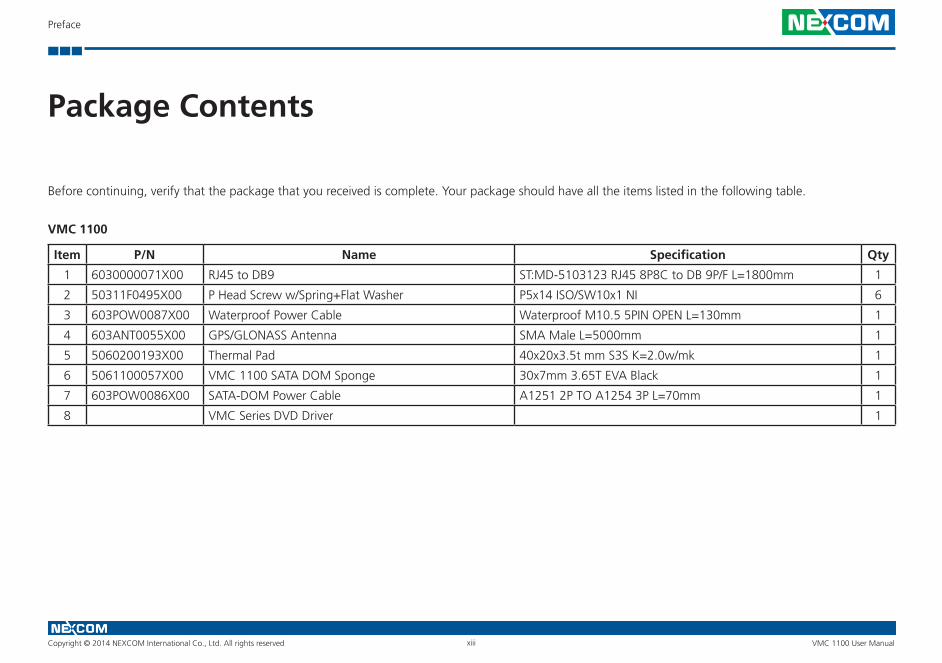
Before continuing, verify that the package that you received is complete. Your package should have all the items listed in the following table.
VMC 1100
Item P/N Name Specification Qty
1 6030000071X00 RJ45 to DB9 ST:MD-5103123 RJ45 8P8C to DB 9P/F L=1800mm 1
2 50311F0495X00 P Head Screw w/Spring+Flat Washer P5x14 ISO/SW10x1 NI 6
3 603POW0087X00 Waterproof Power Cable Waterproof M10.5 5PIN OPEN L=130mm 1
4 603ANT0055X00 GPS/GLONASS Antenna SMA Male L=5000mm 1
5 5060200193X00 Thermal Pad 40x20x3.5t mm S3S K=2.0w/mk 1
6 5061100057X00 VMC 1100 SATA DOM Sponge 30x7mm 3.65T EVA Black 1
7 603POW0086X00 SATA-DOM Power Cable A1251 2P TO A1254 3P L=70mm 1
8 VMC Series DVD Driver 1
Copyright © 2014 NEXCOM International Co., Ltd. All rights reserved xiv VMC 1100 User Manual
Preface
Ordering Information
The following provides ordering information.
• VMC 1100 (P/N: 10VC0110000X0) – VMC 1100 7” vehicle mount computer w/ Intel® AtomTM E3825, 2GB, 4w T/S
Copyright © 2014 NEXCOM International Co., Ltd. All rights reserved 1 VMC 1100 User Manual
Chapter 1: Product Introduction
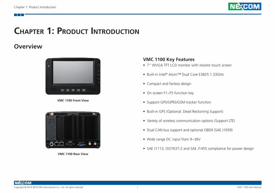
VMC 1100 Key Features• 7” WVGA TFT LCD monitor with resistor touch screen
• Built-in Intel® Atom™ Dual Core E3825 1.33GHz
• Compact and fanless design
• On screen F1~F5 function key
• Support GPS/GPRS/GSM tracker function
• Built-in GPS (Optional: Dead Reckoning Support)
• Variety of wireless communication options (Support LTE)
• Dual CAN bus support and optional OBDII (SAE J1939)
• Wide range DC input from 9~36V
• SAE J1113, ISO7637-2 and SAE J1455 compliance for power design
VMC 1100 Front View
VMC 1100 Rear View
ChaPter 1: ProduCt IntroduCtIon
Overview
Copyright © 2014 NEXCOM International Co., Ltd. All rights reserved 2 VMC 1100 User Manual
Chapter 1: Product Introduction
VMC 1100, a new generation 7-inch vehicle mount computer with dual core Intel® Atom™ processor, is designed for transportation applications requiring real-time vehicle tracking. Adopting the latest low power consumption processor and integrating a WVGA LCD with a brightness of 400nits and a 4-wire resistive touch sensor, VMC 1100 does not compromise with its space to sacrifice its functional features. It provides dual CANbus, RS-232, RS-485, USB 3.0, GPIO, analog input, PWM and LAN signal. For security, VMC 1100 supports real-time vehicle tracking through GPS and SMS/GSM/GPRS. VMC 1100 can also be upgraded to a different LCD resolution and include other features such as LTE, projected capacitive touch, CANbus protocol support and backup battery.
Copyright © 2014 NEXCOM International Co., Ltd. All rights reserved 3 VMC 1100 User Manual
Chapter 1: Product Introduction
Hardware Specifications
VMC 1100
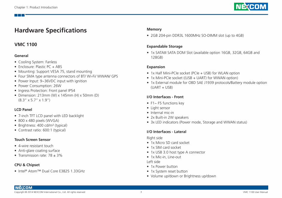
General
• Cooling System: Fanless• Enclosure: Plastic PC + ABS• Mounting: Support VESA 75, stand mounting• Four SMA type antenna connectors of BT/ Wi-Fi/ WWAN/ GPS• Power Input: 9~36VDC input with ignition• Power Consumption: 26W• Ingress Protection: Front panel IP54• Dimension: 213mm (W) x 145mm (H) x 50mm (D) (8.3” x 5.7” x 1.9”)
LCD Panel
• 7-inch TFT LCD panel with LED backlight• 800 x 480 pixels (WVGA)• Brightness: 400 cd/m² (typical)• Contrast ratio: 600:1 (typical)
Touch Screen Sensor
• 4-wire resistant touch• Anti-glare coating surface• Transmission rate: 78 ± 3%
CPU & Chipset
• Intel® Atom™ Dual Core E3825 1.33GHz
Memory
• 2GB 204-pin DDR3L 1600MHz SO-DIMM slot (up to 4GB)
Expandable Storage
• 1x SATAIII SATA DOM Slot (available option 16GB, 32GB, 64GB and 128GB)
Expansion
• 1x Half Mini-PCIe socket (PCIe + USB) for WLAN option• 1x Mini-PCIe socket ((USB + UART) for WWAN option)• 1x External module for OBD SAE J1939 protocols/Battery module option
(UART + USB)
I/O Interfaces - Front
• F1~ F5 functions key• Light sensor• Internal mic-in• 2x Built-in 2W speakers• 3x LED indicators (Power mode, Storage and WWAN status)
I/O Interfaces - Lateral
Right side• 1x Micro SD card socket• 1x SIM card socket• 1x USB 3.0 host type A connector• 1x Mic-in, Line-outLeft side• 1x Power button• 1x System reset button• Volume up/down or Brightness up/down
Copyright © 2014 NEXCOM International Co., Ltd. All rights reserved 4 VMC 1100 User Manual
Chapter 1: Product Introduction
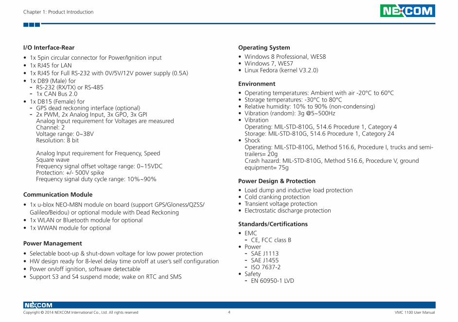
I/O Interface-Rear
• 1x 5pin circular connector for Power/Ignition input• 1x RJ45 for LAN• 1x RJ45 for Full RS-232 with 0V/5V/12V power supply (0.5A)• 1x DB9 (Male) for
- RS-232 (RX/TX) or RS-485 - 1x CAN Bus 2.0
• 1x DB15 (Female) for - GPS dead reckoning interface (optional)
- 2x PWM, 2x Analog Input, 3x GPO, 3x GPI Analog Input requirement for Voltages are measured Channel: 2 Voltage range: 0~38V Resolution: 8 bit
Analog Input requirement for Frequency, Speed Square wave Frequency signal offset voltage range: 0~15VDC Protection: +/- 500V spike Frequency signal duty cycle range: 10%~90%
Communication Module
• 1x u-blox NEO-M8N module on board (support GPS/Gloness/QZSS/Galileo/Beidou) or optional module with Dead Reckoning
• 1x WLAN or Bluetooth module for optional• 1x WWAN module for optional
Power Management
• Selectable boot-up & shut-down voltage for low power protection• HW design ready for 8-level delay time on/off at user’s self configuration• Power on/off ignition, software detectable• Support S3 and S4 suspend mode; wake on RTC and SMS
Operating System
• Windows 8 Professional, WES8• Windows 7, WES7• Linux Fedora (kernel V3.2.0)
Environment
• Operating temperatures: Ambient with air -20°C to 60°C• Storage temperatures: -30°C to 80°C• Relative humidity: 10% to 90% (non-condensing)• Vibration (random): 3g @5~500Hz• Vibration Operating: MIL-STD-810G, 514.6 Procedure 1, Category 4 Storage: MIL-STD-810G, 514.6 Procedure 1, Category 24• Shock Operating: MIL-STD-810G, Method 516.6, Procedure I, trucks and semi-
trailers= 20g Crash hazard: MIL-STD-810G, Method 516.6, Procedure V, ground
equipment= 75g
Power Design & Protection
• Load dump and inductive load protection• Cold cranking protection• Transient voltage protection• Electrostatic discharge protection
Standards/Certifications
• EMC - CE, FCC class B
• Power - SAE J1113 - SAE J1455 - ISO 7637-2
• Safety - EN 60950-1 LVD
Copyright © 2014 NEXCOM International Co., Ltd. All rights reserved 5 VMC 1100 User Manual
Chapter 1: Product Introduction
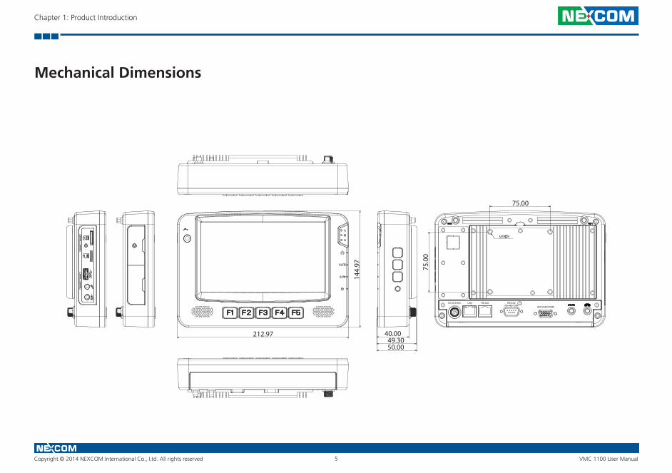
LAN RS-232
GPIO/ADC/PWM
DC IN 9-36V RS-232/RS-485+CAN
212.97
144.
97 75.0
0
75.00
40.0049.3050.00
Mechanical Dimensions
Copyright © 2014 NEXCOM International Co., Ltd. All rights reserved 6 VMC 1100 User Manual
Chapter 1: Product Introduction
Getting to Know VMC 1100
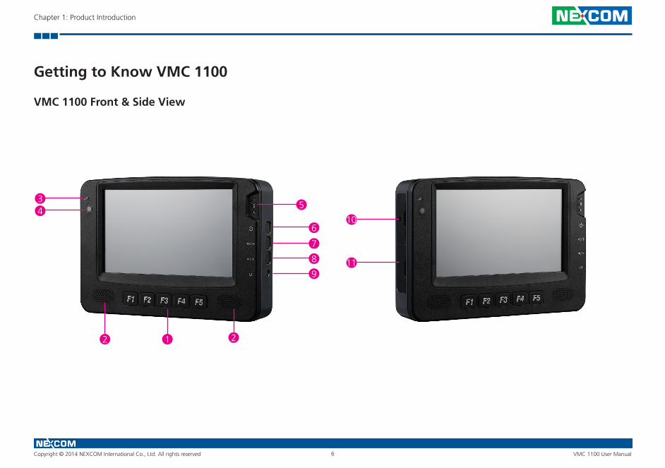
VMC 1100 Front & Side View
12 2
5
6
7
8
9
34
10
11

Copyright © 2014 NEXCOM International Co., Ltd. All rights reserved 7 VMC 1100 User Manual
Chapter 1: Product Introduction
VMC 1100 Rear View
20
19
12 12
18 17 16 15 14 13

Copyright © 2014 NEXCOM International Co., Ltd. All rights reserved 8 VMC 1100 User Manual
Chapter 1: Product Introduction
Item Function Description
1 Function Key There are five buttons and 5 function keys on VMC 1100.
2 Speaker VMC 1100 includes the dual speaker; the specification is 2W/ 8Ω.
3 Internal Mic-in Built-in microphone, does not need any monophonic input from an external microphone.
4 Light Sensor Light sensors can adjust a display’s backlight, which improves the power savings and optimizes the display’s viewability.
5 Indicator
• Power modeNo power, no lightInitial power-on: Green indicator stays lit around 2~3 seconds.Boot loader or BIOS status: Orange indicator blinking for 1 second.System login in status: Green indicator blinking for 1 second.All process ready in system, ready for customer use: Green indicator stays lit.
• Storage: Green, data is being read from or written to the storage driver.•WWAN: Green, the wireless WAN is on, and the radio link is ready for use. Blinking green, data is being transmitted.
6 Power Key
•When the ignition is from “low” to “high”, VMC will turn on automatically.•When the ignition is “high”, press the power button 5 seconds to turn on/off VMC.•When the ignition is from “high” to “low”, VMC will turn off automatically.•When the ignition is “low”, pressing the power button will not turn on VMC.•When you press it for 1 second, the display will turn on/off.
7, 8Volume key/
Brightness Control key
Volume Up/ Down (Default): Audio volume can be adjusted in 10 levels using the buttons.Brightness Control: There are two modes for Brightness Control: Manual Mode and Auto Mode.In Manual Mode, LCD brightness can be adjusted in 10 levels using the “+” or “-” buttons.
9 Reset Hardware reset.
10Left Side I/O with
Special Screw Lock
VMC 1100• SIM card slot•Micro SD slot

Copyright © 2014 NEXCOM International Co., Ltd. All rights reserved 9 VMC 1100 User Manual
Chapter 1: Product Introduction
Item Function Description
11 Left Side I/O
VMC 1100• USB 3.0•Mic-in• Line-out
12Wi-Fi Antenna
Connector• The 2 external SMA type antenna mounting connectors are used to connect the antenna to a WLAN module and
Bluetooth.
13GPS Antenna
Connector• The external SMA type antenna mounting connector is used to connect the antenna to a GPS module.
14WWAN Antenna
Connector• The external SMA type antenna mounting connector is used to connect the antenna to a WWAN module.
15 Multi I/O Port
DB15 female connector with GPIO/ADC/PWM.
Pin Description
1 Speed 1
2 Speed 2
3 ADC 0
4 ADC 1
5 A_GND
6 GPI 1
7 GPI 2
8 MDI 1 (for tracker, SOS)
Pin Description
9 GPO 1
10 GPO 2
11 MDI 2 (for tracker, release KEY)
12 DR GPS_IPPS
13 DR GPS_ODO
14 DR GPS_DIR
15 GND
Copyright © 2014 NEXCOM International Co., Ltd. All rights reserved 10 VMC 1100 User Manual
Chapter 1: Product Introduction
Item Function Description
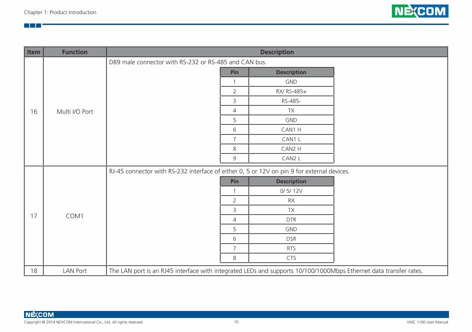
16 Multi I/O Port
DB9 male connector with RS-232 or RS-485 and CAN bus.
Pin Description
1 GND
2 RX/ RS-485+
3 RS-485-
4 TX
5 GND
6 CAN1 H
7 CAN1 L
8 CAN2 H
9 CAN2 L
17 COM1
RJ-45 connector with RS-232 interface of either 0, 5 or 12V on pin 9 for external devices.
Pin Description
1 0/ 5/ 12V
2 RX
3 TX
4 DTR
5 GND
6 DSR
7 RTS
8 CTS
18 LAN Port The LAN port is an RJ45 interface with integrated LEDs and supports 10/100/1000Mbps Ethernet data transfer rates.
Copyright © 2014 NEXCOM International Co., Ltd. All rights reserved 11 VMC 1100 User Manual
Chapter 1: Product Introduction
Item Function Description
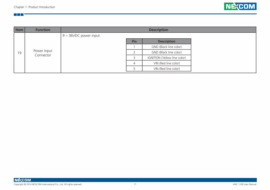
19Power Input Connector
9 ~ 36VDC power input
Pin Description
1 GND (Black line color)
2 GND (Black line color)
3 IGNITION (Yellow line color)
4 VIN (Red line color)
5 VIN (Red line color)

Copyright © 2014 NEXCOM International Co., Ltd. All rights reserved 12 VMC 1100 User Manual
Chapter 2: Using the GPS Feature
ChaPter 2: usIng the gPs feature
The VMC has a built-in GNSS receiver module by default.
You need to install the third-party GPS navigation software to take advantage of the GPS feature.
Setup and Using GPS InformationUsers can use the GPSinfo.exe program to verify that the GPS is correctly configured and working properly. Also, users can use the GPSinfo.exe pro-gram to enable WAAS/EGNOS and power saving mode.
1. Go to Device Manager to ensure the device is installed correctly.
Module: VIOB-GPS-02T
Chip:
• Receiver Type:
• O-M8N 72-channel u-blox M8 engine• GPS/QZSS L1 C/A, GLONASS L10F, BeiDou B1• SBAS L1 C/A: WAAS, EGNOS, MSAS
• Navigation Update Rate:
• Up to 18 Hz
• Accuracy Position:
• 2 m CEP
• Acquisition:
• Cold starts: 26s• Aided starts: 2s• Hot starts: 1s
• Sensitivity:
• Tracking: –167 dBm• Cold starts: –148 dBm• Hot starts: –156 dBm
COM Port for GPS: This COM comes from USB, so the address will change by the order of installing driver.Baud Rate: 9600
Copyright © 2014 NEXCOM International Co., Ltd. All rights reserved 13 VMC 1100 User Manual
Chapter 2: Using the GPS Feature
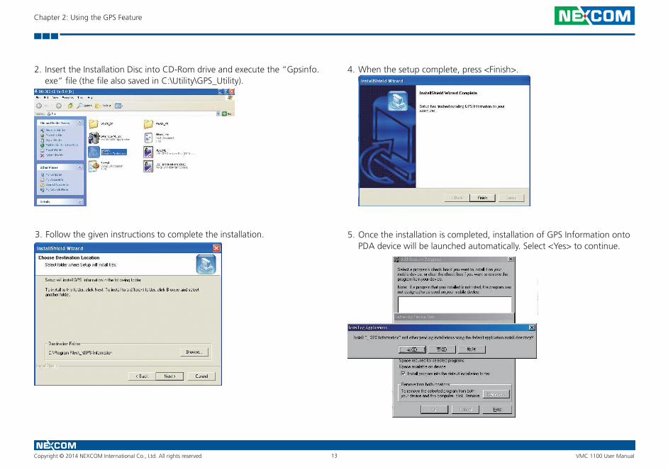
2. Insert the Installation Disc into CD-Rom drive and execute the “Gpsinfo.exe” file (the file also saved in C:\Utility\GPS_Utility).
3. Follow the given instructions to complete the installation.
4. When the setup complete, press <Finish>.
5. Once the installation is completed, installation of GPS Information onto PDA device will be launched automatically. Select <Yes> to continue.
Copyright © 2014 NEXCOM International Co., Ltd. All rights reserved 14 VMC 1100 User Manual
Chapter 2: Using the GPS Feature
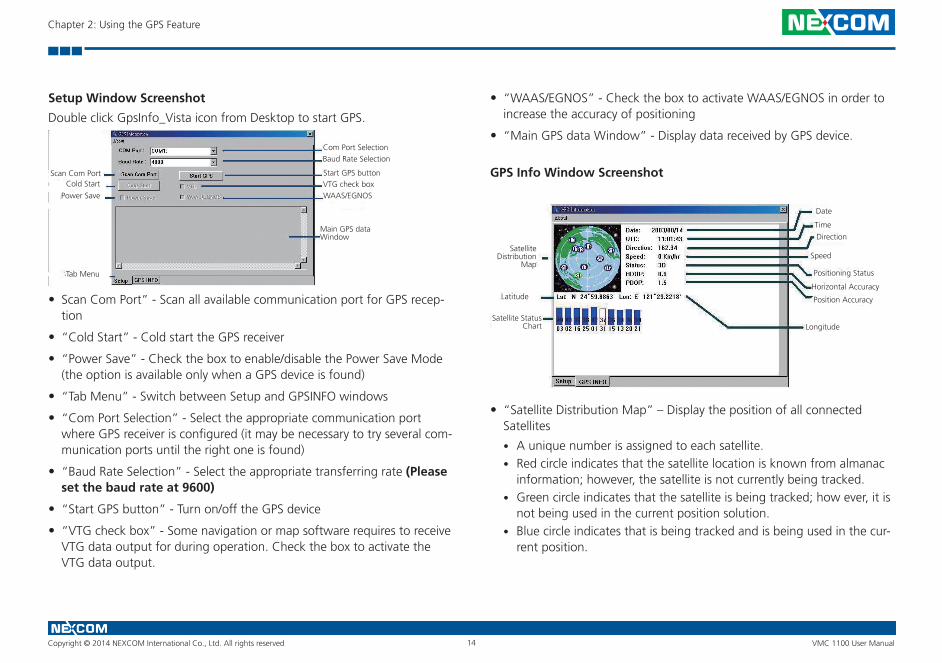
Setup Window Screenshot
Double click GpsInfo_Vista icon from Desktop to start GPS.
• Scan Com Port” - Scan all available communication port for GPS recep-tion
• “Cold Start” - Cold start the GPS receiver
• “Power Save” - Check the box to enable/disable the Power Save Mode (the option is available only when a GPS device is found)
• “Tab Menu” - Switch between Setup and GPSINFO windows
• “Com Port Selection” - Select the appropriate communication port where GPS receiver is configured (it may be necessary to try several com-munication ports until the right one is found)
• “Baud Rate Selection” - Select the appropriate transferring rate (Please set the baud rate at 9600)
• “Start GPS button” - Turn on/off the GPS device
• “VTG check box” - Some navigation or map software requires to receive VTG data output for during operation. Check the box to activate the VTG data output.
Com Port SelectionBaud Rate Selection
Start GPS buttonCold Start
Scan Com Port
Main GPS data Window
VTG check boxWAAS/EGNOSPower Save
Tab Menu
• “WAAS/EGNOS” - Check the box to activate WAAS/EGNOS in order to increase the accuracy of positioning
• “Main GPS data Window” - Display data received by GPS device.
GPS Info Window Screenshot
• “Satellite Distribution Map” – Display the position of all connected Satellites
• A unique number is assigned to each satellite.• Red circle indicates that the satellite location is known from almanac
information; however, the satellite is not currently being tracked.• Green circle indicates that the satellite is being tracked; how ever, it is
not being used in the current position solution.• Blue circle indicates that is being tracked and is being used in the cur-
rent position.
Satellite Distribution
Map
Latitude
Satellite Status Chart Longitude
Position Accuracy
Horizontal Accuracy
Positioning Status
Speed
Direction
Time
Date
Copyright © 2014 NEXCOM International Co., Ltd. All rights reserved 15 VMC 1100 User Manual
Chapter 2: Using the GPS Feature
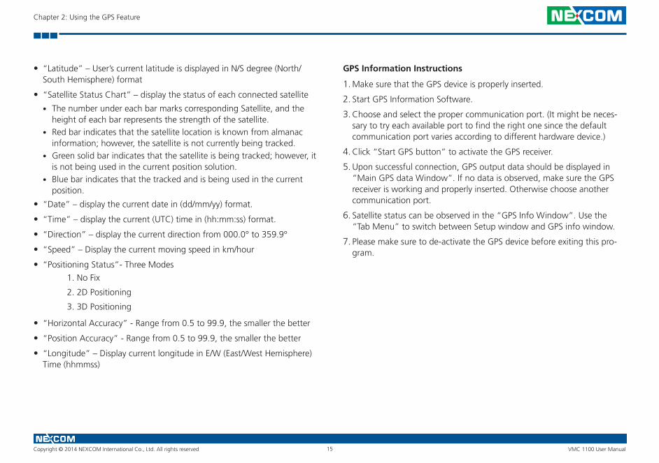
• “Latitude” – User’s current latitude is displayed in N/S degree (North/South Hemisphere) format
• “Satellite Status Chart” – display the status of each connected satellite
• The number under each bar marks corresponding Satellite, and the height of each bar represents the strength of the satellite.
• Red bar indicates that the satellite location is known from almanac information; however, the satellite is not currently being tracked.
• Green solid bar indicates that the satellite is being tracked; however, it is not being used in the current position solution.
• Blue bar indicates that the tracked and is being used in the current position.
• “Date” – display the current date in (dd/mm/yy) format.
• “Time” – display the current (UTC) time in (hh:mm:ss) format.
• “Direction” – display the current direction from 000.0° to 359.9°
• “Speed” – Display the current moving speed in km/hour
• “Positioning Status”- Three Modes
1. No Fix
2. 2D Positioning
3. 3D Positioning
• “Horizontal Accuracy” - Range from 0.5 to 99.9, the smaller the better
• “Position Accuracy” - Range from 0.5 to 99.9, the smaller the better
• “Longitude” – Display current longitude in E/W (East/West Hemisphere) Time (hhmmss)
GPS Information Instructions
1. Make sure that the GPS device is properly inserted.
2. Start GPS Information Software.
3. Choose and select the proper communication port. (It might be neces-sary to try each available port to find the right one since the default communication port varies according to different hardware device.)
4. Click “Start GPS button” to activate the GPS receiver.
5. Upon successful connection, GPS output data should be displayed in “Main GPS data Window”. If no data is observed, make sure the GPS receiver is working and properly inserted. Otherwise choose another communication port.
6. Satellite status can be observed in the “GPS Info Window”. Use the “Tab Menu” to switch between Setup window and GPS info window.
7. Please make sure to de-activate the GPS device before exiting this pro-gram.
Copyright © 2014 NEXCOM International Co., Ltd. All rights reserved 16 VMC 1100 User Manual
Chapter 3: Jumpers and Connectors
ChaPter 3: JumPers and ConneCtors
This chapter describes how to set the jumpers on the motherboard.
Before You Begin • Ensure you have a stable, clean working environment. Dust and dirt can
get into components and cause a malfunction. Use containers to keep small components separated.
• Adequate lighting and proper tools can prevent you from accidentally damaging the internal components. Most of the procedures that follow require only a few simple tools, including the following:
• A Philips screwdriver • A flat-tipped screwdriver • A set of jewelers Screwdrivers • A grounding strap • An anti-static pad
• Using your fingers can disconnect most of the connections. It is recom-mended that you do not use needle-nosed pliers to disconnect connec-tions as these can damage the soft metal or plastic parts of the connec-tors.
• Before working on internal components, make sure that the power is off. Ground yourself before touching any internal components, by touching a metal object. Static electricity can damage many of the electronic com-ponents. Humid environment tend to have less static electricity than dry
environments. A grounding strap is warranted whenever danger of static electricity exists.
Precautions Computer components and electronic circuit boards can be damaged by discharges of static electricity. Working on the computers that are still con-nected to a power supply can be extremely dangerous.
Follow the guidelines below to avoid damage to your computer or yourself:
• Always disconnect the unit from the power outlet whenever you are working inside the case.
• If possible, wear a grounded wrist strap when you are working inside the computer case. Alternatively, discharge any static electricity by touching the bare metal chassis of the unit case, or the bare metal body of any other grounded appliance.
• Hold electronic circuit boards by the edges only. Do not touch the com-ponents on the board unless it is necessary to do so. Don’t flex or stress the circuit board.
• Leave all components inside the static-proof packaging that they shipped with until they are ready for installation.
• Use correct screws and do not over tighten screws.
Copyright © 2014 NEXCOM International Co., Ltd. All rights reserved 17 VMC 1100 User Manual
Chapter 3: Jumpers and Connectors
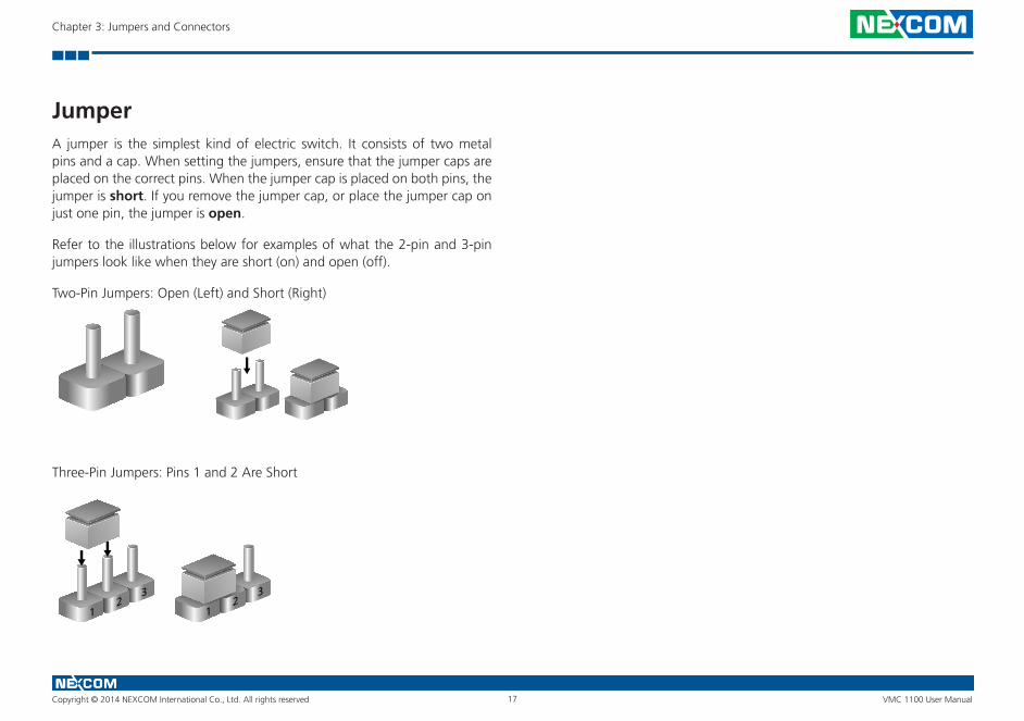
JumperA jumper is the simplest kind of electric switch. It consists of two metal pins and a cap. When setting the jumpers, ensure that the jumper caps are placed on the correct pins. When the jumper cap is placed on both pins, the jumper is short. If you remove the jumper cap, or place the jumper cap on just one pin, the jumper is open.
Refer to the illustrations below for examples of what the 2-pin and 3-pin jumpers look like when they are short (on) and open (off).
Two-Pin Jumpers: Open (Left) and Short (Right)
Three-Pin Jumpers: Pins 1 and 2 Are Short
12
3
12
3
Copyright © 2014 NEXCOM International Co., Ltd. All rights reserved 18 VMC 1100 User Manual
Chapter 3: Jumpers and Connectors
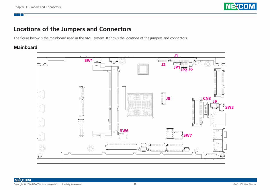
Locations of the Jumpers and ConnectorsThe figure below is the mainboard used in the VMC system. It shows the locations of the jumpers and connectors.
J2
J1
JP1
SW1
SW3
JP2
CN3
SW6SW7
J9J8
J6
Mainboard
Copyright © 2014 NEXCOM International Co., Ltd. All rights reserved 19 VMC 1100 User Manual
Chapter 3: Jumpers and Connectors
Internal Connectors and DIP Switch Settings
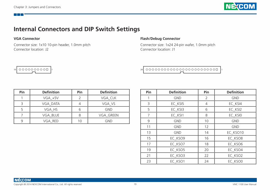
Pin Definition Pin Definition
1 VGA_+5V 2 VGA_CLK
3 VGA_DATA 4 VGA_VS
5 VGA_HS 6 GND
7 VGA_BLUE 8 VGA_GREEN
9 VGA_RED 10 GND
VGA Connector
Connector size: 1x10 10-pin header, 1.0mm pitchConnector location: J2
10 1 24 1
Flash/Debug Connector
Connector size: 1x24 24-pin wafer, 1.0mm pitchConnector location: J1
Pin Definition Pin Definition
1 GND 2 GND
3 EC_KSI5 4 EC_KSI4
5 EC_KSI3 6 EC_KSI2
7 EC_KSI1 8 EC_KSI0
9 GND 10 GND
11 GND 12 GND
13 GND 14 EC_KSO10
15 EC_KSO9 16 EC_KSO8
17 EC_KSO7 18 EC_KSO6
19 EC_KSO5 20 EC_KSO4
21 EC_KSO3 22 EC_KSO2
23 EC_KSO1 24 EC_KSO0
Copyright © 2014 NEXCOM International Co., Ltd. All rights reserved 20 VMC 1100 User Manual
Chapter 3: Jumpers and Connectors
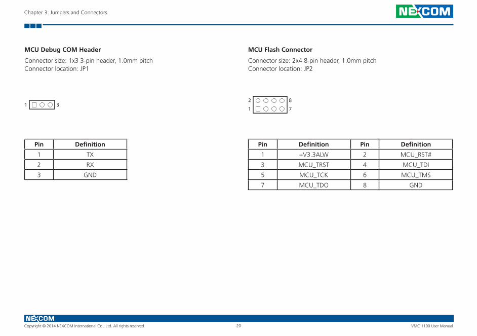
MCU Debug COM Header
Connector size: 1x3 3-pin header, 1.0mm pitchConnector location: JP1
Pin Definition
1 TX
2 RX
3 GND
MCU Flash Connector
Connector size: 2x4 8-pin header, 1.0mm pitchConnector location: JP2
1 7
2 8
Pin Definition Pin Definition
1 +V3.3ALW 2 MCU_RST#
3 MCU_TRST 4 MCU_TDI
5 MCU_TCK 6 MCU_TMS
7 MCU_TDO 8 GND
1 3

Copyright © 2014 NEXCOM International Co., Ltd. All rights reserved 21 VMC 1100 User Manual
Chapter 3: Jumpers and Connectors
EC Debug COM Connector
Connector size: 1x3 3-pin header, 1.0mm pitchConnector location: J6
Pin Definition
1 RX
2 GND
3 TX
1 3
Pin Definition Pin Definition
1 GND 2 PCIRST#
3 33M_CLK 4 LPC_FRAME#
5 LPC_AD3 6 LPC_AD2
7 LPC_AD1 8 LPC_AD0
9 VCC3 10 VCC3
Port 80 Debug Connector
Connector size: 1x10 10-pin header, 1.0mm pitchConnector location: J8
10 1
Copyright © 2014 NEXCOM International Co., Ltd. All rights reserved 22 VMC 1100 User Manual
Chapter 3: Jumpers and Connectors
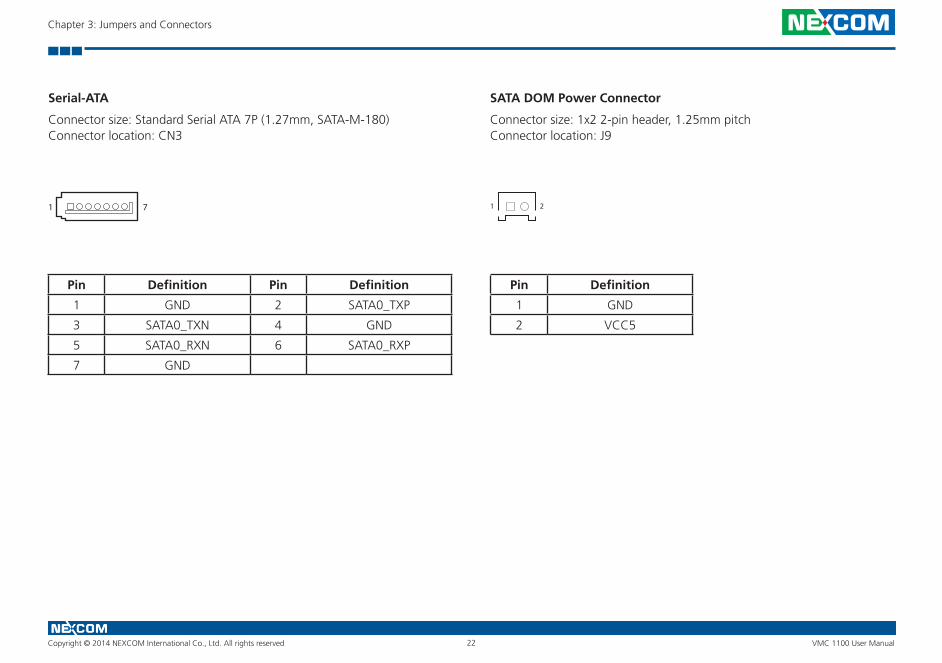
Serial-ATA
Connector size: Standard Serial ATA 7P (1.27mm, SATA-M-180)Connector location: CN3
SATA DOM Power Connector
Connector size: 1x2 2-pin header, 1.25mm pitchConnector location: J9
Pin Definition Pin Definition
1 GND 2 SATA0_TXP
3 SATA0_TXN 4 GND
5 SATA0_RXN 6 SATA0_RXP
7 GND
Pin Definition
1 GND
2 VCC5
1 7 1 2
Copyright © 2014 NEXCOM International Co., Ltd. All rights reserved 23 VMC 1100 User Manual
Chapter 3: Jumpers and Connectors
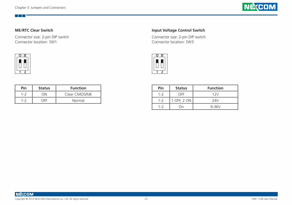
ME/RTC Clear Switch
Connector size: 2-pin DIP switchConnector location: SW1
Input Voltage Control Switch
Connector size: 2-pin DIP switchConnector location: SW3
Pin Status Function
1-2 ON Clear CMOS/ME
1-2 OFF Normal
Pin Status Function
1-2 OFF 12V
1-2 1 OFF, 2 ON 24V
1-2 On 9-36V
1
O N
2 1
O N
2
Copyright © 2014 NEXCOM International Co., Ltd. All rights reserved 24 VMC 1100 User Manual
Chapter 3: Jumpers and Connectors
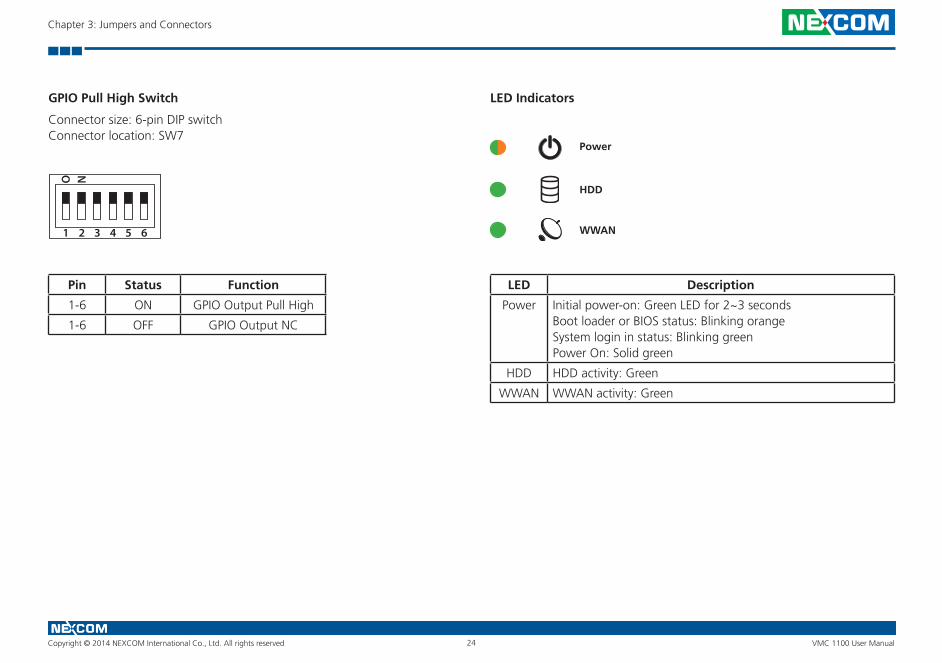
GPIO Pull High Switch
Connector size: 6-pin DIP switchConnector location: SW7
Pin Status Function
1-6 ON GPIO Output Pull High
1-6 OFF GPIO Output NC
1
O N
2 3 4 5 6
LED Indicators
Power
HDD
WWAN
LED Description
Power Initial power-on: Green LED for 2~3 secondsBoot loader or BIOS status: Blinking orange System login in status: Blinking greenPower On: Solid green
HDD HDD activity: Green
WWAN WWAN activity: Green
Copyright © 2014 NEXCOM International Co., Ltd. All rights reserved 25 VMC 1100 User Manual
Chapter 3: Jumpers and Connectors
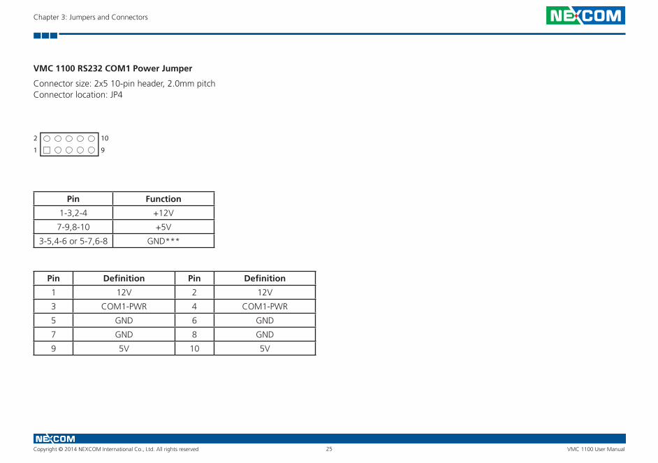
VMC 1100 RS232 COM1 Power Jumper
Connector size: 2x5 10-pin header, 2.0mm pitchConnector location: JP4
1 9
2 10
Pin Function
1-3,2-4 +12V
7-9,8-10 +5V
3-5,4-6 or 5-7,6-8 GND***
Pin Definition Pin Definition
1 12V 2 12V
3 COM1-PWR 4 COM1-PWR
5 GND 6 GND
7 GND 8 GND
9 5V 10 5V
Copyright © 2014 NEXCOM International Co., Ltd. All rights reserved 26 VMC 1100 User Manual
Chapter 3: Jumpers and Connectors
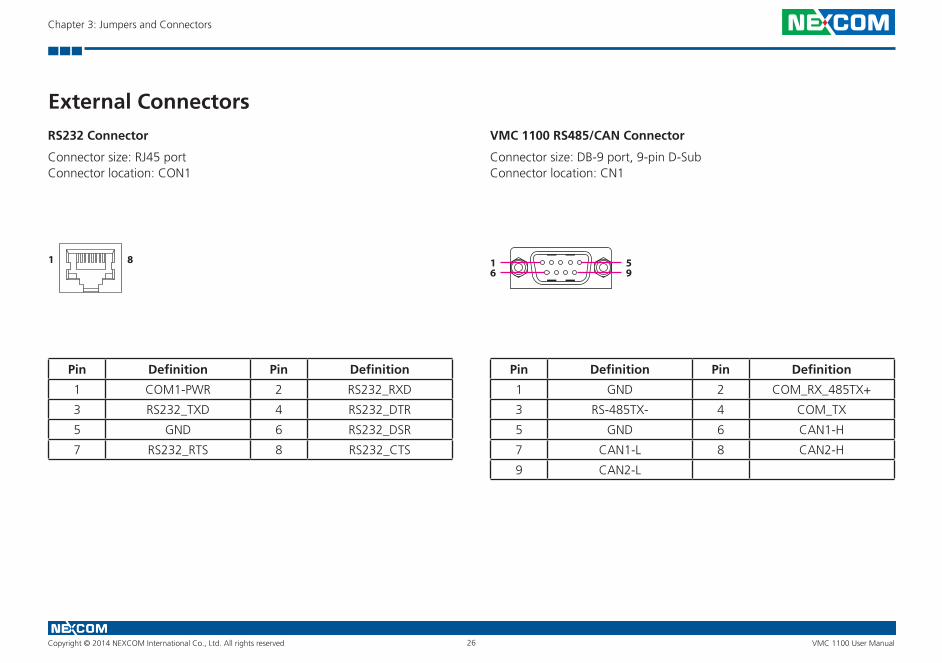
External ConnectorsRS232 Connector
Connector size: RJ45 portConnector location: CON1
Pin Definition Pin Definition
1 COM1-PWR 2 RS232_RXD
3 RS232_TXD 4 RS232_DTR
5 GND 6 RS232_DSR
7 RS232_RTS 8 RS232_CTS
VMC 1100 RS485/CAN Connector
Connector size: DB-9 port, 9-pin D-SubConnector location: CN1
Pin Definition Pin Definition
1 GND 2 COM_RX_485TX+
3 RS-485TX- 4 COM_TX
5 GND 6 CAN1-H
7 CAN1-L 8 CAN2-H
9 CAN2-L
81 1 596
Copyright © 2014 NEXCOM International Co., Ltd. All rights reserved 27 VMC 1100 User Manual
Chapter 3: Jumpers and Connectors
5
15 11
1
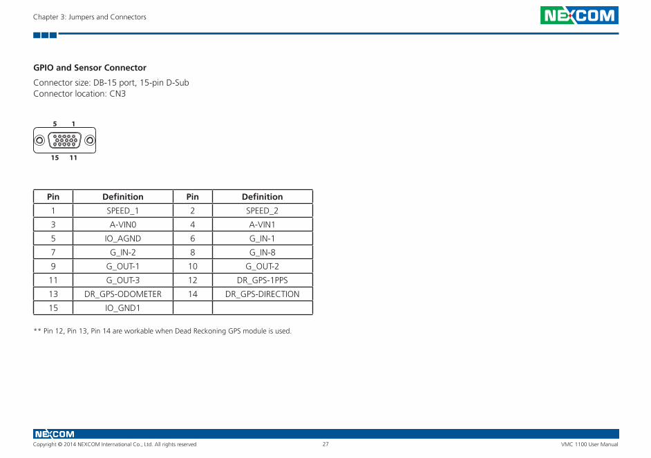
GPIO and Sensor Connector
Connector size: DB-15 port, 15-pin D-SubConnector location: CN3
Pin Definition Pin Definition
1 SPEED_1 2 SPEED_2
3 A-VIN0 4 A-VIN1
5 IO_AGND 6 G_IN-1
7 G_IN-2 8 G_IN-8
9 G_OUT-1 10 G_OUT-2
11 G_OUT-3 12 DR_GPS-1PPS
13 DR_GPS-ODOMETER 14 DR_GPS-DIRECTION
15 IO_GND1
** Pin 12, Pin 13, Pin 14 are workable when Dead Reckoning GPS module is used.
Copyright © 2014 NEXCOM International Co., Ltd. All rights reserved 28 VMC 1100 User Manual
Chapter 4: Function Key Code Constants
ChaPter 4: funCtIon Key Code Constants
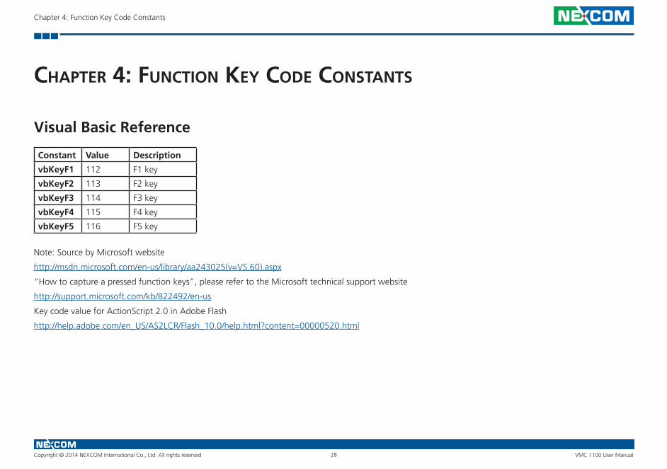
Visual Basic Reference
Constant Value Description
vbKeyF1 112 F1 key
vbKeyF2 113 F2 key
vbKeyF3 114 F3 key
vbKeyF4 115 F4 key
vbKeyF5 116 F5 key
Note: Source by Microsoft website
http://msdn.microsoft.com/en-us/library/aa243025(v=VS.60).aspx
“How to capture a pressed function keys”, please refer to the Microsoft technical support website
http://support.microsoft.com/kb/822492/en-us
Key code value for ActionScript 2.0 in Adobe Flash
http://help.adobe.com/en_US/AS2LCR/Flash_10.0/help.html?content=00000520.html
Copyright © 2014 NEXCOM International Co., Ltd. All rights reserved 29 VMC 1100 User Manual
Chapter 4: Function Key Code Constants
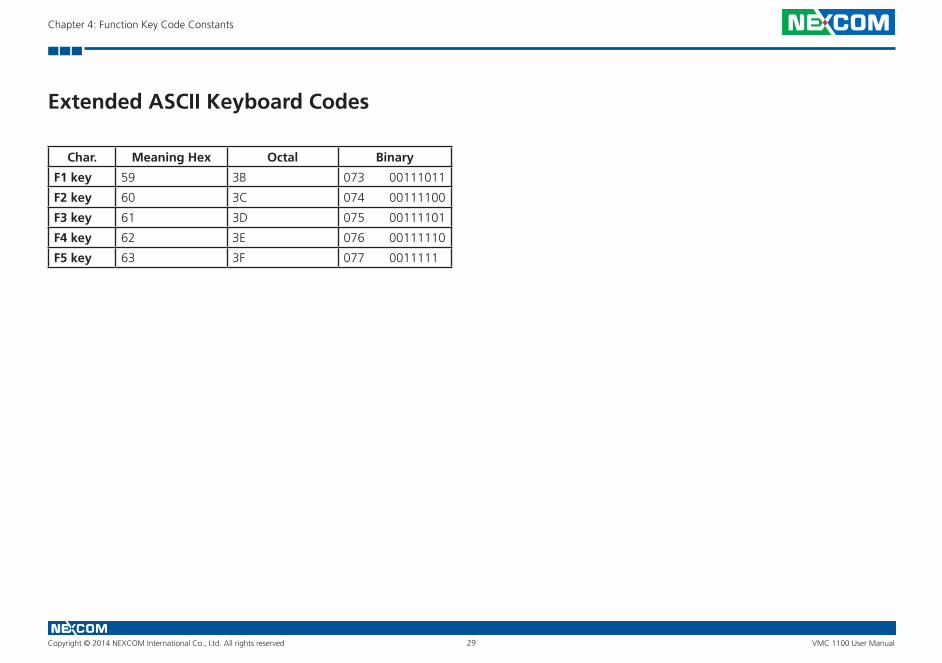
Extended ASCII Keyboard Codes
Char. Meaning Hex Octal Binary
F1 key 59 3B 073 00111011
F2 key 60 3C 074 00111100
F3 key 61 3D 075 00111101
F4 key 62 3E 076 00111110
F5 key 63 3F 077 0011111
Copyright © 2014 NEXCOM International Co., Ltd. All rights reserved 30 VMC 1100 User Manual
Chapter 5: Touchscreen Driver Installation
ChaPter 5: touChsCreen drIver InstallatIon
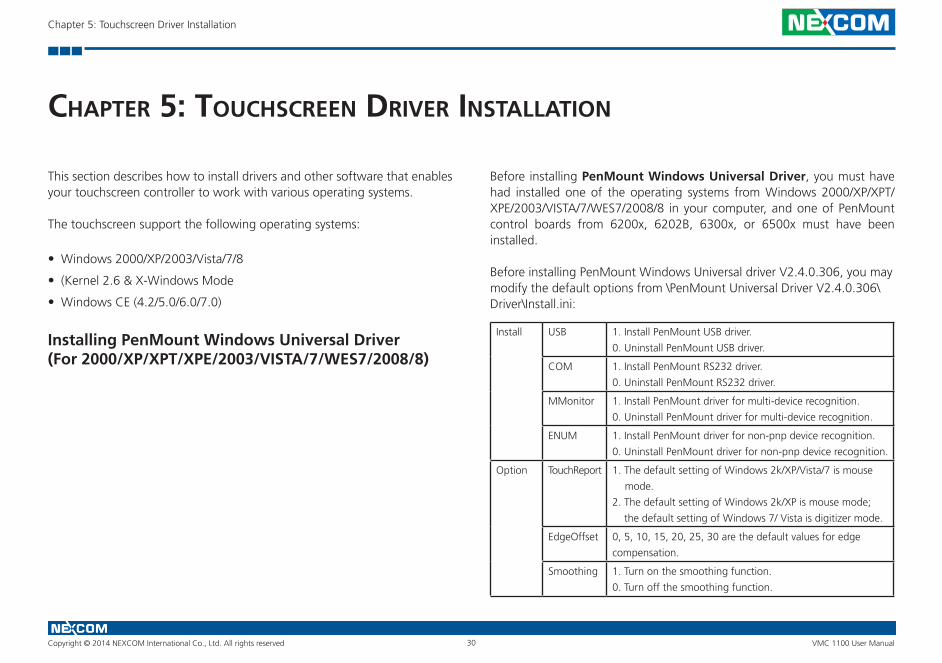
This section describes how to install drivers and other software that enables your touchscreen controller to work with various operating systems.
The touchscreen support the following operating systems:
• Windows 2000/XP/2003/Vista/7/8
• (Kernel 2.6 & X-Windows Mode
• Windows CE (4.2/5.0/6.0/7.0)
Installing PenMount Windows Universal Driver (For 2000/XP/XPT/XPE/2003/VISTA/7/WES7/2008/8)
Before installing PenMount Windows Universal Driver, you must have had installed one of the operating systems from Windows 2000/XP/XPT/XPE/2003/VISTA/7/WES7/2008/8 in your computer, and one of PenMount control boards from 6200x, 6202B, 6300x, or 6500x must have been installed.
Before installing PenMount Windows Universal driver V2.4.0.306, you may modify the default options from \PenMount Universal Driver V2.4.0.306\Driver\Install.ini:
Install USB 1. Install PenMount USB driver.
0. Uninstall PenMount USB driver.
COM 1. Install PenMount RS232 driver.
0. Uninstall PenMount RS232 driver.
MMonitor 1. Install PenMount driver for multi-device recognition.
0. Uninstall PenMount driver for multi-device recognition.
ENUM 1. Install PenMount driver for non-pnp device recognition.
0. Uninstall PenMount driver for non-pnp device recognition.
Option TouchReport 1. The default setting of Windows 2k/XP/Vista/7 is mouse
mode.
2. The default setting of Windows 2k/XP is mouse mode;
the default setting of Windows 7/ Vista is digitizer mode.
EdgeOffset 0, 5, 10, 15, 20, 25, 30 are the default values for edge
compensation.
Smoothing 1. Turn on the smoothing function.
0. Turn off the smoothing function.
Copyright © 2014 NEXCOM International Co., Ltd. All rights reserved 31 VMC 1100 User Manual
Chapter 5: Touchscreen Driver Installation
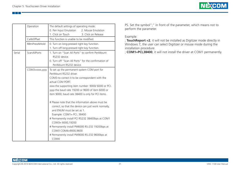
Operation The default settings of operating mode:
0. Pen Input Emulation 2. Mouse Emulation
1. Click on Touch 3. Click on Release
CalibOffset This function is unable to be modified.
RBtnPressNHold 0. Turn on long-pressed right key function.
1. Turn off long-pressed right key function.
Serial ScanAllPorts 1. Turn on “Scan All Ports” to confirm PenMount
RS232 device.
0. Turn off “Scan All Ports” for the confirmation of
PenMount RS232 device.
COM3=xxxx,yyyy To set up the permanent system COM port for
PenMount RS232 driver.
COM3-to correct it to be correspondent with the
actual COM PORT.
xxxx-the supporting item number: 9000/ 6000 or PCI.
yyyy-the baud rate 19200 or 9600 of item 6000 or
item 9000; baud rate 38400 is only for PCI items.
# Please note that the information above must be
correct, so that the device can just work normally,
and ENUM must be set as 1.
Example: COM1= PCI, 38400
# Permanently install PCI RS232 38400bps at COM1
COM3= 6000,19200
# Permanently install PM6000 RS-232 19200bps at
COM3 COM4=9000,9600
# Permanently install PM9000 RS-232 9600bps at
COM4
PS. Set the symbol”;” in front of the parameter, which means not to perform the parameter.
Example: ; TouchReport =2, it will not be installed as Digitizer mode directly in Windows 7, the user can select Digitizer or mouse mode during the installation procedure.; COM1=PCI,38400, it will not install the driver at COM1 permanently.
Copyright © 2014 NEXCOM International Co., Ltd. All rights reserved 32 VMC 1100 User Manual
Chapter 5: Touchscreen Driver Installation
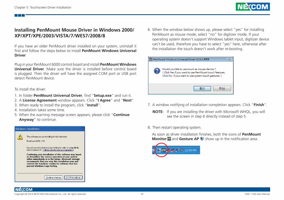
Installing PenMount Mouse Driver in Windows 2000/XP/XPT/XPE/2003/VISTA/7/WES7/2008/8
If you have an older PenMount driver installed on your system, uninstall it first and follow the steps below to install PenMount Windows Universal Driver:
Plug in your PenMount 6000 control board and install PenMount Windows Universal Driver. Make sure the driver is installed before control board is plugged. Then the driver will have the assigned COM port or USB port detect PenMount device.
To install the driver:
1. In folder PenMount Universal Driver, find “Setup.exe” and run it.2. A License Agreement window appears. Click “I Agree” and “Next”.3. When ready to install the program, click “Install”.4. Installation takes some time.5. When the warning message screen appears, please click “Continue
Anyway” to continue.
6. When the window below shows up, please select “yes” for installing PenMount as mouse mode; select “no” for digitizer mode. If your operating system doesn’t support Windows tablet input, digitizer device can’t be used, therefore you have to select “yes” here, otherwise after the installation the touch doesn’t work after re-booting.
7. A window notifying of installation completion appears. Click “Finish”.
NOTE: If you are installing the driver with Microsoft WHQL, you will see the screen in step 6 directly instead of step 5.
8. Then restart operating system.
As soon as driver installation finishes, both the icons of PenMount Monitor and Gesture AP show up in the notification area.
Copyright © 2014 NEXCOM International Co., Ltd. All rights reserved 33 VMC 1100 User Manual
Chapter 5: Touchscreen Driver Installation
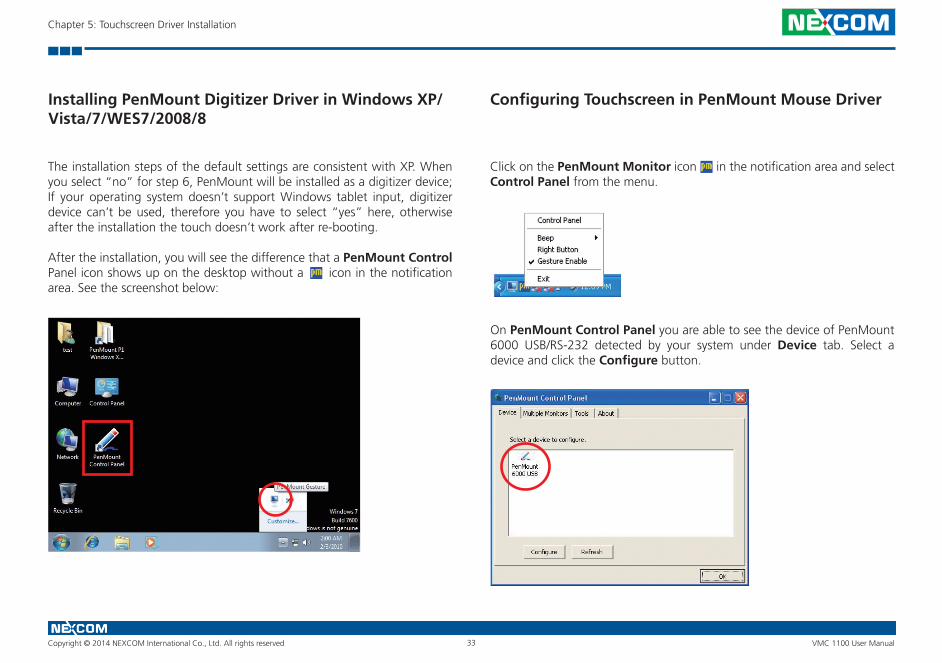
Installing PenMount Digitizer Driver in Windows XP/Vista/7/WES7/2008/8
The installation steps of the default settings are consistent with XP. When you select “no” for step 6, PenMount will be installed as a digitizer device; If your operating system doesn’t support Windows tablet input, digitizer device can’t be used, therefore you have to select “yes” here, otherwise after the installation the touch doesn’t work after re-booting.
After the installation, you will see the difference that a PenMount Control Panel icon shows up on the desktop without a icon in the notification area. See the screenshot below:
Configuring Touchscreen in PenMount Mouse Driver
Click on the PenMount Monitor icon in the notification area and select Control Panel from the menu.
On PenMount Control Panel you are able to see the device of PenMount 6000 USB/RS-232 detected by your system under Device tab. Select a device and click the Configure button.
Copyright © 2014 NEXCOM International Co., Ltd. All rights reserved 34 VMC 1100 User Manual
Chapter 5: Touchscreen Driver Installation
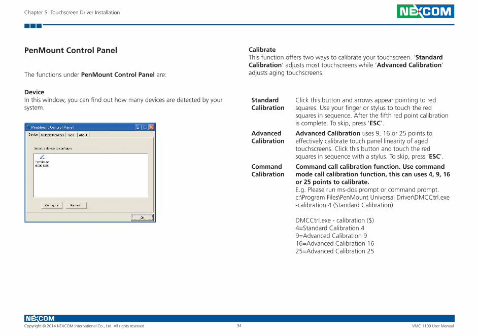
PenMount Control Panel
The functions under PenMount Control Panel are:
DeviceIn this window, you can find out how many devices are detected by your system.
CalibrateThis function offers two ways to calibrate your touchscreen. ‘Standard Calibration’ adjusts most touchscreens while ‘Advanced Calibration’ adjusts aging touchscreens.
Standard Calibration
Click this button and arrows appear pointing to red squares. Use your finger or stylus to touch the red squares in sequence. After the fifth red point calibration is complete. To skip, press ‘ESC’.
Advanced Calibration
Advanced Calibration uses 9, 16 or 25 points to effectively calibrate touch panel linearity of aged touchscreens. Click this button and touch the red squares in sequence with a stylus. To skip, press ‘ESC’.
Command Calibration
Command call calibration function. Use command mode call calibration function, this can uses 4, 9, 16 or 25 points to calibrate.E.g. Please run ms-dos prompt or command prompt.c:\Program Files\PenMount Universal Driver\DMCCtrl.exe -calibration 4 (Standard Calibration)
DMCCtrl.exe - calibration ($)4=Standard Calibration 49=Advanced Calibration 916=Advanced Calibration 1625=Advanced Calibration 25
Copyright © 2014 NEXCOM International Co., Ltd. All rights reserved 35 VMC 1100 User Manual
Chapter 5: Touchscreen Driver Installation
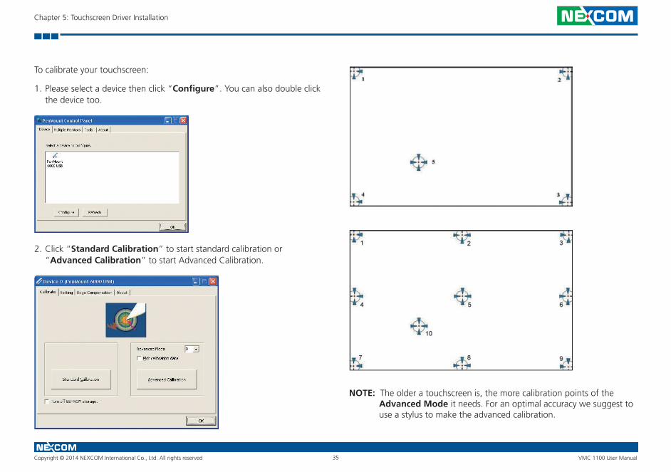
To calibrate your touchscreen:
1. Please select a device then click “Configure”. You can also double click the device too.
2. Click “Standard Calibration” to start standard calibration or “Advanced Calibration” to start Advanced Calibration.
NOTE: The older a touchscreen is, the more calibration points of the Advanced Mode it needs. For an optimal accuracy we suggest to use a stylus to make the advanced calibration.
Copyright © 2014 NEXCOM International Co., Ltd. All rights reserved 36 VMC 1100 User Manual
Chapter 5: Touchscreen Driver Installation
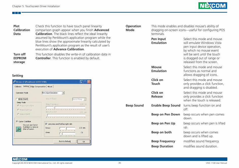
Plot Calibration Data
Check this function to have touch panel linearity comparison graph appear when you finish Advanced Calibration. The black lines reflect the ideal linearity assumed by PenMount’s application program while the blue lines show the approximate linearity calculated by PenMount’s application program as the result of user’s execution of Advance Calibration.
Turn off EEPROM storage
This function disables the write-in of calibration data in Controller. This function is enabled by default.
Setting
Operation Mode
This mode enables and disables mouse’s ability of dragging on-screen icons—useful for configuring POS terminals.
Pen Input Emulation
Select this mode and mouse will emulate Windows Vista pen input device operation, by which no mouse event will be sent until the touch is dragged out of range or released from the screen.
Mouse Emulation
Select this mode and mouse functions as normal and allows dragging of icons.
Click on Touch
Select this mode and mouse only provides a click function, and dragging is disabled.
Click on Release
Select this mode and mouse only provides a click function when the touch is released.
Beep Sound Enable Beep Sound turns beep function on and off.
Beep on Pen Down beep occurs when pen comes down.
Beep on Pen Up beep occurs when pen is lifted up.
Beep on both beep occurs when comes down and is lifted up.
Beep Frequency modifies sound frequency.
Beep Duration modifies sound duration.
Copyright © 2014 NEXCOM International Co., Ltd. All rights reserved 37 VMC 1100 User Manual
Chapter 5: Touchscreen Driver Installation
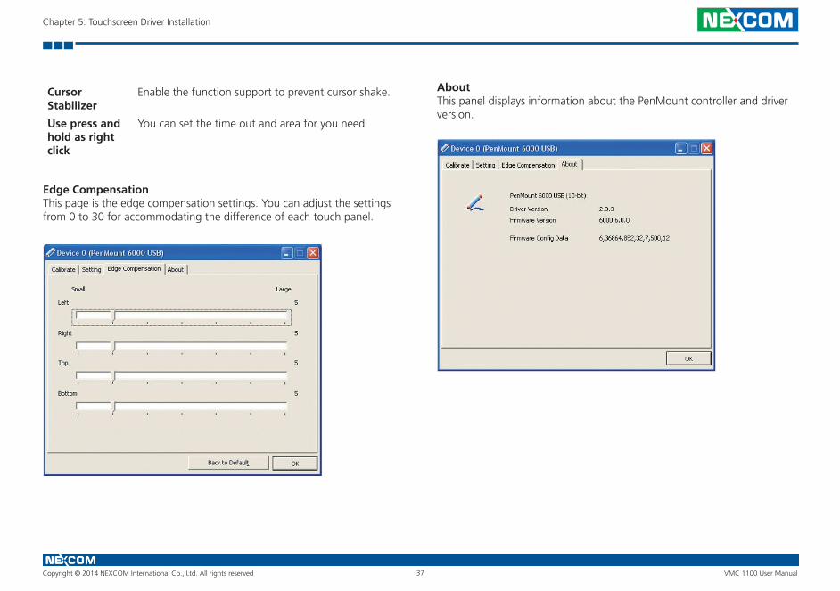
Edge CompensationThis page is the edge compensation settings. You can adjust the settings from 0 to 30 for accommodating the difference of each touch panel.
About This panel displays information about the PenMount controller and driver version.
Cursor Stabilizer
Enable the function support to prevent cursor shake.
Use press andhold as right click
You can set the time out and area for you need
Copyright © 2014 NEXCOM International Co., Ltd. All rights reserved 38 VMC 1100 User Manual
Chapter 5: Touchscreen Driver Installation
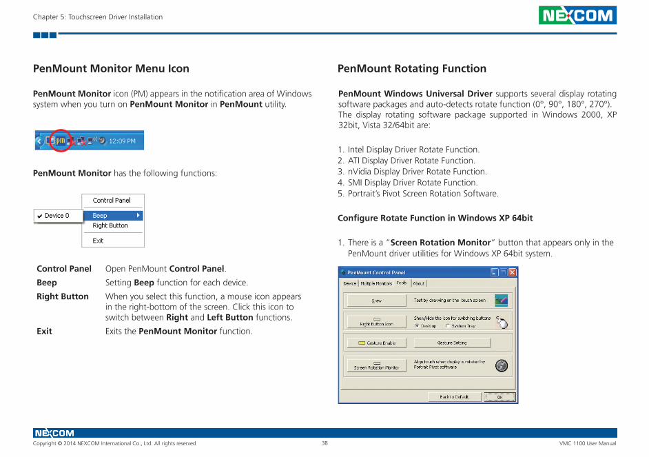
PenMount Monitor Menu Icon
PenMount Monitor icon (PM) appears in the notification area of Windows system when you turn on PenMount Monitor in PenMount utility.
PenMount Monitor has the following functions:
Control Panel Open PenMount Control Panel.
Beep Setting Beep function for each device.
Right Button When you select this function, a mouse icon appears in the right-bottom of the screen. Click this icon to switch between Right and Left Button functions.
Exit Exits the PenMount Monitor function.
PenMount Rotating Function
PenMount Windows Universal Driver supports several display rotating software packages and auto-detects rotate function (0°, 90°, 180°, 270°). The display rotating software package supported in Windows 2000, XP 32bit, Vista 32/64bit are:
1. Intel Display Driver Rotate Function.2. ATI Display Driver Rotate Function. 3. nVidia Display Driver Rotate Function. 4. SMI Display Driver Rotate Function. 5. Portrait’s Pivot Screen Rotation Software.
Configure Rotate Function in Windows XP 64bit
1. There is a “Screen Rotation Monitor” button that appears only in the PenMount driver utilities for Windows XP 64bit system.
Copyright © 2014 NEXCOM International Co., Ltd. All rights reserved 39 VMC 1100 User Manual
Chapter 5: Touchscreen Driver Installation
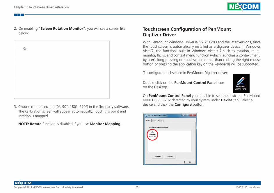
2. On enabling “Screen Rotation Monitor”, you will see a screen like below:
3. Choose rotate function (0°, 90°, 180°, 270°) in the 3rd party software. The calibration screen will appear automatically. Touch this point and rotation is mapped.
NOTE: Rotate function is disabled if you use Monitor Mapping.
Touchscreen Configuration of PenMount Digitizer Driver
With PenMount Windows Universal V2.2.0.283 and the later versions, since the touchscreen is automatically installed as a digitizer device in Windows Vista/7, the functions built in Windows Vista / 7 such as rotation, multi-monitor, flicks, and context menu function (which launches a context menu by user’s long-pressing on touchscreen rather than clicking the right mouse button or pressing the application key on the keyboard) will be supported.
To configure touchscreen in PenMount Digitizer driver:
Double-click on the PenMount Control Panel icon on the Desktop.
On PenMount Control Panel you are able to see the device of PenMount 6000 USB/RS-232 detected by your system under Device tab. Select a device and click the Configure button.
Copyright © 2014 NEXCOM International Co., Ltd. All rights reserved 40 VMC 1100 User Manual
Chapter 5: Touchscreen Driver Installation
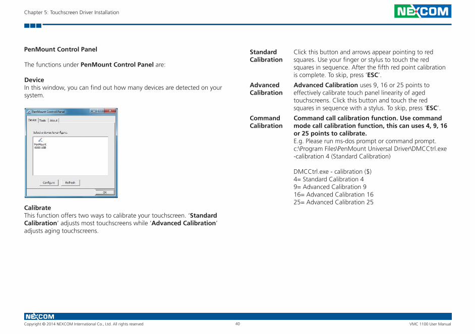
PenMount Control Panel
The functions under PenMount Control Panel are:
DeviceIn this window, you can find out how many devices are detected on your system.
CalibrateThis function offers two ways to calibrate your touchscreen. ‘Standard Calibration’ adjusts most touchscreens while ‘Advanced Calibration’ adjusts aging touchscreens.
Standard Calibration
Click this button and arrows appear pointing to red squares. Use your finger or stylus to touch the red squares in sequence. After the fifth red point calibration is complete. To skip, press ‘ESC’.
Advanced Calibration
Advanced Calibration uses 9, 16 or 25 points to effectively calibrate touch panel linearity of aged touchscreens. Click this button and touch the red squares in sequence with a stylus. To skip, press ‘ESC’.
Command Calibration
Command call calibration function. Use command mode call calibration function, this can uses 4, 9, 16 or 25 points to calibrate.E.g. Please run ms-dos prompt or command prompt.c:\Program Files\PenMount Universal Driver\DMCCtrl.exe -calibration 4 (Standard Calibration)
DMCCtrl.exe - calibration ($)4= Standard Calibration 49= Advanced Calibration 916= Advanced Calibration 1625= Advanced Calibration 25
Copyright © 2014 NEXCOM International Co., Ltd. All rights reserved 41 VMC 1100 User Manual
Chapter 5: Touchscreen Driver Installation
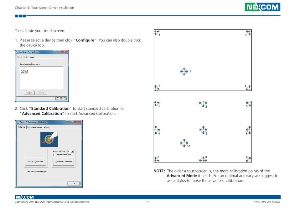
To calibrate your touchscreen:
1. Please select a device then click “Configure”. You can also double click the device too.
2. Click “Standard Calibration” to start standard calibration or “Advanced Calibration” to start Advanced Calibration.
NOTE: The older a touchscreen is, the more calibration points of the Advanced Mode it needs. For an optimal accuracy we suggest to use a stylus to make the advanced calibration.

Copyright © 2014 NEXCOM International Co., Ltd. All rights reserved 42 VMC 1100 User Manual
Chapter 5: Touchscreen Driver Installation
Plot CalibrationData
Check this function to have touch panel linearity comparison graph appear when you finish Advanced Calibration. The black lines reflect the ideal linearity assumed by PenMount’s application program while the blue lines show the approximate linearity calculated by PenMount’s application program as the result of user’s execution of Advance Calibration.
Turn off EEPROM storage
This function disables the write-in of calibration data in Controller. This function is enabled by default.
Edge CompensationThis page is the edge compensation settings. You can adjust the settings from 0 to 30 for accommodating the difference of each touch panel.
AboutThis panel displays information about the PenMount controller and driver version.
Copyright © 2014 NEXCOM International Co., Ltd. All rights reserved 43 VMC 1100 User Manual
Chapter 5: Touchscreen Driver Installation
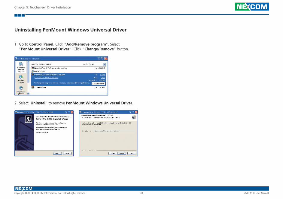
Uninstalling PenMount Windows Universal Driver
1. Go to Control Panel. Click “Add/Remove program”. Select ”PenMount Universal Driver”. Click “Change/Remove” button.
2. Select ‘Uninstall’ to remove PenMount Windows Universal Driver.
Copyright © 2014 NEXCOM International Co., Ltd. All rights reserved 44 VMC 1100 User Manual
Chapter 5: Touchscreen Driver Installation
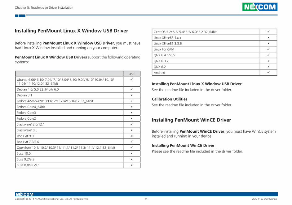
Installing PenMount Linux X Window USB Driver
Before installing PenMount Linux X Window USB Driver, you must have had Linux X Window installed and running on your computer.
PenMount Linux X Window USB Drivers support the following operating systems:
USB
Ubuntu 6.06/ 6.10/ 7.04/ 7.10/ 8.04/ 8.10/ 9.04/ 9.10/ 10.04/ 10.10/ 11.04/ 11.10/12.04 32_64bit
Debian 4.0/ 5.0 32_64bit/ 6.0
Debian 3.1
Fedora 4/5/6/7/89/10/11/12/13 /14/15/16/17 32_64bit
Fedora Core4_64bit
Fedora Core3
Fedora Core2
Slackware12.0/12.1
Slackware10.0
Red Hat 9.0
Red Hat 7.3/8.0
OpenSuse 10.1/ 10.2/ 10.3/ 11/ 11.1/ 11.2/ 11.3/ 11.4/ 12.1 32_64bit
Suse 10.0
Suse 9.2/9.3
Suse 8.0/9.0/9.1
Cent OS 5.2/ 5.3/ 5.4/ 5.5/ 6.0/ 6.2 32_64bit
Linux XFree86 4.x.x
Linux XFree86 3.3.6
Linux For GPM
QNX 6.4.1/ 6.5
QNX 6.3.2
QNX 6.2
Android
Installing PenMount Linux X Window USB Driver
See the readme file included in the driver folder.
Calibration Utilities
See the readme file included in the driver folder.
Installing PenMount WinCE Driver
Before installing PenMount WinCE Driver, you must have WinCE system installed and running in your device.
Installing PenMount WinCE Driver
Please see the readme file included in the driver folder.
Copyright © 2014 NEXCOM International Co., Ltd. All rights reserved 45 VMC 1100 User Manual
Chapter 5: Touchscreen Driver Installation
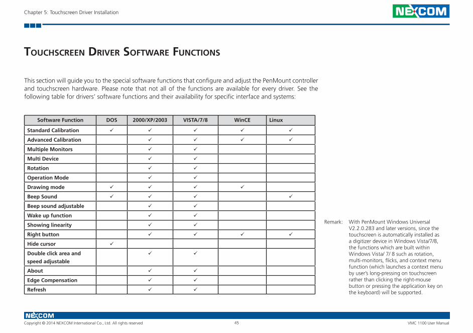
touChsCreen drIver software funCtIons
This section will guide you to the special software functions that configure and adjust the PenMount controller and touchscreen hardware. Please note that not all of the functions are available for every driver. See the following table for drivers’ software functions and their availability for specific interface and systems:
Software Function DOS 2000/XP/2003 VISTA/7/8 WinCE Linux
Standard Calibration
Advanced Calibration
Multiple Monitors
Multi Device
Rotation
Operation Mode
Drawing mode
Beep Sound
Beep sound adjustable
Wake up function
Showing linearity
Right button
Hide cursor
Double click area and
speed adjustable
About
Edge Compensation
Refresh
Remark: With PenMount Windows Universal V2.2.0.283 and later versions, since the touchscreen is automatically installed as a digitizer device in Windows Vista/7/8, the functions which are built within Windows Vista/ 7/ 8 such as rotation, multi-monitors, flicks, and context menu function (which launches a context menu by user’s long-pressing on touchscreen rather than clicking the right-mouse button or pressing the application key on the keyboard) will be supported.
Copyright © 2014 NEXCOM International Co., Ltd. All rights reserved 46 VMC 1100 User Manual
Chapter 5: Touchscreen Driver Installation
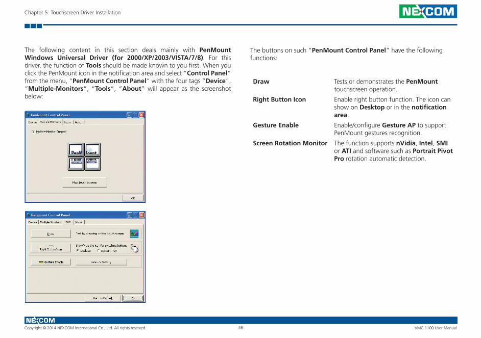
The following content in this section deals mainly with PenMount Windows Universal Driver (for 2000/XP/2003/VISTA/7/8). For this driver, the function of Tools should be made known to you first. When you click the PenMount icon in the notification area and select “Control Panel” from the menu, “PenMount Control Panel” with the four tags “Device”, “Multiple-Monitors”, “Tools”, “About” will appear as the screenshot below:
The buttons on such “PenMount Control Panel” have the following functions:
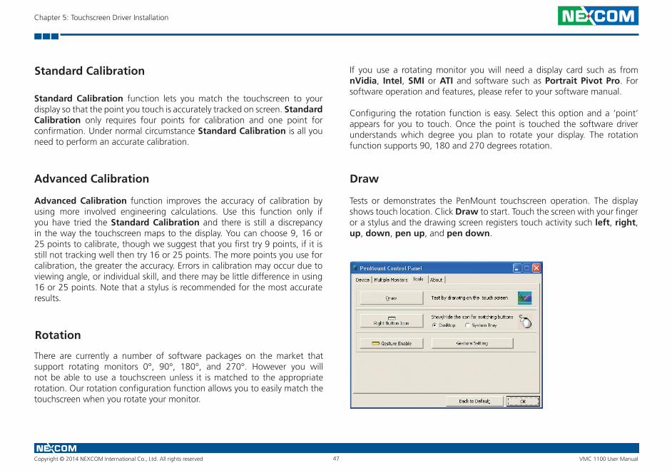
Draw Tests or demonstrates the PenMount touchscreen operation.
Right Button Icon Enable right button function. The icon can show on Desktop or in the notification area.
Gesture Enable Enable/configure Gesture AP to support PenMount gestures recognition.
Screen Rotation Monitor The function supports nVidia, Intel, SMI or ATI and software such as Portrait Pivot Pro rotation automatic detection.
Copyright © 2014 NEXCOM International Co., Ltd. All rights reserved 47 VMC 1100 User Manual
Chapter 5: Touchscreen Driver Installation
Standard Calibration
Standard Calibration function lets you match the touchscreen to your display so that the point you touch is accurately tracked on screen. Standard Calibration only requires four points for calibration and one point for confirmation. Under normal circumstance Standard Calibration is all you need to perform an accurate calibration.
Advanced Calibration
Advanced Calibration function improves the accuracy of calibration by using more involved engineering calculations. Use this function only if you have tried the Standard Calibration and there is still a discrepancy in the way the touchscreen maps to the display. You can choose 9, 16 or 25 points to calibrate, though we suggest that you first try 9 points, if it is still not tracking well then try 16 or 25 points. The more points you use for calibration, the greater the accuracy. Errors in calibration may occur due to viewing angle, or individual skill, and there may be little difference in using 16 or 25 points. Note that a stylus is recommended for the most accurate results.
Rotation
There are currently a number of software packages on the market that support rotating monitors 0°, 90°, 180°, and 270°. However you will not be able to use a touchscreen unless it is matched to the appropriate rotation. Our rotation configuration function allows you to easily match the touchscreen when you rotate your monitor.
If you use a rotating monitor you will need a display card such as from nVidia, Intel, SMI or ATI and software such as Portrait Pivot Pro. For software operation and features, please refer to your software manual.
Configuring the rotation function is easy. Select this option and a ‘point’ appears for you to touch. Once the point is touched the software driver understands which degree you plan to rotate your display. The rotation function supports 90, 180 and 270 degrees rotation.
Draw
Tests or demonstrates the PenMount touchscreen operation. The display shows touch location. Click Draw to start. Touch the screen with your finger or a stylus and the drawing screen registers touch activity such left, right, up, down, pen up, and pen down.
Copyright © 2014 NEXCOM International Co., Ltd. All rights reserved 48 VMC 1100 User Manual
Chapter 5: Touchscreen Driver Installation
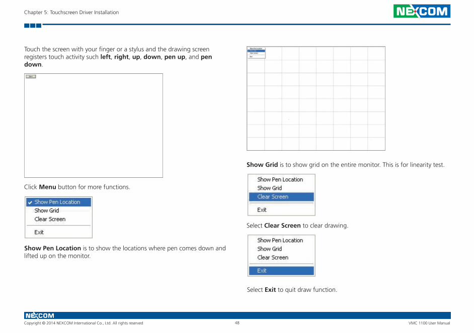
Touch the screen with your finger or a stylus and the drawing screen registers touch activity such left, right, up, down, pen up, and pen down.
Click Menu button for more functions.
Show Pen Location is to show the locations where pen comes down and lifted up on the monitor.
Show Grid is to show grid on the entire monitor. This is for linearity test.
Select Clear Screen to clear drawing.
Select Exit to quit draw function.
Copyright © 2014 NEXCOM International Co., Ltd. All rights reserved 49 VMC 1100 User Manual
Chapter 5: Touchscreen Driver Installation
Mouse Operation Mode
Mouse Operation Mode enables and disables mouse’s ability of dragging onscreen icons, which is applicable to the configuration of POS terminals.
Pen Input Emulation
Select this mode and mouse will emulate Windows Vista pen input device operation, by which no mouse event will be sent until the touch is dragged out of range or released from the screen.
MouseEmulation
Select this mode and mouse functions as normal and allows dragging of icons.
Click on Touch Select this mode and mouse only provides a click function, and dragging is disabled.
Click on Release Select this mode and mouse only provides a click function when the touch is released.
Beep Sound
All of PenMount’s drivers support the beep sound function; however some PC systems may only offer a fixed buzzer sound.
Beep Sound Adjustable
Software drivers for Windows systems let the user adjust the frequency and length of the beep sound. The drivers let the user adjust the desired touch-screen sound, as well as turn the sound off.
Wake Up Function
Wake Up function lets the user touch the screen and wake the system up from ‘suspend’ mode.
Plot Calibration Data
Plot Calibration Data function displays the touchscreen linearity map, which is available if the PenMount driver provides an Advance Calibration function. When touchscreens age their touch linearity declines. This non-linearity is apparent when the touched point on the touchscreen is not the same as the point on the display. The Plot Calibration Data function shows the linearity status of the touchscreen. This is only a support function for the user. The exact linearity of a touchscreen requires a linearity test machine.
Right Button
Right Button function simulates the right button function of a mouse. Click the right button and the user can only touch the screen once and the driver changes the touch definition to the left button.
Hide Cursor
Hide Cursor function keeps the cursor arrow and other cursor symbols from appearing when using the touchscreen. The cursor appears when user turns this function off.
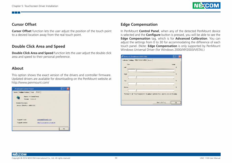
Copyright © 2014 NEXCOM International Co., Ltd. All rights reserved 50 VMC 1100 User Manual
Chapter 5: Touchscreen Driver Installation
Cursor Offset
Cursor Offset function lets the user adjust the position of the touch point to a desired location away from the real touch point.
Double Click Area and Speed
Double Click Area and Speed function lets the user adjust the double click area and speed to their personal preference.
About
This option shows the exact version of the drivers and controller firmware. Updated drivers are available for downloading on the PenMount website at http://www.penmount.com/
Edge Compensation
In PenMount Control Panel, when any of the detected PenMount device is selected and the Configure button is pressed, you will be able to see the Edge Compensation tag, which is for Advanced Calibration. You can adjust the settings from 0 to 30 for accommodating the difference of each touch panel. (Note: Edge Compensation is only supported by PenMount Windows Universal Driver (for Windows 2000/XP/2003/VISTA).)
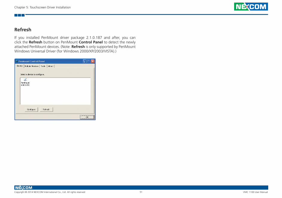
Copyright © 2014 NEXCOM International Co., Ltd. All rights reserved 51 VMC 1100 User Manual
Chapter 5: Touchscreen Driver Installation
Refresh
If you installed PenMount driver package 2.1.0.187 and after, you can click the Refresh button on PenMount Control Panel to detect the newly attached PenMount devices. (Note: Refresh is only supported by PenMount Windows Universal Driver (for Windows 2000/XP/2003/VISTA).)
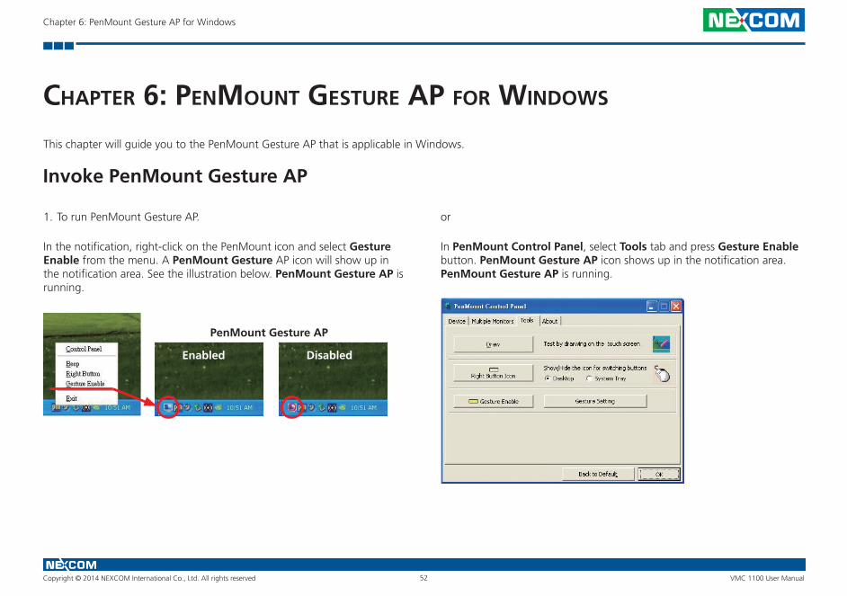
Copyright © 2014 NEXCOM International Co., Ltd. All rights reserved 52 VMC 1100 User Manual
Chapter 6: PenMount Gesture AP for Windows
ChaPter 6: Penmount gesture aP for wIndows
This chapter will guide you to the PenMount Gesture AP that is applicable in Windows.
Invoke PenMount Gesture AP
1. To run PenMount Gesture AP.
In the notification, right-click on the PenMount icon and select Gesture Enable from the menu. A PenMount Gesture AP icon will show up in the notification area. See the illustration below. PenMount Gesture AP is running.
PenMount Gesture AP
Enabled Disabled
In PenMount Control Panel, select Tools tab and press Gesture Enable button. PenMount Gesture AP icon shows up in the notification area. PenMount Gesture AP is running.
or
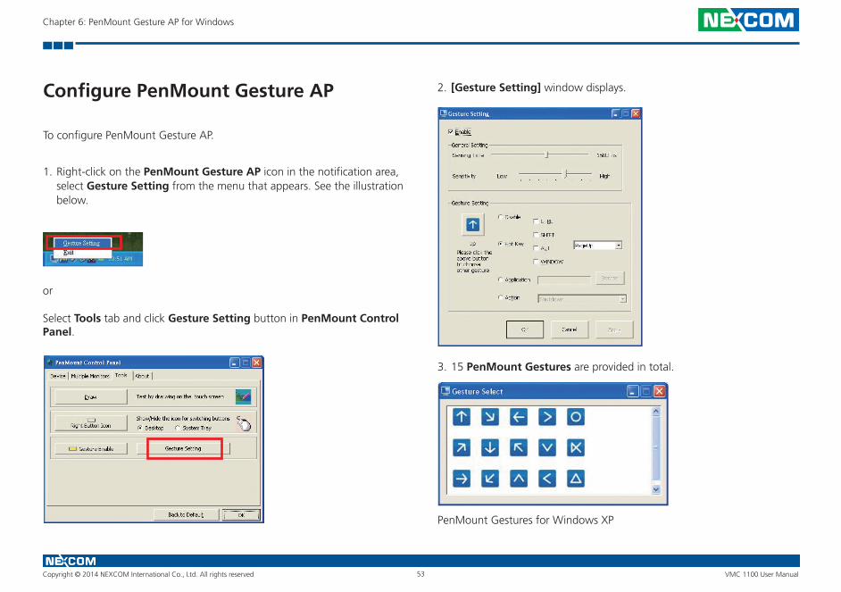
Copyright © 2014 NEXCOM International Co., Ltd. All rights reserved 53 VMC 1100 User Manual
Chapter 6: PenMount Gesture AP for Windows
Configure PenMount Gesture AP
To configure PenMount Gesture AP.
1. Right-click on the PenMount Gesture AP icon in the notification area, select Gesture Setting from the menu that appears. See the illustration below.
or
Select Tools tab and click Gesture Setting button in PenMount Control Panel.
2. [Gesture Setting] window displays.
3. 15 PenMount Gestures are provided in total.
PenMount Gestures for Windows XP
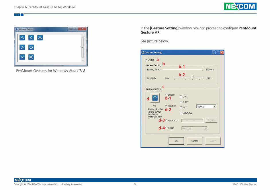
Copyright © 2014 NEXCOM International Co., Ltd. All rights reserved 54 VMC 1100 User Manual
Chapter 6: PenMount Gesture AP for Windows
PenMount Gestures for Windows Vista / 7/ 8
In the [Gesture Setting] window, you can proceed to configure PenMount Gesture AP:
See picture below.
ab
b-1
b-2
c
d d-1
d-2
d-3
d-4
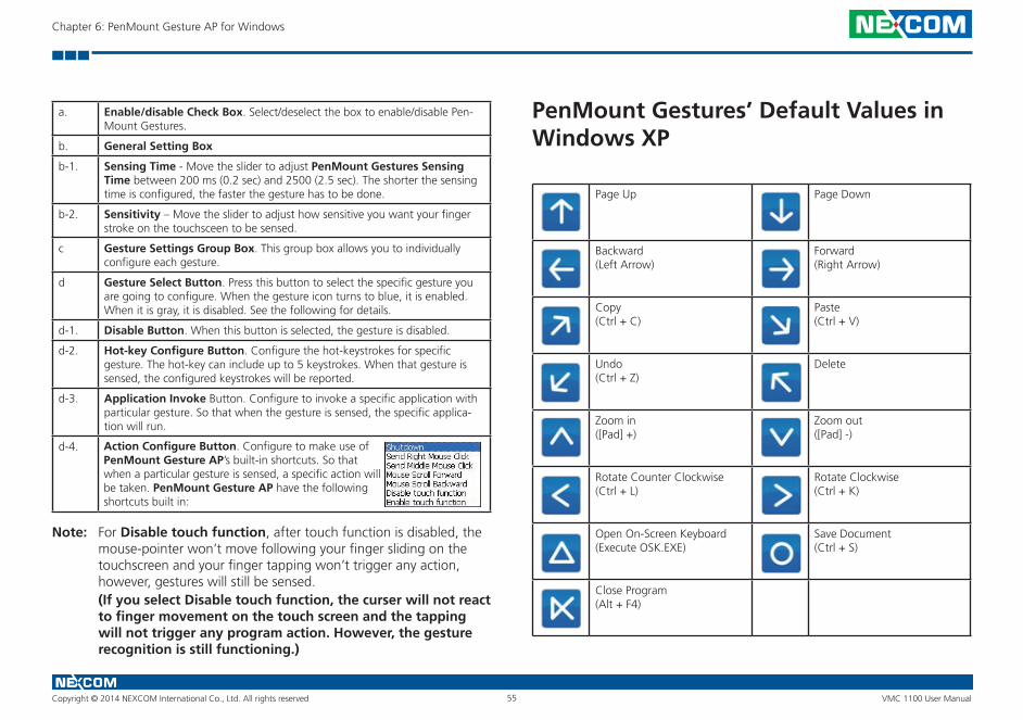
Copyright © 2014 NEXCOM International Co., Ltd. All rights reserved 55 VMC 1100 User Manual
Chapter 6: PenMount Gesture AP for Windows
a. Enable/disable Check Box. Select/deselect the box to enable/disable Pen-Mount Gestures.
b. General Setting Box
b-1. Sensing Time - Move the slider to adjust PenMount Gestures Sensing Time between 200 ms (0.2 sec) and 2500 (2.5 sec). The shorter the sensing time is configured, the faster the gesture has to be done.
b-2. Sensitivity – Move the slider to adjust how sensitive you want your finger stroke on the touchsceen to be sensed.
c Gesture Settings Group Box. This group box allows you to individually configure each gesture.
d Gesture Select Button. Press this button to select the specific gesture you are going to configure. When the gesture icon turns to blue, it is enabled. When it is gray, it is disabled. See the following for details.
d-1. Disable Button. When this button is selected, the gesture is disabled.
d-2. Hot-key Configure Button. Configure the hot-keystrokes for specific gesture. The hot-key can include up to 5 keystrokes. When that gesture is sensed, the configured keystrokes will be reported.
d-3. Application Invoke Button. Configure to invoke a specific application with particular gesture. So that when the gesture is sensed, the specific applica-tion will run.
d-4.
For Disable touch function, after touch function is disabled, the mouse-pointer won’t move following your finger sliding on the touchscreen and your finger tapping won’t trigger any action, however, gestures will still be sensed.
Action Configure Button. Configure to make use of PenMount Gesture AP’s built-in shortcuts. So that when a particular gesture is sensed, a specific action will be taken. PenMount Gesture AP have the following shortcuts built in:
(If you select Disable touch function, the curser will not react to finger movement on the touch screen and the tapping will not trigger any program action. However, the gesture recognition is still functioning.)
Note:
PenMount Gestures’ Default Values in Windows XP
Page Up Page Down
Backward(Left Arrow)
Forward(Right Arrow)
Copy(Ctrl + C)
Paste(Ctrl + V)
Undo(Ctrl + Z)
Delete
Zoom in([Pad] +)
Zoom out([Pad] -)
Rotate Counter Clockwise(Ctrl + L)
Rotate Clockwise(Ctrl + K)
Open On-Screen Keyboard(Execute OSK.EXE)
Save Document(Ctrl + S)
Close Program(Alt + F4)
Copyright © 2014 NEXCOM International Co., Ltd. All rights reserved 56 VMC 1100 User Manual
Chapter 7: Enable a Hibernate Once/Resume Many
ChaPter 7: enable a hIbernate onCe/resume many
Environment by Using EWFPlease note that EWF is only available for VMC 1100 series. The following instructions help you easily enable the EWF function.
Please refer to the following link.
https://msdn.microsoft.com/en-US/library/ff794943(v=winembedded.60).aspx
Here is all the syntax for EWF Manager (Standard 7 SP1)
https://msdn.microsoft.com/en-US/library/ff794092(v=winembedded.60).aspx
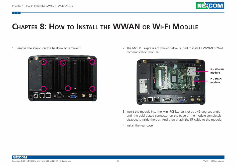
Copyright © 2014 NEXCOM International Co., Ltd. All rights reserved 57 VMC 1100 User Manual
Chapter 8: How to Install the WWAN or Wi-Fi Module
ChaPter 8: how to Install the wwan or wI-fI module
1. Remove the screws on the heatsink to remove it. 2. The Mini PCI express slot shown below is used to install a WWAN or Wi-Fi communication module.
For WWAN module
For Wi-Fi module
3. Insert the module into the Mini PCI Express slot at a 45 degrees angle until the gold-plated connector on the edge of the module completely disappears inside the slot. And then attach the RF cable to the module.
4. Install the rear cover.
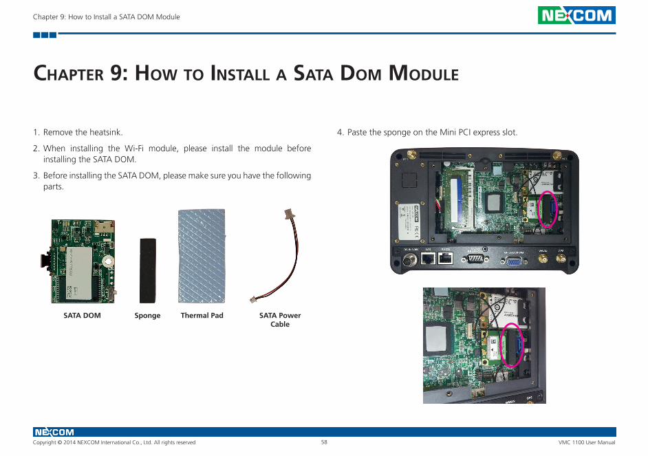
Copyright © 2014 NEXCOM International Co., Ltd. All rights reserved 58 VMC 1100 User Manual
Chapter 9: How to Install a SATA DOM Module
ChaPter 9: how to Install a sata dom module
1. Remove the heatsink.
2. When installing the Wi-Fi module, please install the module before installing the SATA DOM.
3. Before installing the SATA DOM, please make sure you have the following parts.
SATA DOM Thermal PadSponge SATA Power Cable
4. Paste the sponge on the Mini PCI express slot.
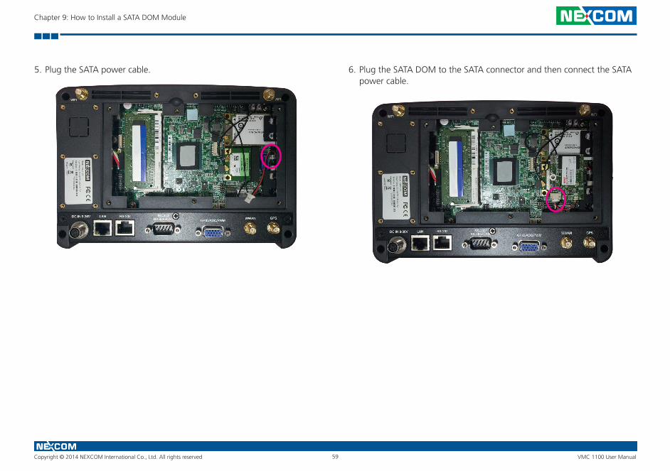
Copyright © 2014 NEXCOM International Co., Ltd. All rights reserved 59 VMC 1100 User Manual
Chapter 9: How to Install a SATA DOM Module
5. Plug the SATA power cable. 6. Plug the SATA DOM to the SATA connector and then connect the SATA power cable.
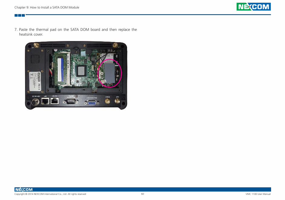
Copyright © 2014 NEXCOM International Co., Ltd. All rights reserved 60 VMC 1100 User Manual
Chapter 9: How to Install a SATA DOM Module
7. Paste the thermal pad on the SATA DOM board and then replace the heatsink cover.
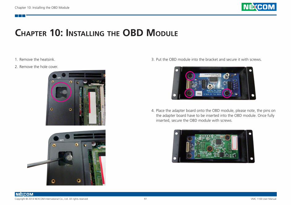
Copyright © 2014 NEXCOM International Co., Ltd. All rights reserved 61 VMC 1100 User Manual
Chapter 10: Installing the OBD Module
ChaPter 10: InstallIng the obd module
1. Remove the heatsink.
2. Remove the hole cover.
3. Put the OBD module into the bracket and secure it with screws.
4. Place the adapter board onto the OBD module, please note, the pins on the adapter board have to be inserted into the OBD module. Once fully inserted, secure the OBD module with screws.
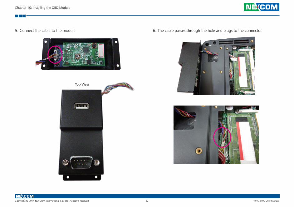
Copyright © 2014 NEXCOM International Co., Ltd. All rights reserved 62 VMC 1100 User Manual
Chapter 10: Installing the OBD Module
5. Connect the cable to the module. 6. The cable passes through the hole and plugs to the connector.
Top View
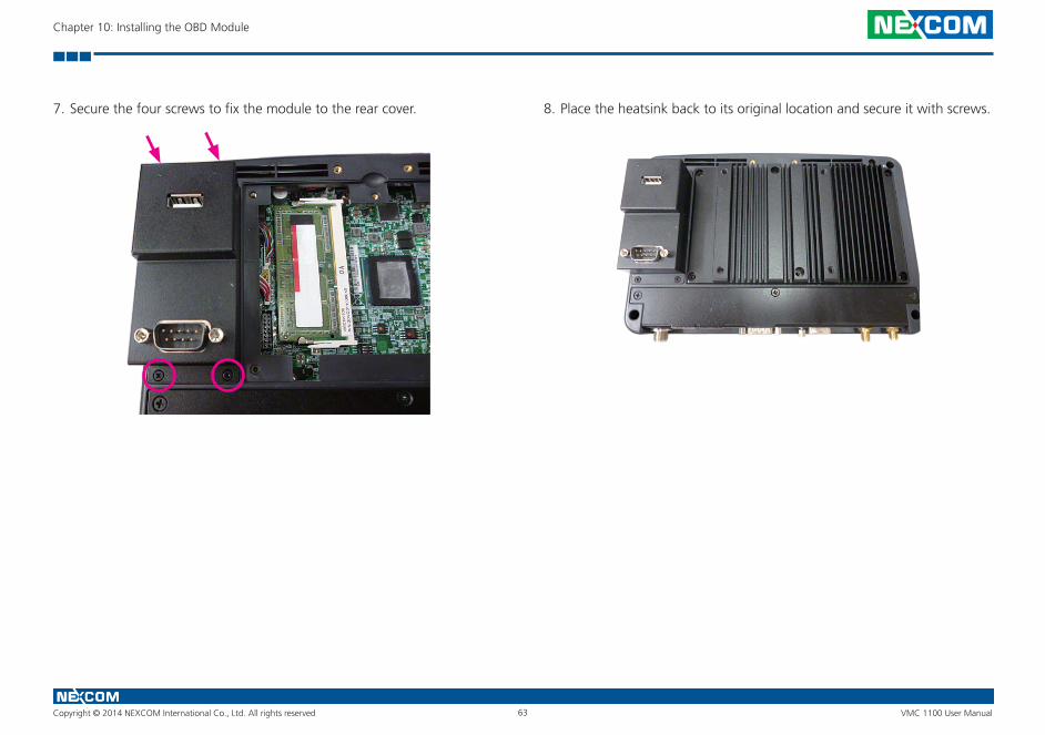
Copyright © 2014 NEXCOM International Co., Ltd. All rights reserved 63 VMC 1100 User Manual
Chapter 10: Installing the OBD Module
7. Secure the four screws to fix the module to the rear cover. 8. Place the heatsink back to its original location and secure it with screws.
Copyright © 2014 NEXCOM International Co., Ltd. All rights reserved 64 VMC 1100 User Manual
Appendix A: I/O Address Function
aPPendIx a: I/o address funCtIon
IO ADDRESS:0EE0H~0EEFH
(*) for default setting
1. Ignition_status/ Battery_status/12V_status/
I/O port : 0EE0H
Bit 0: Reseversion
Bit 1: Reseversion
Bit 2: Ignition (read only)
0: OFF
1: ON
Bit 3: Status of Car Battery
0: Car Battery is OK
1: Car Battery is Low voltage
Bit 4: Status of +12V output
0: circuit normal(under 4A)
1: over circuit(over 4A)
Bit 5: Status of Car Battery bypass output
0: circuit normal(under 4A)
1: over circuit(over 4A)
Bit 4 and Bit 5: The action will delay 10ms~15ms
Copyright © 2014 NEXCOM International Co., Ltd. All rights reserved 65 VMC 1100 User Manual
Appendix A: I/O Address Function
2. Capacity of NEXCOM battery (8 bits)
I/O port :0EE1H
Bit 7 Bit 6 Bit 5 Bit 4 Bit 3 Bit 2 Bit1 Bit 0
Description 8 bits data (Bit 7 is highest bit of data)
3. Voltage of NEXCOM battery (8 bits)
I/O port : 0EE2H
Bit 7 Bit 6 Bit 5 Bit 4 Bit 3 Bit 2 Bit1 Bit 0
Description 8 bits data (Bit 7 is highest bit of data)
Copyright © 2014 NEXCOM International Co., Ltd. All rights reserved 66 VMC 1100 User Manual
Appendix A: I/O Address Function
4. Status of NEXCOM battery (8 bits)
I/O port : 0EE3H
Bit 0: Status for G sensor detection
0: Normal
1: Abnormal (X-axis or Y-axis degree is about 90 or -90)
Bit 1: POWER mode
0: 24V system
1: 12V system
Bit 2: Fan mode
0: auto
1: always on
Bit 3: status of smart battery
0: no discharging
1: discharging
Bit 4: status of FAN R?
0: well
1: failed
Bit 5: status of FAN R?
0: action
1: inaction
Bit 6: status of FAN L?
0: well
1: failed
Bit 7: status of FAN L?
0: action
1: inaction
5. GPIO
I/O port : 0EE4H
Bit0~3: GPO0~3
Bit4~7: GPI0~3
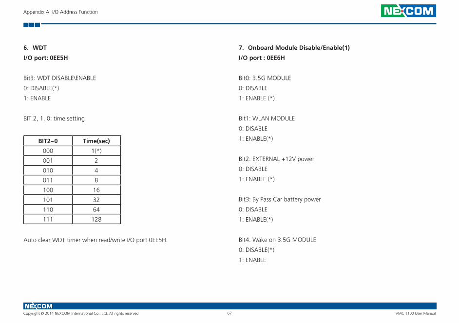
Copyright © 2014 NEXCOM International Co., Ltd. All rights reserved 67 VMC 1100 User Manual
Appendix A: I/O Address Function
6. WDT
I/O port: 0EE5H
Bit3: WDT DISABLE\ENABLE
0: DISABLE(*)
1: ENABLE
BIT 2, 1, 0: time setting
BIT2~0 Time(sec)
000 1(*)
001 2
010 4
011 8
100 16
101 32
110 64
111 128
Auto clear WDT timer when read/write I/O port 0EE5H.
7. Onboard Module Disable/Enable(1)
I/O port : 0EE6H
Bit0: 3.5G MODULE
0: DISABLE
1: ENABLE (*)
Bit1: WLAN MODULE
0: DISABLE
1: ENABLE(*)
Bit2: EXTERNAL +12V power
0: DISABLE
1: ENABLE (*)
Bit3: By Pass Car battery power
0: DISABLE
1: ENABLE(*)
Bit4: Wake on 3.5G MODULE
0: DISABLE(*)
1: ENABLE
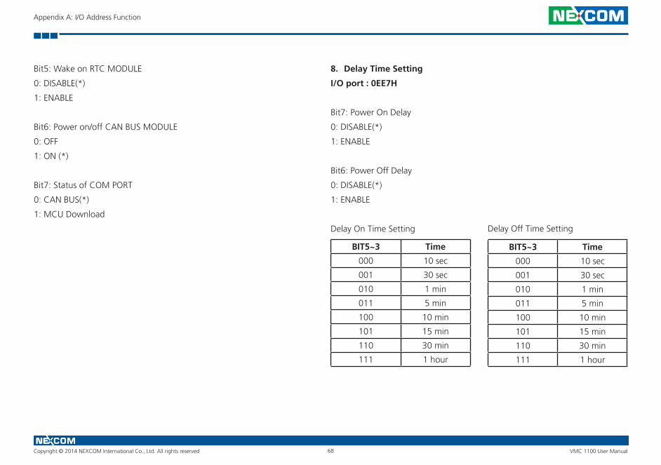
Copyright © 2014 NEXCOM International Co., Ltd. All rights reserved 68 VMC 1100 User Manual
Appendix A: I/O Address Function
Bit5: Wake on RTC MODULE
0: DISABLE(*)
1: ENABLE
Bit6: Power on/off CAN BUS MODULE
0: OFF
1: ON (*)
Bit7: Status of COM PORT
0: CAN BUS(*)
1: MCU Download
8. Delay Time Setting
I/O port : 0EE7H
Bit7: Power On Delay
0: DISABLE(*)
1: ENABLE
Bit6: Power Off Delay
0: DISABLE(*)
1: ENABLE
Delay On Time Setting
BIT5~3 Time
000 10 sec
001 30 sec
010 1 min
011 5 min
100 10 min
101 15 min
110 30 min
111 1 hour
BIT5~3 Time
000 10 sec
001 30 sec
010 1 min
011 5 min
100 10 min
101 15 min
110 30 min
111 1 hour
Delay Off Time Setting
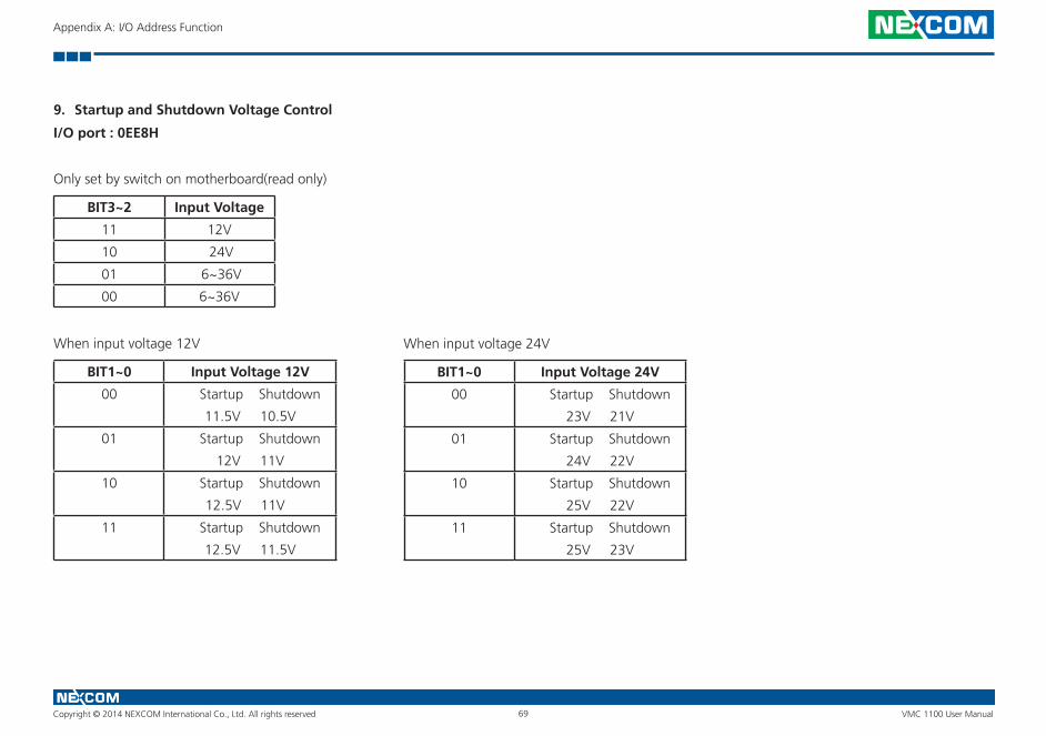
Copyright © 2014 NEXCOM International Co., Ltd. All rights reserved 69 VMC 1100 User Manual
Appendix A: I/O Address Function
9. Startup and Shutdown Voltage Control
I/O port : 0EE8H
Only set by switch on motherboard(read only)
BIT3~2 Input Voltage
11 12V
10 24V
01 6~36V
00 6~36V
When input voltage 12V
BIT1~0 Input Voltage 12V
00 Startup Shutdown
11.5V 10.5V
01 Startup Shutdown
12V 11V
10 Startup Shutdown
12.5V 11V
11 Startup Shutdown
12.5V 11.5V
BIT1~0 Input Voltage 24V
00 Startup Shutdown
23V 21V
01 Startup Shutdown
24V 22V
10 Startup Shutdown
25V 22V
11 Startup Shutdown
25V 23V
When input voltage 24V
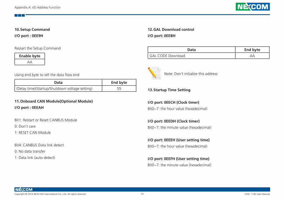
Copyright © 2014 NEXCOM International Co., Ltd. All rights reserved 70 VMC 1100 User Manual
Appendix A: I/O Address Function
10. Setup Command
I/O port : 0EE9H
Restart the Setup Command
Enable byte
AA
Using end byte to tell the data flow end
Data End byte
(Delay time)(Startup/Shutdown voltage setting) 55
11. Onboard CAN Module(Optional Module)
I/O port : 0EEAH
Bit1: Restart or Reset CANBUS Module
0: Don’t care
1: RESET CAN Module
Bit4: CANBUS Data link detect
0: No data transfer
1: Data link (auto detect)
12. GAL Download control
I/O port: 0EEBH
Data End byte
GAL CODE Download AA
Note: Don’t initialize this address
13. Startup Time Setting
I/O port: 0EECH (Clock timer)
Bit0~7: the hour value (hexadecimal)
I/O port: 0EEDH (Clock timer)
Bit0~7: the minute value (hexadecimal)
I/O port: 0EEEH (User setting time)
Bit0~7: the hour value (hexadecimal)
I/O port: 0EEFH (User setting time)
Bit0~7: the minute value (hexadecimal)
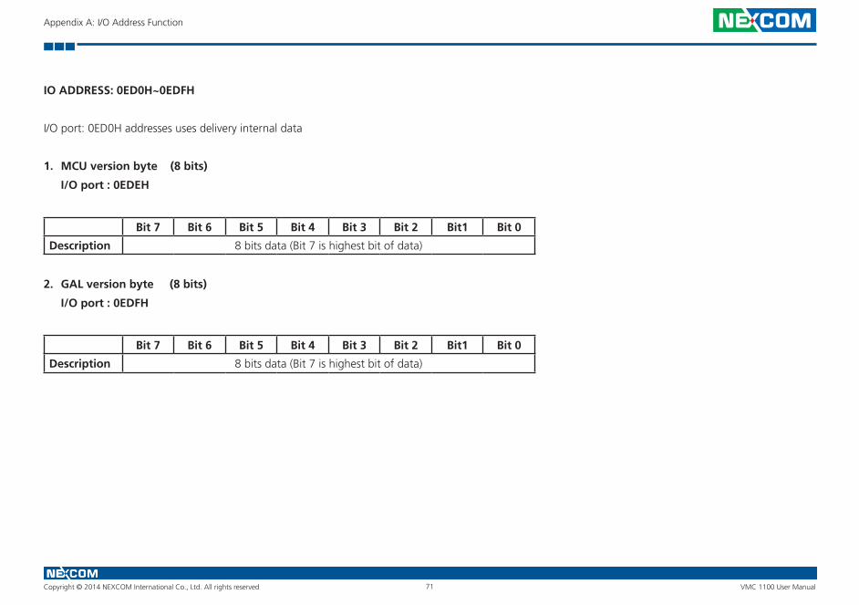
Copyright © 2014 NEXCOM International Co., Ltd. All rights reserved 71 VMC 1100 User Manual
Appendix A: I/O Address Function
IO ADDRESS: 0ED0H~0EDFH
I/O port: 0ED0H addresses uses delivery internal data
1. MCU version byte (8 bits)
I/O port : 0EDEH
Bit 7 Bit 6 Bit 5 Bit 4 Bit 3 Bit 2 Bit1 Bit 0
Description 8 bits data (Bit 7 is highest bit of data)
2. GAL version byte (8 bits)
I/O port : 0EDFH
Bit 7 Bit 6 Bit 5 Bit 4 Bit 3 Bit 2 Bit1 Bit 0
Description 8 bits data (Bit 7 is highest bit of data)

Copyright © 2014 NEXCOM International Co., Ltd. All rights reserved 72 VMC 1100 User Manual
Appendix A: I/O Address Function
G-sensor device I2C address: = 0x1D
Datasheet download
1. G-sensor (ANALOG DEVICES - ADXL345-EP)
http://www.analog.com/static/imported-files/data_sheets/ADXL345-EP.pdf
IO ADDRESS: 0EE0H~0EEFH I/O port : 0EE0H
(*) for default setting
2. Ignition_status/ Battery_status/12V_status /
I/O port : 0EE0H
Bit 0: Reseversion
Bit 1: Reseversion
Bit 2: Ignition (read only)
0: OFF
1: ON
Bit 3: Status of Car Battery
0: Car Battery is OK
1: Car Battery is Low voltage
Bit 4: Status of +12V output
0: circuit normal(under 4A)
1: over circuit(over 4A)
Bit 5: Status of Car Battery bypass output
0: circuit normal(under 4A)
1: over circuit(over 4A)
Bit 4 and Bit 5: The action will delay 10ms~15ms

Copyright © 2014 NEXCOM International Co., Ltd. All rights reserved 73 VMC 1100 User Manual
Appendix A: I/O Address Function
2. Capacity of NEXCOM battery (8 bits)
I/O port: 0EE1H
Bit 7 Bit 6 Bit 5 Bit 4 Bit 3 Bit 2 Bit 1 Bit 0
Description 8 bits data (Bit 7 is highest bit of data)
3. Voltage of NEXCOM battery (8 bits)
I/O port: 0EE2H
Bit 7 Bit 6 Bit 5 Bit 4 Bit 3 Bit 2 Bit 1 Bit 0
Description 8 bits data (Bit 7 is highest bit of data)
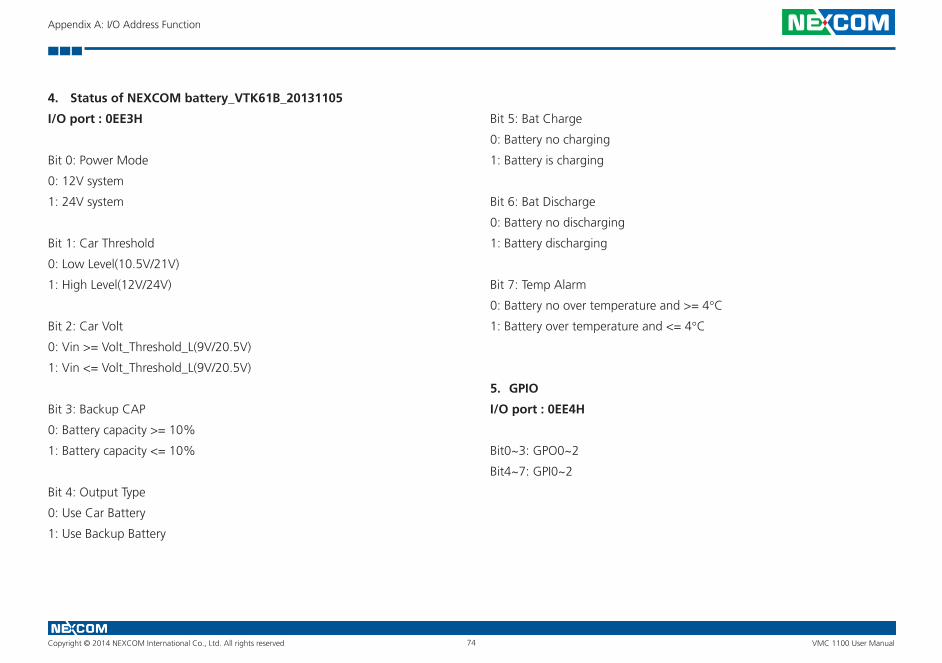
Copyright © 2014 NEXCOM International Co., Ltd. All rights reserved 74 VMC 1100 User Manual
Appendix A: I/O Address Function
4. Status of NEXCOM battery_VTK61B_20131105
I/O port : 0EE3H
Bit 0: Power Mode
0: 12V system
1: 24V system
Bit 1: Car Threshold
0: Low Level(10.5V/21V)
1: High Level(12V/24V)
Bit 2: Car Volt
0: Vin >= Volt_Threshold_L(9V/20.5V)
1: Vin <= Volt_Threshold_L(9V/20.5V)
Bit 3: Backup CAP
0: Battery capacity >= 10%
1: Battery capacity <= 10%
Bit 4: Output Type
0: Use Car Battery
1: Use Backup Battery
Bit 5: Bat Charge
0: Battery no charging
1: Battery is charging
Bit 6: Bat Discharge
0: Battery no discharging
1: Battery discharging
Bit 7: Temp Alarm
0: Battery no over temperature and >= 4°C1: Battery over temperature and <= 4°C
5. GPIO
I/O port : 0EE4H
Bit0~3: GPO0~2
Bit4~7: GPI0~2
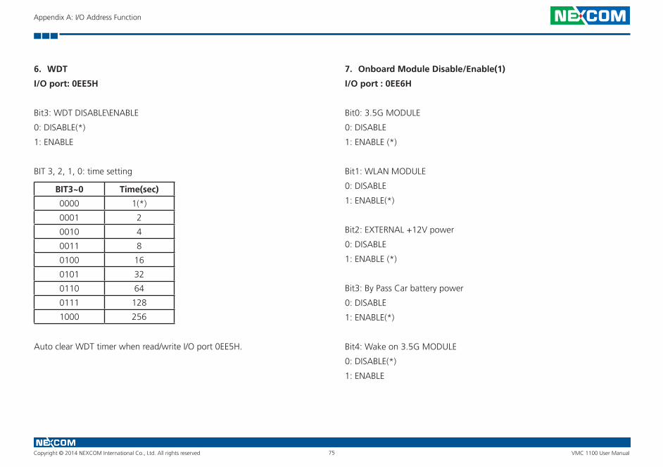
Copyright © 2014 NEXCOM International Co., Ltd. All rights reserved 75 VMC 1100 User Manual
Appendix A: I/O Address Function
6. WDT
I/O port: 0EE5H
Bit3: WDT DISABLE\ENABLE
0: DISABLE(*)
1: ENABLE
BIT 3, 2, 1, 0: time setting
BIT3~0 Time(sec)
0000 1(*)
0001 2
0010 4
0011 8
0100 16
0101 32
0110 64
0111 128
1000 256
Auto clear WDT timer when read/write I/O port 0EE5H.
7. Onboard Module Disable/Enable(1)
I/O port : 0EE6H
Bit0: 3.5G MODULE
0: DISABLE
1: ENABLE (*)
Bit1: WLAN MODULE
0: DISABLE
1: ENABLE(*)
Bit2: EXTERNAL +12V power
0: DISABLE
1: ENABLE (*)
Bit3: By Pass Car battery power
0: DISABLE
1: ENABLE(*)
Bit4: Wake on 3.5G MODULE
0: DISABLE(*)
1: ENABLE
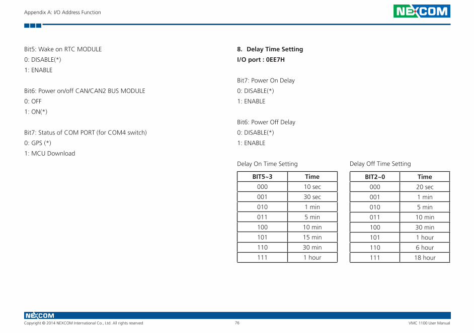
Copyright © 2014 NEXCOM International Co., Ltd. All rights reserved 76 VMC 1100 User Manual
Appendix A: I/O Address Function
Bit5: Wake on RTC MODULE
0: DISABLE(*)
1: ENABLE
Bit6: Power on/off CAN/CAN2 BUS MODULE
0: OFF
1: ON(*)
Bit7: Status of COM PORT (for COM4 switch)
0: GPS (*)
1: MCU Download
8. Delay Time Setting
I/O port : 0EE7H
Bit7: Power On Delay
0: DISABLE(*)
1: ENABLE
Bit6: Power Off Delay
0: DISABLE(*)
1: ENABLE
Delay On Time Setting
BIT5~3 Time
000 10 sec
001 30 sec
010 1 min
011 5 min
100 10 min
101 15 min
110 30 min
111 1 hour
BIT2~0 Time
000 20 sec
001 1 min
010 5 min
011 10 min
100 30 min
101 1 hour
110 6 hour
111 18 hour
Delay Off Time Setting

Copyright © 2014 NEXCOM International Co., Ltd. All rights reserved 77 VMC 1100 User Manual
Appendix A: I/O Address Function
9. Startup and Shutdown Voltage Control
I/O port : 0EE8H
Only set by switch on motherboard(read only)
BIT3~2 Input Voltage
11 12V
10 24V
01 6~36V
00 6~36V
When input voltage 12V
BIT1~0 Input Voltage 12V
00 Startup Shutdown
11.5V 10.5V
01 Startup Shutdown
12V 11V
10 Startup Shutdown
12.5V 11V
11 Startup Shutdown
12.5V 11.5V
BIT1~0 Input Voltage 24V
00 Startup Shutdown
23V 21V
01 Startup Shutdown
24V 22V
10 Startup Shutdown
25V 22V
11 Startup Shutdown
25V 23V
When input voltage 24V
Copyright © 2014 NEXCOM International Co., Ltd. All rights reserved 78 VMC 1100 User Manual
Appendix A: I/O Address Function
10. Setup Command
I/O port : 0EE9H
Restart the Setup Command
Enable byte
AA
Using end byte to tell the data flow end
Data End byte
(Delay time)(Startup/Shutdown voltage setting) 55
11. Onboard CAN Module(Optional Module)
I/O port : 0EEAH
Bit1: Restart or Reset CANBUS Module
0: Don’t care
1: RESET CAN Module
Bit2: CAN2_DI Data link detect
0: No data transfer
1: Data link (auto detect)
Bit4: CANBUS Data link detect
0: No data transfer
1: Data link (auto detect)
12. GAL Download control
I/O port: 0EEBH
Data End byte
GAL CODE Download AA
Note: Don’t initialize this address
13. Startup Time Setting
I/O port: 0EECH (Clock timer)
Bit0~7: the hour value (hexadecimal)
I/O port: 0EEDH (Clock timer)
Bit0~7: the minute value (hexadecimal)
I/O port: 0EEEH (User setting time)
Bit0~7: the hour value (hexadecimal)
I/O port: 0EEFH (User setting time)
Bit0~7: the minute value (hexadecimal)
Bit5: CAN2_DO Data link detect
0: No data transfer
1: Data link (auto detect)

Copyright © 2014 NEXCOM International Co., Ltd. All rights reserved 79 VMC 1100 User Manual
Appendix A: I/O Address Function
IO ADDRESS: 0ED0H~0EDFH
I/O port: 0ED0H addresses uses delivery internal data
1. MCU version byte (8 bits)
I/O port : 0EDEH
Bit 7 Bit 6 Bit 5 Bit 4 Bit 3 Bit 2 Bit 1 Bit 0
Description 8 bits data (Bit 7 is highest bit of data)
2. GAL version byte (8 bits)
I/O port : 0EDFH
Bit 7 Bit 6 Bit 5 Bit 4 Bit 3 Bit 2 Bit 1 Bit 0
Description 8 bits data (Bit 7 is highest bit of data)
Copyright © 2014 NEXCOM International Co., Ltd. All rights reserved 80 VMC 1100 User Manual
Appendix A: I/O Address Function
IO ADDRESS: I/O port: 0ED1H
Bit0: WLAN2_DIS
0: Disable
1: Enable (*)
Bit1: GPS_PWR_EN
0: Disable
1: Enable (*)
Bit2: Modem_PWR_EN
0: ON (*)
1: OFF
Bit3: Modem_SEL
0: ON (*)
1: OFF
Bit4: COM2 RS485/RS422
0: COM2 RS485 (*)
1: COM2 RS422
Bit5: COM2 RS232 / RS485_RS422
0: COM2 RS232 (*)
1: COM2 RS485/RS422
IO ADDRESS: I/O port: 0EDCH
Bit 5-7: Type
000: VTC
001: VMC
010: nROK
Bit 0-4: Model
Bit 0-4: 00001
Bit 5-7: 001
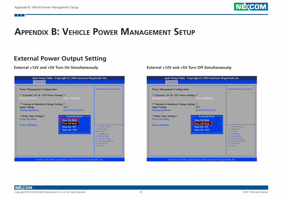
Copyright © 2014 NEXCOM International Co., Ltd. All rights reserved 81 VMC 1100 User Manual
Appendix B: Vehicle Power Management Setup
aPPendIx b: vehICle Power management setuP
External Power Output SettingExternal +12V and +5V Turn Off SimultaneouslyExternal +12V and +5V Turn On Simultaneously
Advanced
Version 2.10.1208. Copyright (C) 2010 American Megatrends, Inc.
Aptio Setup Utility - Copyright (C) 2010 American Megatrends, Inc.
→←: Select Screen↑↓: Select ItemEnter: Select+/-: Change Opt.F1: General HelpF2: Previous ValuesF3: Optimized DefaultsF4: Save & ExitESC: Exit
Enable/Disable External PowerPower Management Configuration
** External +5V & +12V Power Setting **External Power
** Startup & Shutdown Voltage Setting **Input VoltageStartup,Shutdown
**Delay Time Setting**Power On Delay
Power Off Delay
[Turn Off Both]
12 V[(11.5,10.5)/(23,21)]
External Power
Turn Off BothTurn On Both
Turn On +5VTurn On +12V
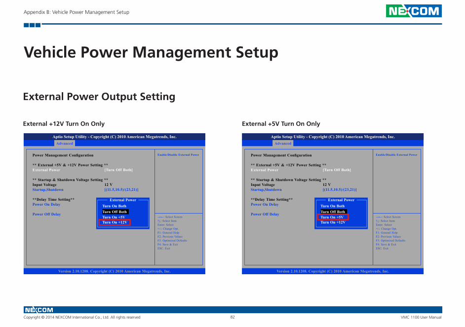
Copyright © 2014 NEXCOM International Co., Ltd. All rights reserved 82 VMC 1100 User Manual
Appendix B: Vehicle Power Management Setup
Vehicle Power Management Setup
External +5V Turn On OnlyExternal +12V Turn On Only
External Power Output Setting
Advanced
Version 2.10.1208. Copyright (C) 2010 American Megatrends, Inc.
Aptio Setup Utility - Copyright (C) 2010 American Megatrends, Inc.
→←: Select Screen↑↓: Select ItemEnter: Select+/-: Change Opt.F1: General HelpF2: Previous ValuesF3: Optimized DefaultsF4: Save & ExitESC: Exit
Enable/Disable External PowerPower Management Configuration
** External +5V & +12V Power Setting **External Power
** Startup & Shutdown Voltage Setting **Input VoltageStartup,Shutdown
**Delay Time Setting**Power On Delay
Power Off Delay
[Turn Off Both]
12 V[(11.5,10.5)/(23,21)]
External Power
Turn Off BothTurn On Both
Turn On +5VTurn On +12V
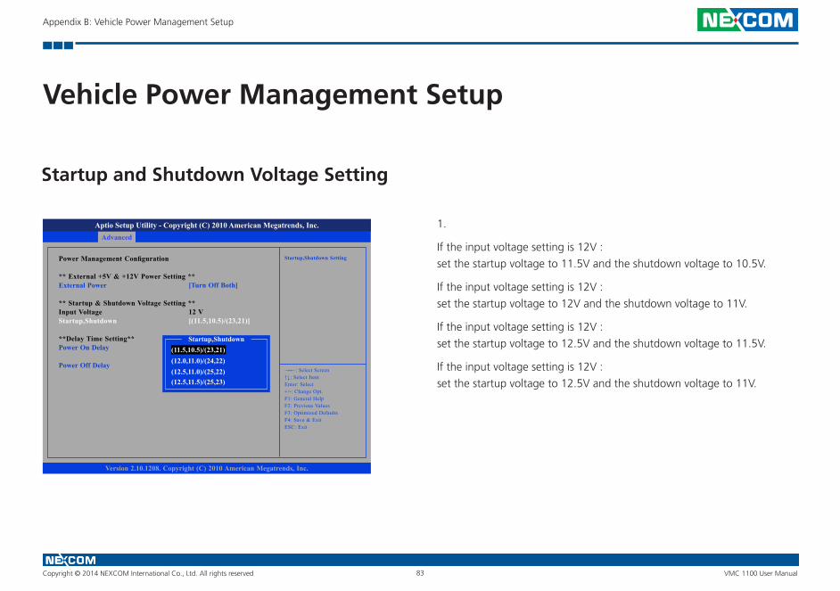
Copyright © 2014 NEXCOM International Co., Ltd. All rights reserved 83 VMC 1100 User Manual
Appendix B: Vehicle Power Management Setup
Vehicle Power Management Setup
Startup and Shutdown Voltage Setting
1.
If the input voltage setting is 12V :
set the startup voltage to 11.5V and the shutdown voltage to 10.5V.
If the input voltage setting is 12V :
set the startup voltage to 12V and the shutdown voltage to 11V.
If the input voltage setting is 12V :
set the startup voltage to 12.5V and the shutdown voltage to 11.5V.
If the input voltage setting is 12V :
set the startup voltage to 12.5V and the shutdown voltage to 11V.
Advanced
Version 2.10.1208. Copyright (C) 2010 American Megatrends, Inc.
Aptio Setup Utility - Copyright (C) 2010 American Megatrends, Inc.
→←: Select Screen↑↓: Select ItemEnter: Select+/-: Change Opt.F1: General HelpF2: Previous ValuesF3: Optimized DefaultsF4: Save & ExitESC: Exit
Startup,Shutdown SettingPower Management Configuration
** External +5V & +12V Power Setting **External Power
** Startup & Shutdown Voltage Setting **Input VoltageStartup,Shutdown
**Delay Time Setting**Power On Delay
Power Off Delay
[Turn Off Both]
12 V[(11.5,10.5)/(23,21)]
Startup,Shutdown(11.5,10.5)/(23,21)(12.0,11.0)/(24,22)(12.5,11.0)/(25,22)(12.5,11.5)/(25,23)

Copyright © 2014 NEXCOM International Co., Ltd. All rights reserved 84 VMC 1100 User Manual
Appendix B: Vehicle Power Management Setup
Vehicle Power Management Setup
Startup and Shutdown Voltage Setting
2.
If the input voltage setting is 24V :
set the startup voltage to 23V and the shutdown voltage to 21V.
If the input voltage setting is 24V :
set the startup voltage to 24V and the shutdown voltage to 22V.
If the input voltage setting is 24V :
set the startup voltage to 25V and the shutdown voltage to 22V.
If the input voltage setting is 24V :
set the startup voltage to 25V and the shutdown voltage to 23V.
Advanced
Version 2.10.1208. Copyright (C) 2010 American Megatrends, Inc.
Aptio Setup Utility - Copyright (C) 2010 American Megatrends, Inc.
→←: Select Screen↑↓: Select ItemEnter: Select+/-: Change Opt.F1: General HelpF2: Previous ValuesF3: Optimized DefaultsF4: Save & ExitESC: Exit
Startup,Shutdown SettingPower Management Configuration
** External +5V & +12V Power Setting **External Power
** Startup & Shutdown Voltage Setting **Input VoltageStartup,Shutdown
**Delay Time Setting**Power On Delay
Power Off Delay
[Turn Off Both]
24 V[(11.5,10.5)/(23,21)]
(11.5,10.5)/(23,21)(12.0,11.0)/(24,22)(12.5,11.0)/(25,22)(12.5,11.5)/(25,23)
Startup,Shutdown

Copyright © 2014 NEXCOM International Co., Ltd. All rights reserved 85 VMC 1100 User Manual
Appendix B: Vehicle Power Management Setup
Vehicle Power Management Setup
Startup and Shutdown Voltage Setting
4.
If the input voltage setting is 6v~36V ignore the startup/shutdown setting.Advanced
Version 2.10.1208. Copyright (C) 2010 American Megatrends, Inc.
Aptio Setup Utility - Copyright (C) 2010 American Megatrends, Inc.
→←: Select Screen↑↓: Select ItemEnter: Select+/-: Change Opt.F1: General HelpF2: Previous ValuesF3: Optimized DefaultsF4: Save & ExitESC: Exit
Startup,Shutdown SettingPower Management Configuration
** External +5V & +12V Power Setting **External Power
** Startup & Shutdown Voltage Setting **Input VoltageStartup,Shutdown
**Delay Time Setting**Power On Delay
Power Off Delay
[Turn Off Both]
6-36V[(11.5,10.5)/(23,21)]
[Disable]
[Disable]
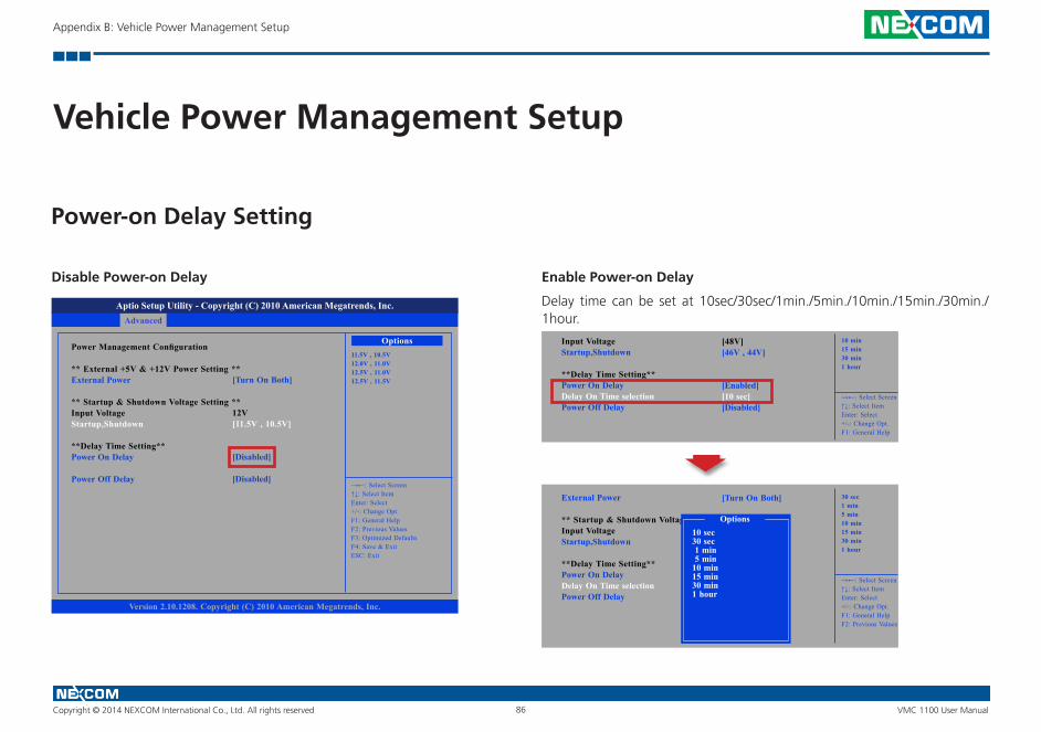
Copyright © 2014 NEXCOM International Co., Ltd. All rights reserved 86 VMC 1100 User Manual
Appendix B: Vehicle Power Management Setup
Vehicle Power Management Setup
Enable Power-on Delay
Delay time can be set at 10sec/30sec/1min./5min./10min./15min./30min./1hour.
Disable Power-on Delay
Power-on Delay Setting
Advanced
Version 2.10.1208. Copyright (C) 2010 American Megatrends, Inc.
Aptio Setup Utility - Copyright (C) 2010 American Megatrends, Inc.
→←: Select Screen↑↓: Select ItemEnter: Select+/-: Change Opt.F1: General HelpF2: Previous ValuesF3: Optimized DefaultsF4: Save & ExitESC: Exit
11.5V , 10.5V12.0V , 11.0V12.5V , 11.0V12.5V , 11.5V
Power Management Configuration
** External +5V & +12V Power Setting **External Power
** Startup & Shutdown Voltage Setting **Input VoltageStartup,Shutdown
**Delay Time Setting**Power On Delay
Power Off Delay
[Turn On Both]
12V[11.5V , 10.5V]
[Disabled]
[Disabled]
Options
→←: Select Screen↑↓: Select ItemEnter: Select+/-: Change Opt.F1: General Help
10 min15 min30 min1 hour
Input VoltageStartup,Shutdown
**Delay Time Setting**Power On DelayDelay On Time selectionPower Off Delay
[48V][46V , 44V]
[Enabled][10 sec][Disabled]
→←: Select Screen↑↓: Select ItemEnter: Select+/-: Change Opt.F1: General HelpF2: Previous Values
30 sec1 min5 min10 min15 min30 min1 hour
External Power
** Startup & Shutdown Voltage **Input VoltageStartup,Shutdown
**Delay Time Setting**Power On DelayDelay On Time selectionPower Off Delay
[Turn On Both]
10 sec 30 sec 1 min 5 min 10 min 15 min 30 min 1 hour
Options
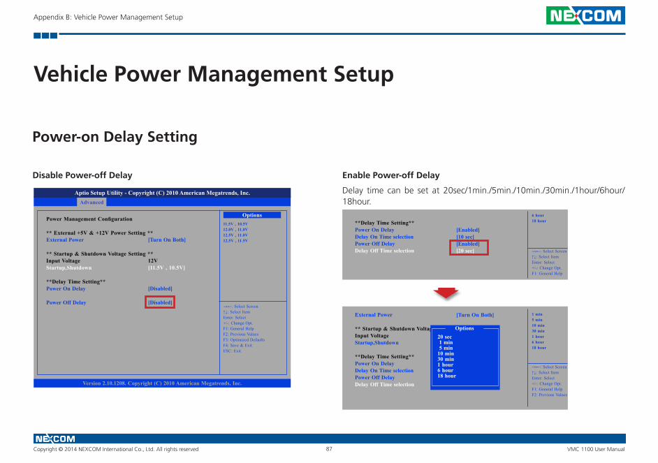
Copyright © 2014 NEXCOM International Co., Ltd. All rights reserved 87 VMC 1100 User Manual
Appendix B: Vehicle Power Management Setup
Vehicle Power Management Setup
Disable Power-off Delay
Power-on Delay Setting
Enable Power-off Delay
Delay time can be set at 20sec/1min./5min./10min./30min./1hour/6hour/ 18hour.Advanced
Version 2.10.1208. Copyright (C) 2010 American Megatrends, Inc.
Aptio Setup Utility - Copyright (C) 2010 American Megatrends, Inc.
→←: Select Screen↑↓: Select ItemEnter: Select+/-: Change Opt.F1: General HelpF2: Previous ValuesF3: Optimized DefaultsF4: Save & ExitESC: Exit
11.5V , 10.5V12.0V , 11.0V12.5V , 11.0V12.5V , 11.5V
Power Management Configuration
** External +5V & +12V Power Setting **External Power
** Startup & Shutdown Voltage Setting **Input VoltageStartup,Shutdown
**Delay Time Setting**Power On Delay
Power Off Delay
[Turn On Both]
12V[11.5V , 10.5V]
[Disabled]
[Disabled]
Options
→←: Select Screen↑↓: Select ItemEnter: Select+/-: Change Opt.F1: General Help
6 hour18 hour**Delay Time Setting**
Power On DelayDelay On Time selectionPower Off DelayDelay Off Time selection
[Enabled][10 sec][Enabled][20 sec]
→←: Select Screen↑↓: Select ItemEnter: Select+/-: Change Opt.F1: General HelpF2: Previous Values
1 min5 min10 min30 min1 hour6 hour18 hour
External Power
** Startup & Shutdown Voltage **Input VoltageStartup,Shutdown
**Delay Time Setting**Power On DelayDelay On Time selectionPower Off DelayDelay Off Time selection
[Turn On Both]
20 sec 1 min 5 min 10 min 30 min 1 hour 6 hour 18 hour
Options
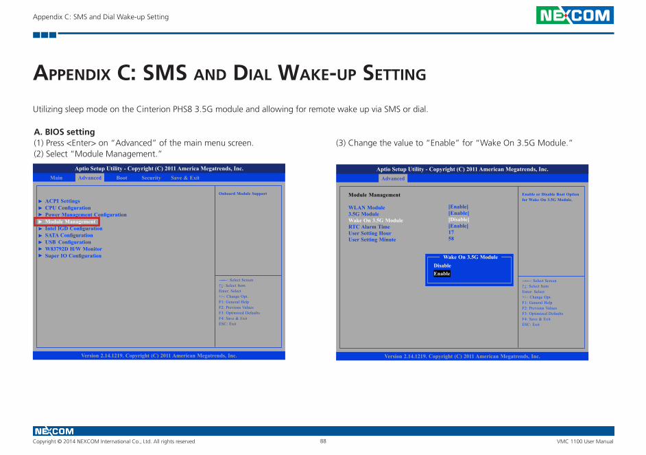
Copyright © 2014 NEXCOM International Co., Ltd. All rights reserved 88 VMC 1100 User Manual
Appendix C: SMS and Dial Wake-up Setting
aPPendIx C: sms and dIal waKe-uP settIng
A. BIOS setting(1) Press <Enter> on “Advanced” of the main menu screen.(2) Select “Module Management.”
Utilizing sleep mode on the Cinterion PHS8 3.5G module and allowing for remote wake up via SMS or dial.
(3) Change the value to “Enable” for “Wake On 3.5G Module.”
Advanced Boot Security Save & ExitMain
Version 2.14.1219. Copyright (C) 2011 American Megatrends, Inc.
Aptio Setup Utility - Copyright (C) 2011 America Megatrends, Inc.
→←: Select Screen↑↓: Select ItemEnter: Select+/-: Change Opt.F1: General HelpF2: Previous ValuesF3: Optimized DefaultsF4: Save & ExitESC: Exit
Onboard Module Support
ACPI SettingsCPU ConfigurationPower Management ConfigurationModule ManagementIntel IGD ConfigurationSATA ConfigurationUSB ConfigurationW83792D H/W MonitorSuper IO Configuration
Advanced
Version 2.14.1219. Copyright (C) 2011 American Megatrends, Inc.
Aptio Setup Utility - Copyright (C) 2011 American Megatrends, Inc.
→←: Select Screen↑↓: Select ItemEnter: Select+/-: Change Opt.F1: General HelpF2: Previous ValuesF3: Optimized DefaultsF4: Save & ExitESC: Exit
Enable or Disable Boot Option for Wake On 3.5G Module.
Module Management
WLAN Module3.5G ModuleWake On 3.5G ModuleRTC Alarm TimeUser Setting HourUser Setting Minute
[Enable][Enable][Disable][Enable]1758
Wake On 3.5G Module
EnableDisable
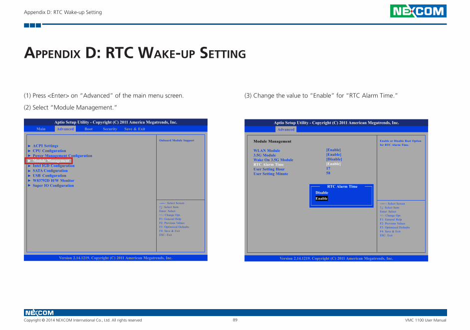
Copyright © 2014 NEXCOM International Co., Ltd. All rights reserved 89 VMC 1100 User Manual
Appendix D: RTC Wake-up Setting
aPPendIx d: rtC waKe-uP settIng
(1) Press <Enter> on “Advanced” of the main menu screen.
(2) Select “Module Management.”
(3) Change the value to “Enable” for “RTC Alarm Time.”
Advanced Boot Security Save & ExitMain
Version 2.14.1219. Copyright (C) 2011 American Megatrends, Inc.
Aptio Setup Utility - Copyright (C) 2011 America Megatrends, Inc.
→←: Select Screen↑↓: Select ItemEnter: Select+/-: Change Opt.F1: General HelpF2: Previous ValuesF3: Optimized DefaultsF4: Save & ExitESC: Exit
Onboard Module Support
ACPI SettingsCPU ConfigurationPower Management ConfigurationModule ManagementIntel IGD ConfigurationSATA ConfigurationUSB ConfigurationW83792D H/W MonitorSuper IO Configuration
Advanced
Version 2.14.1219. Copyright (C) 2011 American Megatrends, Inc.
Aptio Setup Utility - Copyright (C) 2011 American Megatrends, Inc.
→←: Select Screen↑↓: Select ItemEnter: Select+/-: Change Opt.F1: General HelpF2: Previous ValuesF3: Optimized DefaultsF4: Save & ExitESC: Exit
Enable or Disable Boot Option for RTC Alarm Time.
Module Management
WLAN Module3.5G ModuleWake On 3.5G ModuleRTC Alarm TimeUser Setting HourUser Setting Minute
[Enable][Enable][Disable][Enable]1758
RTC Alarm Time
EnableDisable
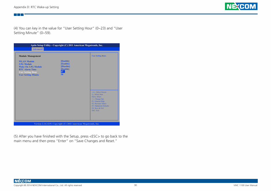
Copyright © 2014 NEXCOM International Co., Ltd. All rights reserved 90 VMC 1100 User Manual
Appendix D: RTC Wake-up Setting
(4) You can key in the value for “User Setting Hour” (0~23) and “User Setting Minute” (0~59).
(5) After you have finished with the Setup, press <ESC> to go back to the main menu and then press “Enter” on “Save Changes and Reset.”
Advanced
Version 2.14.1219. Copyright (C) 2011 American Megatrends, Inc.
Aptio Setup Utility - Copyright (C) 2011 American Megatrends, Inc.
→←: Select Screen↑↓: Select ItemEnter: Select+/-: Change Opt.F1: General HelpF2: Previous ValuesF3: Optimized DefaultsF4: Save & ExitESC: Exit
User Setting Hour.Module Management
WLAN Module3.5G ModuleWake On 3.5G ModuleRTC Alarm TimeUser Setting HourUser Setting Minute
[Enable][Enable][Disable][Enable]175817
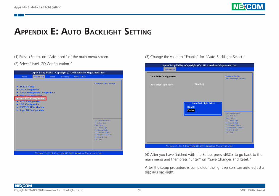
Copyright © 2014 NEXCOM International Co., Ltd. All rights reserved 91 VMC 1100 User Manual
Appendix E: Auto Backlight Setting
aPPendIx e: auto baCKlIght settIng
(1) Press <Enter> on “Advanced” of the main menu screen.
(2) Select “Intel IGD Configuration.”
(3) Change the value to “Enable” for “Auto-BackLight Select.”
Advanced Boot Security Save & ExitMain
Version 2.14.1219. Copyright (C) 2011 American Megatrends, Inc.
Aptio Setup Utility - Copyright (C) 2011 America Megatrends, Inc.
→←: Select Screen↑↓: Select ItemEnter: Select+/-: Change Opt.F1: General HelpF2: Previous ValuesF3: Optimized DefaultsF4: Save & ExitESC: Exit
Config Intel IGD Settings.
ACPI SettingsCPU ConfigurationPower Management ConfigurationModule ManagementIntel IGD ConfigurationSATA ConfigurationUSB ConfigurationW83792D H/W MonitorSuper IO Configuration
Advanced
Version 2.14.1219. Copyright (C) 2011 American Megatrends, Inc.
Aptio Setup Utility - Copyright (C) 2011 American Megatrends, Inc.
→←: Select Screen↑↓: Select ItemEnter: Select+/-: Change Opt.F1: General HelpF2: Previous ValuesF3: Optimized DefaultsF4: Save & ExitESC: Exit
Enable or Disable Auto-BackLight function.
Intel IGD Configuration
Auto-BackLight Select [Disabled]
Auto-BackLight Select
EnableDisable
(4) After you have finished with the Setup, press <ESC> to go back to the main menu and then press “Enter” on “Save Changes and Reset.”
After the setup procedure is completed, the light sensors can auto-adjust a display’s backlight.
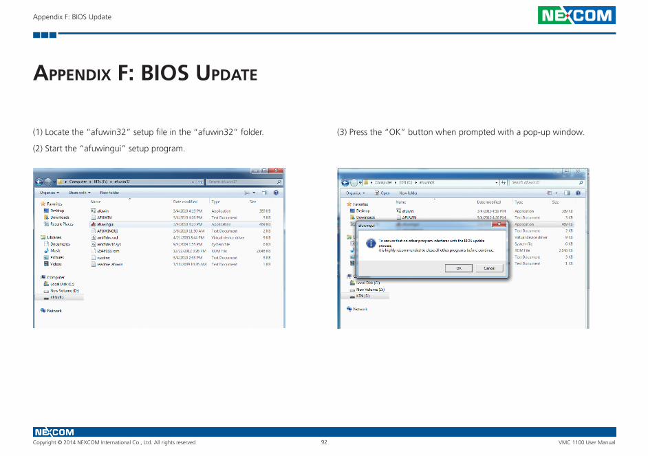
Copyright © 2014 NEXCOM International Co., Ltd. All rights reserved 92 VMC 1100 User Manual
Appendix F: BIOS Update
aPPendIx f: bIos uPdate
(1) Locate the “afuwin32” setup file in the “afuwin32” folder.
(2) Start the “afuwingui” setup program.
(3) Press the “OK” button when prompted with a pop-up window.
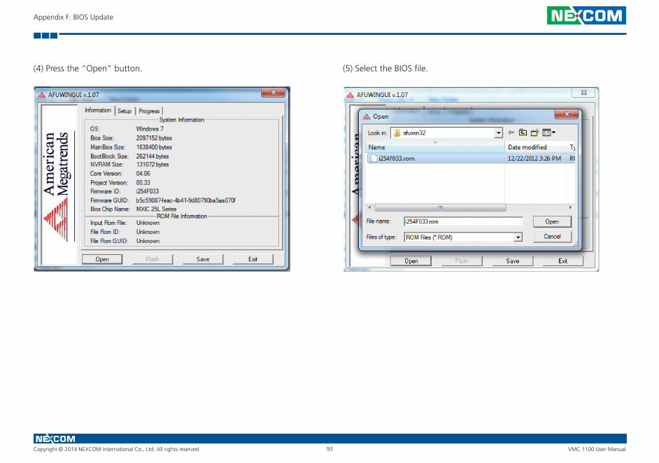
Copyright © 2014 NEXCOM International Co., Ltd. All rights reserved 93 VMC 1100 User Manual
Appendix F: BIOS Update
(4) Press the “Open” button. (5) Select the BIOS file.

Copyright © 2014 NEXCOM International Co., Ltd. All rights reserved 94 VMC 1100 User Manual
Appendix F: BIOS Update
(6) Check all the options in “Block Options” and then press the “Flash” button.
(7) The BIOS will be updated automatically, when the update is completed, please restart the VMC.
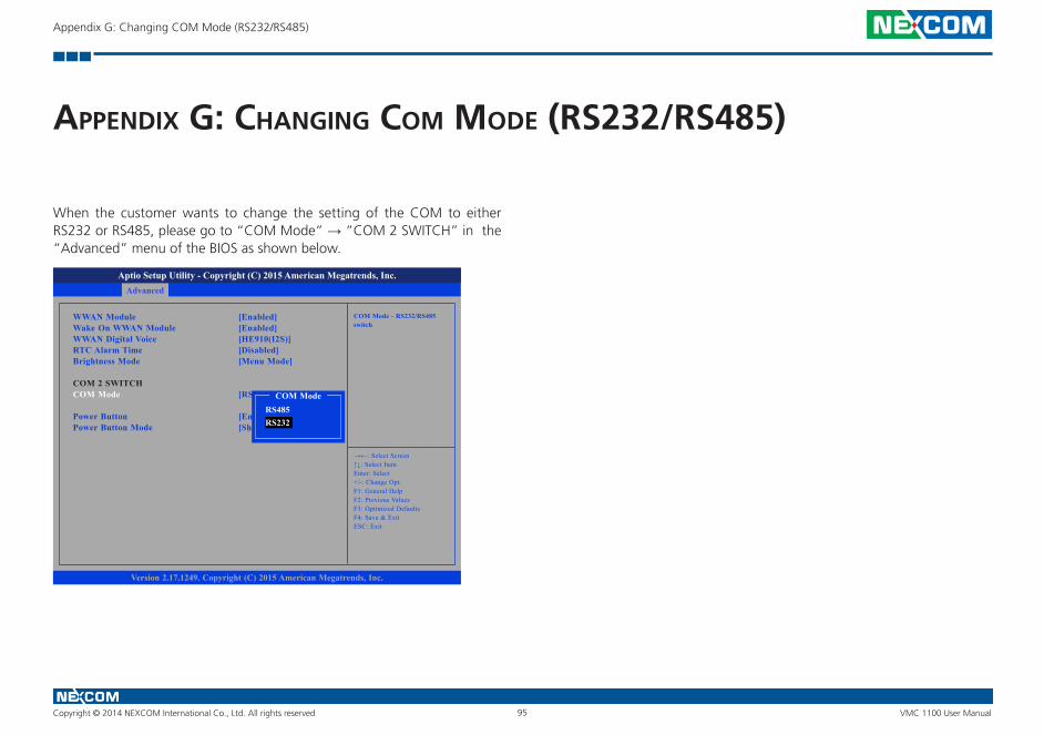
Copyright © 2014 NEXCOM International Co., Ltd. All rights reserved 95 VMC 1100 User Manual
Appendix G: Changing COM Mode (RS232/RS485)
aPPendIx g: ChangIng Com mode (rs232/rs485)
When the customer wants to change the setting of the COM to either RS232 or RS485, please go to “COM Mode” → ”COM 2 SWITCH” in the “Advanced” menu of the BIOS as shown below.
Advanced Boot Security Save & ExitMain
Version 2.17.1249. Copyright (C) 2015 American Megatrends, Inc.
Aptio Setup Utility - Copyright (C) 2015 American Megatrends, Inc.
→←: Select Screen↑↓: Select ItemEnter: Select+/-: Change Opt.F1: General HelpF2: Previous ValuesF3: Optimized DefaultsF4: Save & ExitESC: Exit
COM Mode - RS232/RS485 switch
WWAN ModuleWake On WWAN ModuleWWAN Digital VoiceRTC Alarm TimeBrightness Mode
COM 2 SWITCHCOM Mode
Power ButtonPower Button Mode
[Enabled][Enabled][HE910(I2S)][Disabled][Menu Mode]
[RS232]
[En[Sh RS232
RS485COM Mode