Embed Size (px)
Citation preview

ROTOR LESS GENERATOR
A PROJECT REPORT
Submitted by
ANANTHARAMAN.M 41710105002
ARUN NEHRU.N 41710105003
ATTHARUDDIN.S 41710105005
In partial fulfillment for the award of the degree
Of
BACHELOR OF ENGINEERING
IN
ELECTRICAL AND ELECTRONICS ENGINEERING
SHRI ANDAL ALAGAR COLLEGE OF ENGINEERING
DEPARTMENT OF ELECTRICAL AND ELECTRONICS ENGINEERING
MAMANDUR
ANNA UNIVERSITY: CHENNAI 600 025.
APRIL 2014.

ANNA UNIVERSITY: CHENNAI 600 025
BONAFIDE CERTIFICATE
Certified that this project report “ROTOR LESS GENERATOR” is the bonafide work of
“S.ATTHARUDDIN, N.ARUN NEHRU, M.ANANTHARAMAN” who carried out the
project work under my supervision.
SIGNATURE SIGNATURE
Dr.A.SOLLIAPPAN Ph.D. Mr. Mr.Kirubanandan.R M.Tech.,HEAD OF THE DEPARTMENT, ASSISTANT PROFESSOR,
Department of EEE Department of EEE,
Electrical and Electronics Engineering Electrical and Electronics Engineering
Shri Andal Alagar College of Engg. Shri Andal Alagar College of Engg.
Mamandur. Mamandur.
Submitted for the university Examination held on __________________
INTERNAL EXAMINER EXTERNAL EXAMINER

ACKNOWLEDGEMENT
At this moment we wish to record our sincere thanks to the management
“SHRI ANDAL ALAGAR COLLEGE OF ENGINEERING” for the
permission granted to carry-out this project.
Our sincere thanks to the chairperson Mrs.PREMALATHA VIJAYAKANTH,
secretary Mr.L.K.SUDHISH and correspondent for providing the facilities. We
wish to thank our principal Dr.N.KARTHIKEYAN for his encouragement during
this work.
We sincerely thank our project guide Dr.A.SOLIAPPAN Ph.D., for the effective
guidance and useful suggestions during the period of this project work.
We would also thank to Teaching and Non Teaching staff of ELECTRICAL
AND ELECTRONICS Department for providing their support in our project
work.
We would also thank to our friends and parents for their backing in our successful
completion our project. Last but not least, we thank our parents for their unstinting
faith in us and their unconditional love and support, without whom, this never
would have been possible.
ABSTRACT
The Rotor less Generator is a generator which does not have a rotating part, instead
it uses the Rotating Magnetic Field (RMF) for the production of Power. That is,
initially when the Armature is standstill the flux Rotating magnetic field cut every
solid conductor of the Armature. As a rotor (armature) conductor are stationary
and sinusoidal stator field is rotating, there will be change in flux linkage. As a
result there is a induced current in the Armature conductors as per the Faradays
law of Electromagnetic induction. Therefore the rotating magnetic field (RMF) is
employed for the generation of EMF. So that it removes the work of PRIME
MOVER in a Generating plant hence which reduces the size of the power plants,
cost and maintenance, turbine unit is removed and system is pollution free. The
output EMF can be varied by varying the supply frequency. Power electronics is
employed in controlling the supply frequency to the magnetic circuits.

CHAPTER-1
INTRODUCTION
In electricity generation, an electric generator is a device that converts
mechanical energy to electrical energy. A generator forces electric current to flow
through an external circuit. The source of mechanical energy may be a
reciprocating or turbine steam engine, water falling through a turbine or
waterwheel, an internal combustion engine, a wind turbine a hand crank,
compressed air, or any other source of mechanical energy. Generators provide
nearly all of the power for electric power grids.
The reverse conversion of electrical energy into mechanical energy is done
by an electric motor, and motors and generators have many similarities. Many
motors can be mechanically driven to generate electricity and frequently make
acceptable generators
1.1 HISTORY
Large power generation dynamos are now rarely seen due to the now nearly
universal use of alternating current for power distribution. Before the adoption of
AC, very large direct-current dynamos were the only means of power generation
and distribution. AC has come to dominate due to the ability of AC to be easily
transformed to and from very high voltages to permit low losses over large
distances.

Before the connection between magnetism and electricity was discovered,
electrostatic generators were used. They operated on electrostatic principles. Such
generators generated very high voltage and low current. They operated by using
moving electrically charged belts, plates, and disks that carried charge to a high
potential electrode. The charge was generated using either of two mechanisms:
Electrostatic induction
The triboelectric effect, where the contact between two insulators leaves
them charged.
Because of their inefficiency and the difficulty of insulating machines that
produced very high voltages, electrostatic generators had low power ratings, and
were never used for generation of commercially significant quantities of electric
power. The Wimshurst machine and Van de Graaff generator are examples of these
machines that have survived.
In 1827, Hungarian Anyos Jedlik started experimenting with the
electromagnetic rotating devices which he called electromagnetic self-rotors, now
called the Jedlik's dynamo. In the prototype of the single-pole electric starter
(finished between 1852 and 1854) both the stationary and the revolving parts were
electromagnetic. He formulated the concept of the dynamo at least 6 years before
Siemens and Wheatstone but didn't patent it as he thought he wasn't the first to
realize this. In essence the concept is that instead of permanent magnets, two
electromagnets opposite to each other induce the magnetic field around the rotor. It
was also the discovery of the principle of self-excitation.

1.2 A Brief History of Dynamos and Generators
The generator evolved from work by Michael Faraday and Joseph Henry in
the 1820s. Once these two inventors discovered and documented the phenomena of
electromagnetic induction, it lead to experimentation by others in both Europe and
North America.
1.2.1 1832 - Hippolyte Pixii (France) built the first dynamo using a commutator,
his model created pulses of electricity separated by no current. He also by accident
created the first alternator. He did not know what to do with the changing current,
he concentrated on trying to eliminate the alternating current to get DC power, this
led him to create the commutator.
1.2.2 1830s-1860s - The battery is still the most powerful way to supply electricity
for the various experimentation going on in that period. Electricity was still not
commercially viable. A battery powered electric train from Washington DC to
Baltimore failed, proving a gross embarrassment to the new field of electricity.
After m illions of dollars wasted steam still proved to be a better power source.
Electricity still needed to prove to be reliable and commercially.
He filled the magnetic field with an iron core which made a better path for
magnetic flux. This increased the power of the dynamo to the point where it was
usable for many commercial applications.
1.2.3 1870s - There was an explosion of new designs in dynamos, designs ranged a
wild assortment, only a few stood out as being superior in efficiency.

1.2.4 1877 - The Franklin Institute (Philadelphia) conducts test on dynamos from
around the world. Publicity from this event spurs development by others like Elihu
Thomson, Lord Kelvin, and Thomas Edison.
1.2.5 1878 - The Ganz Company begins to use AC generators in small commercial
installations in Budapest.
1.2.6 1880-1886 - Alternating Current systems develop in Europe with Siemens,
Sabastian Ferranti, Lucien Gaulard, and others. DC dynamos reign supreme in the
lucrative American market, many are skeptical to invest in AC. AC generators
were powerful, however the generator alone was not the biggest problem. Systems
for control and distribution of AC power needed to be improved before it could
compete with DC on a market.
1.2.7 1886-1891 - Polyphase AC generators are developed by C.S. Bradly (US),
August Haselwander (Germany), Mikhail Dolivo-Dobrovsky (Germany/Russia),
Galileo Ferraris (Italy), and others. AC systems which include better control and
powerful electric motors allow AC to compete
1.2.8 1891 - Three-Phase AC power proves to be the best system for power
generation and distribution at the International Electro-Technical Exhibition in
Frankfurt.
1.2.9 1892 - Charles P. Steinmetz presents his paper to the AIEE on hysteresis.
Steinmetz's understanding of the mathematics of AC power is published and helps
revolutionize AC power system design, including large AC Generators.

1.3 DC GENERATOR
It is based on the principle of production of dynamically (or motionally) induced
e.m.f (Electromotive Force). Whenever a conductor cuts magnetic flux,
dynamically induced e.m.f. is produced in it according to Faraday's Laws of
Electromagnetic Induction. This e.m.f. causes a current to flow if the conductor
circuit is closed.
Hence, the basic essential parts of an electric generator are :
A magnetic field and
A conductor or conductors which can so move as to cut the flux
1.3.1 Commutator Segments
Inside a DC generator, the commutator is split into two segments. Both of
these segments are insulated so no electricity is actually transmitted directly
from one part of the commutator to the other. The loop of wire that rotates is
connected to both ends of the commutator at each end. There are also two
brushes made of carbon connected to the commutator. These carbon brushes
each have a very specific purpose--one brush is responsible for pushing the
electrical current out of the generator to whatever devices are being
powered, and the other brush pulls electrical current into the generator.
1.3.2 Carbon Brushes
All of the components on the inside of a DC generator are synced up to
operate at very specific time intervals. Once the electrical current gets going
inside of the generator, the segment of the commutator that holds all the
electricity that will be going outside of the current is always touching the

carbon brush that pushes the charge outside of the the unit. The electricity is
essentially "swept" from the commutator to the electrical devices connected
to the generator by the brush.
1.4 AC GENERATOR
A simple AC generator consists of: (a) a strong magnetic field, (b)
conductors that rotate through that magnetic field, and (c) a means by which
a continuous connection is provided to the conductors as they are rotating
the strong magnetic field is produced by a current flow through the field coil
of the rotor. The field coil in the rotor receives excitation through the use of
slip rings and brushes. Two brushes are spring-held in contact with the slip
rings to provide the continuous connection between the field coil and the
external excitation circuit. The armature is contained within the windings of
the stator and is connected to the output. Each time the rotor makes one
complete revolution, one complete cycle of AC is developed. A generator
has many turns of wire wound into the slots of the rotor.
A Delta Connection is a connection that has each coil end connected end-to-
end to form a closed loop. In a Delta Connection, the three windings are all
connected in series and form a closed circuit. A Delta Connection appears
like the Greek Letter Delta (Δ).
A Wye Connection is a connection that has one end of each coil connected
together and the other end of each coil left open for external connections. A
Wye Connection appears as the letter Y.

1.5 ROTORLESS INDUCTION GENERATOR
Current is produced in a conductor when it is moved through a magnetic
field because the magnetic lines of force are applying a force on the free
electrons in the conductor and causing them to move. This process of
generating current in a conductor by placing the conductor in a changing
magnetic field is called induction. This is called induction because there is
no physical connection between the conductor and the magnet. The current
is said to be induced in the conductor by the magnetic field. One
requirement for this electromagnetic induction to take place is that the
conductor, which is often a piece of wire, must be perpendicular to the
magnetic lines of force in order to produce the maximum force on the free
electrons. The direction that the induced current flows is determined by the
direction of the lines of force and by the direction the wire is moving in the
field. In the animation above the ammeter (the instrument used to measure
current) indicates when there is current in the conductor.
If an AC current is fed through a piece of wire, the electromagnetic
field that is produced is constantly growing and shrinking due to the
constantly changing current in the wire. This growing and shrinking
magnetic field can induce electrical current in another wire that is held close
to the first wire. The current in the second wire will also be AC and in fact
will look very similar to the current flowing in the first wire. It is common to
wrap the wire into a coil to concentrate the strength of the magnetic field at
the ends of the coil. Wrapping the coil around an iron bar will further
concentrate the magnetic field in the iron bar. The magnetic field will be
strongest inside the bar and at its ends (poles).

CHAPTER-2
2.0 OVERVIEW OF ROTOR-LESS GENERATOR
• Principle
• Construction
• Stator
• Armature
• Working
• Control techniques
• Advantages
• Application
• Conclusion
2.1 PRINCIPLE
The electric machine works on the principle of faraday’s law of
electromagnetic induction. i.e. When a conductor placed in a rotating magnetic
field, the flux cuts the conductor and induces an EMF in the conductor ,when the
output path of the conductors are closed the current flows through it. The Output
voltage can be varied with the –
• The supply frequency
• Strength of the field
• With increase the number of Tph
2.2 Construction
The rotor less generator uses the Stator of Three Phase stator winding
The stator of the three phase winding consists of three main parts:
Stator frame
Stator core
Stator winding or field winding and
The Armature
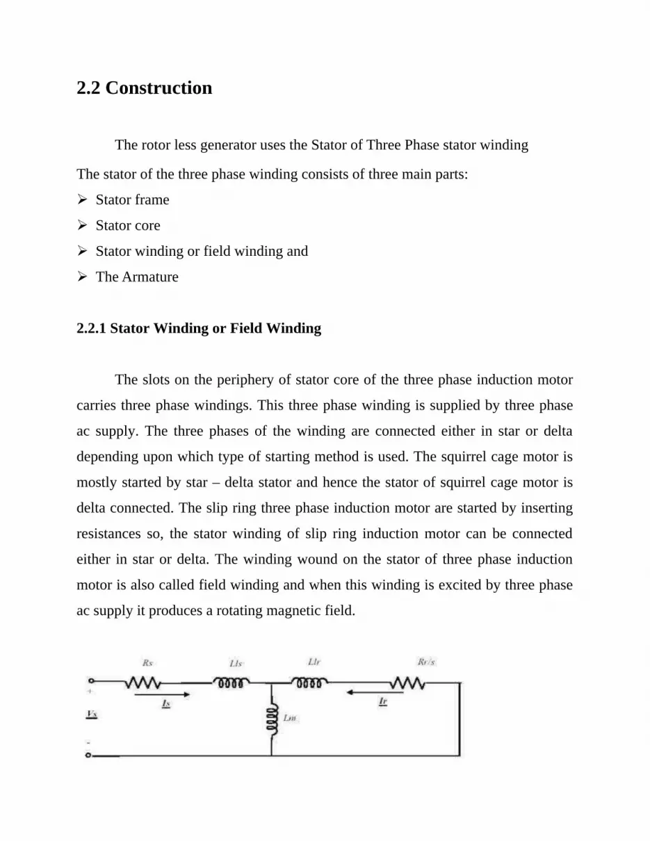
2.2.1 Stator Winding or Field Winding
The slots on the periphery of stator core of the three phase induction motor
carries three phase windings. This three phase winding is supplied by three phase
ac supply. The three phases of the winding are connected either in star or delta
depending upon which type of starting method is used. The squirrel cage motor is
mostly started by star – delta stator and hence the stator of squirrel cage motor is
delta connected. The slip ring three phase induction motor are started by inserting
resistances so, the stator winding of slip ring induction motor can be connected
either in star or delta. The winding wound on the stator of three phase induction
motor is also called field winding and when this winding is excited by three phase
ac supply it produces a rotating magnetic field.

a) Single Phase -equivalent circuit of three phase induction stator
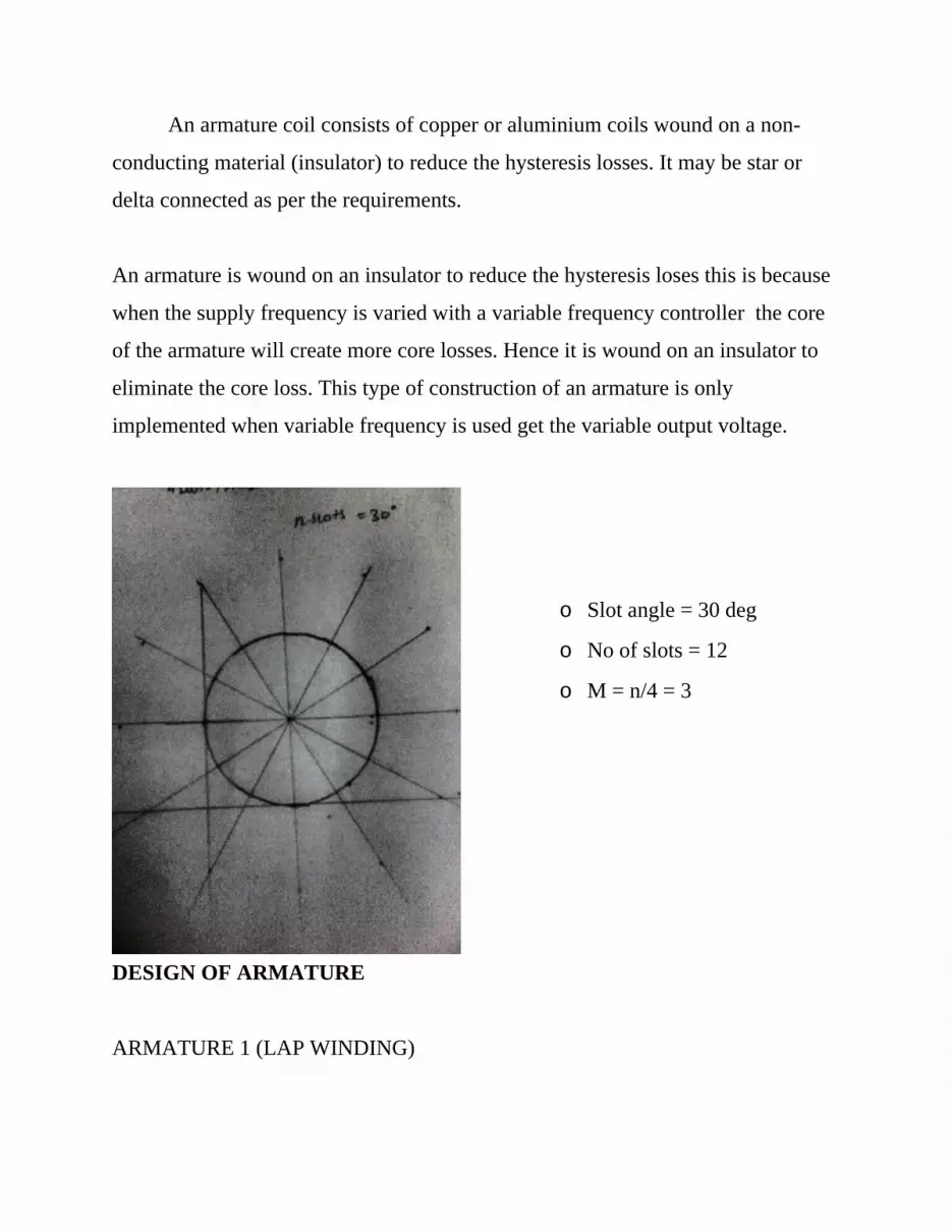
2.2.2 Armature coilAn armature coil consists of copper or aluminium coils wound on a non-
conducting material (insulator) to reduce the hysteresis losses. It may be star or
delta connected as per the requirements.
2.2.3 WorkingWhen an alternating supply is applied to the field or armature, the
field/armature produces a magnetic field which is electrically rotating called
Rotating magnetic field (RMF). In a 3 phase connection the rotating magnetic field
is 120` electrical. Thus producing a RMF. This RMF when passes through the
conductor ,due to the change in flux linkage an EMF induces in the conductor,
when closed the current flows. The RMF can be controlled by vvvf controller.
b) The T- equivalent stator and armature circuit:

2.3.1 Effect of 3 Phase Current Passing Through Stator Winding
When a 3 phase AC current passes through the winding, something very
interesting happens. It produces a rotating magnetic field. As shown in figure
below a magnetic field is produced which is rotating in nature.
• To understand this phenomenon much better consider a simplified 3 phase
winding with just 3 coils. A wire carrying current produces magnetic field
around it. Now for this special arrangement magnetic field produced by 3
phase A.C current will be as shown at a particular instant.

b) Magnetic field produced around the simplified winding and a single wire
With variation in A.C current, magnetic field takes a different orientation as
shown. From these 3 positions it’s clear that, it is like a magnetic field of uniform
strength rotating. Speed of rotation of magnetic field is known as synchronous
speed.
c) Rotating magnetic field produced over simplified winding
3.2 Effect of RMF on a Closed Conductor

Assume you are putting a closed conductor inside it. Since the magnetic
field is fluctuating an e.m.f will be induced in the loop according to Faraday’s law.
The e.m.f will produce a current through the loop. So the situation has become like
a current carrying loop is situated in a magnetic field. This current carrying
conductor can be taken to the load.
d) Effect of RMF on a closed conductor
DERIVATION OF AC MACHINE
1. The speed of the rotating magnetic field
ωsyn =2πf1/P/2 (rad/s)
or nsyn =60f1/P/2 (rev/min)
where
f1= is the frequency of the stator,

P = number of poles.
2. The armature speed of an induction machine is generally different from the
speed of the rotating magnetic field. The percentage difference of speed, known as
slip, is defined as
S =ωsyn-ωm/ωsyn
=nsyn-n/nsyn
where ωm and n are the speed of the armature in rad/s and rev/min, respectively.
3. The induced emf in one phase of the stator winding is
• E1 = 4.44f1N1kw1Φm
• and the emf in the armature winding
• E2s = 4.44f2N2kw2Φm
• where f1 and f2 are the frequencies of the emf's in the stator and rotor
windings, N1kw1 and N2kw2 the effective number of turns of the stator and
rotor windings, and Φm the magnitude of the rotating magnetic flux.
• Since f2=sf1, we have
• E2s=sE2
where E2 = 4.44f1N2kw2Φm is the armature when the armature is standstill.
CHAPTER-3

FIELD DESIGN
Outer
diameter
Inner
diamet
er
Stator
Bore
length
Slot
length
Slot
diameter
poles sl
ot
s
F
(H
Z)
Vph
(v)
PF H.P KW
10 8 12 6 7.5 4 24 50 415 .69 .50 .37
Table 3.1
OUTPUT EQUATION OF STATOR
Output equation of three phase machine:-
KVA rating of an 3phase machine = 3Vph*Iph*10-3
Synchronous speed = 120f/p
Frequency=NsP/120
Kw1=kd1*kp1
Φm=flux/pole
Tph=No of turns/phase
Iph=Stator current/Phase
Where,
kw1= the winding factor
Vph=voltage per phase
Iph=current per phase
F=supply frequency
P=Poles

Ns=synchronous speed
Specific Magnetic Loading= pφm=BavπDL/2
Where,
Specific Electric Loading=No of r.m.s ampere-conductor/unit of the air gap
circumference
q=3*Iph*zph/πD
Conductors/Phase Zph=Z/3
Total Conductor=Z=3ZphZph=2TphZ=6TphIphTph=πqd/6
Specific Electric Loading :
The Specific Electric loading q determines the I2R losses of the
machine and depends upon the following factors
1.Number of poles:
• Machines with smaller number of poles are high speed machines and have
a smaller armature diameter.
• Owing to the smaller dimensions great difficulty is experienced in
accommonding the copper of the windings and generally in such machines
q is lower.
2.Voltage of the machine:
• In high voltage machines a greater percentage of the slot area is occupied
by insulation.
• This allows a lesser amount a lesser amount of copper to be
accommodated.

• The value of q is thus smaller in high voltage machines.
3.Frequency:
• At lower frequencies the iron losses (consisting of hysteresis and eddy
current losses) are smaller.
• Hence proportionately more copper could be used which will increase I2R
lpsses.
• Therefore, at low frequencies, the value of q is proportionally higher.
4.Overload Capacity:
• It will be seen from calculations of slot reactance that reluctance of the
leakage flux path through the slot depends upon the ratio(slot width)/(slot
depth).
• Now greater the slot depth, lesser will be the slot reluctance hence more
the leakage flux(since φ=mmf/reluctance) and also the leakage reactance.
• In short, therfore, slot reactance increases as the depth is increased.
• Heating of the conductor in the winding wil depend upon the I2R losses,
which in turn depend upon q.
• On the other hand heat dissipated depends upon the surfaces of the
conductor.
The temperature rise of the conductors will, therefore, depend upon the
ratio, q/surface area per ampere.
If q is large,
• The surface area of the conductor per ampere has to be greater and hence
a greater amount of copper will have to be used to keep the temperature
rise within reasonable limits.

• It is normally not possible to increase the width of slot much, and so to
accommodate the greater amount of copper, the depth of slot will have to
be increased thereby increasing the slot reactance.
• The increase of reactance reduces the diameter of circle diagram=E/X, and
hence the maximum torque (or) overload capacity of machine.
• Assumptions:
• when sufficient data is not given, we shall assume the values:
• Q=25,000 amp-load/m
• Current density=3.5 A/mm2
Specific Magnetic Loading:
• The value of Bav the specific magnetic loading, should not be so high as to
cause magnetic saturation of the teeth.
If Bav is large,
• Iron loss proportional to flux density increases, hence the temperature rise
and the machine will have a low efficiency.
• For a given voltage,if the flux/pole is larger, the number of turns will have to
be less.
• This reduces the leakage reactances and increases the maximum torque by
increasing the diameter of the circle diagram.
• The magnetising current Im=(0.427p*AT/Kw1 Tph ) depending on the flux
density increases.
• The magnetising currents in such a component of current which lags upon
the applied voltage and tends to lower the power factor of the machine.
• Therefore, greater the air gap, lower will be the power factor of the
machine.

• Considering this factor the designer will have a tendency to provide a very
small air gap.
• From the above discussions, Bav and q cannot chosen arbitrarily, but
optimum values are to be used in due consideratons of above factors.
• For normal 50hz machine Bav lies between (0.3-0.6) wb/m2
• For crane, rolling mill and similar drives it may be around 0.65 wb/m2
• The specific electric loading(q) lies between (5000 to 45000) ac/m 3
• For preliminary design cosφ and n may be taken as each 0.9
Kw1, the winding factor equal the product of the distribution factor and
pitch factor.
When nothing is given, assume a phase spread of 60, whereby Kd1= 0.955
and full pitched coils whereby Kp1=1 i.e., Kw1=Kd1*Kp1=0.955*1 =0.955
Assumptions:
Q=25,000 amp-load/m
Current density=3.5 A/mm2
Magnetic Loading:
Magnetising Current
Im=(0.427p*AT/Kw1*Tph)
Assumptions:
• For Normal 50hz machine
Bav lies between (0.3 to 0.6)wb/m2
• For Preliminary design cos φ and n=0.9
Kd1=0.955
Kp1=1
Kd1=0.955
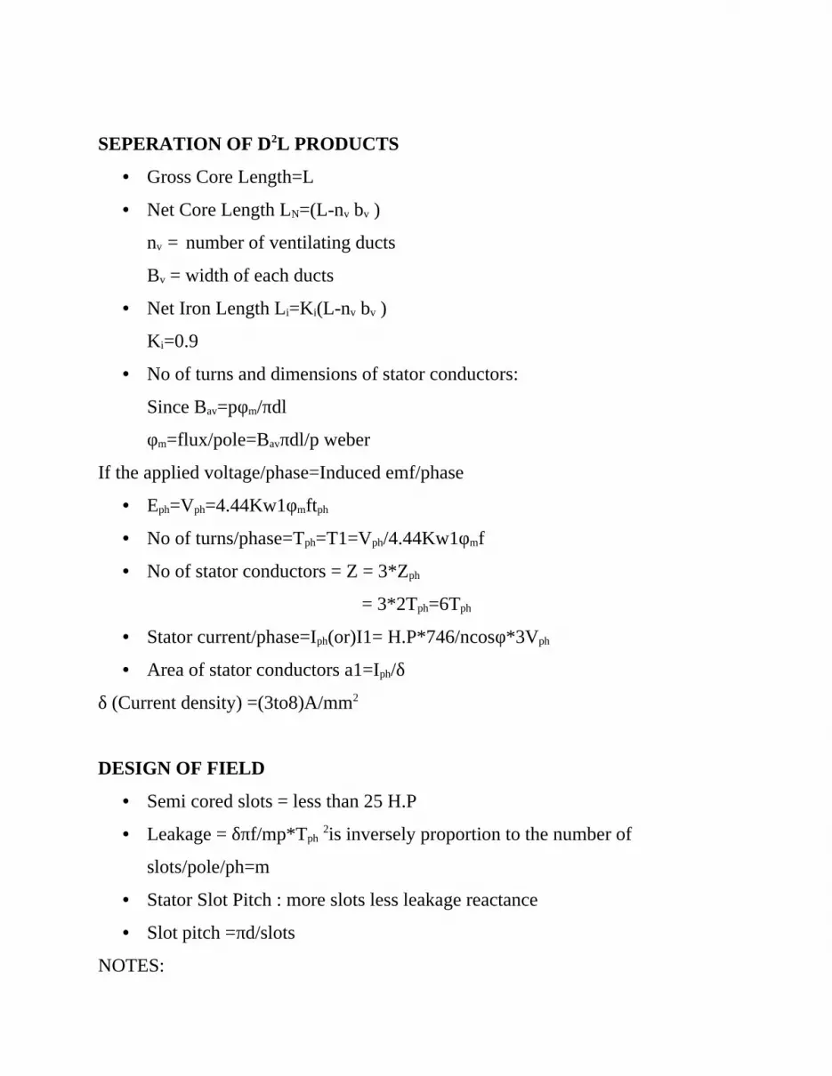
SEPERATION OF D2L PRODUCTS
• Gross Core Length=L
• Net Core Length LN=(L-nv bv )
nv = number of ventilating ducts
Bv = width of each ducts
• Net Iron Length Li=Ki(L-nv bv )
Ki=0.9
• No of turns and dimensions of stator conductors:
Since Bav=pφm/πdl
φm=flux/pole=Bavπdl/p weber
If the applied voltage/phase=Induced emf/phase
• Eph=Vph=4.44Kw1φmftph
• No of turns/phase=Tph=T1=Vph/4.44Kw1φmf
• No of stator conductors = Z = 3*Zph
= 3*2Tph=6Tph
• Stator current/phase=Iph(or)I1= H.P*746/ncosφ*3Vph
• Area of stator conductors a1=Iph/δ
δ (Current density) =(3to8)A/mm2
DESIGN OF FIELD
• Semi cored slots = less than 25 H.P
• Leakage = δπf/mp*Tph 2is inversely proportion to the number of
slots/pole/ph=m
• Stator Slot Pitch : more slots less leakage reactance
• Slot pitch =πd/slots
NOTES:

• Slots/pole/phase should not be less than 2
• Number of slots/poles/phase(m) lies between (21/2 to 5)
• Usually 3 and 4 are common
• Slot pitch = πd/s1 for mechanical should not be less than 1cm
Semi closed slots=(1.0 to 1.5 )cms
Insulations:
• Not exceeding 440v = Class A Insulation
• The slot insulation consists of lines of =MICANITE AND LEATHEROLD
each of 0.25mm thick ( above 500v)
• Slot width of stator=bss =(2-4mm)
Depth of stator core :
• Flux density in stator core Bcs =(φm/2) / dcsLi
Bcs = 0.9 and 1.4 wb/m2
MAIN DIMENSIONS
D2L= H.P*0.746/ncos φc0ns
C0=11*10-3 Kw1Bavq
C0=11*10-3*0.955*Bav*25000
C0=137.184Bav
No of poles (P)= 120f/N = 120*50/1360 =4.411
Practically, it is not possible, so select p=4
Synchronous speed in rpm (Ns)=120f/p = 120*50/4 = 1500rpm
Ns= 1500/60 =25rps
D2l=H.P*0.746/n cosφc0*ns
Bav = 0.373/0.71*0.69*11*10-3*0.955*13000*25*6.776*10-4

Bav=0.329wb/m2
Q=13059 amp – load/m
TURNS PER PHASE
flux/pole (φm) = πBavdl/p
= π*0.329*11*10-2*5.6*10-2 /4
φm= 0.00159 weber
Stator turns/phase T1 or Tph=Vph/4.44*kw1fφm
=415/4.44*0.955*50*0.0015917
Tph = 1230
No of stator slots =24 =s1
Total no of stator conductors =z1=6Tph=6*1230 =7380
Conductors/slots= 7380/24 = 307.5
OVERALL DIMENSIONS OF CONSIDER MACHINE
Diameter of the stator core = 11*10-2m
Length of the stator core (L) =5.6*10-2m
Number of stator slots (s1) =24
Stator turns per phase (T1)(Tph) =1230
Total no of stator conductors (z1)=7380
Total no of conductors/slot=307
Flux/pole(φm)=0.0015917 weber
Stator current/phase (Iph) or (I) = 0.61155 A
=0.10192 for (s=6)
Area of stator conductors(a1) = 0.2038 for (s=3)

Area of stator conductors(a2)=0.15288 for (s=4)
Area of stator conductors(a3)=0.12230 for (s=5)
Average flux density(Bav)=0.329 wb/m2
Conductors per phase(Zph)=2460
Specific electric loading=13059 amp-load/m
Slot pitch = πd/slots = π*11*10-2 = 0.01440
Induced emf/phase = Vph = Eph =415.07127 volts
Q=3*Iph*zph/πd
=3*0.6115*2460/π*11*10-2
=13059.0
Conductors/phase Zph=Z/3
Zph=2Tph
Iph=(0.76138/3)*103/415
Iph=0.61155A
MACHINE OVERALL DESIGN
Rated Frame
Size
Type ref.
B3
Operating characteristics
at rated output
With
DOL
Rotor Net
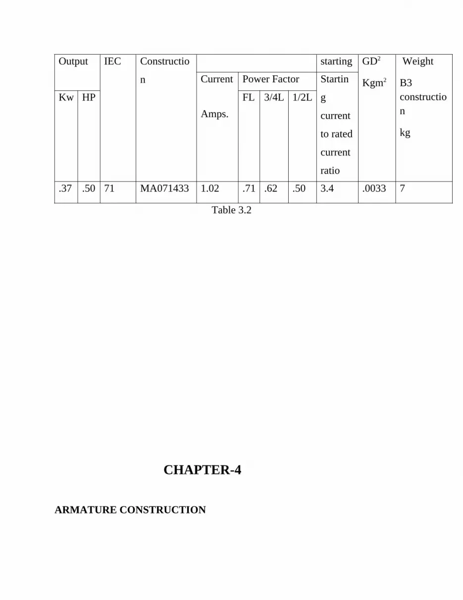
Output IEC Constructio
n
starting GD2
Kgm2
Weight
B3 construction
kg
Current
Amps.
Power Factor Startin
g
current
to rated
current
ratio
Kw HP FL 3/4L 1/2L
.37 .50 71 MA071433 1.02 .71 .62 .50 3.4 .0033 7
Table 3.2
CHAPTER-4
ARMATURE CONSTRUCTION
An armature coil consists of copper or aluminium coils wound on a non-
conducting material (insulator) to reduce the hysteresis losses. It may be star or
delta connected as per the requirements.
An armature is wound on an insulator to reduce the hysteresis loses this is because
when the supply frequency is varied with a variable frequency controller the core
of the armature will create more core losses. Hence it is wound on an insulator to
eliminate the core loss. This type of construction of an armature is only
implemented when variable frequency is used get the variable output voltage.
o Slot angle = 30 deg
o No of slots = 12
o M = n/4 = 3
DESIGN OF ARMATURE
ARMATURE 1 (LAP WINDING)

Slot
Length
(cm)
Slot
Width
(cm)
Slot
depth
(cm)
Conductor
size (swg)
Diameter
(cm)
Turns
per
phase
(Tph)
Output
Voltage
(V0)
6 0.6 0.8 32 5.6 300 8
ARMATURE 2 (WAVE WINDING)
Slot
length
(cm)
Slot width
(cm)
Slot depth
(cm)
Conductor
size (swg)
Diameter
(cm)
Turns
per
phase
(Tph)
Outpu
t
voltag
e (V0)
6 0.6 0.8 32 5.6 400 13

ARMATURE 3 (DISTRIBUTED WINDING)
Slot
length
(cm)
Slot width
(cm)
Slot depth
(cm)
Conductor
size (swg)
Diameter
(cm)
Turns
per
phase
(Tph)
Outpu
t
voltag
e (V0)
6 0.6 0.8 32 5.6 400 13
CHAPTER-5
TESTING OF MACHINES

TEST ON STATOR
Ω0=√3v0I0cosφ0
=√3*415*0.6115*0.69
Ω0=303.28734 watts
Note: watts consumed to produce the field Bav=0.329 Tesla.
Consideration 1
If a 4pole three phase 1500rpm, star connected alternators has 24slots there are
2coil slides /slot
And total 14 conductors/slot if flux/pole is 0.0015917wb
Rms value of emf in a conductor:-
P=4,Ns=1500
F=p*Ns/120=4*1500/120 = 50hz
Average value of emf in a conductor=2fφ
Therefore, rms value =1.11*2fφ
=2.22*50*0.0015917
=0.17668v
Average value of emf in a turn=4fφ
=4*50*0.0015317
=0.31834v
Now each slot has 14conductors and 2 coil slides:-
So conductor/coil side = 14/2=7
Such coil slides,so there are 7 turns
Therfore rms value of emf in a coil :-
Rms value of emf/turn*no of turns/coil
=0.31834*7
=2.22838
Now total conductors Z=conductors/coil slide * No of slots
Z=14*24
Z=336
Zph=336/3 =Z/3
Zph=112
Tph=Zph/2=112/2 =56
N=slots/pole =24/4 =6
M=n/3=6/3=2
B=180/n =180/6 =30
Kd=Sin(mβ/2)/mSinβ/2) = Sin(2*30/2)/2sin(30/2) =0.96593
Eph=4.44KckdφfTph
=4.44*1*0.96593*50*0.0015917*56
=19.22v
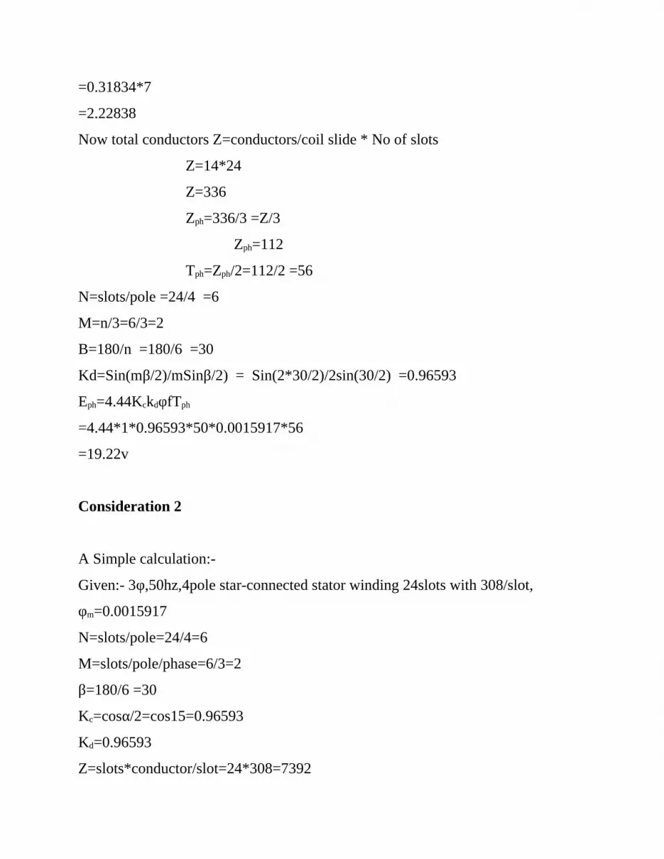
Consideration 2
A Simple calculation:-
Given:- 3φ,50hz,4pole star-connected stator winding 24slots with 308/slot,
φm=0.0015917
N=slots/pole=24/4=6
M=slots/pole/phase=6/3=2
β=180/6 =30
Kc=cosα/2=cos15=0.96593
Kd=0.96593
Z=slots*conductor/slot=24*308=7392

Zph=2464
Tph=1232
Eph=406.17v
Eline=Eph*√3
=703.52 volts star connected
CHAPTER – 6
VARIABLE VOLTAGE VARIABLE FREQUENCY CONTROLLER

METHOD OF OUTPUT VOLTAGE CONTROL
Supply frequency control
We are going to study supply frequency control method. we can
conveniently adjust the speed of generator by changing the frequency applied to
the generator. We could adjust generator speed by adjusting the number of poles,
but this physical change to the generator, would require rewinding, and result in a
step change to the speed. So for convenience, cost efficiency. precision, we change
the frequency.
Variable voltage variable frequency controller:
A variable frequency drive (VVVFD) is a system for controlling the
rotational speed of an alternating current (AC) electric generator by controlling the
frequency of the electrical power supplied to the generator. A variable frequency
drive a specific type of adjustable speed drive. Variable frequency drives are also
known as adjustable frequency drives (AFD),variable speed drives (VSD), AC
drives or inverter drives.
Voltage induced in stator is proportional to the product of supply frequencies
and area flux, if stator drop is neglected , terminal voltage can be considered
proportional to product of frequency and flux .Any reduction in supply
frequencies without change in terminal voltage causes an increase air gap flux.
The increase in flux will saturate the motor.
While an increase in flux beyond rated value is undesirable from the
consideration of saturation effects. A decrease in flux is avoided to retain the
torque capability of the motor. Therefore the variable frequency control below

the rated frequency is generally carried out at rated air gap flux varying the
terminal voltage with frequency so as to maintain (V/F) ratio constant at rated
value.
OPERATING PRINCIPLE
Variable frequency drives operate under the principle that the synchronous speed
of an AC motor is determined the frequency of the AC supply and the number of
poles in the stator winding, according to the relation.
R.P.M=120*f/p
Where,
RPM = Revolutions per minute
f = AC power frequency (Hertz)
p = Number of poles (an even number)


