Embed Size (px)
Citation preview
ROBOTIC SOFT ESOPHAGUS (RoSE) ENHANCEMENT FOR IN- VITRO SIMULATIONS OF HUMAN SWALLOWING
SHERINE JESNA VALIYAVEETIL ALI
A thesis submitted in fulfilment of the requirements for the degree of Doctor of Philosophy in Mechatronics Engineering, the University of Auckland, 2021.
Department of Mechanical and Mechatronics Engineering Faculty of Engineering
The University of Auckland
December 2021
i
ROBOTIC SOFT ESOPHAGUS (RoSE) ENHANCEMENT FOR IN-
VITRO SIMULATIONS OF HUMAN SWALLOWING
Author : Sherine Jesna V. Ali
Supervisor : Prof. Peter (Weiliang) Xu
Co-supervisor : Prof. Leo K. Cheng
Co-supervisor : Dr. Jacqueline Allen
Co-supervisor : Prof. Richard Clarke
Department of Mechanical and Mechatronics Engineering Faculty of Engineering
The University of Auckland
December 2021
ii
Abstract
Dysphagia or trouble swallowing is a prevalent medical condition among the elderly, individuals
with esophageal strictures, and persons on long-term pill medication, with patient age, different
pathologies, and solid dosage product characteristics (e.g., size, shape, and composition)
contributing to the cause. All the in-vitro studies aiming to improve the therapeutic interventions
in dysphagia lack the technologies to associate the effects of the dynamic forces involved in the
esophageal peristalsis. The RoSE (Robotic Soft Esophagus) addresses this gap by combining the
fields of material sciences, actuation, and control technologies. The RoSE is an open loop,
pneumatically controlled, compliant, and continuous soft robotic actuator designed to mimic
peristalsis.
Many attributes of the esophagus, such as conduit length, diameter, peristalsis velocity, and
conduit wall activation, are replicated in RoSE. Still, it lacks embedded sensors mimicking the
mechanoreceptors in an esophageal lumen. Exploring the opportunities in improving the RoSE as
an analytical tool for in-vitro swallowing studies has been the focus of this research. The
components of this research were the following: 1) Design and characterize soft stretchable
carbon black sensors and their modeling for sensor-actuator calibration and control, 2)
Developing fluid-structure interaction simulation model to learn the parameter variations in
bolus transit which are unknown due to lack of sensors, 3) Develop clinically relevant protocols
and conduct in-vitro swallow studies for stent migration and solid dosage medication transit
analysis.
Many of the existing sensors technologies suffer the drawbacks such as robot occlusion,
interference, or difficulties in surface compatibility. Designing soft stretchable sensing devices
compatible with the soft robot and designing robust controllers are challenging problems in and
of themselves. Carbon-based nanomaterials embedded in elastomers are cost-effective choices in
designing stretchable sensor arrays. Piezo-resistive sensors have more hysteresis and produce
nonlinear responses but have better gauge factors and sensitivity. The 4 loop sensor with a mass
fraction of 11.11 (%wt) (carbon black in the elastomer), having a gauge factor of 2.35, and
hysteresis of 22% at the standard operating point in RoSE is selected. Before the final selection,
three distinct concentrations for different sensor architectures are fabricated and tested for the
cyclic loading, strain rate, and stretch direction tests. The single-layer flat RoSE (fRoSE) and 6-
layer RoSE versions of sensor-embedded actuators were developed for calibration and control.
Data sets from image processing and articulography were used to calibrate these versions of
RoSE. The sensor-actuator system transfer characteristics computed from fRoSE sensor data
demonstrated the sensor contribution to system nonlinearities. This study used recurrent neural
iii
network-based algorithms to predict temporal nonlinearities such as sensor drift. A feedforward
compensated, gain scheduled linear controller is designed on the piecewise linearised transfer
characteristics of the fRoSE. The controller responses for set-point tracking with feedforward
compensation attains the desired steady-state error design constraints. This contributes a
general framework for the future initiatives in developing full body closed loop deformation
control of RoSE or any soft robotic actuators.
The fluid pressure variations, fluid velocity variations, and stress variations for different bolus
consistencies under different trajectories in RoSE are unknown due to the lack of sensors. For
addressing this, a multi-physics finite element-based (FEM) simulation model was built and
validated against data sets from image processing and manometry experiments. The fluid
velocity, pressure, and dynamic viscosity in the bolus during propagation through the conduit are
conspicuously affected by the trajectory parameters and the contracting forces.
The RoSE is an in-vitro tool for food texture analysis, but it has found use in swallow studies of
esophageal stenting and solid dosage form transit. In both stent migration and pill swallow
studies, clinically meaningful test protocols for RoSE in the supine position are developed and
implemented. In tests comparing two stents of differing stiffness, the stent with the lowest
stiffness reported in-situ migration and up to a maximum of 47 mm relative displacement under
different trajectories. The study discovered that the direction of stent migration is also affected
by bolus viscosity. The stent migration is explained with the dynamic models developed in
previous investigations. The effects of internal and environmental factors on RoSE pill transit are
also investigated. The pill transit time is affected by coating, surface polish, size, and pill volume
density. In RoSE, the pill transit is found to be dependent on the peristalsis trajectory velocity as
well as the bolus properties such as viscosity and volume. The uncoated pills had longer transit
times, whereas the encapsulated pills were faster. The pill transit variations are explained with
the help of finite element-based simulation models developed in this research.

iv
-To my mother, my daughter, my love
and
God the Almighty-

v
Acknowledgments
My most tremendous gratitude goes out to my supervisor and mentor, Professor Peter Xu, who
has guided and encouraged me throughout my Ph.D. research journey. The thesis would never
have taken shape if it hadn't been for his attentive support and thorough monitoring. With
productive discussions and dialogues, his consistent excitement and motivation kept me engaged
throughout the journey, allowing me to adjust the cruise whenever the journey became bumpy.
He has inspired me to pursue new and engaging opportunities, and he has been my most steadfast
supporter.
I would like to extend my sincere thanks to my co-supervisors, Prof. Leo K. Cheng, Prof. Richard
Clarke, and Dr. Jacqueline Allen, who have been patient with me to understand the versatility of
the domain and contribute to the research. Their outstanding domain expertise in bioengineering,
computational modeling, physiology, and medical backgrounds, as well as timely
recommendations, are treasure mines of relevant and intriguing ideas for our project.
I am grateful to Prof. Krishnan Jayaraman, the HoD, and his colleagues for the meticulously
maintained department support system, which has greatly assisted my path. I would like to
express my appreciation to Marshall Lim, Emanuele Romalo, Dinesh Mathur and Logan Stuart for
extending their technical expertise and support for my project. I thank my fellow Ph.D. students,
Dr. Dipankar Bhattacharya, Dr. Eshwar C., Shahab Kazemi, Shubham Gupta, and Sam Duanmu,
whose help was vital in completing this study. I acknowledge the University of Auckland for
providing different platforms and support for the success of this research. I want to acknowledge
the Riddet Institute for the financial assistance provided in the project.
The road had been bumpy, and the pandemic added some unexpected turns. I thank the Almighty
for blessing me with the support system of friends and family for accompanying me on this
adventure. I acknowledge every teacher I had who opened the door for me to pursue knowledge.
I thank my pals, Nathan, Aparna, and Yangcheng Karma, for making me laugh. I am grateful to my
parents and brothers for their unwavering support and unconditional love. I owe a debt of
gratitude to Alphonsa and Iris, my incredible mothers by birth and karma, for inspiring me to go
for the stars. This voyage was made possible through their determination, prayers, and blessings.
My most profound appreciation goes to Winston, my spouse, for believing in me. He has been
nothing but a consistent source of inspiration in the darkest hours. Last but not least, I am grateful
to Melissa, my 5-year-old daughter, who has shown maturity and understanding beyond her years
and made sacrifices for me to achieve my dream.

vi
Contents
Abstract
ii
Acknowledgments v
Table of contents vi
List of Figures ix
List of Tables xii
Abbreviations xiii
Co-Authorship forms xiv
1 Introduction 1
1.1 Research Motivation 5
1.2 Aims and Objectives 7
1.2.1 Objective 1: Design and characterization of stretchable strain
sensors
8
1.2.2 Objective 2: Research the mathematical mapping between sensor
measurements and the actuator geometry
10
1.2.3 Objective 3. Learning the bolus transit characteristics from finite
element model simulation
11
1.2.4 Objective 4. RoSE capability in investigating stent migration and
pill transit
11
1.3 Scope of the project 13
1.4 Research contributions 15
2 Literature Review 17
2.1 Deglutition, dysphagia and pathology management 18
2.1.1 Deglutition 18
2.1.2 Pathology and Risks of Dysphagia 21
2.1.3 Management of Dysphagia 22
2.1.4 In-vitro studies in deglutition 24
2.2 Soft robotics ‒ changing the warp and weft of medical diagnostics and
therapeutics
31
2.2.1 Soft robotic devices for therapeutics, surgeries and rehabilitation 33
2.2.2 Soft robotic simulators and organ phantoms 35
2.2.3 Future scope of soft robotics in medical applications 36
2.3 The Robotic Soft Esophagus (RoSE) : state of the art and future direction 37
2.3.1 Actuator design, fabrication and actuation 37
2.3.2 Challenges in the in-vitro swallowing in RoSE 43

vii
2.4 Stretchable rubber electronic materials and applications 46
2.5 Challenges in embedded sensors in modelling and algorithms
implemented in soft sensing
51
2.6 Potentials of in-vitro simulation of esophageal swallowing 59
2.7 Summary of literature review 61
3 Soft stretchable sensor design for strain measurement 64
3.1 Strain measurement requirement of RoSE 65
3.2 The standard operating range requirements for strain measurement in
RoSE
67
3.3 Strain sensing methodology 69
3.4 Sensor geometry, design considerations and developing procedure 74
3.4.1 Design constraints 74
3.4.2 Materials and methods 76
3.4.3 Sensor geometry 79
3.5 Sensor characterization 81
3.5.1 Stretch cycle tests 81
3.5.2 Strain direction test results 84
3.5.3 Strain rate test results 85
3.5.4 Cyclic loading test results 86
3.5.5 Capacitive sensor results 86
3.6 Discussions 87
3.7 Chapter summary 88
4 Calibration of sensor embedded actuator and control 89
4.1 LSTM based sensor modelling and prediction 90
4.2 Controller design 92
4.3 Methodology 93
4.3.1 Sensor modeling and calibration 94
4.3.2 Gain scheduled PI controller with feed forward compensation 96
4.4 Results and discussions 97
4.4.1 Cyclic stair-case input loading and unloading of the piezoelectric
sensor
97
4.4.2 Loading of the single-layer flat-RoSE (fRoSE) with a piezoelectric
sensor and calibration
101
4.4.3 Calibration of sensors in 6-layer version of RoSE 103
4.4.4 Controller design with proposed sensor 105
4.5 Chapter Summary 108
viii
5 Multi-physical modelling of RoSE using the finite element method 109
5.1 Mathematical analysis for fluid structure interaction 110
5.1.1 Fluid dynamics 111
5.1.2 The robot physical properties 115
5.2 Methodology 116
5.3 Results and discussion 123
5.4 Validation of the simulation model 130
5.5 Chapter summary 137
6 RoSE in-vitro simulation studies 138
6.1 The reach of the study 138
6.2 Food bolus preparation 144
6.3 The stent configuration and pill physical attributes 145
6.4 Testing protocols 147
6.4.1 The protocol of stent migration measurement 147
6.4.2 The protocol of pill transit time measurement 148
6.5 Results and discussion 152
6.5.1 Stent migration testing results 152
6.5.2 Pill transit testing results 155
6.6 Chapter summary 161
7 Conclusions and future recommendations 162
7.1 Research outcomes 162
7.1.1 Soft stretchable sensor design for strain measurement 163
7.1.2 Calibration of sensor embedded actuator and control 164
7.1.3 Multi-physical modeling of RoSE with FEM 164
7.1.4 RoSE in-vitro simulation studies 165
7.2 Accomplishments of the research 166
7.3 Future perspectives 167
Appendix A 170
References 173

ix
List of Figures
Fig. 1.1 The Robotic Soft Esophagus (RoSE) 04
Fig. 1.2 Overview of objectives 07
Fig. 1.3 Sequence of the conducted subtasks 09
Fig. 2.1 Overview of literature review 17
Fig. 2.2 The process of deglutition 19
Fig. 2.3 Deglutition system in process control engineering aspect 21
Fig. 2.4 Stent implant management 24
Fig. 2.5 Illustration of the contributing research fields in swallowing robotics. 25
Fig. 2.6 Various swallowing robots, developed to enhance the understanding
of the mechanics of swallowing and to monitor food bolus transport
30
Fig. 2.7 Bioinspired locomotion 32
Fig. 2.8 The intermediate assemblies obtained in the fabrication process 40
Fig. 2.9 The hardware setup of RoSE 43
Fig. 2.10 The compact unit of Recurrent neural network 55
Fig. 2.11 LSTM cell in the network model 56
Fig. 3.1 The circumferential changes while RoSE is in actuation 66
Fig. 3.2 Strain deformation in the robot conduit 67
Fig. 3.3 Frontal and top cross-sectional views of the robot conduit 68
Fig. 3.4 Tensile strain on an elastomer strip 70
Fig. 3.5 Series and Parallel Resistor combinations 72
Fig. 3.6 Carbon black- elastomer sensor arrangement 75
Fig. 3.7 The general process of sensor development 77
Fig. 3.8 The resistance strain sensor development 78
Fig. 3.9 SEM images of CB/Ecoflex composite 78
Fig. 3.10 The loop strain sensor pattern 79
Fig. 3.11 The stretchable strain sensor patterns in the EcoflexTM-0030 layer 80
Fig. 3.12 The sensor response to 100% strain test for mass fraction 11.11 % 82
x
Fig. 3.13 The 100% cyclic loading and unloading sensor response 83
Fig. 3.14 The 100% strain loading of 4-loop sensor in different directions 84
Fig. 3.15 The sensor response to different strain rates 85
Fig. 3.16 The 4 loop sensor response to cyclic loading for 5 cycles 86
Fig. 3.17 The capacitor sensor response to cyclic loading 87
Fig. 4.1 The flat RoSE model 94
Fig. 4.2 The carbon black stretch sensors in six layer RoSE 95
Fig. 4.3 The block diagram representation of the feedforward gain scheduling
controller
97
Fig. 4.4 The cyclic loading response of 4 loop sensor on motorized stage 98
Fig. 4.5 The particle displacement of the carbon black 99
Fig. 4.6 The LSTM sensor dynamics prediction 100
Fig. 4.7 The support vector regression(SVR) modelling of sensor response 101
Fig. 4.8 The fRoSE sensor actuator response 102
Fig. 4.9 The RoSE sensor calibration inputs 103
Fig. 4.10 The RoSE sensor calibration against articulography displacement data
in layer 𝐿𝐿1
104
Fig. 4.11 The RoSE embedded sensor response to inflating pressure inputs 105
Fig. 4.12 The RoSE embedded sensor response to inflating pressure inputs with
gain scheduled PID controller
106
Fig. 4.13 The feedforward compensation function 106
Fig. 4.14 System response with feedforward compensation 107
Fig. 5.1 Reference geometry of RoSE 110
Fig. 5.2 Reference trajectory pressure actuation of RoSE 113
Fig. 5.3 Hyper-elastic parameters tuning 117
Fig. 5.4 Mesh optimisation 121
Fig. 5.5 The two dimensional surface plot of fluid velocity. 124
Fig. 5.6 The fluid velocity averaged extrema for different bolus inside RoSE
conduit while varying the propagating wave parameters
125

xi
Fig. 5.7 The two-dimensional surface plot for peristalsis parameters =
[‘60mm’, ‘40mmps’] trajectory
126
Fig. 5.8 The two dimensional contour plot for Nectar bolus inside RoSE
conduit while L7, L8, L9 layers are in actuation
127
Fig. 5.9 The two dimensional contour plot for Honey bolus inside RoSE
conduit while L7, L8, L9 layers are in actuation
128
Fig. 5.10 The dynamic viscosity behaviour in the RoSE 129
Fig. 5.11 The velocity measurement of the bolus inside the Region of Interest
(ROI) specified
131
Fig. 5.12 The velocity measurement of the bolus forced out the RoSE 133
Fig. 5.13 The manometry measuring set up with RoSE 134
Fig. 5.14 Illustration of the bolus flow with stress and the pressure variations 135
Fig. 5.15 Rose manometry pressure readings for wave parameters =[‘50mm’,
‘30mmps’]
136
Fig. 6.1 Self-Expandable Metallic Stents (SEMSs) with silicone coating 146
Fig. 6.2 Pills used in pill transit study 147
Fig. 6.3 Schematic of the setup used for measuring stent migration 148
Fig. 6.4 Schematic and the setup used for measuring pill transit 149
Fig. 6.5 Dry bolus swallow experiments for Stent A and Stent B 153
Fig. 6.6 Syrup bolus swallow experiments for Stent A and Stent B 154
Fig. 6.7 Different bolus swallow experiments for Stent A and Stent B 155
Fig. 6.8 Dimension variation of pills before and after swallow 157
Fig. 6.9 Pill transit time for different pills with nectar liquid carrier 160
Fig. A.1 The screen printing of capacitive sensor plates 170
Fig. A.2 Capacitive sensor testing 171
Fig. A.3 The CAD design of flat robot 172

xii
List of Tables
Table 2.1 List of in-vitro and computational models for different phases of
swallowing
28
Table 2.2 Attributes of the esophageal deglutition process from medical
investigations
38
Table 2.3 The multi-casting fabrication procedure 41
Table 2.4 An overview of sensor studies in RoSE 44
Table 2.5 Literature review of conductive rubber composites in literature 49
Table 2.6 Machine learning algorithms used for stretchable sensor modeling
and calibration
54
Table 3.1 Carbon black/Ecoflex composites at different mass fractions 76
Table 3.2 Loop resistor dimensions 80
Table 3.3 The sensor characterization attributes for 27% strain 87
Table 4.1 The controller gains 107
Table 5.1 Attributes of RoSE 116
Table 5.2 Hyper-elastic parameters for RoSE elastomer 119
Table 5.3 Bolus parameters 120
Table 5.4 Mesh convergence specifications 121
Table 5.5 Peristalsis input trajectory parameters 122
Table 5.6 Velocity variations to different trajectories maintaining the
wavelength as the constant variable
125
Table 5.7 Jelly tracker velocity measurements 132
Table 6.1 Quantitative and qualitative characteristics of RoSE 143
Table 6.2 Food bolus consistencies used in the experiments 145
Table 6.3 Pill physical attributes used in the experiments 146
Table 6.4 Drug administration and RoSE parameters used in the experiment 149
Table 6.5 Pill transit study protocol 150
Table 6.6 Pill A swallow results with water as carrier 156

xiii
Acronyms
RoSE Robotic Soft Esophagus
fRoSE flat Robotic Soft Esophagus
LSTM Long Short Term Memory
CB Carbon Black
PID Proportional Integral Derivative
CSRT Channel and Spatial Reliability Tracking
RMSE Root Mean Square Error
SVR Support Vector Regression
ANN Artificial Neural Networks
CNT Carbon Nano Tubes
FEM Finite Element Method

xiv
Co-Authorship Form
School of Graduate StudiesAskAuckland Central Alfred Nathan HouseThe University of AucklandTel: +64 9 373 7599 ext 81321Email: [email protected]
This form is to accompany the submission of any PhD that contains published or unpublished co-authored work. Please include one copy of this form for each co-authored work. Completed forms should be included in all copies of your thesis submitted for examination and library deposit (including digital deposit), following your thesis Acknowledgements. Co-authored works may be included in a thesis if the candidate has written all or the majority of the text and had their contribution confirmed by all co-authors as not less than 65%.
Please indicate the chapter/section/pages of this thesis that are extracted from a co-authored work and give the title and publication details or details of submission of the co-authored work.
Some parts of chapter 6, section 6.3.1, 6.4.1, and 6.5.1 are extracted from Bhattacharya, D., JV Ali, S., Cheng, L. K., & Xu, W. (2020). RoSE: A Robotic Soft Esophagus for Endoprosthetic Stent Testing, Soft Robotics.
Nature of contribution by PhD candidate Carry out experiments, meetings, organising and writing the article.
Extent of contribution by PhD candidate (%) 10
CO-AUTHORS
Name Nature of Contribution
Dipankar Bhattacharya Designing device and carry out experiments, data analysis and writing the article (Collaborator).
Weiliang Xu Discussing ideas and guidance (Main supervisor).
Leo Cheng Discussing ideas and guidance (Co-supervisor).
The undersigned hereby certify that:the above statement correctly reflects the nature and extent of the PhD candidate’s contribution to this work, and the nature of the contribution of each of the co-authors; andthat the candidate wrote all or the majority of thetext.
Name Signature Date
Dipankar Bhattacharya 21/12/2021
Weiliang Xu 21/12/2021
Leo Cheng 27/12/2021
Last updated: 19 February 2021
Certification by Co-Authors

xv
Co-Authorship Form
School of Graduate Studies AskAuckland Central Alfred Nathan House The University of Auckland
Tel: +64 9 373 7599 ext 81321 Email: [email protected]
This form is to accompany the submission of any PhD that contains published or unpublished co-authored
work. Please include one copy of this form for each co-authored work. Completed forms should be
included in all copies of your thesis submitted for examination and library deposit (including digital deposit),
following your thesis Acknowledgements. Co-authored works may be included in a thesis if the candidate has
written all or the majority of the text and had their contribution confirmed by all co-authors as not less than
65%.
Please indicate the chapter/section/pages of this thesis that are extracted from a co-authored work and give the title
and publication details or details of submission of the co-authored work.
Some parts of chapter 2, section 2.2, is extracted from Ali, S. J. V., Cheng, L. K., and Xu, W. "Soft Medical Robots- Revamping the Diagnostics and Therapeutics Technologies." ASME. ASME J of Medical Diagnostics. August 2020; 3(3): 030301.
Nature of contribution by PhD candidate
Conducting literature review, organising and writing the article.
Extent of contribution
by PhD candidate (%) 90
CO-AUTHORS
Name Nature of Contribution
Weiliang Xu Discussing ideas and guidance (Main supervisor)
Leo K Cheng Discussing ideas and guidance (Co-supervisor)
The undersigned hereby certify that:
the above statement correctly reflects the nature and extent of the PhD candidate’s contribution to this
work, and the nature of the contribution of each of the co-authors; and
that the candidate wrote all or the majority of the text.
Name Signature Date
Weiliang Xu
22/12/2021
Leo K Cheng
27/12/2021
Last updated: 19 February 2021
Certification by Co-Authors
1
Chapter 1
Introduction
In developing new therapeutic interventions, whether medications or endoprosthetic
devices, in-vivo and clinical trials are unavoidable. In practice, diagnostics and in-vivo testing
can be augmented with in-vitro investigations to reduce the suffering of the affected
population from evaluation procedures. Most biological systems and processes, like
deglutition or the cardiovascular system, are analogous to a physical engineering system
involving sensing, signal processing, decision control, and actuation [1, 2]. Thus a carefully
engineered in-vitro platform could simulate and vary the physiological and functional
parameters independently, thereby providing mechanistic insights on the success rate of
medical innovation as a fit to a more extensive set of pathological paradigms [3]. Some
examples are swallowing robots, surgical endoscopy instruments, and ventricular assistive
devices [4 -6].
Biological processes and systems have always been a significant source of inspiration for
engineers aiming to design and build robots capable of innocuous, bio-mimicking
interactions with their surroundings in the field of robotics. Conventional robots cannot
match the needs of interactions required in dynamic and unpredictable working situations,
despite extensive research and development. Squeezing, climbing, crawling, and morphing
are examples of bioinspired locomotion that would be impossible to achieve with a rigid-link
technique. Soft robotics entails using nontraditional actuator materials with low Young's
2
modulus or deformability to achieve large-scale deformation of entire robotic structures to
attain biomimetic behaviour. Integration of soft matter into the systems has opened up
opportunities to future-ready robotic systems capable of safely operating in complex,
dynamic environments with compliant and flexible topology [7-10]. As a result, medical
practices that need device-body connection, rapidly adopt a soft-touch approach. Soft
robotics techniques have shown to be a valuable addition to mathematical models and
clinical research in studying human physiology and the validation of medical procedures
[11-13].
The significance of in-vitro studies to reproduce or bio-mimic the various stages of
deglutition have been recognized and fueled by the rising needs in food innovation and
healthcare research, especially for the past two decades [14 -16]. These in-vitro devices have
the advantage of better inter-swallow reliability than human test subjects with significant
effects of inter-person swallow variability and inter-swallow variability [17]. Swallowing is
a multifaceted process, and in vivo investigations have revealed a wealth of information
about swallowing physiology and anatomy. The rhombencephalic swallowing center
coordinates and controls about 30 muscles in the buccopharyngeal cavity, larynx, and
oesophagus. The anatomical structures involved are innervated by the six major cranial
nerves and many peripheral nerves to achieve the normal physiological function of
deglutition, which occurs around 500 times per day on average in a human. The soft tissue
and neural anatomy is complex, with the voluntary and involuntary phases of deglutition
having mostly individual neural controls except for the transitions [18,19]. Dysphagia, or the
patient complaint of inability to swallow properly, limiting swallow efficiency, is a common
symptom of numerous neurologic, immunologic, gastric, and oncological illnesses [20,21].
3
Food texture modification is the most common management strategy for swallow
dysfunction, and it has been extensively explored with regard to management of the disease
among the elderly. Dysphagia is a common symptom in individuals with oesophageal
strictures, and oesophageal stenting is a cost-effective and prompt treatment. However, in-
situ migration challenges the success rates of the stent implants. Also, patients on long-term
medication in the form of solid dosage often reported trouble in swallowing pills and pill
retention, owing to patient age, physical pill properties, and underlying oesophageal motility
disorders. In-vitro studies have yielded a lot of insights. The involvement of stiff mucosa in
reverse bolus transport, the impact of bolus density and viscosity, post-swallow residue,
thermal conduction, and the efficiency of gum-based thickeners over starch thickeners are
only a few examples. Use of robotic in vitro devices has proven to be a more adaptable
complementary approach in deglutition studies compared with mathematical modeling [22-
24].
Although incredibly insightful, to our knowledge, all the other in-vitro oesophageal robotic
devices aimed at improving therapeutic interventions for dysphagia, lack the technology to
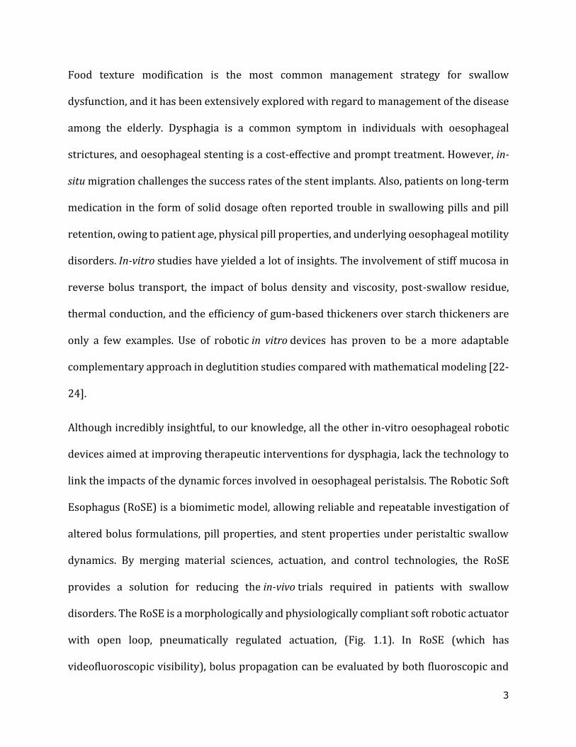
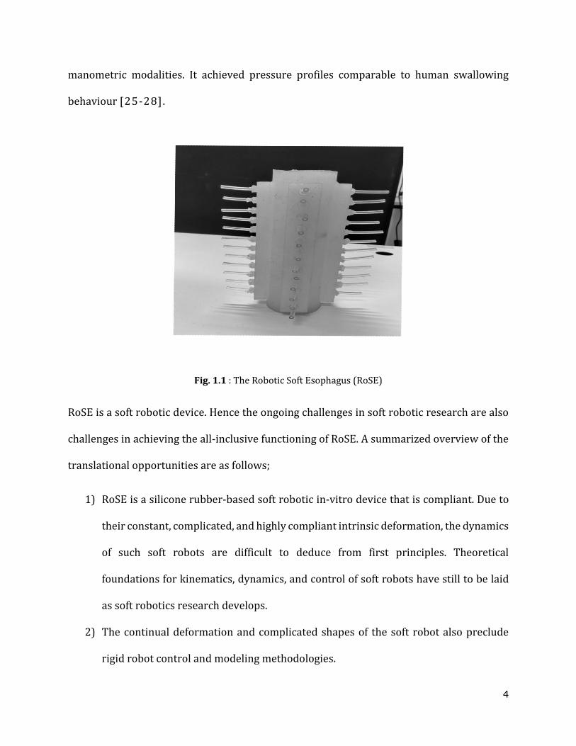
link the impacts of the dynamic forces involved in oesophageal peristalsis. The Robotic Soft
Esophagus (RoSE) is a biomimetic model, allowing reliable and repeatable investigation of
altered bolus formulations, pill properties, and stent properties under peristaltic swallow
dynamics. By merging material sciences, actuation, and control technologies, the RoSE
provides a solution for reducing the in-vivo trials required in patients with swallow
disorders. The RoSE is a morphologically and physiologically compliant soft robotic actuator
with open loop, pneumatically regulated actuation, (Fig. 1.1). In RoSE (which has
videofluoroscopic visibility), bolus propagation can be evaluated by both fluoroscopic and
4
manometric modalities. It achieved pressure profiles comparable to human swallowing
behaviour [25-28].
Fig. 1.1 : The Robotic Soft Esophagus (RoSE)
RoSE is a soft robotic device. Hence the ongoing challenges in soft robotic research are also
challenges in achieving the all-inclusive functioning of RoSE. A summarized overview of the
translational opportunities are as follows;
1) RoSE is a silicone rubber-based soft robotic in-vitro device that is compliant. Due to
their constant, complicated, and highly compliant intrinsic deformation, the dynamics
of such soft robots are difficult to deduce from first principles. Theoretical
foundations for kinematics, dynamics, and control of soft robots have still to be laid
as soft robotics research develops.
2) The continual deformation and complicated shapes of the soft robot also preclude
rigid robot control and modeling methodologies.
5
3) Furthermore, the use of conventional sensors is imperfect due to a lack of compliance
with soft matter.
4) Any compliant soft sensors developed or discussed have highly non-linear
characteristics. Due to omnidirectional compliance, these sensors could have single
conformations (sensor values do not vary at specific system configurations) and non-
unique mappings (i.e., similar sensor readings for different system configurations).
As a result, we aim to incorporate inbuilt sensing capabilities and develop data-driven
approaches based on the sensor–embedded actuator data to model system dynamics and
control for the soft robot configuration. As long as reliable training signals are available for
creating the model, the machine learning approach can solve the problem of modeling
unknown sensor and system dynamics.
1.1 Research Motivation
The swallow dynamics of the biological oesophagus is an adaptive process to the physical
form and viscosity of the bolus swallowed. In other words, the natural swallowing process
employed an intelligent and self-adaptive closed-loop motor-neuron control. However, the
temporal-spatial dynamics of RoSE for bolus transport are open-loop regulated. As stated
earlier, many existing sensors have issues, including occlusion, interference, or trouble
integrating with the robot. The constant deformation and complex shapes attained while
RoSE is in actuation, on the other hand, limit conventional control and modeling methods. As
a result, intrinsic sensing capabilities and data-driven control approaches based on the
robot's observations are proposed.

6
To enhance RoSE, a better understanding of how bolus qualities affect the flow and swallow
efficacy within the conduit might be beneficial. Under RoSE-mimicked peristalsis, bolus
transport trajectories, fluctuations in intra-bolus pressure, fluid velocity, and apparent food
bolus viscosity could be considered direct markers of swallow efficacy. Because manometry
is solely based on intra-bolus pressure measurements, it is insufficient for the intended
investigation. The physical features of the bolus-wall interface during swallowing, such as
pressure and shear stress, could provide information for evaluating the bolus transit in RoSE.
These findings will aid in a better understanding of the relationship between food
rheological qualities and bolus transit since the interaction is more closely related to
swallowing behaviour. In the absence of specific sensors, the RoSE multi-physics finite
element method (FEM) based simulation model could provide answers to these questions.
With bio-mimicking the peristaltic trajectory, a compliant soft robotic oesophagus has many
extended applications such as endo-prosthetic stent testing, pill swallow transit evaluation,
and modified food texture transit testing. Establishing clinically significant protocols for
testing is necessary so that the observations and findings are relevant in therapeutics and
dysphagia management.
The research proposes developing and characterizing stretchable elastomeric sensors to
investigate the deformations of the sensor-embedded RoSE and designing universally
applicable the closed-loop control of the sensor-embedded soft robotic actuators. The
research also proposes developing a fluid-structure interaction simulation model of RoSE to
study the physical variables of bolus flow dynamics under RoSE peristalsis. The research

7
correspondingly proposes to construct clinically significant test protocols for testing
therapeutic measures and devices for swallow disorders management.
1.2 Aims and Objectives
This research aims to enhance the RoSE to use it as an investigative tool in in-vitro
swallowing research. The aim can be broken down further into 1) Development and
calibration of a sensor embedded actuator for modeling and control, 2) Developing a FEM
models simulation model to learn about bolus transit parameters under RoSE pre-defined
trajectories, and 3) Developing therapeutically applicable methods and conducting in-vitro
swallow studies for stent migration and pill transit assessments.
Objectives 1 and 2 will establish a universal framework for the customized sensor matrix
development and data processing methodology for the RoSE conduit Fig. 1.2. Objectives 3
and 4 will fulfill the second and third parts of the aim, respectively.
Fig. 1.2: Overview of objectives 1 and 2. a) Robot cross-section under actuation b) proposed sensor matrix
c) hardware and algorithms for sensor modeling, deformation capturing, and actuator control.
8
The objectives to achieve the aim are identified by extensive research, which is outlined as
follows:
1.2.1 Objective 1: Design and characterization of stretchable strain sensors
The first step towards developing an embedded two-dimensional array of sensors was to
design and fabricate the primary building block of the variety, the sensor unit. Achieving this
objective involves completing the following subtasks:
1. Literature review :A comprehensive study of the existing swallowing devices, the
actuator pneumatic interface, actuation trajectories, and hardware configuration to
understand the sensor requirements and constraints of the targeted environment of
implementation. The review will also include the current state of the art in soft
robotics, stretchable electronics, and sensor technology and identify the design
method, materials to be used, and testing methodologies.
2. Sensor fabrication: The sensors are fabricated with accessible and available
fabrication techniques. To achieve this objective, an embedded stretchable
deformation sensor matrix, based on the carbon nanocomposite, is proposed to
measure and monitor the actuator's performance. Nanomaterial-enhanced sensing
using graphene, graphene oxide, or carbon nanotubes has been identified as the most
sensitive detection system. As a kind of carbon material, carbon black has advantages
such as being lightweight, high chemical and thermal stability, permanent electrical
conductivity, and low cost. CB was also reported to outperform CNT, graphene oxide
and reduced graphene oxide-modified screen printed electrodes in terms of electron
transfer constant, redox reversibility, background currents, and cost-effectiveness.
9
Less adverse effects were observed after inhalation exposure to relatively low specific
surface area carbon black. For the research the nanocomposite is made of carbon
black and Ecoflex mixture. The material compatibility and extreme thinness of the
sensor matrix ensure that it does not interfere with the deformation of the
transporting conduit.
3. Design of experiments: For testing the sensor repeatability, reliability, and hysteresis
of the sensor structure and interconnections. The cyclic loading, strain rate, and
stretch direction tests are conducted in the sensor unit or sensor array.
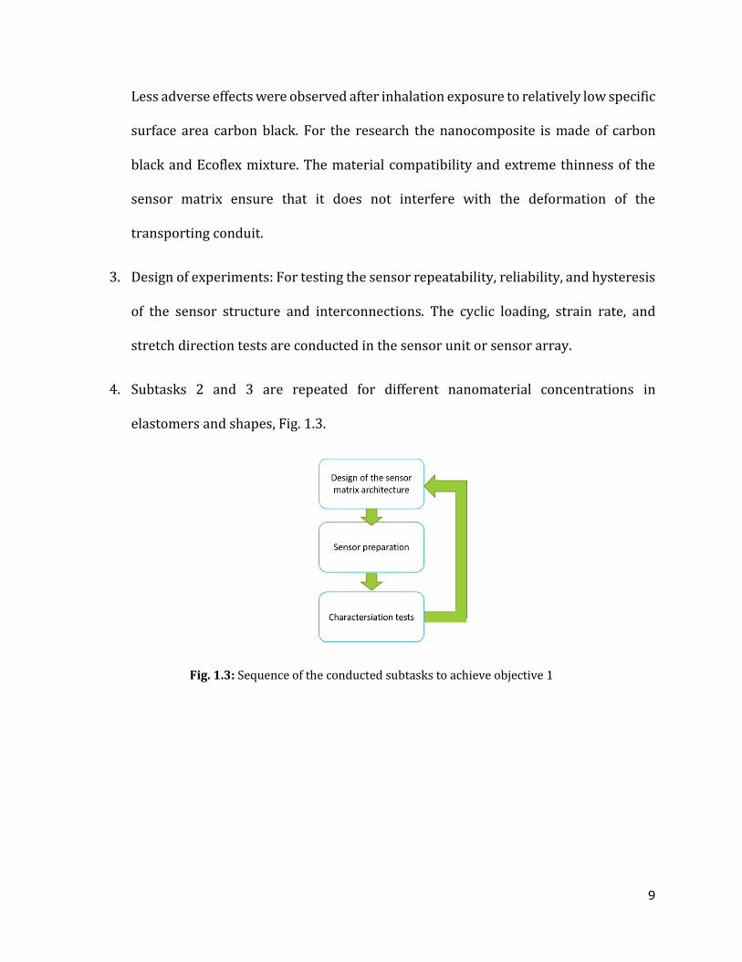
4. Subtasks 2 and 3 are repeated for different nanomaterial concentrations in
elastomers and shapes, Fig. 1.3.
Fig. 1.3: Sequence of the conducted subtasks to achieve objective 1

10
1.2.2 Objective 2: Research the mathematical mapping between sensor measurements and the actuator geometry.
The goal was to validate the performance of the sensor structures and find the relationship
between the inputs and outputs of the sensor. The objective is achieved by completing the
following subtasks:
1. Literature review: Comprehensive review to understand machine learning
algorithms used in soft robotics for actuator modeling, sensor modeling, and control
design.
2. Design of flat robot: To overcome the limited visibility of the RoSE, a testing module
was designed and developed, which is a single layer flattened version of the RoSE,
fRoSE. The sensor data was calibrated against the webcam images of trackers placed
on the fRoSE surface.
3. Design of experiments for sensor modeling: The sensor characterization for cyclic
staircase inputs to mimic peristalsic trajectory. The neural networks and machine
learning approaches to model the soft actuator deformation geometry with sensor
data.
4. Controller design framework: The design and development of controller strategy for
the flat version of the robot called fRoSE. A piecewise linearised controller is designed
utilizing the non-linear sensor modeling data.
5. Validating the sensor for RoSE: The conduit deformation studies are conducted on a
6-layer version of RoSE. The sensor is calibrated and validated against the collected
data from articulography sensor array experiments conducted by Dirven et al. [27].
11
1.2.3 Objective 3. Learning the bolus transit characteristics from finite element model simulation
The FEM modeling will be using simulation software COMSOL Multiphysics® 5.3. The
subtasks of this objective include:
1. Hyper-elastic parameters tuning: The tensile testing of EcoflexTM 00-30 samples
under ASTM D412 standards was conducted on a universal machine. The hyper-
elastic parameters were tuned with various available models.
2. The domains and boundary conditions are defined on the 2D approximation of a 3D
model.
3. Validation of the simulation model:
The pressure signatures of bolus transport inside the RoSE was captured using
a manometric motility catheter and data acquisition system (S98-200C,
P3315205CC152, Sandhill Scientific, USA)
Synthetic honey bolus (starch-thickened water) made using Altrix Rapid
Thickener (Douglas Nutrition Ltd) as per the International Dysphagia Diet
Standardisation Initiative (IDDSI) [41].
Image analysis for velocity tracking of image data set from webcam capturing
set up.
1.2.4 Objective 4. RoSE capability in investigating stent migration and pill transit.
The objective was to assess the use of RoSE in studying the migration of stents and pill
transits characteristics under repeated peristaltic contractions.
12
The objective was achieved by completing the following subtasks:
1. Literature review: Validating the capability of RoSE in the area of stent testing
requires reviewing relevant literature which underlines the major stent designing
parameters and their effect on stent performance. The in-vitro and in-vivo studies
were used in pill parameter variations. Development of RoSE firmware protocol:
Custom firmware modules, written in Python 3.7, was developed on Raspberry Pi 3B+
to command the robot and generated peristaltic waves in RoSE.
2. Designing stent deployment framework: A deployment framework following the
endoscopist approach to deploying stents in the human oesophagus was developed
and employed throughout this study.
3. Designing pill administration protocol: This study developed and employed a
deployment framework following the pill transit studies in the clinical environment.
4. Artificial food bolus formulation: Food boluses of varying consistencies were
prepared in the laboratory using a commercial food thickener (Altrix Rapid
Thickener, Douglas Nutrition Ltd, New Zealand), specially formulated for dysphagia
patients.
5. Stent migration testing: Two commercial covered SEMSs having distinct structures,
material cover patterns, and similar dimensions were tested for stent migration in
RoSE with and without food bolus.
13
1.3 Scope of the project
To explain the scope of this study, several tasks have been identified as beyond the scope of
the research. These include, but are not limited to, the following:
1. A sensor matrix capable of measuring the strain and hence the deformation of RoSE
meeting the strain rate and direction requirements is developed. The design focused
on finalizing the architecture, sensing principle and conductive filler concentration.
2. The control design was done only on a single-layer sensor-actuator model. The initial
experiments have proven that the sensor matrix can provide reliable deformation
measurements in a 6-layer version of RoSE. Further calibrations are still needed for
closed-loop geometrical control.
3. The control design of the robot will not consider the variation in properties of the
material used to design the robot. In the case of silicone components, the stress of a
material during reloading is found to be much lower than the stress of the first loading
at the same strain level, which is known as stress softening in the case of filled
rubbers. It is a material variation that is only present for a short time. After holding it
in a stress-free state at room temperature or annealing it at a high temperature for a
period of time, the pre-stretched material's stress can be restored to its original level.
The stress softening and recovery results reveal that the mechanical behavior of
silicone components changes during application, influencing the appliance's
performance. Hence, the assumption will only discuss the current state of the material
and neglect any change in its qualitative or quantitative characteristics over time and
varying environmental conditions like strain, humidity and temperature.

14
4. Both the simulation studies and swallow studies were conducted with trajectories of
fixed wavelength and velocity. For varying velocity trajectories, fully functional and
embedded sensors are required. This research lays the fundamentals for developing
fully functional sensors.
5. The simulation studies are conducted on the 2D approximation of a 3D CAD model.
Because of the symmetry in the geometry the results obtained can be extended to the
three dimensional robot.
6. The bolus transit behaviour will be analyzed on physiological factors of peristalsis
velocity and wavelength and rheological properties of viscosity. The other
physiological parameters such as temperature, intra-oesophageal pressure and
rheological properties such as homogeneity and particle size will not be considered
and is a future direction for the expansion of the work.
7. The data obtained in stent migration studies and pill swallow studies will be validated
against the literature available and controlled experiments in the laboratory and will
not involve any clinical studies.
8. Because the whole RoSE conduit is constructed of the same silicone rubber material
(EcoflexTM-0030, Smooth-on, USA), the in-vitro studies did not consider the
distribution of different muscle fiber architecture in the oesophagus.
9. The study is strictly limited to proving the usability of RoSE in stent migration testing
and pill swallow transit times. It does not focus on all the design variations of the
stents or pills used to conduct this research.
15
1.4 Research contributions
In the following ways, this study contributed to the body of scientific knowledge and
application:
An in-depth literature review was conducted to understand the current state of the
stretchable sensor and circuit technology and to identify any potential new approach worth
exploring, to develop a new set of sensors that meets specific requirements for the
oesophageal swallowing robot. The swallowing robot has a carbon black nanoparticles –
EcoflexTM sensor matrix that has been created and embedded. This allows for real-time
monitoring of the swallowing robot's circumferential deformation.
The stretchable deformation sensor matrix studies makes the following contributions:
1) The research has established a framework for developing stretchable nanoparticle-
based sensors customized for the application in RoSE. The flexible sensor matrix's
limitations are tailored to meet both engineering and behaviour criteria. A
comparison study between sensors of different nanoparticle concentrations in the
elastomer and the architecture for completing the design criteria of the RoSE
deformations applies to soft robotic sensor design studies.
2) Sensor array characterization and validation in the lab. The recurrent neural network
and support vector regression was used to predict and model the sensor
nonlinearities. This methodology of modeling knowledge is beneficial in using
conventional controller methods to control the sensor-embedded soft actuator.
16
3) The research proposed and followed a general outline for the linearization and
feedforward compensated proportional integral and derivative (PID) controller for
soft robotics.
FEM-based fluid-structure interaction studies for bolus transport in RoSE to our knowledge
are not previously attempted in soft robotics to study fluid dynamics. The rheological
changes in a bolus while in RoSE or a similar device and velocity, pressure, and shear
variations in the absence of sensors can be studied with this approach to validate in-
vitro device performance.
The protocols developed for RoSE assessment for pill swallow transit times and stent
migration are the first of their kind. They could be a collective agreement for similar in-vitro
experiments. The results of these experiments could help improve stent designs without
compromising lumen patency and developing strategies to reduce stent migration. Similarly,
the effects of changes in the physical qualities of solid dosage forms of a pharmaceutical
evaluated in RoSE can pave the way for novel forms of the medication to be introduced.
17
Chapter 2
Literature Review
Diagnostics and in vivo tests in practice to address dysphagia complaints, can be
supplemented with in vitro (in silico) experiments to lessen the misery of the affected
population from evaluation rehearsals and to benefit the pace of innovation in dysphagia
management. From overly idealistic mathematical models to unyieldingly challenging
clinical studies, robotic simulators offer the best compromise being able to address safety
concerns, ethics and efficacy in the context of dysphagia management research. This
literature review will identify the significance of soft robotic base in-vitro swallow device
and the research opportunities presented by such a robot. The literature will pan over to the
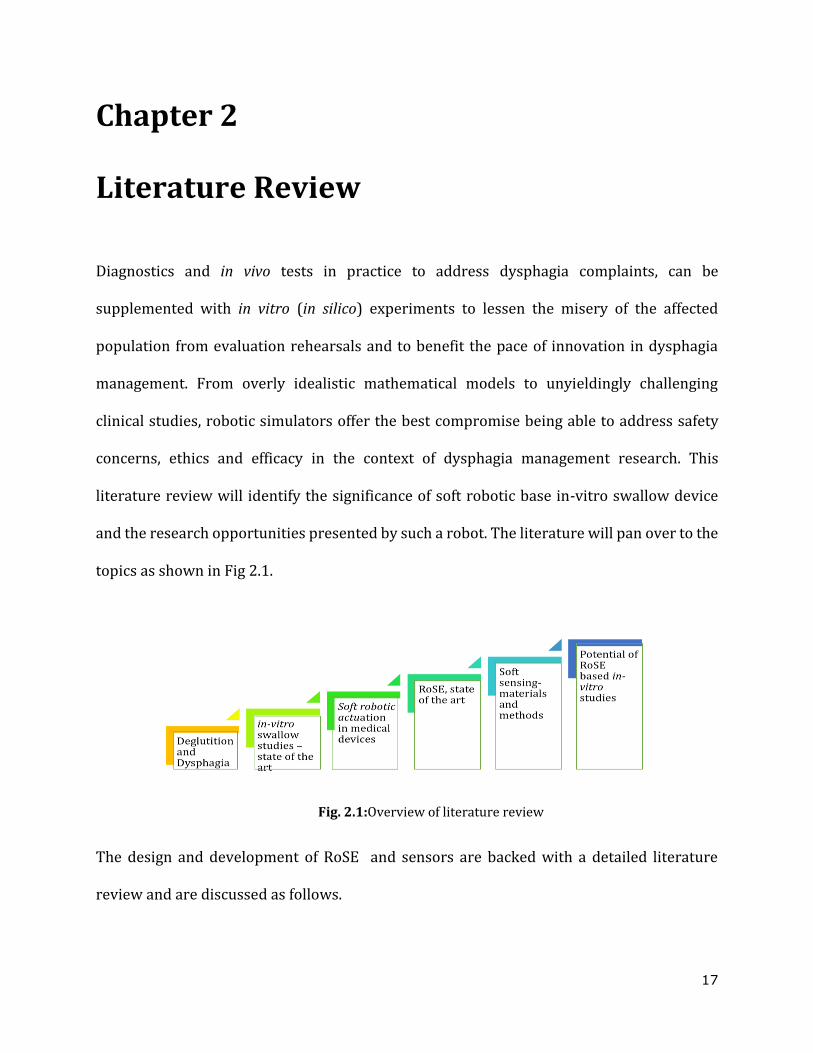
topics as shown in Fig 2.1.
Fig. 2.1:Overview of literature review
The design and development of RoSE and sensors are backed with a detailed literature
review and are discussed as follows.
18
2.1 Deglutition, dysphagia and pathology management
2.1.1 Deglutition
Deglutition is the complex but orderly physiological process of transporting saliva or food
from the mouth into the stomach. The process is documented in physiology texts as involving
four phases: the preparatory phase, oral phase, pharyngeal phase, and oesophageal phase.
The preparatory phase and most of the oral phase are considered to be under voluntary
control, where the food is masticated into an aptly cohesive bolus of small particles, while
the pharyngeal and oesophagal phases of swallowing are grouped as involuntary reflexive
processes, which, once initiated, will be subconsciously progressed [1, 2]. The detailed
process is shown in Fig. 2.1 and is discussed as follows.
The swallowing physiology and anatomy are elucidated with the key insights from the in vivo
studies [18,19,29,30], and it is learned that the initiation of involuntary deglutition, termed
the oropharyngeal phase, is marked by the entry of bolus into the pharynx. The tongue, being
the inferior boundary in the oral cavity, facilitates mastication and manipulation of the food
into a cohesive bolus. As the final phase of oral processing, the bolus is propagated into the
pharynx with a sequential rostro-caudal compression of the tongue against the hard and soft
palate. The coordinated elevation of the soft palate against the posterior pharyngeal wall,
along with relaxation and opening of the glossopalatal sphincter, allows easy entry of the
bolus into the pharynx, seals off the nasopharynx and hence prohibits pharyngeal nasal
regurgitation.
19
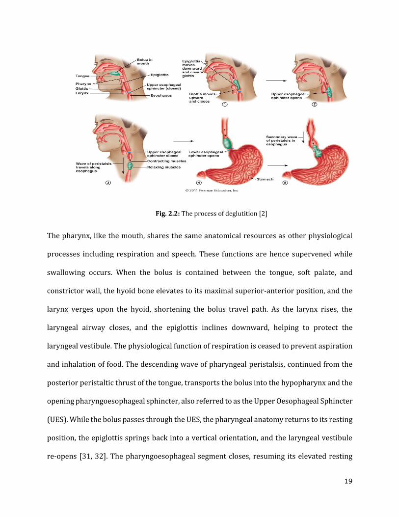
Fig. 2.2: The process of deglutition [2]
The pharynx, like the mouth, shares the same anatomical resources as other physiological
processes including respiration and speech. These functions are hence supervened while
swallowing occurs. When the bolus is contained between the tongue, soft palate, and
constrictor wall, the hyoid bone elevates to its maximal superior-anterior position, and the
larynx verges upon the hyoid, shortening the bolus travel path. As the larynx rises, the
laryngeal airway closes, and the epiglottis inclines downward, helping to protect the
laryngeal vestibule. The physiological function of respiration is ceased to prevent aspiration
and inhalation of food. The descending wave of pharyngeal peristalsis, continued from the
posterior peristaltic thrust of the tongue, transports the bolus into the hypopharynx and the
opening pharyngoesophageal sphincter, also referred to as the Upper Oesophageal Sphincter
(UES). While the bolus passes through the UES, the pharyngeal anatomy returns to its resting
position, the epiglottis springs back into a vertical orientation, and the laryngeal vestibule
re-opens [31, 32]. The pharyngoesophageal segment closes, resuming its elevated resting
20
pressure, and averting any retrograde bolus entry into the hypopharynx. The bolus in the
oesophagus is carried on by oesophageal peristalsis for between 18 and 25 cm to the
stomach. There are six cranial nerve motor nuclei involved in controlling and co-ordinating
deglutition. All the intrinsic muscles of the pharynx, larynx, and a greater part of soft palate
receive motor fibres from the glossopharyngeal and vagus nerves [31, 33].
In humans, the oesophagus mainly consists of two parts: 1) the cervical oesophagus (one-
third of the proximal oesophagus) composed of striated muscles and 2) the thoracic
oesophagus ( two thirds of the distal oesophagus) composed of phasic smooth muscles.
Though the striated muscles are innervated by motor neurons from the nucleus ambigus,
and the smooth muscle of the oesophagus is innervated by neurons from the nucleus vagus,
the peristalsis in both of them are phenotypically similar. The lower oesophageal sphincter
(LES) is characterized by a tonic muscle modulated by the inhibitory and excitatory nerves
from the nucleus vagus. According to its method of stimulation, oesophageal waves of the
peristalsis are classified into primary peristalsis (involves both central and peripheral
elicitation) and secondary peristalsis (involves only peripheral elicitation). About 0.5 to 1.4
seconds after the hypopharyngeal pressure peaks, the LES is elicited to relax, at which point
the rostro-caudal primary peristaltic waves, travelling at an approximate rate of 30 to 40
mmps, squeeze the bolus into the stomach. The secondary peristaltic waves occur multiple
times up to an hour after the swallow and help to clear any remaining oesophageal residue.
In healthy subjects, oesophageal transit times are found to be between 8 and 13 seconds
depending on factors like age, bolus size, and bolus texture [1, 34, 35].
21
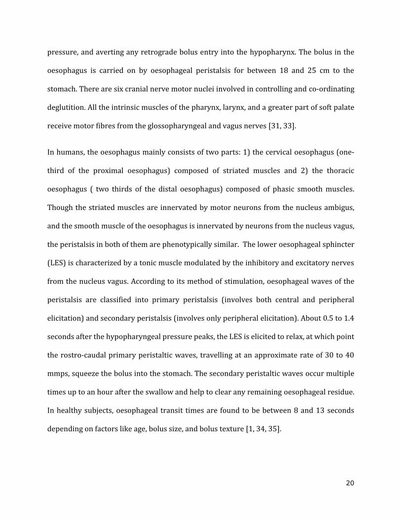
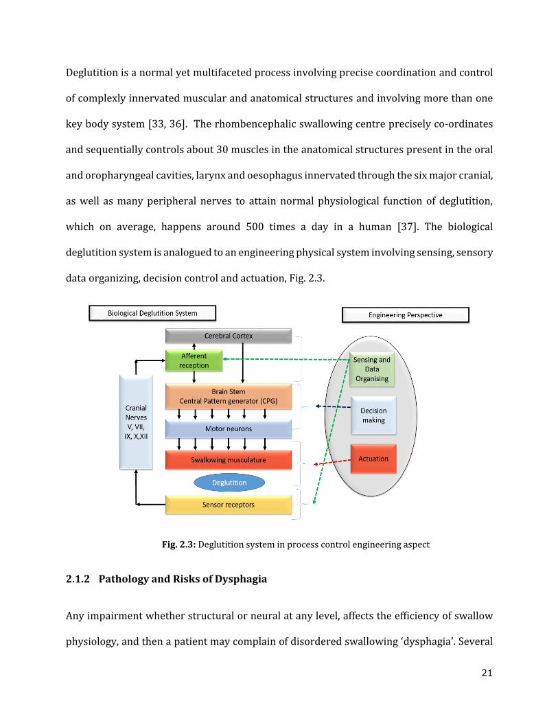
Deglutition is a normal yet multifaceted process involving precise coordination and control
of complexly innervated muscular and anatomical structures and involving more than one
key body system [33, 36]. The rhombencephalic swallowing centre precisely co-ordinates
and sequentially controls about 30 muscles in the anatomical structures present in the oral
and oropharyngeal cavities, larynx and oesophagus innervated through the six major cranial,
as well as many peripheral nerves to attain normal physiological function of deglutition,
which on average, happens around 500 times a day in a human [37]. The biological
deglutition system is analogued to an engineering physical system involving sensing, sensory
data organizing, decision control and actuation, Fig. 2.3.
Fig. 2.3: Deglutition system in process control engineering aspect
2.1.2 Pathology and Risks of Dysphagia
Any impairment whether structural or neural at any level, affects the efficiency of swallow
physiology, and then a patient may complain of disordered swallowing ‘dysphagia’. Several

22
pathologies may result in dysphagia as a common symptom and hence the causes of swallow
impairments are many: 1) neurologic conditions – like Parkinson’s disease, stroke, and
dementia, 2) immunologic conditions – like esophagitis, inflammatory myopathies, and
systemic sclerosis, 3) gastroesophageal conditions – like reflux and motility disorders, or 4)
oncological conditions – like head and neck, oesophageal, gastric, and lung cancer. Physical
obstruction due to post-treatment procedures such as drug-induced injuries, surgery,
chemotherapy or radiation, and traumatic endotracheal intubation also contributes to
swallow problems [20,21,38-40]. Accompanied by lack of care, a vicious cycle materializes
as malnutrition and dehydration, enhancing the swallowing deficits, subsequently affect
more physiological and psychological functionalities and even cause mortality.
2.1.3 Management of Dysphagia
The standard clinical practice involves evaluation of the nature of the swallowing deficit,
using perception studies and in vivo analysis followed by the application of nutritional
support for functional status and quality of life. The method of choice for maintaining
nutrition depending upon the severity and site of the swallow problem, and varies from oral
nutritional supplements, texture modified foods, food administration through feeding tubes,
surgical correction, endoscopic dilation of the sphincters and oesophageal stenting.
a. Food texture management
Dysphagia management with texture modified foods employ diet frameworks and the
recently developed and validate International Dysphagia Diet Standardization Initiative
(IDDSI) framework has been adopted globally to standardize both diet textures and the
discussion of interventions related to texture modification [41]. Though the framework of
23
IDDSI proposes classification of the consistency of foods and drinks, it prevaricates the
rheological problem, through excluding facts about yield stress, shear thinning, and
viscoelasticity of liquid and semisolid products. This information is concluded significant in
the perceived ease of swallow from diagnostics and perception investigations [39, 42, 43].
An improved interpretation of how the bolus properties stipulate the flow and swallow
efficacy, can be advantageous in the design and development of novel food products with
improved texture and swallow-ability, without compromising hydration and nutrition.
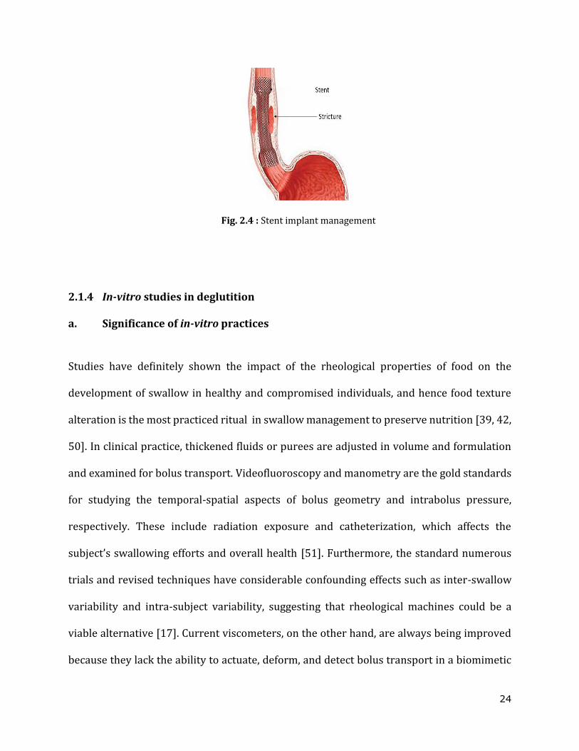
b. Stent implant management
Fixed anatomic pathologies, for instance, benign oesophageal strictures from various
injuries, oesophageal cancer or oesophageal perforations, result in compromised luminal
patency, and hence compromise swallowing. These may be addressed with an
endoprosthetic placement, shown in Fig. 2.4, or oesophageal stenting [21,44-46]. The
earlier use of uncovered stents for palliation was limited and contributed to in-situ erosion,
occlusion, and fistulation. However, the advent of fully coated removable self-expanding
plastic stents (SEPS), self-expanding metallic stents (SEMS) and biodegradable stents,
marked new applications with variable success [47, 48]. With moderate 30-50% long term
success rates, these stents suffer from migration as the main complication. The capability of
providing stronger radial forces for patency may reassure the anchoring position, and have
perceptibility in videofluoroscopy confronting stent engineering [49].
24
Fig. 2.4 : Stent implant management
2.1.4 In-vitro studies in deglutition
a. Significance of in-vitro practices
Studies have definitely shown the impact of the rheological properties of food on the
development of swallow in healthy and compromised individuals, and hence food texture
alteration is the most practiced ritual in swallow management to preserve nutrition [39, 42,
50]. In clinical practice, thickened fluids or purees are adjusted in volume and formulation
and examined for bolus transport. Videofluoroscopy and manometry are the gold standards
for studying the temporal-spatial aspects of bolus geometry and intrabolus pressure,
respectively. These include radiation exposure and catheterization, which affects the
subject’s swallowing efforts and overall health [51]. Furthermore, the standard numerous
trials and revised techniques have considerable confounding effects such as inter-swallow
variability and intra-subject variability, suggesting that rheological machines could be a
viable alternative [17]. Current viscometers, on the other hand, are always being improved
because they lack the ability to actuate, deform, and detect bolus transport in a biomimetic
25
swallowing pattern [52, 53]. However, reading apparent viscosity without taking into
account dynamic forces, the swallowing effort for a formulation is incorrectly indicated.
In practice, diagnostics and in-vivo testing can be augmented with in-vitro (in-silico)
investigations for the following benefits: 1) to reduce the suffering of the affected population
as a result of evaluation procedures 2) to enhance the development of textured foods, and 3)
to enhance the development of stents for dysphagia management. The in-vitro platforms
allow varying the bolus parameters independently, which is crucial to comprehend the effect
of variation in bolus properties as a fit to a larger set of similar pathological paradigms. Also,
in vitro devices have undeniable inter-swallow reliability which is hindered by inter-person
swallow and inter-swallow variability in human test subjects [17]. Robotic simulators, on the
other hand, are the perfect complement to highly idealistic mathematical models and
unyieldingly difficult clinical investigations to examine deglutition.
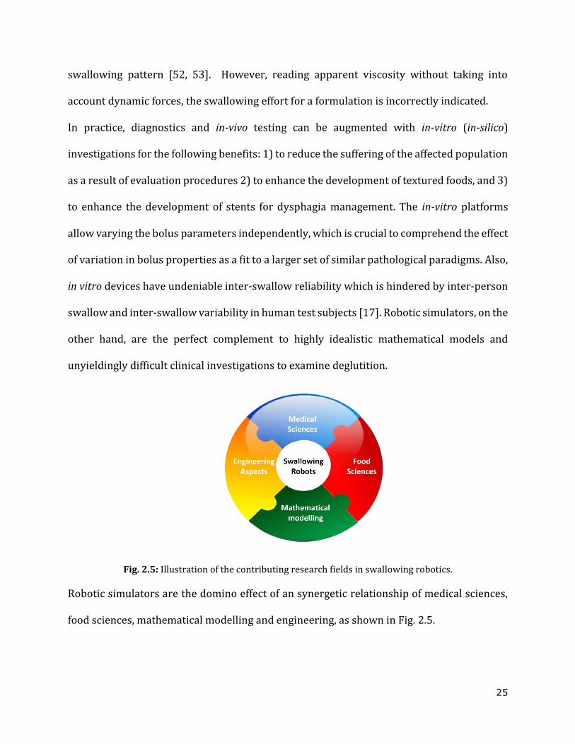
Fig. 2.5: Illustration of the contributing research fields in swallowing robotics.
Robotic simulators are the domino effect of an synergetic relationship of medical sciences,
food sciences, mathematical modelling and engineering, as shown in Fig. 2.5.
26
b. Recent in-vitro swallowing studies and the insights
Though a complexly innervated anatomy, the voluntary and involuntary phases of deglutiton
have mostly individual neural controls except for the transitions [17]. Studies to replicate or
bio-mimic the different phases of deglutition has been driven by mounting needs in food
innovation and healthcare research for the past two decades [54] . With Kobayashi et al. [55]
pioneering robotic simulator work, studies in-silico and in-vitro models of oral phase
[15,22,56-58], pharyngeal phase [17,21,23,59] and oesophageal phase [24,25,60] have
provided a mechanistic insight for interesting archetypes observed in in-vivo investigations.
The spreading area of bolus, effects of bolus density and viscosity, post-swallow residue,
thermal conduction, the effectiveness of gum-based thickeners over starch thickeners, the
role of stiffened mucosa in bolus reverse transport, are some worth mentioning. Table 2.1,
shows the related studies.
c. Actuation in in-vitro swallowing robots
The in-vitro Gothenburg throat model mimics the oral phase by a syringe that delivers a
bolus into the pharyngeal channel [21]. The device can simulate the processes of closing of
the vocal chords, movement of the upper oesophageal sphincter (UES) and the epiglottis, and
opening to the nasopharyngeal channel. The pressure transducers and the ultrasonic
transducers encompass pressure measurements and monitor the bolus velocity profile.
However the device excludes mimicking the swallowing musculature. A robotic tongue,
capable of sending solid substances to the pharynx, has a sequentially controlled McKibben-
type artificial muscle using electro-pneumatic regulators with actuation comparable to the
actual tongue movements in the MRI data as discussed in [58]. A robotic simulator of the

27
pharyngeal phase named Swall-E has sequenced and synchronized motions by actuators
pushing and pulling the metal wires inwardly and radially deforming the silicone conduit
[17]. Noh et al. enhanced the mimicking of initial phases of deglutition research with airway
management. The work involved an in-vitro dynamic unit with 16 servo actuators with wire
driving mechanisms studying bolus flow under videofluroscopy [59]. Some are shown in Fig.
2.6.
28
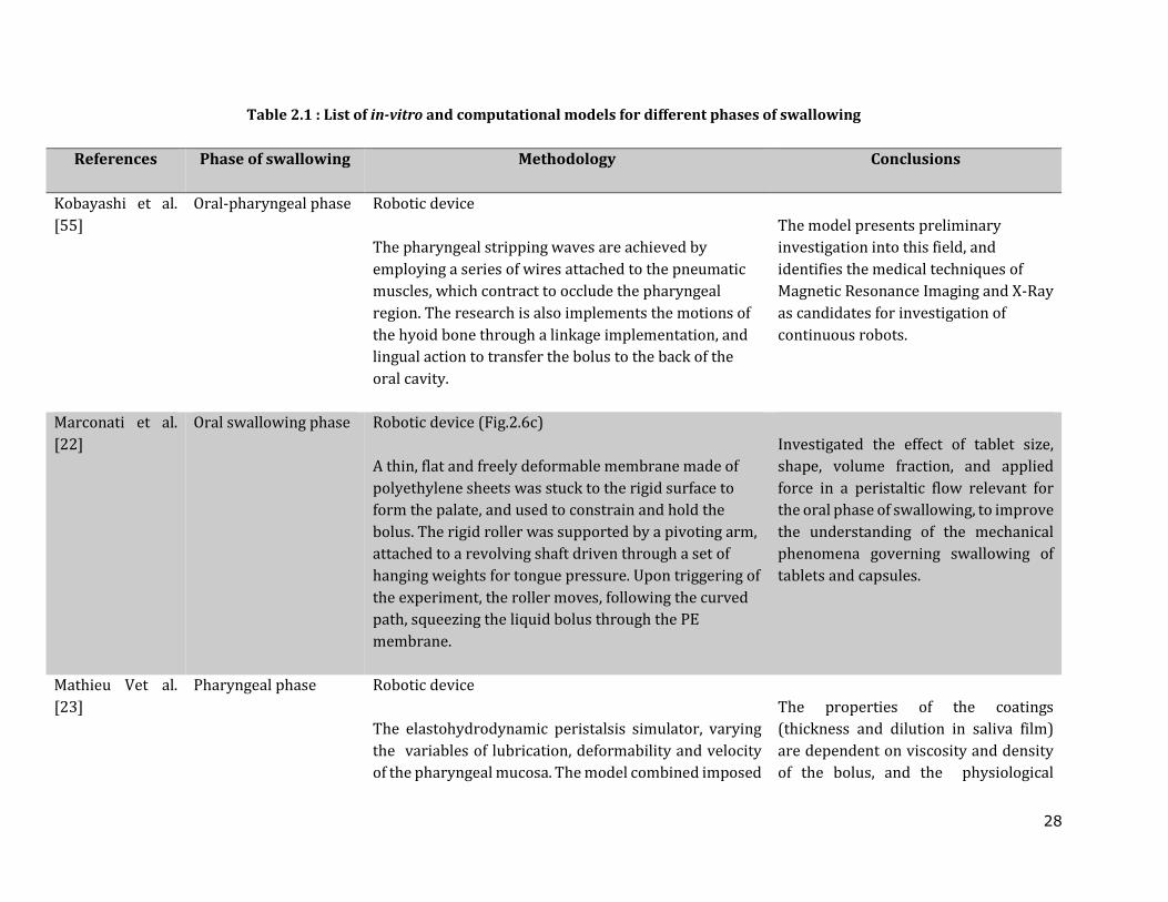
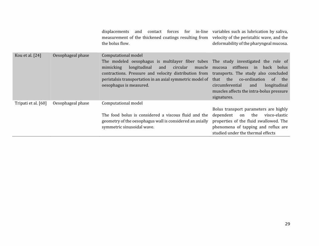
Table 2.1 : List of in-vitro and computational models for different phases of swallowing
References Phase of swallowing Methodology
Conclusions
Kobayashi et al.
[55]
Oral-pharyngeal phase Robotic device
The pharyngeal stripping waves are achieved by
employing a series of wires attached to the pneumatic
muscles, which contract to occlude the pharyngeal
region. The research is also implements the motions of
the hyoid bone through a linkage implementation, and
lingual action to transfer the bolus to the back of the
oral cavity.
The model presents preliminary
investigation into this field, and
identifies the medical techniques of
Magnetic Resonance Imaging and X-Ray
as candidates for investigation of
continuous robots.
Marconati et al.
[22]
Oral swallowing phase Robotic device (Fig.2.6c)
A thin, flat and freely deformable membrane made of
polyethylene sheets was stuck to the rigid surface to
form the palate, and used to constrain and hold the
bolus. The rigid roller was supported by a pivoting arm,
attached to a revolving shaft driven through a set of
hanging weights for tongue pressure. Upon triggering of
the experiment, the roller moves, following the curved
path, squeezing the liquid bolus through the PE
membrane.
Investigated the effect of tablet size,
shape, volume fraction, and applied
force in a peristaltic flow relevant for
the oral phase of swallowing, to improve
the understanding of the mechanical
phenomena governing swallowing of
tablets and capsules.
Mathieu Vet al.
[23]
Pharyngeal phase Robotic device
The elastohydrodynamic peristalsis simulator, varying
the variables of lubrication, deformability and velocity
of the pharyngeal mucosa. The model combined imposed
The properties of the coatings
(thickness and dilution in saliva film)
are dependent on viscosity and density
of the bolus, and the physiological
29
displacements and contact forces for in-line
measurement of the thickened coatings resulting from
the bolus flow.
variables such as lubrication by saliva,
velocity of the peristaltic wave, and the
deformability of the pharyngeal mucosa.
Kou et al. [24] Oesophageal phase Computational model
The modeled oesophagus is multilayer fiber tubes
mimicking longitudinal and circular muscle
contractions. Pressure and velocity distribution from
peristalsis transportation in an axial symmetric model of
oesophagus is measured.
The study investigated the role of
mucosa stiffness in back bolus
transports. The study also concluded
that the co-ordination of the
circumferential and longitudinal
muscles affects the intra-bolus pressure
signatures.
Tripati et al. [60] Oesophageal phase Computational model
The food bolus is considered a viscous fluid and the
geometry of the oesophagus wall is considered an axially
symmetric sinusoidal wave.
Bolus transport parameters are highly
dependent on the visco-elastic
properties of the fluid swallowed. The
phenomena of tapping and reflux are
studied under the thermal effects
30
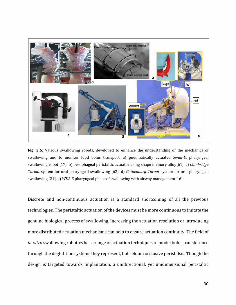
Fig. 2.6: Various swallowing robots, developed to enhance the understanding of the mechanics of
swallowing and to monitor food bolus transport, a) pneumatically actuated Swall-E, pharyngeal
swallowing robot [17], b) oesophageal peristaltic actuator using shape memory alloy[61], c) Cambridge
Throat system for oral-pharyngeal swallowing [62], d) Gothenburg Throat system for oral-pharyngeal
swallowing [21], e) WKA-3 pharyngeal phase of swallowing with airway management[16].
Discrete and non-continuous actuation is a standard shortcoming of all the previous
technologies. The peristaltic actuation of the devices must be more continuous to imitate the
genuine biological process of swallowing. Increasing the actuation resolution or introducing
more distributed actuation mechanisms can help to ensure actuation continuity. The field of
in-vitro swallowing robotics has a range of actuation techniques to model bolus transference
through the deglutition systems they represent, but seldom occlusive peristalsis. Though the
design is targeted towards implantation, a unidirectional, yet unidimensional peristaltic
31
occlusion of flexible conduit by actuation of axially arranged rigid polyvinyl chloride
elements with discrete shape memory alloy springs is discussed by Miki et al. [61]. The
prototype is made up of distinct components. A current is passed through the SMA spring in
each unit, causing it to heat up and deform. Each unit retains its prior state after cooling,
causing propagation of the transport medium.
Most of these models are geometrically factual and formed to the anatomy but still outlying
in the coordinated actuation as the bolus propagates. Each of these has their own inherent
advantages and limitations such as size, force capability, safety, and power consumption. Of
these techniques, pneumatic actuation has been pursued in RoSE due to its excellent
distributed actuation behaviour and intrinsic compliance. The RoSE hence adapts a hybrid
of silicone elastomer transmission of pneumatic actuation that could facilitate design
possibilities without rigid skeletal structures which is imperative to the biomimetic
motivation. The silicone elastomer-based design of RoSE pitches the nuance of soft robotic
opportunities in swallowing robotics.
2.2 Soft robotics ‒ changing the warp and weft of medical diagnostics and
therapeutics
It is apparent that the field of swallowing robotics is becoming more anthropomorphic in the
movement toward rubber material interfaces which mimic the tissue interaction. The
application of soft-robotic techniques can offer compliance and novel shapes as a new
approach to investigating bio-mimicking devices. Soft robotics is the introduction of non-
conventional actuator materials with low Young's modulus or deformability, such as
32
polydimethylsiloxane[7], shape memory alloys[8], shape memory polymers [9], and
electroactive polymers [10] to acquire large‐scale deformation of whole robotic structures
with the vision of acquiring biomimetic behaviour in them. The compliance and elasticity of
soft body parts in a robot allow reactions with interacting forces without control and support
of the bioinspired locomotions such as morphing [9], squeezing [63], climbing [64], growing
[65], crawling [66], and flipping [67] that would not be possible with an approach based
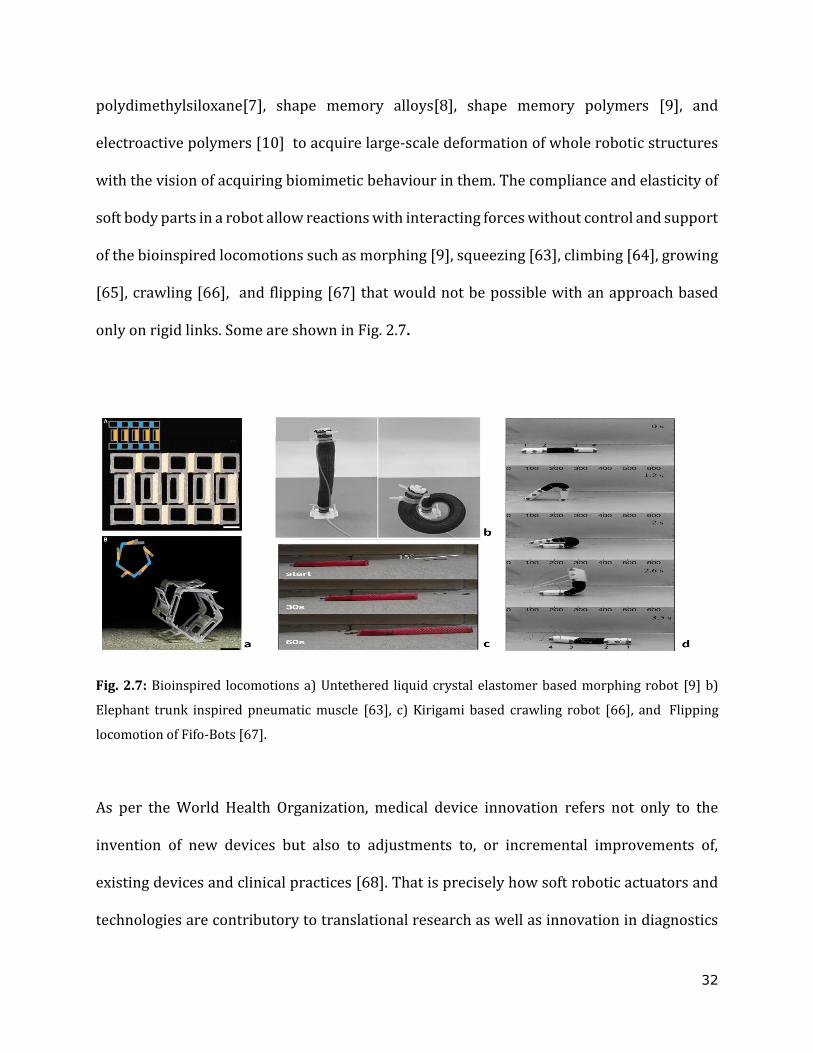
only on rigid links. Some are shown in Fig. 2.7.
Fig. 2.7: Bioinspired locomotions a) Untethered liquid crystal elastomer based morphing robot [9] b)
Elephant trunk inspired pneumatic muscle [63], c) Kirigami based crawling robot [66], and Flipping
locomotion of Fifo-Bots [67].
As per the World Health Organization, medical device innovation refers not only to the
invention of new devices but also to adjustments to, or incremental improvements of,
existing devices and clinical practices [68]. That is precisely how soft robotic actuators and
technologies are contributory to translational research as well as innovation in diagnostics
33
and therapeutic devices. Soft materials, with their compliance, allow conformity and
innocuous cooperation with the human body. Therefore medical practices requiring device-
body interaction have a hastily growing bias for this soft-touch campaign. It would be
interesting to identify soft robotics developments and technologies from original research
that may inspire paradigm shifts in designing soft medical devices.
2.2.1 Soft robotic devices for therapeutics, surgeries and rehabilitation
An exclusive and patient-specific compliant direct cardiac compression (DCC) device
developed by Mac Murray et al. uses compressed air to inflate elastomer foam chambers and
applies compression to the exterior of a heart [3]. This DCC is one of its kind as it accounts
for variations in patient-to-patient heart geometry and applies compression without
adversely squeezing the coronary arteries. A novel VAD surpasses the need for any
triggering mechanism for synchronising with natural rhythm while augmenting the cardiac
function, thanks to its real-time sensing of hemodynamics and automated control [5]. This
modular McKibben actuator based extra-cardial septal bracing incorporates a series of
functionalities to promote diastolic function and temporal synchronisation with the native
heart.
Human body vasculature is intrinsically complicated and it intersperses the whole body.
Navigating through such miniscule tubes is perplexing. A submillimeter-scale soft robot with
new-generation materials succeeded in steerable laser delivery in in-vitro environments
relevant to the clinical challenges of intracranial aneurysm. This self-lubricating soft
continuum robot with omnidirectional steering owes its navigating capabilities to
34
ferromagnetic domains programmed in its soft body while growing a hydrogel skin on its
surface for lubrication [69].
A magnetically driven micro robot, composed of a alginate-hydrogel mix with magnetic
nanoparticles have been used as tumor drug carriers. These robots swell and de-swell in
response to temperature changes caused by external Near-InfraRed (NIR) stimuli
performing therapeutic cell delivery at targeted sites [11]. The micro-cell injection
experiments on crab eggs conducted with piezoresistive force sensors embedded in a soft-
flexure mechanism reported an improved success rate and survival rate of cells [70].
The surgical world was caught in a whirlwind of transformation when soft robotics is
introduced in all forms of Minimally Invasive Surgery (MIS) [6,12,13,71-73]. The STIFF-ness
FLOP projects are addressing many intrinsic difficulties, such as lack of dexterity and
internal triangulation in MIS procedures. A soft robotic optic arm with tunable stiffness
achieved superior angles of vision of the surgical field in the pelvis for total mesorectal
excision (TME) [6]. The ferromagnetic anchors and soft central retractor bag with ground
coffee with a global application of target tissue retraction is an unprecedented development
in MIS. A magnetically anchored soft robot tunes it’s stiffness for specific abdominal organ’
retraction such as liver, stomach, and intestine [12]. A soft modular pneumatic robot with
jamming characteristics in series with a rigid robot (MELFA RV) arm qualifies electrical
diathermy cutting to lower its intraoperative risk index [72].
Other than mechanical tuning, magnetically navigable and vacuum-powered Laparo-
Endoscopic Single-Site (LESS) soft robots are also burgeoning [13, 73]. A soft Magnetic
Anchored and Guidance System (MAGS) with visual control provides video assistance during
35
thoracic surgery that lessens the intricacies in tracking the surgical instrument owing to site
crowding [73]. Bio-inspired vacuum suckers on the kidney surface for the accurate track-
guiding in preoperative imaging for nephrectomy, evade the challenges of organ
repositioning and organ slippage requiring multiple swipes [13] . Purported advances are
reaped in Natural Orifice Transluminal Endoscopic Surgery (NOTES) too [74, 75]. A soft
sarrus-linkage capsule robot, magnetically actuated for fine-needle biopsy in the
gastrointestinal track, has precise needle control and improves the diagnostic accuracy of
submucosal diseases and tumors [75].
Joseph L. McKibben devised the biologically inspired pneumatic artificial muscles (PAMs) in
the 1950s when he developed arm orthotics for his daughter. The idea was later
commmercialized in the 1980s under the name of rubbertuators [73]. A lightweight and
stretchy exo-suit for assisting elderly and rehabilitating patients with movement disorders
due to Parkinson’s disease and stroke, demonstrates a seamless integration of robots with
humans using soft actuators. This suit is adaptable and has personalized control strategies
thereby improving the patient’s balance, strength and endurance [74].
2.2.2 Soft robotic simulators and organ phantoms
Many computational bio-simulator models are more than usually idealistic and fail to
validate, especially in the replication of the mechanical characteristics of the muscles or
vasculature which vary with age and pathophysiological state. Soft robotic in-vitro
simulators are hence developed as a supplementary approach to in-vivo studies of
pathophysiological stages. A unique soft robotic phantom that simulates the cervix softening
through the loading of a Foley catheter-like mechanism is used in training of midwifery and
36
obstetrics students [78]. Researchers have developed a host of radially actuating designs
shaping into bio-mimicking swallowing and digestive organs [79-81]. Soft material tissues
or organ phantoms have already been used in medical practices widely to reproduce surgical
sites or training tissue handling devices [82, 83]. The EndoAbS project is an effort to enrich
open source datasets of endoscopic stereo images with 3D phantom soft abdominal organs
made of a bi‐component polyurethane elastomer with varied stiffness [84].
2.2.3 Future scope of soft robotics in medical applications
The advent of soft medical robotics has undoubtedly revamped the therapeutic practices but
also appealed to greediness. In other words, it exposed those forgotten, however, most
necessary needs of diagnostics, like proprioception of catheters, in-situ muscle-mimetic
actuations, modularization of solutions for global applications and in-situ sensing of
prosthetics. Some of the recent works are in their infancy and are engaged at delivering
pragmatic solutions [85, 86]. Peano-HASEL actuators provide linear and perhaps precisely
controlled musle actuation [87] for grasping and the soft-ring actuator mimicks the circular
muscle actuation paving the way for developing organs with muscular radial occlusion [88].
Omniskins are robotic skins which when attached at different orientations, designate
different functionalities to robot actuators and hence are a suitable modularistion for gait
exo-suits [89]. Furthermore the earthworm inspired both a proprioceptive robot [90] and a
modular robot [91] that are also awaited for their fully functional debut in MIS. Researchers
are deploying artificial intelligence and deep learning in enhancing soft robot in-situ
interactions and reporting to human-machine interfaces [92] .

37
Even though soft robotics has a prolific impact on medical practices, there does not exist a
quantified or qualified measure of the degree of softness required or permitted. Softness can
be intended in various ways: soft texture, soft and deformable materials, soft movement, use
of elastic materials and variable compliance actuators, and ‘soft’ friendly and natural
interactions with people. The measures to initiate the development of a soft robotic ontology
is challenged by these varieties, and seemingly unprecedented forms of robots emerging. A
collective and constructive agreement between the innovators and the practitioners is
henceforth essential to reap the benefits and mould the next-generation medical devices.
2.3 The Robotic Soft Esophagus (RoSE) : state of the art and future direction
The need for a biomimetic model, allowing reliable and repeatable investigation of altered
bolus formulations tested under normal swallow dynamics as well as reducing the in vivo
protocols in dysphagia patients, has motivated the development of a morphologically and
physiologically compliant robot with peristaltic actuation [25, 93]. In other words RoSE is a
holistic application of soft robotics to developing an in-vitro oesophagus simulator which
renders bio-mimicked physiological functionalities. Bolus testing in the
videofluoroscopically-visible soft robot, has mimicked the process of swallowing such that
the manometric pressure profiles and the bolus geometry achieved are comparable to
human swallowing behaviour [26, 94].
2.3.1 Actuator design, fabrication and actuation
The peristalsis in the oesophageal phase of swallowing is formed by the radial occlusion of
oesophagus lumen and the rostro-caudal propagation of continuous contraction waves along
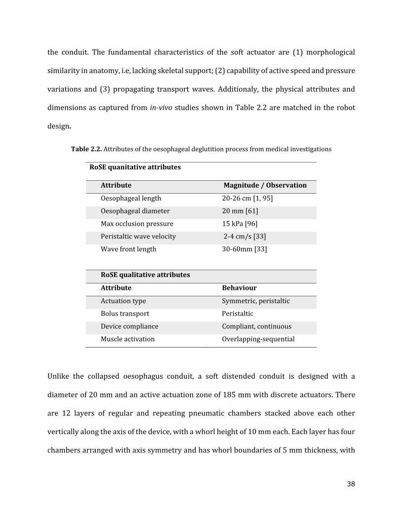
38
the conduit. The fundamental characteristics of the soft actuator are (1) morphological
similarity in anatomy, i.e, lacking skeletal support; (2) capability of active speed and pressure
variations and (3) propagating transport waves. Additionaly, the physical attributes and
dimensions as captured from in-vivo studies shown in Table 2.2 are matched in the robot
design.
Table 2.2. Attributes of the oesophageal deglutition process from medical investigations
RoSE quanitative attributes
Attribute Magnitude / Observation
Oesophageal length 20-26 cm [1, 95]
Oesophageal diameter 20 mm [61]
Max occlusion pressure 15 kPa [96]
Peristaltic wave velocity 2-4 cm/s [33]
Wave front length 30-60mm [33]
RoSE qualitative attributes
Attribute Behaviour
Actuation type Symmetric, peristaltic
Bolus transport Peristaltic
Device compliance Compliant, continuous
Muscle activation Overlapping-sequential
Unlike the collapsed oesophagus conduit, a soft distended conduit is designed with a
diameter of 20 mm and an active actuation zone of 185 mm with discrete actuators. There
are 12 layers of regular and repeating pneumatic chambers stacked above each other
vertically along the axis of the device, with a whorl height of 10 mm each. Each layer has four
chambers arranged with axis symmetry and has whorl boundaries of 5 mm thickness, with
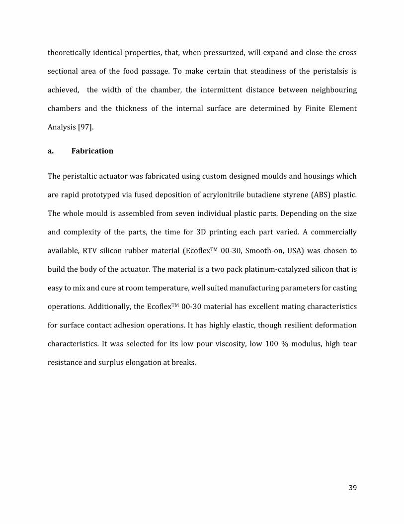
39
theoretically identical properties, that, when pressurized, will expand and close the cross
sectional area of the food passage. To make certain that steadiness of the peristalsis is
achieved, the width of the chamber, the intermittent distance between neighbouring
chambers and the thickness of the internal surface are determined by Finite Element
Analysis [97].
a. Fabrication
The peristaltic actuator was fabricated using custom designed moulds and housings which
are rapid prototyped via fused deposition of acrylonitrile butadiene styrene (ABS) plastic.
The whole mould is assembled from seven individual plastic parts. Depending on the size
and complexity of the parts, the time for 3D printing each part varied. A commercially
available, RTV silicon rubber material (EcoflexTM 00-30, Smooth-on, USA) was chosen to
build the body of the actuator. The material is a two pack platinum-catalyzed silicon that is
easy to mix and cure at room temperature, well suited manufacturing parameters for casting
operations. Additionally, the EcoflexTM 00-30 material has excellent mating characteristics
for surface contact adhesion operations. It has highly elastic, though resilient deformation
characteristics. It was selected for its low pour viscosity, low 100 % modulus, high tear
resistance and surplus elongation at breaks.
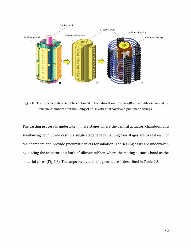
40
Fig. 2.8: The intermediate assemblies obtained in the fabrication process a)RoSE moulds assembled b)
silicone chambers after moulding c) RoSE with final cover and pneumatic fittings.
The casting process is undertaken in five stages where the central actuator, chambers, and
swallowing conduit are cast in a single stage. The remaining four stages are to seal each of
the chambers and provide pneumatic inlets for inflation. The sealing casts are undertaken
by placing the actuator on a bath of silicone rubber, where the mating surfaces bond as the
material cures (Fig.2.8). The steps involved in the procedure is described in Table 2.3.
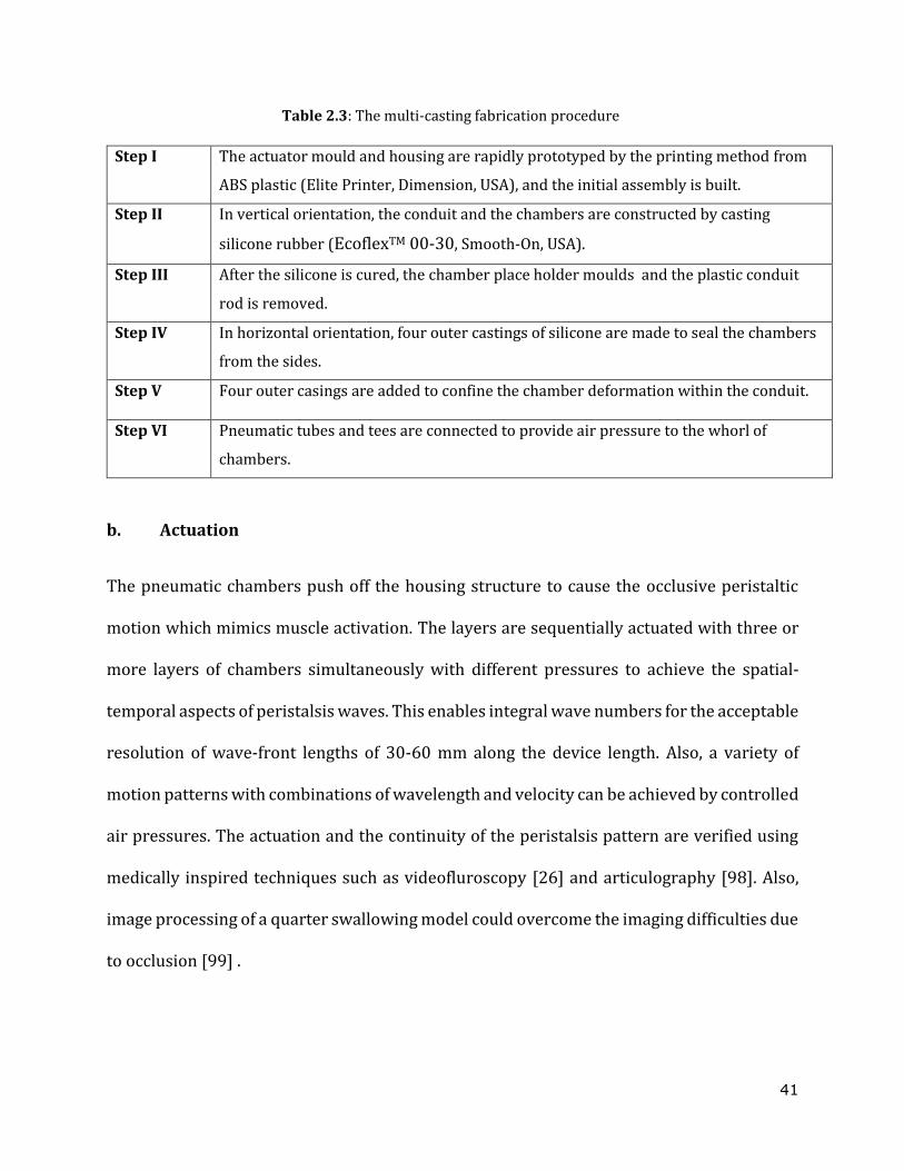
41
Table 2.3: The multi-casting fabrication procedure
Step I The actuator mould and housing are rapidly prototyped by the printing method from
ABS plastic (Elite Printer, Dimension, USA), and the initial assembly is built.
Step II In vertical orientation, the conduit and the chambers are constructed by casting
silicone rubber (EcoflexTM 00-30, Smooth-On, USA).
Step III After the silicone is cured, the chamber place holder moulds and the plastic conduit
rod is removed.
Step IV In horizontal orientation, four outer castings of silicone are made to seal the chambers
from the sides.
Step V Four outer casings are added to confine the chamber deformation within the conduit.
Step VI Pneumatic tubes and tees are connected to provide air pressure to the whorl of
chambers.
b. Actuation
The pneumatic chambers push off the housing structure to cause the occlusive peristaltic
motion which mimics muscle activation. The layers are sequentially actuated with three or
more layers of chambers simultaneously with different pressures to achieve the spatial-
temporal aspects of peristalsis waves. This enables integral wave numbers for the acceptable
resolution of wave-front lengths of 30-60 mm along the device length. Also, a variety of
motion patterns with combinations of wavelength and velocity can be achieved by controlled
air pressures. The actuation and the continuity of the peristalsis pattern are verified using
medically inspired techniques such as videofluroscopy [26] and articulography [98]. Also,
image processing of a quarter swallowing model could overcome the imaging difficulties due
to occlusion [99] .
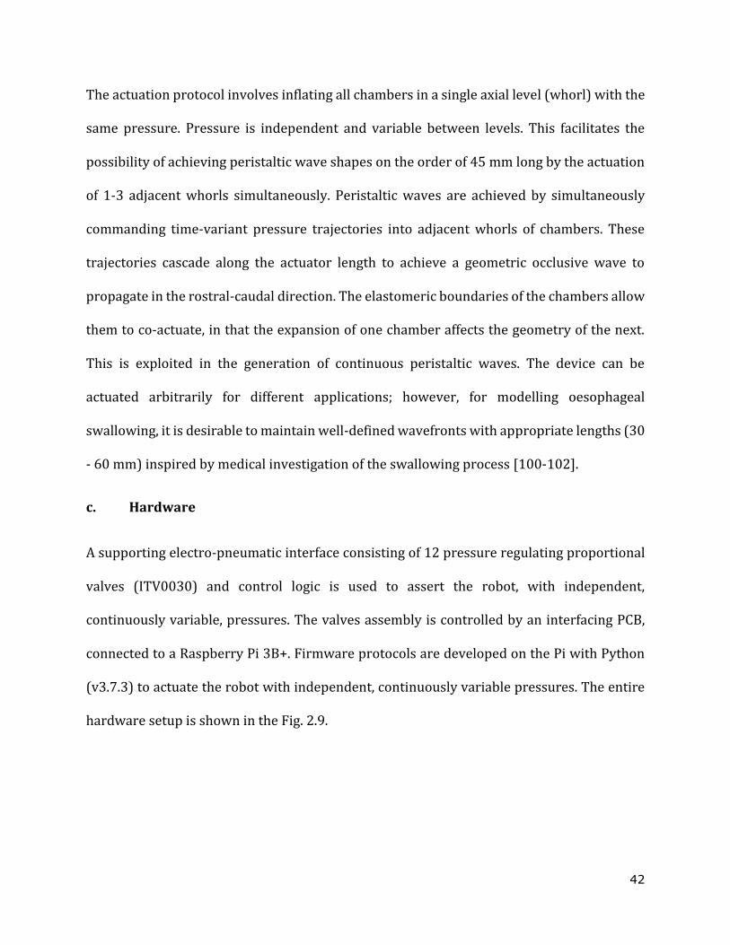
42
The actuation protocol involves inflating all chambers in a single axial level (whorl) with the
same pressure. Pressure is independent and variable between levels. This facilitates the
possibility of achieving peristaltic wave shapes on the order of 45 mm long by the actuation
of 1-3 adjacent whorls simultaneously. Peristaltic waves are achieved by simultaneously
commanding time-variant pressure trajectories into adjacent whorls of chambers. These
trajectories cascade along the actuator length to achieve a geometric occlusive wave to
propagate in the rostral-caudal direction. The elastomeric boundaries of the chambers allow
them to co-actuate, in that the expansion of one chamber affects the geometry of the next.
This is exploited in the generation of continuous peristaltic waves. The device can be
actuated arbitrarily for different applications; however, for modelling oesophageal
swallowing, it is desirable to maintain well-defined wavefronts with appropriate lengths (30
- 60 mm) inspired by medical investigation of the swallowing process [100-102].
c. Hardware
A supporting electro-pneumatic interface consisting of 12 pressure regulating proportional
valves (ITV0030) and control logic is used to assert the robot, with independent,
continuously variable, pressures. The valves assembly is controlled by an interfacing PCB,
connected to a Raspberry Pi 3B+. Firmware protocols are developed on the Pi with Python
(v3.7.3) to actuate the robot with independent, continuously variable pressures. The entire
hardware setup is shown in the Fig. 2.9.
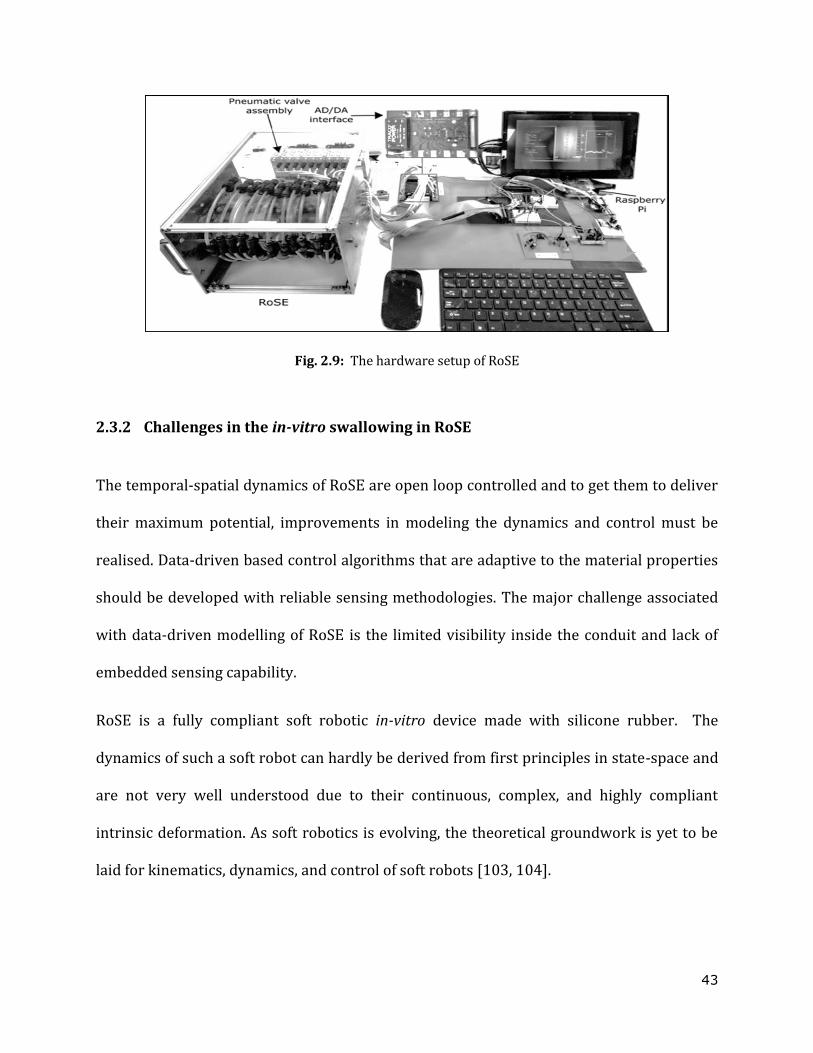
43
Fig. 2.9: The hardware setup of RoSE
2.3.2 Challenges in the in-vitro swallowing in RoSE
The temporal-spatial dynamics of RoSE are open loop controlled and to get them to deliver
their maximum potential, improvements in modeling the dynamics and control must be
realised. Data-driven based control algorithms that are adaptive to the material properties
should be developed with reliable sensing methodologies. The major challenge associated
with data-driven modelling of RoSE is the limited visibility inside the conduit and lack of
embedded sensing capability.
RoSE is a fully compliant soft robotic in-vitro device made with silicone rubber. The
dynamics of such a soft robot can hardly be derived from first principles in state-space and
are not very well understood due to their continuous, complex, and highly compliant
intrinsic deformation. As soft robotics is evolving, the theoretical groundwork is yet to be
laid for kinematics, dynamics, and control of soft robots [103, 104].
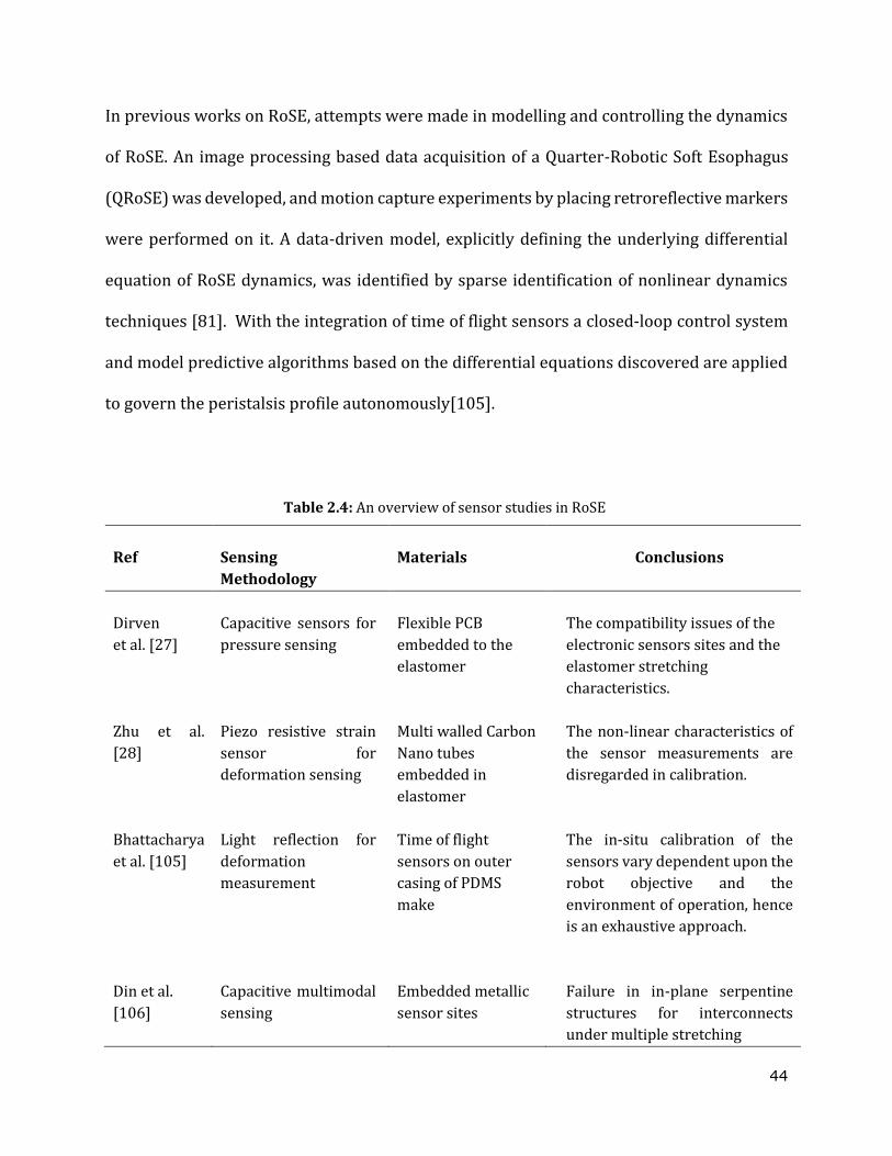
44
In previous works on RoSE, attempts were made in modelling and controlling the dynamics
of RoSE. An image processing based data acquisition of a Quarter-Robotic Soft Esophagus
(QRoSE) was developed, and motion capture experiments by placing retroreflective markers
were performed on it. A data-driven model, explicitly defining the underlying differential
equation of RoSE dynamics, was identified by sparse identification of nonlinear dynamics
techniques [81]. With the integration of time of flight sensors a closed-loop control system
and model predictive algorithms based on the differential equations discovered are applied
to govern the peristalsis profile autonomously[105].
Table 2.4: An overview of sensor studies in RoSE
Ref
Sensing
Methodology
Materials
Conclusions
Dirven
et al. [27]
Capacitive sensors for
pressure sensing
Flexible PCB
embedded to the
elastomer
The compatibility issues of the
electronic sensors sites and the
elastomer stretching
characteristics.
Zhu et al.
[28]
Piezo resistive strain
sensor for
deformation sensing
Multi walled Carbon
Nano tubes
embedded in
elastomer
The non-linear characteristics of
the sensor measurements are
disregarded in calibration.
Bhattacharya
et al. [105]
Light reflection for
deformation
measurement
Time of flight
sensors on outer
casing of PDMS
make
The in-situ calibration of the
sensors vary dependent upon the
robot objective and the
environment of operation, hence
is an exhaustive approach.
Din et al.
[106]
Capacitive multimodal
sensing
Embedded metallic
sensor sites
Failure in in-plane serpentine
structures for interconnects
under multiple stretching

45
A variety of flexible sensor arrays such as the capacitive sensor array [27] , CNT filled ecoflex
composite strain sensor array [28], and a multimodal copper embedded ecoflex stretchable
array of capacitive sensors [106], were put inside the RoSE conduit, and experiments were
conducted to measure the deformation of the chambers, fluid pressure and shear rates.
There are many challenges to overcome in RoSE with the compatibility between electronic
sensors, wire termination techniques, and bonding between these structures and largely
extensible devices. Thus developing compatible sensing capabilities in RoSE strive for
further attention. An overview of sensor studies in RoSE are shown in Table 2.4.
The existing semiconductors used on developing stretchable electronics are either organics
(such as poly(3-hexylthiophene-2,5-diyl) or P3HT, pentacene), or inorganics (such as Si,
GaAs, oxides) which are inherently and mechanically non-stretchable [107]. Prevalent
methodologies to circumvent the stretch-ability limitations of these materials is to employ
special mechanical structures or architectures such as out-of-plane wrinkles [108], in-plane
serpentines [109], rigid islands with deformable interconnects [110], and kirigami
architectures [111]. These designs help to eliminate the mechanical strain while they are
subjected to stretching, but at the cost of requiring 1) sophisticated and detailed structural
designs, 2) complicated manufacturing processes, 3) a large foot area dedicated to stretchable
interconnection, 4) challenges in high-density integration and packaging, 5) associated high
cost, and 6) difficulty in mass production.
Profoundly stretchable elastomeric electronic materials on the other hand, do not need
structural engineering for device fabrication or the manufacturing methods and hence can be
embraced in conventional fabrication processes. In addition, rubbery electronics offer better
46
cost-effectiveness, higher mechanical durability, larger strain tolerance, and tenability [108,
110, 111]. It is interesting to have the wider study to formulate an opinion on the current
materials and applications of the rubbery elastomeric electronic materials.
2.4 Stretchable rubber electronic materials and applications
Rubbery conductors are available in two categories: stretchable conductive polymers (SCPs)
and nanomaterial based rubbery composites. The most common SCPs in use are
polyacetylene, polypyrrole (PPy), polyaniline (PANi), polythiophene, and their derivatives,
poly(3,4-ethylenedioxythiophene) polystyrene sulfonate (PEDOT:PSS) [112]. Among them
PEDOT:PSS electrode material is most popular due to 1) excellent electrical conductivity, 2)
transparency, 3) chemical stability, 4) biocompatibility, 5) solution process-ability and 6)
commercial availability [113-115]. However, PEDOT:PSS films derived from commercially
available aqueous dispersions have a low conductivity normally around 1 S cm−1 with a
fracture limit around 6%, which indicates that the films are not very stretchable or are not
able to meet the criteria of a stretch-ability greater than 10%[116, 117]. However, their
stretch-ability and conductivity can be improved either by secondary doping using a polar
solvent [118], methane and dimethyl sulfoxide (DMSO) [113], or by adding ionic additives
[119].
Another stream of stretchable electronics with promising stretch performance by using
composites are made by percolated conductive nanomaterial 0D nanoparticles (NPs), 1D
nanowires (NW), nanotubes (NT) and 2D nano spheres (NS) fillers in rubber materials. The
process has many versions such as filtrating rubber into conductive filler networks,
synthesizing metallic fillers within rubbers, mixing conductive fillers with rubbers and
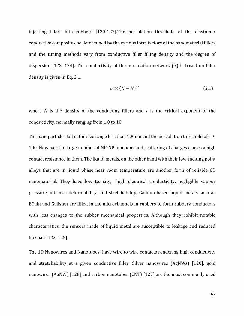
47
injecting fillers into rubbers [120-122].The percolation threshold of the elastomer
conductive composites be determined by the various form factors of the nanomaterial fillers
and the tuning methods vary from conductive filler filling density and the degree of
dispersion [123, 124]. The conductivity of the percolation network () is based on filler
density is given in Eq. 2.1,
𝜎 ∝ (𝑁 − 𝑁𝑐)𝑡 (2.1)
where N is the density of the conducting fillers and t is the critical exponent of the
conductivity, normally ranging from 1.0 to 10.
The nanoparticles fall in the size range less than 100nm and the percolation threshold of 10-
100. However the large number of NP-NP junctions and scattering of charges causes a high
contact resistance in them. The liquid metals, on the other hand with their low-melting point
alloys that are in liquid phase near room temperature are another form of reliable 0D
nanomaterial. They have low toxicity, high electrical conductivity, negligible vapour
pressure, intrinsic deformability, and stretchability. Gallium-based liquid metals such as
EGaln and Galistan are filled in the microchannels in rubbers to form rubbery conductors
with less changes to the rubber mechanical properties. Although they exhibit notable
characteristics, the sensors made of liquid metal are susceptible to leakage and reduced
lifespan [122, 125].
The 1D Nanowires and Nanotubes have wire to wire contacts rendering high conductivity
and stretchability at a given conductive filler. Silver nanowires (AgNWs) [120], gold
nanowires (AuNW) [126] and carbon nanotubes (CNT) [127] are the most commonly used
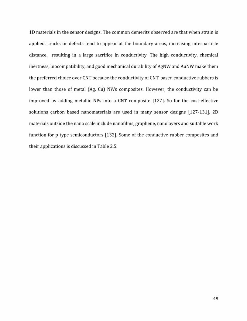
48
1D materials in the sensor designs. The common demerits observed are that when strain is
applied, cracks or defects tend to appear at the boundary areas, increasing interparticle
distance, resulting in a large sacrifice in conductivity. The high conductivity, chemical
inertness, biocompatibility, and good mechanical durability of AgNW and AuNW make them
the preferred choice over CNT because the conductivity of CNT-based conductive rubbers is
lower than those of metal (Ag, Cu) NWs composites. However, the conductivity can be
improved by adding metallic NPs into a CNT composite [127]. So for the cost-effective
solutions carbon based nanomaterials are used in many sensor designs [127-131]. 2D
materials outside the nano scale include nanofilms, graphene, nanolayers and suitable work
function for p-type semiconductors [132]. Some of the conductive rubber composites and
their applications is discussed in Table 2.5.
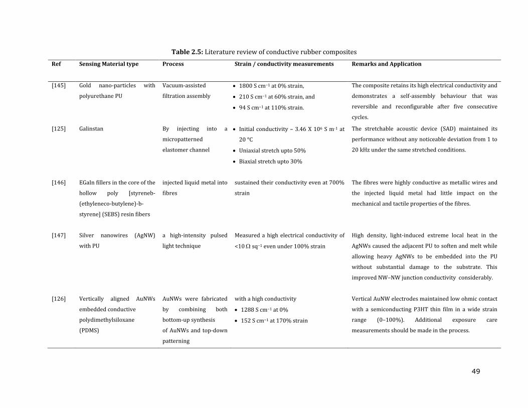
49
Table 2.5: Literature review of conductive rubber composites
Ref Sensing Material type Process Strain / conductivity measurements
Remarks and Application
[145] Gold nano-particles with
polyurethane PU
Vacuum-assisted
filtration assembly
1800 S cm−1 at 0% strain,
210 S cm−1 at 60% strain, and
94 S cm−1 at 110% strain.
The composite retains its high electrical conductivity and
demonstrates a self-assembly behaviour that was
reversible and reconfigurable after five consecutive
cycles.
[125] Galinstan By injecting into a
micropatterned
elastomer channel
Initial conductivity – 3.46 X 10⁶ S m-1 at
20 °C
Uniaxial stretch upto 50%
Biaxial stretch upto 30%
The stretchable acoustic device (SAD) maintained its
performance without any noticeable deviation from 1 to
20 kHz under the same stretched conditions.
[146] EGaIn fillers in the core of the
hollow poly [styreneb-
(ethyleneco-butylene)-b-
styrene] (SEBS) resin fibers
injected liquid metal into
fibres
sustained their conductivity even at 700%
strain
The fibres were highly conductive as metallic wires and
the injected liquid metal had little impact on the
mechanical and tactile properties of the fibres.
[147] Silver nanowires (AgNW)
with PU
a high-intensity pulsed
light technique
Measured a high electrical conductivity of
<10 sq−1 even under 100% strain
High density, light-induced extreme local heat in the
AgNWs caused the adjacent PU to soften and melt while
allowing heavy AgNWs to be embedded into the PU
without substantial damage to the substrate. This
improved NW–NW junction conductivity considerably.
[126] Vertically aligned AuNWs
embedded conductive
polydimethylsiloxane
(PDMS)
AuNWs were fabricated
by combining both
bottom-up synthesis
of AuNWs and top-down
patterning
with a high conductivity
1288 S cm−1 at 0%
152 S cm−1 at 170% strain
Vertical AuNW electrodes maintained low ohmic contact
with a semiconducting P3HT thin film in a wide strain
range (0–100%). Additional exposure care
measurements should be made in the process.
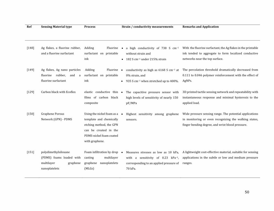
50
Ref Sensing Material type Process Strain / conductivity measurements
Remarks and Application
[148]
Ag flakes, a fluorine rubber,
and a fluorine surfactant
Adding Fluorine
surfactant on printable
ink
a high conductivity of 738 S cm−1
without strain and
182 S cm−1 under 215% strain
With the fluorine surfactant, the Ag flakes in the printable
ink tended to aggregate to form localized conductive
networks near the top surface.
[149] Ag flakes, Ag nano particles
fluorine rubber, and a
fluorine surfactant
Adding Fluorine
surfactant on printable
ink
conductivity as high as 6168 S cm−1 at
0% strain, and
935 S cm−1 when stretched up to 400%.
The percolation threshold dramatically decreased from
0.111 to 0.046 polymer reinforcement with the effect of
AgNPs.
[129] Carbon black with Ecoflex elastic conductive thin
films of carbon black
composite
The capacitive pressure sensor with
high levels of sensitivity of nearly 150
pF/MPa
3D printed tactile sensing network and repeatability with
instantaneous response and minimal hysteresis to the
applied load.
[150] Graphene Porous
Network (GPN) - PDMS
Using the nickel foam as a
template and chemically
etching method, the GPN
can be created in the
PDMS-nickel foam coated
with graphene.
Highest sensitivity among graphene
sensors.
Wide pressure sensing range. The potential applications
in monitoring or even recognizing the walking states,
finger bending degree, and wrist blood pressure.
[151] polydimethylsiloxane
(PDMS) foams loaded with
multilayer graphene
nanoplatelets
Foam infiltration by drop
casting multilayer
graphene nanoplatelets
(MLGs)
Measures stresses as low as 10 kPa,
with a sensitivity of 0.23 kPa−1,
corresponding to an applied pressure of
70 kPa.
A lightweight cost-effective material, suitable for sensing
applications in the subtle or low and medium pressure
ranges.
51
2.5 Challenges in embedded sensors in modelling and algorithms implemented in
soft sensing
Embedded sensing is the most viable solution for strain, stress, contact, and roughness
estimation [133]. Soft robots are known to be highly deformable and stretchable which
makes the process of registering their profile, shape and location in three dimensions
challenging. Self-sensing input devices rendering perception capabilities for robots are a
new epoch in soft robotics. Robotic perception comprises kinematic estimation of self-
contact modelling and mapping of the surroundings. The high dimensionality of soft robots
and soft sensors complicates the selection of type, number, and placement of sensors. The
soft sensors and the encasing dynamic system often exhibit nonlinear time-variant behavior,
which makes them difficult to model. The modelling of soft sensors is challenged by
inconsistencies in their manufacture and nonlinearities in their dynamics. There are subtle
differences between each of the technological solutions for soft sensing that give each unique
advantages depending on the required task [134, 135].
An ideal soft sensor must provide state information along the body of a soft system with
minimal effect on the dynamics of the system. However, the modelling of these embedded
sensors is quite difficult because of high nonlinearities and creep. Although precise
manufacturing may help alleviate these troubles, this is limited. Furthermore, in the case of
interactions with the surroundings, contact modelling is a highly complex mathematical
problem, currently limited to theoretical studies [135]. Because of the complexity in
modelling, most work has adopted empirical or semi-analytical approaches. A machine
52
learning-based approach is used in studying the dynamics, object identification and sensing
with embedded sensors [81, 136, 137]. The different algorithm used is explored in Table 2.6.
Soft sensing is crucial for process control, optimisation, and monitoring because it gives an
accurate assessment of difficult-to-measure variables. The extraction of useful data from a
plethora of accessible data in current industrial processes, as well as the creation of data-
driven soft sensors, are becoming increasingly popular. Multivariate analysis (MVA)
methods such as least squares regression (LSR), principal component regression (PCR), and
partial least squares regression (PLSR) are among the main types of data-driven soft sensors
[138, 139]. Classic MVA approaches, on the other hand, are often restricted in their ability to
handle linear correlations and may not be suitable for nonlinear systems. To address the
issue of process nonlinearity, nonlinear feature extraction and regression approaches such
as locally weighted methods, kernel methods, and machine learning methods such as
support vector regression (SVR) [140] and artificial neural networks (ANNs) [141, 142] have
been developed. Furthermore, because of its superiority in producing high-level abstract
representations from enormous volumes of data, deep neural networks (DNNs)[143] have
become a prominent data processing and feature extraction approach. The main principle
behind data-driven soft sensing is to first extract representations from online variable data
before establishing a link between the representations and the target quality factors.
Some of the most discussed time varying algorithms applied are deliberated below.
a. JITL (Just-in-time learning)
Soft robotic processes are characterised by complex time-varying challenges in general. It is
difficult to create a global model that is accurate. The time-varying property also necessitates
53
self-adaptability in the soft sensor model, which makes it more challenging to build.
Alternatively, by constructing an online local model around the query sample, JITL has the
potential to simultaneously cope with non-linear and time-varying problems. JITL is also
known as lazy learning since it only constructs models when it needs to predict the output
for a query sample. The local model is instantly destroyed after the output is anticipated.
Then, until the next query sample arrives, a fresh JIT model is created. LWPLS (locally
weighted partial least squares) is a popular just-in-time learning method (JITL). In LWPLS,
similarity weights are calculated between historical samples and the query sample. If the
spatial distance is calculated, then it is indeed a spatial adaptive LWPLS. Otherwise, it is a
temporal LWPLS if the sampling interval distance is calculated [144].
b. ANN (Artificial Neural Network):
ANN is a very broad term that encompasses any form of Deep Learning model. ANNs can be
shallow or deep. When there is only one buried layer, they are referred to as shallow (i.e. one
layer between the input and output). When there are multiple hidden layers, they are
referred to as deep network. The term DNN (Deep Neural Network) is derived from this. Low
cost soft stretchable sensor arrays using local capacitance to measure the dense non-rigid
surface deformation has utilized ANN algorithm in sensor modeling.The time multiplexing
connection subsets are trained with ANN with RELu activation and BatchNorm layer [154].
A comparative study of the sensor- actuator modelling with camera data as ground truth
using linear regresson and ANN for bending angel measurement shows that neural network
based algorithms are superior to regression methods[153]. The research implemented a PID
control with PWM generator for bending angle control.
54
c. CNN (Convolutional Neural Network):
These have been created with computer vision in mind (they are sometimes applied
elsewhere though). The CNN algorrithms are more powerful when image processing is
involved. Their name stems from convolutional layers, which are distinct from the normal
(dense) layers of canonical ANNs and were developed specifically to accept and interpret
pixel data[141]. The orbitouch device with array of stretchable capacitor sensors utilised 3D
CNN with softmax activation for gesture recognition. The work further used CNN 2D for
touch recognition (localization) with a tanh activation. An adaptive momentum estimation
based algorithm is used to estimate the loacalised force applied.
d. RNN (Recurrent Neural Network):
Recurrent neural networks are a type of neural network technique for time series analysis.
These networks can handle data sequences and serve as the foundation for forecasting and
language processing algorithms. The concept of the recurrent neural net is one in which the
input is a sequence and the use one previous input act as having a previous state feedback to
the next state (layer). The most common type of recurrent network models are called LSTM
(Long Short Term Memory) and GRU (Gated Recurrent Units). Their cells include small, in-
scale ANNs that pick how much previous information they wish to allow flow through the
model. They modelled "memory" in this way[140, 142]. The recurrent neural network idea
is one in which the input is a series and we wish to use one prior input as previous state
feedback to the next state (layer) in Fig. 2.10.
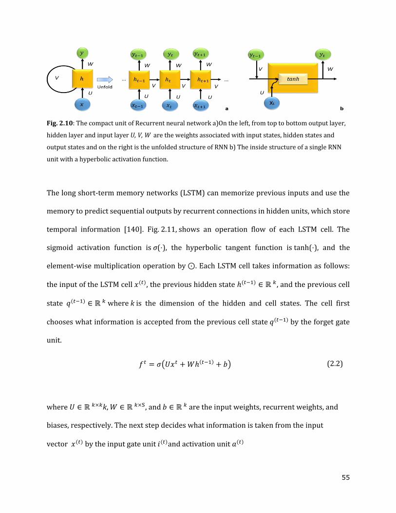
55
Fig. 2.10: The compact unit of Recurrent neural network a)On the left, from top to bottom output layer,
hidden layer and input layer U, V, W are the weights associated with input states, hidden states and
output states and on the right is the unfolded structure of RNN b) The inside structure of a single RNN
unit with a hyperbolic activation function.
The long short-term memory networks (LSTM) can memorize previous inputs and use the
memory to predict sequential outputs by recurrent connections in hidden units, which store
temporal information [140]. Fig. 2.11, shows an operation flow of each LSTM cell. The
sigmoid activation function is σ(⋅), the hyperbolic tangent function is tanh(⋅), and the
element-wise multiplication operation by ⊙. Each LSTM cell takes information as follows:
the input of the LSTM cell 𝑥(𝑡), the previous hidden state ℎ(𝑡−1) ∈ ℝ 𝑘, and the previous cell
state 𝑞(𝑡−1) ∈ ℝ 𝑘 where k is the dimension of the hidden and cell states. The cell first
chooses what information is accepted from the previous cell state 𝑞(𝑡−1) by the forget gate
unit.
𝑓𝑡 = 𝜎(𝑈𝑥𝑡 + 𝑊ℎ(𝑡−1) + 𝑏) (2.2)
where 𝑈 ∈ ℝ 𝑘×𝑘k, 𝑊 ∈ ℝ 𝑘×S, and 𝑏 ∈ ℝ 𝑘 are the input weights, recurrent weights, and
biases, respectively. The next step decides what information is taken from the input
vector 𝑥(𝑡) by the input gate unit 𝑖(𝑡)and activation unit 𝑎(𝑡)
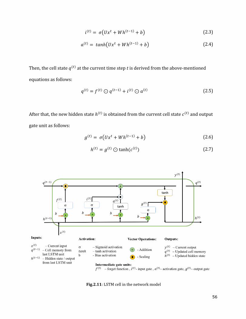
56
𝑖(𝑡) = 𝜎(𝑈𝑥𝑡 + 𝑊ℎ(𝑡−1) + 𝑏) (2.3)
𝑎(𝑡) = 𝑡𝑎𝑛ℎ(𝑈𝑥𝑡 + 𝑊ℎ(𝑡−1) + 𝑏) (2.4)
Then, the cell state 𝑞(𝑡) at the current time step t is derived from the above-mentioned
equations as follows:
𝑞(𝑡) = 𝑓(𝑡) ⊙ 𝑞(𝑡−1) + 𝑖(𝑡) ⊙ 𝑎(𝑡) (2.5)
After that, the new hidden state ℎ(𝑡) is obtained from the current cell state 𝑐(𝑡) and output
gate unit as follows:
𝑔(𝑡) = 𝜎(𝑈𝑥𝑡 + 𝑊ℎ(𝑡−1) + 𝑏) (2.6)
ℎ(𝑡) = 𝑔(𝑡) ⊙ tanh (𝑐(𝑡)) (2.7)
Fig.2.11: LSTM cell in the network model
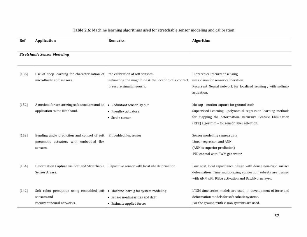
57
Table 2.6: Machine learning algorithms used for stretchable sensor modeling and calibration
Ref Application Remarks Algorithm
Stretchable Sensor Modeling
[136]
Use of deep learning for characterization of
microfluidic soft sensors.
the calibration of soft sensors
estimating the magnitude & the location of a contact
pressure simultaneously.
Hierarchical recurrent sensing
uses vision for sensor caliberation.
Recurrent Neural network for localized sensing , with softmax
activation.
[152] A method for sensorizing soft actuators and its
application to the RBO hand.
Reduntant sensor lay out
Pneuflex actuators
Strain sensor
Mo cap – motion capture for ground truth
Supervised Learning - polynomial regression learning methods
for mapping the deformation. Recursive Feature Elimination
(RFE) algorithm – for sensor layer selection.
[153] Bending angle prediction and control of soft
pneumatic actuators with embedded flex
sensors.
Embedded flex sensor Sensor modelling camera data
Linear regresson and ANN
(ANN is superior prediction)
PID control with PWM generator
[154] Deformation Capture via Soft and Stretchable
Sensor Arrays.
Capacitive sensor with local site deformation Low cost, local capacitance design with dense non-rigid surface
deformation. Time multiplexing connection subsets are trained
with ANN with RELu activation and BatchNorm layer.
[142] Soft robot perception using embedded soft
sensors and
recurrent neural networks.
Machine learnig for system modeling
sensor nonlinearities and drift
Estimate applied forces
LTSM time series models are used in development of force and
deformation models for soft robotic systems.
For the ground truth vision systems are used.
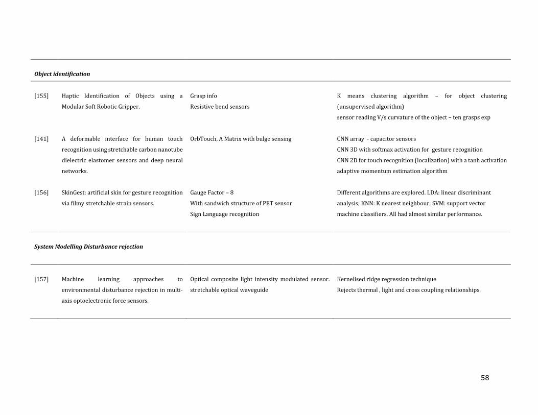
58
Object identification
[155]
Haptic Identification of Objects using a
Modular Soft Robotic Gripper.
Grasp info
Resistive bend sensors
K means clustering algorithm – for object clustering
(unsupervised algorithm)
sensor reading V/s curvature of the object – ten grasps exp
[141] A deformable interface for human touch
recognition using stretchable carbon nanotube
dielectric elastomer sensors and deep neural
networks.
OrbTouch, A Matrix with bulge sensing
CNN array - capacitor sensors
CNN 3D with softmax activation for gesture recognition
CNN 2D for touch recognition (localization) with a tanh activation
adaptive momentum estimation algorithm
[156] SkinGest: artificial skin for gesture recognition
via filmy stretchable strain sensors.
Gauge Factor – 8
With sandwich structure of PET sensor
Sign Language recognition
Different algorithms are explored. LDA: linear discriminant
analysis; KNN: K nearest neighbour; SVM: support vector
machine classifiers. All had almost similar performance.
System Modelling Disturbance rejection
[157]
Machine learning approaches to
environmental disturbance rejection in multi-
axis optoelectronic force sensors.
Optical composite light intensity modulated sensor.
stretchable optical waveguide
Kernelised ridge regression technique
Rejects thermal , light and cross coupling relationships.

59
2.6 Potentials of in-vitro simulation of oesophageal swallowing
The palliation of dysphagia can be addressed with endo-prosthetic stent placement in the
oesophagus. A stent is a braided mesh of entwined helical springs, which can readily hoop
around the oesophageal conduit, and it can expand vulnerable parts of the oesophagus such
as malignant and benign oesophageal strictures for clearance of food. However, stents are
often associated with stent migration, which occurs due to the interaction of the stents with
the recurring peristaltic dynamics in the oesophagus. To mitigate stent migration,
researchers and clinicians are working hand in hand to develop novel stent designs, but
present research on stent testing and modelling for substantial equivalence is still restricted
to analytical modelling and Finite Element Modelling (FEM) since manometry and
videofluoroscopy on stent implanted patients is a primary ethical concern. Despite recent
technological innovations in this field, evidence to show which stent design is better than the
other is narrowed to a few randomized controlled trials in patients with malignant
oesophageal strictures [47, 48]. The efforts to mitigate pain and migration, to improve stent
removability and flexibility, and to ensure stent patency can be revolutionized with a testing
environment with oesophageal physiological simulation parameters.
Another significant field in need of a biomimicking platform is pill transit studies in the
oesophagus. Capsules and tablets are the most prevalent drug products, but one-third of
patients have trouble swallowing them. Difficulty swallowing pills may be due to individual
patient factors: patient age, product factors (i.e., size, shape and composition) and
pathological conditions (i.e., central nervous, oncological). Swallowing impairment is a
common problem for patients on chronic opioid therapy due to the following factors. 1)
60
Extended-release tablets contain bio-adhesive polymers such as polyethylene oxide as a
release retardant. When their surface is hydrated, opioid tablets adhere to mucous
membrane strongly. 2) Extended-release tablets are often large. 3) Chronic use of pills
especially opioids often leads to impaired lower oesophageal sphincter (LES) relaxation and
disorganized peristaltic sequence. 4) A larger percentage of patients on pills suffer from
other pathological conditions that can trigger swallow dysfunction. 5) Opioids create oral
dryness exacerbating difficulty swallowing pills. Therefore, it is critical to develop a tool to
study swallowability differences between generic opioids and reference listed drugs (RLD)
regarding tablet shape, size, and material composition [158, 159] .
There are several in vivo studies where oesophageal transit is measured relating to drug
retention time in the oesophagus and location of arrest in the oesophagus [160]. The
methodology of the studies involved videofluroscopy and endoscopy studies. Barium
swallow studies that implement swallow-ability analysis where patients swallowed and
completed a questionnaire about the experience are available in the literature [161, 162].
The available in vitro methods were mainly used with the purpose of improving
mucoadhesive drug delivery systems. The in-vitro methods developed to investigate the
adhesion of oral dosage forms to the oesophagus were based either on detachment force
determinations or on retention systems [22, 163] . The first kind investigates the mechanical
force required to break an adhesive bond between the dosage form and the oesophageal
tissue which is also called a direct method [163, 164], while the second kind measures the
amount of dosage form retained on the oesophageal tissue after being rinsed with medium
[165, 166]. Studies by J D Smart et. al. incorporated a section of porcine oesophageal mucosa
held flat by the application of a gentle vacuum and kept moist by the application of a
61
simulated saliva solution [164]. However, these studies lack the dynamic forces involved in
the oesophageal lumen due to the propagating peristaltic contractions[54].
2.7 Summary of literature review
The literature review of this thesis primarily explored aspects to establish the current state
of the art of the RoSE and significance of the RoSE in management of dysphagia. The
review also intended to cover the fields of enhancements of the RoSE to be a reliable in-
vitro swallowing device. The key fields of focus in the literature review are the following:
Medical background of oesophageal swallowing
Causes and management of dysphagia
In-vitro swallowing robots and soft robotics adaptations in medical devices
Stretchable sensor technology and machine learning for sensor modelling
Potential of oesophageal swallowing device
Swallowing is a multi-domain physiological process analagous to an engineering process
involving control, actuation and sensing. Any muscular or nerve pathology in the involved
group of organs could reduce the efficiency of the swallowing and is medically termed
deglutitive dysfunction. When patients complain of difficulty swallowing, it is called
dysphagia. Among the dysphagia management measures, food texture alteration and stent
implant management could benefit from use of in-vitro simulation devices to perfect options
and understand correct application of these strategies. Among the existing in-vitro devices,
compliant and bio-mimicking actuations are a rare find. RoSE design has utilized the
pneumatic soft robotic actuation strategy and materials providing a continuous and
compliant peristaltic actuation in the conduit. Soft robotics are producing quintessential
62
vicissitudes in medical diagnostic innovations. The RoSE peristaltic velocities and
wavelength are biologically significant wavefront values, however they are fixed and open
loop controlled. The temporal and spatial dynamics of RoSE can be made phenotypically
similar to their biological counterpart with stretchable sensors. The significant role players
in the stretchable sensors are nanomaterial embedded elastomers, among which, carbon
based nanomaterials are cost effective and ensure high conductivity. But the stretchable
sensors are highly susceptible to nonlinearities such as hysteresis, creep and drift. So to use
stretchable sensors in soft robotics requires machine learning-based algorithms to make
them useful in sensing, object identification, disturbance modelling, system dynamics and
control. The potential and the knowledge gap in in-vitro oesophageal devices in simulating
pill swallow and stent migration studies are researched further.
The literature identifies the following research gaps. The soft robotics uses system specific
modeling and control strategies especially due to the lack of the compliant sensors. The
stretchable sensors developed and discussed in literature fails to establish a general frame
work in extending to universal applications. Being a soft robotic device these challenges are
translational to the RoSE also. The bolus transit characteristics in RoSE are studied with
manometry for intrabolus pressure profiles but lacks information about the viscosity and
velocity variations under stress . The literature are available in discussing computational
models for the swallowing phases but such a simulation model could be beneficial in
explaining the transit characteristics in RoSE. The ultimate aim of the in-vitro device would
be to serve as a patient simulator however, the test protocols significant clinically has not

63
been developed yet. To our knowledge no other in-vitro device is capable of producing
compliant and bio-mimicking peristalsis environment that could be used as a test simulator
for stent implants or pill transit.
This study intend to research upon the following knowledge gaps as
1) The need of establishing a general framework for developing stretchable sensors and
modelling the transfer characteristics for RoSE or any sensor embedded actuator
irrespective of the conductive composites chosen.
2) The lack of sensors in RoSE for characterizing the bolus transit could be addressed
by developing a fluid structure interaction computational models. To our knowledge
a fluid structure interaction study in soft robotics are lacking.
3) The feasibility study of developing testing protocols in RoSE so that the results are
translational to the clinical trials of stent implants and solid dosage forms of
medications.
64
Chapter 3
Soft stretchable sensor design for strain
measurement
The biological swallowing process employs a self-adaptive closed-loop motor-neuron
control. The oesophageal food bolus transportation trajectories are modulated based on
feedbacks from mechanoreceptors located along the alimentary tract. No clinical instrument,
in practice, could replicate the functionalities of the stratified squamous epithelium in the
oesophagus in measuring the interaction between food boluses and the oesophageal wall.
Deglutition studies deemed clinical gold standards like manometry and videofluoroscopy
raise ethical concerns and accessibility issues when considering research and repeated
exposures.
An improved interpretation of how bolus properties condition the flow and the swallow
efficacy can be advantageous in the design and development of novel food products with
enhanced texture and swallow-ability. Variations in intra-bolus pressure and the apparent
viscosity of the food bolus under physiological conditions of bolus transport could be
considered as the direct measures of swallow efficacy. Manometry relies entirely on intra-
bolus pressure measurement and is hence insufficient for the targeted study. Measuring the
physical attributes such as pressure and shear stress at the bolus-wall interface during
swallowing could provide information interpreting the bolus transit as experienced from
65
human perception. These findings would help to improve the understanding of the
relationship between food rheological properties and bolus transit as the interaction relates
more closely to the swallowing behaviour. They are thereby defining the robot swallow
efficacy in terms more similar to the biological swallow efficacy. The control of bolus
transport parameters in a bio-mimicking manner could be achieved if the rate of peristalsis
deformation is controlled. Implementing strain sensors on the air chambers of soft robots
could help in achieving a closed-loop form of deformation control.
The current design of the oesophageal swallowing robot consists of layers of actuators
without any built-in sensing elements. Integrating sensing networks into the robot, vesting
the pressure, shear stress and strain measuring capabilities, could improve the robot
functionalities and result in a more self-contained swallowing simulation platform. This
could moderate the need for any external clinical instrumentations, therefore making it more
portable and cost-effective. The design of sensors for the soft robot is challenging as it
demands the sensors comply with the mechanical compliance and the deformable
characteristics of the soft-bodied robotic actuator. Furthermore, the unique environment
inside the oesophageal conduit requires sensors with a more customized sensing range and
sensitivity.
3.1 Strain measurement requirement of RoSE
Strain measurement of the RoSE is required to evaluate the deformation of the oesophageal
conduit to assess the dynamic changes in conduit diameter. From Fig. 3.1, the circumference
change in the RoSE conduit while in actuation is considered as the difference between the
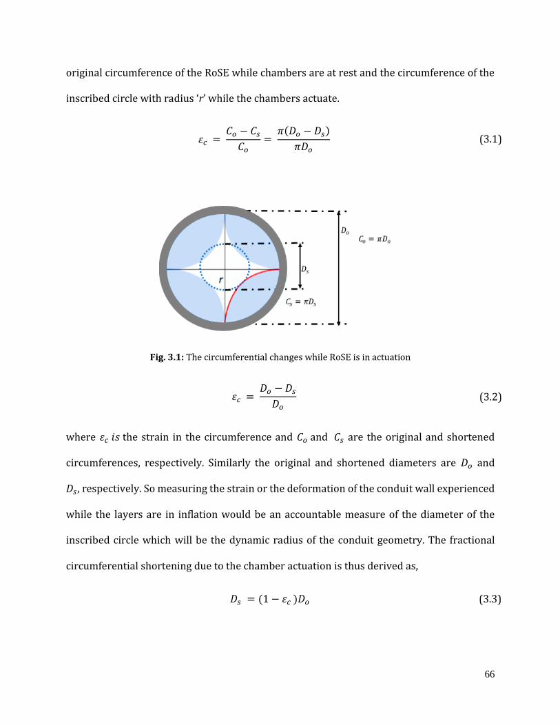
66
original circumference of the RoSE while chambers are at rest and the circumference of the
inscribed circle with radius ‘r’ while the chambers actuate.
𝜀𝑐 = 𝐶𝑜 − 𝐶𝑠
𝐶𝑜=
𝜋(𝐷𝑜 − 𝐷𝑠)
𝜋𝐷𝑜 (3.1)
Fig. 3.1: The circumferential changes while RoSE is in actuation
𝜀𝑐 = 𝐷𝑜 − 𝐷𝑠
𝐷𝑜 (3.2)
where 𝜀𝑐 𝑖𝑠 the strain in the circumference and 𝐶𝑜 and 𝐶𝑠 are the original and shortened
circumferences, respectively. Similarly the original and shortened diameters are 𝐷𝑜 and
𝐷𝑠, respectively. So measuring the strain or the deformation of the conduit wall experienced
while the layers are in inflation would be an accountable measure of the diameter of the
inscribed circle which will be the dynamic radius of the conduit geometry. The fractional
circumferential shortening due to the chamber actuation is thus derived as,
𝐷𝑠 = (1 − 𝜀𝑐 )𝐷𝑜 (3.3)
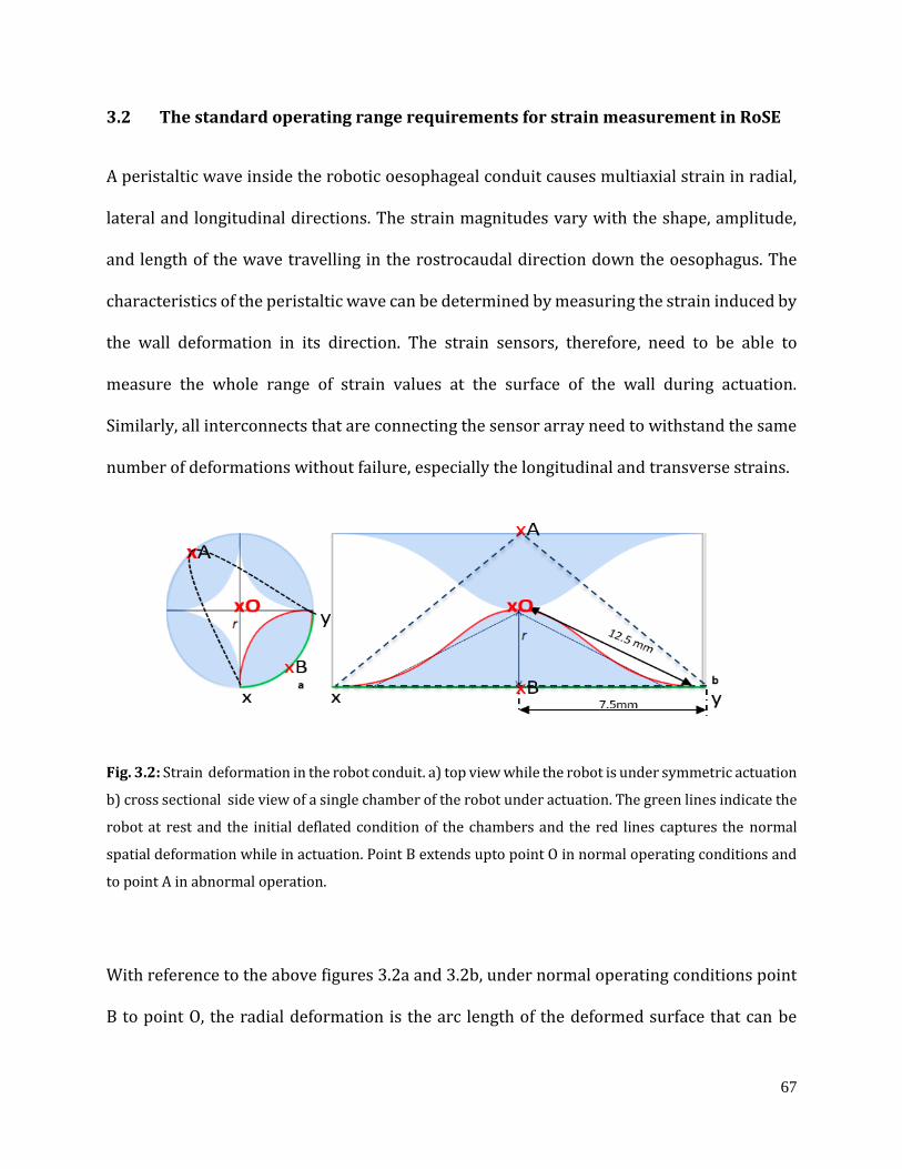
67
3.2 The standard operating range requirements for strain measurement in RoSE
A peristaltic wave inside the robotic oesophageal conduit causes multiaxial strain in radial,
lateral and longitudinal directions. The strain magnitudes vary with the shape, amplitude,
and length of the wave travelling in the rostrocaudal direction down the oesophagus. The
characteristics of the peristaltic wave can be determined by measuring the strain induced by
the wall deformation in its direction. The strain sensors, therefore, need to be able to
measure the whole range of strain values at the surface of the wall during actuation.
Similarly, all interconnects that are connecting the sensor array need to withstand the same
number of deformations without failure, especially the longitudinal and transverse strains.
Fig. 3.2: Strain deformation in the robot conduit. a) top view while the robot is under symmetric actuation
b) cross sectional side view of a single chamber of the robot under actuation. The green lines indicate the
robot at rest and the initial deflated condition of the chambers and the red lines captures the normal
spatial deformation while in actuation. Point B extends upto point O in normal operating conditions and
to point A in abnormal operation.
With reference to the above figures 3.2a and 3.2b, under normal operating conditions point
B to point O, the radial deformation is the arc length of the deformed surface that can be
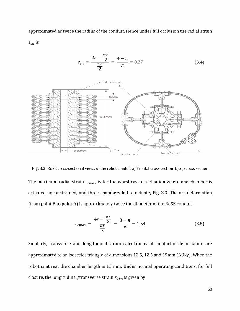
68
approximated as twice the radius of the conduit. Hence under full occlusion the radial strain
𝜀𝑐𝑛 is
𝜀𝑐𝑛 = 2𝑟 −
𝜋𝑟2
𝜋𝑟2
= 4 − 𝜋
𝜋= 0.27 (3.4)
Fig. 3.3: RoSE cross-sectional views of the robot conduit a) Frontal cross section b)top cross section
The maximum radial strain 𝜀𝑐𝑚𝑎𝑥 is for the worst case of actuation where one chamber is
actuated unconstrained, and three chambers fail to actuate, Fig. 3.3. The arc deformation
(from point B to point A) is approximately twice the diameter of the RoSE conduit
𝜀𝑐𝑚𝑎𝑥 = 4𝑟 −
𝜋𝑟2
𝜋𝑟2
= 8 − 𝜋
𝜋= 1.54 (3.5)
Similarly, transverse and longitudinal strain calculations of conductor deformation are
approximated to an isosceles triangle of dimensions 12.5, 12.5 and 15mm (Oxy). When the
robot is at rest the chamber length is 15 mm. Under normal operating conditions, for full
closure, the longitudinal/transverse strain 𝜀𝐿𝑇𝑛 is given by
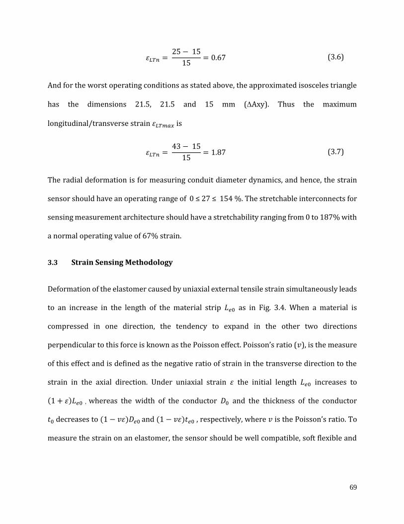
69
𝜀𝐿𝑇𝑛 = 25 − 15
15= 0.67 (3.6)
And for the worst operating conditions as stated above, the approximated isosceles triangle
has the dimensions 21.5, 21.5 and 15 mm (Axy). Thus the maximum
longitudinal/transverse strain 𝜀𝐿𝑇𝑚𝑎𝑥 is
𝜀𝐿𝑇𝑛 = 43 − 15
15= 1.87 (3.7)
The radial deformation is for measuring conduit diameter dynamics, and hence, the strain
sensor should have an operating range of 0 ≤ 27 ≤ 154 %. The stretchable interconnects for
sensing measurement architecture should have a stretchability ranging from 0 to 187% with
a normal operating value of 67% strain.
3.3 Strain Sensing Methodology
Deformation of the elastomer caused by uniaxial external tensile strain simultaneously leads
to an increase in the length of the material strip 𝐿𝑒0 as in Fig. 3.4. When a material is
compressed in one direction, the tendency to expand in the other two directions
perpendicular to this force is known as the Poisson effect. Poisson’s ratio (𝑣), is the measure
of this effect and is defined as the negative ratio of strain in the transverse direction to the
strain in the axial direction. Under uniaxial strain 𝜀 the initial length 𝐿𝑒0 increases to
(1 + 𝜀)𝐿𝑒0 , whereas the width of the conductor 𝐷0 and the thickness of the conductor
𝑡0 decreases to (1 − 𝑣𝜀)𝐷𝑒0 and (1 − 𝑣𝜀)𝑡𝑒0 , respectively, where 𝑣 is the Poisson’s ratio. To
measure the strain on an elastomer, the sensor should be well compatible, soft flexible and
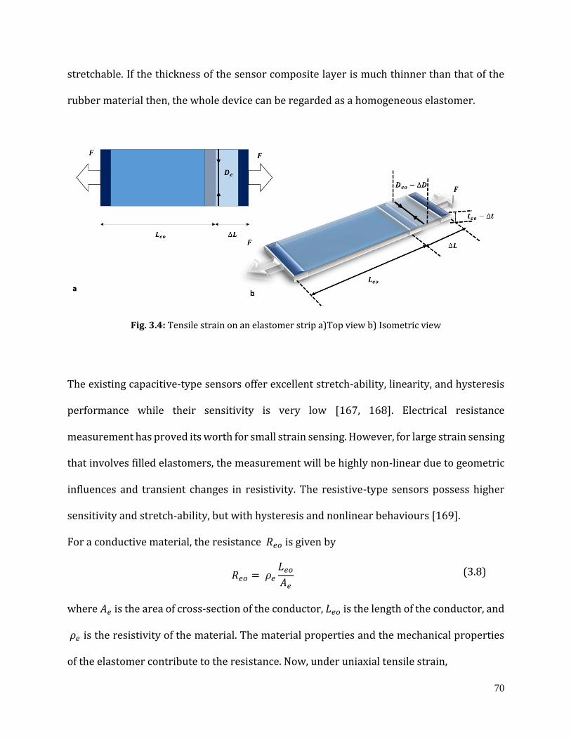
70
stretchable. If the thickness of the sensor composite layer is much thinner than that of the
rubber material then, the whole device can be regarded as a homogeneous elastomer.
Fig. 3.4: Tensile strain on an elastomer strip a)Top view b) Isometric view
The existing capacitive-type sensors offer excellent stretch-ability, linearity, and hysteresis
performance while their sensitivity is very low [167, 168]. Electrical resistance
measurement has proved its worth for small strain sensing. However, for large strain sensing
that involves filled elastomers, the measurement will be highly non-linear due to geometric
influences and transient changes in resistivity. The resistive-type sensors possess higher
sensitivity and stretch-ability, but with hysteresis and nonlinear behaviours [169].
For a conductive material, the resistance 𝑅𝑒𝑜 is given by
𝑅𝑒𝑜 = 𝜌𝑒
𝐿𝑒𝑜
𝐴𝑒 (3.8)
where 𝐴𝑒 is the area of cross-section of the conductor, 𝐿𝑒𝑜 is the length of the conductor, and
𝜌𝑒 is the resistivity of the material. The material properties and the mechanical properties
of the elastomer contribute to the resistance. Now, under uniaxial tensile strain,

71
𝑅𝑒_𝑛𝑒𝑤 = 𝜌(1 + 𝜀)𝐿𝑒0
(1 − 𝑣𝜀)𝐷𝑒0(1 − 𝑣𝜀)𝑡𝑒0= 𝜌
(1 + 𝜀)𝐿𝑒0
(1 − 𝑣𝜀)2𝐴𝑒 (3.9)
For a positive strain and positive Poisson’s ratio
(1 + 𝜀) ≫ (1 − 𝑣𝜀)2 (3.10)
𝑅𝑒_𝑛𝑒𝑤 ≅ (1 + 𝜀)𝑅𝑒𝑜 (3.11)
where 𝑅𝑒_𝑛𝑒𝑤 is the new resistance value. Therefore, if a constant conductivity of the
electrodes is maintained, the relative resistance change should be an excellent coincidence
with the prediction of the strain sensor measurement.
∆𝑅𝑒
𝑅𝑒𝑜= 𝜀
(3.12)
where ∆𝑅𝑒 is the change in resistance value due to strain 𝜀. It should be noted that this linear
function is limited to only a certain amount of strain. If the applied strain is too large, the
linear relationship between different axes via the Poisson’s ratio is not valid to any further
extent for the utilized polymer EcoflexTM 00-30.
3.3.1 Sensor Architecture: Series and parallel combination resistive circuits
The circumferential shortening of the RoSE diameter involves the simultaneous deformation
of all the chambers in a single layer. Hence, the prediction of circumferential strain is better
measured as the useful strain measurement of all the actuated chambers. So a connected
72
architecture of the strain sensors in each layer is an apparent choice for the designated
measurement.
Fig. 3.5: Series and Parallel Resistor combinations
The total resistance in a series resistance 𝑅𝑒𝑞_𝑠 for the circuit Fig. 3.5 is given by
𝑅𝑒𝑞_𝑠 = 𝑅1 + 𝑅2 (3.13)
The total effective resistance is larger than either of the resistances. When connected in
series for strain measurement the change in strain in the respective resistance will
considerably change the total resistance. The percentage change in total resistance in the
series circuits is given by
∆ 𝑅𝑒𝑞_𝑠
𝑅𝑒𝑞_𝑠=
∆𝑅1
𝑅1+
∆𝑅2
𝑅2 (3.14)
The total resistance equivalent 𝑅𝑒𝑞_𝑝 in a parallel circuit is given by
𝑅𝑒𝑞_𝑝 = 𝑅1𝑅2
𝑅1 + 𝑅2 (3.15)
The total effective resistance is less than either of the resistances. When connected in parallel
for strain measurement, the change in strain in the respective resistance will considerably
73
change the total resistances. The percentage change in total resistance in the parallel circuits
is given by
∆𝑅𝑒𝑞_𝑝
𝑅𝑒𝑞_𝑝=
∆𝑅1
𝑅1+
∆𝑅2
𝑅2−
∆𝑅1 + ∆𝑅2
𝑅1 + 𝑅2 (3.16)
The percentage change in the total resistance in response to a strain input in both series and
parallel connections is approximately the same.
Similarly for a capacitive sensor, the capacitance𝐶𝑒𝑜,
𝐶𝑒𝑜 = 𝜖0𝑐𝜖𝑟𝑐
𝐴𝑒
𝑑𝑒 (3.17)
where 𝐴𝑒 is the area of cross-section of the electrodes, 𝑑𝑒 is the distance of the electrodes,
𝜖0𝑐 and 𝜖𝑟𝑐 represent the vacuum and relative permittivity, respectively. The material
properties of the electrodes do not affect the capacitance but are limited to the mechanical
properties of the elastomer. Under uniaxial strain, the width of electrode ‘𝑤𝑒’ and the
distance between electrodes ‘𝑑𝑒’ decreases to (1 − 𝑣𝜀)𝑤𝑒 and (1 − 𝑣𝜀)𝑑𝑒 , respectively. Thus
Eq 3.17 becomes,
𝐶𝑒_𝑛𝑒𝑤 = 𝜖0𝑐𝜖𝑟𝑐
(1 + 𝜀)𝐿𝑒0(1 − 𝑣𝜀)𝑤𝑒
(1 − 𝑣𝜀)𝑑𝑒= 𝜖0𝜖𝑟
(1 + 𝜀)𝐿𝑒0𝑤0𝑒
𝑑0 (3.18)
𝐶𝑒_𝑛𝑒𝑤 = (1 + 𝜀)𝐶𝑒𝑜 (3.19)
Therefore, if constant conductivity of the electrodes is maintained, and is independent of the
ϵ, the relative capacitance change should be an excellent coincidence with the prediction of
strain sensor measurement.
74
∆𝐶𝑒_𝑛𝑒𝑤
𝐶𝑒𝑜= 𝜀
(3.20)
The percentage change in the total capacitance in response to a strain input in both series
and parallel connections is approximately the same and is given by,
∆𝐶𝑒𝑞
𝐶𝑒𝑞=
∆𝐶1
𝐶𝑒𝑞+
∆𝐶2
𝐶𝑒𝑞 (3.21)
3.4 Sensor geometry, design considerations and developing procedure
Elastomer-based sensor studies are contemporary and emerging studies, thus the definitive
study of the general sensor shape for customized applications is up till now unavailable.
Hence three different geometrical shapes have been used in this study and are explained
further. Equally, the concentration of nanomaterial in the elastomer for optimum sensitivity
is an existing topic of research [170], spawning a gap in guidelines to select the optimal ratio
of the conductive material and elastomer. Therefore three different concentrations for
different shapes of sensors are tried and tested before the final selection. The main focus is
to develop a resistive sensor; however, the performance of a capacitive sensor to that of a
resistive sensor is compared before finalizing the sensor selection for its suitability to the
application.
3.4.1 Design constraints
The sensor network geometry design is constrained by the following factors with reference
to Fig. 3.3.

75
a. RoSE geometrical constraints
The geometrical constraints are caused by the small dimensions of the transporting conduit.
The final sensor matrix needs to be embedded in the main body of the swallowing robot, and
the sensor matrix and the main body then become part of the robot as a result. A total of 48
sensor pads are required so that the surface deformation of each inflatable chamber can be
measured.
b. Chamber dimension constraints
The radius of the conduit is 10 mm resulting in a circumference of 62.84 mm. The length of
the conduit is 185 mm. When the inner surface of the conduit is cut open, it can be treated as
a flat sheet covering an area of 62.84x185 mm2. The sensor matrix is required to fit into the
area, and each of the sensor pads is designed to cover the middle part of the inflatable
chamber of dimension 10x10 mm. Thus, the overall dimension of the sensor matrix needs to
fit into the inner surface.
c. Conduit thickness constraints
The thickness of the sensor matrix is required to be minimal to abate its effect on the conduit
deformation and to faithfully retain the transporting conduit geometry. The thickness of the
sensor matrix is assumed to be less than 1 mm, or 0.5% of the wall thickness, this is in
consideration of the fact that the thickness of the conduit wall is 20 mm. So a general
thickness of the embedded sensor is shown in Fig. 3.6.
Fig. 3.6: Carbon black- elastomer sensor arrangement
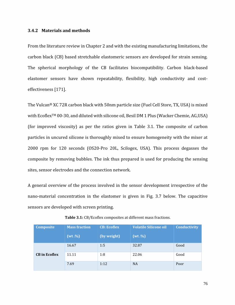
76
3.4.2 Materials and methods
From the literature review in Chapter 2 and with the existing manufacturing limitations, the
carbon black (CB) based stretchable elastomeric sensors are developed for strain sensing.
The spherical morphology of the CB facilitates biocompatibility. Carbon black-based
elastomer sensors have shown repeatability, flexibility, high conductivity and cost-
effectiveness [171].
The Vulcan® XC 72R carbon black with 50nm particle size (Fuel Cell Store, TX, USA) is mixed
with EcoflexTM 00-30, and diluted with silicone oil, Besil DM 1 Plus (Wacker Chemie, AG,USA)
(for improved viscosity) as per the ratios given in Table 3.1. The composite of carbon
particles in uncured silicone is thoroughly mixed to ensure homogeneity with the mixer at
2000 rpm for 120 seconds (OS20-Pro 20L, Scilogex, USA). This process degasses the
composite by removing bubbles. The ink thus prepared is used for producing the sensing
sites, sensor electrodes and the connection network.
A general overview of the process involved in the sensor development irrespective of the
nano-material concentration in the elastomer is given in Fig. 3.7 below. The capacitive
sensors are developed with screen printing.
Table 3.1: CB/Ecoflex composites at different mass fractions.
Composite Mass fraction
(wt .%)
CB: Ecoflex
(by weight)
Volatile Silicone oil
(wt .%)
Conductivity
CB in Ecoflex
16.67 1:5 32.87 Good
11.11 1:8 22.06 Good
7.69 1:12 NA Poor
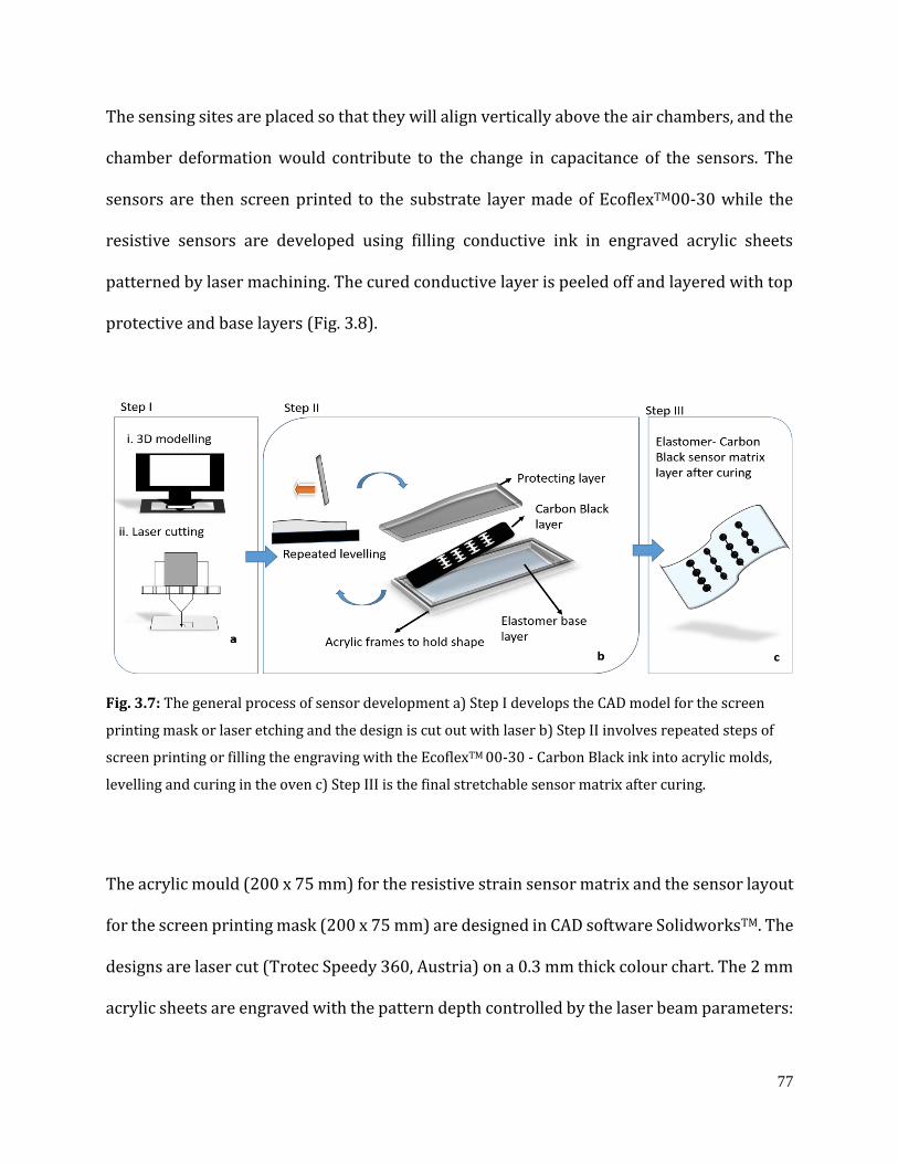
77
The sensing sites are placed so that they will align vertically above the air chambers, and the
chamber deformation would contribute to the change in capacitance of the sensors. The
sensors are then screen printed to the substrate layer made of EcoflexTM00-30 while the
resistive sensors are developed using filling conductive ink in engraved acrylic sheets
patterned by laser machining. The cured conductive layer is peeled off and layered with top
protective and base layers (Fig. 3.8).
Fig. 3.7: The general process of sensor development a) Step I develops the CAD model for the screen
printing mask or laser etching and the design is cut out with laser b) Step II involves repeated steps of
screen printing or filling the engraving with the EcoflexTM 00-30 - Carbon Black ink into acrylic molds,
levelling and curing in the oven c) Step III is the final stretchable sensor matrix after curing.
The acrylic mould (200 x 75 mm) for the resistive strain sensor matrix and the sensor layout
for the screen printing mask (200 x 75 mm) are designed in CAD software SolidworksTM. The
designs are laser cut (Trotec Speedy 360, Austria) on a 0.3 mm thick colour chart. The 2 mm
acrylic sheets are engraved with the pattern depth controlled by the laser beam parameters:
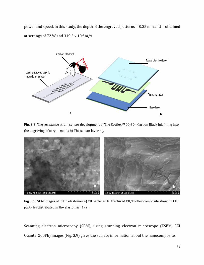
78
power and speed. In this study, the depth of the engraved patterns is 0.35 mm and is obtained
at settings of 72 W and 319.5 x 10⁻² m/s.
Fig. 3.8: The resistance strain sensor development a) The EcoflexTM 00-30 - Carbon Black ink filling into
the engraving of acrylic molds b) The sensor layering.
Fig. 3.9: SEM images of CB in elastomer a) CB particles, b) fractured CB/Ecoflex composite showing CB
particles distributed in the elastomer [172].
Scanning electron microscopy (SEM), using scanning electron microscope (ESEM, FEI
Quanta, 200FE) images (Fig. 3.9) gives the surface information about the nanocomposite.

79
3.4.3 Sensor geometry
The study is using two different designs of sensor geometry to identify the most suitable
sensor to be embedded on the RoSE conduit. Each design is tested for its sensitivity,
hysteresis, resolution and repeatability. The dimensions of the sensing site are constrained
to be 10x10 mm for a single sensor and aligned to be placed vertically above the air
chambers. As discussed earlier, the sensors are intended to measure the circumferential
shortening so the series combination of the four sensors, covering an entire layer of RoSE
conduit, is developed for testing at the initial phase. All the designs of sensor pads were used
to test the initial resistance and resistance variance of the proposed pattern.
Fig. 3.10: The loop strain sensor pattern
a. The bar resistor
The bar resistor (Fig. 3.11b) of dimensions 8x5 mm is made onto the acrylic sheets with 0.35
mm deep engraving. The carbon black ink is filled into the engravings and is layered with a
1 mm thick elastomer. The structure is kept for curing at 25⁰C for four hours. The cured
structure is then provided with a protective layer.
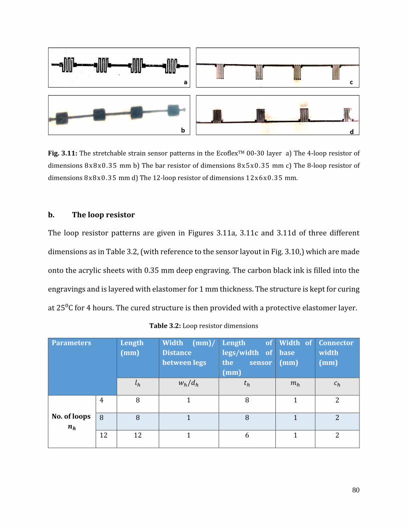
80
Fig. 3.11: The stretchable strain sensor patterns in the EcoflexTM 00-30 layer a) The 4-loop resistor of
dimensions 8x8x0.35 mm b) The bar resistor of dimensions 8x5x0.35 mm c) The 8-loop resistor of
dimensions 8x8x0.35 mm d) The 12-loop resistor of dimensions 12x6x0.35 mm.
b. The loop resistor
The loop resistor patterns are given in Figures 3.11a, 3.11c and 3.11d of three different
dimensions as in Table 3.2, (with reference to the sensor layout in Fig. 3.10,) which are made
onto the acrylic sheets with 0.35 mm deep engraving. The carbon black ink is filled into the
engravings and is layered with elastomer for 1 mm thickness. The structure is kept for curing
at 25⁰C for 4 hours. The cured structure is then provided with a protective elastomer layer.
Table 3.2: Loop resistor dimensions
Parameters Length
(mm)
Width (mm)/
Distance
between legs
Length of
legs/width of
the sensor
(mm)
Width of
base
(mm)
Connector
width
(mm)
𝑙ℎ 𝑤ℎ/𝑑ℎ 𝑡ℎ 𝑚ℎ 𝑐ℎ
No. of loops
𝒏𝒉
4 8 1 8 1 2
8 8 1 8 1 2
12 12 1 6 1 2
81
3.5 Sensor characterization
Characterization of the prepared stretch sensors was carried out using a stretching rig, with
the sensor samples clamped to a motorized precision linear stage. One of the sensor’s ends
is clamped to the movable stage that moves at a controlled rate to stretch the sample
uniaxially and the other end is clamped to a rigid fixture. The connector end terminals were
connected to an LCR meter (Agilent 4263B, LCR, USA) to record the response for cyclic
loading tests, stretching them to up to 200% strain and the response was documented.
The following tests were conducted on the test samples: 1) All the designs of different mass
fractions were tested for cyclic loading tests, 2) All the sensors with different mass fractions
were tested to identify the effect of the applied strain rate on the response of these sensors
with the stretching rate altered 3) The loop sensors were tested to identify the effect of the
direction of applied strain. All the measurements were taken at 1 kHz frequency and
customized data acquisition set up based on LABVIEW interface (National Instruments)
sampled and read the data every 0.05s. As this is an exploratory work, all electrical
measurements were conducted on three samples for each substrate type and the average
values were reported.
3.5.1 Stretch cycle tests
The stretch cycle tests on the different sensor designs with mass fractions were conducted.
The sensor layer with a 7.69% mass fraction had the least conductivity path established and
hence none of the designs showed any reading for change in strain. The other mass fractions
considered in this study were hence further tested for cyclic loading and different rate tests.
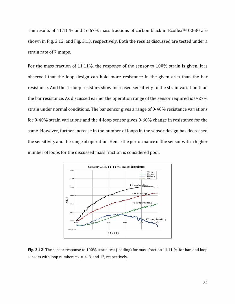
82
The results of 11.11 % and 16.67% mass fractions of carbon black in EcoflexTM 00-30 are
shown in Fig. 3.12, and Fig. 3.13, respectively. Both the results discussed are tested under a
strain rate of 7 mmps.
For the mass fraction of 11.11%, the response of the sensor to 100% strain is given. It is
observed that the loop design can hold more resistance in the given area than the bar
resistance. And the 4 –loop resistors show increased sensitivity to the strain variation than
the bar resistance. As discussed earlier the operation range of the sensor required is 0-27%
strain under normal conditions. The bar sensor gives a range of 0-40% resistance variations
for 0-40% strain variations and the 4-loop sensor gives 0-60% change in resistance for the
same. However, further increase in the number of loops in the sensor design has decreased
the sensitivity and the range of operation. Hence the performance of the sensor with a higher
number of loops for the discussed mass fraction is considered poor.
Fig. 3.12: The sensor response to 100% strain test (loading) for mass fraction 11.11 % for bar, and loop
sensors with loop numbers 𝑛ℎ = 4, 8 and 12, respectively.
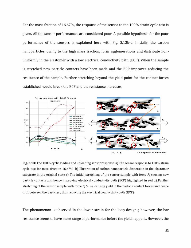
83
For the mass fraction of 16.67%, the response of the sensor to the 100% strain cycle test is
given. All the sensor performances are considered poor. A possible hypothesis for the poor
performance of the sensors is explained here with Fig. 3.13b-d. Initially, the carbon
nanoparticles, owing to the high mass fraction, form agglomerations and distribute non-
uniformly in the elastomer with a low electrical conductivity path (ECP). When the sample
is stretched new particle contacts have been made and the ECP improves reducing the
resistance of the sample. Further stretching beyond the yield point for the contact forces
established, would break the ECP and the resistance increases.
Fig. 3.13: The 100% cyclic loading and unloading sensor response. a) The sensor response to 100% strain
cycle test for mass fraction 16.67% b) Illustration of carbon nanoparticle dispersion in the elastomer
substrate in the original state c) The initial stretching of the sensor sample with force 𝐹𝑖 causing new
particle contacts and hence improving electrical conductivity path (ECP) highlighted in red d) Further
stretching of the sensor sample with force 𝐹𝑗 > 𝐹𝑖 causing yield in the particle contact forces and hence
drift between the particles , thus reducing the electrical conductivity path (ECP).
The phenomenon is observed in the lower strain for the loop designs; however, the bar
resistance seems to have more range of performance before the yield happens. However, the
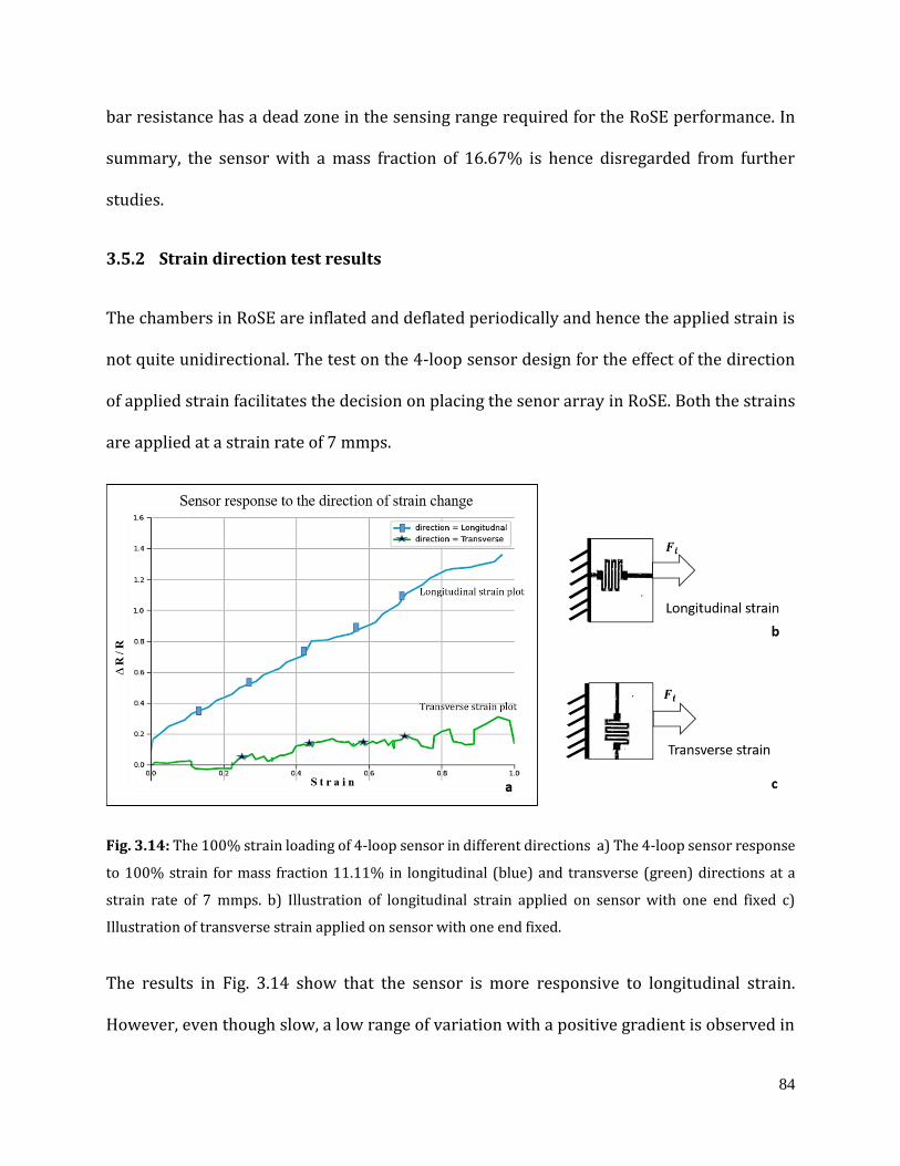
84
bar resistance has a dead zone in the sensing range required for the RoSE performance. In
summary, the sensor with a mass fraction of 16.67% is hence disregarded from further
studies.
3.5.2 Strain direction test results
The chambers in RoSE are inflated and deflated periodically and hence the applied strain is
not quite unidirectional. The test on the 4-loop sensor design for the effect of the direction
of applied strain facilitates the decision on placing the senor array in RoSE. Both the strains
are applied at a strain rate of 7 mmps.
Fig. 3.14: The 100% strain loading of 4-loop sensor in different directions a) The 4-loop sensor response
to 100% strain for mass fraction 11.11% in longitudinal (blue) and transverse (green) directions at a
strain rate of 7 mmps. b) Illustration of longitudinal strain applied on sensor with one end fixed c)
Illustration of transverse strain applied on sensor with one end fixed.
The results in Fig. 3.14 show that the sensor is more responsive to longitudinal strain.
However, even though slow, a low range of variation with a positive gradient is observed in
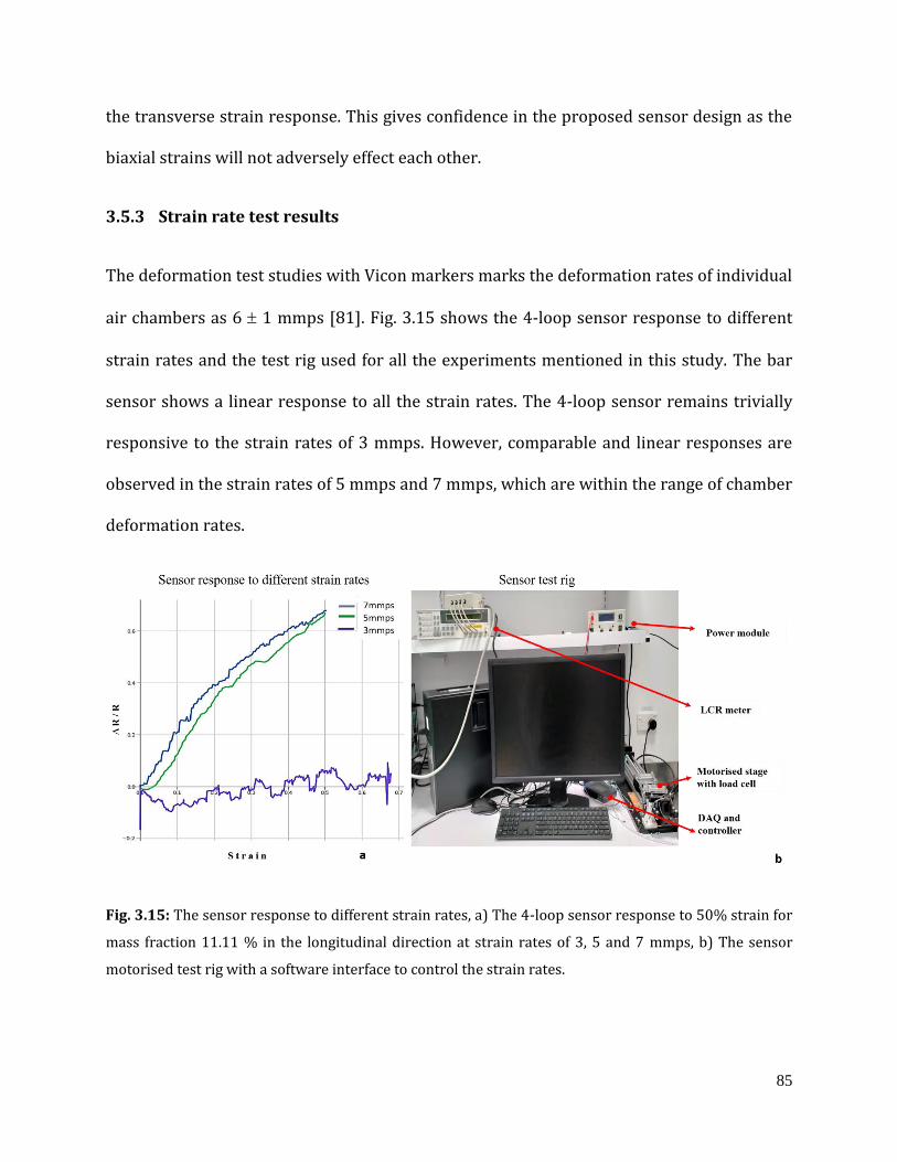
85
the transverse strain response. This gives confidence in the proposed sensor design as the
biaxial strains will not adversely effect each other.
3.5.3 Strain rate test results
The deformation test studies with Vicon markers marks the deformation rates of individual
air chambers as 6 1 mmps [81]. Fig. 3.15 shows the 4-loop sensor response to different
strain rates and the test rig used for all the experiments mentioned in this study. The bar
sensor shows a linear response to all the strain rates. The 4-loop sensor remains trivially
responsive to the strain rates of 3 mmps. However, comparable and linear responses are
observed in the strain rates of 5 mmps and 7 mmps, which are within the range of chamber
deformation rates.
Fig. 3.15: The sensor response to different strain rates, a) The 4-loop sensor response to 50% strain for
mass fraction 11.11 % in the longitudinal direction at strain rates of 3, 5 and 7 mmps, b) The sensor
motorised test rig with a software interface to control the strain rates.
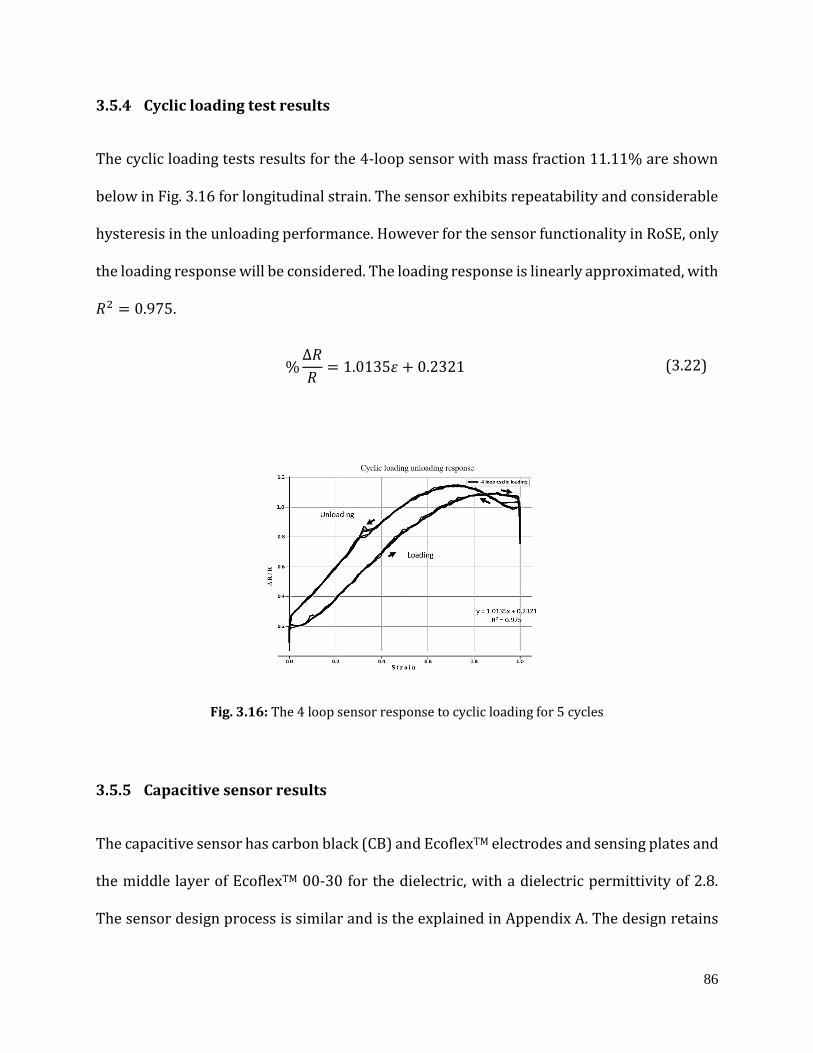
86
3.5.4 Cyclic loading test results
The cyclic loading tests results for the 4-loop sensor with mass fraction 11.11% are shown
below in Fig. 3.16 for longitudinal strain. The sensor exhibits repeatability and considerable
hysteresis in the unloading performance. However for the sensor functionality in RoSE, only
the loading response will be considered. The loading response is linearly approximated, with
𝑅2 = 0.975.
%∆𝑅
𝑅= 1.0135𝜀 + 0.2321 (3.22)
Fig. 3.16: The 4 loop sensor response to cyclic loading for 5 cycles
3.5.5 Capacitive sensor results
The capacitive sensor has carbon black (CB) and EcoflexTM electrodes and sensing plates and
the middle layer of EcoflexTM 00-30 for the dielectric, with a dielectric permittivity of 2.8.
The sensor design process is similar and is the explained in Appendix A. The design retains
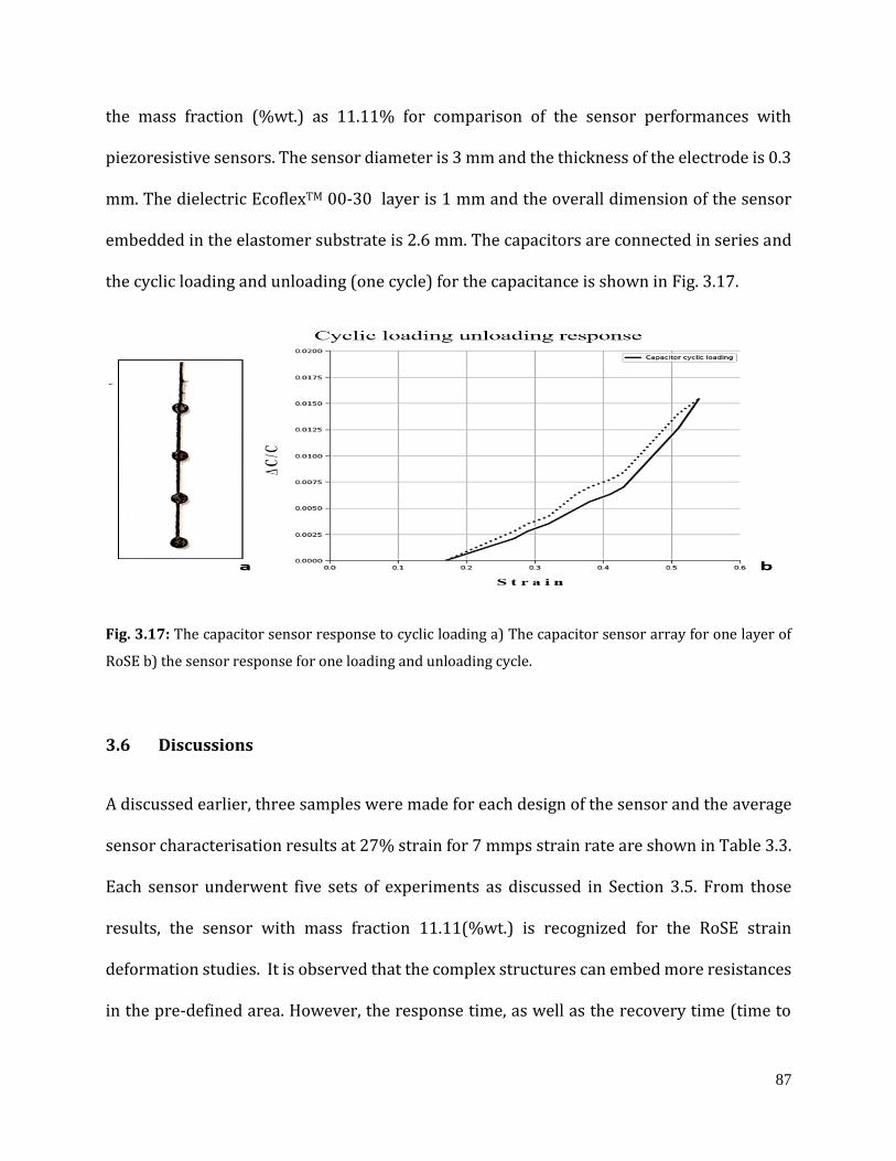
87
the mass fraction (%wt.) as 11.11% for comparison of the sensor performances with
piezoresistive sensors. The sensor diameter is 3 mm and the thickness of the electrode is 0.3
mm. The dielectric EcoflexTM 00-30 layer is 1 mm and the overall dimension of the sensor
embedded in the elastomer substrate is 2.6 mm. The capacitors are connected in series and
the cyclic loading and unloading (one cycle) for the capacitance is shown in Fig. 3.17.
Fig. 3.17: The capacitor sensor response to cyclic loading a) The capacitor sensor array for one layer of
RoSE b) the sensor response for one loading and unloading cycle.
3.6 Discussions
A discussed earlier, three samples were made for each design of the sensor and the average
sensor characterisation results at 27% strain for 7 mmps strain rate are shown in Table 3.3.
Each sensor underwent five sets of experiments as discussed in Section 3.5. From those
results, the sensor with mass fraction 11.11(%wt.) is recognized for the RoSE strain
deformation studies. It is observed that the complex structures can embed more resistances
in the pre-defined area. However, the response time, as well as the recovery time (time to
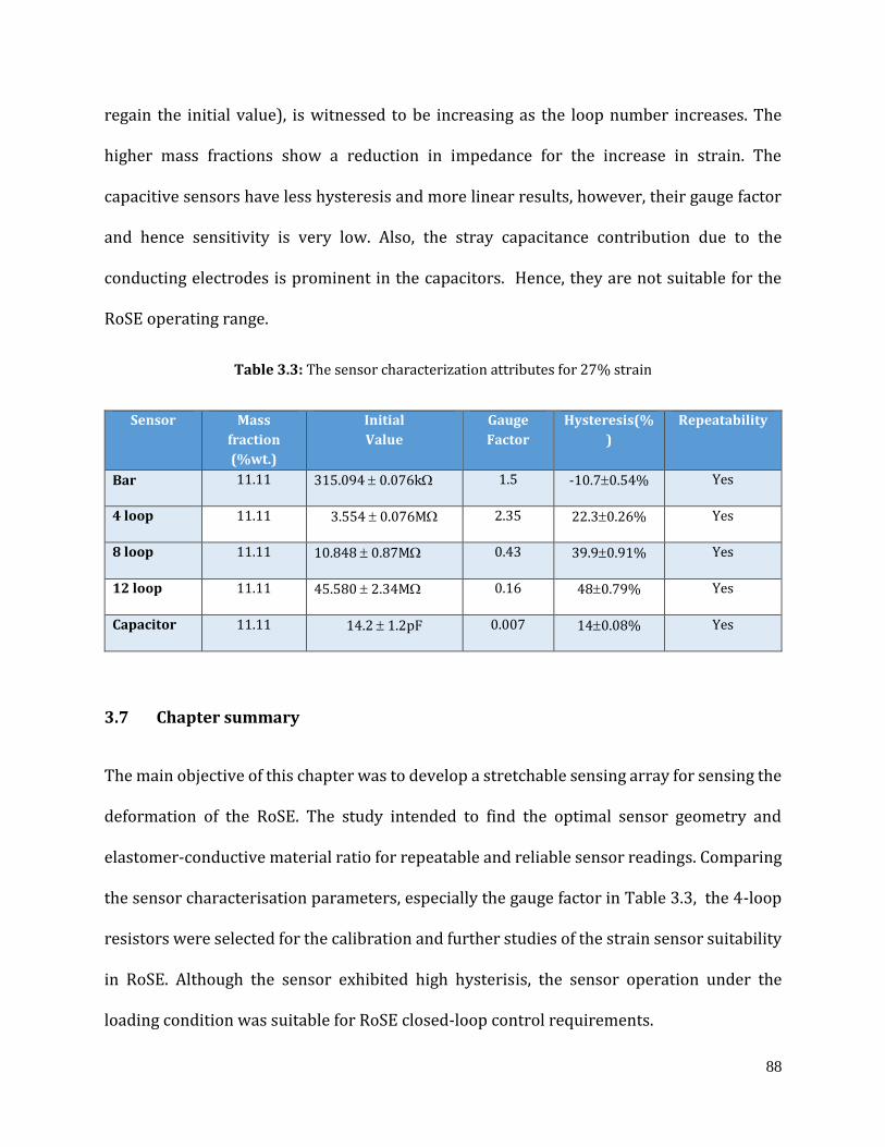
88
regain the initial value), is witnessed to be increasing as the loop number increases. The
higher mass fractions show a reduction in impedance for the increase in strain. The
capacitive sensors have less hysteresis and more linear results, however, their gauge factor
and hence sensitivity is very low. Also, the stray capacitance contribution due to the
conducting electrodes is prominent in the capacitors. Hence, they are not suitable for the
RoSE operating range.
Table 3.3: The sensor characterization attributes for 27% strain
Sensor Mass
fraction
(%wt.)
Initial
Value
Gauge
Factor
Hysteresis(%
)
Repeatability
Bar 11.11 315.094 0.076k 1.5 -10.70.54% Yes
4 loop 11.11 3.554 0.076M 2.35 22.30.26% Yes
8 loop 11.11 10.848 0.87M 0.43 39.90.91% Yes
12 loop 11.11 45.580 2.34M 0.16 480.79% Yes
Capacitor 11.11 14.2 1.2pF 0.007 140.08% Yes
3.7 Chapter summary
The main objective of this chapter was to develop a stretchable sensing array for sensing the
deformation of the RoSE. The study intended to find the optimal sensor geometry and
elastomer-conductive material ratio for repeatable and reliable sensor readings. Comparing
the sensor characterisation parameters, especially the gauge factor in Table 3.3, the 4-loop
resistors were selected for the calibration and further studies of the strain sensor suitability
in RoSE. Although the sensor exhibited high hysterisis, the sensor operation under the
loading condition was suitable for RoSE closed-loop control requirements.
89
Chapter 4
Calibration and control of sensor embedded
actuator
Occlusion and coordinate transformation concerns are not a problem for embedded soft
strain sensors. High omni-directional compliance is necessary when the sensor must be
embedded in a soft system. Understanding sensor dynamics as well as system dynamics is
required for developing dynamic models based on these sensors. These sensors could
theoretically have single conformations and non-unique mappings due to their
omnidirectional compliance. Furthermore, when several mechanical stimuli, such as strain
and pressure, are applied, estimating physical properties from sensor information becomes
more challenging. The pressure effect can be reduced by carefully selecting the sensor
positions [140], but this comes at the cost of a lengthy design procedure. Any machine
learning approach can be used to handle the problem of modelling unknown sensor and
system dynamics as long as the dependable training signals are available for developing the
model. It is projected to solve the problem of nonlinearity and hysteresis of soft sensors using
deep learning for a single sensor network [141] and a multi sensor network [150-153].
Implementation of the proposed strain sensors involves calibration of the resistance change
to the deflation and inflation changes in RoSE. The air chamber surface variations for the
pressure input variations have to be read through the soft stretchable sensory array. The
peristalsis trajectories implemented in RoSE are the superimposed staircase waveforms. The

90
sensor has to be hence tested for the response to the stair-case step response. The carbon
black-based elastomer sensors have non-linearities inherited from the elastomer properties,
non-uniform dispersion and the electrical conductivity path variations cause drift and creep.
Therefore the conventional regression methods may not be suitable for calibrating the
sensor response in correspondence to the physical variations. A prior knowledge of the
sensing induced non-linearities will be accommodated in designing the controllers for the
soft robot.
This chapter investigates:
1. the application of machine learning algorithms to calibrate the non-linear features of
the sensor,
2. the implementation of sensors and calibration of the sensor-embedded actuator
responses on different versions of RoSE,
3. the design and development of controller strategy for the flat version of the robot
called fRoSE.
4.1 LSTM based sensor modelling and prediction
The recurrent neural network, RNN- LTSM learning methods, from the Scikit-learn toolbox
is applied to the recorded training data. The training of the network is done in two steps.
Initially, the network is trained in an open loop by unfolding the recurrent network and
training by Bayesian Regularization [139].
𝑀𝑆𝐸 = 1
𝑇 ∑‖𝑋𝑡 − 𝑓(𝑋𝑡−1, 𝑈𝑡)‖2
𝑇
𝑡=0
(4.1)
91
where, 𝑀𝑆𝐸 is the mean square error, 𝑋𝑡 is the input vector, 𝑈𝑡 is the exogenous input vector
and the function 𝑓 represents the mapping formed by the neural network. For training the
recurrent network, Levenberg-Marquardt backpropagation is used and a validation set is
used to avoid overfitting [151]. The Levenberg-Marquardt algorithm applies the quasi-
Newton method that was designed for minimizing functions that are sums of squares of
nonlinear functions. The weights from open loop training would be used to initalise the
weights in closed loop training. Also, the training and testing sets are divided into continuous
blocks so as to keep time correlations in the ratio 80:20 for the first step (open loop network)
then the training, testing and validation sets are divided in the ratio 70:15:15 for the final
step (closed loop network). The performance function is now represented as:
𝑀𝑆𝐸 = 1
𝑇 ∑‖�̂�𝑡 − 𝑓(𝑋𝑡−1, 𝑈𝑡)‖
2𝑇
𝑡=0
(4.2)
where, �̂�𝑡 is the prediction of the network in the previous iteration. Now the learning
algorithm is not trying to reduce the single-step error, but the whole multi-step prediction
error. Thus the model update would be given by
𝑥𝑘+1 = 𝑥𝑘 − [𝐽𝑇𝐽 + 𝜇𝐼]−1𝐽𝑇𝑒 (4.3)
where 𝑥𝑘is the target update of the kth time instant of the loading loop, 𝐽 is the Jacobian
matrix that holds first derivatives of the errors in the network with respect to the weights
and biases, and 𝑒 is a vector of network errors. When the scalar µ is zero, it becomes
the Newton’s method.
92
4.2 Controller design
The primary goal of the sensor-embedded actuator is to create a data-driven soft robot
controller. The linear transfer response observed in fRoSE emboldens the use of linear
controllers, but the non-linear response seen in the sensor-embedded actuator poses a
problem. Many adaptations of the linear controller to address the non-linearities use
unconventional integration of traditional methods with soft computing algorithms such as
adaptive, fractional order, sliding mode and fuzzy controller [191-193]. The strategy is to
tune with a wide spectrum of the gains for non-linear dynamics in a gain scheduling strategy
that employs a series of linear controllers for nonlinear systems, each of which offers enough
control for a distinct operating point of the system. The scheduling variables are used to
determine the operating area of the system and to enable the appropriate linear controller
using one or more observable variables.
The design methodology of the controller involves the piecewise linearisation of the sensor-
actuator transfer characteristics. A univariate function can be expressed by a piecewise
linear function with a summation of absolute terms [187]. For a non-convex function
𝑓(𝑥), the linear function 𝐿(𝑓(𝑥) can be written as
𝐿[𝑓(𝑥)] = 𝑓(𝑎0) + 𝑠0(𝑥 − 𝑎0) +1
2∑ (𝑠𝑘 − 𝑠𝑘−1)
𝑘:𝑠𝑘<𝑠𝑘−1
(𝑥 − 2𝑧𝑘 + 2𝑎𝑘𝑢𝑘 − 𝑎𝑘) (4.4)
𝑥 + �̅�(𝑢𝑘 − 1) ≤ 𝑧𝑘
(4.5) 𝑧𝑘 ≥ 0
where 𝑠𝑘 < 𝑠𝑘−1
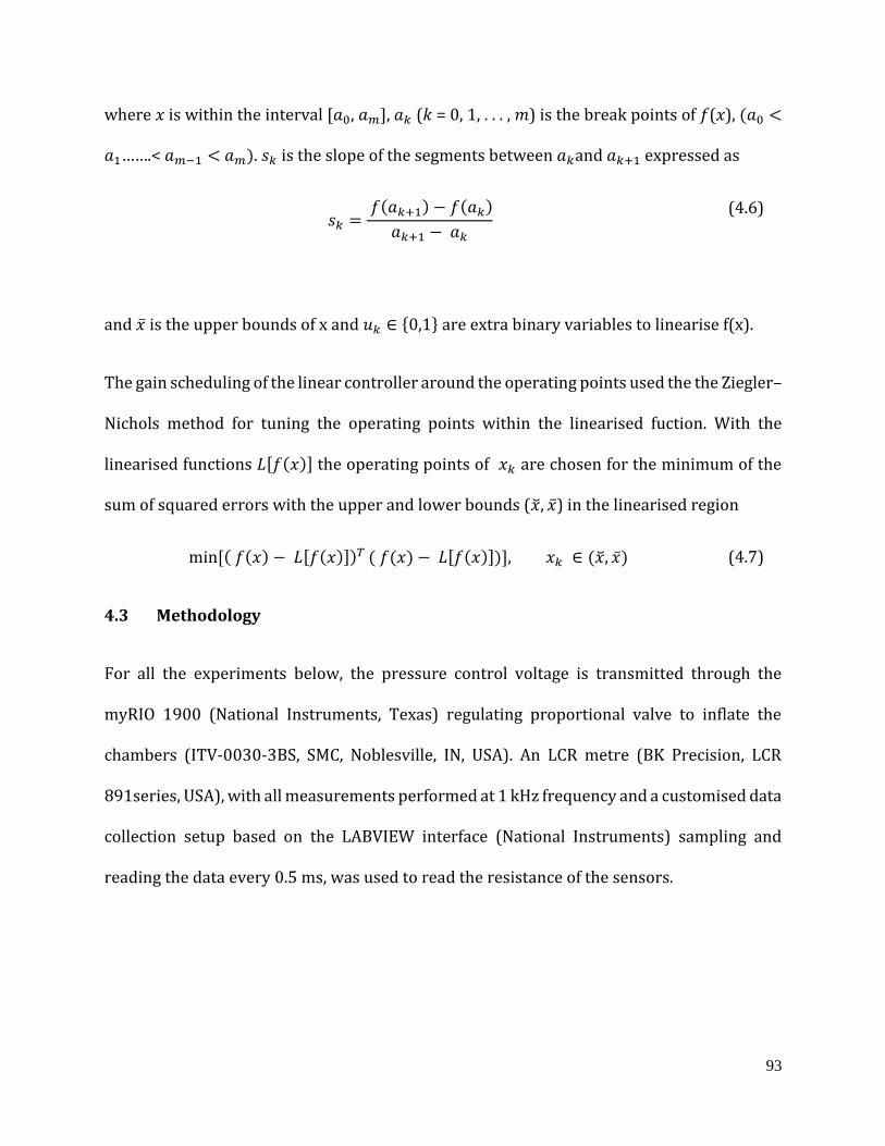
93
where 𝑥 is within the interval [𝑎0, 𝑎𝑚], 𝑎𝑘 (𝑘 = 0, 1, . . . , 𝑚) is the break points of 𝑓(𝑥), (𝑎0 <
𝑎1…….< 𝑎𝑚−1 < 𝑎𝑚). 𝑠𝑘 is the slope of the segments between 𝑎𝑘and 𝑎𝑘+1 expressed as
𝑠𝑘 = 𝑓(𝑎𝑘+1) − 𝑓(𝑎𝑘)
𝑎𝑘+1 − 𝑎𝑘
(4.6)
and �̅� is the upper bounds of x and 𝑢𝑘 ∈ {0,1} are extra binary variables to linearise f(x).
The gain scheduling of the linear controller around the operating points used the the Ziegler–
Nichols method for tuning the operating points within the linearised fuction. With the
linearised functions 𝐿[𝑓(𝑥)] the operating points of 𝑥𝑘 are chosen for the minimum of the
sum of squared errors with the upper and lower bounds (�̆�, �̅�) in the linearised region
min[( 𝑓(𝑥) − 𝐿[𝑓(𝑥)])𝑇 ( 𝑓(𝑥) − 𝐿[𝑓(𝑥)])], 𝑥𝑘 ∈ (�̆�, �̅�) (4.7)
4.3 Methodology
For all the experiments below, the pressure control voltage is transmitted through the
myRIO 1900 (National Instruments, Texas) regulating proportional valve to inflate the
chambers (ITV-0030-3BS, SMC, Noblesville, IN, USA). An LCR metre (BK Precision, LCR
891series, USA), with all measurements performed at 1 kHz frequency and a customised data
collection setup based on the LABVIEW interface (National Instruments) sampling and
reading the data every 0.5 ms, was used to read the resistance of the sensors.
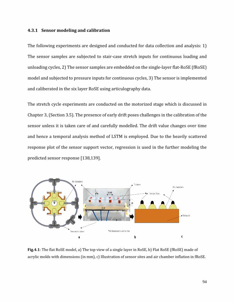
94
4.3.1 Sensor modeling and calibration
The following experiments are designed and conducted for data collection and analysis: 1)
The sensor samples are subjected to stair-case stretch inputs for continuous loading and
unloading cycles, 2) The sensor samples are embedded on the single-layer flat-RoSE (fRoSE)
model and subjected to pressure inputs for continuous cycles, 3) The sensor is implemented
and caliberated in the six layer RoSE using articulography data.
The stretch cycle experiments are conducted on the motorized stage which is discussed in
Chapter 3, (Section 3.5). The presence of early drift poses challenges in the calibration of the
sensor unless it is taken care of and carefully modelled. The drift value changes over time
and hence a temporal analysis method of LSTM is employed. Due to the heavily scattered
response plot of the sensor support vector, regression is used in the further modeling the
predicted sensor response [138,139].
Fig.4.1: The flat RoSE model, a) The top view of a single layer in RoSE, b) Flat RoSE (fRoSE) made of
acrylic molds with dimensions (in mm), c) Illustration of sensor sites and air chamber inflation in fRoSE.
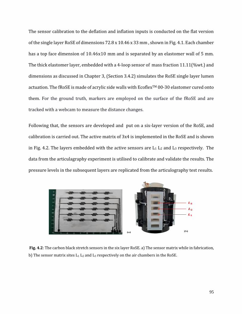
95
The sensor calibration to the deflation and inflation inputs is conducted on the flat version
of the single layer RoSE of dimensions 72.8 x 10.46 x 33 mm , shown in Fig. 4.1. Each chamber
has a top face dimension of 10.46x10 mm and is separated by an elastomer wall of 5 mm.
The thick elastomer layer, embedded with a 4-loop sensor of mass fraction 11.11(%wt.) and
dimensions as discussed in Chapter 3, (Section 3.4.2) simulates the RoSE single layer lumen
actuation. The fRoSE is made of acrylic side walls with EcoflexTM 00-30 elastomer cured onto
them. For the ground truth, markers are employed on the surface of the fRoSE and are
tracked with a webcam to measure the distance changes.
Following that, the sensors are developed and put on a six-layer version of the RoSE, and
calibration is carried out. The active matrix of 3x4 is implemented in the RoSE and is shown
in Fig. 4.2. The layers embedded with the active sensors are L1 L2 and L3 respectively. The
data from the articulagraphy experiment is utilised to calibrate and validate the results. The
pressure levels in the subsequent layers are replicated from the articulography test results.
Fig. 4.2: The carbon black stretch sensors in the six layer RoSE. a) The sensor matrix while in fabrication,
b) The sensor matrix sites L1 L2 and L3 respectively on the air chambers in the RoSE.

96
4.3.2 Gain scheduled PI controller with feed forward compensation
The prime motive of designing the sensor-embedded actuator is to develop a data driven
controller for the soft robot. The scope of this study limits the controller design developed
and applied on the fRoSE robot . The linear transfer response observed on RoSE welcomes
the linear controller designs, however the non-linear response observed in the sensor-
embedded actuator raises challenges. As explained in Section 4.2.2 , the sensor-actuator
transfer characteristic, which is a non-convex function, is piecewise linearised. The operating
range is [0, 4] mm distance, the operating points are chosen with the least square within the
linear bounds. The controller design takes the form
𝑢(𝑡) = 𝐾𝑝e(t) + 𝐾𝑖 ∫ 𝑒(𝑡)𝑑(𝑡) (4.8)
where u(t) is the control effort , 𝐾𝑝 is the proportional gain , 𝐾𝑖is the integral gain and e(t) is
the error signal. The gains are tuned with a Zieglar-Nicholas algorithm at the operating
points. The response of the fRoSE is monitored with the webcam system. The camera
feedback based system for the scheduled gains has acquired the design specification steady
state error of 8%. The cyclic loading responses of the sensor-actuator system with the
feedback controller, however has a poor settling response. The reason for that is due to the
non-linear characteristics of the carbon black sensors.
The temporal sequence modelling data is thus utilized to design a feedforward controller for
compensating the known uncertainities in the sensor-actuator system. The controller takes
the form of Fig. 4.3, with feedforward input 𝑢𝑓(𝑡)
𝑢𝑓(𝑡) = 𝑓(�̅�) (4.9)
97
where �̅� is given by Eq. 4.10 and is bounded by Eq. 4.11.
�̅� = |𝑟𝑚𝑎𝑥 − 𝑟
𝑟𝑚𝑖𝑛| , 𝑟 ∈ 𝓡 (4.10)
‖�̅�‖∞ = 𝑟𝑚𝑖𝑛 ≤ |𝑟𝑚𝑎𝑥 − 𝑟
𝑟𝑚𝑖𝑛| ≤ 𝑟𝑚𝑎𝑥 (4.11)
where 𝓡 is the space of the sensor mappings of the physical parameters.
Fig. 4.3: The block diagram representation of the feedforward gain scheduling controller
4.4 Results and discussions
4.4.1 Cyclic stair-case input loading and unloading of the piezoelectric sensor
The LTSM analysis develops models to capture the sensor non-linear dynamics. As
previously discussed in Chapter 3, Section 3.5, the strain loading is conducted with a
motorized stage. The results of loading the 4-loop sensor sample onto the motorized stage
for a 7 mmps strain rate and with a step-size of 3 mm for 100% loading is shown below.
Three samples are tested for 20 cycles of continuous loading and unloading and the average
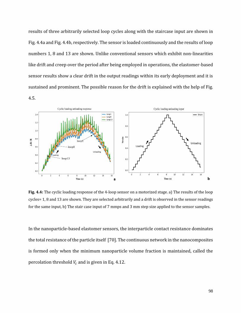
98
results of three arbitrarily selected loop cycles along with the staircase input are shown in
Fig. 4.4a and Fig. 4.4b, respectively. The sensor is loaded continuously and the results of loop
numbers 1, 8 and 13 are shown. Unlike conventional sensors which exhibit non-linearities
like drift and creep over the period after being employed in operations, the elastomer-based
sensor results show a clear drift in the output readings within its early deployment and it is
sustained and prominent. The possible reason for the drift is explained with the help of Fig.
4.5.
Fig. 4.4: The cyclic loading response of the 4-loop sensor on a motorized stage. a) The results of the loop
cycles= 1, 8 and 13 are shown. They are selected arbitrarily and a drift is observed in the sensor readings
for the same input, b) The stair case input of 7 mmps and 3 mm step size applied to the sensor samples.
In the nanoparticle-based elastomer sensors, the interparticle contact resistance dominates
the total resistance of the particle itself [70]. The continuous network in the nanocomposites
is formed only when the minimum nanoparticle volume fraction is maintained, called the
percolation threshold 𝑉𝑐 and is given in Eq. 4.12.
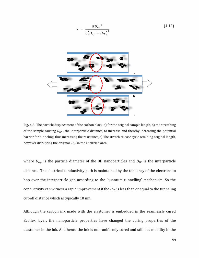
99
𝑉𝑐 = 𝜋𝐷𝑛𝑝
3
6(𝐷𝑛𝑝 + 𝐷𝐼𝑃)3
(4.12)
Fig. 4.5: The particle displacement of the carbon black a) for the original sample length, b) the stretching
of the sample causing 𝐷𝐼𝑃 , the interparticle distance, to increase and thereby increasing the potential
barrier for tunneling, thus increasing the resistance, c) The stretch release cycle retaining original length,
however disrupting the original 𝐷𝐼𝑃 in the encircled area.
where 𝐷𝑛𝑝 is the particle diameter of the 0D nanoparticles and 𝐷𝐼𝑃 is the interparticle
distance. The electrical conductivity path is maintained by the tendency of the electrons to
hop over the interparticle gap according to the ‘quantum tunnelling’ mechanism. So the
conductivity can witness a rapid improvement if the 𝐷𝐼𝑃 is less than or equal to the tunneling
cut-off distance which is typically 10 nm.
Although the carbon ink made with the elastomer is embedded in the seamlessly cured
Ecoflex layer, the nanoparticle properties have changed the curing properties of the
elastomer in the ink. And hence the ink is non-uniformly cured and still has mobility in the
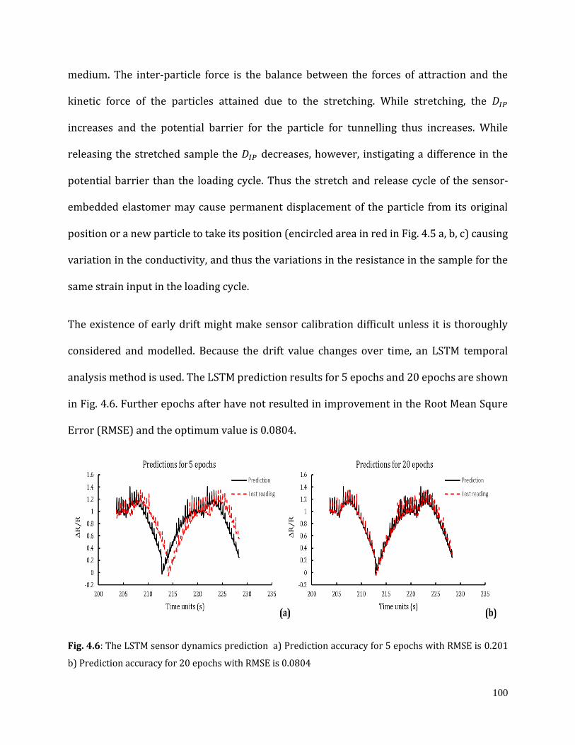
100
medium. The inter-particle force is the balance between the forces of attraction and the
kinetic force of the particles attained due to the stretching. While stretching, the 𝐷𝐼𝑃
increases and the potential barrier for the particle for tunnelling thus increases. While
releasing the stretched sample the 𝐷𝐼𝑃 decreases, however, instigating a difference in the
potential barrier than the loading cycle. Thus the stretch and release cycle of the sensor-
embedded elastomer may cause permanent displacement of the particle from its original
position or a new particle to take its position (encircled area in red in Fig. 4.5 a, b, c) causing
variation in the conductivity, and thus the variations in the resistance in the sample for the
same strain input in the loading cycle.
The existence of early drift might make sensor calibration difficult unless it is thoroughly
considered and modelled. Because the drift value changes over time, an LSTM temporal
analysis method is used. The LSTM prediction results for 5 epochs and 20 epochs are shown
in Fig. 4.6. Further epochs after have not resulted in improvement in the Root Mean Squre
Error (RMSE) and the optimum value is 0.0804.
Fig. 4.6: The LSTM sensor dynamics prediction a) Prediction accuracy for 5 epochs with RMSE is 0.201
b) Prediction accuracy for 20 epochs with RMSE is 0.0804
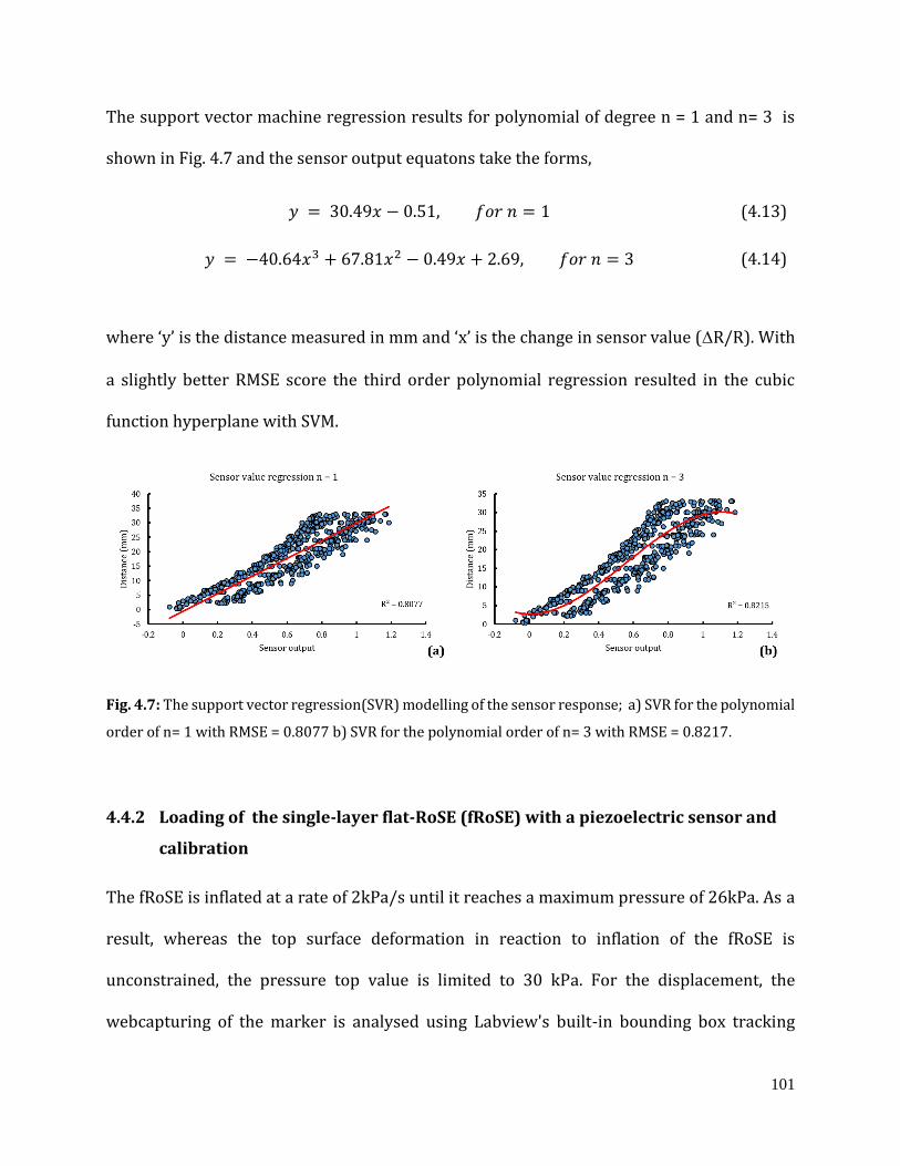
101
The support vector machine regression results for polynomial of degree n = 1 and n= 3 is
shown in Fig. 4.7 and the sensor output equatons take the forms,
𝑦 = 30.49𝑥 − 0.51, 𝑓𝑜𝑟 𝑛 = 1 (4.13)
𝑦 = −40.64𝑥3 + 67.81𝑥2 − 0.49𝑥 + 2.69, 𝑓𝑜𝑟 𝑛 = 3 (4.14)
where ‘y’ is the distance measured in mm and ‘x’ is the change in sensor value (R/R). With
a slightly better RMSE score the third order polynomial regression resulted in the cubic
function hyperplane with SVM.
Fig. 4.7: The support vector regression(SVR) modelling of the sensor response; a) SVR for the polynomial
order of n= 1 with RMSE = 0.8077 b) SVR for the polynomial order of n= 3 with RMSE = 0.8217.
4.4.2 Loading of the single-layer flat-RoSE (fRoSE) with a piezoelectric sensor and
calibration
The fRoSE is inflated at a rate of 2kPa/s until it reaches a maximum pressure of 26kPa. As a
result, whereas the top surface deformation in reaction to inflation of the fRoSE is
unconstrained, the pressure top value is limited to 30 kPa. For the displacement, the
webcapturing of the marker is analysed using Labview's built-in bounding box tracking
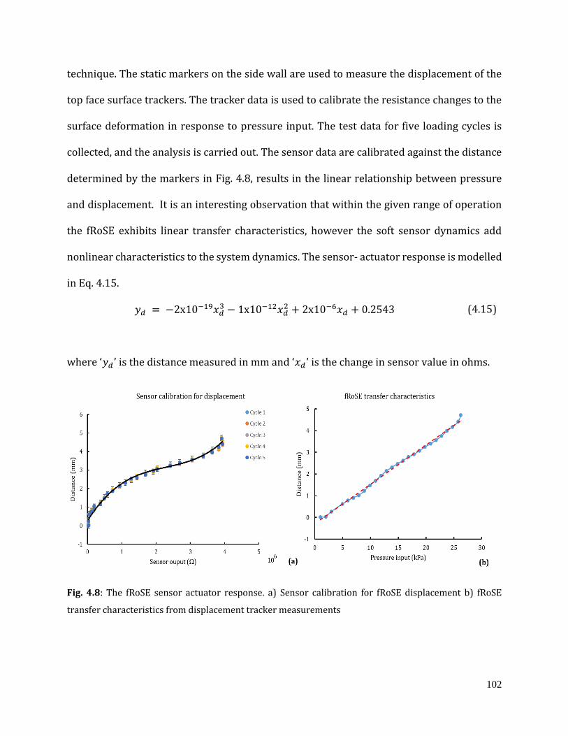
102
technique. The static markers on the side wall are used to measure the displacement of the
top face surface trackers. The tracker data is used to calibrate the resistance changes to the
surface deformation in response to pressure input. The test data for five loading cycles is
collected, and the analysis is carried out. The sensor data are calibrated against the distance
determined by the markers in Fig. 4.8, results in the linear relationship between pressure
and displacement. It is an interesting observation that within the given range of operation
the fRoSE exhibits linear transfer characteristics, however the soft sensor dynamics add
nonlinear characteristics to the system dynamics. The sensor- actuator response is modelled
in Eq. 4.15.
𝑦𝑑 = −2x10⁻¹⁹𝑥𝑑3 − 1x10⁻¹²𝑥𝑑
2 + 2x10⁻⁶𝑥𝑑 + 0.2543 (4.15)
where ‘𝑦𝑑 ’ is the distance measured in mm and ‘𝑥𝑑 ’ is the change in sensor value in ohms.
Fig. 4.8: The fRoSE sensor actuator response. a) Sensor calibration for fRoSE displacement b) fRoSE
transfer characteristics from displacement tracker measurements
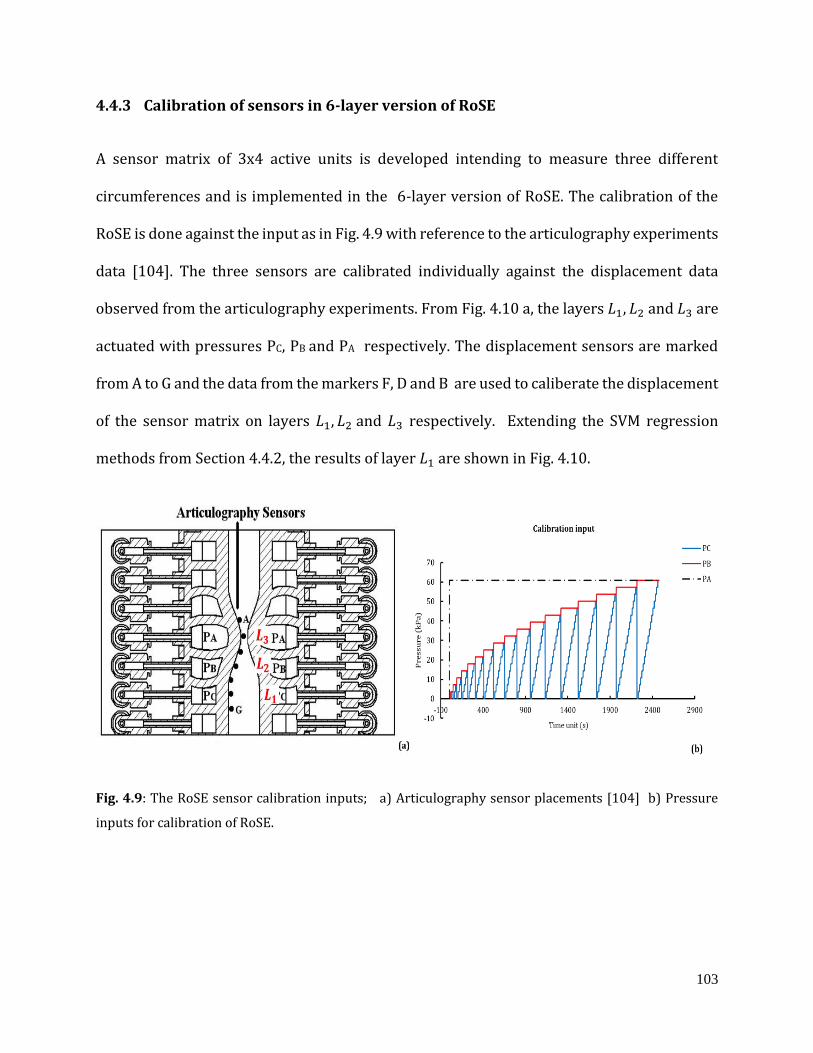
103
4.4.3 Calibration of sensors in 6-layer version of RoSE
A sensor matrix of 3x4 active units is developed intending to measure three different
circumferences and is implemented in the 6-layer version of RoSE. The calibration of the
RoSE is done against the input as in Fig. 4.9 with reference to the articulography experiments
data [104]. The three sensors are calibrated individually against the displacement data
observed from the articulography experiments. From Fig. 4.10 a, the layers 𝐿1, 𝐿2 and 𝐿3 are
actuated with pressures PC, PB and PA respectively. The displacement sensors are marked
from A to G and the data from the markers F, D and B are used to caliberate the displacement
of the sensor matrix on layers 𝐿1, 𝐿2 and 𝐿3 respectively. Extending the SVM regression
methods from Section 4.4.2, the results of layer 𝐿1 are shown in Fig. 4.10.
Fig. 4.9: The RoSE sensor calibration inputs; a) Articulography sensor placements [104] b) Pressure
inputs for calibration of RoSE.
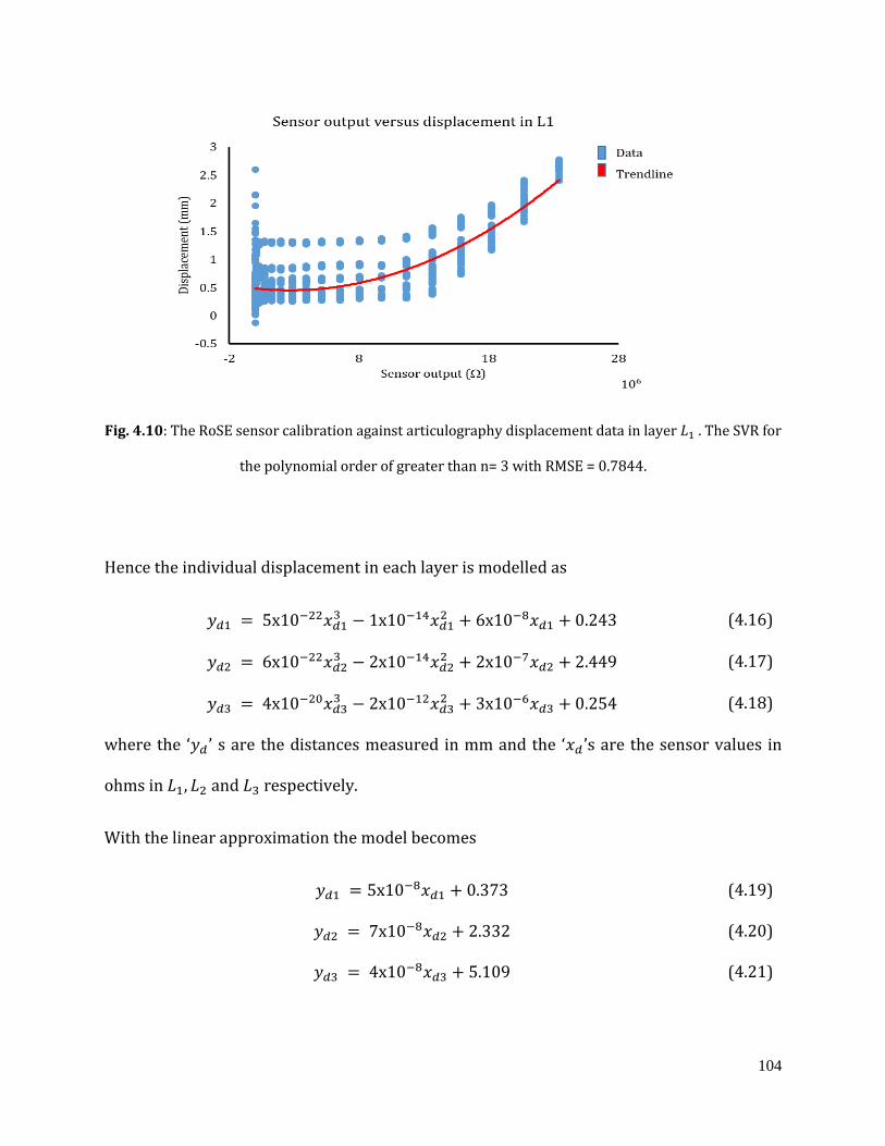
104
Fig. 4.10: The RoSE sensor calibration against articulography displacement data in layer 𝐿1 . The SVR for
the polynomial order of greater than n= 3 with RMSE = 0.7844.
Hence the individual displacement in each layer is modelled as
𝑦𝑑1 = 5x10⁻²²𝑥𝑑13 − 1x10⁻¹⁴𝑥𝑑1
2 + 6x10⁻⁸𝑥𝑑1 + 0.243 (4.16)
𝑦𝑑2 = 6x10⁻²²𝑥𝑑23 − 2x10⁻¹⁴𝑥𝑑2
2 + 2x10⁻⁷𝑥𝑑2 + 2.449 (4.17)
𝑦𝑑3 = 4x10⁻²⁰𝑥𝑑33 − 2x10⁻¹²𝑥𝑑3
2 + 3x10⁻⁶𝑥𝑑3 + 0.254 (4.18)
where the ‘𝑦𝑑 ’ s are the distances measured in mm and the ‘𝑥𝑑 ’s are the sensor values in
ohms in 𝐿1, 𝐿2 and 𝐿3 respectively.
With the linear approximation the model becomes
𝑦𝑑1 = 5x10⁻⁸𝑥𝑑1 + 0.373 (4.19)
𝑦𝑑2 = 7x10⁻⁸𝑥𝑑2 + 2.332 (4.20)
𝑦𝑑3 = 4x10⁻⁸𝑥𝑑3 + 5.109 (4.21)
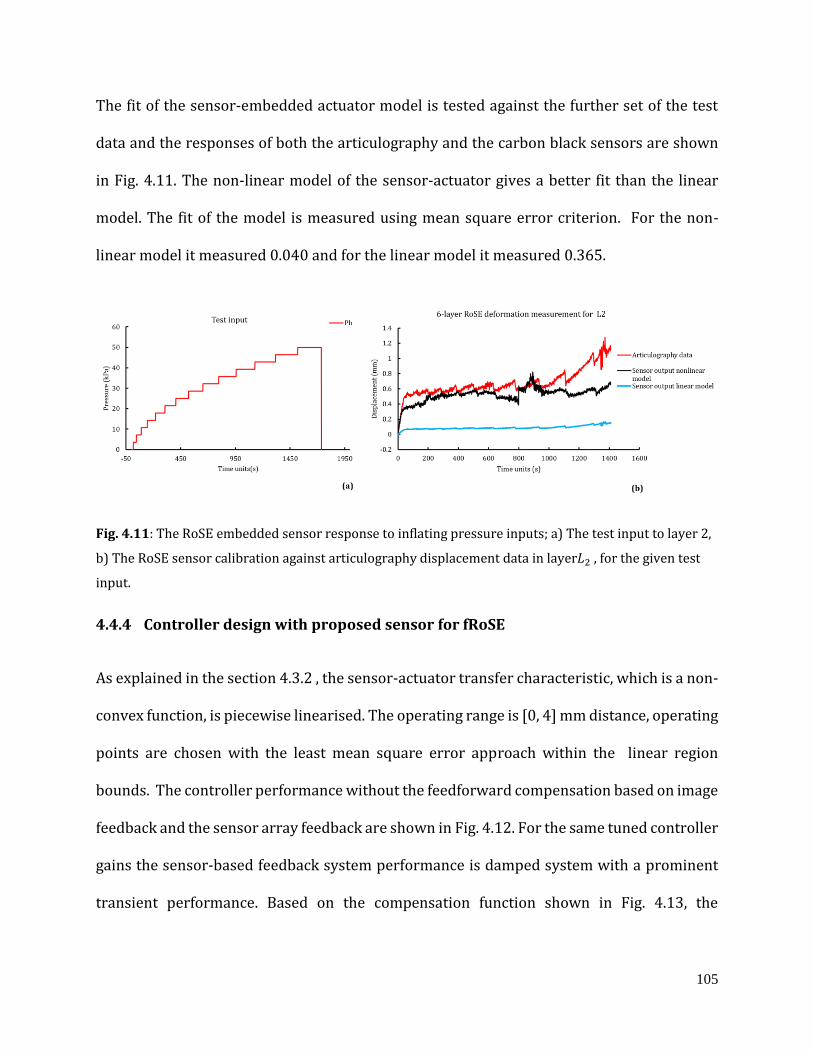
105
The fit of the sensor-embedded actuator model is tested against the further set of the test
data and the responses of both the articulography and the carbon black sensors are shown
in Fig. 4.11. The non-linear model of the sensor-actuator gives a better fit than the linear
model. The fit of the model is measured using mean square error criterion. For the non-
linear model it measured 0.040 and for the linear model it measured 0.365.
Fig. 4.11: The RoSE embedded sensor response to inflating pressure inputs; a) The test input to layer 2,
b) The RoSE sensor calibration against articulography displacement data in layer𝐿2 , for the given test
input.
4.4.4 Controller design with proposed sensor for fRoSE
As explained in the section 4.3.2 , the sensor-actuator transfer characteristic, which is a non-
convex function, is piecewise linearised. The operating range is [0, 4] mm distance, operating
points are chosen with the least mean square error approach within the linear region
bounds. The controller performance without the feedforward compensation based on image
feedback and the sensor array feedback are shown in Fig. 4.12. For the same tuned controller
gains the sensor-based feedback system performance is damped system with a prominent
transient performance. Based on the compensation function shown in Fig. 4.13, the
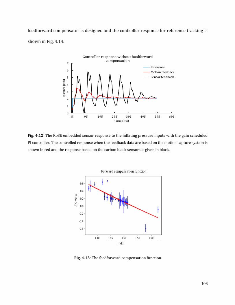
106
feedforward compensator is designed and the controller response for reference tracking is
shown in Fig. 4.14.
Fig. 4.12: The RoSE embedded sensor response to the inflating pressure inputs with the gain scheduled
PI controller. The controlled response when the feedback data are based on the motion capture system is
shown in red and the response based on the carbon black sensors is given in black.
Fig. 4.13: The feedforward compensation function
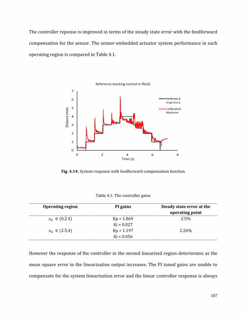
107
The controller reponse is improved in terms of the steady state error with the feedforward
compensation for the sensor. The sensor-embedded actuator system performance in each
operating region is compared in Table 4.1.
Fig. 4.14: System response with feedforward compensation function
Table 4.1: The controller gains
Operating region PI gains Steady state error at the
operating point
𝑥𝑘 ∈ (0,2.4) Kp = 1.869
Ki = 0.027
2.5%
𝑥𝑘 ∈ (2.5,4) Kp = 1.197
Ki = 0.056
2.26%
However the response of the controller in the second linearised region deteriorates as the
mean square error in the linearization output increases. The PI tuned gains are unable to
compensate for the system linearization error and the linear controller response is always
108
prone to such non-linearities. Also the unloading response of the fRoSE system is heavily
affected by the hysteresis in the deformation trajectory followed by the sensor and actuator.
However, for the application of the RoSE the loading dynamics are more important . More
robust controller tuning algorithms should be tested to improve the controller performance.
4.5 Chapter summary
This chapter examined the application of machine learning methods to characterise the non-
linear features, particularly the temporal non-linearities, of the carbon black embedded
elastomer sensor. The sensor drift may be predicted using LSTM networks, and the
knowledge might be used to describe sensor non-linearities while developing dynamics and
navigation controllers. On successive RoSE versions, the installation of sensors and
calibration of sensor-embedded actuator responses were covered in greater detail. The data
analysis and calibration approach was explained. The transfer characteristics of the sensor-
actuator system was derived using data acquired from the fRoSE sensors. The sensor matrix
implementation in a 6-layer RoSE, as well as calibration in the absence of other physical
sensors, were explored. The design and implementation of a piecewise linearization-based
controller technique for the fRoSE flat robot was also described. The results shows the
controller response met the design constraints. The methodology of the controller design
could be extended to the 6-layer or other versions of RoSE and is not explored in this work.
109
Chapter 5
Multi-physical modelling of RoSE using
the finite element method
The RoSE is a unique in-vitro device due to its rostro-caudal peristalsis wave ensuring
thorough conduit occlusion in propagating the bolus. Moreover the compliant nature of the
silicone surface will ensure the conduit anatomy is comparable to that of the oesophageal
lumen. Although explained as advantages, these are also disadvantages of the RoSE as the
existing sensing methodologies are non-compliant with it. A firsthand understanding of the
range of physical parameter fluctuations is useful when building physical sensors. The
process of evaluating any novel sensor for RoSE is hampered by the lack of suitable non-
compliant physical sensors. Different variables such as fluid velocity inside the RoSE, shear
stress and shear rate of the bolus flow, and others are clearly important, but there is
currently little information on them.
Computational models are available for studying the bolus transit characteristics of the
biological oesophagus, however similar studies are lacking in the soft robotic in-vitro models
[24,60]. Finite element analysis is used in developing kinematic models and material
characterisation of soft robots [188-190]. As a result, a simulation study is both necessary
and the ideal way to approach the problem of comprehending the physics involved with
RoSE technology.
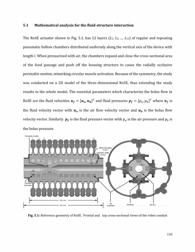
110
5.1 Mathematical analysis for the fluid-structure interaction
The RoSE actuator shown in Fig. 5.1, has 12 layers (L1, L2, ..., L12) of regular and repeating
pneumatic hollow chambers distributed uniformly along the vertical axis of the device with
length 𝑙. When pressurized with air, the chambers expand and close the cross-sectional area
of the food passage and push off the housing structure to cause the radially occlusive
peristaltic motion, mimicking circular muscle activation. Because of the symmetry, the study
was conducted on a 2D model of the three-dimensional RoSE, thus extending the study
results to the whole model. The essential parameters which characterize the bolus flow in
RoSE are the fluid velocities 𝒖𝒇 = [𝒖𝒂, 𝒖𝒃]𝑇 and fluid pressures 𝒑𝒇 = [𝑝𝑎, 𝑝𝑏]𝑇 where 𝒖𝒇 is
the fluid velocity vector with 𝒖𝒂 is the air flow velocity vector and 𝒖𝒃 is the bolus flow
velocity vector. Similarly 𝒑𝒇 is the fluid pressure vector with 𝑝𝑎 is the air pressure and 𝑝𝑏 is
the bolus pressure.
Fig. 5.1: Reference geometry of RoSE. Frontal and top cross-sectional views of the robot conduit

111
The flow velocities and pressures lead to associated stresses developed in the conduit wall,
when subjected to the sequenced air pressure trajectories. This results in the pulsatile bolus
movement which in turn causes radial deformations in the RoSE walls. Thus, in addition to
the flow parameters, structural deformations also need to be considered, thereby leading the
study to be a fluid-structure interaction problem.
5.1.1 Fluid dynamics
The fluid dynamics study, as already discussed, has following fluids in discussion: 1) the
controlled and sequenced airflow through the pressure chambers and 2) the non-Newtonian
bolus propagation through the robot main conduit.
The peristalsis wave propagating along the channel walls is mathematically represented by
ℎ(𝑥, 𝑡) = 𝜖 + 𝛼
2[1 − 𝑐𝑜𝑠 (2𝜋
𝑥 − 𝑐𝑡
𝜆)] (5.1)
where ℎ is transverse vibration of the wall, 𝑥 is the axial coordinate, 𝑡 is the time, 𝜖 is the
width of the channel, 𝛼 is the amplitude of the wave, 𝜆 is the wavelength and 𝑐 is the wave
velocity.
a. The pressure chamber actuation
The Navier- Stokes equation is applied. Eq. 5.2 expresses the conservation of mass:
𝛻. 𝒖𝒂 = 0 (5.2)
where 𝒖𝒂 = (𝑢𝑎, 𝑣𝑎)𝑇 is the airflow velocities in horizontal and vertical directions. Assuming
the air is incompressible, based on its speed is substantially less than the speed of sound in
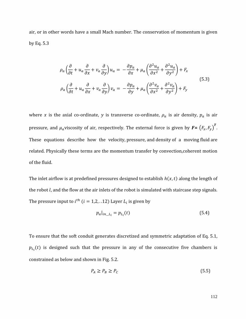
112
air, or in other words have a small Mach number. The conservation of momentum is given
by Eq. 5.3
𝜌𝑎 (𝜕
𝜕𝑡+ 𝑢𝑎
𝜕
𝜕𝑥+ 𝑣𝑎
𝜕
𝜕𝑦) 𝑢𝑎 = −
𝜕𝑝𝑎
𝜕𝑥+ 𝜇𝑎 (
𝜕2𝑢𝑎
𝜕𝑥2+
𝜕2𝑢𝑎
𝜕𝑦2) + 𝐹𝑥
(5.3)
𝜌𝑎 (𝜕
𝜕𝑡+ 𝑢𝑎
𝜕
𝜕𝑥+ 𝑣𝑎
𝜕
𝜕𝑦) 𝑣𝑎 = −
𝜕𝑝𝑎
𝜕𝑦+ 𝜇𝑎 (
𝜕2𝑣𝑎
𝜕𝑥2+
𝜕2𝑣𝑎
𝜕𝑦2) + 𝐹𝑦
where 𝑥 is the axial co-ordinate, 𝑦 is transverse co-ordinate, 𝜌𝑎 is air density, 𝑝𝑎 is air
pressure, and 𝜇𝑎viscosity of air, respectively. The external force is given by 𝑭= (𝐹𝑥 , 𝐹𝑦)𝑻
.
These equations describe how the velocity, pressure, and density of a moving fluid are
related. Physically these terms are the momentum transfer by convection,coherent motion
of the fluid.
The inlet airflow is at predefined pressures designed to establish ℎ(𝑥, 𝑡) along the length of
the robot 𝑙, and the flow at the air inlets of the robot is simulated with staircase step signals.
The pressure input to 𝑖𝑡ℎ (𝑖 = 1,2, . .12) Layer 𝐿𝑖 is given by
𝑝𝑎|𝑖𝑛__𝐿𝑖= 𝑝𝐿𝑖
(𝑡) (5.4)
To ensure that the soft conduit generates discretized and symmetric adaptation of Eq. 5.1,
𝑝𝐿𝑖(𝑡) is designed such that the pressure in any of the consecutive five chambers is
constrained as below and shown in Fig. 5.2.
𝑃𝐴 ≥ 𝑃𝐵 ≥ 𝑃𝐶 (5.5)
113
where 𝑃𝐴, 𝑃𝐵 and 𝑃𝐶 are the predefined pressure input values forming a discretized
peristalsis trajectory.
𝑃𝐿𝑖= 𝑃𝐴, 𝑃𝐿𝑖+1
= 𝑃𝐵, 𝑃𝐿𝑖+2= 𝑃𝐶 when 𝑡 = 𝑡𝑖 (5.6)
𝑃𝐿𝑖+1= 𝑃𝐴, 𝑃𝐿𝑖+2
= 𝑃𝐵, 𝑃𝐿𝑖+3= 𝑃𝐶 when 𝑡 = 𝑡𝑖+1 (5.7)
Fig. 5.2: Reference trajectory pressure actuation of RoSE
The inlet to the air chamber is the same as at the outlet. At the outlet of the conduit, the fluid
pressure is equal to the pressure outside the fluid.
b. The bolus flow model
For modeling the bolus flow the following assumptions are made, 1) the bolus flow is
incompressible 2) the flow is quasi-steady. The governing equations in 2D for
incompressible viscous fluids with variable viscosities are given in the condensed form by,
114
𝜌𝑏(𝒖𝒃 . ∇)𝒖𝒃 = ∇. [− 𝑝𝑏𝐼 + 𝑓𝑏(�̇�𝑏)] + 𝑭 (5.8)
𝜌𝑏(∇. 𝒖𝒃) = 0 (5.9)
Where 𝜌𝑏 is the bolus density, 𝒖𝒃 is the bolus velocity, 𝑝𝑏 is the bolus pressure, and 𝑓(�̇�𝑏) is
the variable viscosity. With co-ordinates 𝒙 = (𝑥, 𝑦)𝑇, and the velocity vector in x and y
directions is 𝒖𝒃 = (𝑢𝑏 , 𝑣𝑏)𝑇.
The bolus is a non-Newtonian fluid and the basic relationship between the viscosity and the
shear rate is approximated using the Power-law fluid model given by:
𝑓𝑏(�̇�𝑏) = 𝑘𝑏(�̇�𝑏)𝑛𝑏−1 (5.10)
where 𝑘𝑏 is the flow consistency coefficient, �̇�𝑏is the shear strain rate and 𝑛𝑏 is the flow
behaviour index with 0 < 𝑛𝑏 < 1 for the shear-thinning behaviour of the bolus.
The boundary conditions for bolus flow are as follows: the bolus cannot flow through the
wall and it sticks to the wall due to the viscosity. In otherwords at the wall, the bolus moves
with the motion of the wall. A no-slip boundary condition has been assumed over the soft
robot walls, as bolus velocity adjacent to the wall in large diameter conduits changes with
the same velocity as the wall. Thus at the wall,
𝑢𝒃|𝑦=ℎ = 0 𝑎𝑛𝑑 𝑢𝒃| 𝑦= −ℎ = 0 (5.11)
𝑣𝑏|𝑦=ℎ = 0 𝑎𝑛𝑑 𝑣𝑏|𝑦= −ℎ = 0 (5.12)
115
The bolus flow at the inlet of the robot is simulated as pulsatile inflow. The bolus volume
flow rate can be controlled by the area of the inflow cross-section and the bolus velocity at
the inlet. Therefore the inflow condition becomes,
𝒖𝒃(𝑥, 𝑦, 𝑡)|𝑖𝑛𝑙𝑒𝑡 = 𝒖𝑖𝑛(𝑡) (5.13)
At the outlet, the fluid is assumed to be unidirectional and the pressure to be equal to the
pressure outside the fluid. The RoSE tube is open to the atmosphere at both sides.
𝜕𝒖𝒃
𝜕𝒏𝒐|
𝑥=𝑙
= 0 (5.14)
𝑝𝑏|𝑥=𝑙 = 𝑝𝑜 (5.15)
where 𝒏𝒐 = (𝑛𝑥, 𝑛𝑦) is the outward pointing normal to the outflow boundary.
5.1.2 The robot physical properties
The 3D geometry for the RoSE was modelled using CAD software with the dimensions
presented in Table 5.1, sourced from previous studies[93].

116
Table 5.1: Attributes of RoSE used in simulation
Attributes Magnitude
1 Conduit length 210 mm
2 Actuating conduit length 185 mm
3 Conduit diameter at rest 20 mm
4 Conduit diameter range 0 – 20 mm
5 Applied pneumatic pressure 0-120 kPa
6 Number of axial levels (layers) 12
7 Chambers per layer 2 (in 2D)
5.2. Methodology
The simulation software COMSOL Multiphysics® 5.3 is used for the study. The domains such
as bolus, air and RoSE walls are explicitly defined as well as boundaries such as Inlet, Outlet,
and Loaded boundaries (interface between fluid domains and RoSE inner wall surface).
a. RoSE silicone-based solid domain hyper-elastic parameters
The robot body was made of silicone EcoflexTM 00-30. The uniaxial tensile tests were
conducted on dumbbell-shaped Ecoflex samples under ASTM D412 standards on a tensile
testing machine (Instron 6800, Instron, USA) at a rate of 500 ± 50 mm/min until the
specimen failed [173]. Fig. 5.3, shows the universal testing machine applying strain on the 3
mm thick elastomer sample.
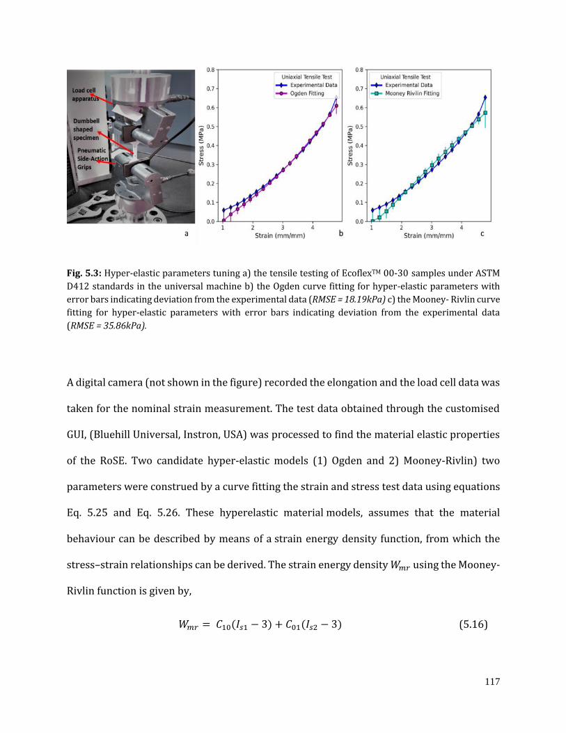
117
Fig. 5.3: Hyper-elastic parameters tuning a) the tensile testing of EcoflexTM 00-30 samples under ASTM
D412 standards in the universal machine b) the Ogden curve fitting for hyper-elastic parameters with
error bars indicating deviation from the experimental data (RMSE = 18.19kPa) c) the Mooney- Rivlin curve
fitting for hyper-elastic parameters with error bars indicating deviation from the experimental data
(RMSE = 35.86kPa).
A digital camera (not shown in the figure) recorded the elongation and the load cell data was
taken for the nominal strain measurement. The test data obtained through the customised
GUI, (Bluehill Universal, Instron, USA) was processed to find the material elastic properties
of the RoSE. Two candidate hyper-elastic models (1) Ogden and 2) Mooney-Rivlin) two
parameters were construed by a curve fitting the strain and stress test data using equations
Eq. 5.25 and Eq. 5.26. These hyperelastic material models, assumes that the material
behaviour can be described by means of a strain energy density function, from which the
stress–strain relationships can be derived. The strain energy density 𝑊𝑚𝑟 using the Mooney-
Rivlin function is given by,
𝑊𝑚𝑟 = 𝐶10(𝐼𝑠1 − 3) + 𝐶01(𝐼𝑠2 − 3) (5.16)

118
where 𝐶10 and 𝐶01 are the material constants. 𝐼𝑠1 and 𝐼𝑠2 are the strain invariants which are
the functions of the three principal stretches indicated by 𝑝1, 𝑝2,𝑝3 in the x, y and z
directions, respectively.
𝐼𝑠1 = 𝑝12 + 𝑝2
2 + 𝑝32 (5.17)
𝐼𝑠2 = (𝑝1𝑝2)2
+ (𝑝2, 𝑝3)2
+ (𝑝3𝑝1)2
(5.18)
𝐼𝑠3 = 𝑝12 𝑝2
2 𝑝32 (5.19)
Under the assumption of incompressibility and isotropic behaviour, the strain energy
density 𝑊𝑠 can be expressed in terms of principal stretches 𝑝and the stress 𝜎𝑝
𝜎𝑝1 − 𝜎𝑝3 = 𝑝1 (𝜕𝑊𝑠
𝜕𝑝1) − 𝑝3 (
𝜕𝑊𝑠
𝜕𝑝3) (5.20)
𝑝1 = 𝑝,𝑝2 = 𝑝3 = 𝑝
−12 (5.21)
𝐼𝑠1 = (𝑝2 +
2
𝑝) (5.22)
𝐼𝑠2 = (2 𝑝 +1
𝑝2) (5.23)
𝐼𝑠3 = 1 (5.24)
so the Mooney- Rivlin stress-strain function becomes
𝜎𝑝 = 2(1 − 𝑝−2) (𝑝𝐶10 + 𝐶01) (5.25)
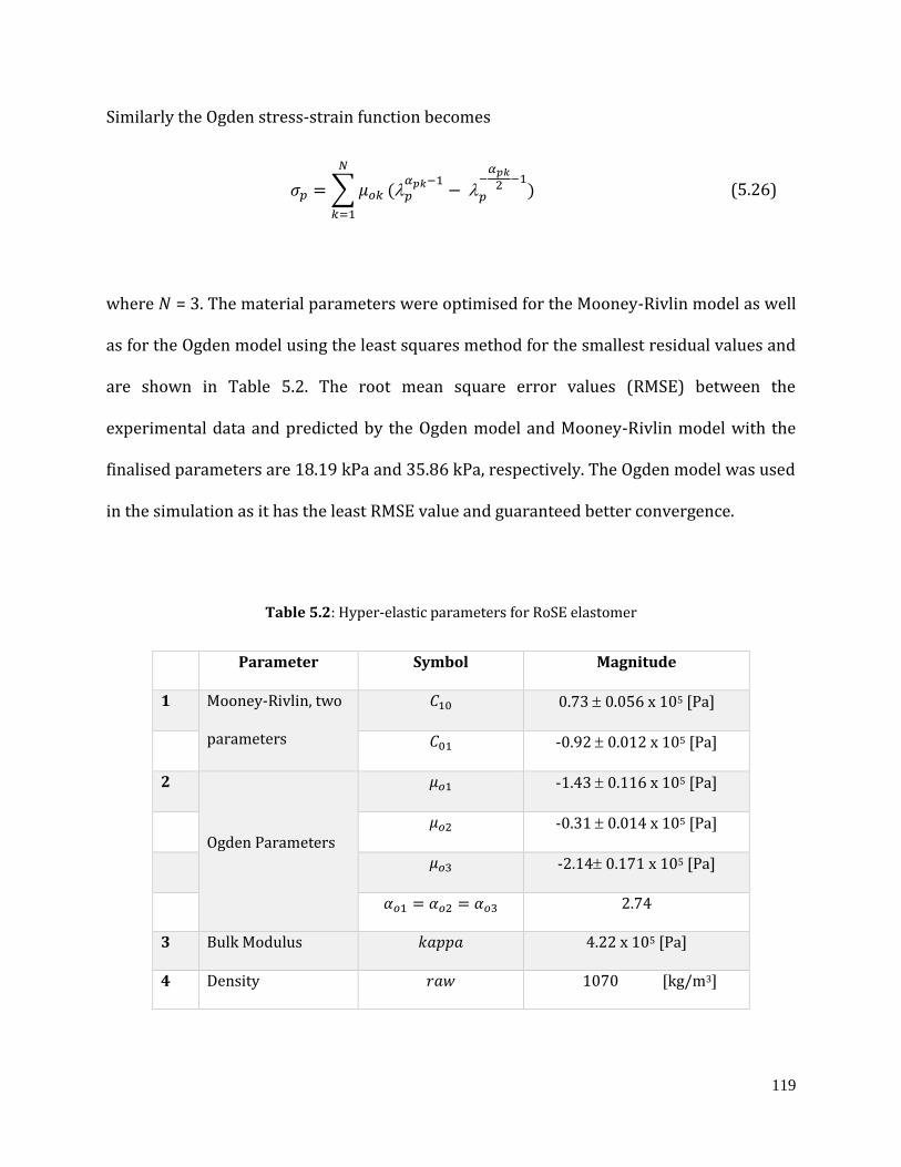
119
Similarly the Ogden stress-strain function becomes
𝜎𝑝 = ∑ 𝜇𝑜𝑘
𝑁
𝑘=1
(𝑝
𝛼𝑝𝑘−1− 𝑝
−𝛼𝑝𝑘
2−1
) (5.26)
where 𝑁 = 3. The material parameters were optimised for the Mooney-Rivlin model as well
as for the Ogden model using the least squares method for the smallest residual values and
are shown in Table 5.2. The root mean square error values (RMSE) between the
experimental data and predicted by the Ogden model and Mooney-Rivlin model with the
finalised parameters are 18.19 kPa and 35.86 kPa, respectively. The Ogden model was used
in the simulation as it has the least RMSE value and guaranteed better convergence.
Table 5.2: Hyper-elastic parameters for RoSE elastomer
Parameter Symbol Magnitude
1 Mooney-Rivlin, two
parameters
𝐶10 0.73 0.056 x 10⁵ [Pa]
𝐶01 -0.92 0.012 x 10⁵ [Pa]
2
Ogden Parameters
𝜇𝑜1 -1.43 0.116 x 10⁵ [Pa]
𝜇𝑜2 -0.31 0.014 x 10⁵ [Pa]
𝜇𝑜3 -2.14 0.171 x 10⁵ [Pa]
𝛼𝑜1 = 𝛼𝑜2 = 𝛼𝑜3 2.74
3 Bulk Modulus 𝑘𝑎𝑝𝑝𝑎 4.22 x 10⁵ [Pa]
4 Density 𝑟𝑎𝑤 1070 [kg/m3]
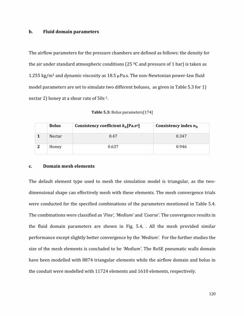
120
b. Fluid domain parameters
The airflow parameters for the pressure chambers are defined as follows: the density for
the air under standard atmospheric conditions (25 0C and pressure of 1 bar) is taken as
1.255 kg/m3 and dynamic viscosity as 18.5 Pa.s. The non-Newtonian power-law fluid
model parameters are set to simulate two different boluses, as given in Table 5.3 for 1)
nectar 2) honey at a shear rate of 50s-1.
Table 5.3: Bolus parameters[174]
Bolus Consistency coefficient 𝒌𝒃[Pa.sn] Consistency index 𝒏𝒃
1 Nectar 0.47 0.347
2 Honey 0.637 0.946
c. Domain mesh elements
The default element type used to mesh the simulation model is triangular, as the two-
dimensional shape can effectively mesh with these elements. The mesh convergence trials
were conducted for the specified combinations of the parameters mentioned in Table 5.4.
The combinations were classified as ‘Fine’, ‘Medium’ and ‘Coarse’. The convergence results in
the fluid domain parameters are shown in Fig. 5.4, . All the mesh provided similar
performance except slightly better convergence by the ‘Medium’. For the further studies the
size of the mesh elements is concluded to be ‘Medium’. The RoSE pneumatic walls domain
have been modelled with 8874 triangular elements while the airflow domain and bolus in
the conduit were modelled with 11724 elements and 1610 elements, respectively.
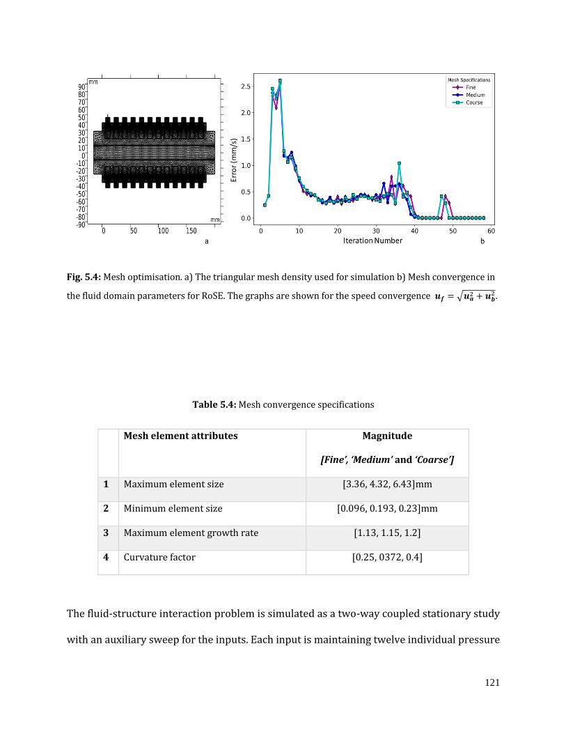
121
Fig. 5.4: Mesh optimisation. a) The triangular mesh density used for simulation b) Mesh convergence in
the fluid domain parameters for RoSE. The graphs are shown for the speed convergence 𝒖𝒇 = √𝒖𝒂2 + 𝒖𝒃
2 .
Table 5.4: Mesh convergence specifications
Mesh element attributes Magnitude
[Fine’, ‘Medium’ and ‘Coarse’]
1 Maximum element size [3.36, 4.32, 6.43]mm
2 Minimum element size [0.096, 0.193, 0.23]mm
3 Maximum element growth rate [1.13, 1.15, 1.2]
4 Curvature factor [0.25, 0372, 0.4]
The fluid-structure interaction problem is simulated as a two-way coupled stationary study
with an auxiliary sweep for the inputs. Each input is maintaining twelve individual pressure
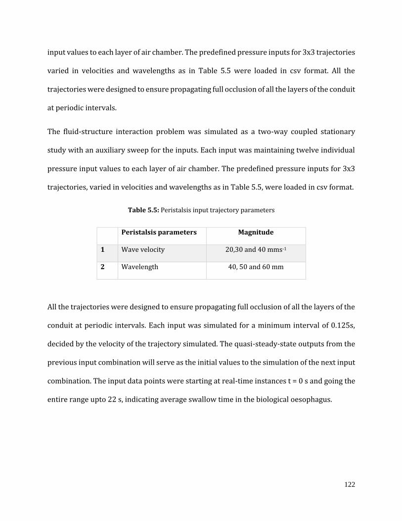
122
input values to each layer of air chamber. The predefined pressure inputs for 3x3 trajectories
varied in velocities and wavelengths as in Table 5.5 were loaded in csv format. All the
trajectories were designed to ensure propagating full occlusion of all the layers of the conduit
at periodic intervals.
The fluid-structure interaction problem was simulated as a two-way coupled stationary
study with an auxiliary sweep for the inputs. Each input was maintaining twelve individual
pressure input values to each layer of air chamber. The predefined pressure inputs for 3x3
trajectories, varied in velocities and wavelengths as in Table 5.5, were loaded in csv format.
Table 5.5: Peristalsis input trajectory parameters
Peristalsis parameters Magnitude
1 Wave velocity 20,30 and 40 mms-1
2 Wavelength 40, 50 and 60 mm
All the trajectories were designed to ensure propagating full occlusion of all the layers of the
conduit at periodic intervals. Each input was simulated for a minimum interval of 0.125s,
decided by the velocity of the trajectory simulated. The quasi-steady-state outputs from the
previous input combination will serve as the initial values to the simulation of the next input
combination. The input data points were starting at real-time instances t = 0 s and going the
entire range upto 22 s, indicating average swallow time in the biological oesophagus.
123
5.3. Results and discussion
In post-processing, various parameters such as distributions of velocity, pressure, wall shear
stress and dynamic viscosity were obtained in the form of surfaces, contours, and slices, etc.
These parameters were obtained at equal intervals of time for each input combination
accumulating in the propagation of the bolus from the input end to the output end. The
simulation results for the bolus parameters mentioned in Table 5.3 and the peristalsis wave
parameters in Table 5.5 are discussed below.
a. Bolus propagation velocity
The surface plots of bolus velocities for honey at different input states for the same trajectory
parameters are shown in Fig. 5.5. The peak minimum and maximum fluid velocity variation
for different boluses inside the RoSE conduit while varying the propagating wave
parameters were recorded. These measurements indicate the nominal average maxima and
minima of the bolus transport velocities in the biological food pipe. The minimum and
maximum velocities observed for different wavelengths with varying wave velocities are
shown in Table 5.6, and a comparison plot is given in Fig. 5.6.
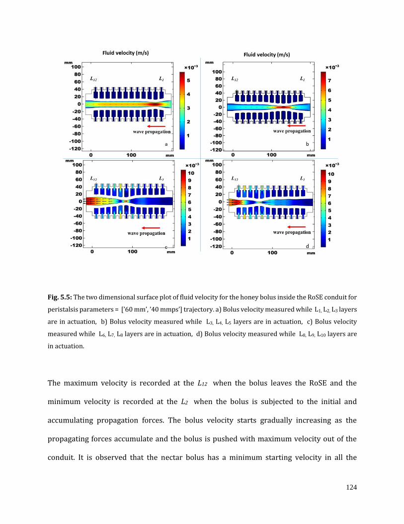
124
Fig. 5.5: The two dimensional surface plot of fluid velocity for the honey bolus inside the RoSE conduit for
peristalsis parameters = [’60 mm’, ’40 mmps’] trajectory. a) Bolus velocity measured while L1, L2, L3 layers
are in actuation, b) Bolus velocity measured while L3, L4, L5 layers are in actuation, c) Bolus velocity
measured while L6, L7, L8 layers are in actuation, d) Bolus velocity measured while L8, L9, L10 layers are
in actuation.
The maximum velocity is recorded at the L12 when the bolus leaves the RoSE and the
minimum velocity is recorded at the L2 when the bolus is subjected to the initial and
accumulating propagation forces. The bolus velocity starts gradually increasing as the
propagating forces accumulate and the bolus is pushed with maximum velocity out of the
conduit. It is observed that the nectar bolus has a minimum starting velocity in all the
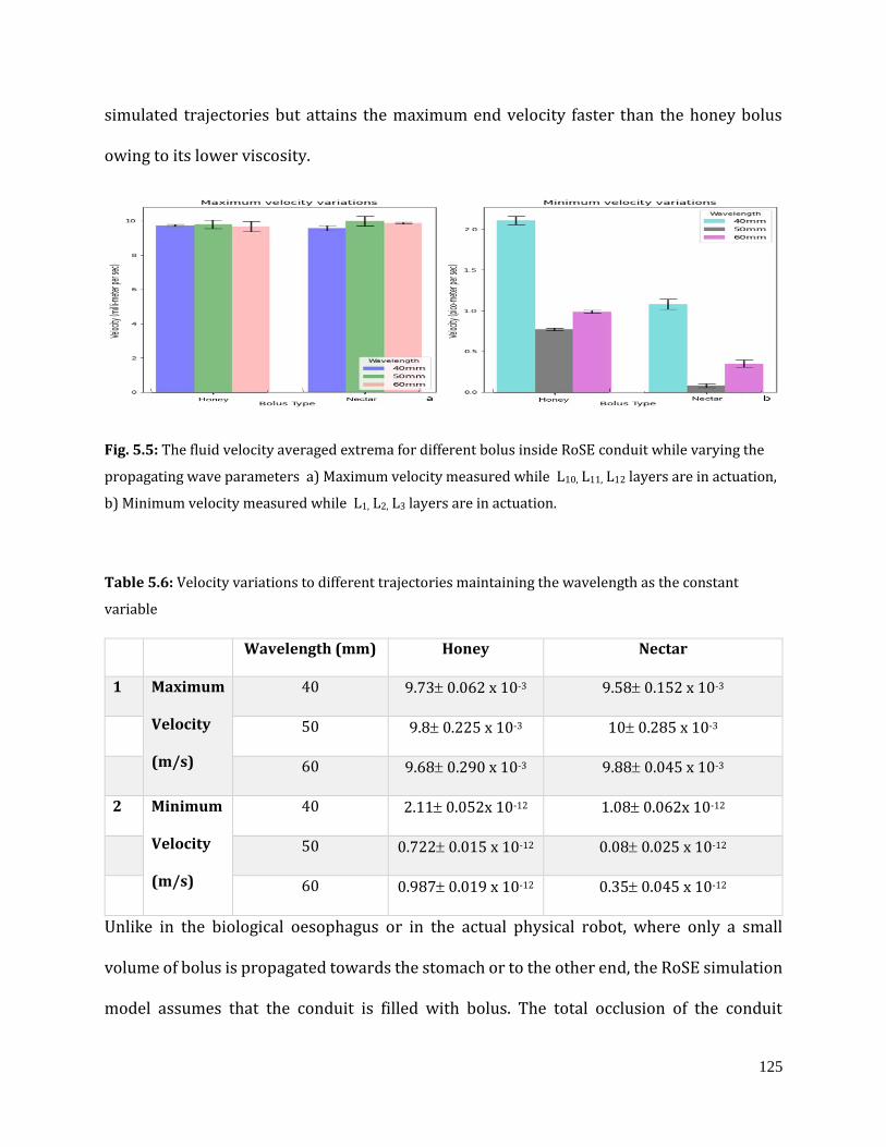
125
simulated trajectories but attains the maximum end velocity faster than the honey bolus
owing to its lower viscosity.
Fig. 5.5: The fluid velocity averaged extrema for different bolus inside RoSE conduit while varying the
propagating wave parameters a) Maximum velocity measured while L10, L11, L12 layers are in actuation,
b) Minimum velocity measured while L1, L2, L3 layers are in actuation.
Table 5.6: Velocity variations to different trajectories maintaining the wavelength as the constant
variable
Wavelength (mm) Honey Nectar
1 Maximum
Velocity
(m/s)
40 9.73 0.062 x 10⁻³ 9.58 0.152 x 10⁻³
50 9.8 0.225 x 10⁻³ 10 0.285 x 10⁻³
60 9.68 0.290 x 10⁻³ 9.88 0.045 x 10⁻³
2 Minimum
Velocity
(m/s)
40 2.11 0.052x 10⁻¹² 1.08 0.062x 10⁻¹²
50 0.722 0.015 x 10⁻¹² 0.08 0.025 x 10⁻¹²
60 0.987 0.019 x 10⁻¹² 0.35 0.045 x 10⁻¹²
Unlike in the biological oesophagus or in the actual physical robot, where only a small
volume of bolus is propagated towards the stomach or to the other end, the RoSE simulation
model assumes that the conduit is filled with bolus. The total occlusion of the conduit
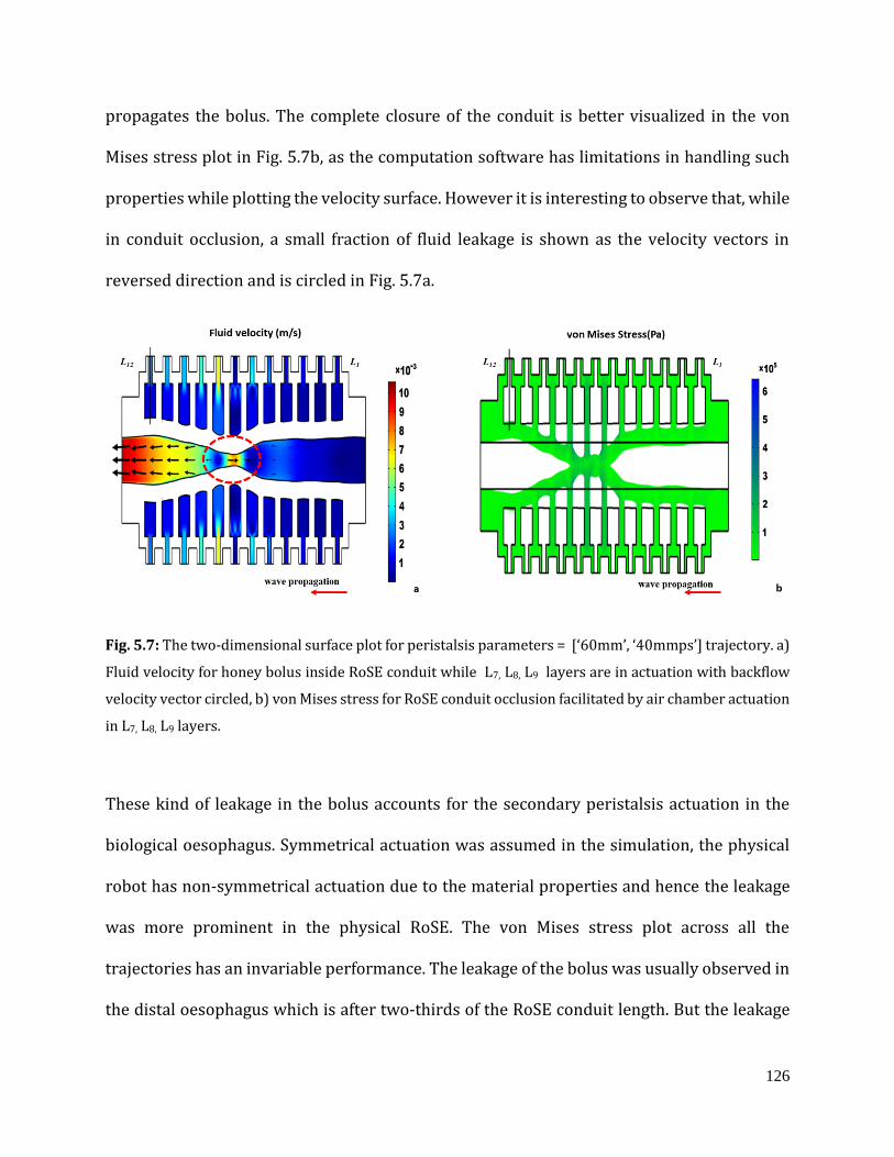
126
propagates the bolus. The complete closure of the conduit is better visualized in the von
Mises stress plot in Fig. 5.7b, as the computation software has limitations in handling such
properties while plotting the velocity surface. However it is interesting to observe that, while
in conduit occlusion, a small fraction of fluid leakage is shown as the velocity vectors in
reversed direction and is circled in Fig. 5.7a.
Fig. 5.7: The two-dimensional surface plot for peristalsis parameters = [‘60mm’, ‘40mmps’] trajectory. a)
Fluid velocity for honey bolus inside RoSE conduit while L7, L8, L9 layers are in actuation with backflow
velocity vector circled, b) von Mises stress for RoSE conduit occlusion facilitated by air chamber actuation
in L7, L8, L9 layers.
These kind of leakage in the bolus accounts for the secondary peristalsis actuation in the
biological oesophagus. Symmetrical actuation was assumed in the simulation, the physical
robot has non-symmetrical actuation due to the material properties and hence the leakage
was more prominent in the physical RoSE. The von Mises stress plot across all the
trajectories has an invariable performance. The leakage of the bolus was usually observed in
the distal oesophagus which is after two-thirds of the RoSE conduit length. But the leakage
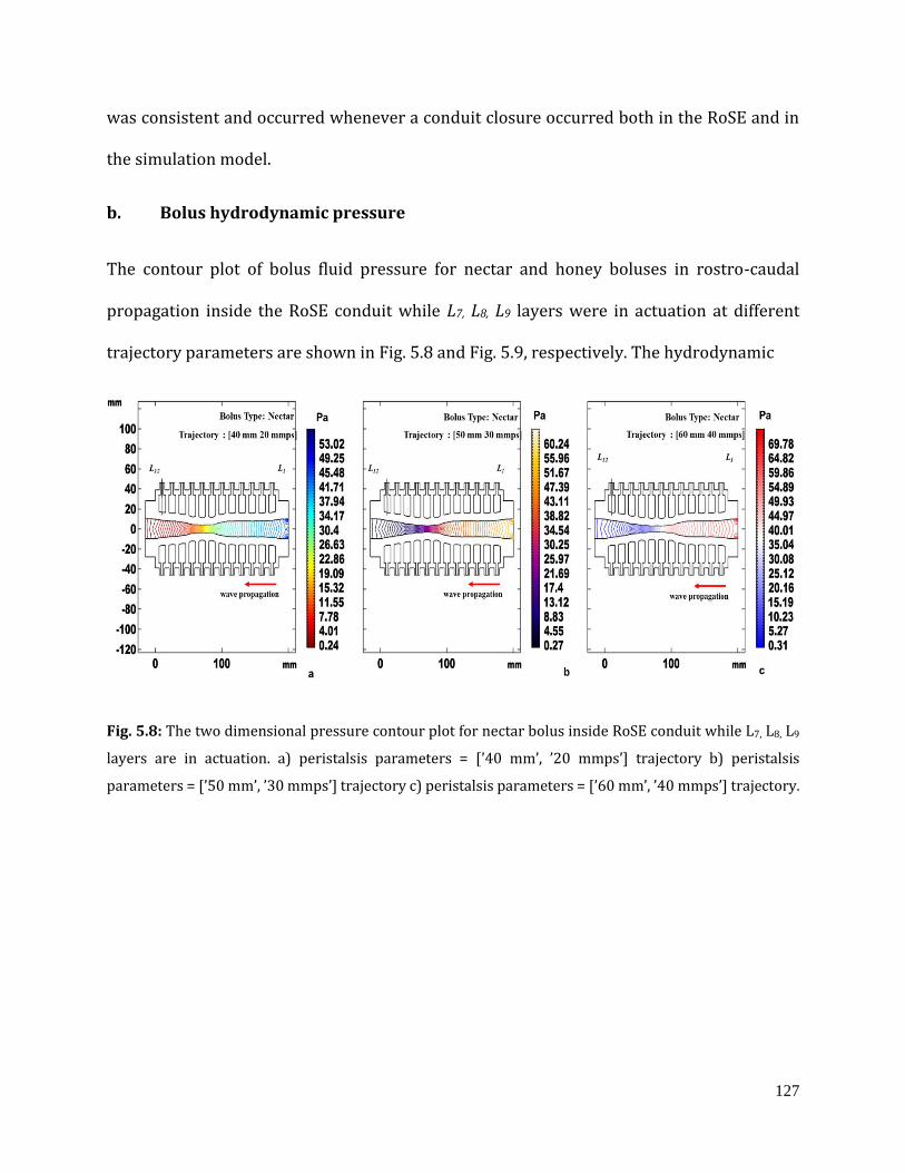
127
was consistent and occurred whenever a conduit closure occurred both in the RoSE and in
the simulation model.
b. Bolus hydrodynamic pressure
The contour plot of bolus fluid pressure for nectar and honey boluses in rostro-caudal
propagation inside the RoSE conduit while L7, L8, L9 layers were in actuation at different
trajectory parameters are shown in Fig. 5.8 and Fig. 5.9, respectively. The hydrodynamic
Fig. 5.8: The two dimensional pressure contour plot for nectar bolus inside RoSE conduit while L7, L8, L9
layers are in actuation. a) peristalsis parameters = [’40 mm’, ’20 mmps’] trajectory b) peristalsis
parameters = [’50 mm’, ’30 mmps’] trajectory c) peristalsis parameters = [’60 mm’, ’40 mmps’] trajectory.
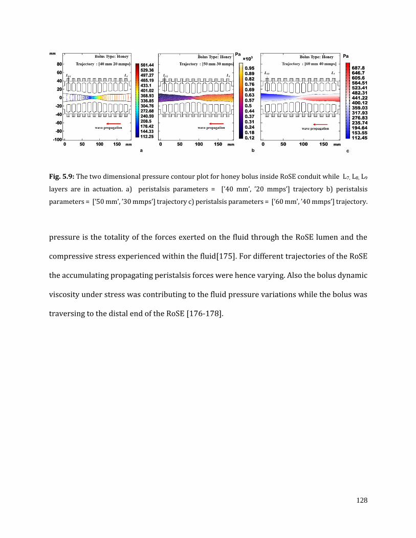
128
Fig. 5.9: The two dimensional pressure contour plot for honey bolus inside RoSE conduit while L7, L8, L9
layers are in actuation. a) peristalsis parameters = [’40 mm’, ’20 mmps’] trajectory b) peristalsis
parameters = [’50 mm’, ’30 mmps’] trajectory c) peristalsis parameters = [’60 mm’, ’40 mmps’] trajectory.
pressure is the totality of the forces exerted on the fluid through the RoSE lumen and the
compressive stress experienced within the fluid[175]. For different trajectories of the RoSE
the accumulating propagating peristalsis forces were hence varying. Also the bolus dynamic
viscosity under stress was contributing to the fluid pressure variations while the bolus was
traversing to the distal end of the RoSE [176-178].
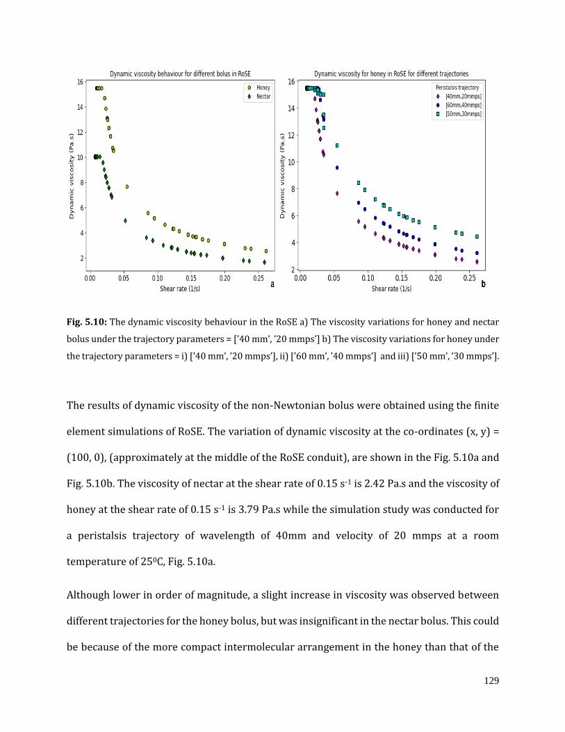
129
Fig. 5.10: The dynamic viscosity behaviour in the RoSE a) The viscosity variations for honey and nectar
bolus under the trajectory parameters = [’40 mm’, ’20 mmps’] b) The viscosity variations for honey under
the trajectory parameters = i) [’40 mm’, ’20 mmps’], ii) [’60 mm’, ’40 mmps’] and iii) [’50 mm’, ’30 mmps’].
The results of dynamic viscosity of the non-Newtonian bolus were obtained using the finite
element simulations of RoSE. The variation of dynamic viscosity at the co-ordinates (x, y) =
(100, 0), (approximately at the middle of the RoSE conduit), are shown in the Fig. 5.10a and
Fig. 5.10b. The viscosity of nectar at the shear rate of 0.15 s-1 is 2.42 Pa.s and the viscosity of
honey at the shear rate of 0.15 s-1 is 3.79 Pa.s while the simulation study was conducted for
a peristalsis trajectory of wavelength of 40mm and velocity of 20 mmps at a room
temperature of 250C, Fig. 5.10a.
Although lower in order of magnitude, a slight increase in viscosity was observed between
different trajectories for the honey bolus, but was insignificant in the nectar bolus. This could
be because of the more compact intermolecular arrangement in the honey than that of the
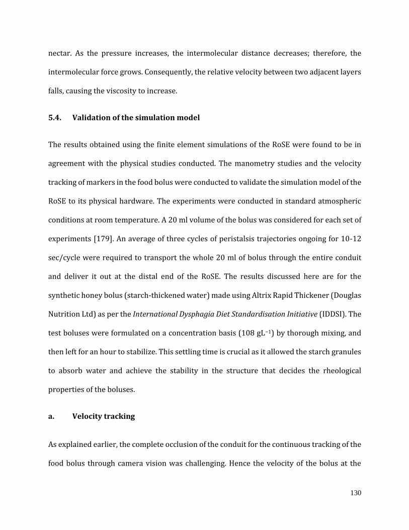
130
nectar. As the pressure increases, the intermolecular distance decreases; therefore, the
intermolecular force grows. Consequently, the relative velocity between two adjacent layers
falls, causing the viscosity to increase.
5.4. Validation of the simulation model
The results obtained using the finite element simulations of the RoSE were found to be in
agreement with the physical studies conducted. The manometry studies and the velocity
tracking of markers in the food bolus were conducted to validate the simulation model of the
RoSE to its physical hardware. The experiments were conducted in standard atmospheric
conditions at room temperature. A 20 ml volume of the bolus was considered for each set of
experiments [179]. An average of three cycles of peristalsis trajectories ongoing for 10-12
sec/cycle were required to transport the whole 20 ml of bolus through the entire conduit
and deliver it out at the distal end of the RoSE. The results discussed here are for the
synthetic honey bolus (starch-thickened water) made using Altrix Rapid Thickener (Douglas
Nutrition Ltd) as per the International Dysphagia Diet Standardisation Initiative (IDDSI). The
test boluses were formulated on a concentration basis (108 gL−1) by thorough mixing, and
then left for an hour to stabilize. This settling time is crucial as it allowed the starch granules
to absorb water and achieve the stability in the structure that decides the rheological
properties of the boluses.
a. Velocity tracking
As explained earlier, the complete occlusion of the conduit for the continuous tracking of the
food bolus through camera vision was challenging. Hence the velocity of the bolus at the
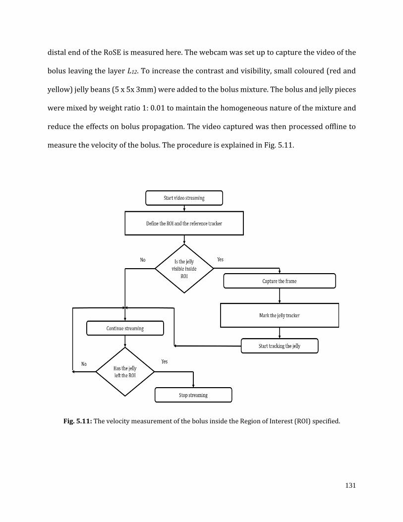
131
distal end of the RoSE is measured here. The webcam was set up to capture the video of the
bolus leaving the layer L12. To increase the contrast and visibility, small coloured (red and
yellow) jelly beans (5 x 5x 3mm) were added to the bolus mixture. The bolus and jelly pieces
were mixed by weight ratio 1: 0.01 to maintain the homogeneous nature of the mixture and
reduce the effects on bolus propagation. The video captured was then processed offline to
measure the velocity of the bolus. The procedure is explained in Fig. 5.11.
Fig. 5.11: The velocity measurement of the bolus inside the Region of Interest (ROI) specified.
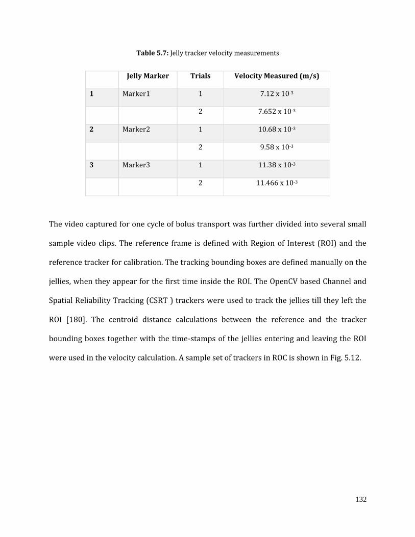
132
Table 5.7: Jelly tracker velocity measurements
Jelly Marker Trials Velocity Measured (m/s)
1 Marker1 1 7.12 x 10⁻³
2 7.652 x 10⁻³
2 Marker2 1 10.68 x 10⁻³
2 9.58 x 10⁻³
3 Marker3 1 11.38 x 10⁻³
2 11.466 x 10⁻³
The video captured for one cycle of bolus transport was further divided into several small
sample video clips. The reference frame is defined with Region of Interest (ROI) and the
reference tracker for calibration. The tracking bounding boxes are defined manually on the
jellies, when they appear for the first time inside the ROI. The OpenCV based Channel and
Spatial Reliability Tracking (CSRT ) trackers were used to track the jellies till they left the
ROI [180]. The centroid distance calculations between the reference and the tracker
bounding boxes together with the time-stamps of the jellies entering and leaving the ROI
were used in the velocity calculation. A sample set of trackers in ROC is shown in Fig. 5.12.
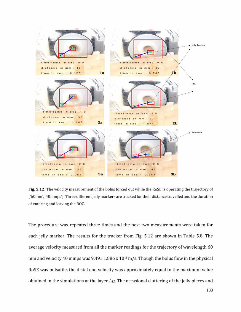
133
Fig. 5.12: The velocity measurement of the bolus forced out while the RoSE is operating the trajectory of
[‘60mm’, ‘40mmps’]. Three different jelly markers are tracked for their distance travelled and the duration
of entering and leaving the ROC.
The procedure was repeated three times and the best two measurements were taken for
each jelly marker. The results for the tracker from Fig. 5.12 are shown in Table 5.8. The
average velocity measured from all the marker readings for the trajectory of wavelength 60
mm and velocity 40 mmps was 9.49 1.886 x 10⁻³ m/s. Though the bolus flow in the physical
RoSE was pulsatile, the distal end velocity was approximately equal to the maximum value
obtained in the simulations at the layer L12. The occasional cluttering of the jelly pieces and
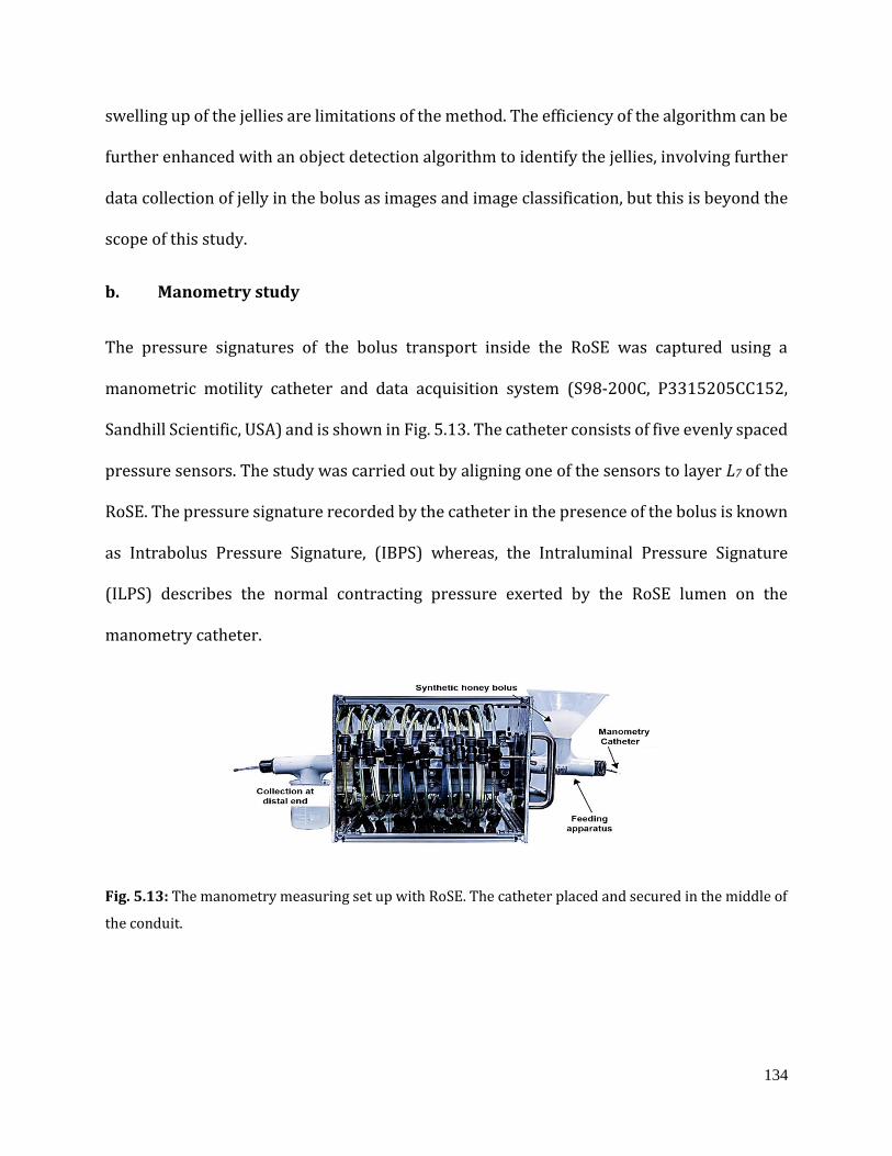
134
swelling up of the jellies are limitations of the method. The efficiency of the algorithm can be
further enhanced with an object detection algorithm to identify the jellies, involving further
data collection of jelly in the bolus as images and image classification, but this is beyond the
scope of this study.
b. Manometry study
The pressure signatures of the bolus transport inside the RoSE was captured using a
manometric motility catheter and data acquisition system (S98-200C, P3315205CC152,
Sandhill Scientific, USA) and is shown in Fig. 5.13. The catheter consists of five evenly spaced
pressure sensors. The study was carried out by aligning one of the sensors to layer L7 of the
RoSE. The pressure signature recorded by the catheter in the presence of the bolus is known
as Intrabolus Pressure Signature, (IBPS) whereas, the Intraluminal Pressure Signature
(ILPS) describes the normal contracting pressure exerted by the RoSE lumen on the
manometry catheter.
Fig. 5.13: The manometry measuring set up with RoSE. The catheter placed and secured in the middle of
the conduit.
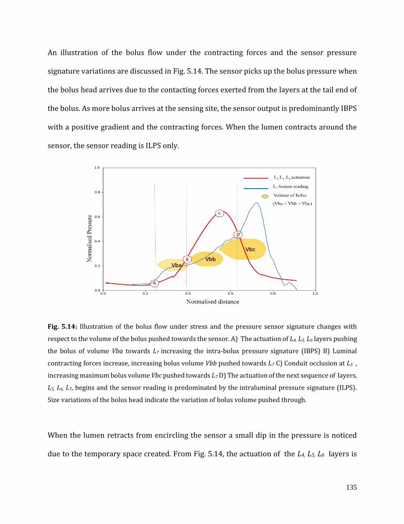
135
An illustration of the bolus flow under the contracting forces and the sensor pressure
signature variations are discussed in Fig. 5.14. The sensor picks up the bolus pressure when
the bolus head arrives due to the contacting forces exerted from the layers at the tail end of
the bolus. As more bolus arrives at the sensing site, the sensor output is predominantly IBPS
with a positive gradient and the contracting forces. When the lumen contracts around the
sensor, the sensor reading is ILPS only.
Fig. 5.14: Illustration of the bolus flow under stress and the pressure sensor signature changes with
respect to the volume of the bolus pushed towards the sensor. A) The actuation of L4, L5, L6 layers pushing
the bolus of volume Vba towards L7 increasing the intra-bolus pressure signature (IBPS) B) Luminal
contracting forces increase, increasing bolus volume Vbb pushed towards L7 C) Conduit occlusion at L5 ,
increasing maximum bolus volume Vbc pushed towards L7 D) The actuation of the next sequence of layers,
L5, L6, L7, begins and the sensor reading is predominated by the intraluminal pressure signature (ILPS).
Size variations of the bolus head indicate the variation of bolus volume pushed through.
When the lumen retracts from encircling the sensor a small dip in the pressure is noticed
due to the temporary space created. From Fig. 5.14, the actuation of the L4, L5, L6 layers is
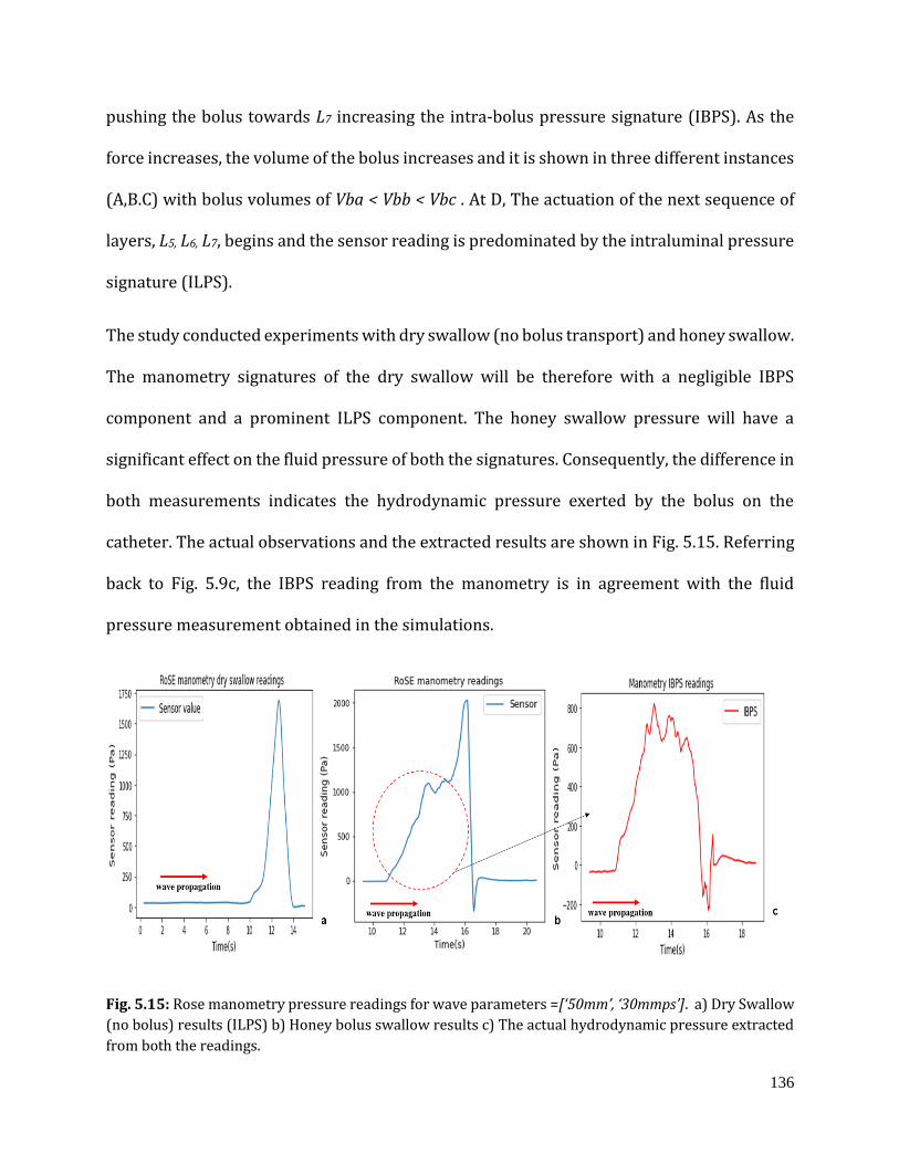
136
pushing the bolus towards L7 increasing the intra-bolus pressure signature (IBPS). As the
force increases, the volume of the bolus increases and it is shown in three different instances
(A,B.C) with bolus volumes of Vba < Vbb < Vbc . At D, The actuation of the next sequence of
layers, L5, L6, L7, begins and the sensor reading is predominated by the intraluminal pressure
signature (ILPS).
The study conducted experiments with dry swallow (no bolus transport) and honey swallow.
The manometry signatures of the dry swallow will be therefore with a negligible IBPS
component and a prominent ILPS component. The honey swallow pressure will have a
significant effect on the fluid pressure of both the signatures. Consequently, the difference in
both measurements indicates the hydrodynamic pressure exerted by the bolus on the
catheter. The actual observations and the extracted results are shown in Fig. 5.15. Referring
back to Fig. 5.9c, the IBPS reading from the manometry is in agreement with the fluid
pressure measurement obtained in the simulations.
Fig. 5.15: Rose manometry pressure readings for wave parameters =[‘50mm’, ‘30mmps’]. a) Dry Swallow
(no bolus) results (ILPS) b) Honey bolus swallow results c) The actual hydrodynamic pressure extracted
from both the readings.
137
5.5 Chapter summary
The multi-physics finite element-based mathematical model was developed for the RoSE and
the analysis was conducted. The RoSE studies were conducted for a broad spectrum of
normal swallowing trajectories observed in the deglutition studies. The sequential actuation
of the RoSE chambers was classified as time programmed inputs and the model was
simulated to a quasi-steady state for each input. The RoSE simulation is a fluid structure
interaction problem, and therefore the results for fluid pressure variations, fluid velocity
variations and the stress variations for different (3x3) trajectories and the two bolus were
recorded. The range of variations observed assist as the basis for the resolution and range of
the physical soft stretchable sensors in development of the RoSE hardware. The simulation
model was developed and the results were validated through the available sensing
methodologies like image processing and manometry reading.
138
Chapter 6
RoSE in-vitro simulation studies
6.1 The reach of the study
The in-vitro studies discussed here are the stent migration and the pill transit study. The
multi-physics based simulation studies of RoSE has given insights about the bolus parameter
variations due to the elastomer structure interactions with both air and bolus flow. In the
absence of relevant inbuit sensors for shear and pressure variations, these FEM studies
remains as the tools for explaining the findings in further in-vitro studies in RoSE. Although
a single sensor embedded actuator module is developed and controlled, the extending the
same to a full version of RoSE require further calibration with dry and variable viscosity
bolus swallow experiments to generate data sets for LSTM models. Before developing closed
loop controlled RoSE , and improvements in the controller hardware is required. Thus the
scope of these in-vitro studies is limited to use the open loop controlled RoSE peristalsis
trajectories. These investigations, contrasting their biological equivalents, considered RoSE
trajectories that were fixed in wavelength and velocity. The peristaltic velocity averages
around 30 mmps in the upper oesophagus, then rises to around 50 mmps in the mid-
oesophagus, before slowing to around 25 mmps distally. As a result, the RoSE swallow
studies are the indication of swallow behaviour in distinct portions of the oesophagus, such
as the proximal, mid, and distal sections.

139
Endoprosthetic stent placement, also known as oesophageal stenting, can be utilised to treat
dysphagia caused by malignant and benign oesophageal strictures from oesophageal cancer
[21, 44-46]. Stents have been shown to be an effective endoprosthetic therapy for both
malignant and benign oesophageal strictures, since they can retain the oesophagus open and
so alleviate the obstacles caused by compromised lumen patency. Furthermore, due to its
flexibility, the insertion method for a Self-Expandable Metallic Stent (SEMS) is less stressful,
and it may be compacted into a smaller delivery system. However, this technique of palliative
treatment has flaws, and one of the most serious is stent migration, which is induced by the
interactions of an implanted stent with the oesophagus wall's continual peristaltic
contractile forces. Stent deployment has a long-term success rate of roughly 30 to 50%, with
migration being the most common related problem in most failure cases [47, 48]
SEMS designs have been revolutionised as a result of efforts to reduce pain and migration,
increase stent removability and flexibility, and ensure stent patency. Stenting has become a
more successful treatment for both benign and malignant oesophageal illnesses as stent
design has improved. Manometry and videofluoroscopy on patients after oesophageal stent
insertion are less preferred methods for studying stent inadequacies (such as stent
migration), because these techniques are not very comfortable for the patients, and there are
major ethical concerns associated with such kinds of studies [49].
Pill ingestion simulation in the RoSE is another part of in-vitro simulation investigations. The
most common method of medication are capsules and pills, yet one-third of patients have
difficulty swallowing them. Individual patient factors (e.g., patient age), product factors (e.g.,
size, shape, and composition), and pathological conditions can all contribute to difficulty
140
swallowing pills (i.e. central nervous, oncological). Swallow dysfunction is a common
concern for people on long-term pill medications [157, 158]. As a result, developing a method
to compare the swallow-ability of generic drugs and reference listed medicines (RLD) in
terms of tablet form, size, and material composition is crucial.
Several in vivo investigations have been conducted to assess oesophageal transit in relation
to drug retention time in the oesophagus and the location of arrest in the oesophagus [159,
180]. The methodology of the studies involves videofluroscopy and endoscopy studies. In
clinical studies the smaller tablets (< 8 mm diameter) generally have been shown to have
significantly faster oesophageal transit times. Barium swallow studies that implement
swallow-ability analysis where patients swallowed and completed a questionnaire about the
experience are available in the literature [160, 161]. Studies in adults on ease of medication
swallowing indicated that increase in size is associated with increase in patient complaints
related to swallowing difficulties, particularly at tablet sizes greater than approximately 8
mm in diameter [180].
In vitro studies suggested that flat tablets have greater adherence to the oesophageal mucosa
than capsule-shaped tablets [164, 165]. And in-vivo studies demonstrated oval tablets were
easier to swallow and have faster oesophageal transit times than round tablets of the same
weight. The size and shape of the tablet or capsule influences oesophageal transit,
irrespective of patient factors and administration techniques (i.e., use of fluids, patient
position) [181, 182]. However, the ability of the patient to swallow the tablet is dependent
on factors such as age, body position, fluid intake, and the presence of certain medical
141
conditions [183]. All patient factors cannot be addressed through pharmaceutical design, but
many can be addressed with the RoSE acting as a patient simulator.
Other physical parameters like the presence and composition of a coating can also
potentially affect the ease of swallowing tablets or capsules [22, 162]. The weight of the
tablet or capsule may affect transit time, with heavier tablets or capsules having faster transit
times compared to similarly-sized, lighter tablets or capsules. Surface area and
disintegration time can influence esophageal transit time (ETT) and have the potential to
affect the performance of the drug product for its intended use [162, 163], However, these
studies lack the dynamic forces involved in the oesophageal lumen due to the propagating
peristaltic contractions. These physical attributes and patient variables should be
considered when developing opioid drugs as well as quality target product profiles (QTPP)
for generic drug products intended to be swallowed intact [181].
The RoSE can physically mimic human swallowing behaviour; thus, instead of actual
patients, the RoSE can be used to conduct studies on the various stent and pill innovatons
before in-vivo trials
This chapter aims to investigate the following capabilities of the RoSE:
to perform experiments on two stents having different radial stiffness characteristics
for evaluating their migration under peristalsis
to perform experiments on two stents having different radial stiffness characteristics
for evaluating their migration with different bolus consistencies
to develop protocols for pill testing in the RoSE to mimic clinical test conditions
142
to perform experiments on commercially available pills varying in size, shape and pill
coating for evaluating their transit time in the RoSE under peristalsis
The RoSE stent testing and pill swallow protocols provide a novel in vitro platform to
perform a wide-ranging assessment of stent behaviour and pill behaviour under the spatio-
temporal dynamics of peristaltic waves.
The RoSE has the physical attributes of its biological counterpart and can vary bolus
parameters and peristaltic parameters (such as wave speed and wavefront length) (Table
6.1) independently, which is crucial to comprehend the effect of these variations as a fit to a
broader set of similar paradigms in motility studies. Studies on the robot behaviour for bolus
swallow on different concentrations of starch thickened water have obtained quantitatively
and qualitatively comparable results for the swallowing process in the RoSE both in supine
and standing positions. The RoSE peristalsis variables are clinically relevant but limited by
non-adaptive and open-loop controlled trajectories, fixed in amplitude with varying
variables of wavelength and velocity of the waveform.
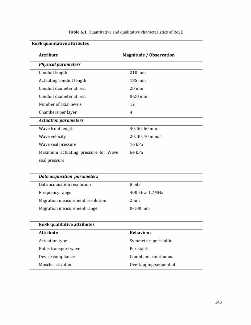
143
Table 6.1. Quantitative and qualitative characteristics of RoSE
RoSE quanitative attributes
Attribute Magnitude / Observation
Physical parameters
Conduit length 210 mm
Actuating conduit length 185 mm
Conduit diameter at rest 20 mm
Conduit diameter at rest 0-20 mm
Number of axial levels 12
Chambers per layer 4
Actuation parameters
Wave front length 40, 50, 60 mm
Wave velocity 20, 30, 40 mms-1
Wave seal pressure 16 kPa
Maximum actuating pressure for Wave
seal pressure
64 kPa
Data acquisition parameters
Data acquisition resolution 8 bits
Frequency range 400 kHz- 1.7MHz
Migration measurement resolution 2mm
Migration measurement range 0-100 mm
RoSE qualitative attributes
Attribute Behaviour
Actuation type Symmetric, peristaltic
Bolus transport wave Peristaltic
Device compliance Compliant, continuous
Muscle activation Overlapping-sequential
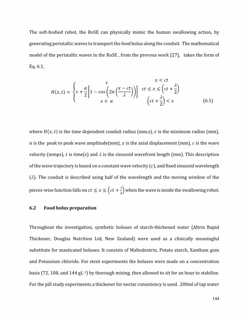
144
The soft-bodied robot, the RoSE can physically mimic the human swallowing action, by
generating peristaltic waves to transport the food bolus along the conduit. The mathematical
model of the peristaltic waves in the RoSE , from the prevous work [27], takes the form of
Eq. 6.1,
𝐻(𝑥, 𝑡) = {
𝜖
𝜖 +𝛼
2[1 − 𝑐𝑜𝑠 (2𝜋 (
𝑥 − 𝑐𝑡
))]
𝜖 + 𝛼
𝑥 < 𝑐𝑡
𝑐𝑡 ≤ 𝑥 ≤ (𝑐𝑡 +
2)
(𝑐𝑡 +
2) < 𝑥
(6.1)
where 𝐻(𝑥, 𝑡) is the time dependent conduit radius (mm,s), 𝜖 is the minimum radius (mm),
𝛼 is the peak to peak wave amplitude(mm), 𝑥 is the axial displacement (mm), 𝑐 is the wave
velocity (mmps), 𝑡 is time(s) and is the sinusoid wavefront length (mm). This description
of the wave trajectory is based on a constant wave velocity (𝑐), and fixed sinusoid wavelength
(). The conduit is described using half of the wavelength and the moving window of the
pieces-wise function falls on 𝑐𝑡 ≤ 𝑥 ≤ (𝑐𝑡 +
2) when the wave is inside the swallowing robot.
6.2 Food bolus preparation
Throughout the investigation, synthetic boluses of starch-thickened water (Altrix Rapid
Thickener, Douglas Nutrition Ltd, New Zealand) were used as a clinically meaningful
substitute for masticated boluses. It consists of Maltodextrin, Potato starch, Xantham gum
and Potassium chloride. For stent experiments the boluses were made on a concentration
basis (72, 108, and 144 gL-1) by thorough mixing, then allowed to sit for an hour to stabilise.
For the pill study experiments a thickener for nectar consistency is used. 200ml of tap water
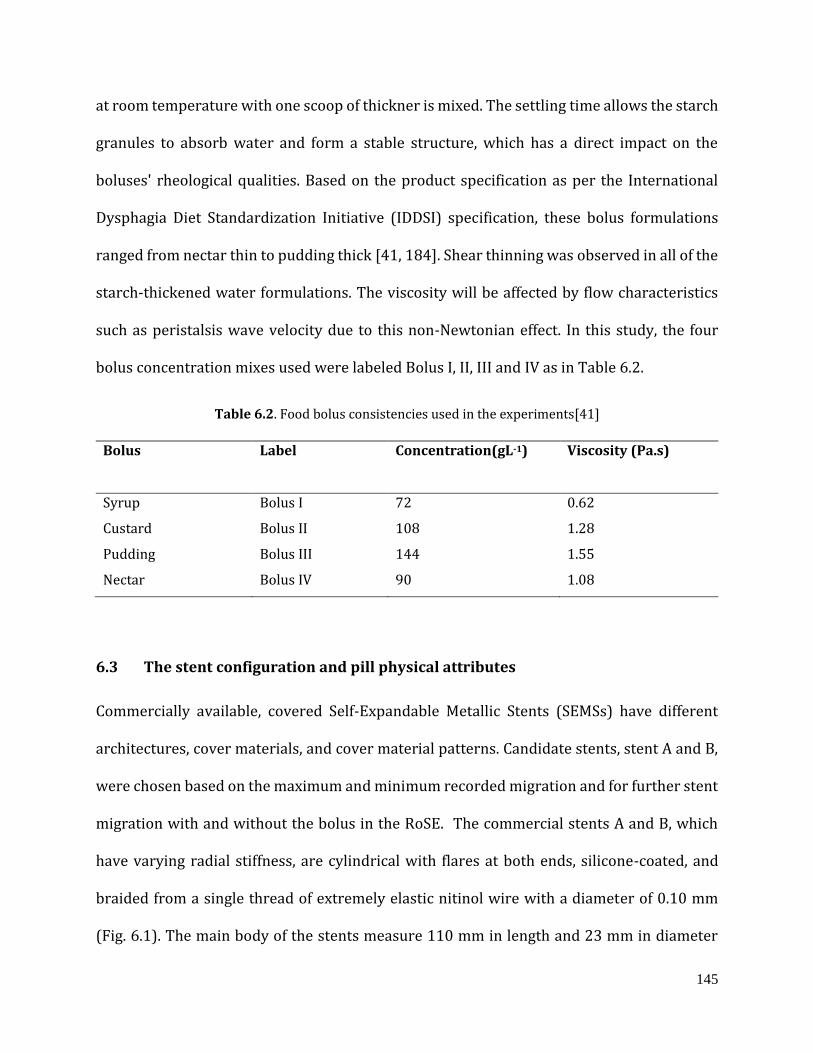
145
at room temperature with one scoop of thickner is mixed. The settling time allows the starch
granules to absorb water and form a stable structure, which has a direct impact on the
boluses' rheological qualities. Based on the product specification as per the International
Dysphagia Diet Standardization Initiative (IDDSI) specification, these bolus formulations
ranged from nectar thin to pudding thick [41, 184]. Shear thinning was observed in all of the
starch-thickened water formulations. The viscosity will be affected by flow characteristics
such as peristalsis wave velocity due to this non-Newtonian effect. In this study, the four
bolus concentration mixes used were labeled Bolus I, II, III and IV as in Table 6.2.
Table 6.2. Food bolus consistencies used in the experiments[41]
Bolus
Label Concentration(gL-1) Viscosity (Pa.s)
Syrup Bolus I 72 0.62
Custard Bolus II 108 1.28
Pudding Bolus III 144 1.55
Nectar Bolus IV 90 1.08
6.3 The stent configuration and pill physical attributes
Commercially available, covered Self-Expandable Metallic Stents (SEMSs) have different
architectures, cover materials, and cover material patterns. Candidate stents, stent A and B,
were chosen based on the maximum and minimum recorded migration and for further stent
migration with and without the bolus in the RoSE. The commercial stents A and B, which
have varying radial stiffness, are cylindrical with flares at both ends, silicone-coated, and
braided from a single thread of extremely elastic nitinol wire with a diameter of 0.10 mm
(Fig. 6.1). The main body of the stents measure 110 mm in length and 23 mm in diameter
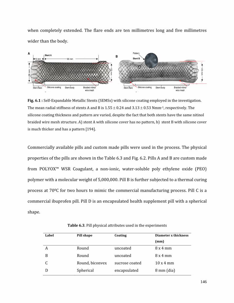
146
when completely extended. The flare ends are ten millimetres long and five millimetres
wider than the body.
Fig. 6.1 : Self-Expandable Metallic Stents (SEMSs) with silicone coating employed in the investigation.
The mean radial stiffness of stents A and B is 1.55 0.24 and 3.13 0.53 Nmm-1, respectively. The
silicone coating thickness and pattern are varied, despite the fact that both stents have the same nitinol
braided wire mesh structure. A) stent A with silicone cover has no pattern, b) stent B with silicone cover
is much thicker and has a pattern [194].
Commercially available pills and custom made pills were used in the process. The physical
properties of the pills are shown in the Table 6.3 and Fig. 6.2. Pills A and B are custom made
from POLYOX™ WSR Coagulant, a non-ionic, water-soluble poly ethylene oxide (PEO)
polymer with a molecular weight of 5,000,000. Pill B is further subjected to a thermal curing
process at 700C for two hours to mimic the commercial manufacturing process. Pill C is a
commercial ibuprofen pill. Pill D is an encapsulated health supplement pill with a spherical
shape.
Table 6.3. Pill physical attributes used in the experiments
Label Pill shape
Coating Diameter x thickness
(mm)
A Round uncoated 8 x 4 mm
B Round uncoated 8 x 4 mm
C Round, biconvex sucrose coated 10 x 4 mm
D Spherical encapsulated 8 mm (dia)
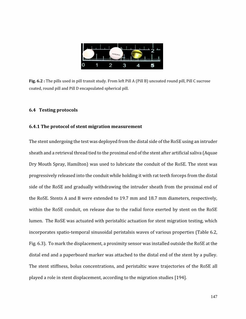
147
Fig. 6.2 : The pills used in pill transit study. From left Pill A (Pill B) uncoated round pill, Pill C sucrose
coated, round pill and Pill D encapsulated spherical pill.
6.4 Testing protocols
6.4.1 The protocol of stent migration measurement
The stent undergoing the test was deployed from the distal side of the RoSE using an intruder
sheath and a retrieval thread tied to the proximal end of the stent after artificial saliva (Aquae
Dry Mouth Spray, Hamilton) was used to lubricate the conduit of the RoSE. The stent was
progressively released into the conduit while holding it with rat teeth forceps from the distal
side of the RoSE and gradually withdrawing the intruder sheath from the proximal end of
the RoSE. Stents A and B were extended to 19.7 mm and 18.7 mm diameters, respectively,
within the RoSE conduit, on release due to the radial force exerted by stent on the RoSE
lumen. The RoSE was actuated with peristaltic actuation for stent migration testing, which
incorporates spatio-temporal sinusoidal peristalsis waves of various properties (Table 6.2,
Fig. 6.3). To mark the displacement, a proximity sensor was installed outside the RoSE at the
distal end and a paperboard marker was attached to the distal end of the stent by a pulley.
The stent stiffness, bolus concentrations, and peristaltic wave trajectories of the RoSE all
played a role in stent displacement, according to the migration studies [194].
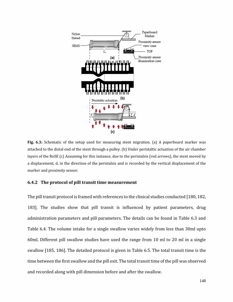
148
Fig. 6.3: Schematic of the setup used for measuring stent migration. (a) A paperboard marker was
attached to the distal end of the stent through a pulley. (b) Under peristaltic actuation of the air chamber
layers of the RoSE (c) Assuming for this instance, due to the peristalsis (red arrows), the stent moved by
a displacement, d, in the direction of the peristalsis and is recorded by the vertical displacement of the
marker and proximity sensor.
6.4.2 The protocol of pill transit time measurement
The pill transit protocol is framed with references to the clinical studies conducted [180, 182,
183]. The studies show that pill transit is influenced by patient parameters, drug
administration parameters and pill parameters. The details can be found in Table 6.3 and
Table 6.4. The volume intake for a single swallow varies widely from less than 30ml upto
60ml. Different pill swallow studies have used the range from 10 ml to 20 ml in a single
swallow [185, 186]. The detailed protocol is given in Table 6.5. The total transit time is the
time between the first swallow and the pill exit. The total transit time of the pill was observed
and recorded along with pill dimension before and after the swallow.
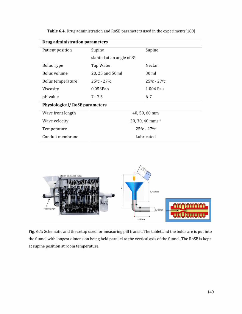
149
Table 6.4. Drug administration and RoSE parameters used in the experiments[180]
Drug administration parameters
Patient position Supine
slanted at an angle of 80
Supine
Bolus Type Tap Water Nectar
Bolus volume 20, 25 and 50 ml 30 ml
Bolus temperature 250c - 270c 250c - 270c
Viscosity 0.053Pa.s 1.006 Pa.s
pH value 7 - 7.5 6-7
Physiological/ RoSE parameters
Wave front length 40, 50, 60 mm
Wave velocity 20, 30, 40 mms-1
Temperature 250c - 270c
Conduit membrane Lubricated
Fig. 6.4: Schematic and the setup used for measuring pill transit. The tablet and the bolus are is put into
the funnel with longest dimension being held parallel to the vertical axis of the funnel. The RoSE is kept
at supine position at room temperature.

150
Table 6.5. Pill transit study protocol
Steps Procedure
I The RoSE is lubricated with saliva and the actuation of layers is initiated. One sequence
of actuation, propagating occlusion from layer 1 to layer 12, without tablet or bolus
and is called a “dry swallow”.
II There is a 5 sec rest after the whole sequence and before beginning the next cycle of
sequences of actuation.
III The tablet is put into the funnel with the longest dimension being held parallel to the
vertical axis of the funnel and at the beginning of the rest period.
IV The 20 ml nectar/water bolus is poured in at the beginning of the next sequence and
at the end of 5 sec rest period, indicated by the GUI in the software. This is called the
“first swallow cycle”.
V Each consecutive cycle of nectar administration is restricted to 15 ml and is
administered at the beginning of the sequential actuation.
VI The cycles repeat till the entire bolus volume is administrated.
VII A 2-cycle wash off period is allowed to clear the bolus from the RoSE mimicking the
secondary peristalsis.
VIII If the pill does not transit through the RoSE even after the 2-cycle wash off , the pill is
considered as retained in the RoSE.
From the Fig. 6.4, ℎ𝑓 is the total height of the funnel, ℎ is total height from which the nectar
is poured (variable), 𝑥 is length of the connector to the RoSE, and 𝑑𝑝 is diameter of the
connector to the RoSE. At a time only 20 ml of the bolus is poured in. So mass of 20 ml bolus
is,
m ≅ 28.09 g = 0.0280 kg (6.1)
Acceleration due to gravity
g ≅ 10 m/s (6.2)

151
Assuming the height from which bolus is poured in,
ℎ ≅ 160 mm = 0.16 m (6.3)
Then the potential energy obtained by the bolus is PE = mgh
PE = 0.044 J = 44 mJ (6.4)
Assuming no loss, the potential energy serves as the kinetic energy , and hence
KE = 44 mJ (6.5)
For the bolus to move forward the distance x the force is
F = KE/x ≅0.044
0.06= 0.73 𝑁 (6.6)
So the initial force with which a 20ml bolus moves to the proximal end of the conduit
through the tunnel is very less and there is no other source of propelling force other than
the potential energy gained. Also now, considering the losses due to bolus viscosity, forces
of adhesion to the inner elastomeric layer, and the energy lost in impact, the total effective
propelling force of the bolus is further reduced. A 20ml bolus reaching the proximal end of
the RoSE conduit, cannot travel the entire conduit length by initial forces alone for a
discontinuous flow. However, the speed of the bolus is a function of the height from which it
is poured out. So if the initial bolus velocity has to be controlled then the height h could be
adjusted. This could associate to the effect of gravity in the initial states of swallow.
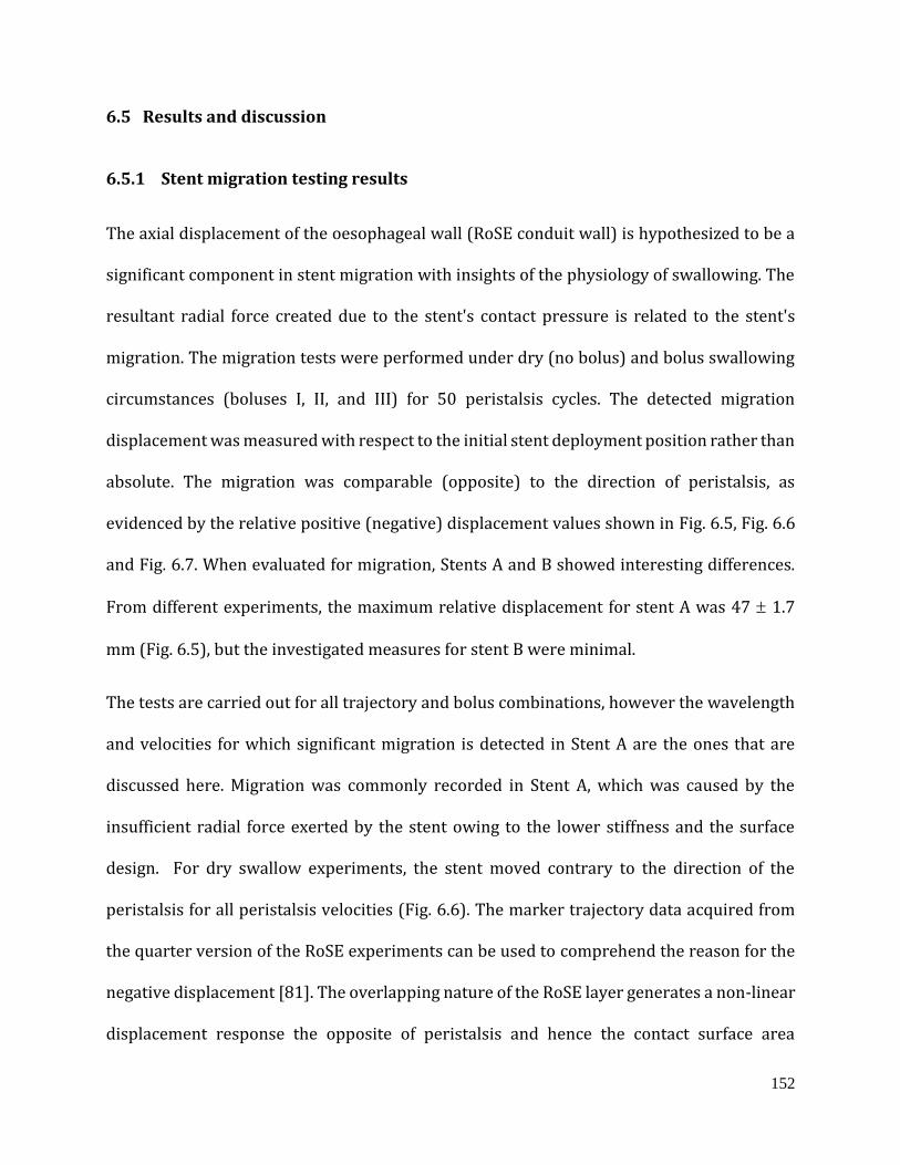
152
6.5 Results and discussion
6.5.1 Stent migration testing results
The axial displacement of the oesophageal wall (RoSE conduit wall) is hypothesized to be a
significant component in stent migration with insights of the physiology of swallowing. The
resultant radial force created due to the stent's contact pressure is related to the stent's
migration. The migration tests were performed under dry (no bolus) and bolus swallowing
circumstances (boluses I, II, and III) for 50 peristalsis cycles. The detected migration
displacement was measured with respect to the initial stent deployment position rather than
absolute. The migration was comparable (opposite) to the direction of peristalsis, as
evidenced by the relative positive (negative) displacement values shown in Fig. 6.5, Fig. 6.6
and Fig. 6.7. When evaluated for migration, Stents A and B showed interesting differences.
From different experiments, the maximum relative displacement for stent A was 47 1.7
mm (Fig. 6.5), but the investigated measures for stent B were minimal.
The tests are carried out for all trajectory and bolus combinations, however the wavelength
and velocities for which significant migration is detected in Stent A are the ones that are
discussed here. Migration was commonly recorded in Stent A, which was caused by the
insufficient radial force exerted by the stent owing to the lower stiffness and the surface
design. For dry swallow experiments, the stent moved contrary to the direction of the
peristalsis for all peristalsis velocities (Fig. 6.6). The marker trajectory data acquired from
the quarter version of the RoSE experiments can be used to comprehend the reason for the
negative displacement [81]. The overlapping nature of the RoSE layer generates a non-linear
displacement response the opposite of peristalsis and hence the contact surface area
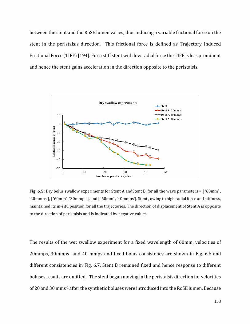
153
between the stent and the RoSE lumen varies, thus inducing a variable frictional force on the
stent in the peristalsis direction. This frictional force is defined as Trajectory Induced
Frictional Force (TIFF) [194]. For a stiff stent with low radial force the TIFF is less prominent
and hence the stent gains acceleration in the direction opposite to the peristalsis.
Fig. 6.5: Dry bolus swallow experiments for Stent A andStent B, for all the wave parameters = [ ‘60mm’ ,
‘20mmps’], [ ‘60mm’ , ‘30mmps’], and [ ‘60mm’ , ‘40mmps’]. Stent , owing to high radial force and stiffness,
maintained its in-situ position for all the trajectories. The direction of displacement of Stent A is opposite
to the direction of peristalsis and is indicated by negative values.
The results of the wet swallow experiment for a fixed wavelength of 60mm, velocities of
20mmps, 30mmps and 40 mmps and fixed bolus consistency are shown in Fig. 6.6 and
different consistencies in Fig. 6.7. Stent B remained fixed and hence response to different
boluses results are omitted. The stent began moving in the peristalsis direction for velocities
of 20 and 30 mms-1 after the synthetic boluses were introduced into the RoSE lumen. Because
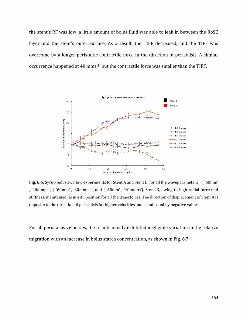
154
the stent's RF was low, a little amount of bolus fluid was able to leak in between the RoSE
layer and the stent's outer surface. As a result, the TIFF decreased, and the TIFF was
overcome by a longer peristaltic contractile force in the direction of peristalsis. A similar
occurrence happened at 40 mms-1, but the contractile force was smaller than the TIFF.
Fig. 6.6: Syrup bolus swallow experiments for Stent A and Stent B, for all the waveparameters = [ ‘60mm’
, ‘20mmps’], [ ‘60mm’ , ‘30mmps’], and [ ‘60mm’ , ‘40mmps’]. Stent B, owing to high radial force and
stiffness, maintained its in-situ position for all the trajectories. The direction of displacement of Stent A is
opposite to the direction of peristalsis for higher velocities and is indicated by negative values.
For all peristalsis velocities, the results mostly exhibited negligible variation in the relative
migration with an increase in bolus starch concentration, as shown in Fig. 6.7.
155
Fig. 6.7: Different bolus swallow experiments for Stent A and Stent B, for all the waveparameters = [
‘60mm’ , ‘30mmps’], The direction of displacement of Stent A is opposite to the direction of peristalsis for
all consistencies due to the reduction in trajectory induced frictional force.
In conclusion, Stent B having high radial force enabled adequate stent fixation on the RoSE
conduit wall during peristalsis, limiting stent migration. The findings, combined, further
indicate that stent migration is linked to lower radial force (RF). Furthermore, to avoid stent
migration and maintain proper luminal patency, a relatively high RF of the stent is essential
to ensure its in-situ position on the RoSE conduit. When used in the event of an oesophageal
stricture, this could ensure its effectiveness.
6.5.2 Pill transit testing results
It is significant to both therapeutics and pharmaceutics to study the pill transit with the
lower volume of liquid carrier, for pills particularly sizes around 8 mm in diameter
[180,181]. The following results were observed and simulated for the pill swallow studies.
1) The total transit time in the RoSE, 2) the pill dimensions before and after the swallow. The
total transit time is the time between the first swallow and the pill exit. The actual transit
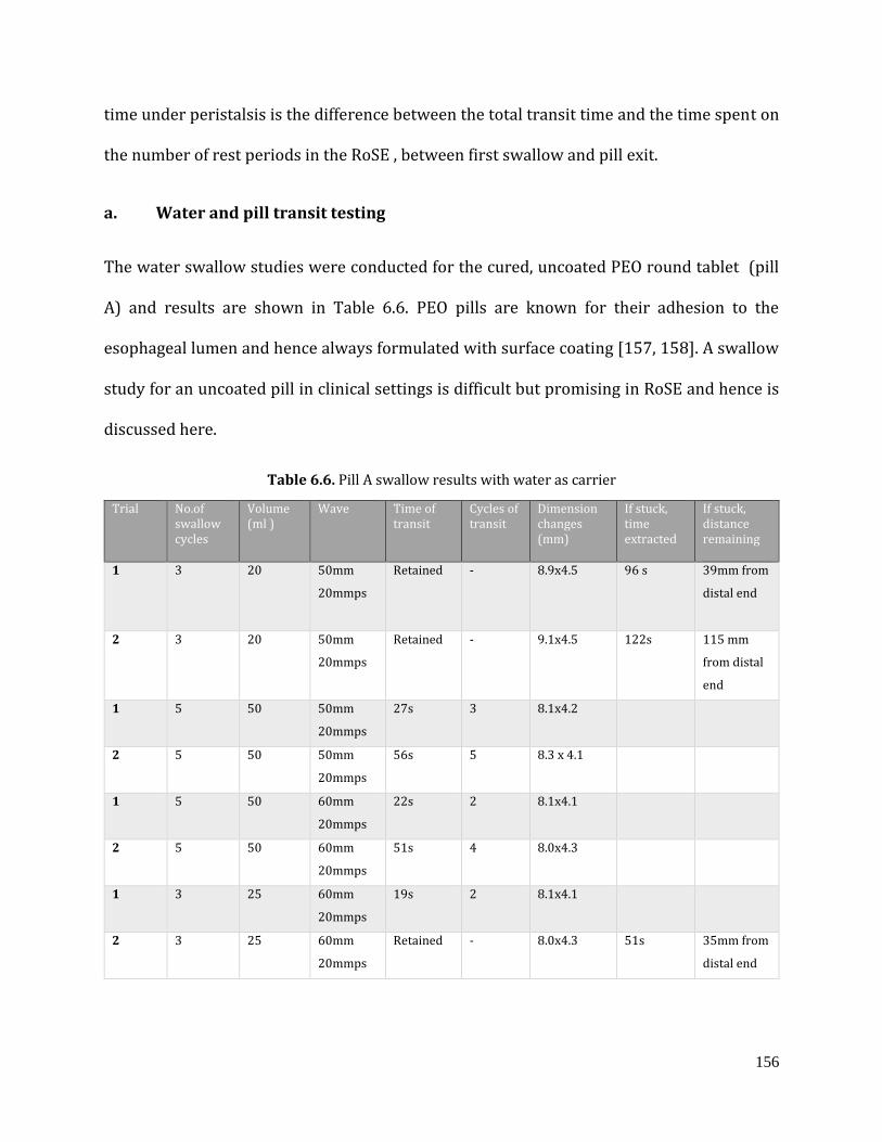
156
time under peristalsis is the difference between the total transit time and the time spent on
the number of rest periods in the RoSE , between first swallow and pill exit.
a. Water and pill transit testing
The water swallow studies were conducted for the cured, uncoated PEO round tablet (pill
A) and results are shown in Table 6.6. PEO pills are known for their adhesion to the
esophageal lumen and hence always formulated with surface coating [157, 158]. A swallow
study for an uncoated pill in clinical settings is difficult but promising in RoSE and hence is
discussed here.
Table 6.6. Pill A swallow results with water as carrier
Trial No.of swallow cycles
Volume (ml )
Wave Time of transit
Cycles of transit
Dimension changes (mm)
If stuck, time extracted
If stuck, distance remaining
1 3 20 50mm
20mmps
Retained
-
8.9x4.5 96 s 39mm from
distal end
2 3 20 50mm
20mmps
Retained
-
9.1x4.5 122s 115 mm
from distal
end
1 5 50 50mm
20mmps
27s 3 8.1x4.2
2 5 50 50mm
20mmps
56s 5 8.3 x 4.1
1 5 50 60mm
20mmps
22s 2 8.1x4.1
2 5 50 60mm
20mmps
51s 4 8.0x4.3
1 3 25 60mm
20mmps
19s 2 8.1x4.1
2 3 25 60mm
20mmps
Retained
-
8.0x4.3 51s 35mm from
distal end
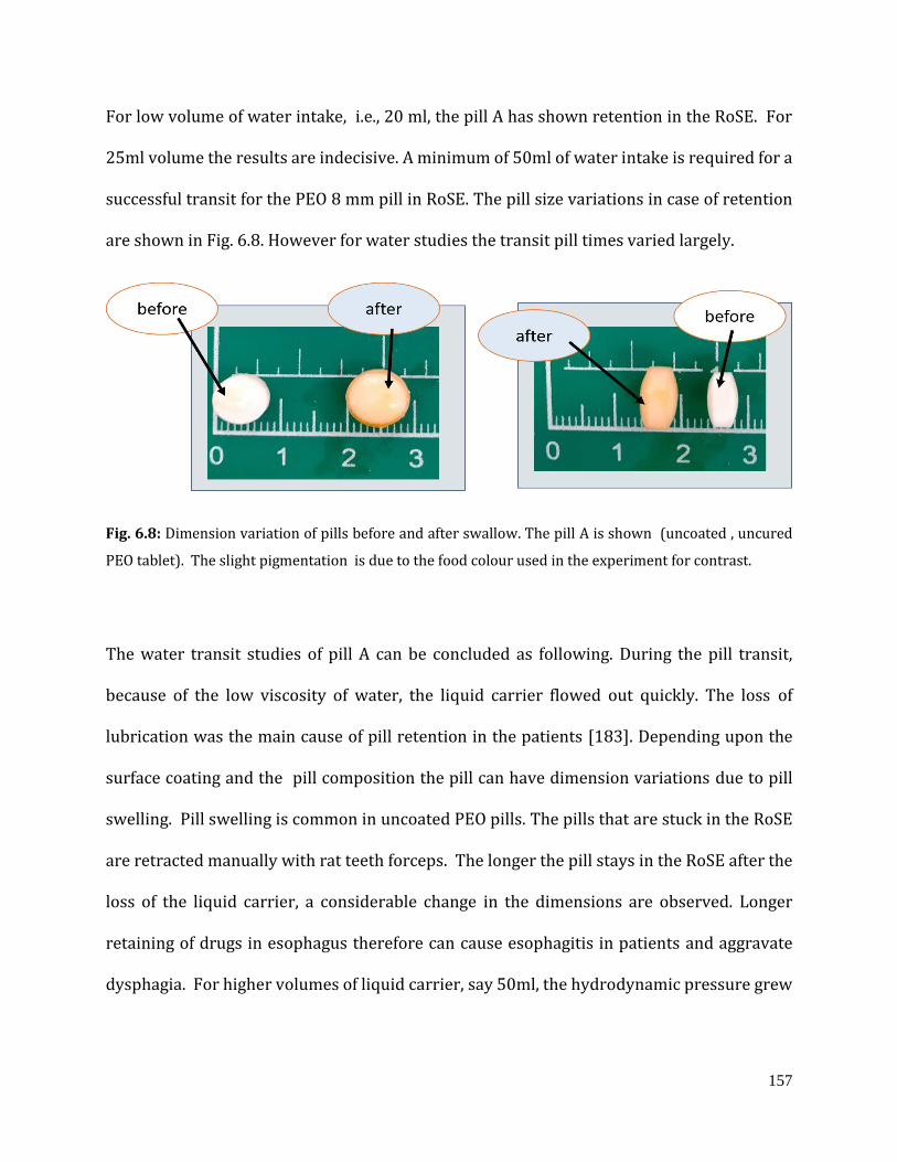
157
For low volume of water intake, i.e., 20 ml, the pill A has shown retention in the RoSE. For
25ml volume the results are indecisive. A minimum of 50ml of water intake is required for a
successful transit for the PEO 8 mm pill in RoSE. The pill size variations in case of retention
are shown in Fig. 6.8. However for water studies the transit pill times varied largely.
Fig. 6.8: Dimension variation of pills before and after swallow. The pill A is shown (uncoated , uncured
PEO tablet). The slight pigmentation is due to the food colour used in the experiment for contrast.
The water transit studies of pill A can be concluded as following. During the pill transit,
because of the low viscosity of water, the liquid carrier flowed out quickly. The loss of
lubrication was the main cause of pill retention in the patients [183]. Depending upon the
surface coating and the pill composition the pill can have dimension variations due to pill
swelling. Pill swelling is common in uncoated PEO pills. The pills that are stuck in the RoSE
are retracted manually with rat teeth forceps. The longer the pill stays in the RoSE after the
loss of the liquid carrier, a considerable change in the dimensions are observed. Longer
retaining of drugs in esophagus therefore can cause esophagitis in patients and aggravate
dysphagia. For higher volumes of liquid carrier, say 50ml, the hydrodynamic pressure grew
158
as the amount of liquid carrier increased, increasing the pushing forces. The variation in the
transit time can accounted to the varying surface adhesion due to the TIFF.
b. Nectar and pill transit testing
Nectar is a good liquid carrier in studies for underlying comorbid conditions [182] and
reduces the likelihood of the pill “beaching” on the oesophageal mucosal luminal surface and
being left behind as the liquid vehicle exits the oesophagus. For nectar volume of 30ml, all
the pills have shown successful transit and hence is discussed further.
A detailed analysis of the effects of the peristaltic parameters on the pill transit was
conducted with nectar, Fig. 6.9. The encapsulated pill transit was the faster and the uncured,
uncoated PEO tablets had the slowest transit in the sample pills selected. The cured tablet
and the sucrose coated pills had similar transit performance with sucrose coated having a
slighter advantage due to the coating. All the pills other than pill A had faster transit times
with the higher wavelength.
The various factors that affect the transit of pills in the RoSE with insights from literature
review and simulation studies in the RoSE are discussed below.
The pill transit time hence largely depends upon the pill property like coating, surface
finishing, size and pill volume density. As is established in Chapter 5 bolus propagation is
thereof the function of forces exerted by the RoSE conduit due to its inflation and deflation.
The RoSE multiphysical simulation studies show that under the supine settings the
maximum velocity attained by the nectar bolus is 10 mmps. The air column present in the
159
RoSE hinders the gain of velocity in the bolus, and similar behaviour is observed in the
oesophagus too [187].
The tablet tends to drift back towards the tail of the bolus and this phenomenon is dependent
on the size and density of the solid oral prescription and the level of its surface finishing [35].
In short, the bolus, being a non-Newtonian fluid and because of its viscosity, adherence and
friction, attains a velocity different to the wall propagating velocity. Unless the bolus volume
is greater than the pill administered, the effective velocity of the bolus is further reduced
because of the drag forces due to the pill. And the carrier velocity in turn affects the pill
transit. For higher volumes of liquid carrier, there is an increment in the hydrodynamic
pressure built, thus the pushing forces on the pill increased. In conclusion, apart from the
pill properties, the pill transit time is thus dependent on the bolus volume, viscosity and the
peristalsis wavevelocities in RoSE.
As mentioned earlier, unlike its biological counterpart, the RoSE trajectories are fixed in
wavelength and velocity. So the RoSE velocity studies could be an approximation of pill
swallow behaviour in different sections of the oesophagus say, proximal, mid and distal. For
example, decoding the results from Fig. 6.9 shows that the cured uncoated pill has a larger
transit time for 20-30 mmps wavevelocities and which signifies the proximal or distal
oesophagus velocities. In patients with underlying oesophageal motility conditions, this may
represent a pill retention hazard if the pill is administrated with a low volume of liquid
carrier.
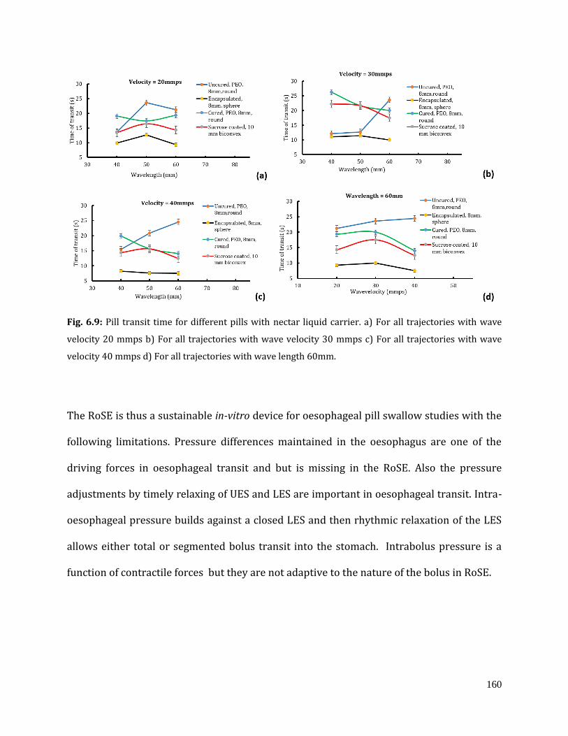
160
Fig. 6.9: Pill transit time for different pills with nectar liquid carrier. a) For all trajectories with wave
velocity 20 mmps b) For all trajectories with wave velocity 30 mmps c) For all trajectories with wave
velocity 40 mmps d) For all trajectories with wave length 60mm.
The RoSE is thus a sustainable in-vitro device for oesophageal pill swallow studies with the
following limitations. Pressure differences maintained in the oesophagus are one of the
driving forces in oesophageal transit and but is missing in the RoSE. Also the pressure
adjustments by timely relaxing of UES and LES are important in oesophageal transit. Intra-
oesophageal pressure builds against a closed LES and then rhythmic relaxation of the LES
allows either total or segmented bolus transit into the stomach. Intrabolus pressure is a
function of contractile forces but they are not adaptive to the nature of the bolus in RoSE.
161
6.6 Chapter summary
The chapter established the need for a biomimicking simulation device to understand the
temporal and spatial dynamics of peristaltic trajectories in therapeutical approaches in
dysphagia management. The chapter discussed the protocols developed for testing stents
for in-situ migration after implantation. Similarly, protocols were established for solid
dosage pressed pills from observing transit studies. This validation result endorses the
feasibility of investigating the mechanical behaviour of SEMSs implanted in a biomimetic
RoSE under a variety of artificial peristaltic settings. The pill transit studies presented in
RoSE provide evidence of the interplay between pill properties , bolus properties and the
peristalsic velocities in determining the transit time of solid pills. The pill transit studies in
RoSE is thus an evaluation tool for safe transit of a pill to avoid retention and hence,
esophagitis and further discomfort.
162
Chapter 7
Conclusions and future recommendations
The RoSE (Robotic Soft Oesophagus) is a solution to the lack of bio-mimicking in-vitro study
devices in developing and improving interventions for complaints of dysphagia. The RoSE is
a soft robotic actuator combining material science, actuation, and control technologies. It
mimics peristalsis and is open loop, pneumatically regulated, compliant, and continuous in
actuation. Even though RoSE shares many physical and actuation characteristics with its
biological counterpart, it lacks implanted sensors that replicate mechanoreceptors in the
oesophageal lumen. Many existing sensor technologies are hindered in RoSE by robot
occlusion, interference, or surface compatibility issues. The effectiveness of RoSE as an
investigative instrument in swallow studies will thus necessitate improvement in both the
physical and computational domains.
This research aimed to investigate methodological enhancements in RoSE to extend its
functionality as an in-vitro oesophageal swallow study device. This chapter aims to re-
emphasize the major accomplishments and achievements in the thesis, followed by a
discussion of the perspectives for future directions.
7.1 Research outcomes
This thesis studied the opportunities for improvement in soft robotic sensing and hence, in
RoSE to facilitate its use as an analytical tool in in-vitro swallowing research. The elements
of the thesis were, 1) the designs and characterisation of soft stretchable carbon black
163
sensors (Chapter 3), 2) calibration and characterisation of sensor–embedded actuator and
designing controller for soft robotic application (Chapter 4), 3) multiphysical modeling and
simulation for understanding the fluid-structure interactions in swallowing studies (Chapter
5) and 4) applicability studies of RoSE in swallow simulation for improvements in
endoprosthetic oesophageal stents and solid dosage forms in therapeutics (Chapter 6).
7.1.1 Soft stretchable sensor design for strain measurement
The ideal architecture of the soft sensor and concentration of nanomaterial in the elastomer
for optimum sensitivity is a standing topic of research. The primary focus of this study is to
develop a framework for designing stretchable strain sensors that are compliant and
compatible with the RoSE lumen. Three different concentrations for different architecture of
sensors are developed and experimented for the cyclic loading test, strain rate test, and
stretch direction test are before final selection. Complex structures, it has been discovered,
can incorporate more resistances in the pre-defined area. However, when the loop number
grows, the response and recovery times are observed to increase. The piezo-resistive
sensors have more hysteresis and produce nonlinear responses, but their gauge factor and
thus sensitivity are superior to capacitive sensors. For RoSE strain deformation studies, the
4 loop sensor with mass fraction 11.11(% wt.) of carbon black in the elastomer is recognized
as most suitable. The finalised sensor design has a gauge factor of 2.35, hysteresis of 22% at
27% strain for a 7 mmps strain rate, and is recommended as the standard operating point in
RoSE for the sensor.
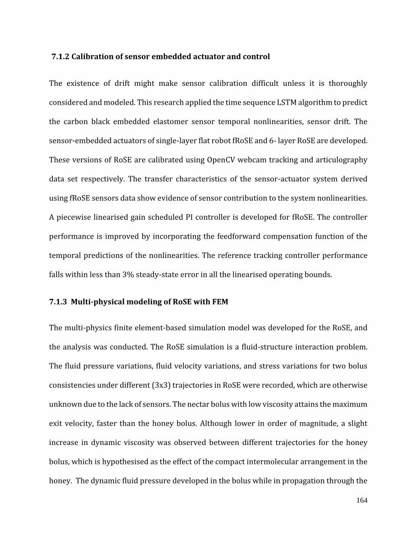
164
7.1.2 Calibration of sensor embedded actuator and control
The existence of drift might make sensor calibration difficult unless it is thoroughly
considered and modeled. This research applied the time sequence LSTM algorithm to predict
the carbon black embedded elastomer sensor temporal nonlinearities, sensor drift. The
sensor-embedded actuators of single-layer flat robot fRoSE and 6- layer RoSE are developed.
These versions of RoSE are calibrated using OpenCV webcam tracking and articulography
data set respectively. The transfer characteristics of the sensor-actuator system derived
using fRoSE sensors data show evidence of sensor contribution to the system nonlinearities.
A piecewise linearised gain scheduled PI controller is developed for fRoSE. The controller
performance is improved by incorporating the feedforward compensation function of the
temporal predictions of the nonlinearities. The reference tracking controller performance
falls within less than 3% steady-state error in all the linearised operating bounds.
7.1.3 Multi-physical modeling of RoSE with FEM
The multi-physics finite element-based simulation model was developed for the RoSE, and
the analysis was conducted. The RoSE simulation is a fluid-structure interaction problem.
The fluid pressure variations, fluid velocity variations, and stress variations for two bolus
consistencies under different (3x3) trajectories in RoSE were recorded, which are otherwise
unknown due to the lack of sensors. The nectar bolus with low viscosity attains the maximum
exit velocity, faster than the honey bolus. Although lower in order of magnitude, a slight
increase in dynamic viscosity was observed between different trajectories for the honey
bolus, which is hypothesised as the effect of the compact intermolecular arrangement in the
honey. The dynamic fluid pressure developed in the bolus while in propagation through the
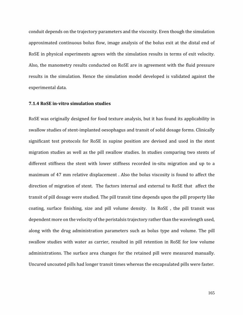
165
conduit depends on the trajectory parameters and the viscosity. Even though the simulation
approximated continuous bolus flow, image analysis of the bolus exit at the distal end of
RoSE in physical experiments agrees with the simulation results in terms of exit velocity.
Also, the manometry results conducted on RoSE are in agreement with the fluid pressure
results in the simulation. Hence the simulation model developed is validated against the
experimental data.
7.1.4 RoSE in-vitro simulation studies
RoSE was originally designed for food texture analysis, but it has found its applicability in
swallow studies of stent-implanted oesophagus and transit of solid dosage forms. Clinically
significant test protocols for RoSE in supine position are devised and used in the stent
migration studies as well as the pill swallow studies. In studies comparing two stents of
different stiffness the stent with lower stiffness recorded in-situ migration and up to a
maximum of 47 mm relative displacement . Also the bolus viscosity is found to affect the
direction of migration of stent. The factors internal and external to RoSE that affect the
transit of pill dosage were studied. The pill transit time depends upon the pill property like
coating, surface finishing, size and pill volume density. In RoSE , the pill transit was
dependent more on the velocity of the peristalsis trajectory rather than the wavelength used,
along with the drug administration parameters such as bolus type and volume. The pill
swallow studies with water as carrier, resulted in pill retention in RoSE for low volume
administrations. The surface area changes for the retained pill were measured manually.
Uncured uncoated pills had longer transit times whereas the encapsulated pills were faster.

166
7.2 Accomplishments of the research
The accomplishment of the research can be summarized as below.
i. The study provided a framework for creating stretchable nanoparticle-based sensors
that are tailored for the design requirements of the RoSE deformations.
ii. Soft robotic sensor design studies can benefit from a comparison study between
sensors with variable nanoparticle concentrations in the elastomer and the
architecture.
iii. The sensor nonlinearities were predicted and modelled by applying a recurrent
neural network and support vector regression.
iv. A broad framework for the linearization and feedforward compensated gain
scheduled proportional integral and derivative (PID) controller for soft robots was
presented and followed in the research.
v. To our knowledge, no previous FEM-based fluid-structure interaction studies for
bolus transport in RoSE have been conducted in soft robotics to examine fluid
dynamics.
vi. This simulation model may be used to validate in-vitro device performance by
studying rheological changes in a bolus while in RoSE or a similar device, as well as
fluid velocity, pressure, and shear fluctuations in the absence of sensors.
vii. The RoSE assessment methodologies for pill swallow transit times and stent
migration are the first of their type. They may be a collective protocol for in-vitro
trials of a similar nature.

167
viii. The findings might be used to enhance stent designs without compromising lumen
patency, as well as create techniques to limit stent migration.
ix. Effects of changes in the physical properties of a pharmaceutical's solid dosage forms
were assessed in RoSE.
7.3 Future perspectives
The big picture for future studies is to attain closed loop control of the spatio–temporal
dynamics of the RoSE adaptive to the type of the bolus used in swallowing simulation for
patient-specific conditions. In line with this objective, more research needs to be undertaken
to further improve the system developed thus far, including:
i. Develop full version of RoSE for with the stretchable strain sensors and calibrating
them for the deformation measurements of the entire conduit length for al the open
loop trajectories. The methodology explained in 6-layer robot can be extended to the
full robot.
ii. Calibrate the sensors for dry swallow and bolus swallow experiments to capture the
effects of hydrodynamic pressure on the deformation at sensor sites. Trajectory
specific and bolus specific calibration data collection should be collected and used in
sensor-actuator modelling. The time sequence models and the unsupervised
classification algorithms can be used to distinguish the sensor charactersitics with
and without bolus interference.
iii. To enable adaptive control specific to bolus requires information on shear rate
variations under propagation. The sensors required to measure the relevant
physical variables have to be developed. Pressure and shear rate sensing range and

168
resolution requirement of the so called sensors are available from the finite element
simulation model developed.
iv. From the simulation studies at the sites of occlusion, the leakage back flow is
observed, sensing these extra bolus signatures could be utilized in triggering
secondary peristalsis generation.
v. Extend the controller design algorithm for closed loop control of the RoSE. The
possibility of robust tuning algorithms such as Fuzzy PID controller or sliding mode
PID controllers .
vi. The current design of the RoSE implements open loop trajectories of fixed wavelength
and wave velocities. The CPG-based trajectory generators could develop open loop
trajectories of variable wavelength and wave velocities. Thus generated trajectory
parameters can be implemented in RoSE while maintain the wave seal pressure and
occlusion performances.
vii. The stent migration and the pill transit protcols should be established in vertical, 45
degree as well as trendelenburg positions which are clinically significant positions.
viii. All of the experiments in this study were carried out at room temperature whereas
body temperature has been shown to affect the qualities of food bolus. So the
environment of the RoSE could be set up to maintain a constant body temperature.
ix. Although the strain sensor modules are developed and tested they are not implanted
in the full version of RoSE. Integrating a sensing network into the robot, vesting the
pressure, shear stress and strain measuring capabilities, could improve the robot
functionalities and result in a more self-contained swallowing simulation platform.

169
This could moderate the need for any external clinical instrumentations, therefore
making it more portable and cost-effective.
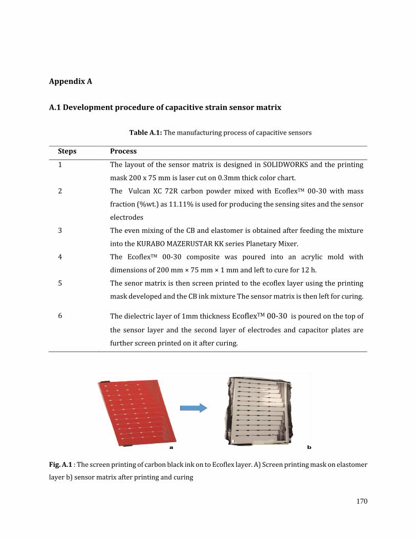
170
Appendix A
A.1 Development procedure of capacitive strain sensor matrix
Table A.1: The manufacturing process of capacitive sensors
Steps Process
1 The layout of the sensor matrix is designed in SOLIDWORKS and the printing
mask 200 x 75 mm is laser cut on 0.3mm thick color chart.
2 The Vulcan XC 72R carbon powder mixed with EcoflexTM 00-30 with mass
fraction (%wt.) as 11.11% is used for producing the sensing sites and the sensor
electrodes
3 The even mixing of the CB and elastomer is obtained after feeding the mixture
into the KURABO MAZERUSTAR KK series Planetary Mixer.
4 The EcoflexTM 00-30 composite was poured into an acrylic mold with
dimensions of 200 mm × 75 mm × 1 mm and left to cure for 12 h.
5 The senor matrix is then screen printed to the ecoflex layer using the printing
mask developed and the CB ink mixture The sensor matrix is then left for curing.
6 The dielectric layer of 1mm thickness EcoflexTM 00-30 is poured on the top of
the sensor layer and the second layer of electrodes and capacitor plates are
further screen printed on it after curing.
Fig. A.1 : The screen printing of carbon black ink on to Ecoflex layer. A) Screen printing mask on elastomer
layer b) sensor matrix after printing and curing
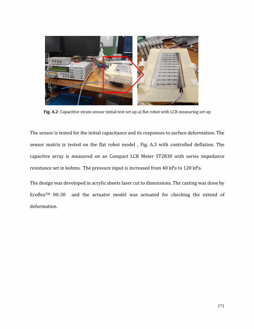
171
Fig. A.2: Capacitive strain sensor initial test set up a) flat robot with LCR measuring set up
The sensor is tested for the initial capacitance and its responses to surface deformation. The
sensor matrix is tested on the flat robot model , Fig. A.3 with controlled deflation. The
capacitve array is measured on an Compact LCR Meter ST2830 with series impedance
resistance set in kohms. The pressure input is increased from 40 kPa to 120 kPa.
The design was developed in acrylic sheets laser cut to dimensions. The casting was done by
EcoflexTM 00-30 and the actuator model was actuated for checking the extend of
deformation.
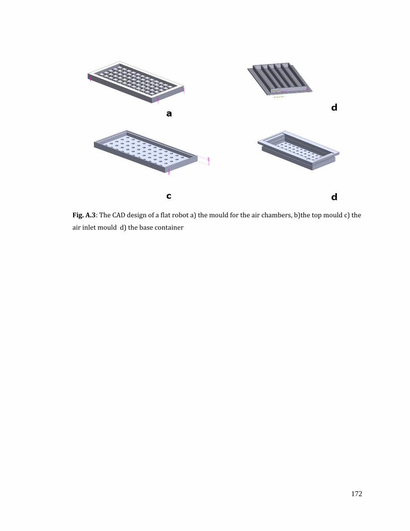
172
Fig. A.3: The CAD design of a flat robot a) the mould for the air chambers, b)the top mould c) the
air inlet mould d) the base container
173
References
[1] W. Dodds, "The physiology of swallowing", Dysphagia, vol. 3, no. 4, pp. 171-178, 1989.
[2] E. Marieb and K. Hoehn, Human anatomy & physiology. San Francisco: Pearson, 2010.
[3] B. Mac Murray et al., "Compliant Buckled Foam Actuators and Application in Patient-
Specific Direct Cardiac Compression", Soft Robotics, vol. 5, no. 1, pp. 99-108, 2018.
[4] M. Nicosia, "Theoretical Estimation of Shear Rate during the Oral Phase of
Swallowing: Effect of Partial Slip", Journal of Texture Studies, vol. 44, no. 2, pp. 132-
139, 2012.
[5] C. Payne et al., "Soft robotic ventricular assist device with septal bracing for therapy
of heart failure", Science Robotics, vol. 2, no. 12, 2017.
[6] A. Arezzo et al., "Total mesorectal excision using a soft and flexible robotic arm: a
feasibility study in cadaver models", Surgical Endoscopy, vol. 31, no. 1, pp. 264-273,
2016.
[7] S. Jeon et al., "A Magnetically Controlled Soft Microrobot Steering a Guidewire in a
Three-Dimensional Phantom Vascular Network", Soft Robotics, vol. 6, no. 1, pp. 54-68,
2019.
[8] M. Moreno et al., "Development of a Non-Blood Contacting Cardiac Assist and Support
Device: An In Vivo Proof of Concept Study", Journal of Medical Devices, vol. 5, no. 4,
2011.
[9] A. Kotikian et al., "Untethered soft robotic matter with passive control of shape
morphing and propulsion", Science Robotics, vol. 4, no. 33, 2019.
174
[10] Z. Xing, J. Zhang, D. McCoul, Y. Cui, L. Sun and J. Zhao, "A Super-Lightweight and Soft
Manipulator Driven by Dielectric Elastomers", Soft Robotics, vol. 7, no. 4, pp. 512-520,
2020.
[11] H. Lee, H. Choi, M. Lee and S. Park, "Preliminary study on alginate/NIPAM hydrogel-
based soft microrobot for controlled drug delivery using electromagnetic actuation
and near-infrared stimulus", Biomedical Microdevices, vol. 20, no. 4, 2018.
[12] A. Cavallo, M. Brancadoro, S. Tognarelli and A. Menciassi, "A Soft Retraction System
for Surgery Based on Ferromagnetic Materials and Granular Jamming", Soft Robotics,
vol. 6, no. 2, pp. 161-173, 2019.
[13] A. Stilli, E. Dimitrakakis, C. D'Ettorre, M. Tran and D. Stoyanov, "Pneumatically
Attachable Flexible Rails for Track-Guided Ultrasound Scanning in Robotic-Assisted
Partial Nephrectomy—A Preliminary Design Study," IEEE Robotics and Automation
Letters, vol. 4, no. 2, pp. 1208-1215, April 2019.
[14] Y. Fujiso, N. Perrin, J. van der Giessen, N. Vrana, F. Neveu and V. Woisard, "Swall-E: A
robotic in-vitro simulation of human swallowing", PLOS ONE, vol. 13, no. 12, p.
e0208193, 2018.
[15] M. Stading, M. Waqas, F. Holmberg, J. Wiklund, R. Kotze and O. Ekberg, "A Device that
Models Human Swallowing", Dysphagia, vol. 34, no. 5, pp. 615-626, 2019.
[16] Y. Noh et al., "Development of Patient Scenario Generation which can reproduce
characteristics of the patient for simulating real-world conditions of task for airway
management training system WKA-3," 2010 IEEE/RSJ International Conference on
Intelligent Robots and Systems, 2010, pp. 331-336, doi: 10.1109/IROS.2010.5648794.
175
[17] Clouse, R., A. Alrakawi, and A. Staiano, "Intersubject and Interswallow Variability in
Topography of Oesophageal Motility", Digestive Diseases and Sciences, vol.43, no.9, pp.
1978-1985, 1998.
[18] K. Kendall, S. McKenzie, R. Leonard, M. Gonçalves and A. Walker, "Timing of Events in
Normal Swallowing: A Videofluoroscopic Study", Dysphagia, vol. 15, no. 2, pp. 74-83,
2000.
[19] J. Logemann, A. Rademaker, B. Pauloski, Y. Ohmae and P. Kahrilas, "Normal
Swallowing Physiology as Viewed by Videofluoroscopy and Videoendoscopy", Folia
Phoniatrica et Logopaedica, vol. 50, no. 6, pp. 311-319, 1998.
[20] A. Khan, R. Carmona and M. Traube, "Dysphagia in the Elderly", Clinics in Geriatric
Medicine, vol. 30, no. 1, pp. 43-53, 2014.
[21] R. Shaker, P. C. Belafsky, G. N. Postma and C. Easterling, Principles of Deglutition : A
Multidisciplinary Text for Swallowing and its Disorders, 1st ed. New York: Springer,
New York, NY, 2013.
[22] M. Marconati, S. Raut, A. Burbidge, J. Engmann and M. Ramaioli, "An in vitro
experiment to simulate how easy tablets are to swallow", International Journal of
Pharmaceutics, vol. 535, no. 1-2, pp. 27-37, 2018.
[23] V. Mathieu, C. de Loubens, C. Thomas, M. Panouillé, A. Magnin and I. Souchon, "An
experimental model to investigate the biomechanical determinants of pharyngeal
mucosa coating during swallowing", Journal of Biomechanics, vol. 72, pp. 144-151,
2018.
176
[24] W. Kou, J. Pandolfino, P. Kahrilas and N. Patankar, "Simulation studies of the role of
oesophageal mucosa in bolus transport", Biomechanics and Modeling in
Mechanobiology, vol. 16, no. 3, pp. 1001-1009, 2017.
[25] S. Dirven, W. Xu and L. K. Cheng, "Sinusoidal Peristaltic Waves in Soft Actuator for
Mimicry of Esophageal Swallowing," in IEEE/ASME Transactions on Mechatronics, vol.
20, no. 3, pp. 1331-1337, June 2015.
[26] M. Zhu, W. Xu and L. K. Cheng, "Measuring and imaging of a soft-bodied swallowing
robot conduit deformation and internal structural change using
videofluoroscopy," 2016 23rd International Conference on Mechatronics and Machine
Vision in Practice (M2VIP), 2016, pp. 1-6.
[27] Dirven, S., "Biomimetic Design and Experimental Methods Towards a Biologically
Inspired, Soft Bodied, Peristaltic, Oesophageal Swallowing Robot", Ph.D, University of
Auckland ,2015.
[28] M. Zhu, M. Xie, W. Xu and L. K. Cheng, "A Nanocomposite-Based Stretchable
Deformation Sensor Matrix for a Soft-Bodied Swallowing Robot," IEEE Sensors
Journal, vol. 16, no. 10, pp. 3848-3855, May 2016.
[29] W. Dodds, E. Stewart and J. Logemann, "Physiology and radiology of the normal oral
and pharyngeal phases of swallowing.", American Journal of Roentgenology, vol. 154,
no. 5, pp. 953-963, 1990.
[30] S. Zhang, A. Olthoff and J. Frahm, "Real-time magnetic resonance imaging of normal
swallowing", Journal of Magnetic Resonance Imaging, vol. 35, no. 6, pp. 1372-1379,
2012.

177
[31] M. Donner, J. Bosnia and D. Robertson, "Anatomy and physiology of the
pharynx", Gastrointestinal Radiology, vol. 10, no. 1, pp. 197-212, 1985.
[32] K. Matsuo and J. Palmer, "Coordination of mastication, swallowing and
breathing", Japanese Dental Science Review, vol. 45, no. 1, pp. 31-40, 2009.
[33] A. Jean, "Brain Stem Control of Swallowing: Neuronal Network and Cellular
Mechanisms", Physiological Reviews, vol. 81, no. 2, pp. 929-969, 2001.
[34] R. Goyal and A. Chaudhury, "Physiology of Normal Oesophageal Motility", Journal of
Clinical Gastroenterology, vol. 42, no. 5, pp. 610-619, 2008.
[35] F. Ingelfinger, "Oesophageal Motility", Physiological Reviews, vol. 38, no. 4, pp. 533-
584, 1958.
[36] A. Miller, "Swallowing: Neurophysiologic control of the oesophageal
phase", Dysphagia, vol. 2, no. 2, pp. 72-82, 1987.
[37] S. Mistry and S. Hamdy, "Neural Control of Feeding and Swallowing", Physical
Medicine and Rehabilitation Clinics of North America, vol. 19, no. 4, pp. 709-728, 2008.
[38] J. Garcia, E. Chambers IV, M. Clark, J. Helverson and Z. Matta, "Quality of care issues
for dysphagia: modifications involving oral fluids", Journal of Clinical Nursing, vol. 19,
no. 11-12, pp. 1618-1624, 2010.
[39] B. Hanson, C. Steele, P. Lam and J. Cichero, "Fluid Testing Methods Recommended by
IDDSI", Dysphagia, vol. 34, no. 5, pp. 716-717, 2018.
[40] J. Patterson, E. McColl, P. Carding, A. Hildreth, C. Kelly and J. Wilson, "Swallowing in
the first year after chemoradiotherapy for head and neck cancer: Clinician-and
patient-reported outcomes", Head & Neck, vol. 36, no. 3, pp. 352-358, 2013.

178
[41] J. Cichero et al., "Development of International Terminology and Definitions for
Texture-Modified Foods and Thickened Fluids Used in Dysphagia Management: The
IDDSI Framework", Dysphagia, vol. 32, no. 2, pp. 293-314, 2016.
[42] S. Coster and W. Schwarz, "Rheology and the swallow-safe bolus", Dysphagia, vol. 1,
no. 3, pp. 113-118, 1987.
[43] J. Mitchell, "Food Texture and Viscosity: Concept and Measurement", International
Journal of Food Science and Technology, vol. 38, no. 7, pp. 839-840, 2003.
[44] A. Lowe and M. Sheridan, "Oesophageal Stenting", Seminars in Interventional
Radiology, vol. 21, no. 03, pp. 157-166, 2004. Available: 10.1055/s-2004-860874.
[45] P. Dodrill, "Typical Feeding and Swallowing Development in Infants and Children",
in Dysphagia Clinical Management in Adults and Children, 2nd ed., M. E. Groher and M.
A. Crary, Ed. Mosby, 2016, pp. 253-269.
[46] S. Elhanafi et al., "Oesophageal perforation post pneumatic dilatation for achalasia
managed by oesophageal stenting", American Journal of Case Reports, vol. 14, pp. 532-
535, 2013.
[47] Y. Kang, "A Review of Self-Expanding Oesophageal Stents for the Palliation Therapy
of Inoperable Oesophageal Malignancies", BioMed Research International, vol. 2019,
pp. 1-11, 2019.
[48] N. Christie et al., "Results of expandable metal stents for malignant oesophageal
obstruction in 100 patients: short-term and long-term follow-up", The Annals of
Thoracic Surgery, vol. 71, no. 6, pp. 1797-1802, 2001.
[49] Dua K. S., "Oesophageal Stenting for Relief of Dysphagia", in Principles of Deglutition ,
Shaker R., Belafsky P., Postma G., Easterling C., Springer, New York, NY.
179
[50] S. Leder, B. Judson, E. Sliwinski and L. Madson, "Promoting Safe Swallowing When
Puree is Swallowed Without Aspiration but Thin Liquid is Aspirated: Nectar is
Enough", Dysphagia, vol. 28, no. 1, pp. 58-62, 2012.
[51] N. Roy, J. Stemple, R. Merrill and L. Thomas, "Dysphagia in the Elderly: Preliminary
Evidence of Prevalence, Risk Factors, and Socioemotional Effects", Annals of Otology,
Rhinology & Laryngology, vol. 116, no. 11, pp. 858-865, 2007.
[52] B. Hallmark et al., "A portable and affordable extensional rheometer for field
testing", Measurement Science and Technology, vol. 27, no. 12, p. 125302, 2016.
[53] N. Ali, D. Roux, L. Cipelletti and F. Caton, "RheoSpeckle: a new tool to investigate local
flow and microscopic dynamics of soft matter under shear", Measurement Science and
Technology, vol. 27, no. 12, p. 125902, 2016.
[54] M. Marconati, J. Engmann, A. Burbidge, V. Mathieu, I. Souchon and M. Ramaioli, "A
review of the approaches to predict the ease of swallowing and post-swallow
residues", Trends in Food Science & Technology, vol. 86, pp. 281-297, 2019.
[55] Kikuchi, T., H. Kobayashi, and Y. Michiwaki," Development of swallowing robot
reproducing hyoid bone and epiglottis during swallowing", Dysphagia, vol. 24, no.4:
pp. 467-468, 2009.
[56] A. Ho et al., "Inferring the effects of saliva on liquid bolus flow using computer
simulation", Computers in Biology and Medicine, vol. 89, pp. 304-313, 2017.
[57] S. Mossaz et al., "Measuring and predicting the spreading of dairy products in the
mouth: sensory, instrumental and modelling approaches", Food Hydrocolloids, vol. 24,
no. 8, pp. 681-688, 2010.
180
[58] Y. Michiwaki and M. Nagumo, "Development of humanoid robot reproducing tongue
movements at swallowing", International Journal of Oral and Maxillofacial Surgery,
vol. 34, p. 34, 2005.
[59] Y. Noh et al., "Development of a robot which can simulate swallowing of food boluses
with various properties for the study of rehabilitation of swallowing disorders," 2011
IEEE International Conference on Robotics and Automation, 2011, pp. 4676-4681.
[60] D. Tripathi, S. Pandey and O. Bég, "Mathematical modelling of heat transfer effects on
swallowing dynamics of viscoelastic food bolus through the human
oesophagus", International Journal of Thermal Sciences, vol. 70, pp. 41-53, 2013.
[61] H. Miki et al., "Artificial-oesophagus with peristaltic motion using shape memory
alloy", International Journal of Applied Electromagnetics and Mechanics, vol. 33, no. 1-
2, pp. 705-711, 2010.
[62] S. Patel, W. McAuley, M. Cook, Y. Sun, S. Hamdy and F. Liu, "The Swallowing
Characteristics of Thickeners, Jellies and Yoghurt Observed Using an In Vitro
Model", Dysphagia, vol. 35, no. 4, pp. 685-695, 2019.
[63] Q. Guan, J. Sun, Y. Liu, N. Wereley and J. Leng, "Novel Bending and Helical
Extensile/Contractile Pneumatic Artificial Muscles Inspired by Elephant Trunk", Soft
Robotics, vol. 7, no. 5, pp. 597-614, 2020. Available: 10.1089/soro.2019.0079.
[64] M. Verma, A. Ainla, D. Yang, D. Harburg and G. Whitesides, "A Soft Tube-Climbing
Robot", Soft Robotics, vol. 5, no. 2, pp. 133-137, 2018.
[65] A. Sadeghi, E. Del Dottore, A. Mondini and B. Mazzolai, "Passive Morphological
Adaptation for Obstacle Avoidance in a Self-Growing Robot Produced by Additive
Manufacturing", Soft Robotics, vol. 7, no. 1, pp. 85-94, 2020.
181
[66] A. Rafsanjani, Y. Zhang, B. Liu, S. Rubinstein and K. Bertoldi, "Kirigami skins make a
simple soft actuator crawl", Science Robotics, vol. 3, no. 15, 2018.
[67] J. Wang, Y. Fei and Z. Liu, "FifoBots: Foldable Soft Robots for Flipping
Locomotion", Soft Robotics, vol. 6, no. 4, pp. 532-559, 2019.
[68] World Health, O. and O. World Health, Medical Devices; Managing the Mismatch : An
Outcome of the Priority Medical Devices Project. 2010, Albany, Switzerland: World
Health Organization.
[69] Y. Kim, G. Parada, S. Liu and X. Zhao, "Ferromagnetic soft continuum robots", Science
Robotics, vol. 4, no. 33, 2019.
[70] J. Wang, Y. Fei and W. Chen, "Integration, Sensing, and Control of a Modular Soft-Rigid
Pneumatic Lower Limb Exoskeleton", Soft Robotics, vol. 7, no. 2, pp. 140-154, 2020.
[71] M. Runciman, A. Darzi and G. Mylonas, "Soft Robotics in Minimally Invasive
Surgery", Soft Robotics, vol. 6, no. 4, pp. 423-443, 2019.
[72] F. J. Comin, C. M. Saaj, S. M. Mustaza and R. Saaj, "Safe Testing of Electrical Diathermy
Cutting Using a New Generation Soft Manipulator," IEEE Transactions on Robotics,
vol. 34, no. 6, pp. 1659-1666, Dec. 2018.
[73] T. Cheng, W. Li, C. S. H. Ng, P. W. Y. Chiu and Z. Li, "Visual Servo Control of a Novel
Magnetic Actuated Endoscope for Uniportal Video-Assisted Thoracic Surgery," IEEE
Robotics and Automation Letters, vol. 4, no. 3, pp. 3098-3105, July 2019.
[74] M. Gifari, H. Naghibi, S. Stramigioli and M. Abayazid, "A review on recent advances in
soft surgical robots for endoscopic applications", The International Journal of Medical
Robotics and Computer Assisted Surgery, vol. 15, no. 5, 2019.
182
[75] D. Son, H. Gilbert and M. Sitti, "Magnetically Actuated Soft Capsule Endoscope for Fine-
Needle Biopsy", Soft Robotics, vol. 7, no. 1, pp. 10-21, 2020.
[76] Johnson, R.E. and J.W. Sensinger, "Chapter Two - Actuator Technologies", in Handbook
of Biomechatronics, J. Segil, Editor. 2019, Academic Press.
[77] Y. Ding, M. Kim, S. Kuindersma and C. Walsh, "Human-in-the-loop optimization of hip
assistance with a soft exosuit during walking", Science Robotics, vol. 3, no. 15, 2018.
[78] M. Luk, D. Lobb and J. Smith, "A Dynamic Compliance Cervix Phantom Robot for Latent
Labor Simulation", Soft Robotics, vol. 5, no. 3, pp. 330-338, 2018.
[79] Y. Dang, H. Devaraj, M. Stommel, L. Cheng, A. McDaid and W. Xu, "Experimental
Investigation into the Dynamics of a Radially Contracting Actuator with Embedded
Sensing Capability", Soft Robotics, vol. 7, no. 4, pp. 478-490, 2020.
[80] X. Lu, W. Xu and X. Li, "A Soft Robotic Tongue—Mechatronic Design and Surface
Reconstruction," in IEEE/ASME Transactions on Mechatronics, vol. 22, no. 5, pp. 2102-
2110, Oct. 2017.
[81] D. Bhattacharya, L. K. Cheng and W. Xu, "Sparse Machine Learning Discovery of
Dynamic Differential Equation of an Oesophageal Swallowing Robot," in IEEE
Transactions on Industrial Electronics, vol. 67, no. 6, pp. 4711-4720, June 2020.
[82] F. Zhong, Y. Wang, Z. Wang and Y. Liu, "Dual-Arm Robotic Needle Insertion With
Active Tissue Deformation for Autonomous Suturing," in IEEE Robotics and
Automation Letters, vol. 4, no. 3, pp. 2669-2676, July 2019.
[83] E. Mendoza and J. P. Whitney, "A Testbed for Haptic and Magnetic Resonance Imaging-
Guided Percutaneous Needle Biopsy," in IEEE Robotics and Automation Letters, vol. 4,
no. 4, pp. 3177-3183, Oct. 2019.
183
[84] V. Penza, A. Ciullo, S. Moccia, L. Mattos and E. De Momi, "EndoAbS dataset: Endoscopic
abdominal stereo image dataset for benchmarking 3D stereo reconstruction
algorithms", The International Journal of Medical Robotics and Computer Assisted
Surgery, vol. 14, no. 5, p. e1926, 2018.
[85] T. Helps and J. Rossiter, "Proprioceptive Flexible Fluidic Actuators Using Conductive
Working Fluids", Soft Robotics, vol. 5, no. 2, pp. 175-189, 2018.
[86] A. Maziz, A. Concas, A. Khaldi, J. Stålhand, N. Persson and E. Jager, "Knitting and
weaving artificial muscles", Science Advances, vol. 3, no. 1, 2017.
[87] N. Kellaris, V. Gopaluni Venkata, G. Smith, S. Mitchell and C. Keplinger, "Peano-HASEL
actuators: Muscle-mimetic, electrohydraulic transducers that linearly contract on
activation", Science Robotics, vol. 3, no. 14, 2018.
[88] Y. Dang, M. Stommel, L. Cheng and W. Xu, "A Soft Ring-Shaped Actuator for Radial
Contracting Deformation: Design and Modeling", Soft Robotics, vol. 6, no. 4, pp. 444-
454, 2019.
[89] J. Booth et al., "OmniSkins: Robotic skins that turn inanimate objects into
multifunctional robots", Science Robotics, vol. 3, no. 22, 2018.
[90] A. Calderón, J. Ugalde, L. Chang, J. Cristóbal Zagal and N. Pérez-Arancibia, "An
earthworm-inspired soft robot with perceptive artificial skin", Bioinspiration &
Biomimetics, vol. 14, no. 5, p. 056012, 2019.
[91] B. Zhang, Y. Fan, P. Yang, T. Cao and H. Liao, "Worm-Like Soft Robot for Complicated
Tubular Environments", Soft Robotics, vol. 6, no. 3, pp. 399-413, 2019.
[92] I. Van Meerbeek, C. De Sa and R. Shepherd, "Soft optoelectronic sensory foams with
proprioception", Science Robotics, vol. 3, no. 24, 2018.
184
[93] S. Dirven, F. Chen, W. Xu, J. Bronlund, J. Allen and L. Cheng, "Design and
Characterization of a Peristaltic Actuator Inspired by Oesophageal
Swallowing", IEEE/ASME Transactions on Mechatronics, vol. 19, no. 4, pp. 1234-1242,
2014.
[94] S. Dirven, W. Xu, L. K. Cheng and J. Allen, "Biomimetic Investigation of Intrabolus
Pressure Signatures by a Peristaltic Swallowing Robot," IEEE Transactions on
Instrumentation and Measurement, vol. 64, no. 4, pp. 967-974, April 2015
[95] Patti, M. G., Gantert, W., & Way, L. W. , "Surgery of the oesophagus: Anatomy and
physiology", The Surgical clinics of North America, vol. 77 no.5, 959–970,1997.
[96] W. Yang, "Finite element simulation of food transport through the oesophageal
body", World Journal of Gastroenterology, vol. 13, no. 9, p. 1352, 2007.
[97] F. Chen, S. Dirven, W. Xu, X. Li, and J. Bronlund, "Design and Fabrication of a Soft
Actuator for a Swallowing Robot", in Robot Intelligence Technology and Applications
2. Advances in Intelligent Systems and Computing, 1st ed., J. Kim, P. Xu, E. Matson and
H. Myung, Ed. Springer, Cham, 2014.
[98] S. Dirven, M. Stommel, R. Hashem and W. Xu, "Medically-inspired approaches for the
analysis of soft-robotic motion control," 2016 IEEE 14th International Workshop on
Advanced Motion Control (AMC), 2016, pp. 370-375.
[99] Bhattacharya, D., L.K. Cheng, and W. Xu, " Artificial Intelligence Approach to the
Trajectory Generation And Dynamics of a Soft Robotic Swallowing Simulator Sparse
Machine Learning Discovery of Dynamic Differential Equation of an Oesophageal
Swallowing Robot", in Robot Intelligence Technology and Applications 5. Advances in
185
Intelligent Systems and Computing, 1st ed., J. Kim, P. Xu, E. Matson and H. Myung, Ed.
Springer, Cham, 2019.
[100] W. Yang, "Finite element simulation of food transport through the oesophageal
body", World Journal of Gastroenterology, vol. 13, no. 9, p. 1352, 2007. Available:
10.3748/wjg.v13.i9.1352.
[101] J. Misra and S. Pandey, "A mathematical model for oesophageal swallowing of a food-
bolus", Mathematical and Computer Modelling, vol. 33, no. 8-9, pp. 997-1009, 2001.
[102] R. Clouse, A. Staiano, S. Bickston and S. Cohn, "Characteristics of the propagating
pressure wave in the oesophagus", Digestive Diseases and Sciences, vol. 41, no. 12, pp.
2369-2376, 1996.
[103] R. Pfeifer, M. Lungarella and F. Iida, "Self-Organization, Embodiment, and Biologically
Inspired Robotics", Science, vol. 318, no. 5853, pp. 1088-1093, 2007.
[104] D. Rus and M. Tolley, "Design, fabrication and control of soft robots", Nature, vol. 521,
no. 7553, pp. 467-475, 2015.
[105] D. Bhattacharya, "Robotic Soft Esophagus Design, Modeling, and Control for
Endoprosthetic Stent Testing and Food Swallow Investigation", Ph.D, University of
Auckland, 2020..
[106] S. Din, W. Xu, L. K. Cheng and S. Dirven, "A Stretchable Array of Electronic Receptors
for Oesophageal Swallowing Robot for Biomimetic Simulations of Bolus Transport,"
in IEEE Sensors Journal, vol. 18, no. 13, pp. 5497-5506, July 2018.
[107] K. Sim, Z. Rao, F. Ershad and C. Yu, "Rubbery Electronics Fully Made of Stretchable
Elastomeric Electronic Materials", Advanced Materials, vol. 32, no. 15, p. 1902417,
2019.
186
[108] M. Kaltenbrunner et al., "An ultra-lightweight design for imperceptible plastic
electronics", Nature, vol. 499, no. 7459, pp. 458-463, 2013.
[109] J. Kim et al., "Stretchable silicon nanoribbon electronics for skin prosthesis", Nature
Communications, vol. 5, no. 1, 2014.
[110] S. Xu et al., "Stretchable batteries with self-similar serpentine interconnects and
integrated wireless recharging systems", Nature Communications, vol. 4, no. 1, 2013.
[111] A. Lamoureux, K. Lee, M. Shlian, S. Forrest and M. Shtein, "Dynamic kirigami
structures for integrated solar tracking", Nature Communications, vol. 6, no. 1, 2015.
[112] N. Kim et al., "Highly Conductive PEDOT:PSS Nanofibrils Induced by Solution-
Processed Crystallization", Advanced Materials, vol. 26, no. 14, pp. 2268-2272, 2013.
[113] R. Singh, J. Tharion, S. Murugan and A. Kumar, "ITO-Free Solution-Processed Flexible
Electrochromic Devices Based on PEDOT:PSS as Transparent Conducting
Electrode", ACS Applied Materials & Interfaces, vol. 9, no. 23, pp. 19427-19435, 2016.
[114] X. Strakosas, B. Wei, D. Martin and R. Owens, "Biofunctionalization of
polydioxythiophene derivatives for biomedical applications", Journal of Materials
Chemistry B, vol. 4, no. 29, pp. 4952-4968, 2016.
[115] A. de Izarra, S. Park, J. Lee, Y. Lansac and Y. Jang, "Ionic Liquid Designed for PEDOT:PSS
Conductivity Enhancement", Journal of the American Chemical Society, vol. 140, no. 16,
pp. 5375-5384, 2018.
[116] J. Lee et al., "Highly Conductive, Stretchable, and Transparent PEDOT:PSS Electrodes
Fabricated with Triblock Copolymer Additives and Acid Treatment", ACS Applied
Materials & Interfaces, vol. 10, no. 33, pp. 28027-28035, 2018.
187
[117] C. Palumbiny, F. Liu, T. Russell, A. Hexemer, C. Wang and P. Müller-Buschbaum, "The
Crystallization of PEDOT:PSS Polymeric Electrodes Probed In Situ during
Printing", Advanced Materials, vol. 27, no. 22, pp. 3391-3397, 2015.
[118] M. Teo et al., "Highly Stretchable and Highly Conductive PEDOT:PSS/Ionic Liquid
Composite Transparent Electrodes for Solution-Processed Stretchable
Electronics", ACS Applied Materials & Interfaces, vol. 9, no. 1, pp. 819-826, 2016.
[119] S. Yao and Y. Zhu, "Nanomaterial-Enabled Stretchable Conductors: Strategies,
Materials and Devices", Advanced Materials, vol. 27, no. 9, pp. 1480-1511, 2015.
[120] N. Matsuhisa et al., "Printable elastic conductors by in situ formation of silver
nanoparticles from silver flakes", Nature Materials, vol. 16, no. 8, pp. 834-840, 2017.
[121] T. Sekitani, Y. Noguchi, K. Hata, T. Fukushima, T. Aida and T. Someya, "A Rubberlike
Stretchable Active Matrix Using Elastic Conductors", Science, vol. 321, no. 5895, pp.
1468-1472, 2008.
[122] S. Gong and W. Cheng, "One‐Dimensional Nanomaterials for Soft
Electronics", Advanced Electronic Materials, vol. 3, no. 3, p. 1600314, 2016.
[123] C. Wang, Z. Huang and S. Xu, "Materials and Structures toward Soft
Electronics", Advanced Materials, vol. 30, no. 50, p. 1801368, 2018.
[124] S. Jin et al., "Stretchable Loudspeaker using Liquid Metal Microchannel", Scientific
Reports, vol. 5, no. 1, 2015.
[125] J. Liu, W. Cao, H. Jin, J. Yuan, D. Zhang and M. Cao, "Enhanced permittivity and multi-
region microwave absorption of nanoneedle-like ZnO in the X-band at elevated
temperature", Journal of Materials Chemistry C, vol. 3, no. 18, pp. 4670-4677, 2015.
188
[126] X. Wang, T. Li, J. Adams and J. Yang, "Transparent, stretchable, carbon-nanotube-
inlaid conductors enabled by standard replication technology for capacitive pressure,
strain and touch sensors", Journal of Materials Chemistry A, vol. 1, no. 11, p. 3580,
2013.
[127] K. Chun et al., "Highly conductive, printable and stretchable composite films of carbon
nanotubes and silver", Nature Nanotechnology, vol. 5, no. 12, pp. 853-857, 2010.
[128] H. Devaraj et al., "Highly elastic and flexible multi-layered carbon black/elastomer
composite based capacitive sensor arrays for soft robotics", Measurement: Sensors,
vol. 2-4, p. 100004, 2019.
[129] T. Yamada et al., "A stretchable carbon nanotube strain sensor for human-motion
detection", Nature Nanotechnology, vol. 6, no. 5, pp. 296-301, 2011.
[130] L. Wang, F. Ma, Q. Shi, H. Liu and X. Wang, "Study on compressive resistance creep and
recovery of flexible pressure sensitive material based on carbon black filled silicone
rubber composite", Sensors and Actuators A: Physical, vol. 165, no. 2, pp. 207-215,
2011.
[131] S. Cho et al., "Fully Elastic Conductive Films from Viscoelastic Composites", ACS
Applied Materials & Interfaces, vol. 9, no. 50, pp. 44096-44105, 2017.
[132] N. Wettels, V. Santos, R. Johansson and G. Loeb, "Biomimetic Tactile Sensor
Array", Advanced Robotics, vol. 22, no. 8, pp. 829-849, 2008.
[133] M. Amjadi, K. Kyung, I. Park and M. Sitti, "Stretchable, Skin-Mountable, and Wearable
Strain Sensors and Their Potential Applications: A Review", Advanced Functional
Materials, vol. 26, no. 11, pp. 1678-1698, 2016.
189
[134] H. Wang, M. Totaro and L. Beccai, "Toward Perceptive Soft Robots: Progress and
Challenges", Advanced Science, vol. 5, no. 9, p. 1800541, 2018.
[135] S. Han, T. Kim, D. Kim, Y. -L. Park and S. Jo, "Use of Deep Learning for Characterization
of Microfluidic Soft Sensors," in IEEE Robotics and Automation Letters, vol. 3, no. 2, pp.
873-880, April 2018.
[136] D. M. Vogt, Y. Park and R. J. Wood, "Design and Characterization of a Soft Multi-Axis
Force Sensor Using Embedded Microfluidic Channels," in IEEE Sensors Journal, vol. 13,
no. 10, pp. 4056-4064, Oct. 2013.
[137] X. Yuan, Z. Ge, B. Huang, Z. Song and Y. Wang, "Semisupervised JITL Framework for
Nonlinear Industrial Soft Sensing Based on Locally Semisupervised Weighted PCR,"
in IEEE Transactions on Industrial Informatics, vol. 13, no. 2, pp. 532-541, April 2017.
[138] Q. Jiang, X. Yan, H. Yi and F. Gao, "Data-Driven Batch-End Quality Modeling and
Monitoring Based on Optimized Sparse Partial Least Squares," in IEEE Transactions
on Industrial Electronics, vol. 67, no. 5, pp. 4098-4107, May 2020.
[139] W. Yan, H. Shao and X. Wang, "Soft sensing modeling based on support vector machine
and Bayesian model selection", Computers & Chemical Engineering, vol. 28, no. 8, pp.
1489-1498, 2004.
[140] T. Thuruthel, B. Shih, C. Laschi and M. Tolley, "Soft robot perception using embedded
soft sensors and recurrent neural networks", Science Robotics, vol. 4, no. 26, 2019.
[141] X. Yan, J. Wang and Q. Jiang, "Deep relevant representation learning for soft
sensing", Information Sciences, vol. 514, pp. 263-274, 2020.
190
[142] X. Yuan, J. Zhou and Y. Wang, "A spatial-temporal LWPLS for adaptive soft sensor
modeling and its application for an industrial hydrocracking process", Chemometrics
and Intelligent Laboratory Systems, vol. 197, p. 103921, 2020.
[143] Y. Kim et al., "Stretchable nanoparticle conductors with self-organized conductive
pathways", Nature, vol. 500, no. 7460, pp. 59-63, 2013.
[144] S. Zhu et al., "Ultrastretchable Fibers with Metallic Conductivity Using a Liquid Metal
Alloy Core", Advanced Functional Materials, vol. 23, no. 18, pp. 2308-2314, 2012.
[145] Y. Yang et al., "Facile fabrication of stretchable Ag nanowire/polyurethane electrodes
using high intensity pulsed light", Nano Research, vol. 9, no. 2, pp. 401-414, 2016.
[146] N. Matsuhisa et al., "Printable elastic conductors with a high conductivity for
electronic textile applications", Nature Communications, vol. 6, no. 1, 2015.
[147] M. Park et al., "Highly stretchable electric circuits from a composite material of silver
nanoparticles and elastomeric fibres", Nature Nanotechnology, vol. 7, no. 12, pp. 803-
809, 2012. Available: 10.1038/nnano.2012.206.
[148] Y. Pang et al., "Flexible, Highly Sensitive, and Wearable Pressure and Strain Sensors
with Graphene Porous Network Structure", ACS Applied Materials & Interfaces, vol. 8,
no. 40, pp. 26458-26462, 2016.
[149] A. Rinaldi, A. Tamburrano, M. Fortunato and M. Sarto, "A Flexible and Highly Sensitive
Pressure Sensor Based on a PDMS Foam Coated with Graphene
Nanoplatelets", Sensors, vol. 16, no. 12, p. 2148, 2016.
[150] V. Wall, G. Zöller and O. Brock, "A method for sensorizing soft actuators and its
application to the RBO hand 2," 2017 IEEE International Conference on Robotics and
Automation (ICRA), 2017, pp. 4965-4970.
191
[151] K. Elgeneidy, N. Lohse and M. Jackson, "Bending angle prediction and control of soft
pneumatic actuators with embedded flex sensors – A data-driven
approach", Mechatronics, vol. 50, pp. 234-247, 2018.
[152] O. Glauser, D. Panozzo, O. Hilliges and O. Sorkine-Hornung, "Deformation Capture via
Soft and Stretchable Sensor Arrays", ACM Transactions on Graphics, vol. 38, no. 2, pp.
1-16, 2019. Available: 10.1145/3311972.
[153] B. S. Homberg, R. K. Katzschmann, M. R. Dogar and D. Rus, "Haptic identification of
objects using a modular soft robotic gripper," 2015 IEEE/RSJ International Conference
on Intelligent Robots and Systems (IROS), 2015, pp. 1698-1705, doi:
10.1109/IROS.2015.7353596.
[154] L. Li, S. Jiang, P. Shull and G. Gu, "SkinGest: artificial skin for gesture recognition via
filmy stretchable strain sensors", Advanced Robotics, vol. 32, no. 21, pp. 1112-1121,
2018.
[155] H. Zhao, K. O’Brien, S. Li and R. Shepherd, "Optoelectronically innervated soft
prosthetic hand via stretchable optical waveguides", Science Robotics, vol. 1, no. 1,
2016.
[156] J. Lancaster, "Dysphagia: its nature, assessment and management", British Journal of
Community Nursing, vol. 20, no. 6, pp. S28-S32, 2015.
[157] J. Fields, J. Go and K. Schulze, "Pill Properties that Cause Dysphagia and Treatment
Failure", Current Therapeutic Research, vol. 77, pp. 79-82, 2015.
[158] H. Hey, F. Jorgensen, K. Sorensen, H. Hasselbalch and T. Wamberg, "Oesophageal
transit of six commonly used tablets and capsules.", British Medical Journal, vol. 285,
no. 6356, pp. 1717-1719, 1982.
192
[159] T. Kakuda et al., "Single-dose pharmacokinetics of pediatric and adult formulations of
etravirine and swallowability of the 200-mg tablet: results from three Phase 1
studies", Int. Journal of Clinical Pharmacology and Therapeutics, vol. 51, no. 09, pp.
725-736, 2013.
[160] A. Miles, S. Clark, M. Jardine and J. Allen, "Oesophageal Swallowing Timing Measures
in Healthy Adults During Videofluoroscopy", Annals of Otology, Rhinology &
Laryngology, vol. 125, no. 9, pp. 764-769, 2016.
[161] C. Woertz, M. Preis, J. Breitkreutz and P. Kleinebudde, "Assessment of test methods
evaluating mucoadhesive polymers and dosage forms: An overview", European
Journal of Pharmaceutics and Biopharmaceutics, vol. 85, no. 3, pp. 843-853, 2013.
Available: 10.1016/j.ejpb.2013.06.023.
[162] J. Smart, S. Dunkley, J. Tsibouklis and S. Young, "An in vitro model for the evaluation
of the adhesion of solid oral dosage forms to the oesophagus", International Journal
of Pharmaceutics, vol. 447, no. 1-2, pp. 199-203, 2013. A
[163] M. Marvola, K. Vahervuo, A. Sothmann, E. Marttila and M. Rajaniemi, "Development of
a Method for Study of the Tendency of Drug Products to Adhere to the
Oesophagus", Journal of Pharmaceutical Sciences, vol. 71, no. 9, pp. 975-977, 1982.
[164] D. Dobrozsi, R. Smith and A. Sakr, "Comparative mucoretention of sucralfate
suspensions in an everted rat oesophagus model", International Journal of
Pharmaceutics, vol. 189, no. 1, pp. 81-89, 1999.
[165] X. Guo, Y. Huang, X. Cai, C. Liu and P. Liu, "Capacitive wearable tactile sensor based on
smart textile substrate with carbon black /silicone rubber composite
dielectric", Measurement Science and Technology, vol. 27, no. 4, p. 045105, 2016.
193
[166] H. Shin, A. Charalambides, I. Penskiy and S. Bergbreiter, "A soft microfabricated
capacitive sensor for high dynamic range strain sensing," 2016 IEEE/RSJ International
Conference on Intelligent Robots and Systems (IROS), 2016, pp. 5572-5578.
[167] M. Amjadi, Y. Yoon and I. Park, "Ultra-stretchable and skin-mountable strain sensors
using carbon nanotubes–Ecoflex nanocomposites", Nanotechnology, vol. 26, no. 37, p.
375501, 2015.
[168] Devaraj, H., "Design and development of a portable five-fingered hand rehabilitation
exoskeleton" , PhD, University of Auckland 2012.
[169] E. Cholleti, J. Stringer, M. Assadian, V. Battmann, C. Bowen and K. Aw, "Highly
Stretchable Capacitive Sensor with Printed Carbon Black Electrodes on Barium
Titanate Elastomer Composite", Sensors, vol. 19, no. 1, p. 42, 2018.
[170] H. Devaraj, T. Giffney, A. Petit, M. Assadian and K. Aw, "The Development of Highly
Flexible Stretch Sensors for a Robotic Hand", Robotics, vol. 7, no. 3, p. 54, 2018.
Available: 10.3390/robotics7030054.
[171] M. Sasso, G. Palmieri, G. Chiappini and D. Amodio, "Characterization of hyperelastic
rubber-like materials by biaxial and uniaxial stretching tests based on optical
methods", Polymer Testing, vol. 27, no. 8, pp. 995-1004, 2008.
[172] N. Bambang, M. Ikhsan, Tensiska, N. Sukri and Mahani, "Rheological Properties of
Honey and its Application on Honey Flow Simulation through Vertical Tube", IOP
Conference Series: Earth and Environmental Science, vol. 334, no. 1, p. 012041, 2019.
[173] J. Brasseur and W. Dodds, "Interpretation of intraluminal manometric measurements
in terms of swallowing mechanics", Dysphagia, vol. 6, no. 2, pp. 100-119, 1991.
194
[174] P. Bridgman, "The Viscosity of Liquids under Pressure", Proceedings of the National
Academy of Sciences, vol. 11, no. 10, pp. 603-606, 1925.
[175] S. Srinivasan and K. Rajagopal, "A note on the flow of a fluid with pressure-dependent
viscosity in the annulus of two infinitely long coaxial cylinders", Applied Mathematical
Modelling, vol. 34, no. 11, pp. 3255-3263, 2010.
[176] J. Wonham, "Effect of Pressure on the Viscosity of Water", Nature, vol. 215, no. 5105,
pp. 1053-1054, 1967.
[177] S. Dirven, J. Allen, W. Xu and L. Cheng, "Soft-robotic oesophageal swallowing as a
clinically-inspired bolus rheometry technique", Measurement Science and Technology,
vol. 28, no. 3, p. 035701, 2017.
[178] J. A. Torregrosa Olivero, C. María Burgos Anillo, J. P. Guerrero Barrios, E. Montoya
Morales, E. J. Gachancipá and C. Andrés Zamora de la Torre, "Comparing state-of-the-
art methods of detection and tracking people on security cameras video," 2019 XXII
Symposium on Image, Signal Processing and Artificial Vision (STSIVA), 2019, pp. 1-5,
doi: 10.1109/STSIVA.2019.8730271.
[179] K. Channer and J. Virjee, "The effect of formulation on oesophageal transit", Journal of
Pharmacy and Pharmacology, vol. 37, no. 2, pp. 126-129, 1985.
[180] R. Mittal, K. Muta, M. Ledgerwood-Lee and A. Zifan, "Relationship between distension-
contraction waveforms during oesophageal peristalsis: effect of bolus volume,
viscosity, and posture", American Journal of Physiology-Gastrointestinal and Liver
Physiology, vol. 319, no. 4, pp. G454-G461, 2020.
195
[181] A. Miles, K. Bennett and J. Allen, "Oesophageal Transit Times Vary with Underlying
Comorbid Disease", Otolaryngology–Head and Neck Surgery, vol. 161, no. 5, pp. 829-
834, 2019.
[182] K. Garand, L. Culp, B. Wang, K. Davidson and B. Martin-Harris, "Aging Effects on
Oesophageal Transit Time in the Upright Position During Videofluoroscopy", Annals
of Otology, Rhinology & Laryngology, vol. 129, no. 6, pp. 618-624, 2020.
[183] J. Garcia, E. Chambers, Z. Matta and M. Clark, "Viscosity Measurements of Nectar- and
Honey-thick Liquids: Product, Liquid, and Time Comparisons", Dysphagia, vol. 20, no.
4, pp. 325-335, 2005.
[184] T. Hughes and C. Wiles, "Clinical measurement of swallowing in health and in
neurogenic dysphagia", QJM, vol. 89, no. 2, pp. 109-116, 1996.
[185] Kim, S.I., et.al , "Measurement of Volume of a Swallow for Liquid Swallowing in
Healthy Young Adults", Journal of the Korean Society of Clinical Toxicology, vol 11,
no.2, pp. 114–118, 2013.
[186] H. Imam, S. Shay, A. Ali and M. Baker, "Bolus transit patterns in healthy subjects: a
study using simultaneous impedance monitoring, videoesophagram, and
oesophageal manometry", American Journal of Physiology-Gastrointestinal and Liver
Physiology, vol. 288, no. 5, pp. G1000-G1006, 2005.
[187] Ming-Hua Lin, John Gunnar Carlsson, Dongdong Ge, Jianming Shi, Jung-Fa Tsai, "A
Review of Piecewise Linearization Methods", Mathematical Problems in
Engineering, vol. 2013, Article ID 101376, 8 pages, 2013.
196
[188] K. -H. Lee et al., "FEM-based soft robotic control framework for intracavitary
navigation," 2017 IEEE International Conference on Real-time Computing and
Robotics (RCAR), 2017, pp. 11-16, doi: 10.1109/RCAR.2017.8311828.
[189] C. Duriez, "Control of elastic soft robots based on real-time finite element method,"
2013 IEEE International Conference on Robotics and Automation, 2013, pp. 3982-
3987.
[190] M. Xavier, A. Fleming and Y. Yong, "Finite Element Modeling of Soft Fluidic Actuators:
Overview and Recent Developments", Advanced Intelligent Systems, vol. 3, no. 2, p.
2000187, 2020.
[191] A. H. Khan and S. Li, "Sliding Mode Control With PID Sliding Surface for Active
Vibration Damping of Pneumatically Actuated Soft Robots," in IEEE Access, vol. 8, pp.
88793-88800, 2020.
[192] A. H. Khan, Z. Shao, S. Li, Q. Wang and N. Guan, "Which is the best PID variant for
pneumatic soft robots? an experimental study," in IEEE/CAA Journal of Automatica
Sinica, vol. 7, no. 2, pp. 451-460, March 2020.
[193] S. Amini, H. Moeenfard and A. Akbarzadeh, "Stabilization of Biped Trunk in the
Presense of Hip Motion Disturbance Using a Fuzzy-PID Controller," 2018 6th RSI
International Conference on Robotics and Mechatronics (IcRoM), 2018, pp. 512-517.
[194] D. Bhattacharya, S. Ali, L. Cheng and W. Xu, "RoSE: A Robotic Soft Esophagus for
Endoprosthetic Stent Testing", Soft Robotics, vol. 8, no. 4, pp. 397-415, 2021.

197


