Embed Size (px)
Citation preview
SIGNALS & SYSTEMS
REPORT BY :
SUBMITTED TO:
Sir Umair ullah tariq
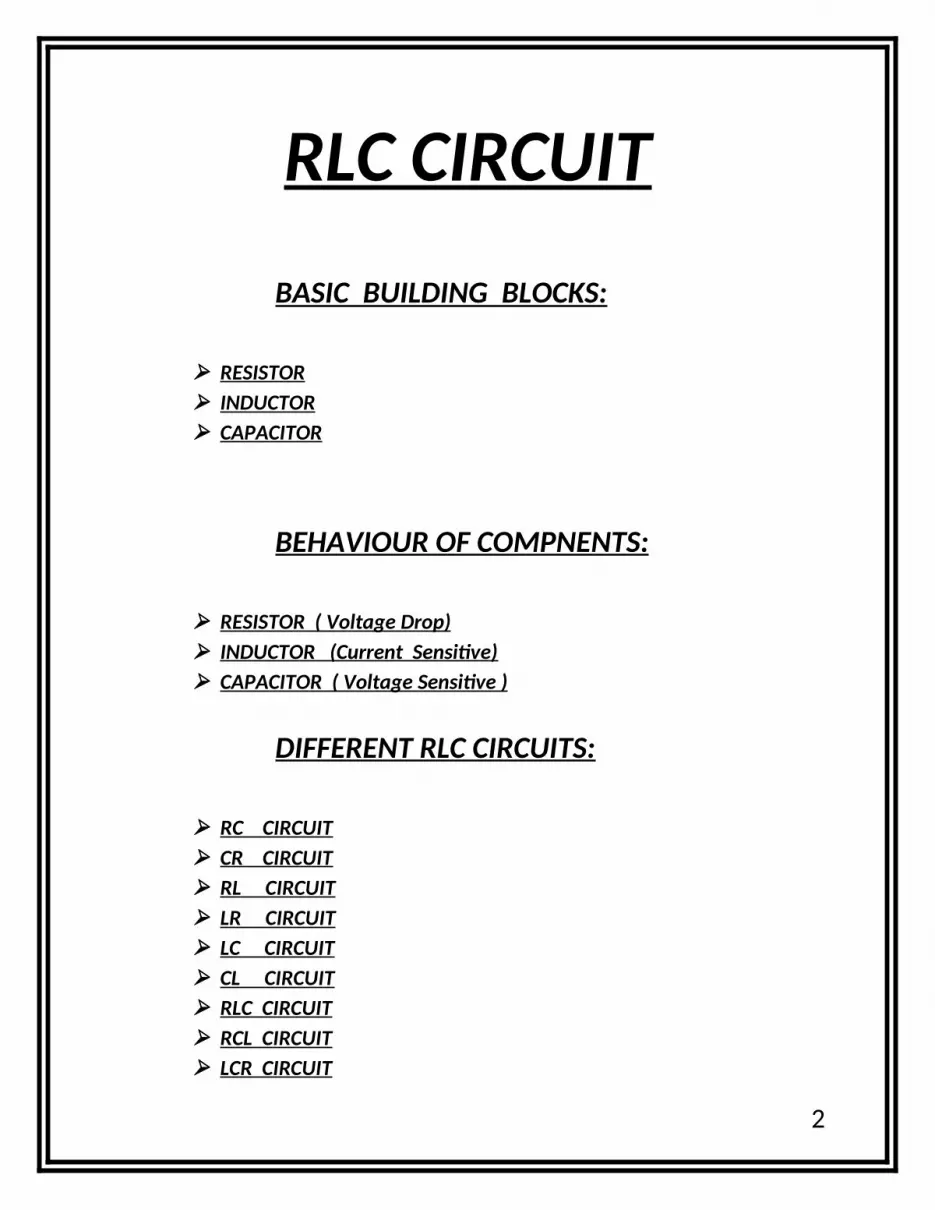
RLC CIRCUIT
BASIC BUILDING BLOCKS:
RESISTOR INDUCTOR CAPACITOR
BEHAVIOUR OF COMPNENTS:
RESISTOR ( Voltage Drop) INDUCTOR (Current Sensitive) CAPACITOR ( Voltage Sensitive )
DIFFERENT RLC CIRCUITS:
RC CIRCUIT CR CIRCUIT RL CIRCUIT LR CIRCUIT LC CIRCUIT CL CIRCUIT RLC CIRCUIT RCL CIRCUIT LCR CIRCUIT
2

RC CIRCUIT ( OUTPUT ACROSS CAPACITOR ) % RC cicuitfunction[] = project1()clccloseallclearalldisplay(' The output across CAPACITOR ');display(' enter the value of R = ');R = input('');display(' enter the value of C = ');C = input('');% the calculation gave us the Vout / Vin as num/denum forma = 1/(R*C);num = [0 a]denum = [1 a]p = tf(num,denum)subplot(3,1,1)step(p);subplot(3,1,2)impulse(p);subplot(3,1,3)pzmap(p);
In RC circuits pole will always lie at (-1/RC) , if we provide an impulse as input capacitor will start charging till peak input voltage, when impulse input is removed capacitor starts to discharge via resistor hence its output will be decaying exponential. Provided step input capacitor will charge till Vp and maintain its input voltage and will never discharge.
3

CR CIRCUIT ( OUTPUT ACROSS RESISTOR ) 4

% CR circuitfunction[] = project2()clccloseallclearalldisplay(' The output across RESISTOR ');display(' enter the value of C = ');C = input('');display(' enter the value of R = ');R = input('');% the calculation gave us the Vout / Vin as num/denum formnum = [1 0]denum = [1 (1/(R*C))]p = tf(num,denum)subplot(3,1,1)step(p);subplot(3,1,2)impulse(p);subplot(3,1,3)pzmap(p);
5

6

LR CIRCUIT (OUTPUT ACROSS RESISTOR) % LR cicuitfunction[] = project4()clccloseallclearalldisplay(' The output across RESISTOR ');display(' enter the value of R = ');R = input('');display(' enter the value of L = ');L = input('');% the calculation gave us the Vout / Vin as num/denum forma = R/L;num = [a]denum = [1 a]p = tf(num,denum)subplot(3,1,1)step(p);subplot(3,1,2)impulse(p);subplot(3,1,3)pzmap(p);
In LR circuit, inductor stores the charge, when input is removed it will start to discharge via resistor. Pole is at (-1/LR)
7

8

RL CIRCUIT (OUTPUT ACROSS INDUCTOR) % RL circuitfunction[] = project3()clccloseallclearalldisplay(' The output across INDUCTOR ');display(' enter the value of R = ');R = input('');display(' enter the value of L = ');L = input('');% the calculation gave us the Vout/Vin as num/denum formnum = [1 0]denum = [1 (R/L)]p = tf(num,denum)subplot(3,1,1)step(p);subplot(3,1,2)impulse(p);subplot(3,1,3)pzmap(p);
9

10

LC CIRCUIT (OUTPUT ACROSS CAPACITOR) % LC cicuitfunction[] = project5()clccloseallclearalldisplay(' The output across CAPACITOR ');display(' enter the value of L = ');L = input('');display(' enter the value of C = ');C = input('');% the calculation gave us the (Vout/Vin) as (num/denum) forma = 1/(L*C);num = [a]denum = [1 0 a]p = tf(num,denum)subplot(3,1,1)step(p);subplot(3,1,2);impulse(p);subplot(3,1,3)pzmap(p);
Inductor and capacitor are both energy storing devices, when impulse input is provided one of device will charge and when input is removed that device will discharge and 2nd device will start charging. Poles are at jw axis shows the oscillatory effect of LC circuit. Transfer functions of LC circuit include sin term.
11

12

CL CIRCUIT (OUTPUT ACROSS INDUCTOR) % CL cicuitfunction[] = project6()clccloseallclearalldisplay(' The output across INDUCTOR ');display(' enter the value of L = ');L = input('');display(' enter the value of C = ');C = input('');% the calculation gave us the (Vout/Vin) as (num/denum) forma = 1/(L*C);num = [1 0 0]denum = [1 0 a]p = tf(num,denum)subplot(3,1,1)step(p);subplot(3,1,2);impulse(p);subplot(3,1,3)pzmap(p);
13
14

RCL CIRCUIT (OUTPUT ACROSS INDUCTOR) % RCL cicuitfunction[] = project8()clccloseallclearalldisplay(' The output across INDUCTOR ');display(' enter the value of R = ');R = input('');display(' enter the value of L = ');L = input('');display(' enter the value of C = ');C = input('');% the calculation gave us the (Vout/Vin) as (num/denum) forma = 1/(L*C);b = R/L;num = [1 0 0]denum = [1 b a]p = tf(num,denum)subplot(3,1,1)step(p);subplot(3,1,2);impulse(p);subplot(3,1,3)pzmap(p);
15

16
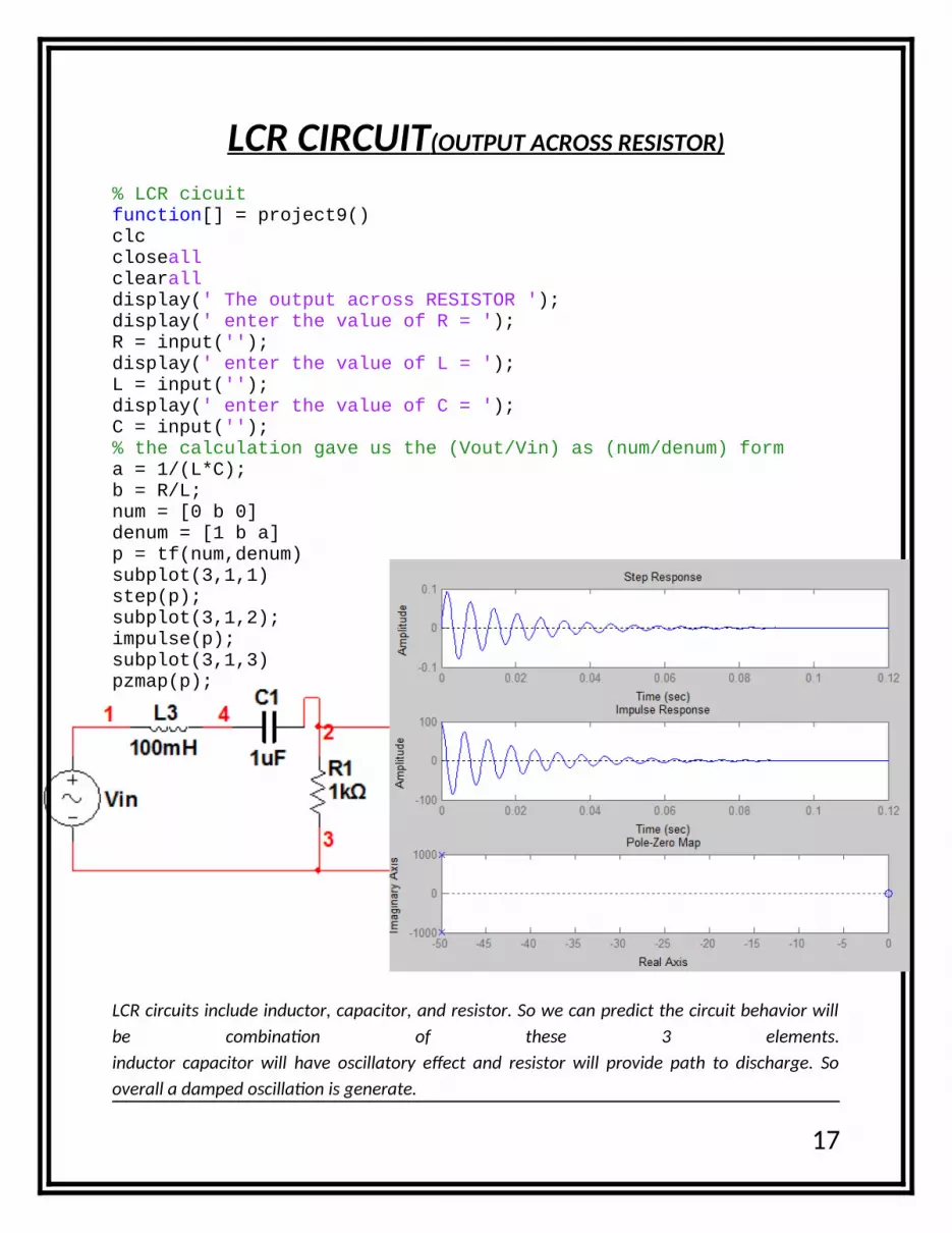
LCR CIRCUIT (OUTPUT ACROSS RESISTOR) % LCR cicuitfunction[] = project9()clccloseallclearalldisplay(' The output across RESISTOR ');display(' enter the value of R = ');R = input('');display(' enter the value of L = ');L = input('');display(' enter the value of C = ');C = input('');% the calculation gave us the (Vout/Vin) as (num/denum) forma = 1/(L*C);b = R/L;num = [0 b 0]denum = [1 b a]p = tf(num,denum)subplot(3,1,1)step(p);subplot(3,1,2);impulse(p);subplot(3,1,3)pzmap(p);
LCR circuits include inductor, capacitor, and resistor. So we can predict the circuit behavior will be combination of these 3 elements.inductor capacitor will have oscillatory effect and resistor will provide path to discharge. So overall a damped oscillation is generate.
17

18

RLC CIRCUIT (OUTPUT ACROSS INDUCTOR)
% RLC cicuitfunction[] = project7()clccloseallclearalldisplay(' The output across CAPACITOR ');display(' enter the value of R = ');R = input('');display(' enter the value of L = ');L = input('');display(' enter the value of C = ');C = input('');% the calculation gave us the (Vout/Vin) as (num/denum) forma = 1/(L*C);b = R/L;num = [0 0 1]denum = [1 b a]p = tf(num,denum)subplot(3,1,1)step(p);subplot(3,1,2);impulse(p);subplot(3,1,3)pzmap(p);
19

20


