Embed Size (px)
Citation preview
KR9700104KAERI/TR-811/97
Review of Design Analysis & Site Installation Method
of ASME Vessel of Fuel Test Loop of HANARO
v te 2 2
KAERI/TR-811/97
Review of Design Analysis & Site Installation Method
of ASME Vessel of Fuel Test Loop of HANARO
1997. 2.
S
s.
SLSi\ ±$-&: %-S-^- <>1-8-711 *
M 5?
717H
ASME m Section NB/NC/ND QA Category I
Seismic Category I ^-a-ol a ^ - s l ^ ^XJ-s. M J - ^ <&# ?fl*3|-
FTL RM1.2.
(ASME ffl NCE-3000
NA o ] f ^ ji-fj-)*}- U.S Joseph Oat Co. (N < y ^ ^
al 7lx>7|) f^oflAi FTL
-8-71-S-^ ASME m NC(Safety Class 2)£L#-& ^ ^ « V ^ -&
o] Safety Injection accumulators)- ASME VI &.#<>] ^ -8-s)^ -8-71
Pressurizerl- cflIL^«.S. ^ d ^ ^ - ^ Code
, '97.

Summary
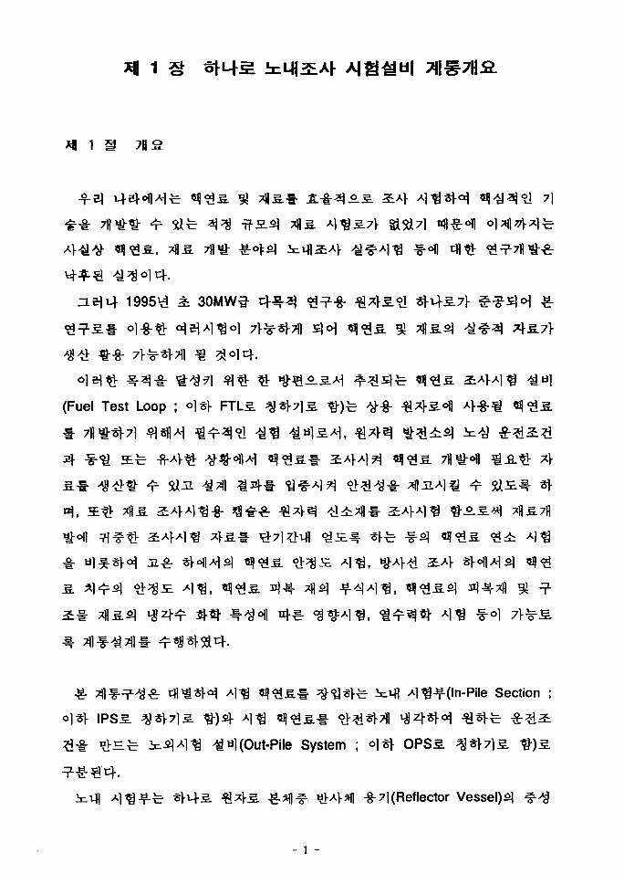
HANARO (Hi-Flux Advanced Neutron Application Reactor) whichwas Completed in April 1995 is a 30MW Korea Multi-purposeResearch Reactor with the Capabilities of the fuel and materialtesting, production of key radioisotopes and neutron activationanalysis etc. Now further utilization research on the core is highlyrequired to satisfy various needs. The manufacturing of equipmentsuch as vessels, valves and pipes is in progress for the Fuel TestLoop Facilities (FTL) after the completion of the system design.
Out Pile system (OPS) of FTL should be comprised in highly densearrangement of it's lay out because of space limitation due to notincluding in the process of HANARO Construction.
FTL should be met the technical requirements same as primarysystem of Nuclear Power Plant (NPP) including ASME III NB/NC/ND,QA category I and seismic category I . In addition, the project ofFTL depends on a rather small scale compared with NPP, whichwill be restricted in application.
Reviewing the situation above, we could expect many difficultiesand obstacles to follow up the OPS, even in the on-going stage ofthose manufacturing.
In the full operation of HANARO, the installation time of the OPSmust be minimized to secure the whole operation and solve theproblem of hard access to the limited space, FTL RM1, at the field.
The purpose of this report is to take the advantages under control,and provide basic solutions for field installation. In order to accessto technical availability, the scope, limitation, and possibilities ofdesign requirements are carefully considered in this.
The Safety injection accumulator and the Pressurizer arerepresentatively selected for this purpose, and conducted for detail
1U
design in reference to code requirements. The former Is located Inthe FTL RM1, and belongs to the uppermost degree, satisfyingASME III NC(Safety Class 2). The pressurizer is also one of themost important equipment in making by the cooperation of theSamsung Trade Company(having a certificate of NA according toASME III NCE-3000) and U.S Joseph Oat Co.(having a certificate ofN) under the contract. The latter is assigned to ASME VIIIconditions. The chapter 3 deals with Seismic stress analysis ofthese vessels, using manufacturers' Finite Eiement Analysis data.
The test of manufactured equipment is scheduled to hold nearfuture. The evaluation criteria and inspection specifications for thequality release are well illustrated in the chapter IV to efficientlycheck out the items. The full considerations for field installation arealso reviewed with that in terms of space limit.
Following the inspection and test of manufacturer's shop, theresults will be promptly reported. Based on installation principlesand the analysis in this report, updated procedure and methodologyfor the installation will be applied to the field in more details andbetter breakdown precision in the coming years.
IV
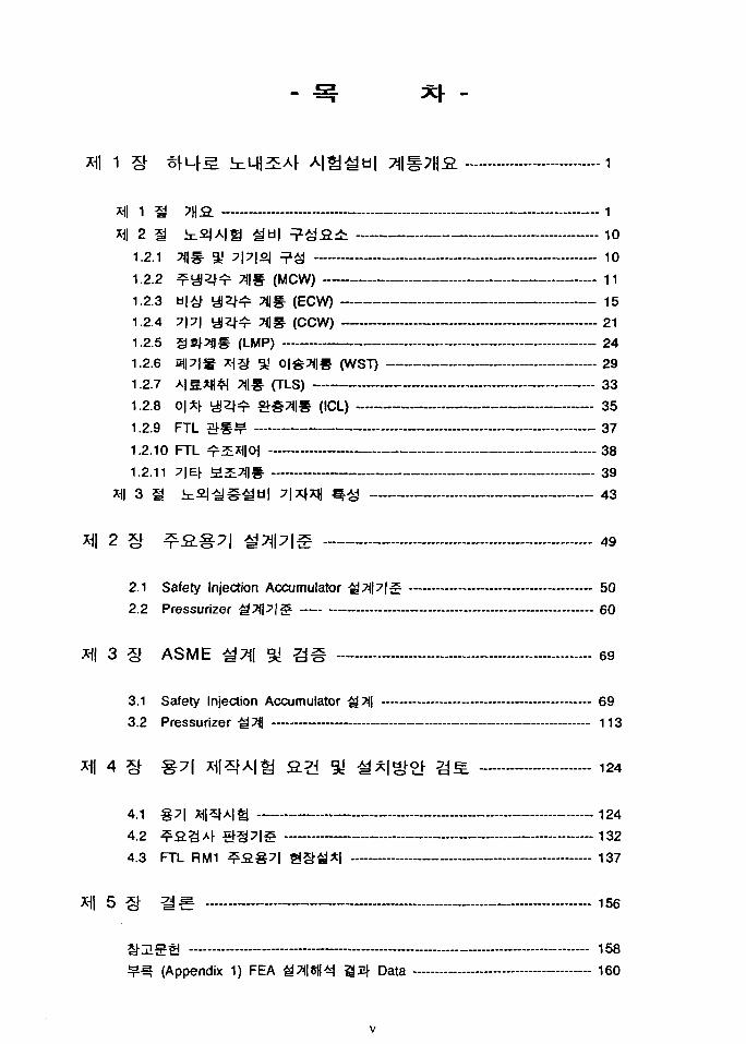
III 1 ^ 7U O „ -J
Xfl 2 § ic2|A|£j gu| ^£f i ;£ 101 '£•• * -'llo^ A -M^l-H I o — — — — — — — — — — — — — . — — . . . — —- — iu
1 99 ^.UITJ-I^ Tjis. /urw^ — — - - 11
1.2.3 b|Af y | 2 ^ 7||g. (ECW) 151 2 4 7 l7 l Ul^>^- 71 S- ^PCW^ — . — 5>1
1.2.5 S^TJIS (LMP) 24
1.2.6 a|| 71g *1£r 5t' 0|£71|S (WST) 291 ? 7 Al^All&l Tll-S
1.2.9 FTL 5 f § ^ 37
1 ? 10 FTI ^^XHIOJ - _ — — - ^ft
1.2.11 7|Ef a=E^|§ 39
3 S in2J-^S^tl| ?\*m ^ 43
2 § ^ S g 7 | ^7j|7|§ 49
2.1 Safety Injection Accumulator ^ 7 < M £ 50
2.2 Pressurizer MWlZi — 60
X\\ 3 § AS ME ^7*| 31 S i 69
3.1 Safety Injection Accumulator -gTil 693.2 Pressurizer ^ ^ | 113
4 § %71 Xi|**A|tJ 2.2 °1 ^7:|^o[ ?j£ 124
A 1 S-7I X-Jl^Al*! — —
4 9 ^.Q>iAt lU^^I-^. — . —
4.3 FTL RM1 ^ S g ? | S § g * | 137
5 ^ 3 S. 156
158(Appendix 1) FEA g7HS||4j S 4 Data 160
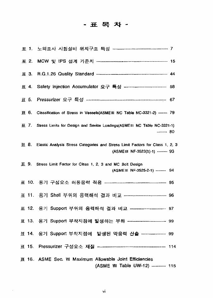
3 1. infillAF A|*j^d| $ J * | ^ S g 7
fi 2. MCW 3S IPS M*\ 7 |S* | 15
S 3. R.G.1.26 Quality Standard 44
3 4. Safety Injection Accumulator S.^1 <g 58
3. 5. Pressurizer 2.^ ^^& — 67
3. 6. Classification of Stress in Vessels(ASMEIII NC Table NC-3321-2) 79
3. 7. Stress Limits for Design and Sevice Loadings(ASMEIII NC Table NC-3321-1)
80
S. 8. Elastic Analysis Stress Categories and Stress Limit Factors for Class 1, 2, 3
(ASMEIII NF-3523(b)-1) 93
S. 9. Stress Limit Factor for Class 1, 2, 3 and MC Bolt Design
(ASMEIII NF-3525-2-1) 94
S. 10. #7| ^-^8.± ^i-g-S^ ^-S 95
s. 11. %y\ Shell *ms\ #^*H4j 1 4 ti\m 96
3. 12. §7| Support ^ ^ ° | g SH<M SJjlf d|5l 97
3 13. S7| Support ^*fx|go|| i ^ s f e ¥^r 99
a 14. %71 Support ^5|^|§0i| gfgjg ° | § ^ >4# 99
3. 15. Pressurizer ^ ^ S i t : XUU 114
16.- ASME Sec. VIII Maximum Allowable Joint Efficiencies(ASME VIII Table UW-12) 115
VI
S. 17. Conical Head°| M2J * J # 2 2 118
S. 18. Pressurizer * Jg ¥ s r i 2 123
S. 19. xni^Ah A|*J ^ ^ A i * l | # * ! ^ 124
3. 20. § 7 | ^x |A| ^ S * ^ 4 : S S - 147
S. 21. Primary Hole Drill Dia. & Depth. 149
S. 22. Undercutting Tool Dia. & Tolerance 150
S. 23. ?t|5H Sizeojl a±m Torque &nf 2JS^ 155
VII
Fig. 1 SfLfS g*fl ^ a ^ * | g b||*| 3
Fig. 2 CANDU ^ PWRg tM|A|S¥ « l ^ ¥ * l 5
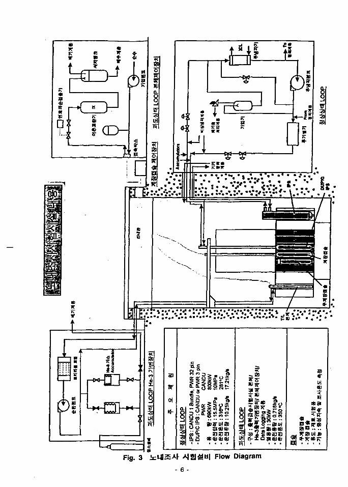
Fig. 3 ±mz^M A |g^b| Flow Diagram 6
Fig. 4 in2|A|tJ^a| ^ 2 . SH|dH*| 8
Fig. 6 b|# tilZt^S ^ I ^ F ^ 18
Fig. 7 7|7| a ^ l ^ ^ l # ? ^ 22
Fig. 8 §4f7)|# ^ l ^ ^ ^ 26
Fig. 9 a(7|g x j§ 51 0|^71|# 30
Fig. 10 A|.g*H4N ^ £ M | # - 34
Fig. 11 0|*f ^ 2 | ^ )|S 36
Fig. 12 Safety Injection Accumulator S^^ IS 59
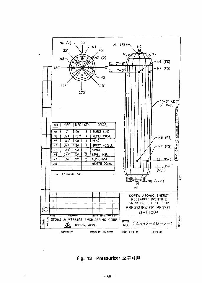
Fig. 13 Pressurizer S T ^ I I S — 68
Fig. 14 § 7 | ^ Head ¥^2J ^ S 72
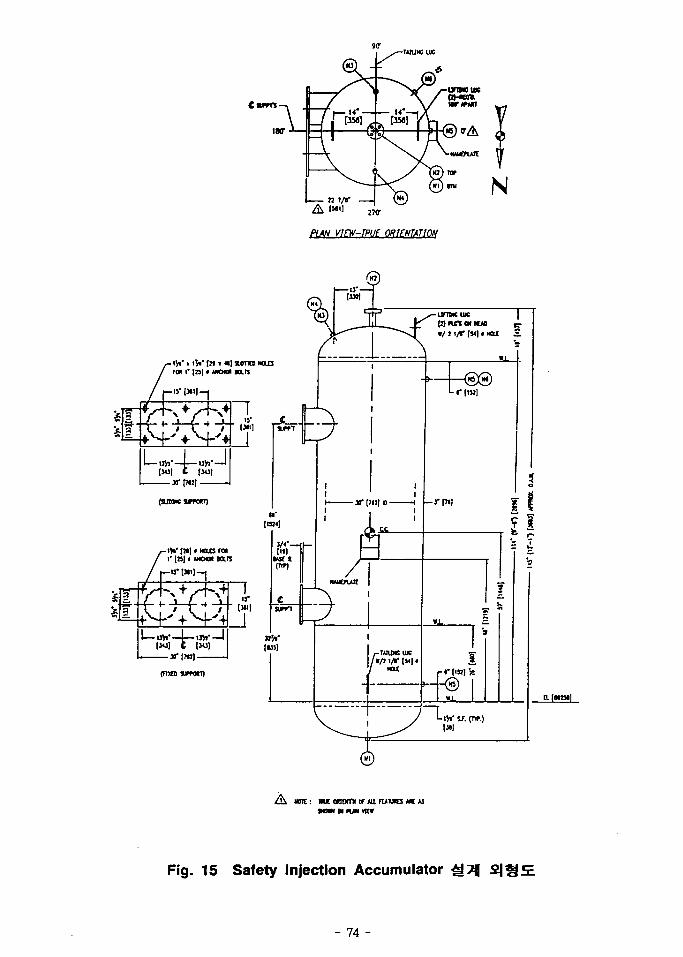
Fig. 15 Safety Injection Accumulator g?i\ 2JS5E - - 74
Fig. 16 Accumulator mSSH I Wire Frame Plot 86
Fig. 17 FTL RM1 # « § . § 7 | ^ tfx| f|*| 1 107
Fig. 18 FTL RM1 #¥& %^\^ ^ * l Support Plan 108
Fig. 19 §7|CH| a&|fe S a s J ^ Pull-Out Strength <3<% — 112
viii
Fig. 20 Pressurizer ^7)| s j g 122
Fig. 21 FTL RM1 uH*l S^ l Lay Out 1 138
Fig. 22 FTL RM1 bH*| S? | Lay Out 2 139
Fig. 23 FTLg HELB 7J|g aU^sj jfojj 144
Fig. 24 Drill-Undercutting g^f1 151
Fin
IX
S
-a3
(Fuel Test Loop ; <>1^ FTLs.
Section ;
fct i i ^ H ^ ^«1 (Out-Pile System ; ol«V OPSS. ^
*\-^£- QxlS. -g-^]^ Ht^y^i -8-7l(Reflector Vessel)^
- l -
Fleldofl 3*13- <T^ 2 ^ } ^ Large Hole(LHH
3. ^-8- ^ ^ o | Jz);g iO2.4min^ CANDU
79.1nun?] $*&*$<% PWR
Module^-
Ufl
40TC)?HI
ki l l Al^^.^ *|*lfc ^^.g. ^2*o ] i+ ^ ^ g . 7fl^7l7il- o]-g-
.£ €^-s. ^ ^ ifl oll 7)
-aTil 5i ^
Aj.tt.ofl o}*)^ Man-Bridge^^A^ 4<a^7f Hoist Craned
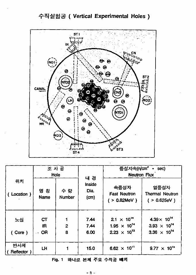
( Vertical Experimental Holes )
fl*l
( Location )
( Core )
( Reflector)
Hole
Name
CTIR
• - O R
LH
Number
128
1
Mi 3InsideDia.(cm)
7.447.446.00
15.0
^ x H ^ n / c m * . sec)
Neutron Flux
^§£*rFast Neutron
( > 0.82MeV )
2.1 x 1OW
1.95 x 10¹⁴
2.23 x 10¹³
6.62 x 10"
ThermaJ Neutron( > 0.625eV )
4.39 x 10¹⁴
3.93 x 10¹⁴
3.36 x 10¹⁴
9.77 x 101a
Fig. 1
Man-Bridge #41*1 *^«<>1 * ! 3 i ^ A S . -8-<>l*r7fl
* • £ • W2- ' r i S -¥-3 Active Gallery*
7171
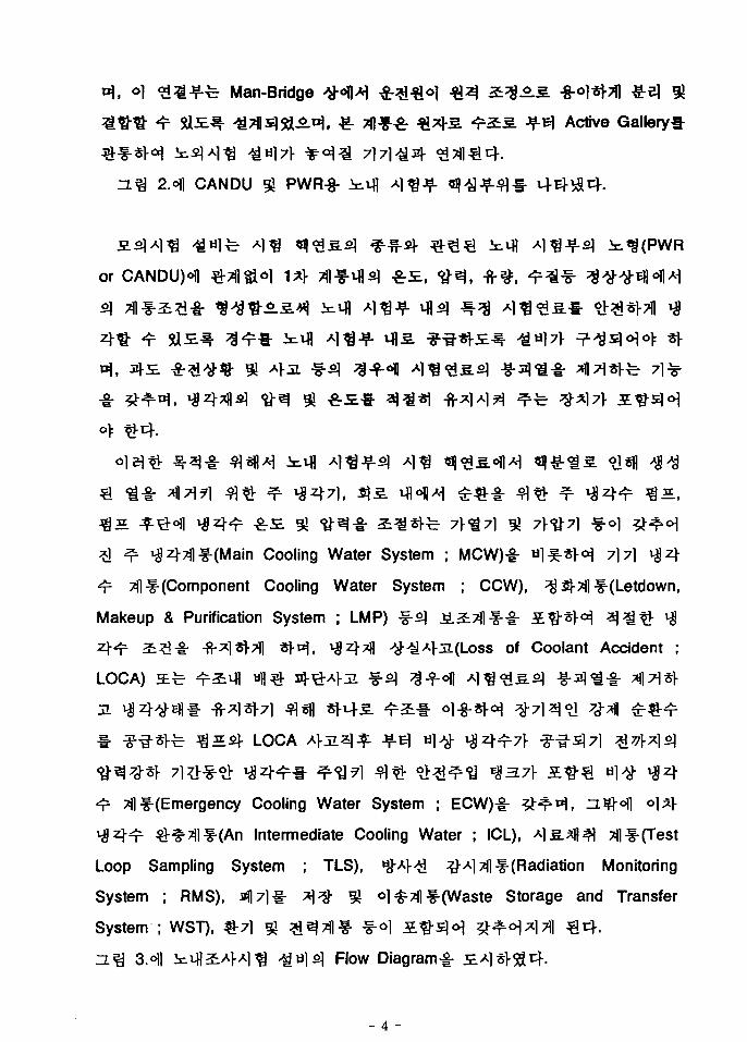
2.ofl CANDU 5? PWR-8-
or CANDUH
o]«fl
71-^71 ^ 71-^71
1 ^ i | z|-7il f-(Main Cooling Water System ; MCW)-§- o l^ -«H 7]7l
^r ^lf-(Component Cooling Water System ; CCW), ^ 2J-31 f-(Letdown,
Makeup & Purification System ; LMP) ^s ] j£i7Jlf-§- 5 # * H ^ j ^ ^ ^
^^r 2i#-i; -fr l«1-7ll *}-^ f *$Z\T§ AJ-^A>OI(LOSS of Coolant Accident ;
LOCA)
M LOCA
Til (Emergency Cooling Water System ; ECW)^-
^•^^•f-tAn Intermediate Cooling Water ; ICL), Ais^ll^l 7flf-(Test
Loop Sampling System ; TLS), ^Af/H ^-Al^f-(Radiation Monitoring
System ; RMS), all71!- 7]% ^ ol^Tfl^f-(Waste Storage and Transfer
System ; WST), &7] gj ^^Tf l f - &°] a^5 l<
n ^ 3.<HI inf laAl-Al^ ^ « l 51 Flow Diagram^-
- 4 -
l?«i.4i (top or ruti «u«oit • *« )J7K0
en
>fi
•a
3
© PWR FUEL TEST LOOP ASSEMBLY
CANDU FUEL TEST LOOP ASSEMBLY
VMmv•I
HI
eFig. 3 Id-fl^E Flow Diagram
- 6 -
Room No.
FTL RM1
FTL RM2
9i i ?^ m*
Elevation
EL 76.6
EL 72.3
^ 2.
2.7m x 9m x 2.95m
4.8m x i 4.8m x 3.1m
it £
as ¥^OII
moi aeoi
§5^1 S, ^ ^ ^
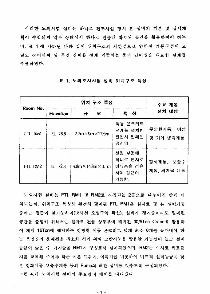
^ FTL RM1
FTL
30/5Ton Crane-i-
4.ofl ufl^l
- 7 -
FTLROOM1
Fig. 4
272^ ^ £ 2 ] 371-g 5?
System, - ^ £ System, Battery Room
70J: '94. 1.
31 - "97. 7. 31)££ ^31 *l-£#-fr ^ - ^ - ^ ^ n]5f Stone Webster Co.^ ^«^
S. ^ 4 -g-^711- -B- l l-7] ^ tV 31 f- ^7(I# ^ r ^ * H , US Battelle
7)7] 5
KOPECo] - g - ^ ^ ^ ('96. 6. 13 ~ '97. 3. 31)
-ga]
('95. 11. 14 ~ '97. 4r
AEA Technology^
('96. 12. 23 -
ASME -8-7]
- 9 -
1.2.1 n
# 210 Unit : * ^ " ^ "tf- (Main Cooling Water System : MCW)
#> 220 Unit : H l ^ 1 ^ ~*£ (Emergency Cooling Water System ; ECW)
# 230 Unit : ""• I~"I "M"^ 1 * (Component Cooling Water System : CCW)
# 240 Unit : S - " ^ * (Letdown, Makeup, and Purification System ; LMP)
# 250 Unit : "ni-g- ***$ °l ^ ^ - i
(Waste Storage and Transfer System ; WST)
# 231 Unit : 2*r ^ ^ f - " ^ ^
(Intermediate Cooling Water System ; ICL)
# 260 Unit : l-£-*«*< ""If- (Test Loop Sampling System ; TLS)
ol«2|o)i FTL ^ i ^ f - - ? - (FTL Pool Penetrations ; FPS),
(Radiation Monitoring System ; RMS), ^^^o] Tflf- (Hydrogen Control
System ; HCS), ^ ^ 7 f l ^ ^J 11 <H (Associated Instrumentation and Controls)
^ ^ HVAC Tflf-
°1
1.2.2 ^ a ^ ^ | g (MCW)
MCWfe IPS5] t^^o) ]^ JfE^ Alafl-sH Pool Penetration^ Pipe
Gallery
(Pressurizer),
IPS
FTLS]
3L7)
71^-g-
MCWfij
MCWfi]
71
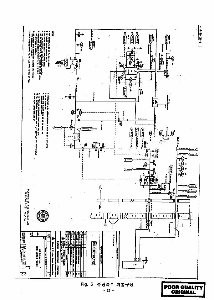
5.oflAl MCWSl
MCW51
-. MCW
Stainless Steels
- 11 -
fgfsfHi {fil
liij Hi!'
Fig. 5- 12 - POOR QUALITY
ORIGINAL
Canned
•a-
MCW
Si711
MCW
Air-Operated ^ s | ^ « . f e MCW
IPS!- MCWJf^
-fi-5.(Single
Pass)5] Shell & Tube^ - i i E ^ ^ o i u i , ICL A^-^-S
^ ECW ^lf-ofl ^«fl MCW Tf l f -^S.
ECW ^l^f-^: 27fl 3 ^2q-7fl ^«a^3(Water Injection Accumulator)^ 2tfl
^ H l ^ ^ 2 t | £ S ^ ^ s j o l SU4- Accumulator^- MH -BJ-TC!- ^\3L^\ &
£ 7R>-§-«?]- >|ZJ-^|J|- IPSofl ^ ^ S r ^ c f l Af^-^cj-. ^ ^ ^ Upset ^ 3 A ]
^•^r 7l^>§-?>5] ^z^-sj- u))^- 4^-Af5lAl %7}# ^^-(Long Term
Cooling)^ Af-fr^t)-. ^ = fe MCW1- *tffl ^ 4 ^ 1 # ^ ^ * A ] 7 ] U I CCW
- 13 -
MCW
- MCW 741^^ *fl3j:4 * r ^ 5 L ^ ^ LMP Tfl^f-f- f-sfl °l-f-<H;5!4- LMP
7], Degasifier, ^ ^ ^ ^ ^ 3 3! S . - ^ ^ ^ 5 - ^ ^ ^ 4 - MCW^
FTL
4 . 71^-4 ^ ^ l ^ f i l *$^A n*\ ^3} -^ LMP 7l|Jfofl o ] ^ Automatic
Letdown^ 4^/cfoJ=(Redunclant/Diverse)^ 1*1- ^l- f-^-w^
-§-€ ^r Xi4- ^^^11 fl€-^ ^.-^(Letdown and Makeup)^
(Margin)l- 7\A3- CANDU
Surge Flow*
IPSS.
2*17i iflofl Ambient Room Temperature
- 14 -
MCWs]
2 i ^ FTL
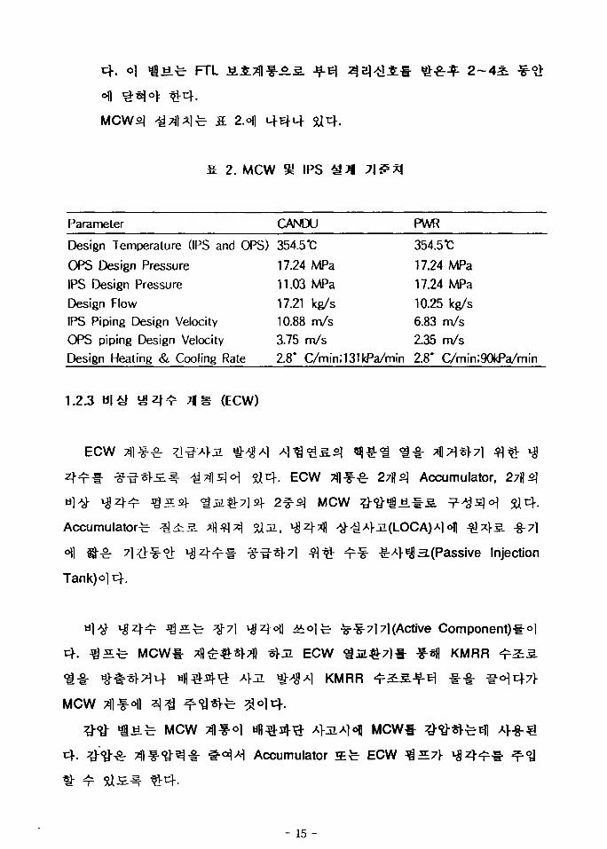
s. 2M\
I t 2. MCW S! IPS
Parameter CANDU PWR
Design Temperature (IPS and OPS) 354.5*C
OPS Design Pressure 17.24 MPa
IPS Design Pressure 11.03 MPa
Design Flow 17.21 kg/s
IPS Piping Design Velocity 10.88 m/s
OPS piping Design Velocity 3.75 m/s
354.5TC
17.24 MPa
17.24 MPa
10.25 kg/s
6.83 m/s
2.35 m/s
Design Heating & Cooling Rate 2.8* C/min;131kPa/min 2.8' C/min;90kPa/min
1.2.3 nm (ECW)
ECW
Accumulator^
. ECW ^f-^- 27fl5| Accumulator,
MCW ^ - ^ f a . ! - ^ ? - ^ £ M
OL(LOCA)A] 6fl - ^ ^ 5 . -g-7l
-g-4^Ss(Passive Injection
Tank)
MCW1-
l(Active Component)-!-^]
ECW ^5 l€-7] l - f-*fl KMRR
AI KMRR
MCW
«.fe MCW MCWI-Accumulator a fe ECW ^
- 15 -
A>J1* «fl 9«V7l ^ Sfl RCPBS] * * ! -§ • -fr
ECW1-
FTL-i- ?V i«>7fl ^X|*|-fe^| ^ ^ L ^ : Afji jf. #A](pOst Accident Monitoring)
* ^c f . (R.G 1.97, Category 1, Type A, B, and C)
Ufl IPS
ECW 2)5 .^ ofEfl H]
- Accumulator^] Gas
-Accumulator^
- Afai^f ^ A ] 7 1 ^ ^r*g (R.G 1.97, Category 2, Type D)
KMRR ^ 1 1 JfE] i g z K 1 * ^ « a ^ f e ECW ^ } ^ - ^ ^ ^ « l f e MCW
Suction Valve)^ ^ ^ ^ ^ Vent Valvef- £7)] tfS-^ojt}.. ^ • ^ ^ • « r Vent
Valves MCW Tflf-^ # ^ - # 4 1 ^^s l<H ^ 4 . tfe|#*|. Valve^ 7 ] ^ ^ #
Accumulator^ ^z ] -^7 f FTLofl ^ ^ £ j H # *rfe 5}°)cf. ECW
- 16 -
ASME m, NC-7000, ND-700CW
ECW 6.34
*r Class 1E
Sfe FTLo]
ECW ^ i ^ IPSfi]
. ECW ^ =
ECW ^ S . ^ 0PS4
Leg
ECW ^ ^
IPS
, OPS Sfe IPS
. ECW ^
Hot Leg^lM A
MCWofl
?! $f-^t(Alignment)^ MCW5) Cold
!(Re-alignment)&°1 Main Loop ^
(Re-alignment)^
IPS
Accumulator^ 7}^
Accumulator^
Vessel Test #£.7}
Accumulator^
4 . Accumulator-^
^-717|]
Manual
IPS«H|
. ECW Accumulator-^ IPS
, ECW
FTLS.
- 17 -
- 18 -POOR QUALITY I
ORIQINAL I
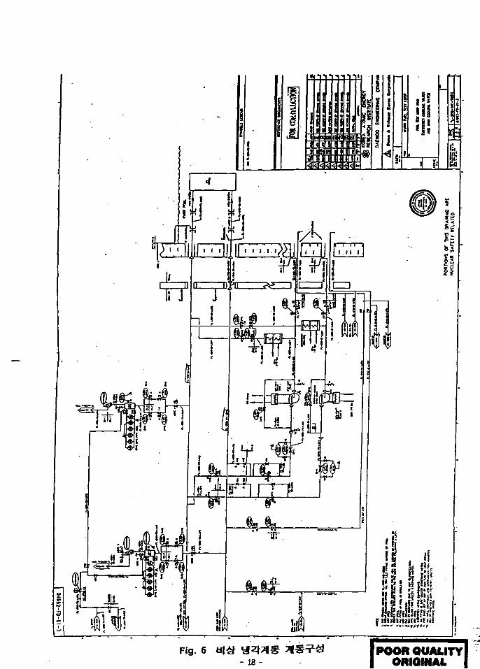
Accumulators}
Line
Accumulator^
. Accumulator^ j q ^ ^ - Main Steamvflofl
cf. w)>y- ^ m ^ 7 l ^ 7171 1 ^ z ^ ^ Tjlf-ofl ojsfl x^z^-s]^ shell and
Tube
Accumulator
- ECW ^ ^ ^ ^ o f l £ £ ^ 1 KMRR ^^S. - ^ 5 }
Modes,
Test Room 1
IPS A>
KMRR ^ fl
Room 1 LOCAsl- ^ E l ^ a . ^J-^^] Accumulator# A
^ s l - s - s - mL IPS ^g-sl'i^ sl«fl
371(1 ")O1 4 .
ECW ^ l
- 19 -
ti. Trip 4 l £ 4 * A H T 1 | # € 4 . SOVfe
IPS<=fl ^A<T7\ 4*1 *8*M*r ^3L7> 5UA^ J 4 N 3 4 .
tj-A) X#:Z}-;*f)7f
KMRR
4" ^^ f -J f l - 3/4" ECW
* ^ « V i 5U«H ^r2D|2] KMRR
IPS
^^-7] 7](Single Active Component)^
^ ^ ^ ^ ( S i n g l e Failure)^
71714
ECW1-
- 20 -
1S]
1.2.4 (CCW)
FTL 7l7]i|z]-^(CCW)
ECW Tflf-
. CCW
Annulus§ f-sfl
ECW Tflf-AS.
Room 14 KMRR Pool^
KMRR Pools. ^ MCW
o]
Room 13] H1
Annulus JE-
«1 £€ • Hot Pipe
ECW <g5L^7l «21- ECW Pump
^1 l-3^JiV!!4. CCW
CCW <iJf*}7}- KMRR
CCW 7 4 1 ^ ^ ZL^ 7.
Room
CCW Pump
CCW Pump J L ^ A H i
CCW Pump
KMRR
o.s. KMRR PooHl
XI
CCW^
- CCW
ECW
- 21 -
5IS,
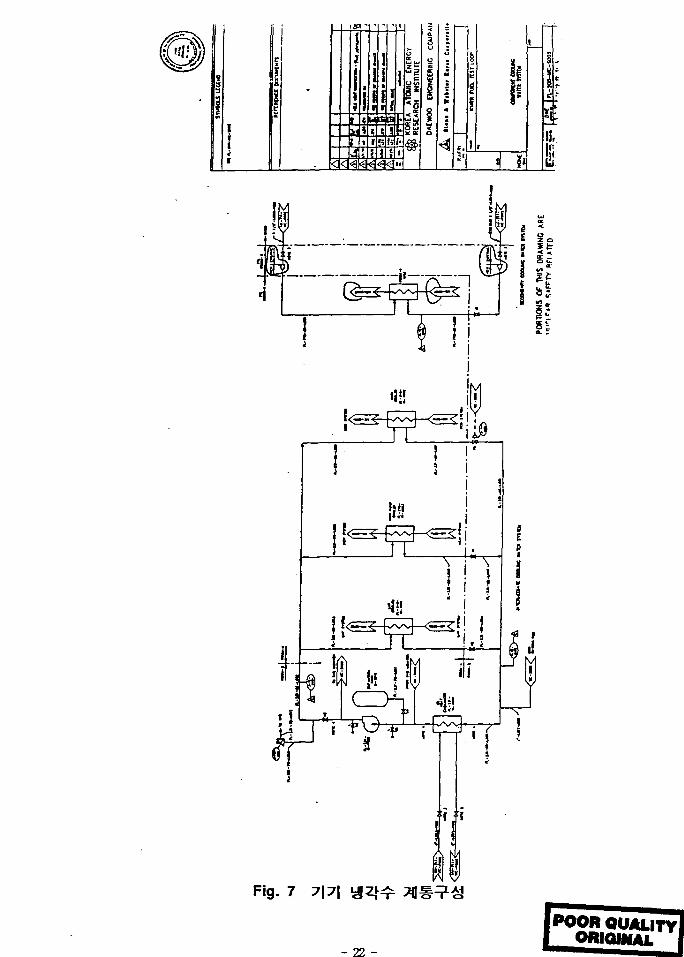
Fig. 7 7|7|
- 22 -
POORQUALITYIORIGINAL
. CCW ^ = f e ASME Section m Subsection
CCW $2. -g^^r KMRR Pools. Jf*H c f # ^ "H^(Redundant Line)-g-
o l - f -o^ t } . 1^-^ 13 zH^(Redundant Cooling Water)^ CCW Pump
KMRR ^ 2 : 5
4 « ^ f - f ^471^ ^T|S1 CCW 4J47H
^ ^(Redundant Cooling Water Coonection)£ CCW Pumps]
- KMRR Pooler MCW
CCW
CCW Pumpfe Class 1E
cf. LOCA2] A>
CCW Pump^.
ccw
CCW Pumps] -g?fl# i r t §£- 2 0 ^ ^ ] ^ FTLs]
^-^54 ^ ^ ] 7 l ^ a?iofl>H 4 4 s ]
4", 6" ZLS]J I 8" ^-^Jf0!! ^ ^ ^ ^ . 5 .
Lfe MCWs]- CCW
CCW
- 23 -
MCW/CCW
MCW-&
Annulus
fe 2-1/2" (6"
na la i CCW £ t J 3 - * l * $1*11 Annulus
- Annulus 3-?Kg: ^ - € - ^ ^ 5 . MCWS. J?-3 CCW TU^-^-S. <
Foam Glassy. ^ 'S^ 'H 5U4. KMRR 4^3:^ # # #
Pools. 7flȣs}<H KMRR <t^7} CCW Tfl^.2-
Room 1 Annulus fi]«fl
Tflf-fi]
^ ^ ^(Thermal Relief)
NC-7000 ZLT!)5L ND-70002]
Seismic Category is]
5a
ASME B & PV, Section ffl, Articles
CCW
- Category I 7]7]-l-
1.2.5 (LMP)
LMP
MCW
MCWfi]
MCW
Degasifier
- 24 -
Metering ^ = , £.&<?•
CANDUvJ- PWR
LMP
(Changing) ^ i E . LMP
PWR
MCW
2 0 £
CANDU
MCW«
MCW
• I -
FTL-i-
MCW
MCW*
, 2 a ^ 37]7]&ol 7]^(Seismic n / I Design)
LMP2]
FTL £330) ] MCW
tj-^^(Diverse)
KMRR
MCWofl
l MCW
. FTL ^ - ^ ^ # ^7}-
KMRR Pools. Jft) CCW ^ ^ ^ # #
* Pump ^ ^ ^ 4-^/H
711 0} - g - ^ ^ 20 -«?>^ FTL^-
Sources.
- 25 -
t M a a a >i !
35'
$f
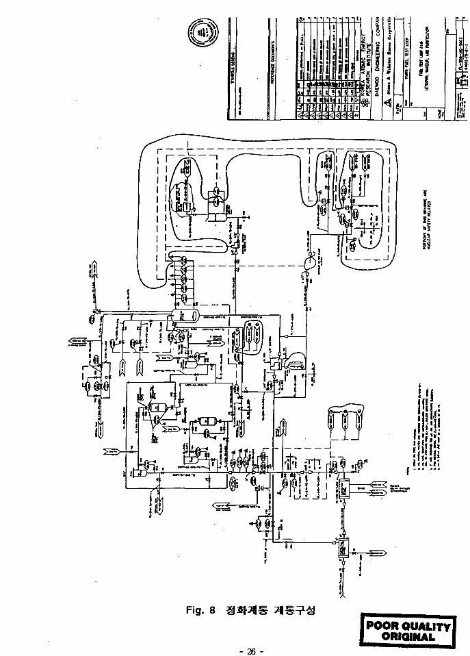
Fig. 8
POOR QUALITY]ORIGINAL
- 26 -
Low Levels- * ^ Level*]
Low Low Levels
MCW 31 f-
MCW
FTL IL
H^; 7l5.fi] -fr^JSlfe MCVVS
-8-ofl
MCW
100%
7V ^^1?> ol«1-7> SlTfl ^ 5 ( 1 ^ 5U^- ° l^r S ^ 7 l f e o]
- 27 -
^^-(Disposable) 7\m.
pH, O 2 ^ £ (MCW
(Boron)
ail
- 28 -
i Sampling Station^.5.
LMP ^ l f - ^ £€ • J I ^ I M * ] ^Jf^-^r Room 1<%
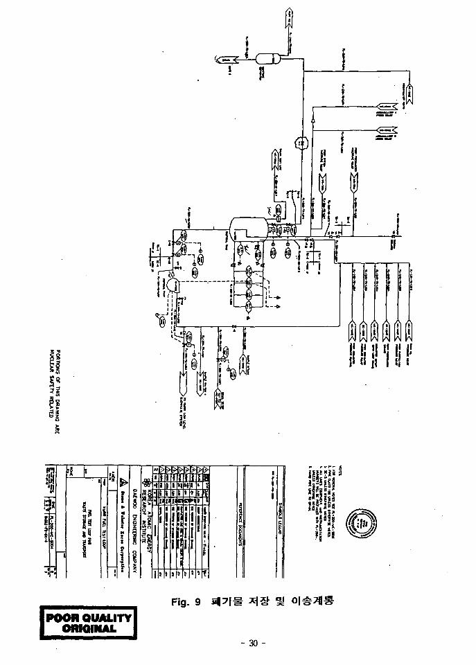
1.2.6 m\m ns s 01^ (WST)
1 1 1 ] # 4 l ^ ( ) ) f FTL5.
-§- KMRR q*\] «c}-Apj s(|7l# Tilf-olu)- KMRR RCI
FTL
KMRR
500 mrems}
- MCW, ECW, LMP Tilf-^-S. J f^ ^ ^ ^ ^ . ( S V ) H ^ a l
- LMP n%±3, -^-^o] ^ . ^ ^ ^ ^ ^^*>c^ ^ ^ 1 - J l ^ ^ ^Af Bfl7l
- 29 -
!
•t !i •111
I'
i i
illiii
POOR QUALITYORIGINAL
Fig. 9
- 30 -
1. 2. 3 7}7]7\
- o j - _g.i£ : IPS Mfl^s] Drain,
B||7]l-i- KMRR RCI
4 2 S . ^ -H] WST
- WST
WST 7)^
LMP
. 7l-<a-7) SV, ECW SV, MCE Heater RV, HE)
SV
RV &
cf€ FTL RV (Thermal)
- WST ^ 3 ^ ) -g-^^r 7j]f- 7]*A1 3^5.o] ^ a j ^^-3)- A].JLA] SV^ RV
- 31 -
KMRR
5a4.
KMRR Pools.
. o] ^-«g(Rupture) Disk-
M KMRR RCI
KMRR HVAC « J 1 3
- WST
Sampling Station^.5.
- 32 -
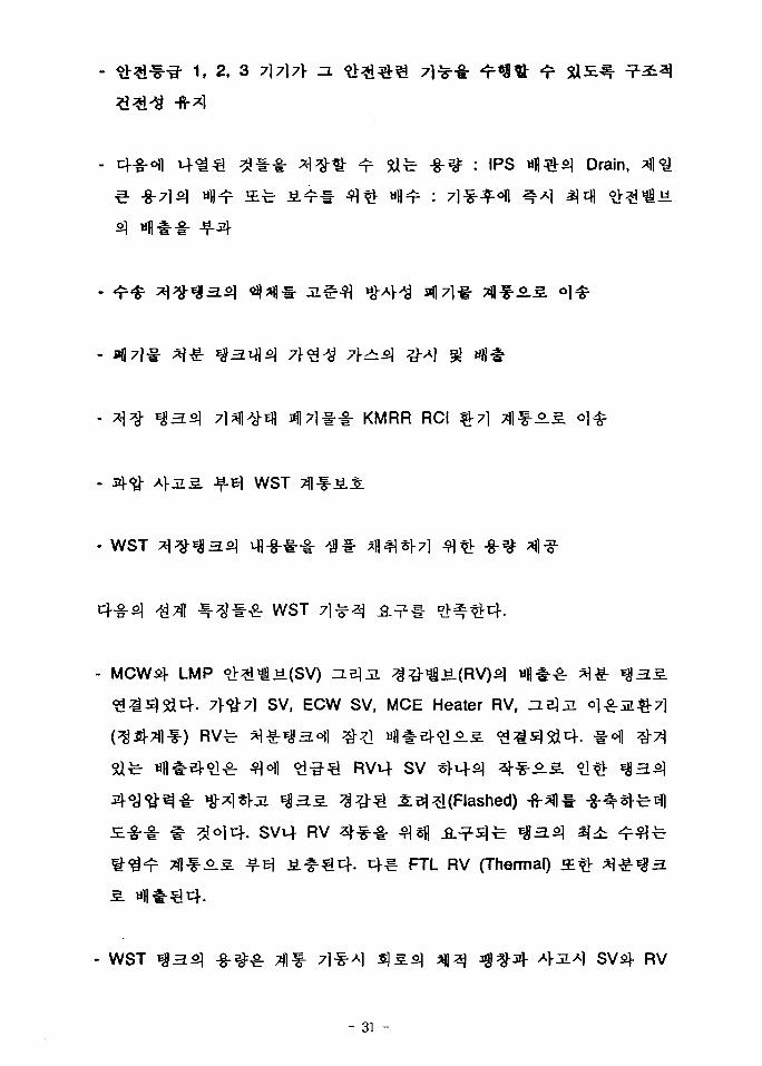
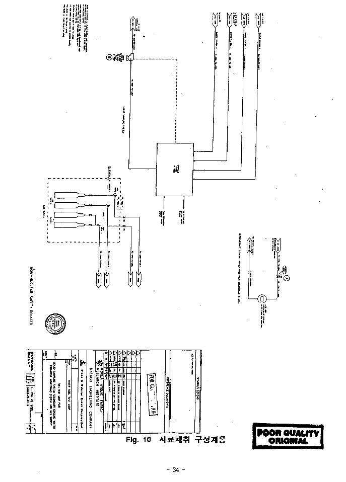
1.2.7 A |S* |3 * g (TLS) ? 3 2 £ 3! ?ll§
TLS T f l ^ FTLS] ^ - § - ^71^0.5. ^-Al^^cfl A>-g- -cf. H ^ 10.<Hj
^-^^8: TLS71-
Panel
TLS 7flf-£
- MCW, ECW, LMP7]-
-*i- 71^-1-
, 2 afe 3o] o > ^ ^ ^ 7l^(Seismic n / I
Panel
- 33 -
Ka
sS if
is35 E
$•
10POOflQUAUTYl
ORMUNM
- 34 -
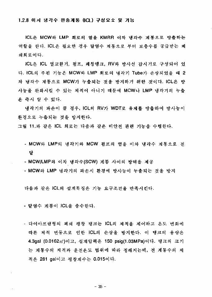
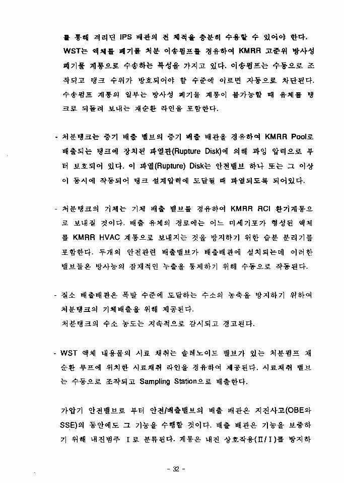
1.2.8 0|*f a ^ &mnm (ICL)
MCW^- LMP SjS.si <i-g- KMRR
ICL£r ICL ^
t } . ICLfi ^ ^ 7 ] - ^ ^ MCWsf LMP $£.$] ^2+7l Tube7|- ^
AS. MCW7} ^ r ^ S ] ^ ^ ^ - «ov^l*f7] ^ ^ ?
LMP
RV7)-
11.34 £ £ ICL flS^- 4 ^ " ^ ^ ^ r
MCW ^^L
MCW/LMPs]-
LMP
ICLS]
ICL-I-
4.3gal (0.0162m')ol^, ^ T f l ^ ^ ^ r 150 psig(1.03MPa)ol4- *$3.$) 3.7}
281 galolJi ^ ^ T f l ^ ^ 0.015olcf.
- 35 -
-P- VIF-T
a -<•tu
0D
DOCUMCNFI
s
KOREA ATOMC ENERCrHtSEARCH
OAEWOO ENGMEERINC COUPAMT
KMM run ic^t LOOP
ma mi uw rto
ooouHc V4iu mnta
= • _ • — . I we Fl-KO-K-SM
Fig.
- 36 -
POOH QUALITYORIGINAL
- MCWS]
°] >i*l7\ MCW . MCW ^ =
ICL ^ ^ 7 l f e 67l|si Tube7V
32" (812mm)o]oL, ^ ^
Jf^- -8-*}^: MCW
(1x10⁶ Btu/h), MCW
Shell <£%SH$i. °1 Shelly ifl
^ > ;^ Tube^ ^ ° l f e 5ft (1.524m)o]
(2.173 ~ 4.295 x10⁶ Btu/h), LMP H}6 Btu/h)o|c)-.
- ICL JgS-b 531 gpm(32.59 kg/s)°laL, TDH-b 135ft(41.15m)o]c)-. ICL Jg
^-8-^^r MCW ^2q-7], LMP ^2^71, MCW %IL ^ 4 7 1 ^ -fi-^ofl 713:
**• ^^1^1 - f r^^ -^ -^ 301 ~ 531 gpm a fe 147490 1b/h ~ 1260190
1b/h
- ICL ?ilf- 150 psigolJi, RV
1.2.9 FT1 (FTL Penetrations)
KMRR Gallery A|-olo]l
Room 1 ^ofl MCW, ECWi4
(Hydraulic Barrier)
-fi-^fl
a]
Room 66TC (15O'P)-
- 37 -
1.2.10 FTL <£S*|(H nm (HCS)
FTL HCSfe nf-g-s; H] o ^ ^
- ^ £ # HCS *1# ^H*)°JH Room 2°fl
- MCW
1, 2, 3 7l7l l -ol n. <L>*l7l^(Seismic
HCS3
Room 2<Hl
HCS9)
1.2.11
7\. FTL ^71711^ (HVAC)
- Test Room 1
- KMRR HVAC Tflf-^ Test Room 2-i
- 38 -
FTL $7 l7 f lS£ FTL Room 1 4 2 ^ ^ ^ l ^ l f H I ^J8.^>^- Room
HVAC T f lS* KMRR ^ -^T f l f - ^ Af^-^-c}-.
Room 1 » |4^ . ^ ^ Jg^- ^z^Tjlf-o] FTL
KMRR * 7 l 7 | | f - * «"7l
-^o l HVAC
Test Room 1 HVAC^
(NPS)
- Test Room 1 ^ 2°fl 3*l«fl S i t NPS ^ ^ 1 1 5 . ^ - ^ FTL 7l7ls. ^
wfl^(Venting)AI ^ i ^ f £ # ^i]^5r7i ^ s f M Degasifier
- ECW Accumulators*!] J i^ f i ] Cover 7 ^ ##•£
t^-g" ^ -^^ r NPS
NCSs] <a-^-|- #<>l7l ^s|]A^ oj-^ <a^-fr^l wJ«.(Pressure Regulating
Valve)!- s(|7l#
ECW Accumulator
ECW Accumulators^ ^rfc Cover 71-i-
i ^ Room 2o)l $ i ^ oi<a- -8-7H
SC-5(NNS)o]c^.
(IAS)
Pl-c)- KMRRS] A ] t f l i ^ 7 * 1 ^ 7 1 * Room m 2<fl
, 2 a t 3
- 39 -
IAS . (NNS)
FTL cf-g-
- FTL MCW, LMP, TLS KMRR
. (Seismic n / I Design)
SC-5(NNS)o]c]-.
- LMP
- WST
- ECW
SC-5(NNS)o]t|-.
«>. Test Rooom 14 2
Test Room c}-g-
- 7] 7) * . j i Building Sumps.
- 40 -
Water)!-
, 2 5E*r 3
(Seismic D / I Design)
] iV^i-g-^-fe SC-5(NNS)ol^.
(RMS)
% 711 f -8-
, Til 71, #= -
Effluent ^ -471^-g- 2-51
-S.-E- 71^1
- 41 -
- 42 -
1$ (Regulatory Gu ide)£
7171
-, 7l7ll-f i l ^ -^ -^ 10 CFR 50 Appendix B
10 CFR 50, 55a
-"^ 10 CFR 50,
ASME B&PV Code Sec m Class 1 7l7l^l .fi.:?l-§-
10 CFR 507>
l 10 CFR 100 ?l
3j-8-*|-^f # ^ ^ - ^ - f e 10 CFR 50,
55a _fi_:?Hl n}-^. Regulatory Guide 1.26 "Qulity Group Classification and
Standards for Water, Steam, and Radioactive Waste Containing Components
of Nuclear Power Plants"-!-
- 43 -
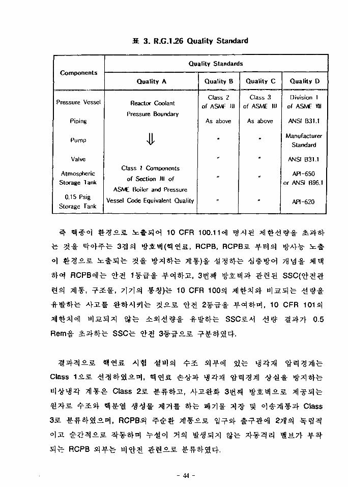
3. R.G.I .26 Quality Standard
Components
Pressure Vessel
Piping
Pump
Valve
Atmospheric
Storage Tank
0.15 Psig
Storage Tank
Quality Standards
Quality A
Reactor Coolant
Pressure Boundary
Class 1 Components
of Section III of
ASME Boiler and Pressure
Vessel Code Equivalent Quality
Quality B
Class 2of ASME III
As above
Quality C
Class 3of ASME III
As above
n
it
it
Quality D
Division 1
of ASME VW
ANSI B3I.1
ManufacturerStandard
ANSI B31.1
API-650or ANSI B96.1
API-620
10 CFR 100.11°fl *$ *] €
S., RCPB, RCPBS.
10 CFR 1003
10 CFR
0.5
Rem-I-
Class 15.
Class 25.
a||71 Class
RCPB
- 44 -
- 10CFR50 Appendix A, GDC 14 - Reactor Coolant Pressure
Boundary
- 10CFR50 Appendix A, GDC 15 - Reactor Coolant System
Design
- 10CFR50 Appendix A, GDC 30 - Quality of Reactor Coolant
Pressure Boundary
- 10CFR50 Appendix A, GDC 31 - Fracture Prevention of Reactor
Coolant Pressure Boundary
- 10CFR50 Appendix A, GDC 32 - Inspection Reactor Coolant
Pressure Boundary
5J £ # (Codes
and Standards)-!
- Piping and Piping Components :
ASME m sub-section NB(from the inside wall of the Penetrations
to and including the loop isolation valves)
ASME m sub-section ND(Inside the pool) ;
- 45 -
ASME B31.1 (outside the loop isolation valves)
- Tanks, Pressure Vessels & Heat Exchanges :
ASME HI, Subsection ND ; ASME VI (remainder of components)
- Pumps : Hydraulie Institute Standards
10CFR50 Appendix A, General Design Criterion 34
Residual Heat Removal
10CFR50 Appendix A, General Design Criterion 35
Emergency Core Cooling
10CFR50 Appendix A, General Design Criterion 36
Inspection of Emergency Core Cooling
10CFR50 Appendix A, General Design Criterion 37
Testing of Emergency Core Cooling
- ANSI/ANS-58.8, "Time Response Design Criteria for Safety-
Related Operator Actions"
ECW31 ^7 j ] , a)]4, ^ ^ ] % A } ^ ^ . 4 ^ - ^ -str gj ^ ^ (Codes and
- 46 -
Standards)^-
- Piping and Piping Components : ASME HI, Sub-section NC (all
porions of system except for steam vent lines) ;
ASME HI, Sub-section ND(steam vent lines)
- Pressure Vessels & Heat Exchangers : ASME, Sub-section NC
- Pumps : ASME III, Sub-section NC
7\7\
- 10CFR50 Appendix A, General Design Criterion 44 -
Cooling Water
- 10CFR50 Appendix A, General Design Criterion 45 -
Inspection of Cooling Water System
- 10CFR50 Appendix A, General Design Criterion 46 -
Testing of Cooling Water System
£ 3.B. (Codes
and Standards)^
- Piping and piping Components : ASME m, Sub-section ND
- Pressure Vessels & Heat Exchangers : ASME m, Sub-section NC
- Pumps : ASME m, Sub-section ND
- 47 -
$ LMPs} ^79 , * * K 4**1 % *}•%•& t}-g-s} 2 E g S.& (Codes
and Standards)^-
- Piping and piping Components : ANSI B31.1
- Pressure Vessels : ASME VI
- Atmospheric Tanks (0-15 psig) : American Petroleum Institute
(API) 650
- Pumps : Hydraulic Institute Standards
3 H ^ ^ ( C o d e s
and Standards)-^- nJ-E-cf.
- Piping and piping Components : ASME in, Sub-section ND
(piping Connected to waste disposal tank) ; ASNI B31.1
(remainder of piping)
- Pressure Vessels : ASME m, Sub-section NC
(waste disposal tank)
- Pumps : Hydraulic Institute Standard
- 48 -
((ASME CODE m Section NB(SCI :
SAFETY CLASS 1) ^ QA CATEGORY 1. SEISMIC CATEGORY 1
ASMEID NCA-3000 &.#<$ v$& "N" gj "NA" <&&*\ (CERTIFICATE OF
AUTHORIZATION) ^ US NRC 10CFR50 APP.B ANSI / ASME NQA-1,
NCA-4000 £^r o|S}
N 5J NA
Jeseph Oat Co(N
^ , Code Ai«1l 4€- ^^1 ^ i ^ ^ * f l ^ ° l Sl^-v], ^-*1 *>M-5- Fuel Test
Loop RM14 RM251
ASME ^7«7V x^-^ 5^-5)<H Xl^-H, ^-8- «^-S.«1l Af-g-slfe ASME
15%
- 49 -
NA
Packaged ^MJ*M #«g ^^7) - ^ s H ^7l<=fl FTL
zM: ^«.S., «- ^ofl-HSj i L«*H^ >a«| ^ A TJl-f^ n)^-o^ Joseph Oat
Co.7\ * * 7fl^=o.S. # < ^ « H ^ ^ - ^ ^ ^ ^ ] ASME Vessel ^ Tank# «?V
•l-S-o| ^ ^ ^ ^ . A ^ ASME ffl Safety Class 2 Code £.&
Safety Injection Accumulators}- cfls.^^-5. ASME VI -fi.:?l-§-
fe- Pressurizer Vessels] ^7})7l§-§- fc*|-7ls * > ^ , *fl 3 ^ > H c Code
2.1 Safety Injection Accumulator
Stone Wester^ ^ ^«V<^ ^ - ^ ^ 7l#A>«8= No. FL-070-DD-S004 Rev
-8-71 41*1 ^ ^ 2 : ? i 5?
: FTL RM 1 («J-M-S. RX
o£• s. : 0
<& ^ : -1/4" w.g.
£• JE : 20 ~ 90 (%)
1.1x10" (Beta) ; 2.7 x10⁷ (Gamma) ;
Total Dose Over 20 years)
- 50 -
Spray : None
Submergence : None
Time :
O ^l^- t t ^ ^ (Upset Plant Operation)
: -1/4" w.g.
: 90 (%)
: 1.1x10" (Beta) ; 2.7x10⁷ (Gamma) ;
Total Dose Over 20 years)
Spray : None
Submergence : None
Time : 2]/2 days/year
O >M-:n. £ 3 (DBE)
: 172 kpa gage
: 100 (%)
: 4x10⁷ (Beta) ; 6 X 1 0 7 (Gamma)
Total Accumulated dose)
Spray : None
Submergence : None
Time : 1 year
O
PH : 5.5 - 6.5
Chlorides, ppb : < 0.2
Turbidity : < 1 NTU
Conductivity : < 5juMHo/cm
- 51 -
Fe ppm : < 0.5
Cu ppm : < 0.1
SO4 ppm : < 0.2
Code
- -g-71 ^ f l ^ -a .^ : ASME Sec m Subsection NC
- Support aH2j-.fi.:?] : ASME Sec m Subsection NF
QA Category I 31 Seismic Category I
- Code ^Tfl-S-^ £^ .8 .? ] : ASME m NF-1132
"Boundary Between Component or
Piping Supports and Building Structure"
: • ASME m NC (3100/3000/3900)
• ASME m & R.G 1.84 ^ 1.85
- Support -a3] 5? ^ r ^ ^ ^ i : • ASME m NF (3100/3300/3400)
• ASME ffl & R.G 1.84
- • ASME m NC/ND-2120 (-§-7])
• ASME ffl NF-2120 (Support)
° Regulatory Guide 1.85
- ASME m (SA) « a t ASME nH>H o ] ^ s | - A S T M
- 52 -
Austenitic Stainless Steels)
Carbon ^ - f i - ^o l 331 0.03%
427 ~
, ASTM A262 Practice A or E
Austenitic Stainless Steel^ -g-^ ^ ^ ^ o f l ^ ajcj) interpass
350T1-
- Asbestos
- 4-8- ^ ^ ASME m NC/ND-231134 NF-2311(a) - (g)ofl
fe Inpact Test7)-
1) Service Limit -g-^-
O Service Limit A - Operating Pressure, Temperature, Deadweight,
Nozzle Loads Due To Piping
- 53 -
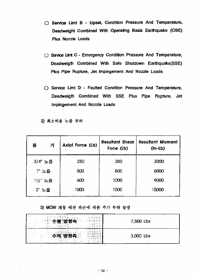
O Service Limt B - Upset, Condition Pressure And Temperature,
Deadweight Combined With Operating Basis Earthquake (OBE)
Plus Nozzle Loads
O Service LJmt C - Emergency Condition Pressure And Temperature,
Deadweigth Combined With Safe Shutdown Earthquake(SSE)
Plus Pipe Rupture, Jet impingement And Nozzle Loads
O Service Limt D - Faulted Condition Pressure And Temperature,
Deadweigth Combined With SSE Plus Pipe Rupture, Jet
Impingement And Nozzle Loads
2)
3/4" i n #
Til
2" inS
Axial Force (Lb)
250
500
600
1000
Resultant ShearFoce (Lb)
380
800
1000
1500
Resultant Moment(In-Lb)
3000
6000
9000
15000
3) MCW Tfl f-
7,500 Lbs
3,000 Lbs
- 54 -
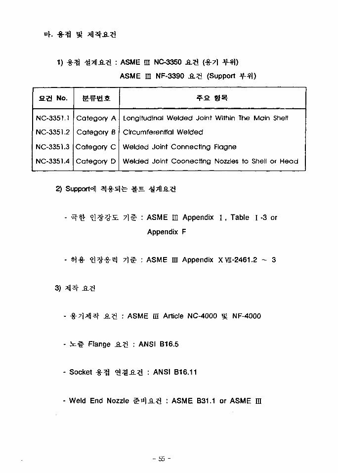
: ASME m NC-3350
ASME m NF-3390 .£.£ (Support
£.2 No.
NC-3351.1
NC-3351.2
NC-3351.3
NC-3351.4
Category
Category
Category
Category
A
B
C
D
Longitudinal Welded Joint
Circumferential Welded
Welded Joint Connecting
Welded Joint Coonecting
Within
Flagne
Nozzles
The
to
Main
Shell
Shell
or Head
2) Support^ 3-8-3fc- - i - ^ .
ASME m Appendix I , Table I -3 or
Appendix F
ASME m Appendix XVD-2461.2 - 3
3)
ASME ffl Article NC-4000 ^ NF-4000
Flange .fi.*! : ANSI B16.5
- Socket : ANSI B16.11
- Weld End Nozzle : ASME B31.1 or ASME m
- 55 -
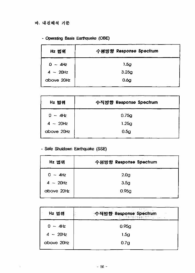
- Operating Basis Earthquake (OBE)
Hz a?i
0 ~ 4Hz
4 ~ 20Hz
above 20Hz
^ S g l l Response Spectrum
1.5g
3.26g
0.6g
Hz S 3
0 ~ 4Hz
4 - 20Hz
above 20Hz
4=^1 SHr" Response Spectrum
0.75g
1.25g
0.6g
- Safe Shutdown Earthquake (SSE)
Hz SSI
0 ~ 4Hz
4 ~ 20Hz
above 20Hz
T ^ S ^ S Response Spectrum
2.0g
3.5g
0.95g
Hz asi
0 ~ 4Hz
4 ~ 20Hz
above 20Hz
T ^ ^ I ^ S Response Spectrum
0.96g
1.5g
0.7g
- 56 -
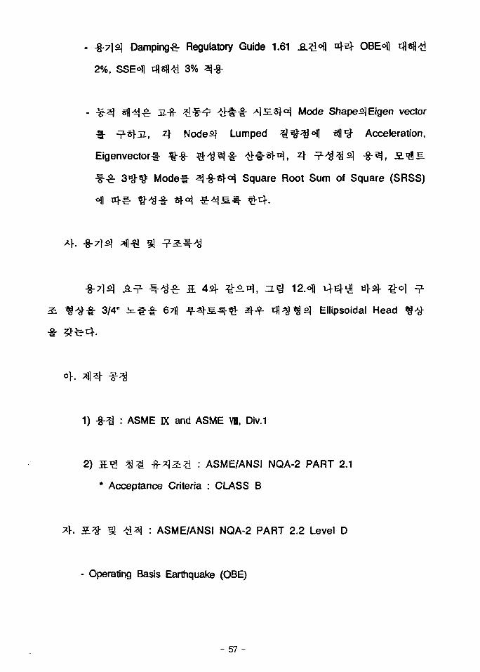
Damping^ Regulatory Guide 1.61 J L ^ ^ I ^ OBEofl
2%, SSE°I| rflsfl/H 3%
;z-f}- ;*l-§^ ##•§• ^ J E S H Mode Shape^Eigen vector
* ^^[JL, z\ Nodes] Lumped ^ ^ o f l sfl1^ Acceleration,
Eigenvectorl- %-g- # ^ 3 - § - ^ t - « r ^ , A T 1 ^ ^ ^ * ^ , S -^S
3^-^= Mode# ^}-8-*roi Square Root Sum of Square (SRSS)
3/4" i i#-§- 67)| JfSj-s.^-^- aHf c f l ^^s ] Ellipsoidal Head
1) -§-^ : ASME K and ASME VI, Div.1
2) S.# ^ ^ -fr*l2:?I : ASME/ANSI NQA-2 PART 2.1
* Acceptance Criteria : CLASS B
: ASME/ANSI NQA-2 PART 2.2 Level D
- Operating Basis Earthquake (OBE)
- 57 -
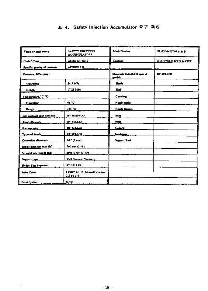
IE 4. Safety"Injection Accumulator fin1
Vessel or talk name
Code/Class
Specific cranrc of contents
SAFETY INJECTIONACCUMULATORS
ASME m / SC-2
APPROX 1.0
m a s o n . MPa <png):
Operatms*
Daicn
14.5 MP.
17.23 MPi
Temneralure.'C (F):
Onentm*
Deucn
SHc ambMnt max and min
Joint eflicMacv
RadiocraDOT
Trpaofbods
Corrosoa allowance
Inside diameter nun (in)
Straight tidt height mm
Support type
Hvdro Test Pressure
Paint Color
Paint Svstem
66'C
3SS'C
BY DAEWOO
BY SELLER
BY SELLER
BY SELLER
1/8' (3 mm)
760 mm <T-6~)
2S95.6 mm (9-6*)
Will Mounud Vertically
BY SELLER
UOHT BLUE; MUUMU NumtMT2.5 PB S/6
N-107
Mark Number
Contents
Mauriah (SA/ASTM ipec Airadeh
Heads
SheB
CmnUncs
Nozzle necks
Nozzle flanxes
BoKs
Nats
Caskets
Suppott Steel
FL-220-M«T004 A *. B
DEMINERALIZEO WATER
BY SELLER
- 58 -
45"
1 SO-
2 7 0 "
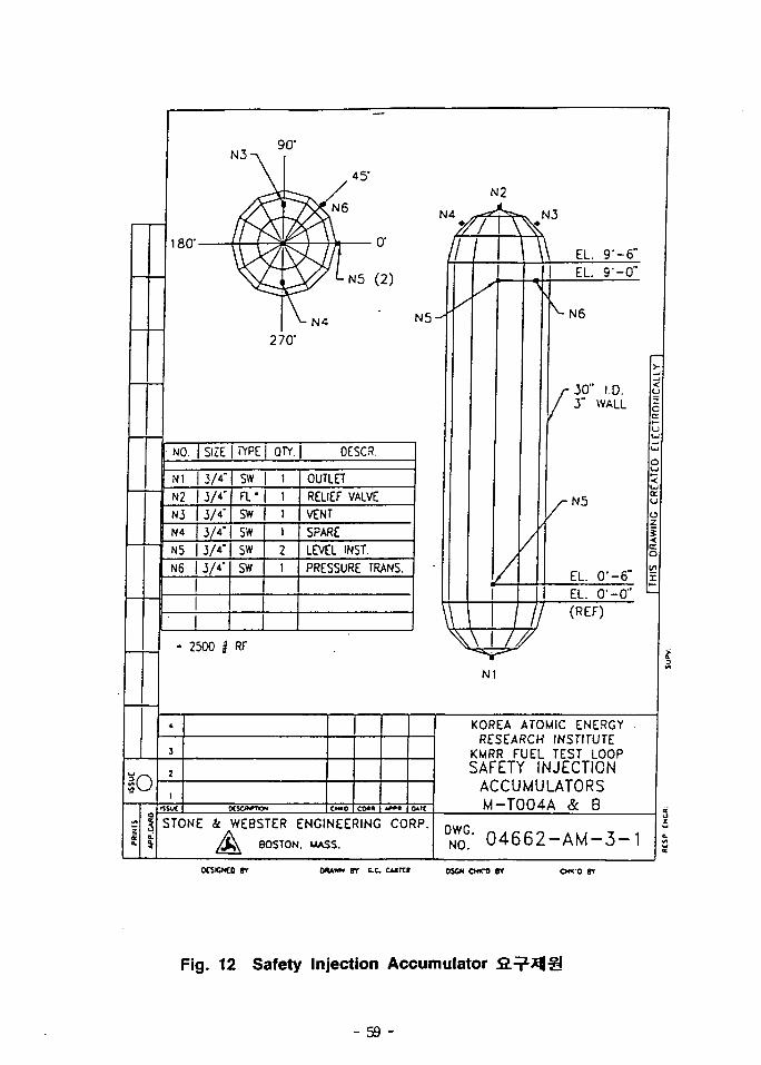
NO. | SIZE | TYPE I OTY.J DESC3.
N1 | 3/4"N2 I 3/4"N3 3/4'N4 3/4
N5 3/4'N6 I 3/4"
SW
FL"SW
SW
SW
SW
OUTLET
RELIEF VALVEVENT
SPARE
LEVEL INST.
PRESSURE TRANS.
2500 i RF
r \ \ \ EL 9"-6"EL. 9--0"
•N6
30" 1.0.1" WALL
u
• N5
EL. O'-6"
(REF)
N1
EL. O'-O" " -
!O
KOREA ATOMIC ENERGYRESEARCH INSTITUTE
KMRR FUEL TEST LOOP
SAFETY INJECTIONACCUMULATORSM-T004A & B
TONE 4 WEBSTER ENGINEERING CORP.
^ > BOSTON, MASS.DNW
0G- 0 4 6 6 2 - A M - 3 - 1
OCSCNCO gr DAAWN 6T C C OSCK CWTO »T C W O BT
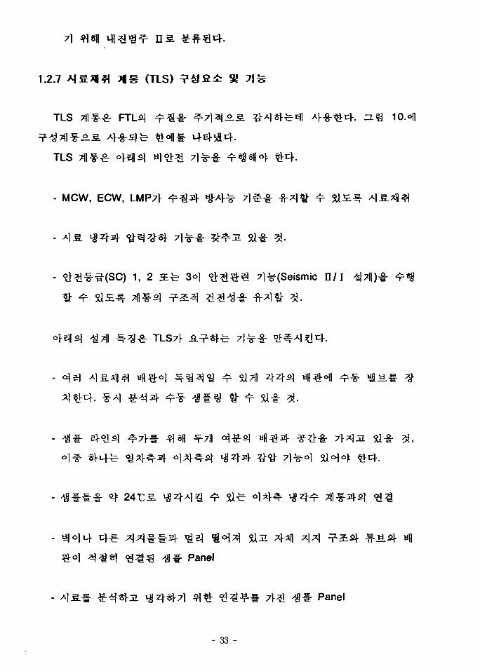
Fig. 12 Safety Injection Accumulator
- 59 -
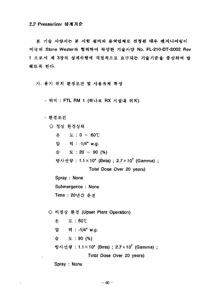
2.2 Pressurizer
stone Western ^^«|-<^ ^<%& 7]&A}<& NO. FL-210-DT-S002 Rev
: FTL RM 1 (*m-s RX
O
£ £ : 0 ~
•8- 3 : -1/4" w.g.
# £ : 20 ~ 90 (%)
H o v 4 ^ ^ : 1.1x10" (Beta) ; 2.7x10⁷ (Gamma) ;
Total Dose Over 20 years)
Spray : None
Submergence : None
Time :
O tiH^ ^ ^ (Upset Plant Operation)
£ S. : 60 t
ft 3 : -1/4" w.g.
<£ £ : 90 (%)Hov4-a^ : 1.1x10" (Beta) ; 2.7 x10⁷ (Gamma) ;
Total Dose Over 20 years)
Spray : None
- 60 -
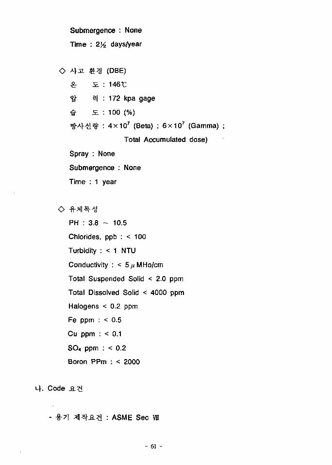
Submergence : None
Time : 2>A days/year
O A > J I £ 3 (DBE)
£ i : 146t
<& e] : 172 kpa gage
«£ S. : 100 (%)
^ l - ^ ] ^ : 4x10 7 (Beta) ; 6 X 1 0 7 (Gamma)
Total Accumulated dose)
Spray : None
Submergence : None
Time : 1 year
OPH : 3.8 - 10.5
Chlorides, ppb : < 100
Turbidity : < 1 NTU
Conductivity : < 5//M Ho/cm
Total Suspended Solid < 2.0 ppm
Total Dissolved Solid < 4000 ppm
Halogens < 0.2 ppm
Fe ppm : < 0.5
Cu ppm : < 0.1
SO4 ppm : < 0.2
Boron PPm : < 2000
Code
- -g-7] *f|*hS.:?l : ASME Sec VIH
- 61 -
- Support afl^-fi.?! : ASME Sec m Subsection NF
QA Category n 9J Seismic Category I
- Code ^Tf lJf^ $%£.£ : ASME ffl NF-1132
"Boundary Between Component or
Piping Supports and Building Structure"
ASME VI
- Support ^Tfl ^ S r ^ i ? ! : . ASME ffl NF (3100/3300/3400)
• ASME ffl & R.G 1.84
• ASME VII NC/ND-2120 (-§-7l)
• ASME ffl NF-2120 (Support)
« Regulatory Guide 1.85
- ASME VI (SA) ^f l^ afe ASME VI°fl4 t l ^^ fe- ASTM zfl^l-t- 4
Austenitic Stainless Steels] ^-f-fe- 1^5 ] a ^ - i - ?>•
Carbon fl-fr^=<>l ^cfl 0.03% nj^r-oiji, A>^- ^ ^ O ]
427 - 8161: >S xfl<i11 5 ^ 5 ] ^ ^^-^4 Ferrite^ ^•
ASTM A262 Practice A or E
- 62 -
Austenitic Stainless Steels] -g-^j
3 5 0 T *
Interpass
- Asbestos-i- >i^ -f-
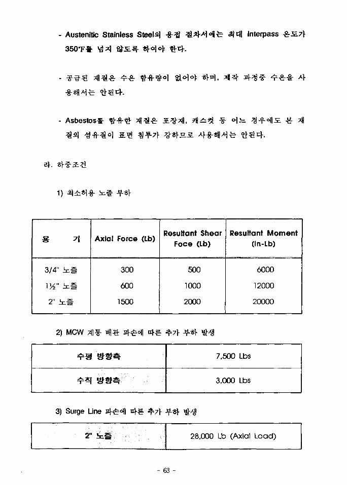
3/4" k f
1^" ing
2" t #
Axial Force (Lb)
300
600
1500
Resultant ShearFoce (Lb)
500
1000
2000
Resultant Moment(In-Lb)
6000
12000
20000
2) MCW 31 f-
7,500 Lbs
3.000 Lbs
3) Surge Line ^7}
28,000 Lb (Axial Load)
- 63 -
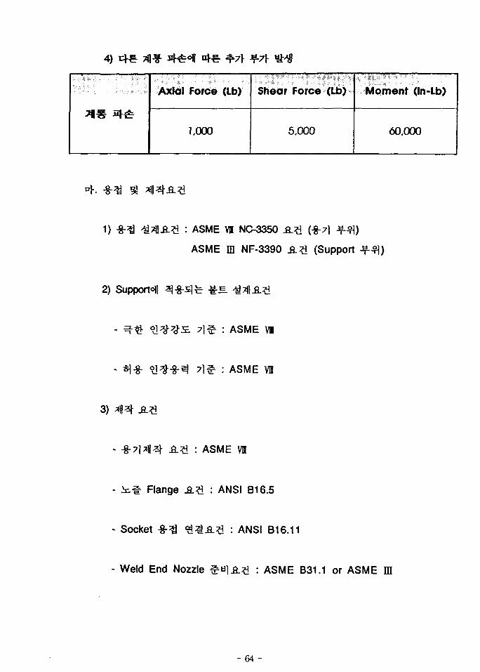
4)
Axial Force (Lb)
1,000
Shear Force (Lb)
5.000
Moment (in-lb)
60,000
1) ASME VB NC-3350
ASME m NF-3390
(-8-7]
(Support
2) Supports
: ASME VI
: ASME VB
3)
: ASME VH
Flange JS.?1 : ANSI B16.5
- Socket -8-3 : ANSI B16.11
- Weld End Nozzle : ASME B31.1 or ASME ffl
- 64 -
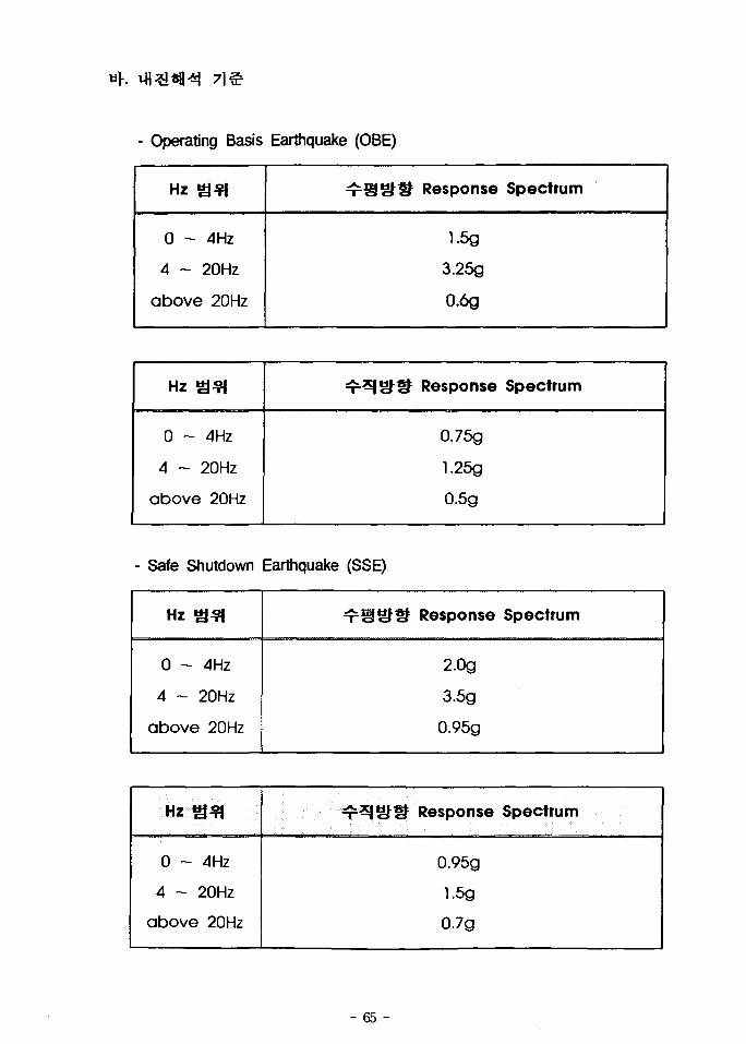
- Operating Basis Earthquake (OBE)
Hz S* l
0 ~ 4Hz
4 ~ 20Hz
above 20Hz
^ S S f i f Response Spectrum
1.5g
3.25g
0.6g
HZ a ^
0 - 4Hz
4 - 20Hz
above 20Hz
^ ^ 3 ^ ^ Response Spectrum
0.75g
1.25g
0.5g
- Safe Shutdown Earthquake (SSE)
Hz £31
0 - 4Hz
4 ~ 20Hz
above 20Hz
T ^ c J i f Response Spectrum
2.0g
3.5g
0.95g
0 - 4Hz
4 - 20Hz
above 20Hz
*r*ISHf Response Spectrum
0.95g
1.5g
0.7g
- 65 -
Damping^ Ftequlatory Guide 1.61 .fi.;?H nj-e). OBE°fl
2%, SSE4I rfl«fl d 3%
Mode Shaped Eigen vector
i , 4 Nodes] Lumped ^ # ^ 1 ell's- Acceleration,
Eigenvector!- ^--8- # ^ 3 - § - ^ # * > ^ , 4 ^ - ^ ^ s ] -g-^, S.*&E.
3*9-^ Model- ^-S-^l-^ Square Root Sum of Square (SRSS)
-8-71 o;
Ellipsoidal Head <g-y-
- 66 -
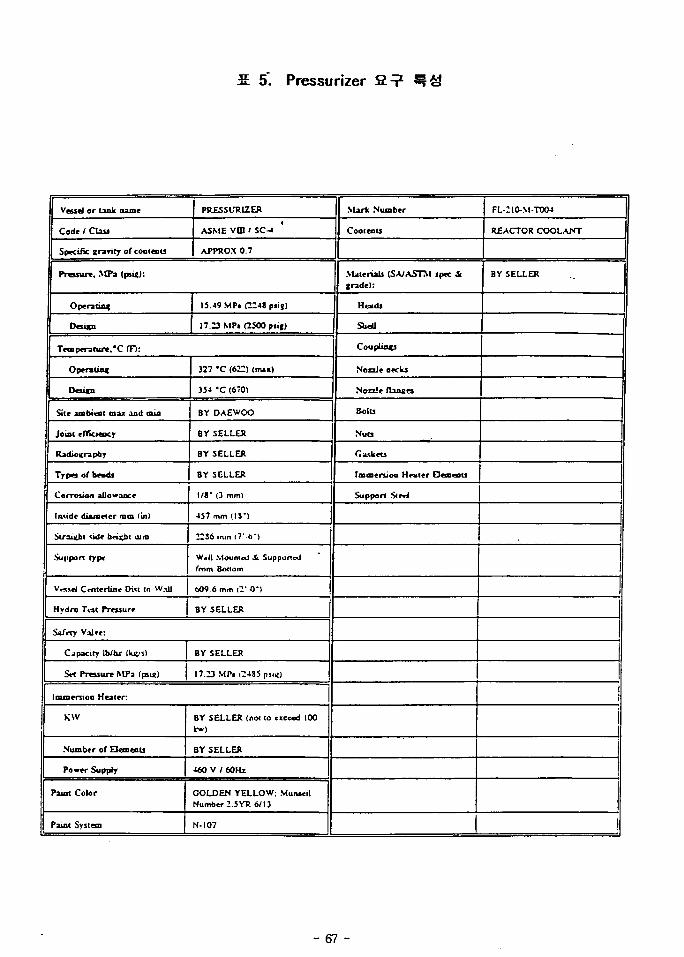
2 5". Pressurizer 2 ?
Vend or lank name
Code / Class
Specific (rarity of contents
PRESSURIZER
ASME v m ' SC-«
APPROX 0.7
Pressure. MPa (psi«):
Opera tins;
Design
15.49 MPi f2248 piig)
17.13 MP« OSOOptij)
Temperature. *C (F):
Operating
Desitu
Site ambieot max and min
Joint efficiency
Radiography
Types of tmds
Corrosion allowance
Iiuidc dijunder mm (in)
Stroiiehl suit bnKbt uim
.Support type
V « M I Cmtrrlinc Di« (o W.iil
Hydro T*3t Pressure
327 *C (672) InuO
354 'C (6701
BY DAEWOO
BY SELLER
BY SELLER
BY SELLER
\IV (3 mm)
457 mm f 19")
2236 injn (7*-o*)
Wall Mounled Sc Supportedfmm Boaom
609 6 mm |2"-O-1
BY SELLER
Sa/rty Val»e:
Capacity Ib/bx MugM)
S« Pressure M F i (psi«)
BY SELLER
17.23 MPt C4S5 p..*)
aifoersioa Heater:
KW
Number of Elements
Power Supply
Paint Color
'aint System
BY SELLER (not 10 exceed 100fcw)
BY SELLER
460 V / 60 H i
GOLDEN YELLOW; MunuilNumber 2.5 YR 6/13
N-107
Mark Number
Coolents
Materials (SA/ASTM spec 3Ltrade):
Heads
Shell
Coupling]
Nozzle necks
Nozzle ftanxes
Bolts
Nuts
Caskets
fmmeruoa Hmler E3ea«nts
Support Str*4
FL-210-M-T004
REACTOR COOLANT
BY SELLER
- 67 -
N6 (2)-
" \
iecr H«
- )/225"
NO. | SIZE
Nl | 2"
N2 1 3/*"NiNt
N5N5N7
N3
3/4"
3/4'3/*3/*"3/*"
?"
|TTPE
1 swFL*SW
swswswsw
1
•# 3_5oo it KF
)cr
'a
OTY.
1 111
11
22
N4- N 4
A (2)
V a ^. 7-
\315"
DESC3.
SURGE LINE
RELIEF VALVE
VENT
SPRAY NOZZLE
SPARE
LEVEL INST.
LEVEL INST.
HEATER CONN.
ICx.0 COM 1 **** 1 O'C
s I STONE & WEBSTER ENGINEERING CORP.£ * A BOSTON. MASS.
-0" 1
1
\ \ \
n y - N 6 <FS)> f L -N7 (FS)
/ 3" WALL daro
uUJUJ
UJ
/-N6 (FS) «
^ N 7 (FS) 1
/ / °/ I 1 EL. 0--6" -
1 1 EL O'-O"_ / / / (REF,
N1
•^^UilNa (TYP.)
KOREA ATOMIC ENERGYRESEARCH INSTITUTE
KMRR FUEL TEST LOOP
PRESSURIZER VESSELM-T1004
N*0* 04662-AM-2-1 \
OOCMCO er txu«x (r u . u n a
Fig. 13 Pressurizer
- 68 -
ASME an si
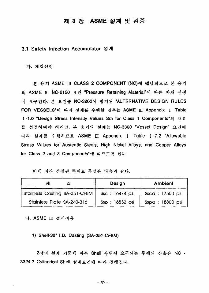
3.1 Safety Injection Accumulator 4>
£ -g-7j ASME DI CLASS 2 COMPONENT (NC)ofl s f l ^s lH.5 . £ -g-?l
s] ASME IE NC-2120 _S.;£ "Pressure Retaining Material"ofl a}-§. ^ ^
o] ^ . ^ ^ 4 . ^- ^ ^ ^ NC-3200<H] ^ 7 ] ^ "ALTERNATIVE DESIGN RULES
FOR VESSELS"^ oj-sj- ^ T i l l - ^ ^ ^ ^ - f ^ ASME ffl Appendix I Table
1-1.0 "Design Stress Intensity Values Sm for Class 1 Components"^
nv, ^ . -g-7lfi) +4A^ NC-3300 "Vessel Design"
rH.3. ASME m Appendix I Table 1-7.2 "Allowable
Stress Values for Austentic Steels, High Nickel Alloys, and Copper Alloys
for Class 2 and 3 Components"^] 14.5 J
o}6\]
Stainless Casting SA-351-CF8M
Stainless Plate SA-240-316
Design
Ssc : 16474 psi
Ssp : 16532 psi
Ambient
Ssca : 17500 psi
Sspa : 18800 psi
. ASME m
1) Shell-30" I.D. Casting (SA-351-CF8M)
3324.3 Cylindrical Shell
Shell NC -
- 69 -
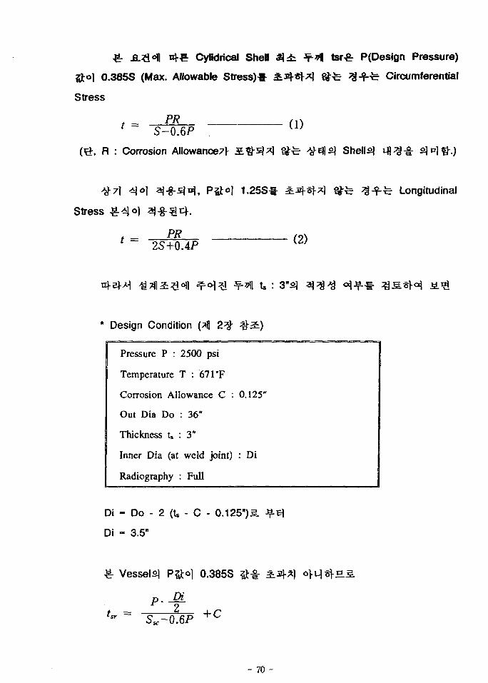
Cylidrical Shell
Sito] 0.385S (Max. Allowable Stress)*
Stress
PR
-!f-*l| tsr^r P(Design Pressure)
Circumferential
t = S-0.6P
, R : Corrosion Allowance7r
(1)
Shelly
Stress
1.25S*
PR2S+0.4P
(2)
Longitudinal
* Design Condition (*fl 2 ^
Pressure P :
Temperature
2500 psi
T : 67TF
Corrosion Allowance C :
Out Dia Do
Thickness t»
Inner Dia (at
Radiography
: 36"
: 3"
weld joint)
: Full
0.125"
: Di
Di - Do - 2 (U - C - 0.125")^.
Di - 3.5"
-g- Vessel^ P&o] 0.385S
P . Dit = 4-Cv Su.-0.6P °
- 70 -
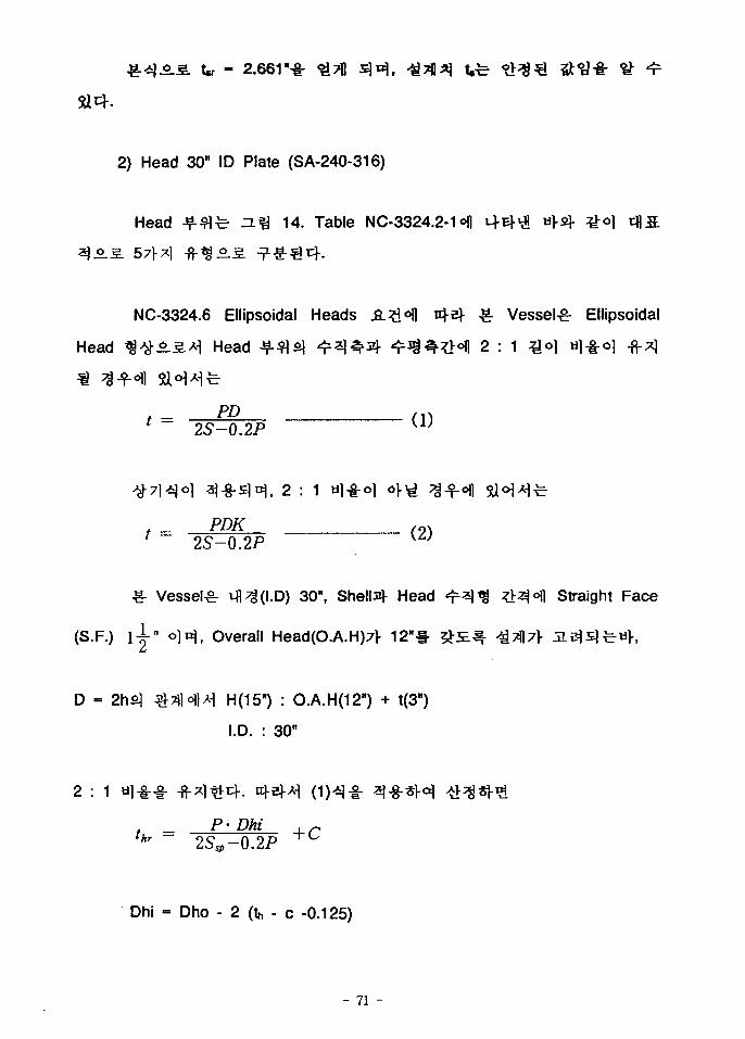
- 2.661"-!:
2) Head 30" ID Plate (SA-240-316)
Head 14. Table NC-3324.2-1 °fl
NC-3324.6 Ellipsoidal Heads
Head < § ^ i ^ Head
2S-0.2P
^. Vessel^ Ellipsoidal
2 : 1 *M «l-ir°l
, 2
. _ PDK2S-0.2P
Vessel^ 30", Shells)- Head
(S.F.) l ^ - n o ] ^ , Overall Head(O.A.H)7l- 12 " *
Straight Face
D - : O.A.H(12") + t(3")
I.D. : 30"
2 :
hr 2S.p-Q.2P
Dhi = Dho - 2 (th - c -0.125)
- 71 -
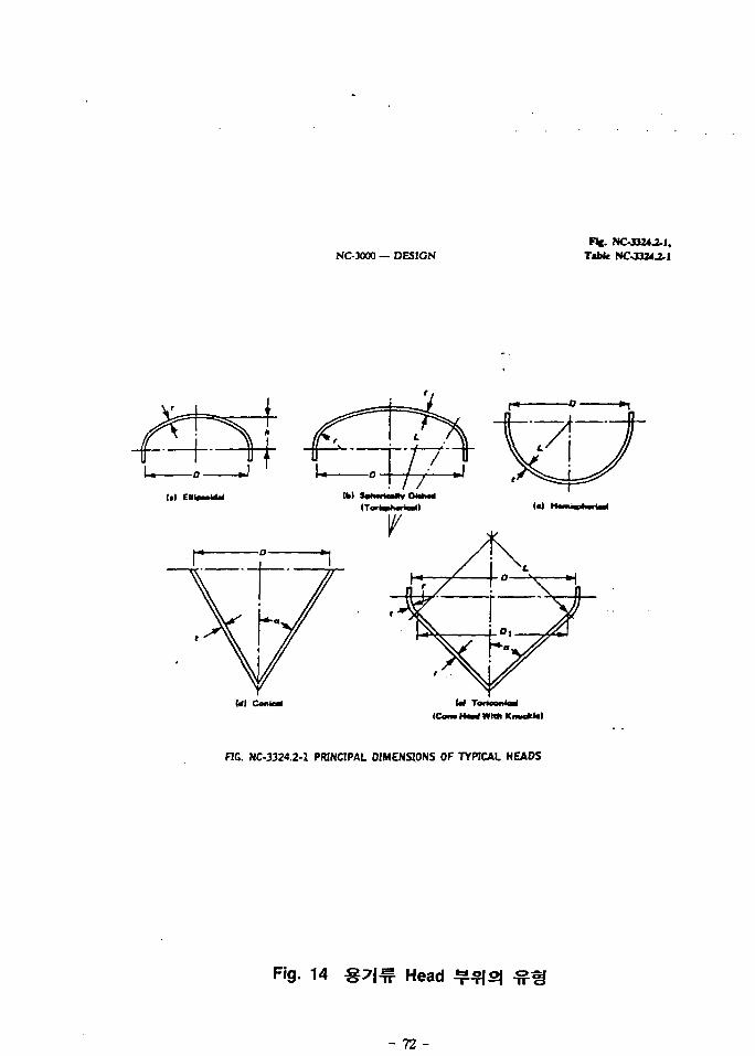
NCOOOO — DESIGNFfe. NC-XJ24J-1,
TaMc NCJ324.il
Ml Conic*(Cans H«d WMi Knuc*)*)
RG. NC-3324.2-1 PRINCIPAL DIMENSIONS OF TYPICAL HEADS
Fig. 14 Head
- 72 -
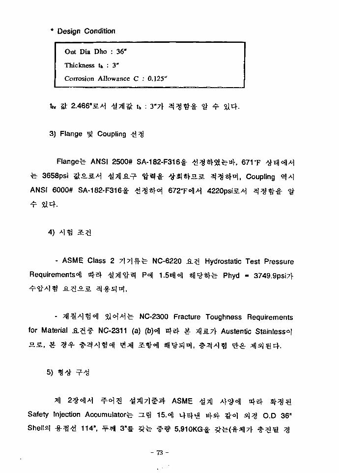
Design Condition
Out Dia Dho : 36"
Thickness th : 3"
Corrosion Allowance C : 0.125"
th : 3"7\
3) Flange ^ Coupling #;$
Flanged ANSI 2500# SA-182-F316-§-
^ 3658psi ^5.S.Ai ^TflA^-
ANSI 6000# SA-182-F316£
K 671'F
, Coupling
4220psi5.^
4)
- ASME Class 2
Requirements*!]
NC-6220
1.5«1H
Hydrostatic Test Pressure
3>fe Phyd = 3749.9psi7V
for Material
NC-2300 Fracture Toughness Requirements
NC-2311 (a) (bH n -ef ^- ^s.7} Austentic Stainlesso]
5)
Safety Injection Accumulator
Shelly -g-^A^ 114", ^ ^ 3"
ASME
15.<>H M-E)-^ M}$\- go]
5.910KG*
O.D 36"
- 73 -
N
PIAN VICW-TPUf ORIENTATION
IV>' • 1 V (If i « l SOTTttl MU3rot r [n|« ANOOI MLB
W i t : WC OOOUK IT All f O I U O « t *SSOW M HAH VICt
Fig. 15 Safety Injection Accumulator
- 74 -
- f : 7.390KG) ^*j<§ ejsfluL^ Tankojcf. s.^ ?<%£L±S=: 316 Stainless
Steel Tfl ' IS'H, Shell ^ - ^ fe SA-351-CF8M Costing, Supports SA-312-316
Pipe, Base Plated SA-240-316
7]&°.g.*\ Shell vflJfs] Corrosion Allowanced 1/8"o]:n,
671'F°ll*l 2500 psigS.*! FTL RMIofl
Doc. FL-080-DS-D112
Rev.1 Appendix 4S-2 "Seismic Qualification Requirement for Seismic
Category 1"ofl ^ 7 i * > ^ ^^sl<Ho]: ^.cf.
- Support &3.Q 7-
5.2^-^ "Qualification by Analytical Method Only" ^
10.1.1 "Analytical Qualification in Case of Rigid Equipment and Rigid
Support" Ji^ol] tr}eH ^vi)*) 4 ^ . 0 . ^ ^ o l ^o ] Floor4
Floor Response Spectrum (FRS)^-S. - ^ f e Zero Period
Acceleration (ZPA)ol
- f i - ^ M sfl^ (Finite Element Analysis : FEA)<>1
sjs.5., ^-^ .o l lA^ ^. ^ - ^ ^ ^ l ^ l - ^^? ] Joseph Oat7V %-g-^- Images 3-D
Version 3.0s} Data!
VesseH] JL^sl<>1o> ^- S V f ^ NC-3111 Loading Conditionofl
, Nozzle^ ^e] fe s ^ « V ^ 5J w f l ^ ^ ^ ^ * a | . vfl^l y\
£ Vesselo) ^ ^ ^ ^ r ^ ^ E f l ^ ^-S^of l £a j
Supports] -8-3 o] ^-g-s)£^. ^7j]£)Ji t Vessel©
- 75 -
2 Levels.
^ Shell°fl $•<$& -^-g- -8-^o.SAi WRC-107 Bulletin, "Local
Stresses in Spherical & Cylindrical Shells due to External Loadings"^- %-§-
- $ # * W , «]-§- ^3*$ cfl»l7> 7 } ^ ^ . o]*}q°_£.^ Vessel, Support
gj Anchor^ ^-
FEA Node°fl
FEA Program^ A
Vessel^
-¥-*}• -fr
SHI
^ Vessel^ ^ ? } c ] ^ 2J0]
Modeler ^r*«r7|| Beam Type Element^- 5U4. #• 4
, -8-
Slot
Models
ModeN
71
33Hz
Supports
, ^ ^ - Supports
HS., SupportoJl
Support
ZPA «J-4j ^
^ Shelly Support^
Support^ Shell ^
-8--§-71
- 76 -
^-(Translational Inertial Body Loads)5.*)
DataSj- « H FEA
3-g.sl-.ELi2.
-g- -g-^3}- tilJ
2) -8-7] Support Support
3) -8-7) Support^ Shell
L WRC-107 sfl Support-Pipeofl
4) Supports) ^V^ JfaV-i- %-g-^H Base Plates}- Sole Plated Sl°\*\
, Support 7-
5) Supports]
el-. -g-7]s]
Expansion Anchors]
Drillco Maxi-Bolts] sj-g-
3/4"
- 77 -
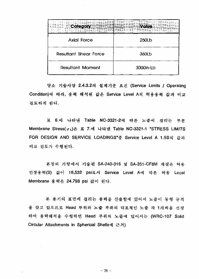
Category
Axial Force
Resultant Shear Force
Resultant Moment
Value
250Lb
380Lb
3000in-Lb
*S± 7l-g-AV<g= 2.4.3.2s] J£$}7]& &.£ (Service Limits / Operating
Condition)^ of a]-, -g-ej s f l ^ &•& Service Level As] *\-%-•%• ^
S. 6. oil M-Ef'd? Table NC-3321-2o)) nf-s. ; t#o) ]
Membrane Stress( a L)£- S 7.< J t+E)-\fl Table NC-3321-1 "STRESS LIMITS
FOR DESIGN AND SERVICE LOADINGS"^ Service Level A 1.5SS]
SA-240-316 ^ SA-351-CF8M
5)tol 16,532 psi5.A^ Service Level A«fl nf€- «l-8- Local
Membrane -g-^^r 24.798 psi 5Jt<>l
^-S.S. Head
Head
Circular Attachments in Spherical Shells0)]
sl<H>Hfe' (WRC-107 Solid
- 78 -
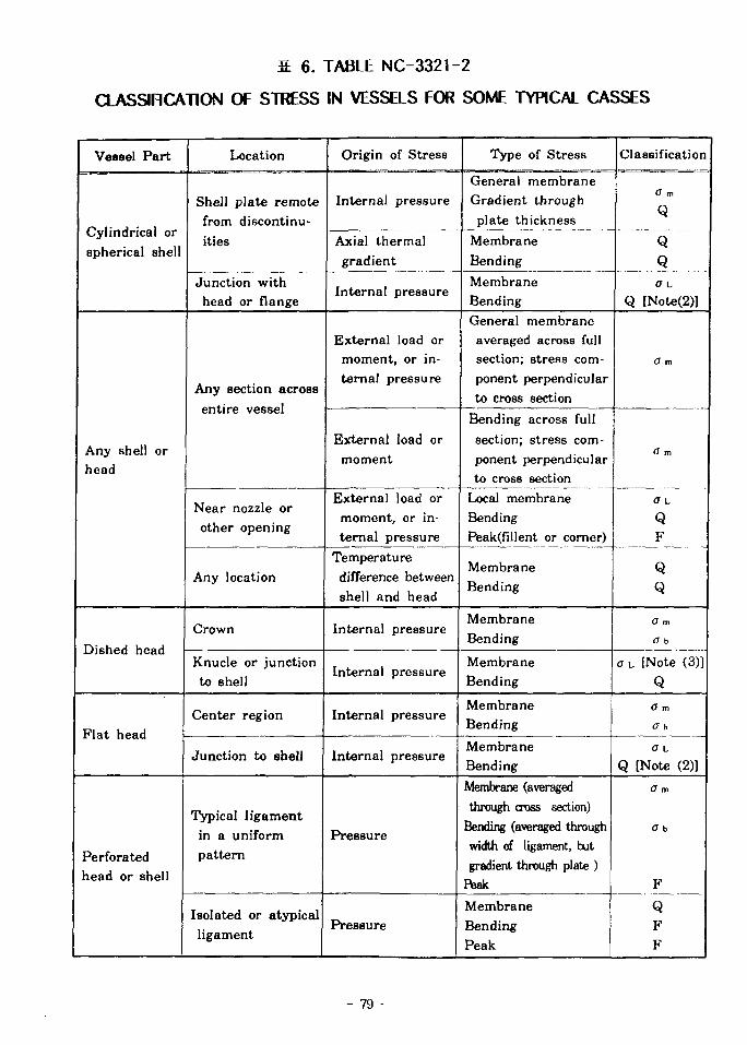
S 6. TABLE NC-3321-2
CLASSIRCATION OF STRESS IN VESSELS FOR SOME TYPICAL CASSES
Vessel Part
Cylindrical orspherical shell
Any shell orhead
Dished head
Flat head
Perforatedhead or shell
Location
Shell plate remotefrom discontinu-ities
Junction withhead or flange
Any section acrossentire vessel
Near nozzle orother opening
Any location
Crown
Knucle or junctionto shell
Center region
Junction to shell
Typical ligamentin a uniformpattern
Isolated or atypicalligament
Origin of Stress
Internal pressure
Axial thermalgradient
Internal pressure
External load ormoment, or in-ternal pressure
External load ormoment
External load ormoment, or in-ternal pressure
Temperaturedifference betweenshell and head
Internal pressure
Internal pressure
Internal pressure
Internal pressure
Pressure
Pressure
Type of Stress
General membraneGradient throughplate thickness
MembraneBending
MembraneBendingGeneral membraneaveraged across fullsection; stress com-ponent perpendicularto cross section
Bending across fullsection; stress com-ponent perpendicularto cross section
Local membraneBendingPeak(fillent or corner)
MembraneBending
MembraneBending
MembraneBending
MembraneBending
MembraneBending
Membrane (averagedthrough cross section)
Bending (averaged throughwidth of ligament, butgradient through plate )
Peak
MembraneBendingPeak
Classification
O m
Q
QQa L
Q [Note(2)]
0 m
O m
a L
QF
O m
a b
CTL [Note (3)]
Q
O m
a b
a L
Q [Note (2)]
O m
Ob
F
QFF
- 79 -
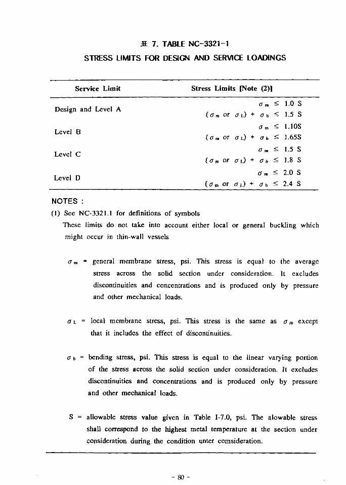
S. 7. TABLE NC-3321-1
STRESS LIMITS FOR DESIGN AND SERVICE LOADINGS
Service Limit Stress Limits [Note (2)]
<7m ^ 1.0 SDesign and Level A
(<7™ or <7L) + Ob ^ 1.5 S
am < 1.10SLevel B
( u r a or a0 + Ob ^ 1.65S
, , ^ <Tra < 1.5 SLevel C
(<7m Or (JL) + (7b ^ 1.8 S
, , ~ <T m < 2.0 SLevel D
(<7m or OL) + Ob ^ 2.4 S
NOTES :
(1) See NC-3321.1 for definitions of symbols
These limits do not take into account either local or general buckling which
might occur in thin-wall vessels
a m = general membrane stress, psi. This stress is equal to the average
stress across the solid section under consideration. It excludes
discontinuities and concentrations and is produced only by pressure
and other mechanical loads.
(TL = local membrane stress, psi. This stress is the same as am except
that it includes the effect of discontinuities.
a b = bending stress, psi. This stress is equal to the linear varying portion
of the stress across the solid section under consideration. It excludes
discontinuities and concentrations and is produced only by pressure
and other mechanical loads.
S = allowable stress value given in Table 1-7.0, psi. The alowable stress
shall correspond to the highest metal temperature at the section under
consideration during the condition unter comsideration.
- 80 -
LbH
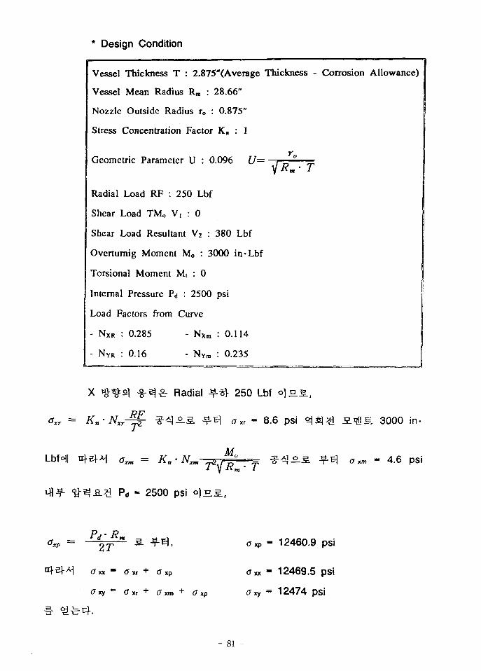
* Design Condition
Vessel Thickness T : 2.875"(Average Thickness - Corrosion Allowance)
Vessel Mean Radius Rra : 28.66"
Nozzle Outside Radius ro : 0.875"
Stress Concentration Factor Kn : 1
Geometric Parameter U : 0.096 U=
Radial Load RF : 250 Lbf
Shear Load TMO V, : 0
Shear Load Resultant V2 : 380 Lbf
Ovcrturnig Moment Mo : 3000 in*Lbf
Torsional Moment M, : 0
Internal Pressure P<j : 2500 psi
Load Factors from Curve
- NXR : 0.285 - NXm : 0.114
- NYR : 0.16 - NYra : 0.235
Radial ^-t} 250 Lbf o]a.
o x r = K n - N M
<7«* = Kn
8.6 psi
Mo
Pd - 2500 psi o ] £ l ,
e. 3000 in-
- 4.6 psi
2T
O xx ~ G xr + <T xp
xy (7 xr + (7 xm +xp
£Txp - 12460.9 psi
(7 xx - 12469.5 psi
<7xy - 12474 psi
- 81 -
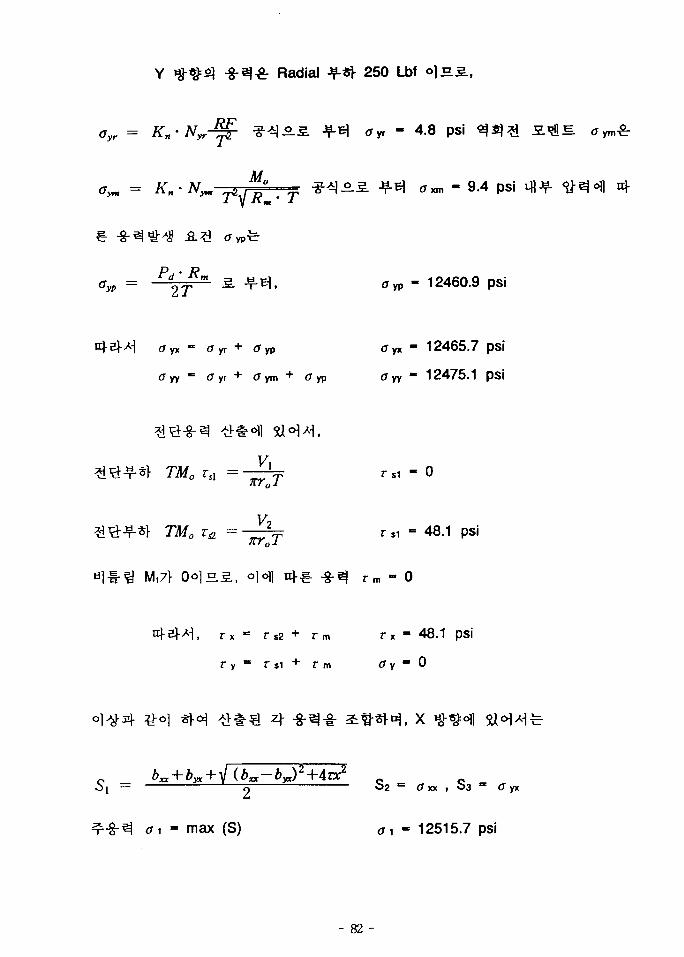
Radial ^-«1- 250 Lbf °}E.£.,
Gyr = Kn'Nyr-^- ^QSLS, +1% <Xyr - 4.8 pSi ^ 5) # S.^^. O
a™ - 9.4 psi
£TyP - 12460.9 psi
ffyx=(7yr+<Typ f T y x " 1 2 4 6 5 . 7 pSJ
< 7 y y - = C r y r + ( J y m + C T y p CTyy" 1 2 4 7 5 . 1 pSJ
TMO vA =-^T
^ = - ^ f r, i - 48.1 psi
M,7l- OolHS., o]ofl n*€- -8-^ rm - 0
r x = r S 2 + r m rx = 48.1 psi
, X
O2 = <JKX , 0 3 = C yx
max (S) tf1 - 12515.7 psi
- 82 -
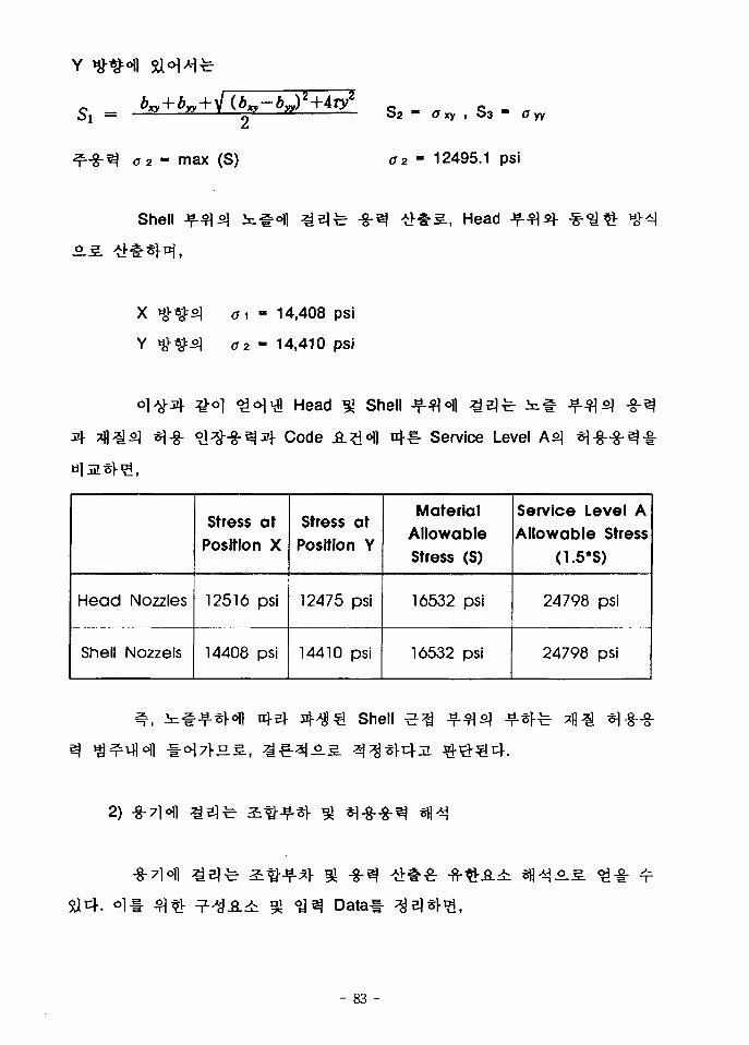
_
<T2 - max (S) - 12495.1 psi
Shell -g-ej , Head
X
Y
ff1 - 14,408 psi
«y2 - 14,410 psi
«l-8-
Head gj Shell
Code A?i<fl uj-^- Service Level
Head Nozzles
Shell Nozzels
Stress atPosition X
12516 psi
14408 psi
Stress at
Position Y
12475 psi
14410 psi
MaterialAllowableStress (S)
16532 psi
16532 psi
Service Level AAllowable Stress
(1.5*S)
24798 psi
24798 psi
Shell
2)
- 83 -
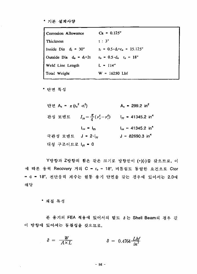
Corrosion Allowance
Thickness
Inside Dia ds = 30"
Outside Dia d« - di+2t
Weld Line Length
Total Weight
Ca
t :
h =
To "
L =
W
- 0.125"
3"
= 0.5-di+c, =
• 0.5-do ro
= 114"
= 16250 Lbf
15.125"
= 18"
2 , 2 \A, = x (roz -if)
Izz ~ lyy
J - 2-lyy
Ivz - 0
lyy
299.2 in2
41345.2 in4
la - 41345.2 in4
J = 82690.3 in4
Recovery
C - 18", ^ i ^ - g - ^ Tll^r
3.7] 3.
C - ro - 18",
^ f " -§-71
. Ctor
2.0°ll
-8-71S) FEA Shell Beamfi]
1\
S = 0.4764-rfe
- 84 -
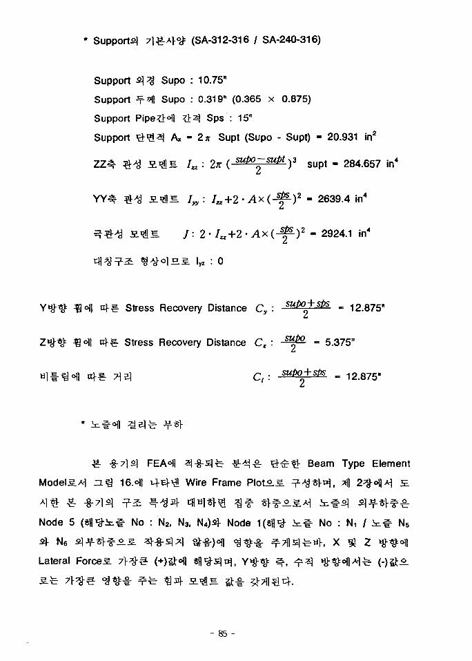
* Support^ 7l£-A|-<y: (SA-312-316 / SA-240-316)
Support 5 ] ^ Supo : 10.75"
Support ^^ Supo : 0.319" (0.365 x 0.875)
Support Pipe#°fl # 3 Sps : 15"
Support ^ ^ ^ j Ax - 2n Supt (Supo - Supt) - 20.931 in2
Ia: 2K ( supo - supt ^ s u p t . 284.657 in4
- 2639.4 in4
IL J: 2- /«+2 • Ax ( -^ - ) 2 - 2924.1 in4
lHS. lyz : 0
Stress Recovery Distance Cy : ^P0^^ - 12.875"
ZHHI= ^ ° f l ^ l - ^ - Stress Recovery Distance C^ : - ^ - - 5.375"
n?-€- ^ 3 C, : Mpo + sPs - 12.875"
€- -§-7ls] FEA ll ^-g-slfe ^ -^^ r # £ ^ Beam Type Element
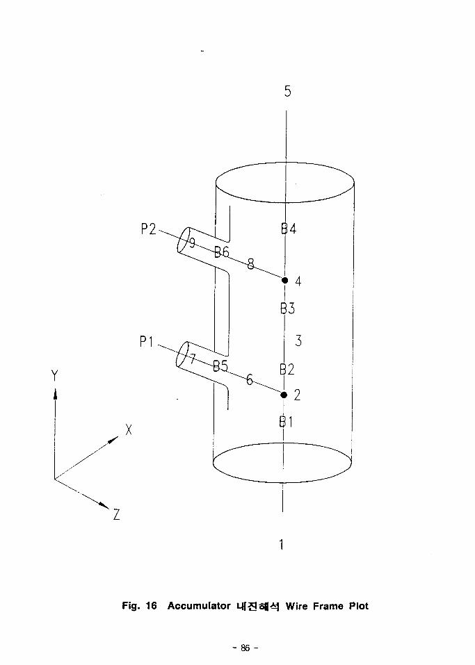
n% i6.ofl v+Ei-VI Wire Frame Plot^.5. ^ ^ ^ V ^ , ^1 2^-oflA-l £
Node 5 ( S f l ^ i ^ No : N2, N3, N4)4 Node 1(sfl^- i^-t No : Ni / i i # N5
Lateral Forced
- 85 -
Y
X
Z
Fig. 16 Accumulator Wire Frame Plot
- 86 -
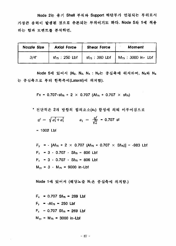
Node 2fe -8-71 Shell Support * r#J?-7r
. Node
Nozzle Size
3/4"
Axial Force
sf75 : 250 Lbf
Shear Force
sf76 : 380 Lbf
Moment
M76 : 3000 in- Lbf
N o d e 5<fl 5tt*H-H ( N 2 , N 3 , N 4 :
^ - ^ ^ o f l ( L a t e r a l ) < H l
N4
Fx - 0.707-sfTs + 2 x 0.707 (Af75 + 0.707 x sf75)
2711
- 0.707 sf
1002 Lbf
Fz
- [Af76 + 2 x 0.707 (Af75 + 0.707 x Sf75)]
3 • 0.707 • Sf75 = 806 Lbf
3 • 0.707 • Sf75 - 806 Lbf
3 • M75 - 9000 in-Lbf
-983 Lbf
Node
- 0.707 Sfre - 269 Lbf
- -Af75 - 250 Lbf
= 0.707 Sfre - 269 Lbf
- M re - 3000 in-Lbf
- 87 -
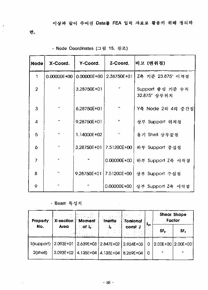
Data l - FEA
- Node Coordinates 15.
Node
1
2
3
4
5
6
7
8
9
X-Coord.
O.OOOOOE+00
i t
»
»
••
••
••
••
••
Y-Coord.
O.OOOOOE+00
3.28750E+01
6.28750E+01
9.28750E+01
1.14000E+02
3.28750E+01
»
9.28750E+01
i i
Z-Coord.
2.38750E+01
I I
i t
t i
••
7.51200E+00
O.OOOOOE+00
7.51200E+00
O.OOOOOE+00
Z-^ 7 ] ^ 23.875" o l ^ ^
Support f^-a ?]& ^^32.875" ^ - ? - ^ A ]
Y# Node 22f 4s] ^ ^ - ^
^•«. Support * 1 ^
-8-7] Shell #^%
*>Y- Support 4 ] ^
«l-f Support Z^ AI^J-^
^ ^ - Support 4 ] ^
^-f- Support Z^ ^1^]-^
- Beam
Property
No.
1 (support)
2(shell)
X-sectfon
Area
2.093E+01
2.093E+02
Moment
Of ly
2.639E+03
4.135E+04
InertiaIz
2.847E+02
4.135E+04
Torsionalconst J
2.924E+03
8.269E+04
!„
0
0
Shear ShapeFactor
SFy
2.00E+00
SFz
2.00E+00
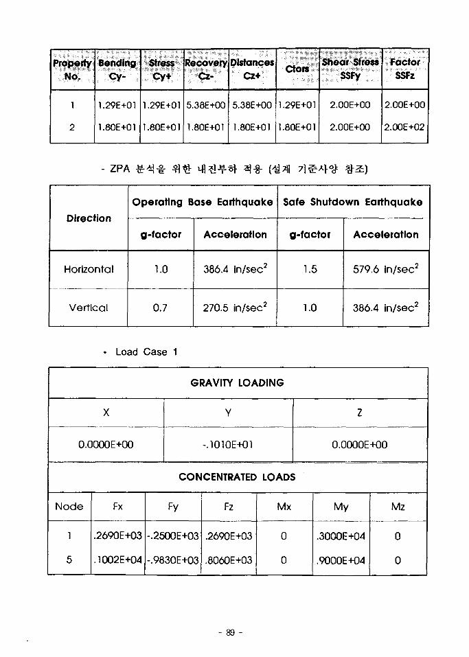
PropertyNo.
l
2
BendingCy-
1.29E+01
1.80E+01
Stress
Cy+
1.29E+01
1.80E+01
RecoveryCz-
5.38E+00
1.80E+01
Distances
Cz+
5.38E+00
1.80E+01
Ctors
1.29E+01
1.80E+01
Shear StressSSFy
2.00E+00
2.00E+00
FactorSSFz
2.00E+00
2.00E+02
- ZPA
Direction
Horizontal
Vertical
Operating Base Earthquake
g-factor
1.0
0.7
Acceleration
386.4 in/sec2
270.5 in/sec2
Safe Shutdown Earthquake
g-factor
1.5
1.0
Acceleration
579.6 in/sec2
386.4 in/sec2
• Load Case 1
GRAVITY LOADING
X
0.0000E+00
Node
1
5
Fx
.2690E+03
.1002E+04
Y
-.1010E+01
CONCENTRATED
Fy
-.2500E+03
-.9830E+03
Fz
.2690E+03
.8060E+03
Z
0.0000E+00
LOADS
Mx
0
0
My
.3000E+O4
.9000E+O4
Mz
0
0
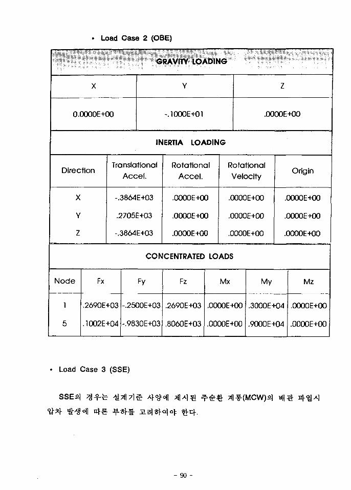
• Load Case 2 (OBE)
GRAVITY LOADING
X
0.0000E+00
Y
-.1000E+01
Z
.0000E+00
INERTIA LOADING
Direction
X
Y
Z
Translational
Accel.
-.3864E+03
.2705E+03
-.3864E+03
Rotational
Accel .
.0000E+00
.0000E+00
.00O0E+O0
Rotational
Velocity
.0000E+00
.0000E+00
.0000E+00
Origin
.OOOOE+00
.OOOOE+00
.OOOOE+00
CONCENTRATED LOADS
Node
1
5
Fx
.2690E+03
.1002E+04
Fy
-.2500E+03
-.9830E+03
Fz
.2690E+03
.8060E+03
Mx
.0000E+00
.0000E+00
My
.3000E-K)4
.9000E+04
Mz
•0000E+00
.OOOOE+00
Load Case 3 (SSE)
- 90 -
GRAVITY LOADING
X
0.0000E+00
Y
-.1000E+01
Z
.OOOOE+00
INERTIA LOADING
Direction
X
Y
Z
TranslationalAccel.
-.5796E+03
.3864E+03
-.5796E+03
RotationalAccel.
.OOOOE+00
.0000E+O0
.OOOOE+00
RotationalVelocity
.0000E+00
.0000E+00
.0000E+00
Origin
.0000E+00
.OOOOE+00
.0O00E+O0
CONCENTRATED LOADS
Node
1
3
5
Fx
.2690E+03
.7500E+04
.1002E+04
Fy
-.2500E+03
-.3000E+04
-.9830E+03
Fz
.2690E+03
.0000E+00
.8060E+03
Mx
.0000E+00
.0000E+00
.0000E+00
My
.3000E+O4
.0000E+00
.9000E+04
Mz
.OOOOE+00
.0000E+00
.0000E+00
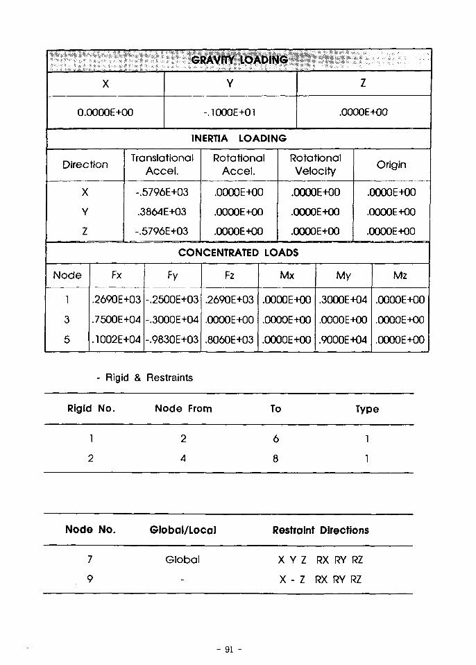
- Rigid & Restraints
Rigid No.
1
2
Node No.
7
9
Node From
2
4
Global/Local
Global
To
6
8
Restraint
X Y Z
X - Z
Type
1
1
Directions
RX RY RZ
RX RY RZ
91 -
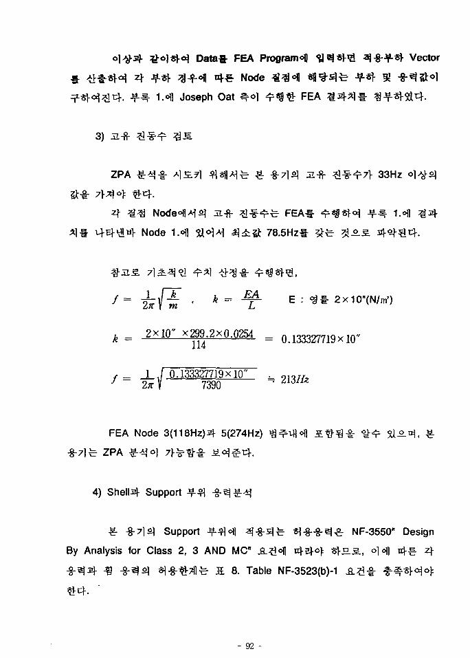
Data* FEA Programofl ^ e j * ! ^ 3-§••¥-*!• Vector
«!•€• Node 33«( l * f l # 3 ^ •¥-«* 91
1.41 Joseph Oat *r°\ <?*&& FEA
3) Ji-fr
ZPA £4 j - | : A] £7] fl«||A]fe- ^ .g-713 ul-fr ^ ^ ^ 7 V 33Hz
JL-fr
Node 1.«l| 5U°1^ ^ ^ 5 t 78.5Hz*
- ^ E : <3f- 2x10"(N/m')
k = 2X10" X299.2X0.Q254 = 0.133327719x10"
- 1 ./ 0.133327719x10"~ \ 7390
FEA Node 3(118Hz)3|- 5(274Hz)
ZPA
4) Shells Support
Support ^-^<H1 3-§-=1TT ^ -g -8 -^^ r NF-3550" Design
By Analysis for Class 2, 3 AND MC" A^lofl nj-ej-oj: « } £ £ , olofl n - - zl-
S 8. Table NF-3523(b)-1
- 92 -
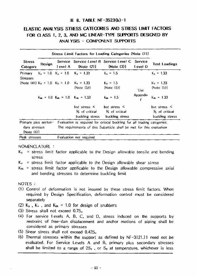
S. 8. TABLE NF-3523(b)-1
aASTIC ANALYSIS STRESS CATEGORIES AND STRESS LIMIT FACTORS
FOR CLASS 1. 2, 3, AND MC LINEAR-TYPE SUPPORTS DESIGNED BYANALYSIS - COMPONENT SUPPORTS
Stress Limit Factors for Loading Categories (Note (1)]
Stress . Service Service Level B Service Level C ServiceCategory D c S ' 8 n Level A [Note (2)) [Note (3)] Level D l c s l L o a d l n « s
Primary Ks = 1.0 K, = 1.0 Ks = 1.33Stresses[Note (4)) Kv = 1.0 Kv = 1.0 Kv = 1.33
[Note (5))
= 1.0 = 1.0 = 1.33
Ks = 1.5
Kv = 1.5[Note (5)]
Kt* = 1.5
UseAppendix
f
but stress ^ but stress ^%, of critical % of criticalbuckling stress buckling stress
K5 = 1.33
Kv = 1.33[Note (5))
K* = 1.33
but stress ^% of criticalbuckling stress
Primary plus secton- Evaluation is required for critical buckling for all loading categories,dary stresses The requirements of this Subarticle shall be met for this evaluation[Note (6)]
Peak stresses Evaluation not required
NOMENCLATURE :Ks = stress limit factor applicable to the Design allowable tensile and bending
stressKv = stress limit factor applicable to the Design allowable shear stressKbi = stress limit factor applicable to the Design allowable compressive axial
and bending stresses to determine buckling limit
NOTES :(1) Control of deformation is not insured by these stress limit factors. When
required by Design Specification, deformation control must be consideredseparately
(2) Ks , Kv , and Kbk = 1.0 for design of snubbers(3) Stress shall not exceed 0.7Su
(4) For service Levels A, B, C, and D, stress induced on the supports byrestraint of free-dan displacement and anchor motions of piping shall beconsidered as primary stresses
(5) Shear stress shall not exceed 0.42Su
(6) Thermal stresses within the support as defined by NF-3121.11 need not beevaluated. For Service Levels A and B, primary plus secondary stressesshall be limited to a range of 2SV , or Su at temperature, whichever is less
- 93 -
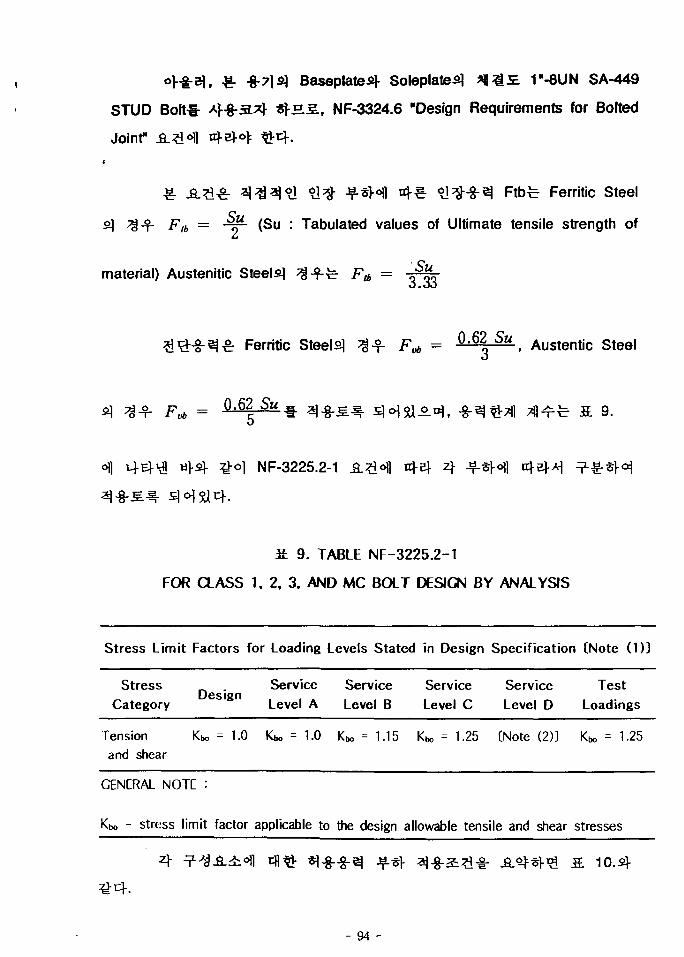
Baseplates Soleplate^ afl^JE. T-8UN SA-449
STUD BofHr A}&3.?$ SJ-H5., NF-3324.6 "Design Requirements for Bolted
Joint"
£- £-£•& 3 3 3? ] 91% J f * H nj-e ^ l^-S-^ Ftb-^ Ferritic Steel
F,6 = -§*• (Su : Tabulated values of Ultimate tensile strength of
material) Austenitic Steely J^pr
Ferritic Steely ^ ^ - f\* - ° - 6 | S " , Austentic Steel
Su » a j 8 ^ ^ ^«H5aAt^ g^^T f l ? j l ^ ^ a 9.
oil 143-^ «>4 ^°1 NF-3225.2-1
£ 9. TABLE NF-3225.2-1
FOR CLASS 1. 2, 3. AND MC BOLT DESIGN BY ANALYSIS
Stress Limit Factors for Loading Levels Stated in Design Specification (Note (1))
Stress Service Service Service Service TestDesign
Category Level A Level B Level C Level D Loadings
Tension Kbo = 1.0 Kbo = 1.0 Kbo = 1.15 Kbo = 1.25 (Note (2)) Kbo = 1-25and shear
GENERAL NOTE :
Kbo - stress limit factor applicable to the design allowable tensile and shear stresses
- 94 -
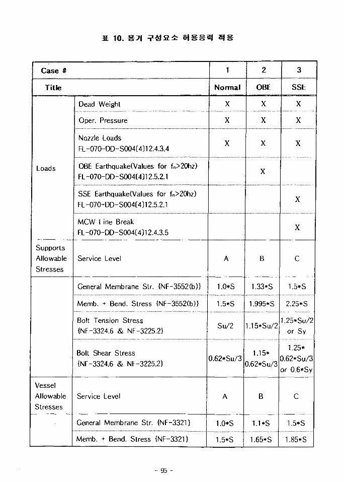
10.
Case #
Title
Loads
Supports
Allowable
Stresses
VesselAllowableStresses
Dead Weight
Oper. Pressure
Nozzle LoadsFL-070-DD-S004C4112.4.3.4
OBE Earthquake(Values for fn>20hz)FL -O7O-DD-SOO4C4312.5.2.1
SSE Earthquake(Values for fn>20hz)
FL-070-DD-S004(4)12.5.2.1
MCW Line Break
FL-070-DD-S004(4)12.4.3.5
Service Level
General Membrane Str. {NF-3552(b)}
Memb. + Bend. Stress {NF-3552(b)}
Bolt Tension Stress{NF-3324.6 & NF-3225.2}
Bolt Shear Stress
{NF-3324.6 & NF-3225.2}
Service Level
General Membrane Str. {NF-3321}
Memb. + Bend. Stress {NF-3321}
1
Normal
X
X
X
A
1.0*S
1.5*S
Su/2
0.62*Su/3
A
1.0*S
1.5*S
2
OBE
X
X
X
X
B
1.33*S
1.995*S
.15*Su/2
1.15*
0.62*Su/3
B
1.1 *S
1.65*S
3
SSE
X
X
X
X
X
c
1.5*S
2.25*S
.25*Su/2or Sy
1.25*
0.62*Su/3
or 0.6*Sy
C
1.5*S
1.85*S
- 95 -
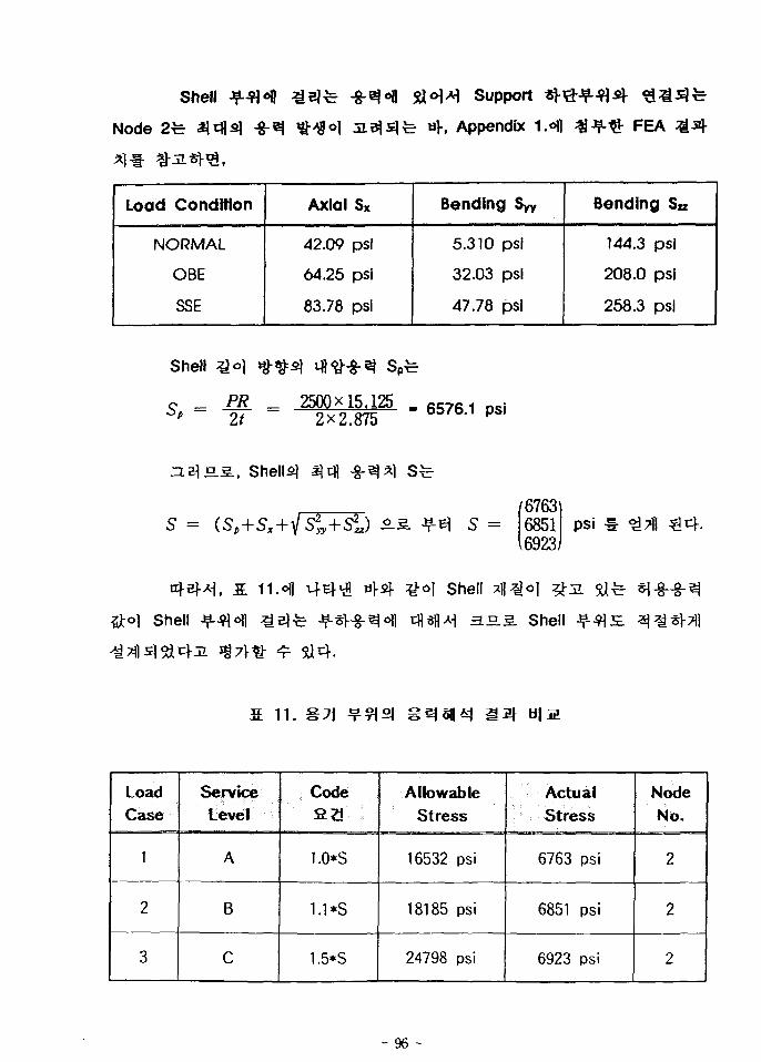
Shell
Node -§-3
SU«H-H Support
- uf, Appendix I.ofl FEA
Load Condition
NORMAL
OBE
SSE
Axial Sx
42.09 psi
64.25 psi
83.78 psi
Bending Syy
5.310 psi
32.03 psi
47.78 psi
Bending Sn
144.3 psi
208.0 psi
258.3 psi
Shell
_ PK~ It
2500x15.1252x2.875
- DSj' PSI
5.2., Shells
5 = S =
Shell
676368516923
psi
shell
.S.S. Shell
S 11.
LoadCase
1
2
3
ServiceLevel
A
B
C
Code£2
1.0*S
1.1*S
1.5*S
AllowableStress
16532 psi
18185 psi
24798 psi
ActualStress
6763 psi
6851 psi
6923 psi
Node
No.
2
2
2
- 96 -
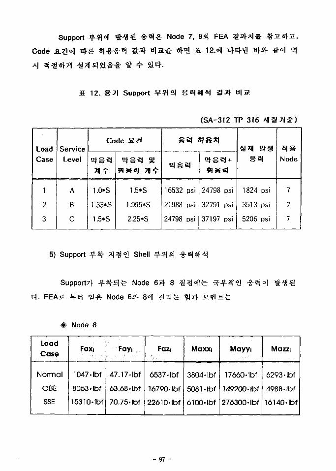
Support
Code ^J
& • * % • ^ wi
Node 7, 9e\ FEA
£ 12. Support b|
(SA-312 TP 316
LoadCase
1
2
3
ServiceLevel
A
B
C
Code
1.0*S
1.33*S
1.5*S
•
aa
1.5*S
1.995*S
2.25*S
. . .
16532
21988
24798
m <
- «
psi
psi
psi
• a'
24798
32791
37197
Vpsi
psi
psi
1824
3513
5206
^
psi
psi
psi
£J gNode
7
7
7
5) Support Jf*h shell
Support7f -^-^-5]^ Node 6 4 8
FEA5. ^ -B] <££ Node
# Node 8
LoadCase
Normal
OBE
SSE
Faxi
1047-Ibf
8063- Ibf
15310-lbf
47
63
70
Fayt
.17-lbf
.68-Ibf
.75-Ibf
Faz
6537-
16790
22610
4
Ibf
•Ibf
•Ibf
Maxxi
3804
6081
6100
•Ibf
•Ibf
•Ibf
Mayyi
17660-Ibf
149200-Ibf
276300-Ibf
Mazzi
6293-Ibf
4988-Ibf
16140-lbf
- 97 -
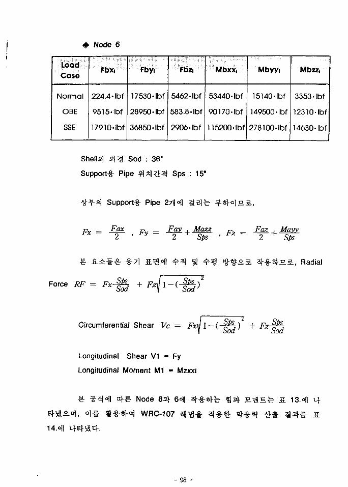
LoadCase
Normal
OBE
SSE
Node 6
Fbxi
224.4-
9515-
17910
Ibf
Ibf
Ibf
Fbyi
17530-
28950-
36850-
Ibf
Ibf
Ibf
Fbzi
5462-Ibf
583.8-Ibf
2906- Ibf
Mbxxi
53440
90170-
115200
Ibf
Ibf
•Ibf
Mbyyi
15140-
149500
278100
Ibf
•Ibf
Ibf
Mbzz,
3353-
12310
14630-
Ibf
Ibf
Ibf
Shells] <z)^ Sod : 36"
Support-g- Pipe 3*1 # 3 Sps : 15"
Support-g- Pipe 27flofl
Fax Fay . Mazz2 ^ Sps
Faz , Mayy2 Sps
Force RF =
-8-71
+
HS., Radial
Circumferential Shear Vfc = FicJl-(-§&) +V Sod' Sod
Longitudinal Shear V1 - Fy
Longitudinal Moment M1 - Mzxxi
Node 8^ 6«\)
WRC-107
s ^ S.
- 98 -
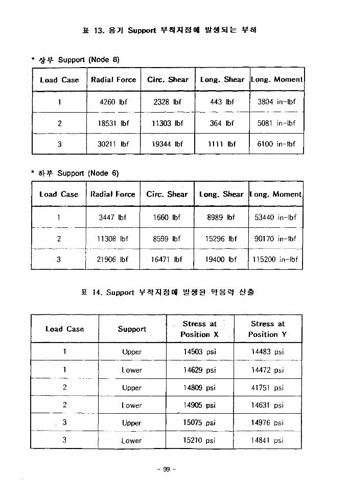
fi 13. Support
Load
Support
Case
1
2
3
(Node 8)
Radial Force
4260 Ibf
18531 Ibf
30211 Ibf
Circ. Shear
2328
11303
19344
Ibf
Ibf
Ibf
Long.
443
364
1111
Shear
Ibf
Ibf
Ibf
Long.
3804
5081
6100
Moment
in-lbf
in-lbf
in-lbf
* i\^- Support
Load Case
1
2
3
(Node 6)
Radial Force
3447 Ibf
11308 Ibf
21906 Ibf
Circ. Shear
1660
8599
16471
Ibf
Ibf
Ibf
Long. Shear
8989
15296
19400
Ibf
Ibf
Ibf
Long. Moment
53440 in-lbf
90170 in-lbf
115200 in-lbf
14. Support ti
Load Case
1
1
2
2
3
3
Support
Upper
Lower
Upper
Lower
Upper
Lower
Stress atPosition X
14503 psi
14629 psi
14809 psi
14905 psi
15075 psi
15210 psi
Stress atPosition Y
14483 psi
14472 psi
41751 psi
14631 psi
14976 psi
14841 psi
- 99 -
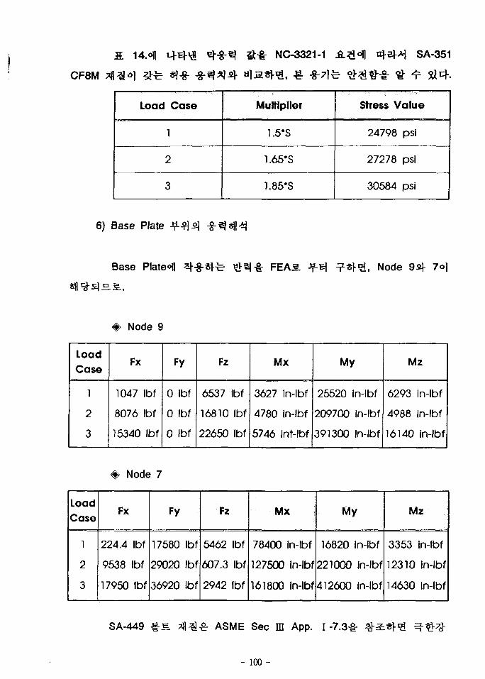
NC-3321-1 SA-351
CF8M
Load Case
1
2
3
Multiplier
1.5*S
1.65*S
1.85*S
Stress Value
24798 psi
27278 psi
30684 psi
6) Base Plate
Base Plateofl
#• Node 9
FEA5. , Node 9fif 7oj
LoadCase
1
2
3
Fx
1047
8076
15340
Ibf
Ibf
Ibf
0
0
0
Fy
Ibf
Ibf
Ibf
Fz
6537
16810
22650
Ibf
Ibf
Ibf
Mx
3627
4780
5746
In-lbf
in-lbf
int-lbf
My
25520 in-lbf
209700 in-lbf
391300 in-lbf
Mz
6293
4988
16140
in-lbf
in-lbf
in-lbf
<#• Node 7
LoadCase
1
2
3
Fx
224.4
9538
17950
Ibf
Ibf
Ibf
Fy
17580
29020
36920
Ibf
Ibf
Ibf
Fz
5462
607.3
2942
Ibf
Ibf
Ibf
Mx
78400
127500
161800
in-lbf
in-lbf
in-lbf
My
16820 in-lbf
221000 in-lbf
412600 in-lbf
Mz
3353
12310
14630
in-lbf
in-lbf
in-lbf
SA-449 -irS ASME Sec ffl App. 1-7.3^-
- 100 -
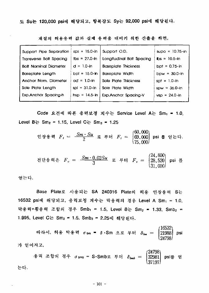
S. Sufe 120,000 psiofl Syfe 92,000 psi°fl
Support Pipe Separation
Transverse Bolt Spacing
Bolt Nominal Diameter
Baseplate Length
Anchor Nom. Diameter
Sole Plate Length
Exp.Anchor Spacing-h
sps = 15.0-in
tbs = 27.0-in
d = 1.0-in
bpl = 15.0-in
ad = 1.0« in
spl = 31.0-in
hsp = 14.5-in
Support O.D.
Longitudinal Bolt Spacing
Baseplate Thickness
Baseplate Width
Sole Plate Thickness
Sole Plate Width
Exp.Anchor Spacing-V
supo = 10.75-in
lbs = 10.5- in
bpt = 0.75-in
bpw = 30.0 -in
spt = 1.0. in
spw = 36.0-in
vsp = 24.0-in
Level
Code
^ Sm2 - 1.15, Level Cfe- Sm3
Service Level A-b Smi - 1.0,
1.25
Ft =Sm Su
F, =60,00069,00075,000
Fv =
psi
24,80028,52031,000
psi
Base Plates. *l~g-£]fe- SA 240316 Plates] *]%•
16532 psN d f l ^ ^ j i , ^ - ^ ^ . ^ Tfl^fe- ^$-^2\ ^ J f Level A Smi = 1.0,
eH-ej+^-S-el ^^-5] ^ - f Smbi = 1.5, Level Bfe Sm2 - 1.33, Smb2 =
1.995, Level Cfe- Sm3 - 1.5, Smb3 - 2.25^1
= S-SmbS.
165322198824798
psi
247983298137197
psii
- 101 -
PlateS
3552s]
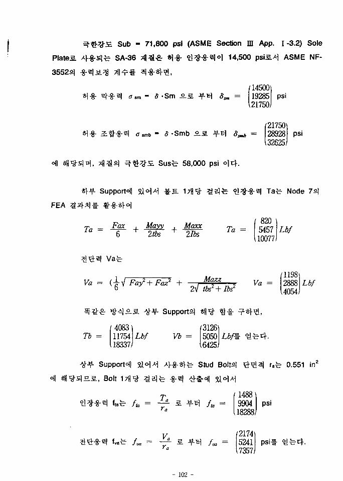
Sub - 71,800 psi (ASME Section m App. 1-3.2) Sole
SA-36 ^ £ *|-g- 1 -S~^°1 14,500 psiS>H ASME NF-
psi1450011928521750/
*l-8- - 8 -Smb .2.3.21750\28928 psi32625)
58,000 psi
FEA
SupporfHl
Afayy M2xc_ _
Node
820545710077
Lbf
Va - (-i-6
Mazz2V tbs2+ lbs2 Va -
119828884054
Lbf
oil
Tb =40831175418337
Lbf
Support^
., Bolt
Supports]
(3126Vb = 5050
16425/
WSr
Stud Bolts] afe 0.551 in2
1488990418288
psi
(21745241
17357psi!- £*r
- 102 -
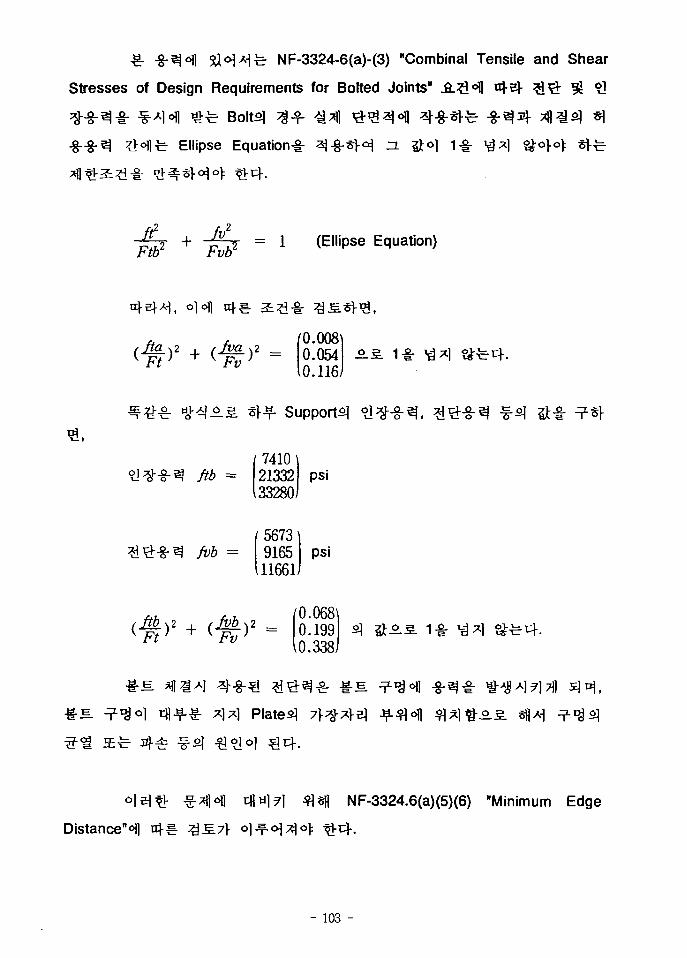
-£ -8-^H &<H*lfc- NF-3324-6(a)-(3) "Combinal Tensile and Shear
Stresses of Design Requirements for Bolted Joints" iL^lsfl «4e]- %\x£ 3! o]
H £ t Bolts] 3 - f ^*fl &#z\<% 4 - 8 - ^ t -8 -3^ ^ g g ) «]
Ellipse Equation-i-
= 1 (Ellipse Equation)
Ft
<$>2
Fv
ftb =
0.0080.0540.116
Supports]
74102133233280
5673916511661
psi
psi
0.068\0.1990.338/
Plated
-s. 1-i-
Distance"^]
NF-3324.6(a)(5)(6) "Minimum Edge
- 103 -
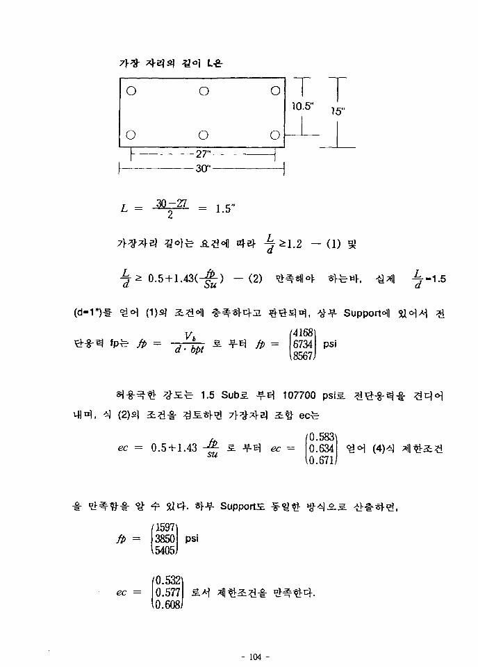
o
o
o
o
o
o
110.5"
27"30"
15"
L = = L5>>
- (1)
- ( 2 ) i-,5
(d-1") Support^
//> = fp =(4168)6734 psi
18567J
1.5 107700
(2)2]
ec = 0.5 + 1.430.583^0.6340.671/
/1597fp = 3850
\5405psi
Supports
ec =0.5320.5770.608
- 104 -
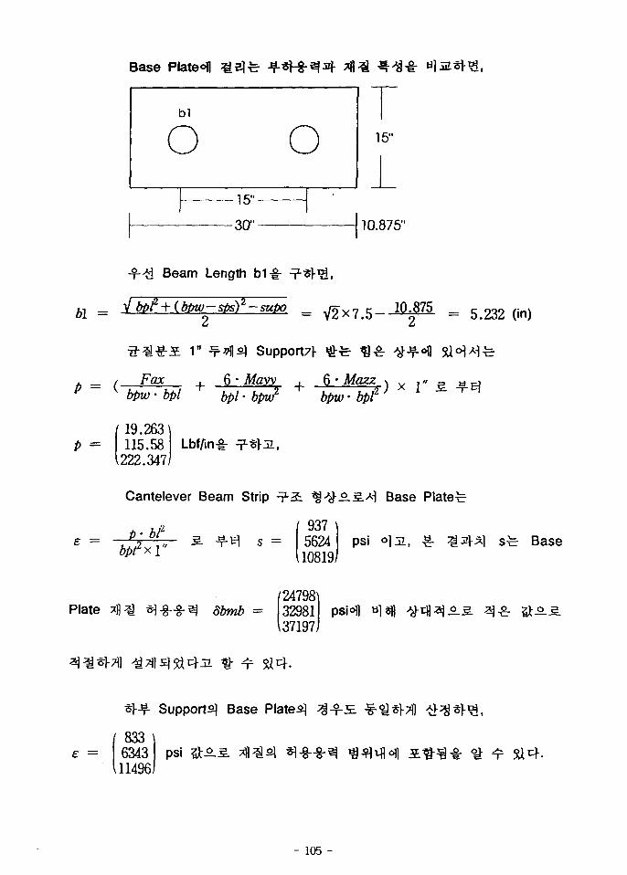
Base Plateofl
10.875"
Beam Length b1-g-
bl = = 5.232 (in)
= ( •
Support7l-
Fax 6 • Mayybpw • bpl bpl • bpw2 bpw - bpl2
p =f 19.263
115.581222.347
Lbf/in-g-
Cantelever Beam Strip ^ . 5 . ^ Base Plated
937 \562410819)
psi Base
Plate24798\3298137197)
e =
*>-¥• Support^ Base Plated
833634311496
psi &SL
- 105 -
. -8-71 £794 4
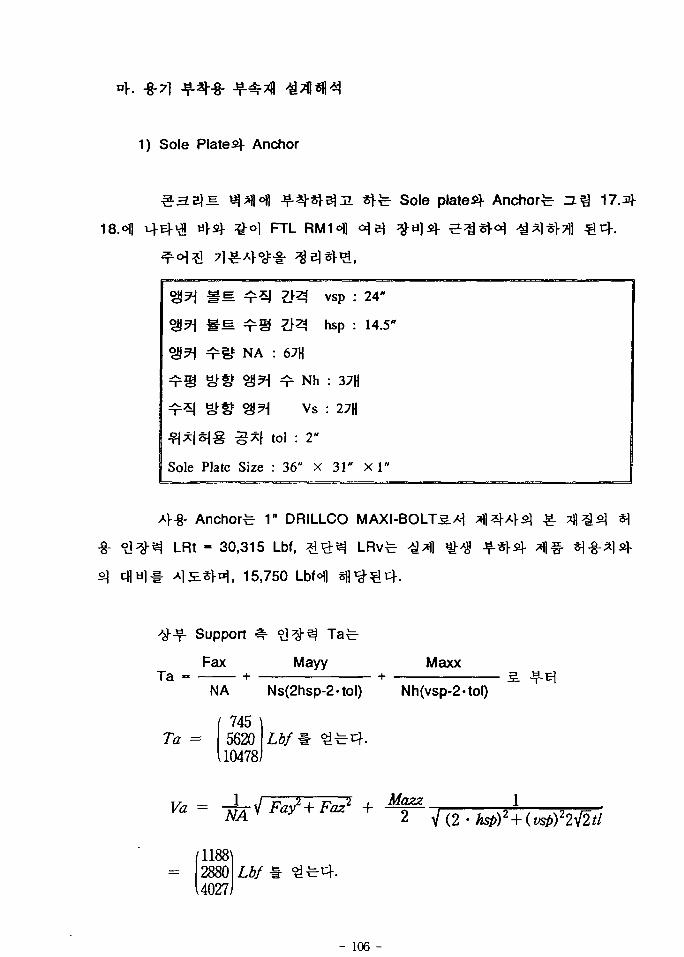
1) Sole Plated Anchor
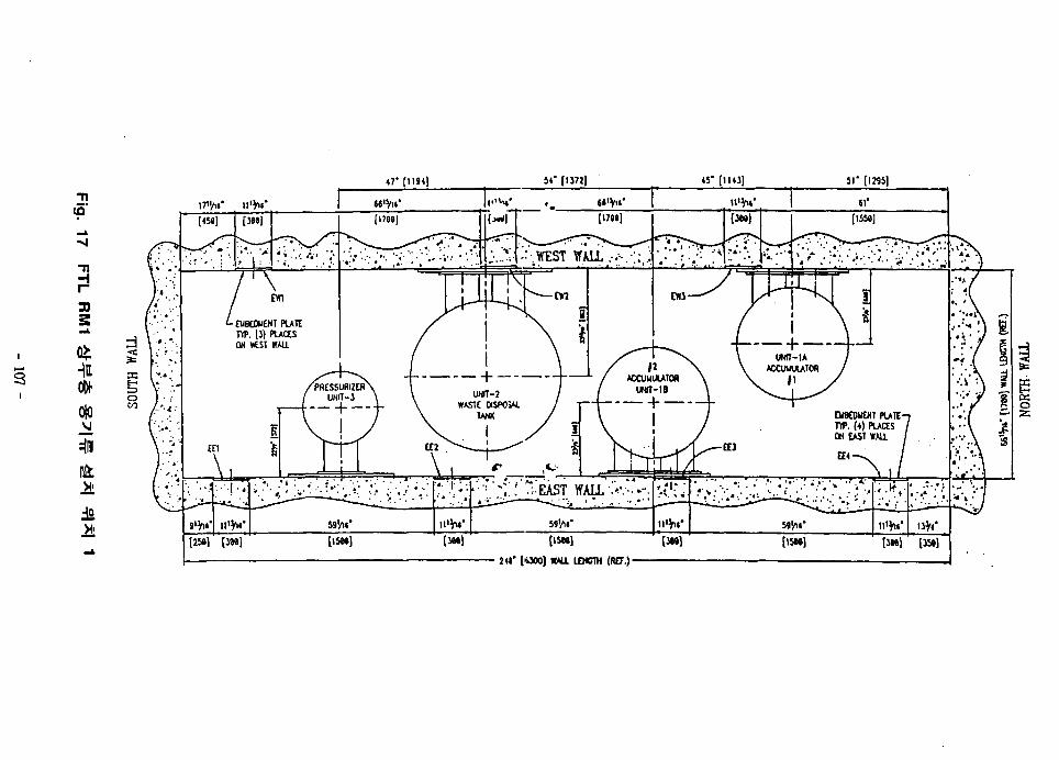
18.ofl
Sole plated Anchor-
FTL
*n MM ^SM m^ ^s*&?] TSS1 NA
^rS gjtf 2!^
^r*l &Sf ?S^
Sole Plate Size
: 67H
1 T Nh
Vs
tol : 2"
: 36" x
vsp :
hsp :
: 37(j
: 27H
31"
24"
14.5"
X 1"
Anchor^ 1n DRILLCO
LRt - 30,315 Lbf,
, 15,750 LbH
Support
FaxTa +
Mayy Maxx
NA Ns(2hsp-2-tol) Nh(vsp-2-tol)
745Ta = 5620
10478
118828804027
- 106 -
47' [1184] 4V [1143] 51" [1295]
to
- a
30
s
•in
it
17»/U'
[254) • [3M] [15M] [ISM]
241* [UOO] K*U LEHCTH (R£T.) -
o
i
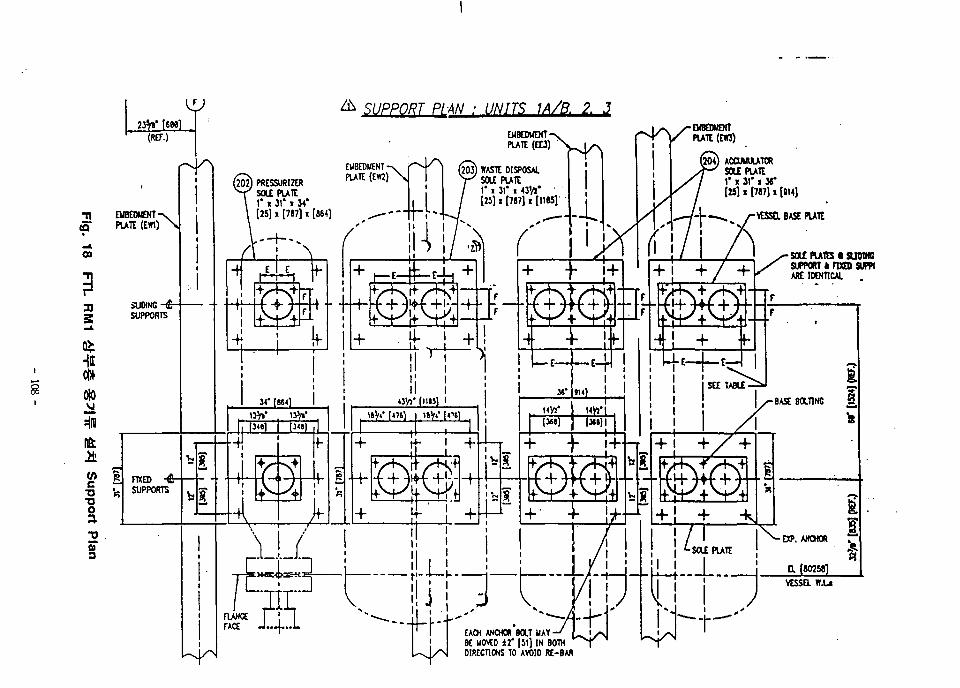
SUPP0R1LPLAN • UNITS 1A/B. 2. 3
•nS
09
3)3
Hi
ifcit
TJ
O
a.
(EW3)
[204) ACCUUULATORSOLE PLATE* « 31 ' « X'
[25] » [787] x [914]
VESSEL BASE PVATE
SOU PU1ES • SUOINCSIWORT k FIXED SUPPIARE IDENTICAL
EMBEDWEHTPLATE (ED)
203) WASTE DISPOSALSOLE PLATE1* J 31* t 4J'/J*[25] i [787] i [1165]
202) PRBSURIZtRSOLE PLATE1* x 31 ' « 14'[25] x [787] x [864]EMBEDMENT-v
PLATE (EW1) \
EACH AMOKXt BOLT MAYBE liOVEO 1 2 ' [S I ] IN BOTHDIRECTIONS TO AVOID RE-BAR
Support Tb =/1681
8135I13040
Lbf
312150306402
Lbf
Sole Plated Bolt 3S.-I- , Base Plated
;*1 1.2
Supports
1.5 Sus - 87,000 psLS. Sfl^
//> =
J i ^
118828804027
psiS.
0.5+ 1.43-^-3. •?-El
^ H S . Code
0.529^0.5710.599i
#°.iiL -^ = 1.5
*r-r- Supports]
fP =312150306402/
psit-
Plate
ec —0.5770.6240.658
Sole Plated
P =5,841 \
39,41974,983)
Lbfin
Code
b1 - 8.544"
s =426 \
28785474J
psi
Base
- 109
Supports
2)
Stress Cone^- 45*
Stress Cone
£ Pullout
-S. I7flofl
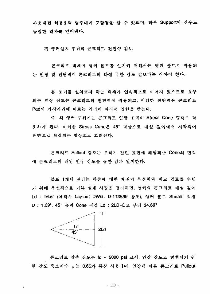
Ld : 16.5" (a|sM- Lay-out DWG. D-113539 # 2 ) , °8?] &E. Sheath
D : 1.69", 45° -g-^ Cone Q% Ld : 2LD+D5. JfE 34.69"
Ld45°
2Ld
fc = 5000 psi
0.657f H. Pullout
- no -
SC = ty-ffc *!-£-£. Jf£| SC - 183.848 psi
°<!M ^ ^ 67flolji, ACI-349 App.BS. - f 3 Expansion
sf = 2.57> 3-§-£4. °<S?RH # 3 £ ^ «o^^l Sl«H^^ Re -
?}>y# 2 ^ o]z* ^^-^i 2"1- Jiej*)-^, Sph = 12.5",
spv - 20-ojt}-.
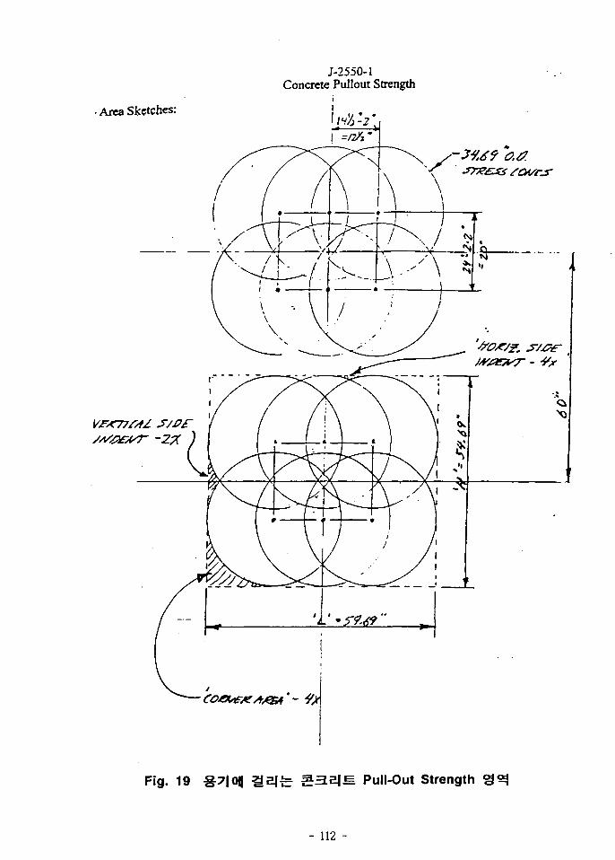
] L « 2psh + cd = 59.69", %°]^ H - spv + cd - 54.69"
o_3-*\ A, = 3264.4 in2ol
Cones] f^o .3 . o]*
^ 3 j (A2) £>£
f= 4x — 2 _ A _ 258,251 in2
4
A3 = 19 in2
3. - f A4 = 40.6 in2
Cone
Aa = 2933 in2 Aa = H(A) -JV-f Z?2
4
- I l l -
J-2550-1Concrete Pullout Strength
• Area Sketches:
Fig. 19 S7|0|| a e j ^ M Pull-Out Strength
- 112 -
2.51- uL3]$ «fi^5]fe ^ £ 1 2 ^ 2 } Pullout 91
Pu = ^ * c f 5. J f3 Pu - 35947.9 Lbf iM « 8 ^ # m 171)71-
30315
3.2 Pressurizer
-8-71^- ASME Boiler & Pressure Vessel Code Section ffl .S.:?I°ll
£.#•& Division I JB}- n i ^ - g - ^ ^ , £- -§-7]^ Division I
3000 psi o)^o\ .g.7iofl «fl^s]jE.s. Division I
7\.
Part UG "General Requirements for All Methods of
Construction and All Materials" .S.?!^ UG-4 (Material General)tfl *1 UG-14
(Rod and BarsH ^ 7 l ^ «>cfls. ^ ^-^£.±7} %^ &.#<*} -^t\s.^ ^
^-^^8: ASME Section ffl-D, Table 1A<>n
- 113 -
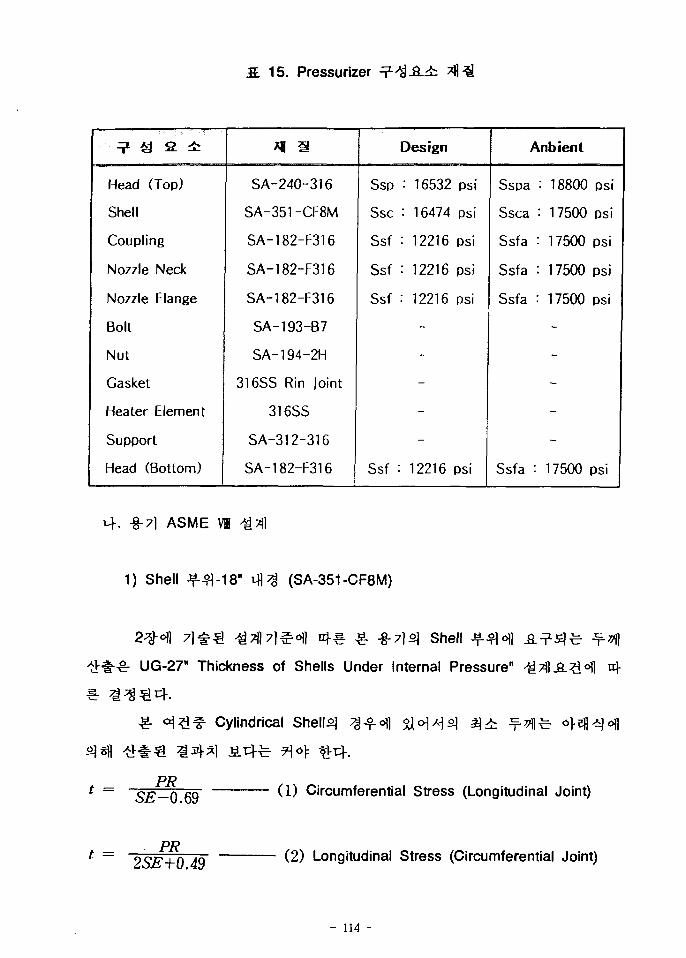
S. 15. Pressurizer
? £ S 4r
Head (Top)
Shell
Coupling
Nozzle Neck
Nozzle Flange
Bolt
Nut
Gasket
Heater Element
Support
Head (Bottom)
*l i!
SA-240-316
SA-351-CF8M
SA-182-F316
SA-182-F316
SA-182-F316
SA-193-B7
SA-194-2H
316SS Rin Joint
316SS
SA-312-316
SA-182-F316
Ssp
Ssc
Ssf
Ssf
Ssf
Ssf
Design
: 16532
: 16474
: 12216
: 12216
: 12216
-
-
-
-
-
: 12216
psi
psi
psi
psi
psi
psi
Anbienl
Sspa •'
Ssca :
Ssf a :
Ssf a :
Ssfa :
Ssfa :
18800
17500
17500
17500
17500
-
-
-
-
-
17500
psi
psi
psi
psi
psi
psi
. -§-71 ASME VI >£Til
1) Shell (SA-351-CF8M)
-S-
t =
t =
Shell Jf
UG-27" Thickness of Shells Under Internal Pressure"
Cylindrical Shells]
5^-0.69
PR2SE+0.49
(1) Circumferential Stress (Longitudinal Joint)
(2) Longitudinal Stress (Circumferential Joint)
- 114 -
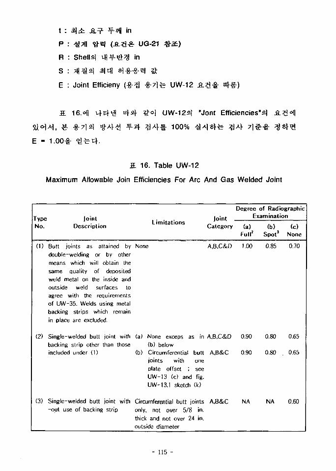
t :
P :
Ft : Shelly
S : «£]
E : Joint Efficieny
in
UG-21
in
UW-12 n}~§-)
16. UW-125] "Jont Efficiencies"^
100% ^
E - 1.00^- ^ f e ^ .
S 16. Table UW-12
Maximum Allowable Join Efficiencies For Arc And Gas Welded Joint
TypeNo.
(1)
(2)
(3)
JointDescription
Butt joints as attained bydouble-welding or by othermeans which will obtain thesame quality of depositedweld metal on the inside andoutside weld surfaces toagree with the requirementsof UW-35. Welds using metalbacking strips which remainin place are excluded.
Single-welded butt joint withbacking strip other than thoseincluded under (1)
Single-welded butt joint with-out use of backing strip
Limitations
None
(a) None exceps as in(b) below
(b) Circumferential buttjoints with oneplate offset ; seeUW-13 (c) and fig.UW-13.1 sketch (k)
Circumferential butt jointsonly, not over 5/8 in.thick and not over 24 in.outside diameter
JointCategory
A,B,C&D
A.B.C&D
A.B&C
A.B&C
Degree of RadiographicExamination
(a)Full2
1.00
0.90
0.90
NA
(b)Spot3
0.85
0.80
0.80
NA
(c)None
0.70
0.65
0.65
0.60
- 115 -
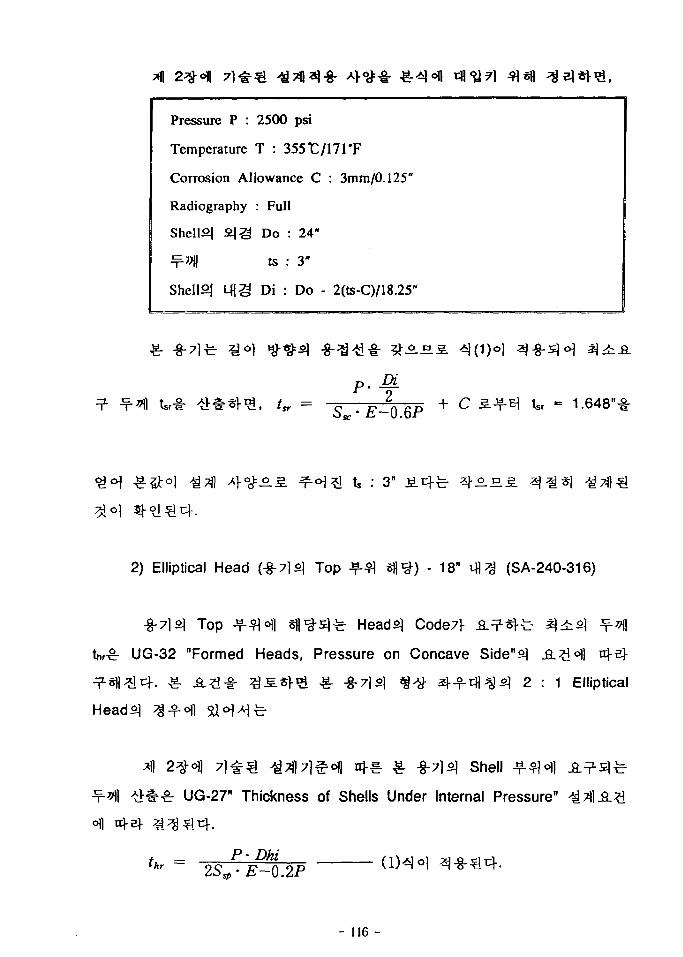
Pressure P :
Temperature
2500 psi
T : 355rj/171*F
Corrosion Allowance C : 3mm/0.125"
Radiography
Shell°| 2 J 3
Shelly Mjg
: Full
Do : 24"
ts : 3"
Di : Do - 2(ts-C)/18.25"
p. ^+ C ^ ^ tsrE-Q6P
: 3"
2) Elliptical Head (-8-71S) Top Jf f l sfl^) - 18" t f l ^ (SA-240-316)
-8-7lfil Top J M H s f l ^^ fe Head^ Code7f
UG-32 "Formed Heads, Pressure on Concave Side"s] .&£<>))
2 : 1 Elliptical
71 # ^ ^7fl7l^oi] uj.^. . -§-7)0] shell J
UG-27" Thickness of Shells Under Internal Pressure"
S • E-0.2P
- 116 -
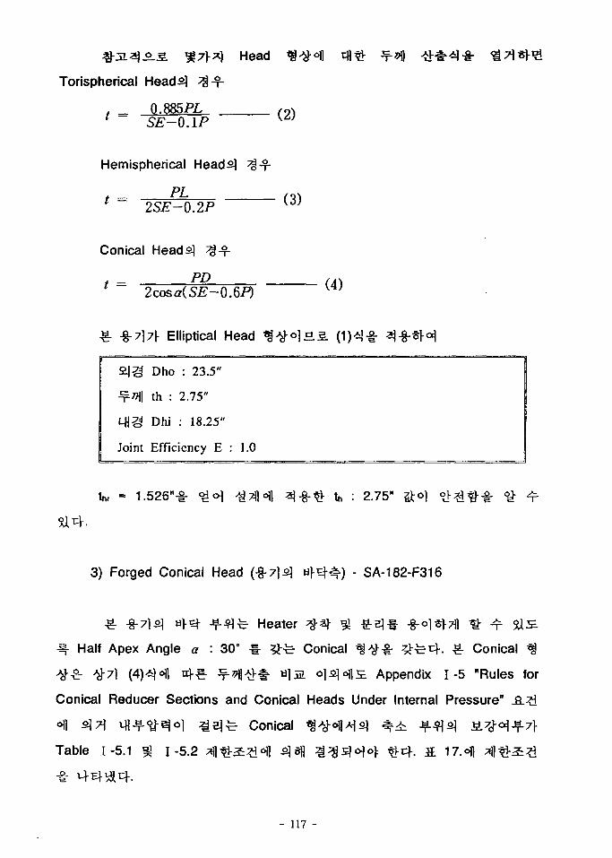
Head
Torispherical Heads] %•%-
. _ 0.885PL1 ~ SE-O.IP
Hemispherical Heads] ^-%-
PL* — 2SE-0.2P
Conical Heads] ^
, _ PD1 2cosa(SE-0.6P)
•%-7\7\ Elliptical Head
£|g Dho
•x-^l th :
LH3 Dhi
: 23.5"
2.75"
: 18.25"
Joint Efficiency E : 1.0
1.526"-§- «£<H ^7ll<Hl ^-8-^- ^ : 2.75"
3) Forged Conical Head (-g-7|s] a f ^ # ) - SA-182-F316
^. -8-71SJ «f^- -^-flfe Heater
Half Apex Angle a : 30° » ^ f e Conical $#•§- ^ ^ 4 . >& Conical ^
^"7l (4)^<Hl n|-^. -^7)l## «l3a oj^ofls. Appendix 1-5 "Rules for
Conical Reducer Sections and Conical Heads Under Internal Pressure" A ^ i
ofl 2 M Mi-^-^^oi z i e ] ^ Conical ^ ^ * f l ^ s ] ^ ^ ^ -^s ] SL#O=JJ=L7J-
Table 1-5.1 ^ 1-5.2
- 117 -
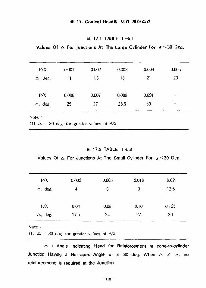
S. 17. Conical Head21 2.1} *«t*3&2l
2 17.1 TABLE I -5.1
Values Of A For Junctions At The Large Cylinder For a ^30 Deg.
P/X
A , deg.
P/X
A , deg.
0.001
11
0.006
25
0.002
1.5
0.007
27
0.003
18
0.008
28.5
0.004
21
0.091
30
0.005
23
-
-
Note :(1) A = 3 0 deg. for greater values of P/X
3. 17.2 TABLE 1-5.2
Values Of A For Junctions At The Small Cylinder For a <30 Deg.
P/X
A , deg.
P/X
A, deg.
Note :
(1) A = 3 0 deg.
0.002
4
0.04
17.5
for greater
0.005
6
0.08
24
values of PA
0.010
9
0.10
27
0.02
12.5
0.125
30
A : Angle Indicating Head for Reinforcement at cone-to-cylinder
Junction Having a Half-apex Angle a <. 30 deg. When A < a, no
reinforcemene is required at the Junction
- 118 -
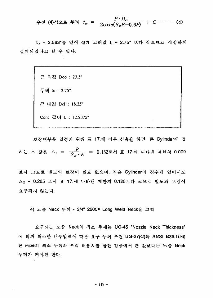
(4)
2.583"^- <2<H J&rt j i !3j# tc - 2.75" J i 4 4 A £
Cone 1J
Deo :
: 2.75"
Dei :
O| L :
23.5"
18.25"
12.9375"
A , = CP _ = 0.1525.^ a 17.o)l q-Ef l ^ltlrAl 0.009
Si^.^, ^-^r Cylinder^
A2 - 0.205 £.*1 S 17.ofl
4) i^# Neck -f-^l - 3/4" 2500# Long Weld Neck -
Neck5| %± tf-y\]t UG-45 "Nozzle Neck Thickness"
4€- .8.^ ^ ^ 2? i UG-27(C)3]- ANSI B36.10oll
Pipesl 3)± ^*llsl- -f-^l ^-§-^11- fl-^- ^Jt oflAi e S i 4 r t # Neck
- 119 -
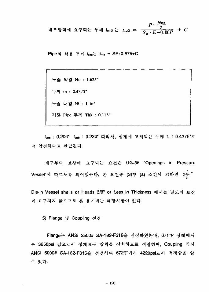
p. ML
*)-§- * M trnbfe tmb - SP-0.875+C
¥-*H tn :
him Mia
7 | # Pipe
No : 1.625
0.4375"
Ni : 1 in"
•7 1 Thk : 0.113"
0.206" U : 0.224" uJ-aM, £%<% ^ 3 j s ] ^ ^ 7 i t, : 0.4375
UG-36 "Openings in Pressure
Vessel"^ ttl-5.S.^ sl^Sifewf, «• -fi-^f^ (3)^ (a) S ? H ^1*>^ 2 - | "
Dia-in Vessel shells or Heads 3/8" or Less in Thickness
5) Flange §J Coupling ^ ^
Flanged ANSI 2500# SA-182-F316^- ^ ^ ^ ^ ^ 4 , 671T
fe 3658psi ^A^A- j >i7JlA^- <&^•£: ^ i | « f E £ ^ i ^ ^ ^ . Coupling
ANSI 6000# SA-182-F316^ ^Jd^^H 672'F«fl-H 4220psi3.*]
- 120 -
6)
- 3750psi7f
7)
UG-99 phyd
Pressurizerfe
8 3 " * * f e
7.ofl
ASME
16B Shelly - g - ^ ^ 110",
3 - f •• 4.002KG)
FTL RM1
Corrosion Allowance7f 1/8"o]Ji 671
•8-7H *l-g-=l^ ^ - § - ^ 4 ^ ^ - ^ - ^ ^ UG-23(C) "Maximum Allowable
Stress Values" .2_:£Hl ofBf ^-g-s]t^, Support^ §^^ 7]'£Q Accumulatorsf
^ ^ ^ - ASME ffl NF-3552, NF-3224/32257f
Code %•%•&.£•%• £ S ^ - ^ ^ 5. 18. }-
ASME m Accumulator
S.S.
- 121 -
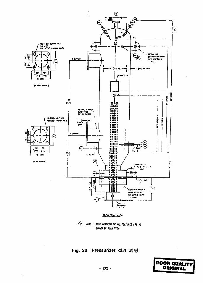
5-9
COWtMUOKlC ~f« unwc loiat IHSTTCK.T
FIFVATJON Vint
(K NOTE : TRUE ORIENT* Of A a FEATURES ARE ASSHOWN IN PLAN VIEW
Fig. 20 Pressurizer
- 122 -POOR QUALITY]
ORIQINAL
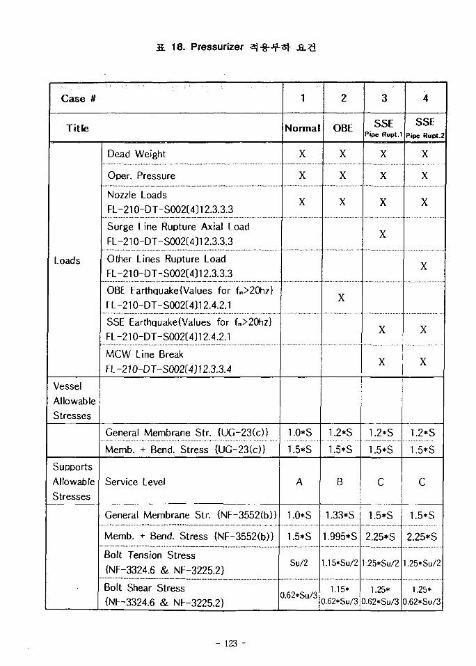
S. 18. Pressurizer jfi.?i
Case #
Title
Loads
VesselAllowableStresses
SupportsAllowableStresses
Dead Weight
Oper. Pressure
Nozzle LoadsFL-21O-DT-SOO2C4312.3.3.3
Surge Line Rupture Axial LoadFL-210-DT-S002(4)12.3.3.3
Other Lines Rupture LoadFL-210-DT-S002(4)12.3.3.3
OBE EarthquakeiValues for fn>20hz}FL-210-DT-S002(4)12.4.2.1
SSE EarthquakelValues for fn>20hz}FL-210-DT-S002[4)12.4.2.1
MCW Line Break
FL-210-DT-S002(4)12.3.3.4
General Membrane Str. {UC-23(c)}
Memb. + Bend. Stress (UC-23(c)}
Service Level
General Membrane Str. (NF-3552(b)}
Memb. + Bend. Stress {NF-3552(b)>
Bolt Tension Stress
{NF-3324.6 & NF-3225.2}
Bolt Shear Stress
{NF-3324.6 & NF-3225.2}
1
Norma
X
X
X
1.0*S
1.5*S
A
1.0*S
1.5*S
Su/2
.62*Su/3
2
OBE
X
X
X
X
1.2*S
1.5*S
B
1.33*S
1.995*S
.15*Su/2
1.15*.62*Su/3
3
SSEPipe Rupt.1
X
X
X
X
X
X
1.2*S
1.5*S
C
1.5*S
2.25*S
.25*Su/2
1.25*.62*Su/3
4
SSEPipe Rupt.2
X
X
X
X
X
X
1.2*S
1.5*S
c
1.5*S
2.25*S
,25*Su/2
1.25*.62*Su/3
- 123 -
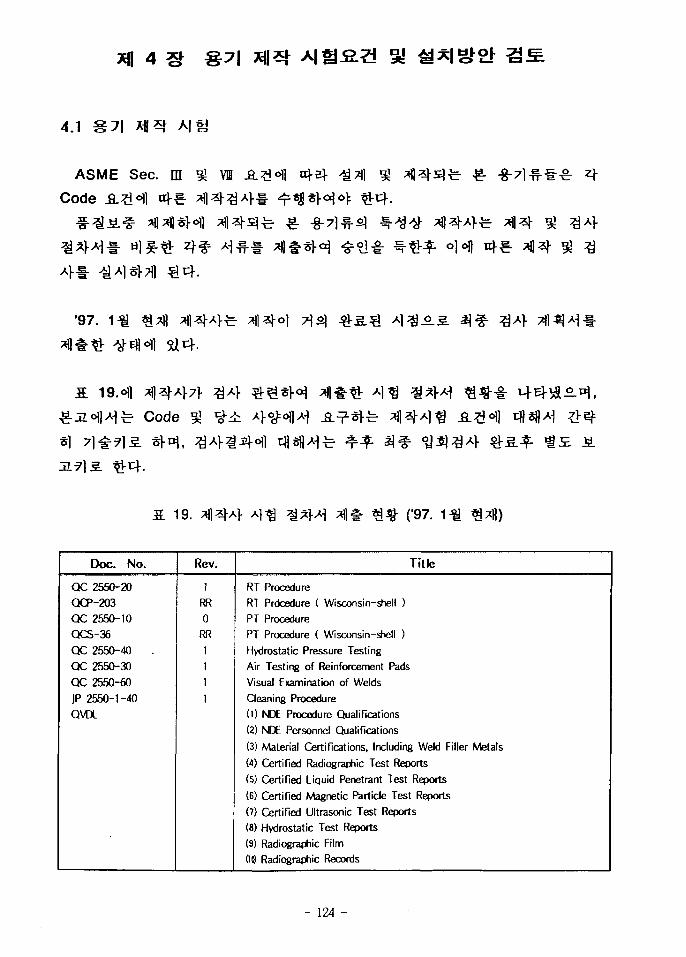
4.1
ASME Sec. ffl §J VI
Code
4* -
•97.
« « • •
Code
19. ("97.
Doc. No.
QC 2550-20
CXP-203
QC 2550-10
QCS-36
QC 2550-40 ,
QC 2550-30
QC 2550-60
JP 2550-1-40
QVDL
Rev.
1
RR
0
RR
1
1
1
1
Title
RT Procedure
RT Prdcedure ( Wisconsin-shell )
PT ProcedurePT Procedure ( Wisconsin-shell )
Hydrostatic Pressure Testing
Air Testing of Reinforcement Pads
Visual Examination of Welds
Cleaning Procedure
(0 NDE Procedure Qualifications
(2) NDE Personnel Qualifications
(3) Material Certifications, Including Weld Filler Metals
(4) Certified Radiographic Test Reports
(5) Certified Liquid Penetrant Test Reports
(6) Certified Magnetic Particle Test Reports
(7) Certified Ultrasonic Test Reports
(8) Hydrostatic Test Reports
(9) Radiographic Film
(10) Radiographic Records
- 124 -
7\. Hi 31 A]
1)
ASME SEC II -8-7loJl
sf ASEM III
S.A1 owners!
owenrs] QC
SNT-TC-1A«>)1
owners QC
ASME
owners
ownerofl
2:^-340)1 s i ^ - Volumetric Examination^ &E.
A?i^- 4?i *H-t«H owner
Head pointl-
NDE ASME
(1) Manufacturer's Name
(2) Purchaser's Purchase order number
(3) Name of pant and part identification number
(4) Procedure, method, technique used
- 125 -
(5) examination result
(6) Personei qualification
(7) Applicable material specification
2)
outline S^o f l i=g7]
ASME II 9J
(1) Type 3 ^ - 1 - owners] ^ ^ H ^ Af-g-sHo): *}.j7 Type 4
(2) ^ 3 4-8"
(3) 2^- Rim
(4) ^ - ^ ^ ^ l £ f e 3 3 ^ Densitometer
(5) *$%
(6) S.-&
(7) -8-3 A l ^ J f f l ^ - -8-^ - ^ 5? Heat Affect Zoneo] £#£ |<Ho) *}
nj, Heat Affect Zone^r weld fusion line #
(8) Weld-end preparations]
3)
ASME II
(1) oqsfl ^ ^ . A ] ^ ^ . A ] ^ w-^ofl blasting^
- 126 -
(2) -g-afl ^ -fi-Sj-afl Types? Penetrantfe -8-3-¥-41 9? 7l7fl7V^- -»j»-*H A>
(3) Weld-end Preparations} -g-^ ^J f f l f e - A ] ^ S ] j ^ o f l 2^s\^ 7\
(4) ^r-8-^ Penetrant^: Cast, Forged
Types? Penetranfe
4)
Magnetic particle ^ 1 ^ ^ ^ 7 l ^ ^ r ASME II _8.:?H n}-^0): * r^ °1-
(i) Overall Circular ^ longitudinal magnetization wov^^- A)-§-sM°>
(2) 7l7j)7F§- a ^ ^ r ^ ^ w ^ ^ - ^ r ^ l ^ H ^ * H , £ ^ # Particle^- A]-
. Cast, Welded ZLS]IL forged
(3) A ] $ ^
(4) A ] ^ ^ i^-fe owners ^sf l Yoke techniqueAl-g-oi
rectified alternating current
(5) Magnetic
(6) <5>efl A V * O ^ Progressive magnetic particle
a <y=^.°5. -§-^*>-b Jf-flofl weld roofe back gouging ^ 2*1- -§-
b.
- 127 -
c. Owners]
d. A)^j,g- ASME V -fl-SH a -sl- dry powder A)-g- 3J rectified AC
e. Progressive
f. ^l^Jf S ^ s ] Overheating ^ ^ burning^
g. Weld-end preparations] -8-3
5)
a)
Ultrasonic A ] ^ ^ ^ - ^ 7 1 ^ ^ ASME III A S ^ n|-5i-o>
b) -8-^Jf A ] ^ ( Weld Examination )
weld fusion
^ £ ^ - 90"
• i -
-8-^ 9J Heat Affected Zone?H
Heat Affected Zone£ weld fusion line 3
Ultrasonic A ] ^ ^ . - § - ^ ^
- 128 -
-8-3 ^
plate ^D^iHl lamination^- #<>l-ifl7l
Plate
c) Tubular Products
Ultrasonic
(l)
(2)
d)
Ultrasonicofl
(1)
(2)
(3)
^ reference blocks
Ultrasonic
6)
a) Casting
SL€- casting
defect^
MSS SP55°I]
- 129 -
MSS SP55
(1) defect Ill.V.Xllfil Rgures (e)3- (d)fe reject
(2) defect VIII si Figure ( c ) ^ reject A } ^ O ] o } ^ .
(3) S.€- Cast steely MSS SP553 fj-zj
b)
ASME III
coating ^
(1)
(2)
(3)
(4) ^ T f l ^ -8-3 ^ ^ s i i-Aflfe a . ^ -8-3^<H
(5) Flush ^<Ho> «Kr -8-3 a ^ ^ r A ^ ^ o i ^ l f e ^ - ^ j a . ^ S-iiJIM- -S-
33 T ^ V ^ M ^ l <&s.^ Flush
(6) Single pass -g-^^r 7 ] i 7 }
(7) SDi^iUr 1/31-g-
(8)
(9)
Weave ^ £ -§-3
- 130 -
ASME III
$• -g-71 ^ c
^ iA]?>jit|. g-Tfl A ] ^ * > ^ ^ . f ^ - rA l ^ ^ - -i-o] ^.^p- Chemical
nj-o>o|: el-^, stainless
ductile-brittle
Nozzle Reinforcement
-g-7]s] ^^-o]] -Jf2j-£] fe reinforcing platesfil- saddle •§-£: a j4 :^ 1
telltale hole (^tf l 3 7 l : 1/4'pipe tape ) •§- 7 r ^ °> ^ - 4 .
ol hole^r - g - ^ ^ - ^ ^ T i ^ i ^ ^ - A]^§|-7l 4]«H Compressed Air5. bubble
testl-
, compressed airs}- bubble test
Gas and Bubble Formation Testing Section of Article 10, ASME V
leak
4.2
7K
ASME ffl NC £.#°\] 1 -4 ^]2]-s1fe Accumulator-^
NC-4220 "Forming Tolerances" °11 *
.a. 3
-§-71 Shell
*}o}7\ inch o.S (D+50)/200 ^ D/100^
Dfe Shells]
013 ^ i l t ^ NC-4221.2(a)-1
"Maximum Permissible Deviation "e" from A True Circular Form"
-8-71 Head
1.25%
Knuckle
Inch 7 j^«.S. (D+50)/200 % D/100^
*vcf. s.*) Heads] t § ^ ^ Ellipsoidal^ 3 - f
^s^ o.875% o]^o] ^ - ^ S ] A ^ ?Vs]^, 2:1 Ellipsoidal
^ -g-7l vfl^s] 17%<>I]
ASME VI Pressurized UG-80
UG-80-1S]
Shell
1% o] xfl o]
- 132 -
Head ^ s ] *l-8-^*r£- Section m -8-71*1-
(Radiographic Acceptance Standards : NC-5320)
RadiograpM
(1)
(2)
a, t7V 3/4"
b, \7\ 3/4" ^JIJ- 2 ^ " ol*J.o] 3 4 . !/3 t
c, 17)- 2 ^ " ^3 ) - ^ 7J4- 3/4"
(3) 12t
(4) ^ ^ ^ I A H cf l^ ^ ^ 71^-g- Appendix VI
2:-S-34 ^ - ^ ^ 1 ^ ^ - ^ 7 ] ^ (Ultrasonic Acceptance Standards : NC-5330)
20%!
(1)
- 133 -
a, V\ 3/4"
b, t7l- 3/4"
c, 17} 2%"
1/3 t
3/4"
(2)
(Magnetic Particle Acceptance Standards : NC-5340)
(1)
3Bfl
- 134 -
(2)
- 1/16"
Tfl
3«fl
a.
b. 3/6"
c. 1/16" a fe J i ^ ^ ^ Q^SLsL ^ ^ -?-4l7f ^-^sl<H 5Ufe 47fl
d. 6" W 3 3 Ml<Hl 107fl
D>. ^ - r - ^ ^ A l ^ fJ-2J7lir (Liquid Denetrant Acceptance Standards : NC-5350)
(1) ^1^51
- 135 -
(2)
- 1/16"
a. ^ ^
b. 3/6"
c. 1/16
d. 6"
47fl
107fl
- 136 -
4.3 FTL RM1
Safety Injection Accumulator 27\i\ ^ A ) S ) ^ FTL RM1£- 5. 1.°fl
RM1S]
Shut -Down
, Safety Injection Accumulators «15-^ FTL RM1<>fl
-8-7I g| ufl^-, Accessory^ - ^ ^
FTL
FTL RMIofl uflA)s]^ 71^1-^)^ ZL% 212)- 22<H1 v+Bl-'dl ^ ^ ^ °1 EL.
Level 76.6 JfB] &3.B]E. ^Tfl i ^ - ^ - EL 85.7 Levels} ^^r^flofl ^ ^ 1 € 4 .
^-*1 Accumulator 271^1- Waste Disposal Tank 171 3! Pressurizer 171^- ZL
^ 22.°11 1 4 ^ w> 4 ^o] EL 79.533-1- ^^^(Waste Disposal Tank
o.S. * r fe RM1
3.1. n>*^oflAi o]nl 7 l#^c f lS ACI-Appendix B
7r ? 3 5 ] H n l ^ l ^ ^ ^ g : ^ . ?1^- ^ 3 ^ E . 7 ) - ^ ^ Pull-out Stregth
- 137 -
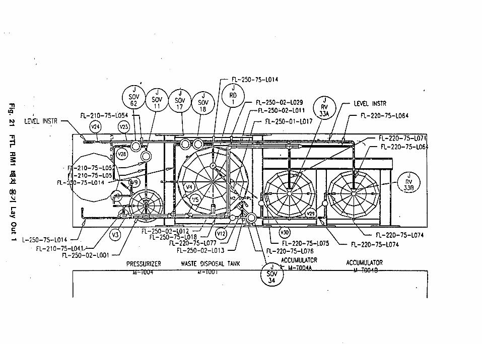
a-250-75-L014J
RDFL-250-02-L029-FL-25O-02-L011
M L E V E L I N S T R
LEVEL INSTR
a-220-75-L064
£
to•<
L-250-75-L0HFL-210-75-
FL-220-75-L07IFL-220-75-L06
FL-i
-L04.1>-/ /-250-02-L001 —J
P R E S S U R I Z E S
F L - 2 5 0 - 0 2 - L 0 1 2F L - 2 5 O - 7 5 - L O 1 8
F L - 2 2 0 - 7 5 - L 0 7 7F L - 2 5 0 - 0 2 - L 0 1 3
W A S T E D I S P O S A L T A N K
F L - 2 2 0 - 7 5 - L 0 7 5F L - 2 2 O - 7 5 - L O 7 6
A C C U M U L A T O RM - T Q Q 4 A
F L - 2 2 0 - 7 5 - L 0 7 4F L - 2 2 0 - 7 5 - L 0 7 4
A C C U M U L A T O R— M T O O 1 D
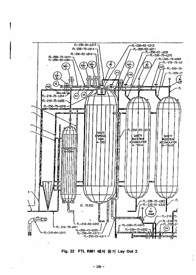
a-2SO-OI-L017a-25O-75-lOU
a-250-75-WU-a-2SO-02-C001-
a-250-O2-L012n.-2so-o2-u)n
a-25O-02-L029a-220-75-L075
a-220-75-LO69a-220-75-L0"
FT.-21O-75-LO54
a-2IO-7S-LO5O-N]
a-250-75-L018
a-25O-O2-COI3-a-250-02-C0M-
r a-23O-IS-L0t5a-230-
Fig. 22 FTL RM1 %7\ Lay Out 2
- 139 -
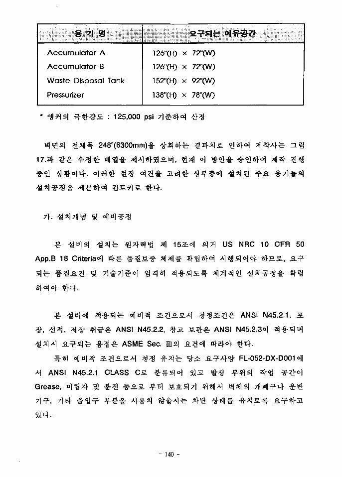
Accumulator A
Accumulator B
Waste Disposal Tank
Pressurlzer
126"(H)
126"(H)
152"(H)
138"(H)
X
X
X
X
fi^fe own
72"(W)
72"(W)
92"(W)
78"(W)
: 125,000 psi
248"(6300mm)-i-
71-.
US NRC 10 CFR 50
App.B 18 Criteria<Hl
ANSI N45.2.2,
^ ASME Sec.
Ai ANSI N45.2.1 CLASS C5.
Grease,
7
S ^ ^ r ANSI N45.2.1,
ANSI N45.2.3O]
Si
FL-052-DX-D001
- 140 -
Vacuum Cleaning^) sj-g-s]<Ho>
Checkl-
71 Til Chipoluj- Solvent
Solvent^ Tape
&|tl: Clean Room-§-
•?• -&&!•§•
Code
FTL -8-71 si £ 5910Kg(Accumulator
S H I S
Accumulator
Pressurizer
Main Cooler
Waste Disposal Tank
M ^ I S g
5910 Kg
2580 Kg
470 Kg
2125 Kg ( f i g s«f)
30/5 Ton Craned-
- 141 -
419mm
- FTL
. ^ f e FTL RM1
FTL
FTL RM1 7lx>7fl
FTL 4
^.S- ^ ^ ^ -8-71^1- « 1 ^ - ^ Pump, ^51^7] f-
7)- ^ ^ ) € * a ) ] ^ ^ ^ 0 ] °1^-<H^1^, ^^2 j -5 .5 . | 1 ^ •§- Accessory
t}7]
5flo.S.S.,
- 142 -
EL 85.7
LeveN Truck-Access Area7r 9X2-E.3., 30/5 Ton Crane-i- °
$• EL 77.3 Levels S]^- Shutter £-g-
Air-Tight
Shutters-3|-
Crater*
; * Crater
FTL
Truck Access^.
Air-Tight# ^n f l t i -8-
, FTL RM2
FTL RM1-8- 7}
-8-EL. 72.3 LeveN
Repture Discs}-
AS.Ai 30" FTL
High Energy Line Break (HELB)
RM2SJ
^-A] Sleeve ^-g-
7711 ±(400x400 Size •§-)!• Chipping
- 143 -
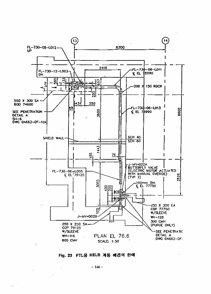
FL-730-08-L012UP
550 X 300 SA800 74600
SEE PENETRATIONOETAIL ASH-6OWC 04662-DF-104
-08-L0118990
FL-730-12-L0O3ON
73C -O6-L013
SHIELD WALL—
J-MV.002ABUTTERFLY VALVE(ELECTRIC MOTOR ACTUATEDWITH MANUAL OVERIDE)
FL-730-06TL005C_ EL'79125
100mm DIA.EL 77750
250 X 250 SACOP 79125W/SLEEVEWH-116600 CMH
750 X 300 EACOP 77750W/SLEEVEWH-128
\ 300 CMHNV (PURGE ONLY)
PLAN EL 76.6SCALE: 1:50
PENETRAT1COETAIL ADWG 04662-DF-
Fig. 23 FTLS HELB 7J#
- 144 -
Core-Drilling
-8-71
RM13J-
RM2S1 ^-^.Jff ls ^*>JI. FTL RM1^ o ] ^ ^ - 2 ^ ^ S>||» ^7H*fol 1*}-
Vynil
lfe °J^] Flexible ^-f- ^ H 1 * H ^ j - ^ ^^S . -?-^ Truck
Access Area!- ^4 * } - ^ ^^-S. D M £ ^-7]7l-
-5.5. FTL RM1-4
JjS-3 FTL RM2
Air-Tight
-f-^-S.
- 145 -
£-*fl7V £)fe -g-7] ^J Shop Fabricated P ipe t FTL RM1°fl
71
Fabricated Pipe
FTL
FTL
•§-
Shop
g-o] 51
RM2S]
FTL RM1
Room %-g-oi
HELB
Size
RM2
EL. 72.3 LeveN Control
7\
•8-7]S)
Pool4 Service Poo l^ Vynil Pool ?H1
Support
Filter
f Spent-Fuel
HEPA
-g-
- 146 -
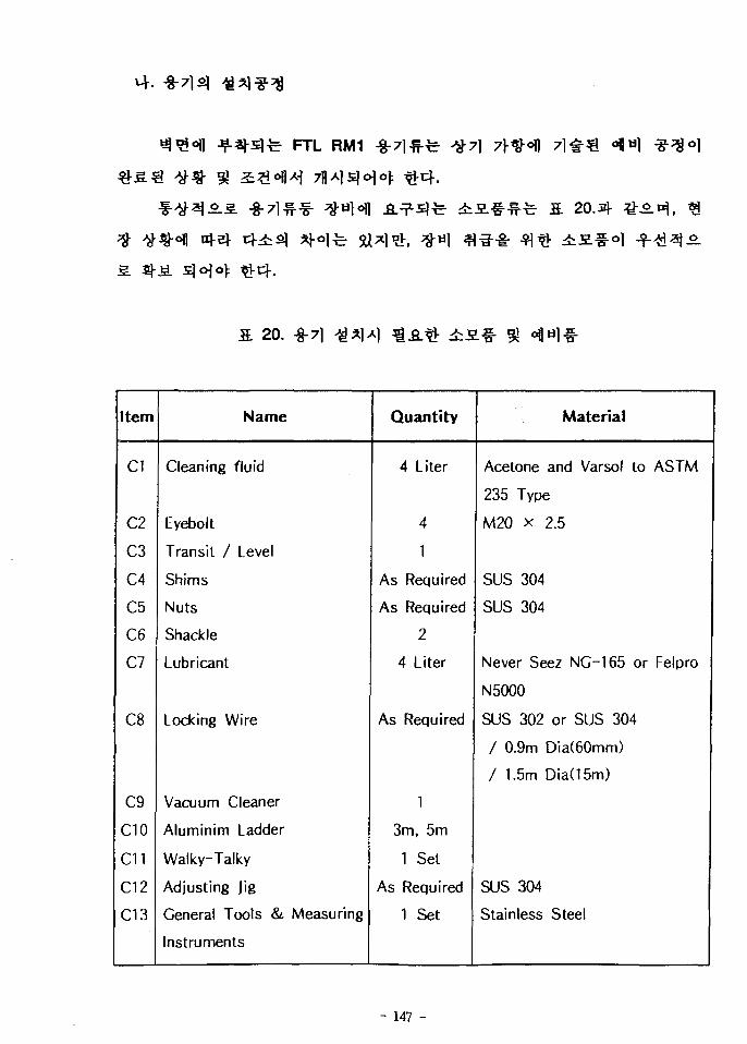
FTL RM1
20.
Item
Cl
C2
C3
C4
C5
C6
C7
C8
C9
CIO
C11
C12
C13
Name
Cleaning fluid
Eyebolt
Transit / Level
Shims
Nuts
Shackle
Lubricant
Locking Wire
Vacuum Cleaner
Aluminim Ladder
Walky-Talky
Adjusting Jig
General Tools & Measuring
Instruments
Quantity
4 Liter
4
1
As Required
As Required
2
4 Liter
As Required
1
3m, 5m
1 Set
As Required
1 Set
Material
Acetone and Varsol to ASTM
235 Type
M20 x 2.5
SUS 304
SUS 304
Never Seez NG-165 or Felpro
N5000
SUS 302 or SUS 304
/ 0.9m Dia(60mm)
/ 1.5m Dia(15m)
SUS 304
Stainless Steel
- 147 -
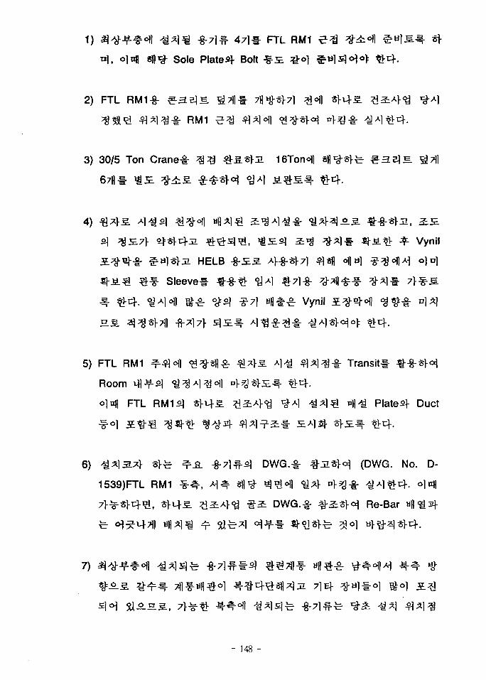
FTL RM1
Sole Plated Bolt
2) FTL RM1-§- ^ H B ] E . g>D5 71)^71
- RM1
3) 30/5 Ton Crane-§- ^ ^ ^ - ^ . ^J i 16Ton< |
67fll- ^ £
4) ^
s\ ^£71- ^*>c^3. ^ - ^ s ] ^ , ^ £ ^ a ^ ^ - * ] # ^ - ^ . ^ ^ Vynil
HELB -§-£5. A>-8-*|-7] ^«fl ofla) ^-^oflAi o]n]
Sleeve* «-8-^ °JA1 «r7
^ 7 ] Hft#^ Vynil
5) FTL RM1 ^ ^ o i i o ^ s f l ^ J&Tbs. *]<£ ^ * ] ^ - g - Transitl
Room \1\if2\ ^ ^ A i ^ o f l P > ^ * > £ ^ . *Vuf.
olnfl FTL RM1S1 ^>u}-5. 2^4<a ^ A l A d * l ^ D l l ^ Plated Duct
6) ^*]3.x}- t}^ ^ A -§-71 -fi] DWG.^r # :HSH (DWG. No. D-
1539)FTL RM1 * ^ , A ^ Sfl^ ^^of l <i}*} p>?ol - ^ A l ^ - ^ . olnfl
Re-Bar
71 E|- ^ t i l f r
- 148 -
Accumulator
, Accumulators] Sole Plated Torque
8) A 5 . Accumulator
Drill
Room
JL3|-
9) Drillco Maxi-Bolt $&±
Hig U]E.-C- Rebar Eaten-f Diamond Core
Bit7r
SL 21.J4
21. Primary Hole Drill Diameters and Hole Depths
NominalAnchor Size
1/4"
3/8"
1/2"
5/8"
3/4"
1"
1 1/4"
1/2" Heavy
Drill DiameterMaximum
0.530"
0.655"
0.778"
0.975"
1.172"
1.690"
2.065"
0.845"
Minimum Hole depthAnchor Embement Plus
1 inch
1 inch
1 inch
1 inch
1 1/2 inch
2 inches
2 inches
1 inch
- 149 -
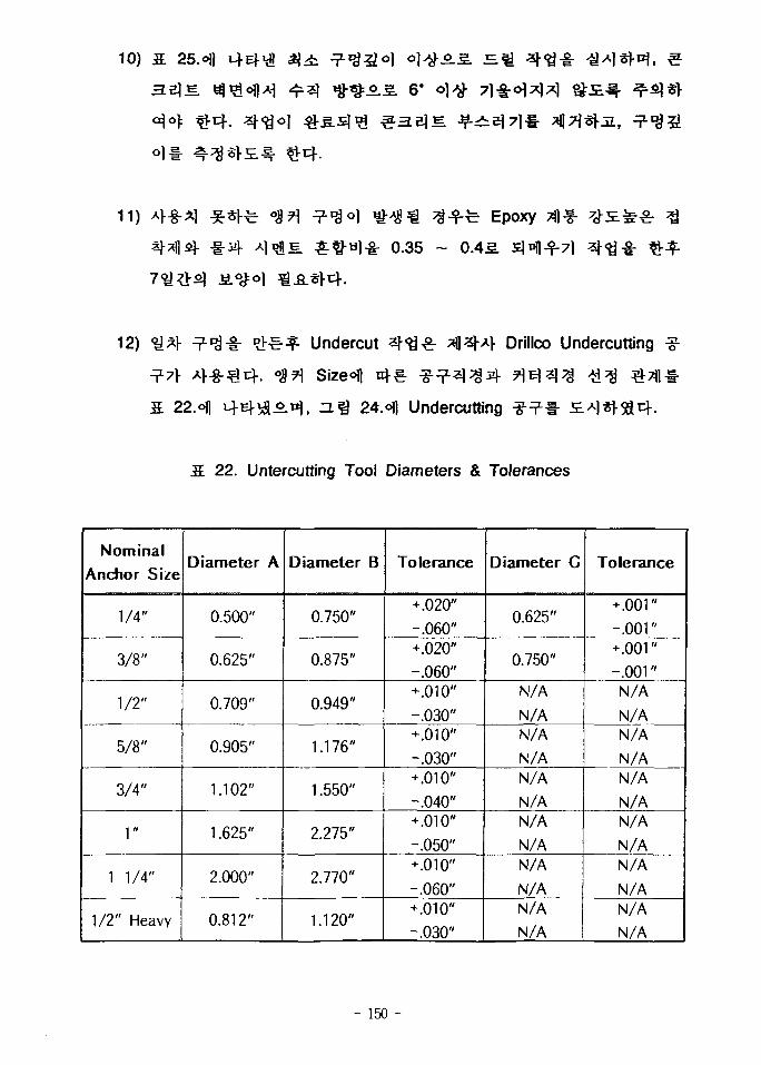
©.S 6'
11) Epoxy
0.35 ~ 0.45.
12) * l * r
fi. 22.ofl
Undercut
Sizeofl
Z L ^ 24.ofl Undercutting
Drillco Undercutting
22. Untercutting Tool Diameters & Tolerances
Nominal
Anchor Size
1/4"
3/8"
1/2"
5/8"
3/4"
1"
1 1/4"
1/2" Heavy
Diameter A
0.500"
0.625"
0.709"
0.905"
1.102"
1.625"
2.000"
0.812"
Diameter B
0.750"
0.875"
0.949"
1.176"
1.550"
2.275"
2.770"
1.120"
Tolerance
+.020"
-.060"+.020"
-.060"+.010"
-.030"+.010"
-.030"+.010"
-.040"+.010"
-.050"+.010"
-.060"+.010"
-.030"
Diameter G
0.625"
0.750"
N/A
N/AN/A
N/AN/A
N/AN/A
N/AN/A
N/AN/A
N/A
Tolerance
+ .001"
-.001"+.001"
-.001"N/A
N/AN/A
N/AN/A
N/AN/A
N/AN/A
N/AN/A
N/A
- 150 -
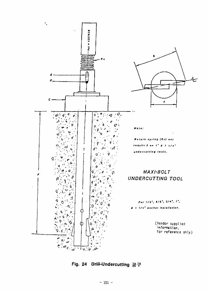
D 1
Rtturn spring (Hi) not
f q u l t c j on f 4 l t/4 •
undercutting teolt.
MAXI-BOLTUNDERCUTTING TOOL
For 1/2'. S/*% 3/*". ' " .
i I 1/4' tnehor Intttllstlon.
(Vendor suppl iedinformation,for reference only)
Fig. 24 Drill-Undercutting
- 151 -
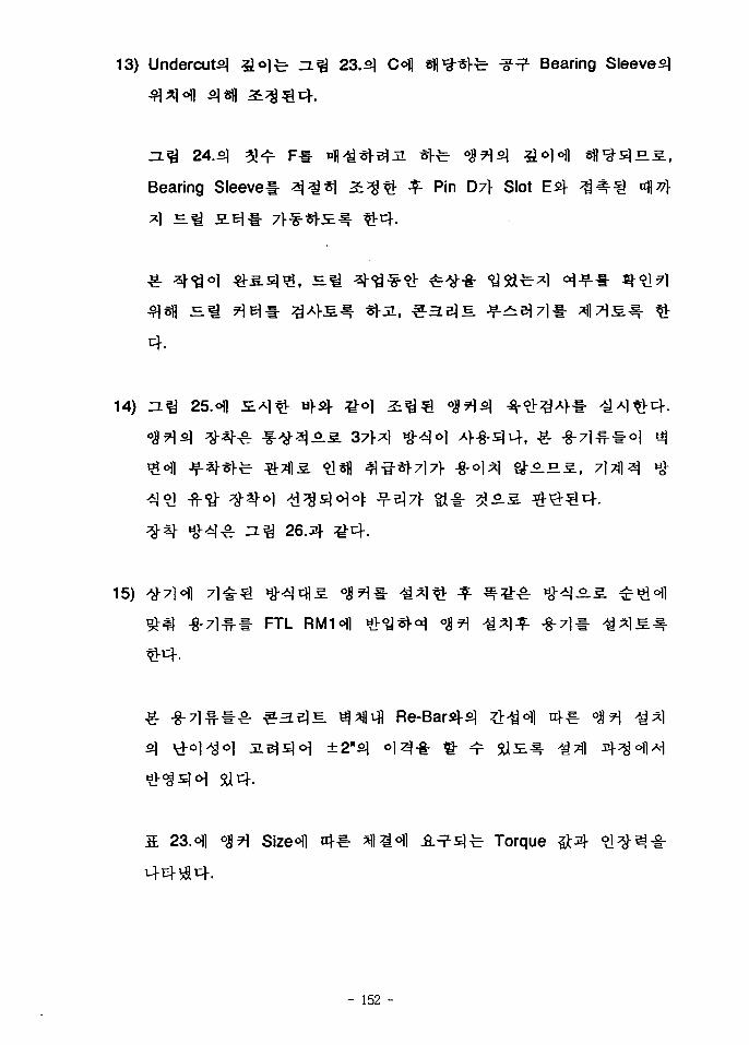
13) Undercuts] £ 0 ] ^ =L% 23. <N C°)l Sfi^s]-^ ^ Bearing Sleeve^
Bearing Sleevel- ^ j ^ * l ^ ^ $- Pin D7f Slot
15)
- FTL
- 152 -
14) ZL^ 25.ofl HA]^- H><4 ^-o]
, ^. -8-71 - #
5a4-
23. oil °<!l Size<Hl 4€- ^l^0 ! ] -8.^3 fe- Torque
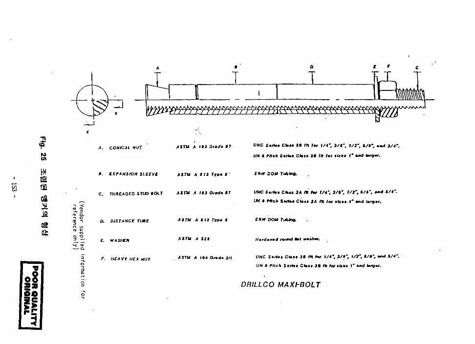
•n
9to
V11 L/I / / /////// //7i\ \ \ \ Vs. \ \ \ \ \ ^ \;\ \ \ \ \
A. CONICAL HUT A ITU A l»i Oimdt BT VNC S*tU» CkM IB til /•» \/4'. 3/f. 1/2', £/$', and J/4*
UN B Uteh Smrtf Ctet< IB IH for «U«« I* **d
ftfflH
JO
t. EXPANSION AtTU A Hi Tip* i •
O T33 —
o
i
C. TMMAOED tTUO BOLT AtTU A I»J Or*d* BT
a DISTANCE Time
£. WAStEH
F. HEAVY HEX NUT
At TV A Hi TYJH t
ASTU A 121
Arm A la-t and* an
1A rtt for f/4% )/»'. i/t'. «/«". »»« 1/4'
Ctai* /» m lot ttin.l' tnd
£HW DOW
UNC StrHt
IM $ PBoli
EltW DOM Tub+iQ.
ll,nltn*d mwtd Mat wit>**.
UNC StrUt Ctou J l f f l / w 1/4", 3/«*. 1/7*. «/•". •»<* *J4'
UN I rllch S*rUt Ctaa* 2B (X hot «iiu I* **<* lvg«(,
DRILLCO MAXhBOLT
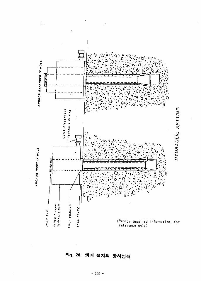
! •
«. s
Viv';'?;''O'-Vi'-° ^ • • • ° "
CD
UJ.CO
o
ccQ
3:
(Vendor supplied infonration,reference only)
for
Fig. 26
- 154 -
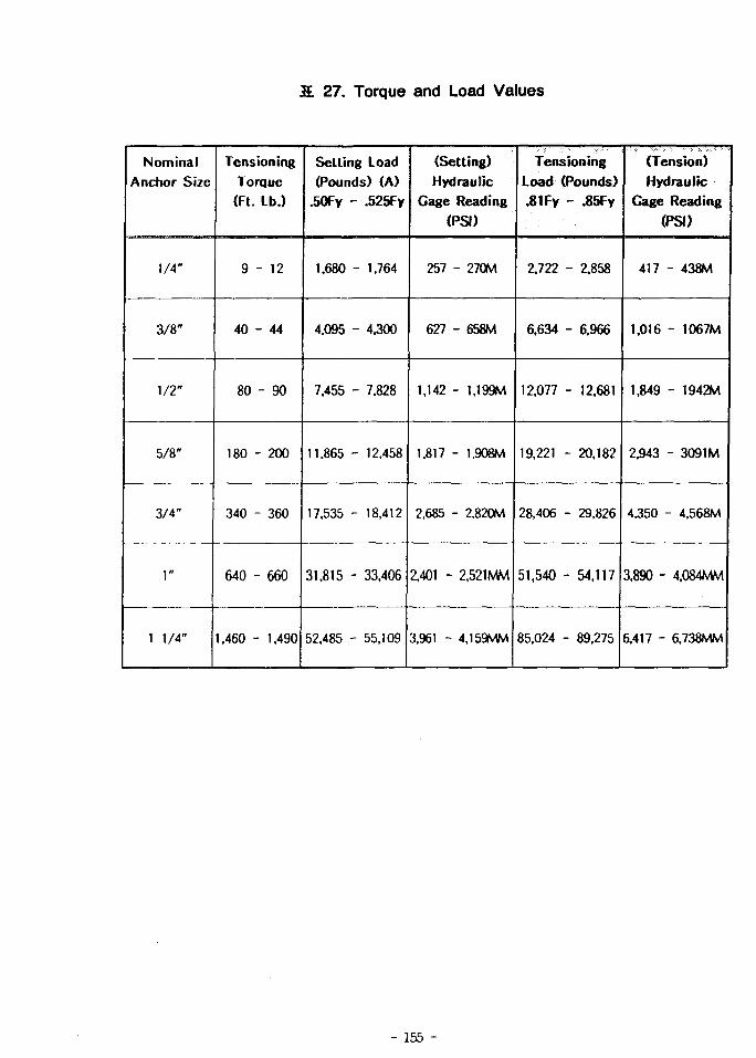
IE 27. Torque and Load Values
Nominal
Anchor Size
1/4"
3/8"
1/2"
5/8"
3/4"
1"
1 1/4"
Tension ingTorque(Ft. Lb.)
9 -
40 -
80
180 -
340 -
640 -
1,460 -
- 12
- 44
- 90
200
360
660
1,490
Setting Load
(Pounds) (A)
.50Fy - .525Fy
1.680
4.095 •
7.455 -
11.865 -
17,535 -
31.815 -
52,485 -
- 1.764
- 4.300
- 7,828
- 12,458
- 18,412
33,406
55.109
(Setting)
Hydraulic
Gage Reading
(PSI)
257 - 270M
627 - 658M
1,142 - U99M
1,817 - 1.908M
2,685 - 2.820M
2.401 - Z521MM
3.961 - 4.159MM
Tensioning
Load (Pounds)
.81 Fy -•• .85Fy
2.722
6.634
12.077
19.221 -
28,406 -
51,540 -
85,024 -
- 2,858
- 6.966
- 12,681
- 20.182
- 29,826
- 54.117
89.275
(Tension)
Hydraulic
Gage Reading
(PSI)
417
1.016
1,849
2,943
4.350
3,890 -
6.417 -
- 438M
- 1067M
- 1942M
- 3091M
- 4.568M
4.084MM
6.738MM
- 155 -
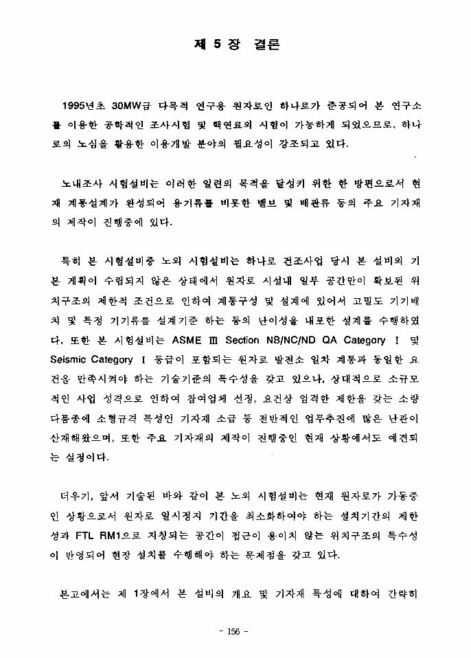
30MW-3-
-M 741 7] e « f t ^"3 V+ol^-i- M15L^ ^7 f l » ^««l-5a
tf. a ^ £• A l ^ ^ a l ^ . ASME m Section NB/NC/ND QA Category I 5J
Seismic Category I -f-g-ol i ^ -£ ] fe €^>S. ^ - ^ i ^ ^ Tfl-f-sl- •S-'S^ A.
FTL
- 156 -
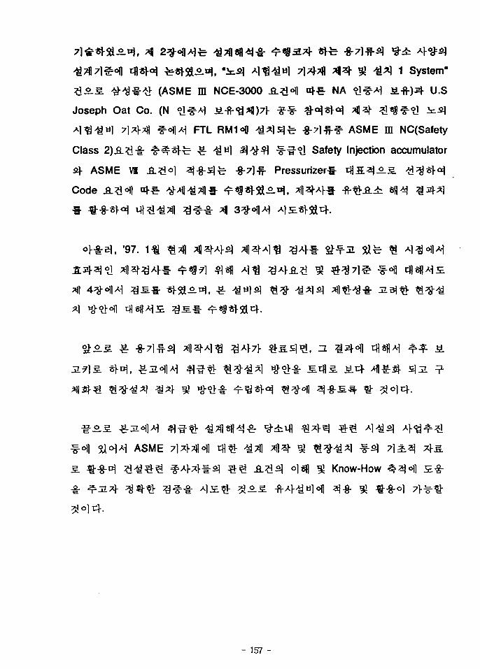
-8-7HMJ *
J ^ ^ 1 System"
(ASME m NCE-3000 .6.3 °fl nj-^ NA °1&*\ ^.- fr)^ U.S
Joseph Oat Co. (N <y-g^ j±-fr<a*l|)7l- * * 4 M « H ^ 1 ^ ^ f ^ ^ l i c ^
A ) ^ ^ W ] 71*1-*)1 ^oflA^ FTL RM1<fl ^ ^ l s l ^ - -g-71-^-^ ASME ffl NC(Safety
Class 2)^ .^^ - ^ ^ ^ l - c -g- ^«1 ^ ^ ^ 1 f-^-^1 Safety Injection accumulator
4 ASME Vt &.#<>] ^ -§-51^ -g-7l# Pressurizerg-
code
, '97.
ASME l ^ f l l fl^ ^ J ^
o}^ *£ Know-How
- 157 -
1. Joseph Oat Corporation Fabrication Drawings : D-11482 (Outline). D-11483
{Assemblyl. and D-11484 {Details)
2. Joseph Oat Corporation Vessel Wall Mounting Drawing : D-11539
3. KAER1 Specification "Technical Specification for Tanks and Pressure Vessel for
KMRR-FTL", FL-070-DD-S004. Addendum 3 to Revision 1. 31 January 1996
4. KAER1 Specification. Appendix 4S-2, "Seismic Qualification Requirement for
Seismic Category I . Items". FL-080-DD-D112, Revision 1, 24 May 1996
5. ASME Boiler & Pressure Vessel Code. Section m. Division 1. Part NC. 1989
Edition. No Addenda.
6. ASME Boiler & Pressure Vessel Code. Section ID. Division 1, Part NF, 1989
Edition, No Addenda.
7. ASME Boiler & Pressure Vessel Code. Section IU, Division 1. Appendices, 1989
Edition. No Addenda.
8. ACI Code Requirements for Nuclear Safety Related Concrete Structures. ACI-349
Appendix B, "Steel Embedments". 1980
9. WRC Bulletin, "Local Stresses In Spherical and Cylindrical Shells due to
External Loadings", WRC-107. 1979
10. ASME Boiler & Pressure Vessel Code, Section VI, Division 1. 1995 Edition. No
Addenda
'\ KAERI/RR-1510/94
- 158 -
12. Joseph Oat Corporation Fabrication Drawings : D11519 {Outline}. D-11520
{Assembly}, and D-11521 (Details)
13. KAERJ Specification. "Technical Specification for (the) Pressurlzer Vessel for
KMRR-FTL". FL-210-DT-S002. Addendum 3 to Revision 1. 31 January 1996
14. Appendix 4S-2. "Seismic Qualification Requirement for Selsmec Category I .
Items". FL-080-DS-D112. Revision 1, 24 May 1996
- 159 -

(Appendix I )
FEA 3* Data
Joseph Oat Co.
- 160 -
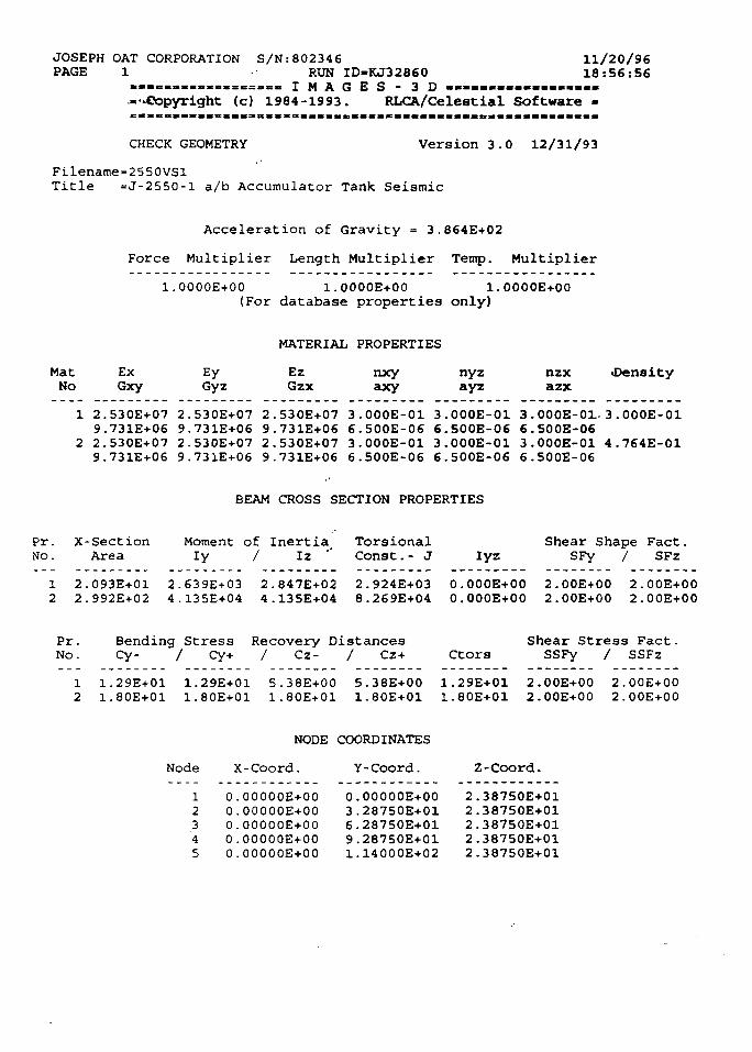
JOSEPH OAT CORPORATION S/N:802346PAGE 1 RUN ID-KJ32860
. . . » . . « . . « . . s s = . e . I M A G E S - 3 D — — — — — —...Copyright (c) 1984-1993. RLCA/Celestial Software
11/20/9618:56:56
CHECK GEOMETRY Version 3.0 12/31/93
Filename=2550VSlTitle =J-2550-l a/b Accumulator Tank Seismic
Acceleration of Gravity = 3.864E+02
Force Multiplier Length Multiplier Temp. Multiplier
1.0000E+00 1.0000E+00 1.0000E+00(For database properties only)
MATERIAL PROPERTIES
MatNo
ExGxy
EyGyz
EzGzx
nxyaxy
nyzayz
nzxazx
•Density
1 2.530E+07 2.530E+07 2.530E+07 3.000E-01 3.000E-01 3.000E-01-3.000E-019.731E+06 9.731E+06 9.731E+06 6.500E-06 6.500E-06 6.500E-06
2 2.530E+07 2.530E+07 2.530E+07 3.000E-01 3.000E-01 3.000E-01 4.764E-019.731E+06 9.731E+06 9.731E+06 6.500E-06 6.500E-06 6.500E-06
BEAM CROSS SECTION PROPERTIES
Pr.No.
X-SectionArea
Moment of InertiaIy / Iz •'
Torsional Shear Shape Fact.Const.- J lyz SFy / SFz
2.093E+012.992E+02
2.639E+034.135E+04
2.847E+024.135E-t-04
2.924E+038.269E+04
0.000E+000.000E+00
2.00E+002.00E+00
2.00E+002.00E+00
Pr. Bending Stress Recovery DistancesNo. Cy- / Cy+ / Cz- / Cz+ Ctors
Shear Stress Fact.SSFy / SSFz
12
1.29E+011.80E+01
1.29E+011.80E+01
5.38E+001.80E+01
5.38E+001.80E+01
1.29E+011.80E+01
2.00E+002.00E+00
2.00E+002.00E+00
Node
NODE COORDINATES
X-Coord. Y-Coord. Z-Coord.
12345
O.OOOOOE+000.00000E+000.00000E+000.OOOOOE+000.00000E+00
0.00000E+003.28750E+016.28750E+019.28750E+011.14000E+02
2.38750E+012.38750E+012.38750E+012.38750E+012.38750E+01
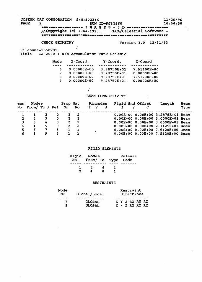
JOSEPH OAT CORPORATIONPAGE 2
S/N.-802346 11/20/96RUN ID-KJ32860 16:56:56
.................. I M A G E S - 3 D — » . — — . = - — » —
.-..Copyright (c) 1984-1993. RLCA/Celestial Software -
CHECK GEOMETRY Version 3.0 12/31/93
Filename=2550VSlTitle =J-2550-l a/b Accumulator Tank Seismic
Node X-Coord. Y-Coord.
6 O.0OO00E+O07 0.00000E+008 0.00000E+OO9 0.00000E+00
3.28750E+013.28750E+019.28750E+019.28750E+01
Z-Coord.
7.51200E+000.00000E+007.51200E+000.OO0OOE+0O
BEAM CONNECTIVITY
earnMo
123456
NodesFrom/
123468
To /
234579
Ref
000086
PropNo
222211
MatNo
222211
PincodesI / J
Rigid End OffsetI
O.OOE+000.00E+000.00E+000.00E+000.00E+000.00E+00
/ J
O.OOE+000.00E+000.00E+000.00E+000.00E+000.00E+00
Length
3.2875E+013.0000E+013.0000E+012.1125E+017.5120E+007.5120E+00
BeamType
BeamBeamBeamBeamBeamBeam
RIGID ELEMENTS
Rigid Nodes ReleaseNo. From/ To Type Code
24
68
RESTRAINTS
NodeNo
79
Global/Local
GLOBALGLOBAL
RestraintDirections
X Y Z RX RY RZX - Z RX RY RZ
JOSEPH OAT CORPORATION S/N:802346 11/20/96PAGE 3 Run ID-KJ32860 18:57:22
................. IMAGES-3D — — — —•/.Copyright (c) 1984-1993. RLCA/Celestial Software -
WEIGHTS Version 3.0 12/31/93
Filename=2550VSlTitle =J-2550-l a/b Accumulator Tank Seismic
CONCENTRATED WEIGHTS
W e i g h t s / R o t a r y W e i g h t sNode X Y Z / X Y Z
Total: .OOOOE+00 .0000E+00 .0000E+00 / .0000E+00 .0000E+00 .0000E+00
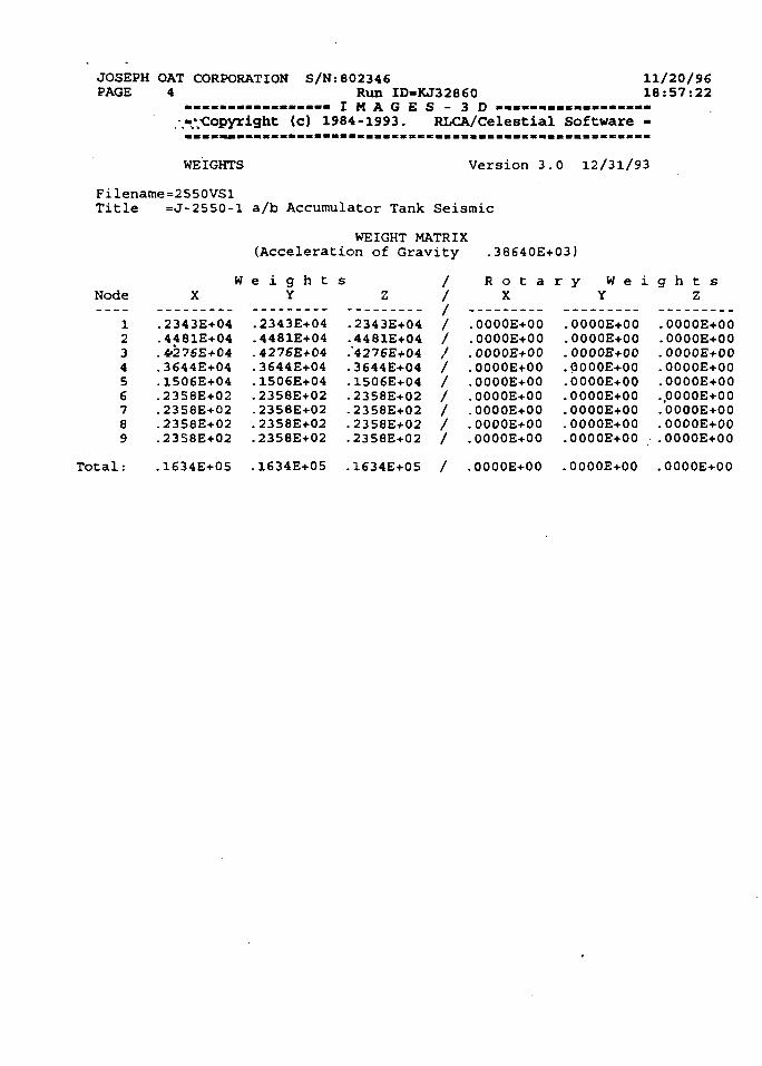
JOSEPH OAT CORPORATIONPAGE 4
S/N:802346 11/20/96Run ID-KJ32860 18:57:22
. . . . . . . . . . . . . . . . . I M A G E S - 3 D - . . . . . . . . . . - . - > . . - .•^•Copyright <c) 1984-1993. RLCA/Celestial Software -
WEIGHTS Version 3.0 12/31/93
Filename=2550VSlTitle =J-2550-l a/b Accumulator Tank Seismic
WEIGHT MATRIX(Acceleration of Gravity .38640E+03)
Node
123456789
WX
.2343E+04
.4481E+04
.4276E+04
.3644E+04
.1506E+04
.2358E+02
.2358E+02
.2358E+02
.2358E+02
.1634E+05
e i g h tY
.2343E+04
.4481E+04-4276E+04.3644E+04.1506E+04.2358E+02.2358E+02.2358E+02.2358E+02
.1634E+05
S /
z /-2343E+04 /-4481E+04 /.'4276E+04 /.3644E+04 /-1506E+04 /.2358E+02 /-2358E+02 /.2358E+02 /.2358E+02 /
.1634E+05 /
R o t aX
.OOOOE+00
.OOOOE+00
.OOOOE+00
.OOOOE+00
.OOOOE+00
.OOOOE+00
.OOOOE+00
.OOOOE+00
.OOOOE+00
.OOOOE+00
r y W e iY
.OOOOE+00
.OOOOE+00
.OOOOE+00•QOOOE+00.OOOOE+00.OOOOE+00.OOOOE+00.OOOOE+00.OOOOE+00
.OOOOE+00
g h t sZ
.OOOOE+00
.OOOOE+00
.OOOOE+00
.OOOOE+00
.OOOOE+00
.,OOOOE+00
.OOOOE+00
.OOOOE+00
.OOOOE+00
.OOOOE+00
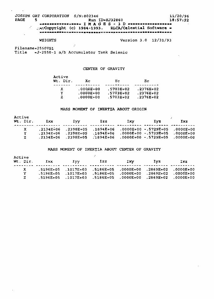
JOSEPH OAT CORPORATION S/N:802346PAGE 5 Run ID-KJ32860
...«««.—««:,«.. I M A G E S - 3 D — — » — — = — —. .nvCopyright (c) 1984-1993. RLCA/Celestial Software
11/20/9618:57:22
WEIGHTS Version 3.0 12/31/93
Filename=2550VSlTitle =J-2550-l a/b Accumulator Tank Seismic
CENTER OF GRAVITY
ActiveWt. Dir. Xc Yc Zc
XYZ
. OOOOE+OO
. OOO'OE+00
.0000E+00
.5703E+02
.5703E+02•5703E+02
.2376E+02
.2376E+02
.2376E+02
MASS MOMENT OF INERTIA ABOUT ORIGIN
ActiveWt. Dir.
XYZ
Ixx
.2134E+06
.2134E+06
.2134E+06
lyy
.2398E+05
.2398E+05
.2398E+05
Izz
.1894E+06
.1894E+06
."1894E+06
Ixy
.0000E+00
.0000E+00
.0000E+00
Iyz
-.5729E+05-.5729E+05-.5729E+05
Ixz
.OOOOE+00
.0000E+00
.0000E+00
MASS MOMENT OF INERTIA ABOUT CENTER OF GRAVITY
ActiveWt. Dir.
XYZ
Ixx
.5196E+05
.5196E+05
.5196E+05
iyy
.1017E+03
.1017E+03
.1017E+03
Izz
.5186E+05
.5186E+0S
.5186E+05
ixy
.0000E+00
.0000E+00
.0000E+00
Iyz
.2869E+02
.2869E+02
.2869E+02
Ixz
.0000E+00
.OOOOE+00
.0000E+00
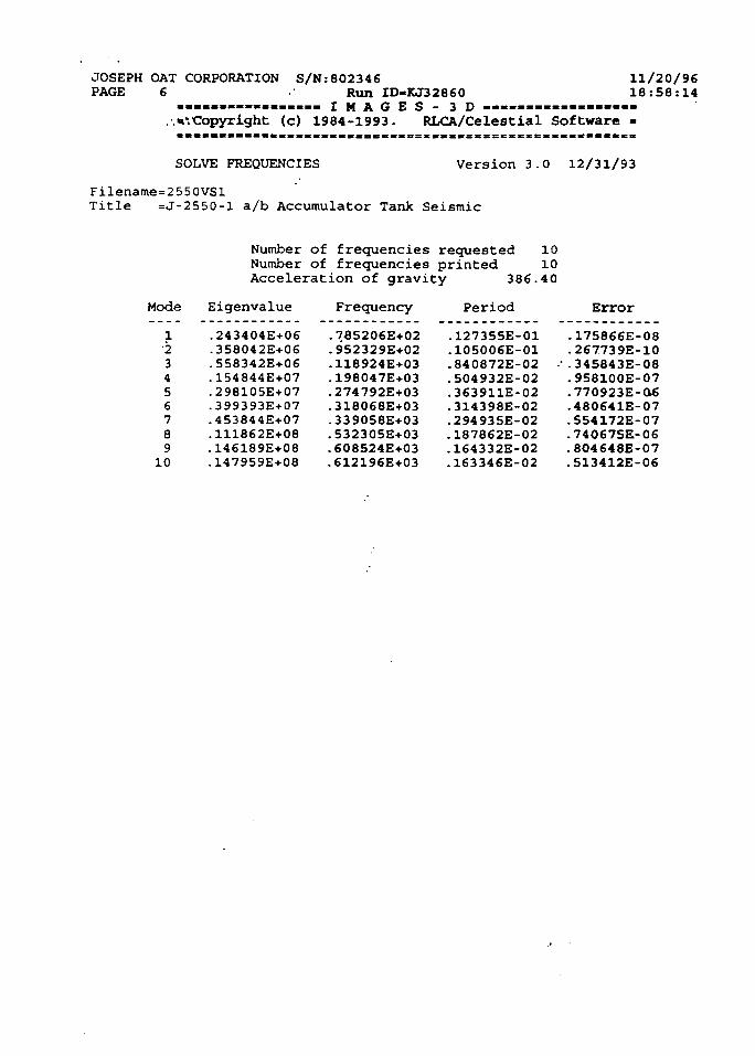
JOSEPH OAT CORPORATION S/N:802346 11/20/96
PAGE 6 Run ID-KJ32860 18:58:14................. I M A G E S - 3 D — « — • — — — —
..^Copyright (c) 1984-1993. RLCA/Celestial Software -
SOLVE FREQUENCIES Version 3.0 12/31/93
Filename=2550VSlTitle =J-2550-l a/b Accumulator Tank Seismic
Number of frequencies requested 10Number of frequencies printed 10Acceleration of gravity 386.40
Mode
1•23456789
10
Eigenvalue
.243404E+06
.358042E+06
.558342E+06
.154844E+07
.298105E+07
.399393E+07
.453844E+07
.111862E+08
.146189E+08
.147959E+08
Frequency
.785206E+02
.9S2329E+02
.118924E+03
.198047E+03
.274792E+03
.318068E+03
.339058E+03
.532305E+03
.608S24E+03-612196E+03
Period
.127355E-01
.105006E-01
.840872E-02
.504932E-02
.363911E-02
.314398E-02
.294935E-02
.187862E-02
.164332E-02
.163346E-02
Error
-175866E-08.267739E-10
•• . 345843E-08-9S8100E-07-770923E-O6.480641E-07.554172E-07-740675E-06. 804648E-07.513412E-06
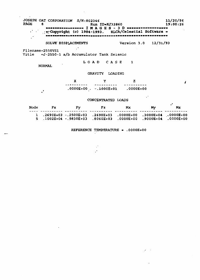
JOSEPH OAT CORPORATION S/N:802346 11/20/96PAGE 8 Run ID-KJ32860 19:00:26
................. I M A G E S - 3 D — — — — — — —:";Copyright (c) 1984-1993. RLCA/Celestial Software -
SOLVE DISPLACEMENTS Version 3.0 12/31/93
Filename=2550VSlTitle =J-2550-l a/b Accumulator Tank Seismic
L O A D C A S E 1
NORMAL
GRAVITY LOADING
X Y Z f
.0000E+00 . -.1000E+01 .0000E+00
CONCENTRATED LOADS
Node Fx Fy Fz Mx My Mz
1 .2690E+03 -.2500E+03 .2690E+03 .0000E+00 .3000E+04 .0000E+005 .1002E+04 -.9830E+03 .8060E+03 .0000E+00 .9000E+04 .O0OOE+00
REFERENCE TEMPERATURE = .0000E+00
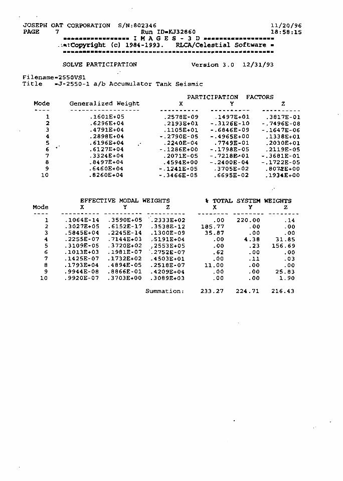
JOSEPH OAT CORPORATIONPAGE 7
S/N:802346Run ID-KJ32860
. . . . . . . . . . . . . . . . I M A G E S - 3 D — — — — — —{Copyright (c) 19B4-1993. RLCA/Celestial Software
11/20/9618:58:15
SOLVE PARTICIPATION Version 3.0 12/31/93
Filename-255OVS1Title -J-2550-1 a/b Accumulator Tank Seismic
Mode Generalized WeightPARTICIPATION FACTORS
X Y Z
123456 ''789
10
.1601E+05
.6296E+04
.4791E+04
.2898E+04
.6196E+04
.6127E+04
.3324E+04
.8497E+04
.6460E+04
.8260E+04
.2578E-09
.2193E+01
.1105E+01-.2790E-05.2240E-04
-.1286E+00.2071E-05.4594E+00
-.1241E-05-.3466E-05
.1497E+01-.3126E-10-.6846E-09-.4965E+00.7749E-01
-.1798E-05-.7218E>01-.2400E-04-3705E-02.6695E-02
.3817E-01-.7496E-08-.1647E-06.1338E+01.2030E+01.2119E-05
-.3681E-01-.1722E-05.807.2E+00. 1934E+00
ModeEFFECTIVE MODAL WEIGHTSX Y Z
V TOTAL SYSTEM WEIGHTSX Y Z
123456789
10
.1064E-14
.3027E+05
.5845E+04
.2255E-07
.3109E-05
.1013E+03
.1425E-07
.1793E+04
.9944E-08
.9920E-07
.3590E+05
.6152E-17-2245E-14.7144E+03.3720E+02.1981E-07.1732E+02.4894E-05.8866E-01.3703E+00
'.2333E+02.3538E-12.1300E-09.5191E+04.2553E+05'.2752E-07.4S03E+01.2518E-07.4209E+04.3089E+03
Summation:
18535
11
233
.00
.77
.87
.00
.00
.62
.00
.00
.00
.00
.27
220
4
224
.00
.00
.00
.38
.23
.00
.11
.00
.00
.00
.71
31156
251
216
.14
.00
.00
.85
.69
.00
.03
.00
.83
.90
.43
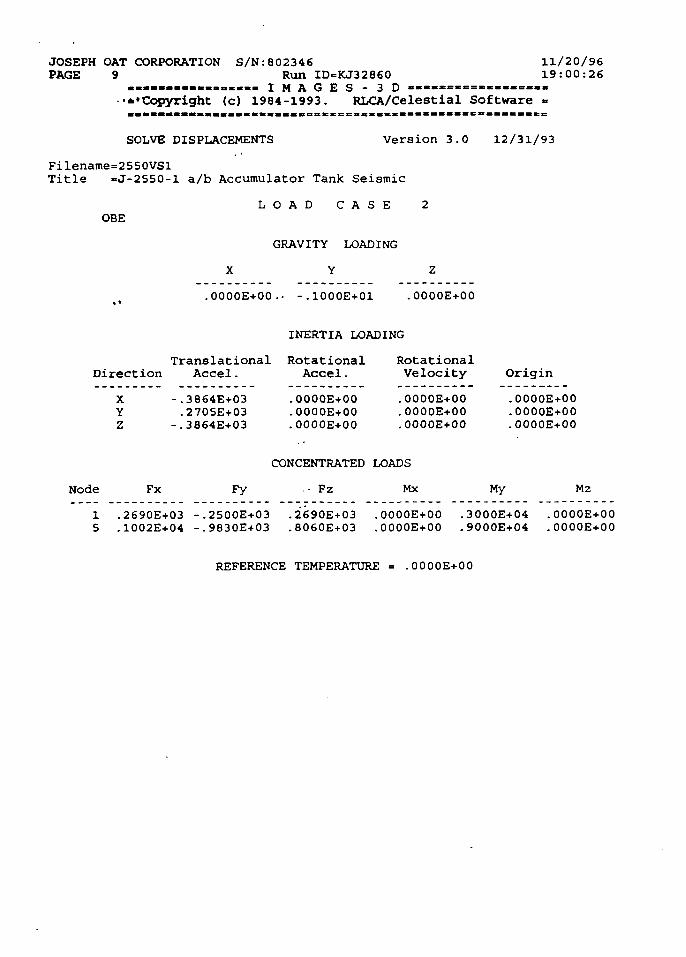
JOSEPH OAT CORPORATION S/N:802346PAGE 9 Run ID-KJ32860
..........<.o>... I M A G E S - 3 D•••Copyright (c) 1984-1993. RLCA/Celestial Software
11/20/9619:00:26
SOLVE DISPLACEMENTS Version 3.0 12/31/93
Filename=2550VSlTitle «J-2550-l a/b Accumulator Tank Seismic
L O A D C A S EOBE
GRAVITY LOADING
X Y Z
.0000E+00.- -.1000E+01 .0000E+00
INERTIA LOADING
Translational RotationalDirection Accel. Accel.
XYZ
-.3864E+03.2705E+03
-.3864E+03
.0000E+00
.0000E+00
.0000E+00
RotationalVelocity
.0000E+00
.OOOOE+00
.0000E+00
Origin
.0000E+00
.0000E+00
.0000E+00
Node Fx Fy
CONCENTRATED LOADS
. • Fz Mx My Mz
.2690E+03
.1002E+04.2500E+03. 9830E+03
.2690E+03
.8060E+03.0000E+00.0000E+00
.3000E+04
.9000E+04.0000E+00.0000E+00
REFERENCE TEMPERATURE .0000E+00
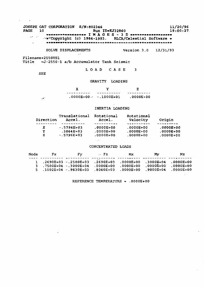
JOSEPH OAT CORPORATION S/N:802346 11/20/96PAGE 10 Run ID-KJ32860 19:00:27
................. I M A G E S - 3 D - « . — . - — - — —•' " -**ttopyright (c) 1984-1993. RLCA/Celestial Software -
SOLVE DISPLACEMENTS Version 3.0 12/31/93
Filename«2S50VSlTitle =J-2550-l a/b Accumulator Tank Seismic
SSEL O A D C A S E 3
GRAVITY LOADING
X Y Z
.OOOOE+00 •• -.1000E+01 .OOOOE+00
INERTIA LOADING
Translational Rotational RotationalDirection Accel. Accel. Velocity
XYZ
-.5796E+03.3864E+03
-.5796E+03
.0000E+00
.0000E+00
.0000E+00
.0000E+00
.0000E+00
.0000E+00
Origin
.0000E+00
.0000E+00
.0000E+00
Node Fx
CONCENTRATED LOADS
Fy - Fz Mx My Mz
.2690E+03
.7500E+04
.1002E+04
.2500E+03
.3000E+04
.9830E+03
.2690E+03
.0000E+00
.8060E+03
.0000E+00
.OOOOE+00
.OOOOE+00
.3000E+04
.0000E+00
.9000E+04
.0000E+00
.0000E+00
.0000E+00
REFERENCE TEMPERATURE = .0000E+OO
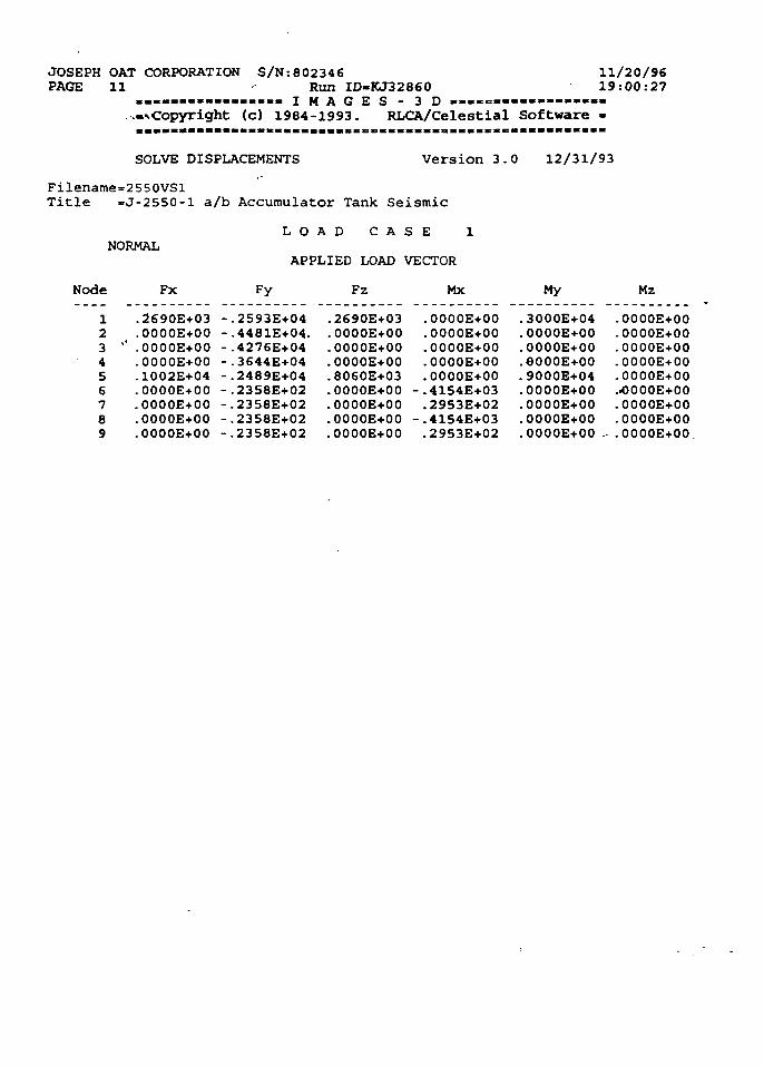
JOSEPH OAT CORPORATIONPAGE 11
S/N:802346Run ID-KJ32860
. . . . . . . — — . « . . - I M A G E S - 3 D - — = — — — —-•.Copyright (c) 1984-1993. RLCA/Celestial Software
11/20/9619:00:27
SOLVE DISPLACEMENTS Version 3.0 12/31/93
Filename=2 550VSlTitle =J-2550-l a/b Accumulator Tank Seismic
NORMALL O A D C A S E 1
APPLIED LOAD VECTOR
Node Fx Fy Fz Mx My Mz
123 '456789
.2690E+03
.0000E+00' .OOOOE+00.0000E+00.1002E+04.0000E+00.00O0E+00.0000E+00.0000E+00
-.2593E+04-.4481E+04.-.4276E+04-.3644E+04-.2489E+04-.2358E+02-.2358E+02-.2358E+02-.2358E+02
.2690E+03
.0000E+00
.OOOOE+00
.0000E+00
. 8060E+03
.OOOOE+00
.0000E+00
.0000E+00
.OOOOE+00
.OOOOE+00
.0000E+00
.0000E+00
.0000E+00
.OOOOE+00-.4154E+03.2953E+02
-.4154E+03.2953E+02
.3000E+04
.0000E+00
.0000E+00
.O000E+00
.9000E+04
.0000E+00
.0000E+00
.0000E+00
.0000E+00 .
.0000E+00
.0000E+00
.0000E+00
.0000E+00
.0000E+00
..OOOOE+00
.0000E+00
.OOOOE+00•.0000E+00
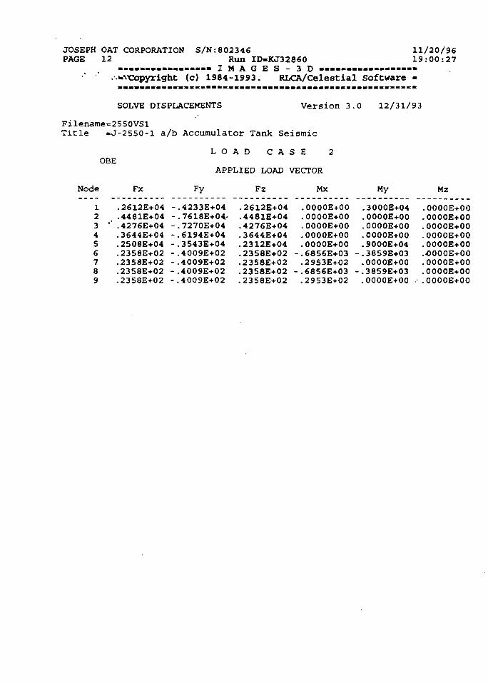
JOSEPH OAT CORPORATIONPAGE 12
S/N:802346 11/20/96Run ID-KJ32860 19:00:27
. . . . . . . . . . . . . . . . . I M A G E S - 3 D — — — — — —. .*vcopyright (c) 1984-1993. RLCA/Celestial Software -
SOLVE DISPLACEMENTS Version 3.0 12/31/93
Filename=2S50VSlTitle =J-2550-l a/b Accumulator Tank Seismic
L O A D C A S EOBE
APPLIED LOAD VECTOR
Node Fx Fy Fz Mx My Mz
123456789
.2612E+04
.4481E+04'" .4276E+04.3644E+04.2508E+04.2358E+02.2358E+02.23S8E+02.2358E+02
-.4233E+04-.7618E+04.--.7270E+04-.6194E+04-.3543E+04-.4009E+02-.4009E+02-.4009E+02--4009E+02
.2612E+04
.4481E+04
.4276E+04
.3644E+04•2312E+04.2358E+02.2358E+02.2358E+02.2358E+02
.0000E+00
.0000E+00
.0000E+00
.0000E+00
.0000E+00-.6856E+03.2953E+02
-.6856E+03.2953E+02
. 3000E+04
.0000E+00
.0000E+00
.OO00E+O0
.9000E+04-.3859E+03.0000E+00
-.3859E+03.0000E+00 •
.0000E+00
.0000E+00
.0000E+00-0000E+00.0000E+00.-0000E+00.OOOOE+00-0O00E+00.00OOE+0O
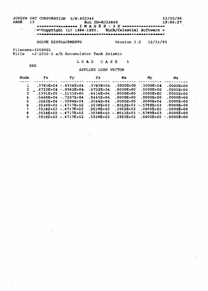
JOSEPH OAT CORPORATIONPAGE 13
S/N:802346Run ID-KJ32860
. « « . . . . - . . „ _ « « « . I M A G E S - 3 D — — » - - = « « — « -.^•Copyright (c) 1984-1993- RLCA/Celestial Software
11/20/9619:00:27
SOLVE DISPLACEMENTS Version 3.0 12/31/93
Filename=2550VSlTitle =J-2S50-l a/b Accumulator Tank Seismic
SSEL O A D C A S E 3
APPLIED LOAD VECTOR
Node Fx Fy Fz MX My Mz
123456789
.3783E+04
.6722E+04
.1391E+05
.5465E+04
.3260E+04
.3538E+02
.3538E+02
.3538E+02-3538E+02
-.4936E+04-.8962E+04--.1155E+05-.7287E+04-.3994E+04-.4717E+02-.4717E+02-.4717E+02-.4717E+02
.3783E+04
.6722E+04
.6414E+04
.5465E+04
.3064E+04
.3538E+02
.3538E+02•3538E+02.3538E+02
. 0000E+00
.0000E+00
.0000E+00
.0000E+00
.0000E+00-.8013E+03.2953E+02
-.8013E+03.2953E+02
.3000E+04
.0000E+00
. 0000E+00
.0000E+00
.9000E+04-.5789E+03.0000E+00
-.5789E+03.0000E+00
.0000E+00
. 0000E+00
.OOOOE+00
.0000E+00
.OOOOE+00
.OOOOE+00
.0000E+00
.OOOOE+00' .0000E+00
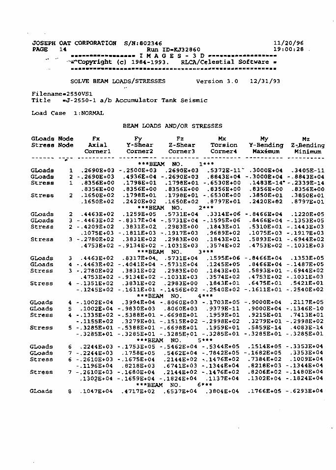
JOSEPH OAT CORPORATION S/N:802346PAGE 14 Run ID-KJ32860
. . . . . . . . . . . . . . . . . I M A G E S - 3 D — — • « • — • - « « « .•^Copyright (c) 1984-1993. RLCA/Celestial Software
11/20/9619:00:28
SOLVE BEAM LOADS/STRESSES Version 3.0 12/31/93
Filename«2550VSlTitle -J-2S50-1 a/b Accumulator Tank Seismic
Load Case 1:
GLoadsStress
GLoadsGLoadsStress
Stress
GLoadsGLoadsStress
Stress
GLoadsGLoadsStress
Stress
GLoadsGLoadsStress
Stress
GLoadsGLoadsStress
Stress
GLoads
NodeNode
0*
12 -1
2
23 -2 -
3 -
34 -3 -
4 --
4 -54 -
-5 -
-
67 -6 -
-7 -
8
NORMAL
FxAxialCorner1
.2690E+03
.2690E+03
.8356E+00
. 8356E+00
.1650E+02
.1650E+02
.4463E+02
.4463E+02
.4209E+02
.1075E+03
.2780E+02
.4753E+02
. 4463E+02
.4463E+02
.2780E+02
.4753E+02
.1351E+02
.1245E+02
.1002E+04
.1002E+04
.1335E+02-1155E+02.3285E+01.3285E+01
.2244E+03
.2244E+03
.2610E+03-1196E+04.2610E+03.1302E+04
.1047E+04
BEAM LOADS
FyY-ShearCorner2
***BEAM-.2S00E+03.4936E+04 -.1798E+01.8356E+00.1798E+01.2420E+02
***BEAM.1259E+05
-.8317E+04 -.3831E+02.
-.1811E+03 -.3831E+02
-.9134E+02 -***BEAM
.8317E+04.-.4041E+04 -.3831E+02
-.9134E+02 -.3831E+02
-.1611E+01 -***BEAM
.3994E+04 --.9830E+03-.5388E+01 -.3279E+01 -
-.5388E+01 --.3285E+01 -
***BEAM-.1753E+05 -,.1758E+05
-.1675E+04 ..8218E+03 .
-.1680E+04 .-.1659E+04 -.
***BEAM.4717E+02 .
AND/OR STRESSES
FzZ-ShearCorner3
NO..2690E+03.2690E+03.1798E+01.8356E+00.1798E+01.1650E+02NO.
.5731E+04
.5731E+04
.2983E+00
.1917E+03
.2983E+00
.1031E+03NO.
.5731E+04
.5731E+04
.2983E+00-1031E+03.2983E+00.1456E+02NO.
.8060E+03
.8060E+03
.6698E+01
.1515E+02
.6698E+01
.3285E+01NO. !
. 5462E+04
.5462E+04
.2144E+02
.6741E+03•2144E+02. 1824E+04NO. (
.6537E+04
MxTorsionCorner4
1***.5372E-11.8843E+04
-.6530E+00.8356E+00
-.6S30E+00.8797E+01
2***.3314E+06
-.1595E+06.1843E+01.9689E+02.1843E+01.3574E+02
3***.1595E+06.1245E+05.1843E+01.3574E+02.1843E+01
-.2540E+02
-.1703E+05.9379E-11.1959E+01
-.2998E+02.1959E+01
-.3285E+01
-.5344E+05-.7842E+05^.1476E+02-.1344E+04-.1476E+02.1137E+04
.3804E+04
MyY-BendingMaximum
~ .3000E+04-.3000E+04.1483E-14".8356E+00-3850E+01.2420E+02
-.8466E+04.8466E+04.5310E+01.1075E+03.5893E+01.4753E+02
-.8466E+04. 8466E+04.5893E+01.47S3E+02.6475E+01
-.1611E+01
--9000E+04.9000E+04.9215E+01.3279E+01-5859E-14
-.3285E+01
.1514E+05-.1682E+05.7384E+02.8218E+03.8206E+02.1302E+04
.1766E+05
MzZ BendingMinimum
.3405E-11--8843E+04-.2339E-14.83S6E+00.3850E+01.8797E+01
.1220E+05--1353E+0S-.1443E+03-.1917E+03-.6944E+02-.1031E+03
-1353E+05- .1487E+05-.6944E+02-.1031E+03.5421E+01
-.2540E+02
.2117E+05-.1346E-10.7413E+01
-.2998E+02.4083E-14
-.3285E+01
-.3353E+04.3353E+04.1009E+04
-.1344E-t-04-.1480E+04-.1824E+04
-.6293E+04
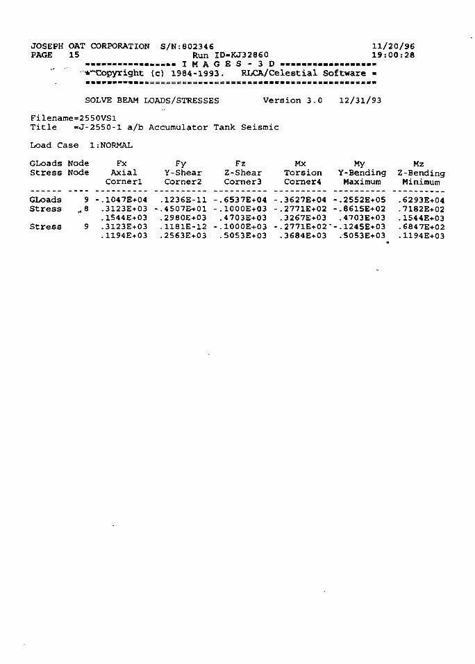
JOSEPH OAT CORPORATIONPAGE 15
S/N:802346Run ID-KJ32860
. . . « . . . . . . . . . . _ , . I M A G E S - 3 D - - « « . . . = . - . - - . - . -• *~Copyright (c) 1984-1993. RLCA/Celestial Software
11/20/9619:00:28
SOLVE BEAM LOADS/STRESSES Version 3.0 12/31/93
Filename=2550VSlTitle =J-2550-l a/b Accumulator Tank Seismic
Load Case 1:NORMAL
GLoads Node Fx Fy Fz Mx My MzStress Node Axial Y-Shear Z-Shear Torsion Y-Bending Z-Bending
Cornerl Corner2 Corner3 Corner4 Maximum Minimum
GLoadsStress
Stress
9,8
•.1047E+04.3123E+03.1544E+03.3123E+03.1194E+03
.1236E-11
.4507E-t-01
.2980E+03
.1181E-12
.2563E+03
.6537E+04
.1000E+03
.4703E+03
.1000E+03
.5053E+03
.3627E+04
. 2771E+02
.3267E+03
. 2771E+02'
.3684E+03
•.2552E+05. 8615E+02.4703E+03. 1245E+03.5053E+03
.6293E+04
.7182E+02
.1544E+03
.6847E+02
.1194E+03
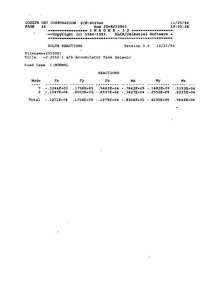
JOSEPH OAT CORPORATION S/N:802346 11/20/96PAGE 16 • Run ID-KJ32860 19:00:28
................. I M A G E S - 3 D - . - - . — » « — « — -••^Copyright (c) 1984-1993. RLCA/Celestial Software -
SOLVE REACTIONS Version 3.0 12/31/93
Filename=2550VSlTitle =J-2550-l a/b Accumulator Tank Seismic
Load Case 1:NORMAL
REACTIONS
Node Fx Fy Fz Mx My Mz
7 -.2244E+03 .1758E+05 .5462E+04 -.7842E+05 --1682E+05 .3353E+049 -.1047E+04 .0000E+0Q. -.6537E+04 -.3627E+04 -.2552E+05 .6293E+04
Total -.1271E+04 .17S8E+05 -.1075E+04 -.8204E+05 -.4235E+05 .9646E+04
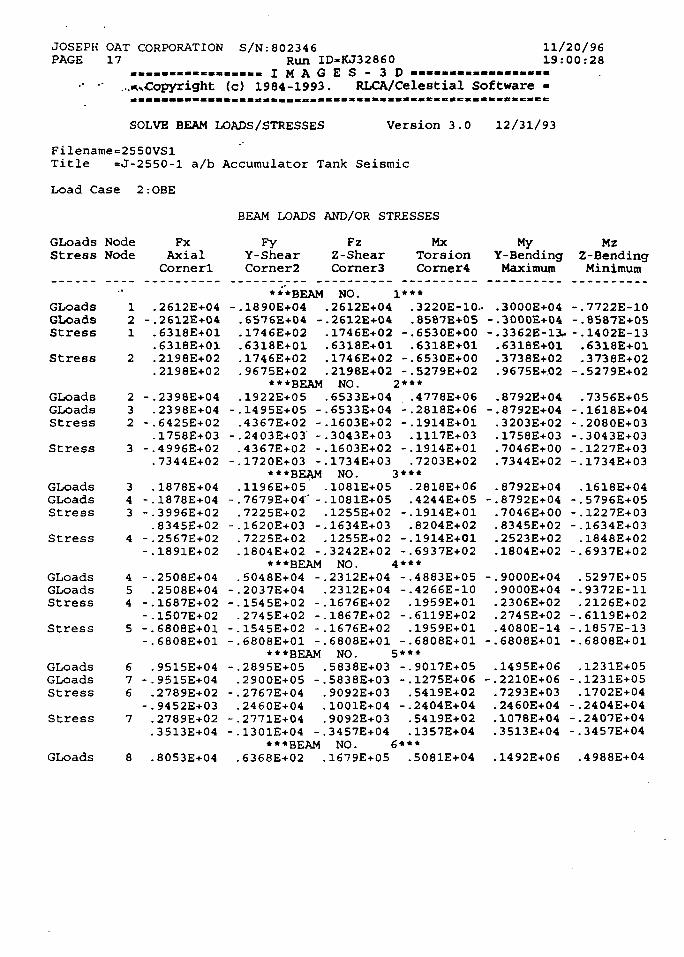
JOSEPH OAT CORPORATION S/N:802346PAGE 17 Run ID-KJ32860
. « , . . « . . . » . . . . . . I M A G E S - 3 D — • — — — — « .• - ...^Copyright (c) 1984-1993. RLCA/Celestial Software
11/20/9619:00:28
SOLVE BEAM LOADS/STRESSES Version 3.0 12/31/93
Filename=2550VSlTitle =J-2550-l a/b Accumulator Tank Seismic
Load Case 2:
GLoadsStress
GLoadsGLoadsStress
Stress
GLoadsGLoadsStress
Stress
GLoadsGLoadsStress
Stress
GLoadsGLoadsStress
Stress
GLoadsGLoadsStress
Stress
GLoads
NodeNode
-•12 -1
2
2 -32 -
3 -
34 -3 -
4 --
4 -54 -
-5 -
-
67 -6
-7
8
OBE
FxAxialCornerl
.2612E+04
.2612E+04
.6318E+01
.6318E+01
.2198E+02-2198E+02
-2398E+04.2398E+04.6425E+02.1758E+03.4996E+02.7344E+02
.1878E+04
.1878E+04
.3996E+02
.8345E+02
.2567E+02
.1891E+02
-2508E+04.2508E+04.1687E+02.1507E+02.6808E+01.6808E+01
.9515E+04
.9515E+04
.2789E+02
.9452E+03
.2789E+02
.3513E+04
.8053E+04
BEAM LOADS
FyY-ShearCorner2
**'*BEAM-.1890E+04.6576E+04 -.1746E+02.6318E+01.1746E+02.9675E+02
***BEAM.1922E+05
-.1495E+05 -.4367E+02 -
-.2403E+03' -.4367E+02 -
-.1720E+03 -***BEAM
.1196E+05- . 7679E+04"' -.7225E+02
-.1620E+03 -.7225E+02.1804E+02 -
***BEAM.5048E+04 -
-.2037E+04-.1545E+02 -.2745E+02 -
-.1545E+02 --.6808E+01 -
***BEAM-.2895E+05.2900E+05 -
-.2767E+04.2460E+04
-.2771E+04-.1301E+04 -
***BEAM.6368E+02
AND/OR STRESSES
FzZ-ShearCorner3
NO.. 2612E+04. 2612E+04.1746E+02.6318E+01.1746E+02.2198E+02NO.
.6533E+04
.6533E+04
.1603E+02
.3043E+03
.1603E+02
.1734E+03NO.
-1081E+05.1081E+05.1255E+02.1634E+03.1255E+02.3242E+02NO.
.2312E+04
.2312E+04
. 1676E+02
.1867E+02
.1676E+02
.6808E+01NO. !
.5838E+03
.5838E+03
.9092E+03
.1001E+04
.9092E+03
. 3457E+04NO. i
.1679E+05
MxTorsionCorner4
1***.3220E-10.8587E+0S
-.6530E+00.6318E+01
-.6S30E+00-.5279E+02
2***.4778E+06
- .2818E+06-.1914E+01.1117E+03
-.1914E+01.7203E+02
3***.2818E+06.4244E+05
- . 1914E+01-8204E+02
-.1914E+01-.6937E+02
4***- .4883E+05-.4266E-10.19S9E+01
-.6119E+02.1959E+01
-.6808E+015***-.9017E+05-.1275E+06.5419E+02
-.2404E+04.5419E+02.1357E+04
S***.5081E+04
MyY-BendingMaximum
.- . 3000E+04-.3000E+04-.3362E-11.•6318E+01-3738E+02.9675E+.02
.8792E+04-.8792E+04.3203E+02.1758E+03.7046E+00-7344E+02
-8792E+04-.8792E+04.7046E+00.8345E+02.2523E+02.1804E+02
-.9000E+04.9000E+04.2306E+02.2745E+02.4080E-14
-.6808E+01
.1495E+06-.2210E+06.7293E+03.2460E+04.1078E+04.3513E+04
.1492E+06
MzZ-BendingMinimum
-.7722E-10--8587E+05-.1402E-13•6318E+01.3738E+02
-.5279E+02
.7356E+05--1618E+04-.2080E+03- .3043E+03-.1227E+03-.1734E+03
.1618E+04-.5796E+05-.1227E+03-.1634E+03.1848E+02
-.6937E+02
.5297E+05-.9372E-11.2126E+02
-.6119E+02-.1857E-13-.6808E+01
-1231E+05-.1231E+05.1702E+04
-.2404E+04-.2407E+04-.3457E+04
.4988E+04
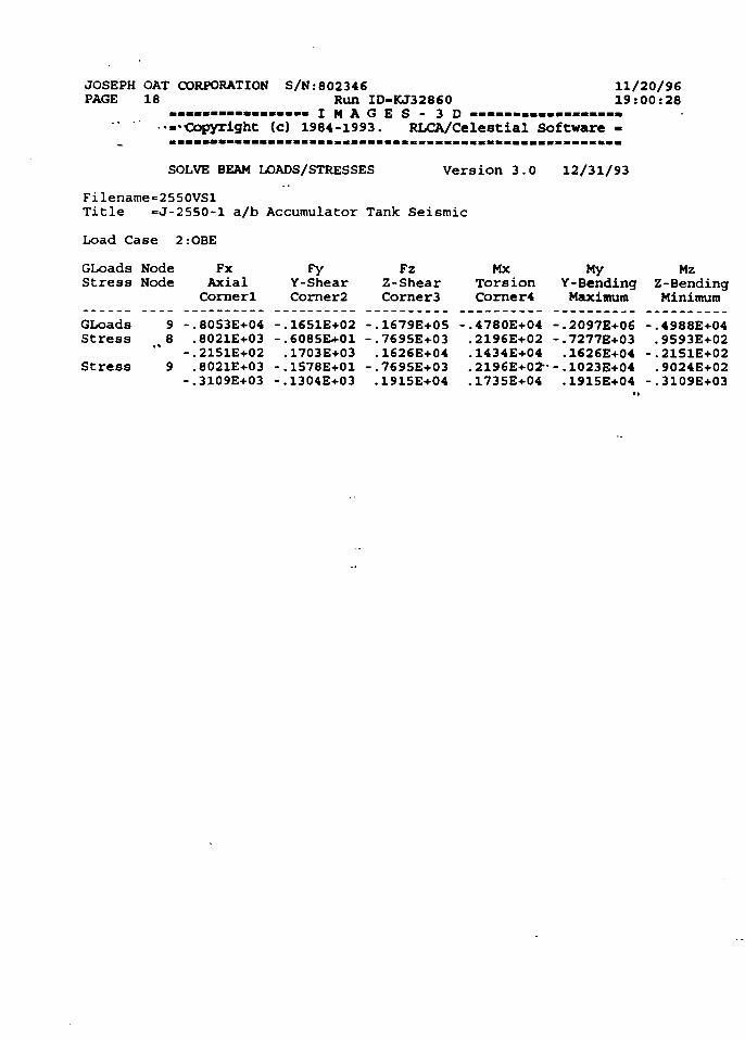
JOSEPH OAT CORPORATIONPAGE 18
•Copyright
S/N:802346Run ID-KJ32860
. . . . . I M A G E S - 3 D — — — — — —(c) 1984-1993. RLCA/Celestial Software
11/20/9619:00:28
SOLVE BEAM LOADS/STRESSES Version 3.0 12/31/93
Filename=2550VSlTitle =J-2550-l a/b Accumulator Tank Seismic
Load Case 2.-OBE
GLoads Node Fx Fy Fz Mx My MzStress Node Axial Y-Shear Z-Shear Torsion Y-Bending Z-Bending
Cornerl Corner2 Corner3 Corner4 Maximum Minimum
GLoadsStress
Stress
9 -.8053E+048 .8021E+03
-.21S1E+029 .8021E+03-.3109E+03
.1651E+02
.6085EU-01
.1703E+03
.1578E+01
.1304E+03
.1679E+05
.7695E+03
.1626E+04
.769SE+03
.1915E+04
.4780E+04
.2196E+02
. 1434E+04
.2196E+02"
.1735E+04
-.2097E+06•.7277E+03.1626E+04•-1023E+04.1915E+04
.4988E+04
.9593E+02
.2151E+02
.9024E+02
. 3109E+03
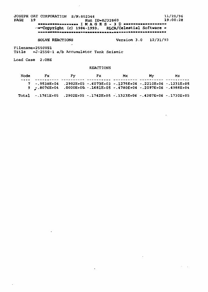
JOSEPH OAT CORPORATION S/N:802346 11/20/96PAGE 19 Run ID-KJ32860 19:00:28
. . . . . . . . . . . . . . . . . I M A G E S - 3 D « « - - . — — . - . « . - .•••« Copyright (c) 1984-1993. RLCA/Celestial Software -
SOLVE REACTIONS Version 3.0 12/31/93
Filename=2550VSl
Title =J-2S50-l a/b Accumulator Tank Seismic
Load Case 2:OBE
REACTIONS
Node Fx Fy Fz Mx My Mz7 -.9538E+04 .2902E+05 -.6073E+03 -.1275E+06 -.2210E+06 -.1231E+059 --.8076E+04 .0000E+0O. -.1681E+05 -.4780E+04 -.2097E+06 -.4988E+04
Total -.1761E+05 .2902E+05 -.1742E+05 -.1323E+06 -.4307E+06 -.1730E+05
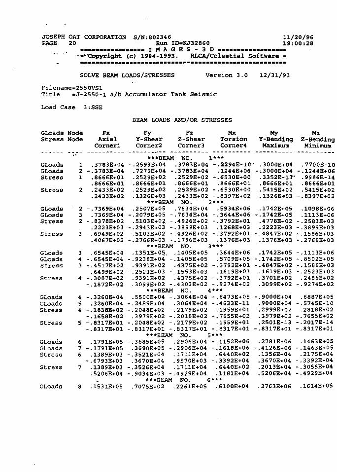
JOSEPH OAT CORPORATION S/N:802346PAGE 20 Run ID-KJ32860
. . . . . . . . . . . . . . . . . I M A G E S - 3 D . . . . . . . . . . . . . . . . .•••"Copyright (c) 1984-1993. RLCA/Celest ial Software
11/20/9619:00:28
SOLVE BEAM LOADS/STRESSES Version 3.0 12/31/93
Filename=2550VSlTitle =J-2550-l a/b Accumulator Tank Seismic
Load Case 3:SSE
BEAM LOADS AND/OR STRESSES
GLoadsStress
GLoadsGLoadsStress
Stress
GLoadsGLoadsStress
Stress
GLoadsGLoadsStress
Stress
GLoadsGLoadsStress
Stress
GLoadsGLoadsStress
Stress
GLoads
NodeNode
••121
2
232
3
343
4
454
5
676
7
8
FxAxialCornerl
.3783E+04-.3783E+04.8666E+01.8666E+01.2433E+02.2433E+02
-.7369E+04.7369E+04
-.8378E+02.2223E+03
-.6949E+02.4067E+02
.6545E+04-.6545E+04-.4517E+02.6499E+02
-.3087E+02-.1872E+02
-.3260E+04.3260E+04
-.1838E+02-.1658E+02-.8317E+01-.8317E+01
.1791E+05-.1791E+05.1389E+03
-.6793E+03.1389E+03.5206E+04
.1531E+05
FyY-ShearCorner2
•••BEAM-.2593E+04 ..7279E+04 -..2529E+02 ..8666E+01 ..2S29E+02 ..1326E+03 .
•••BEAM.2507E+05 .
-.2079E+05 -..5103E+02. -.
-.2943E+03 -..5103E+02 -.
--2766E+03 -.•••BEAM
.1351E+05. .-.9238E+04 -..9391E+02 .
-.2523E+03 -.•9391E+02 ..3099E+02 -.
•••BEAM.5500E+04 -.
-.2489E+04 .-.2048E+02 -..3979E+02 -.
-.2048E+02 -.-.8317E+01 -.
•••BEAM-.3685E+05 ..3690E+05 -.
-.3521E+04 ..3670E+04 .
-.3526E+04 .-.9034E+03 -.
•••BEAM.7075E+02 .
FzZ-ShearCorner3
NO. ]3783E+043783E+042529E+028666E+012529E+022433E+02
MxTorsionCorner4
-.2294E-10". 1244E+06
--6530E+00.8666E+01
-.6530E+00-.8397E+02
NO. 2***7634E+047634E+044926E+023899E+034926E+021796E+03
.5934E+06-.3644E+06-.3792E+01.1268E+03
-.3792E+01.1376E+03
NO. 3***1405E+051405E+054375E+021553E+034375E+024303E+02NO. 43064E+043064E+042179E+022018E+022179E+028317E+01NO. 52906E+042906E+041711E+049570E+031711E+044929E+04NO. 62261E+05
.3644E+06
.5709E+05-.3792E+01.1619E+03
-.3792E+01-.9274E+02***-.6473E+05-.4633E-11.1959E+01
-.7655E+02.1959E+01
-.8317E+01***-.1152E+06-.1618E+06.6440E+02
-.3392E+04. 6440E+-02.1181E+04
• * *
.6100E+04
MyY- BendingMaximum
' .3000E+04-.3000E+04.3352E-13*. 8666E+01.5415E+02.1326E+03
.1742E+05-.1742E+05.4778E+02.2223E+03
-.4847E+02.1376E+03
.1742E+05-.1742E+05-.4847E+02.1619E+03.3701E+02.3099E+02
-.9000E+04.9000E+04.2999E+02.3979E+02.2501E-13
-.8317E+01
.2781E+06-.4126E+06.1356E+04.3670E+04.2013E+04.5206E+04
.2763E+06
MzZ-BendingMinimum
.7700E-10--1244E+06.9986E-14.8666E+01.5415E+02
--8397E+02
.1098E+06
.1113E+06--2583E+03-.3899E+03--1586E+03-.2766E+03
--1113E+06-.8502E+05-.1586E+03-.2523E+03. 2486E+02
-.9274E+02
.6887E+05-.5745E-10.2818E+02
-.7655E+02-.2017E-14-.8317E+01
.1463E+05-.1463E+05.2175E+04
-.3392E+04-.3055E+04-.4929E+04
.1614E+05
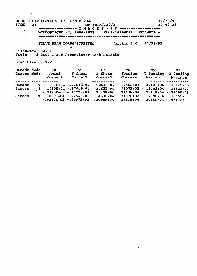
JOSEPH OAT CORPORATIONPAGE 21
S/N:802346Run ID-KJ32860
. . . . . . . . . . . . . . . . . I M A G E S - 3 D - . — « - — — — .••-.-copyright (c) 1984-1993. RLCA/Celestial Software
11/20/9619:00:28
SOLVE BEAM LOADS/STRESSES Version 3.0 12/31/93
Filename«2550VSlTitle -J-2550-1 a/b Accumulator Tank Seismic
Load Case 3:SSE
GLoads NodeStress Node
FxAxialCornerl
FyY-ShearCorner2
FzZ-ShearCorner3
MXTorsionCorner4
MyY-BendingMaximum
MzZ-BendingMinimum
GLoads 9 -.1531E+0S -.2358E+02 -.2261E+05 -.5746E+04 -.3913E+06 -.1614E+05Stress ..8 .1080E+04 -.6761E+01 -.1463E+04 .7107E+02 -.1348E+04 .1152E+03
-.3825E+03 -.1522E+03 .2543E+04 .2313E+04 .2543E+04 -.3825E+03Stress 9 .1080E+04 -.2254E+01 -.1463E+04 .7107E+02" -. 1909E+04 .1085E-I-03
-.9367E+03 -.7197E+03 .3098E+04 .2881E+04 .3098E+04 -.9367E+03
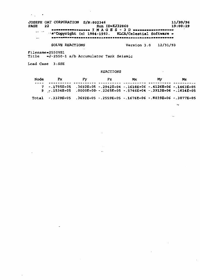
JOSEPH OAT CORPORATION S/N:802346 11/20/96PAGE 22 Run ID-KJ32860 19:00:29
................. I M A G E S - 3 D . — — — — — —•-'Copyright (c) 1984-1993. RLCA/Celestial Software -
SOLVE REACTIONS Version 3.0 12/31/93
Filename=2550VSl
Title -J-2550-1 a/b Accumulator Tank Seismic
Load Case 3:SSE
REACTIONS
Node Fx Fy Fz Mx My Mz7 -.1795E+05 .3692E+05 -.2942E+04 -.1618E+06 -.4126E+06 -.1463E+059 .r-1534E+05 .0000E+00- -.2265E+05 -.5746E+04 -.3913E+06 -.1614E+05
Total -.3329E+05 .3692E+05 -.2559E+05 -.1676E+06 -.8039E+06 -.3077E+05
* *) * * * 4
KAERI/TR-811/97
INIS I S H
t w + s ^ M I ^ A F ^ w ] ^ - L-g-7] ^ 7 n ^ - 5J ^ * j * ? t ^
(TR, AR?] ^ - T - ^ r ^ F )
<g ^ . ^} 51 ja. A] ig
uj o] ;*]
^ d
183 p.
as
* * 41 «^1*«)
«ms. ^MI^4 , l f 71 -j)
a 7]
1997. 2
29 Cm.
]
^ (15-20*01^)
(ASME IH Section NB/NC/ND QA Ca
Joseph Oat)7V ^ r « J ^ ^ ^^1<H| tfl
^ * »
^-^ «
7,^ 4 ^
tegory I «J Seismic Category I )-§- J I S
7A$-3L A|-jg.S^D|, - -S) ^^>S^F 7)-^-^
^JE. ?J 'Jh'y- S.-i?-§- sj-S1 . ^ ^ *1
ASME -8-7], 'gTfl^'lr, ^*]Sh?h, ^AV 5J ^ -^ , ^ ^ 1 7 ] ^
Ul-o} aflsM- (U.S
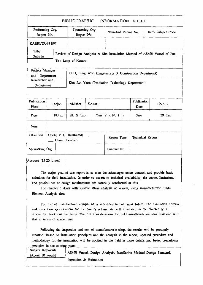
BIBLIOGRAPHIC INFORMATION SHEET
Performing Org.
Report No.
Sponsoring Org.
Report No.Stamdard Report No. INIS Subject Code
KAERI/TR-811/97
Title/
SubtitleReview of Design Analysis & Site Installation Method of ASME Vessel of Fuel
Test Loop of Hanaro
Project Manager
and DepartmentCHO, Sung Won (Engineering & Construction Department)
Researcher and
DepartmentKim Jun Yeon (Irradiation Technology Department)
Publication
PlaceTaejon Publisher KAERI
Publication
Date1997. 2
Page 183 p. 111. & Tab. Yes( V ), No ( ) Size 29 Cm.
Note
Classified Open( V ), Restricted( ),
Gass DocumentReport Type Technical Report
Sponsoring Org. Contract No.
i Abstract (15-20 Lines)
The major goal of this report is to take the advantages under control, and provide basic
solutions for field installation. In order to access to technical availability, the scope, limitation,
and possibilities of design requirements are carefully considered in this.
The chapter 3 deals with seismic stress analysis of vessels, using manufacturers' Finite
Element Analysis data.
The test of manufactured equipment is scheduled to bold near future. The evaluation criteria
and inspection specifications for the quality release are well illustrated in the chapter IV to
efficiently check out the items. The full considerations for field installation are also reviewed with
that in terms of space limit
Following the inspection and test of manufacturer's shop, the results will be promptly
reported. Based on installation principles and the analysis in the report, updated procedure and
methodology for the installation will be applied to the field in more details and better breakdown
precision in the coming years.Subject Keywords
(About 10 words)ASME Vessel, Design Analysis, Installation Method Design Standard,
Inspection & Estimation


