Embed Size (px)
Citation preview

A N I N T E R N A T I O N A L S T A N D A R D
ASME Y14.5-2009[Revision of ASME Y14.5M-1994 (R2004)]
Dimensioningand TolerancingEngineering Drawing and Related Documentation Practices
Copyright ASME International Provided by IHS under license with ASME Licensee=FMC Technologies /5914950002
Not for Resale, 05/07/2009 00:24:44 MDTNo reproduction or networking permitted without license from IHS
--`,,`,,,``,`,``,,``,`,`,,,`,`,`-`-`,,`,,`,`,,`---

ASME Y14.5
ADOPTION NOTICE
ASME Y14.5, Dimensioning and Tolerancing, was adopted on 9 February 2009 for use by the Department ofDefense (DoD). Proposed changes by DoD activities must be submitted to the DoD Adopting Activity: Commander,U.S. Army Research, Development and Engineering Center (ARDEC), ATTN: AMSRD-AAR-QES-E, PicatinnyArsenal, NJ 07806-5000. Copies of this document may be purchased from The American Society of MechanicalEngineers (ASME), 22 Law Drive, P.O. Box 2900, Fairfield, NJ 07007-2900, http://www.asme.org.
Custodians: Adopting Activity:Army — AR Army — ARNavy — SA (Project DRPR-2009-003)Air Force — 16
Review Activities:Army — CR, IE, MI, PT, TM2Navy — AS, CG, CH, EC, MC, NP, TDAir Force — 13, 99DLA — DHOSD — SENSA — NSOther — CM, MP, DC2
NOTE: The activities listed above were interested in this document as of the dateof this document. Since organizations and responsibilities can change, you shouldverify the currency of the information above using the ASSIST Online databaseat http://assist.daps.dla.mil.
AMSC N/A AREA DRPR
DISTRIBUTION STATEMENT A. Approved for public release; distribution is unlimited.
Copyright ASME International Provided by IHS under license with ASME Licensee=FMC Technologies /5914950002
Not for Resale, 05/07/2009 00:24:44 MDTNo reproduction or networking permitted without license from IHS
--`,,`,,,``,`,``,,``,`,`,,,`,`,`-`-`,,`,,`,`,,`---
ASME Y14.5-2009
Dimensioning and Tolerancing
Engineering Drawing and Related Documentation Practices
A N I N T E R N A T I O N A L S T A N D A R D
[Revision of ASME Y14.5M-1994 (R2004)]
Copyright ASME International Provided by IHS under license with ASME Licensee=FMC Technologies /5914950002
Not for Resale, 05/07/2009 00:24:44 MDTNo reproduction or networking permitted without license from IHS
--`,,`,,,``,`,``,,``,`,`,,,`,`,`-`-`,,`,,`,`,,`---

Date of Issuance: March 27, 2009
This Standard will be revised when the Society approves the issuance of a new edition. There will be no addenda or written interpretations of the requirements of this Standard issued to this edition.
Periodically certain actions of the ASME Y14 Committee may be published as Cases. Cases are published on the ASME Web site under the Committee Pages at http://cstools.asme.org as they are issued.
ASME is the registered trademark of The American Society of Mechanical Engineers.
This code or standard was developed under procedures accredited as meeting the criteria for American National Standards. The Standards Committee that approved the code or standard was balanced to assure that individuals from competent and concerned interests have had an opportunity to participate. The proposed code or standard was made available for public review and comment that provides an opportunity for additional public input from industry, academia, regulatory agencies, and the public-at-large.
ASME does not “approve,” “rate,” or “endorse” any item, construction, proprietary device, or activity.ASME does not take any position with respect to the validity of any patent rights asserted in connection with any items mentioned in this
document, and does not undertake to insure anyone utilizing a standard against liability for infringement of any applicable letters patent, nor assumes any such liability. Users of a code or standard are expressly advised that determination of the validity of any such patent rights, and the risk of infringement of such rights, is entirely their own responsibility.
Participation by federal agency representative(s) or person(s) affiliated with industry is not to be interpreted as government or industry endorsement of this code or standard.
ASME accepts responsibility for only those interpretations of this document issued in accordance with the established ASME procedures and policies, which precludes the issuance of interpretations by individuals.
No part of this document may be reproduced in any form,in an electronic retrieval system or otherwise,
without the prior written permission of the publisher.
The American Society of Mechanical EngineersThree Park Avenue, New York, NY 10016-5990
Copyright © 2009 byTHE AMERICAN SOCIETY OF MECHANICAL ENGINEERS
All rights reservedPrinted in U.S.A.
Copyright ASME International Provided by IHS under license with ASME Licensee=FMC Technologies /5914950002
Not for Resale, 05/07/2009 00:24:44 MDTNo reproduction or networking permitted without license from IHS
--`,,`,,,``,`,``,,``,`,`,,,`,`,`-`-`,,`,,`,`,,`---
iii
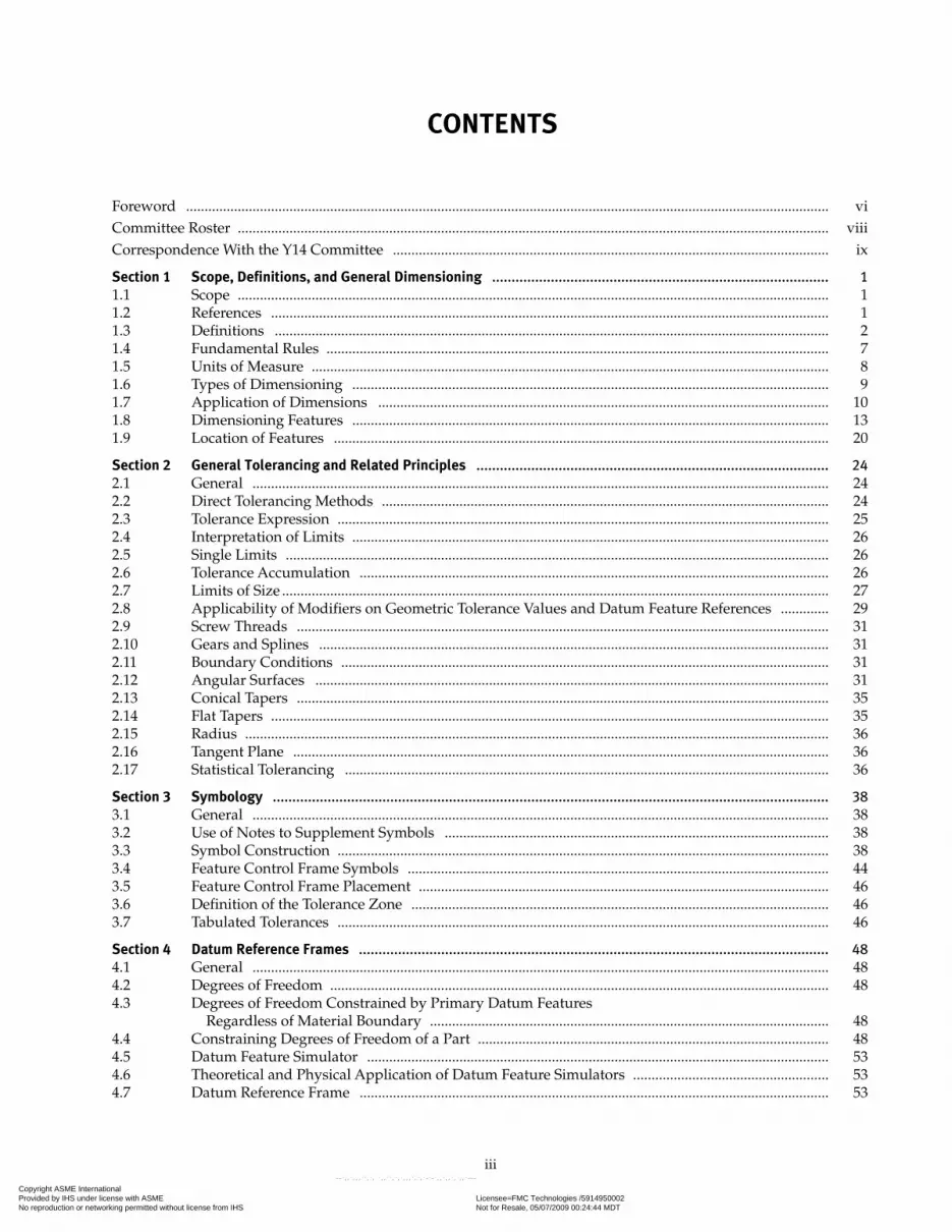
CONTENTS
Foreword .............................................................................................................................................................................. viCommittee Roster ................................................................................................................................................................ viiiCorrespondence With the Y14 Committee ...................................................................................................................... ix
Section 1 Scope, Definitions, and General Dimensioning ...................................................................................... 11.1 Scope ................................................................................................................................................................ 11.2 References ....................................................................................................................................................... 11.3 Definitions ...................................................................................................................................................... 21.4 Fundamental Rules ........................................................................................................................................ 71.5 Units of Measure ............................................................................................................................................ 81.6 Types of Dimensioning ................................................................................................................................. 91.7 Application of Dimensions .......................................................................................................................... 101.8 Dimensioning Features ................................................................................................................................. 131.9 Location of Features ...................................................................................................................................... 20
Section 2 General Tolerancing and Related Principles .......................................................................................... 242.1 General ............................................................................................................................................................ 242.2 Direct Tolerancing Methods ......................................................................................................................... 242.3 Tolerance Expression ..................................................................................................................................... 252.4 Interpretation of Limits ................................................................................................................................. 262.5 Single Limits ................................................................................................................................................... 262.6 Tolerance Accumulation ............................................................................................................................... 262.7 Limits of Size .................................................................................................................................................... 272.8 Applicability of Modifiers on Geometric Tolerance Values and Datum Feature References ............. 292.9 Screw Threads ................................................................................................................................................ 312.10 Gears and Splines .......................................................................................................................................... 312.11 Boundary Conditions .................................................................................................................................... 312.12 Angular Surfaces ........................................................................................................................................... 312.13 Conical Tapers ................................................................................................................................................ 352.14 Flat Tapers ....................................................................................................................................................... 352.15 Radius .............................................................................................................................................................. 362.16 Tangent Plane ................................................................................................................................................. 362.17 Statistical Tolerancing ................................................................................................................................... 36
Section 3 Symbology .............................................................................................................................................. 383.1 General ............................................................................................................................................................ 383.2 Use of Notes to Supplement Symbols ........................................................................................................ 383.3 Symbol Construction ..................................................................................................................................... 383.4 Feature Control Frame Symbols .................................................................................................................. 443.5 Feature Control Frame Placement ............................................................................................................... 463.6 Definition of the Tolerance Zone ................................................................................................................. 463.7 Tabulated Tolerances ..................................................................................................................................... 46
Section 4 Datum Reference Frames ........................................................................................................................ 484.1 General ............................................................................................................................................................ 484.2 Degrees of Freedom ....................................................................................................................................... 484.3 Degrees of Freedom Constrained by Primary Datum Features
Regardless of Material Boundary ............................................................................................................ 484.4 Constraining Degrees of Freedom of a Part ............................................................................................... 484.5 Datum Feature Simulator ............................................................................................................................. 534.6 Theoretical and Physical Application of Datum Feature Simulators ..................................................... 534.7 Datum Reference Frame ............................................................................................................................... 53
Copyright ASME International Provided by IHS under license with ASME Licensee=FMC Technologies /5914950002
Not for Resale, 05/07/2009 00:24:44 MDTNo reproduction or networking permitted without license from IHS
--`,,`,,,``,`,``,,``,`,`,,,`,`,`-`-`,,`,,`,`,,`---

iv
4.8 Datum Features .............................................................................................................................................. 574.9 Datum Feature Controls ............................................................................................................................... 584.10 Specifying Datum Features in an Order of Precedence ........................................................................... 584.11 Establishing Datums ..................................................................................................................................... 594.12 Multiple Datum Features ............................................................................................................................. 654.13 Mathematically Defined Surface ................................................................................................................. 694.14 Multiple Datum Reference Frames ............................................................................................................. 694.15 Functional Datum Features .......................................................................................................................... 694.16 Rotational Constraint About a Datum Axis or Point ................................................................................ 704.17 Application of MMB, LMB, and RMB to Irregular Features of Size ...................................................... 744.18 Datum Feature Selection Practical Application ......................................................................................... 754.19 Simultaneous Requirements ........................................................................................................................ 764.20 Restrained Condition .................................................................................................................................... 794.21 Datum Reference Frame Identification ...................................................................................................... 794.22 Customized Datum Reference Frame Construction ................................................................................. 814.23 Application of a Customized Datum Reference Frame ........................................................................... 814.24 Datum Targets ................................................................................................................................................ 83
Section 5 Tolerances of Form .................................................................................................................................. 915.1 General ............................................................................................................................................................ 915.2 Form Control .................................................................................................................................................. 915.3 Specifying Form Tolerances ......................................................................................................................... 915.4 Form Tolerances ............................................................................................................................................. 915.5 Application of Free-State Symbol ................................................................................................................ 95
Section 6 Tolerances of Orientation ....................................................................................................................... 996.1 General ............................................................................................................................................................ 996.2 Orientation Control ....................................................................................................................................... 996.3 Orientation Symbols ...................................................................................................................................... 996.4 Specifying Orientation Tolerances .............................................................................................................. 996.5 Tangent Plane ................................................................................................................................................. 1036.6 Alternative Practice ....................................................................................................................................... 103
Section 7 Tolerances of Location ............................................................................................................................ 1087.1 General ............................................................................................................................................................ 1087.2 Positional Tolerancing ................................................................................................................................... 1087.3 Positional Tolerancing Fundamentals: I ..................................................................................................... 1087.4 Positional Tolerancing Fundamentals: II .................................................................................................... 1197.5 Pattern Location ............................................................................................................................................. 1277.6 Coaxial Feature Controls .............................................................................................................................. 1487.7 Tolerancing for Symmetrical Relationships ............................................................................................... 156
Section 8 Tolerances of Profile ............................................................................................................................... 1588.1 General ............................................................................................................................................................ 1588.2 Profile .............................................................................................................................................................. 1588.3 Tolerance Zone Boundaries .......................................................................................................................... 1588.4 Profile Applications ....................................................................................................................................... 1658.5 Material Condition and Boundary Condition Modifiers as
Related to Profile Controls ....................................................................................................................... 1678.6 Composite Profile .......................................................................................................................................... 1678.7 Multiple Single-Segment Profile Tolerancing ............................................................................................ 1758.8 Combined Controls ......................................................................................................................................... 175
Section 9 Tolerances of Runout .............................................................................................................................. 1809.1 General ............................................................................................................................................................ 1809.2 Runout ............................................................................................................................................................. 1809.3 Runout Tolerance ........................................................................................................................................... 1809.4 Types of Runout Tolerances ......................................................................................................................... 1809.5 Application ..................................................................................................................................................... 1829.6 Specification ................................................................................................................................................... 182
Copyright ASME International Provided by IHS under license with ASME Licensee=FMC Technologies /5914950002
Not for Resale, 05/07/2009 00:24:44 MDTNo reproduction or networking permitted without license from IHS
--`,,`,,,``,`,``,,``,`,`,,,`,`,`-`-`,,`,,`,`,,`---
v
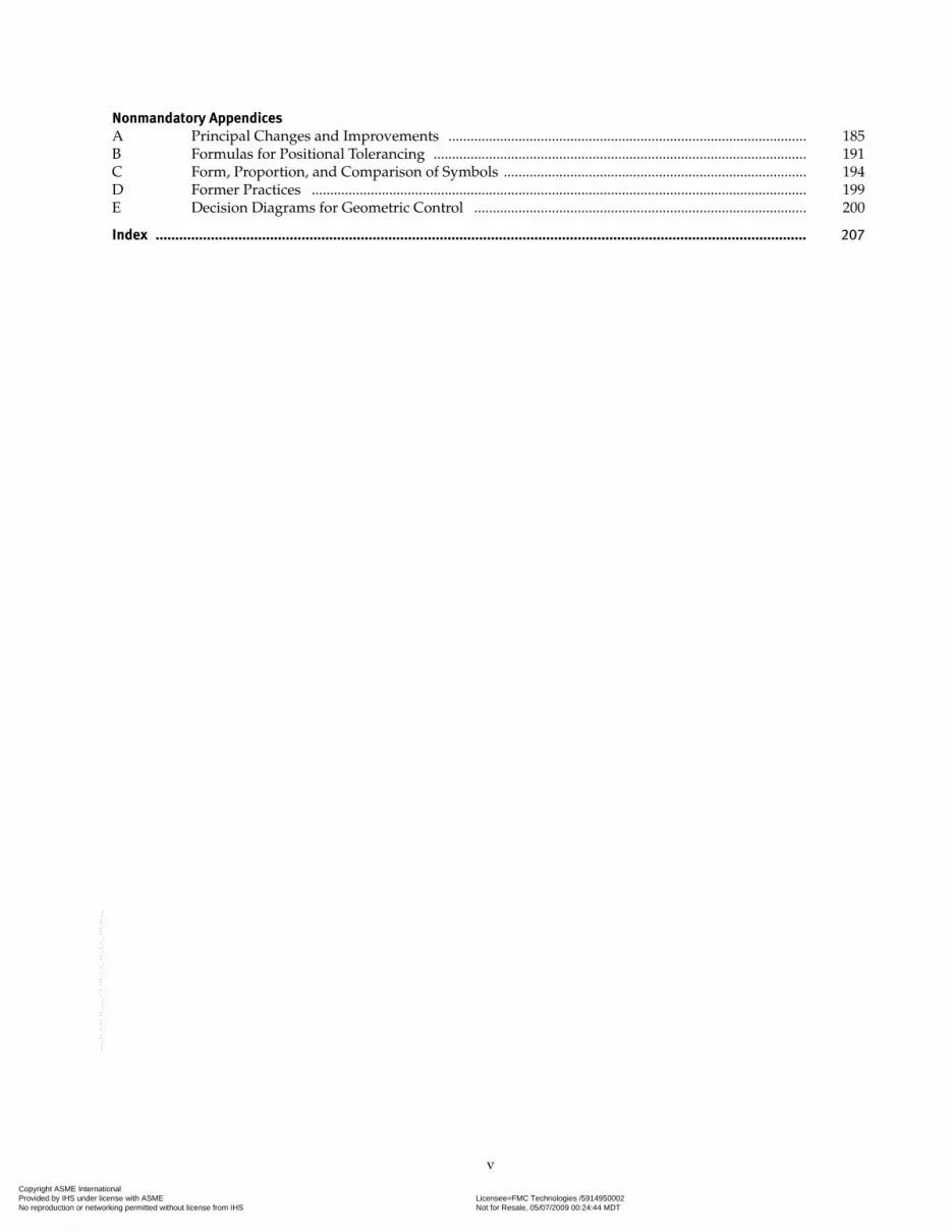
Nonmandatory AppendicesA Principal Changes and Improvements ................................................................................................. 185B Formulas for Positional Tolerancing ..................................................................................................... 191C Form, Proportion, and Comparison of Symbols .................................................................................. 194D Former Practices ...................................................................................................................................... 199E Decision Diagrams for Geometric Control .......................................................................................... 200
Index ..................................................................................................................................................................... 207
Copyright ASME International Provided by IHS under license with ASME Licensee=FMC Technologies /5914950002
Not for Resale, 05/07/2009 00:24:44 MDTNo reproduction or networking permitted without license from IHS
--`,,`,,,``,`,``,,``,`,`,,,`,`,`-`-`,,`,,`,`,,`---

vi
FOREWORD
This issue is a revision of ASME Y14.5M-1994, Dimensioning and Tolerancing. The main object for this revision has been to rearrange the material to better direct the thought process of the user when applying Geometric Dimensioning and Tolerancing. The subject matter of Sections 1 through 4 remains the same as in the previous revision. Sections 5 and 6 were formerly titled “Tolerances of Location” and “Tolerances of Form, Profile, Orientation, and Runout.” The new order following Section 4, Datums, is Section 5, Tolerances of Form; Section 6, Tolerances of Orientation; Section 7, Tolerances of Location; Section 8, Tolerances of Profile; and Section 9, Tolerances of Runout. When applying GD&T the first consideration is to establish a datum reference frame based on the function of the part in the assembly with its mat-ing parts. After the datum reference frame is established, the form of the primary datum feature is controlled, followed by the orientation and/or location of the secondary and tertiary datum features. After the datum features are related relative to each other, the remaining features are controlled for orientation and location relative to the datum reference framework. Further rearrangement has occurred within each section so that the basic concepts are presented first and then the material builds to the more complex. The subcommittee believes this will aid the user of the Standard to better understand the subject of Dimensioning and Tolerancing.
Three new terms that are introduced are used only with datums. The terms are “maximum material boundary (MMB),” “least material boundary (LMB),” and “regardless of material boundary (RMB).” These terms better describe that there is a boundary defined when applying datums. MMB and LMB may be a maximum material or least material boundary, respectively, or the applicable virtual condition. The MMB would be an actual maximum material boundary if the tolerance (location or orientation) for that datum feature was zero at MMC. The LMB would be an actual least material boundary if the tolerance (location or orientation) for that datum feature was zero at LMC. In the case of a fea-ture of size as a primary datum feature, the MMB or LMB would be the actual maximum or least material boundary if the form of the feature of size was controlled by Rule #1, or a zero at MMC or LMC straightness of the axis or flatness of the center plane was applied. RMB indicates that the datum features apply at any boundary based on the actual size of the feature and any geometric tolerance applied that together generate a unique boundary.
Since many major industries are becoming more global, resulting in the decentralization of design and manufactur-ing, it is even more important that the design more precisely state the functional requirements. To accomplish this it is becoming increasingly important that the use of geometric and dimensioning (GD&T) replace the former limit dimensioning for form, orientation, location, and profile of part features. This revision contains paragraphs that give a stronger admonition than in the past that the fully defined drawing should be dimensioned using GD&T with limit dimensioning reserved primarily for the size dimensions for features of size. Additionally, recognizing the need to automate the design, analysis, and measurement processes, and reduce the number of “view dependent tolerances,” additional symbology has been introduced for some more common tolerancing practices.
Work on this issue began at a meeting in Sarasota, Florida in January 1994. Numerous deferred comments from the public review for the previous revision, as well as proposals for revision and improvement from the subcommittee and interested parties from the user community, were evaluated at subsequent semi-annual meetings. The subcommittee divided into working groups for several meetings and then reconvened as a subcommittee as a whole to review and ensure the continuity of the revision.
Internationally, a new joint harmonization group formed in January 1993 was called the ISO/TC 3-10-57 JHG. The object was to harmonize the work and principles among ISO/TC3 Surface Texture, ISO/TC 10 SC 5 Dimensioning and Tolerancing, and ISO/TC 57 Measurement. The task of this group was to identify and suggest resolutions to problems among the three disciplines. Many representatives of the ASME Y14.5 subcommittee participated in the meetings of this group from September 1993 through June 1996. In Paris in June 1996 the ISO/TC 3-10-57 JHG became ISO/TC 213, and the responsibilities of the three other ISO committees were transferred to ISO/TC 213. Representatives of the U.S. have participated in all of the ISO/TC 213 meetings from June 1996 through January 1999. Because of difficulties, the U.S. was not represented again until January 2006, and representation is now ongoing.
In the U.S., a similar committee was formed following the formation of ISO/TC 213 as a home for the U.S. TAG (Technical Advisory Group) to ISO/TC 213 and also to serve as an advisory committee to the three U.S. committees and subcommittees that are parallel to the ISO groups (Surface Texture B46, Dimensioning and Tolerancing Y14.5, and Measurement B89). This new committee, called H213, was formed at a meeting in 1997 by representatives of the three U.S. committees or subcommittees. H213 does not have responsibility for all three subjects as does the ISO committee, but rather serves as an intermediary to identify and facilitate a resolution to problems that may exist among the three disciplines as well as the home for the U.S. TAG.
Copyright ASME International Provided by IHS under license with ASME Licensee=FMC Technologies /5914950002
Not for Resale, 05/07/2009 00:24:44 MDTNo reproduction or networking permitted without license from IHS
--`,,`,,,``,`,``,,``,`,`,,,`,`,`-`-`,,`,,`,`,,`---
vii
Suggestions for improvement of this Standard are welcome. They should be sent to The American Society of Mechanical Engineers; Attn: Secretary, Y14 Standards Committee; Three Park Avenue, New York, NY 10016.
This revision was approved as an American National Standard on February 6, 2009.
NOTE: The user’s attention is called to the possibility that compliance with this Standard may require use of an inven-tion covered by patent rights.
By publication of this Standard, no position is taken with respect to the validity of any such claim(s) or of any patent rights in connection therewith. If a patent holder has fi led a statement of willingness to grant a license under these rights on reasonable and nondiscriminatory terms and conditions to applicants desiring to obtain such a license, then details may be obtained from the standards developer.
Acknowledgments
P. J. McCuistion, Ohio University, created the illustrations for this Standard.
Copyright ASME International Provided by IHS under license with ASME Licensee=FMC Technologies /5914950002
Not for Resale, 05/07/2009 00:24:44 MDTNo reproduction or networking permitted without license from IHS
--`,,`,,,``,`,``,,``,`,`,,,`,`,`-`-`,,`,,`,`,,`---

viii
ASME Y14 COMMITTEEEngineering Drawing and Related Documentation Practices
(The following is the roster of the Committee at the time of approval of this Standard.)
STANDARDS COMMITTEE OFFICERS
F. Bakos, ChairW. A. Kaba, Vice ChairC. J. Gomez, Secretary
STANDARDS COMMITTEE PERSONNEL
A. R. Anderson, Dimensional Control Systems, Inc./ W. A. Kaba, Spirit AeroSystems, Inc. Dimensional Dynamics, LLC K. S. King, BAE SystemsF. Bakos, Consultant A. Krulikowski, Effective Training Inc.J. V. Burleigh, Consultant P. J. McCuistion, Ohio UniversityD. E. Day, TEC-EASE, Inc. J. D. Meadows, James D. Meadows and Associates, Inc.K. Dobert, Siemens PLM Software, Inc./Geometric Design Services J. M. Smith, Caterpillar, Inc.C. W. Ferguson, WM Education Services N. H. Smith, Spirit AeroSystems, Inc.C. J. Gomez, The American Society of Mechanical Engineers K. E. Wiegandt, Sandia National LaboratoriesB. A. Harding, Purdue University R. G. Wilhelm, University of North CarolinaD. H. Honsinger, Consultant B. A. Wilson, The Boeing Company
SUBCOMMITTEE 5 — DIMENSIONING AND TOLERANCING
A. R. Anderson, Chair, Dimensional Control Systems, Inc./ K. S. King, BAE Systems Dimensional Dynamics, LLC. A. Krulikowski, Effective Training, Inc.F. Bakos, Consultant P. J. McCuistion, Ohio UniversityN. W. Cutler, Dimensional Management, Inc. M. E. Meloro, Secretary, Northrop Grumman Corp.D. E. Day, TEC-EASE, Inc. T. C. Miller, Los Alamos National LaboratoryK. Dobert, Siemens PLM Software, Inc./Geometric Design Services A. G. Neumann, Technical Consultants, Inc.P. J. Drake, Jr., MechSigma Consulting, Inc E. Niemiec, ConsultantC. W. Ferguson, WM Education Service G. M. Patterson, GE Aircraft EnginesC. J. Gomez, Staff Secretary, The American Society of D. W. Shepherd, Shepherd Industries Mechanical Engineers J. M. Smith, Caterpillar, Inc.C. Houk, Hamilton Sundstrand Corporation B. A. Wilson, The Boeing CompanyD. P. Karl, Vice Chair, Karl Engineering Services Inc. M. P. Wright, Lockheed Martin Aeronautics Co.J. D. Keith, Spirit Aero Systems, Inc.
SUBCOMMITTEE 5 — SUPPORT GROUP
O. J. Deschepper, General Motors J. I. Miles, Lockheed Martin AeronauticsB. R. Fischer, Advanced Dimensional Management, LLC M. A. Murphy, General Motors CorporationB. A. Harding, Purdue University R. A. Wheeler, Goodrich AerostructuresD. H. Honsinger, Consultant R. D. Wiles, Datum Inspection ServicesP. Mares, The Boeing Company J. E. Winconek, ConsultantJ. D. Meadows, James D. Meadows and Associates, Inc.
Copyright ASME International Provided by IHS under license with ASME Licensee=FMC Technologies /5914950002
Not for Resale, 05/07/2009 00:24:44 MDTNo reproduction or networking permitted without license from IHS
--`,,`,,,``,`,``,,``,`,`,,,`,`,`-`-`,,`,,`,`,,`---

ix
CORRESPONDENCE WITH THE Y14 COMMITTEE
General. ASME Standards are developed and maintained with the intent to represent the consensus of concerned interests. As such, users of this Standard may interact with the Committee by proposing revisions and attending Committee meetings. Correspondence should be addressed to:
Secretary, Y14 Standards CommitteeThe American Society of Mechanical EngineersThree Park AvenueNew York, NY 10016-5990
Proposing Revisions. Revisions are made periodically to the Standard to incorporate changes that appear neces-sary or desirable, as demonstrated by the experience gained from the application of the Standard. Approved revi-sions will be published periodically.
The Committee welcomes proposals for revisions to this Standard. Such proposals should be as specific as possible, citing the paragraph number(s), the proposed wording, and a detailed description of the reasons for the proposal including any pertinent documentation.
Proposing a Case. Cases may be issued for the purpose of providing alternative rules when justified, to permit early implementation of an approved revision when the need is urgent, or to provide rules not covered by exist-ing provisions. Cases are effective immediately upon ASME approval and shall be posted on the ASME Committee Web page.
Requests for Cases shall provide a Statement of Need and Background Information. The request should identify the standard, the paragraph, figure or table number(s), and be written as a Question and Reply in the same format as existing Cases. Requests for Cases should also indicate the applicable edition(s) of the standard to which the pro-posed Case applies.
Attending Committee Meetings. The Y14 Standards Committee regularly holds meetings or telephone conferences, which are open to the public. Persons wishing to attend any meeting or telephone conference should contact the Secretary of the Y14 Standards Committee or check our Web site at http://cstools.asme.org/csconnect/.
Copyright ASME International Provided by IHS under license with ASME Licensee=FMC Technologies /5914950002
Not for Resale, 05/07/2009 00:24:44 MDTNo reproduction or networking permitted without license from IHS
--`,,`,,,``,`,``,,``,`,`,,,`,`,`-`-`,,`,,`,`,,`---

x
INTENTIONALLY LEFT BLANK
Copyright ASME International Provided by IHS under license with ASME Licensee=FMC Technologies /5914950002
Not for Resale, 05/07/2009 00:24:44 MDTNo reproduction or networking permitted without license from IHS
--`,,`,,,``,`,``,,``,`,`,,,`,`,`-`-`,,`,,`,`,,`---

ASME Y14.5-2009
DIMENSIONING AND TOLERANCING
Section 1Scope, Definitions, and General Dimensioning
1
1.1 SCOPE
This Standard establishes uniform practices for stating and interpreting dimensioning, tolerancing, and related requirements for use on engineering drawings and in related documents. For a mathematical expla-nation of many of the principles in this Standard, see ASME Y14.5.1. Practices unique to architectural and civil engineering and welding symbology are not included.
1.1.1 General
Section 1 establishes definitions, fundamental rules, and practices for general dimensioning. For tolerancing practices, see Sections 2 through 9. Additional informa-tion about tolerancing maybe found in Nonmandatory Appendices A through E.
1.1.2 Units
The International System of Units (SI) is featured in this Standard because SI units are expected to supersede United States (U.S.) customary units specified on engineer-ing drawings. Customary units could equally well have been used without prejudice to the principles established.
1.1.3 Reference to This Standard
Where drawings are based on this Standard, this fact shall be noted on the drawings or in a document refer-enced on the drawings. References to this Standard shall state ASME Y14.5-2009.
1.1.4 Figures
The figures in this Standard are intended only as illustrations to aid the user in understanding the prin-ciples and methods of dimensioning and tolerancing described in the text. The absence of a figure illustrat-ing the desired application is neither reason to assume inapplicability, nor basis for drawing rejection. In some instances, figures show added detail for emphasis. In other instances, figures are incomplete by intent. Numerical values of dimensions and tolerances are illustrative only. Multiview drawings contained within figures are third angle projection.
NOTE: To assist the users of this Standard, a listing of the paragraph(s) that refer to an illustration appears in the lower right-hand corner of each figure. This listing may not be all-inclusive. The absence of a listing is not a reason to assume inapplicabil-ity. Some illustrations may diverge from Y14 drawing practices to clarify the meanings of principles.
1.1.5 Notes
Notes herein in capital letters are intended to appear on finished drawings. Notes in lowercase letters are explana-tory only and are not intended to appear on drawings.
1.1.6 Reference to Gaging
This document is not intended as a gaging standard. Any reference to gaging is included for explanatory purposes only. For gaging principles see ASME Y14.43 Dimension -ing and Tolerancing Principles for Gages and Fixtures.
1.1.7 Symbols
Adoption of symbols indicating dimensional requirements, as shown in Fig. C-2 of Nonmandatory Appendix C, does not preclude the use of equivalent terms or abbreviations where symbology is considered inappropriate.
1.2 REFERENCES
The following revisions of American National Standards form a part of this Standard to the extent speci-fied herein. A more recent revision may be used provided there is no conflict with the text of this Standard. In the event of a conflict between the text of this Standard and the references cited herein, the text of this Standard shall take precedence.
1.2.1 Cited Standards
ANSI/ASME B89.6.2-1973 (R2003), Temperature and Humidity Environment for Dimensional Measurement
ANSI/ASME B94.6-1984 (R2003), KnurlingANSI B4.2-1978 (R2004), Preferred Metric Limits
and Fits
Copyright ASME International Provided by IHS under license with ASME Licensee=FMC Technologies /5914950002
Not for Resale, 05/07/2009 00:24:44 MDTNo reproduction or networking permitted without license from IHS
--`,,`,,,``,`,``,,``,`,`,,,`,`,`-`-`,,`,,`,`,,`---
ASME Y14.5-2009
2
ANSI B89.3.1-1972 (R2003), Measurement of Out-of-Roundness
ANSI B92.1-1996,1 Involute Splines and Inspection, Inch Version
ANSI B92.2M-1980,1 Metric Module, Involute Splines
ANSI Y14.6-2001 (R2007), Screw Thread Representation
ANSI Y14.6aM-1981 (R1998), Screw Thread Representation (Metric Supplement)
Publisher: American National Standards Institute (ANSI), 25 West 43rd Street, New York, NY 10036
ASME B5.10-1994, Machine Tapers — Self Holding and Steep Taper Series
ASME B46.1-2002, Surface Texture, Surface Roughness, Waviness, and Lay
ASME B94.11M-1993, Twist DrillsASME Y14.1-2005, Drawing Sheet Size and FormatASME Y14.1M-2005, Metric Drawing Sheet Size
and FormatASME Y14.2-2008, Line Conventions and LetteringASME Y14.5.1M-1994 (R2004), Mathematical
Definition of Dimensioning and Tolerancing Principles
ASME Y14.8-2009, Castings and ForgingsASME Y14.36M-1996 (R2008), Surface Texture
SymbolsASME Y14.41-2003 (R2008), Digital Product
Definition Data PracticesASME Y14.43-2003 (R2008), Dimensioning and
Tolerancing Principles for Gages and Fixtures
Publisher: The American Society of Mechanical Engineers (ASME), Three Park Avenue, New York, NY 10016; Order Department: 22 Law Drive, P.O. Box 2300, Fairfield, NJ 07007-2300
IEEE/ASTM SI 10-2002 ERRATA 2005, Standard for Use of the International System of Units (SI) — The Modern Metric System
Publisher: Institute of Electrical and Electronics Engineers (IEEE), 445 Hoes Lane, Piscataway, NJ 08854
1.2.2 Additional Sources (Not Cited)
ANSI/ASME B1.2-1983 (R2007), Gages and Gaging for Unified Inch Screw Threads
ANSI B4.4M-1981, Inspection of Workpieces
Publisher: American National Standards Institute (ANSI), 25 West 43rd Street, New York, NY 10036
ASME Y14.3M-2003 (R2008), Multiview and Sectional View Drawings
ASME Y14.38M-2007, AbbreviationsASME Y14.100-2004, Engineering Drawing Practices
Publisher: The American Society of Mechanical Engineers (ASME), Three Park Avenue, New York, NY 10016; Order Department: 22 Law Drive, P.O. Box 2300, Fairfield, NJ 07007-2300
1.3 DEFINITIONS
The following terms are defined as their use applies in this Standard. Additionally, definitions throughout the Standard of italicized terms are given in sections describing their application. Their location may be iden-tified by referring to the index.
1.3.1 Angularity
angularity: see para. 6.3.1.
1.3.2 Boundary, Inner
boundary, inner: a worst-case boundary generated by the smallest feature (MMC for an internal feature and LMC for an external feature) minus the stated geomet-ric tolerance and any additional geometric tolerance (if applicable) resulting from the feature’s departure from its specified material condition. See Figs. 2-12 through 2-17.
1.3.3 Boundary, Least Material (LMB)
boundary, least material (LMB): the limit defined by a tolerance or combination of tolerances that exists on or inside the material of a feature(s).
1.3.4 Boundary, Maximum Material (MMB)
boundary, maximum material (MMB): the limit defined by a tolerance or combination of tolerances that exists on or outside the material of a feature(s).
1.3.5 Boundary, Outer
boundary, outer: a worst-case boundary generated by the largest feature (LMC for an internal feature and MMC for an external feature) plus the stated geometric tolerance and any additional geometric tolerance (if applicable) resulting from the feature’s departure from its specified material condition. See Figs. 2-12 through 2-17.
1.3.6 Circularity (Roundness)
circularity (roundness): see para. 5.4.3.
Copyright ASME International Provided by IHS under license with ASME Licensee=FMC Technologies /5914950002
Not for Resale, 05/07/2009 00:24:44 MDTNo reproduction or networking permitted without license from IHS
--`,,`,,,``,`,``,,``,`,`,,,`,`,`-`-`,,`,,`,`,,`---

ASME Y14.5-2009
3
1.3.7 Coaxiality
coaxiality: see para. 7.6.
1.3.8 Complex Feature
complex feature: a single surface of compound curva-ture or a collection of other features that constrains up to six degrees of freedom.
1.3.9 Concentricity
concentricity: see para. 7.6.4.
1.3.10 Coplanarity
coplanarity: see para. 8.4.1.1.
1.3.11 Constraint
constraint: a limit to one or more degrees of freedom.
1.3.12 Cylindricity
cylindricity: see para. 5.4.4.
1.3.13 Datum
datum: a theoretically exact point, axis, line, plane, or combination thereof derived from the theoretical datum feature simulator.
1.3.14 Datum Axis
datum axis: the axis of a datum feature simulator estab-lished from the datum feature.
1.3.15 Datum Center Plane
datum center plane: the center plane of a datum feature simulator established from the datum feature.
1.3.16 Datum Feature
datum feature: a feature that is identified with either a datum feature symbol or a datum target symbol.
1.3.17 Datum Feature Simulator
datum feature simulator: encompasses two types: theo-retical and physical. See paras. 1.3.17.1 and 1.3.17.2.
1.3.17.1 Datum Feature Simulator (Theoretical). datum feature simulator (theoretical): the theoretically perfect boundary used to establish a datum from a specified datum feature.
NOTE: Whenever the term “datum feature simulator” is used in this Standard, it refers to the theoretical, unless specifically other-wise indicated.
1.3.17.2 Datum Feature Simulator (Physical). datum feature simulator (physical): the physical boundary used to establish a simulated datum from a specified datum feature.
NOTE: For example, a gage, fixture element, or digital data (such as machine tables, surface plates, a mandrel, or mathematical simulation) —although not true planes — are of sufficient quality that the planes derived from them are used to establish simulated datums. Physical datum feature simulators are used as the physi-cal embodiment of the theoretical datum feature simulators during manufacturing and inspection. See ASME Y14.43.
1.3.18 Datum Reference Frame
datum reference frame: see para. 4.1.
1.3.19 Datum, Simulated
datum, simulated: a point, axis, line, or plane (or combi-nation thereof) coincident with or derived from process-ing or inspection equipment, such as the following simulators: a surface plate, a gage surface, a mandrel, or mathematical simulation. See para. 4.6.
1.3.20 Datum Target
datum target: see para. 4.24.
1.3.21 Diameter, Average
diameter, average: see para. 5.5.3.
1.3.22 Dimension
dimension: a numerical value(s) or mathematical expression in appropriate units of measure used to define the form, size, orientation or location, of a part or feature.
1.3.23 Dimension, Basic
dimension, basic: a theoretically exact dimension.
NOTE: A basic dimension is indicated by one of the methods shown in Figs. 3-10 and 7-1.
1.3.24 Dimension, Reference
dimension, reference: a dimension, usually without a tolerance, that is used for informational purposes only.
Copyright ASME International Provided by IHS under license with ASME Licensee=FMC Technologies /5914950002
Not for Resale, 05/07/2009 00:24:44 MDTNo reproduction or networking permitted without license from IHS
--`,,`,,,``,`,``,,``,`,`,,,`,`,`-`-`,,`,,`,`,,`---

ASME Y14.5-2009
4
NOTE: A reference dimension is a repeat of a dimension or is derived from other values shown on the drawing or on related drawings. It is considered auxiliary information and does not gov-ern production or inspection operations. See Figs. 1-19 and 1-20. Where a basic dimension is repeated on a drawing, it need not be identified as reference. For information on how to indicate a refer-ence dimension, see para 1.7.6.
1.3.25 Envelope, Actual Mating
envelope, actual mating: this envelope is outside the material. A similar perfect feature(s) counterpart of
smallest size that can be contracted about an external feature(s) or largest size that can be expanded within an internal feature(s) so that it coincides with the surface(s) at the highest points. Two types of actual mating enve-lopes — unrelated and related — are described in paras. 1.3.25.1 and 1.3.25.2.
1.3.25.1 Unrelated Actual Mating Envelope. unrel-ated actual mating envelope: a similar perfect feature(s) counterpart expanded within an internal feature(s) or contracted about an external feature(s), and not con-strained to any datum(s). See Fig. 1-1.
Fig. 1-1 Related and Unrelated Actual Mating Envelope
Fig. 1-1 Related and Unrelated Actual Mating Envelope (Cont’d)
Copyright ASME International Provided by IHS under license with ASME Licensee=FMC Technologies /5914950002
Not for Resale, 05/07/2009 00:24:44 MDTNo reproduction or networking permitted without license from IHS
--`,,`,,,``,`,``,,``,`,`,,,`,`,`-`-`,,`,,`,`,,`---

ASME Y14.5-2009
5
1.3.25.2 Related Actual Mating Envelope. related actual mating envelope: a similar perfect feature coun-terpart expanded within an internal feature(s) or con-tracted about an external feature(s) while constrained either in orientation or location or both to the applicable datum(s). See Fig. 1-1.
1.3.26 Envelope, Actual Minimum Material
envelope, actual minimum material: this envelope is within the material. A similar perfect feature(s) coun-terpart of largest size that can be expanded within an external feature(s) or smallest size that can be con-tracted about an internal feature(s) so that it coincides with the surface(s) at the lowest points. Two types of actual minimum material envelopes — unrelated and related — are described in paras. 1.3.26.1 and 1.3.26.2.
1.3.26.1 Unrelated Actual Minimum Material Env-elope. unrelated actual minimum material envelope: a similar perfect feature(s) counterpart contracted about an internal feature(s) or expanded within an external feature(s), and not constrained to any datum reference frame. See Fig. 1-2.
1.3.26.2 Related Actual Minimum Material Env-elope. related actual minimum material envelope: a similar perfect feature(s) counterpart contracted about an inter-nal feature(s) or expanded within an external feature(s) while constrained in either orientation or location or both to the applicable datum(s). See Fig. 1-2.
1.3.27 Feature
feature: a physical portion of a part such as a surface, pin, hole, or slot or its representation on drawings, mod-els, or digital data files.
1.3.28 Feature Axis
feature axis: the axis of the unrelated actual mating envelope of a feature.
NOTE: In this Standard, when the term “feature axis” is used, it refers to the axis of the unrelated actual mating envelope unless specified otherwise.
1.3.29 Feature, Center Plane of
feature, center plane of: the center plane of the unrelated actual mating envelope of a feature.
Fig. 1-2 Related and Unrelated Actual Minimum Envelope From Figure 1-1
Copyright ASME International Provided by IHS under license with ASME Licensee=FMC Technologies /5914950002
Not for Resale, 05/07/2009 00:24:44 MDTNo reproduction or networking permitted without license from IHS
--`,,`,,,``,`,``,,``,`,`,,,`,`,`-`-`,,`,,`,`,,`---

ASME Y14.5-2009
6
NOTE: In this Standard, when the term “feature center plane” is used, it refers to the center plane of the unrelated actual mating envelope unless specified otherwise.
1.3.30 Derived Median Plane
derived median plane: an imperfect (abstract) plane formed by the center points of all line segments bounded by the feature. These line segments are normal (perpen-dicular) to the center plane of the unrelated actual mat-ing envelope.
1.3.31 Derived Median Line
derived median line: an imperfect (abstract) line formed by the center points of all cross sections of the feature. These cross sections are normal (perpendicular) to the axis of the unrelated actual mating envelope.
1.3.32 Feature of Size
feature of size: encompasses two types: regular and irregular. See paras. 1.3.32.1 and 1.3.32.2.
1.3.32.1 Regular Feature of Size. regular feature of size: one cylindrical or spherical surface, a circular ele-ment, and a set of two opposed parallel elements or opposed parallel surfaces, each of which is associated with a directly toleranced dimension. See para. 2.2.
1.3.32.2 Irregular Feature of Size. irregular feature of size: the two types of irregular features of size are as follows:
(a) a directly toleranced feature or collection of fea-tures that may contain or be contained by an actual mat-ing envelope that is a sphere, cylinder, or pair of parallel planes
(b) a directly toleranced feature or collection of fea-tures that may contain or be contained by an actual mat-ing envelope other than a sphere, cylinder, or pair of parallel planes
1.3.33 Feature Control Frame
feature control frame: see para. 3.4.1.
1.3.34 Feature-Relating Tolerance Zone Framework (FRTZF)
feature-relating tolerance zone framework (FRTZF): the tolerance zone framework(s) that controls the basic relationship between the features in a pattern with that framework constrained in rotational degrees of freedom relative to any referenced datum features.
1.3.35 Free State
free state: the condition of a part free of applied forces.
1.3.36 Free-State Variation
free-state variation: see para. 5.5.
1.3.37 Flatness
flatness: see para. 5.4.2.
1.3.38 Least Material Condition (LMC)
least material condition (LMC): the condition in which a feature of size contains the least amount of material within the stated limits of size (e.g., maximum hole diameter, minimum shaft diameter).
1.3.39 Maximum Material Condition (MMC)
maximum material condition (MMC): the condition in which a feature of size contains the maximum amount of material within the stated limits of size (e.g., mini-mum hole diameter, maximum shaft diameter).
1.3.40 Non-Uniform Tolerance Zone
non-uniform tolerance zone: see para. 8.3.2.
1.3.41 Parallelism
parallelism: see para. 6.3.2.
1.3.42 Pattern
pattern: two or more features or features of size to which a locational geometric tolerance is applied and are grouped by one of the following methods: nX, n COAXIAL HOLES, ALL OVER, A ↔ B, n SURFACES, simulta-neous requirements, or INDICATED.
1.3.43 Pattern-Locating Tolerance Zone Framework (PLTZF)
pattern-locating tolerance zone framework (PLTZF): the tolerance zone framework that controls the basic rela-tionship between the features in a pattern with that framework constrained in translational and rotational degrees of freedom relative to the referenced datum features.
1.3.44 Perpendicularity
perpendicularity: see para. 6.3.3.
1.3.45 Plane, Tangent
plane, tangent: a plane that contacts the high points of the specified feature surface.
1.3.46 Position
position: see para. 7.2.
Copyright ASME International Provided by IHS under license with ASME Licensee=FMC Technologies /5914950002
Not for Resale, 05/07/2009 00:24:44 MDTNo reproduction or networking permitted without license from IHS
--`,,`,,,``,`,``,,``,`,`,,,`,`,`-`-`,,`,,`,`,,`---

ASME Y14.5-2009
7
1.3.47 Profile
profile: see para. 8.2
1.3.48 Regardless of Feature Size (RFS)
regardless of feature size (RFS): indicates a geometric tolerance applies at any increment of size of the actual mating envelope of the feature of size.
1.3.49 Regardless of Material Boundary (RMB)
regardless of material boundary (RMB): indicates that a datum feature simulator progresses from MMB toward LMB until it makes maximum contact with the extremi-ties of a feature(s).
1.3.50 Restraint
restraint: the application of force(s) to a part to simu-late its assembly or functional condition resulting in possible distortion of a part from its free-state condition. See para. 4.20.
1.3.51 Resultant Condition
resultant condition: the single worst-case bound-ary generated by the collective effects of a feature of the size’s specified MMC or LMC, the geometric toler-ance for that material condition, the size tolerance, and the additional geometric tolerance derived from the feature’s departure from its specified material condi-tion. See Figs. 2-12, 2-13, 2-15, and 2-16.
1.3.52 Runout
runout: see para. 9.2.
1.3.53 Simultaneous Requirement
simultaneous requirement: see para. 4.19.
1.3.54 Size, Actual Local
size, actual local: the measured value of any individ-ual distance at any cross section of a feature of size. See Fig. 1-1.
1.3.55 Size, Limits of
size, limits of: the specified maximum and minimum sizes. See para. 2.7.
1.3.56 Size, Nominal
size, nominal: the designation used for purposes of general identification.
1.3.57 Straightness
straightness: see para. 5.4.1.
1.3.58 Statistical Tolerancing
statistical tolerancing: see para. 2.17.
1.3.59 Symmetry
symmetry: see para. 7.7.2.
1.3.60 Tolerance
tolerance: the total amount a specific dimension is per-mitted to vary. The tolerance is the difference between the maximum and minimum limits.
1.3.61 Tolerance, Bilateral
tolerance, bilateral: a tolerance in which variation is per-mitted in both directions from the specified dimension.
1.3.62 Tolerance, Geometric
tolerance, geometric: the general term applied to the cat-egory of tolerances used to control size, form, profile, orientation, location, and runout.
1.3.63 Tolerance, Unilateral
tolerance, unilateral: a tolerance in which variation is permitted in one direction from the specified dimension.
1.3.64 True Position
true position: the theoretically exact location of a fea-ture of size, as established by basic dimensions.
1.3.65 True Profile
true profile: see para. 8.2.
1.3.66 Uniform Tolerance Zone
uniform tolerance zone: see para. 8.3.1.
1.3.67 Virtual Condition
virtual condition: a constant boundary generated by the collective effects of a considered feature of the size’s spec-ified MMC or LMC and the geometric tolerance for that material condition. See Figs. 2-12, 2-13, 2-15, and 2-16.
1.4 FUNDAMENTAL RULES
Dimensioning and tolerancing shall clearly define engineering intent and shall conform to the following.
Copyright ASME International Provided by IHS under license with ASME Licensee=FMC Technologies /5914950002
Not for Resale, 05/07/2009 00:24:44 MDTNo reproduction or networking permitted without license from IHS
--`,,`,,,``,`,``,,``,`,`,,,`,`,`-`-`,,`,,`,`,,`---
ASME Y14.5-2009
8
(a) Each dimension shall have a tolerance, except for those dimensions specifically identified as reference, max-imum, minimum, or stock (commercial stock size). The tolerance may be applied directly to the dimension (or indirectly in the case of basic dimensions), indicated by a general note, or located in a supplementary block of the drawing format. See ASME Y14.1 and ASME Y14.1M.
(b) Dimensioning and tolerancing shall be complete so there is full understanding of the characteristics of each feature. Values may be expressed in an engineering drawing or in a CAD product definition data set. See ASME Y14.41. Neither scaling (measuring directly from an engineering drawing) nor assumption of a distance or size is permitted, except as follows: undimensioned drawings, such as loft, printed wiring, templates, and master layouts prepared on stable material, pro-vided the necessary control dimensions are specified.
(c) Each necessary dimension of an end product shall be shown. No more dimensions than those necessary for complete definition shall be given. The use of reference dimensions on a drawing should be minimized.
(d) Dimensions shall be selected and arranged to suit the function and mating relationship of a part and shall not be subject to more than one interpretation.
(e) The drawing should define a part without speci-fying manufacturing methods. Thus, only the diameter of a hole is given without indicating whether it is to be drilled, reamed, punched, or made by any other opera-tion. However, in those instances where manufactur-ing, processing, quality assurance, or environmental information is essential to the definition of engineering requirements, it shall be specified on the drawing or in a document referenced on the drawing.
(f) Nonmandatory processing dimensions shall be identified by an appropriate note, such as “NONMANDATORY (MFG DATA).” Examples of nonman-datory data are processing dimensions that provide for finish allowance, shrink allowance, and other require-ments, provided the final dimensions are given on the drawing.
(g) Dimensions should be arranged to pro-vide required information for optimum readability. Dimensions should be shown in true profile views and refer to visible outlines.
(h) Wires, cables, sheets, rods, and other materials manufactured to gage or code numbers shall be speci-fied by linear dimensions indicating the diameter or thickness. Gage or code numbers may be shown in parentheses following the dimension.
(i) A 90° angle applies where center lines and lines depicting features are shown on a 2D orthographic drawing at right angles and no angle is specified. See para. 2.1.1.3.
(j) A 90° basic angle applies where center lines of fea-tures in a pattern or surfaces shown at right angles on a 2D orthographic drawing are located or defined by basic dimensions and no angle is specified. See para. 2.1.1.4.
(k) A zero basic dimension applies where axes, center planes, or surfaces are shown coincident on a draw-ing, and geometric tolerances establish the relationship among the features. See para. 2.1.1.4.
(l) Unless otherwise specified, all dimensions and tolerances are applicable at 20°C (68°F) in accordance with ANSI/ASME B89.6.2. Compensation may be made for measurements made at other temperatures.
(m) Unless otherwise specified, all dimensions and tolerances apply in a free-state condition. For exceptions to this rule see paras. 4.20 and 5.5.
(n) Unless otherwise specified, all tolerances apply for full depth, length, and width of the feature.
(o) Dimensions and tolerances apply only at the draw-ing level where they are specified. A dimension specified for a given feature on one level of drawing (e.g., a detail drawing) is not mandatory for that feature at any other level (e.g., an assembly drawing).
(p) Where a coordinate system is shown on the draw-ing, it shall be right-handed unless otherwise specified. Each axis shall be labeled and the positive direction shall be shown.
NOTE: Where a model coordinate system is shown on the draw-ing, it shall be in compliance with ASME Y14.41.
1.5 UNITS OF MEASURE
For uniformity, all dimensions in this Standard are given in SI units. However, the unit of measure selected should be in accordance with the policy of the user.
1.5.1 SI (Metric) Linear Units
The SI linear unit commonly used on engineering drawings is the millimeter.
1.5.2 U.S. Customary Linear Units
The U.S. Customary linear unit commonly used on engineering drawings is the decimal inch.
1.5.3 Identification of Linear Units
On drawings where all dimensions are in millimeters or all dimensions are in inches, individual identifica-tion of linear units is not required. However, the draw-ing shall contain a note stating “UNLESS OTHERWISE SPECIFIED, ALL DIMENSIONS ARE IN MILLIMETERS (or IN INCHES, as applicable).”
1.5.4 Combination SI (Metric) and U.S. Customary Linear Units
Where some inch dimensions are shown on a millimeter-dimensioned drawing, the abbreviation IN shall follow the inch values. Where some millimeter dimensions are shown on an inch-dimensioned drawing, the symbol mm shall follow the millimeter values.
Copyright ASME International Provided by IHS under license with ASME Licensee=FMC Technologies /5914950002
Not for Resale, 05/07/2009 00:24:44 MDTNo reproduction or networking permitted without license from IHS
--`,,`,,,``,`,``,,``,`,`,,,`,`,`-`-`,,`,,`,`,,`---

ASME Y14.5-2009
9
1.5.5 Angular Units
Angular dimensions are expressed in both degrees and decimal parts of a degree or in degrees, minutes, and seconds. These latter dimensions are expressed by the following symbols:
(a) degrees: °(b) minutes: '(c) seconds: "
Where degrees are indicated alone, the numerical value shall be followed by the symbol. Where only min-utes or seconds are specified, the number of minutes or seconds shall be preceded by 0° or 0°0', as applicable. Where decimal degrees less than one are specified, a zero shall precede the decimal value. See Fig. 1-3.
1.6 TYPES OF DIMENSIONING
Decimal dimensioning shall be used on drawings except where certain commercial commodities are iden-tified by standardized nominal size designations, such as pipe and lumber sizes.
1.6.1 Millimeter Dimensioning
The following shall be observed where specifying mil-limeter dimensions on drawings:
(a) Where the dimension is less than one millimeter, a zero precedes the decimal point. See Fig. 1-4.
(b) Where the dimension is a whole number, neither the decimal point nor a zero is shown. See Fig. 1-4.
(c) Where the dimension exceeds a whole number by a decimal fraction of one millimeter, the last digit to the right of the decimal point is not followed by a zero. See Fig. 1-4.
NOTE: This practice differs for tolerances expressed bilaterally or as limits. See paras. 2.3.1(b) and (c).
(d) Neither commas nor spaces shall be used to sepa-rate digits into groups in specifying millimeter dimen-sions on drawings.
1.6.2 Decimal Inch Dimensioning
The following shall be observed where specifying decimal inch dimensions on drawings:
(a) A zero is not used before the decimal point for val-ues less than 1 in.
(b) A dimension is expressed to the same number of decimal places as its tolerance. Zeros are added to the right of the decimal point where necessary. See Fig. 1-5 and para. 2.3.2.
Fig. 1-3 Angular Units
Fig. 1-4 Millimeter Dimensions
Fig. 1-5 Decimal Inch Dimensions
Copyright ASME International Provided by IHS under license with ASME Licensee=FMC Technologies /5914950002
Not for Resale, 05/07/2009 00:24:44 MDTNo reproduction or networking permitted without license from IHS
--`,,`,,,``,`,``,,``,`,`,,,`,`,`-`-`,,`,,`,`,,`---

ASME Y14.5-2009
10
1.6.3 Decimal Points
Decimal points must be uniform, dense, and large enough to be clearly visible and meet the reproduc-tion requirements of ASME Y14.2M. Decimal points are placed in line with the bottom of the associated digits.
1.6.4 Conversion and Rounding of Linear Units
For information on conversion and rounding of U.S. Customary linear units, see IEEE/ASTM SI 10.
1.7 APPLICATION OF DIMENSIONS
Dimensions are applied by means of dimension lines, extension lines, chain lines, or a leader from a dimen-sion, note, or specification directed to the appropriate feature. See Fig. 1-6. General notes are used to convey additional information. For further information on dimension lines, extension lines, chain lines, and lead-ers, see ASME Y14.2.
1.7.1 Dimension Lines
A dimension line, with its arrowheads, shows the direction and extent of a dimension. Numerals indicate the number of units of a measurement. Preferably, dimen-sion lines should be broken for insertion of numerals as
shown in Fig. 1-6. Where horizontal dimension lines are not broken, numerals are placed above and parallel to the dimension lines.
NOTE: The following shall not be used as a dimension line: a center line, an extension line, a phantom line, a line that is part of the outline of the object, or a continuation of any of these lines. A dimension line is not used as an extension line, except where a simplified method of coordinate dimensioning is used to define curved outlines. See Fig. 1-35
1.7.1.1 Alignment. Dimension lines shall be aligned if practicable and grouped for uniform appearance. See Fig. 1-7.
1.7.1.2 Spacing. Dimension lines are drawn parallel to the direction of measurement. The space between the first dimension line and the part outline should be not less than 10 mm; the space between succeeding parallel dimen-sion lines should be not less than 6 mm. See Fig. 1-8.
NOTE: These spacings are intended as guides only. If the drawing meets the reproduction requirements of the accepted industry or military reproduction specification, nonconformance to these spac-ing requirements is not a basis for rejection of the drawing.
Where there are several parallel dimension lines, the numerals should be staggered for easier reading. See Fig. 1-9.
Fig. 1-6 Application of Dimensions
Fig. 1-7 Grouping of Dimensions Fig. 1-9 Staggered Dimensions
Fig. 1-8 Spacing of Dimension Lines
Copyright ASME International Provided by IHS under license with ASME Licensee=FMC Technologies /5914950002
Not for Resale, 05/07/2009 00:24:44 MDTNo reproduction or networking permitted without license from IHS
--`,,`,,,``,`,``,,``,`,`,,,`,`,`-`-`,,`,,`,`,,`---

ASME Y14.5-2009
11
1.7.1.3 Angle Dimensions. The dimension line of an angle is an arc drawn with its center at the apex of the angle. The arrowheads terminate at the extensions of the two sides. See Figs. 1-3 and 1-6.
1.7.1.4 Crossing Dimension Lines. Crossing dimen-sion lines should be avoided. Where unavoidable, the dimension lines are unbroken.
1.7.2 Extension (Projection) Lines
Extension lines are used to indicate the extension of a surface or point to a location preferably outside the part outline. See para. 1.7.8. On 2D orthographic drawings, extension lines start with a short visible gap from the out-line of the part and extend beyond the outermost related dimension line. See Fig. 1-8. Extension lines are drawn
perpendicular to dimension lines. Where space is lim-ited, extension lines may be drawn at an oblique angle to clearly illustrate where they apply. Where oblique lines are used, the dimension lines are shown in the direction in which they apply. See Fig. 1-10.
1.7.2.1 Crossing Extension Lines. Wherever practica-ble, extension lines should neither cross one another nor cross dimension lines. To minimize such crossings, the shortest dimension line is shown nearest the outline of the object. See Fig. 1-9. Where extension lines must cross other extension lines, dimension lines, or lines depicting features, they are not broken. Where extension lines cross arrowheads or dimension lines close to arrowheads, a break in the extension line is permissible. See Fig. 1-11.
1.7.2.2 Locating Points or Intersections. Where a point is located by extension lines only, the extension lines from surfaces should pass through the point or intersection. See Fig. 1-12.
1.7.3 Limited Length or Area Indication
Where it is desired to indicate that a limited length or area of a surface is to receive additional treatment or consideration within limits specified on the drawing, the extent of these limits may be indicated by use of a chain line. See Fig. 1-13.
Fig. 1-10 Oblique Extension Lines
Fig. 1-11 Breaks in Extension Lines
Fig. 1-12 Point Locations
Fig. 1-13 Limited Length or Area Indication
Copyright ASME International Provided by IHS under license with ASME Licensee=FMC Technologies /5914950002
Not for Resale, 05/07/2009 00:24:44 MDTNo reproduction or networking permitted without license from IHS
--`,,`,,,``,`,``,,``,`,`,,,`,`,`-`-`,,`,,`,`,,`---

ASME Y14.5-2009
12
1.7.3.1 Chain Lines. In an appropriate view or sec-tion, a chain line is drawn parallel to the surface profile at a short distance from it. Dimensions are added for length and location. If applied to a surface of revolution, the indication may be shown on one side only. See Fig. 1-13, illustration (a).
1.7.3.2 Omitting Chain Line Dimensions. If the chain line clearly indicates the location and extent of the sur-face area, dimensions may be omitted. See Fig. 1-13, illustration (b).
1.7.3.3 Area Indication Identification. Where the desired area is shown on a direct view of the surface, the area is section lined within the chain line boundary and appropriately dimensioned. See Fig. 1-13, illustration (c).
1.7.4 Leaders (Leader Lines)
A leader is used to direct a dimension, note, or sym-bol to the intended place on the drawing. Normally, a leader terminates in an arrowhead. However, where it is intended for a leader to refer to a surface by ending within the outline of that surface, the leader should ter-minate in a dot. A leader should be an inclined straight line except for a short horizontal portion extending to the mid-height of the first or last letter or digit of the note or dimension. Two or more leaders to adjacent areas on the drawing should be drawn parallel to each other. See Fig. 1-14.
1.7.4.1 Leader-Directed Dimensions. Leader-directed dimensions are specified individually to avoid com-plicated leaders. See Fig. 1-15. Where too many leaders would impair the legibility of the drawing, letters or sym-bols should be used to identify features. See Fig. 1-16.
1.7.4.2 Circle and Arc. Where a leader is directed to a circle or an arc, its direction should be radial. See Fig. 1-17.
1.7.5 Reading Direction
Reading direction for the following specifications apply:
1.7.5.1 Notes. Notes should be placed to read from the bottom of the drawing with regard to the orientation of the drawing format.
1.7.5.2 Dimensions. Dimensions shown with dim-ension lines and arrowheads should be placed to read from the bottom of the drawing. See Fig. 1-18.
1.7.5.3 Baseline Dimensioning. Baseline dimen-sions should be shown aligned to their extension lines and read from the bottom or right side of the drawing. See Fig. 1-50.
1.7.5.4 Feature Control Frames. Feature control frames should be placed to read from the bottom of the drawing.
Fig. 1-14 Leaders
Fig. 1-15 Leader-Directed Dimensions
Fig. 1-16 Minimizing Leaders
Fig. 1-17 Leader Directions
Copyright ASME International Provided by IHS under license with ASME Licensee=FMC Technologies /5914950002
Not for Resale, 05/07/2009 00:24:44 MDTNo reproduction or networking permitted without license from IHS
--`,,`,,,``,`,``,,``,`,`,,,`,`,`-`-`,,`,,`,`,,`---
ASME Y14.5-2009
13
1.7.5.5 Datum Feature Symbols. Datum feature symbols should be placed to read from the bottom of the drawing.
1.7.6 Reference Dimensions
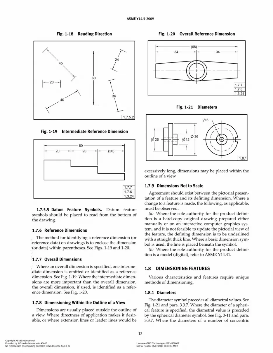
The method for identifying a reference dimension (or reference data) on drawings is to enclose the dimension (or data) within parentheses. See Figs. 1-19 and 1-20.
1.7.7 Overall Dimensions
Where an overall dimension is specified, one interme-diate dimension is omitted or identified as a reference dimension. See Fig. 1-19. Where the intermediate dimen-sions are more important than the overall dimension, the overall dimension, if used, is identified as a refer-ence dimension. See Fig. 1-20.
1.7.8 Dimensioning Within the Outline of a View
Dimensions are usually placed outside the outline of a view. Where directness of application makes it desir-able, or where extension lines or leader lines would be
excessively long, dimensions may be placed within the outline of a view.
1.7.9 Dimensions Not to Scale
Agreement should exist between the pictorial presen-tation of a feature and its defining dimension. Where a change to a feature is made, the following, as applicable, must be observed.
(a) Where the sole authority for the product defini-tion is a hard-copy original drawing prepared either manually or on an interactive computer graphics sys-tem, and it is not feasible to update the pictorial view of the feature, the defining dimension is to be underlined with a straight thick line. Where a basic dimension sym-bol is used, the line is placed beneath the symbol.
(b) Where the sole authority for the product defini-tion is a model (digital), refer to ASME Y14.41.
1.8 DIMENSIONING FEATURES
Various characteristics and features require unique methods of dimensioning.
1.8.1 Diameters
The diameter symbol precedes all diametral values. See Fig. 1-21 and para. 3.3.7. Where the diameter of a spheri-cal feature is specified, the diametral value is preceded by the spherical diameter symbol. See Fig. 3-11 and para. 3.3.7. Where the diameters of a number of concentric
Fig. 1-18 Reading Direction
Fig. 1-19 Intermediate Reference Dimension
Fig. 1-20 Overall Reference Dimension
Fig. 1-21 Diameters
Copyright ASME International Provided by IHS under license with ASME Licensee=FMC Technologies /5914950002
Not for Resale, 05/07/2009 00:24:44 MDTNo reproduction or networking permitted without license from IHS
--`,,`,,,``,`,``,,``,`,`,,,`,`,`-`-`,,`,,`,`,,`---

ASME Y14.5-2009
14
cylindrical features are specified, such diameters should be dimensioned in a longitudinal view if practical.
1.8.2 Radii
Each radius value is preceded by the appropriate radius symbol. See Figs. 1-22 and 3-11 and para. 3.3.7. A radius dimension line uses one arrowhead, at the arc end. An arrowhead is never used at the radius center. Where location of the center is important and space per-mits, a dimension line is drawn from the radius center with the arrowhead touching the arc, and the dimension is placed between the arrowhead and the center. Where space is limited, the dimension line is extended through the radius center. Where it is inconvenient to place the arrowhead between the radius center and the arc, it may be placed outside the arc with a leader. Where the center of a radius is not dimensionally located, the center shall not be indicated. See Fig. 1-22.
1.8.2.1 Center of Radius. Where a dimension is given to the center of a radius, a small cross is drawn at
the center. Extension lines and dimension lines are used to locate the center. See Fig. 1-23. Where location of the center is unimportant, the drawing must clearly show that the arc location is controlled by other dimensioned features such as tangent surfaces. See Fig. 1-24.
1.8.2.2 Foreshortened Radii. Where the center of a radius is outside the drawing or interferes with another view, the radius dimension line may be foreshort-ened. See Fig. 1-25. That portion of the dimension line extending from the arrowhead is radial relative to the arc. Where the radius dimension line is foreshortened and the center is located by coordinate dimensions, the dimension line locating the center is also foreshortened.
1.8.2.3 True Radius. On a 2D orthographic draw-ing, where a radius is dimensioned in a view that does not show the true shape of the radius, TRUE is added before the radius dimension. See Fig. 1-26. This practice is applicable to other foreshortened features as well as radii. See Fig. 4-28.
Fig. 1-22 Radii
Fig. 1-23 Radius With Located Center
Fig. 1-24 Radii With Unlocated Centers
Fig. 1-25 Foreshortened Radii
Copyright ASME International Provided by IHS under license with ASME Licensee=FMC Technologies /5914950002
Not for Resale, 05/07/2009 00:24:44 MDTNo reproduction or networking permitted without license from IHS
--`,,`,,,``,`,``,,``,`,`,,,`,`,`-`-`,,`,,`,`,,`---

ASME Y14.5-2009
15
1.8.2.4 Multiple Radii. Where a part has a number of radii of the same dimension, a note may be used instead of dimensioning each radius separately.
1.8.2.5 Spherical Radii. Where a spherical surface is dimensioned by a radius, the radius dimension is pre-ceded by the symbol SR. See Fig. 1-27.
1.8.3 Chords, Arcs, and Angles
The dimensioning of chords, arcs, and angles shall be as shown in Fig. 1-28.
1.8.4 Rounded Ends and Slotted Holes
Features having rounded ends, including slot-ted holes, are dimensioned using one of the methods
shown in Fig. 1-29. For fully rounded ends, the radii are indicated but not dimensioned. For features with partially rounded ends, the radii are dimensioned. See Fig. 1-30.
1.8.5 Rounded Corners
Where corners are rounded, dimensions define the edges, and the arcs are tangent. See Fig. 1-31.
Fig. 1-26 True Radius
Fig. 1-27 Spherical Radius
Fig. 1-28 Dimensioning Chords, Arcs, and Angles
Fig. 1-29 Slotted Holes
Fig. 1-30 Partially Rounded Ends
Fig. 1-31 Rounded Corners
Copyright ASME International Provided by IHS under license with ASME Licensee=FMC Technologies /5914950002
Not for Resale, 05/07/2009 00:24:44 MDTNo reproduction or networking permitted without license from IHS
--`,,`,,,``,`,``,,``,`,`,,,`,`,`-`-`,,`,,`,`,,`---

ASME Y14.5-2009
16
Fig. 1-32 Circular Arc Outline
Fig. 1-33 Coordinate or Offset Outline
Fig. 1-34 Tabulated Outline
1.8.6 Outlines Consisting of Arcs
A curved outline composed of two or more arcs is dimensioned by giving the radii of all arcs and locat-ing the necessary centers with coordinate dimensions. Other radii are located on the basis of their points of tan-gency. See Fig. 1-32.
1.8.7 Irregular Outlines
Irregular outlines may be dimensioned as shown in Figs. 1-33 and 1-34. Circular or noncircular outlines may be dimensioned by the rectangular coordinate or offset method. See Fig. 1-33. Coordinates are dimensioned from base lines. Where many coordinates are required to define an outline, the vertical and horizontal coordinate dimensions may be tabulated, as in Fig. 1-34.
1.8.8 Grid System
Curved pieces that represent patterns may be defined by a grid system with numbered grid lines.
1.8.9 Symmetrical Outlines
Symmetrical outlines may be dimensioned on one side of the center line of symmetry. Such is the case where,
due to the size of the part or space limitations, only part of the outline can be conveniently shown. See Fig. 1-35. One-half the outline of the symmetrical shape is shown and symmetry is indicated by applying symbols for part symmetry to the center line. See ASME Y14.2.
1.8.10 Round Holes
Round holes are dimensioned as shown in Fig. 1-36. Where it is not clear that a hole goes through, the nota-tion THRU follows a dimension. Where multiple features are involved, additional clarification may be required. The depth dimension of a blind hole is the depth of the full diameter from the outer surface of the part. Where the depth dimension is not clear, as from a curved sur-face, the depth should be dimensioned pictorially. For methods of specifying blind holes, see Fig. 1-36.
1.8.11 Counterbored Holes
Counterbored holes may be specified as shown in Fig. 1-37. Where the thickness of the remaining mate-rial has significance, this thickness (rather than the depth) is dimensioned. The relationship of the coun-terbore and the hole shall be specified. See Figs. 7-24 and 7-25. For holes having more than one counterbore,
Fig. 1-35 Symmetrical Outlines
Copyright ASME International Provided by IHS under license with ASME Licensee=FMC Technologies /5914950002
Not for Resale, 05/07/2009 00:24:44 MDTNo reproduction or networking permitted without license from IHS
--`,,`,,,``,`,``,,``,`,`,,,`,`,`-`-`,,`,,`,`,,`---
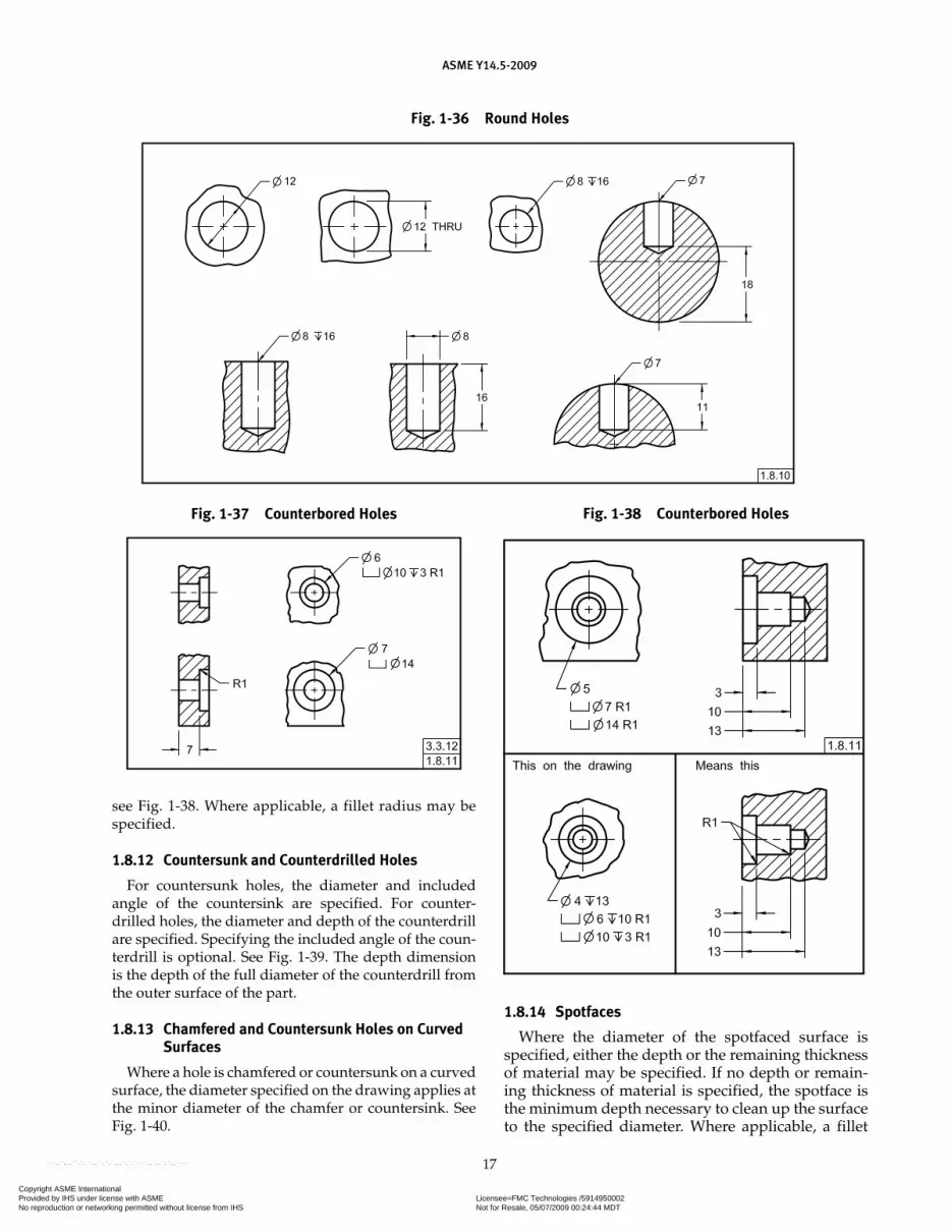
ASME Y14.5-2009
17
see Fig. 1-38. Where applicable, a fillet radius may be specified.
1.8.12 Countersunk and Counterdrilled Holes
For countersunk holes, the diameter and included angle of the countersink are specified. For counter-drilled holes, the diameter and depth of the counterdrill are specified. Specifying the included angle of the coun-terdrill is optional. See Fig. 1-39. The depth dimension is the depth of the full diameter of the counterdrill from the outer surface of the part.
1.8.13 Chamfered and Countersunk Holes on Curved Surfaces
Where a hole is chamfered or countersunk on a curved surface, the diameter specified on the drawing applies at the minor diameter of the chamfer or countersink. See Fig. 1-40.
1.8.14 Spotfaces
Where the diameter of the spotfaced surface is specified, either the depth or the remaining thickness of material may be specified. If no depth or remain-ing thickness of material is specified, the spotface is the minimum depth necessary to clean up the surface to the specified diameter. Where applicable, a fillet
Fig. 1-36 Round Holes
Fig. 1-37 Counterbored Holes Fig. 1-38 Counterbored Holes
Copyright ASME International Provided by IHS under license with ASME Licensee=FMC Technologies /5914950002
Not for Resale, 05/07/2009 00:24:44 MDTNo reproduction or networking permitted without license from IHS
--`,,`,,,``,`,``,,``,`,`,,,`,`,`-`-`,,`,,`,`,,`---

ASME Y14.5-2009
18
Fig. 1-39 Countersunk and Counterdrilled Holes
Fig. 1-40 Countersink on a Curved Surface
radius may be indicated for the spotface. In some cases, such as with a through hole, a notation may be necessary to indicate the surface to be spotfaced. See Fig. 1-41. A spotface may be specified by note only and need not be shown pictorially.
1.8.15 Machining Centers
Where machining centers are to remain on the fin-ished part, they are indicated by a note or dimensioned on the drawing. See ASME B94.11M.
Copyright ASME International Provided by IHS under license with ASME Licensee=FMC Technologies /5914950002
Not for Resale, 05/07/2009 00:24:44 MDTNo reproduction or networking permitted without license from IHS
--`,,`,,,``,`,``,,``,`,`,,,`,`,`-`-`,,`,,`,`,,`---
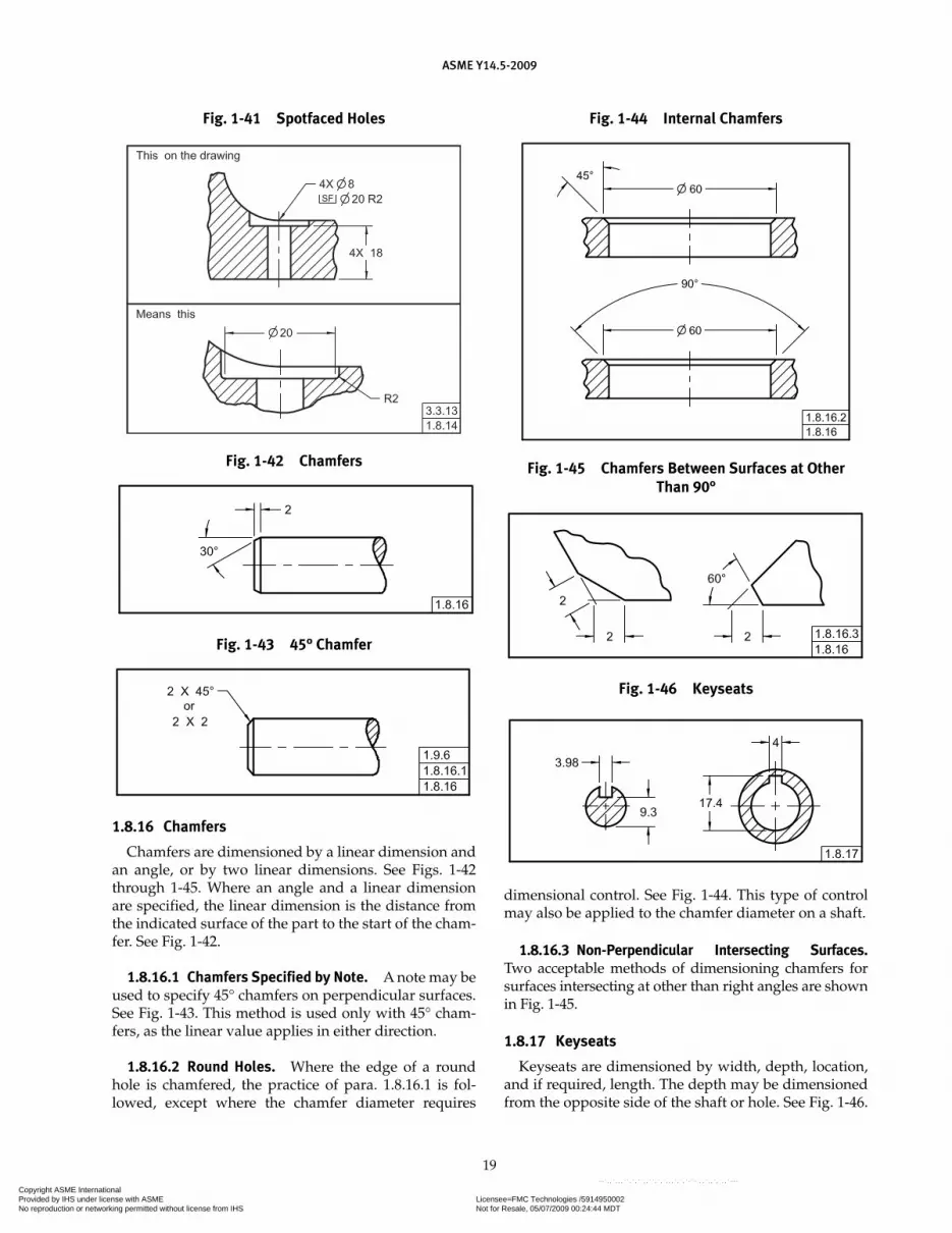
ASME Y14.5-2009
19
1.8.16 Chamfers
Chamfers are dimensioned by a linear dimension and an angle, or by two linear dimensions. See Figs. 1-42 through 1-45. Where an angle and a linear dimension are specified, the linear dimension is the distance from the indicated surface of the part to the start of the cham-fer. See Fig. 1-42.
1.8.16.1 Chamfers Specified by Note. A note may be used to specify 45° chamfers on perpendicular surfaces. See Fig. 1-43. This method is used only with 45° cham-fers, as the linear value applies in either direction.
1.8.16.2 Round Holes. Where the edge of a round hole is chamfered, the practice of para. 1.8.16.1 is fol-lowed, except where the chamfer diameter requires
dimensional control. See Fig. 1-44. This type of control may also be applied to the chamfer diameter on a shaft.
1.8.16.3 Non-Perpendicular Intersecting Surfaces. Two acceptable methods of dimensioning chamfers for surfaces intersecting at other than right angles are shown in Fig. 1-45.
1.8.17 Keyseats
Keyseats are dimensioned by width, depth, location, and if required, length. The depth may be dimensioned from the opposite side of the shaft or hole. See Fig. 1-46.
Fig. 1-41 Spotfaced Holes
Fig. 1-42 Chamfers
Fig. 1-43 45° Chamfer
Fig. 1-45 Chamfers Between Surfaces at Other Than 90°
Fig. 1-44 Internal Chamfers
Fig. 1-46 Keyseats
Copyright ASME International Provided by IHS under license with ASME Licensee=FMC Technologies /5914950002
Not for Resale, 05/07/2009 00:24:44 MDTNo reproduction or networking permitted without license from IHS
--`,,`,,,``,`,``,,``,`,`,,,`,`,`-`-`,,`,,`,`,,`---

ASME Y14.5-2009
20
1.8.18 Knurling
Knurling is specified in terms of type, pitch, and diameter before and after knurling. Where control is not required, the diameter after knurling is omitted. Where only a portion of a feature requires knurling, the location and length of the knurl shall be specified. See Fig. 1-47.
1.8.18.1 Knurling for Press Fit. Where required to provide a press fit between parts, knurling is speci-fied by a note that includes the type of knurl required, its pitch, the toleranced diameter of the feature before knurling, and the minimum acceptable diameter after knurling. See Fig. 1-48.
1.8.18.2 Knurling Standard. For information on inch knurling, see ANSI/ASME B94.6.
1.8.19 Rods and Tubing Details
Rods and tubing may be dimensioned in three coor-dinate directions and toleranced using geometric toler-ances or by specifying the straight lengths, bend radii, angles of bend, and angles of twist for all portions of each feature. This may be done by means of auxiliary views, tabulation, or supplementary data.
1.8.20 Screw Threads
Methods of specifying and dimensioning screw threads are covered in ASME Y14.6.
1.8.21 Surface Texture
Methods of specifying surface texture requirements are covered in ASME Y14.36M. For additional informa-tion, see ASME B46.1.
1.8.22 Involute Splines
Methods of specifying involute spline requirements are covered in the ANSI B92 series of standards.
1.8.23 Castings, Forgings, and Molded Parts
Methods of specifying requirements peculiar to cast-ings, forgings, and molded parts are covered in ASME Y14.8.
1.9 LOCATION OF FEATURES
Rectangular coordinate or polar coordinate dimen-sions locate features with respect to one another, and as a group or individually, from a datum or an origin. The features that establish this datum or origin must be iden-tified. See para. 7.2.1.3. Round holes or other features of symmetrical contour are located by giving distances, or distances and directions, to the feature centers.
1.9.1 Rectangular Coordinate Dimensioning
Where rectangular coordinate dimensioning is used to locate features, linear dimensions specify distances in coordinate directions from two or three mutually perpendicular planes. See Fig. 1-49. Coordinate dimen-sioning must clearly indicate which features of the part establish these planes. For methods to accomplish this, see Figs. 4-2 and 4-8.
1.9.2 Rectangular Coordinate Dimensioning Without Dimension Lines
Dimensions may be shown on extension lines without the use of dimension lines or arrowheads. The base lines are indicated as zero coordinates. See Fig. 1-50.
1.9.3 Tabular Dimensioning
Tabular dimensioning is a type of rectangular coordinate dimensioning in which dimensions from mutually perpendicular planes are listed in a table on the drawing, rather than on the pictorial delineation. See Fig. 1-51. Tables are prepared in any suitable manner that adequately locates the features.
Fig. 1-47 Knurls Fig. 1-48 Knurls for Press Fits
Copyright ASME International Provided by IHS under license with ASME Licensee=FMC Technologies /5914950002
Not for Resale, 05/07/2009 00:24:44 MDTNo reproduction or networking permitted without license from IHS
--`,,`,,,``,`,``,,``,`,`,,,`,`,`-`-`,,`,,`,`,,`---
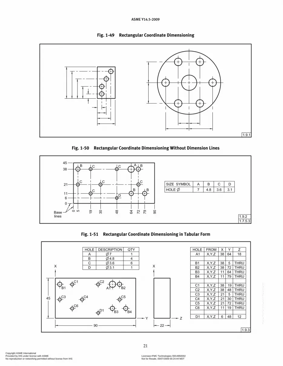
ASME Y14.5-2009
21
Fig. 1-49 Rectangular Coordinate Dimensioning
Fig. 1-50 Rectangular Coordinate Dimensioning Without Dimension Lines
Fig. 1-51 Rectangular Coordinate Dimensioning in Tabular Form
Copyright ASME International Provided by IHS under license with ASME Licensee=FMC Technologies /5914950002
Not for Resale, 05/07/2009 00:24:44 MDTNo reproduction or networking permitted without license from IHS
--`,,`,,,``,`,``,,``,`,`,,,`,`,`-`-`,,`,,`,`,,`---

ASME Y14.5-2009
22
1.9.4 Polar Coordinate Dimensioning
Where polar coordinate dimensioning is used to locate features, a linear and an angular dimension specifies a distance from a fixed point at an angular direction from two or three mutually perpendicular planes. The fixed point is the intersection of these planes. See Fig. 1-52.
1.9.5 Repetitive Features or Dimensions
Repetitive features or dimensions may be specified by the use of an X in conjunction with a numeral to indicate the “number of places” required. See Figs. 1-53 through 1-57. Where used with a basic dimension, the X may be placed either inside or outside the basic dimension frame.
Fig. 1-52 Polar Coordinate Dimensioning
Fig. 1-53 Repetitive Features
Fig. 1-54 Repetitive Features
Fig. 1-55 Repetitive Features and Dimensions
Fig. 1-57 Repetitive Features and Dimensions
Fig. 1-56 Repetitive Features and Dimensions
Copyright ASME International Provided by IHS under license with ASME Licensee=FMC Technologies /5914950002
Not for Resale, 05/07/2009 00:24:44 MDTNo reproduction or networking permitted without license from IHS
--`,,`,,,``,`,``,,``,`,`,,,`,`,`-`-`,,`,,`,`,,`---

ASME Y14.5-2009
23
A space is used between the X and the dimension. See Figs. 4-39 and 7-16.
1.9.5.1 Series and Patterns. Features, such as holes and slots, which are repeated in a series or pattern, may be specified by giving the required number of features and an X followed by the size dimension of the feature. A space is used between the X and the dimension. See Figs. 1-53 through 1-57.
1.9.5.2 Spacing. Equal spacing of features in a series or pattern may be specified by giving the required number of spaces and an X, followed by the applica-ble dimension. A space is used between the X and the
dimension. See Figs. 1-55 through 1-57. Where it is dif-ficult to distinguish between the dimension and the number of spaces, as in Fig. 1-55, one space may be dimensioned and identified as reference.
1.9.6 Use of X to Indicate “By”
An X may be used to indicate “by” between coordi-nate dimensions as shown in Fig. 1-43. In such cases, the X shall be preceded and followed by one character space.
NOTE: Where the practices described in paras. 1.9.5 and 1.9.6 are used on the same drawing; care must be taken to be sure each usage is clear.
Copyright ASME International Provided by IHS under license with ASME Licensee=FMC Technologies /5914950002
Not for Resale, 05/07/2009 00:24:44 MDTNo reproduction or networking permitted without license from IHS
--`,,`,,,``,`,``,,``,`,`,,,`,`,`-`-`,,`,,`,`,,`---
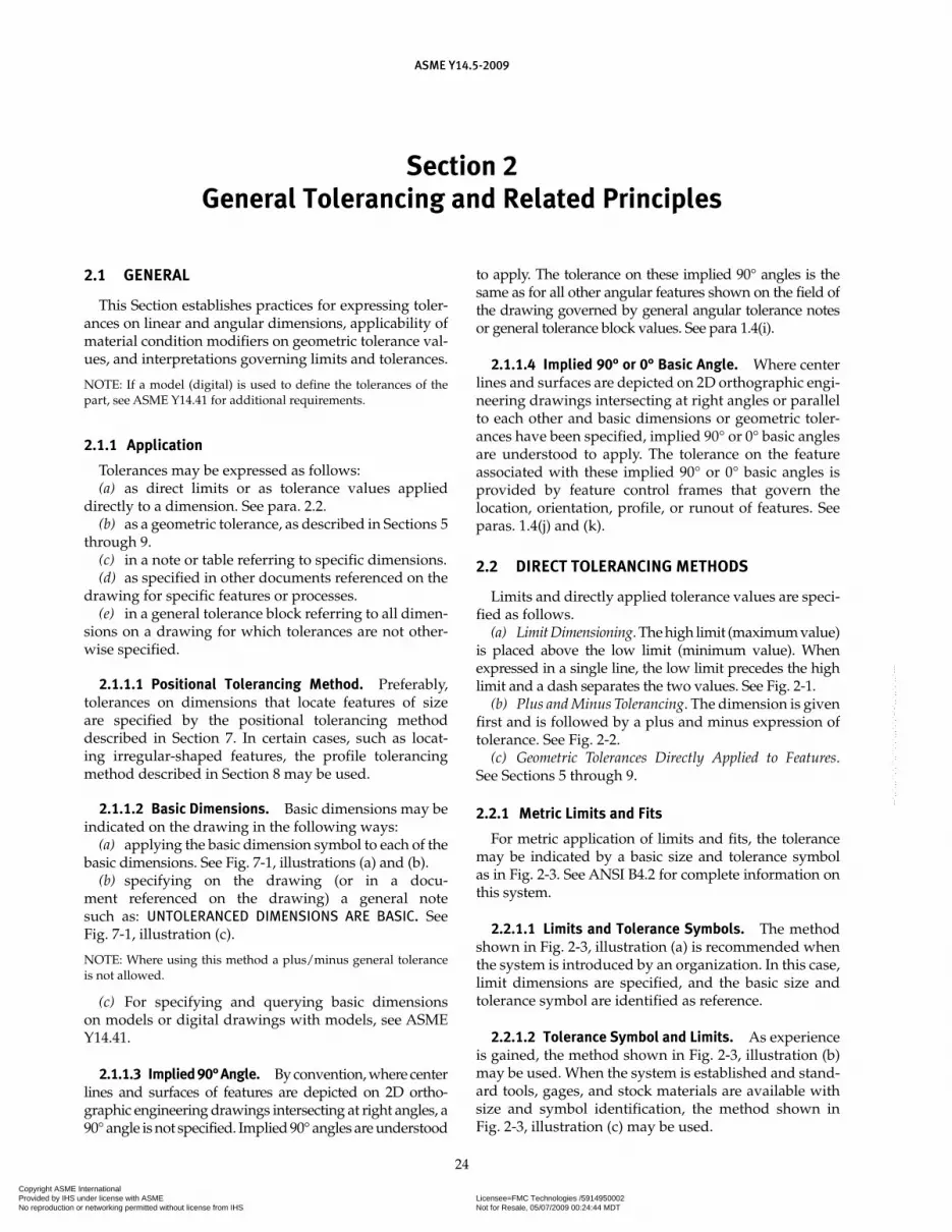
Section 2General Tolerancing and Related Principles
ASME Y14.5-2009
24
2.1 GENERAL
This Section establishes practices for expressing toler-ances on linear and angular dimensions, applicability of material condition modifiers on geometric tolerance val-ues, and interpretations governing limits and tolerances.
NOTE: If a model (digital) is used to define the tolerances of the part, see ASME Y14.41 for additional requirements.
2.1.1 Application
Tolerances may be expressed as follows:(a) as direct limits or as tolerance values applied
directly to a dimension. See para. 2.2.(b) as a geometric tolerance, as described in Sections 5
through 9.(c) in a note or table referring to specific dimensions.(d) as specified in other documents referenced on the
drawing for specific features or processes.(e) in a general tolerance block referring to all dimen-
sions on a drawing for which tolerances are not other-wise specified.
2.1.1.1 Positional Tolerancing Method. Preferably, tolerances on dimensions that locate features of size are specified by the positional tolerancing method described in Section 7. In certain cases, such as locat-ing irregular-shaped features, the profile tolerancing method described in Section 8 may be used.
2.1.1.2 Basic Dimensions. Basic dimensions may be indicated on the drawing in the following ways:
(a) applying the basic dimension symbol to each of the basic dimensions. See Fig. 7-1, illustrations (a) and (b).
(b) specifying on the drawing (or in a docu-ment referenced on the drawing) a general note such as: UNTOLERANCED DIMENSIONS ARE BASIC. See Fig. 7-1, illustration (c).
NOTE: Where using this method a plus/minus general tolerance is not allowed.
(c) For specifying and querying basic dimensions on models or digital drawings with models, see ASME Y14.41.
2.1.1.3 Implied 90° Angle. By convention, where center lines and surfaces of features are depicted on 2D ortho-graphic engineering drawings intersecting at right angles, a 90° angle is not specified. Implied 90° angles are understood
to apply. The tolerance on these implied 90° angles is the same as for all other angular features shown on the field of the drawing governed by general angular tolerance notes or general tolerance block values. See para 1.4(i).
2.1.1.4 Implied 90° or 0° Basic Angle. Where center lines and surfaces are depicted on 2D orthographic engi-neering drawings intersecting at right angles or parallel to each other and basic dimensions or geometric toler-ances have been specified, implied 90° or 0° basic angles are understood to apply. The tolerance on the feature associated with these implied 90° or 0° basic angles is provided by feature control frames that govern the location, orientation, profile, or runout of features. See paras. 1.4(j) and (k).
2.2 DIRECT TOLERANCING METHODS
Limits and directly applied tolerance values are speci-fied as follows.
(a) Limit Dimensioning. The high limit (maximum value) is placed above the low limit (minimum value). When expressed in a single line, the low limit precedes the high limit and a dash separates the two values. See Fig. 2-1.
(b) Plus and Minus Tolerancing. The dimension is given first and is followed by a plus and minus expression of tolerance. See Fig. 2-2.
(c) Geometric Tolerances Directly Applied to Features. See Sections 5 through 9.
2.2.1 Metric Limits and Fits
For metric application of limits and fits, the tolerance may be indicated by a basic size and tolerance symbol as in Fig. 2-3. See ANSI B4.2 for complete information on this system.
2.2.1.1 Limits and Tolerance Symbols. The method shown in Fig. 2-3, illustration (a) is recommended when the system is introduced by an organization. In this case, limit dimensions are specified, and the basic size and tolerance symbol are identified as reference.
2.2.1.2 Tolerance Symbol and Limits. As experience is gained, the method shown in Fig. 2-3, illustration (b) may be used. When the system is established and stand-ard tools, gages, and stock materials are available with size and symbol identification, the method shown in Fig. 2-3, illustration (c) may be used.
Copyright ASME International Provided by IHS under license with ASME Licensee=FMC Technologies /5914950002
Not for Resale, 05/07/2009 00:24:44 MDTNo reproduction or networking permitted without license from IHS
--`,,`,,,``,`,``,,``,`,`,,,`,`,`-`-`,,`,,`,`,,`---

ASME Y14.5-2009
25
Fig. 2-2 Plus and Minus Tolerancing
Fig. 2-3 Indicating Symbols for Metric Limits and Fits
2.3 TOLERANCE EXPRESSION
The conventions shown in the following paragraphs shall be observed pertaining to the number of decimal places carried in the tolerance.
2.3.1 Millimeter Tolerances
Where millimeter dimensions are used on the draw-ings, the following apply.
(a) Where unilateral tolerancing is used and either the plus or minus value is nil, a single zero is shown without a plus or minus sign. In this example the 32 value is the nominal size.
EXAMPLE:
320
or 32�0.02
�0.02 0
(b) Where bilateral tolerancing is used, both the plus and minus values have the same number of decimal places, using zeros where necessary. In this example the 32 value is the nominal size.
EXAMPLE:
32�0.25
not 32�0.25
�0.10 �0.1
(c) Where limit dimensioning is used and either the maximum or minimum value has digits following
Fig. 2-1 Limit Dimensioning
Copyright ASME International Provided by IHS under license with ASME Licensee=FMC Technologies /5914950002
Not for Resale, 05/07/2009 00:24:44 MDTNo reproduction or networking permitted without license from IHS
--`,,`,,,``,`,``,,``,`,`,,,`,`,`-`-`,,`,,`,`,,`---

ASME Y14.5-2009
26
a decimal point, the other value has zeros added for uniformity.
EXAMPLE:
25.45not
25.45
25.00 25
(d) Where basic dimensions are used, associated tol-erances contain the number of decimal places necessary for control. The basic dimension value observes the practices of para. 1.6.1.
EXAMPLE:
2.3.2 Inch Tolerances
Where inch dimensions are used on the drawing, the following apply:
(a) Where unilateral tolerancing is used and either the plus or minus value is nil, its dimension shall be expressed with the same number of decimal places, and the appropriate plus or minus sign.
EXAMPLE:
.500�.005
not .500�.005
�.000 0
(b) Where bilateral tolerancing is used, both the plus and minus values and the dimension have the same number of decimal places.
EXAMPLE:
.500 � .005 not .50 � .005
(c) Where limit dimensioning is used and either the maximum or minimum value has digits following a deci-mal point, the other value has zeros added for uniformity.
EXAMPLE:
.750not
.75
.748 .748
(d) Where basic dimensions are used, associated tolerances contain the number of decimal places neces-sary for control. There is no requirement for the basic dimension value to be expressed with the same number of decimal places as the tolerance.
EXAMPLE:
2.3.3 Angle Tolerances
Where angle dimensions are used, both the plus and minus values and the angle have the same number of decimal places.
EXAMPLE:
25.0� � 0.2� not 25� � .2�
25� � 0�30' not 25� � 30'
2.4 INTERPRETATION OF LIMITS
All limits are absolute. Dimensional limits, regardless of the number of decimal places, are used as if they were continued with zeros.
EXAMPLES:
12.2 means 12.20 . . . 0
12.0 means 12.00 . . . 0
12.01 means 12.010 . . . 0
2.4.1 Plated or Coated Parts
Where a part is to be plated or coated, the drawing or referenced document shall specify whether the dimen-sions apply before or after plating. Typical examples of notes are the following:
(a) “DIMENSIONAL LIMITS APPLY AFTER PLATING.”(b) “DIMENSIONAL LIMITS APPLY BEFORE PLATING.”(For processes other than plating, substitute the
appropriate term.)
2.5 SINGLE LIMITS
MIN or MAX is placed after a dimension where other elements of the design definitely determine the other unspecified limit. Features, such as depths of holes, lengths of threads, corner radii, chamfers, etc., may be limited in this way. Single limits are used where the intent will be clear, and the unspecified limit can be zero or approach infinity and will not result in a condition detrimental to the design.
2.6 TOLERANCE ACCUMULATION
Figure 2-4 compares the tolerance values resulting from the following three methods of dimensioning.
Copyright ASME International Provided by IHS under license with ASME Licensee=FMC Technologies /5914950002
Not for Resale, 05/07/2009 00:24:44 MDTNo reproduction or networking permitted without license from IHS
--`,,`,,,``,`,``,,``,`,`,,,`,`,`-`-`,,`,,`,`,,`---

ASME Y14.5-2009
27
(a) Chain Dimensioning. The maximum variation between two features is equal to the sum of the tolerances on the intermediate distances; this results in the greatest tolerance accumulation. In Fig. 2-4, illustration (a), the tol-erance accumulation between surfaces X and Y is �0.15.
(b) Base Line Dimensioning. The maximum vari-ation between two features is equal to the sum of the tolerances on the two dimensions from their origin to the features; this results in a reduction of the tolerance accumulation. In Fig. 2-4, illustration (b), the tolerance accumulation between surfaces X and Y is ±0.1.
(c) Direct Dimensioning. The maximum variation between two features is controlled by the tolerance on the dimension between the features; this results in the least tolerance. In Fig. 2-4, illustration (c), the tolerance between surfaces X and Y is ±0.05.
NOTE: When basic dimensions are used, there is no accumula-tion of tolerances. A geometric tolerance is required to create the tolerance zone. In this case, the style of dimensioning (chain,
baseline, direct) is up to the discretion of the user. Locating features using directly toleranced dimensions is not recommended.
2.6.1 Dimensional Limits Related to an Origin
In certain cases, it is necessary to indicate that a dimen-sion between two features shall originate from one of these features and not the other. The high points of the surface indicated as the origin define a plane for meas-urement. The dimensions related to the origin are taken from the plane or axis and define a zone within which the other features must lie. This concept does not estab-lish a datum reference frame as described in Section 4. Such a case is illustrated in Fig. 2-5, where a part having two parallel surfaces of unequal length is to be mounted on the shorter surface. In this example, the dimension origin symbol described in para. 3.3.17 signifies that the dimension originates from the plane established by the shorter surface and dimensional limits apply to the other surface. Without such indication, the longer sur-face could have been selected as the origin, thus permit-ting a greater angular variation between surfaces.
2.7 LIMITS OF SIZE
Unless otherwise specified, the limits of size of a fea-ture prescribe the extent within which variations of geo-metric form, as well as size, are allowed. This control applies solely to individual regular features of size as
Fig. 2-4 Tolerance Accumulation Fig. 2-5 Relating Dimensional Limits to an Origin
Copyright ASME International Provided by IHS under license with ASME Licensee=FMC Technologies /5914950002
Not for Resale, 05/07/2009 00:24:44 MDTNo reproduction or networking permitted without license from IHS
--`,,`,,,``,`,``,,``,`,`,,,`,`,`-`-`,,`,,`,`,,`---

ASME Y14.5-2009
28
defined in para. 1.3.32.1. The actual local size of an indi-vidual feature at each cross section shall be within the specified tolerance of size.
2.7.1 Variations of Form (Rule #1: Envelope Principle)
The form of an individual regular feature of size is controlled by its limits of size to the extent prescribed in the following paragraphs and illustrated in Fig. 2-6.
(a) The surface or surfaces of a regular feature of size shall not extend beyond a boundary (envelope) of per-fect form at MMC. This boundary is the true geometric form represented by the drawing. No variation in form is permitted if the regular feature of size is produced at its MMC limit of size unless a straightness or flatness tolerance is associated with the size dimension or the Independency symbol is applied per para. 2.7.3. See Fig. 2-7.
(b) Where the actual local size of a regular feature of size has departed from MMC toward LMC, a local variation in form is allowed equal to the amount of such departure.
(c) Where is no default requirement for a boundary of perfect form at LMC. Thus, a regular feature of size produced at its LMC limit of size is permitted to vary
from true form to the maximum variation allowed by the boundary of perfect form at MMC.
(d) In cases where a geometric tolerance is specified to apply at LMC, perfect form at LMC is required. See para. 7.3.5.
2.7.2 Form Control Does Not Apply (Exceptions to Rule #1)
The control of geometric form prescribed by limits of size does not apply to the following:
(a) stock, such as bars, sheets, tubing, structural shapes, and other items produced to established indus-try or government standards that prescribe limits for straightness, flatness, and other geometric character-istics. Unless geometric tolerances are specified on the drawing of a part made from these items, standards for these items govern the surfaces that remain in the as-furnished condition on the finished part.
(b) parts subject to free-state variation in the unre-strained condition. See para. 5.5.
2.7.3 Perfect Form at MMC Not Required
Where perfect form at MMC is not required, the Independency symbol may be placed next to the appropri-ate dimension or notation. See Fig. 3-11 and para. 3.3.24.
CAUTION: Without a supplementary form control, the feature form is entirely uncontrolled. See Fig. 2-7.
2.7.4 Relationship Between Individual Features
The limits of size do not control the orientation or location relationship between individual features. Features shown perpendicular, coaxial, or symmetrical
Fig. 2-6 Extreme Variations of Form Allowed by a Size Tolerance
Fig. 2-7 Independency and Flatness Application
Copyright ASME International Provided by IHS under license with ASME Licensee=FMC Technologies /5914950002
Not for Resale, 05/07/2009 00:24:44 MDTNo reproduction or networking permitted without license from IHS
--`,,`,,,``,`,``,,``,`,`,,,`,`,`-`-`,,`,,`,`,,`---
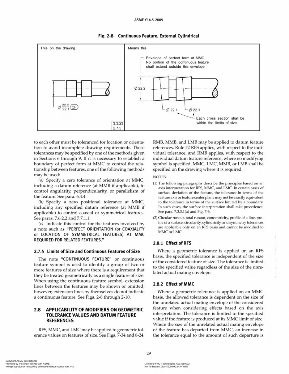
ASME Y14.5-2009
29
to each other must be toleranced for location or orienta-tion to avoid incomplete drawing requirements. These tolerances may be specified by one of the methods given in Sections 6 through 9. If it is necessary to establish a boundary of perfect form at MMC to control the rela-tionship between features, one of the following methods may be used:
(a) Specify a zero tolerance of orientation at MMC, including a datum reference (at MMB if applicable), to control angularity, perpendicularity, or parallelism of the feature. See para. 6.4.4.
(b) Specify a zero positional tolerance at MMC, including any specified datum reference (at MMB if applicable) to control coaxial or symmetrical features. See paras. 7.6.2.2 and 7.7.1.1.
(c) Indicate this control for the features involved by a note such as “PERFECT ORIENTATION (or COAXIALITY or LOCATION OF SYMMETRICAL FEATURES) AT MMC REQUIRED FOR RELATED FEATURES.”
2.7.5 Limits of Size and Continuous Features of Size
The note “CONTINUOUS FEATURE” or continuous feature symbol is used to identify a group of two or more features of size where there is a requirement that they be treated geometrically as a single feature of size. When using the continuous feature symbol, extension lines between the features may be shown or omitted; however, extension lines by themselves do not indicate a continuous feature. See Figs. 2-8 through 2-10.
2.8 APPLICABILITY OF MODIFIERS ON GEOMETRIC TOLERANCE VALUES AND DATUM FEATURE REFERENCES
RFS, MMC, and LMC may be applied to geometric tol-erance values on features of size. See Figs. 7-34 and 8-24.
RMB, MMB, and LMB may be applied to datum feature references. Rule #2 RFS applies, with respect to the indi-vidual tolerance, and RMB applies, with respect to the individual datum feature reference, where no modifying symbol is specified. MMC, LMC, MMB, or LMB shall be specified on the drawing where it is required.
NOTES:
(1) The following paragraphs describe the principles based on an axis interpretation for RFS, MMC, and LMC. In certain cases of surface deviation of the feature, the tolerance in terms of the feature axis or feature center plane may not be exactly equivalent to the tolerance in terms of the surface limited by a boundary. In such cases, the surface interpretation shall take precedence. See para. 7.3.3.1(a) and Fig. 7-6.
(2) Circular runout, total runout, concentricity, profile of a line, pro-file of a surface, circularity, cylindricity, and symmetry tolerances are applicable only on an RFS basis and cannot be modified to MMC or LMC.
2.8.1 Effect of RFS
Where a geometric tolerance is applied on an RFS basis, the specified tolerance is independent of the size of the considered feature of size. The tolerance is limited to the specified value regardless of the size of the unre-lated actual mating envelope.
2.8.2 Effect of MMC
Where a geometric tolerance is applied on an MMC basis, the allowed tolerance is dependent on the size of the unrelated actual mating envelope of the considered feature when considering effects based on the axis interpretation. The tolerance is limited to the specified value if the feature is produced at its MMC limit of size. Where the size of the unrelated actual mating envelope of the feature has departed from MMC, an increase in the tolerance equal to the amount of such departure is
Fig. 2-8 Continuous Feature, External Cylindrical
Copyright ASME International Provided by IHS under license with ASME Licensee=FMC Technologies /5914950002
Not for Resale, 05/07/2009 00:24:44 MDTNo reproduction or networking permitted without license from IHS
--`,,`,,,``,`,``,,``,`,`,,,`,`,`-`-`,,`,,`,`,,`---

ASME Y14.5-2009
30
Fig. 2-9 Continuous Feature, Internal Cylindrical
Fig. 2-10 Continuous Feature, External Width
allowed. The total permissible variation in the specified geometric characteristic is maximum when the feature is at LMC, unless a maximum is specified.
2.8.3 Effect of Zero Tolerance at MMC
Where a tolerance of position or orientation is applied on a zero tolerance at MMC basis, the tolerance is totally dependent on the size of the unrelated actual mating envelope of the considered feature. No tolerance of posi-tion or orientation is allowed if the feature is produced at its MMC limit of size; and in this case, it must be located at true position or be perfect in orientation, as applicable. Where the size of the unrelated actual mating envelope of the considered feature has departed from MMC, a tol-erance equal to the amount of such departure is allowed. The total permissible variation in position or orientation
is maximum when the feature is at LMC, unless a maxi-mum is specified. See Figs. 6-14 and 6-15.
2.8.4 Effect of LMC
Where a geometric tolerance is applied on an LMC basis, perfect form at LMC is required. Perfect form at MMC is not required. This is the reciprocal of the MMC concept. See Fig. 2-11. Where a geometric toler-ance is applied on an LMC basis, the allowed tolerance is dependent on the unrelated actual minimum material envelope of the considered feature. The tolerance is lim-ited to the specified value if the feature is produced at its LMC limit of size. Where the unrelated actual minimum material envelope of the feature has departed from LMC, an increase in the tolerance equal to the amount of such departure is allowed. The total permissible variation
Copyright ASME International Provided by IHS under license with ASME Licensee=FMC Technologies /5914950002
Not for Resale, 05/07/2009 00:24:44 MDTNo reproduction or networking permitted without license from IHS
--`,,`,,,``,`,``,,``,`,`,,,`,`,`-`-`,,`,,`,`,,`---
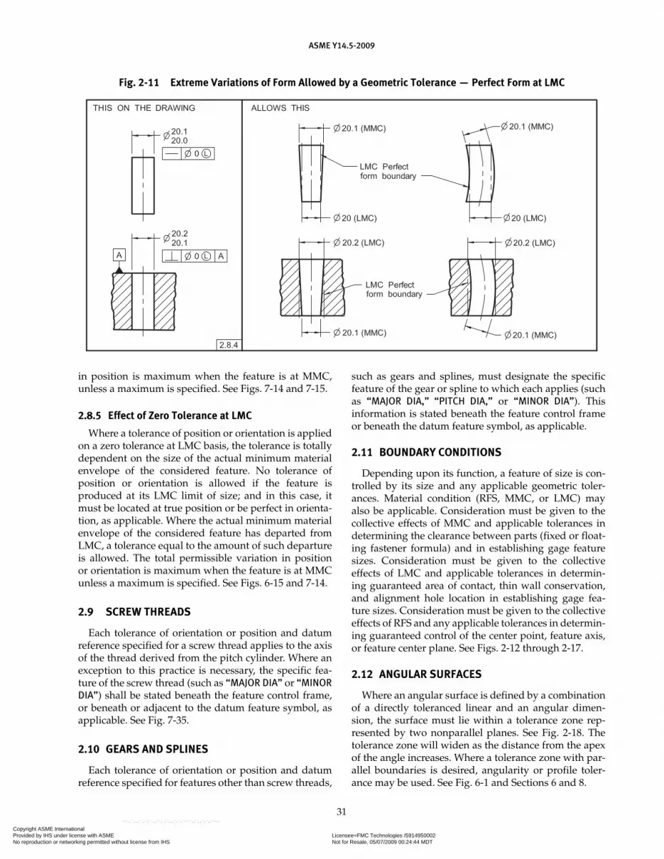
ASME Y14.5-2009
31
in position is maximum when the feature is at MMC, unless a maximum is specified. See Figs. 7-14 and 7-15.
2.8.5 Effect of Zero Tolerance at LMC
Where a tolerance of position or orientation is applied on a zero tolerance at LMC basis, the tolerance is totally dependent on the size of the actual minimum material envelope of the considered feature. No tolerance of position or orientation is allowed if the feature is produced at its LMC limit of size; and in this case, it must be located at true position or be perfect in orienta-tion, as applicable. Where the actual minimum material envelope of the considered feature has departed from LMC, a tolerance equal to the amount of such departure is allowed. The total permissible variation in position or orientation is maximum when the feature is at MMC unless a maximum is specified. See Figs. 6-15 and 7-14.
2.9 SCREW THREADS
Each tolerance of orientation or position and datum reference specified for a screw thread applies to the axis of the thread derived from the pitch cylinder. Where an exception to this practice is necessary, the specific fea-ture of the screw thread (such as “MAJOR DIA” or “MINOR DIA”) shall be stated beneath the feature control frame, or beneath or adjacent to the datum feature symbol, as applicable. See Fig. 7-35.
2.10 GEARS AND SPLINES
Each tolerance of orientation or position and datum reference specified for features other than screw threads,
such as gears and splines, must designate the specific feature of the gear or spline to which each applies (such as “MAJOR DIA,” “PITCH DIA,” or “MINOR DIA”). This information is stated beneath the feature control frame or beneath the datum feature symbol, as applicable.
2.11 BOUNDARY CONDITIONS
Depending upon its function, a feature of size is con-trolled by its size and any applicable geometric toler-ances. Material condition (RFS, MMC, or LMC) may also be applicable. Consideration must be given to the collective effects of MMC and applicable tolerances in determining the clearance between parts (fixed or float-ing fastener formula) and in establishing gage feature sizes. Consideration must be given to the collective effects of LMC and applicable tolerances in determin-ing guaranteed area of contact, thin wall conservation, and alignment hole location in establishing gage fea-ture sizes. Consideration must be given to the collective effects of RFS and any applicable tolerances in determin-ing guaranteed control of the center point, feature axis, or feature center plane. See Figs. 2-12 through 2-17.
2.12 ANGULAR SURFACES
Where an angular surface is defined by a combination of a directly toleranced linear and an angular dimen-sion, the surface must lie within a tolerance zone rep-resented by two nonparallel planes. See Fig. 2-18. The tolerance zone will widen as the distance from the apex of the angle increases. Where a tolerance zone with par-allel boundaries is desired, angularity or profile toler-ance may be used. See Fig. 6-1 and Sections 6 and 8.
Fig. 2-11 Extreme Variations of Form Allowed by a Geometric Tolerance — Perfect Form at LMC
Copyright ASME International Provided by IHS under license with ASME Licensee=FMC Technologies /5914950002
Not for Resale, 05/07/2009 00:24:44 MDTNo reproduction or networking permitted without license from IHS
--`,,`,,,``,`,``,,``,`,`,,,`,`,`-`-`,,`,,`,`,,`---

ASME Y14.5-2009
32
Fig. 2-12 Virtual and Resultant Condition Boundaries Using MMC Concept — Internal Feature
Fig. 2-13 Virtual and Resultant Condition Boundaries Using LMC Concept — Internal Feature
Copyright ASME International Provided by IHS under license with ASME Licensee=FMC Technologies /5914950002
Not for Resale, 05/07/2009 00:24:44 MDTNo reproduction or networking permitted without license from IHS
--`,,`,,,``,`,``,,``,`,`,,,`,`,`-`-`,,`,,`,`,,`---

ASME Y14.5-2009
33
Fig. 2-14 Inner and Outer Boundaries Using RFS Concept — Internal Feature
Fig. 2-15 Virtual and Resultant Condition Boundaries Using MMC Concept — External Feature
Copyright ASME International Provided by IHS under license with ASME Licensee=FMC Technologies /5914950002
Not for Resale, 05/07/2009 00:24:44 MDTNo reproduction or networking permitted without license from IHS
--`,,`,,,``,`,``,,``,`,`,,,`,`,`-`-`,,`,,`,`,,`---
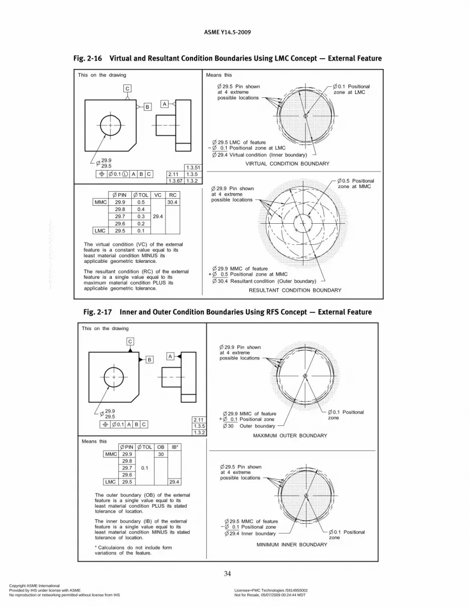
ASME Y14.5-2009
34
Fig. 2-16 Virtual and Resultant Condition Boundaries Using LMC Concept — External Feature
Fig. 2-17 Inner and Outer Condition Boundaries Using RFS Concept — External Feature
Copyright ASME International Provided by IHS under license with ASME Licensee=FMC Technologies /5914950002
Not for Resale, 05/07/2009 00:24:44 MDTNo reproduction or networking permitted without license from IHS
--`,,`,,,``,`,``,,``,`,`,,,`,`,`-`-`,,`,,`,`,,`---
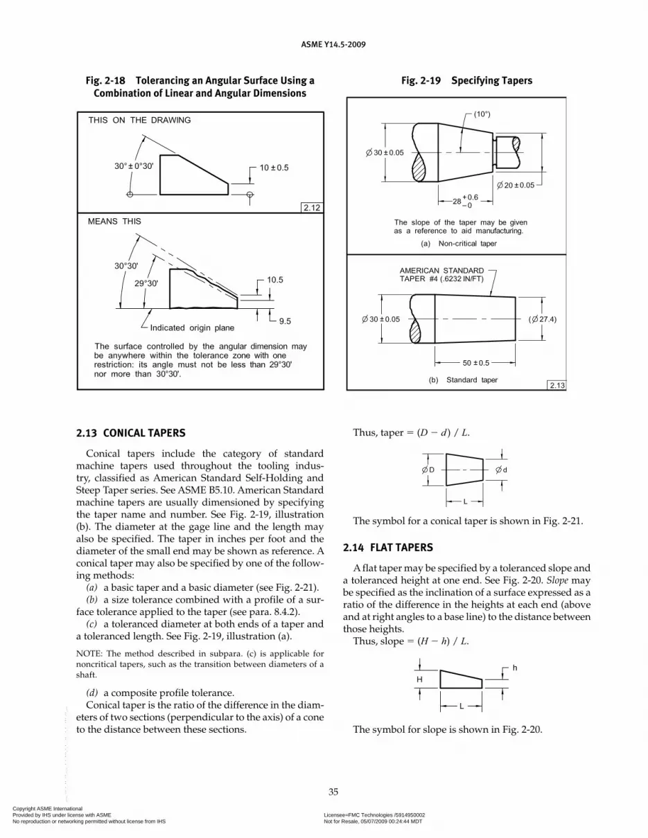
ASME Y14.5-2009
35
Fig. 2-18 Tolerancing an Angular Surface Using a Combination of Linear and Angular Dimensions
Fig. 2-19 Specifying Tapers
2.13 CONICAL TAPERS
Conical tapers include the category of standard machine tapers used throughout the tooling indus-try, classified as American Standard Self-Holding and Steep Taper series. See ASME B5.10. American Standard machine tapers are usually dimensioned by specifying the taper name and number. See Fig. 2-19, illustration (b). The diameter at the gage line and the length may also be specified. The taper in inches per foot and the diameter of the small end may be shown as reference. A conical taper may also be specified by one of the follow-ing methods:
(a) a basic taper and a basic diameter (see Fig. 2-21).(b) a size tolerance combined with a profile of a sur-
face tolerance applied to the taper (see para. 8.4.2).(c) a toleranced diameter at both ends of a taper and
a toleranced length. See Fig. 2-19, illustration (a).
NOTE: The method described in subpara. (c) is applicable for noncritical tapers, such as the transition between diameters of a shaft.
(d) a composite profile tolerance.Conical taper is the ratio of the difference in the diam-
eters of two sections (perpendicular to the axis) of a cone to the distance between these sections.
Thus, taper � (D � d ) / L.
The symbol for a conical taper is shown in Fig. 2-21.
2.14 FLAT TAPERS
A flat taper may be specified by a toleranced slope and a toleranced height at one end. See Fig. 2-20. Slope may be specified as the inclination of a surface expressed as a ratio of the difference in the heights at each end (above and at right angles to a base line) to the distance between those heights.
Thus, slope � (H � h) / L.
The symbol for slope is shown in Fig. 2-20.
Copyright ASME International Provided by IHS under license with ASME Licensee=FMC Technologies /5914950002
Not for Resale, 05/07/2009 00:24:44 MDTNo reproduction or networking permitted without license from IHS
--`,,`,,,``,`,``,,``,`,`,,,`,`,`-`-`,,`,,`,`,,`---

ASME Y14.5-2009
36
2.15 RADIUS
A radius is any straight line extending from the center to the periphery of a circle or sphere.
2.15.1 Radius Tolerance
A radius symbol, R, creates a zone defined by two arcs (the minimum and maximum radii). The part surface must lie within this zone. See Fig. 2-22.
2.15.2 Controlled Radius Tolerance
A controlled radius symbol, CR, creates a tolerance zone defined by two arcs (the minimum and maximum
radii) that are tangent to the adjacent surfaces. Where a controlled radius is specified, the part contour within the crescent-shaped tolerance zone must be a fair curve without reversals. It is recommended that the CR be fur-ther defined with an engineering control specification. Additionally, radii taken at all points on the part contour shall neither be smaller than the specified minimum limit nor larger than the maximum limit. See Fig. 2-23. Where it is necessary to apply further restrictions to the part radius, they shall be specified on the drawing or in a document referenced on the drawing.
2.16 TANGENT PLANE
Where it is desired to control a tangent plane estab-lished by the contacting points of a surface, the tangent plane symbol shall be added in the feature control frame after the stated tolerance. See Fig. 6-18. If the tangent plane is unstable it may be optimized. See para. 4.11.2 and ASME Y14.5.1M.
2.17 STATISTICAL TOLERANCING
Statistical tolerancing is the assigning of tolerances to related components of an assembly on the basis of sound statistics (such as the assembly tolerance is equal to the square root of the sum of the squares of the individual tolerances).
2.17.1 Application to Assemblies
The tolerances assigned to component items of an assembly are determined by arithmetically dividing the
Fig. 2-20 Specifying a Flat Taper
Fig. 2-21 Specifying a Basic Taper and a Basic Diameter
Fig. 2-22 Specifying a Radius
Fig. 2-23 Specifying a Controlled Radius
Copyright ASME International Provided by IHS under license with ASME Licensee=FMC Technologies /5914950002
Not for Resale, 05/07/2009 00:24:44 MDTNo reproduction or networking permitted without license from IHS
--`,,`,,,``,`,``,,``,`,`,,,`,`,`-`-`,,`,,`,`,,`---

ASME Y14.5-2009
37
assembly tolerances among the individual components of the assembly. Where tolerances assigned by arithme-tic stacking are restrictive, statistical tolerancing may be used for increased individual feature tolerance. The increased tolerance may reduce manufacturing cost, but shall only be employed where the appropriate statistical process control will be used. For application see appro-priate statistics or engineering design manuals.
2.17.2 Identification
Statistical tolerances on dimensions are designated as illustrated in Figs. 2-24 through 2-26.
(a) A note such as the following shall be placed on the drawing: “FEATURES IDENTIFIED AS STATISTICALLY
TOLERANCED SHALL BE PRODUCED WITH STATISTICAL PROCESS CONTROLS.” See Fig. 2-24.
(b) It may be necessary to designate both the statisti-cal limits and the arithmetic stacking limits where the dimension has the possibility of being produced with-out statistical process control (SPC). A note such as the following shall be placed on the drawing: “FEATURES IDENTIFIED AS STATISTICALLY TOLERANCED SHALL BE PRODUCED WITH STATISTICAL PROCESS CONTROLS, OR TO THE MORE RESTRICTIVE ARITHMETIC LIMITS.” See Fig. 2-25.
CAUTION: Where using the statistical tolerancing symbol, the necessary statistical indices should be specified.
Fig. 2-24 Statistical Tolerancing
Fig. 2-25 Statistical Tolerancing With Arithmetic Limits
Fig. 2-26 Statistical Tolerancing With Geometric Controls
Copyright ASME International Provided by IHS under license with ASME Licensee=FMC Technologies /5914950002
Not for Resale, 05/07/2009 00:24:44 MDTNo reproduction or networking permitted without license from IHS
--`,,`,,,``,`,``,,``,`,`,,,`,`,`-`-`,,`,,`,`,,`---
Section 3Symbology
ASME Y14.5-2009
38
3.1 GENERAL
This Section establishes the symbols for specifying geometric characteristics and other dimensional require-ments on engineering drawings. Symbols shall be of suf-ficient clarity to meet the legibility and reproducibility requirements of ASME Y14.2M. Symbols shall be used only as described herein.
3.2 USE OF NOTES TO SUPPLEMENT SYMBOLS
Situations may arise where the desired geometric requirements cannot be completely conveyed by sym-bology. In such cases, a note may be used to describe the requirement, either separately or to supplement a geo-metric symbol. See Figs. 6-16, 6-17, and 7-54.
3.3 SYMBOL CONSTRUCTION
Information related to the construction, form, and proportion of individual symbols described herein is contained in Nonmandatory Appendix C.
3.3.1 Geometric Characteristic Symbols
The symbolic means of indicating geometric charac-teristics are shown in Fig. 3-1.
3.3.2 Datum Feature Symbol
The symbolic means of indicating a datum feature con-sists of a capital letter enclosed in a square or rectangular frame and a leader line extending from the frame to the feature, terminating with a triangle. The triangle may be filled or not filled. See Fig. 3-2. Letters of the alphabet (except I, O, and Q) shall be used as datum identifying letters. Each datum feature of a part requiring identifi-cation shall be assigned a different letter. When datum features requiring identification on a drawing are so numerous as to exhaust the single alpha series, the dou-ble alpha series (AA through AZ, BA through BZ, etc.) shall be used and enclosed in a rectangular frame. Where the same datum feature symbol is repeated to identify the same feature in other locations of a drawing, it need not be identified as reference. The datum feature symbol is applied to the feature surface outline, extension line, dimension line, or feature control frame as follows:
(a) placed on the outline of a feature surface, on an extension line of the feature outline, clearly separated from the dimension line, when the datum feature is the
surface itself, or on a leader line directed to the surface. On 2D orthographic drawings where the datum fea-ture is not on the visible surface, the leader line may be shown as a dashed line. See Fig. 3-3.
(b) placed on the dimension line or an extension of the dimension line of a feature of size when the datum is an axis or center plane. If there is insufficient space for the two arrows, one of them may be replaced by the datum feature triangle. See Figs. 3-4, illustrations (a) through (c), (f), and (h); 4-33; and 4-35, illustrations (c) and (d).
(c) placed on the outline of a cylindrical feature surface or an extension line of the feature outline, separated from the size dimension, when the datum is an axis. For digital data files, the triangle may be tangent to the feature. See Fig. 3-4, illustrations (e) and (g).
(d) placed on the horizontal portion of a dimension leader line for the size dimension. See Figs. 3-4, illustra-tion (d); 4-33; and 4-35, illustrations (a) and (b).
(e) placed above or below and attached to the feature control frame. See para. 3.4.6 and Figs. 3-5 and 3-27.
(f) placed on a chain line that indicates a partial datum feature. See Fig. 4-27.
3.3.3 Datum Target Symbol
The symbolic means of indicating a datum target shall be a circle divided horizontally into halves. The lower half contains a letter identifying the associated datum, fol-lowed by the target number assigned sequentially starting with 1 for each datum. See Figs. 3-6 and 4-48. A radial line attached to the symbol is directed to a target point, target line, or target area, as applicable. See para. 4.24.1. Where the datum target is an area, the size and shape of the area (true geometric counterpart) is entered in the upper half of the symbol; otherwise, the upper half is left blank. If there is not sufficient space within the compartment, the size and shape of the area may be placed outside and con-nected to the compartment by a leader line terminating with a dot. See Figs. 3-6 and 4-42.
3.3.3.1 Datum Target Points. A datum target point is indicated by the target point symbol, dimensionally located in a direct view of the surface. Where there is no direct view, the point location is dimensioned on two adjacent views. See Fig. 3-7.
3.3.3.2 Datum Target Lines. A datum target line is indicated by the datum target point symbol on an edge view of the surface, a phantom line on the direct view,
Copyright ASME International Provided by IHS under license with ASME Licensee=FMC Technologies /5914950002
Not for Resale, 05/07/2009 00:24:44 MDTNo reproduction or networking permitted without license from IHS
--`,,`,,,``,`,``,,``,`,`,,,`,`,`-`-`,,`,,`,`,,`---

ASME Y14.5-2009
39
Fig. 3-1 Geometric Characteristic Symbols
Fig. 3-2 Datum Feature Symbol Fig. 3-3 Datum Feature Symbols on a Feature Surface and an Extension Line
Copyright ASME International Provided by IHS under license with ASME Licensee=FMC Technologies /5914950002
Not for Resale, 05/07/2009 00:24:44 MDTNo reproduction or networking permitted without license from IHS
--`,,`,,,``,`,``,,``,`,`,,,`,`,`-`-`,,`,,`,`,,`---
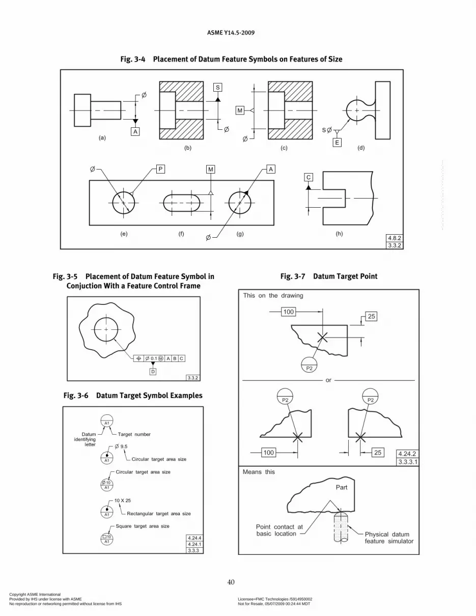
ASME Y14.5-2009
40
Fig. 3-5 Placement of Datum Feature Symbol in Conjuction With a Feature Control Frame
Fig. 3-6 Datum Target Symbol Examples
Fig. 3-7 Datum Target Point
Fig. 3-4 Placement of Datum Feature Symbols on Features of Size
Copyright ASME International Provided by IHS under license with ASME Licensee=FMC Technologies /5914950002
Not for Resale, 05/07/2009 00:24:44 MDTNo reproduction or networking permitted without license from IHS
--`,,`,,,``,`,``,,``,`,`,,,`,`,`-`-`,,`,,`,`,,`---

ASME Y14.5-2009
41
or both. See Fig. 3-8. Where it is necessary to control the length of the datum target line, its length and location are dimensioned.
3.3.3.3 Datum Target Areas. Where it is determined that an area or areas of contact is necessary to assure establishment of the datum (that is, where spherical or pointed pins would be inadequate), a target area of the desired shape is specified. The datum target area is indicated by section lines inside a phantom outline of the desired shape, with controlling dimensions added. The diameter of circular areas is given in the upper half of the datum target symbol. See Fig. 3-9, illustration (a). Where it becomes impractical to delineate a circular target area, the method of indication shown in Fig. 3-9, illustration (b) may be used.
3.3.4 Basic Dimension Symbol
The symbolic means of indicating a basic dimension shall be as shown in Fig. 3-10.
3.3.5 Material Condition/Boundary Symbols
The symbolic means of indicating “at maximum mate-rial condition” or “at maximum material boundary,” “at least material condition” or “at least material boundary” shall be as shown in Figs. 3-11 and 4-5.
3.3.6 Projected Tolerance Zone Symbol
The symbolic means of indicating a projected tolerance zone shall be as shown in Figs. 3-11, 7-21, and 7-22.
3.3.7 Diameter and Radius Symbols
The symbols used to indicate diameter, spherical diameter, radius, spherical radius, and controlled radius shall be as shown in Fig. 3-11. These symbols shall pre-cede the value of a dimension or tolerance given as a diameter or radius, as applicable. The symbol and the value shall not be separated by a space.
3.3.8 Reference Symbol
The symbolic means of indicating a dimension or other dimensional data as reference shall be by enclosing the dimension (or dimensional data) within parenthe-ses. See Figs. 2-3 and 3-11. In written notes, parentheses retain their grammatical interpretation unless otherwise
Fig. 3-8 Datum Target Line Fig. 3-9 Datum Target Area
Fig. 3-10 Basic Dimension Symbol Application
Copyright ASME International Provided by IHS under license with ASME Licensee=FMC Technologies /5914950002
Not for Resale, 05/07/2009 00:24:44 MDTNo reproduction or networking permitted without license from IHS
--`,,`,,,``,`,``,,``,`,`,,,`,`,`-`-`,,`,,`,`,,`---

ASME Y14.5-2009
42
specified. When it is necessary to define dimensions or dimensional data as reference in a note, the term “REFERENCE” or abbreviation “REF” shall be used.
3.3.9 Arc Length Symbol
The symbolic means of indicating that a dimension is an arc length measured on a curved outline shall be as shown in Fig. 3-11. The symbol shall be placed above the dimen-sion and applies to the surface nearest the dimension.
3.3.10 Statistical Tolerancing Symbol
The symbolic means of indicating that a tolerance is based on statistical tolerancing shall be as shown in Fig. 3-11. If the tolerance is a statistical geometric toler-ance, the symbol shall be placed in the feature control frame following the stated tolerance and any modifier. See Fig. 3-12. If the tolerance is a statistical size toler-ance, the symbol shall be placed adjacent to the size dimension. See Fig. 3-13.
3.3.11 Between Symbol
The symbolic means of indicating that a tolerance or other specification apply across multiple features or to a limited segment of a feature between designated extremities is shown in Figs. 3-11, 3-14, 8-6, and 8-7. The leader from the feature control frame is directed to the portion of the feature to which that tolerance applies. In Fig. 3-14, for example, the tolerance applies only between G and H. G and H may be points, lines, or features.
3.3.12 Counterbore Symbol
The symbolic means of indicating a counterbore shall be as shown in Figs. 1-37 and 3-15. The symbol shall pre-cede, with no space, the dimension of the counterbore.
3.3.13 Spotface Symbol
The symbolic means of indicating a spotface shall be as shown in Figs. 1-41 and 3-15. The symbol shall precede, with no space, the dimension of the spotface.
Fig. 3-11 Modifying Symbols Fig. 3-12 Indicating the Specified Tolerance is a Statistical Geometric Tolerance
Fig. 3-13 Statistical Tolerance Symbol
Fig. 3-14 Between Symbol
Copyright ASME International Provided by IHS under license with ASME Licensee=FMC Technologies /5914950002
Not for Resale, 05/07/2009 00:24:44 MDTNo reproduction or networking permitted without license from IHS
--`,,`,,,``,`,``,,``,`,`,,,`,`,`-`-`,,`,,`,`,,`---
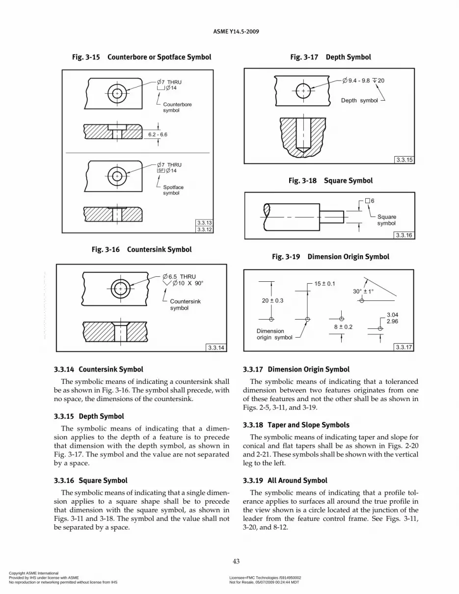
ASME Y14.5-2009
43
3.3.14 Countersink Symbol
The symbolic means of indicating a countersink shall be as shown in Fig. 3-16. The symbol shall precede, with no space, the dimensions of the countersink.
3.3.15 Depth Symbol
The symbolic means of indicating that a dimen-sion applies to the depth of a feature is to precede that dimension with the depth symbol, as shown in Fig. 3-17. The symbol and the value are not separated by a space.
3.3.16 Square Symbol
The symbolic means of indicating that a single dimen-sion applies to a square shape shall be to precede that dimension with the square symbol, as shown in Figs. 3-11 and 3-18. The symbol and the value shall not be separated by a space.
3.3.17 Dimension Origin Symbol
The symbolic means of indicating that a toleranced dimension between two features originates from one of these features and not the other shall be as shown in Figs. 2-5, 3-11, and 3-19.
3.3.18 Taper and Slope Symbols
The symbolic means of indicating taper and slope for conical and flat tapers shall be as shown in Figs. 2-20 and 2-21. These symbols shall be shown with the vertical leg to the left.
3.3.19 All Around Symbol
The symbolic means of indicating that a profile tol-erance applies to surfaces all around the true profile in the view shown is a circle located at the junction of the leader from the feature control frame. See Figs. 3-11, 3-20, and 8-12.
Fig. 3-15 Counterbore or Spotface Symbol
Fig. 3-16 Countersink Symbol
Fig. 3-17 Depth Symbol
Fig. 3-18 Square Symbol
Fig. 3-19 Dimension Origin Symbol
Copyright ASME International Provided by IHS under license with ASME Licensee=FMC Technologies /5914950002
Not for Resale, 05/07/2009 00:24:44 MDTNo reproduction or networking permitted without license from IHS
--`,,`,,,``,`,``,,``,`,`,,,`,`,`-`-`,,`,,`,`,,`---
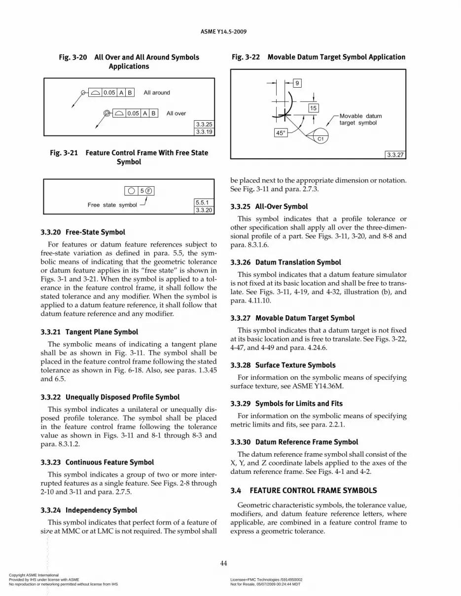
ASME Y14.5-2009
44
3.3.20 Free-State Symbol
For features or datum feature references subject to free-state variation as defined in para. 5.5, the sym-bolic means of indicating that the geometric tolerance or datum feature applies in its “free state” is shown in Figs. 3-1 and 3-21. When the symbol is applied to a tol-erance in the feature control frame, it shall follow the stated tolerance and any modifier. When the symbol is applied to a datum feature reference, it shall follow that datum feature reference and any modifier.
3.3.21 Tangent Plane Symbol
The symbolic means of indicating a tangent plane shall be as shown in Fig. 3-11. The symbol shall be placed in the feature control frame following the stated tolerance as shown in Fig. 6-18. Also, see paras. 1.3.45 and 6.5.
3.3.22 Unequally Disposed Profile Symbol
This symbol indicates a unilateral or unequally dis-posed profile tolerance. The symbol shall be placed in the feature control frame following the tolerance value as shown in Figs. 3-11 and 8-1 through 8-3 and para. 8.3.1.2.
3.3.23 Continuous Feature Symbol
This symbol indicates a group of two or more inter-rupted features as a single feature. See Figs. 2-8 through 2-10 and 3-11 and para. 2.7.5.
3.3.24 Independency Symbol
This symbol indicates that perfect form of a feature of size at MMC or at LMC is not required. The symbol shall
be placed next to the appropriate dimension or notation. See Fig. 3-11 and para. 2.7.3.
3.3.25 All-Over Symbol
This symbol indicates that a profile tolerance or other specification shall apply all over the three-dimen-sional profile of a part. See Figs. 3-11, 3-20, and 8-8 and para. 8.3.1.6.
3.3.26 Datum Translation Symbol
This symbol indicates that a datum feature simulator is not fixed at its basic location and shall be free to trans-late. See Figs. 3-11, 4-19, and 4-32, illustration (b), and para. 4.11.10.
3.3.27 Movable Datum Target Symbol
This symbol indicates that a datum target is not fixed at its basic location and is free to translate. See Figs. 3-22, 4-47, and 4-49 and para. 4.24.6.
3.3.28 Surface Texture Symbols
For information on the symbolic means of specifying surface texture, see ASME Y14.36M.
3.3.29 Symbols for Limits and Fits
For information on the symbolic means of specifying metric limits and fits, see para. 2.2.1.
3.3.30 Datum Reference Frame Symbol
The datum reference frame symbol shall consist of the X, Y, and Z coordinate labels applied to the axes of the datum reference frame. See Figs. 4-1 and 4-2.
3.4 FEATURE CONTROL FRAME SYMBOLS
Geometric characteristic symbols, the tolerance value, modifiers, and datum feature reference letters, where applicable, are combined in a feature control frame to express a geometric tolerance.
Fig. 3-20 All Over and All Around Symbols Applications
Fig. 3-21 Feature Control Frame With Free State Symbol
Fig. 3-22 Movable Datum Target Symbol Application
Copyright ASME International Provided by IHS under license with ASME Licensee=FMC Technologies /5914950002
Not for Resale, 05/07/2009 00:24:44 MDTNo reproduction or networking permitted without license from IHS
--`,,`,,,``,`,``,,``,`,`,,,`,`,`-`-`,,`,,`,`,,`---

ASME Y14.5-2009
45
3.4.1 Feature Control Frame
A feature control frame is a rectangle divided into com-partments containing the geometric characteristic symbol followed by the tolerance value or description, modi-fiers, and any applicable datum feature references. See Figs. 3-23, 4-2, and 7-4. Where applicable, the tolerance is preceded by the diameter or spherical diameter symbol and followed by a material condition modifier.
3.4.2 Feature Control Frame Incorporating One Datum Feature Reference
Where a geometric tolerance is related to a datum, this relationship is indicated by entering the datum feature reference letter in a compartment following the toler-ance. Where applicable, the datum feature reference letter is followed by a material boundary modifier. See Fig. 3-24. Where a datum is established by two or more datum features (e.g., an axis established by two datum features) all datum feature reference letters, separated by a dash, are entered in a single compartment. Where applicable, each datum feature reference letter is fol-lowed by a material boundary modifier. See Figs. 3-25, illustration (a), and 4-25 and para. 4.12.2.
3.4.3 Feature Control Frame Incorporating Two or Three Datum Feature References
Where more than one datum is required, the datum feature reference letters (each followed by a material
boundary modifier, where applicable) are entered in separate compartments in the desired order of prec-edence, from left to right. See Fig. 3-25, illustrations (b) and (c). Datum feature reference letters need not be in alphabetical order in the feature control frame.
3.4.4 Composite Feature Control Frame
A composite feature control frame contains a single entry of a geometric characteristic symbol (position or profile) followed by each tolerance and datum require-ment, one above the other. See Fig. 3-26, illustration (a), and paras. 7.5.1 and 8.6.
3.4.5 Two Single-Segment Feature Control Frames
The symbolic means of representing two single-segment feature control frames shall be as shown in Fig. 3-26, illustration (b). Application of this control is described in para. 7.5.2.
3.4.6 Combined Feature Control Frame and Datum Feature Symbol
Where a feature or pattern of features controlled by a geometric tolerance also serves as a datum feature, the
Fig. 3-23 Feature Control Frame Fig. 3-25 Order of Precedence of Datum Reference
Fig. 3-24 Feature Control Frame Incorporating a Datum Feature Reference
Fig. 3-26 Multiple Feature Control Frames
Copyright ASME International Provided by IHS under license with ASME Licensee=FMC Technologies /5914950002
Not for Resale, 05/07/2009 00:24:44 MDTNo reproduction or networking permitted without license from IHS
--`,,`,,,``,`,``,,``,`,`,,,`,`,`-`-`,,`,,`,`,,`---

ASME Y14.5-2009
46
feature control frame and datum feature symbol may be combined. The datum feature symbol may be attached to the feature control frame. See Fig. 3-27. In the posi-tional tolerance example in Fig. 3-27, a feature is con-trolled for position in relation to datums A and B, and identified as datum feature C.
3.4.7 Feature Control Frame With a Projected Tolerance Zone
Where a positional or an orientation tolerance is specified as a projected tolerance zone, the projected tolerance zone symbol shall be placed in the feature control frame, along with the dimension indicating the minimum height of the tolerance zone. This shall follow the stated tolerance and any modifier. See Figs. 3-28 and 7-21. Where necessary for clarification, the projected tol-erance zone shall be indicated with a chain line, and the minimum height of the tolerance zone is specified in a drawing view. The height dimension may then be omit-ted from the feature control frame. See Fig. 7-22.
3.5 FEATURE CONTROL FRAME PLACEMENT
A feature control frame is related to a considered fea-ture by one of the following methods and as depicted in Fig. 3-29:
(a) locating the frame below or attached to a leader-directed note or dimension pertaining to the feature
(b) attaching a leader from the frame pointing to the feature
(c) attaching a side, corner, or an end of the frame to an extension line from the feature, provided it is a plane surface
(d) attaching a side, corner, or an end of the frame to an extension of the dimension line pertaining to a fea-ture of size
(e) placing in a note, chart, or the general tolerance block
3.6 DEFINITION OF THE TOLERANCE ZONE
Where the specified tolerance value represents the diameter of a cylindrical or spherical zone, the diameter or spherical diameter symbol shall precede the tolerance value. Where the tolerance zone is other than a diameter, the diameter symbol shall be omitted, and the specified tolerance value represents the distance between two par-allel straight lines or planes, or the distance between two uniform boundaries, as the specific case may be. In some cases the tolerance zone is nonuniform and is specified as described in para. 8.3.2.
3.7 TABULATED TOLERANCES
Where the tolerance in a feature control frame is tabu-lated, a letter representing the tolerance, preceded by the abbreviation TOL, shall be entered as shown in Fig. 3-30.
Fig. 3-27 Combined Feature Control Frame and Datum Feature Symbol
Fig. 3-28 Feature Control Frame With a Projected Tolerance Zone Symbol
Copyright ASME International Provided by IHS under license with ASME Licensee=FMC Technologies /5914950002
Not for Resale, 05/07/2009 00:24:44 MDTNo reproduction or networking permitted without license from IHS
--`,,`,,,``,`,``,,``,`,`,,,`,`,`-`-`,,`,,`,`,,`---

ASME Y14.5-2009
47
Fig. 3-29 Feature Control Frame Placement
Fig. 3-30 Tabulated Tolerances
Copyright ASME International Provided by IHS under license with ASME Licensee=FMC Technologies /5914950002
Not for Resale, 05/07/2009 00:24:44 MDTNo reproduction or networking permitted without license from IHS
--`,,`,,,``,`,``,,``,`,`,,,`,`,`-`-`,,`,,`,`,,`---

Section 4Datum Reference Frames
ASME Y14.5-2009
48
4.1 GENERAL
This Section establishes the principles of identifying features as datum features for establishing relationships imposed by geometric tolerances and for constraining degrees of freedom. This Section also establishes the cri-teria for establishing datums and the datum reference frame using datum feature simulators derived from datum features. Datums are theoretically exact points, axes, lines, and planes. A datum reference frame is three mutually perpendicular intersecting datum planes. See Fig. 4-1.
NOTE: Whenever the term “datum feature simulator” is used in this Standard, it refers to the theoretical, unless specifically other-wise indicated.
4.2 DEGREES OF FREEDOM
All parts have six degrees of freedom, three transla-tional and three rotational, which may be constrained by datum feature references in a feature control frame. The three translational degrees of freedom are termed X, Y, and Z. The three rotational degrees of freedom are termed u, v, and w. See Figs. 4-1, 4-2, illustration (c); 4-2, illustration (d); and 4-2, illustration (e).
NOTE: In the means this portion of some figures in this Standard, the translational and rotational degrees of freedom are annotated such as in Figs. 4-1, 4-2, 4-3, and 4-44 to aid the user in interpreta-tion of the drawing.
4.3 DEGREES OF FREEDOM CONSTRAINED BY PRIMARY DATUM FEATURES REGARDLESS OF MATERIAL BOUNDARY
The relationship between the primary datum feature and its datum feature simulator constrains the degrees of freedom according to the material boundary condi-tion applied to the datum feature in the feature control frame. The datum feature simulator restricts the move-ment of the datum feature and establishes the datum(s). See Fig. 4-3 for some examples of degrees of freedom constrained by primary datum features regardless of material boundary (RMB). Although collections of fea-tures may be used to establish a single datum, for sim-plicity, the chart in Fig. 4-3 illustrates only single datum features. The degrees of freedom constrained depend on whether the datum feature is referenced as a primary, a secondary, or a tertiary datum feature. See Figs. 4-2,
4-8, and 4-12. The following primary datums are derived from the associated datum feature simulator:
(a) a planar datum feature (nominally flat) establishes a datum feature simulator that creates a datum plane and constrains three degrees of freedom (one translation and two rotations). See Fig. 4-3, illustration (a).
(b) a width as a datum feature (two opposed parallel surfaces) establishes a datum feature simulator that creates a datum center plane and constrains three degrees of freedom (one translation and two rotations). See Fig. 4-3, illustration (b).
(c) a spherical datum feature establishes a datum feature simulator that creates a datum center point and constrains three translational degrees of freedom. See Fig. 4-3, illustration (c).
(d) a cylindrical datum feature establishes a datum feature simulator that creates a datum axis (line) and constrains four degrees of freedom (two translations and two rotations). See Fig. 4-3, illustration (d).
(e) a conical shaped datum feature establishes a datum feature simulator that creates a datum axis and a datum point and constrains five degrees of freedom (three translations and two rotations). See Fig. 4-3, illus-tration (e).
(f) a datum feature of linear extruded shape estab-lishes a datum feature simulator that creates a datum plane and a datum axis and constrains five degrees of freedom (two translations and three rotations). See Fig. 4-3, illustration (f).
(g) a complex datum feature establishes a datum feature simulator that creates a datum plane, datum point, and a datum axis and constrains six degrees of freedom (three translations and three rotations). See Fig. 4-3, illustration (g).
4.4 CONSTRAINING DEGREES OF FREEDOM OF A PART
Where datum features are referenced in a feature con-trol frame, the part is constrained in rotation and transla-tion relative to the applicable datum feature simulators in the specified order of precedence with applicable modifi-ers that establish the datum reference frame. This defines the geometric relationships that exist between the geo-metric tolerance zones and the datum reference frame. See Figs. 4-2, 4-5, 4-6, and 4-9. Datum feature simulators are used to associate the datum features and the datums. This constrains the motion (degrees of freedom) between the part and the associated datum reference frame.
Copyright ASME International Provided by IHS under license with ASME Licensee=FMC Technologies /5914950002
Not for Resale, 05/07/2009 00:24:44 MDTNo reproduction or networking permitted without license from IHS
--`,,`,,,``,`,``,,``,`,`,,,`,`,`-`-`,,`,,`,`,,`---
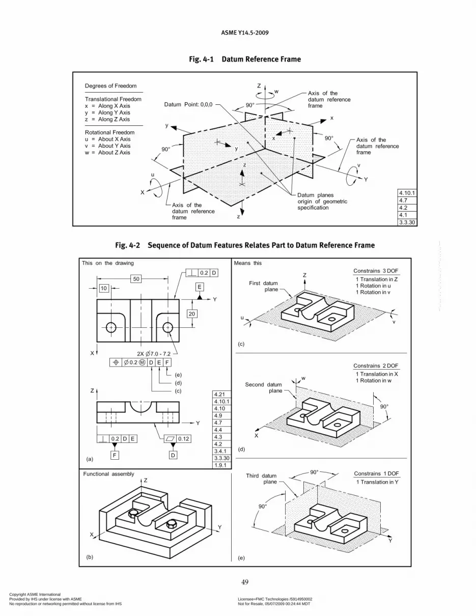
ASME Y14.5-2009
49
Fig. 4-1 Datum Reference Frame
Fig. 4-2 Sequence of Datum Features Relates Part to Datum Reference Frame
Copyright ASME International Provided by IHS under license with ASME Licensee=FMC Technologies /5914950002
Not for Resale, 05/07/2009 00:24:44 MDTNo reproduction or networking permitted without license from IHS
--`,,`,,,``,`,``,,``,`,`,,,`,`,`-`-`,,`,,`,`,,`---

ASME Y14.5-2009
50
Fig. 4-3 Constrained Degrees of Freedom for Primary Datum Features
Copyright ASME International Provided by IHS under license with ASME Licensee=FMC Technologies /5914950002
Not for Resale, 05/07/2009 00:24:44 MDTNo reproduction or networking permitted without license from IHS
--`,,`,,,``,`,``,,``,`,`,,,`,`,`-`-`,,`,,`,`,,`---

ASME Y14.5-2009
51
Fig. 4-5 Part Where Rotational Constraint Is Important
Fig. 4-4 Multiple Datum Reference Frames and Their Interrelationships
Copyright ASME International Provided by IHS under license with ASME Licensee=FMC Technologies /5914950002
Not for Resale, 05/07/2009 00:24:44 MDTNo reproduction or networking permitted without license from IHS
--`,,`,,,``,`,``,,``,`,`,,,`,`,`-`-`,,`,,`,`,,`---

ASME Y14.5-2009
52
Fig. 4-6 Development of a Datum Reference Frame for Part in Fig. 4-5
Fig. 4-7 Inclined Datum Features
Copyright ASME International Provided by IHS under license with ASME Licensee=FMC Technologies /5914950002
Not for Resale, 05/07/2009 00:24:44 MDTNo reproduction or networking permitted without license from IHS
--`,,`,,,``,`,``,,``,`,`,,,`,`,`-`-`,,`,,`,`,,`---

ASME Y14.5-2009
53
NOTE: The sequence of establishing a datum reference frame from datum features and datum feature simulators is described in the preceding paragraph. In subsequent text, for brevity, this process will be described as establishing a datum reference frame from datum features.
4.5 DATUM FEATURE SIMULATOR
A datum feature simulator, as defined in para. 1.3.17, shall be the inverse shape of the datum feature, unless oth-erwise specified. See Figs. 4-10, 4-11, 4-12, 4-13, and 4-14.
4.5.1 Examples
A datum feature simulator may be one of the following:(a) a maximum material boundary (MMB)(b) a least material boundary (LMB)(c) an actual mating envelope(d) a minimum material envelope(e) a tangent plane(f) a datum target(s)(g) a mathematically defined contour
4.5.2 Requirements
Datum feature simulators shall have the following requirements:
(a) perfect form.(b) basic orientation relative to one another for all the
datum references in a feature control frame.(c) basic location relative to other datum feature sim-
ulators for all the datum references in a feature control frame, unless a translation modifier or movable datum target symbol is specified. See Figs. 4-9, 4-19, and 4-32, illustration (a).
(d) movable location when the translation modifier or the movable datum target symbol is specified. See Figs. 4-19, 4-32, illustration (b), and 4-49.
(e) fixed at the designated size, when MMB or LMB is specified.
(f) adjustable in size, when the datum feature applies at RMB.
4.6 THEORETICAL AND PHYSICAL APPLICATION OF DATUM FEATURE SIMULATORS
This Standard defines engineering specifications rel-ative to theoretical datums established from theoretical datum feature simulators. In the practical application, measurements cannot be made from datums or datum feature simulators which are theoretical, therefore sim-ulated datums are established using physical datum feature simulators. For example, machine tables and surface plates, though not true planes, are of such quality that the planes derived from them are used to establish the simulated datums from which measure-ments are taken and dimensions verified. See Fig. 4-10. Also, for example, ring and plug gages, and mandrels, though not true cylinders, are of such quality that their axes are used as simulated datums from which measurements are taken and dimensions verified. See Figs. 4-11 and 4-12. When magnified surfaces of manu-factured parts are seen to have irregularities, contact is made with a datum feature simulator at a number of surface extremities or high points. The principles in this Standard are based on theoretical datum feature simulators and do not take into account any tolerances or error in the physical datum feature simulators. See ASME Y14.43.
4.7 DATUM REFERENCE FRAME
Sufficient datum features or designated portions of these features are chosen to position the part in rela-tion to a set of three mutually perpendicular planes, jointly called a datum reference frame. This reference frame exists in theory only and not on the part. See Fig. 4-1. Therefore, it is necessary to establish a method of simulating the theoretical reference frame from the actual features of the part. In practice, the features are associated with physical or mathematical elements
Fig. 4-8 Part With Cylindrical Datum Feature
Copyright ASME International Provided by IHS under license with ASME Licensee=FMC Technologies /5914950002
Not for Resale, 05/07/2009 00:24:44 MDTNo reproduction or networking permitted without license from IHS
--`,,`,,,``,`,``,,``,`,`,,,`,`,`-`-`,,`,,`,`,,`---
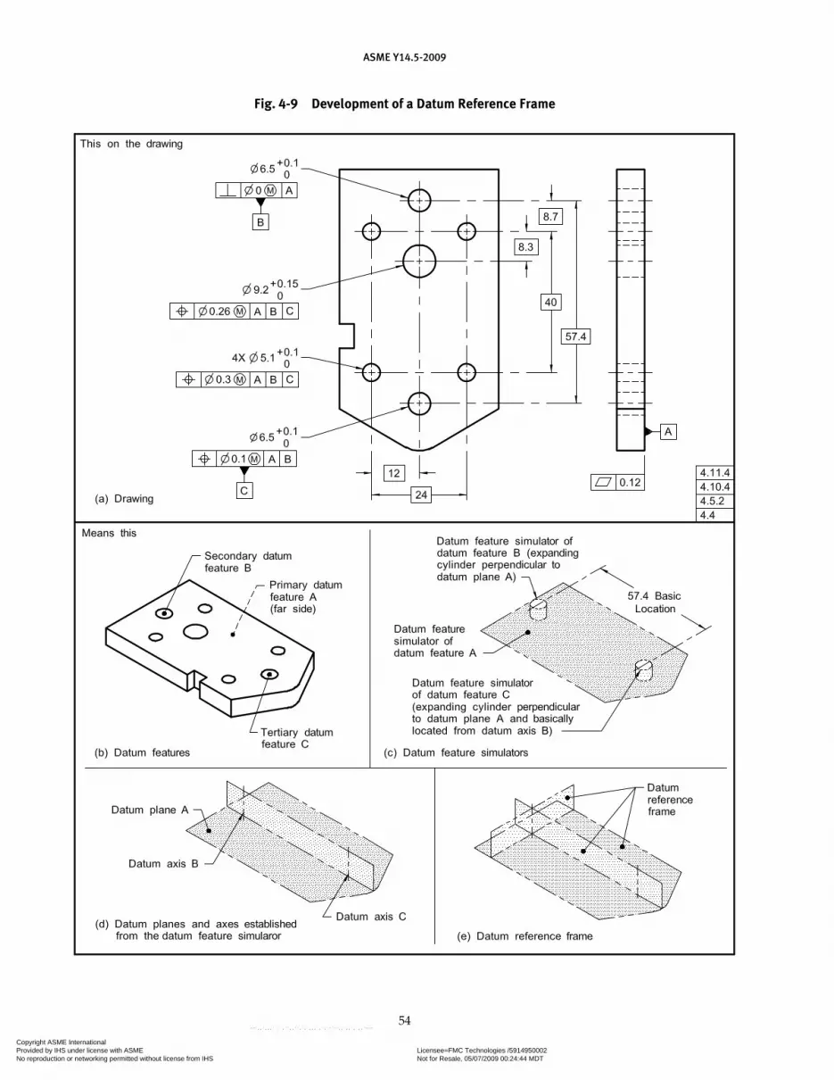
ASME Y14.5-2009
54
Fig. 4-9 Development of a Datum Reference Frame
Copyright ASME International Provided by IHS under license with ASME Licensee=FMC Technologies /5914950002
Not for Resale, 05/07/2009 00:24:44 MDTNo reproduction or networking permitted without license from IHS
--`,,`,,,``,`,``,,``,`,`,,,`,`,`-`-`,,`,,`,`,,`---

ASME Y14.5-2009
55
Fig. 4-10 Datum Plane Establishment
Fig. 4-11 Establishment of Datums — For External Cylindrical Feature — RMB
Copyright ASME International Provided by IHS under license with ASME Licensee=FMC Technologies /5914950002
Not for Resale, 05/07/2009 00:24:44 MDTNo reproduction or networking permitted without license from IHS
--`,,`,,,``,`,``,,``,`,`,,,`,`,`-`-`,,`,,`,`,,`---

ASME Y14.5-2009
56
Fig. 4-13 Establishment of Datums — For External Datum Width — RMB
Fig. 4-12 Establishment of Datums — For Internal Cylindrical Feature — RMB
Copyright ASME International Provided by IHS under license with ASME Licensee=FMC Technologies /5914950002
Not for Resale, 05/07/2009 00:24:44 MDTNo reproduction or networking permitted without license from IHS
--`,,`,,,``,`,``,,``,`,`,,,`,`,`-`-`,,`,,`,`,,`---

ASME Y14.5-2009
57
that simulate the datum feature simulators in a stated order of precedence and according to applicable modi-fiers. This constrains the applicable degrees of freedom between the part and the associated datum reference frame. See Figs. 4-2, 4-5, 4-6, 4-7, and 4-8.
4.7.1 Mutually Perpendicular Planes
The planes of the datum reference frame are simulated in a mutually perpendicular relationship to provide direction as well as the origin for related dimensions. Thus, when the part is positioned relative to the datum reference frame (by contact between each datum feature and its counterpart in the associated processing equipment), dimensions related to the datum reference frame by a feature control frame or note are basically related. This theoretical reference frame constitutes the three-plane dimensioning system used for dimensioning and tolerancing.
4.7.2 Number of Datum Reference Frames
In some cases, a single datum reference frame will suf-fice. In others, additional datum reference frames may be necessary where physical separation or the functional relationship of features requires that different datum ref-erence frames be applied. In such cases, each feature con-trol frame must contain the datum feature references that are applicable. Any difference in the order of precedence or in the material boundary of any datum features refer-enced in multiple feature control frames requires different datum simulation methods and, consequently, establishes a different datum reference frame. See Fig. 4-4.
4.8 DATUM FEATURES
A datum feature is selected on the basis of its functional relationship to the toleranced feature and the requirements of the design. See Figs. 4-5, 4-6, 4-36, 4-37, and 4-38. To ensure proper assembly, corre-sponding interfacing features of mating parts should be selected as datum features. However, a datum feature should be accessible on the part and of suf-ficient size to permit its use. Datum features must be readily discernible on the part. Therefore, in the case of symmetrical parts or parts with identical features, physical identification of the datum feature on the part may be necessary.
4.8.1 Temporary and Permanent Datum Features
Features of in-process parts, such as castings, forgings, machinings, or fabrications, may be used as temporary datum features to create permanent datum features. Such temporary datum features may or may not be sub-sequently removed by machining. Permanent datum features should be surfaces or diameters not appreciably changed by subsequent processing operations.
4.8.2 Datum Feature Identification
Datum features are identified on the drawing by means of a datum feature symbol. See Figs. 3-2, 3-3, and 3-4. The datum feature symbol identifies physical features and shall not be applied to center lines, center planes, or axes.
Fig. 4-14 Establishment of Datums — For Internal Datum Width — RMB
Copyright ASME International Provided by IHS under license with ASME Licensee=FMC Technologies /5914950002
Not for Resale, 05/07/2009 00:24:44 MDTNo reproduction or networking permitted without license from IHS
--`,,`,,,``,`,``,,``,`,`,,,`,`,`-`-`,,`,,`,`,,`---

ASME Y14.5-2009
58
4.9 DATUM FEATURE CONTROLS
Geometric tolerances related to a datum reference frame do not take into account any variations in form, orientation, or location of the datum features. Datum features shall be controlled directly by applying appro-priate geometric tolerances or indirectly by dimensions such as the size of a primary datum feature of size. This in turn makes it possible to calculate the datum feature simulator boundaries of each datum feature in a datum reference frame. The relationships between datum fea-tures to be considered are the
(a) form of the primary datum feature(s) (see Figs. 4-2 and 4-5) and/or the location between features in a pat-tern used to establish the primary datum. See Figs. 4-24 and 4-25.
(b) secondary datum features’ orientation and/or location as applicable, to higher precedence datums. See Figs. 4-2, 4-5, 4-26, and 4-30.
(c) tertiary datum features’ orientation and/or loca-tion to higher precedence datums as applicable. See Figs. 4-2 and 4-5.
4.10 SPECIFYING DATUM FEATURES IN AN ORDER OF PRECEDENCE
Datum features must be specified in an order of prec-edence to position a part properly relative to the datum reference frame. Figure 4-2 illustrates a part where the datum features are planar surfaces. The desired order of precedence is indicated by entering the appropriate datum feature reference letters, from left to right, in the feature control frame.
4.10.1 Development of a Datum Reference Frame for Parts With Planar Surface Datum Features
The feature control frame in Fig. 4-2 illustrates the datum reference frame for the part shown in its func-tional assembly in Fig. 4-2, illustration (b). Figure 4-2 illustrates the development of the datum reference frame along with degrees of freedom. The datum fea-tures referenced in the feature control frame immobilize the part and constrain the six degrees of freedom (three translations and three rotations) to establish a datum reference frame. Relating a part to a datum feature simulator and a datum reference frame in this man-ner ensures consistent understanding of engineering requirements. See Fig. 4-1.
(a) In Fig. 4-2, illustration (a), datum feature D is specified as the primary datum feature. Where a surface is specified as a datum feature, the high point(s) on the surface establish a datum plane. This primary datum feature contacts the datum feature simulator on a mini-mum of three points (see para. 4.11.2 for discussion on rocking or unstable datum features). In this example, where the primary datum feature contacts the datum
feature simulator, three degrees of freedom (one transla-tion and two rotations) are constrained: rotation about the X-axis (u), rotation about the Y-axis (v), and transla-tion in the Z direction.
(b) Datum feature E is specified as the secondary datum feature. This feature contacts the datum feature simulator at a minimum of two points. See Fig. 4-2, illustration (d). In this example, where the secondary datum feature con-tacts its datum feature simulator, two degrees of freedom (one translation and one rotation) are constrained: transla-tion in the X direction and rotation about the Z-axis (w).
(c) Datum feature F is specified as the tertiary datum feature. See Fig. 4-2, illustration (e). In this example, where the tertiary datum feature contacts its datum fea-ture simulator at a minimum of one point, the remain-ing degree of freedom is constrained: translation in the Y direction.
4.10.2 Parts With Inclined Datum Features
For parts with inclined datum features as shown in Fig. 4-7, a datum feature simulator plane is oriented at the basic angle of the datum feature. The corre-sponding plane of the datum reference frame passes through the vertex of the basic angle and is mutually perpendicular to the other two planes.
4.10.3 Parts With Cylindrical Datum Features
The datum of a cylindrical datum feature is the axis of the datum feature simulator. This axis serves as the origin for relationships defined by geometric tolerances. See Figs. 4-8, 4-11, and 4-12. A primary cylindrical datum feature is always associated with two theoretical planes intersecting at right angles on the datum axis. Depending on the number of planes established by higher prece-dence datums, secondary and tertiary datum axes may establish zero, one, or two theoretical planes.
4.10.3.1 Cylindrical Datum Feature. Figure 4-8 illus-trates a part having a cylindrical datum feature. Primary datum feature K relates the part to the first datum plane. Since secondary datum feature M is cylindrical, it is associated with two theoretical planes, the second and third in a three-plane relationship.
4.10.3.2 Datum Axis and Two Planes. The two theo-retical planes are represented on a drawing by center lines crossing at right angles, as in Fig. 4-8, illustration (a). The intersection of these planes coincides with the datum axis. See Fig. 4-8, illustration (b). Once estab-lished, the datum axis becomes the origin for related dimensions.
4.10.3.3 Orientation of Two Planes. The orienta-tion of the second and third planes of the datum refer-ence frame in Fig. 4-8 is not specified, as rotation of the
Copyright ASME International Provided by IHS under license with ASME Licensee=FMC Technologies /5914950002
Not for Resale, 05/07/2009 00:24:44 MDTNo reproduction or networking permitted without license from IHS
--`,,`,,,``,`,``,,``,`,`,,,`,`,`-`-`,,`,,`,`,,`---

ASME Y14.5-2009
59
pattern of holes about the datum axis has no effect on the function of the part. In such cases, only two datum features are referenced in the feature control frame:
(a) primary datum feature K, which establishes a datum plane
(b) secondary datum feature M, which establishes a datum axis perpendicular to datum plane K
4.10.4 Constraining Rotational Degrees of Freedom.
To constrain the rotational degree of freedom of two planes about a datum axis, a lower precedence datum feature is referenced in the feature control frame. See para. 4.16.
(a) Figure 4-5 illustrates the constraint of the rota-tional degree of freedom of the two planes intersecting through the secondary datum feature B, established by the center plane of the tertiary datum feature C. Figure 4-6 illustrates the development of the datum reference frame for the positional tolerance of the three holes in Fig. 4-5.
(b) Figure 4-9 illustrates the constraint of the rota-tional degree of freedom of the two planes intersecting through the secondary datum feature B. Constraint is established by the tertiary datum feature C.
(c) Figures 4-29 through 4-31 illustrate the con-straint of the rotational degree of freedom of the two planes intersecting through datum feature A. Constraint is established by datum feature B.
4.11 ESTABLISHING DATUMS
The following paragraphs define the criteria for estab-lishing datums from datum features.
4.11.1 Plane Surfaces as Datum Features
Where a nominally flat surface is specified as a datum feature, the corresponding datum feature simulator is a plane contacting points of that surface. See Fig. 4-10. The number of points contacted by the datum feature simulator depends on whether the surface is a primary, a secondary, or a tertiary datum feature. See para. 4.10.1.
4.11.2 Irregularities on Datum Features
If irregularities on a datum feature are such that the part is unstable (that is, it rocks) when brought into con-tact with the corresponding datum feature simulator, the default stabilization procedure is per the candidate datum set as outlined in ASME Y14.5.1M. If a different procedure is desired (Chebychev, least squares, transla-tional least squares, etc.), it must be specified.
4.11.3 Effect of Material Boundary Modifiers Applied to Datum Feature References
MMB, LMB, and RMB conditions may be applied/implied to any datum feature reference in a feature
control frame. Modifiers applicable to datum features referenced in a feature control frame will affect the rela-tionship of the part to the datum reference frame. See Figs. 4-20 and 4-21.
4.11.4 Specifying Datum Features RMB
Where a datum feature is referenced at RMB in a feature control frame, the datum feature simula-tor geometry originates at the MMB and progresses proportionally through the tolerance zone to make maximum possible contact with the extremities of the datum feature or collection of features. If another fit-ting routine is required, it shall be stated on the draw-ing. As a practical example, a machine element that is variable (such as a chuck, mandrel, vise, or centering device) is used to simulate a datum feature simulator of the feature and to establish the simulated datum.
(a) Primary Datum Feature: Diameter RMB. The datum is the axis of the datum feature simulator of the datum feature. The datum feature simulator (or unrelated actual mating envelope) is the smallest circumscribed (for an external feature) or largest inscribed (for an internal feature) perfect cylinder that makes maximum possible contact with the datum feature surface. See Figs. 4-3, illustration (d); 4-11; and 4-12.
(b) Primary Datum Feature: Width RMB. The datum is the center plane of the datum feature simulator of the datum feature. The datum feature simulator (or unre-lated actual mating envelope) is two parallel planes at minimum separation (for an external feature) or maxi-mum separation (for an internal feature) that makes maximum possible contact with the corresponding sur-faces of the datum feature. See Figs. 4-3, illustration (b); 4-13; and 4-14.
(c) Primary Datum Feature: Sphere RMB. The datum is the center point of the datum feature simulator of the datum feature. The datum feature simulator (or unre-lated actual mating envelope) is the smallest circum-scribed (for an external feature) or largest inscribed (for an internal feature) perfect sphere that make maximum possible contact with the datum feature surface. See Fig. 4-3, illustration (c).
(d) Secondary Datum Feature RMB: Diameter or Width. For both external and internal features, the secondary datum (axis or center plane) is established in the same manner as indicated in subparas. (a) and (b) above with an additional requirement. The theoretical cylinder or parallel planes of the datum feature simulator must be oriented and/or located to the primary datum feature’s datum feature simulator. Datum feature B in Fig. 4-15 illustrates this principle for diameters, and Fig. 4-32, illustration (a), illustrates the same principle for widths. In Fig. 4-32, illustration (a), the secondary datum feature simulator at RMB expands and makes maximum pos-sible contact constraining all possible remaining degrees of freedom, before the tertiary datum feature simulator is allowed to expand.
Copyright ASME International Provided by IHS under license with ASME Licensee=FMC Technologies /5914950002
Not for Resale, 05/07/2009 00:24:44 MDTNo reproduction or networking permitted without license from IHS
--`,,`,,,``,`,``,,``,`,`,,,`,`,`-`-`,,`,,`,`,,`---
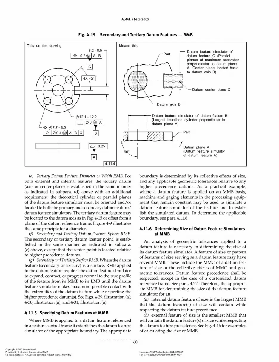
ASME Y14.5-2009
60
Fig. 4-15 Secondary and Tertiary Datum Features — RMB
(e) Tertiary Datum Feature: Diameter or Width RMB. For both external and internal features, the tertiary datum (axis or center plane) is established in the same manner as indicated in subpara. (d) above with an additional requirement: the theoretical cylinder or parallel planes of the datum feature simulator must be oriented and/or located to both the primary and secondary datum features’ datum feature simulators. The tertiary datum feature may be located to the datum axis as in Fig. 4-15 or offset from a plane of the datum reference frame. Figure 4-9 illustrates the same principle for a diameter.
(f) Secondary and Tertiary Datum Feature: Sphere RMB. The secondary or tertiary datum (center point) is estab-lished in the same manner as indicated in subpara. (c) above, except that the center point is located relative to higher precedence datums.
(g) Secondary and Tertiary Surface RMB. Where the datum feature (secondary or tertiary) is a surface, RMB applied to the datum feature requires the datum feature simulator to expand, contract, or progress normal to the true profile of the feature from its MMB to its LMB until the datum feature simulator makes maximum possible contact with the extremities of the datum feature while respecting the higher precedence datum(s). See Figs. 4-29, illustration (a); 4-30, illustration (a); and 4-31, illustration (a).
4.11.5 Specifying Datum Features at MMB
Where MMB is applied to a datum feature referenced in a feature control frame it establishes the datum feature simulator of the appropriate boundary. The appropriate
boundary is determined by its collective effects of size, and any applicable geometric tolerances relative to any higher precedence datums. As a practical example, where a datum feature is applied on an MMB basis, machine and gaging elements in the processing equip-ment that remain constant may be used to simulate a datum feature simulator of the feature and to estab-lish the simulated datum. To determine the applicable boundary, see para 4.11.6.
4.11.6 Determining Size of Datum Feature Simulators at MMB
An analysis of geometric tolerances applied to a datum feature is necessary in determining the size of its datum feature simulator. A feature of size or pattern of features of size serving as a datum feature may have several MMB. These include the MMC of a datum fea-ture of size or the collective effects of MMC and geo-metric tolerances. Datum feature precedence shall be respected, except in the case of a customized datum reference frame. See para. 4.22. Therefore, the appropri-ate MMB for determining the size of the datum feature simulator for an
(a) internal datum feature of size is the largest MMB that the datum feature(s) of size will contain while respecting the datum feature precedence.
(b) external feature of size is the smallest MMB that will contain the datum feature(s) of size while respecting the datum feature precedence. See Fig. 4-16 for examples of calculating the size of MMB.
Copyright ASME International Provided by IHS under license with ASME Licensee=FMC Technologies /5914950002
Not for Resale, 05/07/2009 00:24:44 MDTNo reproduction or networking permitted without license from IHS
--`,,`,,,``,`,``,,``,`,`,,,`,`,`-`-`,,`,,`,`,,`---
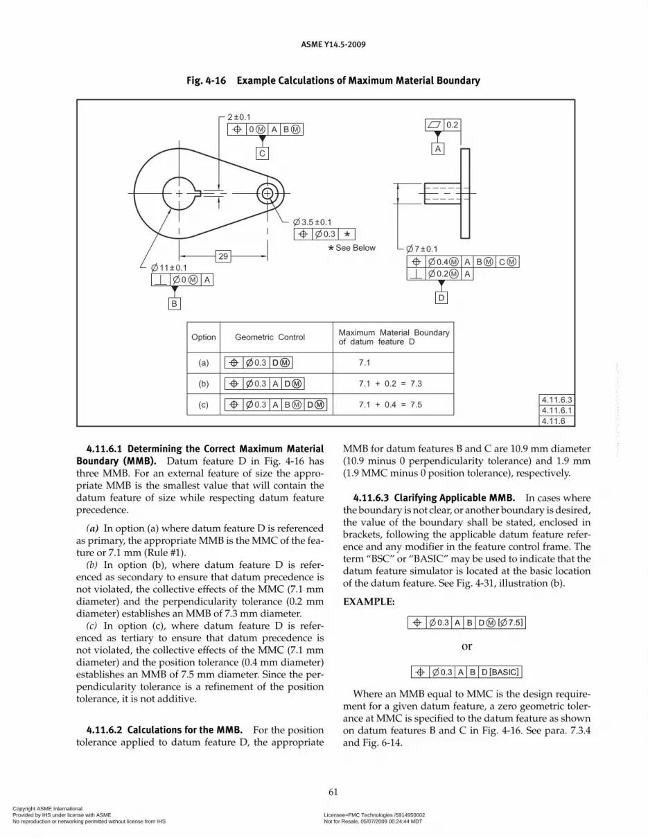
ASME Y14.5-2009
61
4.11.6.1 Determining the Correct Maximum Material Boundary (MMB). Datum feature D in Fig. 4-16 has three MMB. For an external feature of size the appro-priate MMB is the smallest value that will contain the datum feature of size while respecting datum feature precedence.
(a) In option (a) where datum feature D is referenced as primary, the appropriate MMB is the MMC of the fea-ture or 7.1 mm (Rule #1).
(b) In option (b), where datum feature D is refer-enced as secondary to ensure that datum precedence is not violated, the collective effects of the MMC (7.1 mm diameter) and the perpendicularity tolerance (0.2 mm diameter) establishes an MMB of 7.3 mm diameter.
(c) In option (c), where datum feature D is refer-enced as tertiary to ensure that datum precedence is not violated, the collective effects of the MMC (7.1 mm diameter) and the position tolerance (0.4 mm diameter) establishes an MMB of 7.5 mm diameter. Since the per-pendicularity tolerance is a refinement of the position tolerance, it is not additive.
4.11.6.2 Calculations for the MMB. For the position tolerance applied to datum feature D, the appropriate
MMB for datum features B and C are 10.9 mm diameter (10.9 minus 0 perpendicularity tolerance) and 1.9 mm (1.9 MMC minus 0 position tolerance), respectively.
4.11.6.3 Clarifying Applicable MMB. In cases where the boundary is not clear, or another boundary is desired, the value of the boundary shall be stated, enclosed in brackets, following the applicable datum feature refer-ence and any modifier in the feature control frame. The term “BSC” or “BASIC” may be used to indicate that the datum feature simulator is located at the basic location of the datum feature. See Fig. 4-31, illustration (b).
EXAMPLE:
or
Where an MMB equal to MMC is the design require-ment for a given datum feature, a zero geometric toler-ance at MMC is specified to the datum feature as shown on datum features B and C in Fig. 4-16. See para. 7.3.4 and Fig. 6-14.
Fig. 4-16 Example Calculations of Maximum Material Boundary
Copyright ASME International Provided by IHS under license with ASME Licensee=FMC Technologies /5914950002
Not for Resale, 05/07/2009 00:24:44 MDTNo reproduction or networking permitted without license from IHS
--`,,`,,,``,`,``,,``,`,`,,,`,`,`-`-`,,`,,`,`,,`---
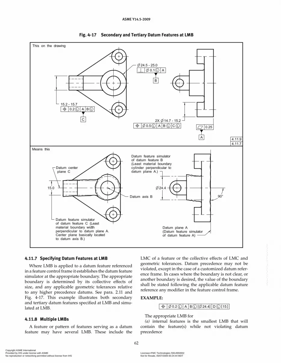
ASME Y14.5-2009
62
4.11.7 Specifying Datum Features at LMB
Where LMB is applied to a datum feature referenced in a feature control frame it establishes the datum feature simulator at the appropriate boundary. The appropriate boundary is determined by its collective effects of size, and any applicable geometric tolerances relative to any higher precedence datums. See para. 2.11 and Fig. 4-17. This example illustrates both secondary and tertiary datum features specified at LMB and simu-lated at LMB.
4.11.8 Multiple LMBs
A feature or pattern of features serving as a datum feature may have several LMB. These include the
LMC of a feature or the collective effects of LMC and geometric tolerances. Datum precedence may not be violated, except in the case of a customized datum refer-ence frame. In cases where the boundary is not clear, or another boundary is desired, the value of the boundary shall be stated following the applicable datum feature reference any modifier in the feature control frame.
EXAMPLE:
The appropriate LMB for(a) internal features is the smallest LMB that will
contain the feature(s) while not violating datum precedence
Fig. 4-17 Secondary and Tertiary Datum Features at LMB
Copyright ASME International Provided by IHS under license with ASME Licensee=FMC Technologies /5914950002
Not for Resale, 05/07/2009 00:24:44 MDTNo reproduction or networking permitted without license from IHS
--`,,`,,,``,`,``,,``,`,`,,,`,`,`-`-`,,`,,`,`,,`---
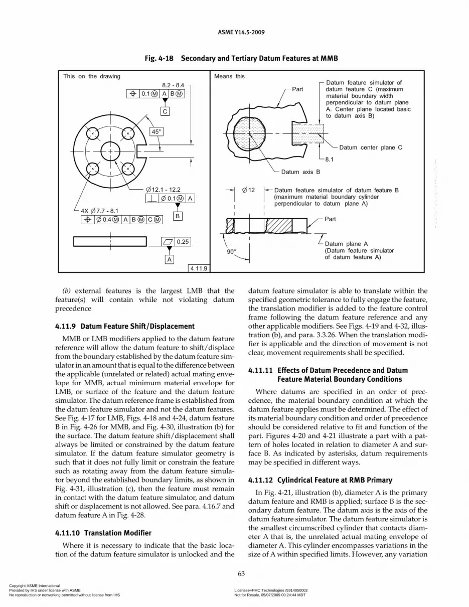
ASME Y14.5-2009
63
(b) external features is the largest LMB that the feature(s) will contain while not violating datum precedence
4.11.9 Datum Feature Shift/Displacement
MMB or LMB modifiers applied to the datum feature reference will allow the datum feature to shift/displace from the boundary established by the datum feature sim-ulator in an amount that is equal to the difference between the applicable (unrelated or related) actual mating enve-lope for MMB, actual minimum material envelope for LMB, or surface of the feature and the datum feature simulator. The datum reference frame is established from the datum feature simulator and not the datum features. See Fig. 4-17 for LMB, Figs. 4-18 and 4-24, datum feature B in Fig. 4-26 for MMB, and Fig. 4-30, illustration (b) for the surface. The datum feature shift/displacement shall always be limited or constrained by the datum feature simulator. If the datum feature simulator geometry is such that it does not fully limit or constrain the feature such as rotating away from the datum feature simula-tor beyond the established boundary limits, as shown in Fig. 4-31, illustration (c), then the feature must remain in contact with the datum feature simulator, and datum shift or displacement is not allowed. See para. 4.16.7 and datum feature A in Fig. 4-28.
4.11.10 Translation Modifier
Where it is necessary to indicate that the basic loca-tion of the datum feature simulator is unlocked and the
datum feature simulator is able to translate within the specified geometric tolerance to fully engage the feature, the translation modifier is added to the feature control frame following the datum feature reference and any other applicable modifiers. See Figs. 4-19 and 4-32, illus-tration (b), and para. 3.3.26. When the translation modi-fier is applicable and the direction of movement is not clear, movement requirements shall be specified.
4.11.11 Effects of Datum Precedence and Datum Feature Material Boundary Conditions
Where datums are specified in an order of prec-edence, the material boundary condition at which the datum feature applies must be determined. The effect of its material boundary condition and order of precedence should be considered relative to fit and function of the part. Figures 4-20 and 4-21 illustrate a part with a pat-tern of holes located in relation to diameter A and sur-face B. As indicated by asterisks, datum requirements may be specified in different ways.
4.11.12 Cylindrical Feature at RMB Primary
In Fig. 4-21, illustration (b), diameter A is the primary datum feature and RMB is applied; surface B is the sec-ondary datum feature. The datum axis is the axis of the datum feature simulator. The datum feature simulator is the smallest circumscribed cylinder that contacts diam-eter A that is, the unrelated actual mating envelope of diameter A. This cylinder encompasses variations in the size of A within specified limits. However, any variation
Fig. 4-18 Secondary and Tertiary Datum Features at MMB
Copyright ASME International Provided by IHS under license with ASME Licensee=FMC Technologies /5914950002
Not for Resale, 05/07/2009 00:24:44 MDTNo reproduction or networking permitted without license from IHS
--`,,`,,,``,`,``,,``,`,`,,,`,`,`-`-`,,`,,`,`,,`---

ASME Y14.5-2009
64
Fig. 4-19 Development of a Datum Reference Frame With Translation Modifier
Copyright ASME International Provided by IHS under license with ASME Licensee=FMC Technologies /5914950002
Not for Resale, 05/07/2009 00:24:44 MDTNo reproduction or networking permitted without license from IHS
--`,,`,,,``,`,``,,``,`,`,,,`,`,`-`-`,,`,,`,`,,`---
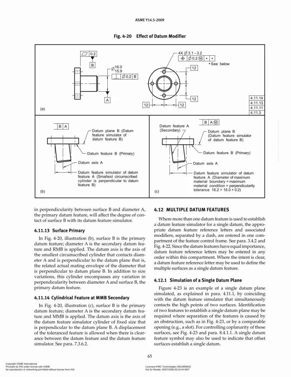
ASME Y14.5-2009
65
in perpendicularity between surface B and diameter A, the primary datum feature, will affect the degree of con-tact of surface B with its datum feature simulator.
4.11.13 Surface Primary
In Fig. 4-20, illustration (b), surface B is the primary datum feature; diameter A is the secondary datum fea-ture and RMB is applied. The datum axis is the axis of the smallest circumscribed cylinder that contacts diam-eter A and is perpendicular to the datum plane that is, the related actual mating envelope of the diameter that is perpendicular to datum plane B. In addition to size variations, this cylinder encompasses any variation in perpendicularity between diameter A and surface B, the primary datum feature.
4.11.14 Cylindrical Feature at MMB Secondary
In Fig. 4-20, illustration (c), surface B is the primary datum feature; diameter A is the secondary datum fea-ture and MMB is applied. The datum axis is the axis of the datum feature simulator cylinder of fixed size that is perpendicular to the datum plane B. A displacement of the toleranced feature is allowed when there is clear-ance between the datum feature and the datum feature simulator. See para. 7.3.6.2.
4.12 MULTIPLE DATUM FEATURES
Where more than one datum feature is used to establish a datum feature simulator for a single datum, the appro-priate datum feature reference letters and associated modifiers, separated by a dash, are entered in one com-partment of the feature control frame. See para. 3.4.2 and Fig. 4-22. Since the datum features have equal importance, datum feature reference letters may be entered in any order within this compartment. Where the intent is clear, a datum feature reference letter may be used to define the multiple surfaces as a single datum feature.
4.12.1 Simulation of a Single Datum Plane
Figure 4-23 is an example of a single datum plane simulated, as explained in para. 4.11.1, by coinciding with the datum feature simulator that simultaneously contacts the high points of two surfaces. Identification of two features to establish a single datum plane may be required where separation of the features is caused by an obstruction, such as in Fig. 4-23, or by a comparable opening (e.g., a slot). For controlling coplanarity of these surfaces, see Fig. 4-23 and para. 8.4.1.1. A single datum feature symbol may also be used to indicate that offset surfaces establish a single datum.
Fig. 4-20 Effect of Datum Modifier
Copyright ASME International Provided by IHS under license with ASME Licensee=FMC Technologies /5914950002
Not for Resale, 05/07/2009 00:24:44 MDTNo reproduction or networking permitted without license from IHS
--`,,`,,,``,`,``,,``,`,`,,,`,`,`-`-`,,`,,`,`,,`---

ASME Y14.5-2009
66
Fig. 4-21 Effect of Material Condition
Copyright ASME International Provided by IHS under license with ASME Licensee=FMC Technologies /5914950002
Not for Resale, 05/07/2009 00:24:44 MDTNo reproduction or networking permitted without license from IHS
--`,,`,,,``,`,``,,``,`,`,,,`,`,`-`-`,,`,,`,`,,`---

ASME Y14.5-2009
67
4.12.2 Single Axis of Two Coaxial Features of Size
Figures 4-24 and 4-25 are examples of a single datum axis established from the axes of the datum feature sim-ulators that constrain the two coaxial diameters simulta-neously. The datum features in Fig. 4-24 may be at RMB or specified to apply at MMB or LMB as applicable. In Fig. 4-25 the datum features for the runout tolerances can only apply at RMB.
4.12.3 Pattern of Features of Size at MMB
Multiple features of size, such as a pattern of holes at MMB, may be used as a group in the establishment of a datum feature simulator to derive a datum refer-ence frame. See Fig. 4-26. In this case, when the part is mounted on the datum feature simulator of primary datum feature A, the pattern of holes establishes the datum feature simulator that is used to derive the sec-ond and third planes of the datum reference frame. The datum feature simulator of datum feature B is the col-lection of the MMB of all of the holes located at true position. The origin of the datum reference frame may be established at the center of the pattern of the datum feature simulator where it intersects plane A, as shown in Fig. 4-26 or at any other location defined with basic dimensions relative to the datum feature simulator as in Fig. 4-28. Where datum feature B is referenced at MMB, a displacement is permitted between the actual hole pat-tern and the datum reference frame. Such displacement is related to any clearance between the surface of datum feature B and the MMB of each hole. This clearance is determined by the size, orientation, and location of each of the holes collectively.
4.12.4 Pattern of Features of Size at RMB
Where RMB is applied in a feature control frame to multiple datum features of size used to establish a single datum, the datum feature simulator of each feature shall be fixed in a location relative to one another. The datum feature simulators shall expand or contract simultane-ously from their MMB to their LMB until the datum fea-ture simulators make maximum possible contact with the extremities of the datum feature(s). See Fig. 4-25.
Fig. 4-22 Planar Multiple Datum Fig. 4-23 Two Datum Features Establishing a Single Datum Plane
Copyright ASME International Provided by IHS under license with ASME Licensee=FMC Technologies /5914950002
Not for Resale, 05/07/2009 00:24:44 MDTNo reproduction or networking permitted without license from IHS
--`,,`,,,``,`,``,,``,`,`,,,`,`,`-`-`,,`,,`,`,,`---

ASME Y14.5-2009
68
Fig. 4-24 Two Coaxial Datum Features, Single Datum Axis
Fig. 4-25 Two Datum Features at RMB, Single Datum Axis
Copyright ASME International Provided by IHS under license with ASME Licensee=FMC Technologies /5914950002
Not for Resale, 05/07/2009 00:24:44 MDTNo reproduction or networking permitted without license from IHS
--`,,`,,,``,`,``,,``,`,`,,,`,`,`-`-`,,`,,`,`,,`---

ASME Y14.5-2009
69
4.12.5 Partial Surfaces as Datum Features
It is often desirable to specify only part of a surface, instead of the entire surface to serve as a datum fea-ture. This may be indicated by means of a chain line (2D orthographic drawing only) drawn parallel to the sur-face profile (dimensioned for length and location) as in Fig. 4-27, specified in note form, or by a datum target.
4.13 MATHEMATICALLY DEFINED SURFACE
It is sometimes necessary to identify a compound curve or a contoured surface as a datum feature. A mathematically defined feature shall be defined within a three-dimensional coordinate system. Where such a
feature is specified as a datum feature, its datum fea-ture simulator (derived from the math data) is used in establishing the datum reference frame. Aligning the high points of the datum feature with its datum feature simulator restricts movement of the part to the datum reference frame. Where the datum feature alone will not adequately restrict the required degrees of freedom of the part, additional datum features will be required. See Fig. 4-28.
NOTE: If the datum feature is specified to apply at MMB as in Fig. 4-28 or LMB, the math data is adjusted by the value of the tol-erance applicable at that boundary to determine the datum feature simulator.
4.14 MULTIPLE DATUM REFERENCE FRAMES
More than one datum reference frame may be necessary for certain parts, depending upon functional requirements. Where more than one datum reference frame is used and it is necessary to determine the relationships and calculate boundaries between the reference frames, the relationship between the datum reference frames shall be specified. In Fig. 4-4, datum features A and B establish one datum ref-erence frame, while datum features C and D establish a different datum reference frame.
4.15 FUNCTIONAL DATUM FEATURES
Only the required datum features should be referenced in feature control frames when specifying geometric tolerances. An understanding of the geometric control provided by these tolerances (as explained in Sections 5 through 9) is necessary to determine effectively the number of datum feature references required for a given application. The functional requirements of the design
Fig. 4-26 Hole Pattern Identified as Datum
Fig. 4-27 Partial Surface as a Datum Feature
Copyright ASME International Provided by IHS under license with ASME Licensee=FMC Technologies /5914950002
Not for Resale, 05/07/2009 00:24:44 MDTNo reproduction or networking permitted without license from IHS
--`,,`,,,``,`,``,,``,`,`,,,`,`,`-`-`,,`,,`,`,,`---

ASME Y14.5-2009
70
should be the basis for selecting the related datum features to be referenced in the feature control frame. Figures 4-36 through 4-38 illustrate parts in an assembly where geometric tolerances are specified, each having the required number of datum feature references.
4.16 ROTATIONAL CONSTRAINT ABOUT A DATUM AXIS OR POINT
Where a datum reference frame is established from a primary or secondary datum axis or point, a lower prec-edence datum feature surface or feature of size may be used to constrain rotation. See para. 4.10.4. Depending
on functional requirements, there are many ways to constrain the rotational degrees of freedom about the higher precedence datum. Figures 4-8 and 4-29 through 4-32 illustrate the development of a datum reference frame based on the principles outlined in the datum feature simulator requirements. In these figures, datum feature A establishes an axis. The lower precedence datum feature B is located (positioned or profiled) to datum feature A and is then used to orient the rotational degrees of freedom to establish the datum reference frame that is used to locate the two 6-mm diameter holes. Depending on functional requirements, this lower prec-edence datum feature may apply at RMB or be modified
Fig. 4-28 Contoured Surface as a Datum Feature
Copyright ASME International Provided by IHS under license with ASME Licensee=FMC Technologies /5914950002
Not for Resale, 05/07/2009 00:24:44 MDTNo reproduction or networking permitted without license from IHS
--`,,`,,,``,`,``,,``,`,`,,,`,`,`-`-`,,`,,`,`,,`---

ASME Y14.5-2009
71
to apply at MMB or LMB. The datum reference frame is established from the datum feature simulators and not the datum features.
4.16.1 Contoured Datum Feature at RMB Constraining a Rotational Degree of Freedom
In Fig. 4-29, illustration (a), datum feature B applies at RMB. This requires the datum feature simulator geom-etry to originate at the MMB of R14.9 mm and progress through the profile tolerance zone toward the LMB of R15.1 mm until it makes maximum contact with datum feature B and constrains the rotational degree of free-dom of the part around the axis of the datum feature simulator from datum feature A.
4.16.2 Contoured Datum Feature at MMB Constraining a Rotational Degree of Freedom
In Fig. 4-29, illustration (b), datum feature B is modi-fied to apply at MMB. This requires the datum feature simulator to be fixed at the MMB of R14.9 mm and thus orients the two planes that originate at the axis of the
datum feature simulator of datum feature A. Datum feature B may rotate within the confines created by its departure from MMB and might not remain in contact with the datum feature simulator.
4.16.3 Planar Datum Feature at RMB Constraining a Rotational Degree of Freedom
In Fig. 4-30, illustration (a), datum feature B applies at RMB. This requires the datum feature simulator geometry to originate at MMB of 15.1 mm and progress through the profile tolerance zone toward the LMB of 14.9 mm until it makes maximum contact with datum feature B and constrains the rotational degree of free-dom of the part around the axis of the datum feature simulator of datum feature A.
4.16.4 Planar Datum Feature at MMB Constraining a Rotational Degree of Freedom
In Fig. 4-30, illustration (b), datum feature B is modi-fied to apply at MMB. This requires the datum feature simulator to be fixed at the MMB of 15.1 mm and thus
Fig. 4-29 Contoured Datum Feature Constraining a Rotational Degree of Freedom
Copyright ASME International Provided by IHS under license with ASME Licensee=FMC Technologies /5914950002
Not for Resale, 05/07/2009 00:24:44 MDTNo reproduction or networking permitted without license from IHS
--`,,`,,,``,`,``,,``,`,`,,,`,`,`-`-`,,`,,`,`,,`---
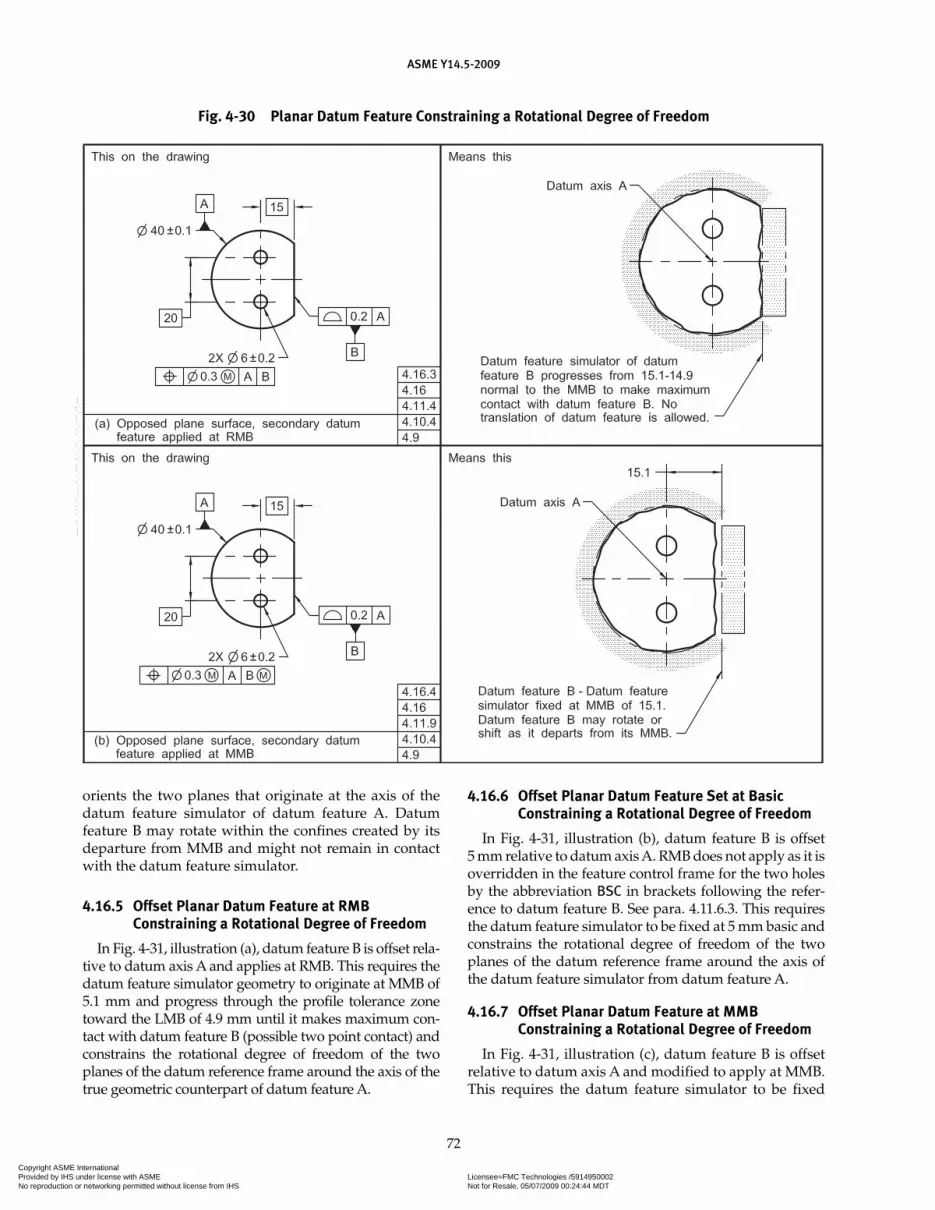
ASME Y14.5-2009
72
orients the two planes that originate at the axis of the datum feature simulator of datum feature A. Datum feature B may rotate within the confines created by its departure from MMB and might not remain in contact with the datum feature simulator.
4.16.5 Offset Planar Datum Feature at RMB Constraining a Rotational Degree of Freedom
In Fig. 4-31, illustration (a), datum feature B is offset rela-tive to datum axis A and applies at RMB. This requires the datum feature simulator geometry to originate at MMB of 5.1 mm and progress through the profile tolerance zone toward the LMB of 4.9 mm until it makes maximum con-tact with datum feature B (possible two point contact) and constrains the rotational degree of freedom of the two planes of the datum reference frame around the axis of the true geometric counterpart of datum feature A.
4.16.6 Offset Planar Datum Feature Set at Basic Constraining a Rotational Degree of Freedom
In Fig. 4-31, illustration (b), datum feature B is offset 5 mm relative to datum axis A. RMB does not apply as it is overridden in the feature control frame for the two holes by the abbreviation BSC in brackets following the refer-ence to datum feature B. See para. 4.11.6.3. This requires the datum feature simulator to be fixed at 5 mm basic and constrains the rotational degree of freedom of the two planes of the datum reference frame around the axis of the datum feature simulator from datum feature A.
4.16.7 Offset Planar Datum Feature at MMB Constraining a Rotational Degree of Freedom
In Fig. 4-31, illustration (c), datum feature B is offset relative to datum axis A and modified to apply at MMB. This requires the datum feature simulator to be fixed
Fig. 4-30 Planar Datum Feature Constraining a Rotational Degree of Freedom
Copyright ASME International Provided by IHS under license with ASME Licensee=FMC Technologies /5914950002
Not for Resale, 05/07/2009 00:24:44 MDTNo reproduction or networking permitted without license from IHS
--`,,`,,,``,`,``,,``,`,`,,,`,`,`-`-`,,`,,`,`,,`---

ASME Y14.5-2009
73
Fig. 4-31 Datum Modifier Effects — Plane Surface
Copyright ASME International Provided by IHS under license with ASME Licensee=FMC Technologies /5914950002
Not for Resale, 05/07/2009 00:24:44 MDTNo reproduction or networking permitted without license from IHS
--`,,`,,,``,`,``,,``,`,`,,,`,`,`-`-`,,`,,`,`,,`---

ASME Y14.5-2009
74
at the MMB of 5.1 mm and constrains the rotational degree of freedom of the two planes of the datum refer-ence frame that originate at the datum feature simulator of datum feature A. Where the datum feature simula-tor and the higher precedence datum axis do not limit rotation in both directions about the datum axis, the datum feature must always contact the datum feature simulator.
4.16.8 Datum Feature of Size at RMB Constraining a Rotational Degree of Freedom
In Fig. 4-32, illustration (a), datum feature B applies at RMB and is located relative to datum axis A. This requires the center plane of the datum feature simulator geometry to be fixed at the basic 5 mm dimension and the datum feature simulator geometry to expand until it makes maximum contact with datum feature B. This constrains the rotational degree of freedom of the two planes of the datum reference frame around the axis of the datum feature simulator of datum feature A.
4.16.9 Datum Feature of Size at RMB With Translation Modifier Constraining Rotational Degrees of Freedom
In Fig. 4-32, illustration (b), datum feature B applies at RMB with a translation modifier. This allows the center plane of the datum feature simulator to trans-late while maintaining its orientation to higher prece-dence datums. The parallel planes of the datum feature simulator expand to make maximum contact with the datum feature.
4.17 APPLICATION OF MMB, LMB, AND RMB TO IRREGULAR FEATURES OF SIZE
MMB, LMB, and RMB may be applied to irregular fea-tures of size when they are selected as datum features.
(a) In some applications, irregular features of size that contain or may be contained by an actual mating enve-lope or actual minimum material envelope from which a center point, an axis, or a center plane can be derived
Fig. 4-32 Datum Modifier Effects — Size Feature
Copyright ASME International Provided by IHS under license with ASME Licensee=FMC Technologies /5914950002
Not for Resale, 05/07/2009 00:24:44 MDTNo reproduction or networking permitted without license from IHS
--`,,`,,,``,`,``,,``,`,`,,,`,`,`-`-`,,`,,`,`,,`---

ASME Y14.5-2009
75
may be used as datum features. See para. 1.3.32.2(a) and Figs. 4-33, 4-34, and 4-35. RMB, MMB, and LMB princi-ples may be applied to these types of irregular features of size.
(b) In other applications (such as an irregular shaped feature) where a boundary has been defined using pro-file tolerancing, a center point, an axis, or a center plane may not be readily definable. See para. 1.3.32.2(b) and Fig. 8-24. MMB and LMB principles may be applied to this type of irregular feature of size. When RMB is
applied, the fitting routine may be the same as for a regular feature of size, a specific fitting routine may be defined, or datum targets may be used.
4.18 DATUM FEATURE SELECTION PRACTICAL APPLICATION
Figure 4-36 illustrates an assembly of mating parts. Datum features were selected based on functional assem-bly and mating conditions. Figure 4-37 illustrates the
Fig. 4-33 Irregular and Regular Features of Size Datum Features
Copyright ASME International Provided by IHS under license with ASME Licensee=FMC Technologies /5914950002
Not for Resale, 05/07/2009 00:24:44 MDTNo reproduction or networking permitted without license from IHS
--`,,`,,,``,`,``,,``,`,`,,,`,`,`-`-`,,`,,`,`,,`---

ASME Y14.5-2009
76
pulley and the datum features selected based on the func-tional interrelationship with the adapter in the assembly. The internal bore on the pulley is selected as the primary datum feature (identified as A) based on the amount of contact it has with the pilot diameter of the adapter. The shoulder has the secondary contact with the adapter, and it is selected as secondary datum feature (identified as B). The assembly of the pulley to the adapter depends on the clamping of the bolt and washer, and a tertiary datum feature is not necessary. Figure 4-38 illustrates the adapter with its datum features and appropriate geometric tolerances based on function. An analysis of the relationship between the adapter and the crankshaft indicates that the shoulder has the most contact with the crankshaft; and because the bolt force on the assembly will load the shoulder surface plane into contact with the end of the crankshaft, establishing an initial orientation, it is selected as the primary datum feature (identified as A). Secondary contact is between the pilot on the adapter and the bore on the crankshaft, and, therefore, the pilot is
selected as the secondary datum feature (identified as B) for the adapter. In this example, a tertiary datum feature is unnecessary as the rotation is constrained by the five clearance holes, and other features on the part do not need to be controlled for rotation. Selection of datum fea-tures in this manner minimizes tolerance accumulation within an assembly and is also representative of actual function.
4.19 SIMULTANEOUS REQUIREMENTS
A simultaneous requirement is where two or more geometric tolerances apply as a single pattern or part requirement. A simultaneous requirement applies to position and profile tolerances that are located by basic dimensions, related to common datum features ref-erenced in the same order of precedence at the same boundary conditions. In a simultaneous requirement there is no translation or rotation between the datum reference frames of the included geometric tolerances,
Fig. 4-34 Coaxial Irregular Feature of Size Datum Feature
Copyright ASME International Provided by IHS under license with ASME Licensee=FMC Technologies /5914950002
Not for Resale, 05/07/2009 00:24:44 MDTNo reproduction or networking permitted without license from IHS
--`,,`,,,``,`,``,,``,`,`,,,`,`,`-`-`,,`,,`,`,,`---

ASME Y14.5-2009
77
Fig. 4-35 Datum Possibilities From Three Pins for an Irregular Feature of Size
Fig. 4-36 Mating Parts for Functional Datum Selection
Copyright ASME International Provided by IHS under license with ASME Licensee=FMC Technologies /5914950002
Not for Resale, 05/07/2009 00:24:44 MDTNo reproduction or networking permitted without license from IHS
--`,,`,,,``,`,``,,``,`,`,,,`,`,`-`-`,,`,,`,`,,`---
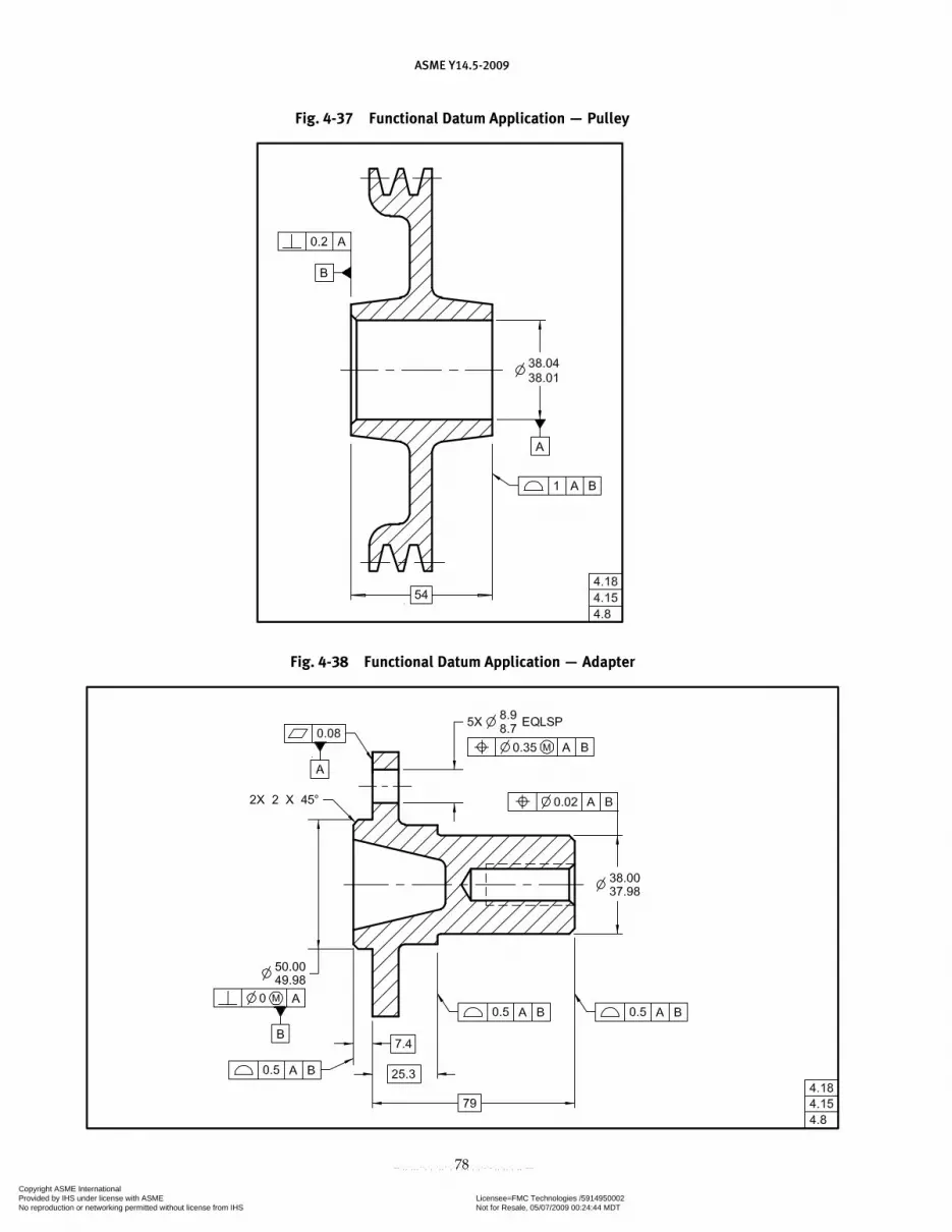
ASME Y14.5-2009
78
Fig. 4-37 Functional Datum Application — Pulley
Fig. 4-38 Functional Datum Application — Adapter
Copyright ASME International Provided by IHS under license with ASME Licensee=FMC Technologies /5914950002
Not for Resale, 05/07/2009 00:24:44 MDTNo reproduction or networking permitted without license from IHS
--`,,`,,,``,`,``,,``,`,`,,,`,`,`-`-`,,`,,`,`,,`---

ASME Y14.5-2009
79
thus creating a single pattern. Figures 4-39 and 4-40 show examples of simultaneous requirements. If such interre-lationship is not required, a notation such as SEP REQT is placed adjacent to each applicable feature control frame. See Figs. 4-41 and 7-54 and para. 7.5.4.2. This principle does not apply to the lower segments of composite fea-ture control frames. See para. 7.5.4.2. If a simultaneous requirement is desired for the lower segments of two or more composite feature control frames, a notation such as SIM REQT shall be placed adjacent to each applicable lower segment of the feature control frames.
4.20 RESTRAINED CONDITION
Unless otherwise specified, all tolerances apply in a free-state condition. In some cases, it may be desirable to restrain a part on its datum features to simulate their
function or interaction with other features or parts. To invoke a restrained condition, a note is specified or ref-erenced on the drawing defining the specific require-ments. See Fig. 4-42. This figure illustrates a part that should be restrained until sufficient reinforcement is added to retain its design shape. In this illustration, the restraint must be per a document referenced on the drawing. In a restrained application, it is permissible to use as many datum targets as necessary to establish the datum features.
4.21 DATUM REFERENCE FRAME IDENTIFICATION
Where a datum reference frame has been properly established and it is considered necessary to illustrate the axes of a datum reference frame on the drawing, the axes or center planes may be labeled to determine
Fig. 4-39 Simultaneous Position and Profile Tolerances
Copyright ASME International Provided by IHS under license with ASME Licensee=FMC Technologies /5914950002
Not for Resale, 05/07/2009 00:24:44 MDTNo reproduction or networking permitted without license from IHS
--`,,`,,,``,`,``,,``,`,`,,,`,`,`-`-`,,`,,`,`,,`---

ASME Y14.5-2009
80
Fig. 4-40 Aligned Features — Simultaneous Requirement
Fig. 4-41 Pattern of Features Not Aligned — Specified Separate Requirements
Copyright ASME International Provided by IHS under license with ASME Licensee=FMC Technologies /5914950002
Not for Resale, 05/07/2009 00:24:44 MDTNo reproduction or networking permitted without license from IHS
--`,,`,,,``,`,``,,``,`,`,,,`,`,`-`-`,,`,,`,`,,`---
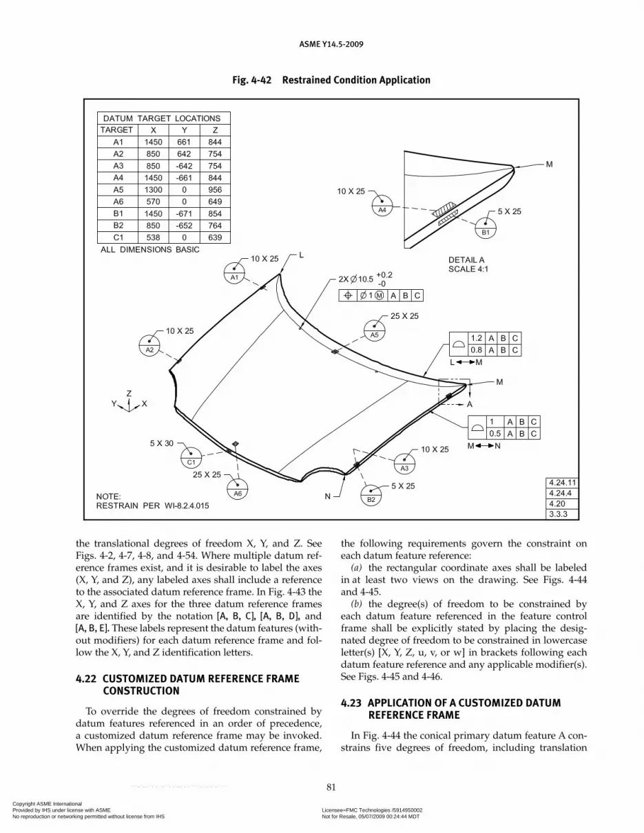
ASME Y14.5-2009
81
the translational degrees of freedom X, Y, and Z. See Figs. 4-2, 4-7, 4-8, and 4-54. Where multiple datum ref-erence frames exist, and it is desirable to label the axes (X, Y, and Z), any labeled axes shall include a reference to the associated datum reference frame. In Fig. 4-43 the X, Y, and Z axes for the three datum reference frames are identified by the notation [A, B, C], [A, B, D], and [A, B, E]. These labels represent the datum features (with-out modifiers) for each datum reference frame and fol-low the X, Y, and Z identification letters.
4.22 CUSTOMIZED DATUM REFERENCE FRAME CONSTRUCTION
To override the degrees of freedom constrained by datum features referenced in an order of precedence, a customized datum reference frame may be invoked. When applying the customized datum reference frame,
the following requirements govern the constraint on each datum feature reference:
(a) the rectangular coordinate axes shall be labeled in at least two views on the drawing. See Figs. 4-44 and 4-45.
(b) the degree(s) of freedom to be constrained by each datum feature referenced in the feature control frame shall be explicitly stated by placing the desig-nated degree of freedom to be constrained in lowercase letter(s) [X, Y, Z, u, v, or w] in brackets following each datum feature reference and any applicable modifier(s). See Figs. 4-45 and 4-46.
4.23 APPLICATION OF A CUSTOMIZED DATUM REFERENCE FRAME
In Fig. 4-44 the conical primary datum feature A con-strains five degrees of freedom, including translation
Fig. 4-42 Restrained Condition Application
Copyright ASME International Provided by IHS under license with ASME Licensee=FMC Technologies /5914950002
Not for Resale, 05/07/2009 00:24:44 MDTNo reproduction or networking permitted without license from IHS
--`,,`,,,``,`,``,,``,`,`,,,`,`,`-`-`,,`,,`,`,,`---

ASME Y14.5-2009
82
Fig. 4-43 Datum Reference Frame Identification
Fig. 4-44 Conical Datum Feature
Copyright ASME International Provided by IHS under license with ASME Licensee=FMC Technologies /5914950002
Not for Resale, 05/07/2009 00:24:44 MDTNo reproduction or networking permitted without license from IHS
--`,,`,,,``,`,``,,``,`,`,,,`,`,`-`-`,,`,,`,`,,`---

ASME Y14.5-2009
83
in Z. The origin of the datum reference frame to locate the 6-diameter hole is from the apex of the conical datum feature simulator. In some applications it may be necessary to customize the datum reference frame. The following are examples of applications of customized datum reference frames:
(a) In Fig. 4-45, the design intent is that the primary datum feature A constrains four degrees of freedom, excluding translation in Z. Secondary datum feature B is a thrust face and when customized constrains the translational degree of freedom (Z). The 6-diam-eter hole is located to the conical feature with transla-tion Z omitted. Secondary datum feature B constrains translation in Z. In this example, the declared degrees of constraint for datum feature A are X, Y, u, and v. The declared degree of constraint for datum feature B is Z.
(b) In Fig. 4-46 datum feature B would normally restrain two translational degrees of freedom, X and Y, and one rotational degree of freedom, w. See Fig. 4-3, illustration (f). The purpose of the square hole is to trans-fer torque but not to orient the part. Therefore, the design intent is that datum feature B restrains two translational
degrees of freedom, but not the rotational degree of freedom. In the position tolerance for the three holes, datum feature A constrains three degrees of freedom, Z, u, and v. Even though datum feature B would normally constrain the three remaining degrees of freedom, using the customized datum reference frame constraint require-ments, datum feature B constrains only two translational degrees of freedom, X and Y. Datum feature C, then, con-strains the remaining degree of rotational freedom, w.
4.24 DATUM TARGETS
Datum targets are the designated points, lines, or areas that are used in establishing a datum. Datum targets are used in establishing a datum reference frame. Because of inherent irregularities, the entire surface of some fea-tures cannot be effectively used to establish a datum. Examples are nonplanar or uneven surfaces produced by casting, forging, or molding; surfaces of weldments; and thin-section surfaces subject to bowing, warping, or other inherent or induced distortions. Datum tar-gets and datum features (as described earlier) may be
Fig. 4-45 Conical Datum Feature
Copyright ASME International Provided by IHS under license with ASME Licensee=FMC Technologies /5914950002
Not for Resale, 05/07/2009 00:24:44 MDTNo reproduction or networking permitted without license from IHS
--`,,`,,,``,`,``,,``,`,`,,,`,`,`-`-`,,`,,`,`,,`---
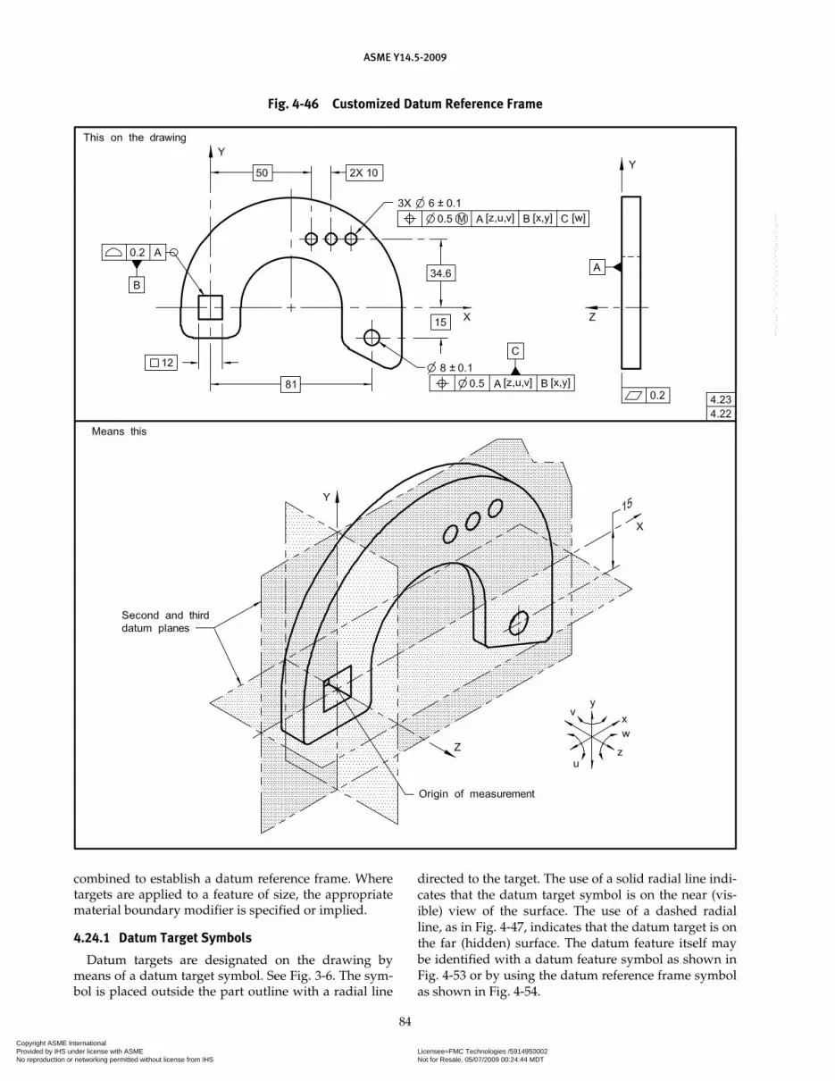
ASME Y14.5-2009
84
Fig. 4-46 Customized Datum Reference Frame
combined to establish a datum reference frame. Where targets are applied to a feature of size, the appropriate material boundary modifier is specified or implied.
4.24.1 Datum Target Symbols
Datum targets are designated on the drawing by means of a datum target symbol. See Fig. 3-6. The sym-bol is placed outside the part outline with a radial line
directed to the target. The use of a solid radial line indi-cates that the datum target symbol is on the near (vis-ible) view of the surface. The use of a dashed radial line, as in Fig. 4-47, indicates that the datum target is on the far (hidden) surface. The datum feature itself may be identified with a datum feature symbol as shown in Fig. 4-53 or by using the datum reference frame symbol as shown in Fig. 4-54.
Copyright ASME International Provided by IHS under license with ASME Licensee=FMC Technologies /5914950002
Not for Resale, 05/07/2009 00:24:44 MDTNo reproduction or networking permitted without license from IHS
--`,,`,,,``,`,``,,``,`,`,,,`,`,`-`-`,,`,,`,`,,`---
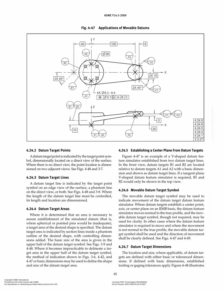
ASME Y14.5-2009
85
4.24.2 Datum Target Points
A datum target point is indicated by the target point sym-bol, dimensionally located on a direct view of the surface. Where there is no direct view, the point location is dimen-sioned on two adjacent views. See Figs. 4-48 and 3-7.
4.24.3 Datum Target Lines
A datum target line is indicated by the target point symbol on an edge view of the surface, a phantom line on the direct view, or both. See Figs. 4-48 and 3-8. Where the length of the datum target line must be controlled, its length and location are dimensioned.
4.24.4 Datum Target Areas
Where it is determined that an area is necessary to assure establishment of the simulated datum (that is, where spherical or pointed pins would be inadequate), a target area of the desired shape is specified. The datum target area is indicated by section lines inside a phantom outline of the desired shape, with controlling dimen-sions added. The basic size of the area is given in the upper half of the datum target symbol. See Figs. 3-9 and 4-48. Where it becomes impracticable to delineate a tar-get area in the upper half of the datum target symbol, the method of indication shown in Figs. 3-6, 4-42, and 4-47 or basic dimensions may be used to define the shape and size of the datum target area.
4.24.5 Establishing a Center Plane From Datum Targets
Figure 4-47 is an example of a V-shaped datum fea-ture simulator established from two datum target lines. In the front view, datum targets B1 and B2 are located relative to datum targets A1 and A2 with a basic dimen-sion and shown as datum target lines. If a tangent plane V-shaped datum feature simulator is required, B1 and B2 would only be shown in the top view.
4.24.6 Movable Datum Target Symbol
The movable datum target symbol may be used to indicate movement of the datum target datum feature simulator. Where datum targets establish a center point, axis, or center plane on an RMB basis, the datum feature simulator moves normal to the true profile, and the mov-able datum target symbol, though not required, may be used for clarity. In other cases where the datum feature simulator is required to move and where the movement is not normal to the true profile, the movable datum tar-get symbol shall be used and the direction of movement shall be clearly defined. See Figs. 4-47 and 4-49.
4.24.7 Datum Target Dimensions
The location and size, where applicable, of datum tar-gets are defined with either basic or toleranced dimen-sions. If defined with basic dimensions, established tooling or gaging tolerances apply. Figure 4-48 illustrates
Fig. 4-47 Applications of Movable Datums
Copyright ASME International Provided by IHS under license with ASME Licensee=FMC Technologies /5914950002
Not for Resale, 05/07/2009 00:24:44 MDTNo reproduction or networking permitted without license from IHS
--`,,`,,,``,`,``,,``,`,`,,,`,`,`-`-`,,`,,`,`,,`---
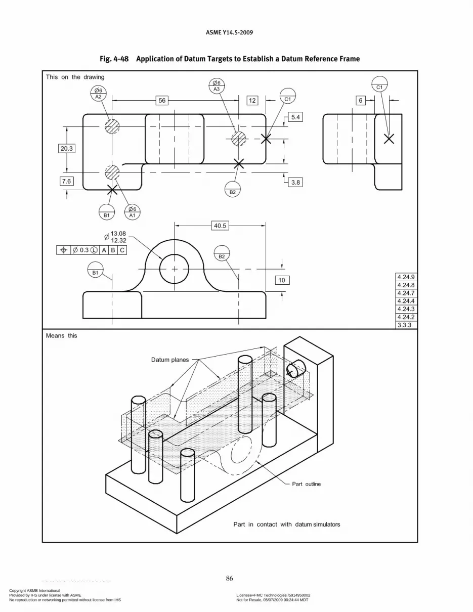
ASME Y14.5-2009
86
Fig. 4-48 Application of Datum Targets to Establish a Datum Reference Frame
Copyright ASME International Provided by IHS under license with ASME Licensee=FMC Technologies /5914950002
Not for Resale, 05/07/2009 00:24:44 MDTNo reproduction or networking permitted without license from IHS
--`,,`,,,``,`,``,,``,`,`,,,`,`,`-`-`,,`,,`,`,,`---
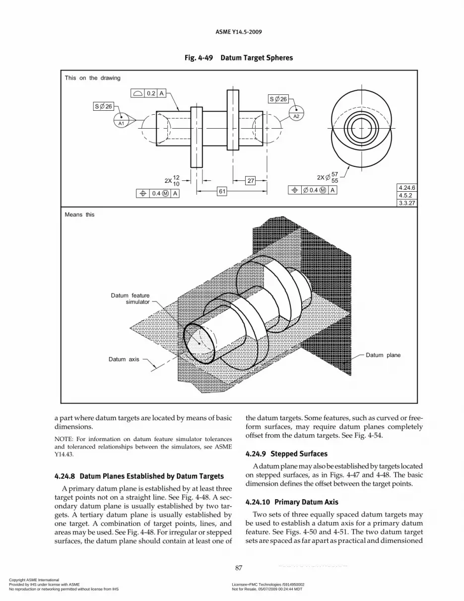
ASME Y14.5-2009
87
a part where datum targets are located by means of basic dimensions.
NOTE: For information on datum feature simulator tolerances and toleranced relationships between the simulators, see ASME Y14.43.
4.24.8 Datum Planes Established by Datum Targets
A primary datum plane is established by at least three target points not on a straight line. See Fig. 4-48. A sec-ondary datum plane is usually established by two tar-gets. A tertiary datum plane is usually established by one target. A combination of target points, lines, and areas may be used. See Fig. 4-48. For irregular or stepped surfaces, the datum plane should contain at least one of
the datum targets. Some features, such as curved or free-form surfaces, may require datum planes completely offset from the datum targets. See Fig. 4-54.
4.24.9 Stepped Surfaces
A datum plane may also be established by targets located on stepped surfaces, as in Figs. 4-47 and 4-48. The basic dimension defines the offset between the target points.
4.24.10 Primary Datum Axis
Two sets of three equally spaced datum targets may be used to establish a datum axis for a primary datum feature. See Figs. 4-50 and 4-51. The two datum target sets are spaced as far apart as practical and dimensioned
Fig. 4-49 Datum Target Spheres
Copyright ASME International Provided by IHS under license with ASME Licensee=FMC Technologies /5914950002
Not for Resale, 05/07/2009 00:24:44 MDTNo reproduction or networking permitted without license from IHS
--`,,`,,,``,`,``,,``,`,`,,,`,`,`-`-`,,`,,`,`,,`---

ASME Y14.5-2009
88
from the secondary datum feature. At RMB, a center-ing procedure used to establish the datum axis has two sets of three equally spaced contacting datum target simulators capable of moving radially at an equal rate from a common axis. To ensure repeatability of the location of the three datum target points, a tertiary datum feature may be necessary. For MMB, the center-ing procedure used to establish the datum axis has two sets of three equally spaced datum target simulators set at a fixed radial distance based on the maximum material boundary. Where two cylindrical datum fea-tures are used to establish a datum axis, as in Fig. 4-51, each datum feature is identified with a different letter.
4.24.11 Circular and Cylindrical Targets
Circular target lines and cylindrical target areas may be used to establish a datum axis on round features.
See Fig. 4-52. When a datum target area or datum target line is shown on a non-planar surface, the shape of the datum target line simulator is the same as the shape of the surface. In Fig. 4-42, the datum target area simula-tors for A1 through A5 are the same as the contour of the part surface.
4.24.12 Secondary Datum Axis
For a secondary datum feature, a set of three equally spaced targets may be used to establish a datum axis. See Fig. 4-53. In this example, the datum targets and the contacting datum feature simulators are oriented relative to the datum reference frame. At RMB, a typical center-ing method used to establish the datum axis has a set of three equally spaced contacting datum feature simula-tors capable of moving radially at an equal rate from a common axis that is perpendicular to the primary datum
Fig. 4-50 Primary Datum Axis Established by Datum Target Points on a Single Cylindrical Feature
Fig. 4-51 Primary and Secondary Datum Established by Datum Target Lines on Two Cylindrical Features and a Surface
Copyright ASME International Provided by IHS under license with ASME Licensee=FMC Technologies /5914950002
Not for Resale, 05/07/2009 00:24:44 MDTNo reproduction or networking permitted without license from IHS
--`,,`,,,``,`,``,,``,`,`,,,`,`,`-`-`,,`,,`,`,,`---

ASME Y14.5-2009
89
Fig. 4-52 Datum Target Line and Areas
Fig. 4-53 Secondary Datum Axis
plane. For MMB, the centering method used to establish the datum axis has a set of three equally spaced features set at a fixed radial distance based on the MMB.
4.24.13 Datums Established From Complex or Irregular Surfaces
Datum targets may be used to establish a datum from a complex or irregular surface. Where a datum reference frame has been properly established but its planes are unclear, the datum reference frame coordinate axes may be labeled to appropriate extension or center lines as needed. See Fig. 4-54. The datum feature symbol should
be attached only to identifiable datum features. Where datums are established by targets on complex or irregu-lar surfaces, the datum may be identified by a note such as DATUM AXIS A or DATUM PLANE A.
4.24.14 Datum Features Established From Datum Targets With Fewer Than Three Mutually Perpendicular Planes
When using datum features that are defined by datum targets in a feature control frame established by fewer than three mutually perpendicular planes, the datums that are the basis for the feature control frame shall be
Copyright ASME International Provided by IHS under license with ASME Licensee=FMC Technologies /5914950002
Not for Resale, 05/07/2009 00:24:44 MDTNo reproduction or networking permitted without license from IHS
--`,,`,,,``,`,``,,``,`,`,,,`,`,`-`-`,,`,,`,`,,`---
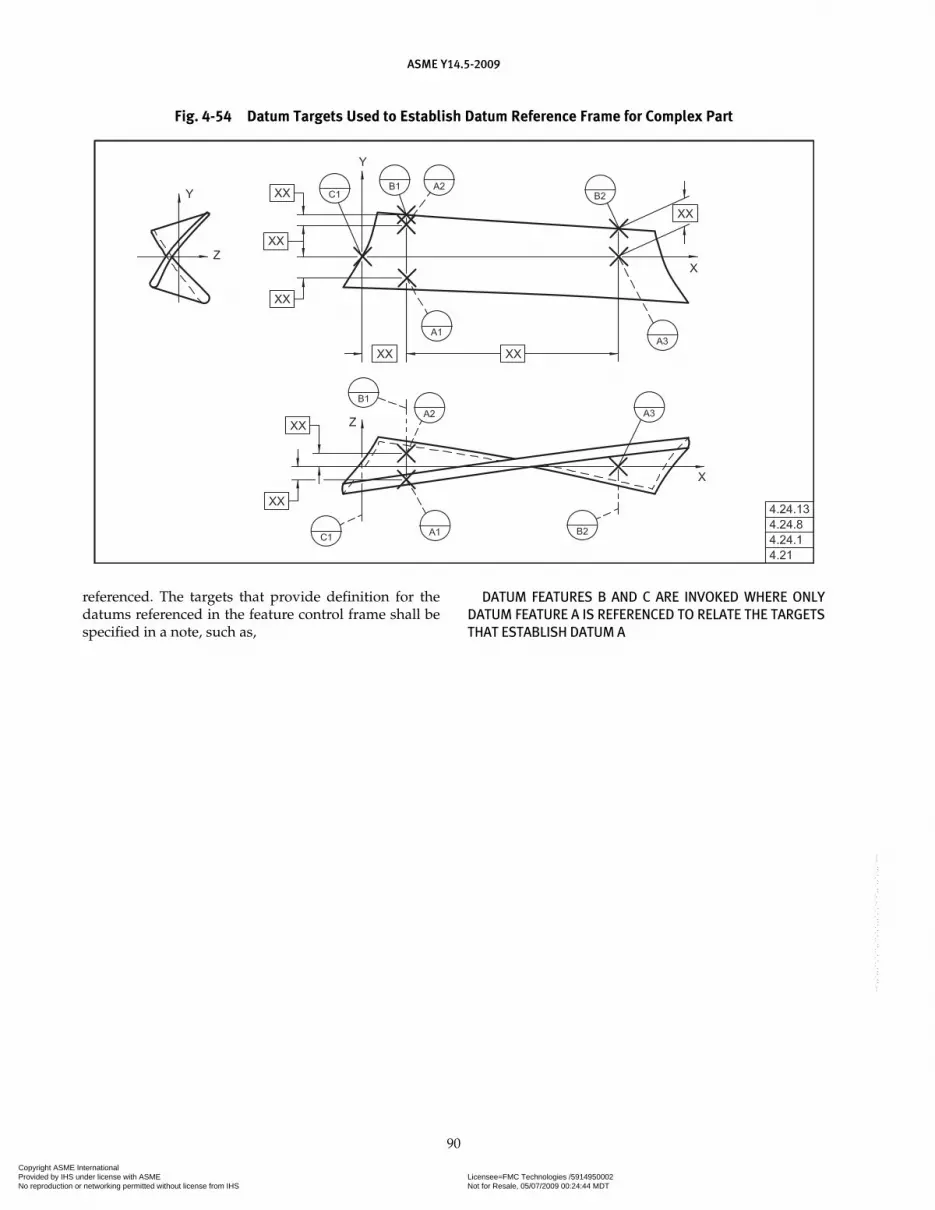
ASME Y14.5-2009
90
referenced. The targets that provide definition for the datums referenced in the feature control frame shall be specified in a note, such as,
DATUM FEATURES B AND C ARE INVOKED WHERE ONLY DATUM FEATURE A IS REFERENCED TO RELATE THE TARGETS THAT ESTABLISH DATUM A
Fig. 4-54 Datum Targets Used to Establish Datum Reference Frame for Complex Part
Copyright ASME International Provided by IHS under license with ASME Licensee=FMC Technologies /5914950002
Not for Resale, 05/07/2009 00:24:44 MDTNo reproduction or networking permitted without license from IHS
--`,,`,,,``,`,``,,``,`,`,,,`,`,`-`-`,,`,,`,`,,`---
Section 5Tolerances of Form
ASME Y14.5-2009
91
5.1 GENERAL
This Section establishes the principles and methods of dimensioning and tolerancing to control the form of features.
5.2 FORM CONTROL
Form tolerances control straightness, flatness, circu-larity, and cylindricity. When specifying a form toler-ance, consideration must be given to the control of form already established through other tolerances such as size (Rule #1), orientation, runout, and profile controls. See para. 2.7 and Fig. 2-6.
5.3 SPECIFYING FORM TOLERANCES
Form tolerances critical to function and interchange-ability are specified where the tolerances of size do not provide sufficient control. A tolerance of form may be specified where no tolerance of size is given (e.g., in the control of flatness after assembly of the parts). A form tolerance specifies a zone within which the considered feature, its line elements, its derived median line, or its derived median plane must be contained.
5.4 FORM TOLERANCES
Form tolerances are applicable to single (individual) features, elements of single features, or features of size; therefore, form tolerances are not related to datums. The following subparagraphs cover the particulars of the form tolerances: straightness, flatness, circularity, and cylindricity.
5.4.1 Straightness
Straightness is a condition where an element of a sur-face, or derived median line, is a straight line. A straight-ness tolerance specifies a tolerance zone within which the considered element of a surface or derived median line must lie. A straightness tolerance is applied in the view where the elements to be controlled are repre-sented by a straight line.
5.4.1.1 Cylindrical Features. Figure 5-1 shows an example of a cylindrical feature where all circular ele-ments of the surface are to be within the specified size tolerance. Each longitudinal element of the surface must
lie between two parallel lines separated by the amount of the prescribed straightness tolerance and in a plane com-mon with the axis of the unrelated actual mating enve-lope of the feature. The feature control frame is attached to a leader directed to the surface or extension line of the surface but not to the size dimension. The straightness tolerance must be less than the size tolerance and any other geometric tolerances that affect the straightness of line elements. Since the limits of size must be respected, the full straightness tolerance may not be available for opposite elements in the case of waisting or barreling of the surface. See Fig. 5-1. When the independency sym-bol is applied to the size dimension, the requirement for perfect form at MMC is removed and the form tolerance may be larger than the size tolerance.
5.4.1.2 Violation of MMC Boundary. Figures 5-2 and 5-3 show examples of cylindrical features where all circular elements of the surface are to be within the spec-ified size tolerance; however, the boundary of perfect form at MMC may be violated. This violation is permis-sible when the feature control frame is associated with the size dimension or attached to an extension of the dimension line. In this instance, a diameter symbol pre-cedes the tolerance value, and the tolerance is applied on either an RFS or MMC basis. Where necessary and when not used in conjunction with an orientation or posi-tion tolerance, the straightness tolerance may be greater than the size tolerance. Where the straightness tolerance is used in conjunction with an orientation tolerance or position tolerance value, the specified straightness toler-ance value shall not be greater than the specified orien-tation or position tolerance value. The collective effect of size and form variation can produce a virtual condi-tion or outer or inner boundary equal to the MMC size plus the straightness tolerance. When applied on an RFS basis, as in Fig. 5-2, the maximum straightness tolerance is the specified tolerance. When applied on an MMC basis, as in Fig. 5-3, the maximum straightness tolerance is the specified tolerance plus the amount the actual local size as the feature departs from its MMC size. The derived median line of an actual feature at MMC must lie within a cylindrical tolerance zone as specified. As each actual local size departs from MMC, an increase in the local diameter of the tolerance zone that is equal to the amount of such departure is allowed. Each circular element of the surface (that is, actual local size) must be within the specified limits of size.
Copyright ASME International Provided by IHS under license with ASME Licensee=FMC Technologies /5914950002
Not for Resale, 05/07/2009 00:24:44 MDTNo reproduction or networking permitted without license from IHS
--`,,`,,,``,`,``,,``,`,`,,,`,`,`-`-`,,`,,`,`,,`---

ASME Y14.5-2009
92
5.4.1.3 Applied on a Unit Basis. Straightness may be applied on a unit basis as a means of limiting an abrupt surface variation within a relatively short length of the feature. See Fig. 5-4. When using unit control on a fea-ture of size, a maximum limit is typically specified to limit the relatively large theoretical variations that may result if left unrestricted. If the unit variation appears as a “bow” in the toleranced feature, and the “bow” is allowed to continue at the same rate for several units, the overall tolerance variation may result in an unsatisfactory part. Figure 5-5 illustrates the possible condition where straightness per unit length given in Fig. 5-4 is used alone (i.e., if straightness for the total length is not specified).
5.4.1.4 Straightness of Line Elements. Figure 5-6 illustrates the use of straightness tolerance on a flat sur-face. Straightness may be applied to control line elements
in a single direction on a flat surface; it may also be applied in two directions as shown. Where function requires the line elements to be related to a datum feature(s), pro-file of a line should be specified related to datums. See Fig. 8-27.
5.4.2 Flatness
Flatness is the condition of a surface or derived median plane having all elements in one plane. A flat-ness tolerance specifies a tolerance zone defined by two parallel planes within which the surface or derived median plane must lie. When a flatness tolerance is spec-ified on a surface, the feature control frame is attached to a leader directed to the surface or to an extension line of the surface. It is placed in a view where the sur-face elements to be controlled are represented by a line. See Fig. 5-7. With flatness of a surface, where the con-sidered surface is associated with a size dimension, the flatness tolerance must be less than the size tolerance. When the independency symbol is applied to the size dimension, the requirement for perfect form at MMC is removed and the form tolerance may be larger than the size tolerance.
5.4.2.1 Application of Flatness RFS, MMC, or LMC to Noncylindrical Features. As an extension of the princi-ples of para. 5.4.1.2, flatness may be applied on an RFS, MMC, or LMC basis to noncylindrical features of size. In this instance, the derived median plane must lie in a tolerance zone between two parallel planes separated by the amount of the tolerance. Feature control frame
Fig. 5-2 Specifying Straightness RFSFig. 5-1 Specifying Straightness of Surface Elements
Copyright ASME International Provided by IHS under license with ASME Licensee=FMC Technologies /5914950002
Not for Resale, 05/07/2009 00:24:44 MDTNo reproduction or networking permitted without license from IHS
--`,,`,,,``,`,``,,``,`,`,,,`,`,`-`-`,,`,,`,`,,`---

ASME Y14.5-2009
93
Fig. 5-3 Specifying Straightness at MMC
Fig. 5-4 Specifying Straightness Per Unit Length With Specified Total Straightness, Both RFS
Copyright ASME International Provided by IHS under license with ASME Licensee=FMC Technologies /5914950002
Not for Resale, 05/07/2009 00:24:44 MDTNo reproduction or networking permitted without license from IHS
--`,,`,,,``,`,``,,``,`,`,,,`,`,`-`-`,,`,,`,`,,`---
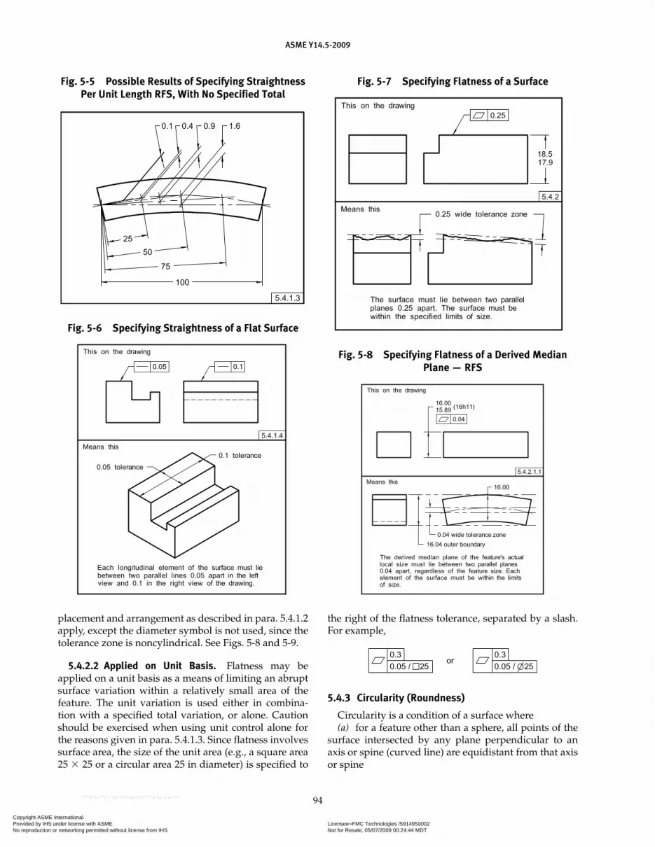
ASME Y14.5-2009
94
placement and arrangement as described in para. 5.4.1.2 apply, except the diameter symbol is not used, since the tolerance zone is noncylindrical. See Figs. 5-8 and 5-9.
5.4.2.2 Applied on Unit Basis. Flatness may be applied on a unit basis as a means of limiting an abrupt surface variation within a relatively small area of the feature. The unit variation is used either in combina-tion with a specified total variation, or alone. Caution should be exercised when using unit control alone for the reasons given in para. 5.4.1.3. Since flatness involves surface area, the size of the unit area (e.g., a square area 25 � 25 or a circular area 25 in diameter) is specified to
the right of the flatness tolerance, separated by a slash. For example,
5.4.3 Circularity (Roundness)
Circularity is a condition of a surface where(a) for a feature other than a sphere, all points of the
surface intersected by any plane perpendicular to an axis or spine (curved line) are equidistant from that axis or spine
Fig. 5-5 Possible Results of Specifying Straightness Per Unit Length RFS, With No Specified Total
Fig. 5-6 Specifying Straightness of a Flat Surface
Fig. 5-7 Specifying Flatness of a Surface
Fig. 5-8 Specifying Flatness of a Derived Median Plane — RFS
Copyright ASME International Provided by IHS under license with ASME Licensee=FMC Technologies /5914950002
Not for Resale, 05/07/2009 00:24:44 MDTNo reproduction or networking permitted without license from IHS
--`,,`,,,``,`,``,,``,`,`,,,`,`,`-`-`,,`,,`,`,,`---
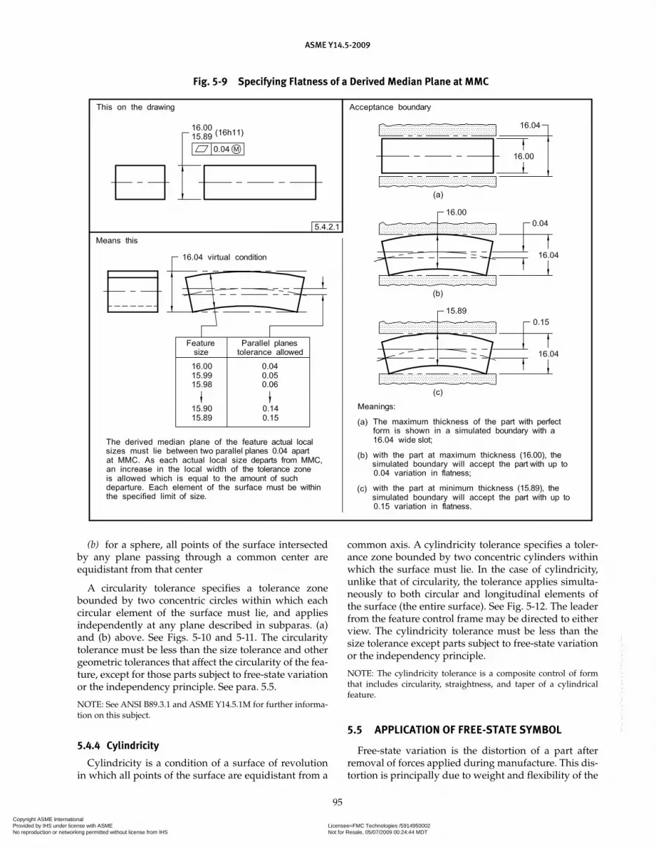
ASME Y14.5-2009
95
Fig. 5-9 Specifying Flatness of a Derived Median Plane at MMC
(b) for a sphere, all points of the surface intersected by any plane passing through a common center are equidistant from that center
A circularity tolerance specifies a tolerance zone bounded by two concentric circles within which each circular element of the surface must lie, and applies independently at any plane described in subparas. (a) and (b) above. See Figs. 5-10 and 5-11. The circularity tolerance must be less than the size tolerance and other geometric tolerances that affect the circularity of the fea-ture, except for those parts subject to free-state variation or the independency principle. See para. 5.5.
NOTE: See ANSI B89.3.1 and ASME Y14.5.1M for further informa-tion on this subject.
5.4.4 Cylindricity
Cylindricity is a condition of a surface of revolution in which all points of the surface are equidistant from a
common axis. A cylindricity tolerance specifies a toler-ance zone bounded by two concentric cylinders within which the surface must lie. In the case of cylindricity, unlike that of circularity, the tolerance applies simulta-neously to both circular and longitudinal elements of the surface (the entire surface). See Fig. 5-12. The leader from the feature control frame may be directed to either view. The cylindricity tolerance must be less than the size tolerance except parts subject to free-state variation or the independency principle.
NOTE: The cylindricity tolerance is a composite control of form that includes circularity, straightness, and taper of a cylindrical feature.
5.5 APPLICATION OF FREE-STATE SYMBOL
Free-state variation is the distortion of a part after removal of forces applied during manufacture. This dis-tortion is principally due to weight and flexibility of the
Copyright ASME International Provided by IHS under license with ASME Licensee=FMC Technologies /5914950002
Not for Resale, 05/07/2009 00:24:44 MDTNo reproduction or networking permitted without license from IHS
--`,,`,,,``,`,``,,``,`,`,,,`,`,`-`-`,,`,,`,`,,`---

ASME Y14.5-2009
96
Fig. 5-10 Specifying Circularity for a Cylinder or Cone
Fig. 5-11 Specifying Circularity of a Sphere Fig. 5-12 Specifying Cylindricity
part and the release of internal stresses resulting from fabrication. A part of this kind (e.g., a part with a very thin wall in proportion to its diameter) is referred to as a nonrigid part. In some cases, it may be required that the part meet its tolerance requirements while in the free state. See Fig. 5-13. In others, it may be necessary to simulate the mating part interface to verify individual or related feature tolerances. This is done by restraining
the appropriate features, such as the datum features in Fig. 5-14. The restraining forces are those that would be exerted in the assembly or functioning of the part. However, if the dimensions and tolerances are met in the free state, it is usually not necessary to restrain the part unless the effect of subsequent restraining forces on the concerned features could cause other features of the part to exceed specified limits. Free-state variation
Copyright ASME International Provided by IHS under license with ASME Licensee=FMC Technologies /5914950002
Not for Resale, 05/07/2009 00:24:44 MDTNo reproduction or networking permitted without license from IHS
--`,,`,,,``,`,``,,``,`,`,,,`,`,`-`-`,,`,,`,`,,`---
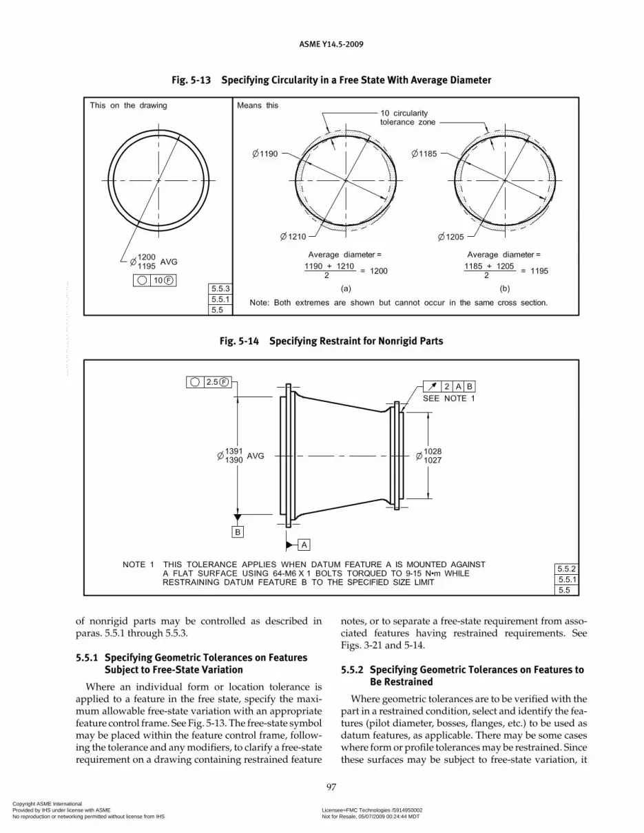
ASME Y14.5-2009
97
of nonrigid parts may be controlled as described in paras. 5.5.1 through 5.5.3.
5.5.1 Specifying Geometric Tolerances on Features Subject to Free-State Variation
Where an individual form or location tolerance is applied to a feature in the free state, specify the maxi-mum allowable free-state variation with an appropriate feature control frame. See Fig. 5-13. The free-state symbol may be placed within the feature control frame, follow-ing the tolerance and any modifiers, to clarify a free-state requirement on a drawing containing restrained feature
notes, or to separate a free-state requirement from asso-ciated features having restrained requirements. See Figs. 3-21 and 5-14.
5.5.2 Specifying Geometric Tolerances on Features to Be Restrained
Where geometric tolerances are to be verified with the part in a restrained condition, select and identify the fea-tures (pilot diameter, bosses, flanges, etc.) to be used as datum features, as applicable. There may be some cases where form or profile tolerances may be restrained. Since these surfaces may be subject to free-state variation, it
Fig. 5-13 Specifying Circularity in a Free State With Average Diameter
Fig. 5-14 Specifying Restraint for Nonrigid Parts
Copyright ASME International Provided by IHS under license with ASME Licensee=FMC Technologies /5914950002
Not for Resale, 05/07/2009 00:24:44 MDTNo reproduction or networking permitted without license from IHS
--`,,`,,,``,`,``,,``,`,`,,,`,`,`-`-`,,`,,`,`,,`---

ASME Y14.5-2009
98
is necessary to specify the maximum force necessary to restrain each of them. Determine the amount of the restraining or holding forces and other requirements necessary to simulate expected assembly conditions. Specify on the drawing that if restrained to this condi-tion, the remainder of the part or certain features thereof shall be within stated tolerances. See Fig. 5-14.
5.5.3 Average Diameter
An average diameter is the average of several diamet-ric measurements across a circular or cylindrical fea-ture. Normally, enough (at least four) measurements are taken to ensure the establishment of an average diame-ter. If practical, an average diameter may be determined by a peripheral tape measurement. Where form control,
such as circularity, is specified in a free state for a circu-lar or cylindrical feature, the pertinent diameter is quali-fied with the abbreviation AVG. See Fig. 5-13. Specifying circularity on the basis of an average diameter on a non-rigid part is necessary to ensure that the actual diam-eter of the feature can be restrained to the desired shape at assembly. Note that the free-state circularity toler-ance is greater than the size tolerance on the diameter. Figure 5-13, illustrations (a) and (b), simplified by showing only two measurements, give the permissible diameters in the free state for two extreme conditions of maximum average diameter and minimum average diameter, respectively. The same method applies when the average diameter is anywhere between maximum and minimum limits.
Copyright ASME International Provided by IHS under license with ASME Licensee=FMC Technologies /5914950002
Not for Resale, 05/07/2009 00:24:44 MDTNo reproduction or networking permitted without license from IHS
--`,,`,,,``,`,``,,``,`,`,,,`,`,`-`-`,,`,,`,`,,`---

Section 6Tolerances of Orientation
ASME Y14.5-2009
99
6.1 GENERAL
This Section establishes the principles and methods of dimensioning and tolerancing to control orientation of features.
6.2 ORIENTATION CONTROL
An orientation tolerance controls parallel, perpen-dicular, and all other angular relationships. Note that an orientation tolerance, when applied to a plane sur-face, controls flatness to the extent of the orientation tolerance. When the flatness control in the orientation tolerance is not sufficient, a separate flatness tolerance should be considered. An orientation tolerance does not control the location of features. When specifying an ori-entation tolerance, consideration must be given to the control of orientation already established through other tolerances such as location, runout, and profile controls. See Fig. 7-8.
6.3 ORIENTATION SYMBOLS
There are three orientation relationships and three sym-bols to define those relationships. The three orientation relationships are noted in paras. 6.3.1 through 6.3.3.
6.3.1 Angularity
Angularity is the condition of a surface, feature’s center plane, or feature’s axis at any specified angle from a datum plane or datum axis. See Fig. 3-1.
6.3.2 Parallelism
Parallelism is the condition of a surface or feature’s center plane, equidistant at all points from a datum plane; or a feature’s axis, equidistant along its length from one or more datum planes or datum axis. See Fig. 3-1.
6.3.3 Perpendicularity
Perpendicularity is the condition of a surface, fea-ture’s center plane, or feature’s axis at a right angle to a datum plane or datum axis. See Fig. 3-1.
6.4 SPECIFYING ORIENTATION TOLERANCES
When specifying an orientation tolerance, the consid-ered feature shall be related to one or more datums. See Figs. 4-4 and 6-4. Orientation tolerances are constrained
only in rotational degrees of freedom relative to the referenced datums; they are not constrained in the translational degrees of freedom. Thus, with orienta-tion tolerances, even in those instances where datum features may constrain all degrees of freedom, the toler-ance zone only orients to that datum reference frame. Sufficient datum features should be referenced to con-strain the required rotational degrees of freedom. If the primary datum feature alone does not constrain suf-ficient degrees of freedom, additional datum features may be specified.
6.4.1 Orientation Tolerance Zone
An orientation tolerance specifies a zone within which the considered feature, its line elements, its axis, or its center plane must be contained.
6.4.2 Orientation Tolerance
An orientation tolerance specifies one of the following:(a) a tolerance zone defined by two parallel planes
at the specified basic angle from, parallel to, or perpen-dicular to one or more datum planes or a datum axis, within which the surface or center plane of the consid-ered feature must lie. See Figs. 6-1 through 6-5.
(b) a tolerance zone defined by two parallel planes at the specified basic angle from, parallel to, or perpen-dicular to one or more datum planes or a datum axis, within which the axis of the considered feature must lie. See Figs. 6-6 and 6-7.
(c) a cylindrical tolerance zone at the specified basic angle from, parallel to, or perpendicular to one or more datum planes or a datum axis, within which the axis of the considered feature must lie. See Figs. 6-8 through 6-15.
(d) a tolerance zone defined by two parallel lines at the specified basic angle from, parallel to, or perpen-dicular to a datum plane or axis, within which the line element of the surface must lie. See Figs. 6-16 and 6-17.
6.4.3 Tolerance Zones
Tolerance zones apply to the full extent of the fea-ture, unless otherwise indicated. Where it is a require-ment to control only individual line elements of a surface, a qualifying notation, such as EACH ELEMENT or EACH RADIAL ELEMENT, is added to the drawing. See Figs. 6-16 and 6-17. This permits control of individual elements of the surface independently in relation to the datum and does not limit the total surface to an
Copyright ASME International Provided by IHS under license with ASME Licensee=FMC Technologies /5914950002
Not for Resale, 05/07/2009 00:24:44 MDTNo reproduction or networking permitted without license from IHS
--`,,`,,,``,`,``,,``,`,`,,,`,`,`-`-`,,`,,`,`,,`---
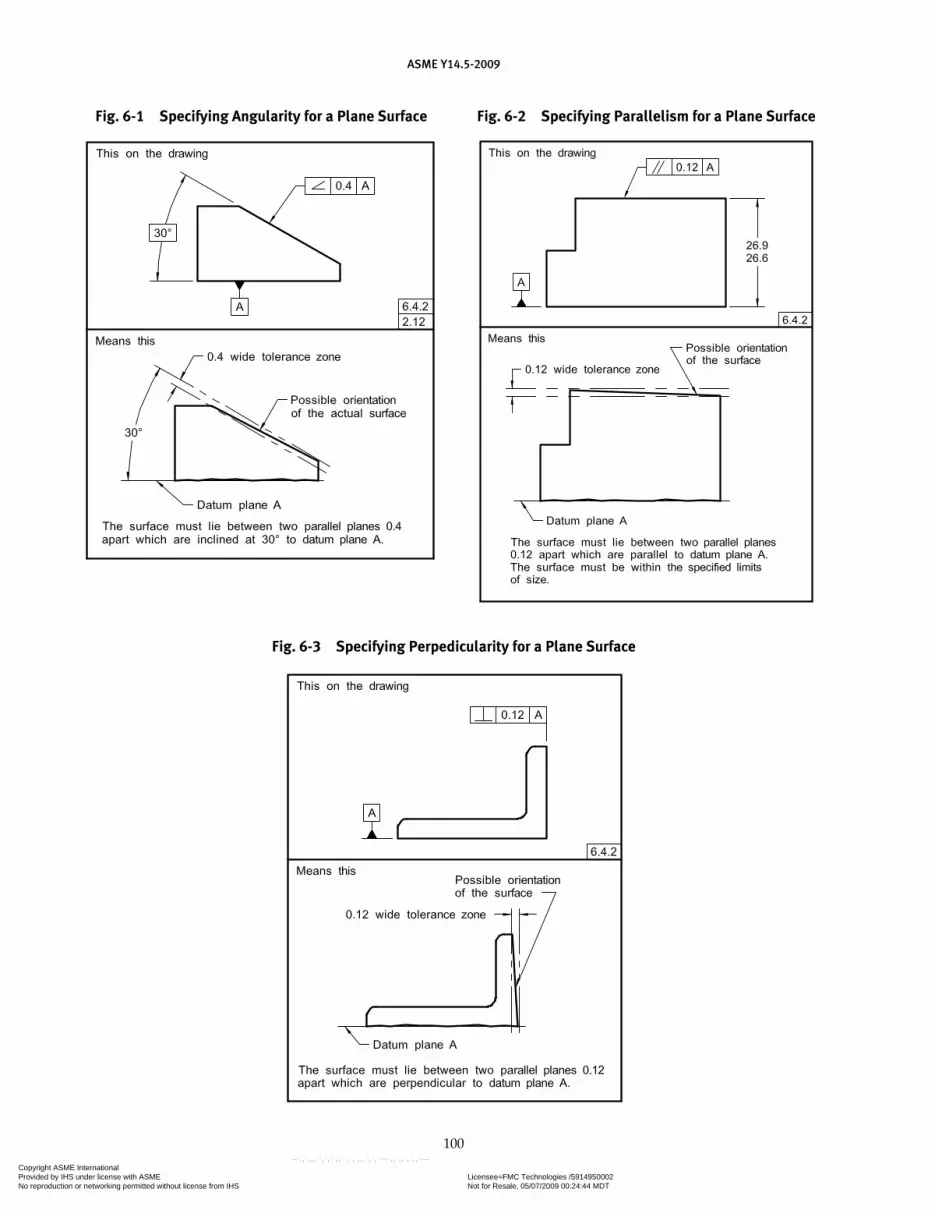
ASME Y14.5-2009
100
Fig. 6-1 Specifying Angularity for a Plane Surface Fig. 6-2 Specifying Parallelism for a Plane Surface
Fig. 6-3 Specifying Perpedicularity for a Plane Surface
Copyright ASME International Provided by IHS under license with ASME Licensee=FMC Technologies /5914950002
Not for Resale, 05/07/2009 00:24:44 MDTNo reproduction or networking permitted without license from IHS
--`,,`,,,``,`,``,,``,`,`,,,`,`,`-`-`,,`,,`,`,,`---
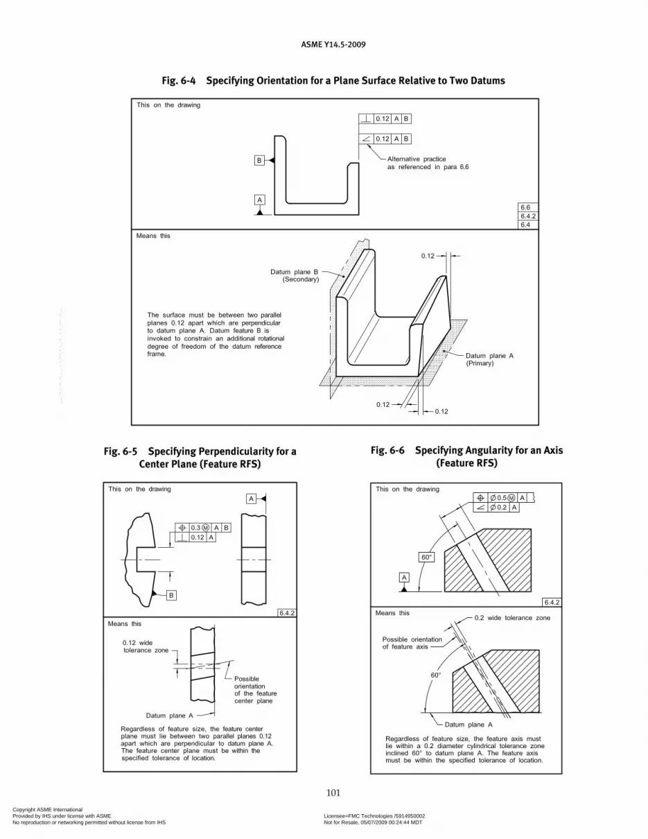
ASME Y14.5-2009
101
Fig. 6-4 Specifying Orientation for a Plane Surface Relative to Two Datums
Fig. 6-5 Specifying Perpendicularity for a Center Plane (Feature RFS)
Fig. 6-6 Specifying Angularity for an Axis (Feature RFS)
Copyright ASME International Provided by IHS under license with ASME Licensee=FMC Technologies /5914950002
Not for Resale, 05/07/2009 00:24:44 MDTNo reproduction or networking permitted without license from IHS
--`,,`,,,``,`,``,,``,`,`,,,`,`,`-`-`,,`,,`,`,,`---

ASME Y14.5-2009
102
Fig. 6-7 Specifying Parallelism for an Axis (Feature RFS)
Fig. 6-8 Specifying Angularity for an Axis (Feature RFS)
encompassing zone. Although orientation tolerances are only constrained in rotational degrees of freedom relative to the referenced datums, the notation of EACH RADIAL ELEMENT adds a requirement for the tolerance zone(s) to be constrained in location relative to the axis from which the radial elements emanate. Tolerances for individual elements may also be specified using a line profile tolerance.
6.4.4 Application of Zero Tolerance at MMC
Where no variations of orientation are permitted at the MMC size limit of a feature of size, the feature con-trol frame contains a zero for the tolerance, modified by the symbol for MMC. If the feature of size is at its MMC limit of size, it must be perfect in orientation with respect to the datum. A tolerance can exist only as the feature of size departs from MMC. The allowable orientation tolerance is equal to the amount of such departure. See Figs. 6-14 and 6-15. These principles are also applicable to features of size toleranced for orientation at LMC. There may be applications where the full additional tolerance allowable may not meet the functional requirements.
In such cases, the amount of additional tolerance may be limited by stating a MAX following the MMC modifier. See Fig. 6-15.
6.4.5 Explanation of Orientation Tolerance at MMC
An orientation tolerance applied at MMC may be explained in terms of the surface or the feature axis. In certain cases of extreme form deviation (within limits of size) of the hole, the tolerance in terms of the feature axis may not be exactly equivalent to the tolerance in terms of the surface. In such cases, the surface interpretation shall take precedence as in Fig. 7-6.
(a) In Terms of the Surface of a Hole. While maintaining the specified size limits of the hole, no element of the hole surface shall be inside a theoretical boundary (vir-tual condition) oriented to the datum reference frame. See Fig. 7-6.
(b) In Terms of the Axis of a Hole. Where a hole is at MMC (minimum diameter), the feature axis must fall within a cylindrical tolerance zone whose axis is oriented to the datum reference frame. The diam-eter of this zone is equal to the orientation tolerance.
Copyright ASME International Provided by IHS under license with ASME Licensee=FMC Technologies /5914950002
Not for Resale, 05/07/2009 00:24:44 MDTNo reproduction or networking permitted without license from IHS
--`,,`,,,``,`,``,,``,`,`,,,`,`,`-`-`,,`,,`,`,,`---

ASME Y14.5-2009
103
Fig. 6-9 Specifying Parallelism for an Axis (Both Feature and Datum Feature RFS)
Fig. 6-10 Specifying Parallelism for an Axis (Feature at MMC and Datum Feature RFS)
See Fig. 6-14. It is only where the hole is at MMC that the specified tolerance zone applies. Where the unre-lated actual mating envelope size of the hole is larger than MMC, additional orientation tolerance results. This increase of orientation tolerance is equal to the differ-ence between the specified maximum material condi-tion limit of size (MMC) and the unrelated actual mating envelope size of the hole. Where the unrelated actual mating envelope size is larger than MMC, the specified orientation tolerance for a hole may be exceeded and still satisfy function and interchangeability requirements.
NOTE: These concepts are equally applicable to all features of size.
6.5 TANGENT PLANE
Where it is desired to control a tangent plane estab-lished by the contacting points of a surface, the tangent
plane symbol is added in the feature control frame after the stated tolerance. See Fig. 6-18. Where a tangent plane symbol is specified with a geometric tolerance, the flat-ness of the toleranced feature is not controlled by the geometric tolerance. Where the tangent plane rocks on a convex surface, see ASME Y14.5.1M for methods of verification.
NOTE: The tangent plane symbol is illustrated with orientation tolerances; however, it may also have applications using other geometric characteristic symbols where the feature is related to a datum(s).
6.6 ALTERNATIVE PRACTICE
As an alternative practice, the angularity symbol may be used to control parallel and perpendicular relation-ships. The tolerance zones derived are the same as those described in para. 6.4.2. See Fig. 6-4.
Copyright ASME International Provided by IHS under license with ASME Licensee=FMC Technologies /5914950002
Not for Resale, 05/07/2009 00:24:44 MDTNo reproduction or networking permitted without license from IHS
--`,,`,,,``,`,``,,``,`,`,,,`,`,`-`-`,,`,,`,`,,`---

ASME Y14.5-2009
104
Fig. 6-11 Specifying Perpendicularity for an Axis at a Projected Height (Threaded Hole or Insert at MMC)
Fig. 6-12 Specifying Perpendicularity for an Axis (Pin or Boss RFS)
Copyright ASME International Provided by IHS under license with ASME Licensee=FMC Technologies /5914950002
Not for Resale, 05/07/2009 00:24:44 MDTNo reproduction or networking permitted without license from IHS
--`,,`,,,``,`,``,,``,`,`,,,`,`,`-`-`,,`,,`,`,,`---

ASME Y14.5-2009
105
Fig. 6-13 Specifying Perpendicularity for an Axis Showing Acceptance Boundary (PIN or Boss at MMC)
Copyright ASME International Provided by IHS under license with ASME Licensee=FMC Technologies /5914950002
Not for Resale, 05/07/2009 00:24:44 MDTNo reproduction or networking permitted without license from IHS
--`,,`,,,``,`,``,,``,`,`,,,`,`,`-`-`,,`,,`,`,,`---

ASME Y14.5-2009
106
Fig. 6-14 Specifying Perpendicularity for an Axis (Zero Tolerance at MMC)
Fig. 6-15 Specifying Perpendicularity for an Axis (Zero Tolerance at MMC With a Maximum Specified)
Copyright ASME International Provided by IHS under license with ASME Licensee=FMC Technologies /5914950002
Not for Resale, 05/07/2009 00:24:44 MDTNo reproduction or networking permitted without license from IHS
--`,,`,,,``,`,``,,``,`,`,,,`,`,`-`-`,,`,,`,`,,`---

ASME Y14.5-2009
107
Fig. 6-16 Specifying Perpendicularity for a Radial Element of a Surface
Fig. 6-17 Specifying Perpendicularity for a Radial Element of a Surface
Fig. 6-18 Specifying a Tangent Plane
Copyright ASME International Provided by IHS under license with ASME Licensee=FMC Technologies /5914950002
Not for Resale, 05/07/2009 00:24:44 MDTNo reproduction or networking permitted without license from IHS
--`,,`,,,``,`,``,,``,`,`,,,`,`,`-`-`,,`,,`,`,,`---

Section 7Tolerances of Location
ASME Y14.5-2009
108
7.1 GENERAL
This Section establishes the principles of tolerances of location. Included are position, concentricity, and sym-metry used to control the following relationships:
(a) center distance between features of size such as holes, slots, bosses, and tabs
(b) location of features of size [such as in subpara. (a) above] as a group, from datum features, such as plane and cylindrical surfaces
(c) coaxiality of features of size(d) concentricity or symmetry of features of size—
center distances of correspondingly located feature ele-ments equally disposed about a datum axis or plane
7.2 POSITIONAL TOLERANCING
Position is the location of one or more features of size relative to one another or to one or more datums. A posi-tional tolerance defines either of the following:
(a) a zone within which the center, axis, or center plane of a feature of size is permitted to vary from a true (theoretically exact) position
(b) (where specified on an MMC or LMC basis) a boundary, defined as the virtual condition, located at the true (theoretically exact) position, that may not be vio-lated by the surface or surfaces of the considered feature of size.
Basic dimensions establish the true position from specified datums and between interrelated features. A positional tolerance is indicated by the position symbol, a tolerance value, applicable material condition modi-fiers, and appropriate datum references placed in a fea-ture control frame.
7.2.1 Components of Positional Tolerancing
The following subparagraphs describe the compo-nents of positional tolerancing.
7.2.1.1 Dimensions for True Position. Dimensions used to locate true position shall be basic and defined in accordance with para. 2.1.1.2. See Fig. 7-1. For applicable notes in digital data files, see ASME Y14.41.
7.2.1.2 Use of Feature Control Frame. A feature con-trol frame is added to the notation used to specify the size
and number of features. See Figs. 7-2 through 7-4. These figures show different types of feature pattern dimen-sioning. Figure 7-3, illustration (b) is a screen image of a digital data file with positional tolerance feature control frames and the required datum feature symbols.
7.2.1.3 Identifying Features to Establish Datums. It is necessary to identify features or features of size on a part to establish datums for dimensions locating true positions except where the positioned features establish the primary datum. (The exception is explained in para. 7.6.2.3.) For example, in Fig. 7-2, if datum references had been omitted, it would not be clear whether the inside diameter or the outside diameter was the intended datum feature for the dimensions locating true posi-tions. The intended datum features are identified with datum feature symbols, and the applicable datum fea-ture references are included in the feature control frame. For information on specifying datums in an order of precedence, see para. 4.10.
7.3 POSITIONAL TOLERANCING FUNDAMENTALS: I
The following is a general explanation of positional tolerancing.
7.3.1 Material Condition Basis
Positional tolerancing is applied on an MMC, RFS, or LMC basis. Where MMC or LMC is required, the appropriate modifier follows the specified tolerance. See para. 2.8.
7.3.2 RFS as Related to Positional Tolerancing
The design or function of a part may require the positional tolerance, datum reference, or both, to be main-tained regardless of the features’ actual mating envelope sizes. RFS, where applied to the positional tolerance of circular features of size, requires the axis or center point of each feature of size to be located within the specified positional tolerance regardless of the size of the feature. In Fig. 7-5, the six holes may vary in size from 25 to 25.6 diameter. Each hole must be located within the specified positional tolerance regardless of the size of that hole. A positional tolerance applied at RFS is more restrictive than the same positional tolerance applied at MMC or LMC.
Copyright ASME International Provided by IHS under license with ASME Licensee=FMC Technologies /5914950002
Not for Resale, 05/07/2009 00:24:44 MDTNo reproduction or networking permitted without license from IHS
--`,,`,,,``,`,``,,``,`,`,,,`,`,`-`-`,,`,,`,`,,`---

ASME Y14.5-2009
109
7.3.3 MMC as Related to Positional Tolerancing
The positional tolerance and maximum material con-dition of mating features are considered in relation to each other.
7.3.3.1 Explanation of Positional Tolerance at MMC. A positional tolerance applied at MMC may be explained in terms of the surface or the axis of the feature of size. In certain cases of extreme form deviation (within limits of size) or orientation deviation of the hole, the tolerance in terms of the axis may not be exactly equivalent to the tolerance in terms of the surface. See Fig. 7-6. In such cases, the surface interpretation shall take precedence. In some instances, the additional tolerance may indi-rectly benefit features other than the one that departed from MMC.
(a) Surface Interpretation. While maintaining the speci-fied size limits of the feature, no element of the surface shall violate a theoretical boundary (virtual condition) located at true position. See Fig. 7-7.
(b) Axis or Center Plane Interpretation. Where a fea-ture of size is at MMC, its axis or center plane must fall within a tolerance zone located at true position. The size of this zone is equal to the positional toler-ance. See Fig. 7-8, illustrations (a) and (b). This toler-ance zone also defines the limits of variation in the orientation of the axis or center plane of the feature of size in relation to the datum surface. See Fig. 7-8, illustration (c). It is only where the feature of size is at MMC that the specified tolerance zone applies. Where the unrelated actual mating envelope size of the feature of size departs from MMC, additional positional toler-ance results. See Fig. 7-9. This increase of positional tolerance is equal to the difference between the speci-fied maximum material condition limit of size (MMC) and the unrelated actual mating envelope size. Where the unrelated actual mating envelope size has departed from MMC, the specified positional tolerance for a feature of size may be larger than the stated value and still satisfy function and interchangeability requirements.
7.3.3.2 Calculating Positional Tolerance. Figure 7-10 shows a drawing for one of two identical plates to be assembled with four 14-mm maximum diam-eter fasteners. The 14.25 minimum diameter clearance holes are selected with a size tolerance as shown. The required positional tolerance is found by the equation and other considerations as given in Nonmandatory Appendix B. The shown formula does not accom-modate factors other than hole and fastener diameter tolerances.
T = H − F
= 14.25 − 14
= 0.25 diameter
Fig. 7-1 Identifying Basic Dimensions
Copyright ASME International Provided by IHS under license with ASME Licensee=FMC Technologies /5914950002
Not for Resale, 05/07/2009 00:24:44 MDTNo reproduction or networking permitted without license from IHS
--`,,`,,,``,`,``,,``,`,`,,,`,`,`-`-`,,`,,`,`,,`---

ASME Y14.5-2009
110
Fig. 7-2 Positional Tolerancing With Datum References
NOTE: If the clearance holes were located exactly at true position, the parts would still assemble with clearance holes as small as 14 diameter (or slightly larger). However, otherwise usable parts having clearance holes smaller than 14.25 diameter would be rejected for violating size limits.
7.3.4 Zero Positional Tolerance at MMC
The application of MMC permits the position toler-ance zone to increase larger than the value specified, provided the features of size are within size limits, and the feature of size locations are such as to make the part acceptable. However, rejection of usable parts can occur where these features of size are actually located on or close to their true positions, but produced to a size smaller than the specified minimum (outside of limits). The principle of positional tolerancing at MMC allows the maximum amount of tolerance for the func-tion of assembly. This is accomplished by adjusting the
minimum size limit of a hole to the absolute minimum required for insertion of an applicable maximum fas-tener located precisely at true position, and specifying a zero positional tolerance at MMC. In this case, the positional tolerance allowed is totally dependent on the unrelated actual mating envelope size of the con-sidered feature, as explained in para. 2.8.3. Figure 7-11 shows a drawing of the same part with a zero posi-tional tolerance at MMC specified. Note that the maxi-mum size limit of the clearance holes remains the same, but the minimum was adjusted to correspond with a 14-mm diameter fastener. This results in an increase in the size tolerance for the clearance holes, with the increase being equal to the positional tolerance speci-fied in Fig. 7-10. Although the positional tolerance specified in Fig. 7-11 is zero at MMC, the positional tol-erance allowed increases directly with the actual clear-ance hole size as shown by the following tabulation:
Copyright ASME International Provided by IHS under license with ASME Licensee=FMC Technologies /5914950002
Not for Resale, 05/07/2009 00:24:44 MDTNo reproduction or networking permitted without license from IHS
--`,,`,,,``,`,``,,``,`,`,,,`,`,`-`-`,,`,,`,`,,`---

ASME Y14.5-2009
111
Fig. 7-3 Positional Tolerancing Relative to Plane Datum Feature Surfaces
Copyright ASME International Provided by IHS under license with ASME Licensee=FMC Technologies /5914950002
Not for Resale, 05/07/2009 00:24:44 MDTNo reproduction or networking permitted without license from IHS
--`,,`,,,``,`,``,,``,`,`,,,`,`,`-`-`,,`,,`,`,,`---

ASME Y14.5-2009
112
Fig. 7-5 RFS Applied to a Feature and RMB to a Datum Feature Reference
Fig. 7-6 Illustration of Difference Between Surface and Axis Interpretations of Position Tolerancing
for a Cylindrical Hole
Fig. 7-4 Positional Tolerancing at MMC Relative to Datum Feature Center Planes
Fig. 7-7 Boundary for Surface of Hole at MMC
Copyright ASME International Provided by IHS under license with ASME Licensee=FMC Technologies /5914950002
Not for Resale, 05/07/2009 00:24:44 MDTNo reproduction or networking permitted without license from IHS
--`,,`,,,``,`,``,,``,`,`,,,`,`,`-`-`,,`,,`,`,,`---
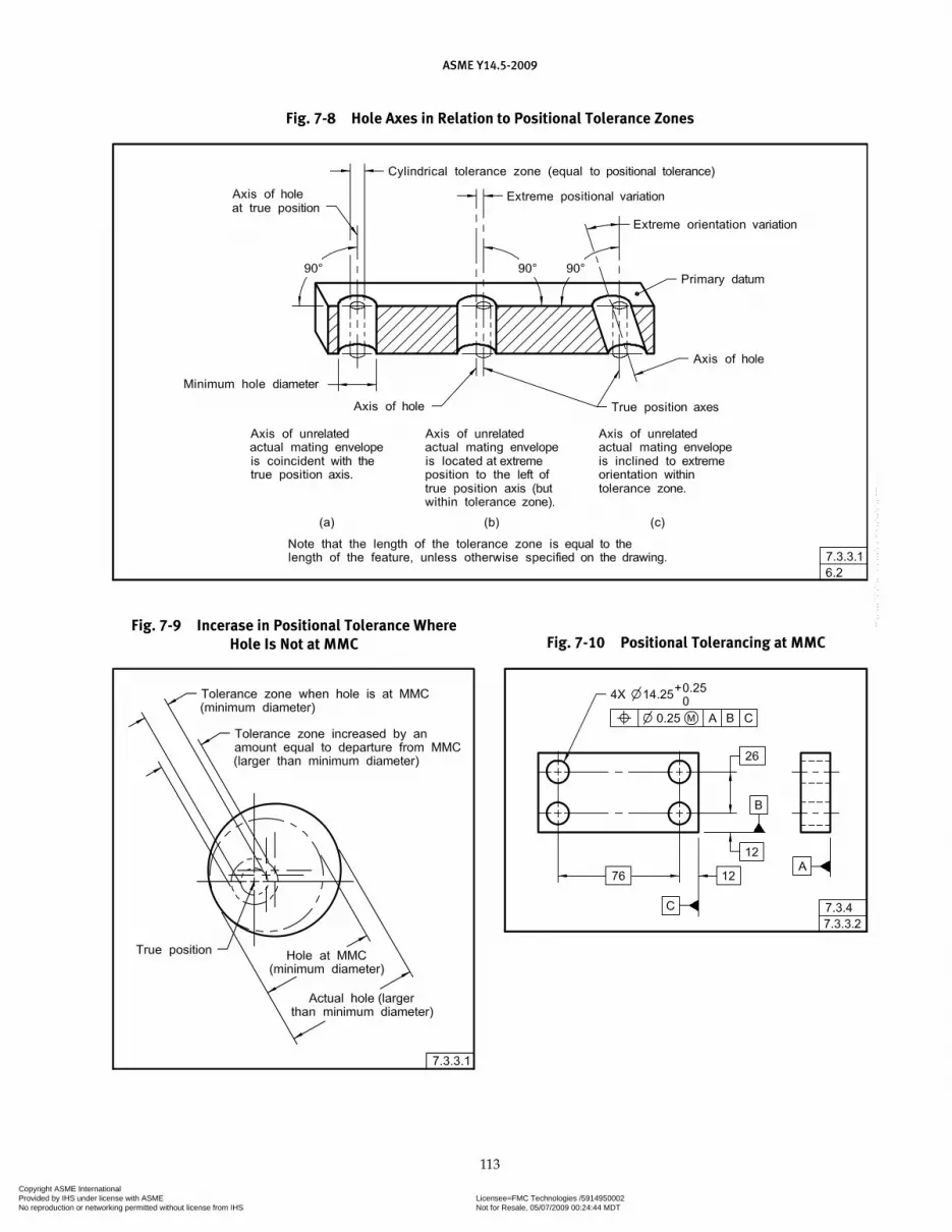
ASME Y14.5-2009
113
Fig. 7-9 Incerase in Positional Tolerance Where Hole Is Not at MMC Fig. 7-10 Positional Tolerancing at MMC
Fig. 7-8 Hole Axes in Relation to Positional Tolerance Zones
Copyright ASME International Provided by IHS under license with ASME Licensee=FMC Technologies /5914950002
Not for Resale, 05/07/2009 00:24:44 MDTNo reproduction or networking permitted without license from IHS
--`,,`,,,``,`,``,,``,`,`,,,`,`,`-`-`,,`,,`,`,,`---

ASME Y14.5-2009
114
Clearance Hole Diameter(Feature Actual Mating Size)
Positional Tolerance Diameter Allowed
14 0
14.1 0.1
14.2 0.2
14.25 0.25
14.3 0.3
14.4 0.4
14.5 0.5
7.3.5 LMC as Related to Positional Tolerancing
Where positional tolerancing at LMC is specified, the stated positional tolerance applies at the feature size limit that results in the least material in the part. Specification of LMC requires perfect form at LMC. Perfect form at MMC is not required. Where the feature departs from its LMC limit of size, an increase in positional tolerance is allowed, equal to the amount of such departure. See Fig. 7-12. LMC may be specified in positional toleranc-ing applications where the functional consideration is to ensure a minimum distance is maintained while allow-ing an increase in tolerance as the feature of size departs from LMC. See Figs. 7-13 through 7-17. LMC is used to maintain a desired relationship between the surface of a feature and its true position at tolerance extremes. As with MMC, the surface interpretation shall take prec-edence over the axis interpretation. See para. 7.3.3.1 and Fig. 7-6.
7.3.5.1 LMC to Protect Wall Thickness. Figure 7-13 illustrates a boss and hole combination located by basic dimensions. Wall thickness is minimum where the boss and hole are at their LMC sizes and both features of size are displaced in opposite extremes. As each feature of size departs from LMC, the wall thickness may increase. The departure from LMC permits a corresponding increase in the positional tolerance, thus maintaining the desired minimum wall thickness between these surfaces.
7.3.5.2 LMC Applied to Single Features of Size. LMC may also be applied to single features of size, such as the hole shown in Fig. 7-15. In this example, the posi-tion of the hole relative to the inside web is critical. RFS can be specified. However, LMC is applied, permitting an increase in the positional tolerance while protecting the wall thickness.
7.3.5.3 Zero Positional Tolerance at LMC. The application of LMC permits the tolerance to exceed the value specified, provided features of size are within size limits, and the feature of size locations are such as to make the part acceptable. However, rejection of usable parts can occur where features of size such as holes are actually located on or close to their true positions, but produced to a size larger than the specified maximum (outside of size limits). The principle of zero positional tolerancing at LMC can be extended in applications where it is desired to protect a minimum distance on a part and allow an increase in tolerance when the toleranced feature departs from LMC. This is accom-plished by adjusting the maximum size limit of a hole to the absolute maximum allowed to meet functional requirements (such as wall thickness) while specifying a zero positional tolerance at LMC. When this is done, the positional tolerance allowed is totally dependent on the actual minimum material size of the considered feature of size. Figure 7-14 shows the same drawing as Fig. 7-13, except the tolerances have been changed to show zero positional tolerance at LMC. Note that the minimum size limit of the hole remains the same, but the maximum was adjusted to correspond with a 20.25-diameter virtual condition. This results in an
Fig. 7-11 Zero Positional Tolerancing at MMC Fig. 7-12 Increase in Positional Tolerance Where Hole Is Not at LMC
Copyright ASME International Provided by IHS under license with ASME Licensee=FMC Technologies /5914950002
Not for Resale, 05/07/2009 00:24:44 MDTNo reproduction or networking permitted without license from IHS
--`,,`,,,``,`,``,,``,`,`,,,`,`,`-`-`,,`,,`,`,,`---
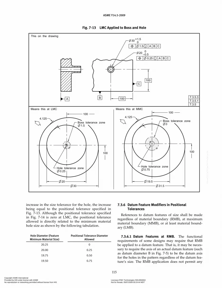
ASME Y14.5-2009
115
increase in the size tolerance for the hole, the increase being equal to the positional tolerance specified in Fig. 7-13. Although the positional tolerance specified in Fig. 7-14 is zero at LMC, the positional tolerance allowed is directly related to the minimum material hole size as shown by the following tabulation.
Hole Diameter (Feature Minimum Material Size)
Positional Tolerance Diameter Allowed
20.25 0
20.00 0.25
19.75 0.50
19.50 0.75
7.3.6 Datum Feature Modifiers in Positional Tolerances
References to datum features of size shall be made regardless of material boundary (RMB), at maximum material boundary (MMB), or at least material bound-ary (LMB).
7.3.6.1 Datum Features at RMB. The functional requirements of some designs may require that RMB be applied to a datum feature. That is, it may be neces-sary to require the axis of an actual datum feature (such as datum diameter B in Fig. 7-5) to be the datum axis for the holes in the pattern regardless of the datum fea-ture’s size. The RMB application does not permit any
Fig. 7-13 LMC Applied to Boss and Hole
Copyright ASME International Provided by IHS under license with ASME Licensee=FMC Technologies /5914950002
Not for Resale, 05/07/2009 00:24:44 MDTNo reproduction or networking permitted without license from IHS
--`,,`,,,``,`,``,,``,`,`,,,`,`,`-`-`,,`,,`,`,,`---

ASME Y14.5-2009
116
Fig. 7-14 Zero Tolerance at LMC Applied to Boss and Hole
Fig. 7-15 LMC Applied to a Single Feature
Copyright ASME International Provided by IHS under license with ASME Licensee=FMC Technologies /5914950002
Not for Resale, 05/07/2009 00:24:44 MDTNo reproduction or networking permitted without license from IHS
--`,,`,,,``,`,``,,``,`,`,,,`,`,`-`-`,,`,,`,`,,`---

ASME Y14.5-2009
117
Fig. 7-16 LMC Applied to Pattern of Slots
Fig. 7-17 Datum Feature at LMB
Copyright ASME International Provided by IHS under license with ASME Licensee=FMC Technologies /5914950002
Not for Resale, 05/07/2009 00:24:44 MDTNo reproduction or networking permitted without license from IHS
--`,,`,,,``,`,``,,``,`,`,,,`,`,`-`-`,,`,,`,`,,`---
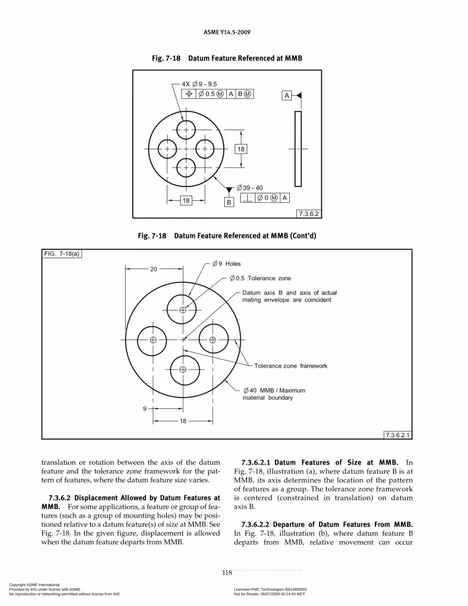
ASME Y14.5-2009
118
translation or rotation between the axis of the datum feature and the tolerance zone framework for the pat-tern of features, where the datum feature size varies.
7.3.6.2 Displacement Allowed by Datum Features at MMB. For some applications, a feature or group of fea-tures (such as a group of mounting holes) may be posi-tioned relative to a datum feature(s) of size at MMB. See Fig. 7-18. In the given figure, displacement is allowed when the datum feature departs from MMB.
7.3.6.2.1 Datum Features of Size at MMB. In Fig. 7-18, illustration (a), where datum feature B is at MMB, its axis determines the location of the pattern of features as a group. The tolerance zone framework is centered (constrained in translation) on datum axis B.
7.3.6.2.2 Departure of Datum Features From MMB. In Fig. 7-18, illustration (b), where datum feature B departs from MMB, relative movement can occur
Fig. 7-18 Datum Feature Referenced at MMB
Fig. 7-18 Datum Feature Referenced at MMB (Cont’d)
Copyright ASME International Provided by IHS under license with ASME Licensee=FMC Technologies /5914950002
Not for Resale, 05/07/2009 00:24:44 MDTNo reproduction or networking permitted without license from IHS
--`,,`,,,``,`,``,,``,`,`,,,`,`,`-`-`,,`,,`,`,,`---
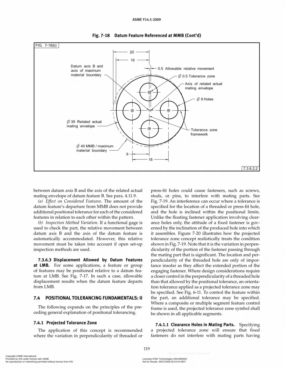
ASME Y14.5-2009
119
between datum axis B and the axis of the related actual mating envelope of datum feature B. See para. 4.11.9.
(a) Effect on Considered Features. The amount of the datum feature’s departure from MMB does not provide additional positional tolerance for each of the considered features in relation to each other within the pattern.
(b) Inspection Method Variation. If a functional gage is used to check the part, the relative movement between datum axis B and the axis of the datum feature is automatically accommodated. However, this relative movement must be taken into account if open set-up inspection methods are used.
7.3.6.3 Displacement Allowed by Datum Features at LMB. For some applications, a feature or group of features may be positioned relative to a datum fea-ture at LMB. See Fig. 7-17. In such a case, allowable displacement results when the datum feature departs from LMB.
7.4 POSITIONAL TOLERANCING FUNDAMENTALS: II
The following expands on the principles of the pre-ceding general explanation of positional tolerancing.
7.4.1 Projected Tolerance Zone
The application of this concept is recommended where the variation in perpendicularity of threaded or
press-fit holes could cause fasteners, such as screws, studs, or pins, to interfere with mating parts. See Fig. 7-19. An interference can occur where a tolerance is specified for the location of a threaded or press-fit hole, and the hole is inclined within the positional limits. Unlike the floating fastener application involving clear-ance holes only, the attitude of a fixed fastener is gov-erned by the inclination of the produced hole into which it assembles. Figure 7-20 illustrates how the projected tolerance zone concept realistically treats the condition shown in Fig. 7-19. Note that it is the variation in perpen-dicularity of the portion of the fastener passing through the mating part that is significant. The location and per-pendicularity of the threaded hole are only of impor-tance insofar as they affect the extended portion of the engaging fastener. Where design considerations require a closer control in the perpendicularity of a threaded hole than that allowed by the positional tolerance, an orienta-tion tolerance applied as a projected tolerance zone may be specified. See Fig. 6-11. To control the feature within the part, an additional tolerance may be specified. Where a composite or multiple segment feature control frame is used, the projected tolerance zone symbol shall be shown in all applicable segments.
7.4.1.1 Clearance Holes in Mating Parts. Specifying a projected tolerance zone will ensure that fixed fasteners do not interfere with mating parts having
Fig. 7-18 Datum Feature Referenced at MMB (Cont’d)
Copyright ASME International Provided by IHS under license with ASME Licensee=FMC Technologies /5914950002
Not for Resale, 05/07/2009 00:24:44 MDTNo reproduction or networking permitted without license from IHS
--`,,`,,,``,`,``,,``,`,`,,,`,`,`-`-`,,`,,`,`,,`---
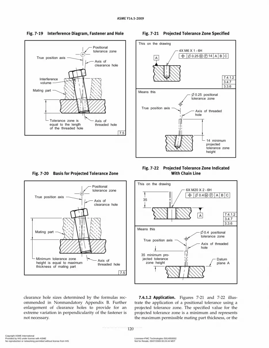
ASME Y14.5-2009
120
clearance hole sizes determined by the formulas rec-ommended in Nonmandatory Appendix B. Further enlargement of clearance holes to provide for an extreme variation in perpendicularity of the fastener is not necessary.
7.4.1.2 Application. Figures 7-21 and 7-22 illus-trate the application of a positional tolerance using a projected tolerance zone. The specified value for the projected tolerance zone is a minimum and represents the maximum permissible mating part thickness, or the
Fig. 7-19 Interference Diagram, Fastener and Hole
Fig. 7-20 Basis for Projected Tolerance Zone
Fig. 7-21 Projected Tolerance Zone Specified
Fig. 7-22 Projected Tolerance Zone Indicated With Chain Line
Copyright ASME International Provided by IHS under license with ASME Licensee=FMC Technologies /5914950002
Not for Resale, 05/07/2009 00:24:44 MDTNo reproduction or networking permitted without license from IHS
--`,,`,,,``,`,``,,``,`,`,,,`,`,`-`-`,,`,,`,`,,`---
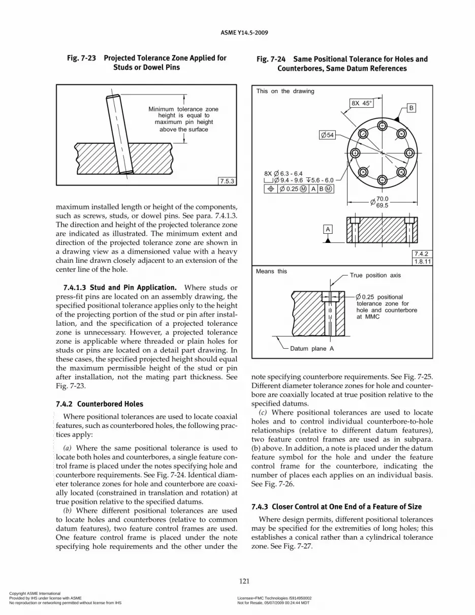
ASME Y14.5-2009
121
maximum installed length or height of the components, such as screws, studs, or dowel pins. See para. 7.4.1.3. The direction and height of the projected tolerance zone are indicated as illustrated. The minimum extent and direction of the projected tolerance zone are shown in a drawing view as a dimensioned value with a heavy chain line drawn closely adjacent to an extension of the center line of the hole.
7.4.1.3 Stud and Pin Application. Where studs or press-fit pins are located on an assembly drawing, the specified positional tolerance applies only to the height of the projecting portion of the stud or pin after instal-lation, and the specification of a projected tolerance zone is unnecessary. However, a projected tolerance zone is applicable where threaded or plain holes for studs or pins are located on a detail part drawing. In these cases, the specified projected height should equal the maximum permissible height of the stud or pin after installation, not the mating part thickness. See Fig. 7-23.
7.4.2 Counterbored Holes
Where positional tolerances are used to locate coaxial features, such as counterbored holes, the following prac-tices apply:
(a) Where the same positional tolerance is used to locate both holes and counterbores, a single feature con-trol frame is placed under the notes specifying hole and counterbore requirements. See Fig. 7-24. Identical diam-eter tolerance zones for hole and counterbore are coaxi-ally located (constrained in translation and rotation) at true position relative to the specified datums.
(b) Where different positional tolerances are used to locate holes and counterbores (relative to common datum features), two feature control frames are used. One feature control frame is placed under the note specifying hole requirements and the other under the
note specifying counterbore requirements. See Fig. 7-25. Different diameter tolerance zones for hole and counter-bore are coaxially located at true position relative to the specified datums.
(c) Where positional tolerances are used to locate holes and to control individual counterbore-to-hole relationships (relative to different datum features), two feature control frames are used as in subpara. (b) above. In addition, a note is placed under the datum feature symbol for the hole and under the feature control frame for the counterbore, indicating the number of places each applies on an individual basis. See Fig. 7-26.
7.4.3 Closer Control at One End of a Feature of Size
Where design permits, different positional tolerances may be specified for the extremities of long holes; this establishes a conical rather than a cylindrical tolerance zone. See Fig. 7-27.
Fig. 7-23 Projected Tolerance Zone Applied for Studs or Dowel Pins
Fig. 7-24 Same Positional Tolerance for Holes and Counterbores, Same Datum References
Copyright ASME International Provided by IHS under license with ASME Licensee=FMC Technologies /5914950002
Not for Resale, 05/07/2009 00:24:44 MDTNo reproduction or networking permitted without license from IHS
--`,,`,,,``,`,``,,``,`,`,,,`,`,`-`-`,,`,,`,`,,`---

ASME Y14.5-2009
122
7.4.4 Bidirectional Positional Tolerancing of Features of Size
Where it is desired to specify a greater tolerance in one direction than another, bidirectional positional toleranc-ing may be applied. Bidirectional positional tolerancing results in a noncylindrical tolerance zone for locating round holes; therefore, the diameter symbol is omitted from the feature control frame in these applications.
NOTE: A further refi nement of perpendicularity within the posi-tional tolerance may be required.
7.4.4.1 Rectangular Coordinate Method. For fea-tures located by rectangular coordinate dimensions, separate feature control frames are used to indicate the direction and magnitude of each positional toler-ance relative to specified datums. See Fig. 7-28. The feature control frames are attached to dimension lines applied in perpendicular directions. Each tolerance value represents a distance between two parallel planes equally disposed about the true position.
7.4.4.2 Polar Coordinate Method. Bidirectional posi-tional tolerancing may also be applied to features located by polar coordinate dimensions relative to specified datums. Where a different tolerance is desired in each direction, one dimension line is applied in a radial direc-tion, and the other perpendicular to the line-of-centers. The positional tolerance values represent distances between two concentric arc boundaries (for the radial direction), and two parallel planes, equally disposed about the true position. See Fig. 7-29. In this example, a further requirement of perpendicularity within the posi-tional tolerance zone has been specified. The example in Fig. 7-29 is typical of a gear center application. In all cases, the shape and extent of the tolerance zone shall be made clear.
Fig. 7-25 Different Positional Tolerances for Holes and Counterbores, Same Datum References
Fig. 7-26 Positional Tolerances for Holes and Counterbores, Different Datum References
Copyright ASME International Provided by IHS under license with ASME Licensee=FMC Technologies /5914950002
Not for Resale, 05/07/2009 00:24:44 MDTNo reproduction or networking permitted without license from IHS
--`,,`,,,``,`,``,,``,`,`,,,`,`,`-`-`,,`,,`,`,,`---

ASME Y14.5-2009
123
7.4.5 Noncircular Features of Size
The fundamental principles of true position dimen-sioning and positional tolerancing for circular features of size, such as holes and bosses, apply also to noncir-cular features of size, such as open-end slots, tabs, and elongated holes. For such features of size, a positional tolerance is used to locate the center plane established by parallel surfaces of the feature of size. The tolerance
value represents a distance between two parallel planes. The diameter symbol is omitted from the feature control frame. See Figs. 7-30 and 7-31.
7.4.5.1 Noncircular Features of Size at MMC. Where a positional tolerance of a noncircular feature of size applies at MMC, the following apply.
(a) In Terms of the Surfaces of an Internal Feature of Size. While maintaining the specified size limits of the inter-nal feature, no element of the internal feature of size sur-faces shall be inside a theoretical boundary located at true position. See Fig. 7-32.
(b) In Terms of the Center Plane of an Internal Feature of Size. Where an internal feature of size is at MMC (mini-mum size), its center plane must fall within a tolerance zone defined by two parallel planes equally disposed about true position. The width of this zone is equal to the positional tolerance. See Fig. 7-33. This tolerance zone also defines the limits of variations in the orientation of the center plane of the internal feature of size in relation to the datum surface. It is only where the internal fea-ture of size is at MMC that the specified tolerance zone applies. Where the unrelated actual mating envelope size of the internal feature of size is larger than MMC, additional positional tolerance results. This increase of positional tolerance is equal to the difference between the specified maximum material condition limit of size (MMC) and the unrelated actual mating envelope size of the internal feature of size. Where the unrelated actual mating envelope size is larger than MMC, the specified positional tolerance for an internal feature of size may be exceeded and still satisfy function and interchange-ability requirements.
(c) In Terms of the Boundary of an Internal Feature of Size. A positional tolerance applied to a feature of size estab-lishes a control of the surface relative to a boundary. While maintaining the specified size limits of the feature of size, no element of its surface shall violate a theoreti-cal boundary of identical shape located at true position. The size of the boundary is equal to the MMC size of the internal feature of size minus its positional tolerance. See Fig. 7-34. The term BOUNDARY may be placed beneath the feature control frames, but is not required. In this example, a greater positional tolerance is allowed for its length than for its width. Where the same positional tol-erance can be allowed for both, only one feature control frame is necessary, directed to the feature by a leader and separated from the size dimensions.
NOTE: This boundary concept can also be applied to other irregu-lar shaped features of size — such as a D-shaped hole (with a fl at-tened side) — where the center is not conveniently identifi able. See para. 8.8.
7.4.5.2 LMC Applied to a Radial Pattern of Slots. In Fig. 7-16, a radial pattern of slots is located relative to an end face and a center hole. LMC is specified to
Fig. 7-27 Different Positional Tolerance at Each End of Long Hole
Copyright ASME International Provided by IHS under license with ASME Licensee=FMC Technologies /5914950002
Not for Resale, 05/07/2009 00:24:44 MDTNo reproduction or networking permitted without license from IHS
--`,,`,,,``,`,``,,``,`,`,,,`,`,`-`-`,,`,,`,`,,`---
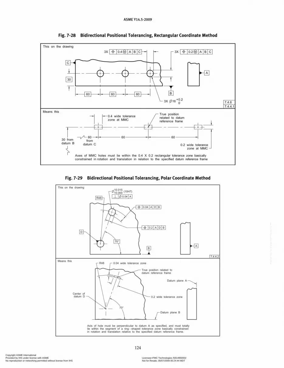
ASME Y14.5-2009
124
Fig. 7-28 Bidirectional Positional Tolerancing, Rectangular Coordinate Method
Fig. 7-29 Bidirectional Positional Tolerancing, Polar Coordinate Method
Copyright ASME International Provided by IHS under license with ASME Licensee=FMC Technologies /5914950002
Not for Resale, 05/07/2009 00:24:44 MDTNo reproduction or networking permitted without license from IHS
--`,,`,,,``,`,``,,``,`,`,,,`,`,`-`-`,,`,,`,`,,`---

ASME Y14.5-2009
125
Fig. 7-30 Positional Tolerancing of Tabs Fig. 7-31 Positional Tolerancing of Slots
Fig. 7-32 Virtual Condition for Surfaces of Slot at MMC
Fig. 7-33 Tolerance Zone for Center Plane of Slot at MMC
Copyright ASME International Provided by IHS under license with ASME Licensee=FMC Technologies /5914950002
Not for Resale, 05/07/2009 00:24:44 MDTNo reproduction or networking permitted without license from IHS
--`,,`,,,``,`,``,,``,`,`,,,`,`,`-`-`,,`,,`,`,,`---
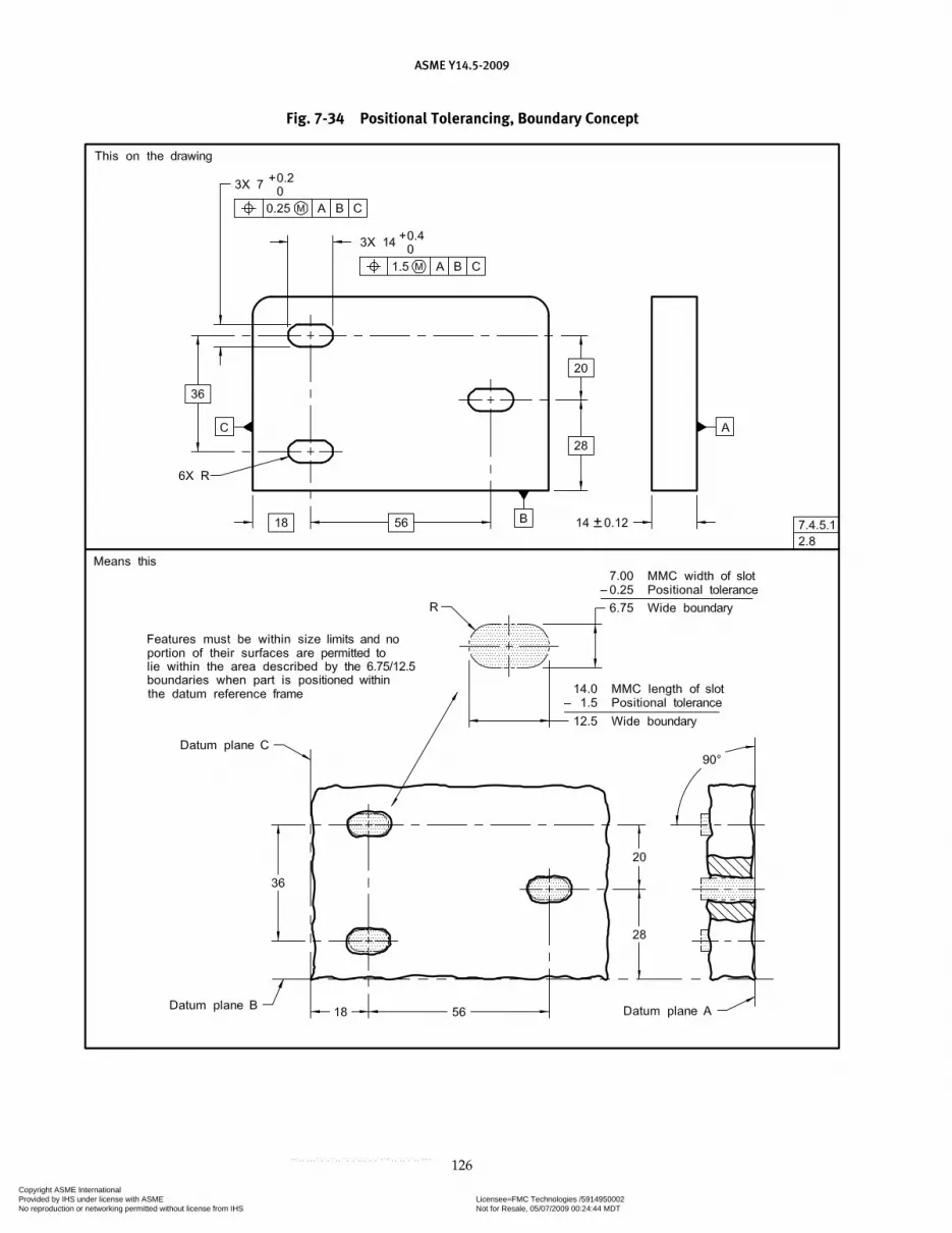
ASME Y14.5-2009
126
Fig. 7-34 Positional Tolerancing, Boundary Concept
Copyright ASME International Provided by IHS under license with ASME Licensee=FMC Technologies /5914950002
Not for Resale, 05/07/2009 00:24:44 MDTNo reproduction or networking permitted without license from IHS
--`,,`,,,``,`,``,,``,`,`,,,`,`,`-`-`,,`,,`,`,,`---
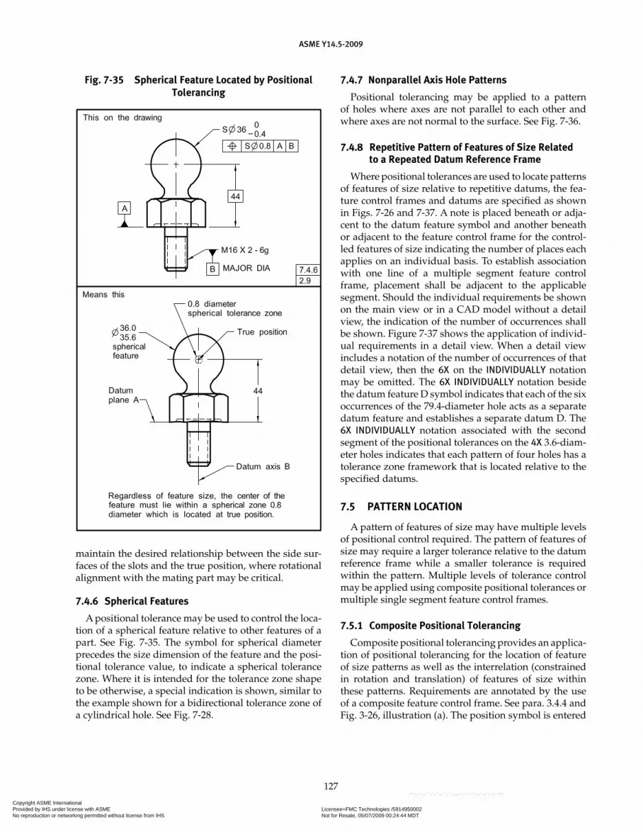
ASME Y14.5-2009
127
maintain the desired relationship between the side sur-faces of the slots and the true position, where rotational alignment with the mating part may be critical.
7.4.6 Spherical Features
A positional tolerance may be used to control the loca-tion of a spherical feature relative to other features of a part. See Fig. 7-35. The symbol for spherical diameter precedes the size dimension of the feature and the posi-tional tolerance value, to indicate a spherical tolerance zone. Where it is intended for the tolerance zone shape to be otherwise, a special indication is shown, similar to the example shown for a bidirectional tolerance zone of a cylindrical hole. See Fig. 7-28.
7.4.7 Nonparallel Axis Hole Patterns
Positional tolerancing may be applied to a pattern of holes where axes are not parallel to each other and where axes are not normal to the surface. See Fig. 7-36.
7.4.8 Repetitive Pattern of Features of Size Related to a Repeated Datum Reference Frame
Where positional tolerances are used to locate patterns of features of size relative to repetitive datums, the fea-ture control frames and datums are specified as shown in Figs. 7-26 and 7-37. A note is placed beneath or adja-cent to the datum feature symbol and another beneath or adjacent to the feature control frame for the control-led features of size indicating the number of places each applies on an individual basis. To establish association with one line of a multiple segment feature control frame, placement shall be adjacent to the applicable segment. Should the individual requirements be shown on the main view or in a CAD model without a detail view, the indication of the number of occurrences shall be shown. Figure 7-37 shows the application of individ-ual requirements in a detail view. When a detail view includes a notation of the number of occurrences of that detail view, then the 6X on the INDIVIDUALLY notation may be omitted. The 6X INDIVIDUALLY notation beside the datum feature D symbol indicates that each of the six occurrences of the 79.4-diameter hole acts as a separate datum feature and establishes a separate datum D. The 6X INDIVIDUALLY notation associated with the second segment of the positional tolerances on the 4X 3.6-diam-eter holes indicates that each pattern of four holes has a tolerance zone framework that is located relative to the specified datums.
7.5 PATTERN LOCATION
A pattern of features of size may have multiple levels of positional control required. The pattern of features of size may require a larger tolerance relative to the datum reference frame while a smaller tolerance is required within the pattern. Multiple levels of tolerance control may be applied using composite positional tolerances or multiple single segment feature control frames.
7.5.1 Composite Positional Tolerancing
Composite positional tolerancing provides an applica-tion of positional tolerancing for the location of feature of size patterns as well as the interrelation (constrained in rotation and translation) of features of size within these patterns. Requirements are annotated by the use of a composite feature control frame. See para. 3.4.4 and Fig. 3-26, illustration (a). The position symbol is entered
Fig. 7-35 Spherical Feature Located by Positional Tolerancing
Copyright ASME International Provided by IHS under license with ASME Licensee=FMC Technologies /5914950002
Not for Resale, 05/07/2009 00:24:44 MDTNo reproduction or networking permitted without license from IHS
--`,,`,,,``,`,``,,``,`,`,,,`,`,`-`-`,,`,,`,`,,`---

ASME Y14.5-2009
128
Fig. 7-36 Nonparallel Holes Including Those Not Normal to Surface
Fig. 7-37 Multiple Patterns of Features
Copyright ASME International Provided by IHS under license with ASME Licensee=FMC Technologies /5914950002
Not for Resale, 05/07/2009 00:24:44 MDTNo reproduction or networking permitted without license from IHS
--`,,`,,,``,`,``,,``,`,`,,,`,`,`-`-`,,`,,`,`,,`---

ASME Y14.5-2009
129
once and is applicable to all horizontal segments. Each complete horizontal segment in the feature control frames of Figs. 7-38 and 7-39 may be verified separately.
(a) Pattern-Locating Tolerance Zone Framework (PLTZF). (The acronym is pronounced “Plahtz.”) Where com-posite controls are used, the uppermost segment is the pattern-locating control. The PLTZF is constrained in rotation and translation relative to the specified datums. It specifies the larger positional tolerance for the location of the pattern of features of size as a group. Applicable datum features are referenced in a desired order of prec-edence, and serve to relate the PLTZF to the datum refer-ence frame. See Fig. 7-38, illustration (a).
(b) Feature-Relating Tolerance Zone Framework (FRTZF). (The acronym is pronounced “Fritz.”) Each lower segment is a feature-relating control. They gov-ern the smaller positional tolerance for each feature of size within the pattern (feature-to-feature relationship). Basic dimensions used to relate the PLTZF to specified datums are not applicable to the location of the FRTZF. See Fig. 7-38, illustration (b).
(1) Where datum references are not specified in a lower segment of the composite feature control frame, the FRTZF is free to rotate and translate within the boundaries established and governed by the PLTZF.
(2) If datums are specified in a lower segment, they govern the rotation of the FRTZF relative to the datums and within the boundaries established and gov-erned by the PLTZF.
(3) Where datum feature references are specified, one or more of the datum feature references specified in the upper segment of the frame are repeated, as appli-cable, and in the same order of precedence, to constrain rotation of the FRTZF. In some instances the repeated datum feature references may not constrain any degrees of freedom; however, they are necessary to maintain the identical datum reference frame, such as datum feature B in the lower segment in Fig. 7-42.
7.5.1.1 Primary Datum Repeated in Lower Segment. As can be seen from the sectional view of the tolerance zones in Fig. 7-38, illustration (c), since datum plane A has been repeated in the lower segment of the composite feature control frame, the axes of both the PLTZF and FRTZF cylinders are perpendicular to datum plane A and therefore parallel to each other. In certain instances, portions of the smaller zones may fall beyond the peripheries of the larger tolerance zones. However, these portions of the smaller tolerance zones are not usable because the axes of the features must not violate
Fig. 7-38 Hole Patterns Located by Composite Positional Tolerancing
Copyright ASME International Provided by IHS under license with ASME Licensee=FMC Technologies /5914950002
Not for Resale, 05/07/2009 00:24:44 MDTNo reproduction or networking permitted without license from IHS
--`,,`,,,``,`,``,,``,`,`,,,`,`,`-`-`,,`,,`,`,,`---
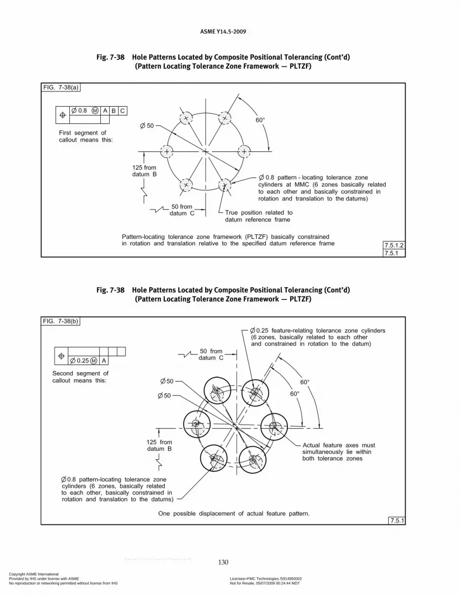
ASME Y14.5-2009
130
Fig. 7-38 Hole Patterns Located by Composite Positional Tolerancing (Cont’d)(Pattern Locating Tolerance Zone Framework — PLTZF)
Fig. 7-38 Hole Patterns Located by Composite Positional Tolerancing (Cont’d)(Pattern Locating Tolerance Zone Framework — PLTZF)
Copyright ASME International Provided by IHS under license with ASME Licensee=FMC Technologies /5914950002
Not for Resale, 05/07/2009 00:24:44 MDTNo reproduction or networking permitted without license from IHS
--`,,`,,,``,`,``,,``,`,`,,,`,`,`-`-`,,`,,`,`,,`---
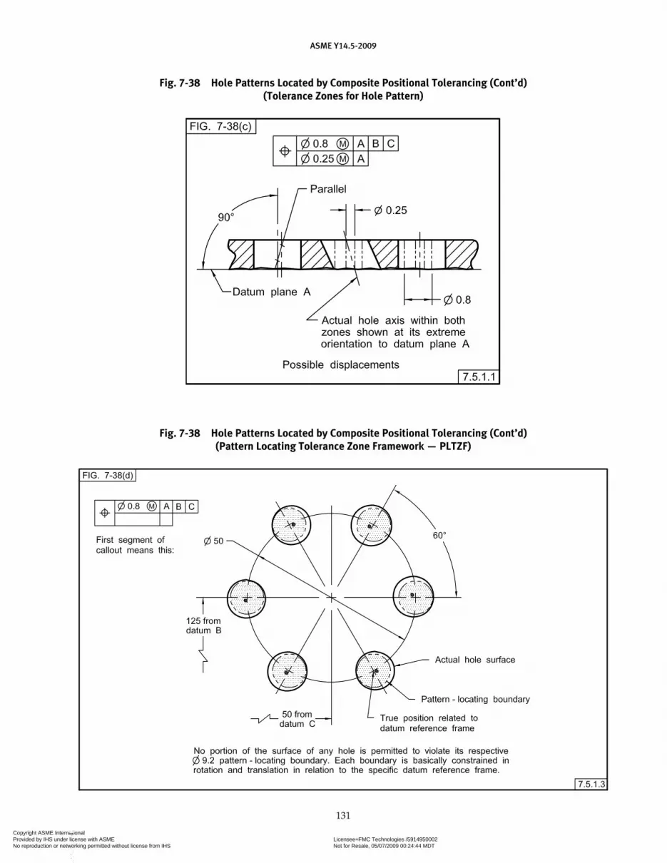
ASME Y14.5-2009
131
Fig. 7-38 Hole Patterns Located by Composite Positional Tolerancing (Cont’d)(Tolerance Zones for Hole Pattern)
Fig. 7-38 Hole Patterns Located by Composite Positional Tolerancing (Cont’d)(Pattern Locating Tolerance Zone Framework — PLTZF)
Copyright ASME International Provided by IHS under license with ASME Licensee=FMC Technologies /5914950002
Not for Resale, 05/07/2009 00:24:44 MDTNo reproduction or networking permitted without license from IHS
--`,,`,,,``,`,``,,``,`,`,,,`,`,`-`-`,,`,,`,`,,`---

ASME Y14.5-2009
132
Fig. 7-38 Hole Patterns Located by Composite Positional Tolerancing (Cont’d)(Feature-Relating Tolerance Zone Framework — FRTZF)
the boundaries of the larger tolerance zones. The axes of the holes must lie within the larger tolerance zones and within the smaller tolerance zones. The axes of the actual holes may vary obliquely (out of perpendicular-ity) only within the confines of the respective smaller positional tolerance zones (FRTZF).
NOTE: The zones in Figs. 7-38 and 7-39 are shown as they exist at MMC of the features. The large zones would increase in size by
the amount the features depart from MMC, as would the smaller zones; the two zones are not cumulative.
7.5.1.2 Primary and Secondary Datums Repeated in Lower Segment. Figure 7-39 repeats the hole patterns of Fig. 7-38. In Fig. 7-39, the lower segment of the com-posite feature control frame repeats datums A and B. The pattern-locating tolerance requirements established by
Fig. 7-38 Hole Patterns Located by Composite Positional Tolerancing (Cont’d)(Acceptance Boundaries for Holes in Pattern)
Copyright ASME International Provided by IHS under license with ASME Licensee=FMC Technologies /5914950002
Not for Resale, 05/07/2009 00:24:44 MDTNo reproduction or networking permitted without license from IHS
--`,,`,,,``,`,``,,``,`,`,,,`,`,`-`-`,,`,,`,`,,`---

ASME Y14.5-2009
133
Fig. 7-39 Hole Patterns of Fig. 7-38 With Secondary Datums in Feature-Relating Segments of Composite Feature Control Frames
Fig. 7-39 Hole Patterns for Fig. 7-39 With Secondary Datums in Feature-Relating Segments of Composite Feature Control Frames (Cont’d) (Tolerance Zones for Six-Hole Pattern)
Copyright ASME International Provided by IHS under license with ASME Licensee=FMC Technologies /5914950002
Not for Resale, 05/07/2009 00:24:44 MDTNo reproduction or networking permitted without license from IHS
--`,,`,,,``,`,``,,``,`,`,,,`,`,`-`-`,,`,,`,`,,`---
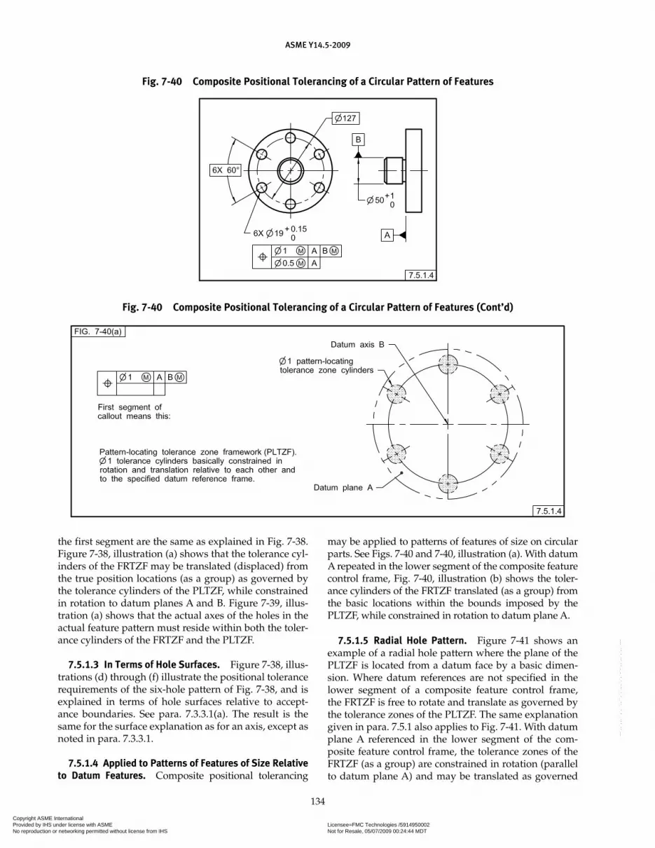
ASME Y14.5-2009
134
the first segment are the same as explained in Fig. 7-38. Figure 7-38, illustration (a) shows that the tolerance cyl-inders of the FRTZF may be translated (displaced) from the true position locations (as a group) as governed by the tolerance cylinders of the PLTZF, while constrained in rotation to datum planes A and B. Figure 7-39, illus-tration (a) shows that the actual axes of the holes in the actual feature pattern must reside within both the toler-ance cylinders of the FRTZF and the PLTZF.
7.5.1.3 In Terms of Hole Surfaces. Figure 7-38, illus-trations (d) through (f) illustrate the positional tolerance requirements of the six-hole pattern of Fig. 7-38, and is explained in terms of hole surfaces relative to accept-ance boundaries. See para. 7.3.3.1(a). The result is the same for the surface explanation as for an axis, except as noted in para. 7.3.3.1.
7.5.1.4 Applied to Patterns of Features of Size Relative to Datum Features. Composite positional tolerancing
may be applied to patterns of features of size on circular parts. See Figs. 7-40 and 7-40, illustration (a). With datum A repeated in the lower segment of the composite feature control frame, Fig. 7-40, illustration (b) shows the toler-ance cylinders of the FRTZF translated (as a group) from the basic locations within the bounds imposed by the PLTZF, while constrained in rotation to datum plane A.
7.5.1.5 Radial Hole Pattern. Figure 7-41 shows an example of a radial hole pattern where the plane of the PLTZF is located from a datum face by a basic dimen-sion. Where datum references are not specified in the lower segment of a composite feature control frame, the FRTZF is free to rotate and translate as governed by the tolerance zones of the PLTZF. The same explanation given in para. 7.5.1 also applies to Fig. 7-41. With datum plane A referenced in the lower segment of the com-posite feature control frame, the tolerance zones of the FRTZF (as a group) are constrained in rotation (parallel to datum plane A) and may be translated as governed
Fig. 7-40 Composite Positional Tolerancing of a Circular Pattern of Features
Fig. 7-40 Composite Positional Tolerancing of a Circular Pattern of Features (Cont’d)
Copyright ASME International Provided by IHS under license with ASME Licensee=FMC Technologies /5914950002
Not for Resale, 05/07/2009 00:24:44 MDTNo reproduction or networking permitted without license from IHS
--`,,`,,,``,`,``,,``,`,`,,,`,`,`-`-`,,`,,`,`,,`---

ASME Y14.5-2009
135
by the tolerance zones of the PLTZF. See also Fig. 7-41, illustrations (a) through (d).
7.5.1.6 Where Radial Location is Important. The control shown in Figs. 7-42 and 7-43 may be specified where rotational constraint is important. The design, however, permits a feature-relating tolerance zone to be displaced within the bounds governed by a pattern-locating tolerance zone, while held parallel and perpen-dicular to the three mutually perpendicular planes of
the datum reference frame. See also Fig. 7-42, illustra-tions (a) and (b).
7.5.1.7 Projected Tolerance Zones for Composite Positional Tolerancing. Where the design dictates the use of a projected tolerance zone for composite posi-tional tolerancing, the projected tolerance zone symbol is placed in the applicable segment(s) of the composite fea-ture control frame as required. The projected tolerance zone applies only to the segment in which the symbol is shown. Where a projected tolerance zone is specified, the feature axes shall simultaneously lie within both the pattern and feature locating tolerance zones.
7.5.1.8 Composite Positional Tolerances: Multiple Segments. Composite tolerances have two or more segments. Each segment establishes tolerance zones and constraints to any referenced datums shown in the seg-ment. Datum references in the first segment establish all applicable rotational and translational constraints relative to the referenced datums. Datum references in the second and subsequent segments establish only rotational constraints relative to the referenced datums. See Fig. 7-44. Absence of datum references in a segment indicate that no rotational or translation constraints are established by that segment. For a pattern of features with a composite positional tolerance applied, a PLTZF is created by the first segment, and a separate FRTZF is created by each of the subsequent segments. Each FRTZF is constrained only to the referenced datums within the segment. See Fig. 7-45. The first segment of the given
Fig. 7-41 Radial Hole Pattern Located by Composite Positional Tolerancing
Fig. 7-40 Composite Positional Tolerancing of a Circular Pattern of Features (Cont’d)
Copyright ASME International Provided by IHS under license with ASME Licensee=FMC Technologies /5914950002
Not for Resale, 05/07/2009 00:24:44 MDTNo reproduction or networking permitted without license from IHS
--`,,`,,,``,`,``,,``,`,`,,,`,`,`-`-`,,`,,`,`,,`---
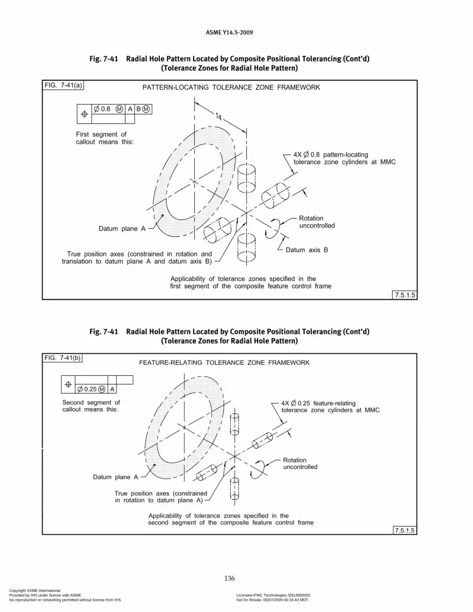
ASME Y14.5-2009
136
Fig. 7-41 Radial Hole Pattern Located by Composite Positional Tolerancing (Cont’d)(Tolerance Zones for Radial Hole Pattern)
Fig. 7-41 Radial Hole Pattern Located by Composite Positional Tolerancing (Cont’d)(Tolerance Zones for Radial Hole Pattern)
Copyright ASME International Provided by IHS under license with ASME Licensee=FMC Technologies /5914950002
Not for Resale, 05/07/2009 00:24:44 MDTNo reproduction or networking permitted without license from IHS
--`,,`,,,``,`,``,,``,`,`,,,`,`,`-`-`,,`,,`,`,,`---

ASME Y14.5-2009
137
Fig. 7-41 Radial Hole Pattern Located by Composite Positional Tolerancing (Cont’d)(Tolerance Zones for Radial Hole Pattern)
Fig. 7-41 Radial Hole Pattern Located by Composite Positional Tolerancing (Cont’d)(Tolerance Zones for Radial Hole Pattern)
Copyright ASME International Provided by IHS under license with ASME Licensee=FMC Technologies /5914950002
Not for Resale, 05/07/2009 00:24:44 MDTNo reproduction or networking permitted without license from IHS
--`,,`,,,``,`,``,,``,`,`,,,`,`,`-`-`,,`,,`,`,,`---

ASME Y14.5-2009
138
Fig. 7-42 Radial Hole Pattern Located by Composite Positional Tolerancing
Fig. 7-42 Radial Hole Pattern Located by Composite Positional Tolerancing (Cont’d)(Tolerance Zones for Radial Hole Pattern)
Fig. 7-42 Radial Hole Pattern Located by Composite Positional Tolerancing (Cont’d)(Tolerance Zones for Radial Hole Pattern)
Copyright ASME International Provided by IHS under license with ASME Licensee=FMC Technologies /5914950002
Not for Resale, 05/07/2009 00:24:44 MDTNo reproduction or networking permitted without license from IHS
--`,,`,,,``,`,``,,``,`,`,,,`,`,`-`-`,,`,,`,`,,`---

ASME Y14.5-2009
139
example creates a PLTZF that is a straight segment with two 0.5-diameter tolerance zones (at MMC) constrained in rotation and translation relative to datums A, B at MMB, and C at MMB. The second segment creates a FRTZF that is a straight segment with two 0.12-diameter tolerance zones (at MMC) that are constrained in rotation relative to datum A. The third segment creates a FRTZF that is a straight segment with two 0.07-diameter toler-ance zones (at MMC) with no constraint to any datum.
7.5.2 Multiple Single-Segment Positional Tolerancing
Multiple single-segment positional tolerances pro-vide multiple positional tolerancing requirements for the location of features of size and establishes require-ments for pattern location as well as the interrelation (constrained in rotation and translation) of features of size within the patterns. Requirements are anno-tated by the use of two or more feature control frames. The position symbol is entered in each of the single segments. The datum feature references in any seg-ment are not permitted to be an exact repeat of all the datum feature references in other segments. Each com-plete horizontal segment is verified separately. Where multiple single-segment positional controls are used, each segment creates a tolerance zone framework. It is neither a PLTZF nor FRTZF, since those terms are spe-cific to composite tolerances. Applicable datum feature references are specified in a desired order of precede-nce and serve to relate the tolerance zone framework to the datum reference frame. See Figs. 3-26, illustration (b); 7-46; 7-47; and 7-48.
7.5.2.1 Multiple Single-Segment Feature Control Frames. Where it is desired to invoke basic dimen-sions along with the datum references, single-segment feature control frames are used. Figure 7-46 shows two single-segment feature control frames. The lower fea-ture control frame repeats datums A and B. Figure 7-46, illustration (a) shows that the tolerance cylinders of the tolerance zone framework for Segment 2 (as a group) are free to be translated (displaced) to the left or right as governed by the basically located tolerance cylinders of the tolerance zone framework for Segment 1, while remaining perpendicular to datum plane A and basi-cally located to datum plane B. Figure 7-46, illustration (b) shows that the actual axes of the holes in the actual feature pattern must reside within both the tolerance cylinders of the tolerance zone framework for Segment 2 and the tolerance zone framework for Segment 1. Figure 7-46, illustration (c) repeats the heretofore-described relationships for the six-hole pattern of fea-tures shown in Fig. 7-46.
7.5.2.2 Multiple Single Segments Applied to Patterns of Features of Size Relative to Datum Features. Multiple single-segment positional tolerancing may be applied to patterns of features of size on circular parts. Figure 7-47 shows two single-segment feature control frames. These are used where it is desired to establish a coaxiality relationship between the tolerance zone framework for Segment 2 and the Segment 1. Figure 7-47, illustration (a) shows that the tolerance zone frame-work for Segment 2 may rotate relative to the tolerance
Fig. 7-43 Orientation Relative to Three Datum Planes
Copyright ASME International Provided by IHS under license with ASME Licensee=FMC Technologies /5914950002
Not for Resale, 05/07/2009 00:24:44 MDTNo reproduction or networking permitted without license from IHS
--`,,`,,,``,`,``,,``,`,`,,,`,`,`-`-`,,`,,`,`,,`---

ASME Y14.5-2009
140
Fig. 7-44 Positional Tolerancing for Coaxial Holes of Same Size, Partial (Parallelism) Refinement of Feature-Relating Axis Relative to Datums A and B With Further Refinement of Parallelism to Datum A
Fig. 7-45 Three Segment Composite Tolerance
Copyright ASME International Provided by IHS under license with ASME Licensee=FMC Technologies /5914950002
Not for Resale, 05/07/2009 00:24:44 MDTNo reproduction or networking permitted without license from IHS
--`,,`,,,``,`,``,,``,`,`,,,`,`,`-`-`,,`,,`,`,,`---

ASME Y14.5-2009
141
Fig. 7-46 Hole Patterns of Fig. 7-38. Multiple Single-Segment Feature Control Frames With Secondary Datum in Lower Feature Control Frame
Fig. 7-46 Hole Patterns of Fig. 7-46. Multiple Single-Segment Feature Control Frames With Secondary Datum in Lower Feature Control Frame (Cont’d)
(Tolerance Zones for Three-Hole Pattern)
Copyright ASME International Provided by IHS under license with ASME Licensee=FMC Technologies /5914950002
Not for Resale, 05/07/2009 00:24:44 MDTNo reproduction or networking permitted without license from IHS
--`,,`,,,``,`,``,,``,`,`,,,`,`,`-`-`,,`,,`,`,,`---
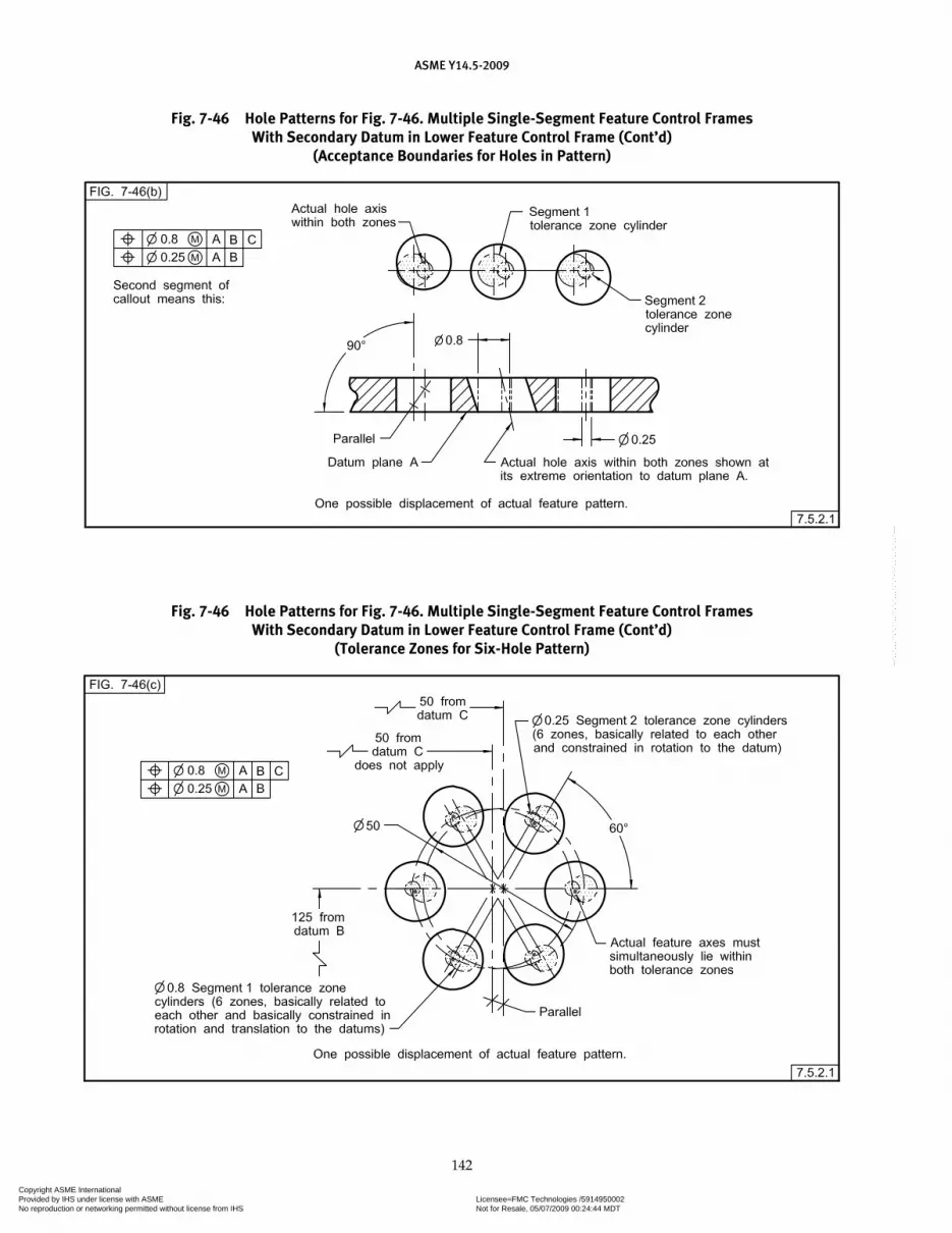
ASME Y14.5-2009
142
Fig. 7-46 Hole Patterns for Fig. 7-46. Multiple Single-Segment Feature Control Frames With Secondary Datum in Lower Feature Control Frame (Cont’d)
(Acceptance Boundaries for Holes in Pattern)
Fig. 7-46 Hole Patterns for Fig. 7-46. Multiple Single-Segment Feature Control Frames With Secondary Datum in Lower Feature Control Frame (Cont’d)
(Tolerance Zones for Six-Hole Pattern)
Copyright ASME International Provided by IHS under license with ASME Licensee=FMC Technologies /5914950002
Not for Resale, 05/07/2009 00:24:44 MDTNo reproduction or networking permitted without license from IHS
--`,,`,,,``,`,``,,``,`,`,,,`,`,`-`-`,,`,,`,`,,`---

ASME Y14.5-2009
143
Fig. 7-47 Positional Tolerancing With Multiple Single-Segment Feature Control Frames
Fig. 7-48 Radial Hole Pattern Located by Multiple Single-Segment Feature Control Frames
Fig. 7-47 Multiple Single-Segment Tolerancing of a Circular Pattern of Features (Cont’d)
Copyright ASME International Provided by IHS under license with ASME Licensee=FMC Technologies /5914950002
Not for Resale, 05/07/2009 00:24:44 MDTNo reproduction or networking permitted without license from IHS
--`,,`,,,``,`,``,,``,`,`,,,`,`,`-`-`,,`,,`,`,,`---

ASME Y14.5-2009
144
Fig. 7-48 Radial Hole Pattern Located by Multiple Single-Segment Feature Control Frames (Cont’d)(Tolerance Zones for Radial Hole Pattern)
zone framework for Segment 1. The actual hole axes of the actual feature of size pattern must reside within both the tolerance cylinders of the tolerance zone framework for Segment 2 and the tolerance zone framework for Segment 1.
7.5.2.3 Multiple Single Segments Applied to a Radial Hole Pattern. Figure 7-48 shows two single-segment feature control frames. These are used where it is desired
to specify a need for a coaxiality relationship between the tolerance zone framework for Segment 2 and the tolerance zone framework for Segment 1. A secondary datum refer-ence is shown in the lower feature control frame. Figure 7-48, illustration (a) shows that the tolerance zones of the tolerance zone framework for Segment 2 are parallel to datum plane A and coaxial about datum axis B. While remaining parallel and coaxial, the tolerance zone frame-work for Segment 2 may be displaced rotationally, as
Fig. 7-48 Radial Hole Pattern Located by Multiple Single-Segment Feature Control Frames (Cont’d)(Tolerance Zones for Radial Hole Pattern)
Copyright ASME International Provided by IHS under license with ASME Licensee=FMC Technologies /5914950002
Not for Resale, 05/07/2009 00:24:44 MDTNo reproduction or networking permitted without license from IHS
--`,,`,,,``,`,``,,``,`,`,,,`,`,`-`-`,,`,,`,`,,`---

ASME Y14.5-2009
145
governed by the tolerance cylinders of the tolerance zone framework for Segment 1. The axes of the features in the actual feature pattern may be displaced, individually or as a pattern, within the boundaries of the smaller tolerance cylinders. Portions of the smaller tolerance zones located outside the larger tolerance zones are not usable, since the actual feature axes must reside within the boundaries of both zones. See Fig. 7-48, illustration (b).
7.5.3 Coaxial Positional Tolerances
The following is an explanation of positional toleranc-ing as applied to coaxial patterns of features of size.
7.5.3.1 Coaxial Pattern of Features of Size. A com-posite positional tolerance may be used to control the alignment of two or more coaxial features of size. This method allows specific control of feature of size-to-feature of size coaxiality without excessively restricting the pattern-locating tolerance.
7.5.3.2 Two or More Features of Size in Pattern-Locating Tolerance. Controls, such as those shown in Fig. 7-49, may be specified where it is desired to produce two or more coaxial features of size within a relatively larger pattern-locating tolerance zone. The central axis of the PLTZF cylinders is parallel to datums A and B. Since the lower (feature-relating) segment of the feature control frame does not invoke orientation datums, the central axis of the FRTZF cylinders may be skewed relative to the central axis of the PLTZF cyl-inders. Depending upon the actually produced size of each coaxial feature of size, each individual feature of size axis may be inclined within its respective tolerance zone cylinder.
7.5.3.3 Rotational Constraint of Feature-Relating Tolerances. Where it is desired to refine the rotational constraint of the FRTZF cylinders as governed by the boundary established by the PLTZF cylinders, datum
Fig. 7-49 Positional Tolerancing for Coaxial Holes of Same Size
Copyright ASME International Provided by IHS under license with ASME Licensee=FMC Technologies /5914950002
Not for Resale, 05/07/2009 00:24:44 MDTNo reproduction or networking permitted without license from IHS
--`,,`,,,``,`,``,,``,`,`,,,`,`,`-`-`,,`,,`,`,,`---

ASME Y14.5-2009
146
references specified in the upper segment of the frame are repeated, as applicable, and in the same order of precedence, in the lower segment of the feature control frame. See Fig. 7-50. Since the lower (feature-relating) segment of the feature control frame invokes datums A and B, the common axis of the FRTZF cylinders must be parallel to the common axis of the PLTZF cylinders. Where holes are of different specified sizes and the same requirements apply to all holes, a single feature con-trol symbol, supplemented by a notation such as TWO COAXIAL HOLES is used. See Fig. 7-51. The same tolerance zone relationships apply as for Fig. 7-49.
7.5.4 Simultaneous Requirements
Simultaneous requirements are applicable to posi-tional tolerances
7.5.4.1 Simultaneous Requirement: RMB. Where multiple patterns of features of size are located relative to common datum features not subject to size tolerances, or to common datum features of size specified on an RMB basis, they are considered to be a single pattern. For example, in Fig. 7-52 each pattern of features of size
is located relative to common datum features not subject to size tolerances. Since all locating dimensions are basic and all measurements are from a common datum ref-erence frame, positional tolerance requirements for the part are considered a single requirement as illustrated by Fig. 7-53. The actual centers of all holes must lie on or within their respective tolerance zones when measured from datums A, B, and C.
NOTE: The explanation given in Fig. 7-53 still applies where inde-pendent verifi cation of pattern locations becomes necessary due to size or complexity of the part.
7.5.4.2 Simultaneous Requirement: MMB. Where any of the common datums in multiple patterns of features of size is specified on an MMB basis, there is an option whether the patterns are to be considered as a single pattern or as having separate requirements. If no note is added adjacent to the feature control frames, the patterns are to be treated as a single pattern. Where it is desired to permit the patterns to be treated as separate patterns, a notation such as SEP REQT is placed adjacent to each feature control frame. See Fig. 7-54. This allows
Fig. 7-50 Positional Tolerancing for Coaxial Holes of Same Size, Partial (Parallelism) Refinement of Feature-Relating Axis
Copyright ASME International Provided by IHS under license with ASME Licensee=FMC Technologies /5914950002
Not for Resale, 05/07/2009 00:24:44 MDTNo reproduction or networking permitted without license from IHS
--`,,`,,,``,`,``,,``,`,`,,,`,`,`-`-`,,`,,`,`,,`---
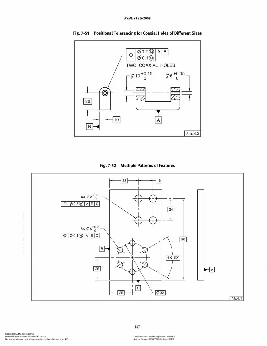
ASME Y14.5-2009
147
Fig. 7-51 Positional Tolerancing for Coaxial Holes of Different Sizes
Fig. 7-52 Multiple Patterns of Features
Copyright ASME International Provided by IHS under license with ASME Licensee=FMC Technologies /5914950002
Not for Resale, 05/07/2009 00:24:44 MDTNo reproduction or networking permitted without license from IHS
--`,,`,,,``,`,``,,``,`,`,,,`,`,`-`-`,,`,,`,`,,`---

ASME Y14.5-2009
148
the datum features of size to establish a separate datum reference frame for each pattern of features of size, as a group. These datum reference frames may translate and rotate independently of each other, resulting in an inde-pendent relationship between the patterns. This princi-ple does not apply to the lower segments of composite feature control frames except as noted in para. 4.19.
7.5.5 Multiple Positional Tolerances for a Pattern of Features of Size
If different datums, different datum modifiers, or the same datums in a different order of precedence are
specified, this constitutes a different datum reference frame and design requirements. This is not to be specified using the composite positional tolerancing method. A separately specified tolerance, using a second single-segment feature control frame is used, including applicable datums, as an independent requirement. See Fig. 7-55.
7.6 COAXIAL FEATURE CONTROLS
Coaxiality is that condition where the axes of the unre-lated actual mating envelope, axis of the unrelated mini-mum material envelope, or median points, as applicable of one or more surfaces of revolution, are coincident
Fig. 7-53 Tolerance Zones for Patterns Shown in Fig. 7-52
Copyright ASME International Provided by IHS under license with ASME Licensee=FMC Technologies /5914950002
Not for Resale, 05/07/2009 00:24:44 MDTNo reproduction or networking permitted without license from IHS
--`,,`,,,``,`,``,,``,`,`,,,`,`,`-`-`,,`,,`,`,,`---

ASME Y14.5-2009
149
with a datum axis or another feature axis. The amount of permissible variation from coaxiality may be expressed by a variety of means, including a positional tolerance, a runout tolerance, a concentricity tolerance, or a profile of a surface tolerance.
7.6.1 Selection of Coaxial Feature Controls
Selection of the proper control depends on the func-tional requirements of the design.
(a) Where the axis or surface of features must be controlled, and the use of RFS, MMC, or LMC material condition is applicable, positional tolerancing is recom-mended. See para. 7.6.2.
(b) Where the surface of a feature must be controlled relative to the datum axis, runout tolerancing is recom-mended. See para. 9.2.
(c) Where the relationship between the derived median points of the controlled feature and the datum axis is a primary design concern, or where the coaxial control of noncircular features is a design require-ment, concentricity tolerancing is recommended. See para. 7.6.4 and the note in para. 7.6.4.1.
(d) Where it is desired to achieve a combined con-trol of size, form, orientation, and location of a feature within the stated tolerance, profile tolerancing is recom-mended. See para. 7.6.5.
7.6.2 Positional Tolerance Control
Where the surfaces of revolution are cylindrical and the control of the axes can be applied on a material con-dition basis, positional tolerancing is recommended.
7.6.2.1 Coaxial Relationships. A coaxial relationship may be controlled by specifying a positional tolerance at MMC. See Fig. 7-56. A coaxial relationship may also be controlled by specifying a positional tolerance at RFS (as in Fig. 7-57) or LMC (as in Fig. 7-17). The datum feature may be specified on an MMB, LMB, or an RMB basis, depending upon the design requirements. In Fig. 7-56, the datum feature is specified on an MMB basis. In such cases, any departure of the datum feature from MMB may result in an additional displacement between its axis and the axis of the considered feature. See the con-ditions shown in Fig. 7-58. Where two or more features are coaxially related to such a datum (e.g., a shaft having several diameters) the considered features are displaced as a group relative to the datum feature, as explained in para. 7.5.3.2 for a pattern of features.
7.6.2.2 Coaxial Features Controlled Within Limits of Size. Where it is necessary to control coaxiality of related features within their limits of size, a zero posi-tional tolerance at MMC is specified. The datum feature
Fig. 7-54 Multiple Patterns of Features, Separate Requirements
Copyright ASME International Provided by IHS under license with ASME Licensee=FMC Technologies /5914950002
Not for Resale, 05/07/2009 00:24:44 MDTNo reproduction or networking permitted without license from IHS
--`,,`,,,``,`,``,,``,`,`,,,`,`,`-`-`,,`,,`,`,,`---

ASME Y14.5-2009
150
Fig. 7-55 Multiple Positional Tolerancing for a Pattern of Features
Copyright ASME International Provided by IHS under license with ASME Licensee=FMC Technologies /5914950002
Not for Resale, 05/07/2009 00:24:44 MDTNo reproduction or networking permitted without license from IHS
--`,,`,,,``,`,``,,``,`,`,,,`,`,`-`-`,,`,,`,`,,`---
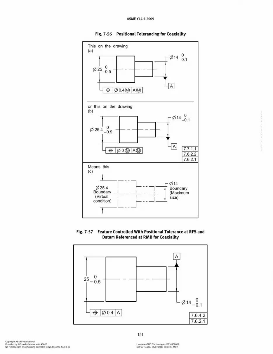
ASME Y14.5-2009
151
Fig. 7-56 Positional Tolerancing for Coaxiality
Fig. 7-57 Feature Controlled With Positional Tolerance at RFS and Datum Referenced at RMB for Coaxiality
Copyright ASME International Provided by IHS under license with ASME Licensee=FMC Technologies /5914950002
Not for Resale, 05/07/2009 00:24:44 MDTNo reproduction or networking permitted without license from IHS
--`,,`,,,``,`,``,,``,`,`,,,`,`,`-`-`,,`,,`,`,,`---

ASME Y14.5-2009
152
Fig. 7-58 Some of the Allowable Conditions of Part Shown in Fig. 7-56
is normally specified on an MMB basis. See Fig. 7-56, illustration (b). The tolerance establishes coaxial bound-aries of perfect form. Variations in coaxiality between the features are permitted only where the features depart from their MMC sizes toward LMC. The allowable posi-tional variation is within the “means this” portion of Fig. 7-56. See Fig. 7-58 for possible displacements.
7.6.2.3 Coaxial Features Without Datum Refer-ences. A coaxial relationship may be controlled by
specifying a positional tolerance without datum refer-ences, as shown in Fig. 7-59. This method allows specific control of feature-to-feature coaxiality. Where features are specified with different sizes, a single feature con-trol frame, supplemented by a notation, such as TWO COAXIAL FEATURES, is used. A positional tolerance speci-fication with no datum reference creates a relationship between the toleranced features, but implies no relation-ship to any other features. The toleranced features may be identified as a single datum feature that may then
Copyright ASME International Provided by IHS under license with ASME Licensee=FMC Technologies /5914950002
Not for Resale, 05/07/2009 00:24:44 MDTNo reproduction or networking permitted without license from IHS
--`,,`,,,``,`,``,,``,`,`,,,`,`,`-`-`,,`,,`,`,,`---

ASME Y14.5-2009
153
be referenced in the feature control frames of other fea-tures, as needed.
7.6.3 Runout Tolerance Control
For information on controlling surfaces of revolution, such as cylinders and cones, relative to a datum axis, with a runout tolerance, see para. 9.2.
7.6.4 Concentricity
Concentricity is that condition where the median points of all diametrically opposed elements of a surface of revolution (or the median points of corre-spondingly located elements of two or more radially disposed features) are congruent with a datum axis (or center point).
7.6.4.1 Concentricity Tolerancing. A concentricity tolerance is a cylindrical (or spherical) tolerance zone whose axis (or center point) coincides with the axis (or center point) of the datum feature(s). The median points of all correspondingly located elements of the feature(s) being controlled, regardless of feature size, must lie within the cylindrical (or spherical) tolerance zone. The specified tolerance can only apply on an RFS basis, and the datum reference can only apply on an RMB basis. See Fig. 7-60. Unlike the positional control defined in para. 7.6.2, where measurements taken along a surface of revolution are made to determine the location (eccen-tricity) of the axis or center point, a concentricity toler-ance requires the establishment and verification of the feature’s median points.
NOTE: Concentricity requirement as described above is substan-tially different than position, profi le, or runout tolerances.
7.6.4.2 Differences Between Concentricity and Other Coaxiality Controls. The items shown in Figs. 7-61 and 7-62 are two possible acceptable configurations of the item depicted in Fig. 7-57.
7.6.4.2.1 Controlling Features With Positional Tolerances. In Fig. 7-61, the axis of the controlled fea-ture’s unrelated actual mating envelope has been dis-placed 0.2 to the left, relative to the axis of datum feature A, and 0.5 material has been removed from the right side of the feature’s surface. In Fig. 7-62, the axis of the con-trolled feature’s unrelated actual mating envelope has also been displaced 0.2 to the left, relative to the axis of datum feature A, while 0.25 material has been removed from the upper side of the feature’s surface and 0.25 material has been removed from the lower side of the feature’s surface. Since the size of the unrelated actual mating envelope of the controlled features in Figs. 7-61 and 7-62 is 25 diameter, the controlled features remain within acceptable limits of size. For coaxial positional tolerance, the location of the axis of the feature’s unre-lated actual mating envelope is controlled relative to the axis of the datum feature. Where checked for a coaxial positional tolerance relationship, the items depicted in Figs. 7-61 and 7-62 are acceptable.
7.6.4.2.2 Controlling Features With Concentricity. For concentricity, the locations of the midpoints of dia-metrically opposed (or the median points of correspond-ingly located) feature elements are controlled relative to a datum axis. See Fig. 7-63. Where the items depicted in Figs. 7-61 and 7-62 are checked for a concentricity relationship, only the part depicted in Fig. 7-62 would be acceptable, since the midpoints of some of the dia-metrically opposed elements in Fig. 7-61 would exceed
Fig. 7-59 Two Datum Features, Single Datum Axis
Copyright ASME International Provided by IHS under license with ASME Licensee=FMC Technologies /5914950002
Not for Resale, 05/07/2009 00:24:44 MDTNo reproduction or networking permitted without license from IHS
--`,,`,,,``,`,``,,``,`,`,,,`,`,`-`-`,,`,,`,`,,`---

ASME Y14.5-2009
154
Fig. 7-60 Concentricity Tolerancing
Fig. 7-61 One Possible Acceptable Configuration of Part Depicted in Fig. 7-57
Copyright ASME International Provided by IHS under license with ASME Licensee=FMC Technologies /5914950002
Not for Resale, 05/07/2009 00:24:44 MDTNo reproduction or networking permitted without license from IHS
--`,,`,,,``,`,``,,``,`,`,,,`,`,`-`-`,,`,,`,`,,`---

ASME Y14.5-2009
155
Fig. 7-62 One Possible Acceptable Configuration of Part Depicted in Fig. 7-57
Fig. 7-63 Item Depicted in Fig. 7-57 Controlled for Concentricity
Copyright ASME International Provided by IHS under license with ASME Licensee=FMC Technologies /5914950002
Not for Resale, 05/07/2009 00:24:44 MDTNo reproduction or networking permitted without license from IHS
--`,,`,,,``,`,``,,``,`,`,,,`,`,`-`-`,,`,,`,`,,`---
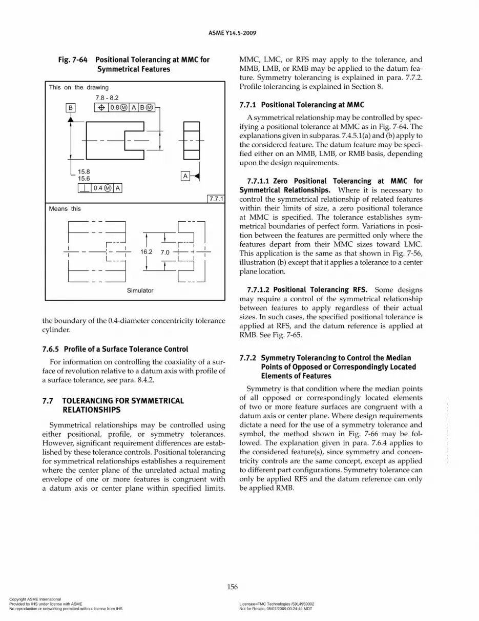
ASME Y14.5-2009
156
the boundary of the 0.4-diameter concentricity tolerance cylinder.
7.6.5 Profile of a Surface Tolerance Control
For information on controlling the coaxiality of a sur-face of revolution relative to a datum axis with profile of a surface tolerance, see para. 8.4.2.
7.7 TOLERANCING FOR SYMMETRICAL RELATIONSHIPS
Symmetrical relationships may be controlled using either positional, profile, or symmetry tolerances. However, significant requirement differences are estab-lished by these tolerance controls. Positional tolerancing for symmetrical relationships establishes a requirement where the center plane of the unrelated actual mating envelope of one or more features is congruent with a datum axis or center plane within specified limits.
MMC, LMC, or RFS may apply to the tolerance, and MMB, LMB, or RMB may be applied to the datum fea-ture. Symmetry tolerancing is explained in para. 7.7.2. Profile tolerancing is explained in Section 8.
7.7.1 Positional Tolerancing at MMC
A symmetrical relationship may be controlled by spec-ifying a positional tolerance at MMC as in Fig. 7-64. The explanations given in subparas. 7.4.5.1(a) and (b) apply to the considered feature. The datum feature may be speci-fied either on an MMB, LMB, or RMB basis, depending upon the design requirements.
7.7.1.1 Zero Positional Tolerancing at MMC for Symmetrical Relationships. Where it is necessary to control the symmetrical relationship of related features within their limits of size, a zero positional tolerance at MMC is specified. The tolerance establishes sym-metrical boundaries of perfect form. Variations in posi-tion between the features are permitted only where the features depart from their MMC sizes toward LMC. This application is the same as that shown in Fig. 7-56, illustration (b) except that it applies a tolerance to a center plane location.
7.7.1.2 Positional Tolerancing RFS. Some designs may require a control of the symmetrical relationship between features to apply regardless of their actual sizes. In such cases, the specified positional tolerance is applied at RFS, and the datum reference is applied at RMB. See Fig. 7-65.
7.7.2 Symmetry Tolerancing to Control the Median Points of Opposed or Correspondingly Located Elements of Features
Symmetry is that condition where the median points of all opposed or correspondingly located elements of two or more feature surfaces are congruent with a datum axis or center plane. Where design requirements dictate a need for the use of a symmetry tolerance and symbol, the method shown in Fig. 7-66 may be fol-lowed. The explanation given in para. 7.6.4 applies to the considered feature(s), since symmetry and concen-tricity controls are the same concept, except as applied to different part configurations. Symmetry tolerance can only be applied RFS and the datum reference can only be applied RMB.
Fig. 7-64 Positional Tolerancing at MMC for Symmetrical Features
Copyright ASME International Provided by IHS under license with ASME Licensee=FMC Technologies /5914950002
Not for Resale, 05/07/2009 00:24:44 MDTNo reproduction or networking permitted without license from IHS
--`,,`,,,``,`,``,,``,`,`,,,`,`,`-`-`,,`,,`,`,,`---
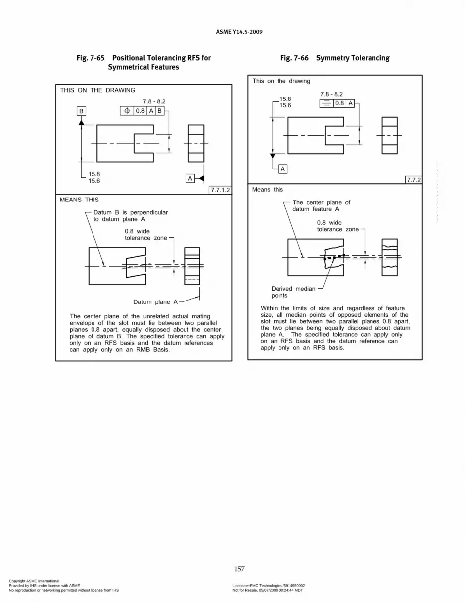
ASME Y14.5-2009
157
Fig. 7-66 Symmetry TolerancingFig. 7-65 Positional Tolerancing RFS for Symmetrical Features
Copyright ASME International Provided by IHS under license with ASME Licensee=FMC Technologies /5914950002
Not for Resale, 05/07/2009 00:24:44 MDTNo reproduction or networking permitted without license from IHS
--`,,`,,,``,`,``,,``,`,`,,,`,`,`-`-`,,`,,`,`,,`---

Section 8Tolerances of Profile
ASME Y14.5-2009
158
8.1 GENERAL
This Section establishes the principles and methods of dimensioning and tolerancing to control the profile of various features.
8.2 PROFILE
A profile is an outline of a surface, a shape made up of one or more features, or a two-dimensional element of one or more features. Profile tolerances are used to define a tolerance zone to control form or combinations of size, form, orientation, and location of a feature(s) relative to a true profile. Depending upon the design requirements, profile tolerance zones may or may not be related to datums. A digital data file or an appropriate view on a drawing shall define the true profile. A true profile is a profile defined by basic radii, basic angular dimensions, basic coordinate dimensions, basic size dimensions, undimensioned drawings, formulas, or mathematical data, including design models. Where used as a refinement of a size tolerance created by toleranced dimensions, the profile tolerance must be contained within the size limits. For more information on design models, see ASME Y14.41.
8.2.1 Types of Profile Tolerances
A profile tolerance may be applied to an entire part, multiple features, individual surfaces, or to individual profiles taken at various cross sections through a part. The two types of profile tolerances — profile of a surface and profile of a line — are explained in paras. 8.2.1.1 and 8.2.1.2:
8.2.1.1 Profile of a Surface. The tolerance zone established by the profile of a surface tolerance is three-dimensional (a volume), extending along the length and width (or circumference) of the considered feature or features. Profile of a surface may be applied to parts of any shape, including parts having a constant cross sec-tion as in Fig. 8-5, parts having a surface of revolution as in Fig. 8-17, or parts having a profile tolerance applied all over as in Fig. 8-8. Where the extent of the application of the profile tolerance is unclear, the between symbol should be used.
8.2.1.2 Profile of a Line. Each line element tolerance zone established by the profile of a line tolerance require-ment is two-dimensional (an area) and the tolerance zone is normal to the true profile of the feature at each line element. A design solid model or a drawing view is created to show the true profile. Profile of a line may be applied to parts having a varying cross section, such as the tapered wing of an aircraft, or a constant cross sec-tion, such as an extrusion, where it is not desired to have a tolerance zone include the entire surface of the feature as a single entity. See Fig. 8-27.
8.2.2 Profile Specification
The profile tolerance zone specifies a uniform or nonuniform tolerance boundary along the true pro-file within which the surface or single elements of the surface must lie.
8.2.3 Profile Tolerances as General Requirements
Where the profile tolerance feature control frame is placed in a general note or the general tolerance block, the tolerance applies to all features unless otherwise specified.
8.3 TOLERANCE ZONE BOUNDARIES
Uniform, bilateral, unequally disposed, or non-uniform tolerance zones can be applied to profile tolerances.
8.3.1 Uniform Tolerance Zone
A uniform tolerance zone is the distance between two boundaries equally or unequally disposed about the true profile or entirely disposed on one side of the true profile. Profile tolerances apply normal (perpendicular) to the true profile at all points along the profile. The boundaries of the tolerance zone follow the geometric shape of the true profile. The actual surface or line ele-ment must be within the specified tolerance zone. Since the surface may lie anywhere within the profile bound-ary, the actual part contour could have abrupt surface variations. If this is undesirable, the drawing must indi-cate the design requirements, such as rate of change and/or blend requirements. Where a profile tolerance encompasses a sharp corner, the tolerance zone extends
Copyright ASME International Provided by IHS under license with ASME Licensee=FMC Technologies /5914950002
Not for Resale, 05/07/2009 00:24:44 MDTNo reproduction or networking permitted without license from IHS
--`,,`,,,``,`,``,,``,`,`,,,`,`,`-`-`,,`,,`,`,,`---

ASME Y14.5-2009
159
to the intersection of the boundary lines. See Fig. 8-12. Since the intersecting surfaces may lie anywhere within the converging zone, the actual part contour could be rounded. If this is undesirable, the drawing must indi-cate the design requirements, such as by specifying the maximum radius. See Fig. 8-5.
8.3.1.1 Bilateral Profile Tolerance Zone. The toler-ance zone may be divided bilaterally to both sides of the true profile. Where an equally disposed bilateral tolerance is intended, it is necessary to show the fea-ture control frame with a leader directed to the surface or an extension line of the surface, but not to the basic dimension.
8.3.1.2 Unilateral and Unequally Disposed Profile Tolerance. A unilateral and unequally disposed pro-file tolerance is indicated with an unequally disposed profile symbol placed in the feature control frame. See Fig. 3-11. The unequally disposed symbol is placed in the feature control frame following the tolerance value. A second value is added following the unequally dis-posed symbol to indicate the tolerance in the direction that would allow additional material to be added to the true profile.
(a) Unilateral Tolerance in the Direction That Adds Material. Where a unilateral profile tolerance is 0.3 and applies from the true profile in the direction that adds material, the tolerance value would be 0.3 and the value following the unequally disposed symbol would be 0.3. See Fig. 8-1.
(b) Unilateral Tolerance in the Direction That Removes Material. Where a unilateral profile tolerance is 0.3 and
applies from the true profile in the direction that removes material, the tolerance value would be 0.3, and the value following the unequally disposed symbol would be 0. See Fig. 8-2.
(c) Unequally Disposed Tolerance. Where an unequally disposed profile tolerance is 0.3, 0.1 applies from the true profile in the direction that adds material, and 0.2 applies from the true profile in the direction that re-moves material, the tolerance value would be 0.3, and the value following the unequally disposed symbol would be 0.1. See Fig. 8-3.
8.3.1.3 Indication of Tolerance Zones on 2D Drawings. In orthographic 2D drawing views, as an alternate to using the unequally disposed profile symbol, it is per-missible to indicate an unequally disposed or unilateral tolerance by showing graphically the distribution of the appropriate tolerance zone. Phantom lines are drawn parallel to the true profile to indicate the tolerance zone boundary. One end of the dimension line is extended to the feature control frame. The phantom line should extend only a sufficient distance to make its application clear. See Fig. 8-4.
8.3.1.4 All Around Specification. Where a profile tolerance applies all around the true profile of the desig-nated features of the part (in the view where it is speci-fied), the all-around symbol is placed on the leader from the feature control frame. See Fig. 8-5. The all-around symbol shall not be applied in an axonometric view on a 2D drawing. Where the requirement is that the tolerance applies all over a part, the all over application is used. See para. 8.3.1.6.
Fig. 8-1 Profile of a Surface Application (Unilaterally Outside)
Copyright ASME International Provided by IHS under license with ASME Licensee=FMC Technologies /5914950002
Not for Resale, 05/07/2009 00:24:44 MDTNo reproduction or networking permitted without license from IHS
--`,,`,,,``,`,``,,``,`,`,,,`,`,`-`-`,,`,,`,`,,`---

ASME Y14.5-2009
160
Fig. 8-2 3D Profile of a Surface Application (Unilaterally Inside)
Fig. 8-3 3D Profile of a Surface Application (Unequally Disposed)
Copyright ASME International Provided by IHS under license with ASME Licensee=FMC Technologies /5914950002
Not for Resale, 05/07/2009 00:24:44 MDTNo reproduction or networking permitted without license from IHS
--`,,`,,,``,`,``,,``,`,`,,,`,`,`-`-`,,`,,`,`,,`---

ASME Y14.5-2009
161
Fig. 8-4 Application of Profile of a Surface Tolerance to a Basic Contour
8.3.1.5 Limited Segment of a Profile. Where seg-ments of a profile have different tolerances, the extent of each profile tolerance may be indicated by the use of ref-erence letters to identify the extremities or limits of each requirement accompanied with the use of the between symbol with each profile tolerance. See Fig. 8-6. Similarly, if some segments of the profile are controlled by a profile tolerance and other segments by individually toleranced dimensions, the extent of the profile tolerance shall be indicated. See Fig. 8-7.
8.3.1.6 All-Over Specification. A profile tolerance may be applied all over the 3-dimensional profile of a part unless
otherwise specified. It may be applied in one of the follow-ing ways:
(a) Place the “all over” symbol on the leader from the feature control frame as shown in Fig. 8-8.
(b) Place the term “ALL OVER” beneath the feature control frame.
8.3.2 Non-Uniform Zone
A non-uniform tolerance zone is a maximum mate-rial boundary and a least material boundary, of unique shape, that encompasses the true profile. These bounda-ries are defined in a CAD file or by basic dimensions
Copyright ASME International Provided by IHS under license with ASME Licensee=FMC Technologies /5914950002
Not for Resale, 05/07/2009 00:24:44 MDTNo reproduction or networking permitted without license from IHS
--`,,`,,,``,`,``,,``,`,`,,,`,`,`-`-`,,`,,`,`,,`---
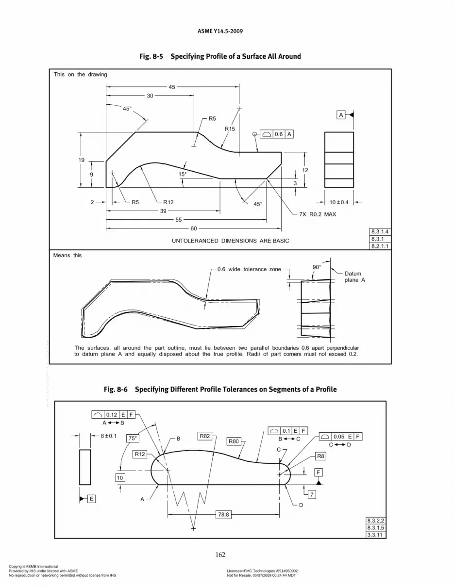
ASME Y14.5-2009
162
Fig. 8-5 Specifying Profile of a Surface All Around
Fig. 8-6 Specifying Different Profile Tolerances on Segments of a Profile
Copyright ASME International Provided by IHS under license with ASME Licensee=FMC Technologies /5914950002
Not for Resale, 05/07/2009 00:24:44 MDTNo reproduction or networking permitted without license from IHS
--`,,`,,,``,`,``,,``,`,`,,,`,`,`-`-`,,`,,`,`,,`---

ASME Y14.5-2009
163
Fig. 8-7 Specifying Profile of a Surface Between Points
Fig. 8-8 Specifying Profile of a Surface All Over
Copyright ASME International Provided by IHS under license with ASME Licensee=FMC Technologies /5914950002
Not for Resale, 05/07/2009 00:24:44 MDTNo reproduction or networking permitted without license from IHS
--`,,`,,,``,`,``,,``,`,`,,,`,`,`-`-`,,`,,`,`,,`---

ASME Y14.5-2009
164
on a drawing with phantom lines to indicate the tol-erance zone. The term “NON-UNIFORM” replaces the tolerance value within the feature control frame. See Figs. 8-9, 8-10, and 8-11.
8.3.2.1 Drawing Indication. For the non-uniform tolerance zone, the leader line from the feature con-trol frame is directed to the true profile. See Fig. 8-9.
Where individual segments of a profile are toleranced, the extent of each profile segment may be indicated by use of reference letters to identify the extremities or lim-its of each segment. See Fig. 8-10.
8.3.2.2 Non-Uniform Zones to Smooth the Transitions. Figure 8-11, illustration (a) shows the tolerance zones for Fig. 8-6. This figure illustrates abrupt transitions that occur
Fig. 8-9 Non-Uniform Profile Tolerance Zone Fig. 8-10 Non-Uniform Profile Tolerance Zone
Fig. 8-11 Non-Uniform Profile Tolerance Zone
Copyright ASME International Provided by IHS under license with ASME Licensee=FMC Technologies /5914950002
Not for Resale, 05/07/2009 00:24:44 MDTNo reproduction or networking permitted without license from IHS
--`,,`,,,``,`,``,,``,`,`,,,`,`,`-`-`,,`,,`,`,,`---

ASME Y14.5-2009
165
Fig. 8-12 Specifying Profile of a Surface for Sharp Corners
at the transition points B and C when different profile tol-erances are specified on adjoining segments of a feature. A nonuniform profile tolerance zone may be used to smooth the transition areas. See Fig. 8-11, illustration (b).
NOTE: A profile per unit length, similar to that shown in Fig. 5-4 for the control of straightness, may be used to control abrupt tran-sitions that occur when profile tolerances are specified on adjoin-ing segments of a feature.
8.4 PROFILE APPLICATIONS
Applications of profile tolerancing are described in the following paragraphs.
8.4.1 Profile Tolerance for Plane Surfaces
Profile tolerancing may be used to control form, ori-entation, and location of plane surfaces. In Fig. 8-13, a profile of a surface is used to control a plane surface inclined to two datum features.
8.4.1.1 Coplanarity. Coplanarity is the condition of two or more surfaces having all elements in one plane. A profile of a surface tolerance may be used where it is desired to treat two or more surfaces as a single inter-rupted or noncontinuous surface. In this case, a control is provided similar to that achieved by a flatness tolerance applied to a single plane surface. As shown in Fig. 8-14, the profile of a surface tolerance establishes a tolerance
zone defined by two parallel planes within which the considered surfaces must lie. As in the case of flatness, no datum reference is stated. Where two or more sur-faces are involved, it may be desirable to identify which specific surface(s) are to be used as the datum feature(s). Datum feature symbols are applied to these surfaces with the appropriate tolerance for their relationship to each other. The datum reference letters are added to the feature control frame for the features being controlled. See Fig. 8-15.
8.4.1.2 Offset Surfaces. A profile of a surface toler-ance may be used where it is desired to control two or more offset surfaces to each other. The feature control frame is associated with the applicable surfaces. The desired offset is shown with a basic dimension. See Fig. 8-16.
8.4.2 Conicity
A profile tolerance may be specified to control the conicity of a surface in two ways: as an independ-ent control of form as in Fig. 8-17, or as combinations of size, form, orientation, and location, as in Fig. 8-18. Figure 8-17 depicts a conical feature controlled by a pro-file of a surface tolerance where conicity of the surface is a refinement of size. In Fig. 8-18, the same control is applied but is oriented to a datum axis. In each case, the feature must be within size limits.
Copyright ASME International Provided by IHS under license with ASME Licensee=FMC Technologies /5914950002
Not for Resale, 05/07/2009 00:24:44 MDTNo reproduction or networking permitted without license from IHS
--`,,`,,,``,`,``,,``,`,`,,,`,`,`-`-`,,`,,`,`,,`---

ASME Y14.5-2009
166
Fig. 8-13 Specifying Profile of a Surface for a Plane Surface
Fig. 8-14 Specifying Profile of a Surface for Coplanar Surfaces
Fig. 8-15 Specifying Profile of a Surface for Coplanar Surfaces to a Datum Established by
Two Surfaces
Fig. 8-16 Specifying Profile of a Surface for Stepped Surfaces
Copyright ASME International Provided by IHS under license with ASME Licensee=FMC Technologies /5914950002
Not for Resale, 05/07/2009 00:24:44 MDTNo reproduction or networking permitted without license from IHS
--`,,`,,,``,`,``,,``,`,`,,,`,`,`-`-`,,`,,`,`,,`---
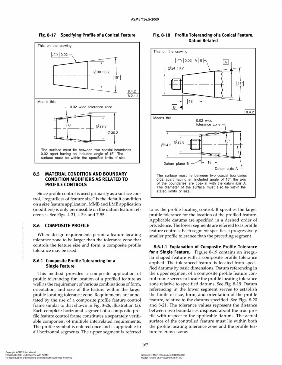
ASME Y14.5-2009
167
Fig. 8-17 Specifying Profile of a Conical Feature
8.5 MATERIAL CONDITION AND BOUNDARY CONDITION MODIFIERS AS RELATED TO PROFILE CONTROLS
Since profile control is used primarily as a surface con-trol, “regardless of feature size” is the default condition on a size feature application. MMB and LMB application (modifiers) is only permissible on the datum feature ref-erences. See Figs. 4-31, 4-39, and 7-55.
8.6 COMPOSITE PROFILE
Where design requirements permit a feature locating tolerance zone to be larger than the tolerance zone that controls the feature size and form, a composite profile tolerance may be used.
8.6.1 Composite Profile Tolerancing for a Single Feature
This method provides a composite application of profile tolerancing for location of a profiled feature as well as the requirement of various combinations of form, orientation, and size of the feature within the larger profile locating tolerance zone. Requirements are anno-tated by the use of a composite profile feature control frame similar to that shown in Fig. 3-26, illustration (a). Each complete horizontal segment of a composite pro-file feature control frame constitutes a separately verifi-able component of multiple interrelated requirements. The profile symbol is entered once and is applicable to all horizontal segments. The upper segment is referred
to as the profile locating control. It specifies the larger profile tolerance for the location of the profiled feature. Applicable datums are specified in a desired order of precedence. The lower segments are referred to as profile feature controls. Each segment specifies a progressively smaller profile tolerance than the preceding segment.
8.6.1.1 Explanation of Composite Profile Tolerance for a Single Feature. Figure 8-19 contains an irregu-lar shaped feature with a composite profile tolerance applied. The toleranced feature is located from speci-fied datums by basic dimensions. Datum referencing in the upper segment of a composite profile feature con-trol frame serves to locate the profile locating tolerance zone relative to specified datums. See Fig. 8-19. Datum referencing in the lower segment serves to establish the limits of size, form, and orientation of the profile feature, relative to the datums specified. See Figs. 8-20 and 8-21. The tolerance values represent the distance between two boundaries disposed about the true pro-file with respect to the applicable datums. The actual surface of the controlled feature must lie within both the profile locating tolerance zone and the profile fea-ture tolerance zone.
Fig. 8-18 Profile Tolerancing of a Conical Feature, Datum Related
Copyright ASME International Provided by IHS under license with ASME Licensee=FMC Technologies /5914950002
Not for Resale, 05/07/2009 00:24:44 MDTNo reproduction or networking permitted without license from IHS
--`,,`,,,``,`,``,,``,`,`,,,`,`,`-`-`,,`,,`,`,,`---

ASME Y14.5-2009
168
Fig. 8-19 Composite Profile Tolerancing of an Irregular Feature
8.6.1.2 Composite Profile Tolerancing for Multiple Features (Feature Pattern Location). Where design requirements for a pattern of features permit a profile Feature-Relating Tolerance Zone Framework (FRTZF) to be located and oriented within limits imposed upon it by a profile Pattern-Locating Tolerance Zone Framework (PLTZF), composite profile tolerancing is used.
8.6.1.3 Explanation of Composite Profile Tolerancing for Multiple Features. This provides a composite application of profile tolerancing for the location and constraint (rotation and translation) of a feature pattern (PLTZF) as well as the interrelation (location, size, form,
orientation) of profiled features within these patterns (FRTZF). Requirements are annotated by the use of a composite feature control frame. The profile symbol is entered once and is applicable to each horizontal seg-ment. Each horizontal segment in the feature control frame may be verified separately. See Fig. 8-21.
(a) Pattern-Locating Tolerance Zone Framework (PLTZF). Where composite controls are used, the uppermost seg-ment is the pattern-locating control. The PLTZF is con-strained in rotation and translation relative to the specified datums. It specifies the larger profile tolerance for the location of the pattern of profiled features as a group. Applicable datum features are referenced in the desired
Copyright ASME International Provided by IHS under license with ASME Licensee=FMC Technologies /5914950002
Not for Resale, 05/07/2009 00:24:44 MDTNo reproduction or networking permitted without license from IHS
--`,,`,,,``,`,``,,``,`,`,,,`,`,`-`-`,,`,,`,`,,`---
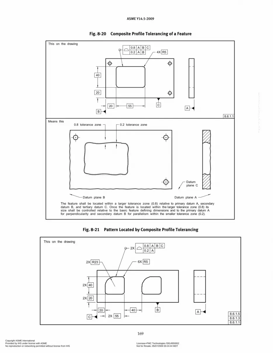
ASME Y14.5-2009
169
Fig. 8-20 Composite Profile Tolerancing of a Feature
Fig. 8-21 Pattern Located by Composite Profile Tolerancing
Copyright ASME International Provided by IHS under license with ASME Licensee=FMC Technologies /5914950002
Not for Resale, 05/07/2009 00:24:44 MDTNo reproduction or networking permitted without license from IHS
--`,,`,,,``,`,``,,``,`,`,,,`,`,`-`-`,,`,,`,`,,`---
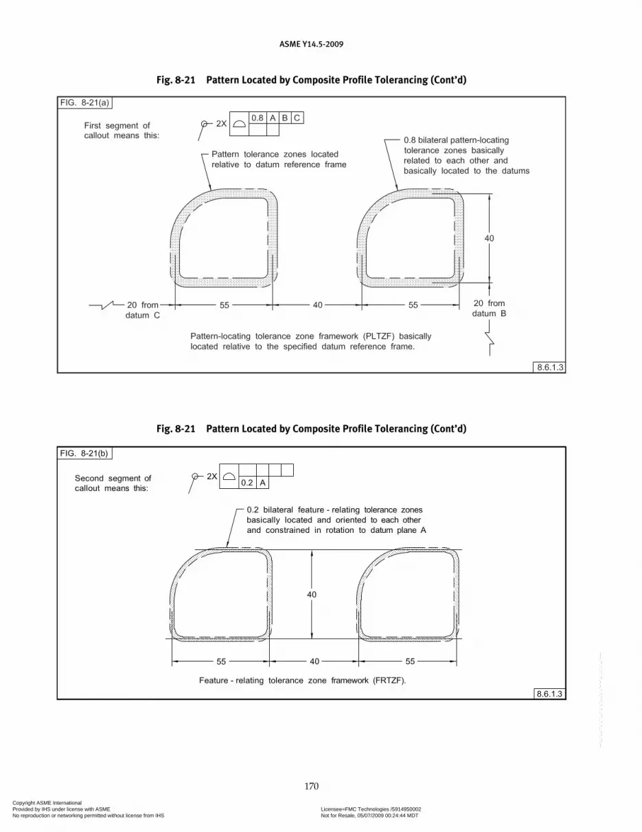
ASME Y14.5-2009
170
Fig. 8-21 Pattern Located by Composite Profile Tolerancing (Cont’d)
Fig. 8-21 Pattern Located by Composite Profile Tolerancing (Cont’d)
Copyright ASME International Provided by IHS under license with ASME Licensee=FMC Technologies /5914950002
Not for Resale, 05/07/2009 00:24:44 MDTNo reproduction or networking permitted without license from IHS
--`,,`,,,``,`,``,,``,`,`,,,`,`,`-`-`,,`,,`,`,,`---

ASME Y14.5-2009
171
Fig. 8-21 Tolerance Zones for Composite Profile Pattern (Cont’d)
order of precedence, and serve to relate the PLTZF to the datum reference frame. See Figs. 8-21, illustration (a) and 8-22, illustration (a).
(b) Feature-Relating Tolerance Zone Framework (FRTZF). Each of the lower segments is referred to as the profile feature-relating control. They govern the smaller tol-erance for size, form, orientation, and location within the pattern of features and may include constraints on rotation of a FRTZF to specified datums. Basic loca-tion dimensions used to relate the PLTZF to specified datums are not applicable to the location of any FRTZF. The toleranced feature shall lie within both the PLTZF and the FRTZF. See Figs. 8-21, illustration (b) and 8-22, illustration (b).
(1) Where datum references are not specified in a lower segment of the composite feature control frame,
the FRTZF is free to rotate and translate within the boundaries established and governed by the PLTZF.
(2) If datums are specified in the lower segment(s), they govern the rotation of the FRTZF relative to the datums and within the boundaries established and governed by the PLTZF. In some instances portions of the FRTZF may lie outside of the PLTZF and are not usable. See Figs. 8-21, illustration (c) and 8-22, illustration (b).
(3) Where datum references are specified, one or more of the datums specified in the upper segment of the frame are repeated, as applicable, and in the same order of precedence, to constrain rotation of the FRTZF.
(c) Different Datum Reference Frame and Design Require-ments. If different datums, different datum modifiers, or the same datums in a different order of precedence are specified, this constitutes a different datum reference
Copyright ASME International Provided by IHS under license with ASME Licensee=FMC Technologies /5914950002
Not for Resale, 05/07/2009 00:24:44 MDTNo reproduction or networking permitted without license from IHS
--`,,`,,,``,`,``,,``,`,`,,,`,`,`-`-`,,`,,`,`,,`---
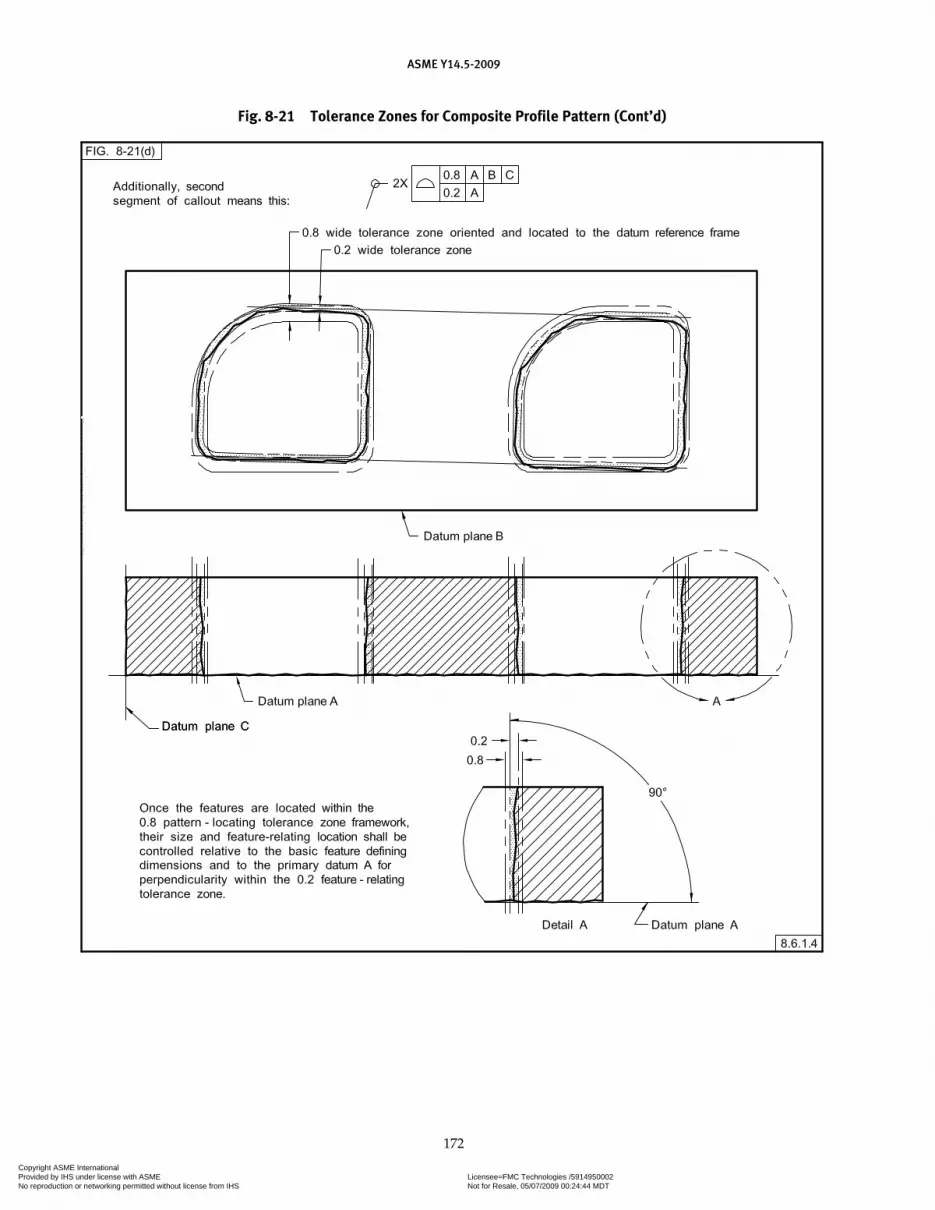
ASME Y14.5-2009
172
Fig. 8-21 Tolerance Zones for Composite Profile Pattern (Cont’d)
Copyright ASME International Provided by IHS under license with ASME Licensee=FMC Technologies /5914950002
Not for Resale, 05/07/2009 00:24:44 MDTNo reproduction or networking permitted without license from IHS
--`,,`,,,``,`,``,,``,`,`,,,`,`,`-`-`,,`,,`,`,,`---

ASME Y14.5-2009
173
Fig. 8-22 Pattern Located by Composite Profile Tolerancing
Fig. 8-22 Tolerance Zones for Composite Profile Pattern (Cont’d)
Copyright ASME International Provided by IHS under license with ASME Licensee=FMC Technologies /5914950002
Not for Resale, 05/07/2009 00:24:44 MDTNo reproduction or networking permitted without license from IHS
--`,,`,,,``,`,``,,``,`,`,,,`,`,`-`-`,,`,,`,`,,`---
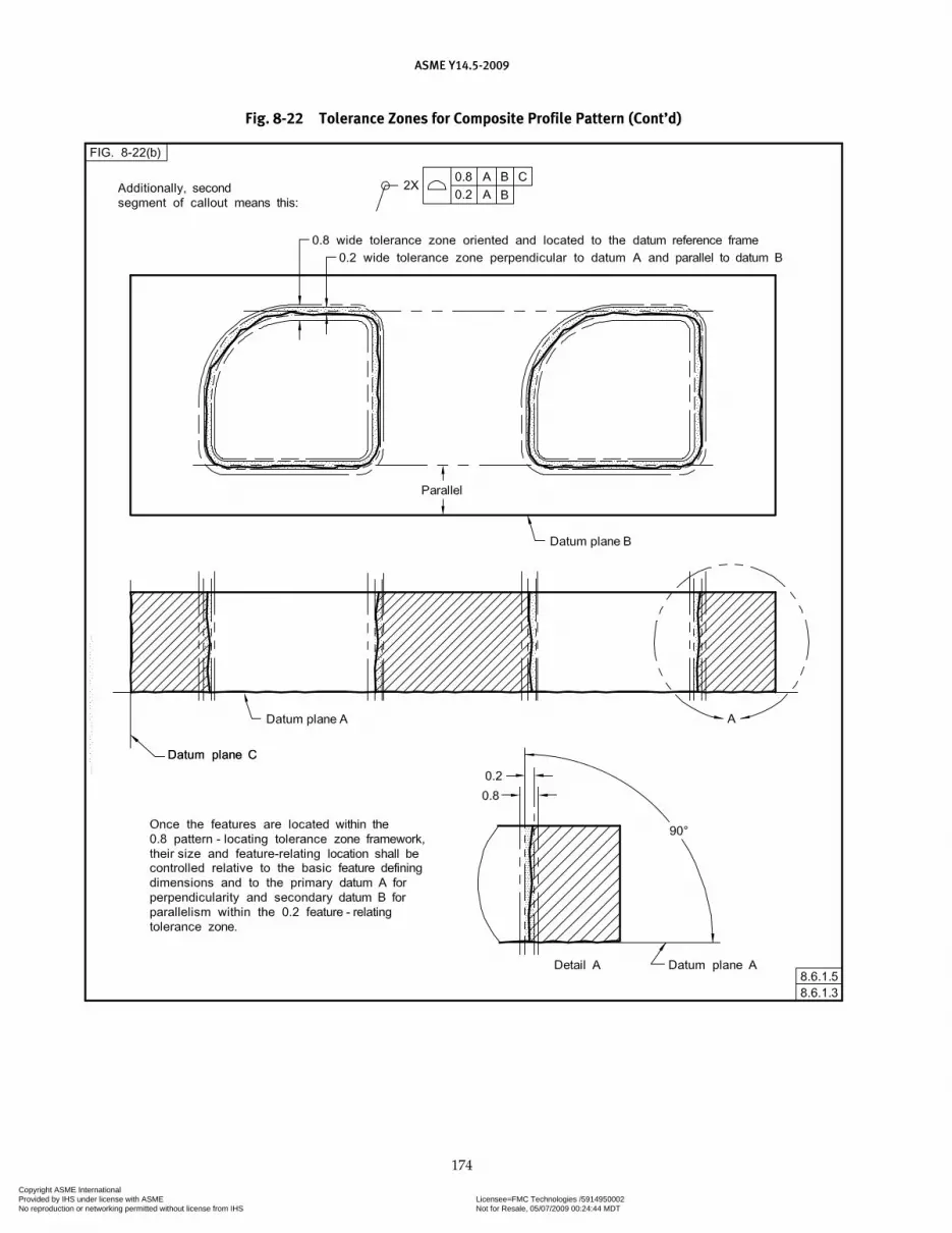
ASME Y14.5-2009
174
Fig. 8-22 Tolerance Zones for Composite Profile Pattern (Cont’d)
Copyright ASME International Provided by IHS under license with ASME Licensee=FMC Technologies /5914950002
Not for Resale, 05/07/2009 00:24:44 MDTNo reproduction or networking permitted without license from IHS
--`,,`,,,``,`,``,,``,`,`,,,`,`,`-`-`,,`,,`,`,,`---

ASME Y14.5-2009
175
frame and design requirements. This is not to be specified using the composite profile tolerancing method.
8.6.1.4 Primary Datum Repeated in Lower Segment. As can be seen from the sectional view of the tolerance zones in Fig. 8-21, illustration (d), since datum plane A has been repeated in the lower segment of the com-posite feature control frame, the profile zones of both the PLTZF and FRTZF are perpendicular to datum plane A and, therefore, parallel to each other. In certain instances, portions of the smaller zones may fall beyond the peripheries of the larger tolerance zones. However, these portions of smaller tolerance zones are not usable because the surface of the features must not violate the boundaries of the larger tolerance zones. See also Fig. 8-21, illustration (c). The profile of the actual fea-ture may vary obliquely (out of perpendicularity) only within the confines of the respective smaller feature relating tolerance zones (FRTZF).
8.6.1.5 Primary and Secondary Datums Repeated in Lower Segment. Figure 8-22 repeats the feature pat-terns of Fig. 8-21. In Fig. 8-22, the lower segment of the composite feature control frame repeats datums A and B. Figure 8-22, illustrations (a) and (b), shows that the tol-erance zones of the FRTZF may be translated from the true locations (as a group), as governed by the tolerance zones of the PLTZF, constrained in rotation by datum planes A and B. Figure 8-22, illustration (a) shows that the actual surfaces of the features must reside within both the tolerance zones of the FRTZF and the PLTZF.
8.6.2 Composite Profile With Independent Size/Form Control
Where the design requires that the size and form of one or more features be controlled independently of the composite profile tolerance, a separate single segment profile feature control frame is used followed by the term INDIVIDUALLY. The size/form tolerance specified must be less than the tolerance in the lower segment (FRTZF) of the composite profile control. See Fig. 8-23.
8.7 MULTIPLE SINGLE-SEGMENT PROFILE TOLERANCING
For multiple single-segment profile tolerancing, datum feature references are interpreted the same as for multiple single-segment positional tolerancing. See para. 7.5.2.
8.8 COMBINED CONTROLS
Profile tolerancing may be combined with other types of geometric tolerancing. Profile tolerancing may be com-bined with positional tolerancing where it is necessary to control the boundary of a noncylindrical feature. See Fig. 8-24. In this example the basic dimensions and the profile tolerance establish a tolerance zone to control the shape and size of the feature. Additionally, the positional tolerance establishes a theoretical boundary shaped identically to the true profile. For an internal feature the boundary equals the MMC size of the profile minus the positional tolerance, and the entire feature surface must
Fig. 8-23 Irregular-Shaped Feature With a Profile Size/Form Control and the Pattern Located by Composite Profile Tolerance
Copyright ASME International Provided by IHS under license with ASME Licensee=FMC Technologies /5914950002
Not for Resale, 05/07/2009 00:24:44 MDTNo reproduction or networking permitted without license from IHS
--`,,`,,,``,`,``,,``,`,`,,,`,`,`-`-`,,`,,`,`,,`---

ASME Y14.5-2009
176
lie outside the boundary. For an external feature, the boundary equals the MMC size of the profile plus the positional tolerance, and the entire feature surface must lie within the boundary. The term BOUNDARY is optional and may be placed beneath the positional feature control frame. Figure 8-25 illustrates a surface that has a profile tolerance refined by a parallelism tolerance. The surface must not only be within the profile tolerance, but each straight line element of the surface must also be parallel to the datum within the tolerance specified. Figure 8-26
illustrates a surface that has a profile tolerance refined by a runout tolerance. The entire surface must be within the profile tolerance, and the circular elements must be within the specified runout tolerance. Figure 8-27 illus-trates a part with a profile of a line tolerance where size is controlled by a separate tolerance. Line elements of the surface along the profile must lie within the profile tolerance zone and within a size limiting zone. In this application, the datum references only orient the profile of a line tolerance.
Fig. 8-24 MMC Principle Used With Profile Controls
Copyright ASME International Provided by IHS under license with ASME Licensee=FMC Technologies /5914950002
Not for Resale, 05/07/2009 00:24:44 MDTNo reproduction or networking permitted without license from IHS
--`,,`,,,``,`,``,,``,`,`,,,`,`,`-`-`,,`,,`,`,,`---

ASME Y14.5-2009
177
Fig. 8-25 Specifying Combined Profile and Parallelism Tolerances
Copyright ASME International Provided by IHS under license with ASME Licensee=FMC Technologies /5914950002
Not for Resale, 05/07/2009 00:24:44 MDTNo reproduction or networking permitted without license from IHS
--`,,`,,,``,`,``,,``,`,`,,,`,`,`-`-`,,`,,`,`,,`---

ASME Y14.5-2009
178
Fig. 8-26 Profile of a Surface of Revolution
Copyright ASME International Provided by IHS under license with ASME Licensee=FMC Technologies /5914950002
Not for Resale, 05/07/2009 00:24:44 MDTNo reproduction or networking permitted without license from IHS
--`,,`,,,``,`,``,,``,`,`,,,`,`,`-`-`,,`,,`,`,,`---

ASME Y14.5-2009
179
Fig. 8-27 Profile of a Line and Size Control
Copyright ASME International Provided by IHS under license with ASME Licensee=FMC Technologies /5914950002
Not for Resale, 05/07/2009 00:24:44 MDTNo reproduction or networking permitted without license from IHS
--`,,`,,,``,`,``,,``,`,`,,,`,`,`-`-`,,`,,`,`,,`---
Section 9Tolerances of Runout
ASME Y14.5-2009
180
9.1 GENERAL
This Section establishes the principles and methods of dimensioning and tolerancing to control runout of vari-ous geometrical shapes.
9.2 RUNOUT
Runout is a tolerance used to control the functional relationship of one or more features to a datum axis established from a datum feature specified at RMB.
NOTE: The figures in this Section use measurement techniques to explain the tolerance zones. It is neither the intent nor within the scope of this Standard to define measurement methods.
9.3 RUNOUT TOLERANCE
The types of features controlled by runout tolerances include those surfaces constructed around a datum axis and those constructed at right angles to a datum axis. See Fig. 9-1.
9.3.1 Datum Features for Runout Tolerances
The datum axis for a runout tolerance may be established by a cylindrical datum feature of sufficient length, two or more cylindrical datum features having sufficient axial separation, or a cylindrical datum feature and a face at right angles to it. Features used as datum features for establishing axes should be functional, such as mounting features that establish an axis of rotation.
9.3.2 Rotation About an Axis
When the part is rotated about the datum axis, full indicator movement (FIM) for each considered fea-ture must be within its runout tolerance. This may also include the datum features as a part of the runout toler-ance control where so designated.
9.4 TYPES OF RUNOUT TOLERANCES
There are two types of runout tolerances, circular runout and total runout. The type used is dependent upon design requirements and manufacturing consid-erations. Circular runout is normally a less complex
requirement than total runout. The following para-graphs describe both types of runout.
9.4.1 Control of Circular Elements
Circular runout provides control of circular elements of a surface. The tolerance is applied independently at each circular measuring position as the part is rotated the full angular extent of the surface about the simulated datum axis. See Fig. 9-2. Where applied to surfaces constructed around a datum axis, circular runout may be used to control the cumulative varia-tions of circularity and coaxiality. Where applied to surfaces constructed at right angles to the datum axis, circular runout controls circular elements of a plane surface (wobble). When verifying circular runout, the indicator is fixed in a position normal to the toleranced surface.
9.4.2 Total Runout for Control of Surfaces
Total runout provides control of all surface elements. The tolerance is applied simultaneously to all circular and profile measuring positions as the part is rotated 360 º about the datum axis. See Fig. 9-3. When verifying total runout, the indicator is fixed in orientation normal to and translates along the toleranced surface.
9.4.2.1 Applied to Surfaces Around an Axis. Where applied to surfaces, constructed around a datum axis, total runout may be used to control cumulative varia-tions such as circularity, straightness, coaxiality, angu-larity, taper, and profile of a surface.
9.4.2.2 Applied to Surfaces Normal to an Axis. Where applied to surfaces at right angles to a datum axis, total runout controls cumulative variations of per-pendicularity (to detect wobble) and flatness (to detect concavity or convexity).
9.4.2.3 Applied to a Portion of Surface. Where a runout tolerance applies to a specific portion of a sur-face, a thick chain line is drawn adjacent to the surface profile on one side of the datum axis for the desired length. Basic dimensions are used to define the extent of the portion so indicated. See Fig. 9-2.
Copyright ASME International Provided by IHS under license with ASME Licensee=FMC Technologies /5914950002
Not for Resale, 05/07/2009 00:24:44 MDTNo reproduction or networking permitted without license from IHS
--`,,`,,,``,`,``,,``,`,`,,,`,`,`-`-`,,`,,`,`,,`---

ASME Y14.5-2009
181
Fig. 9-1 Features Applicable to Runout Tolerancing
Fig. 9-2 Specifying Circular Runout Relative to a Datum Diameter
Fig. 9-3 Specifying Total Runout Relative to a Datum Diameter
Copyright ASME International Provided by IHS under license with ASME Licensee=FMC Technologies /5914950002
Not for Resale, 05/07/2009 00:24:44 MDTNo reproduction or networking permitted without license from IHS
--`,,`,,,``,`,``,,``,`,`,,,`,`,`-`-`,,`,,`,`,,`---
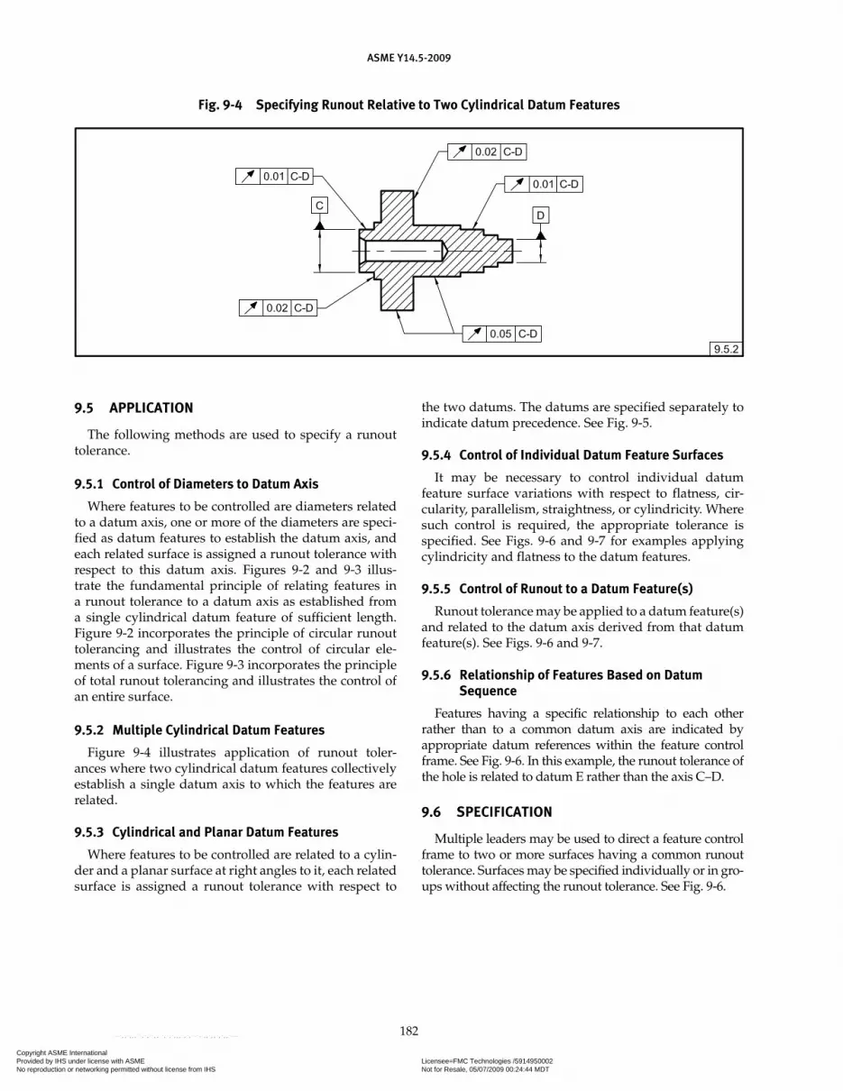
ASME Y14.5-2009
182
Fig. 9-4 Specifying Runout Relative to Two Cylindrical Datum Features
9.5 APPLICATION
The following methods are used to specify a runout tolerance.
9.5.1 Control of Diameters to Datum Axis
Where features to be controlled are diameters related to a datum axis, one or more of the diameters are speci-fied as datum features to establish the datum axis, and each related surface is assigned a runout tolerance with respect to this datum axis. Figures 9-2 and 9-3 illus-trate the fundamental principle of relating features in a runout tolerance to a datum axis as established from a single cylindrical datum feature of sufficient length. Figure 9-2 incorporates the principle of circular runout tolerancing and illustrates the control of circular ele-ments of a surface. Figure 9-3 incorporates the principle of total runout tolerancing and illustrates the control of an entire surface.
9.5.2 Multiple Cylindrical Datum Features
Figure 9-4 illustrates application of runout toler-ances where two cylindrical datum features collectively establish a single datum axis to which the features are related.
9.5.3 Cylindrical and Planar Datum Features
Where features to be controlled are related to a cylin-der and a planar surface at right angles to it, each related surface is assigned a runout tolerance with respect to
the two datums. The datums are specified separately to indicate datum precedence. See Fig. 9-5.
9.5.4 Control of Individual Datum Feature Surfaces
It may be necessary to control individual datum feature surface variations with respect to flatness, cir-cularity, parallelism, straightness, or cylindricity. Where such control is required, the appropriate tolerance is specified. See Figs. 9-6 and 9-7 for examples applying cylindricity and flatness to the datum features.
9.5.5 Control of Runout to a Datum Feature(s)
Runout tolerance may be applied to a datum feature(s) and related to the datum axis derived from that datum feature(s). See Figs. 9-6 and 9-7.
9.5.6 Relationship of Features Based on Datum Sequence
Features having a specific relationship to each other rather than to a common datum axis are indicated by appropriate datum references within the feature control frame. See Fig. 9-6. In this example, the runout tolerance of the hole is related to datum E rather than the axis C–D.
9.6 SPECIFICATION
Multiple leaders may be used to direct a feature control frame to two or more surfaces having a common runout tolerance. Surfaces may be specified individually or in gro-ups without affecting the runout tolerance. See Fig. 9-6.
Copyright ASME International Provided by IHS under license with ASME Licensee=FMC Technologies /5914950002
Not for Resale, 05/07/2009 00:24:44 MDTNo reproduction or networking permitted without license from IHS
--`,,`,,,``,`,``,,``,`,`,,,`,`,`-`-`,,`,,`,`,,`---
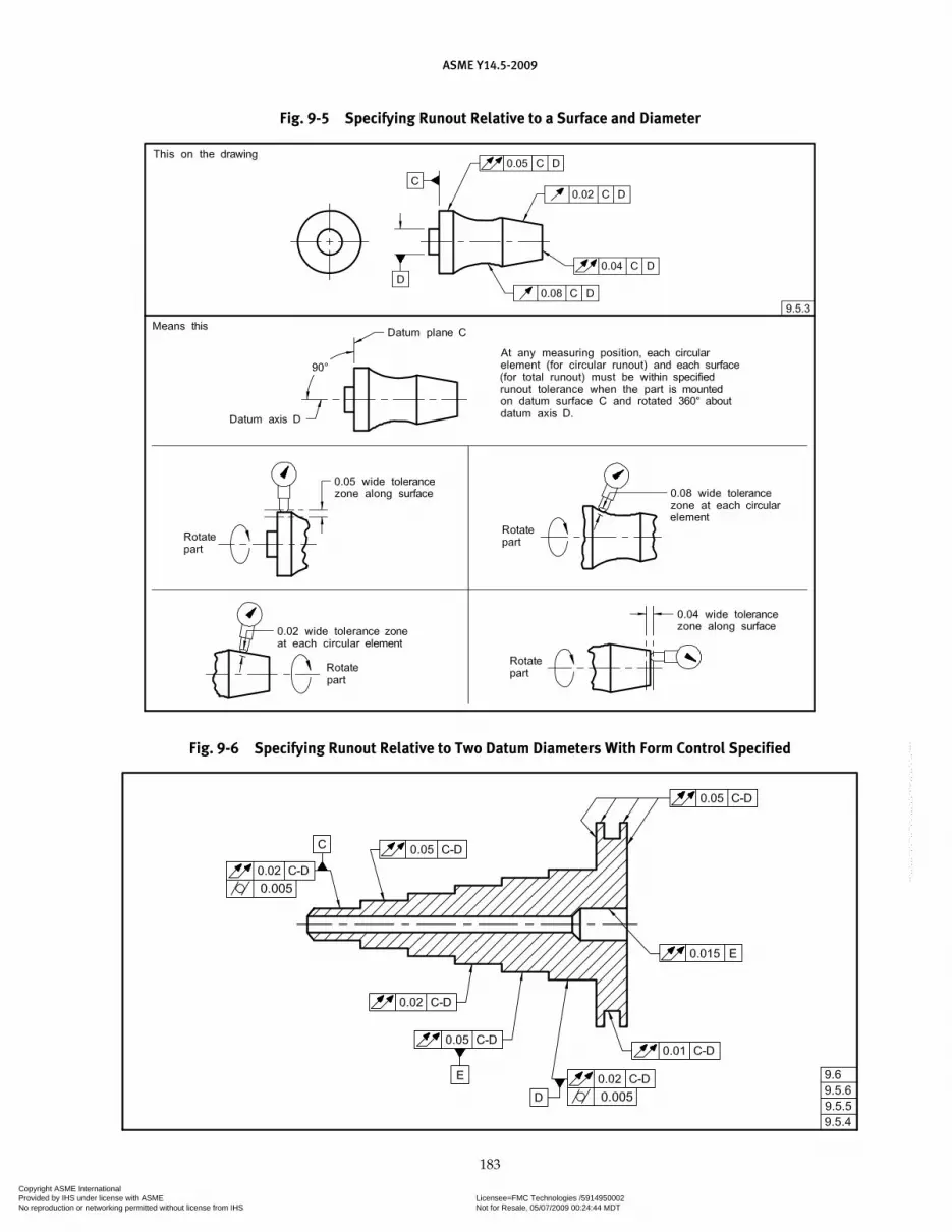
ASME Y14.5-2009
183
Fig. 9-5 Specifying Runout Relative to a Surface and Diameter
Fig. 9-6 Specifying Runout Relative to Two Datum Diameters With Form Control Specified
Copyright ASME International Provided by IHS under license with ASME Licensee=FMC Technologies /5914950002
Not for Resale, 05/07/2009 00:24:44 MDTNo reproduction or networking permitted without license from IHS
--`,,`,,,``,`,``,,``,`,`,,,`,`,`-`-`,,`,,`,`,,`---

ASME Y14.5-2009
184
Fig. 9-7 Specifying Runout Relative to a Surface and Diameter With Form Control Specified
Copyright ASME International Provided by IHS under license with ASME Licensee=FMC Technologies /5914950002
Not for Resale, 05/07/2009 00:24:44 MDTNo reproduction or networking permitted without license from IHS
--`,,`,,,``,`,``,,``,`,`,,,`,`,`-`-`,,`,,`,`,,`---

ASME Y14.5-2009
185
NONMANDATORY APPENDIX APRINCIPAL CHANGES AND IMPROVEMENTS
A.1 GENERAL
The purpose of this Appendix is to provide users a list of the principal changes and improvements in this revi-sion of the Standard as compared to the previous issue. The changes are summarized for each section or appen-dix in the form of additions, clarifications, extensions of principles, or resolution of differences.
A.2 STANDARD FORMAT
The format of the Standard has been revised to present the material in the sequence most used when applying geometric dimensioning and tolerancing. Section 1 con-tinues to present the Scope, Definitions, and General Dimensioning. Section 2, as in previous revisions, is General Tolerancing and Related Principles, Section 3 is Symbology, and Section 4 is Datum Reference Frames. The revisions in sequence begin with Section 5, Tolerances of Form; Section 6, Tolerances of Orientation; Section 7, Tolerances of Location; Section 8, Tolerance of Profile; and Section 9, Tolerances of Runout.
This format was adopted to guide the user of this Standard in first selecting the necessary datums based on the part’s function to constrain the workpiece in order to perform the necessary manufacturing steps or to inspect the workpiece. After datums are selected, form toler-ances should be considered to control the accuracy of a primary datum, and then orientation controls should be considered to properly relate the secondary datum feature to the primary datum feature. Finally, tertiary datum features are generally related to the primary and secondary datum features using either position or pro-file tolerancing. In the case of a primary datum feature that is a cylinder, runout tolerancing may be used to control the secondary datum feature in relationship to the datum axis.
Form, orientation, position, profile, and runout are also used to control other features on the workpiece and are not limited to datum features.
Similarly, the text within each section has been reor-ganized to present the foundational (basic) principles first and then build on the foundations. Additionally, new material has been added where necessary for clari-fication, or to extend and enhance the principles pre-sented in previous revisions of the Standard.
A.3 SECTION 1, SCOPE, DEFINITIONS, AND GENERAL DIMENSIONING
A.3.1 References Added
Reference to ASME Y14.43 was added in para. 1.1.6, Reference to Gaging.
A.3.2 Additional References Added
The following references were added:(a) ASME Y14.41-2003, Digital Product Definition
Data Practices(b) ASME Y14.43-2003, Dimensioning and Tolerancing
Principles for Gages and Fixtures(c) ASME Y14.38-2007, Abbreviations(d) ASME Y14.100-2004, Engineering Drawing
Practices
A.3.3 Definitions and Terms
Definitions and terms have been enhanced by expan-sion, addition, clarification, and reorganization.
A.3.4 New or Revised Terms and Definitions
A.3.4.1 boundary, least material (LMB)
A.3.4.2 boundary, maximum material (MMB)
A.3.4.3 boundary, regardless of material (RMB)
A.3.4.4 datum feature
A.3.4.5 datum target
A.3.4.6 dimension
A.3.4.7 dimension reference
A.3.4.8 envelope, actual mating
A.3.4.9 unrelated actual mating envelope
A.3.4.10 related actual mating envelope
A.3.4.11 feature axis
Copyright ASME International Provided by IHS under license with ASME Licensee=FMC Technologies /5914950002
Not for Resale, 05/07/2009 00:24:44 MDTNo reproduction or networking permitted without license from IHS
--`,,`,,,``,`,``,,``,`,`,,,`,`,`-`-`,,`,,`,`,,`---

ASME Y14.5-2009
186
A.3.4.12 feature center plane
A.3.4.13 derived median line
A.3.4.14 derived median plane
A.3.4.15 feature of size(a) regular feature of size(b) irregular feature of size
A.3.4.16 plane, tangent
A.3.5 Fundamental Rules Revised
A.3.5.1 Paragraph 1.4(b) was revised to add “Values may be expressed in an engineering drawing or in a CAD product definition set. (See ASME Y14.41.)”
A.3.5.2 For para. 1.4(f), the structure of the rule was changed so that the rule is stated first and then examples are given.
A.3.6 Fundamental Rules Added
A.3.6.1 For para. 1.4(k), a zero basic dimension applies where axes, center planes, or surfaces that are shown congruent on a drawing and geometric controls establish the relationship between the features.
A.3.6.2 For para. 1.4(p), where a coordinate system is shown on the drawing, it shall be right-handed unless otherwise specified. Each axis shall be labeled, and the positive direction shall be shown.
A.3.7 Paragraphs Revised
A.3.7.1 Paragraph 1.7.9: Dimensions Not to Scale. Subparagraph (a) added a requirement for a basic dimension not to scale.
A.3.7.2 Paragraph 1.8.4: Rounded Ends and Slotted Holes. Slotted holes were added to this paragraph.
A.3.7.3 Paragraph 1.8.10: Round Holes. Clarification added, indicating that when the depth dimension is not clear the dimension should be shown pictorially.
A.3.7.4 Paragraph 1.8.14: Spotfaces. Clarification added, indicating that if no depth or remaining material is specified, the spotface is the minimum depth to clean up the surface.
A.3.7.5 Paragraph 1.8.16.3. This new paragraph introduces two methods of dimensioning chamfers for surfaces intersecting at angles other than right angles.
A.4 SECTION 2, GENERAL TOLERANCING AND RELATED PRINCIPLES
A.4.1 Paragraph 2.1.1
Paragraph 2.1.1 has been revised to emphasize/encourage the use of use of basic dimensions and geo-metric tolerancing as the preferred method of control-ling the form, orientation, and location of features. The use of direct tolerancing methods, limit dimensioning, and plus minus tolerancing should be used to control the size of features only.
A.4.2 Paragraph 2.1.1.4
Paragraph 2.1.1.4 on implied 90º angles has been expanded to include basically dimensioned angles con-trolled by geometric tolerancing.
A.4.3 Paragraph 2.4
Paragraph 2.4 on interpretation of limits has been revised to eliminate the discussion on deviation outside the limiting value of a dimension.
A.4.4 Paragraph 2.6
In para. 2.6, a note has been added on the effect of tol-erance accumulation when using basic dimensioning.
A.4.5 Paragraph 2.7.1
In para. 2.7.1, Rule #1 has been expanded for clarification.
A.4.6 Paragraph 2.7.5
Limits of size of a continuous feature are defined in para. 2.7.5.
A.4.7 Paragraph 2.8.4
In para. 2.8.4, perfect form at LMC when a tolerance applies at LMC is clarified.
A.4.8 Paragraph 2.16
The placement of the tangent plane symbol within the feature control frame is specified in para. 2.16.
A.4.9 Paragraph 2.11.1
Paragraph 2.11.1 in ASME 14.5M-1994 (Virtual Condition) has been removed. This concept is covered in para. 2.11, Boundary Conditions.
A.4.10 Paragraph 2.11.2
Paragraph 2.11.2 in ASME Y14.5M-1994 (Resultant Condition) has been removed. This concept is covered in para. 2.11, Boundary Conditions.
Copyright ASME International Provided by IHS under license with ASME Licensee=FMC Technologies /5914950002
Not for Resale, 05/07/2009 00:24:44 MDTNo reproduction or networking permitted without license from IHS
--`,,`,,,``,`,``,,``,`,`,,,`,`,`-`-`,,`,,`,`,,`---

ASME Y14.5-2009
187
A.4.11 Paragraph 2.11.3
Paragraph 2.11.3 in ASME Y14.5M-1994 (Datum Features at Virtual Condition) has been removed. This concept is covered in para. 4.11.9 (Datum Feature Shift/Displacement) and para. 7.3.6 (Datum Feature Modifiers in Positional Tolerances).
A.5 SECTION 3, SYMBOLOGY
A.5.1 Addition of New Symbols
A.5.1.1 all over
A.5.1.2 continuous feature
A.5.1.3 independency
A.5.1.4 unequally disposed profile
A.5.1.5 movable datum target
A.5.1.6 datum translation
A.6 SECTION 4, DATUM REFERENCE FRAMES
A.6.1 Title
Section 4 on Datum Reference Frames has been reti-tled to better reflect the content of the section. It has also been reorganized and several new concepts and some new technology have been incorporated.
A.6.2 Degrees of Freedom
There is a greater emphasis on the degrees of free-dom constrained by the primary, secondary, and tertiary datum features.
A.6.3 Terms
The following new terms for the boundaries that are derived from datum features have been added.
A.6.3.1 Maximum Material Boundary (MMB) using the same symbol as MMC.
A.6.3.2 Least Material Boundary (LMB) using the same symbol as LMC.
A.6.3.3 Regardless of Material (RMB), which is the implied condition and has no symbol.
A.6.4 Figure 4-3
New Fig. 4-3 identifies the derived datum and the degrees of freedom constrained by various types of pri-mary datum features at RMB.
A.6.5 Datum Feature Simulator Term
The term “datum feature simulator” has been defined as theoretically perfect for use in this Standard and has replaced the term “true geometric counterpart.”
A.6.6 Datum Feature Simulator Requirements
The requirements for datum feature simulators are defined.
A.6.7 Small Assembly Example
Inclusion of an example of a small assembly and the logic behind the selection of the datum feature for the parts in the assembly is explained.
A.6.8 Calculation of MMB
Calculation of various MMB depending on the datum features and their order of precedence has been illus-trated in Fig. 4-16.
A.6.9 Addition of the Datum Feature Simulator Value in the Feature Control Frame
The ability to add the value of the datum feature sim-ulator in the feature control frame with either a dimen-sion or the term BASIC or BSC for clarification has been explained.
A.6.10 Datum Feature Shift
The new term “Datum Feature Shift” is explained.
A.6.11 Secondary and Tertiary Datum Features
New illustrations of secondary and tertiary datum features at LMB and their effect.
A.6.12 Role of a Secondary or Tertiary Datum
The role of a secondary or tertiary datum relative to a higher precedence datum axis has been clarified and expanded.
A.6.13 Translation Modifier Symbol
Introduced a new symbol to indicate that a datum feature simulator translates called a translation modifier.
A.6.14 Symbol for Datum Feature Simulator
A new symbol for the datum reference frame labeled with the X, Y, Z translational degrees of freedom has been added.
Copyright ASME International Provided by IHS under license with ASME Licensee=FMC Technologies /5914950002
Not for Resale, 05/07/2009 00:24:44 MDTNo reproduction or networking permitted without license from IHS
--`,,`,,,``,`,``,,``,`,`,,,`,`,`-`-`,,`,,`,`,,`---
ASME Y14.5-2009
188
A.6.15 Part With a Contoured Datum Feature
Illustration of a part with a contoured datum feature has been added.
A.6.16 Part Contours
Illustrations of several part contours and the effect of datum feature modifiers on these configurations have been added.
A.6.17 Restrained Parts
New text on restrained parts and the application of datum features to these types of features has been added.
A.6.18 Customized Datum Reference Frame Construction
A new concept on customized datum reference frame construction and the applicable requirements has been added.
A.6.19 Movable Datum Target Symbol
A new movable datum target symbol adopted from ASME Y14.8 and ASME Y14.41 has been aded.
A.7 SECTION 5, TOLERANCES OF FORM
A.7.1 Location of Form Tolerances Section
Form tolerances were formerly in Section 6 with pro-file, orientation, and runout. To better guide the user of the Standard in the application of geometric dimension-ing and tolerancing, form tolerances now are in a sepa-rate section.
A.7.2 Straightness of a Center Plane
Straightness of a center plane has been revised to flat-ness of a center plane to better reflect that it is a three-dimension control, even though it is the same principle as in the previous edition of the Standard.
A.8 SECTION 6, TOLERANCES OF ORIENTATION
A.8.1 Location of Orientation Tolerances Section
Orientation tolerances were formerly in Section 6 with form, profile, and runout. To better guide the user of the Standard in the application of geometric dimensioning and tolerancing, orientation tolerances now are in a sep-arate section.
A.8.2 Definitions
The definitions of the three orientation tolerances in ASME Y14.5M-1994 were basically the same, the only difference being the inclusion of the particular orienta-tion tolerance. The definitions for angularity, perpendic-ularity, and parallelism are all in one paragraph, and the text applies to all of the orientation tolerances.
A.8.3 Angularity Symbol
The use of the angularity symbol meaning orientation is introduced as an alternative practice to using perpen-dicularity and parallelism.
A.9 SECTION 7, TOLERANCES OF LOCATION
A.9.1 Location of Tolerances of Position Section
Tolerances of position were formerly in Section 5. To better guide the user of the Standard in the application of geometric dimensioning and tolerancing, tolerances of position have been moved to the new Section 7.
A.9.2 Reformatting
Tolerances of position have been reformatted so that the material flows from the basic to more complex principles.
A.9.3 Definitions
Paragraph 7.2 defines positional tolerances to include their relationship to other features and relative to datums.
A.9.4 Paragraph 7.2.1.1
Paragraph 7.2.1.1 added basic dimensions defined by CAD data.
A.9.5 Paragraph 7.3.3.1
Previously a note had indicated that the surface inter-pretation takes precedence over the axis interpretation of positional tolerance. This was made part of para. 7.3.3.1.
A.9.6 Paragraph 7.3.5.3
Zero positional tolerance at LMC has been added.
A.9.7 Effects of Datum References in Positional Tolerances
Effects of datum references in positional tolerances are explained in degrees of freedom.
A.9.8 Paragraph 7.3.6.2.2
Effects on position tolerances caused by datum fea-ture departure from MMB have been explained.
A.9.9 Paragraph 7.4.8
Positional tolerances on repetitive patterns of features have been explained.
A.9.10 Sequential Figures for Composite Positional Tolerances
Sequential figures for composite positional tolerances have been simplified so that each figure contains only the information to build on the previously shown figure. This reduced the amount of information that was
Copyright ASME International Provided by IHS under license with ASME Licensee=FMC Technologies /5914950002
Not for Resale, 05/07/2009 00:24:44 MDTNo reproduction or networking permitted without license from IHS
--`,,`,,,``,`,``,,``,`,`,,,`,`,`-`-`,,`,,`,`,,`---

ASME Y14.5-2009
189
repeated and makes finding the relevant information much easier.
A.9.11 Paragraph 7.5.1.7
Projected tolerance zones for composite tolerances are shown and explained.
A.9.12 Paragraph 7.5.1.8
Addition of multiple segments to a composite tolerance feature control frame are illustrated and explained.
A.9.13 Paragraph 7.6.2.3
Position tolerance is shown without a datum refer-ence to control coaxial features.
A.9.14 Paragraph 7.6.5
Profile tolerancing has been added as a method to control coaxiality.
A.10 SECTION 8, TOLERANCES OF PROFILE
A.10.1 Location of Tolerances of Profile Section
Profile tolerances were formerly in Section 6 with form, orientation, and runout. To better guide the user of the Standard in the application of geometric dimen-sioning and tolerancing, profile tolerances now are in a separate section.
A.10.2 Unequally Disposed Profile Symbol
A new symbolic method of indicating that a profile tolerance is either unilateral or unequally disposed bilateral using a new unequally disposed profile symbol has been added.
A.10.3 All-Over Application of Profile
Two ways may now be used for the all-over applica-tion of profile. A new symbol has been created, placed at the intersection of the horizontal and radial portions of the leader line from the feature control frame, or the term “ALL OVER” may be used beneath the feature con-trol frame.
A-10.4 Application of a Non-Uniform Tolerance Zone
An application of a non-uniform tolerance zone has been illustrated. The term “NON-UNIFORM” replaces the tolerance value in the feature control frame and the two extremes of the tolerance zone are dimensioned.
A.10.5 Abrupt Transitions
Abrupt transitions when different profile tolerances are specified on adjoining segments of a feature has
been addressed with the use of a non-uniform tolerance application.
A.10.6 X Symbol
The X symbol (for example, 2X) has replaced the note designation (for example, 2 SURFACES) for a number of surfaces.
A.10.7 Control of Two or More Offset Surfaces
An example has been added for control of two or more offset surfaces to each other similar to co-planar surfaces.
A.10.8 Boundary of an Irregular Feature of Size
The term “BOUNDARY” beneath the feature control frame is now optional in an application where it is necessary to control the boundary of an irregular feature of size.
A.10.9 Composite Profile Tolerancing
Composite profile tolerancing has been expanded to include multiple features in a pattern.
A.10.10 Profile Locating Features
Profile, with a datum reference, has replaced plus/minus (�/�) for location of features to each other or other features on a part.
A.11 SECTION 9, TOLERANCES OF RUNOUT
Runout tolerances were formerly in Section 6 with form, profile, and orientation. To better guide the user of the Standard in the application of geometric dimen-sioning and tolerancing, runout tolerances now are in a separate section.
A.12 NONMANDATORY APPENDIX A
Nonmandatory Appendix A has been completely revised to reflect the revisions in this revision of the Standard.
A.13 NONMANDATORY APPENDIX B
A.13.1 Metric Values
Nonmandatory Appendix B has been revised to reflect actual metric values for the illustrated fastener sizes and has used the same size fastener throughout the appendix for uniformity.
A.13.2 B7 Limits and Fits
B7, Limits and Fits, has been revised to better reflect actual practice.
Copyright ASME International Provided by IHS under license with ASME Licensee=FMC Technologies /5914950002
Not for Resale, 05/07/2009 00:24:44 MDTNo reproduction or networking permitted without license from IHS
--`,,`,,,``,`,``,,``,`,`,,,`,`,`-`-`,,`,,`,`,,`---
ASME Y14.5-2009
190
A.14 NONMANDATORY APPENDIX C
A.14.1 New Symbols
The new symbols listed below have been introduced.
A.14.1.1 movable datum target
A.14.1.2 all over
A.14.1.3 unequally disposed profile
A.14.1.4 translation modifier
A.14.1.5 independency
A.14.1.6 continuous feature
A.14.2 Comparison of Symbols
The symbols listed below have been added to the Comparison of Symbols charts.
A.14.2.1 all over
A.14.2.2 at maximum material boundary
A.14.2.3 at least material boundary
A.14.2.4 continuous feature
A.14.2.5 unequally disposed profile
A.14.2.6 translation modifier
A.14.2.7 spotface
A.14.2.8 movable datum target
A.15 NONMANDATORY APPENDIX D
Information on significant former practices once fea-tured in the 1994 issue of this Standard is provided.
A.16 NONMANDATORY APPENDIX E
A.16.1
The flow of material has been revised so that the order of the figures reflects the order that various subjects are addressed in this Standard.
A.16.1.1 Figure E-1: Design Requirements
A.16.1.2 Figure E-2: Datum Selections
A.16.1.3 Figure E-3: Form
A.16.1.4 Figure E-4: Orientation
A.16.1.5 Figure E-5: Location
A.16.1.6 Figure E-6: Profile
A.16.1.7 Figure E-7: Runout
A.16.2 Datum selection has been revised to reflect the pos-
sibility of applying material modifiers (MMB and LMB) to plane surfaces.
A.16.3 Form has been revised to include the new concept of
flatness rather than straightness of a center plane.
Copyright ASME International Provided by IHS under license with ASME Licensee=FMC Technologies /5914950002
Not for Resale, 05/07/2009 00:24:44 MDTNo reproduction or networking permitted without license from IHS
--`,,`,,,``,`,``,,``,`,`,,,`,`,`-`-`,,`,,`,`,,`---

ASME Y14.5-2009
191
NONMANDATORY APPENDIX BFORMULAS FOR POSITIONAL TOLERANCING
B.1 GENERAL
The purpose of this Appendix is to present formulas for determining the required positional tolerances or the required sizes of mating features to ensure that parts will assemble. The formulas are valid for all types of features or patterns of features and will give a “no inter-ference, no clearance” fit when features are at maximum material condition with their locations in the extreme of positional tolerance. Consideration must be given for additional geometric conditions that could affect func-tions not accounted for in the following formulas.
B.2 FORMULA SYMBOLS
B.2.1 Use of Symbols
Formulas given herein use the five symbols listed below.
B.2.1.1 D � minimum depth of thread or minimum thickness of part with restrained or fixed fastener
B.2.1.2 F � maximum diameter of fastener (MMC limit)
B.2.1.3 H � minimum diameter of clearance hole (MMC limit)
B.2.1.4 P � maximum thickness of part with clear-ance hole, or maximum projection of fastener, such as a stud
B.2.1.5 T � positional tolerance diameter
B.2.2 Subscripts
Subscripts are used where more than one size feature or tolerance is involved.
B.3 FLOATING FASTENER CASE
Where two or more parts are assembled with fasteners, such as bolts and nuts, and all parts have clearance holes for the bolts, it is termed the “floating fastener case.” See Fig. B-1. Where the fasteners are of the same diameter, and it is desired to use the same clearance hole diameters and the same positional tolerances for the parts to be assembled, the following formula applies:
H � F � T
or
T � H � F
EXAMPLE: Given that the fasteners in Fig. B-1 are 6-diameter maximum and the clearance holes are 6.44-diameter minimum, find the required positional tolerance:
T � 6.44 � 6
� 0.44 diameter for each part
Any number of parts with different hole sizes and positional tolerances may be mated, provided the for-mula H � F � T or T � H � F is applied to each part individually.
B.4 FIXED FASTENER CASE WHEN PROJECTED TOLERANCE ZONE IS USED
Where one of the parts to be assembled has restrained fasteners, such as screws in tapped holes or studs, it is termed the “fixed fastener case.” See Fig. B-2. Where the fasteners are of the same diameter and it is desired to use the same positional tolerance in each of the parts to be assembled, the following formula applies:
H � F � 2T
or
TH F
��
2
Note that the allowable positional tolerance for each part is one-half that for the comparable floating fastener case.
EXAMPLE: Given that the fasteners in Fig. B-2 have a maximum diameter of 6 and the clearance holes have a minimum diameter of 6.44, find the required positional tolerance:
T ��6 44 6
2.
� 0.22 diameter for each part
Where it is desired that the part with tapped holes have a larger positional tolerance than the part with clearance holes, the total positional tolerance of both holes (2T) can be separated into T1 and T2 in any appro-priate manner such that
2T � T1 � T2
Copyright ASME International Provided by IHS under license with ASME Licensee=FMC Technologies /5914950002
Not for Resale, 05/07/2009 00:24:44 MDTNo reproduction or networking permitted without license from IHS
--`,,`,,,``,`,``,,``,`,`,,,`,`,`-`-`,,`,,`,`,,`---
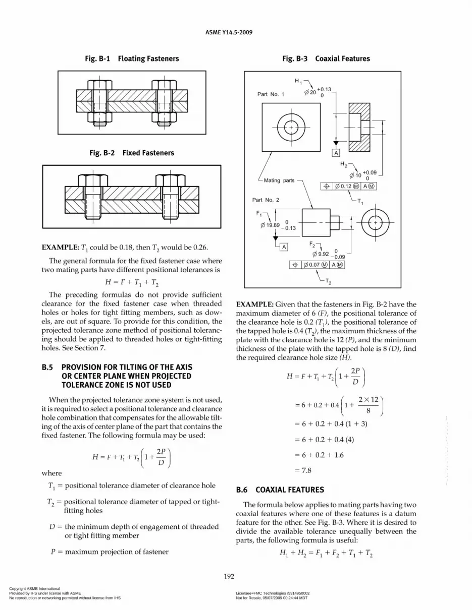
ASME Y14.5-2009
192
EXAMPLE: T1 could be 0.18, then T2 would be 0.26.
The general formula for the fixed fastener case where two mating parts have different positional tolerances is
H � F � T1 � T2
The preceding formulas do not provide sufficient clearance for the fixed fastener case when threaded holes or holes for tight fitting members, such as dow-els, are out of square. To provide for this condition, the projected tolerance zone method of positional toleranc-ing should be applied to threaded holes or tight-fitting holes. See Section 7.
B.5 PROVISION FOR TILTING OF THE AXIS OR CENTER PLANE WHEN PROJECTED TOLERANCE ZONE IS NOT USED
When the projected tolerance zone system is not used, it is required to select a positional tolerance and clearance hole combination that compensates for the allowable tilt-ing of the axis of center plane of the part that contains the fixed fastener. The following formula may be used:
HP
DF T T� � � �1 2 1
2⎛⎝⎜
⎞⎠⎟
where
T1 � positional tolerance diameter of clearance hole
T2 � positional tolerance diameter of tapped or tight-fitting holes
D � the minimum depth of engagement of threaded or tight fitting member
P � maximum projection of fastener
EXAMPLE: Given that the fasteners in Fig. B-2 have the maximum diameter of 6 (F), the positional tolerance of the clearance hole is 0.2 (T1), the positional tolerance of the tapped hole is 0.4 (T2), the maximum thickness of the plate with the clearance hole is 12 (P), and the minimum thickness of the plate with the tapped hole is 8 (D), find the required clearance hole size (H).
HP
DF T T� � � �1 2 1
2⎛⎝⎜
⎞⎠⎟
= ⎛⎝⎜
⎞⎠⎟6
2 128
0 2 0 4 1� � ��
. .
� 6 � 0.2 � 0.4 (1 � 3)
� 6 � 0.2 � 0.4 (4)
� 6 � 0.2 � 1.6
� 7.8
B.6 COAXIAL FEATURES
The formula below applies to mating parts having two coaxial features where one of these features is a datum feature for the other. See Fig. B-3. Where it is desired to divide the available tolerance unequally between the parts, the following formula is useful:
H1 � H2 � F1 � F2 � T1 � T2
Fig. B-2 Fixed Fasteners
Fig. B-3 Coaxial FeaturesFig. B-1 Floating Fasteners
Copyright ASME International Provided by IHS under license with ASME Licensee=FMC Technologies /5914950002
Not for Resale, 05/07/2009 00:24:44 MDTNo reproduction or networking permitted without license from IHS
--`,,`,,,``,`,``,,``,`,`,,,`,`,`-`-`,,`,,`,`,,`---

ASME Y14.5-2009
193
(This formula is valid only for simple coaxial parts that are of similar length as shown here. Consideration must be given for other geometric conditions [i.e. orientation, pro-jected tolerance, etc.] that may be required for function.)
EXAMPLE: Given the information shown in Fig. B-3, solve for T1 and T2:
H1 � H2 � F1 � F2 � T1 � T2
T1 � T2 � (H1 � H2) � (F1 � F2)
� (20 � 10) � (19.89 � 9.92)
� 0.19 total available tolerance
This total available tolerance may be divided in any desired manner, such as
T1 � 0.12
T2 � 0.07
B.7 LIMITS AND FITS
Where requirements for the size and fit of mating features are specified by symbols per ANSI B4.2, the for-mulas for positional tolerancing are also applicable.
The above symbols have been used with ANSI B4.2, Table 2 to obtain the limit values shown in Fig. B-3. Table B2 and B3 of ANSI B4.2 show the following:
(a) For the hole basic size 20,
Fundamental Deviation H20 � 0
(b) For the hole basic size 10,
Fundamental Deviation H10 � 0
(c) For the shaft basic size 20,
Fundamental Deviation c20 � �0.11
(d) For the shaft basic size 10,
Fundamental Deviation c10 � �0.08
Note that the total available tolerance is
T1 � T2 � (H20 � c20) � (H10 � c10)
� (0 � 0.11) � (0 � 0.08)
� 0.19
This total available tolerance may be divided in any desired manner, such as
T1 � 0.12
T2 � 0.07
Copyright ASME International Provided by IHS under license with ASME Licensee=FMC Technologies /5914950002
Not for Resale, 05/07/2009 00:24:44 MDTNo reproduction or networking permitted without license from IHS
--`,,`,,,``,`,``,,``,`,`,,,`,`,`-`-`,,`,,`,`,,`---
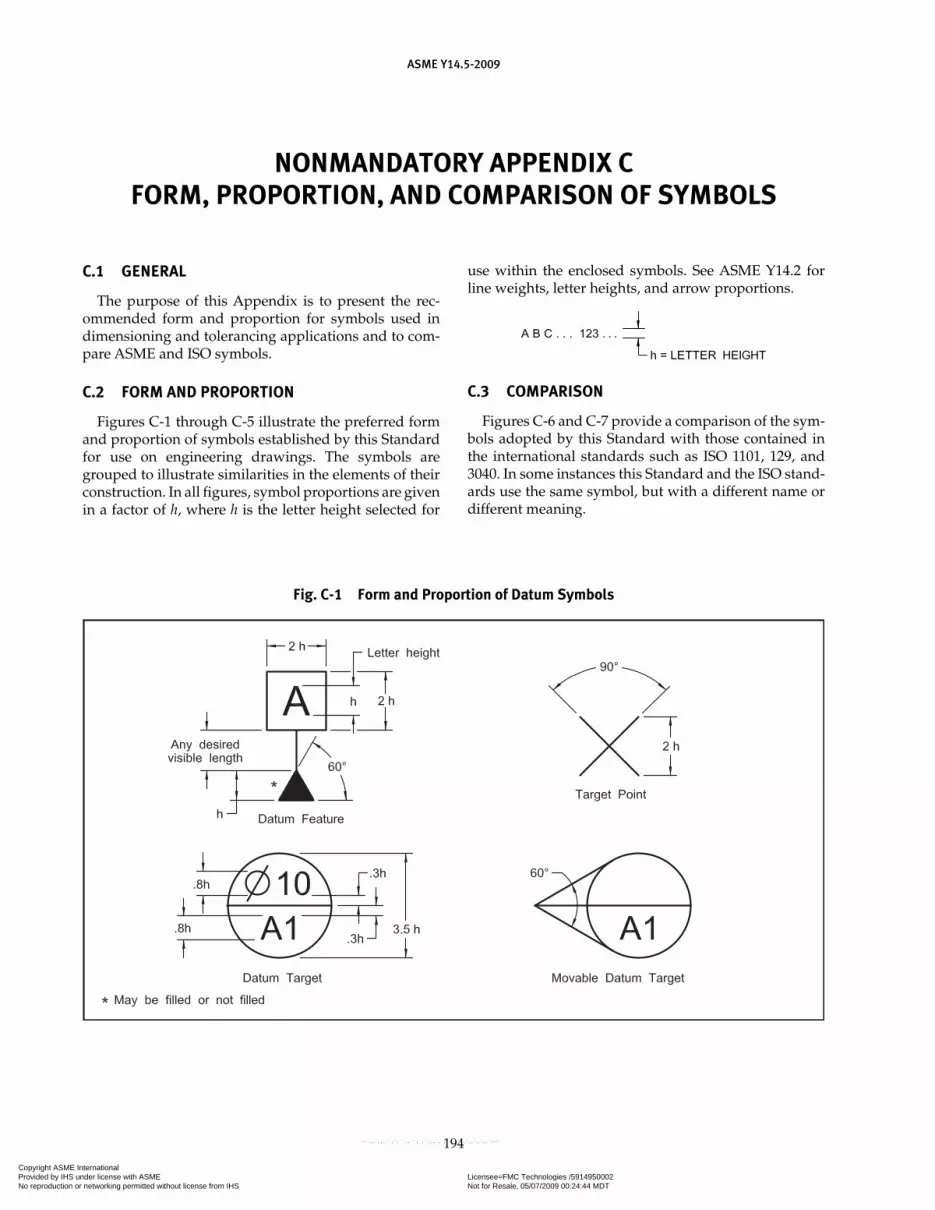
NONMANDATORY APPENDIX CFORM, PROPORTION, AND COMPARISON OF SYMBOLS
ASME Y14.5-2009
194
C.1 GENERAL
The purpose of this Appendix is to present the rec-ommended form and proportion for symbols used in dimensioning and tolerancing applications and to com-pare ASME and ISO symbols.
C.2 FORM AND PROPORTION
Figures C-1 through C-5 illustrate the preferred form and proportion of symbols established by this Standard for use on engineering drawings. The symbols are grouped to illustrate similarities in the elements of their construction. In all figures, symbol proportions are given in a factor of h, where h is the letter height selected for
use within the enclosed symbols. See ASME Y14.2 for line weights, letter heights, and arrow proportions.
C.3 COMPARISON
Figures C-6 and C-7 provide a comparison of the sym-bols adopted by this Standard with those contained in the international standards such as ISO 1101, 129, and 3040. In some instances this Standard and the ISO stand-ards use the same symbol, but with a different name or different meaning.
Fig. C-1 Form and Proportion of Datum Symbols
Copyright ASME International Provided by IHS under license with ASME Licensee=FMC Technologies /5914950002
Not for Resale, 05/07/2009 00:24:44 MDTNo reproduction or networking permitted without license from IHS
--`,,`,,,``,`,``,,``,`,`,,,`,`,`-`-`,,`,,`,`,,`---
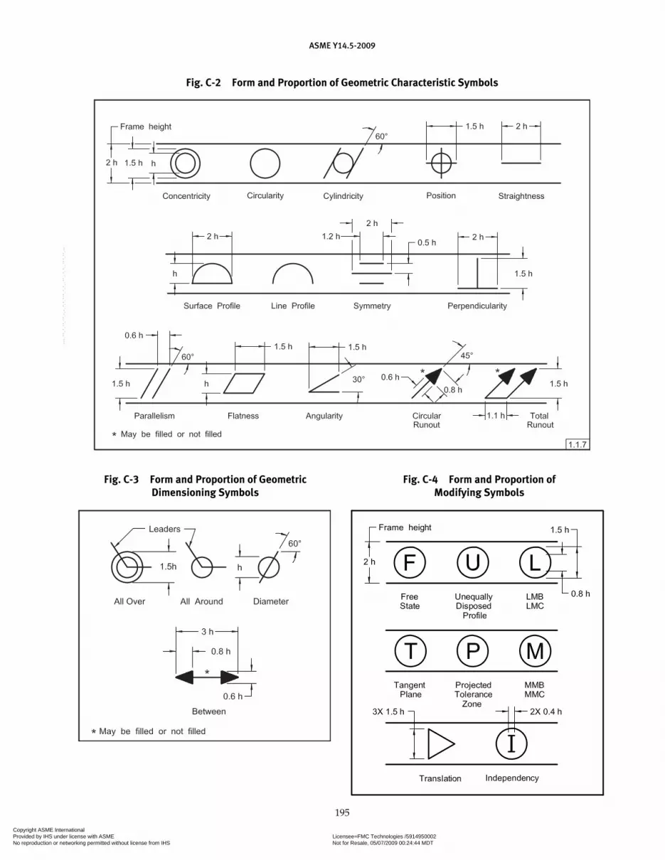
ASME Y14.5-2009
195
Fig. C-2 Form and Proportion of Geometric Characteristic Symbols
Fig. C-3 Form and Proportion of Geometric Dimensioning Symbols
Fig. C-4 Form and Proportion of Modifying Symbols
Copyright ASME International Provided by IHS under license with ASME Licensee=FMC Technologies /5914950002
Not for Resale, 05/07/2009 00:24:44 MDTNo reproduction or networking permitted without license from IHS
--`,,`,,,``,`,``,,``,`,`,,,`,`,`-`-`,,`,,`,`,,`---

ASME Y14.5-2009
196
Fig. C-5 Form and Proportion of Dimensioning Symbols and Letters
Copyright ASME International Provided by IHS under license with ASME Licensee=FMC Technologies /5914950002
Not for Resale, 05/07/2009 00:24:44 MDTNo reproduction or networking permitted without license from IHS
--`,,`,,,``,`,``,,``,`,`,,,`,`,`-`-`,,`,,`,`,,`---

ASME Y14.5-2009
197
Fig. C-6 Comparison of Symbols
Copyright ASME International Provided by IHS under license with ASME Licensee=FMC Technologies /5914950002
Not for Resale, 05/07/2009 00:24:44 MDTNo reproduction or networking permitted without license from IHS
--`,,`,,,``,`,``,,``,`,`,,,`,`,`-`-`,,`,,`,`,,`---
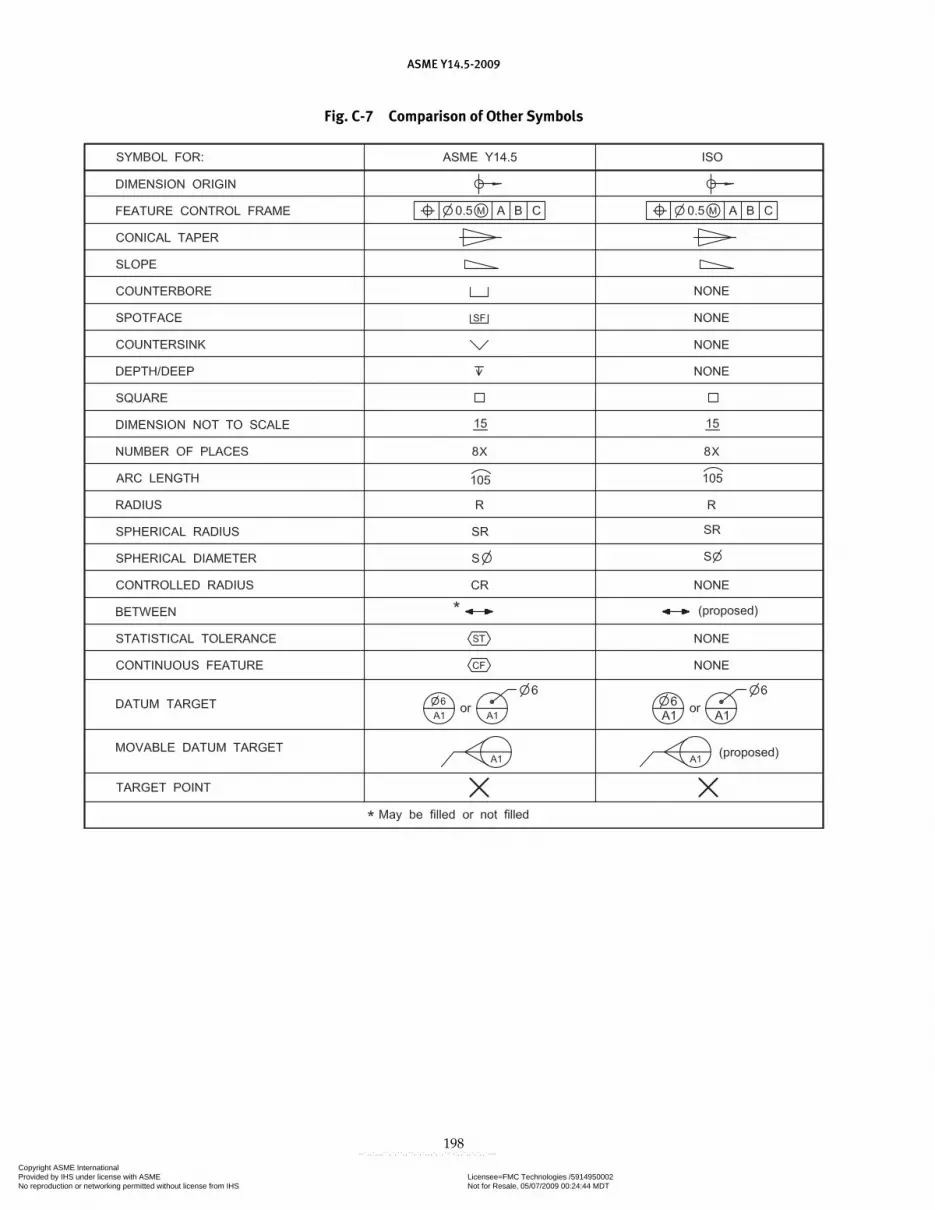
ASME Y14.5-2009
198
Fig. C-7 Comparison of Other Symbols
Copyright ASME International Provided by IHS under license with ASME Licensee=FMC Technologies /5914950002
Not for Resale, 05/07/2009 00:24:44 MDTNo reproduction or networking permitted without license from IHS
--`,,`,,,``,`,``,,``,`,`,,,`,`,`-`-`,,`,,`,`,,`---
ASME Y14.5-2009
199
NONMANDATORY APPENDIX DFORMER PRACTICES
D.1 GENERAL
The purpose of this Appendix is to identify and illus-trate former symbols, terms, and methods of dimension-ing featured in ASME Y14.5M-1994. For information on changes and improvements, see Nonmandatory Appendix A and the Foreword. The following informa-tion is provided to assist the interpretation of existing drawings on which former practices may appear.
D.2 SPECIFICATION OF RFS FOR POSITION TOLERANCES
In the previous issue, the RFS symbol was no longer required to indicate “regardless of feature size” for a tol-erance of position. An alternate Rule #2(b) allowed the
option of continuing that practice. In this revision of the Standard, Rule #2(b) has been eliminated.
D.3 SPECIFICATION OF STRAIGHTNESS TO CONTROL THE FLATNESS OF A DERIVED MEDIAN PLANE
The practice of using straightness to control the flatness of a derived median plane has been discontinued.
D.4 MMC, LMC, AND RFS FOR DATUM FEATURES
The terms “MMC,” “LMC,” and “RFS” no longer are used in reference to datum features. The current terms are “MMB,” “LMB,” and “RMB.”
Copyright ASME International Provided by IHS under license with ASME Licensee=FMC Technologies /5914950002
Not for Resale, 05/07/2009 00:24:44 MDTNo reproduction or networking permitted without license from IHS
--`,,`,,,``,`,``,,``,`,`,,,`,`,`-`-`,,`,,`,`,,`---

NONMANDATORY APPENDIX EDECISION DIAGRAMS FOR GEOMETRIC CONTROL
ASME Y14.5-2009
200
E.1 PURPOSE
The purpose of this Appendix is to assist the user in selecting the correct geometric characteristic for a particu-lar application. Decision diagrams that are based on design requirements and the application of datums, geometric tol-erances, and modifiers have been developed. The diagrams encourage the user to think in terms of design intent and functional requirements, and assist in the development of the contents of feature control frames.
E.2 FUNCTIONAL REQUIREMENTS
When documenting design intent, the user must consider both the stabilization of the part and the functional requirements of the individual features. See Fig. E-1. In dealing with Individual Features, both Form and Profile controls must be considered. If the application deals with Related Features, then Location, Orientation, Runout, and Profile controls must be considered.
E.2.1 Type of Application
Once the type of application is determined, the user is directed to more specific diagrams. These diagrams prompt additional user decisions, such as what needs to be controlled (center plane, axis, or surface), functional tolerance to be met, applicable modifiers, and necessary datum relationships.
E.3 REFERENCE TO STANDARD
A reference is shown in many diagram boxes to the appropriate section within ASME Y14.5-2009 that con-tains specific information concerning that control.
E.4 GEOMETRIC CONTROLS
The box titled “Consider Limits of Size” serves as a reminder to examine the size limits before applying addi-tional form controls. See Fig. E-3. As stated in para. 2.7.1, the dimensional limits of a feature of size may also serve to control the allowable variations in form (Rule #1). When this is the case, and the functional requirements of the design are met, no additional form controls are needed.
E.4.1 Choosing Form Controls
Assuming that form controls are necessary, the dia-grams lead the user through the various applications and suggests a variety of possible choices, as dictated by the design function. See Fig. E-3.
E.5 CHOOSING OTHER CONTROLS
Other aspects of each feature of a part must be consid-ered for their orientation, location, profile, and runout as they relate to other features. The diagrams shown in Figs. E-4 through E-7 have been developed to guide the user through the appropriate selection processes.
E.6 USE OF MODIFIERS
Modifiers are an integral part of geometric tolerances, but are only applicable when utilizing features of size. If a modifier is not applicable to the geometric characteris-tic, modifiers are not included in the decision diagrams. See Figs. E-2 through E-5. In the cases where modifiers are applicable, the diagrams prompt decisions as to which modifiers are appropriate.
E.7 DATUMS
Like modifiers, datums do not apply to all geometric characteristics. Datums do not apply to form controls. If datums do not apply, they are not addressed in the dia-grams. When datums are applicable, the user is referred to Fig. E-2.
E.7.1 Datum Modifiers
When a feature of size has been selected as a datum, a material boundary modifier must be considered. See Fig. E-2 and para. 2.8.
E.7.2 Multiple Datums
Some applications require only a primary datum, while others may need secondary and tertiary datums. When more than one datum is needed, the diagrams loop back until the datum reference framework is com-plete. See Fig. E-2.
Copyright ASME International Provided by IHS under license with ASME Licensee=FMC Technologies /5914950002
Not for Resale, 05/07/2009 00:24:44 MDTNo reproduction or networking permitted without license from IHS
--`,,`,,,``,`,``,,``,`,`,,,`,`,`-`-`,,`,,`,`,,`---

ASME Y14.5-2009
201
Fig. E-1 Design Requirements
Copyright ASME International Provided by IHS under license with ASME Licensee=FMC Technologies /5914950002
Not for Resale, 05/07/2009 00:24:44 MDTNo reproduction or networking permitted without license from IHS
--`,,`,,,``,`,``,,``,`,`,,,`,`,`-`-`,,`,,`,`,,`---

ASME Y14.5-2009
202
Fig. E-2 Datum Selections
Copyright ASME International Provided by IHS under license with ASME Licensee=FMC Technologies /5914950002
Not for Resale, 05/07/2009 00:24:44 MDTNo reproduction or networking permitted without license from IHS
--`,,`,,,``,`,``,,``,`,`,,,`,`,`-`-`,,`,,`,`,,`---

ASME Y14.5-2009
203
Fig. E-3 Form
Copyright ASME International Provided by IHS under license with ASME Licensee=FMC Technologies /5914950002
Not for Resale, 05/07/2009 00:24:44 MDTNo reproduction or networking permitted without license from IHS
--`,,`,,,``,`,``,,``,`,`,,,`,`,`-`-`,,`,,`,`,,`---
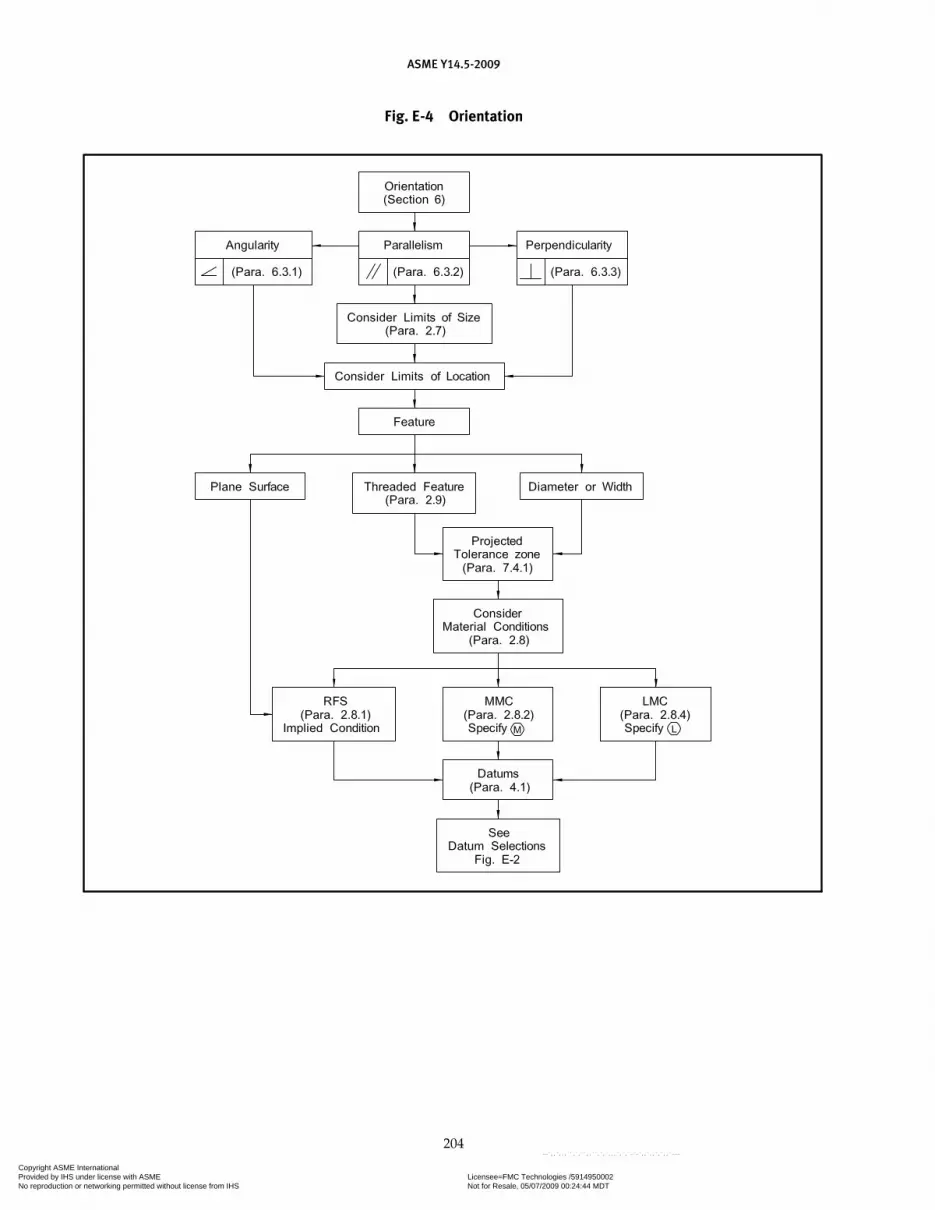
ASME Y14.5-2009
204
Fig. E-4 Orientation
Copyright ASME International Provided by IHS under license with ASME Licensee=FMC Technologies /5914950002
Not for Resale, 05/07/2009 00:24:44 MDTNo reproduction or networking permitted without license from IHS
--`,,`,,,``,`,``,,``,`,`,,,`,`,`-`-`,,`,,`,`,,`---
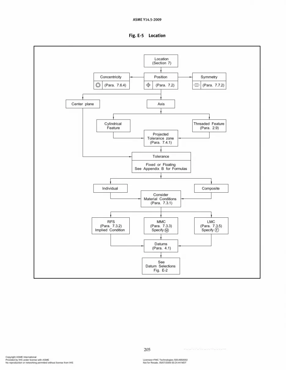
ASME Y14.5-2009
205
Fig. E-5 Location
Copyright ASME International Provided by IHS under license with ASME Licensee=FMC Technologies /5914950002
Not for Resale, 05/07/2009 00:24:44 MDTNo reproduction or networking permitted without license from IHS
--`,,`,,,``,`,``,,``,`,`,,,`,`,`-`-`,,`,,`,`,,`---

ASME Y14.5-2009
206
Fig. E-6 Profile
Fig. E-7 Runout
Copyright ASME International Provided by IHS under license with ASME Licensee=FMC Technologies /5914950002
Not for Resale, 05/07/2009 00:24:44 MDTNo reproduction or networking permitted without license from IHS
--`,,`,,,``,`,``,,``,`,`,,,`,`,`-`-`,,`,,`,`,,`---

ASME Y14.5-2009
207
Index
Actual sizeActual local size, 1.3.53Aligned dimensions, 1.7.1.1Angle tolerances, 2.3.3
All aroundSpecification, 8.3.1.4Symbol, 3.3.19
All overSpecification, 8.3.1.6Symbol, 3.3.25
Angles, 1.4(i), 1.4(j), 1.8.3, 2.1.1.3, 2.1.1.4Implied 90˚, 1.4(i), 1.4(j), 2.1.1.3Implied 90˚ or 0˚ basicUnspecified, 1.4(i), 1.4(j)
AngularOrientation, 4.9Surfaces, 2.12Units, 1.5.5
Angularity, 6.3.1Symbol, 3.3.1Tolerance, 6.4.2
ApplicationsDimensions, 1.7, 7.2.1.1Tolerances, 2.1.1
Arc length symbol, 3.3.9Architectural drawing practices, 1.1Arcs, 1.8.3, 1.8.6Areas, datum target, 4.24.4Average diameter, 5.5.3Axis
X, 4.10.1, 4.21Y, 4.10.1, 4.21Z, 4.10.1, 4.21Primary datum, 4.3, 4.11.4(a)Secondary datum, 4.11.4(d)Tertiary datum, 4.11.4(e)
Base line dimensioning, 2.6(b)Basic angle, 1.4(j), 2.1.1.4, 6.4.2Basic dimension, 1.3.23Basic dimension symbol, 3.3.4
Bilateral tolerance, 1.3.61, 8.3.1.1Bilateral tolerance
Unequally disposed, 8.3.1.2Boundary
Inner, 1.3.2Least material (LMB), 1.3.3Maximum material (MMB), 1.3.4Outer, 1.3.5Regardless of material (RMB), 1.3.49
Capital letter notes, 1.1.5Center lines, 1.4(i), 1.4(j), 4.8.2Centers, machining, 1.8.15Chain dimensioning, 2.6(a)Chamfers, 1.8.16, 1.8.16.1Chords, 1.8.3Circularity
Symbol, 3.3.1Tolerance, 5.4.3
Civil engineering drawing practice, 1.1Coating, effect of, 2.4.1Coaxial features, 7.1(c), 7.4.2, 7.5.3, 7.6Code numbers, 1.4(h)Composite tolerancing
Positional, 7.5.1, 7.5.3.1, 7.5.4.2, 7.5.5Profile, 8.6
Computer-Aided Design, 1.4(b)Concentricity
Symbol, 3.3.1Tolerance, 7.6.4
ConditionLeast material, 1.3.38Maximum material, 1.3.39Virtual, 1.3.67
Conical tapers, 2.13Contacts, datum, 4.6, 4.7.1, 4.10.1(a), 4.10.1(b), 4.10.1(c)Control
Coaxiality, 7.6Combined, 8.8Concentricity, 7.6.4Coplanarity, 8.4.1.1
Copyright ASME International Provided by IHS under license with ASME Licensee=FMC Technologies /5914950002
Not for Resale, 05/07/2009 00:24:44 MDTNo reproduction or networking permitted without license from IHS
--`,,`,,,``,`,``,,``,`,`,,,`,`,`-`-`,,`,,`,`,,`---

ASME Y14.5-2009
208
Composite, 7.5.1, 8.6Datum feature, 4.9Form, 5Profile, 8Runout, 9
Conversion of units, 1.6.4Coordinate
Dimensioning, 1.9, 1.9.1, 1.9.2, 1.9.4System, 1.4(p), 4.13
Coplanarity, 8.4.1.1Corners, rounded, 1.8.5Counterbore symbol, 3.3.12Counterbored holes, 1.8.11, 7.4.2Countersink symbol, 3.3.14Countersunk holes, 1.8.12Cylindrical datum features, 4.10.3Cylindricity
Symbol, 3.3.1Tolerance, 5.4.4
DatumAngular orientation, 4.5.2(b), 4.9, 4.10.3.3Application
Customized datum reference frame, 4.23Datum feature simulator, 4.18MMB, LMB, and RMB to irregular
features of size, 4.17Restrained condition, 4.20Theoretical and physical datum
feature simulators, 4.6Axis, 4.5(c)
Primary, 4.3, 4.10.3, 4.11.4(a)Secondary, 4.11.4(d)Single-axis two features, 4.12.2Tertiary, 4.11.4(e)
Contact points, 4.11.1Definition, 1.3.13Establishing, 4.11Feature, 1.3.16
Control, 4.9Cylindrical, 4.10.3LMB, 4.11.7, 4.11.8MMB, 4.11.5, 4.11.6, 4.11.6.1, 4.11.6.2, 4.11.6.3Multiple, 4.12Order of precedence, 4.10Partial surface, 4.12.5Pattern, 4.12.3, 4.12.4Permanent, 4.8.1Primary, 4.3
Primary datum axis, 4.24.10RMB, 4.11.4, 4.11.12, 4.12.4, 4.17Secondary, 4.11.4, 4.24.12Symbol, 3.3.2Temporary, 4.8.1Tertiary, 4.11.4(b)Virtual condition, 1.3.67
Gears, 2.10Order of precedence, 4.10Planes, 4.7.1, 4.24.8Reference frame, 4.1, 4.7Screw threads, 1.8.20, 2.9Secondary datum axis, 4.6, 4.11.3.3, 4.12.3(d), 4.12.8.3Splines, 2.10Target, 4.24
Areas, 4.24.4Complex/irregular surfaces, 4.24.13Dimensions, 4.16.7Lines, 4.16.3Movable, 4.24.6Movable symbol, 3.3.27, 4.24.6Points, 4.16.2Symbol, 3.3.2
Tertiary, 4.11.4(e), 4.11.4(g)Translation symbol, 3.3.26, 4.11.10, 4.16.9
Decimal inch, 1.5.2, 1.6.2Decimal point, 1.6.3Definition of terms
Angularity, 1.3.1, 6.3.1Boundary, inner, 1.3.2Boundary, least material (LMB), 1.3.3Boundary, maximum material (MMB), 1.3.4Boundary, outer, 1.3.5Circularity, 1.3.6, 5.4.3Coaxiality, 1.3.7, 7.6Complex feature, 1.3.8Concentricity, 1.3.9, 7.6.4Constraint, 1.3.11Coplanarity, 1.3.10, 8.4.1.1Cylindricity, 1.3.12, 5.4.4Datum, 1.3.13Datum axis, 1.3.14Datum center plane, 1.3.15Datum feature, 1.3.16Datum feature simulator, 1.3.17
Datum feature simulator (theoretical), 1.3.17(a)Datum feature simulator (physical), 1.3.17(b)
Datum reference frame, 1.3.18, 4.1Datum simulated, 1.3.19
Copyright ASME International Provided by IHS under license with ASME Licensee=FMC Technologies /5914950002
Not for Resale, 05/07/2009 00:24:44 MDTNo reproduction or networking permitted without license from IHS
--`,,`,,,``,`,``,,``,`,`,,,`,`,`-`-`,,`,,`,`,,`---

ASME Y14.5-2009
209
Datum target, 1.3.20, 4.24Diameter, average, 1.3.21, 5.5.3Dimension, 1.3.22Dimension, basic, 1.3.23Dimension, reference, 1.3.24Envelope, actual mating, 1.3.25
Unrelated actual mating envelope, 1.3.25(a)Related actual mating envelope, 1.3.25(b)
Envelope, actual minimum material, 1.3.26Unrelated actual minimum material
envelope, 1.3.26(a)Related actual minimum material
envelope, 1.3.26(b)Feature, 1.3.27Feature, axis of, 1.3.28Feature, center plane of, 1.3.29Feature, derived median plane of, 1.3.30Feature, derived medial line of, 1.3.31Feature of size, 1.3.32
Regular feature of size, 1.3.32.1Irregular feature of size, 1.3.32.2
Feature control frame, 1.3.33Feature-relating tolerance zone framework
(FRTZF), 1.3.34, 7.5.1(b), 8.6.1.3(b)Free state, 1.3.35Free-state variation, 1.3.36, 5.5Flatness, 1.3.37, 5.4.2Least material condition (LMC), 1.3.38Maximum material condition (MMC), 1.3.39Non-uniform tolerance zone, 1.3.40, 8.3.2Parallelism, 1.3.41, 6.3.2Pattern, 1.3.42Pattern-locating tolerance zone framework
(FLTZF), 1.3.43, 8.6.1.3(a)Perpendicularity, 1.3.44, 6.3.3Plane, tangent, 1.3.45Position, 1.3.46, 7.2Profile, 1.3.47, 8.2Regardless of feature size (RFS), 1.3.48Regardless of material boundary (RMB), 1.3.49Restraint, 1.3.50Resultant condition, 1.3.51Runout, 1.3.52, 9.2Simultaneous requirement, 1.3.53, 4.19Size, actual local, 1.3.54Size, limits of, 1.3.55Size, nominal, 1.3.56Straightness, 1.3.57Statistical tolerancing, 1.3.58, 2.17
Symmetry, 1.3.59, 7.7.2Tolerance, 1.3.60Tolerance, bilateral, 1.3.61Tolerance, geometric, 1.3.62Tolerance, unilateral, 1.3.63True position, 1.3.64True profile, 1.3.65, 8.2Uniform tolerance zone, 1.3.66, 8.3.1Virtual condition, 1.3.67
Degrees of freedom (DOF), 4.2, 4.3Depth symbol, 3.3.15Diameter, 1.8.1
Average, 5.5.3Spherical, 7.4.6Symbol, 3.3.7
DimensionApplication, 1.7Aligned, 1.7.1.1Arrangement, 1.4(g)Base line, 2.6(b)Basic, 1.3.23, 7.2Chain, 2.6(a)Conical taper, 2.13Conversion, 1.6.4Coordinate, 1.9.1, 1.9.2, 1.9.4Decimal inch, 1.6.2Diameters, 1.8.1Direct, 2.6(c)Features, 1.8Flat tapers, 2.14 Limited area, 1.7.3Limit, 2.2(a), 2.4, 2.6.1Line, 1.7.1Maximum, 1.4(a), 2.5Millimeter, 1.6.1Minimum, 1.4(a), 2.5Not to scale, 1.7.9Origin of, 2.6.1Origin symbol, 3.3.17Overall, 1.7.7Plus and minus, 2.2(b)Polar coordinates, 1.9.4, 7.4.4.2Radii, 1.8.2Reading direction, 1.7.5Rectangular coordinate, 1.9.1, 1.9.2, 7.4.4.1Reference, 1.3.24, 1.7.6Repetitive, 1.9.5Rounded corners, 1.8.5
Copyright ASME International Provided by IHS under license with ASME Licensee=FMC Technologies /5914950002
Not for Resale, 05/07/2009 00:24:44 MDTNo reproduction or networking permitted without license from IHS
--`,,`,,,``,`,``,,``,`,`,,,`,`,`-`-`,,`,,`,`,,`---

ASME Y14.5-2009
210
Rounded ends, 1.8.4Round holes, 1.8.10Rounding off, 1.6.4Rules for, 1.4, 2.7.1Selection, 1.4(d)Series and patterns, 1.9.5.1Spacing, 1.9.5.2Tabular, 1.9.3True radius, 1.8.2.3Types of, 1.6Within outline of view, 1.7.8
Direct dimensioning, 2.6(c)Documents, reference, 1.2Drawing practices
Architectural, 1.1Civil engineering, 1.1Welding, 1.1
Drawings, undimensioned, 1.4(b)Dual dimension, units, 1.5.4
Effect of LMC, 2.8.4Effects of zero tolerance at LMC, 2.8.5Effect of MMC, 2.8.2Effects of zero tolerance at MMC, 2.8.3Effect of RFS, 2.8.1Effect of surface coating, 2.4.1Ends, rounded, 1.8.4Equal spacing, 1.9.5.2Extension lines, 1.7.2
FastenerFixed, B.4Floating, B.3
FeatureCenter distance, 7.1(a), (d)Control datum, 4.9Control frame, 3.4Datum, 1.3.16, 4.1, 4.3
Cylindrical, 4.10.3LMB, 4.11.7, 4.11.8MMB, 4.11.5, 4.11.6RMB, 4.3, 4.11.4, 4.11.12Shift/displacement, 4.11.9Simulator, 4.6Temporary, 4.8.1
Definition, 1.3.27Dimensioning, 1.8Interrelated, 2.7.4Location, 1.9
Multiple patterns, 7.5.4.1, 7.5.4.2Noncircular, 7.6.1Pattern location, 7.5Relationship, 2.7.4Repetitive, 1.9.5Restrained, 4.20, 5.5.2Size, 1.3.32
Regular, 1.3.32.1Irregular, 1.3.32.2
Spherical, 7.4.6Symmetrical, 7.7
Finish, 2.4.1Fixed fastener formula, B.4Flat tapers, 2.14Flatness
Symbol, 3.3.1Tolerance, 5.4.2
Floating fastener formula, B.3Forgings, 1.8.23Form
Control, 5Perfect at MMC, 2.7.1Tolerance, specifying, 5.3Tolerance, zero, 2.7.4(a), 2.8.3Variations, 2.7.1
Former practices, Nonmandatory Appendix DSpecification of RFS for positional tolerances, D.2Specification of straightness to control the flatness
of a derived median plane, D.3MMC, LMC, and RFS for datum features, D.4
Formula, positional tolerances, Nonmandatory Appendix B Frame, datum reference, 4.7FRTZF, 1.3.34Free-state variation, 2.7.2(b), 5.5Fundamental rules, dimensioning, 1.4
Gage, functional, 7.3.6.2.2(b)Gaging, reference to, 1.1.6Gears, 1.8.22, 2.10General tolerance note, 2.1.1(e)Geometric characteristic symbols, 3.3.1, Nonmandatory
Appendix CGeometric tolerance, 1.3.62
HolesAxis, 7.3.3.1(b)Clearance, 7.4.1.1Coaxial, 7.5.3Counterbored, 1.8.11, 7.4.2
Copyright ASME International Provided by IHS under license with ASME Licensee=FMC Technologies /5914950002
Not for Resale, 05/07/2009 00:24:44 MDTNo reproduction or networking permitted without license from IHS
--`,,`,,,``,`,``,,``,`,`,,,`,`,`-`-`,,`,,`,`,,`---

ASME Y14.5-2009
211
Counterdrilled, 1.8.12Countersunk, 1.8.12Nonparallel, 7.4.7Round, 1.8.10Surface of, 7.3.3.1(a)
Identification of linear units, 1.5.3International System of Units, SI, 1.1.2Irregular outlines, 1.8.7
Keyseats, 1.8.17Knurling, 1.8.18
Least material boundary, 1.3.3Least material condition, 1.3.38, 2.8, 2.8.4, 7.3.5Limit dimensioning, 2.1.1(a), 2.2(a), 2.4, 2.5Limits, 2.1.1(a), 2.4
Interpretation of, 2.4Single, 2.5
Limits and fits, 2.2.1, B.7Limits of size, 1.3.55, 2.7Limited segment of a profile, 8.3.1.5Linear units
Dual, 1.5.4Identification, 1.5.3
LinesChain, 1.7.3.1Datum target, 3.3.3.2, 4.24.3Dimension, 1.7.1Extension, 1.7.2Leader, 1.7.4Profile of, 8.2.1.2
LMBApplicability, 4.11.7Datum feature displacement, 7.3.6.3Definition, 1.3.3Effect of, 4.11.3Irregular feature of size, 4.17Symbol, 3.3.5
LMCApplicability, 2.8Definition, 1.3.38Effect of, 2.8.4Positional tolerancing, 7.3.5Symbol, 3.3.5Zero tolerancing, 2.8.5, 7.3.5.3
Location of features, 1.9
Machining centers, 1.8.15
Manufacturing processes, 1.4(e)Maximum material boundary, 1.3.4Maximum material condition, 1.3.39, 2.8, 2.8.2Measurement, units of, 1.5Metric limits and fits, 2.2.1Metric linear units, 1.5.1Millimeter dimensions, 1.6.1MMB
Applicability, 4.11.5Definition, 1.3.4Effect of, 4.11.3Irregular feature of size, 4.17Symbol, 3.3.5
MMCApplicability, 2.8Definition, 1.3.39Effect of, 2.8.2Perfect form, 2.7.1Positional tolerancing, 7.3.3Symbol, 3.3.5Zero tolerancing, 2.8.3, 6.6.4, 7.3.4
Noncircular features, 7.4.5Nonmandatory dimensions, 1.4(f)Nonrigid parts, 5.5Nonparallel holes, 7.4.7Note, general, 1.4(a), 1.7, 2.1.1.2(b), 8.2.3Notes, 1.1.5, 1.7.5.1, 3.2
Origin of dimension, 2.6.1Outlines
Arcs, 1.8.6Circular, 1.8.7Dimension within, 1.7.8Irregular, 1.8.7Noncircular, 1.8.7Symmetrical, 1.8.9
OrientationControl, 6.2Tolerance, 6.4
Overall dimension, 1.7.7
Parallelism, 6.3.2Symbol, 3.3.1Tolerance, 6.4.2
Pattern, feature, 7.5Patterns, multiple, 7.5.4.1, 7.5.4.2Perfect form, MMC, 2.7.1Perpendicularity, 6.3.3
Copyright ASME International Provided by IHS under license with ASME Licensee=FMC Technologies /5914950002
Not for Resale, 05/07/2009 00:24:44 MDTNo reproduction or networking permitted without license from IHS
--`,,`,,,``,`,``,,``,`,`,,,`,`,`-`-`,,`,,`,`,,`---
ASME Y14.5-2009
212
Symbol, 3.3.1Tolerance, 6.4.2
Planes, datum, 4.10.3, 4.16.3, 4.16.4, 4.16.5, 4.16.6, 4.16.7, 4.24.8
Plated parts, 2.4.1PLTZF, 1.3.43, 7.5.1(a), 8.6.1.3(a)Plus and minus dimensioning, 2.2(b)Points, datum targets, 3.3.3.1, 4.24.2Polar coordinate dimensioning, 1.9.4, 7.4.4.2Positional tolerancing, 7
Bidirectional, 7.4.4Coaxial controls, 7.6.1, 7.6.2.1, 7.6.2.2, 7.6.2.3Composite, 7.5.1Conical zone, 7.4.3Formulas, Nonmandatory Appendix BFundamental explanation, 7.2LMB, 7.3.6, 7.3.6.3LMC, 2.8, 7.3.5Material condition, 7.3.1MMB, 7.3.6, 7.3.6.2, 7.5.4.2MMC, 2.8, 7.3.3Noncircular, 7.4.5Rectangular coordinate, 7.4.4.1RMB, 7.3.6.1, 7.5.4.1RFS, 2.8, 7.3.2, 7.7.1.2Spherical features, 7.4.6Symmetrical, 7.7Zero, LMC, 2.8.5, 7.3.5.3Zero, MMC, 2.8.3, 7.3.4
Position symbol, 3.3.1Position, true, see Positional tolerancingPrecedence, datum, 4.10Preferred sizes, B.7Primary datum feature, 4.3Profile for conical feature, 8.4.2Profile of
Line symbol, 3.3.1Line tolerance, 8.2.1.2Surface symbol, 3.3.1Surface tolerance, 8.2.1.1
Profile tolerancing, 8.2Combined controls, 8.8Composite, 8.6Coplanar surface, 8.4.1.1Tolerance zone, 8.3
Projected tolerance zone, 7.4.1, 7.5.1.7, B4Projected tolerance zone symbol, 3.3.6Processing, 1.4(e)Processing information, nonmandatory, 1.4(f)
Radius, 1.8.2, 2.15.1Spherical, 1.8.2.5Symbol, 3.3.7Tangent, 2.15.1
Radius, controlled, 2.15.2Symbol, 3.3.7
Rectangular coordinate, 7.4.4.1Reference
Dimension, 1.7.6Symbol, 3.3.8To gaging, 1.1.6To this Standard, 1.1.3
Regardless of feature size, 1.3.48, 2.8, 2.8.1, 7.3.2Regardless of material boundary, 1.3.49Repetitive dimensions, 1.9.5Repetitive features, 1.9.5Resultant condition, 1.3.51RFS
Applicability, 2.8Definition, 1.3.48Effect of, 2.8.1Positional tolerancing, 7.3.2Symbol, 3.3.5
RMBApplicability, 4.3Definition, 1.3.49Effect of, 2.8.1Irregular feature of size, 4.17Symbol, 3.3.5
Rods, 1.8.19Round hole, 1.8.10Rounded corners, 1.8.5Rounded ends, 1.8.4Rounding dimensions, 1.6.4Roundness tolerance, 5.4.3Rules for dimensioning, 1.4Runout
Control, 9.2Symbols, 3.3.1Tolerance, 9.3, 9.4
Circular, 9.4.1Total, 9.4.2
Scale, dimensions not to, 1.7.9Screw threads, 1.8.20
Tolerancing, 2.9Size
Actual local, 1.3.54“BY” (X), 1.9.6
Copyright ASME International Provided by IHS under license with ASME Licensee=FMC Technologies /5914950002
Not for Resale, 05/07/2009 00:24:44 MDTNo reproduction or networking permitted without license from IHS
--`,,`,,,``,`,``,,``,`,`,,,`,`,`-`-`,,`,,`,`,,`---
ASME Y14.5-2009
213
Limits of, 2.7Stock, 1.4(a), 2.7.2(a)Variation, 2.7.1(b)
Slope symbol, 3.3.18Specifying form tolerances, 5.3Spherical features, positional tolerancing, 7.4.6Spherical radius, 1.8.2.5Splines, 2.10Spotface, 1.8.14Spotface symbol, 3.3.13Square symbol, 3.3.16Standard, reference to, 1.1.3Straightness
Symbol, 3.3.1Tolerance, 5.4.1
Studs, 7.4.1Surfaces
Angular, 2.12Coplanar, 8.4.1.1Profile of, 8.2.1.1
Surface texture, 1.8.21Symbols, 1.1.7
All around, 3.3.19All over, 3.3.25Arc length, 3.3.9Basic dimension, 3.3.4Between, 3.3.11Comparison, C.3Construction, 3.3Continuous feature, 3.3.23Counterbore, 3.3.12Countersink, 3.3.14Datum feature, 3.3.2Datum reference frame, 3.3.30Datum target, 3.3.3
Areas, 3.3.3.3Lines, 3.3.3.1Points, 3.3.3.2
Datum translation, 3.3.26Depth, 3.3.15Diameter, 3.3.7Dimension origin, 3.3.17Feature control, frame, 3.4Free state, 3.3.20Geometric characteristic, 3.3.1Independency, 3.3.24Limits and fits, 3.3.29Material boundary, 3.3.5
Material condition, 3.3.5Moveable datum target, 3.3.27, 4.24.6Projected tolerance zone, 3.3.6Radius, 3.3.7Radius, controlled, 3.3.7Radius, spherical, 3.3.7Reference, 3.3.8Slope, 3.3.18Spotface, 3.3.12Statistical tolerance, 3.3.10Surface texture, 3.3.28Tangent plane, 3.3.21Taper, 3.3.17Tolerance zone identification, 3.6Unequally disposed profile, 3.3.22
Symmetrical outlines, 1.8.9Symmetry, 7.7.2
Tabular dimensioning, 1.9.3Tabulated tolerances, 3.7Tangent plane symbol, 3.3.21Tangent radii, 2.16Taper symbol, 3.3.18Tapers
Conical, 2.13Flat, 2.14
TargetDatum, 4.24Datum, area, 4.24.4Datum dimensions, 4.24.7Datum line, 4.24.3Datum planes, 4.24.5Datum points, 4.24.2Datum symbol, 4.24.1
Temporary datum feature, 4.8.1Tertiary datum, 4.9(c), 4.11.4(e)Threads, 1.8.20, 2.9Three-plane relationship, 4.1 Tolerance
Accumulation, 2.6Angularity, 6.3.1Application, 2.1.1Base line, 2.6(b)Bilateral, 1.3.61Chain, 2.6(a)Circularity, 5.4.3Coatings, effects of, 2.4.1Combination, see Virtual condition
Copyright ASME International Provided by IHS under license with ASME Licensee=FMC Technologies /5914950002
Not for Resale, 05/07/2009 00:24:44 MDTNo reproduction or networking permitted without license from IHS
--`,,`,,,``,`,``,,``,`,`,,,`,`,`-`-`,,`,,`,`,,`---
ASME Y14.5-2009
214
Composite, position, 7.5.1Composite, profile, 8.6Conical zone, 7.4.3Cylindricity, 5.4.4Decimal inch, 2.3.2Definition, 1.3.60Direct, 2.2, 2.6(c)Expression, 2.3Flatness, 5.4.2Form, 5.4Gears, 2.10General, 2Geometric, 1.3.62Inch, 2.3.2Limit, 2.1.1(a)Limit of size, 1.3.55, 2.7Limits and fits, 2.2.1Limits, interpretation, 2.4Location, 7Metric, 2.2.1, 2.3.1Note, 2.1.1(c)Orientation, 6Parallelism, 6.3.2Perpendicularity, 6.3.3Plating, effects of, 2.4.1Polar coordinates, 7.4.4.2Positional, 7.2, 7.3, 7.4
Bidirectional, 7.4.4Composite, 7.5.1Formulas, Nonmandatory Appendix BLMC, 2.8, 2.8.4, 7.3.5MMC, 2.8, 2.8.2, 7.3.3RFS, 2.8, 2.8.1, 7.3.2Zero MMC, 2.8.3, 7.3.4Zero LMC, 2.8.5, 7.3.5.3
Plus and minus, 2.2(b)Profile, 8Roundness, 5.4.3Runout, 9Screw threads, 1.8.20, 2.9
Single limits, 2.5Size, limits of, 2.7Splines, 2.10Straightness, 5.4.1Tabulated tolerances, 3.7Tolerance of location, 7Unequally disposed profile, 8.3.1.2Unilateral tolerance, 1.3.63, 8.3.1.2Zero, 2.8.3, 2.8.5, 7.3.4, 7.3.5.3, 7.7.1.1Zone
Definition, 3.6Projected, 7.4.1
True position, 1.3.64True radius, 1.8.2.3Tubing, 1.8.19Types of dimensions, 1.6
Undimensioned drawing, 1.4(b)Unilateral tolerance, 1.3.63Units, 1.1.2Units of measure, 1.5
Angular, 1.5.5Linear
Dual, 1.5.4Identification, 1.5.3Metric, 1.5.1U.S. Customary, 1.5.2
Unspecified angles, 2.1.1.3, 2.1.1.4
Virtual condition, 1.3.67
“X” (BY), 1.9.6
Zero form tolerance, 2.7.1Zero positional tolerance, 7.3.4, 7.3.5.3
LMC, 7.3.5.3MMC, 7.3.4
Zero tolerance, 2.8.3, 2.8.5Zone tolerance, projected, 7.4.1
Copyright ASME International Provided by IHS under license with ASME Licensee=FMC Technologies /5914950002
Not for Resale, 05/07/2009 00:24:44 MDTNo reproduction or networking permitted without license from IHS
--`,,`,,,``,`,``,,``,`,`,,,`,`,`-`-`,,`,,`,`,,`---

N00509
ASME Y14.5-2009
ASME also provides you an integrated suite of related offerings on geometric dimensioning and tolerancing (GD&T): • Standards; • Personnel Certifications; • Handbooks, and; • Training Courses.
Build your design expertise, direct from the GD&T source!
For details, call 1-800-THE-ASME (843-2763) or visit go.asme.org/gdt.
Copyright ASME International Provided by IHS under license with ASME Licensee=FMC Technologies /5914950002
Not for Resale, 05/07/2009 00:24:44 MDTNo reproduction or networking permitted without license from IHS
--`,,`,,,``,`,``,,``,`,`,,,`,`,`-`-`,,`,,`,`,,`---


![[123doc vn] - Tai lieu 2004 ASME BOILER & PRESSURE VESSEL CODE docx](https://img.dokumen.tips/doc/110x75/631a2689fd704e1d390a0059/123doc-vn-tai-lieu-2004-asme-boiler-pressure-vessel-code-docx.jpg)
