Embed Size (px)
Citation preview

Report onComments
2019 ASSOCIATION TECHNICALMEETING CONVENTION
Reno, Nevada | Silver Legacy Resort | September 24, 2019
A Compilation of IAPMO Mechanical Technical CommitteeReport on Comments for Review Prior to Consideration at the IAPMO September Association Technical Meeting Convention.

Information on IAPMO Codes and Standards Development 1. Applicable Regulations. The primary rules governing the processing of the Uniform Plumbing Code and UniformMechanical Code are the IAPMO Regulations Governing Committee Projects (RGCP). Other applicable rules includeBylaws, Assembly Consideration Session Rules, Technical Meeting Convention Rules, Guide for the Conduct ofParticipants in the IAPMO Codes and Standards Development Process, and the Regulations Governing Petitionsto the Board of Directors from Decisions of the Standards Council. For copies of these documents, contact the CodeDevelopment Department at IAPMO World Headquarters at 4755 E. Philadelphia Street, Ontario, CA 91761-2816USA, or at 909-472-4100. These documents are also available at the IAPMO website at www.iapmo.org.
The following is general information on the IAPMO process. All participants, however, should refer to the actual rules and regulations for a full understanding of this process and for the criteria that govern participation.
2. Technical Committee Report (TCR). The Technical Committee Report is defined as the Report of the TechnicalCommittee and Technical Correlating Committee (if any) consisting of the Report on Proposals (ROP), as modifiedby the Report on Comments (ROC), published by the Association (see 1-4 of RGCP).
3. Report on Proposals (ROP). The ROP is defined as “a report to the Association on the actions taken byTechnical Committees and/or Technical Correlating Committees, accompanied by a ballot statement and one ormore proposals on text for a new Document or to amend an existing Document” (see 1-4 of RGCP). The ROPand the ROC together comprise the Technical Committee Report. Anyone who does not pursue an issue as aproposed amendment of the Association Meeting will be considered as having their objection resolved.
4. Assembly Comment. The Assembly Consideration Session, held during the second year of the codedevelopment cycle, will be held during IAPMO’s annual conference from September 30 - October 4, 2018, inPhiladelphia, Pennsylvania. The Assembly Consideration Session is scheduled for October 2, 2018. Anyone inthe Assembly who objects to an action of the Technical Committee, as published in the ROP, may make a motionin accordance with Section 4-4.3.1.2 of the RGCP and, if such motion is sustained by majority vote, both the TCaction established by a letter ballot and the Assembly’s action, which shall be considered as a comment inaccordance with Section 4- 4.3.1, shall be included in the ROC.
5. Report on Comments (ROC). The ROC is defined as “a report to the Association on the actions taken byTechnical Committees and/or Technical Correlating Committees accompanied by a ballot statement and one ormore comments resulting from public review of the Report on Proposals (ROP)” (see 1-4 of RGCP). The ROPand the ROC together constitute the Technical Committee Report. Anyone who does not pursue an issue, eitherin person or by designated representative in accordance with Section 4-5.4(c) of the RGCP, as a proposedamendment of the Association Meeting will be considered as having their objection resolved.
6. Association Amendments. The Technical Committee Reports, consisting of the ROP and ROC, will be presentedat the Association Technical Meeting Convention for action. This meeting, held during the final year of the codedevelopment cycle, will be held during IAPMO’s annual conference from September 22 - 26, 2019, in Reno,Nevada. Amending motions made to the Technical Committee Reports may be made only at the AssociationTechnical Meeting Convention in accordance with 4-5 and other applicable sections of the RGCP. Amending motionsmay be made in person or by a designated representative in accordance with Section 4-5.4(c) of the RGCP.Objections are deemed to be resolved if not pursued at this level.
7. Council Appeals. Anyone can appeal to the Standards Council concerning procedural or substantive mattersrelated to the development, content, or issuance of any Document of the Association or on matters within the purviewof the authority of the Council. Such appeals must be in written form and filed with the Secretary of the StandardsCouncil (see 1-6 of RGCP). Time constraints for filing an appeal must be in accordance with 1-6.2 of the RGCP.Objections are deemed to be resolved if not pursued at this level.
8. Document Issuance. The Standards Council is the issuer of the Uniform Plumbing Code and UniformMechanical Code. The Council acts on the issuance of a Document within sixty days from the date of therecommendation from the Association Technical Meeting Convention, unless this period is extended by the Council(see 4-7 of RGCP).
9. Petitions to the Board of Directors. The Standards Council has been delegated the responsibility for theadministration of the codes and standards development process and the issuance of documents. However, whereextraordinary circumstances requiring the intervention of the Board of Directors exist, the Board of Directors maytake any action necessary to fulfill its obligations to preserve the integrity of the IAPMO codes and standardsdevelopment process. The rules for petitioning the Board of Directors can be found in the Regulations GoverningPetitions to the Board of Directors from Decisions of the Standards Council and in 1-7 of the RGCP.

To: IAPMO Members and Other Interested Parties Date: August 21, 2019 Enclosed is your 2019 Report on Comments (ROC). These comments were presented to the Mechanical Technical Committee who met in Denver, Colorado on May 1 – 2, 2019. At the Annual Education and Business Conference to be held September 23 – 26, 2019 in Reno, Nevada, IAPMO members and others attending the convention will have the opportunity to discuss and debate these comments. The IAPMO voting membership present at that conference will then vote on the actions taken by the Technical Committee. Following the comments is a copy of how the 2021 edition of the Uniform Mechanical Code (pre-print) would appear if all committee actions are accepted by the membership. This preprint is provided to you as a courtesy. All changes are tentative and subject to revision. This document is not to be considered the final version of the 2021 Uniform Mechanical Code. Specific authorization from IAPMO is required for republication or quotation.
THE BALLOT RESULTS ON ALL COMMITTEE ACTIONS ON PUBLIC COMMENTS PASSED EXCEPT FOR THE FOLLOWING TWO ACTIONS: ITEM # 083 COMMENT 1 FAILED TO ACHIEVE THE NECESSARY 2/3 AFFIRMATIVE VOTE OF RETURNED BALLOTS. ITEM # 086 COMMENT 1 FAILED TO ACHIEVE THE NECESSARY 2/3 AFFIRMATIVE VOTE OF RETURNED BALLOTS. In accordance with Section 4-4.6.4 where the technical committee actions failed to achieve the necessary 2/3 affirmative vote, the technical committee action on the public comment shall be reported in the ROC as rejected.
Bill Erickson Chair
IAPMO Standards Council
Gabriella Davis Recording Secretary
IAPMO Standards Council
Dan Daniels Chair
Plumbing Code TC
Harvey Kreitenberg Chair
Mechanical Code TC

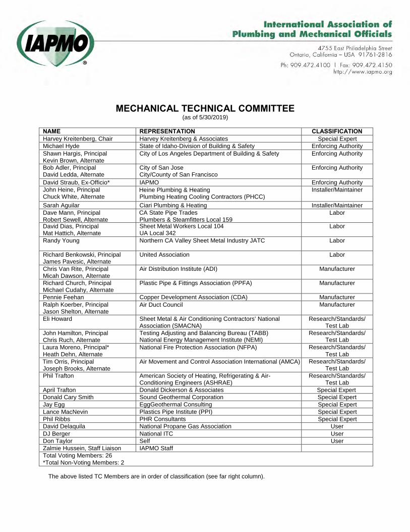
MECHANICAL TECHNICAL COMMITTEE (as of 5/30/2019)
NAME REPRESENTATION CLASSIFICATION Harvey Kreitenberg, Chair Harvey Kreitenberg & Associates Special Expert Michael Hyde State of Idaho-Division of Building & Safety Enforcing Authority Shawn Hargis, Principal Kevin Brown, Alternate
City of Los Angeles Department of Building & Safety Enforcing Authority
Bob Adler, Principal David Ledda, Alternate
City of San Jose City/County of San Francisco
Enforcing Authority
David Straub, Ex-Officio* IAPMO Enforcing Authority John Heine, Principal Chuck White, Alternate
Heine Plumbing & Heating Plumbing Heating Cooling Contractors (PHCC)
Installer/Maintainer
Sarah Aguilar Ciari Plumbing & Heating Installer/Maintainer Dave Mann, Principal Robert Sewell, Alternate
CA State Pipe Trades Plumbers & Steamfitters Local 159
Labor
David Dias, Principal Mat Hattich, Alternate
Sheet Metal Workers Local 104 UA Local 342
Labor
Randy Young Northern CA Valley Sheet Metal Industry JATC Labor
Richard Benkowski, Principal James Pavesic, Alternate
United Association Labor
Chris Van Rite, Principal Micah Dawson, Alternate
Air Distribution Institute (ADI) Manufacturer
Richard Church, Principal Michael Cudahy, Alternate
Plastic Pipe & Fittings Association (PPFA) Manufacturer
Pennie Feehan Copper Development Association (CDA) Manufacturer Ralph Koerber, Principal Jason Shelton, Alternate
Air Duct Council Manufacturer
Eli Howard Sheet Metal & Air Conditioning Contractors’ National Association (SMACNA)
Research/Standards/ Test Lab
John Hamilton, Principal Chris Ruch, Alternate
Testing Adjusting and Balancing Bureau (TABB) National Energy Management Institute (NEMI)
Research/Standards/ Test Lab
Laura Moreno, Principal* Heath Dehn, Alternate
National Fire Protection Association (NFPA) Research/Standards/ Test Lab
Tim Orris, Principal Joseph Brooks, Alternate
Air Movement and Control Association International (AMCA) Research/Standards/ Test Lab
Phil Trafton American Society of Heating, Refrigerating & Air-Conditioning Engineers (ASHRAE)
Research/Standards/ Test Lab
April Trafton Donald Dickerson & Associates Special Expert Donald Cary Smith Sound Geothermal Corporation Special Expert Jay Egg EggGeothermal Consulting Special Expert Lance MacNevin Plastics Pipe Institute (PPI) Special Expert Phil Ribbs PHR Consultants Special Expert David Delaquila National Propane Gas Association User DJ Berger National ITC User Don Taylor Self User Zalmie Hussein, Staff Liaison IAPMO Staff Total Voting Members: 26 *Total Non-Voting Members: 2
The above listed TC Members are in order of classification (see far right column).

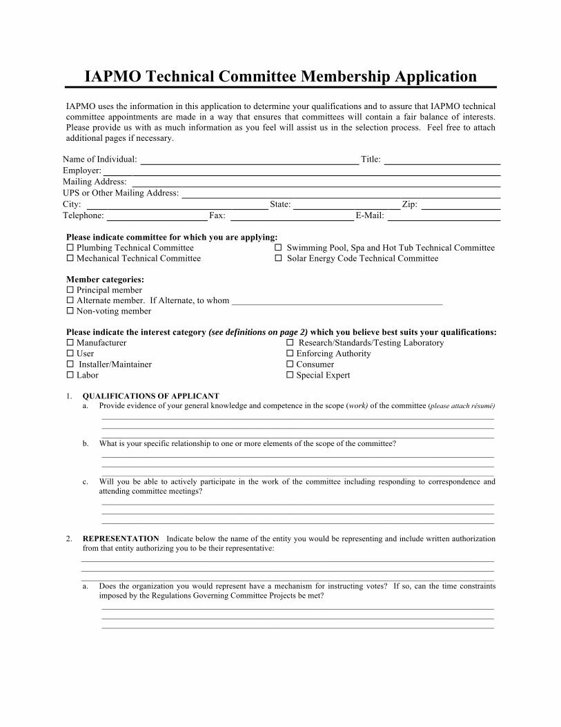
IAPMO Technical Committee Membership Application
IAPMO uses the information in this application to determine your qualifications and to assure that IAPMO technical committee appointments are made in a way that ensures that committees will contain a fair balance of interests. Please provide us with as much information as you feel will assist us in the selection process. Feel free to attach additional pages if necessary.
Name of Individual: Title: Employer: Mailing Address: UPS or Other Mailing Address: City: State: Zip: Telephone: Fax: E-Mail:
Please indicate committee for which you are applying: Plumbing Technical Committee Swimming Pool, Spa and Hot Tub Technical Committee Mechanical Technical Committee Solar Energy Code Technical Committee
Member categories: Principal member Alternate member. If Alternate, to whom ______________________________________________ Non-voting member
Please indicate the interest category (see definitions on page 2) which you believe best suits your qualifications: Manufacturer Research/Standards/Testing Laboratory User Enforcing Authority Installer/Maintainer Consumer Labor Special Expert
1. QUALIFICATIONS OF APPLICANTa. Provide evidence of your general knowledge and competence in the scope (work) of the committee (please attach résumé)
_____________________________________________________________________________________________________________________________________________________________________________________________________________________________________________________________________________________________
b. What is your specific relationship to one or more elements of the scope of the committee?_____________________________________________________________________________________________________________________________________________________________________________________________________________________________________________________________________________________________
c. Will you be able to actively participate in the work of the committee including responding to correspondence andattending committee meetings?_____________________________________________________________________________________________________________________________________________________________________________________________________________________________________________________________________________________________
2. REPRESENTATION Indicate below the name of the entity you would be representing and include written authorizationfrom that entity authorizing you to be their representative:____________________________________________________________________________________________________________________________________________________________________________________________________________________________________________________________________________________________________________a. Does the organization you would represent have a mechanism for instructing votes? If so, can the time constraints
imposed by the Regulations Governing Committee Projects be met?_____________________________________________________________________________________________________________________________________________________________________________________________________________________________________________________________________________________________
International Association of Plumbing & Mechanical Officials 4755 E. Philadelphia Street • Ontario, CA • 91761
Tel: 909-472-4100 • Fax: 909-472-4150 www.iapmo.org
3. FUNDING SOURCE(S) FOR YOUR PARTICIPATIONa. What person(s) or organization(s) would fund your participation as a committee member, either in whole or in part?
(You should list your employer if your participation is funded by your employer or if your participation is part of youremployment responsibilities or otherwise related to your employment.)_____________________________________________________________________________________________________________________________________________________________________________________________________________________________________________________________________________________________
b. Background and description of your employer and/or other person(s) or organization(s) funding participation:____________________________________________________________________________________________________________________________________________________________________________________________________________________________________________________________________________________________________________________________________________________________________________________________
4. ADDITIONAL COMMENTS____________________________________________________________________________________________________________________________________________________________________________________________________________________________________________________________________________________________________________________________________________________________________________________________________________________________
Languages other than English_____________________________________________________________________
COMPLETE A SEPARATE APPLICATION FORM FOR EACH COMMITTEE ON WHICH YOU DESIRE TO SERVE. IN ORDER TO ASSURE THE PROMPT PROCESSING OF YOUR REQUEST, PLEASE BE SURE TO COMPLETE ALL QUESTIONS AND SIGN THIS APPLICATION.
If appointed, I agree to abide by the rules and guidelines of IAPMO. In addition, I hereby agree to notify the Secretary of the IAPMO Standards Council of a change in status, including change of employment, organization represented, or funding source. I also agree that IAPMO shall have, and I hereby grant, all and full rights in copyright in any material that I author, either individually or with others, as a member of this committee, or that I submit for the proposed use of the committee in an IAPMO code or standard or other IAPMO document. I further acknowledge that I acquire no rights in any publication of IAPMO and that copyright and all rights in all materials produced by IAPMO technical committees are owned by IAPMO and that IAPMO may register copyright in its own name.
I do not now hold and I do not intend to hold any patent, the use of which would be required for compliance with any material that I author – either individually or with others – as a member of this committee, or that I submit for the proposed use of the committee in an IAPMO code or standard or other IAPMO document.
I attest that all of the information on this application is true and accurate.
By signing below, I attest to my ability to communicate with IAPMO staff and the members of the Technical Committee through electronic means, namely via email and the internet.
Signature ______________________________________________________ Date___________________________
INTEREST CATEGORIES (a) Manufacturer. A representative of a maker or marketer of a product, assembly or system, or portion thereof that is affected by the
document.(b) User. A representative of an entity that is subject to the provisions of the Document or that voluntarily uses the Document.(c) Installer/Maintainer. A representative of an entity that is in the business of installing or maintaining a product, assembly, or system
affected by the Document.(d) Labor. A labor representative or employee concerned with safety in the workplace within the scope of the Document.(e) Research/Standards/Testing Laboratory. A representative of an independent research organization; an organization that develops codes,
standards and other similar documents; or an independent testing laboratory.(f) Enforcing Authority. A representative of an agency or an organization that promulgates or enforces the Document. (g) Consumer. A person who is or represents the ultimate purchaser of a product, system or service affected by the Document but who is not a
User as defined in 3-2.5.1(b).(h) Special Expert. A person not representing 3-2.5.1(a) through (g) and who has special expertise in the scope of the Document or portion
thereof.
adopted by the iaPMo Board of directors, september 4, 2000, and approved by the iaPMo standards council on november 30, 2000.
amended by the iaPMo standards council on February 27, 2002 and on the november 6, 2002.
the association technical Meetings are an important step indeveloping a complete record to assist the iaPMo standardscouncil in determining the degree of consensus achieved.these convention rules, or any part of same, may not be sus-pended. the transaction of business at association technicalMeetings shall be governed, in order of precedence, by theRegulations governing committee Projects (see especially sec-tion 4-5) and these convention Rules.
1. Meetings. the secretary of the standards councilshall develop and publish in advance, an agenda foreach association technical Meeting. at the discre-tion of the secretary, the meeting may take place ina single session or may be divided into more thanone session. all items on the agenda scheduled forconsideration at a session shall be completed beforethe adjournment of that session.
2. Adjournment. adjournment of each session shalltake place only upon completion of the scheduledagenda.
3. Recess. a session may be recessed at any time at thediscretion of the chair. a motion to recess shall beallowed at the discretion of the chair.
4. Question of Privilege. Ruled on by the chair.
5. Call for Orders of the Day. any change to the pub-lished agenda is to be announced by the chair at thecommencement of the session.
6. Lay on the Table. not allowed.
7. Previous Question. Requires a two-thirds vote ofthose present. For informational purposes prior tothe vote, the chair has the authority to ask if there isanyone who wishes to speak, who has not spoken,and who has something new to add. a successfulmotion of the previous question will close debate onthe pending motion and bring it to an immediatevote.
8. Limit or Extend Debate. each speaker is allowedten minutes to present their arguments.
9. Postpone Definitely. not allowed.
10. Commit or Refer. not allowed.
11. Amending Motions. see Regulations governing committee Projects atsection 4-5 (especially 4-5.4 through 4-5.8).
12. Postpone Indefinitely. not allowed.
13. Voting on Motions. except as otherwise providedin these rules, the vote on motions shall be taken bya show of hands. if the chair is uncertain of the resultof the vote, he or she can order a counting of thevote. a motion that the vote be counted is allowedand requires a majority vote of those present.
14. Main Motion (not applicable). all motions havebeen submitted prior to sessions as per Regulationsgoverning committee Projects and program.
15. Point of Order. allowed.
16. Appeal. decisions of the chair can be appealed ex-cept as otherwise prohibited by these rules. theproper venue for appeal of these rules is by an ap-peal filed with the iaPMo standards council.
17. Suspend Rules. not allowed.
18. Division of Question. allowable at the discretion ofthe chair.
19. Division of Assembly. not allowed (see paragraph14).
20. Parliamentary Inquiry or Point of Information. al-lowed.
21. Withdraw Motion. a motion can be withdrawn onlyby a majority vote of the members assembled.
22. Take from the Table. not allowed.
23. Visual Aids and Physical Simulations. Visual aidsand physical simulations of any kind are prohibited.only verbal presentations are allowed.
24. Distribution of Materials. all materials distributedwithin the association technical Meeting room shallhave prior approval by the secretary of the iaPMostandards council. only iaPMo staff shall be per-mitted to distribute such materials.
25. Reconsider, Rescind, or Amend Something Pre-viously Adopted. applicable only within the pe-riod of discussion of the specific document andprior to the final vote.

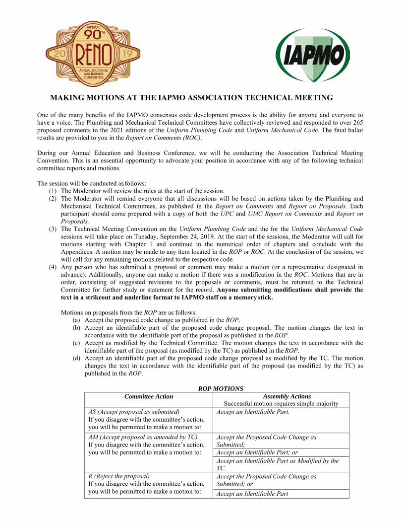
MAKING MOTIONS AT THE IAPMO ASSOCIATION TECHNICAL MEETING
One of the many benefits of the IAPMO consensus code development process is the ability for anyone and everyone to have a voice. The Plumbing and Mechanical Technical Committees have collectively reviewed and responded to over 265 proposed comments to the 2021 editions of the Uniform Plumbing Code and Uniform Mechanical Code. The final ballot results are provided to you in the Report on Comments (ROC).
During our Annual Education and Business Conference, we will be conducting the Association Technical Meeting Convention. This is an essential opportunity to advocate your position in accordance with any of the following technical committee reports and motions.
The session will be conducted as follows: (1) The Moderator will review the rules at the start of the session.(2) The Moderator will remind everyone that all discussions will be based on actions taken by the Plumbing and
Mechanical Technical Committees, as published in the Report on Comments and Report on Proposals. Eachparticipant should come prepared with a copy of both the UPC and UMC Report on Comments and Report onProposals.
(3) The Technical Meeting Convention on the Uniform Plumbing Code and the for the Uniform Mechanical Codesessions will take place on Tuesday, September 24, 2019. At the start of the sessions, the Moderator will call formotions starting with Chapter 1 and continue in the numerical order of chapters and conclude with theAppendices. A motion may be made to any item located in the ROP or ROC. At the conclusion of the session, wewill call for any remaining motions related to the respective code.
(4) Any person who has submitted a proposal or comment may make a motion (or a representative designated inadvance). Additionally, anyone can make a motion if there was a modification in the ROC. Motions that are inorder, consisting of suggested revisions to the proposals or comments, must be returned to the TechnicalCommittee for further study or statement for the record. Anyone submitting modifications shall provide thetext in a strikeout and underline format to IAPMO staff on a memory stick.
Motions on proposals from the ROP are as follows:(a) Accept the proposed code change as published in the ROP.(b) Accept an identifiable part of the proposed code change proposal. The motion changes the text in
accordance with the identifiable part of the proposal as published in the ROP.(c) Accept as modified by the Technical Committee. The motion changes the text in accordance with the
identifiable part of the proposal (as modified by the TC) as published in the ROP.(d) Accept an identifiable part of the proposed code change proposal as modified by the TC. The motion
changes the text in accordance with the identifiable part of the proposal (as modified by the TC) aspublished in the ROP.
ROP MOTIONS Committee Action Assembly Actions
Successful motion requires simple majority AS (Accept proposal as submitted) If you disagree with the committee’s action, you will be permitted to make a motion to:
Accept an Identifiable Part.
AM (Accept proposal as amended by TC) If you disagree with the committee’s action, you will be permitted to make a motion to:
Accept the Proposed Code Change as Submitted; Accept an Identifiable Part; or Accept an Identifiable Part as Modified by the TC.
R (Reject the proposal) If you disagree with the committee’s action, you will be permitted to make a motion to:
Accept the Proposed Code Change as Submitted; or Accept an Identifiable Part

Motions on proposals from the ROC are as follows: (a) Accept the comment. The motion changes the text in accordance with the comment as published in
the ROC.(b) Accept an identifiable part of the proposed public comment. The motion changes the text in
accordance with the identifiable part of the comment as published in the ROC.(c) Accept a comment as modified by the Technical Committee. The motion changes the text in
accordance with the committee action on the comment as published in the ROC.(d) Accept an identifiable part of the public comment as modified by the Technical Committee. The
motion changes the text in accordance with the identifiable part of the comment as published inthe ROC.
(e) Reject the comment. The motion returns that portion to ROP text.(f) Reject an identifiable part of a comment. The motion returns that portion to ROP text.
ROC MOTIONS Committee Action Assembly Actions
Successful motion requires simple majority AS (Accept the comment as submitted) If you disagree with the committee’s action, you will be permitted to make a motion to:
Accept an Identifiable Part of the Comment; Reject the Comment; or Reject an Identifiable Part of the Comment.
AM (Accept the comment as amended by TC) If you disagree with the committee’s action, you will be permitted to make a motion to:
Accept the comment as submitted; Accept an Identifiable Part of the Comment; Accept an Identifiable Part of the Comment as Modified by the TC; Reject the Comment; or Reject an Identifiable Part of the Comment.
R (Reject the comment) If you disagree with the committee’s action, you will be permitted to make a motion to:
Accept the comment as submitted; or Accept an Identifiable Part of the Comment.
For those who are planning to make a motion during the session, please state (your) name and affiliation; clearly state the motion (proposal or comment number with the page number in the ROP or ROC) and wait for the Moderator to acknowledge. Once you have been recognized by the Moderator, proceed with discussion. For discussion purposes, please keep the information simple and to the point, and provide any applicable references to statements and ballots in the ROP or ROC. Audio and visual presentations are prohibited. Please present any handouts to IAPMO staff for approval. IAPMO staff will be available Tuesday, September 24 from 8:00 am – 9:00 am in order to assist members making motions.
The 2019 Annual Education and Business Conference will be held from September 22 - 26, 2019 at the Silver Legacy Resort in Reno, Nevada. For more information on the event, please visit our web site at www.iapmo.org/events or contact Enrique Gonzalez, Plumbing Code Administrator, at (909) 230-5535 or at [email protected] or Zalmie Hussein, Mechanical Code Administrator, at (909) 218-8122 or at [email protected].
We look forward to seeing you in Reno!
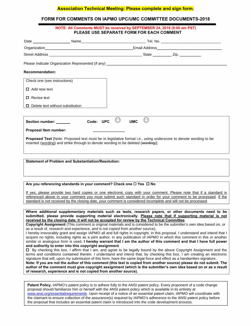
Association Technical Meeting: Please complete and sign form.
FORM FOR COMMENTS ON IAPMO UPC/UMC COMMITTEE DOCUMENTS-2018
NOTE: All Comments MUST be received by SEPTEMBER 24, 2019 (9:00 am PST)PLEASE USE SEPARATE FORM FOR EACH COMMENT
Date Name Tel. No. _____________________________
Organization Email Address Street Address State Zip.
Please Indicate Organization Represented (if any)
Recommendation:
Check one (see instructions)
Add new text
Revise text
Delete text without substitution
Section number: Code: UPC UMC
Proposal Item number:
Proposed Text [Note: Proposed text must be in legislative format i.e., using underscore to denote wording to be inserted (wording) and strike through to denote wording to be deleted (wording)].
Statement of Problem and Substantiation/Resolution:
Are you referencing standards in your comment? Check one Yes No
If yes, please provide two hard copies or one electronic copy with your comment. Please note that if a standard is referenced above in your comment you must submit such standard in order for your comment to be processed. If the standard is not received by the closing date, your comment is considered incomplete and will not be processed.
Where additional supplementary materials such as tests, research papers, or other documents need to be submitted, please provide supporting material electronically. Please note that if supporting material is not received by the closing date, it will not be accepted for review by the Technical Committee. Copyright Assignment (This comment is original materials and is considered to be the submitter’s own idea based on, or as a result of, research and experience, and is not copied from another source). I hereby irrevocably grant and assign IAPMO all and full rights in copyright, in this proposal. I understand and intend that I acquire no rights, including rights as a joint author, in any publication of IAPMO in which this comment in this or another similar or analogous form is used. I hereby warrant that I am the author of this comment and that I have full power and authority to enter into this copyright assignment. By checking this box, I affirm that I am, and agree to be legally bound by the above Copyright Assignment and theterms and conditions contained therein. I understand and intend that, by checking this box, I am creating an electronicsignature that will, upon my submission of this form, have the same legal force and effect as a handwritten signature.Note: If you are not the author of this comment (this text is copied from another source) please do not submit. Theauthor of the comment must give copyright assignment (which is the submitter’s own idea based on or as a resultof research, experience and is not copied from another source).
Patent Policy. IAPMO’s patent policy is to adhere fully to the ANSI patent policy. Every proponent of a code change proposal should familiarize him or herself with the ANSI patent policy which is available in its entirety at www.ansi.org/essentialrequirements. Upon receipt of a notice of an essential patent claim, IAPMO will coordinate with the claimant to ensure collection of the assurance(s) required by IAPMO’s adherence to the ANSI patent policy before the proposal that includes an essential patent claim is introduced into the code development process.
INSTRUCTIONS FOR SUBMITTING COMMENTS
PLEASE READ CAREFULLY
1. Check the appropriate box to indicate whether this comment recommends adding new text, revising existing
text, or delete text without substitution (see examples below). 2. Enter the appropriate comment on proposal item number that the proposed text applies to. 3. In the space identified as “Proposed Text” indicate the exact wording you propose as new or revised text or
the text you propose to be deleted. 4. In the space titled, “Statement of Problem and Substantiation/Resolution,” state the problem that will be
resolved by your recommendation and give the specific reason for your comment. 5. Where referencing a standard in your comment, such standard needs to be submitted in accordance with
the Guidelines for Referencing Mandatory Standards. Please provide two hard copies or one electronic copy with your comment. Please note that if the standard is not received by the closing date, your comment is considered incomplete and will not be processed.
6. Where additional supplementary materials such as tests, research papers, or other documents, need to be submitted, please provide supporting material electronically. Please note that if supporting material is not received by the closing date, it will not be accepted for review by the Technical Committee.
7. Check the box for copyright assignment. Please note if you are not the author of this comment (this text is copied from another source) please do not submit the proposed change. The author of the comment must give copyright assignment (which is the submitter’s own idea based on or as a result of research, experience and is not copied from another source).
Note: Content of Comments shall be in accordance with Section 4-4.5 of the IAPMO Regulations Governing Committee Projects of the UPC and UMC. Failure to comply with the above requirements will result in the comment not being processed. For further information on the standards process, please contact Code Development at 909-472-4111. For technical assistance, please call 909-230-5535 or 909-218-8122, or email [email protected]. Please support IAPMO’s green initiative to remain paper free by providing the Proposed Monographs, Report on Proposals and Report on Comments in digital Adobe PDF. Note printed copies of the above referenced documents will not be available at the hearings.
Examples for applying charging statement for adding text, deleting text and revising text Add new text as follows (applies only when adding a new section or all new text): Water Service. Piping from the water main or source of water supply to the water distribution piping of the building or premises served irrespective of the water meter location. Revise text as follows (applies when revising an existing section by deleting text, adding text or both as follows): Building Supply. The pipe carrying potable water from the water meter or other source of water supply to the building or other point of use or distribution on the lot. Building supply shall also mean water service. Piping from the water main or source of water supply to the water distribution piping of the building or premises served irrespective of the water meter location. Delete text without substitution (applies when deleting an entire section, table or both as follows): 302.0 Iron Pipe Size (IPS) Pipe. Iron, steel, brass and copper pipe shall be standard weight iron pipe size (IPS) pipe. 306.1 It shall be unlawful for any person to deposit, by any means whatsoever, into any plumbing fixture, floor drain, interceptor, sump, receptor, or device, which is connected to any drainage system, public sewer, private sewer, septic tank, or cesspool, any ashes; cinders; solids; rags; inflammable, poisonous, or explosive liquids or gas; oils; grease; or any other thing whatsoever that would, or could, cause damage to the drainage system or public sewer.
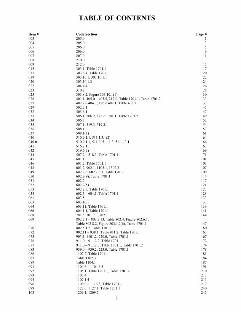
TABLE OF CONTENTS
i
Item # Code Section Page # 003 205.0 1 004 205.0 3 005 206.0 5 006 206.0 9 007 207.0 11 008 210.0 13 009 212.0 15 015 303.1, Table 1701.1 17 017 303.8.4, Table 1701.1 20 019 303.10.1, 303.10.1.1 22 020 303.10.1.3 24 022 304.4.4 26 023 310.2 28 025 303.8.2, Figure 303.10.1(1) 30 026 401.1, 405.0 – 405.5, 217.0, Table 1701.1, Table 1701.2 33 027 402.2 – 404.3, Table 402.1, Table 403.7 37 029 502.2.1 45 032 505.6.1 47 033 506.1, 506.2, Table 1701.1, Table 1701.2 49 034 506.3 52 035 507.1, 519.3, 519.3.1 54 036 508.1 57 037 508.1(1) 61 040 510.9.1.1, 511.1.3.1(2) 64 040.01 510.9.1.1, 511.0, 511.1.3, 511.1.3.1 66 041 516.2.1 67 042 519.5(3) 69 044 507.2 – 518.3, Table 1701.1 71 045 601.1 101 046 601.2, Table 1701.1 103 048 601.2, 902.1, 1105.1, 1302.3 107 049 602.2.6, 602.2.6.1, Table 1701.1 109 050 602.2(9), Table 1701.1 114 051 602.2 117 052 602.2(5) 121 053 602.2.5, Table 1701.1 123 054 602.3 – 604.1, Table 1701.1 128 061 603.5 133 063 603.10.1 137 064 603.11, Table 1701.1 139 066 604.1.1, Table 1701.1 141 068 701.5, 701.7.3, 702.1 144 069 802.2.1 – 803.2.13, Table 802.4, Figure 802.6.1, Table 802.8.2, Figure 803.1.2(6), Table 1701.1 147 070 802.5.1.2, Table 1701.1 160 072 902.11 – 938.1, Table 911.2, Table 1701.1 163 073 903.1, 1101.2, 220.0, Table 1701.1 167 076 911.0 – 911.2.2, Table 1701.1 172 077 911.0 – 911.2.3, Table 1701.1, Table 1701.2 174 083 939.0 – 939.2, 223.0, Table 1701.1 178 086 1102.2, Table 1701.1 181 087 Table 1102.3 184 089 Table 1104.1 187 091 1104.6 – 1104.6.3 191 092 1105.1, Table 1701.1, Table 1701.2 210 093 1105.4 213 094 1107.1.4 215 096 1109.0 – 1116.8, Table 1701.1 217 099 1127.0, 1127.1, Table 1701.1 240 103 1209.1, 1209.2 242
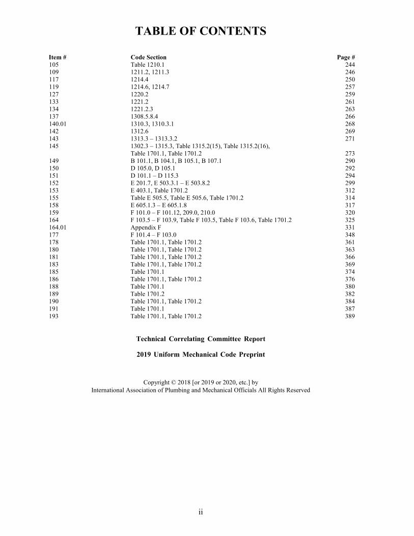
TABLE OF CONTENTS
ii
Item # Code Section Page # 105 Table 1210.1 244 109 1211.2, 1211.3 246 117 1214.4 250 119 1214.6, 1214.7 257 127 1220.2 259 133 1221.2 261 134 1221.2.3 263 137 1308.5.8.4 266 140.01 1310.3, 1310.3.1 268 142 1312.6 269 143 1313.3 – 1313.3.2 271 145 1302.3 – 1315.3, Table 1315.2(15), Table 1315.2(16), Table 1701.1, Table 1701.2 273 149 B 101.1, B 104.1, B 105.1, B 107.1 290 150 D 105.0, D 105.1 292 151 D 101.1 – D 115.3 294 152 E 201.7, E 503.3.1 – E 503.8.2 299 153 E 403.1, Table 1701.2 312 155 Table E 505.5, Table E 505.6, Table 1701.2 314 158 E 605.1.3 – E 605.1.8 317 159 F 101.0 – F 101.12, 209.0, 210.0 320 164 F 103.5 – F 103.9, Table F 103.5, Table F 103.6, Table 1701.2 325 164.01 Appendix F 331 177 F 101.4 – F 103.0 348 178 Table 1701.1, Table 1701.2 361 180 Table 1701.1, Table 1701.2 363 181 Table 1701.1, Table 1701.2 366 183 Table 1701.1, Table 1701.2 369 185 Table 1701.1 374 186 Table 1701.1, Table 1701.2 376 188 Table 1701.1 380 189 Table 1701.2 382 190 Table 1701.1, Table 1701.2 384 191 Table 1701.1 387 193 Table 1701.1, Table 1701.2 389
Technical Correlating Committee Report
2019 Uniform Mechanical Code Preprint
Copyright © 2018 [or 2019 or 2020, etc.] by International Association of Plumbing and Mechanical Officials All Rights Reserved
Item #: 003Comment #: 1
CHAPTER 2DEFINITIONS
Proposals
Edit Proposal
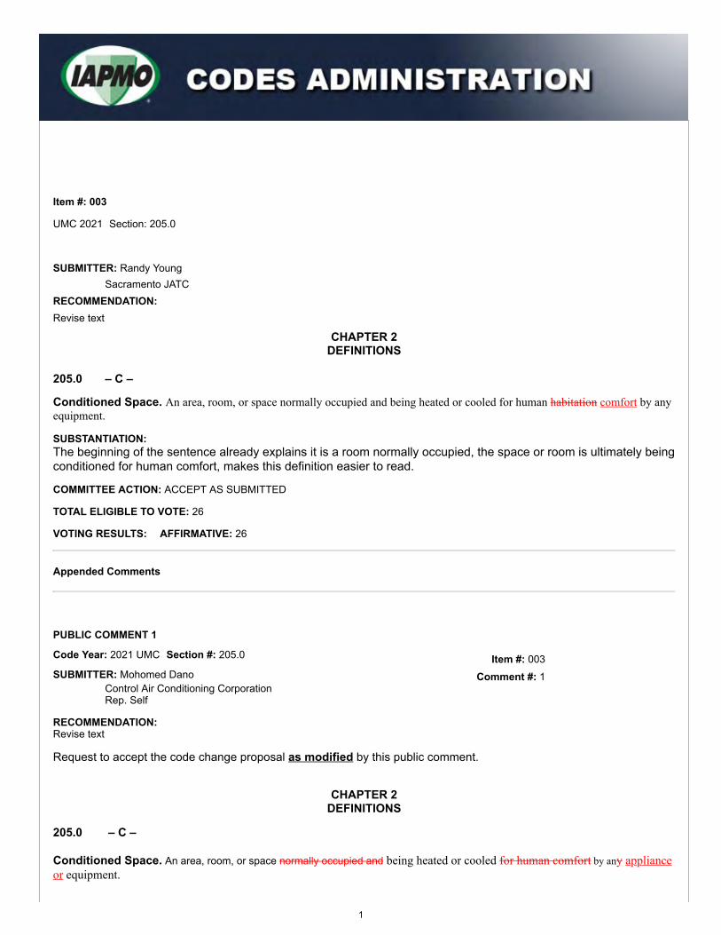
Item #: 003
UMC 2021 Section: 205.0
SUBMITTER: Randy YoungSacramento JATC
RECOMMENDATION: Revise text
205.0 – C –
Conditioned Space. An area, room, or space normally occupied and being heated or cooled for human habitation comfort by anyequipment.
SUBSTANTIATION:The beginning of the sentence already explains it is a room normally occupied, the space or room is ultimately beingconditioned for human comfort, makes this definition easier to read.
COMMITTEE ACTION: ACCEPT AS SUBMITTED
TOTAL ELIGIBLE TO VOTE: 26
VOTING RESULTS: AFFIRMATIVE: 26
Appended Comments
Edit Comment
PUBLIC COMMENT 1
Code Year: 2021 UMC Section #: 205.0
SUBMITTER: Mohomed DanoControl Air Conditioning CorporationRep. Self
RECOMMENDATION:Revise text
Request to accept the code change proposal as modified by this public comment.
CHAPTER 2DEFINITIONS
205.0 – C –
Conditioned Space. An area, room, or space normally occupied and being heated or cooled for human comfort by any applianceor equipment.
1
SUBSTANTIATION:The definition of “conditioned space” should be further revised as a conditioned space is not always "normallyoccupied" and is not always for "human comfort." For example, computer rooms or data rooms may be conditioned,but are not for human comfort, rather they are for maintaining suitable temperatures for the functionality of thecomputer equipment.
COMMITTEE ACTION: REJECT
COMMITTEE STATEMENT:The comment is being rejected as the proposed change does not improve or strengthen the code.
TOTAL ELIGIBLE TO VOTE: 26
VOTING RESULTS: AFFIRMATIVE: 25 NOT RETURNED: 1 HOWARD
2
Item #: 004
Comment #: 1
Proposals
Edit Proposal
Item #: 004
UMC 2021 Section: 205.0
SUBMITTER: Randy YoungSacramento JATC
RECOMMENDATION: Revise text
CHAPTER 2DEFINITIONS
205.0 – C –
Cooling System. All of the equipment, ducts and components, including refrigeration, intended or installed for the purpose ofcooling air by mechanical means and discharging such air into any room or conditioned space. This definition shall not include anevaporative cooler.
SUBSTANTIATION:Adding "ducts and components" clearly helps to identify the cooling system in its entirety.
COMMITTEE ACTION: ACCEPT AS SUBMITTED
TOTAL ELIGIBLE TO VOTE: 26
VOTING RESULTS: AFFIRMATIVE: 26
Appended Comments
Edit Comment
PUBLIC COMMENT 1
Code Year: 2021 UMC Section #: 203.0, 205.0, 207.0, 218.0
SUBMITTER: Mohamed DanoControl Air Conditioning CorporationRep. Self
RECOMMENDATION:Revise text
Request to accept the code change proposal as modified by this public comment.
CHAPTER 2DEFINITIONS
3
203.0 - A -
Air, Return. Air from the conditioned space area that is returned to the conditioning equipment for reconditioning.Air, Supply. Air being conveyed to a conditioned space area through ducts or plenums from a heat exchanger of a heating,cooling, absorption, or evaporative cooling system.
205.0 - C-
Cooling System. All of the equipment, ducts and components, including refrigeration, intended or installed for the purposeof cooling air by mechanical means and discharging such air into any room or conditioned space. This definition shall notinclude an evaporative cooler.Evaporative Cooling System, Evaporative. Equipment, ducts and components intended or installed for the purpose ofenvironmental cooling by an evaporative cooler from which the conditioned air is distributed through ducts or plenums to theconditioned space area.
218.0 - P -
Portable Evaporative Cooler. An evaporative cooler that discharges the conditioned air directly into the conditioned spacearea without the use of ducts and can be readily transported from place to place without dismantling any portion thereof.
SUBSTANTIATION:In harmony with the action taken on UMC Item # 004, the definitions of "Evaporative Cooling System," "Air, Return,"and "Air, Supply" should also be modified as the terms “ducts and components” and/or “conditioned space” alsoapply to these systems and to be consistent with the Committee action for the definition for “Cooling System.” Lastly,the definition for “Evaporative Cooling System” is being relocated from Section 207.0 to Section 205.0 below“Cooling System” for ease of use of the code.
COMMITTEE ACTION: REJECT
COMMITTEE STATEMENT:The comment is being rejected as the definitions are already correct and the change does nothing to improve the code.
TOTAL ELIGIBLE TO VOTE: 26
VOTING RESULTS: AFFIRMATIVE: 25 NOT RETURNED: 1 HOWARD
4
CHAPTER 2DEFINITIONS
Proposals
Edit Proposal
Item #: 005
UMC 2021 Section: 206.0
SUBMITTER: Randy YoungSacramento JATC
RECOMMENDATION: Revise text
205.0 – C –
Combination Fire and Smoke Damper. A device that meets both the fire damper and smoke damper requirements. [NFPA5000:3.3.139.2]
206.0 – D –
Damper. A valve or plate for controlling draft or the flow of gases, including air. [NFPA 211:3.3.52]
Combination Fire-Smoke Damper. An automatic-closing metal assembly consisting of one or more louvers, blades, slats,or vanes that closes upon detection of heat or smoke as to restrict the passage of heat and smoke and is listed to the applicablerecognized standard.
SUBSTANTIATION:To clearly define the materials used to construct and to clearly define it can be used in both fire control and smokecontrol.
COMMITTEE ACTION: ACCEPT AS AMENDED BY THE TC
Amend proposal as follows:
206.0 – D –
Damper. A valve or plate for controlling draft or the flow of gases, including air. [NFPA 211:3.3.52]
Combination Fire-Smoke Damper. An automatic-closing metal assembly consisting of one or more louvers, blades, slats,or vanes that closes upon detection of heat or smoke as to restrict the passage of heat and smoke and is listed to the applicablerecognized standard.
COMMITTEE STATEMENT:The definition is being modified as it contains specific requirements which are not in accordance with the Manual ofStyle.
TOTAL ELIGIBLE TO VOTE: 26
VOTING RESULTS: AFFIRMATIVE: 26
Appended Comments
5
Item #: 005
Item #: 005
Comment #: 1
Comment #: 2
Edit Comment
PUBLIC COMMENT 1
Code Year: 2021 UMC Section #: 206.0
SUBMITTER: Danial AldibVaritec SolutionsRep. Self
RECOMMENDATION:Revise text
Request to accept the code change proposal as modified by this public comment.
CHAPTER 2DEFINITIONS
206.0 - D -
Damper. A valve or plate for controlling draft or the flow of gases, including air. [NFPA 211:3.3.52]
Combination Fire-/Smoke Damper. An automatic-closing metal assembly consisting of one or more louvers, blades, slats,or vanes that closes upon detection of heat or smoke as to restrict the passage of heat flame and smoke.
SUBSTANTIATION:The definition of "Combination Fire/Smoke Damper" should be further modified to clarify that these devices restrictthe passage of flame, not only heat. This is consistent with the definition for "Fire Damper" in the UMC, whichstates, "to restrict the passage of flame."
COMMITTEE ACTION: ACCEPTED AS SUBMITTED
TOTAL ELIGIBLE TO VOTE: 26
VOTING RESULTS: AFFIRMATIVE: 25 NOT RETURNED: 1 HOWARD
Edit Comment
PUBLIC COMMENT 2
Code Year: 2021 UMC Section #: 206.0
SUBMITTER: Danial AldibVaritec SolutionsRep. Self
RECOMMENDATION:Revise text
Request to accept the code change proposal as modified by this public comment.
CHAPTER 2DEFINITIONS
206.0 - D -
Damper. A valve or plate for controlling draft or the flow of gases, including air. [NFPA 211:3.3.52]Fire Damper. An automatic-closing metal assembly consisting of one or more louvers, blades, slats, or vanes that closesupon detection of heat so as to restrict the passage of flame and is listed to the applicable recognized standards.Smoke Damper. A damper arranged to seal off airflow automatically through a part of an air duct system so as to restrictthe passage of smoke and controlled by a smoke detection system and is listed to the applicable recognized standard.
SUBSTANTIATION:Listing requirements do not belong in definitions. Listing requirements should only be in the body of the code andthis will be consistent with the action taken for Item # 005. Furthermore, smoke dampers are controlled by thesmoke detection system.
6
Item #: 005
Comment #: 3
COMMITTEE ACTION: ACCEPTED AS AMENDED
Amend comment as follows:
CHAPTER 2DEFINITIONS
206.0 - D -
Damper. A valve or plate for controlling draft or the flow of gases, including air. [NFPA 211:3.3.52]Fire Damper. An automatic-closing metal assembly consisting of one or more louvers, blades, slats, or vanes that closesupon detection of heat so as to restrict the passage of flame.Smoke Damper. A damper arranged to seal off airflow automatically through a part of an air duct system so as to restrictthe passage of smoke and controlled by a smoke detection system.
COMMITTEE STATEMENT:The modification removes language that does not belong in the definitions, as definitions are not meant to explain how adevice is controlled.
TOTAL ELIGIBLE TO VOTE: 26
VOTING RESULTS: AFFIRMATIVE: 25 NOT RETURNED: 1 HOWARD
Edit Comment
PUBLIC COMMENT 3
Code Year: 2021 UMC Section #: 205.0, 206.0
SUBMITTER: Danial AldibVaritec SolutionsRep. Self
RECOMMENDATION:Revise text
Request to accept the code change proposal as modified by this public comment.
CHAPTER 2DEFINITIONS
205.0 - C -
Ceiling Radiation Damper. A listed device installed in a ceiling membrane of a fire-resistance-rated floor-ceiling or roof-ceilingassembly to automatically limit the radiative heat transfer through an air inlet/outlet opening. [NFPA 5000:3.3.139.1]
206.0 - D -
Damper. A valve or plate for controlling draft or the flow of gases, including air. [NFPA 211:3.3.52]Ceiling Radiation Damper. A listed device installed in a ceiling membrane of a fire-resistance-rated floor-ceiling or roof-ceiling assembly to automatically limit the radiative heat transfer through an air inlet/outlet opening. [NFPA 5000:3.3.140.1]
SUBSTANTIATION:The definition of "Ceiling Radiation Damper" needs to be relocated to below the rest of the "Damper" definitions forease of use of the code.
COMMITTEE ACTION: ACCEPTED AS SUBMITTED
TOTAL ELIGIBLE TO VOTE: 26
VOTING RESULTS: AFFIRMATIVE: 25 NOT RETURNED: 1 HOWARD
7
Item #: 005
Comment #: 4
Code Year: 2021 UMC Section #: 606.3
SUBMITTER: Danial AldibVaritec SolutionsRep. Self
RECOMMENDATION:Add new text
Request to accept the code change proposal as modified by this public comment.
606.0 Smoke Dampers, Fire Dampers, and Ceiling Dampers.
606.3 Combination Fire/Smoke Dampers. Combination fire/smoke dampers shall comply with the smoke damper and firedamper requirements in Section 606.1 and Section 606.2.
(renumber remaining sections)
SUBSTANTIATION:The UMC currently does not have a section that addresses the requirements for combination fire/smoke dampers,therefore, a new section needs to be added to address such requirements. The new section follows the sameformat as the requirements for "smoke dampers" and "fire dampers" which are addressed in UMC Sections 606.1and 606.2.
COMMITTEE ACTION: REJECT
COMMITTEE STATEMENT:The comment is being rejected as the new language is located in the wrong section and provisions for combination dampersdo not belong in a section for smoke and fire dampers (Section 606.0).
TOTAL ELIGIBLE TO VOTE: 26
VOTING RESULTS: AFFIRMATIVE: 25 NOT RETURNED: 1 HOWARD
8
Edit Comment
PUBLIC COMMENT 4
8
Item #: 006
Comment #: 1
Proposals
Edit Proposal
Item #: 006
UMC 2021 Section: 206.0
SUBMITTER: Phil PettitControl Air Conditioning Corporation
RECOMMENDATION:Revise text
CHAPTER 2DEFINITIONS
206.0 – D –
Duct. A tube or conduit passageway for transmission of air, fumes, vapors, or dust. This definition shall not include:(1) A vent, vent connector, or chimney connector.(2) A tube or conduit wherein the pressure of the air exceeds 1 psi (7 kPa).(3) The air passages of listed self-contained systems.
SUBSTANTIATION:The term “passageway” is consistent with the language found in the definition of “Duct System” and clearlydescribes the function and purpose of a duct, more so than the term “conduit”.
COMMITTEE ACTION: REJECT
COMMITTEE STATEMENT:The proposed change to the term “passageway” is vague and creates confusion.
TOTAL ELIGIBLE TO VOTE: 26
VOTING RESULTS: AFFIRMATIVE: 26
Appended Comments
Edit Comment
PUBLIC COMMENT 1
Code Year: 2021 UMC Section #: 206.0
SUBMITTER: Mohamed DanoControl Air Conditioning CorporationRep. Self
RECOMMENDATION:Revise text
Request to replace the code change proposal by this public comment.
CHAPTER 2DEFINITIONS
9
206.0 – D –
Duct. A tube or conduit or passageway for transmission of air, fumes, vapors, or dust. This definition shall not include:(1) A vent, vent connector, or chimney connector.(2) A tube or conduit wherein the pressure of the air exceeds 1 psi (7 kPa).(3) The air passages of listed self-contained systems.
SUBSTANTIATION:The term “conduit” would be better used in the definition for “duct” rather than the term “tube.” Furthermore, NFPA 96 usesthe term "conduit or passageway" to define “air duct” as shown below:
NFPA 96:3.3.5: "Air Duct. A conduit or passageway for conveying air to or from heating, cooling, air-conditioning, orventilating equipment, but not including the plenum."
COMMITTEE ACTION: REJECT
COMMITTEE STATEMENT:The comment is being rejected as the term "passageway" is vague and may be misinterpreted for a hallway or corridor.
TOTAL ELIGIBLE TO VOTE: 26
VOTING RESULTS: AFFIRMATIVE: 25 NOT RETURNED: 1 HOWARD
10
Item #: 007
Comment #: 1
CHAPTER 2DEFINITIONS
Proposals
Edit Proposal
Item #: 007
UMC 2021 Section: 207.0
SUBMITTER: Randy YoungSacramento JATC
RECOMMENDATION: Revise text
207.0 – E –
Emergency Alarm System. A system intended to provide the indication notification and warning of abnormal conditions andsummon appropriate aid.
SUBSTANTIATION:Removing "the indication" and adding "notification" makes this easier to read.
COMMITTEE ACTION: ACCEPT AS SUBMITTED
TOTAL ELIGIBLE TO VOTE: 26
VOTING RESULTS: AFFIRMATIVE: 26
Appended Comments
Edit Comment
PUBLIC COMMENT 1
Code Year: 2021 UMC Section #: 207.0
SUBMITTER: Phil PettitControl AirRep. Self
RECOMMENDATION:Revise text
Request to accept the code change proposal as modified by this public comment.
CHAPTER 2DEFINITIONS
207.0 – E –
Emergency Alarm System. A system intended to provide a visual or audible notification and warning of abnormal conditions andsummon appropriate aid.
SUBSTANTIATION:The proposed modification provides clarification that an Emergency Alarm System includes "a visual or audible warning".This language clearly defines what an emergency alarm system is and what it should do.
11
COMMITTEE ACTION: REJECT
COMMITTEE STATEMENT:The comment is being rejected as the emergency alarm system may be audible or visual or both. The current definition iscorrect.
TOTAL ELIGIBLE TO VOTE: 26
VOTING RESULTS: AFFIRMATIVE: 25 NOT RETURNED: 1 HOWARD
12
Item #: 008
Comment #: 1
Proposals
Edit Proposal
Item #: 008
UMC 2021 Section: 210.0
SUBMITTER: Reinhard HanselkaMenlo Park Fire Protection DistrictRep: Consultant To District
RECOMMENDATION:Revise text
CHAPTER 2DEFINITIONS
210.0 – H –
HPM Storage Room. A room used for the storage or dispensing of hazardous production material (HPM) and that isclassified as a Group H, Division 1, or Division 2, Division 3, or Division 4 Occupancy.
SUBSTANTIATION:This is an update to the new potential Occupancies in the current Building and fire Codes.
COMMITTEE ACTION: ACCEPT AS SUBMITTED
TOTAL ELIGIBLE TO VOTE: 26
VOTING RESULTS: AFFIRMATIVE: 26
Appended Comments
Edit Comment
PUBLIC COMMENT 1
Code Year: 2021 UMC Section #: 210.0
SUBMITTER: Reinhard HanselkaMenlo Park Fire Protection District
RECOMMENDATION:Revise text
Request to accept the code change proposal as modified by this public comment.
CHAPTER 2DEFINITIONS
210.0 – H –
HPM Storage Room. A room used for the storage or dispensing of hazardous production material (HPM) and that is classified asa Group H, Division 1, Division 2, Division 3, or Division 4, or Division 5 Occupancy.
13
SUBSTANTIATION:I am further modifying my original proposal. Division 5 Occupancy was not included in the original proposal and should beadded to the definition of “HPM Storage Room” as it is part of Group H of the HPM (Hazardous Production Material)classifications. Division 5 covers semiconductor fabrication facilities and comparable research and development areas.
COMMITTEE ACTION: ACCEPTED AS SUBMITTED
TOTAL ELIGIBLE TO VOTE: 26
VOTING RESULTS: AFFIRMATIVE: 25 NOT RETURNED: 1 HOWARD
14
Proposals
Edit Proposal
Item #: 009
UMC 2021 Section: 212.0
SUBMITTER: Mark FaselViega LLC
RECOMMENDATION: Revise text
CHAPTER 2DEFINITIONS
212.0 – J –
Joint, Press-Connect. A permanent mechanical joint consisting of an elastomeric seal or an elastomeric seal and corrosion-resistant grip or bite ring. The joint is made with a pressing tool and jaw or ring approved by the fitting manufacturer.
SUBSTANTIATION:We have discovered that the mechanical attaching grip "or bite" ring is referred to as a grip ring by some manufacturer's anda bite ring by others. The proposed addition of the words "or bite" are for clarification that a Press-Connect joint mayincorporate a grip or a bite ring in the design. These terms are usually found in the dimensional drawings of the fittings. Thisrevision will provide clarification for the Building Official and Installer so there are no misunderstandings on what may beconsidered a Press-Connect Joint.
COMMITTEE ACTION: REJECT
COMMITTEE STATEMENT:
The proposed change is unnecessary and does not strengthen the code.
TOTAL ELIGIBLE TO VOTE: 26
VOTING RESULTS: AFFIRMATIVE: 20 NEGATIVE: 6
EXPLANATION OF AFFIRMATIVE:
MANN: There was no technical justification provided for the addition of "bite.”
EXPLANATION OF NEGATIVE:
CUDAHY: I believe this language was accepted in another model code.
FEEHAN: The term bite is used in the industry and does not change the code, but gives more information to the end user
HOWARD: The additional language does provide clarification. The Committee rationale should not always be based on if it strengthensthe code, but rather does it provide a benefit to the end users.
KOERBER: I do not see a problem with adding "bite ring" reference for clarification.
MACNEVIN: No technical objection to adding "bite.”
A. TRAFTON: The term bite is used in submittals and in standard industry language.
Appended Comments
15
Item #: 009
Comment #: 1
Edit Comment
PUBLIC COMMENT 1
Code Year: 2021 UMC Section #: 212.0
SUBMITTER: Mark FaselViega LLC
RECOMMENDATION:Revise text
Request to accept the code change proposal as submitted by this public comment.
SUBSTANTIATION:The proposed language is necessary and will strengthen the code since it has been discovered that the mechanicalattaching grip "or bite" ring is referred to as a grip ring by some manufacturers and a bite ring by others. The proposedaddition of the words "or bite" is for clarification that a Press-Connect joint may incorporate a "grip" or a "bite" ring in thedesign. These terms are usually found in the dimensional drawings of the fittings. This revision will provide clarification forthe Building Official and Installer so there are no misunderstandings on what may be considered a Press-Connect Joint.
COMMITTEE ACTION: REJECT
COMMITTEE STATEMENT:The comment is being rejected as the term "bite ring" may be used in the field, but it is not used in standards. Furthermore,this change was also rejected in the UPC by request of the submitter.
TOTAL ELIGIBLE TO VOTE: 26
VOTING RESULTS: AFFIRMATIVE: 24 NEGATIVE: 1 NOT RETURNED: 1 HOWARD
EXPLANATION OF NEGATIVE:
KOERBER: I am not opposed to adding the proposed "bite" reference.
16
Proposals
Edit Proposal
Item #: 015
UMC 2021 Section: 303.1, Table 1701.1
SUBMITTER: David C. BixbyAir Conditioning Contractors of America
RECOMMENDATION:Revise text
303.0 Installation.303.1 Listed Appliances. The installation of equipment and appliances regulated by this code shall be in accordance with the conditions of the listing, the manufacturer’s installation instructions and this code. The manufacturer’s installation and operating instructions shall be attached to the appliance. Minimum criteria for the proper installation of HVAC systems shall comply with ACCA 5 QI. Clearances of listed equipment and appliances from combustible materials shall be as specified in the listing or on therating plate.
TABLE 1701.1REFERENCED STANDARDS
STANDARD NUMBER STANDARD TITLE APPLICATION REFERENCEDSECTION
ANSI/ACCA 5 QI-2015 HVAC Quality Installation Specification Equipment 303.1
(portion of table not shown remains unchanged)
Note: ACCA 5 QI meets the requirements for mandatory reference standards in accordance with Section 3-3.7.1of IAPMO's Regulations Governing Committee Projects.
SUBSTANTIATION:ACCA 5 QI details nationally-recognized minimum criteria for the proper installation of HVAC systems in new and existingresidential and commercial buildings. This standard provides a universally accepted definition for quality installation across abroad spectrum of the HVAC industry (e.g., manufacturers, distributors, contractors, user groups, customers, utilities,efficiency advocates, trade associations, professional societies, and governmental agencies). In this Standard, the QIelements focus on the application and how well the system is selected and actually installed. ACCA 5 QI is also aconsensus-based ANSI standard.
The addition of ACCA 5 QI is needed to support its proposed reference as a new requirement under 303.1. ACCA 5 QI is aconsensus-based ANSI standard that meets the requirements for mandatory reference standards in accordance with Section3-3.7.1 of IAPMO’s Regulations Governing Projects.
COMMITTEE ACTION: REJECT
COMMITTEE STATEMENT:The proposed text is not needed as the manufacturer’s installation instructions already provide installation procedures and themanufacturer's installation instructions take precedence.
TOTAL ELIGIBLE TO VOTE: 26
VOTING RESULTS: AFFIRMATIVE: 24 NEGATIVE: 1 NOT RETURNED: 1 Howard
17
Item #: 015
Comment #: 1
EXPLANATION OF NEGATIVE:
WHITE: ACCA 5 QI is an industry supported standard necessary for quality installations.
Appended Comments
Edit Comment
PUBLIC COMMENT 1
Code Year: 2021 UMC Section #: 303.1, Table 1701.1
SUBMITTER: David BixbyAir Conditioning Contractors of America
RECOMMENDATION:Revise text
Request to replace the code change proposal by this public comment.
303.0 Installation.303.1 Listed Appliances. The installation of equipment and appliances regulated by this code shall be in accordance with theconditions of the listing, the manufacturer's installation instructions and this code. The manufacturer's installation and operatinginstructions shall be attached to the appliance. Minimum criteria for the proper design, equipment selection, and installation of HVACsystems shall comply with ACCA 5 QI. Clearances of listed equipment and appliances from combustible materials shall be asspecified in the listing or on the rating plate.
TABLE 1701.1REFERENCED STANDARDS
STANDARD NUMBER STANDARD TITLE APPLICATION REFERENCEDSECTION
ACCA 5 QI-2015 HVAC Quality Installation Specification Equipment 303.1
(portion of table not shown remains unchanged)
Note: ACCA 5 QI meets the requirements for mandatory reference standards in accordance with Section 3-3.7.1of IAPMO's Regulations Governing Committee Projects.
SUBSTANTIATION:In addition to referring to the manufacturer's instructions, ACCA 5 QI focuses how well the system is designed, selected,installed, and tested, which has a large impact on occupant satisfaction and energy savings. For this Standard, core areasthat characterize a quality installation include:(1) Design Aspects, such as heat gain/loss load calculations, equipment capacity selection;(2) Distribution Aspects, such as duct leakage, airflow balance;(3) Equipment Installation Aspects, such as electrical requirements, system controls, refrigerant charge, and SystemDocumentation; and(4) Owner Education Aspects for proper system documentation and owner/operator education. Those who are currentlyknowledgeable in performing such work are already using the same minimum core requirements that are outlined in ACCA 5QI. The standard is also available to all interested stakeholders as a free download. (www.acca.org/quality)
COMMITTEE ACTION: REJECT
COMMITTEE STATEMENT:Installation instructions for HVAC systems are already provided by the manufacturer, therefore, there is no need to providean additional standard for installers of HVAC systems.
TOTAL ELIGIBLE TO VOTE: 26
VOTING RESULTS: AFFIRMATIVE: 23 NEGATIVE: 1 ABSTAIN: 1 NOT RETURNED: 1 HOWARD
EXPLANATION OF NEGATIVE:
WHITE: It is widely known that improper installation has a detrimental effect on HVAC system efficiency. Utilizing ACCA 5 QI would bean important step in resolving many of these installation issues which many times are not in the manufacturer's instructions.
18
EXPLANATION OF ABSTAIN:
KOERBER: I think the TC could have included reference to the standard with a modification to the proposal such as, "HVAC systemsmeeting the requirements of ACCA 5QI are considered to meet the minimum criteria."
19
Proposals
Edit Proposal
Item #: 017
UMC 2021 Section: 303.8.4, Table 1701.1
SUBMITTER: David DiasSheet Metal Workers Local 104
RECOMMENDATION:Revise text
303.0 Installation.
303.8 Appliances on Roofs. (remaining text unchanged)
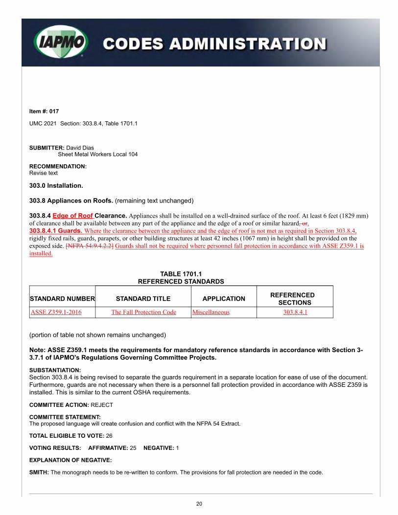
303.8.4 Edge of Roof Clearance. Appliances shall be installed on a well-drained surface of the roof. At least 6 feet (1829 mm) of clearance shall be available between any part of the appliance and the edge of a roof or similar hazard, or.303.8.4.1 Guards. Where the clearance between the appliance and the edge of roof is not met as required in Section 303.8.4, rigidly fixed rails, guards, parapets, or other building structures at least 42 inches (1067 mm) in height shall be provided on the exposed side. [NFPA 54:9.4.2.2] Guards shall not be required where personnel fall protection in accordance with ASSE Z359.1 is installed.
TABLE 1701.1REFERENCED STANDARDS
STANDARD NUMBER STANDARD TITLE APPLICATION REFERENCED SECTIONS
ASSE Z359.1-2016 The Fall Protection Code Miscellaneous 303.8.4.1
(portion of table not shown remains unchanged)
Note: ASSE Z359.1 meets the requirements for mandatory reference standards in accordance with Section 3-3.7.1 of IAPMO's Regulations Governing Committee Projects.
SUBSTANTIATION:Section 303.8.4 is being revised to separate the guards requirement in a separate location for ease of use of the document.Furthermore, guards are not necessary when there is a personnel fall protection provided in accordance with ASSE Z359 isinstalled. This is similar to the current OSHA requirements.
COMMITTEE ACTION: REJECT
COMMITTEE STATEMENT:The proposed language will create confusion and conflict with the NFPA 54 Extract.
TOTAL ELIGIBLE TO VOTE: 26
VOTING RESULTS: AFFIRMATIVE: 25 NEGATIVE: 1
EXPLANATION OF NEGATIVE:
SMITH: The monograph needs to be re-written to conform. The provisions for fall protection are needed in the code.
20
Item #: 017
Comment #: 1
Appended Comments
Edit Comment
PUBLIC COMMENT 1
Code Year: 2021 UMC Section #: 303.8.4, 303.8.4.1, Table 1701.1
SUBMITTER: David DiasSheet Metal Workers Local 104
RECOMMENDATION:Revise text
Request to replace the code change proposal by this public comment.
303.0 Installation.
303.8 Appliances on Roofs. (remaining text unchanged)
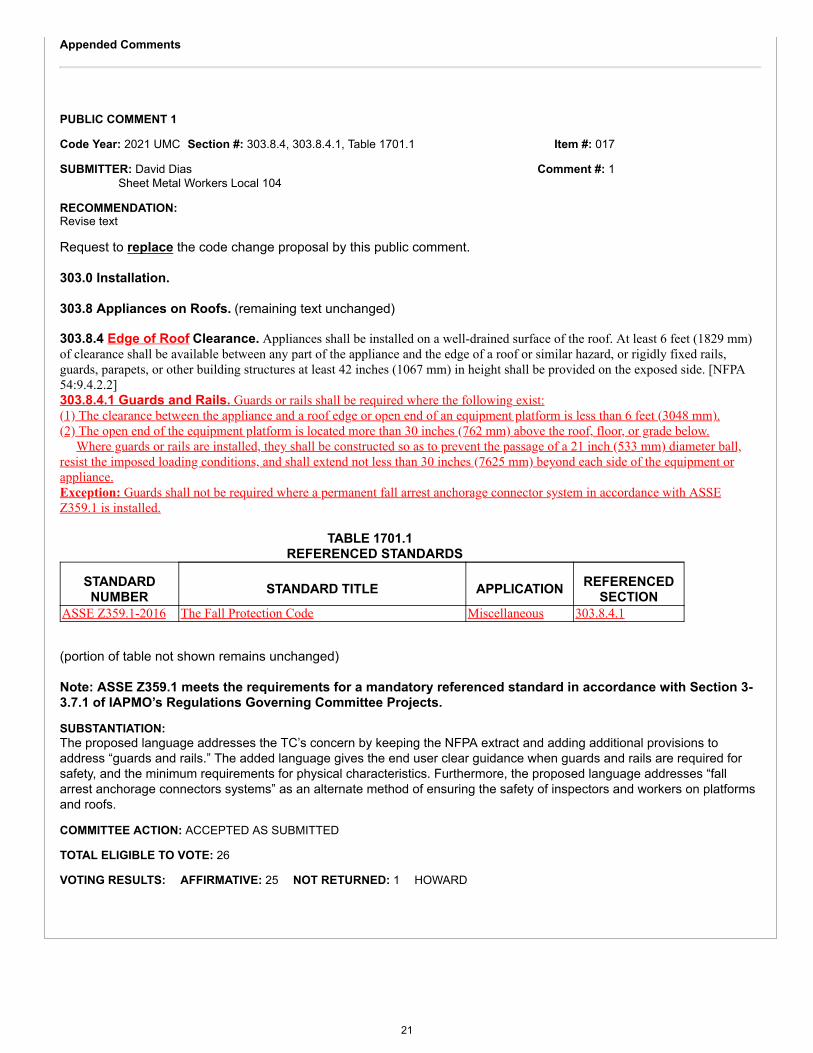
303.8.4 Edge of Roof Clearance. Appliances shall be installed on a well-drained surface of the roof. At least 6 feet (1829 mm)of clearance shall be available between any part of the appliance and the edge of a roof or similar hazard, or rigidly fixed rails,guards, parapets, or other building structures at least 42 inches (1067 mm) in height shall be provided on the exposed side. [NFPA54:9.4.2.2]303.8.4.1 Guards and Rails. Guards or rails shall be required where the following exist:(1) The clearance between the appliance and a roof edge or open end of an equipment platform is less than 6 feet (3048 mm).(2) The open end of the equipment platform is located more than 30 inches (762 mm) above the roof, floor, or grade below. Where guards or rails are installed, they shall be constructed so as to prevent the passage of a 21 inch (533 mm) diameter ball,resist the imposed loading conditions, and shall extend not less than 30 inches (7625 mm) beyond each side of the equipment orappliance.Exception: Guards shall not be required where a permanent fall arrest anchorage connector system in accordance with ASSEZ359.1 is installed.
TABLE 1701.1 REFERENCED STANDARDS
STANDARDNUMBER STANDARD TITLE APPLICATION REFERENCED
SECTIONASSE Z359.1-2016 The Fall Protection Code Miscellaneous 303.8.4.1
(portion of table not shown remains unchanged)
Note: ASSE Z359.1 meets the requirements for a mandatory referenced standard in accordance with Section 3-3.7.1 of IAPMO’s Regulations Governing Committee Projects.
SUBSTANTIATION:The proposed language addresses the TC’s concern by keeping the NFPA extract and adding additional provisions toaddress “guards and rails.” The added language gives the end user clear guidance when guards and rails are required forsafety, and the minimum requirements for physical characteristics. Furthermore, the proposed language addresses “fallarrest anchorage connectors systems” as an alternate method of ensuring the safety of inspectors and workers on platformsand roofs.
COMMITTEE ACTION: ACCEPTED AS SUBMITTED
TOTAL ELIGIBLE TO VOTE: 26
VOTING RESULTS: AFFIRMATIVE: 25 NOT RETURNED: 1 HOWARD
21
Item #: 019
Comment #: 1
Proposals
Edit Proposal
Item #: 019
UMC 2021 Section: 303.10.1, 303.10.1.1
SUBMITTER: Mohamed DanoControl Air Conditioning Corporation
RECOMMENDATION:Revise text
303.0 Installation.
303.10 Clearances. (remaining text unchanged)303.10.1 Clearance Reduction. Reduce clearances to combustible construction for listed equipment and appliances shall comply with the listing and Table 303.10.1, except for specific applications and provision as stated in Section 303.10.1.1 through Section 303.10.1.3. Where permitted by the manufacturer, and not provided in this code, reduce clearances to combustible construction for unlisted equipment and appliances shall comply with Table 303.10.1.303.10.1.1 Type I Hood Exhaust System, Commercial Kitchens. Reduce clearances for Type I exhaust systems used in commercial kitchens shall be in accordance with Section 507.4.2 through Section 507.4.2.3. Clearances from the duct or the exhaust fan to the interior surface of enclosures of combustible construction shall be in accordance with Section 510.7.3 and clearances shall not be reduced.
SUBSTANTIATION:Section 303.10.1 and Section 303.10.1.1 is being revised for clarity. For example, Section 303.10.1 should be revised to include language which sends the end user for specific reduce clearances requirements. The current language seems to indicate that all reduce clearances must comply with Table 303.10.1 which is not the case.
Section 303.10.1.1 is being revised to clarify that the section is specific to commercial kitchens. Thought the term “Type 1” it is common language for those of us who deal with these types of systems in our daily lives, it is not is not common language for those contractors or installers who may come across with these systems.
COMMITTEE ACTION: REJECT
COMMITTEE STATEMENT:The proposed language is not necessary and does not enhance and strengthen the enforceability of the code.
TOTAL ELIGIBLE TO VOTE: 26
VOTING RESULTS: AFFIRMATIVE: 26
Appended Comments
Edit Comment
PUBLIC COMMENT 1
Code Year: 2021 UMC Section #: 303.10.1
SUBMITTER: Keith BlazerRep. Self
RECOMMENDATION:Revise text
22
Request to replace the code change proposal by this public comment.
303.0 Installation.
303.10 Clearances. (remaining text unchanged)
303.10.1 Clearance Reduction. Reduced clearances to combustible construction for listed equipment and appliances shallcomply with the listing and Table 303.10.1. Where permitted by the manufacturer, and not provided in this code, reduced clearancesto combustible construction for unlisted equipment and appliances shall comply with Table 303.10.1.Exception: Specific applications and provisions as stated in Section 303.10.1.1 through Section 303.10.1.3.
303.10.1.1 Type I Hood Exhaust System. Reduce clearances for Type I exhaust systems shall be in accordance withSection 507.4.2 through Section 507.4.2.3. Clearances from the duct or the exhaust fan to the interior surface ofenclosures of combustible construction shall be in accordance with Section 510.7.3 and clearances shall not bereduced.303.10.1.2 Product Conveying Ducts. Reduce clearances to combustibles construction for product conveying ductsshall be in accordance with Section 506.10.3 through Section 506.11.6.3.303.10.1.3 Solid-Fuel Burning Appliances. For solid-fuel burning appliances, the clearance, after reduction, shall notbe less than 12 inches (305 mm) to combustible walls and not less than 18 inches (457 mm) to combustible ceilings.The clearance, after reduction, shall be permitted to be less than 12 inches (305 mm) to combustible walls and less than18 inches (457 mm) to combustible ceilings where the solid-fuel burning appliances is listed for lesser clearance.
SUBSTANTIATION:The proposed revision relocates language from the original proposal in Section 303.10.1 to an exception, where it makesmore sense to have it. This is a simple relocation that would strengthen the code and add clarity for the end user.
COMMITTEE ACTION: REJECT
COMMITTEE STATEMENT:The comment is being rejected as the language is not necessary and does not improve the enforceability of the code.
TOTAL ELIGIBLE TO VOTE: 26
VOTING RESULTS: AFFIRMATIVE: 25 NOT RETURNED: 1 HOWARD
23
Item #: 020
Comment #: 1
Proposals
Edit Proposal
Item #: 020
UMC 2021 Section: 303.10.1.3
SUBMITTER: Randy YoungSacramento JATC
RECOMMENDATION:Revise text
303.0 Installation.
303.10 Clearances. (remaining text unchanged)303.10.1 Clearance Reduction. (remaining text unchanged)
303.10.1.3 Solid-Fuel Burning Appliances. For solid-fuel burning appliances, the clearance, after reduction, shall not be less than 12 inches (305 mm) to combustible walls and not less than 18 inches (457 mm) to combustible ceilings. The clearance, after reduction, shall be permitted to be less than 12 inches (305 mm) to combustible walls and less than 18 inches (457 mm) to combustible ceilings where the solid-fuel burning appliances is listed for lesser clearance. Solid-fuel burning appliances listed for lesser clearances shall be permitted to be installed in accordance with the manufacturer’s instructions and their listing.
SUBSTANTIATION:This made no sense as written, with "after reduction” in the first sentence made this seem contradictory. Simple clean up.
COMMITTEE ACTION: ACCEPT AS SUBMITTED
TOTAL ELIGIBLE TO VOTE: 26
VOTING RESULTS: AFFIRMATIVE: 26
Appended Comments
Edit Comment
PUBLIC COMMENT 1
Code Year: 2021 UMC Section #: 221.0
SUBMITTER: Maria YepremianCounty of Los Angeles Building and Safety
RECOMMENDATION:Add new text
Request to accept the code change proposal as modified by this public comment.
CHAPTER 2DEFINITIONS
221.0 – S –Solid-Fuel. Wood, charcoal, peat, biomass, coal, Hexamine fuel tablets, pellets made from wood, corn, wheat, rye and other grains,and other similar organic material and any combination of them that are used as fuel to produce energy, providing heat and light,usually released through the process of combustion.
24
Solid-Fuel Burning Appliance. A chimney-connected device that burns solid-fuel for the purpose of heating or cooking.
SUBSTANTIATION:Definitions are being added for "Solid-Fuel" and "Solid-Fuel Burning Appliance." There are currently no definitions for theseterms in the code. The definitions for "Solid Cooking Fuel" and "Solid-Fuel Cooking Equipment," which already in the code,are not covered by these new definitions. Solid Fuel can be used for purposes other than cooking, such as space heating.The addition of these definitions will assist the AHJ with enforceability.
COMMITTEE ACTION: REJECT
COMMITTEE STATEMENT:The comment is being rejected as the proposed terms are already covered in the definitions of the UMC.
TOTAL ELIGIBLE TO VOTE: 26
VOTING RESULTS: AFFIRMATIVE: 25 NOT RETURNED: 1 HOWARD
25
Item #: 022
Comment #: 1
Proposals
Edit Proposal
Item #: 022
UMC 2021 Section: 304.4.4
SUBMITTER: Christopher JensenUL LLC
RECOMMENDATION:Delete text without substitution
304.0 Accessibility for Service.
304.4 Appliances in Attics and Under-Floor Spaces. (remaining text unchanged)
304.4.4 Lighting and Convenience Outlet. A permanent 120 volt receptacle outlet and a lighting fixture shall be installed near the appliance. The switch controlling the lighting fixture shall be located at the entrance to the passageway. [NFPA 54:9.5.3]
SUBSTANTIATION:The requirements for lighting and power for appliances installed in Attics and underfloor spaces are adequately covered in NFPA 70 Sections 210.63, 210.70(A)(3) and 210.70(C). There are conflicts with some of the terms used in this section and the corresponding requirements found in NFPA 70. (1) The term “Lighting Fixture” has been replaced in the 2002 edition of NFPA 70 with the term “Luminaire”. The termluminaire is used internationally for lighting products. The NEC permits the required illumination for an appliance to beprovided by either a lampholder or a luminaire.(2) Receptacles are rated at 125 volt not 120 volt in accordance with UL 489. Branch circuits are rated at 120 volts nominal.Proposals are being submitted to NFPA to address this issue in NFPA 54 National Fuel Gas Code.
COMMITTEE ACTION: REJECT
COMMITTEE STATEMENT:The proposed text deletion should remain in the code as the language is needed for enforcement of the code in regards tolighting and power for appliances.
TOTAL ELIGIBLE TO VOTE: 26
VOTING RESULTS: AFFIRMATIVE: 26
Appended Comments
Edit Comment
PUBLIC COMMENT 1
Code Year: 2021 UMC Section #: 304.4.4
SUBMITTER: Phil PettitControl AirRep. Self
RECOMMENDATION:Revise text
Request to replace the code change proposal by this public comment.
26
304.0 Accessibility for Service.
304.4 Appliances in Attics and Under-Floor Spaces. (remaining text unchanged)
304.4.4 Lighting and Convenience Outlet. A permanent 120 volt receptacle outlet and a lighting fixture luminaire shall be installed nearthe appliance. The switch controlling the lighting fixture shall be located at the entrance to the passageway. [{NFPA 54:9.5.3}]
SUBSTANTIATION:The term "luminaire" should replace the term "lighting fixture" for consistency to correlate with the action taken on UMC Item # 067.Also, the NFPA 54 extract needs to be removed as the extracted language is being changed.
COMMITTEE ACTION: ACCEPTED AS AMENDED
Amend comment as follows:
304.0 Accessibility for Service.
304.4 Appliances in Attics and Under-Floor Spaces. (remaining text unchanged)
304.4.4 Lighting and Convenience Outlet. A permanent 120 volt receptacle outlet and a luminaire shall be installed near the appliance.The switch controlling the lighting fixture luminaire shall be located at the entrance to the passageway. {NFPA 54:9.5.3}
COMMITTEE STATEMENT:The comment is being modified as the second "lighting fixture" term should also be changed to "luminaire."
TOTAL ELIGIBLE TO VOTE: 26
VOTING RESULTS: AFFIRMATIVE: 25 NOT RETURNED: 1 HOWARD
27
Item #: 023
Comment #: 1
Proposals
Edit Proposal
Item #: 023
UMC 2021 Section: 310.2
SUBMITTER: Randy YoungSacramento JATC
RECOMMENDATION:Revise text
310.0 Condensate Wastes and Control.
310.2 Condensate Control. Where an equipment or appliance is installed in a space where damage is capable of resulting from condensate overflow, other than damage to replaceable lay-in ceiling tiles, a drain line shall be provided and shall be drained in accordance with Section 310.1. An additional protection method for condensate overflow shall be provided in accordance with one of the following:(1) A water level detecting device that will shut off the equipment or appliance in the event the primary drain is blocked.(2) An additional watertight pan of corrosion-resistant material, with a separate drain line, installed beneath the cooling coil, unit, or
the appliance to catch the overflow condensate due to a clogged primary condensate drain.(3) An additional drain line at a level that is higher than the primary drain line connection of the drain pan.(4) An additional watertight pan of corrosion-resistant material with a water level detection device installed beneath the cooling coil,
unit, or the appliance to catch the overflow condensate due to a clogged primary condensate drain and to shut off the equipment.
The additional pan or the additional drain line connection shall be provided with a drain pipe of not less than 3/4 of an inch (20mm) nominal pipe size, discharging at a point that is readily observed.
SUBSTANTIATION:Where equipment or appliances are installed in any area and condensate has a potential of causing any damage, properprecautions should be taken to prevent such damage. Ceiling tiles are like sponges, they will accept and retain moisturewhich could lead to mold and mildew growth. Damage to items located below the ceiling such as files, computers, desks orwhatever else the building owner decides to place under an area unknown to him/her if the ceiling is going to hiding a leakyhazard.
COMMITTEE ACTION: ACCEPT AS SUBMITTED
TOTAL ELIGIBLE TO VOTE: 26
VOTING RESULTS: AFFIRMATIVE: 25 NOT RETURNED: 1 HOWARD
Appended Comments
Edit Comment
PUBLIC COMMENT 1
Code Year: 2021 UMC Section #: 310.2
SUBMITTER: Randy YoungSacramento JATC
RECOMMENDATION:Revise text
28
Item #: 023
Comment #: 2
Request to accept the code change proposal as modified by this public comment.
310.0 Condensate Wastes and Control.310.2 Condensate Control. Where an any equipment or appliance is installed in a space where damage is capable of resultingfrom condensate overflow, a drain line shall be provided and shall be drained in accordance with Section 310.1. An additionalprotection method for condensate overflow shall be provided in accordance with one of the following:(1) - (4) (remaining text unchanged)
SUBSTANTIATION:The propose revision will correlate with similar change done to the UPC inregards to "any" equipment or appliance installedin a space where damage is capable of resulting from condensate overflow.
COMMITTEE ACTION: ACCEPTED AS SUBMITTED
TOTAL ELIGIBLE TO VOTE: 26
VOTING RESULTS: AFFIRMATIVE: 25 NOT RETURNED: 1 HOWARD
Edit Comment
PUBLIC COMMENT 2
Code Year: 2021 UMC Section #: 310.5
SUBMITTER: Phillip H RibbsPHR Consultants
RECOMMENDATION:Revise text
Request to accept the code change proposal as modified by this public comment.
310.0 Condensate Wastes and Control.
310.5 Point of Discharge. Air-conditioning condensate waste pipes shall connect indirectly, except where permitted in Section310.6, to the drainage system through an air gap or air break to trapped and vented receptors, roof drains, dry wells, leach pits, or the tailpieceof plumbing fixtures. A condensate drain shall be trapped in accordance with the appliance manufacturer’s instructions or asapproved.Exception: Where permitted in Section 310.6.
310.6 Condensate Waste From Air-Conditioning Coils. Where the condensate waste from air-conditioning coils dischargesby direct connection to a lavatory tailpiece or to an approved accessible inlet on a bathtub overflow, the connection shall be locatedin the area controlled by the same person controlling the air-conditioned space.
SUBSTANTIATION:As written, the exception may be misinterpreted as pertaining to the described fixtures. However, the fixtures are not part of theexception. The proposed modification removes any ambiguity by adding the exception to the bottom. Furthermore, roof drains arebeing added as it is an appropriate location for air-conditioning condensate waste pipes to connect indirectly. This change will correlatewith the action taken on UPC Item # 130.
COMMITTEE ACTION: REJECT
COMMITTEE STATEMENT:The comment is being rejected as the point of discharge for HVAC condensate waste should not include roof drains.Furthermore, this would conflict with federal regulations.
TOTAL ELIGIBLE TO VOTE: 26
VOTING RESULTS: AFFIRMATIVE: 24 ABSTAIN: 1 NOT RETURNED: 1 HOWARD
EXPLANATION OF ABSTAIN:
HYDE: I stepped away from the discussion and was not able to provide a vote.
29
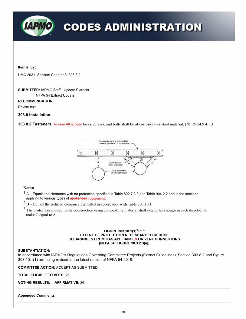
Proposals
Edit Proposal
Item #: 025
UMC 2021 Section: Chapter 3: 303.8.2
SUBMITTER: IAPMO Staff - Update ExtractsNFPA 54 Extract Update
RECOMMENDATION:Revise text
303.0 Installation.
303.8.2 Fasteners. Access All access locks, screws, and bolts shall be of corrosion-resistant material. [NFPA 54:9.4.1.3]
Notes:1 A – Equals the clearance with no protection specified in Table 802.7.3.3 and Table 904.2.2 and in the sections
applying to various types of appliances equipment.2 B – Equals the reduced clearance permitted in accordance with Table 303.10.1.3 The protection applied to the construction using combustible material shall extend far enough in each direction to
make C equal to A.
FIGURE 303.10.1(1)1, 2, 3
EXTENT OF PROTECTION NECESSARY TO REDUCECLEARANCES FROM GAS APPLIANCES OR VENT CONNECTORS
[NFPA 54: FIGURE 10.3.2.3(a)]
SUBSTANTIATION:In accordance with IAPMO's Regulations Governing Committee Projects (Extract Guidelines), Section 303.8.2 and Figure303.10.1(1) are being revised to the latest edition of NFPA 54-2018.
COMMITTEE ACTION: ACCEPT AS SUBMITTED
TOTAL ELIGIBLE TO VOTE: 26
VOTING RESULTS: AFFIRMATIVE: 26
Appended Comments
30
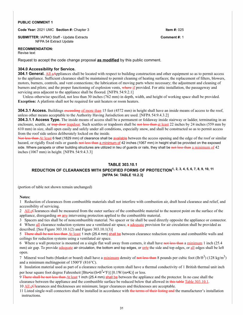
Item #: 025
Comment #: 1
Edit Comment
PUBLIC COMMENT 1
Code Year: 2021 UMC Section #: Chapter 3
SUBMITTER: IAPMO Staff - Update ExtractsNFPA 54 Extract Update
RECOMMENDATION:Revise text
Request to accept the code change proposal as modified by this public comment.
304.0 Accessibility for Service.304.1 General. All aAppliances shall be located with respect to building construction and other equipment so as to permit accessto the appliance. Sufficient clearance shall be maintained to permit cleaning of heating surfaces; the replacement of filters, blowers,motors, burners, controls, and vent connections; the lubrication of moving parts where necessary; the adjustment and cleaning ofburners and pilots; and the proper functioning of explosion vents, where if provided. For attic installation, the passageway andservicing area adjacent to the appliance shall be floored. [NFPA 54:9.2.1] Unless otherwise specified, not less than 30 inches (762 mm) in depth, width, and height of working space shall be provided.Exception: A platform shall not be required for unit heaters or room heaters.
304.3.1 Access. Buildings exceeding of more than 15 feet (4572 mm) in height shall have an inside means of access to the roof,unless other means acceptable to the Authority Having Jurisdiction are used. [NFPA 54:9.4.3.2]304.3.1.1 Access Type. The inside means of access shall be a permanent or foldaway inside stairway or ladder, terminating in anenclosure, scuttle, or trap door trapdoor. Such scuttles or trapdoors shall be not less than at least 22 inches by 24 inches (559 mm by610 mm) in size, shall open easily and safely under all conditions, especially snow, and shall be constructed so as to permit accessfrom the roof side unless deliberately locked on the inside.Not less than At least 6 feet (1829 mm) of clearance shall be available between the access opening and the edge of the roof or similarhazard, or rigidly fixed rails or guards not less than a minimum of 42 inches (1067 mm) in height shall be provided on the exposedside. Where parapets or other building structures are utilized in lieu of guards or rails, they shall be not less than a minimum of 42inches (1067 mm) in height. [NFPA 54:9.4.3.3]
TABLE 303.10.1REDUCTION OF CLEARANCES WITH SPECIFIED FORMS OF PROTECTION1, 2, 3, 4, 5, 6, 7, 8, 9, 10, 11
[NFPA 54: TABLE 10.2.3]
(portion of table not shown remain unchanged)
Notes:1 Reduction of clearances from combustible materials shall not interfere with combustion air, draft hood clearance and relief, andaccessibility of servicing.2 All cClearances shall be measured from the outer surface of the combustible material to the nearest point on the surface of theappliance, disregarding an any intervening protection applied to the combustible material.3 Spacers and ties shall be of noncombustible material. No spacer or tie shall be used directly opposite the appliance or connector.4 Where all clearance reduction systems use a ventilated air space, a adequate provision for air circulation shall be provided asdescribed. [See Figure 303.10.1(2) and Figure 303.10.1(3)]5 There shall be not less than At least 1 inch (25.4 mm) shall be between clearance reduction systems and combustible walls andceilings for reduction systems using a ventilated air space.6 Where a wall protector is mounted on a single flat wall away from corners, it shall have not less than a minimum 1 inch (25.4mm) air gap. To provide adequate air circulation, the bottom and top edges, or only the side and top edges, or all edges shall be leftopen.7 Mineral wool batts (blanket or board) shall have a minimum density of not less than 8 pounds per cubic foot (lb/ft3) (128 kg/m3)and a minimum meltingpoint of 1500°F (816°C).8 Insulation material used as part of a clearance reduction system shall have a thermal conductivity of 1 British thermal unit inchper hour square foot degree Fahrenheit [Btu•in/(h•ft2•°F)] [0.1W/(m•K)] or less.9 There shall be not less than At least 1 inch (25.4 mm) shall be between the appliance and the protector. In no case shall theclearance between the appliance and the combustible surface be reduced below that allowed in this table Table 303.10.1.10 All cClearances and thicknesses are minimum; larger clearances and thicknesses are acceptable.11 Listed single-wall connectors shall be installed in accordance with the terms of their listing and the manufacturer’s installation
instructions.
31
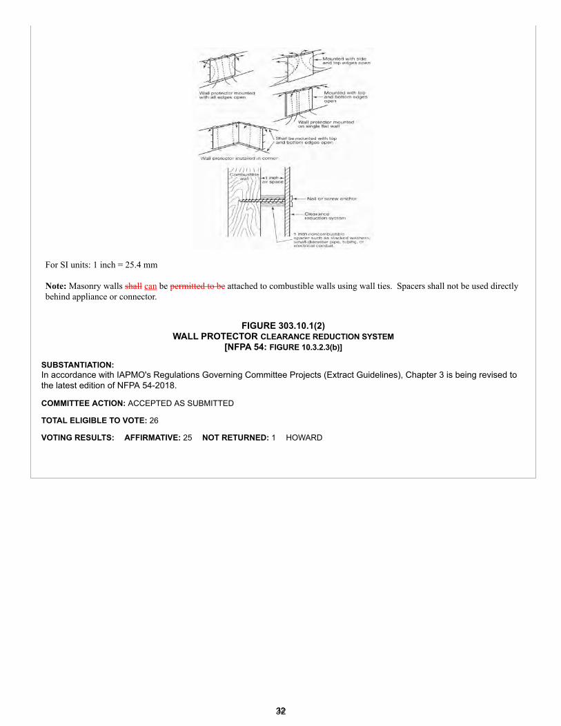
For SI units: 1 inch = 25.4 mm
Note: Masonry walls shall can be permitted to be attached to combustible walls using wall ties. Spacers shall not be used directlybehind appliance or connector.
FIGURE 303.10.1(2)WALL PROTECTOR CLEARANCE REDUCTION SYSTEM
[NFPA 54: FIGURE 10.3.2.3(b)]
SUBSTANTIATION:In accordance with IAPMO's Regulations Governing Committee Projects (Extract Guidelines), Chapter 3 is being revised tothe latest edition of NFPA 54-2018.
COMMITTEE ACTION: ACCEPTED AS SUBMITTED
TOTAL ELIGIBLE TO VOTE: 26
VOTING RESULTS: AFFIRMATIVE: 25 NOT RETURNED: 1 HOWARD
3232
Proposals
Edit Proposal
Item #: 026
UMC 2021 Section: 401.1, 405.0 - 405.5, 217.0, Table 1701.1, Table 1701.2
SUBMITTER: David DiasSheet Metal Workers Local 104
RECOMMENDATION:Revise text
401.0 General.401.1 Applicability. This chapter contains requirements for ventilation air supply, exhaust, and makeup air requirements for occupiable spaces within a building. Spaces within buildings, except those within dwelling unit in residential occupancies where occupants are nontransient, shall comply with Section 402.0 through Section 404.0. 402.1.2 Dwelling. Requirements for ventilation air rate for single-family dwellings units in residential occupancies, where the occupants are nontransient, shall be in accordance with this chapter or ASHRAE 62.2 Section 405.0.
405.0 Indoor Air Quality for Residential Occupancies.
405.1 General. Rooms or occupied spaces within residential occupancies, where the occupants are nontransient, shall be designed to have mechanical ventilation and exhaust air in accordance with Section 405.2 through Section 405.5.
405.1.1 Natural Ventilation. Where approved by the Authority Having Jurisdiction, natural ventilation shall be permittedfor Climate Zone 1, Climate Zone 2; or for thermally conditioned buildings for less than 876 hours per year.
405.2 Ventilation Air Rate. The required mechanical ventilation outdoor air rate (Qtot) shall be as calculated in accordancewith Equation 405.2.Exceptions: For existing buildings and where permitted by the Authority Having Jurisdiction, the total mechanical ventilation(Qtot) is not required where Qtot is calculated to be not more than 15 ft3/min (0.007 m3/s).
Qtot = 0.03Afloor + 7.5 (Nbr + 1) Equation 405.2
Where:Qtot = Total required ventilation outdoor air rate, cfmAfloor = Floor area, ft2
Nbr = Number of bedrooms more than 1For SI Units: 1 cubic foot per minute = 0.00047 m3/s
405.2.1 Reduced Ventilation Air Rate. Where permitted by the Authority Having Jurisdiction, the mechanical ventilationair rate required in Section 405.2 shall be permitted to be reduced where an infiltration rate is determined in accordance withASTM E779.
405.3 Bathroom Exhaust. A mechanical exhaust directly to the outdoors shall be provided in each room containing abathtub, shower, or tub/shower combination. The fan shall run intermittently (on demand) or continuously. A readily accessiblemanual control designed to be operated as needed or an automatic control shall be provided for intermittent operations.
405.3.1 Exhaust Rate. The exhaust rate shall be not less than 50 ft3/min (0.02 m3/s) for intermittent operation and 20ft3/min (0.009 m3/s) for continuous operation.
405.4 Kitchen Exhaust. A mechanical exhaust directly to the outdoors shall be provided in each kitchen. The fan shall runintermittently (on demand) or continuously. A readily accessible manual control designed to be operated as needed or anautomatic control shall be provided for intermittent operations.
33
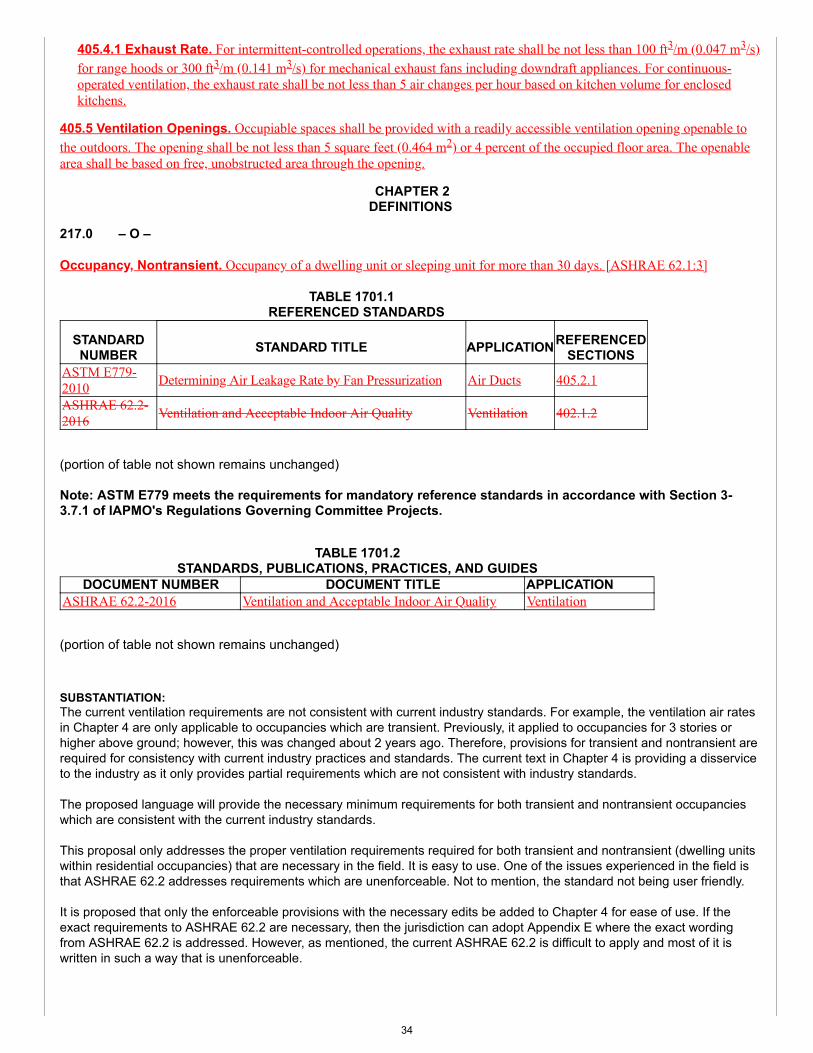
405.4.1 Exhaust Rate. For intermittent-controlled operations, the exhaust rate shall be not less than 100 ft3/m (0.047 m3/s)for range hoods or 300 ft3/m (0.141 m3/s) for mechanical exhaust fans including downdraft appliances. For continuous-operated ventilation, the exhaust rate shall be not less than 5 air changes per hour based on kitchen volume for enclosedkitchens.
405.5 Ventilation Openings. Occupiable spaces shall be provided with a readily accessible ventilation opening openable tothe outdoors. The opening shall be not less than 5 square feet (0.464 m2) or 4 percent of the occupied floor area. The openablearea shall be based on free, unobstructed area through the opening.
CHAPTER 2DEFINITIONS
217.0 – O –
Occupancy, Nontransient. Occupancy of a dwelling unit or sleeping unit for more than 30 days. [ASHRAE 62.1:3]
TABLE 1701.1 REFERENCED STANDARDS
STANDARDNUMBER STANDARD TITLE APPLICATIONREFERENCED
SECTIONSASTM E779-2010 Determining Air Leakage Rate by Fan Pressurization Air Ducts 405.2.1
ASHRAE 62.2-2016 Ventilation and Acceptable Indoor Air Quality Ventilation 402.1.2
(portion of table not shown remains unchanged)
Note: ASTM E779 meets the requirements for mandatory reference standards in accordance with Section 3-3.7.1 of IAPMO's Regulations Governing Committee Projects.
TABLE 1701.2STANDARDS, PUBLICATIONS, PRACTICES, AND GUIDES
DOCUMENT NUMBER DOCUMENT TITLE APPLICATIONASHRAE 62.2-2016 Ventilation and Acceptable Indoor Air Quality Ventilation
(portion of table not shown remains unchanged)
SUBSTANTIATION:The current ventilation requirements are not consistent with current industry standards. For example, the ventilation air ratesin Chapter 4 are only applicable to occupancies which are transient. Previously, it applied to occupancies for 3 stories orhigher above ground; however, this was changed about 2 years ago. Therefore, provisions for transient and nontransient arerequired for consistency with current industry practices and standards. The current text in Chapter 4 is providing a disserviceto the industry as it only provides partial requirements which are not consistent with industry standards.
The proposed language will provide the necessary minimum requirements for both transient and nontransient occupancieswhich are consistent with the current industry standards.
This proposal only addresses the proper ventilation requirements required for both transient and nontransient (dwelling unitswithin residential occupancies) that are necessary in the field. It is easy to use. One of the issues experienced in the field isthat ASHRAE 62.2 addresses requirements which are unenforceable. Not to mention, the standard not being user friendly.
It is proposed that only the enforceable provisions with the necessary edits be added to Chapter 4 for ease of use. If theexact requirements to ASHRAE 62.2 are necessary, then the jurisdiction can adopt Appendix E where the exact wordingfrom ASHRAE 62.2 is addressed. However, as mentioned, the current ASHRAE 62.2 is difficult to apply and most of it iswritten in such a way that is unenforceable.
34
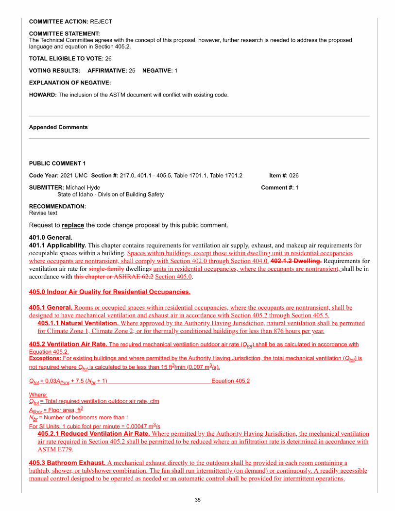
Item #: 026
Comment #: 1
COMMITTEE ACTION: REJECT
COMMITTEE STATEMENT:The Technical Committee agrees with the concept of this proposal, however, further research is needed to address the proposedlanguage and equation in Section 405.2.
TOTAL ELIGIBLE TO VOTE: 26
VOTING RESULTS: AFFIRMATIVE: 25 NEGATIVE: 1
EXPLANATION OF NEGATIVE:
HOWARD: The inclusion of the ASTM document will conflict with existing code.
Appended Comments
Edit Comment
PUBLIC COMMENT 1
Code Year: 2021 UMC Section #: 217.0, 401.1 - 405.5, Table 1701.1, Table 1701.2
SUBMITTER: Michael HydeState of Idaho - Division of Building Safety
RECOMMENDATION:Revise text
Request to replace the code change proposal by this public comment.
401.0 General.401.1 Applicability. This chapter contains requirements for ventilation air supply, exhaust, and makeup air requirements foroccupiable spaces within a building. Spaces within buildings, except those within dwelling unit in residential occupancieswhere occupants are nontransient, shall comply with Section 402.0 through Section 404.0. 402.1.2 Dwelling. Requirements forventilation air rate for single-family dwellings units in residential occupancies, where the occupants are nontransient, shall be inaccordance with this chapter or ASHRAE 62.2 Section 405.0.
405.0 Indoor Air Quality for Residential Occupancies.
405.1 General. Rooms or occupied spaces within residential occupancies, where the occupants are nontransient, shall bedesigned to have mechanical ventilation and exhaust air in accordance with Section 405.2 through Section 405.5.
405.1.1 Natural Ventilation. Where approved by the Authority Having Jurisdiction, natural ventilation shall be permittedfor Climate Zone 1, Climate Zone 2; or for thermally conditioned buildings for less than 876 hours per year.
405.2 Ventilation Air Rate. The required mechanical ventilation outdoor air rate (Qtot) shall be as calculated in accordance withEquation 405.2.Exceptions: For existing buildings and where permitted by the Authority Having Jurisdiction, the total mechanical ventilation (Qtot) isnot required where Qtot is calculated to be less than 15 ft3/min (0.007 m3/s).
Qtot = 0.03Afloor + 7.5 (Nbr + 1) Equation 405.2
Where:Qtot = Total required ventilation outdoor air rate, cfmAfloor = Floor area, ft2Nbr = Number of bedrooms more than 1For SI Units: 1 cubic foot per minute = 0.00047 m3/s
405.2.1 Reduced Ventilation Air Rate. Where permitted by the Authority Having Jurisdiction, the mechanical ventilationair rate required in Section 405.2 shall be permitted to be reduced where an infiltration rate is determined in accordance withASTM E779.
405.3 Bathroom Exhaust. A mechanical exhaust directly to the outdoors shall be provided in each room containing abathtub, shower, or tub/shower combination. The fan shall run intermittently (on demand) or continuously. A readily accessiblemanual control designed to be operated as needed or an automatic control shall be provided for intermittent operations.
35
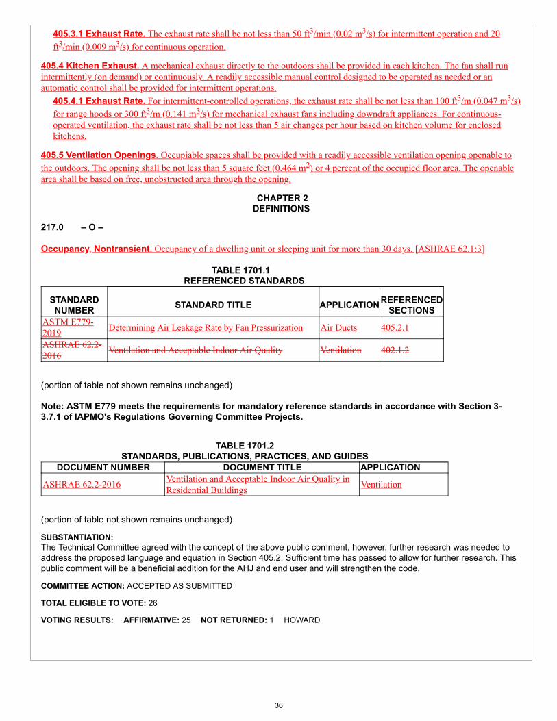
405.3.1 Exhaust Rate. The exhaust rate shall be not less than 50 ft3/min (0.02 m3/s) for intermittent operation and 20ft3/min (0.009 m3/s) for continuous operation.
405.4 Kitchen Exhaust. A mechanical exhaust directly to the outdoors shall be provided in each kitchen. The fan shall runintermittently (on demand) or continuously. A readily accessible manual control designed to be operated as needed or anautomatic control shall be provided for intermittent operations.
405.4.1 Exhaust Rate. For intermittent-controlled operations, the exhaust rate shall be not less than 100 ft3/m (0.047 m3/s)for range hoods or 300 ft3/m (0.141 m3/s) for mechanical exhaust fans including downdraft appliances. For continuous-operated ventilation, the exhaust rate shall be not less than 5 air changes per hour based on kitchen volume for enclosedkitchens.
405.5 Ventilation Openings. Occupiable spaces shall be provided with a readily accessible ventilation opening openable tothe outdoors. The opening shall be not less than 5 square feet (0.464 m2) or 4 percent of the occupied floor area. The openablearea shall be based on free, unobstructed area through the opening.
CHAPTER 2DEFINITIONS
217.0 – O –
Occupancy, Nontransient. Occupancy of a dwelling unit or sleeping unit for more than 30 days. [ASHRAE 62.1:3]
TABLE 1701.1 REFERENCED STANDARDS
STANDARDNUMBER STANDARD TITLE APPLICATIONREFERENCED
SECTIONSASTM E779-2019 Determining Air Leakage Rate by Fan Pressurization Air Ducts 405.2.1
ASHRAE 62.2-2016 Ventilation and Acceptable Indoor Air Quality Ventilation 402.1.2
(portion of table not shown remains unchanged)
Note: ASTM E779 meets the requirements for mandatory reference standards in accordance with Section 3-3.7.1 of IAPMO's Regulations Governing Committee Projects.
TABLE 1701.2STANDARDS, PUBLICATIONS, PRACTICES, AND GUIDES
DOCUMENT NUMBER DOCUMENT TITLE APPLICATION
ASHRAE 62.2-2016 Ventilation and Acceptable Indoor Air Quality inResidential Buildings Ventilation
(portion of table not shown remains unchanged)
SUBSTANTIATION:The Technical Committee agreed with the concept of the above public comment, however, further research was needed toaddress the proposed language and equation in Section 405.2. Sufficient time has passed to allow for further research. Thispublic comment will be a beneficial addition for the AHJ and end user and will strengthen the code.
COMMITTEE ACTION: ACCEPTED AS SUBMITTED
TOTAL ELIGIBLE TO VOTE: 26
VOTING RESULTS: AFFIRMATIVE: 25 NOT RETURNED: 1 HOWARD
36
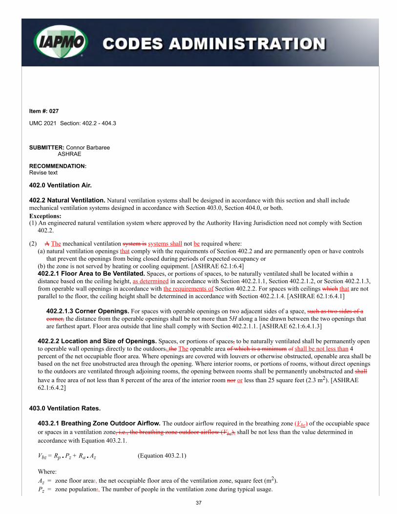
Proposals
Edit Proposal
Item #: 027
UMC 2021 Section: 402.2 - 404.3
SUBMITTER: Connor BarbareeASHRAE
RECOMMENDATION:Revise text
402.0 Ventilation Air.
402.2 Natural Ventilation. Natural ventilation systems shall be designed in accordance with this section and shall include mechanical ventilation systems designed in accordance with Section 403.0, Section 404.0, or both.Exceptions:(1) An engineered natural ventilation system where approved by the Authority Having Jurisdiction need not comply with Section
402.2.
(2) A The mechanical ventilation system is systems shall not be required where:(a) natural ventilation openings that comply with the requirements of Section 402.2 and are permanently open or have controls
that prevent the openings from being closed during periods of expected occupancy or(b) the zone is not served by heating or cooling equipment. [ASHRAE 62.1:6.4]402.2.1 Floor Area to Be Ventilated. Spaces, or portions of spaces, to be naturally ventilated shall be located within adistance based on the ceiling height, as determined in accordance with Section 402.2.1.1, Section 402.2.1.2, or Section 402.2.1.3,from operable wall openings in accordance with the requirements of Section 402.2.2. For spaces with ceilings which that are notparallel to the floor, the ceiling height shall be determined in accordance with Section 402.2.1.4. [ASHRAE 62.1:6.4.1]
402.2.1.3 Corner Openings. For spaces with operable openings on two adjacent sides of a space, such as two sides of acorner, the distance from the operable openings shall be not more than 5H along a line drawn between the two openings thatare farthest apart. Floor area outside that line shall comply with Section 402.2.1.1. [ASHRAE 62.1:6.4.1.3]
402.2.2 Location and Size of Openings. Spaces, or portions of spaces, to be naturally ventilated shall be permanently opento operable wall openings directly to the outdoors,.the The openable area of which is a minimum of shall be not less than 4percent of the net occupiable floor area. Where openings are covered with louvers or otherwise obstructed, openable area shall bebased on the net free unobstructed area through the opening. Where interior rooms, or portions of rooms, without direct openingsto the outdoors are ventilated through adjoining rooms, the opening between rooms shall be permanently unobstructed and shallhave a free area of not less than 8 percent of the area of the interior room nor or less than 25 square feet (2.3 m2). [ASHRAE62.1:6.4.2]
403.0 Ventilation Rates.
403.2.1 Breathing Zone Outdoor Airflow. The outdoor airflow required in the breathing zone (Vbz) of the occupiable spaceor spaces in a ventilation zone, i.e., the breathing zone outdoor airflow (Vbz), shall be not less than the value determined inaccordance with Equation 403.2.1.
Vbz = Rp • Pz + Ra • Az (Equation 403.2.1)
Where:Az = zone floor area:, the net occupiable floor area of the ventilation zone, square feet (m2).Pz = zone population:, The number of people in the ventilation zone during typical usage.
37
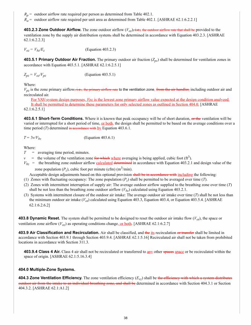
Rp = outdoor airflow rate required per person as determined from Table 402.1.Ra = outdoor airflow rate required per unit area as determined from Table 402.1. [ASHRAE 62.1:6.2.2.1]
403.2.3 Zone Outdoor Airflow. The zone outdoor airflow (Voz), i.e., the outdoor airflow rate that shall be provided to theventilation zone by the supply air distribution system, shall be determined in accordance with Equation 403.2.3. [ASHRAE62.1:6.2.2.3]
Voz = Vbz/Ez (Equation 403.2.3)
403.5.1 Primary Outdoor Air Fraction. The primary outdoor air fraction (Zpz) shall be determined for ventilation zones inaccordance with Equation 403.5.1. [ASHRAE 62.1:6.2.5.1]
Zpz = Voz/Vpz (Equation 403.5.1)
Where:Vpz is the zone primary airflow, i.e., the primary airflow rate to the ventilation zone, from the air handler, including outdoor air andrecirculated air. For VAV-system design purposes, Vpz is the lowest zone primary airflow value expected at the design condition analyzed. It shall be permitted to determine these parameters for only selected zones as outlined in Section 404.0. [ASHRAE62.1:6.2.5.1]
403.6.1 Short-Term Conditions. Where it is known that peak occupancy will be of short duration, or the ventilation will bevaried or interrupted for a short period of time, or both, the design shall be permitted to be based on the average conditions over atime period (T) determined in accordance with by Equation 403.6.1.
T = 3v/Vbz (Equation 403.6.1)
Where:T = averaging time period, minutes.v = the volume of the ventilation zone for which where averaging is being applied, cubic foot (ft3).Vbz = the breathing zone outdoor airflow calculated determined in accordance with Equation 403.2.1 and design value of the
zone population (Pz), cubic foot per minute (cfm) (m3/min).Acceptable design adjustments based on this optional provision shall be in accordance with including the following:
(1) Zones with fluctuating occupancy: The zone population (Pz) shall be permitted to be averaged over time (T).(2) Zones with intermittent interruption of supply air: The average outdoor airflow supplied to the breathing zone over time (T)
shall be not less than the breathing zone outdoor airflow (Vbz) calculated using Equation 403.2.1.(3) Systems with intermittent closure of the outdoor air intake: The average outdoor air intake over time (T) shall be not less than
the minimum outdoor air intake (Vot) calculated using Equation 403.3, Equation 403.4, or Equation 403.5.4. [ASHRAE62.1:6.2.6.2]
403.8 Dynamic Reset. The system shall be permitted to be designed to reset the outdoor air intake flow (Vot), the space orventilation zone airflow (Voz) as operating conditions change, or both. [ASHRAE 62.1:6.2.7]
403.9 Air Classification and Recirculation. Air shall be classified, and the its recirculation or transfer shall be limited inaccordance with Section 403.9.1 through Section 403.9.4. [ASHRAE 62.1:5.16] Recirculated air shall not be taken from prohibitedlocations in accordance with Section 311.3.
403.9.4 Class 4 Air. Class 4 air shall not be recirculated or transferred to any other spaces space or be recirculated within thespace of origin. [ASHRAE 62.1:5.16.3.4]
404.0 Multiple-Zone Systems.
404.3 Zone Ventilation Efficiency. The zone ventilation efficiency (Evz) shall be the efficiency with which a system distributesoutdoor air from the intake to an individual breathing zone, and shall be determined in accordance with Section 404.3.1 or Section404.3.2. [ASHRAE 62.1:A1.2]
38
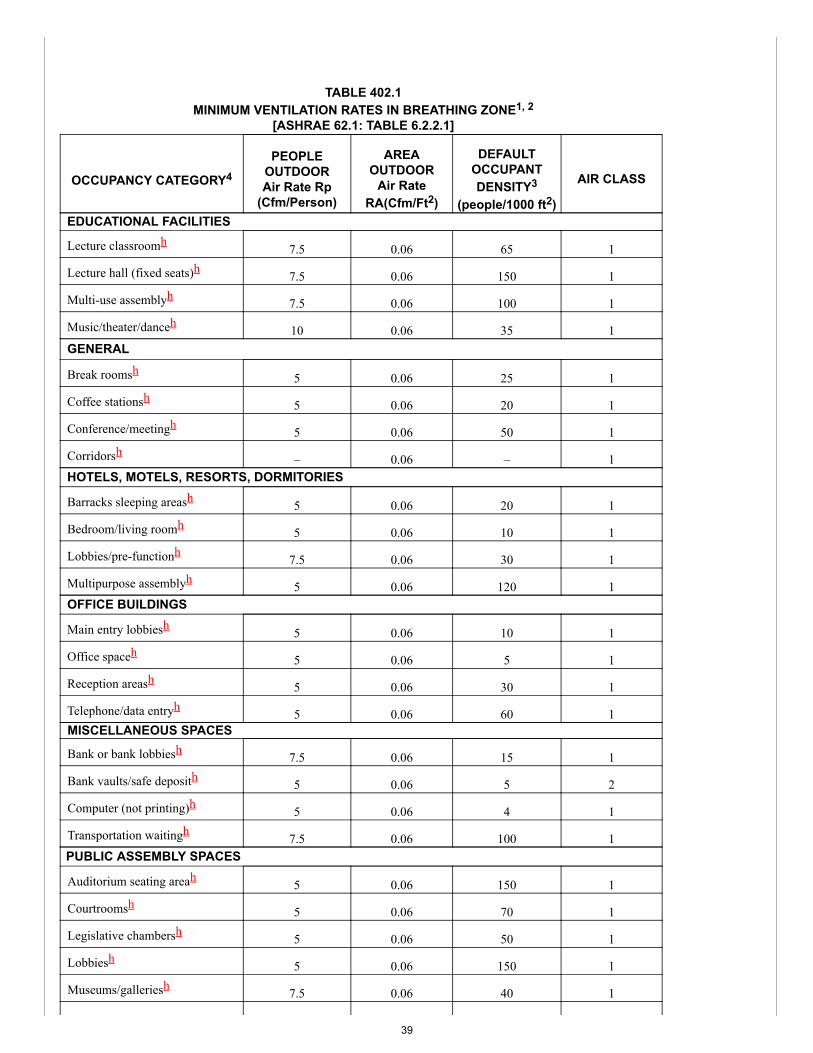
TABLE 402.1MINIMUM VENTILATION RATES IN BREATHING ZONE1, 2
[ASHRAE 62.1: TABLE 6.2.2.1]
OCCUPANCY CATEGORY4
PEOPLEOUTDOORAir Rate Rp
(Cfm/Person)
AREAOUTDOOR
Air RateRA(Cfm/Ft2)
DEFAULTOCCUPANTDENSITY3
(people/1000 ft2)
AIR CLASS
EDUCATIONAL FACILITIES
Lecture classroomh 7.5 0.06 65 1
Lecture hall (fixed seats)h 7.5 0.06 150 1
Multi-use assemblyh 7.5 0.06 100 1
Music/theater/danceh 10 0.06 35 1GENERAL
Break roomsh 5 0.06 25 1
Coffee stationsh 5 0.06 20 1
Conference/meetingh 5 0.06 50 1
Corridorsh – 0.06 – 1HOTELS, MOTELS, RESORTS, DORMITORIES
Barracks sleeping areash 5 0.06 20 1
Bedroom/living roomh 5 0.06 10 1
Lobbies/pre-functionh 7.5 0.06 30 1
Multipurpose assemblyh 5 0.06 120 1OFFICE BUILDINGS
Main entry lobbiesh 5 0.06 10 1
Office spaceh 5 0.06 5 1
Reception areash 5 0.06 30 1
Telephone/data entryh 5 0.06 60 1MISCELLANEOUS SPACES
Bank or bank lobbiesh 7.5 0.06 15 1
Bank vaults/safe deposith 5 0.06 5 2
Computer (not printing)h 5 0.06 4 1
Transportation waitingh 7.5 0.06 100 1PUBLIC ASSEMBLY SPACES
Auditorium seating areah 5 0.06 150 1
Courtroomsh 5 0.06 70 1
Legislative chambersh 5 0.06 50 1
Lobbiesh 5 0.06 150 1
Museums/galleriesh 7.5 0.06 40 1
39
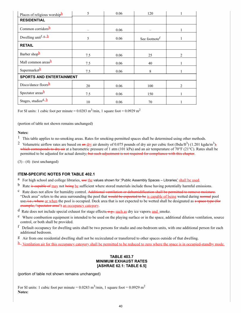
Places of religious worshiph 5 0.06 120 1
RESIDENTIAL
Common corridorsh – 0.06 – 1
Dwelling unitf, g, h 5 0.06 See footnotef 1
RETAIL
Barber shoph 7.5 0.06 25 2
Mall common areash 7.5 0.06 40 1
Supermarketh 7.5 0.06 8 1SPORTS AND ENTERTAINMENT
Disco/dance floorsh 20 0.06 100 2
Spectator areash 7.5 0.06 150 1
Stages, studiosd, h 10 0.06 70 1
For SI units: 1 cubic foot per minute = 0.0283 m3/min, 1 square foot = 0.0929 m2
(portion of table not shown remains unchanged)
Notes:1 This table applies to no-smoking areas. Rates for smoking-permitted spaces shall be determined using other methods.2 Volumetric airflow rates are based on an dry air density of 0.075 pounds of dry air per cubic foot (lbda/ft3) (1.201 kgda/m3),
which corresponds to dry air at a barometric pressure of 1 atm (101 kPa) and an air temperature of 70°F (21°C). Rates shall bepermitted to be adjusted for actual density, but such adjustment is not required for compliance with this chapter.
(3) - (4) (text unchanged)
ITEM-SPECIFIC NOTES FOR TABLE 402.1a For high school and college libraries, use the values shown for “Public Assembly Spaces – Libraries” shall be used.b Rate is capable of may not being be sufficient where stored materials include those having potentially harmful emissions.c Rate does not allow for humidity control. Additional ventilation or dehumidification shall be permitted to remove moisture.
“Deck area” refers to the area surrounding the pool that would be expected to be is capable of being wetted during normal pooluse, i.e., where or when the pool is occupied. Deck area that is not expected to be wetted shall be designated as a space type (forexample, “spectator area”) an occupancy category.
d Rate does not include special exhaust for stage effects, e.g., such as dry ice vapors, and smoke.e Where combustion equipment is intended to be used on the playing surface or in the space, additional dilution ventilation, source
control, or both shall be provided.f Default occupancy for dwelling units shall be two persons for studio and one-bedroom units, with one additional person for each
additional bedroom.g Air from one residential dwelling shall not be recirculated or transferred to other spaces outside of that dwelling.h Ventilation air for this occupancy category shall be permitted to be reduced to zero where the space is in occupied-standby mode.
TABLE 403.7MINIMUM EXHAUST RATES[ASHRAE 62.1: TABLE 6.5]
(portion of table not shown remains unchanged)
For SI units: 1 cubic foot per minute = 0.0283 m3/min, 1 square foot = 0.0929 m2
Notes:
40
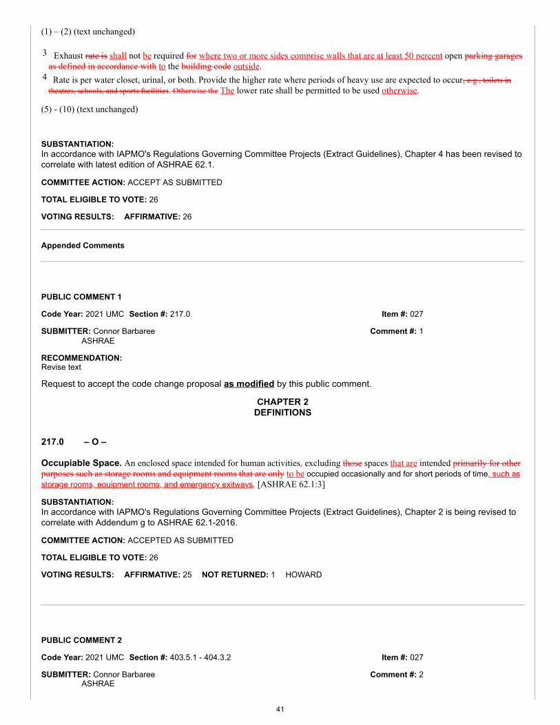
Item #: 027
Item #: 027
Comment #: 1
Comment #: 2
(1) – (2) (text unchanged)
3 Exhaust rate is shall not be required for where two or more sides comprise walls that are at least 50 percent open parking garagesas defined in accordance with to the building code outside.
4 Rate is per water closet, urinal, or both. Provide the higher rate where periods of heavy use are expected to occur, e.g., toilets intheatres, schools, and sports facilities. Otherwise the The lower rate shall be permitted to be used otherwise.
(5) - (10) (text unchanged)
SUBSTANTIATION:In accordance with IAPMO's Regulations Governing Committee Projects (Extract Guidelines), Chapter 4 has been revised tocorrelate with latest edition of ASHRAE 62.1.
COMMITTEE ACTION: ACCEPT AS SUBMITTED
TOTAL ELIGIBLE TO VOTE: 26
VOTING RESULTS: AFFIRMATIVE: 26
Appended Comments
Edit Comment
PUBLIC COMMENT 1
Code Year: 2021 UMC Section #: 217.0
SUBMITTER: Connor BarbareeASHRAE
RECOMMENDATION:Revise text
Request to accept the code change proposal as modified by this public comment.
CHAPTER 2DEFINITIONS
217.0 – O –
Occupiable Space. An enclosed space intended for human activities, excluding those spaces that are intended primarily for otherpurposes such as storage rooms and equipment rooms that are only to be occupied occasionally and for short periods of time, such asstorage rooms, equipment rooms, and emergency exitways. [ASHRAE 62.1:3]
SUBSTANTIATION:In accordance with IAPMO's Regulations Governing Committee Projects (Extract Guidelines), Chapter 2 is being revised tocorrelate with Addendum g to ASHRAE 62.1-2016.
COMMITTEE ACTION: ACCEPTED AS SUBMITTED
TOTAL ELIGIBLE TO VOTE: 26
VOTING RESULTS: AFFIRMATIVE: 25 NOT RETURNED: 1 HOWARD
Edit Comment
PUBLIC COMMENT 2
Code Year: 2021 UMC Section #: 403.5.1 - 404.3.2
SUBMITTER: Connor BarbareeASHRAE
41
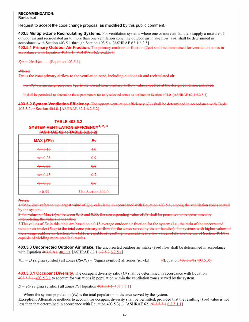
RECOMMENDATION:Revise text
Request to accept the code change proposal as modified by this public comment.
403.5 Multiple-Zone Recirculating Systems. For ventilation systems where one or more air handlers supply a mixture ofoutdoor air and recirculated air to more than one ventilation zone, the outdoor air intake flow (Vot) shall be determined inaccordance with Section 403.5.1 through Section 403.5.4. [ASHRAE 62.1:6.2.5]403.5.1 Primary Outdoor Air Fraction. The primary outdoor air fraction (Zpz) shall be determined for ventilation zones inaccordance with Equation 403.5.1. [ASHRAE 62.1:6.2.5.1]
Zpz = Voz/Vpz (Equation 403.5.1)
Where:Vpz is the zone primary airflow to the ventilation zone, including outdoor air and recirculated air.
For VAV-system design purposes, Vpz is the lowest zone primary airflow value expected at the design condition analyzed.
It shall be permitted to determine these parameters for only selected zones as outlined in Section 404.0. [ASHRAE 62.1:6.2.5.1]
403.5.2 System Ventilation Efficiency. The system ventilation efficiency (Ev) shall be determined in accordance with Table403.5.2 or Section 404.0. [ASHRAE 62.1:6.2.5.2]
TABLE 403.5.2SYSTEM VENTILATION EFFICIENCY1, 2, 3
[ASHRAE 62.1: TABLE 6.2.5.2]
MAX (ZPz) Ev
</= 0.15 1.0
</= 0.25 0.9
</= 0.35 0.8
</= 0.45 0.7
</= 0.55 0.6
> 0.55 Use Section 404.0
Notes:1 “Max Zpz” refers to the largest value of Zpz, calculated in accordance with Equation 403.5.1, among the ventilation zones servedby the system.2 For values of Max (Zpz) between 0.15 and 0.55, the corresponding value of Ev shall be permitted to be determined byinterpolating the values in the table.3 The values of Ev in this table are based on a 0.15 average outdoor air fraction for the system (i.e., the ratio of the uncorrectedoutdoor air intake (Vou) to the total zone primary airflow for the zones served by the air handler). For systems with higher values ofthe average outdoor air fraction, this table is capable of resulting in unrealistically low values of Ev and the use of Section 404.0 iscapable of yielding more practical results.
403.5.3 Uncorrected Outdoor Air Intake. The uncorrected outdoor air intake (Vou) flow shall be determined in accordancewith Equation 403.5.3(1) 403.5.3. [ASHRAE 62.1:6.2.5.3 6.2.5.1]
Vou = D (Sigma symbol) all zones (Rp•Pz) + (Sigma symbol) all zones (Ra•Az) [(Equation 403.5.3(1) 403.5.3)]
403.5.3.1 Occupant Diversity. The occupant diversity ratio (D) shall be determined in accordance with Equation403.5.3(2) 403.5.3.1 to account for variations in population within the ventilation zones served by the system.
D = Ps/ (Sigma symbol) all zones Pz [Equation 403.5.3(2) 403.5.3.1]
Where the system population (Ps) is the total population in the area served by the system.Exception: Alternative methods to account for occupant diversity shall be permitted, provided that the resulting (Vou) value is notless than that determined in accordance with Equation 403.5.3(1). [ASHRAE 62.1:6.2.5.3.1 6.2.5.1.1]
42
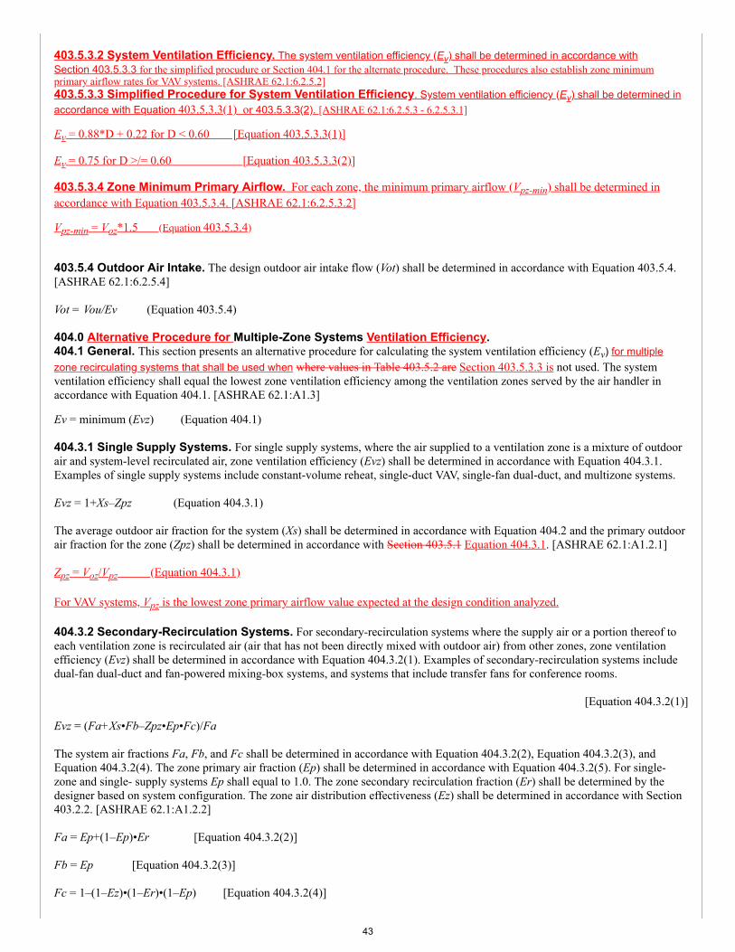
403.5.3.2 System Ventilation Efficiency. The system ventilation efficiency (Ev) shall be determined in accordance withSection 403.5.3.3 for the simplified procudure or Section 404.1 for the alternate procedure. These procedures also establish zone minimumprimary airflow rates for VAV systems. [ASHRAE 62.1:6.2.5.2]403.5.3.3 Simplified Procedure for System Ventilation Efficiency. System ventilation efficiency (Ev) shall be determined inaccordance with Equation 403.5.3.3(1) or 403.5.3.3(2). [ASHRAE 62.1:6.2.5.3 - 6.2.5.3.1]
Ev = 0.88*D + 0.22 for D < 0.60 [Equation 403.5.3.3(1)]
Ev = 0.75 for D >/= 0.60 [Equation 403.5.3.3(2)]
403.5.3.4 Zone Minimum Primary Airflow. For each zone, the minimum primary airflow (Vpz-min) shall be determined inaccordance with Equation 403.5.3.4. [ASHRAE 62.1:6.2.5.3.2]
Vpz-min = Voz*1.5 (Equation 403.5.3.4)
403.5.4 Outdoor Air Intake. The design outdoor air intake flow (Vot) shall be determined in accordance with Equation 403.5.4.[ASHRAE 62.1:6.2.5.4]
Vot = Vou/Ev (Equation 403.5.4)
404.0 Alternative Procedure for Multiple-Zone Systems Ventilation Efficiency.404.1 General. This section presents an alternative procedure for calculating the system ventilation efficiency (Ev) for multiplezone recirculating systems that shall be used when where values in Table 403.5.2 are Section 403.5.3.3 is not used. The systemventilation efficiency shall equal the lowest zone ventilation efficiency among the ventilation zones served by the air handler inaccordance with Equation 404.1. [ASHRAE 62.1:A1.3]
Ev = minimum (Evz) (Equation 404.1)
404.3.1 Single Supply Systems. For single supply systems, where the air supplied to a ventilation zone is a mixture of outdoorair and system-level recirculated air, zone ventilation efficiency (Evz) shall be determined in accordance with Equation 404.3.1.Examples of single supply systems include constant-volume reheat, single-duct VAV, single-fan dual-duct, and multizone systems.
Evz = 1+Xs–Zpz (Equation 404.3.1)
The average outdoor air fraction for the system (Xs) shall be determined in accordance with Equation 404.2 and the primary outdoorair fraction for the zone (Zpz) shall be determined in accordance with Section 403.5.1 Equation 404.3.1. [ASHRAE 62.1:A1.2.1]
Zpz = Voz/Vpz (Equation 404.3.1)
For VAV systems, Vpz is the lowest zone primary airflow value expected at the design condition analyzed.
404.3.2 Secondary-Recirculation Systems. For secondary-recirculation systems where the supply air or a portion thereof toeach ventilation zone is recirculated air (air that has not been directly mixed with outdoor air) from other zones, zone ventilationefficiency (Evz) shall be determined in accordance with Equation 404.3.2(1). Examples of secondary-recirculation systems includedual-fan dual-duct and fan-powered mixing-box systems, and systems that include transfer fans for conference rooms.
[Equation 404.3.2(1)]
Evz = (Fa+Xs•Fb–Zpz•Ep•Fc)/Fa
The system air fractions Fa, Fb, and Fc shall be determined in accordance with Equation 404.3.2(2), Equation 404.3.2(3), andEquation 404.3.2(4). The zone primary air fraction (Ep) shall be determined in accordance with Equation 404.3.2(5). For single-zone and single- supply systems Ep shall equal to 1.0. The zone secondary recirculation fraction (Er) shall be determined by thedesigner based on system configuration. The zone air distribution effectiveness (Ez) shall be determined in accordance with Section403.2.2. [ASHRAE 62.1:A1.2.2]
Fa = Ep+(1–Ep)•Er [Equation 404.3.2(2)]
Fb = Ep [Equation 404.3.2(3)]
Fc = 1–(1–Ez)•(1–Er)•(1–Ep) [Equation 404.3.2(4)]
43
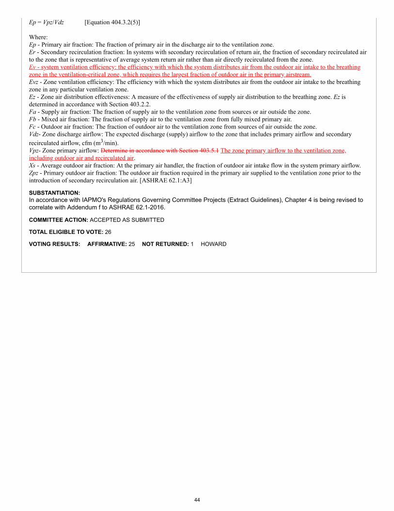
Ep = Vpz/Vdz [Equation 404.3.2(5)]
Where:Ep - Primary air fraction: The fraction of primary air in the discharge air to the ventilation zone.Er - Secondary recirculation fraction: In systems with secondary recirculation of return air, the fraction of secondary recirculated airto the zone that is representative of average system return air rather than air directly recirculated from the zone.Ev - system ventilation efficiency: the efficiency with which the system distributes air from the outdoor air intake to the breathingzone in the ventilation-critical zone, which requires the largest fraction of outdoor air in the primary airstream.Evz - Zone ventilation efficiency: The efficiency with which the system distributes air from the outdoor air intake to the breathingzone in any particular ventilation zone.Ez - Zone air distribution effectiveness: A measure of the effectiveness of supply air distribution to the breathing zone. Ez isdetermined in accordance with Section 403.2.2.Fa - Supply air fraction: The fraction of supply air to the ventilation zone from sources or air outside the zone.Fb - Mixed air fraction: The fraction of supply air to the ventilation zone from fully mixed primary air.Fc - Outdoor air fraction: The fraction of outdoor air to the ventilation zone from sources of air outside the zone.Vdz- Zone discharge airflow: The expected discharge (supply) airflow to the zone that includes primary airflow and secondaryrecirculated airflow, cfm (m3/min).Vpz- Zone primary airflow: Determine in accordance with Section 403.5.1 The zone primary airflow to the ventilation zone,including outdoor air and recirculated air.Xs - Average outdoor air fraction: At the primary air handler, the fraction of outdoor air intake flow in the system primary airflow.Zpz - Primary outdoor air fraction: The outdoor air fraction required in the primary air supplied to the ventilation zone prior to theintroduction of secondary recirculation air. [ASHRAE 62.1:A3]
SUBSTANTIATION:In accordance with IAPMO's Regulations Governing Committee Projects (Extract Guidelines), Chapter 4 is being revised tocorrelate with Addendum f to ASHRAE 62.1-2016.
COMMITTEE ACTION: ACCEPTED AS SUBMITTED
TOTAL ELIGIBLE TO VOTE: 26
VOTING RESULTS: AFFIRMATIVE: 25 NOT RETURNED: 1 HOWARD
44
Item #: 029
Comment #: 1
Proposals
Edit Proposal
Item #: 029
UMC 2021 Section: 502.2.1
SUBMITTER: Scott WaylandASHRAE
RECOMMENDATION:Revise text
502.0 Termination.
502.2 Termination of Exhaust Ducts. (remaining text unchanged)
502.2.1 Environmental Air Ducts. Environmental air duct exhaust shall terminate not less than 3 feet (914 mm) from a property line, 10 feet (3048 mm) from a forced air inlet, and 3 feet (914 mm) from openings into the building. Environmental exhaust ducts shall not discharge onto a public walkway at an elevation less than 10 feet (3048 mm) above adjoining grade.
SUBSTANTIATION:The code section is too prohibitive towards conventional design practice where the only place a tenant can discharge economizer air is out the front façade of a suite in a mixed use and/or multistory building.
Additionally, the statement is too ambiguous for a local AHJ to enforce. the elements in the statement are not defined anywhere in the UMC or the architectural code, nor do you cross reference.
COMMITTEE ACTION: REJECT
COMMITTEE STATEMENT:No technical substantiation was provided to merit such change.
TOTAL ELIGIBLE TO VOTE: 26
VOTING RESULTS: AFFIRMATIVE: 21 NEGATIVE: 4 NOT RETURNED: 1 HOWARD
EXPLANATION OF NEGATIVE:
KOERBER: The proposal attempts to address the issue by allowing exhaust at a height at least equal to the 10 foot distance to inlets.
P. TRAFTON: At 10' above grade, environmental exhaust does not create any conditions that would affect those in a public walkway.
HEINE: No substantiation was provided.
SMITH: The proposed change provides the best effort at a usable height.
Appended Comments
Edit Comment
PUBLIC COMMENT 1
Code Year: 2021 UMC Section #: 502.2.1
SUBMITTER: Ralph Koerber
45
Item #: 029
Comment #: 2
ATCO Rubber Products, Inc.Rep. Air Duct Council
RECOMMENDATION:Revise text
Request to replace the code change proposal by this public comment.
502.0 Termination.
502.2 Termination of Exhaust Ducts. (remaining text unchanged)502.2.1 Environmental Air Ducts. Environmental air duct exhaust shall terminate not less than 3 feet (914 mm) from a propertyline, 10 feet (3048 mm) from a forced air inlet, 10 feet (3048 mm) above a public walkway, and 3 feet (914 mm) from openings into thebuilding. Environmental exhaust ducts shall not be directed discharge onto a public walkways.
SUBSTANTIATION:I believe the original proposal had merit. The current text already places a minimum 10 feet discharge distance from a forcedair inlet and from openings into the building. It seems the same distance limitation would be warranted above a walkwaywhen the air is not directed specifically onto the walkway. I propose this text as alternative language. This would beconsistent with comparable code language allowing exhaust discharge locations at "10 feet above adjoining grade" but stillnot directed onto a public walkway.
COMMITTEE ACTION: ACCEPTED AS SUBMITTED
TOTAL ELIGIBLE TO VOTE: 26
VOTING RESULTS: AFFIRMATIVE: 25 NOT RETURNED: 1 HOWARD
Edit Comment
PUBLIC COMMENT 2
Code Year: 2021 UMC Section #: 502.2.1
SUBMITTER: Keith BlazerSelf
RECOMMENDATION:Revise text
Request to accept the code change proposal as submitted by this public comment.
SUBSTANTIATION:At 10 feet above grade, the environmental exhaust would not create any negative or harmful conditions that would affectthose in a public walkway. This should be accepted as submitted.
COMMITTEE ACTION: ACCEPTED AS AMENDED
Amend comment as follows:
502.0 Termination.
502.2 Termination of Exhaust Ducts. (remaining text unchanged)
502.2.1 Environmental Air Ducts. Environmental air duct exhaust shall terminate not less than 3 feet (914 mm) from aproperty line, 10 feet (3048 mm) from a forced air inlet, 10 feet (3048 mm) above a public walkway, and 3 feet (914 mm)from openings into the building. The discharge of Eenvironmental exhaust ducts shall not discharge be directed onto apublic walkway at an elevation less than 10 feet (3048 mm) above adjoining grade.
COMMITTEE STATEMENT:The original proposal had merit. The current text already places a minimum 10 feet discharge distance from a forced air inletand from openings into the building. It seems the same distance limitation would be warranted above a walkway when the airis not directed specifically onto the walkway. This would be consistent with comparable code language allowing exhaustdischarge locations at "10 feet above adjoining grade" but still not directed onto a public walkway, therefore, the lastsentence is also being clarified by changing the term "discharge" to "be directed."
TOTAL ELIGIBLE TO VOTE: 26
VOTING RESULTS: AFFIRMATIVE: 25 NOT RETURNED: 1 HOWARD
46
Item #: 032
Comment #: 1
Proposals
Edit Proposal
Item #: 032
UMC 2021 Section: 505.6.1
SUBMITTER: Reinhard HanselkaMenlo Park Fire Protection District
RECOMMENDATION:Revise text
505.0 Product-Conveying Systems.
505.6 Fire Dampers. (remaining text unchanged)
505.6.1 Prohibited. Fire Dampers shall not be installed if the material being exhausted is Ttoxic, Highly Toxic, Unstable Reactive, Corrosive, Flammable, or a virulent Biologics and if a risk evaluation indicates that the toxic hazard imposed is greater than the fire hazard. [NFPA 91:4.2.10]
SUBSTANTIATION:This section was rewritten based on the Building and Fire Code hazard risk classes and the recognition that a closed damper will cause a potential great risk to the occupants within the room served by that specific exhaust system.
COMMITTEE ACTION: REJECT
COMMITTEE STATEMENT:The proposed language is vague and ambiguous. Furthermore, the proposed language does not improve the code.
TOTAL ELIGIBLE TO VOTE: 26
VOTING RESULTS: AFFIRMATIVE: 23 NEGATIVE: 3
EXPLANATION OF NEGATIVE:
HEINE: There is no improvement to the code and is very vague.
MACNEVIN: Proposed language included additional types of hazardous material descriptions that were substantiated; new language improves the section.
A. TRAFTON: New language improves the section.
Appended Comments
Edit Comment
PUBLIC COMMENT 1
Code Year: 2021 UMC Section #: 505.6.1
SUBMITTER: Keith BlazerSelf
RECOMMENDATION:Revise text
47
Request to replace the code change proposal by this public comment.
505.6.1 Prohibited. Fire Dampers shall not be installed if the material being exhausted is toxic, reactive, corrosive, orflammable and if a risk evaluation indicates that the toxic hazard imposed by the exhaust material is greater than the fire hazard.[{NFPA 91:4.2.10}]
SUBSTANTIATION:Occupational Health & Safety states, “a substance is defined as hazardous if it has one or more of the followingcharacteristics: flammable, corrosive, toxic, or reactive.” The original proposal has been modified to remove the unnecessaryadjectives before the hazard type, only keeping the name of the specific hazard. This change improves the code by addingthe specific exhaust types and characteristics where fire dampers are not to be installed. Toxic exhaust is not the onlyexhaust type that does not need a fire damper; reactive, corrosive, or flammable exhaust also do not need a fire damper.Listing these hazardous characteristics is beneficial and necessary for public health and safety and to determine when firedampers must not be installed.
COMMITTEE ACTION: REJECT
COMMITTEE STATEMENT:The comment is being rejected as a copy of NFPA 91 was not provided for the Committee to review.
TOTAL ELIGIBLE TO VOTE: 26
VOTING RESULTS: AFFIRMATIVE: 25 NOT RETURNED: 1 HOWARD
48
Proposals
Edit Proposal
Item #: 033
UMC 2021 Section: 506.1, 506.2, Table 1701.1, Table 1701.2
SUBMITTER: David DiasSheet Metal Workers Local 104
RECOMMENDATION:Revise text
506.0 Product-Conveying Ducts.506.1 Materials. Materials used in product-conveying duct systems shall be suitable for the intended use and shall be of metal. Exceptions:(1) – (2) (remaining text unchanged)(3) Ducts used in central vacuum cleaning systems within a dwelling unit shall be constructed of materials in accordance with the applicable standards referenced in Chapter 17 ASTM F2158. Penetrations of fire walls or floor-ceiling or roof-ceiling assemblies shall be in accordance with the building code.
(remaining text unchanged)
506.2 Construction. Ducts used for conveying products shall be airtight construction as approved by the Authority Having Jurisdiction, and shall not have openings other than those required for operation and maintenance of the system. Ducts constructed of steel shall comply with Table 506.2(1) or Table 506.2(2).Exceptions:(1) (remaining text unchanged)(2) Ducts used in central vacuuming systems within a dwelling unit shall be constructed of materials in accordance with theapplicable standards referenced in Chapter 17 ASTM F2158. Penetrations of fire-resistive walls or floor-ceiling or roof-ceilingassemblies shall be in accordance with the building code. Copper or ferrous pipes or conduit extending from within the separationbetween a garage and dwelling unit to the central vacuum unit shall be permitted to be used.
(remaining text unchanged)
TABLE 1701.1REFERENCED STANDARDS
STANDARD NUMBER STANDARD TITLE APPLICATION REFERENCEDSECTION
ASTM F2158-2008 (R2016) Residential Central-Vacuum Tube and Fittings Exhaust Systems 506.1, 506.2
(portions of table not shown remain unchanged)
Note: ASTM F2158 meets the requirements for mandatory reference standards in accordance with Section 3-3.7.1 of IAPMO’s Regulations Governing Committee Projects.
49
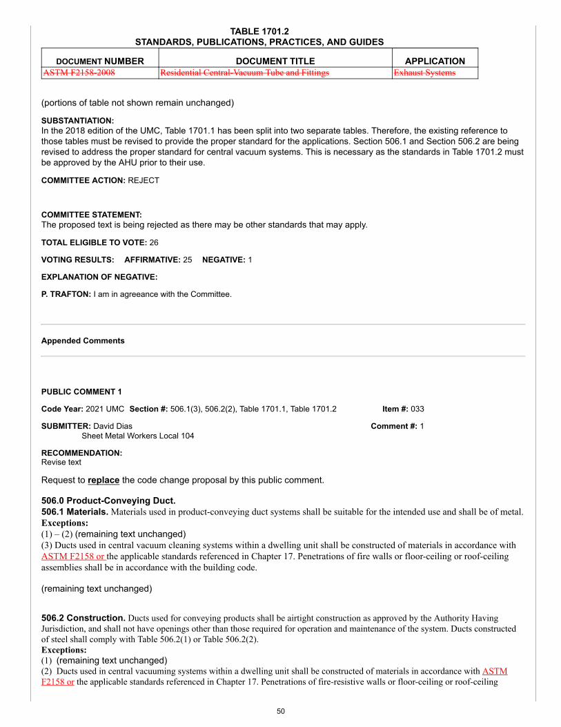
Item #: 033
Comment #: 1
TABLE 1701.2STANDARDS, PUBLICATIONS, PRACTICES, AND GUIDES
DOCUMENT NUMBER DOCUMENT TITLE APPLICATIONASTM F2158-2008 Residential Central-Vacuum Tube and Fittings Exhaust Systems
(portions of table not shown remain unchanged)
SUBSTANTIATION:In the 2018 edition of the UMC, Table 1701.1 has been split into two separate tables. Therefore, the existing reference tothose tables must be revised to provide the proper standard for the applications. Section 506.1 and Section 506.2 are beingrevised to address the proper standard for central vacuum systems. This is necessary as the standards in Table 1701.2 mustbe approved by the AHU prior to their use.
COMMITTEE ACTION: REJECT
COMMITTEE STATEMENT:The proposed text is being rejected as there may be other standards that may apply.
TOTAL ELIGIBLE TO VOTE: 26
VOTING RESULTS: AFFIRMATIVE: 25 NEGATIVE: 1
EXPLANATION OF NEGATIVE:
P. TRAFTON: I am in agreeance with the Committee.
Appended Comments
Edit Comment
PUBLIC COMMENT 1
Code Year: 2021 UMC Section #: 506.1(3), 506.2(2), Table 1701.1, Table 1701.2
SUBMITTER: David DiasSheet Metal Workers Local 104
RECOMMENDATION:Revise text
Request to replace the code change proposal by this public comment.
506.0 Product-Conveying Duct.506.1 Materials. Materials used in product-conveying duct systems shall be suitable for the intended use and shall be of metal.Exceptions:(1) – (2) (remaining text unchanged)(3) Ducts used in central vacuum cleaning systems within a dwelling unit shall be constructed of materials in accordance withASTM F2158 or the applicable standards referenced in Chapter 17. Penetrations of fire walls or floor-ceiling or roof-ceilingassemblies shall be in accordance with the building code.
(remaining text unchanged)
506.2 Construction. Ducts used for conveying products shall be airtight construction as approved by the Authority HavingJurisdiction, and shall not have openings other than those required for operation and maintenance of the system. Ducts constructedof steel shall comply with Table 506.2(1) or Table 506.2(2).Exceptions:(1) (remaining text unchanged)(2) Ducts used in central vacuuming systems within a dwelling unit shall be constructed of materials in accordance with ASTMF2158 or the applicable standards referenced in Chapter 17. Penetrations of fire-resistive walls or floor-ceiling or roof-ceiling
50
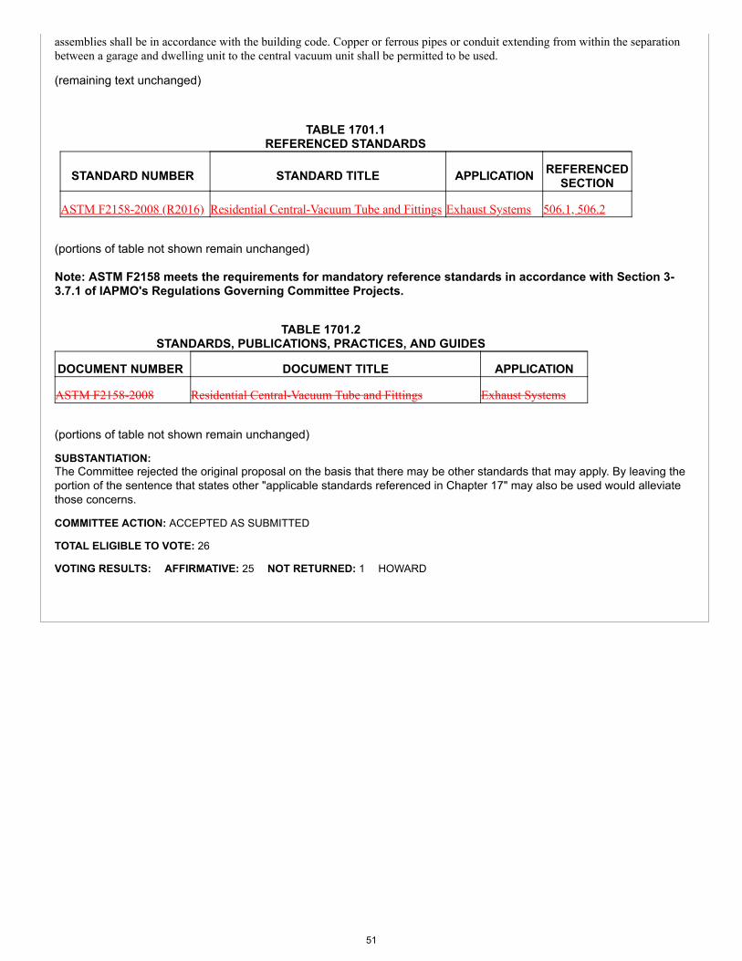
assemblies shall be in accordance with the building code. Copper or ferrous pipes or conduit extending from within the separationbetween a garage and dwelling unit to the central vacuum unit shall be permitted to be used.
(remaining text unchanged)
TABLE 1701.1REFERENCED STANDARDS
STANDARD NUMBER STANDARD TITLE APPLICATION REFERENCEDSECTION
ASTM F2158-2008 (R2016) Residential Central-Vacuum Tube and Fittings Exhaust Systems 506.1, 506.2
(portions of table not shown remain unchanged)
Note: ASTM F2158 meets the requirements for mandatory reference standards in accordance with Section 3-3.7.1 of IAPMO's Regulations Governing Committee Projects.
TABLE 1701.2STANDARDS, PUBLICATIONS, PRACTICES, AND GUIDES
DOCUMENT NUMBER DOCUMENT TITLE APPLICATION
ASTM F2158-2008 Residential Central-Vacuum Tube and Fittings Exhaust Systems
(portions of table not shown remain unchanged)
SUBSTANTIATION:The Committee rejected the original proposal on the basis that there may be other standards that may apply. By leaving theportion of the sentence that states other "applicable standards referenced in Chapter 17" may also be used would alleviatethose concerns.
COMMITTEE ACTION: ACCEPTED AS SUBMITTED
TOTAL ELIGIBLE TO VOTE: 26
VOTING RESULTS: AFFIRMATIVE: 25 NOT RETURNED: 1 HOWARD
51
Item #: 034
Comment #: 1
Proposals
Edit Proposal
Item #: 034
UMC 2021 Section: 506.3
SUBMITTER: David DiasSheet Metal Workers Local 104
RECOMMENDATION:Revise text
506.0 Product-Conveying Ducts.
506.3 Penetrations. Exhaust ducts shall not pass through fire walls, as defined by NFPA 221. [NFPA 91:4.2.11]
SUBSTANTIATION:Section 506.3 should be revised as it is unnecessary to send the end user to NFPA 221 for a definition. The term “fire wall” is already defined in Chapter 2 of the UMC and it reads as follows:
Fire Wall. A wall separating buildings or subdividing a building to prevent the spread of the fire and having a fire resistance rating and structural stability. [NFPA 96:3.3.26]
The definition used in NFPA 221 for “fire wall” is as follows:
3.3.14.6* Fire Wall. A wall separating buildings or subdividing a building to prevent the spread of fire and having afire resistance rating and structural stability.
Therefore, it is apparent that both definitions read the same and it is unnecessary to send the user to a different document.
COMMITTEE ACTION: REJECT
COMMITTEE STATEMENT:The proposed text deletion should remain as it is unnecessary to remove the NFPA 221 reference and NFPA 91 extract since they are needed for enforcement of the code.
TOTAL ELIGIBLE TO VOTE: 26
VOTING RESULTS: AFFIRMATIVE: 25 NEGATIVE: 1
EXPLANATION OF NEGATIVE:
HEINE: It is unnecessary to remove the NFPA 221 reference as it is needed for enforcement.
Appended Comments
Edit Comment
PUBLIC COMMENT 1
Code Year: 2021 UMC Section #: 506.3
SUBMITTER: David DiasSheet Metal Workers Local 104
RECOMMENDATION:Revise text
52
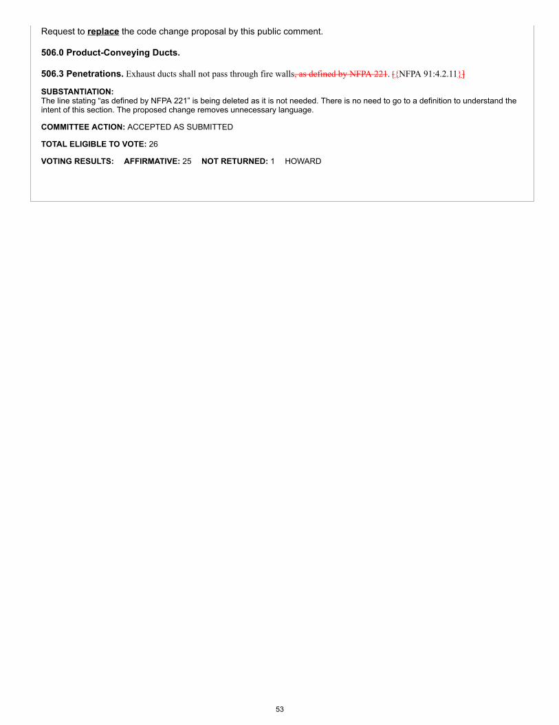
Request to replace the code change proposal by this public comment.
506.0 Product-Conveying Ducts.
506.3 Penetrations. Exhaust ducts shall not pass through fire walls, as defined by NFPA 221. [{NFPA 91:4.2.11}]
SUBSTANTIATION:The line stating “as defined by NFPA 221” is being deleted as it is not needed. There is no need to go to a definition to understand theintent of this section. The proposed change removes unnecessary language.
COMMITTEE ACTION: ACCEPTED AS SUBMITTED
TOTAL ELIGIBLE TO VOTE: 26
VOTING RESULTS: AFFIRMATIVE: 25 NOT RETURNED: 1 HOWARD
53
Item #: 035
Proposals
Edit Proposal
Item #: 035
UMC 2021 Section: 507.1, 519.3
SUBMITTER: Mohamed DanoControl Air Conditioning Corporation
RECOMMENDATION:Revise text
507.0 General Requirements.507.1 Type I Hood Exhaust System. Exhaust systems serving Type I hoods shall comply with Section 507.0 through Section 518.0. Exhaust systems serving Type II hoods shall comply with Section 519.0.
519.0 Type II Hood Exhaust System Requirements.
519.3 Type II Hood Exhaust System Net Airflow. The net airflow for Type II hoods shall be in accordance with Section 508.5.1.5 for light-duty cooking appliances. The net airflow for Type II hoods serving washing machines shall comply with Section 519.3.1.519.3 519.3.1 Dishwashing Appliances. The net airflow for Type II hoods used for dishwashing equipment shall be not lessthan 200 cubic feet per minute (0.094 m3/s) per linear foot (m) of hood length.
(renumber remaining sections)
SUBSTANTIATION:Section 507.1 should be revised to clarify that Type II exhaust systems must comply with Section 519.0. Furthermore, Section 519.0 is being added as currently there is no guidance as to the required exhaust rate for Type II hoods. Section 508.5.1.5 applies to light-duty appliances.
Section 508.5.1.5 states: The minimum net airflow for hoods used for cooking appliances such as gas and electric ovens (including standard, bake, roasting, revolving, retherm, convection, combination convection/steamer, rotisserie, countertop conveyorized baking/finishing, deck, and pastry), discrete element ranges (with or without oven), electric and gas steam-jacketed kettles less than 20 gallons (76 L), electric and gas pasta cookers, electric and gas compartment steamers (both pressure and atmospheric), electric and gas cheese melters, electric and gas tilting skillets (braising pans) electric and gas rotisseries, and electric and gas salamanders shall be in accordance with Table 508.5.1.5.
COMMITTEE ACTION: REJECT
COMMITTEE STATEMENT:The proposed text does not assist the AHJ or installer in regards to Type II hoods.
TOTAL ELIGIBLE TO VOTE: 26
VOTING RESULTS: AFFIRMATIVE: 26
Appended Comments
Edit Comment
PUBLIC COMMENT 1
Code Year: 2021 UMC Section #: 519.3 - 519.3.1
54
Item #: 035
Comment #: 1
Comment #: 2
SUBMITTER: Mohamed DanoControl Air Conditioning CorporationRep. Self
RECOMMENDATION:Revise text
Request to replace the code change proposal by this public comment.
519.0 Type II Hood Exhaust System Requirements.
519.3 Type II Hood Exhaust System Net Airflow. The net airflow for Type II hoods shall be in accordance with Section508.5.1.5 for light-duty cooking appliances. The net airflow for Type II hoods serving washing machines shall comply with Section519.3.1.519.3 519.3.1 Dishwashing Appliances. The net airflow for Type II hoods used for dishwashing equipment shall be not lessthan 200 cubic feet per minute (0.094 m3/s) per linear foot (m) of hood length.
SUBSTANTIATION:Section 519.3 is being added as currently there is no guidance as to the required exhaust rate for Type II hoods. Section508.5.1.5 applies to light-duty appliances. Section 508.5.1.5 states: "The minimum net airflow for hoods used for cookingappliances such as gas and electric ovens (including standard, bake, roasting, revolving, retherm, convection, combinationconvection/steamer, rotisserie, countertop conveyorized baking/finishing, deck, and pastry), discrete element ranges (with orwithout oven), electric and gas steam-jacketed kettles less than 20 gallons (76 L), electric and gas pasta cookers, electricand gas compartment steamers (both pressure and atmospheric), electric and gas cheese melters, electric and gas tiltingskillets (braising pans) electric and gas rotisseries, and electric and gas salamanders shall be in accordance with Table508.5.1.5." The reference to Type I hoods has been removed from the original proposal in Section 507.1 to alleviate anyconcerns about Type II hoods being referenced in a section for Type I hoods.
COMMITTEE ACTION: REJECT
COMMITTEE STATEMENT:The comment is being rejected as the change does not assist the AHJ or installer in the enforcement of the code with regardto Type II hoods.
TOTAL ELIGIBLE TO VOTE: 26
VOTING RESULTS: AFFIRMATIVE: 25 NOT RETURNED: 1 HOWARD
Edit Comment
PUBLIC COMMENT 2
Code Year: 2021 UMC Section #: 507.1, 519.3 - 519.3.1
SUBMITTER: Rudy B. Utulo, PE; Martin EspinosaM & P Consulting Engineers, Inc.
RECOMMENDATION:Revise text
Request to accept the code change proposal as submitted by this public comment.
SUBSTANTIATION:The proposed change greatly assists the AHJ, designer, installer, and end user by clarifying the airflow requirements for TypeII hood exhaust systems. I believe this change will be very beneficial in locating and determining Type II CFM airflowrequirements that currently do not exist in the UMC. The location of this new Section fits well below Section 519.2(Construction of Type II Hoods).
COMMITTEE ACTION: REJECT
COMMITTEE STATEMENT:The comment is being rejected as the change does not assist the AHJ or installer in the enforcement of the code with regardto Type II hoods.
TOTAL ELIGIBLE TO VOTE: 26
VOTING RESULTS: AFFIRMATIVE: 25 NOT RETURNED: 1 HOWARD
55
Item #: 035
Comment #: 3
Edit Comment
PUBLIC COMMENT 3
Code Year: 2021 UMC Section #: 519.1
SUBMITTER: Rudy B. Utulo, PE; Martin EspinosaM & P Consulting Engineers, Inc.
RECOMMENDATION:Revise text
Request to replace the code change proposal by this public comment.
519.0 Type II Hood Exhaust System Requirements.519.1 Where Required. Type II hoods shall be installed above equipment and dishwashers that generate steam, heat, and orproducts of combustion, and where grease or smoke is not present.
SUBSTANTIATION:The current language in Section 519.1 creates confusion. The proposed change from “and” to “or” assists the AHJ, installer,and end user by clarifying where Type II hood exhaust systems are required; where either steam, heat, OR products ofcombustion are generated. The exhaust created under Type II hoods will not always have all of these characteristics at thesame time. Therefore, Type II hoods are required where steam, heat, OR products of combustion are generated.
COMMITTEE ACTION: ACCEPTED AS SUBMITTED
TOTAL ELIGIBLE TO VOTE: 26
VOTING RESULTS: AFFIRMATIVE: 25 NOT RETURNED: 1 HOWARD
56
Item #: 036
Proposals
Edit Proposal
Item #: 036
UMC 2021 Section: 508.1
SUBMITTER: Christopher JensenUL LLC
RECOMMENDATION:Revise text
508.0 Type I Hoods.508.1 Where Required. Type I hoods shall be installed at or above commercial-type deep-fat fryers, broilers, grills, hot-topranges, ovens, barbecues, rotisseries, and similar equipment that emits comparable amounts of smoke or grease in a food-processingestablishment. For the purpose of this section, a food-processing establishment shall include a building or portion thereof used forthe processing of food, but shall not include a dwelling unit.Exceptions:(1) Cooking appliance that is listed in accordance with UL 710B for reduced emissions where the grease discharge does not exceed2.9 E-09 ounces per cubic inch (oz/in3) (5.0E-06 kg/m3) where operated with a total airflow of 500 cubic feet per minute (cfm)(0.236 m3/s).(2) Recirculating systems listed in accordance with UL 710B and installed in accordance with Section 516.0.(3) Downdraft appliance ventilation system listed and installed in accordance with Section 518.0.
SUBSTANTIATION:A downdraft appliance ventilation system that has been listed and installed in accordance with Section 518.0 is alreadyprovided the minimum safety requirements for the exhaust of the smoke and grease, and thus does not require an additionalType I hood above.
COMMITTEE ACTION: REJECT
COMMITTEE STATEMENT:Section 518.0 applies to downdraft appliances and it is not necessary to add downdraft appliances to Section 508.1 as anexception.
TOTAL ELIGIBLE TO VOTE: 26
VOTING RESULTS: AFFIRMATIVE: 25 NEGATIVE: 1
EXPLANATION OF NEGATIVE:
KOERBER: I believe the proposal provides clarity. Also, I believe products should be "listed" where applicable, not just "in accordancewith.”
Appended Comments
Edit Comment
PUBLIC COMMENT 1
Code Year: 2021 UMC Section #: 508.1
57
Item #: 036
Comment #: 1
Comment #: 2
SUBMITTER: Rudy B. Utulo, PE; Martin EspinosaM & P Consulting Engineers, Inc.
RECOMMENDATION:Revise text
Request to replace the code change proposal by this public comment.
508.0 Type I Hoods
508.1 Where Required. Type I hoods shall be installed at or above commercial-type deep-fat fryers, broilers, grills, hot-topranges, ovens, barbecues, rotisseries, and similar equipment that emits comparable amounts of smoke or grease in a food-processingestablishment. For the purpose of this section, a food-processing establishment shall include a building or portion thereof used forthe processing of food, but shall not include a dwelling unit.Exceptions:(1) Cooking appliances that is listed in accordance with UL 710B for reduced emissions where the grease discharge does not exceed2.9 E-09 ounces per cubic inch (oz/in3) (5.0E-06 kg/m3) where operated with a total airflow of 500 cubic feet per minute (cfm)(0.236 m3/s).(2) Recirculating systems listed in accordance with UL 710B and installed in accordance with Section 516.0.(3) Downdraft appliance ventilation systems listed and installed in accordance with Section 518.0.
SUBSTANTIATION:The addition of note (3) to the Exceptions clarifies that a downdraft appliance ventilation system that is listed and installed inaccordance with Section 518.0 already provides the minimum safety requirements for removing smoke and grease, thus notrequiring a Type I hood to be installed. This change assists the AHJ in the proper enforcement of Type I hoods.
COMMITTEE ACTION: REJECT
COMMITTEE STATEMENT:The comment is being rejected as Section 518.0 already applies to downdraft appliances, therefore, provisions for downdraftappliances should not be located in Section 508.0.
TOTAL ELIGIBLE TO VOTE: 26
VOTING RESULTS: AFFIRMATIVE: 24 NEGATIVE: 1 NOT RETURNED: 1 HOWARD
EXPLANATION OF NEGATIVE:
KOERBER: Requirement should be "listed" rather than "in accordance with."
Edit Comment
PUBLIC COMMENT 2
Code Year: 2021 UMC Section #: 508.1
SUBMITTER: Christopher JensenUL LLC
RECOMMENDATION:Revise text
Request to accept the code change proposal as submitted by this public comment.
SUBSTANTIATION:The committee statement for rejection was “Section 518.0 applies to downdraft appliances and it is not necessary to adddowndraft appliances to Section 508.1 as an exception.” Section 508.1 specifies what type of commercial cooking appliancesare required to be installed beneath a Type I hood. Listed Downdraft appliances installed in accordance with Section 518.0do not need to be installed beneath a Type I hood. Section 518.0 does not clearly indicate that these appliances are notrequired to be installed beneath a Type I hood. Adding listed downdraft appliances to the exceptions for commercial cookingequipment that do not require installation beneath a Type I hood will provide clarity for code users.
Exception (1) permits cooking appliances that are in accordance with UL 710B for reduced emissions to be installed withouta Type I hood. For the AHJ to verify that the cooking appliance is in accordance with UL 710B the appliance needs to belisted. This would be consistent with the other methods in the Exceptions to Section 508.1.
58
Item #: 036
Comment #: 3
COMMITTEE ACTION: REJECT
COMMITTEE STATEMENT:The comment is being rejected as Section 518.0 already applies to downdraft appliances, therefore, provisions for downdraftappliances should not be located in Section 508.0.
TOTAL ELIGIBLE TO VOTE: 26
VOTING RESULTS: AFFIRMATIVE: 24 NEGATIVE: 1 NOT RETURNED: 1 HOWARD
EXPLANATION OF NEGATIVE:
CHURCH: The proposed change helps avoid confusion and should be included.
Edit Comment
PUBLIC COMMENT 3
Code Year: 2021 UMC Section #: 508.1
SUBMITTER: Ralph KoerberATCO Rubber Products, Inc.Rep. Air Duct Council
RECOMMENDATION:Revise text
Request to replace the code change proposal by this public comment.
508.0 Type I Hoods.508.1 Where Required. Type I hoods shall be installed at or above commercial-type deep-fat fryers, broilers, grills, hot-topranges, ovens, barbecues, rotisseries, and similar equipment that emits comparable amounts of smoke or grease in a food-processing establishment. For the purpose of this section, a food-processing establishment shall include a building or portion thereofused for the processing of food, but shall not include a dwelling unit.
Exceptions:(1) Cooking appliances that is listed in accordance with UL 710B for reduced emissions where the grease discharge does not exceed2.9 E-09 ounces per cubic inch (oz/in3) (5.0 E-06 kg/m3) where operated with a total airflow of 500 cubic feet per minute (cfm)(0.236 m3/s).(2) Recirculating systems listed in accordance with UL 710B and installed in accordance with Section 516.0.(3) Ventilation systems in accordance with Section 518.0.
SUBSTANTIATION:Using the language "listed in accordance with" for exception (1) brings clarity and consistency to the section. The addition ofexception (3) provides clarity as listed systems covered under Section 518.0 do not require the use of Type I hoods.
COMMITTEE ACTION: REJECT
COMMITTEE STATEMENT:The comment is being rejected as Section 518.0 already applies to downdraft appliances, therefore, provisions for downdraftappliances should not be located in Section 508.0.
TOTAL ELIGIBLE TO VOTE: 26
VOTING RESULTS: AFFIRMATIVE: 24 NEGATIVE: 1 NOT RETURNED: 1 HOWARD
EXPLANATION OF NEGATIVE:
KOERBER: Requirement should be "listed" rather than "in accordance with."
Edit Comment
PUBLIC COMMENT 4
59
Item #: 036
Comment #: 4
Code Year: 2021 UMC Section #: 508.2
SUBMITTER: Rudy B. Utulo, PE; Martin EspinosaM & P Consulting Engineers, Inc.
RECOMMENDATION:Add new text
Request to replace the code change proposal by this public comment.
508.0 Type I Hoods.508.1 Where Required. (remaining text unchanged)508.2 Separate Grease Duct System. A separate grease duct system shall be provided for each Type I hood.Exceptions: A separate grease duct system shall not be required where all of the following conditions are met:(1) All interconnected hoods are located within the same story.(2) All interconnected hoods are located within the same room or in adjoining rooms.(3) Interconnecting ducts do not penetrate assemblies required to be fire-resistance rated.(4) The grease duct system does not serve solid-fuel fired appliances.
(renumber remaining sections)
SUBSTANTIATION:A section for separate grease ducts requirements does not currently exist in the UMC. There must be guidelines added tothe code addressing when grease ducts are allowed to be combined together, and when they need have their own separateduct system. The new language would assist the AHJ and installers in the proper installation of grease duct systems for TypeI hoods.
COMMITTEE ACTION: REJECT
COMMITTEE STATEMENT:The comment is being rejected as there was no technical justification provided to merit such change.
TOTAL ELIGIBLE TO VOTE: 26
VOTING RESULTS: AFFIRMATIVE: 25 NOT RETURNED: 1 HOWARD
60
Item #: 037
Comment #: 1
Proposals
Edit Proposal
Item #: 037
UMC 2021 Section: 508.1
SUBMITTER: Kaveh RazaviCounty of Los Angeles Building and Safety
RECOMMENDATION:Revise text
508.0 Type I Hoods.508.1 Where Required. Type I hoods shall be installed at or above commercial-type deep-fat fryers, broilers, grills, hot-topranges, ovens, barbecues, rotisseries, and similar equipment that emits comparable amounts of smoke or grease in a food-processingestablishment. For the purpose of this section, a food-processing establishment shall include a building or portion thereof used forthe processing of food, but shall not include a dwelling unit.Exceptions:(1) A Type I hood shall not be required for a cCooking appliance that is listed in accordance with UL 710B for reduced emissionswhere the grease discharge does not exceed 2.9 E-09 ounces per cubic inch (oz/in3) (5.0 E-06 kg/m3) where operated with a totalairflow of 500 cubic feet per minute (cfm) (0.236 m3/s).(2) Recirculating systems listed in accordance with UL 710B and installed in accordance with Section 516.0.
SUBSTANTIATION:Section 508.1 (exception 1) is being revised as the exception 1 is creating confusion during plan check and in the field forAuthority Having Jurisdictions. Many in the field are interpreting this section as excepting hoods altogether. However, thissection only exempts the use of Type I hoods but not the use of Type II hoods. Type II hoods shall be required whenexcessive heat and/or steam is being emitted. UL 710B only tests hoods to be exempt from grease applications but not forexcessive heat or steam such as bread ovens. In addition, exception 1 does not have language specifying that the cookingappliance must be "listed" in accordance with UL 710B, which is causing issues for Authority Having Jurisdictions. The words"listed in accordance with..." should be used in exception 1 just like they are in exception 2.
COMMITTEE ACTION: REJECT
COMMITTEE STATEMENT:The proposed change is unnecessary as Section 508.0 already applies to Type I hoods as indicated by the title andlanguage within the section.
TOTAL ELIGIBLE TO VOTE: 26
VOTING RESULTS: AFFIRMATIVE: 25 NOT RETURNED: 1 HOWARD
Appended Comments
Edit Comment
PUBLIC COMMENT 1
Code Year: 2021 UMC Section #: 508.1(1)
SUBMITTER: Maria YepremianCounty of Los Angeles Building and Safety
RECOMMENDATION:Revise text
61
Item #: 037
Comment #: 2
Request to accept the code change proposal as submitted by this public comment.
SUBSTANTIATION:The proposed change is necessary for clarification that the Section 508.1 exceptions apply only to Type I hoods. Section508.1 exception (1) is being revised as this exception is creating confusion during plan check and in the field for AHJs. Manyin the field are interpreting this section as excepting hoods altogether. However, this section only exempts the use of Type Ihoods, not the use of Type II hoods. Type II hoods shall be required when excessive heat and/or steam is being emitted. UL710B only tests hoods to be exempt from grease applications but not for excessive heat or steam such as bread ovens. Inaddition, exception (1) does not have language specifying that the cooking appliance must be "listed" in accordance with UL710B, which is causing issues for AHJs. The phrase "listed in accordance with" should be used in exception (1) the sameway as exception (2).
COMMITTEE ACTION: REJECT
COMMITTEE STATEMENT:The comment is being rejected as the proposed change is not necessary and Type I hoods are already covered in Section508.1, as indicated by the title of the section.
TOTAL ELIGIBLE TO VOTE: 26
VOTING RESULTS: AFFIRMATIVE: 25 NOT RETURNED: 1 HOWARD
Edit Comment
PUBLIC COMMENT 2
Code Year: 2021 UMC Section #: 508.1, 508.5.1.4
SUBMITTER: Rudy B. Utulo, PE; Martin EspinosaM & P Consulting Engineers, Inc.
RECOMMENDATION:Revise text
Request to replace the code change proposal by this public comment.
508.0 Type I Hoods.508.1 Where Required. Type I hoods shall be installed at or above commercial-type deep-fat fryers, broilers, grills, hot-top ranges,ovens (including pizza ovens), barbecues, rotisseries, and similar equipment that emits comparable amounts of smoke or grease in afood-processing establishment. For the purpose of this section, a food-processing establishment shall include a building or portionthereof used for the processing of food, but shall not include a dwelling unit.
(remaining text unchanged)
508.5.1.4 Medium-Duty Cooking Appliances. The minimum net airflow for hoods used for cooking appliances such aselectric and gas hot-top ranges, gas open-burner ranges (with or without oven), electric and gas flat griddles, electric and gas double-sided griddles, electric and gas fryers (including open deep fat fryers, donut fryers, kettle fryers, and pressure fryers), and electricand gas conveyor pizza ovens shall be in accordance with Table 508.5.1.4.
SUBSTANTIATION:I have had several discussions with local building jurisdictions regarding whether the term “ovens” includes pizza ovens asrequiring Type I hoods. In the past, Type II hoods were acceptable for pizza ovens. Nowadays, building officials are requiringType I hoods for commercial pizza ovens. Adding “pizza ovens” to the broad term “ovens” clarifies the intent of the section.
Furthermore, since commercial pizza ovens are considered as requiring a Type I hood as pizza since they are capable ofemitting smoke and grease, Section 508.5.1.4 applies to not only to conveyor-type pizza ovens, but to all pizza ovens,including rotary- and stationary-type pizza ovens. Therefore, striking out the word “conveyor” will clarify the intent of thesection to include all electric and gas pizza ovens.
COMMITTEE ACTION: ACCEPTED AS AMENDED
Amend comment as follows:
508.0 Type I Hoods.508.1 Where Required. Type I hoods shall be installed at or above commercial-type deep-fat fryers, broilers, grills, hot-top ranges,ovens (including pizza ovens), barbecues, rotisseries, and similar equipment that emits comparable amounts of smoke or grease in a
62
Item #: 037
Comment #: 3
food-processing establishment. For the purpose of this section, a food-processing establishment shall include a building or portionthereof used for the processing of food, but shall not include a dwelling unit.
(remaining text unchanged)
508.5.1.4 Medium-Duty Cooking Appliances. The minimum net airflow for hoods used for cooking appliances such aselectric and gas hot-top ranges, gas open-burner ranges (with or without oven), electric and gas flat griddles, electric and gas double-sided griddles, electric and gas fryers (including open deep fat fryers, donut fryers, kettle fryers, and pressure fryers), and electricand gas conveyor pizza ovens shall be in accordance with Table 508.5.1.4.
COMMITTEE STATEMENT:The comment is being modified back to the existing language as all ovens already require Type I hoods, therefore, pizzaovens are already addressed in Section 508.1 and it is not necessary to add the proposed language. Furthermore, the term"conveyor" is necessary in Section 508.5.1.4 as it distinguishes conveyor-type ovens from other pizza ovens.
TOTAL ELIGIBLE TO VOTE: 26
VOTING RESULTS: AFFIRMATIVE: 25 NOT RETURNED: 1 HOWARD
Edit Comment
PUBLIC COMMENT 3
Code Year: 2021 UMC Section #: 508.5.1.4
SUBMITTER: Rudy B. Utulo, PE; Martin EspinosaM & P Consulting Engineers, Inc.
RECOMMENDATION:Revise text
Request to replace the code change proposal by this public comment.
508.0 Type I Hoods.
508.5 Hood Size. (remaining text unchanged)
508.5.1 Canopy Size and Location. (remaining text unchanged)
508.5.1.4 Medium-Duty Cooking Appliances. The minimum net airflow for hoods used for cooking appliances such aselectric and gas hot-top ranges, gas open-burner ranges (with or without oven), electric and gas flat griddles, electric and gas double-sided griddles, electric and gas fryers (including open deep fat fryers, donut fryers, kettle fryers, tortilla chip fryers, and pressurefryers), and electric and gas conveyor pizza ovens shall be in accordance with Table 508.5.1.4.
SUBSTANTIATION:An ongoing issue that has been occurring consistently in Los Angeles as well as in other states is the requirements for hoodsused for tortilla chip deep fryers. There have been several individuals who have been sidestepping the Type I hoodrequirement, stating that a tortilla chip deep fryer is not a deep fryer because these devices are not specifically listed in thecode. A deep fryer regardless of the capacity is still a deep fryer and still falls under the Type I hood requirement, and shouldbe added to clarify the intention of code.
COMMITTEE ACTION: REJECT
COMMITTEE STATEMENT:The comment is being rejected as the proposed change is unnecessary and the applicability of Type I hoods is alreadycovered in Section 508.5.1.4.
TOTAL ELIGIBLE TO VOTE: 26
VOTING RESULTS: AFFIRMATIVE: 25 NOT RETURNED: 1 HOWARD
63
Item #: 040
Proposals
Edit Proposal
Item #: 040
UMC 2021 Section: 510.9.1.1, 511.1.3.1(2)
SUBMITTER: Maria YepremianCounty of Los Angeles Building and Safety
RECOMMENDATION:Revise text
510.0 Exhaust Duct Systems.
510.9 Termination of Type I Hood Exhaust System. (remaining text unchanged)510.9.1 Rooftop Terminations. (remaining text unchanged)510.9.1.1 Listed Flexible Connectors. Listed flexible connectors shall be permitted to be used on exterior roof locationswhere required for proper equipment vibration isolation.
(renumber remaining sections)
511.0 Air Movement.511.1 Exhaust Fans for Commercial Cooking Operations. (remaining text unchanged)
511.1.3 Utility Set Exhaust Fans. (remaining text unchanged)511.1.3.1 At the Rooftop. Fans installed at the rooftop termination point shall be in accordance with the following:(1) Section 510.9.1 and Section 510.9.1.2.(2) Flexible connectors shall be permitted prohibited.(3) A drain shall be directed to a readily accessible and visible grease receptacle not to exceed 1 gallon (4 L).
SUBSTANTIATION:Section 510.9.1.1 is being deleted as there currently is no listing for flexible connectors applicable for grease ductapplications. Section 510.9.1.1 is creating problems for the AHJ as there currently is no guidance in the UMC as to what theacceptable listing for such flexible connector is. NFPA 96, which is the source document for the majority of provisions forcommercial kitchen ventilation, prohibits the use of flexible connectors altogether per sections 8.1.3.3 and 8.1.4.5 of the 2017edition. The UMC shall either provide the appropriate listing for flexible connectors or prohibit their use as they do in NFPA96.
COMMITTEE ACTION: REJECT
COMMITTEE STATEMENT:The current language is needed for clarification and direction to the AHJ and installer.
TOTAL ELIGIBLE TO VOTE: 26
VOTING RESULTS: AFFIRMATIVE: 25 NOT RETURNED: 1 HOWARD
Appended Comments
Edit Comment
PUBLIC COMMENT 1
Code Year: 2021 UMC Section #: 510.9.1.1, 511.1.3.1(2)
64
Comment #: 1SUBMITTER: Maria YepremianCounty of Los Angeles Building and Safety
RECOMMENDATION:Revise text
Request to accept the code change proposal as submitted by this public comment.
SUBSTANTIATION:Section 510.9.1.1 (Listed Flexible Connectors) is being deleted as there currently is no listing for flexible connectorsapplicable for grease duct applications. Section 510.9.1.1 is creating problems for the AHJ as there currently is no guidancein the UMC as to what the acceptable listing for such flexible connector is. NFPA 96, which is the source document for themajority of provisions for commercial kitchen ventilation, prohibits the use of flexible connectors altogether per sections8.1.3.3 and 8.1.4.5 of the 2017 edition. The UMC shall either provide the appropriate listing for flexible connectors or prohibittheir use as they do in NFPA 96.
COMMITTEE ACTION: REJECT
COMMITTEE STATEMENT:The comment is being rejected as flexible connectors may be used in the field as long as they are used for the purpose inwhich they were manufactured and approved by the AHJ.
TOTAL ELIGIBLE TO VOTE: 26
VOTING RESULTS: AFFIRMATIVE: 25 NOT RETURNED: 1 HOWARD
65
Item #: 040.01
Comment #: 1
Comments
Edit Comment
Code Year: 2021 UMC Section #: 510.9.1.1, 511.0, 511.1.3, 511.1.3.1
SUBMITTER: UMC Technical Committee Comment
RECOMMENDATION:Revise text
Request to accept the code change proposal as modified by this committee comment.
510.9.1.1 Listed Flexible Vibration Isolation Connectors. Listed flexible vibration isolation connectors shall be permitted tobe used on exterior roof locations where required for proper equipment vibration isolation.
511.0 Air Movement.511.1 Exhaust Fans for Commercial Cooking Operations. (remaining text unchanged)
511.1.3 Utility Set Exhaust Fans. (remaining text unchanged)511.1.3.1 At the Rooftop. Fans installed at the rooftop termination point shall be in accordance with the following:(1) Section 510.9.1 and Section 510.9.1.2.(2) Flexible connectors shall be permitted.(3) A drain shall be directed to a readily accessible and visible grease receptacle not to exceed 1 gallon (4 L).
SUBSTANTIATION:Requiring these connectors to be specifically listed for the purpose will ensure that all concerns are addressed for thespecific application. The requirements used for the listing these connectors shall be appropriate for the application. Changingthe name of these connectors provides clarity as to what the purpose of these connectors are, and avoids any confusion withthe term “flexible connectors” used elsewhere in codes and standards.
COMMITTEE ACTION: ACCEPTED AS AMENDED
Amend comment as follows:
510.9.1.1 Listed Vibration Isolation Connectors. Listed vibration isolation connectors shall be permitted to be used onexterior roof locations where required for proper equipment vibration isolation.
511.0 Air Movement.511.1 Exhaust Fans for Commercial Cooking Operations. (remaining text unchanged)
511.1.3 Utility Set Exhaust Fans. (remaining text unchanged)511.1.3.1 At the Rooftop. Fans installed at the rooftop termination point shall be in accordance with the following:(1) Section 510.9.1 and Section 510.9.1.2.(2) Flexible Vibration isolation connectors shall be permitted.(3) A drain shall be directed to a readily accessible and visible grease receptacle not to exceed 1 gallon (4 L).
COMMITTEE STATEMENT:The committee comment is being modified to change the second "flexible connectors" term to "vibration isolation connectors"for consistency in the code.
TOTAL ELIGIBLE TO VOTE: 26
VOTING RESULTS: AFFIRMATIVE: 25 NOT RETURNED: 1 HOWARD
EXPLANATION OF AFFIRMATIVE:
YOUNG: This should assist in providing clarity to the issue surrounding flexible connectors.
66
Item #: 041
Comment #: 1
Proposals
Edit Proposal
Item #: 041
UMC 2021 Section: 516.2.1
SUBMITTER: David DiasSheet Metal Workers Local 104
RECOMMENDATION:Revise text
516.0 Recirculating Systems.
516.2 Design Restrictions. (remaining text unchanged)516.2.1 Gas/Electrically Fueled Cooking Appliances. Gas-fueled or electrically fueled cooking appliances shall be used.Listed gas-fueled equipment designed for use with specific recirculating systems shall have the flue outlets connected in theintended manner. Gas-fueled appliances shall have not less than 18 inches (457 mm) of clearance from the flue outlet to the filterinlet in accordance with Section 509.2.2 through Section 509.2.2.3 and shall be in accordance with the installation requirements ofNFPA 54 this Code or NFPA 58. [NFPA 96:13.2.1– 13.2.3]
SUBSTANTIATION:It is not necessary to refer the end user to NFPA 54 as the UMC extracts the necessary requirements from NFPA 54 for gasand electric fueled cooking appliances. All the necessary appliances are addressed in Chapter 9 of the UMC. This currentlycreates confusion for inspectors.
COMMITTEE ACTION: REJECT
COMMITTEE STATEMENT:The proposed deletion of the NFPA 54 reference would create confusion for the end user as it is part of the language extracted fromNFPA 96.
TOTAL ELIGIBLE TO VOTE: 26
VOTING RESULTS: AFFIRMATIVE: 26
Appended Comments
Edit Comment
PUBLIC COMMENT 1
Code Year: 2021 UMC Section #: 516.2.1
SUBMITTER: David DiasSheet Metal Workers Local 104
RECOMMENDATION:Revise text
Request to replace the code change proposal by this public comment.
516.0 Recirculating Systems.
516.2 Design Restrictions. (remaining text unchanged)516.2.1 Gas/Electrically Fueled Cooking Appliances. Gas-fueled or electrically fueled cooking appliances shall be used.
67
Listed gas-fueled equipment designed for use with specific recirculating systems shall have the flue outlets connected in the intendedmanner. Gas-fueled appliances shall have not less than 18 inches (457 mm) of clearance from the flue outlet to the filter inlet inaccordance with Section 509.2.2 through Section 509.2.2.3 and shall be in accordance with the installation requirements of this code,NFPA 54 or NFPA 58. [{NFPA 96:13.2.1– 13.2.3}]
SUBSTANTIATION:The UMC extracts the necessary requirements from NFPA 54 for gas and electric fueled cooking appliances. It is notnecessary to refer the end user only to NFPA 54 or NFPA 58. All the necessary appliances are addressed in Chapter 9 of theUMC. This currently creates confusion for inspectors. Adding "this code" provides ease of use of the end user and the AHJ.Similar code changes were accepted on UMC Item # 074 and # 079.
COMMITTEE ACTION: ACCEPTED AS SUBMITTED
TOTAL ELIGIBLE TO VOTE: 26
VOTING RESULTS: AFFIRMATIVE: 25 NOT RETURNED: 1 HOWARD
68
Item #: 042
Comment #: 1
Proposals
Edit Proposal
Item #: 042
UMC 2021 Section: 519.5
SUBMITTER: Jeremy MartinezGolden Gate Chapter ASHRAERep: ASHRAE
RECOMMENDATION:Revise text
519.0 Type II Hood Exhaust System Requirements.
519.5 Termination of Type II Hood Exhaust System. The exhaust system shall terminate as follows:(1) Rooftop terminations shall terminate not less than 10 feet (3048 mm) from a property line, and the exhaust flow shall be directedaway from the roof surface of the roof, not less than 40 inches (1016 mm)(2) Horizontal terminations shall terminate not less than 10 feet (3048 mm) from adjacent buildings, property lines, operableopenings, and from grade level.(3) The termination outlet shall not be directed onto a public way.
SUBSTANTIATION:Disallowing Type II exhaust to be onto a public way is onerous – urban restaurants often have only one wall and it is onto apublic way so they have no other options. There is already a 10’ above grade limitation which is sufficient given Type IIexhaust is generally just moist or hot air. Note that Type I exhaust terminations have no limitations relative to walkways andType I exhaust is much more likely to be a nuisance due to odors and smoke.
COMMITTEE ACTION: ACCEPT AS SUBMITTED
TOTAL ELIGIBLE TO VOTE: 26
VOTING RESULTS: AFFIRMATIVE: 26
Appended Comments
Edit Comment
PUBLIC COMMENT 1
Code Year: 2021 UMC Section #: 519.5 (3)
SUBMITTER: Keith BlazerSelf
RECOMMENDATION:Revise text
Request to accept the code change proposal as modified by this public comment.
519.5 Termination of Type II Hood Exhaust System. The exhaust system shall terminate as follows:(1) Rooftop terminations shall terminate not less than 10 feet (3048 mm) from a property line, and the exhaust flow shall be directedaway from the roof surface of the roof, not less than 40 inches (1016 mm)(2) Horizontal terminations shall terminate not less than 10 feet (3048 mm) from adjacent buildings, property lines, operable
69
openings, and from grade level.(3) The termination outlet shall not be directed onto a public way at an elevation less than 10 feet (3048 mm) above adjoining grade.
SUBSTANTIATION:Note (3) is being added back with an elevation requirement. It is more beneficial to add a height requirement for terminatingType II exhaust over public walkways rather than deleting the language and having no guidelines at all. At 10 feet abovegrade, the exhaust does not create unsafe conditions that would affect those on a public walkway. 10 feet is a practicalheight and does not create a negative environment.
COMMITTEE ACTION: ACCEPTED AS AMENDED
Amend comment as follows:
519.5 Termination of Type II Hood Exhaust System. The exhaust system shall terminate as follows:(1) Rooftop terminations shall terminate not less than 10 feet (3048 mm) from a property line, and the exhaust flow shall be directedaway from the roof surface of the roof, not less than 40 inches (1016 mm)(2) Horizontal terminations shall terminate not less than 10 feet (3048 mm) from adjacent buildings, property lines, operableopenings, and from grade level.(3) The termination outlet shall not be directed onto a public way at an elevation less than 10 feet (3048 mm) above adjoining grade.The discharge outlet shall not be directed onto a public walkway.
COMMITTEE STATEMENT:The modification clarifies that Type II hood exhaust discharge shall not be directed onto a public walkway, and is consistentwith Item # 029.
TOTAL ELIGIBLE TO VOTE: 26
VOTING RESULTS: AFFIRMATIVE: 25 NOT RETURNED: 1 HOWARD
70
Proposals
Edit Proposal
Item #: 044
UMC 2021 Section: Chapter 5: 507.2 - 518.3
SUBMITTER: IAPMO Staff - Update ExtractsNFPA 96 Extract Update
RECOMMENDATION:Revise text
507.0 General Requirements.507.2 Exhaust System. Cooking equipment used in processes producing smoke or grease-laden vapors shall be equipped with anexhaust system that is in accordance complies with all the equipment and performance requirements of this chapter. [NFPA 96:4.1.1]All Ssuch equipment and its performance shall be maintained in accordance with the requirements of this chapter during all periodsof operation of the cooking equipment. [NFPA 96:4.1.2] The following equipment shall be kept in working condition:(1) Cooking equipment(2) Hoods(3) Ducts (where if applicable)(4) Fans(5) Fire-extinguishing equipment(6) Special effluent or energy control equipment [NFPA 96:4.1.3]
Maintenance and repairs shall be performed on all components at intervals necessary to maintain good working conditions. asfollows: [NFPA 96:4.1.3.1](1)507.2.1 Airflow. All aAirflows shall be maintained. [NFPA 96:4.1.4](2)507.2.2 Responsibility. The responsibility for inspection, testing, maintenance, and cleanliness of the ventilation control andfire protection of the commercial cooking operations, including cooking appliances, shall ultimately be that of the owner of thesystem, provided that this responsibility has not been transferred in written form to a management company, tenant, or other party.[NFPA 96:4.1.5](3)507.2.3 Solid-fuel Cooking Equipment. All sSolid-fuel cooking equipment shall comply with the requirements of Section517.0. [NFPA 96:4.1.6](4)507.2.4 Multitenant Applications. Multitenant applications shall require the concerted cooperation of design, installation,operation, and maintenance responsibilities by tenants and by the building owner. [NFPA 96:4.1.7](5)507.2.5 Interior Surfaces. All iInterior surfaces of the exhaust system shall be accessible for cleaning and inspectionpurposes. [NFPA 96:4.1.8](6)507.2.6 Used in Other Applications. Cooking equipment used in fixed, mobile, or temporary concessions, such as trucks,buses, trailers, pavilions, tents, or a any form of roofed enclosure, shall be in accordance comply with this chapter unless otherwiseexempted by the Authority Having Jurisdiction. [NFPA 96:4.1.9]
507.4.4 Factory Built. Factory-built grease duct enclosures shall be protected with a through-penetration firestop systemclassified in accordance with ASTM E814 or UL 1479 having an “F” and a “T” rating equal to the fire resistance rating of theassembly being penetrated from the point at which the duct penetrates a ceiling, wall, or floor to the outlet terminal. [NFPA 96:4.3.3]507.4.4.1 Listing. The factory-built grease duct protection system shall be listed in accordance with UL 2221. [NFPA 96:4.3.3.1]507.4.4.2 Single Wall. Listed single wall factory-built grease ducts shall be permitted to be enclosed with field-applied greaseduct enclosure material where the material and the assembly of duct and material are listed for that application and installed inaccordance with the grease duct manufacturer’s listing and their installation instructions. [NFPA 96:4.3.3.2]507.4.4.3 Installation. The factory-built grease duct protection system shall be installed in accordance with the manufacturer’sinstallation instructions and the listing requirements. [NFPA 96:4.3.3.3]
508.0 Type I Hoods.508.2 Listed Type I Hood Assemblies. Listed hood assemblies shall be installed in accordance with the terms of their listingand the manufacturer’s installation instructions. Listed hood assemblies shall be tested in accordance with UL 710 or equivalent.
71
[NFPA 96:5.4.1, 5.4.2]508.2.1 Listed Ultraviolet Hoods. Listed ultraviolet hoods shall be installed and maintained in accordance with the terms oftheir listing and the manufacturer’s installation instructions. Duct systems connected to ultraviolet hoods shall comply with Section510.0. Ultraviolet hoods shall be tested and listed in accordance with UL 710 and UL 710C. [NFPA 96:5.5-5.5.2]508.2.2 Listed Ventilated Ceiling Technology. Listed ventilated ceiling technology shall be installed and maintained inaccordance with the terms of its listing and the manufacturer's instructions. [NFPA 96:5.6]
(renumber remaining sections)
508.3 Construction of Type I Hoods. The hood or that portion of a primary collection means designed for collecting cookingvapors and residues shall be constructed of and be supported by steel shall be not less than 0.048 of an inch (1.219 mm) (No. 18MSG), in thickness, stainless steel not less than 0.036 of an inch (0.914 mm) (No. 20 MSG) in thickness, or other approved materialof equivalent strength and fire and corrosion resistance. [NFPA 96:5.1.1]Exception: Listed exhaust hoods.
509.0 Grease Removal Devices in Hoods.509.1 Grease Removal Devices. Listed grease filters or other listed grease removal devices intended for use with commercialcooking operations shall be provided. Listed grease filters and grease removal devices that are removable, but not an integralcomponent of a specific listed exhaust hood, shall be listed in accordance with ANSI/UL 1046 and shall be designated on the filter.[NFPA 96:6.1.1, 6.1.2]
509.2.1 Vertical Distance. Where grease removal devices are used in conjunction with charcoal solid fuel or charcoal solid fuel-type broilers, including gas or electrically heated charbroilers, a minimum vertical distance of not less than 4 feet (1219 mm) shallbe maintained between the lower edge of the grease removal device and the cooking surface. [NFPA 96:6.2.1.2]Exceptions:(1) For cooking equipment without exposed flame and where flue gases bypass grease removal devices, the minimum verticaldistance shall be permitted to be reduced to not less than 6 inches (152 mm). [NFPA 96:6.2.1.3](2) Where a grease removal device is listed for separation distances less than those required in Section 509.2 and Section 509.2.1,the listing requirements shall be permitted. [NFPA 96:6.2.1.4](3) Grease removal devices supplied as part of listed hood assemblies shall be installed in accordance with the terms of the listingand the manufacturer’s installation instructions. [NFPA 96:6.2.1.5]
509.2.3.1 Arrangement. Grease filters shall be arranged so that all exhaust air passes through the grease filters. [NFPA96:6.2.3.4]
509.2.4.1 Size and Pitch. Grease drip trays shall be kept to the minimum size needed to collect grease. Grease drip trays and shallbe pitched to drain into an enclosed metal container having a capacity not exceeding 1 gallon (4 L). [NFPA 96:6.2.4.2, 6.2.4.3]509.2.5 Grease Filter Orientation. Grease filters that require a specific orientation to drain grease shall be clearly so designatedon the face of the filter as to be visible with the filter installed, or the hood or filter shall be constructed so that filters cannot beinstalled in the wrong orientation. [NFPA 96:6.2.5]
510.0 Exhaust Duct Systems.510.1.2 Interconnection. Duct systems shall not be interconnected with a any other building ventilation or exhaust system. [NFPA96:7.1.3]510.1.3 Duct Installation. All dDucts shall be installed with not less than a minimum 2 percent slope on horizontal runs up to 75feet (22 860 mm) and not less than a minimum 8 percent slope on horizontal runs more greater than 75 feet (22 860 mm). Factory-built grease ducts shall be permitted to be installed at a lesser slope in accordance with the listing and the manufacturer’s installationinstructions. All hHorizontal ducts shall be provided with access in accordance with Section 510.3.3.Drains shall be provided at low points in horizontal ducts. Where provided, drains shall be continuously welded to the exhaust ductor listed grease duct drains in accordance with the terms of the listing and the manufacturer’s installation instructions manual.All dDucts shall be installed without forming dips or traps. In manifold (common duct) systems, the lowest end of the main ductshall be connected flush on the bottom with the branch duct. [NFPA 96:7.1.4 – 7.1.4.5]
510.1.5 Sign. A sign stating the following shall be placed on all access panels stating the following:ACCESS PANEL – DO NOT OBSTRUCT [NFPA 96:7.1.6]
510.1.7 Type I Exhaust Duct Systems. Listed grease ducts shall be installed in accordance with the terms of their listings andmanufacturer’s installation instructions. [NFPA 96:7.1.7]510.3.4.2 Safe Access and Work Platform. Where If not easily accessible from the floor or a 10 foot (3048 mm) stepladder,openings on vertical grease ducts shall be provided with safe access and a work platform. [NFPA 96:7.4.2.3]
510.3.6 Access Panels. Access panels shall be of the same material and thickness as the duct. Access panels shall have a gasketor sealant that is rated for 1500°F (816°C) and shall be greasetight. Fasteners, such as bolts, weld studs, latches, or wing nuts, used
72
to secure the access panels shall be carbon steel or stainless steel and shall not penetrate duct walls. [NFPA 96:7.4.3.1-7.4.3.3]Exception:510.3.6.1 Listed Grease Ducts. Listed grease duct access door assemblies (access panels) shall be installed inaccordance with the terms of the listings and the manufacturer’s installation instructions. [NFPA 96:7.4.3 7.4.3.4]
510.4 Listed Grease Ducts. Listed grease ducts shall be installed in accordance with the terms of the listing and themanufacturer’s installation instructions. [NFPA 96:7.1.7]
510.5.5 Telescoping and Bell-Type Connections. For telescoping and bell-type connections, the inside duct section shallalways be uphill of the outside duct section. [NFPA 96:7.5.5.3]
510.7 Interior Installations. In all buildings more than one story in height, and in one-story buildings where the roof-ceilingassembly is required to have a fire resistance rating, the ducts shall be enclosed in a continuous enclosure extending from the lowestfire-rated ceiling or floor above the hood, through any concealed spaces, to or through the roof, to maintain the integrity of the fireseparations required by the applicable building code provisions. The enclosure shall be sealed around the duct at the point ofpenetration of the first fire-rated barrier after the hood, to maintain the fire resistance rating of the enclosure. The enclosure shall bevented to the exterior of the building through weather-protected openings. [NFPA 96:7.7.1.2 – 7.7.1.4]Exception: The continuous enclosure provisions shall not be required where a field-applied grease duct enclosure or a factory-builtgrease duct enclosure (see Section 507.4.4 through Section 507.4.6) is protected with a listed duct-through-penetration protectionsystem equivalent to the fire resistance rating of the assembly being penetrated, and where the materials are installed in accordancewith the conditions of the listings and the manufacturer’s installation instructions and are acceptable to the Authority HavingJurisdiction. [NFPA 96:7.7.1.5]
510.7.3 Clearance. Clearance from the duct or the exhaust fan to the interior surface of enclosures of combustible constructionshall be not less than 18 inches (457 mm),. and Cclearance from the duct to the interior surface of enclosures of noncombustible orlimited-combustible construction shall be not less than 6 inches (152 mm). Provisions for reducing clearances as described inSection 507.4 through Section 507.4.3.3 shall not be applicable to enclosures. [NFPA 96:7.7.2.2.1 – 7.7.2.2.3]Exception: Clearance from the outer surfaces of field-applied grease duct enclosures and factory-built grease duct enclosures to theinterior surfaces of construction installed around them shall be permitted to be reduced where the field-applied grease duct enclosurematerials and the factory-built grease duct enclosures are installed in accordance with the conditions of the listings and themanufacturer’s installation instructions and are acceptable to the Authority Having Jurisdiction. [NFPA 96:7.7.2.2.4]510.7.4 Mechanical and Structural Integrity. Field-applied grease duct enclosures and factory-built grease duct enclosuresshall provide mechanical and structural integrity, resiliency, and stability where when subjected to expected building environmentalconditions, duct movement under general operating conditions, and duct movement as a result of interior and exterior fireconditions. [NFPA 96:7.7.2.2.5]
510.7.5.1 Protection from Physical Damage. Measures shall be taken to prevent physical damage to a any covering orenclosure material. Damage Any damage to the covering or enclosure shall be repaired, and the covering or enclosure shall berestored in accordance with to meet its intended listing and fire-resistance rating, and to be acceptable to the Authority HavingJurisdiction. [NFPA 96:7.7.3.1, 7.7.3.2]510.7.5.2 Inspection. In the event of a fire within a kitchen exhaust system, the duct, the enclosure, and the covering directlyapplied to the duct shall be inspected by qualified personnel to determine whether the duct, the enclosure, and the covering directlyapplied to the duct are structurally sound, capable of maintaining their fire protection functions, approved suitable for continuedoperation, and acceptable to the Authority Having Jurisdiction. [NFPA 96:7.7.3.3]
510.7.7 Fire Doors. Where openings in the enclosure walls are provided, they shall be protected by listed fire doors of properrating. Fire doors shall be installed in accordance with NFPA 80. Openings on other listed materials or products shall be clearlyidentified and labeled according to the terms of the listing and the manufacturer’s instructions and shall be acceptable to theAuthority Having Jurisdiction. [NFPA 96:7.7.4.1 – 7.7.4.3] The fire door shall be readily accessible, aligned, and of a sufficient sizeto allow access to the rated access panels on the ductwork. [NFPA 96:7.7.4.4]510.7.8 Ducts with Enclosure(s). AEach duct system shall constitute an individual system serving only exhaust hoods in onefire zone on one floor. Multiple ducts shall not be permitted in a single enclosure unless acceptable to the Authority HavingJurisdiction. [NFPA 96:7.7.5 7.7.5 – 7.7.5.2]
510.9.1 Rooftop Terminations. Rooftop terminations shall be arranged with or provided with the following:(1) Not less than A minimum of 10 feet (3048 mm) of horizontal clearance from the outlet to adjacent buildings, property lines, andair intakes.(2) Not less than A minimum of 5 feet (1524 mm) of horizontal clearance from the outlet (fan housing) to a any combustiblestructure.(3) A vertical separation of 3 feet (914 mm) below an exhaust outlet for above any air intakes within 10 feet (3048 mm) of the exhaustoutlet.(4) The ability to drain grease out of traps or low points formed in the fan or duct near the termination of the system into acollection container that is noncombustible, closed, rainproof, and structurally sound for the service to which it is applied, and thatwill not sustain combustion.
73
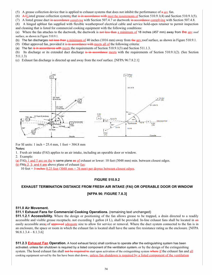
(5) A grease collection device that is applied to exhaust systems that does not inhibit the performance of a any fan.(6) A lListed grease collection systems that is in accordance with meet the requirements of Section 510.9.1(4) and Section 510.9.1(5).(7) A listed grease duct in accordance complying with Section 507.4.7 or ductwork in accordance complying with Section 507.4.8.(8) A hinged upblast fan supplied with flexible weatherproof electrical cable and service hold-open retainer to permit inspectionand cleaning that is listed for commercial cooking equipment with the following conditions:(a) Where the fan attaches to the ductwork, the ductwork is not less than a minimum of 18 inches (457 mm) away from the any roofsurface, as shown in Figure 510.9.1.(b) The fan discharges not less than a minimum of 40 inches (1016 mm) away from the any roof surface, as shown in Figure 510.9.1.(9) Other approved fan, provided it is in accordance with meets all of the following criteria:(a) The fan is in accordance with meets the requirements of Section 510.9.1(3) and Section 511.1.3.(b) Its discharge or its extended duct discharge is in accordance meets with the requirements of Section 510.9.1(2). (See Section511.1.3)(c) Exhaust fan discharge is directed up and away from the roof surface. [NFPA 96:7.8.2.1]
For SI units: 1 inch = 25.4 mm, 1 foot = 304.8 mmNotes:1. Fresh air intake (FAI) applies to an air intake, including an operable door or window.2. Example:(a) FAIs 1 and 5 are on the is same plane as of exhaust or lower: 10 feet (3048 mm) min. between closest edges.(b) FAIs 2, 3, and 4 are above plane of exhaust fan:
10 feet + 3 inches 0.25 feet (3048 mm + 76 mm) per degree between closest edges.
FIGURE 510.9.2
EXHAUST TERMINATION DISTANCE FROM FRESH AIR INTAKE (FAI) OR OPERABLE DOOR OR WINDOW
[NFPA 96: FIGURE 7.8.3]
511.0 Air Movement.511.1 Exhaust Fans for Commercial Cooking Operations. (remaining text unchanged)511.1.2.1 Accessibility. Where the design or positioning of the fan allows grease to be trapped, a drain directed to a readilyaccessible and visible grease receptacle, not exceeding 1 gallon (4 L), shall be provided. In-line exhaust fans shall be located in aneasily accessible areas of approved adequate size to allow for service or removal. Where the duct system connected to the fan is inan enclosure, the space or room in which the exhaust fan is located shall have the same fire resistance rating as the enclosure. [NFPA96:8.1.3.4 – 8.1.3.6]
511.2.3 Exhaust Fan Operation. A hood exhaust fan(s) shall continue to operate after the extinguishing system has beenactivated, unless fan shutdown is required by a listed component of the ventilation system, or by the design of the extinguishingsystem. The hood exhaust fan shall not be required to start upon activation of the extinguishing system where if the exhaust fan and allcooking equipment served by the fan have been shut down., unless fan shutdown is required by a listed component of the ventilation
74
system or by the listing of the extinguishing system. The exhaust fan shall be provided with a means so that the fan is activated when an anyheat-producing cooking appliance under the hood is turned on. [NFPA 96:8.2.3.1-8.2.3.3]
512.0 Auxiliary Equipment.512.2 Electrical Equipment. Wiring systems of any type shall not be installed in ducts. [NFPA 96:9.2.1]512.2.1 Device Installation in Ducts. Motors, lights, and other electrical devices shall be permitted to be installed in ducts orhoods or to be located in the path of travel of exhaust products only where specifically listed for such use. [NFPA 96:9.2.2]512.2.2 Lighting Units. Lighting units in on hoods shall not be located in concealed spaces except as permitted by Section 512.2.3and Section 512.2.4. [NFPA 96:9.2.3.2]
512.3 Other Equipment. Fume incinerators, thermal recovery units, air pollution control devices, or other devices shall bepermitted to be installed in ducts, or hoods or to be located in the path of travel of exhaust products where specifically listed for suchuse. [NFPA 96:9.3.1]512.3.1 Access Required. Equipment shall have space provided to all access panels or doors for the safe removal and servicing ofcontrol devices, such as filters, electrostatic precipitator cells, and odor control media beds, and for cleaning of the equipmenthousing. [NFPA 96:9.3.1.3]512.3.2 Downgrading. Downgrading other parts of the exhaust system due to the installation of these approved devices, whetherlisted or not, shall not be permitted allowed. [NFPA 96:9.3.1, 9.3.2]512.3.1 512.3.3 Fire-Extinguishing System. An Any equipment, listed or otherwise, installed in the path of exhaust products thatprovides secondary filtration or air pollution control and that is installed in the path of travel of exhaust products shall be providedwith an approved automatic fire-extinguishing system, installed in accordance with the fire-extinguishing system manufacturer’sinstallation instructions, for the. [NFPA 96:9.3.3]512.3.3.1 Protection. The fire-extinguishing system required by Section 512.3.3 shall provide protection of for the componentsections of the equipment, and shall include protection of the ductwork downstream of the equipment, whether or not the equipmentis provided with a damper. [NFPA 96:9.3.3.1]512.3.3.2 Filter Media. Filter media used in secondary filtration or air pollution control units and not in accordance complying withSection 509.2.3 shall have fire protection that is adequate for the filter media being used in accordance with the fire-extinguishingsystem manufacturer’s installation instructions. [NFPA 96:9.3.3.2]512.3.4 Source of Ignition. Where If the equipment provides a source of ignition, it shall be provided with a detection to operatethe fire-extinguishing system protecting the equipment. [NFPA 96:9.3.3 – 9.3.4]512.3.2 512.3.5 Air Recirculation. Where a cooking exhaust system employs an air pollution control device that recirculates airinto the building, the requirements of Section 516.0 shall apply. [NFPA 96:9.3.5]512.3.6 Carbon Monoxide Required. If the heat source is non-electric and open flames are used, a carbon monoxide detectorshall be installed in both the kitchen and dining areas. [NFPA 96:9.3.7]
513.0 Fire-Extinguishing Equipment.513.1 General. (remaining text unchanged)513.1.1 Devices in Exhaust Ducts. Fume incinerators, thermal recovery units, air pollution control devices, or other devicesinstalled in the exhaust duct, shall be protected by an automatic fire-extinguishing system. [NFPA 96:10.1.3]
513.2.1 Identification. A placard shall be conspicuously placed near the fire each Class K extinguisher that states that the fireprotection system shall be activated prior to using the fire-extinguisher. [NFPA 96:10.2.2]
513.2.5 Fixed Baffle Hoods with Water Wash. Grease removal devices, hood exhaust plenums, and exhaust ducts Areasrequiring protection in accordance with Section 513.1 shall be permitted to be protected by a listed fixed baffle hood containing aconstant or fire-actuated water-wash system that is listed and as a fire-extinguishing system in accordance compliance with UL 300 orother equivalent standards and shall be installed in accordance with the requirements of their its listing. [NFPA 96:10.2.8.1]513.2.5.1 Listed for the Purpose. Each such area not provided with a listed water-wash fire-extinguishing system shall beprovided with a fire-extinguishing system listed for the purpose. [NFPA 96:10.2.8.2]
(renumber remaining sections)
513.2.5.1 Domestic Water Supply. The water supply for listed, fixed baffle hood assemblies water-wash fire-extinguishing systemsshall be permitted to be supplied from the domestic water supply where when the minimum water pressure and flow are provided inaccordance with the terms of the listing. [NFPA 96:10.2.8.3]513.2.5.2 Control Valve. The water supply for water-wash fire-extinguishing systems shall be controlled by a supervised watersupply control listed indicating valve. [NFPA 96:10.2.8.4]513.2.5.3 Activation. The water wash in the fixed baffle hood specifically listed to extinguish a fire shall be activated by thecooking equipment extinguishing system. Where a separate fire-extinguishing system is used for protection of cooking equipmentonly, a water-wash fire-extinguishing system listed for protection of the grease removal device(s), hood exhaust plenum(s), exhaustduct(s), or combination thereof shall be provided with instructions and appropriate means for electrical interface for simultaneousactivation. [NFPA 96:10.2.8.5]
75
513.2.5.4 Water-Wash System. A water-wash system approved to be used for protection of the grease removal device(s), hoodexhaust plenum(s), exhaust duct(s), or combination thereof shall include instructions and appropriate electrical interface forsimultaneous activation of the water-wash system from an automatic fire-extinguishing system, where the automatic fire-extinguishing system is used for cooking equipment protection only. [NFPA 96:10.2.8.6]513.2.5.5 Exception. Where the automatic fire-extinguishing system in accordance with NFPA 17A provides protection for thecooking equipment, hood, and duct, activation of in a fixed baffle hood containing a water-wash system, the water-wash system shall notbe required made inoperable or delayed for a minimum of 60 seconds upon operation of the automatic fire-extinguishing system.[NFPA 96:10.2.8.7]513.2.5.6 Water Supply. The water required for listed automatic fire-extinguishing systems shall be permitted to be supplied fromthe domestic water supply where the minimum water pressure and flow are provided in accordance with the terms of the listing. Thewater supply shall be controlled by a supervised water supply control valve. Where the water supply is from a dedicated fireprotection water supply in a building with one or more fire sprinkler systems, separate indicating control valves and drains shall beprovided and arranged so that the hood system and sprinkler system are capable of being systems can be controlled individually.[NFPA 96:10.2.910.2.9.1, 10.2.9.2]513.2.6 Water Valve Supervision. Valves controlling the water supply to listed fixed baffle hood assemblies water-wash fire-extinguishing systems, automatic fire-extinguishing systems, or both shall be listed indicating type of valve and shall be supervisedopen by one of the following methods:(1) Central station, proprietary, or remote station alarm service.(2) Local alarm service that will cause the sounding of an audible signal at a constantly attended point.(3) Locking valves open.(4) Sealing of valves and approved weekly recorded inspection. [NFPA 96:10.2.10]
513.3 Simultaneous Operation. Fixed pipe extinguishing systems in a single hazard area shall be arranged for simultaneousautomatic operation upon actuation of any one of the systems. [NFPA 96:10.3.1]513.3.1 Hoods. Hoods installed end to end, back to back, or both, or sharing a common ductwork, not exceeding 75 feet (22 860mm) in distance from the farthest hood, and having a grease producing appliance(s) located under one or more of the hoods, shall beconsidered a single hazard area requiring simultaneous automatic fire protection in all hoods and ducts. [NFPA 96:10.3.1.1]513.3.1.1 Common Ductwork. In hoods that are installed end to end, back to back, or both, and that share a common ductwork,the ductwork beyond 75 feet (22 860 mm) from the farthest hood shall be protected by an independent fire-extinguishing systemwith its own detection system or by a fire-extinguishing system that activates simultaneously with the fire-extinguishing system(s)protecting the hoods. [NFPA 96:10.3.1.1.1]513.3.2 Independent Systems. Hoods installed end to end, back to back, or both that do not share a common exhaust duct andare separated by a wall(s) or other means to ensure that grease-laden vapors exhausted under one hood cannot propagate to the otherhoods, the hoods’ fire-extinguishing system(s) shall be independent and shall not be required to simultaneously discharge. [NFPA96:10.3.1.2]513.3.3 Exempt Equipment. Fume incinerators, thermal recovery units, air pollution control devices, or other devices installedin the exhaust duct shall not be required to comply with Section 513.3.1. [NFPA 96:10.3.1.3]
(renumber remaining sections)
513.3.1 Automatic Sprinkler System. Simultaneous operation shall not be required where the one fixed pipe extinguishingsystem is an automatic sprinkler system. Where an automatic sprinkler system is used in conjunction with a water-based fire-extinguishing system served by the same water supply, hydraulic calculations shall consider both systems operating simultaneously.[NFPA 96:10.3.2, 10.3.2.1]513.3.2 Dry or Wet Chemical Systems. Simultaneous operation shall be required where a dry or wet chemical system is usedto protect common exhaust ductwork by one of the methods specified in NFPA 17 or NFPA 17A. [NFPA 96:10.3.3]
513.4.1 Steam. Steam supplied from an external source shall not be required to automatically shut off. [NFPA 96:10.4.2]
513.5 Manual Activation. All systems shall have both automatic and manual methods of actuation. At least one manual actuationdevice shall be located in a means of egress or at a location acceptable to the Authority Having Jurisdiction.
The manual actuation device shall clearly identify the hazard protected. An automatic sprinkler system shall not require amethod of manual actuation.A readily accessible means for manual activation shall be located between 42 inches and 48 inches (1067 mm and 1219 mm) abovethe floor, be accessible in the event of a fire, be located in a path of egress, and clearly identify the hazard protected. Not less thanone manual actuation device shall be located not less than 10 feet (3048 mm) and not more than 20 feet (6096 mm) from theprotected exhaust system(s) within the path of egress or at an alternative location acceptable to the Authority Having Jurisdiction.Manual actuation using a cable-operated pull station shall not require more than 40 pounds-force (lbf) (178 N) of force, with a pullmovement not to exceed 14 inches (356 mm) to activate the automatic fire extinguishing system. The automatic and manual meansof system activation external to the control head or releasing device shall be separate and independent of each other so that failure ofone will not impair the operation of the other except as permitted in Section 513.5.1. [NFPA 96:10.5.1 – 10.5.2]513.5.1 Location of Manual Activation Device. The manual means of system activation shall be permitted to be common withthe automatic means where the manual activation device is located between the control head or releasing device and the first fusible
76
link. [NFPA 96:10.5.3]513.5.2 Automatic Sprinkler System. An automatic sprinkler system shall not require a manual means of system activation.[NFPA 96:10.5.4]513.5.3 Manual Actuator(s). The means for manual activation shall be mechanical or rely on electrical power for activation inaccordance with Section 513.5.4. [NFPA 96:10.5.5]513.5.4 Standby Power Supply. Electrical power shall be permitted to be used for manual activation where a standby powersupply is provided or where supervision is provided in accordance with Section 513.7. [NFPA 96:10.5.6]
513.7 System Supervision. Where electrical power is required to operate the fixed automatic fire-extinguishing system, thesystem shall be provided with a reserve power supply and be monitored by a supervisory alarm except as permitted in accordancewith Section 513.7.1. [NFPA 96:10.7.1]513.7.1 Automatic Fire-Extinguishing System. Where a fixed automatic fire-extinguishing system includes automaticmechanical detection and actuation as a backup detection system, electrical power monitoring, and reserve power supply shall not berequired. [NFPA 96:10.7.2]513.7.2 Supervision. System supervision shall not be required where a fire-extinguishing system(s) is interconnected orinterlocked with the cooking equipment power source(s) so that where the fire-extinguishing system becomes inoperable due topower failure, sources of fuel or electric power that produce heat to cooking equipment serviced by that hood shall automaticallyshut off. [NFPA 96:10.7.3]513.7.3 Listed Water Wash System. System supervision shall not be required where an automatic fire-extinguishing system,including automatic mechanical detection and actuation, is electrically connected to a listed fire-actuated water-wash system forsimultaneous operation of both systems. [NFPA 96:10.7.4]513.8 Special Design and Application. Hoods containing automatic fire-extinguishing systems are protected areas; therefore,these hoods are shall not be considered obstructions to overhead sprinkler systems and shall not require floor additional sprinklercoverage underneath. [NFPA 96:10.8.1 10.7.1]513.8.1 Single Device. A single detection device, listed with the extinguishing system, shall be permitted for more than oneappliance where installed in accordance with the terms of the listing. [NFPA 96:10.8.2]
513.10 Installation Requirements. Installation of systems shall be performed only by persons properly trained and qualified toinstall the specific system being provided. The installer shall provide certification to the Authority Having Jurisdiction that theinstallation is in agreement with the terms of the listing and the manufacturer’s installation instructions, and/or approved design, orboth. [NFPA 96:10.9.2 10.8.2.1, 10.8.2.2]513.11 Portable Fire Extinguishers. Portable fire extinguishers shall be selected and installed in kitchen cooking areas inaccordance with NFPA 10 and shall be specifically listed for such use. Class K fire extinguishers shall be provided for cookingappliances hazards that involve combustible cooking media such as (vegetable oils, and animal oils, and fats). [NFPA 96:10.10.1,10.10.2 10.9.1, 10.9.2]513.11.1 Other Fire Extinguishers. Portable fire extinguishers shall be provided for other hazards in kitchen areas and shall beselected and installed in accordance with NFPA 10. [NFPA 96:10.10.3 10.9.3]513.11.2 Carbon Dioxide-Type. Carbon dioxide-type extinguishers shall not be permitted. [NFPA 96:10.9.4]
514.0 Procedures for the Use, Inspection, Testing, and Maintenance of Equipment.514.1 Operating Procedures. Exhaust systems shall be operated where whenever cooking equipment is turned on. [NFPA96:11.1.1]
514.1.6 Secondary Control Equipment. Secondary filtration and pollution control equipment shall be operated in accordancewith the terms of its listing and the manufacturer’s instructions recommendations. [NFPA 96:11.1.7]514.1.7 Inspection Frequency. Inspection and maintenance of “other equipment” as allowed in Section 512.3 shall beconducted by properly trained and qualified persons at a frequency determined by the manufacturer’s instructions or the equipmentlisting. [NFPA 96:11.1.8]514.2 Inspection, Testing, and Maintenance. Maintenance of the fire-extinguishing systems and listed exhaust hoodscontaining a constant or fire-activated water system that is listed to extinguish a fire in the grease removal devices, hood exhaustplenums, and exhaust ducts shall be made by properly trained, qualified, and certified person(s) acceptable to the Authority HavingJurisdiction not less than at least every 6 months. [NFPA 96:11.2.1]514.2.1 Requirements. Actuation All actuation and control components, including remote manual pull stations, mechanical andelectrical devices, detectors, and actuators, shall be tested for proper operation during the inspection in accordance with themanufacturer’s instructions procedures. The specific inspection and maintenance requirements of the extinguishing system standardsas well as the applicable installation and maintenance manuals for the listed system and service bulletins shall be followed. [NFPA96:11.2.2, 11.2.3]514.2.2 Fusible Links and Sprinklers. Fusible links of the metal alloy type and automatic sprinklers of the metal alloy typeshall be replaced not less than at least semiannually except as permitted by Section 514.2.3 and Section 514.2.4. [NFPA 96:11.2.4]
514.2.4 Temperature-Sensing Elements. Fixed temperature-sensing elements other than the fusible metal alloy type shall bepermitted to remain continuously in service, provided they are inspected and cleaned, or replaced where if necessary in accordancewith the manufacturer’s instructions, every 12 months or more frequently to ensure proper operation of the system. [NFPA96:11.2.7]
77
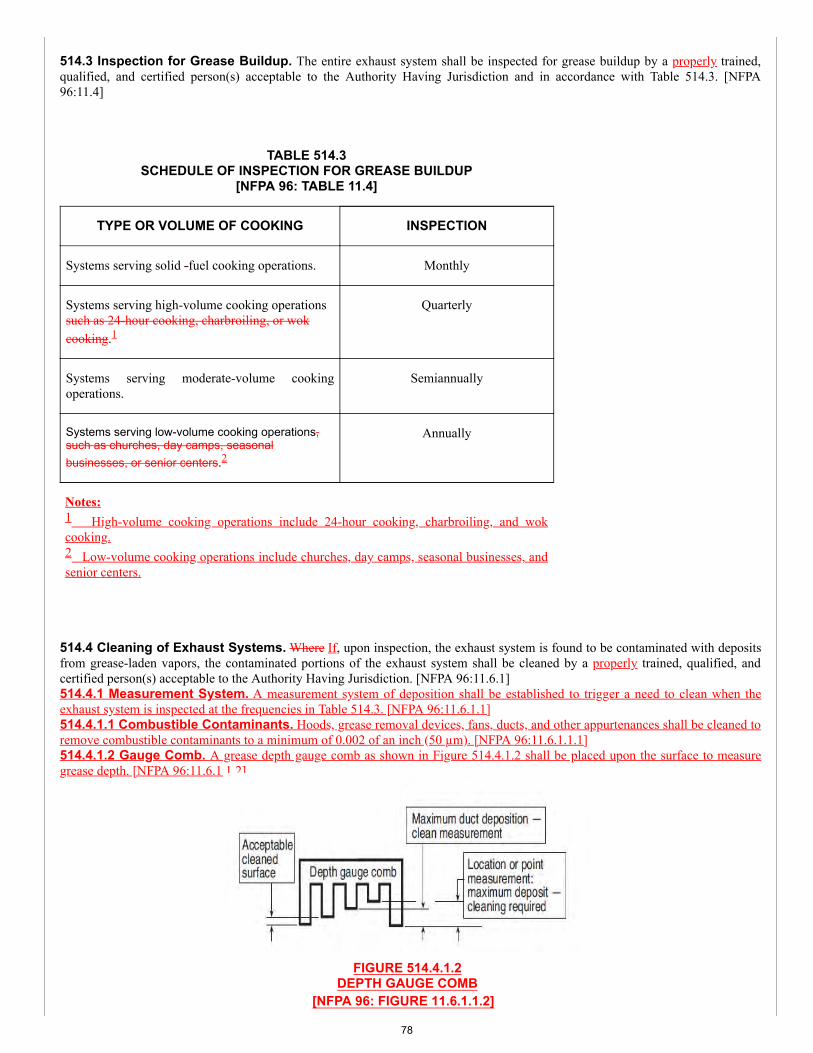
514.3 Inspection for Grease Buildup. The entire exhaust system shall be inspected for grease buildup by a properly trained,qualified, and certified person(s) acceptable to the Authority Having Jurisdiction and in accordance with Table 514.3. [NFPA96:11.4]
TABLE 514.3SCHEDULE OF INSPECTION FOR GREASE BUILDUP
[NFPA 96: TABLE 11.4]
TYPE OR VOLUME OF COOKING INSPECTION
Systems serving solid -fuel cooking operations. Monthly
Systems serving high-volume cooking operationssuch as 24-hour cooking, charbroiling, or wokcooking.1
Quarterly
Systems serving moderate-volume cookingoperations.
Semiannually
Systems serving low-volume cooking operations,such as churches, day camps, seasonalbusinesses, or senior centers.2
Annually
Notes:1 High-volume cooking operations include 24-hour cooking, charbroiling, and wokcooking.2 Low-volume cooking operations include churches, day camps, seasonal businesses, andsenior centers.
514.4 Cleaning of Exhaust Systems. Where If, upon inspection, the exhaust system is found to be contaminated with depositsfrom grease-laden vapors, the contaminated portions of the exhaust system shall be cleaned by a properly trained, qualified, andcertified person(s) acceptable to the Authority Having Jurisdiction. [NFPA 96:11.6.1]514.4.1 Measurement System. A measurement system of deposition shall be established to trigger a need to clean when theexhaust system is inspected at the frequencies in Table 514.3. [NFPA 96:11.6.1.1]514.4.1.1 Combustible Contaminants. Hoods, grease removal devices, fans, ducts, and other appurtenances shall be cleaned toremove combustible contaminants to a minimum of 0.002 of an inch (50 µm). [NFPA 96:11.6.1.1.1]514.4.1.2 Gauge Comb. A grease depth gauge comb as shown in Figure 514.4.1.2 shall be placed upon the surface to measuregrease depth. [NFPA 96:11.6.1.1.2]
FIGURE 514.4.1.2DEPTH GAUGE COMB
[NFPA 96: FIGURE 11.6.1.1.2]
78
514.4.1.3 Cleaning Method. Where a measured depth of 0.078 of an inch (2000µm) is observed, the surfaces shall becleaned in accordance with Section 514.4. [NFPA 96:11.6.1.1.3]514.4.1.4 Combustible Contaminants. Where a measured depth of 0.125 of an inch (3175 µm) is observed in a fanhousing, the surfaces shall be cleaned in accordance with Section 514.4. [NFPA 96:11.6.1.1.4]
(renumber remaining sections)
514.4.4 Inoperable. Fire-extinguishing systems shall be permitted to be rendered inoperable during the cleaning processwhere serviced by properly trained and qualified persons. [NFPA 96:11.6.5]
514.4.8 Access Panels and Cover Plates. Where When cleaning procedures are completed, all access panels (doors)and cover plates shall be restored to their normal operational condition. [NFPA 96:11.6.9]514.4.9 Date of Inspection. Where When an access panel is removed, a service company label or tag preprinted with thename of the company and giving the date of inspection or cleaning shall be affixed near the affected access panels. [NFPA96:11.6.10]
514.4.11 Operable State. Where When cleaning procedures are completed, all electrical switches and system componentsshall be returned to an operable state. [NFPA 96:11.6.12]514.4.12 Certification of Service. Where When an exhaust cleaning service system is used inspected or cleaned, acertificate showing the name of the servicing company, the name of the person performing the work, and the date ofinspection or cleaning shall be maintained on the premises. [NFPA 96:11.6.13]
514.4.15 Metal Containers. Metal containers used to collect grease drippings shall be inspected or emptied at leastweekly. [NFPA 96:11.6.16]
515.0 Minimum Safety Requirements for Cooking Equipment.515.1 Cooking Equipment. (remaining text unchanged)515.1.1 Installation. Listed All listed appliances shall be installed in accordance with the terms of their listings and themanufacturer’s installation instructions. Solid fuel used for flavoring within a gas-operated appliance shall be in a solid fuelholder (smoker box) that is listed with the equipment. [NFPA 96:12.1.2.1, 12.1.2.1.1]
515.1.1.2 Prior Location. The fire-extinguishing system shall not require re-evaluation where the cooking appliances aremoved for the purposes of maintenance and cleaning, provided the appliances are returned to approved design location priorto cooking operations, and any disconnected fire-extinguishing system nozzles attached to the appliances are reconnected inaccordance with the manufacturer’s instructions and listing listed design manual. [NFPA 96:12.1.2.3]
516.0 Recirculating Systems.516.1 General Requirements. Recirculating systems containing or for use with appliances used in processes producingsmoke or grease-laden vapors shall be equipped with components in accordance complying with the following:(1) The clearance requirements of Section 507.4.(2) The A hood shall comply complying with the requirements of Section 508.0.(3) Grease removal devices shall comply complying with Section 509.0.(4) The air movement requirements of Section 511.2.1 and Section 511.2.2.(5) Auxiliary equipment (such as particulate and odor removal devices) shall comply complying with Section 512.0.(6) Fire-extinguishing equipment shall comply complying with the requirements of Section 513.0.Exception: Fire-extinguishing equipment in accordance with Section 513.1 and Section 513.5.(7) The use and maintenance requirements of Section 514.0.(8) The minimum safety requirements of Section 515.0.(9) The All the requirements of Section 516.0. [NFPA 96:13.1](10) Provisions shall be provided for latent heat and excessive moisture acceptable to the Authority Having Jurisdiction.
516.2.9 Listing Evaluation. Listing evaluation shall include the following:(1) Capture and containment of vapors at published and labeled airflows.(2) Grease discharge at the exhaust outlet of the system not to exceed an average of 2.9 E-09 (oz/in3) (5.0 E-06 kg/m3) ofexhausted air sampled from that equipment at maximum amount of product that is capable of being processed over acontinuous 8 hour test per EPA Test Method 202, with the system operating at its minimum listed airflow.(3) Listing and labeling of clearance to combustibles from the all sides, top, and bottom.(4) Electrical connection in the field in accordance with NFPA 70.(5) Interlocks on all removable components that lie in the path of airflow within the unit to ensure that they are in place
79
during operation of the cooking appliance. [NFPA 96:13.2.12]
516.3.4 Airflow Switch or Transducer. An airflow switch or transducer shall be provided after the last filter componentto ensure that a minimum airflow is maintained. The airflow switch or transducer shall open the interlock circuit where whenthe airflow falls 25 percent below the system’s normal operating flow or 10 percent below its listed minimum rating,whichever is lower. The airflow switch or transducer shall be a manual reset device or circuit. [NFPA 96:13.3.5.1 – 13.3.5.3]
516.5 Additional Fire Safety Requirements. In addition to the appliance nozzle(s), a recirculating system shall be listedwith the appropriate fire protection for grease filters, grease filtration, odor filtration units, and ductwork, where applicable.[NFPA 96:13.5.1]
516.6.2 Cleaning Schedule. All ESPs shall be cleaned a minimum of once per week and in accordance with according tothe manufacturer’s cleaning instructions. [NFPA 96:13.6.3]516.6.3 Hood Plenum and Blower Section Cleaning Schedule. The entire hood plenum and the blower section shallbe cleaned not less than a minimum of once every 3 months. [NFPA 96:13.6.4]
516.6.4 Inspection of Safety Interlocks. Inspection and testing of the total operation and all safety interlocks inaccordance with the manufacturer’s instructions shall be performed by qualified service personnel not less than a minimum ofonce every 6 months, or more frequently where if required. [NFPA 96:13.6.5]
517.0 Solid-Fuel Cooking Operations.517.3 Hoods for Solid-Fuel Cooking. (remaining text unchanged)517.3.1 Separation. (remaining text unchanged)517.3.1.1 Equipment with Solid Fuel for Flavoring. Gas-operated equipment utilizing solid fuel for flavoring that is inaccordance with meets all the following conditions shall not be required to have a separate exhaust system:(1) The solid fuel holder (smoker box) shall be listed with the gas-operated equipment.(2) The solid fuel holder shall be located underneath the gas burners.(3) Spark arresters that are in accordance conforming with Section 517.1.6 shall be provided.(4) The maximum quantity of solid fuel consumed shall not exceed 4.5 pounds 1 pound (2.04 0.45 kg) per hour per 100 000Btu/hr (29 kW) of gas burner capacity.(5) The gas-operated equipment shall be protected by a fire suppression system listed for the equipment, including the solidfuel holder.(6) Gas-operated equipment with integral solid fuel holder(s) intended for flavoring, such as a radiant charbroiler(s), shallcomply simultaneously with the requirements of ANSI/UL 300 that address the gas radiant charbroiler(s) and mesquite woodcharbroiler(s).(7) A fire suppression system nozzle(s) shall be installed to protect the solid fuel holder.(8) The fire suppression system shall be designed and installed to protect the entire cooking operation.(9) The Each solid fuel holder shall be limited to a size of 2000 150 cubic inches (2.5 L 0.0328 m3), with no dimension toexceed 20 inches (508 mm).(10) A maximum of one solid fuel holder for each 100 000 Btu/hr (29 kW), or portion thereof, of burner capacity shall bepermitted.(11) Solid fuel shall be immersed in water for a continuous period of at least 24 hours immediately prior to being placed in thecooking equipment.(12) The inspection frequency shall be the same as for solid fuel cooking operations in Table 514.3. [NFPA 96:14.3.4]
517.6 Air Movement for Solid-Fuel Cooking. Exhaust system requirements shall comply with Section 511.0 for hoodedoperation or shall be installed in accordance with the manufacturer’s installation instructions recommendations for unhoodedapplications. [NFPA 96:14.6.1]
517.7.6 Fuel Storage. Fuel All fuel storage areas shall be provided with a sprinkler system in accordance with meeting therequirements of NFPA 13 except where as permitted in accordance with the following:(1) Where approved by acceptable to the Authority Having Jurisdiction, fuel storage areas shall be permitted to be protectedwith a fixed water pipe system with a hose capable of reaching all parts of the area.(2) In lieu of the sprinkler system outlined in Section 517.7.6, a listed 2-A rated water spray fire extinguisher or a 1.6 gallon (6.1 L) wetchemical fire extinguisher listed for Class K fires with a maximum travel distance of not more than 20 feet (6096 mm) to the solid fuel pilesshall be permitted to be used for a solid fuel pile, provided that the fuel pile does not exceed 5 cubic feet (0.14 m3) volume. [NFPA 96:14.9.2.8– 9.2.8.2 14.9.2.8.2]
517.8.2 Additional Devices. Except for the spark arresters required in Section 517.1.6, there shall be no additional devicesof any type in a any portion of the appliance, flue pipe, and chimney of a natural draft solid-fuel operation. [NFPA96:14.9.4.4]517.8.3 Prohibited. No solid-fuel cooking device of any type shall be permitted for deep-fat frying involving more than 1quart (qt) (1 L) of liquid shortening, and nor shall any solid-fuel cooking device shall not be permitted within 3 feet (914 mm)
80
of a any deep-fat frying unit. [NFPA 96:14.9.4.5]
518.0 Downdraft Appliances.518.3 Fire-Extinguishing Equipment. For fire Fire-extinguishing equipment on a downdraft appliance ventilation systemshall comply with systems, the following shall apply:(1) Cooking surface, duct, and plenum protection shall be provided.(2) Not less than At least one fusible link or heat detector shall be installed within an each exhaust duct opening in accordancewith the manufacturer’s listing.(3) A fusible link or heat detector shall be provided above the for each protected cooking appliance and located in the plenumarea of that appliance or in accordance with the extinguishing system manufacturer’s listing.(4) A manual activation device shall be provided as part of the each appliance at a height acceptable to the approved by theAuthority Having Jurisdiction.(5) Portable fire extinguishers shall be installed provided in accordance with Section 513.11. [NFPA 96:15.2]
TABLE 1701.1REFERENCED STANDARDS
STANDARD NUMBER STANDARD TITLE APPLICATION REFERENCEDSECTION
EPA Test Method 202-2016 Best Practices Handbook Commercial Kitchens 516.2.9
Note: EPA Test Method 202 does not meet the requirements for a mandatory reference standard in accordancewith Section 3-3.7.1 of IAPMO’s Regulations Governing Committee Projects.
(portion of table not shown remains unchanged)
SUBSTANTIATION:In accordance with IAPMO's Regulations Governing Committee Projects (Extract Guidelines), Section Chapter 5 is beingrevised to the latest edition of NFPA 96-2018.
COMMITTEE ACTION: ACCEPT AS AMENDED BY THE TC
Amend proposal as follows:
507.0 General Requirements.
507.2 Exhaust System. Cooking equipment used in processes producing smoke or grease-laden vapors shall be equipped with anexhaust system that complies with all the equipment and performance requirements of this chapter. [NFPA 96:4.1.1] All suchequipment and its performance shall be maintained in accordance with the requirements of this chapter during all periods ofoperation of the cooking equipment. [NFPA 96:4.1.2] The following equipment shall be kept in working condition:(1) Cooking equipment(2) Hoods(3) Ducts (if applicable)(4) Fans(5) Fire-extinguishing equipment(6) Special effluent or energy control equipment [NFPA 96:4.1.3] Maintenance and repairs shall be performed on all components atintervals necessary to maintain good working conditions. [NFPA 96:4.1.3.1]507.2.1 Airflow. All airflows shall be maintained. [NFPA 96:4.1.4]507.2.2 Responsibility. The responsibility for inspection, testing, maintenance, and cleanliness of the ventilation control and fireprotection of the commercial cooking operations, including cooking appliances, shall ultimately be that of the owner of the system,provided that this responsibility has not been transferred in written form to a management company, tenant, or other party. [NFPA96:4.1.5]507.2.3 Solid-fuel Cooking Equipment. All solid-fuel cooking equipment shall comply with the requirements of Section 517.0.[NFPA 96:4.1.6]507.2.4 Multitenant Applications. Multitenant applications shall require the concerted cooperation of design, installation,operation, and maintenance responsibilities by tenants and by the building owner. [NFPA 96:4.1.7]507.2.5 Interior Surfaces. All interior surfaces of the exhaust system shall be accessible for cleaning and inspection purposes.[NFPA 96:4.1.8]507.2.6 Used in Other Applications. Cooking equipment used in fixed, mobile, or temporary concessions, such as trucks,buses, trailers, pavilions, tents, or any form of roofed enclosure, shall comply with this chapter. [NFPA 96:4.1.9]
507.4.4 Factory Built. Factory-built grease duct enclosures shall be protected with a through-penetration firestop system
81
classified in accordance with ASTM E814 or UL 1479 having an “F” and a “T” rating equal to the fire resistance rating of theassembly being penetrated from the point at which the duct penetrates a ceiling, wall, or floor to the outlet terminal. [NFPA 96:4.3.3]507.4.4.1 Listing. The factory-built grease duct protection system shall be listed in accordance with UL 2221. [NFPA 96:4.3.3.1]507.4.4.2 Single Wall. Listed single wall factory-built grease ducts shall be permitted to be enclosed with field-applied greaseduct enclosure material where the material and the assembly of duct and material are listed for that application and installed inaccordance with the grease duct manufacturer’s listing and their installation instructions. [NFPA 96:4.3.3.2]507.4.4.3 Installation. The factory-built grease duct protection system shall be installed in accordance with the manufacturer’sinstallation instructions and the listing requirements. [NFPA 96:4.3.3.3]
508.0 Type I Hoods.508.2 Listed Type I Hood Assemblies. Listed hood assemblies shall be installed in accordance with the terms of their listingand the manufacturer’s instructions. Listed hood assemblies shall be tested in accordance with UL 710 or equivalent. [NFPA96:5.4.1, 5.4.2]508.2.1 Listed Ultraviolet Hoods. Listed ultraviolet hoods shall be installed and maintained in accordance with the terms oftheir listing and the manufacturer’s instructions. Duct systems connected to ultraviolet hoods shall comply with Section 510.0.Ultraviolet hoods shall be tested and listed in accordance with UL 710 and UL 710C. [NFPA 96:5.5-5.5.2]507.4.4.3 Listed Ventilated Ceiling Technology. Listed ventilated ceiling technology shall be installed and maintained inaccordance with the terms of its listing and the manufacturer's instructions. [NFPA 96:5.6]
(renumber remaining sections)
508.3 Construction of Type I Hoods. The hood or that portion of a primary collection means designed for collecting cookingvapors and residues shall be constructed of and be supported by steel not less than 0.048 of an inch (1.219 mm) (No. 18 MSG), inthickness, stainless steel not less than 0.036 of an inch (0.914 mm) (No. 20 MSG) in thickness, or other approved material ofequivalent strength and fire and corrosion resistance. [NFPA 96:5.1.1]Exception: Listed exhaust hoods.
509.0 Grease Removal Devices in Hoods.509.1 Grease Removal Devices. Listed grease filters or other listed grease removal devices intended for use with commercialcooking operations shall be provided. Listed grease filters and grease removal devices that are removable but not an integralcomponent of a specific listed exhaust hood shall be listed in accordance with ANSI/UL 1046 and shall be designated on the filter.[NFPA 96:6.1.1, 6.1.2] 509.2.1 Vertical Distance. Where grease removal devices are used in conjunction with solid fuel or solid fuel-type broilers,including gas or electrically heated charbroilers, a minimum vertical distance of 4 feet (1219 mm) shall be maintained between thelower edge of the grease removal device and the cooking surface. [NFPA 96:6.2.1.2]Exceptions:(1) For cooking equipment without exposed flame and where flue gases bypass grease removal devices, the minimum verticaldistance shall be permitted to be reduced to not less than 6 inches (152 mm). [NFPA 96:6.2.1.3](2) Where a grease removal device is listed for separation distances less than those required in Section 509.2 and Section 509.2.1,the listing requirements shall be permitted. [NFPA 96:6.2.1.4](3) Grease removal devices supplied as part of listed hood assemblies shall be installed in accordance with the terms of the listingand the manufacturer’s instructions. [NFPA 96:6.2.1.5] 509.2.3.1 Arrangement. Grease filters shall be arranged so that all exhaust air passes through the grease filters. [NFPA96:6.2.3.4] 509.2.4.1 Size and Pitch. Grease drip trays shall be kept to the minimum size needed to collect grease. Grease drip trays shall bepitched to drain into an enclosed metal container having a capacity not exceeding 1 gallon (4 L). [NFPA 96:6.2.4.2, 6.2.4.3]509.2.5 Grease Filter Orientation. Grease filters that require a specific orientation to drain grease shall be clearly so designatedon the face of the filter as to be visible with the filter installed, or the hood or filter shall be constructed so that filters cannot beinstalled in the wrong orientation. [NFPA 96:6.2.5] 510.0 Exhaust Duct Systems.510.1.2 Interconnection. Duct systems shall not be interconnected with any other building ventilation or exhaust system. [NFPA96:7.1.3]510.1.3 Duct Installation. All ducts shall be installed with a minimum 2 percent slope on horizontal runs up to 75 feet (22 860mm) and a minimum 8 percent slope on horizontal runs greater than 75 feet (22 860 mm). Factory-built grease ducts shall bepermitted to be installed at a lesser slope in accordance with the listing and the manufacturer’s instructions. All horizontal ducts shallbe provided with access in accordance with Section 510.3.3.Drains shall be provided at low points in horizontal ducts. Where provided, drains shall be continuously welded to the exhaust ductin accordance with the terms of the listing and the manufacturer’s installation manual.All ducts shall be installed without forming dips or traps. In manifold (common duct) systems, the lowest end of the main duct shall
82
be connected flush on the bottom with the branch duct. [NFPA 96:7.1.4 – 7.1.4.5]
510.1.5 Sign. A sign stating the following shall be placed on all access panels:ACCESS PANEL – DO NOT OBSTRUCT [NFPA 96:7.1.6]
510.1.7 Type I Exhaust Duct Systems. Listed grease ducts shall be installed in accordance with the terms of their listings andmanufacturer’s instructions. [NFPA 96:7.1.7]
510.3.4.2 Safe Access and Work Platform. If not easily accessible from the floor or a 10 foot (3048 mm) stepladder, openingson vertical grease ducts shall be provided with safe access and a work platform. [NFPA 96:7.4.2.3]
510.3.6 Access Panels. Access panels shall be of the same material and thickness as the duct. Access panels shall have a gasketor sealant that is rated for 1500°F (816°C) and shall be greasetight. Fasteners, such as bolts, weld studs, latches, or wing nuts, usedto secure the access panels shall be carbon steel or stainless steel and shall not penetrate duct walls. [NFPA 96:7.4.3.1-7.4.3.3]510.3.6.1 Listed Grease Ducts. Listed grease duct access door assemblies (access panels) shall be installed in accordance withthe terms of the listing and the manufacturer’s instructions. [NFPA 96:7.4.3.4]
510.4 Listed Grease Ducts. Listed grease ducts shall be installed in accordance with the terms of the listing and themanufacturer’s instructions. [NFPA 96:7.1.7]
510.5.5 Telescoping and Bell-Type Connections. For telescoping and bell-type connections, the inside duct section shallalways be uphill of the outside duct section. [NFPA 96:7.5.5.3] The overlap shall not exceed 2 inches (51 mm) as shown in Figure510.5.3.2(1).
510.7 Interior Installations. In all buildings more than one story in height and in one-story buildings where the roof-ceilingassembly is required to have a fire resistance rating, the ducts shall be enclosed in a continuous enclosure extending from the lowestfire-rated ceiling or floor above the hood, through any concealed spaces, to or through the roof, to maintain the integrity of the fireseparations required by the applicable building code provisions. The enclosure shall be sealed around the duct at the point ofpenetration of the first fire-rated barrier after the hood, to maintain the fire resistance rating of the enclosure. The enclosure shall bevented to the exterior of the building through weather-protected openings. [NFPA 96:7.7.1.2 – 7.7.1.4]Exception: The continuous enclosure provisions shall not be required where a field-applied grease duct enclosure or a factory-builtgrease duct enclosure (see Section 507.4.4 through Section 507.4.6) is protected with a listed duct-through-penetration protectionsystem equivalent to the fire resistance rating of the assembly being penetrated and where the materials are installed in accordancewith the conditions of the listings and the manufacturer’s instructions and are acceptable to the Authority Having Jurisdiction.[NFPA 96:7.7.1.5]
510.7.3 Clearance. Clearance from the duct or the exhaust fan to the interior surface of enclosures of combustible constructionshall be not less than 18 inches (457 mm). Clearance from the duct to the interior surface of enclosures of noncombustible orlimited-combustible construction shall be not less than 6 inches (152 mm). Provisions for reducing clearances as described inSection 507.4 through Section 507.4.3.3 shall not be applicable to enclosures. [NFPA 96:7.7.2.2.1 – 7.7.2.2.3]Exception: Clearance from the outer surfaces of field-applied grease duct enclosures and factory-built grease duct enclosures to theinterior surfaces of construction installed around them shall be permitted to be reduced where the field-applied grease duct enclosurematerials and factory-built grease duct enclosures are installed in accordance with the conditions of the listing and themanufacturer’s instructions and are acceptable to the Authority Having Jurisdiction. [NFPA 96:7.7.2.2.4]510.7.4 Mechanical and Structural Integrity. Field-applied grease duct enclosures and factory-built grease duct enclosuresshall provide mechanical and structural integrity, resiliency, and stability when subjected to expected building environmentalconditions, duct movement under general operating conditions, and duct movement as a result of interior and exterior fireconditions. [NFPA 96:7.7.2.2.5]
510.7.5.1 Protection from Physical Damage. Measures shall be taken to prevent physical damage to any covering orenclosure material. Any damage to the covering or enclosure shall be repaired, and the covering or enclosure shall be restored tomeet its intended listing and fire resistance rating and to be acceptable to the Authority Having Jurisdiction. [NFPA 96:7.7.3.1,7.7.3.2]510.7.5.2 Inspection. In the event of a fire within a kitchen exhaust system, the duct, the enclosure, and the covering directlyapplied to the duct shall be inspected by qualified personnel to determine whether the duct, the enclosure, and the covering directlyapplied to the duct are structurally sound, capable of maintaining their fire protection functions, suitable for continued operation, andacceptable to the Authority Having Jurisdiction. [NFPA 96:7.7.3.3]
510.7.7 Fire Doors. Where openings in the enclosure walls are provided, they shall be protected by listed fire doors of properrating. Fire doors shall be installed in accordance with NFPA 80. Openings on other listed materials or products shall be clearlyidentified and labeled according to the terms of the listing and the manufacturer’s instructions and shall be acceptable to theAuthority Having Jurisdiction. [NFPA 96:7.7.4.1 – 7.7.4.3] The fire door shall be readily accessible, aligned, and of sufficient size toallow access to the rated access panels on the ductwork. [NFPA 96:7.7.4.4]
83
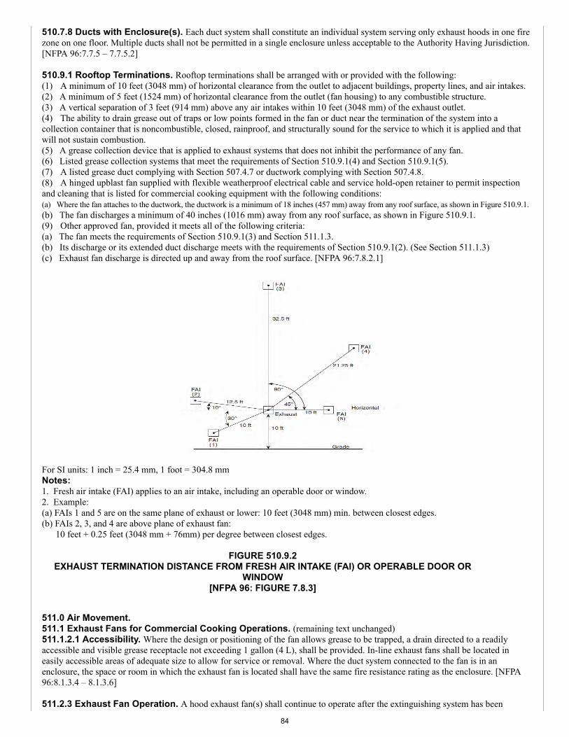
510.7.8 Ducts with Enclosure(s). Each duct system shall constitute an individual system serving only exhaust hoods in one firezone on one floor. Multiple ducts shall not be permitted in a single enclosure unless acceptable to the Authority Having Jurisdiction.[NFPA 96:7.7.5 – 7.7.5.2]
510.9.1 Rooftop Terminations. Rooftop terminations shall be arranged with or provided with the following:(1) A minimum of 10 feet (3048 mm) of horizontal clearance from the outlet to adjacent buildings, property lines, and air intakes.(2) A minimum of 5 feet (1524 mm) of horizontal clearance from the outlet (fan housing) to any combustible structure.(3) A vertical separation of 3 feet (914 mm) above any air intakes within 10 feet (3048 mm) of the exhaust outlet.(4) The ability to drain grease out of traps or low points formed in the fan or duct near the termination of the system into acollection container that is noncombustible, closed, rainproof, and structurally sound for the service to which it is applied and thatwill not sustain combustion.(5) A grease collection device that is applied to exhaust systems that does not inhibit the performance of any fan.(6) Listed grease collection systems that meet the requirements of Section 510.9.1(4) and Section 510.9.1(5).(7) A listed grease duct complying with Section 507.4.7 or ductwork complying with Section 507.4.8.(8) A hinged upblast fan supplied with flexible weatherproof electrical cable and service hold-open retainer to permit inspectionand cleaning that is listed for commercial cooking equipment with the following conditions:(a) Where the fan attaches to the ductwork, the ductwork is a minimum of 18 inches (457 mm) away from any roof surface, as shown in Figure 510.9.1.(b) The fan discharges a minimum of 40 inches (1016 mm) away from any roof surface, as shown in Figure 510.9.1.(9) Other approved fan, provided it meets all of the following criteria:(a) The fan meets the requirements of Section 510.9.1(3) and Section 511.1.3.(b) Its discharge or its extended duct discharge meets with the requirements of Section 510.9.1(2). (See Section 511.1.3)(c) Exhaust fan discharge is directed up and away from the roof surface. [NFPA 96:7.8.2.1]
For SI units: 1 inch = 25.4 mm, 1 foot = 304.8 mmNotes:1. Fresh air intake (FAI) applies to an air intake, including an operable door or window.2. Example:(a) FAIs 1 and 5 are on the same plane of exhaust or lower: 10 feet (3048 mm) min. between closest edges.(b) FAIs 2, 3, and 4 are above plane of exhaust fan:
10 feet + 0.25 feet (3048 mm + 76mm) per degree between closest edges.
FIGURE 510.9.2EXHAUST TERMINATION DISTANCE FROM FRESH AIR INTAKE (FAI) OR OPERABLE DOOR OR
WINDOW[NFPA 96: FIGURE 7.8.3]
511.0 Air Movement.511.1 Exhaust Fans for Commercial Cooking Operations. (remaining text unchanged)511.1.2.1 Accessibility. Where the design or positioning of the fan allows grease to be trapped, a drain directed to a readilyaccessible and visible grease receptacle not exceeding 1 gallon (4 L), shall be provided. In-line exhaust fans shall be located ineasily accessible areas of adequate size to allow for service or removal. Where the duct system connected to the fan is in anenclosure, the space or room in which the exhaust fan is located shall have the same fire resistance rating as the enclosure. [NFPA96:8.1.3.4 – 8.1.3.6]
511.2.3 Exhaust Fan Operation. A hood exhaust fan(s) shall continue to operate after the extinguishing system has been
84
activated unless fan shutdown is required by a listed component of the ventilation system or by the design of the extinguishingsystem. The hood exhaust fan shall start upon activation of the extinguishing system if the exhaust fan and all cooking equipmentserved by the fan have been shut down, unless fan shutdown is required by a listed component of the ventilation system or by thelisting of the extinguishing system. The exhaust fan shall be provided with a means so that the fan is activated when any heat-producing cooking appliance under the hood is turned on. [NFPA 96:8.2.3.1-8.2.3.3] 512.0 Auxiliary Equipment.512.2 Electrical Equipment. Wiring systems of any type shall not be installed in ducts. [NFPA 96:9.2.1]512.2.1 Device Installation in Ducts. Motors, lights, and other electrical devices shall be permitted to be installed in ducts orhoods or to be located in the path of travel of exhaust products only where specifically listed for such use. [NFPA 96:9.2.2]512.2.2 Lighting Units. Lighting units on hoods shall not be located in concealed spaces except as permitted by Section 512.2.3and Section 512.2.4. [NFPA 96:9.2.3.2] 512.3 Other Equipment. Fume incinerators, thermal recovery units, air pollution control devices, or other devices shall bepermitted to be installed in ducts or hoods or to be located in the path of travel of exhaust products where specifically listed for suchuse. [NFPA 96:9.3.1]512.3.1 Access Required. Equipment shall have space provided to all access panels or doors for the safe removal and servicing ofcontrol devices, such as filters, electrostatic precipitator cells, and odor control media beds, and for cleaning of the equipmenthousing. [NFPA 96:9.3.1.3]512.3.2 Downgrading. Downgrading other parts of the exhaust system due to the installation of approved devices, whether listedor not, shall not be allowed. [NFPA 96:9.3.2]512.3.3 Fire-Extinguishing System. Any equipment installed in the path of exhaust products that provides secondary filtrationor air pollution control shall be provided with an approved automatic fire-extinguishing system, installed in accordance with the fire-extinguishing system manufacturer’s instructions. [NFPA 96:9.3.3]512.3.3.1 Protection. The fire-extinguishing system required by Section 512.3.3 shall provide protection for the componentsections of the equipment, and ductwork downstream of the equipment. [NFPA 96:9.3.3.1]512.3.3.2 Filter Media. Filter media used in secondary filtration or air pollution control units and not complying with Section509.2.3 shall have fire protection that is adequate for the filter media being used in accordance with the fire-extinguishing systemmanufacturer’s instructions. [NFPA 96:9.3.3.2]512.3.4 Source of Ignition. If the equipment provides a source of ignition, it shall be provided with detection to operate the fire-extinguishing system protecting the equipment. [NFPA 96:9.3.4]512.3.5 Air Recirculation. Where a cooking exhaust system employs an air pollution control device that recirculates air into thebuilding, the requirements of Section 516.0 shall apply. [NFPA 96:9.3.5]512.3.6 Carbon Monoxide Required. If the heat source is non-electric and open flames are used, a carbon monoxide detectorshall be installed in both the kitchen and dining areas. [NFPA 96:9.3.7] 513.0 Fire-Extinguishing Equipment.513.1 General. (remaining text unchanged)513.1.1 Devices in Exhaust Ducts. Fume incinerators, thermal recovery units, air pollution control devices, or other devicesinstalled in the exhaust duct, shall be protected by an automatic fire-extinguishing system. [NFPA 96:10.1.3] 513.2.1 Identification. A placard shall be conspicuously placed near each Class K extinguisher that states that the fire protectionsystem shall be activated prior to using the fire extinguisher. [NFPA 96:10.2.2] 513.2.5 Baffle Hoods with Water Wash. Areas requiring protection in accordance with Section 513.1 shall be permitted to beprotected by a water-wash system that is listed as a fire-extinguishing system in compliance with UL 300 or other equivalentstandards and installed in accordance with the requirements of its listing. [NFPA 96:10.2.8.1]
513.2.5.1 Listed for the Purpose. Each such area not provided with a listed water-wash fire-extinguishing system shall beprovided with a fire-extinguishing system listed for the purpose. [NFPA 96:10.2.8.2] (renumber remaining sections)
513.2.5.1 Domestic Water Supply. The water supply for water-wash fire-extinguishing systems shall be permitted to besupplied from the domestic water supply when the minimum water pressure and flow are provided in accordance with the terms ofthe listing. [NFPA 96:10.2.8.3]513.2.5.2 Control Valve. The water supply for water-wash fire-extinguishing systems shall be controlled by a listed indicatingvalve. [NFPA 96:10.2.8.4]513.2.5.3 Activation. Where a separate fire-extinguishing system is used for protection of cooking equipment only, a water-washfire-extinguishing system listed for protection of the grease removal device(s), hood exhaust plenum(s), exhaust duct(s), orcombination thereof shall be provided with instructions and appropriate means for electrical interface for simultaneous activation.[NFPA 96:10.2.8.5]513.2.5.4 Water-Wash System. A water-wash system approved to be used for protection of the grease removal device(s), hood
85
exhaust plenum(s), exhaust duct(s), or combination thereof shall include instructions and appropriate electrical interface forsimultaneous activation of the water-wash system from an automatic fire-extinguishing system, where the automatic fire-extinguishing system is used for cooking equipment protection only. [NFPA 96:10.2.8.6]513.2.5.5 Exception. Where the automatic fire-extinguishing system in accordance with NFPA 17A provides protection for thehood and duct in a fixed baffle hood containing a water-wash system, the water-wash system shall be made inoperable or delayed fora minimum of 60 seconds upon operation of the automatic fire-extinguishing system. [NFPA 96:10.2.8.7]513.2.5.6 Water Supply. The water required for listed automatic fire-extinguishing systems shall be permitted to be supplied fromthe domestic water supply where the minimum water pressure and flow are provided in accordance with the terms of the listing. Thewater supply shall be controlled by a supervised water supply control valve. Where the water supply is from a dedicated fireprotection water supply in a building with one or more fire sprinkler systems, separate indicating control valves and drains shall beprovided and arranged so that the hood system and sprinkler systems can be controlled individually. [NFPA 96:10.2.9.1, 10.2.9.2]513.2.6 Water Valve Supervision. Valves controlling the water supply to listed water-wash fire-extinguishing systems,automatic fire-extinguishing systems, or both shall be listed indicating type of valve and shall be supervised open by one of thefollowing methods:(1) Central station, proprietary, or remote station alarm service.(2) Local alarm service that will cause the sounding of an audible signal at a constantly attended point.(3) Locking valves open.(4) Sealing of valves and approved weekly recorded inspection. [NFPA 96:10.2.10] 513.3 Simultaneous Operation. Fixed pipe extinguishing systems in a single hazard area shall be arranged for simultaneousautomatic operation upon actuation of any one of the systems. [NFPA 96:10.3.1]513.3.1 Hoods. Hoods installed end to end, back to back, or both, or sharing a common ductwork, not exceeding 75 feet (22 860mm) in distance from the farthest hood, and having a grease producing appliance(s) located under one or more of the hoods, shall beconsidered a single hazard area requiring simultaneous automatic fire protection in all hoods and ducts. [NFPA 96:10.3.1.1]513.3.1.1 Common Ductwork. In hoods that are installed end to end, back to back, or both, and that share a common ductwork,the ductwork beyond 75 feet (22 860 mm) from the farthest hood shall be protected by an independent fire-extinguishing systemwith its own detection system or by a fire-extinguishing system that activates simultaneously with the fire-extinguishing system(s)protecting the hoods. [NFPA 96:10.3.1.1.1]513.3.2 Independent Systems. Hoods installed end to end, back to back, or both that do not share a common exhaust duct andare separated by a wall(s) or other means to ensure that grease-laden vapors exhausted under one hood cannot propagate to the otherhoods, the hoods’ fire-extinguishing system(s) shall be independent and shall not be required to simultaneously discharge. [NFPA96:10.3.1.2]513.3.3 Exempt Equipment. Fume incinerators, thermal recovery units, air pollution control devices, or other devices installedin the exhaust duct shall not be required to comply with Section 513.3.1. [NFPA 96:10.3.1.3] (renumber remaining sections) 513.3.1 Automatic Sprinkler System. Simultaneous operation shall not be required where the one fixed pipe extinguishingsystem is an automatic sprinkler system. Where an automatic sprinkler system is used in conjunction with a water-based fire-extinguishing system served by the same water supply, hydraulic calculations shall consider both systems operating simultaneously.[NFPA 96:10.3.2, 10.3.2.1]513.3.2 Dry or Wet Chemical Systems. Simultaneous operation shall be required where a dry or wet chemical system is usedto protect common exhaust ductwork by one of the methods specified in NFPA 17 or NFPA 17A. [NFPA 96:10.3.3] 513.4.1 Steam. Steam supplied from an external source shall not be required to automatically shut off. [NFPA 96:10.4.2] 513.5 Manual Activation. All systems shall have both automatic and manual methods of actuation. At least one manual actuationdevice shall be located in a means of egress or at a location acceptable to the Authority Having Jurisdiction. The manual actuation device shall clearly identify the hazard protected. An automatic sprinkler system shall not require amethod of manual actuation. [NFPA 96:10.5.1 – 10.5.2]
513.8 Special Design and Application. Hoods containing automatic fire-extinguishing systems are protected areas; therefore,these hoods shall not be considered obstructions to overhead sprinkler systems and shall not require floor additional sprinklercoverage underneath. [NFPA 96:10.7.1]
513.10 Installation Requirements. Installation of systems shall be performed only by persons properly trained and qualified toinstall the specific system being provided. The installer shall provide certification to the Authority Having Jurisdiction that theinstallation is in agreement with the terms of the listing and the manufacturer’s instructions and/or approved design. [NFPA96:10.8.2.1, 10.8.2.2]
513.11 Portable Fire Extinguishers. Portable fire extinguishers shall be selected and installed in kitchen cooking areas inaccordance with NFPA 10 and shall be specifically listed for such use. Class K fire extinguishers shall be provided for cookingappliance hazards that involve combustible cooking media (vegetable oils and animal oils and fats). [NFPA 96:10.9.1, 10.9.2]
86

513.11.1 Other Fire Extinguishers. Portable fire extinguishers shall be provided for other hazards in kitchen areas and shall beselected and installed in accordance with NFPA 10. [NFPA 96:10.9.3]513.11.2 Carbon Dioxide-Type. Carbon dioxide-type extinguishers shall not be permitted. [NFPA 96:10.9.4]
514.0 Procedures for the Use, Inspection, Testing, and Maintenance of Equipment.514.1 Operating Procedures. Exhaust systems shall be operated whenever cooking equipment is turned on. [NFPA 96:11.1.1]
514.1.6 Secondary Control Equipment. Secondary filtration and pollution control equipment shall be operated in accordancewith the terms of its listing and the manufacturer’s recommendations. [NFPA 96:11.1.7]514.1.7 Inspection Frequency. Inspection and maintenance of “other equipment” as allowed in Section 512.3 shall beconducted by properly trained and qualified persons at a frequency determined by the manufacturer’s instructions or the equipmentlisting. [NFPA 96:11.1.8]514.2 Inspection, Testing, and Maintenance. Maintenance of the fire-extinguishing systems and listed exhaust hoodscontaining a constant or fire-activated water system that is listed to extinguish a fire in the grease removal devices, hood exhaustplenums, and exhaust ducts shall be made by properly trained, qualified, and certified person(s) acceptable to the Authority HavingJurisdiction at least every 6 months. [NFPA 96:11.2.1]514.2.1 Requirements. All actuation and control components, including remote manual pull stations, mechanical and electricaldevices, detectors, and actuators shall be tested for proper operation during the inspection in accordance with the manufacturer’sprocedures. The specific inspection and maintenance requirements of the extinguishing system standards as well as the applicableinstallation and maintenance manuals for the listed system and service bulletins shall be followed. [NFPA 96:11.2.2, 11.2.3]514.2.2 Fusible Links and Sprinklers. Fusible links of the metal alloy type and automatic sprinklers of the metal alloy typeshall be replaced at least semiannually. [NFPA 96:11.2.4]
514.2.4 Temperature-Sensing Elements. Fixed temperature-sensing elements other than the fusible metal alloy type shall bepermitted to remain continuously in service, provided they are inspected and cleaned, or replaced if necessary in accordance with themanufacturer’s instructions, every 12 months or more frequently to ensure proper operation of the system. [NFPA 96:11.2.7]
514.3 Inspection for Grease Buildup. The entire exhaust system shall be inspected for grease buildup by a properly trained,qualified, and certified person(s) acceptable to the Authority Having Jurisdiction and in accordance with Table 514.3. [NFPA96:11.4]
TABLE 514.3SCHEDULE OF INSPECTION FOR GREASE BUILDUP
[NFPA 96: TABLE 11.4]
TYPE OR VOLUME OF COOKING INSPECTION
Systems serving solid fuel cooking operations. Monthly
Systems serving high-volume cooking operations.1 Quarterly
Systems serving moderate-volume cooking operations. Semiannually
Systems serving low-volume cooking operations.2 Annually
Notes:1 High-volume cooking operations include 24-hour cooking, charbroiling, and wokcooking.2 Low-volume cooking operations include churches, day camps, seasonalbusinesses, and senior centers.
514.4 Cleaning of Exhaust Systems. If, upon inspection, the exhaust system is found to be contaminated with deposits fromgrease-laden vapors, the contaminated portions of the exhaust system shall be cleaned by a properly trained, qualified, and certifiedperson(s) acceptable to the Authority Having Jurisdiction. [NFPA 96:11.6.1]514.4.1 Measurement System. A measurement system of deposition shall be established to trigger a need to clean when theexhaust system is inspected at the frequencies in Table 514.3. [NFPA 96:11.6.1.1]514.4.1.1 Combustible Contaminants. Hoods, grease removal devices, fans, ducts, and other appurtenances shall be cleaned toremove combustible contaminants to a minimum of 0.002 of an inch (50 µm). [NFPA 96:11.6.1.1.1]514.4.1.2 Gauge Comb. A grease depth gauge comb as shown in Figure 514.4.1.2 shall be placed upon the surface to measuregrease depth. [NFPA 96:11.6.1.1.2]
87
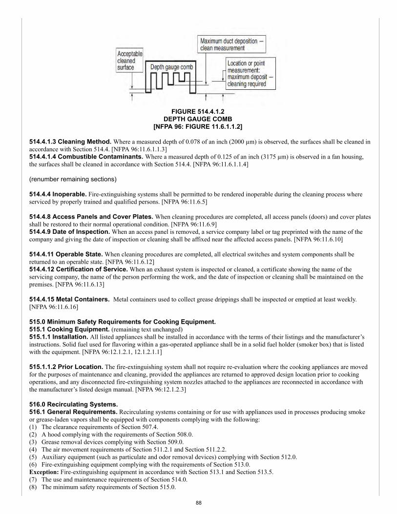
FIGURE 514.4.1.2DEPTH GAUGE COMB
[NFPA 96: FIGURE 11.6.1.1.2]
514.4.1.3 Cleaning Method. Where a measured depth of 0.078 of an inch (2000 µm) is observed, the surfaces shall be cleaned inaccordance with Section 514.4. [NFPA 96:11.6.1.1.3]514.4.1.4 Combustible Contaminants. Where a measured depth of 0.125 of an inch (3175 µm) is observed in a fan housing,the surfaces shall be cleaned in accordance with Section 514.4. [NFPA 96:11.6.1.1.4]
(renumber remaining sections)
514.4.4 Inoperable. Fire-extinguishing systems shall be permitted to be rendered inoperable during the cleaning process whereserviced by properly trained and qualified persons. [NFPA 96:11.6.5]
514.4.8 Access Panels and Cover Plates. When cleaning procedures are completed, all access panels (doors) and cover platesshall be restored to their normal operational condition. [NFPA 96:11.6.9]514.4.9 Date of Inspection. When an access panel is removed, a service company label or tag preprinted with the name of thecompany and giving the date of inspection or cleaning shall be affixed near the affected access panels. [NFPA 96:11.6.10]
514.4.11 Operable State. When cleaning procedures are completed, all electrical switches and system components shall bereturned to an operable state. [NFPA 96:11.6.12]514.4.12 Certification of Service. When an exhaust system is inspected or cleaned, a certificate showing the name of theservicing company, the name of the person performing the work, and the date of inspection or cleaning shall be maintained on thepremises. [NFPA 96:11.6.13]
514.4.15 Metal Containers. Metal containers used to collect grease drippings shall be inspected or emptied at least weekly.[NFPA 96:11.6.16]
515.0 Minimum Safety Requirements for Cooking Equipment.515.1 Cooking Equipment. (remaining text unchanged)515.1.1 Installation. All listed appliances shall be installed in accordance with the terms of their listings and the manufacturer’sinstructions. Solid fuel used for flavoring within a gas-operated appliance shall be in a solid fuel holder (smoker box) that is listedwith the equipment. [NFPA 96:12.1.2.1, 12.1.2.1.1]
515.1.1.2 Prior Location. The fire-extinguishing system shall not require re-evaluation where the cooking appliances are movedfor the purposes of maintenance and cleaning, provided the appliances are returned to approved design location prior to cookingoperations, and any disconnected fire-extinguishing system nozzles attached to the appliances are reconnected in accordance withthe manufacturer’s listed design manual. [NFPA 96:12.1.2.3]
516.0 Recirculating Systems.516.1 General Requirements. Recirculating systems containing or for use with appliances used in processes producing smokeor grease-laden vapors shall be equipped with components complying with the following:(1) The clearance requirements of Section 507.4.(2) A hood complying with the requirements of Section 508.0.(3) Grease removal devices complying with Section 509.0.(4) The air movement requirements of Section 511.2.1 and Section 511.2.2.(5) Auxiliary equipment (such as particulate and odor removal devices) complying with Section 512.0.(6) Fire-extinguishing equipment complying with the requirements of Section 513.0.Exception: Fire-extinguishing equipment in accordance with Section 513.1 and Section 513.5.(7) The use and maintenance requirements of Section 514.0.(8) The minimum safety requirements of Section 515.0.
88
(9) All the requirements of Section 516.0. [NFPA 96:13.1]
516.2.9 Listing Evaluation. Listing evaluation shall include the following:(1) Capture and containment of vapors at published and labeled airflows.(2) Grease discharge at the exhaust outlet of the system not to exceed an average of 2.9 E-09 (oz/in3) (5.0 E-06 kg/m3) ofexhausted air sampled from that equipment at maximum amount of product that is capable of being processed over a continuous 8hour test per EPA Test Method 202, with the system operating at its minimum listed airflow.(3) Listing and labeling of clearance to combustibles from all sides, top, and bottom.(4) Electrical connection in the field in accordance with NFPA 70.(5) Interlocks on all removable components that lie in the path of airflow within the unit to ensure that they are in place duringoperation of the cooking appliance. [{NFPA 96:13.2.12}]
516.3.4 Airflow Switch or Transducer. An airflow switch or transducer shall be provided after the last filter component toensure that a minimum airflow is maintained. The airflow switch or transducer shall open the interlock circuit when the airflow falls25 percent below the system’s normal operating flow or 10 percent below its listed minimum rating, whichever is lower. The airflowswitch or transducer shall be a manual reset device or circuit. [NFPA 96:13.3.5.1 – 13.3.5.3]
516.5 Additional Fire Safety Requirements. In addition to the appliance nozzle(s), a recirculating system shall be listed withthe appropriate fire protection for grease filters, grease filtration, odor filtration units, and ductwork, where applicable. [NFPA96:13.5.1]
516.6.2 Cleaning Schedule. All ESPs shall be cleaned a minimum of once per week and according to the manufacturer’scleaning instructions. [NFPA 96:13.6.3]516.6.3 Hood Plenum and Blower Section Cleaning Schedule. The entire hood plenum and the blower section shall becleaned a minimum of once every 3 months. [NFPA 96:13.6.4]516.6.4 Inspection of Safety Interlocks. Inspection and testing of the total operation and all safety interlocks in accordancewith the manufacturer’s instructions shall be performed by qualified service personnel a minimum of once every 6 months or morefrequently if required. [NFPA 96:13.6.5]
517.0 Solid-Fuel Cooking Operations.
517.3 Hoods for Solid-Fuel Cooking. (remaining text unchanged)517.3.1 Separation. (remaining text unchanged)517.3.1.1 Equipment with Solid Fuel for Flavoring. Gas-operated equipment utilizing solid fuel for flavoring that meets allthe following conditions shall not be required to have a separate exhaust system:(1) The solid fuel holder (smoker box) shall be listed with the gas-operated equipment.(2) The solid fuel holder shall be located underneath the gas burners.(3) Spark arresters conforming with Section 517.1.6 shall be provided.(4) The maximum quantity of solid fuel consumed shall not exceed 1 pound (0.45 kg) per hour per 100 000 Btu/hr (29 kW) of gasburner capacity.(5) The gas-operated equipment shall be protected by a fire suppression system listed for the equipment, including the solid fuelholder.(6) Gas-operated equipment with integral solid fuel holder(s) intended for flavoring, such as radiant charbroiler(s), shall complysimultaneously with the requirements of ANSI/UL 300 that address the gas radiant charbroiler(s) and mesquite wood charbroiler(s).(7) A fire suppression system nozzle(s) shall be installed to protect the solid fuel holder.(8) The fire suppression system shall be designed and installed to protect the entire cooking operation.(9) Each solid fuel holder shall be limited to a size of 150 cubic inches (2.5 L), with no dimension to exceed 20 inches (508 mm).(10) A maximum of one solid fuel holder for each 100 000 Btu/hr (29 kW), or portion thereof, of burner capacity shall be permitted.(11) Solid fuel shall be immersed in water for a continuous period of at least 24 hours immediately prior to being placed in thecooking equipment.(12) The inspection frequency shall be the same as for solid fuel cooking operations in Table 514.3. [NFPA 96:14.3.4]
517.6 Air Movement for Solid-Fuel Cooking. Exhaust system requirements shall comply with Section 511.0 for hoodedoperation or shall be installed in accordance with the manufacturer’s recommendations for unhooded applications. [NFPA 96:14.6.1]
517.7.6 Fuel Storage. All fuel storage areas shall be provided with a sprinkler system meeting the requirements of NFPA 13except as permitted in accordance with the following:(1) Where acceptable to the Authority Having Jurisdiction, fuel storage areas shall be permitted to be protected with a fixed waterpipe system with a hose capable of reaching all parts of the area.(2) In lieu of the sprinkler system outlined in Section 517.7.6, a listed 2-A rated water spray fire extinguisher or a 1.6 gallon (6.1 L) wet chemical fireextinguisher listed for Class K fires with a maximum travel distance of 20 feet (6096 mm) to the solid fuel piles shall be permitted to be used for asolid fuel pile, provided that the fuel pile does not exceed 5 cubic feet (0.14 m3) volume. [NFPA 96:14.9.2.8 – 14.9.2.8.2]
89
517.8.2 Additional Devices. Except for the spark arresters required in Section 517.1.6, there shall be no additional devices ofany type in any portion of the appliance, flue pipe, and chimney of a natural draft solid fuel operation. [NFPA 96:14.9.4.4]517.8.3 Prohibited. No solid fuel cooking device of any type shall be permitted for deep fat frying involving more than 1 quart(qt) (1 L) of liquid shortening, nor shall any solid fuel cooking device be permitted within 3 feet (914 mm) of any deep fat fryingunit. [NFPA 96:14.9.4.5]
518.0 Downdraft Appliances.518.3 Fire-Extinguishing Equipment. For fire-extinguishing equipment on downdraft appliance ventilation systems, thefollowing shall apply:(1) Cooking surface, duct, and plenum protection shall be provided.(2) At least one fusible link or heat detector shall be installed within each exhaust duct opening in accordance with themanufacturer’s listing.(3) A fusible link or heat detector shall be provided for each protected cooking appliance located in the plenum area of thatappliance or in accordance with the extinguishing system manufacturer’s listing.(4) A manual activation device shall be provided as part of each appliance at a height acceptable to the Authority HavingJurisdiction.(5) Portable fire extinguishers shall be provided in accordance with Section 513.11. [NFPA 96:15.2]
TABLE 1701.1REFERENCED STANDARDS
STANDARD NUMBER STANDARD TITLE APPLICATION REFERENCEDSECTION
EPA Test Method 202-2016 Best Practices Handbook CommercialKitchens 516.2.9
(portion of table not shown remains unchanged)
COMMITTEE STATEMENT:The proposed text in Section 510.5.5 is being revised to correlate with Item # 39. Furthermore, the reference to EPA TestMethod 202 is being removed from Section 516.2.9 as it is not an enforceable document.
TOTAL ELIGIBLE TO VOTE: 26
VOTING RESULTS: AFFIRMATIVE: 25 NOT RETURNED: 1 HOWARD
The TCC has the responsibility to resolve conflicts and achieve correlation among the recommendations of the TechnicalCommittee. The TCC has the authority to choose between alternative text recommended by the Technical Committee, butonly as necessary for correlation, consistency, and the correction of errors and omissions in accordance with Section 3-4 ofthe Regulations Governing Committee Projects.
Actions taken on UMC Item # 044, Section 509.1 (Grease Removal Devices) and Section 517.3.1.1 (Equipment with SolidFuel for Flavoring) resulted in conflicting language between UPC Item # 157, Section 1211.3 (Arc-Resistant Jacketed CSST).In order to correlate the language, the Technical Correlating Committee proposed the following modifications to the UMC:
509.1 Grease Removal Devices. Listed grease filters or other listed grease removal devices intended for use with commercialcooking operations shall be provided. Listed grease filters and grease removal devices that are removable but not an integralcomponent of a specific listed exhaust hood shall be listed in accordance with ANSI/UL 1046 and shall be designated on the filter.[NFPA 96:6.1.1, 6.1.2]
517.3.1.1 Equipment with Solid Fuel for Flavoring. Gas-operated equipment utilizing solid fuel for flavoring that meets allthe following conditions shall not be required to have a separate exhaust system:(1) The solid fuel holder (smoker box) shall be listed with the gas-operated equipment.(2) The solid fuel holder shall be located underneath the gas burners.(3) Spark arresters conforming with Section 517.1.6 shall be provided.(4) The maximum quantity of solid fuel consumed shall not exceed 1 pound (0.45 kg) per hour per 100 000 Btu/hr (29 kW) of gasburner capacity.(5) The gas-operated equipment shall be protected by a fire suppression system listed for the equipment, including the solid fuelholder.(6) Gas-operated equipment with integral solid fuel holder(s) intended for flavoring, such as radiant charbroiler(s), shall complysimultaneously with the requirements of ANSI/UL 300 that address the gas radiant charbroiler(s) and mesquite wood charbroiler(s).(7) A fire suppression system nozzle(s) shall be installed to protect the solid fuel holder.
90
Item #: 044
Item #: 044
Comment #: 1
Comment #: 2
(8) The fire suppression system shall be designed and installed to protect the entire cooking operation.(9) Each solid fuel holder shall be limited to a size of 150 cubic inches (2.5 L), with no dimension to exceed 20 inches (508 mm).(10) A maximum of one solid fuel holder for each 100 000 Btu/hr (29 kW), or portion thereof, of burner capacity shall be permitted.(11) Solid fuel shall be immersed in water for a continuous period of at least 24 hours immediately prior to being placed in thecooking equipment.(12) The inspection frequency shall be the same as for solid fuel cooking operations in Table 514.3. [NFPA 96:14.3.4]
TCC ACTION: ACCEPT AS SUBMITTED
TCC STATEMENT: The language in UMC Item # 044, Section 509.1 (Grease Removal Devices) and Section 517.3.1.1 (Equipmentwith Solid Fuel for Flavoring) are being revised to correlate with the language approved by the UPC TC Item # 157, Section 1211.3(Arc-Resistant Jacketed CSST) with regards to the term “ANSI” not being part of the standard title as referenced throughout the UPCand UMC.
The action moves forward as approved by the TCC and supersedes the recommendation from the UMC TC for actions taken forSection 509.1 (Grease Removal Devices) and Section 517.3.1.1 (Equipment with Solid Fuel for Flavoring) with regard to the standardtitle reference within the codes.
Appended Comments
Edit Comment
PUBLIC COMMENT 1
Code Year: 2021 UMC Section #: Chapter 5
SUBMITTER: IAPMO Staff - Update ExtractsNFPA 54 Extract Update
RECOMMENDATION:Revise text
Request to accept the code change proposal as modified by this public comment.
504.4.1 Provisions for Makeup Air. Makeup air shall be provided in accordance with the following:(1) Makeup air shall be provided for Type 1 clothes dryers in accordance with the manufacturer’s installation instructions. [NFPA54:10.4.3.1] Where a closet is designed for the installation of a clothes dryer, an opening of not less than 100 square inches (0.065m2) for makeup air shall be provided in the door or by other approved means.(2) Provision for makeup air shall be provided for Type 2 clothes dryers, with a minimum free area of not less than 1 square inch(0.0006 m2) for each 1000 British thermal units per hour (Btu/h) (0.293 kW) total input rating of the dryer(s) installed. [NFPA54:10.4.3.2]
SUBSTANTIATION:In accordance with IAPMO's Regulations Governing Committee Projects (Extract Guidelines), the above sections are beingrevised to the latest edition of NFPA 54-2018.
COMMITTEE ACTION: ACCEPTED AS SUBMITTED
TOTAL ELIGIBLE TO VOTE: 26
VOTING RESULTS: AFFIRMATIVE: 25 NOT RETURNED: 1 HOWARD
Edit Comment
PUBLIC COMMENT 2
Code Year: 2021 UMC Section #: Chapter 5
SUBMITTER: IAPMO Staff - Update ExtractsNFPA 91 Extract Update
RECOMMENDATION:Revise text
91
Request to accept the code change proposal as modified by this public comment.
505.2 Incompatible Materials. Incompatible materials shall not be conveyed in the same system. [NFPA 91:4.2.2]505.3 Flammability Limit. Unless the circumstances stipulated in Section 505.3.1, Section 505.3.2, or Section 505.3.3 exist, insystems conveying flammable vapors, gases, or mists, the concentration shall not exceed 25 percent of the lower flammability limit(LFL). [NFPA 91:4.2.3]505.3.1 Higher Concentrations. Higher concentrations shall be permitted where if the exhaust system is designed and protectedin accordance with NFPA 69, using one or more of the following techniques:(1) Combustible concentration reduction(2) Oxidant concentration reduction(3) Deflagration suppression(4) Deflagration pressure containment [NFPA 91:4.2.3.1] 505.5 Generating Flames, Sparks, or Hot Materials. Operations generating flames, sparks, or hot material such as fromgrinding wheels and welding shall not be manifolded into an any exhaust system that air conveys flammable or combustiblematerials. [NFPA 91:4.2.6] 505.7 Fire Detection and Alarm Systems. Unless the conditions circumstances stipulated in Section 505.7.1 or Section505.7.2 exist, fire detection and alarm systems shall not be interlocked to shut down air-moving devices. [NFPA 91:4.2.14]
TABLE 505.9RANGE OF MINIMUM DUCT DESIGN VELOCITIES*
[NFPA 91: TABLE A.4.1.5 TABLE A.4.2.5]
NATURE OF CONTAINMENT EXAMPLES DESIGN VELOCITY(feet per minute)
Vapors, gases, smoke All vapors Vapors, gases, and smoke Any 1000 – 2000*
Fumes Welding 2000 - 2500
Very fine Fine light dusts dust Cotton lint, wood flour, litho powder 2500 - 3000
Dry dusts and powders Fine rubber dust, molding powder dust, jute lint, cotton dust,shavings (light), soap dust, leather shavings 3000 - 4000
Average industrial dusts
Grinding dust, buffing lint (dry), wool jute dust (shaker waste),coffee beans, shoe dust, granite dust, silica flour, generalmaterial handling, brick cutting, clay dust, foundry (general),limestone dust, packaging and weighing asbestos dust in textileindustries
3500 - 4000
Heavy dustsSawdust (heavy and wet), metal turnings, foundry tumblingbarrels and shake-out, sandblast dust, wood blocks, hog waste,brass turning, cast-iron boring dust, lead dust
4000 - 4500
Heavy or moist dustsLead dust with chips, moist cement dust, asbestos chunks fromtransite pipe cutting machines, buffing lint (sticky), quick-limedust
4500 and up
For SI units: 1 foot per minute = 0.005 m/s* Systems that are handling combustible particulate solids shall be in accordance with NFPA 654 Any desired velocity (economicoptimum velocity usually within this range).
506.3.1 Fire Barriers. Exhaust ducts passing through a fire barrier having a fire resistance rating of 2 hours or more greater shallmeet one of the following specifications:(1) Wrapped or encased with listed or approved materials having a fire resistance rating equal to the fire barrier for 10 feet (3048mm) of the duct on each side of the fire barrier including duct supports within this span.(2) Constructed of materials and supports having a minimum fire resistance rating equal to the fire barrier.(3) Enclosed with a shaft that is constructed of material having a fire resistance rating equal to the fire barrier for 10 feet (3048mm) of the duct on each side of the fire barrier with no inlets to the duct within this distance, and the duct entry into and exit fromthe shaft is protected in accordance with Section 506.3.2. [NFPA 91:4.2.12]
92
Item #: 044
506.8.1 Loads. Duct supports shall be designed to carry the weight of the duct half filled with material. Where sprinkler protectionis provided or cleaning of the duct will be performed, the hanger’s design shall include the weight of the any expected liquidaccumulation. Duct supports shall be designed to prevent placing loads on connected equipment. [NFPA 91:4.6.1 – 4.6.3]506.8.2 Corrosion. Hangers and supports exposed to corrosive atmospheres shall be corrosion resistant to the corrosiveatmospheres. [NFPA 91:4.6.4]506.8.3 Vibration and Stress. To prevent avoid vibration and stress on the duct, hangers and supports shall be securely fastenedto the building or structure. [NFPA 91:4.6.5]
506.10 Duct Clearances. Unless the conditions stipulated in Section 506.10.1 or Section 506.10.2 exist, all duct systems andsystem components shall have a clearance of at least 6 inches (152 mm) from stored combustible materials, and not less than 1/2 ofan inch (13 mm) clearance from combustible construction. [NFPA 91:4.7.1]506.10.2 Systems Conveying Combustible Materials. Unless the conditions stipulated in Section 506.10.3 exist, all ductsystems and system components handling combustible material materials shall have a clearance of not less than 18 inches (457 mm)from stored combustible materials construction or a combustible material construction. [NFPA 91:4.7.2]
506.11.2 Wool Batts Insulation. Mineral wool batts (blanket or board) shall have a minimum density of not less than 8 poundsper cubic feet (lb/ft3) (128 kg/m3) and have a minimum melting point of not less than 1500°F (816°C). [NFPA 91:4.7.4.3]
506.11.4 Duct and Thermal Shield. With all clearance reduction systems, not less than at least 1 inch (25.4 mm) clear spaceshall be provided between the duct and the thermal shield. [NFPA 91:4.7.4.5]
506.11.5 Thermal Shield and Combustible Surface. When using clearance reduction systems that include an air gap, not lessthan at least 1 inch (25.4 mm) clear space shall be provided between the thermal shield and the combustible surface. [NFPA91:4.7.4.6]506.11.6 Reduced Clearance with Air Gaps. When using clearance reduction systems that include an air gap between thecombustible surface and the selected means of protection, air circulation shall be provided by one of the methods in accordance withSection 506.11.6.1 through Section 506.11.6.2. [NFPA 91:4.7.4.7]506.11.6.1 Air Circulation. Air circulation shall be permitted to be provided by leaving all edges of the wall protecting systemopen with at least a 1 inch (25.4 mm) air gap. [NFPA 91:4.7.4.7.1]506.11.6.2 Single Flat Wall. If the means for of protection is mounted on a single flat wall away from corners, air circulationshall be permitted to be provided by one of the following:(1) Leaving only the top and bottom edges open to circulation by maintaining the 1 inch (25.4 mm) air gap.(2) Leaving the top and both side edges open to circulation by maintaining the 1 inch (25.4 mm) air gap. [NFPA 91:4.7.4.7.2]506.11.6.3 Thermal Shielding. Thermal shielding that covers two walls in a corner shall be permitted to be open at the top andbottom edges with not less than at least 1 inch (25.4 mm) air gap. [NFPA 91:4.7.4.7.3]
TABLE 1701.1REFERENCED STANDARDS
STANDARD NUMBER STANDARD TITLE APPLICATION REFERENCEDSECTION
NFPA 654-2017 Prevention of Fire and DustExplosions from the Manufacturing,Processing, and Handling ofCombustible Particulate Solids
Dust ExplosionPrevention, Gutters
506.6, Table 505.9
(portion of table not shown remains unchanged)
SUBSTANTIATION:In accordance with IAPMO's Regulations Governing Committee Projects (Extract Guidelines), the above sections are beingrevised to the latest edition of NFPA 91-2015.
COMMITTEE ACTION: ACCEPTED AS SUBMITTED
TOTAL ELIGIBLE TO VOTE: 26
VOTING RESULTS: AFFIRMATIVE: 25 NOT RETURNED: 1 HOWARD
Edit Comment
PUBLIC COMMENT 3
Code Year: 2021 UMC Section #: Chapter 5
93
Comment #: 3SUBMITTER: IAPMO Staff - Update ExtractsNFPA 96 Extract Update
RECOMMENDATION:Revise text
Request to accept the code change proposal as modified by this public comment.
507.4 Clearance. Where enclosures are not required, hoods, grease removal devices, exhaust fans, and ducts shall have aclearance of at least not less than 18 inches (457 mm) to combustible material, 3 inches (76 mm) to limited-combustible material,and 0 inches (0 mm) to noncombustible material. [NFPA 96:4.2.1]507.4.1 Listed. Where a hood, duct, or grease removal device is listed for clearances less than those required in accordance withSection 507.4, the listing requirements shall be permitted. [NFPA 96:4.2.2]507.4.2 Clearance Reduction. Where a clearance reduction system consisting of 0.013 of an inch (0.33 mm) (28 gauge) sheetmetal spaced out 1 inch (25.4 mm) on noncombustible spacers is provided, there shall be a minimum of not less than 9 inches (229mm) clearance to combustible material. [NFPA 96:4.2.3.1]507.4.2.1 Mineral Wool Batts or Ceramic Fiber Blanket. Where a clearance reduction system consisting of 0.027 of an inch(0.686 mm) (22 gauge) sheet metal on 1 inch (25.4 mm) mineral wool batts or ceramic fiber blanket reinforced with wire mesh orequivalent spaced out 1 inch (25.4 mm) on noncombustible spacers is provided, there shall be not less than a minimum of 3 inches(76 mm) clearance to combustible material. [NFPA 96:4.2.3.2] 507.4.3 Clearance Integrity. In the event of damage, the material or product shall be repaired and restored to meet its intendedlisting or clearance requirements and shall be approved by acceptable to the Authority Having Jurisdiction. [NFPA 96:4.2.4.1]507.4.3.1 Fire. In the event of a fire within a kitchen exhaust system, the duct and its enclosure (rated shaft, factory-built greaseduct enclosure, or field-applied grease duct enclosure) shall be inspected by qualified personnel to determine whether the duct andprotection method are structurally sound, capable of maintaining their fire protection function, and in accordance compliance withthis chapter for continued operation. [NFPA 96:4.2.4.2] 507.4.4.3 Installation. The factory-built grease duct protection system shall be installed in accordance with the manufacturer’sinstallation instructions and the listing requirements. [NFPA 96:4.3.3.3]507.4.5 Field Applied. Field-applied grease duct enclosures shall be protected with a through penetration firestop systemclassified in accordance with ASTM E814 or UL 1479 having an “F” and a “T” rating equal to the fire resistance rating of theassembly being penetrated. The surface of the field fabricated grease duct shall be continuously covered on all sides from the pointat which the duct enclosure penetrates a ceiling, wall, or floor to the outlet terminal. The field-applied grease duct shall be listed inaccordance with ASTM E2336 and installed in accordance with the manufacturer’s installation instructions and the listingrequirements. [NFPA 96:4.3.1 – 4.3.1.2]507.4.8 Clearance Between Duct and Interior Surfaces. Clearances between the duct and interior surfaces of enclosuresshall be in accordance with meet the requirements of Section 507.4. [NFPA 96:4.5]507.5 Drawings. A drawing(s) of the exhaust system installation along with a copy copies of operating instructions forsubassemblies and components used in the exhaust system, including electrical schematics, shall be on the premises. [NFPA 96:4.6]507.6 Notification of Change. Where If required by the Authority Having Jurisdiction, notification in writing shall be given ofany alteration, replacement, or relocation of any exhaust, or extinguishing system or part thereof or cooking equipment. [NFPA96:4.7]Satisfaction shall be provided to the Authority Having Jurisdiction that the complete exhaust system as addressed in this chapter isinstalled and operable in accordance with the approved design and the manufacturer’s installation instructions. 508.3.1 Grease Vapor. Wall-mounted exhaust hood assemblies shall be tight fitting against the back wall so as to not permitpassage of grease vapor behind the hood, or between the back wall and the hood assembly. [NFPA 96:5.1.13]508.3.2 Seams, Joints, and Penetrations. All Sseams, joints, and penetrations of the hood enclosure that direct and capturegrease-laden vapors and exhaust gases shall have a liquid-tight continuous external weld to the hood’s lower outermost perimeter.[NFPA 96:5.1.2]Exceptions:(1) Seams, joints, and penetrations of the hood shall be permitted to be internally welded, provided that the weld is formed smoothor ground smooth, so as to not trap grease, and is cleanable. [NFPA 96:5.1.3](2) Penetrations shall be permitted to be sealed by devices that are listed for such use and whose presence does not detract from thehood’s or duct’s structural integrity. [NFPA 96:5.1.5] 508.3.4 Insulation. Insulation materials other than electrical insulation shall have a flame spread index of not more than 25 or less,where when tested in accordance with ASTM E84 or UL 723. Adhesives or cements used in the installation of insulating materialsshall be in accordance comply with the requirements of this section where when tested with the specific insulating material. [NFPA96:5.1.9, 5.1.10]508.3.5 Exhaust Hood Assemblies with Integrated Supply-Air Plenums. The construction and size of exhaust hoodassemblies with integrated supply air plenums shall be in accordance comply with the requirements of Section 508.1 throughSection 508.5. [NFPA 96:5.3.1]
94
508.3.5.1 Outer Shell. The construction of the outer shell or the inner exhaust shell shall be in accordance comply with Section508.1 through Section 508.3.4. [NFPA 96:5.3.2] 508.3.5.3.2 Actuating Temperature. The actuation device shall have a maximum temperature rating not to exceed of 286°F(141°C). [NFPA 96:5.3.4.3] 509.2 Installation. The distance between the grease removal device and the cooking surface shall be as great as possible but notless than 18 inches (457 mm). [NFPA 96:6.2.1.1] 509.2.2.2 Size and Location. The baffle plate shall be sized and located so that flames or combustion gases shall travel adistance not less than 18 inches (457 mm) from the heat source to the grease removal device. [NFPA 96:6.2.2.3]
510.1.1 Fire Hazards. All Dducts shall lead as directly to the exterior of the building, so as not to unduly increase any fire hazard.[NFPA 96:7.1.2] 510.1.7 Type I Exhaust Duct Systems. Listed grease ducts shall be installed in accordance with the terms of their listings andthe manufacturer’s instructions. [NFPA 96:7.1.7] 510.3.3.2 Safe Access and Work Platform. Where If not easily accessible from a 10 foot (3048 mm) stepladder, openings onhorizontal grease duct systems shall be provided with safe access and a work platform. [NFPA 96:7.4.1.3]510.3.3.3 Support. Support systems for horizontal grease duct systems 24 inches (610 mm) and larger in any cross-sectionaldimension shall be designed for the weight of the ductwork plus 800 pounds (362.9 kg) at any point in the duct systems. [NFPA96:7.4.1.4]510.3.4.1 Access. Where personnel entry is not possible, an adequate access for cleaning shall be provided on each floor. [NFPA96:7.4.2.2]510.3.7 Fire Protection System Devices. Openings for installation, servicing, and inspection of listed fire protection systemdevices and for duct cleaning shall be provided in ducts and enclosures and shall be in accordance with the requirements of Section510.3 through Section 510.3.2 and Section 510.7.7. Enclosure openings required to reach access panels in the ductwork shall belarge enough for removal of the access panel through the enclosure opening. [NFPA 96:7.4.4 7.4.4.1 – 7.4.4.2] 510.5.3 Installation. All Sseams, joints, penetrations, and duct-to-hood collar connections shall have a liquid-tight continuousexternal weld. [NFPA 96:7.5.2.1]Exceptions:(1) Factory-built grease ducts listed in accordance with UL 1978 shall be permitted to incorporate nonwelded joint construction inaccordance with their listings. [NFPA 96:7.5.2.1.1](2) Duct-to-hood collar connections as shown in Figure 510.5.3 shall not require a liquid-tight continuous external weld. [NFPA96:7.5.2.2](3) Penetrations shall be permitted to be sealed by other listed devices that are tested to be greasetight and are evaluated under thesame conditions of fire severity as the hood or enclosure of listed grease extractors and whose presence does not detract from thehood’s or duct’s structural integrity. [NFPA 96:7.5.2.3](4) Internal welding shall be permitted, provided the joint is formed or ground smooth and is readily accessible for inspection.[NFPA 96:7.5.2.4]510.5.3.1 Duct Leakage Test. Prior to the use of or concealment of any portion of a grease duct system, a leakage test shall beperformed to determine that all welded joints and seams are liquid tight. [NFPA 96:7.5.2.1.2]510.5.3.2 Welded Duct Connection. Acceptable Dduct-to-duct connection shall be as follows:(1) Telescoping joint, as shown in Figure 510.5.3.2(1).(2) Bell-type joint, as shown in Figure 510.5.3.2(2).(3) Flange with edge weld, as shown in Figure 510.5.3.2(3).(4) Flange with filled weld, as shown in Figure 510.5.3.2(4). [NFPA 96:7.5.5.1] 510.6.1 Weather Protection. All Dducts shall be protected on the exterior by paint or other suitable weather-protective coating.Ducts constructed of stainless steel shall not be required to have additional paint or weather-protective coatings. Ductwork subject tocorrosion shall have minimal contact with the building surface. [NFPA 96:7.6.4 – 7.6.6]510.7.8 Ducts with Enclosure(s). Each duct system shall constitute an individual system serving only exhaust hoods in one firezone on one floor. Multiple ducts shall not be permitted in a single enclosure unless acceptable to the Authority Having Jurisdiction.[NFPA 96:7.7.5.1 – 7.7.5.2] 510.9 Termination of Type I Hood Exhaust System. The exhaust system shall terminate as follows:(1) Outside the building with a fan or duct.(2) Through the roof or to the roof from outside, in accordance with as in Section 510.9.1, or through a wall, in accordance with asin Section 510.9.2. [NFPA 96:7.8.1]510.9.1 Rooftop Terminations. Rooftop terminations shall be arranged with or provided with the following:(1) A minimum of 10 feet (3048 mm) of horizontal clearance from the outlet to adjacent buildings, property lines, and air intakes.
95
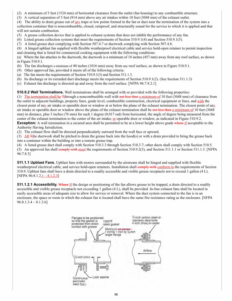
(2) A minimum of 5 feet (1524 mm) of horizontal clearance from the outlet (fan housing) to any combustible structure.(3) A vertical separation of 3 feet (914 mm) above any air intakes within 10 feet (3048 mm) of the exhaust outlet.(4) The ability to drain grease out of any traps or low points formed in the fan or duct near the termination of the system into acollection container that is noncombustible, closed, rainproof, and structurally sound for the service to which it is applied and thatwill not sustain combustion.(5) A grease collection device that is applied to exhaust systems that does not inhibit the performance of any fan.(6) Listed grease collection systems that meet the requirements of Section 510.9.1(4) and Section 510.9.1(5).(7) A listed grease duct complying with Section 507.4.7 or ductwork complying with Section 507.4.8.(8) A hinged upblast fan supplied with flexible weatherproof electrical cable and service hold-open retainer to permit inspectionand cleaning that is listed for commercial cooking equipment with the following conditions:(a) Where the fan attaches to the ductwork, the ductwork is a minimum of 18 inches (457 mm) away from any roof surface, as shownin Figure 510.9.1.(b) The fan discharges a minimum of 40 inches (1016 mm) away from any roof surface, as shown in Figure 510.9.1.(9) Other approved fan, provided it meets all of the following criteria:(a) The fan meets the requirements of Section 510.9.1(3) and Section 511.1.3.(b) Its discharge or its extended duct discharge meets the requirements of Section 510.9.1(2). (See Section 511.1.3)(c) Exhaust fan discharge is directed up and away from the roof surface. [NFPA 96:7.8.2.1]
510.9.2 Wall Terminations. Wall terminations shall be arranged with or provided with the following properties:(1) The termination shall be Tthrough a noncombustible wall with not less than a minimum of 10 feet (3048 mm) of clearance fromthe outlet to adjacent buildings, property lines, grade level, combustible construction, electrical equipment or lines, and with theclosest point of any air intake or operable door or window at or below the plane of the exhaust termination. The closest point of anyair intake or operable door or window above the plane of the exhaust termination shall be not less than a minimum of 10 feet (3048mm) in distance, plus 3 inches (76 mm) for each 1 degree (0.017 rad) from horizontal, the angle of degree being measured from thecenter of the exhaust termination to the center of the air intake, or operable door or window, as indicated in Figure 510.9.2.Exception: A wall termination in a secured area shall be permitted to be at a lower height above grade where if acceptable to theAuthority Having Jurisdiction.(2) The exhaust flow shall be directed perpendicularly outward from the wall face or upward.(3) All Tthe ductwork shall be pitched to drain the grease back into the hood(s) or with a drain provided to bring the grease backinto a container within the building or into a remote grease trap.(4) A listed grease duct shall comply with Section 510.3.3 through Section 510.3.7; other ducts shall comply with Section 510.5.(5) An approved fan shall comply with meet the requirements of Section 510.9.2(3), and Section 511.1.1 or Section 511.1.3. [NFPA96:7.8.3]
511.1.1 Upblast Fans. Upblast fans with motors surrounded by the airstream shall be hinged and supplied with flexibleweatherproof electrical cable, and service hold-open retainers. Installation shall comply with conform to the requirements of Section510.9. Upblast fans shall have a drain directed to a readily accessible and visible grease receptacle not to exceed 1 gallon (4 L).[NFPA 96:8.1.2.1 – 8.1.2.3]
511.1.2.1 Accessibility. Where If the design or positioning of the fan allows grease to be trapped, a drain directed to a readilyaccessible and visible grease receptacle not exceeding 1 gallon (4 L), shall be provided. In-line exhaust fans shall be located ineasily accessible areas of adequate size to allow for service or removal. Where the duct system connected to the fan is in anenclosure, the space or room in which the exhaust fan is located shall have the same fire resistance rating as the enclosure. [NFPA96:8.1.3.4 – 8.1.3.6]
96
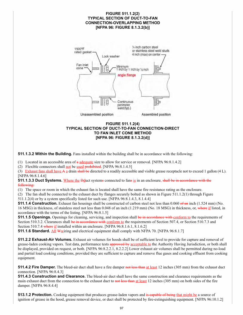
FIGURE 511.1.2(2)TYPICAL SECTION OF DUCT-TO-FAN
CONNECTION-OVERLAPPING METHOD[NFPA 96: FIGURE 8.1.3.2(b)]
FIGURE 511.1.2(4)TYPICAL SECTION OF DUCT-TO-FAN CONNECTION-DIRECT
TO FAN INLET CONE METHOD[NFPA 96: FIGURE 8.1.3.2(d)]
511.1.3.2 Within the Building. Fans installed within the building shall be in accordance with the following:
(1) Located in an accessible area of a adequate size to allow for service or removal. [NFPA 96:8.1.4.2](2) Flexible connectors shall not be used prohibited. [NFPA 96:8.1.4.5](3) Exhaust fans shall have A a drain shall be directed to a readily accessible and visible grease receptacle not to exceed 1 gallon (4 L).[NFPA 96:8.1.4.6]511.1.3.3 Duct Systems. Where the Dduct systems connected to fans is in an enclosure, shall be in accordance with thefollowing:(1) The space or room in which the exhaust fan is located shall have the same fire resistance rating as the enclosure.(2) The fan shall be connected to the exhaust duct by flanges securely bolted as shown in Figure 511.1.2(1) through Figure511.1.2(4) or by a system specifically listed for such use. [NFPA 96:8.1.4.3, 8.1.4.4]511.1.4 Construction. Exhaust fan housings shall be constructed of carbon steel not less than 0.060 of an inch (1.524 mm) (No.16 MSG) in thickness, of stainless steel not less than 0.048 of an inch (1.219 mm) (No. 18 MSG) in thickness, or, where if listed, inaccordance with the terms of the listing. [NFPA 96:8.1.5]511.1.5 Openings. Openings for cleaning, servicing, and inspection shall be in accordance with conform to the requirements ofSection 510.3.2. Clearances shall be in accordance with conform to the requirements of Section 507.4, or Section 510.7.3 andSection 510.7.4 where if installed within an enclosure. [NFPA 96:8.1.6.1, 8.1.6.2]511.1.6 Standard. All Wwiring and electrical equipment shall comply with NFPA 70. [NFPA 96:8.1.7]
511.2.2 Exhaust-Air Volumes. Exhaust air volumes for hoods shall be of sufficient level to provide for capture and removal ofgrease-laden cooking vapors. Test data, performance tests approved by acceptable to the Authority Having Jurisdiction, or both shallbe displayed, provided on request, or both. [NFPA 96:8.2.2.1, 8.2.2.2] Lower exhaust air volumes shall be permitted during no-loadand partial load cooking conditions, provided they are sufficient to capture and remove flue gases and cooking effluent from cookingequipment. 511.4.2 Fire Damper. The bleed-air duct shall have a fire damper not less than at least 12 inches (305 mm) from the exhaust ductconnection. [NFPA 96:8.4.3]511.4.3 Construction and Clearance. The bleed-air duct shall have the same construction and clearance requirements as themain exhaust duct from the connection to the exhaust duct to not less than at least 12 inches (305 mm) on both sides of the firedamper. [NFPA 96:8.4.4] 513.1.2 Protection. Cooking equipment that produces grease-laden vapors and is capable of being that might be a source ofignition of grease in the hood, grease removal device, or duct shall be protected by fire-extinguishing equipment. [NFPA 96:10.1.2]
97
513.2.2 Standard. Automatic fire-extinguishing systems shall comply with UL 300 or other equivalent standards and shall beinstalled in accordance with the requirements of the listing. In existing dry or wet chemical systems not in accordance compliancewith UL 300, the fire-extinguishing system shall be made in accordance to comply with this section where one when any of thefollowing occurs:(1) The cooking medium is changed from animal oils and fats to vegetable oils.(2) The positioning of the cooking equipment is changed.(3) Cooking equipment is replaced.(4) The equipment is no longer supported by the manufacturer. [NFPA 96:10.2.3, 10.2.3.1]Exception: Automatic fire-extinguishing equipment provided as part of listed recirculating systems in accordance shall comply withUL 710B. [NFPA 96:10.2.5]
513.2.4 Modification of Existing Hood Systems. Any abandoned pipe or conduit from a previous installation shall be removedfrom within the hood, plenum, and exhaust duct. [NFPA 96:10.2.7.1]513.2.4.2 Obstructions. The addition of obstructions to spray patterns from the cooking appliance nozzle(s) such as baffle plates,shelves, or any modification shall not be permitted. [NFPA 96:10.2.7.3]
513.4 Fuel and Electric Power Shutoff. Upon activation of any fire-extinguishing system for a cooking operation, all sources offuel and electrical power that produce heat to all equipment requiring protection by that system shall automatically shut off. [NFPA96:10.4.1]Exception: Solid-fuel cooking operations.513.4.1 Steam. Steam supplied from an external source shall not be required to automatically shut off. [NFPA 96:10.4.2]513.4.2 Protection Not Required. Any gas appliance not requiring protection, but located under ventilating equipment whereprotected appliances are located, shall be automatically shut off upon activation of the extinguishing system. [NFPA 96:10.4.3]
514.1.3 Posting of Instructions. Instructions for manually operating the fire-extinguishing system shall be posted conspicuously inthe kitchen and shall be reviewed with employees by the management. [NFPA 96: B.11.1.4 11.1.4.3]
514.5.1 Cleaning. Cooking equipment that collects grease below the surface, behind the equipment, or in cooking equipment flue gasexhaust, such as griddles or charbroilers, shall be inspected and, where if found with grease accumulation, cleaned by a properly trained,qualified, and certified person(s) acceptable to the Authority Having Jurisdiction. [NFPA 96:11.7.2]
515.1.1.3 Minimum Space. All Ddeep-fat fryers shall be installed with not less than at least a 16 inch (406 mm) space between thefryer and surface flames from adjacent cooking equipment. [NFPA 96:12.1.2.4]515.1.1.4 Space Not Required. Where a steel or tempered glass baffle plate is installed not less than at a minimum 8 inches (203mm) in height between the fryer and surface flames of the adjacent appliance, the requirement for a 16 inch (406 mm) space shall notapply. [NFPA 96:12.1.2.5]515.1.1.5 Minimum Height. Where If the fryer and the surface flames are at different horizontal planes, a the minimum height of notless than 8 inches (203 mm) shall be measured from the higher of the two. [NFPA 96:12.1.2.5.1]
516.2 Design Restrictions. All Rrecirculating systems shall comply with the requirements of Section 516.2.1 through Section516.2.9. [NFPA 96:13.2]516.2.1 Gas/Electrically Fueled Cooking Appliances. Only Ggas-fueled or electrically fueled cooking appliances shall be used.Listed gas-fueled equipment designed for use with specific recirculating systems shall have the flue outlets connected in the intendedmanner. Gas-fueled appliances shall have not less than a minimum 18 inches (457 mm) of clearance from the flue outlet to the filterinlet in accordance with Section 509.2.2 through Section 509.2.2.3 and shall be in accordance with meet the installationrequirements of NFPA 54 or NFPA 58. [NFPA 96:13.2.1 – 13.2.3]516.2.3 Protection. Cooking appliances that require protection and that are under a recirculating hood shall be protected by either theintegral fire protection system in accordance with UL 710B or a system in accordance with Section 513.0. [NFPA 96:13.2.4.2]
516.2.8 Power Supply. The power supply of any electrostatic precipitator (ESP) shall be of the “cold spark,” ferroresonant type inwhich the voltage falls off as the current draw of a short increases. [NFPA 96:13.2.11]
516.3 Interlocks. The recirculating system shall be provided with interlocks of critical components and operations as indicated inSection 516.3.1 through Section 516.3.3.1 such that, where if any of these interlock is are interrupted, the cooking appliance shall willnot be able to operate. [NFPA 96:13.3.1]516.3.1 Airflow Sections. All Cclosure panels encompassing airflow sections shall have interlocks to ensure that the panels are inplace and fully sealed. [NFPA 96:13.3.2]
516.4 Location and Application Restrictions. The location of recirculating systems shall be approved by the AuthorityHaving Jurisdiction. Items to be reviewed in the fire risk assessment shall include, but not be limited to, life safety, combustibility ofsurroundings, proximity to air vents, and total fuel load. [NFPA 96:13.4.1 – 13.4.2]
98
516.5.1 Installation Downstream. In addition to any other fire-extinguishing system activation device, there shall be a fire-extinguishing system activation device installed downstream of any ESP. [NFPA 96:13.5.2] 516.6.1 Manufacturer’s Instructions. All Ffilters shall be cleaned or replaced in accordance with the manufacturer’sinstructions. [NFPA 96:13.6.2] 517.1.1 Natural Draft. Where solid-fuel cooking equipment is required by the manufacturer to have a natural draft, the vent shall bein accordance comply with Section 517.4. [NFPA 96:14.1.1]517.1.2 System Compliance. Where the solid-fuel cooking equipment has a self-contained top, is the appliance to be vented in anisolated space (except for a single water heater with its own separate vent), has a separate makeup air system, and is provided withsupply and return air (not supplied or returned from other spaces), the system shall be in accordance comply with Section 517.4 andSection 517.6. [NFPA 96:14.1.2]517.1.3 Makeup Air System. Where the solid-fuel cooking equipment is located in a space with other vented equipment, the allvented equipment shall have an exhaust system interlocked with a makeup air system for the space in accordance with per Section517.6. [NFPA 96:14.1.3] 517.2 Location of Appliances. Every Aappliances shall be located with respect to building construction and other equipment so asto permit access to the appliance. [NFPA 96:14.2.1]517.2.1 Prohibited Location. Solid-fuel cooking appliances shall not be installed in confined spaces. [NFPA 96:14.2.2]Exception: Solid-fuel cooking appliances listed for installation in confined spaces such as alcoves shall be installed in accordance withthe terms of the listing and the manufacturer’s installation instructions. [NFPA 96:14.2.3]517.2.2 Flammable Vapors. Solid-fuel cooking appliances shall not be installed in any location where gasoline or any otherflammable vapors or gases are present. [NFPA 96:14.2.4]517.3 Hoods for Solid-Fuel Cooking. Hoods shall be sized and located in a manner capable of capturing and containing all theeffluent discharging from the appliances. The hood and its exhaust system shall be in accordance comply with the provisionsrequirements of Section 508.0 through Section 513.0. [NFPA 96:14.3.1, 14.3.2]517.3.1 Separation. Except as permitted in Section 517.3.1.1, exhaust systems serving solid-fuel cooking equipment, includinggas or electrically operated equipment, shall be separate from all other exhaust systems. [NFPA 96:14.3.3]Exception: Cooking equipment not requiring automatic fire-extinguishing equipment (in accordance with per Section 513.0) shallbe permitted to be installed under a common hood with solid-fuel cooking equipment that is served by a duct system separate fromall other exhaust systems. [NFPA 96:14.3.5] 517.4 Exhaust Systems for Solid-Fuel Cooking. Where a hood is not required, in buildings where the duct system is threestories or less in height, a duct complying with Section 510.0 shall be provided. [NFPA 96:14.4]517.4.1 Hood. Where If a hood is used in buildings where the duct system is three stories or less in height, the duct system shallcomply with Section 510.0. [NFPA 96:14.4.1]517.4.2 Building Exceeding Four Stories. A listed or approved grease duct system that is four stories in height or greater shall beprovided for solid-fuel cooking exhaust systems. [NFPA 96:14.4.2]517.4.3 Prohibited. Wall terminations of solid-fuel exhaust systems shall be prohibited. [NFPA 96:14.4.4]517.5.1 Spark Arrester Devices. Where If airborne sparks and embers can be generated by the solid fuel cooking operation,spark arrester devices shall be used prior to using the grease removal device, to minimize the entrance of these sparks and embers intothe grease removal device and into the hood and the duct system. [NFPA 96:14.5.2]517.5.2 Filters. Filters shall be not less than a minimum of 4 feet (1219 mm) above the appliance cooking surface. [NFPA96:14.5.3]517.6.1 Replacement Air. A replacement or makeup air system shall be provided to ensure a positive supply of replacement air atall times during cooking operations. [NFPA 96:14.6.2]517.6.2 Operation. Makeup air systems serving solid-fuel cooking operations shall be interlocked with the exhaust air system andpowered, where if necessary, to prevent the space from attaining a negative pressure while the solid-fuel appliance is in operation.[NFPA 96:14.6.3]517.7 Fire-Extinguishing Equipment for Solid-Fuel Cooking. Solid-fuel cooking appliances that produce grease-ladenvapors shall be protected by listed fire-extinguishing equipment.Exception: Where acceptable to the Authority Having Jurisdiction, solid-fuel cooking appliances constructed of solid masonry orreinforced pPortland or refractory cement concrete and vented in accordance with NFPA 211 shall not require fixed automatic fire-extinguishing equipment. [NFPA 96:14.7.1, 14.7.2]517.7.1 Grease Removal Devices, Hoods, and Duct Systems. Listed fire-extinguishing equipment shall be provided for theprotection of grease removal devices, hoods, and duct systems. [NFPA 96:14.7.3]Exception: Where acceptable to the Authority Having Jurisdiction, solid-fuel cooking appliances constructed of solid masonry orreinforced pPortland or refractory cement concrete and vented in accordance with NFPA 211 shall not require automatic fire-extinguishing equipment for the protection of grease removal devices, hoods, and duct systems. [NFPA 96:14.7.4]517.7.2 Listed Fire-Extinguishing Equipment. Listed fire-extinguishing equipment for solid-fuel-burning cooking appliances,where required, shall be in accordance comply with Section 513.0 and shall use water-based agents. [NFPA 96:14.7.5]517.7.3 Rating and Design. The Ffire-extinguishing equipment shall be rated and designed to extinguish solid-fuel cooking fires.The fire-extinguishing equipment shall be of sufficient size to totally extinguish fire in the entire hazard area and prevent reignition of
99
the fuel. [NFPA 96:14.7.6, 14.7.7]517.7.4 Listing/Class. All solid fuel appliances (whether or not under a hood or not) with fireboxes of 5 cubic feet (0.14 m3)volume or less shall have not less than at least a listed 2-A rated water-spray fire extinguisher or a 1.6 gallon (6.1 L) wet chemical fireextinguisher listed for Class K fires in accordance with NFPA 10 with a maximum travel distance of not more than 20 feet (6096 mm)to the appliance. [NFPA 96:14.7.8]517.7.5 Fixed-Water Pipe System. Solid fuel appliances with fireboxes exceeding 5 cubic feet (0.14 m3) shall be provided with afixed-water pipe system with a hose in the kitchen capable of reaching the firebox. The hose shall be equipped with an adjustablenozzle capable of producing a fine to medium spray or mist. The nozzle shall be of the type that cannot produce a straight stream. Thesystem shall have an minimum operating pressure of not less than 40 psi (276 kPa) and shall provide not less than a minimum of 5gallons per minute (gpm) (0.3 L/s). [NFPA 96:14.7.9.1 – 14.7.9.2] 517.7.7 Auxiliary Fuel. In addition to the requirements of Section 517.7.4, Section 517.7.5 and Section 517.8, where any solid-fuelcooking appliance is also provided with auxiliary electric, gas, oil, or other fuel for ignition or supplemental heat and the appliance isalso served by any portion of a fire-extinguishing system in accordance complying with Section 513.0, such auxiliary fuel shall beshut off upon actuation of the fire-extinguishing system. [NFPA 96:14.7.11]517.8.1 Site-Built Solid Fuel Cooling Appliances. Site-built solid-fuel cooking appliances shall be submitted for approval tothe Authority Having Jurisdiction before being considered for installation. All Uunits submitted to the Authority Having Jurisdictionshall be installed, operated, and maintained in accordance with the approved terms of the manufacturer’s instructions andany additional requirements in accordance with set forth by the Authority Having Jurisdiction. [NFPA 96:14.9.4.3.1 – 14.9.4.3.2] 518.0 Downdraft Appliances.518.1 General. A Ddowndraft appliance ventilation system containing, or for use with appliances used in processes that produce,producing smoke or grease-laden vapors shall be equipped with components that are in accordance complying with the following:(1) The clearance requirements in accordance with of Section 507.4.(2) The primary collection means designed for collecting cooking vapors and residues in accordance complying with therequirements of Section 508.0.(3) Grease removal devices that comply complying with Section 509.0.(4) Special-purpose filters as listed in accordance with UL 1046.(5) Exhaust ducts that comply complying with Section 510.0.(6) The air movement requirements in accordance with of Section 511.2.1 and Section 511.2.2.(7) Auxiliary equipment (such as particulate and odor removal devices) are in accordance complying with Section 512.0.(8) Fire-extinguishing equipment that is in accordance complying with the requirements of Section 513.0, and as specified inSection 518.3.(9) The use and maintenance requirements in accordance with of Section 514.0.(10) The minimum safety requirements in accordance with of Section 515.0. [NFPA 96:15.1.1]518.2 Ventilation System. The downdraft appliance ventilation system shall be capable of capturing and containing all theeffluent discharge from the appliance(s) it is serving. [NFPA 96:15.1.2] 518.3.1 Integral Fire-Extinguishing System. A listed downdraft appliance ventilation system employing an integral fire-extinguishing system including detection systems that has been evaluated for grease and smoke capture, fire extinguishing, anddetection shall be considered to be in accordance as complying with Section 518.3. [NFPA 96:15.2.1]518.3.2 Interlocks. The downdraft appliance ventilation system shall be provided with interlocks such that the cooking fuelsupply will not be activated unless the exhaust and supply air systems have been activated. [NFPA 96:15.2.2]518.4.1 Interlocks. The airflow switch or transducer shall open the interlock circuit when the airflow is less than falls 25 percentbelow the system’s normal operating flow or less than 10 percent its listed minimum rating, whichever is less lower. [NFPA96:15.3.2] 518.5 Surface Materials. Any Ssurfaces located directly above the cooking appliance shall be of noncombustible or limited-combustible materials. [NFPA 96:15.4]
SUBSTANTIATION:In accordance with IAPMO's Regulations Governing Committee Projects (Extract Guidelines), the above sections are beingrevised to the latest edition of NFPA 96-2017.
COMMITTEE ACTION: ACCEPTED AS SUBMITTED
TOTAL ELIGIBLE TO VOTE: 26
VOTING RESULTS: AFFIRMATIVE: 25 NOT RETURNED: 1 HOWARD
100
Item #: 045
Comment #: 1
Proposals
Edit Proposal
Item #: 045
UMC 2021 Section: 601.1
SUBMITTER: Christopher JensenUL LLC
RECOMMENDATION:Revise text
601.0 General.601.1 Applicability. Ducts and plenums that are portions of a heating, cooling, ventilation, or exhaust system shall comply withthe requirements of this chapter, except as specified otherwise in Chapters 5 and 7.
SUBSTANTIATION:Chapters 5 and 7 have specific requirements for specific types of ducts, such as grease ducts, product-conveying ducts,combustion air ducts, and laundry exhaust ducts. These specific requirements are critical for addressing the associatedhazards involved with those types of systems. Several of the requirements included in Chapter 6 are not applicable to thoseinstallations, and, if followed, would result in an unsafe installation.
COMMITTEE ACTION: REJECT
COMMITTEE STATEMENT:The proposed change is not necessary as there are sections in Chapter 5 that require compliance with Chapter 6.
TOTAL ELIGIBLE TO VOTE: 26
VOTING RESULTS: AFFIRMATIVE: 23 NEGATIVE: 2 NOT RETURNED: 1 HOWARD
EXPLANATION OF NEGATIVE:
HYDE: I believe this clarification would further clarify that the duct construction identified within Chapter 6 does not take precedenceover duct construction identified in Chapters 5 and 7.
KOERBER: Adding this language would provide clarity between the applicable requirements in Chapters 5, 6, and 7.
Appended Comments
Edit Comment
PUBLIC COMMENT 1
Code Year: 2021 UMC Section #: 601.1
SUBMITTER: Michael HydeState of Idaho - Division of Building Safety
RECOMMENDATION:Revise text
Request to replace the code change proposal by this public comment.
101
Item #: 045
Comment #: 2
601.1 Applicability. Ducts and plenums that are portions of a heating, cooling, ventilation, or exhaust system shall comply withthe requirements of this chapter and Chapter 5.
SUBSTANTIATION:This modification will add “Chapter 5” to the applicable requirements for ducts and plenums as Chapter 5 provides specificrequirements for specific ducts, such as grease ducts, product-conveying ducts, combustion air ducts, and laundry exhaustducts.
COMMITTEE ACTION: ACCEPTED AS SUBMITTED
TOTAL ELIGIBLE TO VOTE: 26
VOTING RESULTS: AFFIRMATIVE: 25 NOT RETURNED: 1 HOWARD
EXPLANATION OF AFFIRMATIVE:
KOERBER: Voting to affirm. However, I still believe the original proposal, including Chapter 7, was appropriate.
Edit Comment
PUBLIC COMMENT 2
Code Year: 2021 UMC Section #: 601.1
SUBMITTER: Ralph KoerberATCO Rubber Products, Inc.Rep. Air Duct Council
RECOMMENDATION:Revise text
Request to accept the code change proposal as submitted by this public comment.
SUBSTANTIATION:The current language in Section 601.1 indicates that ducts and plenums for heating, cooling, ventilation, and exhaustsystems shall comply with Chapter 6 while specific sections in Chapters 5 and 7 for ducts serving unique ventilation andexhaust conditions have additional and/or conflicting requirements.
Revising the text to include this exception clarifies the intention for each chapter to be reviewed to ascertain the appropriaterequirements specific to the duct system in question. Just as Chapter 5 refers back to Chapter 6 where appropriate, Chapter6 should reciprocate. Chapter 7 should also be referenced for specific requirements for combustion air ducts that differ fromChapter 6.
This revision would bring clarity to the code sections.
COMMITTEE ACTION: REJECT
COMMITTEE STATEMENT:Reject Comment # 2 based on the action taken on Comment # 1.
TOTAL ELIGIBLE TO VOTE: 26
VOTING RESULTS: AFFIRMATIVE: 24 ABSTAIN: 1 NOT RETURNED: 1 HOWARD
EXPLANATION OF ABSTAIN:
KOERBER: Voting to abstain as I still believe the original proposal including Chapter 7 was appropriate.
102
Proposals
Edit Proposal
Item #: 046
UMC 2021 Section: 601.2, Table 1701.1
SUBMITTER: David C. BixbyAir Conditioning Contractors of America
RECOMMENDATION:Revise text
601.0 General.
601.2 Sizing Requirements. Duct systems shall be sized in accordance with ACCA Manual D listed in Table 1701.1, or by otherapproved methods; zoned duct systems shall also comply with ACCA Manual Zr.
TABLE 1701.1REFERENCED STANDARDS
STANDARD NUMBER STANDARD TITLE APPLICATION REFERENCEDSECTION
ANSI/ACCA Manual Zr-2018 (Draft) Residential HVAC System Zoning Ducts 601.2
(portion of table not shown remains unchanged)
Note: ACCA Manual Zr is a working draft and is not completed at the time of this monograph.
SUBSTANTIATION:Currently there is no coverage in the UMC to address the design of zoned duct systems. ACCA Manual Zr providesprocedures for designing zoned comfort systems for single family detached homes, duplex and triplex homes, row houses,town houses, and large multi-family structures that are compatible with ACCA Manual J procedures for residential loadcalculations. In addition, use of Manual Zr will avoid the potential for an improperly designed zoned duct system to adverselyimpact the safe operation and durability of the heating/cooling equipment. For code officials, Manual Zr has three normativesections to determine clear compliance. Manual Zr is also a consensus-based ANSI standard.
The addition of ACCA Manual Zr is needed to support its proposed reference as a new requirement under 601.2. Manual Zris a consensus-based ANSI standard that meets the requirements for mandatory reference standards in accordance withSection 3-3.7.1 of IAPMO’s Regulations Governing Projects.
COMMITTEE ACTION: REJECT
COMMITTEE STATEMENT:The proposal is being rejected as ACCA Manual Zr is a working draft and is not completed at the time of this monograph.
TOTAL ELIGIBLE TO VOTE: 26
VOTING RESULTS: AFFIRMATIVE: 24 NEGATIVE: 1 NOT RETURNED: 1 HOWARD
EXPLANATION OF NEGATIVE:
HYDE: I believe this Standard should be a referenced standard in conjunction with ACCA Manual D for all residential duct designsystems that choose to "zone" their systems.
103
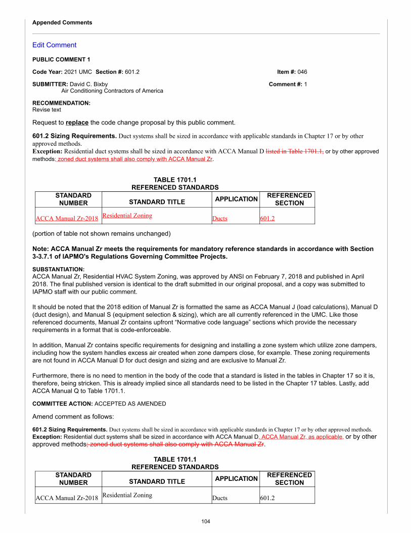
Item #: 046
Comment #: 1
Appended Comments
Edit Comment
PUBLIC COMMENT 1
Code Year: 2021 UMC Section #: 601.2
SUBMITTER: David C. BixbyAir Conditioning Contractors of America
RECOMMENDATION:Revise text
Request to replace the code change proposal by this public comment.
601.2 Sizing Requirements. Duct systems shall be sized in accordance with applicable standards in Chapter 17 or by otherapproved methods.Exception: Residential duct systems shall be sized in accordance with ACCA Manual D listed in Table 1701.1, or by other approvedmethods; zoned duct systems shall also comply with ACCA Manual Zr.
TABLE 1701.1REFERENCED STANDARDS
STANDARDNUMBER STANDARD TITLE APPLICATION REFERENCED
SECTION
ACCA Manual Zr-2018 Residential Zoning Ducts 601.2
(portion of table not shown remains unchanged)
Note: ACCA Manual Zr meets the requirements for mandatory reference standards in accordance with Section3-3.7.1 of IAPMO's Regulations Governing Committee Projects.
SUBSTANTIATION:ACCA Manual Zr, Residential HVAC System Zoning, was approved by ANSI on February 7, 2018 and published in April2018. The final published version is identical to the draft submitted in our original proposal, and a copy was submitted toIAPMO staff with our public comment.
It should be noted that the 2018 edition of Manual Zr is formatted the same as ACCA Manual J (load calculations), Manual D(duct design), and Manual S (equipment selection & sizing), which are all currently referenced in the UMC. Like thosereferenced documents, Manual Zr contains upfront “Normative code language” sections which provide the necessaryrequirements in a format that is code-enforceable.
In addition, Manual Zr contains specific requirements for designing and installing a zone system which utilize zone dampers,including how the system handles excess air created when zone dampers close, for example. These zoning requirementsare not found in ACCA Manual D for duct design and sizing and are exclusive to Manual Zr.
Furthermore, there is no need to mention in the body of the code that a standard is listed in the tables in Chapter 17 so it is,therefore, being stricken. This is already implied since all standards need to be listed in the Chapter 17 tables. Lastly, addACCA Manual Q to Table 1701.1.
COMMITTEE ACTION: ACCEPTED AS AMENDED
Amend comment as follows:
601.2 Sizing Requirements. Duct systems shall be sized in accordance with applicable standards in Chapter 17 or by other approved methods.Exception: Residential duct systems shall be sized in accordance with ACCA Manual D, ACCA Manual Zr, as applicable, or by otherapproved methods; zoned duct systems shall also comply with ACCA Manual Zr.
TABLE 1701.1REFERENCED STANDARDS
STANDARDNUMBER STANDARD TITLE APPLICATION REFERENCED
SECTION
ACCA Manual Zr-2018 Residential Zoning Ducts 601.2
104
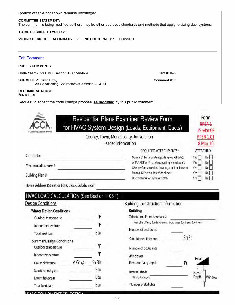
Item #: 046
Comment #: 2
(portion of table not shown remains unchanged)
COMMITTEE STATEMENT:The comment is being modified as there may be other approved standards and methods that apply to sizing duct systems.
TOTAL ELIGIBLE TO VOTE: 26
VOTING RESULTS: AFFIRMATIVE: 25 NOT RETURNED: 1 HOWARD
Edit Comment
PUBLIC COMMENT 2
Code Year: 2021 UMC Section #: Appendix A
SUBMITTER: David BixbyAir Conditioning Contractors of America (ACCA)
RECOMMENDATION:Revise text
Request to accept the code change proposal as modified by this public comment.
105
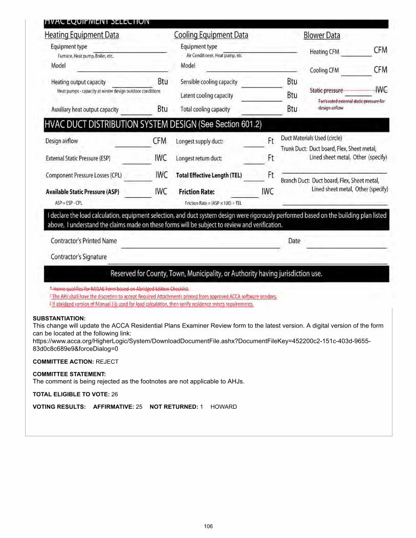
SUBSTANTIATION:This change will update the ACCA Residential Plans Examiner Review form to the latest version. A digital version of the formcan be located at the following link: https://www.acca.org/HigherLogic/System/DownloadDocumentFile.ashx?DocumentFileKey=452200c2-151c-403d-9655-83d0c8c689e9&forceDialog=0
COMMITTEE ACTION: REJECT
COMMITTEE STATEMENT:The comment is being rejected as the footnotes are not applicable to AHJs.
TOTAL ELIGIBLE TO VOTE: 26
VOTING RESULTS: AFFIRMATIVE: 25 NOT RETURNED: 1 HOWARD
106
Proposals
Edit Proposal
Item #: 048
UMC 2021 Section: 601.2, 902.1, 1105.1, 1302.3
SUBMITTER: David DiasSheet Metal Workers Local 104
RECOMMENDATION:Revise text
601.0 General.
601.2 Sizing Requirements. Duct systems shall be sized in accordance with ACCA Manual D listed in Table 1701.1, or by otherapproved methods.
902.0 General.902.1 Nonindustrial Appliance. This chapter is applicable primarily to nonindustrial-type appliances and installations and,unless specifically indicated, does not apply to industrial-type appliances and installations. Listed appliances shall be installed inaccordance with their listing and the manufacturer’s installation instructions or, as elsewhere specified in this chapter, as applicableto the appliance. Unlisted appliances shall be installed as specified in this part as applicable to the appliances. For additionalinformation concerning particular appliances and accessories, including industrial types, reference can be made to the standards listed in Chapter 17.
1105.0 General Requirements.1105.1 Human Comfort. Cooling systems used for human comfort shall be in accordance with the return-air and outside-airprovisions for furnaces in Section 904.7 and Section 904.8. Cooling equipment used for human comfort in dwelling units shall beselected to satisfy the calculated loads determined in accordance with the reference standards in Chapter 17 or other approved methods.Refrigerants used for human comfort shall be in accordance with Section 1104.6.
1302.0 Coverage of Piping System.
1302.3 Applications. This code shall not apply to the following items (reference standards for some of which appear in Chapter 17):
(remaining text unchanged)
SUBSTANTIATION:In the 2018 edition of the UMC, Table 1701.1 has been split into two separate tables. Therefore, the existing reference tothose tables must be revised to provide the proper standard for the applications. Section 601.2, Section 902.1, 1105.1, andSection 1302.3 are being revised to remove the reference to Table 1701.1 as it is unnecessary. All standards referenced inthe body of the code are listed in Table 1701.1.
COMMITTEE ACTION: ACCEPT AS AMENDED BY THE TC
Amend proposal as follows:
601.0 General.
601.2 Sizing Requirements. Duct systems shall be sized in accordance with applicable standards in Chapter 17 ACCA ManualD or by other approved methods.Exception: Residential duct systems shall be sized in accordance with ACCA Manual D listed in Table 1701.1, or by otherapproved methods.
902.0 General.107
Item #: 048
Comment #: 1
902.1 Nonindustrial Appliance. This chapter is applicable primarily to nonindustrial-type appliances and installations and,unless specifically indicated, does not apply to industrial-type appliances and installations. Listed appliances shall be installed inaccordance with their listing and the manufacturer’s installation instructions or, as elsewhere specified in this chapter, as applicableto the appliance. Unlisted appliances shall be installed as specified in this part as applicable to the appliances.
1105.0 General Requirements.1105.1 Human Comfort. Cooling systems used for human comfort shall be in accordance with the return-air and outside-airprovisions for furnaces in Section 904.7 and Section 904.8. Cooling equipment used for human comfort in dwelling units shall beselected to satisfy the calculated loads determined. Refrigerants used for human comfort shall be in accordance with Section 1104.6.
1302.0 Coverage of Piping System.
1302.3 Applications. This code shall not apply to the following items:
(remaining text unchanged)
COMMITTEE STATEMENT:The modification clarifies the intent of the code in regards to residential unit duct systems that are sized to ACCA Manual D.
TOTAL ELIGIBLE TO VOTE: 26
VOTING RESULTS: AFFIRMATIVE: 25 NOT RETURNED: 1 HOWARD
Appended Comments
Edit Comment
PUBLIC COMMENT 1: (Assembly Action)
Code Year: 2021 UMC Section #: 302.1.2
SUBMITTER: David MannSelf
RECOMMENDATION:Revise text
Request to accept the code change proposal as modified by this public comment.
302.0 Materials – Standards and Alternates.
302.1 Minimum Standards. (remaining text unchanged)
302.1.2 Standards. Standards listed or referred to in this chapter or other chapters cover materials that will conform to therequirements of this code, where used in accordance with the limitations imposed in this or other chapters thereof and their listing.Where a standard covers materials of various grades, weights, quality, or configurations, the portion of the listed standard that isapplicable shall be used. Design and materials for special conditions or materials not provided for herein shall be permitted to beused by special permission of the Authority Having Jurisdiction after the Authority Having Jurisdiction has been satisfied as to theiradequacy. A list of mechanical standards that appear in specific sections of this code is referenced in Table 1701.1. Standardsreferenced in Table 1701.1 shall be applied as indicated in the applicable referenced section. A list of additional approved standards,publications, practices and guides that are not referenced in specific sections of this code appear in Table 1701.2. The documentsindicated in Table 1701.2 shall be permitted in accordance with Section 302.2.
SUBSTANTIATION:Section 302.1.2 is being revised as the action taken on Item # 048 (Section 601.2) contradicts with Section 302.1.2.Furthermore, the revision allows the end user to use an applicable approved standard in Table 1701.2. The proposedmodification will prevent confusion in the field and will prevent contradictions within the UMC. Section 302.1.2 must berevised as the approved standards in Table 1701.2 can be used, where applicable, without additional approval in accordancewith Section 302.2.
COMMITTEE ACTION: ACCEPTED AS SUBMITTED
TOTAL ELIGIBLE TO VOTE: 26
VOTING RESULTS: AFFIRMATIVE: 25 NOT RETURNED: 1 HOWARD
108
Proposals
Edit Proposal
Item #: 049
UMC 2021 Section: 602.2, Table 1701.1
SUBMITTER: Christopher JensenUL LLC
RECOMMENDATION:Add new text
602.0 Material.
602.2 Combustibles Within Ducts or Plenums. (remaining text unchanged)
602.2.6 Plastic Piping and Tubing in Plumbing Systems. Plastic piping and tubing used in plumbing systems shall bepermitted to be used within a plenum if it exhibits a flame spread index of 25 or less and a smoke developed index of 50 or lesswhen tested in accordance with ASTM E84 or UL 723, at full width of the tunnel and with no water or any other liquid in the pipeduring the test, unless otherwise permitted by Section 602.2.6.1. [NFPA 90A 4.3.11.5.5.7]
602.2.6.1 Plastic Water Distribution Piping and Tubing. Plastic water distribution piping and tubing listed as having amaximum peak optical density of 0.5 or less, an average optical density of 0.15 or less, and a maximum flame spread distance of 5 ft(1.5 m) or less when tested in accordance with UL 2846, and installed in accordance with its listing, shall be permitted to be usedwithin a plenum. [NFPA 90A 4.3.11.5.5.8]
TABLE 1701.1
REFERENCED STANDARDS
STANDARDNUMBER STANDARD TITLE APPLICATION
REFERENCEDSECTIONS
ASTM E84-2016 Surface Burning Characteristics of Building Materials Miscellaneous 508.3.4, 602.2, 602.2.6,604.1.2, 1201.2
UL 723-2008 Test for Surface Burning Characteristics of BuildingMaterials (with revisions through August 12, 2013)
Miscellaneous 508.3.4, 602.2, 602.2.6,604.1.2, 1201.2
UL 2846-2014Fire Test of Plastic Water Distribution Plumbing Pipefor Visible Flame and Smoke Characteristics (withrevisions through December 20, 2016)
Miscellaneous 602.2.6.1
(portion of table not shown remains unchanged)
Note: ASTM E84, UL 723, and UL 2846 meet the requirements for mandatory reference standards in accordancewith Section 3-3.7.1 of IAPMO's Regulations Governing Committee Projects.
SUBSTANTIATION:The 2018 edition of NFPA 90A, Standard for the Installation of Air-Conditioning and Ventilating Systems, which is an ANSIstandard, provides specific requirements for the installation in plenums for plastic piping and tubing used in plumbingsystems. NFPA 90A also permits the installation of plastic water distribution piping and tubing in plenums, where tested inaccordance with UL 2846. This proposal is a direct extract from NFPA 90A.
UL 2846 is an ANSI standard that includes a test method for determining values of flame propagation distance and optical
109
Item #: 049
Comment #: 1
smoke density for individual pairs of plastic plumbing pipes for distribution of potable water that can be installed in ducts,plenums, and other spaces used for environmental air.The scope of this standard can be viewed at http://ulstandards.ul.com/standard/?id=2846. The acceptance criteria specified(peak optical density not greater than 0.50, an average optical density not greater than 0.15, and a flame spread distance notgreater than 5 feet) is consistent with values in Sections 602.2.1, 602.2.2 and 602.2.3.
COMMITTEE ACTION: REJECT
COMMITTEE STATEMENT:The proposed change is being rejected based on the action taken on Item # 051. Furthermore, the proposed languageaddresses requirements that belong in a standard rather than in the code.
TOTAL ELIGIBLE TO VOTE: 26
VOTING RESULTS: AFFIRMATIVE: 20 NEGATIVE: 5 NOT RETURNED: 1 HOWARD
EXPLANATION OF NEGATIVE:
CUDAHY: While I prefer the approach in Item # 050, at least this introduces UL 2846. Vote to overturn Item # 050.
EGG: It seems the new language improves the code.
KOERBER: I believe this proposal, placing into the code, the requirements from the NFPA standard makes sense.
MACNEVIN: The proposed new language improves the code. UL 2846 is the most appropriate test method for plastic pipes formechanical or plumbing applications. This proposal accurately adds reference to UL 2846, and includes appropriate requirements forsafe installation of these materials within plenums.
A. TRAFTON: The new language improves the code.
Appended Comments
Edit Comment
PUBLIC COMMENT 1
Code Year: 2021 UMC Section #: 602.2(5), 602.2.5, Table 1701.1
SUBMITTER: Christopher JensenUL LLC
RECOMMENDATION:Revise text
Request to replace the code change proposal by this public comment.
602.0 Material.
602.2 Combustibles Within Ducts or Plenums. Materials exposed within ducts or plenums shall be noncombustible or shallhave a flame spread index not to exceed 25 and a smoke-developed index not to exceed 50, where tested as a composite product inaccordance with ASTM E84 or UL 723. Plastic piping installed in plenums shall be tested in accordance with all requirements ofASTM E84 or UL 723. Mounting methods, supports and sample sizes of materials for testing that are not specified in ASTM E84 orUL 723 shall be prohibited.
Exceptions:(1) - (4) (remaining text unchanged)(5) Products listed and labeled for installation within plenums in accordance with Section 602.2.1 through 602.2.3 602.2.5.(6) - (8) (remaining text unchanged)
602.2.5 Plastic Water Distribution Piping and Tubing. Plastic water distribution piping and tubing listed as having amaximum peak optical density of 0.5 or less, an average optical density of 0.15 or less, and a maximum flame spread distance of 5 ft(1524 mm) or less when tested in accordance with UL 2846, and installed in accordance with its listing, shall be permitted to beused within a raised floor plenum. [NFPA 90A:4.3.11.5.5.8]
110
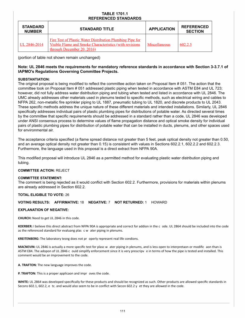
TABLE 1701.1REFERENCED STANDARDS
STANDARDNUMBER STANDARD TITLE APPLICATION REFERENCED
SECTION
UL 2846-2014Fire Test of Plastic Water Distribution Plumbing Pipe forVisible Flame and Smoke Characteristics (with revisionsthrough December 20, 2016)
Miscellaneous 602.2.5
(portion of table not shown remain unchanged)
Note: UL 2846 meets the requirements for mandatory reference standards in accordance with Section 3-3.7.1 ofIAPMO's Regulations Governing Committee Projects.
SUBSTANTIATION:The original proposal is being modified to reflect the committee action taken on Proposal Item # 051. The action that thecommittee took on Proposal Item # 051 addressed plastic piping when tested in accordance with ASTM E84 and UL 723;however, did not fully address water distribution piping and tubing when tested and listed in accordance with UL 2846. TheUMC already addresses other materials used in plenums tested to specific methods, such as electrical wiring and cables toNFPA 262, non-metallic fire sprinkler piping to UL 1887, pneumatic tubing to UL 1820, and discrete products to UL 2043.These specific methods address the unique nature of these different materials and intended installations. Similarly, UL 2846specifically addresses individual pairs of plastic plumbing pipes for distributions of potable water. As directed several timesby the committee that specific requirements should be addressed in a standard rather than a code, UL 2846 was developedunder ANSI consensus process to determine values of flame propagation distance and optical smoke density for individualpairs of plastic plumbing pipes for distribution of potable water that can be installed in ducts, plenums, and other spaces usedfor environmental air.
The acceptance criteria specified (a flame spread distance not greater than 5 feet, peak optical density not greater than 0.50,and an average optical density not greater than 0.15) is consistent with values in Sections 602.2.1, 602.2.2 and 602.2.3.Furthermore, the language used in this proposal is a direct extract from NFPA 90A.
This modified proposal will introduce UL 2846 as a permitted method for evaluating plastic water distribution piping andtubing.
COMMITTEE ACTION: REJECT
COMMITTEE STATEMENT:The comment is being rejected as it would conflict with Section 602.2. Furthermore, provisions for materials within plenumsare already addressed in Section 602.2.
TOTAL ELIGIBLE TO VOTE: 26
VOTING RESULTS: AFFIRMATIVE: 18 NEGATIVE: 7 NOT RETURNED: 1 HOWARD
EXPLANATION OF NEGATIVE:
CHURCH: Need to get UL 2846 in this code.
KOERBER: I believe this direct abstract from NFPA 90A is appropriate and correct for addi�on in the c ode. UL 2864 should be included into the codeas the referenced standard for evalua�ng plas �c w ater piping in plenums.
KREITENBERG: The laboratory tes�ng does not pr operly represent real life condi�ons.
MACNEVIN: UL 2846 is actually a more specific test for plas�c w ater piping in plenums, and is less open to interpreta�on or modific a�on than isASTM E84. The adop�on of UL 2846 c ould simplify enforcement since it is very prescrip�v e in terms of how the pipe is tested and installed. Thiscomment would be an improvement to the code.
A. TRAFTON: The new language improves the code.
P. TRAFTON: This is a proper applica�on and impr oves the code.
WHITE: UL 2864 was developed specifically for these products and should be recognized as such. Other products are allowed specific standards inSec�ons 602.1, 602.2, e tc. and would also seem to be in conflict with Sec�on 602.2 y et they are allowed in the code.
111
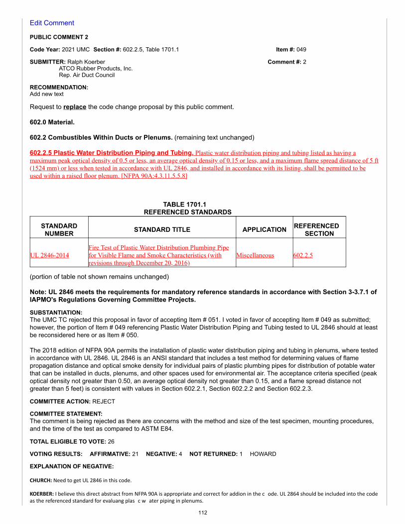
Item #: 049
Comment #: 2
Edit Comment
PUBLIC COMMENT 2
Code Year: 2021 UMC Section #: 602.2.5, Table 1701.1
SUBMITTER: Ralph KoerberATCO Rubber Products, Inc.Rep. Air Duct Council
RECOMMENDATION:Add new text
Request to replace the code change proposal by this public comment.
602.0 Material.
602.2 Combustibles Within Ducts or Plenums. (remaining text unchanged)
602.2.5 Plastic Water Distribution Piping and Tubing. Plastic water distribution piping and tubing listed as having amaximum peak optical density of 0.5 or less, an average optical density of 0.15 or less, and a maximum flame spread distance of 5 ft(1524 mm) or less when tested in accordance with UL 2846, and installed in accordance with its listing, shall be permitted to beused within a raised floor plenum. [NFPA 90A:4.3.11.5.5.8]
TABLE 1701.1REFERENCED STANDARDS
STANDARDNUMBER STANDARD TITLE APPLICATION REFERENCED
SECTION
UL 2846-2014Fire Test of Plastic Water Distribution Plumbing Pipefor Visible Flame and Smoke Characteristics (withrevisions through December 20, 2016)
Miscellaneous 602.2.5
(portion of table not shown remains unchanged)
Note: UL 2846 meets the requirements for mandatory reference standards in accordance with Section 3-3.7.1 ofIAPMO's Regulations Governing Committee Projects.
SUBSTANTIATION:The UMC TC rejected this proposal in favor of accepting Item # 051. I voted in favor of accepting Item # 049 as submitted;however, the portion of Item # 049 referencing Plastic Water Distribution Piping and Tubing tested to UL 2846 should at leastbe reconsidered here or as Item # 050.
The 2018 edition of NFPA 90A permits the installation of plastic water distribution piping and tubing in plenums, where testedin accordance with UL 2846. UL 2846 is an ANSI standard that includes a test method for determining values of flamepropagation distance and optical smoke density for individual pairs of plastic plumbing pipes for distribution of potable waterthat can be installed in ducts, plenums, and other spaces used for environmental air. The acceptance criteria specified (peakoptical density not greater than 0.50, an average optical density not greater than 0.15, and a flame spread distance notgreater than 5 feet) is consistent with values in Section 602.2.1, Section 602.2.2 and Section 602.2.3.
COMMITTEE ACTION: REJECT
COMMITTEE STATEMENT:The comment is being rejected as there are concerns with the method and size of the test specimen, mounting procedures,and the time of the test as compared to ASTM E84.
TOTAL ELIGIBLE TO VOTE: 26
VOTING RESULTS: AFFIRMATIVE: 21 NEGATIVE: 4 NOT RETURNED: 1 HOWARD
EXPLANATION OF NEGATIVE:
CHURCH: Need to get UL 2846 in this code.
KOERBER: I believe this direct abstract from NFPA 90A is appropriate and correct for addi�on in the c ode. UL 2864 should be included into the codeas the referenced standard for evalua�ng plas �c w ater piping in plenums.
112
MACNEVIN: Same response as for Comment 01: "UL 2846 is actually a more specific test for plas�c w ater piping in plenums, and is less open tointerpreta�on or modific a�on than is AS TM E84. The adop�on of UL 2846 c ould simplify enforcement since it is very prescrip�v e in terms of howthe pipe is tested and installed. This comment would be an improvement to the code." WHITE: UL 2864 should be accepted in this code as a recognized method for evalua�ng piping ma terials.
113
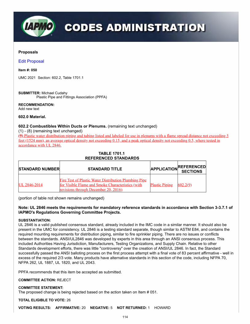
Proposals
Edit Proposal
Item #: 050
UMC 2021 Section: 602.2, Table 1701.1
SUBMITTER: Michael CudahyPlastic Pipe and Fittings Association (PPFA)
RECOMMENDATION:Add new text
602.0 Material.
602.2 Combustibles Within Ducts or Plenums. (remaining text unchanged)(1) - (8) (remaining text unchanged)(9) Plastic water distribution piping and tubing listed and labeled for use in plenums with a flame spread distance not exceeding 5feet (1524 mm), an average optical density not exceeding 0.15, and a peak optical density not exceeding 0.5, where tested inaccordance with UL 2846.
TABLE 1701.1 REFERENCED STANDARDS
STANDARD NUMBER STANDARD TITLE APPLICATIONREFERENCEDSECTIONS
UL 2846-2014Fire Test of Plastic Water Distribution Plumbing Pipefor Visible Flame and Smoke Characteristics (withrevisions through December 20, 2016)
Plastic Piping 602.2(9)
(portion of table not shown remains unchanged)
Note: UL 2846 meets the requirements for mandatory reference standards in accordance with Section 3-3.7.1 ofIAPMO's Regulations Governing Committee Projects.
SUBSTANTIATION:UL 2846 is a valid published consensus standard, already included in the IMC code in a similar manner. It should also bepresent in the UMC for consistency. UL 2846 is a testing standard separate, though similar to ASTM E84, and contains therequired mounting requirements for distribution piping, similar to fire sprinkler piping. There are no issues or conflictsbetween the standards. ANSI/UL2846 was developed by experts in this area through an ANSI consensus process. Thisincluded Authorities Having Jurisdiction, Manufacturers, Testing Organizations, and Supply Chain. Relative to otherStandards development efforts, there was little "controversy" over the creation of ANSI/UL 2846. In fact, the Standardsuccessfully passed the ANSI balloting process on the first process attempt with a final vote of 83 percent affirmative - well inexcess of the required 2/3 vote. Many products have alternative standards in this section of the code, including NFPA 70,NFPA 262, UL 1887, UL 1820, and UL 2043.
PPFA recommends that this item be accepted as submitted.
COMMITTEE ACTION: REJECT
COMMITTEE STATEMENT:The proposed change is being rejected based on the action taken on Item # 051.
TOTAL ELIGIBLE TO VOTE: 26
VOTING RESULTS: AFFIRMATIVE: 20 NEGATIVE: 5 NOT RETURNED: 1 HOWARD
114

Item #: 050
Comment #: 1
EXPLANATION OF NEGATIVE:
CUDAHY: I am voting AGAINST the committee action to reject on this item from the meeting. The UL 2846 standard is a consensusstandard by UL, and is already in another model mechanical code a full cycle. Codes should adopt testing standards made specificallyfor items that follow the required process. ASTM E84 is a general test for any product and, therefore, there are alternative standardsdesigned for testing many products with morphologies similar to pipe – such as wire, pneumatic tubing, and fire sprinklers already inthe codes. This item does not conflict with any other proposal items. There was some confusing discussion during the item, but UL2846 is a dry test, no water. Therefore, vote AGAINST the committee action on Item # 050 to overturn.
EGG: The new language improves the code.
KOERBER: Reference to the standard should be included.
MACNEVIN: The proposed new language improves the code. UL 2846 is the most appropriate test method for plastic pipes formechanical or plumbing applications. This proposal accurately adds reference to UL 2846, and includes appropriate requirements forsafe installation of these materials within plenums.
A. TRAFTON: Reference to the standard should be included.
Appended Comments
Edit Comment
PUBLIC COMMENT 1
Code Year: 2021 UMC Section #: 602.2(9)
SUBMITTER: Ralph Koerber (ATCO Rubber Products, Inc., Air Duct Council); ForestHampton III (Lubrizol Advanced Materials, Inc.); Michael Cudahy (PPFA)
RECOMMENDATION:Add new text
Request to accept the code change proposal as submitted by this public comment.
SUBSTANTIATION:
KOERBER:The UMC TC rejected this proposal in favor of accepting Item # 051. I voted in favor of accepting Item # 050 as submitted (or acceptingthe corresponding portion of Item # 049). This standard is the proper test method for testing of plastic water distribution piping andtubing. UL 2846 is an ANSI standard that includes a test method for determining values of flame propagation distance and optical smokedensity for individual pairs of plastic plumbing pipes for distribution of potable water that can be installed in ducts, plenums, and otherspaces used for environmental air. The acceptance criteria specified (peak optical density not greater than 0.50, an average opticaldensity not greater than 0.15, and a flame spread distance not greater than 5 feet) is consistent with values in Sections 602.2.1,602.2.2 and 602.2.3.
HAMPTON III: The UL 2846 standard is a consensus standard written by UL and describes how to mount and test plastic water distribution plumbingpipe. ASTM E84 was written originally for flat products and in the UMC there are alternative standards referenced for testing productswith morphologies similar to water distribution pipe – such as wire, pneumatic tubing, and fire sprinkler pipe. The Committee Statementof, “The proposed change is being rejected based on the action taken on Item # 051” is not relevant as the proposed changes in item #051 do not have anything to do with mounting and testing water distribution pipe. Therefore, it is not a sufficient technical justificationfor rejecting this proposal. There were some confusing discussions during testimony as to if the standard allowed pipe to be tested withwater. It does not. UL 2846 Section 4.1 states, “…There shall be no water or any other liquid in the pipe during the test.”
CUDAHY:PPFA recommends approval as submitted of Item # 050. The UL 2846 standard is a consensus standard by UL, and is already inanother model mechanical code over a full cycle. Codes should adopt testing standards made specifically for items that follow therequired process. ASTM E84 is a general test for any product and, therefore, there are alternative standards designed for testing manyproducts with morphologies similar to pipe - such as wire, pneumatic tubing, and fire sprinklers already in the codes. This item does notconflict with any other proposal items. UL 2846 is a dry test, no water.
COMMITTEE ACTION: REJECT
COMMITTEE STATEMENT:The change is being rejected as there are concerns for public health and safety if UL 2846 is followed and installation is doneincorrectly. UL 2846 is limited to testing and does not give clear direction for its application. Furthermore, this change willconflict with Section 602.2.
115
TOTAL ELIGIBLE TO VOTE: 26
VOTING RESULTS: AFFIRMATIVE: 20 NEGATIVE: 4 ABSTAIN: 1 NOT RETURNED: 1 HOWARD
EXPLANATION OF NEGATIVE:
MACNEVIN: UL 2846 is actually a more specific test for plas�c w ater piping in plenums and is less open to interpreta�on or modific a�on than isASTM E84. UL 2846 is no less rigorous than the ASTM E84 test, and in some cases, UL 2846 is more rigorous, as there are no modifica�ons allo wed.The adop�on of UL 2846 c ould simplify enforcement since it is very prescrip�v e in terms of how the pipe is tested and installed. This commentwould be an improvement to the Code. For the next cycle, an "educa�on session" should be pr esented by UL staff about the differences betweenASTM E84 and UL 2846 tes�ng. WHITE: UL 2846 should be accepted into the code as a recognized tes�ng me thod. KOERBER: UL 2864 should be included into the code as the referenced standard for evalua�ng plas �c w ater piping in plenums. CHURCH: The reasons for rejec�on ar e quite interes�ng bec ause my notes show and my recollec�on is tha t the reasons for rejec�on specific allyaddressed the length of the test and the fact that it is a test for two pipes up to 4 inches in diameter. The reason for rejec�on as published sa ysthere are concerns for public health - I guess that includes the length of test and the two-pipe test. There's some further comment about beinginstalled incorrectly - that has no place in this proceeding; every product could be installed incorrectly and create a hazard. Another reason given is: "Furthermore, this change will conflict with Sec�on 602.2." Tha t also seems invalid because similar excep�ons alr eadyexist and most of these excep�ons ar e based on tests that mirror UL 2846. You heard tes�mon y that this test is a more stringent test than ASTM E84 because it runs twice as long and the smoke genera�on t ests aremeasured over�me and f or a peak density - two criteria, not one, for starters. A paper that was passed out to some TC members before the itemwas heard was full of misinforma�on and seemed t o confuse the requirements of ASTM E84 and UL 2846. What we have is a legi�ma te test, that truly already exists in the code for other materials, that is an American Na�onal St andard and is the mostimportant way that plas�c w ater distribu�on pipe c an be tested for use in plenums. We sincerely hope the TC will reverse its ac�on on this issue.
EXPLANATION OF ABSTAIN:
DELAQUILA: Nega�v e commenters bring up legi�ma te concerns.
116
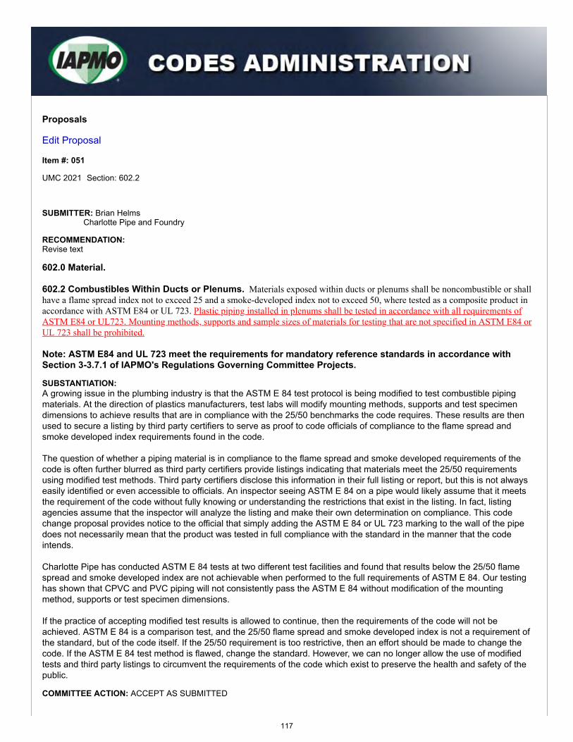
Proposals
Edit Proposal
Item #: 051
UMC 2021 Section: 602.2
SUBMITTER: Brian HelmsCharlotte Pipe and Foundry
RECOMMENDATION:Revise text
602.0 Material.
602.2 Combustibles Within Ducts or Plenums. Materials exposed within ducts or plenums shall be noncombustible or shallhave a flame spread index not to exceed 25 and a smoke-developed index not to exceed 50, where tested as a composite product inaccordance with ASTM E84 or UL 723. Plastic piping installed in plenums shall be tested in accordance with all requirements ofASTM E84 or UL723. Mounting methods, supports and sample sizes of materials for testing that are not specified in ASTM E84 orUL 723 shall be prohibited.
Note: ASTM E84 and UL 723 meet the requirements for mandatory reference standards in accordance withSection 3-3.7.1 of IAPMO's Regulations Governing Committee Projects.
SUBSTANTIATION:A growing issue in the plumbing industry is that the ASTM E 84 test protocol is being modified to test combustible pipingmaterials. At the direction of plastics manufacturers, test labs will modify mounting methods, supports and test specimendimensions to achieve results that are in compliance with the 25/50 benchmarks the code requires. These results are thenused to secure a listing by third party certifiers to serve as proof to code officials of compliance to the flame spread andsmoke developed index requirements found in the code.
The question of whether a piping material is in compliance to the flame spread and smoke developed requirements of thecode is often further blurred as third party certifiers provide listings indicating that materials meet the 25/50 requirementsusing modified test methods. Third party certifiers disclose this information in their full listing or report, but this is not alwayseasily identified or even accessible to officials. An inspector seeing ASTM E 84 on a pipe would likely assume that it meetsthe requirement of the code without fully knowing or understanding the restrictions that exist in the listing. In fact, listingagencies assume that the inspector will analyze the listing and make their own determination on compliance. This codechange proposal provides notice to the official that simply adding the ASTM E 84 or UL 723 marking to the wall of the pipedoes not necessarily mean that the product was tested in full compliance with the standard in the manner that the codeintends.
Charlotte Pipe has conducted ASTM E 84 tests at two different test facilities and found that results below the 25/50 flamespread and smoke developed index are not achievable when performed to the full requirements of ASTM E 84. Our testinghas shown that CPVC and PVC piping will not consistently pass the ASTM E 84 without modification of the mountingmethod, supports or test specimen dimensions.
If the practice of accepting modified test results is allowed to continue, then the requirements of the code will not beachieved. ASTM E 84 is a comparison test, and the 25/50 flame spread and smoke developed index is not a requirement ofthe standard, but of the code itself. If the 25/50 requirement is too restrictive, then an effort should be made to change thecode. If the ASTM E 84 test method is flawed, change the standard. However, we can no longer allow the use of modifiedtests and third party listings to circumvent the requirements of the code which exist to preserve the health and safety of thepublic.
COMMITTEE ACTION: ACCEPT AS SUBMITTED
117
Item #: 051
Comment #: 1
TOTAL ELIGIBLE TO VOTE: 26
VOTING RESULTS: AFFIRMATIVE: 20 NEGATIVE: 5 ABSTAIN: 1
EXPLANATION OF NEGATIVE:
CUDAHY: This is poor code language and should not be specific to only plastic pipe, or it would need to be repeated after everystandard for every product. Urge rejection.
KOERBER: I agree with the intent of this proposal - to stop the potential "gaming" of the test standard in order to achieve the requiredvalues. Perhaps the wording is not the best and may not be enforceable but without spelling it out. What mechanism is in place toprevent this practice? If my memory serves, NFPA specifically indicates plastic piping tested across the full width of the tunnel andwithout water or other liquid in the piping. This indicates there is a concern for this happening.
MACNEVIN: The proposed new language is duplicative, redundant and confusing. The requirements for all materials, including plasticpipes, are already stated clearly in proper code language.
A. TRAFTON: This is poor code language. It does not help the code.
P. TRAFTON: In agreeance with the committee.
EXPLANATION OF ABSTAIN:
HOWARD: The referenced standard should be sufficient for enforcement. If the manufacturer opts to run contrary to the referencedstandard then their product should be denied use by the AHJ.
Appended Comments
Edit Comment
PUBLIC COMMENT 1
Code Year: 2021 UMC Section #: 602.2
SUBMITTER: Keith BlazerSelf
RECOMMENDATION:Revise text
Request to accept the code change proposal as modified by this public comment.
602.0 Material.602.1 General. (remaining text unchanged)602.2 Combustibles Within Ducts or Plenums. Materials exposed within ducts or plenums shall be noncombustible or shallhave a flame spread index not to exceed 25 and a smoke-developed index not to exceed 50, where tested as a composite product inaccordance with ASTM E84 or UL 723. Plastic piping installed in plenums shall be tested in accordance with all requirements ofASTM E84 or UL723. Mounting methods, supports and sample sizes of materials for testing that are not specified in ASTM E84 orUL 723 shall be prohibited.
(remaining text unchanged)
SUBSTANTIATION:The phrase “all requirements of” is being stricken as it does not add value to the code. The code already indicates that youmust comply with ASTM E84 and UL 723 and it is not necessary to indicate "all requirements of." The AHJ would not be ableto determine how the manufacture's third-party certifier tests products prior to passing the product and adding the standardspecified markings onto the piping. Furthermore, the last sentence is being stricken as it is not enforceable and should beadded to the standard, not in the code. This language belongs as part of the product standard and is thereforeunenforceable.
COMMITTEE ACTION: REJECT
COMMITTEE STATEMENT:The comment is being rejected as the proposed deleted language is necessary to ensure compliance with all of therequirements of ASTM E84 or UL 723.
TOTAL ELIGIBLE TO VOTE: 26
118
Item #: 051
Comment #: 2
VOTING RESULTS: AFFIRMATIVE: 18 NEGATIVE: 7 NOT RETURNED: 1 HOWARD
EXPLANATION OF NEGATIVE:
CHURCH: This proposed change is in direct conflict with ASTM E84. There is no justification for the TC to write standards language.This should be left up to the applicable standards committee(s).
KOERBER: I agree with the intent of the wording but think this would have been better handled with acceptance of the languageproposed in Item #049.
KREITENBERG: Plenums and ducts are for air, not to accommodate other trades.
MACNEVIN: The new language should be rejected because it infringes upon the authority of the ASTM E05 technical committee whichcontrols ASTM E84. The new language puts the certifier/test lab in a difficult situation with regards to mounting of products; ASTM E84does not explicitly explain every detail of mounting for all products, so some interpretation is allowed. This new language is not animprovement to the code, and is not technically sound.
A. TRAFTON: The TC should not be writing standard language.
P. TRAFTON: Should not be in conflict with ASTM documents.
WHITE: The language proposed to be deleted is redundant. The work must be done in compliance with the standard, and one has toknow what is required by the standard to know when work is in violation of said standard.
Edit Comment
PUBLIC COMMENT 2
Code Year: 2021 UMC Section #: 602.2
SUBMITTER: Michael Cudahy (PPFA); Forest Hampton III (Lubrizol Advanced Materials,Inc.)
RECOMMENDATION:Delete text without substitution
Request to reject the code change proposal by this public comment.
SUBSTANTIATION:
CUDAHY:PPFA recommends disapproval of Item # 051. This is poor code language and should not be specific to only plastic pipe orthe new language would need to be repeated after every standard for every product. Mounting methods and otherrequirements can be outside of ASTM E84.
HAMPTON III: This is poor code language and unenforceable. Standards writing should be left to ASTM.
COMMITTEE ACTION: REJECT
COMMITTEE STATEMENT:The comment is being rejected as the proposed deleted language is necessary to ensure compliance with all of therequirements of ASTM E84 or UL 723.
TOTAL ELIGIBLE TO VOTE: 26
VOTING RESULTS: AFFIRMATIVE: 19 NEGATIVE: 6 NOT RETURNED: 1 HOWARD
EXPLANATION OF NEGATIVE:
CHRUCH: This proposed change is in direct conflict with ASTM E84. There is no justification for the TC to write standards language.This should be left up to the applicable standards committee(s).
KOERBER: I agree with the intent of the wording but think this would have been better handled with acceptance of the languageproposed and commented on in Item #049.
MACNEVIN: I support the public comment and recommend to remove the new language. The new language should be rejectedbecause it infringes upon the authority of the ASTM E05 technical committee which controls ASTM E84. The new language puts thecertifier/test lab in a difficult situation with regards to mounting of products; ASTM E84 does not explicitly explain every detail of
119
mounting for all products, so some interpretation is allowed. This new language is not an improvement to the code, and is nottechnically sound.
A. TRAFTON: The TC should not write standard language.
P. TRAFTON: Should not be writing code language.
WHITE: I support the comments of Michael Cudahy: "This is poor code language and should not be specific to only plastic pipeor the new language would need to be repeated after every standard for every product. Mounting methods and otherrequirements can be outside of ASTM E84."
120
Item #: 052
Comment #: 1
Proposals
Edit Proposal
Item #: 052
UMC 2021 Section: 602.2(5)
SUBMITTER: Christopher JensenUL LLC
RECOMMENDATION:Revise text
602.0 Material.
602.2 Combustibles Within Ducts or Plenums. Materials exposed within ducts or plenums shall be noncombustible or shallhave a flame spread index not to exceed 25 and a smoke-developed index not to exceed 50, where tested as a composite product inaccordance with ASTM E84 or UL 723.Exceptions:
(1) - (4) (text unchanged)(5) Products listed and labeled for installation within plenums in accordance with Section 602.2.1 through Section 602.2.3 602.2.4.(6) - (8) (text unchanged)
SUBSTANTIATION:The requirements of discrete products listed and labeled in accordance with UL 2043 as indicated in Section 602.2.4(Discrete Products in Plenums) are also an exception to the requirement for these products to be noncombustible, or have aflame spread index not more than 25 and a smoke developed index not more than 50 where tested in accordance withASTM E84 or UL 723.
COMMITTEE ACTION: REJECT
COMMITTEE STATEMENT:The proposed change lacks technical reasoning to merit such a change.
TOTAL ELIGIBLE TO VOTE: 26
VOTING RESULTS: AFFIRMATIVE: 24 NEGATIVE: 1 NOT RETURNED: 1 HOWARD
EXPLANATION OF NEGATIVE:
KOERBER: This proposal should be accepted as it properly refers to materials that should be allowed as they are listed to theappropriate standard.
Appended Comments
Edit Comment
PUBLIC COMMENT 1
Code Year: 2021 UMC Section #: 602.2(5)
SUBMITTER: Christopher JensenUL LLC
121
RECOMMENDATION:Revise text
Request to accept the code change proposal as submitted by this public comment.
SUBSTANTIATION:The committee rejected this proposal with the statement "The proposed change lacks technical reasoning to merit such achange". This proposal was submitted to correct an editorial error. The Committee Action taken during the 2018 UMCTechnical Committee Meeting on Proposal Item # 050 was to include 602.2.5 (Discrete Products in Plenums) to Section602.2, exception (5). Additionally Proposal Item # 052 in the same cycle removed the existing Section 602.2.4 Loudspeakersand Recessed Lighting and resulted in 602.2.5 being renumbered to Section 602.2.4. The results of the Technical Committeeactions on the 2018 UMC was to add Section 602.2.4 (Discrete Products in Plenums) to Section 602.2, exception (5). Therewere no Public Comments that were acted on that resulted in a modification of the committee actions taken at the TechnicalCommittee meeting on Proposals. Discrete products listed and labeled to UL 2043 are no different than electrical wiringlisted to NFPA 262, fire sprinkler pipes listed to UL 1887, or pneumatic tubing listed to UL 1820 and should be included inSection 602.2, exception (5).
COMMITTEE ACTION: REJECT
COMMITTEE STATEMENT:The comment is being rejected as the proposed change lacks technical reasoning to merit such change in regards to therequirements of combustibles within ducts or plenums.
TOTAL ELIGIBLE TO VOTE: 26
VOTING RESULTS: AFFIRMATIVE: 22 NEGATIVE: 2 ABSTAIN: 1 NOT RETURNED: 1 HOWARD
EXPLANATION OF NEGATIVE:
KOERBER: This proposal and comment should be accepted. The language is appropriate and the justification is in fact there.
MACNEVIN: This proposal was technically correct, in my opinion.
EXPLANATION OF ABSTAIN:
CHURCH: We can't support the TC statement.
122
Proposals
Edit Proposal
Item #: 053
UMC 2021 Section: 602.2.5, Table 1701.1
SUBMITTER: Christopher JensenUL LLC
RECOMMENDATION:Add new text
602.0 Material.
602.2 Combustibles Within Ducts or Plenums. (remaining text unchanged)
602.2.5 Communications Raceways. Communications raceways shall be listed as having a maximum peak optical density of0.50 or less, an average optical density of 0.15 or less, and a maximum flame spread distance of 5 feet (1524 mm) or less whentested in accordance with UL 2024. [NFPA 90A: 4.3.11.2.6.4]
TABLE 1701.1 REFERENCED STANDARDS
STANDARD NUMBER STANDARD TITLE APPLICATION REFERENCEDSECTIONS
UL 2024-2014 Cable Routing Assemblies and CommunicationsRaceways (with revisions through January 9, 2015) Miscellaneous 602.2.5
(portion of table not shown remains unchanged)
Note: UL 2024 meets the requirements for mandatory reference standards in accordance with Section 3-3.7.1 ofIAPMO's Regulations Governing Committee Projects.
SUBSTANTIATION:The 2018 edition of NFPA 90A, Standard for the Installation of Air-Conditioning and Ventilating Systems, which is an ANSIstandard, also permits the installation of communication raceways in plenums, where tested in accordance with UL 2024.This proposal is a direct extract from NFPA 90A. The acceptance criteria specified (peak optical density not greater than0.50, an average optical density not greater than 0.15, and a flame spread distance not greater than 5 feet) is consistent withvalues in Sections 602.2.1, 602.2.2 and 602.2.3.
COMMITTEE ACTION: REJECT
COMMITTEE STATEMENT:The proposed change is being rejected as communication raceways are not within the scope of the UMC.
TOTAL ELIGIBLE TO VOTE: 26
VOTING RESULTS: AFFIRMATIVE: 22 NEGATIVE: 3 NOT RETURNED: 1 HOWARD
EXPLANATION OF NEGATIVE:
HYDE: I believe that this would provide further clarity to the specific combustibles within the ducts/plenums for inspectors and installers.
123

Item #: 053
Comment #: 1
KOERBER: I disagree with the committee action and statement. This requirement for communication cable raceways should be addedto the chapter.
MACNEVIN: This addition is technically accurate and improves the code with additional requirements for polymer raceways.
Appended Comments
Edit Comment
PUBLIC COMMENT 1
Code Year: 2021 UMC Section #: 602.2.5, Table 1701.1
SUBMITTER: Keith BlazerSelf
RECOMMENDATION:Add new text
Request to replace the code change proposal by this public comment.
602.0 Material.
602.2 Combustibles Within Ducts or Plenums. (remaining text unchanged)
602.2.5 Communications Raceways. Communications raceways shall be listed and tested in accordance with UL 2024 andshall have a peak optical density not more than 0.50, an average optical density not more than 0.15, and a flame spread distance notmore than 5 feet (1524 mm).
TABLE 1701.1 REFERENCED STANDARDS
STANDARD NUMBER STANDARD TITLE APPLICATION REFERENCEDSECTIONS
UL 2024-2014 Cable Routing Assemblies and CommunicationsRaceways (with revisions through January 9, 2015) Miscellaneous 602.2.5
(portion of table not shown remains unchanged)
Note: UL 2024 meets the requirements for mandatory reference standards in accordance with Section 3-3.7.1 ofIAPMO's Regulations Governing Committee Projects.
SUBSTANTIATION:UMC proposal Item # 053 has been rewritten with enforceable code language. Communications raceways should beincluded in the UMC under Section 602.2 (Combustibles Within Ducts or Plenums). These provisions will improve the codeand assist the AHJ in the enforcement of communications raceways.
COMMITTEE ACTION: REJECT
COMMITTEE STATEMENT:The comment is being rejected as communications raceways should not be allowed in ducts or plenums since they woulddisrupt airflow. Furthermore, communications raceways and the material within the raceways are outside the scope of theUMC. This would also conflict with UL 555 and UL 555S.
TOTAL ELIGIBLE TO VOTE: 26
VOTING RESULTS: AFFIRMATIVE: 19 NEGATIVE: 5 ABSTAIN: 1 NOT RETURNED: 1 HOWARD
EXPLANATION OF NEGATIVE:
CHURCH: The TC reasons for rejection, we believe, are incorrect.
KOERBER: I disagree with the committee action and statement. This requirement for communication cable raceways is within thescope of the code and should be added to the chapter. In my opinion, the NFPA extract originally proposed was the appropriate
124
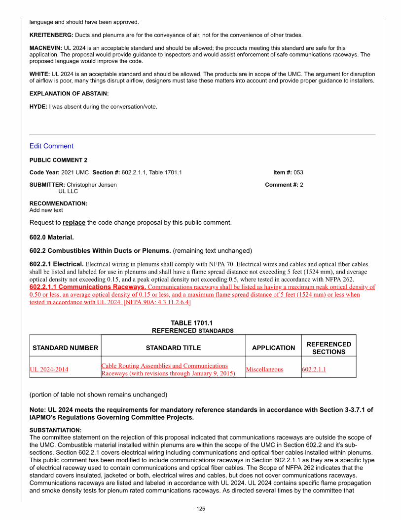
Item #: 053
Comment #: 2
language and should have been approved.
KREITENBERG: Ducts and plenums are for the conveyance of air, not for the convenience of other trades.
MACNEVIN: UL 2024 is an acceptable standard and should be allowed; the products meeting this standard are safe for thisapplication. The proposal would provide guidance to inspectors and would assist enforcement of safe communications raceways. Theproposed language would improve the code.
WHITE: UL 2024 is an acceptable standard and should be allowed. The products are in scope of the UMC. The argument for disruptionof airflow is poor, many things disrupt airflow, designers must take these matters into account and provide proper guidance to installers.
EXPLANATION OF ABSTAIN:
HYDE: I was absent during the conversation/vote.
Edit Comment
PUBLIC COMMENT 2
Code Year: 2021 UMC Section #: 602.2.1.1, Table 1701.1
SUBMITTER: Christopher JensenUL LLC
RECOMMENDATION:Add new text
Request to replace the code change proposal by this public comment.
602.0 Material.
602.2 Combustibles Within Ducts or Plenums. (remaining text unchanged)
602.2.1 Electrical. Electrical wiring in plenums shall comply with NFPA 70. Electrical wires and cables and optical fiber cablesshall be listed and labeled for use in plenums and shall have a flame spread distance not exceeding 5 feet (1524 mm), and averageoptical density not exceeding 0.15, and a peak optical density not exceeding 0.5, where tested in accordance with NFPA 262.602.2.1.1 Communications Raceways. Communications raceways shall be listed as having a maximum peak optical density of0.50 or less, an average optical density of 0.15 or less, and a maximum flame spread distance of 5 feet (1524 mm) or less whentested in accordance with UL 2024. [NFPA 90A: 4.3.11.2.6.4]
TABLE 1701.1 REFERENCED STANDARDS
STANDARD NUMBER STANDARD TITLE APPLICATION REFERENCEDSECTIONS
UL 2024-2014 Cable Routing Assemblies and CommunicationsRaceways (with revisions through January 9, 2015) Miscellaneous 602.2.1.1
(portion of table not shown remains unchanged)
Note: UL 2024 meets the requirements for mandatory reference standards in accordance with Section 3-3.7.1 ofIAPMO's Regulations Governing Committee Projects.
SUBSTANTIATION:The committee statement on the rejection of this proposal indicated that communications raceways are outside the scope ofthe UMC. Combustible material installed within plenums are within the scope of the UMC in Section 602.2 and it’s sub-sections. Section 602.2.1 covers electrical wiring including communications and optical fiber cables installed within plenums.This public comment has been modified to include communications raceways in Section 602.2.1.1 as they are a specific typeof electrical raceway used to contain communications and optical fiber cables. The Scope of NFPA 262 indicates that thestandard covers insulated, jacketed or both, electrical wires and cables, but does not cover communications raceways.Communications raceways are listed and labeled in accordance with UL 2024. UL 2024 contains specific flame propagationand smoke density tests for plenum rated communications raceways. As directed several times by the committee that
125
Item #: 053
Comment #: 3
specific requirements should be addressed in a standard rather than a code, UL 2024 was developed under ANSI consensusprocess to determine values of flame propagation distance and optical smoke density for communications raceways that canbe installed in ducts, plenums, and other spaces used for environmental air. The acceptance criteria specified (a flamespread distance not greater than 5 feet, peak optical density not greater than 0.50, and an average optical density notgreater than 0.15) is consistent with values in Sections 602.2.1, 602.2.2 and 602.2.3. Furthermore, the language used in thisproposal is a direct extract from NFPA 90A.
COMMITTEE ACTION: REJECT
COMMITTEE STATEMENT:The comment is being rejected as communications raceways should not be allowed in ducts or plenums since they woulddisrupt airflow. Furthermore, communications raceways and the material within the raceways are outside the scope of theUMC. This would also conflict with UL 555 and UL 555S.
TOTAL ELIGIBLE TO VOTE: 26
VOTING RESULTS: AFFIRMATIVE: 19 NEGATIVE: 5 ABSTAIN: 1 NOT RETURNED: 1 HOWARD
EXPLANATION OF NEGATIVE:
CHURCH: We believe the TC reasons for rejections are incorrect.
KOERBER: I disagree with the committee action and statement. This requirement for communication cable raceways is within thescope of the code and should be added to the chapter. In my opinion, the NFPA extract originally proposed was the appropriatelanguage and should have been approved.
KREITENBERG: Ducts and plenums are for air, not to accommodate other trades.
MACNEVIN: UL 2024 is an acceptable standard and should be allowed; the products meeting this standard are safe for thisapplication. The proposal would provide guidance to inspectors and would assist enforcement of safe communications raceways. Theproposed language would improve the code.
WHITE: UL 2024 is an acceptable standard and should be allowed. The products are in scope of the UMC. The argument for disruptionof airflow is poor, many things disrupt airflow, designers must take these matters into account and provide proper guidance to installers.
EXPLANATION OF ABSTAIN:
HYDE: I was absent during the conversation/vote.
Edit Comment
PUBLIC COMMENT 3
Code Year: 2021 UMC Section #: 602.2.5
SUBMITTER: Ralph KoerberATCO Rubber Products, Inc.Rep. Air Duct Council
RECOMMENDATION:Add new text
Request to accept the code change proposal as submitted by this public comment.
SUBSTANTIATION:I disagree with the TC statement that communication raceways are not within the scope of the UMC. They can becombustible and they can be within ducts and plenums and therefore should be included in this section, same as the otheritems in Section 602.2.1 through Section 602.2.4. This proposal should be accepted as submitted.
COMMITTEE ACTION: REJECT
COMMITTEE STATEMENT:The comment is being rejected as communications raceways should not be allowed in ducts or plenums since they woulddisrupt airflow. Furthermore, communications raceways and the material within the raceways are outside the scope of theUMC. This would also conflict with UL 555 and UL 555S.
126
TOTAL ELIGIBLE TO VOTE: 26
VOTING RESULTS: AFFIRMATIVE: 19 NEGATIVE: 5 ABSTAIN: 1 NOT RETURNED: 1 HOWARD
EXPLANATION OF NEGATIVE:
CHURCH: We believe the TC reasons for rejection are incorrect.
KOERBER: I disagree with the committee action and statement. This requirement for communication cable raceways is within thescope of the code and should be added to the chapter. In my opinion, the NFPA extract originally proposed was the appropriatelanguage and should have been approved.
KREITENBERG: Ducts and plenums are intended to convey air - they are not created/constructed as chases to accommodate othertrades.
MACNEVIN: UL 2024 is an acceptable standard and should be allowed; the products meeting this standard are safe for thisapplication. The proposal would provide guidance to inspectors and would assist enforcement of safe communications raceways. Theproposed language would improve the code.
WHITE: UL 2024 is an acceptable standard and should be allowed. The products are in scope of the UMC. The argument for disruptionof airflow is poor, many things disrupt airflow, designers must take these matters into account and provide proper guidance to installers.
EXPLANATION OF ABSTAIN:
HYDE: Was absent during the conversation/vote.
127
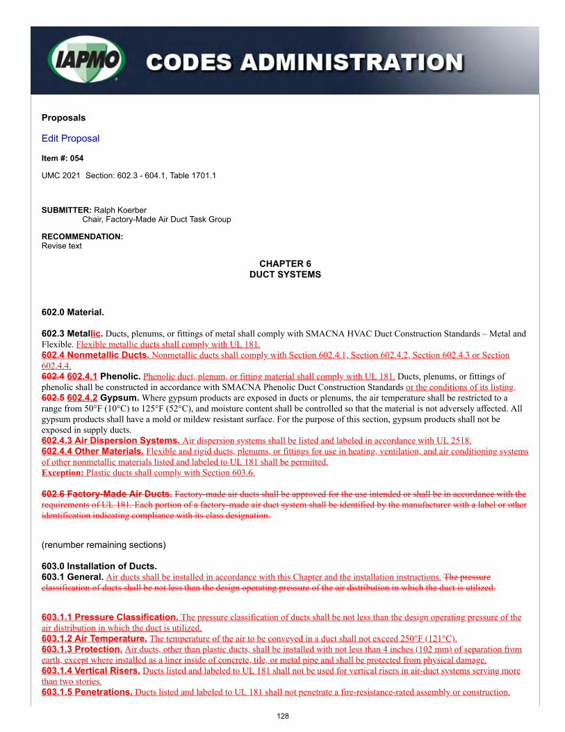
Proposals
Edit Proposal
Item #: 054
UMC 2021 Section: 602.3 - 604.1, Table 1701.1
SUBMITTER: Ralph KoerberChair, Factory-Made Air Duct Task Group
RECOMMENDATION:Revise text
CHAPTER 6DUCT SYSTEMS
602.0 Material.
602.3 Metallic. Ducts, plenums, or fittings of metal shall comply with SMACNA HVAC Duct Construction Standards – Metal andFlexible. Flexible metallic ducts shall comply with UL 181.602.4 Nonmetallic Ducts. Nonmetallic ducts shall comply with Section 602.4.1, Section 602.4.2, Section 602.4.3 or Section602.4.4.602.4 602.4.1 Phenolic. Phenolic duct, plenum, or fitting material shall comply with UL 181. Ducts, plenums, or fittings ofphenolic shall be constructed in accordance with SMACNA Phenolic Duct Construction Standards or the conditions of its listing.602.5 602.4.2 Gypsum. Where gypsum products are exposed in ducts or plenums, the air temperature shall be restricted to arange from 50°F (10°C) to 125°F (52°C), and moisture content shall be controlled so that the material is not adversely affected. Allgypsum products shall have a mold or mildew resistant surface. For the purpose of this section, gypsum products shall not beexposed in supply ducts.602.4.3 Air Dispersion Systems. Air dispersion systems shall be listed and labeled in accordance with UL 2518.602.4.4 Other Materials. Flexible and rigid ducts, plenums, or fittings for use in heating, ventilation, and air conditioning systemsof other nonmetallic materials listed and labeled to UL 181 shall be permitted.Exception: Plastic ducts shall comply with Section 603.6.
602.6 Factory-Made Air Ducts. Factory-made air ducts shall be approved for the use intended or shall be in accordance with therequirements of UL 181. Each portion of a factory-made air duct system shall be identified by the manufacturer with a label or otheridentification indicating compliance with its class designation.
(renumber remaining sections)
603.0 Installation of Ducts.603.1 General. Air ducts shall be installed in accordance with this Chapter and the installation instructions. The pressureclassification of ducts shall be not less than the design operating pressure of the air distribution in which the duct is utilized.
603.1.1 Pressure Classification. The pressure classification of ducts shall be not less than the design operating pressure of theair distribution in which the duct is utilized.603.1.2 Air Temperature. The temperature of the air to be conveyed in a duct shall not exceed 250°F (121°C).603.1.3 Protection. Air ducts, other than plastic ducts, shall be installed with not less than 4 inches (102 mm) of separation fromearth, except where installed as a liner inside of concrete, tile, or metal pipe and shall be protected from physical damage.603.1.4 Vertical Risers. Ducts listed and labeled to UL 181 shall not be used for vertical risers in air-duct systems serving morethan two stories.603.1.5 Penetrations. Ducts listed and labeled to UL 181 shall not penetrate a fire-resistance-rated assembly or construction.
128
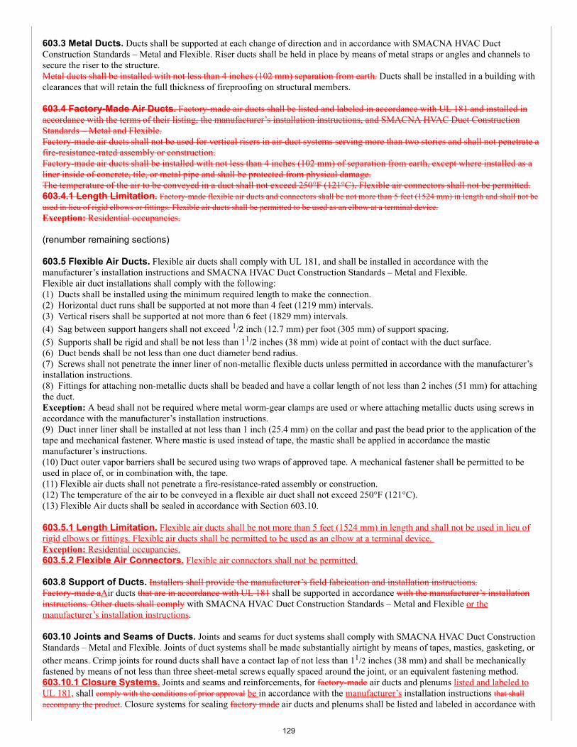
603.3 Metal Ducts. Ducts shall be supported at each change of direction and in accordance with SMACNA HVAC DuctConstruction Standards – Metal and Flexible. Riser ducts shall be held in place by means of metal straps or angles and channels tosecure the riser to the structure. Metal ducts shall be installed with not less than 4 inches (102 mm) separation from earth. Ducts shall be installed in a building withclearances that will retain the full thickness of fireproofing on structural members.
603.4 Factory-Made Air Ducts. Factory-made air ducts shall be listed and labeled in accordance with UL 181 and installed inaccordance with the terms of their listing, the manufacturer’s installation instructions, and SMACNA HVAC Duct ConstructionStandards – Metal and Flexible.Factory-made air ducts shall not be used for vertical risers in air-duct systems serving more than two stories and shall not penetrate afire-resistance-rated assembly or construction.Factory-made air ducts shall be installed with not less than 4 inches (102 mm) of separation from earth, except where installed as aliner inside of concrete, tile, or metal pipe and shall be protected from physical damage.The temperature of the air to be conveyed in a duct shall not exceed 250°F (121°C). Flexible air connectors shall not be permitted.603.4.1 Length Limitation. Factory-made flexible air ducts and connectors shall be not more than 5 feet (1524 mm) in length and shall not beused in lieu of rigid elbows or fittings. Flexible air ducts shall be permitted to be used as an elbow at a terminal device.Exception: Residential occupancies.
(renumber remaining sections)
603.5 Flexible Air Ducts. Flexible air ducts shall comply with UL 181, and shall be installed in accordance with themanufacturer’s installation instructions and SMACNA HVAC Duct Construction Standards – Metal and Flexible.Flexible air duct installations shall comply with the following:(1) Ducts shall be installed using the minimum required length to make the connection.(2) Horizontal duct runs shall be supported at not more than 4 feet (1219 mm) intervals.(3) Vertical risers shall be supported at not more than 6 feet (1829 mm) intervals.(4) Sag between support hangers shall not exceed 1/2 inch (12.7 mm) per foot (305 mm) of support spacing.(5) Supports shall be rigid and shall be not less than 11/2 inches (38 mm) wide at point of contact with the duct surface.(6) Duct bends shall be not less than one duct diameter bend radius.(7) Screws shall not penetrate the inner liner of non-metallic flexible ducts unless permitted in accordance with the manufacturer’sinstallation instructions.(8) Fittings for attaching non-metallic ducts shall be beaded and have a collar length of not less than 2 inches (51 mm) for attachingthe duct.Exception: A bead shall not be required where metal worm-gear clamps are used or where attaching metallic ducts using screws inaccordance with the manufacturer’s installation instructions.(9) Duct inner liner shall be installed at not less than 1 inch (25.4 mm) on the collar and past the bead prior to the application of thetape and mechanical fastener. Where mastic is used instead of tape, the mastic shall be applied in accordance the masticmanufacturer’s instructions.(10) Duct outer vapor barriers shall be secured using two wraps of approved tape. A mechanical fastener shall be permitted to beused in place of, or in combination with, the tape.(11) Flexible air ducts shall not penetrate a fire-resistance-rated assembly or construction.(12) The temperature of the air to be conveyed in a flexible air duct shall not exceed 250°F (121°C).(13) Flexible Air ducts shall be sealed in accordance with Section 603.10.
603.5.1 Length Limitation. Flexible air ducts shall be not more than 5 feet (1524 mm) in length and shall not be used in lieu ofrigid elbows or fittings. Flexible air ducts shall be permitted to be used as an elbow at a terminal device. Exception: Residential occupancies.603.5.2 Flexible Air Connectors. Flexible air connectors shall not be permitted.
603.8 Support of Ducts. Installers shall provide the manufacturer’s field fabrication and installation instructions.Factory-made aAir ducts that are in accordance with UL 181 shall be supported in accordance with the manufacturer’s installationinstructions. Other ducts shall comply with SMACNA HVAC Duct Construction Standards – Metal and Flexible or themanufacturer’s installation instructions.
603.10 Joints and Seams of Ducts. Joints and seams for duct systems shall comply with SMACNA HVAC Duct ConstructionStandards – Metal and Flexible. Joints of duct systems shall be made substantially airtight by means of tapes, mastics, gasketing, orother means. Crimp joints for round ducts shall have a contact lap of not less than 11/2 inches (38 mm) and shall be mechanicallyfastened by means of not less than three sheet-metal screws equally spaced around the joint, or an equivalent fastening method.603.10.1 Closure Systems. Joints and seams and reinforcements, for factory-made air ducts and plenums listed and labeled toUL 181, shall comply with the conditions of prior approval be in accordance with the manufacturer’s installation instructions that shallaccompany the product. Closure systems for sealing factory made air ducts and plenums shall be listed and labeled in accordance with
129
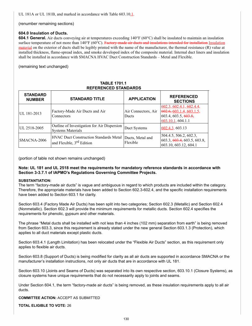
UL 181A or UL 181B, and marked in accordance with Table 603.10.1.
(renumber remaining sections)
604.0 Insulation of Ducts.604.1 General. Air ducts conveying air at temperatures exceeding 140°F (60°C) shall be insulated to maintain an insulationsurface temperature of not more than 140°F (60°C). Factory-made air ducts and insulations intended for installation Insulationmaterial on the exterior of ducts shall be legibly printed with the name of the manufacturer, the thermal resistance (R) value atinstalled thickness, flame-spread index, and smoke developed index of the composite material. Internal duct liners and insulationshall be installed in accordance with SMACNA HVAC Duct Construction Standards – Metal and Flexible.
(remaining text unchanged)
TABLE 1701.1 REFERENCED STANDARDS
STANDARDNUMBER STANDARD TITLE APPLICATION REFERENCED
SECTIONS
UL 181-2013 Factory-Made Air Ducts and AirConnectors
Air Connectors, AirDucts
602.3, 602.4.1, 602.4.4,602.6, 603.1.4, 603.1.5,603.4, 603.5, 603.8,603.10.1, 604.1.1
UL 2518-2005 Outline of Investigation for Air DispersionSystems Materials Duct Systems 602.4.3, 603.13
SMACNA-2006HVAC Duct Construction Standards Metaland Flexible, 3rd Edition
Ducts, Metal andFlexible
504.4.5, 506.2, 602.3,603.3, 603.4, 603.5, 603.8,603.10, 603.12, 604.1
(portion of table not shown remains unchanged)
Note: UL 181 and UL 2518 meet the requirements for mandatory reference standards in accordance withSection 3-3.7.1 of IAPMO’s Regulations Governing Committee Projects.
SUBSTANTIATION:The term “factory-made air ducts” is vague and ambiguous in regard to which products are included within the category.Therefore, the appropriate materials have been added to Section 602.3-602.4, and the specific installation requirementshave been added to Section 603.1 for clarity.
Section 603.4 (Factory Made Air Ducts) has been split into two categories; Section 602.3 (Metallic) and Section 602.4(Nonmetallic). Section 602.3 will provide the minimum requirements for metallic ducts. Section 602.4 specifies therequirements for phenolic, gypsum and other materials.
The phrase “Metal ducts shall be installed with not less than 4 inches (102 mm) separation from earth” is being removedfrom Section 603.3, since this requirement is already stated under the new general Section 603.1.3 (Protection), whichapplies to all duct materials except plastic ducts.
Section 603.4.1 (Length Limitation) has been relocated under the “Flexible Air Ducts” section, as this requirement onlyapplies to flexible air ducts.
Section 603.8 (Support of Ducts) is being modified for clarity as all air ducts are supported in accordance SMACNA or themanufacturer’s installation instructions, not only air ducts that are in accordance with UL 181.
Section 603.10 (Joints and Seams of Ducts) was separated into its own respective section, 603.10.1 (Closure Systems), asclosure systems have unique requirements that do not necessarily apply to joints and seams.
Under Section 604.1, the term “factory-made air ducts” is being removed, as these insulation requirements apply to all airducts.
COMMITTEE ACTION: ACCEPT AS SUBMITTED
TOTAL ELIGIBLE TO VOTE: 26
130
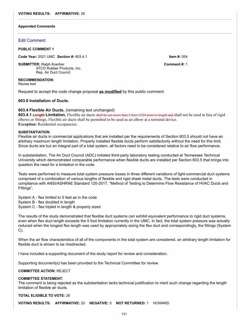
Item #: 054
Comment #: 1
VOTING RESULTS: AFFIRMATIVE: 26
Appended Comments
Edit Comment
PUBLIC COMMENT 1
Code Year: 2021 UMC Section #: 603.4.1
SUBMITTER: Ralph KoerberATCO Rubber Products, Inc.Rep. Air Duct Council
RECOMMENDATION:Revise text
Request to accept the code change proposal as modified by this public comment.
603.0 Installation of Ducts.
603.4 Flexible Air Ducts. (remaining text unchanged)603.4.1 Length Limitation. Flexible air ducts shall be not more than 5 feet (1524 mm) in length and shall not be used in lieu of rigidelbows or fittings. Flexible air ducts shall be permitted to be used as an elbow at a terminal device.Exception: Residential occupancies.
SUBSTANTIATION:Flexible air ducts in commercial applications that are installed per the requirements of Section 603.5 should not have anarbitrary maximum length limitation. Properly installed flexible ducts perform satisfactorily without the need for this limit.Since ducts are but an integral part of a total system, all factors need to be considered relative to air flow performance.
In substantiation, The Air Duct Council (ADC) initiated third-party laboratory testing conducted at Tennessee TechnicalUniversity which demonstrated comparable performance when flexible ducts are installed per Section 603.5 that brings intoquestion the need for a limitation in the code.
Tests were performed to measure total system pressure losses in three different variations of light-commercial duct systemscomprised of a combination of various lengths of flexible and rigid sheet metal ducts. The tests were conducted incompliance with ANSI/ASHRAE Standard 120-2017, “Method of Testing to Determine Flow Resistance of HVAC Ducts andFittings”.
System A - flex limited to 5 feet as in the codeSystem B - flex doubled in lengthSystem C - flex tripled in length & properly sized
The results of the study demonstrated that flexible duct systems can exhibit equivalent performance to rigid duct systems,even when flex duct length exceeds the 5 foot limitation currently in the UMC. In fact, the total system pressure was actuallyreduced when the longest flex length was used by appropriately sizing the flex duct and correspondingly, the fittings (SystemC).
When the air flow characteristics of all of the components in the total system are considered, an arbitrary length limitation forflexible duct is shown to be misdirected.
I have included a supporting document of the study report for review and consideration.
Supporting document(s) has been provided to the Technical Committee for review.
COMMITTEE ACTION: REJECT
COMMITTEE STATEMENT:The comment is being rejected as the substantiation lacks technical justification to merit such change regarding the lengthlimitation of flexible air ducts.
TOTAL ELIGIBLE TO VOTE: 26
VOTING RESULTS: AFFIRMATIVE: 20 NEGATIVE: 5 NOT RETURNED: 1 HOWARD
131
EXPLANATION OF NEGATIVE:
CHURCH: TC reason for rejection does not appear to be valid; technical justification for the proposal was provided.
KOERBER: The TC statement indicates there was no technical justification to support removing the 5 feet length restriction. However, the results of the study provided as substantiation did technically demonstrate that flexible ducts can exhibit equivalentperformance to rigid ducts when the length exceeds the 5 foot limit currently in the UMC. Discussions during the meeting centered on poor installation practices rather than the technical comparison demonstrated by thestudy. It was said that the system configurations tested were not "typical"; however, it should be noted that they were "comparative".The test program was designed to look at both duct types and compare the results. When the air flow characteristics of ALL components in a duct system are considered, an arbitrary length limitation for one duct typewas shown by the technical substantiation provided to be misdirected.
A. TRAFTON: The proposal should be accepted. The proposal had sufficient backup for the proposal.
P. TRAFTON: More than sufficient backup has been provided and this is a valid and justified change.
WHITE: A study was provided to support the proposed change. Maintaining the selection of a 5 foot limitation is arbitrary and limitsdesign options.
132
Item #: 061
Comment #: 1
Proposals
Edit Proposal
Item #: 061
UMC 2021 Section: 603.5
SUBMITTER: David DiasSheet Metal Workers Local 104
RECOMMENDATION:Revise text
603.0 Installation of Ducts.
603.5 Flexible Air Ducts. Flexible air ducts shall comply with UL 181, and shall be installed in accordance with themanufacturer’s installation instructions and SMACNA HVAC Duct Construction Standards – Metal and Flexible.Flexible air duct installations shall comply with the following:(1) - (7) (remaining text unchanged)(8) Fittings for attaching non-metallic ducts shall be beaded and have a collar length of not less than 2 inches (51 mm) for attachingthe duct. Metal worm-gear clamps shall be used.Exception: A bead shall not be required where metal worm-gear clamps are used or wWhere attaching metallic ducts using screwsin accordance with the manufacturer’s installation instructions.
SUBSTANTIATION:Beads should always be used to prevent the flexible duct from slipping off the metal fitting. Metal clamps should be requiredbecause there are too many nonmetallic clamps being installed that are not UL listed which makes it very hard for a buildingofficial to catch and enforce.
COMMITTEE ACTION: ACCEPT AS SUBMITTED
TOTAL ELIGIBLE TO VOTE: 26
VOTING RESULTS: AFFIRMATIVE: 24 NEGATIVE: 1 NOT RETURNED: 1 HOWARD
EXPLANATION OF NEGATIVE:
KOERBER: Requiring use of beaded fittings and metallic clamps is overly restrictive.
Appended Comments
Edit Comment
PUBLIC COMMENT 1
Code Year: 2021 UMC Section #: 603.4(8)
SUBMITTER: Ralph Koerber (ATCO Rubber Products, Inc., Rep. Air Duct Council);Kenneth A Christian (HellermannTyton); Randal Denney (American Elite Molding, LLC); Charles McGaughy (ABB); Teru Chen (Hua Wei Industrial, Co., Ltd.)
RECOMMENDATION:Revise text
Request to accept the code change proposal as modified by this public comment.
133
603.0 Installation of Ducts.
603.4 Flexible Air Ducts. Flexible air ducts shall comply with UL 181, and shall be installed in accordance with themanufacturer’s installation instructions and SMACNA HVAC Duct Construction Standards – Metal and Flexible. Flexible air duct installations shall comply with the following:(1) - (7) (remaining text unchanged)(8) Fittings for attaching non-metallic ducts shall be beaded and have a collar length of not less than 2 inches (51 mm) for attachingthe duct. Metal worm-gear clamps shall be used.Exception: Where attaching metallic ducts using screws in accordance with the manufacturer’s installation instructions.(9) - (13) (remaining text unchanged)
SUBSTANTIATION:
KOERBER:Non-metallic mechanical fasteners listed and labeled to the UL 181B Standard and labeled UL 181B-C have been in use for more than15 years since the addition of Part III to the UL 181B Standard. And for many years prior to that time, non-metallic straps were used;however, approval to the was maintained by the individual flexible duct manufacturers. Flexible duct manufacturer's installation instructions require the use of UL 181B-C non-metallic mechanical fasteners when plasticstraps are chosen. UMC Chapter 6 does as well. No data was provided to substantiate that the use of UL 181B-C labeled non-metallic mechanical fasteners, as currently referencedin Section 603.9.1 (Closure Systems) cannot be validated and enforced by building officials. Requiring the use of only metal worm-gearclamps for flexible duct is overly restrictive.
CHRISTIAN: I disagree about not allowing "non-metallic clamps". Inspectors should be inspecting the clamps, metal or plastic, before they getinstalled. The packaging of UL listed products should appear on the packaging. I don't understand why the products with UL listing can'tbe caught on non-metallic clamps yet is caught on metallic clamps? Whats the difference with UL ID on metal vs non-metallic? It'a alsohard to believe that having non-metallic would be a cost savings. Using non-metallic clamps are easier on the installer, which is also animportant if your installing all day, day after day.
DENNEY: As a USA manufacturer of non-metallic Duct Straps, we oppose the changes to UMC 2021, Section 603.4 note (8), i.e. the insertion ofthe verbiage: “Metal worm-gear clamps shall be used.” We currently manufacture and sell over 50 million 36” duct straps within theHVAC industry, all of which are UL-181 approved. We have spent millions of dollars at our factory in Crestview, Florida to assure ourproduct meets or exceeds all aspects of UL181 B-C for flex duct attachment over the past few years, while employing over 100manufacturing workers in the USA. This change would ultimately destroy and devastate part of the USA manufacturing economydedicated to providing UL181 B-C nonmetallic duct straps to the HVAC industry. I believe, working together, we can find solutions that will help the inspectors better identify nonmetallic UL181 B-C approved nylonduct straps within the industry. I believe the forcing of the usage of metal clamps is too restrictive. According to UL 181 B, page 28, Section 36: “36.1 Each non-metallic mechanical fastener product or optionally, each smallest unitcontainer of the non-metallic fasteners shall have a durable, legible, distinctive marking identifying the following:(a) The marking "181B-C";(b) The manufacturer’s or private labeler’s name or identifying symbol; and (c) The distinctive type or model designation;” If the problem is the inspectors are not able catch or enforce non-UL listed strap, they could require the contractors to maintain thestrap packaging. The package would contain all of the required information. We will be happy to be as involved, or provide anyinformation, as needed.
MCGAUGHY: We oppose this change because of the restrictive nature of only allowing metallic clamps for securement. We have no opposition torequire beaded fittings when installing flexible duct. To help resolve the issue on how a building official can enforce the use of UL listednonmetallic clamps the installer can provide packaging or listing information to the inspection authority. The packaging contains all thetechnical data including the listing information needed to confirm that the clamps are UL listed for that application.
CHEN: Requiring use of metallic clamps is overly restrictive and will narrow the market for plastic clamps. Relative spec and certificationshould be considered and clearly determined to solve this issue instead of limiting the material to metal.
COMMITTEE ACTION: REJECT
COMMITTEE STATEMENT:The comment is being rejected as the substantiation lacks technical justification to merit removing the requirement for metalworm-gear clamps to be used. Metal worm-gear clamps are necessary for longevity.
TOTAL ELIGIBLE TO VOTE: 26
VOTING RESULTS: AFFIRMATIVE: 18 NEGATIVE: 6 ABSTAIN: 1 NOT RETURNED: 1 HOWARD
EXPLANATION OF NEGATIVE:
DELAQUILA: As far as I understand this proposal and comment, requiring metal clamps was not a requirement before this comment.So the reason for rejecting the comment is not valid, i.e., longevity. If the previous method was overly restrictive, this new requirement
134
Item #: 061
Comment #: 2
most definitely is. Comment should be accepted.
KOERBER: Non-metallic mechanical fasteners listed and labeled to the UL181B Standard have been in use and required per this codefor considerable time now. Their use should continue to be allowed. I am having trouble with the committee statement provided - "The comment is being rejected as the substantiation lacks technicaljustification to merit such change regarding removing the requirement for metal worm-gear clamps to be used. Metal worm-gear clampsare necessary for longevity." Especially since the substantiation provided in the original proposal was neither technically justified -"Metal clamps should be required because there are too many nonmetallic clamps being installed that are not UL listed which makes itvery hard for a building official to catch and enforce." How did we go from "hard for a building official to enforce if the straps used arelisted or not" to "no justification to remove the requirement (which is currently NOT a requirement in the code) for metal worm-gearclamps because they are needed for longevity"? This is a slippery slope for the TC.
KREITENBERG: Limiting attachment modality to metal clamps is too restrictive. Other methods have performed successfully over thelifetime of a system.
A. TRAFTON: These products are widely used and should be allowed.
P. TRAFTON: Products have been used successfully for many years.
WHITE: There is no technical justification provided for banning non-metallic fasteners. Products are made in compliance with thestandard and have been used for many years in thousands, if not millions, of installations.
EXPLANATION OF ABSTAIN:
CHURCH: The TC statement is overly broad and consequently may be inaccurate: "Metal worm-gear clamps are necessary for longevity."
Edit Comment
PUBLIC COMMENT 2
Code Year: 2021 UMC Section #: 603.4
SUBMITTER: Christopher Jensen (UL LLC); Rick Estano (Avery Dennison); Amit Somani(Blackburn & Co.pvt.ltd)
RECOMMENDATION:Revise text
Request to reject the code change proposal by this public comment.
SUBSTANTIATION:
JENSEN:UMC Section 603.4 requires flexible air ducts to comply with UL 181 and be installed in accordance with the manufacturer's installationinstructions and SMACNA HVAC Duct Construction Standards-Metal and Flexible. UL 181B "Closure Systems for Use With Flexible AirDucts and Air Connectors" is the standard used to evaluate mechanical fasteners for use with flexible air ducts. This standard isreferenced in multiple places within the UMC. Both UL 181B and the SMACNA Standard permit the use of non-metallic draw band typemechanical fasteners. Requiring metal worm-gear clamps as the only means for attaching non-metal flexible air ducts is in conflict withthe SMACNA HVAC Duct Construction Standards-Metal and Flexible, UL 181B and the manufacturer's installation instructions. Thesubstantiation for prohibiting the use of non-metallic draw band type mechanical fasteners is that many of the clamps being used arenot UL listed. UL 181B requires mechanical fasteners for use with flexible air ducts to be marked with a product designation of “181B-C” on the product or the smallest unit packaging. This modified proposal would replace the new language with the existing language inthe 2018 UMC Section 603.5(8).
ESTANO:Avery Dennison opposes proposal as written.
SOMANI:Proposal for using metal clamps instead of cable ties doesn't solve the problem. 1. The metal clamps will also need to be identified as they will require UL 181B/C approval. How will one ensure if it is coming from aUL approved source? What will prevent the supposed issue with cable ties not occurring with metal clamps? 2. It can be mandated that the UL 181 B/C file number of the manufacturer be engraved on the cable tie. This will allow the inspector tosearch for the relevant file number in the UL database on their phone immediately and verify if the cable ties are produced by a UL 181B/C approved source. Below is a picture with UL 181 B/C and relevant file number engraved on the body of the cable tie making iteasily visible for the inspector.
135
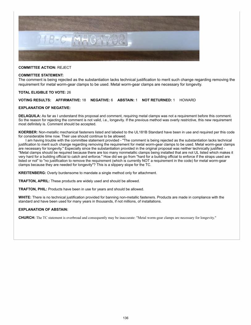
COMMITTEE ACTION: REJECT
COMMITTEE STATEMENT:The comment is being rejected as the substantiation lacks technical justification to merit such change regarding removing therequirement for metal worm-gear clamps to be used. Metal worm-gear clamps are necessary for longevity.
TOTAL ELIGIBLE TO VOTE: 26
VOTING RESULTS: AFFIRMATIVE: 18 NEGATIVE: 6 ABSTAIN: 1 NOT RETURNED: 1 HOWARD
EXPLANATION OF NEGATIVE:
DELAQUILA: As far as I understand this proposal and comment, requiring metal clamps was not a requirement before this comment.So the reason for rejecting the comment is not valid, i.e., longevity. If the previous method was overly restrictive, this new requirementmost definitely is. Comment should be accepted.
KOERBER: Non-metallic mechanical fasteners listed and labeled to the UL181B Standard have been in use and required per this codefor considerable time now. Their use should continue to be allowed. I am having trouble with the committee statement provided - "The comment is being rejected as the substantiation lacks technicaljustification to merit such change regarding removing the requirement for metal worm-gear clamps to be used. Metal worm-gear clampsare necessary for longevity." Especially since the substantiation provided in the original proposal was neither technically justified -"Metal clamps should be required because there are too many nonmetallic clamps being installed that are not UL listed which makes itvery hard for a building official to catch and enforce." How did we go from "hard for a building official to enforce if the straps used arelisted or not" to "no justification to remove the requirement (which is currently NOT a requirement in the code) for metal worm-gearclamps because they are needed for longevity"? This is a slippery slope for the TC.
KREITENBERG: Overly burdensome to mandate a single method only for attachment.
TRAFTON, APRIL: These products are widely used and should be allowed.
TRAFTON, PHIL: Products have been in use for years and should be allowed.
WHITE: There is no technical justification provided for banning non-metallic fasteners. Products are made in compliance with thestandard and have been used for many years in thousands, if not millions, of installations.
EXPLANATION OF ABSTAIN:
CHURCH: The TC statement is overbroad and consequently may be inaccurate: "Metal worm-gear clamps are necessary for longevity."
136
Item #: 063
Comment #: 1
Proposals
Edit Proposal
Item #: 063
UMC 2021 Section: 603.10.1
SUBMITTER: Jeremy MartinezGolden Gate Chapter ASHRAERep: ASHRAE
RECOMMENDATION:Revise text
603.0 Installation of Ducts.
603.10 Joints and Seams of Ducts. (remaining text unchanged)603.10.1 Duct Leakage Tests. Ductwork that is designed to operate at static pressures in excess of 3 inches of water column (0.7kPa) and all ductwork located outdoors shall be leak-tested in accordance with the SMACNA HVAC Air Duct Leakage Test Manual.Representative sections totaling not less than 10 percent of the total installed duct area shall be tested. Where the tested 10 percentfail to comply with the requirements of this section, then 40 percent of the total installed duct area shall be tested. Where the tested40 percent fail to comply with the requirements of this section, then 100 percent of the total installed duct area shall be tested.Sections shall be selected by the building owner or designated representative of the building owner. Positive pressure leakage testingshall be permitted for negative pressure ductwork. The permitted duct leakage shall be not more than the following:
(remaining text unchanged)
SUBSTANTIATION:The current requirement calls for leakage testing of all ductwork. This is onerous and not cost effective. The proposedwording is to make the requirement consistent with ASHRAE Standard 90.1.
COMMITTEE ACTION: REJECT
COMMITTEE STATEMENT:All ductwork should be tested, not only ductwork located outdoors or in excess of three inches of water column.
TOTAL ELIGIBLE TO VOTE: 26
VOTING RESULTS: AFFIRMATIVE: 25 NOT RETURNED: 1 HOWARD
Appended Comments
Edit Comment
PUBLIC COMMENT 1
Code Year: 2021 UMC Section #: 603.9.2
SUBMITTER: Vanessa LassesonWestern Allied Mechanical Inc
RECOMMENDATION:Revise text
Request to replace the code change proposal by this public comment.
137
603.0 Installation of Ducts.
603.9 Joints and Seams of Ducts. (remaining text unchanged)
603.9.2 Duct Leakage Tests. Ductwork that is designed to operate at static pressures in excess of 1 inch of water column (0.2 kPa)shall be leak-tested in accordance with the SMACNA HVAC Air Duct Leakage Test Manual. Representative sections totaling not lessthan 10 percent of the total installed duct area shall be tested. Where the tested 10 percent fail to comply with the requirements ofthis section, then 40 percent of the total installed duct area shall be tested. Where the tested 40 percent fail to comply with therequirements of this section, then 100 percent of the total installed duct area shall be tested. Sections shall be selected by thebuilding owner or designated representative of the building owner. Positive pressure leakage testing shall be permitted for negativepressure ductwork. The permitted duct leakage shall be not more than the following:
(remaining text unchanged)
SUBSTANTIATION:The current requirement calls for leakage testing of all ductwork. The proposed wording is to remove ductwork conveyingtransfer air from the duct leakage requirement.
Duct leakage testing should not apply to transfer air ductwork. The purpose of leakage testing is to minimize or eliminate theamount of conditioned air lost to the space, as duct leakage wastes energy and negatively affects building performance.However, transfer air is not conditioned and will have a minimal effect on building performance.
Ductwork conveying transfer air is typically designed for less than 1 inch of water column to prevent over pressurizing thespace. The proposed wording amends the previous recommendation to apply to ductwork conveying transfer air only.
COMMITTEE ACTION: ACCEPTED AS AMENDED
Amend comment as follows:
603.9.2 Duct Leakage Tests.
Ductwork that is designed to operate at static pressures in excess of 1 inch of water column (0.2 kPa) shall be leak-tested inaccordance with the SMACNA HVAC Air Duct Leakage Test Manual. Representative sections totaling not less than 10percent of the total installed duct area shall be tested. Where the tested 10 percent fail to comply with the requirementsof this section, then 40 percent of the total installed duct area shall be tested. Where the tested 40 percent fail to complywith the requirements of this section, then 100 percent of the total installed duct area shall be tested. Sections shall beselected by the building owner or designated representative of the building owner. Positive pressure leakage testingshall be permitted for negative pressure ductwork. The permitted duct leakage shall be not more than the following:(remaining text unchanged)Exception: Transfer air duct operating at less than 1 inch of water column (0.2 kPa).
COMMITTEE STATEMENT:The comment is being modified as ductwork conveying transfer air is typically designed for less than 1 inch of water columnto prevent over-pressurizing the space.
TOTAL ELIGIBLE TO VOTE: 26
VOTING RESULTS: AFFIRMATIVE: 24 NEGATIVE: 1 NOT RETURNED: 1 HOWARD
EXPLANATION OF NEGATIVE:
WHITE: It is an onerous requirement to require all ducts be subjected to this testing. Is there a definition of transfer air duct in the UMCfor the provided exception?
138
Item #: 064
Comment #: 1
Proposals
Edit Proposal
Item #: 064
UMC 2021 Section: 603.11, Table 1701.1
SUBMITTER: Jeremy MartinezGolden Gate Chapter ASHRAERep: ASHRAE
RECOMMENDATION:Revise text
603.0 Installation of Ducts.
603.11 Cross Contamination. Exhaust ducts that convey Class 4 air shall be negatively pressurized relative to ducts, plenums,or occupiable spaces through which the ducts pass. Exhaust ducts and venting systems under positive pressure that convey Class 2or Class 3 air shall not extend into or pass through ducts, or plenums, or occupiable spaces other than the space from which theexhaust air is drawn.Exception: Exhaust ducts conveying Class 2 air and exhaust ducts conveying air from residential kitchen hoods that are sealed inaccordance with SMACNA Seal Class A. [ASHRAE 62.1:5.2.1, 5.2.2]
TABLE 1701.1
REFERENCED STANDARDSSTANDARDNUMBER STANDARD TITLE APPLICATION REFERENCED
SECTIONSSMACNA-2012 HVAC Air Duct Leakage Test Manual, 2nd Edition Ducts 603.10.1, 603.11
(portion of table not shown remains unchanged)
Note: SMACNA HVAC Air Duct Leakage Test Manual, 2nd Edition meets the requirements for mandatoryreference standards in accordance with Section 3-3.7.1 of IAPMO's Regulations Governing Committee Projects.
SUBSTANTIATION:To make wording consistent with Section 5.2 of ASHRAE Standard 62.1-2016.
COMMITTEE ACTION: ACCEPT AS SUBMITTED
TOTAL ELIGIBLE TO VOTE: 26
VOTING RESULTS: AFFIRMATIVE: 25 NOT RETURNED: 1 HOWARD
Appended Comments
Edit Comment
PUBLIC COMMENT 1
Code Year: 2021 UMC Section #: 603.10
SUBMITTER: Randy YoungSacramento JATC
139
RECOMMENDATION:Revise text
Request to accept the code change proposal as modified by this public comment.
603.10 Cross Contamination. Exhaust ducts that convey Class 4 air shall be negatively pressurized relative to ducts, plenums,or occupiable spaces through which the ducts pass. Exhaust ducts systems under positive pressure that convey Class 2 or Class 3 airshall not extend into or pass through ducts, plenums, or occupiable spaces other than the space from which the exhaust air is drawn.Exception: Exhaust ducts conveying Class 2 air and exhaust ducts conveying air from residential kitchen hoods that are sealed inaccordance with SMACNA Seal Class A of the SMACNA HVAC Air Duct Leakage Test Manual. [{ASHRAE 62.1:5.2.1, 5.2.2}]
SUBSTANTIATION:The SMACNA standard title needs to be included, not only the section name within the standard, because there are manySMACNA standards. Additionally, the term “systems” should be deleted.
COMMITTEE ACTION: ACCEPTED AS SUBMITTED
TOTAL ELIGIBLE TO VOTE: 26
VOTING RESULTS: AFFIRMATIVE: 25 NOT RETURNED: 1 HOWARD
140
Proposals
Edit Proposal
Item #: 066
UMC 2021 Section: 604.1.1, Table 1701.1
SUBMITTER: Jay PetersCodes and Standards InternationalRep: Copper Development Association
RECOMMENDATION:Revise text
604.0 Insulation of Ducts.604.1 General. (remaining text unchanged)604.1.1 Within Ducts or Plenums. Materials installed within ducts and plenums for insulating, sound deadening, or otherpurposes shall have a mold, humidity, and erosion-resistant surface where tested in accordance with UL 181. Duct liners in systemsoperating with air velocities exceeding 2000 feet per minute (10.16 m/s) shall be fastened with both adhesive and mechanicalfasteners, and exposed edges shall have approved treatment to withstand the operating velocity. Where the internal insulation iscapable of being in contact with condensates or other liquids, the material shall be water-resistant. Pipe and duct insulation shall not beused to reduce the maximum flame and smoke requirements in Section 602.2 unless tested in accordance with ASTM E84 or UL 723as a composite assembly of the duct or pipe and its associated insulation, coatings and adhesives.
TABLE 1701.1 REFERENCED STANDARDS
STANDARDNUMBER STANDARD TITLE APPLICATION REFERENCED
SECTIONSASTM E84-20162017a Surface Burning Characteristics of Building Materials Miscellaneous 508.3.4, 602.2, 604.1.1,
604.1.2, 1201.2
UL 723-2008Test for Surface Burning Characteristics of BuildingMaterials (with revisions through August 12, 2013December 21, 2017)
Miscellaneous 508.3.4, 602.2, 604.1.1,604.1.2, 1201.2
(portion of table not shown remains unchanged)
Note: ASTM E84 and UL 723 meet the requirements for mandatory reference standards in accordance with Section3-3.7.1 of IAPMO's Regulations Governing Committee Projects.
SUBSTANTIATION:Fire walls, partitions, and similar protective assemblies are tested as composite assemblies, not as individual components. Itis critical to have the best understanding possible of how an installed system will perform in the field which equates toreplicating those conditions, especially in a plenum. This proposal clarifies that when materials do not meet minimum plenumsafety requirements, simply covering them with plenum rated insulation may not be adequate protection, depending on theproperties of the material being protected. Some insulation manufacturers market insulation materials for plenums, utilizing a"modified" E84 test, yet the code does not have provisions to use modified tests. Although there are insulation products thatmeet the flame and smoke requirements for plenums, the materials wrapped within them may begin to degrade, deteriorateand off-gas toxic fumes and substances into plenum spaces due to the high heat, even when protected. This off-gas couldresult in potential health and life-safety issues for occupants and first responders. All materials within plenums must meet theminimum plenum criteria and the code specifically identifies the proper tests. The IMC does not currently allow for "modified"test procedures in plenums. insulation materials for plenums, utilizing a "modified" E84 test, yet the code does not haveprovisions to use modified tests. Although there are insulation products that meet the flame and smoke requirements forplenums, the materials wrapped within them may begin to degrade, deteriorate and off-gas toxic fumes and substances intoplenum spaces due to the high heat, even when protected. This off-gas could result in potential health and life-safety issues
141
Item #: 066
Item #: 066
Comment #: 1
Comment #: 2
for occupants and first responders. All materials within plenums must meet the minimum plenum criteria and the codespecifically identifies the proper tests. The UMC does not currently allow for "modified" test procedures in plenums.
COMMITTEE ACTION: ACCEPT AS SUBMITTED
TOTAL ELIGIBLE TO VOTE: 26
VOTING RESULTS: AFFIRMATIVE: 26
Appended Comments
Edit Comment
PUBLIC COMMENT 1
Code Year: 2021 UMC Section #: 605.1.1
SUBMITTER: Mohamed DanoControl Air Conditioning CorporationRep. Self
RECOMMENDATION:Revise text
Request to accept the code change proposal as modified by this public comment.
605.1.1 Within Ducts or Plenums. Materials installed within ducts and plenums for insulating, sound deadening, or otherpurposes shall have a mold, humidity, and erosion-resistant surface where tested in accordance with UL 181. Duct liners in systemsoperating with air velocities exceeding 2000 feet per minute (10.16 m/s) shall be fastened with both adhesive and mechanicalfasteners, and exposed edges shall have approved treatment to withstand the operating velocity. Where the internal insulation iscapable of being in contact with condensates or other liquids, the material shall be water-resistant. Pipe and duct insulation shall not beused to reduce the maximum flame and smoke requirements in Section 602.2 unless listed for application in plenums and tested inaccordance with ASTM E84 or UL 723 as a composite assembly of the duct or pipe and its associated insulation, coatings andadhesives.
SUBSTANTIATION:The added language clarifies that along with being tested in accordance with ASTM E84 or UL 723, the composite pipe andduct insulation shall also be listed for application within plenums.
COMMITTEE ACTION: ACCEPTED AS SUBMITTED
TOTAL ELIGIBLE TO VOTE: 26
VOTING RESULTS: AFFIRMATIVE: 25 NOT RETURNED: 1 HOWARD
Edit Comment
PUBLIC COMMENT 2
Code Year: 2021 UMC Section #: 605.1.2
SUBMITTER: Danial AldibVaritec SolutionsRep. Self
RECOMMENDATION:Revise text
Request to accept the code change proposal as modified by this public comment.
605.1.2 Duct Coverings and Linings. Insulation applied to the surface of ducts, including duct coverings, linings, polyurethanefoam, tapes, and adhesives, located in buildings shall have a flame-spread index not to exceed 25 and a smoke-developed index notto exceed 50, where tested in accordance with ASTM E84 or UL 723. The specimen preparation and mounting procedures of ASTME2231 shall be used. Air duct coverings and linings shall not flame, glow, smolder, or smoke where tested in accordance withASTM C411 at the temperature to which they are exposed in service. In no case shall the test temperature be less than 250°F(121°C). Coverings shall not penetrate a fire-resistance-rated assembly.
142

SUBSTANTIATION:This modification adds provisions for spray-applied polyurethane foam insulation to the list of insulation types covered inSection 605.1.2. The current list does not indicate that polyurethane foam should have a flame-spread index not to exceed25 and a smoke-developed index not to exceed 50 when tested against ASTM E84 or UL 723. Therefore, it is necessary toadd it to the code for clarity.
COMMITTEE ACTION: REJECT
COMMITTEE STATEMENT:The comment is being rejected as there is no reason to add polyurethane foam, as it is already addressed in Section605.1.2.
TOTAL ELIGIBLE TO VOTE: 26
VOTING RESULTS: AFFIRMATIVE: 25 NOT RETURNED: 1 HOWARD
143
Proposals
Edit Proposal
Item #: 068
UMC 2021 Section: Chapter 7: 701.5, 701.7.3, 702.1
SUBMITTER: IAPMO Staff - Update ExtractsNFPA 54 Extract Update
RECOMMENDATION:Revise text
701.0 General.
701.5 Indoor Opening Size and Location. Openings used to connect indoor spaces shall be sized and located in accordancewith the following:(1) Combining spaces on the same story. Each opening shall have a minimum free area of not less than 1 square inch per 1000 Btu/h
(0.002 m2/kW) of the total input rating of all appliances in the space, but not less than 100 square inches (0.065 m2). Onepermanent opening shall commence within 12 inches (305 mm) of the top of the enclosure, and one permanent opening shallcommence within 12 inches (305 mm) of the bottom of the enclosure (see Figure 701.5). The minimum dimension of airopenings shall not be not less than 3 inches (76 mm).
(2) Combining spaces in different stories. The volumes of spaces in different stories shall be considered as communicating spaceswhere such spaces are connected by one or more permanent openings in doors or floors having a total minimum free area of notless than 2 square inches per 1000 Btu/h (0.004 m2/kw) of total input rating of all appliances. [NFPA 54:9.3.2.3]
701.7 Combination Indoor and Outdoor Combustion Air. (remaining text unchanged)
701.7.3 Outdoor Opening(s) Size. The outdoor opening(s) size shall be calculated in accordance with the following:(1) The ratio of the interior spaces shall be the available volume of all communicating spaces divided by the required volume.(2) The outdoor size reduction factor shall be one 1 minus the ratio of interior spaces.(3) The minimum size of outdoor opening(s) shall be the full size of outdoor opening(s) calculated in accordance with Section
701.6, multiplied by the reduction factor. The minimum dimension of air openings shall not be less than 3 inches (76 mm).[NFPA 54:9.3.4(3)]
702.0 Extra Device or Attachment.
702.1 General. No device or attachment shall be installed on an any appliance that is capable of impairing could in any way impairthe combustion of gas. [NFPA 54:9.1.15]
SUBSTANTIATION:In accordance with IAPMO's Regulations Governing Committee Projects (Extract Guidelines), Section 701.5, Section701.7.3, and Section 702.1 are being revised to the latest edition of NFPA 54-2018.
COMMITTEE ACTION: ACCEPT AS SUBMITTED
TOTAL ELIGIBLE TO VOTE: 26
VOTING RESULTS: AFFIRMATIVE: 25 NOT RETURNED: 1 HOWARD
Appended Comments
Edit Comment
144
Item #: 068
Comment #: 1
PUBLIC COMMENT 1
Code Year: 2021 UMC Section #: Chapter 7
SUBMITTER: IAPMO Staff - Update ExtractsNFPA 54 Extract Update
RECOMMENDATION:Revise text
Request to accept the code change proposal as modified by this public comment.
701.2 Pressure Difference. Where used, a draft hood or a barometric draft regulator shall be installed in the same room orenclosure as the appliance served so as to prevent a any difference in pressure between the hood or regulator and the combustion-_air supply. [NFPA 54:9.3.1.4]
701.4.1 Standard Method. The minimum required volume shall be not less than 50 cubic feet per 1000 British thermal units perhour (Btu/h) (4.83 m3/kW). [NFPA 54:9.3.2.1]
FIGURE 701.5ALL COMBUSTION AIR FROM ADJACENT INDOOR SPACES
THROUGH INDOOR COMBUSTION AIR OPENINGS[NFPA 54: FIGURE A.9.3.2.3(1)]
701.6 Outdoor Combustion Air. Outdoor combustion air shall be provided through opening(s) to the outdoors in accordancewith the methods in Section 701.6.1 or Section 701.6.2. The minimum dimension of air openings shall be not be less than 3 inches(76 mm). [NFPA 54:9.3.3]701.6.1 Two Permanent Openings Method. Two permanent openings, one commencing within 12 inches (305 mm) of the topof the enclosure and one commencing within 12 inches (305 mm) of the bottom of the enclosure, shall be provided. The openingsshall communicate directly, or by ducts, with the outdoors or spaces that freely communicate with the outdoors as follows:(1) Where directly communicating with the outdoors or where communicating to the outdoors through vertical ducts, each openingshall have a minimum free area of not less than 1 square inch per 4000 Btu/h (0.0005 m2/kW) of total input rating of all appliancesin the enclosure. [See Figure 701.6.1(1) and Figure 701.6.1(2)](2) Where communicating with the outdoors through horizontal ducts, each opening shall have a minimum free area of not lessthan 1 square inch per 2000 Btu/ h (0.001 m2/kW) of total input rating of all appliances in the enclosure. [See Figure 701.6.1(3)][NFPA 54:9.3.3.1]
FIGURE 701.6.1(1)ALL COMBUSTION AIR FROM OUTDOORS – INLET AIR FROM VENTILATED
CRAWL SPACE AND OUTLET AIR TO VENTILATED ATTIC[NFPA 54: FIGURE A.9.3.3.1(1)(a)]
FIGURE 701.6.1(2)ALL COMBUSTION AIR FROM OUTDOORS THROUGH VENTILATED ATTIC
[NFPA 54: FIGURE A.9.3.3.1(1)(b)]
FIGURE 701.6.1(3)ALL COMBUSTION AIR FROM OUTDOORS THROUGH HORIZONTAL DUCTS
[NFPA 54: FIGURE A.9.3.3.1(2)]
701.7.1 Indoor Openings. Where used, openings connecting the interior spaces shall be in accordance comply with Section701.5. [NFPA 54:9.3.4(1)]701.7.2 Outdoor Opening(s) Location. Outdoor opening(s) shall be located in accordance with Section 701.6. [NFPA 54:9.3.4(2)]701.7.3 Outdoor Opening(s) Size. The outdoor opening(s) size shall be calculated in accordance with the following:(1) The ratio of the interior spaces shall be the available volume of all communicating spaces divided by the required volume.(2) The outdoor size reduction factor shall be 1 minus the ratio of interior spaces.(3) The minimum size of outdoor opening(s) shall be the full size of outdoor opening(s) calculated in accordance with Section701.6, multiplied by the reduction factor. The minimum dimension of air openings shall not be less than 3 inches (76 mm). [NFPA54:9.3.4(3)]
145
701.9 Mechanical Combustion Air Supply. Where all combustion air is provided by a mechanical air supply system, thecombustion air shall be supplied from outdoors at the minimum rate of not less than 0.35 cubic feet per minute per 1000 Btu/h[0.034 (m3/min)/kW] for all appliances located within the space. [NFPA 54:9.3.6]
FIGURE 701.6.2ALL COMBUSTION AIR FROM OUTDOORS THROUGH SINGLE COMBUSTION AIR OPENING
[NFPA 54: FIGURE A.9.3.3.2]
701.10.1 Minimum Screen Mesh Size. Screens shall be not less be smaller than 1/4 of an inch (6.4 mm) mesh. [NFPA54:9.3.7.2]701.10.2 Motorized Louvers. Motorized louvers shall be interlocked with the appliance so they are proven in the full openposition prior to main burner ignition and during main burner operation. Means shall be provided to prevent the main burnerfrom igniting where should the louver fail to open during burner start-up startup and to shut down the main burner where if thelouvers close during burner operation. [NFPA 54:9.3.7.3]
SUBSTANTIATION:In accordance with IAPMO's Regulations Governing Committee Projects (Extract Guidelines), the above sections are beingrevised to the latest edition of NFPA 54-2018.
COMMITTEE ACTION: ACCEPTED AS SUBMITTED
TOTAL ELIGIBLE TO VOTE: 26
VOTING RESULTS: AFFIRMATIVE: 25 NOT RETURNED: 1 HOWARD
146
Proposals
Edit Proposal
Item #: 069
UMC 2021 Section: Chapter 8: 802.2.1 - 803.2.13, Table 802.4, Table 1701.1
SUBMITTER: IAPMO Staff - Update ExtractsNFPA 54 Extract Update
RECOMMENDATION:Revise text
802.0 Venting of Appliances.
802.2.1 Appliances Not Required to be Vented. The following appliances shall not be required to be vented:(1) Listed ranges.(2) Built-in domestic cooking units listed and marked for optional venting.(3) Listed hot plates and listed laundry stoves.(4) Listed Type 1 clothes dryers exhausted in accordance with Section 504.4.(5) A single listed booster-type (automatic instantaneous) water heater, when designed and used solely for the sanitizing rinse
requirements of a dishwashing machine, provided that the appliance is installed with the draft hood in place and unaltered, if adraft hood is required, in a commercial kitchen having a mechanical exhaust system;. [Wwhere installed in this manner, the drafthood outlet shall not be less than 36 inches (914 mm) vertically and 6 inches (152 mm) horizontally from any surface other thanthe appliance.]
(6) Listed refrigerators.(7) Counter appliances.(8) Room heaters listed for unvented use.(9) Direct gas-fired make-up air heaters.(10) Other appliances listed for unvented use and not provided with flue collars.(11) Specialized appliances of limited input such as laboratory burners or gas lights. [NFPA 54:12.3.2]
802.2.4 Ventilating Hoods. The use of vVentilating hoods and exhaust systems shall be permitted to be used to vent appliancesshall be limited to industrial appliances and appliances installed in commercial applications and to vent industrial appliances,particularly where the process itself requires fume disposal. [NFPA 54:12.3.3]
802.2.5 Well-Ventilated Spaces. The operation of flue gases from industrial-type appliances shall not be required to be ventedto the outdoors where such that its flue gases are discharged directly into a large and well-ventilated industrial space shall bepermitted. [NFPA 54:12.3.4]
802.3 Design and Construction. Venting systems shall be designed and constructed to convey all flue and vent gases to theoutdoors. [NFPA 54:12.1]
802.3.3 Mechanical Draft Systems. Mechanical draft systems shall be listed in accordance with UL 378 and installed inaccordance with both the appliance and the mechanical draft system manufacturer’s installation instructions. [NFPA 54:12.4.3.1]
802.3.3.2 Leakage. Forced draft systems and all portions of induced draft systems under positive pressure during operation shallbe designed and installed so as to prevent leakage of flue or vent gases into a building. [NFPA 54:12.4.3.3]
802.3.4 Ventilating Hoods and Exhaust Systems. Ventilating hoods and exhaust systems shall be permitted to be used tovent appliances installed in commercial applications. [NFPA 54:12.4.4.1]
802.3.4.1 Automatically Operated Appliances. Where automatically operated appliances, other than commercial cookingappliances, are vented through a ventilating hood or exhaust system equipped with a damper or with a power means of exhaust,provisions shall be made to allow the flow of gas to the main burners where only when the damper is open to a position to properlyvent the appliance and where when the power means of exhaust is in operation. [NFPA 54:12.4.4.21]
147
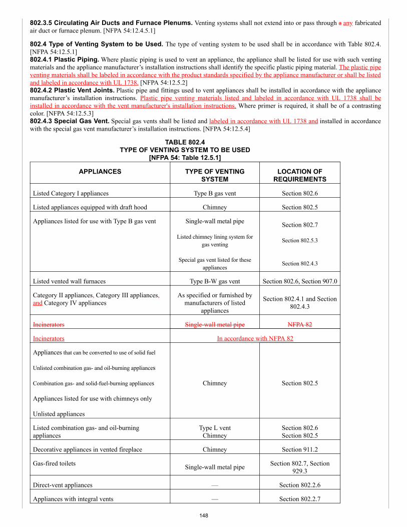
802.3.5 Circulating Air Ducts and Furnace Plenums. Venting systems shall not extend into or pass through a any fabricatedair duct or furnace plenum. [NFPA 54:12.4.5.1]
802.4 Type of Venting System to be Used. The type of venting system to be used shall be in accordance with Table 802.4.[NFPA 54:12.5.1]802.4.1 Plastic Piping. Where plastic piping is used to vent an appliance, the appliance shall be listed for use with such ventingmaterials and the appliance manufacturer’s installation instructions shall identify the specific plastic piping material. The plastic pipeventing materials shall be labeled in accordance with the product standards specified by the appliance manufacturer or shall be listedand labeled in accordance with UL 1738. [NFPA 54:12.5.2]802.4.2 Plastic Vent Joints. Plastic pipe and fittings used to vent appliances shall be installed in accordance with the appliancemanufacturer’s installation instructions. Plastic pipe venting materials listed and labeled in accordance with UL 1738 shall beinstalled in accordance with the vent manufacturer's installation instructions. Where primer is required, it shall be of a contrastingcolor. [NFPA 54:12.5.3]802.4.3 Special Gas Vent. Special gas vents shall be listed and labeled in accordance with UL 1738 and installed in accordancewith the special gas vent manufacturer’s installation instructions. [NFPA 54:12.5.4]
TABLE 802.4TYPE OF VENTING SYSTEM TO BE USED
[NFPA 54: Table 12.5.1]
APPLIANCES TYPE OF VENTINGSYSTEM
LOCATION OFREQUIREMENTS
Listed Category I appliances Type B gas vent Section 802.6
Listed appliances equipped with draft hood Chimney Section 802.5
Appliances listed for use with Type B gas vent Single-wall metal pipe
Listed chimney lining system forgas venting
Special gas vent listed for theseappliances
Section 802.7
Section 802.5.3
Section 802.4.3
Listed vented wall furnaces Type B-W gas vent Section 802.6, Section 907.0
Category II appliances, Category III appliances,and Category IV appliances
As specified or furnished bymanufacturers of listed
appliances
Section 802.4.1 and Section802.4.3
Incinerators Single-wall metal pipe NFPA 82
Incinerators In accordance with NFPA 82
Appliances that can be converted to use of solid fuel
Unlisted combination gas- and oil-burning appliances
Combination gas- and solid-fuel-burning appliances
Appliances listed for use with chimneys only
Unlisted appliances
Chimney Section 802.5
Listed combination gas- and oil-burningappliances
Type L ventChimney
Section 802.6Section 802.5
Decorative appliances in vented fireplace Chimney Section 911.2
Gas-fired toilets Single-wall metal pipe Section 802.7, Section929.3
Direct-vent appliances — Section 802.2.6
Appliances with integral vents — Section 802.2.7
148
802.5.3 Masonry Chimneys. Masonry chimneys shall be built and installed in accordance with NFPA 211 and lined withapproved one of the following:(1) Approved clay flue lining, a listed,.(2) Aa listed chimney lining system, or other listed and labeled in accordance with UL 1777.(3) Other approved material that resists corrosion, erosion, softening, or cracking from vent gases at temperatures not exceeding up
to 1800°F (982°C).
Exception: Masonry chimney flues lined with a chimney lining system specifically listed for use with listed appliances with drafthoods, Category I appliances, and other appliances listed for use with Type B vents shall be permitted. The liner shall be installed inaccordance with the liner manufacturer’s installation instructions. A permanent identifying label shall be attached at the point wherethe connection is to be made to the liner. The label shall read: “This chimney liner is for appliances that burn gas only. Do notconnect to solid-or liquid-fuel-burning appliances or incinerators.” [NFPA 54:12.6.1.3]
802.5.7.2 Cleanouts. Cleanouts shall be examined to determine that and where they will do not remain tightly closed where whennot in use, they shall be repaired or replaced. [NFPA 54:12.6.4.3]
802.5.7.3 Existing Chimney. Where When inspection reveals that an existing chimney is not safe for the intended application, itshall be repaired, rebuilt, lined, relined, or replaced with a vent or chimney in accordance with to conform to NFPA 211, and shall beapproved suitable for the appliances to be attached. [NFPA 54:12.6.4.4]
802.5.8.3 Combination Gas- and Oil-Burning Appliances. A single chimney flue serving a listed combination gas- and oil-burning appliance shall be sized to properly vent in accordance with the appliance manufacturer’s instructions. [NFPA 54:12.6.5.4]
802.6.1 Termination Requirements Gas Vent Termination. A The termination of gas vents shall terminate in accordancewith one of comply with the following requirements:(1) A gas vent shall terminate in accordance with one of the following:
(1a) Gas vents that are 12 inches (300 mm) or less in size and located not less than 8 feet (2438 mm) from a vertical wall orsimilar obstruction shall terminate above the roof in accordance with Figure 802.6.1 and Table 802.6.1.
(2b) Gas vents that are over 12 inches (300 mm) in size or are located less than 8 feet (2438 mm) from a vertical wall or similarobstruction shall terminate not less than 2 feet (610 mm) above the highest point where they pass through the roof and notless than 2 feet (610 mm) above a portion of a building within 10 feet (3048 mm) horizontally.
(3c) Industrial appliances as provided in Section 802.2.5.(4d) Direct- vent systems as provided in Section 802.2.6.(5e) Appliances with integral vents as provided in Section 802.2.7.(6f) Mechanical draft systems as provided in Section 802.3.3 through Section 802.3.3.5.(7g) Ventilating hoods and exhaust systems as provided in Section 802.3.4 and Section 802.3.4.1.[NFPA 54:12.7.2(1)]
(2) 802.6.1.1 Type B and L Vents. A Type B or a Type L gas vent shall terminate not less than at least 5 feet (1524 mm) invertical height above the highest connected appliance draft hood or flue collar. [NFPA 54:12.7.2(2)]
(3) 802.6.1.2 Type B-W Vents. A Type B-W gas vent shall terminate not less than at least 12 feet (3658 mm) in vertical heightabove the bottom of the wall furnace. [NFPA 54:12.7.2(3)]
(4) 802.6.1.3 Exterior Wall Termination. A gas vent extending through an exterior wall shall not terminate adjacent to the wall or beloweaves or parapets, except as provided in Section 802.2.6 and Section 802.3.3 through Section 802.3.3.5. [NFPA 54:12.7.2(4)]
(5) 802.6.1.4 Decorative Shrouds. Decorative shrouds shall not be installed at the termination of gas vents except where suchshrouds are listed for use with the specific gas venting system and are installed in accordance with the manufacturer’s installationinstructions. [NFPA 54:12.7.2(5)]
(6) 802.6.1.5 Termination Cap. All gas vents shall extend through the roof flashing, roof jack, or roof thimble and terminate witha listed cap or listed roof assembly. [NFPA 54:12.7.2(6)]
(7) 802.6.1.6 Forced Air Inlet. A gas vent shall terminate not less than at least 3 feet (914 mm) above a forced air inlet locatedwithin 10 feet (3048 mm). [NFPA 54:12.7.2(7)] [NFPA 54:12.7.3]
149
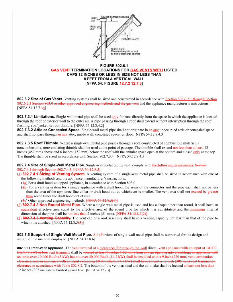
FIGURE 802.6.1GAS VENT TERMINATION LOCATIONS FOR GAS VENTS WITH LISTED
CAPS 12 INCHES OR LESS IN SIZE NOT LESS THAN8 FEET FROM A VERTICAL WALL[NFPA 54: FIGURE 12.7.2 12.7.3]
802.6.2 Size of Gas Vents. Venting systems shall be sized and constructed in accordance with Section 802.6.2.1 through Section802.6.2.3 Section 803.0 or other approved engineering methods and the gas vent and the appliance manufacturer’s instructions.[NFPA 54:12.7.34]
802.7.3.1 Limitations. Single-wall metal pipe shall be used only for runs directly from the space in which the appliance is locatedthrough the roof or exterior wall to the outer air. A pipe passing through a roof shall extend without interruption through the roofflashing, roof jacket, or roof thimble. [NFPA 54:12.8.4.2]802.7.3.2 Attic or Concealed Space. Single-wall metal pipe shall not originate in an any unoccupied attic or concealed spaceand shall not pass through an any attic, inside wall, concealed space, or floor. [NFPA 54:12.8.4.3]
802.7.3.5 Roof Thimble. Where a single-wall metal pipe passes through a roof constructed of combustible material, anoncombustible, nonventilating thimble shall be used at the point of passage. The thimble shall extend not less than at least 18inches (457 mm) above and 6 inches (152 mm) below the roof with the annular space open at the bottom and closed only at the top.The thimble shall be sized in accordance with Section 802.7.3.4. [NFPA 54:12.8.4.5]
802.7.4 Size of Single-Wall Metal Pipe. Single-wall metal piping shall comply with the following requirements: Section802.7.4.1 through Section 802.7.4.3. [NFPA 54:12.8.5](1) 802.7.4.1 Sizing of Venting System. A venting system of a single-wall metal pipe shall be sized in accordance with one of
the following methods and the appliance manufacturer’s instructions:(1a) For a draft hood-equipped appliance, in accordance with Section 803.0.(2b) For a venting system for a single appliance with a draft hood, the areas of the connector and the pipe each shall not be less
than the area of the appliance flue collar or draft hood outlet, whichever is smaller. The vent area shall not exceed be greaterthan seven times the draft hood outlet area.
(3c) Other approved engineering methods. [NFPA 54:12.8.5(1)](2) 802.7.4.2 Non-Round Metal Pipe. Where a single-wall metal pipe is used and has a shape other than round, it shall have an
equivalent effective area equal to the effective area of the round pipe for which it is substituted, and the minimum internaldimension of the pipe shall be not less than 2 inches (51 mm). [NFPA 54:12.8.5(2)]
(3) 802.7.4.3 Venting Capacity. The vent cap or a roof assembly shall have a venting capacity not less than that of the pipe towhich it is attached. [NFPA 54:12.8.5(3)]
802.7.5 Support of Single-Wall Metal Pipe. All pPortions of single-wall metal pipe shall be supported for the design andweight of the material employed. [NFPA 54:12.8.6]
802.8.2 Direct-Vent Appliance. The vent terminal of a clearances for through-the-wall direct -vent appliance with an input of 10 000Btu/h (3 kW) or less vent terminals shall be located at least 6 inches (152 mm) from any air opening into a building, an appliance withan input over 10 000 Btu/h (3 kW) but not over 50 000 Btu/h (14.7 kW) shall be installed with a 9 inch (229 mm) vent terminationclearance, and an appliance with an input exceeding 50 000 Btu/h (14.7 kW) shall have at least a 12 inch (305 mm) vent terminationclearance in accordance with Table 802.8.2. The bottom of the vent terminal and the air intake shall be located at least not less than12 inches (305 mm) above finished ground level. [NFPA 54:12.9.3]
150
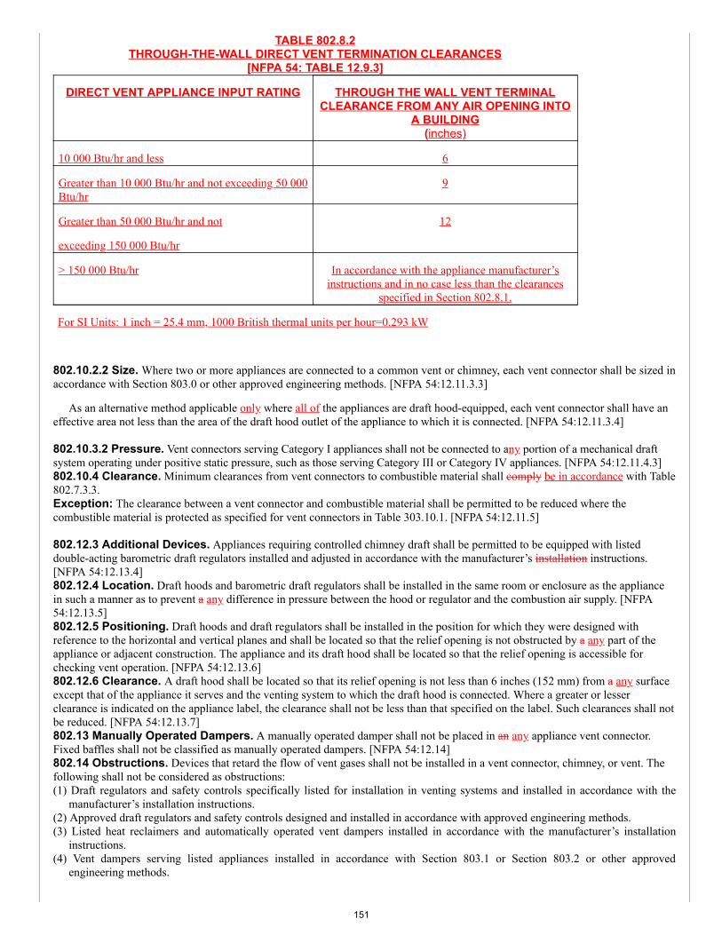
TABLE 802.8.2THROUGH-THE-WALL DIRECT VENT TERMINATION CLEARANCES
[NFPA 54: TABLE 12.9.3]
DIRECT VENT APPLIANCE INPUT RATING THROUGH THE WALL VENT TERMINALCLEARANCE FROM ANY AIR OPENING INTO
A BUILDING(inches)
10 000 Btu/hr and less 6
Greater than 10 000 Btu/hr and not exceeding 50 000Btu/hr
9
Greater than 50 000 Btu/hr and not
exceeding 150 000 Btu/hr
12
> 150 000 Btu/hr In accordance with the appliance manufacturer’sinstructions and in no case less than the clearances
specified in Section 802.8.1.
For SI Units: 1 inch = 25.4 mm, 1000 British thermal units per hour=0.293 kW
802.10.2.2 Size. Where two or more appliances are connected to a common vent or chimney, each vent connector shall be sized inaccordance with Section 803.0 or other approved engineering methods. [NFPA 54:12.11.3.3]
As an alternative method applicable only where all of the appliances are draft hood-equipped, each vent connector shall have aneffective area not less than the area of the draft hood outlet of the appliance to which it is connected. [NFPA 54:12.11.3.4]
802.10.3.2 Pressure. Vent connectors serving Category I appliances shall not be connected to any portion of a mechanical draftsystem operating under positive static pressure, such as those serving Category III or Category IV appliances. [NFPA 54:12.11.4.3]802.10.4 Clearance. Minimum clearances from vent connectors to combustible material shall comply be in accordance with Table802.7.3.3.Exception: The clearance between a vent connector and combustible material shall be permitted to be reduced where thecombustible material is protected as specified for vent connectors in Table 303.10.1. [NFPA 54:12.11.5]
802.12.3 Additional Devices. Appliances requiring controlled chimney draft shall be permitted to be equipped with listeddouble-acting barometric draft regulators installed and adjusted in accordance with the manufacturer’s installation instructions.[NFPA 54:12.13.4]802.12.4 Location. Draft hoods and barometric draft regulators shall be installed in the same room or enclosure as the appliancein such a manner as to prevent a any difference in pressure between the hood or regulator and the combustion air supply. [NFPA54:12.13.5]802.12.5 Positioning. Draft hoods and draft regulators shall be installed in the position for which they were designed withreference to the horizontal and vertical planes and shall be located so that the relief opening is not obstructed by a any part of theappliance or adjacent construction. The appliance and its draft hood shall be located so that the relief opening is accessible forchecking vent operation. [NFPA 54:12.13.6]802.12.6 Clearance. A draft hood shall be located so that its relief opening is not less than 6 inches (152 mm) from a any surfaceexcept that of the appliance it serves and the venting system to which the draft hood is connected. Where a greater or lesserclearance is indicated on the appliance label, the clearance shall not be less than that specified on the label. Such clearances shall notbe reduced. [NFPA 54:12.13.7]802.13 Manually Operated Dampers. A manually operated damper shall not be placed in an any appliance vent connector.Fixed baffles shall not be classified as manually operated dampers. [NFPA 54:12.14]802.14 Obstructions. Devices that retard the flow of vent gases shall not be installed in a vent connector, chimney, or vent. Thefollowing shall not be considered as obstructions:(1) Draft regulators and safety controls specifically listed for installation in venting systems and installed in accordance with the
manufacturer’s installation instructions.(2) Approved draft regulators and safety controls designed and installed in accordance with approved engineering methods.(3) Listed heat reclaimers and automatically operated vent dampers installed in accordance with the manufacturer’s installation
instructions.(4) Vent dampers serving listed appliances installed in accordance with Section 803.1 or Section 803.2 or other approved
engineering methods.
151
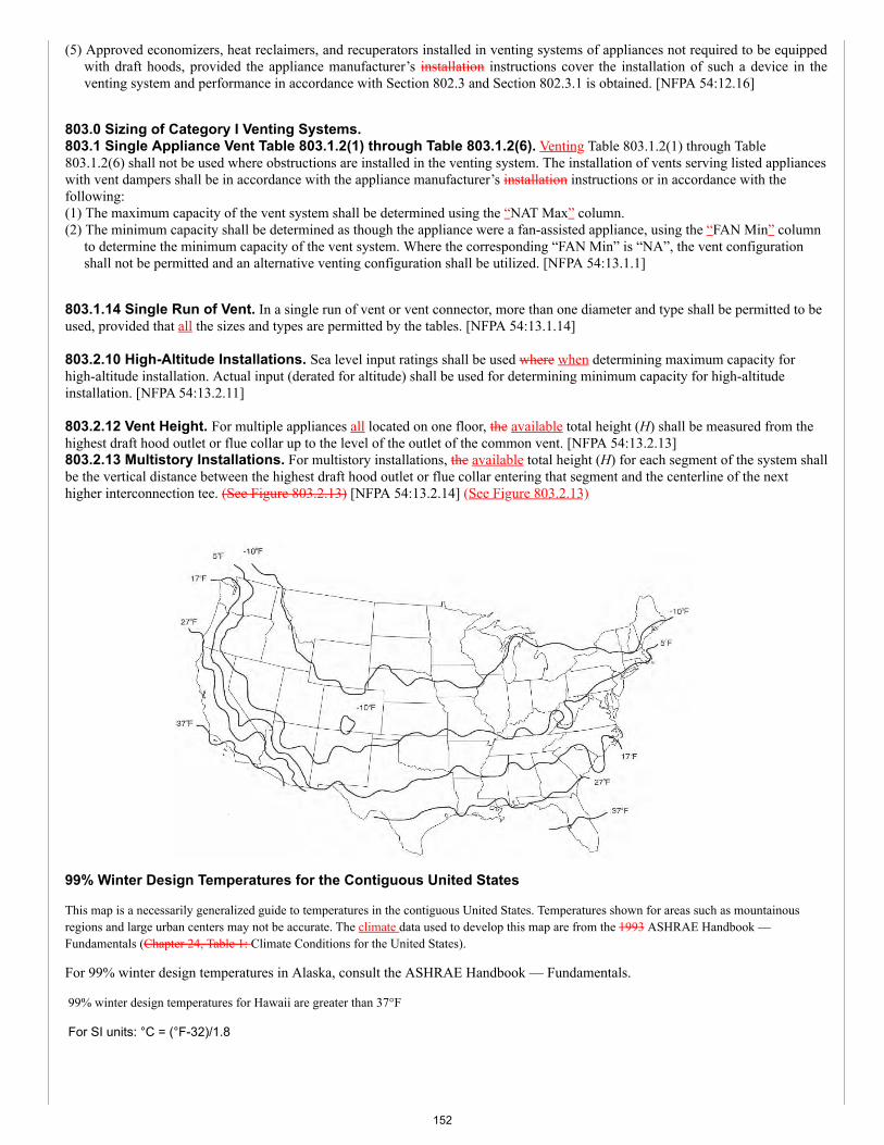
(5) Approved economizers, heat reclaimers, and recuperators installed in venting systems of appliances not required to be equippedwith draft hoods, provided the appliance manufacturer’s installation instructions cover the installation of such a device in theventing system and performance in accordance with Section 802.3 and Section 802.3.1 is obtained. [NFPA 54:12.16]
803.0 Sizing of Category I Venting Systems.803.1 Single Appliance Vent Table 803.1.2(1) through Table 803.1.2(6). Venting Table 803.1.2(1) through Table803.1.2(6) shall not be used where obstructions are installed in the venting system. The installation of vents serving listed applianceswith vent dampers shall be in accordance with the appliance manufacturer’s installation instructions or in accordance with thefollowing:(1) The maximum capacity of the vent system shall be determined using the “NAT Max” column.(2) The minimum capacity shall be determined as though the appliance were a fan-assisted appliance, using the “FAN Min” column
to determine the minimum capacity of the vent system. Where the corresponding “FAN Min” is “NA”, the vent configurationshall not be permitted and an alternative venting configuration shall be utilized. [NFPA 54:13.1.1]
803.1.14 Single Run of Vent. In a single run of vent or vent connector, more than one diameter and type shall be permitted to beused, provided that all the sizes and types are permitted by the tables. [NFPA 54:13.1.14]
803.2.10 High-Altitude Installations. Sea level input ratings shall be used where when determining maximum capacity forhigh-altitude installation. Actual input (derated for altitude) shall be used for determining minimum capacity for high-altitudeinstallation. [NFPA 54:13.2.11]
803.2.12 Vent Height. For multiple appliances all located on one floor, the available total height (H) shall be measured from thehighest draft hood outlet or flue collar up to the level of the outlet of the common vent. [NFPA 54:13.2.13]803.2.13 Multistory Installations. For multistory installations, the available total height (H) for each segment of the system shallbe the vertical distance between the highest draft hood outlet or flue collar entering that segment and the centerline of the nexthigher interconnection tee. (See Figure 803.2.13) [NFPA 54:13.2.14] (See Figure 803.2.13)
99% Winter Design Temperatures for the Contiguous United States
This map is a necessarily generalized guide to temperatures in the contiguous United States. Temperatures shown for areas such as mountainousregions and large urban centers may not be accurate. The climate data used to develop this map are from the 1993 ASHRAE Handbook —Fundamentals (Chapter 24, Table 1: Climate Conditions for the United States).
For 99% winter design temperatures in Alaska, consult the ASHRAE Handbook — Fundamentals.
99% winter design temperatures for Hawaii are greater than 37°F
For SI units: °C = (°F-32)/1.8
152
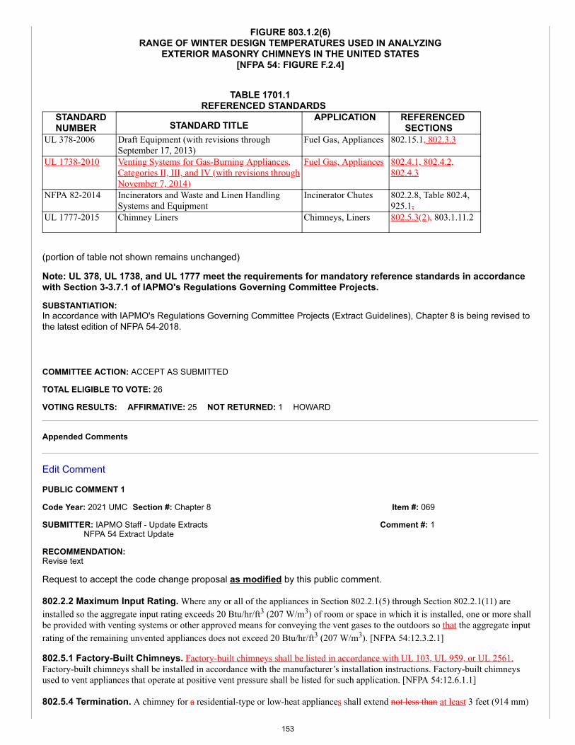
Item #: 069
Comment #: 1
FIGURE 803.1.2(6)RANGE OF WINTER DESIGN TEMPERATURES USED IN ANALYZING
EXTERIOR MASONRY CHIMNEYS IN THE UNITED STATES[NFPA 54: FIGURE F.2.4]
TABLE 1701.1 REFERENCED STANDARDS
STANDARDNUMBER STANDARD TITLE
APPLICATION REFERENCEDSECTIONS
UL 378-2006 Draft Equipment (with revisions throughSeptember 17, 2013)
Fuel Gas, Appliances 802.15.1, 802.3.3
UL 1738-2010 Venting Systems for Gas-Burning Appliances,Categories II, III, and IV (with revisions throughNovember 7, 2014)
Fuel Gas, Appliances 802.4.1, 802.4.2,802.4.3
NFPA 82-2014 Incinerators and Waste and Linen HandlingSystems and Equipment
Incinerator Chutes 802.2.8, Table 802.4,925.1,
UL 1777-2015 Chimney Liners Chimneys, Liners 802.5.3(2), 803.1.11.2
(portion of table not shown remains unchanged)
Note: UL 378, UL 1738, and UL 1777 meet the requirements for mandatory reference standards in accordancewith Section 3-3.7.1 of IAPMO's Regulations Governing Committee Projects.
SUBSTANTIATION:In accordance with IAPMO's Regulations Governing Committee Projects (Extract Guidelines), Chapter 8 is being revised tothe latest edition of NFPA 54-2018.
COMMITTEE ACTION: ACCEPT AS SUBMITTED
TOTAL ELIGIBLE TO VOTE: 26
VOTING RESULTS: AFFIRMATIVE: 25 NOT RETURNED: 1 HOWARD
Appended Comments
Edit Comment
PUBLIC COMMENT 1
Code Year: 2021 UMC Section #: Chapter 8
SUBMITTER: IAPMO Staff - Update ExtractsNFPA 54 Extract Update
RECOMMENDATION:Revise text
Request to accept the code change proposal as modified by this public comment.
802.2.2 Maximum Input Rating. Where any or all of the appliances in Section 802.2.1(5) through Section 802.2.1(11) areinstalled so the aggregate input rating exceeds 20 Btu/hr/ft3 (207 W/m3) of room or space in which it is installed, one or more shallbe provided with venting systems or other approved means for conveying the vent gases to the outdoors so that the aggregate inputrating of the remaining unvented appliances does not exceed 20 Btu/hr/ft3 (207 W/m3). [NFPA 54:12.3.2.1]
802.5.1 Factory-Built Chimneys. Factory-built chimneys shall be listed in accordance with UL 103, UL 959, or UL 2561.Factory-built chimneys shall be installed in accordance with the manufacturer’s installation instructions. Factory-built chimneysused to vent appliances that operate at positive vent pressure shall be listed for such application. [NFPA 54:12.6.1.1]
802.5.4 Termination. A chimney for a residential-type or low-heat appliances shall extend not less than at least 3 feet (914 mm)
153
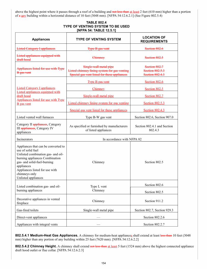
above the highest point where it passes through a roof of a building and not less than at least 2 feet (610 mm) higher than a portionof a any building within a horizontal distance of 10 feet (3048 mm). [NFPA 54:12.6.2.1] (See Figure 802.5.4)
TABLE 802.4TYPE OF VENTING SYSTEM TO BE USED
[NFPA 54: TABLE 12.5.1]
Appliances TYPE OF VENTING SYSTEM LOCATION OFREQUIREMENTS
Listed Category I appliances Type B gas vent Section 802.6
Listed appliances equipped withdraft hood Chimney Section 802.5
Appliances listed for use with TypeB gas vent
Single-wall metal pipeListed chimney lining system for gas ventingSpecial gas vent listed for these appliances
Section 802.7Section 802.5.3Section 802.4.3
Listed Category I appliancesListed appliances equipped withdraft hoodAppliances listed for use with TypeB gas vent
Type B gas vent Section 802.6
Chimney Section 802.5
Single-wall metal pipe Section 802.7
Listed chimney lining system for gas venting Section 802.5.3
Special gas vent listed for these appliances Section 802.4.3
Listed vented wall furnaces Type B-W gas vent Section 802.6, Section 907.0
Category II appliances, CategoryIII appliances, Category IVappliances
As specified or furnished by manufacturersof listed appliances
Section 802.4.1 and Section802.4.3
Incinerators In accordance with NFPA 82
Appliances that can be converted touse of solid fuelUnlisted combination gas- and oil-burning appliances Combinationgas- and solid-fuel-burningappliances Appliances listed for use withchimneys onlyUnlisted appliances
Chimney Section 802.5
Listed combination gas- and oil-burning appliances
Type L ventChimney
Section 802.6
Section 802.5
Decorative appliances in ventedfireplace Chimney Section 911.2
Gas-fired toilets Single-wall metal pipe Section 802.7, Section 929.3
Direct-vent appliances — Section 802.2.6
Appliances with integral vents — Section 802.2.7
802.5.4.1 Medium-Heat Gas Appliances. A chimney for medium-heat appliances shall extend at least less than 10 feet (3048mm) higher than any portion of any building within 25 feet (7620 mm). [NFPA 54:12.6.2.2]
802.5.4.2 Chimney Height. A chimney shall extend not less than at least 5 feet (1524 mm) above the highest connected appliancedraft hood outlet or flue collar. [NFPA 54:12.6.2.3]
154

802.5.7 Inspection of Chimneys. Before replacing an existing appliance or connecting a vent connector to a chimney, thechimney passageway shall be examined to ascertain that it is clear and free of obstructions and shall be cleaned where if previouslyused for venting solid- or liquid- fuel-burning appliances or fireplaces. [NFPA 54:12.6.4.1]
802.5.8.1 Gas and Liquid Fuel-Burning Appliances. Where one chimney serves gas appliances and liquid fuel-burningappliances, the appliances shall be connected through separate openings or shall be connected through a single opening where joinedby a suitable fitting located as close as practical to the chimney. Where two or more openings are provided into one chimney flue,they shall be at different levels. Where the gas appliance is automatically controlled, it shall be equipped with a safety shutoffdevice. [NFPA 54:12.6.5.2]
802.5.10 Cleanouts. Where a chimney that formerly carried flue products from liquid or solid fuel-burning appliances is usedwith an appliance using fuel gas, an accessible cleanout shall be provided. The cleanout shall have a tight-fitting cover and beinstalled so its upper edge is not less than at least 6 inches (152 mm) below the lower edge of the lowest chimney inlet opening.[NFPA 54:12.6.7]
TABLE 802.6.1ROOF PITCH HEIGHT[NFPA 54: TABLE 12.7.3]
ROOF PITCH SLOPE H (minimum) (feet)
Flat to 6/12 1.0
Over 6/12 to 7/12 1.25
Over 7/12 to 8/12 1.5
Over 8/12 to 9/12 2.0
Over 9/12 to 10/12 2.5
Over 10/12 to 11/12 3.25
Over 11/12 to 12/12 4.0
Over 12/12 to 14/12 5.0
Over 14/12 to 16/12 6.0
Over 16/12 to 18/12 7.0
Over 18/12 to 20/12 7.5
Over 20/12 to 21/12 8.0
For SI Units: 1 inch = 25.4 mm, 1 foot = 304.8 mm
802.6.2.1 Category I Appliances. The sizing of natural draft venting systems serving one or more listed appliances equippedwith a draft hood or appliances listed for use with a Type B gas vent, installed in a single story of a building, shall be in accordancewith one of the following:(1) The provisions of Section 803.0.(2) Vents serving fan-assisted combustion system appliances, or combinations of fan-assisted combustion system and draft hood-equipped appliances, shall be sized in accordance with Section 803.0 or other approved engineering methods.(3) For sizing an individual gas vent for a single, draft hood-equipped appliance, the effective area of the vent connector and thegas vent shall be not less than the area of the appliance draft hood outlet or exceeding greater than seven times the draft hood outletarea.(4) For sizing a gas vent connected to two appliances, with draft hoods, the effective area of the vent shall be not less than the areaof the larger draft hood outlet plus 50 percent of the area of the smaller draft hood outlet or exceeding greater than seven times thesmaller draft hood outlet area.(5) Other aApproved engineering practices. [NFPA 54:12.7.4.1]
802.6.2.3 Category II, Category III, and Category IV Appliances. The sizing of gas vents for Category II, Category III, andCategory IV appliances shall be in accordance with the appliance manufacturer’s instructions. The sizing of plastic pipe specified bythe appliance manufacturer as a venting material for Category II, Category III, and Category IV appliances shall be in accordance
155
with the appliance manufacturers’ instructions. [NFPA 54:12.7.4.3]802.6.3.1 Occupiable Space. All appliances connected to the common vent shall be located in rooms separated from anoccupiable space. Each of these rooms shall have provisions for an adequate supply of combustion, ventilation, and dilution air thatis not supplied from an occupiable space. [NFPA 54:12.7.5.2] (See Figure 802.6.3.1)
802.7.3.3 Clearances. Minimum clearances from single-wall metal pipe to combustible material shall be in accordance withTable 802.7.3.3. Reduced clearances from single-wall metal pipe to combustible material shall be as specified for vent connectors inTable 303.10.1. [NFPA 54:12.8.4.4]802.7.3.4 Combustible Exterior Wall. Single-wall metal pipe shall not pass through a combustible exterior wall unless guardedat the point of passage by a ventilated metal thimble not smaller than the following:(1) For listed appliances with draft hoods and appliances listed for use with Type B gas vents, the thimble shall be a minimum of 4inches (102 mm) larger in diameter than the metal pipe. Where there is a run of not less than 6 feet (1829 mm) of metal pipe in theopening between the draft hood outlet and the thimble, the thimble shall be a minimum of 2 inches (51 mm) larger in diameter thanthe metal pipe.(2) For unlisted appliances having draft hoods, the thimble shall be a minimum of 6 inches (152 mm) larger in diameter than themetal pipe.(3) For residential and low-heat appliances, the thimble shall be a minimum of 12 inches (305 mm) larger in diameter than themetal pipe.Exception: In lieu of thimble protection, all combustible material in the wall shall be removed a sufficient distance from the metalpipe to provide the specified clearance from such metal pipe to combustible material. Any material used to close up such openingshall be noncombustible. [NFPA 54:12.8.4.6]
802.8.1 Mechanical Draft Venting System. A mechanical draft venting system of other than direct- vent type shall terminatenot less than 4 feet (1219 mm) below, 4 feet (1219 mm) horizontally from, or 1 foot (305 mm) above a any door, operable window,or gravity air inlet into a any building. The bottom of the vent terminal shall be located not less than at least 12 inches (305 mm)above finished ground level. [NFPA 54:12.9.2]
802.10.1 Materials. A vent connector shall be made of noncombustible, corrosion-resistant material capable of withstanding thevent gas temperature produced by the appliance and of a sufficient thickness to withstand physical damage. [NFPA 54:12.11.2.1]
802.10.9 Chimney Connection. Where entering a flue in a masonry or metal chimney, the vent connector shall be installedabove the extreme bottom to avoid stoppage. Where a thimble or slip joint is used to facilitate removal of the connector, theconnector shall be firmly attached to or inserted into the thimble or slip joint to prevent the connector from falling out. Means shallbe employed to prevent the connector from entering so far as to restrict the space between its end and the opposite wall of thechimney flue. [NFPA 54:12.11.10]
802.12 Draft Hoods and Draft Controls. Vented appliances shall be installed with draft hoods.Exception: Dual oven-type combination ranges; incinerators; direct-_vent appliances; fan-assisted combustion system appliances;appliances requiring chimney draft for operation; single-firebox boilers equipped with conversion burners with inputs exceedinggreater than 400 000 Btu/h (117 kW); appliances equipped with blast, power, or pressure burners that are not listed for use with drafthoods; and appliances designed for forced venting.[NFPA 54:12.13.1]802.12.1 Installation. A draft hood supplied with or forming a part of a listed vented appliances shall be installed withoutalteration, exactly as furnished and specified by the appliance manufacturer. [NFPA 54:12.13.2]Where If a draft hood is not supplied by the appliance manufacturer where one is required, a draft hood shall be installed, be of alisted or approved type, and, in the absence of other instructions, be of the same size as the appliance flue collar. Where a draft hoodis required with a conversion burner, it shall be of a listed or approved type. [NFPA 54:12.13.2.1]Where a draft hood of special design is needed or preferable, the installation shall be approved and in accordance with therecommendations of the appliance manufacturer. [NFPA 54:12.13.2.2]
803.1.1 Vent Downsizing. Where the vent size determined from the tables is smaller than the appliance draft hood outlet or fluecollar, the use of the smaller size shall be permitted, provided that the installation is in accordance complies with all of the followingrequirements:(1) The total vent height (H) is not less than at least 10 feet (3048 mm).(2) Vents for appliance draft hood outlets or flue collars 12 inches (305 mm) in diameter or smaller are not reduced more than onetable size.(3) Vents for appliance draft hood outlets or flue collars exceeding larger than 12 inches (305 mm) in diameter are not reducedmore than two table sizes.(4) The maximum capacity listed in the tables for a fan-assisted appliance is reduced by 10 percent (0.90 x maximum tablecapacity).(5) The draft hood outlet exceeds is greater than 4 inches (102 mm) in diameter. A 3 inch (76 mm) diameter vent shall not beconnected to a 4 inch (102 mm) diameter draft hood outlet. This provision shall not apply to fan-assisted appliances. [NFPA54:13.1.2]
156
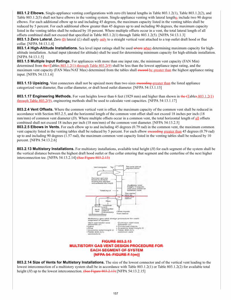
803.1.2 Elbows. Single-appliance venting configurations with zero (0) lateral lengths in Table 803.1.2(1), Table 803.1.2(2), andTable 803.1.2(5) shall not have elbows in the venting system. Single-appliance venting with lateral lengths, include two 90 degreeelbows. For each additional elbow up to and including 45 degrees, the maximum capacity listed in the venting tables shall bereduced by 5 percent. For each additional elbow greater than 45 degrees up to and including 90 degrees, the maximum capacitylisted in the venting tables shall be reduced by 10 percent. Where multiple offsets occur in a vent, the total lateral length of alloffsets combined shall not exceed that specified in Table 803.1.2(1) through Table 803.1.2(5). [NFPA 54:13.1.3]803.1.3 Zero Lateral. Zero (0) lateral (L) shall apply only to a straight vertical vent attached to a top outlet draft hood or fluecollar. [NFPA 54:13.1.4]803.1.4 High-Altitude Installations. Sea level input ratings shall be used where when determining maximum capacity for high-altitude installation. Actual input (derated for altitude) shall be used for determining minimum capacity for high-altitude installation.[NFPA 54:13.1.5]803.1.5 Multiple Input Ratings. For appliances with more than one input rate, the minimum vent capacity (FAN Min)determined from the tTables 803.1.2(1) through Table 803.2(9) shall be less than the lowest appliance input rating, and themaximum vent capacity (FAN Max/NAT Max) determined from the tables shall exceed be greater than the highest appliance ratinginput. [NFPA 54:13.1.6]
803.1.13 Upsizing. Vent connectors shall not be upsized more than two sizes exceeding greater than the listed appliancecategorized vent diameter, flue collar diameter, or draft hood outlet diameter. [NFPA 54:13.1.13]
803.1.17 Engineering Methods. For vent heights lower than 6 feet (1829 mm) and higher than shown in the tTables 803.1.2(1)through Table 803.2(9), engineering methods shall be used to calculate vent capacities. [NFPA 54:13.1.17]
803.2.4 Vent Offsets. Where the common vertical vent is offset, the maximum capacity of the common vent shall be reduced inaccordance with Section 803.2.5, and the horizontal length of the common vent offset shall not exceed 18 inches per inch (18mm/mm) of common vent diameter (D). Where multiple offsets occur in a common vent, the total horizontal length of all offsetscombined shall not exceed 18 inches per inch (18 mm/mm) of the common vent diameter. [NFPA 54:13.2.5]803.2.5 Elbows in Vents. For each elbow up to and including 45 degrees (0.79 rad) in the common vent, the maximum commonvent capacity listed in the venting tables shall be reduced by 5 percent. For each elbow exceeding greater than 45 degrees (0.79 rad)up to and including 90 degrees (1.57 rad), the maximum common vent capacity listed in the venting tables shall be reduced by 10percent. [NFPA 54:13.2.6]
803.2.13 Multistory Installations. For multistory installations, available total height (H) for each segment of the system shall bethe vertical distance between the highest draft hood outlet or flue collar entering that segment and the centerline of the next higherinterconnection tee. [NFPA 54:13.2.14] (See Figure 803.2.13)
FIGURE 803.2.13MULTISTORY GAS VENT DESIGN PROCEDURE FOR
EACH SEGMENT OF SYSTEM[NFPA 54: FIGURE F.1(m)]
803.2.14 Size of Vents for Multistory Installations. The size of the lowest connector and of the vertical vent leading to thelowest interconnection of a multistory system shall be in accordance with Table 803.1.2(1) or Table 803.1.2(2) for available totalheight (H) up to the lowest interconnection. (See Figure 803.2.13) [NFPA 54:13.2.15]
157
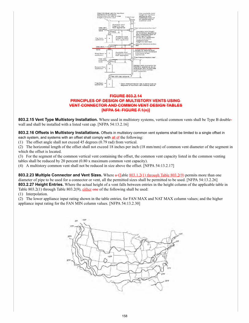
FIGURE 803.2.14PRINCIPLES OF DESIGN OF MULTISTORY VENTS USING
VENT CONNECTOR AND COMMON VENT DESIGN TABLES[NFPA 54: FIGURE F.1(n)]
803.2.15 Vent Type Multistory Installation. Where used in multistory systems, vertical common vents shall be Type B double-wall and shall be installed with a listed vent cap. [NFPA 54:13.2.16]
803.2.16 Offsets in Multistory Installations. Offsets in multistory common vent systems shall be limited to a single offset ineach system, and systems with an offset shall comply with all of the following:(1) The offset angle shall not exceed 45 degrees (0.79 rad) from vertical.(2) The horizontal length of the offset shall not exceed 18 inches per inch (18 mm/mm) of common vent diameter of the segment inwhich the offset is located.(3) For the segment of the common vertical vent containing the offset, the common vent capacity listed in the common ventingtables shall be reduced by 20 percent (0.80 x maximum common vent capacity).(4) A multistory common vent shall not be reduced in size above the offset. [NFPA 54:13.2.17]
803.2.23 Multiple Connector and Vent Sizes. Where a tTable 803.1.2(1) through Table 803.2(9) permits more than onediameter of pipe to be used for a connector or vent, all the permitted sizes shall be permitted to be used. [NFPA 54:13.2.26]803.2.27 Height Entries. Where the actual height of a vent falls between entries in the height column of the applicable table inTable 803.2(1) through Table 803.2(9), either one of the following shall be used:(1) Interpolation.(2) The lower appliance input rating shown in the table entries, for FAN MAX and NAT MAX column values; and the higherappliance input rating for the FAN MIN column values. [NFPA 54:13.2.30]
158
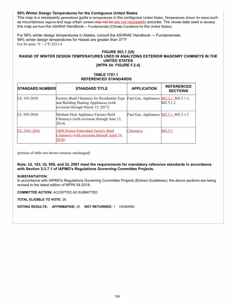
99% Winter Design Temperatures for the Contiguous United StatesThis map is a necessarily generalized guide to temperatures in the contiguous United States. Temperatures shown for areas suchas mountainous regions and large urban centers may not be are not necessarily accurate. The climate data used to developthis map are from the ASHRAE Handbook – Fundamentals (Climate Conditions for the United States).
For 99% winter design temperatures in Alaska, consult the ASHRAE Handbook — Fundamentals.99% winter design temperatures for Hawaii are greater than 37°FFor SI units: °C = (°F-32)/1.8
FIGURE 803.1.2(6)RANGE OF WINTER DESIGN TEMPERATURES USED IN ANALYZING EXTERIOR MASONRY CHIMNEYS IN THE
UNITED STATES[NFPA 54: FIGURE F.2.4]
TABLE 1701.1 REFERENCED STANDARDS
STANDARD NUMBER STANDARD TITLE APPLICATION REFERENCEDSECTIONS
UL 103-2010 Factory-Built Chimneys for Residential Typeand Building Heating Appliances (withrevisions through March 15, 2017)
Fuel Gas, Appliances 802.5.1, 802.5.1.1,802.5.1.2
UL 959-2010 Medium Heat Appliance Factory-BuiltChimneys (with revisions through June 12,2014)
Fuel Gas, Appliances 802.5.1, 802.5.1.2
UL 2561-2016 1400 Degree Fahrenheit Factory-BuiltChimneys (with revisions through April 19,2018)
Chimneys 802.5.1
(portion of table not shown remains unchanged) Note: UL 103, UL 959, and UL 2561 meet the requirements for mandatory reference standards in accordancewith Section 3-3.7.1 of IAPMO's Regulations Governing Committee Projects.
SUBSTANTIATION:In accordance with IAPMO's Regulations Governing Committee Projects (Extract Guidelines), the above sections are beingrevised to the latest edition of NFPA 54-2018.
COMMITTEE ACTION: ACCEPTED AS SUBMITTED
TOTAL ELIGIBLE TO VOTE: 26
VOTING RESULTS: AFFIRMATIVE: 25 NOT RETURNED: 1 HOWARD
159
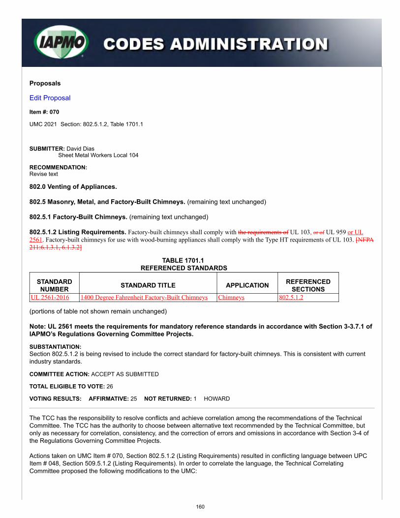
Proposals
Edit Proposal
Item #: 070
UMC 2021 Section: 802.5.1.2, Table 1701.1
SUBMITTER: David DiasSheet Metal Workers Local 104
RECOMMENDATION:Revise text
802.0 Venting of Appliances.
802.5 Masonry, Metal, and Factory-Built Chimneys. (remaining text unchanged)
802.5.1 Factory-Built Chimneys. (remaining text unchanged)
802.5.1.2 Listing Requirements. Factory-built chimneys shall comply with the requirements of UL 103, or of UL 959 or UL2561. Factory-built chimneys for use with wood-burning appliances shall comply with the Type HT requirements of UL 103. [NFPA211:6.1.3.1, 6.1.3.2]
TABLE 1701.1 REFERENCED STANDARDS
STANDARDNUMBER STANDARD TITLE APPLICATION REFERENCED
SECTIONSUL 2561-2016 1400 Degree Fahrenheit Factory-Built Chimneys Chimneys 802.5.1.2
(portions of table not shown remain unchanged)
Note: UL 2561 meets the requirements for mandatory reference standards in accordance with Section 3-3.7.1 ofIAPMO’s Regulations Governing Committee Projects.
SUBSTANTIATION:Section 802.5.1.2 is being revised to include the correct standard for factory-built chimneys. This is consistent with currentindustry standards.
COMMITTEE ACTION: ACCEPT AS SUBMITTED
TOTAL ELIGIBLE TO VOTE: 26
VOTING RESULTS: AFFIRMATIVE: 25 NOT RETURNED: 1 HOWARD
The TCC has the responsibility to resolve conflicts and achieve correlation among the recommendations of the TechnicalCommittee. The TCC has the authority to choose between alternative text recommended by the Technical Committee, butonly as necessary for correlation, consistency, and the correction of errors and omissions in accordance with Section 3-4 ofthe Regulations Governing Committee Projects.
Actions taken on UMC Item # 070, Section 802.5.1.2 (Listing Requirements) resulted in conflicting language between UPCItem # 048, Section 509.5.1.2 (Listing Requirements). In order to correlate the language, the Technical CorrelatingCommittee proposed the following modifications to the UMC:
160
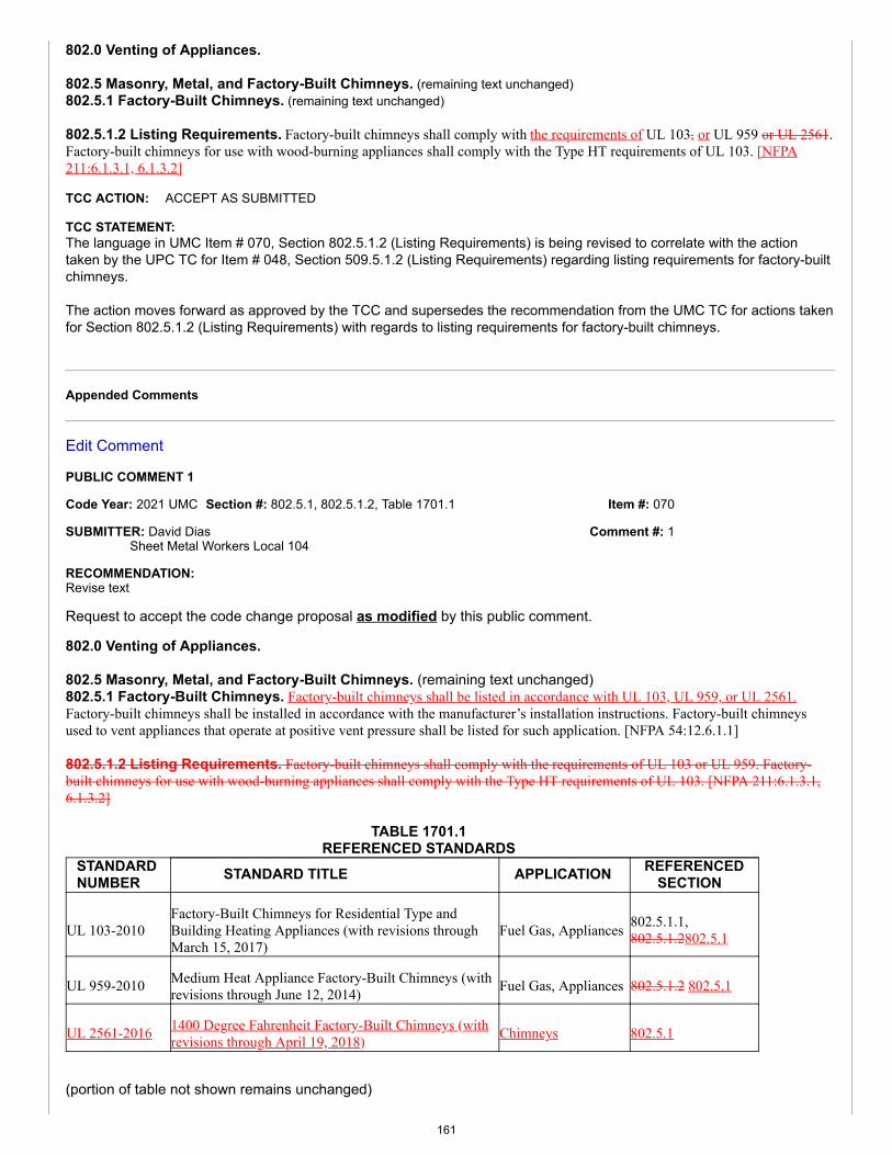
Item #: 070
Comment #: 1
802.0 Venting of Appliances.
802.5 Masonry, Metal, and Factory-Built Chimneys. (remaining text unchanged)802.5.1 Factory-Built Chimneys. (remaining text unchanged)
802.5.1.2 Listing Requirements. Factory-built chimneys shall comply with the requirements of UL 103, or UL 959 or UL 2561.Factory-built chimneys for use with wood-burning appliances shall comply with the Type HT requirements of UL 103. [NFPA211:6.1.3.1, 6.1.3.2]
TCC ACTION: ACCEPT AS SUBMITTED
TCC STATEMENT:The language in UMC Item # 070, Section 802.5.1.2 (Listing Requirements) is being revised to correlate with the actiontaken by the UPC TC for Item # 048, Section 509.5.1.2 (Listing Requirements) regarding listing requirements for factory-builtchimneys.
The action moves forward as approved by the TCC and supersedes the recommendation from the UMC TC for actions takenfor Section 802.5.1.2 (Listing Requirements) with regards to listing requirements for factory-built chimneys.
Appended Comments
Edit Comment
PUBLIC COMMENT 1
Code Year: 2021 UMC Section #: 802.5.1, 802.5.1.2, Table 1701.1
SUBMITTER: David DiasSheet Metal Workers Local 104
RECOMMENDATION:Revise text
Request to accept the code change proposal as modified by this public comment.
802.0 Venting of Appliances.
802.5 Masonry, Metal, and Factory-Built Chimneys. (remaining text unchanged)802.5.1 Factory-Built Chimneys. Factory-built chimneys shall be listed in accordance with UL 103, UL 959, or UL 2561.Factory-built chimneys shall be installed in accordance with the manufacturer’s installation instructions. Factory-built chimneysused to vent appliances that operate at positive vent pressure shall be listed for such application. [NFPA 54:12.6.1.1]
802.5.1.2 Listing Requirements. Factory-built chimneys shall comply with the requirements of UL 103 or UL 959. Factory-built chimneys for use with wood-burning appliances shall comply with the Type HT requirements of UL 103. [NFPA 211:6.1.3.1,6.1.3.2]
TABLE 1701.1REFERENCED STANDARDS
STANDARDNUMBER STANDARD TITLE APPLICATION REFERENCED
SECTION
UL 103-2010Factory-Built Chimneys for Residential Type andBuilding Heating Appliances (with revisions throughMarch 15, 2017)
Fuel Gas, Appliances 802.5.1.1,802.5.1.2802.5.1
UL 959-2010 Medium Heat Appliance Factory-Built Chimneys (withrevisions through June 12, 2014) Fuel Gas, Appliances 802.5.1.2 802.5.1
UL 2561-2016 1400 Degree Fahrenheit Factory-Built Chimneys (withrevisions through April 19, 2018) Chimneys 802.5.1
(portion of table not shown remains unchanged)
161
Note: UL 103, UL 959, and UL 2561 meet the requirements for mandatory reference standards in accordancewith Section 3-3.7.1 of IAPMO's Regulations Governing Committee Projects.
SUBSTANTIATION:The proposed code change updates the NFPA 54 extract in Section 802.5.1 (Factory-Built Chimneys) to the latest edition ofNFPA 54-2018.
Furthermore, Section 802.5.1.2 (Listing Requirements) is being stricken as the language addresses the same standards asSection 802.5.1 with the addition of UL 2561 for factory-built chimneys. The stricken language is redundant and not needed.
COMMITTEE ACTION: ACCEPTED AS SUBMITTED
TOTAL ELIGIBLE TO VOTE: 26
VOTING RESULTS: AFFIRMATIVE: 25 NOT RETURNED: 1 HOWARD
162
Proposals
Edit Proposal
Item #: 072
UMC 2021 Section: Chapter 9: 902.11 - 938.1, Table 1701.1
SUBMITTER: IAPMO Staff - Update ExtractsNFPA 54 Extract Update
RECOMMENDATION:Revise text
902.0 General.902.11 Combination of Appliances and Equipment. A Any combination of appliances, equipment, attachments, or devicesused together in a any manner shall be in accordance comply with the standards that apply to the individual appliance andequipment. [NFPA 54:9.1.21]
911.0 Decorative Appliances for Installation in Vented Fireplaces.
TABLE 911.2FREE OPENING AREA OF CHIMNEY DAMPER FOR VENTING FLUE GASES FROM UNLISTED
DECORATIVE APPLIANCES FOR INSTALLATION IN VENTED FIREPLACES[NFPA 54: TABLE 10.6.2.3]
MINIMUM PERMANENT FREE OPENING(square inches)*
CHIMNEYHEIGHT
(feet)
8 13 20 29 39 51 64
APPLIANCE INPUT RATING(Btu/h)
6 7800 14 000 23 200 34 000 46 400 62 400 80 000
8 8400 15 200 25 200 37 000 50 400 68 000 86 000
10 9000 16 800 27 600 40 400 55 800 74 400 96 400
15 9800 18 200 30 200 44 600 62 400 84 000 108 800
20 10 600 20 200 32 600 50 400 68 400 94 000 122 200
30 11 200 21 600 36 600 55 200 76 800 105 800 138 600
For SI units: 1 foot = 304.8 mm, 1000 British thermal units per hour = 0.293 kW, 1 square inch = 0.000645 m2
* The first six minimum permanent free openings [8 square inches (0.005 m2) to 51 square inches (0.03 m2)] correspondapproximately to the cross-sectional areas of chimneys having diameters of 3 inches (76 mm) through 8 inches (203 mm),respectively. The 64 square inch (0.04 m2) opening corresponds to the cross-sectional area of a standard 8 inch (203 mm) by 8inch (203 mm) chimney tile.
914.0 Non-Recirculating Direct Gas-Fired Industrial Air Heaters.
914.3 Installation. Non-recirculating direct gas-fired industrial air heaters shall be installed in accordance with the manufacturer’sinstructions. [NFPA 54:10.8.3.1]
163
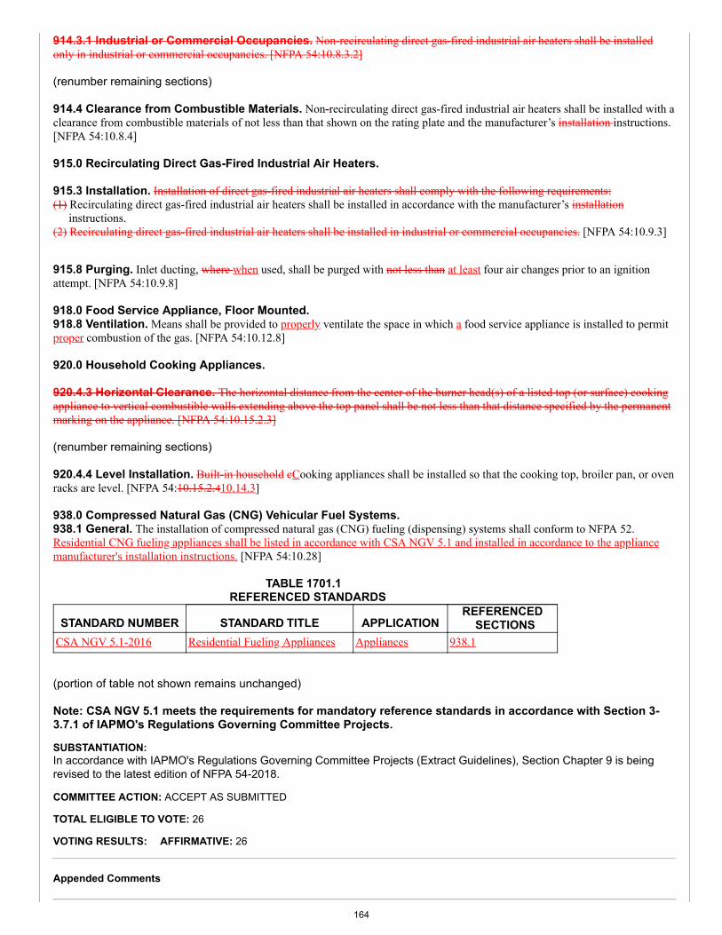
914.3.1 Industrial or Commercial Occupancies. Non-recirculating direct gas-fired industrial air heaters shall be installedonly in industrial or commercial occupancies. [NFPA 54:10.8.3.2]
(renumber remaining sections)
914.4 Clearance from Combustible Materials. Non-recirculating direct gas-fired industrial air heaters shall be installed with aclearance from combustible materials of not less than that shown on the rating plate and the manufacturer’s installation instructions.[NFPA 54:10.8.4]
915.0 Recirculating Direct Gas-Fired Industrial Air Heaters.
915.3 Installation. Installation of direct gas-fired industrial air heaters shall comply with the following requirements:(1) Recirculating direct gas-fired industrial air heaters shall be installed in accordance with the manufacturer’s installation
instructions.(2) Recirculating direct gas-fired industrial air heaters shall be installed in industrial or commercial occupancies. [NFPA 54:10.9.3]
915.8 Purging. Inlet ducting, where when used, shall be purged with not less than at least four air changes prior to an ignitionattempt. [NFPA 54:10.9.8]
918.0 Food Service Appliance, Floor Mounted.918.8 Ventilation. Means shall be provided to properly ventilate the space in which a food service appliance is installed to permitproper combustion of the gas. [NFPA 54:10.12.8]
920.0 Household Cooking Appliances.
920.4.3 Horizontal Clearance. The horizontal distance from the center of the burner head(s) of a listed top (or surface) cookingappliance to vertical combustible walls extending above the top panel shall be not less than that distance specified by the permanentmarking on the appliance. [NFPA 54:10.15.2.3]
(renumber remaining sections)
920.4.4 Level Installation. Built-in household cCooking appliances shall be installed so that the cooking top, broiler pan, or ovenracks are level. [NFPA 54:10.15.2.410.14.3]
938.0 Compressed Natural Gas (CNG) Vehicular Fuel Systems.938.1 General. The installation of compressed natural gas (CNG) fueling (dispensing) systems shall conform to NFPA 52.Residential CNG fueling appliances shall be listed in accordance with CSA NGV 5.1 and installed in accordance to the appliancemanufacturer's installation instructions. [NFPA 54:10.28]
TABLE 1701.1 REFERENCED STANDARDS
STANDARD NUMBER STANDARD TITLE APPLICATIONREFERENCED
SECTIONSCSA NGV 5.1-2016 Residential Fueling Appliances Appliances 938.1
(portion of table not shown remains unchanged)
Note: CSA NGV 5.1 meets the requirements for mandatory reference standards in accordance with Section 3-3.7.1 of IAPMO's Regulations Governing Committee Projects.
SUBSTANTIATION:In accordance with IAPMO's Regulations Governing Committee Projects (Extract Guidelines), Section Chapter 9 is beingrevised to the latest edition of NFPA 54-2018.
COMMITTEE ACTION: ACCEPT AS SUBMITTED
TOTAL ELIGIBLE TO VOTE: 26
VOTING RESULTS: AFFIRMATIVE: 26
Appended Comments
164
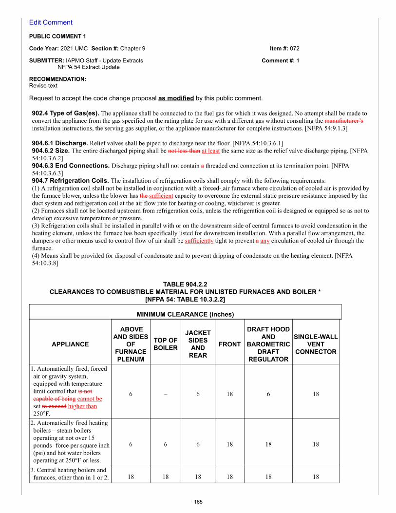
Item #: 072
Comment #: 1
Edit Comment
PUBLIC COMMENT 1
Code Year: 2021 UMC Section #: Chapter 9
SUBMITTER: IAPMO Staff - Update ExtractsNFPA 54 Extract Update
RECOMMENDATION:Revise text
Request to accept the code change proposal as modified by this public comment.
902.4 Type of Gas(es). The appliance shall be connected to the fuel gas for which it was designed. No attempt shall be made toconvert the appliance from the gas specified on the rating plate for use with a different gas without consulting the manufacturer’sinstallation instructions, the serving gas supplier, or the appliance manufacturer for complete instructions. [NFPA 54:9.1.3]
904.6.1 Discharge. Relief valves shall be piped to discharge near the floor. [NFPA 54:10.3.6.1]904.6.2 Size. The entire discharged piping shall be not less than at least the same size as the relief valve discharge piping. [NFPA54:10.3.6.2]904.6.3 End Connections. Discharge piping shall not contain a threaded end connection at its termination point. [NFPA54:10.3.6.3]904.7 Refrigeration Coils. The installation of refrigeration coils shall comply with the following requirements:(1) A refrigeration coil shall not be installed in conjunction with a forced- air furnace where circulation of cooled air is provided bythe furnace blower, unless the blower has the sufficient capacity to overcome the external static pressure resistance imposed by theduct system and refrigeration coil at the air flow rate for heating or cooling, whichever is greater.(2) Furnaces shall not be located upstream from refrigeration coils, unless the refrigeration coil is designed or equipped so as not todevelop excessive temperature or pressure.(3) Refrigeration coils shall be installed in parallel with or on the downstream side of central furnaces to avoid condensation in theheating element, unless the furnace has been specifically listed for downstream installation. With a parallel flow arrangement, thedampers or other means used to control flow of air shall be sufficiently tight to prevent a any circulation of cooled air through thefurnace.(4) Means shall be provided for disposal of condensate and to prevent dripping of condensate on the heating element. [NFPA54:10.3.8]
TABLE 904.2.2CLEARANCES TO COMBUSTIBLE MATERIAL FOR UNLISTED FURNACES AND BOILER *
[NFPA 54: TABLE 10.3.2.2]
MINIMUM CLEARANCE (inches)
APPLIANCE
ABOVEAND SIDES
OFFURNACEPLENUM
TOP OFBOILER
JACKETSIDESAND
REARFRONT
DRAFT HOODAND
BAROMETRICDRAFT
REGULATOR
SINGLE-WALLVENT
CONNECTOR
1. Automatically fired, forcedair or gravity system,equipped with temperaturelimit control that is notcapable of being cannot beset to exceed higher than250°F.
6 – 6 18 6 18
2. Automatically fired heatingboilers – steam boilersoperating at not over 15pounds- force per square inch(psi) and hot water boilersoperating at 250°F or less.
6 6 6 18 18 18
3. Central heating boilers andfurnaces, other than in 1 or 2. 18 18 18 18 18 18
165
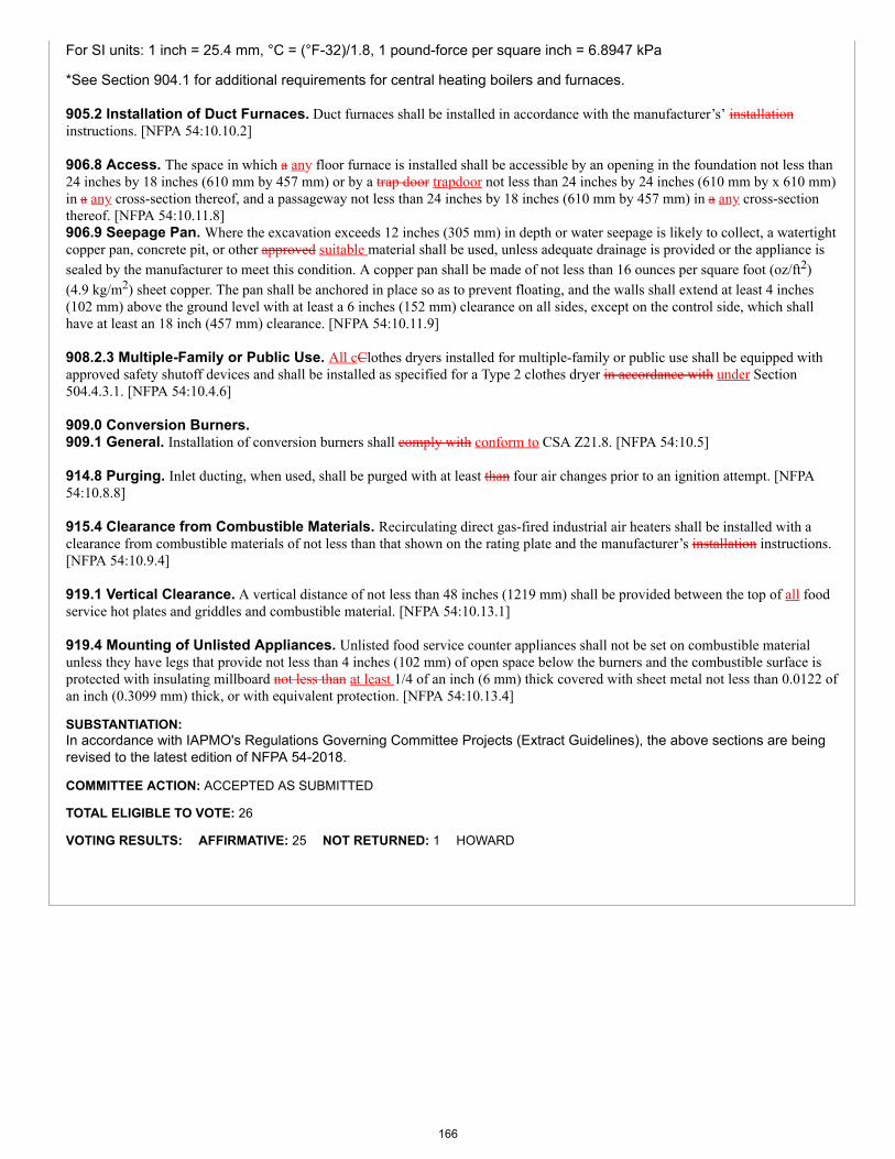
For SI units: 1 inch = 25.4 mm, °C = (°F-32)/1.8, 1 pound-force per square inch = 6.8947 kPa
*See Section 904.1 for additional requirements for central heating boilers and furnaces.
905.2 Installation of Duct Furnaces. Duct furnaces shall be installed in accordance with the manufacturer’s’ installationinstructions. [NFPA 54:10.10.2]
906.8 Access. The space in which a any floor furnace is installed shall be accessible by an opening in the foundation not less than24 inches by 18 inches (610 mm by 457 mm) or by a trap door trapdoor not less than 24 inches by 24 inches (610 mm by x 610 mm)in a any cross-section thereof, and a passageway not less than 24 inches by 18 inches (610 mm by 457 mm) in a any cross-sectionthereof. [NFPA 54:10.11.8]906.9 Seepage Pan. Where the excavation exceeds 12 inches (305 mm) in depth or water seepage is likely to collect, a watertightcopper pan, concrete pit, or other approved suitable material shall be used, unless adequate drainage is provided or the appliance issealed by the manufacturer to meet this condition. A copper pan shall be made of not less than 16 ounces per square foot (oz/ft2)(4.9 kg/m2) sheet copper. The pan shall be anchored in place so as to prevent floating, and the walls shall extend at least 4 inches(102 mm) above the ground level with at least a 6 inches (152 mm) clearance on all sides, except on the control side, which shallhave at least an 18 inch (457 mm) clearance. [NFPA 54:10.11.9]
908.2.3 Multiple-Family or Public Use. All cClothes dryers installed for multiple-family or public use shall be equipped withapproved safety shutoff devices and shall be installed as specified for a Type 2 clothes dryer in accordance with under Section504.4.3.1. [NFPA 54:10.4.6]
909.0 Conversion Burners.909.1 General. Installation of conversion burners shall comply with conform to CSA Z21.8. [NFPA 54:10.5]
914.8 Purging. Inlet ducting, when used, shall be purged with at least than four air changes prior to an ignition attempt. [NFPA54:10.8.8]
915.4 Clearance from Combustible Materials. Recirculating direct gas-fired industrial air heaters shall be installed with aclearance from combustible materials of not less than that shown on the rating plate and the manufacturer’s installation instructions.[NFPA 54:10.9.4]
919.1 Vertical Clearance. A vertical distance of not less than 48 inches (1219 mm) shall be provided between the top of all foodservice hot plates and griddles and combustible material. [NFPA 54:10.13.1]
919.4 Mounting of Unlisted Appliances. Unlisted food service counter appliances shall not be set on combustible materialunless they have legs that provide not less than 4 inches (102 mm) of open space below the burners and the combustible surface isprotected with insulating millboard not less than at least 1/4 of an inch (6 mm) thick covered with sheet metal not less than 0.0122 ofan inch (0.3099 mm) thick, or with equivalent protection. [NFPA 54:10.13.4]
SUBSTANTIATION:In accordance with IAPMO's Regulations Governing Committee Projects (Extract Guidelines), the above sections are beingrevised to the latest edition of NFPA 54-2018.
COMMITTEE ACTION: ACCEPTED AS SUBMITTED
TOTAL ELIGIBLE TO VOTE: 26
VOTING RESULTS: AFFIRMATIVE: 25 NOT RETURNED: 1 HOWARD
166
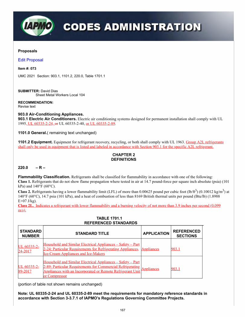
Proposals
Edit Proposal
Item #: 073
UMC 2021 Section: 903.1, 1101.2, 220.0, Table 1701.1
SUBMITTER: David DiasSheet Metal Workers Local 104
RECOMMENDATION:Revise text
903.0 Air-Conditioning Appliances.903.1 Electric Air Conditioners. Electric air conditioning systems designed for permanent installation shall comply with UL1995, UL 60335-2-24, or UL 60335-2-40, or UL 60335-2-89.
1101.0 General.( remaining text unchanged)
1101.2 Equipment. Equipment for refrigerant recovery, recycling, or both shall comply with UL 1963. Group A2L refrigerantsshall only be used in equipment that is listed and labeled in accordance with Section 903.1 for the specific A2L refrigerant.
CHAPTER 2DEFINITIONS
220.0 – R –
Flammability Classification. Refrigerants shall be classified for flammability in accordance with one of the following:Class 1. Refrigerants that do not show flame propagation where tested in air at 14.7 pound-force per square inch absolute (psia) (101kPa) and 140°F (60°C).Class 2. Refrigerants having a lower flammability limit (LFL) of more than 0.00625 pound per cubic foot (lb/ft3) (0.10012 kg/m3) at140°F (60°C), 14.7 psia (101 kPa), and a heat of combustion of less than 8169 British thermal units per pound (Btu/lb) (1.8988E+07 J/kg).Class 2L. Indicates a refrigerant with lower flammability and a burning velocity of not more than 3.9 inches per second (0.099m/s).
TABLE 1701.1 REFERENCED STANDARDS
STANDARDNUMBER STANDARD TITLE APPLICATION REFERENCED
SECTIONS
UL 60335-2-24-2017
Household and Similar Electrical Appliances – Safety – Part2-24: Particular Requirements for Refrigerating Appliances,Ice-Cream Appliances and Ice-Makers
Appliances 903.1
UL 60335-2-89-2017
Household and Similar Electrical Appliances – Safety – Part2-89: Particular Requirements for Commercial RefrigeratingAppliances with an Incorporated or Remote Refrigerant Unitor Compressor
Appliances 903.1
(portion of table not shown remains unchanged)
Note: UL 60335-2-24 and UL 60335-2-89 meet the requirements for mandatory reference standards inaccordance with Section 3-3.7.1 of IAPMO’s Regulations Governing Committee Projects.
167
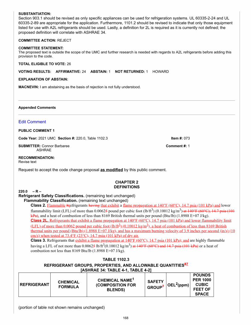
Item #: 073
Comment #: 1
SUBSTANTIATION:Section 903.1 should be revised as only specific appliances can be used for refrigeration systems. UL 60335-2-24 and UL60335-2-89 are appropriate for the application. Furthermore, 1101.2 should be revised to indicate that only those equipmentlisted for use with A2L refrigerants should be used. Lastly, a definition for 2L is required as it is currently not defined; theproposed definition will correlate with ASHRAE 34.
COMMITTEE ACTION: REJECT
COMMITTEE STATEMENT:The proposed text is outside the scope of the UMC and further research is needed with regards to A2L refrigerants before adding thisprovision to the code.
TOTAL ELIGIBLE TO VOTE: 26
VOTING RESULTS: AFFIRMATIVE: 24 ABSTAIN: 1 NOT RETURNED: 1 HOWARD
EXPLANATION OF ABSTAIN:
MACNEVIN: I am abstaining as the basis of rejection is not fully understood.
Appended Comments
Edit Comment
PUBLIC COMMENT 1
Code Year: 2021 UMC Section #: 220.0, Table 1102.3
SUBMITTER: Connor BarbareeASHRAE
RECOMMENDATION:Revise text
Request to accept the code change proposal as modified by this public comment.
CHAPTER 2DEFINITIONS
220.0 – R –Refrigerant Safety Classifications. (remaining text unchanged)
Flammability Classification. (remaining text unchanged)Class 2. Flammable Rrefrigerants having that exhibit a flame propagation at 140°F (60°C), 14.7 psia (101 kPa) and lowerflammability limit (LFL) of more than 0.00625 pound per cubic foot (lb/ft3) (0.10012 kg/m3) at 140°F (60°C), 14.7 psia (101kPa), and a heat of combustion of less than 8169 British thermal units per pound (Btu/lb) (1.8988 E+07 J/kg).Class 2L. Refrigerants that exhibit a flame propagation at 140°F (60°C), 14.7 psia (101 kPa) and lower flammability limit(LFL) of more than 0.0062 pound per cubic foot (lb/ft3) (0.10012 kg/m3), a heat of combustion of less than 8169 Britishthermal units per pound (Btu/lb) (1.8988 E+07 J/kg), and has a maximum burning velocity of 3.9 inches per second (in/s) (10cm/s) when tested at 73.4°F (23°C), 14.7 psia (101 kPa) of dry air.Class 3. Refrigerants that exhibit a flame propagation at 140°F (60°C), 14.7 psia (101 kPa); and are highly flammablehaving a LFL of not more than 0.00625 lb/ft3(0.10012 kg/m3) at 140°F (60°C) and 14.7 psia (101 kPa) or a heat ofcombustion not less than 8169 Btu/lb (1.8988 E+07 J/kg).
TABLE 1102.3REFRIGERANT GROUPS, PROPERTIES, AND ALLOWABLE QUANTITIES87
[ASHRAE 34: TABLE 4-1, TABLE 4-2]
REFRIGERANT CHEMICALFORMULA
CHEMICAL NAME1
(COMPOSITION FORBLENDS)
SAFETYGROUP7 OEL2(ppm)
POUNDSPER 1000
CUBICFEET OFSPACE
(portion of table not shown remains unchanged)
168
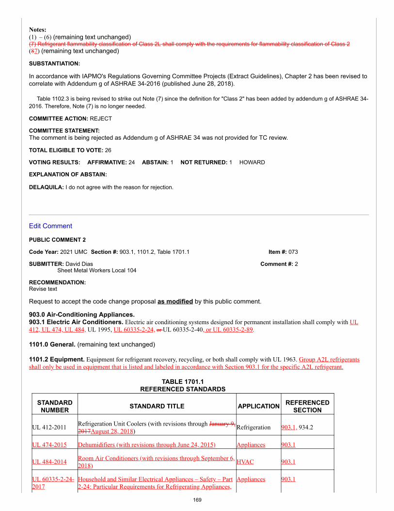
Item #: 073
Comment #: 2
Notes:(1) – (6) (remaining text unchanged)(7) Refrigerant flammability classification of Class 2L shall comply with the requirements for flammability classification of Class 2(87) (remaining text unchanged)
SUBSTANTIATION:
In accordance with IAPMO's Regulations Governing Committee Projects (Extract Guidelines), Chapter 2 has been revised tocorrelate with Addendum g of ASHRAE 34-2016 (published June 28, 2018).
Table 1102.3 is being revised to strike out Note (7) since the definition for "Class 2" has been added by addendum g of ASHRAE 34-2016. Therefore, Note (7) is no longer needed.
COMMITTEE ACTION: REJECT
COMMITTEE STATEMENT:The comment is being rejected as Addendum g of ASHRAE 34 was not provided for TC review.
TOTAL ELIGIBLE TO VOTE: 26
VOTING RESULTS: AFFIRMATIVE: 24 ABSTAIN: 1 NOT RETURNED: 1 HOWARD
EXPLANATION OF ABSTAIN:
DELAQUILA: I do not agree with the reason for rejection.
Edit Comment
PUBLIC COMMENT 2
Code Year: 2021 UMC Section #: 903.1, 1101.2, Table 1701.1
SUBMITTER: David DiasSheet Metal Workers Local 104
RECOMMENDATION:Revise text
Request to accept the code change proposal as modified by this public comment.
903.0 Air-Conditioning Appliances.903.1 Electric Air Conditioners. Electric air conditioning systems designed for permanent installation shall comply with UL412, UL 474, UL 484, UL 1995, UL 60335-2-24, or UL 60335-2-40, or UL 60335-2-89.
1101.0 General. (remaining text unchanged)
1101.2 Equipment. Equipment for refrigerant recovery, recycling, or both shall comply with UL 1963. Group A2L refrigerantsshall only be used in equipment that is listed and labeled in accordance with Section 903.1 for the specific A2L refrigerant.
TABLE 1701.1REFERENCED STANDARDS
STANDARDNUMBER STANDARD TITLE APPLICATION REFERENCED
SECTION
UL 412-2011 Refrigeration Unit Coolers (with revisions through January 9,2017August 28, 2018) Refrigeration 903.1, 934.2
UL 474-2015 Dehumidifiers (with revisions through June 24, 2015) Appliances 903.1
UL 484-2014 Room Air Conditioners (with revisions through September 6,2018) HVAC 903.1
UL 60335-2-24-2017
Household and Similar Electrical Appliances – Safety – Part2-24: Particular Requirements for Refrigerating Appliances,
Appliances 903.1
169
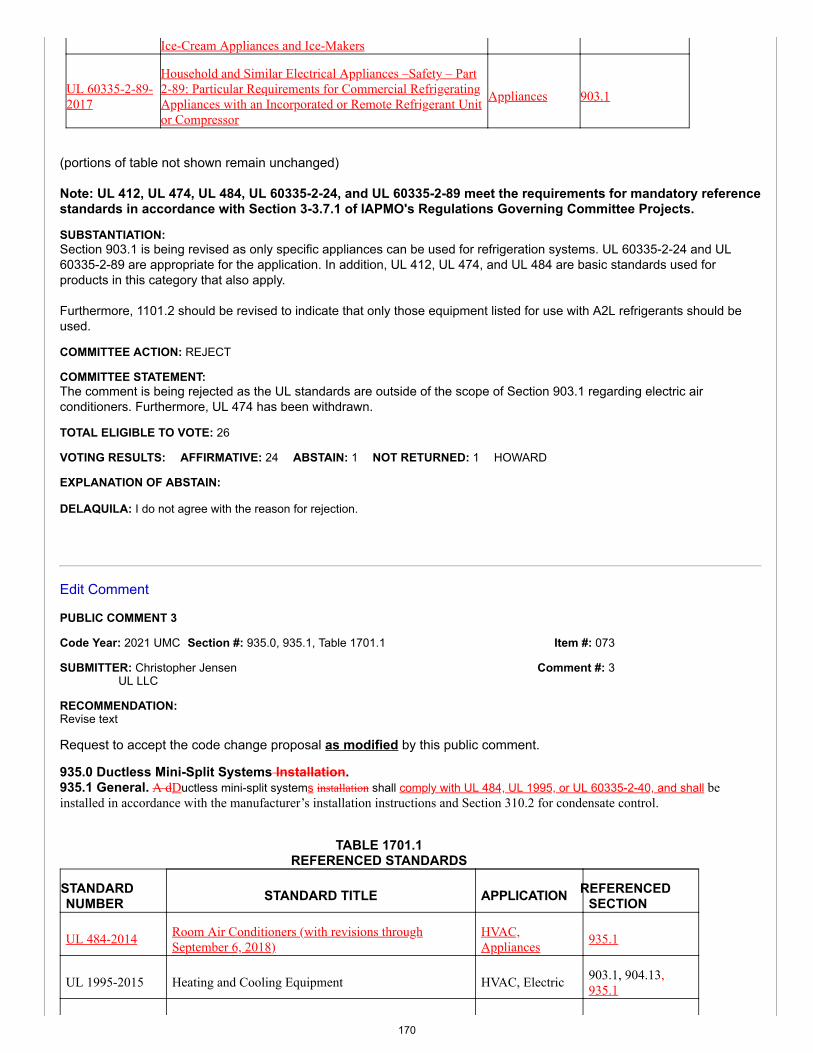
Item #: 073
Comment #: 3
Ice-Cream Appliances and Ice-Makers
UL 60335-2-89-2017
Household and Similar Electrical Appliances –Safety – Part2-89: Particular Requirements for Commercial RefrigeratingAppliances with an Incorporated or Remote Refrigerant Unitor Compressor
Appliances 903.1
(portions of table not shown remain unchanged)
Note: UL 412, UL 474, UL 484, UL 60335-2-24, and UL 60335-2-89 meet the requirements for mandatory referencestandards in accordance with Section 3-3.7.1 of IAPMO's Regulations Governing Committee Projects.
SUBSTANTIATION:Section 903.1 is being revised as only specific appliances can be used for refrigeration systems. UL 60335-2-24 and UL60335-2-89 are appropriate for the application. In addition, UL 412, UL 474, and UL 484 are basic standards used forproducts in this category that also apply.
Furthermore, 1101.2 should be revised to indicate that only those equipment listed for use with A2L refrigerants should beused.
COMMITTEE ACTION: REJECT
COMMITTEE STATEMENT:The comment is being rejected as the UL standards are outside of the scope of Section 903.1 regarding electric airconditioners. Furthermore, UL 474 has been withdrawn.
TOTAL ELIGIBLE TO VOTE: 26
VOTING RESULTS: AFFIRMATIVE: 24 ABSTAIN: 1 NOT RETURNED: 1 HOWARD
EXPLANATION OF ABSTAIN:
DELAQUILA: I do not agree with the reason for rejection.
Edit Comment
PUBLIC COMMENT 3
Code Year: 2021 UMC Section #: 935.0, 935.1, Table 1701.1
SUBMITTER: Christopher JensenUL LLC
RECOMMENDATION:Revise text
Request to accept the code change proposal as modified by this public comment.
935.0 Ductless Mini-Split Systems Installation.935.1 General. A dDuctless mini-split systems installation shall comply with UL 484, UL 1995, or UL 60335-2-40, and shall beinstalled in accordance with the manufacturer’s installation instructions and Section 310.2 for condensate control.
TABLE 1701.1REFERENCED STANDARDS
STANDARDNUMBER STANDARD TITLE APPLICATION REFERENCED
SECTION
UL 484-2014 Room Air Conditioners (with revisions throughSeptember 6, 2018)
HVAC,Appliances 935.1
UL 1995-2015 Heating and Cooling Equipment HVAC, Electric 903.1, 904.13,935.1
170
UL 60335-2-40-2017
Household and Similar Electrical Appliances - Safety -Part 2-40: Particular Requirements for Electrical HeatPumps, Air-Conditioners and Dehumidifiers
Appliances 903.1, 904.13,935.1
(portions of table not shown remain unchanged)
Note: UL 484, UL 1995, and UL 60335-2-40 meet the requirements for a mandatory referenced standard inaccordance with Section 3-3.7.1 of IAPMO’s Regulations Governing Committee Projects.
SUBSTANTIATION:Referencing the appropriate product safety standard for ductless mini-split systems in the UMC will aid the code official inverifying a safe installation. This proposal references the appropriate standards for these appliances similar to numerousexisting UMC Sections such as Section 934.1 for Self-Contained Refrigerators and Freezers, Section 934.2 for Unit Coolers,and Section 934.3 for Self-Contained Mechanical Refrigeration Systems.
COMMITTEE ACTION: REJECT
COMMITTEE STATEMENT:The comment is being rejected as the UL standards are not being accepted into Section 935.1 since standards are nottypically put in the general section of the code. Furthermore, the proposed change would conflict with Chapter 11 by allowingA2L in direct systems.
TOTAL ELIGIBLE TO VOTE: 26
VOTING RESULTS: AFFIRMATIVE: 24 ABSTAIN: 1 NOT RETURNED: 1 HOWARD
EXPLANATION OF ABSTAIN:
DELAQUILA: I do not agree with the reason for rejection.
171
Proposals
Edit Proposal
Item #: 076
UMC 2021 Section: 911.0 - 911.2.2, Table 1701.1
SUBMITTER: Maria YepremianCounty of Los Angeles Building and Safety
RECOMMENDATION:Revise text
911.0 Decorative Appliances for Installation in Vented Fireplaces.911.1 Prohibited Installations In Vented Fireplaces. Decorative appliances for installation in vented fireplaces shall not beinstalled in bathrooms or bedrooms unless the appliance is listed and the bedroom or bathroom has the required volume inaccordance with Section 701.4. [NFPA 54:10.6.1]911.2 911.1.1 Installation. A decorative appliance for installation in a vented fireplace shall be installed only in a vented fireplacehaving a working chimney flue and constructed of noncombustible materials. These appliances shall not be thermostaticallycontrolled. [NFPA 54:10.6.2]911.2.1911.1.2 Listed Decorative Appliance. A listed decorative appliance for installation in a vented fireplace shall beinstalled in accordance with its listing and the manufacturer’s installation instructions.911.2.2 911.1.3 In Manufactured Homes. A decorative appliance for installation in a vented fireplace, where installed in amanufactured home, shall be listed for installation in manufactured homes. [NFPA 54:10.6.2.2]911.2.3 911.1.4 Unlisted Decorative Appliance. An unlisted decorative appliance for installation in a vented fireplace shall beinstalled in a fireplace having a permanent free opening, based on appliance input rating and chimney height, equal to or greater thanthat specified in Table 911.2. [NFPA 54:10.6.2.3]911.3 911.1.5 Fireplace Screens. A fireplace screen shall be installed with a decorative appliance for installation in a ventedfireplace. [NFPA 54:10.6.3]911.2 Unvented Decorative Appliances. Unvented factory-built decorative appliances shall be installed in accordance with themanufacturer’s installation instructions and its listing.911.2.1 Alcohol Fuel Burning. Factory-built unvented liquid or gelled alcohol based intended to be fixed shall comply with UL1370. No combustible material shall be within 18 inches (457 mm) of the appliance.911.2.2 Prohibited Use. Factory-built unvented decorative appliances shall be used for decorative purposes and shall not be usedas a primary heat source, a cooking appliance, or in conjunction with a blower assembly. Unvented decorative appliances shall not be installed in spaces in which flammable vapors or gases may be present.
Unvented decorative appliances shall not be installed in bathrooms or bedrooms unless the appliance is listed for such purpose,and the bedroom or bathroom has the required volume of indoor air in accordance with Section 701.4.
TABLE 1701.1REFERENCED STANDARDS
STANDARDNUMBER STANDARD TITLE APPLICATION REFERENCED
SECTIONS
UL 1370-2011 Unvented Alcohol Fuel Burning Decorative Appliances(with revisions through March 25, 2016)
UnventedAppliances 911.2.1
(portions of table not shown remain unchanged)
Note: UL 1370 meets the requirements for mandatory reference standards in accordance with Section 3-3.7.1 ofIAPMO’s Regulations Governing Committee Projects.
172
Item #: 076
Comment #: 1
SUBSTANTIATION:The existing code does not provide any information for unvented decorative appliances such as alcohol base space heaters.These systems are being installed more and more everyday and the UMC does not provide guidance as to what are theappropriate requirements for the safe installation for such systems. UL 1370 is the appropriate standards for suchapplication. However, Section 911.2 will clarify that such systems shall be installed in accordance with the manufacturer’sinstallation instructions and its listing. This is necessary because there have been instances where the manufacture’sinstallation instructions conflict the listing. In such case where the installation instructions conflict the listing, the morestringent provisions shall prevail in accordance with Section 102.1 of the UMC.
COMMITTEE ACTION: REJECT
COMMITTEE STATEMENT:The proposed change raises grave safety concerns as to public health and safety.
TOTAL ELIGIBLE TO VOTE: 26
VOTING RESULTS: AFFIRMATIVE: 25 NOT RETURNED: 1 HOWARD
Appended Comments
Edit Comment
PUBLIC COMMENT 1
Code Year: 2021 UMC Section #: 911.0 - 911.2.2, Table 1701.1
SUBMITTER: Maria YepremianCounty of Los Angeles Building and Safety
RECOMMENDATION:Revise text
Request to accept the code change proposal as submitted by this public comment.
SUBSTANTIATION:The existing code does not provide any information for unvented decorative appliances such as alcohol-based spaceheaters. These systems are being installed more and more every day and the UMC does not provide guidance as to whatare the appropriate requirements for the safe installation of such systems. UL 1370 is the appropriate standard for suchapplication. Section 911.2 will clarify that such systems shall be installed in accordance with the manufacturer’s installationinstructions and its listing. This is necessary because there have been instances where the manufacturer's installation instructions conflict with the listing. Insuch case, where the installation instructions conflict with the listing, the more stringent provisions shall prevail in accordance withSection 102.1 of the UMC.
COMMITTEE ACTION: REJECT
COMMITTEE STATEMENT:The proposed change raises grave safety concerns as to public health and safety.
TOTAL ELIGIBLE TO VOTE: 26
VOTING RESULTS: AFFIRMATIVE: 25 NOT RETURNED: 1 HOWARD
173
Proposals
Edit Proposal
Item #: 077
UMC 2021 Section: 911.0 - 911.2.3, Table 1701.1, Table 1701.2
SUBMITTER: Mohamed DanoControl Air Conditioning Corporation
RECOMMENDATION:Revise text
911.0 Decorative Appliances for Installation in Vented Fireplaces.911.1 Prohibited Installations In Vented Fireplaces. Decorative appliances for installation in vented fireplaces shall not beinstalled in bathrooms or bedrooms unless the appliance is listed and the bedroom or bathroom has the required volume inaccordance with Section 701.4. [NFPA 54:10.6.1]
911.2 911.1.1 Installation. A decorative appliance for installation in a vented fireplace shall be installed only in a ventedfireplace having a working chimney flue and constructed of noncombustible materials. These appliances shall not bethermostatically controlled. [NFPA 54:10.6.2]911.2.1 911.1.2 Listed Decorative Appliance. A listed decorative appliance for installation in a vented fireplace shall beinstalled in accordance with its listing and the manufacturer’s installation instructions.911.2.2 911.1.3 In Manufactured Homes. A decorative appliance for installation in a vented fireplace, where installed in amanufactured home, shall be listed for installation in manufactured homes. [NFPA 54:10.6.2.2]911.2.3 911.1.4 Unlisted Decorative Appliance. An unlisted decorative appliance for installation in a vented fireplace shallbe installed in a fireplace having a permanent free opening, based on appliance input rating and chimney height, equal to orgreater than that specified in Table 911.2. [NFPA 54:10.6.2.3]911.3 911.1.5 Fireplace Screens. A fireplace screen shall be installed with a decorative appliance for installation in a ventedfireplace. [NFPA 54:10.6.3]
911.2 In Solid Fuel-Burning Fireplaces. Decorative gas appliances for installation in solid fuel-burning fireplace and having aninput rating of not more than 400 000 Btu/hr (117 kW) shall comply with CSA Z21.60 and shall be installed in accordance with themanufacturer’s installation instructions. Manually lighted, natural gas decorative appliances shall comply with CSA Z21.84.
911.2.1 Natural Log. Decorative appliances used in a solid fuel-burning fireplace shall be comply with CSA Z21.60 and shallbe installed in accordance with the manufacturer’s installation instructions.911.2.2 Thermostatic Control. The decorative gas appliance shall not be thermostatically controlled.911.2.3 Automatic Shutoff. The decorative gas appliance shall be provided with a flame safeguard device that willautomatically shut off the gas supply to the main burner when the flame or ignition source is not provided.
TABLE 1701.1REFERENCED STANDARDS
STANDARDNUMBER STANDARD TITLE APPLICATION REFERENCED
SECTIONSCSA Z21.60-2017 Decorative Gas Appliances for Installation in Solid-
Fuel Burning Fireplaces (same as CSA 2.26)Decorative GasAppliances 911.2, 911.2.1
CSA Z21.84-2017Manually Lighted, Natural Gas, DecorativeGas Appliances for Installation in Solid-FuelBurning Appliances
Decorative GasAppliances 911.2
(portions of table not shown remain unchanged)
174
Item #: 077
Comment #: 1
Note: CSA Z21.60 and CSA Z21.84 meet the requirements for mandatory reference standards in accordancewith Section 3-3.7.1 of IAPMO's Regulations Governing Committee Projects.
TABLE 1701.2
STANDARDS, PUBLICATIONS, PRACTICES, AND GUIDES
DOCUMENTNUMBER DOCUMENT TITLE APPLICATION
CSA Z21.60-2012 Decorative Gas Appliances for Installation in Solid-Fuel Burning Fireplaces (same as CSA 2.26)
Decorative Appliances, DecorativeFireplace Appliances
(portions of table not shown remain unchanged)
SUBSTANTIATION:Section 911.0 has been revised to include standards for decorative appliances. The UMC currently does not has theminimum requirements for solid-fuel burning fireplaces and natural logs. Such requirements are needed for enforceablepurposes.
COMMITTEE ACTION: REJECT
COMMITTEE STATEMENT:The proposed new language is already addressed in the current code language. Furthermore, the term "solid-fuel burningfireplaces" is not defined.
TOTAL ELIGIBLE TO VOTE: 26
VOTING RESULTS: AFFIRMATIVE: 25 NOT RETURNED: 1 HOWARD
Appended Comments
Edit Comment
PUBLIC COMMENT 1
Code Year: 2021 UMC Section #: 911.0 - 911.2.3
SUBMITTER: Mohamed DanoControl Air Conditioning CorporationRep. Self
RECOMMENDATION:Revise text
Request to accept the code change proposal as submitted by this public comment.
SUBSTANTIATION:This change adds necessary provisions for solid-fuel-burning fireplaces that do not currently exist in the UMC. Section 911.0has been revised to include standards for decorative appliances. The UMC currently does not have the minimumrequirements for solid-fuel-burning fireplaces and natural logs. Such requirements are needed for enforceable purposes byAHJ.
COMMITTEE ACTION: REJECT
COMMITTEE STATEMENT:The comment is being rejected based on the action taken on Item # 083. The proposed language may cause confusion inthe field. Furthermore, there is no definition for "solid fuel burning appliances."
TOTAL ELIGIBLE TO VOTE: 26
VOTING RESULTS: AFFIRMATIVE: 25 NOT RETURNED: 1 HOWARD
Edit Comment
175
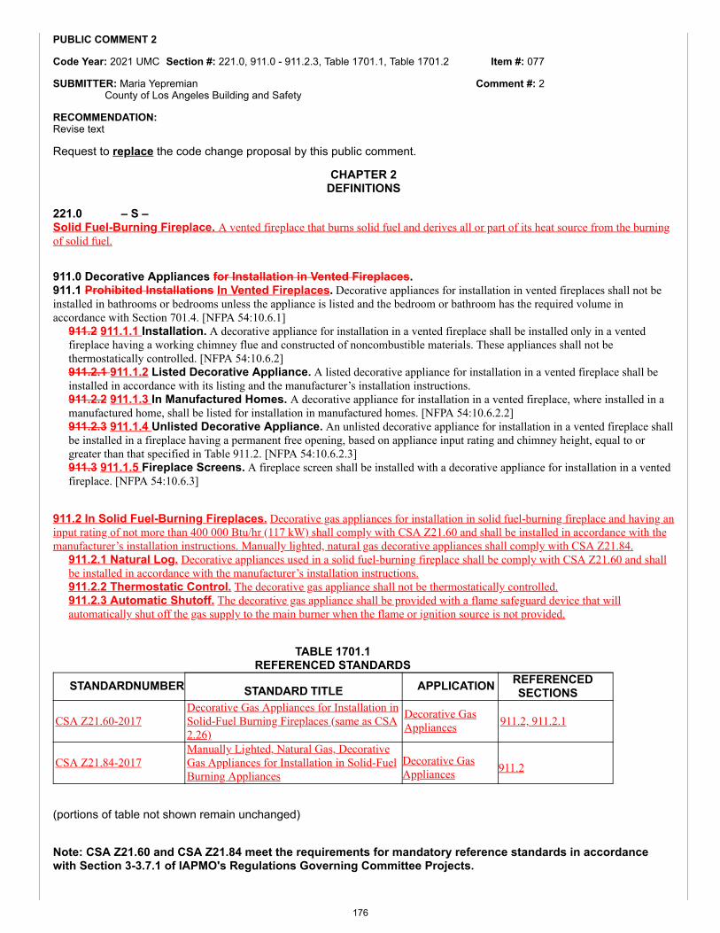
Item #: 077
Comment #: 2
PUBLIC COMMENT 2
Code Year: 2021 UMC Section #: 221.0, 911.0 - 911.2.3, Table 1701.1, Table 1701.2
SUBMITTER: Maria YepremianCounty of Los Angeles Building and Safety
RECOMMENDATION:Revise text
Request to replace the code change proposal by this public comment.
CHAPTER 2DEFINITIONS
221.0 – S –Solid Fuel-Burning Fireplace. A vented fireplace that burns solid fuel and derives all or part of its heat source from the burningof solid fuel.
911.0 Decorative Appliances for Installation in Vented Fireplaces.911.1 Prohibited Installations In Vented Fireplaces. Decorative appliances for installation in vented fireplaces shall not beinstalled in bathrooms or bedrooms unless the appliance is listed and the bedroom or bathroom has the required volume inaccordance with Section 701.4. [NFPA 54:10.6.1]
911.2 911.1.1 Installation. A decorative appliance for installation in a vented fireplace shall be installed only in a ventedfireplace having a working chimney flue and constructed of noncombustible materials. These appliances shall not bethermostatically controlled. [NFPA 54:10.6.2]911.2.1 911.1.2 Listed Decorative Appliance. A listed decorative appliance for installation in a vented fireplace shall beinstalled in accordance with its listing and the manufacturer’s installation instructions.911.2.2 911.1.3 In Manufactured Homes. A decorative appliance for installation in a vented fireplace, where installed in amanufactured home, shall be listed for installation in manufactured homes. [NFPA 54:10.6.2.2]911.2.3 911.1.4 Unlisted Decorative Appliance. An unlisted decorative appliance for installation in a vented fireplace shallbe installed in a fireplace having a permanent free opening, based on appliance input rating and chimney height, equal to orgreater than that specified in Table 911.2. [NFPA 54:10.6.2.3]911.3 911.1.5 Fireplace Screens. A fireplace screen shall be installed with a decorative appliance for installation in a ventedfireplace. [NFPA 54:10.6.3]
911.2 In Solid Fuel-Burning Fireplaces. Decorative gas appliances for installation in solid fuel-burning fireplace and having aninput rating of not more than 400 000 Btu/hr (117 kW) shall comply with CSA Z21.60 and shall be installed in accordance with themanufacturer’s installation instructions. Manually lighted, natural gas decorative appliances shall comply with CSA Z21.84.
911.2.1 Natural Log. Decorative appliances used in a solid fuel-burning fireplace shall be comply with CSA Z21.60 and shallbe installed in accordance with the manufacturer’s installation instructions.911.2.2 Thermostatic Control. The decorative gas appliance shall not be thermostatically controlled.911.2.3 Automatic Shutoff. The decorative gas appliance shall be provided with a flame safeguard device that willautomatically shut off the gas supply to the main burner when the flame or ignition source is not provided.
TABLE 1701.1REFERENCED STANDARDS
STANDARDNUMBER STANDARD TITLE APPLICATION REFERENCEDSECTIONS
CSA Z21.60-2017Decorative Gas Appliances for Installation inSolid-Fuel Burning Fireplaces (same as CSA2.26)
Decorative GasAppliances 911.2, 911.2.1
CSA Z21.84-2017Manually Lighted, Natural Gas, DecorativeGas Appliances for Installation in Solid-FuelBurning Appliances
Decorative GasAppliances 911.2
(portions of table not shown remain unchanged)
Note: CSA Z21.60 and CSA Z21.84 meet the requirements for mandatory reference standards in accordancewith Section 3-3.7.1 of IAPMO's Regulations Governing Committee Projects.
176
TABLE 1701.2STANDARDS, PUBLICATIONS, PRACTICES, AND GUIDES
DOCUMENTNUMBER DOCUMENT TITLE APPLICATION
CSA Z21.60-2012 Decorative Gas Appliances for Installation in Solid-Fuel Burning Fireplaces (same as CSA 2.26)
Decorative Appliances, DecorativeFireplace Appliances
(portions of table not shown remain unchanged)
SUBSTANTIATION:There was concern that “Solid Fuel-Burning Fireplaces” is not defined in the UMC, therefore, a definition for “Solid Fuel-Burning Fireplaces” is being added. This definition is consistent with the way the term is applied throughout the code. Theaddition of this definition will assist the AHJ with the enforcement of Solid Fuel-Burning Fireplaces. Furthermore,differentiation will be made between a “Solid Fuel-Burning Fireplace” and a "Fireplace Stove" which is already defined in theUMC.
COMMITTEE ACTION: REJECT
COMMITTEE STATEMENT:The comment is being rejected as the proposed language contains ambiguous terms and may cause confusion in the field.
TOTAL ELIGIBLE TO VOTE: 26
VOTING RESULTS: AFFIRMATIVE: 25 NOT RETURNED: 1 HOWARD
177
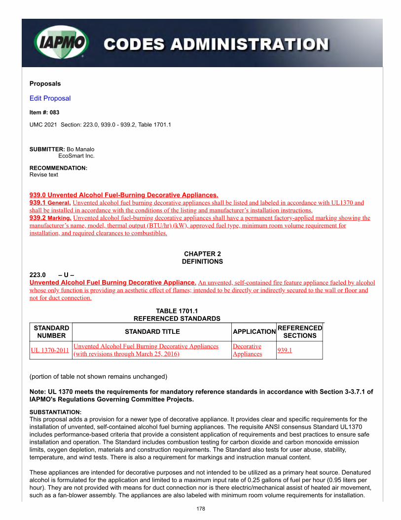
Proposals
Edit Proposal
Item #: 083
UMC 2021 Section: 223.0, 939.0 - 939.2, Table 1701.1
SUBMITTER: Bo ManaloEcoSmart Inc.
RECOMMENDATION:Revise text
939.0 Unvented Alcohol Fuel-Burning Decorative Appliances.939.1 General. Unvented alcohol fuel burning decorative appliances shall be listed and labeled in accordance with UL1370 andshall be installed in accordance with the conditions of the listing and manufacturer’s installation instructions.939.2 Marking. Unvented alcohol fuel-burning decorative appliances shall have a permanent factory-applied marking showing themanufacturer’s name, model, thermal output (BTU/hr) (kW), approved fuel type, minimum room volume requirement forinstallation, and required clearances to combustibles.
CHAPTER 2DEFINITIONS
223.0 – U –Unvented Alcohol Fuel Burning Decorative Appliance. An unvented, self-contained fire feature appliance fueled by alcoholwhose only function is providing an aesthetic effect of flames; intended to be directly or indirectly secured to the wall or floor andnot for duct connection.
TABLE 1701.1REFERENCED STANDARDS
STANDARDNUMBER STANDARD TITLE APPLICATION REFERENCED
SECTIONS
UL 1370-2011 Unvented Alcohol Fuel Burning Decorative Appliances(with revisions through March 25, 2016)
DecorativeAppliances 939.1
(portion of table not shown remains unchanged)
Note: UL 1370 meets the requirements for mandatory reference standards in accordance with Section 3-3.7.1 ofIAPMO's Regulations Governing Committee Projects.
SUBSTANTIATION:This proposal adds a provision for a newer type of decorative appliance. It provides clear and specific requirements for theinstallation of unvented, self-contained alcohol fuel burning appliances. The requisite ANSI consensus Standard UL1370includes performance-based criteria that provide a consistent application of requirements and best practices to ensure safeinstallation and operation. The Standard includes combustion testing for carbon dioxide and carbon monoxide emissionlimits, oxygen depletion, materials and construction requirements. The Standard also tests for user abuse, stability,temperature, and wind tests. There is also a requirement for markings and instruction manual content.
These appliances are intended for decorative purposes and not intended to be utilized as a primary heat source. Denaturedalcohol is formulated for the application and limited to a maximum input rate of 0.25 gallons of fuel per hour (0.95 liters perhour). They are not provided with means for duct connection nor is there electric/mechanical assist of heated air movement,such as a fan-blower assembly. The appliances are also labeled with minimum room volume requirements for installation.
178
Item #: 083
Comment #: 1
The proposal improves the Code by providing installers and building officials with a clear path on the specifications thatpertain to these products. Installation is intended to be in accordance with local codes, the manufacturer’s installationinstructions and markings on the appliance.
COMMITTEE ACTION: REJECT
COMMITTEE STATEMENT:The proposed change raises safety concerns as to public health and safety. If the AHJ would like to approve theseappliances, they can do so by the Alternate Materials and Methods approval process in accordance with Section 302.2 of theUMC.
TOTAL ELIGIBLE TO VOTE: 26
VOTING RESULTS: AFFIRMATIVE: 24 NEGATIVE: 1 NOT RETURNED: 1 HOWARD
EXPLANATION OF NEGATIVE:
HYDE: As an enforcing agency, we are starting to see more and more of these types of appliances and nothing in any code regulatesthe installation of these types of appliances.
Appended Comments
Edit Comment
PUBLIC COMMENT 1
Code Year: 2021 UMC Section #: 223.0, 939.0 - 939.2, Table 1701.1
SUBMITTER: Maria YepremianCounty of Los Angeles Building and Safety
RECOMMENDATION:Add new text
Request to accept the code change proposal as submitted by this public comment.
SUBSTANTIATION:A section and definition for "Unvented Alcohol Fuel Burning Decorative Appliances" is needed in the code. The proposed change adds a definition for "Unvented Alcohol Fuel Burning Decorative Appliances." This definition clarifies that such decorative appliances are not intended to be connected to ductwork. The addition of this section and definition will assist the AHJ with the enforceability of Unvented Alcohol Fuel Burning Decorative Appliances.
COMMITTEE ACTION: Reject the public comment (Failed Ballot)
TOTAL ELIGIBLE TO VOTE: 26
VOTING RESULTS: AFFIRMATIVE: 14 NEGATIVE: 9 ABSTAIN: 2 NOT RETURNED: 1 HOWARD
NOTE: Item 083 Comment 1 failed to achieve the necessary two-thirds affirmative vote of returned ballots. In accordance with Section 4-4.6.4 of the Regulations Governing Committee Projects, the TC action shall be reported in the ROC as rejected.
EXPLANATION OF NEGATIVE:
ADLER: I agree with Dave Mann. The proposed change raises grave concerns as to public health and safety.
AGUILAR: The proposed change raises grave concerns as to public health and safety. If the AHJ wishes to approve these appliances they can do so by the alternate material and methods process in accordance with Section 302.2 of the UMC; this would allow the AHJ to approve on a case by case basis.
BENKOWSKI: AHJ should determine alternate methods.
DIAS: I agree with Dave Mann. The proposed change raises grave concerns as to public health and safety. If the AHJ wishes to approve these appliances they can do so by the alternate material and methods process in accordance with Section 302.2 of the UMC; this would allow the AHJ to approve on a case by case basis.
KREITENBERG: I concur with Dave Mann and Phil Ribbs -- The proposed change raises grave concerns as to public health and safety. The appliance(s) need to be reviewed by the AHJ based on room location, room volume, tightness of building construction, and altitude where appliance is proposed to be installed.
179
MANN: The proposed change raises grave concerns as to public health and safety. If the AHJ wishes to approve these appliances they can do so by the alternate material and methods process in accordance with Section 302.2 of the UMC; this would allow the AHJ to approve on a case by case basis.
RIBBS: The proposed change raises grave concerns as to public health and safety. The appliance(s) need to be reviewed by the AHJ based on room location, room volume, tightness of building construction, and altitude where an appliance is proposed to be installed.
SMITH: Agree with Dave Mann. The issue should be handled by the AHJ.
YOUNG: I have discussed this issue with a few inspectors in the area of Placer County. The inspectors I spoke to indicated they would prefer to review these type products prior to approving them. They mentioned they want to know where exactly it will be located, taking into consideration all surrounding factors prior to approving.
EXPLANATION OF ABSTAIN:
HAMILTON: The local AHJ should make the call.
VAN RITE: I am not familiar enough to cast a vote on this topic.
180
Proposals
Edit Proposal
Item #: 086
UMC 2021 Section: 1102.2, Table 1701.1
SUBMITTER: Jeffrey ShapiroInternational Code ConsultantsRep: IIAR
RECOMMENDATION:Revise text
1102.0 Refrigeration Systems.
1102.2 Ammonia Refrigeration Systems. Refrigeration systems using ammonia as the refrigerant shall comply with IIAR 2,IIAR 3, IIAR 4, and IIAR 5, and IIAR 6 and shall not be required to comply with this chapter.
TABLE 1701.1REFERENCED STANDARDS
STANDARDNUMBER STANDARD TITLE APPLICATION REFERENCED
SECTIONS
IIAR 6-2018 Standard for Inspection, Testing, and Maintenance ofClosed-Circuit Ammonia Refrigeration Systems
AmmoniaRefrigerationSystems
1102.2
(portions of table not shown remain unchanged)
Note: IIAR 6 meets the requirements for mandatory reference standards in accordance with Section 3-3.7.1 ofIAPMO's Regulations Governing Committee Projects.
SUBSTANTIATION:IIAR 6 is a new standard for maintenance and inspection of closed-circuit ammonia refrigeration systems that is part of thesuite of IIAR standards regulating ammonia refrigeration systems. Because this standard addresses system maintenance,which is part of the UMC scope in Section 101.2, it is important to have the standard referenced by the UMC to provide forproper compliance and enforcement of ammonia system regulations.
COMMITTEE ACTION: REJECT
COMMITTEE STATEMENT:The proposed standard is being rejected as it is a maintenance manual and is a draft standard that is not yet completed atthe time of this monograph.
TOTAL ELIGIBLE TO VOTE: 26
VOTING RESULTS: AFFIRMATIVE: 25 NOT RETURNED: 1 HOWARD
Appended Comments
Edit Comment
181
Item #: 086
Comment #: 1
PUBLIC COMMENT 1
Code Year: 2021 UMC Section #: 1102.2
SUBMITTER: Jeffrey ShapiroInternational Code ConsultantsRep. IIAR
RECOMMENDATION:Revise text
Request to accept the code change proposal as modified by this public comment.
1102.0 Refrigeration Systems.
1102.2 Ammonia Refrigeration Systems. Refrigeration systems using ammonia as the refrigerant shall comply with IIAR 2,IIAR 3, IIAR 4, and IIAR 5, and IIAR 6 and shall not be required to comply with this chapter.
TABLE 1701.1REFERENCED STANDARDS
STANDARDNUMBER STANDARD TITLE APPLICATION REFERENCED
SECTION
IIAR 6-2019 Standard for Inspection, Testing, and Maintenance ofClosed-Circuit Ammonia Refrigeration Systems
Ammonia RefrigerationSystems 1102.2
(portions of table not shown remain unchanged)
Note: IIAR 6-2019 is a working draft and is not completed at the time of this monograph.
SUBSTANTIATION:This public comment is requesting that approval of the original proposal. At the ROP meeting, the committee correctly rejected the original proposal because the standard had not yet been completed. It is anticipated that the standard will be finalized prior to the ROC meeting.
IIAR 6 is a brand new standard covering inspection, testing, and maintenance of closed-circuit ammonia refrigeration systems and is part of the suite of IIAR standards regulating ammonia refrigeration systems referenced by the UMC and NFPA 1.
Because this standard addresses system maintenance, which is part of the UMC scope in Section 101.2, it is important to have the standard referenced by the UMC to give inspectors the needed tool ensuring compliance of ammonia system regulations. If this comment is not accepted, there will be no mandatory system maintenance regulations covering ammonia refrigeration in the UMC, which is a safety concern.
Processing of IIAR 6 is down to a single unresolved commenter and the 4th public review cycle to resolve remaining comments closed in mid-January. The balance should be wrapped up by April. A copy of the most recent consensus draft is being provided with this comment, and a final copy will be provided in advance of the ROC meeting. For reference, ICC has given final approval to referencing IIAR 6 in the 2021 codes.
COMMITTEE ACTION: Reject the public comment (Failed Ballot)
TOTAL ELIGIBLE TO VOTE: 26
VOTING RESULTS: AFFIRMATIVE: 14 NEGATIVE: 8 ABSTAIN: 3 NOT RETURNED: 1 HOWARD
NOTE: Item 086 Comment 1 failed to achieve the necessary two-thirds affirmative vote of returned ballots. In accordance with Section 4-4.6.4 of the Regulations Governing Committee Projects, the TC action shall be reported in the ROC as rejected.
EXPLANATION OF NEGATIVE:
ADLER: The proposed standard is a working draft and should not be approved by this committee.
AGUILAR: The proposed standard is a working draft and should not be approved by this committee.
BENKOWSKI: Working drafts should be held until finalized.
DIAS: The proposed standard is a working draft and should not be approved by this committee.
182
KREITENBERG: Subject document is a work in progress and not ripe.
MANN: The proposed standard is a working draft and should not be approved by this committee.
RIBBS: The proposed standard is a working draft and should not be approved by this committee.
YOUNG: "Processing of IIAR 6 is down to a single unresolved commenter and the 4th public review cycle to resolve remaining comments closed in mid-January. The balance should be wrapped up by April." This is by the submitter's own incomplete submission. We as a committee are unsure exactly what the last revision is.
EXPLANATION OF ABSTAIN:
HAMILTON: I need to abstain due to lack of information on this at this time.
SMITH: Do not know the actual status of the standard.
VAN RITE: I am not familiar enough to cast a vote on this subject.
183
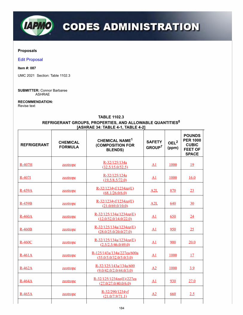
Proposals
Edit Proposal
Item #: 087
UMC 2021 Section: Table 1102.3
SUBMITTER: Connor BarbareeASHRAE
RECOMMENDATION:Revise text
TABLE 1102.3REFRIGERANT GROUPS, PROPERTIES, AND ALLOWABLE QUANTITIES8
[ASHRAE 34: TABLE 4-1, TABLE 4-2]
REFRIGERANT CHEMICALFORMULA
CHEMICAL NAME1
(COMPOSITION FORBLENDS)
SAFETYGROUP7
OEL2
(ppm)
POUNDSPER 1000
CUBICFEET OFSPACE
R-407H zeotrope R-32/125/134a(32.5/15.0/52.5) A1 1000 19
R-407I zeotrope R-32/125/124a(19.5/8.5/72.0) A1 1000 16.0
R-459A zeotrope R-32/1234yf/1234ze(E)(68.1/26.0/6.0) A2L 870 23
R-459B zeotrope R-32/1234yf/1234ze(E)(21.0/69.0/10.0) A2L 640 30
R-460A zeotrope R-32/125/134a/1234ze(E)(12.0/52.0/14.0/22.0) A1 650 24
R-460B zeotrope R-32/125/134a/1234ze(E)(28.0/25.0/20.0/27.0) A1 950 25
R-460C zeotrope R-32/125/134a/1234ze(E)(2.5/2.5/46.0/49.0) A1 900 20.0
R-461A zeotrope R-125/143a/134a/227ea/600a(55.0/5.0/32.0/5.0/3.0) A1 1000 17
R-462A zeotrope R-32/125/143a/134a/600(9.0/42.0/2.0/44.0/3.0) A2 1000 3.9
R-464A zeotrope R-32/125/1234ze(E)/227ea(27.0/27.0/40.0/6.0) A1 930 27.0
R-465A zeotrope R-32/290/1234yf(21.0/7.9/71.1) A2 660 2.5
184
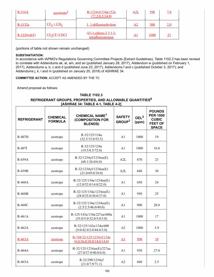
R-516A azeotrope3 R-1234yf/134a/152a(77.5/8.5/14.0)
A2L 590 7.0
R-1132a CF2 = CH2 1, 1-difluoroethylene A2 500 2.0
R-1224yd(Z) CF3CF=CHCl (Z)-1-chloro-2,3,3,3-tetrafluoropropen A1 1000 23
(portions of table not shown remain unchanged)
SUBSTANTIATION:In accordance with IAPMO's Regulations Governing Committee Projects (Extract Guidelines), Table 1102.3 has been revisedto correlate with Addendums ak, al, am, and an (published January 28, 2017), Addendum w (published on February 1,2017), Addendums a, b, c and d (published June 23, 2017), Addendums f and c (published October 3, 2017); andAddendums j, k, l and m (published on January 20, 2018) of ASHRAE 34.
COMMITTEE ACTION: ACCEPT AS AMENDED BY THE TC
Amend proposal as follows:
TABLE 1102.3REFRIGERANT GROUPS, PROPERTIES, AND ALLOWABLE QUANTITIES8
[ASHRAE 34: TABLE 4-1, TABLE 4-2]
REFRIGERANT CHEMICALFORMULA
CHEMICAL NAME1
(COMPOSITION FORBLENDS)
SAFETYGROUP7
OEL2
(ppm)
POUNDSPER 1000
CUBICFEET OFSPACE
R-407H zeotrope R-32/125/134a(32.5/15.0/52.5) A1 1000 19
R-407I zeotrope R-32/125/124a(19.5/8.5/72.0) A1 1000 16.0
R-459A zeotrope R-32/1234yf/1234ze(E)(68.1/26.0/6.0) A2L 870 23
R-459B zeotrope R-32/1234yf/1234ze(E)(21.0/69.0/10.0) A2L 640 30
R-460A zeotrope R-32/125/134a/1234ze(E)(12.0/52.0/14.0/22.0) A1 650 24
R-460B zeotrope R-32/125/134a/1234ze(E)(28.0/25.0/20.0/27.0) A1 950 25
R-460C zeotrope R-32/125/134a/1234ze(E)(2.5/2.5/46.0/49.0) A1 900 20.0
R-461A zeotrope R-125/143a/134a/227ea/600a(55.0/5.0/32.0/5.0/3.0) A1 1000 17
R-462A zeotrope R-32/125/143a/134a/600(9.0/42.0/2.0/44.0/3.0) A2 1000 3.9
R-463A zeotrope R-744/32/125/1234yf/134a(6.0/36.0/30.0/14.0/14.0) A1 990 19
R-464A zeotrope R-32/125/1234ze(E)/227ea(27.0/27.0/40.0/6.0) A1 930 27.0
R-465A zeotrope R-32/290/1234yf(21.0/7.9/71.1) A2 660 2.5
185
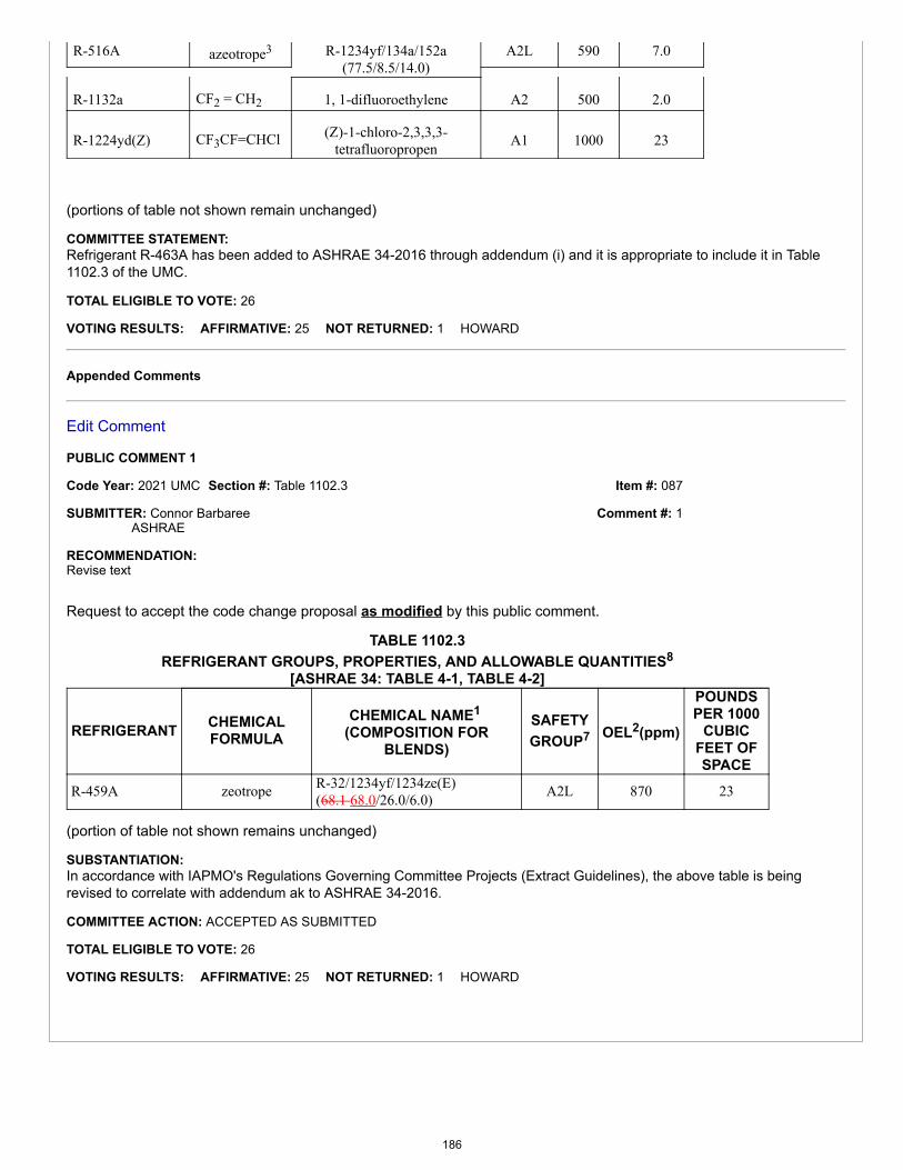
Item #: 087
Comment #: 1
R-516A azeotrope3 R-1234yf/134a/152a(77.5/8.5/14.0)
A2L 590 7.0
R-1132a CF2 = CH2 1, 1-difluoroethylene A2 500 2.0
R-1224yd(Z) CF3CF=CHCl (Z)-1-chloro-2,3,3,3-tetrafluoropropen A1 1000 23
(portions of table not shown remain unchanged)
COMMITTEE STATEMENT:Refrigerant R-463A has been added to ASHRAE 34-2016 through addendum (i) and it is appropriate to include it in Table1102.3 of the UMC.
TOTAL ELIGIBLE TO VOTE: 26
VOTING RESULTS: AFFIRMATIVE: 25 NOT RETURNED: 1 HOWARD
Appended Comments
Edit Comment
PUBLIC COMMENT 1
Code Year: 2021 UMC Section #: Table 1102.3
SUBMITTER: Connor BarbareeASHRAE
RECOMMENDATION:Revise text
Request to accept the code change proposal as modified by this public comment.
TABLE 1102.3REFRIGERANT GROUPS, PROPERTIES, AND ALLOWABLE QUANTITIES8
[ASHRAE 34: TABLE 4-1, TABLE 4-2]
REFRIGERANT CHEMICALFORMULA
CHEMICAL NAME1
(COMPOSITION FORBLENDS)
SAFETYGROUP7 OEL2(ppm)
POUNDSPER 1000
CUBICFEET OFSPACE
R-459A zeotrope R-32/1234yf/1234ze(E) (68.1 68.0/26.0/6.0) A2L 870 23
(portion of table not shown remains unchanged)
SUBSTANTIATION:In accordance with IAPMO's Regulations Governing Committee Projects (Extract Guidelines), the above table is beingrevised to correlate with addendum ak to ASHRAE 34-2016.
COMMITTEE ACTION: ACCEPTED AS SUBMITTED
TOTAL ELIGIBLE TO VOTE: 26
VOTING RESULTS: AFFIRMATIVE: 25 NOT RETURNED: 1 HOWARD
186
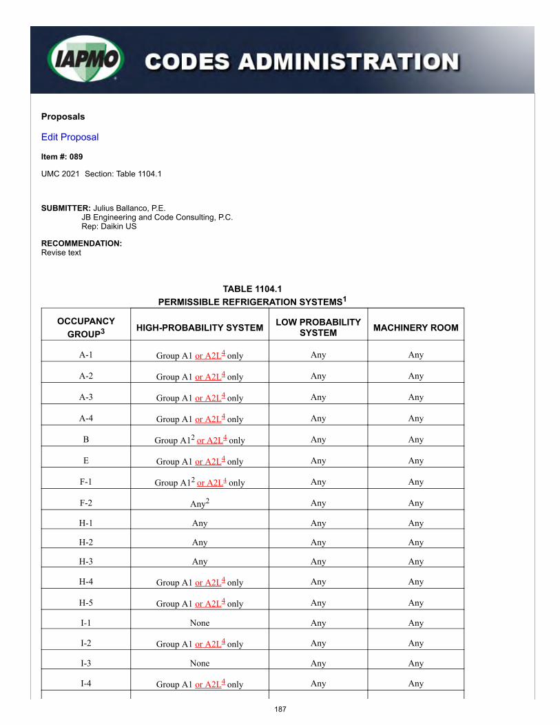
Proposals
Edit Proposal
Item #: 089
UMC 2021 Section: Table 1104.1
SUBMITTER: Julius Ballanco, P.E.JB Engineering and Code Consulting, P.C.Rep: Daikin US
RECOMMENDATION:Revise text
TABLE 1104.1PERMISSIBLE REFRIGERATION SYSTEMS1
OCCUPANCYGROUP3 HIGH-PROBABILITY SYSTEM LOW PROBABILITY
SYSTEM MACHINERY ROOM
A-1 Group A1 or A2L4 only Any Any
A-2 Group A1 or A2L4 only Any Any
A-3 Group A1 or A2L4 only Any Any
A-4 Group A1 or A2L4 only Any Any
B Group A12 or A2L4 only Any Any
E Group A1 or A2L4 only Any Any
F-1 Group A12 or A2L4 only Any Any
F-2 Any2 Any Any
H-1 Any Any Any
H-2 Any Any Any
H-3 Any Any Any
H-4 Group A1 or A2L4 only Any Any
H-5 Group A1 or A2L4 only Any Any
I-1 None Any Any
I-2 Group A1 or A2L4 only Any Any
I-3 None Any Any
I-4 Group A1 or A2L4 only Any Any
187
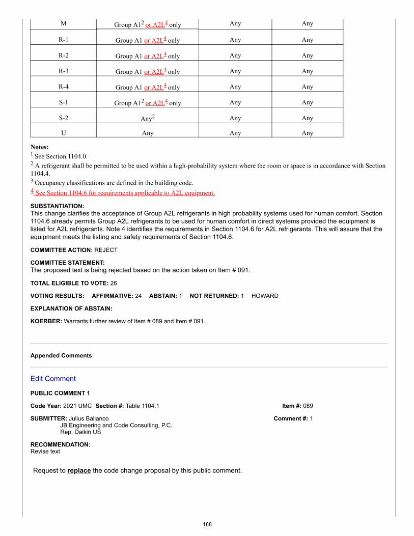
Item #: 089
Comment #: 1
M Group A12 or A2L4 only Any Any
R-1 Group A1 or A2L4 only Any Any
R-2 Group A1 or A2L4 only Any Any
R-3 Group A1 or A2L4 only Any Any
R-4 Group A1 or A2L4 only Any Any
S-1 Group A12 or A2L4 only Any Any
S-2 Any2 Any Any
U Any Any Any
Notes:1 See Section 1104.0.2 A refrigerant shall be permitted to be used within a high-probability system where the room or space is in accordance with Section1104.4.3 Occupancy classifications are defined in the building code.4 See Section 1104.6 for requirements applicable to A2L equipment.
SUBSTANTIATION:This change clarifies the acceptance of Group A2L refrigerants in high probability systems used for human comfort. Section1104.6 already permits Group A2L refrigerants to be used for human comfort in direct systems provided the equipment islisted for A2L refrigerants. Note 4 identifies the requirements in Section 1104.6 for A2L refrigerants. This will assure that theequipment meets the listing and safety requirements of Section 1104.6.
COMMITTEE ACTION: REJECT
COMMITTEE STATEMENT:The proposed text is being rejected based on the action taken on Item # 091.
TOTAL ELIGIBLE TO VOTE: 26
VOTING RESULTS: AFFIRMATIVE: 24 ABSTAIN: 1 NOT RETURNED: 1 HOWARD
EXPLANATION OF ABSTAIN:
KOERBER: Warrants further review of Item # 089 and Item # 091.
Appended Comments
Edit Comment
PUBLIC COMMENT 1
Code Year: 2021 UMC Section #: Table 1104.1
SUBMITTER: Julius BallancoJB Engineering and Code Consulting, P.C.Rep. Daikin US
RECOMMENDATION:Revise text
Request to replace the code change proposal by this public comment.
188

TABLE 1104.1PERMISSIBLE REFRIGERATION SYSTEMS1
OCCUPANCYGROUP3 HIGH-PROBABILITY SYSTEM
LOWPROBABILITY
SYSTEMMACHINERY
ROOM
A-1 Group A1 or A2L4 only Any Any
A-2 Group A1 or A2L4 only Any Any
A-3 Group A1 or A2L4 only Any Any
A-4 Group A1 or A2L4 only Any Any
B Group A12 or A2L2,4 only Any Any
E Group A1 or A2L4 only Any Any
F-1 Group A12 or A2L2,4 only Any Any
F-2 Any2 Any Any
H-1 Any Any Any
H-2 Any Any Any
H-3 Any Any Any
H-4 Group A1 or A2L4 only Any Any
H-5 Group A1 or A2L4 only Any Any
I-1 None Any Any
I-2 Group A1 or A2L4 only Any Any
I-3 None Any Any
I-4 Group A1 or A2L4 only Any Any
M Group A12 or A2L2,4 only Any Any
R-1 Group A1 or A2L4 only Any Any
R-2 Group A1 or A2L4 only Any Any
R-3 Group A1 or A2L4 only Any Any
R-4 Group A1 or A2L4 only Any Any
S-1 Group A12 or A2L2,4 only Any Any
S-2 Any2 Any Any
U Any Any Any
Notes:1 See Section 1104.0.2 A refrigerant shall be permitted to be used within a high-probability system where the room or space is in accordance with Section1104.4.3 Occupancy classifications are defined in the building code.4 See Section 1104.6 for requirements applicable to A2L equipment.
189
SUBSTANTIATION:Note 2 appears following Group A1 refrigerants for Occupancy Groups B, F-1, F-2, M, S-1, and S-2. When adding GroupA2L, the Note 2 should also appear with Note 4 for these Occupancy Groups. This is the modification to the originalproposal.
It was also noticed that Note 4 did not appear under the use Group F. This was an editorial error that is also corrected by thismodification.
This change was rejected based on the action taken on Item # 091. A Public Comment has been submitted to Item # 091 toapprove the change with modifications. The modification would allow the use of Group A2L refrigerants in high-probabilitydirect systems. This change is needed for consistency with Item # 089.
COMMITTEE ACTION: REJECT
COMMITTEE STATEMENT:The comment is being rejected as the industry is not ready to allow A2L refrigerants for human comfort as there is a lack oftraining programs and installation requirements available at this time. Furthermore, there are concerns for life safety andflammability. Although the adoption of A2L for the use of human comfort is progressing, these provisions should not beadopted until adequate training is complete and HVAC contractors are able to safely handle A2L refrigerants. Additional timeis needed to allow for ongoing research to be done. The committee is concerned that there are no listed detectors to protectthe public safety.
TOTAL ELIGIBLE TO VOTE: 26
VOTING RESULTS: AFFIRMATIVE: 23 ABSTAIN: 2 NOT RETURNED: 1 HOWARD
EXPLANATION OF ABSTAIN:
KOERBER: I am abstaining as the testimony and discussion regarding A2L's and acceptance/non-acceptance in the code remains "allover the board." Previously the TC discussions were centered around waiting for ASHRAE 15 to be completed so the UMC could beconsistent with the standard. With the standard now updated, the discussion has moved to the need for more training and moreresearch. I feel we are kicking this down the road rather than addressing it appropriately.
MACNEVIN: I am abstaining because both sides of this proposal, proponents and opponents, have valid substantiations. It is difficult toweigh the potential risks of A2L refrigerants being distributed throughout buildings - which I oppose - against the benefits of far lowergreenhouse gas (GWP) emissions from these refrigerants. When safer handling of the refrigerants and safer installation of thesesystems are the established norms, the decision will be easier.
190
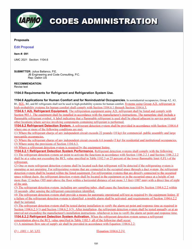
Proposals
Edit Proposal
Item #: 091
UMC 2021 Section: 1104.6
SUBMITTER: Julius Ballanco, P.E.JB Engineering and Code Consulting, P.C.Rep: Daikin US
RECOMMENDATION:Revise text
1104.0 Requirements for Refrigerant and Refrigeration System Use.
1104.6 Applications for Human Comfort and for Nonindustrial Occupancies. In nonindustrial occupancies, Group A2, A3,B1, B2L, B2, and B3 refrigerants shall not be used in high-probability systems for human comfort. Systems using Group A2L refrigerant inhigh-probability systems for human comfort shall comply with Section 1104.6.1 through Section 1104.6.3.1104.6.1 A2L Refrigerant Equipment. The refrigeration equipment using A2L refrigerant shall be listed and comply withSection 903.1. The equipment shall be installed in accordance with the manufacturer's instructions. The nameplate shall include aflammable refrigerant symbol. A label indicating that a flammable refrigerant is used shall be placed adjacent to service ports andother locations where service involving components containing refrigerant is performed.1104.6.2 Refrigerant Detection System. A refrigerant detection system shall be provided in accordance with Section 1104.6.4where one or more of the following conditions are met:(1) Where the refrigerant charge of any independent circuit exceeds 22 pounds (10 kg) for commercial, public assembly and largemercantile occupancies.(2) Where the refrigerant charge of any independent circuit exceeds 6.6 pounds (3 kg) for residential and institutional occupancies.(3) Where using the provisions of Section 1104.6.3.(4) Where a refrigerant detection system is required by the equipment listing.1104.6.2.1 Refrigerant Detection System Performance. Refrigerant detection systems shall comply with the following:(1) The refrigerant detection system set point to activate the functions in accordance with Section 1106.2.2.1 and Section 1106.2.2.2shall be at a value not exceeding the RCL value specified in Table 1102.3 or 25 percent of the lower flammable limit (LFL) of therefrigerant.(2) One or more refrigerant detection systems shall be located such that refrigerant will be detected if the refrigerating system isoperating or not operating. For refrigerating systems that are connected to the occupied space through a duct system, the refrigerantdetection system shall be located within the listed equipment. For refrigerating systems that are directly connected to the occupiedspace without ducts, the refrigerant detection system shall be located in the equipment or in the occupied space at a height of notmore than 12 inches (305 mm) above the floor within a horizontal distance of not more 3.3 feet (1007 mm) with a direct line of sightof the unit.(3) The refrigerant detection system, including any sampling tubes, shall cause the functions required by Section 1104.6.2.2 within10 seconds, after sensing the refrigerant concentration identified.(4) The refrigerant detection system shall provide a means for automatic operational self-test as required by the equipment listing. Ifa failure of the refrigerant detection system is identified, a trouble alarm shall be activated, and requirements of Section 1104.6.2.2shall be initiated.(5) The refrigerant detection system shall be tested during installation to verify the alarm set point and response time as required inSection 1104.6.2.1(1) and Section 1104.6.2.1(3). After installation, the refrigerant detection system shall be tested annually or at aninterval not exceeding the manufacturer's installation instructions, whichever is less to verify the alarm set point and response time.1104.6.2.2 Refrigerant Detection System Activation. When the refrigerant detection system senses a refrigerantconcentration above the RCL value specified in Table 1102.3, all of the following shall occur:(1) A minimum flow rate of supply air shall be provided in accordance with Equation 1104.6.2.2:
Q = 1001 × M / LFL [Equation 1104.6.2.2)]
191
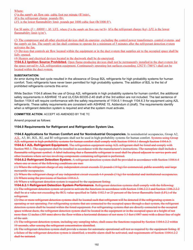
Where:Q is the supply air flow rate, cubic foot per minute (ft³/min). M is the refrigerant charge, pounds (lb).LFL is the lower flammability limit, pounds per 1000 cubic foot (lb/1000 ft³).
For SI units: Q = 60000 × M / LFL, where Q is the supply air flow rate (m³/h), M is the refrigerant charge (kg), LFL is the lowerflammability limit (g/m³).
(2) The compressor and all other electrical devices shall de-energize, excluding the control power transformers, control systems, andthe supply air fan. The supply air fan shall continue to operate for a minimum of 5 minutes after the refrigerant detection systemactivates the fan.(3) Devices that controls air flow located within the equipment or in the duct system that supplies air to the occupied space shall befully opened.(4) Heaters and electrical devices located in the ductwork shall be de-energized.1104.6.3 Ignition Source Prohibited. Open flame-producing devices shall not be permanently installed in the duct system forthe space served by A2L refrigeration equipment. Continuously operating hot surfaces exceeding 1292°F (700°C) shall not belocated within the duct system.
SUBSTANTIATION:An error during the last cycle resulted in the allowance of Group B2L refrigerants for high probability systems for humancomfort. Toxic refrigerants have never been permitted for high probability systems. The addition of B2L to the list ofprohibited refrigerants corrects this error.
While Section 1104.6 allows the use of Group A2L refrigerants in high probability systems for human comfort, the additionalsafety requirements in ASHRAE 15 and UL/CSA 60335-2-40 draft of the 3rd edition are not included. The last sentence ofSection 1104.6 will require conformance with the safety requirements of 1104.6.1 through 1104.6.3 for equipment using A2Lrefrigerants. These safety requirements are consistent with ASHRAE 15, Addendum d (draft). The requirements identifywhen a refrigerant detection system is required and what the system must activate.
COMMITTEE ACTION: ACCEPT AS AMENDED BY THE TC
Amend proposal as follows:
1104.0 Requirements for Refrigerant and Refrigeration System Use.
1104.6 Applications for Human Comfort and for Nonindustrial Occupancies. In nonindustrial occupancies, Group A2,A2L, A3, B1, B2L, B2, and B3 refrigerants shall not be used in high-probability systems for human comfort. Systems using GroupA2L refrigerant in high-probability systems for human comfort shall comply with Section 1104.6.1 through Section 1104.6.3.1104.6.1 A2L Refrigerant Equipment. The refrigeration equipment using A2L refrigerant shall be listed and comply withSection 903.1. The equipment shall be installed in accordance with the manufacturer's instructions. The nameplate shall include aflammable refrigerant symbol. A label indicating that a flammable refrigerant is used shall be placed adjacent to service ports andother locations where service involving components containing refrigerant is performed.1104.6.2 Refrigerant Detection System. A refrigerant detection system shall be provided in accordance with Section 1104.6.4where one or more of the following conditions are met:(1) Where the refrigerant charge of any independent circuit exceeds 22 pounds (10 kg) for commercial, public assembly and largemercantile occupancies.(2) Where the refrigerant charge of any independent circuit exceeds 6.6 pounds (3 kg) for residential and institutional occupancies.(3) Where using the provisions of Section 1104.6.3.(4) Where a refrigerant detection system is required by the equipment listing.1104.6.2.1 Refrigerant Detection System Performance. Refrigerant detection systems shall comply with the following:(1) The refrigerant detection system set point to activate the functions in accordance with Section 1106.2.2.1 and Section 1106.2.2.2shall be at a value not exceeding the RCL value specified in Table 1102.3 or 25 percent of the lower flammable limit (LFL) of therefrigerant.(2) One or more refrigerant detection systems shall be located such that refrigerant will be detected if the refrigerating system isoperating or not operating. For refrigerating systems that are connected to the occupied space through a duct system, the refrigerantdetection system shall be located within the listed equipment. For refrigerating systems that are directly connected to the occupiedspace without ducts, the refrigerant detection system shall be located in the equipment or in the occupied space at a height of notmore than 12 inches (305 mm) above the floor within a horizontal distance of not more 3.3 feet (1007 mm) with a direct line of sightof the unit.(3) The refrigerant detection system, including any sampling tubes, shall cause the functions required by Section 1104.6.2.2 within10 seconds, after sensing the refrigerant concentration identified.(4) The refrigerant detection system shall provide a means for automatic operational self-test as required by the equipment listing. Ifa failure of the refrigerant detection system is identified, a trouble alarm shall be activated, and requirements of Section 1104.6.2.2shall be initiated.
192
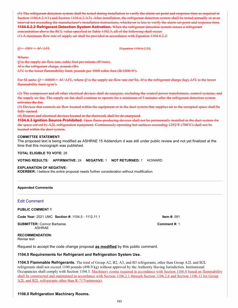
Item #: 091
Comment #: 1
(5) The refrigerant detection system shall be tested during installation to verify the alarm set point and response time as required inSection 1104.6.2.1(1) and Section 1104.6.2.1(3). After installation, the refrigerant detection system shall be tested annually or at aninterval not exceeding the manufacturer's installation instructions, whichever is less to verify the alarm set point and response time.1104.6.2.2 Refrigerant Detection System Activation. When the refrigerant detection system senses a refrigerantconcentration above the RCL value specified in Table 1102.3, all of the following shall occur:(1) A minimum flow rate of supply air shall be provided in accordance with Equation 1104.6.2.2:
Q = 1001 × M / LFL [Equation 1104.6.2.2)]
Where:Q is the supply air flow rate, cubic foot per minute (ft³/min).M is the refrigerant charge, pounds (lb).LFL is the lower flammability limit, pounds per 1000 cubic foot (lb/1000 ft³).
For SI units: Q = 60000 × M / LFL, where Q is the supply air flow rate (m³/h), M is the refrigerant charge (kg), LFL is the lowerflammability limit (g/m³).
(2) The compressor and all other electrical devices shall de-energize, excluding the control power transformers, control systems, andthe supply air fan. The supply air fan shall continue to operate for a minimum of 5 minutes after the refrigerant detection systemactivates the fan.(3) Devices that controls air flow located within the equipment or in the duct system that supplies air to the occupied space shall befully opened.(4) Heaters and electrical devices located in the ductwork shall be de-energized.1104.6.3 Ignition Source Prohibited. Open flame-producing devices shall not be permanently installed in the duct system forthe space served by A2L refrigeration equipment. Continuously operating hot surfaces exceeding 1292°F (700°C) shall not belocated within the duct system.
COMMITTEE STATEMENT:The proposed text is being modified as ASHRAE 15 Addendum d was still under public review and not yet finalized at thetime that this monograph was published.
TOTAL ELIGIBLE TO VOTE: 26
VOTING RESULTS: AFFIRMATIVE: 24 NEGATIVE: 1 NOT RETURNED: 1 HOWARD
EXPLANATION OF NEGATIVE:KOERBER: I believe the entire proposal needs further consideration without modification.
Appended Comments
Edit Comment
PUBLIC COMMENT 1
Code Year: 2021 UMC Section #: 1104.5 - 1112.11.1
SUBMITTER: Connor BarbareeASHRAE
RECOMMENDATION:Revise text
Request to accept the code change proposal as modified by this public comment.
1104.0 Requirements for Refrigerant and Refrigeration System Use.
1104.5 Flammable Refrigerants. The total of Group A2, B2, A3, and B3 refrigerants, other than Group A2L and B2Lrefrigerants shall not exceed 1100 pounds (498.9 kg) without approval by the Authority Having Jurisdiction. InstitutionalOccupancies shall comply with Section 1104.3. Machinery rooms required in accordance with Section 1106.0 based on flammabilityshall be constructed and maintained in accordance with Section 1106.2.1 through Section 1106.2.6 and Section 1106.13 for GroupA2L and B2L refrigerants other than R-717(ammonia).
1106.0 Refrigeration Machinery Rooms.
193
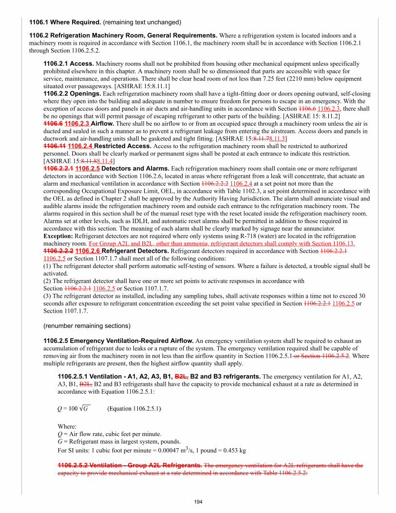
1106.1 Where Required. (remaining text unchanged)
1106.2 Refrigeration Machinery Room, General Requirements. Where a refrigeration system is located indoors and amachinery room is required in accordance with Section 1106.1, the machinery room shall be in accordance with Section 1106.2.1through Section 1106.2.5.2.
1106.2.1 Access. Machinery rooms shall not be prohibited from housing other mechanical equipment unless specificallyprohibited elsewhere in this chapter. A machinery room shall be so dimensioned that parts are accessible with space forservice, maintenance, and operations. There shall be clear head room of not less than 7.25 feet (2210 mm) below equipmentsituated over passageways. [ASHRAE 15:8.11.1]1106.2.2 Openings. Each refrigeration machinery room shall have a tight-fitting door or doors opening outward, self-closingwhere they open into the building and adequate in number to ensure freedom for persons to escape in an emergency. With theexception of access doors and panels in air ducts and air-handling units in accordance with Section 1106.6 1106.2.3, there shallbe no openings that will permit passage of escaping refrigerant to other parts of the building. [ASHRAE 15: 8.11.2]1106.6 1106.2.3 Airflow. There shall be no airflow to or from an occupied space through a machinery room unless the air isducted and sealed in such a manner as to prevent a refrigerant leakage from entering the airstream. Access doors and panels inductwork and air-handling units shall be gasketed and tight fitting. [ASHRAE 15:8.11.78.11.3]1106.11 1106.2.4 Restricted Access. Access to the refrigeration machinery room shall be restricted to authorizedpersonnel. Doors shall be clearly marked or permanent signs shall be posted at each entrance to indicate this restriction.[ASHRAE 15:8.11.88.11.4]1106.2.2.1 1106.2.5 Detectors and Alarms. Each refrigeration machinery room shall contain one or more refrigerantdetectors in accordance with Section 1106.2.6, located in areas where refrigerant from a leak will concentrate, that actuate analarm and mechanical ventilation in accordance with Section 1106.2.2.2 1106.2.4 at a set point not more than thecorresponding Occupational Exposure Limit, OEL, in accordance with Table 1102.3, a set point determined in accordance withthe OEL as defined in Chapter 2 shall be approved by the Authority Having Jurisdiction. The alarm shall annunciate visual andaudible alarms inside the refrigeration machinery room and outside each entrance to the refrigeration machinery room. Thealarms required in this section shall be of the manual reset type with the reset located inside the refrigeration machinery room.Alarms set at other levels, such as IDLH, and automatic reset alarms shall be permitted in addition to those required inaccordance with this section. The meaning of each alarm shall be clearly marked by signage near the annunciator.Exception: Refrigerant detectors are not required where only systems using R-718 (water) are located in the refrigerationmachinery room. For Group A2L and B2L, other than ammonia, refrigerant detectors shall comply with Section 1106.13.1106.2.2.2 1106.2.6 Refrigerant Detectors. Refrigerant detectors required in accordance with Section 1106.2.2.11106.2.5 or Section 1107.1.7 shall meet all of the following conditions:(1) The refrigerant detector shall perform automatic self-testing of sensors. Where a failure is detected, a trouble signal shall beactivated.(2) The refrigerant detector shall have one or more set points to activate responses in accordance withSection 1106.2.2.1 1106.2.5 or Section 1107.1.7.(3) The refrigerant detector as installed, including any sampling tubes, shall activate responses within a time not to exceed 30seconds after exposure to refrigerant concentration exceeding the set point value specified in Section 1106.2.2.1 1106.2.5 orSection 1107.1.7.
(renumber remaining sections)
1106.2.5 Emergency Ventilation-Required Airflow. An emergency ventilation system shall be required to exhaust anaccumulation of refrigerant due to leaks or a rupture of the system. The emergency ventilation required shall be capable ofremoving air from the machinery room in not less than the airflow quantity in Section 1106.2.5.1 or Section 1106.2.5.2. Wheremultiple refrigerants are present, then the highest airflow quantity shall apply.
1106.2.5.1 Ventilation - A1, A2, A3, B1, B2L, B2 and B3 refrigerants. The emergency ventilation for A1, A2,A3, B1, B2L, B2 and B3 refrigerants shall have the capacity to provide mechanical exhaust at a rate as determined inaccordance with Equation 1106.2.5.1:
Where:Q = Air flow rate, cubic feet per minute.G = Refrigerant mass in largest system, pounds.For SI units: 1 cubic foot per minute = 0.00047 m3/s, 1 pound = 0.453 kg
1106.2.5.2 Ventilation - Group A2L Refrigerants. The emergency ventilation for A2L refrigerants shall have thecapacity to provide mechanical exhaust at a rate determined in accordance with Table 1106.2.5.2:
194
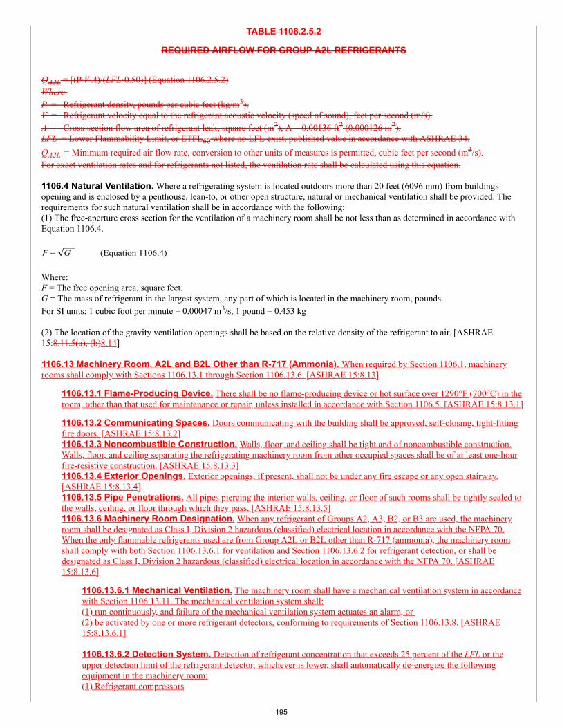
TABLE 1106.2.5.2
REQUIRED AIRFLOW FOR GROUP A2L REFRIGERANTS
QA2L = [(P·V·A)/(LFL·0.50)] (Equation 1106.2.5.2)Where:P = Refrigerant density, pounds per cubic feet (kg/m3).V = Refrigerant velocity equal to the refrigerant acoustic velocity (speed of sound), feet per second (m/s).A = Cross-section flow area of refrigerant leak, square feet (m2), A = 0.00136 ft2 (0.000126 m2).LFL = Lower Flammability Limit, or ETFL60 where no LFL exist, published value in accordance with ASHRAE 34.QA2L = Minimum required air flow rate, conversion to other units of measures is permitted, cubic feet per second (m3/s).For exact ventilation rates and for refrigerants not listed, the ventilation rate shall be calculated using this equation.
1106.4 Natural Ventilation. Where a refrigerating system is located outdoors more than 20 feet (6096 mm) from buildingsopening and is enclosed by a penthouse, lean-to, or other open structure, natural or mechanical ventilation shall be provided. Therequirements for such natural ventilation shall be in accordance with the following:(1) The free-aperture cross section for the ventilation of a machinery room shall be not less than as determined in accordance withEquation 1106.4.
Where:F = The free opening area, square feet.G = The mass of refrigerant in the largest system, any part of which is located in the machinery room, pounds.For SI units: 1 cubic foot per minute = 0.00047 m3/s, 1 pound = 0.453 kg
(2) The location of the gravity ventilation openings shall be based on the relative density of the refrigerant to air. [ASHRAE15:8.11.5(a), (b)8.14]
1106.13 Machinery Room, A2L and B2L Other than R-717 (Ammonia). When required by Section 1106.1, machineryrooms shall comply with Sections 1106.13.1 through Section 1106.13.6. [ASHRAE 15:8.13]
1106.13.1 Flame-Producing Device. There shall be no flame-producing device or hot surface over 1290°F (700°C) in theroom, other than that used for maintenance or repair, unless installed in accordance with Section 1106.5. [ASHRAE 15:8.13.1]
1106.13.2 Communicating Spaces. Doors communicating with the building shall be approved, self-closing, tight-fittingfire doors. [ASHRAE 15:8.13.2]1106.13.3 Noncombustible Construction. Walls, floor, and ceiling shall be tight and of noncombustible construction.Walls, floor, and ceiling separating the refrigerating machinery room from other occupied spaces shall be of at least one-hourfire-resistive construction. [ASHRAE 15:8.13.3]1106.13.4 Exterior Openings. Exterior openings, if present, shall not be under any fire escape or any open stairway.[ASHRAE 15:8.13.4]1106.13.5 Pipe Penetrations. All pipes piercing the interior walls, ceiling, or floor of such rooms shall be tightly sealed tothe walls, ceiling, or floor through which they pass. [ASHRAE 15:8.13.5]1106.13.6 Machinery Room Designation. When any refrigerant of Groups A2, A3, B2, or B3 are used, the machineryroom shall be designated as Class I, Division 2 hazardous (classified) electrical location in accordance with the NFPA 70.When the only flammable refrigerants used are from Group A2L or B2L other than R-717 (ammonia), the machinery roomshall comply with both Section 1106.13.6.1 for ventilation and Section 1106.13.6.2 for refrigerant detection, or shall bedesignated as Class I, Division 2 hazardous (classified) electrical location in accordance with the NFPA 70. [ASHRAE15:8.13.6]
1106.13.6.1 Mechanical Ventilation. The machinery room shall have a mechanical ventilation system in accordancewith Section 1106.13.11. The mechanical ventilation system shall:(1) run continuously, and failure of the mechanical ventilation system actuates an alarm, or (2) be activated by one or more refrigerant detectors, conforming to requirements of Section 1106.13.8. [ASHRAE15:8.13.6.1]
1106.13.6.2 Detection System. Detection of refrigerant concentration that exceeds 25 percent of the LFL or theupper detection limit of the refrigerant detector, whichever is lower, shall automatically de-energize the followingequipment in the machinery room:(1) Refrigerant compressors
195
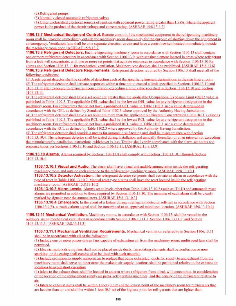
(2) Refrigerant pumps(3) Normally closed automatic refrigerant valves(4) Other unclassified electrical sources of ignition with apparent power rating greater than 1 kVA, where the apparentpower is the product of the circuit voltage and current rating. [ASHRAE 15:8.13.6.2]
1106.13.7 Mechanical Equipment Control. Remote control of the mechanical equipment in the refrigerating machineryroom shall be provided immediately outside the machinery room door solely for the purpose of shutting down the equipment inan emergency. Ventilation fans shall be on a separate electrical circuit and have a control switch located immediately outsidethe machinery room door. [ASHRAE 15:8.13.7]1106.13.8 Refrigerant Detectors. Each refrigerating machinery room in accordance with Section 1106.13 shall containone or more refrigerant detectors in accordance with Section 1106.13.9, with sensing element located in areas where refrigerantfrom a leak will concentrate, with one or more set points that activate responses in accordance with Section 1106.13.10 foralarms and Section 1106.13.11 for mechanical ventilation. Multiport type devices shall be prohibited. [ASHRAE 15:8.13.8]1106.13.9 Refrigerant Detectors Requirements. Refrigerant detectors required by Section 1106.13 shall meet all of thefollowing conditions:(1) A refrigerant detector shall be capable of detecting each of the specific refrigerant designations in the machinery room.(2) The refrigerant detector shall activate responses within a time not to exceed a limit specified in Sections 1106.13.10 and1106.13.11 after exposure to refrigerant concentration exceeding a limit value specified in Section 1106.13.10 and Section1106.13.11.(3) The refrigerant detector shall have a set point not greater than the applicable Occupational Exposure Limit (OEL) value aspublished in Table 1102.3. The applicable OEL value shall be the lowest OEL value for any refrigerant designation in themachinery room. For refrigerants that do not have a published OEL value in Table 1102.3, use a value determined inaccordance with the OEL as defined by Standard Table 1102.3 where approved by the Authority Having Jurisdiction.(4) The refrigerant detector shall have a set point not more than the applicable Refrigerant Concentration Limit (RCL) value aspublished in Table 1102.3. The applicable RCL value shall be the lowest RCL value for any refrigerant designation in themachinery room. For refrigerants that do not have a published RCL value in Table 1102.3, use a value determined inaccordance with the RCL as defined by Table 1102.3 where approved by the Authority Having Jurisdiction.(5) The refrigerant detector shall provide a means for automatic self-testing and shall be in accordance with Section1106.13.10.4. The refrigerant detector shall be tested during installation and annually thereafter, or at an interval not exceedingthe manufacturer’s installation instructions, whichever is less. Testing shall verify compliance with the alarm set points andresponse times per Sections 1106.13.10 and Section 1106.13.11. [ASHRAE 15:8.13.9]
1106.13.10 Alarms. Alarms required by Section 1106.13.8 shall comply with Section 1106.13.10.1 through Section1106.13.10.4.
1106.13.10.1 Visual and Audio. The alarm shall have visual and audible annunciation inside the refrigeratingmachinery room and outside each entrance to the refrigerating machinery room. [ASHRAE 15:8.13.10.11106.13.10.2 Detector Activation. The refrigerant detector set points shall activate an alarm in accordance with thetype of reset in Table 1106.13.10.2. Manual reset type alarms shall have the reset located inside the refrigeratingmachinery room. [ASHRAE 15:8.13.10.2]1106.13.10.3 Alarm Levels. Alarms set at levels other than Table 1106.13.10.2 (such as IDLH) and automatic resetalarms are permitted in addition to those required by Section 1106.13.10. The meaning of each alarm shall be clearlymarked by signage near the annunciators. [ASHRAE 15:8.13.10.3]1106.13.10.4 Emergency. In the event of a failure during a refrigerant detector self-test in accordance with Section1106.13.9(5), a trouble alarm signal shall be transmitted to an approved monitored location. [ASHRAE 15:8.13.10.4]
1106.13.11 Mechanical Ventilation. Machinery rooms, in accordance with Section 1106.13, shall be vented to theoutdoors, using mechanical ventilation in accordance with Section 1106.13.11.1, Section 1106.13.11.2, and Section1106.13.11.3. [ASHRAE 15:8.13.11.3]
1106.13.11.1 Mechanical Ventilation Requirements. Mechanical ventilation referred to in Section 1106.13.11shall be in accordance with all of the following:(1) Include one or more power-driven fans capable of exhausting air from the machinery room; multispeed fans shall bepermitted.(2) Electric motors driving fans shall not be placed inside ducts; fan rotating elements shall be nonferrous or non-sparking, or the casing shall consist of or be lined with such material.(3) Include provision to supply make-up air to replace that being exhausted; ducts for supply to and exhaust from themachinery room shall serve no other area; the makeup air supply locations shall be positioned relative to the exhaust airlocations to avoid short circuiting(4) inlets to the exhaust ducts shall be located in an area where refrigerant from a leak will concentrate, in considerationof the location of the replacement supply air paths, refrigerating machines, and the density of the refrigerant relative toair.(5) Inlets to exhaust ducts shall be within 1 foot (0.3 m) of the lowest point of the machinery room for refrigerants thatare heavier than air and shall be within 1 foot (0.3 m) of the highest point for refrigerants that are lighter than
196
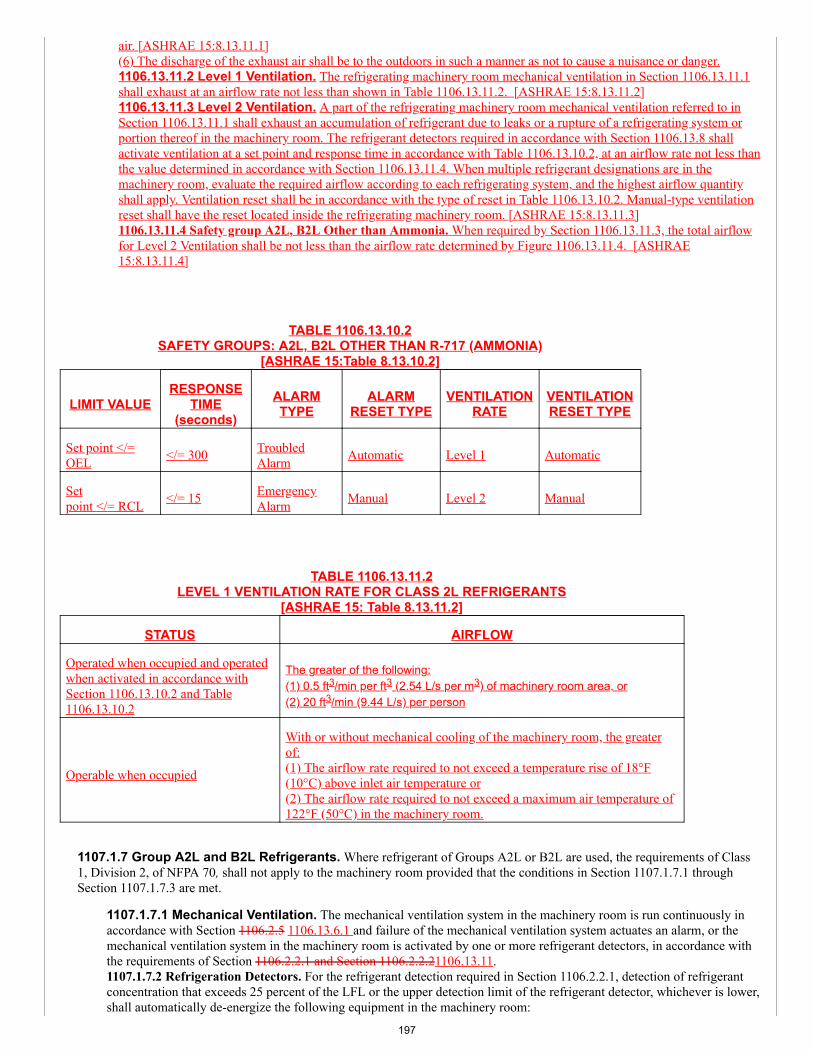
air. [ASHRAE 15:8.13.11.1](6) The discharge of the exhaust air shall be to the outdoors in such a manner as not to cause a nuisance or danger.1106.13.11.2 Level 1 Ventilation. The refrigerating machinery room mechanical ventilation in Section 1106.13.11.1shall exhaust at an airflow rate not less than shown in Table 1106.13.11.2. [ASHRAE 15:8.13.11.2]1106.13.11.3 Level 2 Ventilation. A part of the refrigerating machinery room mechanical ventilation referred to inSection 1106.13.11.1 shall exhaust an accumulation of refrigerant due to leaks or a rupture of a refrigerating system orportion thereof in the machinery room. The refrigerant detectors required in accordance with Section 1106.13.8 shallactivate ventilation at a set point and response time in accordance with Table 1106.13.10.2, at an airflow rate not less thanthe value determined in accordance with Section 1106.13.11.4. When multiple refrigerant designations are in themachinery room, evaluate the required airflow according to each refrigerating system, and the highest airflow quantityshall apply. Ventilation reset shall be in accordance with the type of reset in Table 1106.13.10.2. Manual-type ventilationreset shall have the reset located inside the refrigerating machinery room. [ASHRAE 15:8.13.11.3]1106.13.11.4 Safety group A2L, B2L Other than Ammonia. When required by Section 1106.13.11.3, the total airflowfor Level 2 Ventilation shall be not less than the airflow rate determined by Figure 1106.13.11.4. [ASHRAE15:8.13.11.4]
TABLE 1106.13.10.2SAFETY GROUPS: A2L, B2L OTHER THAN R-717 (AMMONIA)
[ASHRAE 15:Table 8.13.10.2]
LIMIT VALUERESPONSE
TIME(seconds)
ALARMTYPE
ALARMRESET TYPE
VENTILATIONRATE
VENTILATIONRESET TYPE
Set point </=OEL </= 300 Troubled
Alarm Automatic Level 1 Automatic
Setpoint </= RCL </= 15 Emergency
Alarm Manual Level 2 Manual
TABLE 1106.13.11.2LEVEL 1 VENTILATION RATE FOR CLASS 2L REFRIGERANTS
[ASHRAE 15: Table 8.13.11.2]
STATUS AIRFLOW
Operated when occupied and operatedwhen activated in accordance withSection 1106.13.10.2 and Table1106.13.10.2
The greater of the following:(1) 0.5 ft3/min per ft3 (2.54 L/s per m3) of machinery room area, or(2) 20 ft3/min (9.44 L/s) per person
Operable when occupied
With or without mechanical cooling of the machinery room, the greaterof:(1) The airflow rate required to not exceed a temperature rise of 18°F(10°C) above inlet air temperature or(2) The airflow rate required to not exceed a maximum air temperature of122°F (50°C) in the machinery room.
1107.1.7 Group A2L and B2L Refrigerants. Where refrigerant of Groups A2L or B2L are used, the requirements of Class1, Division 2, of NFPA 70, shall not apply to the machinery room provided that the conditions in Section 1107.1.7.1 throughSection 1107.1.7.3 are met.
1107.1.7.1 Mechanical Ventilation. The mechanical ventilation system in the machinery room is run continuously inaccordance with Section 1106.2.5 1106.13.6.1 and failure of the mechanical ventilation system actuates an alarm, or themechanical ventilation system in the machinery room is activated by one or more refrigerant detectors, in accordance withthe requirements of Section 1106.2.2.1 and Section 1106.2.2.21106.13.11.1107.1.7.2 Refrigeration Detectors. For the refrigerant detection required in Section 1106.2.2.1, detection of refrigerantconcentration that exceeds 25 percent of the LFL or the upper detection limit of the refrigerant detector, whichever is lower,shall automatically de-energize the following equipment in the machinery room:
197
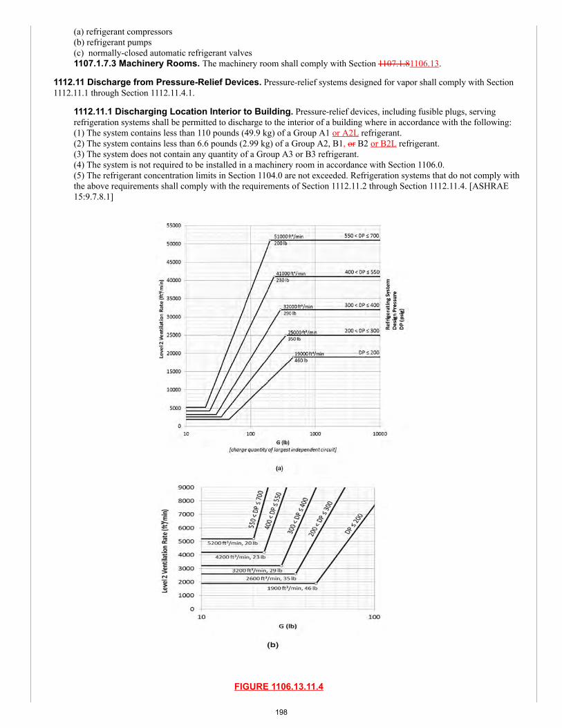
(a) refrigerant compressors(b) refrigerant pumps(c) normally-closed automatic refrigerant valves1107.1.7.3 Machinery Rooms. The machinery room shall comply with Section 1107.1.81106.13.
1112.11 Discharge from Pressure-Relief Devices. Pressure-relief systems designed for vapor shall comply with Section1112.11.1 through Section 1112.11.4.1.
1112.11.1 Discharging Location Interior to Building. Pressure-relief devices, including fusible plugs, servingrefrigeration systems shall be permitted to discharge to the interior of a building where in accordance with the following:(1) The system contains less than 110 pounds (49.9 kg) of a Group A1 or A2L refrigerant.(2) The system contains less than 6.6 pounds (2.99 kg) of a Group A2, B1, or B2 or B2L refrigerant.(3) The system does not contain any quantity of a Group A3 or B3 refrigerant.(4) The system is not required to be installed in a machinery room in accordance with Section 1106.0.(5) The refrigerant concentration limits in Section 1104.0 are not exceeded. Refrigeration systems that do not comply withthe above requirements shall comply with the requirements of Section 1112.11.2 through Section 1112.11.4. [ASHRAE15:9.7.8.1]
FIGURE 1106.13.11.4
198
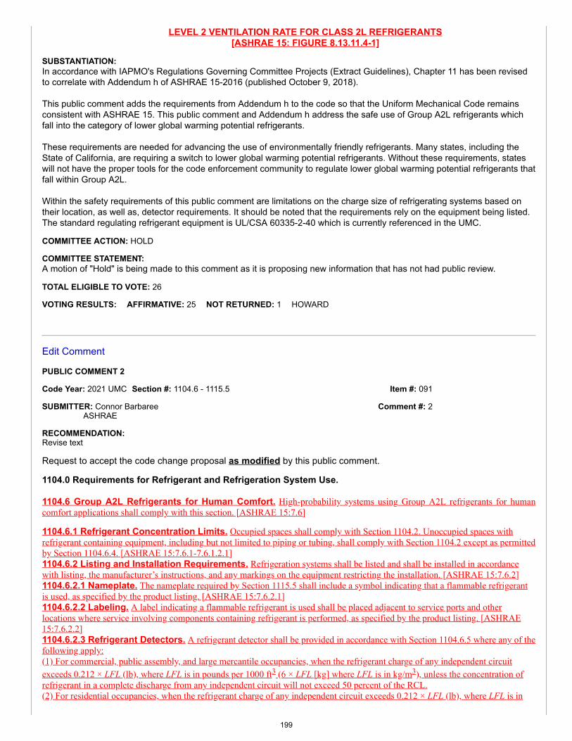
Item #: 091
Comment #: 2
LEVEL 2 VENTILATION RATE FOR CLASS 2L REFRIGERANTS[ASHRAE 15: FIGURE 8.13.11.4-1]
SUBSTANTIATION:In accordance with IAPMO's Regulations Governing Committee Projects (Extract Guidelines), Chapter 11 has been revised to correlate with Addendum h of ASHRAE 15-2016 (published October 9, 2018).
This public comment adds the requirements from Addendum h to the code so that the Uniform Mechanical Code remains consistent with ASHRAE 15. This public comment and Addendum h address the safe use of Group A2L refrigerants which fall into the category of lower global warming potential refrigerants.
These requirements are needed for advancing the use of environmentally friendly refrigerants. Many states, including the State of California, are requiring a switch to lower global warming potential refrigerants. Without these requirements, states will not have the proper tools for the code enforcement community to regulate lower global warming potential refrigerants that fall within Group A2L.
Within the safety requirements of this public comment are limitations on the charge size of refrigerating systems based on their location, as well as, detector requirements. It should be noted that the requirements rely on the equipment being listed. The standard regulating refrigerant equipment is UL/CSA 60335-2-40 which is currently referenced in the UMC.
COMMITTEE ACTION: HOLD
COMMITTEE STATEMENT:A motion of "Hold" is being made to this comment as it is proposing new information that has not had public review.
TOTAL ELIGIBLE TO VOTE: 26
VOTING RESULTS: AFFIRMATIVE: 25 NOT RETURNED: 1 HOWARD
Edit Comment
PUBLIC COMMENT 2
Code Year: 2021 UMC Section #: 1104.6 - 1115.5
SUBMITTER: Connor BarbareeASHRAE
RECOMMENDATION:Revise text
Request to accept the code change proposal as modified by this public comment.
1104.0 Requirements for Refrigerant and Refrigeration System Use.
1104.6 Group A2L Refrigerants for Human Comfort. High-probability systems using Group A2L refrigerants for humancomfort applications shall comply with this section. [ASHRAE 15:7.6]
1104.6.1 Refrigerant Concentration Limits. Occupied spaces shall comply with Section 1104.2. Unoccupied spaces withrefrigerant containing equipment, including but not limited to piping or tubing, shall comply with Section 1104.2 except as permittedby Section 1104.6.4. [ASHRAE 15:7.6.1-7.6.1.2.1]1104.6.2 Listing and Installation Requirements. Refrigeration systems shall be listed and shall be installed in accordancewith listing, the manufacturer’s instructions, and any markings on the equipment restricting the installation. [ASHRAE 15:7.6.2]1104.6.2.1 Nameplate. The nameplate required by Section 1115.5 shall include a symbol indicating that a flammable refrigerantis used, as specified by the product listing. [ASHRAE 15:7.6.2.1]1104.6.2.2 Labeling. A label indicating a flammable refrigerant is used shall be placed adjacent to service ports and otherlocations where service involving components containing refrigerant is performed, as specified by the product listing. [ASHRAE15:7.6.2.2]1104.6.2.3 Refrigerant Detectors. A refrigerant detector shall be provided in accordance with Section 1104.6.5 where any of thefollowing apply:(1) For commercial, public assembly, and large mercantile occupancies, when the refrigerant charge of any independent circuitexceeds 0.212 × LFL (lb), where LFL is in pounds per 1000 ft3 (6 × LFL [kg] where LFL is in kg/m3), unless the concentration ofrefrigerant in a complete discharge from any independent circuit will not exceed 50 percent of the RCL.(2) For residential occupancies, when the refrigerant charge of any independent circuit exceeds 0.212 × LFL (lb), where LFL is in
199
pounds per 1000 ft3 (6 × LFL [kg] where LFL is in kg/m3).(3) When the occupancy classification is institutional.(4) When required by the product listing.(5) When using the provisions of Section 1104.6.4. [ASHRAE 15:7.6.2.3]1104.6.2.4 Refrigerant Concentration Above Limit. When the refrigerant detector senses a rise in refrigerant concentrationabove the value specified in Section 1104.6.5(2), the following actions shall be taken:
(1) The minimum airflow rate of the supply air fan shall be in accordance with the following equation.
Q min = 1000 × M/LFL [Equation 1104.6.2.4]
Where:Qmin = minimum airflow rate, ft3/minM = refrigerant charge of the largest independent refrigerating circuit of the system, lbLFL = lower flammability limit, lb per 1000 ft3
For SI units: Q = 60000 × M /LFL, where Q is the supply air flow rate (m³/h), M is the refrigerant charge (kg), LFL is the lowerflammability limit (g/m³).
(2) Turn off the compressor and all other electrical devices, excluding the control power transformers, control systems, and thesupply air fan. The supply air fan shall continue to operate for at least five minutes after the refrigerant detector has sensed a drop inthe refrigerant concentration below the value specified in Section 1104.6.5(2).(3) Any device that controls airflow located within the product or in ductwork that supplies air to the occupied space shall be fullyopen. Any device that controls airflow shall be listed.(4) Turn off any heaters and electrical devices located in the ductwork. The heaters and electrical devices shall remain off for at leastfive minutes after the refrigerant detector has sensed a drop in the refrigerant concentration below the value specified in Section1104.6.5(2). [ASHRAE 15:7.6.2.4]1104.6.3 Ignition Sources Located in Ductwork. Open-flame producing devices shall not be permanently installed in theductwork that serves the space. Unclassified electrical devices shall not be located within the ductwork that serves the space.Devices containing hot surfaces exceeding 1290°F (700°C) shall not be located in the ductwork that serves the space unless there isa minimum airflow of 200 ft/min (1.0 m/s) across the heating device(s) and there is proof of airflow before the heating device(s) isenergized. [ASHRAE 15:7.6.3-7.6.3.3]1104.6.4 Compressors and Pressure Vessel Located Indoors. For refrigeration compressors and pressure vessels locatedin an indoor space that is accessible only during service and maintenance, it shall be permissible to exceed the RCL if all of thefollowing provisions are met:(1) The refrigerant charge of largest independent refrigerating circuit shall not exceed(a) 6.6 lb (3 kg) for residential and institutional occupancies and(b) 22 lb (10 kg) for commercial and public/large mercantile occupancies.(2) The space where the equipment is located shall be provided with a mechanical ventilation system in accordance with Section1104.6.4(3) and a refrigerant detector in accordance with Section 1104.6.5. The mechanical ventilation system shall be started whenthe refrigerant detector senses refrigerant in accordance with Section 1104.6.5. The mechanical ventilation system shall continue tooperate for at least five minutes after the refrigerant detector has sensed a drop in the refrigerant concentration below the valuespecified in Section 1104.6.5(2).(3) A mechanical ventilation system shall be provided that will mix air with leaked refrigerant and remove it from the space wherethe equipment is located. The space shall be provided with an exhaust fan. The exhaust fan shall remove air from the space wherethe equipment is located in accordance with the following equation.
Q min = 1000 × M/LFL
Where:Qmin = minimum airflow rate, ft3/minM = refrigerant charge of the largest independent refrigerating circuit of the system, lbLFL = lower flammability limit in lb per 1000 ft3
For SI units: Q = 60000 × M /LFL, where Q is the supply air flow rate (m³/h), M is the refrigerant charge (kg), LFL is the lowerflammability limit (g/m³).
(4) The exhaust air inlet shall be located where refrigerant from a leak is expected to accumulate. The bottom of the air inletelevation shall be within 12 in. (30 cm) of the lowest elevation in the space where the compressor or pressure vessel is located.Provision shall be made for make-up air to replace that being exhausted. Openings for the make-up air shall be positioned such thatair will mix with leaked refrigerant.(5) Air that is exhausted from the ventilation system shall be either
200
(a) discharged outside of the building envelope or(b) discharged to an indoor space, provided that the refrigerant concentration will not exceed the limit specified in Section 1104.6.1.(6) In addition to the requirements of Section 1104.6.3, there shall be no open-flame producing devices that do not contain a flamearrestor, or hot surfaces exceeding 1290°F (700 °C) that are installed within space where the equipment is located. [ASHRAE15:7.6.4]1104.6.5 Refrigerant Detectors. Refrigerant detectors required by Section 1104.6.2 shall meet the following requirements:(1) Refrigerant detectors that are part of the listing shall be evaluated by the testing laboratory as part of the equipment listing.(2) Refrigerant detectors as installed shall activate the functions required by Section 1104.6.2.4 within a time not to exceed 15seconds when the refrigerant concentration reaches 25 percent of the lower flammability limit (LFL).(3) Refrigerant detectors shall be located such that refrigerant will be detected if the refrigerating system is operating or notoperating. Use of more than one refrigerant detector shall be permitted.(a) For refrigerating systems that are connected to the occupied space through ductwork, refrigerant detectors shall be located withinthe listed equipment.(b) For refrigerating systems that are directly connected to the occupied space without ductwork, the refrigerant detector shall belocated in the equipment, or shall be located in the occupied space at a height of not more than 12 inches. (30 cm) above the floorand within a horizontal distance of not more 3.3 feet (1.0 m) with a direct line of sight of the unit.(4) Refrigerant detectors shall provide a means for an automatic operational self-test as provided in the product listing. Use of arefrigerant test gas is not required. If a failure is detected, a trouble alarm shall be activated, and the actions required by Section1104.6.2.4 shall be initiated.(5) Refrigerant detectors shall be tested during installation to verify the set point and response time as required by Section1104.6.5(2). After installation, the refrigerant detector shall be tested to verify the set point and response time annually or at aninterval not exceeding the manufacturer’s installation instructions, whichever is less. [ASHRAE 15:7.6.5]
1104.6 1104.7 Applications for Human Comfort and for Nonindustrial Occupancies. In nonindustrial occupancies,Group A2, A2L, A3, B1, B2L, B2, and B3 refrigerants shall not be used in high-probability systems for human comfort. Use of GroupA2L refrigerants shall be in accordance with Section 1104.6.
(renumber remaining sections)
1115.5 Nameplate. Each unit system and each separate condensing unit, compressor, or compressor unit sold for field assembly ina refrigerating system shall carry a nameplate marked with the manufacturer’s name, nationally registered trademark or trade name,identification number, design pressures, and refrigerant for which it is designed. The refrigerant shall be designated by therefrigerant number (R number) as shown in Table 1102.3. [ASHRAE 15:9.15]
SUBSTANTIATION:In accordance with IAPMO's Regulations Governing Committee Projects (Extract Guidelines), Chapter 11 has been revisedto correlate with Addendum d of ASHRAE 15-2016 (published October 23, 2018).
This public comment adds the requirements from Addendum d to the code so that the Uniform Mechanical Code remainsconsistent with ASHRAE 15. This public comment and Addendum d address the safe use of Group A2L refrigerants whichfall into the category of lower global warming potential refrigerants.
These requirements are needed for advancing the use of environmentally friendly refrigerants. Many states, including theState of California, are requiring a switch to lower global warming potential refrigerants. Without these requirements, stateswill not have the proper tools for the code enforcement community to regulate lower global warming potential refrigerants thatfall within Group A2L.
Within the safety requirements of this public comment are limitations on the charge size of refrigerating systems based ontheir location, as well as, detector requirements. It should be noted that the requirements rely on the equipment being listed.The standard regulating refrigerant equipment is UL/CSA 60335-2-40 which is currently referenced in the UMC.
COMMITTEE ACTION: REJECT
COMMITTEE STATEMENT:The comment is being rejected as the industry is not ready to allow A2L refrigerants for human comfort as there are a lack oftraining programs and installation requirements available at this time. Furthermore, there are concerns for life safety andflammability. Although the adoption of A2L for the use of human comfort is progressing, these provisions should not beadopted until adequate training is complete and HVAC contractors are able to safely handle A2L refrigerants. Additional timeis needed to allow for ongoing research to be done. The committee is also concerned that there are no listed detectors toprotect public safety.
TOTAL ELIGIBLE TO VOTE: 26
VOTING RESULTS: AFFIRMATIVE: 21 NEGATIVE: 1 ABSTAIN: 3 NOT RETURNED: 1 HOWARD
201
Item #: 091
Comment #: 3
EXPLANATION OF AFFIRMATIVE:
RIBBS: I am commenting because both sides of this proposal, proponents and opponents, have valid substantiations. It is difficult toweigh the potential risks of A2L refrigerants being distributed throughout buildings against the benefits of far lower greenhousegas(GWP) emissions from these refrigerants. When safer handling of the refrigerants, "listed" leak detection devices, and saferinstallation of these systems are the established norms, the decision will be easier.
EXPLANATION OF NEGATIVE:
CHURCH: The TC reasons for rejection are in direct conflict with the substantial testimony that was given at the TC meeting. This andthe remaining proposals should be accepted.
EXPLANATION OF ABSTAIN:
DELAQUILA: I do not agree with the reasons for rejection.
KOERBER: I am abstaining as the testimony and discussion regarding A2L's and acceptance/non-acceptan ce in the code remains "allover the board". Previously the TC discussions were centered around waiting for ASHRAE 15 to be completed so the UMC could beconsistent with the standard. With the standard now updated the discussion has moved to the need for more training and moreresearch. I feel we are kicking this down the road rather than addressing it appropriately.
MACNEVIN: I am abstaining because both sides of this proposal, proponents and opponents, have valid substantiations. It is difficult toweigh the potential risks of A2L refrigerants being distributed throughout buildings - which I oppose - against the benefits of far lowergreenhouse gas(GWP) emissions from these refrigerants. When safer handling of the refrigerants and safer installation of thesesystems are the established norms, the decision will be easier.
Edit Comment
PUBLIC COMMENT 3
Code Year: 2021 UMC Section #: 1104.6 - 1104.6.1.5
SUBMITTER: Connor BarbareeASHRAE
RECOMMENDATION:Add new text
Request to accept the code change proposal as modified by this public comment.
1104.0 Requirements for Refrigerant and Refrigeration System Use.
1104.6 Applications for Human Comfort and for Nonindustrial Occupancies. In nonindustrial occupancies, GroupA2, A2L, A3, B1, B2L, B2, and B3 refrigerants shall not be used in high-probability systems for human comfort. Systems usingGroup A2L refrigerant in high-probability systems for human comfort shall comply with Section 1104.6.1 through Section 1104.6.3.
1104.6.1 Group A2L Refrigerants. The refrigeration equipment using A2L refrigerant shall be listed and comply with Section903.1. The equipment shall be installed in accordance with the manufacturer's instructions. The nameplate shall include a flammablerefrigerant symbol. A label indicating that a flammable refrigerant is used shall be placed adjacent to service ports and otherlocations where service involving components containing refrigerant is performed. High-probability systems using Group A2Lrefrigerants for human comfort applications shall comply with Sections 1104.6.1.1 through 1104.6.1.5. Nonoccupiable spaces withrefrigerant containing equipment, including piping, shall comply with the amounts indicated in Table 1102.3, except as permitted bySection 1104.6.1.4.1104.6.1.1 Installation Requirements. A refrigerant detector shall be provided in accordance with Section 1104.6.1.5 whereany of the following conditions apply:1. For Commercial, Public Assembly and Large Mercantile occupancies where the refrigerant charge of any independent circuitexceeds 0.212 x LFL (lb) where LFL is in lb/1000 ft3 (6 x LFL(kg) where LFL is in kg/m3) unless the concentration of refrigerant ina complete discharge from any independent circuit will not exceed 50 percent of the RCL.2. For Institutional occupancies.3. For residential occupancies, when the refrigerant charge of any independent circuit exceeds 0.212 x LFL where LFL is in lb/1000ft3 (6 x LFL where LFL is in kg/m3).4. Where using the provisions of Section 1104.6.1.4.5. Where a refrigerant detector is required by the product listing. 1104.6.1.2 Detector Activation. When the refrigerant detector senses a rise in refrigerant concentration above the value specified
202
in Section 1104.6.1.5, all of the following shall apply:1. A minimum flow rate of supply air shall be provided in accordance with the following equation:
Q = 1001 × M/LFL, [Equation 1104.6.1.2]
Where:Q = the supply air flow rate ft³/min (m³/h),M = the refrigerant charge lb (kg), andLFL = the lower flammablity limit lb per 1000 ft³ (g/m³).
For SI units: Q = 60000 × M /LFL, where Q is the supply air flow rate (m³/h), M is the refrigerant charge (kg), LFL is the lowerflammability limit (g/m³).
2. The compressor and all other electrical devices shall be turned off, excluding the control power transformers, control systems, andthe supply air fan. The supply air fan shall continue to operate for not less than 5 minutes after the refrigerant detector has sensed adrop in the refrigerant concentration below the value specified in Section 1104.6.1.5.3. Any device that controls air flow located within the product or in duct work that supplies air to the occupied space shall be fullyopened. Any device that controls air flow shall be listed.4. Heaters and electrical devices located in the ductwork shall be turned off. The heaters and electrical devices shall remain off for atleast 5 minutes after the refrigerant detector has sensed a drop in the refrigerant concentration below the value specified in Section1104.6.1.5.1104.6.1.3 Ignition Sources. Open flame-producing devices shall not be permanently installed in the ductwork that serves thespace. Continuously operating hot surfaces exceeding 1292°F (700°C) shall not be located within the ductwork that serves the space.Unclassified electrical devices shall not be located within the ductwork that serves the space.1104.6.1.4 Refrigerant Containing Equipment Located Indoors. For refrigeration compressors and pressure vessels locatedin an indoor space that is accessible only during service and maintenance it shall be permissible to exceed the amounts indicated inTable 1102.3 where all of the following conditions apply:Exceptions:1. The largest single circuit charge does not exceed 6.6 lb (3 kg) for Residential and Institutional occupancies, and does not exceed22 lb (10 kg) for C.2. The space where compressors and pressure vessels are located is provided with an air distribution system in accordance with thefollowing equation:
Q = 1001 × M /LFL, [Equation 1104.6.1.4]
Where:Q = the supply air flow rate ft³/min (m³/h),M = the refrigerant charge lb (kg), andLFL = the lower flammablity limit lb per 1000 ft³ (g/m³).
For SI units: Q = 60000 × M / LFL, where Q is the supply air flow rate (m³/h), M is the refrigerant charge (kg), LFL is the lowerflammability limit (g/m³).
3. Exhaust air is removed from the air distribution system at a minimum rate of 4 air changes per hour and the system has provisionsfor makeup air. Exhaust air that is removed from the air distribution system is either discharged outside of the building envelope, ordischarged to an indoor space, provided that the refrigerant concentration will not exceed the amount indicated in Table 1102.2.4. The air distribution system is started when the refrigerant detector senses refrigerant in accordance with Section 1104.6.1.5. Thelocation of the refrigerant detector is in accordance with Section 1104.6.1.5. The air distribution system continues to operate for notless than 30 minutes after the refrigerant detector has sensed a drop in the refrigerant concentration below the value specified inSection 1104.6.1.5 (1.).5. The inlet for return air to the air distribution system is located where refrigerant from a leak is expected to accumulate. The inletelevation is within 12 inches (30 cm) of the lowest elevation in the space where the compressor or pressure vessel is located.6. In addition to the requirements of Section 1104.6.1.3 there are no open flame producing devices or continuously operating hotsurfaces exceeding 1292°F (700°C) that are located within space where the equipment is installed.1104.6.1.5 Refrigerant Detectors. Refrigerant detectors shall comply with all of the following:1. The refrigerant detector set point to activate the functions required by Section 1104.6.1.2 shall be at a value not exceeding 25% ofthe lower flammable limit (LFL).2. One or more refrigerant detectors shall be located such that refrigerant will be detected if the refrigerating system is operating, ornot operating. For refrigerating systems that are connected to the occupied space through ductwork, refrigerant detectors shall belocated within the listed equipment. For refrigerating systems that are directly connected to the occupied space without ductwork,the refrigerant detector shall be located in the equipment, or shall be located in the occupied space at a height of not more than 12inches (30 cm) above the floor and within a horizontal distance of not more 3.3 feet (1.0 m) with a direct line of sight of the unit.3. The refrigerant detector as installed, including any sampling tubes, shall cause the functions required by Section 1104.6.1.2 withina time not to exceed 10 seconds, after exposure to a refrigerant concentration exceeding 25 percent of the LFL.
203
4. The refrigerant detector shall provide a means for automatic operational self-test as provided in the product listing. Use of arefrigerant test gas is not required. If a failure is detected, a trouble alarm shall be activated and the actions required by Section1104.6.1.2 shall be initiated.5. The refrigerant detector shall be tested during installation to verify the alarm set point and response time as required by Section1104.6.1.5 items 1 and 3. After installation, the refrigerant detector shall be tested to verify the alarm set point and response timeannually or at an interval not exceeding the manufacturer's installation instructions, whichever is less.
SUBSTANTIATION:The original change was modified during the first hearing by deleting the text applying to A2L refrigerants. The reason for themodification was that the ASHRAE 15 Committee had not completed Addendum d. Since that time, Addendum d has beencompleted and published. Additionally, the changes from Addendum d will appear in the 2019 edition of ASHRAE 15.
This public comment adds the requirements from Addendum d to the code so that the Uniform Mechanical Code remainsconsistent with ASHRAE 15. This public comment and Addendum d address the safe use of Group A2L refrigerants whichfall into the category of lower global warming potential refrigerants.
These requirements are needed for advancing the use of environmentally friendly refrigerants. Many states, including theState of California, are requiring a switch to lower global warming potential refrigerants. Without these requirements, stateswill not have the proper tools for the code enforcement community to regulate lower global warming potential refrigerants thatfall within Group A2L.
Within the safety requirements of this public comment are limitations on the charge size of refrigerating systems based ontheir location, as well as, detector requirements. It should be noted that the requirements rely on the equipment being listed.The standard regulating refrigerant equipment is UL/CSA 60335-2-40 which is currently referenced in the UMC.
COMMITTEE ACTION: REJECT
COMMITTEE STATEMENT:The comment is being rejected as the industry is not ready to allow A2L refrigerants for human comfort as there are a lack oftraining programs and installation requirements available at this time. Furthermore, there are concerns for life safety andflammability. Although the adoption of A2L for the use of human comfort is progressing, these provisions should not beadopted until adequate training is complete and HVAC contractors are able to safely handle A2L refrigerants. Additional timeis needed to allow for ongoing research to be done. The committee is also concerned that there are no listed detectors toprotect public safety.
TOTAL ELIGIBLE TO VOTE: 26
VOTING RESULTS: AFFIRMATIVE: 20 NEGATIVE: 2 ABSTAIN: 3 NOT RETURNED: 1 HOWARD
EXPLANATION OF AFFIRMATIVE:
RIBBS: See my statement regarding Item #91, Comment 02.
EXPLANATION OF NEGATIVE:
CHURCH: The TC reasons for rejection are in direct conflict with the substantial testimony that was given at the TC meeting. This andthe remaining proposals should be accepted.
A. TRAFTON: I do not agree with the reasons for the rejection.
EXPLANATION OF ABSTAIN:
DELAQUILA: I do not agree with the reasons for rejection.
KOERBER: I am abstaining as the testimony and discussion regarding A2L's and acceptance/non-acceptan ce in the code remains "allover the board". Previously the TC discussions were centered around waiting for ASHRAE 15 to be completed so the UMC could beconsistent with the standard. With the standard now updated the discussion has moved to the need for more training and moreresearch. I feel we are kicking this down the road rather than addressing it appropriately.
MACNEVIN: I am abstaining because both sides of this proposal, proponents and opponents, have valid substantiations. It is difficult toweigh the potential risks of A2L refrigerants being distributed throughout buildings - which I oppose - against the benefits of far lowergreenhouse gas(GWP) emissions from these refrigerants. When safer handling of the refrigerants and safer installation of thesesystems are the established norms, the decision will be easier.
Edit Comment
204

Item #: 091
Comment #: 4
PUBLIC COMMENT 4
Code Year: 2021 UMC Section #: 1104.6 - 1104.6.1.5
SUBMITTER: Julius BallancoJB Engineering and Code Consulting, P.C.Rep. Daikin US
RECOMMENDATION:Revise text
Request to accept the code change proposal as modified by this public comment.
1104.0 Requirements for Refrigerant and Refrigeration System Use.
1104.6 Applications for Human Comfort and for Nonindustrial Occupancies. In nonindustrial occupancies, Group A2,A2L, A3, B1, B2L, B2, and B3 refrigerants shall not be used in high-probability systems for human comfort. Systems using GroupA2L refrigerant in high-probability systems for human comfort shall comply with Section 1104.6.1 through Section 1104.6.3.
1104.6.1 Group A2L Refrigerants. The refrigeration equipment using A2L refrigerant shall be listed and comply with Section903.1. The equipment shall be installed in accordance with the manufacturer's instructions. The nameplate shall include a flammablerefrigerant symbol. A label indicating that a flammable refrigerant is used shall be placed adjacent to service ports and otherlocations where service involving components containing refrigerant is performed. High-probability systems using Group A2Lrefrigerants for human comfort applications shall comply with Sections 1104.6.1.1 through 1104.6.1.5. Nonoccupiable spaces withrefrigerant containing equipment, including piping, shall comply with the amounts indicated in Table 1102.3, except as permitted bySection 1104.6.1.4.
1104.6.1.1 Installation Requirements. A refrigerant detector shall be provided in accordance with Section 1104.6.1.5 whereany of the following conditions apply:1. For commercial, public assembly and large mercantile occupancies where the refrigerant charge of any independent circuitexceeds 0.212 x LFL (lb) where LFL is in lb/1000 ft3 (6 x LFL(kg) where LFL is in kg/m3) unless the concentration of refrigerant ina complete discharge from any independent circuit will not exceed 50 percent of the RCL.2. For Institutional occupancies.3. For residential occupancies, when the refrigerant charge of any independent circuit exceeds 0.212 x LFL where LFL is in lb/1000ft3 (6 x LFL where LFL is in kg/m3).4. Where using the provisions of Section 1104.6.1.4.5. Where a refrigerant detector is required by the product listing.
1104.6.1.2 Detector Activation. When the refrigerant detector senses a rise in refrigerant concentration above the value specifiedin Section 1104.6.1.5, all of the following shall apply:1. A minimum flow rate of supply air shall be provided in accordance with the following equation:
Q = 1000 × M / LFL (Equation 1104.6.1.2)
Where:Q = the supply air flow rate ft³/min (m³/h),M = the refrigerant charge lb (kg), andLFL = the lower flammablity limit lb per 1000 ft³ (g/m³).
For SI units: Q = 60000 × M / LFL, where Q is the supply air flow rate (m³/h), M is the refrigerant charge (kg), LFL is the lowerflammability limit (g/m³).
2. The compressor and all other electrical devices shall be turned off, excluding the control power transformers, control systems, andthe supply air fan. The supply air fan shall continue to operate for not less than 5 minutes after the refrigerant detector has sensed adrop in the refrigerant concentration below the value specified in Section 1104.6.1.5.3. Any device that controls air flow located within the product or in duct work that supplies air to the occupied space shall be fullyopened. Any device that controls air flow shall be listed.4. Heaters and electrical devices located in the ductwork shall be turned off. The heaters and electrical devices shall remain off for atleast 5 minutes after the refrigerant detector has sensed a drop in the refrigerant concentration below the value specified in Section1104.6.1.5.
1104.6.1.3 Ignition Sources. Open flame-producing devices shall not be permanently installed in the ductwork that serves thespace. Continuously operating hot surfaces exceeding 1292°F (700°C) shall not be located within the ductwork that serves the space.Unclassified electrical devices shall not be located within the ductwork that serves the space.
205
1104.6.1.4 Refrigerant Containing Equipment Located Indoors. For refrigeration compressors and pressure vessels locatedin an indoor space that is accessible only during service and maintenance it shall be permissible to exceed the amounts indicated inTable 1102.3 where all of the following conditions apply:Exceptions:1. The largest single circuit charge does not exceed 6.6 lb (3 kg) for Residential and Institutional occupancies, and does not exceed22 lb (10 kg) for C.2. The space where compressors and pressure vessels are located is provided with an air distribution system in accordance with thefollowing equation:
Q = 1000 × M / LFL (Equation 1104.6.1.4)
Where:Q = the supply air flow rate ft³/min (m³/h),M = the refrigerant charge lb (kg), andLFL = the lower flammable limit lb per 1000 ft³ (g/m³).
For SI units: Q = 60000 × M / LFL, where Q is the supply air flow rate (m³/h), M is the refrigerant charge (kg), LFL is the lowerflammability limit (g/m³).
3. Exhaust air is removed from the air distribution system at a minimum rate of 4 air changes per hour and the system has provisionsfor makeup air. Exhaust air that is removed from the airdistribution system is either discharged outside of the building envelope, or discharged to anindoor space, provided that the refrigerant concentration will not exceed the amount indicated in Table 1102.2.4. The air distribution system is started when the refrigerant detector senses refrigerant inaccordance with Section 1104.6.1.5. The location of the refrigerant detector is in accordancewith Section 1104.6.1.5. The air distribution system continues to operate for not less than 5minutes after the refrigerant detector has sensed a drop in the refrigerant concentration belowthe value specified in Section 1104.6.1.5 (1).5. The inlet for return air to the air distribution system is located where refrigerant from a leak is expected to accumulate. The inletelevation is within 12 inches (30 cm) of the lowest elevation in the space where the compressor or pressure vessel is located.6. In addition to the requirements of Section 1104.6.1.3 there are no open flame producing devices or continuously operating hotsurfaces exceeding 1292°F (700°C) that are located within space where the equipment is installed.
1104.6.1.5 Refrigerant Detectors. Refrigerant detectors shall comply with all of the following:1. The refrigerant detector set point to activate the functions required by Section 1104.6.1.2 shall be at a value not exceeding 25percent of the lower flammable limit (LFL).2. One or more refrigerant detectors shall be located such that refrigerant will be detected if the refrigerating system is operating, ornot operating. For refrigerating systems that are connected to the occupied space through ductwork, refrigerant detectors shall belocated within the listed equipment. For refrigerating systems that are directly connected to the occupied space without ductwork,the refrigerant detector shall be located in the equipment, or shall be located in the occupied space at a height of not more than 12inches (30 cm) above the floor and within a horizontal distance of not more 3.3 feet (1.0 m) with a direct line of sight of the unit.3. The refrigerant detector as installed, including any sampling tubes, shall cause the functionsrequired by Section 1104.6.1.2 within a time not to exceed 15 seconds, after exposure to a refrigerant concentration exceeding 25percent of the LFL.4. The refrigerant detector shall provide a means for automatic operational self-test as provided in the product listing. Use of arefrigerant test gas is not required. If a failure is detected, a trouble alarm shall be activated and the actions required by Section1104.6.1.2 shall be initiated.5. The refrigerant detector shall be tested during installation to verify the alarm set point andresponse time as required by Section 1104.6.1.5 items 1 and 3. After installation, the refrigerant detector shall be tested to verify thealarm set point and response time annually or at an interval not exceeding the manufacturer's installation instructions, whichever isless.
SUBSTANTIATION:The original change was modified during the first hearing by deleting the text applying to A2L refrigerants. The reason for themodification was that the ASHRAE 15 Committee had not completed Addendum d. Since that time, Addendum d has beencompleted and published. Additionally, the changes from Addendum d will appear in the 2019 edition of ASHRAE 15.
This public comment adds the requirements from Addendum d to the code so that the Uniform Mechanical Code remainsconsistent with ASHRAE 15. This public comment and Addendum d address the safe use of Group A2L refrigerants whichfall into the category of lower global warming potential refrigerants.
These requirements are needed for advancing the use of environmentally friendly refrigerants. Many states, including theState of California, are requiring a switch to lower global warming potential refrigerants. Without these requirements, states
206
Item #: 091
Comment #: 5
will not have the proper tools for the code enforcement community to regulate lower global warming potential refrigerants thatfall within Group A2L.
Within the safety requirements of this public comment are limitations on the charge size of refrigerating systems based ontheir location, as well as, detector requirements. It should be noted that the requirements rely on the equipment being listed.The standard regulating refrigerant equipment is UL/CSA 60335-2-40 which is currently referenced in the UMC.
COMMITTEE ACTION: REJECT
COMMITTEE STATEMENT:The comment is being rejected as the industry is not ready to allow A2L refrigerants for human comfort as there are a lack oftraining programs and installation requirements available at this time. Furthermore, there are concerns for life safety andflammability. Although the adoption of A2L for the use of human comfort is progressing, these provisions should not beadopted until adequate training is complete and HVAC contractors are able to safely handle A2L refrigerants. Additional timeis needed to allow for ongoing research to be done. The committee is also concerned that there are no listed detectors toprotect public safety.
TOTAL ELIGIBLE TO VOTE: 26
VOTING RESULTS: AFFIRMATIVE: 21 NEGATIVE: 2 ABSTAIN: 2 NOT RETURNED: 1 HOWARD
EXPLANATION OF AFFIRMATIVE:
RIBBS: See my statement regarding Item # 091 Comment 02: "I am commenting because both sides of this proposal, proponents andopponents, have valid substantiations. It is difficult to weigh the potential risks of A2L refrigerants being distributed throughout buildingsagainst the benefits of far lower greenhouse gas (GWP) emissions from these refrigerants. When safer handling of the refrigerants,"listed" leak detection devices, and safer installation of these systems are the established norms, the decision will be easier."
EXPLANATION OF NEGATIVE:
CHURCH: The TC reasons for rejection are in direct conflict with the substantial testimony that was given at the TC meeting. This andthe remaining proposals should be accepted.
A. TRAFTON: There is insufficient reason to reject this proposal.
EXPLANATION OF ABSTAIN:
DELAQUILA: I do not agree with the reasons for rejection.
KOERBER: I am abstaining as the testimony and discussion regarding A2L's and acceptance/non-acceptan ce in the code remains "allover the board". Previously the TC discussions were centered around waiting for ASHRAE 15 to be completed so the UMC could beconsistent with the standard. With the standard now updated the discussion has moved to the need for more training and moreresearch. I feel we are kicking this down the road rather than addressing it appropriately.
Edit Comment
PUBLIC COMMENT 5
Code Year: 2021 UMC Section #: 1104.6 - 1104.6.1.5
SUBMITTER: Andrew KleinA S Klein Engineering, PLLCRep. The Chemours Company
RECOMMENDATION:Revise text
Request to accept the code change proposal as modified by this public comment.
1104.0 Requirements for Refrigerant and Refrigeration System Use.
1104.6 Applications for Human Comfort and for Nonindustrial Occupancies. In nonindustrial occupancies, Group A2, A2L, A3,B1, B2L, B2, and B3 refrigerants shall not be used in high-probability systems for human comfort. Systems using Group A2Lrefrigerant in high-probability systems for human comfort shall comply with Section 1104.6.1 through Section 1104.6.1.5.
1104.6.1 Group A2L Refrigerants. The refrigeration equipment using A2L refrigerant shall be listed and comply with Section903.1. The equipment shall be installed in accordance with the manufacturer's instructions. The nameplate shall include a flammable
207
refrigerant symbol. A label indicating that a flammable refrigerant is used shall be placed adjacent to service ports and otherlocations where service involving components containing refrigerant is performed. High-probability systems using Group A2Lrefrigerants for human comfort applications shall comply with Sections 1104.6.1.1 through 1104.6.1.5. Nonoccupiable spaces withrefrigerant containing equipment, including piping, shall comply with the amounts indicated in Table 1102.3, except as permitted bySection 1104.6.1.4.1104.6.1.1 Installation Requirements. A refrigerant detector shall be provided in accordance with Section 1104.6.1.5 where any of thefollowing conditions apply:1. For commercial, public assembly and large mercantile occupancies where the refrigerant charge of any independent circuit exceeds 0.212 x LFL(lb) where LFL is in lb/1000 ft3 (6 x LFL(kg) where LFL is in kg/m3) unless the concentration of refrigerant in a complete discharge from anyindependent circuit will not exceed 50 percent of the RCL.2. For Institutional occupancies.3. For Residential occupancies, when the refrigerant charge of any independent circuit exceeds 0.212 x LFL where LFL is in lb/1000 ft3 (6 x LFLwhere LFL is in kg/m3).4. Where using the provisions of Section 1104.6.1.4.5. Where a refrigerant detector is required by the product listing.1104.6.1.2 Detector Activation. When the refrigerant detector senses a rise in refrigerant concentration above the value specified inSection 1104.6.1.5, all of the following shall apply:1. A minimum flow rate of supply air shall be provided in accordance with the following equation:
Q = 1001 × M /LFL, [Equation 1104.6.1.2]
(for SI: Q = 60000 × M / LFL),
Where: Q is the supply air flow rate ft3/min (m3/h), M is the refrigerant charge lb (kg), and LFL is the lower flammability limit lbper 1000 ft3 (g/m3).
2. The compressor and all other electrical devices shall be turned off, excluding the control power transformers, control systems, and the supply airfan. The supply air fan shall continue to operate for not less than 5 minutes after the refrigerant detector has sensed a drop in the refrigerantconcentration below the value specified in Section 1104.6.1.5.3. Any device that controls air flow located within the product or in duct work that supplies air to the occupied space shall be fully opened. Anydevice that controls air flow shall be listed.4. Heaters and electrical devices located in the ductwork shall be turned off. The heaters and electrical devices shall remain off for at least 5 minutesafter the refrigerant detector has sensed a drop in the refrigerant concentration below the value specified in Section 1104.6.1.5.1104.6.1.3 Ignition Sources. Open flame-producing devices shall not be permanently installed in the ductwork that serves the space.Continuously operating hot surfaces exceeding 1292°F (700°C) shall not be located within the ductwork that serves the space. Unclassified electricaldevices shall not be located within the ductwork that serves the space.1104.6.1.4 Refrigerant Containing Equipment Located Indoors. For refrigeration compressors and pressure vessels located in an indoorspace that is accessible only during service and maintenance it shall be permissible to exceed the amounts indicated in Table 1102.3 where all of thefollowing conditions apply:Exceptions:1. The largest single circuit charge does not exceed 6.6 lb (3 kg) for Residential and Institutional occupancies, and does not exceed 22 lb (10 kg) forC.2. The space where compressors and pressure vessels are located is provided with an air distribution system in accordance with the followingequation:
Q = 1001 × M / LFL, [Equation 1104.6.1.4]
(for SI: Q = 60000 × M / LFL),
Where: Q is the supply air flow rate ft³/min (m³/h), M is the refrigerant charge lb (kg), and LFL is the lower flammable limit lb per1000 ft³ (g/m³).
3. Exhaust air is removed from the air distribution system at a minimum rate of 4 air changes per hour and the system has provisionsfor makeup air. Exhaust air that is removed from the air distribution system is either discharged outside of the building envelope, ordischarged to an indoor space, provided that the refrigerant concentration will not exceed the amount indicated in Table 1102.2.4. The air distribution system is started when the refrigerant detector senses refrigerant in accordance with Section 1104.6.1.5. Thelocation of the refrigerant detector is in accordance with Section 1104.6.1.5. The air distribution system continues to operate for notless than 30 minutes after the refrigerant detector has sensed a drop in the refrigerant concentration below the value specified inSection 1104.6.1.5 (1.).5. The inlet for return air to the air distribution system is located where refrigerant from a leak is expected to accumulate. The inletelevation is within 12 inches (30 cm) of the lowest elevation in the space where the compressor or pressure vessel is located.6. In addition to the requirements of Section 1104.6.1.3 there are no open flame producing devices or continuously operating hot
208
surfaces exceeding 1292°F (700°C) that are located within space where the equipment is installed.1104.6.1.5 Refrigerant Detectors. Refrigerant detectors shall comply with all of the following:1. The refrigerant detector set point to activate the functions required by Section 1104.6.1.2 shall be at a value not exceeding 25percent of the lower flammable limit (LFL).2. One or more refrigerant detectors shall be located such that refrigerant will be detected if the refrigerating system is operating, ornot operating. For refrigerating systems that are connected to the occupied space through ductwork, refrigerant detectors shall belocated within the listed equipment. For refrigerating systems that are directly connected to the occupied space without ductwork,the refrigerant detector shall be located in the equipment, or shall be located in the occupied space at a height of not more than 12inches (30 cm) above the floor and within a horizontal distance of not more 3.3 feet (1.0 m) with a direct line of sight of the unit.3. The refrigerant detector as installed, including any sampling tubes, shall cause the functions required by Section 1104.6.1.2 withina time not to exceed 10 seconds, after exposure to a refrigerant concentration exceeding 25 percent of the LFL.4. The refrigerant detector shall provide a means for automatic operational self-test as provided in the product listing. Use of arefrigerant test gas is not required. If a failure is detected, a trouble alarm shall be activated and the actions required by Section1104.6.1.2 shall be initiated.5. The refrigerant detector shall be tested during installation to verify the alarm set point and response time as required by Section1104.6.1.5 items 1 and 3. After installation, the refrigerant detector shall be tested to verify the alarm set point and response timeannually or at an interval not exceeding the manufacturer's installation instructions, whichever is less.
SUBSTANTIATION:We support ASHRAE’s efforts to align the UMC with the 2019 edition of ASHRAE 15.
COMMITTEE ACTION: REJECT
COMMITTEE STATEMENT:The comment is being rejected as the industry is not ready to allow A2L refrigerants for human comfort as there are a lack oftraining programs and installation requirements available at this time. Furthermore, there are concerns for life safety andflammability. Although the adoption of A2L for the use of human comfort is progressing, these provisions should not beadopted until adequate training is complete and HVAC contractors are able to safely handle A2L refrigerants. Additional timeis needed to allow for ongoing research to be done. The committee is also concerned that there are no listed detectors toprotect public safety.
TOTAL ELIGIBLE TO VOTE: 26
VOTING RESULTS: AFFIRMATIVE: 22 NEGATIVE: 1 ABSTAIN: 2 NOT RETURNED: 1 HOWARD
EXPLANATION OF NEGATIVE:
CHURCH: The TC reasons for rejection are in direct conflict with the substantial testimony that was given at the TC meeting. This andthe remaining proposals should be accepted.
EXPLANATION OF ABSTAIN:
DELAQUILA: I do not agree with the reasons for rejection.
KOERBER: I am abstaining as the testimony and discussion regarding A2L's and acceptance/non-acceptan ce in the code remains "allover the board." Previously the TC discussions were centered around waiting for ASHRAE 15 to be completed so the UMC could beconsistent with the standard. With the standard now updated the discussion has moved to the need for more training and moreresearch. I feel we are kicking this down the road rather than addressing it appropriately.
209
Proposals
Edit Proposal
Item #: 092
UMC 2021 Section: 1105.1, Table 1701.1, Table 1701.2
SUBMITTER: David C. BixbyAir Conditioning Contractors of America
RECOMMENDATION:Revise text
1105.0 General Requirements.1105.1 Human Comfort. Cooling systems used for human comfort shall be in accordance with the return-air and outside-airprovisions for furnaces in Section 904.7 and Section 904.8. Cooling equipment used for human comfort in dwelling units shall beselected in accordance with ACCA Manual S to satisfy the calculated loads determined in accordance with the reference standardsin Chapter 17 ACCA Manual J or other approved methods. Refrigerants used for human comfort shall be in accordance with Section1104.6.
TABLE 1701.1REFERENCED STANDARDS
STANDARD NUMBER STANDARD TITLE APPLICATION REFERENCEDSECTION
ANSI/ACCA Manual J-2016 Residential Load Calculations Ducts 1105.1
ANSI/ACCA Manual S-2014 Residential Equipment Selection Equipment 1105.1
(portion of table not shown remains unchanged)
Note: ACCA Manual J and ACCA Manual S meet the requirements for mandatory reference standards inaccordance with Section 3-3.7.1 of IAPMO's Regulations Governing Committee Projects.
TABLE 1701.2STANDARDS, PUBLICATIONS, PRACTICES, AND GUIDES
DOCUMENT NUMBER DOCUMENT TITLE APPLICATION
ACCA Manual J-2016 Residential Load Calculations Ducts
(portion of table not shown remains unchanged)
SUBSTANTIATION:The 2018 UMC mandates the use of ACCA Manual D (Residential Duct Systems) in Section 601.2 for duct sizing. However,mandating the use of only Manual D without using Manual J and Manual S will result in an incomplete design and installationas it will not account for calculating heating/cooling loads (Manual J) which is critical for duct sizing. In addition, Manual Sneeds to be used as it covers the design, sizing and selection of heating/cooling equipment based on use of Manuals D andJ. Moreover, by not having the UMC mandate the use of Manuals S and J, the safety and performance of the HVAC systemcould be adversely affected and potentially impact the health and safety of the occupants. One concern is related to thepotential for undersizing or oversizing HVAC equipment if these Manuals are not required. Such a condition could createexcessive humidity levels in a home which in turn allows for the formation of mold with its potential associated health effects.
210
Item #: 092
Comment #: 1
Like ACCA Manual D, ACCA Manuals J and S also include a Normative code-enforceable section and are both ANSIstandards that meet the requirements for mandatory reference standards in accordance with Section 3-3.7.1 of IAPMO’sRegulations Governing Projects.
The addition of ACCA Manual J to Table 1701.1 is needed to support its proposed reference as a new requirement under1105.1. Manual J includes a Normative code-enforceable section and is an ANSI standard that meets the requirements formandatory reference standards in accordance with Section 3-3.7.1 of IAPMO’s Regulations Governing Projects.
The addition of ACCA Manual S to Table 1701.1 is needed to (1) support its current reference in Appendix E 607.2(3), and(2) support its proposed reference as a new requirement under 1105.1. Manual S includes a Normative code-enforceablesection and is an ANSI standard that meets the requirements for mandatory reference standards in accordance with Section3-3.7.1 of IAPMO’s Regulations Governing Projects.
COMMITTEE ACTION: ACCEPT AS AMENDED BY THE TC
Amend proposal as follows:
1105.0 General Requirements.1105.1 Human Comfort. Cooling systems used for human comfort shall be in accordance with the return-air and outside-airprovisions for furnaces in Section 904.7 and Section 904.8. Cooling equipment used for human comfort in dwelling units residentialbuildings shall be selected in accordance with ACCA Manual S to satisfy the calculated loads determined in accordance with ACCAManual J or other approved methods. Refrigerants used for human comfort shall be in accordance with Section 1104.6.
TABLE 1701.1REFERENCED STANDARDS
STANDARD NUMBER STANDARD TITLE APPLICATION REFERENCEDSECTION
ANSI/ACCA Manual J-2016 Residential Load Calculations Ducts 1105.1
ANSI/ACCA Manual S-2014 Residential Equipment Selection Equipment 1105.1
(portion of table not shown remains unchanged)
COMMITTEE STATEMENT:The modification further clarifies the intent of code in regards to the section applying to "residential buildings" as thestandards referenced only apply to residential occupancies.
TOTAL ELIGIBLE TO VOTE: 26
VOTING RESULTS: AFFIRMATIVE: 25 NOT RETURNED: 1 HOWARD
Appended Comments
Edit Comment
PUBLIC COMMENT 1
Code Year: 2021 UMC Section #: 1105.1, Table 1701.1, Table 1701.2
SUBMITTER: David C. BixbyAir Conditioning Contractors of America
RECOMMENDATION:Add new text
Request to accept the code change proposal as modified by this public comment.
1105.1 Human Comfort. Cooling systems used for human comfort shall be in accordance with the return-air and outside-airprovisions for furnaces in Section 601.4 and Section 904.7. Cooling equipment used for human comfort in residential buildings shallbe selected in accordance with ACCA Manual S to satisfy the calculated loads determined in accordance with ACCA Manual J orother approved methods. Refrigerants used for human comfort shall be in accordance with Section 1104.6.
211
Cooling equipment used for human comfort in commercial buildings shall be selected in accordance with ACCA Manual CSto satisfy the calculated loads determined in accordance with ACCA Manual N or other approved methods.
TABLE 1701.1REFERENCED STANDARDS
STANDARD NUMBER STANDARD TITLE APPLICATION REFERENCEDSECTION
ACCA Manual CS-1993 Commercial Systems Overview Equipment 1105.1
ACCA Manual N-2012 Commercial Load Calculations Ducts 1105.1
(portion of table not shown remain unchanged)
Note: ACCA Manual CS and ACCA Manual N meet the requirements for a mandatory referenced standard inaccordance with Section 3-3.7.1 of IAPMO’s Regulations Governing Committee Projects.
TABLE 1701.2STANDARDS, PUBLICATIONS, PRACTICES, AND GUIDES
DOCUMENT NUMBER DOCUMENT TITLE APPLICATION
ACCA Manual N-2012 Commercial Load Calculations Ducts
(portion of table not shown remain unchanged)
SUBSTANTIATION:This change addresses Commercial applications for cooling equipment in Section 1105.1 (Human Comfort). ACCA ManualCS is the Commercial application counterpart to ACCA Manual S, and ACCA Manual N is the Commercial applicationcounterpart to ACCA Manual J.
COMMITTEE ACTION: REJECT
COMMITTEE STATEMENT:The comment is being rejected as ACCA Manual CS is an outdated standard and was not provided for Committee review.
TOTAL ELIGIBLE TO VOTE: 26
VOTING RESULTS: AFFIRMATIVE: 25 NOT RETURNED: 1 HOWARD
212

Item #: 093
Comment #: 1
Proposals
Edit Proposal
Item #: 093
UMC 2021 Section: 1105.4
SUBMITTER: Christopher JensenUL LLC
RECOMMENDATION:Delete text without substitution
1105.0 General Requirements.
1105.4 Illumination and Service Receptacles. In addition to the requirements of Section 301.4, permanent lighting fixturesshall be installed for equipment required by this code to be accessible or readily accessible. Such fixtures shall provide illuminationto perform the required tasks for which access is provided. Control of the illumination source shall be provided at the accessentrance.Exception:(1) Lighting fixtures shall be permitted to be omitted where the fixed lighting of the building will provide the required illumination.(2) Equipment located on the roof or on the exterior walls of a building.
(renumber remaining sections)
SUBSTANTIATION:The requirements for a lighting outlet to illuminate appliances installed in attics, underfloor spaces, utility rooms andbasement are adequately covered in NFPA 70 Sections 210.70(A)(3) and 210.70(C). The requirements found in NFPA 70cover all equipment that requires serving not just refrigeration equipment. There are conflicts with some of the terms used inthis section and the corresponding requirements found in NFPA 70. The term “Lighting Fixture” has been replaced in the2002 edition of NFPA 70 to the term “Luminaire” which is used internationally for lighting products. By removing specificelectrical requirements from this code and leaving them in NFPA 70 it guarantees that there will be no conflicts between thecodes.
COMMITTEE ACTION: REJECT
COMMITTEE STATEMENT:The current language should remain in the code in order to give direction to the installer and to the AHJ.
TOTAL ELIGIBLE TO VOTE: 26
VOTING RESULTS: AFFIRMATIVE: 25 NOT RETURNED: 1 HOWARD
Appended Comments
Edit Comment
PUBLIC COMMENT 1
Code Year: 2021 UMC Section #: 1105.4
SUBMITTER: Phil PettitControl AirRep. Self
213
RECOMMENDATION:Revise text
Request to replace the code change proposal by this public comment.
1105.4 Illumination and Service Receptacles. In addition to the requirements of Section 301.4, permanent lighting fixturesluminaires shall be installed for equipment required by this code to be accessible or readily accessible. Such fixtures shall provideillumination to perform the required tasks for which access is provided. Control of the illumination source shall be provided at theaccess entrance.Exception:(1) Lighting fixtures Luminaires shall be permitted to be omitted where the fixed lighting of the building will provide the requiredillumination.(2) Equipment located on the roof or on the exterior walls of a building.
SUBSTANTIATION:In harmony with the action taken on UMC Item # 067, replace the term "Lighting Fixture" with the term "Luminaire." The term“Luminaire” is the proper term used in the industry, not “Lighting Fixture.”
COMMITTEE ACTION: ACCEPTED AS AMENDED
Amend comment as follows:
1105.4 Illumination and Service Receptacles. In addition to the requirements of Section 301.4, permanent luminaires shall beinstalled for equipment required by this code to be accessible or readily accessible. Such fixtures luminaires shall provideillumination to perform the required tasks for which access is provided. Control of the illumination source shall beprovided at the access entrance.Exception:(1) Luminaires shall be permitted to be omitted where the fixed lighting of the building will provide the requiredillumination.(2) Equipment located on the roof or on the exterior walls of a building.
COMMITTEE STATEMENT:The comment is being further modified to change the term "fixture" to "luminaire" for consistency.
TOTAL ELIGIBLE TO VOTE: 26
VOTING RESULTS: AFFIRMATIVE: 25 NOT RETURNED: 1 HOWARD
214
Item #: 094
Comment #: 1
Proposals
Edit Proposal
Item #: 094
UMC 2021 Section: 1107.1.4
SUBMITTER: Connor BarbareeASHRAE
RECOMMENDATION:Delete text without substitution
1107.0 Machinery Room, Special Requirements. 1107.1 General. (remaining text unchanged)
1107.1.4 Machinery Rooms. The refrigeration machinery room shall have a door that opens directly to the outdoors or through avestibule equipped with self-closing, tightfitting doors.
(renumber remaining sections)
SUBSTANTIATION:Section 1107.1.4 is being deleted to be consistent with industry standards. Furthermore, ASHRAE 15 also publishedAddenda F where the same provision was removed.
COMMITTEE ACTION: REJECT
COMMITTEE STATEMENT:The proposed deletion is being rejected because the text is needed for enforcement of the code.
TOTAL ELIGIBLE TO VOTE: 26
VOTING RESULTS: AFFIRMATIVE: 24 NEGATIVE: 1 NOT RETURNED: 1 HOWARD
EXPLANATION OF NEGATIVE:P. TRAFTON: ASHRAE standards has elected this requirement and it's the prior standard for refrigeration rooms.
Appended Comments
Edit Comment
PUBLIC COMMENT 1
Code Year: 2021 UMC Section #: 1107.1.4
SUBMITTER: Connor BarbareeASHRAE
RECOMMENDATION:Delete text without substitution
Request to accept the code change proposal as submitted by this public comment.
SUBSTANTIATION:ASHRAE SSPC 15 requests that this proposal be approved as originally submitted. The original change is requested by thispublic comment to Item # 094. Section 1107.1.4 is being deleted to be consistent with industry standards. Furthermore,ASHRAE 15 also published Addenda F where the same provision was removed.
215
COMMITTEE ACTION: REJECT
COMMITTEE STATEMENT:The proposed deletion is being rejected because the text is needed for enforcement of the code.
TOTAL ELIGIBLE TO VOTE: 26
VOTING RESULTS: AFFIRMATIVE: 25 NOT RETURNED: 1 HOWARD
216
Proposals
Edit Proposal
Item #: 096
UMC 2021 Section: 1109.0 - 1116.8, Table 1701.1
SUBMITTER: Julius Ballanco, P.E.JB Engineering and Code Consulting, P.C.Rep: Daikin US
RECOMMENDATION:Revise text
1109.0 Refrigeration Piping, Containers, and Valves.1109.1 Materials. Materials used in the construction and installation of refrigerating systems shall be compatible with theconveying refrigerant used. Materials shall not be used that will deteriorate due to the chemical action of the refrigerant, lubricant, orcombination of both where exposed to air or moisture to a degree that poses a safety hazard. [ASHRAE 15:9.1.1] Refrigerant pipingshall be metallic.1109.1.1 Copper and Copper Alloy Pipe. Copper and copper alloy refrigeration piping, valves, fittings, and related parts used inthe construction and installation of refrigeration systems shall be approved for the intended use. Refrigeration piping shall complywith ASME B31.5.1109.1.2 Copper Linesets. Copper linesets shall comply with ASTM B280 or ASTM B1003.1109.1.3 Iron and Steel. Iron and steel refrigeration piping, valves, fittings, and related parts shall be approved for the intendeduse. Pipe exceeding 2 inches (50 mm) iron pipe size shall be electric-resistance welded or seamless pipe. Refrigeration piping shallcomply with ASME B31.5.1109.1.4 Prohibited Contact. Aluminum, zinc, magnesium, or their alloys shall not be used in contact with methyl chloride.Magnesium alloys shall not be used where in contact with halogenated refrigerants. [ASHRAE 15:9.1.2]1109.2 Joints. Iron or steel pipe joints shall be of approved threaded, flanged, or welded types. Exposed threads shall be tinned orcoated with an approved corrosion inhibitor. Copper or copper alloy pipe joints of iron pipe size shall be of approved threaded,flanged, press-connect or brazed types. Copper tubing joints and connections shall be connected by approved flared, lapped, swaged,or brazed joints, soldered joints, or mechanical joints that comply with UL 207 either individually or as part of an assembly or asystem by an approved nationally recognized laboratory. Piping and tubing shall be installed so as to prevent vibration and strains atjoints and connections.1109.3 Penetration of Piping. Refrigerant piping shall not penetrate floors, ceilings, or roofs.Exceptions:(1) Penetrations connecting the basement and the first floor.(2) Penetrations connecting the top floor and a machinery penthouse or roof installation.(3) Penetrations connecting adjacent floors served by the refrigeration system.(4) Penetrations of a direct system where the refrigerant concentration does not exceed that listed in Table 1102.3 for the smallestoccupied space through which the refrigerant piping passes.(5) In other than industrial occupancies and where the refrigerant concentration exceeds that listed in Table 1102.3 for the smallestoccupied space, penetrations that connect separate pieces of equipment that are in accordance with one of the following:(a) Enclosed by an approved gastight, fire-resistive duct or shaft with openings to those floors served by the refrigerating system.(b) Located on the exterior wall of a building where vented to the outdoors or to the space served by the system and not used as anair shaft, closed court, or similar space. [ASHRAE 15:8.10.3]1109.4 Location of Refrigeration Piping. Refrigerant piping crossing an open space that affords passageway in a building shallbe not less than 7.25 feet (2210 mm) above the floor unless the piping is located against the ceiling of such space and is permitted bythe Authority Having Jurisdiction. [ASHRAE 15:8.10.1]1109.4.1 Protection from Mechanical Damage. Passages shall not be obstructed by refrigerant piping. Refrigerant pipingshall not be located in an elevator, dumbwaiter, or other shaft containing a moving object, or in a shaft that has openings to livingquarters, or to means of egress. Refrigerant piping shall not be installed in an enclosed public stairway, stair landing, or means ofegress. [ASHRAE 15:8.10.2]1109.5 Underground Piping. Refrigerant piping placed underground shall be protected against corrosion.
217
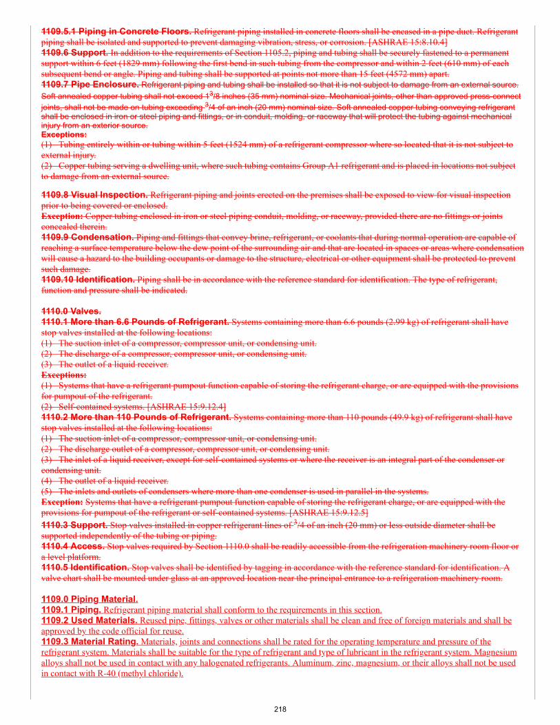
1109.5.1 Piping in Concrete Floors. Refrigerant piping installed in concrete floors shall be encased in a pipe duct. Refrigerantpiping shall be isolated and supported to prevent damaging vibration, stress, or corrosion. [ASHRAE 15:8.10.4]1109.6 Support. In addition to the requirements of Section 1105.2, piping and tubing shall be securely fastened to a permanentsupport within 6 feet (1829 mm) following the first bend in such tubing from the compressor and within 2 feet (610 mm) of eachsubsequent bend or angle. Piping and tubing shall be supported at points not more than 15 feet (4572 mm) apart.1109.7 Pipe Enclosure. Refrigerant piping and tubing shall be installed so that it is not subject to damage from an external source.Soft annealed copper tubing shall not exceed 13/8 inches (35 mm) nominal size. Mechanical joints, other than approved press-connectjoints, shall not be made on tubing exceeding 3/4 of an inch (20 mm) nominal size. Soft annealed copper tubing conveying refrigerantshall be enclosed in iron or steel piping and fittings, or in conduit, molding, or raceway that will protect the tubing against mechanicalinjury from an exterior source.Exceptions:(1) Tubing entirely within or tubing within 5 feet (1524 mm) of a refrigerant compressor where so located that it is not subject toexternal injury.(2) Copper tubing serving a dwelling unit, where such tubing contains Group A1 refrigerant and is placed in locations not subjectto damage from an external source.
1109.8 Visual Inspection. Refrigerant piping and joints erected on the premises shall be exposed to view for visual inspectionprior to being covered or enclosed.Exception: Copper tubing enclosed in iron or steel piping conduit, molding, or raceway, provided there are no fittings or jointsconcealed therein.1109.9 Condensation. Piping and fittings that convey brine, refrigerant, or coolants that during normal operation are capable ofreaching a surface temperature below the dew point of the surrounding air and that are located in spaces or areas where condensationwill cause a hazard to the building occupants or damage to the structure, electrical or other equipment shall be protected to preventsuch damage.1109.10 Identification. Piping shall be in accordance with the reference standard for identification. The type of refrigerant,function and pressure shall be indicated.
1110.0 Valves.1110.1 More than 6.6 Pounds of Refrigerant. Systems containing more than 6.6 pounds (2.99 kg) of refrigerant shall havestop valves installed at the following locations:(1) The suction inlet of a compressor, compressor unit, or condensing unit.(2) The discharge of a compressor, compressor unit, or condensing unit.(3) The outlet of a liquid receiver.Exceptions:(1) Systems that have a refrigerant pumpout function capable of storing the refrigerant charge, or are equipped with the provisionsfor pumpout of the refrigerant.(2) Self-contained systems. [ASHRAE 15:9.12.4]1110.2 More than 110 Pounds of Refrigerant. Systems containing more than 110 pounds (49.9 kg) of refrigerant shall havestop valves installed at the following locations:(1) The suction inlet of a compressor, compressor unit, or condensing unit.(2) The discharge outlet of a compressor, compressor unit, or condensing unit.(3) The inlet of a liquid receiver, except for self-contained systems or where the receiver is an integral part of the condenser orcondensing unit.(4) The outlet of a liquid receiver.(5) The inlets and outlets of condensers where more than one condenser is used in parallel in the systems.Exception: Systems that have a refrigerant pumpout function capable of storing the refrigerant charge, or are equipped with theprovisions for pumpout of the refrigerant or self-contained systems. [ASHRAE 15:9.12.5]1110.3 Support. Stop valves installed in copper refrigerant lines of 3/4 of an inch (20 mm) or less outside diameter shall besupported independently of the tubing or piping.1110.4 Access. Stop valves required by Section 1110.0 shall be readily accessible from the refrigeration machinery room floor ora level platform.1110.5 Identification. Stop valves shall be identified by tagging in accordance with the reference standard for identification. Avalve chart shall be mounted under glass at an approved location near the principal entrance to a refrigeration machinery room.
1109.0 Piping Material.1109.1 Piping. Refrigerant piping material shall conform to the requirements in this section.1109.2 Used Materials. Reused pipe, fittings, valves or other materials shall be clean and free of foreign materials and shall beapproved by the code official for reuse.1109.3 Material Rating. Materials, joints and connections shall be rated for the operating temperature and pressure of therefrigerant system. Materials shall be suitable for the type of refrigerant and type of lubricant in the refrigerant system. Magnesiumalloys shall not be used in contact with any halogenated refrigerants. Aluminum, zinc, magnesium, or their alloys shall not be usedin contact with R-40 (methyl chloride).
218
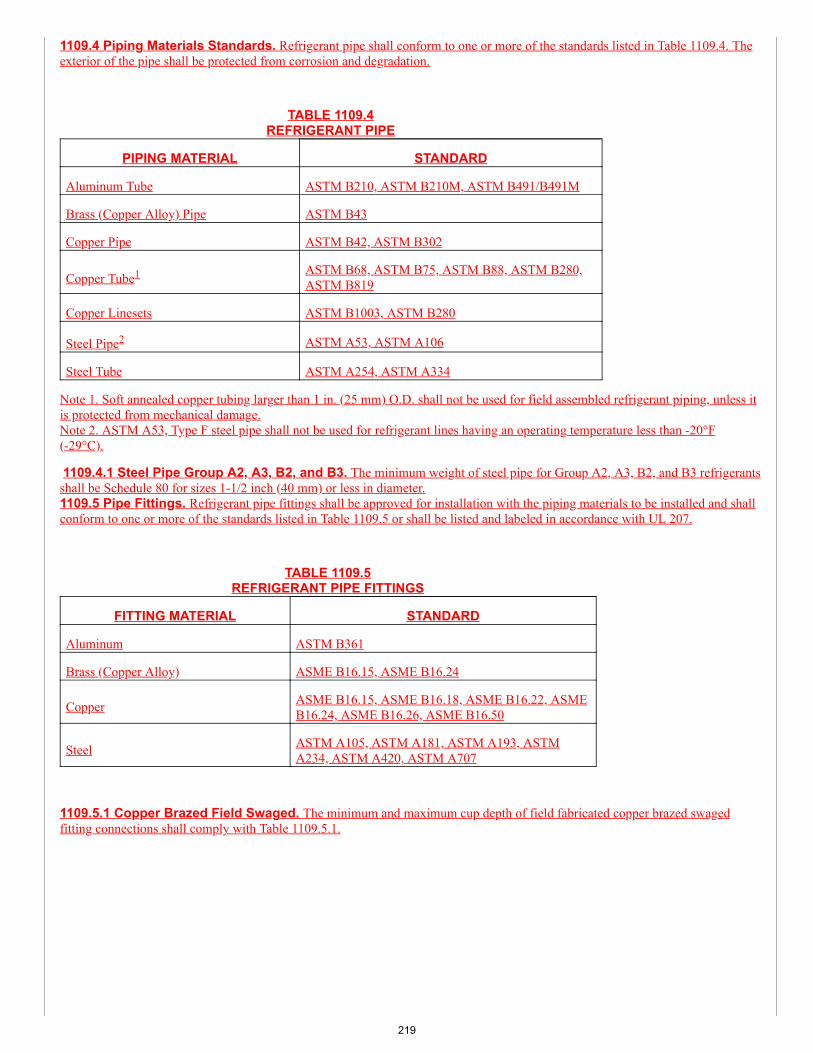
1109.4 Piping Materials Standards. Refrigerant pipe shall conform to one or more of the standards listed in Table 1109.4. Theexterior of the pipe shall be protected from corrosion and degradation.
TABLE 1109.4REFRIGERANT PIPE
PIPING MATERIAL STANDARD
Aluminum Tube ASTM B210, ASTM B210M, ASTM B491/B491M
Brass (Copper Alloy) Pipe ASTM B43
Copper Pipe ASTM B42, ASTM B302
Copper Tube1 ASTM B68, ASTM B75, ASTM B88, ASTM B280,ASTM B819
Copper Linesets ASTM B1003, ASTM B280
Steel Pipe2 ASTM A53, ASTM A106
Steel Tube ASTM A254, ASTM A334
Note 1. Soft annealed copper tubing larger than 1 in. (25 mm) O.D. shall not be used for field assembled refrigerant piping, unless itis protected from mechanical damage.Note 2. ASTM A53, Type F steel pipe shall not be used for refrigerant lines having an operating temperature less than -20°F(-29°C).
1109.4.1 Steel Pipe Group A2, A3, B2, and B3. The minimum weight of steel pipe for Group A2, A3, B2, and B3 refrigerantsshall be Schedule 80 for sizes 1-1/2 inch (40 mm) or less in diameter.1109.5 Pipe Fittings. Refrigerant pipe fittings shall be approved for installation with the piping materials to be installed and shallconform to one or more of the standards listed in Table 1109.5 or shall be listed and labeled in accordance with UL 207.
TABLE 1109.5REFRIGERANT PIPE FITTINGS
FITTING MATERIAL STANDARD
Aluminum ASTM B361
Brass (Copper Alloy) ASME B16.15, ASME B16.24
Copper ASME B16.15, ASME B16.18, ASME B16.22, ASMEB16.24, ASME B16.26, ASME B16.50
Steel ASTM A105, ASTM A181, ASTM A193, ASTMA234, ASTM A420, ASTM A707
1109.5.1 Copper Brazed Field Swaged. The minimum and maximum cup depth of field fabricated copper brazed swagedfitting connections shall comply with Table 1109.5.1.
219
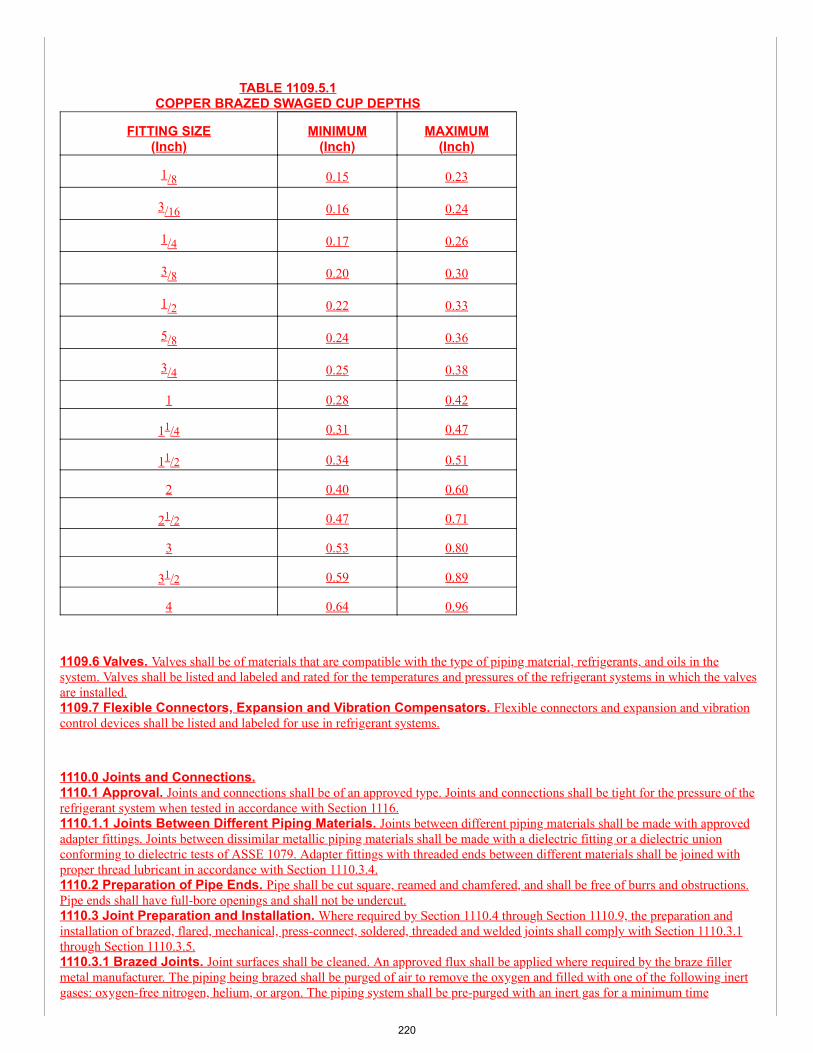
TABLE 1109.5.1COPPER BRAZED SWAGED CUP DEPTHS
FITTING SIZE(Inch)
MINIMUM(Inch)
MAXIMUM(Inch)
1/8 0.15 0.23
3/16 0.16 0.24
1/4 0.17 0.26
3/8 0.20 0.30
1/2 0.22 0.33
5/8 0.24 0.36
3/4 0.25 0.38
1 0.28 0.42
11/4 0.31 0.47
11/2 0.34 0.51
2 0.40 0.60
21/2 0.47 0.71
3 0.53 0.80
31/2 0.59 0.89
4 0.64 0.96
1109.6 Valves. Valves shall be of materials that are compatible with the type of piping material, refrigerants, and oils in thesystem. Valves shall be listed and labeled and rated for the temperatures and pressures of the refrigerant systems in which the valvesare installed.1109.7 Flexible Connectors, Expansion and Vibration Compensators. Flexible connectors and expansion and vibrationcontrol devices shall be listed and labeled for use in refrigerant systems.
1110.0 Joints and Connections.1110.1 Approval. Joints and connections shall be of an approved type. Joints and connections shall be tight for the pressure of therefrigerant system when tested in accordance with Section 1116.1110.1.1 Joints Between Different Piping Materials. Joints between different piping materials shall be made with approvedadapter fittings. Joints between dissimilar metallic piping materials shall be made with a dielectric fitting or a dielectric unionconforming to dielectric tests of ASSE 1079. Adapter fittings with threaded ends between different materials shall be joined withproper thread lubricant in accordance with Section 1110.3.4.1110.2 Preparation of Pipe Ends. Pipe shall be cut square, reamed and chamfered, and shall be free of burrs and obstructions.Pipe ends shall have full-bore openings and shall not be undercut.1110.3 Joint Preparation and Installation. Where required by Section 1110.4 through Section 1110.9, the preparation andinstallation of brazed, flared, mechanical, press-connect, soldered, threaded and welded joints shall comply with Section 1110.3.1through Section 1110.3.5.1110.3.1 Brazed Joints. Joint surfaces shall be cleaned. An approved flux shall be applied where required by the braze fillermetal manufacturer. The piping being brazed shall be purged of air to remove the oxygen and filled with one of the following inertgases: oxygen-free nitrogen, helium, or argon. The piping system shall be pre-purged with an inert gas for a minimum time
220
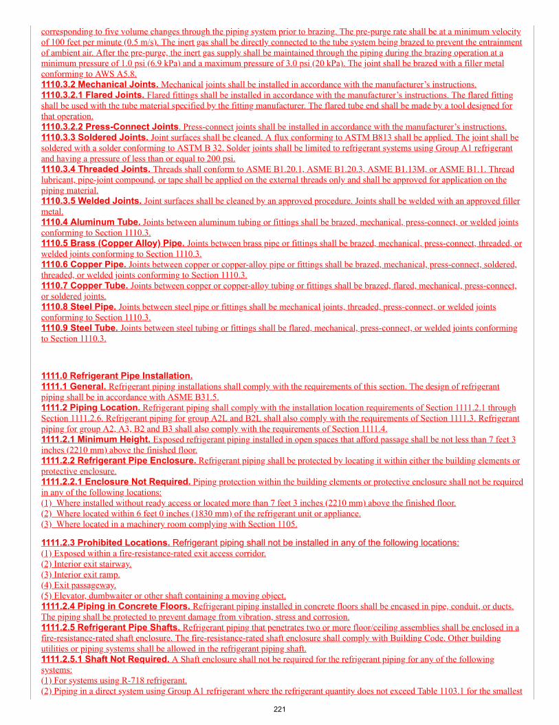
corresponding to five volume changes through the piping system prior to brazing. The pre-purge rate shall be at a minimum velocityof 100 feet per minute (0.5 m/s). The inert gas shall be directly connected to the tube system being brazed to prevent the entrainmentof ambient air. After the pre-purge, the inert gas supply shall be maintained through the piping during the brazing operation at aminimum pressure of 1.0 psi (6.9 kPa) and a maximum pressure of 3.0 psi (20 kPa). The joint shall be brazed with a filler metalconforming to AWS A5.8.1110.3.2 Mechanical Joints. Mechanical joints shall be installed in accordance with the manufacturer’s instructions.1110.3.2.1 Flared Joints. Flared fittings shall be installed in accordance with the manufacturer’s instructions. The flared fittingshall be used with the tube material specified by the fitting manufacturer. The flared tube end shall be made by a tool designed forthat operation.1110.3.2.2 Press-Connect Joints. Press-connect joints shall be installed in accordance with the manufacturer’s instructions.1110.3.3 Soldered Joints. Joint surfaces shall be cleaned. A flux conforming to ASTM B813 shall be applied. The joint shall besoldered with a solder conforming to ASTM B 32. Solder joints shall be limited to refrigerant systems using Group A1 refrigerantand having a pressure of less than or equal to 200 psi.1110.3.4 Threaded Joints. Threads shall conform to ASME B1.20.1, ASME B1.20.3, ASME B1.13M, or ASME B1.1. Threadlubricant, pipe-joint compound, or tape shall be applied on the external threads only and shall be approved for application on thepiping material.1110.3.5 Welded Joints. Joint surfaces shall be cleaned by an approved procedure. Joints shall be welded with an approved fillermetal.1110.4 Aluminum Tube. Joints between aluminum tubing or fittings shall be brazed, mechanical, press-connect, or welded jointsconforming to Section 1110.3.1110.5 Brass (Copper Alloy) Pipe. Joints between brass pipe or fittings shall be brazed, mechanical, press-connect, threaded, orwelded joints conforming to Section 1110.3.1110.6 Copper Pipe. Joints between copper or copper-alloy pipe or fittings shall be brazed, mechanical, press-connect, soldered,threaded, or welded joints conforming to Section 1110.3.1110.7 Copper Tube. Joints between copper or copper-alloy tubing or fittings shall be brazed, flared, mechanical, press-connect,or soldered joints.1110.8 Steel Pipe. Joints between steel pipe or fittings shall be mechanical joints, threaded, press-connect, or welded jointsconforming to Section 1110.3.1110.9 Steel Tube. Joints between steel tubing or fittings shall be flared, mechanical, press-connect, or welded joints conformingto Section 1110.3.
1111.0 Refrigerant Pipe Installation.1111.1 General. Refrigerant piping installations shall comply with the requirements of this section. The design of refrigerantpiping shall be in accordance with ASME B31.5.1111.2 Piping Location. Refrigerant piping shall comply with the installation location requirements of Section 1111.2.1 throughSection 1111.2.6. Refrigerant piping for group A2L and B2L shall also comply with the requirements of Section 1111.3. Refrigerantpiping for group A2, A3, B2 and B3 shall also comply with the requirements of Section 1111.4.1111.2.1 Minimum Height. Exposed refrigerant piping installed in open spaces that afford passage shall be not less than 7 feet 3inches (2210 mm) above the finished floor.1111.2.2 Refrigerant Pipe Enclosure. Refrigerant piping shall be protected by locating it within either the building elements orprotective enclosure.1111.2.2.1 Enclosure Not Required. Piping protection within the building elements or protective enclosure shall not be requiredin any of the following locations:(1) Where installed without ready access or located more than 7 feet 3 inches (2210 mm) above the finished floor.(2) Where located within 6 feet 0 inches (1830 mm) of the refrigerant unit or appliance.(3) Where located in a machinery room complying with Section 1105.
1111.2.3 Prohibited Locations. Refrigerant piping shall not be installed in any of the following locations:(1) Exposed within a fire-resistance-rated exit access corridor.(2) Interior exit stairway.(3) Interior exit ramp.(4) Exit passageway.(5) Elevator, dumbwaiter or other shaft containing a moving object.1111.2.4 Piping in Concrete Floors. Refrigerant piping installed in concrete floors shall be encased in pipe, conduit, or ducts.The piping shall be protected to prevent damage from vibration, stress and corrosion.1111.2.5 Refrigerant Pipe Shafts. Refrigerant piping that penetrates two or more floor/ceiling assemblies shall be enclosed in afire-resistance-rated shaft enclosure. The fire-resistance-rated shaft enclosure shall comply with Building Code. Other buildingutilities or piping systems shall be allowed in the refrigerant piping shaft.1111.2.5.1 Shaft Not Required. A Shaft enclosure shall not be required for the refrigerant piping for any of the followingsystems:(1) For systems using R-718 refrigerant.(2) Piping in a direct system using Group A1 refrigerant where the refrigerant quantity does not exceed Table 1103.1 for the smallest
221
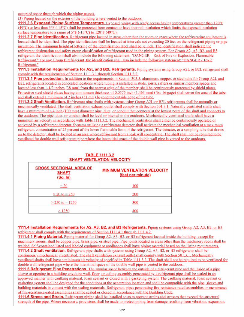
occupied space through which the piping passes.(3) Piping located on the exterior of the building where vented to the outdoors.1111.2.6 Exposed Piping Surface Temperature. Exposed piping with ready access having temperatures greater than 120°F(49°C) or less than 5°F (-15°C) shall be protected from contact or have thermal insulation which limits the exposed insulationsurface temperature to a range of 5°F (-15°C) to 120°F (49°C).1111.2.7 Pipe Identification. Refrigerant pipe located in areas other than the room or space where the refrigerating equipment islocated shall be identified. The pipe identification shall be located at intervals not exceeding 20 feet on the refrigerant piping or pipeinsulation. The minimum height of lettering of the identification label shall be ½ inch. The identification shall indicate therefrigerant designation and safety group classification of refrigerant used in the piping system. For Group A2, A3, B2, and B3refrigerant the identification shall also include the following statement: "DANGER – Risk of Fire or Explosion. FlammableRefrigerant." For any Group B refrigerant, the identification shall also include the following statement: "DANGER - ToxicRefrigerant."1111.3 Installation Requirements for A2L and B2L Refrigerants. Piping systems using Group A2L or B2L refrigerant shallcomply with the requirements of Section 1111.3.1 through Section 1111.3.2.1111.3.1 Pipe protection. In addition to the requirements in Section 305.5, aluminum, copper, or steel tube for Group A2L andB2L refrigerants located in concealed locations where tubing is installed in studs, joists, rafters or similar member spaces andlocated less than 1-1/2 inches (38 mm) from the nearest edge of the member, shall be continuously protected by shield plates.Protective steel shield plates having a minimum thickness of 0.0575 inch (1.463 mm) (No. 16 gage) shall cover the area of the tube,and shall extend a minimum of 2 inches (51 mm) beyond the outside edge of the tube.1111.3.2 Shaft Ventilation. Refrigerant pipe shafts with systems using Group A2L or B2L refrigerants shall be naturally ormechanically ventilated. The shaft ventilation exhaust outlet shall comply with Section 501.3.1. Naturally ventilated shafts shallhave a minimum of a 4 inch (100 mm) diameter pipe, duct, or conduit that connects at the lowest point of the shaft and connects tothe outdoors. The pipe, duct, or conduit shall be level or pitched to the outdoors. Mechanically ventilated shafts shall have aminimum air velocity in accordance with Table 1111.3.2. The mechanical ventilation shall either be continuously operated oractivated by a refrigerant detector. Systems utilizing a refrigerant detector shall activate the mechanical ventilation at a maximumrefrigerant concentration of 25 percent of the lower flammable limit of the refrigerant. The detector, or a sampling tube that drawsair to the detector, shall be located in an area where refrigerant from a leak will concentrate. The shaft shall not be required to beventilated for double wall refrigerant pipe where the interstitial space of the double wall pipe is vented to the outdoors.
TABLE 1111.3.2SHAFT VENTILATION VELOCITY
CROSS SECTIONAL AREA OFSHAFT(Sq. In)
MINIMUM VENTILATION VELOCITY(feet per minute)
= 20 100
> 20 to = 250 200
> 250 to = 1250 300
> 1250 400
1111.4 Installation Requirements for A2, A3, B2, and B3 Refrigerants. Piping systems using Group A2, A3, B2, or B3refrigerant shall comply with the requirements of Section 1111.4.1 through 1111.4.2.1111.4.1 Piping Material. Piping material for Group A2, A3, B2, or B3 refrigerant located inside the building, except formachinery rooms, shall be copper pipe, brass pipe, or steel pipe. Pipe joints located in areas other than the machinery room shall bewelded. Self-contained listed and labeled equipment or appliances shall have piping material based on the listing requirements.1111.4.2 Shaft ventilation. Refrigerant pipe shafts with systems using Group A2, A3, B2, or B3 refrigerants shall becontinuously mechanically ventilated. The shaft ventilation exhaust outlet shall comply with Section 501.3.1. Mechanicallyventilated shafts shall have a minimum air velocity of specified in Table 1111.3.2. The shaft shall not be required to be ventilated fordouble wall refrigerant pipe where the interstitial space of the double wall pipe is vented to the outdoors.1111.5 Refrigerant Pipe Penetrations. The annular space between the outside of a refrigerant pipe and the inside of a pipesleeve or opening in a building envelope wall, floor, or ceiling assembly penetrated by a refrigerant pipe shall be sealed in anapproved manner with caulking material, foam sealant or closed with a gasketing system. The caulking material, foam sealant orgasketing system shall be designed for the conditions at the penetration location and shall be compatible with the pipe, sleeve andbuilding materials in contact with the sealing materials. Refrigerant pipes penetrating fire-resistance-rated assemblies or membranesof fire-resistance-rated assemblies shall be sealed or closed in accordance with the Building Code.1111.6 Stress and Strain. Refrigerant piping shall be installed so as to prevent strains and stresses that exceed the structuralstrength of the pipe. Where necessary, provisions shall be made to protect piping from damage resulting from vibration, expansion,
222
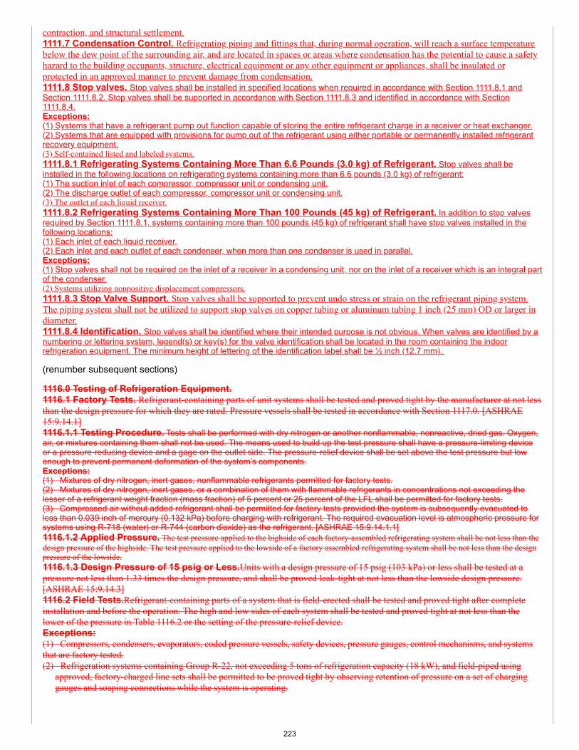
contraction, and structural settlement.1111.7 Condensation Control. Refrigerating piping and fittings that, during normal operation, will reach a surface temperaturebelow the dew point of the surrounding air, and are located in spaces or areas where condensation has the potential to cause a safetyhazard to the building occupants, structure, electrical equipment or any other equipment or appliances, shall be insulated orprotected in an approved manner to prevent damage from condensation.1111.8 Stop valves. Stop valves shall be installed in specified locations when required in accordance with Section 1111.8.1 andSection 1111.8.2. Stop valves shall be supported in accordance with Section 1111.8.3 and identified in accordance with Section1111.8.4.Exceptions:(1) Systems that have a refrigerant pump out function capable of storing the entire refrigerant charge in a receiver or heat exchanger.(2) Systems that are equipped with provisions for pump out of the refrigerant using either portable or permanently installed refrigerantrecovery equipment.(3) Self-contained listed and labeled systems.1111.8.1 Refrigerating Systems Containing More Than 6.6 Pounds (3.0 kg) of Refrigerant. Stop valves shall beinstalled in the following locations on refrigerating systems containing more than 6.6 pounds (3.0 kg) of refrigerant:(1) The suction inlet of each compressor, compressor unit or condensing unit.(2) The discharge outlet of each compressor, compressor unit or condensing unit.(3) The outlet of each liquid receiver.1111.8.2 Refrigerating Systems Containing More Than 100 Pounds (45 kg) of Refrigerant. In addition to stop valvesrequired by Section 1111.8.1, systems containing more than 100 pounds (45 kg) of refrigerant shall have stop valves installed in thefollowing locations:(1) Each inlet of each liquid receiver.(2) Each inlet and each outlet of each condenser, when more than one condenser is used in parallel.Exceptions:(1) Stop valves shall not be required on the inlet of a receiver in a condensing unit, nor on the inlet of a receiver which is an integral partof the condenser.(2) Systems utilizing nonpositive displacement compressors.1111.8.3 Stop Valve Support. Stop valves shall be supported to prevent undo stress or strain on the refrigerant piping system.The piping system shall not be utilized to support stop valves on copper tubing or aluminum tubing 1 inch (25 mm) OD or larger indiameter.1111.8.4 Identification. Stop valves shall be identified where their intended purpose is not obvious. When valves are identified by anumbering or lettering system, legend(s) or key(s) for the valve identification shall be located in the room containing the indoorrefrigeration equipment. The minimum height of lettering of the identification label shall be ½ inch (12.7 mm).
(renumber subsequent sections)
1116.0 Testing of Refrigeration Equipment.1116.1 Factory Tests. Refrigerant-containing parts of unit systems shall be tested and proved tight by the manufacturer at not lessthan the design pressure for which they are rated. Pressure vessels shall be tested in accordance with Section 1117.0. [ASHRAE15:9.14.1]1116.1.1 Testing Procedure. Tests shall be performed with dry nitrogen or another nonflammable, nonreactive, dried gas. Oxygen,air, or mixtures containing them shall not be used. The means used to build up the test pressure shall have a pressure-limiting deviceor a pressure-reducing device and a gage on the outlet side. The pressure-relief device shall be set above the test pressure but lowenough to prevent permanent deformation of the system’s components.Exceptions:(1) Mixtures of dry nitrogen, inert gases, nonflammable refrigerants permitted for factory tests.(2) Mixtures of dry nitrogen, inert gases, or a combination of them with flammable refrigerants in concentrations not exceeding thelesser of a refrigerant weight fraction (mass fraction) of 5 percent or 25 percent of the LFL shall be permitted for factory tests.(3) Compressed air without added refrigerant shall be permitted for factory tests provided the system is subsequently evacuated toless than 0.039 inch of mercury (0.132 kPa) before charging with refrigerant. The required evacuation level is atmospheric pressure forsystems using R-718 (water) or R-744 (carbon dioxide) as the refrigerant. [ASHRAE 15:9.14.1.1]1116.1.2 Applied Pressure. The test pressure applied to the highside of each factory-assembled refrigerating system shall be not less than thedesign pressure of the highside. The test pressure applied to the lowside of a factory assembled refrigerating system shall be not less than the designpressure of the lowside.1116.1.3 Design Pressure of 15 psig or Less.Units with a design pressure of 15 psig (103 kPa) or less shall be tested at apressure not less than 1.33 times the design pressure, and shall be proved leak-tight at not less than the lowside design pressure.[ASHRAE 15:9.14.3]1116.2 Field Tests.Refrigerant-containing parts of a system that is field-erected shall be tested and proved tight after completeinstallation and before the operation. The high and low sides of each system shall be tested and proved tight at not less than thelower of the pressure in Table 1116.2 or the setting of the pressure-relief device.Exceptions:(1) Compressors, condensers, evaporators, coded pressure vessels, safety devices, pressure gauges, control mechanisms, and systemsthat are factory tested.(2) Refrigeration systems containing Group R-22, not exceeding 5 tons of refrigeration capacity (18 kW), and field-piped using
approved, factory-charged line sets shall be permitted to be proved tight by observing retention of pressure on a set of charginggauges and soaping connections while the system is operating.
223
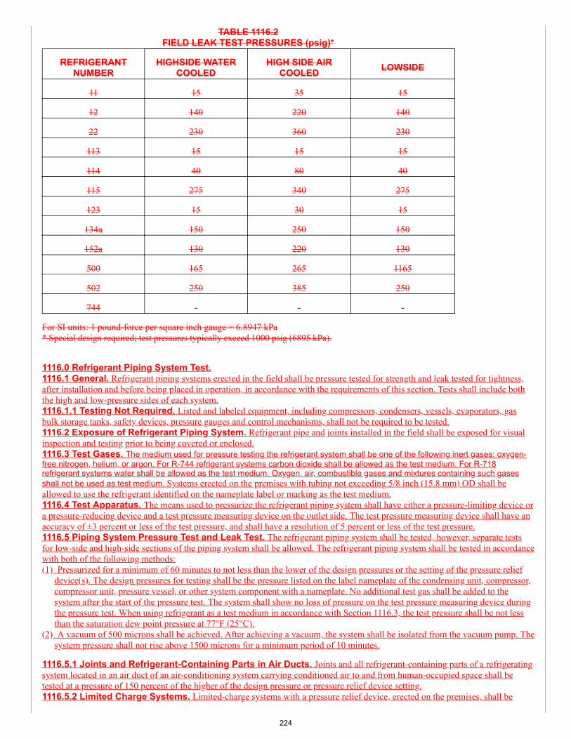
TABLE 1116.2FIELD LEAK TEST PRESSURES (psig)*
REFRIGERANTNUMBER
HIGHSIDE WATERCOOLED
HIGH SIDE AIRCOOLED LOWSIDE
11 15 35 15
12 140 220 140
22 230 360 230
113 15 15 15
114 40 80 40
115 275 340 275
123 15 30 15
134a 150 250 150
152a 130 220 130
500 165 265 1165
502 250 385 250
744 - - -
For SI units: 1 pound-force per square inch gauge = 6.8947 kPa* Special design required; test pressures typically exceed 1000 psig (6895 kPa).
1116.0 Refrigerant Piping System Test.1116.1 General. Refrigerant piping systems erected in the field shall be pressure tested for strength and leak tested for tightness,after installation and before being placed in operation, in accordance with the requirements of this section. Tests shall include boththe high and low-pressure sides of each system.1116.1.1 Testing Not Required. Listed and labeled equipment, including compressors, condensers, vessels, evaporators, gasbulk storage tanks, safety devices, pressure gauges and control mechanisms, shall not be required to be tested.1116.2 Exposure of Refrigerant Piping System. Refrigerant pipe and joints installed in the field shall be exposed for visualinspection and testing prior to being covered or enclosed.1116.3 Test Gases. The medium used for pressure testing the refrigerant system shall be one of the following inert gases: oxygen-free nitrogen, helium, or argon. For R-744 refrigerant systems carbon dioxide shall be allowed as the test medium. For R-718refrigerant systems water shall be allowed as the test medium. Oxygen, air, combustible gases and mixtures containing such gasesshall not be used as test medium. Systems erected on the premises with tubing not exceeding 5/8 inch (15.8 mm) OD shall beallowed to use the refrigerant identified on the nameplate label or marking as the test medium.1116.4 Test Apparatus. The means used to pressurize the refrigerant piping system shall have either a pressure-limiting device ora pressure-reducing device and a test pressure measuring device on the outlet side. The test pressure measuring device shall have anaccuracy of ±3 percent or less of the test pressure, and shall have a resolution of 5 percent or less of the test pressure.1116.5 Piping System Pressure Test and Leak Test. The refrigerant piping system shall be tested, however, separate testsfor low-side and high-side sections of the piping system shall be allowed. The refrigerant piping system shall be tested in accordancewith both of the following methods:(1) Pressurized for a minimum of 60 minutes to not less than the lower of the design pressures or the setting of the pressure relief
device(s). The design pressures for testing shall be the pressure listed on the label nameplate of the condensing unit, compressor,compressor unit, pressure vessel, or other system component with a nameplate. No additional test gas shall be added to thesystem after the start of the pressure test. The system shall show no loss of pressure on the test pressure measuring device duringthe pressure test. When using refrigerant as a test medium in accordance with Section 1116.3, the test pressure shall be not lessthan the saturation dew point pressure at 77°F (25°C).
(2) A vacuum of 500 microns shall be achieved. After achieving a vacuum, the system shall be isolated from the vacuum pump. Thesystem pressure shall not rise above 1500 microns for a minimum period of 10 minutes.
1116.5.1 Joints and Refrigerant-Containing Parts in Air Ducts. Joints and all refrigerant-containing parts of a refrigeratingsystem located in an air duct of an air-conditioning system carrying conditioned air to and from human-occupied space shall betested at a pressure of 150 percent of the higher of the design pressure or pressure relief device setting.1116.5.2 Limited Charge Systems. Limited-charge systems with a pressure relief device, erected on the premises, shall be
224
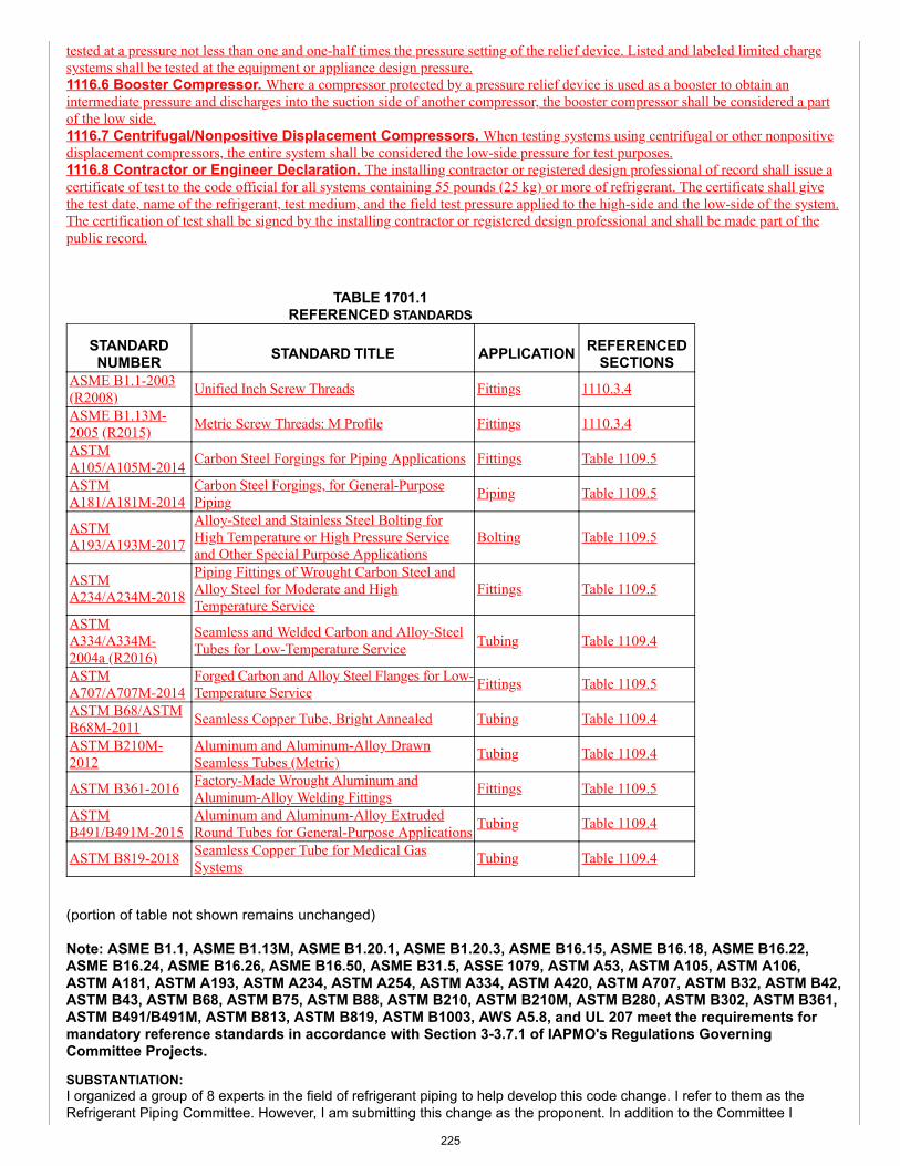
tested at a pressure not less than one and one-half times the pressure setting of the relief device. Listed and labeled limited chargesystems shall be tested at the equipment or appliance design pressure.1116.6 Booster Compressor. Where a compressor protected by a pressure relief device is used as a booster to obtain anintermediate pressure and discharges into the suction side of another compressor, the booster compressor shall be considered a partof the low side.1116.7 Centrifugal/Nonpositive Displacement Compressors. When testing systems using centrifugal or other nonpositivedisplacement compressors, the entire system shall be considered the low-side pressure for test purposes.1116.8 Contractor or Engineer Declaration. The installing contractor or registered design professional of record shall issue acertificate of test to the code official for all systems containing 55 pounds (25 kg) or more of refrigerant. The certificate shall givethe test date, name of the refrigerant, test medium, and the field test pressure applied to the high-side and the low-side of the system.The certification of test shall be signed by the installing contractor or registered design professional and shall be made part of thepublic record.
TABLE 1701.1REFERENCED STANDARDS
STANDARDNUMBER STANDARD TITLE APPLICATION REFERENCED
SECTIONSASME B1.1-2003(R2008) Unified Inch Screw Threads Fittings 1110.3.4
ASME B1.13M-2005 (R2015) Metric Screw Threads: M Profile Fittings 1110.3.4
ASTMA105/A105M-2014 Carbon Steel Forgings for Piping Applications Fittings Table 1109.5
ASTMA181/A181M-2014
Carbon Steel Forgings, for General-PurposePiping Piping Table 1109.5
ASTMA193/A193M-2017
Alloy-Steel and Stainless Steel Bolting forHigh Temperature or High Pressure Serviceand Other Special Purpose Applications
Bolting Table 1109.5
ASTMA234/A234M-2018
Piping Fittings of Wrought Carbon Steel andAlloy Steel for Moderate and HighTemperature Service
Fittings Table 1109.5
ASTMA334/A334M-2004a (R2016)
Seamless and Welded Carbon and Alloy-SteelTubes for Low-Temperature Service Tubing Table 1109.4
ASTMA707/A707M-2014
Forged Carbon and Alloy Steel Flanges for Low-Temperature Service Fittings Table 1109.5
ASTM B68/ASTMB68M-2011 Seamless Copper Tube, Bright Annealed Tubing Table 1109.4
ASTM B210M-2012
Aluminum and Aluminum-Alloy DrawnSeamless Tubes (Metric) Tubing Table 1109.4
ASTM B361-2016 Factory-Made Wrought Aluminum andAluminum-Alloy Welding Fittings Fittings Table 1109.5
ASTMB491/B491M-2015
Aluminum and Aluminum-Alloy ExtrudedRound Tubes for General-Purpose Applications Tubing Table 1109.4
ASTM B819-2018 Seamless Copper Tube for Medical GasSystems Tubing Table 1109.4
(portion of table not shown remains unchanged)
Note: ASME B1.1, ASME B1.13M, ASME B1.20.1, ASME B1.20.3, ASME B16.15, ASME B16.18, ASME B16.22,ASME B16.24, ASME B16.26, ASME B16.50, ASME B31.5, ASSE 1079, ASTM A53, ASTM A105, ASTM A106,ASTM A181, ASTM A193, ASTM A234, ASTM A254, ASTM A334, ASTM A420, ASTM A707, ASTM B32, ASTM B42,ASTM B43, ASTM B68, ASTM B75, ASTM B88, ASTM B210, ASTM B210M, ASTM B280, ASTM B302, ASTM B361,ASTM B491/B491M, ASTM B813, ASTM B819, ASTM B1003, AWS A5.8, and UL 207 meet the requirements formandatory reference standards in accordance with Section 3-3.7.1 of IAPMO's Regulations GoverningCommittee Projects.
SUBSTANTIATION:I organized a group of 8 experts in the field of refrigerant piping to help develop this code change. I refer to them as theRefrigerant Piping Committee. However, I am submitting this change as the proponent. In addition to the Committee I
225
created, I circulated a draft to other experts in the field of refrigeration. I received a number of comments through that review.Those comments have been incorporated in the final text that I am submitting.
It is the intent of the Refrigerant Piping Committee to submit a similar change to ASHRAE 15. A change has already beensubmitted to the IMC. The goal is to update all refrigerant piping requirements addressing every type of refrigerant systemother than ammonia.
This proposed change reorganizes and updates the requirements for refrigerant piping. Many of the requirements remain thesame as in the current code. The change follows the Manual of Style for listing piping material, joints and connections, andinstallation requirements.
Section 1109 is the piping material section. Section 1109.1 is the general section indicating that compliance to the section formaterial requirements. It should be understood that ammonia piping requirements are regulated by IIAR 2. The codecurrently requires compliance with IIAR 2 for ammonia systems. Hence, these requirements do not cover ammoniarefrigerant piping systems.
There is currently no section regarding used materials, yet other chapters include requirements for used materials. Thissection is similar to the used material requirements in other chapters.
Section 1109.3 is a general requirement for the piping material to be rated for the temperatures, pressures, and type ofrefrigerant. The aluminum, zinc, and magnesium alloys exception for R-40 (methyl chloride) is the same as the currentSection 1109.1.3. The same is true for magnesium alloys which cannot be used with any halogenated refrigerants since thematerial will react and fail.
Section 1109.4 includes a table for listing all of the acceptable piping material. The appropriate standards for the pipingmaterial are listed in the table. While the word brass was previously convert to copper alloy throughout the code, ASTM B43is still identified as a brass pipe standard. Therefore, brass was used with copper alloy included in parenthesis.
The current code has a restriction on the use of mechanical joints with annealed copper tubing. This is a hold overrequirement that is out of date. ASME B31.5 has a different limitation. Note 1 to the table includes the requirements listed inASME B31.5.
Note 2 of the table currently appears in in the code. The requirement remains the same.
Section 1109.5 includes a table of the fitting standards used in refrigerant piping systems. Some of the standards are new tothis chapter since the previous requirements were weak with regard to referencing the appropriate fitting standards. There isalso a general reference to UL 207. There are refrigerant fittings that do not meet fitting standard, however, they are listed toUL 207. This is an appropriate standard for specialty type of refrigerant fittings.
Copper tubing is a common material used in refrigerant piping systems. A common joint is a swaged fitting which is made inthe field. Since the swaging of copper expands the wall of the pipe, thus weakening the outer tube of the joint where notsupported by the joint filler material and inner tube, the depth of the swage must be included. This depth is similar to thebrazed fitting cup depths in the ASME B16.50 standard. The maximum depth allows a 50% increase in cup depth. A greaterdepth will result in too weak a pipe wall.
Section 1109.6 adds requirements for valves. The current code has valve installation requirements but is missing valvematerial requirements.
Section 1109.7 adds material requirements for flexible connectors and expansion and vibration compensators. Thesecomponents are required to be listed and labeled for refrigerant systems.
Section 1110 is organized with general requirements in the beginning, followed by joining methods, and completed withpiping material allowances of various joining methods. Many of the requirements are new since the current coderequirements are not up to date.
Section 1110.1 is the general section on joints requiring them to be approved and meet the tightness requirements to passthe system test.
Section 1110.1.1 lists requirements for joints between different materials. A reference to the testing requirements in ASSE1079 is made in the section for joints between dissimilar metals. The standard has appropriate testing requirements fordielectric tests that can be used on refrigeration piping systems even though the standard appears to address water pipingsystems.
226
Section 1110.2 is similar to the preparation of pipe ends found in other chapters. The same requirements would apply torefrigerant piping.
Section 1110.3 lists all of the acceptable joining methods. For brazing, there are requirements for using an inert gas insidethe piping. This prevents oxidation on the interior of the piping. If there is excessive oxidation, it could result in obstruction ofsmall piping or components in the system, as well as other system chemistry degradation, increasing the probability of futurerepair work. Reducing the frequency of opening refrigerating systems for repair reduces the exposure to numerous hazardsand risks. For many of the joints, a reference to UL 207 is included. This standard covers the various refrigerant joiningmethods. The press-connect refrigerant fittings are listed to this standard, as are many mechanical joints.
Section 1110.3.4 includes all of the various threads that are used in refrigerant piping systems. This expands the listing ofASME standards for threaded joints.
Section 1110.4 through Section 1110.9 list each material and the acceptable joining methods for the particular material.
The piping installation requirements are listed in a separate section from the material and joints and connections. The pipingrequirements have been expanded to address the necessary safety measures to assure a proper piping installation.
With a greater use of VRV and VRF systems, there is significantly more refrigerant piping installed inside a building.Additionally, with split systems and multi-split systems in multistory residential buildings, there is also a significant amount ofpiping installed.
There will be an expanded use of Group A2L refrigerants that are low global warming potential refrigerants. Theserefrigerants were previously listed as a subgroup of A2 refrigerants. As a separate group, the requirements need to beprovided to address the installation of piping with Group A2L refrigerants.
The new section on piping is divided into four main subject matters. The first part of the section addresses pipingrequirements for all types of refrigerants being used. The second part is for Group A2L and B2L refrigerants. The third part isfor piping requirements for Group A2, A3, B2, and B3 refrigerants. The last part has additional general requirements forpiping installations.
Section 1111.1 includes a reference to ASME B31.5. This standard is currently referenced in Section 1109.1. There is nochange regarding the application of ASME B31.5.
Section 1111.2 identifies which sections are applicable to which refrigerant groups.
Section 1111.2.1 is a rewording of the requirements currently found in Section 1109.4.
Section 1111.2.2 is a new section requiring refrigerant piping to be concealed within the building elements. While this isimplied in the current code, it is not stated. Section 1111.2.2.1, allowing refrigerant piping to be exposed, is similar to thecurrent allowance specified in Section 1109.4 and Section 1109.4.1. The other allowance would be refrigerant piping locatedin a machinery room. Exposed piping is anticipated in a machinery room where access is restricted to authorized personnel.
Section 1111.2.3 is similar to current Section 1109.2. One of the changes is the allowance for refrigerant piping to be locatedin the ceiling of a corridor, hence, not exposed. This appears to be implied, however, when the ceiling space is considered apart of the corridor, it appears to be prohibited. Refrigerant piping, especially for multi-split systems is often installed in theceiling of a corridor. If the RCL requirements are met, there is no hazard posed to the corridor.
Section 1111.2.4 is a duplication of the requirements currently found in Section 1109.5.1.
Section 1111.2.5 is a new section regulating the requirements for shaft containing refrigerant piping. A fire-resistance-ratedshaft will be required when the refrigerant piping connects three or more stories. Other utilities can also be located within thesame shaft. There are three exceptions proposed to the shaft requirements in Section 1111.2.5.1, one is when water is use,that is R718 refrigerant. The second is for the use of Group A1 refrigerants provided the smallest space in which the pipepass meets the RCL requirements for the refrigerant. The last exception is for when the piping is installed on the outside ofthe building where any leak would vent to atmosphere.
Section 1111.2.6 is also a new requirement. This section is intended to protect an individual from directly contacting a hot orcold refrigerant pipe. The temperatures are based on avoiding burning the skin or causing frostbite or frost damage to theskin. One of the methods of protection would adding insulation around the pipe. This is the most common method ofprotection for exposed piping.
Section 1111.2.7 lists the requirements for identifying the piping material. Since Group B refrigerant is toxic, there are special
227
requirements to label the pipe as containing toxic refrigerant. For flammable refrigerants, Group A2 and A3, the piping mustindicate that the refrigerant is flammable and there is a risk of fire or explosion.
Section 1111.3 is a new section regulating the installation of piping using Group A2L or B2L refrigerants. These refrigerantsare lower flammable, lower burning velocity refrigerants. While the refrigerant will burn, it doesn’t ignite or burn very easily.Since it is flammable additional protection requirements are proposed.
Section 1111.3.1 will require continuous protection when the piping is located within 1-1/2 inches of the nearest edge of amember. Currently the code requires a level of protection in Section 316 for certain locations, such as the top plate andbottom plate. This section will require the protection where ever the piping is installed. The protection is intended to preventthe tubing from be punctured by a nail or screw.
Section 1111.3.2 requires ventilation of the shaft in which the refrigerant piping is located. A minimal movement of air willexhaust the leaking refrigerant out of the shaft. The velocity rates identified in Table 1111.3.2 are taken from a peer reviewedpaper published by ASME and ensure that density differences between air and refrigerant will not defeat the purpose toexhaust the released refrigerant out of the shaft, whether in horizontal or vertical shaft orientation.
The ventilation would only be required when there is a leak of refrigerant. A leak detector is required in the shaft to identifywhen a leak occurs. Another option would be to naturally ventilate the shaft or continuously ventilate the shaft. Since mostrefrigerants are heavier than air, they tend to move downward. If naturally ventilated, the refrigerant moves to outside thebuilding. An exception to the ventilation requirements would be the use of double wall pipe. While this is not commonlyinstalled, the possibility exists that there will be greater use of double wall pipe.
Section 1111.4 has the special requirement for the more flammable and more toxic refrigerants. Section 1111.4.1 requires thesystems to be installed using only pipe, not tubing. The added strength of the pipe will reduce any potential leak from apuncture. The exception to this requirement would be self-contained listed equipment. Some refrigerators and similarappliances are using Group A3 refrigerants. However, these appliances are tested and listed.
Section 1111.4.2 requires any shaft with these refrigerants to be continuously ventilated. The same velocity requirementsapply to this group of refrigerants as Group A2L and B2L. There is also an exception for double wall pipe.
Section 1111.5 is a new section regulating pipe penetrations. Any time a pipe penetrated a wall, floor, or ceiling, it must besealed to prevent the passage of any refrigerant that may be leaking. There is a direct reference to the building code forpenetrations of fire-resistance-rated assemblies.
Section 1111.6 is a new requirement for pipe protection. These requirements are similar to other piping systems in theMechanical Code and the Plumbing Code. The requirements are also applicable to refrigerant piping.
Section 1111.7 through Section 1111.8.4 are rewording and relocation of current Section 1109.9, Section 1109.10, andSection 1110.0.
The Refrigerant Piping Committee spent a considerable amount of time rewriting and discussing the testing requirements.The basis for Section 1116 is the current Section 1116. The key elements of Section 1116 are captured in the new section.The significant differences relate to the test medium, the test equipment, and the pressure and vacuum test.
The test gas is specified as being either oxygen-free nitrogen, helium, or argon. These are the three inert gases used fortesting refrigerant piping systems. Carbon dioxide refrigerant systems are permitted to be tested with carbon dioxide. Waterrefrigerant piping systems are permitted to be tested with water.
For smaller systems, refrigerant contractors have used the refrigerant for testing. This would be permitted for systems having5/8 inch or smaller tubing.
The accuracy of the test gage is not currently specified. Most test gages used by refrigerant contractors have an accuracywithin 2-1/2 percent. The allowance for up to 3 percent takes into consideration other gages that may be used.
For the testing of the system, the Committee believes it is important to run two tests; one is a pressure test, the other is avacuum test. When testing with internal pressures, a one-way leak in the reverse direction may not be discovered. However,when a vacuum is placed on the system, the leak will be identified. The standard test for refrigerant systems is one hour forpressure and 10 minutes for a vacuum. These tests have been added to the section.
COMMITTEE ACTION: REJECT
228
Item #: 096
Comment #: 1
COMMITTEE STATEMENT:The proposed change contains overly stringent language. Furthermore, Table 1109.5.1 is overly restrictive and is not user-friendly.
TOTAL ELIGIBLE TO VOTE: 26
VOTING RESULTS: AFFIRMATIVE: 25 NOT RETURNED: 1 HOWARD
Appended Comments
Edit Comment
PUBLIC COMMENT 1
Code Year: 2021 UMC Section #: 1109.0 - 1116.8, Table 1701.1
SUBMITTER: Julius BallancoJB Engineering and Code Consulting, P.C.Rep. Daikin US
RECOMMENDATION:Revise text
Request to replace the code change proposal by this public comment.
1109.0 Refrigeration Piping, Containers, and Valves.1109.1 Materials. Materials used in the construction and installation of refrigerating systems shall be compatible with theconveying refrigerant used. Materials shall not be used that will deteriorate due to the chemical action of the refrigerant, lubricant, orcombination of both where exposed to air or moisture to a degree that poses a safety hazard. [ASHRAE 15:9.1.1] Refrigerant pipingshall be metallic.1109.1.1 Copper and Copper Alloy Pipe. Copper and copper alloy refrigeration piping, valves, fittings, and related parts used inthe construction and installation of refrigeration systems shall be approved for the intended use. Refrigeration piping shall complywith ASME B31.5.1109.1.2 Copper Linesets. Copper linesets shall comply with ASTM B280 or ASTM B1003.1109.1.3 Iron and Steel. Iron and steel refrigeration piping, valves, fittings, and related parts shall be approved for the intendeduse. Pipe exceeding 2 inches (50 mm) iron pipe size shall be electric-resistance welded or seamless pipe. Refrigeration piping shallcomply with ASME B31.5.1109.1.4 Prohibited Contact. Aluminum, zinc, magnesium, or their alloys shall not be used in contact with methyl chloride.Magnesium alloys shall not be used where in contact with halogenated refrigerants. [ASHRAE 15:9.1.2]1109.2 Joints. Iron or steel pipe joints shall be of approved threaded, flanged, or welded types. Exposed threads shall be tinned orcoated with an approved corrosion inhibitor. Copper or copper alloy pipe joints of iron pipe size shall be of approved threaded,flanged, press-connect or brazed types. Copper tubing joints and connections shall be connected by approved flared, lapped, swaged,or brazed joints, soldered joints, or mechanical joints that comply with UL 207 either individually or as part of an assembly or asystem by an approved nationally recognized laboratory. Piping and tubing shall be installed so as to prevent vibration and strains atjoints and connections.1109.3 Penetration of Piping. Refrigerant piping shall not penetrate floors, ceilings, or roofs.Exceptions:(1) Penetrations connecting the basement and the first floor.(2) Penetrations connecting the top floor and a machinery penthouse or roof installation.(3) Penetrations connecting adjacent floors served by the refrigeration system.(4) Penetrations of a direct system where the refrigerant concentration does not exceed that listed in Table 1102.3 for the smallestoccupied space through which the refrigerant piping passes.(5) In other than industrial occupancies and where the refrigerant concentration exceeds that listed in Table 1102.3 for the smallestoccupied space, penetrations that connect separate pieces of equipment that are in accordance with one of the following:(a) Enclosed by an approved gastight, fire-resistive duct or shaft with openings to those floors served by the refrigerating system.(b) Located on the exterior wall of a building where vented to the outdoors or to the space served by the system and not used as anair shaft, closed court, or similar space. [ASHRAE 15:8.10.3]1109.4 Location of Refrigeration Piping. Refrigerant piping crossing an open space that affords passageway in a building shallbe not less than 7.25 feet (2210 mm) above the floor unless the piping is located against the ceiling of such space and is permitted bythe Authority Having Jurisdiction. [ASHRAE 15:8.10.1]1109.4.1 Protection from Mechanical Damage. Passages shall not be obstructed by refrigerant piping. Refrigerant pipingshall not be located in an elevator, dumbwaiter, or other shaft containing a moving object, or in a shaft that has openings to livingquarters, or to means of egress. Refrigerant piping shall not be installed in an enclosed public stairway, stair landing, or means ofegress. [ASHRAE 15:8.10.2]
229
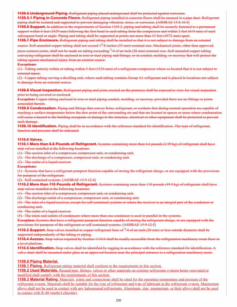
1109.5 Underground Piping. Refrigerant piping placed underground shall be protected against corrosion.1109.5.1 Piping in Concrete Floors. Refrigerant piping installed in concrete floors shall be encased in a pipe duct. Refrigerantpiping shall be isolated and supported to prevent damaging vibration, stress, or corrosion. [ASHRAE 15:8.10.4]1109.6 Support. In addition to the requirements of Section 1105.2, piping and tubing shall be securely fastened to a permanentsupport within 6 feet (1829 mm) following the first bend in such tubing from the compressor and within 2 feet (610 mm) of eachsubsequent bend or angle. Piping and tubing shall be supported at points not more than 15 feet (4572 mm) apart.1109.7 Pipe Enclosure. Refrigerant piping and tubing shall be installed so that it is not subject to damage from an externalsource. Soft annealed copper tubing shall not exceed 13/8 inches (35 mm) nominal size. Mechanical joints, other than approvedpress-connect joints, shall not be made on tubing exceeding 3/4 of an inch (20 mm) nominal size. Soft annealed copper tubingconveying refrigerant shall be enclosed in iron or steel piping and fittings, or in conduit, molding, or raceway that will protect thetubing against mechanical injury from an exterior source.Exceptions:(1) Tubing entirely within or tubing within 5 feet (1524 mm) of a refrigerant compressor where so located that it is not subject toexternal injury.(2) Copper tubing serving a dwelling unit, where such tubing contains Group A1 refrigerant and is placed in locations not subjectto damage from an external source.
1109.8 Visual Inspection. Refrigerant piping and joints erected on the premises shall be exposed to view for visual inspectionprior to being covered or enclosed.Exception: Copper tubing enclosed in iron or steel piping conduit, molding, or raceway, provided there are no fittings or jointsconcealed therein.1109.9 Condensation. Piping and fittings that convey brine, refrigerant, or coolants that during normal operation are capable ofreaching a surface temperature below the dew point of the surrounding air and that are located in spaces or areas where condensationwill cause a hazard to the building occupants or damage to the structure, electrical or other equipment shall be protected to preventsuch damage.1109.10 Identification. Piping shall be in accordance with the reference standard for identification. The type of refrigerant,function and pressure shall be indicated.
1110.0 Valves.1110.1 More than 6.6 Pounds of Refrigerant. Systems containing more than 6.6 pounds (2.99 kg) of refrigerant shall havestop valves installed at the following locations:(1) The suction inlet of a compressor, compressor unit, or condensing unit.(2) The discharge of a compressor, compressor unit, or condensing unit.(3) The outlet of a liquid receiver.Exceptions:(1) Systems that have a refrigerant pumpout function capable of storing the refrigerant charge, or are equipped with the provisionsfor pumpout of the refrigerant.(2) Self-contained systems. [ASHRAE 15:9.12.4]1110.2 More than 110 Pounds of Refrigerant. Systems containing more than 110 pounds (49.9 kg) of refrigerant shall havestop valves installed at the following locations:(1) The suction inlet of a compressor, compressor unit, or condensing unit.(2) The discharge outlet of a compressor, compressor unit, or condensing unit.(3) The inlet of a liquid receiver, except for self-contained systems or where the receiver is an integral part of the condenser orcondensing unit.(4) The outlet of a liquid receiver.(5) The inlets and outlets of condensers where more than one condenser is used in parallel in the systems.Exception: Systems that have a refrigerant pumpout function capable of storing the refrigerant charge, or are equipped with theprovisions for pumpout of the refrigerant or self-contained systems. [ASHRAE 15:9.12.5]1110.3 Support. Stop valves installed in copper refrigerant lines of 3/4 of an inch (20 mm) or less outside diameter shall besupported independently of the tubing or piping.1110.4 Access. Stop valves required by Section 1110.0 shall be readily accessible from the refrigeration machinery room floor ora level platform.1110.5 Identification. Stop valves shall be identified by tagging in accordance with the reference standard for identification. Avalve chart shall be mounted under glass at an approved location near the principal entrance to a refrigeration machinery room.
1109.0 Piping Material.1109.1 Piping. Refrigerant piping material shall conform to the requirements in this section.1109.2 Used Materials. Reused pipe, fittings, valves or other materials on existing refrigerant systems being renovated ormodified shall comply with the requirements of this section.1109.3 Material Rating. Materials, joints and connections shall be rated for the operating temperature and pressure of therefrigerant system. Materials shall be suitable for the type of refrigerant and type of lubricant in the refrigerant system. Magnesiumalloys shall not be used in contact with any halogenated refrigerants. Aluminum, zinc, magnesium, or their alloys shall not be usedin contact with R-40 (methyl chloride).
230
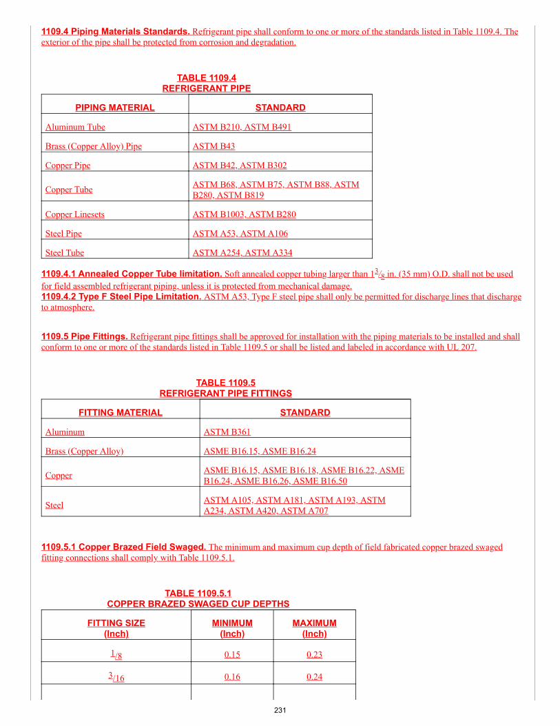
1109.4 Piping Materials Standards. Refrigerant pipe shall conform to one or more of the standards listed in Table 1109.4. Theexterior of the pipe shall be protected from corrosion and degradation.
TABLE 1109.4REFRIGERANT PIPE
PIPING MATERIAL STANDARD
Aluminum Tube ASTM B210, ASTM B491
Brass (Copper Alloy) Pipe ASTM B43
Copper Pipe ASTM B42, ASTM B302
Copper Tube ASTM B68, ASTM B75, ASTM B88, ASTMB280, ASTM B819
Copper Linesets ASTM B1003, ASTM B280
Steel Pipe ASTM A53, ASTM A106
Steel Tube ASTM A254, ASTM A334
1109.4.1 Annealed Copper Tube limitation. Soft annealed copper tubing larger than 13/8 in. (35 mm) O.D. shall not be usedfor field assembled refrigerant piping, unless it is protected from mechanical damage.1109.4.2 Type F Steel Pipe Limitation. ASTM A53, Type F steel pipe shall only be permitted for discharge lines that dischargeto atmosphere.
1109.5 Pipe Fittings. Refrigerant pipe fittings shall be approved for installation with the piping materials to be installed and shallconform to one or more of the standards listed in Table 1109.5 or shall be listed and labeled in accordance with UL 207.
TABLE 1109.5REFRIGERANT PIPE FITTINGS
FITTING MATERIAL STANDARD
Aluminum ASTM B361
Brass (Copper Alloy) ASME B16.15, ASME B16.24
Copper ASME B16.15, ASME B16.18, ASME B16.22, ASMEB16.24, ASME B16.26, ASME B16.50
Steel ASTM A105, ASTM A181, ASTM A193, ASTMA234, ASTM A420, ASTM A707
1109.5.1 Copper Brazed Field Swaged. The minimum and maximum cup depth of field fabricated copper brazed swagedfitting connections shall comply with Table 1109.5.1.
TABLE 1109.5.1COPPER BRAZED SWAGED CUP DEPTHS
FITTING SIZE(Inch)
MINIMUM(Inch)
MAXIMUM(Inch)
1/8 0.15 0.23
3/16 0.16 0.24
231
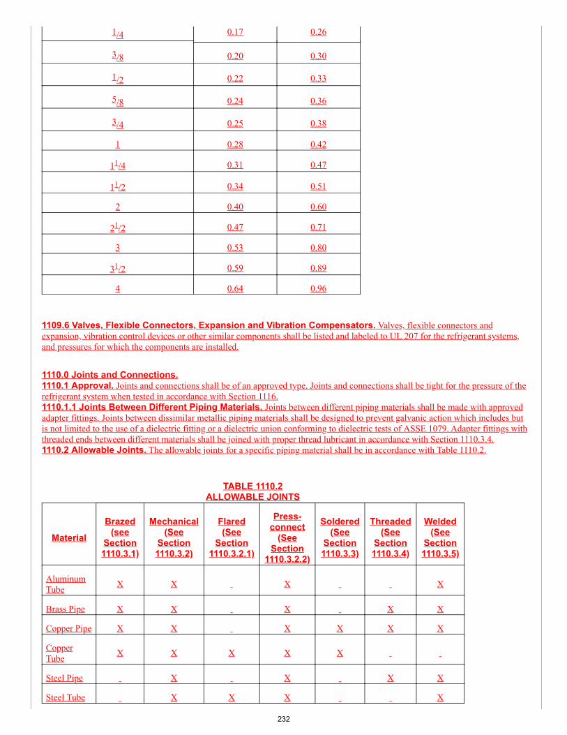
1/4 0.17 0.26
3/8 0.20 0.30
1/2 0.22 0.33
5/8 0.24 0.36
3/4 0.25 0.38
1 0.28 0.42
11/4 0.31 0.47
11/2 0.34 0.51
2 0.40 0.60
21/2 0.47 0.71
3 0.53 0.80
31/2 0.59 0.89
4 0.64 0.96
1109.6 Valves, Flexible Connectors, Expansion and Vibration Compensators. Valves, flexible connectors andexpansion, vibration control devices or other similar components shall be listed and labeled to UL 207 for the refrigerant systems,and pressures for which the components are installed.
1110.0 Joints and Connections.1110.1 Approval. Joints and connections shall be of an approved type. Joints and connections shall be tight for the pressure of therefrigerant system when tested in accordance with Section 1116.1110.1.1 Joints Between Different Piping Materials. Joints between different piping materials shall be made with approvedadapter fittings. Joints between dissimilar metallic piping materials shall be designed to prevent galvanic action which includes butis not limited to the use of a dielectric fitting or a dielectric union conforming to dielectric tests of ASSE 1079. Adapter fittings withthreaded ends between different materials shall be joined with proper thread lubricant in accordance with Section 1110.3.4.1110.2 Allowable Joints. The allowable joints for a specific piping material shall be in accordance with Table 1110.2.
TABLE 1110.2ALLOWABLE JOINTS
MaterialBrazed
(seeSection1110.3.1)
Mechanical(See
Section1110.3.2)
Flared(See
Section1110.3.2.1)
Press-connect
(SeeSection
1110.3.2.2)
Soldered(See
Section1110.3.3)
Threaded(See
Section1110.3.4)
Welded(See
Section1110.3.5)
AluminumTube X X X X
Brass Pipe X X X X X
Copper Pipe X X X X X X
CopperTube X X X X X
Steel Pipe X X X X
Steel Tube X X X X
232
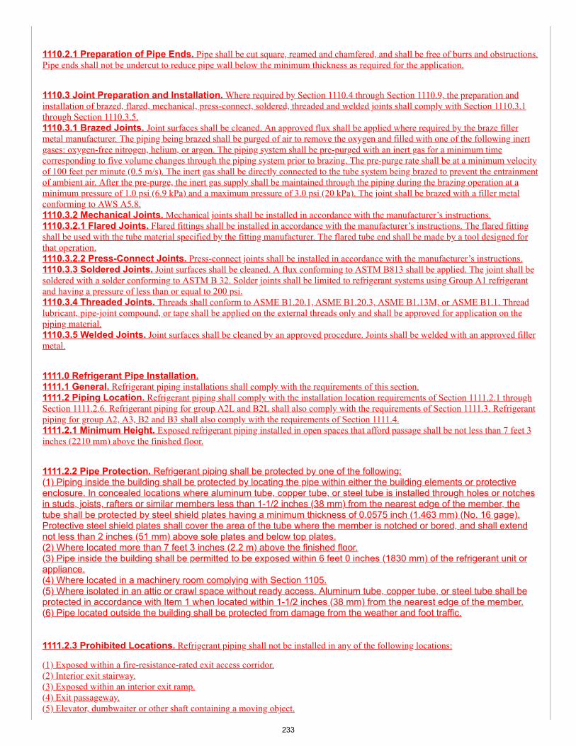
1110.2.1 Preparation of Pipe Ends. Pipe shall be cut square, reamed and chamfered, and shall be free of burrs and obstructions.Pipe ends shall not be undercut to reduce pipe wall below the minimum thickness as required for the application.
1110.3 Joint Preparation and Installation. Where required by Section 1110.4 through Section 1110.9, the preparation andinstallation of brazed, flared, mechanical, press-connect, soldered, threaded and welded joints shall comply with Section 1110.3.1through Section 1110.3.5.1110.3.1 Brazed Joints. Joint surfaces shall be cleaned. An approved flux shall be applied where required by the braze fillermetal manufacturer. The piping being brazed shall be purged of air to remove the oxygen and filled with one of the following inertgases: oxygen-free nitrogen, helium, or argon. The piping system shall be pre-purged with an inert gas for a minimum timecorresponding to five volume changes through the piping system prior to brazing. The pre-purge rate shall be at a minimum velocityof 100 feet per minute (0.5 m/s). The inert gas shall be directly connected to the tube system being brazed to prevent the entrainmentof ambient air. After the pre-purge, the inert gas supply shall be maintained through the piping during the brazing operation at aminimum pressure of 1.0 psi (6.9 kPa) and a maximum pressure of 3.0 psi (20 kPa). The joint shall be brazed with a filler metalconforming to AWS A5.8.1110.3.2 Mechanical Joints. Mechanical joints shall be installed in accordance with the manufacturer’s instructions.1110.3.2.1 Flared Joints. Flared fittings shall be installed in accordance with the manufacturer’s instructions. The flared fittingshall be used with the tube material specified by the fitting manufacturer. The flared tube end shall be made by a tool designed forthat operation.1110.3.2.2 Press-Connect Joints. Press-connect joints shall be installed in accordance with the manufacturer’s instructions.1110.3.3 Soldered Joints. Joint surfaces shall be cleaned. A flux conforming to ASTM B813 shall be applied. The joint shall besoldered with a solder conforming to ASTM B 32. Solder joints shall be limited to refrigerant systems using Group A1 refrigerantand having a pressure of less than or equal to 200 psi.1110.3.4 Threaded Joints. Threads shall conform to ASME B1.20.1, ASME B1.20.3, ASME B1.13M, or ASME B1.1. Threadlubricant, pipe-joint compound, or tape shall be applied on the external threads only and shall be approved for application on thepiping material.1110.3.5 Welded Joints. Joint surfaces shall be cleaned by an approved procedure. Joints shall be welded with an approved fillermetal.
1111.0 Refrigerant Pipe Installation.1111.1 General. Refrigerant piping installations shall comply with the requirements of this section.1111.2 Piping Location. Refrigerant piping shall comply with the installation location requirements of Section 1111.2.1 throughSection 1111.2.6. Refrigerant piping for group A2L and B2L shall also comply with the requirements of Section 1111.3. Refrigerantpiping for group A2, A3, B2 and B3 shall also comply with the requirements of Section 1111.4.1111.2.1 Minimum Height. Exposed refrigerant piping installed in open spaces that afford passage shall be not less than 7 feet 3inches (2210 mm) above the finished floor.
1111.2.2 Pipe Protection. Refrigerant piping shall be protected by one of the following:(1) Piping inside the building shall be protected by locating the pipe within either the building elements or protectiveenclosure. In concealed locations where aluminum tube, copper tube, or steel tube is installed through holes or notchesin studs, joists, rafters or similar members less than 1-1/2 inches (38 mm) from the nearest edge of the member, thetube shall be protected by steel shield plates having a minimum thickness of 0.0575 inch (1.463 mm) (No. 16 gage).Protective steel shield plates shall cover the area of the tube where the member is notched or bored, and shall extendnot less than 2 inches (51 mm) above sole plates and below top plates.(2) Where located more than 7 feet 3 inches (2.2 m) above the finished floor.(3) Pipe inside the building shall be permitted to be exposed within 6 feet 0 inches (1830 mm) of the refrigerant unit orappliance.(4) Where located in a machinery room complying with Section 1105.(5) Where isolated in an attic or crawl space without ready access. Aluminum tube, copper tube, or steel tube shall beprotected in accordance with Item 1 when located within 1-1/2 inches (38 mm) from the nearest edge of the member.(6) Pipe located outside the building shall be protected from damage from the weather and foot traffic.
1111.2.3 Prohibited Locations. Refrigerant piping shall not be installed in any of the following locations:
(1) Exposed within a fire-resistance-rated exit access corridor.(2) Interior exit stairway.(3) Exposed within an interior exit ramp.(4) Exit passageway.(5) Elevator, dumbwaiter or other shaft containing a moving object.
233
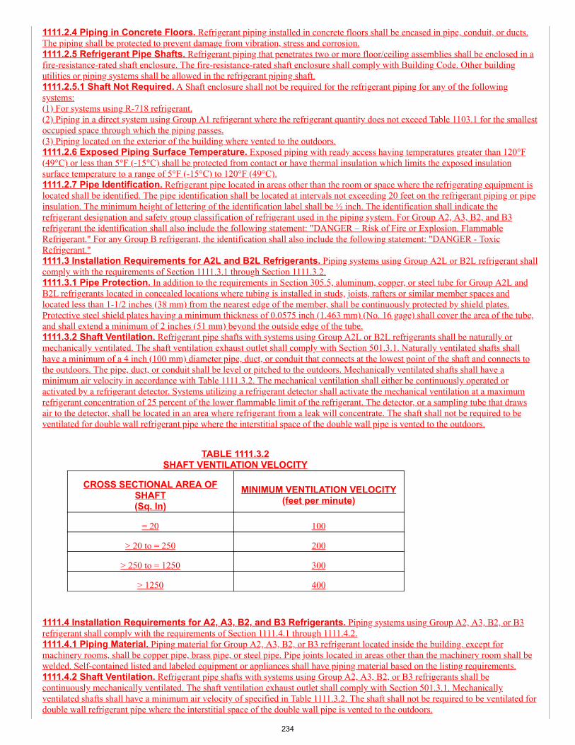
1111.2.4 Piping in Concrete Floors. Refrigerant piping installed in concrete floors shall be encased in pipe, conduit, or ducts.The piping shall be protected to prevent damage from vibration, stress and corrosion.1111.2.5 Refrigerant Pipe Shafts. Refrigerant piping that penetrates two or more floor/ceiling assemblies shall be enclosed in afire-resistance-rated shaft enclosure. The fire-resistance-rated shaft enclosure shall comply with Building Code. Other buildingutilities or piping systems shall be allowed in the refrigerant piping shaft.1111.2.5.1 Shaft Not Required. A Shaft enclosure shall not be required for the refrigerant piping for any of the followingsystems:(1) For systems using R-718 refrigerant.(2) Piping in a direct system using Group A1 refrigerant where the refrigerant quantity does not exceed Table 1103.1 for the smallestoccupied space through which the piping passes.(3) Piping located on the exterior of the building where vented to the outdoors.1111.2.6 Exposed Piping Surface Temperature. Exposed piping with ready access having temperatures greater than 120°F(49°C) or less than 5°F (-15°C) shall be protected from contact or have thermal insulation which limits the exposed insulationsurface temperature to a range of 5°F (-15°C) to 120°F (49°C).1111.2.7 Pipe Identification. Refrigerant pipe located in areas other than the room or space where the refrigerating equipment islocated shall be identified. The pipe identification shall be located at intervals not exceeding 20 feet on the refrigerant piping or pipeinsulation. The minimum height of lettering of the identification label shall be ½ inch. The identification shall indicate therefrigerant designation and safety group classification of refrigerant used in the piping system. For Group A2, A3, B2, and B3refrigerant the identification shall also include the following statement: "DANGER – Risk of Fire or Explosion. FlammableRefrigerant." For any Group B refrigerant, the identification shall also include the following statement: "DANGER - ToxicRefrigerant."1111.3 Installation Requirements for A2L and B2L Refrigerants. Piping systems using Group A2L or B2L refrigerant shallcomply with the requirements of Section 1111.3.1 through Section 1111.3.2.1111.3.1 Pipe Protection. In addition to the requirements in Section 305.5, aluminum, copper, or steel tube for Group A2L andB2L refrigerants located in concealed locations where tubing is installed in studs, joists, rafters or similar member spaces andlocated less than 1-1/2 inches (38 mm) from the nearest edge of the member, shall be continuously protected by shield plates.Protective steel shield plates having a minimum thickness of 0.0575 inch (1.463 mm) (No. 16 gage) shall cover the area of the tube,and shall extend a minimum of 2 inches (51 mm) beyond the outside edge of the tube.1111.3.2 Shaft Ventilation. Refrigerant pipe shafts with systems using Group A2L or B2L refrigerants shall be naturally ormechanically ventilated. The shaft ventilation exhaust outlet shall comply with Section 501.3.1. Naturally ventilated shafts shallhave a minimum of a 4 inch (100 mm) diameter pipe, duct, or conduit that connects at the lowest point of the shaft and connects tothe outdoors. The pipe, duct, or conduit shall be level or pitched to the outdoors. Mechanically ventilated shafts shall have aminimum air velocity in accordance with Table 1111.3.2. The mechanical ventilation shall either be continuously operated oractivated by a refrigerant detector. Systems utilizing a refrigerant detector shall activate the mechanical ventilation at a maximumrefrigerant concentration of 25 percent of the lower flammable limit of the refrigerant. The detector, or a sampling tube that drawsair to the detector, shall be located in an area where refrigerant from a leak will concentrate. The shaft shall not be required to beventilated for double wall refrigerant pipe where the interstitial space of the double wall pipe is vented to the outdoors.
TABLE 1111.3.2SHAFT VENTILATION VELOCITY
CROSS SECTIONAL AREA OFSHAFT(Sq. In)
MINIMUM VENTILATION VELOCITY(feet per minute)
= 20 100
> 20 to = 250 200
> 250 to = 1250 300
> 1250 400
1111.4 Installation Requirements for A2, A3, B2, and B3 Refrigerants. Piping systems using Group A2, A3, B2, or B3refrigerant shall comply with the requirements of Section 1111.4.1 through 1111.4.2.1111.4.1 Piping Material. Piping material for Group A2, A3, B2, or B3 refrigerant located inside the building, except formachinery rooms, shall be copper pipe, brass pipe, or steel pipe. Pipe joints located in areas other than the machinery room shall bewelded. Self-contained listed and labeled equipment or appliances shall have piping material based on the listing requirements.1111.4.2 Shaft Ventilation. Refrigerant pipe shafts with systems using Group A2, A3, B2, or B3 refrigerants shall becontinuously mechanically ventilated. The shaft ventilation exhaust outlet shall comply with Section 501.3.1. Mechanicallyventilated shafts shall have a minimum air velocity of specified in Table 1111.3.2. The shaft shall not be required to be ventilated fordouble wall refrigerant pipe where the interstitial space of the double wall pipe is vented to the outdoors.
234
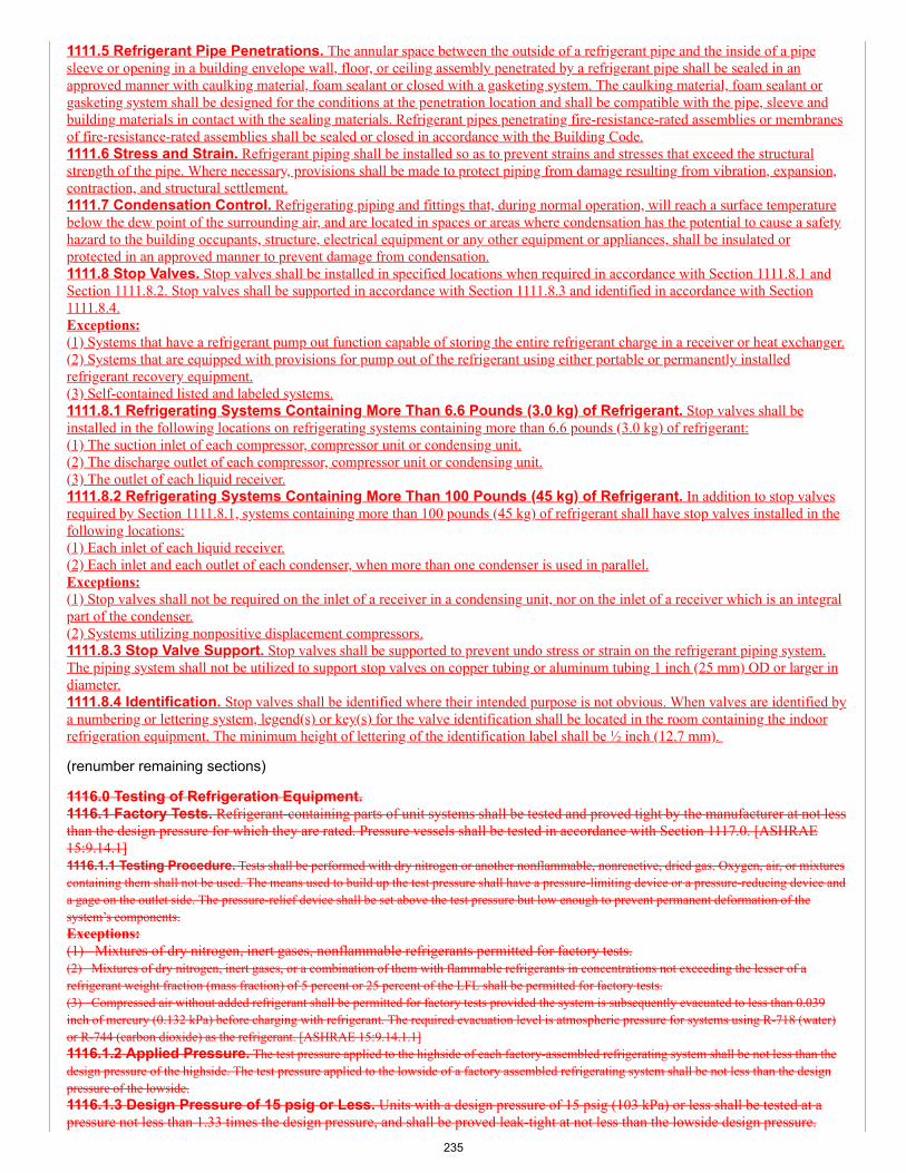
1111.5 Refrigerant Pipe Penetrations. The annular space between the outside of a refrigerant pipe and the inside of a pipesleeve or opening in a building envelope wall, floor, or ceiling assembly penetrated by a refrigerant pipe shall be sealed in anapproved manner with caulking material, foam sealant or closed with a gasketing system. The caulking material, foam sealant orgasketing system shall be designed for the conditions at the penetration location and shall be compatible with the pipe, sleeve andbuilding materials in contact with the sealing materials. Refrigerant pipes penetrating fire-resistance-rated assemblies or membranesof fire-resistance-rated assemblies shall be sealed or closed in accordance with the Building Code.1111.6 Stress and Strain. Refrigerant piping shall be installed so as to prevent strains and stresses that exceed the structuralstrength of the pipe. Where necessary, provisions shall be made to protect piping from damage resulting from vibration, expansion,contraction, and structural settlement.1111.7 Condensation Control. Refrigerating piping and fittings that, during normal operation, will reach a surface temperaturebelow the dew point of the surrounding air, and are located in spaces or areas where condensation has the potential to cause a safetyhazard to the building occupants, structure, electrical equipment or any other equipment or appliances, shall be insulated orprotected in an approved manner to prevent damage from condensation.1111.8 Stop Valves. Stop valves shall be installed in specified locations when required in accordance with Section 1111.8.1 andSection 1111.8.2. Stop valves shall be supported in accordance with Section 1111.8.3 and identified in accordance with Section1111.8.4.Exceptions:(1) Systems that have a refrigerant pump out function capable of storing the entire refrigerant charge in a receiver or heat exchanger.(2) Systems that are equipped with provisions for pump out of the refrigerant using either portable or permanently installedrefrigerant recovery equipment.(3) Self-contained listed and labeled systems.1111.8.1 Refrigerating Systems Containing More Than 6.6 Pounds (3.0 kg) of Refrigerant. Stop valves shall beinstalled in the following locations on refrigerating systems containing more than 6.6 pounds (3.0 kg) of refrigerant:(1) The suction inlet of each compressor, compressor unit or condensing unit.(2) The discharge outlet of each compressor, compressor unit or condensing unit.(3) The outlet of each liquid receiver.1111.8.2 Refrigerating Systems Containing More Than 100 Pounds (45 kg) of Refrigerant. In addition to stop valvesrequired by Section 1111.8.1, systems containing more than 100 pounds (45 kg) of refrigerant shall have stop valves installed in thefollowing locations:(1) Each inlet of each liquid receiver.(2) Each inlet and each outlet of each condenser, when more than one condenser is used in parallel.Exceptions:(1) Stop valves shall not be required on the inlet of a receiver in a condensing unit, nor on the inlet of a receiver which is an integralpart of the condenser.(2) Systems utilizing nonpositive displacement compressors.1111.8.3 Stop Valve Support. Stop valves shall be supported to prevent undo stress or strain on the refrigerant piping system.The piping system shall not be utilized to support stop valves on copper tubing or aluminum tubing 1 inch (25 mm) OD or larger indiameter.1111.8.4 Identification. Stop valves shall be identified where their intended purpose is not obvious. When valves are identified bya numbering or lettering system, legend(s) or key(s) for the valve identification shall be located in the room containing the indoorrefrigeration equipment. The minimum height of lettering of the identification label shall be ½ inch (12.7 mm).
(renumber remaining sections)
1116.0 Testing of Refrigeration Equipment.1116.1 Factory Tests. Refrigerant-containing parts of unit systems shall be tested and proved tight by the manufacturer at not lessthan the design pressure for which they are rated. Pressure vessels shall be tested in accordance with Section 1117.0. [ASHRAE15:9.14.1]1116.1.1 Testing Procedure. Tests shall be performed with dry nitrogen or another nonflammable, nonreactive, dried gas. Oxygen, air, or mixturescontaining them shall not be used. The means used to build up the test pressure shall have a pressure-limiting device or a pressure-reducing device anda gage on the outlet side. The pressure-relief device shall be set above the test pressure but low enough to prevent permanent deformation of thesystem’s components.Exceptions:(1) Mixtures of dry nitrogen, inert gases, nonflammable refrigerants permitted for factory tests.(2) Mixtures of dry nitrogen, inert gases, or a combination of them with flammable refrigerants in concentrations not exceeding the lesser of arefrigerant weight fraction (mass fraction) of 5 percent or 25 percent of the LFL shall be permitted for factory tests.(3) Compressed air without added refrigerant shall be permitted for factory tests provided the system is subsequently evacuated to less than 0.039inch of mercury (0.132 kPa) before charging with refrigerant. The required evacuation level is atmospheric pressure for systems using R-718 (water)or R-744 (carbon dioxide) as the refrigerant. [ASHRAE 15:9.14.1.1]1116.1.2 Applied Pressure. The test pressure applied to the highside of each factory-assembled refrigerating system shall be not less than thedesign pressure of the highside. The test pressure applied to the lowside of a factory assembled refrigerating system shall be not less than the designpressure of the lowside.1116.1.3 Design Pressure of 15 psig or Less. Units with a design pressure of 15 psig (103 kPa) or less shall be tested at apressure not less than 1.33 times the design pressure, and shall be proved leak-tight at not less than the lowside design pressure.
235
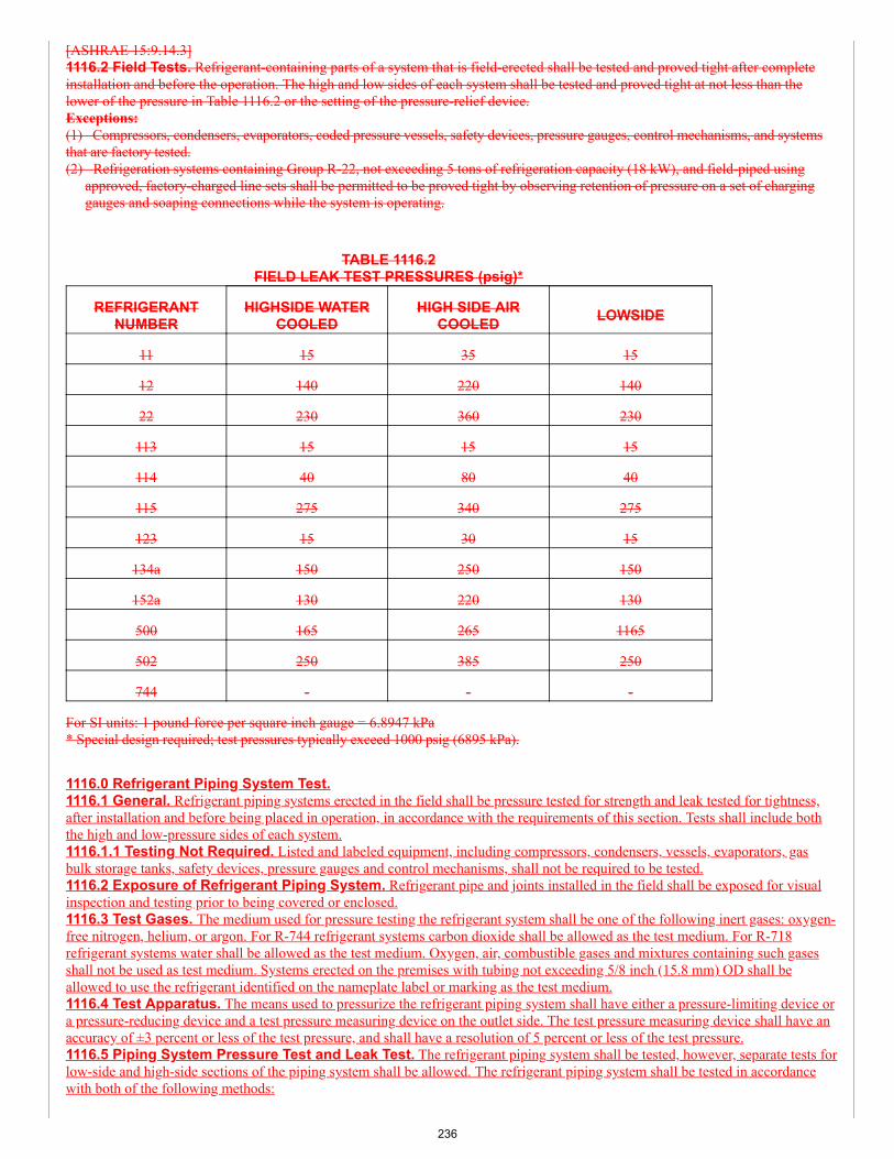
[ASHRAE 15:9.14.3]1116.2 Field Tests. Refrigerant-containing parts of a system that is field-erected shall be tested and proved tight after completeinstallation and before the operation. The high and low sides of each system shall be tested and proved tight at not less than thelower of the pressure in Table 1116.2 or the setting of the pressure-relief device.Exceptions:(1) Compressors, condensers, evaporators, coded pressure vessels, safety devices, pressure gauges, control mechanisms, and systemsthat are factory tested.(2) Refrigeration systems containing Group R-22, not exceeding 5 tons of refrigeration capacity (18 kW), and field-piped using
approved, factory-charged line sets shall be permitted to be proved tight by observing retention of pressure on a set of charginggauges and soaping connections while the system is operating.
TABLE 1116.2FIELD LEAK TEST PRESSURES (psig)*
REFRIGERANTNUMBER
HIGHSIDE WATERCOOLED
HIGH SIDE AIRCOOLED LOWSIDE
11 15 35 15
12 140 220 140
22 230 360 230
113 15 15 15
114 40 80 40
115 275 340 275
123 15 30 15
134a 150 250 150
152a 130 220 130
500 165 265 1165
502 250 385 250
744 - - -
For SI units: 1 pound-force per square inch gauge = 6.8947 kPa* Special design required; test pressures typically exceed 1000 psig (6895 kPa).
1116.0 Refrigerant Piping System Test.1116.1 General. Refrigerant piping systems erected in the field shall be pressure tested for strength and leak tested for tightness,after installation and before being placed in operation, in accordance with the requirements of this section. Tests shall include boththe high and low-pressure sides of each system.1116.1.1 Testing Not Required. Listed and labeled equipment, including compressors, condensers, vessels, evaporators, gasbulk storage tanks, safety devices, pressure gauges and control mechanisms, shall not be required to be tested.1116.2 Exposure of Refrigerant Piping System. Refrigerant pipe and joints installed in the field shall be exposed for visualinspection and testing prior to being covered or enclosed.1116.3 Test Gases. The medium used for pressure testing the refrigerant system shall be one of the following inert gases: oxygen-free nitrogen, helium, or argon. For R-744 refrigerant systems carbon dioxide shall be allowed as the test medium. For R-718refrigerant systems water shall be allowed as the test medium. Oxygen, air, combustible gases and mixtures containing such gasesshall not be used as test medium. Systems erected on the premises with tubing not exceeding 5/8 inch (15.8 mm) OD shall beallowed to use the refrigerant identified on the nameplate label or marking as the test medium.1116.4 Test Apparatus. The means used to pressurize the refrigerant piping system shall have either a pressure-limiting device ora pressure-reducing device and a test pressure measuring device on the outlet side. The test pressure measuring device shall have anaccuracy of ±3 percent or less of the test pressure, and shall have a resolution of 5 percent or less of the test pressure.1116.5 Piping System Pressure Test and Leak Test. The refrigerant piping system shall be tested, however, separate tests forlow-side and high-side sections of the piping system shall be allowed. The refrigerant piping system shall be tested in accordancewith both of the following methods:
236
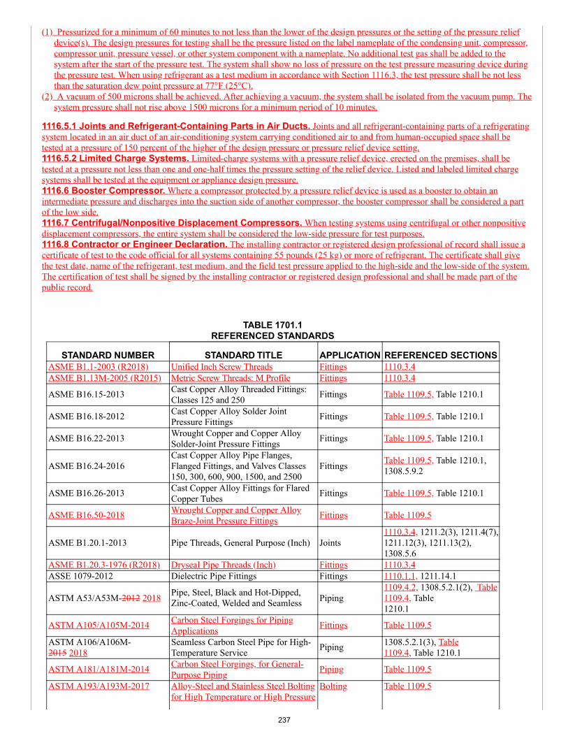
(1) Pressurized for a minimum of 60 minutes to not less than the lower of the design pressures or the setting of the pressure reliefdevice(s). The design pressures for testing shall be the pressure listed on the label nameplate of the condensing unit, compressor,compressor unit, pressure vessel, or other system component with a nameplate. No additional test gas shall be added to thesystem after the start of the pressure test. The system shall show no loss of pressure on the test pressure measuring device duringthe pressure test. When using refrigerant as a test medium in accordance with Section 1116.3, the test pressure shall be not lessthan the saturation dew point pressure at 77°F (25°C).
(2) A vacuum of 500 microns shall be achieved. After achieving a vacuum, the system shall be isolated from the vacuum pump. Thesystem pressure shall not rise above 1500 microns for a minimum period of 10 minutes.
1116.5.1 Joints and Refrigerant-Containing Parts in Air Ducts. Joints and all refrigerant-containing parts of a refrigeratingsystem located in an air duct of an air-conditioning system carrying conditioned air to and from human-occupied space shall betested at a pressure of 150 percent of the higher of the design pressure or pressure relief device setting.1116.5.2 Limited Charge Systems. Limited-charge systems with a pressure relief device, erected on the premises, shall betested at a pressure not less than one and one-half times the pressure setting of the relief device. Listed and labeled limited chargesystems shall be tested at the equipment or appliance design pressure.1116.6 Booster Compressor. Where a compressor protected by a pressure relief device is used as a booster to obtain anintermediate pressure and discharges into the suction side of another compressor, the booster compressor shall be considered a partof the low side.1116.7 Centrifugal/Nonpositive Displacement Compressors. When testing systems using centrifugal or other nonpositivedisplacement compressors, the entire system shall be considered the low-side pressure for test purposes.1116.8 Contractor or Engineer Declaration. The installing contractor or registered design professional of record shall issue acertificate of test to the code official for all systems containing 55 pounds (25 kg) or more of refrigerant. The certificate shall givethe test date, name of the refrigerant, test medium, and the field test pressure applied to the high-side and the low-side of the system.The certification of test shall be signed by the installing contractor or registered design professional and shall be made part of thepublic record.
TABLE 1701.1REFERENCED STANDARDS
STANDARD NUMBER STANDARD TITLE APPLICATION REFERENCED SECTIONSASME B1.1-2003 (R2018) Unified Inch Screw Threads Fittings 1110.3.4ASME B1.13M-2005 (R2015) Metric Screw Threads: M Profile Fittings 1110.3.4
ASME B16.15-2013 Cast Copper Alloy Threaded Fittings:Classes 125 and 250 Fittings Table 1109.5, Table 1210.1
ASME B16.18-2012 Cast Copper Alloy Solder JointPressure Fittings Fittings Table 1109.5, Table 1210.1
ASME B16.22-2013 Wrought Copper and Copper AlloySolder-Joint Pressure Fittings Fittings Table 1109.5, Table 1210.1
ASME B16.24-2016Cast Copper Alloy Pipe Flanges,Flanged Fittings, and Valves Classes150, 300, 600, 900, 1500, and 2500
Fittings Table 1109.5, Table 1210.1,1308.5.9.2
ASME B16.26-2013 Cast Copper Alloy Fittings for FlaredCopper Tubes Fittings Table 1109.5, Table 1210.1
ASME B16.50-2018 Wrought Copper and Copper AlloyBraze-Joint Pressure Fittings Fittings Table 1109.5
ASME B1.20.1-2013 Pipe Threads, General Purpose (Inch) Joints1110.3.4, 1211.2(3), 1211.4(7),1211.12(3), 1211.13(2),1308.5.6
ASME B1.20.3-1976 (R2018) DryseaI Pipe Threads (Inch) Fittings 1110.3.4ASSE 1079-2012 Dielectric Pipe Fittings Fittings 1110.1.1, 1211.14.1
ASTM A53/A53M-2012 2018 Pipe, Steel, Black and Hot-Dipped,Zinc-Coated, Welded and Seamless Piping
1109.4.2, 1308.5.2.1(2), Table1109.4, Table1210.1
ASTM A105/A105M-2014 Carbon Steel Forgings for PipingApplications Fittings Table 1109.5
ASTM A106/A106M-2015 2018
Seamless Carbon Steel Pipe for High-Temperature Service Piping 1308.5.2.1(3), Table
1109.4, Table 1210.1
ASTM A181/A181M-2014 Carbon Steel Forgings, for General-Purpose Piping Piping Table 1109.5
ASTM A193/A193M-2017 Alloy-Steel and Stainless Steel Boltingfor High Temperature or High Pressure
Bolting Table 1109.5
237
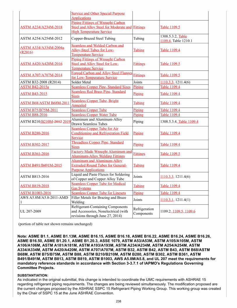
Service and Other Special PurposeApplications
ASTM A234/A234M-2018Piping Fittings of Wrought CarbonSteel and Alloy Steel for Moderate andHigh Temperature Service
Fittings Table 1109.5
ASTM A254/A254M-2012 Copper-Brazed Steel Tubing Tubing 1308.5.3.2, Table1109.4, Table 1210.1
ASTM A334/A334M-2004a(R2016)
Seamless and Welded Carbon andAlloy-Steel Tubes for Low-Temperature Service
Tubing Table 1109.4
ASTM A420/A420M-2016Piping Fittings of Wrought CarbonSteel and Alloy Steel for Low-Temperature Service
Fittings Table 1109.5
ASTM A707/A707M-2014 Forged Carbon and Alloy Steel Flangesfor Low-Temperature Service Fittings Table 1109.5
ASTM B32-2008 (R2014) Solder Metal Joints 1110.3.3, 1211.4(6)ASTM B42-2015a Seamless Copper Pipe, Standard Sizes Piping Table 1109.4
ASTM B43-2015 Seamless Red Brass Pipe, StandardSizes Piping Table 1109.4
ASTM B68/ASTM B68M-2011 Seamless Copper Tube, BrightAnnealed Tubing Table 1109.4
ASTM B75/B75M-2011 Seamless Copper Tube Piping Table 1109.4ASTM B88-2016 Seamless Copper Water Tube Piping Table 1109.4
ASTM B210/B210M-2012 2019 Aluminum and Aluminum-AlloyDrawn Seamless Tubes Piping 1308.5.3.4, Table 1109.4
ASTM B280-2016Seamless Copper Tube for AirConditioning and Refrigeration FieldService
Piping Table 1109.4
ASTM B302-2017 Threadless Copper Pipe, StandardSizes Piping Table 1109.4
ASTM B361-2016 Factory-Made Wrought Aluminum andAluminum-Alloy Welding Fittings Fittings Table 1109.5
ASTM B491/B491M-2015Aluminum and Aluminum-AlloyExtruded Round Tubes for General-Purpose Applications
Tubing Table 1109.4
ASTM B813-2016 Liquid and Paste Fluxes for Solderingof Copper and Copper Alloy Tube Joints 1110.3.3, 1211.4(6)
ASTM B819-2018 Seamless Copper Tube for MedicalGas Systems Tubing Table 1109.4
ASTM B1003-2016 Seamless Copper Tube for Linesets Piping Table 1109.4AWS A5.8M/A5.8-2011-AMD1
Filler Metals for Brazing and BrazeWelding Joints 1110.3.1, 1211.4(1)
UL 207-2009Refrigerant-Containing Componentsand Accessories, Nonelectrical (withrevisions through June 27, 2014)
RefrigerationComponents 1109.2, 1109.5, 1109.6
(portion of table not shown remains unchanged)
Note: ASME B1.1, ASME B1.13M, ASME B16.15, ASME B16.18, ASME B16.22, ASME B16.24, ASME B16.26,ASME B16.50, ASME B1.20.1, ASME B1.20.3, ASSE 1079, ASTM A53/A53M, ASTM A105/A105M, ASTMA106/A106M, ASTM A181/A181M, ASTM A193/A193M, ASTM A234/A234M, ASTM A254/A254M, ASTMA334/A334M, ASTM A420/A420M, ASTM A707/A707M, ASTM B32, ASTM B42, ASTM B43, ASTM B68/ASTMB68M, ASTM B75/B75M, ASTM B88, ASTM B210/B210M, ASTM B280, ASTM B302, ASTM B361, ASTMB491/B491M, ASTM B813, ASTM B819, ASTM B1003, AWS A5.8M/A5.8, and UL 207 meet the requirements formandatory reference standards in accordance with Section 3-3.7.1 of IAPMO's Regulations GoverningCommittee Projects.
SUBSTANTIATION:As indicated in the original submittal, this change is intended to coordinate the UMC requirements with ASHRAE 15regarding refrigerant piping requirements. The changes are being reviewed simultaneously. The modification proposed arethe current changes proposed by the ASHRAE SSPC 15 Refrigerant Piping Working Group. This working group was createdby the Chair of SSPC 15 at the June ASHRAE Convention.
238
The reason for rejection was that the proposed change contains overly restrictive language. The only specific given was thatTable 1109.5.1 is overly restrictive and not user friendly. Table 1109.5.1 is provided by Copper Development Association. Assuch, it is a standard requirement for copper tube swaged brazed joints that are field made. This table is very important toavoid field failures of brazed joints. There is nothing overly restrictive with the requirements. Furthermore, the table is rathereasy to use since it lists pipe size, minimum cup depth of the joint and maximum cup depth of the joint. It could not be madeany easier to follow than what appears in the table.
As for other overly restrictive requirements, nothing else is identified. Refrigerant piping must be restrictive to assure the longterm performance of the piping system. The industry does not want unrestrictive requirements that could result in the leakageof refrigerant into the atmosphere.
The modification proposed by the ASHRAE working group and shown in the modifications to this item are intended toaddress issues found in the original proposal. The first modification is to the used material section. It is important that anyexisting piping that is reused when equipment or appliances are changed must comply with the current code requirementsfor piping material. This will prevent failure of the piping systems when new equipment is installed.
The change to the piping material table removes the notes and converts them to separate code sections. Furthermore, thelimitation on Type F steel pipe is limited to discharge line similar to the requirements in ASHRAE 15.
The restriction on Group A2, A3, B2, and B3 refrigerants for steel pipe is removed. This was found to be an antiquatedrequirement that should not be continued. Schedule 40 pipe will perform adequately for the temperatures and pressures ofthese piping systems.
The Valves section was combined with the Flexible connectors and expansion, vibration control devices section to create asingle section addressing the requirements. Added to the list is “or other similar components” to cover items that may not beindividually listed.
For adapter fittings, the allowance of listed fittings was added. While this was always the intent, it was not clear in the originalproposed text. The galvanic protection requirement was further clarified to allow options for preventing galvanic corrosion.
The allowable joints for refrigerant piping was reduced to a table format. This will make it easier to understand without havingto read a lot of text. All the allowable joints are listed in the table.
The reference for design of piping systems to ASME B31.5 has been deleted. The standard is already referenced as anoption in ASHRAE 15 and should not be added to this section.
The final change is to the piping protection requirements. It was determined that a single section listing all of the options forprotecting the piping is a better for clarifying the requirements. In addition, text was added regarding exposed piping in a stairenclosure. Without this text, it would not be possible to condition that air in a stair enclosure. However, the refrigerant pipingto the units in the stair enclosure in not exposed.
The Technical Committee is encouraged to accept these important changes on refrigerant piping.
COMMITTEE ACTION: REJECT
COMMITTEE STATEMENT:The comment is being rejected as it contains overly stringent requirements. Table 1109.5.1 is overly restrictive and is notuser-friendly.
TOTAL ELIGIBLE TO VOTE: 26
VOTING RESULTS: AFFIRMATIVE: 24 ABSTAIN: 1 NOT RETURNED: 1 HOWARD
EXPLANATION OF ABSTAIN:
KOERBER: I am abstaining as the revision is extensive and appears contentious with most of the TC. I prefer to wait for furtherdevelopment of standards and proposals on this subject.
239
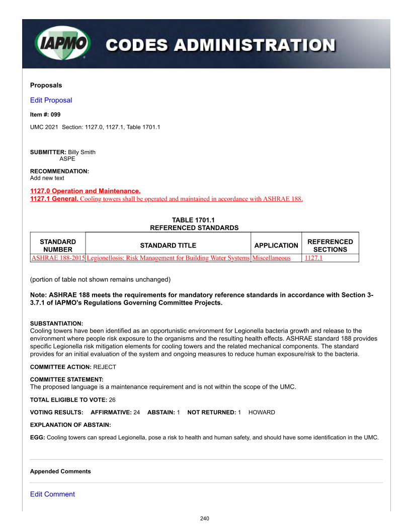
Proposals
Edit Proposal
Item #: 099
UMC 2021 Section: 1127.0, 1127.1, Table 1701.1
SUBMITTER: Billy SmithASPE
RECOMMENDATION:Add new text
1127.0 Operation and Maintenance.1127.1 General. Cooling towers shall be operated and maintained in accordance with ASHRAE 188.
TABLE 1701.1 REFERENCED STANDARDS
STANDARDNUMBER STANDARD TITLE APPLICATION REFERENCED
SECTIONSASHRAE 188-2015 Legionellosis: Risk Management for Building Water Systems Miscellaneous 1127.1
(portion of table not shown remains unchanged)
Note: ASHRAE 188 meets the requirements for mandatory reference standards in accordance with Section 3-3.7.1 of IAPMO's Regulations Governing Committee Projects.
SUBSTANTIATION:Cooling towers have been identified as an opportunistic environment for Legionella bacteria growth and release to theenvironment where people risk exposure to the organisms and the resulting health effects. ASHRAE standard 188 providesspecific Legionella risk mitigation elements for cooling towers and the related mechanical components. The standardprovides for an initial evaluation of the system and ongoing measures to reduce human exposure/risk to the bacteria.
COMMITTEE ACTION: REJECT
COMMITTEE STATEMENT:The proposed language is a maintenance requirement and is not within the scope of the UMC.
TOTAL ELIGIBLE TO VOTE: 26
VOTING RESULTS: AFFIRMATIVE: 24 ABSTAIN: 1 NOT RETURNED: 1 HOWARD
EXPLANATION OF ABSTAIN:
EGG: Cooling towers can spread Legionella, pose a risk to health and human safety, and should have some identification in the UMC.
Appended Comments
Edit Comment
240
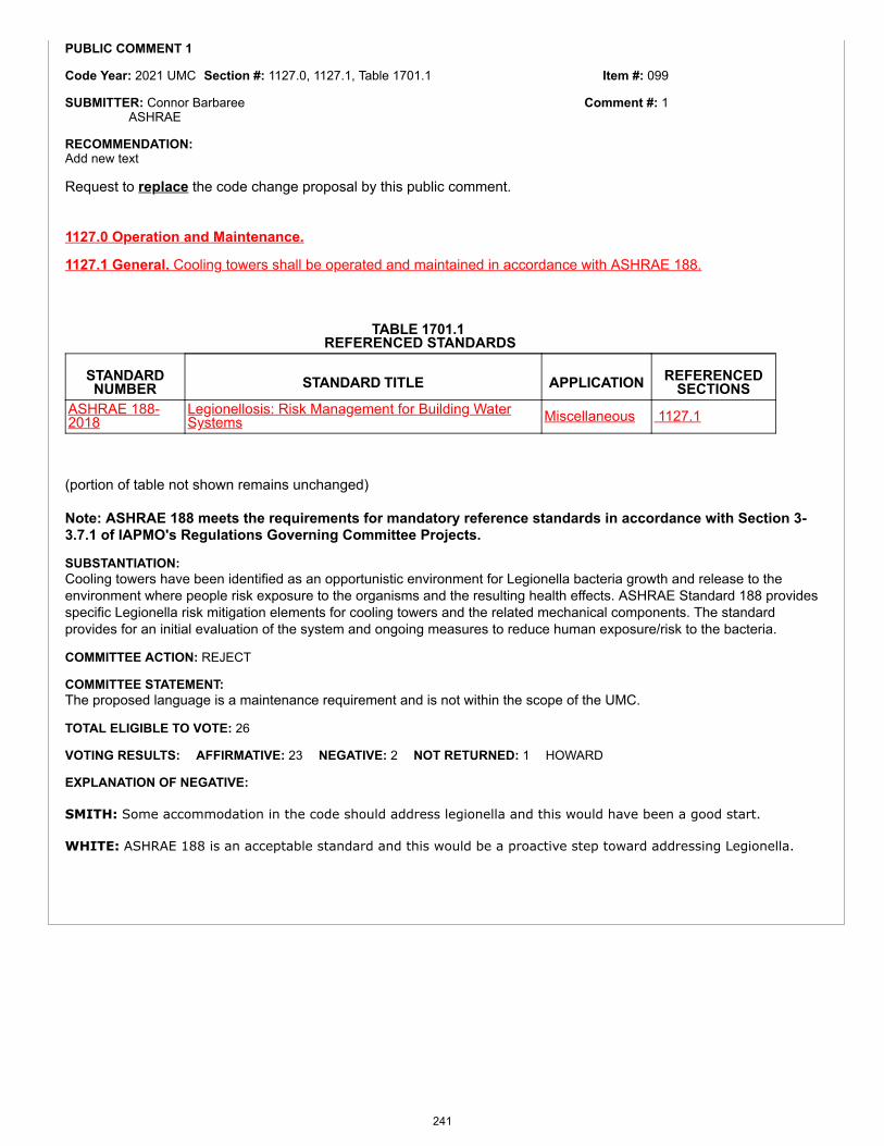
Item #: 099
Comment #: 1
PUBLIC COMMENT 1
Code Year: 2021 UMC Section #: 1127.0, 1127.1, Table 1701.1
SUBMITTER: Connor BarbareeASHRAE
RECOMMENDATION:Add new text
Request to replace the code change proposal by this public comment.
1127.0 Operation and Maintenance.
1127.1 General. Cooling towers shall be operated and maintained in accordance with ASHRAE 188.
TABLE 1701.1 REFERENCED STANDARDS
STANDARDNUMBER STANDARD TITLE APPLICATION REFERENCED
SECTIONSASHRAE 188-2018
Legionellosis: Risk Management for Building WaterSystems Miscellaneous 1127.1
(portion of table not shown remains unchanged)
Note: ASHRAE 188 meets the requirements for mandatory reference standards in accordance with Section 3-3.7.1 of IAPMO's Regulations Governing Committee Projects.
SUBSTANTIATION:Cooling towers have been identified as an opportunistic environment for Legionella bacteria growth and release to theenvironment where people risk exposure to the organisms and the resulting health effects. ASHRAE Standard 188 providesspecific Legionella risk mitigation elements for cooling towers and the related mechanical components. The standardprovides for an initial evaluation of the system and ongoing measures to reduce human exposure/risk to the bacteria.
COMMITTEE ACTION: REJECT
COMMITTEE STATEMENT:The proposed language is a maintenance requirement and is not within the scope of the UMC.
TOTAL ELIGIBLE TO VOTE: 26
VOTING RESULTS: AFFIRMATIVE: 23 NEGATIVE: 2 NOT RETURNED: 1 HOWARD
EXPLANATION OF NEGATIVE:
SMITH: Some accommodation in the code should address legionella and this would have been a good start.
WHITE: ASHRAE 188 is an acceptable standard and this would be a proactive step toward addressing Legionella.
241
Item #: 103
Comment #: 1
Proposals
Edit Proposal
Item #: 103
UMC 2021 Section: 1209.1 - 1209.2
SUBMITTER: Lance MacNevin, P.Eng.Plastic Pipe Institute
RECOMMENDATION:Revise text
1209.0 Expansion Tanks.
1209.1 General. An expansion tank shall be installed in each closed hydronic system to control system pressure due to thermalexpansion and contraction. Expansion tanks shall be of the closed or open type. Expansion Ttanks shall be rated for the pressure ofthe system.
1209.2 Installation. Expansion tanks shall be accessible for maintenance and shall be installed in accordance with themanufacturer’s installation instructions. Each tank shall be equipped with a shutoff device that will remain open during operation ofthe heating hydronic system. Valve handles shall be locked open or removed to prevent from being inadvertently shut off. Provisionsshall be made for draining the tank without emptying the system. Expansion tanks shall be securely fastened to the structure. Supportsshall be capable of carrying twice the weight of the tank filled with water without placing a strain on connecting piping. Hot-water-heating systems incorporating hot water tanks or fluid relief columns shall be installed to prevent freezing under normal operatingconditions.
SUBSTANTIATION:The revision to Section 1209.1 and Section 1209.2 will provide clarity in regard to expansion tanks. Furthermore, themodification will correlate with the action taken by the USEHC Technical Committee.
COMMITTEE ACTION: ACCEPT AS SUBMITTED
TOTAL ELIGIBLE TO VOTE: 26
VOTING RESULTS: AFFIRMATIVE: 25 NOT RETURNED: 1 HOWARD
Appended Comments
Edit Comment
PUBLIC COMMENT 1
Code Year: 2021 UMC Section #: 1209.2
SUBMITTER: Lance MacNevin, P.Eng.Plastic Pipe Institute
RECOMMENDATION:Revise text
Request to accept the code change proposal as modified by this public comment.
242
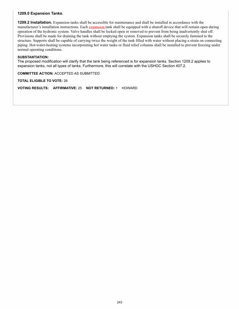
1209.0 Expansion Tanks.
1209.2 Installation. Expansion tanks shall be accessible for maintenance and shall be installed in accordance with themanufacturer’s installation instructions. Each expansion tank shall be equipped with a shutoff device that will remain open duringoperation of the hydronic system. Valve handles shall be locked open or removed to prevent from being inadvertently shut off.Provisions shall be made for draining the tank without emptying the system. Expansion tanks shall be securely fastened to thestructure. Supports shall be capable of carrying twice the weight of the tank filled with water without placing a strain on connectingpiping. Hot-water-heating systems incorporating hot water tanks or fluid relief columns shall be installed to prevent freezing undernormal operating conditions.
SUBSTANTIATION:The proposed modification will clarify that the tank being referenced is for expansion tanks. Section 1209.2 applies toexpansion tanks, not all types of tanks. Furthermore, this will correlate with the USHGC Section 407.2.
COMMITTEE ACTION: ACCEPTED AS SUBMITTED
TOTAL ELIGIBLE TO VOTE: 26
VOTING RESULTS: AFFIRMATIVE: 25 NOT RETURNED: 1 HOWARD
243
Proposals
Edit Proposal
Item #: 105
UMC 2021 Section: Table 1210.1
SUBMITTER: Lance MacNevin, P.Eng.Plastics Pipe Institute
RECOMMENDATION:Revise text
TABLE 1210.1MATERIALS FOR HYDRONIC SYSTEM PIPING, TUBING, AND FITTINGS
MATERIALSTANDARDS
PIPING/TUBING FITTINGS
Cross-Linked Polyethylene (PEX) ASTM F876, CSA B137.5, NSF 358-3
ASSE 1061, ASTM F877, ASTM F1055,ASTM F1807, ASTM F1960, ASTMF1961, ASTM F2080, ASTM F2098,ASTM F2159, ASTM F2735, CSAB137.5, NSF 358-3
(portion of table not shown remains unchanged)
Note: ASTM F1055 meets the requirements for mandatory reference standards in accordance with Section 3-3.7.1 of IAPMO's Regulations Governing Committee Projects.
SUBSTANTIATION:ASTM F1055 electrofusion fittings are compatible with PEX tubing described in ASTM F876 and CSA B137.5 and should beadded into the FITTINBG column for PEX tubing. The addition of F876 PEX tubing into ASTM F1055 was approved by the ASTM F17 Technical Committee in 2013, to attestto the compatibility of connections made between F876 PEX tubing and F1055 fittings. Connections between F876 PEXtubing and F1055 fittings must meet the same requirements as those between HDPE tubing and F1055 fittings. Although F1055 fittings produced of HDPE material should not be used for hydronic applications operating at temperaturesabove 140F, there are many hydronic applications, including low-temperature radiant heating and chilled water systems, forwhich F1055 fittings are very suitable for use with PEX tubing.F1055 fittings are already listed in Table 1210.1 for use with HDPE and PE-RT pipe and tubing, and also in Table E505.6.
COMMITTEE ACTION: ACCEPT AS SUBMITTED
TOTAL ELIGIBLE TO VOTE: 26
VOTING RESULTS: AFFIRMATIVE: 25 NOT RETURNED: 1 HOWARD
Appended Comments
244
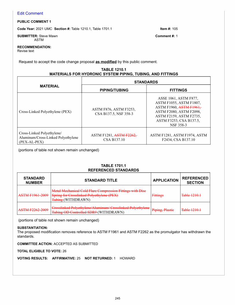
Item #: 105
Comment #: 1
Edit Comment
PUBLIC COMMENT 1
Code Year: 2021 UMC Section #: Table 1210.1, Table 1701.1
SUBMITTER: Steve MawnASTM
RECOMMENDATION:Revise text
Request to accept the code change proposal as modified by this public comment.
TABLE 1210.1MATERIALS FOR HYDRONIC SYSTEM PIPING, TUBING, AND FITTINGS
MATERIALSTANDARDS
PIPING/TUBING FITTINGS
Cross-Linked Polyethylene (PEX) ASTM F876, ASTM F3253, CSA B137.5, NSF 358-3
ASSE 1061, ASTM F877, ASTM F1055, ASTM F1807, ASTM F1960, ASTM F1961, ASTM F2080, ASTM F2098, ASTM F2159, ASTM F2735, ASTM F3253, CSA B137.5,
NSF 358-3
Cross-Linked Polyethylene/Aluminum/Cross-Linked Polyethylene(PEX-AL-PEX)
ASTM F1281, ASTM F2262, CSA B137.10
ASTM F1281, ASTM F1974, ASTMF2434, CSA B137.10
(portions of table not shown remain unchanged)
TABLE 1701.1REFERENCED STANDARDS
STANDARDNUMBER STANDARD TITLE APPLICATION REFERENCED
SECTION
ASTM F1961-2009Metal Mechanical Cold Flare Compression Fittings with DiscSpring for Crosslinked Polyethylene (PEX)Tubing (WITHDRAWN)
Fittings Table 1210.1
ASTM F2262-2009 Crosslinked Polyethylene/Aluminum/ Crosslinked PolyethyleneTubing OD Controlled SDR9 (WITHDRAWN) Piping, Plastic Table 1210.1
(portions of table not shown remain unchanged)
SUBSTANTIATION:The proposed modification removes reference to ASTM F1961 and ASTM F2262 as the promulgator has withdrawn thestandards.
COMMITTEE ACTION: ACCEPTED AS SUBMITTED
TOTAL ELIGIBLE TO VOTE: 26
VOTING RESULTS: AFFIRMATIVE: 25 NOT RETURNED: 1 HOWARD
245
Item #: 109
Comment #: 1
Proposals
Edit Proposal
Item #: 109
UMC 2021 Section: 1211.2, 1211.3
SUBMITTER: Lance MacNevin, P.Eng.Plastic Pipe Institute
RECOMMENDATION:Revise text
1211.0 Joints and Connections.
1211.2 Chlorinated Polyvinyl Chloride (CPVC) Pipe. Joints between chlorinated polyvinyl chloride (CPVC) pipe or fittingsshall be installed in accordance with one of the following methods:(1) Mechanical joints shall include, but not be limited to, flanged, grooved, and push fit fittings. Removable and non-removable push fitfittings with an elastomeric o-ring that employ quick assembly push fit connectors shall be in accordance with ASSE 1061.(2) – (3) (remaining text unchanged)
1211.3 CPVC/AL/CPVC Plastic Pipe and Joints. Joints between chlorinated polyvinyl chloride/aluminum/ chlorinatedpolyvinyl chloride (CPVC/AL/CPVC) pipe or fittings shall be installed in accordance with one of the following methods:(1) Mechanical joints shall include, but not be limited to, flanged and grooved fittings.(2) (remaining text unchanged)
SUBSTANTIATION:The proposed modification will clarify that other mechanical joints may be included. Furthermore, the modification willcorrelate with the action taken by the USEHC Committee.
COMMITTEE ACTION: REJECT
COMMITTEE STATEMENT:The proposed language is unenforceable and may lead to misinterpretation of the sections.
TOTAL ELIGIBLE TO VOTE: 26
VOTING RESULTS: AFFIRMATIVE: 24 NEGATIVE: 1 NOT RETURNED: 1 HOWARD
EXPLANATION OF NEGATIVE:
HYDE: I believe that the USHGC and the UMC shall be consistent where applicable for those AHJs that adopt both codes.
Appended Comments
Edit Comment
PUBLIC COMMENT 1
Code Year: 2021 UMC Section #: 1211.3
SUBMITTER: Lance MacNevin, P.Eng.Plastic Pipe Institute
246
Item #: 109
Comment #: 2
RECOMMENDATION:Revise text
Request to replace the code change proposal by this public comment.
1211.0 Joints and Connections.
1211.3 CPVC/AL/CPVC Plastic Pipe and Joints. Joints between chlorinated polyvinyl chloride/aluminum/ chlorinatedpolyvinyl chloride (CPVC/AL/CPVC) pipe or and fittings shall be installed in accordance with one of the following methods:(1) Mechanical joints shall include, but not be limited to, flanged, and grooved, and push-fit fittings.(2) (remaining text unchanged)
SUBSTANTIATION:The proposed modification will clarify that push-fit fitting type mechanical joints may also be included. Push-fit fittings arealready allowed in the code and need to be added to the list along with flanged and grooved. Adding the new inclusivelanguage will give the AHJ the opportunity to allow other approved joining methods. Furthermore, the modification willcorrelate with the USHGC.
COMMITTEE ACTION: ACCEPTED AS AMENDED
Amend comment as follows:
211.0 Joints and Connections.
1211.3 CPVC/AL/CPVC Plastic Pipe and Joints. Joints between chlorinated polyvinyl chloride/aluminum/ chlorinatedpolyvinyl chloride (CPVC/AL/CPVC) pipe and fittings shall be installed in accordance with one of the following methods:(1) Mechanical joints shall include, but not be limited to, flanged, grooved, and push-fit fittings.(2) (remaining text unchanged)
COMMITTEE STATEMENT:The proposed change is being modified to remove the ambiguous language "but not be limited to."
TOTAL ELIGIBLE TO VOTE: 26
VOTING RESULTS: AFFIRMATIVE: 25 NOT RETURNED: 1 HOWARD
Edit Comment
PUBLIC COMMENT 2
Code Year: 2021 UMC Section #: 1211.0 - 1211.13
SUBMITTER: David DiasSheet Metal Workers Local 104
RECOMMENDATION:Revise text
Request to accept the code change proposal as modified by this public comment.
1211.0 Joints and Connections.1211.1 General. Joints and connections shall be of an approved type. Joints shall be gas and watertight and designed for the pressureof the hydronic system. Changes in direction shall be made by the use of fittings or with pipe bends. Pipe bends shall have a radiusof not less than six times the outside diameter of the tubing or shall be in accordance with the manufacturer’s installationinstructions. Joints between pipe and fittings shall be installed in accordance with the manufacturer’s installation instructions.1211.2 Chlorinated Polyvinyl Chloride (CPVC) Pipe. Joints between chlorinated polyvinyl chloride (CPVC) pipe or and fittingsshall be installed in accordance with one of the following methods:(1) - (3) (remaining text unchanged)
1211.4 Copper or Copper Alloy Pipe and Tubing. Joints between copper or copper alloy pipe, or tubing, or and fittings shall beinstalled in accordance with one of the following methods:(1) Brazed joints between copper or copper alloy pipe, or tubing, or and fittings shall be made with brazing alloys having a liquidtemperature above 1000°F (538°C). The joint surfaces to be brazed shall be cleaned bright by either manual or mechanical means.Tubing shall be cut square and reamed to full inside diameter. Brazing flux shall be applied to the joint surfaces where required bymanufacturer’s recommendation. Brazing filler metal in accordance with AWS A5.8 shall be applied at the point where the pipe ortubing enters the socket of the fitting.
247
(2) - (5) (remaining text unchanged)(6) Soldered joints between copper or copper alloy pipe, or tubing, or and fittings shall be made in accordance with ASTM B828.Pipe or tubing shall be cut square and reamed to the full inside diameter including the removal of burrs on the outside of the pipe ortubing. Surfaces to be joined shall be cleaned bright by manual or mechanical means. Flux shall be applied to pipe or tubing andfittings and shall be in accordance with ASTM B813, and shall become noncorrosive and nontoxic after soldering. Insert pipe ortubing into the base of the fitting and remove excess flux. Pipe or tubing and fitting shall be supported to ensure a uniform capillaryspace around the joint. Solder in accordance with ASTM B32 shall be applied to the joint surfaces until capillary action draws themolten solder into the cup. Joint surfaces shall not be disturbed until cool, and any remaining flux residue shall be cleaned.(7) Threaded joints for copper or copper alloy pipe shall be made with pipe threads in accordance with ASME B1.20.1. Threadsealant tape or compound shall be applied only on male threads, and such material shall be of approved types, insoluble in water,and nontoxic.1211.5 Cross-Linked Polyethylene (PEX) Pipe. Joints between cross-linked polyethylene (PEX) pipe or and fittings shall beinstalled with fittings for PEX tubing that comply with the applicable standards referenced in Table 1210.1. PEX tubing labeled inaccordance with ASTM F876 shall be marked with the applicable standard designation for the fittings specified for use with thetubing. Mechanical joints shall be installed in accordance with the manufacturer’s installation instructions.1211.6 Cross-Linked Polyethylene/Aluminum/Cross-Linked Polyethylene (PEX-AL-PEX) Pipe. Joints between cross-linkedpolyethylene/aluminum/cross-linked polyethylene (PEX-AL-PEX) pipe or and fittings shall be installed in accordance with one ofthe following methods:(1) Mechanical joints between PEX-AL-PEX pipe or and fittings shall include mechanical and compression type fittings and insertfittings with a crimping ring. Insert fittings utilizing a crimping ring shall be in accordance with ASTM F1974 or ASTM F2434.Crimp joints for crimp insert fittings shall be joined to PEX-AL-PEX pipe by the compression of a crimp ring around the outercircumference of the pipe, forcing the pipe material into annular spaces formed by ribs on the fitting.(2) Compression joints shall include compression insert fittings and shall be joined to PEX-AL-PEX pipe through the compressionof a split ring or compression nut around the outer circumference of the pipe, forcing the pipe material into the annular space formedby the ribs on the fitting.1211.7 Ductile Iron Pipe. Joints between ductile iron pipe or and fittings shall be installed in accordance with one of the followingmethods:(1) Mechanical joints for ductile iron pipe or and fittings shall consist of a bell that is cast integrally with the pipe or fitting andprovided with an exterior flange having bolt holes and a socket with annular recesses for the sealing gasket and the plain end of thepipe or fitting. The elastomeric gasket shall comply with AWWA C111. Lubricant recommended for the application by the pipemanufacturer shall be applied to the gasket and plain end of the pipe.(2) Push-on joints for ductile iron pipe or and fittings shall consist of a single elastomeric gasket that shall be assembled bypositioning the elastomeric gasket in an annular recess in the pipe or fitting socket and forcing the plain end of the pipe or fitting intothe socket. The plain end shall compress the elastomeric gasket to form a positive seal and shall be designed so that the elastomericgasket shall be locked in place against displacement. The elastomeric gasket shall comply with AWWA C111. Lubricantrecommended for the application by the pipe manufacturer shall be applied to the gasket and plain end of the pipe.1211.8 Polyethylene (PE) Plastic Pipe/Tubing. Joints between polyethylene (PE) plastic pipe, or tubing, or and fittings shall beinstalled in accordance with one of the following methods:(1) Butt-fusion joints shall be installed in accordance with ASTM F2620 and shall be made by heating the squared ends of twopipes, pipe and fitting, or two fittings by holding ends against a heated element. The heated element shall be removed where theproper melt is obtained, and joined ends shall be placed together with applied force.(2) Electro-fusion joints shall be heated internally by a conductor at the interface of the joint. Align and restrain fitting to pipe toprevent movement and apply electric current to the fitting. Turn off the current when the proper time has elapse to heat the joint. Thejoint shall fuse together and remain undisturbed until cool.(3) Socket-fusion joints shall be installed in accordance ASTM F2620 and shall be made by simultaneously heating the outsidesurface of a pipe end and the inside of a fitting socket. Where the proper melt is obtained, the pipe and fitting shall be joined byinserting one into the other with applied force. The joint shall fuse together and remain undisturbed until cool.(4) Mechanical joints between PE plastic pipe, or tubing, or and fittings shall include insert and mechanical compression fittingsthat provide a pressure seal resistance to pullout. Joints for insert fittings shall be made by cutting the pipe square, using a cutterdesigned for plastic piping, and removal of sharp edges. Two stainless steel clamps shall be placed over the end of the pipe. Fittingsshall be checked for proper size based on the diameter of the pipe. The end of pipe shall be placed over the barbed insert fitting,making contact with the fitting shoulder. Clamps shall be positioned equal to 180 degrees (3.14 rad) apart and shall be tightened toprovide a leak tight joint. Compression type couplings and fittings shall be permitted for use in joining PE piping and tubing.Stiffeners that extend beyond the clamp or nut shall be prohibited. Bends shall be not less than 30 pipe diameters, or the coil radiuswhere bending with the coil. Bends shall not be permitted closer than 10 pipe diameters of a fitting or valve. Mechanical joints shallbe designed for their intended use.1211.9 Polyethylene/Aluminum/Polyethylene (PE-AL-PE). Joints between polyethylene/aluminum/ polyethylene (PE-AL-PE) pipeor and fittings shall be installed in accordance with one of the following methods:(1) Mechanical joints for PE-AL-PE plastic pipe, or tubing, or and fittings shall be either of the metal insert fittings with a split ringand compression nut or metal insert fittings with copper crimp rings. Metal insert fittings shall comply with ASTM F1974. Crimpinsert fittings shall be joined to the pipe by placing the copper crimp ring around the outer circumference of the pipe, forcing thepipe material into the space formed by the ribs on the fitting until the pipe contacts the shoulder of the fitting. The crimp ring shallthen be positioned on the pipe so the edge of the crimp ring is 1/8 of an inch (3.2 mm) to 1/4 of an inch (6.4 mm) from the end of the
248
pipe. The jaws of the crimping tool shall be centered over the crimp ring and tool perpendicular to the barb. The jaws shall be closedaround the crimp ring and shall not be crimped more than once.(2) Compression joints for PE-AL-PE plastic pipe, or tubing, or and fittings shall be joined through the compression of a split ring,by a compression nut around the circumference of the pipe. The compression nut and split ring shall be placed around the pipe. Theribbed end of the fitting shall be inserted onto the pipe until the pipe contacts the shoulder of the fitting. Position and compress thesplit ring by tightening the compression nut onto the insert fitting.1211.10 Polyethylene of Raised Temperature (PE-RT). Joints between polyethylene of raised temperature (PE-RT) tubing or andfittings shall be installed with fittings for PE-RT tubing that comply with the applicable standards referenced in Table 1210.1. Metalinsert fittings, metal compression fittings, and plastic fittings shall be manufactured to and marked in accordance with the standardsfor fittings in Table 1210.1.1211.11 Polypropylene (PP) Pipe. Joints between polypropylene pipe or and fittings shall be installed in accordance with one of thefollowing methods:(1) - (2) (remaining text unchanged)1211.12 Polyvinyl Chloride (PVC) Pipe. Joints between polyvinyl chloride pipe or and fittings shall be installed in accordance withone of the following methods:(1) Mechanical joints shall be designed to provide a permanent seal and shall be of the mechanical or push-on joint. The mechanicaljoint shall include a pipe spigot that has a wall thickness to withstand without deformation or collapse; the compressive force exertedwhere the fitting is tightened. The push-on joint shall have a minimum wall thickness of the bell at any point between the ring andthe pipe barrel. The elastomeric gasket shall comply with ASTM D3139, and be of such size and shape as to provide a compressiveforce against the spigot and socket after assembly to provide a positive seal.(2) Solvent cement joints for PVC pipe or and fittings shall be clean from dirt and moisture. Pipe shall be cut square and pipe shallbe deburred. Where surfaces to be joined are cleaned and free of dirt, moisture, oil, and other foreign material, apply primer purplein color in accordance with ASTM F656. Primer shall be applied until the surface of the pipe and fitting is softened. Solvent cementsin accordance with ASTM D2564 shall be applied to all joint surfaces. Joints shall be made while both the inside socket surface andoutside surface of pipe are wet with solvent cement. Hold joint in place and undisturbed for 1 minute after assembly.(3) Threads shall comply with ASME B1.20.1. A minimum of Schedule 80 shall be permitted to be threaded; however, the pressurerating shall be reduced by 50 percent. The use of molded fittings shall not result in a 50 percent reduction in the pressure rating ofthe pipe provided that the molded fittings shall be fabricated so that the wall thickness of the material is maintained at the threads.Thread sealant compound that is compatible with the pipe and fitting, insoluble in water, and nontoxic shall be applied to malethreads. Caution shall be used during assembly to prevent over tightening of the PVC components once the thread sealant has beenapplied. Female PVC threaded fittings shall be used with plastic male threads only.1211.13 Steel Pipe and Tubing. Joints between steel pipe, or tubing, or and fittings shall be installed in accordance with one of thefollowing methods:(1) - (4) (remaining text unchanged)
SUBSTANTIATION:The proposed modification changes the term “or” to “and” since joints include pipe, tubing, and fittings. Using the term “and”clarifies the intent of the code. UMC Item # 151 (D 113.3) and Item # 152 (E 503.4.7.1.2) also made changes from the term“or” to “and.” Furthermore, this will also correlate with the action taken by the USHGC Technical Committee.
COMMITTEE ACTION: ACCEPTED AS SUBMITTED
TOTAL ELIGIBLE TO VOTE: 26
VOTING RESULTS: AFFIRMATIVE: 25 NOT RETURNED: 1 HOWARD
249
Proposals
Edit Proposal
Item #: 117
UMC 2021 Section: 1214.4
SUBMITTER: Lee H StevensLH Stevens Constructors LLc
RECOMMENDATION:Revise text
1214.0 Pressure and Flow Controls.
1214.4 Automatic Makeup Fluid. Where an automatic makeup fluid supply fill device is used to maintain the water content ofthe heat-source unit, or any closed loop in the system, the makeup supply shall be located at the expansion tank connection or otherapproved location. Where an automatic makeup water supply fill device for a closed loop system is supplied by a potable water supply, the fillsystem shall automatically shut off flow when the supplied makeup water volume exceeds the greater of 5 gallons (19 L) or fivepercent of the total system fluid volume. A manual reset shall be required. Where an automatic makeup fluid fill device for a closed loop system is supplied by an isolated tank, the fluid capacity of thetank shall not exceed the greater of 5 gallons (19 L) or 5 percent of the total system fluid volume. A pressure-reducing valve shall be installed on a makeup water feed line. The pressure of the feed line shall be set in accordancewith the design of the system, and connections to potable water shall be in accordance with Section 1202.0 to prevent contaminationdue to backflow.
SUBSTANTIATION:Homeowners insurance property losses for water damage (2011-2015) are the second most frequent loss category, andsecond costliest per claim. Water damage from a leaking hydronic system can include mold damage, structural damage, andmay render a building temporarily uninhabitable and or subject to freezing up with additional damage.
An automatic feed valve will maintain water pressure in a hydronic system, but will also continually supply a breachedsystem at a potentially high rate of flow. Particularly if a breach occurs while a structure is unattended, the potential exists forthe consequent water damage to far exceed the actual damage to the hydronic system.
As building codes and industry practices have evolved in recent decades, largely pushed by the mandates of energy codes,hydronic systems have become more susceptible to damage and leakage.1. Setback thermostats, along with houses being left unattended, increase the risk of freeze-thaw damage.2. Cast iron boilers have largely been replaced by high-efficiency units with low-mass stainless steel heat exchangers, whichare much more subject to corrosion damage due to water quality issues. 3. High efficiency in-floor radiant heating systems inherently have a greater vulnerability to physical damage, such asfastener penetration, than traditional baseboard systems.
A code requirement to limit water release through an automatic feed valve would be a significant step towards addressingconsequential damage. This proposal also specifically addresses the trade practice of use of a system feeder, in lieu of anautomatic feed valve, for the purpose of limiting water release. A release volume limit as a percentage of total system volumehas the intent to address and allow for the usual losses of larger volume systems.
COMMITTEE ACTION: ACCEPT AS AMENDED BY THE TC
Amend proposal as follows:
250
Item #: 117
Comment #: 1
1214.0 Pressure and Flow Controls.
1214.4 Automatic Makeup Fluid. Where an automatic makeup fluid supply fill device is used to maintain the water fluid content of theheat-source unit, or any closed loop in the system, the makeup supply shall be located at the expansion tank connection or otherapproved location. Where an automatic makeup water supply fill device for a closed loop system is supplied by a potable water supply, the fillsystem shall automatically shut off flow when the supplied makeup water volume exceeds the greater of 5 gallons (19 L) or fivepercent of the total system fluid volume. A manual reset shall be required. Where an automatic makeup fluid fill device for a closed loop system is supplied by an isolated tank, the fluid capacity of thetank shall not exceed the greater of 5 gallons (19 L) or 5 percent of the total system fluid volume. A pressure-reducing valve shall be installed on a makeup water feed line. The pressure of the feed line shall be set in accordance withthe design of the system, and connections to potable water shall be in accordance with Section 1202.0 to prevent contamination dueto backflow.
COMMITTEE STATEMENT:The proposed modification adds changes accepted in Item #115. Furthermore, Item #117 is being accepted in favor of Item#116 as this change applies to water in large and small systems.
TOTAL ELIGIBLE TO VOTE: 26
VOTING RESULTS: AFFIRMATIVE: 24 NEGATIVE: 1 NOT RETURNED: 1 HOWARD
EXPLANATION OF NEGATIVE:
MACNEVIN: I am concerned that the technology that could be used to satisfy the new language is not readily available in the hydronicmarket.
Appended Comments
Edit Comment
PUBLIC COMMENT 1
Code Year: 2021 UMC Section #: 1214.4
SUBMITTER: Lance MacNevinPlastics Pipe Institute
RECOMMENDATION:Revise text
Request to reject the code change proposal by this public comment.
SUBSTANTIATION:As currently accepted as amended in the UMC ROP Preprint, Item #117 will force all hydronic systems, from small residentialradiant heating systems to large commercial systems in hotels, hospitals, etc. to utilize a series of electronic flow sensors todetect small leaks, to measure the accumulated flow of those leaks over time, and then to automatically shut-off the supply ofmake-up fluid to the hydronic system when a leak is detected or perceived. There are several concerns about this proposal:
1. In large hydronic systems with a significant volume of fluid (100s to 1000s of gallons), it is not unreasonable that 5 percentof the system volume is entrained air that will be released in the early days and weeks of operation of the system. Accordingto a Taco publication, “Cold water contains dissolved gases such as oxygen, nitrogen, carbon dioxide, and the other gasesthat constitute air. These gas molecules are dissolved in with the water (H2O) molecules, and thus cannot be seen. A givenvolume of cold water at a temperature of 50ºF and pressure of 50 psi can be up to 10 percent dissolved gas molecules (90percent H2O, 10 percent gases). As water is heated its ability to retain these gas molecules decreases. The gas moleculescoalesce into tiny bubbles along the surface that is heating the water. This is usually the inside surface of the boiler’s heatexchanger. The tiny bubbles eventually merge into visible bubbles and rise upward within the boiler. This mixture of bubblesand liquid water is not desirable for the reasons cited earlier. Hence, it makes sense to “grab” the air bubbles where they areavailable and eject them from the system as soon as possible.” See https://www.taco-hvac.com/uploads/FileLibrary/AirElimination.pdf.
Existing air elimination devices required by the UMC perform this function – while the air is eliminated, make-up water or fluidreplaces the expelled air. If the theoretical item described in Item #117 was installed, then adequate make-up water of more
251
Item #: 117
Comment #: 2
than 5 percent of system volume would not be allowed into the system, and the hydronic system would fail. Failure includesshutting off (bad) or exploding (very bad).
2. The inclusion of a leak measurement and auto shut-off device or system can create significant safety issues in all affectedbuildings. This is because with most commercial and residential boilers shutting off the flow of make-up water in the case ofa detected leak, or any other reason that tricks the shut-off device into thinking there is a leak, can cause the boiler tomalfunction in ways that could result in boiler failure and potential explosion. This is because low water levels in boilers can“boil over” and flash to steam with a tremendous and instantaneous increase in volume, causing pressurized componentssuch as boilers to fail. This can cause grave risk to life and limb of building occupants.
3. The UMC does not require low-water fuel cut-off devices for boilers; see Section 1214.3. However, if a boiler has an(optional) appropriate low-water fuel cut-off control which prevents low-water levels (that could be caused by a small leak)from causing boiler failure, then the boiler would automatically shut-off after a leak of 5 gallons or 5 percent of the systemvolume is detected. This would deactivate the heating system for the building, possibly allowing freeze-up and damagethroughout the building, lack of domestic water, frozen fire protection sprinklers, and even more serious damage in the causeof a health care facility, for instance. Having No Heat on a cold winter day is far more serious than a small water leak.
4. Finally, there are no commercially available leak measurement and auto shut-off devices that would satisfy the newrequirements proposed in Item #117 for all types of hydronic systems.
This means that new electro-mechanical devices which can measure the accumulated flow of make-up water (due to airelimination and small leaks over time) must be invented, standardized, codified, certified, and put into production in time for2021 code implementation, at a cost that would likely add $1000s of dollars to every hydronic system using make-up water.More likely, such devices will not be available for many years, so that hydronic systems will simply not be able to meet theCode. In essence, then the code would severely restrict the use of hydronic systems.
For these reasons, it’s my opinion that item #117 should be stricken from the code. If this is not an option, then I plan todiscuss these concerns during Hearing on Public Comments in May 2019, in Denver.
COMMITTEE ACTION: ACCEPTED AS SUBMITTED
TOTAL ELIGIBLE TO VOTE: 26
VOTING RESULTS: AFFIRMATIVE: 25 NOT RETURNED: 1 HOWARD
Edit Comment
PUBLIC COMMENT 2
Code Year: 2021 UMC Section #: 1214.4, 1214.4.1
SUBMITTER: Lance MacNevinPlastics Pipe Institute
RECOMMENDATION:Revise text
Request to accept the code change proposal as modified by this public comment.
1214.4 Automatic Makeup Fluid. Where an automatic makeup fluid supply fill device is used to maintain the fluid content ofthe heat-source unit, or any closed loop in the system, the makeup supply shall be located at the expansion tank connection or otherapproved location. Where an automatic makeup water supply fill device for a closed loop system is supplied by a potable water supply, the fillsystem shall automatically shut off flow when the supplied makeup water volume exceeds the greater of 5 gallons (19 L) or fivepercent of the total system fluid volume. A manual reset shall be required. Where an automatic makeup fluid fill device for a closed loop system is supplied by an isolated tank, the fluid capacity of thetank shall not exceed the greater of 5 gallons (19 L) or 5 percent of the total system fluid volume. A pressure-reducing valve shall be installed on a makeup feed line. The pressure of the feed line shall be set in accordancewith the design of the system, and connections to potable water shall be in accordance with Section 1202.0 to prevent contaminationdue to backflow.1214.4.1 Automatic Shut Off. Where an automatic makeup water supply fill device for a closed loop system is supplied by apotable water supply, the fill system shall automatically shut off flow when the supplied makeup water volume exceeds the greaterof 5 gallons (19 L) or five percent of the total system fluid volume. A manual reset shall be required.
252

Exception: An automatic shut-off device shall not be required when the closed loop system is supplied by a potable water supplywith a shut-off valve to manually prevent flow of water into the closed loop system.
SUBSTANTIATION:The new requirements from Item # 117 should be added in their own sub-sections, such as Section 1214.4.1, as they aredistinct from the existing text.
The new Exception is proposed so that hydronic systems which are constructed with a manual shut-off valve for the make-upwater will not be required to employ an automatic device as described in the new text that was approved for Item # 117.
Although a system that automatically shuts off the flow of make-up water when its volume exceeds 5 gallons or 5 percent ofthe system volume is theoretically a good idea, it is not known if reliable devices exist that can accomplish this requirement,or if such devices meet any consensus standard, or if such devices are certified for this purpose. For these reasons, anException is important until further research into such automatic shut-off devices is provided to the TC.
COMMITTEE ACTION: REJECT
COMMITTEE STATEMENT:As currently accepted as amended in the UMC ROP Preprint, Item #117 will force all hydronic systems, from small residentialradiant heating systems to large commercial systems in hotels, hospitals, etc. to utilize a series of electronic flow sensors todetect small leaks, to measure the accumulated flow of those leaks over time, and then to automatically shut-off the supply ofmake-up fluid to the hydronic system when a leak is detected or perceived. There are several concerns about this proposal:
1. In large hydronic systems with a significant volume of fluid (100s to 1000s of gallons), it is not unreasonable that 5 percentof the system volume is entrained air that will be released in the early days and weeks of operation of the system. Accordingto a Taco publication, “Cold water contains dissolved gases such as oxygen, nitrogen, carbon dioxide, and the other gasesthat constitute air. These gas molecules are dissolved in with the water (H2O) molecules, and thus cannot be seen. A givenvolume of cold water at a temperature of 50ºF and pressure of 50 psi can be up to 10 percent dissolved gas molecules (90percent H2O, 10 percent gases). As water is heated its ability to retain these gas molecules decreases. The gas moleculescoalesce into tiny bubbles along the surface that is heating the water. This is usually the inside surface of the boiler’s heatexchanger. The tiny bubbles eventually merge into visible bubbles and rise upward within the boiler. This mixture of bubblesand liquid water is not desirable for the reasons cited earlier. Hence, it makes sense to “grab” the air bubbles where they areavailable and eject them from the system as soon as possible.” See https://www.taco-hvac.com/uploads/FileLibrary/AirElimination.pdf.
Existing air elimination devices required by the UMC perform this function – while the air is eliminated, make-up water or fluidreplaces the expelled air. If the theoretical item described in Item #117 was installed, then adequate make-up water of morethan 5 percent of system volume would not be allowed into the system, and the hydronic system would fail. Failure includesshutting off (bad) or exploding (very bad).
2. The inclusion of a leak measurement and auto shut-off device or system can create significant safety issues in all affectedbuildings. This is because with most commercial and residential boilers shutting off the flow of make-up water in the case ofa detected leak, or any other reason that tricks the shut-off device into thinking there is a leak, can cause the boiler tomalfunction in ways that could result in boiler failure and potential explosion. This is because low water levels in boilers can“boil over” and flash to steam with a tremendous and instantaneous increase in volume, causing pressurized componentssuch as boilers to fail. This can cause grave risk to life and limb of building occupants.
3. The UMC does not require low-water fuel cut-off devices for boilers; see Section 1214.3. However, if a boiler has an(optional) appropriate low-water fuel cut-off control which prevents low-water levels (that could be caused by a small leak)from causing boiler failure, then the boiler would automatically shut-off after a leak of 5 gallons or 5 percent of the systemvolume is detected. This would deactivate the heating system for the building, possibly allowing freeze-up and damagethroughout the building, lack of domestic water, frozen fire protection sprinklers, and even more serious damage in the causeof a health care facility, for instance. Having No Heat on a cold winter day is far more serious than a small water leak.
4. Finally, there are no commercially available leak measurement and auto shut-off devices that would satisfy the newrequirements proposed in Item #117 for all types of hydronic systems.
This means that new electro-mechanical devices which can measure the accumulated flow of make-up water (due to airelimination and small leaks over time) must be invented, standardized, codified, certified, and put into production in time for2021 code implementation, at a cost that would likely add $1000s of dollars to every hydronic system using make-up water.More likely, such devices will not be available for many years, so that hydronic systems will simply not be able to meet theCode. In essence, then the code would severely restrict the use of hydronic systems.
253
Item #: 117
Comment #: 3
TOTAL ELIGIBLE TO VOTE: 26
VOTING RESULTS: AFFIRMATIVE: 25 NOT RETURNED: 1 HOWARD
Edit Comment
PUBLIC COMMENT 3
Code Year: 2021 UMC Section #: 1214.4
SUBMITTER: Lance MacNevinPlastics Pipe Institute
RECOMMENDATION:Revise text
Request to accept the code change proposal as modified by this public comment.
1214.4 Automatic Makeup Fluid. Where an automatic makeup fluid supply fill device is used to maintain the fluid content ofthe heat-source unit, or any closed loop in the system, the makeup supply shall be located at the expansion tank connection or otherapproved location. Where an automatic makeup water supply fill device for a closed loop system is supplied by a potable water supply, the fillsystem shall automatically shut off flow when the supplied makeup water volume exceeds the greater of 5 gallons (19 L) or fivepercent of the total system fluid volume. A manual reset shall be required. Where an automatic makeup fluid fill device for a closed loop system is supplied by an isolated tank, the fluid capacity of thetank shall not exceed the greater of 5 gallons (19 L) or 5 percent of the total system fluid volume. A pressure-reducing valve shall be installed on a makeup feed line. The pressure of the feed line shall be set in accordance withthe design of the system, and connections to potable water shall be in accordance with Section 1202.0 to prevent contamination dueto backflow.
1214.4.2 Tank Capacity. Where an automatic makeup fluid fill device for a closed loop system is supplied by an isolated tank,the fluid capacity of the tank shall not exceed the greater of 5 gallons (19 L) or 5 percent of the total system fluid volume.
SUBSTANTIATION:The new requirements from Item # 117 should be added in their own sub-sections, such as Section 1214.4.2, as they aredistinct from the existing text.
A separate proposal was submitted for the proposed new text of Sub-Section 1214.4.1.
COMMITTEE ACTION: REJECT
COMMITTEE STATEMENT:As currently accepted as amended in the UMC ROP Preprint, Item #117 will force all hydronic systems, from small residentialradiant heating systems to large commercial systems in hotels, hospitals, etc. to utilize a series of electronic flow sensors todetect small leaks, to measure the accumulated flow of those leaks over time, and then to automatically shut-off the supply ofmake-up fluid to the hydronic system when a leak is detected or perceived. There are several concerns about this proposal:
1. In large hydronic systems with a significant volume of fluid (100s to 1000s of gallons), it is not unreasonable that 5 percentof the system volume is entrained air that will be released in the early days and weeks of operation of the system. Accordingto a Taco publication, “Cold water contains dissolved gases such as oxygen, nitrogen, carbon dioxide, and the other gasesthat constitute air. These gas molecules are dissolved in with the water (H2O) molecules, and thus cannot be seen. A givenvolume of cold water at a temperature of 50ºF and pressure of 50 psi can be up to 10 percent dissolved gas molecules (90percent H2O, 10 percent gases). As water is heated its ability to retain these gas molecules decreases. The gas moleculescoalesce into tiny bubbles along the surface that is heating the water. This is usually the inside surface of the boiler’s heatexchanger. The tiny bubbles eventually merge into visible bubbles and rise upward within the boiler. This mixture of bubblesand liquid water is not desirable for the reasons cited earlier. Hence, it makes sense to “grab” the air bubbles where they areavailable and eject them from the system as soon as possible.” See https://www.taco-hvac.com/uploads/FileLibrary/AirElimination.pdf.
Existing air elimination devices required by the UMC perform this function – while the air is eliminated, make-up water or fluidreplaces the expelled air. If the theoretical item described in Item #117 was installed, then adequate make-up water of morethan 5 percent of system volume would not be allowed into the system, and the hydronic system would fail. Failure includesshutting off (bad) or exploding (very bad).
254
Item #: 117
Comment #: 4
2. The inclusion of a leak measurement and auto shut-off device or system can create significant safety issues in all affectedbuildings. This is because with most commercial and residential boilers shutting off the flow of make-up water in the case ofa detected leak, or any other reason that tricks the shut-off device into thinking there is a leak, can cause the boiler tomalfunction in ways that could result in boiler failure and potential explosion. This is because low water levels in boilers can“boil over” and flash to steam with a tremendous and instantaneous increase in volume, causing pressurized componentssuch as boilers to fail. This can cause grave risk to life and limb of building occupants.
3. The UMC does not require low-water fuel cut-off devices for boilers; see Section 1214.3. However, if a boiler has an(optional) appropriate low-water fuel cut-off control which prevents low-water levels (that could be caused by a small leak)from causing boiler failure, then the boiler would automatically shut-off after a leak of 5 gallons or 5 percent of the systemvolume is detected. This would deactivate the heating system for the building, possibly allowing freeze-up and damagethroughout the building, lack of domestic water, frozen fire protection sprinklers, and even more serious damage in the causeof a health care facility, for instance. Having No Heat on a cold winter day is far more serious than a small water leak.
4. Finally, there are no commercially available leak measurement and auto shut-off devices that would satisfy the newrequirements proposed in Item #117 for all types of hydronic systems.
This means that new electro-mechanical devices which can measure the accumulated flow of make-up water (due to airelimination and small leaks over time) must be invented, standardized, codified, certified, and put into production in time for2021 code implementation, at a cost that would likely add $1000s of dollars to every hydronic system using make-up water.More likely, such devices will not be available for many years, so that hydronic systems will simply not be able to meet theCode. In essence, then the code would severely restrict the use of hydronic systems.
TOTAL ELIGIBLE TO VOTE: 26
VOTING RESULTS: AFFIRMATIVE: 25 NOT RETURNED: 1 HOWARD
Edit Comment
PUBLIC COMMENT 4
Code Year: 2021 UMC Section #: 1214.4
SUBMITTER: Jeff MatsonViega LLC
RECOMMENDATION:Revise text
Request to accept the code change proposal as modified by this public comment.
1214.0 Pressure and Flow Controls.
1214.4 Automatic Makeup Fluid. Where an automatic makeup fluid supply fill device is used to maintain the fluid content ofthe heat-source unit, or any closed loop in the system, the makeup supply shall be located at the expansion tank connection or otherapproved location. Where an automatic makeup water supply fill device for a closed loop system is supplied by a potable water supply, the fillsystem shall automatically shut off flow when the supplied makeup water volume exceeds the greater of 5 gallons (19 L) or fivepercent of the total system volume. A manual reset shall be required. Where an automatic makeup fluid fill device for a closed loop system is supplied by an isolated tank, the fluid capacity of thetank shall not exceed the greater of 5 gallons (19 L) or 5 percent of the total system fluid volume. A pressure-reducing valve shall be installed on a makeup feed line. The pressure of the feed line shall be set in accordancewith the design of the system, and connections to potable water shall be in accordance with Section 1202.0 to prevent contaminationdue to backflow.Exception: Where a manual shutoff valve is provided for makeup water supply line(s) and remains closed while unattended, anautomatic shutoff shall not be required.
SUBSTANTIATION:Products which fulfill the intent of the proposed text (to automatically limit system fill due to leaks) are not currently readilyavailable in the US, thus the proposal may unduly complicate or limit hydronic installations. This is a good goal for theindustry to work toward, and adding an exception for fill lines with closed valves allows currently available fill valves to beinstalled until such time as automatic limiting fill valves are more readily available.
COMMITTEE ACTION: REJECT
255
COMMITTEE STATEMENT:As currently accepted as amended in the UMC ROP Preprint, Item #117 will force all hydronic systems, from small residentialradiant heating systems to large commercial systems in hotels, hospitals, etc. to utilize a series of electronic flow sensors todetect small leaks, to measure the accumulated flow of those leaks over time, and then to automatically shut-off the supply ofmake-up fluid to the hydronic system when a leak is detected or perceived. There are several concerns about this proposal:
1. In large hydronic systems with a significant volume of fluid (100s to 1000s of gallons), it is not unreasonable that 5 percentof the system volume is entrained air that will be released in the early days and weeks of operation of the system. Accordingto a Taco publication, “Cold water contains dissolved gases such as oxygen, nitrogen, carbon dioxide, and the other gasesthat constitute air. These gas molecules are dissolved in with the water (H2O) molecules, and thus cannot be seen. A givenvolume of cold water at a temperature of 50ºF and pressure of 50 psi can be up to 10 percent dissolved gas molecules (90percent H2O, 10 percent gases). As water is heated its ability to retain these gas molecules decreases. The gas moleculescoalesce into tiny bubbles along the surface that is heating the water. This is usually the inside surface of the boiler’s heatexchanger. The tiny bubbles eventually merge into visible bubbles and rise upward within the boiler. This mixture of bubblesand liquid water is not desirable for the reasons cited earlier. Hence, it makes sense to “grab” the air bubbles where they areavailable and eject them from the system as soon as possible.” See https://www.taco-hvac.com/uploads/FileLibrary/AirElimination.pdf.
Existing air elimination devices required by the UMC perform this function – while the air is eliminated, make-up water or fluidreplaces the expelled air. If the theoretical item described in Item #117 was installed, then adequate make-up water of morethan 5 percent of system volume would not be allowed into the system, and the hydronic system would fail. Failure includesshutting off (bad) or exploding (very bad).
2. The inclusion of a leak measurement and auto shut-off device or system can create significant safety issues in all affectedbuildings. This is because with most commercial and residential boilers shutting off the flow of make-up water in the case ofa detected leak, or any other reason that tricks the shut-off device into thinking there is a leak, can cause the boiler tomalfunction in ways that could result in boiler failure and potential explosion. This is because low water levels in boilers can“boil over” and flash to steam with a tremendous and instantaneous increase in volume, causing pressurized componentssuch as boilers to fail. This can cause grave risk to life and limb of building occupants.
3. The UMC does not require low-water fuel cut-off devices for boilers; see Section 1214.3. However, if a boiler has an(optional) appropriate low-water fuel cut-off control which prevents low-water levels (that could be caused by a small leak)from causing boiler failure, then the boiler would automatically shut-off after a leak of 5 gallons or 5 percent of the systemvolume is detected. This would deactivate the heating system for the building, possibly allowing freeze-up and damagethroughout the building, lack of domestic water, frozen fire protection sprinklers, and even more serious damage in the causeof a health care facility, for instance. Having No Heat on a cold winter day is far more serious than a small water leak.
4. Finally, there are no commercially available leak measurement and auto shut-off devices that would satisfy the newrequirements proposed in Item #117 for all types of hydronic systems.
This means that new electro-mechanical devices which can measure the accumulated flow of make-up water (due to airelimination and small leaks over time) must be invented, standardized, codified, certified, and put into production in time for2021 code implementation, at a cost that would likely add $1000s of dollars to every hydronic system using make-up water.More likely, such devices will not be available for many years, so that hydronic systems will simply not be able to meet theCode. In essence, then the code would severely restrict the use of hydronic systems.
TOTAL ELIGIBLE TO VOTE: 26
VOTING RESULTS: AFFIRMATIVE: 25 NOT RETURNED: 1 HOWARD
256
Item #: 119
Comment #: 1
Proposals
Edit Proposal
Item #: 119
UMC 2021 Section: 1214.6, 1214.7
SUBMITTER: Lance MacNevin, P.Eng.Plastic Pipe Institute
RECOMMENDATION:Revise text
1214.0 Pressure and Flow Controls.
1214.6 Air-Removal Device. Provision shall be made for the removal of air in the heat-distribution piping system from fluid inhydronic systems. The aAir-removal devices shall be located in the areas of the hydronic piping system where air is likely toaccumulate. Air-removal devices shall be installed to facilitate their removal for examination, repair, or replacement.Exception: Drainback type solar thermal systems shall not require an air-removal device.1214.7 Air-Separation Device. To assist with the removal of entrained air, an air-separation device shall be installed in hydronicsystems. The device shall be located in accordance with the manufacturer’s installation instructions or at the point of nomechanically-induced pressure change within the distribution hydronic system.
SUBSTANTIATION:The proposed modification clarifies that the air-separation device are required for hydronic systems. Furthermore, this willcorrelate with the action taken by the USEHC Technical Committee.
COMMITTEE ACTION: ACCEPT AS SUBMITTED
TOTAL ELIGIBLE TO VOTE: 26
VOTING RESULTS: AFFIRMATIVE: 25 NOT RETURNED: 1 HOWARD
Appended Comments
Edit Comment
PUBLIC COMMENT 1
Code Year: 2021 UMC Section #: 1214.6
SUBMITTER: David DiasSheet Metal Workers Local 104
RECOMMENDATION:Delete text
Request to accept the code change proposal as modified by this public comment.
1214.6 Air-Removal Device. Provisions shall be made for the removal of air from fluid in hydronic systems. Air-removaldevices shall be located in the areas of the hydronic piping system where air is likely to accumulate. Air-removal devices shall beinstalled to facilitate their removal for examination, repair, or replacement.Exception: Drainback type solar thermal systems shall not require an air-removal device.
257
SUBSTANTIATION:Section 1214.6 is being further modified to clarify that Chapter 12 does not apply to solar thermal systems, therefore theexception referencing solar thermal systems is unnecessary and creates confusion. Solar provisions are already covered inChapter 15 of the UMC and in the USHGC.
COMMITTEE ACTION: ACCEPTED AS SUBMITTED
TOTAL ELIGIBLE TO VOTE: 26
VOTING RESULTS: AFFIRMATIVE: 25 NOT RETURNED: 1 HOWARD
258
Item #: 127
Comment #: 1
Proposals
Edit Proposal
Item #: 127
UMC 2021 Section: 1220.2
SUBMITTER: Lance MacNevin, P.Eng.Plastic Pipe Institute
RECOMMENDATION:Revise text
1220.0 Auxiliary Systems.
1220.2 Snow and Ice Melt Controls. An automatic thermostatically operating control device that controls the supply hydronicsolution fluid temperature to the snow and ice melt area shall be installed in the system. A means shall be provided to prevent lowreturn hydronic fluid temperature in accordance with Section 1201.5. Snow and ice melt systems shall be protected from freezingwith a mixture of propylene glycol or ethylene glycol, and water, or other approved fluid. Automotive antifreeze shall not be used.
SUBSTANTIATION:The term “solution” has been changed to “fluid” for consistency with other sections. The reference to ethylene glycol is beingremoved as the use of ethylene glycol is highly regulated by local jurisdictions for health and safety reasons. Lastly, themodification to Section 1220.2 will correlate with the action taken by the USEHC Technical Committee. The title is beingrevise to “snow melt” to be consistent with technology used throughout the code.
COMMITTEE ACTION: REJECT
COMMITTEE STATEMENT:The proposed change is not necessary and the current language is needed for enforcement of the code by the AHJ.
TOTAL ELIGIBLE TO VOTE: 26
VOTING RESULTS: AFFIRMATIVE: 24 NEGATIVE: 1 NOT RETURNED: 1 HOWARD
EXPLANATION OF NEGATIVE:
MACNEVIN: The proposed language would improve the code by protecting boilers against low return temperatures, allowing electronicmixing valves, and eliminating toxic ethylene glycol.
Appended Comments
Edit Comment
PUBLIC COMMENT 1
Code Year: 2021 UMC Section #: 1220.4
SUBMITTER: Lance MacNevin, P.Eng.Plastic Pipe Institute
RECOMMENDATION:Revise text
Request to accept the code change proposal as submitted by this public comment.
259
SUBSTANTIATION:The term “solution” has been changed to “fluid” for consistency with other sections. The reference to ethylene glycol is beingremoved as the use of ethylene glycol is highly regulated by local jurisdictions for health and safety reasons. Lastly, themodification to Section 1220.4 will correlate with the action taken by the USHGC Technical Committee.
COMMITTEE ACTION: REJECT
COMMITTEE STATEMENT:The proposed change is not necessary and the current language is needed for enforcement of the code by the AHJ.
TOTAL ELIGIBLE TO VOTE: 26
VOTING RESULTS: AFFIRMATIVE: 25 NOT RETURNED: 1 HOWARD
260
Item #: 133
Comment #: 1
Proposals
Edit Proposal
Item #: 133
UMC 2021 Section: 1221.2
SUBMITTER: Lance MacNevinPlastics Pipe Institute
RECOMMENDATION:Revise text
1221.0 Piping Installation.
1221.2 Embedded Piping Materials and Joints. Piping embedded in concrete shall be steel pipe, Type L copper tubing orplastic pipe or tubing rated at not less than 100 80 psi at 180°F (689 552 kPa at 82°C). Joints of pipe or tubing that are embedded ina portion of the building, such as concrete or plaster shall be installed in accordance with the requirements of Section 1221.2.1through Section 1221.2.3.
SUBSTANTIATION:A pressure rating of 100 psi at 180°F is not necessary for hydronic applications, particularly when the tubing is embedded inconcrete. Hydronic heating systems are typically designed with operating pressures of 12 psi to 20 psi; hydronic expansiontanks are typically factory set to 12 psi. Further, safety relief valves on hot-water boilers are typically set at 30 psi or 50 psi.
Using any pipe or tubing embedded in concrete to convey 180°F fluid is likely to chemically and structurally damage theconcrete, since most concrete mixes are rated for exposure to embedded pipes not higher than 140°F. So the pressure andtemperature required in 1221.2 are extraordinary.
PE-RT tubing listed in Table 1210.1 for HYDRONIC applications is in compliance with ASTM Standard F2623, “StandardSpecification for Polyethylene of Raised Temperature (PE-RT) SDR 9 Tubing” which requires a pressure rating of 80 psi at180°F (551 kPa at 82°C). This proposed change would update section 1221.2 to match the requirements of the productswhich are permitted to be installed in this manner.
COMMITTEE ACTION: ACCEPT AS SUBMITTED
TOTAL ELIGIBLE TO VOTE: 26
VOTING RESULTS: AFFIRMATIVE: 25 NOT RETURNED: 1 HOWARD
Appended Comments
Edit Comment
PUBLIC COMMENT 1
Code Year: 2021 UMC Section #: 1205.2
SUBMITTER: Pennie L FeehanPennie L Feehan ConsultingRep. Copper Development Association
RECOMMENDATION:Add new text
Request to accept the code change proposal as modified by this public comment.
261
1205.2 Pressure Testing. System piping and components shall be tested with a pressure of not less than one and one-half timesthe operating pressure but not less than 100 psi (689 kPa). Piping shall be tested with water or air except that plastic pipe shall not betested with air. Test pressures shall be held for a period of not less than 30 minutes with no perceptible drop in pressure. These testsshall be made in the presence of the Authority Having Jurisdiction.Exceptions:(1) For PEX, PP-R, PP-RCT, PEX-AL-PEX, PE-RT, and PE-AL-PE piping systems, testing with air shall be permitted whereauthorized by the manufacturer’s instructions for the PEX, PP-R, PP-RCT, PEX-AL-PEX, PE-RT, and PE-ALPE pipe and fittingsproducts, and air testing is not prohibited by applicable codes, laws, or regulations outside this code.(2) Copper tubing shall be permitted to be tested at not less than 80 psi (552 kPa).
SUBSTANTIATION:Based on the action taken on Item #133, Section 1205.2 now conflicts with Section 1221.2 as they state conflicting pressureratings; Section 1205.2 states 100 psi and Section 1221.2 states 80 psi. Section 1221.2 is applicable to copper. I am addingan exception note to Section 1205.2 for copper. Therefore, copper will be allowed to be tested at not less than 80 psi inaccordance with Section 1205.2 and PE-RT will be required to be pressure tested at no less than 100 psi in accordance withSection 1221.2. This will remove any confusion or contradictions regarding pressure testing requirements between Section1205.2 and Section 1221.2.
COMMITTEE ACTION: ACCEPTED AS SUBMITTED
TOTAL ELIGIBLE TO VOTE: 26
VOTING RESULTS: AFFIRMATIVE: 25 NOT RETURNED: 1 HOWARD
262
Proposals
Edit Proposal
Item #: 134
UMC 2021 Section: 1221.2.3
SUBMITTER: Lance MacNevin, P.Eng.Plastic Pipe Institute
RECOMMENDATION:Revise text
Request to replace the code change proposal by this public comment.
1221.0 Piping Installation.
1221.2 Embedded Piping Materials and Joints. (remaining text unchanged)
1221.2.3 Plastics. Plastic pipe and tubing shall be installed in continuous lengths or shall be joined by heat fusion methods,solvent cement joints, or other approved fittings in accordance with Table 1210.1 and the manufacturer's installation instructions.
SUBSTANTIATION:Heat fusion is applicable only to certain materials such as PP, PE-RT, or PE. For common hydronic materials such as CPVC,PEX and PE-RT, the ability to use embedded fittings when necessary is important, as fittings might be required to repair pipethat was damaged during construction. Many fittings for plastic tubing have been approved for use in other codes for years,and have been successfully installed in embedded applications for decades. Manufacturers of CPVC, PEX and PE-RT tubingand fittings systems want the ability to recommend use of their fittings in limited embedded applications when necessary.Examples of such fittings are those covered by existing ASTM standards D2846, F877, F1807, F1960, F2080, F2159,F2434, and F2735. In fact, each of these fitting systems are already included in Table 408.1. When manufacturers approvethe use of such fittings for embedded applications, this code should not prohibit that use. The added reference to Table 408.1ensures that only approved fittings for each type of pipe or tubing are eligible for this type of installation. Please see PPIPosition Paper on Installation of PEX Fittings Within and Under Concrete Slabs at this link:http://www.plasticpipe.org/pdf/postion-paper-pex-fitting-locations.pdf and PPI Position Paper on Installation of CPVC FittingsWithin and Under Concrete Slabs at this link: https://plasticpipe.org/pdf/position-paper-cpvc-fitting-locations.pdf
Furthermore, the revision to Section 1221.2.3 will correlate with the action taken by the USEHC Technical Committee.
COMMITTEE ACTION: REJECT
COMMITTEE STATEMENT:The proposed change is being rejected as the language would allow joints under slabs. The TC does not agree that jointscan be under slab except for heat fusion methods.
TOTAL ELIGIBLE TO VOTE: 26
VOTING RESULTS: AFFIRMATIVE: 24 NEGATIVE: 1 NOT RETURNED: 1 HOWARD
EXPLANATION OF NEGATIVE:
MACNEVIN: The submitted language is technically appropriate and should be added to this section.
Appended Comments
263
Item #: 134
Comment #: 1
Edit Comment
PUBLIC COMMENT 1
Code Year: 2021 UMC Section #: 1221.2.3
SUBMITTER: David NickelsonREHAU Construction LLC
RECOMMENDATION:Revise text
Request to replace the code change proposal by this public comment.
1221.0 Piping Installation.
1221.2 Embedded Piping Materials and Joints. (remaining text unchanged)
1221.2.3 Plastics. Plastic pipe and tubing shall be installed in continuous lengths or shall be joined by heat fusion methods or otherapproved fittings in accordance with Table 1210.1 and the manufacturer's installation instructions.
SUBSTANTIATION:Heat fusion (three types) is applicable only to plastic piping materials PP, PE-RT, and PE. For the common hydronic radianttubing materials PEX and PE-RT, the ability to use embedded fittings when necessary is important when fittings are requiredto repair pipe that was damaged during construction. Several types of fittings for PEX and PE-RT plastic tubing have beensuccessfully installed in embedded applications for decades. Examples of such fittings are those covered by existing ASTMstandards F877, F1807, F1960, F2080, F2159, F2434, and F2735; each of these fitting systems are already included inTable 1210.1. None of those fitting standards restrict the use of the fitting to non-embedded applications. The reference toTable 1210.1 within the proposal ensures that only approved fittings for each type of pipe or tubing are eligible for this type ofinstallation.
Manufacturers of PEX and PE-RT tubing and fittings systems recommend the use of their fittings in limited embeddedapplications when necessary. When manufacturers approve the use of such fittings for embedded applications, this codeshould not prohibit that use.
Please see “PPI Position Paper on Installation of PEX Fittings Within and Under Concrete Slabs” at this link:https://plasticpipe.org/pdf/postion-paper-pex-fitting-locations.pdf
Furthermore, this proposed revision to Section 1221.2.3 will correlate with the action taken by the USHGC TechnicalCommittee.
COMMITTEE ACTION: ACCEPTED AS AMENDED
Amend comment as follows:
1221.2 Embedded Piping Materials and Joints. (remaining text unchanged)
1221.2.3 Plastics. Plastic pipe and tubing shall be installed in continuous lengths or shall be joined by heat fusion methods or otherapproved fittings in accordance with Table 1210.1 and the manufacturer's installation instructions.Exception: Solvent cement joints.
COMMITTEE STATEMENT:The modification will clarify that solvent cement joints are exempt from the requirements in Section 1221.2.3.
TOTAL ELIGIBLE TO VOTE: 26
VOTING RESULTS: AFFIRMATIVE: 20 NEGATIVE: 4 ABSTAIN: 1 NOT RETURNED: 1 HOWARD
EXPLANATION OF NEGATIVE:
CHURCH: Two problems with the TC action:1.) There's no technical justification for not allowing joints under slabs because it happens all the time; the TC doesn't offer anytechnical reasons either2.) The TC amendment is confusing because one could argue that exempting solvent cement joints from this code requirement, in fact,allows them to be used; that's fine by us, but it's not the TC intent.
A. TRAFTON: I agree with Richard Church's comment.
264
P. TRAFTON: Agreed that there is no technical reason for rejecting the use of joints under slabs.
WHITE: The exception is ambiguous, there is no technical justification and these are embedded pipes, not below slab pipes.
EXPLANATION OF ABSTAIN:
DELAQUILA: Based on the negative reasons submitted, perhaps there needs to be further review of this proposed code change.
265

Proposals
Edit Proposal
Item #: 137
UMC 2021 Section: 1308.5.8.4
SUBMITTER: David DiasSheet Metal Workers Local 104
RECOMMENDATION:Revise text
1308.0 Gas Piping System Design, Materials, and Components.
1308.5 Acceptable Piping Materials and Joining Methods. (remaining text unchanged)
1308.5.8 Metallic Piping Joints and Fittings. (remaining text unchanged)
1308.5.8.4 Metallic Pipe Fittings (Including Valves, Strainers, Filters). Metallic pipe fittings shall comply with thefollowing:(1) Threaded fittings in sizes exceeding 4 inches (100 mm) shall not be used unless acceptable to the Authority Having Jurisdiction.(2) Fittings used with steel, stainless steel, or wrought-iron pipe shall be steel, stainless steel, copper alloy, bronze, malleable iron, or
cast-iron.(3) – (8) (remaining text unchanged)
(1) Threaded fittings in sizes exceeding 4 inches (100 mm) shall not be used unless acceptable to the Authority Having Jurisdiction.(2) Fittings used with steel, stainless steel, or wrought-iron pipe shall be steel, stainless steel, copper alloy, bronze, malleable iron, or cast-iron.(3) Fittings used with copper or copper alloy pipe shall be copper or copper alloy.(4) Fittings used with aluminum alloy pipe shall be of aluminum alloy.(5) Cast-iron fittings shall comply with the following:(a) Flanges shall be permitted.(b) Bushings shall not be used.(c) Fittings shall not be used in systems containing flammable gas-air mixtures.(d) Fittings in sizes 4 inches (100 mm) and larger shall not be used indoors unless approved by the Authority Having Jurisdiction.(e) Fittings in sizes 6 inches (150 mm) and larger shall not be used unless approved by the Authority Having Jurisdiction.(6) Aluminum alloy fitting threads shall not form the joint seal.(7) Zinc-aluminum alloy fittings shall not be used in systems containing flammable gas-air mixtures.(8) Special fittings such as couplings;, proprietary-type joints;, saddle tees;, gland-type compression fittings;, and flared, flareless, orcompression-type tubing fittings shall be as follows:
SUBSTANTIATION:Section 1308.5.8.4 is being revised to include “stainless steel.” Stainless steel is a common used material in the fuel gas industry. Furthermore, this will be consisting with current industry standards.
COMMITTEE ACTION: ACCEPT AS SUBMITTED
TOTAL ELIGIBLE TO VOTE: 26
VOTING RESULTS: AFFIRMATIVE: 25 NOT RETURNED: 1 HOWARD
The Technical Correlating Committee (TCC) has the responsibility to resolve conflicts and achieve correlation among the recommendations of the Technical Committee (TC). The TCC has the authority to choose between alternative text recommended by the TC, but only as necessary for correlation, consistency, and the correction of errors and omissions in accordance with Section 3-4 of the Regulations Governing Committee Projects.
Actions taken on UMC Item # 137 for Section 1308.5.7.5 are being revised to correlate with the latest NFPA 54 extract updates. In order to correlate the language, the Technical Correlating Committee proposed the following modifications to the UMC:
1308.5.7.5 Metallic Pipe Fittings. Metallic pipe fittings shall comply with the following:
266
(a) Used within the fitting manufacturer’s pressure temperature recommendations.(b) Used within the service conditions anticipated with respect to vibration, fatigue, thermal expansion, or contraction.(c) Installed or braced to prevent separation of the joint by gas pressure or external physical damage.(dc) Acceptable to the Authority Having Jurisdiction.(9) When pipe fittings are drilled and tapped in the field, the operation shall be in accordance with the following:(a) The operation shall be performed on systems having operating pressures of 5 psi (34 kPa) or less.(b) The operation shall be performed by the gas supplier or their designated representative.(c) The drilling and tapping operation shall be performed in accordance with written procedures prepared by the gas supplier.(d) The fittings shall be located outdoors.(e) The tapped fitting assembly shall be inspected and proven to be free of leaks. [NFPA 54:5.6.7.5]
TCC ACTION: ACCEPT AS SUBMITTED
TCC STATEMENT: The language in Section 1308.5.7.5 is being revised to correlate with the latest NFPA 54 extract updates.
The action moves forward as approved by the TCC and supersedes the recommendation from the UMC TC for actions taken for UMC Item # 137 Section 1308.5.7.5 to correlate with the latest NFPA 54 extract updates.
267
Item #: 140.01
Comment #: 1
Comments
Edit Comment
Code Year: 2021 UMC Section #: 1310.3, 1310.3.1
SUBMITTER: UMC Technical Committee Comment
RECOMMENDATION:Revise text
Request to accept the code change proposal as modified by this committee comment.
1310.3 Concealed Piping in Buildings. Gas piping in concealed locations shall be installed in accordance with this section.[NFPA 54:7.3.1]1310.3.1 Connections. Where gas piping is to be concealed, connections shall be of the following type:(1) Pipe fittings such as elbows, tees, couplings, and right/left nipple/couplings.(2) Joining tubing by brazing (see Section 1308.5.8.2.(3) Press-connect Fittings listed to CSA LC 4 for use in concealed spaces or that have been demonstrated to sustain, withoutleakage, forces due to temperature expansion or contraction, vibration, or fatigue based on their geographic location, application, oroperation.(4) CSST fittings listed to CSA LC 1.(45) Where necessary to insert fittings in gas pipe that has been installed in a concealed location, the pipe shall be reconnected bywelding, flanges, or the use of a right/left nipple/coupling.
SUBSTANTIATION:It was in the UMC and exist in NFPA 54. It was dropped during the last code hearings when Press-Connect was added.
COMMITTEE ACTION: ACCEPTED AS SUBMITTED
TOTAL ELIGIBLE TO VOTE: 26
VOTING RESULTS: AFFIRMATIVE: 25 NOT RETURNED: 1 HOWARD
268
Item #: 142
Proposals
Edit Proposal
Item #: 142
UMC 2021 Section: 1312.6
SUBMITTER: Paul CabotAmerican Gas Association
RECOMMENDATION:Revise text
Request to replace the code change proposal by this public comment.
1312.0 Appliance Connections to Building Piping.
1312.6 Appliance Shutoff Valves and Connections. Each appliance connected to a piping system shall have an accessible,approved manual shutoff valve with a nondisplaceable valve member, or a listed gas convenience outlet. Appliance shutoff valvesand convenience outlets shall serve a single appliance only. The shutoff valve shall be located within 6 feet (1829 mm) of theappliance it serves. Where a connector is used, the valve shall be installed upstream of the connector. A union or flanged connectionshall be provided downstream from the valve to permit removal of appliance controls. Shutoff valves serving decorative appliancesshall be permitted to be installed in fireplaces if listed for such use. [NFPA 54:9.6.5, 9.6.5.1(A)(B)]Exceptions:(1) Shutoff valves shall be permitted to be accessibly located inside or under an appliance where such appliance is removed withoutremoval of the shutoff valve.(2) Shutoff valves shall be permitted to be accessibly located inside wall heaters and wall furnaces listed for recessed installationwhere necessary maintenance is performed without removal of the shutoff valve.(3) Where installed at a manifold, the appliance shutoff valve shall be located within 50 feet (15 240 mm) of the appliance servedand shall be readily accessible and permanently identified. The piping from the manifold to within 6 feet (1829 mm) of the applianceshall be designed, sized, installed, and tested in accordance with Chapter 12. [NFPA 54:9.6.5.3]
SUBSTANTIATION:The UPC does not contain the option that allows shutoff valves to be located at a manifold up to 50 ft away from theappliance it serves. The proposed text is taken from the 2018 National Fuel Gas Code. This option is a long standing optionin the NFGC and does not prohibit the installation of a shutoff valve near the appliance if the installer wishes to do so forconvenience of testing or service.
COMMITTEE ACTION: REJECT
COMMITTEE STATEMENT:The proposed text is being rejected as it allows a valve to be installed near a fireplace. Furthermore, it would conflict withSection 1312.6 in regards to the piping within 6 feet of the appliance.
TOTAL ELIGIBLE TO VOTE: 26
VOTING RESULTS: AFFIRMATIVE: 25 NOT RETURNED: 1 HOWARD
Appended Comments
Edit Comment
PUBLIC COMMENT 1
Code Year: 2021 UMC Section #: 1312.6
269
Comment #: 1SUBMITTER: Paul CabotAmerican Gas Association
RECOMMENDATION:Revise text
Request to replace the code change proposal by this public comment.
1312.6 Appliance Shutoff Valves and Connections. Each appliance connected to a piping system shall have an accessible, approvedmanual shutoff valve with a nondisplaceable valve member or a listed gas convenience outlet. Appliance shutoff valves and convenience outlets shallserve a single appliance only. The shutoff valve shall be located within 6 feet (1829 mm) of the appliance it serves. Where a connector is used, thevalve shall be installed upstream of the connector. A union or flanged connection shall be provided downstream from the valve to permit removal ofappliance controls.Exceptions:(1) Shutoff valves serving decorative appliances in a fire-place shall not be located within the fireplace firebox except where the valve is listed forsuch use.(2) Shutoff valves shall be permitted to be accessibly located inside wall heaters and wall furnaces listed for recessed installation where necessarymaintenance is performed without removal of the shutoff valve.(3) Where installed at a manifold, the appliance shutoff valve shall be located within 50 feet (15 240 mm) of the appliance served and shall be readilyaccessible and permanently identified. The piping from the manifold to within 6 feet (1829 mm) of the appliance shall be designed, sized, installed,and tested in accordance with this chapter. [NFPA 54:9.6.5.3]
SUBSTANTIATION:Reconsider the decision to reject this proposal. The committee reason does not state what health and safety concern wouldresult from adoption of the exception. The National Fuel Gas Code, NFPA 54/Z223.1, has long allowed this installation andno evidence of a safety concern has been brought to the committee. The UMC does not contain the option that allows shutoffvalves to be located at a manifold up to 50 ft away from the appliance it serves. The proposed text is taken from the 2018National Fuel Gas Code. This option is a long-standing option in the NFGC and does not prohibit the installation of a shutoffvalve near the appliance if the installer wishes to do so for convenience of testing or service.
COMMITTEE ACTION: REJECT
COMMITTEE STATEMENT:The comment is being rejected as 50 feet for a manifold can be placed in remote locations that may not be accessible whenneeded. This is a health and safety concern. If there is a gas leak, a 50-foot distance may be too far from the manifold toreach in a timely manner and may create a safety issue.
TOTAL ELIGIBLE TO VOTE: 26
VOTING RESULTS: AFFIRMATIVE: 23 NEGATIVE: 2 NOT RETURNED: 1 HOWARD
EXPLANATION OF NEGATIVE:
CHURCH: Use of NFPA extracts should be maintained.
DELAQUILA: I agree that the public comment and NFPA 54 extract should be accepted.
270
Proposals
Edit Proposal
Item #: 143
UMC 2021 Section: 1313.3
SUBMITTER: Paul CabotAmerican Gas Association
RECOMMENDATION:Revise text
1313.0 Pressure Testing and Inspection.
1313.3 Test Pressure. The necessary apparatus for conducting pressure tests shall be furnished by the permit holder. Test gaugesused in conducting pressure tests shall be in accordance with Section 318.0. This inspection shall include an air, CO2, or nitrogenpressure test in the presence of the Authority Having Jurisdiction, at which time the gas piping shall stand a pressure of inaccordance with Section 1313.3.1 or Section 1313.3.2.1313.3.1 Pressure Limits. The test pressure to be used shall be no less than 1½ times the proposed maximum working pressure, butnot less than 3 psi (21 kPa), irrespective of design pressure. Where the test pressure exceeds 125 psi (862 kPa), the test pressure shallnot exceed a value that produces a hoop stress in the piping greater than 50 percent of the specified minimum yield strength of thepipe. [NFPA 54: 8.1.4.2]1313.3.2 Elevated Pressure Test. Where the Authority Having Jurisdiction requires an elevated pressure test, the pressure shallbe not less than 10 psi (69 kPa) gauge pressure. Test pressures shall be held for a length of time satisfactory to the Authority HavingJurisdiction but in no case less than 15 minutes with no perceptible drop in pressure. For welded piping, and for piping carrying gasat pressures in excess of 14 inches water column pressure (3.5 kPa), the test pressure shall be not less than 60 psi (414 kPa) and shallbe continued for a length of time satisfactory to the Authority Having Jurisdiction, but in no case for less than 30 minutes. For CSSTcarrying gas pressures in excess of 14 inches water column (3.5 kPa) pressure, the test pressure shall be not less than 30 psi (207kPa) for 30 minutes. These tests shall be made using air, CO2, or nitrogen pressure and shall be made in the presence of theAuthority Having Jurisdiction. Necessary apparatus for conducting tests shall be furnished by the permit holder. Test gauges used inconducting tests shall be in accordance with Section 318.0.
SUBSTANTIATION:The proposal would permit the use of the pressure test criteria contain in the 2018 National Fuel Gas Code while continuingto allow the current UPC pressure test criteria when it is determined by the AHJ that an elevated pressure test is need for aparticular piping installation. The NFGC test criteria has been successfully used for over 40 years and is widely used in theU.S.
COMMITTEE ACTION: REJECT
COMMITTEE STATEMENT:The proposed text is being rejected as this would reduce the test pressure requirements and will cause confusion in regardsto enforcement of pressure testing and inspection.
TOTAL ELIGIBLE TO VOTE: 26
VOTING RESULTS: AFFIRMATIVE: 25 NOT RETURNED: 1 HOWARD
Appended Comments
Edit Comment
271
Item #: 143
Comment #: 1
PUBLIC COMMENT 1
Code Year: 2021 UMC Section #: 1313.3 - 1313.3.2
SUBMITTER: Paul CabotAmerican Gas Association
RECOMMENDATION:Revise text
Request to accept the code change proposal as submitted by this public comment.
SUBSTANTIATION:Reconsider the rejection of this proposal. The committee reason states that the optional pressure test would causeenforcement confusion. The UMC and UPC has a long history of requiring some installation practices only with thepermission of the AHJ.
The minimum 3 psi test pressure has long been allowed by the National Fuel Gas Code, NFPA 54/Z223.1 and has proven toprovide a safe pressure to test gas piping. The proposal would permit the use of the pressure test criteria contain in the 2018National Fuel Gas Code while continuing to allow the current UPC pressure test criteria when it is determined by the AHJthat an elevated pressure test is need for a particular piping installation. The NFGC test criteria has been successfully usedfor over 40 years and is widely used in the U.S.
COMMITTEE ACTION: REJECT
COMMITTEE STATEMENT:The comment is being rejected as reduced pressure test limits will reduce the safety of the current minimum coderequirement of 10 psi for 15 minutes.
TOTAL ELIGIBLE TO VOTE: 26
VOTING RESULTS: AFFIRMATIVE: 22 NEGATIVE: 3 NOT RETURNED: 1 HOWARD
EXPLANATION OF NEGATIVE:
CHURCH: We do not agree that safety would be compromised, and we believe the NFPA standard should be followed for consistency.
DELAQUILA: I agree that the consistency with NFPA 54 should be maintained and the proposal and comment should be accepted.
MACNEVIN: This proposal is technically correct and clarifies existing language, and should be adopted.
272
Proposals
Edit Proposal
Item #: 145
UMC 2021 Section: Chapter 13: 1302.3 - 1315.3, Table 1701.1, Table 1701.2
SUBMITTER: IAPMO Staff - Update ExtractsNFPA 54 Extract Update
RECOMMENDATION:Revise text
1302.0 Coverage of Piping System.
1302.3 Applications. This code shall not apply to the following items (reference standards for some of which appear in Chapter17):(1) Portable LP-Gas appliances and equipment of all types that are not connected to a fixed fuel piping system.(2) Installation of appliances such as brooders, dehydrators, dryers, and irrigation equipment used for agricultural purposes.(3) Raw material (feedstock) applications except for piping to special atmosphere generators.(4) Oxygen- fuel gas cutting and welding systems.(5) Industrial gas applications using such gases as acetylene and acetylenic compounds, hydrogen, ammonia, carbon monoxide,oxygen, and nitrogen.(6) Petroleum refineries, pipeline compressor or pumping stations, loading terminals, compounding plants, refinery tank farms,and natural gas processing plants.(7) Large integrated chemical plants or portions of such plants where flammable or combustible liquids or gases are produced bychemical reactions or used in chemical reactions.(8) LP-Gas installations at utility gas plants.(9) Liquefied natural gas (LNG) installations.(10) Fuel gas piping in electric utility power plants.(11) Proprietary items of equipment, apparatus, or instruments such as gas-generating sets, compressors, and calorimeters.(12) LP-Gas equipment for vaporization, gas mixing, and gas manufacturing.(13) LP-Gas piping for buildings under construction or renovations that is not to become part of the permanent building pipingsystem—that is, temporary fixed piping for building heat.(14) Installation of LP-Gas systems for railroad switch heating.(15) Installation of LP-Gas and compressed natural gas (CNG) systems on vehicles.(16) Gas piping, meters, gas- pressure regulators, and other appurtenances used by the serving gas supplier in distribution of gas,other than undiluted LP-Gas.(17) Building design and construction, except as specified herein.(18) Fuel gas systems on recreational vehicles manufactured in accordance with NFPA 1192.(19) Fuel gas systems using hydrogen as a fuel.(20) Construction of appliances. [NFPA 54:1.1.1.2]
1308.0 Gas Piping System Design, Materials, and Components.
1308.1.1 Addition to Existing System. When additional appliances are being connected to a gas piping system, the existingpiping shall be checked to determine whether it has adequate capacity. If the capacity of the system is determined to be inadequatefor the additional appliances, the existing system shall be enlarged as required, or separate gas piping of adequate capacity shall beprovided. [NFPA 54:5.1.2 – 5.1.2.2] 1308.4 Sizing of Gas Piping Systems. Gas piping systems shall be of such size and so installed as to provide a supply of gassufficient to meet the maximum demand and supply gas to each appliance inlet at not less than the minimum supply pressurerequired by the appliance. [NFPA 54:5.4.1]
273
1308.4.2 Sizing Methods. Gas piping shall be sized in accordance with one of the following:(1) Pipe sizing tables or sizing equations in this chapter.(2) Other approved engineering methods acceptable to the Authority Having Jurisdiction.(3) Sizing tables included in a listed piping system manufacturer’s installation instructions. [NFPA 54:5.4.3]
1308.5.2.1 Steel, Stainless Steel, and Wrought Iron. Steel, stainless steel, and wrought-iron pipe shall be at least not less thanstandard weight (Schedule 4010) and shall comply with the dimensional standards of ASME B36.10M and one of the followingstandards:(1) ASME B36.10 ASTM A53(2) ASTM A53 ASTM A106(3) ASTM A106 ASTM A312 [NFPA 54:5.6.2.2]
1308.5.3 Metallic Tubing. Seamless copper, aluminum alloy, or steel Ttubing shall not be used with gases corrosive to such thetubing material. [NFPA 54:5.6.3.1]
1308.5.3.1 Stainless Steel. Stainless steel tubing shall comply with one of the following:(1) ASTM A268(2) ASTM A269 [NFPA 54:5.6.3.3]
(renumber remaining sections) 1308.5.4 Plastic Pipe, Tubing, and Fittings. Polyethylene plastic pipe, tubing, and fittings used to supply fuel gas shallconform to ASTM D2513. Pipe to be used shall be marked “gas” and “ASTM D2513.” [NFPA 54:5.6.4.1.1] Polyamide pipe,tubing, and fittings shall be identified in and conform to ASTM F2945. Pipe to be used shall be marked “gas” and “ASTM F2945.”[NFPA 54:5.6.4.1.2] Polyvinyl chloride (PVC) and chlorinated polyvinyl chloride (CPVC) plastic pipe, tubing, and fittings shallnot be used to supply fuel gas. [NFPA 54:5.6.4.1.3]1308.5.6 Protective Coating. Where in contact with material or atmosphere exerting a corrosive action, metallic piping andfittings coated with a corrosion-resistant material shall be used. External or internal coatings or linings used on piping orcomponents shall not be considered as adding strength. [NFPA 54:5.6.6]
1308.5.8.2 TubingPipe Joints. Tubing Schedule 40 and heavier pipe joints shall either be made threaded, flanged, brazed,welded, or assembled with approved gas tubing press-connect fittings, listed to ANSI CSA LC 4/CSA 6.32.(1) Pipe lighter than Schedule 40 shall be brazed with a material having connected using press-connect fittings, flanges, brazing, orwelding.(2) Where nonferrous pipe is brazed, the brazing materials shall have a melting point in excess of 1000°F (538°C), or made bypress-connect fittings in accordance with CSA LC-4.(3) Brazing alloys shall not contain more than 0.05 percent phosphorus. [NFPA 54:5.6.8.27.1]
1308.5.8.3 Copper Tubing Joints. Copper tubing joints shall be assembled with approved gas tubing fittings, shall be brazedwith a material having a melting point in excess of 1000°F (538°C), or shall be assembled with press-connect fittings listed toANSI LC 4/CSA 6.32, Press-Connect Metallic Fittings for Use in Fuel Gas Distribution Systems. Brazing alloys shall not containmore than 0.05 percent phosphorus. [NFPA 54:5.6.7.2]
1308.5.8.4 Stainless Steel Tubing Joints. Stainless steel joints shall be welded, assembled with approved tubing fittings,brazed with a material having a melting point in excess of 1000°F (538°C), or assembled with press-connect fittings listed to ANSILC 4/CSA 6.32, Press-Connect Metallic Fittings for Use in Fuel Gas Distribution Systems. Brazing alloys and fluxes shall berecommended by the manufacturer for use on stainless steel alloys. [NFPA 54:5.6.7.3]
(renumber remaining sections)
1308.5.8.3 Flared Joints. Flared joints shall be used in systems constructed from nonferrous pipe and tubing where experienceor tests have demonstrated that the joint is approved suitable for the conditions and where provisions are made in the design toprevent separation of the joints. [NFPA 54:5.6.8.37.4]
1308.7 Gas Pressure Regulators. A line pressure regulator or gas appliance pressure regulator, as applicable, shall be installedwhere the gas supply pressure is higher than that at which the branch supply line or appliances are designed to operate or vary beyond designpressure limits exceeds the maximum allowable inlet pressure of the appliance served. [NFPA 54:5.8.1]1308.7.1 Listing. Line pressure regulators shall be listed in accordance with CSA Z21.80 where the outlet pressure is set to 2 psior less. [NFPA 54:5.8.2]
1308.7.6 Discharge of Vents. The discharge of vents shall be in accordance with the following:(1) The discharge stacks, vents, or outlet parts of all pressure-relieving and pressure-limiting devices shall be located so that gas issafely discharged to the outdoors. (2) Discharge stacks or vents shall be designed to prevent the entry of water, insects, or other
274
foreign material that could cause blockage. The discharge stack or vent line shall be at least the same size as the outlet of thepressure- relieving device. [NFPA 54:5.9.8.1, 5.9.8.2]
1308.10 Overpressure Protection Devices. Overpressure protection devices shall be one of the following:(1) Pressure relief valve.(2) Monitor regulator.(3) Series regulator installed upstream from the line regulator and set to continuously limit the pressure on the inlet of the lineregulator to the maximum values specified by Section 1308.9 or less.(4) Automatic shutoff device installed in series with the line pressure regulator and set to shut off when the pressure on thedownstream piping system reaches the maximum values specified by Section 1308.9 or less. This device shall be designed so thatit will remain closed until manually reset. [NFPA 54:5.9.3.1]1308.10.1 Separate Devices. The devices in Section 1308.10 shall be installed either as an integral part of the service or linepressure regulator or as separate units. Where separate overpressure protection devices are installed, they shall comply withSection 1308.10.2 through Section 1308.10.7. [NFPA 54:5.9.3.2]1308.10.2 Construction and Installation. All overpressure protection devices shall meet the following requirements:(1) Be constructed of materials so that the operation of the device is not impaired by corrosion of external parts by the atmosphereor of internal parts by the gas.(2) Be designed and installed so they can be operated to determine whether the valve is free. The devices shall also be designedand installed so they can be tested to determine the pressure at which they operate and be examined for leakage when in the closedposition. [NFPA 54:5.9.4]1308.10.3 External Control Piping. External control piping shall be designed and installed so that damage to the controlpiping of one device does not render both the regulator and the overpressure protective device inoperative. [NFPA 54:5.9.5]1308.10.4 Setting. Each pressure limiting or pressure relieving device shall be set so that the gas pressure supplied to theconnected appliance(s) does not exceed the limits specified in Section 1308.9 and Section 1308.9.1. [NFPA 54:5.9.6]1308.10.5 Unauthorized Operation. Where unauthorized operation of any shutoff valve could render a pressure relievingvalve or pressure limiting device inoperative, one of the following shall be accomplished:(1) The valve shall be locked in the open position. Instruct authorized personnel in the importance of leaving the shutoff valveopen and of being present while the shutoff valve is closed so that it can be locked in the open position before leaving thepremises.(2) Duplicate relief valves shall be installed, each having adequate capacity to protect the system, and arrange the isolating valvesor three-way valve so that only one relief valve can be rendered inoperative at a time. [NFPA 54:5.9.7]
1308.7.6 1308.10.6 Discharge of Vents. (remaining text unchanged)
1308.10.7 Size of Fittings, Pipe, and Openings. The fittings, pipe, and openings located between the system to be protectedand the pressure relieving device shall be sized to prevent hammering of the valve and to prevent impairment of relief capacity.[NFPA 54:5.9.9]
(renumber remaining sections)
1310.0 Gas Piping Installation.1310.1 Piping Underground. Underground gas piping shall be installed with approved sufficient clearance from any otherunderground structure to avoid contact therewith, to allow maintenance, and to protect against damage from proximity to otherstructures. In addition, underground plastic piping shall be installed with approved sufficient clearance or shall be insulated fromany source of heat so as to prevent the heat from impairing the serviceability of the pipe. [NFPA 54:7.1.1]
1310.2 CSST Piping Systems. CSST piping systems shall be installed in accordance with this code and the manufacturer'sinstallation instructions. [NFPA 54:7.1.8]1310.2 1310.3 Installation of Piping. (remaining text unchanged)1310.3.1 Protective Coating. Where piping is in contact with a material or an atmosphere corrosive to the piping system, thepiping and fittings shall be coated with a corrosion-resistant material. Any such coating used on piping or components shall not beconsidered as adding strength to the system. [NFPA 54:7.2.2]
(renumber remaining sections)
1310.2.4 Hangers, Supports, and Anchors. Piping shall be supported with metal pipe hooks, metal pipe straps, metal bands,metal brackets, metal hangers, or building structural components, approved suitable for the size of piping, of adequate strength andquality, and located at intervals so as to prevent or damp out excessive vibration. Piping shall be anchored to prevent undue strainson connected appliances and equipment and shall not be supported by other piping. Pipe hangers and supports shall conform to therequirements of MSS SP-58. [NFPA 54:7.2.56.1]
1310.5 Maximum Design Operating Pressure. The maximum design operating pressure for any piping systems locatedinside buildings shall not exceed 5 psi (34 kPa) unless one or more of the following conditions are met:
275
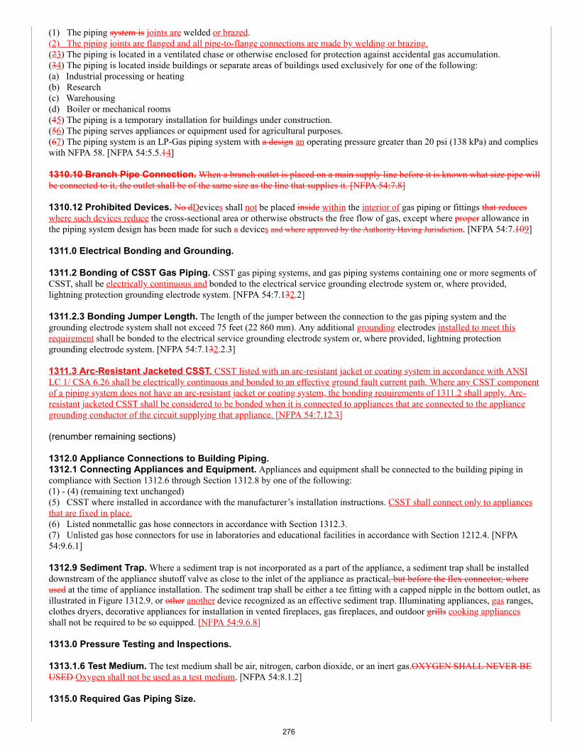
(1) The piping system is joints are welded or brazed.(2) The piping joints are flanged and all pipe-to-flange connections are made by welding or brazing.(23) The piping is located in a ventilated chase or otherwise enclosed for protection against accidental gas accumulation.(34) The piping is located inside buildings or separate areas of buildings used exclusively for one of the following:(a) Industrial processing or heating(b) Research(c) Warehousing(d) Boiler or mechanical rooms(45) The piping is a temporary installation for buildings under construction.(56) The piping serves appliances or equipment used for agricultural purposes.(67) The piping system is an LP-Gas piping system with a design an operating pressure greater than 20 psi (138 kPa) and complieswith NFPA 58. [NFPA 54:5.5.14]
1310.10 Branch Pipe Connection. When a branch outlet is placed on a main supply line before it is known what size pipe willbe connected to it, the outlet shall be of the same size as the line that supplies it. [NFPA 54:7.8]
1310.12 Prohibited Devices. No dDevices shall not be placed inside within the interior of gas piping or fittings that reduceswhere such devices reduce the cross-sectional area or otherwise obstructs the free flow of gas, except where proper allowance inthe piping system design has been made for such a devices and where approved by the Authority Having Jurisdiction. [NFPA 54:7.109]
1311.0 Electrical Bonding and Grounding.
1311.2 Bonding of CSST Gas Piping. CSST gas piping systems, and gas piping systems containing one or more segments ofCSST, shall be electrically continuous and bonded to the electrical service grounding electrode system or, where provided,lightning protection grounding electrode system. [NFPA 54:7.132.2]
1311.2.3 Bonding Jumper Length. The length of the jumper between the connection to the gas piping system and thegrounding electrode system shall not exceed 75 feet (22 860 mm). Any additional grounding electrodes installed to meet thisrequirement shall be bonded to the electrical service grounding electrode system or, where provided, lightning protectiongrounding electrode system. [NFPA 54:7.132.2.3]
1311.3 Arc-Resistant Jacketed CSST. CSST listed with an arc-resistant jacket or coating system in accordance with ANSILC 1/ CSA 6.26 shall be electrically continuous and bonded to an effective ground fault current path. Where any CSST componentof a piping system does not have an arc-resistant jacket or coating system, the bonding requirements of 1311.2 shall apply. Arc-resistant jacketed CSST shall be considered to be bonded when it is connected to appliances that are connected to the appliancegrounding conductor of the circuit supplying that appliance. [NFPA 54:7.12.3]
(renumber remaining sections)
1312.0 Appliance Connections to Building Piping.1312.1 Connecting Appliances and Equipment. Appliances and equipment shall be connected to the building piping incompliance with Section 1312.6 through Section 1312.8 by one of the following:(1) - (4) (remaining text unchanged)(5) CSST where installed in accordance with the manufacturer’s installation instructions. CSST shall connect only to appliancesthat are fixed in place.(6) Listed nonmetallic gas hose connectors in accordance with Section 1312.3.(7) Unlisted gas hose connectors for use in laboratories and educational facilities in accordance with Section 1212.4. [NFPA54:9.6.1]
1312.9 Sediment Trap. Where a sediment trap is not incorporated as a part of the appliance, a sediment trap shall be installeddownstream of the appliance shutoff valve as close to the inlet of the appliance as practical, but before the flex connector, whereused at the time of appliance installation. The sediment trap shall be either a tee fitting with a capped nipple in the bottom outlet, asillustrated in Figure 1312.9, or other another device recognized as an effective sediment trap. Illuminating appliances, gas ranges,clothes dryers, decorative appliances for installation in vented fireplaces, gas fireplaces, and outdoor grills cooking appliancesshall not be required to be so equipped. [NFPA 54:9.6.8]
1313.0 Pressure Testing and Inspections.
1313.1.6 Test Medium. The test medium shall be air, nitrogen, carbon dioxide, or an inert gas.OXYGEN SHALL NEVER BEUSED Oxygen shall not be used as a test medium. [NFPA 54:8.1.2]
1315.0 Required Gas Piping Size.
276
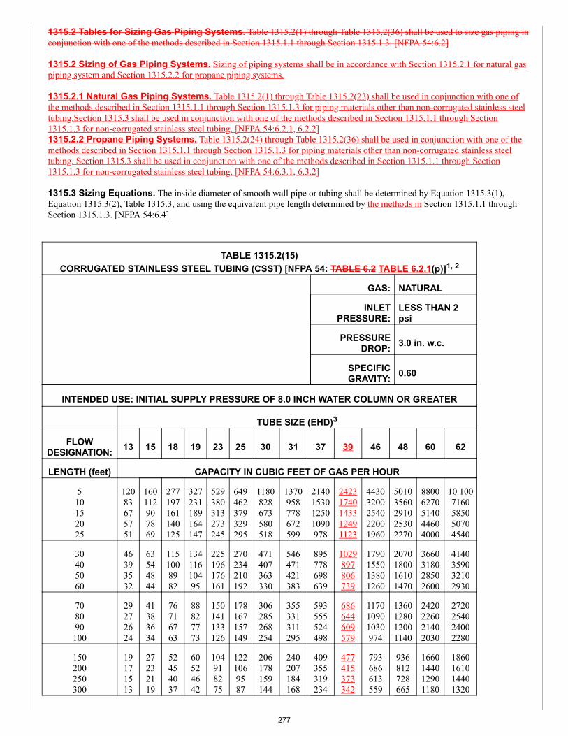
1315.2 Tables for Sizing Gas Piping Systems. Table 1315.2(1) through Table 1315.2(36) shall be used to size gas piping inconjunction with one of the methods described in Section 1315.1.1 through Section 1315.1.3. [NFPA 54:6.2]
1315.2 Sizing of Gas Piping Systems. Sizing of piping systems shall be in accordance with Section 1315.2.1 for natural gaspiping system and Section 1315.2.2 for propane piping systems.
1315.2.1 Natural Gas Piping Systems. Table 1315.2(1) through Table 1315.2(23) shall be used in conjunction with one ofthe methods described in Section 1315.1.1 through Section 1315.1.3 for piping materials other than non-corrugated stainless steeltubing.Section 1315.3 shall be used in conjunction with one of the methods described in Section 1315.1.1 through Section1315.1.3 for non-corrugated stainless steel tubing. [NFPA 54:6.2.1, 6.2.2]1315.2.2 Propane Piping Systems. Table 1315.2(24) through Table 1315.2(36) shall be used in conjunction with one of themethods described in Section 1315.1.1 through Section 1315.1.3 for piping materials other than non-corrugated stainless steeltubing. Section 1315.3 shall be used in conjunction with one of the methods described in Section 1315.1.1 through Section1315.1.3 for non-corrugated stainless steel tubing. [NFPA 54:6.3.1, 6.3.2]
1315.3 Sizing Equations. The inside diameter of smooth wall pipe or tubing shall be determined by Equation 1315.3(1),Equation 1315.3(2), Table 1315.3, and using the equivalent pipe length determined by the methods in Section 1315.1.1 throughSection 1315.1.3. [NFPA 54:6.4]
TABLE 1315.2(15)CORRUGATED STAINLESS STEEL TUBING (CSST) [NFPA 54: TABLE 6.2 TABLE 6.2.1(p)]1, 2
GAS: NATURAL
INLETPRESSURE:
LESS THAN 2psi
PRESSUREDROP: 3.0 in. w.c.
SPECIFICGRAVITY: 0.60
INTENDED USE: INITIAL SUPPLY PRESSURE OF 8.0 INCH WATER COLUMN OR GREATER
TUBE SIZE (EHD)3
FLOWDESIGNATION: 13 15 18 19 23 25 30 31 37 39 46 48 60 62
LENGTH (feet) CAPACITY IN CUBIC FEET OF GAS PER HOUR
510152025
12083675751
160112907869
277197161140125
327231189164147
529380313273245
649462379329295
1180828673580518
1370958778672599
2140153012501090978
24231740143312491123
44303200254022001960
50103560291025302270
88006270514044604000
10 1007160585050704540
30405060
46393532
63544844
1151008982
13411610495
225196176161
270234210192
471407363330
546471421383
895778698639
1029897806739
1790155013801260
2070180016101470
3660318028502600
4140359032102930
708090100
29272624
41383634
76716763
88827773
150141133126
178167157149
306285268254
355331311295
593555524498
686644609579
117010901030974
1360128012001140
2420226021402030
2720254024002280
150200250300
19171513
27232119
52454037
60524642
104918275
1221069587
206178159144
240207184168
409355319234
477415373342
793686613559
936812728665
1660144012901180
1860161014401320
277
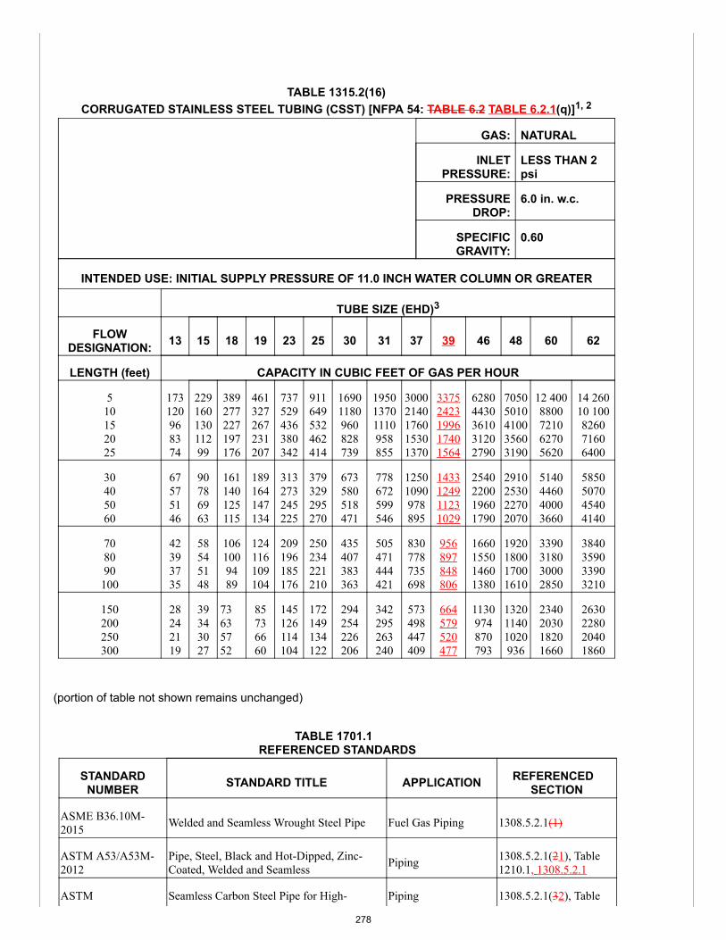
TABLE 1315.2(16)CORRUGATED STAINLESS STEEL TUBING (CSST) [NFPA 54: TABLE 6.2 TABLE 6.2.1(q)]1, 2
GAS: NATURAL
INLETPRESSURE:
LESS THAN 2psi
PRESSUREDROP:
6.0 in. w.c.
SPECIFICGRAVITY:
0.60
INTENDED USE: INITIAL SUPPLY PRESSURE OF 11.0 INCH WATER COLUMN OR GREATER
TUBE SIZE (EHD)3
FLOWDESIGNATION: 13 15 18 19 23 25 30 31 37 39 46 48 60 62
LENGTH (feet) CAPACITY IN CUBIC FEET OF GAS PER HOUR
510152025
173120968374
22916013011299
389277227197176
461327267231207
737529436380342
911649532462414
16901180960828739
195013701110958855
30002140176015301370
33752423199617401564
62804430361031202790
70505010410035603190
12 4008800721062705620
14 26010 100826071606400
30405060
67575146
90786963
161140125115
189164147134
313273245225
379329295270
673580518471
778672599546
12501090978895
1433124911231029
2540220019601790
2910253022702070
5140446040003660
5850507045404140
708090100
42393735
58545148
1061009489
124116109104
209196185176
250234221210
435407383363
505471444421
830778735698
956897848806
1660155014601380
1920180017001610
3390318030002850
3840359033903210
150200250300
28242119
39343027
73635752
85736660
145126114104
172149134122
294254226206
342295263240
573498447409
664579520477
1130974870793
132011401020936
2340203018201660
2630228020401860
(portion of table not shown remains unchanged)
TABLE 1701.1REFERENCED STANDARDS
STANDARDNUMBER STANDARD TITLE APPLICATION REFERENCED
SECTION
ASME B36.10M-2015 Welded and Seamless Wrought Steel Pipe Fuel Gas Piping 1308.5.2.1(1)
ASTM A53/A53M-2012
Pipe, Steel, Black and Hot-Dipped, Zinc-Coated, Welded and Seamless Piping 1308.5.2.1(21), Table
1210.1, 1308.5.2.1
ASTM Seamless Carbon Steel Pipe for High- Piping 1308.5.2.1(32), Table
278
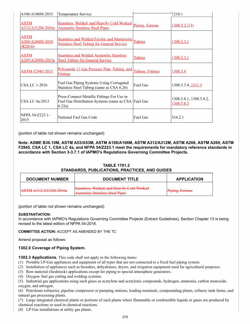
A106/A106M-2015 Temperature Service 1210.1
ASTMA312/A312M-2016a
Seamless, Welded, and Heavily Cold WorkedAustenitic Stainless Steel Pipes Piping, Ferrous 1308.5.2.1(3)
ASTMA268/A268M-2010(R2016)
Seamless and Welded Ferritic and MartensiticStainless Steel Tubing for General Service Tubing 1308.5.3.1
ASTMA269/A269M-2015a
Seamless and Welded Austenitic StainlessSteel Tubing for General Service Tubing 1308.5.3.1
ASTM F2945-2015 Polyamide 11 Gas Pressure Pipe, Tubing, andFittings Tubing, Fittings 1308.5.4
CSA LC 1-2016 Fuel Gas Piping Systems Using CorrugatedStainless Steel Tubing (same as CSA 6.26) Fuel Gas 1308.5.3.4, 1311.3
CSA LC 4a-2013Press-Connect Metallic Fittings For Use inFuel Gas Distribution Systems (same as CSA6.32a)
Fuel Gas 1308.5.8.1, 1308.5.8.2,1308.5.8.3
NFPA 54/Z223.1-2015 National Fuel Gas Code Fuel Gas 516.2.1
(portion of table not shown remains unchanged)
Note: ASME B36.10M, ASTM A53/A53M, ASTM A106/A106M, ASTM A312/A312M, ASTM A268, ASTM A269, ASTMF2945, CSA LC 1, CSA LC 4a, and NFPA 54/Z223.1 meet the requirements for mandatory reference standards inaccordance with Section 3-3.7.1 of IAPMO's Regulations Governing Committee Projects.
TABLE 1701.2STANDARDS, PUBLICATIONS, PRACTICES, AND GUIDES
DOCUMENT NUMBER DOCUMENT TITLE APPLICATION
ASTM A312/A312M-2016a Seamless, Welded, and Heavily Cold WorkedAustenitic Stainless Steel Pipes Piping, Ferrous
(portion of table not shown remains unchanged)
SUBSTANTIATION:In accordance with IAPMO's Regulations Governing Committee Projects (Extract Guidelines), Section Chapter 13 is beingrevised to the latest edition of NFPA 54-2018.
COMMITTEE ACTION: ACCEPT AS AMENDED BY THE TC
Amend proposal as follows:
1302.0 Coverage of Piping System.
1302.3 Applications. This code shall not apply to the following items:(1) Portable LP-Gas appliances and equipment of all types that are not connected to a fixed fuel piping system.(2) Installation of appliances such as brooders, dehydrators, dryers, and irrigation equipment used for agricultural purposes.(3) Raw material (feedstock) applications except for piping to special atmosphere generators.(4) Oxygen- fuel gas cutting and welding systems.(5) Industrial gas applications using such gases as acetylene and acetylenic compounds, hydrogen, ammonia, carbon monoxide,oxygen, and nitrogen.(6) Petroleum refineries, pipeline compressor or pumping stations, loading terminals, compounding plants, refinery tank farms, andnatural gas processing plants.(7) Large integrated chemical plants or portions of such plants where flammable or combustible liquids or gases are produced bychemical reactions or used in chemical reactions.(8) LP-Gas installations at utility gas plants.
279
(9) Liquefied natural gas (LNG) installations.(10) Fuel gas piping in electric utility power plants.(11) Proprietary items of equipment, apparatus, or instruments such as gas-generating sets, compressors, and calorimeters.(12) LP-Gas equipment for vaporization, gas mixing, and gas manufacturing.(13) LP-Gas piping for buildings under construction or renovations that is not to become part of the permanent building pipingsystem—that is, temporary fixed piping for building heat.(14) Installation of LP-Gas systems for railroad switch heating.(15) Installation of LP-Gas and compressed natural gas (CNG) systems on vehicles.(16) Gas piping, meters, gas- pressure regulators, and other appurtenances used by the serving gas supplier in distribution of gas,other than undiluted LP-Gas.(17) Building design and construction, except as specified herein.(18) Fuel gas systems on recreational vehicles manufactured in accordance with NFPA 1192.(19) Fuel gas systems using hydrogen as a fuel.(20) Construction of appliances. [NFPA 54:1.1.1.2]
1308.0 Gas Piping System Design, Materials, and Components.
1308.1.1 Addition to Existing System. When additional appliances are being connected to a gas piping system, the existingpiping shall be checked to determine whether it has adequate capacity. If the capacity of the system is determined to be inadequatefor the additional appliances, the existing system shall be enlarged as required, or separate gas piping of adequate capacity shall beprovided. [NFPA 54:5.1.2] 1308.4 Sizing of Gas Piping Systems. Gas piping systems shall be of such size and so installed as to provide a supply of gassufficient to meet the maximum demand and supply gas to each appliance inlet at not less than the minimum supply pressurerequired by the appliance. [NFPA 54:5.4.1]
1308.4.2 Sizing Methods. Gas piping shall be sized in accordance with one of the following:(1) Pipe sizing tables or sizing equations in this chapter.(2) Other approved engineering methods.(3) Sizing tables included in a listed piping system manufacturer’s installation instructions. [NFPA 54:5.4.3]
1308.5.2.1 Steel, Stainless Steel, and Wrought Iron. Steel, stainless steel, and wrought-iron pipe shall be at least Schedule10 40 and shall comply with the dimensional standards of ASME B36.10M and one of the following:(1) ASTM A53(2) ASTM A106(3) ASTM A312 [NFPA 54:5.6.2.2]
1308.5.3 Metallic Tubing. Tubing shall not be used with gases corrosive to the tubing material. [NFPA 54:5.6.3.1]1308.5.3.1 Stainless Steel. Stainless steel tubing shall comply with one of the following:(1) ASTM A268(2) ASTM A269 [NFPA 54:5.6.3.3]
(renumber remaining sections) 1308.5.4 Plastic Pipe, Tubing, and Fittings. Polyethylene plastic pipe, tubing, and fittings used to supply fuel gas shallconform to ASTM D2513. Pipe to be used shall be marked “gas” and “ASTM D2513.” [NFPA 54:5.6.4.1.1] Polyamide pipe, tubing,and fittings shall be identified in and conform to ASTM F2945. Pipe to be used shall be marked “gas” and “ASTM F2945.” [NFPA54:5.6.4.1.2] Polyvinyl chloride (PVC) and chlorinated polyvinyl chloride (CPVC) plastic pipe, tubing, and fittings shall not be usedto supply fuel gas. [NFPA 54:5.6.4.1.3]
1308.5.8.2 Pipe Joints. Schedule 40 and heavier pipe joints shall be threaded, flanged, brazed, welded, or assembled with press-connect fittings listed to ANSI CSA LC 4/CSA 6.32.(1) Pipe lighter than Schedule 40 shall be connected using press-connect fittings, flanges, brazing, or welding.(21) Where nonferrous pipe is brazed, the brazing materials shall have a melting point in excess of 1000°F (538°C).(32) Brazing alloys shall not contain more than 0.05 percent phosphorus. [NFPA 54:5.6.7.1]1308.5.8.3 Copper Tubing Joints. Copper tubing joints shall be assembled with approved gas tubing fittings, shall be brazedwith a material having a melting point in excess of 1000°F (538°C), or shall be assembled with press-connect fittings listed to ANSILC 4/CSA 6.32, Press-Connect Metallic Fittings for Use in Fuel Gas Distribution Systems. Brazing alloys shall not contain morethan 0.05 percent phosphorus. [NFPA 54:5.6.7.2]1308.5.8.4 Stainless Steel Tubing Joints. Stainless steel joints shall be welded, assembled with approved tubing fittings,brazed with a material having a melting point in excess of 1000°F (538°C), or assembled with press-connect fittings listed to ANSILC 4/CSA 6.32, Press-Connect Metallic Fittings for Use in Fuel Gas Distribution Systems. Brazing alloys and fluxes shall be
280
recommended by the manufacturer for use on stainless steel alloys. [NFPA 54:5.6.7.3]
(renumber remaining sections)
1308.5.8.3 Flared Joints. Flared joints shall be used in systems constructed from nonferrous pipe and tubing where experience ortests have demonstrated that the joint is suitable for the conditions and where provisions are made in the design to prevent separationof the joints. [NFPA 54:5.6.7.4]
1308.7 Gas Pressure Regulators. A line pressure regulator shall be installed where the gas supply pressure exceeds themaximum allowable inlet pressure of the appliance served. [NFPA 54:5.8.1]1308.7.1 Listing. Line pressure regulators shall be listed in accordance with CSA Z21.80 where the outlet pressure is set to 2 psior less. [NFPA 54:5.8.2]
1308.7.6 Discharge of Vents. The discharge stacks, vents, or outlet parts of all pressure-relieving and pressure-limiting devicesshall be located so that gas is safely discharged to the outdoors. Discharge stacks or vents shall be designed to prevent the entry ofwater, insects, or other foreign material that could cause blockage. The discharge stack or vent line shall be at least the same size asthe outlet of the pressure- relieving device. [NFPA 54:5.9.8.1, 5.9.8.2]
1308.10 Overpressure Protection Devices. Overpressure protection devices shall be one of the following:(1) Pressure relief valve.(2) Monitor regulator.(3) Series regulator installed upstream from the line regulator and set to continuously limit the pressure on the inlet of the lineregulator to the maximum values specified by Section 1308.9 or less.(4) Automatic shutoff device installed in series with the line pressure regulator and set to shut off when the pressure on thedownstream piping system reaches the maximum values specified by Section 1308.9 or less. This device shall be designed so that itwill remain closed until manually reset. [NFPA 54:5.9.3.1]1308.10.1 Separate Devices. The devices in Section 1308.10 shall be installed either as an integral part of the service or linepressure regulator or as separate units. Where separate overpressure protection devices are installed, they shall comply with Section1308.10.2 through Section 1308.10.7. [NFPA 54:5.9.3.2]1308.10.2 Construction and Installation. All overpressure protection devices shall meet the following requirements:(1) Be constructed of materials so that the operation of the device is not impaired by corrosion of external parts by the atmosphere orof internal parts by the gas.(2) Be designed and installed so they can be operated to determine whether the valve is free. The devices shall also be designed andinstalled so they can be tested to determine the pressure at which they operate and be examined for leakage when in the closedposition. [NFPA 54:5.9.4]1308.10.3 External Control Piping. External control piping shall be designed and installed so that damage to the control pipingof one device does not render both the regulator and the overpressure protective device inoperative. [NFPA 54:5.9.5]1308.10.4 Setting. Each pressure limiting or pressure relieving device shall be set so that the gas pressure supplied to theconnected appliance(s) does not exceed the limits specified in Section 1308.9 and Section 1308.9.1. [NFPA 54:5.9.6]1308.10.5 Unauthorized Operation. Where unauthorized operation of any shutoff valve could render a pressure relieving valveor pressure limiting device inoperative, one of the following shall be accomplished:(1) The valve shall be locked in the open position. Instruct authorized personnel in the importance of leaving the shutoff valve openand of being present while the shutoff valve is closed so that it can be locked in the open position before leaving the premises.(2) Duplicate relief valves shall be installed, each having adequate capacity to protect the system, and arrange the isolating valves orthree-way valve so that only one relief valve can be rendered inoperative at a time. [NFPA 54:5.9.7]
1308.10.6 Discharge of Vents. (remaining text unchanged)
1308.10.7 Size of Fittings, Pipe, and Openings. The fittings, pipe, and openings located between the system to be protectedand the pressure relieving device shall be sized to prevent hammering of the valve and to prevent impairment of relief capacity.[NFPA 54:5.9.9]
(renumber remaining sections)
1310.0 Gas Piping Installation.1310.1 Piping Underground. Underground gas piping shall be installed with sufficient clearance from any other undergroundstructure to avoid contact therewith, to allow maintenance, and to protect against damage from proximity to other structures. Inaddition, underground plastic piping shall be installed with sufficient clearance or shall be insulated from any source of heat so as toprevent the heat from impairing the serviceability of the pipe. [NFPA 54:7.1.1]
1310.2 CSST Piping Systems. CSST piping systems shall be installed in accordance with this code and the manufacturer'sinstallation instructions. [NFPA 54:7.1.8]
281
1310.3 Installation of Piping. (remaining text unchanged)
1310.3.1 Protective Coating. Where piping is in contact with a material or an atmosphere corrosive to the piping system, thepiping and fittings shall be coated with a corrosion-resistant material. Any such coating used on piping or components shall not beconsidered as adding strength to the system. [NFPA 54:7.2.2]
(renumber remaining sections)
1310.2.4 Hangers, Supports, and Anchors. Piping shall be supported with metal pipe hooks, metal pipe straps, metal bands,metal brackets, metal hangers, or building structural components, suitable for the size of piping, of adequate strength and quality,and located at intervals so as to prevent or damp out excessive vibration. Piping shall be anchored to prevent undue strains onconnected appliances and equipment and shall not be supported by other piping. Pipe hangers and supports shall conform to therequirements of MSS SP-58. [NFPA 54:7.2.6.1]
1310.5 Maximum Design Operating Pressure. The maximum operating pressure for any piping systems located insidebuildings shall not exceed 5 psi (34 kPa) unless one or more of the following conditions are met:(1) The piping joints are welded or brazed.(2) The piping joints are flanged and all pipe-to-flange connections are made by welding or brazing.(3) The piping is located in a ventilated chase or otherwise enclosed for protection against accidental gas accumulation.(4) The piping is located inside buildings or separate areas of buildings used exclusively for one of the following:(a) Industrial processing or heating(b) Research(c) Warehousing(d) Boiler or mechanical rooms(5) The piping is a temporary installation for buildings under construction.(6) The piping serves appliances or equipment used for agricultural purposes.(7) The piping system is an LP-Gas piping system with an operating pressure greater than 20 psi (138 kPa) and complies with NFPA58. [NFPA 54:5.5.4]
1310.12 Prohibited Devices. Devices shall not be placed within the interior of gas piping or fittings where such devices reducethe cross-sectional area or otherwise obstruct the free flow of gas, except where allowance in the piping system design has beenmade for such devices. [NFPA 54:7.9]
1311.0 Electrical Bonding and Grounding.
1311.2 Bonding of CSST Gas Piping. CSST gas piping systems, and gas piping systems containing one or more segments ofCSST, shall be electrically continuous and bonded to the electrical service grounding electrode system or, where provided, lightningprotection grounding electrode system. [NFPA 54:7.12.2] 1311.2.3 Bonding Jumper Length. The length of the jumper between the connection to the gas piping system and thegrounding electrode system shall not exceed 75 feet (22 860 mm). Any additional grounding electrodes installed to meet thisrequirement shall be bonded to the electrical service grounding electrode system or, where provided, lightning protection groundingelectrode system. [NFPA 54:7.12.2.3]
1311.3 Arc-Resistant Jacketed CSST. CSST listed with an arc-resistant jacket or coating system in accordance with ANSI LC1/ CSA 6.26 shall be electrically continuous and bonded to an effective ground fault current path. Where any CSST component of apiping system does not have an arc-resistant jacket or coating system, the bonding requirements of 1311.2 shall apply. Arc-resistantjacketed CSST shall be considered to be bonded when it is connected to appliances that are connected to the appliance groundingconductor of the circuit supplying that appliance. [NFPA 54:7.12.3]
(renumber remaining sections)
1312.0 Appliance Connections to Building Piping.1312.1 Connecting Appliances and Equipment. Appliances and equipment shall be connected to the building piping incompliance with Section 1312.6 through Section 1312.8 by one of the following:(1) - (4) (remaining text unchanged)(5) CSST where installed in accordance with the manufacturer’s installation instructions. CSST shall connect only to appliancesthat are fixed in place.(6) Listed nonmetallic gas hose connectors in accordance with Section 1312.3.(7) Unlisted gas hose connectors for use in laboratories and educational facilities in accordance with Section 1212.4. [NFPA54:9.6.1]
282
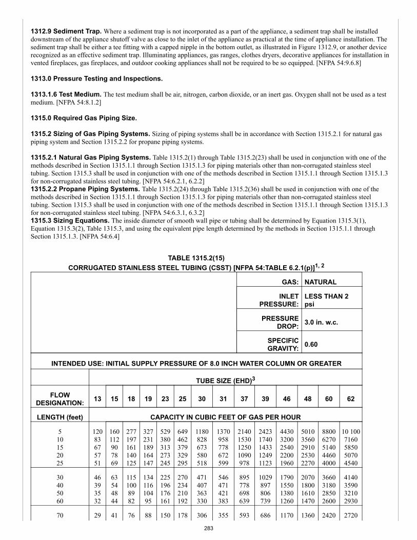
1312.9 Sediment Trap. Where a sediment trap is not incorporated as a part of the appliance, a sediment trap shall be installeddownstream of the appliance shutoff valve as close to the inlet of the appliance as practical at the time of appliance installation. Thesediment trap shall be either a tee fitting with a capped nipple in the bottom outlet, as illustrated in Figure 1312.9, or another devicerecognized as an effective sediment trap. Illuminating appliances, gas ranges, clothes dryers, decorative appliances for installation invented fireplaces, gas fireplaces, and outdoor cooking appliances shall not be required to be so equipped. [NFPA 54:9.6.8]
1313.0 Pressure Testing and Inspections.
1313.1.6 Test Medium. The test medium shall be air, nitrogen, carbon dioxide, or an inert gas. Oxygen shall not be used as a testmedium. [NFPA 54:8.1.2]
1315.0 Required Gas Piping Size.
1315.2 Sizing of Gas Piping Systems. Sizing of piping systems shall be in accordance with Section 1315.2.1 for natural gaspiping system and Section 1315.2.2 for propane piping systems.
1315.2.1 Natural Gas Piping Systems. Table 1315.2(1) through Table 1315.2(23) shall be used in conjunction with one of themethods described in Section 1315.1.1 through Section 1315.1.3 for piping materials other than non-corrugated stainless steeltubing. Section 1315.3 shall be used in conjunction with one of the methods described in Section 1315.1.1 through Section 1315.1.3for non-corrugated stainless steel tubing. [NFPA 54:6.2.1, 6.2.2]1315.2.2 Propane Piping Systems. Table 1315.2(24) through Table 1315.2(36) shall be used in conjunction with one of themethods described in Section 1315.1.1 through Section 1315.1.3 for piping materials other than non-corrugated stainless steeltubing. Section 1315.3 shall be used in conjunction with one of the methods described in Section 1315.1.1 through Section 1315.1.3for non-corrugated stainless steel tubing. [NFPA 54:6.3.1, 6.3.2]1315.3 Sizing Equations. The inside diameter of smooth wall pipe or tubing shall be determined by Equation 1315.3(1),Equation 1315.3(2), Table 1315.3, and using the equivalent pipe length determined by the methods in Section 1315.1.1 throughSection 1315.1.3. [NFPA 54:6.4]
TABLE 1315.2(15)CORRUGATED STAINLESS STEEL TUBING (CSST) [NFPA 54:TABLE 6.2.1(p)]1, 2
GAS: NATURAL
INLETPRESSURE:
LESS THAN 2psi
PRESSUREDROP: 3.0 in. w.c.
SPECIFICGRAVITY: 0.60
INTENDED USE: INITIAL SUPPLY PRESSURE OF 8.0 INCH WATER COLUMN OR GREATER
TUBE SIZE (EHD)3
FLOWDESIGNATION: 13 15 18 19 23 25 30 31 37 39 46 48 60 62
LENGTH (feet) CAPACITY IN CUBIC FEET OF GAS PER HOUR
510152025
12083675751
160112907869
277197161140125
327231189164147
529380313273245
649462379329295
1180828673580518
1370958778672599
2140153012501090978
24231740143312491123
44303200254022001960
50103560291025302270
88006270514044604000
10 1007160585050704540
30405060
46393532
63544844
1151008982
13411610495
225196176161
270234210192
471407363330
546471421383
895778698639
1029897806739
1790155013801260
2070180016101470
3660318028502600
4140359032102930
70 29 41 76 88 150 178 306 355 593 686 1170 1360 2420 2720
283
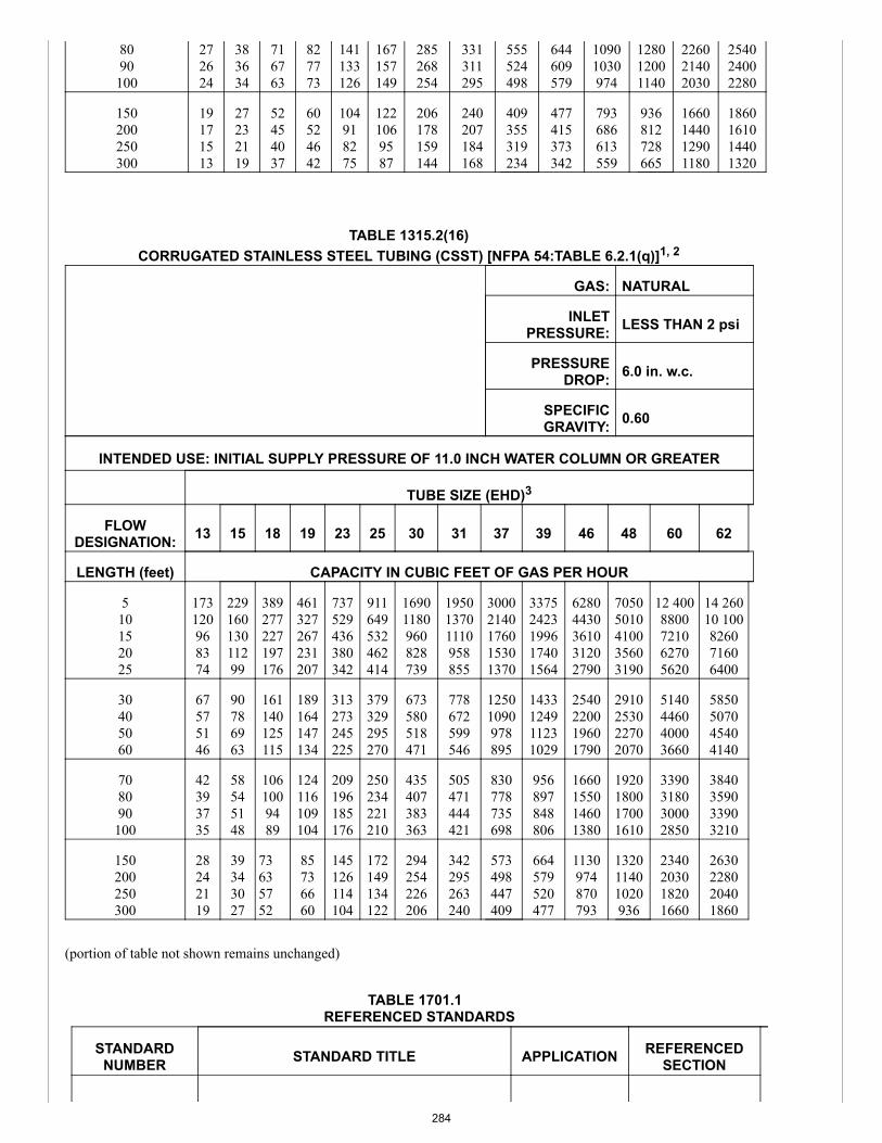
8090100
272624
383634
716763
827773
141133126
167157149
285268254
331311295
555524498
644609579
10901030974
128012001140
226021402030
254024002280
150200250300
19171513
27232119
52454037
60524642
104918275
1221069587
206178159144
240207184168
409355319234
477415373342
793686613559
936812728665
1660144012901180
1860161014401320
TABLE 1315.2(16)CORRUGATED STAINLESS STEEL TUBING (CSST) [NFPA 54:TABLE 6.2.1(q)]1, 2
GAS: NATURAL
INLETPRESSURE: LESS THAN 2 psi
PRESSUREDROP: 6.0 in. w.c.
SPECIFICGRAVITY: 0.60
INTENDED USE: INITIAL SUPPLY PRESSURE OF 11.0 INCH WATER COLUMN OR GREATER
TUBE SIZE (EHD)3
FLOWDESIGNATION: 13 15 18 19 23 25 30 31 37 39 46 48 60 62
LENGTH (feet) CAPACITY IN CUBIC FEET OF GAS PER HOUR
510152025
173120968374
22916013011299
389277227197176
461327267231207
737529436380342
911649532462414
16901180960828739
195013701110958855
30002140176015301370
33752423199617401564
62804430361031202790
70505010410035603190
12 4008800721062705620
14 26010 100826071606400
30405060
67575146
90786963
161140125115
189164147134
313273245225
379329295270
673580518471
778672599546
12501090978895
1433124911231029
2540220019601790
2910253022702070
5140446040003660
5850507045404140
708090100
42393735
58545148
1061009489
124116109104
209196185176
250234221210
435407383363
505471444421
830778735698
956897848806
1660155014601380
1920180017001610
3390318030002850
3840359033903210
150200250300
28242119
39343027
73635752
85736660
145126114104
172149134122
294254226206
342295263240
573498447409
664579520477
1130974870793
132011401020936
2340203018201660
2630228020401860
(portion of table not shown remains unchanged)
TABLE 1701.1REFERENCED STANDARDS
STANDARDNUMBER STANDARD TITLE APPLICATION REFERENCED
SECTION
284
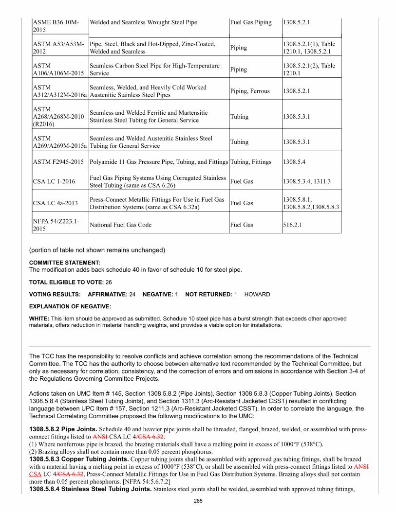
ASME B36.10M-2015
Welded and Seamless Wrought Steel Pipe Fuel Gas Piping 1308.5.2.1
ASTM A53/A53M-2012
Pipe, Steel, Black and Hot-Dipped, Zinc-Coated,Welded and Seamless Piping 1308.5.2.1(1), Table
1210.1, 1308.5.2.1
ASTMA106/A106M-2015
Seamless Carbon Steel Pipe for High-TemperatureService Piping 1308.5.2.1(2), Table
1210.1
ASTMA312/A312M-2016a
Seamless, Welded, and Heavily Cold WorkedAustenitic Stainless Steel Pipes Piping, Ferrous 1308.5.2.1
ASTMA268/A268M-2010(R2016)
Seamless and Welded Ferritic and MartensiticStainless Steel Tubing for General Service Tubing 1308.5.3.1
ASTMA269/A269M-2015a
Seamless and Welded Austenitic Stainless SteelTubing for General Service Tubing 1308.5.3.1
ASTM F2945-2015 Polyamide 11 Gas Pressure Pipe, Tubing, and Fittings Tubing, Fittings 1308.5.4
CSA LC 1-2016 Fuel Gas Piping Systems Using Corrugated StainlessSteel Tubing (same as CSA 6.26) Fuel Gas 1308.5.3.4, 1311.3
CSA LC 4a-2013 Press-Connect Metallic Fittings For Use in Fuel GasDistribution Systems (same as CSA 6.32a) Fuel Gas 1308.5.8.1,
1308.5.8.2,1308.5.8.3
NFPA 54/Z223.1-2015 National Fuel Gas Code Fuel Gas 516.2.1
(portion of table not shown remains unchanged)
COMMITTEE STATEMENT:The modification adds back schedule 40 in favor of schedule 10 for steel pipe.
TOTAL ELIGIBLE TO VOTE: 26
VOTING RESULTS: AFFIRMATIVE: 24 NEGATIVE: 1 NOT RETURNED: 1 HOWARD
EXPLANATION OF NEGATIVE:
WHITE: This item should be approved as submitted. Schedule 10 steel pipe has a burst strength that exceeds other approvedmaterials, offers reduction in material handling weights, and provides a viable option for installations.
The TCC has the responsibility to resolve conflicts and achieve correlation among the recommendations of the TechnicalCommittee. The TCC has the authority to choose between alternative text recommended by the Technical Committee, butonly as necessary for correlation, consistency, and the correction of errors and omissions in accordance with Section 3-4 ofthe Regulations Governing Committee Projects.
Actions taken on UMC Item # 145, Section 1308.5.8.2 (Pipe Joints), Section 1308.5.8.3 (Copper Tubing Joints), Section1308.5.8.4 (Stainless Steel Tubing Joints), and Section 1311.3 (Arc-Resistant Jacketed CSST) resulted in conflictinglanguage between UPC Item # 157, Section 1211.3 (Arc-Resistant Jacketed CSST). In order to correlate the language, theTechnical Correlating Committee proposed the following modifications to the UMC:
1308.5.8.2 Pipe Joints. Schedule 40 and heavier pipe joints shall be threaded, flanged, brazed, welded, or assembled with press-connect fittings listed to ANSI CSA LC 4/CSA 6.32.(1) Where nonferrous pipe is brazed, the brazing materials shall have a melting point in excess of 1000°F (538°C).(2) Brazing alloys shall not contain more than 0.05 percent phosphorus.1308.5.8.3 Copper Tubing Joints. Copper tubing joints shall be assembled with approved gas tubing fittings, shall be brazedwith a material having a melting point in excess of 1000°F (538°C), or shall be assembled with press-connect fittings listed to ANSICSA LC 4/CSA 6.32, Press-Connect Metallic Fittings for Use in Fuel Gas Distribution Systems. Brazing alloys shall not containmore than 0.05 percent phosphorus. [NFPA 54:5.6.7.2]1308.5.8.4 Stainless Steel Tubing Joints. Stainless steel joints shall be welded, assembled with approved tubing fittings,
285
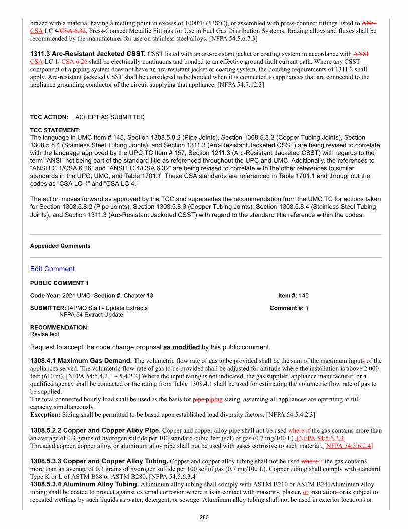
Item #: 145
Comment #: 1
brazed with a material having a melting point in excess of 1000°F (538°C), or assembled with press-connect fittings listed to ANSICSA LC 4/CSA 6.32, Press-Connect Metallic Fittings for Use in Fuel Gas Distribution Systems. Brazing alloys and fluxes shall berecommended by the manufacturer for use on stainless steel alloys. [NFPA 54:5.6.7.3]
1311.3 Arc-Resistant Jacketed CSST. CSST listed with an arc-resistant jacket or coating system in accordance with ANSICSA LC 1/ CSA 6.26 shall be electrically continuous and bonded to an effective ground fault current path. Where any CSSTcomponent of a piping system does not have an arc-resistant jacket or coating system, the bonding requirements of 1311.2 shallapply. Arc-resistant jacketed CSST shall be considered to be bonded when it is connected to appliances that are connected to theappliance grounding conductor of the circuit supplying that appliance. [NFPA 54:7.12.3]
TCC ACTION: ACCEPT AS SUBMITTED
TCC STATEMENT:The language in UMC Item # 145, Section 1308.5.8.2 (Pipe Joints), Section 1308.5.8.3 (Copper Tubing Joints), Section1308.5.8.4 (Stainless Steel Tubing Joints), and Section 1311.3 (Arc-Resistant Jacketed CSST) are being revised to correlatewith the language approved by the UPC TC Item # 157, Section 1211.3 (Arc-Resistant Jacketed CSST) with regards to theterm “ANSI” not being part of the standard title as referenced throughout the UPC and UMC. Additionally, the references to“ANSI LC 1/CSA 6.26” and “ANSI LC 4/CSA 6.32” are being revised to correlate with the other references to similarstandards in the UPC, UMC, and Table 1701.1. These CSA standards are referenced in Table 1701.1 and throughout thecodes as “CSA LC 1" and “CSA LC 4.”
The action moves forward as approved by the TCC and supersedes the recommendation from the UMC TC for actions takenfor Section 1308.5.8.2 (Pipe Joints), Section 1308.5.8.3 (Copper Tubing Joints), Section 1308.5.8.4 (Stainless Steel TubingJoints), and Section 1311.3 (Arc-Resistant Jacketed CSST) with regard to the standard title reference within the codes.
Appended Comments
Edit Comment
PUBLIC COMMENT 1
Code Year: 2021 UMC Section #: Chapter 13
SUBMITTER: IAPMO Staff - Update ExtractsNFPA 54 Extract Update
RECOMMENDATION:Revise text
Request to accept the code change proposal as modified by this public comment.
1308.4.1 Maximum Gas Demand. The volumetric flow rate of gas to be provided shall be the sum of the maximum inputs of theappliances served. The volumetric flow rate of gas to be provided shall be adjusted for altitude where the installation is above 2 000feet (610 m). [NFPA 54:5.4.2.1 – 5.4.2.2] Where the input rating is not indicated, the gas supplier, appliance manufacturer, or aqualified agency shall be contacted or the rating from Table 1308.4.1 shall be used for estimating the volumetric flow rate of gas tobe supplied.The total connected hourly load shall be used as the basis for pipe piping sizing, assuming all appliances are operating at fullcapacity simultaneously.Exception: Sizing shall be permitted to be based upon established load diversity factors. [NFPA 54:5.4.2.3]
1308.5.2.2 Copper and Copper Alloy Pipe. Copper and copper alloy pipe shall not be used where if the gas contains more thanan average of 0.3 grains of hydrogen sulfide per 100 standard cubic feet (scf) of gas (0.7 mg/100 L). [NFPA 54:5.6.2.3]Threaded copper, copper alloy, or aluminum alloy pipe shall not be used with gases corrosive to such material. [NFPA 54:5.6.2.4]
1308.5.3.3 Copper and Copper Alloy Tubing. Copper and copper alloy tubing shall not be used where if the gas containsmore than an average of 0.3 grains of hydrogen sulfide per 100 scf of gas (0.7 mg/100 L). Copper tubing shall comply with standardType K or L of ASTM B88 or ASTM B280. [NFPA 54:5.6.3.4]1308.5.3.4 Aluminum Alloy Tubing. Aluminum alloy tubing shall comply with ASTM B210 or ASTM B241Aluminum alloytubing shall be coated to protect against external corrosion where it is in contact with masonry, plaster, or insulation, or is subject torepeated wettings by such liquids as water, detergent, or sewage. Aluminum alloy tubing shall not be used in exterior locations or
286
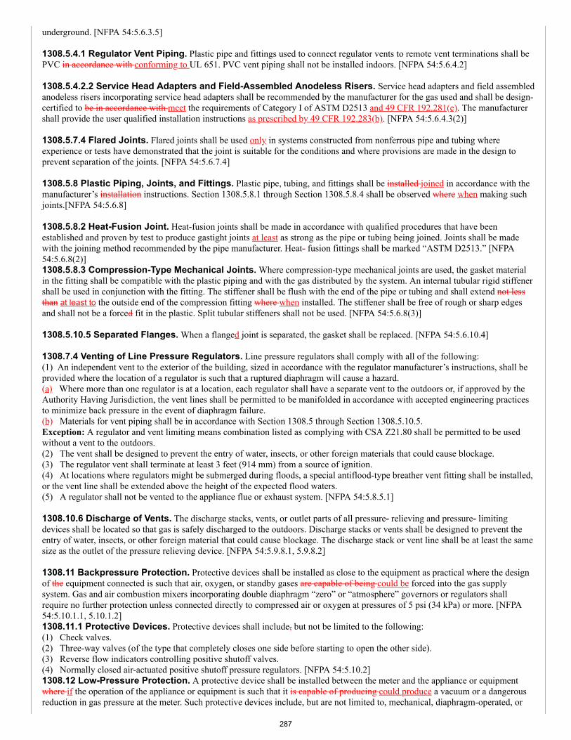
underground. [NFPA 54:5.6.3.5]
1308.5.4.1 Regulator Vent Piping. Plastic pipe and fittings used to connect regulator vents to remote vent terminations shall bePVC in accordance with conforming to UL 651. PVC vent piping shall not be installed indoors. [NFPA 54:5.6.4.2]
1308.5.4.2.2 Service Head Adapters and Field-Assembled Anodeless Risers. Service head adapters and field assembledanodeless risers incorporating service head adapters shall be recommended by the manufacturer for the gas used and shall be design-certified to be in accordance with meet the requirements of Category I of ASTM D2513 and 49 CFR 192.281(e). The manufacturershall provide the user qualified installation instructions as prescribed by 49 CFR 192.283(b). [NFPA 54:5.6.4.3(2)]
1308.5.7.4 Flared Joints. Flared joints shall be used only in systems constructed from nonferrous pipe and tubing whereexperience or tests have demonstrated that the joint is suitable for the conditions and where provisions are made in the design toprevent separation of the joints. [NFPA 54:5.6.7.4]
1308.5.8 Plastic Piping, Joints, and Fittings. Plastic pipe, tubing, and fittings shall be installed joined in accordance with themanufacturer’s installation instructions. Section 1308.5.8.1 through Section 1308.5.8.4 shall be observed where when making suchjoints.[NFPA 54:5.6.8]
1308.5.8.2 Heat-Fusion Joint. Heat-fusion joints shall be made in accordance with qualified procedures that have beenestablished and proven by test to produce gastight joints at least as strong as the pipe or tubing being joined. Joints shall be madewith the joining method recommended by the pipe manufacturer. Heat- fusion fittings shall be marked “ASTM D2513.” [NFPA54:5.6.8(2)]1308.5.8.3 Compression-Type Mechanical Joints. Where compression-type mechanical joints are used, the gasket materialin the fitting shall be compatible with the plastic piping and with the gas distributed by the system. An internal tubular rigid stiffenershall be used in conjunction with the fitting. The stiffener shall be flush with the end of the pipe or tubing and shall extend not lessthan at least to the outside end of the compression fitting where when installed. The stiffener shall be free of rough or sharp edgesand shall not be a forced fit in the plastic. Split tubular stiffeners shall not be used. [NFPA 54:5.6.8(3)]
1308.5.10.5 Separated Flanges. When a flanged joint is separated, the gasket shall be replaced. [NFPA 54:5.6.10.4]
1308.7.4 Venting of Line Pressure Regulators. Line pressure regulators shall comply with all of the following:(1) An independent vent to the exterior of the building, sized in accordance with the regulator manufacturer’s instructions, shall beprovided where the location of a regulator is such that a ruptured diaphragm will cause a hazard.(a) Where more than one regulator is at a location, each regulator shall have a separate vent to the outdoors or, if approved by theAuthority Having Jurisdiction, the vent lines shall be permitted to be manifolded in accordance with accepted engineering practicesto minimize back pressure in the event of diaphragm failure.(b) Materials for vent piping shall be in accordance with Section 1308.5 through Section 1308.5.10.5.Exception: A regulator and vent limiting means combination listed as complying with CSA Z21.80 shall be permitted to be usedwithout a vent to the outdoors.(2) The vent shall be designed to prevent the entry of water, insects, or other foreign materials that could cause blockage.(3) The regulator vent shall terminate at least 3 feet (914 mm) from a source of ignition.(4) At locations where regulators might be submerged during floods, a special antiflood-type breather vent fitting shall be installed,or the vent line shall be extended above the height of the expected flood waters.(5) A regulator shall not be vented to the appliance flue or exhaust system. [NFPA 54:5.8.5.1]
1308.10.6 Discharge of Vents. The discharge stacks, vents, or outlet parts of all pressure- relieving and pressure- limitingdevices shall be located so that gas is safely discharged to the outdoors. Discharge stacks or vents shall be designed to prevent theentry of water, insects, or other foreign material that could cause blockage. The discharge stack or vent line shall be at least the samesize as the outlet of the pressure relieving device. [NFPA 54:5.9.8.1, 5.9.8.2]
1308.11 Backpressure Protection. Protective devices shall be installed as close to the equipment as practical where the designof the equipment connected is such that air, oxygen, or standby gases are capable of being could be forced into the gas supplysystem. Gas and air combustion mixers incorporating double diaphragm “zero” or “atmosphere” governors or regulators shallrequire no further protection unless connected directly to compressed air or oxygen at pressures of 5 psi (34 kPa) or more. [NFPA54:5.10.1.1, 5.10.1.2]1308.11.1 Protective Devices. Protective devices shall include, but not be limited to the following:(1) Check valves.(2) Three-way valves (of the type that completely closes one side before starting to open the other side).(3) Reverse flow indicators controlling positive shutoff valves.(4) Normally closed air-actuated positive shutoff pressure regulators. [NFPA 54:5.10.2]1308.12 Low-Pressure Protection. A protective device shall be installed between the meter and the appliance or equipmentwhere if the operation of the appliance or equipment is such that it is capable of producing could produce a vacuum or a dangerousreduction in gas pressure at the meter. Such protective devices include, but are not limited to, mechanical, diaphragm-operated, or
287
Item #: 145
Comment #: 2
electrically operated low-pressure shutoff valves. [NFPA 54:5.11]
1310.8.1 Metallic Pipe. Metallic pipe bends shall comply with the following:(1) Bends shall be made only with bending tools and procedures intended for that purpose.(2) All bends shall be smooth and free from buckling, cracks, or other evidence of mechanical damage.(3) The longitudinal weld of the pipe shall be near the neutral axis of the bend.(4) Pipe shall not be bent through an arc of more than 90 degrees.(5) The inside radius of a bend shall be not less than six 6 times the outside diameter of the pipe. [NFPA 54:7.5.1]
1315.0 Required Gas Piping Size.1315.1 Pipe Sizing Methods. Where the pipe size is to be determined using a method any of the methods in Section 1315.1.1through Section 1315.1.3, the diameter of each pipe segment shall be obtained from the pipe sizing tables in Section 1315.2 or fromthe sizing equations in Section 1315.3. [NFPA 54:6.1]1315.1.1 Longest Length Method. The pipe size of each section of gas piping shall be determined using the longest length ofpiping from the point of delivery to the most remote outlet and the load of the section. [NFPA 54:6.1.1]1315.1.2 Branch Length Method. Pipe shall be sized as follows:(1) The pPipe size of each section of the longest pipe run from the point of delivery to the most remote outlet shall be determinedusing the longest run of piping and the load of the section.(2) The pipe size of each section of branch piping not previously sized shall be determined using the length of piping from thepoint of delivery to the most remote outlet in each branch and the load of the section. [NFPA 54:6.1.2]
1315.3 Sizing Equations. The inside diameter of smooth wall pipe or tubing shall be determined by Equation 1315.3(1),Equation 1315.3(2), and Table 1315.3, and using the equivalent pipe length determined by the methods in Section 1315.1.1 throughSection 1315.1.3. [NFPA 54:6.4]
TABLE 1701.1REFERENCED STANDARDS
STANDARDNUMBER STANDARD TITLE APPLICATION REFERENCED
SECTION
49 CFR 192.281 Plastic Pipe Piping, Plastic 1308.5.4.2.2
49 CFR 192.283 Plastic Pipe: Qualifying JoiningProcedures Piping, Plastic 1308.5.4.2.2
(portion of table not shown remain unchanged)
Note: 49 CFR 192.281(e) and 49 CFR 192.183(b) do not meet the requirements for mandatory referencestandards in accordance with Section 3-3.7.1 of IAPMO’s Regulations Governing Committee Projects.
SUBSTANTIATION:In accordance with IAPMO's Regulations Governing Committee Projects (Extract Guidelines), the above sections are beingrevised to the latest edition of NFPA 54-2018.
COMMITTEE ACTION: ACCEPTED AS SUBMITTED
TOTAL ELIGIBLE TO VOTE: 26
VOTING RESULTS: AFFIRMATIVE: 25 NOT RETURNED: 1 HOWARD
Edit Comment
PUBLIC COMMENT 2
Code Year: 2021 UMC Section #: 1308.5.2.1, 1308.5.7.1
SUBMITTER: Paul CabotAmerican Gas Association
RECOMMENDATION:Revise text
288
Request to accept the code change proposal as modified by this public comment.
1308.5.2.1 Steel, Stainless Steel, and Wrought-Iron Pipe. Steel, stainless steel, and wrought-iron pipe shall be at least Schedule4010 and shall comply with the dimensional standards of ASME B36.10M and one of the following:(1) ASTM A53(2) ASTM A106(3) ASTM A312 [NFPA 54:5.6.2.2]
1308.5.7.1 Pipe Joints. Schedule 40 and heavier pipe joints shall be threaded, flanged, brazed, welded, or assembled with press-connect fittings listed to CSA LC 4.(1) Pipe lighter than Schedule 40 shall be connected using press-connect fittings, flanges, brazing, or welding.(21) Where nonferrous pipe is brazed, the brazing materials shall have a melting point in excess of 1000°F (53 8°C).(32) Brazing alloys shall not contain more than 0.05 percent phosphorus. [NFPA 54:5.6.7.1]
SUBSTANTIATION:The committee statement for changing the above extracted NFPA 54 material does not provide a valid reason as required byIAPMO's procedures. The committee statement provides only what was done, not why it was done. Without a valid reason Icannot address the committee's concerns regarding their action. AGA still maintains that any TC's action to technical revisean extract violates the IAPMO extract policy.
COMMITTEE ACTION: REJECT
COMMITTEE STATEMENT:The TC has accepted a minimum of Schedule 40 pipe to be used. Furthermore, the TC believes there is no technicaljustification for the NFPA 54 extract to reduce the strength of steel pipe used in the code.
TOTAL ELIGIBLE TO VOTE: 26
VOTING RESULTS: AFFIRMATIVE: 25 NOT RETURNED: 1 HOWARD
289
Item #: 149
Comment #: 1
Proposals
Edit Proposal
Item #: 149
UMC 2021 Section: Appendix B: B 101.1 - B 107.1
SUBMITTER: IAPMO Staff - Update ExtractsNFPA 54 Extract Update
RECOMMENDATION:Revise text
B 101.0 Adjusting the Burner Input.B 101.1 Adjusting Input. The input rate of the burner shall be adjusted to the value in accordance with the appliancemanufacturer’s instructions. Firing at a rate in excess of the nameplate rating shall be prohibited. The input rate shall can be adjustedby changing the size of a fixed orifice, changing the adjustment of an adjustable orifice, or readjusting the appliance’s gas pressureregulator outlet pressure (where a regulator is provided in the appliance). [NFPA 54:11.1.1, 11.1.1.1]
B 104.0 Automatic Ignition.B 104.1 General. Appliances supplied with means for automatic ignition shall be checked for operation within the parametersprovided by the manufacturer. Any adjustments made shall be in accordance with the manufacturer’s installation instructions.[NFPA 54:11.4]
B 105.0 Protective Devices.B 105.1 General. Where required by the manufacturer’s installation instructions, all protective devices furnished with theappliance such as a limit control, fan control to blower, temperature -and pressure -relief valve, low-water cutoff device, or manualoperating features, shall be checked for operation within the parameters provided by the manufacturer. Any aAdjustments made shallbe in accordance with the manufacturer’s installation instructions. [NFPA 54:11.5]
B 107.0 Operating Instructions.B 107.1 General. Operating instructions shall be furnished and shall be left in a prominent position near the appliance for the useof by the consumer. [NFPA 54:11.7]
SUBSTANTIATION:In accordance with IAPMO's Regulations Governing Committee Projects (Extract Guidelines), Section Appendix B is beingrevised to the latest edition of NFPA 54-2018.
COMMITTEE ACTION: ACCEPT AS SUBMITTED
TOTAL ELIGIBLE TO VOTE: 26
VOTING RESULTS: AFFIRMATIVE: 25 NOT RETURNED: 1 HOWARD
Appended Comments
Edit Comment
PUBLIC COMMENT 1
Code Year: 2021 UMC Section #: Appendix B
SUBMITTER: IAPMO Staff - Update ExtractsNFPA 54 Extract Update
290
RECOMMENDATION:Revise text
Request to accept the code change proposal as modified by this public comment.
B 101.0 Adjusting the Burner Input.B 101.1 Adjusting Input. The input rate of the burner shall be adjusted to the proper value in accordance with the appliancemanufacturer’s instructions. Firing at a rate in excess of the nameplate rating shall be prohibited. The input rate can be adjusted byeither changing the size of a fixed orifice, changing the adjustment of an adjustable orifice, or readjusting the appliance’s gaspressure regulator outlet pressure (where a regulator is provided in the appliance). [NFPA 54:11.1.1, 11.1.1.1]B 101.1.2 High Altitude. Gas input ratings of appliances shall be used for elevations up to 2000 feet (610 m). The input ratings ofappliances operating at elevations above 2000 feet (610 m), shall be reduced in accordance with one of the following methods:(1) At the rate of 4 percent for each 1000 feet (305 m) above sea level before selecting appropriately sized appliances.(2) As permitted by the Authority Having Jurisdiction.(3) In accordance with the manufacturer’s installation instructions. [NFPA 54:11.1.2]
B 102.0 Primary Air Adjustment.B 102.1 General. The primary air for injection (Bunsen)-type burners shall be adjusted for proper flame characteristics inaccordance with the appliance manufacturer’s instructions. After setting the primary air, the adjustment means shall be secured inposition. [NFPA 54:11.2]
B 103.1 Safety Shutoff Devices.B 103.1 General. Where a safety shutoff device is provided, it shall be checked for proper operation and adjustment in accordancewith the appliance manufacturer’s instructions. Where the device does not function properly to turn off the gas supply in the event ofpilot outage or other improper operation, it shall be properly serviced or replaced with a new device. [NFPA 54:11.3]
SUBSTANTIATION:In accordance with IAPMO's Regulations Governing Committee Projects (Extract Guidelines), the above sections are beingrevised to the latest edition of NFPA 54-2018.
COMMITTEE ACTION: ACCEPTED AS SUBMITTED
TOTAL ELIGIBLE TO VOTE: 26
VOTING RESULTS: AFFIRMATIVE: 25 NOT RETURNED: 1 HOWARD
291
Item #: 150
Comment #: 1
Proposals
Edit Proposal
Item #: 150
UMC 2021 Section: D 105.0, D 105.1
SUBMITTER: Mohamed DanoControl Air Conditioning Corporation
RECOMMENDATION:Delete text without substitution
D 105.0 Cathodic Protection Requirements.D 105.1 General. Cathodic protection shall be installed for corrosion control of buried or submerged metallic gas piping in accordance with thefollowing requirements:(1) Where amphoteric metals are included in a buried or submerged pipeline containing a metal of different anodicpotential the following protection shall be provided:(a) The buried or submerged pipeline shall be cathodically protected at a negative (cathodic) voltage of 0.85 volt, measured betweenthe structure surface and a saturated copper-copper sulfate half cell contacting the electrolyte.(b) The amphoteric metals shall be electrically isolated from the remainder of the pipeline with insulating flanges, or equivalent, andcathodically protected.(2) The amount of cathodic protection shall be such that the protective coating and the pipe are not damaged.
SUBSTANTIATION:Section D 105.0 and Section D 105.1 are being deleted as they conflict with the other cathodic protection sections that arealready addressed within Appendix D. For example, Section D 110.2 and Section D 110.2.1 already provide cathodicprotection provisions applicable to manufactured homes.
COMMITTEE ACTION: REJECT
COMMITTEE STATEMENT:The proposed deletion of text is being rejected as existing language covers different piping systems and the text is neededfor enforcement of the code in regards to cathodic protection requirements.
TOTAL ELIGIBLE TO VOTE: 26
VOTING RESULTS: AFFIRMATIVE: 25 NOT RETURNED: 1 HOWARD
Appended Comments
Edit Comment
PUBLIC COMMENT 1
Code Year: 2021 UMC Section #: D 105.0, D 105.1
SUBMITTER: Mohamed DanoControl Air Conditioning CorporationRep. Self
RECOMMENDATION:Delete text without substitution
Request to accept the code change proposal as submitted by this public comment.
292

SUBSTANTIATION:Section D 105.0 and Section D 105.1 of Appendix D are being deleted as they conflict with the other cathodic protectionsections that are already addressed within Appendix D. For example, Section D 110.2 and Section D 110.2.1 already providecathodic protection provisions applicable to manufactured homes.
COMMITTEE ACTION: REJECT
COMMITTEE STATEMENT:The proposed deletion of text is being rejected as the existing language covers different piping systems and the text isneeded for enforcement of the code in regards to cathodic protection requirements.
TOTAL ELIGIBLE TO VOTE: 26
VOTING RESULTS: AFFIRMATIVE: 25 NOT RETURNED: 1 HOWARD
293
Proposals
Edit Proposal
Item #: 151
UMC 2021 Section: Appendix D: D 101.1 - D 115.3
SUBMITTER: IAPMO Staff - Update ExtractsNFPA 501A Extract Update
RECOMMENDATION:Revise text
D 101.0 Fuel Gas Piping Systems.D 101.1 General. All Ffuel gas piping systems serving manufactured homes, accessory buildings, or structures and communitiesshall be designed and constructed in accordance with the any applicable provisions of NFPA 54 and NFPA 58. NFPA 31 shall applyto oil fuel-burning systems and shall comply with conform to the criteria of the Authority Having Jurisdiction. [NFPA 501A:4.1.1.1– 4.1.1.2]D 101.2 Gas Supply Connections. Gas supply connections at sites, where provided from an underground gas supply pipingsystem, shall be located and arranged to permit attachment to a manufactured home (M/H) occupying the site. For the installation of liquefied petroleum gas (LP-Gas) storage systems, the applicable provisions of NFPA 58 shall befollowed. [NFPA 501A:4.1.2.1 – 4.1.2.2]D 101.3 Location of Gas Supply Connection. The gas supply to the M/H manufactured home shall be located within 4 feet(1219 mm) of the M/H manufactured home stand.Exception: The requirement of Section D 101.3 shall not apply to Ggas supply connections for manufactured homes located on all-weather wood, concrete, or concrete block foundation systems or on foundations constructed in accordance with the local buildingcode or, in the absence of a local code, with a recognized model building code. [NFPA 501A:4.1.3]
D 102.0 Single and Multiple Manufactured Home Site Fuel Supply Systems.
D 102.1.1 Open-Ended Gastight Conduit. Underground gas piping shall not be installed beneath that portion ofa M/H manufactured home site reserved for the location of a manufactured home or M/H manufactured home accessory building orstructure unless installed in the open-ended gastight conduit of Section D 102.1.2. [NFPA 501A:4.2.1.1]D 102.1.2 Requirements. The open-ended gastight conduit shall comply with conform to the requirements in the following:(1) The conduit shall be not less than Schedule 40 pipe that is approved for underground installation beneath buildings.(2) The interior diameter of the conduit shall be not less than 1/2 of an inch (15 mm) larger than the outside diameter of the gaspiping.(3) The conduit shall extend to a point not less than 4 inches (102 mm) beyond the outside wall of the M/H, manufactured home oraccessory building, or structure, and the outer ends shall not be sealed.(4) Where the conduit terminates within a M/H, manufactured home or accessory building, or structure, it shall be accessible, andthe space between the conduit and the gas piping shall be sealed to prevent leakage of gas into the building. [NFPA 501A:4.2.1.2 –4.2.1.2.4]
D 103.0 Manufactured Home Site Gas Shutoff Valve.D 103.1 General. Each M/H manufactured home site shall have a listed gas shutoff valve installed upstream ofthe M/H manufactured home site gas outlet. The gas shutoff valve shall be located on the outlet riser at a height of not less than 6inches (152 mm) above grade. A gas shutoff valve shall not be located under a M/H any manufactured home. The outlet shall beequipped with a cap or plug to prevent discharge of gas where whenever the M/H manufactured home site outlet is not connected toa M/H manufactured home. [NFPA 501A:4.2.2.1 – 4.2.2.4]Exception: Gas shutoff valves shall conform to Section D 103.1, except for manufactured homes located on foundations constructedin accordance with the local building code or, in the absence of a local code, with a recognized model building code. [NFPA501A:4.2.2]
D 104.0 Gas Meters.
294
D 104.1 Support of Meters. Where installed, gas meters shall be supported by a post or bracket placed on a firm footing or othermeans providing equivalent support and shall not depend on the gas outlet riser for support. [NFPA 501A:4.2.3.1]D 104.2 Location of Meters. Each gas meter shall be installed in an accessible location and shall be provided with unions orother fittings so that the meter is can be removed easily and replaced placed in an upright position. Meters shall not be installed inunventilated or inaccessible locations or closer than 3 feet (914 mm) to sources of ignition. [NFPA 501A:4.2.3.2.1 – 4.2.3.2.2]D 104.3 Meter Shutoff Valve or Cock. All Ggas meter installations shall be provided with shutoff valves or cocks locatedadjacent to and on the inlet side of the meters. In the case of a single meter installation utilizing an LP-Gas container, the containerservice valve shall be permitted to be used in lieu of the shutoff valve or cock. All Ggas meter installations shall be provided withtest tees located adjacent to and on the outlet side of the meters. [NFPA 501A:4.2.4.1 – 4.2.4.3]
D 106.0 Manufactured Home Community LPG Supply Systems.D 106.1 General. Where 10 or more customers are served by one LP-Gas supply system, the installation of the gas supply systemshall be in accordance with 49 CFR 192. Other types of liquefied petroleum gas supply systems and the storage and handling of LP-Gas shall be in accordance with NFPA 58. (see Section D113.0111.1) [NFPA 501A:4.3.2.1 – 4.3.2.2]
D 107.0 Required Gas Supply.D 107.1 General. The minimum hourly volume of gas required at each M/H manufactured home site outlet or a any section of theM/H manufactured home community gas piping system shall be calculated as shown in Table D 107.1. [NFPA 501A:4.3.4.1] In extreme climate areas, additional capacities other than those shown in Table D 107.1 shall be considered.
TABLE D 107.1DEMAND FACTORS FOR USE IN CALCULATING GAS PIPING SYSTEMS IN M/H
MANUFACTURED HOME COMMUNITIES*[NFPA 501A: TABLE 4.3.4.1]
NUMBER OF M/H MANUFACTUREDHOME SITES
BRITISH THERMAL UNITS PERHOUR PER M/H SITE
Btu/hr perMANUFACTURED HOME SITE
1 125 000
2 117 000
3 104 000
4 96 000
5 92 000
6 87 000
7 83 000
8 81 000
9 79 000
10 77 000
11–20 66 000
21–30 62 000
31–40 58 000
41–60 55 000
Over 60 50 000
For SI units: 1000 British thermal units per hour = 0.293 kW* In extreme climate areas, additional capacities shall be considered.
D 108.0 Gas Pipe Sizing and Pressure.
D 108.2 Pressure. Where all connected appliances are operated at their rated capacity, the gas supply pressure shall be not less
295
than 7 inches of water column (1.7 kPa). The gas supply pressure shall not exceed 14 inches of water column (3.5 kPa). [NFPA501A:4.3.5.2]
D 109.0 Gas Piping Materials.
D 109.2 Protection Coatings for Metal Gas Piping. All Bburied or submerged metallic gas piping shall be protected fromcorrosion by approved coatings or wrapping materials. AllGgas pipe protective coatings shall be approved types, shall be machineapplied, and shall comply with conform to recognized standards. Field wrapping shall provide equivalent protection and is restrictedto those short sections and fittings that are necessarily stripped for threading or welding. Risers shall be coated or wrapped to a pointnot less than at least 6 inches (152 mm) above ground. [NFPA 501A:4.3.6.2 – 4.3.6.2.4]
D 110.0 Gas Piping Installations.D 110.1 Minimum Burial Below Ground Level and Clearances. All Ggas piping installed below ground level shall have ana minimum earth cover of not less than 18 inches (457 mm) and shall be installed with not less than at least 12 inches (305 mm) ofclearance in any direction from any other underground utility systems. [NFPA 501A:4.3.7.1]D 110.2 Metallic Gas Piping. All Mmetallic gas piping systems shall be installed in accordance with approved plans andspecifications, construction documents, including provisions for cathodic protection. Each cathodic protection system shall bedesigned and installed to conform to in accordance with the provisions of 49 CFR 192. [NFPA 501A:4.3.7.2.1, 4.3.7.2.2]D 110.2.1 Cathodic Protection. Where the cathodic protection system is designed to protect only the gas piping system, the gaspiping system shall be electrically isolated from all other underground metallic systems or installations. Where only the gas pipingsystem is cathodically protected against corrosion, a dielectric fitting shall be used in the M/H manufactured home gas connection toinsulate the M/H manufactured home from the underground gas piping system. [NFPA 501A:4.3.7.2.3, 4.3.7.2.4]D 110.2.2 Underground Metallic Systems. Where a cathodic protection system is designed to provide all underground metallicsystems and installations with protection against corrosion, all such systems and installations shall be electrically bonded togetherand protected as a whole. [NFPA 501A:4.3.7.2.5]D 110.3 Plastic Gas Piping. Plastic gas piping shall be used only underground and shall be installed with an electricallyconductive wire for locating the pipe. The wire used to locate the plastic pipe shall be copper, not less smaller in size than No. 18AWG, with insulation approved for direct burial. Every Pportions of a plastic gas piping system consisting of metallic pipe shall becathodically protected against corrosion. [NFPA 501A:4.3.7.3.1 – 4.3.7.3.3]D 110.4 Gas Piping System Shutoff Valve. An accessible and identifiable shutoff valve controlling the flow of gas to theentire M/H manufactured home community gas piping system shall be installed in a location approved acceptable by to theAuthority Having Jurisdiction and near the point of connection to the service piping or to the supply connection of an LP-Gascontainer. [NFPA 501A:4.3.7.4]
D 113.0 Fuel Supply Systems Installation.
D 113.2 Use of Approved Pipe and Fittings of Extension. Where it is necessary to extend the M/H a manufactured homeinlet to permit connection of the 6 foot (1829 mm) listed connector to the site gas outlet, the extension shall be of approved materialsof the same size as the M/H manufactured home inlet and shall be adequately supported at not no more than 4 foot (1219 mm)intervals to the M/H manufactured home. [NFPA 501A:4.4.2]D 113.3 Mechanical Protection. All Ggas outlet risers, regulators, meters, valves, or and other exposed equipment shall beprotected against accidental damage. [NFPA 501A:4.4.3]D 113.4 Special Rules on Atmospherically Controlled Regulators. Atmospherically controlled regulators shall beinstalled in such a manner that moisture cannot enter the regulator vent and accumulate above the diaphragm. Where the regulatorvent is obstructed due to snow and icing conditions;, shields, hoods, or other approved suitable devices shall be provided to guardagainst closing of the vent opening. [NFPA 501A:4.4.4.1 – 4.4.4.2]D 113.5 Fuel Gas Piping Test. The M/H manufactured home fuel gas piping system shall be tested only with air before it isconnected to the gas supply. The M/H manufactured homegas piping system shall be subjected to a pressure test with all applianceshutoff valves in their closed positions. [NFPA 501A:4.4.5]D 113.5.1 Procedures. The fuel gas piping test shall consist of air pressure of at not less than 10 inches water column or morethan 14 inches water column (2.5 kPa to 3.5 kPa). The fuel gas piping system shall be isolated from the air pressure source and shallmaintain this pressure for not less than 10 minutes without perceptible leakage. Upon satisfactory completion of the fuel gas pipingtest, the appliance valves shall be opened, and the gas appliance connectors shall be tested with soapy water or bubble solution whileunder the pressure remaining in the piping system. Solutions used for testing for leakage shall not contain corrosive chemicals.Pressure shall be measured with either a manometer, slope gauge, or gauge that is calibrated in either water inch (mm) or psi (kPa),with increments of either 1/10 of an inch (2.5 mm) or 1/10 psi (0.7 kPa) gauge), as applicable. Upon satisfactory completion of thefuel gas piping test, the M/H manufactured home gas supply connector shall be installed, and the connections shall be tested withsoapy water or bubble solution. [NFPA 501A:4.4.5.1 4.4.5.1.1 – 4.4.5.1.6]D 113.5.2 Warning. The following warning shall be supplied to the installer:WARNING: Do not overpressurize the fuel gas piping system. Damage to valves, regulators, and appliances is capable of canoccurring due to pressurization beyond the maximums specified. [NFPA 501A:4.4.5.2]D 113.5.3 Vents. Gas appliance vents shall be visually inspected to ensure that they have not been dislodged in transit and areconnected securely to the appliance. [NFPA 501A:4.4.5.3]
296
Item #: 151
Comment #: 1
D 113.6 Oil Tanks. Oil tank capacities shall comply with the following:(1) Not No more than one 660 gallon (2498 L) tank or two tanks with an aggregate capacity of 660 gallons (2498 L) or less shall beconnected to one oil-burning appliance.(2) Two supply tanks, where used, shall be cross-connected and provided with a single fill and single vent, in accordance with asdescribed in NFPA 31, and shall be on a common slab and rigidly secured, one to the other.(3) Tanks having a capacity of 660 gallons (2498 L) or less shall be securely supported by rigid, noncombustible supports toprevent settling, sliding, or lifting. [NFPA 501A:4.4.6]D 113.6.1 Installation. Oil supply tanks shall be installed in accordance with the applicable provisions of NFPA 31. [NFPA501A:4.4.6.1]D 113.6.2 Capacity. A tank with a capacity not no larger than 60 gallons (227 L) shall be permitted to be a DOT-5 shippingcontainer (drum), and so marked, or a tank constructed in accordance with meeting the provisions of UL 80. Tanks other than DOT-5shipping containers having a capacity of not more than 660 gallons (2498 L) shall be constructed in accordance with meet theprovisions of UL 80. Pressure tanks shall be constructed built in accordance with Section VIII, Pressure Vessels, of the ASMEBoiler and Pressure Vessel Code. [NFPA 501A:4.4.6.2.1-4.4.6.2.2]D 113.6.3 Location. Tanks, as described in Section D 113.6 and Section D 113.6.2, that are adjacent to buildings shall be locatednot less than 10 feet (3048 mm) from a property line that is permitted to be built upon. [NFPA 501A:4.4.6.3]D 113.6.4 Vent. Tanks with a capacity not no larger than 660 gallons (2498 L) shall be equipped with an open vent not no smallerthan 11/2 inch (40 mm) iron pipe size; tanks with a 500 gallon (1892 L) or less capacity shall have a vent of 11/4 inch (32 mm) ironpipe size. [NFPA 501A:4.4.6.4]
D 114.0 Manufactured Home Accessory Building Fuel Supply Systems.D 114.1 General. Fuel gas supply systems installed in a M/H manufactured home accessory building or structure shall be inaccordance comply with the applicable provisions of NFPA 54 and NFPA 58. Fuel oil supply systems shall comply with theapplicable provisions of NFPA 31. [NFPA 501A:4.5.1 – 4.5.2]
D 115.0 Community Building Fuel Supply Systems in Manufactured Home Communities.D 115.1 Fuel Gas Piping and Equipment Installations. Fuel gas piping and equipment installed within a permanent buildingin a M/H manufactured home community shall be in accordance comply with nationally recognized appliance and fuel gas pipingcodes and standards adopted by the Authority Having Jurisdiction. Where the state or other political subdivision does not assumejurisdiction, such fuel gas piping and equipment installations shall be designed and installed in accordance with the applicableprovisions of NFPA 54 or NFPA 58. [NFPA 501A:4.6.1.1 – 4.6.1.2]D 115.2 Oil Supply Systems in M/H Manufactured Home Communities. Oil-burning equipment and installations within aM/H manufactured home community shall be designed and constructed in accordance with the applicable codes and standardsadopted by the Authority Having Jurisdiction. Where the state or other political subdivision does not assume jurisdiction, suchinstallations shall be designed and constructed in accordance with the applicable provisions of NFPA 31. [NFPA 501A:4.6.2.1 –4.6.2.2]D 115.3 Oil-Burning Equipment and Installation. Oil-burning equipment and installations within a building constructed in aM/H manufactured home community in accordance with the local building code or a nationally recognized building code shall be inaccordance comply with nationally recognized codes and standards adopted by the Authority Having Jurisdiction. Where the state orother political subdivision does not assume jurisdiction, such oil-burning equipment and installations shall be designed and installed inaccordance with the applicable provisions of NFPA 31. [NFPA 501A:4.6.3.1 – 4.6.3.2]
SUBSTANTIATION:In accordance with IAPMO's Regulations Governing Committee Projects (Extract Guidelines), Section Appendix D is beingrevised to the latest edition of NFPA 501A-2017.
COMMITTEE ACTION: ACCEPT AS SUBMITTED
TOTAL ELIGIBLE TO VOTE: 26
VOTING RESULTS: AFFIRMATIVE: 25 NOT RETURNED: 1 HOWARD
Appended Comments
Edit Comment
PUBLIC COMMENT 1
Code Year: 2021 UMC Section #: D 101.1
SUBMITTER: Keith BlazerSelf
297
RECOMMENDATION:Revise text
Request to accept the code change proposal as modified by this public comment.
D 101.1 General. All fuel gas piping systems serving manufactured homes, accessory buildings, or structures andcommunities shall be designed and constructed in accordance with any applicable provisions of NFPA 54 Chapter 13 and NFPA58. NFPA 31 shall apply fuel-burning systems and shall conform to the criteria of the Authority Having Jurisdiction. [NFPA501A:4.1.1.1 – 4.1.1.2]
SUBSTANTIATION:There is no need to send the end user to NFPA 54 as Chapter 13 already addresses provisions from NFPA 54 for fuel gaspiping systems serving manufactured homes, accessory buildings, or structures and communities.
COMMITTEE ACTION: ACCEPTED AS SUBMITTED
TOTAL ELIGIBLE TO VOTE: 26
VOTING RESULTS: AFFIRMATIVE: 25 NOT RETURNED: 1 HOWARD
298
Proposals
Edit Proposal
Item #: 152
UMC 2021 Section: E 201.7, E 503.3.1 - E 503.8.2
SUBMITTER: Connor BarbareeASHRAE
RECOMMENDATION:Revise text
E 201.7 Integrated Part-Load Value (IPLV). A single-number figure of merit based on part-load EER, COPC, or kW/tonkWexpressing part-load efficiency for air-conditioning and heat pump equipment on the basis of weighted operation at various loadcapacities for the equipment. [ASHRAE 90.1:3.2]
E 503.3.1 Criteria. The HVAC system shall comply with the following criteria:(1) - (10) (remaining text unchanged) (11) Systems serving hotel/motel guest rooms shall comply with Section E 503.4.6.3.5.(1112) Except for piping within manufacturer’s units, HVAC piping shall be insulated in accordance with Table E 503.7.3(1) and
Table E 503.7.3(2). Insulation exposed to weather shall be suitable for outdoor service, (e.g., protected by aluminum, sheetmetal, painted canvas, or plastic cover). Cellular foam insulation shall be protected as above or painted with a coating that iswater retardant and provides shielding from solar radiation.
(1213) Ductwork and plenums shall be insulated in accordance with Table E 503.7.2 and shall be sealed in accordance withSection E 503.4.7.2.
(1314) Construction documents shall require a ducted system to be air balanced in accordance with industry-acceptedprocedures.
(1415) Outdoor air intake and exhaust systems shall comply with Section E 503.4.6.4 through Section E 503.4.6.5.(1516) Where separate heating and cooling equipment serves the same temperature zone, thermostats shall be interlocked to
prevent simultaneous heating and cooling.(1617) Systems with a design supply air capacity more than 10 000 ft3/min (4.7195 m3/s) shall have optimum start controls.(1718) The system shall comply with the demand control ventilation requirements of Section E 503.4.6.9 and the ventilation
design requirements of Section E 503.5.6.6.(1819) The system shall comply with the door switch requirements of Section E 503.5.14. [ASHRAE 90.1:6.3.2]
E 503.4 Mandatory Provisions. Equipment shown in Table E 503.7.1(1) through Table E 503.7.1(16) shall have a minimumperformance at the specified rating conditions where tested in accordance with the specified test procedure. Where multiple ratingconditions or performance requirements are provided, the equipment shall satisfy the stated requirements unless otherwise exemptedby footnotes in the table. Equipment covered under the Federal Energy Policy Act of 1992 (EPACT) shall have no minimumefficiency requirements for operation at minimum capacity or other than standard rating conditions. Equipment used to provideservice water-heating functions as part of a combination system shall satisfy the stated requirements for the appropriate spaceheating or cooling category.
Tables are as follows:(1) Table E 503.7.1(1), “Electrically Operated Unitary Air Conditioners and Condensing Units-Minimum Efficiency Requirements”(2) Table E 503.7.1 (2), “Electrically Operated Unitary and Applied Heat Pumps-Minimum Efficiency Requirements”(3) Table E 503.7.1 (3), “Water-Chilling Packages-Efficiency Requirements” (See Section E 503.4.1 for water-cooled centrifugal
water-chilling packages that are designed to operate at nonstandard conditions.)(4) Table E 503.7.1 (4), “Electrically Operated Packaged Terminal Air Conditioners, Packaged Terminal Heat Pumps, Single-
Package Vertical Air Conditioners, Single-Package Vertical Heat Pumps, Room Air Conditioners, and Room Air Conditioner
299
Heat Pumps-Minimum Efficiency Requirements”(5) Table E 503.7.1 (5), “Warm-Air Furnaces and Combination Warm-Air Furnaces/Air-Conditioning Units, Warm-Air Duct
Furnaces, and Unit Heaters-Minimum Efficiency Requirements” Heating, Ventilating, and Air Conditioning(6) Table E 503.7.1 (6), “Gas- and Oil-Fired Boilers-Minimum Efficiency Requirements”(7) Table E 503.7.1 (7), “Performance Requirements for Heat-Rejection Equipment”(8) Table E 503.7.1 (8), “Heat Transfer Equipment”(9) Table E 503.7.1 (9), “Electrically Operated Variable-Refrigerant-Flow Air Conditioners- Minimum Efficiency Requirements”(10) Table E 503.7.1 (10), “Electrically Operated Variable-Refrigerant-Flow and Applied Heat Pumps-Minimum Efficiency
Requirements(11) Table E 503.7.1 (11), “Air Conditioners and Condensing Units Serving Computer Rooms”(12) Table E 503.7.1 (12), “Commercial Refrigerators and Freezers-Minimum Efficiency Requirements”(13) Table E 503.7.1 (13), “Commercial Refrigeration-Minimum Efficiency Requirements”(14) Table E 503.7.1 (14), “Vapor-Compression-Based Indoor Pool Dehumidifiers-Minimum Efficiency Requirements”(15) Table E 503.7.1 (15), “Electrically Operated DX-DOAS Units, Single-Package and Remote Condenser, without Energy
Recovery-Minimum Efficiency Requirements”(16) Table E 503.7.1 (16), “Electrically Operated DX-DOAS Units, Single-Package and Remote Condenser, with Energy Recovery-
Minimum Efficiency Requirements”
All furnaces with input ratings of 225 000 Btu/h (66 kW) or more, including electric furnaces, that are not located within theconditioned space shall have jacket losses not exceeding 0.75 percent of the input rating. Air conditioners primarily servingcomputer rooms and covered by ASHRAE 127 shall comply with the requirements in Table E 503.7.1(11). All other air conditionersshall meet the requirements in Table E 503.7.1(1). [ASHRAE 90.1:6.4.1.1]
E 503.4.1 Water-Cooled Centrifugal Chilling Packages. Equipment not designed for operation in accordance with AHRI550/590 test conditions of 44.00°F (6.67°C) leaving and 54.00°F (12.22°C) entering chilled-fluid temperatures, and 2.4 gallons perminute per ton (gpm/ton) (0.00015 L/s/kg) evaporator fluid flow and with 85.00°F (29.44°C) entering and 94.30°F (34.61°C) leavingcondenser-fluid temperatures, with 3.0 gpm/ton (0.00018 L/s/kg) condenser-fluid flow shall have maximum full-load kW/ton(FL) and part-load rating requirements adjusted in accordance with Equation E 503.4.1(1) through Equation E 503.4.1(3): FLadj = FL/Kadj [Equation E 503.4.1(1)]PLVadj = IPLV.IP/Kadj [Equation E 503.4.1(2)]Kadj = A x B [Equation E 503.4.1(3)] Where:FL = full-load kW/ton value from Table E 503.7.1(3)FLadj = maximum full-load kW/ton rating, adjusted for nonstandard conditionsIPLV.IP = IPLV.IP value from Table E 503.7.1(3)IPLVadj = maximum NPLV rating, adjusted for nonstandard conditionsA = 0.00000014592 x (LIFT)4 - 0.0000346496 x (LIFT)3 + 0.00314196 x (LIFT)2 - 0.147199 × (LIFT) + 3.930273B = 0.0015 x LvgEvap + 0.934LIFT = LvgCond - LvgEvapLvgCond = Full-load condenser leaving fluid temperature (°F)LvgEvap = Full-load evaporator leaving temperature (°F)
The FLadj and PLVadj values shall only be applicable for centrifugal chillers in accordance with meeting all of the following
full-load design ranges:(1) Minimum Evaporator Leaving Temperature: 36.00°F (2.22°C) < LvgEvap < 60.00°F (15.56°C)(2) Maximum Condenser Leaving Temperature: 115°F (46°C) LvgCond < 115.00°F (46.11°C)(3) LIFT is not less than 20.00°F (-6.67°C) < and not more than 80.00°F (26.67°C)
Manufacturers shall calculate the FLadj and PLVadj before determining whether to label the chiller in accordance with SectionE 503.4.4. Chillers that are in accordance with ASHRAE 90.1 shall be labeled on chillers in accordance with the scope ofASHRAE 90.1.
Centrifugal chillers designed to operate outside of these ranges shall not be covered under this appendix. Example: Path A, 600 ton (600 000 kg) centrifugal chiller Table E 503.7.1(3) efficiencies.F = 0.5600 kW/tonIPLV = 0.5000 kW/tonLvgCond = 91.16°FLvgEvap = 42.00°FLIFT = 91.16°F – 42.00°F = 49.16°FKadj = A x B
300
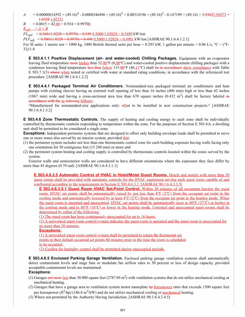
A = 0.00000014592 × (49.16)4 - 0.0000346496 × (49.16)3 + 0.00314196 × (49.16)2 - 0.147199 × (49.16) + 3.93023.93073 =1.0228 1.02331
B = 0.0015 × 42.00 + 0.934 = 0.99700Kadj = A × BFLajd = 0.560/(1.0228 × 0.9970) = 0.549 0.5600/1.02024 = 0.5489 kW/tonPLVadj = 0.500/(1.0228 × 0.9970) = 0.490 0.5000/1.02024 = 0.4901 kW/ton [ASHRAE 90.1:6.4.1.2.1]For SI units: 1 metric ton = 1000 kg, 1000 British thermal units per hour = 0.293 kW, 1 gallon per minute = 0.06 L/s, °C = (°F-32)/1.8
E 503.4.1.1 Positive Displacement (air- and water-cooled) Chilling Packages. Equipment with an evaporatorleaving fluid temperature more higher than 32.00°F (0.00°C) and water-cooled positive displacement chilling packages with acondenser leaving fluid temperature less than below 115.00°F (46.11°C) shall be in accordance show compliance with TableE 503.7.1(3) where when tested or certified with water at standard rating conditions, in accordance with the referenced testprocedure. [ASHRAE 90.1:6.4.1.2.2]
E 503.4.4.1 Packaged Terminal Air Conditioners. Nonstandard-size packaged terminal air conditioners and heatpumps with existing sleeves having an external wall opening of less than 16 inches (406 mm) high or less than 42 inches(1067 mm) wide and having a cross-sectional area less than 670 square inches (0.432 m2) shall be factory labeled inaccordance with the as following follows:“Manufactured for nonstandard-size applications only: nNot to be installed in new construction projects.” [ASHRAE90.1:6.4.1.5.2]
E 503.4.6 Zone Thermostatic Controls. The supply of heating and cooling energy to each zone shall be individuallycontrolled by thermostatic controls responding to temperature within the zone. For the purposes of Section E 503.4.6, a dwellingunit shall be permitted to be considered a single zone.Exceptions: Independent perimeter systems that are designed to offset only building envelope loads shall be permitted to serveone or more zones also served by an interior system, provided that:(1) the perimeter system includes not less than one thermostatic control zone for each building exposure having walls facing only
one orientation for 50 contiguous feet (15 240 mm) or more and(2) the perimeter system heating and cooling supply is controlled by thermostatic controls located within the zones served by the
system.Exterior walls and semiexterior walls are considered to have different orientations where the exposures they face differ by
more than 45 degrees (0.79 rad). [ASHRAE 90.1:6.4.3.1.1]
E 503.4.6.3.5 Automatic Control of HVAC in Hotel/Motel Guest Rooms. Hotels and motels with more than 50guest rooms shall be provided with automatic controls for the HVAC equipment serving each guest room capable of andconfigured according to the requirements in Section E 503.4.6.3.1. [ASHRAE 90.1:6.4.3.3.5]
E 503.4.6.3.5.1 Guest Room HVAC Set-Point Control. Within 30 minutes of all occupants leaving the guestroom, HVAC set points shall be automatically raised by not less than 4°F (2°C) from the occupant set point in thecooling mode and automatically lowered by at least 4°F (2°C) from the occupant set point in the heating mode. Whenthe guest room is unrented and unoccupied, HVAC set points shall be automatically reset to 80°F (27°C) or higher inthe cooling mode and to 60°F (16°C) or lower in the heating mode. Unrented and unoccupied guest rooms shall bedetermined by either of the following:(1) The guest room has been continuously unoccupied for up to 16 hours.(2) A networked guest room control system indicates the guest room is unrented and the guest room is unoccupied forno more than 30 minutes.Exceptions:(1) A networked guest room control system shall be permitted to return the thermostat setpoints to their default occupied set points 60 minutes prior to the time the room is scheduledto be occupied.(2) Cooling for humidity control shall be permitted during unoccupied periods.
E 503.4.6.5 Enclosed Parking Garage Ventilation. Enclosed parking garage ventilation systems shall automaticallydetect contaminant levels and stage fans or modulate fan airflow rates to 50 percent or less of design capacity, providedacceptable contaminant levels are maintained.Exceptions:(1) Garages not more less than 30 000 square feet (2787.09 m2) with ventilation systems that do not utilize mechanical cooling or
mechanical heating.(2) Garages that have a garage area to ventilation system motor nameplate hp horsepower ratio that exceeds 1500 square feet
per horsepower (ft2/hp) (186.8 m2/kW) and do not utilize mechanical cooling or mechanical heating.(3) Where not permitted by the Authority Having Jurisdiction. [ASHRAE 90.1:6.4.3.4.5]
301
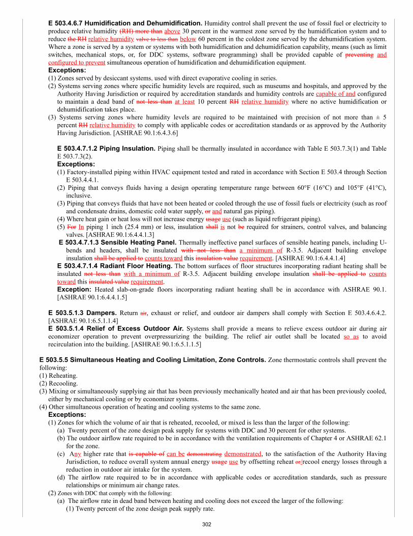
E 503.4.6.7 Humidification and Dehumidification. Humidity control shall prevent the use of fossil fuel or electricity toproduce relative humidity (RH) more than above 30 percent in the warmest zone served by the humidification system and toreduce the RH relative humidity valve to less than below 60 percent in the coldest zone served by the dehumidification system.Where a zone is served by a system or systems with both humidification and dehumidification capability, means (such as limitswitches, mechanical stops, or, for DDC systems, software programming) shall be provided capable of preventing andconfigured to prevent simultaneous operation of humidification and dehumidification equipment.Exceptions:(1) Zones served by desiccant systems, used with direct evaporative cooling in series.(2) Systems serving zones where specific humidity levels are required, such as museums and hospitals, and approved by the
Authority Having Jurisdiction or required by accreditation standards and humidity controls are capable of and configuredto maintain a dead band of not less than at least 10 percent RH relative humidity where no active humidification ordehumidification takes place.
(3) Systems serving zones where humidity levels are required to be maintained with precision of not more than ± 5percent RH relative humidity to comply with applicable codes or accreditation standards or as approved by the AuthorityHaving Jurisdiction. [ASHRAE 90.1:6.4.3.6]
E 503.4.7.1.2 Piping Insulation. Piping shall be thermally insulated in accordance with Table E 503.7.3(1) and TableE 503.7.3(2).Exceptions:(1) Factory-installed piping within HVAC equipment tested and rated in accordance with Section E 503.4 through Section
E 503.4.4.1.(2) Piping that conveys fluids having a design operating temperature range between 60°F (16°C) and 105°F (41°C),
inclusive.(3) Piping that conveys fluids that have not been heated or cooled through the use of fossil fuels or electricity (such as roof
and condensate drains, domestic cold water supply, or and natural gas piping).(4) Where heat gain or heat loss will not increase energy usage use (such as liquid refrigerant piping).(5) For In piping 1 inch (25.4 mm) or less, insulation shall is not be required for strainers, control valves, and balancing
valves. [ASHRAE 90.1:6.4.4.1.3] E 503.4.7.1.3 Sensible Heating Panel. Thermally ineffective panel surfaces of sensible heating panels, including U-
bends and headers, shall be insulated with not less than a minimum of R-3.5. Adjacent building envelopeinsulation shall be applied to counts toward this insulation value requirement. [ASHRAE 90.1:6.4.4.1.4]
E 503.4.7.1.4 Radiant Floor Heating. The bottom surfaces of floor structures incorporating radiant heating shall beinsulated not less than with a minimum of R-3.5. Adjacent building envelope insulation shall be applied to countstoward this insulated value requirement.Exception: Heated slab-on-grade floors incorporating radiant heating shall be in accordance with ASHRAE 90.1.[ASHRAE 90.1:6.4.4.1.5]
E 503.5.1.3 Dampers. Return air, exhaust or relief, and outdoor air dampers shall comply with Section E 503.4.6.4.2.[ASHRAE 90.1:6.5.1.1.4]E 503.5.1.4 Relief of Excess Outdoor Air. Systems shall provide a means to relieve excess outdoor air during aireconomizer operation to prevent overpressurizing the building. The relief air outlet shall be located so as to avoidrecirculation into the building. [ASHRAE 90.1:6.5.1.1.5]
E 503.5.5 Simultaneous Heating and Cooling Limitation, Zone Controls. Zone thermostatic controls shall prevent thefollowing:(1) Reheating.(2) Recooling.(3) Mixing or simultaneously supplying air that has been previously mechanically heated and air that has been previously cooled,
either by mechanical cooling or by economizer systems.(4) Other simultaneous operation of heating and cooling systems to the same zone.
Exceptions:(1) Zones for which the volume of air that is reheated, recooled, or mixed is less than the larger of the following:
(a) Twenty percent of the zone design peak supply for systems with DDC and 30 percent for other systems.(b) The outdoor airflow rate required to be in accordance with the ventilation requirements of Chapter 4 or ASHRAE 62.1
for the zone.(c) Any higher rate that is capable of can be demonstrating demonstrated, to the satisfaction of the Authority Having
Jurisdiction, to reduce overall system annual energy usage use by offsetting reheat or/recool energy losses through areduction in outdoor air intake for the system.
(d) The airflow rate required to be in accordance with applicable codes or accreditation standards, such as pressurerelationships or minimum air change rates.
(2) Zones with DDC that comply with the following:(a) The airflow rate in dead band between heating and cooling does not exceed the larger of the following:
(1) Twenty percent of the zone design peak supply rate.
302
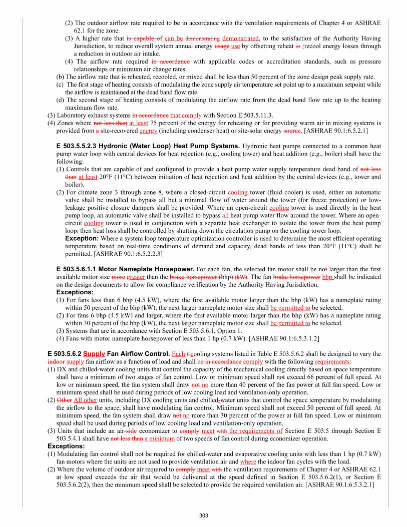
(2) The outdoor airflow rate required to be in accordance with the ventilation requirements of Chapter 4 or ASHRAE62.1 for the zone.
(3) A higher rate that is capable of can be demonstrating demonstrated, to the satisfaction of the Authority HavingJurisdiction, to reduce overall system annual energy usage use by offsetting reheat or /recool energy losses througha reduction in outdoor air intake.
(4) The airflow rate required in accordance with applicable codes or accreditation standards, such as pressurerelationships or minimum air change rates.
(b) The airflow rate that is reheated, recooled, or mixed shall be less than 50 percent of the zone design peak supply rate.(c) The first stage of heating consists of modulating the zone supply air temperature set point up to a maximum setpoint while
the airflow is maintained at the dead band flow rate.(d) The second stage of heating consists of modulating the airflow rate from the dead band flow rate up to the heating
maximum flow rate.(3) Laboratory exhaust systems in accordance that comply with Section E 503.5.11.3.(4) Zones where not less than at least 75 percent of the energy for reheating or for providing warm air in mixing systems is
provided from a site-recovered energy (including condenser heat) or site-solar energy source. [ASHRAE 90.1:6.5.2.1]
E 503.5.5.2.3 Hydronic (Water Loop) Heat Pump Systems. Hydronic heat pumps connected to a common heatpump water loop with central devices for heat rejection (e.g., cooling tower) and heat addition (e.g., boiler) shall have thefollowing:(1) Controls that are capable of and configured to provide a heat pump water supply temperature dead band of not less
than at least 20°F (11°C) between initiation of heat rejection and heat addition by the central devices (e.g., tower andboiler).
(2) For climate zone 3 through zone 8, where a closed-circuit cooling tower (fluid cooler) is used, either an automaticvalve shall be installed to bypass all but a minimal flow of water around the tower (for freeze protection) or low-leakage positive closure dampers shall be provided. Where an open-circuit cooling tower is used directly in the heatpump loop, an automatic valve shall be installed to bypass all heat pump water flow around the tower. Where an open-circuit cooling tower is used in conjunction with a separate heat exchanger to isolate the tower from the heat pumploop, then heat loss shall be controlled by shutting down the circulation pump on the cooling tower loop.Exception: Where a system loop temperature optimization controller is used to determine the most efficient operatingtemperature based on real-time conditions of demand and capacity, dead bands of less than 20°F (11°C) shall bepermitted. [ASHRAE 90.1:6.5.2.2.3]
E 503.5.6.1.1 Motor Nameplate Horsepower. For each fan, the selected fan motor shall be not larger than the firstavailable motor size more greater than the brake horsepower (bhp) (kW). The fan brake horsepower bhp shall be indicatedon the design documents to allow for compliance verification by the Authority Having Jurisdiction.Exceptions:(1) For fans less than 6 bhp (4.5 kW), where the first available motor larger than the bhp (kW) has a nameplate rating
within 50 percent of the bhp (kW), the next larger nameplate motor size shall be permitted to be selected.(2) For fans 6 bhp (4.5 kW) and larger, where the first available motor larger than the bhp (kW) has a nameplate rating
within 30 percent of the bhp (kW), the next larger nameplate motor size shall be permitted to be selected.(3) Systems that are in accordance with Section E 503.5.6.1, Option 1.(4) Fans with motor nameplate horsepower of less than 1 hp (0.7 kW). [ASHRAE 90.1:6.5.3.1.2]
E 503.5.6.2 Supply Fan Airflow Control. Each Ccooling systems listed in Table E 503.5.6.2 shall be designed to vary theindoor supply fan airflow as a function of load and shall be in accordance comply with the following requirements:(1) DX and chilled-water cooling units that control the capacity of the mechanical cooling directly based on space temperature
shall have a minimum of two stages of fan control. Low or minimum speed shall not exceed 66 percent of full speed. Atlow or minimum speed, the fan system shall draw not no more than 40 percent of the fan power at full fan speed. Low orminimum speed shall be used during periods of low cooling load and ventilation-only operation.
(2) Other All other units, including DX cooling units and chilled-water units that control the space temperature by modulatingthe airflow to the space, shall have modulating fan control. Minimum speed shall not exceed 50 percent of full speed. Atminimum speed, the fan system shall draw not no more than 30 percent of the power at full fan speed. Low or minimumspeed shall be used during periods of low cooling load and ventilation-only operation.
(3) Units that include an air-side economizer to comply meet with the requirements of Section E 503.5 through Section E503.5.4.1 shall have not less than a minimum of two speeds of fan control during economizer operation.
Exceptions:(1) Modulating fan control shall not be required for chilled-water and evaporative cooling units with less than 1 hp (0.7 kW)
fan motors where the units are not used to provide ventilation air and where the indoor fan cycles with the load.(2) Where the volume of outdoor air required to comply meet with the ventilation requirements of Chapter 4 or ASHRAE 62.1
at low speed exceeds the air that would be delivered at the speed defined in Section E 503.5.6.2(1), or Section E503.5.6.2(2), then the minimum speed shall be selected to provide the required ventilation air. [ASHRAE 90.1:6.5.3.2.1]
303
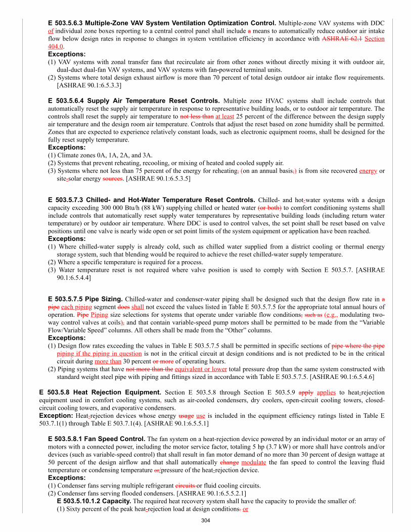
E 503.5.6.3 Multiple-Zone VAV System Ventilation Optimization Control. Multiple-zone VAV systems with DDCof individual zone boxes reporting to a central control panel shall include a means to automatically reduce outdoor air intakeflow below design rates in response to changes in system ventilation efficiency in accordance with ASHRAE 62.1 Section404.0.Exceptions:(1) VAV systems with zonal transfer fans that recirculate air from other zones without directly mixing it with outdoor air,
dual-duct dual-fan VAV systems, and VAV systems with fan-powered terminal units.(2) Systems where total design exhaust airflow is more than 70 percent of total design outdoor air intake flow requirements.
[ASHRAE 90.1:6.5.3.3] E 503.5.6.4 Supply Air Temperature Reset Controls. Multiple zone HVAC systems shall include controls thatautomatically reset the supply air temperature in response to representative building loads, or to outdoor air temperature. Thecontrols shall reset the supply air temperature to not less than at least 25 percent of the difference between the design supplyair temperature and the design room air temperature. Controls that adjust the reset based on zone humidity shall be permitted.Zones that are expected to experience relatively constant loads, such as electronic equipment rooms, shall be designed for thefully reset supply temperature.Exceptions:(1) Climate zones 0A, 1A, 2A, and 3A.(2) Systems that prevent reheating, recooling, or mixing of heated and cooled supply air.(3) Systems where not less than 75 percent of the energy for reheating, (on an annual basis,) is from site recovered energy or
site-solar energy sources. [ASHRAE 90.1:6.5.3.5]
E 503.5.7.3 Chilled- and Hot-Water Temperature Reset Controls. Chilled- and hot-water systems with a designcapacity exceeding 300 000 Btu/h (88 kW) supplying chilled or heated water (or both) to comfort conditioning systems shallinclude controls that automatically reset supply water temperatures by representative building loads (including return watertemperature) or by outdoor air temperature. Where DDC is used to control valves, the set point shall be reset based on valvepositions until one valve is nearly wide open or set point limits of the system equipment or application have been reached.Exceptions:(1) Where chilled-water supply is already cold, such as chilled water supplied from a district cooling or thermal energy
storage system, such that blending would be required to achieve the reset chilled-water supply temperature.(2) Where a specific temperature is required for a process.(3) Water temperature reset is not required where valve position is used to comply with Section E 503.5.7. [ASHRAE
90.1:6.5.4.4]
E 503.5.7.5 Pipe Sizing. Chilled-water and condenser-water piping shall be designed such that the design flow rate in apipe each piping segment does shall not exceed the values listed in Table E 503.5.7.5 for the appropriate total annual hours ofoperation. Pipe Piping size selections for systems that operate under variable flow conditions, such as (e.g., modulating two-way control valves at coils), and that contain variable-speed pump motors shall be permitted to be made from the “VariableFlow/Variable Speed” columns. All others shall be made from the “Other” columns.Exceptions:(1) Design flow rates exceeding the values in Table E 503.5.7.5 shall be permitted in specific sections of pipe where the pipe
piping if the piping in question is not in the critical circuit at design conditions and is not predicted to be in the criticalcircuit during more than 30 percent or more of operating hours.
(2) Piping systems that have not more than the equivalent or lower total pressure drop than the same system constructed withstandard weight steel pipe with piping and fittings sized in accordance with Table E 503.5.7.5. [ASHRAE 90.1:6.5.4.6]
E 503.5.8 Heat Rejection Equipment. Section E 503.5.8 through Section E 503.5.9 apply applies to heat-rejectionequipment used in comfort cooling systems, such as air-cooled condensers, dry coolers, open-circuit cooling towers, closed-circuit cooling towers, and evaporative condensers.Exception: Heat-rejection devices whose energy usage use is included in the equipment efficiency ratings listed in Table E503.7.1(1) through Table E 503.7.1(4). [ASHRAE 90.1:6.5.5.1]
E 503.5.8.1 Fan Speed Control. The fan system on a heat-rejection device powered by an individual motor or an array ofmotors with a connected power, including the motor service factor, totaling 5 hp (3.7 kW) or more shall have controls and/ordevices (such as variable-speed control) that shall result in fan motor demand of no more than 30 percent of design wattage at50 percent of the design airflow and that shall automatically change modulate the fan speed to control the leaving fluidtemperature or condensing temperature or/pressure of the heat-rejection device.Exceptions:(1) Condenser fans serving multiple refrigerant circuits or fluid cooling circuits.(2) Condenser fans serving flooded condensers. [ASHRAE 90.1:6.5.5.2.1]
E 503.5.10.1.2 Capacity. The required heat recovery system shall have the capacity to provide the smaller of:(1) Sixty percent of the peak heat-rejection load at design conditions. or
304
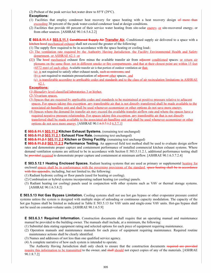
(2) Preheat of the peak service hot-water draw to 85°F (29°C).Exceptions:(1) Facilities that employ condenser heat recovery for space heating with a heat recovery design of more than
exceeding 30 percent of the peak water-cooled condenser load at design conditions.(2) Facilities that provide 60 percent of their service water heating from site-solar energy, or site-recovered energy, or
from other sources. [ASHRAE 90.1:6.5.6.2.2]
E 503.5.11.1.1 503.5.11.1 Conditioned Supply Air Transfer Air. Conditioned supply air delivered to a space with akitchen hood mechanical exhaust shall not exceed the greater of the following:(1) The supply flow required to be in accordance with the space heating or cooling load.;(2) The ventilation rate required by the Authority Having Jurisdiction, the Facility Environmental Health and Safety
department, or ASHRAE 62.1; or(23) The hood mechanical exhaust flow minus the available transfer air from adjacent conditioned spaces. or return air
plenums on the same floor, not in different smoke or fire compartments, and that at their closest point are within 15 feet(4572 mm) of each other. Available transfer air is that portion of outdoor ventilation air that:(a) is not required to satisfy other exhaust needs, such as restrooms, and(b) is not required to maintain pressurization of adjacent other spaces., and(c) is transferable according to applicable codes and standards and to the class of air recirculation limitations in ASHRAE
62.1.Exceptions:(1) Biosafety level classified laboratories 3 or higher.(2) Vivarium spaces.(3) Spaces that are required by applicable codes and standards to be maintained at positive pressure relative to adjacent
spaces. For spaces taking this exception, any transferable air that is not directly transferred shall be made available to theassociated air-handling unit and shall be used whenever economizer or other options do not save more energy.
(4) Spaces where the demand for transfer air may exceed the available transfer airflow rate and where the spaces have arequired negative pressure relationship. For spaces taking this exception, any transferable air that is not directlytransferred shall be made available to the associated air-handling unit and shall be used whenever economizer or otheroptions do not save more energy. [ASHRAE 90.1:6.5.7.1.2 6.5.7.1]
E 503.5.11.1 503.11.2 Kitchen Exhaust Systems. (remaining text unchanged)E 503.5.11.2 503.11.2.1 Exhaust Flow Rate. (remaining text unchanged)E 503.5.11.2.1 503.11.2.2 Kitchen or Dining Facility. (remaining text unchanged)E 503.5.11.2.2 503.11.2.3 Performance Testing. An approved field test method shall be used to evaluate design airflowrates and demonstrate proper capture and containment performance of installed commercial kitchen exhaust systems. Wheredemand ventilation systems are utilized to be in accordance with Section E 503.5.11.2.1, additional performance testing shallbe provided required to demonstrate proper capture and containment at minimum airflow. [ASHRAE 90.1:6.5.7.2.4] E 503.5.12.1 Heating Enclosed Spaces. Radiant heating systems that are used as primary or supplemental heating forenclosed spaces shall be in conformance with the governing provisions of the standard, space heating shall be in accordancewith this appendix, including, but not limited to, the following:(1) Radiant hydronic ceiling or floor panels (used for heating or cooling).(2) Combination or hybrid systems incorporating radiant heating (or cooling) panels.(3) Radiant heating (or cooling) panels used in conjunction with other systems such as VAV or thermal storage systems.
[ASHRAE 90.1:6.5.8.2]
E 503.5.13 Hot Gas Bypass Limitation. Cooling systems shall not use hot gas bypass or other evaporator pressure controlsystems unless the system is designed with multiple steps of unloading or continuous capacity modulation. The capacity of thehot gas bypass shall be limited as indicated in Table E 503.5.13 for VAV units and single-zone VAV units. Hot-gas bypass shallnot be used on constant-volume units. [ASHRAE 90.1:6.5.9]
E 503.6.3.1 Required Information. Construction documents shall require that an operating manual and maintenancemanual be provided to the building owner. The manuals shall include, at a minimum, the following:(1) Submittal data stating equipment rating and selected options for each piece of equipment requiring maintenance.(2) Operation manuals and maintenance manuals for each piece of equipment requiring maintenance. Required routine
maintenance actions shall be clearly identified.(3) Names and addresses of not less than one qualified service agency.(4) A complete narrative of how each system is intended to operate.
The Authority Having Jurisdiction shall only check to ensure that the construction documents required are providedrequire this information to be transmitted to the owner, and shall should not expect copies of any of the materials. [ASHRAE90.1:8.7.2]
305
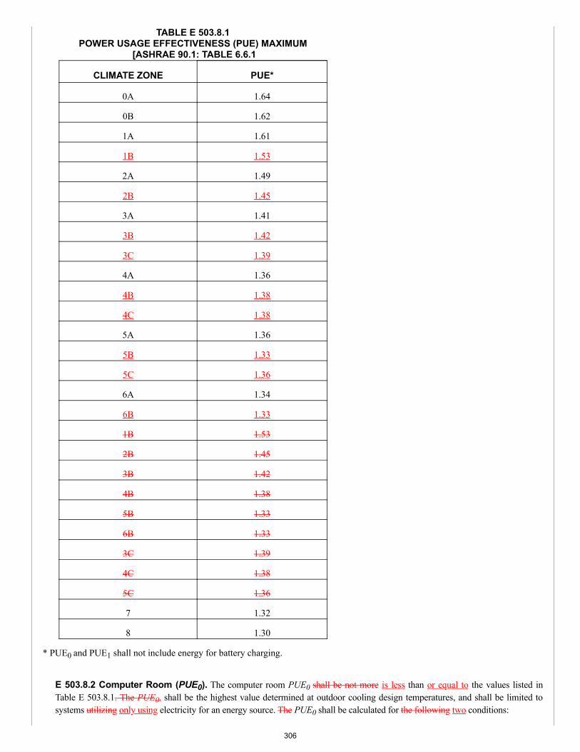
TABLE E 503.8.1POWER USAGE EFFECTIVENESS (PUE) MAXIMUM
[ASHRAE 90.1: TABLE 6.6.1
CLIMATE ZONE PUE*
0A 1.64
0B 1.62
1A 1.61
1B 1.53
2A 1.49
2B 1.45
3A 1.41
3B 1.42
3C 1.39
4A 1.36
4B 1.38
4C 1.38
5A 1.36
5B 1.33
5C 1.36
6A 1.34
6B 1.33
1B 1.53
2B 1.45
3B 1.42
4B 1.38
5B 1.33
6B 1.33
3C 1.39
4C 1.38
5C 1.36
7 1.32
8 1.30
* PUE0 and PUE1 shall not include energy for battery charging.
E 503.8.2 Computer Room (PUE0). The computer room PUE0 shall be not more is less than or equal to the values listed inTable E 503.8.1. The PUE0, shall be the highest value determined at outdoor cooling design temperatures, and shall be limited tosystems utilizing only using electricity for an energy source. The PUE0 shall be calculated for the following two conditions:
306
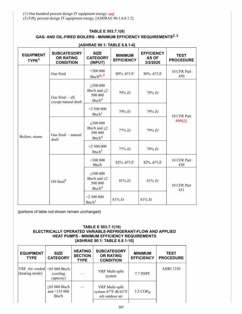
(1) One hundred percent design IT equipment energy. and(2) Fifty percent design IT equipment energy. [ASHRAE 90.1:6.6.1.2]
TABLE E 503.7.1(6)GAS- AND OIL-FIRED BOILERS - MINIMUM EFFICIENCY REQUIREMENTS2, 3
[ASHRAE 90.1: TABLE 6.8.1-6]
EQUIPMENTTYPE1
SUBCATEGORYOR RATINGCONDITION
SIZECATEGORY
(INPUT)MINIMUM
EFFICIENCYEFFICIENCY
AS OF3/2/2020
TESTPROCEDURE
Boilers, steam
Gas fired<300 000Btu/h6, 7 80% AFUE 80% AFUE 10 CFR Part
430
Gas fired— all,except natural draft
>300 000Btu/h and <2
500 000Btu/h4
79% Et 79% Et
10 CFR Part430431
>2 500 000Btu/h1 79% Et 79% Et
Gas fired— naturaldraft
>300 000Btu/h and <2
500 000Btu/h4
77% Et 79% Et
>2 500 000Btu/h1 77% Et 79% Et
Oil fired5
<300 000Btu/h 82% AFUE 82% AFUE 10 CFR Part
430
>300 000Btu/h and £2
500 000Btu/h4
81% Et 81% Et10 CFR Part
431
>2 500 000Btu/h1 81% Et 81% Et
(portions of table not shown remain unchanged)
TABLE E 503.7.1(10)ELECTRICALLY OPERATED VARIABLE-REFRIGERANT-FLOW AND APPLIED
HEAT PUMPS - MINIMUM EFFICIENCY REQUIREMENTS[ASHRAE 90.1: TABLE 6.8.1-10]
EQUIPMENTTYPE
SIZECATEGORY
HEATINGSECTION
TYPE
SUBCATEGORYOR RATINGCONDITION
MINIMUMEFFICIENCY
TESTPROCEDURE
VRF Air cooled(heating mode)
<65 000 Btu/h(coolingcapacity)
— VRF Multi-splitsystem 7.7 HSPF
AHRI 1230
>65 000 Btu/hand <135 000
Btu/h
— VRF Multi-splitsystem 47°F db/43°F
wb outdoor air3.3 COPH
307
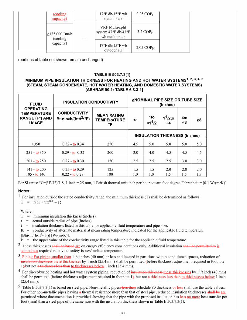
(coolingcapacity)
17°F db/15°F wboutdoor air
2.25 COPH
>135 000 Btu/h(coolingcapacity)
—
VRF Multi-splitsystem 47°F db/43°F
wb outdoor air3.2 COPH
17°F db/15°F wboutdoor air
2.05 COPH
(portions of table not shown remain unchanged)
TABLE E 503.7.3(1)MINIMUM PIPE INSULATION THICKNESS FOR HEATING AND HOT WATER SYSTEMS1, 2, 3, 4, 5
(STEAM, STEAM CONDENSATE, HOT WATER HEATING, AND DOMESTIC WATER SYSTEMS)[ASHRAE 90.1: TABLE 6.8.3-1]
FLUIDOPERATING
TEMPERATURERANGE (F°) AND
USAGE
INSULATION CONDUCTIVITY >NOMINAL PIPE SIZE OR TUBE SIZE(inches)
CONDUCTIVITYBtu•inch/(h•ft2•°F)
MEAN RATINGTEMPERATURE
°F<1
1to<11/2
11/2to<4
4to<8 >8
INSULATION THICKNESS (inches)
>350 0.32 - to 0.34 250 4.5 5.0 5.0 5.0 5.0
251 - to 350 0.29 - to 0.32 200 3.0 4.0 4.5 4.5 4.5
201 - to 250 0.27 - to 0.30 150 2.5 2.5 2.5 3.0 3.0
141 - to 200 0.25 - to 0.29 125 1.5 1.5 2.0 2.0 2.0105 - to 140 0.22 - to 0.28 100 1.0 1.0 1.5 1.5 1.5
For SI units: °C=(°F-32)/1.8, 1 inch = 25 mm, 1 British thermal unit inch per hour square foot degree Fahrenheit = [0.1 W/(m•K)]
Notes:1 For insulation outside the stated conductivity range, the minimum thickness (T) shall be determined as follows:
T = r{(1 + t/r)K/k – 1}
Where:T = minimum insulation thickness (inches).r = actual outside radius of pipe (inches).t = insulation thickness listed in this table for applicable fluid temperature and pipe size.K = conductivity of alternate material at mean rating temperature indicated for the applicable fluid temperature[Btu•in/(h•ft2•°F)] [W/(m•K)].k = the upper value of the conductivity range listed in this table for the applicable fluid temperature.
2 These thicknesses shall be based are on energy efficiency considerations only. Additional insulation shall be permitted to issometimes required relative to safety issues/surface temperature.
3 Piping For piping smaller than 11/2 inches (40 mm) or less and located in partitions within conditioned spaces, reduction ofinsulation thickness these thicknesses by 1 inch (25.4 mm) shall be permitted (before thickness adjustment required in footnote1),but not a thickness less than to thicknesses below 1 inch (25.4 mm).
4 For direct-buried heating and hot water system piping, reduction of insulation thickness these thicknesses by 11/2 inch (40 mm)shall be permitted (before thickness adjustment required in footnote 1), but not a thickness less than to thicknesses below 1 inch(25.4 mm).
5 Table E 503.7.3(1) is based on steel pipe. Non-metallic pipes, less than schedule 80 thickness or less shall use the table values.For other non-metallic pipes having a thermal resistance more than that of steel pipe, reduced insulation thicknesses shall be arepermitted where documentation is provided showing that the pipe with the proposed insulation has less no more heat transfer perfoot (mm) than a steel pipe of the same size with the insulation thickness shown in Table E 503.7.3(1).
308
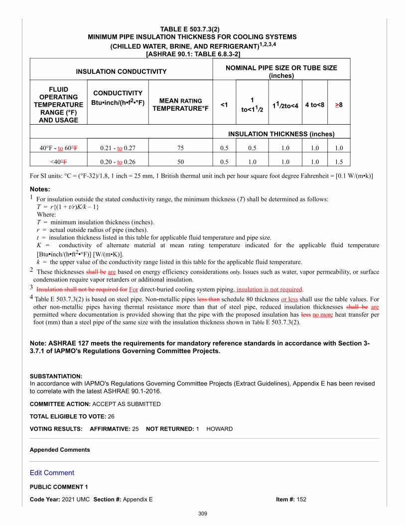
Item #: 152
TABLE E 503.7.3(2)MINIMUM PIPE INSULATION THICKNESS FOR COOLING SYSTEMS
(CHILLED WATER, BRINE, AND REFRIGERANT)1,2,3,4
[ASHRAE 90.1: TABLE 6.8.3-2]
INSULATION CONDUCTIVITY NOMINAL PIPE SIZE OR TUBE SIZE(inches)
FLUIDOPERATING
TEMPERATURERANGE (°F)AND USAGE
CONDUCTIVITYBtu•inch/(h•f2•°F)
MEAN RATINGTEMPERATURE°F <1
1to<11/2 11/2to<4 4 to<8 >8
INSULATION THICKNESS (inches)
40°F - to 60°F 0.21 - to 0.27 75 0.5 0.5 1.0 1.0 1.0
<40°F 0.20 - to 0.26 50 0.5 1.0 1.0 1.0 1.5
For SI units: °C = (°F-32)/1.8, 1 inch = 25 mm, 1 British thermal unit inch per hour square foot degree Fahrenheit = [0.1 W/(m•k)]
Notes:1 For insulation outside the stated conductivity range, the minimum thickness (T) shall be determined as follows:
T = r{(1 + t/r)K/k – 1}Where:T = minimum insulation thickness (inches).r = actual outside radius of pipe (inches).t = insulation thickness listed in this table for applicable fluid temperature and pipe size.K = conductivity of alternate material at mean rating temperature indicated for the applicable fluid temperature[Btu•inch/(h•ft2•°F)] [W/(m•K)].k = the upper value of the conductivity range listed in this table for the applicable fluid temperature.
2 These thicknesses shall be are based on energy efficiency considerations only. Issues such as water, vapor permeability, or surfacecondensation require vapor retarders or additional insulation.
3 Insulation shall not be required for For direct-buried cooling system piping, insulation is not required.4 Table E 503.7.3(2) is based on steel pipe. Non-metallic pipes less than schedule 80 thickness or less shall use the table values. For
other non-metallic pipes having thermal resistance more than that of steel pipe, reduced insulation thicknesses shall be arepermitted where documentation is provided showing that the pipe with the proposed insulation has less no more heat transfer perfoot (mm) than a steel pipe of the same size with the insulation thickness shown in Table E 503.7.3(2).
Note: ASHRAE 127 meets the requirements for mandatory reference standards in accordance with Section 3-3.7.1 of IAPMO's Regulations Governing Committee Projects.
SUBSTANTIATION:In accordance with IAPMO's Regulations Governing Committee Projects (Extract Guidelines), Appendix E has been revisedto correlate with the latest ASHRAE 90.1-2016.
COMMITTEE ACTION: ACCEPT AS SUBMITTED
TOTAL ELIGIBLE TO VOTE: 26
VOTING RESULTS: AFFIRMATIVE: 25 NOT RETURNED: 1 HOWARD
Appended Comments
Edit Comment
PUBLIC COMMENT 1
Code Year: 2021 UMC Section #: Appendix E
309
Comment #: 1SUBMITTER: Keith BlazerSelf
RECOMMENDATION:Revise text
Request to accept the code change proposal as modified by this public comment.
E 503.5.5.3 Dehumidification. Where humidity controls are provided, such controls shall prevent reheating, mixing of hot andcold airstreams, or other means of simultaneous heating and cooling of the same airstream.Exceptions:(1) The system is capable of and configured to reduce supply air volume to 50 percent or less of the design airflow rate or theminimum outdoor air ventilation rate in accordance with Chapter 4 or ASHRAE 62.1 or other applicable federal, state, or local codeor recognized standard, whichever is larger before simultaneous heating and cooling takes place.(2) - (6) (remaining text unchanged) [ASHRAE 90.1:6.5.2.3]
E 503.5.6.6 Ventilation Design. The required minimum outdoor air rate is the larger of the minimum outdoor air rate or theminimum exhaust air rate required by Chapter 4, ASHRAE 62.1, ASHRAE 170, or applicable codes or accreditation standards.Outdoor air ventilation systems shall comply with one of the following:(1) - (3) (remaining text unchanged) [ASHRAE 90.1:6.5.3.7]
E 503.5.10 Exhaust Air Energy Recovery. Each fan system shall have an energy recovery system where the design supply fanairflow rate exceeds the value listed in Table E 503.5.10(1) and Table E 503.5.10(2), based on the climate zone and percentage ofoutdoor air at design airflow conditions. Table E 503.5.10(1) shall be used for all ventilation systems that operate less than 8000hours per year and Table E 503.5.10(2) shall be used for all ventilation systems that operate 8000 or more hours per year. Energy recovery systems required by this section shall result in an enthalpy recovery ratio of not less than 50 percent. A fiftypercent enthalpy recovery ratio shall mean a change in the enthalpy of the outdoor air supply equal to 50 percent of the differencebetween the outdoor air and entering exhaust air enthalpies at design conditions. Provision shall be provided to bypass or control theenergy recovery system to permit air economizer operation in accordance with Section E 503.5.1.Exceptions:(1) - (5) (remaining text unchanged)(6) Where the sum of the airflow rates exhausted and relieved within 20 feet (6096 mm) of each other is less than 75 percent of thedesign outdoor airflow rate, excluding exhaust air that is;(a) used for another energy recovery system,(b) not allowed by ASHRAE 170 for use in energy recovery systems with leakage potential, or(c) of Class 4 as defined in Chapter 2 or ASHRAE 62.1.(7) – (8) (remaining text unchanged) [ASHRAE 90.1:6.5.6.1]
E 503.5.11.1 Transfer Air. Conditioned supply air delivered to a space with a mechanical exhaust shall not exceed the greater ofthe following:(1) The supply flow required to be in accordance with the space heating or cooling load;(2) The ventilation rate required by the Authority Having Jurisdiction, the Facility Environmental Health and Safety department,Chapter 4 or ASHRAE 62.1; or(3) The mechanical exhaust flow minus the available transfer air from conditioned spaces. or return air plenums on the same floor,not in different smoke or fire compartments, and that at their closest point are within 15 feet (4572 mm) of each other. Availabletransfer air is that portion of outdoor ventilation air that:(a) is not required to satisfy other exhaust needs,(b) is not required to maintain pressurization of other spaces, and(c) is transferable according to applicable codes and standards and to the class of air recirculation limitations in Chapter 4 ASHRAE62.1.Exceptions:(1) - (4) (remaining text unchanged) [ASHRAE 90.1:6.5.7.1]
E 606.1 Minimum Indoor Air Quality. The building shall comply with this code Chapter 4 and ASHRAE 62.1 for ventilation airsupply.
SUBSTANTIATION:There is no need to only send the end user to ASHRAE 62.1 as the UMC also has provisions for ventilation in Chapter 4,therefore, adding Chapter 4 will assist the end user and provide greater ease of use. For example, Section E 503.4.6.9Exception (5), E 503.5.5 Exception (1)(b), E 503.5.5 Exception (2)(a)(2), and E 503.5.6.2 Exception (2) make reference to"Chapter 4 or ASHRAE 62.1" when required. Chapter 4 is a direct extract of ASHRAE 62.1. Therefore, referencing Chapter 4is necessary for ease of use of the code.
COMMITTEE ACTION: ACCEPTED AS AMENDED
310
Amend comment as follows:
E 503.5.5.3 Dehumidification. Where humidity controls are provided, such controls shall prevent reheating, mixing of hotand cold airstreams, or other means of simultaneous heating and cooling of the same airstream.Exceptions:(1) The system is capable of and configured to reduce supply air volume to 50 percent or less of the design airflow rateor the minimum outdoor air ventilation rate in accordance with Chapter 4 or ASHRAE 62.1 or other applicable federal, state, or local code orrecognized standard, whichever is larger before simultaneous heating and cooling takes place.
(2) - (6) (remaining text unchanged) [ASHRAE 90.1:6.5.2.3]
E 503.5.6.6 Ventilation Design. The required minimum outdoor air rate is the larger of the minimum outdoor air rate orthe minimum exhaust air rate required by Chapter 4, ASHRAE 62.1, ASHRAE 170, or applicable codes or accreditationstandards. Outdoor air ventilation systems shall comply with one of the following:(1) - (3) (remaining text unchanged) [ASHRAE 90.1:6.5.3.7]
E 503.5.10 Exhaust Air Energy Recovery. Each fan system shall have an energy recovery system where the designsupply fan airflow rate exceeds the value listed in Table E 503.5.10(1) and Table E 503.5.10(2), based on the climatezone and percentage of outdoor air at design airflow conditions. Table E 503.5.10(1) shall be used for all ventilationsystems that operate less than 8000 hours per year and Table E 503.5.10(2) shall be used for all ventilation systemsthat operate 8000 or more hours per year. Energy recovery systems required by this section shall result in an enthalpy recovery ratio of not less than 50percent. A fifty percent enthalpy recovery ratio shall mean a change in the enthalpy of the outdoor air supply equal to 50percent of the difference between the outdoor air and entering exhaust air enthalpies at design conditions. Provisionshall be provided to bypass or control the energy recovery system to permit air economizer operation in accordance withSection E 503.5.1.Exceptions:(1) - (5) (remaining text unchanged)(6) Where the sum of the airflow rates exhausted and relieved within 20 feet (6096 mm) of each other is less than 75percent of the design outdoor airflow rate, excluding exhaust air that is;(a) used for another energy recovery system,(b) not allowed by ASHRAE 170 for use in energy recovery systems with leakage potential, or(c) of Class 4 as defined in Chapter 2 or ASHRAE 62.1.(7) – (8) (remaining text unchanged) [ASHRAE 90.1:6.5.6.1]
E 503.5.11.1 Transfer Air. Conditioned supply air delivered to a space with a mechanical exhaust shall not exceed thegreater of the following:(1) The supply flow required to be in accordance with the space heating or cooling load;(2) The ventilation rate required by the Authority Having Jurisdiction, the Facility Environmental Health and Safetydepartment, Chapter 4 or ASHRAE 62.1; or(3) The mechanical exhaust flow minus the available transfer air from conditioned spaces. or return air plenums on thesame floor, not in different smoke or fire compartments, and that at their closest point are within 15 feet (4572 mm) ofeach other. Available transfer air is that portion of outdoor ventilation air that:(a) is not required to satisfy other exhaust needs,(b) is not required to maintain pressurization of other spaces, and(c) is transferable according to applicable codes and standards and to the class of air recirculation limitations in Chapter4 or ASHRAE 62.1.Exceptions:(1) - (4) (remaining text unchanged) [ASHRAE 90.1:6.5.7.1]
E 606.1 Minimum Indoor Air Quality. The building shall comply with Chapter 4 or and ASHRAE 62.1 for ventilation airsupply.
COMMITTEE STATEMENT:The change is being modfied for consistency by adding the term "or."
TOTAL ELIGIBLE TO VOTE: 26
VOTING RESULTS: AFFIRMATIVE: 25 NOT RETURNED: 1 HOWARD
311
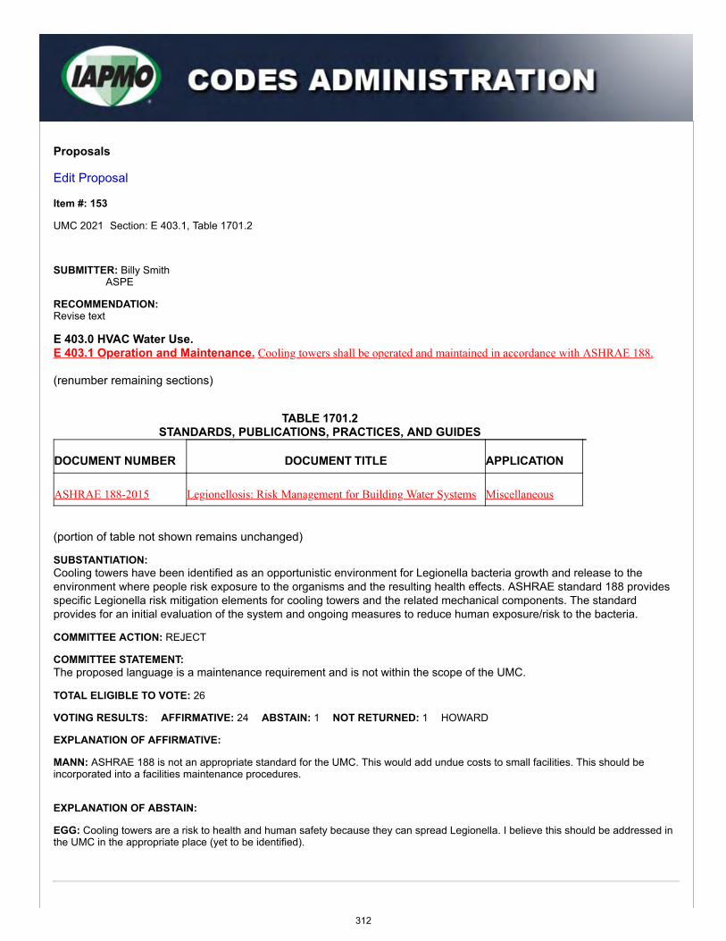
Proposals
Edit Proposal
Item #: 153
UMC 2021 Section: E 403.1, Table 1701.2
SUBMITTER: Billy SmithASPE
RECOMMENDATION:Revise text
E 403.0 HVAC Water Use.E 403.1 Operation and Maintenance. Cooling towers shall be operated and maintained in accordance with ASHRAE 188.
(renumber remaining sections)
TABLE 1701.2STANDARDS, PUBLICATIONS, PRACTICES, AND GUIDES
DOCUMENT NUMBER DOCUMENT TITLE APPLICATION
ASHRAE 188-2015 Legionellosis: Risk Management for Building Water Systems Miscellaneous
(portion of table not shown remains unchanged)
SUBSTANTIATION:Cooling towers have been identified as an opportunistic environment for Legionella bacteria growth and release to theenvironment where people risk exposure to the organisms and the resulting health effects. ASHRAE standard 188 providesspecific Legionella risk mitigation elements for cooling towers and the related mechanical components. The standardprovides for an initial evaluation of the system and ongoing measures to reduce human exposure/risk to the bacteria.
COMMITTEE ACTION: REJECT
COMMITTEE STATEMENT:The proposed language is a maintenance requirement and is not within the scope of the UMC.
TOTAL ELIGIBLE TO VOTE: 26
VOTING RESULTS: AFFIRMATIVE: 24 ABSTAIN: 1 NOT RETURNED: 1 HOWARD
EXPLANATION OF AFFIRMATIVE:
MANN: ASHRAE 188 is not an appropriate standard for the UMC. This would add undue costs to small facilities. This should beincorporated into a facilities maintenance procedures.
EXPLANATION OF ABSTAIN:
EGG: Cooling towers are a risk to health and human safety because they can spread Legionella. I believe this should be addressed inthe UMC in the appropriate place (yet to be identified).
312
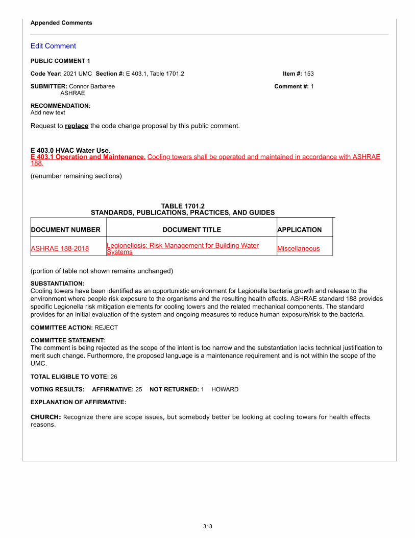
Item #: 153
Comment #: 1
Appended Comments
Edit Comment
PUBLIC COMMENT 1
Code Year: 2021 UMC Section #: E 403.1, Table 1701.2
SUBMITTER: Connor BarbareeASHRAE
RECOMMENDATION:Add new text
Request to replace the code change proposal by this public comment.
E 403.0 HVAC Water Use.E 403.1 Operation and Maintenance. Cooling towers shall be operated and maintained in accordance with ASHRAE188.
(renumber remaining sections)
TABLE 1701.2STANDARDS, PUBLICATIONS, PRACTICES, AND GUIDES
DOCUMENT NUMBER DOCUMENT TITLE APPLICATION
ASHRAE 188-2018 Legionellosis: Risk Management for Building WaterSystems Miscellaneous
(portion of table not shown remains unchanged)
SUBSTANTIATION:Cooling towers have been identified as an opportunistic environment for Legionella bacteria growth and release to theenvironment where people risk exposure to the organisms and the resulting health effects. ASHRAE standard 188 providesspecific Legionella risk mitigation elements for cooling towers and the related mechanical components. The standardprovides for an initial evaluation of the system and ongoing measures to reduce human exposure/risk to the bacteria.
COMMITTEE ACTION: REJECT
COMMITTEE STATEMENT:The comment is being rejected as the scope of the intent is too narrow and the substantiation lacks technical justification tomerit such change. Furthermore, the proposed language is a maintenance requirement and is not within the scope of theUMC.
TOTAL ELIGIBLE TO VOTE: 26
VOTING RESULTS: AFFIRMATIVE: 25 NOT RETURNED: 1 HOWARD
EXPLANATION OF AFFIRMATIVE:
CHURCH: Recognize there are scope issues, but somebody better be looking at cooling towers for health effectsreasons.
313
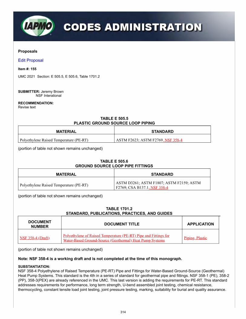
Proposals
Edit Proposal
Item #: 155
UMC 2021 Section: E 505.5, E 505.6, Table 1701.2
SUBMITTER: Jeremy BrownNSF Interational
RECOMMENDATION:Revise text
TABLE E 505.5PLASTIC GROUND SOURCE LOOP PIPING
MATERIAL STANDARD
Polyethylene Raised Temperature (PE-RT) ASTM F2623; ASTM F2769, NSF 358-4
(portion of table not shown remains unchanged)
TABLE E 505.6GROUND SOURCE LOOP PIPE FITTINGS
MATERIAL STANDARD
Polyethylene Raised Temperature (PE-RT) ASTM D3261; ASTM F1807; ASTM F2159; ASTMF2769; CSA B137.1, NSF 358-4
(portion of table not shown remains unchanged)
TABLE 1701.2STANDARD, PUBLICATIONS, PRACTICES, AND GUIDES
DOCUMENTNUMBER DOCUMENT TITLE APPLICATION
NSF 358-4 (Draft) Polyethylene of Raised Temperature (PE-RT) Pipe and Fittings forWater-Based Ground-Source (Geothermal) Heat Pump Systems Piping, Plastic
(portion of table not shown remains unchanged)
Note: NSF 358-4 is a working draft and is not completed at the time of this monograph.
SUBSTANTIATION:NSF 358-4 Polyethylene of Raised Temperature (PE-RT) Pipe and Fittings for Water-Based Ground-Source (Geothermal)Heat Pump Systems. This standard is the 4th in a series of standard for geothermal pipe and fittings. NSF 358-1 (PE), 358-2(PP), 358-3(PEX) are already referenced in the UMC. This last version is adding the requirements for PE-RT. This standardaddresses requirements for performance, long term strength, U-bend assembled joint testing, chemical resistance,thermocycling, constant tensile load joint testing, joint pressure testing, marking, suitability for burial and quality assurance.
314
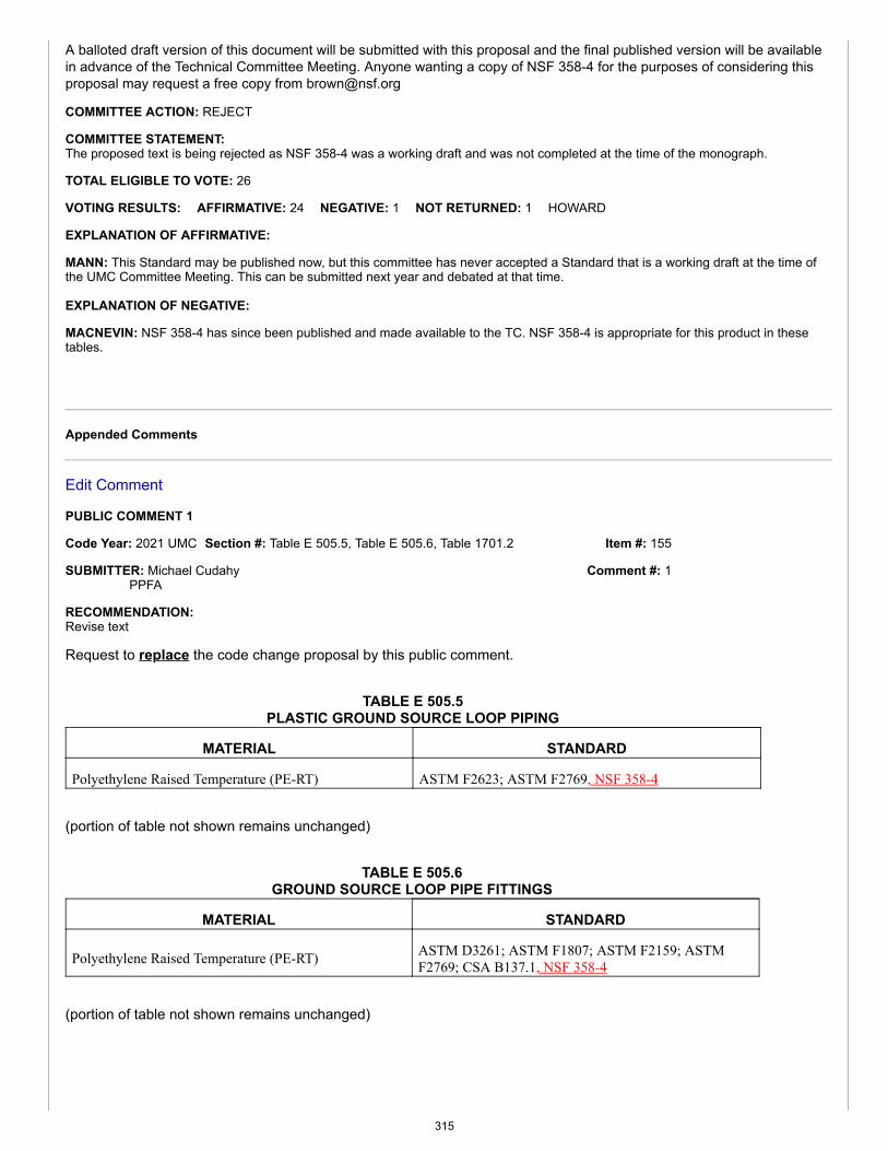
Item #: 155
Comment #: 1
A balloted draft version of this document will be submitted with this proposal and the final published version will be availablein advance of the Technical Committee Meeting. Anyone wanting a copy of NSF 358-4 for the purposes of considering thisproposal may request a free copy from [email protected]
COMMITTEE ACTION: REJECT
COMMITTEE STATEMENT:The proposed text is being rejected as NSF 358-4 was a working draft and was not completed at the time of the monograph.
TOTAL ELIGIBLE TO VOTE: 26
VOTING RESULTS: AFFIRMATIVE: 24 NEGATIVE: 1 NOT RETURNED: 1 HOWARD
EXPLANATION OF AFFIRMATIVE:
MANN: This Standard may be published now, but this committee has never accepted a Standard that is a working draft at the time ofthe UMC Committee Meeting. This can be submitted next year and debated at that time.
EXPLANATION OF NEGATIVE:
MACNEVIN: NSF 358-4 has since been published and made available to the TC. NSF 358-4 is appropriate for this product in thesetables.
Appended Comments
Edit Comment
PUBLIC COMMENT 1
Code Year: 2021 UMC Section #: Table E 505.5, Table E 505.6, Table 1701.2
SUBMITTER: Michael CudahyPPFA
RECOMMENDATION:Revise text
Request to replace the code change proposal by this public comment.
TABLE E 505.5PLASTIC GROUND SOURCE LOOP PIPING
MATERIAL STANDARD
Polyethylene Raised Temperature (PE-RT) ASTM F2623; ASTM F2769, NSF 358-4
(portion of table not shown remains unchanged)
TABLE E 505.6GROUND SOURCE LOOP PIPE FITTINGS
MATERIAL STANDARD
Polyethylene Raised Temperature (PE-RT) ASTM D3261; ASTM F1807; ASTM F2159; ASTMF2769; CSA B137.1, NSF 358-4
(portion of table not shown remains unchanged)
315
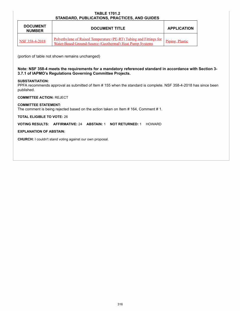
TABLE 1701.2STANDARD, PUBLICATIONS, PRACTICES, AND GUIDES
DOCUMENTNUMBER DOCUMENT TITLE APPLICATION
NSF 358-4-2018 Polyethylene of Raised Temperature (PE-RT) Tubing and Fittings forWater-Based Ground-Source (Geothermal) Heat Pump Systems Piping, Plastic
(portion of table not shown remains unchanged)
Note: NSF 358-4 meets the requirements for a mandatory referenced standard in accordance with Section 3-3.7.1 of IAPMO’s Regulations Governing Committee Projects.
SUBSTANTIATION:PPFA recommends approval as submitted of Item # 155 when the standard is complete. NSF 358-4-2018 has since beenpublished.
COMMITTEE ACTION: REJECT
COMMITTEE STATEMENT:The comment is being rejected based on the action taken on Item # 164, Comment # 1.
TOTAL ELIGIBLE TO VOTE: 26
VOTING RESULTS: AFFIRMATIVE: 24 ABSTAIN: 1 NOT RETURNED: 1 HOWARD
EXPLANATION OF ABSTAIN:
CHURCH: I couldn't stand voting against our own proposal.
316
Proposals
Edit Proposal
Item #: 158
UMC 2021 Section: E 605.1.3 - E 605.1.8
SUBMITTER: Connor BarbareeASHRAE
RECOMMENDATION:Revise text
E 605.0 Indoor Air Quality for Low-Rise Residential.
E 605.1.3 Dwelling-Unit Ventilation. A Mechanical exhaust system, supply system, or combination thereof shall be installed to operatefor each dwelling unit to provide continuous dwelling-unit ventilation with outdoor air at a rate not less than the rate specified in Section E605.1.3.1. [ASHRAE 62.2:4.1]E 605.1.3.1 Total Ventilation Rate. The total required ventilation rate (Qtot) shall be as specified in Table E 605.1.3.1 or, alternatively,calculated in accordance with using Equation E 605.1.3.1.(Equation E 605.1.3.1)Qtot = 0.03Afloor + 7.5(Nbr + 1)
Where:Qtot = total required ventilation rate, cfm cubic feet per minute (ft3/min)Afloor = dwelling unit floor area, square foot (ft2)Nbr = number of bedrooms; (not to be less than one)For SI units: 1 cubic foot per minute = 0.00047 m3/s, 1 square foot = 0.0929 m2
Exceptions: Dwelling-unit mechanical ventilation systems shall are not be required where if the Authority Having Jurisdiction determines thatwindow operation is a locally permissible method of providing ventilation and provided that a least one or more of the following conditions ismet:(1) The building has no mechanical cooling and is located in zone 1 or 2 of the climate zone map.(2) The building is thermally conditioned for human occupancy for less than 876 hours per year. [ASHRAE 62.2:4.1.1]
E 605.1.3.4 Different Occupant Density. Table E 605.1.3.1 and Equation E 605.1.3.1 assume two persons in a studio orone-bedroom dwelling unit and an additional person for each additional bedroom. Where higher occupant densities are known,the rate shall be increased by 7.5 ft3/min (0.003 m3/s) for each additional person. Where When approved by the Authority HavingJurisdiction, lower occupant densities shall be permitted may to be used. [ASHRAE 62.2:4.1.3]E 605.1.4 System Type. The dwelling-unit mechanical ventilation system shall consist of one or more supply or exhaust fansand associated ducts and controls. Local exhaust fans shall be permitted to be part of a mechanical exhaust system. Where localexhaust fans are used to provide dwelling-unit ventilation, the local exhaust airflow shall be permitted may to be credited towardsthe whole dwelling-unit ventilation airflow requirement. Outdoor air ducts connected to the return side of an air handler shall bepermitted as supply ventilation where manufacturer’s requirements for return air temperature are met. See ASHRAE 62.2 forguidance on selection of methods. [ASHRAE 62.2:4.2]E 605.1.5 Airflow Measurement. The airflow required by this section shall be is the quantity of outdoor ventilation air supply, suppliedand/or indoor air, or both exhausted by the mechanical ventilation system as installed and shall be measured according to the ventilationequipment manufacturer’s instructions, or by using a flow hood, flow grid, or other airflow measuring device at the mechanical ventilation fan’sinlet terminals/grilles, outlet terminals/grilles, or in the connected ventilation ducts. Ventilation airflow of systems with multiple operating modesshall be tested in all modes designed to be in accordance with meet this section. [ASHRAE 62.2:4.3]
E 605.1.7.1 Short-Term Average Ventilation. To comply with this section, a variable ventilation system shall be installed to providean average dwelling-unit ventilation rate over any three-hour period that is greater than or equal to Qfan as determined in accordance with
317
Item #: 158
Comment #: 1
calculated using Section E 605.1.3.3. [ASHRAE 62.2:4.5.1]E 605.1.7.2 Scheduled Ventilation. This section shall may only be allowed to be used where when one or more fixed patterns ofdesigned ventilation are known at the time compliance to Section E 605.0 is being determined. Such patterns include those bothclock-driven and driven by typical meteorological data. Compliance with this section shall can be in accordance demonstrated witheither Section E 605.1.7.2.1 or Section E 605.1.7.2.2. [ASHRAE 62.2:4.5.2]E 605.1.7.2.1 Annual Average Schedule. An annual schedule of ventilation complies with this section when the annual averagerelative exposure during occupied periods is not no more than unity as calculated in accordance with ASHRAE 62.2. [ASHRAE 62.2:4.5.2.1]E 605.1.7.2.2 Block Scheduling. The schedule of ventilation complies with this section when if it is broken into blocks of time and eachblock individually has an average relative exposure during occupied periods that is not no more than unity as calculated in ASHRAE 62.2.[ASHRAE 62.2:4.5.2.2]E 605.1.7.3 Real-Time Control. A real-time ventilation controller complies with this section when it is designed to adjust theventilation system based on real-time input to the ventilation calculations so that the average relative exposure during occupiedperiods is not no more than unity as calculated in ASHRAE 62.2. The averaging period shall be not less than at least one day but notno more than one year and shall be based on simple, recursive or running average, but not extrapolation. [ASHRAE 62.2:4.5.3]E 605.1.8 Equivalent Ventilation. A dwelling-unit ventilation system shall be designed and operated in such a way as toprovide the same or lower annual exposure as would be provided in accordance by complying with Section E 605.1.3. Thecalculations shall be based on a single zone with a constant contaminant emission rate. The manufacturer, specifier, or designerof the equivalent ventilation system shall certify that the system is in accordance with meets this intent and provide supportingdocumentation. [ASHRAE 62.2:4.6]
SUBSTANTIATION:In accordance with IAPMO's Regulations Governing Committee Projects (Extract Guidelines), Appendix E has been revisedto correlate with the latest ASHRAE 62.2-2016.
COMMITTEE ACTION: REJECT
COMMITTEE STATEMENT:The proposed change removes mandatory enforceable language.
TOTAL ELIGIBLE TO VOTE: 26
VOTING RESULTS: AFFIRMATIVE: 25 NOT RETURNED: 1 HOWARD
Appended Comments
Edit Comment
PUBLIC COMMENT 1
Code Year: 2021 UMC Section #: E 605.0 - E 605.1.8
SUBMITTER: Connor BarbareeASHRAE
RECOMMENDATION:Revise text
Request to replace the code change proposal by this public comment.
E 605.0 Indoor Air Quality for Low-Rise Residential.
E 605.1.3 Dwelling-Unit Ventilation. A Mechanical exhaust system, supply system, or combination thereof shall be installed tooperate for each dwelling unit to provide continuous dwelling-unit ventilation with outdoor air at a rate not less than the ratespecified in Section E 605.1.3.1. [ASHRAE 62.2:4.1]E 605.1.3.1 Total Ventilation Rate. The total required ventilation rate (Qtot) shall be as specified in Table E 605.1.3.1 or,alternatively, calculated in accordance with using Equation E 605.1.3.1.
(Equation E 605.1.3.1)
Qtot = 0.03Afloor + 7.5(Nbr + 1)
Where:Qtot = total required ventilation rate, cubic feet per minute (ft3/min)Afloor = dwelling unit floor area, square foot (ft2)Nbr = number of bedrooms; (not to be less than one)
318
For SI units: 1 cubic foot per minute = 0.00047 m3/s, 1 square foot = 0.0929 m2
Exceptions: Dwelling-unit mechanical ventilation systems shall not be required where the Authority Having Jurisdiction determinesthat window operation is a locally permissible method of providing ventilation and provided one or more of the following conditionsis met:(1) The building has no mechanical cooling and is located in zone 1 or 2 of the climate zone map.(2) The building is thermally conditioned for human occupancy for less than 876 hours per year.[ASHRAE 62.2:4.1.1]
E 605.1.4 System Type. The dwelling-unit mechanical ventilation system shall consist of one or more supply or exhaust fans andassociated ducts and controls. Local exhaust fans shall be permitted to be part of a mechanical exhaust system. Where local exhaustfans are used to provide dwelling-unit ventilation, the local exhaust airflow shall be permitted to be credited towards the wholedwelling-unit ventilation airflow requirement. Outdoor air ducts connected to the return side of an air handler shall be permitted assupply ventilation where manufacturer’s requirements for return air temperature are met. See ASHRAE 62.2 for guidance onselection of methods. [ASHRAE 62.2:4.2]
E 605.1.5 Airflow Measurement. The airflow required by this section shall be the quantity of outdoor ventilation air supply,supplied and/or indoor air, or both exhausted by the mechanical ventilation system as installed and shall be measured according tothe ventilation equipment manufacturer’s instructions, or by using a flow hood, flow grid, or other airflow measuring device at themechanical ventilation fan’s inlet terminals/grilles, outlet terminals/grilles, or in the connected ventilation ducts. Ventilation airflowof systems with multiple operating modes shall be tested in all modes designed to be in accordance with meet this section. [ASHRAE62.2:4.3]
E 605.1.7.1 Short-Term Average Ventilation. To comply with this section, a variable ventilation system shall be installed toprovide an average dwelling-unit ventilation rate over any three-hour period that is greater than or equal to Qfan as determined inaccordance with calculated using Section E 605.1.3.3. [ASHRAE 62.2:4.E 605.1.7.2 Scheduled Ventilation. This section shall only be allowed to be used where one or more fixed patterns of designedventilation are known at the time compliance to Section E 605.0 is being determined. Such patterns include those both clock-drivenand driven by typical meteorological data. Compliance with this section shall be in accordance demonstrated with either Section E605.1.7.2.1 or Section E 605.1.7.2.2. [ASHRAE 62.2:4.5.2]
SUBSTANTIATION:In accordance with IAPMO's Regulations Governing Committee Projects (Extract Guidelines), Appendix E has been revisedto correlate with the latest ASHRAE 62.2-2016. Furthermore, the proposed modification includes enforceable language asrequired by the TC and in accordance with the IAPMO Manual of Style.
COMMITTEE ACTION: ACCEPTED AS SUBMITTED
TOTAL ELIGIBLE TO VOTE: 26
VOTING RESULTS: AFFIRMATIVE: 25 NOT RETURNED: 1 HOWARD
319

Proposals
Edit Proposal
Item #: 159
UMC 2021 Section: 209.0, F 101.0 - F 101.4
SUBMITTER: Cary SmithSound Geothermal Corporation
RECOMMENDATION:Revise text
CHAPTER 2DEFINITIONS
209.0 – G –Geothermal Energy System. A system that uses thermal energy for space heating and cooling, and water heating.Geothermal Energy System, Closed-Loop. A continuous, sealed, underground, or submerged heat exchanger through which aheat-transfer fluid passes to and returns from a heat pump.Geothermal Energy System, Open-Loop. A liquid-source heat pump system that uses ground water or surface water to extractor reject heat.Ground-Heat Exchanger. An underground closed-loop heat exchanger through which a heat-transfer medium passes to and froma heat pump or other rated mechanical equipment. It includes the buried pipe and connecting main(s) up to and terminating with thebuilding.Ground-Source Heat Pump. A term that is applied to a variety of systems that use the ground, groundwater, or surface water as aheat source and sink. The general terms include ground-coupled (GCHP), groundwater (GWHP), and surface-water (SWHP) heatpumps. Many parallel terms exist [e.g., geothermal heat pumps (GHP), geo-exchange, and ground-source (GS) systems] and are usedto meet a variety of marketing or institutional needs.Groundwater Source. A geothermal energy system that uses the groundwater as a heat source or sink.
210.0 – H –Hydronic System. Relating to, or being a system of, heating or cooling that involves the transfer of heat by a circulating fluid(such as water or vapor).
Part I Closed-Loop SystemsF 101.0 General.F 101.1 Applicability. Part I of this appendix shall apply to geothermal energy systems such as, but not limited to, building systemscoupled with a ground-heat exchanger, submerged heat exchanger or groundwater (well) using water-based fluid as a heat transfermedium. The regulations of this appendix shall govern the construction, location and installation of geothermal energy systems. Indoor piping, fittings, and accessories that are part of the groundwater system shall be in accordance with Section F 103.7 andChapter 12.F 101.1.1 Prior to Construction. Documents for permits shall be submitted prior to the construction of a building system,ground heat exchanger, submerge heat exchanger, or water well. Permits shall be issued by the Authority Having Jurisdiction.F 101.1.2 Equipment, Accessories, Components, and Materials. The mechanical equipment, accessories, components,and materials used shall be of the type and rating approved for the specific use.F 101.2 Construction Documents. The construction documents for the building system portion of the geothermal energysystem shall be submitted to the Authority Having Jurisdiction.F 101.3 Site Survey. A site survey shall be conducted prior to designing the geothermal system. The requirements forconstruction documents shall be defined by the Authority Having Jurisdiction. Where no guidance is provided, the followinginformation shall be provided:(1) Ground heat exchanger dimensions.(2) Grout or sealing specifications, as applicable.
320
(3) Dimensions from building to water well, ground heat exchanger, or submerged heat exchanger.(4) Operating temperatures and pressures.F 101.4 Decommissioning and Abandonment. Prior to the abandonment or decommissioning of a ground-heat exchanger,submerged heat exchanger or ground water (well) the owner shall obtain the necessary permits from the Authority HavingJurisdiction.
E 505.4 F 101.5 Used Materials. The installation of used pipe, fittings, valves, and other materials shall not be permitted.E 508.5 F 101.6 Contact with Building Material. A ground source heat pump ground-loop piping system shall not be in directcontact with building materials that cause the piping or fitting material to degrade or corrode, or that interferes with the operation ofthe system.E 508.6 F 101.7 Strains and Stresses. Piping shall be installed so as to prevent detrimental strains and stresses in the pipe.Provisions shall be made to protect piping from damage resulting from expansion, contraction, and structural settlement. Piping shallbe installed so as to avoid structural stresses or strains within building components.E 508.7 F 101.8 Flood Hazard. Piping located in a flood hazard area shall be capable of resisting hydrostatic and hydrodynamicloads and stresses, including the effects of buoyancy, during the occurrence of flooding to the design flood elevation.E 508.8 F 101.9 Pipe Support. Pipe shall be supported in accordance with Section 313.1.E 508.9 F 101.10 Velocities. Ground source heat pump ground-loop systems shall be designed so that the flow velocities do notexceed the maximum flow velocity recommended by the pipe and fittings manufacturer. Flow velocities shall be controlled toreduce the possibility of water hammer.E 508.11 F 101.11 Chemical Compatibility. Antifreeze and other materials used in the system shall be chemically compatiblewith the pipe, tubing, fittings, and mechanical systems.E 508.12 F 101.12 Transfer Fluid. The transfer fluid shall be compatible with the makeup water supplied to the system.
SUBSTANTIATION:The definition for “Ground-Source Heat Pump” was added to be consistent with definitions provided in the ASHRAE HVACApplications Handbook (Chapter 34) for geothermal energy, current edition. Definitions for “Geothermal Energy Systems”and “Ground-Source Heat Pump” were also added to reflect the new proposed language. The definition for “ground-heatexchanger” will allow for ground-coupling with other types of mechanical equipment such as chillers and cooling towers.Furthermore, it provides clarity as to the extent or boundary of the “ground heat exchanger.”
The definition of “Hydronic System” has been added to encompass existing language within the UMC and to enhance anddifferentiate between the existing definition of “Hydronics”.
Construction documents are required to be of a quality and detail such that the Authority Having Jurisdiction can determinethat the work conforms to the code and other applicable laws and regulations. To properly design a geothermal system, it isimportant to know the seasonal variation in the soil temperature, as well as the soil’s inherent capability to store and transmitheat, namely its heat capacity and thermal conductivity. These soil thermal properties depend on soil porosity and moisturecontent. Therefore, any preliminary assessment of a potential geothermal heat pump system will require knowing the soiltexture and average groundwater level at the site. Another important geologic feature is the depth of bedrock, whichdetermines the feasibility of certain ground loop configurations. The construction phase is dominated by observation ofinstallation and verification of prefunctional checks and tests. The acceptance phase starts with functional tests andverification of all test results.
Proper decommissioning or abandonment eliminates the physical hazard of the well, eliminates a pathway for migration ofcontamination, and prevents hydrologic changes in the aquifer system, such as changes in hydraulic head and mixing ofwater between aquifers. The actual method will depend on both the reason for abandonment and the condition andconstruction details of the borehole or well. Many states have different requirements; therefore, it is imperative to check withthe local jurisdiction.
The sources of information and recommendations for this chapter are included as follows:1. See ASHRAE. Ground-Source Heat Pumps, Design of Geothermal Systems for Commercial and Institutional Buildings,1997. Stephen P. Kavanaugh and Kevin Rafferty. Atlanta, GA.2. See International Ground-Source Heat Pump Association. Closed-Loop/Geothermal Heat Pump Systems, Design andInstallation Standards, 2011. Oklahoma State University, Stillwater, OK.3. See International Ground-Source Heat Pump Association. Ground Source Heat Pump Residential and Light Commercial,Design and Installation Guide, 2011. Oklahoma State University, Stillwater, OK.4. See Oak Ridge National Laboratory. Generic Guide Specifications for Geothermal Heat Pump System Installation, 2000.Warren Thomas and Melissa Madgett. Oakridge, TN.5. See ASHRAE Handbook. Chapter 34 Geothermal Energy, 2011. Atlanta, GA.6. See CSA Standard C448-2016. Design and Installation of Earth Energy Systems. Ontario, Canada.7. 2018 Uniform Solar, Hydronics, and Geothermal Code; 2018 Report on Comments, 2015 Uniform Solar Energy andHydronics Code published by IAPMO.
321
Construction of a geothermal heat pump loop well includes, in continuous order, drilling of the vertical borehole into the earth,placement of the loop tube to the bottom of the vertical borehole with the grout tremie, and grouting of the vertical boreholefrom the bottom of the vertical bore hole to the earth’s surface. When these three steps are completed, the vertical boreholemay now be considered a loop well.
Permitting of the ground-coupled portion of the geothermal energy system varies from state to state. Some states issuepermits, in others, local counties or water agencies issue permits.
Therefore, inclusion of any references to a well of any type is in violation of pre-existing well standards and do not appear inthis section. Statements regarding the ground heat exchange side of the system are deferred to the Authority HavingJurisdiction and shall not be addressed in the UMC. Furthermore, this will correlate with the action taken by the USEHCTechnical Committee.
COMMITTEE ACTION: ACCEPT AS AMENDED BY THE TC
Amend proposal as follows:CHAPTER 2
DEFINITIONS
209.0 – G –Geothermal Energy System. A system that uses thermal energy for space heating and cooling, and water heating.Geothermal Energy System, Closed-Loop. A continuous, sealed, underground, or submerged heat exchanger through which aheat-transfer fluid passes to and returns from a heat pump.Geothermal Energy System, Open-Loop. A liquid-source heat pump system that uses ground water or surface water to extractor reject heat.Ground-Heat Exchanger. An underground closed-loop heat exchanger through which a heat-transfer medium passes to and froma heat pump or other rated mechanical equipment. It includes the buried pipe and connecting main(s) up to and terminating with thebuilding.Ground-Source Heat Pump. A term that is applied to a variety of systems that use the ground, groundwater, or surface water as aheat source and sink. The general terms include ground-coupled (GCHP), groundwater (GWHP), and surface-water (SWHP) heatpumps. Many parallel terms exist [e.g., geothermal heat pumps (GHP), geo-exchange, and ground-source (GS) systems] and are usedto meet a variety of marketing or institutional needs.Groundwater Source. A geothermal energy system that uses the groundwater as a heat source or sink.
210.0 – H –Hydronic System. Relating to, or being a system of heating or cooling that involves the transfer of heat by a circulating fluid (such as water orvapor).
APPENDIX FGEOTHERMAL ENERGY SYSTEMS
Part I Closed-Loop Systems
F 101.0 General.F 101.1 Applicability. Part I of this appendix shall apply to geothermal energy systems such as, but not limited to, building systemscoupled with a ground-heat exchanger, submerged heat exchanger or groundwater (well) using water-based fluid as a heat transfermedium. The regulations of this appendix shall govern the construction, location and installation of geothermal energy systems. Indoor piping, fittings, and accessories that are part of the groundwater system shall be in accordance with Section F 103.7 and Chapter 12.F 101.1.1 Prior to Construction. Documents for permits shall be submitted prior to the construction of a building system, ground heatexchanger, submerge heat exchanger, or water well. Permits shall be issued by the Authority Having Jurisdiction.F 101.1.2 Equipment, Accessories, Components, and Materials. The mechanical equipment, accessories, components,and materials used shall be of the type and rating approved for the specific use.
F 101.2 Definitions.Geothermal Energy System. A system that uses thermal energy for space heating and cooling, and water heating.Geothermal Energy System, Closed-Loop. A continuous, sealed, underground, or submerged heat exchanger through which a heat-transfer fluid passes to and returns from a heat pump.Geothermal Energy System, Open-Loop. A liquid-source heat pump system that uses ground water or surface water to extractor reject heat.Ground-Heat Exchanger. An underground closed-loop heat exchanger through which a heat-transfer medium passes to and from a heat pumpor other rated mechanical equipment. It includes the buried pipe and connecting main(s) up to and terminating with the building.Groundwater Source. A geothermal energy system that uses the groundwater as a heat source or sink.
(renumber remaining sections)
322
Item #: 159
Comment #: 1
F 101.2 Construction Documents. The construction documents for the building system portion of the geothermal energy system shall besubmitted to the Authority Having Jurisdiction.F 101.3 Site Survey. A site survey shall be conducted prior to designing the geothermal system. The requirements for construction documentsshall be defined by the Authority Having Jurisdiction. Where no guidance is provided, the following information shall be provided:(1) Ground heat exchanger dimensions.(2) Grout or sealing specifications, as applicable.(3) Dimensions from building to water well, ground heat exchanger, or submerged heat exchanger.(4) Operating temperatures and pressures.F 101.4 Decommissioning and Abandonment. Prior to the abandonment or decommissioning of a ground-heat exchanger, submergedheat exchanger or ground water (well) the owner shall obtain the necessary permits from the Authority Having Jurisdiction.F 101.5 Used Materials. The installation of used pipe, fittings, valves, and other materials shall not be permitted.F 101.6 Contact with Building Material. A ground source heat pump ground-loop piping system shall not be in direct contact withbuilding materials that cause the piping or fitting material to degrade or corrode, or that interferes with the operation of the system.F 101.7 Strains and Stresses. Piping shall be installed so as to prevent detrimental strains and stresses in the pipe. Provisions shall be madeto protect piping from damage resulting from expansion, contraction, and structural settlement. Piping shall be installed so as to avoid structuralstresses or strains within building components.F 101.8 Flood Hazard. Piping located in a flood hazard area shall be capable of resisting hydrostatic and hydrodynamic loads and stresses,including the effects of buoyancy, during the occurrence of flooding to the design flood elevation.F 101.9 Pipe Support. Pipe shall be supported in accordance with Section 313.1.F 101.10 Velocities. Ground source heat pump ground-loop systems shall be designed so that the flow velocities do not exceed the maximumflow velocity recommended by the pipe and fittings manufacturer. Flow velocities shall be controlled to reduce the possibility of water hammer.F 101.11 Chemical Compatibility. Antifreeze and other materials used in the system shall be chemically compatible with the pipe, tubing,fittings, and mechanical systems.F 101.12 Transfer Fluid. The transfer fluid shall be compatible with the makeup water supplied to the system.
APPENDIX FGSIZING OF VENTING SYSTEMS AND OUTDOOR COMBUSTION
AND VENTILATION OPENING DESIGN
APPENDIX GHEXAMPLE CALCULATION OF OUTDOOR AIR RATE
COMMITTEE STATEMENT:The proposed modification clarifies that this is a new Appendix F and the remaining appendices will berenumbered/relettered accordingly. Furthermore, some of the definitions are being relocated from Chapter 2 to the newAppendix F.
TOTAL ELIGIBLE TO VOTE: 26
VOTING RESULTS: AFFIRMATIVE: 25 NOT RETURNED: 1 HOWARD
Appended Comments
Edit Comment
PUBLIC COMMENT 1
Code Year: 2021 UMC Section #: 1207.3.1, 1207.4
SUBMITTER: Lance MacNevin, P.Eng.Plastic Pipe Institute
RECOMMENDATION:Revise text
Request to accept the code change proposal as modified by this public comment.
1207.3.1 Temperature Limitations. Where a combined space- and water-heating application requires water for space heating attemperatures exceeding 140°F (60°C), a thermostatic mixing valve that is in accordance with ASSE 1017 shall be installed totemper the water supplied to the potable water distribution system to a temperature of 140°F (60°C) or less.1207.4 Solar Heat Collector Systems. Solar water heating systems used in hydronic panel radiant heating systems shall beinstalled in accordance with the Uniform Solar Energy Code and Hydronics Code (USEHC) Uniform Solar, Hydronics andGeothermal Code (USHGC).
323
SUBSTANTIATION:The title of the Solar Code has been updated to include the term “Geothermal,” therefore the title of the Solar Code needs tobe updated when being referenced within the UMC to the correct title. The title is now “Uniform Solar, Hydronics andGeothermal Code” or “USHGC.”
COMMITTEE ACTION: ACCEPTED AS SUBMITTED
TOTAL ELIGIBLE TO VOTE: 26
VOTING RESULTS: AFFIRMATIVE: 25 NOT RETURNED: 1 HOWARD
324
Proposals
Edit Proposal
Item #: 164
UMC 2021 Section: F 103.5 - F 103.9, Table 1701.2
SUBMITTER: Cary SmithSound Geothermal Corporation
RECOMMENDATION:Revise text
E 505.5 F 103.5 Piping and Tubing Materials Standards. For water-based systems, gGround source heat pump ground-looppipe and tubing shall comply with the standards listed in Table E 505.5 F 103.5. Piping and tubing used for DX systems shall be ofcopper in accordance with Section F 103.8.
TABLE E 505.5 F 103.5PLASTIC GROUND SOURCE LOOP PIPING
MATERIAL STANDARD
Chlorinated polyvinyl chloride (CPVC) ASTM D2846; ASTM F441; ASTM F442
Cross-linked polyethylene (PEX) ASTM F876; ASTM F877; CSA B137.5; NSF 358-3, CSAC448
Polyethylene/aluminum/polyethylene (PE-AL-PE)pressure pipe ASTM F1282; CSA B137.9
High Density Polyethylene (HDPE) ASTM D2737; ASTM D3035; ASTM F714; AWWA C901;CSA B137.1; CSA C448; NSF 358-1
Polypropylene (PP) ASTM F2389; CSA B137.11; NSF 358-2
Polyvinyl chloride (PVC) ASTM D1785; ASTM D2241
Polyethylene Raised Temperature (PE-RT) ASTM F2623; ASTM F2769, CSA B137.18, NSF 358-4,CSA C448
E 505.6 F 103.6 Fittings. For water-based systems, fFittings for ground source heat pump systems shall be approved forinstallation with the piping materials to be installed, and shall comply with the standards listed in Table E 505.6 F 103.6. Fittings foruse in DX systems shall comply with Section F 103.8.
TABLE E 505.6 F 103.6GROUND SOURCE LOOP PIPE FITTINGS
MATERIAL STANDARD
Chlorinated polyvinyl chloride (CPVC) ASTM D2846; ASTM F437; ASTM F438; ASTM F439;ASTM F1970; CSA B137.6
Cross-linked polyethylene (PEX)ASTM F877; ASTM F1807; ASTM F1960; ASTM F2080;ASTM F2159; ASTM F2434; CSAB137.5; NSF 358-3, CSAC448, ASTM F 1055
325
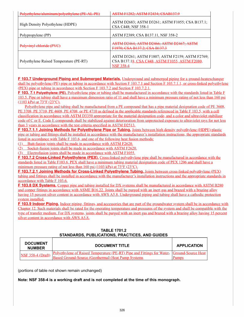
Polyethylene/aluminum/polyethylene (PE-AL-PE) ASTM F1282; ASTM F2434; CSAB137.9
High Density Polyethylene (HDPE) ASTM D2683; ASTM D3261; ASTM F1055; CSA B137.1;CSA C448; NSF 358-1
Polypropylene (PP) ASTM F2389; CSA B137.11, NSF 358-2
Polyvinyl chloride (PVC) ASTM D2464; ASTM D2466; ASTM D2467; ASTMF1970; CSA B137.2; CSA B137.3
Polyethylene Raised Temperature (PE-RT)ASTM D3261; ASTM F1807; ASTM F2159; ASTM F2769;CSA B137.18, CSA C448, ASTM F1055, ASTM F2080,NSF 358-4
F 103.7 Underground Piping and Submerged Materials. Underground and submerged piping for a ground-heatexchangershall be polyethylene (PE) pipe or tubing in accordance with Section F 103.7.1 and Section F 103.7.1.1, or cross-linked polyethylene(PEX) pipe or tubing in accordance with Section F 103.7.2 and Section F 103.7.2.1.F 103. 7.1 Polyethylene (PE). Polyethylene pipe or tubing shall be manufactured in accordance with the standards listed in Table F103.5. Pipe or tubing shall have a maximum dimension ratio of 11 and shall have a minimum pressure rating of not less than 160 psi(1103 kPa) at 73°F (23°C). Polyethylene pipe and tubing shall be manufactured from a PE compound that has a pipe material designation code of PE 3608,PE 3708, PE 3710, PE 4608, PE 4708, or PE 4710 as defined in the applicable standards referenced in Table F 103.5, with a cellclassification in accordance with ASTM D3350 appropriate for the material designation code, and a color and ultraviolet stabilizercode of C or E. Code E compounds shall be stabilized against deterioration from unprotected exposure to ultraviolet rays for not lessthan 3 years in accordance with the test criteria specified in ASTM D2513.F 103.7.1.1 Joining Methods for Polyethylene Pipe or Tubing. Joints between high density polyethylene (HDPE) plasticpipe or tubing and fittings shall be installed in accordance with the manufacturer’s installation instructions, the appropriate standardslisted in accordance with Table F 103.6, and one of the following heat fusion methods:(1) Butt-fusion joints shall be made in accordance with ASTM F2620.(2) Socket-fusion joints shall be made in accordance with ASTM F2620.(3) Electrofusion joints shall be made in accordance with ASTM F1055.F 103.7.2 Cross-Linked Polyethylene (PEX). Cross-linked polyethylene pipe shall be manufactured in accordance with thestandards listed in Table F103.6. PEX shall have a minimum tubing material designation code of PEX 1206 and shall have aminimum pressure rating of not less than 160 psi (1103 kPa) at 73°F (23°C).F 103.7.2.1 Joining Methods for Cross-Linked Polyethylene Tubing. Joints between cross-linked polyethylene (PEX)tubing and fittings shall be installed in accordance with the manufacturer’s installation instructions and the appropriate standards inaccordance with Table F 103.6.F 103.8 DX Systems. Copper pipe and tubing installed for DX systems shall be manufactured in accordance with ASTM B280and copper fittings in accordance with ASME B16.22. Joints shall be purged with an inert gas and brazed with a brazing alloyhaving 15 percent silver content in accordance with AWS A5.8. Underground piping and tubing shall have a cathodic protectionsystem installed.F 103.9 Indoor Piping. Indoor piping, fittings, and accessories that are part of the groundwater system shall be in accordance withChapter 12. Such materials shall be rated for the operating temperature and pressures of the system and shall be compatible with thetype of transfer medium. For DX systems, joints shall be purged with an inert gas and brazed with a brazing alloy having 15 percentsilver content in accordance with AWS A5.8.
TABLE 1701.2STANDARDS, PUBLICATIONS, PRACTICES, AND GUIDES
DOCUMENTNUMBER DOCUMENT TITLE APPLICATION
NSF 358-4 (Draft) Polyethylene of Raised Temperature (PE-RT) Pipe and Fittings for Water-Based Ground-Source (Geothermal) Heat Pump Systems
Ground-Source HeatPumps
(portions of table not shown remain unchanged)
Note: NSF 358-4 is a working draft and is not completed at the time of this monograph.
326
SUBSTANTIATION:Piping, fittings and joints must be compatible with the heat transfer fluid, antifreeze (or the refrigerant in the case of directexchange systems) and corrosion resistant. Piping is divided into underground piping for geothermal applications and indoorpiping. In accordance with ASHRAE, Chapter 34 Geothermal Systems, carbon steel piping has shown good service inseveral systems as long as the system design excluded oxygen. However, the introduction of 0.03 mg/kg oxygen underturbulent flow conditions causes a fourfold increase in uniform corrosion. Saturation with air often increases the corrosionrate by at least 15 times. Oxygen contamination at the 0.05 mg/kg level causes severe pitting and chronic oxygencontamination causes rapid failure. External surfaces of buried steel pipe must be protected from contact with groundwater.Groundwater is aerated and has caused pipe failures by external corrosion. External protection can be obtained by coatings,wraps provided the selected material resists the system operating temperature and thermal stress. Carbon steel piping isprimarily used on the inside or clean loop side of the isolation heat exchanger. In both underground and abovegroundinstallations, allowance for expansion joints or loops must be provided. For these reasons, carbon steel is not recommendedfor underground piping, but may be used as an acceptable indoor piping material.
Copper-tubed fan-coil units and heat exchangers have consistently poor performance because of traces of sulfide speciesfound in geothermal fluids in the United States. Copper tubing rapidly becomes fouled with cuprous sulfide films more than.04 mm thick. Serious crevice corrosion occurs at cracks in the film, and uniform corrosion rates of 50 to 150 mils per yearappear typical, based on failure analysis. Copper pipe shows corrosion behavior similar to copper heat exchange tubesunder conditions of moderate turbulence. Copper is not recommended for use in systems where it is exposed to thegeothermal fluid (underground or indoor piping). This section does not apply to DX systems as the refrigerant is an inert gas -it does not cause electrolysis, so it will not corrode from the inside.
Unlike copper and cupronickel, stainless steels are not affected by traces of hydrogen sulfide. Most heat exchangers are ofthe plate and frame type, most of which are fabricated with one of two standard alloys, Type 304 and Type 316 austeniticstainless steel. Some pump and valve trim also are fabricated from these or other stainless steels. These alloys are subjectto pitting and crevice corrosion above a threshold chloride level, which depends on the chromium and molybdenum contentof the alloy and on the temperature of the geothermal fluid. At elevated temperatures, the passivation film, which gives thestainless steel its corrosion resistance, is ruptured, and local pitting and crevice corrosion occur. Type 304 is resistant at thattemperature until the chloride level reaches approximately 510 mg/kg. Because of its 2% to 3% molybdenum content, Type316 is always more resistant to chlorides than is Type 304. Stainless steel is recommended for the interior piping portion.
Aluminum alloys are not acceptable in most cases because of catastrophic pitting.
CPVC and PVC materials are easily fabricated and are not adversely affected by oxygen intrusion. External protectionagainst groundwater is not required. The mechanical properties of these materials at higher temperatures may vary greatlyfrom those at ambient temperature, and the materials’ mechanical limits should not be exceeded.
The usual mode of failure is creep rupture: strength decays with time. Manufacturer’s directions for joining should be followedto avoid premature failure of joints. CPVC and PVC are not recommended for underground piping of the ground heatexchanger. However, CPVC and PVC have been used for the interior piping portions.
Cross-linked polyethylene (PEX) is a high-density polyethylene material in which the individual molecules are “cross-linked”during the production of the material. The effect of the crosslinking imparts physical qualities to the piping which allow it tomeet the requirements of much higher temperature/pressure applications Joining the piping is accomplished using speciallydesigned, conversion fittings which are generally of brass construction. Piping with and without an oxygen diffusion barrier isavailable. The oxygen barrier prevents the diffusion of oxygen through the piping wall and into the water. This is necessarycorrosion prevention for closed systems in which ferrous materials are included. PEX is used for underground and indoorpiping.
Polyethylene (PE) is a flexible material available in a wide variety of sizes. This is the most common type of piping materialsfor underground portion of a ground source heat pump. Standard dimension ratio (SDR) is the ratio of the pipe outsidediameter to the wall thickness and relates to the pressure rating of the pipe. SDR 17 is generally rated at 100 psi for alldiameters, SDR 11 is rated at 160 psi, and SDR 9 is rated at 200 psi. The only recommended joining method is by thermalfusion. Polyethylene is recommended for underground and indoor piping.
COMMITTEE ACTION: ACCEPT AS AMENDED BY THE TC
Amend proposal as follows:
F 103.5 Piping and Tubing Materials Standards. For water-based systems, ground source heat pump ground-loop pipe andtubing shall comply with the standards listed in Table F 103.5. Piping and tubing used for DX systems shall be of copper inaccordance with Section F 103.8.
327
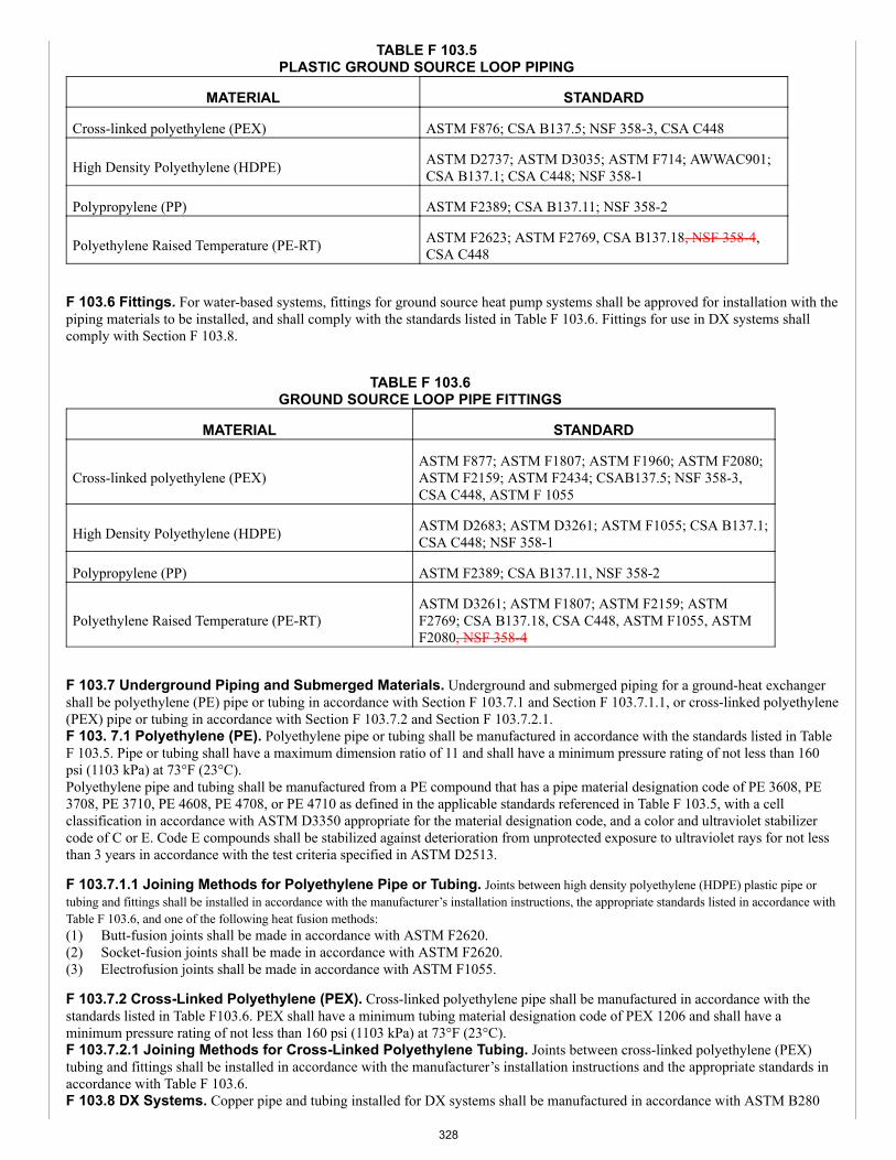
TABLE F 103.5PLASTIC GROUND SOURCE LOOP PIPING
MATERIAL STANDARD
Cross-linked polyethylene (PEX) ASTM F876; CSA B137.5; NSF 358-3, CSA C448
High Density Polyethylene (HDPE) ASTM D2737; ASTM D3035; ASTM F714; AWWAC901;CSA B137.1; CSA C448; NSF 358-1
Polypropylene (PP) ASTM F2389; CSA B137.11; NSF 358-2
Polyethylene Raised Temperature (PE-RT) ASTM F2623; ASTM F2769, CSA B137.18, NSF 358-4,CSA C448
F 103.6 Fittings. For water-based systems, fittings for ground source heat pump systems shall be approved for installation with thepiping materials to be installed, and shall comply with the standards listed in Table F 103.6. Fittings for use in DX systems shallcomply with Section F 103.8.
TABLE F 103.6GROUND SOURCE LOOP PIPE FITTINGS
MATERIAL STANDARD
Cross-linked polyethylene (PEX)ASTM F877; ASTM F1807; ASTM F1960; ASTM F2080;ASTM F2159; ASTM F2434; CSAB137.5; NSF 358-3,CSA C448, ASTM F 1055
High Density Polyethylene (HDPE) ASTM D2683; ASTM D3261; ASTM F1055; CSA B137.1;CSA C448; NSF 358-1
Polypropylene (PP) ASTM F2389; CSA B137.11, NSF 358-2
Polyethylene Raised Temperature (PE-RT)ASTM D3261; ASTM F1807; ASTM F2159; ASTMF2769; CSA B137.18, CSA C448, ASTM F1055, ASTMF2080, NSF 358-4
F 103.7 Underground Piping and Submerged Materials. Underground and submerged piping for a ground-heat exchangershall be polyethylene (PE) pipe or tubing in accordance with Section F 103.7.1 and Section F 103.7.1.1, or cross-linked polyethylene(PEX) pipe or tubing in accordance with Section F 103.7.2 and Section F 103.7.2.1.F 103. 7.1 Polyethylene (PE). Polyethylene pipe or tubing shall be manufactured in accordance with the standards listed in TableF 103.5. Pipe or tubing shall have a maximum dimension ratio of 11 and shall have a minimum pressure rating of not less than 160psi (1103 kPa) at 73°F (23°C).Polyethylene pipe and tubing shall be manufactured from a PE compound that has a pipe material designation code of PE 3608, PE3708, PE 3710, PE 4608, PE 4708, or PE 4710 as defined in the applicable standards referenced in Table F 103.5, with a cellclassification in accordance with ASTM D3350 appropriate for the material designation code, and a color and ultraviolet stabilizercode of C or E. Code E compounds shall be stabilized against deterioration from unprotected exposure to ultraviolet rays for not lessthan 3 years in accordance with the test criteria specified in ASTM D2513.
F 103.7.1.1 Joining Methods for Polyethylene Pipe or Tubing. Joints between high density polyethylene (HDPE) plastic pipe ortubing and fittings shall be installed in accordance with the manufacturer’s installation instructions, the appropriate standards listed in accordance withTable F 103.6, and one of the following heat fusion methods:(1) Butt-fusion joints shall be made in accordance with ASTM F2620.(2) Socket-fusion joints shall be made in accordance with ASTM F2620.(3) Electrofusion joints shall be made in accordance with ASTM F1055.
F 103.7.2 Cross-Linked Polyethylene (PEX). Cross-linked polyethylene pipe shall be manufactured in accordance with thestandards listed in Table F103.6. PEX shall have a minimum tubing material designation code of PEX 1206 and shall have aminimum pressure rating of not less than 160 psi (1103 kPa) at 73°F (23°C).F 103.7.2.1 Joining Methods for Cross-Linked Polyethylene Tubing. Joints between cross-linked polyethylene (PEX)tubing and fittings shall be installed in accordance with the manufacturer’s installation instructions and the appropriate standards inaccordance with Table F 103.6.F 103.8 DX Systems. Copper pipe and tubing installed for DX systems shall be manufactured in accordance with ASTM B280
328
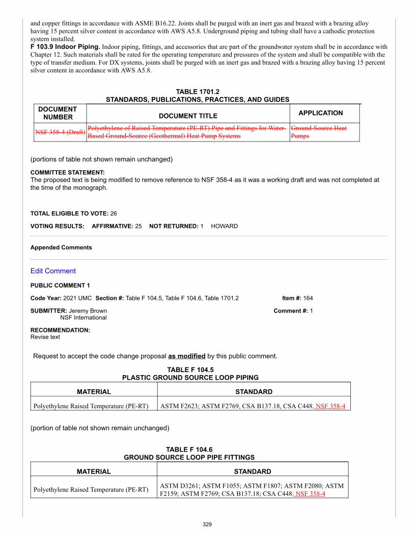
Item #: 164
Comment #: 1
and copper fittings in accordance with ASME B16.22. Joints shall be purged with an inert gas and brazed with a brazing alloyhaving 15 percent silver content in accordance with AWS A5.8. Underground piping and tubing shall have a cathodic protectionsystem installed.F 103.9 Indoor Piping. Indoor piping, fittings, and accessories that are part of the groundwater system shall be in accordance withChapter 12. Such materials shall be rated for the operating temperature and pressures of the system and shall be compatible with thetype of transfer medium. For DX systems, joints shall be purged with an inert gas and brazed with a brazing alloy having 15 percentsilver content in accordance with AWS A5.8.
TABLE 1701.2STANDARDS, PUBLICATIONS, PRACTICES, AND GUIDES
DOCUMENTNUMBER DOCUMENT TITLE APPLICATION
NSF 358-4 (Draft) Polyethylene of Raised Temperature (PE-RT) Pipe and Fittings for Water-Based Ground-Source (Geothermal) Heat Pump Systems
Ground-Source HeatPumps
(portions of table not shown remain unchanged)
COMMITTEE STATEMENT:The proposed text is being modified to remove reference to NSF 358-4 as it was a working draft and was not completed atthe time of the monograph.
TOTAL ELIGIBLE TO VOTE: 26
VOTING RESULTS: AFFIRMATIVE: 25 NOT RETURNED: 1 HOWARD
Appended Comments
Edit Comment
PUBLIC COMMENT 1
Code Year: 2021 UMC Section #: Table F 104.5, Table F 104.6, Table 1701.2
SUBMITTER: Jeremy BrownNSF International
RECOMMENDATION:Revise text
Request to accept the code change proposal as modified by this public comment.
TABLE F 104.5PLASTIC GROUND SOURCE LOOP PIPING
MATERIAL STANDARD
Polyethylene Raised Temperature (PE-RT) ASTM F2623; ASTM F2769, CSA B137.18, CSA C448, NSF 358-4
(portion of table not shown remain unchanged)
TABLE F 104.6GROUND SOURCE LOOP PIPE FITTINGS
MATERIAL STANDARD
Polyethylene Raised Temperature (PE-RT) ASTM D3261; ASTM F1055; ASTM F1807; ASTM F2080; ASTMF2159; ASTM F2769; CSA B137.18; CSA C448; NSF 358-4
329

(portion of table not shown remain unchanged)
TABLE 1701.2STANDARDS, PUBLICATIONS, PRACTICES, AND GUIDES
DOCUMENTNUMBER DOCUMENT TITLE APPLICATION
NSF 358-4-2018 Polyethylene of Raised Temperature (PE-RT) Tubing and Fittings forWater-Based Ground-Source (Geothermal) Heat Pump Systems
Ground-Source HeatPumps
(portion of table not shown remain unchanged)
SUBSTANTIATION:NSF/ANSI 358-4 Polyethylene of Raised Temperature (PE-RT) Tubing and Fittings for Water-Based Ground-Source (Geothermal) HeatPump Systems is now complete and published. This standard is the 4th in a series of standard for geothermal pipe and fittings. NSF358-1 (PE), NSF 358-2 (PP), and NSF 358-3 (PEX) are already referenced in the UMC. This last version, NSF 358-4, is adding therequirements for PE-RT. This standard addresses requirements for performance, long term strength, U-bend assembled joint testing,chemical resistance, thermocycling, constant tensile load joint testing, joint pressure testing, marking, suitability for burial and qualityassurance. This document is appropriate for adoption into the UMC.
A final version of this document is available for review by the Technical Committee . Anyone else wanting a copy of NSF 358-4 for thepurposes of considering this proposal may request a free copy from [email protected].
COMMITTEE ACTION: ACCEPTED AS SUBMITTED
TOTAL ELIGIBLE TO VOTE: 26
VOTING RESULTS: AFFIRMATIVE: 25 NOT RETURNED: 1 HOWARD
330
Item #: 164.01
Comment #: 1
Comments
Edit Comment
Code Year: 2021 UMC Section #: Appendix F
SUBMITTER: UMC Technical Committee Comment
RECOMMENDATION:Revise text
Request to accept the code change proposal as modified by this committee comment.
APPENDIX FGEOTHERMAL ENERGY SYSTEMS
Part I – General.
F 101.0 General.F 101.1 Applicability. Part I of this appendix shall apply to geothermal energy systems such as, but not limited to, buildingsystems coupled with a ground-heat exchanger, submerged heat exchanger using water-based fluid as a heat transfer medium, orgroundwater (well) using water-based fluid as a heat transfer medium. The regulations of this appendix shall govern theconstruction, location and installation of geothermal energy systems.Indoor piping, fittings, and accessories that are part of the groundwater system shall be in accordance with Section F 104.7 F 104.4and Chapter 12.F 101.1.1 Prior to Construction. Documents for permits shall be submitted prior to the construction of a building system,ground heat exchanger, submerged heat exchanger, or water well. Permits shall be issued by the Authority Having Jurisdiction.F 101.1.2 Equipment, Accessories, Components, and Materials. The mechanical equipment, accessories, components,and materials used shall be of the type and rating approved for the specific use.F 102.1 F 101.2 Construction Documents. The construction documents for the building system portion of the geothermalenergy system shall be submitted to the Authority Having Jurisdiction.F 102.2 F 101.3 Site Survey. A site survey shall be conducted prior to designing the geothermal system. The requirements forconstruction documents shall be defined by the Authority Having Jurisdiction. Where no guidance is provided, the followinginformation shall be provided:(1) Ground heat exchanger dimensions.(2) Grout or sealing specifications, as applicable.(3) Dimensions from building to water well, ground heat exchanger, or submerged heat exchanger.(4) Operating temperatures and pressures.F 102.4 F 101.4 Used Materials. The installation of used pipe, fittings, valves, and other materials shall not be permitted.F 102.5 F 101.5 Contact with Building Material. A ground source heat pump ground-loop piping system shall not be in directcontact with building materials that cause the piping or fitting material to degrade or corrode, or that interferes with the operation ofthe system.F 102.6 F 101.6 Strains and Stresses. Piping shall be installed so as to prevent detrimental strains and stresses in the pipe.Provisions shall be made to protect piping from damage resulting from expansion, contraction, and structural settlement. Piping shallbe installed so as to avoid structural stresses or strains within building components.F 102.7 F 101.7 Flood Hazard. Piping located in a flood hazard area shall be capable of resisting hydrostatic and hydrodynamicloads and stresses, including the effects of buoyancy, during the occurrence of flooding to the design flood elevation.F 102.8 F 101.8 Pipe Support. Pipe shall be supported in accordance with Section 313.1.F 102.9 F 101.9 Velocities. Ground source heat pump ground-loop systems shall be designed so that the flow velocities do notexceed the maximum flow velocity recommended by the pipe and fittings manufacturer. Flow velocities shall be controlled toreduce the possibility of water hammer.F 102.10 F 101.10 Chemical Compatibility. Antifreeze and other materials used in the system shall be chemically compatiblewith the pipe, tubing, fittings, and mechanical systems.F 102.11 F 101.11 Transfer Fluid. The transfer fluid shall be compatible with the makeup water supplied to the system.
F 102.0 Definitions.Geothermal Energy System. A system that uses thermal energy for space heating and cooling, and water heating.
331
Geothermal Energy System, Closed-Loop. A continuous, sealed, underground, or submerged heat exchanger through which aheat-transfer fluid passes to and returns from a heat pump.Geothermal Energy System, Open-Loop. A liquid-source heat pump system that uses ground water or surface water to extractor reject heat.Ground-Heat Exchanger. An underground closed-loop heat exchanger through which a heat-transfer medium passes to and froma heat pump or other rated mechanical equipment. It includes the buried pipe and connecting main(s) up to and terminating with thebuilding.Groundwater Source. A geothermal energy system that uses the groundwater as a heat source or sink.Water Well. An excavation that is drilled, cored, bored, washed, driven, dug, jetted, or otherwise constructed for the purposes ofextracting groundwater, using the geothermal properties of the earth or injecting water into an aquifer or subsurface reservoir.
F 103.0 Groundwater Systems.F 103.1 General. The potable water supply connected to a groundwater system shall be protected with an approved backflowprevention device. The connection of a discharge line to the sanitary or storm sewer system, or private sewage disposal system, shallbe in accordance with the plumbing code or in accordance with the Authority Having Jurisdiction.
F 104.0 Design of Systems.F 104.1 Ground-Heat Exchanger Design. The ground-heat exchanger design shall be provided by a licensed professional or adesigner with the appropriate certifications or credentials as defined by the Authority Having Jurisdiction.F 104.5 F 104.2 Piping and Tubing Materials Standards. For water-based systems, ground source heat pump ground-looppipe and tubing shall comply with the standards listed in Table F 104.5 F 104.2. Piping and tubing used for DX systems shall be ofcopper in accordance with Section F 104.8 F 401.3.
TABLE F 104.5 F 104.2PLASTIC GROUND SOURCE LOOP PIPING
MATERIAL STANDARDCross-linked polyethylene (PEX) ASTM F876; CSA B137.5; CSA C448; NSF 358-3High Density Polyethylene(HDPE)
ASTM D2737; ASTM D3035; ASTM F714;AWWAC901; CSA B137.1; CSA C448; NSF 358-1
Polypropylene (PP) ASTM F2389; CSA B137.11; NSF 358-2
Polyethylene Raised Temperature(PE-RT)
ASTM F2623; ASTM F2769; CSA B137.18; CSAC448
E F 104.6 F 104.3 Fittings. For water-based systems, fittings for ground source heat pump systems shall be approved forinstallation with the piping materials to be installed, and shall comply with the standards listed in Table F 104.6 F 104.3. Fittings foruse in DX systems shall comply with Section F 104.8 F 401.3.
TABLE F 104.6 F 104.3GROUND SOURCE LOOP PIPE FITTINGS
MATERIAL STANDARDCross-linked polyethylene (PEX) ASTM F877; ASTM F1055; ASTM F1807; ASTM F1960;
ASTMF2080; ASTM F2159; ASTM F2434; CSA B137.5; CSAC448; NSF 358-3
High Density Polyethylene (HDPE) ASTM D2683; ASTM D3261; ASTM F1055; CSA B137.1; CSAC448; NSF 358-1
Polypropylene (PP) ASTM F2389; CSA B137.11; NSF 358-2
Polyethylene Raised Temperature (PE-RT) ASTM D3261; ASTM F1055; ASTM F1807; ASTM F2080;ASTM F2159; ASTM F2769; CSA B137.18; CSA C448
F 104.7 F 104.4 Underground Piping and Submerged Materials. Underground and submerged piping for a ground-heatexchanger shall be polyethylene (PE) pipe or tubing in accordance with Section F 104.7.1 F 104.4.1 and Section F 104.7.1.1 F104.4.1.1, or cross-linked polyethylene (PEX) pipe or tubing in accordance with Section F 104.7.2 F 104.4.2 and Section F 104.7.2.1F 104.4.2.1.F 104.7.1 F 104.4.1 Polyethylene (PE). Polyethylene pipe or tubing shall be manufactured in accordance with the standards
332
listed in Table F 104.5 F 104.2. Pipe or tubing shall have a maximum dimension ratio of minimum wall thickness equal to SDR-11and shall have a minimum pressure rating of not less than 160 psi (1103 kPa) at 73°F (23°C).Polyethylene pipe and tubing shall be manufactured from a PE compound that has a pipe material designation code of PE 3608, PE3708, PE 3710, PE 4608, PE 4708, or PE 4710 as defined in the applicable standards referenced in Table F 104.5 F 104.2, with a cellclassification in accordance with ASTM D3350 appropriate for the material designation code, and a color and ultraviolet stabilizercode of C or E. Code E compounds shall be stabilized against deterioration from unprotected exposure to ultraviolet rays for not lessthan 3 years in accordance with the test criteria specified in ASTM D2513.F 104.7.1.1 F 104.4.1.1 Joining Methods for Polyethylene Pipe or Tubing. Joints between high density polyethylene(HDPE) plastic pipe or tubing and fittings shall be installed in accordance with the manufacturer’s installation instructions, theappropriate standards listed in accordance with Table F 104.6 F 104.3, and one of the following heat fusion methods:(1) Butt-fusion joints shall be made in accordance with ASTM F2620.(2) Socket-fusion joints shall be made in accordance with ASTM F2620.(3) Electrofusion joints shall be made in accordance with ASTM F1055.F 104.7.2 F 104.4.2 Cross-Linked Polyethylene (PEX). Cross-linked polyethylene pipe shall be manufactured in accordancewith the standards listed in Table F 104.6 F 104.3. PEX shall have a minimum tubing material designation code of PEX 1206 andshall have a minimum pressure rating of not less than 160 psi (1103 kPa) at 73°F (23°C).F 104.7.2.1 F 104.4.2.1 Joining Methods for Cross-Linked Polyethylene Tubing. Joints between cross-linkedpolyethylene (PEX) pipe or tubing and fittings shall be installed in accordance with the manufacturer’s installation instructions andthe appropriate standards in accordance with Table F 104.6 F 104.3.F 104.9 F 104.5 Indoor Piping. Indoor piping, fittings, and accessories that are part of the groundwater system shall be inaccordance with Chapter 12. Such materials shall be rated for the operating temperature and pressures of the system and shall becompatible with the type of transfer medium. For DX systems, joints shall be purged with an inert gas and brazed with a brazingalloy having 15 percent silver content in accordance with AWS A5.8.
F 108.0 F 105.0 Heat Pumps and Distribution System Design.F 108.2 F 105.1 Heat Pump Distribution System. The heat pump distribution system shall be designed as follows:(1) Individual heat pumps shall have the capacity to handle the peak load for each zone at its peak hour.(2) Distribution piping and fittings shall be insulated to prevent condensation inside the building.(3) An isolation valve shall be installed on both supply and return of each unit.(4) Condensate drains on heat pumps shall be installed in accordance with the manufacturer’s installation instructions.(5) Air filters shall be installed for heat pump units.(6) Drain valves shall be installed at the base of each supply and return pipe riser for system flushing.(7) Piping shall be supported in accordance with Section 313.0 and provisions for vibration, expansion or contraction shall beprovided.(8) Specifications for each heat pump, the heating and cooling capacity, the fluid flow rate, the airflow rate, and the externalpressure or head shall be provided on the construction documents.(9) Manually controlled air vents shall be installed at the high points in the system and drains at the low points. Where the heat-transfer fluid is a salt or alcohol, automatic air vents shall not be installed.(10) Means for flow balancing for the building loop shall be provided.(11) Supply and return header temperatures and pressures shall be marked.F 108.3 F 105.2 Circulating Pumps. The circulating pump shall be sized for the operating conditions and the heat transfer fluidproperties
F 110.0 F 106.0 Valves.F 110.1 F 106.1 Where Required. Shutoff valves shall be installed in ground source-loop piping systems in the locationsindicated in Section F 110.2 F 106.2 through Section F 110.8 F 106.8.F 110.2 F 106.2 Heat Exchangers. Shutoff valves shall be installed on the supply and return side of a heat exchanger, exceptwhere the heat exchanger is integral with a boiler or is a component of a manufacturer’s boiler and heat exchanger packaged unit,and is capable of being isolated from the hydronic system by the supply and return valves.F 110.3 F 106.3 Central Systems. Shutoff valves shall be installed on the building supply and return of a central utility system.F 110.4 F 106.4 Pressure Vessels. Shutoff valves shall be installed on the connection to a pressure vessel.F 110.5 F 106.5 Pressure-Reducing Valves. Shutoff valves shall be installed on both sides of a pressure-reducing valve.F 110.6 F 106.6 Equipment and Appliances. Shutoff valves shall be installed on connections to mechanical equipment andappliances. This requirement does not apply to components of a ground source loop system such as pumps, air separators, meteringdevices, and similar equipment.F 110.7 F 106.7 Expansion Tanks. Shutoff valves shall be installed at connections to nondiaphragm-type expansion tanks.F 110.8 F 106.8 Reduced Pressure. A pressure relief valve shall be installed on the low-pressure side of a hydronic pipingsystem that has been reduced in pressure. The relief valve shall be set at the maximum pressure of the system design.
F 106.0 F 107.0 Specific System Components Design.F 108.1 F 107.1 General. Ground coupled and water source heat pumps shall be certified in accordance with
333
AHRI/ASHRAE/ISO 13256-1 for water-to-air heat pumps and AHRI/ASHRAE/ISO 13256-2 for water-to-water heat pumps. DXheat pumps shall be certified in accordance with ASHRAE 194. All heat Ppump equipment used in DX systems shall comply withAHRI 870. Heat pumps shall be fitted with a means to indicate that the compressor is locked out.F 106.1 F 107.2 Heat Exchangers. Heat exchangers used for heat transfer or heat recovery shall protect the potable watersystem from being contaminated by the heat transfer medium. Single-wall heat exchangers shall comply with Section 1218.1.Double-wall heat exchangers shall separate the potable water from the heat transfer medium by providing a space between the twowalls that are vented to the atmosphere.F 106.2 F 107.3 Heat-Transfer Medium. The heat-transfer medium shall be compatible with components with which it comesinto contact. Where antifreeze or corrosion inhibitors are used, such solutions shall be approved by the Authority HavingJurisdiction. The heat-transfer fluid flash point shall be not less than 50°F (27.8°C) above the maximum system operatingtemperature. For DX systems, the heat transfer medium shall be a refrigerant listed in ASHRAE 34 or this code.F 106.4 F 107.4 Insulation. The temperature of surfaces within reach of building occupants shall not exceed 140°F (60°C) unlessthey are protected by insulation. Where sleeves are installed, the sleeve insulation shall retain its full size over the length of thematerial being protected.
F 105.0 F 108.0 Installation Practices.F 201.1.1 F 108.1 Prior to Construction. Documents for permits shall be submitted prior to the construction of a buildingsystem, or water well. Permits shall be issued by the Authority Having Jurisdiction.F 201.1.2 F 108.2 Equipment, Accessories, Components, and Materials. The mechanical equipment, accessories,components, and materials used shall be of the type and rating approved for the specific use.F 201.2 F 108.3 Construction Documents. The construction documents for the building system portion of the geothermalenergy system shall be submitted to the Authority Having Jurisdiction.F 201.3 F 108.4 Site sSurvey rRequirements. The site survey shall identify the physical limitations of the land area, includingits extent, structures, existing wells of all types, proximity of other existing ground source heat pump systems, pavements, trees,grading, ponds, waterways, easements, overhead and underground services, septic systems, any identified septic repair areas, utilityof rights of way, and any other elements that could affect an open- loop configuration.Permission shall be obtained from any adjoining property owner(s), as evidenced by the registration and approval of a formaleasement that meets requirements of the authority having jurisdiction. It shall be received prior to the installation of any open-loopsystem that will extend into, cross, or interfere with the equipment or rights-of-way of utilities, jurisdictions, and other propertyowners.The site survey shall include a subsurface investigation that meets the requirements for an open-loop heat exchanger.F 201.4 F 108.5 Subsurface iInvestigation. A subsurface investigation shall be performed in accordance with Section F201.4.1 F 108.6 as determined by the registered design professional conducting the site survey.F 201.4.1 F 108.6 Subsurface Conditions. The water well logs and other geological records shall be used to anticipate thesubsurface conditions of the aquifer and its potential supply of fresh water, multiple aquifers, saltwater intrusions, contaminatedsoils and groundwater, hazardous gases, and any interference with neighboring water wells and ground source heat exchangers.Geological issues such as permafrost conditions and building stability shall be considered when reviewing available records.F 104.2 F 108.7 Ground-Heat Exchanger Installation Practices. A ground-heat exchanger system shall be installed asfollows:(1) Outside piping or tubing located within 5 feet (1524 mm) of any wall or structure shall be continuously insulated with insulationthat has a minimum R-5 value. Such pipe or tubing installed under the slab or basement floors shall be insulated within 5 feet (1524mm) from the structure to the exterior point of exit from the slab.(2) Freeze protection shall be provided where the design of the ground heat exchanger system would permit the heat-transfermedium to freeze.(3) Horizontal piping shall be installed not less than 12 inches (305 mm) below the frost line.(4) Submerged heat exchangers shall be protected from damage and shall be securely fastened to the bottom of the lake or pond, orother approved submerged structure.(5) A minimum separation distance shall be maintained between the potable water intake and the submerged heat exchanger systemin accordance with the Authority Having Jurisdiction.(6) Vertical and horizontal ground-heat exchangers shall maintain the following setbacks:(a) Ten feet (3048 mm) horizontally from a pressure-tested sewer lateral into a building.(b) Twenty feet (6096 mm) horizontally from a non-pressure tested sewer lateral into a building.(c) Three feet (914 mm) horizontally from buried utilities such as electrical, gas, or water.(d) Fifty feet (15 240 mm) from a water well.(e) Fifty feet (15 240 mm) from a septic tank and 100 feet (30 480 mm) from a subsurface sewage leaching field.(f) One hundred feet (30 480 mm) from a spring; or at distances specified by the Authority Having Jurisdiction.(7) Wells and boreholes shall be sealed in accordance with the Authority Having Jurisdiction. Where grout is required, it shall beapplied in a single continuous operation from the bottom of the borehole by pumping through a tremie pipe.F 105.1 F 108.8 Trenching, Excavation, and Backfill. Prior to excavation, trenching, or drilling, buried utilities, drainage,water, and irrigation systems shall be located. Prior to excavation, trenching, or drilling, the contractor, and owner shall agree inwriting to site restoration requirements and submit to the Authority Having Jurisdiction for approval. Prior to any excavation,trenching, or drilling, all buried utilities including drainage and irrigation systems shall be located and flagged by the appropriateutility and ground source heat pump system contractor representative.
334
F 105.2 F 108.9 Trenches, Tunneling, and Driving. Trenches shall comply with Section 317.1. Tunneling and driving shallcomply with Section 317.2.F 105.3 F 108.10 Excavations and Open Trenches. Excavations required to be made for the installation of piping or tubingshall be in accordance with Section 317.3. Piping or tubing shall be supported to maintain its alignment and prevent sagging. Pipingin the ground shall be laid on a firm bed for its entire length; where other support is otherwise provided, it shall be approved inaccordance with Section 302.0. Piping or tubing shall be backfilled after an inspection in accordance with Section 317.4.F 105.4 F 108.11 Protection of Piping, Materials, and Structures. Piping and tubing passing under or through walls shallbe protected from breakage in accordance with Section 316.1. Piping and tubing shall be installed in accordance with Section 316.2to provide for expansion, contraction, and structural settlement. An electrically continuous corrosion-resistant tracer wire (not lessthan AWG 14) or tape shall be buried with the plastic pipe to facilitate locating. One end shall be brought aboveground at a buildingwall or riser.F 105.5 F 108.12 Sleeves. In exterior walls, annular space between sleeves and pipes shall be sealed and made watertight andshall not be subject to a load from building construction in accordance with Section 316.7 through Section 316.7.2.F 105.6 F 108.13 Steel Nail Plates. Steel nail plates shall be installed for plastic and copper piping penetrating framingmembers to within 1 inch (25.4 mm) of the exposed framing in accordance with Section 316.6.F 106.3 F 108.14 On Site Storage. Exterior piping shall be fitted with end caps and protected from freezing, UV radiation,corrosion, and degradation. For DX systems, copper piping and fittings shall be stored to prevent physical damage, contamination,and each pipe or tubing shall be pressurized with an inert gas and sealed with a cap.F 108.4 F 108.15 Heat Pump and Distribution System Installation. The heat pump and distribution system shall beinstalled in accordance with the system’s design, with this code, and the manufacturer’s installation instructions.F 105.7 F 108.16 Pressurizing During Installation. Ground source heat pump ground loop piping to be embedded in concreteshall be pressure tested prior to pouring concrete. During pouring, the pipe shall be maintained at the proposed operating pressure.F 203.0 F 108.17 Horizontal Geothermal Piping from Extraction Wells and to Injection Wells - Materials andMethods. Horizontal geothermal piping shall be in in accordance with Section F 108.17.1 through Section F 108.18.8.F 203.1 F 108.17.1 Piping mMaterial. Piping materials and joining methods for horizontal piping from extraction wells and toinjection wells the ground-heat exchanger shall in accordance with Section F 104.5 F 104.2, Section F 104.6 F 104.3, Section F104.7 F 104.4, Section F 104.8 F 401.3 and Section F 104.9 F 104.5.F 203.1.1 F 108.17.2 Dissimilar Materials. Transition fittings between dissimilar materials shall be inside or accessible.F 203.1.2 F 108.17.3 Protection of Piping. Pipes passing through walls shall be sleeved and sealed in accordance with Section316.0.F 203.2 F 108.18 Trenches, Excavation, and Backfilled. Excavation for horizontal piping shall comply with Section F203.2.1 F 108.18.1 through Section F 203.2.8 F 108.18.8, Section F 105.1 F 108.8 through Section F 105.4 F 108.11, and inaccordance with requirements of the Authority Having Jurisdiction. Prior to any excavation, trenching, or drilling, all buried utilitiesincluding drainage, and irrigation systems shall be located and flagged by the appropriate utility and ground source heat pumpsystem contractor representative.F 203.2.1 F 108.18.1 Trenches. Trenches for underground piping or tubing shall be excavated in accordance with the setbacksrequirements in Section F 201.5 F 301.4.F 203.2.2 F 108.18.2 Buried Systems. Buried open-loop system piping, shall be installed not less than 3.3 feet (1006 mm)below the finished grade.F 203.2.3 F 108.18.3 Pipe Installation. Piping in horizontal trenches shall be embedded with not less than 6 inches (152 mm) ofinert granular material above and below, or in accordance with the Authority Having Jurisdiction and project specifications.Horizontal piping trenching shall be backfilled with approved material and shall be compacted.F 203.2.4 F 108.18.4 Separation. The horizontal piping shall be separated from fluid-based on-site services systems to preventexcessive short-circuiting heat transfer between such systems.F 203.2.5 F 108.18.5 Insulation. Insulation shall be provided on the piping where there is close proximity of all site services toprevent thermal interference between fluid-based on-site service systems.F 203.2.6 F 108.18.6 Pipe Bends. Sharp bending of pipe shall be prevented or approved elbow fitting shall be used with a bend-radius in accordance with the manufacturer’s installation instructions.F 203.2.7 F 108.18.7 Closed Cell Insulation. Buried horizontal open-loop system pipes passing parallel within 5 feet (1524mm) of a wall, structure, or water pipe shall be insulated with R-2 minimum closed cell insulation.F 203.2.8 F 108.18.8 Tracer Markings. Means shall be provided for underground detection or utility location of the buried pipesystem. This shall include, but is not limited to metallic detectable tape, with a thickness of not less than 11/64 of an inch (4.4 mm)and width of 6 inches (152 mm).This warning marking shall be permanent, conspicuous and resistant to the environmental conditions and shall be placed within 1foot to 2 feet (305 mm to 610 mm) on top of the horizontal piping of the heat exchanger installation.
F 109.0 System Start-Up.F 109.1 General. The following requirements shall be verified prior to system start-up.(1) Piping shall be cleaned, flushed, and purged.(2) DX systems shall be pressurized using nitrogen for not less than 1 hour. There shall be no allowable variance to the testpressure after being corrected for ambient temperature changes during the test. The test pressure shall not exceed 150 psig (1034kPa) when pressure testing the compressor unit and indoor system components.(32) The ground heat exchanger and building piping shall be cleaned, flushed, and, where required, shall be filled with the heat
335
transfer fluid medium. The ground loop system shall be tested at the design flow rate(s) and differential pressure(s) recorded. Wherethe actual pressure change at design flow is more than +/- 10 percent of the design flow pressure drop, the cause shall be identifiedand corrective action taken.(43) A method for the removal of air and a method for adding heat transfer fluid (where necessary) shall be provided.(54) The heat pumps shall be operational and adjustments shall be made in accordance with the manufacturer’s installationinstructions.(65) All necessary additional flow tests of the ground heat exchanger shall be completed prior to heat pump start-up.(76) Ground heat exchanger and building piping, valves, and operating controls, shall be set, adjusted, and operating as required.(87) The system shall be labeled at the loop charging valves with a permanent-type label, indicating the type of heat transfer fluidused. Where antifreeze is used, the labels shall indicate the antifreeze type and concentration.(9) DX systems shall have permanent type labels installed and affixed on the compressor unit with the refrigerant type and quantity.(108) Supply and return lines, as well as associated isolation valves from individual boreholes or water wells, shall be identified andtagged.(11) For DX systems, refrigerant liquid and vapor lines from the loop system shall be identified and tagged.(129) Supply and return lines on submerged systems shall be identified in an approved manner, at the point of entry to a surfacewater resource.F 109.2 Operation and Maintenance Manual. An operation and maintenance manual for the geothermal system shall beprovided to the owner. The manual shall include information on required testing and maintenance of the system. Training shall beprovided on the system’s operation, maintenance requirements, and on the content of the operation and maintenance manual. Theoperation and maintenance manual shall contain a layout of the ground-heat exchanger and building loop.F 109.3 Labeling and Marking. Ground source heat pump ground-loop system piping shall be marked with tape, metal tags, orother methods where it enters a building. The marking shall indicate the following words: “GROUND SOURCE HEAT PUMP-LOOP SYSTEM.” The marking shall indicate antifreeze used in the system by name and concentration.F 205.0 System Start-Up and Delivery.F 205.1 F 109.4 Documentation. The ground source heat pump system as-built installation drawings and instructions shall beprovided to the building owner or designated agent.F 205.2 F 109.5 Maintenance. The periodic maintenance required, in accordance with the design requirements, shall be providedand be made available to the owner or designated agent.F 205.3 F 109.6 Records. The ground source heat pump system construction documents shall be provided to the owner.F 205.4 F 109.7 System Start-Up. System startup shall be in accordance with CSA C448.1, CSA C448.2, and Section F 206.0 F111.0.F 205.5 F 109.8 Contaminants. Particulate contaminants shall be removed from the indoor piping system prior to initial start-up.
F 102.3 F 110.0 Decommissioning and Abandonment. Prior to the abandonment or decommissioning of a ground-heat exchanger,submerged heat exchanger or ground water (well) the owner shall obtain the necessary permits from the Authority HavingJurisdiction.F 110.1 General. Decommissioning of geothermal systems shall comply with CSA C448. Prior to the abandonment ordecommissioning of geothermal systems, the owner shall obtain the necessary permits from the Authority Having Jurisdiction.
Part I II – Closed-Loop Systems.
F 201.0 General.F 201.1 Applicability. Part II of this chapter shall apply to geothermal energy systems such as, but not limited to, building systemscoupled with a closed-loop systems using water-based fluid as a heat transfer medium.F 201.2 Piping and Tubing. Piping and tubing for closed-loop systems shall be in accordance Section F 104.2 and Table F104.2.F 201.3 Borehole Piping and Tubing. Borehole piping or tubing for vertical and horizontally drilled closed-loop systems shallhave a minimum wall thickness equal to SDR-11 and shall have a minimum pressure rating of not less than 160 psi (1103 kPa) at73°F (23°C).F 201.4 Underground Fittings. Underground fittings for closed loop systems shall be in accordance with Section F 104.3 andTable F 104.3.F 104.3 F 201.5 Verification. For closed-loop systems, the system shall be flushed of debris and purged of air after completion ofthe entire ground-heat exchanger. Flow rates and pressure drops shall be compared to calculated values to assure no blockage orkinking of the pipe. A report shall be submitted to the owner to confirm that the loop flow is in accordance with the constructiondocuments.For direct exchange (DX) systems, each u-bend shall be tested and proved tight with an inert gas at not less than 315 psi (2172 kPa)and maintained for 15 minutes without pressure drop. The pressure reading after tremie grouting of the boreholes shall bemaintained in the ground heat exchanger for not less than 2 hours, in accordance with CSA C448.F 104.4 F 201.6 Vertical Bores. Vertical bores shall be drilled to a depth to provide complete insertion of the u-bend pipe to itsspecified depth. The borehole diameter shall be sized for the installation and placement of the heat exchange u-bend and the tremieused to place the grouting material. CSA C448 shall be used for vertical loop depth and borehole diameter sizing guidance. The u-bend joint and pipe shall be visually inspected for integrity in accordance with the manufacturer’s installation instructions. The u-
336
bend joint and pipe shall be pressurized to not less than 100 psi (689 kPa), not to exceed the pressure rating of the pipe at the testtemperature, for 1 hour to check for leaks before insertion into the borehole.F 104.4.1 F 201.6.1 Backfill. Bentonite grout and thermally-enhanced bentonite grout, where used to seal and backfill eachborehole, shall comply with NSF 60. Boreholes shall be backfilled in accordance with the Authority Having Jurisdiction.F 104.4.2 F 201.6.2 U-Bends and Headers. Headers, u-bends and ground loop pipes shall be pressure-tested in accordancewith CSA C448, or as required by the Authority Having Jurisdiction. Before testing, heat fusion joints shall be cooled to ambienttemperature. Mechanical joints shall be completely assembled. Flushing and purging to remove air and debris shall be completedbefore testing. The assembly shall be filled with water (or water/antifreeze solution) and purged at a minimum flow rate of 2 feet persecond (0.6 m/s) to remove air, but not more than the maximum flow velocity recommended by the pipe and fittings manufacturer toremove debris.F 104.4.2.1 F 201.6.2.1 Test Pressure. The maximum test pressure shall be 1.5 times the system design pressure, as determinedby Section F 104.4.2.3 F 201.6.2.3, or Section F 104.4.2.4 F 201.6.2.4, not to exceed 100 psi (689 kPa). Components or devices withlower pressure-ratings than the pipe shall be protected from excessive pressure during testing by removing or isolating from the testsection.Exception: Where lower pressure-rated components or devices cannot be removed or isolated from the test section, the maximumtest pressure shall not exceed the pressure rating of the component or device.F 104.4.2.2 F 201.6.2.2 Testing Procedure. The test section and the test liquid shall be at the same temperature. The testsection shall be filled with liquid and purged of air. The test section shall be brought to the specified test pressure. Test pressure shallbe maintained for 4 hours, with make-up fluid added as needed. The test pressure shall be reduced by 10 psi (69 kPa) and monitoredfor 1 hour with no addition of pressure or make-up fluid. A passing test is indicated where after a period of 1 hour no visual leakageis observed, and pressure remains equal to or greater than 95 percent of the original pressure.F 104.4.2.3 F 201.6.2.3 Calculation of Static Pressure (Water). For water, the static pressure applied shall be equivalent to0.43 psig (2.96 kPa) per foot (305 mm) of elevation.F 104.4.2.4 F 201.6.2.4 Calculation of Static Pressure (Other Fluids). For fluids of different density, the static pressureshall be calculated using the density of the system fluid.
F 107.0 F 202.0 Ground-Heat Exchanger Testing.F 107.1 F 202.1 Testing. Pressure-testing of the ground-heat exchanger shall be performed in accordance with the testing methodin Section F 104.4 F 201.6.F 202.2 Individual Loop Pressure Testing. Individual loop testing shall be performed as required by the Authority HavingJurisdiction.F 202.3 Field Pressure Testing – Final. The ground heat exchanger and building piping shall be cleaned, flushed, and, whererequired, shall be filled with the heat transfer fluid medium. The ground loop system shall be tested at the design flow rate(s) anddifferential pressure(s) recorded. Where the actual pressure change at design flow is more than +/- 10 percent of the design flowpressure drop, the cause shall be identified, and corrective action taken.F 202.4 Field Flow Testing – Final. Final field flow testing shall be performed as required by the Authority Having Jurisdiction.
F 206.0 Decommissioning and Abandonment.F 206.1 General. Prior to the abandonment or decommissioning of an open-loop system, the owner shall obtain the necessarypermits from the Authority Having Jurisdiction.
Part II III – Open-Loop Systems.
F 201.0 F 301.0 General.F 201.1 F 301.1 Applicability. Part II III of this appendix shall apply to geothermal energy systems such as, but not limited to,building systems coupled with a groundwater (well) or surface water open loop using water-based fluid as a heat transfer medium.The regulations of this appendix shall govern the construction, location and installation of geothermal energy systems.Indoor piping, fittings, and accessories that are part of the groundwater system shall be in accordance with Section F 104.7 F 104.4and Chapter 12.F 103.1.1 F 301.2 Test Wells. Test wells drilled to investigate subsurface conditions shall provide details of the groundwaterlocation, chemical and physical characteristics, rock strata, and temperature profiles. The number of test wells shall be determined inaccordance with the Authority Having Jurisdiction. Each test well shall be tested for flow rate for a period of not less than 24 hours.Water samples shall be collected in accordance with the NGWA-01 from each well to establish existing water quality levels areapproved for groundwater system use. Water samples shall be analyzed for standard drinking water, fecal and coliform content,bacterial iron, nitrate, dissolved minerals, pH, hardness, and other compounds in accordance with NGWA-01 or in accordance withthe Authority Having Jurisdiction. Wells shall be tested for water production and recovery. Monitoring wells shall be protected, andmarked to allow for monitoring of ground temperature, groundwater levels, and groundwater quality.F 103.1.2 F 301.3 Installation of Water Wells. Water supply, recharge wells, and pumping equipment shall be hydraulicallytested, sealed, and grouted in accordance with approved well construction practices and submitted to the Authority HavingJurisdiction for approval. Wells shall be tested for water production and recovery, water quality before final system design. Wellsshall be disinfected upon completion in accordance with NGWA-01 or in accordance with the Authority Having Jurisdiction. A copyof the water quality test results and the log of well construction in accordance with NGWA-01 shall be provided to the owner.F 201.5 F 301.4 Setbacks. Open loop ground-heat exchangers shall maintain the following minimum setbacks or at distances
337
specified by the Authority Having Jurisdiction:(a) Ten feet (3048 mm) horizontally from a pressure-tested sewer lateral into a building.(b) Twenty feet (6096 mm) horizontally from a non-pressure tested sewer lateral into a building.(c) Three feet (914 mm) horizontally from buried utilities such as electrical, gas, or water.(d) Fifty feet (15 240 mm) from a water well.(e) Fifty feet (15 240 mm) from a septic tank and 100 feet (30 480 mm) from a subsurface sewage leaching field.(f) One hundred feet (30 480 mm) from a spring.
F 202.0 F 302.0 Open Ground Water Systems.F 202.1 F 302.1 General. The installation and use of water wells shall be in accordance with the Authority Having Jurisdiction.The water well records shall include well logs, pumping tests, and aquifer information.F 202.2 F 302.2 Open-Loop Water Well Drilling Logs. The water well drilling logs shall include the following:(1) The subsurface stratigraphy.(2) The aquifer type and conditions such as, but not limited to, confined, unconfined, flowing and depth.(3) The drilling method used and the penetration speed.(4) The presence of substances known to have a potential risk to health and safety shall be documented in the drill logs and theproperty owner shall be advised of the potential risk to health and safety.F 202.3 F 302.3 Design Considerations. A groundwater heat pump system shall be designed by a registered designprofessional. Due design consideration shall be given to the following:(1) Where multiple heat pumps or fan coils are connected to a common water loop, a diversified building design load shall be use todesign a ground water heat pump.(2) The water supply well(s) and injection wells, or water discharge system, shall be capable of being operated at sustainablepumping rates that exceed the maximum daily requirements without causing an adverse impact to existing or future offsite uses ofgroundwater or surface water bodies.(3) The water temperature and the quality and chemical composition of the water resource are in accordance with the systemmanufacturer’s recommendations.(4) The groundwater and surface water resources shall be protected by returning water to the source aquifer or an aquifer with thesame water quality, or a surface water body.(5) The return capacity of the injection, or surface water body discharge system, shall be suitable under winter conditions.(6) The temperature of the return water shall have no adverse thermal impacts on offsite existing or future uses of groundwater, oron surface water bodies, in accordance with the requirements of the Authority Having Jurisdiction.(7) Pressure gauges shall be provided to aid in start-up and monitoring of the system during operation;(8) The ability to switch over operation of supply and return wells for 100 percent standby, redevelopment, cleaning of wells, andthe thermal balancing of the ground and aquifer shall be provided.(9) There shall be no adverse effects on the quality and quantity of offsite existing or future users of groundwater, in accordancewith the requirements of the Authority Having.F 202.4 F 302.4 Water Wells and Injection Wells. Water wells and injection wells for groundwater heat pump systems shallbe installed and tested by a registered designed professional who qualified to drill wells that comply with the requirements of theAuthority Having Jurisdiction.Water supply wells and injection wells shall be developed in accordance with NGWA-01.F 202.5 F 302.5 Testing and Sampling. Pumping tests and water sampling shall be done as required by the registered designprofessional.F 202.6 F 302.6 Disinfection. Water wells shall be disinfected upon completion in accordance with requirements of theAuthority Having Jurisdiction and NGWA-01.
F 204.0 F 303.0 Testing and Verification.F 204.1 F 303.1 Pumping Test. Water supply wells and injection wells shall undergo a stop and start pumping test todemonstrate the sand-free yield.F 204.2 F 303.2 Retesting. Where sediment is present, the problem shall be corrected and the test shall be repeated untilacceptable results are obtained.F 204.3 F 303.3 Variable Rate Pump Test. The operating conditions of the water supply wells and injection wells shall beevaluated and verify with a variable rate pumping.F 204.4 F 303.4 Constant Rate Pump Test. The sustainable well yield, aquifer coefficients, and zones of influences on thegroundwater flow requirements shall be confirmed with a constant rate-pumping test. The constant rate-pumping test shall be doneon the water supply and injection wells at rates and duration as specified by the registered designed professional.F 204.5 F 303.5 Water Level Monitoring. Water levels shall be monitored in the pumping well and observation wells duringpumping and recovery periods. The monitoring time intervals shall be as specified by the registered designed professional.F 204.6 F 303.6 Injection Wells. Injection testing shall be performed on water wells that are designated to be used as injectionwells at rates specified by the registered designed professional. The results of the drilling and pumping tests shall be provided to theowner or the owner’s representative and provided in accordance with requirements of the Authority Having Jurisdiction.F 204.7 F 303.7 Re-Injected Water. The water quality of re-injected water into the earth shall comply with the requirements ofthe Authority Having Jurisdiction.
338
Part IV – Direct Exchange (DX) Systems.
F 401.0 Direct Exchange (DX) Systems.F 401.1 General. The installation and use of Direct Exchange (DX) wells shall be in accordance with the Authority HavingJurisdiction. The DX well records shall include well logs, pressure tests, and aquifer information.F 401.2 Applicability. Part IV of this chapter shall apply to geothermal energy systems such as, but not limited to, buildingsystems coupled with a DX closed loop using refrigerant as a heat transfer medium. The regulations of this Chapter shall govern theconstruction, location and installation of geothermal energy systems.Indoor piping, fittings, and accessories that are part of the ground source system shall be in accordance with Section F 104.4 andChapter 12.F 104.8 F 401.3 DX Systems. Copper pipe and tubing installed for DX systems shall be manufactured in accordance with ASTMB280 and copper fittings in accordance with ASME B16.22. Joints shall be purged with an inert gas and brazed with a brazing alloyhaving 15 percent silver content in accordance with AWS A5.8. Underground piping and tubing shall have a cathodic protectionsystem installed.F 107.2 F 401.4 DX System Testing. For DX systems, each loop shall be tested with an inert gas at not less than 315 psi (2172kPa) for not less than 15 minutes without pressure drop. The pressure reading after grouting of the boreholes shall be maintained inthe ground-heat exchanger for not less than 2 hours. For direct exchange (DX) systems, each u-bend shall be tested and proved tightwith an inert gas at not less than 315 psi (2172 kPa) and maintained for 15 minutes without pressure drop. The pressure reading aftertremie grouting of the boreholes shall be maintained in the ground heat exchanger for not less than 2 hours, in accordance with CSAC448.F 401.5 Indoor Piping. For DX systems, joints shall be purged with an inert gas and brazed with a brazing alloy having 15percent silver content in accordance with AWS A5.8.F 401.6 On Site Storage. For DX systems, copper piping and fittings shall be stored to prevent physical damage, contamination,and each pipe or tubing shall be pressurized with an inert gas and sealed with a cap.F 401.7 System Start-Up. DX system start-up shall be in accordance with Section F 109.1 and the following:(1) DX systems shall be pressurized using nitrogen for not less than 1 hour. There shall be no allowable variance to the test pressureafter being corrected for ambient temperature changes during the test. The test pressure shall not exceed 150 psig (1034 kPa) whenpressure testing the compressor unit and indoor system components.(2) DX systems shall have permanent type labels installed and affixed on the compressor unit with the refrigerant type and quantity.(3) For DX systems, refrigerant liquid and vapor lines from the loop system shall be identified and tagged.F 401.8 DX Piping. DX Piping should be installed in accordance with approved plans and specifications, including provisions forcathodic protection.
SUBSTANTIATION:This modification contains the material previously approved for Appendix F. Upon review, we found the existing language tobe somewhat repetitive and the sections did not following in a smooth progression. The material was re-organized into ageneral section where all common code requirements are grouped in progression of work from design to decommissioning.The three major types of Ground source systems, closed loop, open loop, and DX were then places in their own sub-sections. Each sub-section’s “Applicability” section was modified to describe the individual sections ground source systemtype. This re-organization will also correlate with the presentation of a modified Chapter 7 in the latest USHGC revision cycleto ensure coordination between the UMC and the USHGC codes.
COMMITTEE ACTION: ACCEPTED AS AMENDED
Amend comment as follows:APPENDIX F
GEOTHERMAL ENERGY SYSTEMS
Part I – General.F 101.0 General.F 101.1 Applicability. Part I of this appendix shall apply to geothermal energy systems such as, but not limited to, buildingsystems coupled with a ground-heat exchanger, submerged heat exchanger using water-based fluid as a heat transfer medium, orgroundwater (well) . The regulations of this appendix shall govern the construction, location and installation of geothermal energysystems.Indoor piping, fittings, and accessories that are part of the groundwater system shall be in accordance with Section F 104.4 andChapter 12.F 101.1.1 Prior to Construction. Documents for permits shall be submitted prior to the construction of a building system,ground heat exchanger, submerged heat exchanger, or water well. Permits shall be issued by the Authority Having Jurisdiction.F 101.1.2 Equipment, Accessories, Components, and Materials. The mechanical equipment, accessories, components,and materials used shall be of the type and rating approved for the specific use. F 101.2 Construction Documents. The construction documents for the building system portion of the geothermal energysystem shall be submitted to the Authority Having Jurisdiction. F 101.3 Site Survey. A site survey shall be conducted prior to designing the geothermal system. The requirements for
339
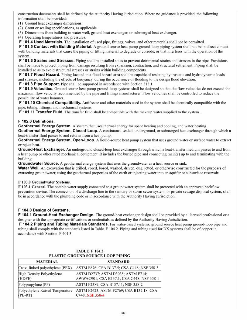
construction documents shall be defined by the Authority Having Jurisdiction. Where no guidance is provided, the followinginformation shall be provided:(1) Ground heat exchanger dimensions.(2) Grout or sealing specifications, as applicable.(3) Dimensions from building to water well, ground heat exchanger, or submerged heat exchanger.(4) Operating temperatures and pressures. F 101.4 Used Materials. The installation of used pipe, fittings, valves, and other materials shall not be permitted. F 101.5 Contact with Building Material. A ground source heat pump ground-loop piping system shall not be in direct contactwith building materials that cause the piping or fitting material to degrade or corrode, or that interferes with the operation of thesystem. F 101.6 Strains and Stresses. Piping shall be installed so as to prevent detrimental strains and stresses in the pipe. Provisionsshall be made to protect piping from damage resulting from expansion, contraction, and structural settlement. Piping shall beinstalled so as to avoid structural stresses or strains within building components. F 101.7 Flood Hazard. Piping located in a flood hazard area shall be capable of resisting hydrostatic and hydrodynamic loadsand stresses, including the effects of buoyancy, during the occurrence of flooding to the design flood elevation. F 101.8 Pipe Support. Pipe shall be supported in accordance with Section 313.1. F 101.9 Velocities. Ground source heat pump ground-loop systems shall be designed so that the flow velocities do not exceed themaximum flow velocity recommended by the pipe and fittings manufacturer. Flow velocities shall be controlled to reduce thepossibility of water hammer. F 101.10 Chemical Compatibility. Antifreeze and other materials used in the system shall be chemically compatible with thepipe, tubing, fittings, and mechanical systems. F 101.11 Transfer Fluid. The transfer fluid shall be compatible with the makeup water supplied to the system.
F 102.0 Definitions.Geothermal Energy System. A system that uses thermal energy for space heating and cooling, and water heating.Geothermal Energy System, Closed-Loop. A continuous, sealed, underground, or submerged heat exchanger through which aheat-transfer fluid passes to and returns from a heat pump.Geothermal Energy System, Open-Loop. A liquid-source heat pump system that uses ground water or surface water to extractor reject heat.Ground-Heat Exchanger. An underground closed-loop heat exchanger through which a heat-transfer medium passes to and froma heat pump or other rated mechanical equipment. It includes the buried pipe and connecting main(s) up to and terminating with thebuilding.Groundwater Source. A geothermal energy system that uses the groundwater as a heat source or sink.Water Well. An excavation that is drilled, cored, bored, washed, driven, dug, jetted, or otherwise constructed for the purposes ofextracting groundwater, using the geothermal properties of the earth or injecting water into an aquifer or subsurface reservoir.
F 103.0 Groundwater Systems.F 103.1 General. The potable water supply connected to a groundwater system shall be protected with an approved backflowprevention device. The connection of a discharge line to the sanitary or storm sewer system, or private sewage disposal system, shallbe in accordance with the plumbing code or in accordance with the Authority Having Jurisdiction.
F 104.0 Design of Systems.F 104.1 Ground-Heat Exchanger Design. The ground-heat exchanger design shall be provided by a licensed professional or adesigner with the appropriate certifications or credentials as defined by the Authority Having Jurisdiction. F 104.2 Piping and Tubing Materials Standards. For water-based systems, ground source heat pump ground-loop pipe andtubing shall comply with the standards listed in Table F 104.2. Piping and tubing used for DX systems shall be of copper inaccordance with Section F 401.3.
TABLE F 104.2PLASTIC GROUND SOURCE LOOP PIPING
MATERIAL STANDARDCross-linked polyethylene (PEX) ASTM F876; CSA B137.5; CSA C448; NSF 358-3High Density Polyethylene(HDPE)
ASTM D2737; ASTM D3035; ASTM F714;AWWAC901; CSA B137.1; CSA C448; NSF 358-1
Polypropylene (PP) ASTM F2389; CSA B137.11; NSF 358-2Polyethylene Raised Temperature(PE-RT)
ASTM F2623; ASTM F2769; CSA B137.18; CSAC448, NSF 358-4
340
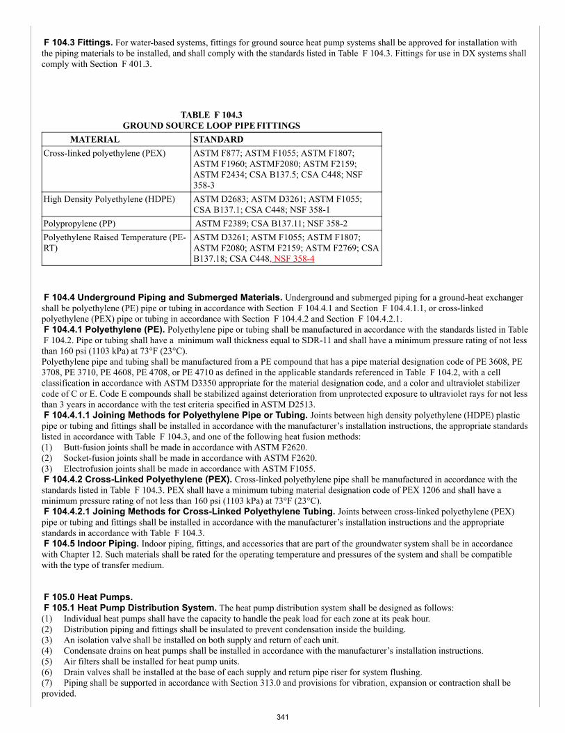
F 104.3 Fittings. For water-based systems, fittings for ground source heat pump systems shall be approved for installation withthe piping materials to be installed, and shall comply with the standards listed in Table F 104.3. Fittings for use in DX systems shallcomply with Section F 401.3.
TABLE F 104.3GROUND SOURCE LOOP PIPE FITTINGS
MATERIAL STANDARDCross-linked polyethylene (PEX) ASTM F877; ASTM F1055; ASTM F1807;
ASTM F1960; ASTMF2080; ASTM F2159;ASTM F2434; CSA B137.5; CSA C448; NSF358-3
High Density Polyethylene (HDPE) ASTM D2683; ASTM D3261; ASTM F1055;CSA B137.1; CSA C448; NSF 358-1
Polypropylene (PP) ASTM F2389; CSA B137.11; NSF 358-2Polyethylene Raised Temperature (PE-RT)
ASTM D3261; ASTM F1055; ASTM F1807;ASTM F2080; ASTM F2159; ASTM F2769; CSAB137.18; CSA C448, NSF 358-4
F 104.4 Underground Piping and Submerged Materials. Underground and submerged piping for a ground-heat exchangershall be polyethylene (PE) pipe or tubing in accordance with Section F 104.4.1 and Section F 104.4.1.1, or cross-linkedpolyethylene (PEX) pipe or tubing in accordance with Section F 104.4.2 and Section F 104.4.2.1. F 104.4.1 Polyethylene (PE). Polyethylene pipe or tubing shall be manufactured in accordance with the standards listed in Table F 104.2. Pipe or tubing shall have a minimum wall thickness equal to SDR-11 and shall have a minimum pressure rating of not lessthan 160 psi (1103 kPa) at 73°F (23°C).Polyethylene pipe and tubing shall be manufactured from a PE compound that has a pipe material designation code of PE 3608, PE3708, PE 3710, PE 4608, PE 4708, or PE 4710 as defined in the applicable standards referenced in Table F 104.2, with a cellclassification in accordance with ASTM D3350 appropriate for the material designation code, and a color and ultraviolet stabilizercode of C or E. Code E compounds shall be stabilized against deterioration from unprotected exposure to ultraviolet rays for not lessthan 3 years in accordance with the test criteria specified in ASTM D2513. F 104.4.1.1 Joining Methods for Polyethylene Pipe or Tubing. Joints between high density polyethylene (HDPE) plasticpipe or tubing and fittings shall be installed in accordance with the manufacturer’s installation instructions, the appropriate standardslisted in accordance with Table F 104.3, and one of the following heat fusion methods:(1) Butt-fusion joints shall be made in accordance with ASTM F2620.(2) Socket-fusion joints shall be made in accordance with ASTM F2620.(3) Electrofusion joints shall be made in accordance with ASTM F1055. F 104.4.2 Cross-Linked Polyethylene (PEX). Cross-linked polyethylene pipe shall be manufactured in accordance with thestandards listed in Table F 104.3. PEX shall have a minimum tubing material designation code of PEX 1206 and shall have aminimum pressure rating of not less than 160 psi (1103 kPa) at 73°F (23°C). F 104.4.2.1 Joining Methods for Cross-Linked Polyethylene Tubing. Joints between cross-linked polyethylene (PEX)pipe or tubing and fittings shall be installed in accordance with the manufacturer’s installation instructions and the appropriatestandards in accordance with Table F 104.3. F 104.5 Indoor Piping. Indoor piping, fittings, and accessories that are part of the groundwater system shall be in accordancewith Chapter 12. Such materials shall be rated for the operating temperature and pressures of the system and shall be compatiblewith the type of transfer medium.
F 105.0 Heat Pumps. F 105.1 Heat Pump Distribution System. The heat pump distribution system shall be designed as follows:(1) Individual heat pumps shall have the capacity to handle the peak load for each zone at its peak hour.(2) Distribution piping and fittings shall be insulated to prevent condensation inside the building.(3) An isolation valve shall be installed on both supply and return of each unit.(4) Condensate drains on heat pumps shall be installed in accordance with the manufacturer’s installation instructions.(5) Air filters shall be installed for heat pump units.(6) Drain valves shall be installed at the base of each supply and return pipe riser for system flushing.(7) Piping shall be supported in accordance with Section 313.0 and provisions for vibration, expansion or contraction shall beprovided.
341
(8) Specifications for each heat pump, the heating and cooling capacity, the fluid flow rate, the airflow rate, and the externalpressure or head shall be provided on the construction documents.(9) Manually controlled air vents shall be installed at the high points in the system and drains at the low points. Where the heat-transfer fluid is a salt or alcohol, automatic air vents shall not be installed.(10) Means for flow balancing for the building loop shall be provided.(11) Supply and return header temperatures and pressures shall be marked. F 105.2 Circulating Pumps. The circulating pump shall be sized for the operating conditions and the heat transfer fluidproperties
F 106.0 Valves. F 106.1 Where Required. Shutoff valves shall be installed in ground source-loop piping systems in the locations indicated inSection F 106.2 through Section F 106.8. F 106.2 Heat Exchangers. Shutoff valves shall be installed on the supply and return side of a heat exchanger, except where theheat exchanger is integral with a boiler or is a component of a manufacturer’s boiler and heat exchanger packaged unit, and iscapable of being isolated from the hydronic system by the supply and return valves. F 106.3 Central Systems. Shutoff valves shall be installed on the building supply and return of a central utility system. F 106.4 Pressure Vessels. Shutoff valves shall be installed on the connection to a pressure vessel. F 106.5 Pressure-Reducing Valves. Shutoff valves shall be installed on both sides of a pressure-reducing valve. F 106.6 Equipment and Appliances. Shutoff valves shall be installed on connections to mechanical equipment and appliances.This requirement does not apply to components of a ground source loop system such as pumps, air separators, metering devices, andsimilar equipment.
F 106.7 Expansion Tanks. Shutoff valves shall be installed at connections to nondiaphragm-type expansion tanks. F 106.8 Reduced Pressure. A pressure relief valve shall be installed on the low-pressure side of a hydronic piping system thathas been reduced in pressure. The relief valve shall be set at the maximum pressure of the system design. F 107.0 Specific System Components Design. F 107.1 General. Ground coupled and water source heat pumps shall be certified in accordance with AHRI/ASHRAE/ISO 13256-1 for water-to-air heat pumps and AHRI/ASHRAE/ISO 13256-2 for water-to-water heat pumps. DX heat pumps shall be certified inaccordance with ASHRAE 194. All heat pump equipment used in DX systems shall comply with AHRI 870. Heat pumps shall befitted with a means to indicate that the compressor is locked out. F 107.2 Heat Exchangers. Heat exchangers used for heat transfer or heat recovery shall protect the potable water system frombeing contaminated by the heat transfer medium. Single-wall heat exchangers shall comply with Section 1218.1. Double-wall heatexchangers shall separate the potable water from the heat transfer medium by providing a space between the two walls that arevented to the atmosphere. F 107.3 Heat-Transfer Medium. The heat-transfer medium shall be compatible with components with which it comes intocontact. Where antifreeze or corrosion inhibitors are used, such solutions shall be approved by the Authority Having Jurisdiction.The heat-transfer fluid flash point shall be not less than 50°F (27.8°C) above the maximum system operating temperature. For DXsystems, the heat transfer medium shall be a refrigerant listed in ASHRAE 34 or this code. F 107.4 Insulation. The temperature of surfaces within reach of building occupants shall not exceed 140°F (60°C) unless they areprotected by insulation. Where sleeves are installed, the sleeve insulation shall retain its full size over the length of the materialbeing protected.
F 108.0 Installation Practices.F 108.1 Prior to Construction. Documents for permits shall be submitted prior to the construction of a building system, or waterwell. Permits shall be issued by the Authority Having Jurisdiction.F 108.2 Equipment, Accessories, Components, and Materials. The mechanical equipment, accessories, components, andmaterials used shall be of the type and rating approved for the specific use.F 108.3 Construction Documents. The construction documents for the building system portion of the geothermal energysystem shall be submitted to the Authority Having Jurisdiction.F 108.4 Site Survey Requirements. The site survey shall identify the physical limitations of the land area, including its extent,structures, existing wells of all types, proximity of other existing ground source heat pump systems, pavements, trees, grading,ponds, waterways, easements, overhead and underground services, septic systems, any identified septic repair areas, utility of rightsof way, and any other elements that could affect an open- loop configuration.Permission shall be obtained from any adjoining property owner(s), as evidenced by the registration and approval of a formaleasement that meets requirements of the authority having jurisdiction. It shall be received prior to the installation of any open-loopsystem that will extend into, cross, or interfere with the equipment or rights-of-way of utilities, jurisdictions, and other propertyowners.The site survey shall include a subsurface investigation that meets the requirements for an open-loop heat exchanger.F 108.5 Subsurface Investigation. A subsurface investigation shall be performed in accordance with Section F 108.6 asdetermined by the registered design professional conducting the site survey.
342
F 108.6 Subsurface Conditions. The water well logs and other geological records shall be used to anticipate the subsurfaceconditions of the aquifer and its potential supply of fresh water, multiple aquifers, saltwater intrusions, contaminated soils andgroundwater, hazardous gases, and any interference with neighboring water wells and ground source heat exchangers.Geological issues such as permafrost conditions and building stability shall be considered when reviewing available records.F 108.7 Ground-Heat Exchanger Installation Practices. A ground-heat exchanger system shall be installed as follows:(1) Outside piping or tubing located within 5 feet (1524 mm) of any wall or structure shall be continuously insulated with insulationthat has a minimum R-5 value. Such pipe or tubing installed under the slab or basement floors shall be insulated within 5 feet (1524mm) from the structure to the exterior point of exit from the slab.(2) Freeze protection shall be provided where the design of the ground heat exchanger system would permit the heat-transfermedium to freeze.(3) Horizontal piping shall be installed not less than 12 inches (305 mm) below the frost line.(4) Submerged heat exchangers shall be protected from damage and shall be securely fastened to the bottom of the lake or pond, orother approved submerged structure.(5) A minimum separation distance shall be maintained between the potable water intake and the submerged heat exchanger systemin accordance with the Authority Having Jurisdiction.(6) Vertical and horizontal ground-heat exchangers shall maintain the following setbacks:(a) Ten feet (3048 mm) horizontally from a pressure-tested sewer lateral into a building.(b) Twenty feet (6096 mm) horizontally from a non-pressure tested sewer lateral into a building.(c) Three feet (914 mm) horizontally from buried utilities such as electrical, gas, or water.(d) Fifty feet (15 240 mm) from a water well.(e) Fifty feet (15 240 mm) from a septic tank and 100 feet (30 480 mm) from a subsurface sewage leaching field.(f) One hundred feet (30 480 mm) from a spring; or at distances specified by the Authority Having Jurisdiction.(7) Wells and boreholes shall be sealed in accordance with the Authority Having Jurisdiction. Where grout is required, it shall beapplied in a single continuous operation from the bottom of the borehole by pumping through a tremie pipe.F 108.8 Trenching, Excavation, and Backfill. Prior to excavation, trenching, or drilling, buried utilities, drainage, water, andirrigation systems shall be located. Prior to excavation, trenching, or drilling, the contractor, and owner shall agree in writing to siterestoration requirements and submit to the Authority Having Jurisdiction for approval. Prior to any excavation, trenching, or drilling,all buried utilities including drainage and irrigation systems shall be located and flagged by the appropriate utility and ground sourceheat pump system contractor representative.F 108.9 Trenches, Tunneling, and Driving. Trenches shall comply with Section 317.1. Tunneling and driving shall complywith Section 317.2.F 108.10 Excavations and Open Trenches. Excavations required to be made for the installation of piping or tubing shall be inaccordance with Section 317.3. Piping or tubing shall be supported to maintain its alignment and prevent sagging. Piping in theground shall be laid on a firm bed for its entire length; where other support is otherwise provided, it shall be approved in accordancewith Section 302.0. Piping or tubing shall be backfilled after an inspection in accordance with Section 317.4.F 108.11 Protection of Piping, Materials, and Structures. Piping and tubing passing under or through walls shall beprotected from breakage in accordance with Section 316.1. Piping and tubing shall be installed in accordance with Section 316.2 toprovide for expansion, contraction, and structural settlement. An electrically continuous corrosion-resistant tracer wire (not less thanAWG 14) or tape shall be buried with the plastic pipe to facilitate locating. One end shall be brought aboveground at a building wallor riser.F 108.12 Sleeves. In exterior walls, annular space between sleeves and pipes shall be sealed and made watertight and shall not besubject to a load from building construction in accordance with Section 316.7 through Section 316.7.2.F 108.13 Steel Nail Plates. Steel nail plates shall be installed for plastic and copper piping penetrating framing members towithin 1 inch (25.4 mm) of the exposed framing in accordance with Section 316.6.F 108.14 On Site Storage. Exterior piping shall be fitted with end caps and protected from freezing, UV radiation, corrosion, anddegradation.F 108.15 Heat Pump and Distribution System Installation. The heat pump and distribution system shall be installed inaccordance with the system’s design, with this code, and the manufacturer’s installation instructions.F 108.16 Pressurizing During Installation. Ground source heat pump ground loop piping to be embedded in concrete shall bepressure tested prior to pouring concrete. During pouring, the pipe shall be maintained at the proposed operating pressure.F 108.17 Horizontal Geothermal Piping - Materials and Methods. Horizontal geothermal piping shall be in in accordancewith Section F 108.17.1 through Section F 108.18.8.F 108.17.1 Piping Material. Piping materials and joining methods for horizontal piping from the ground-heat exchanger shall inaccordance with Section F 104.2, Section F 104.3, Section F 104.4, Section F 401.3 and Section F 104.5.F 108.17.2 Dissimilar Materials. Transition fittings between dissimilar materials shall be inside or accessible.F 108.17.3 Protection of Piping. Pipes passing through walls shall be sleeved and sealed in accordance with Section 316.0.F 108.18 Trenches, Excavation, and Backfill. Excavation for horizontal piping shall comply with Section F F 108.18.1through Section F F 108.18.8, Section F 108.8 through Section F 108.11, and in accordance with requirements of the AuthorityHaving Jurisdiction. Prior to any excavation, trenching, or drilling, all buried utilities including drainage, and irrigation systems shallbe located and flagged by the appropriate utility and ground source heat pump system contractor representative.F 108.18.1 Trenches. Trenches for underground piping or tubing shall be excavated in accordance with the setback requirementsin Section F 301.4.F 108.18.2 Buried Systems. Buried open-loop system piping, shall be installed not less than 3.3 feet (1006 mm) below the
343
finished grade.F 108.18.3 Pipe Installation. Piping in horizontal trenches shall be embedded with not less than 6 inches (152 mm) of inertgranular material above and below, or in accordance with the Authority Having Jurisdiction and project specifications.Horizontal piping trenching shall be backfilled with approved material and shall be compacted.F 108.18.4 Separation. The horizontal piping shall be separated from fluid-based on-site services systems to prevent excessiveshort-circuiting heat transfer between such systems.F 108.18.5 Insulation. Insulation shall be provided on the piping where there is close proximity of all site services to preventthermal interference between fluid-based on-site service systems.F 108.18.6 Pipe Bends. Sharp bending of pipe shall be prevented or approved elbow fitting shall be used with a bend-radius inaccordance with the manufacturer’s installation instructions.F 108.18.7 Closed Cell Insulation. Buried horizontal open-loop system pipes passing parallel within 5 feet (1524 mm) of awall, structure, or water pipe shall be insulated with R-2 minimum closed cell insulation.F 108.18.8 Tracer Markings. Means shall be provided for underground detection or utility location of the buried pipe system.This shall include, but is not limited to metallic detectable tape, with a thickness of not less than 11/64 of an inch (4.4 mm) andwidth of 6 inches (152 mm).This warning marking shall be permanent, conspicuous and resistant to the environmental conditions and shall be placed within 1foot to 2 feet (305 mm to 610 mm) on top of the horizontal piping of the heat exchanger installation.
F 109.0 System Start-Up.F 109.1 General. The following requirements shall be verified prior to system start-up.(1) Piping shall be cleaned, flushed, and purged.(2) The ground heat exchanger and building piping shall be cleaned, flushed, and, where required, shall be filled with the heattransfer fluid medium. The ground loop system shall be tested at the design flow rate(s) and differential pressure(s) recorded. Wherethe actual pressure change at design flow is more than +/- 10 percent of the design flow pressure drop, the cause shall be identifiedand corrective action taken.(3) A method for the removal of air and a method for adding heat transfer fluid (where necessary) shall be provided.(4) The heat pumps shall be operational and adjustments shall be made in accordance with the manufacturer’s installationinstructions.(5) All necessary additional flow tests of the ground heat exchanger shall be completed prior to heat pump start-up.(6) Ground heat exchanger and building piping, valves, and operating controls, shall be set, adjusted, and operating as required.(7) The system shall be labeled at the loop charging valves with a permanent-type label, indicating the type of heat transfer fluidused. Where antifreeze is used, the labels shall indicate the antifreeze type and concentration.(8) Supply and return lines, as well as associated isolation valves from individual boreholes or water wells, shall be identified andtagged.(9) Supply and return lines on submerged systems shall be identified in an approved manner, at the point of entry to a surface waterresource.F 109.2 Operation and Maintenance Manual. An operation and maintenance manual for the geothermal system shall beprovided to the owner. The manual shall include information on required testing and maintenance of the system. Training shall beprovided on the system’s operation, maintenance requirements, and on the content of the operation and maintenance manual. Theoperation and maintenance manual shall contain a layout of the ground-heat exchanger and building loop.F 109.3 Labeling and Marking. Ground source heat pump ground-loop system piping shall be marked with tape, metal tags, orother methods where it enters a building. The marking shall indicate the following words: “GROUND SOURCE HEAT PUMP-LOOP SYSTEM.” The marking shall indicate antifreeze used in the system by name and concentration.F 109.4 Documentation. The ground source heat pump system as-built installation drawings and instructions shall be provided tothe building owner or designated agent.F 109.5 Maintenance. The periodic maintenance required, in accordance with the design requirements, shall be provided and bemade available to the owner or designated agent.F 109.6 Records. The ground source heat pump system construction documents shall be provided to the owner.F 109.7 System Start-Up. System startup shall be in accordance with CSA C448.1, CSA C448.2, and Section F 111.0.F 109.8 Contaminants. Particulate contaminants shall be removed from the indoor piping system prior to initial start-up.
F 110.0 Decommissioning and Abandonment.
F 110.1 General. Decommissioning of geothermal systems shall comply with CSA C448. Prior to the abandonment ordecommissioning of geothermal systems, the owner shall obtain the necessary permits from the Authority Having Jurisdiction.
Part II – Closed-Loop Systems.
F 201.0 General.F 201.1 Applicability. Part II of this chapter shall apply to geothermal energy systems such as, but not limited to, building systemscoupled with a closed-loop systems using water-based fluid as a heat transfer medium.
344
F 201.2 Piping and Tubing. Piping and tubing for closed-loop systems shall be in accordance Section F 104.2 and Table F104.2.F 201.3 Borehole Piping and Tubing. Borehole piping or tubing for vertical and horizontally drilled closed-loop systems shallhave a minimum wall thickness equal to SDR-11 and shall have a minimum pressure rating of not less than 160 psi (1103 kPa) at73°F (23°C).F 201.4 Underground Fittings. Underground fittings for closed loop systems shall be in accordance with Section F 104.3 andTable F 104.3. F 201.5 Verification. For closed-loop systems, the system shall be flushed of debris and purged of air after completion of theentire ground-heat exchanger. Flow rates and pressure drops shall be compared to calculated values to assure no blockage or kinkingof the pipe. A report shall be submitted to the owner to confirm that the loop flow is in accordance with the construction documents. F 201.6 Vertical Bores. Vertical bores shall be drilled to a depth to provide complete insertion of the u-bend pipe to its specifieddepth. The borehole diameter shall be sized for the installation and placement of the heat exchange u-bend and the tremie used toplace the grouting material. CSA C448 shall be used for vertical loop depth and borehole diameter sizing guidance. The u-bend jointand pipe shall be visually inspected for integrity in accordance with the manufacturer’s installation instructions. The u-bend jointand pipe shall be pressurized to not less than 100 psi (689 kPa), not to exceed the pressure rating of the pipe at the test temperature,for 1 hour to check for leaks before insertion into the borehole. F 201.6.1 Backfill. Bentonite grout and thermally-enhanced bentonite grout, where used to seal and backfill each borehole, shallcomply with NSF 60. Boreholes shall be backfilled in accordance with the Authority Having Jurisdiction. F 201.6.2 U-Bends and Headers. Headers, u-bends and ground loop pipes shall be pressure-tested in accordance with CSAC448, or as required by the Authority Having Jurisdiction. Before testing, heat fusion joints shall be cooled to ambient temperature.Mechanical joints shall be completely assembled. Flushing and purging to remove air and debris shall be completed before testing.The assembly shall be filled with water (or water/antifreeze solution) and purged at a minimum flow rate of 2 feet per second (0.6m/s) to remove air, but not more than the maximum flow velocity recommended by the pipe and fittings manufacturer to removedebris. F 201.6.2.1 Test Pressure. The maximum test pressure shall be 1.5 times the system design pressure, as determined by Section F 201.6.2.3, or Section F F 201.6.2.4, not to exceed 100 psi (689 kPa). Components or devices with lower pressure-ratings than thepipe shall be protected from excessive pressure during testing by removing or isolating from the test section.Exception: Where lower pressure-rated components or devices cannot be removed or isolated from the test section, the maximumtest pressure shall not exceed the pressure rating of the component or device. F 201.6.2.2 Testing Procedure. The test section and the test liquid shall be at the same temperature. The test section shall befilled with liquid and purged of air. The test section shall be brought to the specified test pressure. Test pressure shall be maintainedfor 4 hours, with make-up fluid added as needed. The test pressure shall be reduced by 10 psi (69 kPa) and monitored for 1 hourwith no addition of pressure or make-up fluid. A passing test is indicated where after a period of 1 hour no visual leakage isobserved, and pressure remains equal to or greater than 95 percent of the original pressure. F 201.6.2.3 Calculation of Static Pressure (Water). For water, the static pressure applied shall be equivalent to 0.43 psig(2.96 kPa) per foot (305 mm) of elevation. F 201.6.2.4 Calculation of Static Pressure (Other Fluids). For fluids of different density, the static pressure shall becalculated using the density of the system fluid.
F 202.0 Ground-Heat Exchanger Testing. F 202.1 Testing. Pressure-testing of the ground-heat exchanger shall be performed in accordance with the testing method inSection F 201.6.F 202.2 Individual Loop Pressure Testing. Individual loop testing shall be performed as required by the Authority HavingJurisdiction.F 202.3 Field Pressure Testing – Final. The ground heat exchanger and building piping shall be cleaned, flushed, and, whererequired, shall be filled with the heat transfer fluid medium. The ground loop system shall be tested at the design flow rate(s) anddifferential pressure(s) recorded. Where the actual pressure change at design flow is more than +/- 10 percent of the design flowpressure drop, the cause shall be identified, and corrective action taken.F 202.4 Field Flow Testing – Final. Final field flow testing shall be performed as required by the Authority Having Jurisdiction.
Part III – Open-Loop Systems.
F 301.0 General. F 301.1 Applicability. Part III of this appendix shall apply to geothermal energy systems such as, but not limited to, buildingsystems coupled with a groundwater (well) or surface water open loop using water-based fluid as a heat transfer medium. Theregulations of this appendix shall govern the construction, location and installation of geothermal energy systems.Indoor piping, fittings, and accessories that are part of the groundwater system shall be in accordance with Section F 104.4 andChapter 12. F 301.2 Test Wells. Test wells drilled to investigate subsurface conditions shall provide details of the groundwater location,
345
chemical and physical characteristics, rock strata, and temperature profiles. The number of test wells shall be determined inaccordance with the Authority Having Jurisdiction. Each test well shall be tested for flow rate for a period of not less than 24 hours.Water samples shall be collected in accordance with the NGWA-01 from each well to establish existing water quality levels areapproved for groundwater system use. Water samples shall be analyzed for standard drinking water, fecal and coliform content,bacterial iron, nitrate, dissolved minerals, pH, hardness, and other compounds in accordance with NGWA-01 or in accordance withthe Authority Having Jurisdiction. Wells shall be tested for water production and recovery. Monitoring wells shall be protected, andmarked to allow for monitoring of ground temperature, groundwater levels, and groundwater quality. F 301.3 Installation of Water Wells. Water supply, recharge wells, and pumping equipment shall be hydraulically tested,sealed, and grouted in accordance with approved well construction practices and submitted to the Authority Having Jurisdiction forapproval. Wells shall be tested for water production and recovery, water quality before final system design. Wells shall bedisinfected upon completion in accordance with NGWA-01 or in accordance with the Authority Having Jurisdiction. A copy of thewater quality test results and the log of well construction in accordance with NGWA-01 shall be provided to the owner. F 301.4 Setbacks. Open loop ground-heat exchangers shall maintain the following minimum setbacks or at distances specifiedby the Authority Having Jurisdiction:(a) Ten feet (3048 mm) horizontally from a pressure-tested sewer lateral into a building.(b) Twenty feet (6096 mm) horizontally from a non-pressure tested sewer lateral into a building.(c) Three feet (914 mm) horizontally from buried utilities such as electrical, gas, or water.(d) Fifty feet (15 240 mm) from a water well.(e) Fifty feet (15 240 mm) from a septic tank and 100 feet (30 480 mm) from a subsurface sewage leaching field.(f) One hundred feet (30 480 mm) from a spring.
F 302.0 Open Ground Water Systems. F 302.1 General. The installation and use of water wells shall be in accordance with the Authority Having Jurisdiction. The waterwell records shall include well logs, pumping tests, and aquifer information. F 302.2 Open-Loop Water Well Drilling Logs. The water well drilling logs shall include the following:(1) The subsurface stratigraphy.(2) The aquifer type and conditions such as, but not limited to, confined, unconfined, flowing and depth.(3) The drilling method used and the penetration speed.(4) The presence of substances known to have a potential risk to health and safety shall be documented in the drill logs and theproperty owner shall be advised of the potential risk to health and safety. F 302.3 Design Considerations. A groundwater heat pump system shall be designed by a registered design professional. Duedesign consideration shall be given to the following:(1) Where multiple heat pumps or fan coils are connected to a common water loop, a diversified building design load shall be use todesign a ground water heat pump.(2) The water supply well(s) and injection wells, or water discharge system, shall be capable of being operated at sustainablepumping rates that exceed the maximum daily requirements without causing an adverse impact to existing or future offsite uses ofgroundwater or surface water bodies.(3) The water temperature and the quality and chemical composition of the water resource are in accordance with the systemmanufacturer’s recommendations.(4) The groundwater and surface water resources shall be protected by returning water to the source aquifer or an aquifer with thesame water quality, or a surface water body.(5) The return capacity of the injection, or surface water body discharge system, shall be suitable under winter conditions.(6) The temperature of the return water shall have no adverse thermal impacts on offsite existing or future uses of groundwater, oron surface water bodies, in accordance with the requirements of the Authority Having Jurisdiction.(7) Pressure gauges shall be provided to aid in start-up and monitoring of the system during operation;(8) The ability to switch over operation of supply and return wells for 100 percent standby, redevelopment, cleaning of wells, andthe thermal balancing of the ground and aquifer shall be provided.(9) There shall be no adverse effects on the quality and quantity of offsite existing or future users of groundwater, in accordancewith the requirements of the Authority Having. F 302.4 Water Wells and Injection Wells. Water wells and injection wells for groundwater heat pump systems shall beinstalled and tested by a registered designed professional who qualified to drill wells that comply with the requirements of theAuthority Having Jurisdiction.Water supply wells and injection wells shall be developed in accordance with NGWA-01. F 302.5 Testing and Sampling. Pumping tests and water sampling shall be done as required by the registered designprofessional. F 302.6 Disinfection. Water wells shall be disinfected upon completion in accordance with requirements of the Authority HavingJurisdiction and NGWA-01.
F 303.0 Testing and Verification. F 303.1 Pumping Test. Water supply wells and injection wells shall undergo a stop and start pumping test to demonstrate thesand-free yield. F 303.2 Retesting. Where sediment is present, the problem shall be corrected and the test shall be repeated until acceptableresults are obtained.
346
F 303.3 Variable Rate Pump Test. The operating conditions of the water supply wells and injection wells shall be evaluatedand verify with a variable rate pumping. F 303.4 Constant Rate Pump Test. The sustainable well yield, aquifer coefficients, and zones of influences on the groundwaterflow requirements shall be confirmed with a constant rate-pumping test. The constant rate-pumping test shall be done on the watersupply and injection wells at rates and duration as specified by the registered designed professional. F 303.5 Water Level Monitoring. Water levels shall be monitored in the pumping well and observation wells during pumpingand recovery periods. The monitoring time intervals shall be as specified by the registered designed professional. F 303.6 Injection Wells. Injection testing shall be performed on water wells that are designated to be used as injection wells atrates specified by the registered designed professional. The results of the drilling and pumping tests shall be provided to the owneror the owner’s representative and provided in accordance with requirements of the Authority Having Jurisdiction. F 303.7 Re-Injected Water. The water quality of re-injected water into the earth shall comply with the requirements of theAuthority Having Jurisdiction.
Part IV – Direct Exchange (DX) Systems.
F 401.0 Direct Exchange (DX) Systems.F 401.1 General. The installation and use of Direct Exchange (DX) wells shall be in accordance with the Authority HavingJurisdiction. The DX well records shall include well logs, pressure tests, and aquifer information.F 401.2 Applicability. Part IV of this chapter shall apply to geothermal energy systems such as, but not limited to, buildingsystems coupled with a DX closed loop using refrigerant as a heat transfer medium. The regulations of this Chapter shall govern theconstruction, location and installation of geothermal energy systems.Indoor piping, fittings, and accessories that are part of the ground source system shall be in accordance with Section F 104.4 andChapter 12. F 401.3 DX Systems. Copper pipe and tubing installed for DX systems shall be manufactured in accordance with ASTM B280and copper fittings in accordance with ASME B16.22. Joints shall be purged with an inert gas and brazed with a brazing alloyhaving 15 percent silver content in accordance with AWS A5.8. Underground piping and tubing shall have a cathodic protectionsystem installed. F 401.4 DX System Testing. For direct exchange (DX) systems, each u-bend shall be tested and proved tight with an inert gasat not less than 315 psi (2172 kPa) and maintained for 15 minutes without pressure drop. The pressure reading after tremie groutingof the boreholes shall be maintained in the ground heat exchanger for not less than 2 hours, in accordance with CSA C448.F 401.5 Indoor Piping. For DX systems, joints shall be purged with an inert gas and brazed with a brazing alloy having 15percent silver content in accordance with AWS A5.8.F 401.6 On Site Storage. For DX systems, copper piping and fittings shall be stored to prevent physical damage, contamination,and each pipe or tubing shall be pressurized with an inert gas and sealed with a cap.F 401.7 System Start-Up. DX system start-up shall be in accordance with Section F 109.1 and the following:(1) DX systems shall be pressurized using nitrogen for not less than 1 hour. There shall be no allowable variance to the test pressureafter being corrected for ambient temperature changes during the test. The test pressure shall not exceed 150 psig (1034 kPa) whenpressure testing the compressor unit and indoor system components.(2) DX systems shall have permanent type labels installed and affixed on the compressor unit with the refrigerant type and quantity.(3) For DX systems, refrigerant liquid and vapor lines from the loop system shall be identified and tagged.F 401.8 DX Piping. DX Piping should be installed in accordance with approved plans and specifications, including provisions forcathodic protection.
COMMITTEE STATEMENT:Based on the action taken on Item # 164 Comment # 1, the committee comment is being modified to add NSF 358-4 to TableF 104.2 and Table F 104.3 as an acceptable standard for Polyethylene Raised Temperature (PE-RT).
TOTAL ELIGIBLE TO VOTE: 26
VOTING RESULTS: AFFIRMATIVE: 25 NOT RETURNED: 1 HOWARD
347
Proposals
Edit Proposal
Item #: 177
UMC 2021 Section: Appendix F: F 101.4 - F 103.0
SUBMITTER: IAPMO Staff - Update ExtractsNFPA 54 Extract Update
RECOMMENDATION:Revise text
F 101.0 General.F 101.4 Example 2: Single Fan-Assisted Appliance. An installer has an 80 000 Btu/h (23.4 kW) input fan-assisted appliance that shall mustbe installed using 10 feet (3048 mm) of lateral connector attached to a 30 foot (9144 mm) high Type B vent. Two 90-degree (1.57rad) elbows are needed for the installation. Is Can a single-wall metal vent connector permitted to be used for this application? (SeeFigure F 101.4)
Solution:Table 803.1.2(2) refers to the use of single-wall metal vent connectors with Type B vent. In the first column find the row associated with a 30 foot(9144 mm) height and a 10 foot (3048 mm) lateral. Read across this row, looking at the FAN Min and FAN Max columns, to find that a 3 inch (76mm) diameter single-wall metal vent connector is not recommended. Moving to the next larger size single-wall connector [4 inch (102 mm)] we findthat a 4 inch (102 mm) diameter single-wall metal connector has a recommended minimum vent capacity of 91 000 Btu/hr (26.7 kW) and arecommended maximum vent capacity of 144 000 Btu/h (42 kW). The 80 000 Btu/h (23.4 kW) fan-assisted appliance is outside this range, so theconclusion is that a single-wall metal vent connector shall not cannot be used to vent the this appliance using a 10 foot (3048 mm) of lateralfor the connector. However, if the 80 000 Btu/hr (23.4 kW) input appliance is could be moved within 5 feet (1524 mm) of the vertical vent, a4 inch (102 mm) single-wall metal connector shall could be used to vent the appliance. Table 803.1.2(2) shows the acceptable rangeof vent capacities for a 4 inch (102 mm) vent with 5 feet (1524 mm) of lateral to be between 72 000 Btu/h (21.1 kW) and 157 000Btu/h (46 kW). Where If the appliance cannot be moved closer to the vertical vent, then a Type B vent shall could be used as the connector material. Inthis case, Table 803.1.2(1) shows that, for a 30 foot (9144 mm) high vent with 10 feet (3048 mm) of lateral, the acceptable range ofvent capacities for a 4 inch (102 mm) diameter vent attached to a fan-assisted appliance is between 37 000 Btu/h (10.8 kW) and 150000 Btu/h (44 kW).F 101.5 Example 3: Interpolating Between Table Values. An installer has an 80 000 Btu/h (23.4 kW) input appliance with a 4 inch (102 mm)diameter draft hood outlet that needs to be vented into a 12 foot (3658 mm) high Type B vent. The vent connector has a 5 foot (1524 mm) laterallength and is also Type B. Can Is this appliance permitted to be vented using a 4 inch (102 mm) diameter vent?
Solution:Table 803.1.2(1) is used in the case of an all Type B Vent system. However, since there is no entry in Table 803.1.2(1) does not have an entryfor a height of 12 feet (3658 mm), and interpolation shall must be used. Read down the 4 inch (102 mm) diameter NAT Max columnto the row associated with a 10 foot (3048 mm) height and 5 foot (1524 mm) lateral to find the capacity value of 77 000 Btu/h (22.6kW). Read further down to the 15 foot (4572 mm) height, 5 foot (1524 mm) lateral row to find the capacity value of 87 000 Btu/h(25.5 kW). The difference between the 15 foot (4572 mm) height capacity value and the 10 foot (3048 mm) height capacity value is10 000 Btu/h (3 kW). The capacity for a vent system with a 12 foot (3658 mm) height is equal to the capacity for a 10 foot (3048mm) height plus two-fifths of the difference between the 10 foot (3048 mm) and 15 foot (4572 mm) height values, or 77 000 Btu/h(22.6 kW) + 2/5 x 10 000 Btu/h (3 kW) = 81 000 Btu/h (23.7 kW). Therefore, a 4 inch (102 mm) diameter vent shall can be used inthe installation.
F 102.0 Examples Using Common Venting Tables.F 102.1 Example 4: Common Venting Two Draft Hood-Equipped Appliances. A 35 000 Btu/h (10.3 kW) water heater is to be commonvented with a 150 000 Btu/h (44 kW) furnace, using a common vent with a total height of 30 feet (9144 mm). The connector rise is 2 feet (610 mm)for the water heater with a horizontal length of 4 feet (1219 mm). The connector rise for the furnace is 3 feet (914 mm) with a horizontal length of 8feet (2438 mm). Assume single-wall metal connectors will be used with Type B vent. What size connectors and combined vent should be used in this
348
installation? (See Figure F 102.1)
Solution: Table 803.2(2) shall should be used to size single-wall metal vent connectors attached to Type B vertical vents. In the vent connector capacityportion of Table 803.2(2), find the row associated with a 30 foot (9144 mm) vent height. For a 2 foot (610 mm) rise on the vent connector for thewater heater, read the shaded columns for draft hood-equipped appliances to find that a 3 inch (76 mm) diameter vent connector has a capacity of 37000 Btu/h (10.8 kW). Therefore, a 3 inch (76 mm) single-wall metal vent connector shall can be used with the water heater. For a draft hood-equipped furnace with a 3 foot (914 mm) rise, read across the appropriate row to find that a 5 inch (127 mm) diameter vent connector has amaximum capacity of 120 000 Btu/h (35 kW) (which is too small for the furnace), and a 6 inch (152 mm) diameter vent connector has a maximumvent capacity of 172 000 Btu/h (50 kW). Therefore, a 6 inch (152 mm) diameter vent connector shall should be used with the 150 000 Btu/h (44kW) furnace. Since Because both vent connector horizontal lengths are less than the maximum lengths listed in Section 803.2.1, the table valuesshall can be used without adjustments.In the common vent capacity portion of Table 803.2(2), find the row associated with a 30 foot (9144 mm) vent height and read over to the NAT +NAT portion of the 6 inch (152 mm) diameter column to find a maximum combined capacity of 257 000 Btu/h (75 kW). Since the two appliancestotal only 185 000 Btu/h (54 kW), a 6 inch (152 mm) common vent shall can be used.
F 102.2 Example 5(a): Common Venting a Draft Hood-Equipped Water Heater with a Fan-Assisted Furnace into a Type B Vent.In this case, a 35 000 Btu/h (10.3 kW) input draft hood-equipped water heater with a 4 inch (102 mm) diameter draft hood outlet, 2 feet (610 mm) ofconnector rise, and 4 feet (1219 mm) of horizontal length is to be common vented with a 100 000 Btu/h (29 kW) fan-assisted furnace with a 4 inch(102 mm) diameter flue collar, 3 feet (914 mm) of connector rise, and 6 feet (1829 mm) of horizontal length. The common vent consists of a 30 foot(9144 mm) height of Type B vent. What are the recommended vent diameters for each connector and the common vent? The installer would like touse a single-wall metal vent connector. (See Figure F 102.2)
Solution: Water Heater Vent Connector Diameter. Since the water heater vent connector horizontal length of 4 feet (1219 mm) is less than the maximumvalue listed in Table 803.2(2), the venting table values shall can be used without adjustments. Using the Vent Connector Capacity portion ofTable 803.2(2), read down the Total Vent Height (H) column to 30 feet (9144 mm) and read across the 2 feet (610 mm) ConnectorRise (R) row to the first Btu/h rating in the NAT Max column that is equal to or exceeding greater than the water heater input rating. Thetable shows that a 3 inch (76 mm) vent connector has a maximum input rating of 37 000 Btu/h (10.8 kW). Although this rating is exceeding greaterthan the water heater input rating, a 3 inch (76 mm) vent connector is prohibited by Section 803.2.18. A 4 inch (102 mm) vent connector has amaximum input rating of 67 000 Btu/h (19.6 kW) and is equal to the draft hood outlet diameter. A 4 inch (102 mm) vent connector is selected. Sincethe water heater is equipped with a draft hood, there are no minimum input rating restrictions. Furnace Vent Connector Diameter. Using the Vent Connector Capacity portion of Table 803.2(2), read down the Total Vent Height (H) column to30 feet (9144 mm) and across the 3 feet (914 mm) Connector Rise (R) row. Since Because the furnace has a fan-assisted combustion system, findthe first FAN Max column with a Btu/h rating exceeding greater than the furnace input rating. The 4 inch (102 mm) vent connector has amaximum input rating of 119 000 Btu/h (34.9 kW) and a minimum input rating of 85 000 Btu/h (24.9 kW). The 100 000 Btu/h (29 kW) furnace in this example falls within this range, so a 4 inch (102 mm) connector shall be permitted.Since is adequate. Because the furnace vent connector horizontal length of 6 feet (1829 mm) is less than the maximum value listedin Section 803.2.1, the venting table values shall can be used without adjustment. Where If the furnace had an input rating of 80 000Btu/h (23.4 kW), then a Type B vent connector shall would be needed in order to meet the minimum capacity limit. Common Vent Diameter. The total input to the common vent is 135 000 Btu/h (40 kW). Using the Common Vent Capacityportion of Table 803.2(2), read down the Total Vent Height (H) column to 30 feet (9144 mm) and across this row to find the smallestvent diameter in the FAN + NAT column that has a Btu/h rating equal to or exceeding greater than 135 000 Btu/h (40 kW). The 4inch (102 mm) common vent has a capacity of 132 000 Btu/h (39 kW) and the 5 inch (127 mm) common vent has a capacity of 202000 Btu/h (59 kW). Therefore, the 5 inch (127 mm) common vent shall should be used in this example. Summary: In this example, the installer shall can use a 4 inch (102 mm) diameter, single-wall metal vent connector for the waterheater and a 4 inch (102 mm) diameter, single-wall metal vent connector for the furnace. The common vent shall should be a 5 inch(127 mm) diameter Type B vent.
F 102.3 Example 5(b): Common Venting into an Interior Masonry Chimney. In this case, the water heater and fan-assisted furnace ofExample 5(a) are to be common-vented into a clay-tile claytile-lined masonry chimney with a 30 foot (9144 mm) height. The chimney is notexposed to the outdoors below the roof line. The internal dimensions of the clay tile liner are nominally 8 inches (203 mm) by 12 inches(305 mm). Assuming the same vent connector heights, laterals, and materials found in Example 5(a), what are the recommended ventconnector diameters, and is this an acceptable installation?
Solution:Table 803.2(4) is used to size common venting installations involving single-wall connectors into masonry chimneys. Water Heater Vent Connector Diameter. Using Table 803.2(4), Vent Connector Capacity, read down the Total Vent Height (H) column to 30 feet(9144 mm), and read across the 2 feet (610 mm) Connector Rise(R) row to the first Btu/h rating in the NAT Max column that is equal toor exceeding greater than the water heater input rating. The table shows that a 3 inch (76 mm) vent connector has a maximum input of only 31 000Btu/h (9 kW), while a 4 inch (102 mm) vent connector has a maximum input of 57 000 Btu/h (16.7 kW). A 4 inch (102 mm) vent connector shall musttherefore be used. Furnace Vent Connector Diameter. Using the Vent Connector Capacity portion of Table 803.2(4), read down the total Total Vent Height (H) column
349
to 30 feet (9144 mm) and across the 3 feet (914 mm) Connector Rise (R) row. Because the furnace has a fan-assisted combustion system, find the firstFAN Max column with a Btu/h rating exceeding greater than the furnace input rating. The 4 inch (102 mm) vent connector has a maximuminput rating of 127 000 Btu/h (37 kW) and an a minimum input rating of not less than 95 000 Btu/h (27.8 kW). The 100 000 Btu/h (29 kW)furnace in this example falls within this range, so a 4 inch (102 mm) connector shall be permitted is adequate. Masonry Chimney. From Table F 102.3, the eEquivalent aArea for a nNominal lLiner size of 8 inches (203 mm) by 12 inches (305 mm) is63.6 of a square inches (0.041 m2). Using Table 803.2(4), Common Vent Capacity, read down the FAN + NAT column under theMinimum Internal Area of Chimney value of 63 to the row for 30 foot (9144 mm) height to find a capacity value of 739 000 Btu/h (217kW). The combined input rating of the furnace and water heater, 135 000 Btu/h (40 kW), is less than the table value so this is anacceptable installation. Section 803.2.17 requires the common vent area to not exceed be no greater than seven times the smallest listed appliance categorized ventarea, flue collar area, or draft hood outlet area. Both appliances in this installation have 4 inch (102 mm) diameter outlets. From Table F102.3, the equivalent area for an inside diameter of 4 inches (102 mm) is 12.2 of a square inches (0.008 m2). Seven times 12.2 equals85.4, which is exceeding greater than 63.6, so this configuration is acceptable.
F 103.0 Example of Combination Indoor and Outdoor Combustion Air Opening Design. Determine the required combination of indoorand outdoor combustion air opening sizes for the following appliance installation example.
Example Installation: A fan-assisted furnace and a draft hood-equipped water heater with the following inputs are located in a 15 foot by 30 foot(4572 mm by 9144 mm) basement with an 8 foot (2438 mm) ceiling. No additional indoor spaces shall can be used to help meet the appliancecombustion air needs.Fan-Assisted Furnace Input: 100 000 Btu/h (29 kW)Draft Hood-Equipped Water Heater Input: 40 000 Btu/h (11.7 kW)
Solution:(1) Determine the total available room volume.
Appliance room volume.15 feet by 30 feet (4572 mm by 9144 mm) with an 8 foot (2438 mm) ceiling = 3600 cubic feet (101.94 m3)
(2) Determine the total required volume.The sStandard mMethod to determine combustion air shall be is used to calculate the required volume.The combined input for the appliances located in the basement is calculated as follows:100 000 Btu/h (29 kW) + 40 000 Btu/h (11.7 kW) = 140 000 Btu/h (41 kW)The sStandard mMethod requires that the required volume be determined based on 50 cubic feet per 1000 Btu/h (4.83 m3/kW).Using Table F 103.0 the required volume for a 140 000 Btu/h (41 kW) water heater is 7000 cubic feet (198.22 m3).
Conclusion:The iIndoor volume is insufficient to supply combustion air since the total of 3600 cubic feet (101.94 m3) does not meet the requiredvolume of 7000 cubic feet (198.22 m3). Therefore, additional combustion air shall must be provided from the outdoors.
(3) Determine the ratio of the available volume to the required volume.:
3600 cubic feet =0.517000 cubic feet
(4) Determine the reduction factor to be used to reduce the full outdoor air opening size to the minimum required based on ratio ofindoor spaces.:1.00 – 0.51 (from Step 3) = 0.49
(5) Determine the single outdoor combustion air opening size as if though all combustion air is to come from outdoors. In thisexample, the combustion air opening directly communicates with the outdoors.:
140 000 Btu/h = 47 square inch (0.03 m2) 3000 British thermal units
per square inch (Btu/in2)
(6) Determine the minimum outdoor combustion air opening area.:
Outdoor opening area = 0.49 (from Step 4) x 47 square inches (0.03 m2) = 23 square inches (0.01 m2)
Section 701.7.3(3) requires the minimum dimension of the air opening shall be should not be less than 3 inches (76 mm).
SUBSTANTIATION:
350

Item #: 177
Comment #: 1
In accordance with IAPMO's Regulations Governing Committee Projects (Extract Guidelines), Appendix F is being revised tothe latest edition of NFPA 54-2018.
COMMITTEE ACTION: ACCEPT AS SUBMITTED
TOTAL ELIGIBLE TO VOTE: 26
VOTING RESULTS: AFFIRMATIVE: 25 NOT RETURNED: 1 HOWARD
Appended Comments
Edit Comment
PUBLIC COMMENT 1
Code Year: 2021 UMC Section #: Appendix G
SUBMITTER: IAPMO Staff - Update ExtractsNFPA 54 Extract Update
RECOMMENDATION:Revise text
Request to accept the code change proposal as modified by this public comment.
Table 803.1.2(1) is used where when sizing a Type B double-wall gas vent connected directly to the appliance.Note: The appliance is permitted to can be either Category I draft hood-equipped or fan-assisted type.
FIGURE G 101.2(1)TYPE B DOUBLE-WALL VENT SYSTEM SERVING A SINGLE APPLIANCE WITH A TYPE B DOUBLE-WALL VENT
351
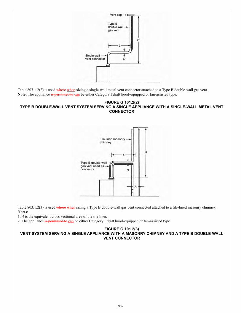
Table 803.1.2(2) is used where when sizing a single-wall metal vent connector attached to a Type B double-wall gas vent.Note: The appliance is permitted to can be either Category I draft hood-equipped or fan-assisted type.
FIGURE G 101.2(2)TYPE B DOUBLE-WALL VENT SYSTEM SERVING A SINGLE APPLIANCE WITH A SINGLE-WALL METAL VENT
CONNECTOR
Table 803.1.2(3) is used where when sizing a Type B double-wall gas vent connected attached to a tile-lined masonry chimney.Notes:1. A is the equivalent cross-sectional area of the tile liner.2. The appliance is permitted to can be either Category I draft hood-equipped or fan-assisted type.
FIGURE G 101.2(3)VENT SYSTEM SERVING A SINGLE APPLIANCE WITH A MASONRY CHIMNEY AND A TYPE B DOUBLE-WALL
VENT CONNECTOR
352
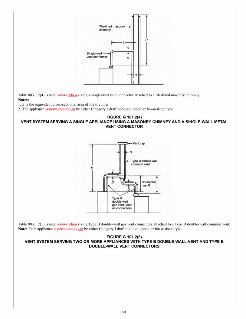
Table 803.1.2(4) is used where when sizing a single-wall vent connector attached to a tile-lined masonry chimney.Notes:1. A is the equivalent cross-sectional area of the tile liner.2. The appliance is permitted to can be either Category I draft hood-equipped or fan-assisted type.
FIGURE G 101.2(4)VENT SYSTEM SERVING A SINGLE APPLIANCE USING A MASONRY CHIMNEY AND A SINGLE-WALL METAL
VENT CONNECTOR
Table 803.1.2(1) is used where when sizing Type B double-wall gas vent connectors attached to a Type B double-wall common vent.Note: Each appliance is permitted to can be either Category I draft hood-equipped or fan-assisted type.
FIGURE G 101.2(6)VENT SYSTEM SERVING TWO OR MORE APPLIANCES WITH TYPE B DOUBLE-WALL VENT AND TYPE B
DOUBLE-WALL VENT CONNECTORS
353
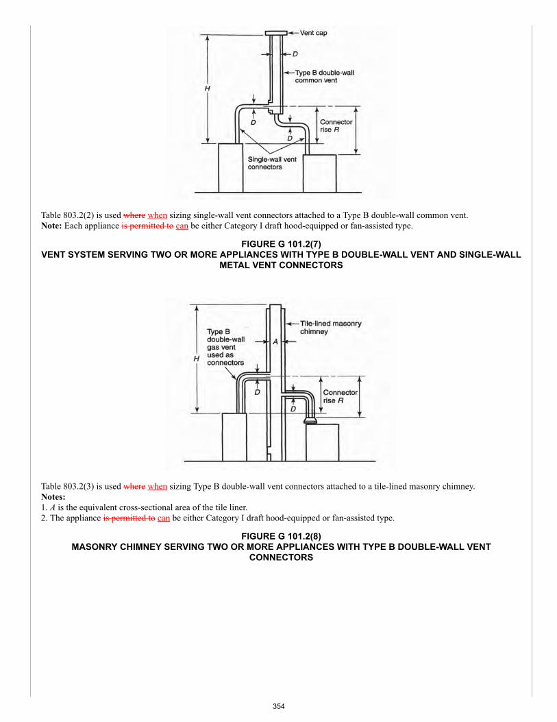
Table 803.2(2) is used where when sizing single-wall vent connectors attached to a Type B double-wall common vent.Note: Each appliance is permitted to can be either Category I draft hood-equipped or fan-assisted type.
FIGURE G 101.2(7)VENT SYSTEM SERVING TWO OR MORE APPLIANCES WITH TYPE B DOUBLE-WALL VENT AND SINGLE-WALL
METAL VENT CONNECTORS
Table 803.2(3) is used where when sizing Type B double-wall vent connectors attached to a tile-lined masonry chimney.Notes:1. A is the equivalent cross-sectional area of the tile liner.2. The appliance is permitted to can be either Category I draft hood-equipped or fan-assisted type.
FIGURE G 101.2(8)MASONRY CHIMNEY SERVING TWO OR MORE APPLIANCES WITH TYPE B DOUBLE-WALL VENT
CONNECTORS
354
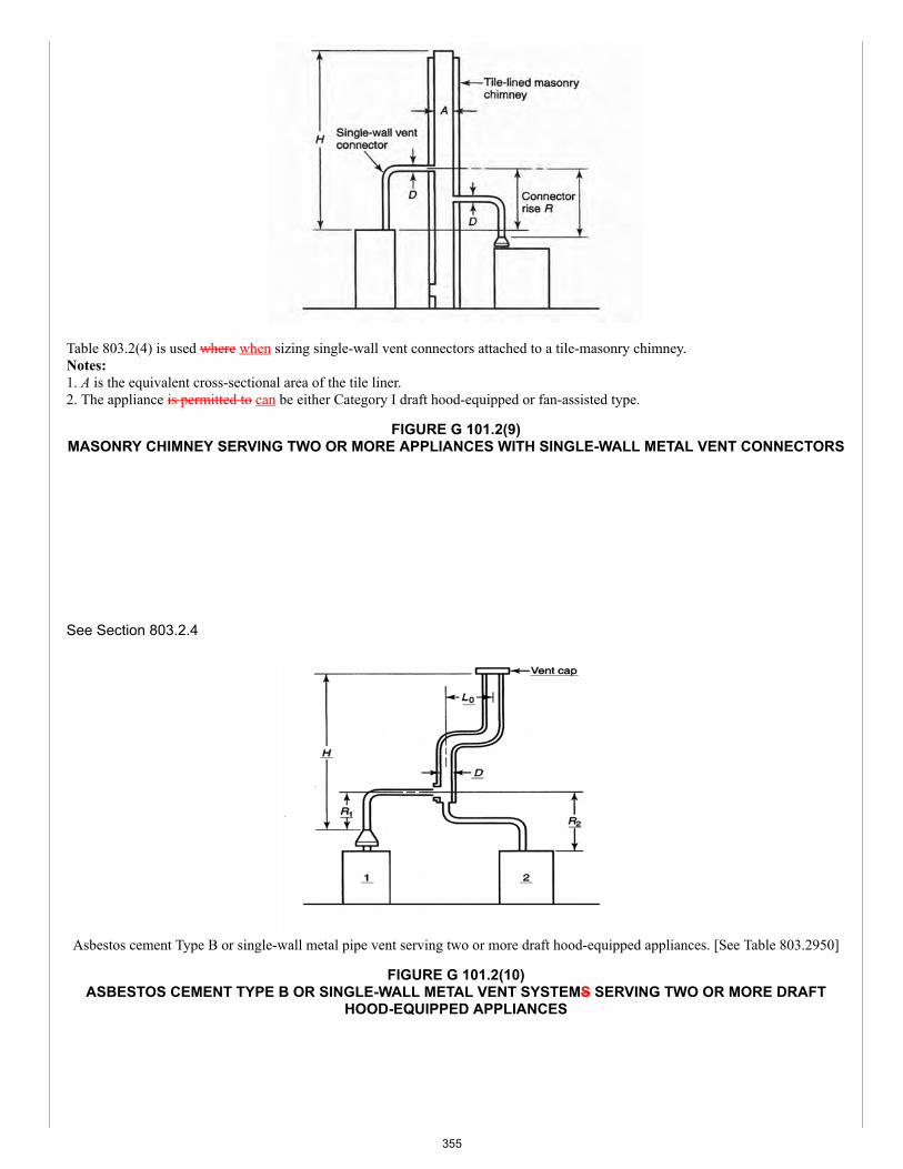
Table 803.2(4) is used where when sizing single-wall vent connectors attached to a tile-masonry chimney.Notes:1. A is the equivalent cross-sectional area of the tile liner.2. The appliance is permitted to can be either Category I draft hood-equipped or fan-assisted type.
FIGURE G 101.2(9)MASONRY CHIMNEY SERVING TWO OR MORE APPLIANCES WITH SINGLE-WALL METAL VENT CONNECTORS
See Section 803.2.4
Asbestos cement Type B or single-wall metal pipe vent serving two or more draft hood-equipped appliances. [See Table 803.2950]
FIGURE G 101.2(10)ASBESTOS CEMENT TYPE B OR SINGLE-WALL METAL VENT SYSTEMS SERVING TWO OR MORE DRAFT
HOOD-EQUIPPED APPLIANCES
355
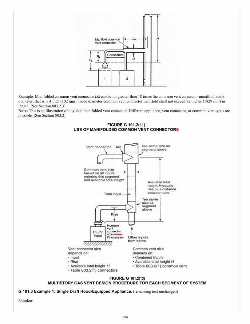
Example: Manifolded common vent connector LM can be no greater than 18 times the common vent connector manifold insidediameter; that is, a 4 inch (102 mm) inside diameter common vent connector manifold shall not exceed 72 inches (1829 mm) inlength. [See Section 803.2.3]Note: This is an illustration of a typical manifolded vent connector. Different appliance, vent connector, or common vent types arepossible. [See Section 803.2]
FIGURE G 101.2(11)USE OF MANIFOLDED COMMON VENT CONNECTORS
FIGURE G 101.2(13)MULTISTORY GAS VENT DESIGN PROCEDURE FOR EACH SEGMENT OF SYSTEM
G 101.3 Example 1: Single Draft Hood-Equipped Appliance. (remaining text unchanged)
Solution:
356
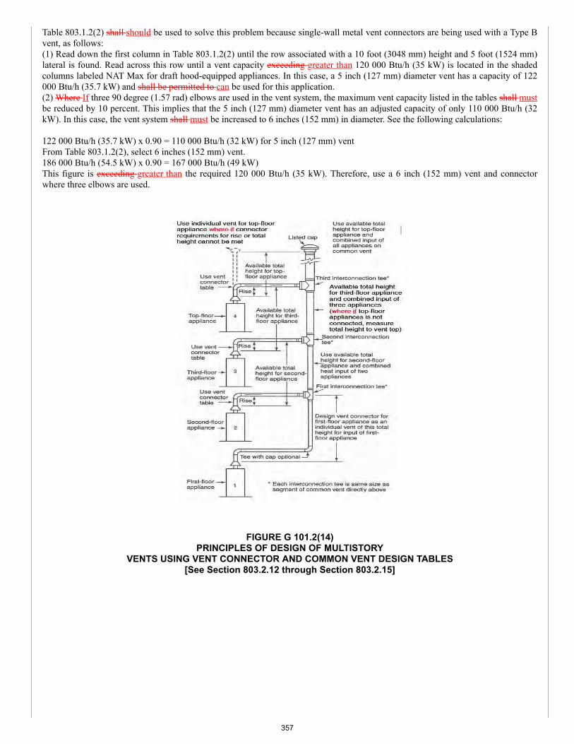
Table 803.1.2(2) shall should be used to solve this problem because single-wall metal vent connectors are being used with a Type Bvent, as follows:(1) Read down the first column in Table 803.1.2(2) until the row associated with a 10 foot (3048 mm) height and 5 foot (1524 mm)lateral is found. Read across this row until a vent capacity exceeding greater than 120 000 Btu/h (35 kW) is located in the shadedcolumns labeled NAT Max for draft hood-equipped appliances. In this case, a 5 inch (127 mm) diameter vent has a capacity of 122000 Btu/h (35.7 kW) and shall be permitted to can be used for this application.(2) Where If three 90 degree (1.57 rad) elbows are used in the vent system, the maximum vent capacity listed in the tables shall mustbe reduced by 10 percent. This implies that the 5 inch (127 mm) diameter vent has an adjusted capacity of only 110 000 Btu/h (32kW). In this case, the vent system shall must be increased to 6 inches (152 mm) in diameter. See the following calculations:
122 000 Btu/h (35.7 kW) x 0.90 = 110 000 Btu/h (32 kW) for 5 inch (127 mm) ventFrom Table 803.1.2(2), select 6 inches (152 mm) vent.186 000 Btu/h (54.5 kW) x 0.90 = 167 000 Btu/h (49 kW)This figure is exceeding greater than the required 120 000 Btu/h (35 kW). Therefore, use a 6 inch (152 mm) vent and connectorwhere three elbows are used.
FIGURE G 101.2(14)PRINCIPLES OF DESIGN OF MULTISTORY
VENTS USING VENT CONNECTOR AND COMMON VENT DESIGN TABLES[See Section 803.2.12 through Section 803.2.15]
357
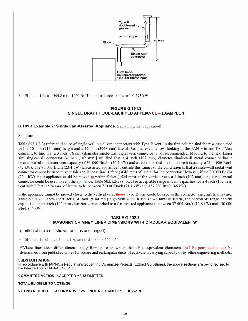
For SI units: 1 foot = 304.8 mm, 1000 British thermal units per hour = 0.293 kW
FIGURE G 101.3SINGLE DRAFT HOOD-EQUIPPED APPLIANCE – EXAMPLE 1
G 101.4 Example 2: Single Fan-Assisted Appliance. (remaining text unchanged)
Solution:
Table 803.1.2(2) refers to the use of single-wall metal vent connectors with Type B vent. In the first column find the row associatedwith a 30 foot (9144 mm) height and a 10 foot (3048 mm) lateral. Read across this row, looking at the FAN Min and FAN Maxcolumns, to find that a 3 inch (76 mm) diameter single-wall metal vent connector is not recommended. Moving to the next largersize single-wall connector [4 inch (102 mm)] we find that a 4 inch (102 mm) diameter single-wall metal connector has arecommended minimum vent capacity of 91 000 Btu/hr (26.7 kW) and a recommended maximum vent capacity of 144 000 Btu/h(42 kW). The 80 000 Btu/h (23.4 kW) fan-assisted appliance is outside this range, so the conclusion is that a single-wall metal ventconnector cannot be used to vent this appliance using 10 foot (3048 mm) of lateral for the connector. However, if the 80 000 Btu/hr(23.4 kW) input appliance could be moved to within 5 feet (1524 mm) of the vertical vent, a 4 inch (102 mm) single-wall metalconnector could be used to vent the appliance. Table 803.1.2(2) shows the acceptable range of vent capacities for a 4 inch (102 mm)vent with 5 feet (1524 mm) of lateral to be between 72 000 Btu/h (21.1 kW) and 157 000 Btu/h (46 kW).
If the appliance cannot be moved closer to the vertical vent, then a Type B vent could be used as the connector material. In this case,Table 803.1.2(1) shows that, for a 30 foot (9144 mm) high vent with 10 feet (3048 mm) of lateral, the acceptable range of ventcapacities for a 4 inch (102 mm) diameter vent attached to a fan-assisted appliance is between 37 000 Btu/h (10.8 kW) and 150 000Btu/h (44 kW).
TABLE G 102.3MASONRY CHIMNEY LINER DIMENSIONS WITH CIRCULAR EQUIVALENTS*
(portion of table not shown remains unchanged)
For SI units, 1 inch = 25.4 mm, 1 square inch = 0.000645 m2
*Where liner sizes differ dimensionally from those shown in this table, equivalent diameters shall be permitted to can bedetermined from published tables for square and rectangular ducts of equivalent carrying capacity or by other engineering methods.
SUBSTANTIATION:In accordance with IAPMO's Regulations Governing Committee Projects (Extract Guidelines), the above sections are being revised tothe latest edition of NFPA 54-2018.
COMMITTEE ACTION: ACCEPTED AS SUBMITTED
TOTAL ELIGIBLE TO VOTE: 26
VOTING RESULTS: AFFIRMATIVE: 25 NOT RETURNED: 1 HOWARD
358
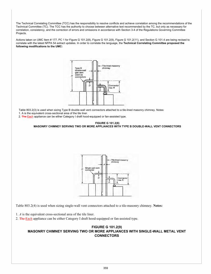
The Technical Correlating Committee (TCC) has the responsibility to resolve conflicts and achieve correlation among the recommendations of the Technical Committee (TC). The TCC has the authority to choose between alternative text recommended by the TC, but only as necessary for correlation, consistency, and the correction of errors and omissions in accordance with Section 3-4 of the Regulations Governing Committee Projects.
Actions taken on UMC Item # 177, PC 1 for Figure G 101.2(8), Figure G 101.2(9), Figure G 101.2(11), and Section G 101.4 are being revised to correlate with the latest NFPA 54 extract updates. In order to correlate the language, the Technical Correlating Committee proposed the following modifications to the UMC:
Table 803.2(3) is used when sizing Type B double-wall vent connectors attached to a tile-lined masonry chimney. Notes: 1. A is the equivalent cross-sectional area of the tile liner.2. The Each appliance can be either Category I draft hood-equipped or fan-assisted type.
FIGURE G 101.2(8) MASONRY CHIMNEY SERVING TWO OR MORE APPLIANCES WITH TYPE B DOUBLE-WALL VENT CONNECTORS
Table 803.2(4) is used when sizing single-wall vent connectors attached to a tile-masonry chimney. Notes:
1. A is the equivalent cross-sectional area of the tile liner.2. The Each appliance can be either Category I draft hood-equipped or fan-assisted type.
FIGURE G 101.2(9) MASONRY CHIMNEY SERVING TWO OR MORE APPLIANCES WITH SINGLE-WALL METAL VENT
CONNECTORS
359
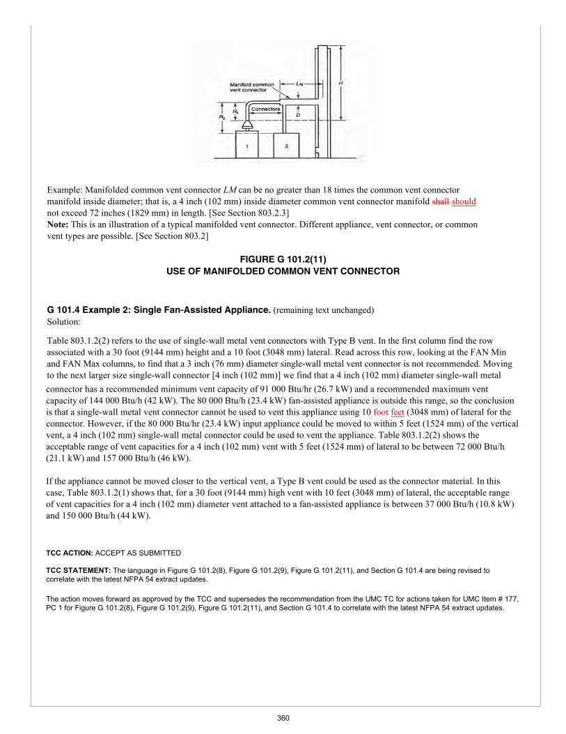
Example: Manifolded common vent connector LM can be no greater than 18 times the common vent connector manifold inside diameter; that is, a 4 inch (102 mm) inside diameter common vent connector manifold shall should not exceed 72 inches (1829 mm) in length. [See Section 803.2.3] Note: This is an illustration of a typical manifolded vent connector. Different appliance, vent connector, or common vent types are possible. [See Section 803.2]
FIGURE G 101.2(11) USE OF MANIFOLDED COMMON VENT CONNECTOR
G 101.4 Example 2: Single Fan-Assisted Appliance. (remaining text unchanged) Solution:
Table 803.1.2(2) refers to the use of single-wall metal vent connectors with Type B vent. In the first column find the row associated with a 30 foot (9144 mm) height and a 10 foot (3048 mm) lateral. Read across this row, looking at the FAN Min and FAN Max columns, to find that a 3 inch (76 mm) diameter single-wall metal vent connector is not recommended. Moving to the next larger size single-wall connector [4 inch (102 mm)] we find that a 4 inch (102 mm) diameter single-wall metalconnector has a recommended minimum vent capacity of 91 000 Btu/hr (26.7 kW) and a recommended maximum vent capacity of 144 000 Btu/h (42 kW). The 80 000 Btu/h (23.4 kW) fan-assisted appliance is outside this range, so the conclusion is that a single-wall metal vent connector cannot be used to vent this appliance using 10 foot feet (3048 mm) of lateral for the connector. However, if the 80 000 Btu/hr (23.4 kW) input appliance could be moved to within 5 feet (1524 mm) of the vertical vent, a 4 inch (102 mm) single-wall metal connector could be used to vent the appliance. Table 803.1.2(2) shows the acceptable range of vent capacities for a 4 inch (102 mm) vent with 5 feet (1524 mm) of lateral to be between 72 000 Btu/h (21.1 kW) and 157 000 Btu/h (46 kW).
If the appliance cannot be moved closer to the vertical vent, a Type B vent could be used as the connector material. In this case, Table 803.1.2(1) shows that, for a 30 foot (9144 mm) high vent with 10 feet (3048 mm) of lateral, the acceptable range of vent capacities for a 4 inch (102 mm) diameter vent attached to a fan-assisted appliance is between 37 000 Btu/h (10.8 kW) and 150 000 Btu/h (44 kW).
TCC ACTION: ACCEPT AS SUBMITTED
TCC STATEMENT: The language in Figure G 101.2(8), Figure G 101.2(9), Figure G 101.2(11), and Section G 101.4 are being revised to correlate with the latest NFPA 54 extract updates.
The action moves forward as approved by the TCC and supersedes the recommendation from the UMC TC for actions taken for UMC Item # 177, PC 1 for Figure G 101.2(8), Figure G 101.2(9), Figure G 101.2(11), and Section G 101.4 to correlate with the latest NFPA 54 extract updates.
360
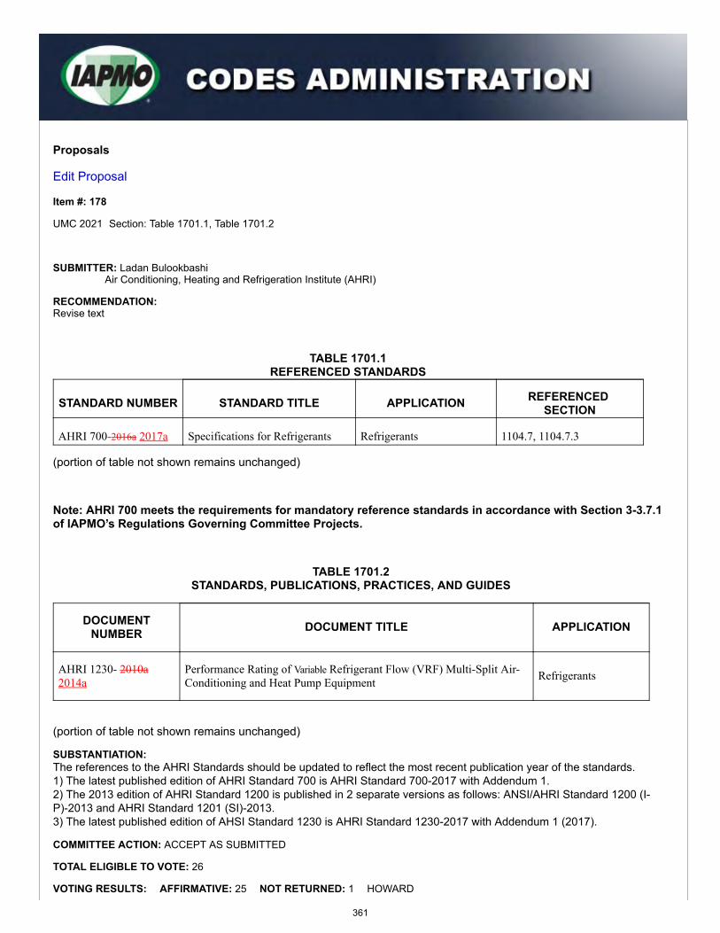
Proposals
Edit Proposal
Item #: 178
UMC 2021 Section: Table 1701.1, Table 1701.2
SUBMITTER: Ladan BulookbashiAir Conditioning, Heating and Refrigeration Institute (AHRI)
RECOMMENDATION:Revise text
TABLE 1701.1REFERENCED STANDARDS
STANDARD NUMBER STANDARD TITLE APPLICATION REFERENCED SECTION
AHRI 700-2016a 2017a Specifications for Refrigerants Refrigerants 1104.7, 1104.7.3
(portion of table not shown remains unchanged)
Note: AHRI 700 meets the requirements for mandatory reference standards in accordance with Section 3-3.7.1of IAPMO’s Regulations Governing Committee Projects.
TABLE 1701.2STANDARDS, PUBLICATIONS, PRACTICES, AND GUIDES
DOCUMENTNUMBER DOCUMENT TITLE APPLICATION
AHRI 1230- 2010a2014a
Performance Rating of Variable Refrigerant Flow (VRF) Multi-Split Air-Conditioning and Heat Pump Equipment Refrigerants
(portion of table not shown remains unchanged)
SUBSTANTIATION:The references to the AHRI Standards should be updated to reflect the most recent publication year of the standards.1) The latest published edition of AHRI Standard 700 is AHRI Standard 700-2017 with Addendum 1.2) The 2013 edition of AHRI Standard 1200 is published in 2 separate versions as follows: ANSI/AHRI Standard 1200 (I-P)-2013 and AHRI Standard 1201 (SI)-2013.3) The latest published edition of AHSI Standard 1230 is AHRI Standard 1230-2017 with Addendum 1 (2017).
COMMITTEE ACTION: ACCEPT AS SUBMITTED
TOTAL ELIGIBLE TO VOTE: 26
VOTING RESULTS: AFFIRMATIVE: 25 NOT RETURNED: 1 HOWARD
361
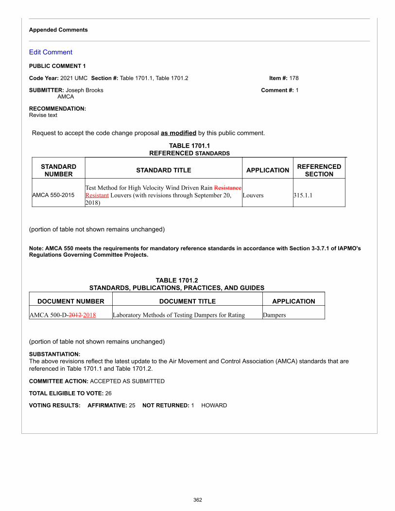
Item #: 178
Comment #: 1
Appended Comments
Edit Comment
PUBLIC COMMENT 1
Code Year: 2021 UMC Section #: Table 1701.1, Table 1701.2
SUBMITTER: Joseph BrooksAMCA
RECOMMENDATION:Revise text
Request to accept the code change proposal as modified by this public comment.
TABLE 1701.1REFERENCED STANDARDS
STANDARDNUMBER STANDARD TITLE APPLICATION REFERENCED
SECTION
AMCA 550-2015Test Method for High Velocity Wind Driven Rain ResistanceResistant Louvers (with revisions through September 20,2018)
Louvers 315.1.1
(portion of table not shown remains unchanged)
Note: AMCA 550 meets the requirements for mandatory reference standards in accordance with Section 3-3.7.1 of IAPMO'sRegulations Governing Committee Projects.
TABLE 1701.2STANDARDS, PUBLICATIONS, PRACTICES, AND GUIDES
DOCUMENT NUMBER DOCUMENT TITLE APPLICATION
AMCA 500-D-2012 2018 Laboratory Methods of Testing Dampers for Rating Dampers
(portion of table not shown remains unchanged)
SUBSTANTIATION:The above revisions reflect the latest update to the Air Movement and Control Association (AMCA) standards that arereferenced in Table 1701.1 and Table 1701.2.
COMMITTEE ACTION: ACCEPTED AS SUBMITTED
TOTAL ELIGIBLE TO VOTE: 26
VOTING RESULTS: AFFIRMATIVE: 25 NOT RETURNED: 1 HOWARD
362

Proposals
Edit Proposal
Item #: 180
UMC 2021 Section: Table 1701.1, Table 1701.2
SUBMITTER: Connor BarbareeASHRAE
RECOMMENDATION:Revise text
TABLE 1701.1REFERENCED STANDARDS
STANDARD NUMBER STANDARD TITLE APPLICATION REFERENCEDSECTION
ASHRAE Handbook-20132017 Fundamentals Climatic Conditions Figure 803.1.2(6)
(portion of table not shown remain unchanged)
Note: The ASHRAE Handbook does not meet the requirements for mandatory reference standards inaccordance with Section 3-3.7.1 of IAPMO’s Regulations Governing Committee Projects.
TABLE 1701.2STANDARDS, PUBLICATIONS, PRACTICES, AND GUIDES
DOCUMENT NUMBER DOCUMENT TITLE APPLICATION
ASHRAE 55-2013 2017 Thermal Environmental Conditions for HumanOccupancy Miscellaneous
ASHRAE Handbook-2012 2016 HVAC Systems and Equipment Design
(portion of table not shown remain unchanged)
SUBSTANTIATION:The above revisions reflect the latest updates to the ASHRAE standards that are referenced in Table 1701.1 and Table1701.2.
COMMITTEE ACTION: ACCEPT AS SUBMITTED
TOTAL ELIGIBLE TO VOTE: 26
VOTING RESULTS: AFFIRMATIVE: 25 NOT RETURNED: 1 HOWARD
Appended Comments
Edit Comment
363
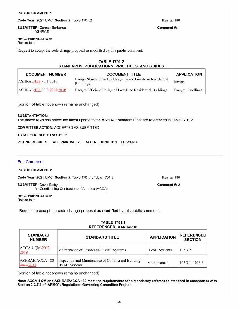
Item #: 180
Item #: 180
Comment #: 1
Comment #: 2
PUBLIC COMMENT 1
Code Year: 2021 UMC Section #: Table 1701.2
SUBMITTER: Connor BarbareeASHRAE
RECOMMENDATION:Revise text
Request to accept the code change proposal as modified by this public comment.
TABLE 1701.2STANDARDS, PUBLICATIONS, PRACTICES, AND GUIDES
DOCUMENT NUMBER DOCUMENT TITLE APPLICATIONASHRAE/IES 90.1-2016 Energy Standard for Buildings Except Low-Rise Residential
Buildings Energy
ASHRAE/IES 90.2-2007 2018 Energy-Efficient Design of Low-Rise Residential Buildings Energy, Dwellings
(portion of table not shown remains unchanged)
SUBSTANTIATION:The above revisions reflect the latest update to the ASHRAE standards that are referenced in Table 1701.2.
COMMITTEE ACTION: ACCEPTED AS SUBMITTED
TOTAL ELIGIBLE TO VOTE: 26
VOTING RESULTS: AFFIRMATIVE: 25 NOT RETURNED: 1 HOWARD
Edit Comment
PUBLIC COMMENT 2
Code Year: 2021 UMC Section #: Table 1701.1, Table 1701.2
SUBMITTER: David BixbyAir Conditioning Contractors of America (ACCA)
RECOMMENDATION:Revise text
Request to accept the code change proposal as modified by this public comment.
TABLE 1701.1REFERENCED STANDARDS
STANDARDNUMBER STANDARD TITLE APPLICATION REFERENCED
SECTION
ACCA 4 QM-20132019 Maintenance of Residential HVAC Systems HVAC Systems 102.3.2
ASHRAE/ACCA 180-2012 2018
Inspection and Maintenance of Commercial BuildingHVAC Systems Maintenance 102.3.1, 1013.3
(portion of table not shown remains unchanged)
Note: ACCA 4 QM and ASHRAE/ACCA 180 meet the requirements for a mandatory referenced standard in accordance withSection 3-3.7.1 of IAPMO’s Regulations Governing Committee Projects.
364

TABLE 1701.2STANDARDS, PUBLICATIONS, PRACTICES, AND GUIDES
DOCUMENT NUMBER DOCUMENT TITLE APPLICATION
ASHRAE/ACCA 183-2007(R2014) (R2017)
Peak Cooling and Heating Load Calculations in BuildingsExcept Low-Rise Residential Buildings
Cooling and HeatingLoad, Miscellaneous
(portion of table not shown remains unchanged)
SUBSTANTIATION:The above revisions reflect the latest updates to the ASHRAE and ACCA standards that are referenced in Table 1701.1 andTable 1701.2.
COMMITTEE ACTION: ACCEPTED AS SUBMITTED
TOTAL ELIGIBLE TO VOTE: 26
VOTING RESULTS: AFFIRMATIVE: 25 NOT RETURNED: 1 HOWARD
365
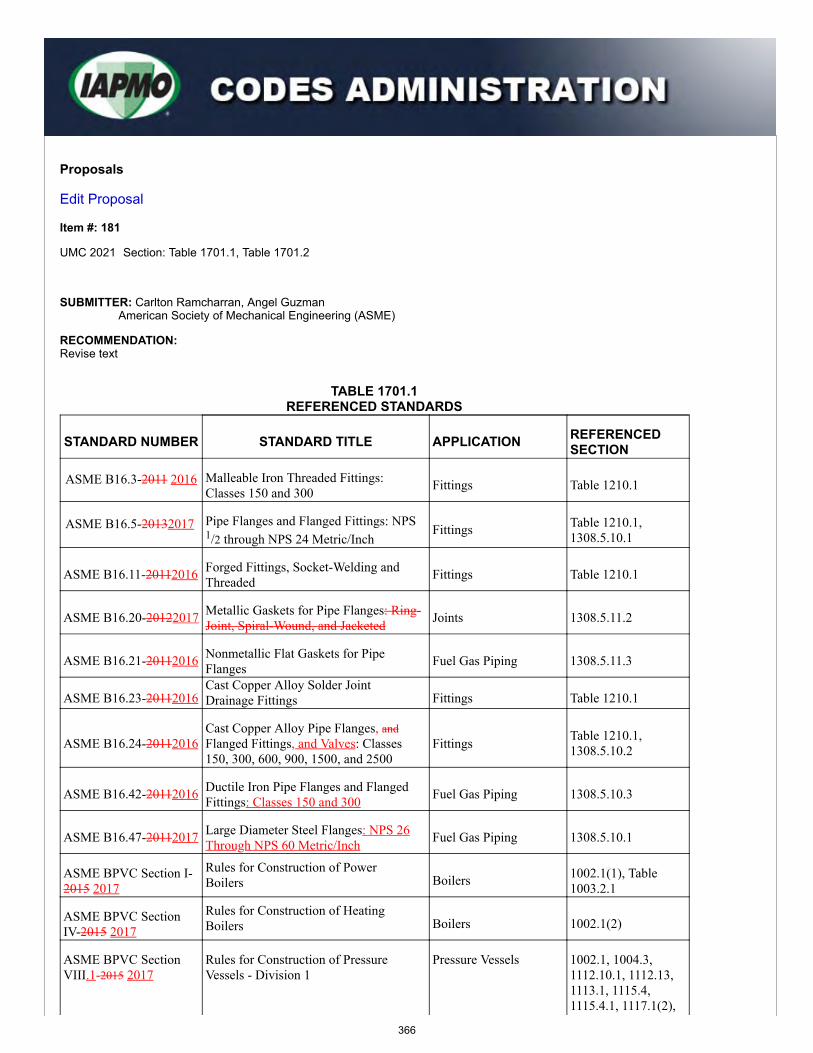
Proposals
Edit Proposal
Item #: 181
UMC 2021 Section: Table 1701.1, Table 1701.2
SUBMITTER: Carlton Ramcharran, Angel GuzmanAmerican Society of Mechanical Engineering (ASME)
RECOMMENDATION:Revise text
TABLE 1701.1REFERENCED STANDARDS
STANDARD NUMBER STANDARD TITLE APPLICATION REFERENCEDSECTION
ASME B16.3-2011 2016 Malleable Iron Threaded Fittings:Classes 150 and 300 Fittings Table 1210.1
ASME B16.5-20132017 Pipe Flanges and Flanged Fittings: NPS1/2 through NPS 24 Metric/Inch
Fittings Table 1210.1,1308.5.10.1
ASME B16.11-20112016 Forged Fittings, Socket-Welding andThreaded Fittings Table 1210.1
ASME B16.20-20122017 Metallic Gaskets for Pipe Flanges: Ring-Joint, Spiral-Wound, and Jacketed Joints 1308.5.11.2
ASME B16.21-20112016 Nonmetallic Flat Gaskets for PipeFlanges Fuel Gas Piping 1308.5.11.3
ASME B16.23-20112016Cast Copper Alloy Solder JointDrainage Fittings Fittings Table 1210.1
ASME B16.24-20112016Cast Copper Alloy Pipe Flanges, andFlanged Fittings, and Valves: Classes150, 300, 600, 900, 1500, and 2500
Fittings Table 1210.1,1308.5.10.2
ASME B16.42-20112016 Ductile Iron Pipe Flanges and FlangedFittings: Classes 150 and 300 Fuel Gas Piping 1308.5.10.3
ASME B16.47-20112017 Large Diameter Steel Flanges: NPS 26Through NPS 60 Metric/Inch Fuel Gas Piping 1308.5.10.1
ASME BPVC Section I-2015 2017
Rules for Construction of PowerBoilers Boilers 1002.1(1), Table
1003.2.1
ASME BPVC SectionIV-2015 2017
Rules for Construction of HeatingBoilers Boilers 1002.1(2)
ASME BPVC SectionVIII.1-2015 2017
Rules for Construction of PressureVessels - Division 1
Pressure Vessels 1002.1, 1004.3,1112.10.1, 1112.13,1113.1, 1115.4,1115.4.1, 1117.1(2),
366
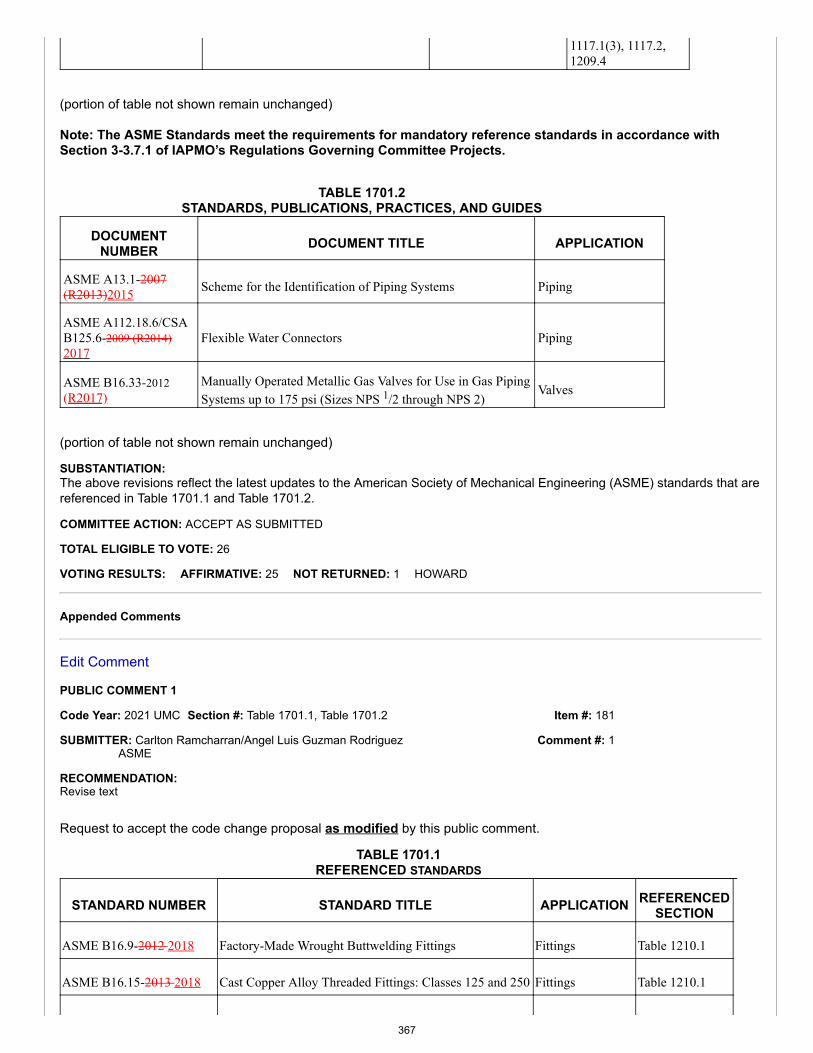
Item #: 181
Comment #: 1
1117.1(3), 1117.2,1209.4
(portion of table not shown remain unchanged)
Note: The ASME Standards meet the requirements for mandatory reference standards in accordance withSection 3-3.7.1 of IAPMO’s Regulations Governing Committee Projects.
TABLE 1701.2STANDARDS, PUBLICATIONS, PRACTICES, AND GUIDES
DOCUMENTNUMBER DOCUMENT TITLE APPLICATION
ASME A13.1-2007(R2013)2015 Scheme for the Identification of Piping Systems Piping
ASME A112.18.6/CSAB125.6-2009 (R2014)2017
Flexible Water Connectors Piping
ASME B16.33-2012(R2017)
Manually Operated Metallic Gas Valves for Use in Gas PipingSystems up to 175 psi (Sizes NPS 1/2 through NPS 2)
Valves
(portion of table not shown remain unchanged)
SUBSTANTIATION:The above revisions reflect the latest updates to the American Society of Mechanical Engineering (ASME) standards that arereferenced in Table 1701.1 and Table 1701.2.
COMMITTEE ACTION: ACCEPT AS SUBMITTED
TOTAL ELIGIBLE TO VOTE: 26
VOTING RESULTS: AFFIRMATIVE: 25 NOT RETURNED: 1 HOWARD
Appended Comments
Edit Comment
PUBLIC COMMENT 1
Code Year: 2021 UMC Section #: Table 1701.1, Table 1701.2
SUBMITTER: Carlton Ramcharran/Angel Luis Guzman RodriguezASME
RECOMMENDATION:Revise text
Request to accept the code change proposal as modified by this public comment.
TABLE 1701.1REFERENCED STANDARDS
STANDARD NUMBER STANDARD TITLE APPLICATION REFERENCEDSECTION
ASME B16.9-2012 2018 Factory-Made Wrought Buttwelding Fittings Fittings Table 1210.1
ASME B16.15-2013 2018 Cast Copper Alloy Threaded Fittings: Classes 125 and 250 Fittings Table 1210.1
367
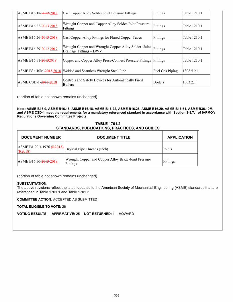
ASME B16.18-2012 2018 Cast Copper Alloy Solder Joint Pressure Fittings Fittings Table 1210.1
ASME B16.22-2013 2018 Wrought Copper and Copper Alloy Solder-Joint PressureFittings Fittings Table 1210.1
ASME B16.26-2013 2018 Cast Copper Alloy Fittings for Flared Copper Tubes Fittings Table 1210.1
ASME B16.29-2012 2017 Wrought Copper and Wrought Copper Alloy Solder- JointDrainage Fittings – DWV Fittings Table 1210.1
ASME B16.51-20132018 Copper and Copper Alloy Press-Connect Pressure Fittings Fittings Table 1210.1
ASME B36.10M-2015 2018 Welded and Seamless Wrought Steel Pipe Fuel Gas Piping 1308.5.2.1
ASME CSD-1-2015 2018 Controls and Safety Devices for Automatically FiredBoilers Boilers 1003.2.1
(portion of table not shown remains unchanged)
Note: ASME B16.9, ASME B16.15, ASME B16.18, ASME B16.22, ASME B16.26, ASME B16.29, ASME B16.51, ASME B36.10M,and ASME CSD-1 meet the requirements for a mandatory referenced standard in accordance with Section 3-3.7.1 of IAPMO’sRegulations Governing Committee Projects.
TABLE 1701.2STANDARDS, PUBLICATIONS, PRACTICES, AND GUIDES
DOCUMENT NUMBER DOCUMENT TITLE APPLICATION
ASME B1.20.3-1976 (R2013)(R2018) Dryseal Pipe Threads (Inch) Joints
ASME B16.50-2013 2018 Wrought Copper and Copper Alloy Braze-Joint PressureFittings Fittings
(portion of table not shown remains unchanged)
SUBSTANTIATION:The above revisions reflect the latest updates to the American Society of Mechanical Engineering (ASME) standards that arereferenced in Table 1701.1 and Table 1701.2.
COMMITTEE ACTION: ACCEPTED AS SUBMITTED
TOTAL ELIGIBLE TO VOTE: 26
VOTING RESULTS: AFFIRMATIVE: 25 NOT RETURNED: 1 HOWARD
368

Proposals
Edit Proposal
Item #: 183
UMC 2021 Section: Table 1701.1, Table 1701.2
SUBMITTER: Steve MawnAmerican Society of Testing and Materials (ASTM)
RECOMMENDATION:Revise text
TABLE 1701.1REFERENCED STANDARDS
STANDARD NUMBER STANDARD TITLE APPLICATION REFERENCEDSECTION
ASTM B135-2010/B135M-2017 Seamless Brass Tube Piping Table 1210.1
ASTM B251-2010/B251M-2017
General Requirements for WroughtSeamless Copper and Copper-Alloy Tube Piping Table 1210.1
ASTM B302-2012 2017 Threadless Copper Pipe, Standard Sizes Piping Table 1210.1
ASTM C411-2011 2017 Hot-Surface Performance of High-Temperature Thermal Insulation
Duct Coverings andLinings 604.1.2
ASTM D2466-2015 2017 Poly (Vinyl Chloride) (PVC) Plastic PipeFittings, Schedule 40 Fittings Table 1210.1
ASTM D2513-2014e12016aPolyethylene (PE) Gas Pressure Pipe,Tubing, and Fittings Piping
1308.5.4,1308.5.4.2.2,1308.5.9.2,1310.1.7.1(1), Table1210.1
ASTM D2846/D2846M-2014 2017b
Chlorinated Poly (Vinyl Chloride) (CPVC)Plastic Hot- and Cold-Water DistributionSystems
Piping 1211.2(2), 1211.3(2),Table 1210.1
ASTM E84-2016 2017a Surface Burning Characteristics of BuildingMaterials Miscellaneous 508.3.4, 602.2,
604.1.2, 1201.2
ASTM E814-2013a (R2017) Fire Tests of Penetration Firestop Systems Miscellaneous 507.4.4, 507.4.5
ASTM F438-2015 2017Socket-Type Chlorinated Poly (VinylChloride) (CPVC) Plastic Pipe Fittings,Schedule 40
Fittings Table 1210.1
ASTM F876-2015a 2017 Crosslinked Polyethylene (PEX) Tubing Piping 1211.5, Table 1210.1
ASTM F1281-2011 2017 CrosslinkedPolyethylene/Aluminum/Crosslinked
Piping Table 1210.1
369
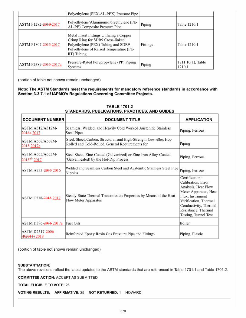
Polyethylene (PEX-AL-PEX) Pressure Pipe
ASTM F1282-2010 2017 Polyethylene/Aluminum/Polyethylene (PE-AL-PE) Composite Pressure Pipe Piping Table 1210.1
ASTM F1807-2015 2017
Metal Insert Fittings Utilizing a CopperCrimp Ring for SDR9 Cross-linkedPolyethylene (PEX) Tubing and SDR9Polyethylene of Raised Temperature (PE-RT) Tubing
Fittings Table 1210.1
ASTM F2389-2015 2017a Pressure-Rated Polypropylene (PP) PipingSystems Piping 1211.10(1), Table
1210.1
(portion of table not shown remain unchanged)
Note: The ASTM Standards meet the requirements for mandatory reference standards in accordance withSection 3-3.7.1 of IAPMO’s Regulations Governing Committee Projects.
TABLE 1701.2STANDARDS, PUBLICATIONS, PRACTICES, AND GUIDES
DOCUMENT NUMBER DOCUMENT TITLE APPLICATION
ASTM A312/A312M-2016a 2017
Seamless, Welded, and Heavily Cold Worked Austenitic StainlessSteel Pipes Piping, Ferrous
ASTM A568/A568M-2015 2017a
Steel, Sheet, Carbon, Structural, and High-Strength, Low-Alloy, Hot-Rolled and Cold-Rolled, General Requirements for Piping
ASTM A653/A653M-2015e1 2017
Steel Sheet, Zinc-Coated (Galvanized) or Zinc-Iron Alloy-Coated(Galvannealed) by the Hot-Dip Process Piping, Ferrous
ASTM A733-2015 2016 Welded and Seamless Carbon Steel and Austenitic Stainless Steel PipeNipples Piping, Ferrous
ASTM C518-2015 2017 Steady-State Thermal Transmission Properties by Means of the HeatFlow Meter Apparatus
Certification:Calibration, ErrorAnalysis, Heat FlowMeter Apparatus, HeatFlux, InstrumentVerification, ThermalConductivity, ThermalResistance, ThermalTesting, Tunnel Test
ASTM D396-2016 2017a Fuel Oils Boiler
ASTM D2517-2006(R2011) 2018 Reinforced Epoxy Resin Gas Pressure Pipe and Fittings Piping, Plastic
(portion of table not shown remain unchanged)
SUBSTANTIATION:The above revisions reflect the latest updates to the ASTM standards that are referenced in Table 1701.1 and Table 1701.2.
COMMITTEE ACTION: ACCEPT AS SUBMITTED
TOTAL ELIGIBLE TO VOTE: 26
VOTING RESULTS: AFFIRMATIVE: 25 NOT RETURNED: 1 HOWARD
370
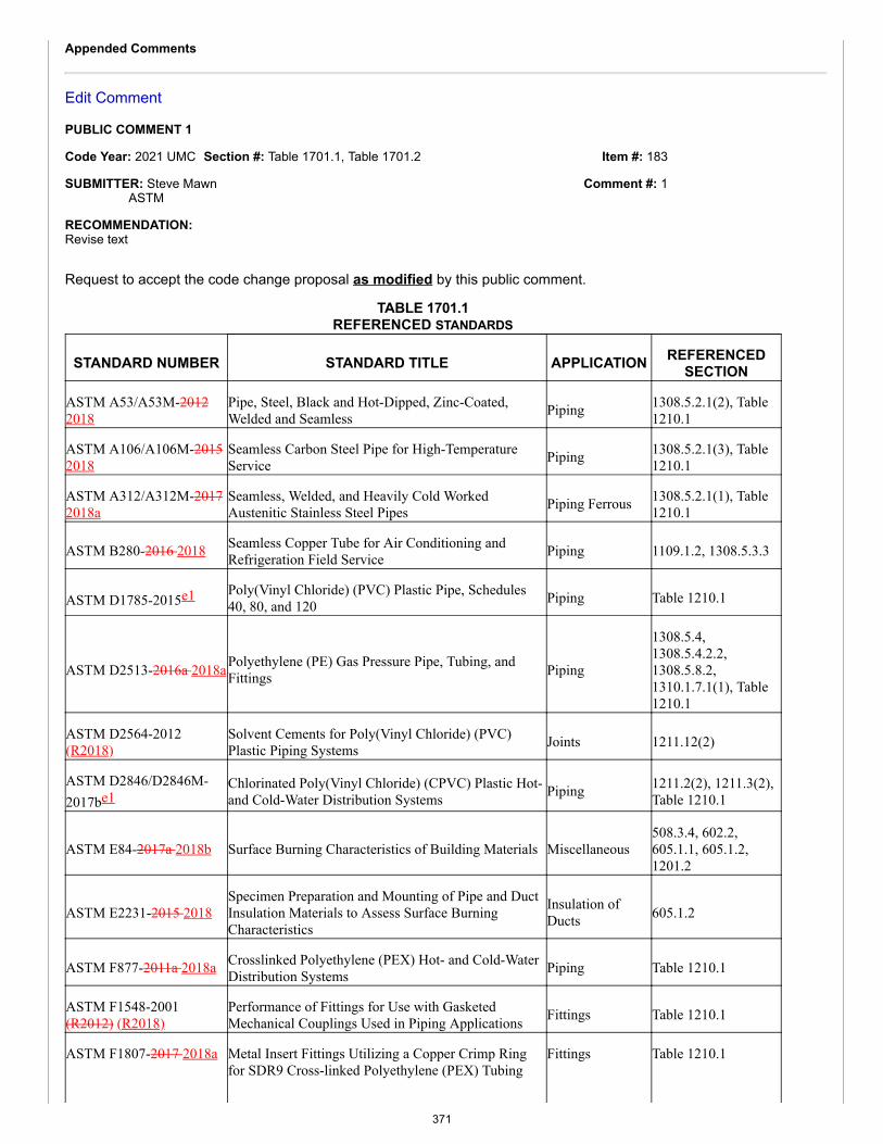
Item #: 183
Comment #: 1
Appended Comments
Edit Comment
PUBLIC COMMENT 1
Code Year: 2021 UMC Section #: Table 1701.1, Table 1701.2
SUBMITTER: Steve MawnASTM
RECOMMENDATION:Revise text
Request to accept the code change proposal as modified by this public comment.
TABLE 1701.1REFERENCED STANDARDS
STANDARD NUMBER STANDARD TITLE APPLICATION REFERENCEDSECTION
ASTM A53/A53M-20122018
Pipe, Steel, Black and Hot-Dipped, Zinc-Coated,Welded and Seamless Piping 1308.5.2.1(2), Table
1210.1
ASTM A106/A106M-20152018
Seamless Carbon Steel Pipe for High-TemperatureService Piping 1308.5.2.1(3), Table
1210.1
ASTM A312/A312M-20172018a
Seamless, Welded, and Heavily Cold WorkedAustenitic Stainless Steel Pipes Piping Ferrous 1308.5.2.1(1), Table
1210.1
ASTM B280-2016 2018 Seamless Copper Tube for Air Conditioning andRefrigeration Field Service Piping 1109.1.2, 1308.5.3.3
ASTM D1785-2015e1 Poly(Vinyl Chloride) (PVC) Plastic Pipe, Schedules40, 80, and 120 Piping Table 1210.1
ASTM D2513-2016a 2018aPolyethylene (PE) Gas Pressure Pipe, Tubing, andFittings Piping
1308.5.4,1308.5.4.2.2,1308.5.8.2,1310.1.7.1(1), Table1210.1
ASTM D2564-2012(R2018)
Solvent Cements for Poly(Vinyl Chloride) (PVC)Plastic Piping Systems Joints 1211.12(2)
ASTM D2846/D2846M-2017be1
Chlorinated Poly(Vinyl Chloride) (CPVC) Plastic Hot-and Cold-Water Distribution Systems Piping 1211.2(2), 1211.3(2),
Table 1210.1
ASTM E84-2017a 2018b Surface Burning Characteristics of Building Materials Miscellaneous508.3.4, 602.2,605.1.1, 605.1.2,1201.2
ASTM E2231-2015 2018Specimen Preparation and Mounting of Pipe and DuctInsulation Materials to Assess Surface BurningCharacteristics
Insulation ofDucts 605.1.2
ASTM F877-2011a 2018a Crosslinked Polyethylene (PEX) Hot- and Cold-WaterDistribution Systems Piping Table 1210.1
ASTM F1548-2001(R2012) (R2018)
Performance of Fittings for Use with GasketedMechanical Couplings Used in Piping Applications Fittings Table 1210.1
ASTM F1807-2017 2018a Metal Insert Fittings Utilizing a Copper Crimp Ringfor SDR9 Cross-linked Polyethylene (PEX) Tubing
Fittings Table 1210.1
371
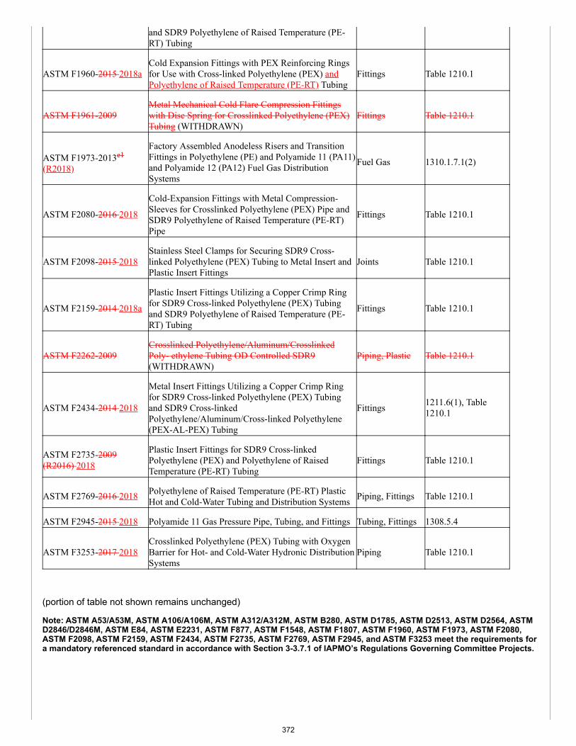
and SDR9 Polyethylene of Raised Temperature (PE-RT) Tubing
ASTM F1960-2015 2018aCold Expansion Fittings with PEX Reinforcing Ringsfor Use with Cross-linked Polyethylene (PEX) andPolyethylene of Raised Temperature (PE-RT) Tubing
Fittings Table 1210.1
ASTM F1961-2009Metal Mechanical Cold Flare Compression Fittingswith Disc Spring for Crosslinked Polyethylene (PEX)Tubing (WITHDRAWN)
Fittings Table 1210.1
ASTM F1973-2013e1
(R2018)
Factory Assembled Anodeless Risers and TransitionFittings in Polyethylene (PE) and Polyamide 11 (PA11)and Polyamide 12 (PA12) Fuel Gas DistributionSystems
Fuel Gas 1310.1.7.1(2)
ASTM F2080-2016 2018
Cold-Expansion Fittings with Metal Compression-Sleeves for Crosslinked Polyethylene (PEX) Pipe andSDR9 Polyethylene of Raised Temperature (PE-RT)Pipe
Fittings Table 1210.1
ASTM F2098-2015 2018Stainless Steel Clamps for Securing SDR9 Cross-linked Polyethylene (PEX) Tubing to Metal Insert andPlastic Insert Fittings
Joints Table 1210.1
ASTM F2159-2014 2018a
Plastic Insert Fittings Utilizing a Copper Crimp Ringfor SDR9 Cross-linked Polyethylene (PEX) Tubingand SDR9 Polyethylene of Raised Temperature (PE-RT) Tubing
Fittings Table 1210.1
ASTM F2262-2009Crosslinked Polyethylene/Aluminum/CrosslinkedPoly- ethylene Tubing OD Controlled SDR9(WITHDRAWN)
Piping, Plastic Table 1210.1
ASTM F2434-2014 2018
Metal Insert Fittings Utilizing a Copper Crimp Ringfor SDR9 Cross-linked Polyethylene (PEX) Tubingand SDR9 Cross-linkedPolyethylene/Aluminum/Cross-linked Polyethylene(PEX-AL-PEX) Tubing
Fittings 1211.6(1), Table1210.1
ASTM F2735-2009(R2016) 2018
Plastic Insert Fittings for SDR9 Cross-linkedPolyethylene (PEX) and Polyethylene of RaisedTemperature (PE-RT) Tubing
Fittings Table 1210.1
ASTM F2769-2016 2018 Polyethylene of Raised Temperature (PE-RT) PlasticHot and Cold-Water Tubing and Distribution Systems Piping, Fittings Table 1210.1
ASTM F2945-2015 2018 Polyamide 11 Gas Pressure Pipe, Tubing, and Fittings Tubing, Fittings 1308.5.4
ASTM F3253-2017 2018Crosslinked Polyethylene (PEX) Tubing with OxygenBarrier for Hot- and Cold-Water Hydronic DistributionSystems
Piping Table 1210.1
(portion of table not shown remains unchanged)
Note: ASTM A53/A53M, ASTM A106/A106M, ASTM A312/A312M, ASTM B280, ASTM D1785, ASTM D2513, ASTM D2564, ASTMD2846/D2846M, ASTM E84, ASTM E2231, ASTM F877, ASTM F1548, ASTM F1807, ASTM F1960, ASTM F1973, ASTM F2080,ASTM F2098, ASTM F2159, ASTM F2434, ASTM F2735, ASTM F2769, ASTM F2945, and ASTM F3253 meet the requirements fora mandatory referenced standard in accordance with Section 3-3.7.1 of IAPMO’s Regulations Governing Committee Projects.
372
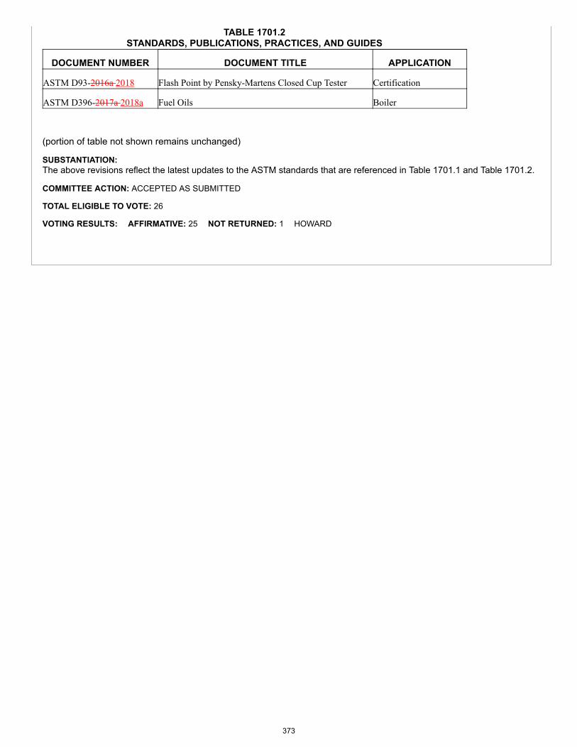
TABLE 1701.2STANDARDS, PUBLICATIONS, PRACTICES, AND GUIDES
DOCUMENT NUMBER DOCUMENT TITLE APPLICATION
ASTM D93-2016a 2018 Flash Point by Pensky-Martens Closed Cup Tester Certification
ASTM D396-2017a 2018a Fuel Oils Boiler
(portion of table not shown remains unchanged)
SUBSTANTIATION:The above revisions reflect the latest updates to the ASTM standards that are referenced in Table 1701.1 and Table 1701.2.
COMMITTEE ACTION: ACCEPTED AS SUBMITTED
TOTAL ELIGIBLE TO VOTE: 26
VOTING RESULTS: AFFIRMATIVE: 25 NOT RETURNED: 1 HOWARD
373
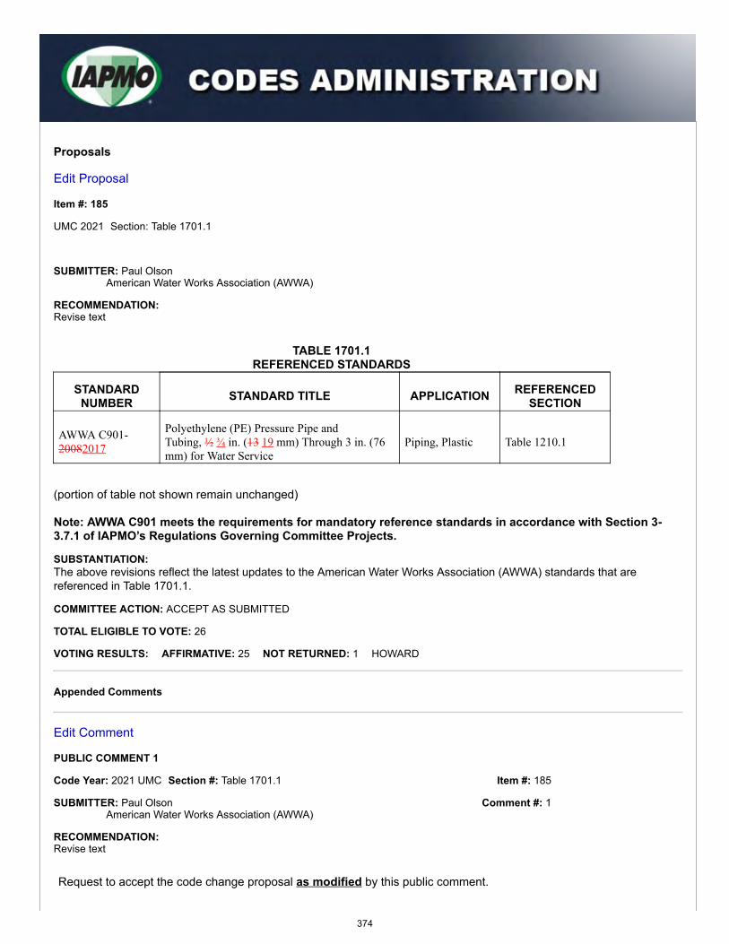
Item #: 185
Comment #: 1
Proposals
Edit Proposal
Item #: 185
UMC 2021 Section: Table 1701.1
SUBMITTER: Paul OlsonAmerican Water Works Association (AWWA)
RECOMMENDATION:Revise text
TABLE 1701.1REFERENCED STANDARDS
STANDARDNUMBER STANDARD TITLE APPLICATION REFERENCED
SECTION
AWWA C901-20082017
Polyethylene (PE) Pressure Pipe andTubing, ½ ¾ in. (13 19 mm) Through 3 in. (76mm) for Water Service
Piping, Plastic Table 1210.1
(portion of table not shown remain unchanged)
Note: AWWA C901 meets the requirements for mandatory reference standards in accordance with Section 3-3.7.1 of IAPMO’s Regulations Governing Committee Projects.
SUBSTANTIATION:The above revisions reflect the latest updates to the American Water Works Association (AWWA) standards that arereferenced in Table 1701.1.
COMMITTEE ACTION: ACCEPT AS SUBMITTED
TOTAL ELIGIBLE TO VOTE: 26
VOTING RESULTS: AFFIRMATIVE: 25 NOT RETURNED: 1 HOWARD
Appended Comments
Edit Comment
PUBLIC COMMENT 1
Code Year: 2021 UMC Section #: Table 1701.1
SUBMITTER: Paul OlsonAmerican Water Works Association (AWWA)
RECOMMENDATION:Revise text
Request to accept the code change proposal as modified by this public comment.
374
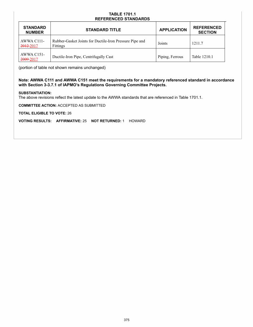
TABLE 1701.1REFERENCED STANDARDS
STANDARDNUMBER STANDARD TITLE APPLICATION REFERENCED
SECTION
AWWA C111-2012 2017
Rubber-Gasket Joints for Ductile-Iron Pressure Pipe andFittings Joints 1211.7
AWWA C151-2009 2017 Ductile-Iron Pipe, Centrifugally Cast Piping, Ferrous Table 1210.1
(portion of table not shown remains unchanged)
Note: AWWA C111 and AWWA C151 meet the requirements for a mandatory referenced standard in accordancewith Section 3-3.7.1 of IAPMO’s Regulations Governing Committee Projects.
SUBSTANTIATION:The above revisions reflect the latest update to the AWWA standards that are referenced in Table 1701.1.
COMMITTEE ACTION: ACCEPTED AS SUBMITTED
TOTAL ELIGIBLE TO VOTE: 26
VOTING RESULTS: AFFIRMATIVE: 25 NOT RETURNED: 1 HOWARD
375
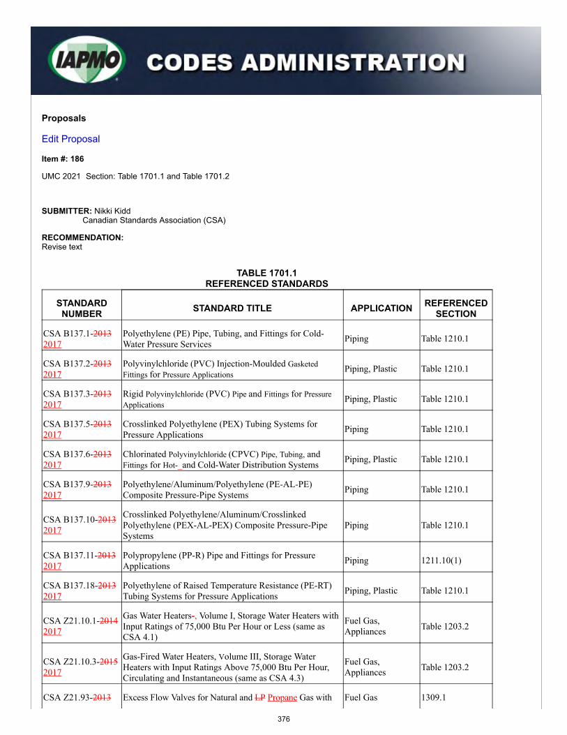
Proposals
Edit Proposal
Item #: 186
UMC 2021 Section: Table 1701.1 and Table 1701.2
SUBMITTER: Nikki KiddCanadian Standards Association (CSA)
RECOMMENDATION:Revise text
TABLE 1701.1REFERENCED STANDARDS
STANDARDNUMBER STANDARD TITLE APPLICATION REFERENCED
SECTION
CSA B137.1-20132017
Polyethylene (PE) Pipe, Tubing, and Fittings for Cold-Water Pressure Services Piping Table 1210.1
CSA B137.2-20132017
Polyvinylchloride (PVC) Injection-Moulded GasketedFittings for Pressure Applications
Piping, Plastic Table 1210.1
CSA B137.3-20132017
Rigid Polyvinylchloride (PVC) Pipe and Fittings for PressureApplications
Piping, Plastic Table 1210.1
CSA B137.5-20132017
Crosslinked Polyethylene (PEX) Tubing Systems forPressure Applications Piping Table 1210.1
CSA B137.6-20132017
Chlorinated Polyvinylchloride (CPVC) Pipe, Tubing, andFittings for Hot-_and Cold-Water Distribution Systems Piping, Plastic Table 1210.1
CSA B137.9-20132017
Polyethylene/Aluminum/Polyethylene (PE-AL-PE)Composite Pressure-Pipe Systems Piping Table 1210.1
CSA B137.10-20132017
Crosslinked Polyethylene/Aluminum/CrosslinkedPolyethylene (PEX-AL-PEX) Composite Pressure-PipeSystems
Piping Table 1210.1
CSA B137.11-20132017
Polypropylene (PP-R) Pipe and Fittings for PressureApplications Piping 1211.10(1)
CSA B137.18-20132017
Polyethylene of Raised Temperature Resistance (PE-RT)Tubing Systems for Pressure Applications Piping, Plastic Table 1210.1
CSA Z21.10.1-20142017
Gas Water Heaters-, Volume I, Storage Water Heaters withInput Ratings of 75,000 Btu Per Hour or Less (same asCSA 4.1)
Fuel Gas,Appliances Table 1203.2
CSA Z21.10.3-20152017
Gas-Fired Water Heaters, Volume III, Storage WaterHeaters with Input Ratings Above 75,000 Btu Per Hour,Circulating and Instantaneous (same as CSA 4.3)
Fuel Gas,Appliances Table 1203.2
CSA Z21.93-2013 Excess Flow Valves for Natural and LP Propane Gas with Fuel Gas 1309.1
376
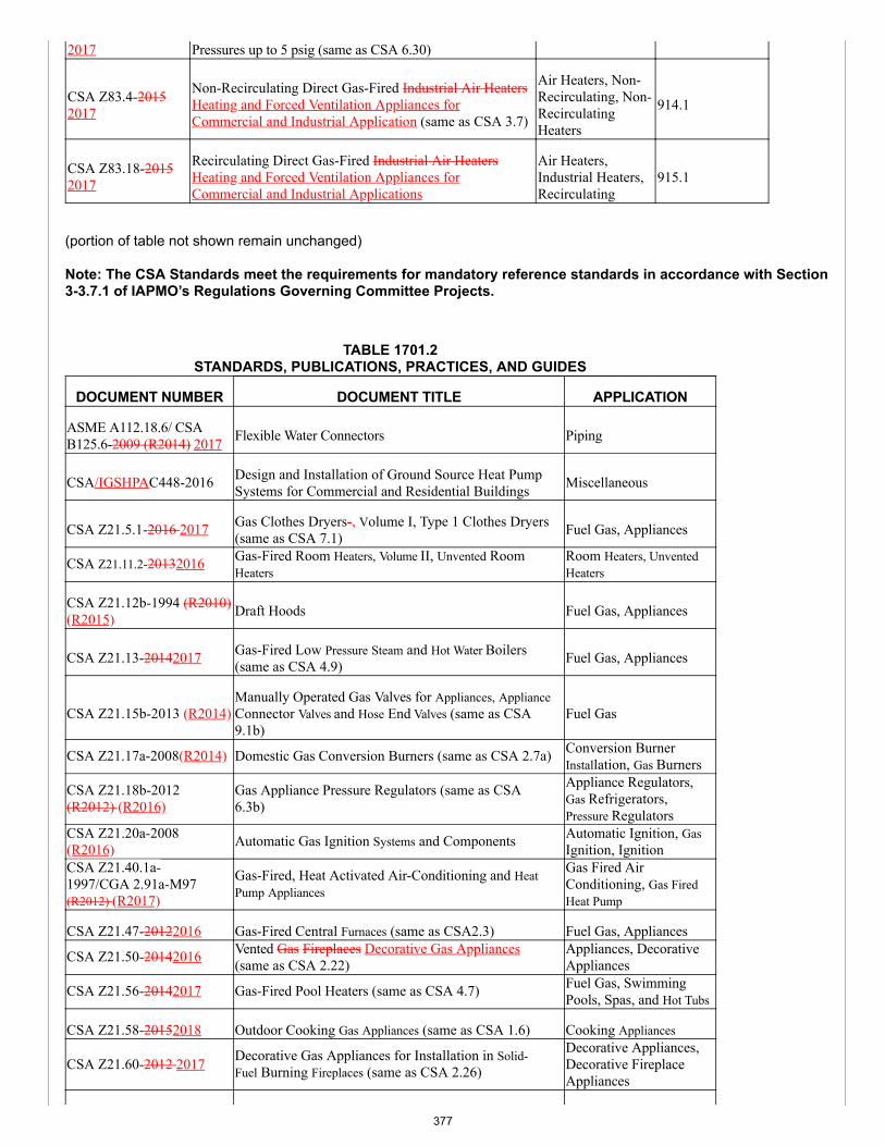
2017 Pressures up to 5 psig (same as CSA 6.30)
CSA Z83.4-20152017
Non-Recirculating Direct Gas-Fired Industrial Air HeatersHeating and Forced Ventilation Appliances forCommercial and Industrial Application (same as CSA 3.7)
Air Heaters, Non-Recirculating, Non-RecirculatingHeaters
914.1
CSA Z83.18-20152017
Recirculating Direct Gas-Fired Industrial Air HeatersHeating and Forced Ventilation Appliances forCommercial and Industrial Applications
Air Heaters,Industrial Heaters,Recirculating
915.1
(portion of table not shown remain unchanged)
Note: The CSA Standards meet the requirements for mandatory reference standards in accordance with Section3-3.7.1 of IAPMO’s Regulations Governing Committee Projects.
TABLE 1701.2STANDARDS, PUBLICATIONS, PRACTICES, AND GUIDES
DOCUMENT NUMBER DOCUMENT TITLE APPLICATION
ASME A112.18.6/ CSAB125.6-2009 (R2014) 2017 Flexible Water Connectors Piping
CSA/IGSHPAC448-2016 Design and Installation of Ground Source Heat PumpSystems for Commercial and Residential Buildings Miscellaneous
CSA Z21.5.1-2016 2017 Gas Clothes Dryers-, Volume I, Type 1 Clothes Dryers(same as CSA 7.1) Fuel Gas, Appliances
CSA Z21.11.2-20132016 Gas-Fired Room Heaters, Volume II, Unvented RoomHeaters
Room Heaters, UnventedHeaters
CSA Z21.12b-1994 (R2010)(R2015) Draft Hoods Fuel Gas, Appliances
CSA Z21.13-20142017 Gas-Fired Low Pressure Steam and Hot Water Boilers(same as CSA 4.9) Fuel Gas, Appliances
CSA Z21.15b-2013 (R2014)Manually Operated Gas Valves for Appliances, ApplianceConnector Valves and Hose End Valves (same as CSA9.1b)
Fuel Gas
CSA Z21.17a-2008(R2014) Domestic Gas Conversion Burners (same as CSA 2.7a) Conversion BurnerInstallation, Gas Burners
CSA Z21.18b-2012(R2012) (R2016)
Gas Appliance Pressure Regulators (same as CSA6.3b)
Appliance Regulators,Gas Refrigerators,Pressure Regulators
CSA Z21.20a-2008(R2016) Automatic Gas Ignition Systems and Components Automatic Ignition, Gas
Ignition, IgnitionCSA Z21.40.1a-1997/CGA 2.91a-M97(R2012) (R2017)
Gas-Fired, Heat Activated Air-Conditioning and HeatPump Appliances
Gas Fired AirConditioning, Gas FiredHeat Pump
CSA Z21.47-20122016 Gas-Fired Central Furnaces (same as CSA2.3) Fuel Gas, Appliances
CSA Z21.50-20142016 Vented Gas Fireplaces Decorative Gas Appliances(same as CSA 2.22)
Appliances, DecorativeAppliances
CSA Z21.56-20142017 Gas-Fired Pool Heaters (same as CSA 4.7) Fuel Gas, SwimmingPools, Spas, and Hot Tubs
CSA Z21.58-20152018 Outdoor Cooking Gas Appliances (same as CSA 1.6) Cooking Appliances
CSA Z21.60-2012 2017 Decorative Gas Appliances for Installation in Solid-Fuel Burning Fireplaces (same as CSA 2.26)
Decorative Appliances,Decorative FireplaceAppliances
377
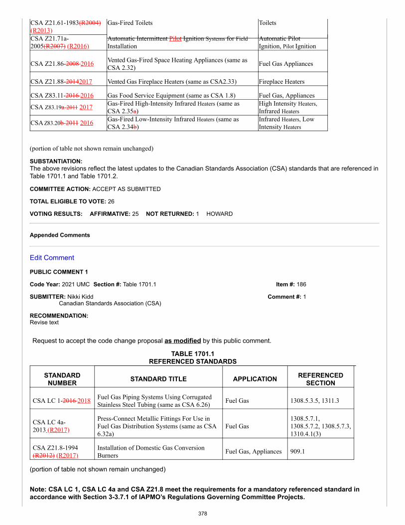
Item #: 186
Comment #: 1
CSA Z21.61-1983(R2004)(R2013)
Gas-Fired Toilets Toilets
CSA Z21.71a-2005(R2007) (R2016)
Automatic Intermittent Pilot Ignition Systems for FieldInstallation
Automatic PilotIgnition, Pilot Ignition
CSA Z21.86-2008 2016 Vented Gas-Fired Space Heating Appliances (same asCSA 2.32) Fuel Gas Appliances
CSA Z21.88-20142017 Vented Gas Fireplace Heaters (same as CSA2.33) Fireplace Heaters
CSA Z83.11-2016 2016 Gas Food Service Equipment (same as CSA 1.8) Fuel Gas, Appliances
CSA Z83.19a-2011 2017 Gas-Fired High-Intensity Infrared Heaters (same asCSA 2.35a)
High Intensity Heaters,Infrared Heaters
CSA Z83.20b-2011 2016 Gas-Fired Low-Intensity Infrared Heaters (same asCSA 2.34b)
Infrared Heaters, LowIntensity Heaters
(portion of table not shown remain unchanged)
SUBSTANTIATION:The above revisions reflect the latest updates to the Canadian Standards Association (CSA) standards that are referenced inTable 1701.1 and Table 1701.2.
COMMITTEE ACTION: ACCEPT AS SUBMITTED
TOTAL ELIGIBLE TO VOTE: 26
VOTING RESULTS: AFFIRMATIVE: 25 NOT RETURNED: 1 HOWARD
Appended Comments
Edit Comment
PUBLIC COMMENT 1
Code Year: 2021 UMC Section #: Table 1701.1
SUBMITTER: Nikki KiddCanadian Standards Association (CSA)
RECOMMENDATION:Revise text
Request to accept the code change proposal as modified by this public comment.
TABLE 1701.1REFERENCED STANDARDS
STANDARDNUMBER STANDARD TITLE APPLICATION REFERENCED
SECTION
CSA LC 1-2016 2018 Fuel Gas Piping Systems Using CorrugatedStainless Steel Tubing (same as CSA 6.26) Fuel Gas 1308.5.3.5, 1311.3
CSA LC 4a-2013 (R2017)
Press-Connect Metallic Fittings For Use inFuel Gas Distribution Systems (same as CSA6.32a)
Fuel Gas1308.5.7.1, 1308.5.7.2, 1308.5.7.3,1310.4.1(3)
CSA Z21.8-1994(R2012) (R2017)
Installation of Domestic Gas ConversionBurners Fuel Gas, Appliances 909.1
(portion of table not shown remain unchanged)
Note: CSA LC 1, CSA LC 4a and CSA Z21.8 meet the requirements for a mandatory referenced standard inaccordance with Section 3-3.7.1 of IAPMO’s Regulations Governing Committee Projects.
378
SUBSTANTIATION:The above revisions reflect the latest updates to the CSA International standards that are referenced in Table 1701.1.
COMMITTEE ACTION: ACCEPTED AS SUBMITTED
TOTAL ELIGIBLE TO VOTE: 26
VOTING RESULTS: AFFIRMATIVE: 25 NOT RETURNED: 1 HOWARD
379
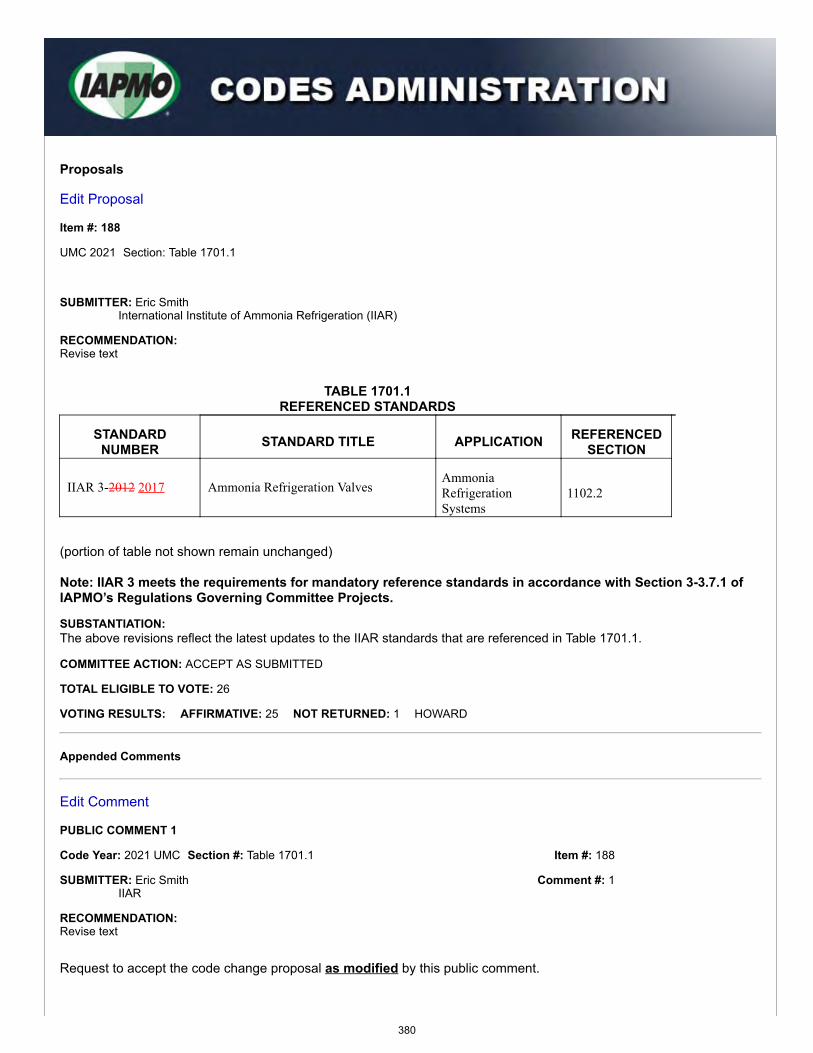
Item #: 188
Comment #: 1
Proposals
Edit Proposal
Item #: 188
UMC 2021 Section: Table 1701.1
SUBMITTER: Eric SmithInternational Institute of Ammonia Refrigeration (IIAR)
RECOMMENDATION:Revise text
TABLE 1701.1REFERENCED STANDARDS
STANDARDNUMBER STANDARD TITLE APPLICATION REFERENCED
SECTION
IIAR 3-2012 2017 Ammonia Refrigeration ValvesAmmoniaRefrigerationSystems
1102.2
(portion of table not shown remain unchanged)
Note: IIAR 3 meets the requirements for mandatory reference standards in accordance with Section 3-3.7.1 ofIAPMO’s Regulations Governing Committee Projects.
SUBSTANTIATION:The above revisions reflect the latest updates to the IIAR standards that are referenced in Table 1701.1.
COMMITTEE ACTION: ACCEPT AS SUBMITTED
TOTAL ELIGIBLE TO VOTE: 26
VOTING RESULTS: AFFIRMATIVE: 25 NOT RETURNED: 1 HOWARD
Appended Comments
Edit Comment
PUBLIC COMMENT 1
Code Year: 2021 UMC Section #: Table 1701.1
SUBMITTER: Eric SmithIIAR
RECOMMENDATION:Revise text
Request to accept the code change proposal as modified by this public comment.
380
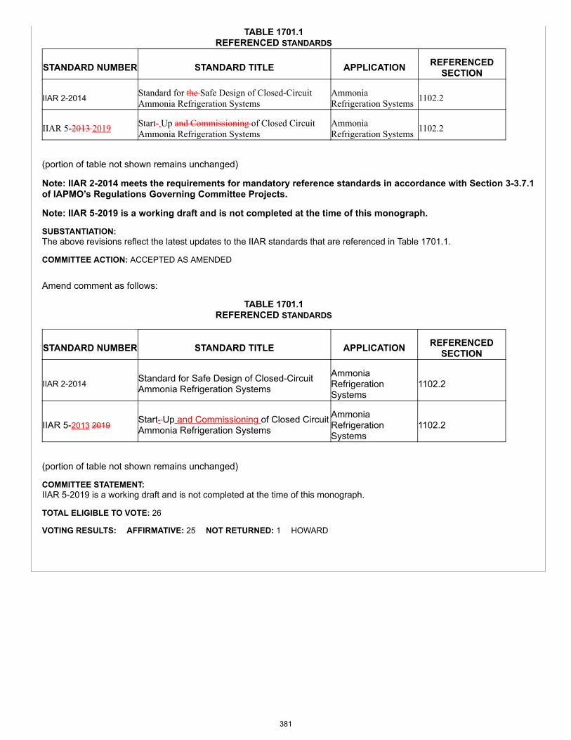
TABLE 1701.1REFERENCED STANDARDS
STANDARD NUMBER STANDARD TITLE APPLICATION REFERENCEDSECTION
IIAR 2-2014 Standard for the Safe Design of Closed-CircuitAmmonia Refrigeration Systems
AmmoniaRefrigeration Systems 1102.2
IIAR 5-2013 2019 Start- Up and Commissioning of Closed CircuitAmmonia Refrigeration Systems
AmmoniaRefrigeration Systems 1102.2
(portion of table not shown remains unchanged)
Note: IIAR 2-2014 meets the requirements for mandatory reference standards in accordance with Section 3-3.7.1of IAPMO’s Regulations Governing Committee Projects.
Note: IIAR 5-2019 is a working draft and is not completed at the time of this monograph.
SUBSTANTIATION:The above revisions reflect the latest updates to the IIAR standards that are referenced in Table 1701.1.
COMMITTEE ACTION: ACCEPTED AS AMENDED
Amend comment as follows:
TABLE 1701.1REFERENCED STANDARDS
STANDARD NUMBER STANDARD TITLE APPLICATION REFERENCEDSECTION
IIAR 2-2014 Standard for Safe Design of Closed-CircuitAmmonia Refrigeration Systems
AmmoniaRefrigerationSystems
1102.2
IIAR 5-2013 2019Start- Up and Commissioning of Closed CircuitAmmonia Refrigeration Systems
AmmoniaRefrigerationSystems
1102.2
(portion of table not shown remains unchanged)
COMMITTEE STATEMENT:IIAR 5-2019 is a working draft and is not completed at the time of this monograph.
TOTAL ELIGIBLE TO VOTE: 26
VOTING RESULTS: AFFIRMATIVE: 25 NOT RETURNED: 1 HOWARD
381
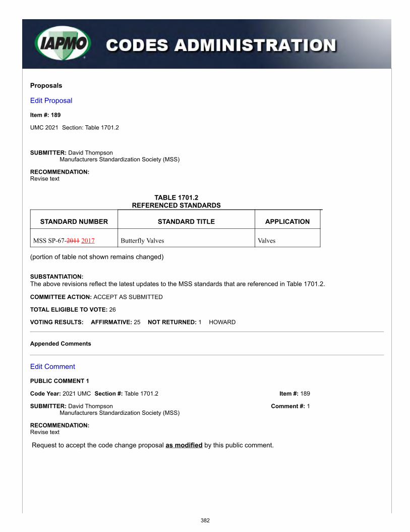
Item #: 189
Comment #: 1
Proposals
Edit Proposal
Item #: 189
UMC 2021 Section: Table 1701.2
SUBMITTER: David ThompsonManufacturers Standardization Society (MSS)
RECOMMENDATION:Revise text
TABLE 1701.2REFERENCED STANDARDS
STANDARD NUMBER STANDARD TITLE APPLICATION
MSS SP-67-2011 2017 Butterfly Valves Valves
(portion of table not shown remains changed)
SUBSTANTIATION:The above revisions reflect the latest updates to the MSS standards that are referenced in Table 1701.2.
COMMITTEE ACTION: ACCEPT AS SUBMITTED
TOTAL ELIGIBLE TO VOTE: 26
VOTING RESULTS: AFFIRMATIVE: 25 NOT RETURNED: 1 HOWARD
Appended Comments
Edit Comment
PUBLIC COMMENT 1
Code Year: 2021 UMC Section #: Table 1701.2
SUBMITTER: David ThompsonManufacturers Standardization Society (MSS)
RECOMMENDATION:Revise text
Request to accept the code change proposal as modified by this public comment.
382
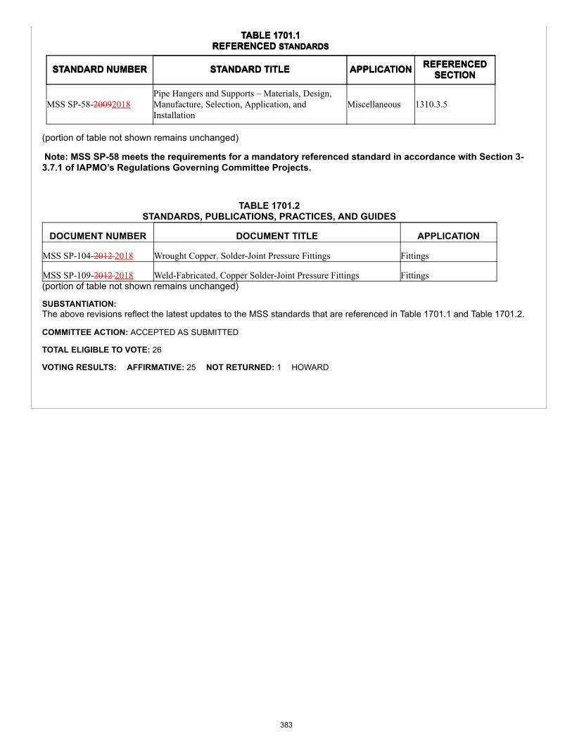
TABLE 1701.1REFERENCED STANDARDS
STANDARD NUMBER STANDARD TITLE APPLICATION REFERENCEDSECTION
TABLE 1701.1REFERENCED STANDARDS
STANDARD NUMBER STANDARD TITLE APPLICATION REFERENCEDSECTION
MSS SP-58-20092018Pipe Hangers and Supports – Materials, Design,Manufacture, Selection, Application, andInstallation
Miscellaneous 1310.3.5
(portion of table not shown remains unchanged)
Note: MSS SP-58 meets the requirements for a mandatory referenced standard in accordance with Section 3-3.7.1 of IAPMO’s Regulations Governing Committee Projects.
TABLE 1701.2STANDARDS, PUBLICATIONS, PRACTICES, AND GUIDES
DOCUMENT NUMBER DOCUMENT TITLE APPLICATION
MSS SP-104-2012 2018 Wrought Copper, Solder-Joint Pressure Fittings Fittings
MSS SP-109-2012 2018 Weld-Fabricated, Copper Solder-Joint Pressure Fittings Fittings(portion of table not shown remains unchanged)
SUBSTANTIATION:The above revisions reflect the latest updates to the MSS standards that are referenced in Table 1701.1 and Table 1701.2.
COMMITTEE ACTION: ACCEPTED AS SUBMITTED
TOTAL ELIGIBLE TO VOTE: 26
VOTING RESULTS: AFFIRMATIVE: 25 NOT RETURNED: 1 HOWARD
383
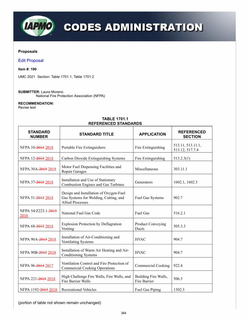
Proposals
Edit Proposal
Item #: 190
UMC 2021 Section: Table 1701.1, Table 1701.2
SUBMITTER: Laura MorenoNational Fire Protection Association (NFPA)
RECOMMENDATION:Revise text
TABLE 1701.1REFERENCED STANDARDS
STANDARDNUMBER STANDARD TITLE APPLICATION REFERENCED
SECTION
NFPA 10-2013 2018 Portable Fire Extinguishers Fire Extinguishing 513.11, 513.11.1,513.12, 517.7.4
NFPA 12-2015 2018 Carbon Dioxide Extinguishing Systems Fire Extinguishing 513.2.3(1)
NFPA 30A-2015 2018 Motor Fuel Dispensing Facilities andRepair Garages Miscellaneous 303.11.1
NFPA 37-2015 2018 Installation and Use of StationaryCombustion Engines and Gas Turbines Generators 1602.1, 1602.3
NFPA 51-2013 2018Design and Installation of Oxygen-FuelGas Systems for Welding, Cutting, andAllied Processes
Fuel Gas Systems 902.7
NFPA 54/Z223.1-20152018 National Fuel Gas Code Fuel Gas 516.2.1
NFPA 68-2013 2018 Explosion Protection by DeflagrationVenting
Product ConveyingDucts 505.3.3
NFPA 90A-2015 2018 Installation of Air-Conditioning andVentilating Systems HVAC 904.7
NFPA 90B-2015 2018 Installation of Warm Air Heating and Air-Conditioning Systems HVAC 904.7
NFPA 96-2014 2017 Ventilation Control and Fire Protection ofCommercial Cooking Operations Commercial Cooking 922.4
NFPA 221-2015 2018 High Challenge Fire Walls, Fire Walls, andFire Barrier Walls
Building Fire Walls,Fire Barrier 506.3
NFPA 1192-2015 2018 Recreational Vehicles Fuel Gas Piping 1302.3
(portion of table not shown remain unchanged)
384
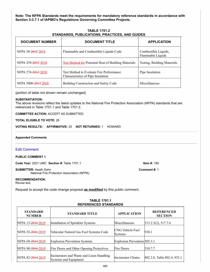
Item #: 190
Comment #: 1
Note: The NFPA Standards meet the requirements for mandatory reference standards in accordance withSection 3-3.7.1 of IAPMO’s Regulations Governing Committee Projects.
TABLE 1701.2STANDARDS, PUBLICATIONS, PRACTICES, AND GUIDES
DOCUMENT NUMBER DOCUMENT TITLE APPLICATION
NFPA 30-2015 2018 Flammable and Combustible Liquids Code Combustible Liquids,Flammable Liquids
NFPA 259-2013 2018 Test Method for Potential Heat of Building Materials Testing, Building Materials
NFPA 274-2013 2018 Test Method to Evaluate Fire PerformanceCharacteristics of Pipe Insulation
Pipe Insulation
NFPA 5000-2015 2018 Building Construction and Safety Code Miscellaneous
(portion of table not shown remain unchanged)
SUBSTANTIATION:The above revisions reflect the latest updates to the National Fire Protection Association (NFPA) standards that arereferenced in Table 1701.1 and Table 1701.2.
COMMITTEE ACTION: ACCEPT AS SUBMITTED
TOTAL ELIGIBLE TO VOTE: 26
VOTING RESULTS: AFFIRMATIVE: 25 NOT RETURNED: 1 HOWARD
Appended Comments
Edit Comment
PUBLIC COMMENT 1
Code Year: 2021 UMC Section #: Table 1701.1
SUBMITTER: Heath DehnNational Fire Protection Association (NFPA)
RECOMMENDATION:Revise text
Request to accept the code change proposal as modified by this public comment.
TABLE 1701.1REFERENCED STANDARDS
STANDARDNUMBER STANDARD TITLE APPLICATION REFERENCED
SECTION
NFPA 13-2016 2019 Installation of Sprinkler Systems Miscellaneous 513.2.3(2), 517.7.6
NFPA 52-2016 2019 Vehicular Natural Gas Fuel Systems Code CNG Vehicle FuelSystems 938.1
NFPA 69-2014 2019 Explosion Prevention Systems Explosion Prevention 505.3.1
NFPA 80-2016 2019 Fire Doors and Other Opening Protectives Fire Doors 510.7.7
NFPA 82-2014 2019 Incinerators and Waste and Linen HandlingSystems and Equipment Incinerator Chutes 802.2.8, Table 802.4, 925.1
385
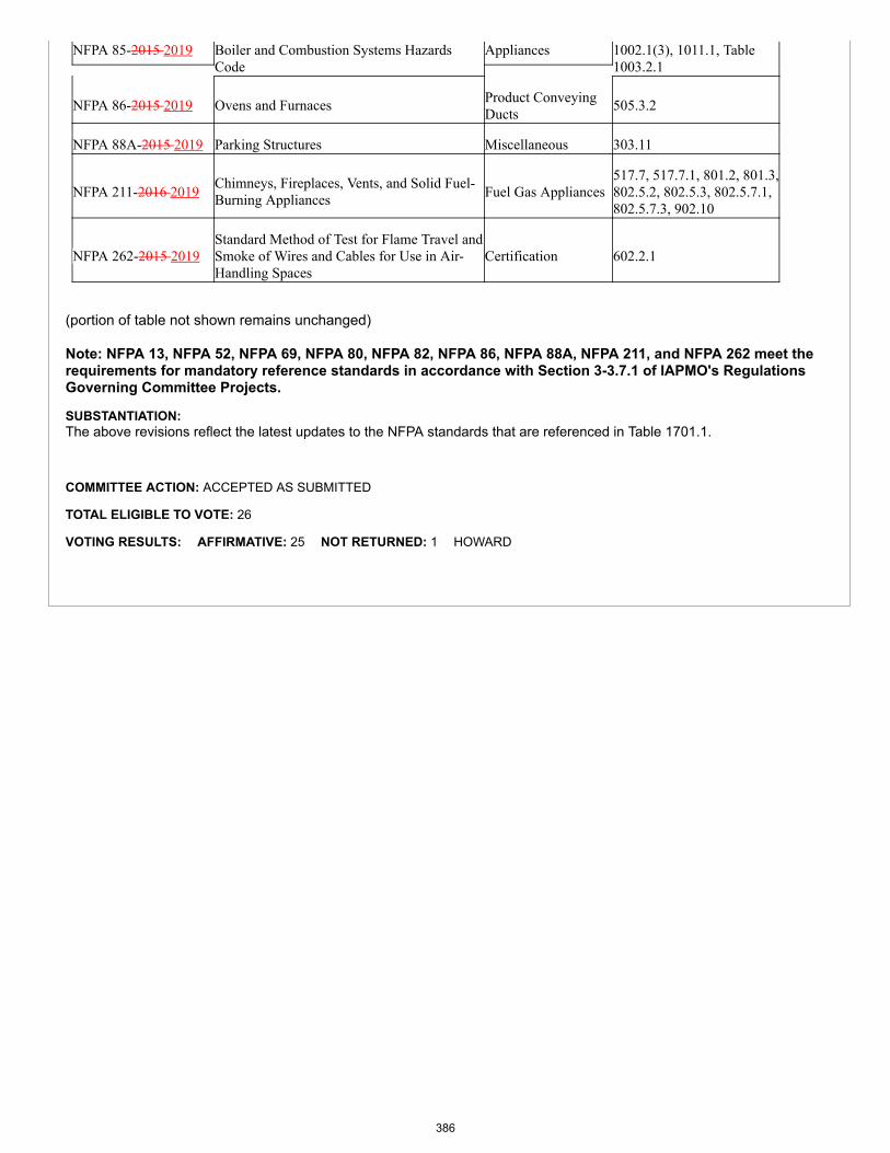
NFPA 85-2015 2019 Boiler and Combustion Systems HazardsCode
Appliances 1002.1(3), 1011.1, Table1003.2.1
NFPA 86-2015 2019 Ovens and Furnaces Product ConveyingDucts 505.3.2
NFPA 88A-2015 2019 Parking Structures Miscellaneous 303.11
NFPA 211-2016 2019 Chimneys, Fireplaces, Vents, and Solid Fuel-Burning Appliances Fuel Gas Appliances
517.7, 517.7.1, 801.2, 801.3,802.5.2, 802.5.3, 802.5.7.1,802.5.7.3, 902.10
NFPA 262-2015 2019Standard Method of Test for Flame Travel andSmoke of Wires and Cables for Use in Air-Handling Spaces
Certification 602.2.1
(portion of table not shown remains unchanged)
Note: NFPA 13, NFPA 52, NFPA 69, NFPA 80, NFPA 82, NFPA 86, NFPA 88A, NFPA 211, and NFPA 262 meet therequirements for mandatory reference standards in accordance with Section 3-3.7.1 of IAPMO's RegulationsGoverning Committee Projects.
SUBSTANTIATION:The above revisions reflect the latest updates to the NFPA standards that are referenced in Table 1701.1.
COMMITTEE ACTION: ACCEPTED AS SUBMITTED
TOTAL ELIGIBLE TO VOTE: 26
VOTING RESULTS: AFFIRMATIVE: 25 NOT RETURNED: 1 HOWARD
386
Item #: 191
Comment #: 1
Proposals
Edit Proposal
Item #: 191
UMC 2021 Section: Table 1701.1
SUBMITTER: Jeremy BrownNSF International
RECOMMENDATION:Revise text
TABLE 1701.1REFERENCED STANDARDS
STANDARDNUMBER STANDARD TITLE APPLICATION REFERENCED
SECTION
NSF 358-1-20142017
Polyethylene Pipe and Fittings for Water-BasedGround-Source “Geothermal” Heat PumpSystems
Piping, Plastic Table 1210.1
(portion of table not shown remain unchanged)
Note: NSF 358-1 meets the requirements for mandatory reference standards in accordance with Section 3-3.7.1of IAPMO’s Regulations Governing Committee Projects.
SUBSTANTIATION:The above revisions reflect the latest updates to the NSF standards that are referenced in Table 1701.1.
COMMITTEE ACTION: ACCEPT AS SUBMITTED
TOTAL ELIGIBLE TO VOTE: 26
VOTING RESULTS: AFFIRMATIVE: 25 NOT RETURNED: 1 HOWARD
Appended Comments
Edit Comment
PUBLIC COMMENT 1
Code Year: 2021 UMC Section #: Table 1701.1, Table 1701.2
SUBMITTER: Jeremy BrownNSF International (NSF)
RECOMMENDATION:Revise text
Request to accept the code change proposal as modified by this public comment.
387
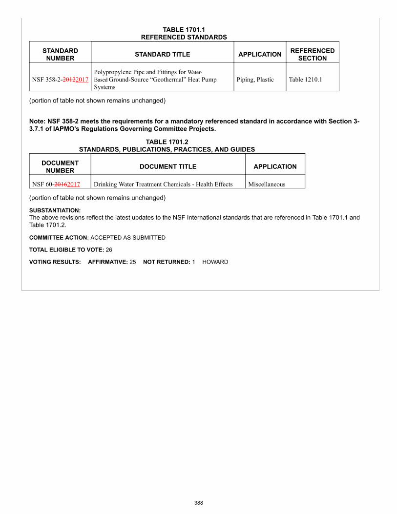
TABLE 1701.1REFERENCED STANDARDS
STANDARDNUMBER STANDARD TITLE APPLICATION REFERENCED
SECTION
NSF 358-2-20122017Polypropylene Pipe and Fittings for Water-Based Ground-Source “Geothermal” Heat PumpSystems
Piping, Plastic Table 1210.1
(portion of table not shown remains unchanged)
Note: NSF 358-2 meets the requirements for a mandatory referenced standard in accordance with Section 3-3.7.1 of IAPMO’s Regulations Governing Committee Projects.
TABLE 1701.2STANDARDS, PUBLICATIONS, PRACTICES, AND GUIDES
DOCUMENTNUMBER DOCUMENT TITLE APPLICATION
NSF 60-20162017 Drinking Water Treatment Chemicals - Health Effects Miscellaneous
(portion of table not shown remains unchanged)
SUBSTANTIATION:The above revisions reflect the latest updates to the NSF International standards that are referenced in Table 1701.1 andTable 1701.2.
COMMITTEE ACTION: ACCEPTED AS SUBMITTED
TOTAL ELIGIBLE TO VOTE: 26
VOTING RESULTS: AFFIRMATIVE: 25 NOT RETURNED: 1 HOWARD
388
Proposals
Edit Proposal
Item #: 193
UMC 2021 Section: Table 1701.1 Table 1701.2
SUBMITTER: John Taecker/Maggie CarrollUnderwriters Laboratories, Inc.
RECOMMENDATION:Revise text
TABLE 1701.1REFERENCED STANDARDS
STANDARDNUMBER
STANDARD TITLE APPLICATION REFERENCEDSECTION
UL 103-2010 Factory-Built Chimneys for Residential Type andBuilding Heating Appliances (with revisions throughJuly 27, 2012 March 15, 2017)
Fuel Gas, Appliances 802.5.1.1, 802.5.1.2
UL 181-2013 Factory-Made Air Ducts and Air Connectors (withrevisions through April 18, 2017)
Air Connectors, Air Ducts 602.6, 603.4, 603.5,603.8, 604.1.1
UL 181A-2013 Closure Systems for Use with Rigid Air Ducts (withrevisions through March 22, 2017)
Air Ducts 603.10, Table 603.10
UL 181B-2013 Closure Systems for Use with Flexible Air Ducts andAir Connectors (with revisions through March 21,2017)
Air Connectors, Air Ducts 603.10, Table 603.10
UL 197-2010 Commercial Electric Cooking Appliances (withrevisions through September 17, 2014 January 26,2018)
Appliances, CommercialCooking, Electric Appliances
921.1
UL 295-20072017
Commercial-Industrial Gas Burners (with revisionsthrough January 30, 2015)
Gas Burners 910.2
UL 296-20032017
Oil Burners (with revisions through June 11, 2015November 29, 2017)
Fuel Gas, Appliances 910.1
UL 412-2011 Refrigeration Unit Coolers (with revisions throughSeptember 17, 2013 January 9, 2017)
Refrigeration 934.2
UL 427-2011 Refrigerating Units (with revisions through February28, 2014 10, 2017)
Refrigeration Systems 934.3
UL 499-2014 Electric Heating Appliances (with revisions throughFebruary 23, 2017)
Kilns 931.4
UL 555C-2014 Ceiling Dampers (with revisions through May 1,2017)
Dampers 605.3
UL 641-2010 Type L Low-Temperature Venting Systems (withrevisions through June 12, 2013 December 12, 2017)
Equipment 802.1
389
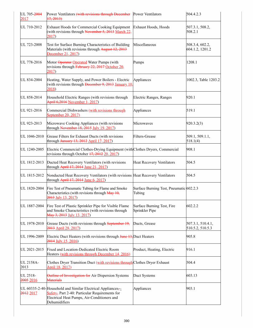
UL 705-20042017
Power Ventilators (with revisions through December17, 2013)
Power Ventilators 504.4.2.3
UL 710-2012 Exhaust Hoods for Commercial Cooking Equipment(with revisions through November 5, 2013 March 22,2017)
Exhaust Hoods, Hoods 507.3.1, 508.2,508.2.1
UL 723-2008 Test for Surface Burning Characteristics of BuildingMaterials (with revisions through August 12, 2013December 21, 2017)
Miscellaneous 508.3.4, 602.2,604.1.2, 1201.2
UL 778-2016 Motor Operater Operated Water Pumps (withrevisions through February 22, 2017 October 20,2017)
Pumps 1208.1
UL 834-2004 Heating, Water Supply, and Power Boilers - Electric(with revisions through December 9, 2013 January 10,2018)
Appliances 1002.3, Table 1203.2
UL 858-2014 Household Electric Ranges (with revisions throughApril 6,2016 November 1, 2017)
Electric Ranges, Ranges 920.1
UL 921-2016 Commercial Dishwashers (with revisions throughSeptember 20, 2017)
Appliances 519.1
UL 923-2013 Microwave Cooking Appliances (with revisionsthrough November 18, 2015 July 19, 2017)
Microwaves 920.3.2(3)
UL 1046-2010 Grease Filters for Exhaust Ducts (with revisionsthrough January 13, 2012 April 17, 2017)
Filters-Grease 509.1, 509.1.1,518.1(4)
UL 1240-2005 Electric Commercial Clothes-Drying Equipment (withrevisions through October 17, 2012 20, 2017)
Clothes Dryers, Commercial 908.1
UL 1812-2013 Ducted Heat Recovery Ventilators (with revisionsthrough April 17, 2014 June 21, 2017)
Heat Recovery Ventilators 504.5
UL 1815-2012 Nonducted Heat Recovery Ventilators (with revisionsthrough April 17, 2014 June 6, 2017)
Heat Recovery Ventilators 504.5
UL 1820-2004 Fire Test of Pneumatic Tubing for Flame and SmokeCharacteristics (with revisions through May 10,2013 July 13, 2017)
Surface Burning Test, PneumaticTubing
602.2.3
UL 1887-2004 Fire Test of Plastic Sprinkler Pipe for Visible Flameand Smoke Characteristics (with revisions throughMay 3, 2013 July 13, 2017)
Surface Burning Test, FireSprinkler Pipe
602.2.2
UL 1978-2010 Grease Ducts (with revisions through September 19,2013 April 28, 2017)
Ducts, Grease 507.3.1, 510.4.1,510.5.2, 510.5.3
UL 1996-2009 Electric Duct Heaters (with revisions through June 13,2014 July 15, 2016)
Duct Heaters 905.8
UL 2021-2015 Fixed and Location-Dedicated Electric RoomHeaters (with revisions through December 14, 2016)
Product, Heating, Electric 916.1
UL 2158A-2013
Clothes Dryer Transition Duct (with revisions throughApril 18, 2017)
Clothes Dryer Exhaust 504.4
UL 2518-2005 2016
Outline of Investigation for Air Dispersion SystemsMaterials
Duct Systems 603.13
UL 60335-2-40-2012 2017
Household and Similar Electrical Appliances, -Safety- Part 2-40: Particular Requirements forElectrical Heat Pumps, Air-Conditioners andDehumidifiers
Appliances 903.1
390
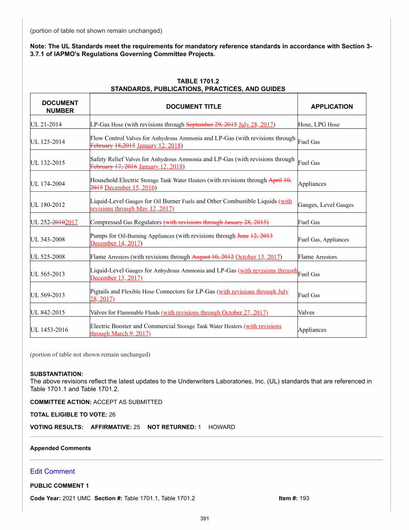
Item #: 193
(portion of table not shown remain unchanged)
Note: The UL Standards meet the requirements for mandatory reference standards in accordance with Section 3-3.7.1 of IAPMO's Regulations Governing Committee Projects.
TABLE 1701.2STANDARDS, PUBLICATIONS, PRACTICES, AND GUIDES
DOCUMENTNUMBER DOCUMENT TITLE APPLICATION
UL 21-2014 LP-Gas Hose (with revisions through September 29, 2015 July 28, 2017) Hose, LPG Hose
UL 125-2014 Flow Control Valves for Anhydrous Ammonia and LP-Gas (with revisions throughFebruary 18,2015 January 12, 2018) Fuel Gas
UL 132-2015 Safety Relief Valves for Anhydrous Ammonia and LP-Gas (with revisions throughFebruary 17, 2016 January 12, 2018) Fuel Gas
UL 174-2004 Household Electric Storage Tank Water Heaters (with revisions through April 10,2015 December 15, 2016) Appliances
UL 180-2012 Liquid-Level Gauges for Oil Burner Fuels and Other Combustible Liquids (withrevisions through May 12, 2017) Gauges, Level Gauges
UL 252-20102017 Compressed Gas Regulators (with revisions through January 28, 2015) Fuel Gas
UL 343-2008 Pumps for Oil-Burning Appliances (with revisions through June 12, 2013December 14, 2017) Fuel Gas, Appliances
UL 525-2008 Flame Arresters (with revisions through August 10, 2012 October 13, 2017) Flame Arrestors
UL 565-2013 Liquid-Level Gauges for Anhydrous Ammonia and LP-Gas (with revisions throughDecember 13, 2017) Fuel Gas
UL 569-2013 Pigtails and Flexible Hose Connectors for LP-Gas (with revisions through July28, 2017) Fuel Gas
UL 842-2015 Valves for Flammable Fluids (with revisions through October 27, 2017) Valves
UL 1453-2016 Electric Booster and Commercial Storage Tank Water Heaters (with revisionsthrough March 9, 2017) Appliances
(portion of table not shown remain unchanged)
SUBSTANTIATION:The above revisions reflect the latest updates to the Underwriters Laboratories, Inc. (UL) standards that are referenced inTable 1701.1 and Table 1701.2.
COMMITTEE ACTION: ACCEPT AS SUBMITTED
TOTAL ELIGIBLE TO VOTE: 26
VOTING RESULTS: AFFIRMATIVE: 25 NOT RETURNED: 1 HOWARD
Appended Comments
Edit Comment
PUBLIC COMMENT 1
Code Year: 2021 UMC Section #: Table 1701.1, Table 1701.2
391
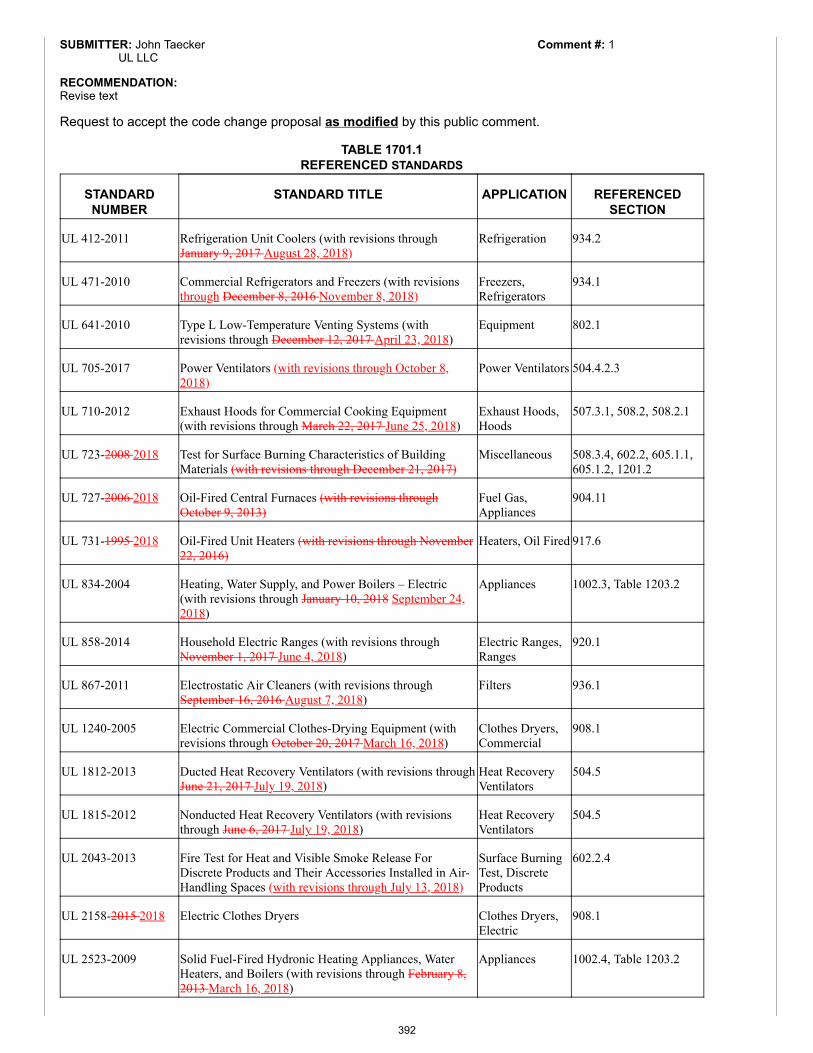
Comment #: 1SUBMITTER: John TaeckerUL LLC
RECOMMENDATION:Revise text
Request to accept the code change proposal as modified by this public comment.
TABLE 1701.1REFERENCED STANDARDS
STANDARDNUMBER
STANDARD TITLE APPLICATION REFERENCEDSECTION
UL 412-2011 Refrigeration Unit Coolers (with revisions throughJanuary 9, 2017 August 28, 2018)
Refrigeration 934.2
UL 471-2010 Commercial Refrigerators and Freezers (with revisionsthrough December 8, 2016 November 8, 2018)
Freezers,Refrigerators
934.1
UL 641-2010 Type L Low-Temperature Venting Systems (withrevisions through December 12, 2017 April 23, 2018)
Equipment 802.1
UL 705-2017 Power Ventilators (with revisions through October 8,2018)
Power Ventilators 504.4.2.3
UL 710-2012 Exhaust Hoods for Commercial Cooking Equipment(with revisions through March 22, 2017 June 25, 2018)
Exhaust Hoods,Hoods
507.3.1, 508.2, 508.2.1
UL 723-2008 2018 Test for Surface Burning Characteristics of BuildingMaterials (with revisions through December 21, 2017)
Miscellaneous 508.3.4, 602.2, 605.1.1,605.1.2, 1201.2
UL 727-2006 2018 Oil-Fired Central Furnaces (with revisions throughOctober 9, 2013)
Fuel Gas,Appliances
904.11
UL 731-1995 2018 Oil-Fired Unit Heaters (with revisions through November22, 2016)
Heaters, Oil Fired 917.6
UL 834-2004 Heating, Water Supply, and Power Boilers – Electric(with revisions through January 10, 2018 September 24,2018)
Appliances 1002.3, Table 1203.2
UL 858-2014 Household Electric Ranges (with revisions throughNovember 1, 2017 June 4, 2018)
Electric Ranges,Ranges
920.1
UL 867-2011 Electrostatic Air Cleaners (with revisions throughSeptember 16, 2016 August 7, 2018)
Filters 936.1
UL 1240-2005 Electric Commercial Clothes-Drying Equipment (withrevisions through October 20, 2017 March 16, 2018)
Clothes Dryers,Commercial
908.1
UL 1812-2013 Ducted Heat Recovery Ventilators (with revisions throughJune 21, 2017 July 19, 2018)
Heat RecoveryVentilators
504.5
UL 1815-2012 Nonducted Heat Recovery Ventilators (with revisionsthrough June 6, 2017 July 19, 2018)
Heat RecoveryVentilators
504.5
UL 2043-2013 Fire Test for Heat and Visible Smoke Release ForDiscrete Products and Their Accessories Installed in Air-Handling Spaces (with revisions through July 13, 2018)
Surface BurningTest, DiscreteProducts
602.2.4
UL 2158-2015 2018 Electric Clothes Dryers Clothes Dryers,Electric
908.1
UL 2523-2009 Solid Fuel-Fired Hydronic Heating Appliances, WaterHeaters, and Boilers (with revisions through February 8,2013 March 16, 2018)
Appliances 1002.4, Table 1203.2
392
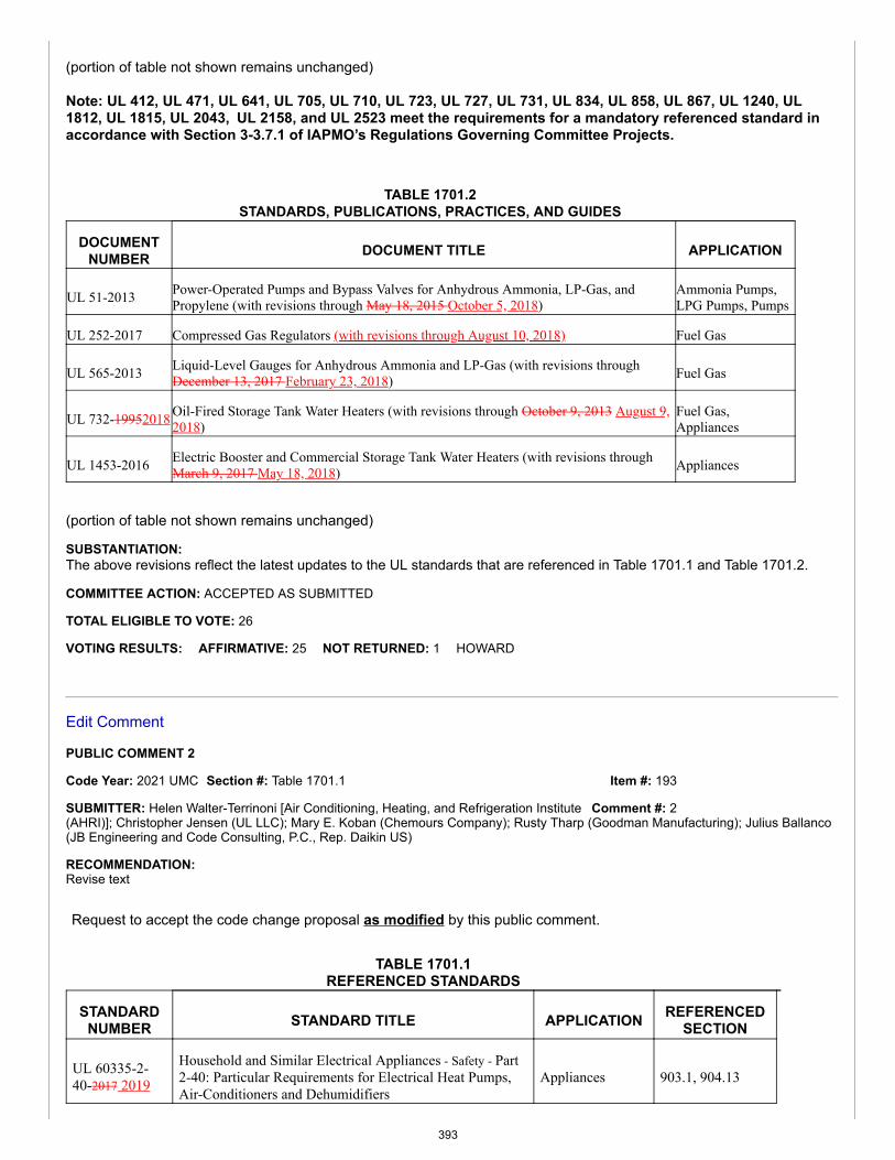
Item #: 193
Comment #: 2
(portion of table not shown remains unchanged)
Note: UL 412, UL 471, UL 641, UL 705, UL 710, UL 723, UL 727, UL 731, UL 834, UL 858, UL 867, UL 1240, UL1812, UL 1815, UL 2043, UL 2158, and UL 2523 meet the requirements for a mandatory referenced standard inaccordance with Section 3-3.7.1 of IAPMO’s Regulations Governing Committee Projects.
TABLE 1701.2STANDARDS, PUBLICATIONS, PRACTICES, AND GUIDES
DOCUMENTNUMBER DOCUMENT TITLE APPLICATION
UL 51-2013 Power-Operated Pumps and Bypass Valves for Anhydrous Ammonia, LP-Gas, andPropylene (with revisions through May 18, 2015 October 5, 2018)
Ammonia Pumps,LPG Pumps, Pumps
UL 252-2017 Compressed Gas Regulators (with revisions through August 10, 2018) Fuel Gas
UL 565-2013 Liquid-Level Gauges for Anhydrous Ammonia and LP-Gas (with revisions throughDecember 13, 2017 February 23, 2018) Fuel Gas
UL 732-19952018 Oil-Fired Storage Tank Water Heaters (with revisions through October 9, 2013 August 9,2018)
Fuel Gas,Appliances
UL 1453-2016 Electric Booster and Commercial Storage Tank Water Heaters (with revisions throughMarch 9, 2017 May 18, 2018) Appliances
(portion of table not shown remains unchanged)
SUBSTANTIATION:The above revisions reflect the latest updates to the UL standards that are referenced in Table 1701.1 and Table 1701.2.
COMMITTEE ACTION: ACCEPTED AS SUBMITTED
TOTAL ELIGIBLE TO VOTE: 26
VOTING RESULTS: AFFIRMATIVE: 25 NOT RETURNED: 1 HOWARD
Edit Comment
PUBLIC COMMENT 2
Code Year: 2021 UMC Section #: Table 1701.1
SUBMITTER: Helen Walter-Terrinoni [Air Conditioning, Heating, and Refrigeration Institute(AHRI)]; Christopher Jensen (UL LLC); Mary E. Koban (Chemours Company); Rusty Tharp (Goodman Manufacturing); Julius Ballanco(JB Engineering and Code Consulting, P.C., Rep. Daikin US)
RECOMMENDATION:Revise text
Request to accept the code change proposal as modified by this public comment.
TABLE 1701.1REFERENCED STANDARDS
STANDARDNUMBER STANDARD TITLE APPLICATION REFERENCED
SECTION
UL 60335-2-40-2017 2019
Household and Similar Electrical Appliances - Safety - Part2-40: Particular Requirements for Electrical Heat Pumps,Air-Conditioners and Dehumidifiers
Appliances 903.1, 904.13
393
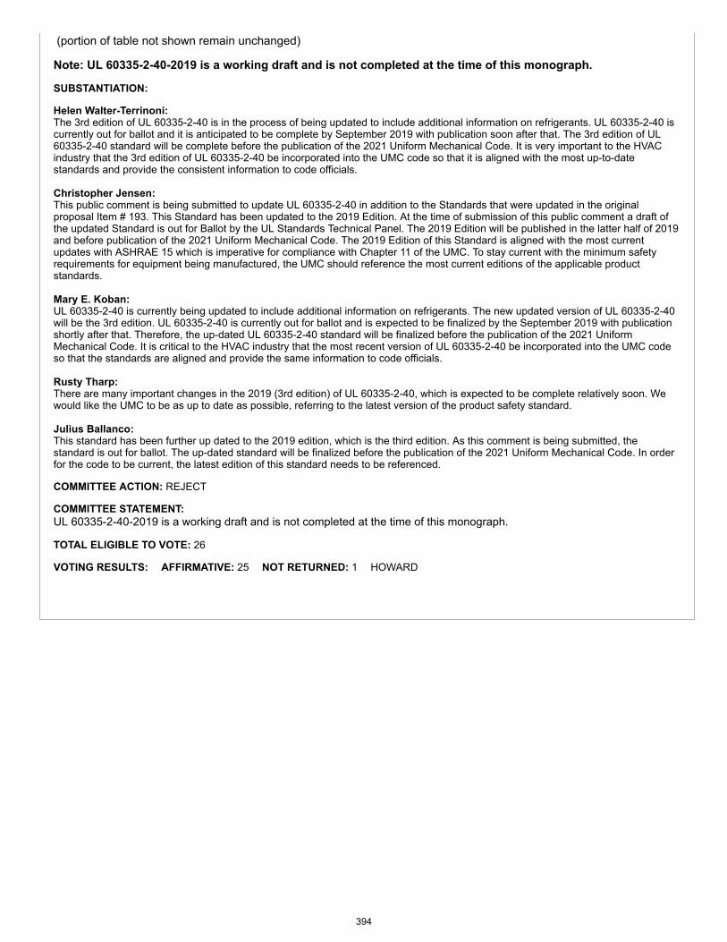
(portion of table not shown remain unchanged)
Note: UL 60335-2-40-2019 is a working draft and is not completed at the time of this monograph.
SUBSTANTIATION:
Helen Walter-Terrinoni: The 3rd edition of UL 60335-2-40 is in the process of being updated to include additional information on refrigerants. UL 60335-2-40 iscurrently out for ballot and it is anticipated to be complete by September 2019 with publication soon after that. The 3rd edition of UL60335-2-40 standard will be complete before the publication of the 2021 Uniform Mechanical Code. It is very important to the HVACindustry that the 3rd edition of UL 60335-2-40 be incorporated into the UMC code so that it is aligned with the most up-to-datestandards and provide the consistent information to code officials.
Christopher Jensen: This public comment is being submitted to update UL 60335-2-40 in addition to the Standards that were updated in the originalproposal Item # 193. This Standard has been updated to the 2019 Edition. At the time of submission of this public comment a draft ofthe updated Standard is out for Ballot by the UL Standards Technical Panel. The 2019 Edition will be published in the latter half of 2019and before publication of the 2021 Uniform Mechanical Code. The 2019 Edition of this Standard is aligned with the most currentupdates with ASHRAE 15 which is imperative for compliance with Chapter 11 of the UMC. To stay current with the minimum safetyrequirements for equipment being manufactured, the UMC should reference the most current editions of the applicable productstandards.
Mary E. Koban:UL 60335-2-40 is currently being updated to include additional information on refrigerants. The new updated version of UL 60335-2-40will be the 3rd edition. UL 60335-2-40 is currently out for ballot and is expected to be finalized by the September 2019 with publicationshortly after that. Therefore, the up-dated UL 60335-2-40 standard will be finalized before the publication of the 2021 UniformMechanical Code. It is critical to the HVAC industry that the most recent version of UL 60335-2-40 be incorporated into the UMC codeso that the standards are aligned and provide the same information to code officials.
Rusty Tharp:There are many important changes in the 2019 (3rd edition) of UL 60335-2-40, which is expected to be complete relatively soon. Wewould like the UMC to be as up to date as possible, referring to the latest version of the product safety standard.
Julius Ballanco:This standard has been further up dated to the 2019 edition, which is the third edition. As this comment is being submitted, thestandard is out for ballot. The up-dated standard will be finalized before the publication of the 2021 Uniform Mechanical Code. In orderfor the code to be current, the latest edition of this standard needs to be referenced.
COMMITTEE ACTION: REJECT
COMMITTEE STATEMENT:UL 60335-2-40-2019 is a working draft and is not completed at the time of this monograph.
TOTAL ELIGIBLE TO VOTE: 26
VOTING RESULTS: AFFIRMATIVE: 25 NOT RETURNED: 1 HOWARD
394


1
2019 IAPMO Technical Correlation Committee (TCC) Report
CORRELATION ITEMS BETWEEN THE UPC and UMC
TCC ITEM # 001
2021 UNIFORM PLUMBING CODE 2021 UNIFORM MECHANICAL CODE ITEM # 060, PC 1 ITEM # 048, PC 1 301.0 General.
301.2 Minimum Standards. (remaining text unchanged)
301.2.2 Standards. Standards listed or referred to in this chapter or other chapters cover materials that will conform to the requirements of this code, where used in accordance with the limitations imposed in this or other chapters thereof and their listing. Where a standard covers materials of various grades, weights, quality, or configurations, the portion of the listed standard that is applicable shall be used. Design and materials for special conditions or materials not provided for herein shall be permitted to be used by special permission of the Authority Having Jurisdiction after the Authority Having Jurisdiction has been satisfied as to their adequacy. A list of plumbing standards that appear in specific sections of this code is referenced in Table 1701.1. Standards referenced in Table 1701.1 shall be applied as indicated in the applicable referenced section. A list of additional approved standards, publications, practices, and guides that are not referenced in specific sections of this code appear in Table 1701.2. The documents indicated in Table 1701.2 shall be permitted in accordance with Section 301.3. An IAPMO Installation Standard is referenced in Appendix I for the convenience of the users of this code. It is not considered as a part of this code unless formally adopted as such by the Authority Having Ju-risdiction. 317.1 General. Food or drink shall not be stored, prepared, or displayed beneath soil or drain pipes unless those areas are protected against leakage or condensation from such pipes reaching the food or drink as described below. Where building design requires that soil or drain pipes be located over such areas, the installation shall be made with the least possible number of joints and shall be installed to connect to the near-est adequately sized vertical stack with the provisions as fol-lows: (1) Openings through floors over such areas shall be sealed
watertight to the floor construction. (2) Floor and shower drains installed above such areas shall
302.0 Materials – Standards and Alternates.
302.1 Minimum Standards. (remaining text unchanged)
302.1.2 Standards. Standards listed or referred to in this chapter or other chapters cover materials that will conform to the requirements of this code, where used in accordance with the limitations imposed in this or other chapters thereof and their listing. Where a standard covers materials of vari-ous grades, weights, quality, or configurations, the portion of the listed standard that is applicable shall be used. Design and materials for special conditions or materials not provid-ed for herein shall be permitted to be used by special per-mission of the Authority Having Jurisdiction after the Au-thority Having Jurisdiction has been satisfied as to their ad-equacy. A list of mechanical standards that appear in specif-ic sections of this code is referenced in Table 1701.1. Stand-ards referenced in Table 1701.1 shall be applied as indicated in the applicable referenced section. A list of addition-al approved standards, publications, practices and guides that are not referenced in specific sections of this code ap-pear in Table 1701.2.
2
2021 UNIFORM PLUMBING CODE 2021 UNIFORM MECHANICAL CODE ITEM # 060, PC 1 ITEM # 048, PC 1
be equipped with integral seepage pans. (3) Soil or drain pipes shall be of an approved material as
listed in Table 1701.1 Chapter 17 and Section 701.2. Ma-terials shall comply with established standards. Cleanouts shall be extended through the floor construction above.
(4) Piping subject to operation at temperatures that will form condensation on the exterior of the pipe shall be thermally insulated.
(5) Where pipes are installed in ceilings above such areas, the ceiling shall be of the removable type or shall be provid-ed with access panels to form a ready access for inspec-tion of piping.
601.3.4 Fixtures. Where vacuum breakers or backflow pre-venters are installed with fixtures listed in Table 1701.1 Chapter 17, identification of the discharge side shall be permitted to be omitted.
603.5.14 Protection from Fire Systems. Except as provided in Section 603.5.14.1 and Section 603.5.14.2, potable water supplies to fire protection systems that are normally under pressure, including but not limited to standpipes and automat-ic sprinkler systems, except in one- or two-family or town-house residential sprinkler systems, piped in materials ap-proved for potable water distribution systems shall be protect-ed from backpressure and backsiphonage by one of the fol-lowing testable devices: (1) Double check valve backflow prevention assembly (DC) (2) Double check detector fire protection backflow prevention assembly (3) Reduced pressure principle backflow prevention assembly (RP) (4) Reduced pressure detector fire protection backflow pre-vention assembly Potable water supplies to fire protection systems that are not normally under pressure shall be protected from backflow and shall be in accordance with the requirements of the appro-priate standards referenced in Table 1701.1 Chapter 17. 701.5 Lead. (See Table 1701.1 Chapter 17) Sheet lead shall comply with the following: (1) For safe pans – not less than 4 pounds per square foot (lb/ft2) (19 kg/m2) or 1/16 of an inch (1.6 mm) thick. (2) For flashings or vent terminals – not less than 3 lb/ft2 (15 kg/m2) or 0.0472 of an inch (1.2 mm) thick. (3) Lead bends and lead traps shall be not less than 1/8 of an inch (3.2 mm) in wall thickness. 906.6 Lead. (See Table 1701.1 Chapter 17) Sheet lead shall comply with the following: (1) For safe pans – not less than 4 pounds per square foot (lb/ft2) (19 kg/m2) or 1/16 of an inch (1.6 mm) thick. (2) For flashings or vent terminals – not less than 3 lb/ft2 (15
3
2021 UNIFORM PLUMBING CODE 2021 UNIFORM MECHANICAL CODE ITEM # 060, PC 1 ITEM # 048, PC 1 kg/m2) or 0.0472 of an inch (1.2 mm) thick. (3) Lead bends and lead traps shall be not less than 1/8 of an inch (3.2 mm) in wall thickness. 1014.3.3 Design. Gravity interceptors shall be constructed in accordance with the applicable standard in Table 1701.1 Chapter 17 or the design approved by the Authority Having Jurisdiction. 1101.4 Material Uses. Pipe, tube, and fittings conveying rainwater shall be of such materials and design as to perform their intended function to the satisfaction of the Authority Having Jurisdiction. Conductors within a vent or shaft shall be of cast-iron, galvanized steel, wrought iron, copper, copper alloy, lead, Schedule 40 ABS DWV, Schedule 40 PVC DWV, stainless steel 304 or 316L [stainless steel 304 pipe and fit-tings shall not be installed underground and shall be kept not less than 6 inches (152 mm) aboveground], or other approved materials, and changes in direction shall be in accordance with the requirements of Section 706.0. ABS and PVC DWV pip-ing installations shall be installed in accordance with applica-ble standards referenced in Table 1701.1 Chapter 17 and Chapter 14 “Firestop Protection.” Except for individual sin-gle-family dwelling units, materials exposed within ducts or plenums shall have a flame-spread index of not more than 25 and a smoke-developed index of not more than 50, where test-ed in accordance with ASTM E84 or UL 723. Plastic piping installed in plenums shall be tested in accordance with all re-quirements of ASTM E84 or UL723. Mounting methods, sup-ports and sample sizes of materials for testing that are not specified in ASTM E84 or UL 723 shall be prohibited.
1603.5.1 Treatment. If the quality of the tested water can-not consistently be maintained at the minimum levels speci-fied in Table 1603.5, then the system shall be equipped with an appropriate treatment device meeting applicable NSF standard referenced in Table 1701.1 Chapter 17.
C 101.4 Standards and Specifications. Components, materials, and equipment shall comply with standards and specifications listed in Table 1701.1 Chapter 17 of this code and other national consensus standards applicable to plumbing systems and materials. C 501.1 General. This section regulates the design and in-stallation provisions for vacuum waste drainage systems. Plans for vacuum waste drainage systems shall be submitted to the Authority Having Jurisdiction for approval and shall be considered an engineered designed system. Such plans shall be prepared by a registered design professional to perform plumbing design work. Details are necessary to ensure com-pliance with the requirements of this section, together with a full description of the complete installation including quality,
4
2021 UNIFORM PLUMBING CODE 2021 UNIFORM MECHANICAL CODE ITEM # 060, PC 1 ITEM # 048, PC 1 grade of materials, equipment, construction, and methods of assembly and installation. Components, materials, and equip-ment shall comply with standards and specifications listed in Table 1701.1 Chapter 17 of this code or approved by the Authority Having Jurisdiction and other national consensus standards applicable to plumbing systems and materials. Where such standards and specifications are not available, alternate materials and equipment shall be approved in ac-cordance with Section 301.3. C 501.3 Fixtures. Fixtures utilized in a vacuum waste drainage system shall be in accordance with referenced stand-ards listed in Table 1701.1 Chapter 17. Components shall be of corrosion resistant materials. The water closet outlet shall be able to pass a 1 inch (25.4 mm) diameter ball and shall have a smooth, impervious surface. The waste outlet and pas-sages shall be free of obstructions, recesses, or chambers that are capable of permitting fouling. The mechanical valve and its seat shall be of such materials and design to provide a leak-free connection where at atmospheric pressure or under vacu-um. The flushing mechanism shall be so designed as to ensure proper cleansing of the interior surfaces during the flushing cycle at a minimum operating flow rate. Mechanical seal mechanisms shall withdraw completely from the path of the waste discharge during the flushing operation. Each mechani-cal seal vacuum water closet shall be equipped with a listed vacuum breaker. The vacuum breaker shall be mounted with the critical level or marking not less than 1 inch (25.4 mm) above the flood-level rim of the fixture. Vacuum breakers shall be installed on the discharge side of the last control valve in the potable water supply line and shall be located to be pro-tected from physical damage and contamination. H 501.13 Materials. The materials used for constructing a septic tank shall be in accordance with the following: (1) Materials used in constructing a concrete septic tank shall be in accordance with applicable standards in Table 1701.1 Chapter 17. (2) The minimum wall thickness of a steel septic tank shall be number 12 U.S. gauge (0.109 of an inch) (2.77 mm), and each such tank shall be protected from corrosion both externally and internally by an approved bituminous coating or by other acceptable means. (3) Septic tanks constructed of alternate materials shall be permitted to be approved by the Authority Having Jurisdiction where in accordance with approved applicable standards. Wooden septic tanks shall be prohibited.
L 402.6.1 Multiple Showerheads Serving One Show-er Compartment. The total allowable flow rate of water from multiple showerheads flowing at a given time, with or without a diverter, including rain systems, waterfalls, bodys-prays, and jets, shall not exceed 2.0 gpm (7.6 L/m) per show-er compartment, where the floor area of the shower compart-
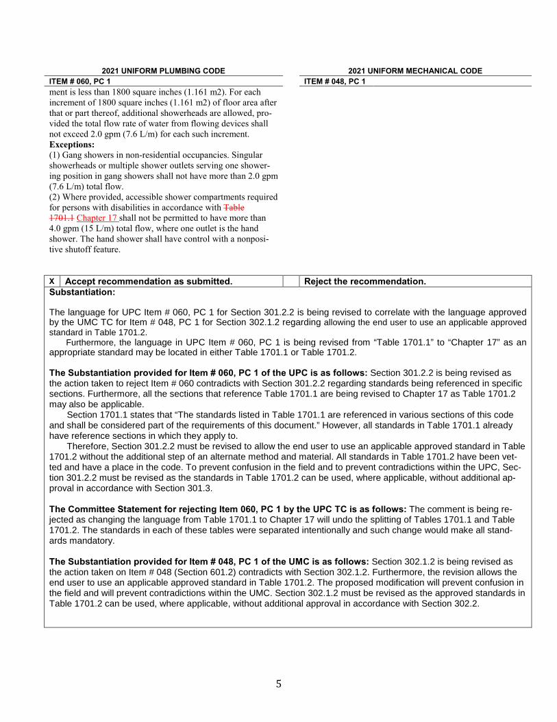
5
2021 UNIFORM PLUMBING CODE 2021 UNIFORM MECHANICAL CODE ITEM # 060, PC 1 ITEM # 048, PC 1 ment is less than 1800 square inches (1.161 m2). For each increment of 1800 square inches (1.161 m2) of floor area after that or part thereof, additional showerheads are allowed, pro-vided the total flow rate of water from flowing devices shall not exceed 2.0 gpm (7.6 L/m) for each such increment. Exceptions: (1) Gang showers in non-residential occupancies. Singular showerheads or multiple shower outlets serving one shower-ing position in gang showers shall not have more than 2.0 gpm (7.6 L/m) total flow. (2) Where provided, accessible shower compartments required for persons with disabilities in accordance with Table 1701.1 Chapter 17 shall not be permitted to have more than 4.0 gpm (15 L/m) total flow, where one outlet is the hand shower. The hand shower shall have control with a nonposi-tive shutoff feature. X Accept recommendation as submitted. Reject the recommendation. Substantiation: The language for UPC Item # 060, PC 1 for Section 301.2.2 is being revised to correlate with the language approved by the UMC TC for Item # 048, PC 1 for Section 302.1.2 regarding allowing the end user to use an applicable approved standard in Table 1701.2. Furthermore, the language in UPC Item # 060, PC 1 is being revised from “Table 1701.1” to “Chapter 17” as an appropriate standard may be located in either Table 1701.1 or Table 1701.2. The Substantiation provided for Item # 060, PC 1 of the UPC is as follows: Section 301.2.2 is being revised as the action taken to reject Item # 060 contradicts with Section 301.2.2 regarding standards being referenced in specific sections. Furthermore, all the sections that reference Table 1701.1 are being revised to Chapter 17 as Table 1701.2 may also be applicable. Section 1701.1 states that “The standards listed in Table 1701.1 are referenced in various sections of this code and shall be considered part of the requirements of this document.” However, all standards in Table 1701.1 already have reference sections in which they apply to. Therefore, Section 301.2.2 must be revised to allow the end user to use an applicable approved standard in Table 1701.2 without the additional step of an alternate method and material. All standards in Table 1701.2 have been vet-ted and have a place in the code. To prevent confusion in the field and to prevent contradictions within the UPC, Sec-tion 301.2.2 must be revised as the standards in Table 1701.2 can be used, where applicable, without additional ap-proval in accordance with Section 301.3.
The Committee Statement for rejecting Item 060, PC 1 by the UPC TC is as follows: The comment is being re-jected as changing the language from Table 1701.1 to Chapter 17 will undo the splitting of Tables 1701.1 and Table 1701.2. The standards in each of these tables were separated intentionally and such change would make all stand-ards mandatory. The Substantiation provided for Item # 048, PC 1 of the UMC is as follows: Section 302.1.2 is being revised as the action taken on Item # 048 (Section 601.2) contradicts with Section 302.1.2. Furthermore, the revision allows the end user to use an applicable approved standard in Table 1701.2. The proposed modification will prevent confusion in the field and will prevent contradictions within the UMC. Section 302.1.2 must be revised as the approved standards in Table 1701.2 can be used, where applicable, without additional approval in accordance with Section 302.2.
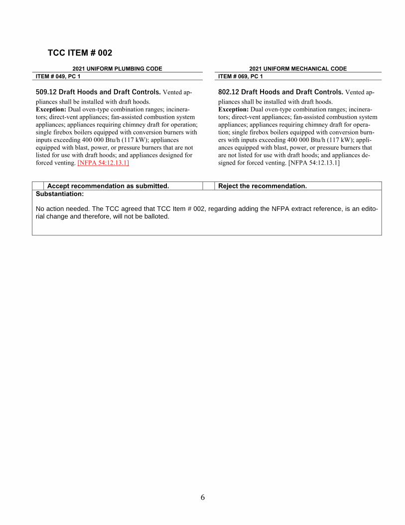
6
TCC ITEM # 002
2021 UNIFORM PLUMBING CODE 2021 UNIFORM MECHANICAL CODE ITEM # 049, PC 1 ITEM # 069, PC 1 509.12 Draft Hoods and Draft Controls. Vented ap-pliances shall be installed with draft hoods. Exception: Dual oven-type combination ranges; incinera-tors; direct-vent appliances; fan-assisted combustion system appliances; appliances requiring chimney draft for operation; single firebox boilers equipped with conversion burners with inputs exceeding 400 000 Btu/h (117 kW); appliances equipped with blast, power, or pressure burners that are not listed for use with draft hoods; and appliances designed for forced venting. [NFPA 54:12.13.1]
802.12 Draft Hoods and Draft Controls. Vented ap-pliances shall be installed with draft hoods. Exception: Dual oven-type combination ranges; incinera-tors; direct-vent appliances; fan-assisted combustion system appliances; appliances requiring chimney draft for opera-tion; single firebox boilers equipped with conversion burn-ers with inputs exceeding 400 000 Btu/h (117 kW); appli-ances equipped with blast, power, or pressure burners that are not listed for use with draft hoods; and appliances de-signed for forced venting. [NFPA 54:12.13.1]
Accept recommendation as submitted. Reject the recommendation. Substantiation: No action needed. The TCC agreed that TCC Item # 002, regarding adding the NFPA extract reference, is an edito-rial change and therefore, will not be balloted.
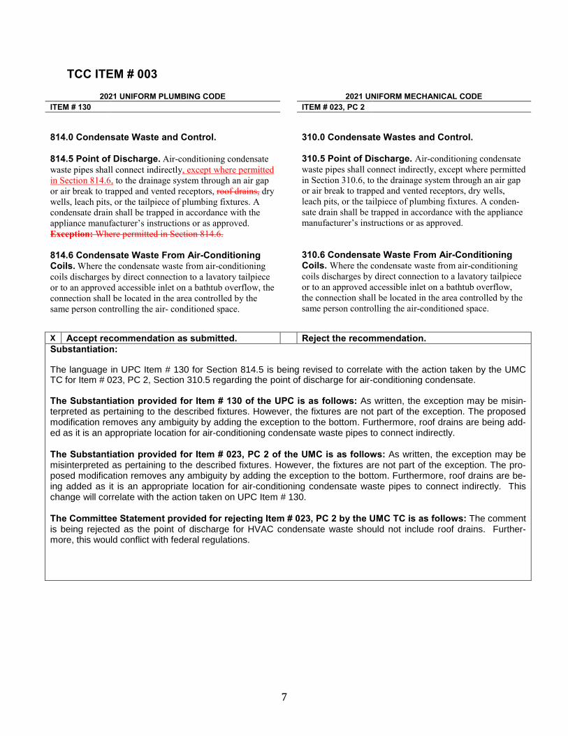
7
TCC ITEM # 003
2021 UNIFORM PLUMBING CODE
2021 UNIFORM MECHANICAL CODE ITEM # 130 ITEM # 023, PC 2 814.0 Condensate Waste and Control. 814.5 Point of Discharge. Air-conditioning condensate waste pipes shall connect indirectly, except where permitted in Section 814.6, to the drainage system through an air gap or air break to trapped and vented receptors, roof drains, dry wells, leach pits, or the tailpiece of plumbing fixtures. A condensate drain shall be trapped in accordance with the appliance manufacturer’s instructions or as approved. Exception: Where permitted in Section 814.6. 814.6 Condensate Waste From Air-Conditioning Coils. Where the condensate waste from air-conditioning coils discharges by direct connection to a lavatory tailpiece or to an approved accessible inlet on a bathtub overflow, the connection shall be located in the area controlled by the same person controlling the air- conditioned space.
310.0 Condensate Wastes and Control. 310.5 Point of Discharge. Air-conditioning condensate waste pipes shall connect indirectly, except where permitted in Section 310.6, to the drainage system through an air gap or air break to trapped and vented receptors, dry wells, leach pits, or the tailpiece of plumbing fixtures. A conden-sate drain shall be trapped in accordance with the appliance manufacturer’s instructions or as approved. 310.6 Condensate Waste From Air-Conditioning Coils. Where the condensate waste from air-conditioning coils discharges by direct connection to a lavatory tailpiece or to an approved accessible inlet on a bathtub overflow, the connection shall be located in the area controlled by the same person controlling the air-conditioned space.
X Accept recommendation as submitted. Reject the recommendation. Substantiation: The language in UPC Item # 130 for Section 814.5 is being revised to correlate with the action taken by the UMC TC for Item # 023, PC 2, Section 310.5 regarding the point of discharge for air-conditioning condensate. The Substantiation provided for Item # 130 of the UPC is as follows: As written, the exception may be misin-terpreted as pertaining to the described fixtures. However, the fixtures are not part of the exception. The proposed modification removes any ambiguity by adding the exception to the bottom. Furthermore, roof drains are being add-ed as it is an appropriate location for air-conditioning condensate waste pipes to connect indirectly. The Substantiation provided for Item # 023, PC 2 of the UMC is as follows: As written, the exception may be misinterpreted as pertaining to the described fixtures. However, the fixtures are not part of the exception. The pro-posed modification removes any ambiguity by adding the exception to the bottom. Furthermore, roof drains are be-ing added as it is an appropriate location for air-conditioning condensate waste pipes to connect indirectly. This change will correlate with the action taken on UPC Item # 130. The Committee Statement provided for rejecting Item # 023, PC 2 by the UMC TC is as follows: The comment is being rejected as the point of discharge for HVAC condensate waste should not include roof drains. Further-more, this would conflict with federal regulations.
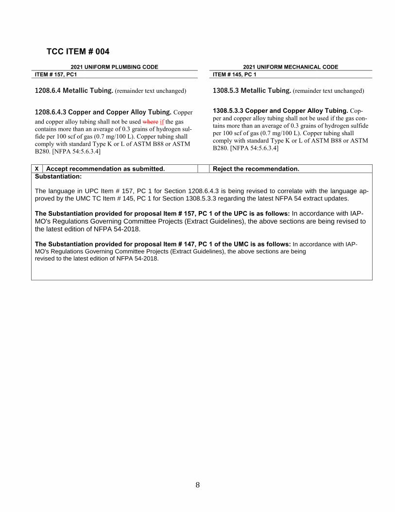
8
TCC ITEM # 004
2021 UNIFORM PLUMBING CODE 2021 UNIFORM MECHANICAL CODE ITEM # 157, PC1 ITEM # 145, PC 1 1208.6.4 Metallic Tubing. (remainder text unchanged) 1208.6.4.3 Copper and Copper Alloy Tubing. Copper and copper alloy tubing shall not be used where if the gas contains more than an average of 0.3 grains of hydrogen sul-fide per 100 scf of gas (0.7 mg/100 L). Copper tubing shall comply with standard Type K or L of ASTM B88 or ASTM B280. [NFPA 54:5.6.3.4]
1308.5.3 Metallic Tubing. (remainder text unchanged) 1308.5.3.3 Copper and Copper Alloy Tubing. Cop-per and copper alloy tubing shall not be used if the gas con-tains more than an average of 0.3 grains of hydrogen sulfide per 100 scf of gas (0.7 mg/100 L). Copper tubing shall comply with standard Type K or L of ASTM B88 or ASTM B280. [NFPA 54:5.6.3.4]
X Accept recommendation as submitted. Reject the recommendation. Substantiation: The language in UPC Item # 157, PC 1 for Section 1208.6.4.3 is being revised to correlate with the language ap-proved by the UMC TC Item # 145, PC 1 for Section 1308.5.3.3 regarding the latest NFPA 54 extract updates. The Substantiation provided for proposal Item # 157, PC 1 of the UPC is as follows: In accordance with IAP-MO's Regulations Governing Committee Projects (Extract Guidelines), the above sections are being revised to the latest edition of NFPA 54-2018. The Substantiation provided for proposal Item # 147, PC 1 of the UMC is as follows: In accordance with IAP-MO's Regulations Governing Committee Projects (Extract Guidelines), the above sections are being revised to the latest edition of NFPA 54-2018.
9
TCC ITEM # 005
2021 UNIFORM PLUMBING CODE 2021 UNIFORM MECHANICAL CODE ITEM # 157 PC 1 ITEM # 137 1208.6.10.6 Metallic Pipe Fittings. Metallic fittings shall comply with the following: (1) Threaded fittings in sizes larger than 4 inches (100 mm) shall not be used. (2) Fittings used with steel, stainless steel, or wrought-iron pipe shall be steel, stainless steel, copper alloy, malleable iron, or cast-iron. (3) Fittings used with copper or copper alloy pipe shall be copper or copper alloy. (4) Fittings used with aluminum alloy pipe shall be alumi-num alloy. (5) Cast-iron fittings shall comply with the following: (a) Flanges shall be permitted. (b) Bushings shall not be used. (c) Fittings shall not be used in systems containing flamma-ble gas-air mixtures. (d) Fittings in sizes 4 inches (100 mm) and larger shall not be used indoors unless approved by the Authority Having Juris-diction. (e) Fittings in sizes 6 inches (150 mm) and larger shall not be used unless approved by the Authority Having Jurisdiction. (6) Aluminum alloy fitting threads shall not form the joint seal. (7) Zinc-aluminum alloy fittings shall not be used in systems containing flammable gas-air mixtures. (8) Special fittings such as couplings, proprietary-type joints, saddle tees, gland-type compression fittings, and flared, flareless, or compression-type tubing fittings shall be as fol-lows: (a) Used within the fitting manufacturer’s pressure- temperature recommendations. (b) Used within the service conditions anticipated with re-spect to vibration, fatigue, thermal expansion, or contraction. (c) Acceptable to the Authority Having Jurisdiction. 9) When pipe fittings are drilled and tapped in the field, the operation shall be in accordance with the following: (a) The operation shall be performed on systems having operating pressures of 5 psi (34 kPa) or less. (b) The operation shall be performed by the gas supplier or their designated representative. (c) The drilling and tapping operation shall be performed in accordance with written procedures prepared by the gas supplier. (d) The fittings shall be located outdoors. (e) The tapped fitting assembly shall be inspected and proven to be free of leaks. [NFPA 54:5.6.7.5 (1-8)]
1308.5.7.5 Metallic Pipe Fittings. Metallic pipe fittings shall comply with the following: (1) Threaded fittings in sizes exceeding 4 inches (100 mm) shall not be used unless acceptable to the Authority Having Jurisdiction. (2) Fittings used with steel, stainless steel, or wrought-iron pipe shall be steel, stainless steel, copper alloy, bronze, malle-able iron, or cast-iron. (3) Fittings used with copper or copper alloy pipe shall be copper or copper alloy. (4) Fittings used with aluminum alloy pipe shall be of alumi-num alloy. (5) Cast-iron fittings shall comply with the following: (a) Flanges shall be permitted. (b) Bushings shall not be used. (c) Fittings shall not be used in systems containing flammable gas-air mixtures. (d) Fittings in sizes 4 inches (100 mm) and larger shall not be used indoors unless approved by the Authority Having Juris-diction. (e) Fittings in sizes 6 inches (150 mm) and larger shall not be used unless approved by the Authority Having Jurisdiction. (6) Aluminum alloy fitting threads shall not form the joint seal. (7) Zinc-aluminum alloy fittings shall not be used in systems containing flammable gas-air mixtures. (8) Special fittings such as couplings;, proprietary-type joints;, saddle tees;, gland-type compression fittings;, and flared, flareless, or compression-type tubing fittings shall be as follows: (a) Used within the fitting manufacturer’s pressure tempera-ture recommendations. (b) Used within the service conditions anticipated with respect to vibration, fatigue, thermal expansion, or contraction. (c) Installed or braced to prevent separation of the joint by gas pressure or external physical damage. (dc) Acceptable to the Authority Having Jurisdiction. 9) When pipe fittings are drilled and tapped in the field, the operation shall be in accordance with the following: (a) The operation shall be performed on systems having operating pressures of 5 psi (34 kPa) or less. (b) The operation shall be performed by the gas supplier or their designated representative. (c) The drilling and tapping operation shall be performed in accordance with written procedures prepared by the gas supplier. (d) The fittings shall be located outdoors. (e) The tapped fitting assembly shall be inspected and
10
2021 UNIFORM PLUMBING CODE 2021 UNIFORM MECHANICAL CODE ITEM # 157 PC 1 ITEM # 137
proven to be free of leaks. [NFPA 54:5.6.7.5]
X Accept recommendation as submitted. Reject the recommendation. Substantiation: The language for UMC Item # 137 for Section 1308.5.7.5 is being revised to correlate with language approved by the UPC TC for Item # 157, PC 1 for Section 1208.6.10.6 regarding the latest NFPA 54 extract updates. Furthermore, the TCC is adding UPC Section 1208.4.10.6(9) and UMC Section 1308.5.7.5(9) to correlate with the latest NFPA 54-2018 extracts as required in accordance with IAPMO’s Regulations Governing Committee Projects (Extract Guidelines) regarding fuel gas metallic fittings that are tapped or drilled in the field. The Substantiation provided for proposal Item # 157 of the UPC is as follows: In accordance with IAPMO's Regu-lations Governing Committee Projects (Extract Guidelines), the above sections are being revised to the latest edition of NFPA 54-2018. The Substantiation provided for proposal Item # 137 of the UMC is as follows: Section 1308.5.8.4 is being re-vised to include “stainless steel.” Stainless steel is a commonly used material in the fuel gas industry. Furthermore, this will be consisting with current industry standards.
11
TCC ITEM # 006
2021 UNIFORM PLUMBING CODE 2021 UNIFORM MECHANICAL CODE ITEM # 152 ITEM # 140.01 (Committee Comment) 1210.0 Gas Piping Installation. 1210.3 Concealed Piping in Buildings. (remaining text unchanged) 1210.3.1 Connections. Where gas piping is to be con-cealed, connections shall be of the following type: (1) Pipe fittings such as elbows, tees, couplings, and right/left nipple/couplings. (2) Joining tubing by brazing (see Section 1208.6.11.2). (3) Press-connect fittings listed to CSA LC 4 for use in con-cealed spaces or that have been demonstrated to sustain, without leakage, forces due to temperature expansion or con-traction, vibration, or fatigue based on their geographic loca-tion, application, or operation. (4) CSST Fittings listed to CSA LC 1. (45) Where necessary to insert fittings in the gas pipe that has been installed in a concealed location, the pipe shall be reconnected by welding, flanges, or the use of a right/left nipple/coupling.
1310.0 Gas Piping Installation.
1310.3 Concealed Piping in Buildings. (remaining text unchanged) 1310.3.1 Connections. Where gas piping is to be con-cealed, connections shall be of the following type: (1) Pipe fittings such as elbows, tees, couplings, and right/left nipple/couplings. (2) Joining tubing by brazing (see Section 1308.5.8.2. (3) Press-connect Fittings listed to CSA LC 4. (4) CSST Fittings listed to CSA LC 1. (5) Where necessary to insert fittings in gas pipe that has been installed in a concealed location, the pipe shall be re-connected by welding, flanges, or the use of a right/left nipple/coupling.
X Accept recommendation as submitted. Reject the recommendation. Substantiation: The language in UPC Item # 152 for Section 1210.3.1 is being revised to correlate with language approved by the UMC TC in Item # 140.01 (Committee Comment) for Section 1310.3.1 regarding press-connect fittings listed to CSA LC 4 and CSST fittings listed to CSA LC 1. The Substantiation provided for Item # 152 of the UPC is as follows: The current language has caused confu-sion of the fittings that are listed and approved for installation in concealed locations. The only fittings that are listed as such are included along with the standards they should be listed to. This language comes directly from NFPA 54 and provides a much clearer understanding for the building official what types of fitting shall be listed and to what standards they shall be listed to. The proposed language will remove confusion in the industry. The Committee Statement provided for amending Item # 152 by the UPC TC is as follows: The current lan-guage is being added back as it is necessary to identify what is required for a concealed fitting. The Substantiation provided for Committee Comment Item # 140.01 of the UMC is as follows: It was in the UMC and exist in NFPA 54. It was dropped during the last code hearings when Press-Connect was added.
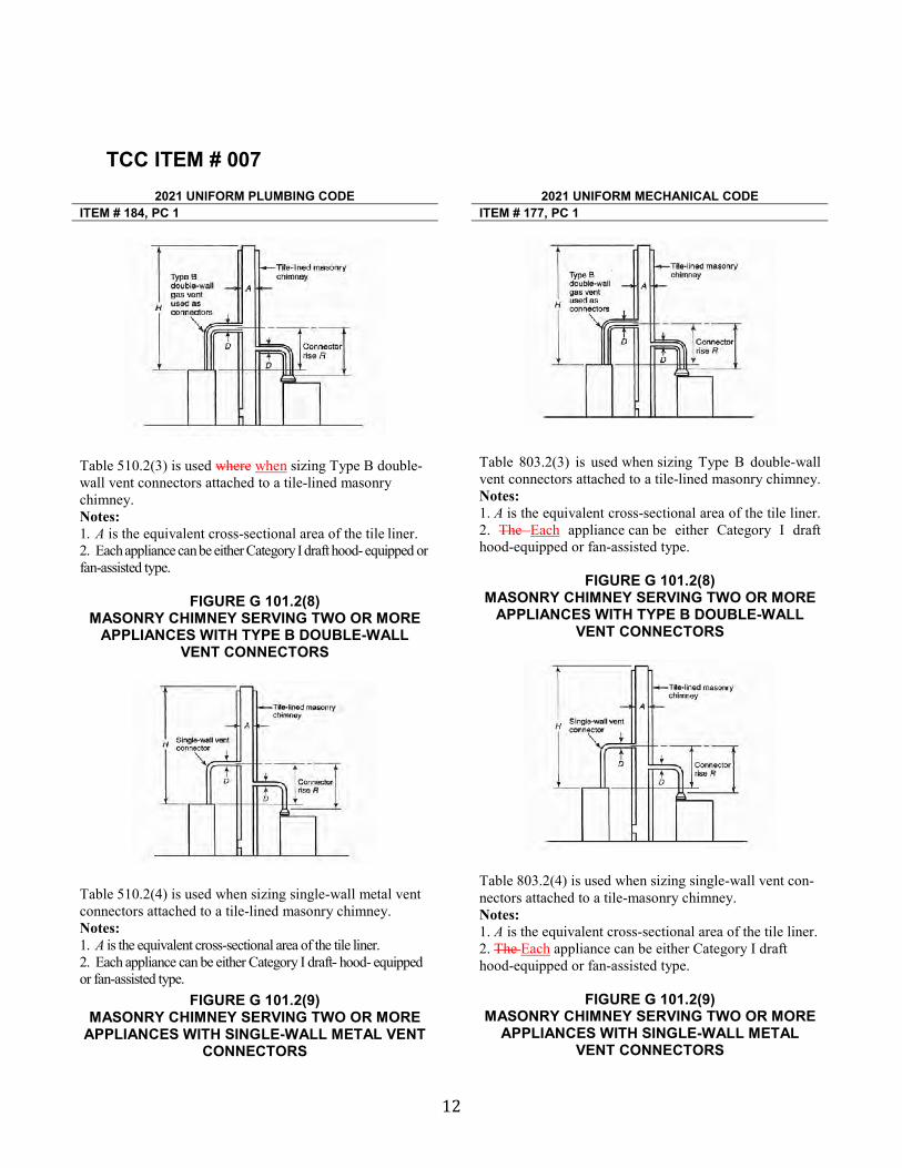
12
TCC ITEM # 007
2021 UNIFORM PLUMBING CODE
2021 UNIFORM MECHANICAL CODE ITEM # 184, PC 1 ITEM # 177, PC 1
Table 510.2(3) is used where when sizing Type B double-wall vent connectors attached to a tile-lined masonry chimney. Notes: 1. A is the equivalent cross-sectional area of the tile liner. 2. Each appliance can be either Category I draft hood- equipped or fan-assisted type.
FIGURE G 101.2(8) MASONRY CHIMNEY SERVING TWO OR MORE
APPLIANCES WITH TYPE B DOUBLE-WALL VENT CONNECTORS
Table 510.2(4) is used when sizing single-wall metal vent connectors attached to a tile-lined masonry chimney. Notes: 1. A is the equivalent cross-sectional area of the tile liner. 2. Each appliance can be either Category I draft- hood- equipped or fan-assisted type.
FIGURE G 101.2(9) MASONRY CHIMNEY SERVING TWO OR MORE
APPLIANCES WITH SINGLE-WALL METAL VENT CONNECTORS
Table 803.2(3) is used when sizing Type B double-wall vent connectors attached to a tile-lined masonry chimney. Notes: 1. A is the equivalent cross-sectional area of the tile liner. 2. The Each appliance can be either Category I draft hood-equipped or fan-assisted type.
FIGURE G 101.2(8) MASONRY CHIMNEY SERVING TWO OR MORE
APPLIANCES WITH TYPE B DOUBLE-WALL VENT CONNECTORS
Table 803.2(4) is used when sizing single-wall vent con-nectors attached to a tile-masonry chimney. Notes: 1. A is the equivalent cross-sectional area of the tile liner. 2. The Each appliance can be either Category I draft hood-equipped or fan-assisted type.
FIGURE G 101.2(9)
MASONRY CHIMNEY SERVING TWO OR MORE APPLIANCES WITH SINGLE-WALL METAL
VENT CONNECTORS
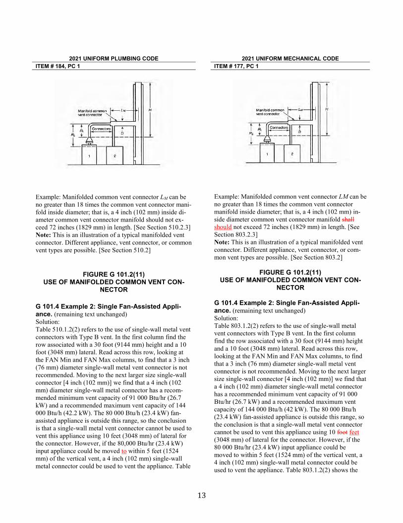
13
2021 UNIFORM PLUMBING CODE
2021 UNIFORM MECHANICAL CODE
ITEM # 184, PC 1 ITEM # 177, PC 1
Example: Manifolded common vent connector LM can be no greater than 18 times the common vent connector mani-fold inside diameter; that is, a 4 inch (102 mm) inside di-ameter common vent connector manifold should not ex-ceed 72 inches (1829 mm) in length. [See Section 510.2.3] Note: This is an illustration of a typical manifolded vent connector. Different appliance, vent connector, or common vent types are possible. [See Section 510.2]
FIGURE G 101.2(11) USE OF MANIFOLDED COMMON VENT CON-
NECTOR
G 101.4 Example 2: Single Fan-Assisted Appli-ance. (remaining text unchanged) Solution: Table 510.1.2(2) refers to the use of single-wall metal vent connectors with Type B vent. In the first column find the row associated with a 30 foot (9144 mm) height and a 10 foot (3048 mm) lateral. Read across this row, looking at the FAN Min and FAN Max columns, to find that a 3 inch (76 mm) diameter single-wall metal vent connector is not recommended. Moving to the next larger size single-wall connector [4 inch (102 mm)] we find that a 4 inch (102 mm) diameter single-wall metal connector has a recom-mended minimum vent capacity of 91 000 Btu/hr (26.7 kW) and a recommended maximum vent capacity of 144 000 Btu/h (42.2 kW). The 80 000 Btu/h (23.4 kW) fan-assisted appliance is outside this range, so the conclusion is that a single-wall metal vent connector cannot be used to vent this appliance using 10 feet (3048 mm) of lateral for the connector. However, if the 80,000 Btu/hr (23.4 kW) input appliance could be moved to within 5 feet (1524 mm) of the vertical vent, a 4 inch (102 mm) single-wall metal connector could be used to vent the appliance. Table
Example: Manifolded common vent connector LM can be no greater than 18 times the common vent connector manifold inside diameter; that is, a 4 inch (102 mm) in-side diameter common vent connector manifold shall should not exceed 72 inches (1829 mm) in length. [See Section 803.2.3] Note: This is an illustration of a typical manifolded vent connector. Different appliance, vent connector, or com-mon vent types are possible. [See Section 803.2]
FIGURE G 101.2(11)
USE OF MANIFOLDED COMMON VENT CON-NECTOR
G 101.4 Example 2: Single Fan-Assisted Appli-ance. (remaining text unchanged) Solution: Table 803.1.2(2) refers to the use of single-wall metal vent connectors with Type B vent. In the first column find the row associated with a 30 foot (9144 mm) height and a 10 foot (3048 mm) lateral. Read across this row, looking at the FAN Min and FAN Max columns, to find that a 3 inch (76 mm) diameter single-wall metal vent connector is not recommended. Moving to the next larger size single-wall connector [4 inch (102 mm)] we find that a 4 inch (102 mm) diameter single-wall metal connector has a recommended minimum vent capacity of 91 000 Btu/hr (26.7 kW) and a recommended maximum vent capacity of 144 000 Btu/h (42 kW). The 80 000 Btu/h (23.4 kW) fan-assisted appliance is outside this range, so the conclusion is that a single-wall metal vent connector cannot be used to vent this appliance using 10 foot feet (3048 mm) of lateral for the connector. However, if the 80 000 Btu/hr (23.4 kW) input appliance could be moved to within 5 feet (1524 mm) of the vertical vent, a 4 inch (102 mm) single-wall metal connector could be used to vent the appliance. Table 803.1.2(2) shows the

14
2021 UNIFORM PLUMBING CODE
2021 UNIFORM MECHANICAL CODE
ITEM # 184, PC 1 ITEM # 177, PC 1 510.1.2(2) shows the acceptable range of vent capacities for a 4 inch (102 mm) vent with 5 feet (1524 mm) of lat-eral to be between 72 000 Btu/h (21.1 kW) and 157 000 Btu/h (46 kW).
If the appliance cannot be moved closer to the vertical vent, a Type B vent could be used as the connector materi-al. In this case, Table 510.1.2(1) shows that, for a 30 foot (9144 mm) high vent with 10 feet (3048 mm) of lateral, the acceptable range of vent capacities for a 4 inch (102 mm) diameter vent attached to a fan-assisted appliance is between 37 000 Btu/h (10.8 kW) and 150 000 Btu/h (44 kW).
acceptable range of vent capacities for a 4 inch (102 mm) vent with 5 feet (1524 mm) of lateral to be between 72 000 Btu/h (21.1 kW) and 157 000 Btu/h (46 kW). If the appliance cannot be moved closer to the vertical vent, a Type B vent could be used as the connector mate-rial. In this case, Table 803.1.2(1) shows that, for a 30 foot (9144 mm) high vent with 10 feet (3048 mm) of lateral, the acceptable range of vent capacities for a 4 inch (102 mm) diameter vent attached to a fan-assisted appliance is between 37 000 Btu/h (10.8 kW) and 150 000 Btu/h (44 kW).
X Accept recommendation as submitted. Reject the recommendation. Substantiation: The language in UPC Item # 184, PC 1 for Figure G 101.2(8) and Section G 101.4 and language in UMC Item # 177, PC 1 for Figure G 101.2(8), Figure G 101.2(9), Figure G 101.2(11), and Section G 101.4 are being revised to correlate with the latest NFPA 54 extract updates. The Substantiation provided for Item # 184, PC 1 of the UPC is as follows: In accordance with IAPMO's Regula-tions Governing Committee Projects (Extract Guidelines), the above sections are being revised to the latest edition of NFPA 54-2018. The Substantiation provided for Item # 177, PC 1 of the UMC is as follows: In accordance with IAPMO's Regula-tions Governing Committee Projects (Extract Guidelines), the above sections are being revised to the latest edition of NFPA 54-2018.
MEMORANDUM
TO: UPC/UMC Technical Correlating Committee
FROM: Zalmie Hussein, Staff Liaison
DATE: July 15, 2019
SUBJECT: TCC UPC/UMC Final Ballot Results - July 2019
Dear UPC/UMC Technical Correlating Committee Members: Attached are the final ballot results for the committee recommendations as a result of the actions taken during your recent meeting. 7 Members eligible to Vote 1 Ballot was not received by the final closing date of July 12, 2019 (Holten) (See attached voting results for details) There are two criteria necessary to pass the letter ballot for each item as follows: 1. The number of affirmative votes needed for each item to pass is ¾ affirmative. 2. In all cases, an affirmative vote of at least a simple majority of the total members eligible to vote is required. All of the committee actions for the Technical Correlating Committee Report achieved the necessary ¾ affirmative votes and simple majority on returned ballots. Thank you for your willingness to participate in this Committee. If you have any questions please contact Enrique Gonzalez at (909) 230-5535 or email at [email protected] or Zalmie Hussein at (909) 218-8122 or email at [email protected]. Best Regards, Zalmie Hussein
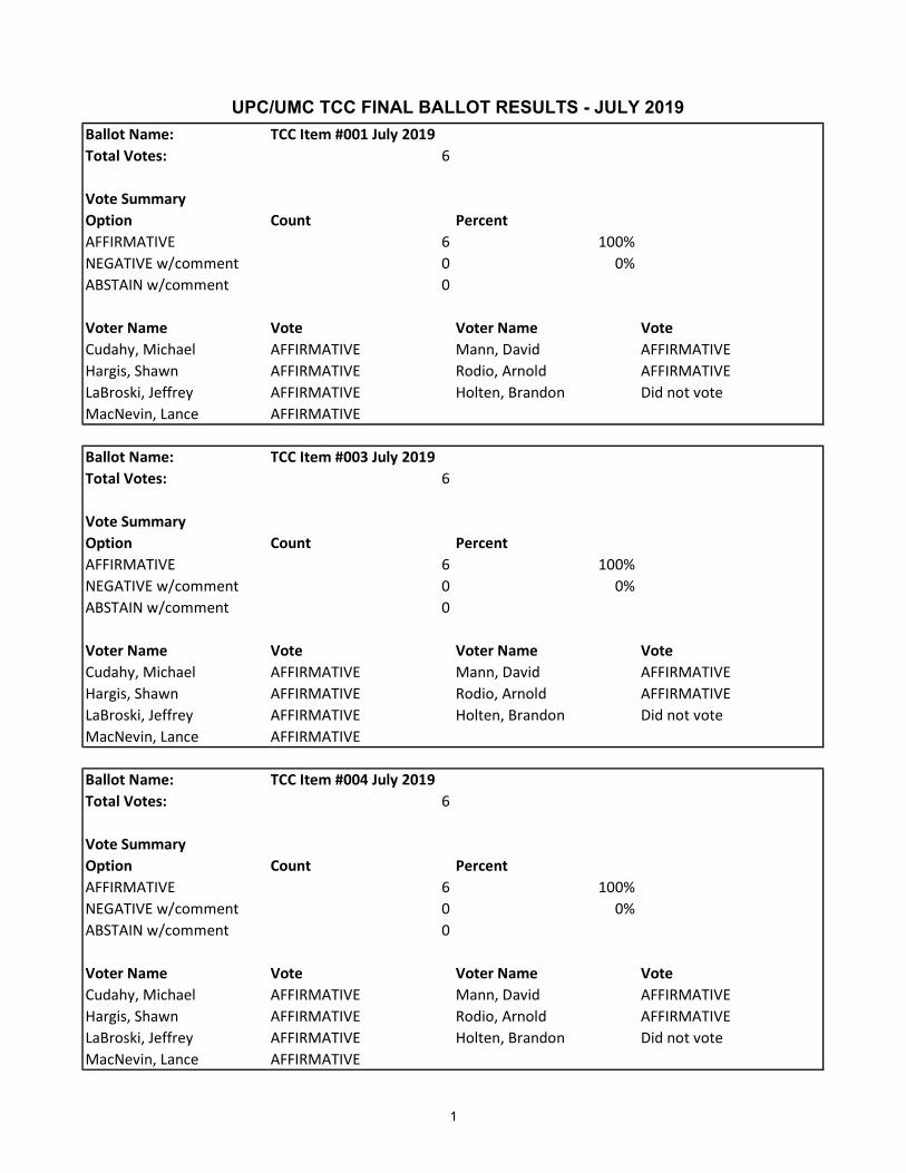
Ballot Name: TCC Item #001 July 2019Total Votes: 6
Vote SummaryOption Count PercentAFFIRMATIVE 6 100%NEGATIVE w/comment 0 0%ABSTAIN w/comment 0
Voter Name Vote Voter Name VoteCudahy, Michael AFFIRMATIVE Mann, David AFFIRMATIVEHargis, Shawn AFFIRMATIVE Rodio, Arnold AFFIRMATIVELaBroski, Jeffrey AFFIRMATIVE Holten, Brandon Did not voteMacNevin, Lance AFFIRMATIVE
Ballot Name: TCC Item #003 July 2019Total Votes: 6
Vote SummaryOption Count PercentAFFIRMATIVE 6 100%NEGATIVE w/comment 0 0%ABSTAIN w/comment 0
Voter Name Vote Voter Name VoteCudahy, Michael AFFIRMATIVE Mann, David AFFIRMATIVEHargis, Shawn AFFIRMATIVE Rodio, Arnold AFFIRMATIVELaBroski, Jeffrey AFFIRMATIVE Holten, Brandon Did not voteMacNevin, Lance AFFIRMATIVE
Ballot Name: TCC Item #004 July 2019Total Votes: 6
Vote SummaryOption Count PercentAFFIRMATIVE 6 100%NEGATIVE w/comment 0 0%ABSTAIN w/comment 0
Voter Name Vote Voter Name VoteCudahy, Michael AFFIRMATIVE Mann, David AFFIRMATIVEHargis, Shawn AFFIRMATIVE Rodio, Arnold AFFIRMATIVELaBroski, Jeffrey AFFIRMATIVE Holten, Brandon Did not voteMacNevin, Lance AFFIRMATIVE
UPC/UMC TCC FINAL BALLOT RESULTS - JULY 2019
1

Ballot Name: TCC Item #005 July 2019Total Votes: 6
Vote SummaryOption Count PercentAFFIRMATIVE 6 100%NEGATIVE w/comment 0 0%ABSTAIN w/comment 0
Voter Name Vote Voter Name VoteCudahy, Michael AFFIRMATIVE Mann, David AFFIRMATIVEHargis, Shawn AFFIRMATIVE Rodio, Arnold AFFIRMATIVELaBroski, Jeffrey AFFIRMATIVE Holten, Brandon Did not voteMacNevin, Lance AFFIRMATIVE
Ballot Name: TCC Item #006 July 2019Total Votes: 6
Vote SummaryOption Count PercentAFFIRMATIVE 6 100%NEGATIVE w/comment 0 0%ABSTAIN w/comment 0
Voter Name Vote Voter Name VoteCudahy, Michael AFFIRMATIVE Mann, David AFFIRMATIVEHargis, Shawn AFFIRMATIVE Rodio, Arnold AFFIRMATIVELaBroski, Jeffrey AFFIRMATIVE Holten, Brandon Did not voteMacNevin, Lance AFFIRMATIVE
Ballot Name: TCC Item #007 July 2019Total Votes: 6
Vote SummaryOption Count PercentAFFIRMATIVE 6 100%NEGATIVE w/comment 0 0%ABSTAIN w/comment 0
Voter Name Vote Voter Name VoteCudahy, Michael AFFIRMATIVE Mann, David AFFIRMATIVEHargis, Shawn AFFIRMATIVE Rodio, Arnold AFFIRMATIVELaBroski, Jeffrey AFFIRMATIVE Holten, Brandon Did not voteMacNevin, Lance AFFIRMATIVE
UPC/UMC TCC FINAL BALLOT RESULTS - JULY 2019
2

Copyright © 2019 By
International Association of Plumbing and Mechanical Officials All Rights Reserved


xv
CHAPTER 1 ADMINISTRATION . . . . . . . . . . . . . 1
101.0 General . . . . . . . . . . . . . . . . . . . . . . . 1
101.1 Title. . . . . . . . . . . . . . . . . . . . . . . . . . 1
101.2 Scope . . . . . . . . . . . . . . . . . . . . . . . . 1
101.3 Purpose . . . . . . . . . . . . . . . . . . . . . . 1
101.4 Unconstitutional . . . . . . . . . . . . . . . . 1
101.5 Validity . . . . . . . . . . . . . . . . . . . . . . . 1
102.0 Applicability. . . . . . . . . . . . . . . . . . . . 1
102.1 Conflicts Between Codes . . . . . . . . . 1
102.2 Existing Installations . . . . . . . . . . . . . 1
102.3 Maintenance . . . . . . . . . . . . . . . . . . . 1
102.4 Additions, Alterations, Renovations, or Repairs . . . . . . . . . . 1
102.5 Health and Safety . . . . . . . . . . . . . . . 1
102.6 Changes in Building
Occupancy . . . . . . . . . . . . . . . . . . . . 1
102.7 Moved Structures . . . . . . . . . . . . . . . 1
102.8 Appendices. . . . . . . . . . . . . . . . . . . . 1
103.0 Duties and Powers of theAuthority Having Jurisdiction . . . . . . 2
103.1 General . . . . . . . . . . . . . . . . . . . . . . . 2
103.2 Liability . . . . . . . . . . . . . . . . . . . . . . . 2
103.3 Applications and Permits . . . . . . . . . 2
103.4 Right of Entry . . . . . . . . . . . . . . . . . . 2
104.0 Permits . . . . . . . . . . . . . . . . . . . . . . . 2
104.1 Permits Required . . . . . . . . . . . . . . . 2
104.2 Exempt Work . . . . . . . . . . . . . . . . . . 2
104.3 Application for Permit . . . . . . . . . . . . 2
104.4 Permit Issuance . . . . . . . . . . . . . . . . 3
104.5 Fees . . . . . . . . . . . . . . . . . . . . . . . . . 4
105.0 Inspections and Testing . . . . . . . . . . 4
105.1 General . . . . . . . . . . . . . . . . . . . . . . . 4
105.2 Required Inspections . . . . . . . . . . . . 4
105.3 Testing of Systems . . . . . . . . . . . . . . 5
105.4 Connection to Service Utilities . . . . . 5
106.0 Violations and Penalties . . . . . . . . . . 5
106.1 General . . . . . . . . . . . . . . . . . . . . . . . 5
106.2 Notices of Correction
or Violation . . . . . . . . . . . . . . . . . . . . 5
106.3 Penalties. . . . . . . . . . . . . . . . . . . . . . 5
106.4 Stop Orders . . . . . . . . . . . . . . . . . . . 5
106.5 Authority to Disconnect Utilities in Emergencies . . . . . . . . . . 6
106.6 Authority to Condemn. . . . . . . . . . . . 6
107.0 Board of Appeals . . . . . . . . . . . . . . . 6
107.1 General . . . . . . . . . . . . . . . . . . . . . . . 6
107.2 Limitations of Authority . . . . . . . . . . . 6
Table 104.5 Mechanical Permit Fees . . . . . . . . . . 7
CHAPTER 2 DEFINITIONS. . . . . . . . . . . . . . . . . . 9
201.0 General . . . . . . . . . . . . . . . . . . . . . . . 9
201.1 Applicability. . . . . . . . . . . . . . . . . . . . 9
202.0 Definition of Terms . . . . . . . . . . . . . . 9
202.1 General . . . . . . . . . . . . . . . . . . . . . . . 9
CHAPTER 3 GENERAL REGULATIONS. . . . . . 23
301.0 General . . . . . . . . . . . . . . . . . . . . . . 23
301.1 Applicability. . . . . . . . . . . . . . . . . . . 23
301.2 Approval . . . . . . . . . . . . . . . . . . . . . 23
301.3 Design of Equipment . . . . . . . . . . . 23
301.4 Electrical Connections . . . . . . . . . . 23
301.5 Oil-Burning Appliances . . . . . . . . . . 23
301.6 Personnel Protection . . . . . . . . . . . 23
302.0 Materials – Standards
and Alternates . . . . . . . . . . . . . . . . 23
302.1 Minimum Standards . . . . . . . . . . . . 23
302.2 Alternate Materials and
Methods of Construction
Equivalency . . . . . . . . . . . . . . . . . . 23
302.3 Alternative
Engineered Design. . . . . . . . . . . . . 24
303.0 Installation . . . . . . . . . . . . . . . . . . . 24
303.1 Listed Appliances . . . . . . . . . . . . . . 24
303.2 Closet or Alcove Installations . . . . . 24
303.3 Unlisted Appliances . . . . . . . . . . . . 24
303.4 Anchorage of Appliances . . . . . . . . 24
303.5 Movement. . . . . . . . . . . . . . . . . . . . 25
303.6 Identification of Equipment . . . . . . . 25
303.7 Liquefied Petroleum Gas Facilities . . . . . . . . . . . . . . . . . 25
303.8 Appliances on Roofs. . . . . . . . . . . . 25
303.9 Avoiding Strain on
Gas Piping . . . . . . . . . . . . . . . . . . . 25
303.10 Clearances . . . . . . . . . . . . . . . . . . . 25
303.11 Installation in Commercial Garages . . . . . . . . . . . . . . . . . . . . . 25
303.12 Installation in Aircraft Hangars . . . . 25
303.13 Pit Location. . . . . . . . . . . . . . . . . . . 25
UNIFORM MECHANICAL CODE - PREPRINT
TABLE OF CONTENTSNote: Page numbers and Section numbers will be updated before publishing.
PREPRINT
xvi
304.0 Accessibility for Service . . . . . . . . . 26
304.1 General . . . . . . . . . . . . . . . . . . . . . . 26
304.2 Sloped Roof . . . . . . . . . . . . . . . . . . 26
304.3 Access to Applianceson Roofs . . . . . . . . . . . . . . . . . . . . . 26
304.4 Appliances in Attics andUnder-Floor Spaces . . . . . . . . . . . . 26
305.0 Location . . . . . . . . . . . . . . . . . . . . . 26
305.1 Installation in Garages . . . . . . . . . . 26
305.2 Flood Hazard Areas . . . . . . . . . . . . 27
305.3 Elevator Shaft . . . . . . . . . . . . . . . . . 27
305.4 Drainage Pan . . . . . . . . . . . . . . . . . 27
306.0 Automatic Control Devices . . . . . . . 27
306.1 General . . . . . . . . . . . . . . . . . . . . . . 27
307.0 Labeling . . . . . . . . . . . . . . . . . . . . . 27
307.1 Fuel-Burning Appliances . . . . . . . . 27
307.2 Electric Heating Appliances . . . . . . 27
307.3 Heat Pump and Electric Cooling Appliances . . . . . . 28
307.4 Absorption Units . . . . . . . . . . . . . . . 28
308.0 Improper Location. . . . . . . . . . . . . . 28
308.1 General . . . . . . . . . . . . . . . . . . . . . . 28
309.0 Workmanship . . . . . . . . . . . . . . . . . 28
309.1 Engineering Practices. . . . . . . . . . . 28
309.2 Concealing Imperfections . . . . . . . . 28
309.3 Installation Practices. . . . . . . . . . . . 28
310.0 Condensate Wastesand Control . . . . . . . . . . . . . . . . . . . 28
310.1 Condensate Disposal . . . . . . . . . . . 28
310.2 Condensate Control . . . . . . . . . . . . 28
310.3 Condensate Waste Pipe Material and Sizing . . . . . . . . . . . . . 29
Table 310.3 Minimum CondensatePipe Size . . . . . . . . . . . . . . . . . . . . 29
310.4 Appliance Condensate
Drains . . . . . . . . . . . . . . . . . . . . . . . 29
310.5 Point of Discharge . . . . . . . . . . . . . 29
310.6 Condensate Waste From Air-Conditioning Coils . . . . . . . . . . . 29
310.7 Plastic Fittings . . . . . . . . . . . . . . . . 29
311.0 Heating or Cooling AirSystem . . . . . . . . . . . . . . . . . . . . . . 29
311.1 Source . . . . . . . . . . . . . . . . . . . . . . 29
311.2 Air Filters . . . . . . . . . . . . . . . . . . . . 29
311.3 Prohibited Source . . . . . . . . . . . . . . 29
311.4 Return-Air Limitations . . . . . . . . . . . 30
312.0 Plumbing Connections . . . . . . . . . . 30
312.1 General . . . . . . . . . . . . . . . . . . . . . . 30
313.0 Hangers and Supports . . . . . . . . . . 30
313.1 General . . . . . . . . . . . . . . . . . . . . . . 30
313.2 Material . . . . . . . . . . . . . . . . . . . . . . 30
313.3 Suspended Piping . . . . . . . . . . . . . 30
313.4 Alignment . . . . . . . . . . . . . . . . . . . . 30
313.5 Underground Installation . . . . . . . . 30
313.6 Hanger Rod Sizes . . . . . . . . . . . . . 30
Table 313.6 Hanger Rod Sizes . . . . . . . . . . . . . 30
313.7 Gas Piping . . . . . . . . . . . . . . . . . . . 30
314.0 Balancing . . . . . . . . . . . . . . . . . . . . 30
314.1 General . . . . . . . . . . . . . . . . . . . . . . 30
315.0 Louvers in Hurricane Prone Regions . . . . . . . . . . . . . . . . 30
315.1 General . . . . . . . . . . . . . . . . . . . . . . 30
316.0 Protection of Piping, Tubing, Materials, and Structures . . . . . . . . 30
316.1 General . . . . . . . . . . . . . . . . . . . . . . 30
316.2 Installation . . . . . . . . . . . . . . . . . . . 31
316.3 Corrosion, Erosion, andMechanical Damage. . . . . . . . . . . . 31
316.4 Protectively Coated Pipe . . . . . . . . 31
316.5 Fire-Resistant Construction . . . . . . 31
316.6 Steel Nail Plates . . . . . . . . . . . . . . . 31
316.7 Sleeves. . . . . . . . . . . . . . . . . . . . . . 31
316.8 Firewalls . . . . . . . . . . . . . . . . . . . . . 31
316.9 Structural Members . . . . . . . . . . . . 31
316.10 Rodentproofing . . . . . . . . . . . . . . . . 31
316.11 Metal Collars. . . . . . . . . . . . . . . . . . 31
317.0 Trenching, Excavation, and Backfill . . . . . . . . . . . . . . . . . . . 31
317.1 Trenches. . . . . . . . . . . . . . . . . . . . . 31
317.2 Tunneling and Driving. . . . . . . . . . . 31
317.3 Open Trenches. . . . . . . . . . . . . . . . 31
317.4 Excavations . . . . . . . . . . . . . . . . . . 31
Table 303.10.1 Reduction of Clearanceswith Specified Forms of Protection . . . . . . . . . . . . . . . . . . 32
Table 313.3 Hangers and Supports . . . . . . . . . . 34
CHAPTER 4 VENTILATION AIR . . . . . . . . . . . . 35
401.0 General . . . . . . . . . . . . . . . . . . . . . . 35
401.1 Applicability. . . . . . . . . . . . . . . . . . . 35
402.0 Ventilation Air . . . . . . . . . . . . . . . . . 35
402.1 Occupiable Spaces. . . . . . . . . . . . . 35
402.2 Natural Ventilation . . . . . . . . . . . . . 35
402.3 Mechanical Ventilation . . . . . . . . . . 35
402.4 Outdoor AirIntake Protection. . . . . . . . . . . . . . . 36
403.0 Ventilation Rates . . . . . . . . . . . . . . 36
UNIFORM MECHANICAL CODE - PREPRINT
PREPRINT
xvii
403.1 General . . . . . . . . . . . . . . . . . . . . . . 36
403.2 Zone Calculations. . . . . . . . . . . . . . 36
403.3 Single-Zone Systems . . . . . . . . . . . 36
403.4 One Hundred Percent Outdoor Air Systems . . . . . . . . . . . 36
403.5 Multiple-Zone Recirculating Systems . . . . . . . . . . 36
403.6 Design for Varying Operating Conditions . . . . . . . . . . . 37
403.7 Exhaust Ventilation. . . . . . . . . . . . . 37
403.8 Dynamic Reset . . . . . . . . . . . . . . . . 37
403.9 Air Classification and Recirculation . . . . . . . . . . . . . . 37
404.0 Multiple-Zone Systems . . . . . . . . . . 38
404.1 General . . . . . . . . . . . . . . . . . . . . . . 38
404.2 Average OutdoorAir Fraction . . . . . . . . . . . . . . . . . . . 38
404.3 Zone Ventilation Efficiency . . . . . . . 38
Table 402.1 Minimum Ventilation Rates in Breathing Zone. . . . . . . . . 39
Table 403.2.2 Zone Air DistributionEffectiveness . . . . . . . . . . . . . . . . . 41
Table 403.5.2 System Ventilation Efficiency . . . . . 41
Table 403.7 Minimum Exhaust Rates. . . . . . . . . 42
CHAPTER 5 EXHAUST SYSTEMS . . . . . . . . . . 43
501.0 General . . . . . . . . . . . . . . . . . . . . . . 43
501.1 Applicability. . . . . . . . . . . . . . . . . . . 43
502.0 Termination. . . . . . . . . . . . . . . . . . . 43
502.1 Exhaust Opening Protection. . . . . . 43
502.2 Termination of Exhaust Ducts . . . . . . . . . . . . . . . . 43
Part I Environmental Air Ducts andProduct-Conveying Systems. . . . 43
503.0 Motors, Fans, and Filters . . . . . . . . 43
503.1 General . . . . . . . . . . . . . . . . . . . . . . 43
503.2 Fans . . . . . . . . . . . . . . . . . . . . . . . . 43
504.0 Environmental Air Ducts . . . . . . . . . 43
504.1 General . . . . . . . . . . . . . . . . . . . . . . 43
504.2 Independent ExhaustSystems . . . . . . . . . . . . . . . . . . . . . 44
504.3 Domestic Range . . . . . . . . . . . . . . . 44
504.4 Clothes Dryers . . . . . . . . . . . . . . . . 44
504.5 Heat (Energy) Recovery Ventilators . . . . . . . . . . . 45
504.6 Gypsum Wallboard Ducts. . . . . . . . 45
505.0 Product-Conveying Systems . . . . . 45
505.1 General . . . . . . . . . . . . . . . . . . . . . . 45
505.2 Incompatible Materials . . . . . . . . . . 45
505.3 Flammability Limit . . . . . . . . . . . . . . 45
505.4 Air Moving Devices. . . . . . . . . . . . . 45
505.5 Generating Flames, Sparks,or Hot Materials . . . . . . . . . . . . . . . 45
505.6 Fire Dampers . . . . . . . . . . . . . . . . . 45
505.7 Fire Detection and Alarm Systems . . . . . . . . . . . . . . . . . . . . . 46
505.8 Product-Conveying DuctsClassification . . . . . . . . . . . . . . . . . 46
505.9 Minimum Velocities and Circulation . . . . . . . . . . . . . . . . 46
Table 505.9 Minimum Duct DesignVelocities . . . . . . . . . . . . . . . . . . . . 46
505.10 Makeup Air . . . . . . . . . . . . . . . . . . . 46
505.11 Hoods and Enclosures . . . . . . . . . . 46
506.0 Product-Conveying Ducts. . . . . . . . 47
506.1 Materials . . . . . . . . . . . . . . . . . . . . . 47
506.2 Construction . . . . . . . . . . . . . . . . . . 47
506.3 Penetrations . . . . . . . . . . . . . . . . . . 47
Table 506.2(1) Minimum Sheet MetalThickness for Round Ducts . . . . . . 48
506.4 Condensate . . . . . . . . . . . . . . . . . . 49
506.5 Fittings . . . . . . . . . . . . . . . . . . . . . . 49
506.6 Explosion Venting. . . . . . . . . . . . . . 49
506.7 Supports . . . . . . . . . . . . . . . . . . . . . 49
506.8 Fire Protection . . . . . . . . . . . . . . . . 49
Table 506.2(2) Minimum Sheet Metal Thickness for Rectangular Ducts . . . . . . . . . . . . . 50
506.9 Protection fromPhysical Damage . . . . . . . . . . . . . . 50
506.10 Duct Clearances . . . . . . . . . . . . . . . 50
Table 506.10.4 Basic Minimum Clearances toUnprotected Surfaces. . . . . . . . . . . 51
506.11 Clearance Reduction Methods . . . . 51
Table 506.11 Reduction of Duct Clearancewith Specified forms ofProtection . . . . . . . . . . . . . . . . . . . . 52
Part II Commercial Hoods andKitchen Ventilation . . . . . . . . . . . . 53
507.0 General Requirements . . . . . . . . . . 53
507.1 Type I Hood Exhaust System . . . . . 53
507.2 Exhaust System . . . . . . . . . . . . . . . 53
507.3 Listed Devices . . . . . . . . . . . . . . . . 53
507.4 Clearance . . . . . . . . . . . . . . . . . . . . 53
507.5 Drawings. . . . . . . . . . . . . . . . . . . . . 54
507.6 Notification of Change . . . . . . . . . . 54
508.0 Type I Hoods . . . . . . . . . . . . . . . . . 55
UNIFORM MECHANICAL CODE - PREPRINT
PREPRINT
xviii
508.1 Where Required . . . . . . . . . . . . . . . 55
508.2 Listed Type IHood Assemblies . . . . . . . . . . . . . . 55
508.3 Construction of Type I Hoods . . . . . 55
508.4 Supports . . . . . . . . . . . . . . . . . . . . . 56
508.5 Hood Size . . . . . . . . . . . . . . . . . . . . 56
Table 508.5.1.2 Extra-Heavy-Duty CookingAppliance Airflow . . . . . . . . . . . . . . 56
Table 508.5.1.3 Heavy-Duty Cooking Appliance Airflow . . . . . . . . . . . . . . 56
Table 508.5.1.4 Medium-Duty Cooking Appliance Airflow . . . . . . . . . . . . . . 57
Table 508.5.1.5 Light-Duty Cooking Appliance Airflow . . . . . . . . . . . . . . 57
508.6 Solid-Fuel Hood Assemblies . . . . . 57
508.7 Exhaust Outlets . . . . . . . . . . . . . . . 57
509.0 Grease Removal Devices in Hoods . . . . . . . . . . . . . . 57
509.1 Grease Removal Devices. . . . . . . . 57
509.2 Installation . . . . . . . . . . . . . . . . . . . 57
509.3 Solid-Fuel Grease RemovalDevices. . . . . . . . . . . . . . . . . . . . . . 58
510.0 Exhaust Duct Systems . . . . . . . . . . 58
510.1 General . . . . . . . . . . . . . . . . . . . . . . 58
510.2 Clearance . . . . . . . . . . . . . . . . . . . . 58
510.3 Openings . . . . . . . . . . . . . . . . . . . . 59
510.4 Listed Grease Ducts . . . . . . . . . . . . 59
510.5 Other Grease Ducts . . . . . . . . . . . . 59
510.6 Exterior Installations . . . . . . . . . . . . 60
510.7 Interior Installations . . . . . . . . . . . . 60
510.8 Underground Installations. . . . . . . . 62
510.9 Termination of Type I HoodExhaust System . . . . . . . . . . . . . . . 62
510.10 Solid-Fuel Duct Systems . . . . . . . . 63
511.0 Air Movement . . . . . . . . . . . . . . . . . 63
511.1 Exhaust Fans for CommercialCooking Operations . . . . . . . . . . . . 63
511.2 Airflow. . . . . . . . . . . . . . . . . . . . . . . 64
511.3 Makeup Air . . . . . . . . . . . . . . . . . . . 65
511.4 Common Duct (Manifold)Systems . . . . . . . . . . . . . . . . . . . . . 66
511.5 Solid-Fuel Air MovementRequirements . . . . . . . . . . . . . . . . . 66
512.0 Auxiliary Equipment . . . . . . . . . . . . 66
512.1 Dampers . . . . . . . . . . . . . . . . . . . . . 66
512.2 Electrical Equipment. . . . . . . . . . . . 66
512.3 Other Equipment . . . . . . . . . . . . . . 66
512.4 Solid-Fuel Auxiliary Equipment . . . . . . . . . . . . 66
513.0 Fire-ExtinguishingEquipment . . . . . . . . . . . . . . . . . . . 66
513.1 General . . . . . . . . . . . . . . . . . . . . . . 66
513.2 Types of Equipment . . . . . . . . . . . . 67
513.3 Simultaneous Operation . . . . . . . . . 68
513.4 Fuel and ElectricPower Shutoff . . . . . . . . . . . . . . . . . 68
513.5 Manual Activation . . . . . . . . . . . . . . 68
513.6 System Annunciation . . . . . . . . . . . 68
513.7 System Supervision . . . . . . . . . . . . 68
513.8 Special Designand Application . . . . . . . . . . . . . . . . 68
513.9 Review and Certification. . . . . . . . . 69
513.10 Installation Requirements . . . . . . . . 69
513.11 Portable Fire Extinguishers . . . . . . 69
513.12 Maintenance . . . . . . . . . . . . . . . . . . 69
513.13 Solid-Fuel Fire-ExtinguishingEquipment . . . . . . . . . . . . . . . . . . . 69
514.0 Procedures for the Use, Inspection, Testing, andMaintenance of Equipment. . . . . . . 69
514.1 Operating Procedures . . . . . . . . . . 69
514.2 Inspection, Testing andMaintenance . . . . . . . . . . . . . . . . . . 69
514.3 Inspection forGrease Buildup. . . . . . . . . . . . . . . . 70
Table 514.3 Schedule of Inspection forGrease Buildup. . . . . . . . . . . . . . . . 70
514.4 Cleaning ofExhaust Systems . . . . . . . . . . . . . . 70
514.5 Cooking Equipment Maintenance . . . . . . . . . . . . . . . . . . 70
515.0 Minimum Safety Requirementsfor Cooking Equipment . . . . . . . . . . 70
515.1 Cooking Equipment . . . . . . . . . . . . 70
515.2 Operating Controls . . . . . . . . . . . . . 71
516.0 Recirculating Systems . . . . . . . . . . 71
516.1 General Requirements . . . . . . . . . . 71
516.2 Design Restrictions. . . . . . . . . . . . . 71
516.3 Interlocks . . . . . . . . . . . . . . . . . . . . 72
516.4 Location and ApplicationRestrictions. . . . . . . . . . . . . . . . . . . 72
516.5 Additional Fire SafetyRequirements . . . . . . . . . . . . . . . . . 72
516.6 Use and Maintenance. . . . . . . . . . . 72
517.0 Solid-FuelCooking Operations . . . . . . . . . . . . 72
517.1 Venting Application. . . . . . . . . . . . . 72
517.2 Location of Appliances . . . . . . . . . . 73
UNIFORM MECHANICAL CODE - PREPRINT
PREPRINT
xix
517.3 Hoods forSolid-Fuel Cooking . . . . . . . . . . . . . 73
517.4 Exhaust Systems forSolid-Fuel Cooking . . . . . . . . . . . . . 73
517.5 Grease Removal Devicesfor Solid-Fuel Cooking . . . . . . . . . . 73
517.6 Air Movement forSolid-Fuel Cooking . . . . . . . . . . . . . 74
517.7 Fire-Extinguishing Equipment for Solid-Fuel Cooking . . . . . . . . . . 74
517.8 Other Safety Requirements . . . . . . 74
518.0 Downdraft Appliances. . . . . . . . . . . 75
518.1 General . . . . . . . . . . . . . . . . . . . . . . 75
518.2 Ventilation System . . . . . . . . . . . . . 75
518.3 Fire-ExtinguishingEquipment . . . . . . . . . . . . . . . . . . . 75
518.4 Airflow Switch orTransducer . . . . . . . . . . . . . . . . . . . 75
518.5 Surface Materials . . . . . . . . . . . . . . 75
519.0 Type II Hood ExhaustSystem Requirements . . . . . . . . . . 75
519.1 Where Required . . . . . . . . . . . . . . . 75
519.2 Construction of Type II Hoods . . . . . . . . . . . . . . . . . . . . . . . 75
519.3 Dishwashing Appliances. . . . . . . . . 75
519.4 Type II Exhaust Duct Systems . . . . 76
519.5 Termination of Type II Hood Exhaust System . . . . . . . . . . 76
519.6 Makeup Air . . . . . . . . . . . . . . . . . . . 76
CHAPTER 6 DUCT SYSTEMS . . . . . . . . . . . . . . 77
601.0 General . . . . . . . . . . . . . . . . . . . . . . 77
601.1 Applicability. . . . . . . . . . . . . . . . . . . 77
601.2 Sizing Requirements . . . . . . . . . . . 77
602.0 Material . . . . . . . . . . . . . . . . . . . . . . 77
602.1 General . . . . . . . . . . . . . . . . . . . . . . 77
602.2 Combustibles WithinDucts or Plenums . . . . . . . . . . . . . . 77
602.3 Metal . . . . . . . . . . . . . . . . . . . . . . . . 77
602.4 Phenolic . . . . . . . . . . . . . . . . . . . . . 77
602.5 Gypsum . . . . . . . . . . . . . . . . . . . . . 77
602.6 Factory-Made Air Ducts . . . . . . . . . 77
602.7 Vibration Isolators. . . . . . . . . . . . . . 77
602.8 Corridors. . . . . . . . . . . . . . . . . . . . . 77
603.0 Installation of Ducts . . . . . . . . . . . . 77
603.1 General . . . . . . . . . . . . . . . . . . . . . . 77
603.2 Under Floor or Crawl Space . . . . . . 78
603.3 Metal Ducts. . . . . . . . . . . . . . . . . . . 78
603.4 Factory-Made Air Ducts . . . . . . . . . 78
603.5 Flexible Air Ducts . . . . . . . . . . . . . . 78
603.6 Plastic Ducts. . . . . . . . . . . . . . . . . . 78
603.7 Protection of Ducts . . . . . . . . . . . . . 79
603.8 Support of Ducts. . . . . . . . . . . . . . . 79
603.9 Protection AgainstFlood Damage . . . . . . . . . . . . . . . . 79
603.10 Joints and Seams of Ducts. . . . . . . 79
Table 603.10 Closure Markings . . . . . . . . . . . . . . 79
603.11 Cross Contamination . . . . . . . . . . . 79
603.12 Underground Installation . . . . . . . . 79
603.13 Air Dispersion Systems . . . . . . . . . 79
604.0 Insulation of Ducts . . . . . . . . . . . . . 79
604.1 General . . . . . . . . . . . . . . . . . . . . . . 79
605.0 Smoke Dampers,Fire Dampers, andCeiling Dampers . . . . . . . . . . . . . . . 80
605.1 Smoke Dampers. . . . . . . . . . . . . . . 80
605.2 Fire Dampers . . . . . . . . . . . . . . . . . 80
605.3 Ceiling Radiation Dampers. . . . . . . 80
605.4 Multiple Arrangements . . . . . . . . . . 80
605.5 Access and Identification . . . . . . . . 80
605.6 Freedom from Interference. . . . . . . 80
605.7 Temperature Classification
of Operating Elements . . . . . . . . . . 80
606.0 Ventilating Ceilings . . . . . . . . . . . . . 80
606.1 General . . . . . . . . . . . . . . . . . . . . . . 80
606.2 Requirements . . . . . . . . . . . . . . . . . 80
607.0 Use of Under-FloorSpace as Supply Plenumfor Dwelling Units . . . . . . . . . . . . . . 81
607.1 General . . . . . . . . . . . . . . . . . . . . . . 81
607.2 Dwelling Units. . . . . . . . . . . . . . . . . 81
607.3 Enclosed. . . . . . . . . . . . . . . . . . . . . 81
607.4 Flammable Materials . . . . . . . . . . . 81
607.5 Access . . . . . . . . . . . . . . . . . . . . . . 81
607.6 Automatic Control . . . . . . . . . . . . . . 81
607.7 Temperature Limit . . . . . . . . . . . . . 81
607.8 Noncombustible Receptacle. . . . . . 81
607.9 Floor Registers . . . . . . . . . . . . . . . . 81
607.10 Exterior Wall and Interior Stud Partitions . . . . . . . . . . . . . . . . 81
607.11 Wall Register . . . . . . . . . . . . . . . . . 81
607.12 Distance from Combustible . . . . . . 81
607.13 Vapor Barrier . . . . . . . . . . . . . . . . . 81
607.14 Prohibited . . . . . . . . . . . . . . . . . . . . 81
608.0 Automatic Shutoffs . . . . . . . . . . . . . 81
608.1 Air-Moving Systemsand Smoke Detectors . . . . . . . . . . . 81
UNIFORM MECHANICAL CODE - PREPRINT
PREPRINT
xx
CHAPTER 7 COMBUSTION AIR . . . . . . . . . . . . 83
701.0 General . . . . . . . . . . . . . . . . . . . . . . 83
701.1 Applicability. . . . . . . . . . . . . . . . . . . 83
701.2 Pressure Difference . . . . . . . . . . . . 83
701.3 Makeup Air . . . . . . . . . . . . . . . . . . . 83
701.4 Indoor Combustion Air . . . . . . . . . . 83
701.5 Indoor Opening Size and Location . . . . . . . . . . . . . . . . . . . . . 83
701.6 Outdoor Combustion Air . . . . . . . . . 83
701.7 Combination Indoor andOutdoor Combustion Air . . . . . . . . . 84
701.8 Engineered Installations . . . . . . . . . 85
701.9 Mechanical Combustion AirSupply. . . . . . . . . . . . . . . . . . . . . . . 85
701.10 Louvers, Grilles, and Screens . . . . . . . . . . . . . . . . . . 85
701.11 Combustion Air Ducts. . . . . . . . . . . 86
701.12 Dampers Prohibited . . . . . . . . . . . . 86
702.0 Extra Device or Attachment . . . . . . 86
702.1 General . . . . . . . . . . . . . . . . . . . . . . 86
CHAPTER 8 CHIMNEYS AND VENTS. . . . . . . . 87
801.0 General . . . . . . . . . . . . . . . . . . . . . . 87
801.1 Applicability. . . . . . . . . . . . . . . . . . . 87
801.2 Venting of Gas
Appliances . . . . . . . . . . . . . . . . . . . 87
801.3 Appliances Fueled
by Other Fuels . . . . . . . . . . . . . . . . 87
802.0 Venting of Appliances. . . . . . . . . . . 87
802.1 Listing . . . . . . . . . . . . . . . . . . . . . . . 87
802.2 Connection toVenting Systems. . . . . . . . . . . . . . . 87
802.3 Design and
Construction . . . . . . . . . . . . . . . . . . 87
802.4 Type of Venting System to be Used . . . . . . . . . . . . . 88
802.5 Masonry, Metal, and Factory-Built Chimneys . . . . . . . . . 88
Table 802.4 Type of Venting System to be Used . . . . . . . . . . . . . 89
802.6 Gas Vents. . . . . . . . . . . . . . . . . . . . 91
Table 802.6.1 Roof Pitch Height . . . . . . . . . . . . . . 92
802.7 Single-Wall Metal Pipe . . . . . . . . . . 94
Table 802.7.3.3 Clearance for Connectors. . . . . . . . 94
802.8 Through-the-Wall Vent Termination. . . . . . . . . . . . . . . . . . . 95
802.9 Condensation Drain . . . . . . . . . . . . 96
802.10 Vent Connectors for Category I Appliances . . . . . . . . . . 96
Table 802.10.1.3 Minimum Thickness for Galvanized Steel Vent Connectors for Low- Heat Appliances . . . . . . . . . . . . . . . 97
Table 802.10.1.4 Minimum Thickness for Steel Vent Connectors for Medium-Heat Appliances . . . . . . . . 97
802.11 Vent Connectors forCategory II, Category III, andCategory IV Appliances . . . . . . . . . 98
802.12 Draft Hoods and DraftControls . . . . . . . . . . . . . . . . . . . . . 98
802.13 Manually OperatedDampers . . . . . . . . . . . . . . . . . . . . . 99
802.14 Obstructions . . . . . . . . . . . . . . . . . . 99
802.15 Automatically OperatedVent Dampers. . . . . . . . . . . . . . . . . 99
803.0 Sizing of Category IVenting Systems. . . . . . . . . . . . . . . 99
803.1 Single Appliance VentTable 803.1.2(1) through Table 803.1.2(6) . . . . . . . . . . . . . . . 99
803.2 Multiple Appliance VentTable 803.2(1) throughTable 803.2(9) . . . . . . . . . . . . . . . 101
Table 803.2.1 Vent Connector Maximum Length . . . . . . . . . . . . . 101
Table 803.1.2(1) Type B Double-WallGas Vent. . . . . . . . . . . . . . . . . . . . 106
Table 803.1.2(2) Type B Double-WallGas Vent. . . . . . . . . . . . . . . . . . . . 109
Table 803.1.2(3) Masonry Chimney. . . . . . . . . . . . . 111
Table 803.1.2(4) Masonry Chimney. . . . . . . . . . . . . 113
Table 803.1.2(5) Single-Wall MetalPipe or Type BAsbestos-Cement Vent. . . . . . . . . 115
Table 803.1.2(6) Exterior Masonry Chimney . . . . . . 116
Table 803.2(1) Type B Double-Wall Vent . . . . . . 117
Table 803.2(2) Type B Double-Wall Vent . . . . . . . 121
Table 803.2(3) Masonry Chimney. . . . . . . . . . . . . 123
Table 803.2(4) Masonry Chimney. . . . . . . . . . . . . 125
Table 803.2(5) Single-Wall MetalPipe or Type BAsbestos – Cement Vent . . . . . . . 127
Table 803.2(6) Exterior Masonry Chimney . . . . . . 127
Table 803.2(7) Exterior Masonry Chimney . . . . . . 128
Table 803.2(8) Exterior Masonry Chimney . . . . . . 129
Table 803.2(9) Exterior Masonry Chimney . . . . . . 130
UNIFORM MECHANICAL CODE - PREPRINT
PREPRINT
xxi
CHAPTER 9 INSTALLATION OF SPECIFIC APPLIANCES. . . . . . . 131
901.0 General . . . . . . . . . . . . . . . . . . . . . 131
901.1 Applicability. . . . . . . . . . . . . . . . . . 131
902.0 General . . . . . . . . . . . . . . . . . . . . . 131
902.1 Nonindustrial Appliance . . . . . . . . 131
902.2 Combustion Air from Bedroom or Bathroom . . . . . . . . . 131
902.3 Added or Converted Appliances . . . . . . . . . . . . . . . . . . 131
902.4 Type of Gas(es) . . . . . . . . . . . . . . 131
902.5 Safety Shutoff Devices forUnlisted LP-Gas ApplianceUsed Indoors . . . . . . . . . . . . . . . . 131
902.6 Fuel Input Rate . . . . . . . . . . . . . . . 131
902.7 Use of Air or Oxygen Under Pressure . . . . . . . . . . . . . . . . . . . . 131
902.8 Building StructuralMembers. . . . . . . . . . . . . . . . . . . . 131
902.9 Flammable Vapors . . . . . . . . . . . . 131
902.10 Solid-Fuel Burning Appliances . . . . . . . . . . . . . . . . . . 131
902.11 Combination of Appliancesand Equipment . . . . . . . . . . . . . . . 131
902.12 Protection of Gas Appliances from Fumes or Gases other thanProducts of Combustion . . . . . . . . 131
902.13 Process Air . . . . . . . . . . . . . . . . . . 132
902.14 Gas Appliance Pressure Regulators . . . . . . . . . . . . . . . . . . 132
902.15 Venting of Gas Appliance Pressure Regulators. . . . . . . . . . . 132
902.16 Bleed Lines for Diaphragm-Type Valves . . . . . . . . 132
903.0 Air-Conditioning Appliances . . . . . 132
903.1 Electric Air Conditioners . . . . . . . . 132
903.2 Gas-Fired Air Conditioners and Heat Pumps. . . . . . . . . . . . . . 132
904.0 Central Heating Boilersand Furnaces . . . . . . . . . . . . . . . . 133
904.1 Location . . . . . . . . . . . . . . . . . . . . 133
904.2 Clearance . . . . . . . . . . . . . . . . . . . 133
Table 904.2.2 Clearances toCombustible Material forUnlisted Furnaces and Boilers . . . . . . . . . . . . . . . . . . 134
904.3 Assembly and Installation. . . . . . . 134
904.4 Temperature- orPressure-Limiting Devices . . . . . . 134
904.5 Low-Water Cutoff . . . . . . . . . . . . . 134
904.6 Steam Safety and Pressure-Relief Valves . . . . . . . . . 134
904.7 Furnace Plenums and Air Ducts . . . . . . . . . . . . . . . . . . . . 135
904.8 Refrigeration Coils . . . . . . . . . . . . 135
904.9 Cooling Units Used withHeating Boilers . . . . . . . . . . . . . . . 135
904.10 Furnace (Upright and Horizontal) . . . . . . . . . . . . . . . 135
904.11 Solid-Fuel-Fired Furnaces . . . . . . 135
904.12 Oil-Fired Central Furnaces . . . . . . 135
904.13 Commercial or IndustrialGas Heaters . . . . . . . . . . . . . . . . . 135
904.14 Electric Central Furnaces . . . . . . . 135
905.0 Duct Furnaces . . . . . . . . . . . . . . . 135
905.1 Clearances . . . . . . . . . . . . . . . . . . 135
905.2 Installation ofDuct Furnaces. . . . . . . . . . . . . . . . 135
905.3 Access Panels . . . . . . . . . . . . . . . 135
905.4 Location of Draft Hoods and Controls . . . . . . . . . . . . . . . . . 135
905.5 Circulating Air . . . . . . . . . . . . . . . . 135
905.6 Duct Furnaces Used withRefrigeration Systems . . . . . . . . . 136
905.7 Installation in Commercial Garages andAircraft Hangars . . . . . . . . . . . . . . 136
905.8 Electric Duct Heaters . . . . . . . . . . 136
906.0 Floor Furnaces . . . . . . . . . . . . . . . 136
906.1 Installation . . . . . . . . . . . . . . . . . . 136
906.2 TemperatureLimit Controls . . . . . . . . . . . . . . . . 136
906.3 Combustion andCirculating Air . . . . . . . . . . . . . . . . 136
906.4 Placement. . . . . . . . . . . . . . . . . . . 136
906.5 Bracing . . . . . . . . . . . . . . . . . . . . . 136
906.6 Support . . . . . . . . . . . . . . . . . . . . . 136
906.7 Clearance . . . . . . . . . . . . . . . . . . . 136
906.8 Access . . . . . . . . . . . . . . . . . . . . . 137
906.9 Seepage Pan . . . . . . . . . . . . . . . . 137
906.10 Wind Protection . . . . . . . . . . . . . . 137
906.11 Upper-Floor Installations . . . . . . . 137
906.12 First Floor Installation . . . . . . . . . . 137
906.13 Oil-Fired Floor Furnaces. . . . . . . . 137
907.0 Wall Furnaces. . . . . . . . . . . . . . . . 137
907.1 Installation . . . . . . . . . . . . . . . . . . 137
907.2 Location . . . . . . . . . . . . . . . . . . . . 138
907.3 Combustion and Circulating Air . . 138
907.4 Oil-Fired Wall Furnaces . . . . . . . . 138
908.0 Clothes Dryers . . . . . . . . . . . . . . . 138
UNIFORM MECHANICAL CODE - PREPRINT
PREPRINT
xxii
908.1 Electric Clothes Dryers . . . . . . . . . 138
908.2 Gas-Fired Clothes Dryers. . . . . . . 138
909.0 Conversion Burners . . . . . . . . . . . 138
909.1 General . . . . . . . . . . . . . . . . . . . . . 138
910.0 Burner Assemblies . . . . . . . . . . . . 138
910.1 Oil Burners . . . . . . . . . . . . . . . . . . 138
910.2 Gas Burners . . . . . . . . . . . . . . . . . 138
911.0 Decorative Appliances for Installation in Vented Fireplaces . . . . . . . . . . . . . . . . . . . 138
911.1 Prohibited Installations . . . . . . . . . 138
911.2 Installation . . . . . . . . . . . . . . . . . . 138
911.3 Fireplace Screens. . . . . . . . . . . . . 138
912.0 Gas Fireplaces, Vented . . . . . . . . 138
912.1 Prohibited Installations . . . . . . . . . 138
912.2 Installation . . . . . . . . . . . . . . . . . . 138
Table 911.2 Free Opening Area of ChimneyDamper for Venting Flue Gasesfrom Unlisted DecorativeAppliances for Installationin Vented Fireplaces. . . . . . . . . . . 139
912.3 Combustion andCirculating Air . . . . . . . . . . . . . . . . 139
913.0 Factory-Built Fireplaces and Fireplace Stoves . . . . . . . . . . 139
913.1 Factory-Built Fireplaces . . . . . . . . 139
913.2 Fireplace Stoves. . . . . . . . . . . . . . 139
913.3 Fireplace Accessories . . . . . . . . . 139
914.0 Non-Recirculating DirectGas-Fired Industrial Air Heaters . . . . . . . . . . . . . . . . . . 139
914.1 Application . . . . . . . . . . . . . . . . . . 139
914.2 Prohibited Installations . . . . . . . . . 139
914.3 Installation . . . . . . . . . . . . . . . . . . 139
914.4 Clearance from CombustibleMaterials . . . . . . . . . . . . . . . . . . . . 139
914.5 Air Supply . . . . . . . . . . . . . . . . . . . 139
914.6 Atmospheric Vents, GasReliefs, or Bleeds . . . . . . . . . . . . . 140
914.7 Relief Openings . . . . . . . . . . . . . . 140
914.8 Purging . . . . . . . . . . . . . . . . . . . . . 140
915.0 Recirculating Direct Gas-FiredIndustrial Air Heaters . . . . . . . . . . 140
915.1 Application . . . . . . . . . . . . . . . . . . 140
915.2 Prohibited Installations . . . . . . . . . 140
915.3 Installation . . . . . . . . . . . . . . . . . . 140
915.4 Clearance from CombustibleMaterials . . . . . . . . . . . . . . . . . . . . 140
915.5 Air Supply . . . . . . . . . . . . . . . . . . . 140
915.6 Atmospheric Vents, Gas Reliefs, or Bleeds . . . . . . . . . . . . . 140
915.7 Relief Openings . . . . . . . . . . . . . . 140
915.8 Purging . . . . . . . . . . . . . . . . . . . . . 140
916.0 Room Heaters . . . . . . . . . . . . . . . 140
916.1 Electric Room Heaters . . . . . . . . . 140
916.2 Gas-Fired Room Heaters . . . . . . . 140
916.3 Solid-Fuel-Type Room Heaters . . . . . . . . . . . . . . . 141
917.0 Unit Heaters . . . . . . . . . . . . . . . . . 141
917.1 Support . . . . . . . . . . . . . . . . . . . . 141
917.2 Clearance . . . . . . . . . . . . . . . . . . 141
917.3 Combustion and Circulating Air . . . . . . . . . . . . . . . . 141
917.4 Ductwork. . . . . . . . . . . . . . . . . . . . 141
917.5 Installation in CommercialGarages and Aircraft Hangars . . . . . . . . . . . . . . . . . . . . 141
917.6 Oil-Fired Unit Heaters. . . . . . . . . . 141
918.0 Food Service Appliance, Floor Mounted . . . . . . . . . . . . . . . 142
918.1 Clearance for ListedAppliances . . . . . . . . . . . . . . . . . . 142
918.2 Clearance for UnlistedAppliances . . . . . . . . . . . . . . . . . . 142
918.3 Mounting on Combustible Floors . . . . . . . . . . . . . . . . . . . . . . 142
918.4 Installation on NoncombustibleFloors . . . . . . . . . . . . . . . . . . . . . . 142
918.5 Combustible Material Adjacent to Cooking Top . . . . . . . 142
918.6 Use with Casters . . . . . . . . . . . . . 142
918.7 Level Installation. . . . . . . . . . . . . . 142
918.8 Ventilation. . . . . . . . . . . . . . . . . . . 142
919.0 Food Service Appliances, Counter Appliances . . . . . . . . . . . 142
919.1 Vertical Clearance . . . . . . . . . . . . 142
919.2 Clearance for Listed Appliances . . . . . . . . . . . . . . . . . . 142
919.3 Clearance for UnlistedAppliances . . . . . . . . . . . . . . . . . . 143
919.4 Mounting of Unlisted Appliances . . . . . . . . . . . . . . . . . . 143
920.0 Household Cooking Appliances . . . . . . . . . . . . . . . . . . 143
920.1 Electric HouseholdCooking Appliances . . . . . . . . . . . 143
920.2 Gas-Fired Household CookingAppliances . . . . . . . . . . . . . . . . . . 143
920.3 Floor-Mounted Units . . . . . . . . . . . 143
920.4 Built-In Units . . . . . . . . . . . . . . . . . 143
UNIFORM MECHANICAL CODE - PREPRINT
PREPRINT
xxiii
921.0 Cooking Appliances Listing . . . . . 144
921.1 Commercial Electric Ranges . . . . . . . . . . . . . . . . . . . . . 144
921.2 Commercial Wood-Fired Baking Ovens . . . . . . . . . . . . . . . . 144
921.3 Oil-Burning Ranges . . . . . . . . . . . 144
922.0 Open-Top Broiler Units. . . . . . . . . 144
922.1 Listed Units. . . . . . . . . . . . . . . . . . 144
922.2 Unlisted Units . . . . . . . . . . . . . . . . 144
922.3 Protection Above Domestic Units . . . . . . . . . . . . . . . 144
922.4 Commercial Units . . . . . . . . . . . . . 144
923.0 Outdoor Cooking Appliances . . . . . . . . . . . . . . . . . . 144
923.1 Listed Units. . . . . . . . . . . . . . . . . . 144
923.2 Unlisted Units . . . . . . . . . . . . . . . . 144
924.0 Illuminating Appliances. . . . . . . . . 144
924.1 Clearances for Listed Appliances . . . . . . . . . . . . . . . . . . 144
924.2 Clearances for UnlistedAppliances . . . . . . . . . . . . . . . . . . 144
Table 924.2.1 Clearances for Unlisted OutdoorOpen-Flame IlluminatingAppliances . . . . . . . . . . . . . . . . . . 145
924.3 Mounting on Buildings . . . . . . . . . 145
924.4 Mounting on Posts . . . . . . . . . . . . 145
924.5 Appliance Pressure Regulators . . . . . . . . . . . . . . . . . . 145
925.0 Incinerators and Crematories . . . . 145
925.1 Field Constructed Commercial-Industrial Incinerators. . . . . . . . . . . . . . . . . . 145
925.2 Factory-Built Commercial Crematories . . . . . . . 145
925.3 Residential Incinerators . . . . . . . . 145
926.0 Infrared Heaters . . . . . . . . . . . . . . 145
926.1 Support . . . . . . . . . . . . . . . . . . . . . 145
926.2 Clearance . . . . . . . . . . . . . . . . . . . 145
926.3 Combustion and Ventilation Air . . . . . . . . . . . . . . . . 145
926.4 Installation in Commercial Garages and Aircraft Hangars . . . . . . . . . . . . . . 145
927.0 Pool Heaters. . . . . . . . . . . . . . . . . 145
927.1 Location . . . . . . . . . . . . . . . . . . . . 145
927.2 Clearance . . . . . . . . . . . . . . . . . . . 145
927.3 Temperature or Pressure-Limiting Devices . . . . . . . . . . . . . . 145
927.4 Bypass Valves . . . . . . . . . . . . . . . 146
927.5 Venting . . . . . . . . . . . . . . . . . . . . . 146
928.0 Refrigerators. . . . . . . . . . . . . . . . . 146
928.1 Clearance . . . . . . . . . . . . . . . . . . . 146
928.2 Venting or Ventilating Kits Approved for Use With a Refrigerator. . . . . . . . . . . . . . . . . . 146
929.0 Gas-Fired Toilets . . . . . . . . . . . . . 146
929.1 Clearance . . . . . . . . . . . . . . . . . . . 146
929.2 Installation on Combustible Floors. . . . . . . . . . . . 146
929.3 Vents . . . . . . . . . . . . . . . . . . . . . . 146
930.0 Appliances for Installationin Manufactured Housing . . . . . . . 146
930.1 General . . . . . . . . . . . . . . . . . . . . . 146
931.0 Small Ceramic Kilns . . . . . . . . . . . 146
931.1 General . . . . . . . . . . . . . . . . . . . . . 146
931.2 Installation . . . . . . . . . . . . . . . . . . 146
931.3 Fuel-Gas Controls . . . . . . . . . . . . 146
931.4 Electrical Equipment. . . . . . . . . . . 146
931.5 Installations Inside Buildings . . . . 146
931.6 Exterior Installations . . . . . . . . . . . 147
932.0 Outdoor Open FlameDecorative Appliances . . . . . . . . . 147
932.1 General . . . . . . . . . . . . . . . . . . . . . 147
933.0 Evaporative Cooling Systems . . . . . . . . . . . . . . . . . . . . 147
933.1 General . . . . . . . . . . . . . . . . . . . . . 147
933.2 Location . . . . . . . . . . . . . . . . . . . . 147
933.3 Access, Inspection, and Repair . . . . . . . . . . . . . . . . . . 147
933.4 Installation . . . . . . . . . . . . . . . . . . 147
934.0 Refrigeration Appliances . . . . . . . 147
934.1 Self-Contained Refrigeratorsand Freezers . . . . . . . . . . . . . . . . 147
934.2 Unit Coolers . . . . . . . . . . . . . . . . . 147
934.3 Self-Contained Mechanical Refrigeration Systems . . . . . . . . . 147
935.0 Ductless Mini-Split Systems Installation . . . . . . . . . . . 147
935.1 General . . . . . . . . . . . . . . . . . . . . . 147
936.0 Air Filter Appliances . . . . . . . . . . . 147
936.1 Electrostatic Air Cleaners . . . . . . . 147
936.2 High-Efficiency Particulate Air Filter Units . . . . . . . . . . . . . . . . 147
937.0 Gaseous Hydrogen Systems . . . . 147
937.1 General . . . . . . . . . . . . . . . . . . . . . 147
938.0 Compressed Natural Gas (CNG)Vehicular Fuel Systems . . . . . . . . 147
938.1 General . . . . . . . . . . . . . . . . . . . . . 147
UNIFORM MECHANICAL CODE - PREPRINT
PREPRINT
xxiv
CHAPTER 10 BOILERS AND PRESSURE VESSELS . . . . . . . . 149
1001.0 General . . . . . . . . . . . . . . . . . . . . . 149
1001.1 Applicability. . . . . . . . . . . . . . . . . . 149
1001.2 Boiler Rooms and Enclosures . . . 149
1001.3 Air for Combustion and Ventilation . . . . . . . . . . . . . . . 149
1001.4 Drainage . . . . . . . . . . . . . . . . . . . . 149
1001.5 Mounting. . . . . . . . . . . . . . . . . . . . 149
1001.6 Chimneys or Vents . . . . . . . . . . . . 149
1002.0 Standards . . . . . . . . . . . . . . . . . . . 149
1002.1 General . . . . . . . . . . . . . . . . . . . . . 149
1002.2 Oil-Burning Boilers . . . . . . . . . . . . 149
1002.3 Electric Boilers . . . . . . . . . . . . . . . 149
1002.4 Solid-Fuel-Fired Boilers . . . . . . . . 149
1002.5 Dual Purpose Water Heater . . . . . 149
1003.0 Detailed Requirements . . . . . . . . . 149
1003.1 Safety Requirements . . . . . . . . . . 149
1003.2 Controls . . . . . . . . . . . . . . . . . . . . 150
1003.3 Gauges . . . . . . . . . . . . . . . . . . . . . 150
1003.4 Stack Dampers . . . . . . . . . . . . . . . 150
1003.5 Welding. . . . . . . . . . . . . . . . . . . . . 150
1004.0 Expansion Tanks . . . . . . . . . . . . . 150
1004.1 General . . . . . . . . . . . . . . . . . . . . . 150
1004.2 Open-Type Expansion Tanks . . . . . . . . . . . . . . . . . . . . . . 150
1004.3 Closed-Type Systems . . . . . . . . . 150
1004.4 Minimum Capacity of Closed-Type Tank. . . . . . . . . . . . . . . . . . . 150
Table 1004.4(1) Expansion Tank Capacities forGravity Hot Water Systems . . . . . 150
Table 1004.4(2) Expansion Tank Capacities forForced Hot Water Systems . . . . . 151
1005.0 Safety or Relief Valve Discharge . . . . . . . . . . . . . . 151
1005.1 General . . . . . . . . . . . . . . . . . . . . . 151
1005.2 Discharge Piping . . . . . . . . . . . . . 151
1005.3 Splash Shield . . . . . . . . . . . . . . . . 151
1005.4 Hazardous Discharge . . . . . . . . . . 151
1005.5 Vacuum Relief Valve . . . . . . . . . . 151
1006.0 Shutoff Valves . . . . . . . . . . . . . . . 151
1006.1 General . . . . . . . . . . . . . . . . . . . . . 151
1007.0 Gas-Pressure Regulators . . . . . . . 151
1007.1 General . . . . . . . . . . . . . . . . . . . . . 151
1008.0 Low-Water Cutoff . . . . . . . . . . . . . 151
1008.1 General . . . . . . . . . . . . . . . . . . . . . 151
1009.0 Combustion Regulators -Safety Valves . . . . . . . . . . . . . . . . 151
1009.1 General . . . . . . . . . . . . . . . . . . . . . 151
1010.0 Clearance for Access . . . . . . . . . . 152
1010.1 General . . . . . . . . . . . . . . . . . . . . . 152
1010.2 Power Boilers . . . . . . . . . . . . . . . . 152
1010.3 Steam-Heating Boilers,Hot Water Boilers, and Power Boilers . . . . . . . . . . . . . . . . 152
1010.4 Package Boilers, Steam-HeatingBoilers, and Hot-Water-Heating Boilers. . . . . . . . . . . . . . . . . . . . . . 152
1011.0 Boilers, Stokers, and Steam Generators . . . . . . . . . . . . 152
1011.1 General . . . . . . . . . . . . . . . . . . . . . 152
1012.0 Operating Adjustments andInstructions . . . . . . . . . . . . . . . . . . 152
1012.1 General . . . . . . . . . . . . . . . . . . . . . 152
1013.0 Inspections and Tests. . . . . . . . . . 152
1013.1 General . . . . . . . . . . . . . . . . . . . . . 152
1013.2 Operating Permit . . . . . . . . . . . . . 152
1013.3 Maintenance Inspection . . . . . . . . 152
1013.4 Power and Miniature Boilers. . . . . 152
1013.5 Steam-Heating and Water-Heating Boilers . . . . . . . . . . . . . . . 153
1013.6 Automatic Steam-HeatingBoilers. . . . . . . . . . . . . . . . . . . . . . 153
1013.7 Unfired Pressure Vessels . . . . . . . 153
1014.0 Operation and Maintenance ofBoilers and Pressure Vessels. . . . 153
1014.1 General . . . . . . . . . . . . . . . . . . . . . 153
Table 1003.2.1 Controls and Limit Devices forAutomatic Boilers . . . . . . . . . . . . . 154
CHAPTER 11 REFRIGERATION . . . . . . . . . . . . 157
1101.0 General . . . . . . . . . . . . . . . . . . . . . 157
1101.1 Applicability. . . . . . . . . . . . . . . . . . 157
1101.2 Equipment . . . . . . . . . . . . . . . . . . 157
Part I Refrigeration Systems . . . . . . . . 157
1102.0 Refrigeration Systems . . . . . . . . . 157
1102.1 General . . . . . . . . . . . . . . . . . . . . . 157
1102.2 Ammonia RefrigerationSystems . . . . . . . . . . . . . . . . . . . . 157
1102.3 Refrigerants . . . . . . . . . . . . . . . . . 157
1103.0 Classification . . . . . . . . . . . . . . . . 157
1103.1 Classification of Refrigerants . . . . 157
1103.2 Classification of RefrigerationSystems . . . . . . . . . . . . . . . . . . . . 157
1103.3 Higher Flammability Refrigerants . . . . . . . . . . . . . . . . . 157
UNIFORM MECHANICAL CODE - PREPRINT
PREPRINT
xxv
1104.0 Requirements for Refrigerantand Refrigeration System Use . . . . . . . . . . . . . . . . . 157
1104.1 System Selection . . . . . . . . . . . . . 157
1104.2 Refrigerant Concentration Limit . . . . . . . . . . . . . . . . . . . . . . . 157
1104.3 Institutional Occupancies . . . . . . . 158
1104.4 Industrial Occupancies andRefrigerated Rooms . . . . . . . . . . . 158
1104.5 Flammable Refrigerants . . . . . . . . 158
1104.6 Applications for Human Comfortand for Nonindustrial Occupancies. . . . . . . . . . . . . . . . . 158
1104.7 Refrigerant Type and Purity . . . . . 158
1104.8 Changing Refrigerants . . . . . . . . . 159
1105.0 General Requirements . . . . . . . . . 159
1105.1 Human Comfort . . . . . . . . . . . . . . 159
1105.2 Supports and Anchorage . . . . . . . 159
1105.3 Access . . . . . . . . . . . . . . . . . . . . . 159
1105.4 Illumination and ServiceReceptacles . . . . . . . . . . . . . . . . . 159
1105.5 Ventilation of Rooms Containing Condensing Units . . . . 159
1105.6 Prohibited Locations . . . . . . . . . . . 160
1105.7 Condensate . . . . . . . . . . . . . . . . . 160
1105.8 Defrost . . . . . . . . . . . . . . . . . . . . . 160
1105.9 Overflows . . . . . . . . . . . . . . . . . . . 160
1105.10 Condensate, Defrost, and Overflow Disposal. . . . . . . . . . . . . 160
1105.11 Refrigerant Port Protection . . . . . . 160
1105.12 Storage . . . . . . . . . . . . . . . . . . . . . 160
1106.0 Refrigeration Machinery Rooms . . 160
1106.1 Where Required . . . . . . . . . . . . . . 160
1106.2 Refrigeration Machinery Room,General Requirements . . . . . . . . . 160
Table 1106.2.5.2 Required Airflow for Group A2L Refrigerants. . . . . . . . . . . . . . 162
1106.3 Normal Operation . . . . . . . . . . . . . 162
1106.4 Natural Ventilation . . . . . . . . . . . . 162
1106.5 Combustion Air . . . . . . . . . . . . . . . 162
1106.6 Airflow. . . . . . . . . . . . . . . . . . . . . . 162
1106.7 Ventilation Intake . . . . . . . . . . . . . 162
1106.8 Maximum Temperature . . . . . . . . 162
1106.9 Refrigerant Parts in Air Duct . . . . . 162
1106.10 Dimensions. . . . . . . . . . . . . . . . . . 163
1106.11 Restricted Access. . . . . . . . . . . . . 163
1106.12 Exits . . . . . . . . . . . . . . . . . . . . . . . 163
1107.0 Machinery Room, SpecialRequirements . . . . . . . . . . . . . . . . 163
1107.1 General . . . . . . . . . . . . . . . . . . . . . 163
1108.0 Refrigeration Machinery Room Equipment and Controls . . . . . . . . 163
1108.1 General . . . . . . . . . . . . . . . . . . . . . 163
1108.2 Electrical . . . . . . . . . . . . . . . . . . . . 163
1108.3 Emergency Shut-off . . . . . . . . . . . 163
1108.4 Installation, Maintenance, and Testing. . . . . . . . . . . . . . . . . . 164
1108.5 Emergency Pressure Control System . . . . . . . . . . . . . . . 164
1109.0 Refrigeration Piping, Containers,and Valves . . . . . . . . . . . . . . . . . . 164
1109.1 Materials . . . . . . . . . . . . . . . . . . . . 164
1109.2 Joints . . . . . . . . . . . . . . . . . . . . . . 164
1109.3 Penetration of Piping . . . . . . . . . . 164
1109.4 Location of Refrigeration Piping . . 164
1109.5 Underground Piping . . . . . . . . . . . 164
1109.6 Support . . . . . . . . . . . . . . . . . . . . . 164
1109.7 Pipe Enclosure . . . . . . . . . . . . . . . 164
1109.8 Visual Inspection . . . . . . . . . . . . . 165
1109.9 Condensation . . . . . . . . . . . . . . . . 165
1109.10 Identification . . . . . . . . . . . . . . . . . 165
1110.0 Valves. . . . . . . . . . . . . . . . . . . . . . 165
1110.1 More than 6.6 Pounds of Refrigerant . . . . . . . . . . . . . . . . 165
1110.2 More than 110 Poundsof Refrigerant . . . . . . . . . . . . . . . . 165
1110.3 Support . . . . . . . . . . . . . . . . . . . . . 165
1110.4 Access . . . . . . . . . . . . . . . . . . . . . 165
1110.5 Identification . . . . . . . . . . . . . . . . . 165
1111.0 Pressure-Limiting Devices . . . . . . 165
1111.1 Where Required . . . . . . . . . . . . . . 165
1111.2 Setting . . . . . . . . . . . . . . . . . . . . . 165
1111.3 Location . . . . . . . . . . . . . . . . . . . . 165
1111.4 Emergency Stop . . . . . . . . . . . . . . 165
1112.0 Pressure-Relief Devices . . . . . . . . 165
1112.1 General . . . . . . . . . . . . . . . . . . . . . 165
1112.2 Positive Displacement Compressor . . . . . . . . . . . . . . . . . 166
1112.3 Liquid-Containing Portionsof Systems . . . . . . . . . . . . . . . . . . 166
1112.4 Evaporators . . . . . . . . . . . . . . . . . 166
1112.5 Hydrostatic Expansion . . . . . . . . . 166
1112.6 Actuation. . . . . . . . . . . . . . . . . . . . 166
1112.7 Stop Valves Prohibited . . . . . . . . . 167
1112.8 Location . . . . . . . . . . . . . . . . . . . . 167
1112.9 Materials . . . . . . . . . . . . . . . . . . . . 167
1112.10 Pressure-Relief Device Settings. . . . . . . . . . . . . . . 167
UNIFORM MECHANICAL CODE - PREPRINT
PREPRINT
xxvi
1112.11 Discharge from Pressure-Relief Devices . . . . . . . . 167
1112.12 Discharge Piping . . . . . . . . . . . . . 168
Table 1112.12.3 Atmospheric Pressure at Nominal Installation Elevation. . . . . . . . . . . . . . . . . . . . 168
1112.13 Rating of Pressure-Relief Device . . . . . . . . . . . . . . . . 169
1112.14 Rating of Rupture Members and Fusible Plugs . . . . . 169
1113.0 Overpressure Protection. . . . . . . . 169
1113.1 General . . . . . . . . . . . . . . . . . . . . . 169
1113.2 Type of Protection . . . . . . . . . . . . 169
1113.3 Discharging Into Lowside of System . . . . . . . . . . . . 169
1113.4 Parallel Pressure-Relief Devices. . . . . . . . . . . . . . . . . . . . . 169
1113.5 Discharge Capacity . . . . . . . . . . . 169
Table 1113.5 Relief Devices Capacity Factor . . . . . . . . . . . . . . 170
1113.6 Three-Way Valve . . . . . . . . . . . . . 170
1114.0 Special Discharge Requirements . . . . . . . . . . . . . . . . 170
1114.1 General . . . . . . . . . . . . . . . . . . . . . 170
1114.2 Design Requirements . . . . . . . . . . 170
1114.3 Testing . . . . . . . . . . . . . . . . . . . . . 170
1115.0 Labeling and Identification . . . . . . 170
1115.1 General . . . . . . . . . . . . . . . . . . . . . 170
1115.2 Volume and Type . . . . . . . . . . . . . 170
1115.3 Permanent Sign . . . . . . . . . . . . . . 170
1115.4 Marking of Pressure-Relief Devices. . . . . . . . . . . . . . . . 170
1116.0 Testing of Refrigeration Equipment . . . . . . . . . . . . . . . . . . 171
1116.1 Factory Tests . . . . . . . . . . . . . . . . 171
1116.2 Field Tests . . . . . . . . . . . . . . . . . . 171
Table 1116.2 Field Leak Test Pressures . . . . . . 171
1116.3 Test Gases . . . . . . . . . . . . . . . . . . 171
1116.4 Declaration . . . . . . . . . . . . . . . . . . 172
1116.5 Brine Systems . . . . . . . . . . . . . . . 172
1117.0 Refrigerant-Containing Pressure Vessels . . . . . . . . . . . . . 172
1117.1 Inside Dimensions 6 inches or Less . . . . . . . . . . . . . . 172
1117.2 Inside Dimensions Morethan 6 inches . . . . . . . . . . . . . . . . 172
1117.3 Pressure Vessels for 15 psig or Less . . . . . . . . . . . . . . . 172
1118.0 Maintenance and Operation . . . . . 172
1118.1 General . . . . . . . . . . . . . . . . . . . . . 172
Part II Cooling Towers. . . . . . . . . . . . . . 172
1119.0 General . . . . . . . . . . . . . . . . . . . . . 172
1119.1 Applicability. . . . . . . . . . . . . . . . . . 172
1120.0 Support and Anchorage . . . . . . . . 172
1120.1 General . . . . . . . . . . . . . . . . . . . . . 172
1121.0 Drainage . . . . . . . . . . . . . . . . . . . . 172
1121.1 General . . . . . . . . . . . . . . . . . . . . . 172
1122.0 Chemical Treatment Systems . . . . . . . . . . . . . . . . . . . . 172
1122.1 General . . . . . . . . . . . . . . . . . . . . . 172
1122.2 Automated Control ofCycles of Concentration . . . . . . . . 172
1123.0 Location . . . . . . . . . . . . . . . . . . . . 172
1123.1 General . . . . . . . . . . . . . . . . . . . . . 172
1124.0 Electrical . . . . . . . . . . . . . . . . . . . . 173
1124.1 General . . . . . . . . . . . . . . . . . . . . . 173
1125.0 Refrigerants and HazardousFluids . . . . . . . . . . . . . . . . . . . . . . 173
1125.1 General . . . . . . . . . . . . . . . . . . . . . 173
1126.0 Drift Eliminators . . . . . . . . . . . . . . 173
1126.1 General . . . . . . . . . . . . . . . . . . . . . 173
Table 1102.3 Refrigerant Groups, Properties, and Allowable Quantities . . . . . . . 174
Table 1104.1 Permissible RefrigerationSystems . . . . . . . . . . . . . . . . . . . . 179
CHAPTER 12 HYDRONICS . . . . . . . . . . . . . . . . 181
1201.0 General . . . . . . . . . . . . . . . . . . . . . 181
1201.1 Applicability. . . . . . . . . . . . . . . . . . 181
1201.2 Insulation . . . . . . . . . . . . . . . . . . . 181
1201.3 Water Hammer . . . . . . . . . . . . . . 181
1201.4 Terminal Units . . . . . . . . . . . . . . . 181
1201.5 Return-Water Low-Temperature Protection . . . . . . . . 181
1202.0 Protection of Potable Water Supply . . . . . . . . . . . . . . . . 181
1202.1 Prohibited Sources . . . . . . . . . . . . 181
1202.2 Chemical Injection . . . . . . . . . . . . 181
1202.3 Compatibility . . . . . . . . . . . . . . . . . 181
1203.0 Capacity of Heat Source. . . . . . . . 181
1203.1 Heat Source . . . . . . . . . . . . . . . . . 181
1203.2 Dual Purpose Water Heater . . . . . 181
Table 1203.2 Water Heaters . . . . . . . . . . . . . . . 181
1203.3 Tankless Water Hater . . . . . . . . . 181
1204.0 Identification of a Potableand Nonpotable Water System . . . . . . . . . . . . . . . . . . . . . 181
1204.1 General . . . . . . . . . . . . . . . . . . . . . 181
UNIFORM MECHANICAL CODE - PREPRINT
PREPRINT
xxvii
1204.2 Color and Information . . . . . . . . . . 181
1204.3 Potable Water. . . . . . . . . . . . . . . . 181
1204.4 Nonpotable Water. . . . . . . . . . . . . 181
Table 1204.3 Minimum Length of ColorField and Size of Letters. . . . . . . . 182
1204.5 Location of Piping Identification . . . . . . . . . . . . . . . . . 182
1204.6 Flow Directions . . . . . . . . . . . . . . . 182
1205.0 Installation, Testing, and Inspection . . . . . . . . . . . . . . . 182
1205.1 Operating Instructions . . . . . . . . . 182
1205.2 Pressure Testing . . . . . . . . . . . . . 182
1205.3 Flushing . . . . . . . . . . . . . . . . . . . . 182
1206.0 Pressure and SafetyDevices. . . . . . . . . . . . . . . . . . . . . 182
1206.1 General . . . . . . . . . . . . . . . . . . . . . 182
1206.2 Discharge Piping . . . . . . . . . . . . . 182
1207.0 Heating Appliances and Equipment . . . . . . . . . . . . . . . 182
1207.1 General . . . . . . . . . . . . . . . . . . . . . 182
1207.2 Boilers. . . . . . . . . . . . . . . . . . . . . . 182
1207.3 Dual-Purpose Water Heaters . . . . 182
1207.4 Solar Heat Collector Systems . . . . . . . . . . . . . . . . . . . . 182
1208.0 Circulators and Pumps . . . . . . . . . 183
1208.1 General . . . . . . . . . . . . . . . . . . . . . 183
1208.2 Mounting. . . . . . . . . . . . . . . . . . . . 183
1208.3 Sizing . . . . . . . . . . . . . . . . . . . . . . 183
1209.0 Expansion Tanks . . . . . . . . . . . . . 183
1209.1 General . . . . . . . . . . . . . . . . . . . . . 183
1209.2 Installation . . . . . . . . . . . . . . . . . . 183
1209.3 Open-TypeExpansion Tanks . . . . . . . . . . . . . 183
1209.4 Closed-Type Tanks . . . . . . . . . . . 183
1209.5 Sizing . . . . . . . . . . . . . . . . . . . . . . 183
1210.0 Materials . . . . . . . . . . . . . . . . . . . . 183
1210.1 Piping, Tubing, and Fittings . . . . . 183
1210.2 Expansion and Contraction . . . . . . 183
1210.3 Hangers and Supports . . . . . . . . . 183
1210.4 Oxygen Diffusion Corrosion . . . . . 183
1211.0 Joints and Connections . . . . . . . . 183
1211.1 General . . . . . . . . . . . . . . . . . . . . . 183
1211.2 Chlorinated Polyvinyl Chloride(CPVC) Pipe . . . . . . . . . . . . . . . . . 183
Table 1210.1 Materials for Hydronic System Piping, Tubing, and Fittings . . . . . . . . . . . . . . . . . . 184
1211.3 CPV/AL/CPVC PlasticPipe and Joints . . . . . . . . . . . . . . . 185
1211.4 Copper or Copper AlloyPipe and Tubing . . . . . . . . . . . . . . 185
1211.5 Crossed-Linked Polyethylene(PEX) Pipe . . . . . . . . . . . . . . . . . . 185
1211.6 Cross-Linked Polyethylene/Aluminum/Cross-Linked Polyethylene (PEX-AL-PEX)Pipe . . . . . . . . . . . . . . . . . . . . . . . . 186
1211.7 Ductile Iron Pipe . . . . . . . . . . . . . . 186
1211.8 Polyethylene (PE) Plastic Pipe/Tubing. . . . . . . . . . . . 186
1211.9 Polyethylene/Aluminum/Polyethylene (PE-AL-PE) . . . . . . . 186
1211.10 Polyethylene of Raised Temperature (PE-RT) . . . . . . . . . . 186
1211.11 Polypropylene (PP) Pipe. . . . . . . . 187
1211.12 Polyvinyl Chloride (PVC) Pipe . . . 187
1211.13 Steel Pipe and Tubing . . . . . . . . . 187
1211.14 Joints Between Various Materials . . . . . . . . . . . . . 187
1212.0 Valves. . . . . . . . . . . . . . . . . . . . . . 187
1212.1 General . . . . . . . . . . . . . . . . . . . . . 187
1212.2 Where Required . . . . . . . . . . . . . . 187
1212.3 Heat Exchanger . . . . . . . . . . . . . . 187
1212.4 Pressure Vessels . . . . . . . . . . . . . 187
1212.5 Pressure Reducing Valves . . . . . . 187
1212.6 Equipment, Components, and Appliances . . . . . . . . . . . . . . . 188
1212.7 Expansion Tank . . . . . . . . . . . . . . 188
1212.8 Flow Balancing Valves . . . . . . . . . 188
1212.9 Mixing or Temperature Control Valves . . . . . . . . . . . . . . . 188
1212.10 Thermosiphoning . . . . . . . . . . . . . 188
1212.11 Air Removal Device or Air Vents. . . . . . . . . . . . . . . . . . 188
1213.0 System Controls . . . . . . . . . . . . . . 188
1213.1 Water Temperature Controls . . . . . . . . . . . . . . . . . . . . 188
1213.2 Operating Steam Controls . . . . . . 188
1213.3 Occupied Spaces . . . . . . . . . . . . . 188
1214.0 Pressure and Flow Controls . . . . . 188
1214.1 Balancing . . . . . . . . . . . . . . . . . . . 188
1214.2 Low-Water Control . . . . . . . . . . . . 188
1214.3 Flow-Sensing Devices . . . . . . . . . 188
1214.4 Automatic Makeup Fluid . . . . . . . . 188
1214.5 Differential Pressure Regulation . . . . . . . . . . . . . . . . . . 188
1214.6 Air-Removal Device . . . . . . . . . . . 188
1214.7 Air-Separation Device. . . . . . . . . . 188
UNIFORM MECHANICAL CODE - PREPRINT
PREPRINT
xxviii
1214.8 Secondary Loops . . . . . . . . . . . . . 188
1215.0 Hydronic Space Heating. . . . . . . . 188
1215.1 General . . . . . . . . . . . . . . . . . . . . . 188
1215.2 Installation . . . . . . . . . . . . . . . . . . 188
1215.3 Freeze Protection . . . . . . . . . . . . . 189
1215.4 Balancing . . . . . . . . . . . . . . . . . . . 189
1215.5 Heat Transfer Fluid. . . . . . . . . . . . 189
1216.0 Steam Systems . . . . . . . . . . . . . . 189
1216.1 Steam Traps . . . . . . . . . . . . . . . . . 189
1216.2 Sloping for Two-Pipe System . . . . . . . . . . . . . . . . . . . . . 189
1216.3 Sloping for One-Pipe System . . . . . . . . . . . . . . . . . . . . . 189
1216.4 Automatic Air Vents . . . . . . . . . . . 189
1216.5 Condensate Flow . . . . . . . . . . . . . 189
1216.6 Steam-Distribution Piping . . . . . . . 189
1217.0 Radiant Heating and Cooling . . . . . . . . . . . . . . . . . . . . . 189
1217.1 Installation . . . . . . . . . . . . . . . . . . 189
1217.2 Radiant Under-Floor Heating . . . . . . . . . . . . . . . . . . . . . 189
1217.3 Radiant Cooling Systems . . . . . . . 189
1217.4 Tube Placement . . . . . . . . . . . . . . 189
Table 1217.4 Maximum Length of ContinuousTubing from a Supply-and-ReturnManifold Arrangement . . . . . . . . . 189
1217.5 Poured Floor StructuralConcrete Slab Systems (Thermal Mass) . . . . . . . . . . . . . . 189
1217.6 Radiant Heating and Cooling Panels . . . . . . . . . . . 190
1218.0 Heat Exchangers . . . . . . . . . . . . . 190
1218.1 General . . . . . . . . . . . . . . . . . . . . . 190
1219.0 Indirect-Fired Domestic Hot-Water Storage Tanks. . . . . . . 190
1219.1 General . . . . . . . . . . . . . . . . . . . . . 190
1220.0 Auxiliary Systems . . . . . . . . . . . . . 190
1220.1 Use of Chemical Additives and Corrosive Fluids . . . . . . . . . . . . . . 190
1220.2 Snow and Ice Melt Controls . . . . . 191
Table 1220.2.1 Loop Lengths for Snow andIce Melt Systems . . . . . . . . . . . . . 191
1220.3 Hydronic Makeup Air Units . . . . . . . . . . . . . . . . . . . . 191
1221.0 Piping Installation . . . . . . . . . . . . . 191
1221.1 General . . . . . . . . . . . . . . . . . . . . . 191
1221.2 Embedded Piping Materials and Joints . . . . . . . . . . . . . . . . . . . 191
1221.3 Pressure Testing . . . . . . . . . . . . . 191
1221.4 System Drainage . . . . . . . . . . . . . 192
1221.5 Condensate Drainage. . . . . . . . . . 192
1221.6 Clearance to Combustibles . . . . . 192
CHAPTER 13 FUEL GAS PIPING . . . . . . . . . . . 193
1301.0 Scope of Gas Piping . . . . . . . . . . 193
1301.1 Applicability. . . . . . . . . . . . . . . . . . 193
1302.0 Coverage of Piping System . . . . . 193
1302.1 General . . . . . . . . . . . . . . . . . . . . . 193
1302.2 Piping System Requirements . . . . 193
1302.3 Applications . . . . . . . . . . . . . . . . . 193
1303.0 Inspection . . . . . . . . . . . . . . . . . . . 193
1303.1 Inspection Notification . . . . . . . . . 193
1303.2 Excavation . . . . . . . . . . . . . . . . . . 193
1303.3 Type of Inspections . . . . . . . . . . . 193
1303.4 Inspection Waived . . . . . . . . . . . . 194
1304.0 Certificate of Inspection . . . . . . . . 194
1304.1 Issuance . . . . . . . . . . . . . . . . . . . . 194
1304.2 Gas Supplier . . . . . . . . . . . . . . . . . 194
1304.3 Unlawful . . . . . . . . . . . . . . . . . . . . 194
1305.0 Authority to Render Gas Service . . . . . . . . . . . . . . . . . . . . . 194
1305.1 Authorized Personnel . . . . . . . . . . 194
1305.2 Outlets . . . . . . . . . . . . . . . . . . . . . 194
1306.0 Authority to Disconnect. . . . . . . . . 194
1306.1 Disconnection . . . . . . . . . . . . . . . . 194
1306.2 Notice . . . . . . . . . . . . . . . . . . . . . . 194
1306.3 Capped Outlets. . . . . . . . . . . . . . . 194
1307.0 Temporary Use of Gas . . . . . . . . . 194
1307.1 General . . . . . . . . . . . . . . . . . . . . . 194
1308.0 Gas Piping System Design,Materials, and Components . . . . . 194
1308.1 Installation of Piping System . . . . 194
1308.2 Provision for Location of Point of Delivery . . . . . . . . . . . . . . 194
1308.3 Interconnections Between Gas Piping Systems. . . . . . . . . . . . . . . 194
1308.4 Sizing of Gas Piping Systems . . . . . . . . . . . . . . . . . . . . 195
1308.5 Acceptable Piping Materials and Joining Methods . . . . . . . . . . 195
Table 1308.4.1 Approximate Gas Input for Typical Appliances . . . . . . . . . . . . 195
Table 1308.5.7.2 Specifications for ThreadingMetallic Pipe . . . . . . . . . . . . . . . . . 196
1308.6 Gas Meters . . . . . . . . . . . . . . . . . . 198
1308.7 Gas Pressure Regulators . . . . . . . 198
1308.8 Overpressure Protection. . . . . . . . 199
UNIFORM MECHANICAL CODE - PREPRINT
PREPRINT
xxix
1308.9 Pressure Limitation Requirements . . . . . . . . . . . . . . . . 199
1308.10 Backpressure Protection . . . . . . . 199
1308.11 Low-Pressure Protection . . . . . . . 200
1308.12 Shutoff Valves . . . . . . . . . . . . . . . 200
1308.13 Expansion and Flexibility . . . . . . . 200
1309.0 Excess Flow Valve . . . . . . . . . . . . 200
1309.1 General . . . . . . . . . . . . . . . . . . . . . 200
1310.0 Gas Piping Installation . . . . . . . . . 200
1310.1 Piping Underground . . . . . . . . . . . 200
1310.2 Installation of Piping . . . . . . . . . . . 201
Table 1310.2.4.1 Support of Piping . . . . . . . . . . . . . 202
1310.3 Concealed Piping in Buildings . . . 202
1310.4 Piping in Vertical Chases . . . . . . . 203
1310.5 Maximum Design Operating Pressure . . . . . . . . . . . . . . . . . . . . 203
1310.6 Appliance Overpressure Protection . . . . . . . . . . . . . . . . . . . 203
1310.7 Gas Pipe Turns. . . . . . . . . . . . . . . 203
1310.8 Drips and Sediment Traps . . . . . . 204
1310.9 Outlets . . . . . . . . . . . . . . . . . . . . . 204
1310.10 Branch Pipe Connection. . . . . . . . 204
1310.11 Manual Gas Shutoff Valves . . . . . 204
1310.12 Prohibited Devices . . . . . . . . . . . . 204
1310.13 Systems Containing Gas-Air Mixtures Outside the FlammableRange . . . . . . . . . . . . . . . . . . . . . . 205
1310.14 Systems Containing FlammableGas-Air Mixtures. . . . . . . . . . . . . . 205
1311.0 Electrical Bonding andGrounding. . . . . . . . . . . . . . . . . . . 206
1311.1 Pipe and Tubing otherthan CSST . . . . . . . . . . . . . . . . . . 206
1311.2 Bonding of CSST Gas Piping . . . . 206
1311.3 Grounding Conductor of Electrode . . . . . . . . . . . . . . . . . 206
1311.4 Lightning Protection System. . . . . 206
1311.5 Electrical Circuits . . . . . . . . . . . . . 206
1311.6 Electrical Connections . . . . . . . . . 206
1312.0 Appliance Connections toBuilding Piping . . . . . . . . . . . . . . . 206
1312.1 Connecting Appliances andEquipment . . . . . . . . . . . . . . . . . . 206
1312.2 Suspended Low-IntensityInfrared Tube Heaters . . . . . . . . . 206
1312.3 Use of Gas Hose Connectors. . . . 207
1312.4 Injection (Bunsen) Burners . . . . . . 207
1312.5 Connection of Portable andMobile Industrial Appliances. . . . . 207
1312.6 Appliance Shutoff Valvesand Connections. . . . . . . . . . . . . . 207
1312.7 Quick-Disconnect Devices . . . . . . 207
1312.8 Gas Convenience Outlets. . . . . . . 207
1312.9 Sediment Trap . . . . . . . . . . . . . . . 207
1312.10 Installation of Piping . . . . . . . . . . . 208
1312.11 Liquefied Petroleum GasFacilities and Piping . . . . . . . . . . . 208
1313.0 Pressure Testing and Inspection . . . . . . . . . . . . . . . 208
1313.1 Piping Installations . . . . . . . . . . . . 208
1313.2 Test Preparation . . . . . . . . . . . . . . 208
1313.3 Test Pressure . . . . . . . . . . . . . . . . 208
1313.4 Detection of Leaks and Defects . . . . . . . . . . . . . . . . . . . . . 209
1313.5 Piping System Leak Test . . . . . . . 209
1313.6 Purging Requirements . . . . . . . . . 209
Table 1313.6.1 Size and Length of Piping. . . . . . . 209
1314.0 Required Gas Supply . . . . . . . . . . 210
1314.1 General . . . . . . . . . . . . . . . . . . . . . 210
1314.2 Volume . . . . . . . . . . . . . . . . . . . . . 210
1314.3 Gas Appliances . . . . . . . . . . . . . . 210
1314.4 Size of Piping Outlets . . . . . . . . . . 210
1315.0 Required Gas Piping Size . . . . . . 210
1315.1 Pipe Sizing Methods. . . . . . . . . . . 210
1315.2 Tables for Sizing Gas Piping Systems . . . . . . . . . . . . . . . . . . . . 211
1315.3 Sizing Equations. . . . . . . . . . . . . . 211
Table 1315.3 Cr and Y for Natural Gas andUndiluted Propane at StandardConditions. . . . . . . . . . . . . . . . . . . 211
1315.4 Sizing of Piping Sections . . . . . . . 211
1315.5 Engineering Methods . . . . . . . . . . 211
1315.6 Variable Gas Pressures . . . . . . . . 211
Table 1315.2(1) Schedule 40 Metallic Pipe . . . . . . 213
Table 1315.2(2) Schedule 40 Metallic Pipe . . . . . . 214
Table 1315.2(3) Schedule 40 Metallic Pipe . . . . . . 215
Table 1315.2(4) Schedule 40 Metallic Pipe . . . . . . 216
Table 1315.2(5) Schedule 40 Metallic Pipe . . . . . . 217
Table 1315.2(6) Schedule 40 Metallic Pipe . . . . . . 218
Table 1315.2(7) Semi-Rigid Copper Tubing . . . . . . 219
Table 1315.2(8) Semi-Rigid Copper Tubing . . . . . . 220
Table 1315.2(9) Semi-Rigid Copper Tubing . . . . . . 221
Table 1315.2(10) Semi-Rigid Copper Tubing . . . . . . 222
Table 1315.2(11) Semi-Rigid Copper Tubing . . . . . . 223
Table 1315.2(12) Semi-Rigid Copper Tubing . . . . . . 224
Table 1315.2(13) Semi-Rigid Copper Tubing . . . . . . 225
Table 1315.2(14) Corrugated Stainless Steel Tubing (CSST) . . . . . . . . . . . . . . . 226
Table 1315.2(15) Corrugated Stainless Steel Tubing (CSST) . . . . . . . . . . . . . . . 227
UNIFORM MECHANICAL CODE - PREPRINT
PREPRINT
xxx
Table 1315.2(16) Corrugated Stainless SteelTubing (CSST) . . . . . . . . . . . . . . . 228
Table 1315.2(17) Corrugated Stainless SteelTubing (CSST) . . . . . . . . . . . . . . . 229
Table 1315.2(18) Corrugated Stainless SteelTubing (CSST) . . . . . . . . . . . . . . . 230
Table 1315.2(19) Polyethylene Plastic Pipe . . . . . . . 231
Table 1315.2(20) Polyethylene Plastic Pipe . . . . . . . 232
Table 1315.2(21) Polyethylene Plastic Pipe . . . . . . . 233
Table 1315.2(22) Polyethylene Plastic Tubing . . . . . 234
Table 1315.2(23) Polyethylene Plastic Tubing . . . . . 234
Table 1315.2(24) Schedule 40 Metallic Pipe . . . . . . 235
Table 1315.2(25) Schedule 40 Metallic Pipe . . . . . . 236
Table 1315.2(26) Schedule 40 Metallic Pipe . . . . . . 237
Table 1315.2(27) Schedule 40 Metallic Pipe . . . . . . 238
Table 1315.2(28) Semi-Rigid Copper Tubing . . . . . . 239
Table 1315.2(29) Semi-Rigid Copper Tubing . . . . . . 240
Table 1315.2(30) Semi-Rigid Copper Tubing . . . . . . 241
Table 1315.2(31) Corrugated Stainless Steel Tubing (CSST) . . . . . . . . . . . . . . . 242
Table 1315.2(32) Corrugated Stainless Steel Tubing (CSST) . . . . . . . . . . . . . . . 243
Table 1315.2(33) Corrugated Stainless Steel Tubing (CSST) . . . . . . . . . . . . . . . 244
Table 1315.2(34) Polyethylene Plastic Pipe . . . . . . . 245
Table 1315.2(35) Polyethylene Plastic Pipe . . . . . . . 246
Table 1315.2(36) Polyethylene Plastic Tubing . . . . . 247
CHAPTER 14 PROCESS PIPING. . . . . . . . . . . . 249
1401.0 General . . . . . . . . . . . . . . . . . . . . . 249
1401.1 Applicability. . . . . . . . . . . . . . . . . . 249
1402.0 Permit . . . . . . . . . . . . . . . . . . . . . . 249
1402.1 General . . . . . . . . . . . . . . . . . . . . . 249
1403.0 Plans Required . . . . . . . . . . . . . . . 249
1403.1 General . . . . . . . . . . . . . . . . . . . . . 249
1404.0 Workmanship . . . . . . . . . . . . . . . . 249
1404.1 General . . . . . . . . . . . . . . . . . . . . . 249
1405.0 Inspections . . . . . . . . . . . . . . . . . . 249
1405.1 General . . . . . . . . . . . . . . . . . . . . . 249
1405.2 Required Inspections . . . . . . . . . . 249
1405.3 Other Inspections . . . . . . . . . . . . . 249
1406.0 Pipe, Tubing, and Fittings. . . . . . . 249
1406.1 General . . . . . . . . . . . . . . . . . . . . . 249
1406.2 Hazardous Process Piping (HPP). . . . . . . . . . . . . . . . . 249
1406.3 Special Requirements for HPPGases . . . . . . . . . . . . . . . . . . . . . . 250
CHAPTER 15 SOLAR ENERGY SYSTEMS. . . . 251
1501.0 General . . . . . . . . . . . . . . . . . . . . . 251
1501.1 Applicability. . . . . . . . . . . . . . . . . . 251
CHAPTER 16 STATIONARY POWER PLANTS . . . . . . . . . . . . . . . . . . . . 253
1601.0 Stationary Fuel CellPower Plants . . . . . . . . . . . . . . . . 253
1601.1 General . . . . . . . . . . . . . . . . . . . . . 253
1602.0 Stationary Gas Engines and Generators. . . . . . . . . . . . . . . 253
1602.1 General . . . . . . . . . . . . . . . . . . . . . 253
1602.2 Connection to the Gas Supply Piping . . . . . . . . . . . . 253
1602.3 Stationary Engine Generators . . . . . . . . . . . . . . . . . . 253
CHAPTER 17 REFERENCED STANDARDS . . . 255
1701.0 General . . . . . . . . . . . . . . . . . . . . . 255
1701.1 Standards . . . . . . . . . . . . . . . . . . . 255
Table 1701.1 Referenced Standards . . . . . . . . . 255
1701.2 Standards, PublicationsPractices, and Guides . . . . . . . . . 266
Table 1701.2 Standards, PublicationsPractices, and Guides . . . . . . . . . 266
APPENDICES TABLE OF CONTENTS. . . . . . . . 271
Appendix A Residential Plan Examiner Review Form for HVAC System Design . . . . . . . . . . . . . . . 273
Appendix B Procedures to be Followed to Place Gas Equipment in Operation . . . . . . . . . . . . . . . . . . . 275
Appendix C Installation and Testing of Oil (Liquid)Fuel-Fired Equipment . . . . . . . . . . 277
Appendix D Fuel Supply: Manufactured/Mobile Home Parks and Recreational Vehicle Parks . . . . . 283
Appendix E Sustainable Practices . . . . . . . . . . 289
Appendix F Sizing of VentingSystems and OutdoorCombustion andVentilation OpeningDesign . . . . . . . . . . . . . . . . . . . . . 397
Appendix G Example Calculation ofOutdoor Air Rate. . . . . . . . . . . . . . 407
INDEX . . . . . . . . . . . . . . . . . . . . . . . . . . . 425
UNIFORM MECHANICAL CODE - PREPRINT
PREPRINT
101.0 General.101.1 Title. This document shall be known as the “UniformMechanical Code,” may be cited as such, and will be referredto herein as “this code.”101.2 Scope. The provisions of this code shall apply to theerection, installation, alteration, repair, relocation, replace-ment, addition to, use, or maintenance of mechanical systemswithin this jurisdiction.101.3 Purpose. This code is an ordinance providing mini-mum requirements and standards for the protection of thepublic health, safety, and welfare.101.4 Unconstitutional. Where a section, subsection, sen-tence, clause, or phrase of this code is, for a reason, held to beunconstitutional, such decision shall not affect the validity ofthe remaining portions of this code. The legislative bodyhereby declares that it would have passed this code, and eachsection, subsection, sentence, clause, or phrase thereof, irre-spective of the fact that one or more sections, subsections,sentences, clauses, and phrases are declared unconstitutional.101.5 Validity. Where a provision of this code, or the appli-cation thereof to a person or circumstance, is held invalid, theremainder of the code, or the application of such provision toother persons or circumstances, shall not be affected thereby.
102.0 Applicability.102.1 Conflicts Between Codes.Where the requirementswithin the jurisdiction of this mechanical code conflict withthe requirements of the plumbing code, the plumbing codeshall prevail. In instances where this code, applicable stan-dards, or the manufacturer’s installation instructions conflict,the more stringent provisions shall prevail. Where there is aconflict between a general requirement and a specific require-ment, the specific requirement shall prevail.102.2 Existing Installations. Mechanical systems law-fully in existence at the time of the adoption of this code shallbe permitted to have their use, maintenance, or repair contin-ued where the use, maintenance, or repair is in accordancewith the original design and location and no hazard to life,health, or property has been created by such mechanical sys-tem.102.3 Maintenance. Mechanical systems, materials, andappurtenances, both existing and new, of a premise under theAuthority Having Jurisdiction shall be maintained in operat-ing condition. Devices or safeguards required by this codeshall be maintained in accordance with the code edition underwhich installed.
The owner or the owner’s designated agent shall beresponsible for maintenance of mechanical systems. To deter-mine compliance with this subsection, the Authority HavingJurisdiction shall be permitted to cause a mechanical systemto be reinspected.
102.3.1 Commercial HVAC Systems. CommercialHVAC systems both existing and new, and parts thereofshall be inspected and maintained in operating conditionin accordance with ASHRAE/ACCA 180. The owner orthe owner’s designated agent shall be responsible formaintenance of mechanical systems and equipment. Todetermine compliance with this subsection, the Author-ity Having Jurisdiction shall be permitted to cause aHVAC system to be reinspected.102.3.2 Residential HVAC Systems. ResidentialHVAC systems both existing and new, and parts thereofshall be inspected in accordance with ACCA 4 QM. Theowner or the owner’s designated agent shall be respon-sible for maintenance of mechanical systems and equip-ment. To determine compliance with this subsection, theAuthority Having Jurisdiction shall be permitted to causea HVAC system to be reinspected.
102.4 Additions, Alterations, Renovations, orRepairs.Additions, alterations, renovations, or repairs shallconform to that required for a new system without requiringthe existing mechanical system to be in accordance with therequirements of this code. Additions, alterations, renovations,or repairs shall not cause an existing system to becomeunsafe, insanitary or overloaded.
Additions, alterations, renovations, or repairs to existingmechanical system installations shall comply with the provi-sions for new construction, unless such deviations are foundto be necessary and are first approved by the Authority Hav-ing Jurisdiction.102.5 Health and Safety. Where compliance with the pro-visions of this code fails to eliminate or alleviate a nuisance,or other dangerous or insanitary condition that involves healthor safety hazards, the owner or the owner’s agent shall installsuch additional mechanical system facilities or shall makesuch repairs or alterations as ordered by the Authority Hav-ing Jurisdiction.102.6 Changes in Building Occupancy. Mechanicalsystems that are a part of a building or structure undergoinga change in use or occupancy, as defined in the building code,shall be in accordance with the requirements of this code thatare applicable to the new use or occupancy.102.7 Moved Structures. Parts of the mechanical system ofa building and part thereof that is moved from one foundationto another, or from one location to another, shall be in accor-dance with the provisions of this code for new installationsand completely tested as prescribed elsewhere in this sectionfor new work, except that walls or floors need not be removedduring such test where equivalent means of inspection accept-able to the Authority Having Jurisdiction are provided.102.8 Appendices. The provisions in the appendices areintended to supplement the requirements of this code andshall not be considered part of this code unless formallyadopted as such.
1UNIFORM MECHANICAL CODE - PREPRINT
CHAPTER 1ADMINISTRATION
PREPRINT
103.0 Duties and Powers of the Authority HavingJurisdiction.103.1 General. The Authority Having Jurisdiction shall bethe Authority duly appointed to enforce this code. For suchpurposes, the Authority Having Jurisdiction shall have thepowers of a law enforcement officer. The Authority HavingJurisdiction shall have the power to render interpretations ofthis code and to adopt and enforce rules and regulations sup-plemental to this code as deemed necessary in order to clar-ify the application of the provisions of this code. Suchinterpretations, rules, and regulations shall comply with theintent and purpose of this code.
In accordance with the prescribed procedures and withthe approval of the appointing authority, the Authority Hav-ing Jurisdiction shall be permitted to appoint such number oftechnical officers, inspectors, and other employees as shallbe authorized from time to time. The Authority Having Juris-diction shall be permitted to deputize such inspectors oremployees as necessary to carry out the functions of the codeenforcement agency.
The Authority Having Jurisdiction shall be permitted torequest the assistance and cooperation of other officials ofthis jurisdiction so far as required in the discharge of theduties required by this code or other pertinent law or ordi-nance.103.2 Liability. The Authority Having Jurisdiction chargedwith the enforcement of this code, acting in good faith andwithout malice in the discharge of the Authority Having Juris-diction’s duties, shall not thereby be rendered personallyliable for damage that accrues to persons or property as aresult of an act or by reason of an act or omission in the dis-charge of such duties. A suit brought against the AuthorityHaving Jurisdiction or employee because of such act or omis-sion performed in the enforcement of provisions of this codeshall be defended by legal counsel provided by this jurisdic-tion until final termination of such proceedings.103.3 Applications and Permits. The Authority HavingJurisdiction shall be permitted to require the submission ofplans, specifications, drawings, and such other informationin accordance with the Authority Having Jurisdiction, prior tothe commencement of, and at a time during the progress of,work regulated by this code.
The issuance of a permit upon construction documentsshall not prevent the Authority Having Jurisdiction fromthereafter requiring the correction of errors in said construc-tion documents or from preventing construction operationsbeing carried on thereunder where in violation of this code orof other pertinent ordinance or from revoking a certificate ofapproval where issued in error.
103.3.1 Licensing. Provision for licensing shall bedetermined by the Authority Having Jurisdiction.
103.4 Right of Entry. Where it is necessary to make aninspection to enforce the provisions of this code, or where theAuthority Having Jurisdiction has reasonable cause to believethat there exists in a building or upon a premises a conditionor violation of this code that makes the building or premises
unsafe, insanitary, dangerous, or hazardous, the AuthorityHaving Jurisdiction shall be permitted to enter the buildingor premises at reasonable times to inspect or to perform theduties imposed upon the Authority Having Jurisdiction bythis code, provided that where such building or premises isoccupied, the Authority Having Jurisdiction shall present cre-dentials to the occupant and request entry. Where such build-ing or premises is unoccupied, the Authority HavingJurisdiction shall first make a reasonable effort to locate theowner or other person having charge or control of the build-ing or premises and request entry. Where entry is refused, theAuthority Having Jurisdiction has recourse to every remedyprovided by law to secure entry.
Where the Authority Having Jurisdiction shall have firstobtained an inspection warrant or other remedy provided bylaw to secure entry, no owner, occupant, or person havingcharge, care or control of a building or premises shall fail orneglect, after a request is made as herein provided, topromptly permit entry herein by the Authority Having Juris-diction for the purpose of inspection and examination pur-suant to this code.
104.0 Permits.104.1 Permits Required. It shall be unlawful for a person,firm, or corporation to make an installation, alteration, repair,replacement, or remodel a mechanical system regulated bythis code except as permitted in Section 104.2, or to cause thesame to be done without first obtaining a separate mechani-cal permit for each separate building or structure.104.2 Exempt Work.A permit shall not be required for thefollowing:(1) A portable heating appliance, portable ventilating equip-
ment, a portable cooling unit, or a portable evaporativecooler.
(2) A closed system of steam, hot, or chilled water pipingwithin heating or cooling equipment regulated by thiscode.
(3) Replacement of a component part that does not alter itsoriginal approval and is in accordance with other appli-cable requirements of this code.
(4) Refrigerating equipment that is part of the equipment forwhich a permit has been issued pursuant to the require-ments of this code.
(5) A unit refrigerating system.Exemption from the permit requirements of this code
shall not be deemed to grant authorization for work to be donein violation of the provisions of the code or other laws or ordi-nances of this jurisdiction.104.3 Application for Permit. To obtain a permit, theapplicant shall first file an application therefore in writing ona form furnished by the Authority Having Jurisdiction for thatpurpose. Such application shall:(1) Identify and describe the work to be covered by the per-
mit for which application is made.
2 UNIFORM MECHANICAL CODE - PREPRINT
ADMINISTRATION
PREPRINT
(2) Describe the land upon which the proposed work is to bedone by legal description, street address, or similardescription that will readily identify and definitely locatethe proposed building or work.
(3) Indicate the use or occupancy for which the proposedwork is intended.
(4) Be accompanied by construction documents and otherdata in accordance with Section 104.3.1.
(5) Be signed by the permittee or the permittee’s authorizedagent. The Authority Having Jurisdiction shall be per-mitted to require evidence to indicate such authority.
(6) Give such other data and information in accordance withthe Authority Having Jurisdiction.104.3.1 Construction Documents. Constructiondocuments, engineering calculations, diagrams, and otherdata shall be submitted in two or more sets with eachapplication for a permit. The construction documents,computations, and specifications shall be prepared by,and the mechanical system designed by, a registereddesign professional. Construction documents shall bedrawn to scale with clarity to identify that the intendedwork to be performed is in accordance with the code.Exception: The Authority Having Jurisdiction shall bepermitted to waive the submission of construction docu-ments, calculations, or other data where the AuthorityHaving Jurisdiction finds that the nature of the workapplied for is such that reviewing of construction docu-ments is not necessary to obtain compliance with thecode.104.3.2 Plan Review Fees.Where a plan or other datais required to be submitted in accordance with Section104.3.1, a plan review fee shall be paid at the time of sub-mitting construction documents for review.
The plan review fees for mechanical system workshall be determined and adopted by this jurisdiction.
The plan review fees specified in this subsection areseparate fees from the permit fees specified in Section104.5.
Where plans are incomplete or changed so as torequire additional review, a fee shall be charged at therate shown in Table 104.5.104.3.3 Time Limitation of Application. Applica-tions for which no permit is issued within 180 days fol-lowing the date of application shall expire by limitation,plans and other data submitted for review thereafter, shallbe returned to the applicant or destroyed by the Author-ity Having Jurisdiction. The Authority Having Jurisdic-tion shall be permitted to extend the time for action bythe applicant for a period not to exceed 180 days uponrequest by the applicant showing that circumstancesbeyond the control of the applicant have prevented actionfrom being taken. No application shall be extended morethan once. In order to renew action on an applicationafter expiration, the applicant shall resubmit plans andpay a new plan review fee.
104.4 Permit Issuance. The application, construction doc-uments, and other data filed by an applicant for a permit shallbe reviewed by the Authority Having Jurisdiction. Such plansshall be permitted to be reviewed by other departments of thisjurisdiction to verify compliance with applicable laws undertheir jurisdiction. Where the Authority Having Jurisdictionfinds that the work described in an application for permit andthe plans, specifications, and other data filed therewith are inaccordance with the requirements of the code and other per-tinent laws and ordinances and that the fees specified in Sec-tion 104.5 have been paid, the Authority Having Jurisdictionshall issue a permit therefore to the applicant.
104.4.1 Approved Plans or Construction Docu-ments.Where the Authority Having Jurisdiction issuesthe permit where plans are required, the Authority Hav-ing Jurisdiction shall endorse in writing or stamp the con-struction documents “APPROVED.” Such approvedconstruction documents shall not be changed, modified,or altered without authorization from the Authority Hav-ing Jurisdiction, and the work shall be done in accor-dance with approved plans.
The Authority Having Jurisdiction shall be permit-ted to issue a permit for the construction of a part of amechanical system before the entire construction docu-ments for the whole system have been submitted orapproved, provided adequate information and detailedstatements have been filed in accordance with pertinentrequirements of this code. The holder of such permitshall be permitted to proceed at the holder’s risk withoutassurance that the permit for the entire building, struc-ture, or mechanical system will be granted.104.4.2 Validity of Permit. The issuance of a permit orapproval of construction documents shall not be con-strued to be a permit for, or an approval of, a violation ofthe provisions of this code or other ordinance of the juris-diction. No permit presuming to give authority to violateor cancel the provisions of this code shall be valid.
The issuance of a permit based upon plans, specifi-cations, or other data shall not prevent the AuthorityHaving Jurisdiction from thereafter requiring the correc-tion of errors in said plans, specifications, and other dataor from preventing building operations being carried onthereunder where in violation of this code or of otherordinances of this jurisdiction.104.4.3 Expiration. A permit issued by the AuthorityHaving Jurisdiction under the provisions of this codeshall expire by limitation and become null and voidwhere the work authorized by such permit is not com-menced within 180 days from the date of such permit, orwhere the work authorized by such permit is suspendedor abandoned at a time after the work is commenced fora period of 180 days. Before such work is recommenced,a new permit shall first be obtained to do so, and the fee,therefore, shall be one-half the amount required for a newpermit for such work, provided no changes have beenmade or will be made in the original construction docu-ments for such work, and provided further that such sus-pension or abandonment has not exceeded 1 year.
3UNIFORM MECHANICAL CODE - PREPRINT
ADMINISTRATION
PREPRINT
104.4.4 Extension. A permittee holding an unexpiredpermit shall be permitted to apply for an extension of thetime within which work shall be permitted to commenceunder that permit where the permittee is unable to com-mence work within the time required by this section. TheAuthority Having Jurisdiction shall be permitted toextend the time for action by the permittee for a periodnot exceeding 180 days upon written request by the per-mittee showing that circumstances beyond the control ofthe permittee have prevented action from being taken.No permit shall be extended more than once. In order torenew action on a permit after expiration, the permitteeshall pay a new full permit fee.104.4.5 Suspension or Revocation. The AuthorityHaving Jurisdiction shall be permitted to, in writing, sus-pend or revoke a permit issued under the provisions ofthis code where the permit is issued in error or on thebasis of incorrect information supplied or in violation ofother ordinance or regulation of the jurisdiction.104.4.6 Retention of Plans.One set of approved con-struction documents and computations shall be retainedby the Authority Having Jurisdiction until final approvalof the work is covered therein.
One set of approved construction documents, com-putations, and manufacturer’s installation instructionsshall be returned to the applicant, and said set shall bekept on the site of the building or work at times duringwhich the work authorized thereby is in progress.
104.5 Fees. Fees shall be assessed in accordance with theprovisions of this section and as set forth in the fee schedule,Table 104.5. The fees are to be determined and adopted bythis jurisdiction.
104.5.1 Work Commencing Before PermitIssuance. Where work for which a permit is requiredby this code has been commenced without first obtainingsaid permit, a special investigation shall be made beforea permit is issued for such work.104.5.2 Investigation Fees. An investigation fee, inaddition to the permit fee, shall be collected whether ornot a permit is then or subsequently issued. The investi-gation fee shall be equal to the amount of the permit feethat is required by this code if a permit were to be issued.The payment of such investigation fee shall not exempta person from compliance with other provisions of thiscode, nor from a penalty prescribed by law.104.5.3 Fee Refunds. The Authority Having Jurisdic-tion shall be permitted to authorize the refunding of a feeas follows:(1) The amount paid hereunder that was erroneously
paid or collected.(2) Refunding of not more than a percentage, as deter-
mined by this jurisdiction where no work has beendone under a permit issued in accordance with thiscode.The Authority Having Jurisdiction shall not author-
ize refunding of a fee paid except upon written applica-tion filed by the original permittee not to exceed 180 daysafter the date of fee payment.
105.0 Inspections and Testing.105.1 General. Mechanical systems for which a permit isrequired by this code shall be inspected by the Authority Hav-ing Jurisdiction.
No mechanical system or portion thereof shall be cov-ered, concealed, or put into use until inspected and approvedas prescribed in this code. Neither the Authority Having Juris-diction nor the jurisdiction shall be liable for expense entailedin the removal or replacement of material required to permitinspection. Mechanical systems regulated by this code shallnot be connected to the energy fuel supply lines until author-ized by the Authority Having Jurisdiction.105.2 Required Inspections. New mechanical systemwork and such portions of existing systems as affected by newwork, or changes, shall be inspected by the Authority HavingJurisdiction to ensure compliance with the requirements ofthis code and to ensure that the installation and constructionof the mechanical system are in accordance with approvedplans. The Authority Having Jurisdiction shall make the fol-lowing inspections and other such inspections as necessary.The permittee or the permittee’s authorized agent shall beresponsible for the scheduling of such inspections as follows:(1) Underground inspection shall be made after trenches or
ditches are excavated and bedded, piping installed, andbefore backfill is put in place.
(2) Rough-in inspection shall be made prior to the installa-tion of wall or ceiling membranes.
(3) Final inspection shall be made upon completion of theinstallation.105.2.1 Uncovering. Where a mechanical system, orpart thereof, which is installed, altered, or repaired, iscovered or concealed before being inspected, tested, andapproved as prescribed in this code, it shall be uncoveredfor inspection after notice to uncover the work has beenissued to the responsible person by the Authority HavingJurisdiction. The requirements of this section shall notbe considered to prohibit the operation of mechanicalsystems installed to replace existing equipment servingan occupied portion of the building in the event a requestfor inspection of such equipment has been filed with theAuthority Having Jurisdiction not more than 72 hoursafter such replacement work is completed, and before aportion of such mechanical system is concealed by a per-manent portion of the building.105.2.2 Other Inspections. In addition to the inspec-tions required by this code, the Authority Having Juris-diction shall be permitted to require other inspections toascertain compliance with the provisions of this code andother laws that are enforced by the Authority HavingJurisdiction.105.2.3 Inspection Requests. It shall be the duty ofthe person doing the work authorized by a permit tonotify the Authority Having Jurisdiction that such workis ready for inspection. The Authority Having Jurisdic-tion shall be permitted to require that a request forinspection be filed not less than 1 working day before
4 UNIFORM MECHANICAL CODE - PREPRINT
ADMINISTRATION
PREPRINT
such inspection is desired. Such request shall be permit-ted to be made in writing or by telephone, at the optionof the Authority Having Jurisdiction.
It shall be the duty of the person requesting inspec-tions in accordance with this code to provide access toand means for inspection of such work.105.2.4 Advance Notice. It shall be the duty of theperson doing the work authorized by the permit to notifythe Authority Having Jurisdiction, orally or in writingthat said work is ready for inspection. Such notificationshall be given not less than 24 hours before the work isto be inspected.105.2.5 Responsibility. It shall be the duty of theholder of a permit to make sure that the work will standthe test prescribed before giving the notification.
The equipment, material, and labor necessary forinspection or tests shall be furnished by the person towhom the permit is issued or by whom inspection isrequested.105.2.6 Reinspections. A reinspection fee shall bepermitted to be assessed for each inspection or reinspec-tion where such portion of work for which inspection iscalled is not complete or where required corrections havenot been made.
This provision shall not be interpreted as requiringreinspection fees the first time a job is rejected for fail-ure to be in accordance with the requirements of thiscode, but as controlling the practice of calling for inspec-tions before the job is ready for inspection or reinspec-tion.
Reinspection fees shall be permitted to be assessedwhere the approved plans are not readily available to theinspector, for failure to provide access on the date forwhich the inspection is requested, or for deviating fromplans requiring the approval of the Authority HavingJurisdiction.
To obtain reinspection, the applicant shall file anapplication therefore in writing upon a form furnishedfor that purpose and pay the reinspection fee in accor-dance with Table 104.5.
In instances where reinspection fees have beenassessed, no additional inspection of the work will beperformed until the required fees have been paid.
105.3 Testing of Systems. Mechanical systems shall betested and approved in accordance with this code or theAuthority Having Jurisdiction. Tests shall be conducted inthe presence of the Authority Having Jurisdiction or theAuthority Having Jurisdiction’s duly appointed representa-tive.
No test or inspection shall be required where a mechan-ical system, or part thereof, is set up for exhibition purposesand has no connection with water or an energy fuel supply. Incases where it would be impractical to provide the requiredwater or air tests, or for minor installations and repairs, theAuthority Having Jurisdiction shall be permitted to make suchinspection as deemed advisable in order to be assured that the
work has been performed in accordance with the intent of thiscode. Joints and connections in the mechanical system shallbe airtight, gastight, or watertight for the pressures requiredby the test.
105.3.1 Defective Systems. In buildings or premisescondemned by the Authority Having Jurisdiction becauseof an insanitary condition of the mechanical system, orpart thereof, the alterations in such system shall be inaccordance with the requirements of this code.105.3.2 Retesting. Where the Authority Having Juris-diction finds that the work will not pass the test, neces-sary corrections shall be made, and the work shall beresubmitted for test or inspection.105.3.3 Approval. Where prescribed tests and inspec-tions indicate that the work is in accordance with this code,a certificate of approval shall be issued by the AuthorityHaving Jurisdiction to the permittee on demand.
105.4 Connection to Service Utilities. No person shallmake connections from a source of energy or fuel to amechanical system or equipment regulated by this code andfor which a permit is required until approved by the Author-ity Having Jurisdiction. The Authority Having Jurisdictionshall be permitted to authorize temporary connection of themechanical system equipment to the source of energy or fuelfor the purpose of testing the equipment.
106.0 Violations and Penalties.106.1 General. It shall be unlawful for a person, firm, orcorporation to erect, construct, enlarge, alter, repair, move,improve, remove, convert, demolish, equip, use, or maintaina mechanical system or permit the same to be done in viola-tion of this code.106.2 Notices of Correction or Violation. Notices ofcorrection or violation shall be written by the Authority Hav-ing Jurisdiction and shall be permitted to be posted at the siteof the work or mailed or delivered to the permittee or theirauthorized representative.
Refusal, failure, or neglect to comply with such noticeor order within 10 days of receipt thereof, shall be considereda violation of this code and shall be subject to the penalties setforth by the governing laws of the jurisdiction.106.3 Penalties. A person, firm, or corporation violating aprovision of this code shall be deemed guilty of a misde-meanor, and upon conviction thereof, shall be punishable bya fine, imprisonment, or both set forth by the governing lawsof the jurisdiction. Each separate day or a portion thereof, dur-ing which a violation of this code occurs or continues, shallbe deemed to constitute a separate offense.106.4 Stop Orders. Where work is being done contrary tothe provisions of this code, the Authority Having Jurisdictionshall be permitted to order the work stopped by notice in writ-ing served on persons engaged in the doing or causing suchwork to be done, and such persons shall forthwith stop workuntil authorized by the Authority Having Jurisdiction to pro-ceed with the work.
5UNIFORM MECHANICAL CODE - PREPRINT
ADMINISTRATION
PREPRINT
106.5 Authority to Disconnect Utilities in Emergen-cies. The Authority Having Jurisdiction shall have theauthority to disconnect a mechanical system to a building,structure, or equipment regulated by this code in case ofemergency where necessary to eliminate an immediate hazardto life or property. 106.6 Authority to Condemn. Where the Authority Hav-ing Jurisdiction ascertains that a mechanical system or portionthereof, regulated by this code, has become hazardous to life,health, or property, or has become insanitary, the AuthorityHaving Jurisdiction shall order in writing that such mechan-ical system either be removed or placed in a safe or sanitarycondition. The order shall fix a reasonable time limit for com-pliance. No person shall use or maintain a defective mechan-ical system after receiving such notice.
Where such mechanical system is to be disconnected,written notice shall be given. In cases of immediate dangerto life or property, such disconnection shall be permitted to bemade immediately without such notice.
107.0 Board of Appeals.107.1 General. In order to hear and decide appeals of orders,decisions, or determinations made by the Authority HavingJurisdiction relative to the application and interpretations ofthis code, there shall be and is hereby created a Board ofAppeals consisting of members who are qualified by experi-ence and training to pass upon matters pertaining to mechan-ical system design, construction, and maintenance and thepublic health aspects of mechanical systems and who are notemployees of the jurisdiction. The Authority Having Juris-diction shall be an ex-officio member and shall act as secre-tary to said board but shall have no vote upon a matter beforethe board. The Board of Appeals shall be appointed by thegoverning body and shall hold office at its pleasure. Theboard shall adopt rules of procedure for conducting its busi-ness and shall render decisions and findings in writing to theappellant with a duplicate copy to the Authority Having Juris-diction.107.2 Limitations of Authority. The Board of Appealsshall have no authority relative to interpretation of the admin-istrative provisions of this code, nor shall the board beempowered to waive requirements of this code.
6 UNIFORM MECHANICAL CODE - PREPRINT
ADMINISTRATION
PREPRINT
TABLE 104.5MECHANICAL PERMIT FEES
Permit Issuance1. For the issuance of each permit ..................................................................................................................................._____1
2. For issuing each supplemental permit for which the original permit has not expired or been canceledor finalized..................................................................................................................................................................._____1
Unit Fee Schedule1. Furnaces:
For the installation or relocation of each forced-air or gravity-type furnace or burner, including ducts and vents attached to such appliance, not exceeding 100 000 British thermal units per hour (Btu/h) ..........................................................................................................................................._____1
For the installation or relocation of each forced-air or gravity-type furnace or burner, including ducts and vents attached to such appliance, exceeding 100 000 Btu/h................................................_____1
For the installation or relocation of each floor furnace, including vent..............................................................._____1
For the installation or relocation of each suspended heater, recessed wall heater,or floor-mounted unit heater ................................................................................................................................_____1
2. Appliance Vents:For the installation, relocation, or replacement of each appliance vent installed and not included in an appliance permit .........................................................................................................................._____1
3. Repairs or Additions:For the repair of, alteration of, or addition to each heating appliance, refrigeration unit, cooling unit, absorption unit, or each heating, cooling, absorption, or evaporative cooling, system including installation of controls regulated by this code ........................................................................._____1
4. Boilers, Compressors, and Absorption Systems:For the installation or relocation of each boiler or compressor, not exceeding 3 horsepower (hp), or each absorption system not exceeding 100 000 Btu/h......................................................_____1
For the installation or relocation of each boiler or compressor exceeding 3 hp, not exceeding 15 hp, or each absorption system exceeding 100 000 Btu/h and including 500 000 Btu/h ................................._____1
For the installation or relocation of each boiler or compressor exceeding 15 hp, not exceeding 30 hp, or each absorption system exceeding 500 000 Btu/h, not exceeding 1 000 000 Btu/h............................._____1
For the installation or relocation of each boiler or compressor exceeding 30 hp, not exceeding 50 hp, or for each absorption system exceeding 1 000 000 Btu/h, not exceeding 1 750 000 Btu/h............................................................................................................................._____1
For the installation or relocation of each boiler or compressor exceeding 50 hp, or each absorption system exceeding 1 750 000 Btu/h ........................................................................................_____1
5. Air Handlers:For each air-handling unit not exceeding 10 000 cubic feet per minute (CFM), including ducts attached thereto ........................................................................................................................_____1, 2
6. Evaporative Coolers:For each air-handling unit exceeding 10 000 CFM ............................................................................................._____1
For each evaporative cooler other than portable type .........................................................................................._____1
7. Ventilation and Exhaust:For each ventilation fan connected to a single duct ............................................................................................._____1
For each ventilation system that is not a portion of a heating or air-conditioning system authorized by a permit.........................................................................................................................................._____1
For the installation of each hood that is served by mechanical exhaust, including the ducts for such hood ........................................................................................................................_____1
8. Incinerators:For the installation or relocation of each domestic-type incinerator...................................................................._____1
For the installation or relocation of each commercial or industrial-type incinerator..........................................._____1
7UNIFORM MECHANICAL CODE - PREPRINT
ADMINISTRATION
PREPRINT

TABLE 104.5 (continued)MECHANICAL PERMIT FEES
9. Miscellaneous:For each appliance or piece of equipment regulated by this code, but not classed in other appliancecategories, or for which no other fee is listed in this table..................................................................................._____1
10. Fuel Gas Piping:Where Chapter 13 or Appendix B is applicable (See Section 101.2), permit fees for fuel-gas piping shall be as follows:For each gas piping system of one to five outlets ................................................................................................_____1
For each additional gas piping system, per outlet ................................................................................................_____1
11. Process Piping:For each hazardous process piping system (HPP) of one to four outlets............................................................._____1
For each HPP piping system of five or more outlets, per outlet .........................................................................._____1
For each nonhazardous process piping system (NPP) of one to four outlets......................................................._____1
For each NPP piping system of five or more outlets, per outlet .........................................................................._____1
Other Inspections and Fees1. Inspections outside of normal business hours, per hour (minimum charge – 2 hours) ..............................................._____1
2. Reinspection fees assessed under provisions of Section 105.2.6, per inspection ......................................................._____1
3. Inspections for which no fee is specifically indicated, per hour (minimum charge – 1⁄2 hour) ..................................._____1
4. Additional plan review required by changes, additions, or revisions to plans or to plans for which an initial review has been completed, per hour (minimum charge – 1⁄2 hour).................................................................._____1
For SI units: 1000 British thermal units per hour = 0.293 kW, 1 horsepower = 0.746 kW, 1 cubic foot per minute = 0.00047 m3/s
Notes:1 Jurisdiction will indicate their fees here.2 This fee shall not apply to an air-handling unit that is a portion of a factory-assembled appliance, cooling unit, evaporative cooler, or absorption unit for which
a permit is required elsewhere in this code.
8 UNIFORM MECHANICAL CODE - PREPRINT
ADMINISTRATION
PREPRINT
201.0 General.201.1 Applicability. For the purpose of this code, the fol-lowing terms have the meanings indicated in this chapter.
No attempt is made to define ordinary words, which areused in accordance with their established dictionary mean-ings, except where a word has been used loosely, and it isnecessary to define its meaning as used in this code to avoidmisunderstanding.
202.0 Definition of Terms.202.1 General.The definitions of terms are arranged alpha-betically according to the first word of the term.
203.0 – A –Absorption Unit. An absorption refrigeration system thathas been factory-assembled and tested prior to its installation.Accepted Engineering Practice. That which conformsto technical or scientific-based principles, test, or standardsthat are accepted by the engineering profession.Access Panel. A closure device used to cover an openinginto a duct, an enclosure, equipment, or an appurtenance.[NFPA 96:3.3.1]Accessible.Where applied to a device, appliance, or equip-ment, “accessible” means having access thereto, but whichfirst may require the removal of an access panel, door, or sim-ilar obstruction.Accessible, Readily. Having a direct access without thenecessity of removing a panel, door, or similar obstruction.Air, Class 1. Air with low contaminant concentration, lowsensory-irritation intensity, and inoffensive odor. [ASHRAE62.1:5.16.1]Air, Class 2. Air with moderate contaminant concentration,mild sensory-irritation intensity, or mildly offensive odors.Class 2 air also includes air that is not necessarily harmful orobjectionable, but that is inappropriate for transfer or recir-culation to spaces used for different purposes. [ASHRAE62.1:5.16.1]Air, Class 3. Air with significant contaminant concentra-tion, significant sensory-irritation intensity, or offensive odor.[ASHRAE 62.1:5.16.1]Air, Class 4. Air with highly objectionable fumes or gasesor with potentially dangerous particles, bioaerosols, or gases,at concentrations high enough to be considered harmful.[ASHRAE 62.1:5.16.1]Air, Combustion. See Combustion Air.Air, Conditioned. Air that has been treated to achieve adesired level of temperature, humidity, or cleanliness.Air, Dilution. Air that enters a draft hood or draft regulatorand mixes with the flue gases. [NFPA 54:3.3.2.2]
Air, Exhaust.Air being removed from any space or piece ofequipment and conveyed directly to the atmosphere by meansof openings or ducts.Air, Makeup. Air that is provided to replace air beingexhausted.Air, Outside. Air from outside the building intentionallyconveyed by openings or ducts to rooms or to conditioningequipment.Air, Return.Air from the conditioned area that is returned tothe conditioning equipment for reconditioning.Air, Supply. Air being conveyed to a conditioned areathrough ducts or plenums from a heat exchanger of a heating,cooling, absorption, or evaporative cooling system.Air Dispersion Systems:Materials intended for use in airhandling systems in exposed locations operating under posi-tive pressure. Air-Handling Unit.A blower or fan used for the purpose ofdistributing supply air to a room, space, or area.Air Intakes. An opening in a building’s envelope whose pur-pose is to allow outside air to be drawn into the structure toreplace inside air that is removed by exhaust systems or toimprove the quality of the inside air by providing a source ofair having a lower concentration of odors, suspended parti-cles, or heating content. [NFPA 96:3.3.2]Air-Moving System. A system designed to provide heat-ing, cooling, or ventilation in which one or more air-handlingunits are used to supply air to a common space or are draw-ing air from a common plenum or space.Air Pollution Control Devices. Equipment and devicesused for the purpose of cleaning air passing through them orby them in such a manner as to reduce or remove the impuri-ties contained therein. [NFPA 96:3.3.3]Anodeless Riser. An assembly of steel-cased plastic pipeused to make the transition between plastic piping installedunderground and metallic piping installed aboveground.[NFPA 54:3.3.4]Appliance. A device that utilizes an energy source to pro-duce light, heat, power, refrigeration, air conditioning, orcompressed fuel gas. This definition also shall include avented decorative appliance.
Appliance, Fan-Assisted Combustion.An applianceequipped with an integral mechanical means to either drawor force products of combustion through the combustionchamber or heat exchanger. [NFPA 54:3.3.5.4]Appliance, Low-Heat. A fuel-burning appliance thatproduces a continuous flue gas temperature, at the pointof entrance to the flue, of not more than 1000°F (538°C).Appliance, Medium-Heat. A fuel-burning appliancethat produces a continuous flue gas temperature, at thepoint of entrance to the flue, of more than 1000°F(538°C) and less than 2000°F (1093°C).
9UNIFORM MECHANICAL CODE - PREPRINT
CHAPTER 2DEFINITIONS
PREPRINT
Appliance Categorized Vent Diameter/Area. The min-imum vent diameter/area permissible for Category I appli-ances to maintain a nonpositive vent static pressure wherewhen tested in accordance with nationally recognized stan-dards. [NFPA 54:3.3.6]Appliance Flue Outlet. The opening or openings in acooking device where vapors, combustion gases, or bothleave the cooking device. [NFPA 96:3.3.4] There might ormight not be ductwork attached to this opening.Appliance Fuel Connector. An assembly of listed semi-rigid or flexible tubing and fittings to carry fuel between afuel-piping outlet and a fuel-burning appliance.Approved. Acceptable to the Authority Having Jurisdiction.Approved Testing Agency. An organization primarilyestablished for purposes of testing to approved standards andapproved by the Authority Having Jurisdiction. Appurtenance. An accessory or a subordinate part thatenables the primary device to perform or improves itsintended function. [NFPA 96:3.3.5]Assembly Building. A building or a portion of a buildingused for the gathering together of 50 or more persons for suchpurposes as deliberation, education, instruction, worship,entertainment, amusement, drinking, dining, or awaitingtransportation. Authority Having Jurisdiction. The organization, office,or individual responsible for enforcing the requirements of acode or standard, or for approving equipment, materials, instal-lations, or procedures. The Authority Having Jurisdiction shallbe a federal, state, local, or other regional department or anindividual such as a plumbing official, mechanical official,labor department official, health department official, buildingofficial, or others having statutory authority. In the absence ofstatutory authority, the Authority Having Jurisdiction may besome other responsible party. This definition shall include theAuthority Having Jurisdiction’s duly authorized representative.Automatic. That which provides a function without thenecessity of human intervention.Automatic Boiler. A boiler equipped with certain controlsand limit devices.Azeotrope. A refrigerant blend containing two or morerefrigerants whose equilibrium vapor and liquid phase com-positions are the same at a given pressure. At this pressure,the slope of the temperature vs. composition curve equalszero, which mathematically is expressed as (dt/dx)p = 0,which, in turn, implies the occurrence of a maximum, mini-mum, or saddle point temperature. Azeotropic blends exhibitsome segregation of components at other conditions. Theextent of the segregation depends on the particular azeotropeand the application. [ASHRAE 34:3]
204.0 – B –Baffle Plate. An object placed in or near an appliance tochange the direction or retard the flow of air, air-fuel mix-tures, or flue gases.
Boiler. A closed vessel used for heating water or liquid, orfor generating steam or vapor by direct application of heatfrom combustible fuels or electricity.Boiler, High-Pressure. A boiler for generating steam atgauge pressures in excess of 15 psi (103 kPa), or for heatingwater to a temperature in excess of 250°F (121°C) or at agauge pressure in excess of 160 psi (gauge pressure of 1103kPa). [NFPA 211:3.3.14.2]Boiler Room. A room where boilers are installed.Bonding Conductor or Jumper. A reliable conductor toensure the required electrical conductivity between metalparts required to be electrically connected. [NFPA 70:100(I)]Breathing Zone. The region within an occupiable spacebetween planes 3 inches and 72 inches (76 mm and 1829 mm)above the floor and exceeds 2 feet (610 mm) from the wallsor fixed air-conditioning equipment. [ASHRAE 62.1:3]Breathing Zone Outdoor Airflow. The outdoor airflowrequired in the breathing zone of the occupiable space orspaces in a ventilation zone. [ASHRAE 62.1:6.2.2.1]Breeching. A metal connector for medium- and high-heatappliances.Broiler.A general term including broilers, salamanders, bar-becues, and other devices cooking primarily by radiated heat,excepting toasters. [NFPA 54:3.3.15]BTU/H. The listed maximum capacity of any appliance,absorption unit, or burner expressed in British thermal unitsinput per hour, unless otherwise noted.Building Code. The building code that is adopted by thisjurisdiction.Building Official. See Authority Having Jurisdiction.Burner, Automatic Boiler. A device to convey fuel intothe combustion chamber in proximity to its combustion airsupply so as to permit a stable, controlled heat release com-patible with the burner design and that is equipped with anignition system to reliably ignite the entire heat release sur-face of the burner assembly.
205.0 – C –CAS Number. The Chemical Abstract System registry num-ber.Ceiling Radiation Damper. A listed device installed in aceiling membrane of a fire-resistance-rated floor-ceiling or roof-ceiling assembly to automatically limit the radiative heat trans-fer through an air inlet/outlet opening. [NFPA 5000:3.3.139.1]Central Heating Plant or Heating Plant. Environmentalheating equipment installed in a manner to supply heat bymeans of ducts or pipes to areas other than the room or spacein which the equipment is located.Certified. A formally stated recognition and approval of anacceptable level of competency, acceptable to the AuthorityHaving Jurisdiction. [NFPA 96:3.3.10]Certified Person. A person trained and certified by theequipment manufacturer, or by a recognized organization
10 UNIFORM MECHANICAL CODE - PREPRINT
DEFINITIONS
PREPRINT
through a formal certification program for the system to beserviced or cleaned; that is acceptable to the Authority Hav-ing Jurisdiction.Chimney. One or more passageways, vertical or nearly so,for conveying flue or vent gases to the outdoors. [NFPA54:3.3.18]
Chimney, Factory-Built. A chimney composed oflisted factory-built components assembled in accordancewith the manufacturer’s installation instructions to formthe completed chimney. [NFPA 54:3.3.18.2]Chimney, Masonry. A field-constructed chimney ofsolid masonry units, bricks, stones, listed masonry chim-ney units, or reinforced pPortland cement concrete, linedwith suitable chimney flue liners. [NFPA 54:3.3.18.3]Chimney, Metal.A field-constructed chimney of metal.[NFPA 54:3.3.18.4]
Chimney Classifications:Chimney, High-Heat Appliance-Type. A factory-built, masonry, or metal chimney suitable for removingthe products of combustion from fuel-burning high-heatappliances producing combustion gases in excess of2000°F (1093°C), measured at the appliance flue outlet.Chimney, Low-Heat Appliance-Type. A factory-built, masonry, or metal chimney suitable for removingthe products of combustion from fuel-burning low-heatappliances producing combustion gases not in excess of1000°F (538°C) under normal operating conditions, butcapable of producing combustion gases of 1400°F(760°C) during intermittent forced firing for periods upto one hour. All temperatures are measured at the appli-ance flue outlet.Chimney, Medium-Heat Appliance-Type. A fac-tory-built, masonry, or metal chimney suitable forremoving the products of combustion from fuel-burningmedium-heat appliances producing combustion gases,not in excess of 2000°F (1093°C), measured at the appli-ance flue outlet.Chimney, Residential Appliance-Type. A factory-built or masonry chimney suitable for removing productsof combustion from residential-type appliances produc-ing combustion gases not in excess of 1000°F (538°C),measured at the appliance flue outlet. Factory-built TypeHT chimneys have high-temperature thermal shockresistance.
Chimney Connector. The pipe that connects a fuel-burn-ing appliance to a chimney. [NFPA 211:3.3.48.1]Circulators (Circulating Pump).A device that circulatesliquids within a closed circuit for an intended purpose.Classified. See Listed (Third Party Certified).Clean(ing). For kitchen exhaust systems and cooking equip-ment, the act of removing grease, oil deposits, and otherresidue. [NFPA 96:3.3.12]Clearly Identified. Capable of being recognized by a per-son of normal vision without causing uncertainty and indeci-siveness about the location or operating process of theidentified item. [NFPA 96:3.3.13]
Closed Combustible Construction. Combustible build-ing construction, including walls, structural framing, roofs,roof ceilings, floors, and floor-ceiling assemblies, continu-ously enclosing a grease duct on four sides where one or moresides require protection in accordance with Section 507.4.Closed Combustion Solid-Fuel-Burning Appliance.A heat-producing appliance that employs a combustion cham-ber that has no openings other than the flue collar, fuel-charg-ing door, and adjustable openings provided to control theamount of combustion air that enters the combustion cham-ber.Closet. See Confined Space.Clothes Dryer. An appliance used to dry wet laundry bymeans of heat. [NFPA 54:3.3.19]
Clothes Dryer, Type 1. Primarily used in family livingenvironment. May or may not be coin-operated for pub-lic use. [NFPA 54:3.3.19.1]Clothes Dryer, Type 2. Used in business with directintercourse of the function with the public. May or maynot be operated by public or hired attendant. May or maynot be coin-operated. [NFPA 54:3.3.19.2]
Coastal High Hazard Areas. An area within the floodhazard area that is subject to high-velocity wave action, andshown on a Flood Insurance Rate Map or other flood hazardmap as Zone V, VO, VE, or V1-30.Code. A standard that is an extensive compilation of provi-sions covering broad subject matter or that is suitable foradoption into law independently of other codes and standards.Combustible Material. A material that, in the form inwhich it is used and under the conditions anticipated, willignite and burn; a material that does not meet the definition ofnoncombustible. [NFPA 54:3.3.64.1]Combustion Air. The total amount of air provided to thespace that contains fuel-burning equipment. Includes air forfuel combustion, draft hood dilution, and ventilation of theequipment enclosure.Combustion Chamber. The portion of an appliance withinwhich combustion occurs. [NFPA 54:3.3.21]Commercial Food Heat-Processing Equipment.Equipment used in a food establishment for heat-processingfood or utensils and that produces grease vapors, steam,fumes, smoke, or odors that are required to be removedthrough a local exhaust ventilation system.Compensating Hood. A hood for commercial food heat-processing equipment that has an outside-air supply with airdelivered below or within the hood. Where makeup air is dif-fused directly into the exhaust within the hood cavity, itbecomes a short-circuit hood.Compressor, Positive Displacement. A compressor inwhich increase in pressure is attained by changing the inter-nal volume of the compression chamber.Compressor, Refrigerant. A machine, with or withoutaccessories, for compressing a refrigerant vapor.Concealed Spaces. That portion(s) of a building behindwalls, over suspended ceilings, in pipe chases, attics, and else-
11UNIFORM MECHANICAL CODE - PREPRINT
DEFINITIONS
PREPRINT
where whose size might normally range from 13⁄4 inch (44mm) stud spaces to 8 foot (2438 mm) interstitial truss spacesand that might contain combustible materials such as build-ing structural members, thermal, electrical insulation, or both,and ducting. Such spaces have sometimes been used asHVAC plenum chambers.Condensate. The liquid phase produced by condensationof a particular gas or vapor.Condenser. The part of the system designed to liquefyrefrigerant vapor by removal of heat.Condensing Appliance.An appliance that condenses partof the water vapor generated by the burning of hydrogen infuels.Condensing Unit.A mechanical refrigeration system, con-sisting of one or more power-driven compressors, condensers,liquid receivers where provided, and the regularly furnishedaccessories that have been factory assembled and tested priorto its installation.Conditioned Space. An area, room, or space normallyoccupied and being heated or cooled for human comfort byany equipment.Confined Space. A room or space having a volume lessthan 50 cubic feet per 1000 British thermal units per hour(Btu/h) (4.83 m3/kW) of the aggregate input rating of allfuel-burning appliances installed in that space.Construction Documents. Plans, specifications, written,graphic, and pictorial documents prepared or assembled fordescribing the design, location, and physical characteristicsof the elements of a project necessary for obtaining a permit.Continuous Enclosure. A recognized architectural ormechanical component of a building having a fire resistancerating as required for the structure and whose purpose is toenclose the vapor removal duct for its full length to its termi-nation point outside the structure without any portion of theenclosure having a fire resistance rating less than the requiredvalue. [NFPA 96:3.3.22.1]Continuous Pilot. A pilot that burns without turndownthroughout the entire period that the boiler is in service,whether or not the main burner is firing.Continuous Weld. A metal-joining method that produces aproduct without visible interruption or variation in quality.[NFPA 96:3.3.15] For the purpose of the definition, it specif-ically includes the exhaust compartment of hoods and weldedjoints of exhaust ducts, yet specifically does not include fil-ter support frames or appendages inside hoods. Conversion Burner, Gas.A unit consisting of a burner andits controls utilizing gaseous fuel for installation in an appli-ance originally utilizing another fuel. [NFPA 54:3.3.17.2]Cooling.Air cooling to provide a room or space temperatureof 68°F (20°C) or above.Cooling System. All of the equipment, ducts and compo-nents, including associated refrigeration, intended or installedfor the purpose of cooling air by mechanical means and dis-charging such air into any room or conditioned space. Thisdefinition shall not include an evaporative cooler.
Cooling Unit.A self-contained refrigeration system that hasbeen factory assembled tested, and installed with or withoutconditioned air and ducts, without connecting any refriger-ant-containing parts. This definition shall not include aportable cooling unit or an absorption unit.Copper Alloy. A homogenous mixture of two or more met-als in which copper is the primary component, such as brassand bronze.Crawl Space. In a building, an area accessible by crawling,having a clearance less than human height, for access toplumbing or wiring, storage, etc.CSST. An acronym for corrugated stainless steel tubing.
206.0 – D –Damper. A valve or plate for controlling draft or the flow ofgases, including air. [NFPA 211:3.3.52]
Ceiling Radiation Damper. A listed device installed ina ceiling membrane of a fire-resistance-rated floor-ceilingor roof-ceiling assembly to automatically limit the radia-tive heat transfer through an air inlet/outlet opening. [NFPA5000:3.3.140.1]Combination Fire-/Smoke Damper. An automatic-closing metal assembly consisting of one or more lou-vers, blades, slats, or vanes that closes upon detection ofheat or smoke as to restrict the passage of heat flame andsmoke.Fire Damper. An automatic-closing metal assemblyconsisting of one or more louvers, blades, slats, or vanesthat closes upon detection of heat so as to restrict the pas-sage of flame and is listed to the applicable recognizedstandards.Smoke Damper.A damper arranged to seal off airflowautomatically through a part of an air duct system so asto restrict the passage of smoke and is listed to the appli-cable recognized standard.Volume Damper. A device that, when installed, willrestrict, retard, or direct the flow of air in any duct, or theproducts of combustion in any heat-producing equip-ment, its vent connector, vent, or chimney.
Design Flood Elevation. The elevation of the “designflood,” including wave height, relative to the datum specifiedon the community’s legally designated flood hazard map. Inareas designated as Zone AO, the design flood elevation isthe elevation of the highest existing grade of the building’sperimeter plus the depth number (in feet) specified on theflood hazard map. In areas designated as Zone AO where adepth number is not specified on the map, the depth numberis taken as being equal to 2 feet (610 mm).Detection Devices. Electrical, pneumatic, thermal,mechanical, or optical sensing instruments, or subcomponentsof such instruments, whose purpose is to cause an automaticaction upon the occurrence of some preselected event. [NFPA96:3.3.17] In the context of this document, the event in ques-tion could be excessive temperature or flame, and the actioncould be the operation of a fire-extinguishing system.
12 UNIFORM MECHANICAL CODE - PREPRINT
DEFINITIONS
PREPRINT
Dips. Depression or cup like places in horizontal duct runs inwhich liquids could accumulate.Direct Gas-Fired Nonrecirculating Industrial AirHeater. A nonrecirculating industrial air heater in which allthe products of combustion generated by the appliance arereleased into the outdoor airstream being heated. [NFPA54:3.3.56.1]Direct Gas-Fired Recirculating Industrial Air Heater.An air recirculating heater in which all of the products ofcombustion generated by the appliance are released into theairstream being heated. [NFPA 54:3.3.56.2]Direct- Vent Appliances. Appliances that are constructedand installed so that all air for combustion is derived directlyfrom the outdoors and all flue gases are discharged to the out-doors. [NFPA 54:3.3.5.3]Discharge. The final portion of a duct or pipe where theproduct being conveyed is emptied or released from confine-ment; the termination point of the pipe or duct. [NFPA96:3.3.18]Discrete Products in Plenums. Individual, distinct prod-ucts which are non-continuous such as pipe hangers, duct reg-isters, duct fittings, and duct straps.District Heating Plant. A power boiler plant designed todistribute hot water or steam to users located off the prem-ises.Draft Hood.A nonadjustable device built into an appliance,or made a part of the vent connector from an appliance, thatis designed to:(1) Provide for the ready escape of the flue gases from the
appliance in the event of no draft, backdraft, or stoppagebeyond the draft hood.
(2) Prevent a backdraft from entering the appliance.(3) Neutralize the effect of stack action of the chimney or
gas vent upon the operation of the appliance. [NFPA54:3.3.31]
Duct. A tube or conduit for transmission of air, fumes,vapors, or dust. This definition shall not include:(1) A vent, vent connector, or chimney connector.(2) A tube or conduit wherein the pressure of the air exceeds
1 psi (7 kPa).(3) The air passages of listed self-contained systems.Duct Furnace. A furnace normally installed in distributionducts of air-conditioning systems to supply warm air for heat-ing. This definition applies only to an appliance that, for aircirculation, depends on a blower not furnished as part of thefurnace. [NFPA 54:3.3.45.3]Duct System. A continuous passageway for the transmis-sion of air and vapors that, in addition to the containmentcomponents themselves, might include duct fittings, dampers,plenums, other items, and air-handling equipment. [NFPA96:3.3.20]Ductless Mini-Split System.A heating and cooling equip-ment that includes one or multiple indoor evaporator, air han-dler, or both units, an outdoor condensing unit that is connected
by refrigerant piping, and electrical wiring. A ductless mini-split system is capable of cooling or heating one or more roomswithout the use of traditional ductwork.Dwelling. A building or portion thereof that contains notmore than two dwelling units.Dwelling Unit. A building or portion thereof that containsliving facilities, including provisions for sleeping, eating,cooking, and sanitation, as required by this code, for not morethan one family.
207.0 – E –Easily Accessible. See Accessible, Readily.Effective Ground-Fault Current Path. An intentionallyconstructed, low- impedance electrically conductive pathdesigned and intended to carry current under ground-faultconditions from the point of a ground fault on a wiring sys-tem to the electrical supply source and that facilitates theoperation of the overcurrent protective device or ground-faultdetectors. [NFPA 54:3.3.34]Electric Duct Heaters. A heater located in the airstreamof a forced-air system where the air-moving unit is not pro-vided as an integral part of the equipment.Electric Heating Appliance. A device that produces heatenergy to create a warm environment by the application ofelectric power to resistance elements, refrigerant compres-sors, or dissimilar material junctions.Electrical Code. The National Electrical Code promulgatedby the National Fire Protection Association, as adopted bythis jurisdiction.Emergency Alarm System. A system intended to providenotification and warning of abnormal conditions and summonappropriate aid.Emergency Control Station. An approved location on thepremises where signals from emergency equipment arereceived.Environmental Air Duct. Ducting used for conveying airat temperatures not exceeding 250°F (121°C) to or from occu-pied areas of any occupancy through other than heating orair-conditioning systems, such as ventilation for humanusage, domestic kitchen range exhaust, bathroom exhaustducts, and domestic-type clothes dryer exhaust ducts.Equipment. A general term including materials, fittings,devices, appliances, and apparatus used as part of or in con-nection with installations regulated by this code.Evaporative Cooler.A device used for reducing the sensi-ble heat of air for cooling by the process of evaporation ofwater into an airstream.Evaporative Cooling System. Equipment intended orinstalled for the purpose of environmental cooling by an evap-orative cooler from which the conditioned air is distributedthrough ducts or plenums to the conditioned area.Evaporator. Part of a refrigeration system in which liquidrefrigerant is vaporized to produce refrigeration.Excess Flow Valve (EFV). A valve designed to activatewhen the fuel gas passing through it exceeds a prescribedflow rate. [NFPA 54:3.3.99.3]
13UNIFORM MECHANICAL CODE - PREPRINT
DEFINITIONS
PREPRINT
208.0 – F –Fabrication Area (Fab Area). An area within a Group HOccupancy semiconductor fabrication facility and relatedresearch and development areas in that there are processesinvolving hazardous production materials. Such areas areallowed to include ancillary rooms or areas such as dressingrooms and offices that are directly related to the fab areaprocesses.Factory-Built Grease Duct Enclosures. A listed fac-tory-built grease duct system evaluated as an enclosure sys-tem for reduced clearances to combustibles and as analternative to a duct with its fire-rated enclosure. [NFPA96:3.3.22.2.1]Field-Applied Grease Duct Enclosures. A listed sys-tem evaluated for reduced clearances to combustibles and asan alternative to a duct with its fire-rated enclosure. [NFPA96:3.3.22.2.2]Fire Code. The fire code adopted by this jurisdiction.Fire Partition. An interior wall or partition of a building thatseparates two areas and serves to restrict the spread of firebut does not qualify as a fire wall.Fire Resistance Rating. The time, in minutes or hours,that materials or assemblies have withstood a fire exposureas established in accordance with ASTM E119 or UL 263.Fire-Resistive Construction. Construction in accordancewith the requirements of the building code for the time periodspecified.Fire Wall.A wall separating buildings or subdividing a build-ing to prevent the spread of the fire and having a fire resist-ance rating and structural stability. [NFPA 96:3.3.26]Fireplace Stove. A chimney-connected, solid-fuel-burningstove (appliance) having part of its fire chamber open to theroom.Flammable Vapor or Fumes. The concentration of flam-mable constituents in air that exceeds 25 percent of its LowerFlammability Limit (LFL).Flood Hazard Area. The greater of the following two areas:(1) The area within a floodplain subject to a 1 percent or
greater chance of flooding in any given year.(2) The area designated as a flood hazard area on a commu-
nity’s flood hazard map, or otherwise legally designated.Floor Furnace. A completely self-contained unit furnacesuspended from the floor of the space being heated, taking airfor combustion from outside this space. [NFPA 54:3.3.45.5]With means for observing flames and lighting the appliancefrom such space.Forced-Air Furnace. A furnace equipped with a fan orblower that provides the primary means for circulation of air.[NFPA 54:3.3.45.6]
Downflow-Type Furnace. A forced-air-type furnacedesigned with airflow essentially in a vertical path, dis-charging air at or near the bottom of the furnace. [NFPA211:3.3.79.2]
Enclosed Furnace. A specific heating or heating andventilating furnace incorporating an integral total enclo-sure and using only outside air for combustion.Horizontal-Type Furnace. A forced-air-type furnacedesigned with airflow through the furnace, essentially ina horizontal path. [NFPA 211:3.3.79.3]Upflow-Type Furnace. A forced-air-type furnacedesigned with airflow essentially in a vertical path, dis-charging air at or near the top of the furnace. [NFPA211:3.3.79.53.3.79.4]
Fractionation. A change in composition of a blend by pref-erential evaporation of the more volatile component or con-densation of the less volatile component.Fuel Gas. Natural, manufactured, liquefied petroleum, or amixture of these.Fume Incinerators. Devices utilizing intense heat or fire tobreak down, oxidize, or both vapors and odors contained ingases or air being exhausted into the atmosphere. [NFPA96:3.3.27]Furnace, Central.A self-contained appliance for heating airby transfer of heat of combustion through metal to the air anddesigned to supply heated air through ducts to spaces remotefrom or adjacent to the appliance location. [NFPA 54:3.3.45.1] Fusible Link. A form of fixed-temperature heat-detectingdevice sometimes employed to restrain the operation of anelectrical or mechanical control until its designed temperatureis reached. [NFPA 96:3.3.28] Such devices are to be replacedfollowing each operation.Fusible Plug.A device arranged to relieve pressure by oper-ation of a fusible member at a predetermined temperature.
209.0 – G –Galvanized Steel. A steel that has been coated with a thinlayer of zinc for corrosion protection.Gas Convenience Outlet. A permanently mounted, hand-operated device providing a means for connecting and dis-connecting an appliance or an appliance connector to the gassupply piping. [NFPA 54:3.3.48]Gas Piping. An installation of pipe, valves, or fittings thatare used to convey fuel gas, installed on any premises or in abuilding, but shall not include:(1) A portion of the service piping.(2) An approved piping connection 6 feet (1829 mm) or less
in length between an existing gas outlet and a gas appli-ance in the same room with the outlet.
Gas Piping System. An arrangement of gas piping or reg-ulators after the point of delivery and each arrangement of gaspiping serving a building, structure, or premises, whether indi-vidually metered or not.Generator. A device equipped with a means of heating usedin an absorption system to drive refrigerant out of solution.Gravity Heating System. A heating system consisting of agravity-type warm air furnace, together with all air ducts orpipes and accessory apparatus installed in connection there-with.
14 UNIFORM MECHANICAL CODE - PREPRINT
DEFINITIONS
PREPRINT
Gravity-Type Floor Furnace.A floor furnace depending pri-marily on circulation of air by gravity. This classification alsoincludes floor furnaces equipped with booster-type fans that donot materially restrict free circulation of air by gravity flowwhen such fans are not in operation. [NFPA 211:3.3.79.12.2]Grease. Rendered animal fat, vegetable shortening, andother such oily matter used for the purposes of and resultingfrom cooking, preparing foods, or both. [NFPA 96:3.3.29]Grease might be liberated and entrained with exhaust air ormight be visible as a liquid or solid.Grease Ducts. A containment system for the transportationof air and grease vapors that is designed and installed toreduce the possibility of the accumulation of combustiblecondensation and the occurrence of damage if a fire occurswithin the system. [NFPA 96:3.3.20.2]Grease Filter. A removable component of the greaseremoval system designed to capture grease and direct it to asafe collection point. [NFPA 96:3.3.24.1] Grease Filter, Mesh-Type. A filter construction consist-ing of a net made from intersecting strands with a spacebetween each strand. [NFPA 96:3.3.24.2] Grease Removal Devices. A system of componentsdesigned and intended to process vapors, gases, or air as it isdrawn through such devices by collecting the airborne greaseparticles and concentrating them for further action at somefuture time, leaving the exiting air with a lower amount ofcombustible matter. Greasetight. Constructed and performing in such a manneras not to permit the passage of grease under normal cookingconditions. [NFPA 96:3.3.31]Ground-Source Heat Pump. A term that is applied to avariety of systems that use the ground, groundwater, or surfacewater as a heat source and sink. The general terms includeground-coupled (GCHP), groundwater (GWHP), and surface-water (SWHP) heat pumps. Many parallel terms exist [e.g.,geothermal heat pumps (GHP), geo-exchange, and ground-source (GS) systems] and are used to meet a variety of mar-keting or institutional needs.Grounding Electrode.A conducting object through whicha direct connection to earth is established. [NFPA 70:100(I)]
210.0 – H –Hazardous Location. An area or space where combustibledust, ignitable fibers, flammable liquids, volatile liquids, gases,vapors, or mixtures are or may be present in the air in quanti-ties sufficient to produce explosive or ignitable mixtures.Hazardous Process Piping (HPP). A process materialpiping or tubing conveying a liquid or gas that has a degree-of-hazard rating in health, flammability, or reactivity of Class 3 or4, as ranked by the fire code.Heat Pump. A refrigeration system that extracts heat fromone substance and transfers it to another portion of the samesubstance or to a second substance at a higher temperature fora beneficial purpose.
Heat (Energy) Recovery Ventilator. A device intended toremove air from buildings, replace it with outside air, and in theprocess transfer heat from the warmer to the colder airstreams.Heating Degree Day. A unit, based upon temperature dif-ference and time, used in estimating fuel consumption andspecifying nominal annual heating load of a building. For anyone day when the mean temperature is less than 65°F (18°C),there exist as many degree days as there is Fahrenheit degreesdifference in temperature between mean temperature for theday and 65°F (18°C).Heating Equipment. Includes warm air furnaces, warm airheaters, combustion products vents, heating air-distributionducts and fans, and all steam and hot water piping, togetherwith all control devices and accessories installed as part of, orin connection with, any environmental heating system orappliance regulated by this code.Heating System. A warm air heating plant consisting of aheat exchanger enclosed in a casing, from which the heatedair is distributed through ducts to various rooms and areas. Aheating system includes the outside air, return air, and supplyair system, and all accessory apparatus and equipmentinstalled in connection therewith.High Limit Control Device.An operating device installedand serving as an integral component of a deep-fat fryer thatprovides secondary limitation of the grease temperature byautomatically disconnecting the thermal energy input whenthe temperature limit is exceeded. [NFPA 96:3.3.32]High Purity Piping. A form of process piping but is usuallyspecified for critical clean applications in the semiconductor,pharmaceutical, biotechnology, chemical, fiber optics, food,and dairy industries.Highside. The parts of a refrigeration system subjected toapproximately condenser pressure.Hood. An air-intake device connected to a mechanicalexhaust system for collecting and removing grease-ladenvapors, fumes, smoke, steam, heat, or odors from commer-cial food heat-processing equipment.
Fixed Baffle. A listed unitary exhaust hood designwhere the grease removal device is a nonremovableassembly that contains an integral fire-activated water-wash fire-extinguishing system listed for this purpose.[NFPA 96-2014:3.3.33.1]Type I. A kitchen hood for collecting and removinggrease and smoke.Type II. A general kitchen hood for collecting andremoving steam, vapor, heat, or odors.
Hot-Water-Heating Boiler. A boiler having a volumeexceeding 120 gallons (454 L), a heat input exceeding 200 000Btu/h (58.6 kW), or an operating temperature exceeding 210°F(99°C) that provides hot water to be used externally to itself.HPM Storage Room. A room used for the storage or dis-pensing of hazardous production material (HPM) and that isclassified as a Group H, Division 1, Division 2, Division 3, orDivision 4, or Division 5 Occupancy.
15UNIFORM MECHANICAL CODE - PREPRINT
DEFINITIONS
PREPRINT
Hydronics.Of or relating to a heating or cooling system thattransfers energy by circulating a fluid through a system ofpipes or tubing.Hydronic System. Relating to, or being a system of, heat-ing or cooling that involves the transfer of heat by a circulat-ing fluid (such as water or vapor).
211.0 – I –IDLH (Immediately Dangerous to Life and Health).Aconcentration of airborne contaminant’s, normally expressedin parts per million (ppm) or milligrams per cubic meter(mg/m3), that represents the maximum level from which oneis capable of escaping within 30 minutes without escape-impairing symptoms or irreversible health effects. This levelis established by the National Institute of Occupational Safetyand Health (NIOSH).Incinerator. An appliance or combustion chamber for thereduction, by burning, of rubbish, garbage, and other wastes.[NFPA 211:3.3.91]Industrial Heating Equipment. Includes appliances,devices, or equipment used, or intended to be used, in anindustrial, manufacturing, or commercial occupancy forapplying heat to any material being processed, but shall notinclude water heaters, boilers, or portable equipment used byartisans in pursuit of a trade.Insanitary Location. An area, space, or room where theair is unfit or undesirable for circulation to occupiable partsof a building.Interconnected.Mutually assembled to another componentin such a manner that the operation of one directly affects theother or that the contents of one specific duct system areallowed to encounter or contact the products being moved byanother duct system. [NFPA 96:3.3.34]Interlock. A device that senses a limit or off-limit conditionor improper sequence of events and shuts down the offendingor related piece of equipment or prevents proceeding in animproper sequence in order to prevent a hazardous conditionfrom developing.Intermittent Pilot. A pilot that burns during light-off andwhile the main burner is firing, and that is shut off with themain burner.Interrupted Pilot. A pilot that burns during light-off andthat is shut off during normal operation of the main burner.
212.0 – J –Joint, Brazed. A joint obtained by joining of metal partswith alloys that melt at temperatures exceeding 840°F(449°C) but less than the melting temperature of the partsbeing joined.Joint, Compression. A multipiece joint with cup-shapedthreaded nuts that, when tightened, compress tapered sleevesso that they form a tight joint on the periphery of the tubingthey connect.Joint, Flanged. One made by bolting together a pair offlanged ends.
Joint, Flared.A metal-to-metal compression joint in whicha conical spread is made on the end of a tube that is com-pressed by a flare nut against a mating flare.Joint, Mechanical.General form for gastight or liquid-tightjoints obtained by the joining of parts through a positive hold-ing mechanical construction.Joint, Press-Connect.A permanent mechanical joint con-sisting of an elastomeric seal or an elastomeric seal and cor-rosion-resistant grip ring. The joint is made with a pressingtool and jaw or ring approved by the fitting manufacturer.Joint, Soldered. A joint obtained by the joining of metalparts with metallic mixtures or alloys that melt at a tempera-ture up to and including 840°F (449°C).Joint, Welded. A gastight joint obtained by the joining ofmetal parts in the plastic molten state.
213.0 – K –No definitions.
214.0 – L –Labeled. Equipment or materials bearing a label of a listingagency (accredited conformity assessment body). See Listed(Third Party Certified). LEL (Lower Explosive Limit). See LFL.LFL (Lower Flammable Limit or Lower Limit of Flam-mability). The minimum concentration of a substance thatpropagates a flame through a homogeneous mixture of thesubstance and air under the specified test conditions. The LFLis sometimes referred to as LEL (Lower Explosive Limit).For the purposes of this definition, LFL and LEL are identi-cal.Limited-Combustible Material. Refers to a building con-struction material that does not comply with the definition ofnoncombustible material that, in the form in which it is used,has a potential heat value not exceeding 3500 British thermalunits per pound-force (Btu/lb) (8141 kJ/kg), where tested inaccordance with NFPA 259, and includes either of the fol-lowing:(1) Materials having a structural base of noncombustible
material, with a surfacing not exceeding a thickness of1⁄8 of an inch (3.2 mm), that has a flame-spread index notgreater than 50.
(2) Materials, in the form and thickness used, having neithera flame-spread index greater than 25 nor evidence ofcontinued progressive combustion, and of such compo-sition that surfaces that would be exposed by cuttingthrough the material on any plane would have neither aflame-spread index greater than 25 nor evidence of con-tinued progressive combustion, where tested in accor-dance with ASTM E84.
Line Contact Installation. An installation in which a fur-nace is installed so that building joists, studs, or framing arecontacted by the furnace jacket upon the lines formed by theintersection of the jacket sides with the top surface.
16 UNIFORM MECHANICAL CODE - PREPRINT
DEFINITIONS
PREPRINT
Lineset.A set of two refrigerant pipes that extends from thecondenser to the evaporator (cooling coil) in direct systems,consisting of a suction line and a liquid line.Liquefied Petroleum Gas (LP-Gas). Means and includesa material composed predominantly of any of the followinghydrocarbons or mixtures of them: propane, propylene,butanes (normal butane or isobutane), and butylenes. Whenreference is made to liquefied petroleum gas in this code, itshall refer to liquefied petroleum gases in either the liquid orgaseous state.Liquefied Petroleum Gas (LP-Gas) Facilities. Liquefiedpetroleum gas (LP-Gas) facilities include tanks, containers,container valves, regulating equipment, meters, appurtenances,or any combination thereof for the storage and supply of liq-uefied petroleum gas for a building, structure, or premises.Liquid-Tight. Constructed and performing in such a manneras not to permit the passage of liquid at any temperature.[NFPA 96:3.3.35]Listed (Third Party Certified). Equipment or materialsincluded in a list published by a listing agency (accreditedconformity assessment body) that maintains periodic inspec-tion of current production of listed equipment or materialsand whose listing states either that the equipment or materialcomplies with approved standards or has been tested andfound suitable for use in a specified manner. Listing Agency. An agency accredited by an independentand authoritative conformity assessment body to operate amaterial and product listing and labeling (certification) sys-tem and that are accepted by the Authority Having Jurisdic-tion, which is in the business of listing or labeling. The systemincludes initial and ongoing product testing, a periodic inspec-tion on current production of listed (certified) products, andthat makes available a published report of such listing inwhich specific information is included that the material orproduct is in accordance with applicable standards and foundsafe for use in a specific manner.Low-Pressure Hot-Water-Heating Boiler. A boiler fur-nishing hot water at pressures not exceeding 160 psi (1103kPa) and at temperatures not exceeding 250°F (121°C).Low-Pressure Steam-Heating Boiler. A boiler furnish-ing steam at pressures not exceeding 15 psi (103 kPa).Low-Probability Pump. A pump that (a) is permanentlysealed to prevent atmospheric release of the pumped fluid,(b) incorporates a static seal to prevent atmospheric release ofthe pumped fluid, or (c) incorporates not less than twosequential dynamic shaft seals and automatically shuts downupon failure of any seal to prevent atmospheric release of thepumped fluid. [ASHRAE 15:3]Lowside. Refers to the parts of a refrigeration system sub-jected to approximate evaporator pressure.
215.0 – M –Machinery. The refrigeration equipment forming a part ofthe refrigeration system, including, but not limited to, the fol-lowing: compressors, condensers, liquid receivers, evapora-tors, and connecting piping.
Mechanical Ventilation.Ventilation provided by mechan-ically powered equipment, such as motor-driven fans andblowers, but not by devices such as wind-driven turbine ven-tilators and mechanically operated windows. [ASHRAE62.1:3]Miniature Boiler. A power boiler having an internal shelldiameter of 16 inches (406 mm) or less, a gross volume of 5cubic feet (0.14 m3) or less, a heating surface of 20 squarefeet (1.86 m2) or less (not applicable to electric boilers), andnot exceeding 100 psi (689 kPa).
216.0 – N –Natural Ventilation.Ventilation provided by thermal, wind,or diffusion effects through doors, windows, or other inten-tional openings in the building. [ASHRAE 62.1:3]Noncombustible Material. As applied to building con-struction material, means a material that in the form in whichit is used is either one of the following:(1) A material that, in the form in which it is used and under
the conditions anticipated, will not ignite, burn, supportcombustion, or release flammable vapors when subjectedto fire or heat. Materials that are reported as passingASTM E136 are considered noncombustible material.
(2) Material having a structural base of noncombustiblematerial as defined in item 1 above, with a surfacingmaterial not over 1⁄8 of an inch (3.2 mm) thick that has aflame-spread index not higher than 50.Noncombustible does not apply to surface finish materi-
als. Material required to be noncombustible for reduced clear-ances to flues, heating appliances, or other sources of hightemperature shall refer to material in accordance with item 1above. No material shall be classed as noncombustible that issubject to increase in combustibility or flame-spread indexbeyond the limits herein established, through the effects ofage, moisture, or other atmospheric condition. Nonhazardous Process Piping (NPP). Productionmaterial piping or tubing conveying a liquid or gas that is notclassified as hazardous production material piping.
217.0 – O –Occupancy. The purpose for which a building or partthereof is used or intended to be used.Occupancy, Nontransient. Occupancy of a dwelling unitor sleeping unit for more than 30 days. [ASHRAE 62.1:3]Occupancy Classification. Classifications are defined inthe building code.Occupational Exposure Limit (OEL). The time-weighted average (TWA) concentration for a normal 8-hourworkday and a 40-hour workweek to which nearly all work-ers can be repeatedly exposed without adverse effect, basedon the OSHA PEL, ACGIH TLV-TWA, TERA OARS-WEEL, or consistent value. [ASHRAE 34:3]Occupiable Space.An enclosed space intended for humanactivities, excluding those spaces that are intended primarily
17UNIFORM MECHANICAL CODE - PREPRINT
DEFINITIONS
PREPRINT
for other purposes such as storage rooms and equipmentrooms that are only to be occupied occasionally and for shortperiods of time, such as storage rooms, equipment rooms, andemergency exitways. [ASHRAE 62.1:3]Open Combustible Construction. Combustible build-ing construction, including wall, structural framing, roof, roofceiling, floor, and floor-ceiling assemblies, adjacent to agrease duct on three or fewer sides where one or more sidesrequire protection in accordance with Section 507.4.
218.0 – P –Package Boiler. A class of boiler defined herein and shallbe a boiler equipped and shipped complete with fuel-burningequipment, automatic controls and accessories, and mechan-ical draft equipment.PE. Polyethylene.PE-AL-PE. Polyethylene-aluminum-polyethylene.PE-RT. Polyethylene of raised temperature.PEL (Permissible Exposure Limit). The time-weightedaverage concentration [set by the U.S. Occupational Safetyand Health Administration (OSHA)] for a normal 8-hourworkday and a 40-hour workweek to which nearly all work-ers can be repeatedly exposed without adverse effect. Chem-ical manufacturers publish similar recommendations [e.g.,acceptable exposure level (AEL), industrial exposure limit(IEL), or occupational exposure limit (OEL), depending onthe company], generally for substances for which PEL hasnot been established. [ASHRAE 34:3] The maximum per-mitted time-weighted average exposures to be utilized arethose published in 29 CFR 1910.1000.PEX. Cross-linked polyethylene.PEX-AL-PEX. Cross-linked polyethylene-aluminum-cross-linked polyethylene.Pilot. A burner smaller than the main burner that is ignitedby a spark or other independent and stable ignition source,and that provides ignition energy required to immediatelylight off the main burner.Piping. The pipe or tube mains for interconnecting the var-ious parts of a system. Piping includes pipe, tube, flanges,bolting, gaskets, valves, fittings the pressure-containing partsof other components such as expansion joints, strainers, anddevices that serve such purposes as mixing, separating, snub-bing, distributing, metering, or controlling flow, pipe-sup-porting fixtures and structural attachments.Pitched. To be fixed or set at a desired angle or inclination.[NFPA 96:3.3.39]Plenum.An air compartment or chamber including uninhab-ited crawl space areas above a ceiling or below a floor, includ-ing air spaces below raised floors of computer/data processingcenters or attic spaces, to one or more ducts are connected andthat forms part of either the supply-air, return-air, or exhaust-air system, other than the occupiable space being conditioned.Plumbing Code. The Uniform Plumbing Code promul-gated by the International Association of Plumbing andMechanical Officials, as adopted by this jurisdiction.
Portable Cooling Unit.A self-contained refrigerating sys-tem, not over 3 horsepower (hp) (2.2 kW) rating that has beenfactory assembled and tested, installed without supply-airducts and without connecting any refrigerant-containingparts. This definition shall not include an absorption unit.Portable Evaporative Cooler.An evaporative cooler thatdischarges the conditioned air directly into the conditionedarea without the use of ducts and can be readily transportedfrom place to place without dismantling any portion thereof.Portable Heating Appliance.A heating appliance designedfor environmental heating that may have a self-contained fuelsupply and is not secured or attached to a building by anymeans other than by a factory-installed power supply cord.Portable Ventilating Equipment. Ventilating equipmentthat can be readily transported from place to place without dis-mantling a portion thereof and that is not connected to a duct.Power Boiler. A boiler in which steam is generated at pres-sures exceeding 15 psi (103 kPa).Power Boiler Plant. One or more power steam boilers orpower hot water boilers and connecting piping and vesselswithin the same premises.Power Hot Water Boiler (High Temperature WaterBoiler). A boiler used for heating water or liquid to a pres-sure exceeding 160 psi (1103 kPa) or to a temperature exceed-ing 250°F (121°C).PP. Polypropylene.Pressure, Design. The maximum working pressure forwhich a specific part of a refrigeration system is designed.Pressure, Field Test. A test performed in the field to provesystem tightness.Pressure-Imposing Element. A device or portion of theequipment used for the purpose of increasing the pressure ofthe refrigerant vapor.Pressure-Limiting Device. A pressure-responsive mech-anism designed to automatically stop the operation of thepressure-imposing element at a predetermined pressure.Pressure-Relief Device. A pressure-actuated valve or rup-ture member or fusible plug designed to automatically relieveexcessive pressure.Pressure Test. The minimum gauge pressure to which aspecific system component is subjected under test condition.Pressure Vessel (Unfired). A closed container, having anominal internal diameter exceeding 6 inches (152 mm) anda volume exceeding 11⁄2 cubic feet (0.04 m3), for liquids,gases, vapors subjected to pressures exceeding 15 psi (103kPa), or steam under a pressure.Pressure Vessel, Refrigerant. A refrigerant-containingreceptacle that is a portion of a refrigeration system, but shallnot include evaporators, headers, or piping of certain limitedsize and capacity.Process Piping. Piping or tubing that conveys liquid orgas, which is used directly in research, laboratory, or pro-duction processes.
18 UNIFORM MECHANICAL CODE - PREPRINT
DEFINITIONS
PREPRINT
Product-Conveying Duct. Ducting used for conveyingsolid particulates, such as refuse, dust, fumes, and smoke; liq-uid particulate matter, such as spray residue, mists, and fogs;vapors, such as vapors from flammable or corrosive liquids;noxious and toxic gases; and air at temperatures exceeding250°F (121°C).Purge. The acceptable method of scavenging the combus-tion chamber, boiler passes, and breeching to remove com-bustible gases.PVC. Polyvinyl chloride.
219.0 – Q –Qualified.A competent and capable person or company thathas met the requirements and training for a given field accept-able to the Authority Having Jurisdiction.Quick-Disconnect Device, Fuel Gas. A hand-operateddevice that provides a means for connecting and disconnect-ing an appliance or an appliance connector to a gas supply andthat is equipped with an automatic means to shut off the gassupply when the device is disconnected. [NFPA 54:3.3.28.3]
220.0 – R –Radiant Room Heater.A room heater designed to transferheat primarily by direct radiation. [NFPA 211:3.3.88.2.2]Receiver, Liquid. A vessel permanently connected to arefrigeration system by inlet and outlet pipes for storage of liq-uid.Recirculating Systems. Systems for control of smoke orgrease-laden vapors from commercial cooking equipment thatdo not exhaust to the outside. [NFPA 96:3.3.41]Reclaimed Refrigerants. Refrigerants reprocessed to thesame specifications as new refrigerants by any means, includ-ing distillation. Such refrigerants have been chemically ana-lyzed to verify that those specifications have been met.[ASHRAE 15:3]Recovered Refrigerants. Refrigerants removed from asystem in any condition without necessarily testing or pro-cessing them. [ASHRAE 15:3]Recycled Refrigerants. Refrigerants for which contami-nants have been reduced by oil separation, removal of non-condensible gases, and single or multiple passes through filterdriers or other devices that reduce moisture, acidity, and par-ticulate matter. [ASHRAE 15:3]Refrigerant Designation. The unique identifying alphanu-meric value assigned to an individual refrigerant.Refrigerant Safety Classifications. Made up of a letter(A or B), that indicates the toxicity class, followed by a num-ber (1, 2, or 3), that indicates the flammability class. Refrig-erant blends are similarly classified, based on the compositionsat their worst cases of fractionation, as separately determinedfor toxicity and flammability. In some cases, the worst caseof fractionation is the original formulation.
Flammability Classification. Refrigerants shall beclassified for flammability in accordance with one of thefollowing:
Class 1. Refrigerants that do not show flame prop-agation where tested in air at 14.7 pound-force persquare inch absolute (psia) (101 kPa) and 140°F(60°C).Class 2. Refrigerants having a lower flammabilitylimit (LFL) of more than 0.00625 pound per cubicfoot (lb/ft3) (0.10012 kg/m3) at 140°F (60°C), 14.7psia (101 kPa), and a heat of combustion of less than8169 British thermal units per pound (Btu/lb)(1.8988 E+07 J/kg).Class 3. Refrigerants that are highly flammablehaving a LFL of not more than 0.00625 lb/ft3
(0.10012 kg/m3) at 140°F (60°C) and 14.7 psia (101kPa) or a heat of combustion not less than 8169Btu/lb (1.8988 E+07 J/kg).
Toxicity Classification. Refrigerants shall be classi-fied for the toxicity in accordance with one of the fol-lowing:
Class A. Refrigerants have an occupational expo-sure limit (OEL) of not less than 400 parts per mil-lion (ppm).Class B. Refrigerants have an OEL of less than 400ppm.
Refrigeration Machinery Room. A room designed tohouse compressors and refrigerant pressure vessels.Refrigeration Room or Space.A room or space in whichan evaporator or brine coil is located for the purpose of reduc-ing or controlling the temperature within the room or space toless than 68°F (20°C).Refrigeration System, Absorption. A heat-operatedclosed refrigeration cycle in which a secondary fluid, theabsorbent, absorbs a primary fluid, the refrigerant that hasbeen vaporized in the evaporator.Refrigeration System, Direct. A system in which theevaporator or condenser of the refrigerating system is in directcontact with the air or other substances to be cooled or heated.[ASHRAE 15:5.1.1]Refrigeration System, Indirect.A system in which a sec-ondary coolant cooled or heated by the refrigerating systemis circulated to the air or other substance to be cooled orheated. Indirect systems are distinguished by the method ofapplication given below. [ASHRAE 15:5.1.2]
Indirect Open Spray System. A system in which asecondary coolant is in direct contact with the air or othersubstance to be cooled or heated. [ASHRAE 15:5.1.2.1]Double Indirect Open Spray System. A system inwhich the secondary substance for an indirect open spraysystem is heated or cooled by the secondary coolant cir-culated from a second enclosure. [ASHRAE 15:5.1.2.2]Indirect Closed System. A system in which a sec-ondary coolant passes through a closed circuit in the airor other substance to be cooled or heated. [ASHRAE15:5.1.2.3]
Refrigeration System, Mechanical. A combination ofinterconnected refrigerant-containing parts constituting one
19UNIFORM MECHANICAL CODE - PREPRINT
DEFINITIONS
PREPRINT
closed refrigerant circuit in which a refrigerant is circulatedfor the purpose of extracting heat and in which a compressoris used for compressing the refrigerant vapor.Refrigeration System, Self-Contained.A complete fac-tory-assembled and tested system that is shipped in one ormore sections and has no refrigerant-containing parts that arejoined in the field by other than companion or block valves.Registered Design Professional. An individual who isregistered or licensed by the laws of the state to perform suchdesign work in the jurisdiction.Relief Valve, Vacuum.A device which automatically opensor closes for relieving a vacuum with the system, dependingon whether the vacuum is above or below a predeterminedvalue.Removable. Capable of being transferred to another loca-tion with a limited application of effort and tools. [NFPA96:3.3.42]Replacement Air. See Air, Makeup.Residential Building. A building or portion thereofdesigned or used for human habitation.Riser Heat Pipe. A duct that extends at an angle of 45degrees (0.79 rad) from the horizontal. This definition shallnot include any boot connection.Room Heater. A freestanding, nonrecessed, environmentalheating appliance installed in the space being heated and notconnected to ducts.Room Heater, Unvented. An unvented, self-contained,freestanding, nonrecessed, fuel gas-burning appliance for fur-nishing warm air by gravity or fan circulation to the space inwhich installed, directly from the heater without duct con-nection. [NFPA 54:3.3.56.6]Rupture Member.A pressure-relief device that operates bythe rupture of a diaphragm within the device on a rise to apredetermined pressure.
221.0 – S –Seam, Welded. See Joint, Welded.Secondary Filtration. Fume incinerators, thermal recoveryunits, air pollution control devices or other filtration mediainstalled in ducts or hoods located in the path of travel ofexhaust products after the initial filtration.Self-Contained.Having all essential working parts, exceptenergy and control connections, so contained in a case orframework that they do not depend on appliances or fasten-ings outside of the machine.Service Corridor. A fully enclosed passage used for trans-porting hazardous production materials and purposes otherthan required exiting.Service Piping. The piping and equipment between thestreet gas main and the gas piping system inlet that is installedby, and is under the control and maintenance of, the servinggas supplier.Shaft. An interior space enclosed by walls or constructionextending through one or more stories or basements that con-
nect openings in successive floors, or floors and roof, toaccommodate elevators, dumbwaiters, mechanical equip-ment, or similar devices to transmit light or ventilation air.Shaft Enclosure. The walls or construction forming theboundaries of a shaft.Shall. Indicates a mandatory requirement.Should. Indicates a recommendation or that which isadvised but not required.Single Hazard Area. Where two or more hazards can besimultaneously involved in fire by reason of their proximity,as determined by the Authority Having Jurisdiction. [NFPA96:3.3.44]Smoke Detector. An approved device that senses visibleor invisible particles of combustion.Solid Cooking Fuel. A solid, organic, consumable fuelsuch as briquettes, mesquite, hardwood, or charcoal. [NFPA96:3.3.45]Solid-Fuel Cooking Equipment. Cooking equipment thatutilizes solid fuel. [NFPA 96:3.3.23.2] This equipmentincludes ovens, tandoori charcoal pots, grills, broilers, rotis-series, barbecue pits, or other type of cooking equipment thatderives all or part of its heat source from the burning of solidcooking fuel.Solvent. A substance (usually liquid) capable of dissolvingor dispersing another substance; a chemical compounddesigned and used to convert solidified grease into a liquidor semiliquid state in order to facilitate a cleaning operation.[NFPA 96:3.3.46]Spark Arrester. A device or method that minimizes the pas-sage of airborne sparks and embers into a plenum, duct, andflue. [NFPA 96:3.3.48]Standard.A document, the main text of which contains onlymandatory provisions using the word “shall” to indicaterequirements and that is in a form generally suitable formandatory reference by another standard or code or for adop-tion into law. Nonmandatory provisions shall be located inan appendix, footnote, or fine-print note and are not to be con-sidered a part of the requirements of a standard.Stationary Fuel Cell Power Plant.A self-contained pack-age or factory-matched packages that constitute an automat-ically operated assembly of integrated systems for generatinguseful electrical energy and recoverable energy that is per-manently connected and fixed in place.Steam-Heating Boiler. A boiler operated at pressures notexceeding 15 psi (103 kPa) for steam.Strength, Ultimate. The highest stress level that the com-ponent can tolerate without rupture.System Outdoor Airflow. The rate of outdoor airflowrequired at the ventilation system outdoor air intake.
222.0 – T –Termination, Duct. The final or intended end portion of aduct system that is designed and functions to fulfill the obliga-tions of the system in a satisfactory manner. [NFPA 96:3.3.19]
20 UNIFORM MECHANICAL CODE - PREPRINT
DEFINITIONS
PREPRINT
Thermal Recovery Unit. A device or series of deviceswhose purpose is to reclaim only the heat content of air, vapors,gases, or fluids that are being expelled through the exhaust sys-tem and to transfer the thermal energy so reclaimed to a loca-tion whereby a useful purpose can be served. [NFPA 96:3.3.49]Trained. A person who has become proficient in performinga skill reliably and safely through instruction and practice/fieldexperience acceptable to the Authority Having Jurisdiction.[NFPA 96:3.3.50]Transition Gas Riser. A listed or approved section or sec-tions of pipe and fittings used to convey fuel gas and installedin a gas piping system for the purpose of providing a transi-tion from belowground to aboveground.Trap. A cuplike or U-shaped configuration located on theinside of a duct system component where liquids can accu-mulate. [NFPA 96:3.3.51]Type B Gas Vent. A factory-made gas vent listed by anationally recognized testing agency for venting listed orapproved appliances equipped to burn only gas.Type B-W Gas Vent. A factory-made gas vent listed by anationally recognized testing agency for venting listed orapproved gas-fired vented wall furnaces. Type L Gas Vent.A venting system consisting of listed ventpiping and fittings for use with oil-burning appliances listedfor use with Type L or with listed gas appliances.
223.0 – U –Unit Heater. A heating appliance designed for nonresiden-tial space heating and equipped with an integral means forcirculation of air.Unusually Tight Construction. Construction where:(1) Walls and ceilings exposed to the outdoors have a con-
tinuous water vapor retarder with a rating of 1 perm orless with openings gasketed or sealed.
(2) Weatherstripping is on openable windows and doors.(3) Caulking or sealants are applied to areas such as joints
around window and door frames, between sole plates andfloors, between wall-ceiling joints, between wall panels,and at penetrations for plumbing, electrical, and gas linesand at other openings.
Use (Material). The placing in action or making availablefor service by opening or connecting a container utilized forconfinement of material, whether a solid, liquid, or gas.
224.0 – V –Vacuum. A pressure less than that exerted by the atmos-phere.Valve, Pressure-Relief. A pressure-actuated valve heldclosed by a spring or other means and designed to automati-cally relieve pressure in excess of its setting.Valve, Stop.A device in a piping system to shut off the flowof the fluid.Valve, Three-Way-Type Stop.A manually operated valvewith one inlet that alternately can stop flow to either of twooutlets.
Valves, Companion or Block. Pairs of mating stop valvesvalving off sections of refrigeration systems and arranged sothat these sections may be joined before opening these valvesor separated after closing them.Vent, Gas. A passageway composed of listed factory-builtcomponents assembled in accordance with the manufacturer’sinstallation instructions for conveying vent gases from appli-ances or their vent connectors to the outdoors. [NFPA 54:3.3.53]Vent Connector, Gas. That portion of a gas-venting sys-tem that connects a listed gas appliance to a gas vent and isinstalled within the space or area in which the appliance islocated.Vent Offset. An arrangement of two or more fittings andpipe installed for the purpose of locating a vertical section ofvent pipe in a different but parallel plane with respect to anadjacent section of vertical vent pipe. [NFPA 54:3.3.102]Vented Appliance Categories.
Category I. An appliance that operates with a nonpos-itive vent static pressure and with a vent gas temperaturethat avoids excessive condensate production in the vent.[NFPA 54:3.3.5.11.1] Category II. An appliance that operates with a nonpos-itive vent static pressure and with a vent gas temperaturethat can cause excessive condensate production in thevent. [NFPA 54:3.3.5.11.2]Category III. An appliance that operates with a positivevent static pressure and with a vent gas temperature thatavoids excessive condensate production in the vent.[NFPA 54:3.3.5.11.3]Category IV.An appliance that operates with a positivevent static pressure and with a vent gas temperature thatcan cause excessive condensate production in the vent.[NFPA 54:3.3.5.11.4]
Vented Decorative Appliance. A vented appliance whoseonly function is providing an aesthetic effect of flames.Vented Wall Furnace. A self-contained, vented, fuel gas-burning appliance complete with grilles or equivalent,designed for incorporation in or permanent attachment to thestructure of a building and furnishing heated air, circulatedby gravity or by a fan, directly into the space to be heatedthrough openings in the casing. [NFPA 54:3.3.45.7]Ventilating Ceiling. A suspended ceiling containing manysmall apertures through which air, at low pressure, is forceddownward from an overhead plenum dimensioned by the con-cealed space between the suspended ceiling and the floor orroof above.Ventilation System. All of that equipment intended orinstalled for the purpose of supplying air to or removing airfrom, any room or space by mechanical means, other thanequipment that is a portion of an environmental heating, cool-ing, absorption, or evaporative cooling system.Venting Collar. The outlet opening of an appliance providedfor connection of the vent system.Venting System. The vent or chimney and its connectors,assembled to form a continuous open passageway from anappliance to the outdoors for the purpose of removing prod-
21UNIFORM MECHANICAL CODE - PREPRINT
DEFINITIONS
PREPRINT

ucts of combustion. This definition also shall include a vent-ing assembly that is an integral part of an appliance.Venting System, Gravity-Type. A system that dependsentirely on the heat from the fuel being used to provide theenergy required to vent an appliance.Venting System, Power-Type. A system that depends ona mechanical device to provide a positive draft within theventing system.Volume, Internal Gross. The volume as determined frominternal dimensions of the container, with no allowance forthe volume of the internal parts.
225.0 – W –Wall Heater. See Vented Wall Furnace.Warm Air Furnace. An environmental heating appliancedesigned or arranged to discharge heated air through any ductor ducts. This definition shall not include a unit heater.Water Heater or Hot-Water-Heating Boiler. An appli-ance designed primarily to supply hot water for domestic orcommercial purposes and equipped with automatic controlslimiting water temperature to a maximum of 210°F (99°C).
226.0 – X –No definitions.
227.0 – Y –No definitions.
228.0 – Z –Zeotropic. Blends comprising multiple components of dif-ferent volatilities that, when used in refrigeration cycles,change volumetric composition and saturation temperaturesas they evaporate or condense at constant pressure.[ASHRAE 34:3]
22 UNIFORM MECHANICAL CODE - PREPRINT
DEFINITIONS
PREPRINT
301.0 General.301.1 Applicability. This chapter covers general require-ments for heating, ventilating, air-conditioning, refrigeration,miscellaneous heat-producing, and energy-utilizing equip-ment or appliances. Such equipment or appliances shall com-ply with the requirements of this code.301.2 Approval. Equipment or appliance shall be approvedby the Authority Having Jurisdiction for safe use or complywith applicable nationally recognized standards as evidencedby the listing and label of an approved agency. A list ofaccepted standards is included in Chapter 17. Defective mate-rials or parts shall be replaced in such a manner as not toinvalidate an approval.301.3 Design of Equipment. The installer or contractorshall furnish satisfactory evidence that the appliance is con-structed in accordance with the requirements of this code. Thepermanently attached label of an approved agency shall bepermitted to be accepted as such evidence.301.4 Electrical Connections. For equipment regulatedby this code: (1) Equipment requiring electrical connections of more than
50 volts shall have a positive means of disconnect adja-cent to and in sight from the equipment served. Exception: Other power disconnect means shall beacceptable where in accordance with NFPA 70.
(2) A 120 volt receptacle shall be located within 25 feet(7620 mm) of the equipment for service and maintenancepurposes. The receptacle outlet shall be on the supplyside of the disconnect switch. The receptacle need not belocated on the same level as the equipment.
(3) Electrical wiring, controls, and connections to equipmentand appliances regulated by this code shall be in accor-dance with NFPA 70.
301.5 Oil-Burning Appliances. The tank, piping, andvalves for appliances burning oil shall be installed in accor-dance with the requirements of NFPA 31.301.6 Personnel Protection. A metal guard shall be pro-vided around exposed flywheels, fans, pulleys, belts, andmoving machinery that are portions of a heating, ventilating,or refrigerating system.
302.0 Materials – Standards and Alternates.302.1 Minimum Standards. Listed pipe, pipe fittings,appliances, appurtenances, equipment, materials, and devicesused in a mechanical system shall be listed (third-party certi-fied) by a listing agency (accredited conformity assessmentbody) as complying with the approved applicable recognizedstandards referenced in this code, and shall be free fromdefects. Unless otherwise provided for in this code, materials,appurtenances, or devices used or entering into the construc-
tion of mechanical systems, or parts thereof, shall be submit-ted to the Authority Having Jurisdiction for approval prior tobeing installed.
302.1.1 Marking. Each length of pipe and each pipe fit-ting, material, and device used in a mechanical systemshall have cast, stamped, or indelibly marked on it anymarkings required by the applicable referenced standardsand listing agency, and the manufacturer’s mark or name,which shall readily identify the manufacturer to the enduser of the product. Where required by the approvedstandard that applies, the product shall be marked withthe weight and the quality of the product. Materials anddevices used or entering into the construction of mechan-ical systems, or parts thereof, shall be marked and iden-tified in a manner satisfactory to the Authority HavingJurisdiction. Such marking shall be done by the manu-facturer. Field markings shall not be acceptable.Exception: Markings shall not be required on nipplescreated from cutting and threading of approved pipe.302.1.2 Standards. Standards listed or referred to inthis chapter or other chapters cover materials that willconform to the requirements of this code, where used inaccordance with the limitations imposed in this or otherchapters thereof and their listing. Where a standard cov-ers materials of various grades, weights, quality, or con-figurations, the portion of the listed standard that isapplicable shall be used. Design and materials for spe-cial conditions or materials not provided for herein shallbe permitted to be used by special permission of theAuthority Having Jurisdiction after the Authority Hav-ing Jurisdiction has been satisfied as to their adequacy. Alist of mechanical standards that appear in specific sec-tions of this code is referenced in Table 1701.1. Stan-dards referenced in Table 1701.1 shall be applied asindicated in the applicable referenced section. A list ofadditional approved standards, publications, practicesand guides that are not referenced in specific sections ofthis code appear in Table 1701.2. The documents indi-cated in Table 1701.2 shall be permitted in accordancewith Section 302.2.302.1.3 Existing Buildings. In existing buildings orpremises in which mechanical installations are to bealtered, repaired, or renovated, the Authority HavingJurisdiction has discretionary powers to permit deviationfrom the provisions of this code, provided that such pro-posal to deviate is first submitted for proper determina-tion in order that health and safety requirements, as theypertain to mechanical systems, shall be observed.
302.2 Alternate Materials and Methods of Construc-tion Equivalency. Nothing in this code is intended to pre-vent the use of systems, methods, or devices of equivalent orsuperior quality, strength, fire resistance, effectiveness, dura-
23UNIFORM MECHANICAL CODE - PREPRINT
CHAPTER 3GENERAL REGULATIONS
PREPRINT
bility, and safety over those prescribed by this code. Techni-cal documentation shall be submitted to the Authority HavingJurisdiction to demonstrate equivalency. The Authority Hav-ing Jurisdiction shall have the authority to approve or disap-prove the system, method, or device for the intended purpose.
However, the exercise of this discretionary approval bythe Authority Having Jurisdiction shall have no effect beyondthe jurisdictional boundaries of said Authority Having Juris-diction. An alternate material or method of construction soapproved shall not be considered as in accordance with therequirements, intent, or both of this code for a purpose otherthan that granted by the Authority Having Jurisdiction wherethe submitted data does not prove equivalency.
302.2.1 Testing. The Authority Having Jurisdictionshall have authority to require tests, as proof of equiva-lency.
302.2.1.1 Tests. Tests shall be made in accordancewith approved testing standards, by an approvedtesting agency at the expense of the applicant. In theabsence of such standards, the Authority HavingJurisdiction shall have the authority to specify thetest procedure.302.2.1.2 Request by the Authority HavingJurisdiction. The Authority Having Jurisdictionshall have the authority to require tests to be made orrepeated where there is reason to believe that a mate-rial or device no longer is in accordance with therequirements on which its approval was based.
302.3 Alternative Engineered Design. An alternativeengineered design shall comply with the intent of the provi-sions of this code and shall provide an equivalent level ofquality, strength, effectiveness, fire resistance, durability, andsafety. Material, equipment, or components shall be designedand installed in accordance with the manufacturer’s installa-tion instructions.
302.3.1 Permit Application. The registered designprofessional shall indicate on the design documents thatthe mechanical system, or parts thereof, is an alternativeengineered design so that it is noted on the constructionpermit application. The permit and permanent permitrecords shall indicate that an alternative engineereddesign was part of the approved installation.302.3.2 Technical Data. The registered design pro-fessional shall submit sufficient technical data to sub-stantiate the proposed alternative engineered design andto prove that the performance meets the intent of thiscode.302.3.3 Design Documents. The registered designprofessional shall provide two complete sets of signedand sealed design documents for the alternative engi-neered design for submittal to the Authority HavingJurisdiction. The design documents shall include floorplans of the work. Where appropriate, the design docu-ments shall indicate location, sizing, and loading ofappurtenances, equipment, appliances, and devices.
302.3.4 Design Approval.An approval of an alterna-tive engineered design shall be at the discretion of theAuthority Having Jurisdiction. The exercise of this dis-cretionary approval by the Authority Having Jurisdictionshall have no effect beyond the jurisdictional boundariesof said Authority Having Jurisdiction. An alternativeengineered design so approved shall not be consideredas in accordance with the requirements, intent, or bothof this code for a purpose other than that granted by theAuthority Having Jurisdiction.302.3.5 Design Review. The Authority Having Juris-diction shall have the authority to require testing of thealternative engineered design in accordance with Section302.2.1, including the authority to require an independ-ent review of the design documents by a registereddesign professional selected by the Authority HavingJurisdiction and at the expense of the applicant.302.3.6 Inspection and Testing. The alternativeengineered design shall be tested and inspected in accor-dance with the submitted testing and inspection plan andthe requirements of this code.
303.0 Installation.303.1 Listed Appliances. The installation of equipmentand appliances regulated by this code shall be in accordancewith the conditions of the listing, the manufacturer’s instal-lation instructions and this code. The manufacturer’s instal-lation and operating instructions shall be attached to theappliance. Clearances of listed equipment and appliancesfrom combustible materials shall be as specified in the listingor on the rating plate.303.2 Closet or Alcove Installations. Central heatingfurnaces and boilers installed in closets or alcoves shall belisted for such installation. Central heating furnaces not listedfor closet or alcove installation shall be installed in a room orspace having a volume not less than 12 times the total vol-ume of the furnace. Central heating boilers not listed forcloset or alcove installation shall be installed in a room orspace having a volume 16 times the volume of the boiler.Where the ceiling height of the room or space exceeds 8 feet(2438 mm), the volume shall be calculated on the basis of an8 foot (2438 mm) height.
The installation clearances shall be in accordance withthe appliance listing, shall not be reduced, and shall beinstalled in accordance with Section 904.1.303.3 Unlisted Appliances. Except as otherwise permit-ted in this code, unlisted equipment and appliances shall beapproved by the Authority Having Jurisdiction prior to beinginstalled. Unlisted equipment and appliances shall be installedin accordance with the manufacturer’s installation instruc-tions and with clearances from combustible materials inaccordance with Section 303.10 or Section 303.10.1.303.4 Anchorage of Appliances.Appliances designed tobe fixed in position shall be securely fastened in place inaccordance with the manufacturer’s installation instructions.
24 UNIFORM MECHANICAL CODE - PREPRINT
GENERAL REGULATIONS
PREPRINT
Supports for appliances shall be designed and constructed tosustain vertical and horizontal loads within the stress limita-tions specified in the building code.303.5 Movement. Movement of appliances with castersshall be limited by a restraining device installed in accordancewith the connector and appliance manufacturer’s installationinstructions.303.6 Identification of Equipment. Where more than oneheating, cooling, ventilating, or refrigerating system isinstalled on the roof of a building or within a building, it shallbe permanently identified as to the area or space served bythe equipment.303.7 Liquefied Petroleum Gas Facilities. Containers,container valves regulating equipment, and appurtenances forthe storage and supply of liquefied petroleum gas shall beinstalled in accordance with NFPA 58.303.8 Appliances on Roofs.Appliances on roofs shall bedesigned or enclosed so as to withstand climatic conditions inthe area in which they are installed. Where enclosures are pro-vided, each enclosure shall permit easy entry and movement,shall be of reasonable height, and shall have at least a 30 inch(762 mm) clearance between the entire service access panel(s)of the appliance and the wall of the enclosure. [NFPA54:9.4.1.1]
303.8.1 Load Capacity. Roofs on which appliancesare to be installed shall be capable of supporting the addi-tional load or shall be reinforced to support the additionalload. [NFPA 54:9.4.1.2]303.8.2 Fasteners. All access locks, screws, and boltsshall be of corrosion-resistant material. [NFPA 54:9.4.1.3]303.8.3 Installation of Appliances on Roofs.Appliances shall be installed in accordance with the man-ufacturer’s installation instructions. [NFPA 54:9.4.2.1]303.8.4 Edge of Roof Clearance. Appliances shallbe installed on a well-drained surface of the roof. At least6 feet (1829 mm) of clearance shall be available betweenany part of the appliance and the edge of a roof or simi-lar hazard, or rigidly fixed rails, guards, parapets, or otherbuilding structures at least 42 inches (1067 mm) in heightshall be provided on the exposed side. [NFPA 54:9.4.2.2]
303.8.4.1 Guards and Rails. Guards or railsshall be required where the following exist:(1) The clearance between the appliance and a roof
edge or open end of an equipment platform isless than 6 feet (1829 mm).
(2) The open end of the equipment platform islocated more than 30 inches (762 mm) abovethe roof, floor, or grade below.Where guards or rails are installed, they shall
be constructed so as to prevent the passage of a 21inch (533 mm) diameter ball, resist the imposedloading conditions, and shall extend not less than 30inches (762 mm) beyond each side of the equipmentor appliance.Exception: Guards shall not be required where apermanent fall arrest anchorage connector system inaccordance with ASSE Z359.1 is installed.
303.8.5 Electrical Power. All appliances requiring anexternal source of electrical power for its operation shallbe provided with the following:(1) A readily accessible electrical disconnecting means
within sight of the appliance that completely de-energizes the appliance.
(2) A 120-V ac grounding-type receptacle outlet on theroof adjacent to the appliance on the supply side ofthe disconnect switch. [NFPA 54:9.4.2.3]
303.8.6 Platform or Walkway.Where water stands onthe roof at the appliance or in the passageways to theappliance, or where the roof is of a design having a waterseal, a suitable platform, walkway, or both shall be pro-vided above the water line. Such platform(s) or walk-way(s) shall be located adjacent to the appliance andcontrol panels so that the appliance can be safely servicedwhere water stands on the roof. [NFPA 54:9.4.2.4]
303.9 Avoiding Strain on Gas Piping. Appliances shallbe supported and connected to the piping so as not to exertundue strain on the connections. [NFPA 54:9.1.17]303.10 Clearances. Appliances and their vent connectorsshall be installed with clearances from combustible materialso their operation does not create a hazard to persons or prop-erty. Minimum clearances between combustible walls and theback and sides of various conventional types of appliancesand their vent connectors are specified in Chapter 8 and Chap-ter 9. [NFPA 54:9.2.2] Where not provided in this code, listedand unlisted equipment or appliances shall be installed tomaintain the required clearances for servicing and to com-bustible construction in accordance with the listing and themanufacturer’s installation instructions.
303.10.1 Clearance Reduction. Reduced clearancesto combustible construction for listed equipment andappliances shall comply with the listing and Table303.10.1. Where permitted by the manufacturer, and notprovided in this code, reduced clearances to combustibleconstruction for unlisted equipment and appliances shallcomply with Table 303.10.1.
303.10.1.1 Type I Hood Exhaust System.Reduced clearances for Type I exhaust systems shallbe in accordance with Section 507.4.2 through Sec-tion 507.4.2.3. Clearances from the duct or theexhaust fan to the interior surface of enclosures ofcombustible construction shall be in accordance withSection 510.7.3 and clearances shall not be reduced.303.10.1.2 Product Conveying Ducts. Reducedclearances to combustibles construction for productconveying ducts shall be in accordance with Section506.10.3 through Section 506.11.6.3.303.10.1.3 Solid-Fuel Burning Appliances.For solid-fuel burning appliances, the clearance shallnot be less than 12 inches (305 mm) to combustiblewalls and not less than 18 inches (457 mm) to com-bustible ceilings. The clearance, after reduction,shall be permitted to be less than 12 inches (305mm) to combustible walls and less than 18 inches
25UNIFORM MECHANICAL CODE - PREPRINT
GENERAL REGULATIONS
PREPRINT
(457 mm) to combustible ceilings. Solid-fuel burn-ing appliances listed for lesser clearances shall bepermitted to be installed in accordance with themanufacturer’s instructions and their listing.
303.11 Installation in Commercial Garages. Appli-ances installed in enclosed, basement, and underground park-ing structures shall be installed in accordance with NFPA88A. [NFPA 54:9.1.11.1]
303.11.1 Repair Garages. Appliances installed inrepair garages shall be installed in accordance withNFPA 30A. [NFPA 54:9.1.11.2]
303.12 Installation in Aircraft Hangars. Heaters in air-craft hangars shall be installed in accordance with NFPA 409.[NFPA 54:9.1.12]
304.0 Accessibility for Service.304.1 General. All aAppliances shall be located withrespect to building construction and other equipment so as topermit access to the appliance. Sufficient clearance shall bemaintained to permit cleaning of heating surfaces; thereplacement of filters, blowers, motors, burners, controls, andvent connections; the lubrication of moving parts where nec-essary; the adjustment and cleaning of burners and pilots; andthe proper functioning of explosion vents, where if provided.For attic installation, the passageway and servicing area adja-cent to the appliance shall be floored. [NFPA 54:9.2.1]
Unless otherwise specified, not less than 30 inches (762mm) in depth, width, and height of working space shall beprovided.Exception: A platform shall not be required for unit heatersor room heaters.304.2 Sloped Roof. Where equipment or appliances thatrequire service are installed on a roof having a slope of 4 unitsvertical in 12 units horizontal (33 percent slope) or more, alevel platform of not less than 30 inches by 30 inches (762mm by 762 mm) shall be provided at the service side of theequipment or appliance.304.3 Access to Appliances on Roofs. Applianceslocated on roofs or other elevated locations shall be accessi-ble. [NFPA 54:9.4.3.1]
304.3.1 Access. Buildings exceeding of more than 15feet (4572 mm) in height shall have an inside means ofaccess to the roof unless other means acceptable to theAuthority Having Jurisdiction are used. [NFPA 54:9.4.3.2]
304.3.1.1 Access Type. The inside means ofaccess shall be a permanent or foldaway inside stair-way or ladder, terminating in an enclosure, scuttle,or trap door trapdoor. Such scuttles or trapdoorsshall be not less than at least 22 inches by 24 inches(559 mm by 610 mm) in size, shall open easily andsafely under all conditions, especially snow, andshall be constructed so as to permit access from theroof side unless deliberately locked on the inside.
Not less than At least 6 feet (1829 mm) of clear-ance shall be available between the access opening
and the edge of the roof or similar hazard, or rigidlyfixed rails or guards not less than a minimum of 42inches (1067 mm) in height shall be provided on theexposed side. Where parapets or other buildingstructures are utilized in lieu of guards or rails, theyshall be not less than a minimum of 42 inches (1067mm) in height. [NFPA 54:9.4.3.3]304.3.1.2 Permanent Ladders. Permanent lad-ders required by Section 304.3.1.1 shall be con-structed in accordance with the following:(1) Side railings shall extend not less than 30 inches
(762 mm) above the roof or parapet wall.(2) Landings shall not exceed 18 feet (5486 mm)
apart measured from the finished grade.(3) Width shall be not less than 14 inches (356 mm)
on center.(4) Rungs spacing shall not exceed 12 inches (305
mm) on center, and each rung shall be capableof supporting a 300 pound (136.1 kg) load.
(5) Toe space shall be not less than 6 inches (152mm).
304.3.2 Permanent Lighting. Permanent lightingshall be provided at the roof access. The switch for suchlighting shall be located inside the building near theaccess means leading to the roof. [NFPA 54:9.4.3.4]
304.4 Appliances in Attics and Under-Floor Spaces.An attic or under-floor space in which an appliance isinstalled shall be accessible through an opening and passage-way not less than the largest component of the appliance, andnot less than 22 inches by 30 inches (559 mm by 762 mm).
304.4.1 Length of Passageway.Where the height ofthe passageway is less than 6 feet (1829 mm), the dis-tance from the passageway access to the appliance shallnot exceed 20 feet (6096 mm) measured along the cen-terline of the passageway. [NFPA 54:9.5.1.1]304.4.2 Width of Passageway. The passageway shallbe unobstructed and shall have solid flooring not lessthan 24 inches (610 mm) wide from the entrance open-ing to the appliance. [NFPA 54:9.5.1.2]304.4.3 Work Platform. A level working platform notless than 30 inches by 30 inches (762 mm by 762 mm)shall be provided in front of the service side of the appli-ance. [NFPA 54:9.5.2]Exception: A working platform need not be providedwhere the furnace is capable of being serviced from therequired access opening. The furnace service side shallnot exceed 12 inches (305 mm) from the access opening.304.4.4 Lighting and Convenience Outlet. A per-manent 120 V receptacle outlet and a lighting fixtureluminaire shall be installed near the appliance. The switchcontrolling the lighting fixture huminaire shall be locatedat the entrance to the passageway. [{NFPA 54:9.5.3}]
305.0 Location.305.1 Installation in Residential Garages. Appliancesin residential garages and in adjacent spaces that open to the
26 UNIFORM MECHANICAL CODE - PREPRINT
GENERAL REGULATIONS
PREPRINT
garage and are not part of the living space of a dwelling unitshall be installed so that all burners and burner-ignitiondevices are located not less than 18 inches (457 mm) abovethe floor unless listed as flammable vapor ignition resistant.[NFPA 54:9.1.10.1]
305.1.1 Physical Damage. Appliances installed ingarages, warehouses, or other areas subject to mechani-cal damage shall be guarded against such damage bybeing installed behind protective barriers or by being ele-vated or located out of the normal path of vehicles.305.1.2 Access from the Outside. Where appliancesare installed in a separate, enclosed space having accessonly from outside of the garage, such appliances shall bepermitted to be installed at floor level, providing therequired combustion air is taken from the exterior of thegarage. [NFPA 54:9.1.10.3]305.1.3 Cellulose Nitrate Plastic Storage.Heatingequipment located in rooms where cellulose nitrate plas-tic is stored or processed shall be in accordance with thefire code.
305.2 Pit Location. Where excavation is necessary to installan appliance, the depth shall extend not less than 6 inches (152mm) below and 12 inches (305 mm) on all sides of the appli-ance, except on the service side, which shall have 30 inches(762 mm). Where the depth of the excavation for either theappliance or passageway exceeds 12 inches (305 mm), wallsshall be lined with concrete or masonry 4 inches (102 mm)above the adjoining ground level.305.3 Flood Hazard Areas. For buildings located in floodhazard areas, heating, ventilating, air-conditioning, refriger-ation, miscellaneous heat-producing, and energy-utilizingequipment and appliances shall be elevated at or above theelevation in accordance with the building code for utilitiesand attendant equipment or the elevation of the lowest floor,whichever is higher.Exception: Equipment and appliances shall be permitted tobe located below the elevation in accordance with the build-ing code for utilities and attendant equipment or the eleva-tion of the lowest floor, whichever is higher, provided thatthe systems are designed and installed to prevent water fromentering or accumulating within their components and thesystems are constructed to resist hydrostatic and hydrody-namic loads and stresses, including the effects of buoyancy,during the occurrence of flooding to such elevation.
305.3.1 Coastal High Hazard Areas. Mechanicalsystems in buildings located in coastal high hazard areasshall be in accordance with the requirements of Section305.3, and mechanical systems, pipes, and appurtenancesshall not be mounted on or penetrate through walls thatare intended to breakaway under flood loads in accor-dance with the building code.305.3.2 Air Exhaust and Intake Openings.Outsideair exhaust openings and air intake openings shall belocated at or above the elevation required by the buildingcode for utilities and attendant equipment or the elevationof the lowest floor, whichever is higher.
305.4 Elevator Shaft.Unless required for the functionalityand safety of the elevator system, mechanical systems shallnot be located in an elevator shaft.305.5 Drainage Pan. Where a water heater is located in anattic, in or on an attic ceiling assembly, floor-ceiling assem-bly, or floor-subfloor assembly where damage results from aleaking water heater, a watertight pan of corrosion-resistantmaterials shall be installed beneath the water heater with notless than 3⁄4 of an inch (20 mm) diameter drain to an approvedlocation. Such pan shall be not less than 11⁄2 inches (38 mm)in depth.
306.0 Automatic Control Devices.306.1 General. Heating appliances shall be equipped witha listed device or devices that will shut off the fuel supply tothe main burner or burners in the event of pilot or ignitionfailure. Liquefied petroleum gas-air-burning heating appli-ances shall be equipped with a listed automatic device ordevices that will shut off the flow of gas to the pilot in theevent of ignition failure.Exception: The listed shutoff devices shall not be required onrange or cooking tops, log lighters, lights, or other open-burner manually operated appliances, or listed appliances notrequiring such devices and specific industrial appliances asapproved by the Authority Having Jurisdiction.
Heating appliances whose manual fuel controls are notreadily accessible from the main portion of the building beingheated shall be equipped with remote controls.
Forced-air and gravity-type warm air furnaces shall beequipped with a listed air outlet temperature limit control thatcannot be set for temperatures exceeding 250°F (121°C).Such controls shall be located in the bonnet or plenum, within2 feet (610 mm) of the discharge side of the heating elementof gravity furnaces or in accordance with the conditions oflisting.
Electric duct heaters shall be equipped with an approvedautomatic reset air outlet temperature limit control that willlimit the outlet air temperature to not exceed 200°F (93°C).The electric elements of the heater shall be equipped withfusible links or a manual reset temperature limit control thatwill prevent outlet air temperature in excess of 250°F (121°C).
307.0 Labeling.307.1 Fuel-Burning Appliances. Fuel-burning heatingappliances shall bear a permanent and legible factory-appliednameplate on which shall appear:(1) The name or trademark of the manufacturer.(2) The approved fuel input rating of the appliance,
expressed in Btu/h (kW).(3) The model number or equivalent.(4) The serial number.(5) Instructions for the lighting, operation, and shutdown of
the appliance.(6) The type of fuel approved for use with the appliance.
27UNIFORM MECHANICAL CODE - PREPRINT
GENERAL REGULATIONS
PREPRINT
(7) The symbol of an approved agency certifying compli-ance of the equipment with recognized standards.
(8) Required clearances from combustible surfaces on whichor adjacent to which it is permitted to be mounted.
307.2 Electric Heating Appliances. Electric heatingappliances shall bear a permanent and legible factory-appliednameplate on which shall appear:(1) The name or trademark of the manufacturer.(2) The model number or equivalent.(3) The serial number.(4) The electrical rating in volts, amperes (or watts), and, for
other than single phase, the number of phases.(5) The output rating in Btu/h (kW).(6) The electrical rating in volts, amperes, or watts of each
field-replaceable electrical component.(7) The symbol of an approved agency certifying compli-
ance of equipment with recognized standards.(8) Required clearances from combustible surfaces on which
or adjacent to which it is permitted to be mounted.An appliance shall be accompanied by clear and com-
plete installation instructions, including required clearancesfrom combustibles other than mounting or adjacent surfaces,and temperature rating of field-installed wiring connectionsexceeding 140°F (60°C).307.3 Heat Pump and Electric Cooling Appliances.Heat pumps and electric cooling appliances shall bear a per-manent and legible factory-applied nameplate on which shallappear:(1) The name or trademark of the manufacturer.(2) The model number or equivalent.(3) The serial number.(4) The amount and type of refrigerant.(5) The factory test pressures or pressures applied.(6) The electrical rating in volts, amperes, and, for other than
single phase, the number of phases.(7) The output rating in Btu/h (kW).(8) The electrical rating in volts, amperes, or watts of each
field replaceable electrical component.(9) The symbol of an approved agency certifying compli-
ance of the equipment with recognized standards.(10) Required clearances from combustible surfaces on which
or adjacent to which it is permitted to be mounted.An appliance shall be accompanied by clear and com-
plete installation instructions, including required clearancesfrom combustible other than mounting or adjacent surfaces,and temperature rating of field-installed wiring connectionsexceeding 140°F (60°C).307.4 Absorption Units. Absorption units shall bear a per-manent and legible factory-applied nameplate on which shallappear:(1) The name or trademark of the manufacturer.(2) The model number or equivalent.(3) The serial number.
(4) The amount and type of refrigerant.(5) Hourly rating in Btu/h (kW).(6) The type of fuel approved for use with the unit.(7) Cooling capacity Btu/h (kW).(8) Required clearances from combustible surfaces on which
or adjacent to which it is permitted to be mounted.(9) The symbol of an approved agency certifying compli-
ance of the equipment with recognized standards.
308.0 Improper Location.308.1 General. Piping or equipment shall not be so located asto interfere with the normal use thereof or with the normal oper-ation and use of windows, doors, or other required facilities.
309.0 Workmanship.309.1 Engineering Practices. Design, construction, andworkmanship shall comply with accepted engineering prac-tices and shall be of such character as to secure the resultssought to be obtained by this code.309.2 Concealing Imperfections. It shall be unlawful toconceal cracks, holes, or other imperfections in materials bywelding, brazing, or soldering, by using therein or thereonpaint, wax, tar, solvent cement, other leak-sealing or repairagent.309.3 Installation Practices. Mechanical systems shallbe installed in a manner that is in accordance with this code,applicable standards, and the manufacturer’s installationinstructions.
310.0 Condensate Wastes and Control.310.1 Condensate Disposal. Condensate from air wash-ers, air-cooling coils, condensing appliances, and the over-flow from evaporative coolers and similar water-suppliedequipment or similar air-conditioning equipment shall be col-lected and discharged to an approved plumbing fixture or dis-posal area. Where discharged into the drainage system,equipment shall drain by means of an indirect waste pipe. Thewaste pipe shall have a slope of not less than 1⁄8 inch per foot(10.4 mm/m) or 1 percent slope and shall be of approved cor-rosion-resistant material not smaller than the outlet size inaccordance with Section 310.3 or Section 310.4 for air-cool-ing coils or condensing appliances, respectively. Condensateor wastewater shall not drain over a public way.
310.1.1 Condensate Pumps.Where approved by theAuthority Having Jurisdiction, condensate pumps shallbe installed in accordance with the manufacturer’s instal-lation instructions. Pump discharge shall rise vertically toa point where it is possible to connect to a gravity con-densate drain and discharged to an approved disposalpoint. Each condensing unit shall be provided with a sep-arate sump and interlocked with the equipment to pre-vent the equipment from operating during a failure.Separate pumps shall be permitted to connect to a singlegravity indirect waste where equipped with check valvesand approved by the Authority Having Jurisdiction.
28 UNIFORM MECHANICAL CODE - PREPRINT
GENERAL REGULATIONS
PREPRINT
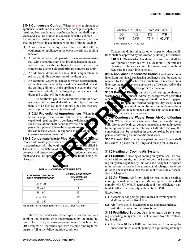
310.2 Condensate Control. Where an any equipment orappliance is installed in a space where damage is capable ofresulting from condensate overflow, a drain line shall be pro-vided and shall be drained in accordance with Section 310.1.An additional protection method for condensate overflowshall be provided in accordance with one of the following:(1) A water level detecting device that will shut off the
equipment or appliance in the event the primary drain isblocked.
(2) An additional watertight pan of corrosion-resistant mate-rial, with a separate drain line, installed beneath the cool-ing coil, unit, or the appliance to catch the overflowcondensate due to a clogged primary condensate drain.
(3) An additional drain line at a level that is higher than theprimary drain line connection of the drain pan.
(4) An additional watertight pan of corrosion-resistant mate-rial with a water level detection device installed beneaththe cooling coil, unit, or the appliance to catch the over-flow condensate due to a clogged primary condensatedrain and to shut off the equipment.
The additional pan or the additional drain line con-nection shall be provided with a drain pipe of not lessthan 3⁄4 of an inch (20 mm) nominal pipe size, discharg-ing at a point that is readily observed.310.2.1 Protection of Appurtenances. Where insu-lation or appurtenances are installed where damage iscapable of resulting from a condensate drain pan overfill,such installations shall occur above the rim of the drainpan with supports. Where the supports are in contact withthe condensate waste, the supports shall be of approvedcorrosion-resistant material.
310.3 Condensate Waste Pipe Material and Sizing.Condensate waste pipes from air-cooling coils shall be sizedin accordance with the equipment capacity as specified inTable 310.3. The material of the piping shall comply with thepressure and temperature rating of the appliance or equip-ment, and shall be approved for use with the liquid being dis-charged.
The size of condensate waste pipes is for one unit or acombination of units, or as recommended by the manufac-turer. The capacity of waste pipes assumes a 1⁄8 inch per foot(10.4 mm/m) or 1 percent slope, with the pipe running three-quarters full at the following pipe conditions:
For SI units: °C = (°F-32)/1.8
Condensate drain sizing for other slopes or other condi-tions shall be approved by the Authority Having Jurisdiction.
310.3.1 Cleanouts. Condensate drain lines shall beconfigured or provided with a cleanout to permit theclearing of blockages and for maintenance withoutrequiring the drain line to be cut.
310.4 Appliance Condensate Drains. Condensate drainlines from individual condensing appliances shall be sized asrequired by the manufacturer’s instructions. Condensate drainlines serving more than one appliance shall be approved by theAuthority Having Jurisdiction prior to installation.310.5 Point of Discharge. Air-conditioning condensatewaste pipes shall connect indirectly, except where permittedin Section 310.6, to the drainage system through an air gap orair break to trapped and vented receptors, dry wells, leachpits, or the tailpiece of plumbing fixtures. A condensate drainshall be trapped in accordance with the appliance manufac-turer’s instructions or as approved.310.6 Condensate Waste From Air-ConditioningCoils. Where the condensate waste from air-conditioningcoils discharges by direct connection to a lavatory tailpiece orto an approved accessible inlet on a bathtub overflow, theconnection shall be located in the area controlled by the sameperson controlling the air-conditioned space.310.7 Plastic Fittings. Female plastic screwed fittings shallbe used with plastic male fittings and plastic male threads.
311.0 Heating or Cooling Air System.311.1 Source. A heating or cooling air system shall be pro-vided with return air, outside air, or both. A heating or cool-ing air system regulated by this code and designed to replacerequired ventilation shall be arranged to discharge into a con-ditioned space not less than the amount of outside air speci-fied in Chapter 4.311.2 Air Filters. Air filters shall be installed in a heating,cooling, or makeup air system. Media-type air filters shallcomply with UL 900. Electrostatic and high efficiency par-ticulate filters shall comply with Section 936.0.Exceptions: (1) Systems serving single guest rooms or dwelling units
shall not require a listed filter.(2) Air filters used in listed appliances and in accordance
with the manufacturer’s instructions.311.3 Prohibited Source. Outside or return air for a heat-ing or cooling air system shall not be taken from the follow-ing locations:(1) Less than 10 feet (3048 mm) in distance from an appli-
ance vent outlet, a vent opening of a plumbing drainage
Outside Air – 20% Room Air – 80%DB WB DB WB
90°F 73°F 75°F 62.5°F
For SI units: 1 ton of refrigeration = 3.52 kW, 1 inch = 25 mm
EQUIPMENT CAPACITY IN TONS OF REFRIGERATION
MINIMUM CONDENSATEPIPE DIAMETER
(inches)
Up to 20 3⁄421 – 40 141 – 90 11⁄491 – 125 11⁄2126 – 250 2
TABLE 310.3MINIMUM CONDENSATE PIPE SIZE
29UNIFORM MECHANICAL CODE - PREPRINT
GENERAL REGULATIONS
PREPRINT
system, or the discharge outlet of an exhaust fan, unlessthe outlet is 3 feet (914 mm) above the outside-air inlet.
(2) Less than 10 feet (3048 mm) above the surface of anabutting public way, sidewalk, street, alley, or driveway.
(3) A hazardous or insanitary location, or a refrigerationmachinery room as defined in this code.
(4) An area, the volume of which is less than 25 percent ofthe entire volume served by such system, unless there isa permanent opening to an area the volume of which isequal to 25 percent of the entire volume served.Exception: Such openings where used for a heating orcooling air system in a dwelling unit shall be permittedto be reduced to not less than 50 percent of the requiredarea, provided the balance of the required return air istaken from a room or hall having not less than three doorsleading to other rooms served by the furnace.
(5) A closet, bathroom, toilet room, or kitchen.(6) Rooms or spaces containing a fuel-burning appliance
therein. Where such room or space serves as source ofreturn-air.Exceptions:(1) This shall not apply to fireplaces, fireplace appli-
ances, residential cooking appliances, direct- ventappliances, enclosed furnaces, and domestic-typeclothes dryers installed within the room or space.
(2) This shall not apply to a gravity-type or listed ventedwall heating or cooling air system.
(3) This shall not apply to a blower-type heating orcooling air system installed in accordance with thefollowing requirements:(a) Where the return air is taken from a room or
space having a volume exceeding 1 cubic foot(0.03 m3) for each 10 Btu/h (0.003 kW) fuelinput rating of fuel-burning appliances therein.
(b) Not less than 75 percent of the supply air is dis-charged back into the same room or space.
(c) Return-air inlets shall not be located within 10feet (3048 mm) from an appliance firebox ordraft diverter in the same enclosed room or con-fined space.
311.4 Return-Air Limitations. Return air from onedwelling unit shall not discharge into another dwelling unitthrough the heating or cooling air system.
312.0 Plumbing Connections.312.1 General. Water supply, sanitary drainage, and back-flow protection shall be in accordance with the plumbingcode.
313.0 Hangers and Supports.313.1 General. Piping, tubing, appliances, and appurte-nances shall be supported in accordance with this code, themanufacturer’s installation instructions, and in accordancewith the Authority Having Jurisdiction.
313.2 Material. Hangers and anchors shall be of sufficientstrength to support the weight of the pipe or tubing and itscontents. Piping or tubing shall be isolated from incompatiblematerials. 313.3 Suspended Piping. Suspended piping or tubingshall be supported at intervals not to exceed those shown inTable 313.3.313.4 Alignment. Piping or tubing shall be supported insuch a manner as to maintain its alignment and prevent sag-ging.313.5 Underground Installation. Piping or tubing in theground shall be laid on a firm bed for its entire length; whereother support is otherwise provided, it shall be approved inaccordance with Section 302.0. 313.6 Hanger Rod Sizes. Hanger rod sizes shall be notsmaller than those shown in Table 313.6.
313.7 Gas Piping. Gas piping shall be supported by metalstraps or hooks at intervals not to exceed those shown inTable 1310.3.5.1.
314.0 Balancing.314.1 General. Heating, ventilating, and air-conditioningsystems (including hydronic systems) shall be balanced inaccordance with one of the following methods:(1) AABC National Standards for Total System Balance(2) ACCA Manual B(3) ASHRAE 111(4) NEBB Procedural Standards for Testing Adjusting Bal-
ancing of Environmental Systems(5) SMACNA HVAC Systems Testing, Adjusting, and Bal-
ancing
315.0 Louvers in Hurricane Prone Regions.315.1 General. Louvers located in areas within hurricane-prone regions that are within 1 mile (2 km) of the coastal meanhigh water line where the basic wind speed is 110 miles perhour (mi/h) (49.2 m/s) or more; or portions of hurricane-proneregions where the basic wind speed is 120 mi/h (53.6 m/s) ormore; or Hawaii, as described in ASCE 7 shall be tested inaccordance with Section 315.1.1 and Section 315.1.2.
315.1.1 Testing. Louvers that protect air intake orexhaust openings shall be tested in accordance withAMCA 550 for resistance to wind-driven rain.
PIPE AND TUBE SIZE(inches)
ROD SIZES(inches)
1⁄2 - 4 3⁄85 - 8 1⁄2
10 - 12 5⁄8
TABLE 313.6HANGER ROD SIZES
For SI units: 1 inch = 25.4 mm
30 UNIFORM MECHANICAL CODE - PREPRINT
GENERAL REGULATIONS
PREPRINT
315.1.2 Impact Resistance Test.Upon request by theAuthority Having Jurisdiction, louvers protecting intakeand exhaust ventilation ducts that are not fixed in theopen position and located within 30 feet (9144 mm) ofthe grade shall be tested for impact resistance in accor-dance with AMCA 540.
316.0 Protection of Piping, Tubing, Materials, andStructures.316.1 General. Piping or tubing passing under or throughwalls shall be protected from breakage. Piping passingthrough or under cinders or other corrosive materials shall beprotected from external corrosion in an approved manner.Approved provisions shall be made for expansion of hotwater piping. Voids around piping or tubing passing throughconcrete floors on the ground shall be sealed.316.2 Installation. Piping or tubing shall be installed so thatthe piping, tubing, or connections will not be subject to unduestrains or stresses, and provisions shall be made for expan-sion, contraction, and structural settlement. No piping or tub-ing, unless designed and listed for such use, shall be directlyembedded in concrete or masonry. No structural membershall be seriously weakened or impaired by cutting, notching,or otherwise as defined in the building code.316.3 Corrosion, Erosion, and Mechanical Damage.Piping or tubing subject to corrosion, erosion, or mechanicaldamage shall be protected in an approved manner.316.4 Protectively Coated Pipe. Protectively coated pipeor tubing shall be inspected and tested, and a visible void,damage, or imperfection to the pipe coating shall be repairedin an approved manner.316.5 Fire-Resistant Construction. Piping, tubing, andduct system penetrations of fire-resistance-rated walls, parti-tions, floors, floor/ceiling assemblies, roof/ceiling assemblies,or shaft enclosures shall be protected in accordance with therequirements of the building code.316.6 Steel Nail Plates. Plastic piping or tubing, copperor copper alloy piping or tubing, and ducts penetrating fram-ing members to within 1 inch (25.4 mm) of the exposed fram-ing shall be protected by steel nail plates not less than No. 18gauge (0.0478 inches) (1.2141 mm) in thickness. The steelnail plate shall extend along the framing member not less than11⁄2 inches (38 mm) beyond the outside diameter of the pipeor tubing.Exception: See Section 1310.4.3.316.7 Sleeves. Sleeves shall be provided to protect pipingthrough concrete and masonry walls and concrete floors.Exception: Sleeves shall not be required where openings aredrilled or bored.
316.7.1 Building Loads. Piping or tubing through con-crete or masonry walls shall not be subject to a load frombuilding construction.316.7.2 Exterior Walls. In exterior walls, annular spacebetween sleeves and pipes or tubing shall be sealed andmade watertight, as approved by the Authority HavingJurisdiction. A penetration through fire-resistive con-struction shall be in accordance with Section 316.5.
316.8 Firewalls. A pipe sleeve through a firewall shall havethe space around the pipe or tubing completely sealed withan approved fire-resistive material in accordance with othercodes.316.9 Structural Members. A structural member weak-ened or impaired by cutting, notching, or otherwise shall bereinforced, repaired, or replaced so as to be left in a safe struc-tural condition in accordance with the requirements of thebuilding code.316.10 Rodentproofing. Mechanical system shall be con-structed in such a manner as to restrict rodents or vermin fromentering a building by following the ductwork from the out-side into the building.316.11 Metal Collars. In or on buildings where openingshave been made in walls, floors, or ceilings for the passage ofductwork or pipes, such openings shall be closed and pro-tected by the installation of approved metal collars securelyfastened to the adjoining structure.
317.0 Trenching, Excavation, and Backfill.317.1 Trenches. Trenches deeper than the footings of abuilding or structure, and paralleling the same, shall belocated not less than 45 degrees (0.79 rad) from the bottomexterior edge of the footing, or as approved in accordancewith Section 302.0.317.2 Tunneling and Driving. Tunneling and driving shallbe permitted to be done in yards, courts, or driveways of abuilding site. Where sufficient depth is available to permit,tunnels shall be permitted to be used between open-cuttrenches. Tunnels shall have a clear height of 2 feet (610 mm)above the pipe and shall be limited in length to one-half thedepth of the trench, with a maximum length of 8 feet (2438mm). Where pipes are driven, the drive pipe shall be not lessthan one size larger than the pipe to be laid.317.3 Open Trenches. Excavations required to be made forthe installation of a mechanical system or part thereof, withinthe walls of a building, shall be open trench work and shall bekept open until it has been inspected, tested, and accepted.317.4 Excavations. Excavations shall be completely back-filled as soon after inspection as practicable. Precaution shallbe taken to ensure compactness of backfill around pipingwithout damage to such piping. Trenches shall be backfilledin thin layers to 12 inches (305 mm) above the top of the pip-ing with clean earth, which shall not contain stones, boulders,cinderfill, frozen earth, construction debris, or other materi-als that will damage or break the piping or cause corrosiveaction. Mechanical devices such as bulldozers, graders, etc.,shall be permitted to then be used to complete backfill tograde. Fill shall be properly compacted. Precautions shall betaken to ensure permanent stability for pipe laid in filled ormade ground.
31UNIFORM MECHANICAL CODE - PREPRINT
GENERAL REGULATIONS
PREPRINT
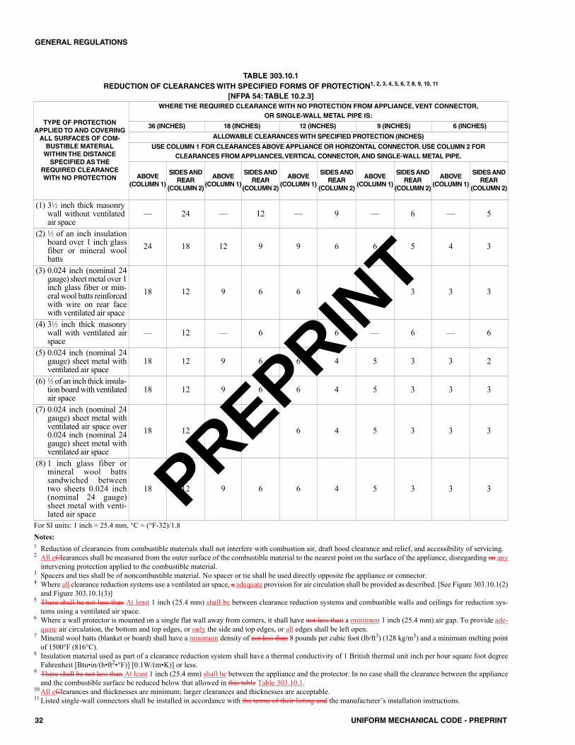
32 UNIFORM MECHANICAL CODE - PREPRINT
GENERAL REGULATIONS
TABLE 303.10.1REDUCTION OF CLEARANCES WITH SPECIFIED FORMS OF PROTECTION1, 2, 3, 4, 5, 6, 7, 8, 9, 10, 11
[NFPA 54: TABLE 10.2.3]
TYPE OF PROTECTIONAPPLIED TO AND COVERINGALL SURFACES OF COM-BUSTIBLE MATERIALWITHIN THE DISTANCESPECIFIED AS THE
REQUIRED CLEARANCEWITH NO PROTECTION
WHERE THE REQUIRED CLEARANCE WITH NO PROTECTION FROM APPLIANCE, VENT CONNECTOR, OR SINGLE-WALL METAL PIPE IS:
36 (INCHES) 18 (INCHES) 12 (INCHES) 9 (INCHES) 6 (INCHES)
ALLOWABLE CLEARANCES WITH SPECIFIED PROTECTION (INCHES)
USE COLUMN 1 FOR CLEARANCES ABOVE APPLIANCE OR HORIZONTAL CONNECTOR. USE COLUMN 2 FOR CLEARANCES FROM APPLIANCES, VERTICAL CONNECTOR, AND SINGLE-WALL METAL PIPE.
ABOVE(COLUMN 1)
SIDES ANDREAR
(COLUMN 2)
ABOVE(COLUMN 1)
SIDES ANDREAR
(COLUMN 2)
ABOVE(COLUMN 1)
SIDES ANDREAR
(COLUMN 2)
ABOVE(COLUMN 1)
SIDES ANDREAR
(COLUMN 2)
ABOVE(COLUMN 1)
SIDES ANDREAR
(COLUMN 2)
(1) 31⁄2 inch thick masonrywall without ventilatedair space
–– 24 –– 12 –– 9 –– 6 –– 5
(2) 1⁄2 of an inch insulationboard over 1 inch glassfiber or mineral woolbatts
24 18 12 9 9 6 6 5 4 3
(3) 0.024 inch (nominal 24gauge) sheet metal over 1inch glass fiber or min-eral wool batts reinforcedwith wire on rear facewith ventilated air space
18 12 9 6 6 4 5 3 3 3
(4) 31⁄2 inch thick masonrywall with ventilated airspace
–– 12 –– 6 –– 6 –– 6 –– 6
(5) 0.024 inch (nominal 24gauge) sheet metal withventilated air space
18 12 9 6 6 4 5 3 3 2
(6) 1⁄2 of an inch thick insula-tion board with ventilatedair space
18 12 9 6 6 4 5 3 3 3
(7) 0.024 inch (nominal 24gauge) sheet metal withventilated air space over0.024 inch (nominal 24gauge) sheet metal withventilated air space
18 12 9 6 6 4 5 3 3 3
(8) 1 inch glass fiber ormineral wool battssandwiched betweentwo sheets 0.024 inch(nominal 24 gauge)sheet metal with venti-lated air space
18 12 9 6 6 4 5 3 3 3
For SI units: 1 inch = 25.4 mm, °C = (°F-32)/1.8Notes:1 Reduction of clearances from combustible materials shall not interfere with combustion air, draft hood clearance and relief, and accessibility of servicing.2 All cClearances shall be measured from the outer surface of the combustible material to the nearest point on the surface of the appliance, disregarding an any
intervening protection applied to the combustible material.3 Spacers and ties shall be of noncombustible material. No spacer or tie shall be used directly opposite the appliance or connector.4 Where all clearance reduction systems use a ventilated air space, a adequate provision for air circulation shall be provided as described. [See Figure 303.10.1(2)
and Figure 303.10.1(3)]5 There shall be not less than At least 1 inch (25.4 mm) shall be between clearance reduction systems and combustible walls and ceilings for reduction sys-
tems using a ventilated air space.6 Where a wall protector is mounted on a single flat wall away from corners, it shall have not less than a minimum 1 inch (25.4 mm) air gap. To provide ade-
quate air circulation, the bottom and top edges, or only the side and top edges, or all edges shall be left open.7 Mineral wool batts (blanket or board) shall have a minimum density of not less than 8 pounds per cubic foot (lb/ft3) (128 kg/m3) and a minimum melting point
of 1500°F (816°C).8 Insulation material used as part of a clearance reduction system shall have a thermal conductivity of 1 British thermal unit inch per hour square foot degree
Fahrenheit [Btu•in/(h•ft2•°F)] [0.1W/(m•K)] or less.9 There shall be not less than At least 1 inch (25.4 mm) shall be between the appliance and the protector. In no case shall the clearance between the appliance
and the combustible surface be reduced below that allowed in this table Table 303.10.1.10 All cClearances and thicknesses are minimum; larger clearances and thicknesses are acceptable.11 Listed single-wall connectors shall be installed in accordance with the terms of their listing and the manufacturer’s installation instructions.
PREPRINT
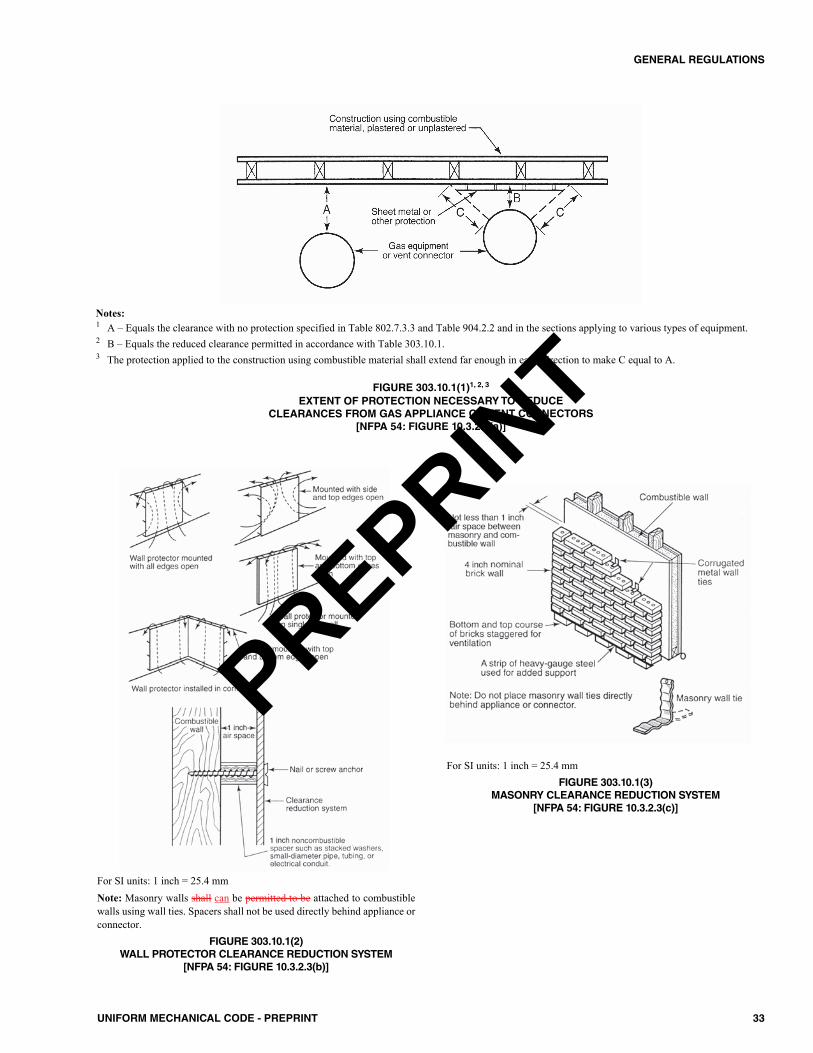
33UNIFORM MECHANICAL CODE - PREPRINT
GENERAL REGULATIONS
FIGURE 303.10.1(1)1, 2, 3
EXTENT OF PROTECTION NECESSARY TO REDUCE CLEARANCES FROM GAS APPLIANCE OR VENT CONNECTORS
[NFPA 54: FIGURE 10.3.2.3(a)]
Notes:1 A – Equals the clearance with no protection specified in Table 802.7.3.3 and Table 904.2.2 and in the sections applying to various types of equipment.2 B – Equals the reduced clearance permitted in accordance with Table 303.10.1. 3 The protection applied to the construction using combustible material shall extend far enough in each direction to make C equal to A.
For SI units: 1 inch = 25.4 mmNote: Masonry walls shall can be permitted to be attached to combustiblewalls using wall ties. Spacers shall not be used directly behind appliance orconnector.
FIGURE 303.10.1(2)WALL PROTECTOR CLEARANCE REDUCTION SYSTEM
[NFPA 54: FIGURE 10.3.2.3(b)]
For SI units: 1 inch = 25.4 mmFIGURE 303.10.1(3)
MASONRY CLEARANCE REDUCTION SYSTEM[NFPA 54: FIGURE 10.3.2.3(c)]
PREPRINT
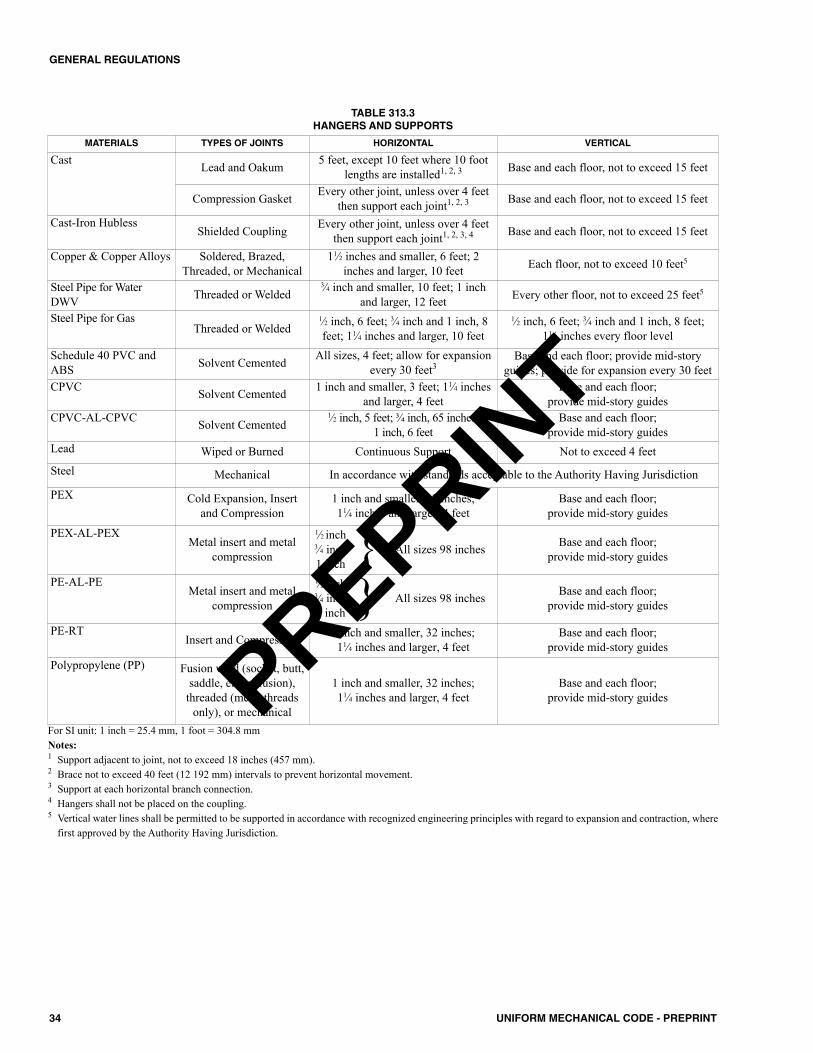
34 UNIFORM MECHANICAL CODE - PREPRINT
GENERAL REGULATIONS
MATERIALS TYPES OF JOINTS HORIZONTAL VERTICAL
Cast Lead and Oakum 5 feet, except 10 feet where 10 footlengths are installed1, 2, 3 Base and each floor, not to exceed 15 feet
Compression Gasket Every other joint, unless over 4 feetthen support each joint1, 2, 3 Base and each floor, not to exceed 15 feet
Cast-Iron HublessShielded Coupling Every other joint, unless over 4 feet
then support each joint1, 2, 3, 4 Base and each floor, not to exceed 15 feet
Copper & Copper Alloys Soldered, Brazed,Threaded, or Mechanical
11⁄2 inches and smaller, 6 feet; 2inches and larger, 10 feet Each floor, not to exceed 10 feet5
Steel Pipe for WaterDWV Threaded or Welded
3⁄4 inch and smaller, 10 feet; 1 inchand larger, 12 feet Every other floor, not to exceed 25 feet5
Steel Pipe for GasThreaded or Welded
1⁄2 inch, 6 feet; 3⁄4 inch and 1 inch, 8feet; 11⁄4 inches and larger, 10 feet
1⁄2 inch, 6 feet; 3⁄4 inch and 1 inch, 8 feet;11⁄4 inches every floor level
Schedule 40 PVC andABS Solvent Cemented All sizes, 4 feet; allow for expansion
every 30 feet3Base and each floor; provide mid-story
guides; provide for expansion every 30 feetCPVC Solvent Cemented 1 inch and smaller, 3 feet; 11⁄4 inches
and larger, 4 feetBase and each floor;
provide mid-story guidesCPVC-AL-CPVC Solvent Cemented
1⁄2 inch, 5 feet; ¾ inch, 65 inches; 1 inch, 6 feet
Base and each floor;provide mid-story guides
Lead Wiped or Burned Continuous Support Not to exceed 4 feetSteel Mechanical In accordance with standards acceptable to the Authority Having Jurisdiction
PEX Cold Expansion, Insertand Compression
1 inch and smaller, 32 inches;11⁄4 inches and larger, 4 feet
Base and each floor; provide mid-story guides
PEX-AL-PEXMetal insert and metal
compression
1⁄2 inch3⁄4 inch1 inch } All sizes 98 inches Base and each floor;
provide mid-story guides
PE-AL-PEMetal insert and metal
compression
1⁄2 inch3⁄4 inch1 inch } All sizes 98 inches Base and each floor;
provide mid-story guides
PE-RTInsert and Compression 1 inch and smaller, 32 inches;
11⁄4 inches and larger, 4 feetBase and each floor;
provide mid-story guidesPolypropylene (PP) Fusion weld (socket, butt,
saddle, electrofusion),threaded (metal threads
only), or mechanical
1 inch and smaller, 32 inches;11⁄4 inches and larger, 4 feet
Base and each floor; provide mid-story guides
TABLE 313.3HANGERS AND SUPPORTS
For SI unit: 1 inch = 25.4 mm, 1 foot = 304.8 mmNotes:1 Support adjacent to joint, not to exceed 18 inches (457 mm).2 Brace not to exceed 40 feet (12 192 mm) intervals to prevent horizontal movement.3 Support at each horizontal branch connection.4 Hangers shall not be placed on the coupling.5 Vertical water lines shall be permitted to be supported in accordance with recognized engineering principles with regard to expansion and contraction, where
first approved by the Authority Having Jurisdiction.
PREPRINT
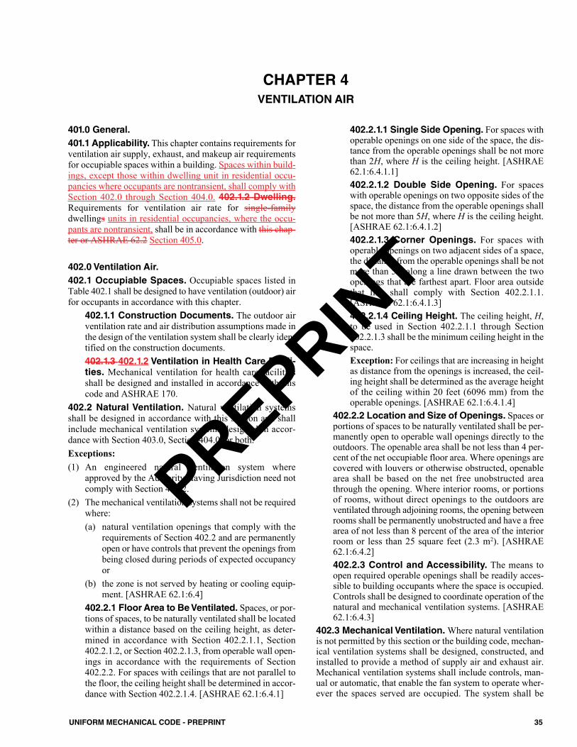
401.0 General. 401.1 Applicability. This chapter contains requirements forventilation air supply, exhaust, and makeup air requirementsfor occupiable spaces within a building. Spaces within build-ings, except those within dwelling unit in residential occu-pancies where occupants are nontransient, shall comply withSection 402.0 through Section 404.0. 402.1.2 Dwelling.Requirements for ventilation air rate for single-familydwellings units in residential occupancies, where the occu-pants are nontransient, shall be in accordance with this chap-ter or ASHRAE 62.2 Section 405.0.
402.0 Ventilation Air.402.1 Occupiable Spaces. Occupiable spaces listed inTable 402.1 shall be designed to have ventilation (outdoor) airfor occupants in accordance with this chapter.
402.1.1 Construction Documents. The outdoor airventilation rate and air distribution assumptions made inthe design of the ventilation system shall be clearly iden-tified on the construction documents.402.1.3 402.1.2 Ventilation in Health Care Facili-ties. Mechanical ventilation for health care facilitiesshall be designed and installed in accordance with thiscode and ASHRAE 170.
402.2 Natural Ventilation. Natural ventilation systemsshall be designed in accordance with this section and shallinclude mechanical ventilation systems designed in accor-dance with Section 403.0, Section 404.0, or both. Exceptions:(1) An engineered natural ventilation system where
approved by the Authority Having Jurisdiction need notcomply with Section 402.2.
(2) The mechanical ventilation systems shall not be requiredwhere:(a) natural ventilation openings that comply with the
requirements of Section 402.2 and are permanentlyopen or have controls that prevent the openings frombeing closed during periods of expected occupancyor
(b) the zone is not served by heating or cooling equip-ment. [ASHRAE 62.1:6.4]
402.2.1 Floor Area to Be Ventilated. Spaces, or por-tions of spaces, to be naturally ventilated shall be locatedwithin a distance based on the ceiling height, as deter-mined in accordance with Section 402.2.1.1, Section402.2.1.2, or Section 402.2.1.3, from operable wall open-ings in accordance with the requirements of Section402.2.2. For spaces with ceilings that are not parallel tothe floor, the ceiling height shall be determined in accor-dance with Section 402.2.1.4. [ASHRAE 62.1:6.4.1]
402.2.1.1 Single Side Opening. For spaces withoperable openings on one side of the space, the dis-tance from the operable openings shall be not morethan 2H, where H is the ceiling height. [ASHRAE62.1:6.4.1.1]402.2.1.2 Double Side Opening. For spaceswith operable openings on two opposite sides of thespace, the distance from the operable openings shallbe not more than 5H, where H is the ceiling height.[ASHRAE 62.1:6.4.1.2]402.2.1.3 Corner Openings. For spaces withoperable openings on two adjacent sides of a space,the distance from the operable openings shall be notmore than 5H along a line drawn between the twoopenings that are farthest apart. Floor area outsidethat line shall comply with Section 402.2.1.1.[ASHRAE 62.1:6.4.1.3]402.2.1.4 Ceiling Height. The ceiling height, H,to be used in Section 402.2.1.1 through Section402.2.1.3 shall be the minimum ceiling height in thespace.Exception: For ceilings that are increasing in heightas distance from the openings is increased, the ceil-ing height shall be determined as the average heightof the ceiling within 20 feet (6096 mm) from theoperable openings. [ASHRAE 62.1:6.4.1.4]
402.2.2 Location and Size of Openings. Spaces orportions of spaces to be naturally ventilated shall be per-manently open to operable wall openings directly to theoutdoors. The openable area shall be not less than 4 per-cent of the net occupiable floor area. Where openings arecovered with louvers or otherwise obstructed, openablearea shall be based on the net free unobstructed areathrough the opening. Where interior rooms, or portionsof rooms, without direct openings to the outdoors areventilated through adjoining rooms, the opening betweenrooms shall be permanently unobstructed and have a freearea of not less than 8 percent of the area of the interiorroom or less than 25 square feet (2.3 m2). [ASHRAE62.1:6.4.2]402.2.3 Control and Accessibility. The means toopen required operable openings shall be readily acces-sible to building occupants where the space is occupied.Controls shall be designed to coordinate operation of thenatural and mechanical ventilation systems. [ASHRAE62.1:6.4.3]
402.3 Mechanical Ventilation.Where natural ventilationis not permitted by this section or the building code, mechan-ical ventilation systems shall be designed, constructed, andinstalled to provide a method of supply air and exhaust air.Mechanical ventilation systems shall include controls, man-ual or automatic, that enable the fan system to operate wher-ever the spaces served are occupied. The system shall be
35UNIFORM MECHANICAL CODE - PREPRINT
CHAPTER 4VENTILATION AIR
PREPRINT
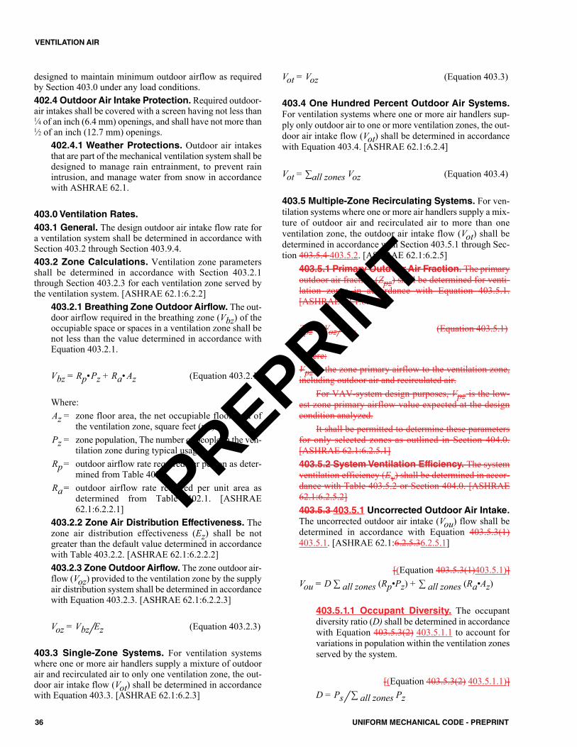
designed to maintain minimum outdoor airflow as requiredby Section 403.0 under any load conditions.402.4 Outdoor Air Intake Protection. Required outdoor-air intakes shall be covered with a screen having not less than1⁄4 of an inch (6.4 mm) openings, and shall have not more than1⁄2 of an inch (12.7 mm) openings.
402.4.1 Weather Protections. Outdoor air intakesthat are part of the mechanical ventilation system shall bedesigned to manage rain entrainment, to prevent rainintrusion, and manage water from snow in accordancewith ASHRAE 62.1.
403.0 Ventilation Rates.403.1 General. The design outdoor air intake flow rate fora ventilation system shall be determined in accordance withSection 403.2 through Section 403.9.4.403.2 Zone Calculations. Ventilation zone parametersshall be determined in accordance with Section 403.2.1through Section 403.2.3 for each ventilation zone served bythe ventilation system. [ASHRAE 62.1:6.2.2]
403.2.1 Breathing Zone Outdoor Airflow. The out-door airflow required in the breathing zone (Vbz) of theoccupiable space or spaces in a ventilation zone shall benot less than the value determined in accordance withEquation 403.2.1.
Vbz = Rp•Pz + Ra• Az (Equation 403.2.1)
Where:Az = zone floor area, the net occupiable floor area of
the ventilation zone, square feet (m2).Pz = zone population, The number of people in the ven-
tilation zone during typical usage. Rp= outdoor airflow rate required per person as deter-
mined from Table 402.1.Ra= outdoor airflow rate required per unit area as
determined from Table 402.1. [ASHRAE62.1:6.2.2.1]
403.2.2 Zone Air Distribution Effectiveness. Thezone air distribution effectiveness (Ez) shall be notgreater than the default value determined in accordancewith Table 403.2.2. [ASHRAE 62.1:6.2.2.2]403.2.3 Zone Outdoor Airflow. The zone outdoor air-flow (Voz) provided to the ventilation zone by the supplyair distribution system shall be determined in accordancewith Equation 403.2.3. [ASHRAE 62.1:6.2.2.3]
Voz = Vbz/Ez (Equation 403.2.3)
403.3 Single-Zone Systems. For ventilation systemswhere one or more air handlers supply a mixture of outdoorair and recirculated air to only one ventilation zone, the out-door air intake flow (Vot) shall be determined in accordancewith Equation 403.3. [ASHRAE 62.1:6.2.3]
Vot = Voz (Equation 403.3)
403.4 One Hundred Percent Outdoor Air Systems.For ventilation systems where one or more air handlers sup-ply only outdoor air to one or more ventilation zones, the out-door air intake flow (Vot) shall be determined in accordancewith Equation 403.4. [ASHRAE 62.1:6.2.4]
Vot = ∑all zones Voz (Equation 403.4)
403.5 Multiple-Zone Recirculating Systems. For ven-tilation systems where one or more air handlers supply a mix-ture of outdoor air and recirculated air to more than oneventilation zone, the outdoor air intake flow (Vot) shall bedetermined in accordance with Section 403.5.1 through Sec-tion 403.5.4 403.5.2. [ASHRAE 62.1:6.2.5]
403.5.1 Primary Outdoor Air Fraction. The primaryoutdoor air fraction (Zpz) shall be determined for venti-lation zones in accordance with Equation 403.5.1.[ASHRAE 62.1:6.2.5.1]
Zpz = Voz/Vpz (Equation 403.5.1)
Where:Vpz is the zone primary airflow to the ventilation zone,including outdoor air and recirculated air.
For VAV-system design purposes, Vpz is the low-est zone primary airflow value expected at the designcondition analyzed.
It shall be permitted to determine these parametersfor only selected zones as outlined in Section 404.0.[ASHRAE 62.1:6.2.5.1]403.5.2 System Ventilation Efficiency. The systemventilation efficiency (Ev) shall be determined in accor-dance with Table 403.5.2 or Section 404.0. [ASHRAE62.1:6.2.5.2]403.5.3 403.5.1 Uncorrected Outdoor Air Intake.The uncorrected outdoor air intake (Vou) flow shall bedetermined in accordance with Equation 403.5.3(1)403.5.1. [ASHRAE 62.1:6.2.5.36.2.5.1]
[(Equation 403.5.3(1)403.5.1)]Vou = D ∑ all zones (Rp•Pz) + ∑ all zones (Ra•Az)
403.5.1.1 Occupant Diversity. The occupantdiversity ratio (D) shall be determined in accordancewith Equation 403.5.3(2) 403.5.1.1 to account forvariations in population within the ventilation zonesserved by the system.
[(Equation 403.5.3(2) 403.5.1.1)]D = Ps/ ∑ all zones Pz
36 UNIFORM MECHANICAL CODE - PREPRINT
VENTILATION AIR
PREPRINT
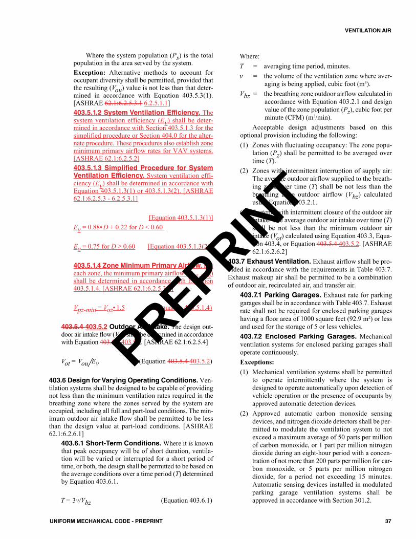
Where the system population (Ps) is the totalpopulation in the area served by the system. Exception: Alternative methods to account foroccupant diversity shall be permitted, provided thatthe resulting (Vou) value is not less than that deter-mined in accordance with Equation 403.5.3(1).[ASHRAE 62.1:6.2.5.3.1 6.2.5.1.1]403.5.1.2 System Ventilation Efficiency. Thesystem ventilation efficiency (Ev) shall be deter-mined in accordance with Section 403.5.1.3 for thesimplified procedure or Section 404.0 for the alter-nate procedure. These procedures also establish zoneminimum primary airflow rates for VAV systems.[ASHRAE 62.1:6.2.5.2]403.5.1.3 Simplified Procedure for SystemVentilation Efficiency. System ventilation effi-ciency (Ev) shall be determined in accordance withEquation 403.5.1.3(1) or 403.5.1.3(2). [ASHRAE62.1:6.2.5.3 - 6.2.5.3.1]
[Equation 403.5.1.3(1)]Ev = 0.88• D + 0.22 for D < 0.60
Ev = 0.75 for D ≥ 0.60 [Equation 403.5.1.3(2)]
403.5.1.4 Zone Minimum Primary Airflow. Foreach zone, the minimum primary airflow (Vpz-min)shall be determined in accordance with Equation403.5.1.4. [ASHRAE 62.1:6.2.5.3.2]
Vpz-min = Voz• 1.5 (Equation 403.5.1.4)
403.5.4 403.5.2 Outdoor Air Intake. The design out-door air intake flow (Vot) shall be determined in accordancewith Equation 403.5.4 403.5.2. [ASHRAE 62.1:6.2.5.4]
Vot = Vou/Ev (Equation 403.5.4 403.5.2)
403.6 Design for Varying Operating Conditions.Ven-tilation systems shall be designed to be capable of providingnot less than the minimum ventilation rates required in thebreathing zone where the zones served by the system areoccupied, including all full and part-load conditions. The min-imum outdoor air intake flow shall be permitted to be lessthan the design value at part-load conditions. [ASHRAE62.1:6.2.6.1]
403.6.1 Short-Term Conditions.Where it is knownthat peak occupancy will be of short duration, ventila-tion will be varied or interrupted for a short period oftime, or both, the design shall be permitted to be based onthe average conditions over a time period (T) determinedby Equation 403.6.1.
T = 3v/Vbz (Equation 403.6.1)
Where:T = averaging time period, minutes.v = the volume of the ventilation zone where aver-
aging is being applied, cubic foot (m3).Vbz = the breathing zone outdoor airflow calculated in
accordance with Equation 403.2.1 and designvalue of the zone population (Pz), cubic foot perminute (CFM) (m3/min).
Acceptable design adjustments based on thisoptional provision including the following:(1) Zones with fluctuating occupancy: The zone popu-
lation (Pz) shall be permitted to be averaged overtime (T).
(2) Zones with intermittent interruption of supply air:The average outdoor airflow supplied to the breath-ing zone over time (T) shall be not less than thebreathing zone outdoor airflow (Vbz) calculatedusing Equation 403.2.1.
(3) Systems with intermittent closure of the outdoor airintake: The average outdoor air intake over time (T)shall be not less than the minimum outdoor airintake (Vot) calculated using Equation 403.3, Equa-tion 403.4, or Equation 403.5.4 403.5.2. [ASHRAE62.1:6.2.6.2]
403.7 Exhaust Ventilation. Exhaust airflow shall be pro-vided in accordance with the requirements in Table 403.7.Exhaust makeup air shall be permitted to be a combinationof outdoor air, recirculated air, and transfer air.
403.7.1 Parking Garages. Exhaust rate for parkinggarages shall be in accordance with Table 403.7. Exhaustrate shall not be required for enclosed parking garageshaving a floor area of 1000 square feet (92.9 m2) or lessand used for the storage of 5 or less vehicles.403.7.2 Enclosed Parking Garages. Mechanicalventilation systems for enclosed parking garages shalloperate continuously.Exceptions:(1) Mechanical ventilation systems shall be permitted
to operate intermittently where the system isdesigned to operate automatically upon detection ofvehicle operation or the presence of occupants byapproved automatic detection devices.
(2) Approved automatic carbon monoxide sensingdevices, and nitrogen dioxide detectors shall be per-mitted to modulate the ventilation system to notexceed a maximum average of 50 parts per millionof carbon monoxide, or 1 part per million nitrogendioxide during an eight-hour period with a concen-tration of not more than 200 parts per million for car-bon monoxide, or 5 parts per million nitrogendioxide, for a period not exceeding 15 minutes.Automatic sensing devices installed in modulatedparking garage ventilation systems shall beapproved in accordance with Section 301.2.
37UNIFORM MECHANICAL CODE - PREPRINT
VENTILATION AIR
PREPRINT
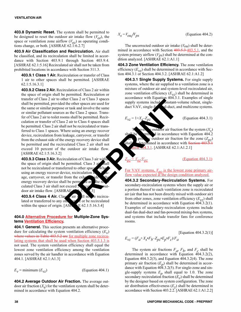
403.8 Dynamic Reset. The system shall be permitted tobe designed to reset the outdoor air intake flow (Vot), thespace or ventilation zone airflow (Voz) as operating condi-tions change, or both. [ASHRAE 62.1:6.2.7]403.9 Air Classification and Recirculation. Air shallbe classified, and its recirculation shall be limited in accor-dance with Section 403.9.1 through Section 403.9.4.[ASHRAE 62.1:5.16] Recirculated air shall not be taken fromprohibited locations in accordance with Section 311.3.
403.9.1 Class 1 Air. Recirculation or transfer of Class1 air to other spaces shall be permitted. [ASHRAE62.1:5.16.3.1]403.9.2 Class 2 Air. Recirculation of Class 2 air withinthe space of origin shall be permitted. Recirculation ortransfer of Class 2 air to other Class 2 or Class 3 spacesshall be permitted, provided the other spaces are used forthe same or similar purpose or task and involve the sameor similar pollutant sources as the Class 2 space. Trans-fer of Class 2 air to toilet rooms shall be permitted. Recir-culation or transfer of Class 2 air to Class 4 spaces shallbe permitted. Class 2 air shall not be recirculated or trans-ferred to Class 1 spaces. Where using an energy recoverdevice, recirculation from leakage, carryover, or transferfrom the exhaust side of the energy recovery device shallbe permitted and the recirculated Class 2 air shall notexceed 10 percent of the outdoor air intake flow.[ASHRAE 62.1:5.16.3.2]403.9.3 Class 3 Air. Recirculation of Class 3 air withinthe space of origin shall be permitted. Class 3 air shallnot be recirculated or transferred to other spaces. Whereusing an energy recover device, recirculation from leak-age, carryover, or transfer from the exhaust side of theenergy recovery device shall be permitted and the recir-culated Class 3 air shall not exceed 5 percent of the out-door air intake flow. [ASHRAE 62.1:5.16.3.3]403.9.4 Class 4 Air. Class 4 air shall not be recircu-lated or transferred to any other space or be recirculatedwithin the space of origin. [ASHRAE 62.1:5.16.3.4]
404.0 Alternative Procedure for Multiple-Zone Sys-tems Ventilation Efficiency.404.1 General. This section presents an alternative proce-dure for calculating the system ventilation efficiency (Ev)where values in Table 403.5.2 are for multiple zone recircu-lating systems that shall be used when Section 403.5.1.3 isnot used. The system ventilation efficiency shall equal thelowest zone ventilation efficiency among the ventilationzones served by the air handler in accordance with Equation404.1. [ASHRAE 62.1:A1.3]
Ev = minimum (Evz) (Equation 404.1)
404.2 Average Outdoor Air Fraction. The average out-door air fraction (Xs) for the ventilation system shall be deter-mined in accordance with Equation 404.2.
Xs =Vou/Vps (Equation 404.2)
The uncorrected outdoor air intake (Vou) shall be deter-mined in accordance with Section 403.5.3 403.5.1, and thesystem primary airflow (Vps) shall be determined at the con-dition analyzed. [ASHRAE 62.1:A1.1]404.3 Zone Ventilation Efficiency. The zone ventilationefficiency (Evz) shall be determined in accordance with Sec-tion 404.3.1 or Section 404.3.2. [ASHRAE 62.1:A1.2]
404.3.1 Single Supply Systems. For single supplysystems, where the air supplied to a ventilation zone is amixture of outdoor air and system-level recirculated air,zone ventilation efficiency (Evz) shall be determined inaccordance with Equation 404.3.1. Examples of singlesupply systems include constant-volume reheat, single-duct VAV, single-fan dual-duct, and multizone systems.
Evz = 1+Xs–Zpz (Equation 404.3.1)
The average outdoor air fraction for the system (Xs)shall be determined in accordance with Equation 404.2and the primary outdoor air fraction for the zone (Zpz)shall be determined in accordance with Section 403.5.1Equation 404.3.1. [ASHRAE 62.1:A1.2.1]
Zpz = Voz/Vpz (Equation 404.3.1)
For VAV systems, Vpz is the lowest zone primary air-flow value expected at the design condition analyzed.404.3.2 Secondary-Recirculation Systems. Forsecondary-recirculation systems where the supply air ora portion thereof to each ventilation zone is recirculatedair (air that has not been directly mixed with outdoor air)from other zones, zone ventilation efficiency (Evz) shallbe determined in accordance with Equation 404.3.2(1).Examples of secondary-recirculation systems includedual-fan dual-duct and fan-powered mixing-box systems,and systems that include transfer fans for conferencerooms.
[Equation 404.3.2(1)]Evz = (Fa+Xs•Fb–Zpz•Ep•Fc)/Fa
The system air fractions Fa, Fb, and Fc shall bedetermined in accordance with Equation 404.3.2(2),Equation 404.3.2(3), and Equation 404.3.2(4). The zoneprimary air fraction (Ep) shall be determined in accor-dance with Equation 404.3.2(5). For single-zone and sin-gle-supply systems Ep shall equal to 1.0. The zonesecondary recirculation fraction (Er) shall be determinedby the designer based on system configuration. The zoneair distribution effectiveness (Ez) shall be determined inaccordance with Section 403.2.2. [ASHRAE 62.1:A1.2.2]
38 UNIFORM MECHANICAL CODE - PREPRINT
VENTILATION AIR
PREPRINT
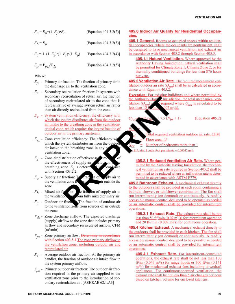
Fa = Ep+(1–Ep)•Er [Equation 404.3.2(2)]
Fb = Ep [Equation 404.3.2(3)]
Fc = 1–(1–Ez)•(1–Er)•(1–Ep) [Equation 404.3.2(4)]
Ep = Vpz/Vdz [Equation 404.3.2(5)]
Where:Ep - Primary air fraction: The fraction of primary air in
the discharge air to the ventilation zone.Er - Secondary recirculation fraction: In systems with
secondary recirculation of return air, the fractionof secondary recirculated air to the zone that isrepresentative of average system return air ratherthan air directly recirculated from the zone.
Ev - System ventilation efficiency: the efficiency withwhich the system distributes air from the outdoorair intake to the breathing zone in the ventilation-critical zone, which requires the largest fraction ofoutdoor air in the primary airstream.
Evz - Zone ventilation efficiency: The efficiency withwhich the system distributes air from the outdoorair intake to the breathing zone in any particularventilation zone.
Ez - Zone air distribution effectiveness: A measure ofthe effectiveness of supply air distribution to thebreathing zone. Ez is determined in accordancewith Section 403.2.2.
Fa - Supply air fraction: The fraction of supply air tothe ventilation zone from sources or air outside thezone.
Fb - Mixed air fraction: The fraction of supply air tothe ventilation zone from fully mixed primary air.
Fc - Outdoor air fraction: The fraction of outdoor airto the ventilation zone from sources of air outsidethe zone.
Vdz - Zone discharge airflow: The expected discharge(supply) airflow to the zone that includes primaryairflow and secondary recirculated airflow, CFM(m3/min).
Vpz - Zone primary airflow: Determine in accordancewith Section 403.5.1 The zone primary airflow tothe ventilation zone, including outdoor air andrecirculated air.
Xs - Average outdoor air fraction: At the primary airhandler, the fraction of outdoor air intake flow inthe system primary airflow.
Zpz - Primary outdoor air fraction: The outdoor air frac-tion required in the primary air supplied to theventilation zone prior to the introduction of sec-ondary recirculation air. [ASHRAE 62.1:A3]
405.0 Indoor Air Quality for Residential Occupan-cies.405.1 General. Rooms or occupied spaces within residen-tial occupancies, where the occupants are nontransient, shallbe designed to have mechanical ventilation and exhaust airin accordance with Section 405.2 through Section 405.5.
405.1.1 Natural Ventilation. Where approved by theAuthority Having Jurisdiction, natural ventilation shallbe permitted for Climate Zone 1, Climate Zone 2; or forthermally conditioned buildings for less than 876 hoursper year.
405.2 Ventilation Air Rate. The required mechanical ven-tilation outdoor air rate (Qtot) shall be as calculated in accor-dance with Equation 405.2.Exception: For existing buildings and where permitted bythe Authority Having Jurisdiction, the total mechanical ven-tilation (Qtot) is not required where Qtot is calculated to beless than 15 ft3/min (0.007 m3/s).
Qtot = 0.03Afloor + 7.5 (Nbr + 1) (Equation 405.2)
Where:Qtot = Total required ventilation outdoor air rate, CFMAfloor = Floor area, ft2
Nbr = Number of bedrooms more than 1For SI Units: 1 cubic foot per minute = 0.00047 m3/s
405.2.1 Reduced Ventilation Air Rate. Where per-mitted by the Authority Having Jurisdiction, the mechan-ical ventilation air rate required in Section 405.2 shall bepermitted to be reduced where an infiltration rate is deter-mined in accordance with ASTM E779.
405.3 Bathroom Exhaust. A mechanical exhaust directlyto the outdoors shall be provided in each room containing abathtub, shower, or tub/shower combination. The fan shallrun intermittently (on demand) or continuously. A readilyaccessible manual control designed to be operated as neededor an automatic control shall be provided for intermittentoperations.
405.3.1 Exhaust Rate. The exhaust rate shall be notless than 50 ft3/min (0.02 m3/s) for intermittent operationand 20 ft3/min (0.009 m3/s) for continuous operation.
405.4 Kitchen Exhaust. A mechanical exhaust directly tothe outdoors shall be provided in each kitchen. The fan shallrun intermittently (on demand) or continuously. A readilyaccessible manual control designed to be operated as neededor an automatic control shall be provided for intermittentoperations.
405.4.1 Exhaust Rate. For intermittent-controlledoperations, the exhaust rate shall be not less than 100ft3/m (0.047 m3/s) for range hoods or 300 ft3/m (0.141m3/s) for mechanical exhaust fans including downdraftappliances. For continuousoperated ventilation, theexhaust rate shall be not less than 5 air changes per hourbased on kitchen volume for enclosed kitchens.
39UNIFORM MECHANICAL CODE - PREPRINT
VENTILATION AIR
PREPRINT

40 UNIFORM MECHANICAL CODE - PREPRINT
VENTILATION AIR
405.5 Ventilation Openings. Occupiable spaces shall beprovided with a readily accessible ventilation opening open-able to the outdoors. The opening shall be not less than 5square feet (0.464 m2) or 4 percent of the occupied floor area.The openable area shall be based on free, unobstructed areathrough the opening.
PREPRINT
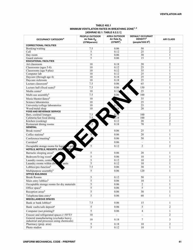
41UNIFORM MECHANICAL CODE - PREPRINT
VENTILATION AIR
OCCUPANCY CATEGORY4PEOPLE OUTDOOR
Air Rate Rp(CFM/person)
AREA OUTDOOR Air Rate Ra(CFM/ft2)
DEFAULT OCCUPANTDENSITY3
(people/1000 ft2)AIR CLASS
CORRECTIONAL FACILITIESBooking/waiting 7.5 0.06 50 2Cell 5 0.12 25 2Day room 5 0.06 30 1Guard stations 5 0.06 15 1EDUCATIONAL FACILITIESArt classroom 10 0.18 20 2Classrooms (ages 5-8) 10 0.12 25 1Classrooms (age 9 plus) 10 0.12 35 1Computer lab 10 0.12 25 1Daycare (through age 4) 10 0.18 25 2Daycare sickroom 10 0.18 25 3Lecture classroomh 7.5 0.06 65 1Lecture hall (fixed seats)h 7.5 0.06 150 1Media centera 10 0.12 25 1Multi-use assemblyh 7.5 0.06 100 1Music/theater/danceh 10 0.06 35 1Science laboratories 10 0.18 25 2University/college laboratories 10 0.18 25 2Wood/metal shop 10 0.18 20 2FOOD AND BEVERAGE SERVICE Bars, cocktail lounges 7.5 0.18 100 2Cafeteria/fast food dining 7.5 0.18 100 2Kitchen (cooking) 7.5 0.12 20 2Restaurant dining rooms 7.5 0.18 70 2GENERAL
Break roomsh 5 0.06 25 1Coffee stationsh 5 0.06 20 1Conference/meetingh 5 0.06 50 1Corridorsh – 0.06 – 1Occupiable storage rooms for liquids or gelsb 5 0.12 2 2HOTELS, MOTELS, RESORTS, DORMITORIES
Barracks sleeping areash 5 0.06 20 1Bedroom/living roomh 5 0.06 10 1Laundry rooms, central 5 0.12 10 2Laundry rooms within dwelling units 5 0.12 10 1Lobbies/pre-functionh 7.5 0.06 30 1Multipurpose assemblyh 5 0.06 120 1OFFICE BUILDINGSBreak Rooms 5 0.12 50 1Main entry lobbiesh 5 0.06 10 1Occupiable storage rooms for dry materials 5 0.06 2 1Office spaceh 5 0.06 5 1Reception areash 5 0.06 30 1Telephone/data entryh 5 0.06 60 1MISCELLANEOUS SPACES
Bank or bank lobbiesh 7.5 0.06 15 1Bank vaults/safe deposith 5 0.06 5 2Computer (not printing)h 5 0.06 4 1Freezer and refrigerated spaces (<50°F)e 10 – – 2General manufacturing (excludes heavyindustrial and processes using chemicals) 10 0.18 7 3Pharmacy (prep. area) 5 0.18 10 2Photo studios 5 0.12 10 1
TABLE 402.1MINIMUM VENTILATION RATES IN BREATHING ZONE1, 2
[ASHRAE 62.1: TABLE 6.2.2.1]
PREPRINT
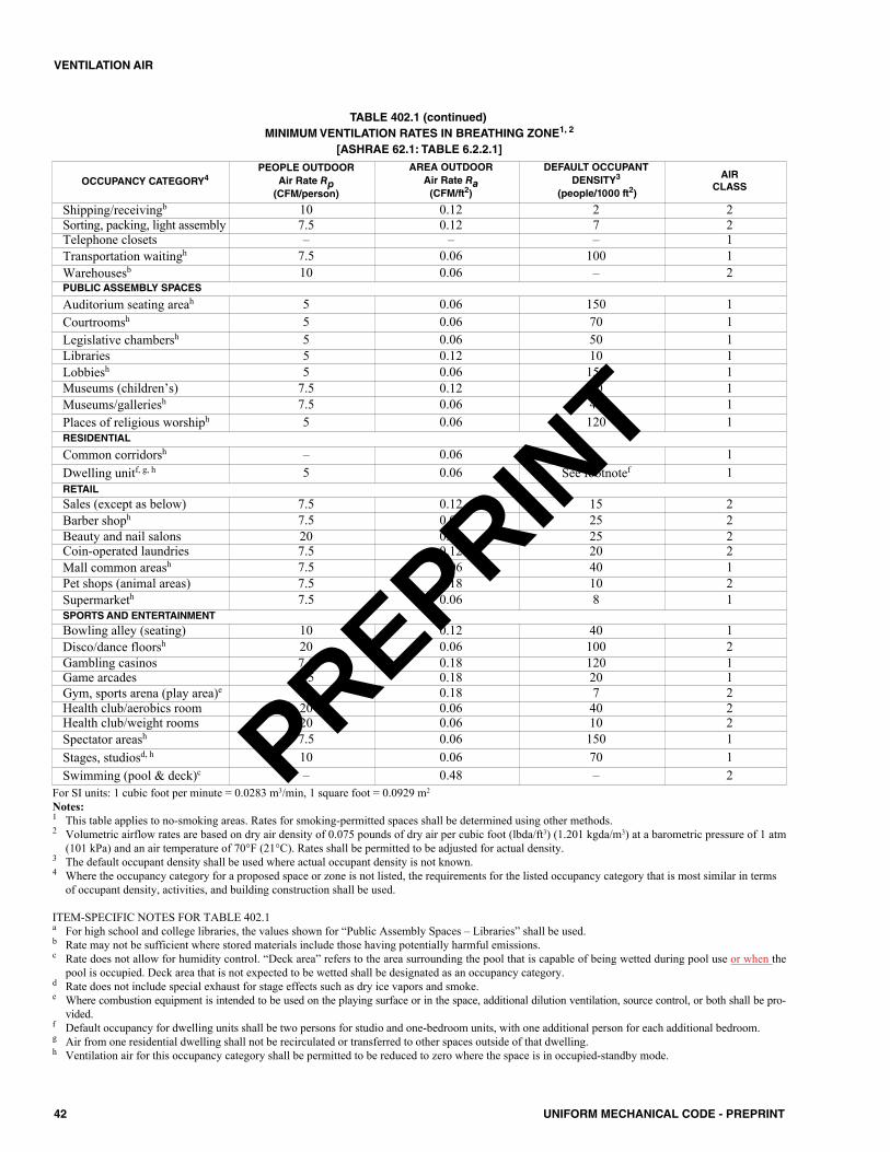
42 UNIFORM MECHANICAL CODE - PREPRINT
VENTILATION AIR
OCCUPANCY CATEGORY4PEOPLE OUTDOOR
Air Rate Rp(CFM/person)
AREA OUTDOOR Air Rate Ra(CFM/ft2)
DEFAULT OCCUPANT DENSITY3
(people/1000 ft2)
AIR CLASS
Shipping/receivingb 10 0.12 2 2Sorting, packing, light assembly 7.5 0.12 7 2Telephone closets – – – 1Transportation waitingh 7.5 0.06 100 1Warehousesb 10 0.06 – 2PUBLIC ASSEMBLY SPACES
Auditorium seating areah 5 0.06 150 1Courtroomsh 5 0.06 70 1Legislative chambersh 5 0.06 50 1Libraries 5 0.12 10 1Lobbiesh 5 0.06 150 1Museums (children’s) 7.5 0.12 40 1Museums/galleriesh 7.5 0.06 40 1Places of religious worshiph 5 0.06 120 1RESIDENTIAL
Common corridorsh – 0.06 – 1Dwelling unitf, g, h 5 0.06 See footnotef 1RETAIL
Sales (except as below) 7.5 0.12 15 2Barber shoph 7.5 0.06 25 2Beauty and nail salons 20 0.12 25 2Coin-operated laundries 7.5 0.12 20 2Mall common areash 7.5 0.06 40 1Pet shops (animal areas) 7.5 0.18 10 2Supermarketh 7.5 0.06 8 1SPORTS AND ENTERTAINMENT
Bowling alley (seating) 10 0.12 40 1Disco/dance floorsh 20 0.06 100 2Gambling casinos 7.5 0.18 120 1Game arcades 7.5 0.18 20 1Gym, sports arena (play area)e 20 0.18 7 2Health club/aerobics room 20 0.06 40 2Health club/weight rooms 20 0.06 10 2Spectator areash 7.5 0.06 150 1Stages, studiosd, h 10 0.06 70 1Swimming (pool & deck)c – 0.48 – 2
TABLE 402.1 (continued)MINIMUM VENTILATION RATES IN BREATHING ZONE1, 2
[ASHRAE 62.1: TABLE 6.2.2.1]
For SI units: 1 cubic foot per minute = 0.0283 m3/min, 1 square foot = 0.0929 m2
Notes:1 This table applies to no-smoking areas. Rates for smoking-permitted spaces shall be determined using other methods.2 Volumetric airflow rates are based on dry air density of 0.075 pounds of dry air per cubic foot (lbda/ft3) (1.201 kgda/m3) at a barometric pressure of 1 atm
(101 kPa) and an air temperature of 70°F (21°C). Rates shall be permitted to be adjusted for actual density.3 The default occupant density shall be used where actual occupant density is not known.4 Where the occupancy category for a proposed space or zone is not listed, the requirements for the listed occupancy category that is most similar in terms
of occupant density, activities, and building construction shall be used.
ITEM-SPECIFIC NOTES FOR TABLE 402.1a For high school and college libraries, the values shown for “Public Assembly Spaces – Libraries” shall be used.b Rate may not be sufficient where stored materials include those having potentially harmful emissions.c Rate does not allow for humidity control. “Deck area” refers to the area surrounding the pool that is capable of being wetted during pool use or when the
pool is occupied. Deck area that is not expected to be wetted shall be designated as an occupancy category.d Rate does not include special exhaust for stage effects such as dry ice vapors and smoke.e Where combustion equipment is intended to be used on the playing surface or in the space, additional dilution ventilation, source control, or both shall be pro-
vided.f Default occupancy for dwelling units shall be two persons for studio and one-bedroom units, with one additional person for each additional bedroom.g Air from one residential dwelling shall not be recirculated or transferred to other spaces outside of that dwelling.h Ventilation air for this occupancy category shall be permitted to be reduced to zero where the space is in occupied-standby mode.
PREPRINT
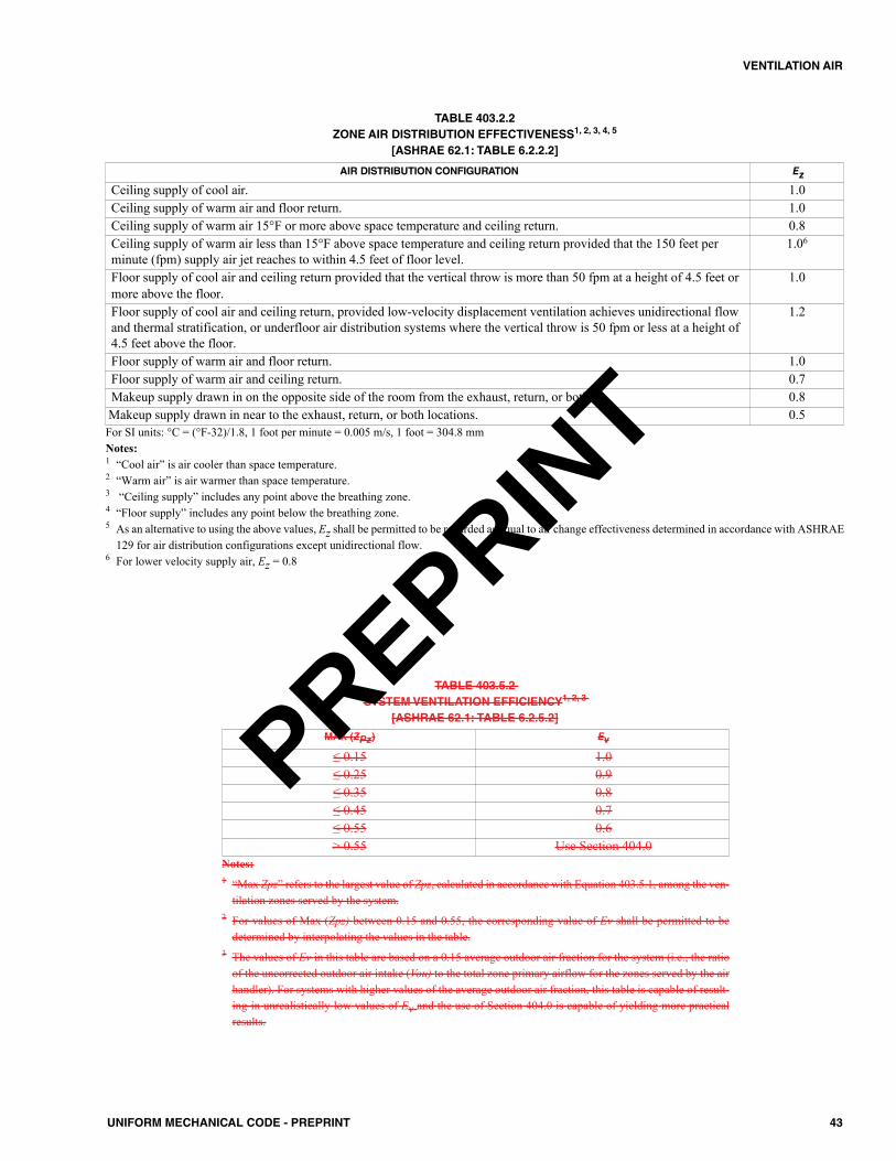
43UNIFORM MECHANICAL CODE - PREPRINT
VENTILATION AIR
TABLE 403.2.2ZONE AIR DISTRIBUTION EFFECTIVENESS1, 2, 3, 4, 5
[ASHRAE 62.1: TABLE 6.2.2.2]
AIR DISTRIBUTION CONFIGURATION Ez
Ceiling supply of cool air. 1.0Ceiling supply of warm air and floor return. 1.0Ceiling supply of warm air 15°F or more above space temperature and ceiling return. 0.8Ceiling supply of warm air less than 15°F above space temperature and ceiling return provided that the 150 feet perminute (fpm) supply air jet reaches to within 4.5 feet of floor level.
1.06
Floor supply of cool air and ceiling return provided that the vertical throw is more than 50 fpm at a height of 4.5 feet ormore above the floor.
1.0
Floor supply of cool air and ceiling return, provided low-velocity displacement ventilation achieves unidirectional flowand thermal stratification, or underfloor air distribution systems where the vertical throw is 50 fpm or less at a height of4.5 feet above the floor.
1.2
Floor supply of warm air and floor return. 1.0Floor supply of warm air and ceiling return. 0.7Makeup supply drawn in on the opposite side of the room from the exhaust, return, or both. 0.8Makeup supply drawn in near to the exhaust, return, or both locations. 0.5For SI units: °C = (°F-32)/1.8, 1 foot per minute = 0.005 m/s, 1 foot = 304.8 mmNotes:1 “Cool air” is air cooler than space temperature.2 “Warm air” is air warmer than space temperature.3 “Ceiling supply” includes any point above the breathing zone.4 “Floor supply” includes any point below the breathing zone.5 As an alternative to using the above values, Ez shall be permitted to be regarded as equal to air change effectiveness determined in accordance with ASHRAE
129 for air distribution configurations except unidirectional flow.6 For lower velocity supply air, Ez = 0.8
TABLE 403.5.2 SYSTEM VENTILATION EFFICIENCY1, 2, 3
[ASHRAE 62.1: TABLE 6.2.5.2]
MAX (ZPz) Ev
≤ 0.15 1.0≤ 0.25 0.9≤ 0.35 0.8≤ 0.45 0.7≤ 0.55 0.6> 0.55 Use Section 404.0
Notes:1 “Max Zpz” refers to the largest value of Zpz, calculated in accordance with Equation 403.5.1, among the ven-
tilation zones served by the system.2 For values of Max (Zpz) between 0.15 and 0.55, the corresponding value of Ev shall be permitted to be
determined by interpolating the values in the table.3 The values of Ev in this table are based on a 0.15 average outdoor air fraction for the system (i.e., the ratio
of the uncorrected outdoor air intake (Vou) to the total zone primary airflow for the zones served by the airhandler). For systems with higher values of the average outdoor air fraction, this table is capable of result-ing in unrealistically low values of Ev and the use of Section 404.0 is capable of yielding more practicalresults.
PREPRINT
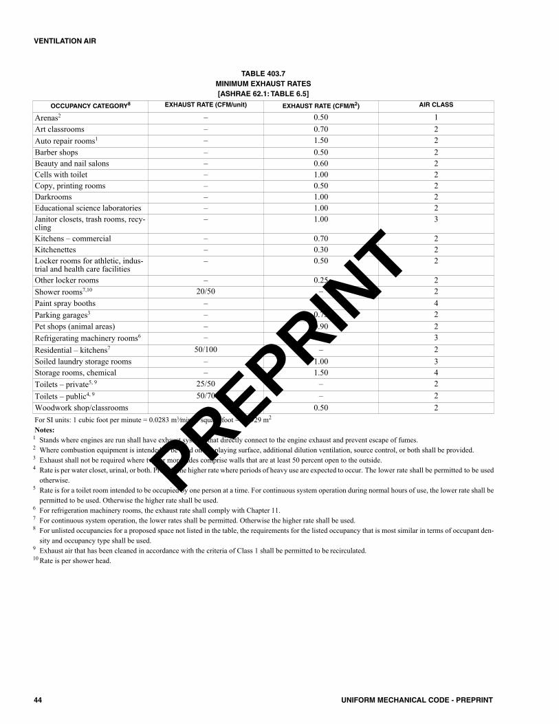
TABLE 403.7 MINIMUM EXHAUST RATES [ASHRAE 62.1: TABLE 6.5]
OCCUPANCY CATEGORY8 EXHAUST RATE (CFM/unit) EXHAUST RATE (CFM/ft2) AIR CLASS
Arenas2 – 0.50 1Art classrooms – 0.70 2Auto repair rooms1 – 1.50 2Barber shops – 0.50 2Beauty and nail salons – 0.60 2Cells with toilet – 1.00 2Copy, printing rooms – 0.50 2Darkrooms – 1.00 2Educational science laboratories – 1.00 2Janitor closets, trash rooms, recy-cling
– 1.00 3
Kitchens – commercial – 0.70 2Kitchenettes – 0.30 2Locker rooms for athletic, indus-trial and health care facilities
– 0.50 2
Other locker rooms – 0.25 2Shower rooms7,10 20/50 – 2Paint spray booths – – 4Parking garages3 – 0.75 2Pet shops (animal areas) – 0.90 2Refrigerating machinery rooms6 – – 3Residential – kitchens7 50/100 – 2Soiled laundry storage rooms – 1.00 3Storage rooms, chemical – 1.50 4Toilets – private5, 9 25/50 – 2Toilets – public4, 9 50/70 – 2Woodwork shop/classrooms – 0.50 2For SI units: 1 cubic foot per minute = 0.0283 m3⁄min, 1 square foot = 0.0929 m2
Notes:1 Stands where engines are run shall have exhaust systems that directly connect to the engine exhaust and prevent escape of fumes.2 Where combustion equipment is intended to be used on the playing surface, additional dilution ventilation, source control, or both shall be provided.3 Exhaust shall not be required where two or more sides comprise walls that are at least 50 percent open to the outside.4 Rate is per water closet, urinal, or both. Provide the higher rate where periods of heavy use are expected to occur. The lower rate shall be permitted to be used
otherwise.5 Rate is for a toilet room intended to be occupied by one person at a time. For continuous system operation during normal hours of use, the lower rate shall be
permitted to be used. Otherwise the higher rate shall be used.6 For refrigeration machinery rooms, the exhaust rate shall comply with Chapter 11.7 For continuous system operation, the lower rates shall be permitted. Otherwise the higher rate shall be used.8 For unlisted occupancies for a proposed space not listed in the table, the requirements for the listed occupancy that is most similar in terms of occupant den-
sity and occupancy type shall be used.9 Exhaust air that has been cleaned in accordance with the criteria of Class 1 shall be permitted to be recirculated.10 Rate is per shower head.
44 UNIFORM MECHANICAL CODE - PREPRINT
VENTILATION AIR
PREPRINT
501.0 General.501.1 Applicability. This chapter includes requirements forenvironmental air ducts, product-conveying systems, andcommercial hoods and kitchen ventilation. Part I addressesenvironmental air ducts and product conveying systems. PartII addresses commercial hoods and kitchen ventilation.
502.0 Termination.502.1 Exhaust Opening Protection. Exhaust openingsterminating to the outdoors shall be covered with a corrosion-resistant screen having not less than 1⁄4 of an inch (6.4 mm)openings, and shall have not more than 1⁄2 of an inch (12.7mm) openings.Exception: Clothes dryers.502.2 Termination of Exhaust Ducts. Exhaust ductsshall terminate in accordance with Section 502.2.1 throughSection 502.2.3.
502.2.1 Environmental Air Ducts. Environmental airduct exhaust shall terminate not less than 3 feet (914 mm)from a property line, 10 feet (3048 mm) from a forcedair inlet, 10 feet (3048 mm) above a public walkway, and3 feet (914 mm) from openings into the building. Thedischarge of Eenvironmental exhaust ducts shall not bedirected discharge onto a public walkway.502.2.2 Product Conveying Ducts. Ducts convey-ing explosive or flammable vapors, fumes, or dusts shallterminate not less than 30 feet (9144 mm) from a prop-erty line, 10 feet (3048 mm) from openings into thebuilding, 6 feet (1829 mm) from exterior walls or roofs,30 feet (9144 mm) from combustible walls or openingsinto the building that are in the direction of the exhaustdischarge, and 10 feet (3048 mm) above adjoining grade.
Other product-conveying outlets shall terminate notless than 10 feet (3048 mm) from a property line, 3 feet(914 mm) from exterior walls or roofs, 10 feet (3048mm) from openings into the building, and 10 feet (3048mm) above adjoining grade.502.2.3 Commercial Kitchen Ducts. Commercialkitchens exhaust ducts shall terminate in accordance withSection 510.9 or Section 519.5.
Part I – Environmental Air Ducts and Product-Conveying Systems.
503.0 Motors, Fans, and Filters.503.1 General. Motors and fans shall be sized to providethe required air movement. Motors in areas that contain flam-mable vapors or dusts shall be of a type approved for suchenvironments. A manually operated remote control installed
at an approved location shall be provided to shut off fans orblowers in flammable vapor or dust systems. Equipment usedin operations that generate explosive or flammable vapors,fumes, or dusts shall be interlocked with the ventilation sys-tem so that the equipment cannot be operated unless the ven-tilation fans are in operation. Motors for fans used to conveyflammable vapors or dusts shall be located outside the duct orshall be protected with approved shields and dustproofing.Where belts are used, they shall not enter the duct unless thebelt and pulley within the duct are enclosed. Motors and fansshall be accessible for servicing and maintenance.503.2 Fans. Parts of fans in contact with explosive or flam-mable vapors, fumes, or dusts shall be of nonferrous or non-sparking materials, or their casing shall be lined orconstructed of such material. Where the size and hardness ofmaterials passing through a fan are capable of producing aspark, both the fan, and the casing shall be of nonsparkingmaterials. Where fans are required to be spark-resistant, theirbearings shall not be within the airstream, and parts of the fanshall be grounded. Fans in systems handling materials thatare likely to clog the blades, and fans in buffing or wood-working exhaust systems, shall be of the radial-blade ortube-axial type.
Equipment used to exhaust explosive or flammablevapors, fumes, or dusts shall bear an identification plate stat-ing the ventilation rate for which the system was designed.
Fans located in systems conveying corrosives shall be ofmaterials that are resistant to the corrosive or shall be coatedwith corrosion-resistant materials.
504.0 Environmental Air Ducts.504.1 General.Where not specified in this chapter, exhaustducts shall be constructed and installed in accordance withChapter 6 and shall be airtight as approved by the AuthorityHaving Jurisdiction. Environmental air ducts that have analternate function as a part of an approved smoke-control sys-tem do not require design as Class 1 product-conveying ducts.Exceptions:(1) Ductless range hoods where installed in accordance with
the manufacturer’s installation instructions.(2) Condensing clothes dryers where installed in accordance
with the manufacturer’s installation instructions.504.1.1 Backdraft Protection. Exhaust ducts shallterminate outside the building and shall be equipped withbackdraft dampers or with motorized dampers that auto-matically shut where the systems or spaces served arenot in use.Exception: Where the exhaust duct does not dischargeinto a common exhaust plenum and one of the follow-ing:
45UNIFORM MECHANICAL CODE - PREPRINT
CHAPTER 5EXHAUST SYSTEMS
PREPRINT
(1) The exhaust fan runs continuously.(2) The exhaust duct serves space(s) that are not
mechanically heated or cooled.(3) The space served is maintained at positive pressure.
504.2 Independent Exhaust Systems. Single or com-bined mechanical exhaust systems shall be independent ofother exhaust systems.504.3 Domestic Range. Ducts used for domestic kitchenrange or cooktop ventilation shall be of metal and shall havesmooth interior surfaces.Exception: Ducts for domestic kitchen downdraft grill-rangeventilation installed under a concrete slab floor shall be per-mitted to be of approved Schedule 40 PVC provided:(1) The under-floor trench in which the duct is installed shall
be completely backfilled with sand or gravel.(2) Not more than 1 inch (25.4 mm) of 6 inch diameter (152
mm) PVC coupling shall be permitted to protrude abovethe concrete floor surface.
(3) PVC pipe joints shall be solvent cemented to provide anair and greasetight duct.
(4) The duct shall terminate above grade outside the build-ing and shall be equipped with a backdraft damper.
504.4 Clothes Dryers. A clothes dryer exhaust duct shall notbe connected to a vent connector, gas vent, chimney, and shallnot terminate into a crawl space, attic, or other concealed space.Exhaust ducts shall not be assembled with screws or other fas-tening means that extend into the duct and that are capable ofcatching lint, and that reduce the efficiency of the exhaust sys-tem. Exhaust ducts shall be constructed of rigid metallicmaterial. Transition ducts used to connect the dryer to theexhaust duct shall be listed and labeled in accordance withUL 2158A, or installed in accordance with the clothes dryermanufacturer’s installation instructions. Clothes dryerexhaust ducts shall terminate to the outside of the building inaccordance with Section 502.2.1 and shall be equipped with abackdraft damper. Screens shall not be installed at the duct ter-mination. Devices, such as fire or smoke dampers that willobstruct the flow of the exhaust shall not be used. Where join-ing of ducts, the male end shall be inserted in the direction of air-flow.
504.4.1 Provisions for Makeup Air.Makeup air shallbe provided in accordance with the following:(1) Makeup air shall be provided for Type 1 clothes dry-
ers in accordance with the manufacturer’s installa-tion instructions. [NFPA 54:10.4.3.1] Where a closetis designed for the installation of a clothes dryer, anopening of not less than 100 square inches (0.065m2) for makeup air shall be provided in the door orby other approved means.
(2) Provision for makeup air shall be provided for Type2 clothes dryers, with a minimum free area of not lessthan 1 square inch (0.0006 m2) for each 1000 Britishthermal units per hour (Btu/h) (0.293 kW) total inputrating of the dryer(s) installed. [NFPA 54:10.4.3.2]
504.4.2 Domestic Clothes Dryers. Where a com-partment or space for a Type 1 clothes dryer is provided,not less than a 4 inch diameter (102 mm) exhaust duct ofapproved material shall be installed in accordance withSection 504.0.
Type 1 clothes dryer exhaust ducts shall be of rigidmetal and shall have smooth interior surfaces. The diam-eter shall be not less than 4 inches nominal (100 mm),and the thickness shall be not less than 0.016 of an inch(0.406 mm).
504.4.2.1 Length Limitation. Unless otherwisepermitted or required by the dryer manufacturer’sinstructions and approved by the Authority HavingJurisdiction, domestic dryer moisture exhaust ductsshall not exceed a total combined horizontal and ver-tical length of 14 feet (4267 mm), including two 90degree (1.57 rad) elbows. A length of 2 feet (610mm) shall be deducted for each 90 degree (1.57 rad)elbow in excess of two.Exception: Where an exhaust duct power ventila-tor, in accordance with Section 504.4.2.3, is used,the maximum length of the dryer exhaust duct shallbe permitted to be in accordance with the dryerexhaust duct power ventilator manufacturer’s instal-lation instructions.504.4.2.2 Transition Ducts. Listed clothes dryertransition ducts not more than 6 feet (1829 mm) inlength shall be permitted to be used to connect theType 1 dryer to the exhaust ducts. Transition ductsand flexible clothes dryer transition ducts shall notbe concealed within construction, and shall beinstalled in accordance with the manufacturer’sinstallation instructions.504.4.2.3 Exhaust Duct Power Ventilators.Dryer exhaust duct power ventilators for single res-idential clothes dryers shall be listed and labeled inaccordance with UL 705 and installed in accordancewith the manufacturer’s installation instructions.
504.4.3 Commercial Clothes Dryers. Commercialdryer exhaust ducts shall be installed in accordance withtheir listings. The installation of commercial clothesdryer exhaust ducts shall comply with the appliance man-ufacturer’s installation instructions.
504.4.3.1 Exhaust Ducts for Type 2 ClothesDryers. Exhaust ducts for Type 2 clothes dryersshall comply with the following:(1) Exhaust ducts for Type 2 clothes dryers shall
comply with Section 504.4. [NFPA 54:10.4.5.1](2) Exhaust ducts for Type 2 clothes dryers shall be
constructed of sheet metal or other noncom-bustible material. Such ducts shall be equivalentin strength and corrosion resistance to ducts madeof galvanized sheet steel not less than 0.0195 ofan inch (0.4953 mm) thick. [NFPA 54:10.4.5.2]
(3) Type 2 clothes dryers shall be equipped orinstalled with lint-controlling means. [NFPA54:10.4.5.3]
46 UNIFORM MECHANICAL CODE - PREPRINT
EXHAUST SYSTEMS
PREPRINT

(4) Exhaust ducts for unlisted Type 2 clothes dry-ers shall be installed with a minimum clearanceof 6 inches (152 mm) from adjacent com-bustible material. Where exhaust ducts for Type2 clothes dryers are installed with reducedclearances, the adjacent combustible materialshall be protected in accordance with Table303.10.1. [NFPA 54:10.4.5.4]
(5) Where ducts pass through walls, floors, or par-titions, the space around the duct shall besealed with noncombustible material. [NFPA54:10.4.5.5]
(6) Multiple installations of Type 2 clothes dryersshall be made in a manner to prevent adverseoperation due to back pressures that might becreated in the exhaust systems. [NFPA54:10.4.5.6] The exhaust fan shall operate con-tinuously or shall be interlocked to exhaust airwhere a clothes dryer is in operation.
504.4.4 Common Exhaust. Where permitted by theclothes dryer manufacturer’s installation instructions,multiple clothes dryers shall be permitted to be installedwith a common exhaust. The common exhaust duct shallbe constructed of rigid metal and shall be installed in afire-resistant rated enclosure in accordance with thebuilding code. The duct material shall be of rigid metalwith a thickness of not less than 0.020 of an inch (0.508mm) (24 gauge). The duct enclosure shall be providedwith a cleanout opening at the base of not less than 12inches by 12 inches (305 mm by 305 mm). The exhaustfan shall be located downstream of branch connectionsand operated continuously and shall be monitored by anapproved means.504.4.5 Duct Supports. Ducts shall be supported inaccordance with SMACNA HVAC Duct ConstructionStandards – Metal and Flexible.
504.5 Heat (Energy) Recovery Ventilators. Heat(energy) recovery ventilators shall be installed in accordancewith their listings and comply with the appliance manufac-turer’s installation instructions. Non-ducted heat recoveryventilators shall comply with UL 1815. Ducted heat recov-ery ventilators shall comply with UL 1812. Heat (energy)recovery ventilator ducts shall comply with Chapter 6.504.6 Gypsum Wallboard Ducts. Bathroom and laundryroom exhaust ducts shall be permitted to be of gypsum wall-board subject to the limitations of Section 602.4.2.
505.0 Product-Conveying Systems.505.1 General.A mechanical ventilation or exhaust systemshall be installed to control, capture, and remove emissionsgenerated from product use or handling where required inaccordance with the building code or fire code and wheresuch emissions result in a hazard to life or property. Thedesign of the system shall be such that the emissions are con-fined to the area in which they are generated by air currents,hoods, or enclosures and shall be exhausted by a duct systemto a safe location or treated by removing contaminants. Ductsconveying explosives or flammable vapors, fumes, or dusts
shall extend directly to the exterior of the building withoutentering other spaces and shall not extend into or throughducts and plenums. Exception: Ducts conveying vapor or fumes having flam-mable constituents less than 25 percent of their Lower Flam-mability Limit (LFL) shall be permitted to pass through otherspaces.
505.1.1 Mechanical Ventilation. A mechanical ven-tilation system shall be interlocked to operate with theequipment used to produce vapors, fumes, or dusts thatare flammable or hazardous.
505.2 Incompatible Materials. Incompatible materialsshall not be conveyed in the same system. [NFPA 91:4.2.2]505.3 Flammability Limit. Unless the circumstances stip-ulated in Section 505.3.1, Section 505.3.2, or Section 505.3.3exist, in systems conveying flammable vapors, gases, ormists, the concentration shall not exceed 25 percent of thelower flammability limit (LFL). [NFPA 91:4.2.3]
505.3.1 Higher Concentrations. Higher concentra-tions shall be permitted where if the exhaust system isdesigned and protected in accordance with NFPA 69,using one or more of the following techniques:(1) Combustible concentration reduction(2) Oxidant concentration reduction(3) Deflagration suppression(4) Deflagration pressure containment [NFPA 91:4.2.3.1]
Contaminated air shall not be recirculated to occu-pied areas unless contaminants have been removed. Aircontaminated with explosive or flammable vapors,fumes, or dusts; flammable or toxic gases; or radioactivematerial shall not be recirculated.505.3.2 Ovens and Furnaces. Higher concentrationsshall be permitted for ovens and furnaces designed andprotected in accordance with NFPA 86. [NFPA 91:4.2.3.2]505.3.3 Deflagration. Higher concentrations shall bepermitted where deflagration venting is provided inaccordance with NFPA 68. [NFPA 91:4.2.3.3]
505.4 Air-Moving Devices. Air-moving devices shall besized to establish the velocity required to capture, control, andconvey materials through the exhaust system. [NFPA91:4.2.5]505.5 Generating Flames, Sparks, or Hot Materials.Operations generating flames, sparks, or hot material such asfrom grinding wheels and welding shall not be manifoldedinto an any exhaust system that air conveys flammable orcombustible materials. [NFPA 91:4.2.6]505.6 Fire Dampers. Fire dampers shall be permitted to beinstalled in exhaust systems in accordance with the following:(1) Where ducts pass through fire barriers(2) Where a collection system installed on the end of the sys-
tem is protected with an automatic extinguishing system(3) Where the duct system is protected with an automatic
extinguishing system(4) Where ducts have been listed with interrupters(5) Where necessary to facilitate the control of smoke pur-
suant to the applicable NFPA standards [NFPA 91:4.2.9]
47UNIFORM MECHANICAL CODE - PREPRINT
EXHAUST SYSTEMS
PREPRINT
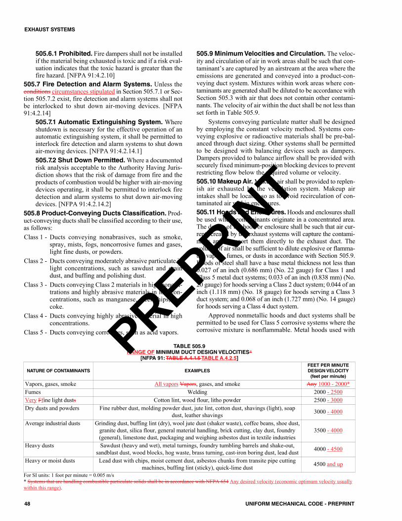
505.6.1 Prohibited. Fire dampers shall not be installedif the material being exhausted is toxic and if a risk eval-uation indicates that the toxic hazard is greater than thefire hazard. [NFPA 91:4.2.10]
505.7 Fire Detection and Alarm Systems. Unless theconditions circumstances stipulated in Section 505.7.1 or Sec-tion 505.7.2 exist, fire detection and alarm systems shall notbe interlocked to shut down air-moving devices. [NFPA91:4.2.14]
505.7.1 Automatic Extinguishing System. Whereshutdown is necessary for the effective operation of anautomatic extinguishing system, it shall be permitted tointerlock fire detection and alarm systems to shut downair-moving devices. [NFPA 91:4.2.14.1]505.7.2 Shut Down Permitted.Where a documentedrisk analysis acceptable to the Authority Having Juris-diction shows that the risk of damage from fire and theproducts of combustion would be higher with air-movingdevices operating, it shall be permitted to interlock firedetection and alarm systems to shut down air-movingdevices. [NFPA 91:4.2.14.2]
505.8 Product-Conveying Ducts Classification. Prod-uct-conveying ducts shall be classified according to their use,as follows:Class 1 - Ducts conveying nonabrasives, such as smoke,
spray, mists, fogs, noncorrosive fumes and gases,light fine dusts, or powders.
Class 2 - Ducts conveying moderately abrasive particulate inlight concentrations, such as sawdust and graindust, and buffing and polishing dust.
Class 3 - Ducts conveying Class 2 materials in high concen-trations and highly abrasive materials in low con-centrations, such as manganese, steel chips, andcoke.
Class 4 - Ducts conveying highly abrasive material in highconcentrations.
Class 5 - Ducts conveying corrosives, such as acid vapors.
505.9 Minimum Velocities and Circulation. The veloc-ity and circulation of air in work areas shall be such that con-taminant’s are captured by an airstream at the area where theemissions are generated and conveyed into a product-con-veying duct system. Mixtures within work areas where con-taminants are generated shall be diluted to be accordance withSection 505.3 with air that does not contain other contami-nants. The velocity of air within the duct shall be not less thanset forth in Table 505.9.
Systems conveying particulate matter shall be designedby employing the constant velocity method. Systems con-veying explosive or radioactive materials shall be pre-bal-anced through duct sizing. Other systems shall be permittedto be designed with balancing devices such as dampers.Dampers provided to balance airflow shall be provided withsecurely fixed minimum-position blocking devices to preventrestricting flow below the required volume or velocity.505.10 Makeup Air.Makeup air shall be provided to replen-ish air exhausted by the ventilation system. Makeup airintakes shall be located so as to avoid recirculation of con-taminated air within enclosures.505.11 Hoods and Enclosures.Hoods and enclosures shallbe used where contaminants originate in a concentrated area.The design of the hood or enclosure shall be such that air cur-rents created by the exhaust systems will capture the contami-nants and transport them directly to the exhaust duct. Thevolume of air shall be sufficient to dilute explosive or flamma-ble vapors, fumes, or dusts in accordance with Section 505.9.Hoods of steel shall have a base metal thickness not less than0.027 of an inch (0.686 mm) (No. 22 gauge) for Class 1 andClass 5 metal duct systems; 0.033 of an inch (0.838 mm) (No.20 gauge) for hoods serving a Class 2 duct system; 0.044 of aninch (1.118 mm) (No. 18 gauge) for hoods serving a Class 3duct system; and 0.068 of an inch (1.727 mm) (No. 14 gauge)for hoods serving a Class 4 duct system.
Approved nonmetallic hoods and duct systems shall bepermitted to be used for Class 5 corrosive systems where thecorrosive mixture is nonflammable. Metal hoods used with
48 UNIFORM MECHANICAL CODE - PREPRINT
EXHAUST SYSTEMS
NATURE OF CONTAMINANTS EXAMPLESFEET PER MINUTEDESIGNVELOCITY (feet per minute)
Vapors, gases, smoke All vapors Vapors, gases, and smoke Any 1000 - 2000*Fumes Welding 2000 - 2500Very Ffine light dusts Cotton lint, wood flour, litho powder 2500 - 3000Dry dusts and powders Fine rubber dust, molding powder dust, jute lint, cotton dust, shavings (light), soap
dust, leather shavings 3000 - 4000
Average industrial dusts Grinding dust, buffing lint (dry), wool jute dust (shaker waste), coffee beans, shoe dust,granite dust, silica flour, general material handling, brick cutting, clay dust, foundry(general), limestone dust, packaging and weighing asbestos dust in textile industries
3500 - 4000
Heavy dusts Sawdust (heavy and wet), metal turnings, foundry tumbling barrels and shake-out,sandblast dust, wood blocks, hog waste, brass turning, cast-iron boring dust, lead dust 4000 - 4500
Heavy or moist dusts Lead dust with chips, moist cement dust, asbestos chunks from transite pipe cuttingmachines, buffing lint (sticky), quick-lime dust 4500 and up
TABLE 505.9 RANGE OF MINIMUM DUCT DESIGN VELOCITIES*
[NFPA 91: TABLE A.4.1.5 TABLE A.4.2.5]
For SI units: 1 foot per minute = 0.005 m/s * Systems that are handling combustible particulate solids shall be in accordance with NFPA 654 Any desired velocity (economic optimum velocity usuallywithin this range).
PREPRINT
Class 5 duct systems shall be protected with an approved cor-rosion-resistant material. Edges of hoods shall be rounded.The minimum clearance between hoods and combustible con-struction shall be the clearance required by the duct system.
506.0 Product-Conveying Ducts.506.1 Materials.Materials used in product-conveying ductsystems shall be suitable for the intended use and shall be ofmetal.Exceptions:(1) Asbestos-cement, concrete, clay, or ceramic materials
shall be permitted to be used where it is shown that thesematerials will be equivalent to metal ducts installed inaccordance with this chapter.
(2) Ducts serving a Class 5 system shall be permitted to beconstructed of approved nonmetallic material where thecorrosive characteristics of the material being conveyedmake a metal system unsuitable and where the mixturebeing conveyed is nonflammable.
Approved nonmetallic material shall be either a listedproduct having a flame-spread index not exceeding 25and a smoke-developed rating of 50 or less on both insideand outside surfaces without evidence of continued pro-gressive combustion, or shall have a flame-spread indexnot exceeding 25 and shall be installed with an automaticfire-sprinkler protection system inside the duct.
(3) Ducts used in central vacuum cleaning systems within adwelling unit shall be constructed of materials in accor-dance with ASTM F2158 or the applicable standards ref-erenced in Chapter 17. Penetrations of fire walls orfloor-ceiling or roof-ceiling assemblies shall be in accor-dance with the building code.Copper or ferrous pipes or conduits extending from
within the separation between a garage and dwelling unit tothe central vacuuming unit shall be permitted to be used.
Aluminum ducts shall not be used in systems conveyingflammable vapors, fumes, or explosive dusts, nor in Class 2,3, or 4 systems. Galvanized steel and aluminum ducts shallnot be used where the temperature of the material being con-veyed exceeds 400°F (204°C).
Metal ducts used in Class 5 systems that are not resistantto the corrosiveness of the product shall be protected with anapproved corrosion-resistant material.506.2 Construction. Ducts used for conveying productsshall be airtight construction as approved by the AuthorityHaving Jurisdiction, and shall not have openings other thanthose required for operation and maintenance of the system.Ducts constructed of steel shall comply with Table 506.2(1)or Table 506.2(2).Exceptions:(1) Class 1 product-conveying ducts that operate at less than
4 inches water column (0.9 kPa) negative pressure andconvey noncorrosive, nonflammable and nonexplosivematerials at temperatures not exceeding 250°F (121°C)shall be permitted to be constructed in accordance withSMACNA HVAC Duct Construction Standards–Metaland Flexible.
(2) Ducts used in central vacuuming systems within adwelling unit shall be constructed of materials in accor-dance with ASTM F2158 or the applicable standards ref-erenced in Chapter 17. Penetrations of fire-resistive wallsor floor-ceiling or roof-ceiling assemblies shall be inaccordance with the building code. Copper or ferrouspipes or conduit extending from within the separationbetween a garage and dwelling unit to the central vac-uum unit shall be permitted to be used.The use of rectangular ducts conveying particulates shall
be subject to approval of the Authority Having Jurisdiction.The design of rectangular ducts shall consider the adhesive-ness and buildup of products being conveyed within the duct.
Aluminum construction shall be permitted to be used inClass 1 duct systems. The thickness of aluminum ducts shallbe not less than two Brown and Sharpe gauges thicker thanthe gauges required for steel ducts set forth in Table 506.2(1)and Table 506.2(2). 506.3 Penetrations. Exhaust ducts shall not pass throughfire walls, as defined by NFPA 221. [{NFPA 91:4.2.11}]
506.3.1 Fire Barriers. Exhaust ducts passing througha fire barrier having a fire resistance rating of 2 hours ormore greater shall meet one of the following specifica-tions:(1) Wrapped or encased with listed or approved materi-
als having a fire resistance rating equal to the firebarrier for 10 feet (3048 mm) of the duct on eachside of the fire barrier including duct supports withinthis span.
(2) Constructed of materials and supports having a min-imum fire resistance rating equal to the fire barrier.
(3) Enclosed with a shaft that is constructed of materialhaving a fire resistance rating equal to the fire bar-rier for 10 feet (3048 mm) of the duct on each sideof the fire barrier with no inlets to the duct withinthis distance, and the duct entry into and exit fromthe shaft is protected in accordance with Section506.3.2. [NFPA 91:4.2.12]
506.3.2 Protection. Exhaust ducts passing through firebarriers of any fire resistance rating shall be protected bysealing the space around the duct with listed or approvedfire stopping having a fire resistance rating equal to thefire resistance rating of the fire barrier. [NFPA 91:4.2.13]
506.4 Condensate. Joints in duct construction shall be liq-uidtight when the conveying system contains condensablevapors or liquids in suspension. [NFPA 91:4.3.6.1]
506.4.1 Drainage. Provisions shall be made fordrainage of condensate at low points in the duct. [NFPA91:4.3.6.2]
506.5 Fittings. Fittings in Class 2, 3, and 4 systems shall benot less than two gauges thicker than the thickness requiredfor straight runs. Flexible metallic duct shall be permitted tobe used for connecting ductwork to vibrating equipment. Ductsystems subject to wide temperature fluctuations shall be pro-vided with expansion joints.
Branches shall connect to main ducts at the large end oftransitions at an angle not exceeding 45 degrees (0.79 rad).
49UNIFORM MECHANICAL CODE - PREPRINT
EXHAUST SYSTEMS
PREPRINT
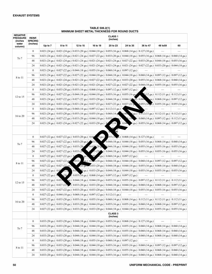
50 UNIFORM MECHANICAL CODE - PREPRINT
EXHAUST SYSTEMS
NEGATIVEPRESSURE(incheswatercolumn)
REINF.SPACING(inches)
CLASS 1 (inches)
Up to 7 8 to 11 12 to 15 16 to 19 20 to 23 24 to 35 36 to 47 48 to59 60
To 7
0 0.021 (24 ga.) 0.021 (24 ga.) 0.033 (20 ga.) 0.044 (18 ga.) 0.055 (16 ga.) 0.068 (14 ga.) 0.127 (10 ga.) –– ––
96 0.021 (24 ga.) 0.021 (24 ga.) 0.021 (24 ga.) 0.027 (22 ga.) 0.033 (20 ga.) 0.044 (18 ga.) 0.055 (16 ga.) 0.068 (14 ga.) 0.068 (14 ga.)
48 0.021 (24 ga.) 0.021 (24 ga.) 0.021 (24 ga.) 0.021 (24 ga.) 0.021 (24 ga.) 0.027 (22 ga.) 0.033 (20 ga.) 0.044 (18 ga.) 0.055 (16 ga.)
24 0.021 (24 ga.) 0.021 (24 ga.) 0.021 (24 ga.) 0.021 (24 ga.) 0.021 (24 ga.) 0.021 (24 ga.) 0.027 (22 ga.) 0.033 (20 ga.) 0.044 (18 ga.)
8 to 11
0 0.021 (24 ga.) 0.027 (22 ga.) 0.044 (18 ga.) 0.055 (16 ga.) 0.068 (14 ga.) 0.097 (12 ga.) –– –– ––
96 0.021 (24 ga.) 0.027 (22 ga.) 0.027 (22 ga.) 0.044 (18 ga.) 0.044 (18 ga.) 0.044 (18 ga.) 0.068 (14 ga.) 0.097 (12 ga.) 0.097 (12 ga.)
48 0.021 (24 ga.) 0.021 (24 ga.) 0.021 (24 ga.) 0.027 (22 ga.) 0.033 (20 ga.) 0.033 (20 ga.) 0.055 (16 ga.) 0.068 (14 ga.) 0.068 (14 ga.)
24 0.021 (24 ga.) 0.021 (24 ga.) 0.021 (24 ga.) 0.021 (24 ga.) 0.027 (22 ga.) 0.027 (22 ga.) 0.044 (18 ga.) 0.055 (16 ga.) 0.055 (16 ga.)
12 to 15
0 0.021 (24 ga.) 0.033 (20 ga.) 0.055 (16 ga.) 0.068 (14 ga.) 0.097 (12 ga.) 0.097 (12 ga.) –– –– ––
96 0.021 (24 ga.) 0.027 (22 ga.) 0.044 (18 ga.) 0.044 (18 ga.) 0.055 (16 ga.) 0.055 (16 ga.) 0.097 (12 ga.) 0.112 (11 ga.) 0.112 (11 ga.)
48 0.021 (24 ga.) 0.027 (22 ga.) 0.027 (22 ga.) 0.033 (20 ga.) 0.044 (18 ga.) 0.044 (18 ga.) 0.068 (14 ga.) 0.068 (14 ga.) 0.097 (12 ga.)
24 0.021 (24 ga.) 0.021 (24 ga.) 0.021 (24 ga.) 0.027 (22 ga.) 0.027 (22 ga.) 0.027 (22 ga.) 0.055 (16 ga.) 0.055 (16 ga.) 0.055 (16 ga.)
16 to 20
0 0.021 (24 ga.) 0.044 (18 ga.) 0.068 (14 ga.) 0.097 (12 ga.) 0.112 (11 ga.) –– –– –– ––
96 0.021 (24 ga.) 0.033 (20 ga.) 0.055 (16 ga.) 0.055 (16 ga.) 0.068 (14 ga.) 0.068 (14 ga.) 0.112 (11 ga.) 0.112 (11 ga.) 0.112 (11 ga.)
48 0.021 (24 ga.) 0.027 (22 ga.) 0.033 (20 ga.) 0.044 (18 ga.) 0.055 (16 ga.) 0.055 (16 ga.) 0.068 (14 ga.) 0.097 (12 ga.) 0.112 (11 ga.)
24 0.021 (24 ga.) 0.021 (24 ga.) 0.027 (22 ga.) 0.033 (20 ga.) 0.044 (18 ga.) 0.044 (18 ga.) 0.055 (16 ga.) 0.068 (14 ga.) 0.097 (12 ga.)
CLASS 2(inches)
To 7
0 0.027 (22 ga.) 0.027 (22 ga.) 0.033 (20 ga.) 0.044 (18 ga.) 0.055 (16 ga.) 0.068 (14 ga.) 0.127 (10 ga.) –– ––
96 0.027 (22 ga.) 0.027 (22 ga.) 0.033 (20 ga.) 0.033 (20 ga.) 0.044 (18 ga.) 0.044 (18 ga.) 0.055 (16 ga.) 0.068 (14 ga.) 0.068 (14 ga.)
48 0.027 (22 ga.) 0.027 (22 ga.) 0.033 (20 ga.) 0.033 (20 ga.) 0.044 (18 ga.) 0.044 (18 ga.) 0.055 (16 ga.) 0.055 (16 ga.) 0.055 (16 ga.)
24 0.027 (22 ga.) 0.027 (22 ga.) 0.033 (20 ga.) 0.033 (20 ga.) 0.044 (18 ga.) 0.044 (18 ga.) 0.055 (16 ga.) 0.055 (16 ga.) 0.055 (16 ga.)
8 to 11
0 0.027 (22 ga.) 0.027 (22 ga.) 0.044 (18 ga.) 0.055 (16 ga.) 0.068 (14 ga.) 0.097 (12 ga.) –– –– ––
96 0.027 (22 ga.) 0.027 (22 ga.) 0.033 (20 ga.) 0.044 (18 ga.) 0.044 (18 ga.) 0.044 (18 ga.) 0.068 (14 ga.) 0.097 (12 ga.) 0.097 (12 ga.)
48 0.027 (22 ga.) 0.027 (22 ga.) 0.033 (20 ga.) 0.033 (20 ga.) 0.044 (18 ga.) 0.044 (18 ga.) 0.055 (16 ga.) 0.068 (14 ga.) 0.068 (14 ga.)
24 0.027 (22 ga.) 0.027 (22 ga.) 0.033 (20 ga.) 0.033 (20 ga.) 0.044 (18 ga.) 0.044 (18 ga.) 0.055 (16 ga.) 0.055 (16 ga.) 0.055 (16 ga.)
12 to 15
0 0.027 (22 ga.) 0.033 (20 ga.) 0.055 (16 ga.) 0.068 (14 ga.) 0.097 (12 ga.) 0.097 (12 ga.) –– –– ––
96 0.027 (22 ga.) 0.033 (20 ga.) 0.044 (18 ga.) 0.044 (18 ga.) 0.055 (16 ga.) 0.055 (16 ga.) 0.097 (12 ga.) 0.112 (11 ga.) 0.112 (11 ga.)
48 0.027 (22 ga.) 0.027 (22 ga.) 0.033 (20 ga.) 0.033 (20 ga.) 0.044 (18 ga.) 0.044 (18 ga.) 0.068 (14 ga.) 0.068 (14 ga.) 0.097 (12 ga.)
24 0.027 (22 ga.) 0.027 (22 ga.) 0.033 (20 ga.) 0.033 (20 ga.) 0.044 (18 ga.) 0.044 (18 ga.) 0.055 (16 ga.) 0.055 (16 ga.) 0.055 (16 ga.)
16 to 20
0 0.027 (22 ga.) 0.044 (18 ga.) 0.068 (14 ga.) 0.097 (12 ga.) 0.112 (11 ga.) –– –– –– ––
96 0.027 (22 ga.) 0.033 (20 ga.) 0.055 (16 ga.) 0.055 (16 ga.) 0.068 (14 ga.) 0.068 (14 ga.) 0.112 (11 ga.) 0.112 (11 ga.) 0.112 (11 ga.)
48 0.027 (22 ga.) 0.033 (20 ga.) 0.033 (20 ga.) 0.044 (18 ga.) 0.055 (16 ga.) 0.055 (16 ga.) 0.068 (14 ga.) 0.068 (14 ga.) 0.097 (12 ga.)
24 0.027 (22 ga.) 0.033 (20 ga.) 0.033 (20 ga.) 0.033 (20 ga.) 0.044 (18 ga.) 0.044 (18 ga.) 0.055 (16 ga.) 0.055 (16 ga.) 0.055 (16 ga.)CLASS 3 (inches)
To 7
0 0.033 (20 ga.) 0.033 (20 ga.) 0.044 (18 ga.) 0.044 (18 ga.) 0.055 (16 ga.) 0.068 (14 ga.) 0.127 (10 ga.) –– ––
96 0.033 (20 ga.) 0.033 (20 ga.) 0.044 (18 ga.) 0.044 (18 ga.) 0.055 (16 ga.) 0.055 (16 ga.) 0.068 (14 ga.) 0.068 (14 ga.) 0.068 (14 ga.)
48 0.033 (20 ga.) 0.033 (20 ga.) 0.044 (18 ga.) 0.044 (18 ga.) 0.055 (16 ga.) 0.055 (16 ga.) 0.068 (14 ga.) 0.068 (14 ga.) 0.068 (14 ga.)
24 0.033 (20 ga.) 0.033 (20 ga.) 0.044 (18 ga.) 0.044 (18 ga.) 0.055 (16 ga.) 0.055 (16 ga.) 0.068 (14 ga.) 0.068 (14 ga.) 0.068 (14 ga.)
8 to 11
0 0.033 (20 ga.) 0.033 (20 ga.) 0.044 (18 ga.) 0.055 (16 ga.) 0.068 (14 ga.) 0.097 (12 ga.) –– –– ––
96 0.033 (20 ga.) 0.033 (20 ga.) 0.044 (18 ga.) 0.044 (18 ga.) 0.055 (16 ga.) 0.055 (16 ga.) 0.068 (14 ga.) 0.097 (12 ga.) 0.097 (12 ga.)
48 0.033 (20 ga.) 0.033 (20 ga.) 0.044 (18 ga.) 0.044 (18 ga.) 0.055 (16 ga.) 0.055 (16 ga.) 0.068 (14 ga.) 0.068 (14 ga.) 0.068 (14 ga.)
24 0.033 (20 ga.) 0.033 (20 ga.) 0.044 (18 ga.) 0.044 (18 ga.) 0.055 (16 ga.) 0.055 (16 ga.) 0.068 (14 ga.) 0.068 (14 ga.) 0.068 (14 ga.)
TABLE 506.2(1)MINIMUM SHEET METAL THICKNESS FOR ROUND DUCTS
PREPRINT
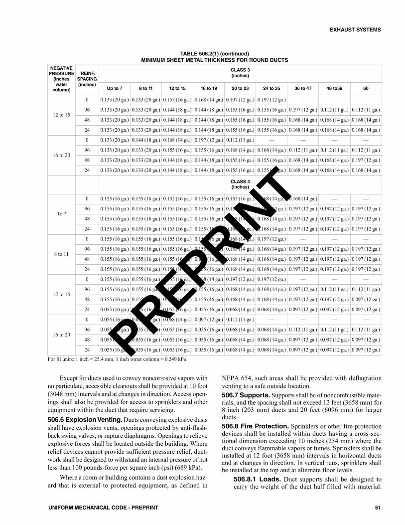
Except for ducts used to convey noncorrosive vapors withno particulate, accessible cleanouts shall be provided at 10 foot(3048 mm) intervals and at changes in direction. Access open-ings shall also be provided for access to sprinklers and otherequipment within the duct that require servicing.506.6 Explosion Venting. Ducts conveying explosive dustsshall have explosion vents, openings protected by anti-flash-back swing valves, or rupture diaphragms. Openings to relieveexplosive forces shall be located outside the building. Whererelief devices cannot provide sufficient pressure relief, duct-work shall be designed to withstand an internal pressure of notless than 100 pounds-force per square inch (psi) (689 kPa).
Where a room or building contains a dust explosion haz-ard that is external to protected equipment, as defined in
NFPA 654, such areas shall be provided with deflagrationventing to a safe outside location.506.7 Supports. Supports shall be of noncombustible mate-rials, and the spacing shall not exceed 12 feet (3658 mm) for8 inch (203 mm) ducts and 20 feet (6096 mm) for largerducts.506.8 Fire Protection. Sprinklers or other fire-protectiondevices shall be installed within ducts having a cross-sec-tional dimension exceeding 10 inches (254 mm) where theduct conveys flammable vapors or fumes. Sprinklers shall beinstalled at 12 foot (3658 mm) intervals in horizontal ductsand at changes in direction. In vertical runs, sprinklers shallbe installed at the top and at alternate floor levels.
506.8.1 Loads. Duct supports shall be designed tocarry the weight of the duct half filled with material.
51UNIFORM MECHANICAL CODE - PREPRINT
EXHAUST SYSTEMS
NEGATIVEPRESSURE(incheswatercolumn)
REINF.SPACING(inches)
CLASS 3 (inches)
Up to 7 8 to 11 12 to 15 16 to 19 20 to 23 24 to 35 36 to 47 48 to59 60
12 to 15
0 0.133 (20 ga.) 0.133 (20 ga.) 0.155 (16 ga.) 0.168 (14 ga.) 0.197 (12 ga.) 0.197 (12 ga.) –– –– ––
96 0.133 (20 ga.) 0.133 (20 ga.) 0.144 (18 ga.) 0.144 (18 ga.) 0.155 (16 ga.) 0.155 (16 ga.) 0.197 (12 ga.) 0.112 (11 ga.) 0.112 (11 ga.)
48 0.133 (20 ga.) 0.133 (20 ga.) 0.144 (18 ga.) 0.144 (18 ga.) 0.155 (16 ga.) 0.155 (16 ga.) 0.168 (14 ga.) 0.168 (14 ga.) 0.168 (14 ga.)
24 0.133 (20 ga.) 0.133 (20 ga.) 0.144 (18 ga.) 0.144 (18 ga.) 0.155 (16 ga.) 0.155 (16 ga.) 0.168 (14 ga.) 0.168 (14 ga.) 0.168 (14 ga.)
16 to 20
0 0.133 (20 ga.) 0.144 (18 ga.) 0.168 (14 ga.) 0.197 (12 ga.) 0.112 (11 ga.) –– –– –– ––
96 0.133 (20 ga.) 0.133 (20 ga.) 0.155 (16 ga.) 0.155 (16 ga.) 0.168 (14 ga.) 0.168 (14 ga.) 0.112 (11 ga.) 0.112 (11 ga.) 0.112 (11 ga.)
48 0.133 (20 ga.) 0.133 (20 ga.) 0.144 (18 ga.) 0.144 (18 ga.) 0.155 (16 ga.) 0.155 (16 ga.) 0.168 (14 ga.) 0.168 (14 ga.) 0.197 (12 ga.)
24 0.133 (20 ga.) 0.133 (20 ga.) 0.144 (18 ga.) 0.144 (18 ga.) 0.155 (16 ga.) 0.155 (16 ga.) 0.168 (14 ga.) 0.168 (14 ga.) 0.168 (14 ga.)
CLASS 4(inches)
To 7
0 0.155 (16 ga.) 0.155 (16 ga.) 0.155 (16 ga.) 0.155 (16 ga.) 0.155 (16 ga.) 0.168 (14 ga.) 0.168 (14 ga.) –– ––
96 0.155 (16 ga.) 0.155 (16 ga.) 0.155 (16 ga.) 0.155 (16 ga.) 0.168 (14 ga.) 0.168 (14 ga.) 0.197 (12 ga.) 0.197 (12 ga.) 0.197 (12 ga.)
48 0.155 (16 ga.) 0.155 (16 ga.) 0.155 (16 ga.) 0.155 (16 ga.) 0.168 (14 ga.) 0.168 (14 ga.) 0.197 (12 ga.) 0.197 (12 ga.) 0.197 (12 ga.)
24 0.155 (16 ga.) 0.155 (16 ga.) 0.155 (16 ga.) 0.155 (16 ga.) 0.168 (14 ga.) 0.168 (14 ga.) 0.197 (12 ga.) 0.197 (12 ga.) 0.197 (12 ga.)
8 to 11
0 0.155 (16 ga.) 0.155 (16 ga.) 0.155 (16 ga.) 0.155 (16 ga.) 0.168 (14 ga.) 0.197 (12 ga.) –– –– ––
96 0.155 (16 ga.) 0.155 (16 ga.) 0.155 (16 ga.) 0.155 (16 ga.) 0.168 (14 ga.) 0.168 (14 ga.) 0.197 (12 ga.) 0.197 (12 ga.) 0.197 (12 ga.)
48 0.155 (16 ga.) 0.155 (16 ga.) 0.155 (16 ga.) 0.155 (16 ga.) 0.168 (14 ga.) 0.168 (14 ga.) 0.197 (12 ga.) 0.197 (12 ga.) 0.197 (12 ga.)
24 0.155 (16 ga.) 0.155 (16 ga.) 0.155 (16 ga.) 0.155 (16 ga.) 0.168 (14 ga.) 0.168 (14 ga.) 0.197 (12 ga.) 0.197 (12 ga.) 0.197 (12 ga.)
12 to 15
0 0.155 (16 ga.) 0.155 (16 ga.) 0.155 (16 ga.) 0.168 (14 ga.) 0.197 (12 ga.) 0.197 (12 ga.) –– –– ––
96 0.155 (16 ga.) 0.155 (16 ga.) 0.155 (16 ga.) 0.155 (16 ga.) 0.168 (14 ga.) 0.168 (14 ga.) 0.197 (12 ga.) 0.112 (11 ga.) 0.112 (11 ga.)
48 0.155 (16 ga.) 0.155 (16 ga.) 0.155 (16 ga.) 0.155 (16 ga.) 0.168 (14 ga.) 0.168 (14 ga.) 0.197 (12 ga.) 0.197 (12 ga.) 0.097 (12 ga.)
24 0.055 (16 ga.) 0.055 (16 ga.) 0.055 (16 ga.) 0.055 (16 ga.) 0.068 (14 ga.) 0.068 (14 ga.) 0.097 (12 ga.) 0.097 (12 ga.) 0.097 (12 ga.)
16 to 20
0 0.055 (16 ga.) 0.055 (16 ga.) 0.068 (14 ga.) 0.097 (12 ga.) 0.112 (11 ga.) –– –– –– ––
96 0.055 (16 ga.) 0.055 (16 ga.) 0.055 (16 ga.) 0.055 (16 ga.) 0.068 (14 ga.) 0.068 (14 ga.) 0.112 (11 ga.) 0.112 (11 ga.) 0.112 (11 ga.)
48 0.055 (16 ga.) 0.055 (16 ga.) 0.055 (16 ga.) 0.055 (16 ga.) 0.068 (14 ga.) 0.068 (14 ga.) 0.097 (12 ga.) 0.097 (12 ga.) 0.097 (12 ga.)
24 0.055 (16 ga.) 0.055 (16 ga.) 0.055 (16 ga.) 0.055 (16 ga.) 0.068 (14 ga.) 0.068 (14 ga.) 0.097 (12 ga.) 0.097 (12 ga.) 0.097 (12 ga.)
For SI units: 1 inch = 25.4 mm, 1 inch water column = 0.249 kPa
TABLE 506.2(1) (continued)MINIMUM SHEET METAL THICKNESS FOR ROUND DUCTS
PREPRINT

Where sprinkler protection is provided or cleaning of theduct will be performed, the hanger’s design shall includethe weight of the any expected liquid accumulation. Ductsupports shall be designed to prevent placing loads onconnected equipment. [NFPA 91:4.6.1 – 4.6.3]506.8.2 Corrosion. Hangers and supports exposed tocorrosive atmospheres shall be corrosion resistant to thecorrosive atmospheres. [NFPA 91:4.6.4]506.8.3 Vibration and Stress. To prevent avoid vibra-tion and stress on the duct, hangers and supports shall besecurely fastened to the building or structure. [NFPA91:4.6.5]506.8.4 Expansion and Contraction. Hangers andsupports shall be designed to allow for expansion andcontraction. [NFPA 91:4.6.6]
506.9 Protection from Physical Damage. Ductsinstalled in locations where they are subject to physical dam-age shall be protected by guards.506.10 Duct Clearances.Unless the conditions stipulatedin Section 506.10.1 or Section 506.10.2 exist, all duct sys-tems and system components shall have a clearance of at least6 inches (152 mm) from stored combustible materials, andnot less than 1⁄2 of an inch (13 mm) clearance from com-bustible construction. [NFPA 91:4.7.1]
506.10.1 Protection Provided. Where stored com-bustible material or combustible construction is protectedfrom ductwork by the use of materials or products listedfor protection purposes, clearance shall be maintained inaccordance with those listings. [NFPA 91:4.7.1.1]
52 UNIFORM MECHANICAL CODE - PREPRINT
EXHAUST SYSTEMS
NEGATIVEPRESSURE(incheswatercolumn)
REINF.SPACING(inches)
LONGEST SIDE OF DUCT
CLASS 1 (inches) CLASS 2 (inches)
Up to 12 13 to 24 25 to 36 37 to 48 49 to 60 Up to 12 13 to 24 25 to 36 37 to 48 49 to 60
To 7
48 0.021 (24 ga.) 0.033 (20 ga.) 0.055 (16 ga.) 0.068 (14 ga.) –– 0.033 (20 ga.) 0.044 (18 ga.) 0.055 (16 ga.) 0.068 (14 ga.) ––
24 0.021 (24 ga.) 0.027 (22 ga.) 0.033 (20 ga.) 0.033 (20 ga.) 0.033 (20 ga.) 0.033 (20 ga.) 0.044 (18 ga.) 0.055 (16 ga.) 0.055 (16 ga.) 0.055 (16 ga.)
12 0.021 (24 ga.) 0.021 (24 ga.) 0.021 (24 ga.) 0.021 (24 ga.) 0.021 (24 ga.) 0.033 (20 ga.) 0.044 (18 ga.) 0.055 (16 ga.) 0.055 (16 ga.) 0.055 (16 ga.)
8 to 11
48 0.027 (22 ga.) 0.068 (14 ga.) 0.097 (12 ga.) 0.097 (12 ga.) –– 0.033 (20 ga.) 0.068 (14 ga.) 0.097 (12 ga.) 0.097 (12 ga.) ––
24 0.027 (22 ga.) 0.055 (16 ga.) 0.055 (16 ga.) 0.068 (14 ga.) 0.068 (14 ga.) 0.033 (20 ga.) 0.055 (16 ga.) 0.055 (16 ga.) 0.068 (14 ga.) 0.068 (14 ga.)
12 0.021 (24 ga.) 0.027 (22 ga.) 0.027 (22 ga.) 0.027 (22 ga.) 0.027 (22 ga.) 0.033 (20 ga.) 0.044 (18 ga.) 0.055 (16 ga.) 0.055 (16 ga.) 0.055 (16 ga.)
12 to 15
48 0.044 (18 ga.) 0.097 (12 ga.) –– –– –– 0.044 (18 ga.) 0.044 (18 ga.) –– –– ––
24 0.044 (18 ga.) 0.055 (16 ga.) 0.097 (12 ga.) 0.097 (12 ga.) 0.097 (12 ga.) 0.044 (18 ga.) 0.044 (18 ga.) 0.097 (12 ga.) 0.097 (12 ga.) 0.097 (12 ga.)
12 0.027 (22 ga.) 0.044 (18 ga.) 0.044 (18 ga.) 0.044 (18 ga.) 0.044 (18 ga.) 0.033 (20 ga.) 0.044 (18 ga.) 0.055 (16 ga.) 0.055 (16 ga.) 0.055 (16 ga.)
16 to 20
48 0.068 (14 ga.) 0.112 (11 ga.) –– –– –– 0.068 (14 ga.) 0.112 (11 ga.) –– –– ––
24 0.068 (14 ga.) 0.068 (14 ga.) 0.112 (11 ga.) 0.112 (11 ga.) 0.112 (11 ga.) 0.068 (14 ga.) 0.068 (14 ga.) 0.112 (11 ga.) 0.112 (11 ga.) 0.112 (11 ga.)
12 0.033 (20 ga.) 0.068 (14 ga.) 0.068 (14 ga.) 0.068 (14 ga.) 0.068 (14 ga.) 0.033 (20 ga.) 0.044 (18 ga.) 0.068 (14 ga.) 0.068 (14 ga.) 0.068 (14 ga.)
CLASS 3 (inches) CLASS 4 (inches)
To 7
48 0.044 (18 ga.) 0.055 (16 ga.) 0.068 (14 ga.) 0.068 (14 ga.) –– 0.055 (16 ga.) 0.068 (14 ga.) 0.097 (12 ga.) 0.097 (12 ga.) ––
24 0.044 (18 ga.) 0.055 (16 ga.) 0.068 (14 ga.) 0.068 (14 ga.) 0.068 (14 ga.) 0.055 (16 ga.) 0.068 (14 ga.) 0.097 (12 ga.) 0.097 (12 ga.) 0.097 (12 ga.)
12 0.044 (18 ga.) 0.055 (16 ga.) 0.068 (14 ga.) 0.068 (14 ga.) 0.068 (14 ga.) 0.055 (16 ga.) 0.068 (14 ga.) 0.097 (12 ga.) 0.097 (12 ga.) 0.097 (12 ga.)
8 to 11
48 0.044 (18 ga.) 0.068 (14 ga.) 0.097 (12 ga.) 0.097 (12 ga.) –– 0.055 (16 ga.) 0.068 (14 ga.) 0.097 (12 ga.) 0.097 (12 ga.) ––
24 0.044 (18 ga.) 0.055 (16 ga.) 0.068 (14 ga.) 0.068 (14 ga.) 0.068 (14 ga.) 0.055 (16 ga.) 0.068 (14 ga.) 0.097 (12 ga.) 0.097 (12 ga.) 0.097 (12 ga.)
12 0.044 (18 ga.) 0.055 (16 ga.) 0.068 (14 ga.) 0.068 (14 ga.) 0.068 (14 ga.) 0.055 (16 ga.) 0.068 (14 ga.) 0.097 (12 ga.) 0.097 (12 ga.) 0.097 (12 ga.)
12 to 15
48 0.044 (18 ga.) 0.097 (12 ga.) –– –– –– 0.055 (16 ga.) 0.097 (12 ga.) –– –– ––
24 0.044 (18 ga.) 0.055 (16 ga.) 0.097 (12 ga.) 0.097 (12 ga.) 0.097 (12 ga.) 0.055 (16 ga.) 0.068 (14 ga.) 0.097 (12 ga.) 0.097 (12 ga.) 0.097 (12 ga.)
12 0.044 (18 ga.) 0.055 (16 ga.) 0.068 (14 ga.) 0.068 (14 ga.) 0.068 (14 ga.) 0.055 (16 ga.) 0.068 (14 ga.) 0.097 (12 ga.) 0.097 (12 ga.) 0.097 (12 ga.)
16 to 20
48 0.068 (14 ga.) 0.112 (11 ga.) –– –– –– 0.055 (16 ga.) 0.112 (11 ga.) –– –– ––
24 0.068 (14 ga.) 0.068 (14 ga.) 0.112 (11 ga.) 0.112 (11 ga.) 0.112 (11 ga.) 0.055 (16 ga.) 0.068 (14 ga.) 0.112 (11 ga.) 0.112 (11 ga.) 0.112 (11 ga.)
12 0.044 (18 ga.) 0.068 (14 ga.) 0.068 (14 ga.) 0.068 (14 ga.) 0.068 (14 ga.) 0.055 (16 ga.) 0.068 (14 ga.) 0.097 (12 ga.) 0.097 (12 ga.) 0.097 (12 ga.)
For SI units: 1 inch = 25.4 mm, 1 inch water column = 0.249 kPa
TABLE 506.2(2)MINIMUM SHEET METAL THICKNESS FOR RECTANGULAR DUCTS
PREPRINT
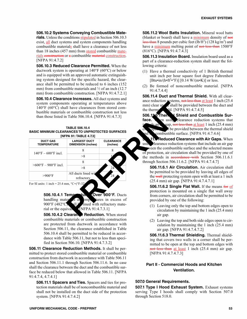
53UNIFORM MECHANICAL CODE - PREPRINT
EXHAUST SYSTEMS
506.10.2 Systems Conveying Combustible Mate-rials. Unless the conditions stipulated in Section 506.10.3exist, all duct systems and system components handlingcombustible materials shall have a clearance of not lessthan 18 inches (457 mm) from stored combustible mate-rials construction or a combustible material construction.[NFPA 91:4.7.2]506.10.3 Reduced Clearance Permitted. When theductwork system is operating at 140°F (60°C) or belowand is equipped with an approved automatic extinguish-ing system designed for the specific hazard, the clear-ance shall be permitted to be reduced to 6 inches (152mm) from combustible materials and 1⁄2 of an inch (12.7mm) from combustible construction. [NFPA 91:4.7.2.1]506.10.4 Clearance Increases.All duct systems andsystem components operating at temperatures above140°F (60°C) shall have clearances from stored com-bustible materials or combustible construction not lessthan those listed in Table 506.10.4. [NFPA 91:4.7.3]
TABLE 506.10.4BASIC MINIMUM CLEARANCES TO UNPROTECTED SURFACES
[NFPA 91: TABLE 4.7.3]
For SI units: 1 inch = 25.4 mm, °C=(°F-32)/1.8
506.10.4.1 Temperatures Over 900°F. Ductshandling materials at temperatures in excess of900°F (482°C) shall be lined with refractory mate-rial or the equivalent. [NFPA 91:4.7.3.1]506.10.4.2 Clearance Reduction.When storedcombustible materials or combustible constructionare protected from ductwork in accordance withSection 506.11, the clearance established in Table506.10.4 shall be permitted to be reduced in accor-dance with Table 506.11, but not to less than speci-fied in Section 506.10. [NFPA 91:4.7.3.2]
506.11 Clearance Reduction Methods. It shall be per-mitted to protect stored combustible material or combustibleconstruction from ductwork in accordance with Table 506.11and Section 506.11.1 through Section 506.11.6. In no caseshall the clearance between the duct and the combustible sur-face be reduced below that allowed in Table 506.11. [NFPA91:4.7.4, 4.7.4.1]
506.11.1 Spacers and Ties. Spacers and ties for pro-tection materials shall be of noncombustible material andshall not be installed on the duct side of the protectionsystem. [NFPA 91:4.7.4.2]
506.11.2 Wool Batts Insulation. Mineral wool batts(blanket or board) shall have a minimum density of notless than 8 pounds per cubic feet (lb/ft3) (128 kg/m3) andhave a minimum melting point of not less than 1500°F(816°C). [NFPA 91:4.7.4.3]506.11.3 Insulation Board. Insulation board used as apart of a clearance-reduction system shall meet the fol-lowing criteria:(1) Have a thermal conductivity of 1 British thermal
unit inch per hour square foot degree Fahrenheit[Btu•in/(h•ft2•°F)] [0.14 W/(m•K)] or less.
(2) Be formed of noncombustible material. [NFPA91:4.7.4.4]
506.11.4 Duct and Thermal Shield. With all clear-ance reduction systems, not less than at least 1 inch (25.4mm) clear space shall be provided between the duct andthe thermal shield. [NFPA 91:4.7.4.5]506.11.5 Thermal Shield and Combustible Sur-face. When using clearance reduction systems thatinclude an air gap, not less than at least 1 inch (25.4 mm)clear space shall be provided between the thermal shieldand the combustible surface. [NFPA 91:4.7.4.6]506.11.6 Reduced Clearance with Air Gaps.Whenusing clearance reduction systems that include an air gapbetween the combustible surface and the selected meansof protection, air circulation shall be provided by one ofthe methods in accordance with Section 506.11.6.1through Section 506.11.6.2. [NFPA 91:4.7.4.7]
506.11.6.1 Air Circulation. Air circulation shallbe permitted to be provided by leaving all edges ofthe wall protecting system open with at least a 1 inch(25.4 mm) air gap. [NFPA 91:4.7.4.7.1]506.11.6.2 Single Flat Wall. If the means for ofprotection is mounted on a single flat wall awayfrom corners, air circulation shall be permitted to beprovided by one of the following:(1) Leaving only the top and bottom edges open to
circulation by maintaining the 1 inch (25.4 mm)air gap.
(2) Leaving the top and both side edges open to cir-culation by maintaining the 1 inch (25.4 mm)air gap. [NFPA 91:4.7.4.7.2]
506.11.6.3 Thermal Shielding. Thermal shield-ing that covers two walls in a corner shall be per-mitted to be open at the top and bottom edges withnot less than at least 1 inch (25.4 mm) air gap.[NFPA 91:4.7.4.7.3]
Part II - Commercial Hoods and KitchenVentilation.
507.0 General Requirements.507.1 Type I Hood Exhaust System. Exhaust systemsserving Type I hoods shall comply with Section 507.0through Section 518.0.
DUCT GAS TEMPERATURE
LARGEST DUCTDIMENSION (inches)
CLEARANCE (inches)
140°F – 600°F incl.8 8
>8 12
>600°F – 900°F incl.8 18
>8 24
>900°F All ducts lined withrefractory 24
PREPRINT
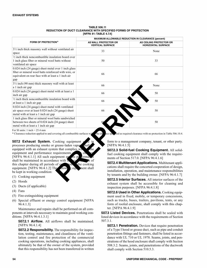
54 UNIFORM MECHANICAL CODE - PREPRINT
EXHAUST SYSTEMS
507.2 Exhaust System. Cooking equipment used inprocesses producing smoke or grease-laden vapors shall beequipped with an exhaust system that complies with all theequipment and performance requirements of this chapter.[NFPA 96:4.1.1] All such equipment and its performanceshall be maintained in accordance with the requirements ofthis chapter during all periods of operation of the cookingequipment. [NFPA 96:4.1.2] The following equipment shallbe kept in working condition:(1) Cooking equipment(2) Hoods(3) Ducts (if applicable)(4) Fans(5) Fire-extinguishing equipment(6) Special effluent or energy control equipment [NFPA
96:4.1.3]Maintenance and repairs shall be performed on all com-
ponents at intervals necessary to maintain good working con-ditions. [NFPA 96:4.1.3.1]
507.2.1 Airflow. All airflows shall be maintained.[NFPA 96:4.1.4] 507.2.2 Responsibility. The responsibility for inspec-tion, testing, maintenance, and cleanliness of the venti-lation control and fire protection of the commercialcooking operations, including cooking appliances, shallultimately be that of the owner of the system, providedthat this responsibility has not been transferred in written
form to a management company, tenant, or other party.[NFPA 96:4.1.5] 507.2.3 Solid-fuel Cooking Equipment. All solid-fuel cooking equipment shall comply with the require-ments of Section 517.0. [NFPA 96:4.1.6]507.2.4 Multitenant Applications.Multitenant appli-cations shall require the concerted cooperation of design,installation, operation, and maintenance responsibilitiesby tenants and by the building owner. [NFPA 96:4.1.7]507.2.5 Interior Surfaces. All interior surfaces of theexhaust system shall be accessible for cleaning andinspection purposes. [NFPA 96:4.1.8]507.2.6 Used in Other Applications. Cooking equip-ment used in fixed, mobile, or temporary concessions,such as trucks, buses, trailers, pavilions, tents, or anyform of roofed enclosure, shall comply with this chap-ter. [NFPA 96:4.1.9]
507.3 Listed Devices. Penetrations shall be sealed withlisted devices in accordance with the requirements of Section507.3.1.
507.3.1 Penetration. Devices that require penetrationof a Type I hood or grease duct, such as pipe and conduitpenetration fittings and fasteners, shall be listed in accor-dance with UL 710 or UL 1978. Seams, joints, and pen-etrations of the hood enclosure shall comply with Section508.3.2. Seams, joints, and penetrations of the ductworkshall comply with Section 510.5.3.
TABLE 506.11 REDUCTION OF DUCT CLEARANCE WITH SPECIFIED FORMS OF PROTECTION
[NFPA 91: TABLE 4.7.4]
For SI units: 1 inch = 25.4 mm* Clearance reduction applied to and covering all combustible surfaces within the distance specified as required clearance with no protection in Table 506.10.4.
FORM OF PROTECTION*MAXIMUM ALLOWABLE REDUCTION IN CLEARANCE (percent)
AS WALL PROTECTOR OR VERTICAL SURFACE
AS CEILING PROTECTOR OR HORIZONTAL SURFACE
31⁄2 inch thick masonry wall without ventilated airspace 33 None1⁄2 inch thick noncombustible insulation board over1 inch glass fiber or mineral wool batts withoutventilated air space
50 33
0.024 inch (24 gauge) sheet metal over 1 inch glassfiber or mineral wool batts reinforced with wire, orequivalent on rear face with at least a 1 inch airgap
66 66
31⁄2 inch (90 mm) thick masonry wall with at leasta 1 inch air gap 66 None
0.024 inch (24 gauge) sheet metal with at least a 1inch air gap 66 501⁄2 inch thick noncombustible insulation board withat least a 1 inch air gap 66 50
0.024 inch (24 gauge) sheet metal with ventilatedair space over at least 0.024 inch (24 gauge) sheetmetal with at least a 1 inch air gap
66 50
1 inch glass fiber or mineral wool batts sandwichedbetween two sheets of 0.024 inch (24 guage) sheetmetal with at least a 1 inch air gap
66 50
PREPRINT

507.4 Clearance.Where enclosures are not required, hoods,grease removal devices, exhaust fans, and ducts shall have aclearance of at least not less than 18 inches (457 mm) to com-bustible material, 3 inches (76 mm) to limited-combustiblematerial, and 0 inches (0 mm) to noncombustible material.[NFPA 96:4.2.1]
507.4.1 Listed.Where a hood, duct, or grease removaldevice is listed for clearances less than those required inaccordance with Section 507.4, the listing requirementsshall be permitted. [NFPA 96:4.2.2]507.4.2 Clearance Reduction. Where a clearancereduction system consisting of 0.013 of an inch (0.33mm) (28 gauge) sheet metal spaced out 1 inch (25.4 mm)on noncombustible spacers is provided, there shall be aminimum of not less than 9 inches (229 mm) clearanceto combustible material. [NFPA 96:4.2.3.1]
507.4.2.1 Mineral Wool Batts or CeramicFiber Blanket. Where a clearance reduction sys-tem consisting of 0.027 of an inch (0.686 mm) (22gauge) sheet metal on 1 inch (25.4 mm) mineralwool batts or ceramic fiber blanket reinforced withwire mesh or equivalent spaced out 1 inch (25.4mm) on noncombustible spacers is provided, thereshall be not less than a miminum of 3 inches (76mm) clearance to combustible material. [NFPA96:4.2.3.2]507.4.2.2 Field-Applied Grease Duct Enclo-sure.Where a clearance reduction system consist-ing of a listed and labeled field-applied grease ductenclosure material, system, product, or method ofconstruction specifically evaluated for such purposein accordance with ASTM E2336, the requiredclearance shall be in accordance with the listing.[NFPA 96:4.2.3.3]507.4.2.3 Zero Clearance. Zero clearance to lim-ited-combustible materials shall be permitted whereprotected by one of the following:(1) Metal lath and plaster.(2) Ceramic tile.(3) Quarry tile.(4) Other noncombustible materials or assembly of
noncombustible materials that are listed for thepurpose of reducing clearance.
(5) Other materials and products that are listed forthe purpose of reducing clearance. [NFPA96:4.2.3.4]
507.4.3 Clearance Integrity. In the event of damage,the material or product shall be repaired and restored tomeet its intended listing or clearance requirements andshall be approved by acceptable to the Authority HavingJurisdiction. [NFPA 96:4.2.4.1]
507.4.3.1 Fire. In the event of a fire within a kitchenexhaust system, the duct and its enclosure (ratedshaft, factory-built grease duct enclosure, or field-applied grease duct enclosure) shall be inspected byqualified personnel to determine whether the ductand protection method are structurally sound, capa-
ble of maintaining their fire protection function, andin accordance compliance with this chapter for con-tinued operation. [NFPA 96:4.2.4.2]507.4.3.2 Required Protection. Protection shallbe provided on the wall from the bottom of the hoodto the floor, or to the top of the noncombustiblematerial extending to the floor, to the same level asrequired in Section 507.4. [NFPA 96:4.2.4.3]507.4.3.3 Protection Methods. The protectionmethods for ducts to reduce clearance shall beapplied to the combustible or limited-combustibleconstruction, not to the duct itself. [NFPA 96:4.2.4.4]
507.4.4 Factory Built. Factory-built grease duct enclo-sures shall be protected with a through-penetrationfirestop system classified in accordance with ASTME814 or UL 1479 having an “F” and a “T” rating equalto the fire resistance rating of the assembly being pene-trated from the point at which the duct penetrates a ceil-ing, wall, or floor to the outlet terminal. [NFPA 96:4.3.3]
507.4.4.1 Listing. The factory-built grease ductprotection system shall be listed in accordance withUL 2221. [NFPA 96:4.3.3.1]507.4.4.2 Single Wall. Listed single wall factory-built grease ducts shall be permitted to be enclosedwith field-applied grease duct enclosure materialwhere the material and the assembly of duct and mate-rial are listed for that application and installed in accor-dance with the grease duct manufacturer’s listing andtheir installation instructions. [NFPA 96:4.3.3.2]507.4.4.3 Installation. The factory-built greaseduct protection system shall be installed in accor-dance with the manufacturer’s installation instruc-tions and the listing requirements. [NFPA 96:4.3.3.3]
507.4.5 Field Applied. Field-applied grease duct enclo-sures shall be protected with a through penetrationfirestop system classified in accordance with ASTME814 or UL 1479 having an “F” and a “T” rating equalto the fire resistance rating of the assembly being pene-trated. The surface of the field fabricated grease ductshall be continuously covered on all sides from the pointat which the duct enclosure penetrates a ceiling, wall, orfloor to the outlet terminal. The field-applied grease ductshall be listed in accordance with ASTM E2336 andinstalled in accordance with the manufacturer’s installa-tion instructions and the listing requirements. [NFPA96:4.3.1 – 4.3.1.2]507.4.6 Both Field-Applied and Factory Built.Field-applied grease duct enclosures and factory-builtgrease duct enclosures shall demonstrate that they pro-vide mechanical and structural integrity, resiliency, andstability where subjected to expected building environ-mental conditions, duct movement under general operat-ing conditions, and duct movement due to fire conditions.[NFPA 96:4.3.4]
507.4.6.1 Physical Damage. Measures shall betaken to prevent physical damage to a material orproduct used for the purpose of reducing clearances.
55UNIFORM MECHANICAL CODE - PREPRINT
EXHAUST SYSTEMS
PREPRINT

Exception: Where the duct is protected with a field-applied grease duct enclosure or factory-built greaseduct enclosure.507.4.6.2 Specification. The specifications ofmaterial, gauge, and construction of the duct used inthe testing and listing of field-applied grease ductenclosures and factory-built grease duct enclosuresshall be included as minimum requirements in theirlisting and installation documentation. [NFPA96:4.3.5]507.4.6.3 Clearance Options. The followingclearance options for which field-applied greaseduct enclosures and factory-built grease duct enclo-sures have been successfully evaluated shall beclearly identified in their listing and installation doc-umentation and on their labels:(1) Open combustible construction clearance at
manufacturer’s requested dimensions. (2) Closed combustible construction clearance at
manufacturer’s requested dimensions, with orwithout specified ventilation.
(3) Rated shaft clearance at manufacturer’srequested dimensions, with or without specifiedventilation. [NFPA 96:4.3.6]
507.4.7 Building and Structural Contact. A ductshall be permitted to contact noncombustible floors, inte-rior walls, and other noncombustible structures or sup-ports, but it shall not be in contact for more than 50percent of its surface area for each linear foot of contactlength. [NFPA 96:4.4.1]
507.4.7.1 Corrosion Protection. Where ductcontact must exceed the requirements of Section507.4.7, the duct shall be protected from corrosion.[NFPA 96:4.4.2]507.4.7.2 Zero Clearance. Where the duct islisted for zero clearance to combustibles or is other-wise protected with a material or product listed forthe purpose of reducing clearance to zero, the ductshall be permitted to exceed the contact limits ofSection 507.4.7 without additional corrosion pro-tection. [NFPA 96:4.4.3]
507.4.8 Clearance Between Duct and InteriorSurfaces. Clearances between the duct and interior sur-faces of enclosures shall be in accordance with meet therequirements of Section 507.4. [NFPA 96:4.5]
507.5 Drawings.A drawing(s) of the exhaust system instal-lation along with a copy copies of operating instructions forsubassemblies and components used in the exhaust system,including electrical schematics, shall be on the premises.[NFPA 96:4.6]507.6 Notification of Change. Where If required by theAuthority Having Jurisdiction, notification in writing shall begiven of an any alteration, replacement, or relocation of anany exhaust, or extinguishing system or part thereof or cook-ing equipment. [NFPA 96:4.7]
Satisfaction shall be provided to the Authority HavingJurisdiction that the complete exhaust system as addressed in
this chapter is installed and operable in accordance with theapproved design and the manufacturer’s installation instruc-tions.
508.0 Type I Hoods.508.1 Where Required. Type I hoods shall be installed ator above commercial-type deep-fat fryers, broilers, grills, hot-top ranges, ovens, barbecues, rotisseries, and similar equip-ment that emits comparable amounts of smoke or grease in afood-processing establishment. For the purpose of this sec-tion, a food-processing establishment shall include a build-ing or portion thereof used for the processing of food, butshall not include a dwelling unit.Exceptions:(1) Cooking appliance that is in accordance with UL 710B
for reduced emissions where the grease discharge doesnot exceed 2.9 E-09 ounces per cubic inch (oz/in3) (5.0E-06 kg/m3) where operated with a total airflow of 500cubic feet per minute (CFM) (0.236 m3/s).
(2) Recirculating systems listed in accordance with UL 710Band installed in accordance with Section 516.0.
508.2 Listed Type I Hood Assemblies. Listed hoodassemblies shall be installed in accordance with the terms oftheir listing and the manufacturer’s instructions. Listed hoodassemblies shall be tested in accordance with UL 710 orequivalent. [NFPA 96:5.4.1, 5.4.2]
508.2.1 Listed Ultraviolet Hoods. Listed ultraviolethoods shall be installed and maintained in accordancewith the terms of their listing and the manufacturer’sinstructions. Duct systems connected to ultraviolet hoodsshall comply with Section 510.0. Ultraviolet hoods shallbe tested and listed in accordance with UL 710 and UL710C. [NFPA 96:5.5 – 5.5.2]508.2.2 Listed Ventilated Ceiling Technology.Listed ventilated ceiling technology shall be installed andmaintained in accordance with the terms of its listing andthe manufacturer's instructions. [NFPA 96:5.6]508.2.3 Construction of Listed Exhaust Hoods.Listed exhaust hoods with or without exhaust dampersshall be permitted to be constructed of materials requiredby the listing. [NFPA 96:5.1.6]508.2.4 Assembly of Listed Exhaust Hoods.Listed exhaust hoods with or without exhaust dampersshall be permitted to be assembled in accordance withthe listing requirements. [NFPA 96:5.1.7]
508.3 Construction of Type I Hoods. The hood or thatportion of a primary collection means designed for collectingcooking vapors and residues shall be constructed of and besupported by steel not less than 0.048 of an inch (1.219 mm)(No. 18 MSG), in thickness, stainless steel not less than 0.036of an inch (0.914 mm) (No. 20 MSG) in thickness, or otherapproved material of equivalent strength and fire and corro-sion resistance. [NFPA 96:5.1.1]Exception: Listed exhaust hoods.
56 UNIFORM MECHANICAL CODE - PREPRINT
EXHAUST SYSTEMS
PREPRINT
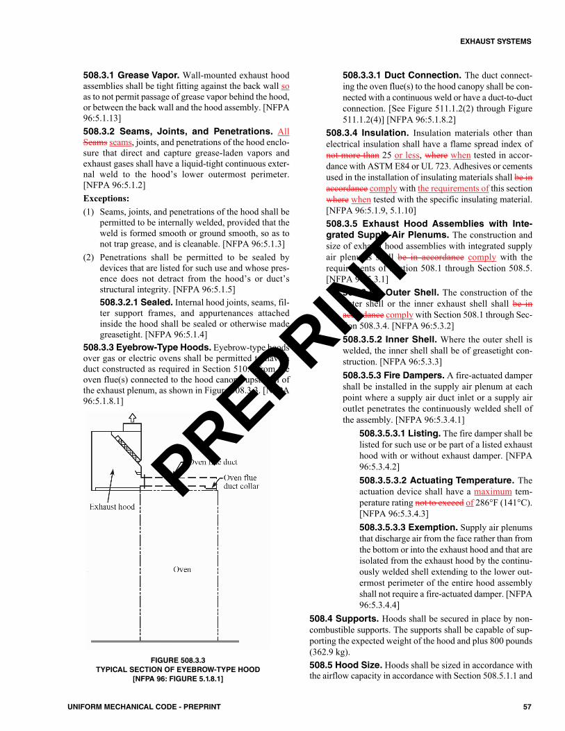
508.3.1 Grease Vapor. Wall-mounted exhaust hoodassemblies shall be tight fitting against the back wall soas to not permit passage of grease vapor behind the hood,or between the back wall and the hood assembly. [NFPA96:5.1.13]508.3.2 Seams, Joints, and Penetrations. AllSeams seams, joints, and penetrations of the hood enclo-sure that direct and capture grease-laden vapors andexhaust gases shall have a liquid-tight continuous exter-nal weld to the hood’s lower outermost perimeter.[NFPA 96:5.1.2]Exceptions:(1) Seams, joints, and penetrations of the hood shall be
permitted to be internally welded, provided that theweld is formed smooth or ground smooth, so as tonot trap grease, and is cleanable. [NFPA 96:5.1.3]
(2) Penetrations shall be permitted to be sealed bydevices that are listed for such use and whose pres-ence does not detract from the hood’s or duct’sstructural integrity. [NFPA 96:5.1.5]508.3.2.1 Sealed. Internal hood joints, seams, fil-ter support frames, and appurtenances attachedinside the hood shall be sealed or otherwise madegreasetight. [NFPA 96:5.1.4]
508.3.3 Eyebrow-Type Hoods. Eyebrow-type hoodsover gas or electric ovens shall be permitted to have aduct constructed as required in Section 510.0 from theoven flue(s) connected to the hood canopy upstream ofthe exhaust plenum, as shown in Figure 508.3.3. [NFPA96:5.1.8.1]
FIGURE 508.3.3TYPICAL SECTION OF EYEBROW-TYPE HOOD
[NFPA 96: FIGURE 5.1.8.1]
508.3.3.1 Duct Connection. The duct connect-ing the oven flue(s) to the hood canopy shall be con-nected with a continuous weld or have a duct-to-ductconnection. [See Figure 511.1.2(2) through Figure511.1.2(4)] [NFPA 96:5.1.8.2]
508.3.4 Insulation. Insulation materials other thanelectrical insulation shall have a flame spread index ofnot more than 25 or less, where when tested in accor-dance with ASTM E84 or UL 723. Adhesives or cementsused in the installation of insulating materials shall be inaccordance comply with the requirements of this sectionwhere when tested with the specific insulating material.[NFPA 96:5.1.9, 5.1.10]508.3.5 Exhaust Hood Assemblies with Inte-grated Supply-Air Plenums. The construction andsize of exhaust hood assemblies with integrated supplyair plenums shall be in accordance comply with therequirements of Section 508.1 through Section 508.5.[NFPA 96:5.3.1]
508.3.5.1 Outer Shell. The construction of theouter shell or the inner exhaust shell shall be inaccordance comply with Section 508.1 through Sec-tion 508.3.4. [NFPA 96:5.3.2]508.3.5.2 Inner Shell. Where the outer shell iswelded, the inner shell shall be of greasetight con-struction. [NFPA 96:5.3.3]508.3.5.3 Fire Dampers. A fire-actuated dampershall be installed in the supply air plenum at eachpoint where a supply air duct inlet or a supply airoutlet penetrates the continuously welded shell ofthe assembly. [NFPA 96:5.3.4.1]
508.3.5.3.1 Listing. The fire damper shall belisted for such use or be part of a listed exhausthood with or without exhaust damper. [NFPA96:5.3.4.2]508.3.5.3.2 Actuating Temperature. Theactuation device shall have a maximum tem-perature rating not to exceed of 286°F (141°C).[NFPA 96:5.3.4.3]508.3.5.3.3 Exemption. Supply air plenumsthat discharge air from the face rather than fromthe bottom or into the exhaust hood and that areisolated from the exhaust hood by the continu-ously welded shell extending to the lower out-ermost perimeter of the entire hood assemblyshall not require a fire-actuated damper. [NFPA96:5.3.4.4]
508.4 Supports. Hoods shall be secured in place by non-combustible supports. The supports shall be capable of sup-porting the expected weight of the hood and plus 800 pounds(362.9 kg).508.5 Hood Size. Hoods shall be sized in accordance withthe airflow capacity in accordance with Section 508.5.1.1 and
57UNIFORM MECHANICAL CODE - PREPRINT
EXHAUST SYSTEMS
PREPRINT
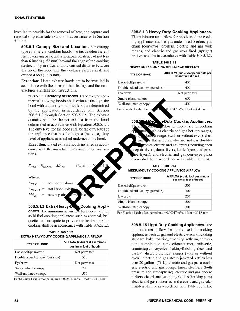
installed to provide for the removal of heat, and capture andremoval of grease-laden vapors in accordance with Section511.2.2.
508.5.1 Canopy Size and Location. For canopytype commercial cooking hoods, the inside edge thereofshall overhang or extend a horizontal distance of not lessthan 6 inches (152 mm) beyond the edge of the cookingsurface on open sides, and the vertical distance betweenthe lip of the hood and the cooking surface shall notexceed 4 feet (1219 mm).Exception: Listed exhaust hoods are to be installed inaccordance with the terms of their listings and the man-ufacturer’s installation instructions.
508.5.1.1 Capacity of Hoods. Canopy-type com-mercial cooking hoods shall exhaust through thehood with a quantity of air not less than determinedby the application in accordance with Section508.5.1.2 through Section 508.5.1.5. The exhaustquantity shall be the net exhaust from the hooddetermined in accordance with Equation 508.5.1.1.The duty level for the hood shall be the duty level ofthe appliance that has the highest (heaviest) dutylevel of appliances installed underneath the hood.Exception: Listed exhaust hoods installed in accor-dance with the manufacturer’s installation instruc-tions.
ENET = EHOOD – MAID (Equation 508.5.1.1)
Where:ENET = net hood exhaustEHOOD = total hood exhaustMAID = makeup air, internal discharge
508.5.1.2 Extra-Heavy-Duty Cooking Appli-ances. The minimum net airflow for hoods used forsolid fuel cooking appliances such as charcoal, bri-quette, and mesquite to provide the heat source forcooking shall be in accordance with Table 508.5.1.2.
508.5.1.3 Heavy-Duty Cooking Appliances.The minimum net airflow for hoods used for cook-ing appliances such as gas under-fired broilers, gaschain (conveyor) broilers, electric and gas wokranges, and electric and gas over-fired (upright)broilers shall be in accordance with Table 508.5.1.3.
508.5.1.4 Medium-Duty Cooking Appliances.The minimum net airflow for hoods used for cookingappliances such as electric and gas hot-top ranges,gas open-burner ranges (with or without oven), elec-tric and gas flat griddles, electric and gas double-sided griddles, electric and gas fryers (including opendeep fat fryers, donut fryers, kettle fryers, and pres-sure fryers), and electric and gas conveyor pizzaovens shall be in accordance with Table 508.5.1.4.
508.5.1.5 Light-Duty Cooking Appliances. Theminimum net airflow for hoods used for cookingappliances such as gas and electric ovens (includingstandard, bake, roasting, revolving, retherm, convec-tion, combination convection/steamer, rotisserie,countertop conveyorized baking/finishing, deck, andpastry), discrete element ranges (with or withoutoven), electric and gas steam-jacketed kettles lessthan 20 gallons (76 L), electric and gas pasta cook-ers, electric and gas compartment steamers (bothpressure and atmospheric), electric and gas cheesemelters, electric and gas tilting skillets (braising pans)electric and gas rotisseries, and electric and gas sala-manders shall be in accordance with Table 508.5.1.5.
TABLE 508.5.1.2EXTRA-HEAVY-DUTY COOKING APPLIANCE AIRFLOW
For SI units: 1 cubic foot per minute = 0.00047 m3/s, 1 foot = 304.8 mm
TYPE OF HOODAIRFLOW (cubic foot per minute
per linear foot of hood)
Backshelf/pass-over Not permittedDouble island canopy (per side) 550Eyebrow Not permittedSingle island canopy 700Wall-mounted canopy 550
TABLE 508.5.1.3HEAVY-DUTY COOKING APPLIANCE AIRFLOW
TYPE OF HOOD AIRFLOW (cubic foot per minute perlinear foot of hood)
Backshelf/pass-over 400Double island canopy (per side) 400Eyebrow Not permittedSingle island canopy 600Wall-mounted canopy 400For SI units: 1 cubic foot per minute = 0.00047 m3/s, 1 foot = 304.8 mm
TABLE 508.5.1.4MEDIUM-DUTY COOKING APPLIANCE AIRFLOW
TYPE OF HOODAIRFLOW (cubic foot per minute
per linear foot of hood)
Backshelf/pass-over 300Double island canopy (per side) 300Eyebrow 250Single island canopy 500Wall-mounted canopy 300For SI units: 1 cubic foot per minute = 0.00047 m3/s, 1 foot = 304.8 mm
58 UNIFORM MECHANICAL CODE - PREPRINT
EXHAUST SYSTEMS
PREPRINT
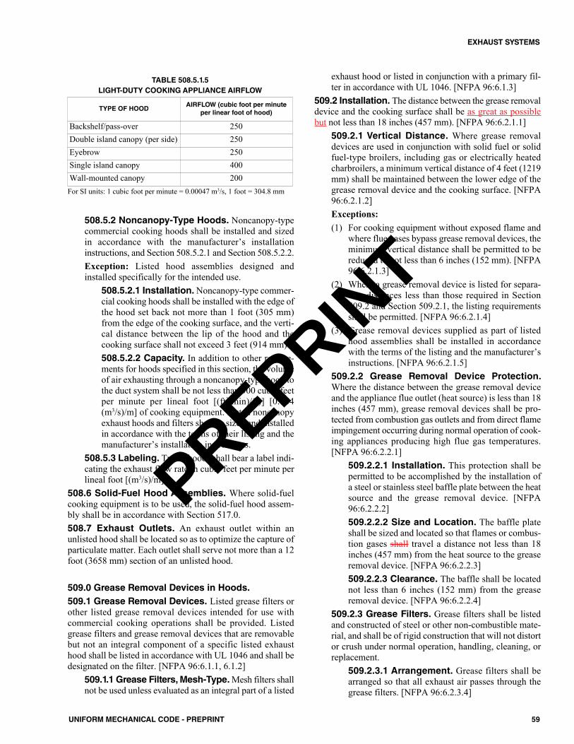
508.5.2 Noncanopy-Type Hoods. Noncanopy-typecommercial cooking hoods shall be installed and sizedin accordance with the manufacturer’s installationinstructions, and Section 508.5.2.1 and Section 508.5.2.2.Exception: Listed hood assemblies designed andinstalled specifically for the intended use.
508.5.2.1 Installation.Noncanopy-type commer-cial cooking hoods shall be installed with the edge ofthe hood set back not more than 1 foot (305 mm)from the edge of the cooking surface, and the verti-cal distance between the lip of the hood and thecooking surface shall not exceed 3 feet (914 mm).508.5.2.2 Capacity. In addition to other require-ments for hoods specified in this section, the volumeof air exhausting through a noncanopy-type hood tothe duct system shall be not less than 300 cubic feetper minute per lineal foot [(ft3/min)/ft)] [0.464(m3/s)/m] of cooking equipment. Listed noncanopyexhaust hoods and filters shall be sized and installedin accordance with the terms of their listing and themanufacturer’s installation instructions.
508.5.3 Labeling. Type I hoods shall bear a label indi-cating the exhaust flow rate in cubic feet per minute perlineal foot [(m3/s)/m].
508.6 Solid-Fuel Hood Assemblies. Where solid-fuelcooking equipment is to be used, the solid-fuel hood assem-bly shall be in accordance with Section 517.0.508.7 Exhaust Outlets. An exhaust outlet within anunlisted hood shall be located so as to optimize the capture ofparticulate matter. Each outlet shall serve not more than a 12foot (3658 mm) section of an unlisted hood.
509.0 Grease Removal Devices in Hoods.509.1 Grease Removal Devices. Listed grease filters orother listed grease removal devices intended for use withcommercial cooking operations shall be provided. Listedgrease filters and grease removal devices that are removablebut not an integral component of a specific listed exhausthood shall be listed in accordance with UL 1046 and shall bedesignated on the filter. [NFPA 96:6.1.1, 6.1.2]
509.1.1 Grease Filters, Mesh-Type.Mesh filters shallnot be used unless evaluated as an integral part of a listed
exhaust hood or listed in conjunction with a primary fil-ter in accordance with UL 1046. [NFPA 96:6.1.3]
509.2 Installation. The distance between the grease removaldevice and the cooking surface shall be as great as possiblebut not less than 18 inches (457 mm). [NFPA 96:6.2.1.1]
509.2.1 Vertical Distance. Where grease removaldevices are used in conjunction with solid fuel or solidfuel-type broilers, including gas or electrically heatedcharbroilers, a minimum vertical distance of 4 feet (1219mm) shall be maintained between the lower edge of thegrease removal device and the cooking surface. [NFPA96:6.2.1.2]Exceptions:(1) For cooking equipment without exposed flame and
where flue gases bypass grease removal devices, theminimum vertical distance shall be permitted to bereduced to not less than 6 inches (152 mm). [NFPA96:6.2.1.3]
(2) Where a grease removal device is listed for separa-tion distances less than those required in Section509.2 and Section 509.2.1, the listing requirementsshall be permitted. [NFPA 96:6.2.1.4]
(3) Grease removal devices supplied as part of listedhood assemblies shall be installed in accordancewith the terms of the listing and the manufacturer’sinstructions. [NFPA 96:6.2.1.5]
509.2.2 Grease Removal Device Protection.Where the distance between the grease removal deviceand the appliance flue outlet (heat source) is less than 18inches (457 mm), grease removal devices shall be pro-tected from combustion gas outlets and from direct flameimpingement occurring during normal operation of cook-ing appliances producing high flue gas temperatures.[NFPA 96:6.2.2.1]
509.2.2.1 Installation. This protection shall bepermitted to be accomplished by the installation ofa steel or stainless steel baffle plate between the heatsource and the grease removal device. [NFPA96:6.2.2.2]509.2.2.2 Size and Location. The baffle plateshall be sized and located so that flames or combus-tion gases shall travel a distance not less than 18inches (457 mm) from the heat source to the greaseremoval device. [NFPA 96:6.2.2.3]509.2.2.3 Clearance. The baffle shall be locatednot less than 6 inches (152 mm) from the greaseremoval device. [NFPA 96:6.2.2.4]
509.2.3 Grease Filters. Grease filters shall be listedand constructed of steel or other non-combustible mate-rial, and shall be of rigid construction that will not distortor crush under normal operation, handling, cleaning, orreplacement.
509.2.3.1 Arrangement. Grease filters shall bearranged so that all exhaust air passes through thegrease filters. [NFPA 96:6.2.3.4]
TABLE 508.5.1.5LIGHT-DUTY COOKING APPLIANCE AIRFLOW
TYPE OF HOODAIRFLOW (cubic foot per minute
per linear foot of hood)
Backshelf/pass-over 250Double island canopy (per side) 250Eyebrow 250Single island canopy 400Wall-mounted canopy 200
For SI units: 1 cubic foot per minute = 0.00047 m3/s, 1 foot = 304.8 mm
59UNIFORM MECHANICAL CODE - PREPRINT
EXHAUST SYSTEMS
PREPRINT
509.2.3.2 Accessibility. Grease filters shall beeasily accessible for removal. [NFPA 96:6.2.3.5]509.2.3.3 Angled Installation. Grease filtersshall be installed at an angle not less than 45 degrees(0.79 rad) from the horizontal. [NFPA 96:6.2.3.6]
509.2.4 Grease Drip Trays. Grease filters shall beequipped with a grease drip tray beneath their loweredges. [NFPA 96:6.2.4.1]
509.2.4.1 Size and Pitch. Grease drip trays shallbe kept to the minimum size needed to collectgrease. Grease drip trays shall be pitched to draininto an enclosed metal container having a capacitynot exceeding 1 gallon (4 L). [NFPA 96:6.2.4.2,6.2.4.3]
509.2.5 Grease Filter Orientation.Grease filters thatrequire a specific orientation to drain grease shall beclearly so designated on the face of the filter as to be vis-ible with the filter installed, or the hood or filter shall beconstructed so that filters cannot be installed in the wrongorientation. [NFPA 96:6.2.5]
509.3 Solid-Fuel Grease Removal Devices. Wheresolid-fuel cooking equipment is provided with grease removaldevices, these devices shall be in accordance with Section517.0.
510.0 Exhaust Duct Systems.510.1 General. Ducts shall not pass through fire walls.[NFPA 96:7.1.1]
510.1.1 Fire Hazards.All Dducts shall lead as directlyto the exterior of the building, so as not to undulyincrease a any fire hazard. [NFPA 96:7.1.2]510.1.2 Interconnection. Duct systems shall not beinterconnected with any other building ventilation orexhaust system. [NFPA 96:7.1.3]510.1.3 Duct Installation. All ducts shall be installedwith a minimum 2 percent slope on horizontal runs up to75 feet (22 860 mm) and a minimum 8 percent slope onhorizontal runs greater than 75 feet (22 860 mm). Fac-tory-built grease ducts shall be permitted to be installedat a lesser slope in accordance with the listing and themanufacturer’s instructions. All horizontal ducts shall beprovided with access in accordance with Section 510.3.3.
Drains shall be provided at low points in horizontalducts. Where provided, drains shall be continuouslywelded to the exhaust duct in accordance with the termsof the listing and the manufacturer’s installation manual.
All ducts shall be installed without forming dips ortraps. In manifold (common duct) systems, the lowestend of the main duct shall be connected flush on the bot-tom with the branch duct. [NFPA 96:7.1.4 – 7.1.4.5]510.1.4 Accessibility. Openings required for accessi-bility shall comply with Section 510.3 through Section510.3.2. [NFPA 96:7.1.5]
510.1.5 Sign. A sign stating the following shall beplaced on all access panels:ACCESS PANEL – DO NOT OBSTRUCT [NFPA96:7.1.6]510.1.6 Bracing and Supports. Duct bracing andsupports shall be of noncombustible material, securelyattached to the structure and designed to carry gravityand lateral loads within the stress limitations of the build-ing code. Bolts, screws, rivets, and other mechanical fas-teners shall not penetrate duct walls.510.1.7 Type I Exhaust Duct Systems. Listed greaseducts shall be installed in accordance with the terms oftheir listings and the manufacturer’s instructions. [NFPA96:7.1.7]
510.2 Clearance. Clearance between ducts and combustiblematerials shall be provided in accordance with the require-ments of Section 507.4. [NFPA 96:7.2]510.3 Openings. Openings shall be provided at the sidesor at the top of the duct, whichever is more accessible, and atchanges of direction. Openings shall be protected byapproved access constructed and installed in accordance withthe requirements of Section 510.3.7. [NFPA 96:7.3.1, 7.3.2]Exception: Openings shall not be required in portions of theduct that are accessible from the duct entry or discharge.[NFPA 96:7.3.3]
510.3.1 Access Panel. For hoods with dampers in theexhaust or supply collar, an access panel for cleaning andinspection shall be provided in the duct or the hood within18 inches (457 mm) of the damper. [NFPA 96:7.3.4]Exception: Dampers that are accessible from under thehood.510.3.2 Access for Cleaning and Inspection.Exhaust fans with ductwork connected to both sides shallhave access for cleaning and inspection within 3 feet(914 mm) of each side of the fan. Wall-mounted exhaustfans shall have access for cleaning and inspection within3 feet (914 mm) of the exhaust fan. [NFPA 96:7.3.7,7.3.8]510.3.3 Horizontal Ducts. On horizontal ducts, atleast one 20 inch by 20 inch (508 mm by 508 mm) open-ing shall be provided for personnel entry. [NFPA96:7.4.1.1]
510.3.3.1 Cleaning. Where an opening of the sizespecified in Section 510.3.3 is not possible, open-ings large enough to permit thorough cleaning shallbe provided at 12 feet (3658 mm) intervals. [NFPA96:7.4.1.2]510.3.3.2 Safe Access and Work Platform.Where If not easily accessible from a 10 foot (3048mm) stepladder, openings on horizontal grease ductsystems shall be provided with safe access and awork platform. [NFPA 96:7.4.1.3] 510.3.3.3 Support. Support systems for horizon-tal grease duct systems 24 inches (610 mm) andlarger in a any cross-sectional dimension shall be
60 UNIFORM MECHANICAL CODE - PREPRINT
EXHAUST SYSTEMS
PREPRINT
designed for the weight of the ductwork plus 800pounds (362.9 kg) at a any point in the duct systems.[NFPA 96:7.4.1.4]
510.3.4 Vertical Ducts. On vertical ductwork wherepersonnel entry is possible, access shall be provided atthe top of the vertical riser to accommodate descent.[NFPA 96:7.4.2.1]
510.3.4.1 Access. Where personnel entry is notpossible, an adequate access for cleaning shall beprovided on each floor. [NFPA 96:7.4.2.2]510.3.4.2 Safe Access and Work Platform. Ifnot easily accessible from the floor or a 10 foot(3048 mm) stepladder, openings on vertical greaseducts shall be provided with safe access and a workplatform. [NFPA 96:7.4.2.3]
510.3.5 Nonlisted Ductwork. On nonlisted ductwork,the edge of the opening shall be not less than 11⁄2 inches(38 mm) from all outside edges of the duct or weldedseams. [NFPA 96:7.4.1.5]510.3.6 Access Panels. Access panels shall be of thesame material and thickness as the duct. Access panelsshall have a gasket or sealant that is rated for 1500°F(816°C) and shall be greasetight. Fasteners, such as bolts,weld studs, latches, or wing nuts, used to secure the accesspanels shall be carbon steel or stainless steel and shall notpenetrate duct walls. [NFPA 96:7.4.3.1 – 7.4.3.3]
510.3.6.1 Listed Grease Ducts.Listed grease ductaccess door assemblies (access panels) shall beinstalled in accordance with the terms of the listingand the manufacturer’s instructions. [NFPA 96:7.4.3.4]510.3.6.2 Within an Enclosure. Where openingsare located in ducts within an enclosure, the accesspanel including its components shall be of the samefire rating as the enclosure.
510.3.7 Fire Protection System Devices. Openingsfor installation, servicing, and inspection of listed fireprotection system devices and for duct cleaning shall beprovided in ducts and enclosures and shall be in accor-dance with the requirements of Section 510.3 throughSection 510.3.2 and Section 510.7.7. Enclosure openingsrequired to reach access panels in the ductwork shall belarge enough for removal of the access panel through theenclosure opening. [NFPA 96:7.4.47.4.4.1 – 7.4.4.2]
510.4 Listed Grease Ducts. Listed grease ducts shall beinstalled in accordance with the terms of the listing and themanufacturer’s instructions. [NFPA 96:7.1.7]
510.4.1 Factory-Built Grease Ducts. Factory-builtgrease ducts in accordance with UL 1978 shall be per-mitted to incorporate non-welded joints in accordancewith their listings.
510.5 Other Grease Ducts. Other grease ducts shall com-ply with the requirements of Section 510.5.1 through Section510.5.5. [NFPA 96:7.5]
510.5.1 Materials. Ducts shall be constructed of andsupported by carbon steel not less than 0.060 of an inch
(1.524 mm) (No. 16 MSG) in thickness or stainless steelnot less than 0.048 of an inch (1.219 mm) (No. 18 MSG)in thickness. [NFPA 96:7.5.1.1]510.5.2 Factory-Built Grease Ducts. Factory-builtgrease ducts listed in accordance with UL 1978 shall bepermitted to use materials in accordance with their list-ing. [NFPA 96:7.5.1.2]510.5.3 Installation. All Sseams, joints, penetrations,and duct-to-hood collar connections shall have a liquid-tight continuous external weld. [NFPA 96:7.5.2.1]Exceptions:(1) Factory-built grease duct ducts listed in accordance
with UL 1978 shall be permitted to incorporate non-welded joint construction in accordance with theirlisting listings. [NFPA 96:7.5.2.1.1]
(2) Duct-to-hood collar connections as shown in Figure510.5.3 shall not require a liquid-tight continuousexternal weld. [NFPA 96:7.5.2.2]
(3) Penetrations shall be permitted to be sealed by otherlisted devices that are tested to be greasetight and areevaluated under the same conditions of fire severityas the hood or enclosure of listed grease extractorsand whose presence does not detract from the hood’sor duct’s structural integrity. [NFPA 96:7.5.2.3]
(4) Internal welding shall be permitted, provided thejoint is formed or ground smooth and is readilyaccessible for inspection. [NFPA 96:7.5.2.4]510.5.3.1 Duct Leakage Test. Prior to the use ofor concealment of a any portion of a grease duct sys-tem, a leakage test shall be performed to determinethat all welded joints and seams are liquid tight.[NFPA 96:7.5.2.1.2]510.5.3.2 Welded Duct Connection. Accept-able Dduct-to-duct connection shall be as follows: (1) Telescoping joint, as shown in Figure
510.5.3.2(1).(2) Bell-type joint, as shown in Figure 510.5.3.2(2).(3) Flange with edge weld, as shown in Figure
510.5.3.2(3).(4) Flange with filled weld, as shown in Figure
510.5.3.2(4). [NFPA 96:7.5.5.1]510.5.4 Butt Welded Connections. Butt welded con-nections shall not be permitted. [NFPA 96:7.5.5.2] 510.5.5 Telescoping and Bell-Type Connections.For telescoping and bell-type connections, the inside ductsection shall always be uphill of the outside duct section.[NFPA 96:7.5.5.3] The overlap shall not exceed 2 inches(51 mm) as shown in Figure 510.5.3.2(1).510.5.6 Duct Leakage Test. Prior to the use of or con-cealment of a grease duct system, a leakage test shall beperformed to determine that welded joints and seams areliquid tight. The leakage test shall consist of a light test,water pressure test, or an approved equivalent test. Thepermit holder shall be responsible for providing the nec-essary equipment and for performing the test. Such testshall be conducted in accordance with ASHRAE 154.
61UNIFORM MECHANICAL CODE - PREPRINT
EXHAUST SYSTEMS
PREPRINT
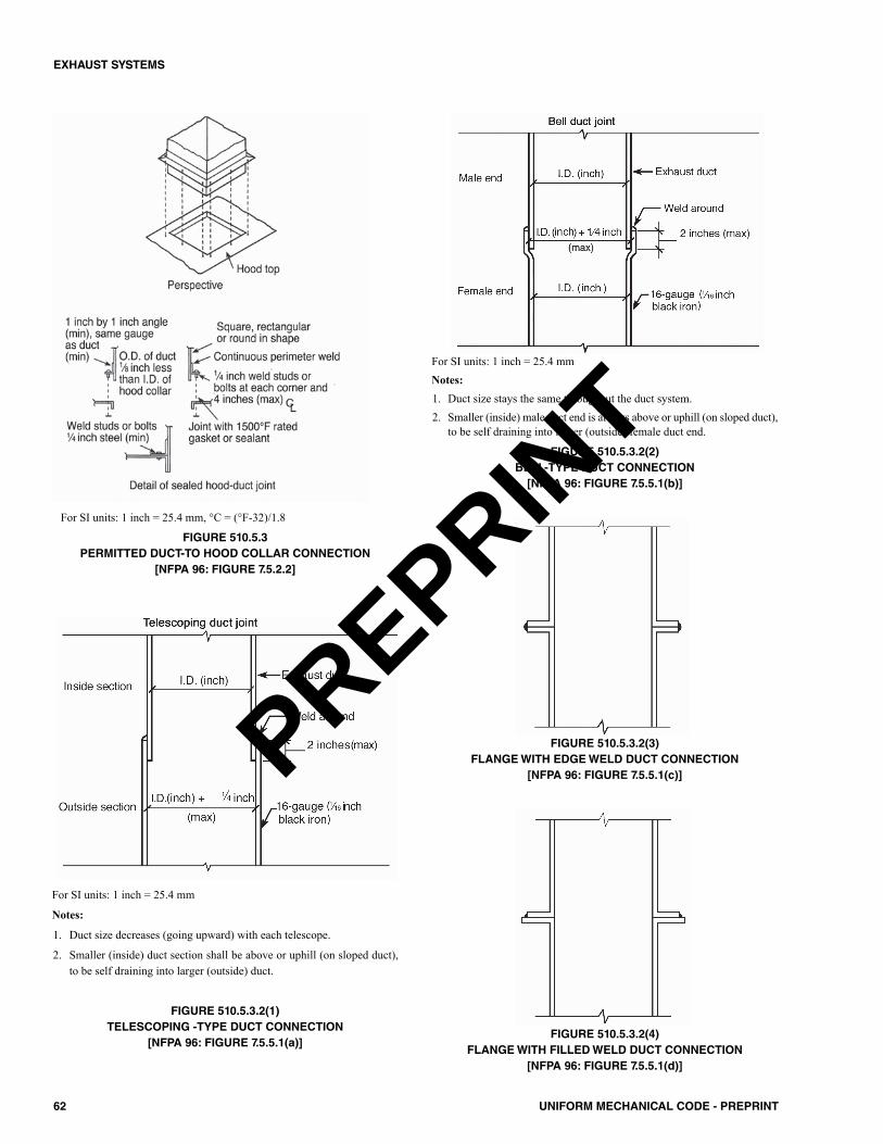
62 UNIFORM MECHANICAL CODE - PREPRINT
EXHAUST SYSTEMS
For SI units: 1 inch = 25.4 mm, °C = (°F-32)/1.8
FIGURE 510.5.3PERMITTED DUCT-TO HOOD COLLAR CONNECTION
[NFPA 96: FIGURE 7.5.2.2]
For SI units: 1 inch = 25.4 mm
Notes:
1. Duct size decreases (going upward) with each telescope.
2. Smaller (inside) duct section shall be above or uphill (on sloped duct),to be self draining into larger (outside) duct.
FIGURE 510.5.3.2(1)TELESCOPING -TYPE DUCT CONNECTION
[NFPA 96: FIGURE 7.5.5.1(a)]
For SI units: 1 inch = 25.4 mmNotes:1. Duct size stays the same throughout the duct system.2. Smaller (inside) male duct end is always above or uphill (on sloped duct),
to be self draining into larger (outside) female duct end.
FIGURE 510.5.3.2(2)BELL-TYPE DUCT CONNECTION[NFPA 96: FIGURE 7.5.5.1(b)]
FIGURE 510.5.3.2(3)FLANGE WITH EDGE WELD DUCT CONNECTION
[NFPA 96: FIGURE 7.5.5.1(c)]
FIGURE 510.5.3.2(4)FLANGE WITH FILLED WELD DUCT CONNECTION
[NFPA 96: FIGURE 7.5.5.1(d)]
PREPRINT

510.6 Exterior Installations. The exterior portion of theductwork shall be vertical wherever possible and shall beinstalled and supported on the exterior of a building. Bolts,screws, rivets, and other mechanical fasteners shall not pen-etrate duct walls. Clearance of ducts shall comply with Sec-tion 507.4. [NFPA 96:7.6.1 – 7.6.3]
510.6.1 Weather Protection.All Dducts shall be pro-tected on the exterior by paint or other suitable weather-protective coating. Ducts constructed of stainless steelshall not be required to have additional paint or weather-protective coatings. Ductwork subject to corrosion shallhave minimal contact with the building surface. [NFPA96:7.6.4 – 7.6.6]
510.7 Interior Installations. In all buildings more than onestory in height and in one-story buildings where the roof-ceil-ing assembly is required to have a fire resistance rating, theducts shall be enclosed in a continuous enclosure extendingfrom the lowest fire-rated ceiling or floor above the hood,through any concealed spaces, to or through the roof, to main-tain the integrity of the fire separations required by the appli-cable building code provisions. The enclosure shall be sealedaround the duct at the point of penetration of the first fire-rated barrier after the hood, to maintain the fire resistance rat-ing of the enclosure. The enclosure shall be vented to theexterior of the building through weather-protected openings.[NFPA 96:7.7.1.2 – 7.7.1.4]Exception: The continuous enclosure provisions shall not berequired where a field-applied grease duct enclosure or a fac-tory-built grease duct enclosure (see Section 507.4.4 throughSection 507.4.6) is protected with a listed duct-through-pen-etration protection system equivalent to the fire resistance rat-ing of the assembly being penetrated and where the materialsare installed in accordance with the conditions of the listingsand the manufacturer’s instructions and are acceptable to theAuthority Having Jurisdiction. [NFPA 96:7.7.1.5]
510.7.1 Less than Four Stories. Buildings less thanfour stories in height shall have an enclosure with a fireresistance rating of not less than 1 hour. [NFPA96:7.7.2.1.1]510.7.2 Four Stories or More. Buildings four storiesor more in height shall have an enclosure with a fireresistance rating of not less than 2 hours. [NFPA96:7.7.2.1.2]510.7.3 Clearance. Clearance from the duct or theexhaust fan to the interior surface of enclosures of com-bustible construction shall be not less than 18 inches (457mm). Clearance from the duct to the interior surface ofenclosures of noncombustible or limited-combustibleconstruction shall be not less than 6 inches (152 mm).Provisions for reducing clearances as described in Sec-tion 507.4 through Section 507.4.3.3 shall not be appli-cable to enclosures. [NFPA 96:7.7.2.2.1 – 7.7.2.2.3]Exception: Clearance from the outer surfaces of field-applied grease duct enclosures and factory-built greaseduct enclosures to the interior surfaces of constructioninstalled around them shall be permitted to be reducedwhere the field-applied grease duct enclosure materialsand factory-built grease duct enclosures are installed in
accordance with the conditions of the listing and the man-ufacturer’s instructions and are acceptable to the Author-ity Having Jurisdiction. [NFPA 96:7.7.2.2.4]510.7.4 Mechanical and Structural Integrity. Field-applied grease duct enclosures and factory-built greaseduct enclosures shall provide mechanical and structuralintegrity, resiliency, and stability when subjected toexpected building environmental conditions, duct move-ment under general operating conditions, and duct move-ment as a result of interior and exterior fire conditions.[NFPA 96:7.7.2.2.5]510.7.5 Materials. For field-applied grease duct enclo-sures and factory-built grease duct enclosures, the mate-rials and products shall be provided in accordance withSection 510.7.5.1 and Section 510.7.5.2.
510.7.5.1 Protection from Physical Damage.Measures shall be taken to prevent physical damageto any covering or enclosure material. Any damageto the covering or enclosure shall be repaired, andthe covering or enclosure shall be restored to meetits intended listing and fire-resistance rating and tobe acceptable to the Authority Having Jurisdiction.[NFPA 96:7.7.3.1, 7.7.3.2]510.7.5.2 Inspection. In the event of a fire withina kitchen exhaust system, the duct, the enclosure,and the covering directly applied to the duct shall beinspected by qualified personnel to determinewhether the duct, the enclosure, and the coveringdirectly applied to the duct are structurally sound,capable of maintaining their fire protection func-tions, suitable for continued operation, and accept-able to the Authority Having Jurisdiction. [NFPA96:7.7.3.3]
510.7.6 Listed. For listed grease ducts, see Section510.4.510.7.7 Fire Doors. Where openings in the enclosurewalls are provided, they shall be protected by listed firedoors of proper rating. Fire doors shall be installed inaccordance with NFPA 80. Openings on other listedmaterials or products shall be clearly identified andlabeled according to the terms of the listing and the man-ufacturer’s instructions and shall be acceptable to theAuthority Having Jurisdiction. [NFPA 96:7.7.4.1 –7.7.4.3] The fire door shall be readily accessible, aligned,and of sufficient size to allow access to the rated accesspanels on the ductwork. [NFPA 96:7.7.4.4]510.7.8 Ducts with Enclosure(s). Each duct systemshall constitute an individual system serving only exhausthoods in one fire zone on one floor. Multiple ducts shallnot be permitted in a single enclosure unless acceptableto the Authority Having Jurisdiction. [NFPA 96:7.7.5.1– 7.7.5.2]
510.8 Underground Installations. Grease ducts installedunderground shall be approved for underground installation.The material of the grease duct shall be corrosion-resistantand shall comply with Section 510.5.1.
510.8.1 Grease Receptacle. The grease duct shall besloped to drain the grease back to an approved grease
63UNIFORM MECHANICAL CODE - PREPRINT
EXHAUST SYSTEMS
PREPRINT

collection device. A grease collection device shall belocated at the base of the vertical riser.510.8.2 Cleanouts. For horizontal installations,cleanouts for cleaning and maintenance shall be providedon the top portion of the grease duct in accordance withSection 510.3 and shall be labeled at the interior portionof the duct.
510.9 Termination of Type I Hood Exhaust System.The exhaust system shall terminate as follows:(1) Outside the building with a fan or duct. (2) Through the roof or to the roof from outside, as in in
accordance with Section 510.9.1, or through a wall, as inin accordance with Section 510.9.2. [NFPA 96:7.8.1]510.9.1 Rooftop Terminations. Rooftop terminationsshall be arranged with or provided with the following:(1) A minimum of 10 feet (3048 mm) of horizontal
clearance from the outlet to adjacent buildings, prop-erty lines, and air intakes.
(2) A minimum of 5 feet (1524 mm) of horizontal clear-ance from the outlet (fan housing) to any combustiblestructure.
(3) A vertical separation of 3 feet (914 mm) above anyair intakes within 10 feet (3048 mm) of the exhaustoutlet.
(4) The ability to drain grease out of any traps or lowpoints formed in the fan or duct near the terminationof the system into a collection container that is non-combustible, closed, rainproof, and structurallysound for the service to which it is applied and thatwill not sustain combustion.
(5) A grease collection device that is applied to exhaustsystems that does not inhibit the performance of anyfan.
(6) Listed grease collection systems that meet the require-ments of Section 510.9.1(4) and Section 510.9.1(5).
(7) A listed grease duct complying with Section 507.4.7or ductwork complying with Section 507.4.8.
(8) A hinged upblast fan supplied with flexible weath-erproof electrical cable and service hold-openretainer to permit inspection and cleaning that islisted for commercial cooking equipment with thefollowing conditions:(a) Where the fan attaches to the ductwork, the
ductwork is a minimum of 18 inches (457 mm)away from any roof surface, as shown in Fig-ure 510.9.1.
(b) The fan discharges a minimum of 40 inches(1016 mm) away from any roof surface, asshown in Figure 510.9.1.
(9) Other approved fan, provided it meets all of the fol-lowing criteria: (a) The fan meets the requirements of Section
510.9.1(3) and Section 511.1.3. (b) Its discharge or its extended duct discharge
meets the requirements of Section 510.9.1(2).(See Section 511.1.3)
(c) Exhaust fan discharge is directed up and awayfrom the roof surface. [NFPA 96:7.8.2.1]
510.9.1.1 Listed Flexible Vibration IsolationConnectors. Listed flexible vibration isolationconnectors shall be permitted to be used on exteriorroof locations where required for proper equipmentvibration isolation.510.9.1.2 Inspection and Cleaning. Fans shallbe provided with safe access and a work surface forinspection and cleaning. [NFPA 96:7.8.2.2]
510.9.2 Wall Terminations. Wall terminations shall bearranged with or provided with the following properties:(1) The termination shall be Tthrough a noncombustible
wall with not less than a minimum of 10 feet (3048mm) of clearance from the outlet to adjacent build-ings, property lines, grade level, combustible con-struction, electrical equipment or lines, and with theclosest point of an any air intake or operable door orwindow at or below the plane of the exhaust termi-nation. The closest point of an any air intake or oper-able door or window above the plane of the exhausttermination shall be not less than a minimum of 10feet (3048 mm) in distance, plus 3 inches (76 mm)for each 1 degree (0.017 rad) from horizontal, theangle of degree being measured from the center ofthe exhaust termination to the center of the airintake, or operable door or window, as indicated inFigure 510.9.2.Exception: A wall termination in a secured areashall be permitted to be at a lower height abovegrade where if acceptable to the Authority HavingJurisdiction.
(2) The exhaust flow shall be directed perpendicularlyoutward from the wall face or upward.
For SI units: 1 inch = 25.4 mm, 1 foot = 304.8 mm
FIGURE 510.9.1UPBLAST FAN CLEARANCES[NFPA 96: FIGURE 7.8.2.1]
64 UNIFORM MECHANICAL CODE - PREPRINT
EXHAUST SYSTEMS
PREPRINT
(3) All Tthe ductwork shall be pitched to drain thegrease back into the hood(s) or with a drain providedto bring the grease back into a container within thebuilding or into a remote grease trap.
(4) A listed grease duct shall comply with Section510.3.3 through Section 510.3.7; other ducts shallcomply with Section 510.5.
(5) An approved fan shall comply with meet the require-ments of Section 510.9.2(3), and Section 511.1.1 orSection 511.1.3. [NFPA 96:7.8.3]
510.10 Solid-Fuel Duct Systems.Where solid-fuel cook-ing equipment is to be vented, the duct system shall be inaccordance with Section 517.0.
511.0 Air Movement. 511.1 Exhaust Fans for Commercial Cooking Opera-tions. Exhaust fans shall be installed in accordance with Sec-tion 511.1.1 through Section 511.1.6. Exhaust fans shallcomply with UL 762 and be installed in accordance with themanufacturer’s installation instructions.
511.1.1 Upblast Fans. Upblast fans with motors sur-rounded by the airstream shall be hinged and suppliedwith flexible weatherproof electrical cable, and servicehold-open retainers. Installation shall comply with con-form to the requirements of Section 510.9. Upblast fansshall have a drain directed to a readily accessible and vis-ible grease receptacle not to exceed 1 gallon (4 L).[NFPA 96:8.1.2.1 – 8.1.2.3]511.1.2 In-Line Exhaust Fans. In-line fans shall beof the type with the motor located outside the airstreamand with belts and pulleys protected from the airstreamby a greasetight housing. In-line fans shall be connectedto the exhaust duct by flanges securely bolted as shownin Figure 511.1.2(1) through Figure 511.1.2(4), or by asystem specifically listed for such use. Flexible connec-tors shall not be used. [NFPA 96:8.1.3.1 – 8.1.3.3]
511.1.2.1 Accessibility. Where If the design orpositioning of the fan allows grease to be trapped, adrain directed to a readily accessible and visiblegrease receptacle not exceeding 1 gallon (4 L), shallbe provided. In-line exhaust fans shall be located ineasily accessible areas of adequate size to allow forservice or removal. Where the duct system con-nected to the fan is in an enclosure, the space orroom in which the exhaust fan is located shall havethe same fire resistance rating as the enclosure.[NFPA 96:8.1.3.4 – 8.1.3.6]
511.1.3 Utility Set Exhaust Fans. Utility set exhaustfans shall be installed in accordance with Section511.1.3.1 through Section 511.1.3.3.
511.1.3.1 At the Rooftop. Fans installed at therooftop termination point shall be in accordancewith the following:(1) Section 510.9.1 and Section 510.9.1.2.(2) Flexible Vibration isolation connectors shall be
permitted.(3) A drain shall be directed to a readily accessible
and visible grease receptacle not to exceed 1gallon (4 L).
511.1.3.2 Within the Building. Fans installedwithin the building shall be in accordance with thefollowing:(1) Located in an accessible area of a adequate size
to allow for service or removal. [NFPA96:8.1.4.2]
(2) Flexible connectors shall not be used prohib-ited. [NFPA 96:8.1.4.5]
(3) Exhaust fans shall have Aa drain shall bedirected to a readily accessible and visiblegrease receptacle not to exceed 1 gallon (4 L).[NFPA 96:8.1.4.6]
65UNIFORM MECHANICAL CODE - PREPRINT
EXHAUST SYSTEMS
For SI units: 1 inch = 25.4 mm, 1 foot = 304.8 mmNotes:1. Fresh air intake (FAI) applies to an air intake, including an operable door
or window.2. Example:
(a) FAIs 1 and 5 are on the same plane of exhaust or lower: 10 feet (3048mm) min. between closest edges.
(b) FAIs 2, 3, and 4 are above plane of exhaust fan: 10 feet + 0.25 feet (3048 mm + 76mm) per degree between closestedges.
FIGURE 510.9.2EXHAUST TERMINATION DISTANCE FROM FRESH AIR INTAKE
(FAI) OR OPERABLE DOOR OR WINDOW[NFPA 96: FIGURE 7.8.3]
PREPRINT
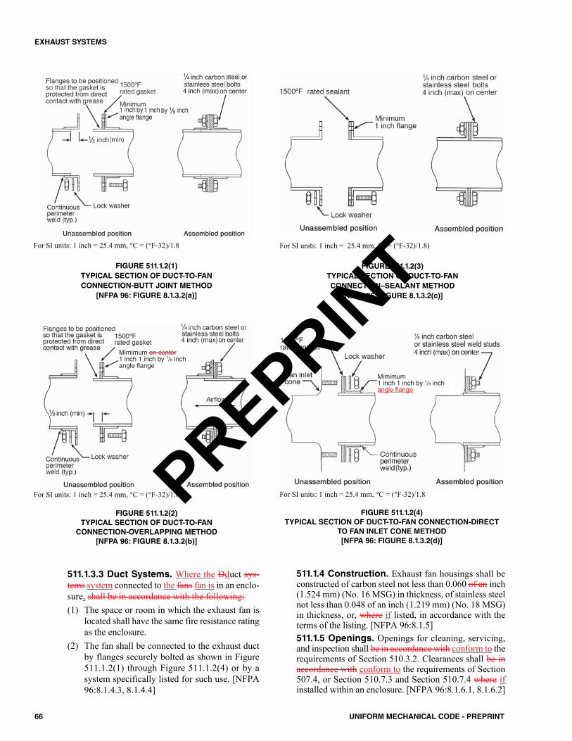
66 UNIFORM MECHANICAL CODE - PREPRINT
EXHAUST SYSTEMS
511.1.3.3 Duct Systems. Where the Dduct sys-tems system connected to the fans fan is in an enclo-sure, shall be in accordance with the following:(1) The space or room in which the exhaust fan is
located shall have the same fire resistance ratingas the enclosure.
(2) The fan shall be connected to the exhaust ductby flanges securely bolted as shown in Figure511.1.2(1) through Figure 511.1.2(4) or by asystem specifically listed for such use. [NFPA96:8.1.4.3, 8.1.4.4]
511.1.4 Construction. Exhaust fan housings shall beconstructed of carbon steel not less than 0.060 of an inch(1.524 mm) (No. 16 MSG) in thickness, of stainless steelnot less than 0.048 of an inch (1.219 mm) (No. 18 MSG)in thickness, or, where if listed, in accordance with theterms of the listing. [NFPA 96:8.1.5]511.1.5 Openings. Openings for cleaning, servicing,and inspection shall be in accordance with conform to therequirements of Section 510.3.2. Clearances shall be inaccordance with conform to the requirements of Section507.4, or Section 510.7.3 and Section 510.7.4 where ifinstalled within an enclosure. [NFPA 96:8.1.6.1, 8.1.6.2]
For SI units: 1 inch = 25.4 mm, °C = (°F-32)/1.8
FIGURE 511.1.2(1)TYPICAL SECTION OF DUCT-TO-FANCONNECTION-BUTT JOINT METHOD
[NFPA 96: FIGURE 8.1.3.2(a)]
For SI units: 1 inch = 25.4 mm, °C = (°F-32)/1.8
FIGURE 511.1.2(2)TYPICAL SECTION OF DUCT-TO-FANCONNECTION-OVERLAPPING METHOD
[NFPA 96: FIGURE 8.1.3.2(b)]
For SI units: 1 inch = 25.4 mm, °C = (°F-32)/1.8)
FIGURE 511.1.2(3)TYPICAL SECTION OF DUCT-TO-FANCONNECTION–SEALANT METHOD[NFPA 96: FIGURE 8.1.3.2(c)]
For SI units: 1 inch = 25.4 mm, °C = (°F-32)/1.8
FIGURE 511.1.2(4)TYPICAL SECTION OF DUCT-TO-FAN CONNECTION-DIRECT
TO FAN INLET CONE METHOD[NFPA 96: FIGURE 8.1.3.2(d)]
Mimimum on center1 inch 1 inch by 1/8 inchangle flange
Mimimum1 inch 1 inch by 1/8 inchangle flange
PREPRINT
511.1.6 Standard. All Wwiring and electrical equip-ment shall comply with NFPA 70. [NFPA 96:8.1.7]
511.2 Airflow. The air velocity through a duct shall be notless than 500 feet per minute (ft/min) (2.54 m/s) and notexceed 2500 ft/min (12.7 m/s).
511.2.1 Exceptions. Transition duct sections that donot exceed 3 feet (914 mm) in length and do not containgrease traps shall be permitted to be connected to hoodsand exhaust fans that do not meet this velocity. [NFPA96:8.2.1.2]511.2.2 Exhaust-Air Volumes. Exhaust air volumesfor hoods shall be of sufficient level to provide for cap-ture and removal of grease-laden cooking vapors. Testdata, performance tests approved by acceptable to theAuthority Having Jurisdiction, or both shall be displayed,provided on request, or both. [NFPA 96:8.2.2.1, 8.2.2.2]Lower exhaust air volumes shall be permitted during no-load and partial load cooking conditions, provided theyare sufficient to capture and remove flue gases and cook-ing effluent from cooking equipment.
511.2.2.1 Performance Test. A performance testshall be conducted upon completion and before finalapproval of the installation of a ventilation systemserving commercial cooking appliances. The testshall verify the rate of exhaust airflow in accordancewith Section 508.5.1.2 through Section 508.5.1.5.The permit holder shall furnish the necessary testequipment and devices required to perform the tests.[ASHRAE 154:4.7.1]511.2.2.2 Capture and Containment Test. Thepermit holder shall verify the capture and containmentperformance of Type I hoods. A field test shall beconducted with all appliances under the hood at oper-ating temperatures, all the hoods operating at designairflows, and with all sources of replacement air oper-ating at design airflows for the restaurant. Capture andcontainment shall be verified visually by observingsmoke or steam produced by actual cooking opera-tion or by simulating cooking using devices such assmoke candles or smoke puffers. Smoke bombs shallnot be used. [ASHRAE 154:4.7.2]
511.2.3 Exhaust Fan Operation. A hood exhaustfan(s) shall continue to operate after the extinguishingsystem has been activated unless fan shutdown isrequired by a listed component of the ventilation systemor by the design of the extinguishing system. The hoodexhaust fan shall start upon activation of the extinguish-ing system if the exhaust fan and all cooking equipmentserved by the fan have been shut down, unless fan shut-down is required by a listed component of the ventila-tion system or by the listing of the extinguishing system.The exhaust fan shall be provided with a means so thatthe fan is activated when any heat-producing cookingappliance under the hood is turned on. [NFPA 96:8.2.3.1– 8.2.3.3]
511.3 Makeup Air. The makeup air quantity shall preventnegative pressures in the commercial cooking area(s) fromexceeding 0.02 inch water column (0.005 kPa). Where the
fire-extinguishing system activates, makeup air suppliedinternally to a hood shall be shut off.
For compensating hoods, where a Type I or Type II hoodhas an internal discharge of makeup air, the makeup air flowshall not exceed 10 percent of the exhaust airflow, the exhaustairflow shall be the net exhaust from the hood in accordancewith Section 508.5.1.2 through Section 508.5.1.5. The totalhood exhaust shall be determined in accordance with Equa-tion 511.3.
ENET = EHOOD – MAID (Equation 511.3)
Where:ENET = net hood exhaustEHOOD = total hood exhaustMAID = makeup air, internal discharge
511.3.1 Air Balance. Design plans for a facility with acommercial kitchen ventilation system shall include aschedule or diagram indicating the design outdoor airbalance. The design outdoor air balance shall indicate theexhaust and replacement air for the facility and the netexfiltration where applicable. The total replacement air-flow rate shall equal the total exhaust airflow rate andthe net exfiltration.
511.4 Common Duct (Manifold) Systems. Masterkitchen exhaust ducts that serve multiple tenants shall includeprovision to bleed air from outdoors or from adjacent spacesinto the master exhaust duct where required to maintain thenecessary minimum air velocity in the master exhaust duct.[NFPA 96:8.4.1]
511.4.1 Connections. Bleed air ducts shall connect tothe top or side of the master exhaust duct. [NFPA96:8.4.2]511.4.2 Fire Damper. The bleed-air duct shall have afire damper not less than at least 12 inches (305 mm)from the exhaust duct connection. [NFPA 96:8.4.3]511.4.3 Construction and Clearance. The bleed-airduct shall have the same construction and clearancerequirements as the main exhaust duct from the connec-tion to the exhaust duct to not less than at least 12 inches(305 mm) on both sides of the fire damper. [NFPA96:8.4.4]511.4.4 Adjustment. Each bleed air duct shall have ameans of adjusting (e.g., by using volume dampers) thebleed air quantity. [NFPA 96:8.4.5]511.4.5 Adjustment Location. Means to adjust thebleed air quantity shall be installed between the firedamper and the source of bleed air. [NFPA 96:8.4.6]511.4.6 Bleed Air Duct. A bleed air duct shall not beused for the exhaust of grease-laden vapors and shall beso labeled. [NFPA 96:8.4.7] 511.4.7 Disconnect. Unused tenant exhaust connec-tions to the master exhaust duct that are not used as bleedair connections shall be disconnected and sealed at themain duct. [NFPA 96:8.4.8]
67UNIFORM MECHANICAL CODE - PREPRINT
EXHAUST SYSTEMS
PREPRINT
511.5 Solid-Fuel Air Movement Requirements. Wheresolid-fuel cooking equipment is used, exhaust and replacementair also shall be in accordance with Section 517.0.
512.0 Auxiliary Equipment.512.1 Dampers. Dampers shall not be installed in exhaustducts or exhaust duct systems. [NFPA 96:9.1.1]
512.1.1 Use. Where specifically listed for such use orwhere required as part of a listed device or system,dampers in exhaust ducts or exhaust duct systems shall bepermitted. [NFPA 96:9.1.2]
512.2 Electrical Equipment. Wiring systems of any typeshall not be installed in ducts. [NFPA 96:9.2.1]
512.2.1 Device Installation in Ducts.Motors, lights,and other electrical devices shall be permitted to beinstalled in ducts or hoods or to be located in the path oftravel of exhaust products only where specifically listedfor such use. [NFPA 96:9.2.2]512.2.2 Lighting Units. Lighting units on hoods shallnot be located in concealed spaces except as permitted bySection 512.2.3 and Section 512.2.4. [NFPA 96:9.2.3.2]512.2.3 Concealed Spaces. Lighting units shall bepermitted in concealed spaces where such units are part ofa listed exhaust hood. [NFPA 96:9.2.3.3]512.2.4 Listed Lighting Units. Listed lighting unitsspecifically listed for such use and installed in accordancewith the terms of the listing shall be permitted to beinstalled in concealed spaces. [NFPA 96:9.2.3.4]512.2.5 Standard. Electrical equipment shall beinstalled in accordance with NFPA 70, with due regard tothe effects of heat, vapor, and grease on the equipment.
512.3 Other Equipment. Fume incinerators, thermal recov-ery units, air pollution control devices, or other devices shall bepermitted to be installed in ducts or hoods or to be located in thepath of travel of exhaust products where specifically listed forsuch use. [NFPA 96:9.3.1]
512.3.1 Access Required. Equipment shall have spaceprovided to all access panels or doors for the safe removaland servicing of control devices, such as filters, electro-static precipitator cells, and odor control media beds, andfor cleaning of the equipment housing. [NFPA 96:9.3.1.3]512.3.2 Downgrading.Downgrading other parts of theexhaust system due to the installation of approved devices,whether listed or not, shall not be allowed. [NFPA96:9.3.2]512.3.3 Fire-Extinguishing System. Any equipmentinstalled in the path of exhaust products that provides sec-ondary filtration or air pollution control shall be providedwith an approved automatic fire-extinguishing system,installed in accordance with the fire-extinguishing systemmanufacturer’s instructions. [NFPA 96:9.3.3]
512.3.3.1 Protection. The fire-extinguishing sys-tem required by Section 512.3.3 shall provide protec-tion for the component sections of the equipment, andductwork downstream of the equipment. [NFPA96:9.3.3.1]
512.3.3.2 Filter Media. Filter media used in sec-ondary filtration or air pollution control units and notcomplying with Section 509.2.3 shall have fire pro-tection that is adequate for the filter media being usedin accordance with the fire-extinguishing systemmanufacturer’s instructions. [NFPA 96:9.3.3.2]
512.3.4 Source of Ignition. If the equipment providesa source of ignition, it shall be provided with detection tooperate the fire-extinguishing system protecting the equip-ment. [NFPA 96:9.3.4]512.3.5 Air Recirculation. Where a cooking exhaustsystem employs an air pollution control device that recir-culates air into the building, the requirements of Section516.0 shall apply. [NFPA 96:9.3.5]512.3.6 Carbon Monoxide Required. If the heatsource is non-electric and open flames are used, a carbonmonoxide detector shall be installed in both the kitchenand dining areas. [NFPA 96:9.3.7]
512.4 Solid-Fuel Auxiliary Equipment.Where solid fuelcooking comprises a part of a cooking operation, additionalprovisions, and equipment as described in Section 517.0 shallbe used where required.
513.0 Fire-Extinguishing Equipment.513.1 General. Fire-extinguishing equipment for the protec-tion of grease removal devices, hood exhaust plenums, andexhaust duct systems shall be provided. [NFPA 96:10.1.1]
513.1.1 Devices in Exhaust Ducts. Fume incinera-tors, thermal recovery units, air pollution control devices,or other devices installed in the exhaust duct, shall be pro-tected by an automatic fire-extinguishing system. [NFPA96:10.1.3]513.1.2 Protection. Cooking equipment that producesgrease-laden vapors and is capable of being that might bea source of ignition of grease in the hood, grease removaldevice, or duct shall be protected by fire-extinguishingequipment. [NFPA 96:10.1.2]
513.2 Types of Equipment. Fire-extinguishing equipmentshall include both automatic fire-extinguishing systems as pri-mary protection and portable fire extinguishers as secondarybackup. [NFPA 96:10.2.1]
513.2.1 Identification.A placard shall be conspicuouslyplaced near each Class K extinguisher that states that thefire protection system shall be activated prior to using thefire extinguisher. [NFPA 96:10.2.2]513.2.2 Standard. Automatic fire-extinguishing systemsshall comply with UL 300 or other equivalent standardsand shall be installed in accordance with the requirementsof the listing. In existing dry or wet chemical systems notin accordance compliance with UL 300, the fire-extin-guishing system shall be made in accordance to complywith this section where one when any of the followingoccurs:(1) The cooking medium is changed from animal oil oils
and fat fats to vegetable oil oils.(2) The positioning of the cooking equipment is changed.
68 UNIFORM MECHANICAL CODE - PREPRINT
EXHAUST SYSTEMS
PREPRINT

(3) Cooking equipment is replaced.(4) The equipment is no longer supported by the manu-
facturer. [NFPA 96:10.2.3, 10.2.3.1]Exception: Automatic fire-extinguishing equipment pro-vided as part of listed recirculating systems in accordanceshall comply with UL 710B. [NFPA 96:10.2.5]513.2.3 Installation. Automatic fire-extinguishing sys-tems shall be installed in accordance with the terms of theirlisting, the manufacturer’s installation instructions, and thefollowing standards where applicable:(1) NFPA 12(2) NFPA 13(3) NFPA 17(4) NFPA 17A513.2.4Modification of Existing Hood Systems. AnAny abandoned pipe or conduit from a previous installationshall be removed from within the hood, plenum, andexhaust duct. [NFPA 96:10.2.7.1]
513.2.4.1 Sealing. Penetrations and holes resultingfrom the removal of conduit or piping shall be sealedwith listed or equivalent liquid-tight sealing devices.[NFPA 96:10.2.7.2]513.2.4.2 Obstructions. The addition of obstruc-tions to spray patterns from the cooking appliancenozzle(s) such as baffle plates, shelves, or a anymodification shall not be permitted. [NFPA96:10.2.7.3]513.2.4.3 System Re-evaluation. Changes ormodifications to the hazard after installation of thefire-extinguishing systems shall result in re-evaluationof the system design by a properly trained, qualified,and certified person(s). [NFPA 96:10.2.7.4]
513.2.5 Baffle Hoods with Water Wash. Areas requir-ing protection in accordance with Section 513.1 shall bepermitted to be protected by a water-wash system that islisted as a fire-extinguishing system in compliance with UL300 or other equivalent standards and installed in accor-dance with the requirements of its listing. [NFPA96:10.2.8.1]
513.2.5.1 Listed for the Purpose. Each such areanot provided with a listed water-wash fire-extinguish-ing system shall be provided with a fire-extinguishingsystem listed for the purpose. [NFPA 96:10.2.8.2]513.2.5.2 Domestic Water Supply.The water sup-ply for water-wash fire-extinguishing systems shall bepermitted to be supplied from the domestic water sup-ply when the minimum water pressure and flow areprovided in accordance with the terms of the listing.[NFPA 96:10.2.8.3]513.2.5.3 Control Valve. The water supply forwater-wash fire-extinguishing systems shall be con-trolled by a listed indicating valve. [NFPA 96:10.2.8.4]513.2.5.4 Activation. Where a separate fire-extin-guishing system is used for protection of cookingequipment only, a water-wash fire-extinguishing sys-
tem listed for protection of the grease removaldevice(s), hood exhaust plenum(s), exhaust duct(s), orcombination thereof shall be provided with instruc-tions and appropriate means for electrical interface forsimultaneous activation. [NFPA 96:10.2.8.5]513.2.5.5 Water-Wash System. A water-wash sys-tem approved to be used for protection of the greaseremoval device(s), hood exhaust plenum(s), exhaustduct(s), or combination thereof shall include instruc-tions and appropriate electrical interface for simulta-neous activation of the water-wash system from anautomatic fire-extinguishing system, where the auto-matic fire-extinguishing system is used for cookingequipment protection only. [NFPA 96:10.2.8.6]513.2.5.6 Exception. Where the automatic fire-extinguishing system in accordance with NFPA 17Aprovides protection for the hood and duct in a fixedbaffle hood containing a water-wash system, thewater-wash system shall be made inoperable ordelayed for a minimum of 60 seconds upon operationof the automatic fire-extinguishing system. [NFPA96:10.2.8.7]513.2.5.7 Water Supply. The water required forlisted automatic fire-extinguishing systems shall bepermitted to be supplied from the domestic water sup-ply where the minimum water pressure and flow areprovided in accordance with the terms of the listing.The water supply shall be controlled by a supervisedwater supply control valve. Where the water supply isfrom a dedicated fire protection water supply in abuilding with one or more fire sprinkler systems, sep-arate indicating control valves and drains shall be pro-vided and arranged so that the hood system andsprinkler systems can be controlled individually.[NFPA 96:10.2.9.1, 10.2.9.2]
513.2.6 Water Valve Supervision. Valves controllingthe water supply to listed water-wash fire-extinguishingsystems, automatic fire-extinguishing systems, or both shallbe listed indicating type of valve and shall be supervisedopen by one of the following methods:(1) Central station, proprietary, or remote station alarm
service.(2) Local alarm service that will cause the sounding of an
audible signal at a constantly attended point. (3) Locking valves open. (4) Sealing of valves and approved weekly recorded
inspection. [NFPA 96:10.2.10]513.3 Simultaneous Operation. Fixed pipe extinguishingsystems in a single hazard area shall be arranged for simultane-ous automatic operation upon actuation of any one of the sys-tems. [NFPA 96:10.3.1]
513.3.1 Hoods. Hoods installed end to end, back to back,or both, or sharing a common ductwork, not exceeding 75feet (22 860 mm) in distance from the farthest hood, andhaving a grease producing appliance(s) located under oneor more of the hoods, shall be considered a single hazardarea requiring simultaneous automatic fire protection in allhoods and ducts. [NFPA 96:10.3.1.1]
69UNIFORM MECHANICAL CODE - PREPRINT
EXHAUST SYSTEMS
PREPRINT

513.3.1.1 Common Ductwork. In hoods that areinstalled end to end, back to back, or both, and thatshare a common ductwork, the ductwork beyond 75feet (22 860 mm) from the farthest hood shall be pro-tected by an independent fire-extinguishing systemwith its own detection system or by a fire-extinguish-ing system that activates simultaneously with the fire-extinguishing system(s) protecting the hoods. [NFPA96:10.3.1.1.1]
513.3.2 Independent Systems. Hoods installed endto end, back to back, or both that do not share a commonexhaust duct and are separated by a wall(s) or other meansto ensure that grease-laden vapors exhausted under onehood cannot propagate to the other hoods, the hoods’ fire-extinguishing system(s) shall be independent and shallnot be required to simultaneously discharge. [NFPA96:10.3.1.2]513.3.3 Exempt Equipment. Fume incinerators, ther-mal recovery units, air pollution control devices, or otherdevices installed in the exhaust duct shall not be requiredto comply with Section 513.3.1. [NFPA 96:10.3.1.3]513.3.4 Automatic Sprinkler System. Simultaneousoperation shall not be required where the one fixed pipeextinguishing system is an automatic sprinkler system.Where an automatic sprinkler system is used in conjunctionwith a water-based fire-extinguishing system served by thesame water supply, hydraulic calculations shall considerboth systems operating simultaneously. [NFPA 96:10.3.2,10.3.2.1]513.3.5 Dry or Wet Chemical Systems. Simultane-ous operation shall be required where a dry or wet chemi-cal system is used to protect common exhaust ductwork byone of the methods specified in NFPA 17 or NFPA 17A.[NFPA 96:10.3.3]
513.4 Fuel and Electric Power Shutoff. Upon activation ofa any fire-extinguishing system for a cooking operation, allsources of fuel and electric electrical power that produce heat toall equipment requiring protection by that system shall auto-matically shut off. [NFPA 96:10.4.1]Exception: Solid-fuel cooking operations.
513.4.1 Steam. Steam supplied from an external sourceshall not be required to automatically shut off. [NFPA96:10.4.2]513.4.2 Protection Not Required. A Any gas appli-ance not requiring protection, but located under ventilatingequipment where protected appliances are located, shall beautomatically shut off upon activation of the extinguishingsystem. [NFPA 96:10.4.3]513.4.3 Manual Reset. Shutoff devices shall requiremanual reset. [NFPA 96:10.4.4]
513.5 Manual Activation. All systems shall have both auto-matic and manual methods of actuation. At least one manualactuation device shall be located in a means of egress or at alocation acceptable to the Authority Having Jurisdiction.
The manual actuation device shall clearly identify the haz-ard protected. An automatic sprinkler system shall not requirea method of manual actuation. [NFPA 96:10.5.1 – 10.5.2]
513.6 System Annunciation. Upon activation of an auto-matic fire-extinguishing system, an audible alarm or visual indi-cator shall be provided to show that the system has activated.[NFPA 96:10.6.1]
513.6.1 Signaling.Where a fire alarm signaling systemis serving the occupancy where the extinguishing system islocated, the activation of the automatic fire-extinguishingsystem shall activate the fire alarm signaling system.[NFPA 96:10.6.2]
513.7 Special Design and Application. Hoods containingautomatic fire-extinguishing systems are protected areas; there-fore, these hoods shall not be considered obstructions to over-head sprinkler systems and shall not require floor additionalsprinkler coverage underneath. [NFPA 96:10.7.1]513.8 Review and Certification. Where required, completedrawings of the system installation, including the hood(s),exhaust duct(s), and appliances, along with the interface of thefire-extinguishing system detectors, piping, nozzles, fuel andelectric power shutoff devices, agent storage container(s), andmanual actuation device(s), shall be submitted to the AuthorityHaving Jurisdiction. [NFPA 96:10.8.1]513.9 Installation Requirements. Installation of systemsshall be performed only by persons properly trained and quali-fied to install the specific system being provided. The installershall provide certification to the Authority Having Jurisdictionthat the installation is in agreement with the terms of the listingand the manufacturer’s instructions and/or approved design.[NFPA 96:10.8.2.1, 10.8.2.2]513.10 Portable Fire Extinguishers. Portable fire extin-guishers shall be selected and installed in kitchen cooking areasin accordance with NFPA 10 and shall be specifically listed forsuch use. Class K fire extinguishers shall be provided for cook-ing appliances hazards that involve combustible cooking media(vegetable oils and animal oils and fats). [NFPA 96:10.9.1,10.9.2]
513.10.1 Other Fire Extinguishers. Portable fire extin-guishers shall be provided for other hazards in kitchen areasand shall be selected and installed in accordance withNFPA 10. [NFPA 96:10.9.3]513.10.2 Carbon Dioxide-Type. Carbon dioxide-typeextinguishers shall not be permitted. [NFPA 96:10.9.4]
513.11 Maintenance. Portable fire extinguishers shall bemaintained in accordance with NFPA 10. [NFPA 96:10.9.5]
513.11.1 Permitted Use. Portable fire extinguisherslisted specifically for use in the kitchen cooking areas shallalso be permitted.
513.12 Solid-Fuel Fire-Extinguishing Equipment.Where solid-fuel cooking equipment is served by fire extin-guishing equipment, the provisions of Section 517.0 shall apply.
514.0 Procedures for the Use, Inspection, Testing, andMaintenance of Equipment.514.1 Operating Procedures. Exhaust systems shall beoperated whenever cooking equipment is turned on. [NFPA96:11.1.1]
514.1.1 Filters. Filter-equipped exhaust systems shall notbe operated with filters removed. [NFPA 96:11.1.2]
70 UNIFORM MECHANICAL CODE - PREPRINT
EXHAUST SYSTEMS
PREPRINT
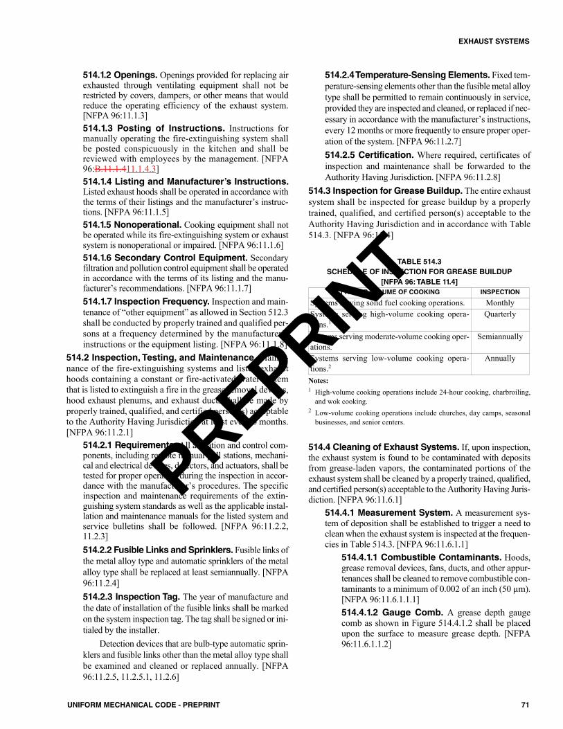
514.1.2 Openings. Openings provided for replacing airexhausted through ventilating equipment shall not berestricted by covers, dampers, or other means that wouldreduce the operating efficiency of the exhaust system.[NFPA 96:11.1.3]514.1.3 Posting of Instructions. Instructions formanually operating the fire-extinguishing system shallbe posted conspicuously in the kitchen and shall bereviewed with employees by the management. [NFPA96:B.11.1.411.1.4.3]514.1.4 Listing and Manufacturer’s Instructions.Listed exhaust hoods shall be operated in accordance withthe terms of their listings and the manufacturer’s instruc-tions. [NFPA 96:11.1.5]514.1.5 Nonoperational. Cooking equipment shall notbe operated while its fire-extinguishing system or exhaustsystem is nonoperational or impaired. [NFPA 96:11.1.6]514.1.6 Secondary Control Equipment. Secondaryfiltration and pollution control equipment shall be operatedin accordance with the terms of its listing and the manu-facturer’s recommendations. [NFPA 96:11.1.7]514.1.7 Inspection Frequency. Inspection and main-tenance of “other equipment” as allowed in Section 512.3shall be conducted by properly trained and qualified per-sons at a frequency determined by the manufacturer’sinstructions or the equipment listing. [NFPA 96:11.1.8]
514.2 Inspection, Testing, and Maintenance. Mainte-nance of the fire-extinguishing systems and listed exhausthoods containing a constant or fire-activated water systemthat is listed to extinguish a fire in the grease removal devices,hood exhaust plenums, and exhaust ducts shall be made byproperly trained, qualified, and certified person(s) acceptableto the Authority Having Jurisdiction at least every 6 months.[NFPA 96:11.2.1]
514.2.1 Requirements. All actuation and control com-ponents, including remote manual pull stations, mechani-cal and electrical devices, detectors, and actuators, shall betested for proper operation during the inspection in accor-dance with the manufacturer’s procedures. The specificinspection and maintenance requirements of the extin-guishing system standards as well as the applicable instal-lation and maintenance manuals for the listed system andservice bulletins shall be followed. [NFPA 96:11.2.2,11.2.3]514.2.2 Fusible Links and Sprinklers. Fusible links ofthe metal alloy type and automatic sprinklers of the metalalloy type shall be replaced at least semiannually. [NFPA96:11.2.4]514.2.3 Inspection Tag. The year of manufacture andthe date of installation of the fusible links shall be markedon the system inspection tag. The tag shall be signed or ini-tialed by the installer.
Detection devices that are bulb-type automatic sprin-klers and fusible links other than the metal alloy type shallbe examined and cleaned or replaced annually. [NFPA96:11.2.5, 11.2.5.1, 11.2.6]
514.2.4 Temperature-Sensing Elements. Fixed tem-perature-sensing elements other than the fusible metal alloytype shall be permitted to remain continuously in service,provided they are inspected and cleaned, or replaced if nec-essary in accordance with the manufacturer’s instructions,every 12 months or more frequently to ensure proper oper-ation of the system. [NFPA 96:11.2.7]514.2.5 Certification. Where required, certificates ofinspection and maintenance shall be forwarded to theAuthority Having Jurisdiction. [NFPA 96:11.2.8]
514.3 Inspection for Grease Buildup. The entire exhaustsystem shall be inspected for grease buildup by a properlytrained, qualified, and certified person(s) acceptable to theAuthority Having Jurisdiction and in accordance with Table514.3. [NFPA 96:11.4]
TABLE 514.3SCHEDULE OF INSPECTION FOR GREASE BUILDUP
[NFPA 96: TABLE 11.4]
Notes:1 High-volume cooking operations include 24-hour cooking, charbroiling,
and wok cooking.2 Low-volume cooking operations include churches, day camps, seasonal
businesses, and senior centers.
514.4 Cleaning of Exhaust Systems. If, upon inspection,the exhaust system is found to be contaminated with depositsfrom grease-laden vapors, the contaminated portions of theexhaust system shall be cleaned by a properly trained, qualified,and certified person(s) acceptable to the Authority Having Juris-diction. [NFPA 96:11.6.1]
514.4.1 Measurement System. A measurement sys-tem of deposition shall be established to trigger a need toclean when the exhaust system is inspected at the frequen-cies in Table 514.3. [NFPA 96:11.6.1.1]
514.4.1.1 Combustible Contaminants. Hoods,grease removal devices, fans, ducts, and other appur-tenances shall be cleaned to remove combustible con-taminants to a minimum of 0.002 of an inch (50 µm).[NFPA 96:11.6.1.1.1]514.4.1.2 Gauge Comb. A grease depth gaugecomb as shown in Figure 514.4.1.2 shall be placedupon the surface to measure grease depth. [NFPA96:11.6.1.1.2]
TYPE OR VOLUME OF COOKING INSPECTION
Systems serving solid fuel cooking operations. MonthlySystems serving high-volume cooking opera-tions.1
Quarterly
Systems serving moderate-volume cooking oper-ations.
Semiannually
Systems serving low-volume cooking opera-tions.2
Annually
71UNIFORM MECHANICAL CODE - PREPRINT
EXHAUST SYSTEMS
PREPRINT
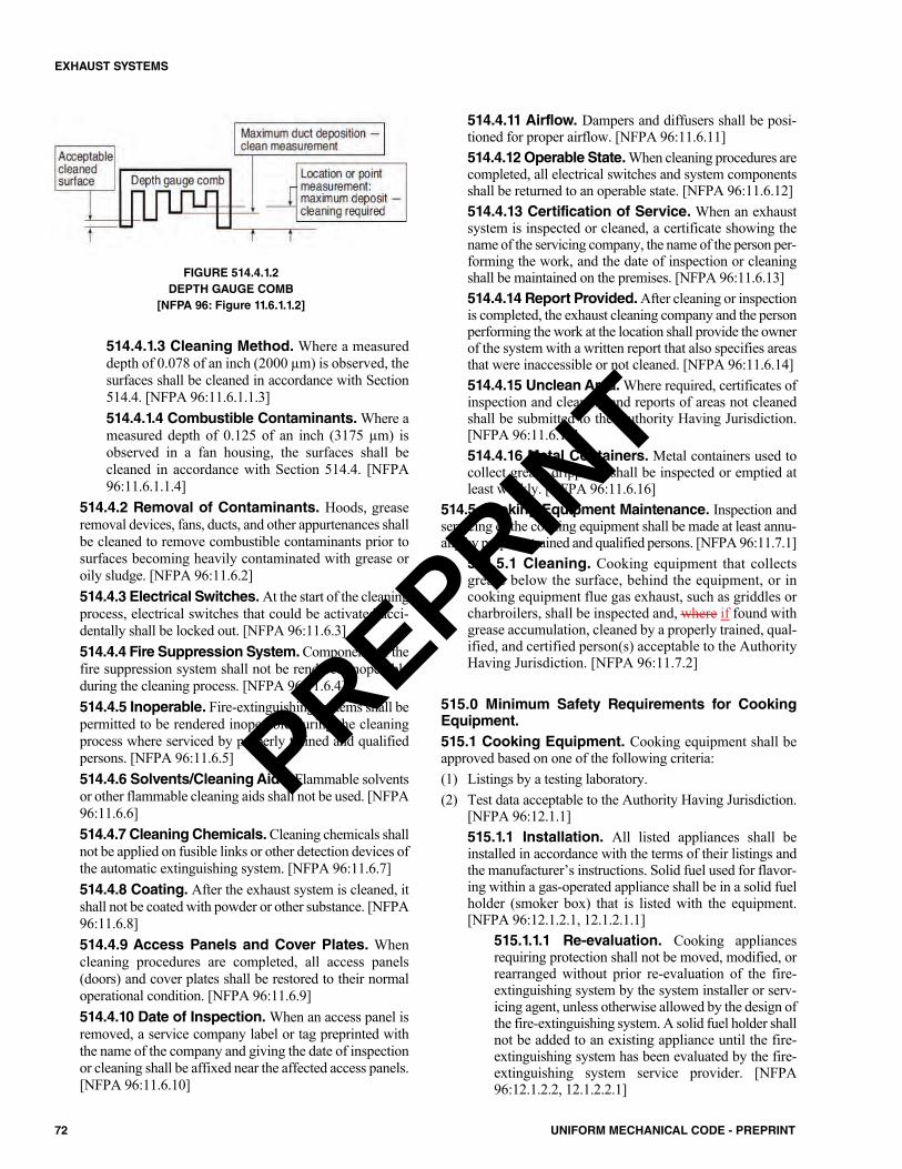
FIGURE 514.4.1.2DEPTH GAUGE COMB
[NFPA 96: Figure 11.6.1.1.2]
514.4.1.3 Cleaning Method. Where a measureddepth of 0.078 of an inch (2000 µm) is observed, thesurfaces shall be cleaned in accordance with Section514.4. [NFPA 96:11.6.1.1.3]514.4.1.4 Combustible Contaminants. Where ameasured depth of 0.125 of an inch (3175 µm) isobserved in a fan housing, the surfaces shall becleaned in accordance with Section 514.4. [NFPA96:11.6.1.1.4]
514.4.2 Removal of Contaminants. Hoods, greaseremoval devices, fans, ducts, and other appurtenances shallbe cleaned to remove combustible contaminants prior tosurfaces becoming heavily contaminated with grease oroily sludge. [NFPA 96:11.6.2]514.4.3 Electrical Switches.At the start of the cleaningprocess, electrical switches that could be activated acci-dentally shall be locked out. [NFPA 96:11.6.3]514.4.4 Fire Suppression System.Components of thefire suppression system shall not be rendered inoperableduring the cleaning process. [NFPA 96:11.6.4]514.4.5 Inoperable. Fire-extinguishing systems shall bepermitted to be rendered inoperable during the cleaningprocess where serviced by properly trained and qualifiedpersons. [NFPA 96:11.6.5]514.4.6 Solvents/Cleaning Aids. Flammable solventsor other flammable cleaning aids shall not be used. [NFPA96:11.6.6]514.4.7 Cleaning Chemicals.Cleaning chemicals shallnot be applied on fusible links or other detection devices ofthe automatic extinguishing system. [NFPA 96:11.6.7]514.4.8 Coating. After the exhaust system is cleaned, itshall not be coated with powder or other substance. [NFPA96:11.6.8]514.4.9 Access Panels and Cover Plates. Whencleaning procedures are completed, all access panels(doors) and cover plates shall be restored to their normaloperational condition. [NFPA 96:11.6.9]514.4.10 Date of Inspection.When an access panel isremoved, a service company label or tag preprinted withthe name of the company and giving the date of inspectionor cleaning shall be affixed near the affected access panels.[NFPA 96:11.6.10]
514.4.11 Airflow. Dampers and diffusers shall be posi-tioned for proper airflow. [NFPA 96:11.6.11]514.4.12 Operable State.When cleaning procedures arecompleted, all electrical switches and system componentsshall be returned to an operable state. [NFPA 96:11.6.12]514.4.13 Certification of Service. When an exhaustsystem is inspected or cleaned, a certificate showing thename of the servicing company, the name of the person per-forming the work, and the date of inspection or cleaningshall be maintained on the premises. [NFPA 96:11.6.13]514.4.14 Report Provided.After cleaning or inspectionis completed, the exhaust cleaning company and the personperforming the work at the location shall provide the ownerof the system with a written report that also specifies areasthat were inaccessible or not cleaned. [NFPA 96:11.6.14]514.4.15 Unclean Area.Where required, certificates ofinspection and cleaning and reports of areas not cleanedshall be submitted to the Authority Having Jurisdiction.[NFPA 96:11.6.15]514.4.16 Metal Containers. Metal containers used tocollect grease drippings shall be inspected or emptied atleast weekly. [NFPA 96:11.6.16]
514.5 Cooking Equipment Maintenance. Inspection andservicing of the cooking equipment shall be made at least annu-ally by properly trained and qualified persons. [NFPA 96:11.7.1]
514.5.1 Cleaning. Cooking equipment that collectsgrease below the surface, behind the equipment, or incooking equipment flue gas exhaust, such as griddles orcharbroilers, shall be inspected and, where if found withgrease accumulation, cleaned by a properly trained, qual-ified, and certified person(s) acceptable to the AuthorityHaving Jurisdiction. [NFPA 96:11.7.2]
515.0 Minimum Safety Requirements for CookingEquipment.515.1 Cooking Equipment. Cooking equipment shall beapproved based on one of the following criteria:(1) Listings by a testing laboratory.(2) Test data acceptable to the Authority Having Jurisdiction.
[NFPA 96:12.1.1]515.1.1 Installation. All listed appliances shall beinstalled in accordance with the terms of their listings andthe manufacturer’s instructions. Solid fuel used for flavor-ing within a gas-operated appliance shall be in a solid fuelholder (smoker box) that is listed with the equipment.[NFPA 96:12.1.2.1, 12.1.2.1.1]
515.1.1.1 Re-evaluation. Cooking appliancesrequiring protection shall not be moved, modified, orrearranged without prior re-evaluation of the fire-extinguishing system by the system installer or serv-icing agent, unless otherwise allowed by the design ofthe fire-extinguishing system. A solid fuel holder shallnot be added to an existing appliance until the fire-extinguishing system has been evaluated by the fire-extinguishing system service provider. [NFPA96:12.1.2.2, 12.1.2.2.1]
72 UNIFORM MECHANICAL CODE - PREPRINT
EXHAUST SYSTEMS
PREPRINT
515.1.1.2 Prior Location. The fire-extinguishingsystem shall not require re-evaluation where the cook-ing appliances are moved for the purposes of mainte-nance and cleaning, provided the appliances arereturned to approved design location prior to cookingoperations, and any disconnected fire-extinguishingsystem nozzles attached to the appliances are recon-nected in accordance with the manufacturer’s listeddesign manual. [NFPA 96:12.1.2.3]515.1.1.3 Minimum Space. All Ddeep-fat fryersshall be installed with not less than at least a 16 inch(406 mm) space between the fryer and surface flamesfrom adjacent cooking equipment. [NFPA 96:12.1.2.4]515.1.1.4 Space Not Required. Where a steel ortempered glass baffle plate is installed not less than ata mimimum 8 inches (203 mm) in height between thefryer and surface flames of the adjacent appliance, therequirement for a 16 inch (406 mm) space shall notapply. [NFPA 96:12.1.2.5]515.1.1.5 Minimum Height.Where If the fryer andthe surface flames are at different horizontal planes, athe mimimum height of not less than 8 inches (203mm) shall be measured from the higher of the two.[NFPA 96:12.1.2.5.1]
515.2 Operating Controls.Deep-fat fryers shall be equippedwith a separate high-limit control in addition to the adjustableoperating control (thermostat) to shut off fuel or energy whenthe fat temperature reaches 475°F (246°C) at 1 inch (25.4 mm)below the surface. [NFPA 96:12.2]
516.0 Recirculating Systems. 516.1 General Requirements. Recirculating systems con-taining or for use with appliances used in processes produc-ing smoke or grease-laden vapors shall be equipped withcomponents complying with the following:(1) The clearance requirements of Section 507.4.(2) A hood complying with the requirements of Section 508.0.(3) Grease removal devices complying with Section 509.0.(4) The air movement requirements of Section 511.2.1 and
Section 511.2.2.(5) Auxiliary equipment (such as particulate and odor removal
devices) complying with Section 512.0.(6) Fire-extinguishing equipment complying with the require-
ments of Section 513.0.Exception: Fire-extinguishing equipment in accordancewith Section 513.1 and Section 513.5.
(7) The use and maintenance requirements of Section 514.0.(8) The minimum safety requirements of Section 515.0.(9) All the requirements of Section 516.0. [NFPA 96:13.1]516.2 Design Restrictions.All Rrecirculating systems shallcomply with the requirements of Section 516.2.1 through Sec-tion 516.2.9. [NFPA 96:13.2]
516.2.1 Gas/Electrically Fueled Cooking Appli-ances. Only gGas-fueled or electrically fueled cookingappliances shall be used. Listed gas-fueled equipment
designed for use with specific recirculating systems shallhave the flue outlets connected in the intended manner.Gas-fueled appliances shall have not less than a minimum18 inches (457 mm) of clearance from the flue outlet to thefilter inlet in accordance with Section 509.2.2 throughSection 509.2.2.3 and shall be in accordance with meetthe installation requirements of this code, NFPA 54 orNFPA 58. [{NFPA 96:13.2.1 – 13.2.3}]516.2.2 Recirculation. Recirculating systems shall belisted with a testing laboratory in accordance with UL710B or equivalent. [NFPA 96:13.2.4]516.2.3 Protection.Cooking appliances that require pro-tection and that are under a recirculating hood shall be pro-tected by either the integral fire protection system inaccordance with UL 710B or a system in accordance withSection 513.0. [NFPA 96:13.2.4.2]516.2.4 Maximum Limits. A recirculating system shallnot use cooking equipment that exceeds that recirculatingsystem’s labeled maximum limits for that type of equip-ment, stated in maximum energy input, maximum cookingtemperature, and maximum square area of cooking surfaceor cubic volume of cooking cavity. [NFPA 96:13.2.6]516.2.5 Label. The listing label shall show the type(s) ofcooking equipment tested and the maximum limits speci-fied in Section 516.2.4. [NFPA 96:13.2.7]516.2.6 Fire Damper. A fire-actuated damper shall beinstalled at the exhaust outlet of the system. [NFPA96:13.2.8] The actuation device for the fire damper shallhave a maximum temperature rating of 375°F (191°C).[NFPA 96:13.2.10]516.2.7 Installation of Electrical Wiring.No electricalwiring shall be installed in the interior sections of the hoodplenum that is capable of becoming exposed to grease.Exception: As permitted by NFPA 70.516.2.8 Power Supply.The power supply of an any elec-trostatic precipitator (ESP) shall be of the “cold spark,” fer-roresonant type in which the voltage falls off as the currentdraw of a short increases. [NFPA 96:13.2.11]516.2.9 Listing Evaluation. Listing evaluation shallinclude the following:(1) Capture and containment of vapors at published and
labeled airflows.(2) Grease discharge at the exhaust outlet of the system
not to exceed an average of 2.9 E-09 (oz/in3) (5.0 E-06kg/m3) of exhausted air sampled from that equipmentat maximum amount of product that is capable ofbeing processed over a continuous 8 hour test with thesystem operating at its minimum listed airflow.
(3) Listing and labeling of clearance to combustibles fromall sides, top, and bottom.
(4) Electrical connection in the field in accordance withNFPA 70.
(5) Interlocks on all removable components that lie in thepath of airflow within the unit to ensure that they arein place during operation of the cooking appliance.[{NFPA 96:13.2.12}]
73UNIFORM MECHANICAL CODE - PREPRINT
EXHAUST SYSTEMS
PREPRINT
516.3 Interlocks. The recirculating system shall be providedwith interlocks of critical components and operations as indi-cated in Section 516.3.1 through Section 516.3.3.1 such that,where if an any of these interlocks is are interrupted, the cook-ing appliance shall will not be able to operate. [NFPA 96:13.3.1]
516.3.1 Airflow Sections.All Cclosure panels encom-passing airflow sections shall have interlocks to ensure thatthe panels are in place and fully sealed. [NFPA 96:13.3.2]516.3.2 Filter Component. Each filter component(grease and odor) shall have an interlock to prove thecomponent is in place. [NFPA 96:13.3.3]516.3.3 ESP Interlocks. Each ESP shall have a sensorto prove its performance is as designed, with no inter-ruption of the power to exceed 2 minutes. [NFPA96:13.3.4.1]
516.3.3.1 Manual Reset. The sensor shall be amanual reset device or circuit. [NFPA 96:13.3.4.2]
516.3.4 Airflow Switch or Transducer. An airflowswitch or transducer shall be provided after the last filtercomponent to ensure that a minimum airflow is main-tained. The airflow switch or transducer shall open theinterlock circuit when the airflow falls 25 percent belowthe system’s normal operating flow or 10 percent belowits listed minimum rating, whichever is lower. The air-flow switch or transducer shall be a manual reset deviceor circuit. [NFPA 96:13.3.5.1 – 13.3.5.3]
516.4 Location and Application Restrictions. Thelocation of recirculating systems shall be approved by theAuthority Having Jurisdiction. Items to be reviewed in thefire risk assessment shall include, but not be limited to, lifesafety, combustibility of surroundings, proximity to air vents,and total fuel load. [NFPA 96:13.4.1 – 13.4.2]516.5 Additional Fire Safety Requirements. In addi-tion to the appliance nozzle(s), a recirculating system shallbe listed with the appropriate fire protection for grease filters,grease filtration, odor filtration units, and ductwork, whereapplicable. [NFPA 96:13.5.1]
516.5.1 Installation Downstream. In addition to anyother fire-extinguishing system activation device, thereshall be a fire-extinguishing system activation deviceinstalled downstream of an any ESP. [NFPA 96:13.5.2]516.5.2 Locations. The requirements of Section 513.6shall also apply to recirculating system locations. [NFPA96:13.5.3]
516.6 Use and Maintenance. Automatic or manual cov-ers on cooking appliances, especially fryers, shall not inter-fere with the application of the fire suppression system.[NFPA 96:13.6.1]
516.6.1 Manufacturer’s Instructions. All Ffiltersshall be cleaned or replaced in accordance with the man-ufacturer’s instructions. [NFPA 96:13.6.2]516.6.2 Cleaning Schedule.All ESPs shall be cleaneda minimum of once per week and according to the manu-facturer’s cleaning instructions. [NFPA 96:13.6.3]
516.6.3 Hood Plenum and Blower Section Clean-ing Schedule. The entire hood plenum and the blowersection shall be cleaned a minimum of once every 3months. [NFPA 96:13.6.4]516.6.4 Inspection of Safety Interlocks. Inspectionand testing of the total operation and all safety interlocksin accordance with the manufacturer’s instructions shallbe performed by qualified service personnel a minimumof once every 6 months or more frequently if required.[NFPA 96:13.6.5]516.6.5 Inspection. Fire-extinguishing equipmentshall be inspected in accordance with Section 514.2.[NFPA 96:13.6.6]516.6.6 Maintenance Log. A signed and dated log ofmaintenance as performed in accordance with Section516.6.3 and Section 516.6.4 shall be available on thepremises for use by the Authority Having Jurisdiction.[NFPA 96:13.6.7]
517.0 Solid-Fuel Cooking Operations.517.1 Venting Application. Venting requirements of solid-fuel cooking operations shall be determined in accordancewith Section 517.1.1 through Section 517.1.6. [NFPA96:14.1]
517.1.1 Natural Draft. Where solid-fuel cooking equip-ment is required by the manufacturer to have a natural draft,the vent shall be in accordance comply with Section 517.4.[NFPA 96:14.1.1]517.1.2 System Compliance. Where the solid-fuelcooking equipment has a self-contained top, is the appli-ance to be vented in an isolated space (except for a singlewater heater with its own separate vent), has a separatemakeup air system, and is provided with supply and returnair (not supplied or returned from other spaces), the sys-tem shall be in accordance comply with Section 517.4 andSection 517.6. [NFPA 96:14.1.2]517.1.3 Makeup Air System. Where the solid-fuel cook-ing equipment is located in a space with other vented equip-ment, the all vented equipment shall have an exhaustsystem interlocked with a makeup air system for the spacein accordance with per Section 517.6. [NFPA 96:14.1.3]517.1.4 Natural Draft Ventilation Systems. Naturaldraft ventilation systems and power-exhausted ventilationsystems shall comply with Section 517.3, Section 517.4,and Section 517.6. [NFPA 96:14.1.4]517.1.5 Opening Requirements. Where a solid-fuelcooking appliance allows effluent to escape from the appli-ance opening, this opening shall be covered by a hood andan exhaust system that meets the requirements of Section517.3, Section 517.4, and Section 517.6. [NFPA 96:14.1.5]517.1.6 Spark Arresters. Solid-fuel cooking operationsshall have spark arresters to minimize the passage of air-borne sparks and embers into plenums and ducts. Wherethe solid-fuel cooking operation is not located under ahood, a spark arrester shall be provided to minimize thepassage of sparks and embers into flues and chimneys.[NFPA 96:14.1.6, 14.1.7]
74 UNIFORM MECHANICAL CODE - PREPRINT
EXHAUST SYSTEMS
PREPRINT
517.2 Location of Appliances. Every Appliances applianceshall be located with respect to building construction and otherequipment so as to permit access to the appliance. [NFPA96:14.2.1]
517.2.1 Prohibited Location. Solid-fuel cooking appli-ances shall not be installed in confined spaces. [NFPA96:14.2.2]Exception: Solid-fuel cooking appliances listed for instal-lation in confined spaces such as alcoves shall be installedin accordance with the terms of the listing and the manu-facturer’s installation instructions. [NFPA 96:14.2.3]517.2.2 Flammable Vapors. Solid-fuel cooking appli-ances shall not be installed in a any location where gasolineor any other flammable vapors or gases are present. [NFPA96:14.2.4]
517.3 Hoods for Solid-Fuel Cooking.Hoods shall be sizedand located in a manner capable of capturing and containing allthe effluent discharging from the appliances. The hood and itsexhaust system shall be in accordance comply with the provi-sions requirements of Section 508.0 through Section 513.0.[NFPA 96:14.3.1, 14.3.2]
517.3.1 Separation. Except as permitted in Section517.3.1.1, exhaust systems serving solid-fuel cookingequipment, including gas or electrically operated equip-ment, shall be separate from all other exhaust systems.[NFPA 96:14.3.3]Exception: Cooking equipment not requiring automaticfire-extinguishing equipment (in accordance with perSection 513.0) shall be permitted to be installed under acommon hood with solid-fuel cooking equipment that isserved by a duct system separate from all other exhaustsystems. [NFPA 96:14.3.5]
517.3.1.1 Equipment with Solid Fuel for Fla-voring. Gas-operated equipment utilizing solid fuelfor flavoring that meets all the following conditionsshall not be required to have a separate exhaust sys-tem:(1) The solid fuel holder (smoker box) shall be listed
with the gas-operated equipment.(2) The solid fuel holder shall be located underneath
the gas burners.(3) Spark arresters conforming with Section 517.1.6
shall be provided.(4) The maximum quantity of solid fuel consumed
shall not exceed 1 pound (0.45 kg) per hour per100 000 Btu/h (29 kW) of gas burner capacity.
(5) The gas-operated equipment shall be protected bya fire suppression system listed for the equipment,including the solid fuel holder.
(6) Gas-operated equipment with integral solid fuelholder(s) intended for flavoring, such as radiantcharbroiler(s), shall comply simultaneously withthe requirements of UL 300 that address the gasradiant charbroiler(s) and mesquite wood char-broiler(s).
(7) A fire suppression system nozzle(s) shall beinstalled to protect the solid fuel holder.
(8) The fire suppression system shall be designed andinstalled to protect the entire cooking operation.
(9) Each solid fuel holder shall be limited to a size of150 cubic inches (2.5 L), with no dimension toexceed 20 inches (508 mm).
(10) A maximum of one solid fuel holder for each 100000 Btu/h (29 kW), or portion thereof, of burnercapacity shall be permitted.
(11) Solid fuel shall be immersed in water for a con-tinuous period of at least 24 hours immediatelyprior to being placed in the cooking equipment.
(12) The inspection frequency shall be the same as forsolid fuel cooking operations in Table 514.3.[NFPA 96:14.3.4]
517.4 Exhaust Systems for Solid-Fuel Cooking. Wherea hood is not required, in buildings where the duct system isthree stories or less in height, a duct complying with Section510.0 shall be provided. [NFPA 96:14.4]
517.4.1 Hood. Where If a hood is used in buildingswhere the duct system is three stories or less in height,the duct system shall comply with Section 510.0. [NFPA96:14.4.1]517.4.2 Building Exceeding Four Stories. A listedor approved grease duct system that is four stories inheight or greater shall be provided for solid-fuel cookingexhaust systems. [NFPA 96:14.4.2]517.4.3 Prohibited. Wall terminations of solid-fuelexhaust systems shall be prohibited. [NFPA 96:14.4.4]
517.5 Grease Removal Devices for Solid-Fuel Cook-ing. Grease removal devices shall be constructed of steel orstainless steel or be approved for solid-fuel cooking. [NFPA96:14.5.1]
517.5.1 Spark Arrester Devices. Where If airbornesparks and embers can be generated by the solid fuel cook-ing operation, spark arrester devices shall be used prior tousing the grease removal device, to minimize the entranceof these sparks and embers into the grease removal deviceand into the hood and the duct system. [NFPA 96:14.5.2]517.5.2 Filters. Filters shall be not less than a minimumof 4 feet (1219 mm) above the appliance cooking surface.[NFPA 96:14.5.3]
517.6 Air Movement for Solid-Fuel Cooking. Exhaustsystem requirements shall comply with Section 511.0 forhooded operation or shall be installed in accordance with themanufacturer’s recommendations for unhooded applications.[NFPA 96:14.6.1]
517.6.1 Replacement Air.A replacement or makeup airsystem shall be provided to ensure a positive supply ofreplacement air at all times during cooking operations.[NFPA 96:14.6.2]517.6.2 Operation. Makeup air systems serving solid-fuel cooking operations shall be interlocked with the
75UNIFORM MECHANICAL CODE - PREPRINT
EXHAUST SYSTEMS
PREPRINT
exhaust air system and powered, where if necessary, toprevent the space from attaining a negative pressure whilethe solid-fuel appliance is in operation. [NFPA 96:14.6.3]
517.7 Fire-Extinguishing Equipment for Solid-FuelCooking. Solid-fuel cooking appliances that produce grease-laden vapors shall be protected by listed fire-extinguishingequipment.Exception: Where acceptable to the Authority Having Juris-diction, solid-fuel cooking appliances constructed of solidmasonry or reinforced portland Portland or refractory cementconcrete and vented in accordance with NFPA 211 shall notrequire fixed automatic fire-extinguishing equipment. [NFPA96:14.7.1, 14.7.2]
517.7.1 Grease Removal Devices, Hoods, and DuctSystems. Listed fire-extinguishing equipment shall beprovided for the protection of grease removal devices,hoods, and duct systems. [NFPA 96:14.7.3]Exception: Where acceptable to the Authority HavingJurisdiction, solid-fuel cooking appliances constructed ofsolid masonry or reinforced portland Portland or refrac-tory cement concrete and vented in accordance with NFPA211 shall not require automatic fire-extinguishing equip-ment for the protection of grease removal devices, hoods,and duct systems. [NFPA 96:14.7.4]517.7.2 Listed Fire-Extinguishing Equipment.Listed fire-extinguishing equipment for solid-fuel-burn-ing cooking appliances, where required, shall be in accor-dance comply with Section 513.0 and shall usewater-based agents. [NFPA 96:14.7.5]517.7.3 Rating and Design. The fFire-extinguishingequipment shall be rated and designed to extinguish solid-fuel cooking fires. The fire-extinguishing equipment shallbe of sufficient size to totally extinguish fire in the entirehazard area and prevent reignition of the fuel. [NFPA96:14.7.6, 14.7.7]517.7.4 Listing/Class.All solid fuel appliances (whetheror not under a hood or not) with fireboxes of 5 cubic feet(0.14 m3) volume or less shall have not less than at least alisted 2-A rated water-spray fire extinguisher or a 1.6 gal-lon (6.1 L) wet chemical fire extinguisher listed for ClassK fires in accordance with NFPA 10 with a maximumtravel distance of not more than 20 feet (6096 mm) to theappliance. [NFPA 96:14.7.8]517.7.5 Fixed-Water Pipe System. Solid fuel appli-ances with fireboxes exceeding 5 cubic feet (0.14 m3) shallbe provided with a fixed-water pipe system with a hose inthe kitchen capable of reaching the firebox. The hose shallbe equipped with an adjustable nozzle capable of produc-ing a fine to medium spray or mist. The nozzle shall be ofthe type that cannot produce a straight stream. The systemshall have an a minimum operating pressure of not lessthan 40 psi (276 kPa) and shall provide not less than a min-imum of 5 gallons per minute (gpm) (0.3 L/s). [NFPA96:14.7.9.1 – 14.7.9.2]
517.7.6 Fuel Storage. All fuel storage areas shall be pro-vided with a sprinkler system meeting the requirements ofNFPA 13 except as permitted in accordance with the fol-lowing:(1) Where acceptable to the Authority Having Jurisdic-
tion, fuel storage areas shall be permitted to be pro-tected with a fixed water pipe system with a hosecapable of reaching all parts of the area.
(2) In lieu of the sprinkler system outlined in Section517.7.6, a listed 2-A rated water spray fire extin-guisher or a 1.6 gallon (6.1 L) wet chemical fire extin-guisher listed for Class K fires with a maximum traveldistance of 20 feet (6096 mm) to the solid fuel pilesshall be permitted to be used for a solid fuel pile, pro-vided that the fuel pile does not exceed 5 cubic feet(0.14 m3) volume. [NFPA 96:14.9.2.8 – 14.9.2.8.2]
517.7.7 Auxiliary Fuel. In addition to the requirements ofSection 517.7.4, Section 517.7.5 and Section 517.8, wherea any solid-fuel cooking appliance is also provided withauxiliary electric, gas, oil, or other fuel for ignition or sup-plemental heat and the appliance is also served by a anyportion of a fire-extinguishing system in accordance com-plying with Section 513.0, such auxiliary fuel shall be shutoff upon on actuation of the fire-extinguishing system.[NFPA 96:14.7.11]
517.8 Other Safety Requirements. Metal-fabricated solid-fuel cooking appliances shall be listed for the applicationwhere produced in practical quantities or shall be approved bythe Authority Having Jurisdiction. Where listed, metal-fabri-cated solid fuel cooking appliances shall be installed in accor-dance with the terms of their listings and with the applicablerequirements of this chapter. [NFPA 96:14.9.4.1, 14.9.4.2]
517.8.1 Site-Built Solid Fuel Cooling Appliances.Site-built solid-fuel cooking appliances shall be submit-ted for approval to the Authority Having Jurisdictionbefore being considered for installation. All Units unitssubmitted to the Authority Having Jurisdiction shall beinstalled, operated, and maintained in accordance withthe approved terms of the manufacturer’s instructionsand any additional requirements in accordance with setforth by the Authority Having Jurisdiction. [NFPA96:14.9.4.3.1 – 14.9.4.3.2]517.8.2 Additional Devices. Except for the sparkarresters required in Section 517.1.6, there shall be noadditional devices of any type in any portion of the appli-ance, flue pipe, and chimney of a natural draft solid-fueloperation. [NFPA 96:14.9.4.4]517.8.3 Prohibited.No solid fuel cooking device of anytype shall be permitted for deep fat frying involving morethan 1 quart (qt) (1 L) of liquid shortening, nor shall anysolid fuel cooking device be permitted within 3 feet (914mm) of any deep fat frying unit. [NFPA 96:14.9.4.5]
518.0 Downdraft Appliances.518.1 General.A dDowndraft appliance ventilation systemcontaining, or for use with appliances used in processes that
76 UNIFORM MECHANICAL CODE - PREPRINT
EXHAUST SYSTEMS
PREPRINT
produce, producing smoke or grease-laden vapors shall beequipped with components that are in accordance complyingwith the following:(1) The clearance requirements in accordance with of Sec-
tion 507.4.(2) The primary collection means designed for collecting
cooking vapors and residues in accordance complyingwith the requirements of Section 508.0.
(3) Grease removal devices that comply complying withSection 509.0.
(4) Special-purpose filters as listed in accordance with UL1046.
(5) Exhaust ducts that comply complying with Section510.0.
(6) The air movement requirements in accordance with ofSection 511.2.1 and Section 511.2.2.
(7) Auxiliary equipment (such as particulate and odorremoval devices) are in accordance complying with Sec-tion 512.0.
(8) Fire-extinguishing equipment that is in accordance com-plying with the requirements of Section 513.0, and asspecified in Section 518.3.
(9) The use and maintenance requirements in accordancewith of Section 514.0.
(10) The minimum safety requirements in accordance with ofSection 515.0. [NFPA 96:15.1.1]
518.2 Ventilation System. The downdraft appliance ven-tilation system shall be capable of capturing and containingall the effluent discharge from the appliance(s) it is serving.[NFPA 96:15.1.2]518.3 Fire-Extinguishing Equipment. For fire-extin-guishing equipment on downdraft appliance ventilation sys-tems, the following shall apply:(1) Cooking surface, duct, and plenum protection shall be
provided.(2) At least one fusible link or heat detector shall be installed
within each exhaust duct opening in accordance with themanufacturer’s listing.
(3) A fusible link or heat detector shall be provided for eachprotected cooking appliance located in the plenum areaof that appliance or in accordance with the extinguish-ing system manufacturer’s listing.
(4) A manual activation device shall be provided as part ofeach appliance at a height acceptable to the AuthorityHaving Jurisdiction.
(5) Portable fire extinguishers shall be provided in accor-dance with Section 513.11. [NFPA 96:15.2]518.3.1 Integral Fire-Extinguishing System. Alisted downdraft appliance ventilation system employingan integral fire-extinguishing system including detectionsystems that has been evaluated for grease and smokecapture, fire extinguishing, and detection shall be con-sidered to be in accordance as complying with Section518.3. [NFPA 96:15.2.1]
518.3.2 Interlocks. The downdraft appliance ventila-tion system shall be provided with interlocks such thatthe cooking fuel supply will not be activated unless theexhaust and supply air system systems have been acti-vated. [NFPA 96:15.2.2]
518.4 Airflow Switch or Transducer.An airflow switch ortransducer shall be provided after the last filter component toensure that a minimum airflow is maintained. [NFPA 96:15.3.1]
518.4.1 Interlocks. The airflow switch or transducershall open the interlock circuit when the airflow is lessthan falls 25 percent below the system’s normal operat-ing flow or less than 10 percent its listed minimum rat-ing, whichever is less lower. [NFPA 96:15.3.2]518.4.2 Manual Reset. The airflow switch or trans-ducer shall be a manual reset device or circuit. [NFPA96:15.3.3]
518.5 Surface Materials. Any Surfaces surface locateddirectly above the cooking appliance shall be of noncom-bustible or limited-combustible materials. [NFPA 96:15.4]
519.0 Type II Hood Exhaust System Requirements.519.1 Where Required. Type II hoods shall be installedabove equipment and dishwashers that generate steam, heat,and or products of combustion, and where grease or smoke isnot present.Exceptions:(1) Dishwashing machines connected to a Type II duct sys-
tem and exhausted directly to the outdoors.(2) Dishwashing machines with a self-contained condensing
system listed in accordance with UL 921 and installed ina space where the HVAC system has been engineered toaccommodate the latent and sensible heat load emittedfrom such appliances as approved by the Authority Hav-ing Jurisdiction. Such equipment shall be provided withan interlocking device to prevent opening of the appli-ance prior to completion of its cycle.
519.2 Construction of Type II Hoods. Type II hoodsconstructed of steel shall be not less than 0.024 of an inch(0.61 mm) (No. 24 gauge). Hoods constructed of copper shallbe of copper sheets weighing not less than 0.17 ounces persquare inch (oz/in2) (7.47 kg/m2). Joints and seams shall besubstantially tight. Solder shall not be used except for sealinga joint or seam. 519.3 Dishwashing Appliances. The net airflow for TypeII hoods used for dishwashing equipment shall be not lessthan 200 cubic feet per minute (0.094 m3/s) per linear foot(m) of hood length.519.4 Type II Exhaust Duct Systems. Ducts andplenums serving Type II hoods shall be constructed of rigidmetallic materials in accordance with Chapter 6. Duct brac-ing and supports shall comply with Chapter 6. Ducts subjectto positive pressure shall be adequately sealed.519.5 Termination of Type II Hood Exhaust System.The exhaust system shall terminate as follows:
77UNIFORM MECHANICAL CODE - PREPRINT
EXHAUST SYSTEMS
PREPRINT
(1) Rooftop terminations shall terminate not less than 10 feet(3048 mm) from a property line, and the exhaust flowshall be directed away from the roof surface of the roof,not less than 40 inches (1016 mm).
(2) Horizontal terminations shall terminate not less than 10feet (3048 mm) from adjacent buildings, property lines,operable openings, and from grade level.
(3) The discharge outlet shall not be directed onto a publicwalkway.
519.6 Makeup Air.Makeup air shall be provided in accor-dance with Section 511.3.
78 UNIFORM MECHANICAL CODE - PREPRINT
EXHAUST SYSTEMS
PREPRINT
601.0 General.601.1 Applicability. Ducts and plenums that are portions ofa heating, cooling, ventilation, or exhaust system shall com-ply with the requirements of this chapter and Chapter 5. 601.2 Sizing Requirements. Duct systems shall be sizedin accordance with applicable standards in Chapter 17 or byother approved methods.Exception: Residential duct systems shall be sized in accor-dance with ACCA Manual D listed in Table 1701.1, ACCAManual Zr, as applicable, or by other approved methods.
602.0 Material.602.1 General. Materials used for duct systems shall com-ply with Section 602.2 through Section 602.6 as applicable.
Concealed building spaces or independent constructionwithin buildings shall be permitted to be used as ducts orplenums. Gypsum board shall not be used for positive pres-sure ducts. Exception: In healthcare facilities, concealed spaces shall notbe permitted to be used as ducts or plenums.602.2 Combustibles Within Ducts or Plenums. Mate-rials exposed within ducts or plenums shall be noncom-bustible or shall have a flame spread index not to exceed 25and a smoke-developed index not to exceed 50, where testedas a composite product in accordance with ASTM E84 or UL723. Plastic piping installed in plenums shall be tested inaccordance with all requirements of ASTM E84 or UL 723.Mounting methods, supports and sample sizes of materialsfor testing that are not specified in ASTM E84 or UL 723shall be prohibited.Exceptions:(1) Return-air and outside-air ducts, plenums, or concealed
spaces that serve a dwelling unit.(2) Air filters in accordance with the requirements of Sec-
tion 311.2.(3) Water evaporation media in an evaporative cooler.(4) Charcoal filters where protected with an approved fire
suppression system.(5) Products listed and labeled for installation within
plenums in accordance with Section 602.2.1 throughSection 602.2.3.
(6) Smoke detectors.(7) Duct insulation, coverings, and linings and other supple-
mentary materials installed in accordance with Section605.0.
(8) Materials in a hazardous fabrication area including theareas above and below the fabrication area sharing acommon air recirculation path with the fabrication area.602.2.1 Electrical. Electrical wiring in plenums shallcomply with NFPA 70. Electrical wires and cables and
optical fiber cables shall be listed and labeled for use inplenums and shall have a flame spread distance notexceeding 5 feet (1524 mm), an average optical densitynot exceeding 0.15, and a peak optical density notexceeding 0.5, where tested in accordance with NFPA262.602.2.2 Fire Sprinkler Piping.Nonmetallic fire sprin-kler piping in plenums shall be listed and labeled for usein plenums and shall have a flame spread distance notexceeding 5 feet (1524 mm), an average optical densitynot exceeding 0.15 and, a peak optical density notexceeding 0.5, where tested in accordance with UL 1887.602.2.3 Pneumatic Tubing. Nonmetallic pneumatictubing in plenums shall be listed and labeled for use inplenums and shall have a flame spread distance notexceeding 5 feet (1524 mm), an average optical densitynot exceeding 0.15, and a peak optical density notexceeding 0.5, where tested in accordance with UL 1820.602.2.4 Discrete Products in Plenums. Discreteplumbing, mechanical, and electrical products that arelocated in a plenum and have exposed combustible mate-rial shall be listed and labeled in accordance with UL2043.
602.3 Metallic. Ducts, plenums, or fittings of metal shallcomply with SMACNA HVAC Duct Construction Standards– Metal and Flexible. Flexible metallic ducts shall complywith UL 181.602.4 Nonmetallic Ducts. Nonmetallic ducts shall complywith Section 602.4.1, Section 602.4.2, Section 602.4.3 or Sec-tion 602.4.4.
602.4.1 Phenolic. Phenolic duct, plenum, or fittingmaterial shall comply with UL 181. Ducts, plenums, orfittings of phenolic shall be constructed in accordancewith SMACNA Phenolic Duct Construction Standardsor the conditions of its listing.602.4.2 Gypsum.Where gypsum products are exposedin ducts or plenums, the air temperature shall berestricted to a range from 50°F (10°C) to 125°F (52°C),and moisture content shall be controlled so that the mate-rial is not adversely affected. All gypsum products shallhave a mold or mildew resistant surface. For the purposeof this section, gypsum products shall not be exposed insupply ducts.602.4.3 Air Dispersion Systems. Air dispersion sys-tems shall be listed and labeled in accordance with UL2518.602.4.4 Other Materials. Flexible and rigid ducts,plenums, or fittings for use in heating, ventilation, andair conditioning systems of other nonmetallic materialslisted and labeled to UL 181 shall be permitted.Exception: Plastic ducts shall comply with Section603.5.
79UNIFORM MECHANICAL CODE - PREPRINT
CHAPTER 6DUCT SYSTEMS
PREPRINT
602.5 Vibration Isolators. Vibration isolation connectorsinstalled between mechanical equipment and metal ducts (orcasings) shall be made of an approved material and shall notexceed 10 inches (254 mm) in length.602.6 Corridors. Corridors shall not be used to convey airto or from rooms where the corridor is required to be of fire-resistive construction in accordance with the building codeexcept where permitted by the building code.
603.0 Installation of Ducts.603.1 General. Air ducts shall be installed in accordancewith this Chapter and the installation instructions.
603.1.1 Pressure Classification. The pressure clas-sification of ducts shall be not less than the design oper-ating pressure of the air distribution in which the duct isutilized.603.1.2 Air Temperature. The temperature of the air tobe conveyed in a duct shall not exceed 250°F (121°C).603.1.3 Protection. Air ducts, other than plastic ducts,shall be installed with not less than 4 inches (102 mm) ofseparation from earth, except where installed as a linerinside of concrete, tile, or metal pipe and shall be pro-tected from physical damage.603.1.4 Vertical Risers. Ducts listed and labeled to UL181 shall not be used for vertical risers in air-duct sys-tems serving more than two stories.603.1.5 Penetrations. Ducts listed and labeled to UL181 shall not penetrate a fire-resistance-rated assembly orconstruction.
603.2 Under Floor or Crawl Space. Air ducts installedunder a floor in a crawl space shall be installed in accordancewith the following: (1) Shall not prevent access to an area of the crawl space.(2) Where it is required to move under ducts for access to
areas of the crawl space, a vertical clearance of not lessthan 18 inches (457 mm) shall be provided.
603.3 Metal Ducts. Ducts shall be supported at each changeof direction and in accordance with SMACNA HVAC DuctConstruction Standards – Metal and Flexible. Riser ductsshall be held in place by means of metal straps or angles andchannels to secure the riser to the structure.
Ducts shall be installed in a building with clearances thatwill retain the full thickness of fireproofing on structuralmembers.
603.3.1 Earthquake Loads. Ducts located in struc-tures that are installed in areas classified as seismicdesign category C, D, E, or F shall be in accordance withthe building code.
603.4 Flexible Air Ducts. Flexible air ducts shall complywith UL 181, and shall be installed in accordance with themanufacturer’s installation instructions and SMACNAHVAC Duct Construction Standards – Metal and Flexible.
Flexible air duct installations shall comply with the following:(1) Ducts shall be installed using the minimum required
length to make the connection.(2) Horizontal duct runs shall be supported at not more than
4 feet (1219 mm) intervals.(3) Vertical risers shall be supported at not more than 6 feet
(1829 mm) intervals.(4) Sag between support hangers shall not exceed 1⁄2 inch
(12.7 mm) per foot (305 mm) of support spacing.(5) Supports shall be rigid and shall be not less than 11⁄2
inches (38 mm) wide at point of contact with the ductsurface.
(6) Duct bends shall be not less than one duct diameter bendradius.
(7) Screws shall not penetrate the inner liner of non-metal-lic flexible ducts unless permitted in accordance with themanufacturer’s installation instructions.
(8) Fittings for attaching non-metallic ducts shall be beadedand have a collar length of not less than 2 inches (51 mm)for attaching the duct. Metal worm-gear clamps shall beused.Exception: Where attaching metallic ducts using screwsin accordance with the manufacturer’s installationinstructions.
(9) Duct inner liner shall be installed at not less than 1 inch(25.4 mm) on the collar and past the bead prior to theapplication of the tape and mechanical fastener. Wheremastic is used instead of tape, the mastic shall be appliedin accordance the mastic manufacturer’s instructions.
(10) Duct outer vapor barriers shall be secured using twowraps of approved tape. A mechanical fastener shall bepermitted to be used in place of, or in combination with,the tape.
(11) Flexible air ducts shall not penetrate a fire-resistance-rated assembly or construction.
(12) The temperature of the air to be conveyed in a flexible airduct shall not exceed 250°F (121°C).
(13) Flexible Air ducts shall be sealed in accordance with Sec-tion 603.9.603.4.1 Length Limitation. Flexible air ducts shall benot more than 5 feet (1524 mm) in length and shall notbe used in lieu of rigid elbows or fittings. Flexible airducts shall be permitted to be used as an elbow at a ter-minal device. Exception: Residential occupancies.603.4.2 Flexible Air Connectors. Flexible air con-nectors shall not be permitted.
603.5 Plastic Ducts. Plastic air ducts and fittings shall bepermitted where installed underground and listed for suchuse.603.6 Protection of Ducts. Ducts installed in locationswhere they are exposed to mechanical damage by vehicles orfrom other causes shall be protected by approved barriers.
80 UNIFORM MECHANICAL CODE - PREPRINT
DUCT SYSTEMS
PREPRINT
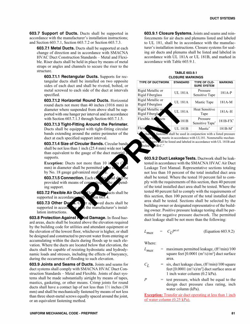
603.7 Support of Ducts. Ducts shall be supported inaccordance with the manufacturer’s installation instructions;and Section 603.7.1, Section 603.7.2 or Section 603.7.3.
603.7.1 Metal Ducts. Ducts shall be supported at eachchange of direction and in accordance with SMACNAHVAC Duct Construction Standards – Metal and Flexi-ble. Riser ducts shall be held in place by means of metalstraps or angles and channels to secure the riser to thestructure.
603.7.1.1 Rectangular Ducts. Supports for rec-tangular ducts shall be installed on two oppositesides of each duct and shall be riveted, bolted, ormetal screwed to each side of the duct at intervalsspecified.603.7.1.2 Horizontal Round Ducts. Horizontalround ducts not more than 40 inches (1016 mm) indiameter where suspended from above shall be sup-ported with one hanger per interval and in accordancewith Section 603.7.1.3 through Section 603.7.1.5.603.7.1.3 Tight-Fitting Around the Perimeter.Ducts shall be equipped with tight-fitting circularbands extending around the entire perimeter of theduct at each specified support interval.603.7.1.4 Size of Circular Bands. Circular bandsshall be not less than 1 inch (25.4 mm) wide nor lessthan equivalent to the gauge of the duct material itsupports.Exception: Ducts not more than 10 inches (254mm) in diameter shall be permitted to be supportedby No. 18 gauge galvanized steel wire.603.7.1.5 Connection. Each circular band shall beprovided with means of connecting to the suspend-ing support.
603.7.2 Flexible Air Ducts. Flexible air ducts shall besupported in accordance with Section 603.4.603.7.3 Other Ducts. Other approved ducts shall besupported in accordance with the manufacturer’s instal-lation instructions.
603.8 Protection Against Flood Damage. In flood haz-ard areas, ducts shall be located above the elevation requiredby the building code for utilities and attendant equipment orthe elevation of the lowest floor, whichever is higher, or shallbe designed and constructed to prevent water from entering oraccumulating within the ducts during floods up to such ele-vation. Where the ducts are located below that elevation, theducts shall be capable of resisting hydrostatic and hydrody-namic loads and stresses, including the effects of buoyancy,during the occurrence of flooding to such elevation.603.9 Joints and Seams of Ducts. Joints and seams forduct systems shall comply with SMACNA HVAC Duct Con-struction Standards – Metal and Flexible. Joints of duct sys-tems shall be made substantially airtight by means of tapes,mastics, gasketing, or other means. Crimp joints for roundducts shall have a contact lap of not less than 11⁄2 inches (38mm) and shall be mechanically fastened by means of not lessthan three sheet-metal screws equally spaced around the joint,or an equivalent fastening method.
603.9.1 Closure Systems. Joints and seams and rein-forcements for air ducts and plenums listed and labeledto UL 181, shall be in accordance with the manufac-turer’s installation instructions. Closure systems for seal-ing air ducts and plenums shall be listed and labeled inaccordance with UL 181A or UL 181B, and marked inaccordance with Table 603.9.1.
603.9.2 Duct Leakage Tests. Ductwork shall be leak-tested in accordance with the SMACNA HVAC Air DuctLeakage Test Manual. Representative sections totalingnot less than 10 percent of the total installed duct areashall be tested. Where the tested 10 percent fail to com-ply with the requirements of this section, then 40 percentof the total installed duct area shall be tested. Where thetested 40 percent fail to comply with the requirements ofthis section, then 100 percent of the total installed ductarea shall be tested. Sections shall be selected by thebuilding owner or designated representative of the build-ing owner. Positive pressure leakage testing shall be per-mitted for negative pressure ductwork. The permittedduct leakage shall be not more than the following:
Lmax = CLP0.65 (Equation 603.9.2)
Where:Lmax = maximum permitted leakage, (ft3/min)/100
square feet [0.0001 (m3/s)/m2] duct surfacearea.
CL = six, duct leakage class, (ft3/min)/100 squarefeet [0.0001 (m3/s)/m2] duct surface area at1 inch water column (0.2 kPa).
P = test pressure, which shall be equal to thedesign duct pressure class rating, inchwater column (kPa).
Exception: Transfer air duct operating at less than 1 inchof water column (0.25 kPa).
TABLE 603.9.1CLOSURE MARKINGS
* Mechanical fasteners shall be used in conjunction with a listed pressuresensitive tape or mastic in accordance with UL181. Nonmetallic mechan-ical fasteners shall be listed and labeled in accordance with UL 181B andlabeled “181B-C.”
TYPE OF DUCTWORK STANDARD TYPE OF CLO-SURE SYSTEM
MARKING
Rigid Metallic orRigid Fiberglass UL 181A Pressure
Sensitive Tape 181A-P
Rigid Metallic orRigid Fiberglass UL 181A Mastic Tape 181A-M
Rigid Metallic orRigid Fiberglass UL 181A Heat Sensitive
Tape 181A–H
Flexible Air Ducts UL 181B Pressure Sensitive Tape* 181B-FX*
Flexible Air Ducts UL 181B Mastic* 181B-M*
81UNIFORM MECHANICAL CODE - PREPRINT
DUCT SYSTEMS
PREPRINT
603.10 Cross Contamination. Exhaust ducts that conveyClass 4 air shall be negatively pressurized relative to ducts,plenums, or occupiable spaces through which the ducts pass.Exhaust ducts systems under positive pressure that conveyClass 2 or Class 3 air shall not extend into or pass throughducts, plenums, or occupiable spaces other than the spacefrom which the exhaust air is drawn.Exception: Exhaust ducts conveying Class 2 air and exhaustducts conveying air from residential kitchen hoods that aresealed in accordance with SMACNA Seal Class A of theSMACNA HVAC Air Duct Leakage Test Manual. [ASHRAE62.1:5.2.1, 5.2.2].603.11 Underground Installation.Ducts installed under-ground shall be approved for the installation and shall have aslope of not less than 1⁄8 inch per foot (10.4 mm/m) back to themain riser. Ducts, plenums, and fittings shall be permitted tobe constructed of concrete, clay, or ceramics where installedin the ground or in a concrete slab, provided the joints aresealed and duct is secured in accordance with SMACNAHVAC Duct Construction Standards – Metal and Flexible.Metal ducts where installed in or under a concrete slab shallbe encased in not less than 2 inches (51 mm) of concrete,secured in accordance with SMACNA HVAC Duct Con-struction Standards – Metal and Flexible.603.12 Air Dispersion Systems.Where installed, air dis-persion systems shall be completely in exposed locations induct systems under positive pressure, and not pass through orpenetrate fire-resistant-rated construction. Air dispersion sys-tems shall be listed and labeled in accordance with UL 2518.603.13 Clearances. Duct clearances shall be in accordancewith Section 603.13.1 through Section 603.13.6.
603.13.1 General. Duct clearances to combustible con-struction shall be in accordance with the listing and themanufacturer’s installation instructions.603.13.2 Supply Air Ducts To Listed Furnaces.Supply air ducts connecting to listed central heating fur-naces shall have the same minimum clearance to com-bustibles as required for the furnace supply plenum for adistance of not less than 3 feet (914 mm) from the sup-ply plenum. Clearance shall not be required beyond the3 feet (914 mm) distance. [NFPA 54:10.3.2.7]603.13.3 Supply Air Ducts to Unlisted Furnaces.Supply air ducts connecting to unlisted central heating fur-naces equipped with temperature limit controls with amaximum setting of 250°F (121°C) shall have a minimumclearance to combustibles of 6 inches (152 mm) for a dis-tance of not less than 6 feet (1829 mm) from the furnacesupply plenum. Clearance shall not be required beyond the6 feet (1829 mm) distance. [NFPA 54:10.3.2.8]603.13.4 Furnace Plenums and Air Ducts. A fur-nace plenum supplied as a part of the air-conditioningappliance shall be installed in accordance with the man-ufacturer’s instructions. Where a furnace plenum is notsupplied with the appliance, any fabrication and installa-tion instructions provided by the manufacturer shall befollowed. The method of connecting supply and return
ducts shall facilitate proper circulation of air. Where theair conditioner is installed within an enclosure, the instal-lation shall comply with Section 604.4. [NFPA 54:10.2.5]603.13.5 Duct Furnaces. Duct furnaces shall beinstalled in accordance with Section 905.0.603.13.6 Fuel-Burning Kilns. A hood and duct serv-ing a fuel-burning kiln shall have a clearance from com-bustible construction of not less than 18 inches (457mm). This clearance shall be permitted to be reduced inaccordance with Table 303.10.1.
604.0 Furnace Plenums and Ducts Used in Fuel-GasAppliances.604.1 Furnace Plenums and Air Ducts. Furnace plenumsand air ducts shall be installed in accordance with this Chap-ter, and NFPA 90A or NFPA 90B. {[NFPA 54:10.3.7.1]}604.2 Supplied As a Part of Furnace. A furnace plenumsupplied as a part of a furnace shall be installed in accordancewith the manufacturer’s instructions. [NFPA 54:10.3.7.2]604.3 Not Supplied With The Furnace. Where a furnaceplenum is not supplied with the furnace, any fabrication andinstallation instructions provided by the manufacturer shallbe followed. The method of connecting supply and returnducts shall facilitate proper circulation of air. [NFPA54:10.3.7.3]604.4 Return Air. Where a furnace is installed so supplyducts carry air circulated by the furnace to areas outside thespace containing the furnace, the return air shall also be han-dled by a duct(s) sealed to the furnace casing and terminatingoutside the space containing the furnace. [NFPA 54:10.3.7.4]
605.0 Insulation of Ducts.605.1 General. Air ducts conveying air at temperaturesexceeding 140°F (60°C) shall be insulated to maintain aninsulation surface temperature of not more than 140°F (60°C).Insulation material on the exterior of ducts shall be legiblyprinted with the name of the manufacturer, the thermal resist-ance (R) value at installed thickness, flame-spread index, andsmoke developed index of the composite material. Internalduct liners and insulation shall be installed in accordance withSMACNA HVAC Duct Construction Standards – Metal andFlexible.Exceptions:(1) Factory-installed plenums, casings, or ductwork fur-
nished as a part of HVAC equipment tested and rated inaccordance with approved energy efficiency standards.
(2) Ducts or plenums located in conditioned spaces whereheat gain or heat loss will not increase energy use.
(3) For runouts less than 10 feet (3048 mm) in length to airterminals or air outlets, the rated R-value of insulationneed not exceed R-3.5.
(4) Backs of air outlets and outlet plenums exposed tounconditioned or indirectly conditioned spaces with faceareas exceeding 5 square feet (0.5 m2) need not exceed R-2; those 5 square feet (0.5 m2) or smaller need not beinsulated.
82 UNIFORM MECHANICAL CODE - PREPRINT
DUCT SYSTEMS
PREPRINT
(5) Ducts and plenums used exclusively for evaporativecooling systems.605.1.1 Within Ducts or Plenums. Materials installedwithin ducts and plenums for insulating, sound deaden-ing, or other purposes shall have a mold, humidity, anderosion-resistant surface where tested in accordance withUL 181. Duct liners in systems operating with air veloc-ities exceeding 2000 feet per minute (10.16 m/s) shall befastened with both adhesive and mechanical fasteners,and exposed edges shall have approved treatment to with-stand the operating velocity. Where the internal insula-tion is capable of being in contact with condensates orother liquids, the material shall be water-resistant. Pipeand duct insulation shall not be used to reduce the maxi-mum flame and smoke requirements in Section 602.2unless listed for application in plenums and tested inaccordance with ASTM E84 or UL 723 as a compositeassembly of the duct or pipe and its associated insulation,coatings and adhesives.605.1.2 Duct Coverings and Linings. Insulationapplied to the surface of ducts, including duct coverings,linings, tapes, and adhesives, located in buildings shallhave a flame-spread index not to exceed 25 and a smoke-developed index not to exceed 50, where tested in accor-dance with ASTM E84 or UL 723. The specimenpreparation and mounting procedures of ASTM E2231shall be used. Air duct coverings and linings shall notflame, glow, smolder, or smoke where tested in accor-dance with ASTM C411 at the temperature to which theyare exposed in service. In no case shall the test tempera-ture be less than 250°F (121°C). Coverings shall not pen-etrate a fire-resistance-rated assembly.
606.0 Smoke Dampers, Fire Dampers, and CeilingDampers.606.1 Smoke Dampers. Smoke dampers shall complywith UL 555S, and shall be installed in accordance with themanufacturer’s installation instructions where required by thebuilding code. 606.2 Fire Dampers. Fire dampers shall comply with UL555, and shall be installed in accordance with the manufac-turer’s installation instructions where required by the buildingcode. Fire dampers shall have been tested for closure underairflow conditions and shall be labeled for both maximum air-flow permitted and direction of flow. Where more than onedamper is installed at a point in a single air path, the entire air-flow shall be assumed to be passing through the smallestdamper area.
Ductwork shall be connected to damper sleeves orassemblies in accordance with the fire damper manufacturer’sinstallation instructions.606.3 Ceiling Radiation Dampers. Ceiling radiationdampers shall comply with UL 555C, and shall be installed inaccordance with the manufacturer’s installation instructionsin the fire-resistive ceiling membrane of floor-ceiling androof-ceiling assemblies where required by the building code.Fire dampers not meeting the temperature limitation of ceil-ing radiation dampers shall not be used as a substitute.
606.4 Multiple Arrangements. Where size requires theuse of multiple dampers, each damper shall be listed for usein multiple arrangements and installed in accordance with themanufacturer’s installation instructions.606.5 Access and Identification. Fire and smokedampers shall be provided with an approved means of accesslarge enough to allow inspection and maintenance of thedamper and its operating parts. The access shall not affect theintegrity of the fire-resistance-rated assembly. The accessopenings shall not reduce the fire-resistance rating of theassembly.
Access shall not require the use of tools. Access doorsin ducts shall be tight fitting and approved for the requiredduct construction. Access points shall be permanently identi-fied on the exterior by a label with letters not less than 1⁄2 ofan inch (12.7 mm) in height reading as one of the following: (1) Smoke Damper (2) Fire Damper (3) Fire/Smoke Damper606.6 Freedom from Interference. Dampers shall beinstalled in a manner to ensure positive closing or opening asrequired by function. Interior liners or insulation shall be heldback from portions of a damper, its sleeve, or adjoining ductthat would interfere with the damper’s proper operation. Exte-rior materials shall be installed so as to not interfere with theoperation or maintenance of external operating devicesneeded for the function of the damper.606.7 Temperature Classification of Operating Ele-ments. Fusible links, thermal sensors, and pneumatic orelectric operators shall have a temperature rating or classifi-cation as in accordance with the building code.
607.0 Ventilating Ceilings.607.1 General. Perforated ceilings shall be permitted to beused for air supply within the limitations of this section. Exitcorridors, where required to be of fire-resistive constructionby the building code, shall not have ventilating ceilings.607.2 Requirements. Ventilating ceilings shall complywith the following:(1) Suspended ventilating ceiling material shall have a Class
1 flame spread classification on both sides, determined inaccordance with the building code. Suspended ventilat-ing ceiling supports shall be of noncombustible materi-als.
(2) Luminaires recessed into ventilating ceilings shall be ofa type approved for that purpose.
608.0 Use of Under-Floor Space as Supply Plenumfor Dwelling Units.608.1 General. An under-floor space shall be permitted tobe used as a supply plenum.608.2 Dwelling Units. The use of under-floor space shallbe limited to dwelling units not more than two stories inheight. Except for the floor immediately above the under-floor plenum, supply ducts shall be provided extending fromthe plenum to registers on other floor levels.
83UNIFORM MECHANICAL CODE - PREPRINT
DUCT SYSTEMS
PREPRINT
Exception: In flood hazard areas, under-floor spaces shallnot be used as supply plenums unless the flood openingrequirements in the building code are met.608.3 Enclosed. Such spaces shall be cleaned of all loosecombustible scrap material and shall be tightly enclosed.608.4 Flammable Materials. The enclosing material ofthe under-floor space, including the sidewall insulation, shallbe not more flammable than 1 inch (25.4 mm) (nominal)wood boards (flame-spread index of 200). Installation offoam plastics is regulated by the building code.608.5 Access. Access shall be through an opening in thefloor and shall be not less than 24 inches by 24 inches (610mm by 610 mm).608.6 Automatic Control. A furnace supplying warm airto under-floor space shall be equipped with an automatic con-trol that will start the air-circulating fan where the air in thefurnace bonnet reaches a temperature not exceeding 150°F(66°C). Such control shall be one that cannot be set to exceed150°F (66°C).608.7 Temperature Limit.A furnace supplying warm air tosuch space shall be equipped with an approved temperaturelimit control that will limit outlet air temperature to 200°F(93°C).608.8 Noncombustible Receptacle. A noncombustiblereceptacle shall be placed below each floor opening into theair chamber, and such receptacle shall comply with Section608.8.1 through Section 608.8.3.
608.8.1 Location. The receptacle shall be securely sus-pended from the floor members and shall be not more than18 inches (457 mm) below the floor opening.608.8.2 Area. The area of the receptacle shall extend 3inches (76 mm) beyond the opening on all sides.608.8.3 Perimeter. The perimeter of the receptacleshall have a vertical lip not less than 1 inch (25.4 mm)high at the open sides where it is at the level of the bot-tom of the joists, or 3 inches (76 mm) high where thereceptacle is suspended.
608.9 Floor Registers. Floor registers shall be designedfor easy removal in order to give access for cleaning thereceptacles. 608.10 Exterior Wall and Interior Stud Partitions.Exterior walls and interior stud partitions shall be fire blockedat the floor.608.11Wall Register. Each wall register shall be connectedto the air chamber by a register box or boot.608.12 Distance from Combustible. A duct complyingwith Section 602.0 shall extend from the furnace supply out-let not less than 6 inches (152 mm) below combustible fram-ing.608.13 Vapor Barrier. The entire ground surface of theunder-floor space shall be covered with a vapor barrier hav-ing a thickness not less than 4 mils (0.1 mm) and a flame-spread index of not more than 200.608.14 Prohibited. Fuel gas lines and plumbing wastecleanouts shall not be located within the space.
609.0 Automatic Shutoffs.609.1 Air-Moving Systems and Smoke Detectors.Air-moving systems supplying air in excess of 2000 cubicfeet per minute (ft3/min) (0.9439 m3/s) to enclosed spaceswithin buildings shall be equipped with an automatic shutoff.Automatic shutoff shall be accomplished by interrupting thepower source of the air-moving equipment upon detection ofsmoke in the main supply-air duct served by such equipment.Duct smoke detectors shall comply with UL 268A and shallbe installed in accordance with the manufacturer’s installa-tion instructions. Such devices shall be compatible with theoperating velocities, pressures, temperatures, and humiditiesof the system. Where fire-detection or alarm systems are pro-vided for the building, the smoke detectors shall be super-vised by such systems in an approved manner.Exceptions:(1) Where the space supplied by the air-moving equipment
is served by a total coverage smoke-detection system inaccordance with the fire code, interconnection to suchsystem shall be permitted to be used to accomplish therequired shutoff.
(2) Automatic shutoff is not required where occupied roomsserved by the air-handling equipment have direct exit tothe exterior, and the travel distance does not exceed 100feet (30 480 mm).
(3) Automatic shutoff is not required for Group R, Division3 and Group U Occupancies.
(4) Automatic shutoff is not required for approved smoke-control systems or where analysis demonstrates shutoffwould create a greater hazard, such as shall be permittedto be encountered in air-moving equipment supplyingspecialized portions of Group H Occupancies. Suchequipment shall be required to have smoke detectionwith remote indication and manual shutoff capability atan approved location.
(5) Smoke detectors that are factory installed in listed air-moving equipment shall be permitted to be used in lieuof smoke detectors installed in the main supply-air ductserved by such equipment.
84 UNIFORM MECHANICAL CODE - PREPRINT
DUCT SYSTEMS
PREPRINT
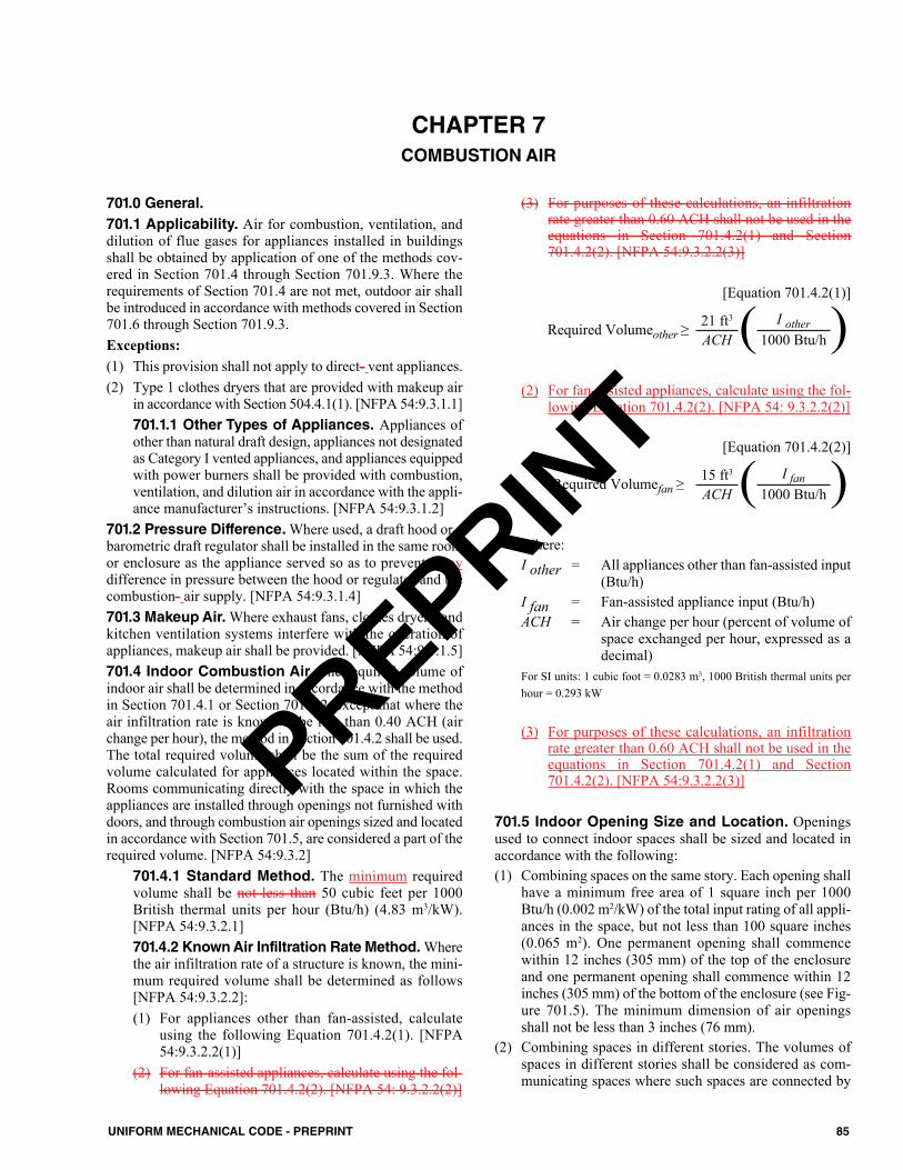
701.0 General.701.1 Applicability. Air for combustion, ventilation, anddilution of flue gases for appliances installed in buildingsshall be obtained by application of one of the methods cov-ered in Section 701.4 through Section 701.9.3. Where therequirements of Section 701.4 are not met, outdoor air shallbe introduced in accordance with methods covered in Section701.6 through Section 701.9.3.Exceptions:(1) This provision shall not apply to direct- vent appliances. (2) Type 1 clothes dryers that are provided with makeup air
in accordance with Section 504.4.1(1). [NFPA 54:9.3.1.1]701.1.1 Other Types of Appliances. Appliances ofother than natural draft design, appliances not designatedas Category I vented appliances, and appliances equippedwith power burners shall be provided with combustion,ventilation, and dilution air in accordance with the appli-ance manufacturer’s instructions. [NFPA 54:9.3.1.2]
701.2 Pressure Difference. Where used, a draft hood or abarometric draft regulator shall be installed in the same roomor enclosure as the appliance served so as to prevent a anydifference in pressure between the hood or regulator and thecombustion- air supply. [NFPA 54:9.3.1.4]701.3 Makeup Air.Where exhaust fans, clothes dryers, andkitchen ventilation systems interfere with the operation ofappliances, makeup air shall be provided. [NFPA 54:9.3.1.5]701.4 Indoor Combustion Air. The required volume ofindoor air shall be determined in accordance with the methodin Section 701.4.1 or Section 701.4.2, except that where theair infiltration rate is known to be less than 0.40 ACH (airchange per hour), the method in Section 701.4.2 shall be used.The total required volume shall be the sum of the requiredvolume calculated for appliances located within the space.Rooms communicating directly with the space in which theappliances are installed through openings not furnished withdoors, and through combustion air openings sized and locatedin accordance with Section 701.5, are considered a part of therequired volume. [NFPA 54:9.3.2]
701.4.1 Standard Method. The minimum requiredvolume shall be not less than 50 cubic feet per 1000British thermal units per hour (Btu/h) (4.83 m3/kW).[NFPA 54:9.3.2.1]701.4.2 Known Air Infiltration Rate Method.Wherethe air infiltration rate of a structure is known, the mini-mum required volume shall be determined as follows[NFPA 54:9.3.2.2]:(1) For appliances other than fan-assisted, calculate
using the following Equation 701.4.2(1). [NFPA54:9.3.2.2(1)]
(2) For fan-assisted appliances, calculate using the fol-lowing Equation 701.4.2(2). [NFPA 54: 9.3.2.2(2)]
(3) For purposes of these calculations, an infiltrationrate greater than 0.60 ACH shall not be used in theequations in Section 701.4.2(1) and Section701.4.2(2). [NFPA 54:9.3.2.2(3)]
[Equation 701.4.2(1)]
(2) For fan-assisted appliances, calculate using the fol-lowing Equation 701.4.2(2). [NFPA 54: 9.3.2.2(2)]
[Equation 701.4.2(2)]
Where:I other = All appliances other than fan-assisted input
(Btu/h)I fan = Fan-assisted appliance input (Btu/h)ACH = Air change per hour (percent of volume of
space exchanged per hour, expressed as adecimal)
For SI units: 1 cubic foot = 0.0283 m3, 1000 British thermal units perhour = 0.293 kW
(3) For purposes of these calculations, an infiltrationrate greater than 0.60 ACH shall not be used in theequations in Section 701.4.2(1) and Section701.4.2(2). [NFPA 54:9.3.2.2(3)]
701.5 Indoor Opening Size and Location. Openingsused to connect indoor spaces shall be sized and located inaccordance with the following:(1) Combining spaces on the same story. Each opening shall
have a minimum free area of 1 square inch per 1000Btu/h (0.002 m2/kW) of the total input rating of all appli-ances in the space, but not less than 100 square inches(0.065 m2). One permanent opening shall commencewithin 12 inches (305 mm) of the top of the enclosureand one permanent opening shall commence within 12inches (305 mm) of the bottom of the enclosure (see Fig-ure 701.5). The minimum dimension of air openingsshall not be less than 3 inches (76 mm).
(2) Combining spaces in different stories. The volumes ofspaces in different stories shall be considered as com-municating spaces where such spaces are connected by
Required Volumeother ≥ 21 ft3 ( I other )ACH 1000 Btu/h
Required Volumefan ≥ 15 ft3 ( I fan )ACH 1000 Btu/h
85UNIFORM MECHANICAL CODE - PREPRINT
CHAPTER 7COMBUSTION AIR
PREPRINT
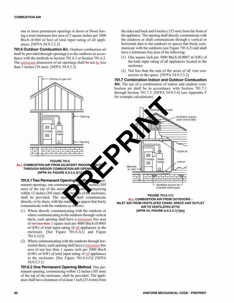
one or more permanent openings in doors or floors hav-ing a total minimum free area of 2 square inches per 1000Btu/h (0.004 m2/kw) of total input rating of all appli-ances. [NFPA 54:9.3.2.3]
701.6 Outdoor Combustion Air. Outdoor combustion airshall be provided through opening(s) to the outdoors in accor-dance with the methods in Section 701.6.1 or Section 701.6.2.The minimum dimension of air openings shall be not be lessthan 3 inches (76 mm). [NFPA 54:9.3.3]
FIGURE 701.5ALL COMBUSTION AIR FROM ADJACENT INDOOR SPACES
THROUGH INDOOR COMBUSTION AIR OPENINGS [NFPA 54: FIGURE A.9.3.2.3(1)]
701.6.1 Two Permanent Openings Method.Two per-manent openings, one commencing within 12 inches (305mm) of the top of the enclosure and one commencingwithin 12 inches (305 mm) of the bottom of the enclosure,shall be provided. The openings shall communicatedirectly, or by ducts, with the outdoors or spaces that freelycommunicate with the outdoors as follows:(1) Where directly communicating with the outdoors or
where communicating to the outdoors through verticalducts, each opening shall have a minimum free areaof not less than 1 square inch per 4000 Btu/h (0.0005m2/kW) of total input rating of all appliances in theenclosure. [See Figure 701.6.1(1) and Figure701.6.1(2)]
(2) Where communicating with the outdoors through hor-izontal ducts, each opening shall have a minimum freearea of not less than 1 square inch per 2000 Btu/h(0.001 m2/kW) of total input rating of all appliancesin the enclosure. [See Figure 701.6.1(3)] [NFPA54:9.3.3.1]
701.6.2 One Permanent Opening Method. One per-manent opening, commencing within 12 inches (305 mm)of the top of the enclosure, shall be provided. The appli-ance shall have clearances of at least 1 inch (25.4 mm) from
the sides and back and 6 inches (152 mm) from the front ofthe appliance. The opening shall directly communicate withthe outdoors or shall communicate through a vertical orhorizontal duct to the outdoors or spaces that freely com-municate with the outdoors (see Figure 701.6.2) and shallhave a minimum free area of the following:(1) One square inch per 3000 Btu/h (0.0007 m2/kW) of
the total input rating of all appliances located in theenclosure.
(2) Not less than the sum of the areas of all vent con-nectors in the space. [NFPA 54:9.3.3.2]
701.7 Combination Indoor and Outdoor CombustionAir. The use of a combination of indoor and outdoor com-bustion air shall be in accordance with Section 701.7.1through Section 701.7.3. [NFPA 54:9.3.4] (see Appendix Ffor example calculations)
FIGURE 701.6.1(1)ALL COMBUSTION AIR FROM OUTDOORS –
INLET AIR FROM VENTILATED CRAWL SPACE AND OUTLETAIR TO VENTILATED ATTIC
[NFPA 54: FIGURE A.9.3.3.1(1)(a)]
86 UNIFORM MECHANICAL CODE - PREPRINT
COMBUSTION AIR
PREPRINT
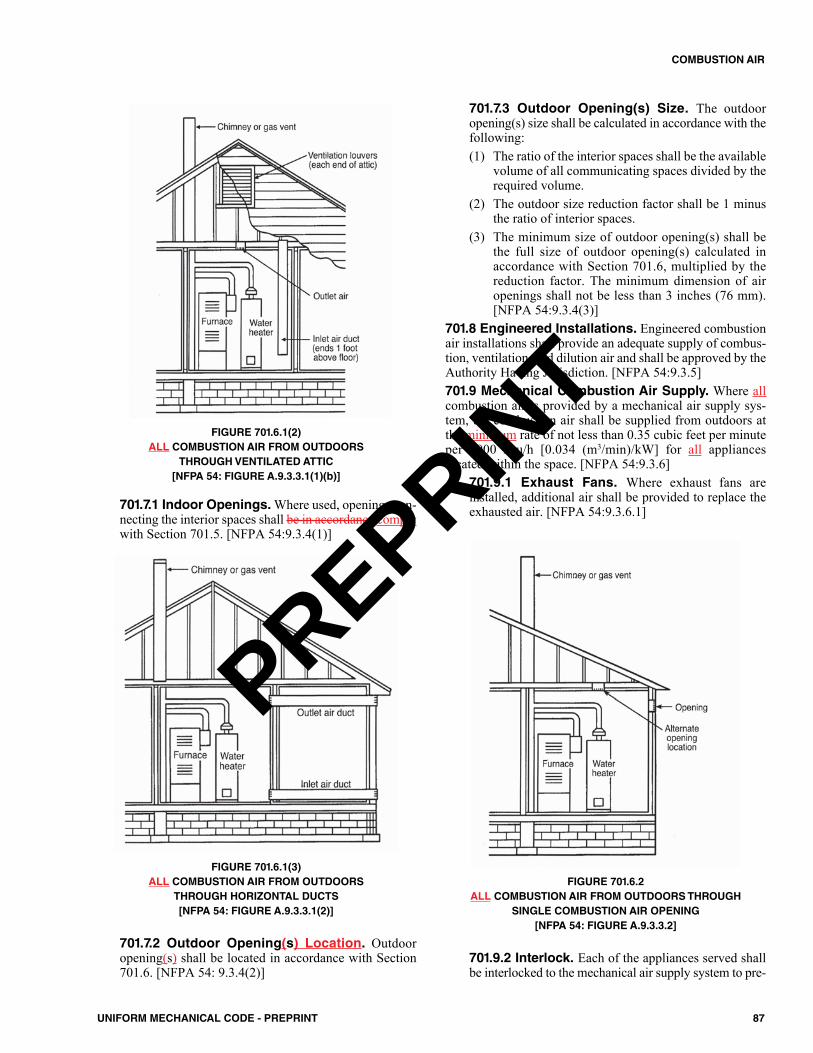
FIGURE 701.6.1(2)ALL COMBUSTION AIR FROM OUTDOORS
THROUGH VENTILATED ATTIC[NFPA 54: FIGURE A.9.3.3.1(1)(b)]
701.7.1 Indoor Openings.Where used, openings con-necting the interior spaces shall be in accordance complywith Section 701.5. [NFPA 54:9.3.4(1)]
FIGURE 701.6.1(3)ALL COMBUSTION AIR FROM OUTDOORS
THROUGH HORIZONTAL DUCTS[NFPA 54: FIGURE A.9.3.3.1(2)]
701.7.2 Outdoor Opening(s) Location. Outdooropening(s) shall be located in accordance with Section701.6. [NFPA 54: 9.3.4(2)]
701.7.3 Outdoor Opening(s) Size. The outdooropening(s) size shall be calculated in accordance with thefollowing:(1) The ratio of the interior spaces shall be the available
volume of all communicating spaces divided by therequired volume.
(2) The outdoor size reduction factor shall be 1 minusthe ratio of interior spaces.
(3) The minimum size of outdoor opening(s) shall bethe full size of outdoor opening(s) calculated inaccordance with Section 701.6, multiplied by thereduction factor. The minimum dimension of airopenings shall not be less than 3 inches (76 mm).[NFPA 54:9.3.4(3)]
701.8 Engineered Installations. Engineered combustionair installations shall provide an adequate supply of combus-tion, ventilation, and dilution air and shall be approved by theAuthority Having Jurisdiction. [NFPA 54:9.3.5]701.9 Mechanical Combustion Air Supply. Where allcombustion air is provided by a mechanical air supply sys-tem, the combustion air shall be supplied from outdoors atthe minimum rate of not less than 0.35 cubic feet per minuteper 1000 Btu/h [0.034 (m3/min)/kW] for all applianceslocated within the space. [NFPA 54:9.3.6]
701.9.1 Exhaust Fans. Where exhaust fans areinstalled, additional air shall be provided to replace theexhausted air. [NFPA 54:9.3.6.1]
FIGURE 701.6.2ALL COMBUSTION AIR FROM OUTDOORS THROUGH
SINGLE COMBUSTION AIR OPENING[NFPA 54: FIGURE A.9.3.3.2]
701.9.2 Interlock. Each of the appliances served shallbe interlocked to the mechanical air supply system to pre-
87UNIFORM MECHANICAL CODE - PREPRINT
COMBUSTION AIR
PREPRINT
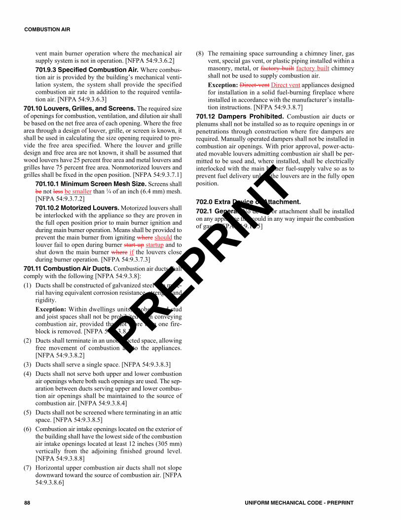
vent main burner operation where the mechanical airsupply system is not in operation. [NFPA 54:9.3.6.2]701.9.3 Specified Combustion Air. Where combus-tion air is provided by the building’s mechanical venti-lation system, the system shall provide the specifiedcombustion air rate in addition to the required ventila-tion air. [NFPA 54:9.3.6.3]
701.10 Louvers, Grilles, and Screens. The required sizeof openings for combustion, ventilation, and dilution air shallbe based on the net free area of each opening. Where the freearea through a design of louver, grille, or screen is known, itshall be used in calculating the size opening required to pro-vide the free area specified. Where the louver and grilledesign and free area are not known, it shall be assumed thatwood louvers have 25 percent free area and metal louvers andgrilles have 75 percent free area. Nonmotorized louvers andgrilles shall be fixed in the open position. [NFPA 54:9.3.7.1]
701.10.1 Minimum Screen Mesh Size. Screens shallbe not less be smaller than 1⁄4 of an inch (6.4 mm) mesh.[NFPA 54:9.3.7.2]701.10.2 Motorized Louvers. Motorized louvers shallbe interlocked with the appliance so they are proven inthe full open position prior to main burner ignition andduring main burner operation. Means shall be provided toprevent the main burner from igniting where should thelouver fail to open during burner start-up startup and toshut down the main burner where if the louvers closeduring burner operation. [NFPA 54:9.3.7.3]
701.11 Combustion Air Ducts. Combustion air ducts shallcomply with the following [NFPA 54:9.3.8]:(1) Ducts shall be constructed of galvanized steel or a mate-
rial having equivalent corrosion resistance, strength, andrigidity. Exception: Within dwellings units, unobstructed studand joist spaces shall not be prohibited from conveyingcombustion air, provided that not more than one fire-block is removed. [NFPA 54:9.3.8.1]
(2) Ducts shall terminate in an unobstructed space, allowingfree movement of combustion air to the appliances.[NFPA 54:9.3.8.2]
(3) Ducts shall serve a single space. [NFPA 54:9.3.8.3](4) Ducts shall not serve both upper and lower combustion
air openings where both such openings are used. The sep-aration between ducts serving upper and lower combus-tion air openings shall be maintained to the source ofcombustion air. [NFPA 54:9.3.8.4]
(5) Ducts shall not be screened where terminating in an atticspace. [NFPA 54:9.3.8.5]
(6) Combustion air intake openings located on the exterior ofthe building shall have the lowest side of the combustionair intake openings located at least 12 inches (305 mm)vertically from the adjoining finished ground level.[NFPA 54:9.3.8.8]
(7) Horizontal upper combustion air ducts shall not slopedownward toward the source of combustion air. [NFPA54:9.3.8.6]
(8) The remaining space surrounding a chimney liner, gasvent, special gas vent, or plastic piping installed within amasonry, metal, or factory-built factory built chimneyshall not be used to supply combustion air.Exception: Direct-vent Direct vent appliances designedfor installation in a solid fuel-burning fireplace whereinstalled in accordance with the manufacturer’s installa-tion instructions. [NFPA 54:9.3.8.7]
701.12 Dampers Prohibited. Combustion air ducts orplenums shall not be installed so as to require openings in orpenetrations through construction where fire dampers arerequired. Manually operated dampers shall not be installed incombustion air openings. With prior approval, power-actu-ated movable louvers admitting combustion air shall be per-mitted to be used and, where installed, shall be electricallyinterlocked with the main burner fuel-supply valve so as toprevent fuel delivery unless the louvers are in the fully openposition.
702.0 Extra Device or Attachment.702.1 General. No device or attachment shall be installedon any appliance that could in any way impair the combustionof gas. [NFPA 54:9.1.15]
88 UNIFORM MECHANICAL CODE - PREPRINT
COMBUSTION AIR
PREPRINT
801.0 General.801.1 Applicability. The requirements of this chapter shallgovern the venting of fuel-burning appliances.801.2 Venting of Gas Appliances. Low-heat andmedium-heat gas appliances shall be vented in accordancewith this chapter. Other gas appliances shall be vented inaccordance with NFPA 211 or other applicable standards.801.3 Appliances Fueled by Other Fuels. Appliancesfueled by fuels other than gas shall be vented in accordancewith NFPA 211 and the appliance manufacturer’s instructions.
802.0 Venting of Appliances.802.1 Listing. Type B and Type B-W gas vents shall com-ply with UL 441, Type L gas vents shall comply with UL 641.
802.1.1 Installation. Listed vents shall be installed inaccordance with this chapter and the manufacturer’sinstallation instructions. [NFPA 54:12.2.1]802.1.2 Prohibited Discharge. Appliance vents shallnot discharge into a space enclosed by screens havingopenings less than 1⁄4 of an inch (6.4 mm) mesh.
802.2 Connection to Venting Systems. Except as per-mitted in Section 802.2.1 through Section 802.2.8, all appli-ances shall be connected to venting systems. [NFPA54:12.3.1]
802.2.1 Appliances Not Required to be Vented.The following appliances shall not be required to bevented:(1) Listed ranges.(2) Built-in domestic cooking units listed and marked
for optional venting.(3) Listed hot plates.(4) Listed Type 1 clothes dryers exhausted in accor-
dance with Section 504.4.(5) A single listed booster-type (automatic instanta-
neous) water heater, when designed and used solelyfor the sanitizing rinse requirements of a dishwash-ing machine, provided that the appliance is installedwith the draft hood in place and unaltered, if a drafthood is required, in a commercial kitchen having amechanical exhaust system. [Where installed in thismanner, the draft hood outlet shall not be less than36 inches (914 mm) vertically and 6 inches (152mm) horizontally from any surface other than theappliance.]
(6) Listed refrigerators.(7) Counter appliances.(8) Room heaters listed for unvented use.(9) Direct gas-fired makeup-air heaters.(10) Other appliances listed for unvented use and not pro-
vided with flue collars.
(11) Specialized appliances of limited input such as lab-oratory burners or gas lights. [NFPA 54:12.3.2]
802.2.2 Maximum Input Rating.Where any or all ofthe appliances in Section 802.2.1(5) through Section802.2.1(11) are installed so the aggregate input ratingexceeds 20 Btu/h/ft3 (207 W/m3) of room or space inwhich it is installed, one or more shall be provided withventing systems or other approved means for conveyingthe vent gases to the outdoors so that the aggregate inputrating of the remaining unvented appliances does notexceed 20 Btu/h/ft3 (207 W/m3). [NFPA 54:12.3.2.1]802.2.3 Adjacent Room or Space. Where the calcu-lation includes the volume of an adjacent room or space,the room or space in which the appliances are installed shallbe directly connected to the adjacent room or space by adoorway, archway, or other opening of comparable sizethat cannot be closed. [NFPA 54:12.3.2.2]802.2.4 Ventilating Hoods.The use of ventilating hoodsand exhaust systems to vent appliances shall be limited toindustrial appliances and appliances installed in commer-cial applications. [NFPA 54:12.3.3]802.2.5 Well-Ventilated Spaces. The flue gases fromindustrial-type appliances shall not be required to be ventedto the outdoors where such gases are discharged into a largeand well-ventilated industrial space. [NFPA 54:12.3.4]802.2.6 Direct Vent Appliances. Listed direct- ventappliances shall be installed in accordance with the manu-facturer’s installation instructions and Section 802.8.2.[NFPA 54:12.3.5]802.2.7 Appliances with Integral Vents. Appliancesincorporating integral venting means shall be installed inaccordance with the manufacturer’s installation instruc-tions, Section 802.8, and Section 802.8.1. [NFPA54:12.3.6]802.2.8 Incinerators, Commericial–Industrial.Com-mercial industrial-type incinerators shall be vented inaccordance with NFPA 82. [NFPA 54:12.3.7]
802.3 Minimum Safe Performance. Venting systems shallbe designed and constructed to convey all flue and vent gases tothe outdoors. [NFPA 54:12.1]
802.3.1 Appliance Draft Requirements. A ventingsystem shall satisfy the draft requirements of the appliancein accordance with the manufacturer’s instructions. [NFPA54:12.4.1]802.3.2 Appliance Venting Requirements. Appli-ances required to be vented shall be connected to a vent-ing system designed and installed in accordance with theprovisions of Section 802.4 through Section 802.15.1.[NFPA 54:12.4.2]802.3.3 Mechanical Draft Systems. Mechanicaldraft systems shall be listed in accordance with UL 378and installed in accordance with both the appliance and
89UNIFORM MECHANICAL CODE - PREPRINT
CHAPTER 8CHIMNEYS AND VENTS
PREPRINT
the mechanical draft system manufacturer’s installationinstructions. [NFPA 54:12.4.3.1]
802.3.3.1 Venting. Appliances requiring ventingshall be permitted to be vented by means of mechan-ical draft systems of either forced or induced draftdesign. [NFPA 54:12.4.3.2]802.3.3.2 Leakage. Forced draft systems and allportions of induced draft systems under positivepressure during operation shall be designed andinstalled so as to prevent leakage of flue or ventgases into a building. [NFPA 54:12.4.3.3]802.3.3.3 Vent Connectors. Vent connectorsserving appliances vented by natural draft shall notbe connected into any portion of mechanical draftsystems operating under positive pressure. [NFPA54:12.4.3.4]802.3.3.4 Operation. Where a mechanical draftsystem is employed, provision shall be made to pre-vent the flow of gas to the main burners when thedraft system is not performing so as to satisfy theoperating requirements of the appliance for safe per-formance. [NFPA 54:12.4.3.5]802.3.3.5 Exit Terminals. The exit terminals ofmechanical draft systems shall be not less than 7 feet(2134 mm) above finished ground level wherelocated adjacent to public walkways and shall belocated as specified in Section 802.8 and Section802.8.1. [NFPA 54:12.4.3.6]
802.3.4 Automatically Operated Appliances. Whereautomatically operated appliances, other than commercialcooking appliances, are vented through a ventilating hoodor exhaust system equipped with a damper or with a powermeans of exhaust, provisions shall be made to allow theflow of gas to the main burners only when the damper isopen to a position to properly vent the appliance and whenthe power means of exhaust is in operation. [NFPA54:12.4.4.1]802.3.5 Circulating Air Ducts, Above-Ceiling Air-Handling Spaces, and Furnace Plenums.Ventingsystems shall not extend into or pass through any fabri-cated air duct or furnace plenum. [NFPA 54:12.4.5.1]802.3.6 Above-Ceiling or Nonducted Air Han-dling System.Where a venting system passes throughan above-ceiling air space or other nonducted portion ofan air-handling system, it shall conform to one of the fol-lowing requirements:(1) The venting system shall be a listed special gas vent,
other system serving a Category III or Category IVappliance, or other positive pressure vent, with jointssealed in accordance with the appliance or vent man-ufacturer’s instructions.
(2) The vent system shall be installed such that no fit-tings or joints between sections are installed in theabove-ceiling space.
(3) The venting system shall be installed in a conduit orenclosure with joints between the interior of theenclosure and the ceiling space sealed. [NFPA54:12.4.5.2]
802.4 Type of Venting System to be Used. The type ofventing system to be used shall be in accordance with Table802.4. [NFPA 54:12.5.1]
802.4.1 Plastic Piping.Where plastic piping is used tovent an appliance, the appliance shall be listed for usewith such venting materials and the appliance manufac-turer’s installation instructions shall identify the specificplastic piping material. The plastic pipe venting materi-als shall be labeled in accordance with the product stan-dards specified by the appliance manufacturer or shall belisted and labeled in accordance with UL 1738. [NFPA54:12.5.2]802.4.2 Plastic Vent Joints. Plastic pipe and fittingsused to vent appliances shall be installed in accordancewith the appliance manufacturer’s installation instruc-tions. Plastic pipe venting materials listed and labeled inaccordance with UL 1738 shall be installed in accor-dance with the vent manufacturer's installation instruc-tions. Where primer is required, it shall be of acontrasting color. [NFPA 54:12.5.3]802.4.3 Special Gas Vents. Special gas vents shallbe listed and labeled in accordance with UL 1738 andinstalled in accordance with the special gas vent manu-facturer’s installation instructions. [NFPA 54:12.5.4]
802.5 Masonry, Metal, and Factory-Built Chimneys.Chimneys shall be installed in accordance with Section802.5.1 through Section 802.5.3.
802.5.1 Factory-Built Chimneys. Factory-builtchimneys shall be listed in accordance with UL 103, UL959, or UL 2561. Factory-built chimneys shall beinstalled in accordance with the manufacturer’s installa-tion instructions. Factory-built chimneys used to ventappliances that operate at positive vent pressure shall belisted for such application. [NFPA 54:12.6.1.1]
802.5.1.1 Decorative Shrouds. Decorativeshrouds addressed in Section 802.5.4.3 shall belisted or labeled in accordance with UL 103 for fac-tory-built residential chimneys, UL 127 for factory-built fireplaces, or UL 1482 for solid-fuel roomheaters.802.5.1.2 Listing Requirements. Factory-builtchimneys shall comply with the requirements of UL103 or UL 959. Factory-built chimneys for use withwood-burning appliances shall comply with the TypeHT requirements of UL 103. [NFPA 211:6.1.3.1,6.1.3.2]
802.5.2 Metal Chimneys. Metal chimneys shall bebuilt and installed in accordance with NFPA 211. [NFPA54:12.6.1.2]802.5.3 Masonry Chimneys. Masonry chimneysshall be built and installed in accordance with NFPA 211and lined with one of the following:
90 UNIFORM MECHANICAL CODE - PREPRINT
CHIMNEYS AND VENTS
PREPRINT
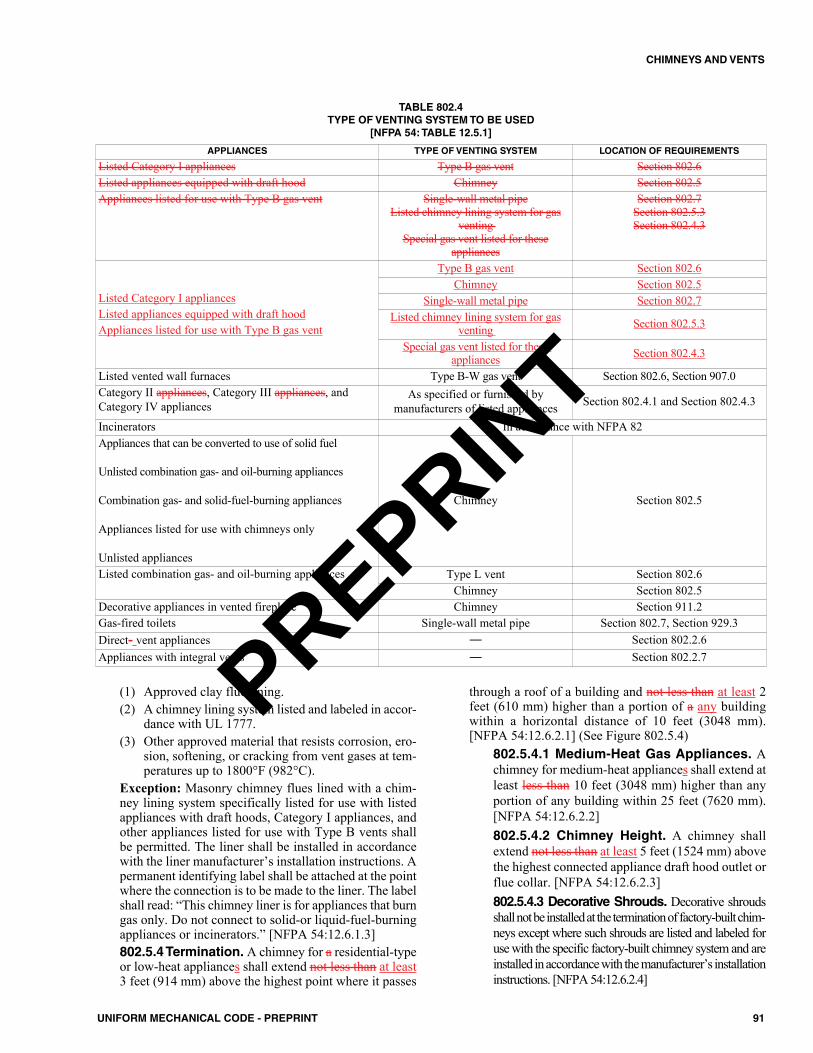
(1) Approved clay flue lining. (2) A chimney lining system listed and labeled in accor-
dance with UL 1777.(3) Other approved material that resists corrosion, ero-
sion, softening, or cracking from vent gases at tem-peratures up to 1800°F (982°C).
Exception: Masonry chimney flues lined with a chim-ney lining system specifically listed for use with listedappliances with draft hoods, Category I appliances, andother appliances listed for use with Type B vents shallbe permitted. The liner shall be installed in accordancewith the liner manufacturer’s installation instructions. Apermanent identifying label shall be attached at the pointwhere the connection is to be made to the liner. The labelshall read: “This chimney liner is for appliances that burngas only. Do not connect to solid-or liquid-fuel-burningappliances or incinerators.” [NFPA 54:12.6.1.3]802.5.4 Termination. A chimney for a residential-typeor low-heat appliances shall extend not less than at least3 feet (914 mm) above the highest point where it passes
through a roof of a building and not less than at least 2feet (610 mm) higher than a portion of a any buildingwithin a horizontal distance of 10 feet (3048 mm).[NFPA 54:12.6.2.1] (See Figure 802.5.4)
802.5.4.1 Medium-Heat Gas Appliances. Achimney for medium-heat appliances shall extend atleast less than 10 feet (3048 mm) higher than anyportion of any building within 25 feet (7620 mm).[NFPA 54:12.6.2.2]802.5.4.2 Chimney Height. A chimney shallextend not less than at least 5 feet (1524 mm) abovethe highest connected appliance draft hood outlet orflue collar. [NFPA 54:12.6.2.3]802.5.4.3 Decorative Shrouds. Decorative shroudsshall not be installed at the termination of factory-built chim-neys except where such shrouds are listed and labeled foruse with the specific factory-built chimney system and areinstalled in accordance with the manufacturer’s installationinstructions. [NFPA 54:12.6.2.4]
91UNIFORM MECHANICAL CODE - PREPRINT
CHIMNEYS AND VENTS
TABLE 802.4 TYPE OF VENTING SYSTEM TO BE USED
[NFPA 54: TABLE 12.5.1]
APPLIANCES TYPE OF VENTING SYSTEM LOCATION OF REQUIREMENTS
Listed Category I appliances Type B gas vent Section 802.6Listed appliances equipped with draft hood Chimney Section 802.5Appliances listed for use with Type B gas vent Single-wall metal pipe
Listed chimney lining system for gasventing
Special gas vent listed for theseappliances
Section 802.7Section 802.5.3Section 802.4.3
Listed Category I appliancesListed appliances equipped with draft hoodAppliances listed for use with Type B gas vent
Type B gas vent Section 802.6Chimney Section 802.5
Single-wall metal pipe Section 802.7Listed chimney lining system for gas
venting Section 802.5.3
Special gas vent listed for these appliances Section 802.4.3
Listed vented wall furnaces Type B-W gas vent Section 802.6, Section 907.0Category II appliances, Category III appliances, andCategory IV appliances
As specified or furnished bymanufacturers of listed appliances Section 802.4.1 and Section 802.4.3
Incinerators In accordance with NFPA 82Appliances that can be converted to use of solid fuel
Unlisted combination gas- and oil-burning appliances
Combination gas- and solid-fuel-burning appliances
Appliances listed for use with chimneys only
Unlisted appliances
Chimney Section 802.5
Listed combination gas- and oil-burning appliances Type L vent Section 802.6Chimney Section 802.5
Decorative appliances in vented fireplace Chimney Section 911.2Gas-fired toilets Single-wall metal pipe Section 802.7, Section 929.3Direct- vent appliances — Section 802.2.6Appliances with integral vents — Section 802.2.7PREPRINT
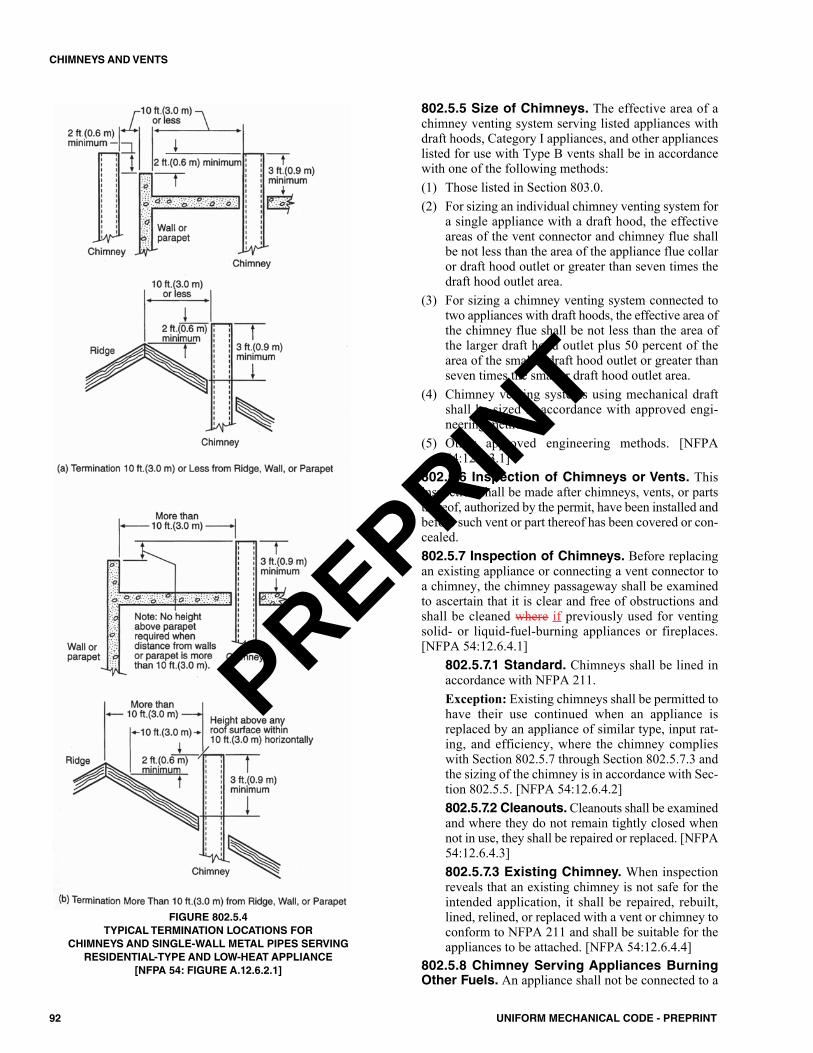
802.5.5 Size of Chimneys. The effective area of achimney venting system serving listed appliances withdraft hoods, Category I appliances, and other applianceslisted for use with Type B vents shall be in accordancewith one of the following methods:(1) Those listed in Section 803.0. (2) For sizing an individual chimney venting system for
a single appliance with a draft hood, the effectiveareas of the vent connector and chimney flue shallbe not less than the area of the appliance flue collaror draft hood outlet or greater than seven times thedraft hood outlet area.
(3) For sizing a chimney venting system connected totwo appliances with draft hoods, the effective area ofthe chimney flue shall be not less than the area ofthe larger draft hood outlet plus 50 percent of thearea of the smaller draft hood outlet or greater thanseven times the smaller draft hood outlet area.
(4) Chimney venting systems using mechanical draftshall be sized in accordance with approved engi-neering methods.
(5) Other approved engineering methods. [NFPA54:12.6.3.1]
802.5.6 Inspection of Chimneys or Vents. Thisinspection shall be made after chimneys, vents, or partsthereof, authorized by the permit, have been installed andbefore such vent or part thereof has been covered or con-cealed.802.5.7 Inspection of Chimneys. Before replacingan existing appliance or connecting a vent connector toa chimney, the chimney passageway shall be examinedto ascertain that it is clear and free of obstructions andshall be cleaned where if previously used for ventingsolid- or liquid-fuel-burning appliances or fireplaces.[NFPA 54:12.6.4.1]
802.5.7.1 Standard. Chimneys shall be lined inaccordance with NFPA 211.Exception: Existing chimneys shall be permitted tohave their use continued when an appliance isreplaced by an appliance of similar type, input rat-ing, and efficiency, where the chimney complieswith Section 802.5.7 through Section 802.5.7.3 andthe sizing of the chimney is in accordance with Sec-tion 802.5.5. [NFPA 54:12.6.4.2]802.5.7.2 Cleanouts. Cleanouts shall be examinedand where they do not remain tightly closed whennot in use, they shall be repaired or replaced. [NFPA54:12.6.4.3]802.5.7.3 Existing Chimney. When inspectionreveals that an existing chimney is not safe for theintended application, it shall be repaired, rebuilt,lined, relined, or replaced with a vent or chimney toconform to NFPA 211 and shall be suitable for theappliances to be attached. [NFPA 54:12.6.4.4]
802.5.8 Chimney Serving Appliances BurningOther Fuels. An appliance shall not be connected to a
92 UNIFORM MECHANICAL CODE - PREPRINT
CHIMNEYS AND VENTS
FIGURE 802.5.4TYPICAL TERMINATION LOCATIONS FOR
CHIMNEYS AND SINGLE-WALL METAL PIPES SERVINGRESIDENTIAL-TYPE AND LOW-HEAT APPLIANCE
[NFPA 54: FIGURE A.12.6.2.1]
PREPRINT
chimney flue serving a separate appliance designed toburn solid fuel. [NFPA 54:12.6.5.1]
802.5.8.1 Gas and Liquid Fuel-BurningAppliances.Where one chimney serves gas appli-ances and liquid fuel-burning appliances, the appli-ances shall be connected through separate openingsor shall be connected through a single openingwhere joined by a suitable fitting located as close aspractical to the chimney. Where two or more open-ings are provided into one chimney flue, they shallbe at different levels. Where the gas appliance isautomatically controlled, it shall be equipped with asafety shutoff device. [NFPA 54:12.6.5.2]802.5.8.2 Gas and Solid Fuel-Burning Appli-ances. A listed combination gas- and solid- fuel-burning appliance connected to a single chimneyflue shall be equipped with a manual reset device toshut off gas to the main burner in the event of sus-tained backdraft or flue gas spillage. The chimneyflue shall be sized to properly vent the appliance.[NFPA 54:12.6.5.3]802.5.8.3 Combination Gas- and Oil-BurningAppliances. A single chimney flue serving a listedcombination gas- and oil-burning appliance shall besized in accordance with the appliance manufacturer’sinstructions. [NFPA 54:12.6.5.4]
802.5.9 Support of Chimneys. All portions of chim-neys shall be supported for the design and weight of thematerials employed. Listed factory-built chimneys shallbe supported and spaced in accordance with the manu-facturer’s installation instructions. [NFPA 54:12.6.6]802.5.10 Cleanouts. Where a chimney that formerlycarried flue products from liquid or solid fuel-burningappliances is used with an appliance using fuel gas, anaccessible cleanout shall be provided. The cleanout shallhave a tight-fitting cover and be installed so its upper edgeis not less than at least 6 inches (152 mm) below the loweredge of the lowest chimney inlet opening. [NFPA54:12.6.7]802.5.11 Space Surrounding Lining or Vent. Theremaining space surrounding a chimney liner, gas vent,special gas vent, or plastic piping installed within amasonry chimney shall not be used to vent another appli-ance. Exception: The insertion of another liner or vent withinthe chimney as provided in this code and the liner or ventmanufacturer’s instructions. [NFPA 54:12.6.8.1]
802.5.11.1 Combustion Air. The remaining spacesurrounding a chimney liner, gas vent, special gasvent, or plastic piping installed within a masonry,metal or factory-built chimney flue shall not be usedto supply combustion air. Exception: Direct- vent appliances designed forinstallation in a solid-fuel-burning fireplace where
installed in accordance with the manufacturer’sinstallation instructions. [NFPA 54:12.6.8.2]
802.6 Gas Vents. The installation of gas vents shall meetthe following requirements:(1) Gas vents shall be installed in accordance with the man-
ufacturer’s installation instructions.(2) A Type B-W gas vent shall have a listed capacity not less
than that of the listed vented wall furnace to which it isconnected.
(3) Gas vents installed within masonry chimneys shall beinstalled in accordance with the manufacturer’s installa-tion instructions. Gas vents installed within masonrychimneys shall be identified with a permanent labelinstalled at the point where the vent enters the chimney.The label shall contain the following language: “This gasvent is for appliances that burn gas. Do not connect tosolid or liquid fuel–burning appliances or incinerators.”
(4) Screws, rivets, and other fasteners shall not penetrate theinner wall of double-wall gas vents, except at the transi-tion from the appliance draft hood outlet, flue collar, orsingle-wall metal connector to a double-wall vent.[NFPA 54:12.7.2]802.6.1 Gas Vent Termination. The termination of gasvents shall comply with the following requirements:(1) A gas vent shall terminate in accordance with one
of the following:(a) Gas vents that are 12 inches (300 mm) or less in
size and located not less than 8 feet (2438 mm)from a vertical wall or similar obstruction shallterminate above the roof in accordance withFigure 802.6.1 and Table 802.6.1.
(b) Gas vents that are over 12 inches (300 mm) insize or are located less than 8 feet (2438 mm)from a vertical wall or similar obstruction shallterminate not less than 2 feet (610 mm) abovethe highest point where they pass through theroof and not less than 2 feet (610 mm) above aportion of a building within 10 feet (3048 mm)horizontally.
(c) Industrial appliances as provided in Section802.2.5.
(d) Direct vent systems as provided in Section802.2.6.
(e) Appliances with integral vents as provided inSection 802.2.7.
(f) Mechanical draft systems as provided in Sec-tion 802.3.3 through Section 802.3.3.5.
(g) Ventilating hoods and exhaust systems as pro-vided in Section 802.3.4.
(2) A Type B or a Type L gas vent shall terminate atleast 5 feet (1524 mm) in vertical height above thehighest connected appliance draft hood or flue col-lar.
93UNIFORM MECHANICAL CODE - PREPRINT
CHIMNEYS AND VENTS
PREPRINT
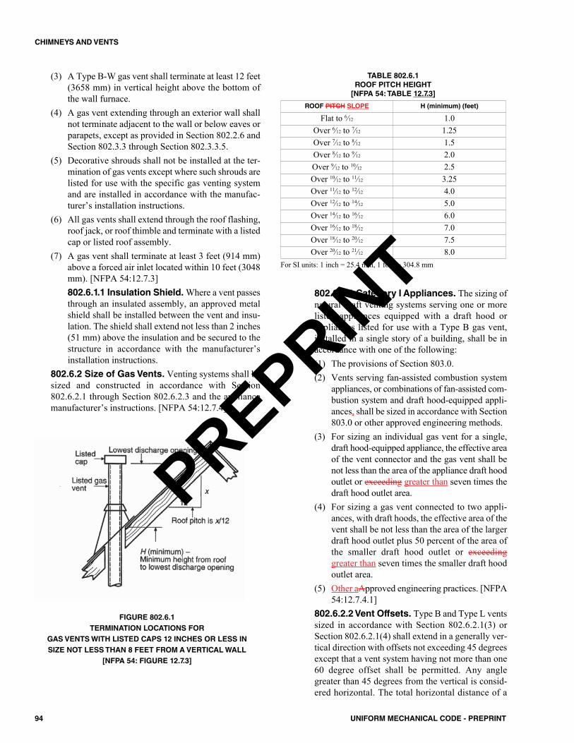
(3) A Type B-W gas vent shall terminate at least 12 feet(3658 mm) in vertical height above the bottom ofthe wall furnace.
(4) A gas vent extending through an exterior wall shallnot terminate adjacent to the wall or below eaves orparapets, except as provided in Section 802.2.6 andSection 802.3.3 through Section 802.3.3.5.
(5) Decorative shrouds shall not be installed at the ter-mination of gas vents except where such shrouds arelisted for use with the specific gas venting systemand are installed in accordance with the manufac-turer’s installation instructions.
(6) All gas vents shall extend through the roof flashing,roof jack, or roof thimble and terminate with a listedcap or listed roof assembly.
(7) A gas vent shall terminate at least 3 feet (914 mm)above a forced air inlet located within 10 feet (3048mm). [NFPA 54:12.7.3]802.6.1.1 Insulation Shield.Where a vent passesthrough an insulated assembly, an approved metalshield shall be installed between the vent and insu-lation. The shield shall extend not less than 2 inches(51 mm) above the insulation and be secured to thestructure in accordance with the manufacturer’sinstallation instructions.
802.6.2 Size of Gas Vents. Venting systems shall besized and constructed in accordance with Section802.6.2.1 through Section 802.6.2.3 and the appliancemanufacturer’s instructions. [NFPA 54:12.7.4]
FIGURE 802.6.1TERMINATION LOCATIONS FOR
GAS VENTS WITH LISTED CAPS 12 INCHES OR LESS INSIZE NOT LESS THAN 8 FEET FROM A VERTICAL WALL
[NFPA 54: FIGURE 12.7.3]
802.6.2.1 Category I Appliances. The sizing ofnatural draft venting systems serving one or morelisted appliances equipped with a draft hood orappliances listed for use with a Type B gas vent,installed in a single story of a building, shall be inaccordance with one of the following:(1) The provisions of Section 803.0. (2) Vents serving fan-assisted combustion system
appliances, or combinations of fan-assisted com-bustion system and draft hood-equipped appli-ances, shall be sized in accordance with Section803.0 or other approved engineering methods.
(3) For sizing an individual gas vent for a single,draft hood-equipped appliance, the effective areaof the vent connector and the gas vent shall benot less than the area of the appliance draft hoodoutlet or exceeding greater than seven times thedraft hood outlet area.
(4) For sizing a gas vent connected to two appli-ances, with draft hoods, the effective area of thevent shall be not less than the area of the largerdraft hood outlet plus 50 percent of the area ofthe smaller draft hood outlet or exceedinggreater than seven times the smaller draft hoodoutlet area.
(5) Other aApproved engineering practices. [NFPA54:12.7.4.1]
802.6.2.2 Vent Offsets. Type B and Type L ventssized in accordance with Section 802.6.2.1(3) orSection 802.6.2.1(4) shall extend in a generally ver-tical direction with offsets not exceeding 45 degreesexcept that a vent system having not more than one60 degree offset shall be permitted. Any anglegreater than 45 degrees from the vertical is consid-ered horizontal. The total horizontal distance of a
TABLE 802.6.1ROOF PITCH HEIGHT[NFPA 54: TABLE 12.7.3]
For SI units: 1 inch = 25.4 mm, 1 foot = 304.8 mm
ROOF PITCH SLOPE H (minimum) (feet)
Flat to 6⁄12 1.0Over 6⁄12 to 7⁄12 1.25Over 7⁄12 to 8⁄12 1.5Over 8⁄12 to 9⁄12 2.0Over 9⁄12 to 10⁄12 2.5Over 10⁄12 to 11⁄12 3.25Over 11⁄12 to 12⁄12 4.0Over 12⁄12 to 14⁄12 5.0Over 14⁄12 to 16⁄12 6.0Over 16⁄12 to 18⁄12 7.0Over 18⁄12 to 20⁄12 7.5Over 20⁄12 to 21⁄12 8.0
94 UNIFORM MECHANICAL CODE - PREPRINT
CHIMNEYS AND VENTS
PREPRINT
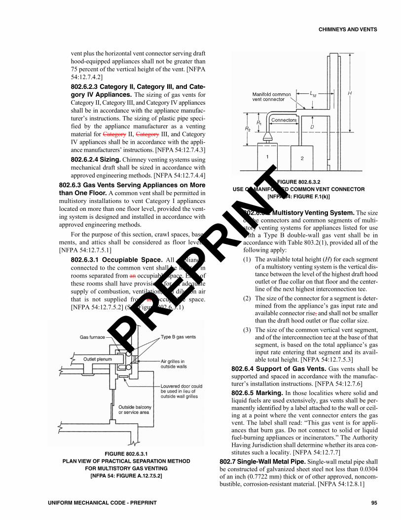
vent plus the horizontal vent connector serving drafthood-equipped appliances shall not be greater than75 percent of the vertical height of the vent. [NFPA54:12.7.4.2]802.6.2.3 Category II, Category III, and Cate-gory IV Appliances. The sizing of gas vents forCategory II, Category III, and Category IV appliancesshall be in accordance with the appliance manufac-turer’s instructions. The sizing of plastic pipe speci-fied by the appliance manufacturer as a ventingmaterial for Category II, Category III, and CategoryIV appliances shall be in accordance with the appli-ance manufacturers’ instructions. [NFPA 54:12.7.4.3]802.6.2.4 Sizing. Chimney venting systems usingmechanical draft shall be sized in accordance withapproved engineering methods. [NFPA 54:12.7.4.4]
802.6.3 Gas Vents Serving Appliances on Morethan One Floor. A common vent shall be permitted inmultistory installations to vent Category I applianceslocated on more than one floor level, provided the vent-ing system is designed and installed in accordance withapproved engineering methods.
For the purpose of this section, crawl spaces, base-ments, and attics shall be considered as floor levels.[NFPA 54:12.7.5.1]
802.6.3.1 Occupiable Space. All appliancesconnected to the common vent shall be located inrooms separated from an occupiable space. Each ofthese rooms shall have provisions for an adequatesupply of combustion, ventilation, and dilution airthat is not supplied from an occupiable space.[NFPA 54:12.7.5.2] (See Figure 802.6.3.1)
FIGURE 802.6.3.1PLAN VIEW OF PRACTICAL SEPARATION METHOD
FOR MULTISTORY GAS VENTING[NFPA 54: FIGURE A.12.7.5.2]
FIGURE 802.6.3.2USE OF MANIFOLDED COMMON VENT CONNECTOR
[NFPA 54: FIGURE F.1(k)]
802.6.3.2 Multistory Venting System. The sizeof the connectors and common segments of multi-story venting systems for appliances listed for usewith a Type B double-wall gas vent shall be inaccordance with Table 803.2(1), provided all of thefollowing apply:(1) The available total height (H) for each segment
of a multistory venting system is the vertical dis-tance between the level of the highest draft hoodoutlet or flue collar on that floor and the center-line of the next highest interconnection tee.
(2) The size of the connector for a segment is deter-mined from the appliance’s gas input rate andavailable connector rise, and shall not be smallerthan the draft hood outlet or flue collar size.
(3) The size of the common vertical vent segment,and of the interconnection tee at the base of thatsegment, is based on the total appliance’s gasinput rate entering that segment and its avail-able total height. [NFPA 54:12.7.5.3]
802.6.4 Support of Gas Vents. Gas vents shall besupported and spaced in accordance with the manufac-turer’s installation instructions. [NFPA 54:12.7.6]802.6.5 Marking. In those localities where solid andliquid fuels are used extensively, gas vents shall be per-manently identified by a label attached to the wall or ceil-ing at a point where the vent connector enters the gasvent. The label shall read: “This gas vent is for appli-ances that burn gas. Do not connect to solid or liquidfuel-burning appliances or incinerators.” The AuthorityHaving Jurisdiction shall determine whether its area con-stitutes such a locality. [NFPA 54:12.7.7]
802.7 Single-Wall Metal Pipe. Single-wall metal pipe shallbe constructed of galvanized sheet steel not less than 0.0304of an inch (0.7722 mm) thick or of other approved, noncom-bustible, corrosion-resistant material. [NFPA 54:12.8.1]
95UNIFORM MECHANICAL CODE - PREPRINT
CHIMNEYS AND VENTS
PREPRINT
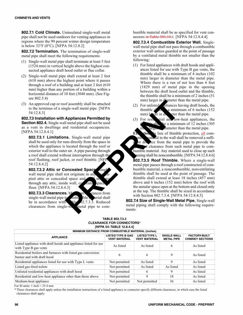
802.7.1 Cold Climate. Uninsulated single-wall metalpipe shall not be used outdoors for venting appliances inregions where the 99 percent winter design temperatureis below 32°F (0°C). [NFPA 54:12.8.2]802.7.2 Termination. The termination of single-wallmetal pipe shall meet the following requirements:(1) Single-wall metal pipe shall terminate at least 5 feet
(1524 mm) in vertical height above the highest con-nected appliance draft hood outlet or flue collar.
(2) Single-wall metal pipe shall extend at least 2 feet(610 mm) above the highest point where it passesthrough a roof of a building and at least 2 feet (610mm) higher than any portion of a building within ahorizontal distance of 10 feet (3048 mm). (See Fig-ure 802.5.4)
(3) An approved cap or roof assembly shall be attachedto the terminus of a single-wall metal pipe. [NFPA54:12.8.3]
802.7.3 Installation with Appliances Permitted bySection 802.4. Single-wall metal pipe shall not be usedas a vent in dwellings and residential occupancies.[NFPA 54:12.8.4.1]
802.7.3.1 Limitations. Single-wall metal pipeshall be used only for runs directly from the space inwhich the appliance is located through the roof orexterior wall to the outer air. A pipe passing througha roof shall extend without interruption through theroof flashing, roof jacket, or roof thimble. [NFPA54:12.8.4.2]802.7.3.2 Attic or Concealed Space. Single-wall metal pipe shall not originate in any unoccu-pied attic or concealed space and shall not passthrough any attic, inside wall, concealed space, orfloor. [NFPA 54:12.8.4.3]802.7.3.3 Clearances.Minimum clearances fromsingle-wall metal pipe to combustible material shallbe in accordance with Table 802.7.3.3. Reducedclearances from single-wall metal pipe to com-
bustible material shall be as specified for vent con-nectors in Table 303.10.1. [NFPA 54:12.8.4.4]802.7.3.4 Combustible Exterior Wall. Single-wall metal pipe shall not pass through a combustibleexterior wall unless guarded at the point of passageby a ventilated metal thimble not smaller than thefollowing: (1) For listed appliances with draft hoods and appli-
ances listed for use with Type B gas vents, thethimble shall be a minimum of 4 inches (102mm) larger in diameter than the metal pipe.Where there is a run of not less than 6 feet(1829 mm) of metal pipe in the openingbetween the draft hood outlet and the thimble,the thimble shall be a minimum of 2 inches (51mm) larger in diameter than the metal pipe.
(2) For unlisted appliances having draft hoods, thethimble shall be a minimum of 6 inches (152mm) larger in diameter than the metal pipe.
(3) For residential and low-heat appliances, thethimble shall be a minimum of 12 inches (305mm) larger in diameter than the metal pipe.
Exception: In lieu of thimble protection, all com-bustible material in the wall shall be removed a suffi-cient distance from the metal pipe to provide thespecified clearance from such metal pipe to com-bustible material. Any material used to close up suchopening shall be noncombustible. [NFPA 54:12.8.4.6]802.7.3.5 Roof Thimble. Where a single-wallmetal pipe passes through a roof constructed of com-bustible material, a noncombustible, nonventilatingthimble shall be used at the point of passage. Thethimble shall extend at least 18 inches (457 mm)above and 6 inches (152 mm) below the roof withthe annular space open at the bottom and closed onlyat the top. The thimble shall be sized in accordancewith Section 802.7.3.4. [NFPA 54:12.8.4.5]
802.7.4 Size of Single-Wall Metal Pipe. Single-wallmetal piping shall comply with the following require-ments:
96 UNIFORM MECHANICAL CODE - PREPRINT
CHIMNEYS AND VENTS
MINIMUM DISTANCE FROM COMBUSTIBLE MATERIAL (inches)
APPLIANCELISTED TYPE B GASVENT MATERIAL
LISTED TYPE LVENT MATERIAL
SINGLE-WALLMETAL PIPE
FACTORY-BUILTCHIMNEY SECTIONS
Listed appliance with draft hoods and appliance listed for usewith Type B gas vents As listed As listed 6 As listed
Residential boilers and furnaces with listed gas conversionburner and with draft hood 6 6 9 As listed
Residential appliances listed for use with Type L vents Not permitted As listed 9 As listedListed gas-fired toilets Not permitted As listed As listed As listedUnlisted residential appliances with draft hood Not permitted 6 9 As listedResidential and low-heat appliance other than those above Not permitted 9 18 As listedMedium-heat appliance Not permitted Not permitted 36 As listed
TABLE 802.7.3.3 CLEARANCE FOR CONNECTORS*
[NFPA 54: TABLE 12.8.4.4]
For SI units: 1 inch = 25.4 mm* These clearances shall apply unless the installation instructions of a listed appliance or connector specify different clearances, in which case the listed
clearances shall apply.
PREPRINT

(1) A venting system of a single-wall metal pipe shall besized in accordance with one of the following meth-ods and the appliance manufacturer’s instructions: (a) For a draft hood-equipped appliance, in accor-
dance with Section 803.0.(b) For a venting system for a single appliance with
a draft hood, the areas of the connector and thepipe each shall not be less than the area of theappliance flue collar or draft hood outlet,whichever is smaller. The vent area shall not begreater than seven times the draft hood outletarea.
(c) Other approved engineering methods.(2) Where a single-wall metal pipe is used and has a
shape other than round, it shall have an equivalenteffective area equal to the effective area of the roundpipe for which it is substituted and the minimuminternal dimension of the pipe shall be 2 inches (51mm).
(3) The vent cap or a roof assembly shall have a ventingcapacity not less than that of the pipe to which it isattached. [NFPA 54:12.8.5]
802.7.5 Support of Single-Wall Metal Pipe. Allportions of single-wall metal pipe shall be supported forthe design and weight of the material employed. [NFPA54:12.8.6]802.7.6 Marking. Single-wall metal pipe shall complywith the marking provisions of Section 802.6.5. [NFPA54:12.8.7]
802.8 Through-the-Wall Vent Termination. A mechan-ical draft venting system shall terminate at least 3 feet (914mm) above any forced air inlet located within 10 feet (3048mm). (See Figure 802.8)Exceptions:(1) This provision shall not apply to the combustion- air
intake of a direct- vent appliance.(2) This provision shall not apply to the separation of the
integral outdoor- air inlet and flue gas discharge of listedoutdoor appliances. [NFPA 54:12.9.1]802.8.1 Mechanical Draft Venting System. Amechanical draft venting system of other than direct-vent type shall terminate not less than 4 feet (1219 mm)below, 4 feet (1219 mm) horizontally from, or 1 foot(305 mm) above a any door, operable window, or grav-ity air inlet into a any building. The bottom of the ventterminal shall be located not less than at least 12 inches(305 mm) above finished ground level. [NFPA54:12.9.2]802.8.2 Direct- Vent Appliance. The clearances forthrough-the-wall direct vent terminals shall be in accor-dance with Table 802.8.2. The bottom of the vent terminaland the air intake shall be located not less than 12 inches(305 mm) above finished ground level. [NFPA 54:12.9.3]
A
802.8.3 Category I through Category IV and Non-categorized Appliances. Through-the-wall vents forCategory II and Category IV appliances and noncatego-rized condensing appliances shall not terminate overpublic walkways or over an area where condensate orvapor could create a nuisance or hazard or could be detri-mental to the operation of regulators, relief valves, orother equipment. Where local experience indicates thatcondensate is a problem with Category I and CategoryIII appliances, this provision shall also apply.
Drains for condensate shall be installed in accor-dance with the appliance and the vent manufacturer’sinstallation instructions. [NFPA 54:12.9.4]802.8.4 Annular Spaces. Where vents, includingthose for direct- vent appliances or combustion air intakepipes, penetrate outside walls of buildings, the annularspaces around such penetrations shall be permanentlysealed using approved materials to prevent entry of com-bustion products into the building. [NFPA 54:12.9.5]802.8.5 Vent Terminals. Vent systems for CategoryIV appliances that terminate through an outside wall ofa building and discharge flue gases perpendicular to theadjacent wall shall be located not less than 10 feet (3048mm) horizontally from an operable opening in an adja-cent building. Exception: This shall not apply to vent terminals that are2 feet (610 mm) or more above or 25 feet (7620 mm) ormore below operable openings. [NFPA 54:12.9.6]
802.9 Condensation Drain. Provision shall be made tocollect and dispose of condensate from venting systems serv-ing Category II and Category IV appliances and noncatego-rized condensing appliances in accordance with Section802.8.3. [NFPA 54:12.10.1]
802.9.1 Local Experience. Where local experienceindicates that condensation is a problem, provision shall bemade to drain off and dispose of condensate from ventingsystems serving Category I and Category III appliances inaccordance with Section 802.8.3. [NFPA 54:12.10.2]
For SI Units: 1 inch = 25.4 mm, 1000 British thermal units per hour = 0.293kW
TABLE 802.8.2THROUGH-THE-WALL DIRECT VENT TERMINATION
CLEARANCES[NFPA 54: TABLE 12.9.3]
DIRECT VENT APPLIANCEINPUT RATING
THROUGH THE WALL VENTTERMINAL CLEARANCE FROM ANYAIR OPENING INTO A BUILDING
(inches)
10 000 Btu/h and less 6Greater than 10 000 Btu/hand not exceeding 50 000Btu/h
9
Greater than 50 000 Btu/hand not exceeding 150 000Btu/h
12
> 150 000 Btu/h In accordance with the appliancemanufacturer’s instructions and in
no case less than the clearancesspecified in Section 802.8.1.
97UNIFORM MECHANICAL CODE - PREPRINT
CHIMNEYS AND VENTS
PREPRINT
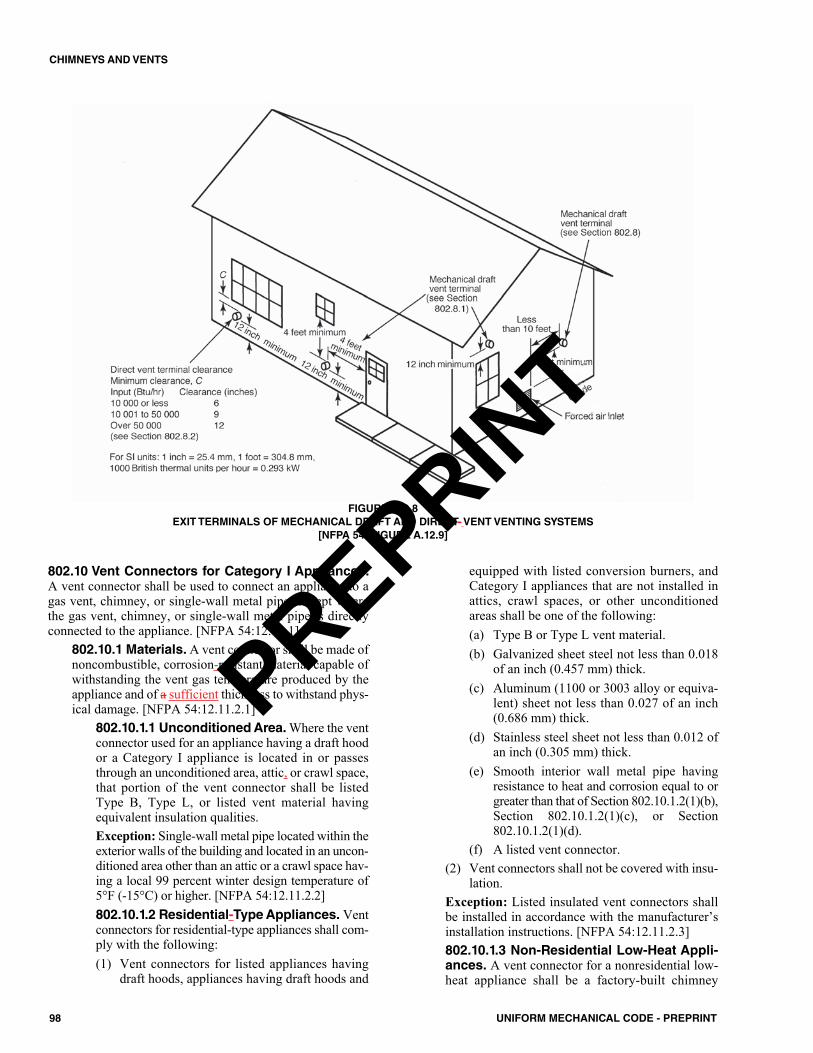
802.10 Vent Connectors for Category I Appliances.A vent connector shall be used to connect an appliance to agas vent, chimney, or single-wall metal pipe, except wherethe gas vent, chimney, or single-wall metal pipe is directlyconnected to the appliance. [NFPA 54:12.11.1]
802.10.1 Materials.A vent connector shall be made ofnoncombustible, corrosion-resistant material capable ofwithstanding the vent gas temperature produced by theappliance and of a sufficient thickness to withstand phys-ical damage. [NFPA 54:12.11.2.1]
802.10.1.1 Unconditioned Area. Where the ventconnector used for an appliance having a draft hoodor a Category I appliance is located in or passesthrough an unconditioned area, attic, or crawl space,that portion of the vent connector shall be listedType B, Type L, or listed vent material havingequivalent insulation qualities.Exception: Single-wall metal pipe located within theexterior walls of the building and located in an uncon-ditioned area other than an attic or a crawl space hav-ing a local 99 percent winter design temperature of5°F (-15°C) or higher. [NFPA 54:12.11.2.2]802.10.1.2 Residential-Type Appliances. Ventconnectors for residential-type appliances shall com-ply with the following:(1) Vent connectors for listed appliances having
draft hoods, appliances having draft hoods and
equipped with listed conversion burners, andCategory I appliances that are not installed inattics, crawl spaces, or other unconditionedareas shall be one of the following:(a) Type B or Type L vent material. (b) Galvanized sheet steel not less than 0.018
of an inch (0.457 mm) thick.(c) Aluminum (1100 or 3003 alloy or equiva-
lent) sheet not less than 0.027 of an inch(0.686 mm) thick.
(d) Stainless steel sheet not less than 0.012 ofan inch (0.305 mm) thick.
(e) Smooth interior wall metal pipe havingresistance to heat and corrosion equal to orgreater than that of Section 802.10.1.2(1)(b),Section 802.10.1.2(1)(c), or Section802.10.1.2(1)(d).
(f) A listed vent connector.(2) Vent connectors shall not be covered with insu-
lation. Exception: Listed insulated vent connectors shallbe installed in accordance with the manufacturer’sinstallation instructions. [NFPA 54:12.11.2.3]802.10.1.3 Non-Residential Low-Heat Appli-ances. A vent connector for a nonresidential low-heat appliance shall be a factory-built chimney
98 UNIFORM MECHANICAL CODE - PREPRINT
CHIMNEYS AND VENTS
FIGURE 802.8EXIT TERMINALS OF MECHANICAL DRAFT AND DIRECT- VENT VENTING SYSTEMS
[NFPA 54: FIGURE A.12.9]
PREPRINT
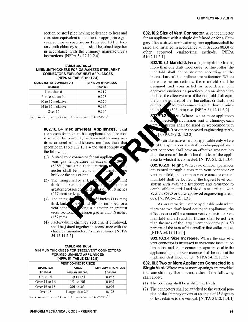
section or steel pipe having resistance to heat andcorrosion equivalent to that for the appropriate gal-vanized pipe as specified in Table 802.10.1.3. Fac-tory-built chimney sections shall be joined togetherin accordance with the chimney manufacturer’sinstructions. [NFPA 54:12.11.2.4]
802.10.1.4 Medium-Heat Appliances. Ventconnectors for medium-heat appliances shall be con-structed of factory-built, medium-heat chimney sec-tions or steel of a thickness not less than thatspecified in Table 802.10.1.4 and shall comply withthe following:(1) A steel vent connector for an appliance with a
vent gas temperature in excess of 1000°F(538°C) measured at the entrance to the con-nector shall be lined with medium-duty firebrick or the equivalent.
(2) The lining shall be at least 21⁄2 inches (64 mm)thick for a vent connector having a diameter orgreatest cross-sectional dimension of 18 inches(457 mm) or less.
(3) The lining shall be at least 41⁄2 inches (114 mm)thick laid on the 41⁄2 inches (114 mm) bed for avent connector having a diameter or greatestcross-sectional dimension greater than 18 inches(457 mm).
(4) Factory-built chimney sections, if employed,shall be joined together in accordance with thechimney manufacturer’s instructions. [NFPA54:12.11.2.5]
802.10.2 Size of Vent Connector. A vent connectorfor an appliance with a single draft hood or for a Cate-gory I fan-assisted combustion system appliance shall besized and installed in accordance with Section 803.0 orother approved engineering methods. [NFPA54:12.11.3.1]
802.10.2.1 Manifold. For a single appliance havingmore than one draft hood outlet or flue collar, themanifold shall be constructed according to theinstructions of the appliance manufacturer. Wherethere are no instructions, the manifold shall bedesigned and constructed in accordance withapproved engineering practices. As an alternativemethod, the effective area of the manifold shall equalthe combined area of the flue collars or draft hoodoutlets, and the vent connectors shall have a mini-mum 1 foot (305 mm) rise. [NFPA 54:12.11.3.2]802.10.2.2 Size. Where two or more appliancesare connected to a common vent or chimney, eachvent connector shall be sized in accordance withSection 803.0 or other approved engineering meth-ods. [NFPA 54:12.11.3.3]
As an alternative method applicable only whereall of the appliances are draft hood-equipped, eachvent connector shall have an effective area not lessthan the area of the draft hood outlet of the appli-ance to which it is connected. [NFPA 54:12.11.3.4]802.10.2.3 Height. Where two or more appliancesare vented through a com mon vent connector orvent manifold, the common vent connector or ventmanifold shall be located at the highest level con-sistent with available headroom and clearance tocombustible material and sized in accordance withSection 803.0 or other approved engineering meth-ods. [NFPA 54:12.11.3.5]
As an alternative method applicable only wherethere are two draft hood-equipped appliances, theeffective area of the common vent connector or ventmanifold and all junction fittings shall be not lessthan the area of the larger vent connector plus 50percent of the area of the smaller flue collar outlet.[NFPA 54:12.11.3.6]802.10.2.4 Size Increase. Where the size of avent connector is increased to overcome installationlimitations and obtain connector capacity equal to theappliance input, the size increase shall be made at theappliance draft hood outlet. [NFPA 54:12.11.3.7]
802.10.3 Two or More Appliances Connected to aSingle Vent. Where two or more openings are providedinto one chimney flue or vent, either of the followingshall apply:(1) The openings shall be at different levels. (2) The connectors shall be attached to the vertical por-
tion of the chimney or vent at an angle of 45 degreesor less relative to the vertical. [NFPA 54:12.11.4.1]
TABLE 802.10.1.4MINIMUM THICKNESS FOR STEEL VENT CONNECTORS
FOR MEDIUM-HEAT APPLIANCES[NFPA 54: TABLE 12.11.2.5]
For SI units: 1 inch = 25.4 mm, 1 square inch = 0.000645 m2
VENT CONNECTOR SIZE
DIAMETER (inches)
AREA (square inches)
MINIMUM THICKNESS(inches)
Up to 14 Up to 154 0.053Over 14 to 16 154 to 201 0.067Over 16 to 18 201 to 254 0.093
Over 18 Larger than 254 0.123
TABLE 802.10.1.3MINIMUM THICKNESS FOR GALVANIZED STEEL VENT
CONNECTORS FOR LOW-HEAT APPLIANCES[NFPA 54: TABLE 12.11.2.4]
DIAMETER OF CONNECTOR(inches)
MINIMUM THICKNESS(inches)
Less than 6 0.0196 to less than 10 0.023
10 to 12 inclusive 0.02914 to 16 inclusive 0.034
Over 16 0.056For SI units: 1 inch = 25.4 mm, 1 square inch = 0.000645 m2
99UNIFORM MECHANICAL CODE - PREPRINT
CHIMNEYS AND VENTS
PREPRINT
802.10.3.1 Height of Connector. Where two ormore vent connectors enter a common vent, chim-ney flue, or single-wall metal pipe, the smaller con-nector shall enter at the highest level consistent withthe available headroom or clearance to combustiblematerial. [NFPA 54:12.11.4.2]802.10.3.2 Pressure. Vent connectors servingCategory I appliances shall not be connected to anyportion of a mechanical draft system operating underpositive static pressure, such as those serving Cate-gory III or Category IV appliances. [NFPA54:12.11.4.3]
802.10.4 Clearance. Minimum clearances from ventconnectors to combustible material shall be in accor-dance with Table 802.7.3.3.Exception: The clearance between a vent connector andcombustible material shall be permitted to be reducedwhere the combustible material is protected as specifiedfor vent connectors in Table 303.10.1. [NFPA 54:12.11.5]802.10.5 Joints. Joints between sections of connectorpiping and connections to flue collars or draft hood out-lets shall be fastened in accordance with one of the fol-lowing methods:(1) Sheet metal screws.(2) Vent connectors of listed vent material assembled
and connected to flue collars or draft hood outlets inaccordance with the manufacturer’s instructions.
(3) Other approved means. [NFPA 54:12.11.6]802.10.6 Slope. A vent connector shall be installedwithout any dips or sags and shall slope upward towardthe vent or chimney at least 1⁄4 inch per foot (20.8 mm/m). Exception: Vent connectors attached to a mechanicaldraft system installed in accordance with appliance andthe draft system manufacturers’ instructions. [NFPA54:12.11.7]802.10.7 Length of Vent Connector. The length ofvent connectors shall comply with Section 802.10.7.1 orSection 802.10.7.2.
802.10.7.1 Single Wall Connector. The maxi-mum horizontal length of a single-wall connectorshall be 75 percent of the height of the chimney orvent, except for engineered systems. [NFPA54:12.11.8.1]802.10.7.2 Type B Double Wall Connector. Themaximum horizontal length of a Type B double-wallconnector shall be 100 percent of the height of thechimney or vent, except for engineered systems. Themaximum length of an individual connector for achimney or vent system serving multiple appliances,from the appliance outlet to the junction with thecommon vent or another connector, shall be 100 per-cent of the height of the chimney or vent. [NFPA54:12.11.8.2]
802.10.8 Support. A vent connector shall be supportedfor the design and weight of the material employed tomaintain clearances and prevent physical damage andseparation of joints. [NFPA 54:12.11.9]
802.10.9 Chimney Connection. Where entering aflue in a masonry or metal chimney, the vent connectorshall be installed above the extreme bottom to avoid stop-page. Where a thimble or slip joint is used to facilitateremoval of the connector, the connector shall be firmlyattached to or inserted into the thimble or slip joint toprevent the connector from falling out. Means shall beemployed to prevent the connector from entering so faras to restrict the space between its end and the oppositewall of the chimney flue. [NFPA 54:12.11.10]802.10.10 Inspection. The entire length of a vent con-nector shall be readily accessible for inspection, clean-ing, and replacement. [NFPA 54:12.11.11]802.10.11 Fireplaces. A vent connector shall not beconnected to a chimney flue serving a fireplace unlessthe fireplace flue opening is permanently sealed. [NFPA54:12.11.12]802.10.12 Passage through Ceilings, Floors, orWalls. A vent connector shall not pass through a ceiling,floor, or fire-resistance-rated wall. A single-wall metalpipe connector shall not pass through an interior wall. Exception: Vent connectors made of listed Type B orType L vent material and serving listed appliances withdraft hoods and other appliances listed for use with TypeB gas vents that pass through walls or partitions con-structed of combustible material shall be installed withnot less than the listed clearance to combustible material.
802.10.12.1 Medium-Heat Appliances. Ventconnectors for medium-heat appliances shall notpass through walls or partitions constructed of com-bustible material. [NFPA 54:12.11.13.2]
802.11 Vent Connectors for Category II, Category III,and Category IV Appliances. The vent connectors forCategory II, Category III, and Category IV appliances shall bein accordance with Section 802.4 through Section 802.4.3.[NFPA 54:12.12]802.12 Draft Hoods and Draft Controls. Vented appli-ances shall be installed with draft hoods.Exception: Dual oven-type combination ranges; incinerators;direct- vent appliances; fan-assisted combustion system appli-ances; appliances requiring chimney draft for operation; sin-gle-firebox boilers equipped with conversion burners withinputs exceeding greater than 400 000 Btu/h (117 kW); appli-ances equipped with blast, power, or pressure burners that arenot listed for use with draft hoods; and appliances designedfor forced venting.[NFPA 54:12.13.1]
802.12.1 Installation. A draft hood supplied with orforming a part of a listed vented appliances shall beinstalled without alteration, exactly as furnished and spec-ified by the appliance manufacturer. [NFPA 54:12.13.2]
Where If a draft hood is not supplied by the appli-ance manufacturer where one is required, a draft hoodshall be installed, be of a listed or approved type, and, inthe absence of other instructions, be of the same size asthe appliance flue collar. Where a draft hood is requiredwith a conversion burner, it shall be of a listed orapproved type. [NFPA 54:12.13.2.1]
100 UNIFORM MECHANICAL CODE - PREPRINT
CHIMNEYS AND VENTS
PREPRINT
Where a draft hood of special design is needed orpreferable, the installation shall be approved and inaccordance with the recommendations of the appliancemanufacturer. [NFPA 54:12.13.2.2]802.12.2 Draft Control Devices. Where a draft con-trol device is part of the appliance or is supplied by theappliance manufacturer, it shall be installed in accor-dance with the manufacturer’s instructions. In theabsence of manufacturer’s instructions, the device shallbe attached to the flue collar of the appliance or as nearto the appliance as practical. [NFPA 54:12.13.3]802.12.3 Additional Devices. Appliances requiringcontrolled chimney draft shall be permitted to be equippedwith listed double-acting barometric draft regulatorsinstalled and adjusted in accordance with the manufac-turer’s instructions. [NFPA 54:12.13.4]802.12.4 Location. Draft hoods and barometric draftregulators shall be installed in the same room or enclo-sure as the appliance in such a manner as to prevent anydifference in pressure between the hood or regulator andthe combustion air supply. [NFPA 54:12.13.5]802.12.5 Positioning. Draft hoods and draft regula-tors shall be installed in the position for which they weredesigned with reference to the horizontal and verticalplanes and shall be located so that the relief opening isnot obstructed by any part of the appliance or adjacentconstruction. The appliance and its draft hood shall belocated so that the relief opening is accessible for check-ing vent operation. [NFPA 54:12.13.6]802.12.6 Clearance. A draft hood shall be located sothat its relief opening is not less than 6 inches (152 mm)from any surface except that of the appliance it servesand the venting system to which the draft hood is con-nected. Where a greater or lesser clearance is indicatedon the appliance label, the clearance shall not be less thanthat specified on the label. Such clearances shall not bereduced. [NFPA 54:12.13.7]
802.13 Manually Operated Dampers. A manually oper-ated damper shall not be placed in any appliance vent con-nector. Fixed baffles shall not be classified as manuallyoperated dampers. [NFPA 54:12.14]802.14 Obstructions. Devices that retard the flow of ventgases shall not be installed in a vent connector, chimney, orvent. The following shall not be considered as obstructions:(1) Draft regulators and safety controls specifically listed for
installation in venting systems and installed in accor-dance with the manufacturer’s installation instructions.
(2) Approved draft regulators and safety controls designedand installed in accordance with approved engineeringmethods.
(3) Listed heat reclaimers and automatically operated ventdampers installed in accordance with the manufacturer’sinstallation instructions.
(4) Vent dampers serving listed appliances installed in accor-dance with Section 803.1 or Section 803.2 or otherapproved engineering methods.
(5) Approved economizers, heat reclaimers, and recupera-tors installed in venting systems of appliances notrequired to be equipped with draft hoods, provided theappliance manufacturer’s instructions cover the installa-tion of such a device in the venting system and perform-ance in accordance with Section 802.3 and Section802.3.1 is obtained. [NFPA 54:12.16]
802.15 Automatically Operated Vent Dampers. Anautomatically operated vent damper shall be of a listed type.[NFPA 54:12.15]
802.15.1 Listing.Automatically operated vent dampersfor oil-fired appliances shall comply with UL 17. Theautomatic damper control shall comply with UL 378.
803.0 Sizing of Category I Venting Systems.803.1 Single Appliance Vent Table 803.1.2(1) throughTable 803.1.2(6). Venting Table 803.1.2(1) through Table803.1.2(6) shall not be used where obstructions are installedin the venting system. The installation of vents serving listedappliances with vent dampers shall be in accordance with theappliance manufacturer’s instructions or in accordance withthe following:(1) The maximum capacity of the vent system shall be deter-
mined using the “NAT Max” column.(2) The minimum capacity shall be determined as though the
appliance were a fan-assisted appliance, using the “FANMin” column to determine the minimum capacity of thevent system. Where the corresponding “FAN Min” is“NA,”, the vent configuration shall not be permitted andan alternative venting configuration shall be utilized.[NFPA 54:13.1.1]803.1.1 Vent Downsizing. Where the vent size deter-mined from the tables is smaller than the appliance drafthood outlet or flue collar, the use of the smaller size shallbe permitted, provided that the installation is in accor-dance complies with all of the following requirements:(1) The total vent height (H) is not less than at least 10
feet (3048 mm).(2) Vents for appliance draft hood outlets or flue collars
12 inches (305mm) in diameter or smaller are notreduced more than one table size.
(3) Vents for appliance draft hood outlets or flue collarsexceeding larger than 12 inches (305 mm) in diam-eter are not reduced more than two table sizes.
(4) The maximum capacity listed in the tables for a fan-assisted appliance is reduced by 10 percent (0.90 xmaximum table capacity).
(5) The draft hood outlet exceeds is greater than 4 inches(102 mm) in diameter. A 3 inch (76 mm) diametervent shall not be connected to a 4 inch (102 mm)diameter draft hood outlet. This provision shall notapply to fan-assisted appliances. [NFPA 54:13.1.2]
803.1.2 Elbows. Single-appliance venting configura-tions with zero (0) lateral lengths in Table 803.1.2(1),Table 803.1.2(2), and Table 803.1.2(5) shall not have
101UNIFORM MECHANICAL CODE - PREPRINT
CHIMNEYS AND VENTS
PREPRINT
elbows in the venting system. Single-appliance ventingwith lateral lengths, include two 90 degree elbows. Foreach additional elbow up to and including 45 degrees,the maximum capacity listed in the venting tables shallbe reduced by 5 percent. For each additional elbowgreater than 45 degrees up to and including 90 degrees,the maximum capacity listed in the venting tables shallbe reduced by 10 percent. Where multiple offsets occurin a vent, the total lateral length of all offsets combinedshall not exceed that specified in Table 803.1.2(1)through Table 803.1.2(5). [NFPA 54:13.1.3]803.1.3 Zero Lateral. Zero (0) lateral (L) shall applyonly to a straight vertical vent attached to a top outletdraft hood or flue collar. [NFPA 54:13.1.4]803.1.4 High-Altitude Installations. Sea level inputratings shall be used where when determining maximumcapacity for high-altitude installation. Actual input (der-ated for altitude) shall be used for determining minimumcapacity for high-altitude installation. [NFPA 54:13.1.5]803.1.5 Multiple Input Ratings. For appliances withmore than one input rate, the minimum vent capacity(FAN Min) determined from the tables Table 803.1.2(1)through Table 803.2(9) shall be less than the lowestappliance input rating, and the maximum vent capacity(FAN Max/NAT Max) determined from the tables shallexceed be greater than the highest appliance rating input.[NFPA 54:13.1.6]803.1.6 Corrugated Chimney Liner Reduction.Listed corrugated metallic chimney liner systems inmasonry chimneys shall be sized by using Table803.1.2(1) or Table 803.1.2(2) for Type B vents, with themaximum capacity reduced by 20 percent (0.80 x maxi-mum capacity) and the minimum capacity as shown inTable 803.1.2(1) or Table 803.1.2(2).
Corrugated metallic liner systems installed withbends or offsets shall have their maximum capacity fur-ther reduced in accordance with Section 803.1.2. The 20percent reduction for corrugated metallic chimney linersystems includes an allowance for one long radius 90degree (1.57 rad) turn at the bottom of the liner. [NFPA54:13.1.7]803.1.7 Connection to Chimney Liners. Connec-tions between chimney liners and listed double-wall con-nectors shall be made with listed adapters designed forsuch purpose. [NFPA 54:13.1.8]803.1.8 Vertical Vent Upsizing Using 7 x Rule.Where the vertical vent has a larger diameter than thevent connector, the vertical vent diameter shall be used todetermine the minimum vent capacity, and the connectordiameter shall be used to determine the maximum ventcapacity. The flow area of the vertical vent shall notexceed seven times the flow area of the listed appliancecategorized vent area, flue collar area, or draft hood out-let area unless designed in accordance with approvedengineering methods. [NFPA 54:13.1.9]
803.1.9 Draft Hood Conversion Accessories.Draft hood conversion accessories for use with masonrychimneys venting listed Category I fan-assisted appli-ances shall be listed and installed in accordance with thelisted accessory manufacturer’s installation instructions.[NFPA 54:13.1.10]803.1.10 Chimney and Vent Locations. Table803.1.2(1) through Table 803.1.2(5) shall be used onlyfor chimneys and vents not exposed to the outdoorsbelow the roof line. A Type B vent or listed chimney lin-ing system passing through an unused masonry chimneyflue shall not be considered to be exposed to the out-doors. Where vents extend outdoors above the roof morethan 5 feet (1524 mm) higher than required by Table802.6.1, and where vents terminate in accordance withSection 802.6.1(2), the outdoor portion of the vent shallbe enclosed as required by this paragraph for vents notconsidered to be exposed to the outdoors, or such vent-ing system shall be engineered. A Type B vent passingthrough an unventilated enclosure or chase insulated to avalue of not less than R8 shall not be considered to beexposed to the outdoors. Table 803.1.2(3) in combina-tion with Table 803.1.2(6) shall be used for clay tile-linedexterior masonry chimneys, provided all of the followingrequirements are met:(1) The vent connector is Type B double wall.(2) The vent connector length is limited to 18 in./in. (18
mm/mm) of vent connector diameter.(3) The appliance is draft hood equipped.(4) The input rating is less than the maximum capacity
given in Table 803.1.2(3).(5) For a water heater, the outdoor design temperature
shall be not be less than 5°F (-15°C).(6) For a space-heating appliance, the input rating is
greater than the minimum capacity given by Table803.1.2(6). [NFPA 54:13.1.11]
803.1.11 Residential and Low-Heat Appliances.Flue lining system for residential and low heat applianceshall be in accordance with Section 803.1.11.1 and Sec-tion 803.1.11.2.
803.1.11.1 Clay Flue Lining. Clay flue liningshall be manufactured in accordance with ASTMC315 or other approved standard.803.1.11.2 Chimney Lining. Chimney lining shallbe listed in accordance with UL 1777.
803.1.12 Corrugated Vent Connector Size. Corru-gated vent connectors shall not be smaller than the listedappliance categorized vent diameter, flue collar diameter,or draft hood outlet diameter. [NFPA 54:13.1.12]803.1.13 Upsizing.Vent connectors shall not be upsizedmore than two sizes exceeding greater than the listedappliance categorized vent diameter, flue collar diameter,or draft hood outlet diameter. [NFPA 54:13.1.13]803.1.14 Single Run of Vent. In a single run of ventor vent connector, more than one diameter and type shallbe permitted to be used, provided that all the sizes andtypes are permitted by the tables. [NFPA 54:13.1.14]
102 UNIFORM MECHANICAL CODE - PREPRINT
CHIMNEYS AND VENTS
PREPRINT
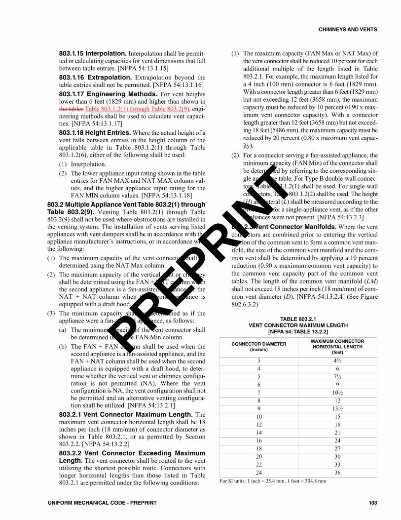
803.1.15 Interpolation. Interpolation shall be permit-ted in calculating capacities for vent dimensions that fallbetween table entries. [NFPA 54:13.1.15]803.1.16 Extrapolation. Extrapolation beyond thetable entries shall not be permitted. [NFPA 54:13.1.16]803.1.17 Engineering Methods. For vent heightslower than 6 feet (1829 mm) and higher than shown inthe tables Table 803.1.2(1) through Table 803.2(9), engi-neering methods shall be used to calculate vent capaci-ties. [NFPA 54:13.1.17]803.1.18 Height Entries. Where the actual height of avent falls between entries in the height column of theapplicable table in Table 803.1.2(1) through Table803.1.2(6), either of the following shall be used:(1) Interpolation.(2) The lower appliance input rating shown in the table
entries for FAN MAX and NAT MAX column val-ues, and the higher appliance input rating for theFAN MIN column values. [NFPA 54:13.1.18]
803.2 Multiple Appliance Vent Table 803.2(1) throughTable 803.2(9). Venting Table 803.2(1) through Table803.2(9) shall not be used where obstructions are installed inthe venting system. The installation of vents serving listedappliances with vent dampers shall be in accordance with theappliance manufacturer’s instructions, or in accordance withthe following: (1) The maximum capacity of the vent connector shall be
determined using the NAT Max column.(2) The maximum capacity of the vertical vent or chimney
shall be determined using the FAN + NAT column whenthe second appliance is a fan-assisted appliance, or theNAT + NAT column when the second appliance isequipped with a draft hood.
(3) The minimum capacity shall be determined as if theappliance were a fan-assisted appliance, as follows:(a) The minimum capacity of the vent connector shall
be determined using the FAN Min column.(b) The FAN + FAN column shall be used when the
second appliance is a fan-assisted appliance, and theFAN + NAT column shall be used when the secondappliance is equipped with a draft hood, to deter-mine whether the vertical vent or chimney configu-ration is not permitted (NA). Where the ventconfiguration is NA, the vent configuration shall notbe permitted and an alternative venting configura-tion shall be utilized. [NFPA 54:13.2.1]
803.2.1 Vent Connector Maximum Length. Themaximum vent connector horizontal length shall be 18inches per inch (18 mm/mm) of connector diameter asshown in Table 803.2.1, or as permitted by Section803.2.2. [NFPA 54:13.2.2]803.2.2 Vent Connector Exceeding MaximumLength. The vent connector shall be routed to the ventutilizing the shortest possible route. Connectors withlonger horizontal lengths than those listed in Table803.2.1 are permitted under the following conditions:
(1) The maximum capacity (FAN Max or NAT Max) ofthe vent connector shall be reduced 10 percent for eachadditional multiple of the length listed in Table803.2.1. For example, the maximum length listed fora 4 inch (100 mm) connector is 6 feet (1829 mm).With a connector length greater than 6 feet (1829 mm)but not exceeding 12 feet (3658 mm), the maximumcapacity must be reduced by 10 percent (0.90 x max-imum vent connector capacity). With a connectorlength greater than 12 feet (3658 mm) but not exceed-ing 18 feet (5486 mm), the maximum capacity must bereduced by 20 percent (0.80 x maximum vent capac-ity).
(2) For a connector serving a fan-assisted appliance, theminimum capacity (FAN Min) of the connector shallbe determined by referring to the corresponding sin-gle appliance table. For Type B double-wall connec-tors, Table 803.1.2(1) shall be used. For single-wallconnectors, Table 803.1.2(2) shall be used. The height(H) and lateral (L) shall be measured according to theprocedures for a single-appliance vent, as if the otherappliances were not present. [NFPA 54:13.2.3]
803.2.3 Vent Connector Manifolds. Where the ventconnectors are combined prior to entering the verticalportion of the common vent to form a common vent man-ifold, the size of the common vent manifold and the com-mon vent shall be determined by applying a 10 percentreduction (0.90 x maximum common vent capacity) tothe common vent capacity part of the common venttables. The length of the common vent manifold (LM)shall not exceed 18 inches per inch (18 mm/mm) of com-mon vent diameter (D). [NFPA 54:13.2.4] (See Figure802.6.3.2)
CONNECTOR DIAMETER(inches)
MAXIMUM CONNECTOR HORIZONTAL LENGTH
(feet)
3 41⁄24 65 71⁄26 97 101⁄28 129 131⁄210 1512 1814 2116 2418 2720 3022 3324 36
TABLE 803.2.1VENT CONNECTOR MAXIMUM LENGTH
[NFPA 54: TABLE 13.2.2]
For SI units: 1 inch = 25.4 mm, 1 foot = 304.8 mm
103UNIFORM MECHANICAL CODE - PREPRINT
CHIMNEYS AND VENTS
PREPRINT
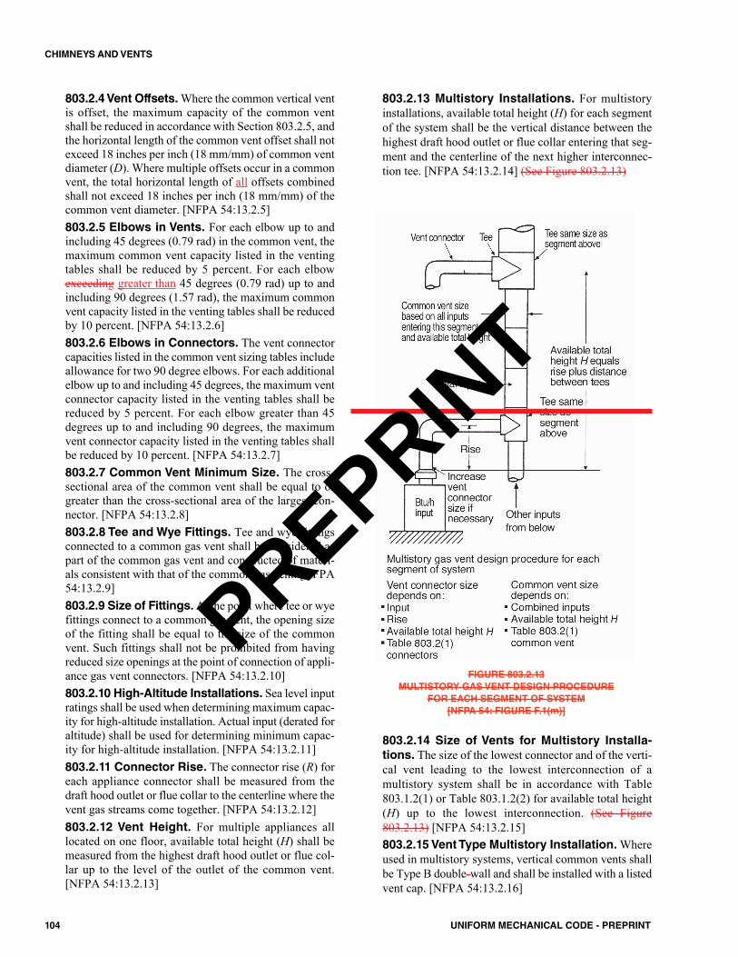
803.2.4 Vent Offsets.Where the common vertical ventis offset, the maximum capacity of the common ventshall be reduced in accordance with Section 803.2.5, andthe horizontal length of the common vent offset shall notexceed 18 inches per inch (18 mm/mm) of common ventdiameter (D). Where multiple offsets occur in a commonvent, the total horizontal length of all offsets combinedshall not exceed 18 inches per inch (18 mm/mm) of thecommon vent diameter. [NFPA 54:13.2.5]803.2.5 Elbows in Vents. For each elbow up to andincluding 45 degrees (0.79 rad) in the common vent, themaximum common vent capacity listed in the ventingtables shall be reduced by 5 percent. For each elbowexceeding greater than 45 degrees (0.79 rad) up to andincluding 90 degrees (1.57 rad), the maximum commonvent capacity listed in the venting tables shall be reducedby 10 percent. [NFPA 54:13.2.6]803.2.6 Elbows in Connectors. The vent connectorcapacities listed in the common vent sizing tables includeallowance for two 90 degree elbows. For each additionalelbow up to and including 45 degrees, the maximum ventconnector capacity listed in the venting tables shall bereduced by 5 percent. For each elbow greater than 45degrees up to and including 90 degrees, the maximumvent connector capacity listed in the venting tables shallbe reduced by 10 percent. [NFPA 54:13.2.7]803.2.7 Common Vent Minimum Size. The cross-sectional area of the common vent shall be equal to orgreater than the cross-sectional area of the largest con-nector. [NFPA 54:13.2.8] 803.2.8 Tee and Wye Fittings. Tee and wye fittingsconnected to a common gas vent shall be considered aspart of the common gas vent and constructed of materi-als consistent with that of the common gas vent. [NFPA54:13.2.9]803.2.9 Size of Fittings. At the point where tee or wyefittings connect to a common gas vent, the opening sizeof the fitting shall be equal to the size of the commonvent. Such fittings shall not be prohibited from havingreduced size openings at the point of connection of appli-ance gas vent connectors. [NFPA 54:13.2.10]803.2.10 High-Altitude Installations. Sea level inputratings shall be used when determining maximum capac-ity for high-altitude installation. Actual input (derated foraltitude) shall be used for determining minimum capac-ity for high-altitude installation. [NFPA 54:13.2.11]803.2.11 Connector Rise. The connector rise (R) foreach appliance connector shall be measured from thedraft hood outlet or flue collar to the centerline where thevent gas streams come together. [NFPA 54:13.2.12]803.2.12 Vent Height. For multiple appliances alllocated on one floor, available total height (H) shall bemeasured from the highest draft hood outlet or flue col-lar up to the level of the outlet of the common vent.[NFPA 54:13.2.13]
803.2.13 Multistory Installations. For multistoryinstallations, available total height (H) for each segmentof the system shall be the vertical distance between thehighest draft hood outlet or flue collar entering that seg-ment and the centerline of the next higher interconnec-tion tee. [NFPA 54:13.2.14] (See Figure 803.2.13)
FIGURE 803.2.13MULTISTORY GAS VENT DESIGN PROCEDURE
FOR EACH SEGMENT OF SYSTEM[NFPA 54: FIGURE F.1(m)]
803.2.14 Size of Vents for Multistory Installa-tions. The size of the lowest connector and of the verti-cal vent leading to the lowest interconnection of amultistory system shall be in accordance with Table803.1.2(1) or Table 803.1.2(2) for available total height(H) up to the lowest interconnection. (See Figure803.2.13) [NFPA 54:13.2.15]803.2.15 Vent Type Multistory Installation.Whereused in multistory systems, vertical common vents shallbe Type B double-wall and shall be installed with a listedvent cap. [NFPA 54:13.2.16]
104 UNIFORM MECHANICAL CODE - PREPRINT
CHIMNEYS AND VENTS
PREPRINT
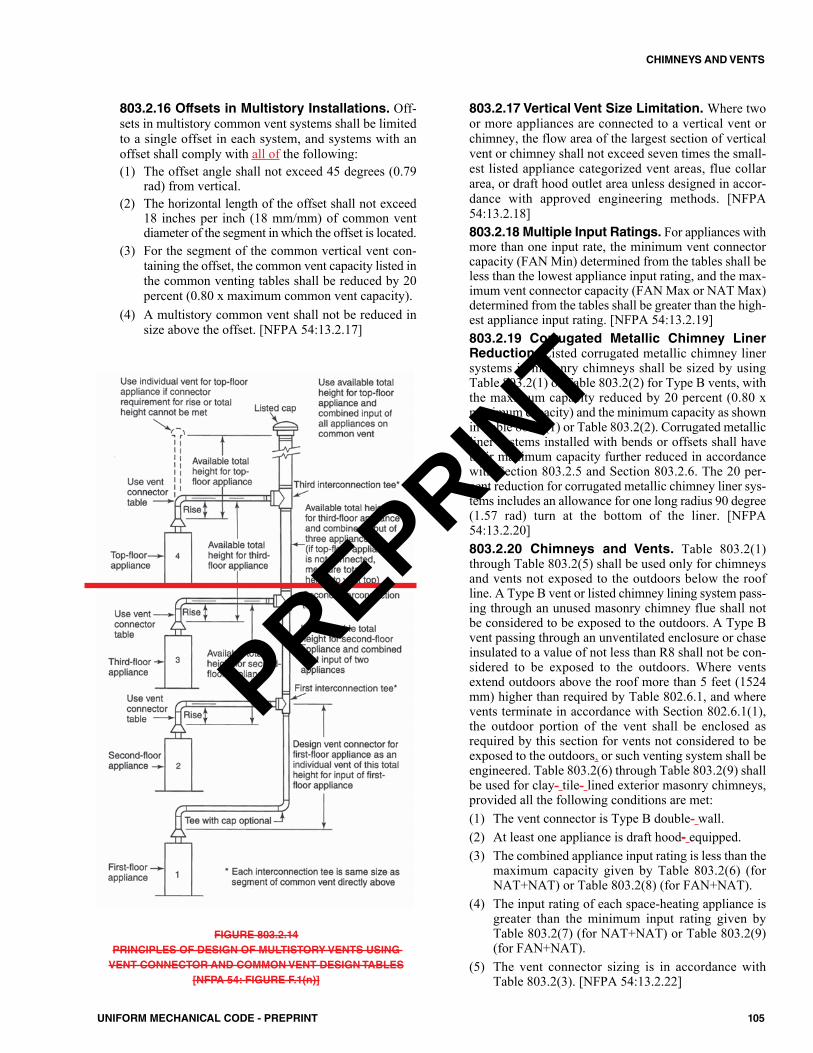
803.2.16 Offsets in Multistory Installations. Off-sets in multistory common vent systems shall be limitedto a single offset in each system, and systems with anoffset shall comply with all of the following: (1) The offset angle shall not exceed 45 degrees (0.79
rad) from vertical.(2) The horizontal length of the offset shall not exceed
18 inches per inch (18 mm/mm) of common ventdiameter of the segment in which the offset is located.
(3) For the segment of the common vertical vent con-taining the offset, the common vent capacity listed inthe common venting tables shall be reduced by 20percent (0.80 x maximum common vent capacity).
(4) A multistory common vent shall not be reduced insize above the offset. [NFPA 54:13.2.17]
FIGURE 803.2.14PRINCIPLES OF DESIGN OF MULTISTORY VENTS USING VENT CONNECTOR AND COMMON VENT DESIGN TABLES
[NFPA 54: FIGURE F.1(n)]
803.2.17 Vertical Vent Size Limitation. Where twoor more appliances are connected to a vertical vent orchimney, the flow area of the largest section of verticalvent or chimney shall not exceed seven times the small-est listed appliance categorized vent areas, flue collararea, or draft hood outlet area unless designed in accor-dance with approved engineering methods. [NFPA54:13.2.18]803.2.18 Multiple Input Ratings. For appliances withmore than one input rate, the minimum vent connectorcapacity (FAN Min) determined from the tables shall beless than the lowest appliance input rating, and the max-imum vent connector capacity (FAN Max or NAT Max)determined from the tables shall be greater than the high-est appliance input rating. [NFPA 54:13.2.19]803.2.19 Corrugated Metallic Chimney LinerReduction. Listed corrugated metallic chimney linersystems in masonry chimneys shall be sized by usingTable 803.2(1) or Table 803.2(2) for Type B vents, withthe maximum capacity reduced by 20 percent (0.80 xmaximum capacity) and the minimum capacity as shownin Table 803.2(1) or Table 803.2(2). Corrugated metallicliner systems installed with bends or offsets shall havetheir maximum capacity further reduced in accordancewith Section 803.2.5 and Section 803.2.6. The 20 per-cent reduction for corrugated metallic chimney liner sys-tems includes an allowance for one long radius 90 degree(1.57 rad) turn at the bottom of the liner. [NFPA54:13.2.20]803.2.20 Chimneys and Vents. Table 803.2(1)through Table 803.2(5) shall be used only for chimneysand vents not exposed to the outdoors below the roofline. A Type B vent or listed chimney lining system pass-ing through an unused masonry chimney flue shall notbe considered to be exposed to the outdoors. A Type Bvent passing through an unventilated enclosure or chaseinsulated to a value of not less than R8 shall not be con-sidered to be exposed to the outdoors. Where ventsextend outdoors above the roof more than 5 feet (1524mm) higher than required by Table 802.6.1, and wherevents terminate in accordance with Section 802.6.1(1),the outdoor portion of the vent shall be enclosed asrequired by this section for vents not considered to beexposed to the outdoors, or such venting system shall beengineered. Table 803.2(6) through Table 803.2(9) shallbe used for clay- tile- lined exterior masonry chimneys,provided all the following conditions are met: (1) The vent connector is Type B double- wall.(2) At least one appliance is draft hood- equipped.(3) The combined appliance input rating is less than the
maximum capacity given by Table 803.2(6) (forNAT+NAT) or Table 803.2(8) (for FAN+NAT).
(4) The input rating of each space-heating appliance isgreater than the minimum input rating given byTable 803.2(7) (for NAT+NAT) or Table 803.2(9)(for FAN+NAT).
(5) The vent connector sizing is in accordance withTable 803.2(3). [NFPA 54:13.2.22]
105UNIFORM MECHANICAL CODE - PREPRINT
CHIMNEYS AND VENTS
PREPRINT
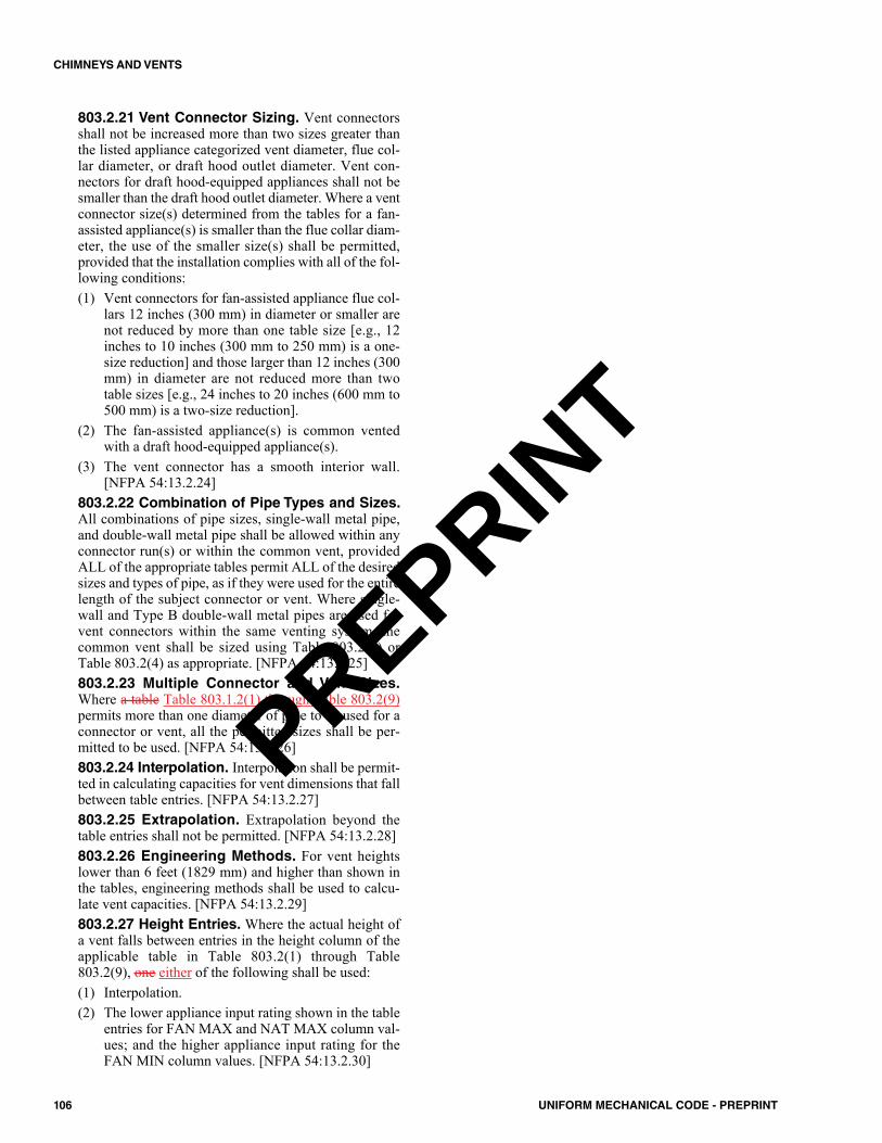
803.2.21 Vent Connector Sizing. Vent connectorsshall not be increased more than two sizes greater thanthe listed appliance categorized vent diameter, flue col-lar diameter, or draft hood outlet diameter. Vent con-nectors for draft hood-equipped appliances shall not besmaller than the draft hood outlet diameter. Where a ventconnector size(s) determined from the tables for a fan-assisted appliance(s) is smaller than the flue collar diam-eter, the use of the smaller size(s) shall be permitted,provided that the installation complies with all of the fol-lowing conditions: (1) Vent connectors for fan-assisted appliance flue col-
lars 12 inches (300 mm) in diameter or smaller arenot reduced by more than one table size [e.g., 12inches to 10 inches (300 mm to 250 mm) is a one-size reduction] and those larger than 12 inches (300mm) in diameter are not reduced more than twotable sizes [e.g., 24 inches to 20 inches (600 mm to500 mm) is a two-size reduction].
(2) The fan-assisted appliance(s) is common ventedwith a draft hood-equipped appliance(s).
(3) The vent connector has a smooth interior wall.[NFPA 54:13.2.24]
803.2.22 Combination of Pipe Types and Sizes.All combinations of pipe sizes, single-wall metal pipe,and double-wall metal pipe shall be allowed within anyconnector run(s) or within the common vent, providedALL of the appropriate tables permit ALL of the desiredsizes and types of pipe, as if they were used for the entirelength of the subject connector or vent. Where single-wall and Type B double-wall metal pipes are used forvent connectors within the same venting system, thecommon vent shall be sized using Table 803.2(2) orTable 803.2(4) as appropriate. [NFPA 54:13.2.25]803.2.23 Multiple Connector and Vent Sizes.Where a table Table 803.1.2(1) through Table 803.2(9)permits more than one diameter of pipe to be used for aconnector or vent, all the permitted sizes shall be per-mitted to be used. [NFPA 54:13.2.26]803.2.24 Interpolation. Interpolation shall be permit-ted in calculating capacities for vent dimensions that fallbetween table entries. [NFPA 54:13.2.27]803.2.25 Extrapolation. Extrapolation beyond thetable entries shall not be permitted. [NFPA 54:13.2.28]803.2.26 Engineering Methods. For vent heightslower than 6 feet (1829 mm) and higher than shown inthe tables, engineering methods shall be used to calcu-late vent capacities. [NFPA 54:13.2.29]803.2.27 Height Entries. Where the actual height ofa vent falls between entries in the height column of theapplicable table in Table 803.2(1) through Table803.2(9), one either of the following shall be used:(1) Interpolation.(2) The lower appliance input rating shown in the table
entries for FAN MAX and NAT MAX column val-ues; and the higher appliance input rating for theFAN MIN column values. [NFPA 54:13.2.30]
106 UNIFORM MECHANICAL CODE - PREPRINT
CHIMNEYS AND VENTS
PREPRINT
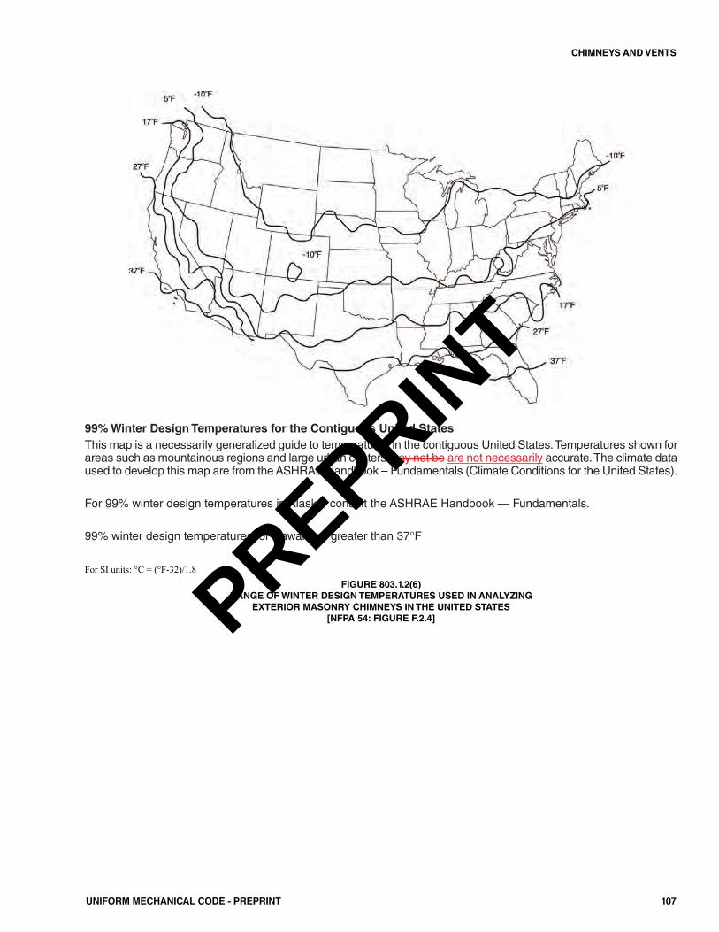
107UNIFORM MECHANICAL CODE - PREPRINT
CHIMNEYS AND VENTS
99% Winter Design Temperatures for the Contiguous United StatesThis map is a necessarily generalized guide to temperatures in the contiguous United States. Temperatures shown forareas such as mountainous regions and large urban centers may not be are not necessarily accurate. The climate dataused to develop this map are from the ASHRAE Handbook – Fundamentals (Climate Conditions for the United States).
For 99% winter design temperatures in Alaska, consult the ASHRAE Handbook — Fundamentals.
99% winter design temperatures for Hawaii are greater than 37°F
For SI units: °C = (°F-32)/1.8FIGURE 803.1.2(6)
RANGE OF WINTER DESIGN TEMPERATURES USED IN ANALYZING EXTERIOR MASONRY CHIMNEYS IN THE UNITED STATES
[NFPA 54: FIGURE F.2.4]PREPRINT
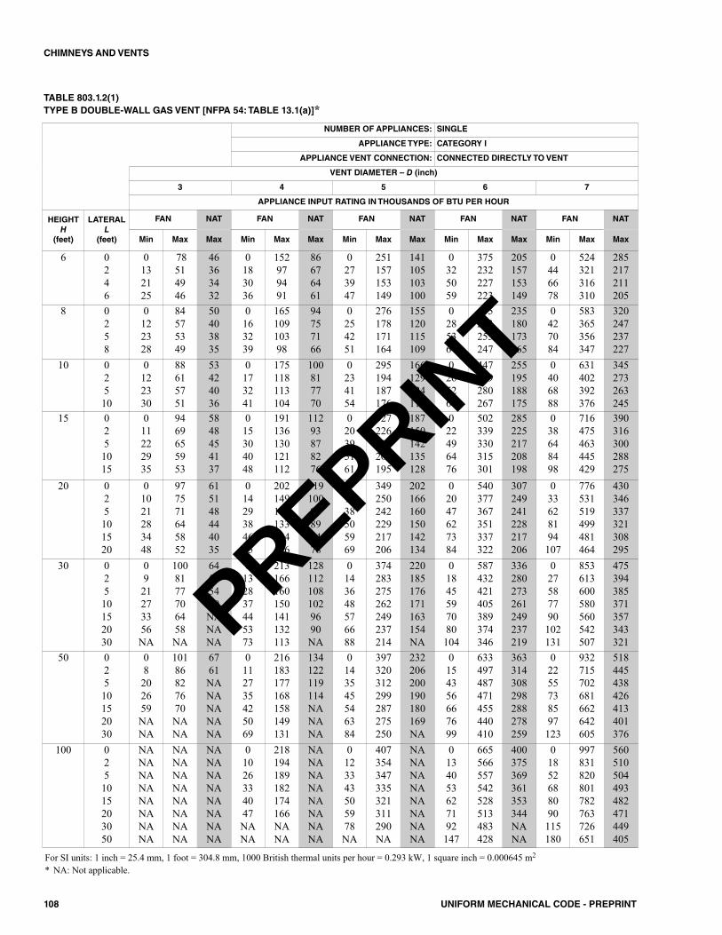
108 UNIFORM MECHANICAL CODE - PREPRINT
CHIMNEYS AND VENTS
NUMBER OF APPLIANCES: SINGLE
APPLIANCE TYPE: CATEGORY I
APPLIANCE VENT CONNECTION: CONNECTED DIRECTLY TO VENT
VENT DIAMETER – D (inch)
3 4 5 6 7
APPLIANCE INPUT RATING IN THOUSANDS OF BTU PER HOUR
HEIGHTH
(feet)
LATERALL
(feet)
FAN NAT FAN NAT FAN NAT FAN NAT FAN NAT
Min Max Max Min Max Max Min Max Max Min Max Max Min Max Max
6 0246
0132125
78514946
46363432
0183036
152979491
86676461
0273947
251157153149
141105103100
0325059
375232227223
205157153149
0446678
524321316310
285217211205
8 0258
0122328
84575349
50403835
0163239
16510910398
94757166
0254251
276178171164
155120115109
0285364
415263255247
235180173165
0427084
583365356347
320247237227
10 02510
0122330
88615751
53424036
0173241
175118113104
100817770
0234154
295194187176
166129124115
0265267
447289280267
255195188175
0406888
631402392376
345273263245
15 0251015
011222935
9469655953
5848454137
015304048
191136130121112
11293878276
020395161
327226219206195
187150142135128
022496476
502339330315301
285225217208198
038648498
716475463445429
390316300288275
20 025101520
01021283448
977571645852
615148444035
01429384655
202149143133124116
11910096898478
01838505969
349250242229217206
202166160150142134
02047627384
540377367351337322
307249241228217206
033628194107
776531519499481464
430346337321308295
30 02510152030
0921273356NA
1008177706458NA
64565450NANANA
0132837445373
213166160150141132113
1281121081029690NA
0143648576688
374283275262249237214
220185176171163154NA
01845597080104
587432421405389374346
336280273261249237219
027587790102131
853613600580560542507
475394385371357343321
50 02510152030
08202659NANA
10186827670NANA
6761NANANANANA
0112735425069
216183177168158149131
134122119114NANANA
0143545546384
397320312299287275250
232206200190180169NA
0154356667699
633497487471455440410
363314308298288278259
02255738597123
932715702681662642605
518445438426413401376
100 0251015203050
NANANANANANANANA
NANANANANANANANA
NANANANANANANANA
01026334047NANA
218194189182174166NANA
NANANANANANANANA
0123343505978NA
407354347335321311290NA
NANANANANANANANA
0134053627192147
665566557542528513483428
400375369361353344NANA
01852688090115180
997831820801782763726651
560510504493482471449405
For SI units: 1 inch = 25.4 mm, 1 foot = 304.8 mm, 1000 British thermal units per hour = 0.293 kW, 1 square inch = 0.000645 m2
* NA: Not applicable.
TABLE 803.1.2(1)TYPE B DOUBLE-WALL GAS VENT [NFPA 54: TABLE 13.1(a)]*
PREPRINT
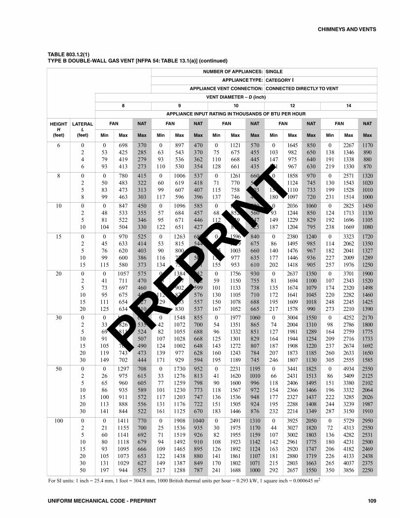
109UNIFORM MECHANICAL CODE - PREPRINT
CHIMNEYS AND VENTS
TABLE 803.1.2(1)TYPE B DOUBLE-WALL GAS VENT [NFPA 54: TABLE 13.1(a)] (continued)
NUMBER OF APPLIANCES: SINGLE
APPLIANCE TYPE: CATEGORY I
APPLIANCE VENT CONNECTION: CONNECTED DIRECTLY TO VENT
VENT DIAMETER – D (inch)
8 9 10 12 14
APPLIANCE INPUT RATING IN THOUSANDS OF BTU PER HOUR
HEIGHTH
(feet)
LATERALL
(feet)
FAN NAT FAN NAT FAN NAT FAN NAT FAN NAT
Min Max Max Min Max Max Min Max Max Min Max Max Min Max Max
6 0246
0537993
698425419413
370285279273
06393110
897543536530
470370362354
075110128
1121675668661
570455445435
0103147171
1645982975967
850650640630
0138191219
2267134613381330
1170890880870
8 0258
0508399
780483473463
415322313303
06099117
1006619607596
537418407396
071115137
1261770758746
660515503490
098154180
1858112411101097
970745733720
0130199231
2571154315281514
1320102010101000
10 02510
04881104
847533522504
450355346330
05795122
1096684671651
585457446427
068112142
1377852839817
720560547525
093149187
2036124412291204
1060850829795
0124192238
2825171316961669
1450113011051080
15 0251015
0457699115
970633620600580
525414403386373
05390116134
1263815800777755
682544529507491
063105135155
159610191003977953
840675660635610
086140177202
23801495147614461418
1240985967936905
0114182227257
33232062204120091976
17201350132712891250
20 025101520
0417395111125
1057711697675654634
575470460443427410
05086112129145
1384917902877853830
752612599576557537
059101130150167
175611501133110510781052
930755738710688665
081135172195217
263716941674164116091578
13501100107910451018990
0107174220248273
370123432320228222452210
190015201498146014251390
30 02510152030
0336991105119149
1173826811788765743702
650535524507490473444
04282107124139171
15481072105510281002977929
855700688668648628594
05496125143160195
1977135113321301127212431189
1060865851829807784745
074127164187207246
3004200419811944190818731807
1550131012891254122011851130
098164209237260305
4252278627592716267426332555
2170180017751733169216501585
50 02510152030
0266586100113141
1297975960935911888844
708615605589572556522
03377101117131161
1730127612591230120311761125
952813798773747722670
04190118136151183
2231162016001567153615051446
11951010996972948924876
066118154177195232
3441243124062366232722882214
1825151314951466143714081349
086151196222244287
4934340933803332328532393150
2550212521022064202619871910
100 0251015203050
021608093105131197
1411115511411118109510731029944
770700692679666653627575
0257194109122149217
19081536151914921465143813871288
1040935926910895880849787
03082108126141170241
24911975195519231892186118021688
13101170115911421124110710711000
044107142163181215292
39253027300229612920288028032657
20501820180317751747171916631550
072136180206226265350
57294313428242314182413340373856
29502550253125002469243823752250
For SI units: 1 inch = 25.4 mm, 1 foot = 304.8 mm, 1000 British thermal units per hour = 0.293 kW, 1 square inch = 0.000645 m2
PREPRINT
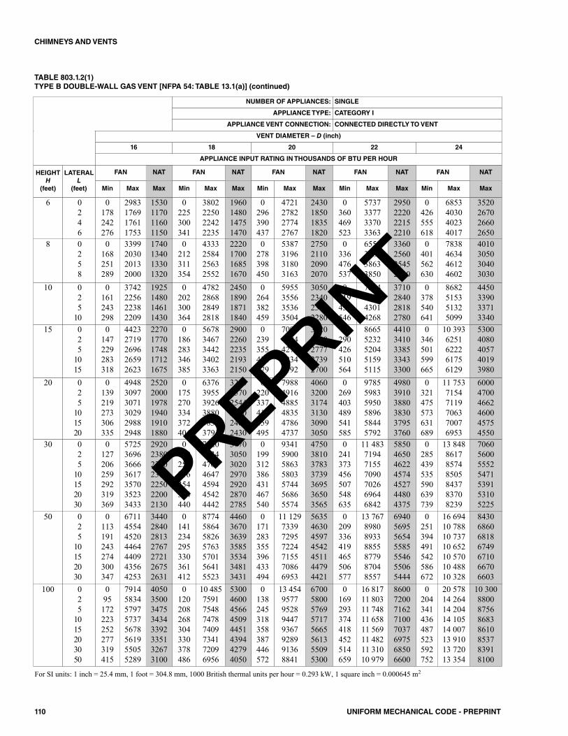
110 UNIFORM MECHANICAL CODE - PREPRINT
CHIMNEYS AND VENTS
TABLE 803.1.2(1)TYPE B DOUBLE-WALL GAS VENT [NFPA 54: TABLE 13.1(a)] (continued)
NUMBER OF APPLIANCES: SINGLE
APPLIANCE TYPE: CATEGORY I
APPLIANCE VENT CONNECTION: CONNECTED DIRECTLY TO VENT
VENT DIAMETER – D (inch)
16 18 20 22 24
APPLIANCE INPUT RATING IN THOUSANDS OF BTU PER HOUR
HEIGHTH
(feet)
LATERALL
(feet)
FAN NAT FAN NAT FAN NAT FAN NAT FAN NAT
Min Max Max Min Max Max Min Max Max Min Max Max Min Max Max
6 0246
0178242276
2983176917611753
1530117011601150
0225300341
3802225022422235
1960148014751470
0296390437
4721278227742767
2430185018351820
0360469523
5737337733703363
2950222022152210
0426555618
6853403040234017
3520267026602650
8 0258
0168251289
3399203020132000
1740134013301320
0212311354
4333258425632552
2220170016851670
0278398450
5387319631803163
2750211020902070
0336476537
6555388238633850
3360256025452530
0401562630
7838463446124602
4010305030403030
10 025
10
0161243298
3742225622382209
1925148014611430
0202300364
4782286828492818
2450189018711840
0264382459
5955355635363504
3050234023182280
0319458546
7254432243014268
3710284028182780
0378540641
8682515351325099
4450339033713340
15 025
1015
0147229283318
44232719269626592623
22701770174817121675
0186283346385
56783467344234023363
29002260223521932150
0239355432479
70994304427842344192
36202800277727392700
0290426510564
86655232520451595115
44103410338533433300
0346501599665
10 3936251622261756129
53004080405740193980
20 025
101520
0139219273306335
494830973071302929882948
252020001978194019101880
0175270334372404
637639553926388038353791
325025702544250024652430
0220337413459495
798849164885483547864737
406032003174313030903050
0269403489541585
978559835950589658445792
498039103880383037953760
0321475573631689
11 75371547119706370076953
600047004662460045754550
30 025
10152030
0127206259292319369
5725369636663617357035233433
2920238023502300225022002130
0159252316354384440
7420473447014647459445424442
3770305030202970292028702785
0199312386431467540
9341590058635803574456865574
4750381037833739369536503565
0241373456507548635
11 483719471557090702669646842
5850465046224574452744804375
0285439535590639739
13 848861785748505843783708239
7060560055525471539153105225
50 025
10152030
0113191243274300347
6711455445204464440943564253
3440284028132767272126752631
0141234295330361412
8774586458265763570156415523
4460367036393585353434813431
0171283355396433494
11 129733972957224715570866953
5635463045974542451144794421
0209336419465506577
13 767898089338855877987048557
6940569556545585554655065444
0251394491542586672
16 69410 78810 73710 65210 57010 48810 328
8430686068186749671066706603
100 025
1015203050
095172223252277319415
79145834579757375678561955055289
40503500347534343392335132673100
0120208268304330378486
10 4857591754874787409734172096956
53004600456645094451439442794050
0138245318358387446572
13 4549577952894479367928991368841
67005800576957175665561355095300
0169293374418452514659
16 81711 80311 74811 65811 56911 48211 31010 979
86007200716271007037697568506600
0204341436487523592752
20 57814 26414 20414 10514 00713 91013 72013 354
10 3008800875686838610853783918100
For SI units: 1 inch = 25.4 mm, 1 foot = 304.8 mm, 1000 British thermal units per hour = 0.293 kW, 1 square inch = 0.000645 m2
PREPRINT
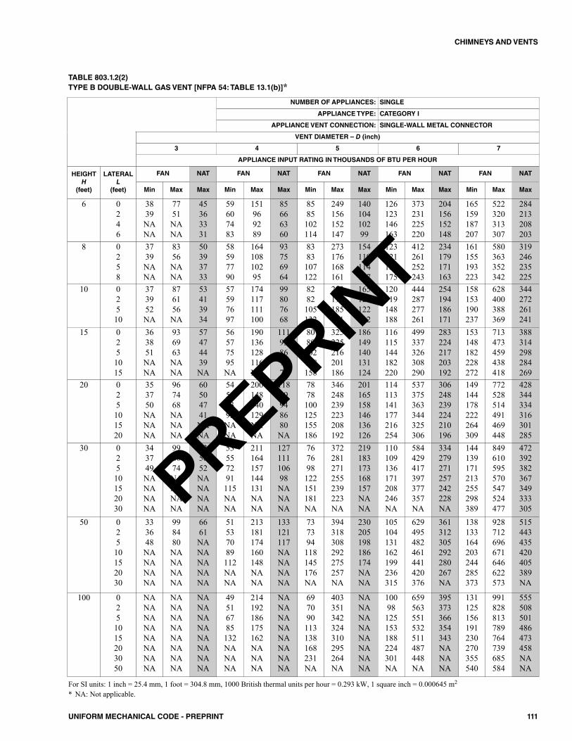
111UNIFORM MECHANICAL CODE - PREPRINT
CHIMNEYS AND VENTS
TABLE 803.1.2(2)TYPE B DOUBLE-WALL GAS VENT [NFPA 54: TABLE 13.1(b)]*
NUMBER OF APPLIANCES: SINGLE
APPLIANCE TYPE: CATEGORY I
APPLIANCE VENT CONNECTION: SINGLE-WALL METAL CONNECTOR
VENT DIAMETER – D (inch)
3 4 5 6 7
APPLIANCE INPUT RATING IN THOUSANDS OF BTU PER HOUR
HEIGHTH
(feet)
LATERALL
(feet)
FAN NAT FAN NAT FAN NAT FAN NAT FAN NAT
Min Max Max Min Max Max Min Max Max Min Max Max Min Max Max
6 0246
3839NANA
7751NANA
45363331
59607483
151969289
85666360
8585102114
249156152147
14010410299
126123146163
373231225220
204156152148
165159187207
522320313307
284213208203
8 0258
3739NANA
8356NANA
50393733
58597790
16410810295
93756964
8383107122
273176168161
154119114107
123121151175
412261252243
234179171163
161155193223
580363352342
319246235225
10 02510
373952NA
876156NA
53413934
57597697
174117111100
99807668
8282105132
293193185171
165128122112
120119148188
444287277261
254194186171
158153190237
628400388369
344272261241
15 0251015
363851NANA
936963NANA
57474439NA
56577595NA
190136128116NA
11193867972
8080102128158
325225216201186
186149140131124
116115144182220
499337326308290
283224217203192
153148182228272
713473459438418
388314298284269
20 025101520
353750NANANA
967468NANANA
60504741NANA
54567393NANA
200148140129NANA
11899948680NA
7878100125155186
346248239223208192
201165158146136126
114113141177216254
537375363344325306
306248239224210196
149144178222264309
772528514491469448
428344334316301285
30 02510152030
343749NANANANA
998074NANANANA
635652NANANANA
53557291115NANA
211164157144131NANA
12711110698NANANA
767698122151181NA
372281271255239223NA
219183173168157NANA
110109136171208246NA
584429417397377357NA
334279271257242228NA
144139171213255298389
849610595570547524477
472392382367349333305
50 02510152030
333648NANANANA
998480NANANANA
6661NANANANANA
51537089112NANA
213181174160148NANA
133121117NANANANA
737394118145176NA
394318308292275257NA
230205198186174NANA
105104131162199236315
629495482461441420376
361312305292280267NA
138133164203244285373
928712696671646622573
515443435420405389NA
100 0251015203050
NANANANANANANANA
NANANANANANANANA
NANANANANANANANA
49516785132NANANA
214192186175162NANANA
NANANANANANANANA
697090113138168231NA
403351342324310295264NA
NANANANANANANANA
10098125153188224301NA
659563551532511487448NA
395373366354343NANANA
131125156191230270355540
991828813789764739685584
555508501486473458NANA
For SI units: 1 inch = 25.4 mm, 1 foot = 304.8 mm, 1000 British thermal units per hour = 0.293 kW, 1 square inch = 0.000645 m2
* NA: Not applicable.
PREPRINT
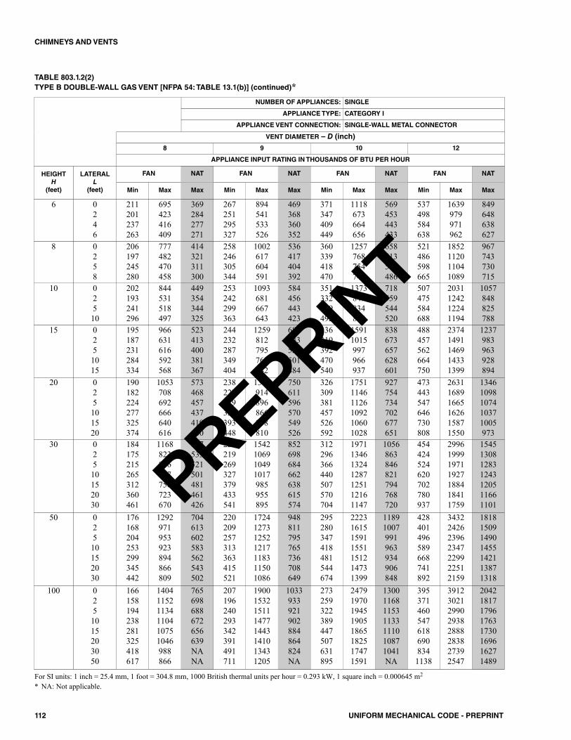
112 UNIFORM MECHANICAL CODE - PREPRINT
CHIMNEYS AND VENTS
TABLE 803.1.2(2)TYPE B DOUBLE-WALL GAS VENT [NFPA 54: TABLE 13.1(b)] (continued)*
NUMBER OF APPLIANCES: SINGLE
APPLIANCE TYPE: CATEGORY I
APPLIANCE VENT CONNECTION: SINGLE-WALL METAL CONNECTOR
VENT DIAMETER – D (inch)
8 9 10 12
APPLIANCE INPUT RATING IN THOUSANDS OF BTU PER HOUR
HEIGHTH
(feet)
LATERALL
(feet)
FAN NAT FAN NAT FAN NAT FAN NAT
Min Max Max Min Max Max Min Max Max Min Max Max
6 0246
211201237263
695423416409
369284277271
267251295327
894541533526
469368360352
371347409449
1118673664656
569453443433
537498584638
1639979971962
849648638627
8 0258
206197245280
777482470458
414321311300
258246305344
1002617604591
536417404392
360339418470
1257768754740
658513500486
521486598665
1852112011041089
967743730715
10 02510
202193241296
844531518497
449354344325
253242299363
1093681667643
584456443423
351332409492
1373849834808
718559544520
507475584688
2031124212241194
1057848825788
15 0251015
195187231284334
966631616592568
523413400381367
244232287349404
1259812795768742
681543526501484
336319392470540
15911015997966937
838673657628601
488457562664750
23741491146914331399
1237983963928894
20 025101520
190182224277325374
1053708692666640616
573468457437419400
238227279339393448
1379914896866838810
750611596570549526
326309381457526592
175111461126109210601028
927754734702677651
473443547646730808
263116891665162615871550
13461098107410371005973
30 02510152030
184175215265312360461
1168823806777750723670
647533521501481461426
229219269327379433541
1542106910491017985955895
852698684662638615574
312296366440507570704
1971134613241287125112161147
1056863846821794768720
454424524620702780937
2996199919711927188418411759
1545130812831243120511661101
50 02510152030
176168204253299345442
1292971953923894866809
704613602583562543502
220209257313363415521
1724127312521217118311501086
948811795765736708649
295280347418481544674
2223161515911551151214731399
11891007991963934906848
428401496589668741892
3432242623962347229922512159
1818150914901455142113871318
100 0251015203050
166158194238281325418617
140411521134110410751046988866
765698688672656639NANA
207196240293342391491711
19001532151114771443141013431205
1033933921902884864824NA
273259322389447507631895
24791970194519051865182517471591
1300116811531133111010871041NA
3953714605476186908341138
39123021299029382888283827392547
20421817179617631730169616271489
For SI units: 1 inch = 25.4 mm, 1 foot = 304.8 mm, 1000 British thermal units per hour = 0.293 kW, 1 square inch = 0.000645 m2
* NA: Not applicable.
PREPRINT

113UNIFORM MECHANICAL CODE - PREPRINT
CHIMNEYS AND VENTS
TABLE 803.1.2(3)MASONRY CHIMNEY [NFPA 54: TABLE 13.1(c)]*
NUMBER OF APPLIANCES: SINGLE
APPLIANCE TYPE: CATEGORY I
APPLIANCE VENT CONNECTION: TYPE B DOUBLE-WALL CONNECTOR
TYPE B DOUBLE-WALL CONNECTOR DIAMETER – D (inch)TO BE USED WITH CHIMNEY AREAS WITHIN THE SIZE LIMITS AT BOTTOM
3 4 5 6 7
APPLIANCE INPUT RATING IN THOUSANDS OF BTU PER HOUR
HEIGHTH
(feet)
LATERALL
(feet)
FAN NAT FAN NAT FAN NAT FAN NAT FAN NAT
Min Max Max Min Max Max Min Max Max Min Max Max Min Max Max
6 25
NANA
NANA
2825
NANA
NANA
5249
NANA
NANA
8682
NANA
NANA
130117
NANA
NANA
180165
8 258
NANANA
NANANA
292624
NANANA
NANANA
555248
NANANA
NANANA
938883
NANANA
NANANA
145134127
NANANA
NANANA
198183175
10 2510
NANANA
NANANA
312825
NANANA
NANANA
615750
NANANA
NANANA
1039687
NANANA
NANANA
162148139
NANANA
NANANA
221204191
15 251015
NANANANA
NANANANA
353528NA
NANANANA
NANANANA
67625548
NANANANA
NANANANA
1141079789
NANANANA
NANANANA
179164153141
53NANANA
475NANANA
250231216201
20 25101520
NANANANANA
NANANANANA
3836NANANA
NANANANANA
NANANANANA
746860NANA
NANANANANA
NANANANANA
1241161079783
NANANANANA
NANANANANA
201184172159148
5180NANANA
522503NANANA
274254237220206
30 2510152030
NANANANANANA
NANANANANANA
41NANANANANA
NANANANANANA
NANANANANANA
827667NANANA
NANANANANANA
NANANANANANA
13712811510791NA
NANANANANANA
NANANANANANA
216198184171159NA
4775NANANANA
581561NANANANA
303281263243227188
50 2510152030
NANANANANANA
NANANANANANA
NANANANANANA
NANANANANANA
NANANANANANA
92NANANANANA
NANANANANANA
NANANANANANA
161151138127NANA
NANANANANANA
NANANANANANA
251230215199185NA
NANANANANANA
NANANANANANA
351323304282264NA
Minimum internal area of
chimney(square inches)
12 19 28 38 50
Maximum internal area of
chimney(square inches)
Seven times the listed appliance categorized vent area, flue collar area, or draft hood outlet areas.
For SI units: 1 inch = 25.4 mm, 1 foot = 304.8 mm, 1000 British thermal units per hour = 0.293 kW, 1 square inch = 0.000645 m2
* NA: Not applicable.
PREPRINT
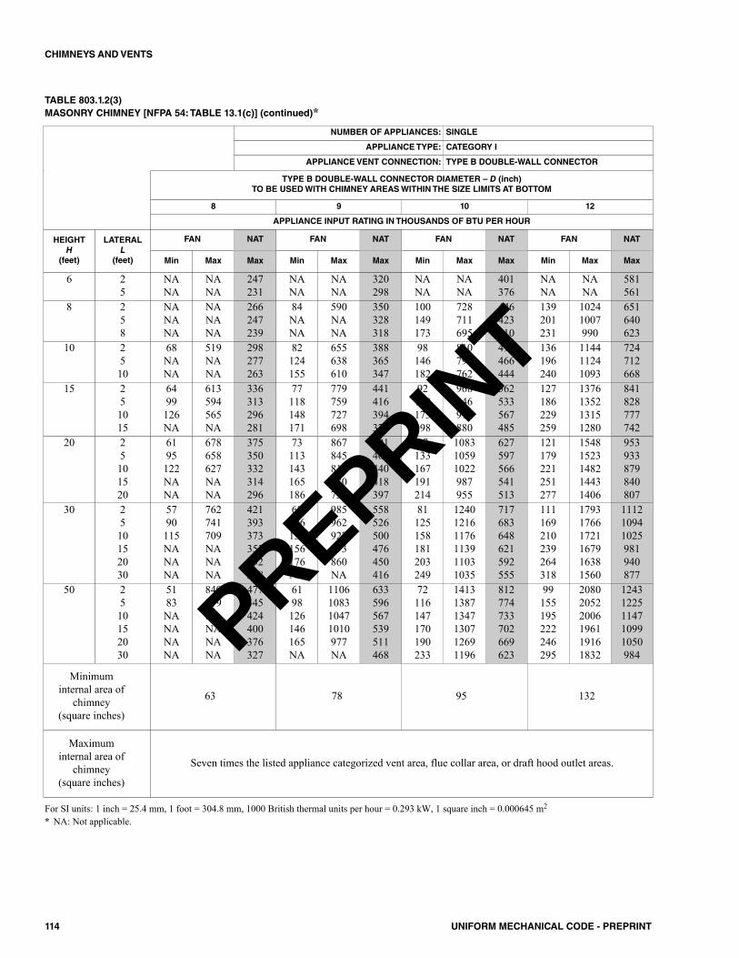
114 UNIFORM MECHANICAL CODE - PREPRINT
CHIMNEYS AND VENTS
TABLE 803.1.2(3)MASONRY CHIMNEY [NFPA 54: TABLE 13.1(c)] (continued)*
For SI units: 1 inch = 25.4 mm, 1 foot = 304.8 mm, 1000 British thermal units per hour = 0.293 kW, 1 square inch = 0.000645 m2
* NA: Not applicable.
NUMBER OF APPLIANCES: SINGLE
APPLIANCE TYPE: CATEGORY I
APPLIANCE VENT CONNECTION: TYPE B DOUBLE-WALL CONNECTOR
TYPE B DOUBLE-WALL CONNECTOR DIAMETER – D (inch)TO BE USED WITH CHIMNEY AREAS WITHIN THE SIZE LIMITS AT BOTTOM
8 9 10 12
APPLIANCE INPUT RATING IN THOUSANDS OF BTU PER HOUR
HEIGHTH
(feet)
LATERALL
(feet)
FAN NAT FAN NAT FAN NAT FAN NAT
Min Max Max Min Max Max Min Max Max Min Max Max
6 25
NANA
NANA
247231
NANA
NANA
320298
NANA
NANA
401376
NANA
NANA
581561
8 258
NANANA
NANANA
266247239
84NANA
590NANA
350328318
100149173
728711695
446423410
139201231
10241007990
651640623
10 2510
68NANA
519NANA
298277263
82124155
655638610
388365347
98146182
810791762
491466444
136196240
114411241093
724712668
15 251015
64 99126NA
613594565NA
336313296281
77118148171
779759727698
441416394375
92139173198
968946912880
562533567485
127186229259
1376135213151280
841828777742
20 25101520
6195122NANA
678658627NANA
375350332314296
73113143165186
867845811780750
491463440418397
87133167191214
108310591022987955
627597566541513
121179221251277
15481523148214431406
953933879840807
30 2510152030
5790115NANANA
762741709NANANA
421393373353332288
68106135156176NA
985962927893860NA
558526500476450416
81125158181203249
124012161176113911031035
717683648621592555
111169210239264318
179317661721167916381560
111210941025981940877
50 2510152030
5183NANANANA
840819NANANANA
477445424400376327
6198126146165NA
1106108310471010977NA
633596567539511468
72116147170190233
141313871347130712691196
812774733702669623
99155195222246295
208020522006196119161832
12431225114710991050984
Minimuminternal area of
chimney(square inches)
63 78 95 132
Maximuminternal area of
chimney(square inches)
Seven times the listed appliance categorized vent area, flue collar area, or draft hood outlet areas.
PREPRINT
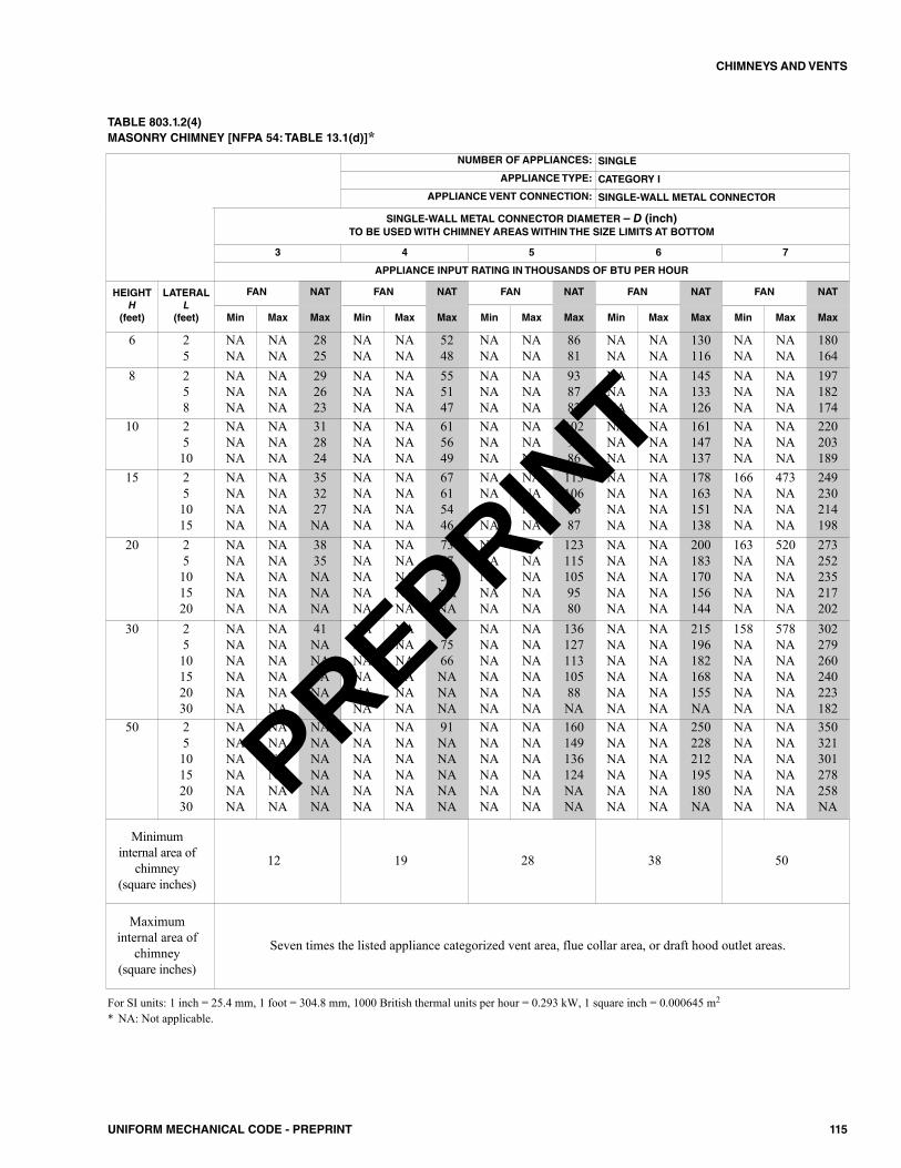
115UNIFORM MECHANICAL CODE - PREPRINT
CHIMNEYS AND VENTS
TABLE 803.1.2(4)MASONRY CHIMNEY [NFPA 54: TABLE 13.1(d)]*
For SI units: 1 inch = 25.4 mm, 1 foot = 304.8 mm, 1000 British thermal units per hour = 0.293 kW, 1 square inch = 0.000645 m2
* NA: Not applicable.
NUMBER OF APPLIANCES: SINGLE
APPLIANCE TYPE: CATEGORY I
APPLIANCE VENT CONNECTION: SINGLE-WALL METAL CONNECTOR
SINGLE-WALL METAL CONNECTOR DIAMETER – D (inch)TO BE USED WITH CHIMNEY AREAS WITHIN THE SIZE LIMITS AT BOTTOM
3 4 5 6 7
APPLIANCE INPUT RATING IN THOUSANDS OF BTU PER HOUR
HEIGHTH
(feet)
LATERALL
(feet)
FAN NAT FAN NAT FAN NAT FAN NAT FAN NAT
Min Max Max Min Max Max Min Max Max Min Max Max Min Max Max
6 25
NANA
NANA
2825
NANA
NANA
5248
NANA
NANA
8681
NANA
NANA
130116
NANA
NANA
180164
8 258
NANANA
NANANA
292623
NANANA
NANANA
555147
NANANA
NANANA
938782
NANANA
NANANA
145133126
NANANA
NANANA
197182174
10 2510
NANANA
NANANA
312824
NANANA
NANANA
615649
NANANA
NANANA
1029586
NANANA
NANANA
161147137
NANANA
NANANA
220203189
15 251015
NANANANA
NANANANA
353227NA
NANANANA
NANANANA
67615446
NANANANA
NANANANA
1131069687
NANANANA
NANANANA
178163151138
166NANANA
473NANANA
249230214198
20 25101520
NANANANANA
NANANANANA
3835NANANA
NANANANANA
NANANANANA
736759NANA
NANANANANA
NANANANANA
1231151059580
NANANANANA
NANANANANA
200183170156144
163NANANANA
520NANANANA
273252235217202
30 2510152030
NANANANANANA
NANANANANANA
41NANANANANA
NANANANANANA
NANANANANANA
817566NANANA
NANANANANANA
NANANANANANA
13612711310588NA
NANANANANANA
NANANANANANA
215196182168155NA
158NANANANANA
578NANANANANA
302279260240223182
50 2510152030
NANANANANANA
NANANANANANA
NANANANANANA
NANANANANANA
NANANANANANA
91NANANANANA
NANANANANANA
NANANANANANA
160149136124NANA
NANANANANANA
NANANANANANA
250228212195180NA
NANANANANANA
NANANANANANA
350321301278258NA
Minimuminternal area of
chimney(square inches)
12 19 28 38 50
Maximuminternal area of
chimney(square inches)
Seven times the listed appliance categorized vent area, flue collar area, or draft hood outlet areas.
PREPRINT
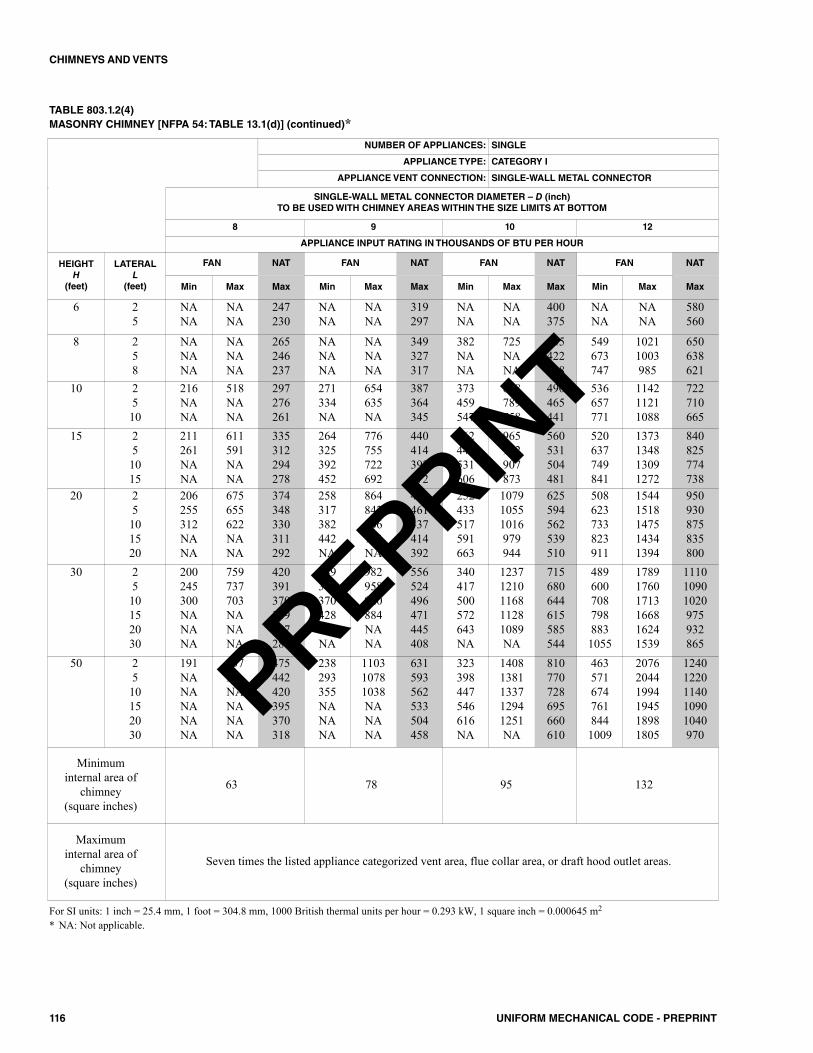
116 UNIFORM MECHANICAL CODE - PREPRINT
CHIMNEYS AND VENTS
TABLE 803.1.2(4)MASONRY CHIMNEY [NFPA 54: TABLE 13.1(d)] (continued)*
For SI units: 1 inch = 25.4 mm, 1 foot = 304.8 mm, 1000 British thermal units per hour = 0.293 kW, 1 square inch = 0.000645 m2
* NA: Not applicable.
NUMBER OF APPLIANCES: SINGLE
APPLIANCE TYPE: CATEGORY I
APPLIANCE VENT CONNECTION: SINGLE-WALL METAL CONNECTOR
SINGLE-WALL METAL CONNECTOR DIAMETER – D (inch)TO BE USED WITH CHIMNEY AREAS WITHIN THE SIZE LIMITS AT BOTTOM
8 9 10 12
APPLIANCE INPUT RATING IN THOUSANDS OF BTU PER HOUR
HEIGHTH
(feet)
LATERALL
(feet)
FAN NAT FAN NAT FAN NAT FAN NAT
Min Max Max Min Max Max Min Max Max Min Max Max
6 25
NANA
NANA
247230
NANA
NANA
319297
NANA
NANA
400375
NANA
NANA
580560
8 258
NANANA
NANANA
265246237
NANANA
NANANA
349327317
382NANA
725NANA
445422408
549673747
10211003985
650638621
10 2510
216NANA
518NANA
297276261
271334NA
654635NA
387364345
373459547
808789758
490465441
536657771
114211211088
722710665
15 251015
211261NANA
611591NANA
335312294278
264325392452
776755722692
440414392372
362444531606
965942907873
560531504481
520637749841
1373134813091272
840825774738
20 25101520
206255312NANA
675655622NANA
374348330311292
258317382442NA
864842806773NA
490461437414392
252433517591663
107910551016979944
625594562539510
508623733823911
15441518147514341394
950930875835800
30 2510152030
200245300NANANA
759737703NANANA
420391370349327281
249306370428NANA
982958920884NANA
556524496471445408
340417500572643NA
12371210116811281089NA
715680644615585544
4896007087988831055
178917601713166816241539
111010901020975932865
50 2510152030
191NANANANANA
837NANANANANA
475442420395370318
238293355NANANA
110310781038NANANA
631593562533504458
323398447546616NA
14081381133712941251NA
810770728695660610
4635716747618441009
207620441994194518981805
12401220114010901040970
Minimuminternal area of
chimney(square inches)
63 78 95 132
Maximuminternal area of
chimney(square inches)
Seven times the listed appliance categorized vent area, flue collar area, or draft hood outlet areas.
PREPRINT
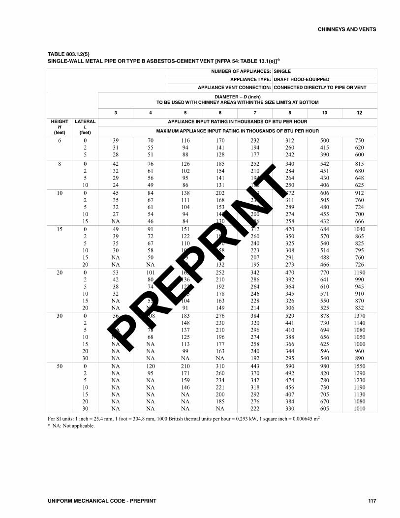
117UNIFORM MECHANICAL CODE - PREPRINT
CHIMNEYS AND VENTS
TABLE 803.1.2(5)SINGLE-WALL METAL PIPE OR TYPE B ASBESTOS-CEMENT VENT [NFPA 54: TABLE 13.1(e)]*
NUMBER OF APPLIANCES: SINGLE
APPLIANCE TYPE: DRAFT HOOD-EQUIPPED
APPLIANCE VENT CONNECTION: CONNECTED DIRECTLY TO PIPE OR VENT
DIAMETER – D (inch)TO BE USED WITH CHIMNEY AREAS WITHIN THE SIZE LIMITS AT BOTTOM
3 4 5 6 7 8 10 12
HEIGHTH
(feet)
LATERALL
(feet)
APPLIANCE INPUT RATING IN THOUSANDS OF BTU PER HOUR
MAXIMUM APPLIANCE INPUT RATING IN THOUSANDS OF BTU PER HOUR
6 025
393128
705551
1169488
170141128
232194177
312260242
500415390
750620600
8 02510
42322924
76615649
1261029586
185154141131
252210194180
340284264250
542451430406
815680648625
10 0251015
45353227NA
8467615446
1381111049484
202168153143130
279233215200186
372311289274258
606505480455432
912760724700666
15 025101520
49393530NANA
9172675850NA
1511221101039382
223186170158144132
312260240223207195
420350325308291273
684570540514488466
1040865825795760726
20 025101520
53423832NANA
10180746555NA
16313612311510491
252210192178163149
342286264246228214
470392364345326306
770641610571550525
1190990945910870832
30 02510152030
5644NANANANANA
108847868NANANA
18314813712511399NA
276230210196177163NA
384320296274258240192
529441410388366344295
878730694656625596540
13701140108010501000960890
50 02510152030
NANANANANANANA
12095NANANANANA
210171159146NANANA
310260234221200185NA
443370342318292276222
590492474456407384330
980820780730705670605
1550129012301190113010801010
For SI units: 1 inch = 25.4 mm, 1 foot = 304.8 mm, 1000 British thermal units per hour = 0.293 kW, 1 square inch = 0.000645 m2
* NA: Not applicable.
PREPRINT
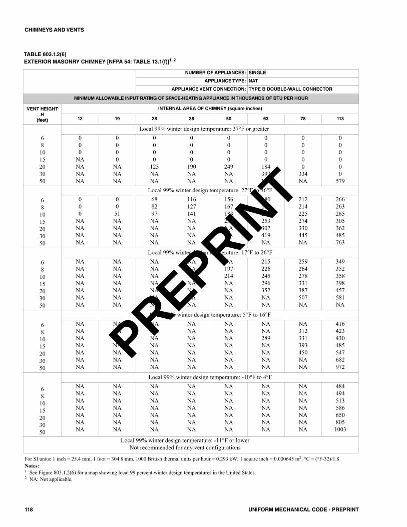
118 UNIFORM MECHANICAL CODE - PREPRINT
CHIMNEYS AND VENTS
TABLE 803.1.2(6)EXTERIOR MASONRY CHIMNEY [NFPA 54: TABLE 13.1(f)]1, 2
NUMBER OF APPLIANCES: SINGLE
APPLIANCE TYPE: NAT
APPLIANCE VENT CONNECTION: TYPE B DOUBLE-WALL CONNECTOR
MINIMUM ALLOWABLE INPUT RATING OF SPACE-HEATING APPLIANCE IN THOUSANDS OF BTU PER HOUR
VENT HEIGHTH
(feet)
INTERNAL AREA OF CHIMNEY (square inches)
12 19 28 38 50 63 78 113
681015203050
Local 99% winter design temperature: 37°F or greater000
NANANANA
0000
NANANA
0000
123NANA
0000
190NANA
0000
249NANA
0000
184393NA
00000
334NA
000000
579
681015203050
Local 99% winter design temperature: 27°F to 36°F000
NANANANA
0051NANANANA
688297NANANANA
116127141NANANANA
156167183233NANANA
180187201253307419NA
212214225274330445NA
266263265305362485763
681015203050
Local 99% winter design temperature: 17°F to 26°FNANANANANANANA
NANANANANANANA
NANANANANANANA
NANANANANANANA
NA197214NANANANA
215226245296352NANA
259264278331387507NA
349352358398457581NA
681015203050
Local 99% winter design temperature: 5°F to 16°FNANANANANANANA
NANANANANANANA
NANANANANANANA
NANANANANANANA
NANANANANANANA
NANA289NANANANA
NA312331393450NANA
416423430485547682972
681015203050
Local 99% winter design temperature: -10°F to 4°FNANANANANANANA
NANANANANANANA
NANANANANANANA
NANANANANANANA
NANANANANANANA
NANANANANANANA
NANANANANANANA
4844945135866508051003
Local 99% winter design temperature: -11°F or lowerNot recommended for any vent configurations
For SI units: 1 inch = 25.4 mm, 1 foot = 304.8 mm, 1000 British thermal units per hour = 0.293 kW, 1 square inch = 0.000645 m2, °C = (°F-32)/1.8Notes:1 See Figure 803.1.2(6) for a map showing local 99 percent winter design temperatures in the United States.2 NA: Not applicable.
PREPRINT
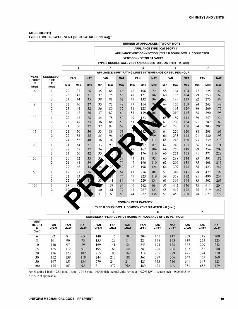
119UNIFORM MECHANICAL CODE - PREPRINT
CHIMNEYS AND VENTS
TABLE 803.2(1)TYPE B DOUBLE-WALL VENT [NFPA 54: TABLE 13.2(a)]*
NUMBER OF APPLIANCES: TWO OR MORE
APPLIANCE TYPE: CATEGORY I
APPLIANCE VENT CONNECTION: TYPE B DOUBLE-WALL CONNECTOR
VENT CONNECTOR CAPACITY
TYPE B DOUBLE-WALL VENT AND CONNECTOR DIAMETER – D (inch)
3 4 5 6 7
APPLIANCE INPUT RATING LIMITS IN THOUSANDS OF BTU PER HOUR
VENTHEIGHT
H(feet)
CONNECTORRISER
(feet)
FAN NAT FAN NAT FAN NAT FAN NAT FAN NAT
Min Max Max Min Max Max Min Max Max Min Max Max Min Max Max
6 123
222324
374144
263135
353738
667581
465562
464849
106121132
728696
586062
164183199
104124139
777982
225253275
142168189
8 123
222324
404447
273236
353637
728087
485764
495153
114128139
7690101
646667
176195210
109129145
848688
243269290
148175198
10 123
222324
434750
283337
343637
788692
505967
495152
123136146
7893104
656769
189206220
113134150
899194
257282303
154182205
15 123
212224
505355
303540
333536
8996102
536371
474951
142153163
8399111
646668
220235248
120142160
889193
298320339
163193218
20 123
212223
545760
313742
333435
99105110
566674
464850
157167176
87104116
626466
246259271
125149168
868991
334354371
171202228
30 123
202122
626466
333944
313334
113118123
597079
454748
181190198
93110124
606264
288299309
134158178
838588
391408423
182215242
50 123
192122
717375
364348
303233
133137141
647686
434546
216223229
101119134
575961
349358366
145172194
788183
477490502
197234263
100 123
181920
828384
374450
283031
158161163
667989
404244
262267272
104123138
535557
442447452
150178200
737578
611619627
204242272
For SI units: 1 inch = 25.4 mm, 1 foot = 304.8 mm, 1000 British thermal units per hour = 0.293 kW, 1 square inch = 0.000645 m2
* NA: Not applicable.
COMMON VENT CAPACITY
TYPE B DOUBLE-WALL COMMON VENT DIAMETER – D (inch)
4 5 6 7
COMBINED APPLIANCE INPUT RATING IN THOUSANDS OF BTU PER HOUR
VENTHEIGHT
H(feet)
FAN+FAN
FAN+NAT
NAT+NAT
FAN+FAN
FAN+NAT
NAT+NAT
FAN+FAN
FAN+NAT
NAT+NAT
FAN+FAN
FAN+NAT
NAT+NAT
681015203050100
92101110125136152167175
819097112123138153163
65737991102118134NA
140155169195215244279311
116129141164183210244277
103114124144160185214NA
204224243283314361421489
161178194228255297353421
147163178206229266310NA
309339367427475547641751
248275299352394459547658
200223242280310360423479
PREPRINT
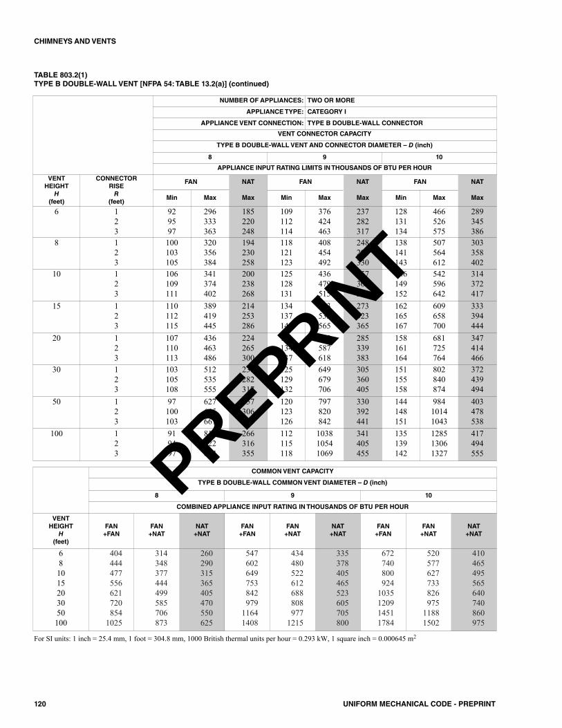
120 UNIFORM MECHANICAL CODE - PREPRINT
CHIMNEYS AND VENTS
TABLE 803.2(1)TYPE B DOUBLE-WALL VENT [NFPA 54: TABLE 13.2(a)] (continued)
NUMBER OF APPLIANCES: TWO OR MORE
APPLIANCE TYPE: CATEGORY I
APPLIANCE VENT CONNECTION: TYPE B DOUBLE-WALL CONNECTOR
VENT CONNECTOR CAPACITY
TYPE B DOUBLE-WALL VENT AND CONNECTOR DIAMETER – D (inch)
8 9 10
APPLIANCE INPUT RATING LIMITS IN THOUSANDS OF BTU PER HOUR
VENTHEIGHT
H(feet)
CONNECTORRISER
(feet)
FAN NAT FAN NAT FAN NAT
Min Max Max Min Max Max Min Max Max
6 123
929597
296333363
185220248
109112114
376424463
237282317
128131134
466526575
289345386
8 123
100103105
320356384
194230258
118121123
408454492
248294330
138141143
507564612
303358402
10 123
106109111
341374402
200238268
125128131
436479515
257305342
146149152
542596642
314372417
15 123
110112115
389419445
214253286
134137140
493532565
273323365
162165167
609658700
333394444
20 123
107110113
436463486
224265300
131134137
552587618
285339383
158161164
681725764
347414466
30 123
103105108
512535555
238282317
125129132
649679706
305360405
151155158
802840874
372439494
50 123
97100103
627645661
257306343
120123126
797820842
330392441
144148151
98410141043
403478538
100 123
919497
810822834
266316355
112115118
103810541069
341405455
135139142
128513061327
417494555
For SI units: 1 inch = 25.4 mm, 1 foot = 304.8 mm, 1000 British thermal units per hour = 0.293 kW, 1 square inch = 0.000645 m2
COMMON VENT CAPACITY
TYPE B DOUBLE-WALL COMMON VENT DIAMETER – D (inch)
8 9 10
COMBINED APPLIANCE INPUT RATING IN THOUSANDS OF BTU PER HOUR
VENT HEIGHT
H(feet)
FAN+FAN
FAN+NAT
NAT+NAT
FAN+FAN
FAN+NAT
NAT+NAT
FAN+FAN
FAN+NAT
NAT+NAT
681015203050100
404444477556621720854
1025
314348377444499585706873
260290315365405470550625
547602649753842979
11641408
434480522612688808977
1215
335378405465523605705800
672740800924
1035120914511784
520577627733826975
11881502
410465495565640740860975
PREPRINT
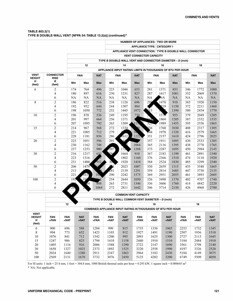
121UNIFORM MECHANICAL CODE - PREPRINT
CHIMNEYS AND VENTS
TABLE 803.2(1)TYPE B DOUBLE-WALL VENT [NFPA 54: TABLE 13.2(a)] (continued)*
NUMBER OF APPLIANCES: TWO OR MORE
APPLIANCE TYPE: CATEGORY I
APPLIANCE VENT CONNECTION: TYPE B DOUBLE-WALL CONNECTOR
VENT CONNECTOR CAPACITY
TYPE B DOUBLE-WALL VENT AND CONNECTOR DIAMETER – D (inch)
12 14 16 18
APPLIANCE INPUT RATING LIMITS IN THOUSANDS OF BTU PER HOUR
VENTHEIGHT
H(feet)
CONNECTORRISER
(feet)
FAN NAT FAN NAT FAN NAT FAN NAT
Min Max Max Min Max Max Min Max Max Min Max Max
6 246
174180NA
764897NA
496616NA
223230NA
10461231NA
653827NA
281287NA
13711617NA
8531081NA
346352NA
17722069NA
10801370NA
8 246
186192198
8229521050
516644772
238244252
112613071445
6968841072
298305313
147817191902
91011501390
365372380
192022112434
115014601770
10 246
196201207
8709971095
536664792
249256263
119513711509
7309241118
311318325
157018041989
95512051455
379387395
204923322556
120515351865
15 246
214221228
96710851181
568712856
272279286
133414991632
79010061222
336344351
176019782157
103013201610
408416424
231725792796
130516652025
20 246
223230237
105111621253
596748900
291298307
144315971726
84010641288
357365373
191121162287
109513951695
430438450
253327782984
138517652145
30 246
216223231
121713161400
632792952
286294303
166418021920
91011601410
367376384
218323662524
119015101830
461474485
289131103299
154019202340
50 246
206213221
147915611631
6898601031
273281290
202321392242
100712911575
350359369
265928142951
131516852055
435447461
354837303893
166521352605
100 246
192200208
192319842035
7128881064
254263272
264427312811
105013461642
326336346
349036063714
137017602150
402414426
470748424968
174022202700
For SI units: 1 inch = 25.4 mm, 1 foot = 304.8 mm, 1000 British thermal units per hour = 0.293 kW, 1 square inch = 0.000645 m2
* NA: Not applicable.
COMMON VENT CAPACITY
TYPE B DOUBLE-WALL COMMON VENT DIAMETER – D (inch)
12 14 16 18
COMBINED APPLIANCE INPUT RATING IN THOUSANDS OF BTU PER HOUR
VENTHEIGHT
H(feet)
FAN+FAN
FAN+NAT
NAT+NAT
FAN+FAN
FAN+NAT
NAT+NAT
FAN+FAN
FAN+NAT
NAT+NAT
FAN+FAN
FAN+NAT
NAT+NAT
681015203050100
900994107612471405165820242569
6967738419861116132716402131
588652712825916102512801670
12841423154217942006237329113732
9901103120014101588189223473076
81591299511581290152518632450
17351927209324402722322039645125
13361491162519102147255831834202
10651190130015101690199024303200
22532507272731843561419751846749
17321936211324842798332641495509
13451510164519102140252030754050
PREPRINT
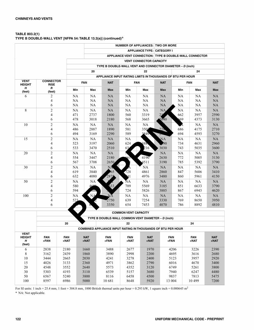
122 UNIFORM MECHANICAL CODE - PREPRINT
CHIMNEYS AND VENTS
TABLE 803.2(1)TYPE B DOUBLE-WALL VENT [NFPA 54: TABLE 13.2(a)] (continued)*
NUMBER OF APPLIANCES: TWO OR MORE
APPLIANCE TYPE: CATEGORY I
APPLIANCE VENT CONNECTION: TYPE B DOUBLE-WALL CONNECTOR
VENT CONNECTOR CAPACITY
TYPE B DOUBLE-WALL VENT AND CONNECTOR DIAMETER – D (inch)
20 22 24
APPLIANCE INPUT RATING LIMITS IN THOUSANDS OF BTU PER HOUR
VENTHEIGHT
H(feet)
CONNECTORRISER
(feet)
FAN NAT FAN NAT FAN NAT
Min Max Max Min Max Max Min Max Max
6 246
NANANA
NANANA
NANANA
NANANA
NANANA
NANANA
NANANA
NANANA
NANANA
8 246
NA471478
NA27373018
NA18002180
NA560568
NA33193665
NA21802640
NA662669
NA39574373
NA25903130
10 246
NA486494
NA28873169
NA18902290
NA581589
NA35023849
NA22802760
NA686694
NA41754593
NA27103270
15 246
NA523533
NA31973470
NA20602510
NA624634
NA38814216
NA24903030
NA734743
NA46315035
NA29603600
20 246
NA554567
NA34473708
NA21802650
NA661671
NA41904511
NA26303190
NA772785
NA50055392
NA31303790
30 246
NA619632
NA38404080
NA23652875
NA728741
NA48614976
NA28603480
NA847860
NA56065961
NA34104150
50 246
NA580594
NA46014808
NA26333208
NA709724
NA55695826
NA31853885
NA851867
NA66336943
NA37904620
100 246
NA523539
NA59826143
NA27503350
NA639654
NA72547453
NA33304070
NA769786
NA86508892
NA39504810
COMMON VENT CAPACITY
TYPE B DOUBLE-WALL COMMON VENT DIAMETER – D (inch)
20 22 24
COMBINED APPLIANCE INPUT RATING IN THOUSANDS OF BTU PER HOUR
VENTHEIGHT
H(feet)
FAN+FAN
FAN+NAT
NAT+NAT
FAN+FAN
FAN+NAT
NAT+NAT
FAN+FAN
FAN+NAT
NAT+NAT
681015203050100
28383162344440264548530365678597
21802439266531333552419352406986
16601860203023602640311038005000
3488389042414971557365398116
10 681
26772998327838624352515764588648
19702200240027903120368045005920
4206469551236016674979409837
13 004
3226361639574670526162477813
10 499
23902680292034003800448054757200
For SI units: 1 inch = 25.4 mm, 1 foot = 304.8 mm, 1000 British thermal units per hour = 0.293 kW, 1 square inch = 0.000645 m2
* NA: Not applicable.
PREPRINT
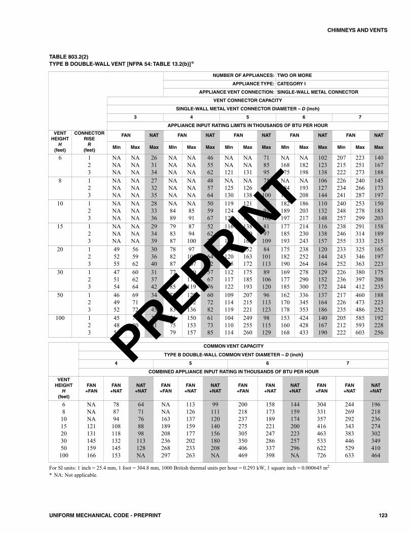
123UNIFORM MECHANICAL CODE - PREPRINT
CHIMNEYS AND VENTS
TABLE 803.2(2)TYPE B DOUBLE-WALL VENT [NFPA 54: TABLE 13.2(b)]*
NUMBER OF APPLIANCES: TWO OR MORE
APPLIANCE TYPE: CATEGORY I
APPLIANCE VENT CONNECTION: SINGLE-WALL METAL CONNECTOR
VENT CONNECTOR CAPACITY
SINGLE-WALL METAL VENT CONNECTOR DIAMETER – D (inch)
3 4 5 6 7
APPLIANCE INPUT RATING LIMITS IN THOUSANDS OF BTU PER HOUR
VENTHEIGHT
H(feet)
CONNECTORRISER
(feet)
FAN NAT FAN NAT FAN NAT FAN NAT FAN NAT
Min Max Max Min Max Max Min Max Max Min Max Max Min Max Max
6 123
NANANA
NANANA
263134
NANANA
NANANA
465562
NANA121
NANA131
718595
NA168175
NA182198
102123138
207215222
223251273
140167188
8 123
NANANA
NANANA
273235
NANANA
NANANA
485764
NA125130
NA126138
7589100
NA184191
NA193208
106127144
226234241
240266287
145173197
10 123
NANANA
NANANA
283336
NA8489
NA8591
505967
119124129
121134144
7791102
182189197
186203217
110132148
240248257
253278299
150183203
15 123
NANANA
NANANA
293439
798387
8794100
526270
116121127
138150160
8197109
177185193
214230243
116138157
238246255
291314333
158189215
20 123
495255
565962
303640
788287
97103107
546472
115120125
152163172
84101113
175182190
238252264
120144164
233243252
325346363
165197223
30 123
475154
606264
313742
778185
110115119
576776
112117122
175185193
89106120
169177185
278290300
129152172
226236244
380397412
175208235
50 123
464952
697172
344045
757983
128132136
607282
109114119
207215221
96113123
162170178
336345353
137164186
217226235
460473486
188223252
100 123
454851
798081
344146
717579
150153157
617385
104110114
249255260
98115129
153160168
424428433
140167190
205212222
585593603
192228256
COMMON VENT CAPACITY
TYPE B DOUBLE-WALL COMMON VENT DIAMETER – D (inch)
4 5 6 7
COMBINED APPLIANCE INPUT RATING IN THOUSANDS OF BTU PER HOUR
VENTHEIGHT
H(feet)
FAN+FAN
FAN+NAT
NAT+NAT
FAN+FAN
FAN+NAT
NAT+NAT
FAN+FAN
FAN+NAT
NAT+NAT
FAN+FAN
FAN+NAT
NAT+NAT
681015203050100
NANANA121131145159166
788794108118132145153
6471768898113128NA
NANA163189208236268297
113126137159177202233263
99111120140156180208NA
200218237275305350406469
158173189221247286337398
144159174200223257296NA
304331357416463533622726
244269292343383446529633
196218236274302349410464
For SI units: 1 inch = 25.4 mm, 1 foot = 304.8 mm, 1000 British thermal units per hour = 0.293 kW, 1 square inch = 0.000645 m2
* NA: Not applicable.
PREPRINT
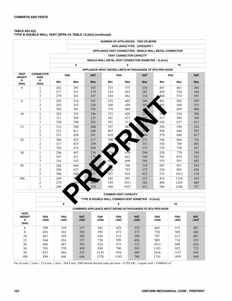
124 UNIFORM MECHANICAL CODE - PREPRINT
CHIMNEYS AND VENTS
TABLE 803.2(2)TYPE B DOUBLE-WALL VENT [NFPA 54: TABLE 13.2(b)] (continued)
NUMBER OF APPLIANCES: TWO OR MORE
APPLIANCE TYPE: CATEGORY I
APPLIANCE VENT CONNECTION: SINGLE-WALL METAL CONNECTOR
VENT CONNECTOR CAPACITY
SINGLE-WALL METAL VENT CONNECTOR DIAMETER – D (inch)
8 9 10
APPLIANCE INPUT RATING LIMITS IN THOUSANDS OF BTU PER HOUR
VENTHEIGHT
H(feet)
CONNECTORRISER
(feet)
FAN NAT FAN NAT FAN NAT
Min Max Max Min Max Max Min Max Max
6 123
262271279
293331361
183219247
325334344
373422462
234281316
447458468
463524574
286344385
8 123
285293302
316353381
191228256
352360370
403450489
244292328
481492501
502560609
299355400
10 123
302311320
335369398
196235265
372381391
429473511
252302339
506517528
534589637
308368413
15 123
312321331
380411438
208248281
397407418
482522557
266317360
556568579
596646690
324387437
20 123
306317326
425453476
217259294
390400412
538574607
276331375
546558570
664709750
336403457
30 123
296307316
497521542
230274309
378389400
630662690
294349394
528541555
779819855
358425482
50 123
284294304
604623640
245293331
364376387
768793816
314375423
507520535
9519831013
384458518
100 123
269279289
774788801
249299339
345358368
99310111027
321383431
476490506
123612591280
393469527
COMMON VENT CAPACITY
TYPE B DOUBLE-WALL COMMON VENT DIAMETER – D (inch)
8 9 10
COMBINED APPLIANCE INPUT RATING IN THOUSANDS OF BTU PER HOUR
VENTHEIGHT
H(feet)
FAN+FAN
FAN+NAT
NAT+NAT
FAN+FAN
FAN+NAT
NAT+NAT
FAN+FAN
FAN+NAT
NAT+NAT
681015203050100
398436467544606703833999
310342369434487570686846
257285309357395459535606
54159263873882495811391378
4294735125996737909541185
332373398456512593689780
6657307879051013118314181741
51556961771880895211571459
407460487553626723838948
For SI units: 1 inch = 25.4 mm, 1 foot = 304.8 mm, 1000 British thermal units per hour = 0.293 kW, 1 square inch = 0.000645 m2
PREPRINT

125UNIFORM MECHANICAL CODE - PREPRINT
CHIMNEYS AND VENTS
TABLE 803.2(3)MASONRY CHIMNEY [NFPA 54: TABLE 13.2(c)]*
NUMBER OF APPLIANCES: TWO OR MORE
APPLIANCE TYPE: CATEGORY I
APPLIANCE VENT CONNECTION: TYPE B DOUBLE-WALL CONNECTOR
VENT CONNECTOR CAPACITY
TYPE B DOUBLE-WALL VENT CONNECTOR DIAMETER – D (inch)
3 4 5 6 7
APPLIANCE INPUT RATING LIMITS IN THOUSANDS OF BTU PER HOUR
VENTHEIGHT
H(feet)
CONNECTORRISER
(feet)
FAN NAT FAN NAT FAN NAT FAN NAT FAN NAT
Min Max Max Min Max Max Min Max Max Min Max Max Min Max Max
6 123
242627
334349
212834
394142
627992
405261
525355
106133155
678597
656769
194230262
101124143
878991
274324369
141173203
8 123
242627
394752
222934
394042
728797
415362
555759
117140159
698698
717375
213246269
105127145
949799
304350383
148179206
10 123
242627
425055
222935
384041
8093105
425463
555758
130153170
7187100
747678
232261284
108129148
101103106
324366397
153184209
15 123
242526
485559
233135
383941
93105115
445564
545657
154174189
7489102
727476
277299319
114134153
100103105
384419448
164192215
20 123
242526
525863
243135
373940
102114123
465665
535557
172190204
7791104
717375
313335353
119138157
98101104
437467493
173199222
30 123
242526
546064
253236
373840
111122131
485866
525456
192208221
8295107
697274
357376392
127145163
9699101
504531554
187209233
50 123
232426
515964
253236
363739
116127135
516169
515355
209225237
89102115
677072
405421435
143161180
929598
582604624
213235260
100 123
232425
465359
243135
353738
108120130
506068
495153
208224237
92105118
656769
428444458
155174193
889294
640660679
237260285
COMMON VENT CAPACITY
MINIMUM INTERNAL AREA OF MASONRY CHIMNEY FLUE (square inches)
12 19 28 38 50
COMBINED APPLIANCE INPUT RATING IN THOUSANDS OF BTU PER HOUR
VENTHEIGHT
H(feet)
FAN+FAN
FAN+NAT
NAT+NAT
FAN+FAN
FAN+NAT
NAT+NAT
FAN+FAN
FAN+NAT
NAT+NAT
FAN+FAN
FAN+NAT
NAT+NAT
FAN+FAN
FAN+NAT
NAT+NAT
681015203050100
NANANANANANANANA
748084NANANANANA
2528313641NANANA
NANANANANANANANA
119130138152NANANANA
4653566775NANANA
NANANANANANANANA
178193207233250270NANA
718290106122137NANA
NANANANANANANANA
257279299334368404NANA
103119131152172198NANA
NANANA523565615NANA
351384409467508564620NA
143163177212243278328348
For SI units: 1 inch = 25.4 mm, 1 foot = 304.8 mm, 1000 British thermal units per hour = 0.293 kW, 1 square inch = 0.000645 m2
* NA: Not applicable.
PREPRINT
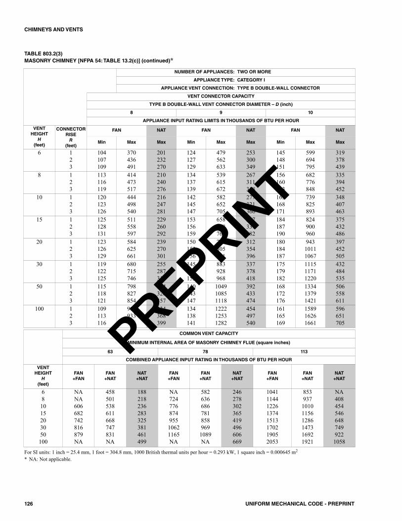
126 UNIFORM MECHANICAL CODE - PREPRINT
CHIMNEYS AND VENTS
TABLE 803.2(3)MASONRY CHIMNEY [NFPA 54: TABLE 13.2(c)] (continued)*
NUMBER OF APPLIANCES: TWO OR MORE
APPLIANCE TYPE: CATEGORY I
APPLIANCE VENT CONNECTION: TYPE B DOUBLE-WALL CONNECTOR
VENT CONNECTOR CAPACITY
TYPE B DOUBLE-WALL VENT CONNECTOR DIAMETER – D (inch)
8 9 10
APPLIANCE INPUT RATING LIMITS IN THOUSANDS OF BTU PER HOUR
VENTHEIGHT
H(feet)
CONNECTORRISER
(feet)
FAN NAT FAN NAT FAN NAT
Min Max Max Min Max Max Min Max Max
6 123
104107109
370436491
201232270
124127129
479562633
253300349
145148151
599694795
319378439
8 123
113116119
414473517
210240276
134137139
539615672
267311358
156160163
682776848
335394452
10 123
120123126
444498540
216247281
142145147
582652705
277321366
165168171
739825893
348407463
15 123
125128131
511558597
229260292
153156159
658718760
297339382
184187190
824900960
375432486
20 123
123126129
584625661
239270301
150153156
752805851
312354396
180184187
94310111067
397452505
30 123
119122125
680715746
255287317
145149152
883928968
337378418
175179182
111511711220
432484535
50 123
115118121
798827854
294326357
140143147
104910851118
392433474
168172176
133413791421
506558611
100 123
109113116
907933956
334368399
134138141
122212531282
454497540
161165169
158916261661
596651705
COMMON VENT CAPACITY
MINIMUM INTERNAL AREA OF MASONRY CHIMNEY FLUE (square inches)
63 78 113
COMBINED APPLIANCE INPUT RATING IN THOUSANDS OF BTU PER HOUR
VENTHEIGHT
H(feet)
FAN+FAN
FAN+NAT
NAT+NAT
FAN+FAN
FAN+NAT
NAT+NAT
FAN+FAN
FAN+NAT
NAT+NAT
681015203050100
NANA606682742816879NA
458501538611668747831NA
188218236283325381461499
NA72477687495510621165NA
5826366867818589691089NA
246278302365419496606669
10411144122613741513170219052053
853937101011561286147316921921
NA4084545466487499221058
For SI units: 1 inch = 25.4 mm, 1 foot = 304.8 mm, 1000 British thermal units per hour = 0.293 kW, 1 square inch = 0.000645 m2
* NA: Not applicable.
PREPRINT
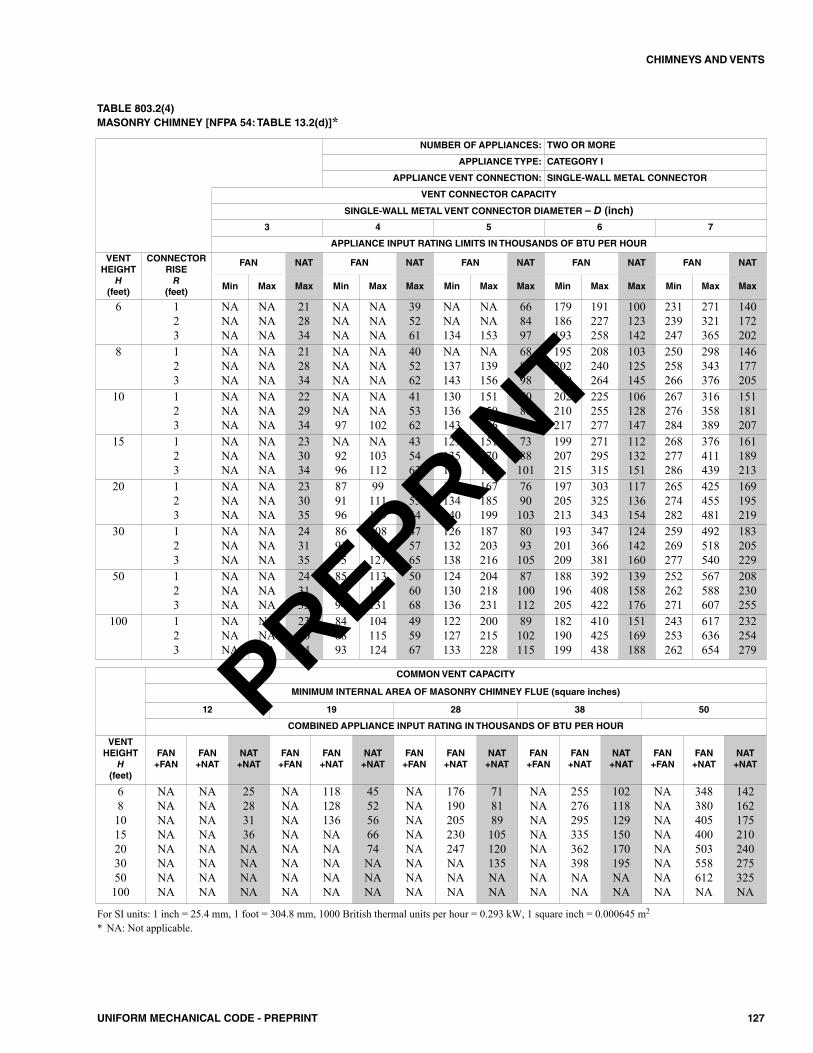
127UNIFORM MECHANICAL CODE - PREPRINT
CHIMNEYS AND VENTS
TABLE 803.2(4)MASONRY CHIMNEY [NFPA 54: TABLE 13.2(d)]*
NUMBER OF APPLIANCES: TWO OR MORE
APPLIANCE TYPE: CATEGORY I
APPLIANCE VENT CONNECTION: SINGLE-WALL METAL CONNECTOR
VENT CONNECTOR CAPACITY
SINGLE-WALL METAL VENT CONNECTOR DIAMETER – D (inch)
3 4 5 6 7
APPLIANCE INPUT RATING LIMITS IN THOUSANDS OF BTU PER HOUR
VENTHEIGHT
H(feet)
CONNECTORRISER
(feet)
FAN NAT FAN NAT FAN NAT FAN NAT FAN NAT
Min Max Max Min Max Max Min Max Max Min Max Max Min Max Max
6 123
NANANA
NANANA
212834
NANANA
NANANA
395261
NANA134
NANA153
668497
179186193
191227258
100123142
231239247
271321365
140172202
8 123
NANANA
NANANA
212834
NANANA
NANANA
405262
NA137143
NA139156
688598
195202210
208240264
103125145
250258266
298343376
146177205
10 123
NANANA
NANANA
222934
NANA97
NANA102
415362
130136143
151150166
708699
202210217
225255277
106128147
267276284
316358389
151181207
15 123
NANANA
NANANA
233034
NA9296
NA103112
435463
129135141
151170185
7388101
199207215
271295315
112132151
268277286
376411439
161189213
20 123
NANANA
NANANA
233035
879196
99111119
455564
128134140
167185199
7690103
197205213
303325343
117136154
265274282
425455481
169195219
30 123
NANANA
NANANA
243135
869195
108119127
475765
126132138
187203216
8093105
193201209
347366381
124142160
259269277
492518540
183205229
50 123
NANANA
NANANA
243135
858994
113123131
506068
124130136
204218231
87100112
188196205
392408422
139158176
252262271
567588607
208230255
100 123
NANANA
NANANA
233034
848893
104115124
495967
122127133
200215228
89102115
182190199
410425438
151169188
243253262
617636654
232254279
COMMON VENT CAPACITY
MINIMUM INTERNAL AREA OF MASONRY CHIMNEY FLUE (square inches)
12 19 28 38 50
COMBINED APPLIANCE INPUT RATING IN THOUSANDS OF BTU PER HOUR
VENTHEIGHT
H(feet)
FAN+FAN
FAN+NAT
NAT+NAT
FAN+FAN
FAN+NAT
NAT+NAT
FAN+FAN
FAN+NAT
NAT+NAT
FAN+FAN
FAN+NAT
NAT+NAT
FAN+FAN
FAN+NAT
NAT+NAT
681015203050100
NANANANANANANANA
NANANANANANANANA
25283136NANANANA
NANANANANANANANA
118128136NANANANANA
4552566674NANANA
NANANANANANANANA
176190205230247NANANA
718189105120135NANA
NANANANANANANANA
255276295335362398NANA
102118129150170195NANA
NANANANANANANANA
348380405400503558612NA
142162175210240275325NA
For SI units: 1 inch = 25.4 mm, 1 foot = 304.8 mm, 1000 British thermal units per hour = 0.293 kW, 1 square inch = 0.000645 m2
* NA: Not applicable.
PREPRINT
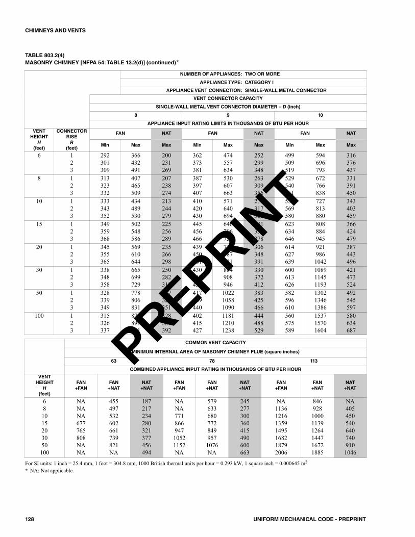
128 UNIFORM MECHANICAL CODE - PREPRINT
CHIMNEYS AND VENTS
TABLE 803.2(4)MASONRY CHIMNEY [NFPA 54: TABLE 13.2(d)] (continued)*
NUMBER OF APPLIANCES: TWO OR MORE
APPLIANCE TYPE: CATEGORY I
APPLIANCE VENT CONNECTION: SINGLE-WALL METAL CONNECTOR
VENT CONNECTOR CAPACITY
SINGLE-WALL METAL VENT CONNECTOR DIAMETER – D (inch)
8 9 10
APPLIANCE INPUT RATING LIMITS IN THOUSANDS OF BTU PER HOUR
VENTHEIGHT
H(feet)
CONNECTORRISER
(feet)
FAN NAT FAN NAT FAN NAT
Min Max Max Min Max Max Min Max Max
6 123
292301309
366432491
200231269
362373381
474557634
252299348
499509519
594696793
316376437
8 123
313323332
407465509
207238274
387397407
530607663
263309356
529540551
672766838
331391450
10 123
333343352
434489530
213244279
410420430
571640694
273317363
558569580
727813880
343403459
15 123
349359368
502548586
225256289
445456466
646706755
291334378
623634646
808884945
366424479
20 123
345355365
569610644
235266298
439450461
734787831
306348391
614627639
9219861042
387443496
30 123
338348358
665699729
250282312
430442452
864908946
330372412
600613626
108911451193
421473524
50 123
328339349
778806831
287320351
417429440
102210581090
383425466
582596610
130213461386
492545597
100 123
315326337
875899921
328361392
402415427
118112101238
444488529
560575589
153715701604
580634687
COMMON VENT CAPACITY
MINIMUM INTERNAL AREA OF MASONRY CHIMNEY FLUE (square inches)
63 78 113
COMBINED APPLIANCE INPUT RATING IN THOUSANDS OF BTU PER HOUR
VENTHEIGHT
H(feet)
FAN+FAN
FAN+NAT
NAT+NAT
FAN+FAN
FAN+NAT
NAT+NAT
FAN+FAN
FAN+NAT
NAT+NAT
681015203050100
NANANA677765808NANA
455497532602661739821NA
187217234280321377456494
NANA77186694710521152NA
5796336807728499571076NA
245277300360415490600663
NA1136121613591495168218792006
846928100011391264144716721885
NA4054505406407409101046
For SI units: 1 inch = 25.4 mm, 1 foot = 304.8 mm, 1000 British thermal units per hour = 0.293 kW, 1 square inch = 0.000645 m2
* NA: Not applicable.
PREPRINT
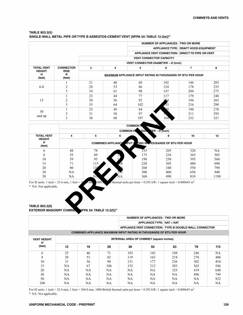
129UNIFORM MECHANICAL CODE - PREPRINT
CHIMNEYS AND VENTS
TABLE 803.2(5)SINGLE-WALL METAL PIPE OR TYPE B ASBESTOS-CEMENT VENT [NFPA 54: TABLE 13.2(e)]*
NUMBER OF APPLIANCES: TWO OR MORE
APPLIANCE TYPE: DRAFT HOOD-EQUIPMENT
APPLIANCE VENT CONNECTION: DIRECT TO PIPE OR VENT
VENT CONNECTOR CAPACITY
VENT CONNECTOR DIAMETER – D (inch)
TOTAL VENT HEIGHT
H(feet)
CONNECTOR RISER
(feet)
3 4 5 6 7 8
MAXIMUM APPLIANCE INPUT RATING IN THOUSANDS OF BTU PER HOUR
6-8123
212834
405361
688698
102124147
146178204
205235275
15123
233035
445664
7792102
117134155
179194216
240265298
30and up
123
253136
495868
8497107
129145164
190211232
270295321
COMMON VENT CAPACITY
COMMON VENT DIAMETER – D (inch)
TOTAL VENT HEIGHT
H(feet)
4 5 6 7 8 10 12
COMBINED APPLIANCE INPUT RATING IN THOUSANDS OF BTU PER HOUR
681015203050
4855597180NANA
788995115129147NA
111128136168186215NA
155175190228260300360
205234250305340400490
320365395480550650810
NA5055606907909401190
For SI units: 1 inch = 25.4 mm, 1 foot = 304.8 mm, 1000 British thermal units per hour = 0.293 kW, 1 square inch = 0.000645 m2
* NA: Not applicable.
NUMBER OF APPLIANCES: TWO OR MORE
APPLIANCE TYPE: NAT + NAT
APPLIANCE VENT CONNECTION: TYPE B DOUBLE-WALL CONNECTOR
COMBINED APPLIANCE MAXIMUM INPUT RATING IN THOUSANDS OF BTU PER HOUR
VENT HEIGHTH
(feet)
INTERNAL AREA OF CHIMNEY (square inches)
12 19 28 38 50 63 78 113
681015203050100
252831NANANANANA
46535667NANANANA
718290106NANANANA
103119131152NANANANA
143163177212NANANANA
188218236283325NANANA
246278302365419496NANA
NA408454546648749922NA
TABLE 803.2(6)EXTERIOR MASONRY CHIMNEY [NFPA 54: TABLE 13.2(f)]*
For SI units: 1 inch = 25.4 mm, 1 foot = 304.8 mm, 1000 British thermal units per hour = 0.293 kW, 1 square inch = 0.000645 m2
* NA: Not applicable.
PREPRINT
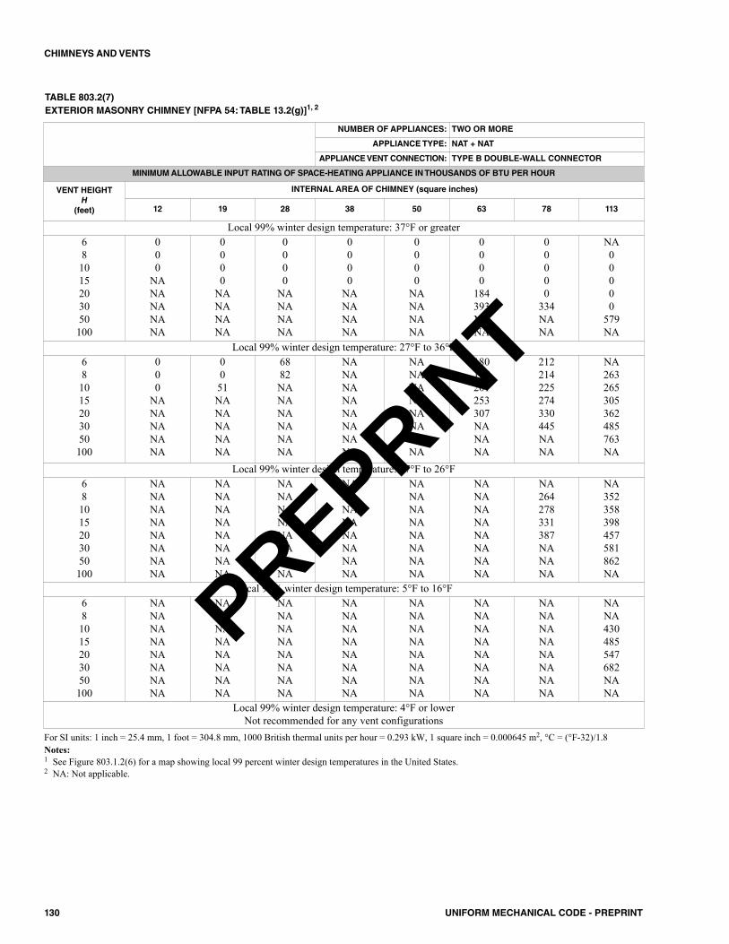
130 UNIFORM MECHANICAL CODE - PREPRINT
CHIMNEYS AND VENTS
TABLE 803.2(7)EXTERIOR MASONRY CHIMNEY [NFPA 54: TABLE 13.2(g)]1, 2
NUMBER OF APPLIANCES: TWO OR MORE
APPLIANCE TYPE: NAT + NAT
APPLIANCE VENT CONNECTION: TYPE B DOUBLE-WALL CONNECTOR
MINIMUM ALLOWABLE INPUT RATING OF SPACE-HEATING APPLIANCE IN THOUSANDS OF BTU PER HOUR
VENT HEIGHTH
(feet)
INTERNAL AREA OF CHIMNEY (square inches)
12 19 28 38 50 63 78 113
Local 99% winter design temperature: 37°F or greater681015203050100
000
NANANANANA
0000
NANANANA
0000
NANANANA
0000
NANANANA
0000
NANANANA
0000
184393NANA
00000
334NANA
NA00000
579NA
Local 99% winter design temperature: 27°F to 36°F681015203050100
000
NANANANANA
0051NANANANANA
6882NANANANANANA
NANANANANANANANA
NANANANANANANANA
180187201253307NANANA
212214225274330445NANA
NA263265305362485763NA
Local 99% winter design temperature: 17°F to 26°F681015203050100
NANANANANANANANA
NANANANANANANANA
NANANANANANANANA
NANANANANANANANA
NANANANANANANANA
NANANANANANANANA
NA264278331387NANANA
NA352358398457581862NA
Local 99% winter design temperature: 5°F to 16°F681015203050100
NANANANANANANANA
NANANANANANANANA
NANANANANANANANA
NANANANANANANANA
NANANANANANANANA
NANANANANANANANA
NANANANANANANANA
NANA430485547682NANA
Local 99% winter design temperature: 4°F or lowerNot recommended for any vent configurations
For SI units: 1 inch = 25.4 mm, 1 foot = 304.8 mm, 1000 British thermal units per hour = 0.293 kW, 1 square inch = 0.000645 m2, °C = (°F-32)/1.8Notes:1 See Figure 803.1.2(6) for a map showing local 99 percent winter design temperatures in the United States.2 NA: Not applicable.
PREPRINT
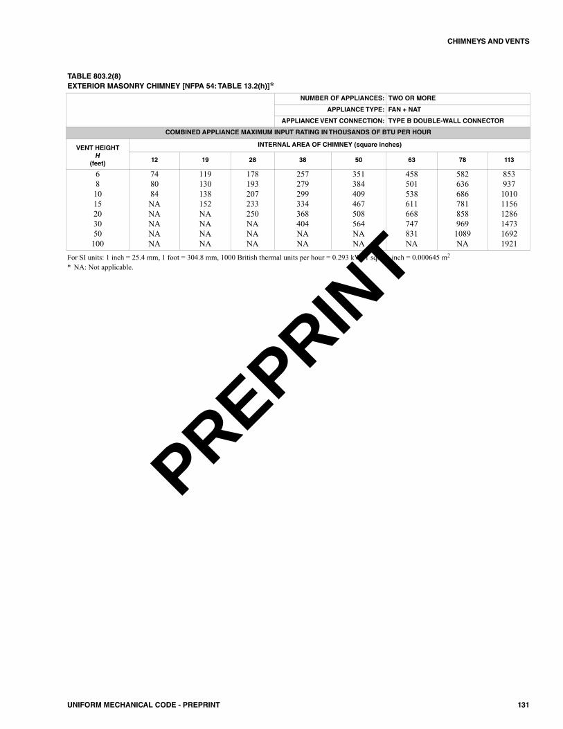
131UNIFORM MECHANICAL CODE - PREPRINT
CHIMNEYS AND VENTS
TABLE 803.2(8)EXTERIOR MASONRY CHIMNEY [NFPA 54: TABLE 13.2(h)]*
NUMBER OF APPLIANCES: TWO OR MORE
APPLIANCE TYPE: FAN + NAT
APPLIANCE VENT CONNECTION: TYPE B DOUBLE-WALL CONNECTOR
COMBINED APPLIANCE MAXIMUM INPUT RATING IN THOUSANDS OF BTU PER HOUR
VENT HEIGHTH
(feet)
INTERNAL AREA OF CHIMNEY (square inches)
12 19 28 38 50 63 78 113
681015203050100
748084NANANANANA
119130138152NANANANA
178193207233250NANANA
257279299334368404NANA
351384409467508564NANA
458501538611668747831NA
5826366867818589691089NA
853937101011561286147316921921
For SI units: 1 inch = 25.4 mm, 1 foot = 304.8 mm, 1000 British thermal units per hour = 0.293 kW, 1 square inch = 0.000645 m2
* NA: Not applicable.
PREPRINT
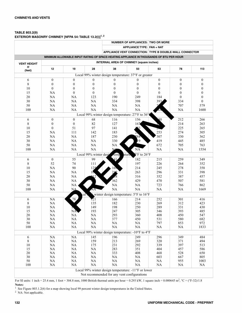
132 UNIFORM MECHANICAL CODE - PREPRINT
CHIMNEYS AND VENTS
TABLE 803.2(9)EXTERIOR MASONRY CHIMNEY [NFPA 54: TABLE 13.2(i)]1, 2
NUMBER OF APPLIANCES: TWO OR MORE
APPLIANCE TYPE: FAN + NAT
APPLIANCE VENT CONNECTION: TYPE B DOUBLE-WALL CONNECTOR
MINIMUM ALLOWABLE INPUT RATING OF SPACE-HEATING APPLIANCE IN THOUSANDS OF BTU PER HOUR
VENT HEIGHTH
(feet)
INTERNAL AREA OF CHIMNEY (square inches)
12 19 28 38 50 63 78 113
Local 99% winter design temperature: 37°F or greater681015203050100
000
NANANANANA
0000
NANANANA
0000
123NANANA
0000
190334NANA
0000
249398NANA
0000
184393714NA
00000
334707NA
000000
5791600
Local 99% winter design temperature: 27°F to 36°F681015203050100
000
NANANANANA
0051111NANANANA
688297142187NANANA
116127141183230330NANA
156167183233284319NANA
180187201253307419672NA
212214225274330445705NA
2662632653053624857631554
Local 99% winter design temperature: 17°F to 26°F681015203050100
052NANANANANANA
557490NANANANANA
99111125167212NANANA
141154169212258362NANA
182197214263316429NANA
215226245296352470723NA
259264278331387507766NA
3493523583984575818621669
Local 99% winter design temperature: 5°F to 16°F681015203050100
NANANANANANANANA
7894111NANANANANA
121135149193NANANANA
166182198247293377NANA
214230250305360450NANA
252269289346408531797NA
301312331393450580853NA
4164234304855476829721833
Local 99% winter design temperature: -10°F to 4°F681015203050100
NANANANANANANANA
NANANANANANANANA
145159175NANANANANA
196213231283333NANANA
249269292351408NANANA
296320339404468603NANA
349371397457528667955NA
4844945135866508051003NA
Local 99% winter design temperature: -11°F or lowerNot recommended for any vent configurations
For SI units: 1 inch = 25.4 mm, 1 foot = 304.8 mm, 1000 British thermal units per hour = 0.293 kW, 1 square inch = 0.000645 m2, °C = (°F-32)/1.8Notes:1 See Figure 803.1.2(6) for a map showing local 99 percent winter design temperatures in the United States.2 NA: Not applicable.
PREPRINT
901.0 General.901.1 Applicability. This chapter addresses requirements forthe design, construction, and installation of specific appliances.In addition to the requirements of this chapter, appliances shallcomply with the general requirements of Chapter 3.
902.0 General.902.1 Nonindustrial Appliance. This chapter is applica-ble primarily to nonindustrial-type appliances and installa-tions and, unless specifically indicated, does not apply toindustrial-type appliances and installations. Listed appliancesshall be installed in accordance with their listing and the man-ufacturer’s installation instructions or, as elsewhere specifiedin this chapter, as applicable to the appliance. Unlisted appli-ances shall be installed as specified in this part as applicableto the appliances.902.2 Combustion Air from Bedroom or Bathroom.Appliances shall not be installed so their combustion, venti-lation, and dilution air are obtained only from a bedroom orbathroom unless the bedroom or bathroom has the requiredvolume in accordance with Section 701.4. [NFPA 54:10.1.2]902.3 Added or Converted Appliances. When addi-tional or replacement appliances or equipment is installed oran appliance is converted to gas from another fuel, the loca-tion in which the appliances or equipment is to be operatedshall be checked to verify the following:(1) Air for combustion and ventilation is provided where
required, in accordance with the provisions of Section701.0. Where existing facilities are not adequate, theyshall be upgraded to meet Section 701.0 specifications.
(2) The installation components and appliances meet theclearances to combustible material provisions of Section303.10. It shall be determined that the installation andoperation of the additional or replacement appliances donot render the remaining appliances unsafe for contin-ued operation.
(3) The venting system is constructed and sized in accor-dance with the provisions of Section 802.0. Where theexisting venting system is not adequate, it shall beupgraded to comply with Section 802.0. [NFPA 54:9.1.2]
902.4 Type of Gas(es). The appliance shall be connectedto the fuel gas for which it was designed. No attempt shall bemade to convert the appliance from the gas specified on therating plate for use with a different gas without consulting themanufacturer’s installation instructions, the serving gas sup-plier, or the appliance manufacturer for complete instructions.[NFPA 54:9.1.3]902.5 Safety Shutoff Devices for Unlisted LP-GasAppliances Used Indoors. Unlisted appliances for usewith undiluted LP-Gases and installed indoors, exceptattended laboratory equipment, shall be equipped with safetyshutoff devices of the complete shutoff type. [NFPA 54:9.1.4]
902.6 Fuel Input Rate. The fuel input rate to the applianceshall not be increased or decreased in violation of theapproved rating at the altitude where it is being used.902.7 Use of Air or Oxygen Under Pressure. Where airor oxygen under pressure is used in connection with the gassupply, effective means such as a back pressure regulator andrelief valve shall be provided to prevent air or oxygen frompassing back into the gas piping. Where oxygen is used, instal-lation shall be in accordance with NFPA 51. [NFPA 54:9.1.5]902.8 Building Structural Members. Appliances andequipment shall be furnished either with load-distributingbases or with a sufficient number of supports to prevent dam-age to either the building structure or the appliance and theequipment. [NFPA 54:9.1.8.1]
902.8.1 Structural Capacity.At the locations selectedfor installation of appliances and equipment, the dynamicand static load-carrying capacities of the building struc-ture shall be checked to determine whether they are ade-quate to carry the additional loads. The appliances andequipment shall be supported and shall be connected tothe piping so as not to exert undue stress on the connec-tions. [NFPA 54:9.1.8.2]
902.9 Flammable Vapors. Appliances shall not beinstalled in areas where the open use, handling, or dispensingof flammable liquids occurs, unless the design, operation, orinstallation reduces the potential of ignition of the flamma-ble vapors. Appliances installed in compliance with Section305.1 through Section 305.1.2, Section 303.11, or Section303.12 shall be considered to comply with the intent of thisprovision. [NFPA 54:9.1.9]902.10 Solid-Fuel Burning Appliances. Unless other-wise specified, solid-fuel burning appliances shall be installedin accordance with NFPA 211 and the manufacturer’s instal-lation instructions.902.11 Combination of Appliances and Equipment.Any combination of appliances, equipment, attachments, ordevices used together in any manner shall comply with thestandards that apply to the individual appliance and equip-ment. [NFPA 54:9.1.21]902.12 Protection of Gas Appliances from Fumes orGases Other than Products of Combustion. Non-direct-vent appliances installed in beauty shops, barber shops,or other facilities where chemicals that generate corrosive orflammable products such as aerosol sprays are routinely usedshall be located in a mechanical room separate or partitionedoff from other areas with provisions for combustion and dilu-tion air from outdoors. Direct- vent appliances in such facil-ities shall be in accordance with the appliance manufacturer’sinstallation instructions. [NFPA 54:9.1.6.2]902.13 Process Air. In addition to air needed for combus-tion in commercial or industrial processes, process air shall beprovided as required for cooling of appliances, equipment, ormaterial; for controlling dew point, heating, drying, oxida-
133UNIFORM MECHANICAL CODE - PREPRINT
CHAPTER 9INSTALLATION OF SPECIFIC APPLIANCES
PREPRINT

tion, dilution, safety exhaust, odor control, and air for com-pressors; and for comfort and proper working conditions forpersonnel. [NFPA 54:9.1.7]902.14 Gas Appliance Pressure Regulators. Where thegas supply pressure is higher than that at which the applianceis designed to operate or varies beyond the design pressurelimits of the appliance, a gas appliance pressure regulatorshall be installed. [NFPA 54:9.1.18]902.15 Venting of Gas Appliance Pressure Regula-tors.Venting of gas appliance pressure regulators shall com-ply with the following requirements:(1) Appliance pressure regulators requiring access to the
atmosphere for successful operation shall be equippedwith vent piping leading outdoors or, if the regulator ventis an integral part of the appliance, into the combustionchamber adjacent to a continuous pilot, unless con-structed or equipped with a vent limiting means to limitthe escape of gas from the vent opening in the event ofdiaphragm failure.
(2) Vent limiting means shall be employed on listed appli-ance pressure regulators only.
(3) In the case of vents leading outdoors, means shall beemployed to prevent water from entering this piping andalso to prevent blockage of vents by insects and foreignmatter.
(4) Under no circumstances shall a regulator be vented to theappliance flue or exhaust system.
(5) In the case of vents entering the combustion chamber,the vent shall be located so the escaping gas is readilyignited by the pilot and the heat liberated thereby doesnot adversely affect the normal operation of the safetyshutoff system. The terminus of the vent shall be securelyheld in a fixed position relative to the pilot. For manu-factured gas, the need for a flame arrester in the vent pip-ing shall be determined.
(6) A vent line(s) from an appliance pressure regulator and ableed line(s) from a diaphragm-type valve shall not be con-nected to a common manifold terminating in a combustionchamber. Vent lines shall not terminate in positive-pres-sure-type combustion chambers. [NFPA 54:9.1.19]
902.16 Bleed Lines for Diaphragm-Type Valves. Bleedlines shall comply with the following requirements:(1) Diaphragm-type valves shall be equipped to convey
bleed gas to the outdoors or into the combustion cham-ber adjacent to a continuous pilot.
(2) In the case of bleed lines leading outdoors, means shallbe employed to prevent water from entering this pipingand also to prevent blockage of vents by insects and for-eign matter.
(3) Bleed lines shall not terminate in the appliance flue orexhaust system.
(4) In the case of bleed lines entering the combustion cham-ber, the bleed line shall be located so the bleed gas is read-ily ignited by the pilot and the heat liberated thereby doesnot adversely affect the normal operation of the safetyshutoff system. The terminus of the bleed line shall besecurely held in a fixed position relative to the pilot. For
manufactured gas, the need for a flame arrester in thebleed line piping shall be determined.
(5) A bleed line(s) from a diaphragm-type valve and a ventline(s) from an appliance pressure regulator shall not beconnected to a common manifold terminating in a com-bustion chamber. Bleed lines shall not terminate in pos-itive-pressure-type combustion chambers. [NFPA54:9.1.20]
903.0 Air-Conditioning Appliances.903.1 Electric Air Conditioners. Electric air conditioningsystems designed for permanent installation shall complywith UL 1995 or UL 60335-2-40.903.2 Gas-Fired Air Conditioners and Heat Pumps.Gas-fired air conditioners shall comply with Section 903.2.1through Section 903.2.6.
903.2.1 Independent Gas Piping. Gas piping serv-ing heating appliances shall be permitted to also servecooling appliances where heating and cooling appliancescannot be operated simultaneously. [NFPA 54:10.2.1] 903.2.2 Connection of Gas Engine-Powered AirConditioners. To protect against the effects of normalvibration in service, gas engines shall not be rigidly con-nected to the gas supply piping. [NFPA 54:10.2.2]903.2.3 Clearances for Indoor Installation. Theinstallation of air-conditioning appliances shall complywith the following requirements:(1) Listed air-conditioning appliances shall be installed
with clearances in accordance with the terms of theirlisting and the manufacturer’s installation instruc-tions.
(2) Unlisted air-conditioning appliances shall beinstalled with clearances from combustible materialof not less than 18 inches (457 mm) above the appli-ance and at the sides, front, and rear and in accor-dance with the manufacturer’s installationinstructions. [NFPA 54:10.2.3(2)]
(3) Listed and unlisted air-conditioning appliances shallbe permitted to be installed with reduced clearancesto combustible material, provided that the com-bustible material or appliance is protected asdescribed in Table 303.10.1 and such reduction isallowed by the manufacturer’s installation instruc-tions. [NFPA 54:10.2.3(3)]
(4) Where the furnace plenum is adjacent to plaster onmetal lath or noncombustible material attached tocombustible material, the clearance shall be meas-ured to the surface of the plaster or other noncom-bustible finish where the clearance specified is 2inches (51 mm) or less. [NFPA 54:10.2.3(4)]
(5) Listed air-conditioning appliances shall have theclearance from supply ducts, within 3 feet (914 mm)of the furnace plenum be not less than that specifiedfrom the furnace plenum. No clearance is necessarybeyond this distance. [NFPA 54:10.2.3(5)]
134 UNIFORM MECHANICAL CODE - PREPRINT
INSTALLATION OF SPECIFIC APPLIANCES
PREPRINT
903.2.4 Assembly and Installation. Air-condition-ing appliances shall be installed in accordance with themanufacturer’s installation instructions. Unless the appli-ance is listed for installation on a combustible surface,such as a floor or roof, or unless the surface is protectedin an approved manner, it shall be installed on a surfaceof noncombustible construction with noncombustiblematerial and surface finish and with no combustiblematerial against the underside thereof. [NFPA 54:10.2.4]903.2.5 Refrigeration Coils. The installation ofrefrigeration coils shall be in accordance with Section904.7 and Section 904.8. [NFPA 54:10.2.6]903.2.6 Switches in Electrical Supply Line. Meansfor interrupting the electrical supply to the air-condi-tioning appliance and to its associated cooling tower (ifsupplied and installed in a location remote from the airconditioner) shall be provided within sight of and notover 50 feet (15 240 mm) from the air conditioner andthe cooling tower. [NFPA 54:10.2.7]
904.0 Central Heating Boilers and Furnaces.904.1 Location. Central heating furnace and low-pressureboiler installations in bedrooms or bathrooms shall complywith one of the following: (1) Central heating furnaces and low-pressure boilers shall
be permitted to be installed in a closet located in the bed-room or bathroom, provided the closet is equipped witha listed, gasketed door assembly, and a listed self-closingdevice. The self-closing door assembly shall comply withthe requirements of Section 904.1.1. The door assemblyshall be installed with a threshold and bottom door sealand shall comply with the requirements of Section904.1.2. Combustion air for such installations shall beobtained from the outdoors. The closet shall be for theexclusive use of the central heating furnace or low-pres-sure boiler.
(2) Central heating furnaces and low-pressure boilers shallbe of the direct- vent type. 904.1.1 Self-Closing Doors. Self-closing doors shallswing easily and freely, and shall be equipped with aself-closing device to cause the door to close and latcheach time it is opened. The closing mechanism shall nothave a hold-open feature. 904.1.2 Gasketing. Gasketing on gasketed doors orframes shall be furnished in accordance with the pub-lished listings of the door, frame, or gasketing materialmanufacturer. Exception: Where acceptable to the Authority HavingJurisdiction, gasketing of noncombustible or limited-combustible material shall be permitted to be applied tothe frame, provided closing and latching of the door arenot inhibited.
904.2 Clearance. Central heating furnaces and low-pres-sure boilers shall be provided with clearances in accordancewith Section 904.2.1 through Section 904.2.7.
904.2.1 Listed Units. Listed central heating furnacesand low-pressure boilers shall be installed with clear-
ances in accordance with the terms of their listings andthe manufacturer’s installation instructions.904.2.2 Unlisted Units. Unlisted central heating fur-naces and low-pressure boilers shall be installed withclearances from combustible material not less than thosespecified in Table 904.2.2. [NFPA 54:10.3.2.2]904.2.3 Listed and Unlisted Units. Listed andunlisted central heating furnaces and low-pressure boil-ers shall be permitted to be installed with reduced clear-ances to combustible material, provided that thecombustible material or appliance is protected asdescribed in Table 303.10.1 and Figure 303.10.1(1)through Figure 303.10.1(3), and such reduction isallowed by the manufacturer’s installation instructions.[NFPA 54:10.3.2.3]904.2.4 Front Clearance. Front clearance shall be suf-ficient for servicing the burner and the furnace or boiler.[NFPA 54:10.3.2.4]904.2.5 Adjacent to Plaster or NoncombustibleMaterials. Where the furnace plenum is adjacent toplaster on metal lath or noncombustible material attachedto combustible material, the clearance shall be measuredto the surface of the plaster or other noncombustible fin-ish where the clearance specified is 2 inches (51 mm) orless. [NFPA 54:10.3.2.5]904.2.6 Interference. The clearances to these appli-ances shall not interfere with combustion air, draft hoodclearance and relief, and accessibility for servicing.[NFPA 54:10.3.2.6]904.2.7 Central Heating Furnaces. Central heatingfurnaces other than those listed in Section 603.13.2 orSection 603.13.3 shall have clearances from the supplyducts of not less than 18 inches (457 mm) from the fur-nace plenum for the first 3 feet (914 mm), then 6 inches(152 mm) for the next 3 feet (914 mm) and 1 inch (25.4mm) beyond 6 feet (1829 mm). [NFPA 54:10.3.2.9]
904.3 Assembly and Installation. A central heatingboiler or furnace shall be installed in accordance with themanufacturer’s instructions in one of the following manners: (1) On a floor of noncombustible construction with non-
combustible flooring, and surface finish and with nocombustible material against the underside thereof.
(2) On fire-resistive slabs or arches having no combustiblematerial against the underside thereof.
Exceptions:(1) Appliances listed for installation on a combustible floor.(2) Installation on a floor protected in an approved manner.
[NFPA 54:10.3.3]904.3.1 Under-Floor Installation. Furnaces installedin an under-floor area of the building shall be in accor-dance with the Section 904.3.1.1 through Section904.3.1.3.
904.3.1.1 Supported by Ground. Where a fur-nace is supported by the ground, it shall be installedon a concrete slab not less than 3 inches (76 mm)above the adjoining ground level.
135UNIFORM MECHANICAL CODE - PREPRINT
INSTALLATION OF SPECIFIC APPLIANCES
PREPRINT
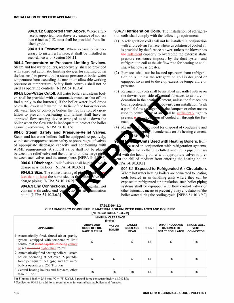
904.3.1.2 Supported from Above. Where a fur-nace is supported from above, a clearance of not lessthan 6 inches (152 mm) shall be provided from fin-ished grade.904.3.1.3 Excavation. Where excavation is nec-essary to install a furnace, it shall be installed inaccordance with Section 303.11.
904.4 Temperature or Pressure Limiting Devices.Steam and hot water boilers, respectively, shall be providedwith approved automatic limiting devices for shutting downthe burner(s) to prevent boiler steam pressure or boiler watertemperature from exceeding the maximum allowable workingpressure or temperature. Safety limit controls shall not beused as operating controls. [NFPA 54:10.3.4]904.5 Low-Water Cutoff. All water boilers and steam boil-ers shall be provided with an automatic means to shut off thefuel supply to the burner(s) if the boiler water level dropsbelow the lowest safe water line. In lieu of the low-water cut-off, water tube or coil-type boilers that require forced circu-lation to prevent overheating and failure shall have anapproved flow sensing device arranged to shut down theboiler when the flow rate is inadequate to protect the boileragainst overheating. [NFPA 54:10.3.5]904.6 Steam Safety and Pressure-Relief Valves.Steam and hot water boilers shall be equipped, respectively,with listed or approved steam safety or pressure- relief valvesof appropriate discharge capacity and conforming withASME requirements. A shutoff valve shall not be placedbetween the relief valve and the boiler or on discharge pipesbetween such valves and the atmosphere. [NFPA 54:10.3.6]
904.6.1 Discharge. Relief valves shall be piped to dis-charge near the floor. [NFPA 54:10.3.6.1]904.6.2 Size. The entire discharged piping shall be notless than at least the same size as the relief valve dis-charge piping. [NFPA 54:10.3.6.2]904.6.3 End Connections.Discharge piping shall notcontain a threaded end connection at its terminationpoint. [NFPA 54:10.3.6.3]
904.7 Refrigeration Coils. The installation of refrigera-tion coils shall comply with the following requirements:(1) A refrigeration coil shall not be installed in conjunction
with a forced- air furnace where circulation of cooled airis provided by the furnace blower, unless the blower hasthe sufficient capacity to overcome the external staticpressure resistance imposed by the duct system andrefrigeration coil at the air flow rate for heating or cool-ing, whichever is greater.
(2) Furnaces shall not be located upstream from refrigera-tion coils, unless the refrigeration coil is designed orequipped so as not to develop excessive temperature orpressure.
(3) Refrigeration coils shall be installed in parallel with or onthe downstream side of central furnaces to avoid con-densation in the heating element, unless the furnace hasbeen specifically listed for downstream installation. Witha parallel flow arrangement, the dampers or other meansused to control flow of air shall be sufficiently tight toprevent a any circulation of cooled air through the fur-nace.
(4) Means shall be provided for disposal of condensate andto prevent dripping of condensate on the heating element.[NFPA 54:10.3.8]
904.8 Cooling Units Used with Heating Boilers. Boil-ers, where used in conjunction with refrigeration systems,shall be installed so that the chilled medium is piped in par-allel with the heating boiler with appropriate valves to pre-vent the chilled medium from entering the heating boiler.[NFPA 54:10.3.9.1]
904.8.1 Exposed to Refrigerated Air Circulation.Where hot water heating boilers are connected to heatingcoils located in air-handling units where they can beexposed to refrigerated air circulation, such boiler pipingsystems shall be equipped with flow control valves orother automatic means to prevent gravity circulation of theboiler water during the cooling cycle. [NFPA 54:10.3.9.2]
136 UNIFORM MECHANICAL CODE - PREPRINT
INSTALLATION OF SPECIFIC APPLIANCES
MINIMUM CLEARANCE(inches)
APPLIANCEABOVE AND SIDES OF FUR-NACE PLENUM
TOP OFBOILER
JACKETSIDES ANDREAR
FRONTDRAFT HOOD ANDBAROMETRIC
DRAFT REGULATOR
SINGLE-WALLVENT
CONNECTOR
1. Automatically fired, forced air or gravitysystem, equipped with temperature limitcontrol that is not capable of being cannotbe set to exceed higher than 250°F.
6 – 6 18 6 18
2. Automatically fired heating boilers – steamboilers operating at not over 15 pounds-force per square inch (psi) and hot waterboilers operating at 250°F or less.
6 6 6 18 18 18
3. Central heating boilers and furnaces, otherthan in 1 or 2. 18 18 18 18 18 18
TABLE 904.2.2CLEARANCES TO COMBUSTIBLE MATERIAL FOR UNLISTED FURNACES AND BOILERS*
[NFPA 54: TABLE 10.3.2.2]
For SI units: 1 inch = 25.4 mm, °C = (°F-32)/1.8, 1 pound-force per square inch = 6.8947 kPa* See Section 904.1 for additional requirements for central heating boilers and furnaces.
PREPRINT
904.9 Furnace (Upright and Horizontal). Upright fur-naces shall be permitted to be installed in an attic, furred, orunder-floor space exceeding 5 feet (1524 mm) in height, pro-vided the required listings and furnace and duct clearancesare observed. Horizontal furnaces shall be permitted to beinstalled in an attic, furred, or under-floor space, provided therequired listings and furnace and duct clearances areobserved.904.10 Solid-Fuel-Fired Furnaces. Factory-built solid-fuel-fired furnaces shall comply with UL 391 and shall beinstalled in accordance with the manufacturer’s installationinstructions.904.11 Oil-Fired Central Furnaces.Oil-fired central fur-naces shall comply with UL 727 and shall be installed inaccordance with the manufacturer’s installation instructions.904.12 Commercial or Industrial Gas Heaters. Com-mercial or industrial gas-fired heaters shall comply with UL795 and shall be installed in accordance with the manufac-turer’s installation instructions.904.13 Electric Central Furnaces. Electric central heat-ing furnaces shall comply with UL 1995 or UL 60335-2-40and shall be installed in accordance with the manufacturer’sinstallation instructions.
905.0 Duct Furnaces.905.1 Clearances. The installation of duct furnaces shallcomply with the following clearance requirements:(1) Listed duct furnaces shall be installed with clearances of
not less than 6 inches (152 mm) between adjacent walls,ceilings, and floors of combustible material and the fur-nace draft hood. Furnaces listed for installation at lesserclearances shall be installed in accordance with their list-ings and the manufacturer’s installation instructions. Inno case shall the clearance be such as to interfere withcombustion air and accessibility.
(2) Unlisted duct furnaces shall be installed with clearancesto combustible material in accordance with the clear-ances specified for unlisted furnaces and boilers in Table904.2.2. Combustible floors under unlisted duct furnacesshall be protected in an approved manner.
905.2 Installation of Duct Furnaces. Duct furnaces shallbe installed in accordance with the manufacturer’s installa-tion instructions. [NFPA 54:10.10.2]905.3 Access Panels. The ducts connected to duct fur-naces shall have removable access panels on both theupstream and downstream sides of the furnace. [NFPA54:10.10.3]905.4 Location of Draft Hoods and Controls. The con-trols, combustion- air inlet, and draft hoods for duct furnacesshall be located outside the ducts. The draft hood shall belocated in the same enclosure from which combustion air istaken. [NFPA 54:10.10.4]905.5 Circulating Air.Where a duct furnace is installed sothat supply ducts carry air circulated by the furnace to areasoutside the space containing the furnace, the return air shallalso be handled by a duct(s) sealed to the furnace casing andterminating outside the space containing the furnace. The duct
furnace shall be installed on the positive-pressure side of thecirculating air blower. [NFPA 54:10.10.5]905.6 Duct Furnaces Used with Refrigeration Sys-tems. A duct furnace shall not be installed in conjunctionwith a refrigeration coil where circulation of cooled air is pro-vided by the blower.Exception: Where the blower has sufficient capacity to over-come the external static resistance imposed by the duct sys-tem, furnace, and the cooling coil and the air throughputnecessary for heating or cooling, whichever is greater. [NFPA54:10.10.6.1]
905.6.1 In Conjunction with Cooling Appliances.Duct furnaces used in conjunction with cooling appli-ances shall be installed in parallel with or on theupstream side of cooling coils to avoid condensationwithin heating elements. With a parallel flow arrange-ment, the dampers or other means used to control theflow of air shall be sufficiently tight to prevent any cir-culation of cooled air through the unit.Exception: Where the duct furnace has been specificallylisted for downstream installation. [NFPA 54:10.10.6.2]905.6.2 Located Upstream from Cooling Coils.Where duct furnaces are to be located upstream fromcooling units, the cooling unit shall be so designed orequipped as to not develop excessive temperatures orpressures. [NFPA 54:10.10.6.3]905.6.3 Heat Exchangers. Where a duct furnace isinstalled downstream of an evaporative cooler or airwasher, the heat exchanger shall be constructed of corro-sion-resistant materials. Stainless steel, ceramic-coatedsteel, and an aluminum-coated steel in which the bondbetween the steel and the aluminum is an iron-aluminumalloy are considered to be corrosion resistant. Air wash-ers operating with chilled water that deliver air below thedew point of the ambient air at the duct furnace shall beconsidered as refrigeration systems. [NFPA 54:10.10.6.4]
905.7 Installation in Commercial Garages and Air-craft Hangars. Duct furnaces installed in garages for morethan three motor vehicles or in aircraft hangars shall be of alisted type and shall be installed in accordance with Section303.11 and Section 303.12. [NFPA 54:10.10.7]905.8 Electric Duct Heaters. Electric duct heaters installedwithin an air duct shall be listed and labeled in accordance withUL 1996 and designed for the maximum air temperature. Theduct heater and fan shall be interlocked such that the electricduct heater operates when the fan is operating.
905.8.1 Installation. Duct heaters shall be installed inaccordance with the manufacturer’s installation instruc-tions, and shall not create a hazard to persons or prop-erty. Where installed 4 feet (1219 mm) or less from aheat pump or air conditioner, the duct heater shall belisted for such installation.905.8.2 Clearance. A working space clearance shallbe maintained to permit replacement of controls andheating elements and for adjusting and cleaning of con-trols. The working space for energized equipment shallcomply with NFPA 70.
137UNIFORM MECHANICAL CODE - PREPRINT
INSTALLATION OF SPECIFIC APPLIANCES
PREPRINT

906.0 Floor Furnaces.906.1 Installation. The installation of floor furnaces shallcomply with the following requirements:(1) Listed floor furnaces shall be installed in accordance with
their listing and the manufacturer’s installation instructions.(2) Unlisted floor furnaces shall not be installed on com-
bustible floors.(3) Thermostats controlling floor furnaces shall not be
located in a room or space that is capable of being sepa-rated from the room or space in which the register of thefloor furnace is located.
906.2 Temperature Limit Controls. Floor furnaces shallbe provided with temperature limit controls in accordancewith the following requirements:(1) Listed automatically operated floor furnaces shall be
equipped with temperature limit controls. [NFPA54:10.11.2.1]
(2) Unlisted automatically operated floor furnaces shall beequipped with a temperature limit control arranged toshut off the flow of gas to the burner in the event the tem-perature at the warm air outlet register exceeds 350°F(177°C) above room temperature. [NFPA 54:10.11.2.2]
906.3 Combustion and Circulating Air. Combustion andcirculating air shall be provided in accordance with Section701.0. [NFPA 54:10.11.3]906.4 Placement. The following provisions apply to fur-naces that serve one story:(1) Floors. Floor furnaces shall not be installed in the floor
of any doorway, stairway landing, aisle, or passagewayof any enclosure, public or private, or in an exitway fromany such room or space.
(2) Walls and Corners. The register of a floor furnace with ahorizontal warm air outlet shall not be placed closer than6 inches (152 mm) from the nearest wall. A distance of atleast 18 inches (457 mm) from two adjoining sides of thefloor furnace register to walls shall be provided to elimi-nate the necessity of occupants walking over the warm airdischarge. The remaining sides shall be a minimum of 6inches (152 mm) from a wall. Wall register models shallnot be placed closer than 6 inches (152 mm) to a corner.
(3) Draperies. The furnace shall be placed so that a door,drapery, or similar object cannot be nearer than 12 inches(305 mm) to any portion of the register of the furnace.[NFPA 54:10.11.4]
906.5 Bracing. The space provided for the furnace shall beframed with doubled joists and with headers not lighter thanthe joists. [NFPA 54:10.11.5]906.6 Support. Means shall be provided to support the fur-nace when the floor register is removed. [NFPA 54:10.11.6]906.7 Clearance. The lowest portion of the floor furnaceshall have at least a 6 inch (152 mm) clearance from the gen-eral ground level. A reduced clearance to a minimum of 2inches (51 mm) shall be permitted, provided the lower 6inches (152 mm) portion of the floor furnace is sealed by themanufacturer to prevent entrance of water. Where these clear-ances are not present, the ground below and to the sides shall
be excavated to form a “basin-like” pit under the furnace sothat the required clearance is provided beneath the lowest por-tion of the furnace. A 12 inch (305 mm) clearance shall beprovided on all sides except the control side, which shall havean 18 inch (457 mm) clearance. [NFPA 54:10.11.7]906.8 Access. The space in which a any floor furnace isinstalled shall be accessible by an opening in the foundationnot less than 24 inches by 18 inches (610 mm by 457 mm) orby a trap door trapdoor not less than 24 inches by 24 inches(610 mm by 610 mm) in a any cross-section thereof, and apassageway not less than 24 inches by 18 inches (610 mm by457 mm) in a any cross-section thereof. [NFPA 54:10.11.8]906.9 Seepage Pan. Where the excavation exceeds 12inches (305 mm) in depth or water seepage is likely to collect,a watertight copper pan, concrete pit, or other approved suit-able material shall be used, unless adequate drainage is pro-vided or the appliance is sealed by the manufacturer to meetthis condition. A copper pan shall be made of not less than 16ounces per square foot (oz/ft2) (4.9 kg/m2) sheet copper. Thepan shall be anchored in place so as to prevent floating, andthe walls shall extend at least 4 inches (102 mm) above theground level with at least a 6 inches (152 mm) clearance onall sides, except on the control side, which shall have at leastan 18 inch (457 mm) clearance. [NFPA 54:10.11.9]906.10 Wind Protection. Floor furnaces shall be protected,where necessary, against severe wind conditions. [NFPA54:10.11.10]906.11 Upper Floor Installations. Listed floor furnacesshall be permitted to be installed in an upper floor, providedthe furnace assembly projects below into a utility room,closet, garage, or similar nonhabitable space. In such instal-lations, the floor furnace shall be enclosed completely(entirely separated from the nonhabitable space) with meansfor air intake to meet the provisions of Section 701.0, withaccess for servicing, minimum furnace clearances of 6 inches(152 mm) to all sides and bottom, and with the enclosure con-structed of portland Portland cement plaster or metal lath orother noncombustible material. [NFPA 54:10.11.11]906.12 First Floor Installation. Listed floor furnacesinstalled in the first or ground floors of buildings shall not berequired to be enclosed unless the basements of these build-ings have been converted to apartments or sleeping quarters,in which case the floor furnace shall be enclosed as specifiedfor upper floor installations and shall project into a nonhab-itable space. [NFPA 54:10.11.12]906.13 Oil-Fired Floor Furnaces.Oil-fired floor furnacesshall comply with UL 729 and installed in accordance withthe manufacturer’s installation instructions.
907.0 Wall Furnaces.907.1 Installation. Listed wall furnaces shall be installed inaccordance with their listings and the manufacturer’s instal-lation instructions. Wall furnaces installed in or attached tocombustible material shall be listed for such installation.
907.1.1 Unlisted Wall Furnaces. Unlisted wall fur-naces shall not be installed in or attached to combustiblematerial. [NFPA 54:10.26.1.2]
138 UNIFORM MECHANICAL CODE - PREPRINT
INSTALLATION OF SPECIFIC APPLIANCES
PREPRINT
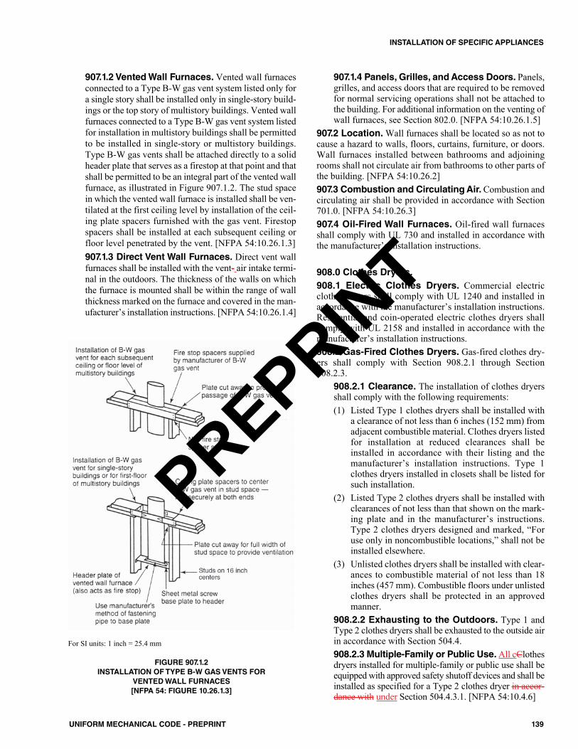
907.1.2 Vented Wall Furnaces. Vented wall furnacesconnected to a Type B-W gas vent system listed only fora single story shall be installed only in single-story build-ings or the top story of multistory buildings. Vented wallfurnaces connected to a Type B-W gas vent system listedfor installation in multistory buildings shall be permittedto be installed in single-story or multistory buildings.Type B-W gas vents shall be attached directly to a solidheader plate that serves as a firestop at that point and thatshall be permitted to be an integral part of the vented wallfurnace, as illustrated in Figure 907.1.2. The stud spacein which the vented wall furnace is installed shall be ven-tilated at the first ceiling level by installation of the ceil-ing plate spacers furnished with the gas vent. Firestopspacers shall be installed at each subsequent ceiling orfloor level penetrated by the vent. [NFPA 54:10.26.1.3]907.1.3 Direct Vent Wall Furnaces. Direct vent wallfurnaces shall be installed with the vent- air intake termi-nal in the outdoors. The thickness of the walls on whichthe furnace is mounted shall be within the range of wallthickness marked on the furnace and covered in the man-ufacturer’s installation instructions. [NFPA 54:10.26.1.4]
907.1.4 Panels, Grilles, and Access Doors. Panels,grilles, and access doors that are required to be removedfor normal servicing operations shall not be attached tothe building. For additional information on the venting ofwall furnaces, see Section 802.0. [NFPA 54:10.26.1.5]
907.2 Location. Wall furnaces shall be located so as not tocause a hazard to walls, floors, curtains, furniture, or doors.Wall furnaces installed between bathrooms and adjoiningrooms shall not circulate air from bathrooms to other parts ofthe building. [NFPA 54:10.26.2]907.3 Combustion and Circulating Air. Combustion andcirculating air shall be provided in accordance with Section701.0. [NFPA 54:10.26.3]907.4 Oil-Fired Wall Furnaces. Oil-fired wall furnacesshall comply with UL 730 and installed in accordance withthe manufacturer’s installation instructions.
908.0 Clothes Dryers.908.1 Electric Clothes Dryers. Commercial electricclothes dryers shall comply with UL 1240 and installed inaccordance with the manufacturer’s installation instructions.Residential and coin-operated electric clothes dryers shallcomply with UL 2158 and installed in accordance with themanufacturer’s installation instructions.908.2 Gas-Fired Clothes Dryers. Gas-fired clothes dry-ers shall comply with Section 908.2.1 through Section908.2.3.
908.2.1 Clearance. The installation of clothes dryersshall comply with the following requirements:(1) Listed Type 1 clothes dryers shall be installed with
a clearance of not less than 6 inches (152 mm) fromadjacent combustible material. Clothes dryers listedfor installation at reduced clearances shall beinstalled in accordance with their listing and themanufacturer’s installation instructions. Type 1clothes dryers installed in closets shall be listed forsuch installation.
(2) Listed Type 2 clothes dryers shall be installed withclearances of not less than that shown on the mark-ing plate and in the manufacturer’s instructions.Type 2 clothes dryers designed and marked, “Foruse only in noncombustible locations,” shall not beinstalled elsewhere.
(3) Unlisted clothes dryers shall be installed with clear-ances to combustible material of not less than 18inches (457 mm). Combustible floors under unlistedclothes dryers shall be protected in an approvedmanner.
908.2.2 Exhausting to the Outdoors. Type 1 andType 2 clothes dryers shall be exhausted to the outside airin accordance with Section 504.4.908.2.3 Multiple-Family or Public Use.All cClothesdryers installed for multiple-family or public use shall beequipped with approved safety shutoff devices and shall beinstalled as specified for a Type 2 clothes dryer in accor-dance with under Section 504.4.3.1. [NFPA 54:10.4.6]
For SI units: 1 inch = 25.4 mm
FIGURE 907.1.2INSTALLATION OF TYPE B-W GAS VENTS FOR
VENTED WALL FURNACES[NFPA 54: FIGURE 10.26.1.3]
139UNIFORM MECHANICAL CODE - PREPRINT
INSTALLATION OF SPECIFIC APPLIANCES
PREPRINT
909.0 Conversion Burners.909.1 General. Installation of conversion burners shall com-ply with conform to CSA Z21.8. [NFPA 54:10.5]
910.0 Burner Assemblies.910.1 Oil Burners. Oil burners shall comply with UL 296and installed in accordance with the manufacturer’s installa-tion instructions.910.2 Gas Burners. Commercial gas burners shall complywith UL 295 and installed in accordance with the manufac-turer’s installation instructions.
911.0 Decorative Appliances for Installation inVented Fireplaces.911.1 Prohibited Installations.Decorative appliances forinstallation in vented fireplaces shall not be installed in bath-rooms or bedrooms unless the appliance is listed and the bed-room or bathroom has the required volume in accordancewith Section 701.4. [NFPA 54:10.6.1]911.2 Installation. A decorative appliance for installationin a vented fireplace shall be installed only in a vented fire-place having a working chimney flue and constructed of non-combustible materials. These appliances shall not bethermostatically controlled. [NFPA 54:10.6.2]
911.2.1 Listed Decorative Appliance. A listed dec-orative appliance for installation in a vented fireplaceshall be installed in accordance with its listing and themanufacturer’s installation instructions. 911.2.2 In Manufactured Homes. A decorative appli-ance for installation in a vented fireplace, where installedin a manufactured home, shall be listed for installationin manufactured homes. [NFPA 54:10.6.2.2]911.2.3 Unlisted Decorative Appliance. An unlisteddecorative appliance for installation in a vented fireplaceshall be installed in a fireplace having a permanent freeopening, based on appliance input rating and chimneyheight, equal to or greater than that specified in Table911.2. [NFPA 54:10.6.2.3]
911.3 Fireplace Screens. A fireplace screen shall beinstalled with a decorative appliance for installation in avented fireplace. [NFPA 54:10.6.3]
912.0 Gas Fireplaces, Vented.912.1 Prohibited Installations. Vented gas fireplacesshall not be installed in bathrooms or bedrooms unless theappliance is listed and the bedroom or bathroom has therequired volume in accordance with Section 701.4.Exception: Direct- vent gas fireplaces. [NFPA 54:10.7.1]912.2 Installation. The installation of vented gas fireplacesshall comply with the following requirements:(1) Listed vented gas fireplaces shall be installed in accor-
dance with their listing and the manufacturer’s installa-tion instructions and where installed in or attached tocombustible material shall be specifically listed for suchinstallation.
(2) Unlisted vented gas fireplaces shall not be installed in orattached to combustible material. They shall have a clear-ance at the sides and rear of not less than 18 inches (457mm). Combustible floors under unlisted vented gas fire-places shall be protected in an approved manner.Unlisted appliances of other than the direct- vent typeshall be equipped with a draft hood and shall be ventedin accordance with Section 802.0. Appliances that usemetal, asbestos, or ceramic material to direct radiation tothe front of the appliance shall have a clearance of 36inches (914 mm) in front and, where constructed with adouble back of metal or ceramic, shall be installed witha clearance of not less than 18 inches (457 mm) at thesides and 12 inches (305 mm) at the rear.
(3) Panels, grilles, and access doors that are required to beremoved for normal servicing operations shall not beattached to the building.
(4) Direct- vent gas fireplaces shall be installed with thevent-air intake terminal in the outdoors and in accordancewith the manufacturer’s installation instructions.
912.3 Combustion and Circulating Air. Combustion andcirculating air shall be provided in accordance with Section701.0. [NFPA 54:10.7.3]
913.0 Factory-Built Fireplaces and Fireplace Stoves.913.1 Factory-Built Fireplaces. Factory-built fireplacesshall comply with UL 127 and installed in accordance withthe manufacturer’s installation instructions.
913.1.1 Gasketed Fireplace Doors.A gasketed fire-place door shall not be installed on a factory-built fire-place, except where the fireplace system has been testedin accordance with UL 127.
913.2 Fireplace Stoves. Fireplace stoves shall complywith UL 737 and installed in accordance with the manufac-turer’s installation instructions.913.3 Fireplace Accessories. Heat exchangers, glassdoors assemblies, combustion air vents, and termination capsshall comply with UL 907 and installed in accordance withthe manufacturer’s installation instructions.
914.0 Non-Recirculating Direct Gas-Fired IndustrialAir Heaters.914.1 Application. Direct gas-fired industrial air heaters ofthe non-recirculating type shall be listed in accordance withCSA Z83.4. [NFPA 54:10.8.1]914.2 Prohibited Installations. Non-recirculating directgas-fired industrial air heaters shall not serve any area con-taining sleeping quarters. Non-recirculating direct gas-firedindustrial air heaters shall not recirculate room air. [NFPA54:10.8.2.1, 10.8.2.2]914.3 Installation.Non-recirculating direct gas-fired indus-trial air heaters shall be installed in accordance with the man-ufacturer’s instructions. [NFPA 54:10.8.3.1]
914.3.1 Fresh Air Ventilation. Non-recirculatingdirect gas-fired industrial air heaters shall be permitted toprovide fresh air ventilation. [NFPA 54:10.8.3.2]
140 UNIFORM MECHANICAL CODE - PREPRINT
INSTALLATION OF SPECIFIC APPLIANCES
PREPRINT
914.3.2 Access Required. Non-recirculating directgas-fired industrial air heaters shall be provided withaccess for removal of burners; for replacement of motors,controls, filters, and other working parts; and for adjust-ment and lubrication of parts requiring maintenance.[NFPA 54:10.8.3.3]
914.4 Clearance from Combustible Materials. Non-recirculating direct gas-fired industrial air heaters shall beinstalled with a clearance from combustible materials of notless than that shown on the rating plate and the manufac-turer’s instructions. [NFPA 54:10.8.4]914.5 Air Supply.All air to the non-recirculating direct gas-fired industrial air heater shall be ducted directly from out-doors. Where outdoor air dampers or closing louvers are used,they shall be verified to be in the open position prior to mainburner operation. [NFPA 54:10.8.5]914.6 Atmospheric Vents, Gas Reliefs, or Bleeds.Non-recirculating direct gas-fired industrial air heaters withvalve train components equipped with atmospheric vents, gasreliefs, or bleeds shall have their vent lines, gas reliefs, orbleeds lead to a safe point outdoors. Means shall be employedon these lines to prevent water from entering and to preventblockage from insects and foreign matter. An atmosphericvent line shall not be required to be provided on a valve traincomponent equipped with a listed vent limiter. [NFPA54:10.8.6]914.7 Relief Openings. The design of the installation shallinclude adequate provisions to permit the non-recirculatingdirect gas-fired industrial air heater to operate at its rated air-flow without overpressurizing the space served by the heaterby taking into account the structure’s designed infiltrationrate, properly designed relief openings, or an interlockedpowered exhaust system, or a combination of these methods.[NFPA 54:10.8.7]
914.7.1 Infiltration Rate. The structure’s designedinfiltration rate and the size of relief opening(s) shall bedetermined by approved engineering methods. [NFPA54:10.8.7.1]
914.7.2 Louver or Gravity Dampers. Louver or coun-terbalanced gravity damper relief openings shall be per-mitted. Where motorized dampers or closeable louvers areused, they shall be proved to be in their open position priorto main burner operation. [NFPA 54:10.8.7.2]
914.8 Purging. Inlet ducting, when used, shall be purgedwith at least than four air changes prior to an ignition attempt.[NFPA 54:10.8.8]
915.0 Recirculating Direct Gas-Fired Industrial AirHeaters.915.1 Application. Direct gas-fired industrial air heaters ofthe recirculating type shall be listed in accordance with CSAZ83.18. [NFPA 54:10.9.1]915.2 Prohibited Installations. Recirculating direct gas-fired industrial air heaters shall not serve any area containingsleeping quarters. Recirculating direct gas-fired industrial airheaters shall not recirculate room air in buildings that containflammable solids, liquids, or gases; explosive materials; orsubstances that can become toxic when exposed to flame orheat. [NFPA 54:10.9.2.1, 10.9.2.2]915.3 Installation. Recirculating direct gas-fired industrialair heaters shall be installed in accordance with the manufac-turer’s instructions. [NFPA 54:10.9.3]915.4 Clearance from Combustible Materials. Recir-culating direct gas-fired industrial air heaters shall be installedwith a clearance from combustible materials of not less thanthat shown on the rating plate and the manufacturer’s instal-lation instructions. [NFPA 54:10.9.4]915.5 Air Supply. Ventilation air to the recirculating directgas-fired industrial air heater shall be ducted directly fromoutdoors. Air to the recirculating direct gas-fired industrialair heater in excess of the minimum ventilation air specifiedon the heater’s rating plate shall be taken from the building,ducted directly from outdoors, or a combination of both.Where outdoor air dampers or closing louvers are used, theyshall be verified to be in the open position prior to mainburner operation. [NFPA 54:10.9.5]
141UNIFORM MECHANICAL CODE - PREPRINT
INSTALLATION OF SPECIFIC APPLIANCES
MINIMUM PERMANENT FREE OPENING (square inches)*
CHIMNEYHEIGHT(feet)
8 13 20 29 39 51 64
APPLIANCE INPUT RATING (Btu/h)
6 7800 14 000 23 200 34 000 46 400 62 400 80 0008 8400 15 200 25 200 37 000 50 400 68 000 86 00010 9000 16 800 27 600 40 400 55 800 74 400 96 40015 9800 18 200 30 200 44 600 62 400 84 000 108 80020 10 600 20 200 32 600 50 400 68 400 94 000 122 20030 11 200 21 600 36 600 55 200 76 800 105 800 138 600
TABLE 911.2FREE OPENING AREA OF CHIMNEY DAMPER FOR VENTING FLUE GASES FROM UNLISTED DECORATIVE
APPLIANCES FOR INSTALLATION IN VENTED FIREPLACES [NFPA 54: TABLE 10.6.2.3]
For SI units: 1 foot = 304.8 mm, 1000 British thermal units per hour = 0.293 kW, 1 square inch = 0.000645 m2
* The first six minimum permanent free openings [8 square inches (0.005 m2) to 51 square inches (0.03 m2)] correspond approximately to the cross-sectionalareas of chimneys having diameters of 3 inches (76 mm) through 8 inches (203 mm), respectively. The 64 square inch (0.04 m2) opening corresponds to thecross-sectional area of a standard 8 inch (203 mm) by 8 inch (203 mm) chimney tile.
PREPRINT
915.6 Atmospheric Vents, Gas Reliefs, or Bleeds.Recirculating direct gas-fired industrial air heaters with valvetrain components equipped with atmospheric vents, gasreliefs, or bleeds shall have their vent lines, gas reliefs, orbleeds lead to a safe point outdoors. Means shall be employedon these lines to prevent water from entering and to preventblockage from insects and foreign matter. An atmosphericvent line shall not be required to be provided on a valve traincomponent equipped with a listed vent limiter. [NFPA54:10.9.6]915.7 Relief Openings. The design of the installation shallinclude adequate provisions to permit the recirculating directgas-fired industrial air heater to operate at its rated airflowwithout overpressurizing the space served by the heater bytaking into account the structure’s designed infiltration rate,properly designed relief openings or an interlocked poweredexhaust system, or a combination of these methods. [NFPA54:10.9.7]
915.7.1 Infiltration Rate. The structure’s designedinfiltration rate and the size of relief opening(s) shall bedetermined by approved engineering methods. [NFPA54:10.9.7.1]915.7.2 Louver or Gravity Dampers. Louver or coun-terbalanced gravity damper relief openings shall be per-mitted. Where motorized dampers or closeable louvers areused, they shall be proved to be in their open position priorto main burner operation. [NFPA 54:10.9.7.2]
915.8 Purging. Inlet ducting, when used, shall be purgedwith at least four air changes prior to an ignition attempt.[NFPA 54:10.9.8]
916.0 Room Heaters.916.1 Electric Room Heaters. Electric room heaters shallcomply with UL 2021.916.2 Gas-Fired Room Heaters. Gas-fired room heatersshall comply with Section 916.2.1 through Section 916.2.4.
916.2.1 Prohibited Installations.Unless specificallypermitted by the Authority Having Jurisdiction, unventedroom heaters shall not be installed as primary heatsources. Unvented room heaters shall not be permittedin spaces that do not have the required volume of indoorair as defined in Section 701.4.
916.2.1.1 Unvented Room Heaters. Unventedroom heaters shall not be installed in bathrooms orbedrooms. Exceptions:(1) Where approved by the Authority Having Juris-
diction, one listed wall-mounted unvented roomheater equipped with an oxygen depletionsafety shutoff system shall be permitted to beinstalled in a bathroom, provided that the inputrating does not exceed 6000 Btu/h (1.76 kW)and combustion and ventilation air is providedas specified in Section 902.2.
(2) Where approved by the Authority Having Juris-diction, one listed wall-mounted unvented roomheater equipped with an oxygen depletion
safety shutoff system shall be permitted to beinstalled in a bedroom, provided that the inputrating does not exceed 10 000 Btu/h (3 kW) andcombustion and ventilation air is provided asspecified in Section 902.2. [NFPA 54:10.22.1]
(3) Portable oil fired unvented heating appliancesused as supplemental heating in storage occu-pancies, utility occupancies, and in accordancewith the fire code.
916.2.2 Installations in Institutions. Room heatersshall not be installed in the following occupancies:(1) Residential board and care (2) Health care [NFPA 54:10.22.3]916.2.3 Clearance. A room heater shall be placed so asnot to cause a hazard to walls, floors, curtains, furniture,doors where open, and to the free movements of personswithin the room. Heaters designed and marked, “For usein noncombustible fireplace only,” shall not be installedelsewhere. Listed room heaters shall be installed inaccordance with their listings and the manufacturer’sinstallation instructions. In no case shall the clearances besuch as to interfere with combustion air and accessibility.Unlisted room heaters shall be installed with clearancesfrom combustible material not less than the following:(1) Circulating type room heaters having an outer jacket
surrounding the combustion chamber, arranged withopenings at top and bottom so that air circulatesbetween the inner and outer jacket, and withoutopenings in the outer jacket to permit direct radia-tion, shall have clearance at sides and rear of not lessthan 12 inches (305 mm).
(2) Radiating type room heaters other than those of thecirculating type described in Section 916.2.3(1) shallhave clearance at sides and rear of not less than 18inches (457 mm), except that heaters that make useof metal, asbestos, or ceramic material to direct radi-ation to the front of the heater shall have a clearanceof 36 inches (914 mm) in front and, where con-structed with a double back of metal or ceramic,shall be permitted to be installed with a clearance of18 inches (457 mm) at sides and 12 inches (305 mm)at rear. Combustible floors under unlisted roomheaters shall be protected in an approved manner.
916.2.4 Wall-Type Room Heaters. Wall-type roomheaters shall not be installed in or attached to walls ofcombustible material unless listed for such installation.[NFPA 54:10.22.5]
916.3 Solid-Fuel-Type Room Heaters. Solid-fuel typeroom heaters shall comply with UL 1482.
917.0 Unit Heaters.917.1 Support. Suspended-type unit heaters shall be safelyand adequately supported, with due consideration given totheir weight and vibration characteristics. Hangers and brack-ets shall be of noncombustible material. [NFPA 54:10.25.1]917.2 Clearance. Suspended-type unit heaters shall complywith the following requirements:
142 UNIFORM MECHANICAL CODE - PREPRINT
INSTALLATION OF SPECIFIC APPLIANCES
PREPRINT
(1) A listed unit heater shall be installed with clearancesfrom combustible material of not less than 18 inches (457mm) at the sides, 12 inches (305 mm) at the bottom, and6 inches (152 mm) above the top where the unit heaterhas an internal draft hood, or 1 inch (25.4 mm) above thetop of the sloping side of a vertical draft hood. A unitheater listed for reduced clearances shall be installed inaccordance with its listing and the manufacturer’s instal-lation instructions.
(2) Unlisted unit heaters shall be installed with clearances tocombustible material of not less than 18 inches (457mm).
(3) Clearances for servicing shall be in accordance with themanufacturer’s installation instructions.917.2.1 Floor-Mounted-Type Unit Heaters. Floor-mounted-type unit heaters shall comply with the follow-ing requirements:(1) A listed unit heater shall be installed with clearances
from combustible material at the back and one sideof not less than 6 inches (152 mm). Where the fluegases are vented horizontally, the 6 inch (152 mm)clearance shall be measured from the draft hood orvent instead of the rear wall of the unit heater. A unitheater listed for reduced clearances shall be installedin accordance with its listing and the manufacturer’sinstallation instructions.
(2) Floor-mounted-type unit heaters installed on com-bustible floors shall be listed for such installation.
(3) Combustible floors under unlisted floor-mountedunit heaters shall be protected in an approved man-ner.
(4) Clearances for servicing shall be in accordance withthe manufacturer’s instructions.
917.3 Combustion and Circulating Air. Combustion andcirculating air shall be provided in accordance with Section701.0. [NFPA 54:10.25.3]917.4 Ductwork. A unit heater shall not be attached to awarm air duct system unless listed and marked for such instal-lation. [NFPA 54:10.25.4]917.5 Installation in Commercial Garages and Air-craft Hangars. Unit heaters installed in garages for morethan three motor vehicles or in aircraft hangars shall be of alisted type and shall be installed in accordance with Section303.11 and Section 303.12. [NFPA 54:10.25.5]917.6 Oil-Fired Unit Heaters. Oil-fired unit heaters shallcomply with UL 731 and installed in accordance with themanufacturer’s installation instructions.
918.0 Food Service Appliance, Floor-Mounted.918.1 Clearance for Listed Appliances. Listed floor-mounted food service appliances, such as ranges for hotelsand restaurants, deep fat fryers, unit broilers, kettles, steamcookers, steam generators, and baking and roasting ovens,shall be installed not less than 6 inches (152 mm) from com-bustible material except that at least a 2 inch (51 mm) clear-
ance shall be maintained between a draft hood and com-bustible material. Floor-mounted food service applianceslisted for installation at lesser clearances shall be installed inaccordance with its listing and the manufacturer’s installationinstructions. Appliances designed and marked, “For use onlyin noncombustible locations,” shall not be installed else-where.918.2 Clearance for Unlisted Appliances. Unlistedfloor-mounted food service appliances shall be installed toprovide a clearance to combustible material of not less than18 inches (457 mm) from the sides and rear of the applianceand from the vent connector and not less than 48 inches (1219mm) above cooking tops and at the front of the appliance.
Clearances for unlisted appliances installed in partiallyenclosed areas such as alcoves shall not be reduced. Reducedclearances for unlisted appliances installed in rooms that arenot partially enclosed shall be in accordance with Table303.10.1. [NFPA 54:10.12.2]918.3 Mounting on Combustible Floors. Listed floor-mounted food service appliances that are listed specificallyfor installation on floors constructed of combustible materialshall be permitted to be installed on combustible floors inaccordance with its listing and the manufacturer’s installationinstructions.
918.3.1 Not Listed for Mounting on CombustibleFloors. Floor-mounted food service appliances that arenot listed for mounting on a combustible floor shall bemounted in accordance with Section 918.4 or be mountedin accordance with one of the following:(1) Where the appliance is set on legs that provide not
less than 18 inches (457 mm) open space under thebase of the appliance or where it has no burners andno portion of any oven or broiler within 18 inches(457 mm) of the floor, it shall be permitted to bemounted on a combustible floor without specialfloor protection, provided at least one sheet metalbaffle is between the burner and the floor.
(2) Where the appliance is set on legs that provide notless than 8 inches (203 mm) open space under thebase of the appliance, it shall be permitted to bemounted on combustible floors, provided the floorunder the appliance is protected with not less than3⁄8 of an inch (9.5 mm) insulating millboard coveredwith sheet metal not less than 0.0195 of an inch(0.4953 mm) thick. The preceding specified floorprotection shall extend not less than 6 inches (152mm) beyond the appliance on all sides.
(3) Where the appliance is set on legs that provide notless than 4 inches (102 mm) under the base of theappliance, it shall be permitted to be mounted oncombustible floors, provided the floor under theappliance is protected with hollow masonry not lessthan 4 inches (102 mm) in thickness covered withsheet metal not less than 0.0195 of an inch (0.4953mm) thick. Such masonry courses shall be laid withends unsealed and joints matched in such a way asto provide for free circulation of air through themasonry.
143UNIFORM MECHANICAL CODE - PREPRINT
INSTALLATION OF SPECIFIC APPLIANCES
PREPRINT
(4) Where the appliance does not have legs at least 4inches (102 mm) high, it shall be permitted to bemounted on combustible floors, provided the floorunder the appliance is protected by two courses of 4inch (102 mm) hollow clay tile, or equivalent, withcourses laid at right angles and with ends unsealedand joints matched in such a way as to provide forfree circulation of air through such masonry courses,and covered with steel plate not less than 3⁄16 of aninch (4.8 mm) in thickness. [NFPA 54:10.12.3.2]
918.4 Installation on Noncombustible Floors. Listedfloor-installed food service appliances that are designed andmarked “For use only in noncombustible locations” shall beinstalled on floors of noncombustible construction with non-combustible flooring and surface finish and with no com-bustible material against the underside thereof, or onnoncombustible slabs or arches having no combustible mate-rial against the underside thereof. Such construction shall inall cases extend not less than 12 inches (305 mm) beyond theappliance on all sides. [NFPA 54:10.12.4.1, 10.12.4.2]918.5 Combustible Material Adjacent to CookingTop. Listed and unlisted food service ranges shall be installedto provide clearance to combustible material not less than 18inches (457 mm) horizontally for a distance of up to 2 feet(610 mm) above the surface of the cooking top where thecombustible material is not completely shielded by highshelving, warming closet, or other system. Reduced com-bustible material clearances are permitted where protected inaccordance with Table 303.10.1. [NFPA 54:10.12.5]918.6 Use with Casters. Floor-mounted appliances withcasters shall be listed for such construction and shall beinstalled in accordance with the manufacturer’s installationinstructions for limiting the movement of the appliance to pre-vent strain on the connection. [NFPA 54:10.12.6]918.7 Level Installation. Floor-mounted food serviceappliances shall be installed level on a firm foundation.[NFPA 54:10.12.7]918.8 Ventilation.Means shall be provided to properly ven-tilate the space in which a food service appliance is installedto permit proper combustion of the gas. [NFPA 54:10.12.8]
919.0 Food Service Appliances, Counter Appliances.919.1 Vertical Clearance. A vertical distance of not lessthan 48 inches (1219 mm) shall be provided between the topof all food service hot plates and griddles and combustiblematerial. [NFPA 54:10.13.1]919.2 Clearance for Listed Appliances. Listed foodservice counter appliances such as hot plates and griddles,food and dish warmers, and coffee brewers and urns, whereinstalled on combustible surfaces, shall be set on their ownbases or legs and shall be installed with a horizontal clear-ance of not less than 6 inches (152 mm) from combustiblematerial, except that not less than a 2 inches (51 mm) clear-ance shall be maintained between a draft hood and com-bustible material. Food service counter appliances listed forinstallation at lesser clearances shall be installed in accor-dance with their listing and the manufacturer’s installationinstructions.
919.3 Clearance for Unlisted Appliances.Unlisted foodservice hot plates and griddles shall be installed with a hori-zontal clearance from combustible material of not less than 18inches (457 mm). Unlisted gas food service counter appli-ances, including coffee brewers and urns, waffle bakers, andhot water immersion sterilizers, shall be installed with a hor-izontal clearance from combustible material of not less than12 inches (305 mm). Reduced clearances for gas food servicecounter appliances shall be in accordance with Table303.10.1. Unlisted food and dish warmers shall be installedwith a horizontal clearance from combustible material of notless than 6 inches (152 mm). [NFPA 54:10.13.3]919.4 Mounting of Unlisted Appliances. Unlisted foodservice counter appliances shall not be set on combustiblematerial unless they have legs that provide not less than 4inches (102 mm) of open space below the burners and thecombustible surface is protected with insulating millboard notless than at least 1⁄4 of an inch (6.4 mm) thick covered withsheet metal not less than 0.0122 of an inch (0.3099 mm) thick,or with equivalent protection. [NFPA 54:10.13.4]
920.0 Household Cooking Appliances.920.1 Electric Household Cooking Appliances. Elec-tric household cooking appliances designed for permanentinstallations shall be installed in accordance with the manu-facturer’s installation instructions. Household electric rangesshall comply with UL 858. 920.2 Gas-Fired Household Cooking Appliances.Gas-fired household cooking appliances shall comply withSection 920.3 though Section 920.4.3.920.3 Floor-Mounted Units. Floor mounted units shall beinstalled in accordance with Section 920.3.1 and Section920.3.2.
920.3.1 Clearance from Combustible Material.The clearances specified as follows shall not interferewith combustion air, accessibility for operation, and serv-icing:(1) Listed floor-mounted household cooking appliances,
where installed on combustible floors, shall be seton their own bases or legs and shall be installed inaccordance with their listing and the manufacturer’sinstallation instructions.
(2) Listed household cooking appliances with listed gasroom heater sections shall be installed so that thewarm air discharge side shall have a clearance of notless than 18 inches (457 mm) from adjacent com-bustible material. A clearance of not less than 36inches (914 mm) shall be provided between the topof the heater section and the bottom of cabinets.
(3) Listed household cooking appliances that include asolid or liquid fuel-burning section shall be spacedfrom combustible material and otherwise installedin accordance with their listing and the manufac-turer’s installation instructions for the supplemen-tary fuel section of the appliance.
144 UNIFORM MECHANICAL CODE - PREPRINT
INSTALLATION OF SPECIFIC APPLIANCES
PREPRINT
(4) Unlisted floor-mounted household cooking appli-ances shall be installed with not less than 6 inches(152 mm) clearance at the back and sides to com-bustible material. Combustible floors under unlistedappliances shall be protected in an approved man-ner.
920.3.2 Vertical Clearance Above Cooking Top.Household cooking appliances shall have a vertical clear-ance above the cooking top of not less than 30 inches(762 mm) to combustible material or metal cabinets. Aminimum clearance of 24 inches (610 mm) is permittedwhere one of the following is installed:(1) The underside of the combustible material or metal
cabinet above the cooking top is protected with notless than 1⁄4 of an inch (6.4 mm) insulating millboardcovered with sheet metal not less than 0.0122 of aninch (0.3099 mm) thick.
(2) A metal ventilating hood of sheet metal not less than0.0122 of an inch (0.3099 mm) thick is installedabove the cooking top with a clearance of not lessthan 1⁄4 of an inch (6.4 mm) between the hood andthe underside of the combustible material or metalcabinet, and the hood is as wide as the appliance andis centered over the appliance.
(3) A listed cooking appliance or microwave oveninstalled over a listed cooking appliance shall be inaccordance with the terms of the upper appliance’slisting and the manufacturer’s installation instruc-tions. Microwave ovens shall comply with UL 923.
920.4 Built-In Units.Built-in units shall be installed in accor-dance with Section 920.4.1 through Section 920.4.3.
920.4.1 Installation. Listed built-in household cook-ing appliances shall be installed in accordance with theirlisting and the manufacturer’s installation instructions.The installation shall not interfere with combustion air,accessibility for operation, and servicing. Unlisted built-in household cooking appliances shall not be installed inor adjacent to combustible material. 920.4.2 Vertical Clearance. Built-in top (or surface)cooking appliances shall have a vertical clearance abovethe cooking top of not less than 30 inches (762 mm) tocombustible material or metal cabinets. A clearance ofnot less than 24 inches (610 mm) is permitted where oneof the following is installed:(1) The underside of the combustible material or metal
cabinet above the cooking top is protected with notless than 1⁄4 of an inch (6.4 mm) insulating millboardcovered with sheet metal not less than 0.0122 of aninch (0.3099 mm) thick.
(2) A metal ventilating hood of sheet metal not less than0.0122 of an inch (0.3099 mm) thick is installedabove the cooking top with a clearance of not lessthan 1⁄4 of an inch (6.4 mm) between the hood andthe underside of the combustible material or metalcabinet, and the hood not less than the width of theappliance and is centered over the appliance.
(3) A listed cooking appliance or microwave oveninstalled over a listed cooking appliance shall be inaccordance with the terms of the upper appliancelisting and the manufacturer’s installation instruc-tions. Microwave ovens shall comply with UL 923.
920.4.3 Level Installation. Cooking appliances shallbe installed so that the cooking top, broiler pan, or ovenracks are level. [NFPA 54:10.14.3]
921.0 Cooking Appliances Listing.921.1 Commercial Electric Ranges. Commercial electricranges shall comply with UL 197 and installed in accordancewith the manufacturer’s installation instructions. 921.2 Commercial Wood-Fired Baking Ovens. Com-mercial wood-fired baking ovens (refractory type) shall com-ply with UL 2162 and installed in accordance with themanufacturer’s installation instructions.921.3 Oil-Burning Ranges. Oil-burning ranges shall com-ply with UL 896 and installed in accordance with the manu-facturer’s installation instructions.
922.0 Open-Top Broiler Units.922.1 Listed Units. Listed open-top broiler units shall beinstalled in accordance with the manufacturer’s installationinstructions. [NFPA 54:10.18.1]922.2 Unlisted Units. Unlisted open-top broiler units shallbe installed in accordance with the manufacturer’s instruc-tions but shall not be installed in combustible material.[NFPA 54:10.18.2]922.3 Protection Above Domestic Units. Domestic open-top broiler units shall be provided with a metal ventilating hoodnot less than 0.0122 of an inch (0.3099 mm) thick with a clear-ance of not less than 1⁄4 of an inch (6.4 mm) between the hoodand the underside of combustible material or metal cabinets. Aclearance of at least 24 inches (610 mm) shall be maintainedbetween the cooking top and the combustible material or metalcabinet, and the hood shall be at least as wide as the open-topbroiler unit and centered over the unit. Listed domestic open-top broiler units incorporating an integral exhaust system andlisted for use without a ventilating hood shall not be requiredto be provided with a ventilating hood if installed in accordancewith Section 920.3.2(1). [NFPA 54:10.18.3]922.4 Commercial Units. Commercial open-top broilerunits shall be provided with ventilation in accordance withChapter 5, Part II. [NFPA 54:10.18.4]
923.0 Outdoor Cooking Appliances.923.1 Listed Units. Listed outdoor cooking appliancesshall be installed in accordance with their listing and the man-ufacturer’s installation instructions.923.2 Unlisted Units. Unlisted outdoor cooking appliancesshall be installed outdoors with clearances to combustiblematerial of not less than 36 inches (914 mm) at the sides andback and not less than 48 inches (1219 mm) at the front. In nocase shall the appliance be located under overhead com-bustible construction. [NFPA 54:10.19.2]
145UNIFORM MECHANICAL CODE - PREPRINT
INSTALLATION OF SPECIFIC APPLIANCES
PREPRINT
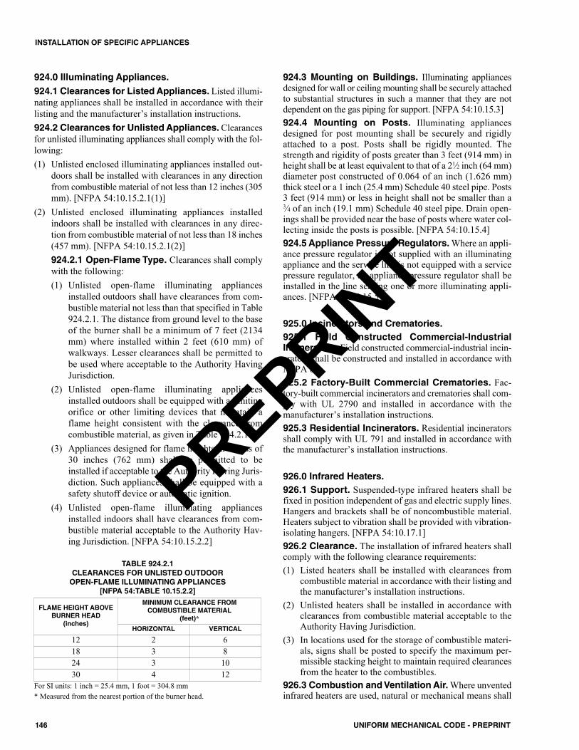
924.0 Illuminating Appliances.924.1 Clearances for Listed Appliances. Listed illumi-nating appliances shall be installed in accordance with theirlisting and the manufacturer’s installation instructions. 924.2 Clearances for Unlisted Appliances. Clearancesfor unlisted illuminating appliances shall comply with the fol-lowing:(1) Unlisted enclosed illuminating appliances installed out-
doors shall be installed with clearances in any directionfrom combustible material of not less than 12 inches (305mm). [NFPA 54:10.15.2.1(1)]
(2) Unlisted enclosed illuminating appliances installedindoors shall be installed with clearances in any direc-tion from combustible material of not less than 18 inches(457 mm). [NFPA 54:10.15.2.1(2)]924.2.1 Open-Flame Type. Clearances shall complywith the following:(1) Unlisted open-flame illuminating appliances
installed outdoors shall have clearances from com-bustible material not less than that specified in Table924.2.1. The distance from ground level to the baseof the burner shall be a minimum of 7 feet (2134mm) where installed within 2 feet (610 mm) ofwalkways. Lesser clearances shall be permitted tobe used where acceptable to the Authority HavingJurisdiction.
(2) Unlisted open-flame illuminating appliancesinstalled outdoors shall be equipped with a limitingorifice or other limiting devices that maintain aflame height consistent with the clearance fromcombustible material, as given in Table 924.2.1.
(3) Appliances designed for flame heights in excess of30 inches (762 mm) shall be permitted to beinstalled if acceptable to the Authority Having Juris-diction. Such appliances shall be equipped with asafety shutoff device or automatic ignition.
(4) Unlisted open-flame illuminating appliancesinstalled indoors shall have clearances from com-bustible material acceptable to the Authority Hav-ing Jurisdiction. [NFPA 54:10.15.2.2]
924.3 Mounting on Buildings. Illuminating appliancesdesigned for wall or ceiling mounting shall be securely attachedto substantial structures in such a manner that they are notdependent on the gas piping for support. [NFPA 54:10.15.3]924.4 Mounting on Posts. Illuminating appliancesdesigned for post mounting shall be securely and rigidlyattached to a post. Posts shall be rigidly mounted. Thestrength and rigidity of posts greater than 3 feet (914 mm) inheight shall be at least equivalent to that of a 21⁄2 inch (64 mm)diameter post constructed of 0.064 of an inch (1.626 mm)thick steel or a 1 inch (25.4 mm) Schedule 40 steel pipe. Posts3 feet (914 mm) or less in height shall not be smaller than a3⁄4 of an inch (19.1 mm) Schedule 40 steel pipe. Drain open-ings shall be provided near the base of posts where water col-lecting inside the posts is possible. [NFPA 54:10.15.4]924.5 Appliance Pressure Regulators. Where an appli-ance pressure regulator is not supplied with an illuminatingappliance and the service line is not equipped with a servicepressure regulator, an appliance pressure regulator shall beinstalled in the line serving one or more illuminating appli-ances. [NFPA 54:10.15.5]
925.0 Incinerators and Crematories.925.1 Field Constructed Commercial-IndustrialIncinerators. Field constructed commercial-industrial incin-erators shall be constructed and installed in accordance withNFPA 82. 925.2 Factory-Built Commercial Crematories. Fac-tory-built commercial incinerators and crematories shall com-ply with UL 2790 and installed in accordance with themanufacturer’s installation instructions.925.3 Residential Incinerators. Residential incineratorsshall comply with UL 791 and installed in accordance withthe manufacturer’s installation instructions.
926.0 Infrared Heaters.926.1 Support. Suspended-type infrared heaters shall befixed in position independent of gas and electric supply lines.Hangers and brackets shall be of noncombustible material.Heaters subject to vibration shall be provided with vibration-isolating hangers. [NFPA 54:10.17.1]926.2 Clearance. The installation of infrared heaters shallcomply with the following clearance requirements:(1) Listed heaters shall be installed with clearances from
combustible material in accordance with their listing andthe manufacturer’s installation instructions.
(2) Unlisted heaters shall be installed in accordance withclearances from combustible material acceptable to theAuthority Having Jurisdiction.
(3) In locations used for the storage of combustible materi-als, signs shall be posted to specify the maximum per-missible stacking height to maintain required clearancesfrom the heater to the combustibles.
926.3 Combustion and Ventilation Air. Where unventedinfrared heaters are used, natural or mechanical means shall
TABLE 924.2.1CLEARANCES FOR UNLISTED OUTDOOROPEN-FLAME ILLUMINATING APPLIANCES
[NFPA 54:TABLE 10.15.2.2]
FLAME HEIGHT ABOVEBURNER HEAD
(inches)
MINIMUM CLEARANCE FROM COMBUSTIBLE MATERIAL
(feet)*HORIZONTAL VERTICAL
12 2 618 3 824 3 1030 4 12
For SI units: 1 inch = 25.4 mm, 1 foot = 304.8 mm* Measured from the nearest portion of the burner head.
146 UNIFORM MECHANICAL CODE - PREPRINT
INSTALLATION OF SPECIFIC APPLIANCES
PREPRINT
be provided to supply and exhaust at least 4 ft3/min/1000Btu/h (0.38 m3/min/kW) input of installed heaters. [NFPA54:10.17.3.1]
926.3.1 Exhaust Openings. Exhaust openings forremoving flue products shall be above the level of theheaters. [NFPA 54:10.17.3.2]
926.4 Installation in Commercial Garages and Air-craft Hangars. Overhead heaters installed in garages formore than three motor vehicles or in aircraft hangars shall beof a listed type and shall be installed in accordance with Sec-tion 303.11 and Section 303.12. [NFPA 54:10.17.4]
927.0 Pool Heaters.927.1 Location. A pool heater shall be located or protectedso as to minimize accidental contact of hot surfaces by per-sons. [NFPA 54:10.20.1]927.2 Clearance. The installation of pool heaters shall com-ply with the following requirements:(1) In no case shall the clearances be such as to interfere with
combustion air, draft hood, or vent terminal clearanceand relief, and accessibility for servicing.
(2) A listed pool heater shall be installed in accordance withits listing and the manufacturer’s installation instructions.
(3) An unlisted pool heater shall be installed with a clear-ance of not less than 12 inches (305 mm) on the sidesand the rear. A combustible floor under an unlisted poolheater shall be protected in an approved manner.
927.3 Temperature or Pressure-Limiting Devices. Anunlisted pool heater shall be provided with overtemperatureprotection or overtemperature and overpressure protection bymeans of an approved device(s). [NFPA 54:10.20.3.1]
927.3.1 Pressure Relief Valve. Where a pool heater isprovided with over-temperature protection only and isinstalled with any device in the discharge line of theheater that can restrict the flow of water from the heaterto the pool (such as a check valve, shutoff valve, thera-peutic pool valving, or flow nozzles), a pressure-reliefvalve shall be installed either in the heater or between theheater and the restrictive device. [NFPA 54:10.20.3.2]
927.4 Bypass Valves. Where an integral bypass system isnot provided as a part of the pool heater, a bypass line andvalve shall be installed between the inlet and outlet piping foruse in adjusting the flow of water through the heater. [NFPA54:10.20.4]927.5 Venting. A pool heater listed for outdoor installationshall be installed with the venting means supplied by the man-ufacturer and in accordance with the manufacturer’s installa-tion instructions. [NFPA 54:10.20.5]
928.0 Refrigerators.928.1 Clearance. Refrigerators shall be provided withclearances for ventilation at the top and back in accordancewith the manufacturer’s instructions. Where such instructionsare not available, at least 2 inches (51 mm) shall be providedbetween the back of the refrigerator and the wall at least 12inches (305 mm) above the top. [NFPA 54:10.21.1]
928.2 Venting or Ventilating Kits Approved for Usewith a Refrigerator. Where an accessory kit is used for con-veying air for burner combustion or unit cooling to the refrig-erator from areas outside the room in which it is located, orfor conveying combustion products diluted with air contain-ing waste heat from the refrigerator to areas outside the roomin which it is located, the kit shall be installed in accordancewith the refrigerator manufacturer’s instructions. [NFPA54:10.21.2]
929.0 Gas-Fired Toilets.929.1 Clearance. A listed gas-fired toilet shall be installedin accordance with its listing and the manufacturer’s installa-tion instructions, provided that the clearance shall be such toafford ready accessibility for use, cleanout, and necessaryservicing.929.2 Installation on Combustible Floors. Listed gas-fired toilets installed on combustible floors shall be listed forsuch installation. [NFPA 54:10.24.2]929.3 Vents. Vents or vent connectors that are capable ofbeing contacted during casual use of the room in which thetoilet is installed shall be protected or shielded to prevent suchcontact. [NFPA 54:10.24.3]
930.0 Appliances for Installation in ManufacturedHousing.930.1 General. Appliances installed in manufactured hous-ing after the initial sale shall be listed for installation in man-ufactured housing, or approved, and shall be installed inaccordance with the requirements of this code and the manu-facturer’s installation instructions. Appliances installed in theliving space of manufactured housing shall be in accordancewith the requirements of Section 701.0. [NFPA 54:10.29]
931.0 Small Ceramic Kilns.931.1 General. The provisions of this section apply to kilnsused for ceramics that have a maximum interior volume of20 cubic feet (0.57 m3) and are used for hobby or noncom-mercial purposes.931.2 Installation. Kilns shall be installed in accordancewith the manufacturer’s installation instructions and the pro-visions of this code.931.3 Fuel-Gas Controls. Fuel-gas controls shall complywith Section 306.0 and Section 902.4. Standing pilots shallnot be used with gas-fired kilns.931.4 Electrical Equipment. All electrical equipment usedas part of, or in connection with, the installation of a kiln shallbe in accordance with the requirements in the electrical code.Electric kilns shall be listed and labeled in accordance withUL 499.931.5 Installations Inside Buildings. In addition to otherrequirements specified in this section, interior installationsshall comply with the requirements of Section 603.13.6 andSection 931.5.1 through Section 931.5.4.
931.5.1 Kiln Clearances. The sides and tops of kilnsshall be located not less than 18 inches (457 mm) from a
147UNIFORM MECHANICAL CODE - PREPRINT
INSTALLATION OF SPECIFIC APPLIANCES
PREPRINT
noncombustible wall surface and 3 feet (914 mm) froma combustible wall surface. Kilns shall be installed onnoncombustible flooring consisting of not less than 2inches (51 mm) of solid masonry or concrete extendingnot less than 12 inches (305 mm) beyond the base or sup-porting members of the kiln.Exception: These clearances shall be permitted to bereduced, provided the kiln is installed in accordance withits listing.
In no case shall the clearance on the gas or electri-cal control side of a kiln be reduced to less than 30 inches(762 mm).931.5.2 Hoods. A canopy-type hood shall be installeddirectly above each kiln. The face opening area of thehood shall be equal to or greater than the top horizontalsurface area of the kiln. The hood shall be constructed ofnot less than 0.024 of an inch (0.61 mm) (No. 24 gauge)galvanized steel or equivalent and be supported at aheight of between 12 inches (305 mm) and 30 inches(762 mm) above the kiln by noncombustible supports.Exception: Electric kilns installed with listed exhaustblowers shall be permitted to be used where marked asbeing suitable for the kiln and installed in accordancewith the manufacturer’s installation instructions.931.5.3 Gravity Ventilation Ducts. Each hood shallbe connected to a gravity ventilation duct extending in avertical direction to outside the building. This duct shallbe of the same construction as the hood and shall have aminimum cross-sectional area of not less than one-fif-teenth of the face opening area of the hood. The ductshall terminate not less than 12 inches (305 mm) abovea portion of a building within 4 feet (1219 mm) and ter-minate not less than 4 feet (1219 mm) from an openablewindow or other opening into the building or adjacentproperty line. The duct opening to the outside shall beshielded, without reduction of duct area, to prevententrance of rain into the duct. The duct shall be supportedat each section by noncombustible supports.931.5.4 Makeup Air. Provisions shall be made for air toenter the room in which a kiln is installed at a rate notless than the air being removed through the kiln hood.
931.6 Exterior Installations. Kilns shall be installed withminimum clearances as specified in Section 931.5.1. Wher-ever a kiln is located under a roofed area and is partiallyenclosed by more than two vertical wall surfaces, a hood andgravity ventilation duct shall be installed in accordance withSection 931.5.2, Section 931.5.3, and Section 603.13.6.
932.0 Outdoor Open Flame Decorative Appliances.932.1 General. Permanently fixed in place outdoor openflame decorative appliances shall be installed in accordancewith Section 932.1.1 through Section 932.1.3. [NFPA54:10.31]
932.1.1 Listed Units. Listed outdoor open flame decora-tive appliances shall be installed in accordance with themanufacturer’s installation instructions. [NFPA 54:10.31.1]
932.1.2 Unlisted Units. Unlisted outdoor open flamedecorative appliances shall be installed outdoors inaccordance with the manufacturer’s installation instruc-tions and with clearances to combustible material of notless than 36 inches (914 mm) from the sides. In no caseshall the appliance be located under overhead com-bustible construction. [NFPA 54:10.31.2]932.1.3 Connection to the Piping System. Theconnection to the gas piping system shall be in accor-dance with Section 1312.1(1), Section 1312.1(2), Sec-tion 1312.1(4), or Section 1312.1(5). [NFPA 54:10.31.3]
933.0 Evaporative Cooling Systems.933.1 General. Evaporative cooling systems, including airducts and fire dampers that are a portion of an evaporativecooling system, shall be in accordance with Section 933.2through Section 933.4.3. Evaporative cooling systems shallbe provided with outside air as specified for cooling systemsin Section 403.0.933.2 Location. Evaporative cooling systems shall beinstalled so as to minimize the probability of damage from anexternal source.933.3 Access, Inspection, and Repair. Evaporativecoolers shall be accessible for inspection, service, andreplacement without removing permanent construction.933.4 Installation. An evaporative cooler supported by thebuilding structure shall be installed on a level base and shallbe secured directly or indirectly to the building structure, toprevent displacement of the cooler.
933.4.1 Modifications to the Supporting Struc-ture. Modifications made to the supporting frameworkof buildings as a result of the installation shall be inaccordance with the requirements of the building code.Openings in exterior walls shall be flashed in anapproved manner in accordance with the requirements ofthe building code.933.4.2 On the Ground. An evaporative cooler sup-ported directly by the ground shall be isolated from theground by a level concrete slab extending not less than 3inches (76 mm) above the adjoining ground level.933.4.3 On a Platform. An evaporative cooler sup-ported on an aboveground platform shall be elevated notless than 6 inches (152 mm) above adjoining groundlevel.
934.0 Refrigeration Appliances.934.1 Self-Contained Refrigerators and Freezers.Factory-built commercial refrigerators and freezers shallcomply with UL 471 or UL 60335-2-89 and shall be installedin accordance with the manufacturer’s installation instruc-tions.934.2 Unit Coolers. Factory-built unit coolers for use inrefrigerators, freezers, refrigerated warehouses, and walk-incoolers shall comply with UL 412 or UL 60335-2-89 andshall be installed in accordance with the manufacturer’sinstallation instructions.
148 UNIFORM MECHANICAL CODE - PREPRINT
INSTALLATION OF SPECIFIC APPLIANCES
PREPRINT
934.3 Self-Contained Mechanical Refrigeration Sys-tems. Self-contained mechanical refrigeration systems foruse in walk-in coolers shall comply with UL 427 or UL60335-2-89 and shall be installed in accordance with the man-ufacturer’s installation instructions.
935.0 Ductless Mini-Split Systems Installation.935.1 General. A ductless mini-split system installationshall be installed in accordance with the manufacturer’sinstallation instructions and Section 310.2 for condensatecontrol.
936.0 Air Filter Appliances.936.1 Electrostatic Air Cleaners. Electrostatic air clean-ers shall comply with UL 867 and installed in accordancewith the manufacturer’s installation instructions.936.2 High-Efficiency Particulate Air Filter Units.High-efficiency particulate air filter units for use in industrialand laboratory exhaust and ventilation systems shall beinstalled in accordance with the manufacturer’s installationinstructions.
937.0 Gaseous Hydrogen Systems.937.1 General. Gaseous hydrogen systems shall be installedin accordance with NFPA 2.
938.0 Compressed Natural Gas (CNG) Vehicular FuelSystems.938.1 General. The installation of compressed natural gas(CNG) fueling (dispensing) systems shall conform to NFPA52. Residential CNG fueling appliances shall be listed inaccordance with CSA NGV 5.1 and installed in accordance tothe appliance manufacturer's installation instructions. [NFPA54:10.28]
149UNIFORM MECHANICAL CODE - PREPRINT
INSTALLATION OF SPECIFIC APPLIANCES
PREPRINT

150 UNIFORM MECHANICAL CODE - PREPRINT
PREPRINT
1001.0 General.1001.1 Applicability. The requirements of this chapter shallapply to the construction, installation, operation, repair, andalteration of boilers and pressure vessels. Low-pressure boil-ers shall comply with this chapter and Section 904.0.Exceptions:(1) Listed and approved potable water heaters with a nomi-
nal capacity not exceeding 120 gallons (454 L) and hav-ing a heat input not exceeding 200 000 British thermalunits per hour (Btu/h) (58.6 kW) used for hot water sup-ply at a pressure not exceeding 160 pounds-force persquare inch (psi) (1103 kPa) and at temperatures notexceeding 210°F (99°C), in accordance with the plumb-ing code.
(2) Pressure vessels used for unheated water supply, includ-ing those containing air that serves as a cushion and iscompressed by the introduction of water and tanks con-nected to sprinkler systems.
(3) Portable unfired pressure vessels and Interstate Com-merce Commission (I.C.C.) containers.
(4) Containers for liquefied petroleum gases, bulk oxygen,and medical gas that are regulated by the fire code.
(5) Unfired pressure vessels in business, factory, hazardous,mercantile, residential, storage, and utility occupancieshaving a volume not exceeding 5 cubic feet (0.14 m3)and operating at pressures not exceeding 250 psi (1724kPa).
(6) Pressure vessels used in refrigeration systems shall com-ply with Chapter 11.
(7) Pressure tanks used in conjunction with coaxial cables,telephone cables, power cables, and other similar humid-ity control systems.
(8) A boiler or pressure vessel subject to regular inspectionby federal inspectors or licensed by federal authorities.
1001.2 Boiler Rooms and Enclosures. Boiler rooms andenclosures shall comply with the building code.1001.3 Air for Combustion and Ventilation. Air forcombustion and ventilation shall be provided in accordancewith Chapter 7.1001.4 Drainage. For heating or hot-water-supply boilerapplications, the boiler room shall be equipped with a floordrain or other approved means for disposing of the accumu-lation of liquid wastes incident to cleaning, recharging, androutine maintenance. No steam pipe shall be directly con-nected to a part of a plumbing or drainage system, nor shall awater having a temperature above 140°F (60°C) be dis-charged under pressure directly into a part of a drainage sys-tem. Pipes from boilers shall discharge by means of indirectwaste piping as determined by the Authority Having Juris-diction or the boiler manufacturer’s instructions.
1001.5 Mounting. Equipment shall be set or mounted on alevel base capable of supporting and distributing the weightcontained thereon. Boilers, tanks, and equipment shall besecurely anchored to the structure. Equipment requiringvibration isolation shall be installed as designed by a regis-tered design professional and approved by the Authority Hav-ing Jurisdiction.
1001.5.1 Floors. Boilers shall be mounted on floors ofnoncombustible construction unless listed for mountingon combustible flooring.
1001.6 Chimneys or Vents. Boilers shall be connected toa chimney or vent, as provided for other fuel-burning equip-ment in Chapter 8 of this code.
1002.0 Standards.1002.1 General. Pressure vessels shall be constructed anddesigned in accordance with the ASME Boiler & PressureVessel Code (BPVC) Section VIII. Boilers shall be con-structed, designed, and installed in accordance with one ofthe following:(1) ASME BPVC Section I(2) ASME BPVC Section IV(3) NFPA 851002.2 Oil-Burning Boilers. Oil-burning boilers shallcomply with Section 1002.2.1 and Section 1002.2.2.
1002.2.1 Listing & Labeling. Oil-burning boilersshall be listed and labeled in accordance with UL 726.1002.2.2 Installation. Tanks, piping, and valves foroil-burning boilers shall be installed in accordance withNFPA 31.
1002.3 Electric Boilers. Electric boilers shall be listed andlabeled in accordance with UL 834.1002.4 Solid-Fuel-Fired Boilers. Solid-fuel-fired boilersshall comply with UL 2523 and shall be installed in accor-dance with the manufacturer’s installation instructions.1002.5 Dual Purpose Water Heater. Water heaters uti-lized for combined space- and water-heating applicationsshall be listed or labeled in accordance with the standards ref-erenced in Table 1203.2, and shall be installed in accordancewith the manufacturer’s installation instructions.
1003.0 Detailed Requirements.1003.1 Safety Requirements. The construction of boil-ers and pressure vessels and the installation thereof shall bein accordance with minimum requirements for safety fromstructural and mechanical failure and excessive pressures asestablished by the Authority Having Jurisdiction in accor-dance with nationally recognized standards.
151UNIFORM MECHANICAL CODE - PREPRINT
CHAPTER 10BOILERS AND PRESSURE VESSELS
PREPRINT
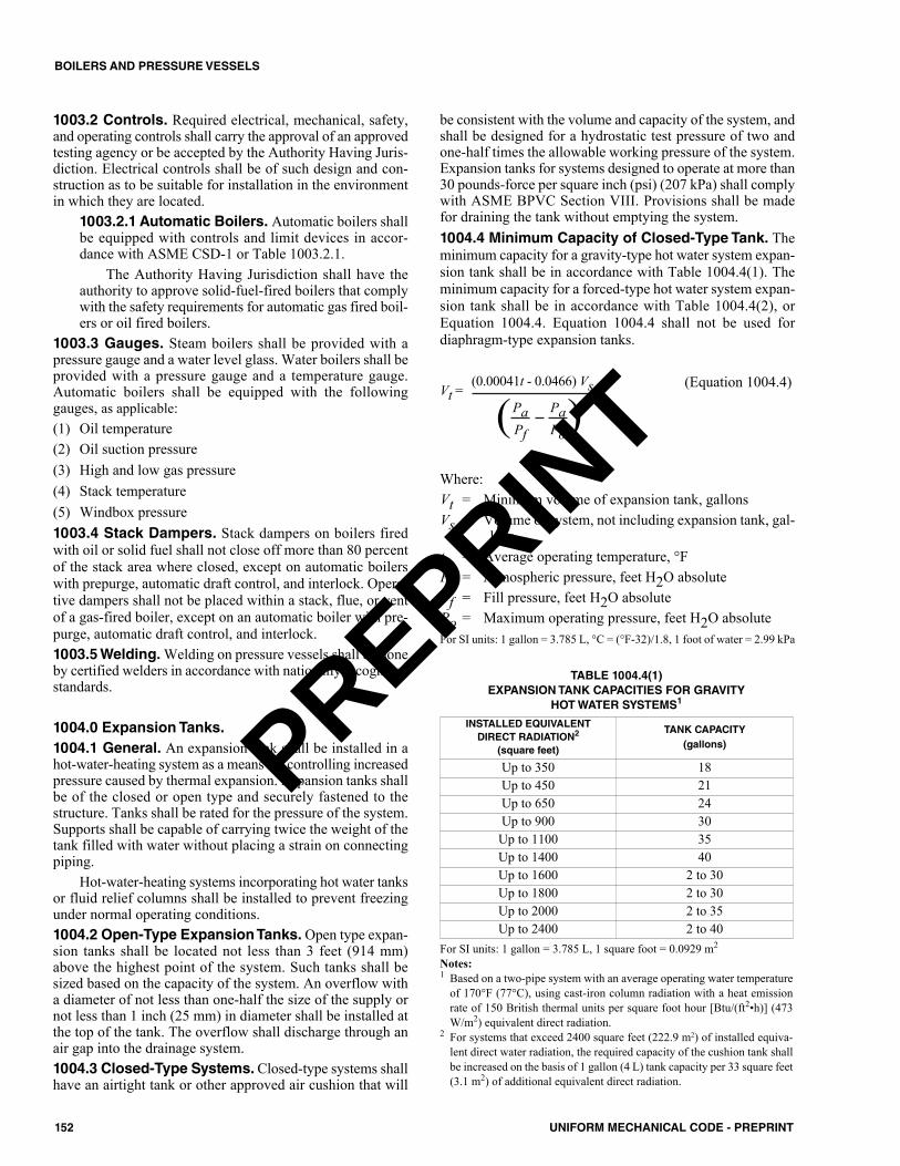
1003.2 Controls. Required electrical, mechanical, safety,and operating controls shall carry the approval of an approvedtesting agency or be accepted by the Authority Having Juris-diction. Electrical controls shall be of such design and con-struction as to be suitable for installation in the environmentin which they are located.
1003.2.1 Automatic Boilers. Automatic boilers shallbe equipped with controls and limit devices in accor-dance with ASME CSD-1 or Table 1003.2.1.
The Authority Having Jurisdiction shall have theauthority to approve solid-fuel-fired boilers that complywith the safety requirements for automatic gas fired boil-ers or oil fired boilers.
1003.3 Gauges. Steam boilers shall be provided with apressure gauge and a water level glass. Water boilers shall beprovided with a pressure gauge and a temperature gauge.Automatic boilers shall be equipped with the followinggauges, as applicable:(1) Oil temperature(2) Oil suction pressure (3) High and low gas pressure (4) Stack temperature(5) Windbox pressure1003.4 Stack Dampers. Stack dampers on boilers firedwith oil or solid fuel shall not close off more than 80 percentof the stack area where closed, except on automatic boilerswith prepurge, automatic draft control, and interlock. Opera-tive dampers shall not be placed within a stack, flue, or ventof a gas-fired boiler, except on an automatic boiler with pre-purge, automatic draft control, and interlock.1003.5 Welding.Welding on pressure vessels shall be doneby certified welders in accordance with nationally recognizedstandards.
1004.0 Expansion Tanks.1004.1 General. An expansion tank shall be installed in ahot-water-heating system as a means for controlling increasedpressure caused by thermal expansion. Expansion tanks shallbe of the closed or open type and securely fastened to thestructure. Tanks shall be rated for the pressure of the system.Supports shall be capable of carrying twice the weight of thetank filled with water without placing a strain on connectingpiping.
Hot-water-heating systems incorporating hot water tanksor fluid relief columns shall be installed to prevent freezingunder normal operating conditions.1004.2 Open-Type Expansion Tanks.Open type expan-sion tanks shall be located not less than 3 feet (914 mm)above the highest point of the system. Such tanks shall besized based on the capacity of the system. An overflow witha diameter of not less than one-half the size of the supply ornot less than 1 inch (25 mm) in diameter shall be installed atthe top of the tank. The overflow shall discharge through anair gap into the drainage system.1004.3 Closed-Type Systems. Closed-type systems shallhave an airtight tank or other approved air cushion that will
be consistent with the volume and capacity of the system, andshall be designed for a hydrostatic test pressure of two andone-half times the allowable working pressure of the system.Expansion tanks for systems designed to operate at more than30 pounds-force per square inch (psi) (207 kPa) shall complywith ASME BPVC Section VIII. Provisions shall be madefor draining the tank without emptying the system. 1004.4 Minimum Capacity of Closed-Type Tank. Theminimum capacity for a gravity-type hot water system expan-sion tank shall be in accordance with Table 1004.4(1). Theminimum capacity for a forced-type hot water system expan-sion tank shall be in accordance with Table 1004.4(2), orEquation 1004.4. Equation 1004.4 shall not be used fordiaphragm-type expansion tanks.
(Equation 1004.4)
Where:Vt = Minimum volume of expansion tank, gallonsVs = Volume of system, not including expansion tank, gal-
lonst = Average operating temperature, °FPa = Atmospheric pressure, feet H2O absolutePf = Fill pressure, feet H2O absolutePo = Maximum operating pressure, feet H2O absoluteFor SI units: 1 gallon = 3.785 L, °C = (°F-32)/1.8, 1 foot of water = 2.99 kPa
Vt =(0.00041t - 0.0466) Vs
(Pa Pa)Pf Po
TABLE 1004.4(1)EXPANSION TANK CAPACITIES FOR GRAVITY
HOT WATER SYSTEMS1
For SI units: 1 gallon = 3.785 L, 1 square foot = 0.0929 m2
Notes:1 Based on a two-pipe system with an average operating water temperature
of 170°F (77°C), using cast-iron column radiation with a heat emissionrate of 150 British thermal units per square foot hour [Btu/(ft2•h)] (473W/m2) equivalent direct radiation.
2 For systems that exceed 2400 square feet (222.9 m2) of installed equiva-lent direct water radiation, the required capacity of the cushion tank shallbe increased on the basis of 1 gallon (4 L) tank capacity per 33 square feet(3.1 m2) of additional equivalent direct radiation.
INSTALLED EQUIVALENTDIRECT RADIATION2
(square feet)
TANK CAPACITY (gallons)
Up to 350 18Up to 450 21Up to 650 24Up to 900 30Up to 1100 35Up to 1400 40Up to 1600 2 to 30Up to 1800 2 to 30Up to 2000 2 to 35Up to 2400 2 to 40
152 UNIFORM MECHANICAL CODE - PREPRINT
BOILERS AND PRESSURE VESSELS
PREPRINT
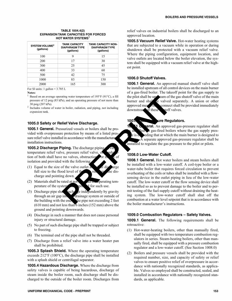
1005.0 Safety or Relief Valve Discharge.1005.1 General. Pressurized vessels or boilers shall be pro-vided with overpressure protection by means of a listed pres-sure relief valve installed in accordance with the manufacturer’sinstallation instructions.1005.2 Discharge Piping. The discharge piping serving atemperature relief valve, pressure relief valve, or combina-tion of both shall have no valves, obstructions, or means ofisolation and provided with the following: (1) Equal to the size of the valve outlet and shall discharge
full size to the flood level of the area receiving the dis-charge and pointing down.
(2) Materials shall be rated at not less than the operating tem-perature of the system and approved for such use.
(3) Discharge pipe shall discharge independently by gravitythrough an air gap into the drainage system or outside ofthe building with the end of the pipe not exceeding 2 feet(610 mm) and not less than 6 inches (152 mm) above theground and pointing downwards.
(4) Discharge in such a manner that does not cause personalinjury or structural damage.
(5) No part of such discharge pipe shall be trapped or subjectto freezing.
(6) The terminal end of the pipe shall not be threaded.(7) Discharge from a relief valve into a water heater pan
shall be prohibited.1005.3 Splash Shield. Where the operating temperatureexceeds 212°F (100°C), the discharge pipe shall be installedwith a splash shield or centrifugal separator. 1005.4 Hazardous Discharge.Where the discharge fromsafety valves is capable of being hazardous, discharge ofsteam inside the boiler room, such discharge shall be dis-charged to the outside of the boiler room. Discharges from
relief valves on industrial boilers shall be discharged to anapproved location.1005.5 Vacuum Relief Valve. Hot-water heating systemsthat are subjected to a vacuum while in operation or duringshutdown shall be protected with a vacuum relief valve.Where the piping configuration, equipment location, andvalve outlets are located below the boiler elevation, the sys-tem shall be equipped with a vacuum relief valve at the high-est point.
1006.0 Shutoff Valves.1006.1 General. An approved manual shutoff valve shallbe installed upstream of all control devices on the main burnerof a gas-fired boiler. The takeoff point for the gas supply tothe pilot shall be upstream of the gas shutoff valve of the mainburner and shall be valved separately. A union or otherapproved means of disconnect shall be provided immediatelydownstream of these shutoff valves.
1007.0 Gas-Pressure Regulators.1007.1 General. An approved gas-pressure regulator shallbe installed on gas-fired boilers where the gas supply pres-sure is exceeding that at which the main burner is designed tooperate. A separate approved gas-pressure regulator shall beinstalled to regulate the gas pressure to the pilot or pilots.
1008.0 Low-Water Cutoff.1008.1 General. Hot water boilers and steam boilers shallbe installed with a low-water cutoff. A coil-type boiler or awater-tube boiler that requires forced circulation to preventoverheating of the coils or tubes shall be installed with a flow-sensing device in the outlet piping in lieu of the low-watercutoff. The low-water cutoff or the flow sensing device shallbe installed so as to prevent damage to the boiler and to per-mit testing of the fuel-supply cutoff without draining the heat-ing system. The low-water cutoff shall shut off thecombustion at a water level setpoint that is in accordance withthe boiler manufacturer’s instructions.
1009.0 Combustion Regulators – Safety Valves.1009.1 General. The following requirements shall beretroactive:(1) Hot-water-heating boilers, other than manually fired,
shall be equipped with two temperature combustion reg-ulators in series. Steam-heating boilers, other than man-ually fired, shall be equipped with a pressure combustionregulator and a low-water cutoff. (See Section 1008.0)
(2) Boilers and pressure vessels shall be provided with therequired number, size, and capacity of safety or reliefvalves to ensure positive relief of overpressure in accor-dance with nationally recognized standards, as applica-ble. Valves so employed shall be constructed, sealed, andinstalled in accordance with nationally recognized stan-dards, as applicable.
TABLE 1004.4(2)EXPANSION TANK CAPACITIES FOR FORCED
HOT WATER SYSTEMS1
For SI units: 1 gallon = 3.785 LNotes:1 Based on an average operating water temperature of 195°F (91°C), a fill
pressure of 12 psig (83 kPa), and an operating pressure of not more than30 psig (207 kPa).
2 Includes volume of water in boiler, radiation, and piping, not includingexpansion tank.
SYSTEM VOLUME2
(gallons)
TANK CAPACITYDIAPHRAGM TYPE
(gallons)
TANK CAPACITY NON-DIAPHRAGM TYPE
(gallons)
100 9 15200 17 30300 25 45400 33 60500 42 751000 83 1502000 165 300
153UNIFORM MECHANICAL CODE - PREPRINT
BOILERS AND PRESSURE VESSELS
PREPRINT
1010.0 Clearance for Access.
1010.1 General. Where boilers are installed or replaced,clearance shall be provided to allow access for inspection,maintenance, and repair. Passageways around all sides ofboilers shall have an unobstructed width of not less than 18inches (457 mm). Clearance for repair and cleaning shall bepermitted to be provided through a door or access panel intoanother area, provided the opening is of sufficient size.Exception: Subject to the approval of the Authority HavingJurisdiction, boilers shall be permitted to be installed with aside clearance of less than 18 inches (457 mm), provided thatthe lesser clearance does not inhibit inspection, maintenance,or repair.1010.2 Power Boilers. Power boilers having a steam-gen-erating capacity in excess of 5000 pounds per hour (lb/h)(0.6299 kg/s) or having a heating surface in excess of 1000square feet (92.9 m2) or input in excess of 5 000 000 Btu/h(1464 kW) shall have a clearance of not less than 7 feet (2134mm) from the top of the boiler to the ceiling.1010.3 Steam-Heating Boilers, Hot Water Boilers, andPower Boilers. Steam-heating boilers and hot-water-heat-ing boilers that exceed one of the following limits: (1) 5 000 000 Btu/h input (1464 kW)(2) 5000 pounds steam per hour (0.6299 kg/s) capacity (3) 1000 square foot (92.9 m2) heating surface
Power boilers that do not exceed one of the followinglimits: (1) 5 000 000 Btu/h input (1464 kW) (2) 5000 pounds steam per hour (0.6299 kg/s) capacity(3) 1000 square foot (92.9 m2) heating surface
Boilers with manholes on top of the boiler, except thosedescribed in Section 1010.2 and Section 1010.4, shall have aclearance of not less than 3 feet (914 mm) from the top of theboiler to the ceiling.1010.4 Package Boilers, Steam-Heating Boilers, andHot-Water-Heating Boilers. Package boilers, steam-heat-ing boilers, and hot-water-heating boilers with no manholeon top of the shell and not exceeding one of the above limitsshall have a clearance of not less than 2 feet (610 mm) fromthe ceiling.
1011.0 Boilers, Stokers, and Steam Generators.
1011.1 General. The design, installation, and operation ofsingle burner boilers, multiple burner boilers, stokers, andatmospheric fluidized-bed boilers with not less than a fuelinput rating of 12.5 E+06 Btu/h (3.663 MW) to pulverizedfuel systems, fired or unfired steam generators used to recoverheat from combustion turbines and to other combustion tur-bine exhaust systems shall be in accordance with NFPA 85.That portion of the oil-burning system supplied on boilers andcovered within the scope of NFPA 85 shall be installed inaccordance with NFPA 85.
1012.0 Operating Adjustments and Instructions.1012.1 General. Hot water boiler installations, upon com-pletion, shall have controls set, adjusted, and tested by theinstalling contractor. A complete control diagram of a per-manent legible type, together with complete boiler operatinginstructions, shall be furnished by the installer for each instal-lation.
1013.0 Inspections and Tests.1013.1 General. An installation for which a permit isrequired shall not be put into service until it has beeninspected and approved by the Authority Having Jurisdiction.
It shall be the duty of the owner or his authorized repre-sentative to notify the Authority Having Jurisdiction that theinstallation is ready for inspection and test. It also shall be theduty of the owner or his authorized representative to post ina conspicuous position on the installation a notice in sub-stantially the following form: “Warning! This installation hasnot been inspected and approved by the Authority HavingJurisdiction and shall not be covered or concealed until soinspected and approved,” and it shall be unlawful for anyoneother than the Authority Having Jurisdiction to remove suchnotice. The Authority Having Jurisdiction shall require suchtests as it deems necessary to determine that the installationis in accordance with the provision of this section. Such testsshall be made by the owner or his authorized representativein the presence of the Authority Having Jurisdiction.Exception: On installations designed and supervised by aregistered design professional, the Authority Having Juris-diction shall have the authority to permit inspection and test-ing by such registered design professional.
Where the owner or his authorized representativerequests inspection of a boiler prior to its installation, theAuthority Having Jurisdiction shall make such inspection.1013.2 Operating Permit. It shall be unlawful to operate aboiler or pressure vessel without first obtaining a valid oper-ating permit to do so from the Authority Having Jurisdiction.Such permit shall be displayed in a conspicuous place adja-cent to the boiler or vessel. The operating permit shall not beissued until the equipment has been inspected and approvedby the Authority Having Jurisdiction.Exception: The operation of steam-heating boilers, low-pres-sure hot-water-heating boilers, hot water supply boilers, andpressure vessels in residential occupancies of less than sixdwelling units and utility occupancies.1013.3 Maintenance Inspection. The Authority HavingJurisdiction shall inspect boilers and pressure vessels oper-ated under a permit in accordance with ASHRAE/ACCA 180at such intervals as deemed necessary, but not less frequentlythan in accordance with Section 1013.4 through Section1013.7.1013.4 Power and Miniature Boilers. Power boilers andminiature boilers shall be inspected externally annually.Where construction and operating conditions permit, theyshall be subject to inspection internally annually.
154 UNIFORM MECHANICAL CODE - PREPRINT
BOILERS AND PRESSURE VESSELS
PREPRINT
1013.5 Steam-Heating and Water-Heating Boilers.Steam-heating boilers and hot-water-heating boilers shall beinspected externally annually. Where construction and oper-ating conditions permit, they shall also be subject to inspec-tion internally annually.1013.6 Automatic Steam-Heating Boilers. Automaticsteam-heating boilers shall be inspected externally biennially.Where construction and operating conditions permit, theyshall be subject to inspection internally biennially.1013.7 Unfired Pressure Vessels. Unfired pressure ves-sels shall be inspected externally biennially. Where subjectto corrosion and construction permits, they shall be subjectto inspection internally biennially.
Inspection of boilers and pressure vessels covered byinsurance shall be permitted to be made by employees of theinsuring company holding commissions from the NationalBoard of Boiler and Pressure Vessel Inspectors, subject toapproval of the Authority Having Jurisdiction. Approvedinsuring company inspectors shall make reports on prescribedforms on inspections authorized by the Authority HavingJurisdiction. The reports shall be filed in the Authority Hav-ing Jurisdiction office. Company inspectors shall notify theAuthority Having Jurisdiction of suspension of insurancebecause of dangerous conditions, new insurance in effect, anddiscontinuance of insurance coverage.
1014.0 Operation and Maintenance of Boilers andPressure Vessels.1014.1 General. Boilers and pressure vessels shall be oper-ated and maintained in accordance with requirements for pro-tection of the public established by the Authority HavingJurisdiction in accordance with nationally recognized stan-dards.
The Authority Having Jurisdiction shall notify the owneror authorized representative of defects or deficiencies andproperly corrected. Where such corrections are not made, orwhere the operation of the boiler or pressure vessel is deemedunsafe by the Authority Having Jurisdiction, they shall havethe authority to revoke the permit to operate the boiler or pres-sure vessel. Where the operation of a boiler or pressure ves-sel is deemed by the Authority Having Jurisdiction toconstitute an immediate danger, the pressure on such boiler orpressure vessel shall be permitted to be relieved at theowner’s cost and the boiler or pressure vessel shall not there-after be operated without the approval of the Authority Hav-ing Jurisdiction.
155UNIFORM MECHANICAL CODE - PREPRINT
BOILERS AND PRESSURE VESSELS
PREPRINT
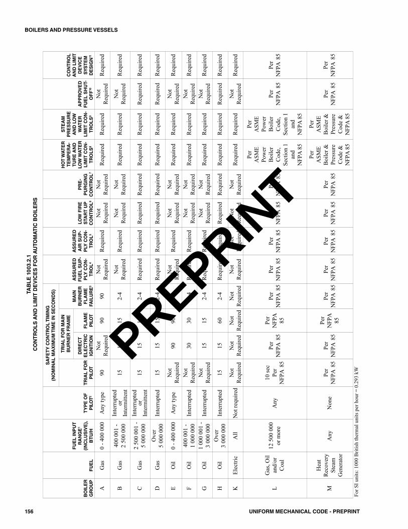
156 UNIFORM MECHANICAL CODE - PREPRINT
BOILERS AND PRESSURE VESSELS
BOILER
GROUP
FUEL
FUEL INPUT
RANGE1
(INCLUSIVE),
BTU/H
TYPE OF
PILOT2
SAFETYCONTROLTIMING
(NOMINAL MAXIMUMTIME IN SECONDS)
ASSURED
FUEL SUP-
PLY CON-
TROL4
ASSURED
AIR SUP-
PLY CON-
TROL5
LOW FIRE
START UP
CONTROL6
PRE-
PURGING
CONTROL7
HOT WATER
TEMPERA-
TURE AND
LOW WATER
LIMIT CON-
TROLS8
STEAM
PRESSURE
AND LOW
WATER
LIMIT CON-
TROLS9
APPROVED
FUEL SHUT-
OFF10
CONTROL
AND LIMIT
DEVICE
SYSTEM
DESIGN11
TRIAL FOR
PILOT
TRIAL FOR MAIN
BURNERFRAME
MAIN
BURNER
FLAME
FAILURE3
DIRECT
ELECTRIC
IGNITION
FLAME
PILOT
AG
as0
- 400
000
Any
type
90N
otRe
quire
d90
90N
otRe
quire
dR
equi
red
Not
Requ
ired
Not
Requ
ired
Req
uire
dR
equi
red
Not
Requ
ired
Req
uire
d
BG
as40
0 00
1 -
2 50
0 00
0In
terr
upte
dor
Inte
rmitt
ent
1515
152-
4N
otRe
quire
dR
equi
red
Not
Requ
ired
Not
Requ
ired
Req
uire
dR
equi
red
Not
Requ
ired
Req
uire
d
CG
as2
500
001
-5
000
000
Inte
rrup
ted
orIn
term
itten
t15
1515
2-4
Req
uire
dR
equi
red
Req
uire
dR
equi
red
Req
uire
dR
equi
red
Req
uire
dR
equi
red
DG
asO
ver
5 00
0 00
0In
terr
upte
d15
1515
2-4
Req
uire
dR
equi
red
Req
uire
dR
equi
red
Req
uire
dR
equi
red
Req
uire
dR
equi
red
EO
il0
- 400
000
Any
type
Not
Requ
ired
9090
90N
otRe
quire
dR
equi
red
Not
Requ
ired
Not
Requ
ired
Req
uire
dR
equi
red
Not
Requ
ired
Req
uire
d
FO
il40
0 00
1 -
1 00
0 00
0In
terr
upte
dN
otRe
quire
d30
302-
4R
equi
red
Req
uire
dN
otRe
quire
dN
otRe
quire
dR
equi
red
Req
uire
dN
otRe
quire
dR
equi
red
GO
il1
000
001
-3
000
000
Inte
rrup
ted
Not
Requ
ired
1515
2-4
Req
uire
dR
equi
red
Not
Requ
ired
Not
Requ
ired
Req
uire
dR
equi
red
Not
Requ
ired
Req
uire
d
HO
ilO
ver
3 00
0 00
0In
terr
upte
d15
1560
2-4
Req
uire
dR
equi
red
Req
uire
dR
equi
red
Req
uire
dR
equi
red
Req
uire
dR
equi
red
KEl
ectri
cA
llN
otre
quire
dN
otRe
quire
dN
otRe
quire
dN
otRe
quire
dN
otRe
quire
dN
otRe
quire
dN
otRe
quire
dN
otRe
quire
dN
otRe
quire
dR
equi
red
Req
uire
dN
otRe
quire
dR
equi
red
LG
as,O
ilan
d/or
Coa
l
12 5
00 0
00or
mor
eA
ny10
sec
Per
NFP
A85
Per
NFP
A85
Per
NFP
A85
Per
NFP
A85
Per
NFP
A85
Per
NFP
A85
Per
NFP
A85
Per
NFP
A85
Per
ASM
EPo
wer
Boi
ler
Cod
e,Se
ctio
n1
and
NFP
A85
Per
ASM
EPo
wer
Boi
ler
Cod
e,Se
ctio
n1
and
NFP
A85
Per
NFP
A85
Per
NFP
A85
M
Hea
tR
ecov
ery
Stea
mG
ener
ator
Any
Non
ePe
rN
FPA
85Pe
r N
FPA
85
Per
NFP
A85
Per
NFP
A85
Per
NFP
A85
Per
NFP
A85
Per
NFP
A85
Per
NFP
A85
Per
ASM
EB
oile
r&Pr
essu
reC
ode
&N
FPA
85
Per
ASM
EB
oile
r&Pr
essu
reC
ode
&N
FPA
85
Per
NFP
A85
Per
NFP
A85
For S
I uni
ts: 1
000
Brit
ish
ther
mal
uni
ts p
er h
our =
0.2
93 k
W
TABLE 1003.2.1
CONTROLS AND LIMIT DEVICES FOR AUTOMATIC BOILERS
PREPRINT
157UNIFORM MECHANICAL CODE - PREPRINT
BOILERS AND PRESSURE VESSELS
FOOTNOTES FORTABLE 1003.2.1 (continued)1 Fuel input shall be determined by one of the following:
The burner input shall not exceed the input shown on the burner nameplate or as otherwise identified by the manufacturer.The nominal boiler rating, as determined by the building official, plus 25 percent.
2 Automatic boilers shall have one flame failure device on each burner, which shall prove the presence of an ignition source at the point where it will ignitethe main burner, except that boiler groups A, B, E, F, and G, which are equipped with direct electric ignition, shall monitor the main burner, and boilergroups using interrupted pilots shall monitor the main burner after the prescribed limited trial and ignition periods. Boiler group A, equipped with continu-ous pilot, shall accomplish 100 percent shutoff within 90 seconds upon pilot flame failure. The use of intermittent pilots in boiler group C is limited toapproved burner units.
3 In boiler groups B, C, and D a 90 second main burner flame failure limit shall be permitted to be applied where continuous pilots are provided on manufac-turer assembled boiler-burner units that have been approved by an approved testing agency in accordance with nationally recognized standards approved bythe building official. Boiler groups F and G equipped to re-energize their ignition systems within 0.8 second after main burner flame failure will be permit-ted 30 seconds for group F or 15 seconds for group G to re-establish their main burner flames.
4 Boiler groups C and D shall have controls interlocked to accomplish a non-recycling fuel shutoff upon high or low gas pressure, and boiler groups F, G, andH using steam or air for fuel atomization shall have controls interlocked to accomplish a nonrecycling fuel shutoff upon low atomizing steam or air pressure.Boiler groups F, G, and H equipped with a preheated oil system shall have controls interlocked to provide fuel shutoff upon low oil temperature.
5 Automatic boilers shall have controls interlocked to shut off the fuel supply in the event of draft failure where forced or induced draft fans are used or, in theevent of low combustion airflow, where a gas power burner is used. Where a single motor directly driving both the fan and the oil pump is used, a separatecontrol is not required.
6 Boiler groups C, D, and H, where firing in excess of 400 000 Btu/h (117 kW) per combustion chamber, shall be provided with low fire start of its main burnersystem to permit smooth light-off. This will normally be a rate of one-third of its maximum firing rate.
7 Boiler groups C, D, and H shall not permit pilot or main burner trial for ignition operation before a purging operation of sufficient duration to permit not lessthan four complete air changes through the furnace, including a combustion chamber and the boiler passes. Where this is not readily determinable, five com-plete air changes of the furnace, including combustion chamber up to the first pass, will be considered equivalent. An atmospheric gas burner with no mechan-ical means of creating air movement or an oil burner that obtains two-thirds or more of the air required for combustion without mechanical means of creatingair movement shall not require purge by means of four air changes, so long as its secondary air openings are not provided with means of closing. Where suchburners have means of closing secondary air openings, a time delay shall be provided that puts these closures in a normally open position for four minutesbefore an attempt for ignition. An installation with a trapped combustion chamber shall, in every case, be provided with a mechanical means of creating airmovement for purging.
8 An automatic hot-water-heating boiler, low-pressure hot-water-heating boiler, and power hot water boiler shall be equipped with two high-temperature limitcontrols with a manual reset on the control, with the higher setting interlocked to shut off the main fuel supply, except that manual reset on the high-tem-perature limit control shall not be required on an automatic package boiler not exceeding 400 000 Btu/h (117 kW) input and that has been approved by anapproved testing agency. An automatic hot-water heating, power boiler, and package hot-water supply boiler shall be equipped with one low-water level limitcontrol with a manual reset interlocked to shut off the fuel supply, so installed as to prevent damage to the boiler and to permit testing of the control with-out draining the heating system, except on boilers used in Group R Occupancies of less than six units and in Group U Occupancies and further, except thatthe low-water level limit control is not required on package hot-water supply boilers approved by a nationally recognized testing agency. However, a low-water flow limit control installed in the circulating water line shall be permitted to be used instead of the low-water level limit control for the same purposeon coil-type boilers.
9 An automatic low-pressure steam-heating boiler, small power boiler, and power steam boiler shall be equipped with two high-steam pressure limit controlsinterlocked to shut off the fuel supply to the main burner with manual reset on the control, with the higher setting and two low-water-level limit controls,one of which shall be provided with a manual reset device and independent of the feed water controller. Coil-type flash steam boilers shall be permitted touse two high-temperature limit controls, one of which shall be manually reset in the hot water coil section of the boiler instead of the low-water level limitcontrol.
10 Boiler groups C, D, and H shall use an approved automatic reset safety shutoff valve for the main burner fuel shutoff, which shall be interlocked to the pro-gramming control devices required. On oil burners where the safety shutoff valve will be subjected to pressures in excess of 10 psi (69 kPa) where the burneris not firing, a second safety shutoff valve shall be provided in series with the first. Boiler groups C and D using gas in excess of 1 psi (7 kPa) pressure orhaving a trapped combustion chamber or employing horizontal fire tubes shall be equipped with two approved safety shutoff valves, one of which shall bean automatic reset type, one of which shall be permitted to be used as an operating control, and both of which shall be interlocked to the limit-control devicesrequired. Boiler groups C and D using gas in excess of 1 psi (7 kPa) pressure shall be provided with a permanent and ready means for making periodic tight-ness checks of the main fuel safety shutoff valves.
11 Control and limit device systems shall be grounded with operating voltage not to exceed 150 volts, except that, upon approval by the building official, exist-ing control equipment to be reused in an altered boiler control system shall be permitted to use 220 volts single phase with one side grounded, provided suchvoltage is used for all controls. Control and limit devices shall interrupt the ungrounded side of the circuit. A readily accessible means of manually discon-necting the control circuit shall be provided with controls so arranged that where they are de-energized, the burner shall be inoperative.
PREPRINT
158 UNIFORM MECHANICAL CODE - PREPRINT
PREPRINT
1101.0 General.1101.1 Applicability. Part I governs the design, installation,and construction of refrigeration systems, equipment, refrig-erant piping, pressure vessels, safety devices, replacement ofparts, alterations, and substitution of different refrigerants.Part II governs the installation and construction of coolingtowers.1101.2 Equipment. Equipment for refrigerant recovery,recycling, or both shall comply with UL 1963.
Part I – Refrigeration Systems.
1102.0 Refrigeration Systems.1102.1 General. Refrigeration systems using a refrigerantother than ammonia shall comply with this chapter andASHRAE 15.1102.2 Ammonia Refrigeration Systems. Refrigerationsystems using ammonia as the refrigerant shall comply withIIAR 2, IIAR 3, IIAR 4, and IIAR 5 and shall not be requiredto comply with this chapter.1102.3 Refrigerants. The refrigerant used shall be of a typelisted in Table 1102.3 or in accordance with ASHRAE 34where approved by the Authority Having Jurisdiction.Exception: Lithium bromide absorption systems using wateras the refrigerant.
1103.0 Classification.1103.1 Classification of Refrigerants. Refrigerants shallbe classified in accordance with Table 1102.3 or in accor-dance with ASHRAE 34 where approved by the AuthorityHaving Jurisdiction.
1103.1.1 Safety Group. Table 1102.3 classifies refrig-erants by toxicity and flammability, and assigns safetygroups using combinations of toxicity class and flam-mability class. For the purposes of this chapter, therefrigerant Groups A1, A2L, A2, A3, B1, B2L, B2, andB3 shall be considered to be individual and distinct safetygroups. Each refrigerant is assigned into not more thanone group.
1103.2 Classification of Refrigeration Systems.Refrigeration systems shall be classified according to thedegree of probability that a leakage of refrigerant will enter anoccupancy-classified area in accordance with Section1103.2.1 and Section 1103.2.2. [ASHRAE 15:5.2]
1103.2.1 High-Probability System. Systems inwhich the basic design, or the location of components, issuch that a leakage of refrigerant from a failed connec-tion, seal, or component will enter the occupied spaceshall be classified as high-probability systems. A high-probability system shall be a direct system or an indirectopen spray system in which the refrigerant is capable of
producing pressure that is more than the secondarycoolant. [ASHRAE 15:5.2.1]1103.2.2 Low-Probability System. Systems in whichthe basic design, or the location of the components, issuch that a leakage of refrigerant from a failed connec-tion, seal, or component is not capable of entering theoccupied space shall be classified as low-probability sys-tems. A low-probability system shall be an indirectclosed system, double indirect system, or an indirectopen spray system. In a low-probability indirect openspray system, the secondary coolant pressure remainsmore than the refrigerant pressure in operating andstandby conditions. [ASHRAE 15:5.2.2]
1103.3 Higher Flammability Refrigerants. Group A3and B3 refrigerants shall not be used except where approvedby the Authority Having Jurisdiction.Exceptions:(1) Laboratories with more than 100 square feet (9.29 m2)
of space per person.(2) Industrial occupancies. (3) Listed self-contained systems containing not more than
0.331 pounds (0.150 kg) of Group A3 refrigerant, pro-vided that the equipment is installed in accordance withthe listing and the manufacturer’s installation instruc-tions. [ASHRAE 15:7.5.3]
1104.0 Requirements for Refrigerant and Refrigera-tion System Use.1104.1 System Selection. Refrigeration systems shall belimited in application in accordance with Table 1104.1, andthe requirements of Section 1104.0.1104.2 Refrigerant Concentration Limit. The concen-tration of refrigerant in a complete discharge of an independ-ent circuit of high-probability systems shall not exceed theamounts shown in Table 1102.3, except as provided in Sec-tion 1104.3 and Section 1104.4. The volume of occupiedspace shall be determined in accordance with Section1104.2.1 through Section 1104.2.3. Exceptions:(1) Listed equipment containing not more than 6.6 pounds
(2.99 kg) of refrigerant, regardless of the refrigerantsafety classification, provided the equipment is installedin accordance with the listing and with the manufac-turer’s installation instructions.
(2) Listed equipment for use in laboratories with more than100 square feet (9.29 m2) of space per person, regardlessof the refrigerant safety classification, provided that theequipment is installed in accordance with the listing andthe manufacturer’s installation instructions. [ASHRAE15:7.2]
159UNIFORM MECHANICAL CODE - PREPRINT
CHAPTER 11REFRIGERATION
PREPRINT
1104.2.1 Volume Calculations. The volume used toconvert from refrigerant concentration limits to refriger-ating system quantity limits for refrigerants in Section1104.2 shall be based on the volume of space to whichrefrigerant disperses in the event of a refrigerant leak.[ASHRAE 15:7.3]1104.2.2 Nonconnecting Spaces. Where a refriger-ating system or part thereof is located in one or moreenclosed occupied spaces that do not connect throughpermanent openings or HVAC ducts, the volume of thesmallest occupied space shall be used to determine therefrigerant quantity limit in the system. Where differentstories and floor levels connect through an open atriumor mezzanine arrangement, the volume to be used in cal-culating the refrigerant quantity limit shall be determinedby multiplying the floor area of the lowest space by 8.2feet (2499 mm). [ASHRAE 15:7.3.1] 1104.2.3 Ventilated Spaces. Where a refrigeratingsystem or a part thereof is located within an air handler,in an air distribution duct system, or in an occupied spaceserved by a mechanical ventilation system, the entire airdistribution system shall be analyzed to determine theworst-case distribution of leaked refrigerant. The worstcase or the smallest volume in which the leaked refrig-erant disperses shall be used to determine the refrigerantquantity limit in the system, subject to the criteria inaccordance with Section 1104.2.3.1 through Section1104.2.3.3. [ASHRAE 15:7.3.2]
1104.2.3.1 Closures. Closures in the air distribu-tion system shall be considered. Where one or morespaces of several arranged in parallel are capable ofbeing closed off from the source of the refrigerantleak, their volume(s) shall not be used in the calcu-lation.Exceptions: The following closure devices are notconsidered:(1) Smoke dampers, fire dampers, and combination
smoke/fire dampers that close only in an emer-gency not associated with a refrigerant leak.
(2) Dampers, such as variable-air-volume (VAV)boxes, that provide limited closure where air-flow is not reduced below 10 percent of its max-imum (with the fan running). [ASHRAE15:7.3.2.1]
1104.2.3.2 Plenums. The space above a sus-pended ceiling shall not be included in calculatingthe refrigerating system quantity limits unless suchspace is part of the air supply or return system.[ASHRAE 15:7.3.2.2]1104.2.3.3 Supply and Return Ducts. The vol-ume of the supply and return ducts and plenumsshall be included when calculating the refrigeratingsystem quantity limits. [ASHRAE 15:7.3.2.3]
1104.3 Institutional Occupancies. The RCL valuerequired in Section 1104.2 shall be reduced by 50 percent forthe areas of institutional occupancies. The total of Group A2,B2, A3, and B3 refrigerants shall not exceed 550 pounds(249.5 kg) in the occupied areas and machinery rooms ofinstitutional occupancies. Exception: The total of all Group A2L refrigerants shall notbe limited in machinery rooms of institutional occupancies.1104.4 Industrial Occupancies and RefrigeratedRooms. Section 1104.2 shall not apply in industrial occu-pancies and refrigerated rooms where in accordance with thefollowing:(1) The space(s) containing the machinery is (are) separated
from other occupancies by tight construction with tight-fitting doors.
(2) Access is restricted to authorized personnel.(3) Refrigerant detectors are installed with the sensing loca-
tion and alarm level as required in refrigeration machin-ery rooms in accordance with Section 1106.2.2.2.
(4) Open flames and surfaces exceeding 800°F (427°C) shallnot be permitted where a Group A2, B2, A3, or B3 refrig-erant, is used.
(5) Electrical equipment that is in accordance with Class 1,Division 2, of NFPA 70 where the quantity of a GroupA2, B2, A3, or B3 refrigerant in an independent circuitis capable of exceeding 25 percent of the lower flamma-bility limit (LFL) upon release to the space based on thevolume determined in accordance with Section 1104.2.1through Section 1104.2.3.
(6) Refrigerant containing parts in systems exceeding 100horsepower (74.6 kW) compressor drive power, exceptevaporators used for refrigeration or dehumidification,condensers used for heating, control and pressure-reliefvalves for either, low-probability pumps, and connectingpiping, are located in a machinery room or outdoors.[ASHRAE 15:7.2.2]
1104.5 Flammable Refrigerants. The total of Group A2,B2, A3, and B3 refrigerants, other than Group A2L and B2Lrefrigerants shall not exceed 1100 pounds (498.9 kg) withoutapproval by the Authority Having Jurisdiction. InstitutionalOccupancies shall comply with Section 1104.3.1104.6 Applications for Human Comfort and for Non-industrial Occupancies. In nonindustrial occupancies,Group A2, A2L, A3, B1, B2L, B2, and B3 refrigerants shallnot be used in high-probability systems for human comfort. 1104.7 Refrigerant Type and Purity. Refrigerants shallbe of a type specified by the equipment manufacturer. Unlessotherwise specified by the equipment manufacturer, refriger-ants used in new equipment shall be of purity in accordancewith AHRI 700.
1104.7.1 Recovered Refrigerants. Recovered refrig-erants shall not be reused except in the system fromwhich they were removed or as provided in Section
160 UNIFORM MECHANICAL CODE - PREPRINT
REFRIGERATION
PREPRINT
1104.7.2 or Section 1104.7.3. When contamination isevident by discoloration, odor, acid test results, or systemhistory, recovered refrigerants shall be reclaimed inaccordance with Section 1104.7.3 before reuse.[ASHRAE 15:7.5.1.4]1104.7.2 Recycled Refrigerants. Recycled refriger-ants shall not be reused except in systems using the samerefrigerant and lubricant designation and belonging tothe same owner as the systems from which they wereremoved. Where contamination is evident by discol-oration, odor, acid test results, or system history, recy-cled refrigerants shall be reclaimed in accordance withSection 1104.7.3.Exception: Drying shall not be required in order to userecycled refrigerants where water is the refrigerant, isused as an absorbent or is a deliberate additive.[ASHRAE 15:7.5.1.5]1104.7.3 Reclaimed Refrigerants. Used refrigerantsshall not be reused in a different owner’s equipmentunless tested and found to be in accordance with therequirements of AHRI 700. Contaminated refrigerantsshall not be used unless reclaimed and is in accordancewith AHRI 700. [ASHRAE 15:7.5.1.6]1104.7.4 Mixing. Refrigerants, including refrigerantblends, with different designations as in accordance withTable 1102.3 shall not be mixed in a system.Exception: Addition of a second refrigerant shall be per-mitted where specified by the equipment manufacturerto improve oil return at low temperatures. The refriger-ant and amount added shall be in accordance with themanufacturer’s instructions. [ASHRAE 15:7.5.1.7]
1104.8 Changing Refrigerants. A change in the type ofrefrigerant in a system shall not be made without notifyingthe Authority Having Jurisdiction, the user, and due obser-vance of safety requirements. The refrigerant being consid-ered shall be evaluated for suitability. [ASHRAE 15:5.3]
1105.0 General Requirements.1105.1 Human Comfort. Cooling systems used for humancomfort shall be in accordance with the return-air and out-side-air provisions for furnaces in Section 604.1 and Section904.7. Cooling equipment used for human comfort in resi-dential buildings shall be selected in accordance with ACCAManual S to satisfy the calculated loads determined in accor-dance with ACCA Manual J or other approved methods.Refrigerants used for human comfort shall be in accordancewith Section 1104.6.1105.2 Supports and Anchorage. Supports and anchor-age for refrigeration equipment and piping shall be designedin accordance with the building code as Occupancy CategoryH (hazardous facilities). Supports shall be made of noncom-bustible materials.Exceptions:(1) Equipment containing Group A1 refrigerants shall be
permitted to be supported by the same materials permit-ted for the building type.
(2) The use of approved vibration isolators specificallydesigned for the normal, wind, and seismic loads encoun-tered, shall be permitted.A compressor or portion of a condensing unit supported
from the ground shall rest on a concrete or other approvedbase extending not less than 3 inches (76 mm) above theadjoining ground level.1105.3 Access. An unobstructed readily accessible open-ing and passageway not less than 36 inches (914 mm) inwidth and 80 inches (2032 mm) in height shall be providedand maintained to the compressor, valves required by thischapter, or other portions of the system requiring routinemaintenance.Exceptions:(1) Refrigerant evaporators, suspended overhead, shall be
permitted to use portable means of access.(2) Air filters, brine control or stop valves, fan motors or
drives, and remotely de-energized electrical connectionsshall be permitted to be provided access to an unob-structed space not less than 30 inches (762 mm) in depth,width, and height. Where an access opening is immedi-ately adjacent to these items and the equipment is capa-ble of being serviced, repaired, and replaced from thisopening, the dimensions shall be permitted to be reducedto 22 inches (559 mm) by 30 inches (762 mm) providedthe largest piece of equipment is removed through theopening.
(3) Cooling equipment, using Group A1 refrigerants orbrine, located in an attic or furred space shall be permit-ted to be provided access by a minimum opening andpassageway thereto of not less than 22 inches (559 mm)by 30 inches (762 mm).
(4) Cooling or refrigeration equipment, using Group A1 orB1 refrigerants or brine, located on a roof or on an exte-rior wall of a building, shall be permitted to be providedaccess as for furnaces in Section 304.3.
1105.4 Illumination and Service Receptacles. In addi-tion to the requirements of Section 301.4, permanent lightingfixtures luminaires shall be installed for equipment requiredby this code to be accessible or readily accessible. Such fix-tures luminaires shall provide illumination to perform therequired tasks for which access is provided. Control of theillumination source shall be provided at the access entrance.Exceptions:(1) Lighting fixtures Luminaires shall be permitted to be
omitted where the fixed lighting of the building will pro-vide the required illumination.
(2) Equipment located on the roof or on the exterior walls ofa building.
1105.5 Ventilation of Rooms Containing CondensingUnits. Where not in a refrigerant machinery room, rooms orspaces in which a refrigerant-containing portion of a con-densing unit is installed shall be provided with ventilation inaccordance with Section 1105.5.1 or Section 1105.5.2. Ven-tilation for machinery rooms shall comply with Section1106.0.
161UNIFORM MECHANICAL CODE - PREPRINT
REFRIGERATION
PREPRINT
1105.5.1 Permanent Gravity Ventilation Open-ings. Permanent gravity ventilation openings of not lessthan 2 square feet (0.2 m2) net free area opening shall beterminated directly to the outside of the building orextend to the outside of the building by continuous ducts.1105.5.2 Mechanical Exhaust System. A mechan-ical exhaust system shall be designed to provide a com-plete change of air not less than every 20 minutes in suchroom or space and shall discharge to the outside of thebuilding.Exceptions:(1) A condensing unit in a room or space where the
cubical content exceeds 1000 cubic feet per horse-power (ft3/hp) (37.95 m3/kW) of the unit.
(2) A condensing unit in a room or space that has per-manent gravity ventilation having an area of 2square feet (0.2 m2) or more to other rooms or open-ings exceeding 1000 ft3/hp (37.95 m3/kW).
1105.6 Prohibited Locations. Refrigeration systems orportions thereof shall not be located within a required exitenclosure. Refrigeration compressors exceeding 5 horsepow-ers (3.7 kW) rating shall be located not less than 10 feet (3048mm) from an exit opening in a Group A; Group B; Group E;Group F; Group I; Group R, Division 1; or Group S Occu-pancy, unless separated by a one-hour fire-resistive occu-pancy separation.1105.7 Condensate. Condensate from air-cooling coilsshall be collected and drained to an approved location. Drainpans and coils shall be arranged to allow thorough drainageand access for cleaning. Where temperatures drop belowfreezing, heat tracing and insulation of condensate drains shallbe installed.1105.8 Defrost. Where defrost cycles are required for por-tions of the system, provisions shall be made for collectionand disposal of the defrost liquid in a safe and sanitary man-ner.1105.9 Overflows. Where condensate or defrost liquids aregenerated in an attic or furred space, and structural damagewill result from overflow, provisions for overflow shall beprovided.1105.10 Condensate, Defrost, and Overflow Dis-posal. Disposal of condensate, defrost, or overflow dis-charges shall comply with Section 310.0.1105.11 Refrigerant Port Protection. Air conditioningrefrigerant circuit access ports located outdoors shall be pro-tected from unauthorized access with locking-type tamper-resistant caps or in a manner approved by the AuthorityHaving Jurisdiction.Exception: Refrigerant ports in secure locations protected bywalls or fencing and requiring key access.1105.12 Storage. Refrigerants and refrigerant oils notcharged within the refrigeration system shall be stored in
accordance with Section 1105.12.1 and the fire code. Storageof materials in a refrigeration machinery room shall complywith the fire code.
1105.12.1 Quantity. The total amount of refrigerantstored in a machinery room in all containers not providedwith relief valves and piping in accordance with Section1113.0 shall not exceed 330 pounds (149.7 kg). Refrig-erant shall be stored in approved storage containers.Additional quantities of refrigerant shall be stored in anapproved storage facility. [ASHRAE 15:11.5]
1106.0 Refrigeration Machinery Rooms.1106.1 Where Required. Refrigeration systems shall beprovided with a refrigeration machinery room where the con-ditions as outlined in Section 1106.1.1 through Section1106.1.4 exist.Exception: Refrigeration equipment shall be permitted to belocated outdoors in accordance with ASHRAE 15.
1106.1.1 Quantity. The quantity of refrigerant in a sin-gle, independent refrigerant circuit of a system exceedsthe amounts of Table 1102.3.1106.1.2 Equipment. Direct- and indirect-fired absorp-tion equipment is used.Exception: Direct and indirect-fired lithium bromideabsorption systems using water as the refrigerant.1106.1.3 A1 System. An A1 system having an aggre-gate combined compressor horsepower of 100 (74.6 kW)or more is used.1106.1.4 A1 Refrigerant. The system contains otherthan a Group A1 refrigerant.Exceptions:(1) Lithium bromide absorption systems using water as
the refrigerant.(2) Systems containing less than 300 pounds (136.1 kg)
of refrigerant R-123 and located in an approvedexterior location.Refrigeration machinery rooms shall house refrig-
erant-containing portions of the system other than thepiping and evaporators permitted by Section 1104.4, dis-charge piping required of this chapter, and cooling tow-ers regulated by Part II of this chapter, and their essentialpiping.
1106.2 Refrigeration Machinery Room, GeneralRequirements. Where a refrigeration system is locatedindoors and a machinery room is required in accordance withSection 1106.1, the machinery room shall be in accordancewith Section 1106.2.1 through Section 1106.2.5.2.
1106.2.1 Access. Machinery rooms shall not be pro-hibited from housing other mechanical equipment unlessspecifically prohibited elsewhere in this chapter. Amachinery room shall be so dimensioned that parts areaccessible with space for service, maintenance, and oper-
162 UNIFORM MECHANICAL CODE - PREPRINT
REFRIGERATION
PREPRINT
ations. There shall be clear head room of not less than7.25 feet (2210 mm) below equipment situated over pas-sageways. [ASHRAE 15:8.11.1]1106.2.2 Openings. Each refrigeration machineryroom shall have a tight-fitting door or doors opening out-ward, self-closing where they open into the building andadequate in number to ensure freedom for persons toescape in an emergency. With the exception of accessdoors and panels in air ducts and air-handling units inaccordance with Section 1106.6, there shall be no open-ings that will permit passage of escaping refrigerant toother parts of the building. [ASHRAE 15: 8.11.2]
1106.2.2.1 Detectors and Alarms. Each refrig-eration machinery room shall contain one or morerefrigerant detectors in accordance with Section1106.2.2.2, located in areas where refrigerant froma leak will concentrate, that actuate an alarm andmechanical ventilation in accordance with Section1106.2.4 at a set point not more than the correspon-ding Occupational Exposure Limit, OEL, in accor-dance with Table 1102.3, a set point determined inaccordance with the OEL as defined in Chapter 2shall be approved by the Authority Having Jurisdic-tion. The alarm shall annunciate visual and audiblealarms inside the refrigeration machinery room andoutside each entrance to the refrigeration machineryroom. The alarms required in this section shall be ofthe manual reset type with the reset located insidethe refrigeration machinery room. Alarms set atother levels, such as IDLH, and automatic resetalarms shall be permitted in addition to thoserequired in accordance with this section. The mean-ing of each alarm shall be clearly marked by signagenear the annunciator.Exception: Refrigerant detectors are not requiredwhere only systems using R-718 (water) are locatedin the refrigeration machinery room.1106.2.2.2 Refrigerant Detectors. Refrigerantdetectors required in accordance with Section1106.2.2.1 or Section 1107.1.7 shall meet all of thefollowing conditions:(1) The refrigerant detector shall perform automatic
self-testing of sensors. Where a failure isdetected, a trouble signal shall be activated.
(2) The refrigerant detector shall have one or moreset points to activate responses in accordancewith Section 1106.2.2.1 or Section 1107.1.7.
(3) The refrigerant detector as installed, includingany sampling tubes, shall activate responseswithin a time not to exceed 30 seconds afterexposure to refrigerant concentration exceedingthe set point value specified in Section1106.2.2.1 or Section 1107.1.7.
1106.2.3 Mechanical Ventilation. Machinery roomsshall be vented to the outdoors, utilizing mechanical ven-
tilation in accordance with Section 1106.2.4 and Section1106.2.5.1106.2.4 Ventilation. Mechanical ventilation referredto in Section 1106.2.3 shall be by one or more power-driven fans capable of exhausting air from the machineryroom at not less than the amount shown in accordancewith Section 1106.2.5.
To obtain a reduced airflow for normal ventilation,multiple fans or multispeed fans shall be used. Provisionshall be made to supply make-up air to replace that beingexhausted. Ducts for supply and exhaust to the machin-ery room shall serve no other area. The makeup air sup-ply locations shall be positioned relative to the exhaustair locations to avoid short-circuiting. Inlets to theexhaust ducts shall be located in an area where refriger-ant from a leak will concentrate, in consideration of thelocation of the replacement supply air paths, refrigeratingmachines, and the density of the refrigerant relative toair.
Inlets to exhaust ducts shall be within 1 foot (305 mm)of the lowest point of the machinery room for refrigerantsthat are heavier than air, and shall be within 1 foot (305mm) of the highest point for refrigerants that are lighterthan air. The discharge of the exhaust air shall be to the out-doors in such a manner as not to cause a nuisance or dan-ger.1106.2.5 Emergency Ventilation-Required Air-flow.An emergency ventilation system shall be requiredto exhaust an accumulation of refrigerant due to leaks ora rupture of the system. The emergency ventilationrequired shall be capable of removing air from themachinery room in not less than the airflow quantity inSection 1106.2.5.1 or Section 1106.2.5.2. Where multi-ple refrigerants are present, then the highest airflowquantity shall apply.
1106.2.5.1 Ventilation - A1, A2, A3, B1, B2L,B2 and B3 refrigerants. The emergency ventila-tion for A1, A2, A3, B1, B2L, B2 and B3 refriger-ants shall have the capacity to provide mechanicalexhaust at a rate as determined in accordance withEquation 1106.2.5.1.
Q = 100 √G (Equation 1106.2.5.1)
Where:Q = Air flow rate, cubic feet per minute.G = Refrigerant mass in largest system, pounds.For SI units: 1 cubic foot per minute = 0.00047 m3/s, 1 pound =0.453 kg
1106.2.5.2 Ventilation - Group A2L Refriger-ants. The emergency ventilation for A2L refriger-ants shall have the capacity to provide mechanicalexhaust at a rate determined in accordance withTable 1106.2.5.2.
163UNIFORM MECHANICAL CODE - PREPRINT
REFRIGERATION
PREPRINT
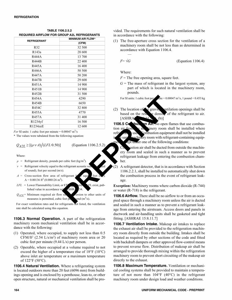
TABLE 1106.2.5.2REQUIRED AIRFLOW FOR GROUP A2L REFRIGERANTS
For SI units: 1 cubic foot per minute = 0.00047 m3/s* The values were tabulated from the following equation:
QA2L ≥ [(ρ∙ν∙A)/(LFL∙0.50)] (Equation 1106.2.5.2)
Where:
ρ = Refrigerant density, pounds per cubic feet (kg/m3).
ν = Refrigerant velocity equal to the refrigerant acoustic velocity (speedof sound), feet per second (m/s).
A = Cross-section flow area of refrigerant leak, square feet (m2), A = 0.00136 ft2 (0.000126 m2).
LFL = Lower Flammability Limit, or ETFL60 where no LFL exist, pub-lished value in accordance with ASHRAE 34.
QA2L= Minimum required air flow rate, conversion to other units ofmeasures is permitted, cubic feet per second (m3/s).
For exact ventilation rates and for refrigerants not listed, the ventilationrate shall be calculated using this equation.
1106.3 Normal Operation. A part of the refrigerationmachinery room mechanical ventilation shall be in accor-dance with the following:(1) Operated, where occupied, to supply not less than 0.5
CFM/ft2 (2.54 L/s/m2) of machinery room area or 20cubic feet per minute (9.44 L/s) per person.
(2) Operable, where occupied at a volume required to notexceed the higher of a temperature rise of 18°F (10°C)above inlet air temperature or a maximum temperatureof 122°F (50°C).
1106.4 Natural Ventilation. Where a refrigerating systemis located outdoors more than 20 feet (6096 mm) from build-ings opening and is enclosed by a penthouse, lean-to, or otheropen structure, natural or mechanical ventilation shall be pro-
vided. The requirements for such natural ventilation shall bein accordance with the following:(1) The free-aperture cross section for the ventilation of a
machinery room shall be not less than as determined inaccordance with Equation 1106.4.
F= √G (Equation 1106.4)
Where:F = The free opening area, square feet.G = The mass of refrigerant in the largest system, any
part of which is located in the machinery room,pounds.
For SI units: 1 cubic foot per minute = 0.00047 m3/s, 1 pound = 0.453 kg
(2) The location of the gravity ventilation openings shall bebased on the relative density of the refrigerant to air.[ASHRAE 15:8.11.5(a), (b)]
1106.5 Combustion Air. No open flames that use combus-tion air from the machinery room shall be installed whererefrigerant is used. Combustion equipment shall not be installedin the same machinery room with refrigerant-containing equip-ment except under one of the following conditions:(1) Combustion air shall be ducted from outside the machin-
ery room and sealed in such a manner as to preventrefrigerant leakage from entering the combustion cham-ber.
(2) A refrigerant detector, that is in accordance with Section1106.2.2.1, shall be installed to automatically shut downthe combustion process in the event of refrigerant leak-age.
Exception: Machinery rooms where carbon dioxide (R-744)or water (R-718) is the refrigerant.1106.6 Airflow. There shall be no airflow to or from an occu-pied space through a machinery room unless the air is ductedand sealed in such a manner as to prevent a refrigerant leak-age from entering the airstream. Access doors and panels inductwork and air-handling units shall be gasketed and tightfitting. [ASHRAE 15:8.11.7]1106.7 Ventilation Intake. Makeup air intakes to replacethe exhaust air shall be provided to the refrigeration machin-ery room directly from outside the building. Intakes shall belocated as required by other sections of the code and fittedwith backdraft dampers or other approved flow-control meansto prevent reverse flow. Distribution of makeup air shall bearranged to provide thorough mixing within the refrigerationmachinery room to prevent short circuiting of the makeup airdirectly to the exhaust.1106.8 Maximum Temperature. Ventilation or mechani-cal cooling systems shall be provided to maintain a tempera-ture of not more than 104°F (40°C) in the refrigerantmachinery room under design load and weather conditions.
REFRIGERANTMINIMUM AIR FLOW*
(CFM)
R32 32 500R143a 28 600R444A 13 700R444B 22 400R445A 16 400R446A 50 500R447A 50 200R447B 29 600R451A 14 900R451B 14 900R452B 31 500R454A 4290R454B 6650R454C 32 800R455A 4770R457A 31 400
R1234yf 16 500R1234zeE 12 600
164 UNIFORM MECHANICAL CODE - PREPRINT
REFRIGERATION
PREPRINT
1106.9 Refrigerant Parts in Air Duct. Joints and refrig-erant-containing parts of a refrigerating system located in anair duct carrying conditioned air to and from an occupiedspace shall be constructed to withstand a temperature of700°F (371°C) without leakage into the airstream. [ASHRAE15:8.8]1106.10 Dimensions. Refrigeration machinery rooms shallbe of such dimensions that system parts are readily accessi-ble with approved space for maintenance and operations. Anunobstructed walking space not less than 36 inches (914 mm)in width and 80 inches (2032 mm) in height shall be main-tained throughout, allowing free access to not less than twosides of moving machinery and approaching each stop valve.Access to refrigeration machinery rooms shall be restrictedto authorized personnel and posted with a permanent sign.1106.11 Restricted Access. Access to the refrigerationmachinery room shall be restricted to authorized personnel.Doors shall be clearly marked or permanent signs shall beposted at each entrance to indicate this restriction. [ASHRAE15:8.11.8]1106.12 Exits. Exits shall comply with the building code forspecial hazards.
1107.0 Machinery Room, Special Requirements.1107.1 General. In cases specified in the rules of Section1106.1, a refrigeration machinery room shall comply with thespecial requirements in accordance with Section 1107.1.1through Section 1107.1.10, in addition to Section 1106.2.
1107.1.1 Flame-Producing Devices. There shall beno flame-producing device or continuously operating hotsurface over 800°F (427°C) permanently installed in theroom.1107.1.2 Doors. Doors communicating with the build-ing shall be approved, self-closing, tight-fitting firedoors.1107.1.3 Walls, Floors, and Ceilings. Walls, floor,and ceiling shall be tight and of noncombustible con-struction. Walls, floor, and ceiling separating the refrig-eration machinery room from other occupied spaces shallbe not less than one-hour fire-resistive construction.1107.1.4 Machinery Rooms. The refrigerationmachinery room shall have a door that opens directly tothe outdoors or through a vestibule equipped with self-closing, tight-fitting doors.1107.1.5 Exterior Openings. Exterior openings, wherepresent, shall not be under a fire escape or an open stair-way.1107.1.6 Sealing. All pipes piercing the interior walls,ceiling, or floor of such rooms shall be tightly sealed tothe walls, ceiling, or floor through which they pass.1107.1.7 Group A2L and B2L Refrigerants.Whererefrigerant of Groups A2L or B2L are used, the require-ments of Class 1, Division 2, of NFPA 70, shall not applyto the machinery room provided that the conditions inSection 1107.1.7.1 through Section 1107.1.7.3 are met.
1107.1.7.1 Mechanical Ventilation. The mechani-cal ventilation system in the machinery room is run
continuously in accordance with Section 1106.2.5 andfailure of the mechanical ventilation system actuatesan alarm, or the mechanical ventilation system in themachinery room is activated by one or more refriger-ant detectors, in accordance with the requirements ofSection 1106.2.2.1 and Section 1106.2.2.2.1107.1.7.2 Refrigeration Detectors. For therefrigerant detection required in Section 1106.2.2.1,detection of refrigerant concentration that exceeds25 percent of the LFL or the upper detection limitof the refrigerant detector, whichever is lower, shallautomatically de-energize the following equipmentin the machinery room:(a) refrigerant compressors (b) refrigerant pumps (c) normally-closed automatic refrigerant valves 1107.1.7.3 Machinery Rooms. The machineryroom shall comply with Section 1107.1.8.
1107.1.8 Group A2, A3, B2, or B3 Refrigerants.Where any refrigerant of Groups A2, A3, B2, or B3 areused, the machinery room shall comply with Class 1,Division 2, of NFPA 70.1107.1.9 Refrigeration Systems. As part of themechanical ventilation system in accordance with Sec-tion 1106.2.4, refrigeration systems that contain morethan 110 pounds (50 kg) of any Group A2L, A2, A3,B2L, B2, or B3, refrigerant shall have not less than oneexhaust air inlet located adjacent to each system not morethan 9 feet (3 m) away.1107.1.10 Remote Control. Remote control of themechanical equipment in the refrigeration machineryroom shall be provided immediately outside the machin-ery room door solely for the purpose of shutting downthe equipment in an emergency. Ventilation fans shall beon a separate electrical circuit and have a control switchlocated immediately outside the machinery room door.
1108.0 Refrigeration Machinery Room Equipmentand Controls.1108.1 General. Equipment, piping, ducts, vents, or similardevices that are not essential for the refrigeration process,maintenance of the equipment, or for the illumination, venti-lation, or fire protection of the room shall not be placed in orpass through a refrigeration machinery room.1108.2 Electrical. Electrical equipment and installationsshall comply with the electrical code. The refrigerationmachinery room shall not be classified as a hazardous loca-tion except as provided in Section 1107.1.7 or Section1107.1.8.1108.3 Emergency Shut-off. A clearly identified emer-gency shut-off switch of the break-glass type or with anapproved tamper-resistant cover shall be provided immedi-ately adjacent to and outside of the principal refrigerationmachinery room entrance. The switch shall provide off-onlycontrol of refrigerant compressors, refrigerant pumps, andnormally-closed automatic refrigerant valves located in themachinery room. For other than A1 and B1 refrigerants,
165UNIFORM MECHANICAL CODE - PREPRINT
REFRIGERATION
PREPRINT
emergency shutoff shall be automatically activated by refrig-erant Alarm 2 in accordance with Section 1106.2.2.1. 1108.4 Installation, Maintenance, and Testing. Detec-tion and alarm systems in accordance with Section 1106.2.2.1shall be installed, maintained, and tested in accordance withthe fire code.1108.5 Emergency Pressure Control System. Whererequired by the fire code, an emergency pressure control sys-tem shall be installed in accordance with applicable fire coderequirements.
1109.0 Refrigeration Piping, Containers, and Valves.1109.1 Materials. Materials used in the construction andinstallation of refrigerating systems shall be suitable for con-veying the refrigerant used. Materials shall not be used thatwill deteriorate because of the refrigerant, lubricant, or theircombination in presence of air or moisture to a degree thatposes a safety hazard. [ASHRAE 15:9.1.1] Refrigerant pipingshall be metallic.
1109.1.1 Copper and Copper Alloy Pipe. Copperand copper alloy refrigeration piping, valves, fittings, andrelated parts used in the construction and installation ofrefrigeration systems shall be approved for the intendeduse. Refrigeration piping shall comply with ASMEB31.5.1109.1.2 Copper Linesets. Copper linesets shall com-ply with ASTM B280 or ASTM B1003.1109.1.3 Iron and Steel. Iron and steel refrigerationpiping, valves, fittings, and related parts shall beapproved for the intended use. Pipe exceeding 2 inches(50 mm) iron pipe size shall be electric-resistance weldedor seamless pipe. Refrigeration piping shall comply withASME B31.5.1109.1.4 Prohibited Contact. Aluminum, zinc, mag-nesium, or their alloys shall not be used in contact withmethyl chloride. Magnesium alloys shall not be usedwhere in contact with halogenated refrigerants.[ASHRAE 15:9.1.2]
1109.2 Joints. Iron or steel pipe joints shall be of approvedthreaded, flanged, or welded types. Exposed threads shall betinned or coated with an approved corrosion inhibitor. Cop-per or copper alloy pipe joints of iron pipe size shall be ofapproved threaded, flanged, press-connect or brazed types.Copper tubing joints and connections shall be connected byapproved flared, lapped, swaged, or brazed joints, solderedjoints, or mechanical joints that comply with UL 207 eitherindividually or as part of an assembly or a system by anapproved nationally recognized laboratory. Piping and tub-ing shall be installed so as to prevent vibration and strains atjoints and connections.1109.3 Penetration of Piping. Refrigerant piping shall notpenetrate floors, ceilings, or roofs.Exceptions:(1) Penetrations connecting the basement and the first floor.(2) Penetrations connecting the top floor and a machinery
penthouse or roof installation.
(3) Penetrations connecting adjacent floors served by therefrigeration system.
(4) Penetrations of a direct system where the refrigerant con-centration does not exceed that listed in Table 1102.3 forthe smallest occupied space through which the refriger-ant piping passes.
(5) In other than industrial occupancies and where the refrig-erant concentration exceeds that listed in Table 1102.3for the smallest occupied space, penetrations that con-nect separate pieces of equipment that are in accordancewith one of the following:(a) Enclosed by an approved gastight, fire-resistive duct
or shaft with openings to those floors served by therefrigerating system.
(b) Located on the exterior wall of a building wherevented to the outdoors or to the space served by thesystem and not used as an air shaft, closed court, orsimilar space. [ASHRAE 15:8.10.3]
1109.4 Location of Refrigeration Piping. Refrigerantpiping crossing an open space that affords passageway in abuilding shall be not less than 7.25 feet (2210 mm) above thefloor unless the piping is located against the ceiling of suchspace and is permitted by the Authority Having Jurisdiction.[ASHRAE 15:8.10.1]
1109.4.1 Protection from Mechanical Damage.Passages shall not be obstructed by refrigerant piping.Refrigerant piping shall not be located in an elevator,dumbwaiter, or other shaft containing a moving object,or in a shaft that has openings to living quarters, or tomeans of egress. Refrigerant piping shall not be installedin an enclosed public stairway, stair landing, or meansof egress. [ASHRAE 15:8.10.2]
1109.5 Underground Piping. Refrigerant piping placedunderground shall be protected against corrosion.
1109.5.1 Piping in Concrete Floors. Refrigerantpiping installed in concrete floors shall be encased in apipe duct. Refrigerant piping shall be isolated and sup-ported to prevent damaging vibration, stress, or corro-sion. [ASHRAE 15:8.10.4]
1109.6 Support. In addition to the requirements of Section1105.2, piping and tubing shall be securely fastened to a per-manent support within 6 feet (1829 mm) following the firstbend in such tubing from the compressor and within 2 feet(610 mm) of each subsequent bend or angle. Piping and tub-ing shall be supported at points not more than 15 feet (4572mm) apart.1109.7 Pipe Enclosure. Refrigerant piping and tubingshall be installed so that it is not subject to damage from anexternal source. Soft annealed copper tubing shall not exceed13⁄8 inches (35 mm) nominal size. Mechanical joints, otherthan approved press-connect joints, shall not be made on tub-ing exceeding 3⁄4 of an inch (20 mm) nominal size. Softannealed copper tubing conveying refrigerant shall beenclosed in iron or steel piping and fittings, or in conduit,molding, or raceway that will protect the tubing againstmechanical injury from an exterior source.
166 UNIFORM MECHANICAL CODE - PREPRINT
REFRIGERATION
PREPRINT

Exceptions:(1) Tubing entirely within or tubing within 5 feet (1524 mm)
of a refrigerant compressor where so located that it is notsubject to external injury.
(2) Copper tubing serving a dwelling unit, where such tub-ing contains Group A1 refrigerant and is placed in loca-tions not subject to damage from an external source.
1109.8 Visual Inspection. Refrigerant piping and jointserected on the premises shall be exposed to view for visualinspection prior to being covered or enclosed. Exception: Copper tubing enclosed in iron or steel pipingconduit, molding, or raceway, provided there are no fittingsor joints concealed therein.1109.9 Condensation. Piping and fittings that conveybrine, refrigerant, or coolants that during normal operationare capable of reaching a surface temperature below the dewpoint of the surrounding air and that are located in spaces orareas where condensation will cause a hazard to the buildingoccupants or damage to the structure, electrical or otherequipment shall be protected to prevent such damage.1109.10 Identification. Piping shall be in accordance withthe reference standard for identification. The type of refrig-erant, function and pressure shall be indicated.
1110.0 Valves.1110.1 More than 6.6 Pounds of Refrigerant. Systemscontaining more than 6.6 pounds (2.99 kg) of refrigerant shallhave stop valves installed at the following locations:(1) The suction inlet of a compressor, compressor unit, or
condensing unit.(2) The discharge of a compressor, compressor unit, or con-
densing unit.(3) The outlet of a liquid receiver.Exceptions: (1) Systems that have a refrigerant pumpout function capa-
ble of storing the refrigerant charge, or are equipped withthe provisions for pumpout of the refrigerant.
(2) Self-contained systems. [ASHRAE 15:9.12.4]1110.2 More than 110 Pounds of Refrigerant. Systemscontaining more than 110 pounds (49.9 kg) of refrigerantshall have stop valves installed at the following locations:(1) The suction inlet of a compressor, compressor unit, or
condensing unit.(2) The discharge outlet of a compressor, compressor unit, or
condensing unit.(3) The inlet of a liquid receiver, except for self-contained
systems or where the receiver is an integral part of thecondenser or condensing unit.
(4) The outlet of a liquid receiver.(5) The inlets and outlets of condensers where more than one
condenser is used in parallel in the systems.Exception: Systems that have a refrigerant pumpout functioncapable of storing the refrigerant charge, or are equipped withthe provisions for pumpout of the refrigerant or self-containedsystems. [ASHRAE 15:9.12.5]
1110.3 Support. Stop valves installed in copper refrigerantlines of 3⁄4 of an inch (20 mm) or less outside diameter shallbe supported independently of the tubing or piping.1110.4 Access. Stop valves required by Section 1110.0 shallbe readily accessible from the refrigeration machinery roomfloor or a level platform.1110.5 Identification. Stop valves shall be identified by tag-ging in accordance with the reference standard for identifica-tion. A valve chart shall be mounted under glass at anapproved location near the principal entrance to a refrigera-tion machinery room.
1111.0 Pressure-Limiting Devices.1111.1 Where Required. Pressure-limiting devices com-plying with Section 1111.2 through Section 1111.4 shall beprovided for compressors on all systems operating aboveatmospheric pressure.Exception: Pressure limiting devices are not required forlisted factory-sealed systems containing less than 22 pounds(9.9 kg) of Group A1 refrigerant. [ASHRAE 15:9.9.1]1111.2 Setting. Pressure limiting devices shall be set inaccordance with one the following:(1) For positive displacement compressors:
(a) When systems are protected by a highside pressurerelief device, the compressor’s pressure limitingdevice shall be set not more than 90 percent of theoperating pressure for the highside pressure reliefdevice.
(b) When systems are not protected by a highside pres-sure relief device, the compressor’s pressure limitingdevice shall be set not more than the system’s high-side design pressure.
(2) For nonpositive displacement compressors:(a) When systems are protected by a highside pressure
relief device, the compressor’s pressure limitingdevice shall be set not more than 90 percent of theoperating pressure for the highside pressure reliefdevice.
(b) When systems are protected by a lowside pressurerelief device that is only subject to lowside pressure,and is provided with a permanent relief pathbetween the systems’ highside and lowside, withoutintervening valves, the compressor’s pressure limit-ing device shall be set not more than the systems’highside design pressure. [ASHRAE 15:9.9.2]
1111.3 Location. Stop valves shall not be installed betweenthe pressure imposing element and pressure limiting devicesserving compressors. [ASHRAE 15:9.9.3]1111.4 Emergency Stop. Activation of a pressure-limitingdevice shall stop the action of the pressure-imposing element.[ASHRAE 15:9.9.4]
1112.0 Pressure-Relief Devices.1112.1 General. Refrigeration systems shall be protected bya pressure-relief device or other approved means to safely
167UNIFORM MECHANICAL CODE - PREPRINT
REFRIGERATION
PREPRINT
relieve pressure due to fire or abnormal conditions.[ASHRAE 15:9.4.1]1112.2 Positive Displacement Compressor.A positivedisplacement compressor with a stop valve in the dischargeconnection shall be equipped with a pressure-relief devicethat is sized, and with a pressure setting, in accordance withthe compressor manufacturer to prevent rupture of the com-pressor or to prevent the pressure from increasing to morethan 10 percent above the maximum allowable working pres-sure of components located in the discharge line between thecompressor and the stop valve or in accordance with Section1113.5, whichever is larger. The pressure-relief device shalldischarge into the low-pressure side of the system or in accor-dance with Section 1112.10.Exception: Hermetic refrigerant motor-compressors that arelisted and have a displacement not more than 50 cubic feetper minute (1.42 m3/min).
The relief device(s) shall be sized based on compressorflow at the following conditions:(1) For compressors in single-stage systems and high-stage
compressors of other systems, the flow shall be calcu-lated based on 50°F (10°C) saturated suction tempera-ture at the compressor suction.
(2) For low-stage or booster compressors in compound sys-tems, the compressors that are capable of running onlywhere discharging to the suction of a high-stage com-pressor, the flow shall be calculated based on the satu-rated suction temperature equal to the design operatingintermediate temperature.
(3) For low-stage compressors in cascade systems, the com-pressors that are located in the lower-temperaturestage(s) of cascade systems, the flow shall be calculatedbased on the suction pressure being equal to the pressuresetpoint of the pressure-relieving devices that protect thelowside of the stage against overpressure.
Exceptions: For Section 1112.2(1), Section 1112.2(2), andSection 1112.2(3), the discharge capacity of the relief deviceshall be permitted to be the minimum regulated flow rate ofthe compressor where the following conditions are met:(1) The compressor is equipped with capacity regulation.(2) Capacity regulation actuates to a flow at not less than 90
percent of the pressure-relief device setting.(3) A pressure-limiting device is installed and set in accor-
dance with the requirements of Section 1111.0.[ASHRAE 15:9.8]
1112.3 Liquid-Containing Portions of Systems. Liq-uid-containing portions of systems, including piping, that isisolated from pressure-relief devices required elsewhere, andthat develops pressures exceeding their working design pres-sures due to temperature rise, shall be protected by the instal-lation of pressure-relief devices.1112.4 Evaporators. Heat exchanger coils located down-stream, or upstream within 18 inches (457 mm), of a heatingsource and capable of being isolated shall be fitted with apressure-relief device that discharges to another part of thesystem in accordance with Section 1112.5 through Section1112.5.2 or outside any enclosed space in accordance with
Section 1112.10. The pressure relief device shall be con-nected at the highest possible location of the heat exchangeror piping between the heat exchanger and its manual isola-tion valves.Exceptions:(1) Relief valves shall not be required on heat exchanger
coils that have a design pressure more than 110 percentof refrigerant saturation pressure when exposed to themaximum heating source temperature.
(2) A relief valve shall not be required on self-contained orunit systems where the volume of the lowside of the sys-tem, which is shut off by valves, is more than the spe-cific volume of the refrigerant at critical conditions oftemperature and pressure, as determined in accordancewith Equation 1112.4.
V1 / [W1 – (V2 – V1) /Vgt] (Equation 1112.4)Shall be more than Vgc
Where:V1 = Lowside volume, cubic foot (m3).V2 = Total volume of system, cubic foot (m3).W1 = Total weight of refrigerant in system, pounds (kg).Vgt = Specific volume of refrigerant vapor at 110°F
(43°C), cubic feet per pound (m3/kg).Vgc = Specific volume at critical temperature and pressure,
cubic feet per pound (m3/kg). [ASHRAE 15:9.4.4]1112.5 Hydrostatic Expansion. Pressure rise resultingfrom hydrostatic expansion due to temperature rise of liquidrefrigerant trapped in or between closed valves shall beaddressed in accordance with Section 1112.5.1 and Section1112.5.2. [ASHRAE 15:9.4.3]
1112.5.1 Hydrostatic Expansion During NormalOperation. Where trapping of liquid with subsequenthydrostatic expansion is capable of occurring automati-cally during normal operation or during standby, ship-ping, or power failure, engineering controls shall be usedthat are capable of preventing the pressure from exceed-ing the design pressure. Acceptable engineering controlsinclude but are not limited to the following:(1) Pressure relief device to relieve hydrostatic pressure
to another part of the system.(2) Reseating pressure relief valve to relieve the hydro-
static pressure to an approved treatment system.[ASHRAE 15:9.4.3.1]
1112.5.2 Hydrostatic Expansion During Mainte-nance. Where trapping of liquid with subsequent hydro-static expansion is capable of occurring only duringmaintenance—i.e., when personnel are performing main-tenance tasks—either engineering or administrative con-trols shall be used to relieve or prevent the hydrostaticoverpressure. [ASHRAE 15:9.4.3.2]
1112.6 Actuation. Pressure-relief devices shall be direct-pressure actuated or pilot operated. Pilot-operated pressure-relief valves shall be self-actuated, and the main valve shall
168 UNIFORM MECHANICAL CODE - PREPRINT
REFRIGERATION
PREPRINT
open automatically at the set pressure and, where an essentialpart of the pilot fails, shall discharge its full rated capacity.[ASHRAE 15:9.4.5]1112.7 Stop Valves Prohibited. Stop valves shall not belocated between a pressure-relief device and parts of the sys-tem protected thereby. A three-way valve, used in conjunctionwith the dual relief valve in accordance with Section 1113.6,shall not be considered a stop valve. [ASHRAE 15:9.4.6]1112.8 Location. Pressure-relief devices shall be connecteddirectly to the pressure vessel or other parts of the system pro-tected thereby. These devices shall be connected above theliquid refrigerant level and installed so that they are accessi-ble for inspection and repair, and so that they are not capableof being readily rendered inoperative.Exception: Where fusible plugs are used on the highside,they shall be located above or below the liquid refrigerantlevel. [ASHRAE 15:9.4.8]1112.9 Materials. The seats and discs of pressure-reliefdevices shall be constructed of compatible material to resistrefrigerant corrosion or other chemical action caused by therefrigerant. Seats or discs of cast iron shall not be used. Seatsand discs shall be limited in distortion, by pressure or othercause, to a set pressure change of not more than 5 percent ina span of five years. [ASHRAE 15:9.4.9]1112.10 Pressure-Relief Device Settings. Pressure-relief valves shall start to function at a pressure not exceed-ing the design pressure of the parts of the system protected.Exception: Relief valves that discharge into other parts ofthe system shall comply with Section 1112.10.1. [ASHRAE15:9.5.1]
1112.10.1 Rupture Member Setting. Rupture mem-bers used in lieu of, or in series with, a relief valve shallhave a nominal rated rupture pressure not exceeding thedesign pressure of the parts of the system protected. Theconditions of application shall comply with ASMEBPVC Section VIII. The size of rupture membersinstalled ahead of relief valves shall not be less than therelief-valve inlet. [ASHRAE 15:9.5.2]
1112.11 Discharge from Pressure-Relief Devices.Pressure-relief systems designed for vapor shall comply withSection 1112.11.1 through Section 1112.11.4.1.
1112.11.1 Discharging Location Interior to Build-ing. Pressure-relief devices, including fusible plugs,serving refrigeration systems shall be permitted to dis-charge to the interior of a building where in accordancewith the following:(1) The system contains less than 110 pounds (49.9 kg)
of a Group A1 refrigerant.(2) The system contains less than 6.6 pounds (2.99 kg)
of a Group A2, B1 or B2 refrigerant.(3) The system does not contain any quantity of a Group
A3 or B3 refrigerant.(4) The system is not required to be installed in a
machinery room in accordance with Section 1106.0.(5) The refrigerant concentration limits in Section
1104.0 are not exceeded. Refrigeration systems that
do not comply with the above requirements shallcomply with the requirements of Section 1112.11.2through Section 1112.11.4. [ASHRAE 15:9.7.8.1]
1112.11.2 Discharging Location Exterior to Build-ing. Pressure-relief devices designed to discharge exter-nal to the refrigeration system shall be arranged todischarge outside of a building and shall be in accordancewith the following:(1) The point of vent discharge shall be located not less
than 15 feet (4572 mm) above the adjoining groundlevel.Exception: Outdoor systems containing Group A1refrigerant shall be permitted to discharge at any ele-vation where the point of discharge is located in anaccess-controlled area accessible to authorized per-sonnel only.
(2) The point of vent discharge shall be located not lessthan 20 feet (6096 mm) from windows, buildingventilation openings, pedestrian walkways, or build-ing exits.
(3) For heavier-than-air refrigerants, the point of ventdischarge shall be located not less than 20 feet (6096mm) horizontally from below-grade walkways,entrances, pits or ramps where a release of the entiresystem charge into such a space would yield a con-centration of refrigerant in excess of the RCL. Thedirect discharge of a relief vent into enclosed out-door spaces, such as a courtyard with walls on allsides, shall not be permitted where a release of theentire system charge into such a space would yielda concentration of refrigerant in excess of the RCL.The volume for the refrigerant concentration calcu-lation shall be determined using the gross area of thespace and a height of 8.2 feet (2499 mm), regardlessof the actual height of the enclosed space.
(4) The termination point of a vent discharge line shallbe made in a manner that prevents discharged refrig-erant from spraying directly onto personnel that arecapable of being in the vicinity.
(5) The termination point of vent discharge line shall bemade in a manner that prevents foreign material ordebris from entering the discharge piping.
(6) Relief vent lines that terminate vertically upwardand are subject to moisture entry shall be providedwith a drip pocket having a length of not less than 24inches (610 mm) and having the size of the vent dis-charge pipe. The drip pocket shall be installed toextend below the first change in vent pipe directionand shall be fitted with a valve or drain plug to per-mit removal of accumulated moisture. [ASHRAE15:9.7.8.2]
1112.11.3 Internal Relief. Pressure-relief valvesdesigned to discharge from a higher-pressure vessel intoa lower pressure vessel internal to the system shall com-ply with the following:(1) The pressure-relief valve that protects the higher-
pressure vessel shall be selected to deliver capacityin accordance with Section 1113.5 without exceed-
169UNIFORM MECHANICAL CODE - PREPRINT
REFRIGERATION
PREPRINT
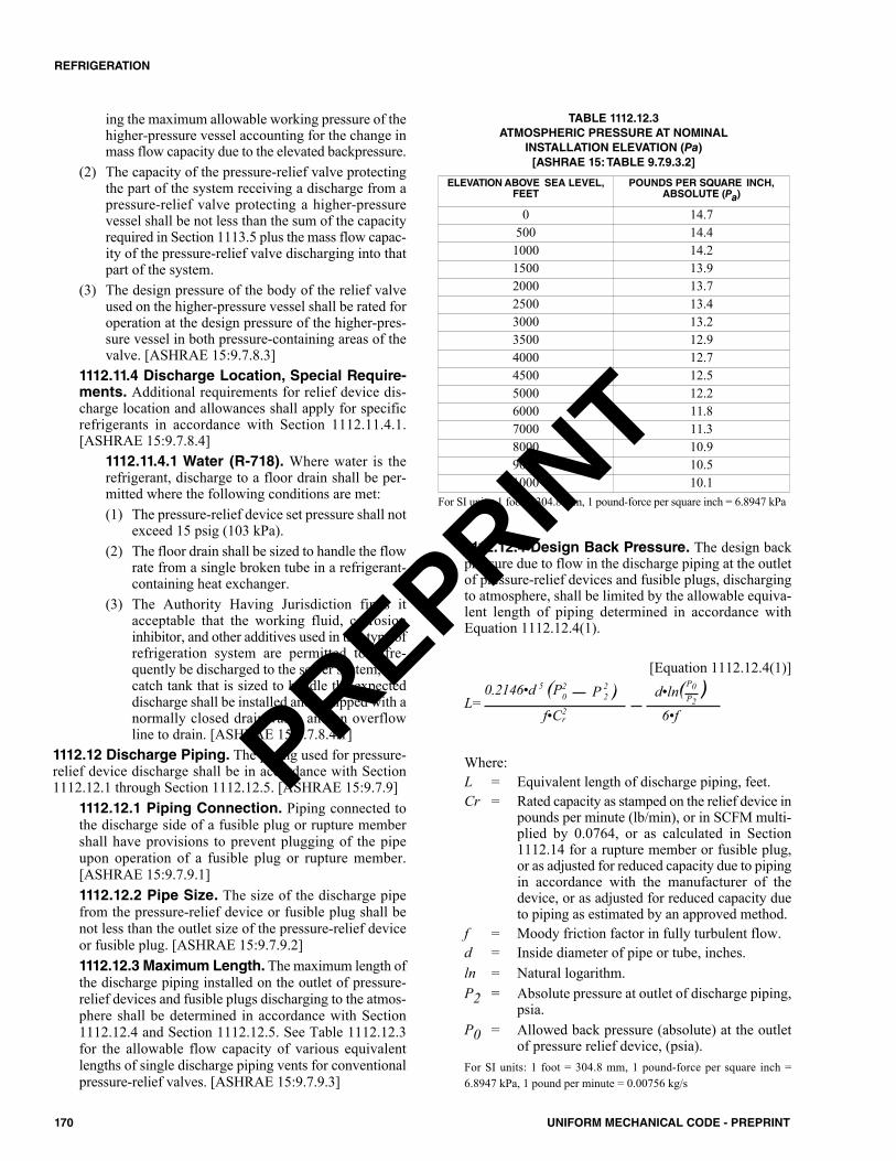
ing the maximum allowable working pressure of thehigher-pressure vessel accounting for the change inmass flow capacity due to the elevated backpressure.
(2) The capacity of the pressure-relief valve protectingthe part of the system receiving a discharge from apressure-relief valve protecting a higher-pressurevessel shall be not less than the sum of the capacityrequired in Section 1113.5 plus the mass flow capac-ity of the pressure-relief valve discharging into thatpart of the system.
(3) The design pressure of the body of the relief valveused on the higher-pressure vessel shall be rated foroperation at the design pressure of the higher-pres-sure vessel in both pressure-containing areas of thevalve. [ASHRAE 15:9.7.8.3]
1112.11.4 Discharge Location, Special Require-ments. Additional requirements for relief device dis-charge location and allowances shall apply for specificrefrigerants in accordance with Section 1112.11.4.1.[ASHRAE 15:9.7.8.4]
1112.11.4.1 Water (R-718). Where water is therefrigerant, discharge to a floor drain shall be per-mitted where the following conditions are met:(1) The pressure-relief device set pressure shall not
exceed 15 psig (103 kPa).(2) The floor drain shall be sized to handle the flow
rate from a single broken tube in a refrigerant-containing heat exchanger.
(3) The Authority Having Jurisdiction finds itacceptable that the working fluid, corrosioninhibitor, and other additives used in this type ofrefrigeration system are permitted to infre-quently be discharged to the sewer system, or acatch tank that is sized to handle the expecteddischarge shall be installed and equipped with anormally closed drain valve and an overflowline to drain. [ASHRAE 15:9.7.8.4.1]
1112.12 Discharge Piping. The piping used for pressure-relief device discharge shall be in accordance with Section1112.12.1 through Section 1112.12.5. [ASHRAE 15:9.7.9]
1112.12.1 Piping Connection. Piping connected tothe discharge side of a fusible plug or rupture membershall have provisions to prevent plugging of the pipeupon operation of a fusible plug or rupture member.[ASHRAE 15:9.7.9.1]1112.12.2 Pipe Size. The size of the discharge pipefrom the pressure-relief device or fusible plug shall benot less than the outlet size of the pressure-relief deviceor fusible plug. [ASHRAE 15:9.7.9.2]1112.12.3 Maximum Length. The maximum length ofthe discharge piping installed on the outlet of pressure-relief devices and fusible plugs discharging to the atmos-phere shall be determined in accordance with Section1112.12.4 and Section 1112.12.5. See Table 1112.12.3for the allowable flow capacity of various equivalentlengths of single discharge piping vents for conventionalpressure-relief valves. [ASHRAE 15:9.7.9.3]
1112.12.4 Design Back Pressure. The design backpressure due to flow in the discharge piping at the outletof pressure-relief devices and fusible plugs, dischargingto atmosphere, shall be limited by the allowable equiva-lent length of piping determined in accordance withEquation 1112.12.4(1).
[Equation 1112.12.4(1)]
Where:L = Equivalent length of discharge piping, feet.Cr = Rated capacity as stamped on the relief device in
pounds per minute (lb/min), or in SCFM multi-plied by 0.0764, or as calculated in Section1112.14 for a rupture member or fusible plug,or as adjusted for reduced capacity due to pipingin accordance with the manufacturer of thedevice, or as adjusted for reduced capacity dueto piping as estimated by an approved method.
f = Moody friction factor in fully turbulent flow.d = Inside diameter of pipe or tube, inches.ln = Natural logarithm.P2 = Absolute pressure at outlet of discharge piping,
psia.P0 = Allowed back pressure (absolute) at the outlet
of pressure relief device, (psia).For SI units: 1 foot = 304.8 mm, 1 pound-force per square inch =6.8947 kPa, 1 pound per minute = 0.00756 kg/s
L=0.2146•d 5 (P2 P 2 ) d•ln (P0 )0 2 P2
f•C2 6•fr
TABLE 1112.12.3 ATMOSPHERIC PRESSURE AT NOMINAL
INSTALLATION ELEVATION (Pa) [ASHRAE 15: TABLE 9.7.9.3.2]
For SI units: 1 foot = 304.8 mm, 1 pound-force per square inch = 6.8947 kPa
ELEVATIONABOVE SEA LEVEL,FEET
POUNDS PER SQUARE INCH,ABSOLUTE (Pa)
0 14.7500 14.41000 14.21500 13.92000 13.72500 13.43000 13.23500 12.94000 12.74500 12.55000 12.26000 11.87000 11.38000 10.99000 10.51000 10.1
170 UNIFORM MECHANICAL CODE - PREPRINT
REFRIGERATION
PREPRINT
Unless the maximum allowable back pressure (P0)is specified by the relief valve manufacturer, the follow-ing maximum allowable back pressure values shall beused for P0, where P is the set pressure and Pa is atmos-pheric pressure at the nominal elevation of the installa-tion (see Table 1112.12.3):For conventional relief valves: 15 percent of set pressure:P0 = (0.15•P)+Pa [Equation 1112.12.4(2)]For balanced relief valves: 25 percent of set pressure:P0 = (0.25•P)+Pa [Equation 1112.12.4(3)]For rupture disks alone: fusible plugs, and pilot operatedrelief devices, 50 percent of set pressure:P0 = (0.50•P)+Pa [Equation 1112.12.4(4)]
For fusible plugs, P shall be the saturated absolutepressure for the stamped temperature melting point of thefusible plug or the critical pressure of the refrigerantused, whichever is smaller. [ASHRAE 15:9.7.9.3.1,9.7.9.3.2]1112.12.5 Simultaneous Operation. When outletsof two or more relief devices or fusible plugs, which areexpected to operate simultaneously, connect to a com-mon discharge pipe, the common pipe shall be sizedlarge enough to prevent the back pressure at each reliefdevice from exceeding the maximum allowable backpressure in accordance with Section 1112.12.4.[ASHRAE 15:9.7.9.3.3]
1112.13 Rating of Pressure-Relief Device. The rateddischarge capacity of a pressure-relief device expressed inpounds of air per minute (kg/s), shall be determined in accor-dance with ASME BPVC Section VIII. Pipe and fittingsbetween the pressure-relief valve and the parts of the systemit protects shall have not less than the area of the pressure-relief valve inlet area. [ASHRAE 15:9.7.6]1112.14 Rating of Rupture Members and FusiblePlugs. The rated discharge capacity of a rupture member orfusible plug discharging to atmosphere under critical flowconditions, in pounds of air per minute (kg/s), shall be deter-mined in accordance with the following formulas:
Where:C = Rated discharge capacity of air, pounds per minute.d = Smallest internal diameter of the inlet pipe, retaining
flanges, fusible plug, or rupture member; inches.
For rupture members:
[Equation 1112.14(3)]P1 = (rated pressure in psig x 1.1) + 14.7 For fusible plugs:
P1 = Absolute saturation pressure, corresponding to thestamped temperature melting point of the fusible plugor the critical pressure of the refrigerant used,whichever is smaller, pound-force per square inchatmosphere, psia. [ASHRAE 15:9.7.7]
For SI units: 1 inch = 25.4 mm, 1 pound-force per square inch = 6.8947 kPa,1 pound per minute = 0.00756 kg/s
1113.0 Overpressure Protection.1113.1 General. Pressure vessels shall be provided withoverpressure protection in accordance with ASME BPVCSection VIII. Pressure vessels containing liquid refrigerantthat are capable of being isolated by stop valves from otherparts of a refrigerating system shall be provided with over-pressure protection. Pressure relief devices or fusible plugsshall be sized in accordance with Section 1113.5. [ASHRAE15:9.7.1, 9.7.2]1113.2 Type of Protection. Pressure vessels with an inter-nal gross volume of 3 cubic feet (0.1 m3) or less shall use oneor more pressure relief devices or a fusible plug. Pressure ves-sels of more than 3 cubic feet (0.1 m3) but less than 10 cubicfeet (0.28 m3) internal gross volume shall use one or morepressure relief devices. Fusible plugs shall not be used.[ASHRAE 15:9.7.2.1, 9.7.2.2] 1113.3 Discharging into Lowside of System. For pres-sure-relief valves discharging into the lowside of the system,a single relief valve (not rupture member) of the requiredrelieving capacity shall not be used on vessels of 10 cubicfeet (0.28 m3) or more internal gross volume except under theconditions permitted in Section 1112.10.1. [ASHRAE15:9.7.3]1113.4 Parallel Pressure-Relief Devices. Two or morepressure-relief devices in parallel to obtain the requiredcapacity shall be considered as one pressure-relief device.The discharge capacity shall be the sum of the capacitiesrequired for each pressure vessel being protected.1113.5 Discharge Capacity. The minimum required dis-charge capacity of the pressure-relief device or fusible plugfor a pressure vessel shall be determined in accordance withEquation 1113.5:
C =ƒDL (Equation 1113.5)
Where:C = Minimum required discharge capacity of the relief
device expressed as mass flow of air, pounds per minute(kg/s).
D = Outside diameter of vessel, feet (m).L = Length of vessel, feet (m).f = Factor dependent upon type of refrigerant from Table
1113.5.
Where combustible materials are used within 20 ft (6096mm) of a pressure vessel, the value of f shall be multiply by2.5. Equation 1113.5 is based on fire conditions, other heatsources shall be calculated separately. Where one pressure-
C = 0.64P1d2 [Equation 1112.14(1)]
d = 1.25 √C/P1 [Equation 1112.14(2)]
171UNIFORM MECHANICAL CODE - PREPRINT
REFRIGERATION
PREPRINT
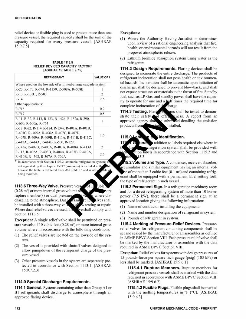
relief device or fusible plug is used to protect more than onepressure vessel, the required capacity shall be the sum of thecapacity required for every pressure vessel. [ASHRAE15:9.7.5]
1113.6 Three-Way Valve. Pressure vessels of 10 cubic feet(0.28 m3) or more internal gross volume shall use one or morerupture member(s) or dual pressure-relief valves where dis-charging to the atmosphere. Dual pressure-relief valves shallbe installed with a three-way valve to allow testing or repair.Where dual relief valves are used, the valve shall comply withSection 1113.5.Exception: A single relief valve shall be permitted on pres-sure vessels of 10 cubic feet (0.28 m3) or more internal grossvolume where in accordance with the following conditions:(1) The relief valves are located on the lowside of the sys-
tem.(2) The vessel is provided with shutoff valves designed to
allow pumpdown of the refrigerant charge of the pres-sure vessel.
(3) Other pressure vessels in the system are separately pro-tected in accordance with Section 1113.1. [ASHRAE15:9.7.2.3]
1114.0 Special Discharge Requirements.1114.1 General. Systems containing other than Group A1 orB1 refrigerants shall discharge to atmosphere through anapproved flaring device.
Exceptions:(1) Where the Authority Having Jurisdiction determines
upon review of a rational engineering analysis that fire,health, or environmental hazards will not result from theproposed atmospheric release.
(2) Lithium bromide absorption system using water as therefrigerant.
1114.2 Design Requirements. Flaring devices shall bedesigned to incinerate the entire discharge. The products ofrefrigerant incineration shall not pose health or environmen-tal hazards. Incineration shall be automatic upon initiation ofdischarge, shall be designed to prevent blow-back, and shallnot expose structures or materials to the threat of fire. Standbyfuel, such as LP-Gas, and standby power shall have the capac-ity to operate for one and a half times the required time forcomplete incineration of the charge.1114.3 Testing. Flaring systems shall be tested to demon-strate their safety and effectiveness. A report from anapproved agency shall be submitted detailing the emissionproducts from the system as installed.
1115.0 Labeling and Identification.1115.1 General. In addition to labels required elsewhere inthis chapter, a refrigeration system shall be provided withidentification labels in accordance with Section 1115.2 andSection 1115.3.1115.2 Volume and Type. A condenser, receiver, absorber,accumulator and similar equipment having an internal vol-ume of more than 3 cubic feet (0.1 m3) and containing refrig-erant shall be equipped with a permanent label setting forththe type of refrigerant in such vessel.1115.3 Permanent Sign. In a refrigeration machinery roomand for a direct refrigerating system of more than 10 horse-power (7.5 kW), there shall be a permanent sign at anapproved location giving the following information:(1) Name of contractor installing the equipment.(2) Name and number designation of refrigerant in system.(3) Pounds of refrigerant in system.1115.4 Marking of Pressure-Relief Devices. Pressure-relief valves for refrigerant containing components shall beset and sealed by the manufacturer or an assembler as definedin ASME BPVC Section VIII. Each pressure relief valve shallbe marked by the manufacturer or assembler with the datarequired in ASME BPVC Section VIII.Exception: Relief valves for systems with design pressures of15 pounds-force per square inch gauge (psig) (103 kPa) orless shall be marked. [ASHRAE 15:9.6.1]
1115.4.1 Rupture Members. Rupture members forrefrigerant pressure vessels shall be marked with the datarequired in accordance with ASME BPVC Section VIII.[ASHRAE 15:9.6.2]1115.4.2 Fusible Plugs. Fusible plugs shall be markedwith the melting temperatures in °F (°C). [ASHRAE15:9.6.3]
REFRIGERANT VALUE OF f
Where used on the lowside of a limited-charge cascade system:R-23, R-170, R-744, R-1150, R-508A, R-508B 1R-13, R-13B1, R-503 2R-14 2.5Other applications:R-718 0.2R-717 0.5R-11, R-32, R-113, R-123, R-142b, R-152a, R-290,R-600, R-600a, R-764 1
R-12, R-22, R-114, R-124, R-134a, R-401A, R-401B,R-401C, R- 405A, R-406A, R-407C, R-407D, R-407E, R-409A, R-409B, R-411A, R-411B, R-411C,R-412A, R-414A, R-414B, R-500, R-1270
1.6
R-143a, R-402B, R-403A, R-407A, R-408A, R-413A 2R-115, R-402A, R-403B, R-404A, R-407B, R-410A,R-410B, R- 502, R-507A, R-509A 2.5
* In accordance with Section 1102.2, ammonia refrigeration systems arenot regulated by this chapter. R-717 (ammonia) is included in this tablebecause the table is extracted from ASHRAE 15 and is not capable ofbeing modified.
TABLE 1113.5RELIEF DEVICES CAPACITY FACTOR*
[ASHRAE 15:TABLE 9.7.5]
172 UNIFORM MECHANICAL CODE - PREPRINT
REFRIGERATION
PREPRINT

1116.0 Testing of Refrigeration Equipment. 1116.1 Factory Tests. Refrigerant-containing parts of unitsystems shall be tested and proved tight by the manufacturerat not less than the design pressure for which they are rated.Pressure vessels shall be tested in accordance with Section1117.0. [ASHRAE 15:9.14.1]
1116.1.1 Testing Procedure. Tests shall be performedwith dry nitrogen or another nonflammable, nonreactive,dried gas. Oxygen, air, or mixtures containing them shallnot be used. The means used to build up the test pressureshall have a pressure-limiting device or a pressure-reduc-ing device and a gage on the outlet side. The pressure-relief device shall be set above the test pressure but lowenough to prevent permanent deformation of the sys-tem’s components.Exceptions:(1) Mixtures of dry nitrogen, inert gases, nonflammable
refrigerants permitted for factory tests.(2) Mixtures of dry nitrogen, inert gases, or a combina-
tion of them with flammable refrigerants in concen-trations not exceeding the lesser of a refrigerantweight fraction (mass fraction) of 5 percent or 25percent of the LFL shall be permitted for factorytests.
(3) Compressed air without added refrigerant shall bepermitted for factory tests provided the system issubsequently evacuated to less than 0.039 inch ofmercury (0.132 kPa) before charging with refriger-ant. The required evacuation level is atmosphericpressure for systems using R-718 (water) or R-744(carbon dioxide) as the refrigerant. [ASHRAE15:9.14.1.1]
1116.1.2 Applied Pressure. The test pressure appliedto the highside of each factory-assembled refrigeratingsystem shall be not less than the design pressure of thehighside. The test pressure applied to the lowside of afactory assembled refrigerating system shall be not lessthan the design pressure of the lowside.1116.1.3 Design Pressure of 15 psig or Less.Unitswith a design pressure of 15 psig (103 kPa) or less shallbe tested at a pressure not less than 1.33 times the designpressure, and shall be proved leak-tight at not less thanthe lowside design pressure. [ASHRAE 15:9.14.3]
1116.2 Field Tests. Refrigerant-containing parts of a sys-tem that is field-erected shall be tested and proved tight aftercomplete installation and before the operation. The high andlow sides of each system shall be tested and proved tight atnot less than the lower of the pressure in Table 1116.2 or thesetting of the pressure-relief device.Exceptions:(1) Compressors, condensers, evaporators, coded pressure
vessels, safety devices, pressure gauges, control mecha-nisms, and systems that are factory tested.
(2) Refrigeration systems containing Group R-22, notexceeding 5 tons of refrigeration capacity (18 kW), andfield-piped using approved, factory-charged line sets
shall be permitted to be proved tight by observing reten-tion of pressure on a set of charging gauges and soapingconnections while the system is operating.
1116.3 Test Gases. Tests shall be performed with dry nitro-gen or other nonflammable, nonreactive, dried gas. Oxygen,air, or mixtures containing them shall not be used. The meansused to build up the test pressure shall have either a pressure-limiting device or a pressure-reducing device and a gauge onthe outlet side. The pressure-relief device shall be set abovethe test pressure but low enough to prevent permanent defor-mation of the system’s components. Exceptions:(1) Mixtures of dry nitrogen, inert gases, or a combination of
them with nonflammable refrigerant in concentrations ofa refrigerant weight fraction (mass fraction) not exceed-ing 5 percent shall be permitted for tests.
(2) Mixtures of dry nitrogen, inert gases, or a combination ofthem with flammable refrigerants in concentrations notexceeding the lower of a refrigerant weight fraction(mass fraction) of 5 percent or 25 percent of the LFLshall be permitted for tests.
(3) Compressed air without added refrigerants shall be per-mitted for tests, provided the system is subsequentlyevacuated to less than 1000 microns (0.1333 kPa) beforecharging with refrigerant. The required evacuation levelis atmospheric pressure for systems using R-718 (water)or R-744 (carbon dioxide) as the refrigerant.
(4) Systems erected on the premises using Group A1 refrig-erant and with copper tubing not exceeding 0.62 of aninch (15.7 mm) outside diameter shall be tested by meansof the refrigerant charged into the system at the saturatedvapor pressure of the refrigerant at not less than 68°F(20°C). [ASHRAE 15:10.1.2]
1116.4 Declaration. A dated declaration of test shall be pro-vided for systems containing more than 55 pounds (24.9 kg)of refrigerant. The declaration shall give the name of the
TABLE 1116.2FIELD LEAK TEST PRESSURES (psig)*
For SI units: 1 pound-force per square inch gauge = 6.8947 kPa* Special design required; test pressures typically exceed 1000 psig (6895
kPa).
REFRIGERANTNUMBER
HIGHSIDEWATER COOLED
HIGHSIDE AIRCOOLED
LOWSIDE
11 15 35 1512 140 220 14022 230 360 230113 15 15 15114 40 80 40115 275 340 275123 15 30 15134a 150 250 150152a 130 220 130500 165 265 165502 250 385 250744* –– –– ––
173UNIFORM MECHANICAL CODE - PREPRINT
REFRIGERATION
PREPRINT

refrigerant and the field test pressure applied to the highsideand the lowside of the system. The declaration of test shallbe signed by the installer and, where an inspector is presentat the tests, the inspector shall also sign the declaration.Where requested, copies of this declaration shall be furnishedto the Authority Having Jurisdiction. [ASHRAE 15:10.2]1116.5 Brine Systems. Brine-containing portions of a sys-tem shall be tested at one and a half times the design pressureof the system using brine as the test fluid.
1117.0 Refrigerant-Containing Pressure Vessels.1117.1 Inside Dimensions 6 inches or Less. Pressurevessels having inside dimensions of 6 inches (152 mm) orless shall be:(1) Listed either individually or as part of an assembly by an
approved, nationally recognized testing laboratory, or(2) Marked directly on the vessel or on a nameplate attached
to the vessel with a “U” or “UM” symbol signifyingcompliance with ASME BPVC Section VIII, or
(3) When requested by the Authority Having Jurisdiction,the manufacturer shall provide documentation to confirmthat the vessel meets the design, fabrication, and testingrequirements of ASME BPVC Section VIII.
Exception: Vessels having an internal or external designpressure of 15 psig (103 kPa) or less.
Pressure vessels having inside dimensions of 6 inches(152 mm) or less shall be protected by either a pressure-reliefdevice or a fusible plug. [ASHRAE 15:9.3.1.1]
1117.1.1 Pressure-Relief Device. Where a pressure-relief device is used to protect a pressure vessel having aninside dimension of 6 inches (152 mm) or less, the ulti-mate strength of the pressure vessel so protected shallwithstand a pressure of not less than 3.0 times the designpressure. [ASHRAE 15:9.3.1.2]1117.1.2 Fusible Plug.Where a fusible plug is used toprotect a pressure vessel having an inside diameter of 6inches (152 mm) or less, the ultimate strength of the pres-sure vessel so protected shall withstand a pressure 2.5times the saturation pressure of the refrigerant used at thetemperature stamped on the fusible plug or 2.5 times thecritical pressure of the refrigerant used, whichever is less.[ASHRAE 15:9.3.1.3]
1117.2 Inside Dimensions More than 6 inches. Pres-sure vessels having an inside diameter exceeding 6 inches(152 mm) and having an internal or external design pressuregreater than 15 psig (103 kPa) shall be directly marked, ormarked on a nameplate, with a “U” or “UM” symbol signi-fying compliance with the rules of ASME BPVC SectionVIII. [ASHRAE 15:9.3.2]1117.3 Pressure Vessels for 15 psig or Less. Pressurevessels having an internal or external design pressure of 15psig (103 kPa) or less shall have an ultimate strength to with-stand not less than 3.0 times the design pressure and shall betested with a pneumatic test pressure of not less than 1.25times the design pressure or a hydrostatic test pressure of notless than 1.5 times the design pressure. [ASHRAE 15:9.3.3]
1118.0 Maintenance and Operation.1118.1 General. Refrigeration systems shall be operated andmaintained as required by the fire code.
Part II – Cooling Towers.
1119.0 General.1119.1 Applicability. Cooling towers, evaporative con-densers, and fluid coolers shall be readily accessible. Wherelocated on roofs, such equipment having combustible exte-rior surfaces shall be protected with an approved automaticfire-extinguishing system.
1120.0 Support and Anchorage.1120.1 General. Cooling towers, evaporative condensers,and fluid coolers shall be supported on noncombustible gril-lage designed in accordance with the building code. Seismicrestraints shall be as required by the building code.
1121.0 Drainage.1121.1 General. Drains, overflows, and blow-down provi-sions shall have an indirect connection to an approved dis-posal location. Discharge of chemical waste shall be asapproved by the regulatory authority.
1122.0 Chemical Treatment Systems.1122.1 General. Chemical treatment systems shall complywith the fire code. Where chemicals used present a contacthazard to personnel, approved emergency eye-wash andshower facilities shall be installed.1122.2 Automated Control of Cycles of Concentra-tion. Cooling towers, evaporative condensers, and fluid cool-ers shall include controls that automate system bleed basedon conductivity, fraction of metered makeup volume, meteredbleed volume, recirculating pump run time, or bleed time.
1123.0 Location.1123.1 General. Cooling towers, evaporative condensers,and fluid coolers shall be located such that their plumes can-not enter occupied spaces. Plume discharges shall be not lessthan 25 feet (7620 mm) away from a ventilation inlet to abuilding. Location on the property shall be as required forbuildings by the building code.
1124.0 Electrical.1124.1 General. Electrical systems shall be in accordancewith the electrical code. Equipment shall be provided with avibration switch to shut off fans operating with excessive vibra-tion. In climates commonly subject to electrical storms, light-ning protection shall be provided on roof-mounted equipment.
1125.0 Refrigerants and Hazardous Fluids.1125.1 General. Equipment containing refrigerants as a partof a closed-cycle refrigeration system shall comply with Part
174 UNIFORM MECHANICAL CODE - PREPRINT
REFRIGERATION
PREPRINT
175UNIFORM MECHANICAL CODE - PREPRINT
REFRIGERATION
I of this chapter. Equipment containing other fluids that areflammable, combustible, or hazardous shall be in accordancewith this code and the fire code.
1126.0 Drift Eliminators.1126.1 General. Cooling towers, evaporative condensers,and fluid coolers shall be equipped with drift eliminators thathave a drift rate of not more than 0.005 percent of the circu-lated water flow rate in accordance with the equipment man-ufacturer’s instructions.
PREPRINT
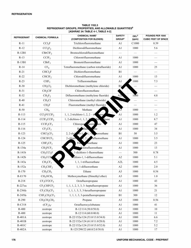
176 UNIFORM MECHANICAL CODE - PREPRINT
REFRIGERATION
REFRIGERANT CHEMICAL FORMULACHEMICAL NAME1
(COMPOSITION FOR BLENDS)
SAFETY
GROUP7OEL2
(ppm)
POUNDS PER 1000
CUBIC FEET OF SPACE
R-11 CCl3F Trichlorofluoromethane A1 C1000 0.39
R-12 CCl2F2 Dichlorodifluoromethane A1 1000 5.6
R-12B1 CBrClF2 Bromochlorodifluoromethane –– –– ––
R-13 CClF3 Chlorotrifluoromethane A1 1000 ––
R-13B1 CBrF3 Bromotrifluoromethane A1 1000 ––
R-14 CF4 Tetrafluoromethane (carbon tetrafluoride) A1 1000 25
R-21 CHCl2F Dichlorofluoromethane B1 –– ––
R-22 CHClF2 Chlorodifluoromethane A1 1000 13
R-23 CHF3 Trifluoromethane A1 1000 7.3
R-30 CH2Cl2 Dichloromethane (methylene chloride) B1 –– ––
R-31 CH2ClF Chlorofluoromethane –– –– ––
R-32 CH2F2 Difluoromethane (methylene fluoride) A2L 1000 4.8
R-40 CH3Cl Chloromethane (methyl chloride) B2 –– ––
R-41 CH3F Fluoromethane (methyl fluoride) –– –– ––
R-50 CH4 Methane A3 1000 ––
R-113 CCl2FCClF2 1, 1, 2-trichloro-1, 2, 2 – trifluoroethane A1 1000 1.2
R-114 CClF2CClF2 1, 2-dichloro-1, 1, 2, 2 tetrafluoroethane A1 1000 8.7
R-115 CClF2CF3 Chloropentafluoroethane A1 1000 47
R-116 CF3CF3 Hexafluoroethane A1 1000 34
R-123 CHCl2CF3 2, 2-dichloro-1, 1, 1, - trifluoroethane B1 50 3.5
R-124 CHClFCF3 2-chloro-1, 1, 1, 2 - tetrafluoroethane A1 1000 3.5
R-125 CHF2CF3 Pentafluoroethane A1 1000 23
R-134a CH2FCF3 1, 1, 1, 2-tetrafluoroethane A1 1000 13
R-141b CH3CCl2F 1, 1-dichloro-1-fluoroethane –– 500 0.78
R-142b CH3CClF2 1-chloro-1, 1-difluoroethane A2 1000 5.1
R-143a CH3CF3 1, 1, 1-trifluoroethane A2L 1000 4.5
R-152a CH3CHF2 1, 1-difluoroethane A2 1000 2.0
R-170 CH3CH3 Ethane A3 1000 0.54
R-E170 CH3OCH3 Methoxymethane (Dimethyl ether) A3 1000 1.0
R-218 CF3CF2CF3 Octafluoropropane A1 1000 43
R-227ea CF3CHFCF3 1, 1, 1, 2, 3, 3, 3- heptafluoropropane A1 1000 36
R-236fa CF3CH2CF3 1, 1, 1, 3, 3, 3-hexafluoropropane A1 1000 21
R-245fa CHF2CH2CF3 1, 1, 1, 3, 3-pentafluoropropane B1 300 12
R-290 CH3CH2CH3 Propane A3 1000 0.56
R-C318 -(CF2)4- Octafluorocyclobutane A1 1000 41R-400 zeotrope R-12/114 (50.0/50.0) A1 1000 10R-400 zeotrope R-12/114 (60.0/40.0) A1 1000 11
R-401A zeotrope R-22/152a/124 (53.0/13.0/34.0) A1 1000 6.6R-401B zeotrope R-22/152a/124 (61.0/11.0/28.0) A1 1000 7.2R-401C zeotrope R-22/152a/124 (33.0/15.0/52.0) A1 1000 5.2R-402A zeotrope R-125/290/22 (60.0/2.0/38.0) A1 1000 17
TABLE 1102.3REFRIGERANT GROUPS, PROPERTIES, AND ALLOWABLE QUANTITIES8
[ASHRAE 34: TABLE 4-1, TABLE 4-2]
PREPRINT
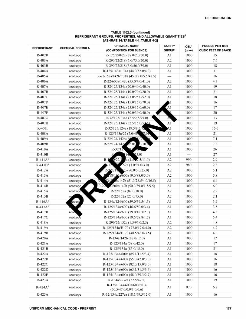
177UNIFORM MECHANICAL CODE - PREPRINT
REFRIGERATION
TABLE 1102.3 (continued)REFRIGERANT GROUPS, PROPERTIES, AND ALLOWABLE QUANTITIES8
[ASHRAE 34: TABLE 4-1, TABLE 4-2]
REFRIGERANT CHEMICAL FORMULACHEMICAL NAME1
(COMPOSITION FOR BLENDS)
SAFETY
GROUP7OEL2
(ppm)
POUNDS PER 1000
CUBIC FEET OF SPACE
R-402B zeotrope R-125/290/22 (38.0/2.0/60.0) A1 1000 15R-403A zeotrope R-290/22/218 (5.0/75.0/20.0) A2 1000 7.6R-403B zeotrope R-290/22/218 (5.0/56.0/39.0) A1 1000 18R-404A zeotrope R-125/143a/134a (44.0/52.0/4.0) A1 1000 31R-405A zeotrope R-22/152a/142b/C318 (45.0/7.0/5.5/42.5) –– 1000 16R-406A zeotrope R-22/600a/142b (55.0/4.0/41.0) A2 1000 4.7R-407A zeotrope R-32/125/134a (20.0/40.0/40.0) A1 1000 19R-407B zeotrope R-32/125/134a (10.0/70.0/20.0) A1 1000 21R-407C zeotrope R-32/125/134a (23.0/25.0/52.0) A1 1000 18R-407D zeotrope R-32/125/134a (15.0/15.0/70.0) A1 1000 16R-407E zeotrope R-32/125/134a (25.0/15.0/60.0) A1 1000 17R-407F zeotrope R-32/125/134a (30.0/30.0/40.0) A1 1000 20R-407G zeotrope R-32/125/134a (2.5/2.5/95.0) A1 1000 13R-407H zeotrope R-32/125/134a (32.5/15.0/52.5) A1 1000 19R-407I zeotrope R-32/125/124a (19.5/8.5/72.0) A1 1000 16.0R-408A zeotrope R-125/143a/22 (7.0/46.0/47.0) A1 1000 21R-409A zeotrope R-22/124/142b (60.0/25.0/15.0) A1 1000 7.1R-409B zeotrope R-22/124/142b (65.0/25.0/10.0) A1 1000 7.3R-410A zeotrope R-32/125 (50.0/50.0) A1 1000 26R-410B zeotrope R-32/125 (45.0/55.0) A1 –– 27R-411A6 zeotrope R-1270/22/152a (1.5/87.5/11.0) A2 990 2.9R-411B6 zeotrope R-1270/22/152a (3.0/94.0/3.0) A2 980 2.8R-412A zeotrope R-22/218/142b (70.0/5.0/25.0) A2 1000 5.1R-413A zeotrope R-218/134a/600a (9.0/88.0/3.0) A2 1000 5.8R-414A zeotrope R-22/124/600a/142b (51.0/28.5/4.0/16.5) A1 1000 6.4R-414B zeotrope R-22/124/600a/142b (50.0/39.0/1.5/9.5) A1 1000 6.0R-415A zeotrope R-22/152a (82.0/18.0) A2 1000 2.9R-415B zeotrope R-22/152a (25.0/75.0) A2 1000 2.1R-416A6 zeotrope R-134a/124/600 (59.0/39.5/1.5) A1 1000 3.9R-417A6 zeotrope R-125/134a/600 (46.6/50.0/3.4) A1 1000 3.5R-417B zeotrope R-125/134a/600 (79.0/18.3/2.7) A1 1000 4.3R-417C zeotrope R-125/134a/600 (19.5/78.8/1.7) A1 1000 5.4R-418A zeotrope R-290/22/152a (1.5/96.0/2.5) A2 1000 4.8R-419A zeotrope R-125/134a/E170 (77.0/19.0/4.0) A2 1000 4.2R-419B zeotrope R-125/134a/E170 (48.5/48.0/3.5) A2 1000 4.6R-420A zeotrope R-134a/142b (88.0/12.0) A1 1000 12R-421A zeotrope R-125/134a (58.0/42.0) A1 1000 17R-421B zeotrope R-125/134a (85.0/15.0) A1 1000 21R-422A zeotrope R-125/134a/600a (85.1/11.5/3.4) A1 1000 18R-422B zeotrope R-125/134a/600a (55.0/42.0/3.0) A1 1000 16R-422C zeotrope R-125/134a/600a (82.0/15.0/3.0) A1 1000 18R-422D zeotrope R-125/134a/600a (65.1/31.5/3.4) A1 1000 16R-422E zeotrope R-125/134a/600a (58.0/39.3/2.7) A1 1000 16R-423A zeotrope R-134a/227ea (52.5/47.5) A1 1000 19
R-424A6 zeotrope R-125/134a/600a/600/601a(50.5/47.0/0.9/1.0/0.6) A1 970 6.2
R-425A zeotrope R-32/134a/227ea (18.5/69.5/12.0) A1 1000 16
PREPRINT
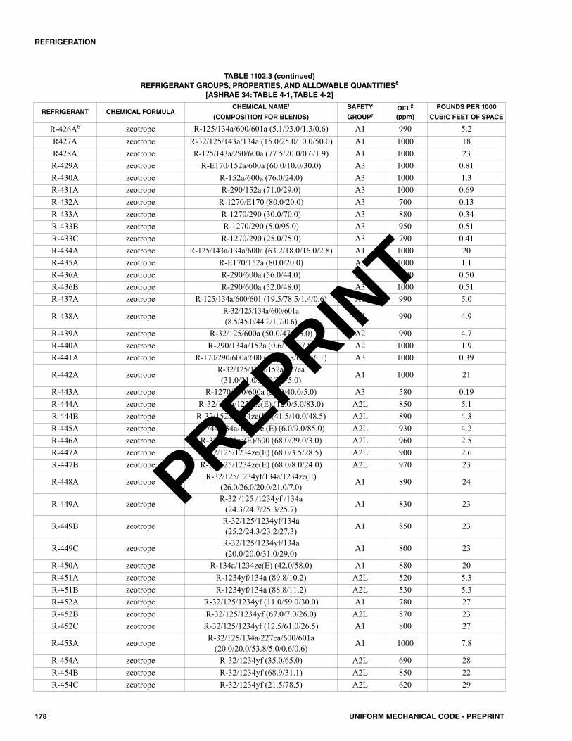
178 UNIFORM MECHANICAL CODE - PREPRINT
REFRIGERATION
TABLE 1102.3 (continued)REFRIGERANT GROUPS, PROPERTIES, AND ALLOWABLE QUANTITIES8
[ASHRAE 34: TABLE 4-1, TABLE 4-2]
REFRIGERANT CHEMICAL FORMULACHEMICAL NAME1
(COMPOSITION FOR BLENDS)
SAFETY
GROUP7OEL2
(ppm)
POUNDS PER 1000
CUBIC FEET OF SPACE
R-426A6 zeotrope R-125/134a/600/601a (5.1/93.0/1.3/0.6) A1 990 5.2R427A zeotrope R-32/125/143a/134a (15.0/25.0/10.0/50.0) A1 1000 18R428A zeotrope R-125/143a/290/600a (77.5/20.0/0.6/1.9) A1 1000 23R-429A zeotrope R-E170/152a/600a (60.0/10.0/30.0) A3 1000 0.81R-430A zeotrope R-152a/600a (76.0/24.0) A3 1000 1.3R-431A zeotrope R-290/152a (71.0/29.0) A3 1000 0.69R-432A zeotrope R-1270/E170 (80.0/20.0) A3 700 0.13R-433A zeotrope R-1270/290 (30.0/70.0) A3 880 0.34R-433B zeotrope R-1270/290 (5.0/95.0) A3 950 0.51R-433C zeotrope R-1270/290 (25.0/75.0) A3 790 0.41R-434A zeotrope R-125/143a/134a/600a (63.2/18.0/16.0/2.8) A1 1000 20R-435A zeotrope R-E170/152a (80.0/20.0) A3 1000 1.1R-436A zeotrope R-290/600a (56.0/44.0) A3 1000 0.50R-436B zeotrope R-290/600a (52.0/48.0) A3 1000 0.51R-437A zeotrope R-125/134a/600/601 (19.5/78.5/1.4/0.6) A1 990 5.0
R-438A zeotrope R-32/125/134a/600/601a(8.5/45.0/44.2/1.7/0.6) A1 990 4.9
R-439A zeotrope R-32/125/600a (50.0/47.0/3.0) A2 990 4.7R-440A zeotrope R-290/134a/152a (0.6/1.6/97.8) A2 1000 1.9R-441A zeotrope R-170/290/600a/600 (3.1/54.8/6.0/36.1) A3 1000 0.39
R-442A zeotrope R-32/125/134a/152a/227ea(31.0/31.0/30.0/3.0/5.0) A1 1000 21
R-443A zeotrope R-1270/290/600a (55.0/40.0/5.0) A3 580 0.19R-444A zeotrope R-32/152a/1234ze(E) (12.0/5.0/83.0) A2L 850 5.1R-444B zeotrope R-32/152a/1234ze(E) (41.5/10.0/48.5) A2L 890 4.3R-445A zeotrope R-744/134a/1234ze (E) (6.0/9.0/85.0) A2L 930 4.2R-446A zeotrope R-32/1234ze(E)/600 (68.0/29.0/3.0) A2L 960 2.5R-447A zeotrope R-32/125/1234ze(E) (68.0/3.5/28.5) A2L 900 2.6R-447B zeotrope R-32/125/1234ze(E) (68.0/8.0/24.0) A2L 970 23
R-448A zeotrope R-32/125/1234yf/134a/1234ze(E)(26.0/26.0/20.0/21.0/7.0) A1 890 24
R-449A zeotrope R-32 /125 /1234yf /134a(24.3/24.7/25.3/25.7) A1 830 23
R-449B zeotrope R-32/125/1234yf/134a(25.2/24.3/23.2/27.3) A1 850 23
R-449C zeotrope R-32/125/1234yf/134a(20.0/20.0/31.0/29.0) A1 800 23
R-450A zeotrope R-134a/1234ze(E) (42.0/58.0) A1 880 20R-451A zeotrope R-1234yf/134a (89.8/10.2) A2L 520 5.3R-451B zeotrope R-1234yf/134a (88.8/11.2) A2L 530 5.3R-452A zeotrope R-32/125/1234yf (11.0/59.0/30.0) A1 780 27R-452B zeotrope R-32/125/1234yf (67.0/7.0/26.0) A2L 870 23R-452C zeotrope R-32/125/1234yf (12.5/61.0/26.5) A1 800 27
R-453A zeotrope R-32/125/134a/227ea/600/601a(20.0/20.0/53.8/5.0/0.6/0.6) A1 1000 7.8
R-454A zeotrope R-32/1234yf (35.0/65.0) A2L 690 28R-454B zeotrope R-32/1234yf (68.9/31.1) A2L 850 22R-454C zeotrope R-32/1234yf (21.5/78.5) A2L 620 29
PREPRINT
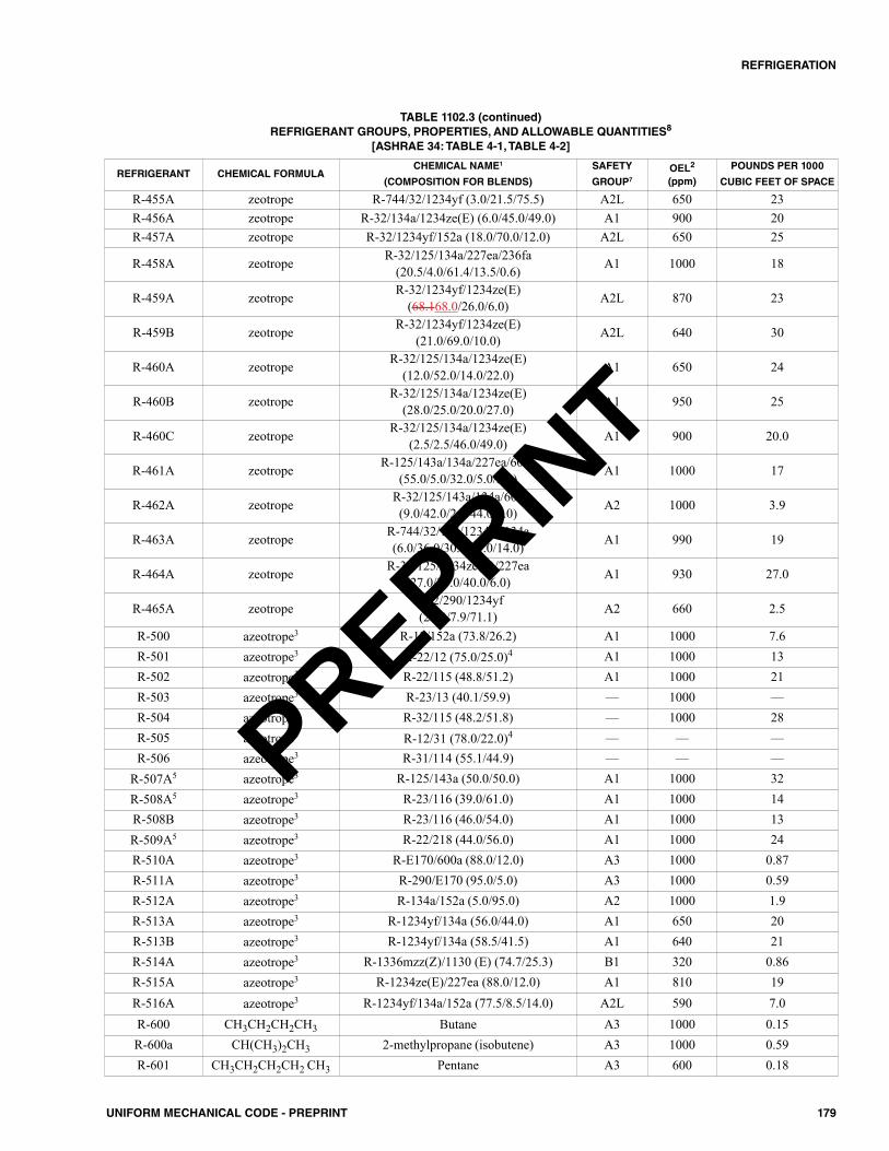
179UNIFORM MECHANICAL CODE - PREPRINT
REFRIGERATION
TABLE 1102.3 (continued)REFRIGERANT GROUPS, PROPERTIES, AND ALLOWABLE QUANTITIES8
[ASHRAE 34: TABLE 4-1, TABLE 4-2]
REFRIGERANT CHEMICAL FORMULACHEMICAL NAME1
(COMPOSITION FOR BLENDS)
SAFETY
GROUP7OEL2
(ppm)
POUNDS PER 1000
CUBIC FEET OF SPACE
R-455A zeotrope R-744/32/1234yf (3.0/21.5/75.5) A2L 650 23R-456A zeotrope R-32/134a/1234ze(E) (6.0/45.0/49.0) A1 900 20R-457A zeotrope R-32/1234yf/152a (18.0/70.0/12.0) A2L 650 25
R-458A zeotrope R-32/125/134a/227ea/236fa(20.5/4.0/61.4/13.5/0.6) A1 1000 18
R-459A zeotrope R-32/1234yf/1234ze(E) (68.168.0/26.0/6.0) A2L 870 23
R-459B zeotrope R-32/1234yf/1234ze(E)(21.0/69.0/10.0) A2L 640 30
R-460A zeotrope R-32/125/134a/1234ze(E)(12.0/52.0/14.0/22.0) A1 650 24
R-460B zeotrope R-32/125/134a/1234ze(E)(28.0/25.0/20.0/27.0) A1 950 25
R-460C zeotrope R-32/125/134a/1234ze(E)(2.5/2.5/46.0/49.0) A1 900 20.0
R-461A zeotrope R-125/143a/134a/227ea/600a(55.0/5.0/32.0/5.0/3.0) A1 1000 17
R-462A zeotrope R-32/125/143a/134a/600(9.0/42.0/2.0/44.0/3.0) A2 1000 3.9
R-463A zeotrope R-744/32/125/1234yf/134a(6.0/36.0/30.0/14.0/14.0) A1 990 19
R-464A zeotrope R-32/125/1234ze(E)/227ea(27.0/27.0/40.0/6.0) A1 930 27.0
R-465A zeotrope R-32/290/1234yf(21.0/7.9/71.1) A2 660 2.5
R-500 azeotrope3 R-12/152a (73.8/26.2) A1 1000 7.6R-501 azeotrope3 R-22/12 (75.0/25.0)4 A1 1000 13R-502 azeotrope3 R-22/115 (48.8/51.2) A1 1000 21R-503 azeotrope3 R-23/13 (40.1/59.9) –– 1000 ––R-504 azeotrope3 R-32/115 (48.2/51.8) –– 1000 28R-505 azeotrope3 R-12/31 (78.0/22.0)4 –– –– ––R-506 azeotrope3 R-31/114 (55.1/44.9) –– –– ––
R-507A5 azeotrope3 R-125/143a (50.0/50.0) A1 1000 32R-508A5 azeotrope3 R-23/116 (39.0/61.0) A1 1000 14R-508B azeotrope3 R-23/116 (46.0/54.0) A1 1000 13R-509A5 azeotrope3 R-22/218 (44.0/56.0) A1 1000 24R-510A azeotrope3 R-E170/600a (88.0/12.0) A3 1000 0.87R-511A azeotrope3 R-290/E170 (95.0/5.0) A3 1000 0.59R-512A azeotrope3 R-134a/152a (5.0/95.0) A2 1000 1.9R-513A azeotrope3 R-1234yf/134a (56.0/44.0) A1 650 20R-513B azeotrope3 R-1234yf/134a (58.5/41.5) A1 640 21R-514A azeotrope3 R-1336mzz(Z)/1130 (E) (74.7/25.3) B1 320 0.86R-515A azeotrope3 R-1234ze(E)/227ea (88.0/12.0) A1 810 19R-516A azeotrope3 R-1234yf/134a/152a (77.5/8.5/14.0) A2L 590 7.0R-600 CH3CH2CH2CH3 Butane A3 1000 0.15R-600a CH(CH3)2CH3 2-methylpropane (isobutene) A3 1000 0.59R-601 CH3CH2CH2CH2 CH3 Pentane A3 600 0.18
PREPRINT
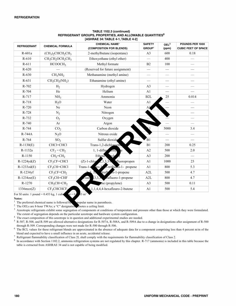
180 UNIFORM MECHANICAL CODE - PREPRINT
REFRIGERATION
TABLE 1102.3 (continued)REFRIGERANT GROUPS, PROPERTIES, AND ALLOWABLE QUANTITIES8
[ASHRAE 34: TABLE 4-1, TABLE 4-2]
For SI units: 1 pound = 0.453 kg, 1 cubic foot = 0.0283 m3
Notes:1 The preferred chemical name is followed by the popular name in parenthesis.2 The OELs are 8-hour TWAs; a “C” designation denotes a ceiling limit.3 Azeotropic refrigerants exhibit some segregation of components at conditions of temperature and pressure other than those at which they were formulated.
The extent of segregation depends on the particular azeotrope and hardware system configuration.4 The exact composition of this azeotrope is in question and additional experimental studies are needed.5 R-507, R-508, and R-509 are allowed alternative designations for R-507A, R-508A, and R-509A due to a change in designations after assignment of R-500
through R-509. Corresponding changes were not made for R-500 through R-506.6 The RCL values for these refrigerant blends are approximated in the absence of adequate data for a component comprising less than 4 percent m/m of the
blend and expected to have a small influence in an acute, accidental release.7 Refrigerant flammability classification of Class 2L shall comply with the requirements for flammability classification of Class 2.8 In accordance with Section 1102.2, ammonia refrigeration systems are not regulated by this chapter. R-717 (ammonia) is included in this table because the
table is extracted from ASHRAE 34 and is not capable of being modified.
REFRIGERANT CHEMICAL FORMULACHEMICAL NAME1
(COMPOSITION FOR BLENDS)
SAFETY
GROUP7OEL2
(ppm)
POUNDS PER 1000
CUBIC FEET OF SPACE
R-601a (CH3)2CHCH2CH3 2-methylbutane (isopentane) A3 600 0.18R-610 CH3CH2OCH2CH3 Ethoxyethane (ethyl ether) –– 400 ––R-611 HCOOCH3 Methyl formate B2 100 ––R-620 –– (Reserved for future assignment) –– –– ––R-630 CH3NH2 Methanamine (methyl amine) –– –– ––
R-631 CH3CH2(NH2) Ethanamine (ethyl amine) –– –– ––R-702 H2 Hydrogen A3 –– ––R-704 He Helium A1 –– ––R-717 NH3 Ammonia B2L 25 0.014R-718 H2O Water A1 –– ––R-720 Ne Neon A1 –– ––R-728 N2 Nitrogen A1 –– ––R-732 O2 Oxygen –– –– ––R-740 Ar Argon A1 –– ––R-744 CO2 Carbon dioxide A1 5000 3.4
R-744A N2O Nitrous oxide –– –– ––R-764 SO2 Sulfur dioxide B1 –– ––
R-1130(E) CHCl=CHCl Trans-1,2-dichloroethene B1 200 0.25R-1132a CF2 = CH2 1, 1-difluoroethylene A2 500 2.0R-1150 CH2=CH2 Ethene (ethylene) A3 200 ––
R-1224yd(Z) CF3CF=CHCl (Z)-1-chloro-2,3,3,3-tetrafluoropropen A1 1000 23R-1233zd(E) CF3CH=CHCl Trans-1-chloro-3,3,3-trifluoro-1- propene A1 800 5.3
R-1234yf CF3CF=CH2 2, 3, 3, 3-tetrafluoro-1-propene A2L 500 4.7R-1234ze(E) CF3CH=CHF Trans-1,3,3,3- tetrafluoro-1-propene A2L 800 4.7
R-1270 CH3CH=CH2 Propene (propylene) A3 500 0.111336mzz(Z) CF3CHCHCF3 Cis-1,1,1,4,4,4-hexaflouro-2-butene A1 500 5.4PREPRINT
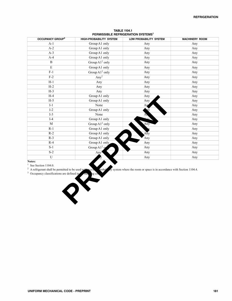
181UNIFORM MECHANICAL CODE - PREPRINT
REFRIGERATION
OCCUPANCY GROUP3 HIGH-PROBABILITY SYSTEM LOW PROBABILITY SYSTEM MACHINERY ROOM
A-1 Group A1 only Any AnyA-2 Group A1 only Any AnyA-3 Group A1 only Any AnyA-4 Group A1 only Any AnyB Group A12 only Any AnyE Group A1 only Any Any
F-1 Group A12 only Any AnyF-2 Any2 Any AnyH-1 Any Any AnyH-2 Any Any AnyH-3 Any Any AnyH-4 Group A1 only Any AnyH-5 Group A1 only Any AnyI-1 None Any AnyI-2 Group A1 only Any AnyI-3 None Any AnyI-4 Group A1 only Any AnyM Group A12 only Any Any
R-1 Group A1 only Any AnyR-2 Group A1 only Any AnyR-3 Group A1 only Any AnyR-4 Group A1 only Any AnyS-1 Group A12 only Any AnyS-2 Any2 Any AnyU Any Any Any
TABLE 1104.1PERMISSIBLE REFRIGERATION SYSTEMS1
Notes:1 See Section 1104.0.2 A refrigerant shall be permitted to be used within a high-probability system where the room or space is in accordance with Section 1104.4.3 Occupancy classifications are defined in the building code.
PREPRINT

182 UNIFORM MECHANICAL CODE - PREPRINT
PREPRINT
1201.0 General.1201.1 Applicability. This chapter shall apply to hydronicpiping systems that are part of heating, cooling, ventilation,refrigeration, and air conditioning systems. Such piping sys-tems include steam, hot water, chilled water, steam conden-sate, condenser water, and ground source heat pump systems.The regulations of this chapter shall govern the construction,location, and installation of hydronic piping systems.1201.2 Insulation. Surfaces within reach of building occu-pants shall not exceed 140°F (60°C). Where sleeves areinstalled, the insulation shall continue full size through them.
Coverings and insulation used for piping shall be ofmaterial approved for the operating temperature of the sys-tem and the installation environment. Where installed in aplenum, the insulation, jackets, and lap-seal adhesives,including pipe coverings and linings, shall have a flame-spread index not to exceed 25 and a smoke-developed indexnot to exceed 50 where tested in accordance with ASTM E84or UL 723.1201.3 Water Hammer. The piping system shall bedesigned to prevent water hammer.1201.4 Terminal Units. Terminal units, valves, and flowcontrol devices shall be installed in accordance with the man-ufacturer’s installation instructions.1201.5 Return-Water Low-Temperature Protection.Where a minimum return-water temperature to the heatsource is specified by the manufacturer, the heating systemshall be designed and installed to meet or exceed the mini-mum return-water temperature during the normal operationof the heat source.
1202.0 Protection of Potable Water Supply.1202.1 Prohibited Sources. Hydronic systems or partsthereof shall be constructed in such a manner that polluted,contaminated water or substances shall not enter a portion ofthe potable water system either during normal use or wherethe system is subject to pressure that exceeds the operatingpressure in the potable water system. Piping, components anddevices in contact with the potable water shall be approvedfor such use and where an additive is used it shall not affectthe performance of the system.1202.2 Chemical Injection. Where systems include anadditive, chemical injection or provisions for such injection,the potable water supply shall be protected by a reduced-pres-sure principle backflow prevention assembly listed or labeledin accordance with ASSE 1013. Such additive or chemicalshall be compatible with system components.1202.3 Compatibility. Fluids used in hydronic systemsshall be compatible with all components that will contact thefluid. Where a heat exchanger is installed with a dual purposewater heater, such application shall comply with the require-ments for a single wall heat exchanger in Section 1218.1.
1203.0 Capacity of Heat Source.1203.1 Heat Source. The heat source shall be sized to thedesign load.1203.2 Dual Purpose Water Heater. Water heaters uti-lized for combined space-heating and water-heating applica-tions shall be listed or labeled in accordance with thestandards referenced in Table 1203.2, and shall be installed inaccordance with the manufacturer’s installation instructions.The total heating capacity of a dual purpose water heater shallbe based on the sum of the potable hot water requirementsand the space heating design requirements corrected for hotwater first-hour draw recovery.
1203.3 Tankless Water Heaters. Tankless water heatersshall be rated by the manufacturer for space- heating applica-tions, and the output performance shall be determined by thetemperature rise and flow rate of water through the unit. Theratings shall be expressed by the water temperature rise at agiven flow rate. Manufacturer’s flow rates shall not beexceeded.
1204.0 Identification of a Potable and NonpotableWater System.1204.1 General. In buildings where potable water and non-potable water systems are installed, each system shall beclearly identified in accordance with Section 1204.2 throughSection 1204.5.1204.2 Color and Information. Each system shall be iden-tified with a colored pipe or band and coded with paint,wraps, and materials compatible with the piping.1204.3 Potable Water. Potable water systems shall be iden-tified with a green background with white lettering. The min-imum size of letters and length of the color field shall be inaccordance with Table 1204.3.1204.4 Nonpotable Water. Nonpotable water systemsshall have a yellow background with black uppercase letter-ing, with the words “CAUTION: NONPOTABLE WATER,DO NOT DRINK.” Each nonpotable system shall be identi-fied to designate the liquid being conveyed, and the direction
TABLE 1203.2WATER HEATERS
For SI units: 1000 British thermal units per hour = 0.293kW
TYPE STANDARDS
Gas-Fired, 75 000 Btu/h or less, Storage CSA Z21.10.1Gas-Fired, Above 75 000 Btu/h, Storageand Instantaneous CSA Z21.10.3
Electric, Space Heating UL 834Solid Fuel-Fired UL 2523
183UNIFORM MECHANICAL CODE - PREPRINT
CHAPTER 12HYDRONICS
PREPRINT
of normal flow shall be clearly shown. The minimum size ofthe letters and length of the color field shall comply withTable 1204.3.
1204.5 Location of Piping Identification. The backgroundcolor and required information shall be indicated every 20 feet(6096 mm) but not less than once per room, and shall be visiblefrom the floor level.1204.6 Flow Directions. Flow directions shall be indicatedon the system.
1205.0 Installation, Testing, and Inspection.1205.1 Operating Instructions.Operating and maintenanceinformation shall be provided to the building owner.1205.2 Pressure Testing. System piping and componentsshall be tested with a pressure of not less than one and one-halftimes the operating pressure but not less than 100 psi (689 kPa).Piping shall be tested with water or air except that plastic pipeshall not be tested with air. Test pressures shall be held for aperiod of not less than 30 minutes with no perceptible drop inpressure. These tests shall be made in the presence of theAuthority Having Jurisdiction.Exceptions:(1) For PEX, PP-R, PP-RCT, PEX-AL-PEX, PE-RT, and PE-
AL-PE piping systems, testing with air shall be permittedwhere authorized by the manufacturer’s instructions for thePEX, PP-R, PP-RCT, PEX-AL-PEX, PE-RT, and PE-AL-PE pipe and fittings products, and air testing is not prohib-ited by applicable codes, laws, or regulations outside thiscode.
(2) Copper tubing shall be permitted to be tested at not lessthan 80 psi (552 kPa).
1205.3 Flushing. Heating and cooling sources, system pip-ing and tubing shall be flushed after installation with water or acleaning solution. Cleaning and flushing of the heating and cool-ing sources shall comply with the manufacturer’s instructions.The cleaning solution shall be compatible with all system com-ponents and shall be used in accordance with the manufacturer’sinstructions.
1206.0 Pressure and Safety Devices.1206.1 General. Each closed hydronic system shall be pro-tected against pressures exceeding design limitations with notless than one pressure relief valve. Each closed section of the
system containing a heat source shall have a relief valve locatedso that the heat source is not capable of being isolated from arelief device. Pressure relief valves shall be installed in accor-dance with their listing and the manufacturer’s installationinstructions.1206.2 Discharge Piping. The discharge piping serving atemperature relief valve, pressure relief valve, or combinationof both shall have no valves, obstructions, or means of isola-tion and be provided with the following:(1) Equal to the size of the valve outlet and shall discharge
full size to the flood level of the area receiving the dis-charge and pointing down.
(2) Materials shall be rated at not less than the operating tem-perature of the system and approved for such use.
(3) Discharge pipe shall discharge independently by gravitythrough an air gap into the drainage system or outside ofthe building with the end of the pipe not exceeding 2 feet(610 mm) and not less than 6 inches (152 mm) above theground and pointing downwards.
(4) Discharge in such a manner that does not cause personalinjury or structural damage.
(5) No part of such discharge pipe shall be trapped or subjectto freezing.
(6) The terminal end of the pipe shall not be threaded.(7) Discharge from a relief valve into a water heater pan shall
be prohibited.
1207.0 Heating Appliances and Equipment.1207.1 General. Heating appliances, equipment, safety andoperational controls shall be listed for its intended use in ahydronic heating system and installed in accordance with themanufacturer’s installation instructions.1207.2 Boilers. Boilers and their control systems shall com-ply with Section 1002.0.
1207.2.1 Condensing Boilers.A condensing boiler, inwhich the heat exchanger and venting system aredesigned to operate with condensing flue gases, shall bepermitted to be connected directly to the panel heatingsystem without a protective mixing device.1207.2.2 Noncondensing Boilers. Where the heatexchanger and venting system are not designed to operatewith condensed flue gases, the boiler shall be permitted toconnect directly to the panel heating system where pro-tected from flue gas condensation. The operating temper-ature of the boiler shall be more than the fluid temperaturein accordance with the manufacturer’s instructions.
1207.3 Dual-Purpose Water Heaters.Water heaters usedfor combined space- and water-heating applications shall be inaccordance with the standards referenced in Table 1203.2, andshall be installed in accordance with the manufacturer’s instal-lation instructions. Water used as the heat transfer fluid in thehydronic heating system shall be isolated from the potablewater supply and distribution in accordance with Section312.1, Section 1202.0, and Section 1218.0.
TABLE 1204.3MINIMUM LENGTH OF COLOR FIELD AND SIZE OF LETTERS
For SI units: 1 inch = 25.4 mm
OUTSIDE DIAMETER OFPIPE OR COVERING
(inches)
MINIMUM LENGTHOF COLOR FIELD
(inches)
MINIMUM SIZE OFLETTERS(inches)
1/2 to 11/4 8 1/2
11/2 to 2 8 3/4
21/2 to 6 12 11/4
8 to 10 24 21/2
over 10 32 31/2
184 UNIFORM MECHANICAL CODE - PREPRINT
HYDRONICS
PREPRINT
1207.3.1 Temperature Limitations. Where a com-bined space- and water-heating application requires waterfor space heating at temperatures exceeding 140°F(60°C), a thermostatic mixing valve that is in accordancewith ASSE 1017 shall be installed to temper the watersupplied to the potable water distribution system to a tem-perature of 140°F (60°C) or less.
1207.4 Solar Heat Collector Systems. Solar water heat-ing systems used in hydronic panel radiant heating systemsshall be installed in accordance with the Uniform Solar EnergyCode and Hydronics Code (USEHC) Uniform Solar, Hydron-ics and Geothermal Code (USHGC).
1208.0 Circulators and Pumps.1208.1 General. Circulators and pumps shall be selectedfor their intended use based on the heat transfer fluid,intended operating temperature range and pressure. Circula-tors and pumps shall be installed to allow for service andmaintenance. The manufacturer’s installation instructionsshall be followed for correct orientation and installation.Motor Operated pumps rated 600V or less shall be listed andlabeled in accordance with UL 778.1208.2 Mounting. The circulator or pump shall be installedin such a way that strain from the piping is not transferred tothe circulator or pump housing. The circulator or pump shallbe permitted to be directly connected to the piping, providedthe piping is supported on each side of the circulator or pump.Where the installation of a circulator or pump will cause strainon the piping, the circulator or pump shall be installed on amounting bracket or base plate. Where means for controllingvibration of a circulator or pump is required, an approvedmeans for support and restraint shall be provided.1208.3 Sizing. The selection and sizing of a circulator orpump shall be based on all of the following:(1) Loop or system head pressure, feet of head (m)(2) Capacity, gallons per minute (L/s)(3) Maximum and minimum temperature, °F (°C)(4) Maximum working pressure, pounds per square inch (kPa)(5) Fluid type
1209.0 Expansion Tanks.1209.1 General.An expansion tank shall be installed in eachclosed hydronic system to control system pressure due to ther-mal expansion and contraction. Expansion tanks shall be ofthe closed or open type. Expansion tanks shall be rated for thepressure of the system. 1209.2 Installation. Expansion tanks shall be accessible formaintenance and shall be installed in accordance with the man-ufacturer’s installation instructions. Each expansion tank shallbe equipped with a shutoff device that will remain open duringoperation of the hydronic system. Valve handles shall be lockedopen or removed to prevent from being inadvertently shut off.Provisions shall be made for draining the tank without empty-ing the system. Expansion tanks shall be securely fastened tothe structure. Supports shall be capable of carrying twice theweight of the tank filled with water without placing a strain onconnecting piping. Hot-water-heating systems incorporating
hot water tanks or fluid relief columns shall be installed to pre-vent freezing under normal operating conditions.1209.3 Open-Type Expansion Tanks. Open type expan-sion tanks shall be located not less than 3 feet (914 mm) abovethe highest point of the system. An overflow with a diameterof not less than one-half the size of the supply or not less than1 inch (25 mm) in diameter shall be installed at the top of thetank. The overflow shall discharge through an air gap into thedrainage system. 1209.4 Closed-Type Tanks. Closed-type expansion tanksshall be designed for a hydrostatic test pressure of two andone-half times the allowable working pressure of the system.Expansion tanks for systems designed to operate at more than30 pounds-force per square inch (psi) (207 kPa) shall complywith ASME BPVC Section VIII. 1209.5 Sizing. Expansion tanks shall be sized to accept thefull expansion volume of the fluid in the system. The mini-mum capacity of a closed-type expansion tank shall be sizedin accordance with Section 1004.4.
1210.0 Materials.1210.1 Piping, Tubing, and Fittings. Hydronic pipe andtubing shall comply with the applicable standards referencedin Table 1210.1 and shall be approved for use based on theintended purpose. Materials shall be rated for the operatingtemperature and pressure of the system and shall be compati-ble with the type of heat transfer fluid. Pipe fittings and valvesshall be approved for the specific installation with the piping,materials to be installed and shall comply with the applicablestandards referenced in Table 1210.1. Where required, exteriorpiping shall be protected against freezing, UV radiation, cor-rosion and degradation. Embedded pipe or tubing shall com-ply with Section 1221.2.1210.2 Expansion and Contraction. Pipe and tubing shallbe so installed that it will not be subject to undue strains orstresses, and provisions shall be made for expansion, contrac-tion, and structural settlement.1210.3 Hangers and Supports. Pipe and tubing shall besupported in accordance with Section 313.3. Equipment that ispart of the piping system shall be provided with additional sup-port in accordance with this code and manufacturer’s installa-tion instructions.1210.4 Oxygen Diffusion Corrosion. PEX and PE-RT tub-ing in closed hydronic systems shall contain an oxygen barrier. Exception: Closed hydronic systems without ferrous compo-nents in contact with the hydronic fluid.
1211.0 Joints and Connections.1211.1 General. Joints and connections shall be of anapproved type. Joints shall be gas and watertight and designedfor the pressure of the hydronic system. Changes in directionshall be made by the use of fittings or with pipe bends. Pipebends shall have a radius of not less than six times the outsidediameter of the tubing or shall be in accordance with the man-ufacturer’s installation instructions. Joints between pipe andfittings shall be installed in accordance with the manufac-turer’s installation instructions.
185UNIFORM MECHANICAL CODE - PREPRINT
HYDRONICS
PREPRINT
1211.2 Chlorinated Polyvinyl Chloride (CPVC) Pipe.Joints between chlorinated polyvinyl chloride (CPVC) pipe orand fittings shall be installed in accordance with one of thefollowing methods:(1) Mechanical joints shall include flanged, grooved, and push
fit fittings. Removable and non-removable push fit fittingswith an elastomeric o-ring that employ quick assemblypush fit connectors shall be in accordance with ASSE 1061.
(2) Solvent cement joints for CPVC pipe and fittings shall beclean from dirt and moisture. Solvent cements in accor-dance with ASTM F493, requiring the use of a primershall be orange in color. The primer shall be colored andbe in accordance with ASTM F656. Listed solventcement in accordance with ASTM F493 that does notrequire the use of primers, yellow or red in color, shall bepermitted for pipe and fittings manufactured in accor-
186 UNIFORM MECHANICAL CODE - PREPRINT
HYDRONICS
MATERIALSTANDARDS
PIPING/TUBING FITTINGS
Copper/Copper Alloy ASTM B42, ASTM B43, ASTM B75, ASTM B88, ASTM B135, ASTM B2512,
ASTM B302, ASTM B447
ASME B16.15, ASME B16.18, ASME B16.22,ASME B16.23, ASME B16.24, ASME B16.26,
ASME B16.29, ASME B16.51, ASSE 1061,IAPMO PS 117
Ductile Iron AWWA C115/A21.15, AWWA C151/A21.51
AWWA C110/A21.101, AWWA C153/A21.53
SteelASTM A53, ASTM A106, ASTM A254 ASME B16.5, ASME B16.9,
ASME B16.11, ASTM A420Stainless Steel ASTM A269, ASTM A312,
ASTM A554, ASTM A778ASTM F1476, ASTM F1548, ASTM F3226, IAPMO PS 117
Gray Iron –– ASTM A126Malleable Iron –– ASME B16.3Chlorinated Polyvinyl Chloride (CPVC)
ASTM D2846, ASTM F441, ASTM F442, CSA B137.6
ASSE 1061, ASTM D2846, ASTM F437,ASTM F438, ASTM F439, ASTM F1970,
CSA B137.6Polyethylene (PE) ASTM D1693, ASTM D2513,
ASTM D2683, ASTM D2737, ASTM D3035, ASTM D3350, ASTM F714, AWWA C901,
CSA B137.1, NSF 358-1
ASTM D2609, ASTM D2683, ASTM D3261,ASTM F1055, CSA B137.1, NSF 358-1
Cross-Linked Polyethylene (PEX)
ASTM F876, ASTM F3253, CSA B137.5,NSF 358-3
ASSE 1061, ASTM F877, ASTM F1055,ASTM F1807, ASTM F1960, ASTM F1961,ASTM F2080, ASTM F2098, ASTM F2159,ASTM F2735, ASTM F3253, CSA B137.5,
NSF 358-3Polypropylene (PP) ASTM F2389, CSA B137.11, NSF 358-2 ASTM F2389, CSA B137.11, NSF 358-2Polyvinyl Chloride (PVC) ASTM D1785, ASTM D2241,
CSA B137.3
ASTM D2464, ASTM D2466,ASTM D2467, ASTM F1970,
CSA B137.2, CSA B137.3Raised Temperature Polyethylene (PE-RT) ASTM F2623, ASTM F2769,
CSA B137.18
ASSE 1061, ASTM F1807, ASTM F2159,ASTM F2735, ASTM F2769, ASTM D3261,
ASTM F1055, CSA B137.18Cross-Linked Polyethylene/Aluminum/Cross-Linked Polyethylene(PEX-AL-PEX)
ASTM F1281, ASTM F2262,CSA B137.10
ASTM F1281, ASTM F1974, ASTM F2434,CSA B137.10
Polyethylene/Aluminum/Polyethylene (PE-AL-PE) ASTM F1282, CSA B137.9 ASTM F1282, ASTM F1974, CSA B137.9
Chlorinated Polyvinyl Chloride/Alu-minum/ Chlorinated Polyvinyl Chloride(CPVC/AL/CPVC)
ASTM F2855 ASTM D2846
TABLE 1210.1MATERIALS FOR HYDRONIC SYSTEM PIPING, TUBING, AND FITTINGS
Note:1 Ductile and gray iron.2 Only type K, L, or M tubing allowed to be installed.
PREPRINT
dance with ASTM D2846, 1/2 of an inch (15 mm) through2 inches (50 mm) in diameter or ASTM F442, 1/2 of aninch (15 mm) through 3 inches (80 mm) in diameter.Apply primer where required inside the fitting and to thedepth of the fitting on pipe. Apply liberal coat of cementto the outside surface of pipe to depth of fitting and insideof fitting. Place pipe inside fitting to forcefully bottomthe pipe in the socket and hold together until joint is set.
(3) Threaded joints for CPVC pipe shall be made with pipethreads in accordance with ASME B1.20.1. A minimum ofSchedule 80 shall be permitted to be threaded, and thepressure rating shall be reduced by 50 percent. The use ofmolded fittings shall not result in a 50 percent reduction inthe pressure rating of the pipe provided that the moldedfittings shall be fabricated so that the wall thickness of thematerial is maintained at the threads. Thread sealant com-pound that is compatible with the pipe and fitting, insolu-ble in water, and nontoxic shall be applied to male threads.Caution shall be used during assembly to prevent overtightening of the CPVC components once the threadsealant has been applied. Female CPVC threaded fittingsshall be used with plastic male threads only.
1211.3 CPVC/AL/CPVC Plastic Pipe and Joints. Jointsbetween chlorinated polyvinyl chloride/aluminum/ chlori-nated polyvinyl chloride (CPVC/AL/CPVC) pipe or and fit-tings shall be installed in accordance with one of thefollowing methods:(1) Mechanical joints shall include flanged, and grooved,
and push-fit fittings.(2) Solvent cement joints for CPVC/AL/CPVC pipe and fit-
tings shall be clean from dirt and moisture. Solventcements in accordance with ASTM F493, requiring theuse of a primer shall be orange in color. The primer shallbe colored and be in accordance with ASTM F656.Listed solvent cement in accordance with ASTM F493that does not require the use of primers, yellow in color,shall be permitted for pipe and fittings manufactured inaccordance with ASTM D2846, 1⁄2 of an inch (15 mm)through 2 inches (50 mm) in diameter, 1⁄2 of an inch (15mm) through 3 inches (80 mm) in diameter. Applyprimer where required inside the fitting and to the depthof the fitting on pipe. Apply liberal coat of cement to theoutside surface of pipe to depth of fitting and inside offitting. Place pipe inside fitting to forcefully bottom thepipe in the socket and hold together until joint is set.
1211.4 Copper or Copper Alloy Pipe and Tubing.Joints between copper or copper alloy pipe, or tubing, or andfittings shall be installed in accordance with one of the fol-lowing methods:(1) Brazed joints between copper or copper alloy pipe, or
tubing, or and fittings shall be made with brazing alloyshaving a liquid temperature above 1000°F (538°C). Thejoint surfaces to be brazed shall be cleaned bright byeither manual or mechanical means. Tubing shall be cutsquare and reamed to full inside diameter. Brazing fluxshall be applied to the joint surfaces where required bymanufacturer’s recommendation. Brazing filler metal in
accordance with AWS A5.8 shall be applied at the pointwhere the pipe or tubing enters the socket of the fitting.
(2) Flared joints for soft copper or copper alloy tubing shallbe made with fittings that are in accordance with theapplicable standards referenced in Table 1210.1. Pipe ortubing shall be cut square using an appropriate tubingcutter. The tubing shall be reamed to full inside diame-ter, resized to round, and expanded with a proper flaringtool.
(3) Mechanically formed tee fittings shall have extracted col-lars that shall be formed in a continuous operation con-sisting of drilling a pilot hole and drawing out the pipe ortube surface to form a collar having a height not less thanthree times the thickness of the branch tube wall. Thebranch pipe or tube shall be notched to conform to theinner curve of the run pipe or tube and shall have twodimple depth stops to ensure that penetration of thebranch pipe or tube into the collar is of a depth for braz-ing and that the branch pipe or tube does not obstruct theflow in the main line pipe or tube. Dimple depth stopsshall be in line with the run of the pipe or tube. The sec-ond dimple shall be 1/4 of an inch (6.4 mm) above thefirst and shall serve as a visual point of inspection. Fit-tings and joints shall be made by brazing. Soldered jointsshall not be permitted.
(4) Pressed fittings for copper or copper alloy pipe or tub-ing shall have an elastomeric o-ring that forms the joint.The pipe or tubing shall be fully inserted into the fitting,and the pipe or tubing marked at the shoulder of the fit-ting. Pipe or tubing shall be cut square, chamfered, andreamed to full inside diameter. The fitting alignmentshall be checked against the mark on the pipe or tubingto ensure the pipe or tubing is inserted into the fitting.The joint shall be pressed using the tool recommended bythe manufacturer.
(5) Removable and nonremovable push fit fittings for copperor copper alloy tubing or pipe that employ quick assem-bly push fit connectors shall be in accordance with ASSE1061. Push fit fittings for copper or copper alloy pipe ortubing shall have an approved elastomeric o-ring thatforms the joint. Pipe or tubing shall be cut square, cham-fered, and reamed to full inside diameter. The tubingshall be fully inserted into the fitting, and the tubingmarked at the shoulder of the fitting. The fitting align-ment shall be checked against the mark on the tubing toensure the tubing is inserted into the fitting and grippingmechanism has engaged on the pipe.
(6) Soldered joints between copper or copper alloy pipe, ortubing, or and fittings shall be made in accordance withASTM B828. Pipe or tubing shall be cut square andreamed to the full inside diameter including the removalof burrs on the outside of the pipe or tubing. Surfaces tobe joined shall be cleaned bright by manual or mechani-cal means. Flux shall be applied to pipe or tubing and fit-tings and shall be in accordance with ASTM B813, andshall become noncorrosive and nontoxic after soldering.Insert pipe or tubing into the base of the fitting andremove excess flux. Pipe or tubing and fitting shall besupported to ensure a uniform capillary space around the
187UNIFORM MECHANICAL CODE - PREPRINT
HYDRONICS
PREPRINT
joint. Solder in accordance with ASTM B32 shall beapplied to the joint surfaces until capillary action drawsthe molten solder into the cup. Joint surfaces shall not bedisturbed until cool, and any remaining flux residue shallbe cleaned.
(7) Threaded joints for copper or copper alloy pipe shall bemade with pipe threads in accordance with ASMEB1.20.1. Thread sealant tape or compound shall beapplied only on male threads, and such material shall beof approved types, insoluble in water, and nontoxic.
1211.5 Cross-Linked Polyethylene (PEX) Pipe. Jointsbetween cross-linked polyethylene (PEX) pipe or and fittingsshall be installed with fittings for PEX tubing that complywith the applicable standards referenced in Table 1210.1.PEX tubing labeled in accordance with ASTM F876 shall bemarked with the applicable standard designation for the fit-tings specified for use with the tubing. Mechanical joints shallbe installed in accordance with the manufacturer’s installa-tion instructions.1211.6 Cross-Linked Polyethylene/Aluminum/Cross-Linked Polyethylene (PEX-AL-PEX) Pipe. Joints betweencross-linked polyethylene/aluminum/cross-linked polyethyl-ene (PEX-AL-PEX) pipe or and fittings shall be installed inaccordance with one of the following methods:(1) Mechanical joints between PEX-AL-PEX pipe or and fit-
tings shall include mechanical and compression type fit-tings and insert fittings with a crimping ring. Insert fittingsutilizing a crimping ring shall be in accordance withASTM F1974 or ASTM F2434. Crimp joints for crimpinsert fittings shall be joined to PEX-AL-PEX pipe by thecompression of a crimp ring around the outer circumfer-ence of the pipe, forcing the pipe material into annularspaces formed by ribs on the fitting.
(2) Compression joints shall include compression insert fit-tings and shall be joined to PEX-AL-PEX pipe through thecompression of a split ring or compression nut around theouter circumference of the pipe, forcing the pipe materialinto the annular space formed by the ribs on the fitting.
1211.7 Ductile Iron Pipe. Joints between ductile iron pipe orand fittings shall be installed in accordance with one of the fol-lowing methods:(1) Mechanical joints for ductile iron pipe or and fittings shall
consist of a bell that is cast integrally with the pipe or fit-ting and provided with an exterior flange having bolt holesand a socket with annular recesses for the sealing gasketand the plain end of the pipe or fitting. The elastomericgasket shall comply with AWWA C111. Lubricant rec-ommended for the application by the pipe manufacturershall be applied to the gasket and plain end of the pipe.
(2) Push-on joints for ductile iron pipe or and fittings shallconsist of a single elastomeric gasket that shall be assem-bled by positioning the elastomeric gasket in an annularrecess in the pipe or fitting socket and forcing the plainend of the pipe or fitting into the socket. The plain endshall compress the elastomeric gasket to form a positiveseal and shall be designed so that the elastomeric gasketshall be locked in place against displacement. The elas-tomeric gasket shall comply with AWWA C111. Lubri-
cant recommended for the application by the pipe manu-facturer shall be applied to the gasket and plain end of thepipe.
1211.8 Polyethylene (PE) Plastic Pipe/Tubing. Jointsbetween polyethylene (PE) plastic pipe, or tubing, or and fit-tings shall be installed in accordance with one of the followingmethods:(1) Butt-fusion joints shall be installed in accordance with
ASTM F2620 and shall be made by heating the squaredends of two pipes, pipe and fitting, or two fittings by hold-ing ends against a heated element. The heated elementshall be removed where the proper melt is obtained, andjoined ends shall be placed together with applied force.
(2) Electro-fusion joints shall be heated internally by a con-ductor at the interface of the joint. Align and restrain fit-ting to pipe to prevent movement and apply electriccurrent to the fitting. Turn off the current when the propertime has elapse to heat the joint. The joint shall fusetogether and remain undisturbed until cool.
(3) Socket-fusion joints shall be installed in accordanceASTM F2620 and shall be made by simultaneously heat-ing the outside surface of a pipe end and the inside of a fit-ting socket. Where the proper melt is obtained, the pipeand fitting shall be joined by inserting one into the otherwith applied force. The joint shall fuse together andremain undisturbed until cool.
(4) Mechanical joints between PE pipe, or tubing, or and fit-tings shall include insert and mechanical compression fit-tings that provide a pressure seal resistance to pullout.Joints for insert fittings shall be made by cutting the pipesquare, using a cutter designed for plastic piping, andremoval of sharp edges. Two stainless steel clamps shallbe placed over the end of the pipe. Fittings shall bechecked for proper size based on the diameter of the pipe.The end of pipe shall be placed over the barbed insert fit-ting, making contact with the fitting shoulder. Clampsshall be positioned equal to 180 degrees (3.14 rad) apartand shall be tightened to provide a leak tight joint. Com-pression type couplings and fittings shall be permitted foruse in joining PE piping and tubing. Stiffeners that extendbeyond the clamp or nut shall be prohibited. Bends shallbe not less than 30 pipe diameters, or the coil radius wherebending with the coil. Bends shall not be permitted closerthan 10 pipe diameters of a fitting or valve. Mechanicaljoints shall be designed for their intended use.
1211.9 Polyethylene/Aluminum/Polyethylene (PE-AL-PE). Joints between polyethylene/aluminum/polyethylene(PE-AL-PE) pipe or and fittings shall be installed in accor-dance with one of the following methods:(1) Mechanical joints for PE-AL-PE pipe, or tubing, or and
fittings shall be either of the metal insert fittings with asplit ring and compression nut or metal insert fittings withcopper crimp rings. Metal insert fittings shall comply withASTM F1974. Crimp insert fittings shall be joined to thepipe by placing the copper crimp ring around the outercircumference of the pipe, forcing the pipe material intothe space formed by the ribs on the fitting until the pipecontacts the shoulder of the fitting. The crimp ring shall
188 UNIFORM MECHANICAL CODE - PREPRINT
HYDRONICS
PREPRINT
then be positioned on the pipe so the edge of the crimpring is 1/8 of an inch (3.2 mm) to 1/4 of an inch (6.4 mm)from the end of the pipe. The jaws of the crimping toolshall be centered over the crimp ring and tool perpendi-cular to the barb. The jaws shall be closed around thecrimp ring and shall not be crimped more than once.
(2) Compression joints for PE-AL-PE pipe, or tubing, or andfittings shall be joined through the compression of a splitring, by a compression nut around the circumference ofthe pipe. The compression nut and split ring shall beplaced around the pipe. The ribbed end of the fitting shallbe inserted onto the pipe until the pipe contacts the shoul-der of the fitting. Position and compress the split ring bytightening the compression nut onto the insert fitting.
1211.10 Polyethylene of Raised Temperature (PE-RT).Joints between polyethylene of raised temperature (PE-RT)tubing or and fittings shall be installed with fittings for PE-RTtubing that comply with the applicable standards referencedin Table 1210.1. Metal insert fittings, metal compression fit-tings, and plastic fittings shall be manufactured to and markedin accordance with the standards for fittings in Table 1210.1.1211.11 Polypropylene (PP) Pipe. Joints betweenpolypropylene pipe or and fittings shall be installed in accor-dance with one of the following methods:(1) Heat-fusion joints for polypropylene (PP) pipe shall be
installed with socket-type heat-fused polypropylene fit-tings, butt-fusion polypropylene fittings or pipe, or elec-tro-fusion polypropylene fittings. Joint surfaces shall beclean and free from moisture. The joint shall be undis-turbed until cool. Joints shall be made in accordance withASTM F2389 or CSA B137.11.
(2) Mechanical and compression sleeve joints shall beinstalled in accordance with the manufacturer’s installa-tion instructions. Polypropylene pipe shall not bethreaded. Polypropylene transition fittings for connec-tion to other piping materials shall only be threaded bythe use of copper alloy or stainless steel inserts moldedin the fitting.
1211.12 Polyvinyl Chloride (PVC) Pipe. Joints betweenpolyvinyl chloride pipe or and fittings shall be installed inaccordance with one of the following methods:(1) Mechanical joints shall be designed to provide a perma-
nent seal and shall be of the mechanical or push-on joint.The mechanical joint shall include a pipe spigot that hasa wall thickness to withstand without deformation or col-lapse; the compressive force exerted where the fitting istightened. The push-on joint shall have a minimum wallthickness of the bell at any point between the ring andthe pipe barrel. The elastomeric gasket shall comply withASTM D3139, and be of such size and shape as to pro-vide a compressive force against the spigot and socketafter assembly to provide a positive seal.
(2) Solvent cement joints for PVC pipe or and fittings shallbe clean from dirt and moisture. Pipe shall be cut squareand pipe shall be deburred. Where surfaces to be joinedare cleaned and free of dirt, moisture, oil, and other for-eign material, apply primer purple in color in accordancewith ASTM F656. Primer shall be applied until the sur-
face of the pipe and fitting is softened. Solvent cementsin accordance with ASTM D2564 shall be applied to alljoint surfaces. Joints shall be made while both the insidesocket surface and outside surface of pipe are wet withsolvent cement. Hold joint in place and undisturbed for1 minute after assembly.
(3) Threads shall comply with ASME B1.20.1. A minimumof Schedule 80 shall be permitted to be threaded; how-ever, the pressure rating shall be reduced by 50 percent.The use of molded fittings shall not result in a 50 per-cent reduction in the pressure rating of the pipe providedthat the molded fittings shall be fabricated so that thewall thickness of the material is maintained at thethreads. Thread sealant compound that is compatiblewith the pipe and fitting, insoluble in water, and nontoxicshall be applied to male threads. Caution shall be usedduring assembly to prevent over tightening of the PVCcomponents once the thread sealant has been applied.Female PVC threaded fittings shall be used with plasticmale threads only.
1211.13 Steel Pipe and Tubing. Joints between steel pipe,or tubing, or and fittings shall be installed in accordance withone of the following methods: (1) Mechanical joints shall be made with an approved and
listed elastomeric gasket.(2) Threaded joints shall be made with pipe threads that are
in accordance with ASME B1.20.1. Thread sealant tapeor compound shall be applied only on male threads, andsuch material shall be of approved types, insoluble inwater, and nontoxic.
(3) Welded joints shall be made by electrical arc or oxy-gen/acetylene method. Joint surfaces shall be cleaned byan approved procedure. Joints shall be welded by anapproved filler metal.
(4) Pressed joints shall have an elastomeric o-ring that formsthe connection. The pipe or tubing shall be fully insertedinto the fitting, and the pipe or tubing marked at theshoulder of the fittings. Pipe or tubing shall be cut square,chamfered, and reamed to full inside diameter. The fit-ting alignment shall be checked against the mark on thepipe or tubing to ensure the pipe or tubing is fullyinserted into the fitting. The joint shall be pressed usingthe tool recommended by the manufacturer.
1211.14 Joints Between Various Materials. Jointsbetween various materials shall be installed in accordancewith the manufacturer’s installation instructions and shallcomply with Section 1211.14.1 and Section 1211.14.2.
1211.14.1 Copper or Copper Alloy Pipe or Tubingto Threaded Pipe Joints. Joints from copper or cop-per alloy pipe or tubing to threaded pipe shall be made bythe use of copper alloy adapter, copper alloy nipple [min-imum 6 inches (152 mm)], dielectric fitting, or dielectricunion in accordance with ASSE 1079. The joint betweenthe copper or copper alloy pipe or tubing and the fittingshall be a soldered, brazed, flared, or pressed joint andthe connection between the threaded pipe and the fittingshall be made with a standard pipe size threaded joint.
189UNIFORM MECHANICAL CODE - PREPRINT
HYDRONICS
PREPRINT
1211.14.2 Plastic Pipe to Other Materials. Whereconnecting plastic pipe to other types of piping, approvedtypes of adapter or transition fittings designed for thespecific transition intended shall be used.
1212.0 Valves.1212.1 General. Valves shall be rated for the operating tem-perature and pressure of the system. Valves shall be compati-ble with the type of heat transfer medium and piping material.1212.2 Where Required. Valves shall be installed inhydronic piping systems in accordance with Section 1212.3through Section 1212.11.1212.3 Heat Exchanger. Isolation valves shall be installedon the supply and return side of the heat exchanger.1212.4 Pressure Vessels. Isolation valves shall beinstalled on connections to pressure vessels.1212.5 Pressure Reducing Valves. Isolation valves shallbe installed on both sides of a pressure reducing valve.1212.6 Equipment, Components, and Appliances.Serviceable equipment, components, and appliances withinthe system shall have isolation valves installed upstream anddownstream of such devices.1212.7 Expansion Tank. Isolation valves shall be installedat connections to non-diaphragm-type expansion tanks.1212.8 Flow Balancing Valves. Where flow balancingvalves are installed, such valves shall be capable of increas-ing or decreasing the amount of flow by means of adjustment.1212.9 Mixing or Temperature Control Valves. Wheremixing or temperature control valves are installed, suchvalves shall be capable of obtaining the design water tem-perature and design flow requirements.1212.10 Thermosiphoning.An approved type check valveshall be installed on liquid heat transfer piping to control ther-mosiphoning of heated liquids.1212.11 Air Removal Device or Air Vents. Isolationvalves shall be installed where air removal devices or auto-matic air vents are utilized to permit cleaning, inspection, orrepair without shutting the system down.
1213.0 System Controls.1213.1 Water Temperature Controls. A heat source orsystem of commonly connected heat sources shall be pro-tected by a water-temperature-activated operating control tostop heat output of the heat source where the system waterreaches a pre-set operating temperature.1213.2 Operating Steam Controls.A steam heat source orsystem of commonly connected steam heat sources shall be pro-tected by a pressure-actuated control to shut off the fuel supplywhere the system pressure reaches a pre-set operating pressure.
1213.2.1 Water-Level Controls. A primary water-level control shall be installed on a steam heat source tocontrol the water level in the heat source. The controlshall be installed in accordance with the manufacturer’sinstallation instructions.
1213.3 Occupied Spaces. A temperature-sensing deviceshall be installed in the occupied space to regulate the opera-tion of the hydronic system.1213.4 Simultaneous Operation. Radiant heating andcooling systems sharing a common space temperature con-trol shall be configured to prevent simultaneous heating andcooling.1213.5 Temperature Reading. A temperature gauge ortransmitter shall be installed for reading the fluid tempera-tures in the panel system supply and heat source outlet. Onetemperature gauge or transmitter shall be permitted where thetemperature between the heat source outlet and panel systemsupply are the same.
1214.0 Pressure and Flow Controls.1214.1 Balancing. A means for balancing distributionloops, heat emitting devices, and multiple boiler installationsshall be provided in accordance with the manufacturer’sinstructions. A means for balancing and flow control shallinclude the piping design, pumping equipment, or balancingdevices.1214.2 Low-Water Control. Direct-fired heat sourceswithin a closed heating system shall have a low-water fuelcut-off device, except as specified in Section 1214.3. Wherea low-water control is integral with the heat source as part ofthe appliance’s integrated control and is listed for such use, aseparate low-water control shall not be required. An externalcut-off device shall be installed in accordance with the heat-source manufacturer’s installation instructions. No valve shallbe located between the external low-water fuel cut-off andthe heat-source unit. Where a pumped condensate return isinstalled, a second low-water cut-off shall be provided.1214.3 Flow-Sensing Devices.A direct-fired heat source,requiring forced circulation to prevent overheating, shall havea flow-sensing device installed with the appliance, or suchdevice shall be integral with the appliance. A low-water fuelcut-off device shall not be required.1214.4 Automatic Makeup Fluid. Where an automaticmakeup fluid supply fill device is used to maintain the fluidcontent of the heat-source unit, or any closed loop in the sys-tem, the makeup supply shall be located at the expansion tankconnection or other approved location.
Where an automatic makeup water supply fill device fora closed loop system is supplied by a potable water supply,the fill system shall automatically shut off flow when the sup-plied makeup water volume exceeds the greater of 5 gallons(19 L) or five percent of the total system fluid volume. Amanual reset shall be required. Where an automatic makeup fluid fill device for a closedloop system is supplied by an isolated tank, the fluid capac-ity of the tank shall not exceed the greater of 5 gallons (19 L)or 5 percent of the total system fluid volume.
A pressure-reducing valve shall be installed on a makeupfeed line. The pressure of the feed line shall be set in accor-dance with the design of the system, and connections topotable water shall be in accordance with Section 1202.0 toprevent contamination due to backflow.
190 UNIFORM MECHANICAL CODE - PREPRINT
HYDRONICS
PREPRINT
1214.5 Differential Pressure Regulation. Provisionsshall be made to bypass zone flows in excess of design veloc-ity in a multi-zone hydronic system where the closing of someor all of the two-way zone valves causes excess flow throughthe open zones or deadheading of a fixed-speed circulator orpump.
1214.5.1 Differential Pressure Bypass Valve.Where a differential pressure bypass valve is used for thepurpose specified in Section 1214.5, it shall be installedand adjusted to provide bypass of the distribution systemwhen most or all of the zones are closed.
1214.6 Air-Removal Device. Provision shall be made forthe removal of air from fluid in hydronic systems. Air-removal devices shall be located in the areas of the hydronicpiping system where air is likely to accumulate. Air-removaldevices shall be installed to facilitate their removal for exam-ination, repair, or replacement.Exception: Drainback type solar thermal systems shall notrequire an air-removal device.1214.7 Air-Separation Device. To assist with the removalof entrained air, an air-separation device shall be installed inhydronic systems. The device shall be located in accordancewith the manufacturer’s installation instructions or at thepoint of no mechanically-induced pressure change within thehydronic system.1214.8 Secondary Loops. Secondary loops that are iso-lated from the primary heat-distribution loop by a heatexchanger are closed-loop hydronic systems and shall have anexpansion tank in accordance with Section 1209.0, an air-removal device in accordance with Section 1214.6, and anair-separation device in accordance with Section 1214.7.
1215.0 Hydronic Space Heating.1215.1 General. Based on the system design, the heat-dis-tribution units shall be selected in accordance with the man-ufacturer’s specifications.1215.2 Installation. Heat-distribution units shall beinstalled in accordance with the manufacturer’s installationinstructions and this code.1215.3 Freeze Protection. Hydronic systems and compo-nents shall be designed, installed, and protected from freez-ing.1215.4 Balancing. System loops shall be installed so thatthe design flow rates are achieved within the system.1215.5 Heat Transfer Fluid. The ignitable flash point ofheat transfer fluid in a hydronic piping system shall be a min-imum of 50°F (28°C) above the maximum system operatingtemperature. The heat transfer fluid shall be compatible withthe makeup fluid supplied to the system.
1216.0 Steam Systems.1216.1 Steam Traps. For other than one-pipe steam sys-tems, each heat-distribution unit shall be supplied with asteam trap that is listed for the application.1216.2 Sloping for Two-Pipe System. Two-pipe steamsystem piping and heat-distribution units shall be sloped
down at not less than 1/8 inch per foot (10.4 mm/m) in thedirection of the steam flow.1216.3 Sloping for One-Pipe System. One-pipe steamsystem piping and heat-distribution units shall be slopeddown at not less than 1/8 inch per foot (10.4 mm/m) towardsthe steam boiler, without trapping.1216.4 Automatic Air Vents. Steam automatic air ventsshall be installed to eliminate air pressure in heat-distributionunits on gravity steam piping systems. Air vents shall not beused on a vacuum system.1216.5 Condensate Flow. System piping shall be installedto allow condensate to flow to the condensate receiver orsteam boiler either by gravity or pump-assisted.1216.6 Steam-Distribution Piping.Where multi-row ele-ments are installed in an enclosure, they shall be top fed andpiped in parallel down to the steam trap. A single steam trapfor each row of heating elements shall be installed. Where thesize of the return header is increased by a minimum of onepipe size, a single steam trap shall be permitted to be installedfor multiple rows. Where multiple steam unit heaters areinstalled, an individual steam trap for each unit shall beinstalled.
1217.0 Radiant Heating and Cooling.1217.1 Installation. Radiant heating and cooling systemsshall be installed in accordance with the system design.
1217.1.1 Manifolds. Manifolds shall be equipped withisolation valves on the supply and return lines. Manifoldsshall be capable of withstanding the pressure and tem-perature of the system. The material of the manifold shallbe compatible with the system fluid and shall be installedin accordance with the manufacturer’s installationinstructions.
1217.2 Radiant Under-Floor Heating. Floor finished sur-face temperatures shall not exceed the following temperaturesfor space heating applications:(1) 85°F (29°C) in general occupied applications.(2) 90°F (32°C) in bathrooms, foyers, distribution areas such
as hallways and indoor swimming pools.(3) 88°F (31°C) in industrial spaces(4) 95°F (35°C) in radiant panel perimeter areas, i.e., up to
2.5 feet (762 mm) from outside walls.The radiant heating system temperature shall not exceed
the maximum temperature rating of the materials used in itsconstruction. 1217.3 Radiant Cooling Systems. Radiant cooling sys-tems shall be designed to minimize the potential for conden-sation. To prevent condensation on any cooled radiantsurface, the supply water temperature for a radiant coolingsystem shall be not less than 3°F (2°C) above the anticipatedspace dewpoint temperature, or in accordance with the man-ufacturer’s recommendation. Chilled water piping, valves,and fittings shall be insulated and vapor sealed to prevent sur-face condensation.1217.4 Tube Placement. Hydronic radiant system tubingshall be installed in accordance with the manufacturer’s
191UNIFORM MECHANICAL CODE - PREPRINT
HYDRONICS
PREPRINT
installation instructions and with the tube layout and spacingin accordance with the system design. Except for distributionmains, tube spacing and the individual loop lengths shall beinstalled with a variance of not more than ±10 percent fromthe design. The maximum loop length of continuous tubingfrom a supply-and-return manifold shall not exceed thelengths specified by the manufacturer or, in the absence ofmanufacturer’s specifications, the lengths specified in Table1217.4. Actual loop lengths shall be determined by spacing,flow rate, and pressure drop requirements as specified in thesystem design.
For the purpose of system balancing, each individualloop shall have a tag securely affixed to the manifold to indi-cate the length of the loop and the room(s) and area(s) served.
1217.5 Poured Floor Structural Concrete Slab Sys-tems (Thermal Mass). Where tubing is embedded in astructural concrete slab such tubes shall not be larger in out-side dimension than one-third of the overall thickness of theslab and shall be spaced not less than three diameters on cen-ter except within 10 feet (3048 mm) of the distribution man-ifold. The top of the tubing shall be embedded in the slab notless than 2 inches (51 mm) below the surface.
1217.5.1 Slab Penetration Tube and Joint Protec-tion. Where embedded in or installed under a concreteslab, tubing shall be protected from damage at penetra-tions of the slab with protective sleeving approved by thetubing manufacturer. The space between the tubing andsleeve shall be sealed with an approved sealant compat-ible with the tubing. The tubing at the location of anexpansion joint in a concrete slab shall be encased in pro-tective pipe sleeving that covers the tubing not less than12 inches (305 mm) on either side of the expansion jointor the tubing shall be installed below the slab.1217.5.2 Insulation. Where a poured concrete radiantfloor system is installed in contact with the soil, insula-tion recommended by the manufacturer for such an appli-cation and with a minimum R-value of 5 shall be placedbetween the soil and the concrete; extend to the outsideedges of the concrete; and be placed on all slab edges.1217.5.3 Types of Tube Fasteners. Tubing that isembedded within concrete shall be fastened according tomanufacturer's instructions. Unless prohibited by themanufacturer, tube fasteners include the following:
(1) Ties made of wire, typically fastened to anchorssuch as rebar or wire mesh.
(2) Plastic tube/cable ties, typically nylon, fastened toanchors such as rebar or wire mesh.
(3) Staples made of metal or plastic or combinationthereof, without sharp edges that would harm tube,fastened to insulation or subfloor.
(4) Plastic rails with integrated tube holders intendedfor the specific type of tube.
(5) Insulation sheets with integrated knobs for holdingthe specific type of tube and intended for this appli-cation.
(6) Other fasteners recommended by the manufacturer.1217.5.4 Spacing of Tube Fasteners. The maximumspacing between tube fasteners within a concrete floorshall not exceed the spacing specified by the manufac-turer or, in the absence of manufacturer's specifications,2.5 feet (762 mm).
1217.6 Joist Systems and Subfloors. Where tubing isinstalled below a subfloor, the tube spacing shall be in accor-dance with the system design and joist space limitations.
Where tubing is installed above or in the subfloor, thetube spacing shall not exceed 12 inches (305 mm) center-to-center for living areas.
Where tubing is installed in the joist cavity, the cavityshall be insulated with not less than R-12 material below theheated space.
An air space of not less than 1 inch (25.4 mm) and notmore than 3 inches (76 mm) shall be maintained between thetop of the insulation and the underside of the floor unless aconductive plate is installed in accordance with manufac-turer’s instructions.
Where tubing is installed in panels above or in the sub-floor and not embedded in concrete, the floor assembly shallbe insulated with not less than R-5 material below the tubingwhen installed over habitable space.
1217.6.1 Tubing Fasteners. Tubing that is installedwithin joist spaces and subfloor panel systems shall befastened according to manufacturer's instructions. Unlessprohibited by the manufacturer, tubing fasteners shallinclude the following:(1) Heat transfer panel systems made of wood, alu-
minum or other thermally conductive materialsintended for this application and the specific type oftube.
(2) Staples made of metal or plastic or combinationthereof, without sharp edges that would harm tube.intended for this application and the specific type oftube fastened to subfloor.
(3) Plastic rails with integrated tube holders intendedfor the specific type of tube.
(4) Other fasteners recommended by the manufacturer.1217.7 Wall and Ceiling Panels.Where piping is installedin the stud wall cavity or the ceiling joist cavity, the cavity
TABLE 1217.4MAXIMUM LENGTH OF CONTINUOUS TUBING FROMA SUPPLY-AND-RETURN MANIFOLD ARRANGEMENT
For SI units: 1 inch = 25.4 mm, 1 foot = 304.8 mm
NOMINAL TUBE SIZE (inches)
MAXIMUM LOOP LENGTH(feet)
1/4 1255/16 2003/8 2501/2 3005/8 4003/4 5001 750
192 UNIFORM MECHANICAL CODE - PREPRINT
HYDRONICS
PREPRINT
shall be insulated with not less than R-12 material. The insu-lation shall be installed in such a manner as to prevent heat-ing or cooling loss from the space intended to be controlled.
An air space of not less than 1 inch (25.4 mm) and notmore than 3 inches (76 mm) shall be maintained between theinsulation and the interior surface of the panel unless a con-ductive plate is installed.1217.8 Radiant Heating and Cooling Panels. Radiantheating and cooling panels shall be installed in accordancewith the manufacturer’s installation instructions.
1217.8.1 Electric Heating Panel Systems. Clear-ances for electric heating panels or between outlets, junc-tion boxes, mounting luminaries, ventilating, or otheropenings shall comply with NFPA 70.1217.8.2 Radiant Wall and Ceiling Panels. Radiantpanels attached to wood, steel, masonry, or concreteframing members shall be fastened by means of anchors,bolts, or approved screws of sufficient size and anchor-age to support the loads applied. Panels shall be installedwith corrosion-resistant fasteners. Piping systems shallbe designed for thermal expansion to prevent the loadbeing transmitted to the panel.
1218.0 Heat Exchangers. 1218.1 General. Systems utilizing heat exchangers shallprotect the potable water system from being contaminated bythe heat transfer medium. Systems that incorporate a single-wall heat exchanger to separate potable water from the heat-transfer fluid shall meet the following requirements:(1) Heat transfer medium is either potable water or contains
fluids recognized as safe by the Food and Drug Admin-istration (FDA) as food grade.
(2) A tag or label shall be securely affixed to the heat sourcewith the word, “CAUTION” and the following statements:(a) The heat transfer medium shall be water or other
nontoxic fluid recognized as safe by the FDA.(b) The maximum operating pressure of the heat
exchanger shall not exceed the maximum operatingpressure of the potable water supply.
(3) The word “CAUTION” and the statements listed aboveshall have an uppercase height of not less than 0.120 ofan inch (3.048 mm). The vertical spacing between linesof type shall be not less than 0.046 of an inch (1.168mm). Lowercase letters shall be not less than compati-ble with the uppercase letter size specification.Systems that do not comply with the requirements for a
single-wall heat exchanger shall install a double wall heatexchanger. Double-wall heat exchangers shall separate thepotable water from the heat transfer medium by providing aspace between the two walls that are vented to the atmosphere.
1219.0 Indirect-Fired Domestic Hot-Water StorageTanks.1219.1 General. Domestic hot-water heat exchangers,whether internal or external to the heating appliance, shall bepermitted to be used to heat water in domestic hot-water stor-
age tanks. Tanks used to store hot water shall be listed for theintended use and constructed in accordance with nationallyrecognized standards. A pressure- and temperature-reliefvalve with a set pressure not exceeding 150 percent of themaximum operating pressure of the system, and at a temper-ature of 210°F (99°C), shall be installed on the storage tank.
Where the normal operating temperature of the boiler ordual-purpose water heater that provides heat input for domes-tic hot water exceeds 140°F (60°C), a thermostatically con-trolled mixing valve as specified in Section 1207.3.1 shall beinstalled to limit the water supplied to the potable hot watersystem to a temperature of 140°F (60°C) or less. The pota-bility of the water shall be maintained throughout the system.
1220.0 Snow and Ice Melt Systems.1220.1 Use of Chemical Additives and Corrosive Flu-ids.Where auxiliary systems contain chemical additives, cor-rosive fluids, or both not intended or designed for use in theprimary system, a double wall heat exchanger shall be used inaccordance with Section 1218.1. The chemical additives inthe auxiliary systems shall be compatible with auxiliary sys-tem components and accepted for use by the heat exchangermanufacturer.1220.2 Types of Tube Fasteners. Tubing that is embed-ded within concrete shall be fastened according to manufac-turer's instructions. Unless prohibited by the manufacturer,tube fasteners include the following:(1) Ties made of wire, typically fastened to anchors such as
rebar or wire mesh.(2) Plastic tube/cable ties, typically nylon, fastened to
anchors such as rebar or wire mesh.(3) Staples made of metal or plastic or combination thereof,
without sharp edges that would harm tube, fastened toinsulation or subfloor.
(4) Plastic rails with integrated tube holders intended for thespecific type of tube.
(5) Insulation sheets with integrated knobs for holding thespecific type of tube and intended for this application.
(6) Other fasteners recommended by the manufacturer.1220.3 Spacing of Tube Fasteners. The maximum spac-ing between tube fasteners within a concrete area shall notexceed the spacing specified by the manufacturer or, in theabsence of manufacturer's specifications, 2.5 feet (762 mm).1220.4 Snow and Ice Melt Controls. An automatic ther-mostatically operating control device that controls the supplyhydronic solution temperature to the snow and ice melt areashall be installed in the system. Snow and ice melt systemsshall be protected from freezing with a mixture of propyleneglycol or ethylene glycol, and water or other approved fluid.Automotive antifreeze shall not be used.
1220.4.1 Tube Placement. Snow and ice melt tubingshall be installed in accordance with the manufacturer’sinstallation instructions and with the tube layout andspacing in accordance with the system design. Except fordistribution mains, tube spacing and the individual looplengths shall be installed with a variance of not more than±10 percent from the design.
193UNIFORM MECHANICAL CODE - PREPRINT
HYDRONICS
PREPRINT
The maximum loop length of continuous tubingfrom a supply-and-return manifold arrangement shall notexceed the lengths specified by the manufacturer or, inthe absence of manufacturer’s specifications, the lengthsspecified in Table 1220.4.1. Actual loop lengths shall bedetermined by spacing, flow rate, and pressure drop inaccordance with the system design.
1220.4.2 Poured Structural Concrete Slab Sys-tems. Where tubes are embedded in a structural con-crete slab, such tubes shall not be larger in outsidedimension than one-third of the overall thickness of theslab and shall be spaced not less than three diameters oncenter except within 10 feet (3048 mm) of the distribu-tion manifold. The top of the tubing shall be embeddedin the slab not less than 2 inches (51 mm) below the sur-face of the finished concrete slab.1220.4.3 Slab Penetration Tube and Joint Pro-tection. Where embedded in or installed under a con-crete slab, tubing shall be protected from damage atpenetrations of the slab with protective sleevingapproved by the tubing manufacturer. The space betweenthe tubing and sleeve shall be sealed with an approvedsealant compatible with the tubing. The tubing at thelocation of an expansion joint in a concrete slab shall beencased in a protective pipe sleeve that covers the tubingnot less than 12 inches (305 mm) on either side of thejoint or the tubing shall be installed below the slab.1220.4.4 Concrete Slab Preparation. A solid foun-dation shall be prepared before the tubing is installed. Com-paction shall be used for slabs, sidewalks, and driveways.1220.4.5 Insulation. Where a poured concrete snowmelt system is installed in contact with the soil, insulationrecommended by the manufacturer for such applicationand with a minimum R-value of 5 shall be placed
between the concrete and the compacted grade; and beextended as close as practicable to the outside edges ofthe concrete.1220.4.6 Testing and Flushing. Testing of snow andice melt systems shall be in accordance with Section1205.2 and flushing shall be in accordance with Section1205.3.
1220.5 Hydronic Makeup Air Units. Hydronic makeupair units that are affected by freezing shall be protectedagainst freezing by a hydronic solution.
1221.0 Piping Installation.1221.1 General. Piping, fittings, and connections shall beinstalled in accordance with the conditions of their approvaland manufacturer’s installation instructions.1221.2 Embedded Piping Materials and Joints. Pip-ing embedded in concrete shall be steel pipe, Type L coppertubing or plastic pipe or tubing rated at not less than 80 psi at180°F (552 kPa at 82°C). Joints of pipe or tubing that areembedded in a portion of the building, such as concrete orplaster shall be installed in accordance with the requirementsof Section 1221.2.1 through Section 1221.2.3.
1221.2.1 Steel Pipe. Steel pipe shall be welded byelectrical arc or oxygen/acetylene method.1221.2.2 Copper Tubing. Copper tubing shall bejoined by brazing with filler metals having a meltingpoint not less than 1000°F (538°C).1221.2.3 Plastics. Plastic pipe and tubing shall beinstalled in continuous lengths or shall be joined by heatfusion methods or other approved fittings in accordancewith Table 1210.1 and the manufacturer's installationinstructions.Exception: Solvent cement joints.
1221.3 Pressure Testing. Piping to be embedded in con-crete shall be pressure-tested in accordance with Section1205.2 prior to pouring concrete. During the pour, the pipesystem shall maintain the test pressure of not less than oneand one-half times the hydronic system operating pressureand not less than 100 psi (689 kPa). During freezing or thepossibility of freezing conditions, testing shall be done withair where permitted by the manufacturer.1221.4 System Drainage. Hydronic piping systems shallbe installed to permit the system to be drained. The systemshall drain by indirect waste in accordance with Section1001.4. Embedded piping underground or under floors is notrequired to be designed for draining the system.1221.5 Condensate Drainage. Condensate drains fromdehumidifying coils shall be constructed and sloped for con-densate removal. Such drains shall be installed in accordancewith Section 310.0.1221.6 Clearance to Combustibles. Hydronic pipingwhere the exterior temperature exceeds 250°F (121°C) shallhave a clearance of not less 1 inch (25.4 mm) to combustiblematerials.
TABLE 1220.4.1LOOP LENGTHS FOR SNOW AND ICE MELT SYSTEMS1,2
For SI units: 1 inch = 25.4 mm, 1 foot = 304.8 mmNotes:1 The total PE-RT and PEX loop lengths consist of two separate sections,
the active loop, and the leader length. The active loop is installed withinthe heated slab. The leader length is the total distance to and from the man-ifold and heated slab, including any vertical distances.
2 The manifolds shall be installed as close to the snow melt area as possible.3 In concrete use minimum Type L copper water tubing. In bituminous
pavement use a Type K copper water tubing.
NOMINAL TUBE SIZE(inches)
MAXIMUM ACTIVE LOOP LENGTH (feet)
TOTAL LOOP LENGTH(feet)
PE-RT and PEX Tubing1/2 115 1405/8 225 2503/4 300 3251 450 475
Copper Tubing3
1/2 – 1403/4 – 280
194 UNIFORM MECHANICAL CODE - PREPRINT
HYDRONICS
PREPRINT
1301.0 Scope of Gas Piping.1301.1 Applicability. The regulations of this chapter shallgovern the installation of fuel gas piping in or in connectionwith a building, structure or within the property lines of prem-ises up to 5 pounds-force per square inch (psi) (34 kPa) fornatural gas and 10 psi (69 kPa) for undiluted propane, otherthan service pipe. Fuel oil piping systems shall be installedin accordance with NFPA 31.
1302.0 Coverage of Piping System.1302.1 General. Coverage of piping systems shall extendfrom the point of delivery to the appliance connections. Forother than undiluted liquefied petroleum gas (LP-Gas) sys-tems, the point of delivery shall be the outlet of the servicemeter assembly or the outlet of the service regulator or serv-ice shutoff valve where no meter is provided. For undilutedLP-Gas systems, the point of delivery shall be considered tobe the outlet of the final pressure regulator, exclusive of linegas regulators where no meter is installed. Where a meter isinstalled, the point of delivery shall be the outlet of the meter.[NFPA 54:1.1.1.1(A)]1302.2 Piping System Requirements. Requirements forpiping systems shall include design, materials, components,fabrication, assembly, installation, testing, inspection, opera-tion, and maintenance. [NFPA 54:1.1.1.1(E)]1302.3 Applications. This code shall not apply to the fol-lowing items:(1) Portable LP-Gas appliances and equipment of all types
that are not connected to a fixed fuel piping system.(2) Installation of appliances such as brooders, dehydrators,
dryers, and irrigation equipment used for agriculturalpurposes.
(3) Raw material (feedstock) applications except for pipingto special atmosphere generators.
(4) Oxygen-fuel gas cutting and welding systems.(5) Industrial gas applications using such gases as acetylene
and acetylenic compounds, hydrogen, ammonia, carbonmonoxide, oxygen, and nitrogen.
(6) Petroleum refineries, pipeline compressor or pumpingstations, loading terminals, compounding plants, refin-ery tank farms, and natural gas processing plants.
(7) Large integrated chemical plants or portions of such plantswhere flammable or combustible liquids or gases are pro-duced by chemical reactions or used in chemical reactions.
(8) LP-Gas installations at utility gas plants.(9) Liquefied natural gas (LNG) installations.(10) Fuel gas piping in electric utility power plants.(11) Proprietary items of equipment, apparatus, or instru-
ments such as gas-generating sets, compressors, andcalorimeters.
(12) LP-Gas equipment for vaporization, gas mixing, and gasmanufacturing.
(13) LP-Gas piping for buildings under construction or reno-vations that is not to become part of the permanent build-ing piping system—that is, temporary fixed piping forbuilding heat.
(14) Installation of LP-Gas systems for railroad switch heat-ing.
(15) Installation of LP-Gas and compressed natural gas(CNG) systems on vehicles.
(16) Gas piping, meters, gas- pressure regulators, and otherappurtenances used by the serving gas supplier in distri-bution of gas, other than undiluted LP-Gas.
(17) Building design and construction, except as specifiedherein.
(18) Fuel gas systems on recreational vehicles manufacturedin accordance with NFPA 1192.
(19) Fuel gas systems using hydrogen as a fuel.(20) Construction of appliances. [NFPA 54:1.1.1.2]
1303.0 Inspection.1303.1 Inspection Notification. Upon completion of theinstallation, alteration, or repair of gas piping, and prior to theuse thereof, the Authority Having Jurisdiction shall be noti-fied that such gas piping is ready for inspection.1303.2 Excavation. Excavations required for the installa-tion of underground piping shall be kept open until such timeas the piping has been inspected and approved. Where suchpiping is covered or concealed before such approval, it shallbe exposed upon the direction of the Authority Having Juris-diction.1303.3 Type of Inspections. The Authority Having Juris-diction shall make the following inspections and either shallapprove that portion of the work as completed or shall notifythe permit holder wherein the same fails to be in accordancewith this code.
1303.3.1 Rough Piping Inspection. This inspectionshall be made after gas piping authorized by the permithas been installed before such piping has been covered orconcealed, or before fixture or appliance has beenattached thereto. This inspection shall include a deter-mination that the gas piping size, material, and installa-tion meet the requirements of this code.1303.3.2 Final Piping Inspection. This inspectionshall be made after piping authorized by the permit hasbeen installed and after portions thereof that are to becovered or concealed are so concealed and before fix-ture, appliance, or shutoff valve has been attachedthereto. This inspection shall comply with Section
195UNIFORM MECHANICAL CODE - PREPRINT
CHAPTER 13FUEL GAS PIPING
PREPRINT
1313.1. Test gauges used in conducting tests shall be inaccordance with Section 1303.3.3 through Section1303.3.3.4.1303.3.3 Test Gauges. Tests required by this code,which are performed utilizing dial gauges, shall be lim-ited to gauges having the following pressure graduationsor increments.
1303.3.3.1 Pressure Tests (10 psi or less).Required pressure tests of 10 psi (69 kPa) or lessshall be performed with gauges of 0.10 psi (0.69kPa) increments or less.1303.3.3.2 Pressure Tests (greater than 10psi to 100 psi). Required pressure tests exceeding10 psi (69 kPa) but less than or equal to 100 psi (689kPa) shall be performed with gauges of 1 psi (7 kPa)increments or less.1303.3.3.3 Pressure Tests (exceeding 100psi). Required pressure tests exceeding 100 psi (689kPa) shall be performed with gauges of 2 percentincrements or less of the required test pressure.1303.3.3.4 Pressure Range. Test gauges shallhave a pressure range not exceeding twice the testpressure applied.
1303.4 Inspection Waived. In cases where the work author-ized by the permit consists of a minor installation of additionalpiping to piping already connected to a gas meter, the forego-ing inspections shall be permitted to be waived at the discretionof the Authority Having Jurisdiction. In this event, the Author-ity Having Jurisdiction shall make such inspection as deemedadvisable in order to be assured that the work has been per-formed in accordance with the intent of this code.
1304.0 Certificate of Inspection.1304.1 Issuance. Whereupon final piping inspection, theinstallation is found to be in accordance with the provisionsof this code, a certificate of inspection shall be permitted to beissued by the Authority Having Jurisdiction.1304.2 Gas Supplier.A copy of the certificate of such finalpiping inspection shall be issued to the serving gas suppliersupplying gas to the premises.1304.3 Unlawful. It shall be unlawful for a serving gas sup-plier or person furnishing gas, to turn on or cause to be turnedon, fuel gas or a gas meter or meters until such certificate offinal inspection, as herein provided, has been issued.
1305.0 Authority to Render Gas Service.1305.1 Authorized Personnel. It shall be unlawful for aperson, firm, or corporation, excepting an authorized agentor employee of a person, firm, or corporation engaged in thebusiness of furnishing or supplying gas and whose servicepipes supply or connect with the particular premises, to turnon or reconnect gas service in or on a premises where gasservice is, at the time, not being rendered.1305.2 Outlets. It shall be unlawful to turn on or connect gasin or on the premises unless outlets are securely connected togas appliances or capped or plugged with screw joint fittings.
1306.0 Authority to Disconnect.1306.1 Disconnection. The Authority Having Jurisdictionor the serving gas supplier is hereby authorized to disconnectgas piping or appliance or both that shall be found not to bein accordance with the requirements of this code or that arefound defective and in such condition as to endanger life orproperty.1306.2 Notice. Where such disconnection has been made, anotice shall be attached to such gas piping or appliance orboth that shall state the same has been disconnected, togetherwith the reasons thereof.1306.3 Capped Outlets. It shall be unlawful to remove ordisconnect gas piping or gas appliance without capping orplugging with a screw joint fitting, the outlet from which saidpipe or appliance was removed. Outlets to which gas appli-ances are not connected shall be left capped and gastight ona piping system that has been installed, altered, or repaired.Exception: Where an approved listed quick-disconnectdevice is used.
1307.0 Temporary Use of Gas.1307.1 General. Where temporary use of gas is desired, andthe Authority Having Jurisdiction deems the use necessary, apermit shall be permitted to be issued for such use for a periodof time not to exceed that designated by the Authority Hav-ing Jurisdiction, provided that such gas piping system other-wise is in accordance with to the requirements of this coderegarding material, sizing, and safety.
1308.0 Gas Piping System Design, Materials, andComponents.1308.1 Installation of Piping System. Where requiredby the Authority Having Jurisdiction, a piping sketch or planshall be prepared before proceeding with the installation. Theplan shall show the proposed location of piping, the size ofdifferent branches, the various load demands, and the loca-tion of the point of delivery. [NFPA 54:5.1.1]
1308.1.1 Addition to Existing System.When addi-tional appliances are being connected to a gas piping sys-tem, the existing piping shall be checked to determinewhether it has adequate capacity. If the capacity of thesystem is determined to be inadequate for the additionalappliances, the existing system shall be enlarged asrequired, or separate gas piping of adequate capacityshall be provided. [NFPA 54:5.1.2]
1308.2 Provision for Location of Point of Delivery.The location of the point of delivery shall be acceptable tothe serving gas supplier. [NFPA 54:5.2]1308.3 Interconnections Between Gas Piping Sys-tems. Where two or more meters, or two or more serviceregulators where meters are not provided, are located on thesame premises and supply separate users, the gas piping sys-tems shall not be interconnected on the outlet side of themeters or service regulators. [NFPA 54:5.3.1]
1308.3.1 Interconnections for Standby Fuels.Where a supplementary gas for standby use is connecteddownstream from a meter or a service regulator where a
196 UNIFORM MECHANICAL CODE - PREPRINT
FUEL GAS PIPING
PREPRINT
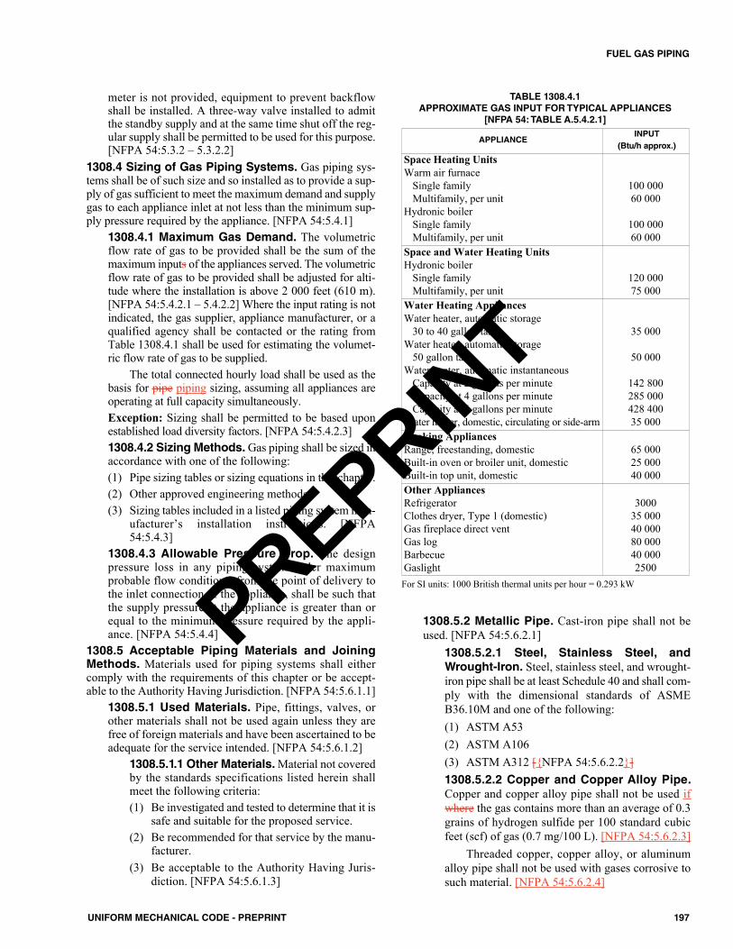
meter is not provided, equipment to prevent backflowshall be installed. A three-way valve installed to admitthe standby supply and at the same time shut off the reg-ular supply shall be permitted to be used for this purpose.[NFPA 54:5.3.2 – 5.3.2.2]
1308.4 Sizing of Gas Piping Systems. Gas piping sys-tems shall be of such size and so installed as to provide a sup-ply of gas sufficient to meet the maximum demand and supplygas to each appliance inlet at not less than the minimum sup-ply pressure required by the appliance. [NFPA 54:5.4.1]
1308.4.1 Maximum Gas Demand. The volumetricflow rate of gas to be provided shall be the sum of themaximum inputs of the appliances served. The volumetricflow rate of gas to be provided shall be adjusted for alti-tude where the installation is above 2 000 feet (610 m).[NFPA 54:5.4.2.1 – 5.4.2.2] Where the input rating is notindicated, the gas supplier, appliance manufacturer, or aqualified agency shall be contacted or the rating fromTable 1308.4.1 shall be used for estimating the volumet-ric flow rate of gas to be supplied.
The total connected hourly load shall be used as thebasis for pipe piping sizing, assuming all appliances areoperating at full capacity simultaneously.Exception: Sizing shall be permitted to be based uponestablished load diversity factors. [NFPA 54:5.4.2.3]1308.4.2 Sizing Methods.Gas piping shall be sized inaccordance with one of the following: (1) Pipe sizing tables or sizing equations in this chapter.(2) Other approved engineering methods.(3) Sizing tables included in a listed piping system man-
ufacturer’s installation instructions. [NFPA54:5.4.3]
1308.4.3 Allowable Pressure Drop. The designpressure loss in any piping system under maximumprobable flow conditions, from the point of delivery tothe inlet connection of the appliance, shall be such thatthe supply pressure at the appliance is greater than orequal to the minimum pressure required by the appli-ance. [NFPA 54:5.4.4]
1308.5 Acceptable Piping Materials and JoiningMethods. Materials used for piping systems shall eithercomply with the requirements of this chapter or be accept-able to the Authority Having Jurisdiction. [NFPA 54:5.6.1.1]
1308.5.1 Used Materials. Pipe, fittings, valves, orother materials shall not be used again unless they arefree of foreign materials and have been ascertained to beadequate for the service intended. [NFPA 54:5.6.1.2]
1308.5.1.1 Other Materials.Material not coveredby the standards specifications listed herein shallmeet the following criteria:(1) Be investigated and tested to determine that it is
safe and suitable for the proposed service.(2) Be recommended for that service by the manu-
facturer.(3) Be acceptable to the Authority Having Juris-
diction. [NFPA 54:5.6.1.3]
1308.5.2 Metallic Pipe. Cast-iron pipe shall not beused. [NFPA 54:5.6.2.1]
1308.5.2.1 Steel, Stainless Steel, andWrought-Iron. Steel, stainless steel, and wrought-iron pipe shall be at least Schedule 40 and shall com-ply with the dimensional standards of ASMEB36.10M and one of the following:(1) ASTM A53(2) ASTM A106(3) ASTM A312 [{NFPA 54:5.6.2.2}]1308.5.2.2 Copper and Copper Alloy Pipe.Copper and copper alloy pipe shall not be used ifwhere the gas contains more than an average of 0.3grains of hydrogen sulfide per 100 standard cubicfeet (scf) of gas (0.7 mg/100 L). [NFPA 54:5.6.2.3]
Threaded copper, copper alloy, or aluminumalloy pipe shall not be used with gases corrosive tosuch material. [NFPA 54:5.6.2.4]
TABLE 1308.4.1APPROXIMATE GAS INPUT FOR TYPICAL APPLIANCES
[NFPA 54: TABLE A.5.4.2.1]
APPLIANCEINPUT
(Btu/h approx.)
Space Heating UnitsWarm air furnace
Single familyMultifamily, per unit
Hydronic boilerSingle familyMultifamily, per unit
100 00060 000
100 00060 000
Space and Water Heating UnitsHydronic boiler
Single familyMultifamily, per unit
120 00075 000
Water Heating AppliancesWater heater, automatic storage
30 to 40 gallon tankWater heater, automatic storage
50 gallon tankWater heater, automatic instantaneous
Capacity at 2 gallons per minuteCapacity at 4 gallons per minuteCapacity at 6 gallons per minute
Water heater, domestic, circulating or side-arm
35 000
50 000
142 800285 000428 40035 000
Cooking AppliancesRange, freestanding, domesticBuilt-in oven or broiler unit, domesticBuilt-in top unit, domestic
65 00025 00040 000
Other AppliancesRefrigeratorClothes dryer, Type 1 (domestic)Gas fireplace direct ventGas logBarbecueGaslight
300035 00040 00080 00040 0002500
For SI units: 1000 British thermal units per hour = 0.293 kW
197UNIFORM MECHANICAL CODE - PREPRINT
FUEL GAS PIPING
PREPRINT
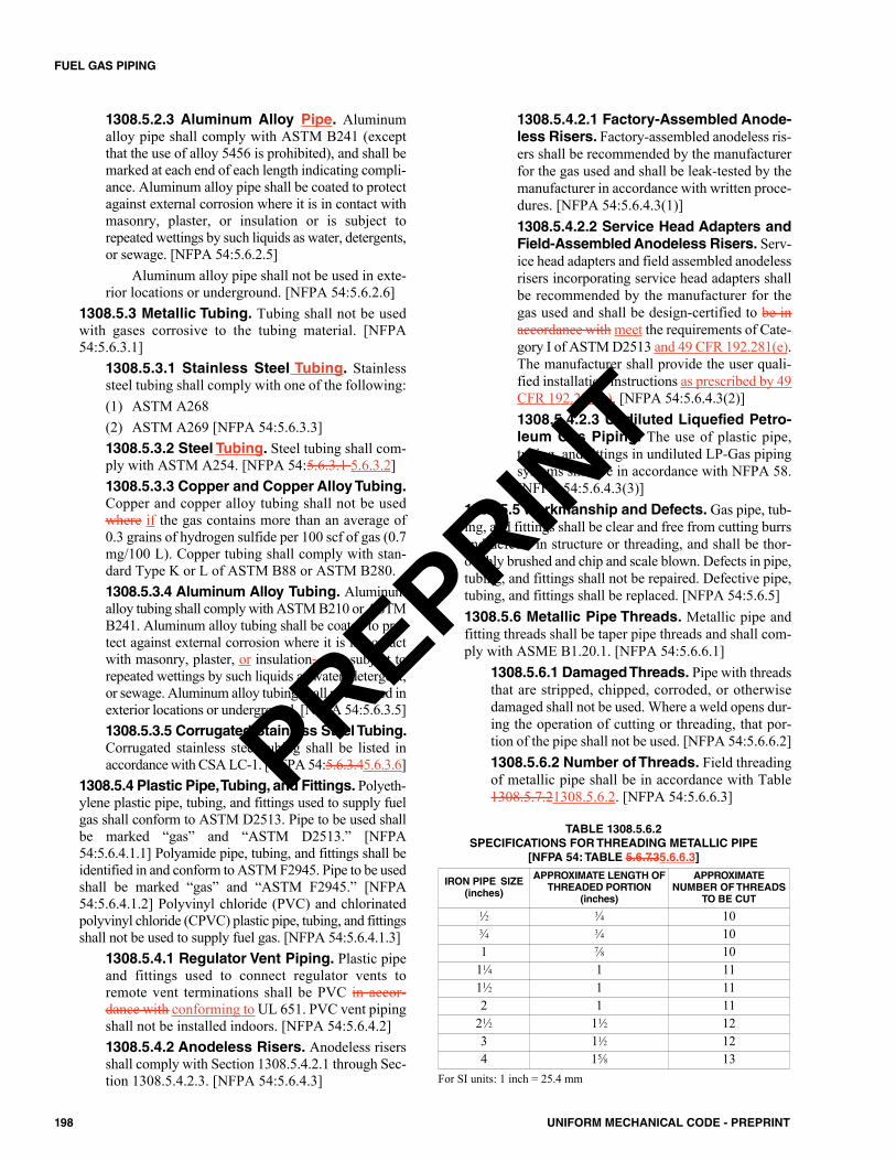
1308.5.2.3 Aluminum Alloy Pipe. Aluminumalloy pipe shall comply with ASTM B241 (exceptthat the use of alloy 5456 is prohibited), and shall bemarked at each end of each length indicating compli-ance. Aluminum alloy pipe shall be coated to protectagainst external corrosion where it is in contact withmasonry, plaster, or insulation or is subject torepeated wettings by such liquids as water, detergents,or sewage. [NFPA 54:5.6.2.5]
Aluminum alloy pipe shall not be used in exte-rior locations or underground. [NFPA 54:5.6.2.6]
1308.5.3 Metallic Tubing. Tubing shall not be usedwith gases corrosive to the tubing material. [NFPA54:5.6.3.1]
1308.5.3.1 Stainless Steel Tubing. Stainlesssteel tubing shall comply with one of the following:(1) ASTM A268(2) ASTM A269 [NFPA 54:5.6.3.3]1308.5.3.2 Steel Tubing. Steel tubing shall com-ply with ASTM A254. [NFPA 54:5.6.3.1 5.6.3.2]1308.5.3.3 Copper and Copper Alloy Tubing.Copper and copper alloy tubing shall not be usedwhere if the gas contains more than an average of0.3 grains of hydrogen sulfide per 100 scf of gas (0.7mg/100 L). Copper tubing shall comply with stan-dard Type K or L of ASTM B88 or ASTM B280.1308.5.3.4 Aluminum Alloy Tubing. Aluminumalloy tubing shall comply with ASTM B210 or ASTMB241. Aluminum alloy tubing shall be coated to pro-tect against external corrosion where it is in contactwith masonry, plaster, or insulation, or is subject torepeated wettings by such liquids as water, detergent,or sewage. Aluminum alloy tubing shall not be used inexterior locations or underground. [NFPA 54:5.6.3.5]1308.5.3.5 Corrugated Stainless Steel Tubing.Corrugated stainless steel tubing shall be listed inaccordance with CSA LC-1. [NFPA 54:5.6.3.45.6.3.6]
1308.5.4 Plastic Pipe, Tubing, and Fittings. Polyeth-ylene plastic pipe, tubing, and fittings used to supply fuelgas shall conform to ASTM D2513. Pipe to be used shallbe marked “gas” and “ASTM D2513.” [NFPA54:5.6.4.1.1] Polyamide pipe, tubing, and fittings shall beidentified in and conform to ASTM F2945. Pipe to be usedshall be marked “gas” and “ASTM F2945.” [NFPA54:5.6.4.1.2] Polyvinyl chloride (PVC) and chlorinatedpolyvinyl chloride (CPVC) plastic pipe, tubing, and fittingsshall not be used to supply fuel gas. [NFPA 54:5.6.4.1.3]
1308.5.4.1 Regulator Vent Piping. Plastic pipeand fittings used to connect regulator vents toremote vent terminations shall be PVC in accor-dance with conforming to UL 651. PVC vent pipingshall not be installed indoors. [NFPA 54:5.6.4.2]1308.5.4.2 Anodeless Risers. Anodeless risersshall comply with Section 1308.5.4.2.1 through Sec-tion 1308.5.4.2.3. [NFPA 54:5.6.4.3]
1308.5.4.2.1 Factory-Assembled Anode-less Risers. Factory-assembled anodeless ris-ers shall be recommended by the manufacturerfor the gas used and shall be leak-tested by themanufacturer in accordance with written proce-dures. [NFPA 54:5.6.4.3(1)]1308.5.4.2.2 Service Head Adapters andField-Assembled Anodeless Risers. Serv-ice head adapters and field assembled anodelessrisers incorporating service head adapters shallbe recommended by the manufacturer for thegas used and shall be design-certified to be inaccordance with meet the requirements of Cate-gory I of ASTM D2513 and 49 CFR 192.281(e).The manufacturer shall provide the user quali-fied installation instructions as prescribed by 49CFR 192.283(b). [NFPA 54:5.6.4.3(2)]1308.5.4.2.3 Undiluted Liquefied Petro-leum Gas Piping. The use of plastic pipe,tubing, and fittings in undiluted LP-Gas pipingsystems shall be in accordance with NFPA 58.[NFPA 54:5.6.4.3(3)]
1308.5.5 Workmanship and Defects. Gas pipe, tub-ing, and fittings shall be clear and free from cutting burrsand defects in structure or threading, and shall be thor-oughly brushed and chip and scale blown. Defects in pipe,tubing, and fittings shall not be repaired. Defective pipe,tubing, and fittings shall be replaced. [NFPA 54:5.6.5]1308.5.6 Metallic Pipe Threads. Metallic pipe andfitting threads shall be taper pipe threads and shall com-ply with ASME B1.20.1. [NFPA 54:5.6.6.1]
1308.5.6.1 Damaged Threads. Pipe with threadsthat are stripped, chipped, corroded, or otherwisedamaged shall not be used. Where a weld opens dur-ing the operation of cutting or threading, that por-tion of the pipe shall not be used. [NFPA 54:5.6.6.2]1308.5.6.2 Number of Threads. Field threadingof metallic pipe shall be in accordance with Table1308.5.7.21308.5.6.2. [NFPA 54:5.6.6.3]
TABLE 1308.5.6.2SPECIFICATIONS FOR THREADING METALLIC PIPE
[NFPA 54: TABLE 5.6.7.35.6.6.3]
IRON PIPE SIZE(inches)
APPROXIMATE LENGTH OFTHREADED PORTION
(inches)
APPROXIMATENUMBER OFTHREADS
TO BE CUT1⁄2 3⁄4 103⁄4 3⁄4 101 7⁄8 10
11⁄4 1 1111⁄2 1 112 1 11
21⁄2 11⁄2 123 11⁄2 124 15⁄8 13
For SI units: 1 inch = 25.4 mm
198 UNIFORM MECHANICAL CODE - PREPRINT
FUEL GAS PIPING
PREPRINT
1308.5.6.3 Thread Joint Compounds. Threadjoint compounds shall be resistant to the action ofLP-Gas or to any other chemical constituents of thegases to be conducted through the piping. [NFPA54:5.6.6.4]
1308.5.7 Metallic Piping Joints and Fittings. Thetype of piping joint used shall be suitable for the pressureand temperature conditions and shall be selected givingconsideration to joint tightness and mechanical strengthunder the service conditions. The joint shall be able to sus-tain the maximum end force due to the internal pressureand any additional forces due to temperature expansion orcontraction, vibration, fatigue, or the weight of the pipeand its contents. [NFPA 54:5.6.7]
1308.5.7.1 Pipe Joints. Schedule 40 and heavierpipe joints shall be threaded, flanged, brazed,welded, or assembled with press-connect fittingslisted to CSA LC 4. [NFPA 54:5.6.7.1](1) Where nonferrous pipe is brazed, the brazing
materials shall have a melting point in excessof 1000°F (538°C). [NFPA 54:5.6.7.1(B)]
(2) Brazing alloys shall not contain more than 0.05percent phosphorus. [NFPA 54:5.6.7.1(C)]
1308.5.7.2 Copper Tubing Joints. Copper tubingjoints shall be assembled with approved gas tubingfittings, shall be brazed with a material having a melt-ing point in excess of 1000°F (538°C), or shall beassembled with press-connect fittings listed to CSALC 4, Press-Connect Metallic Fittings for Use in FuelGas Distribution Systems. Brazing alloys shall notcontain more than 0.05 percent phosphorus. [NFPA54:5.6.7.2]1308.5.7.3 Stainless Steel Tubing Joints. Stain-less steel joints shall be welded, assembled withapproved tubing fittings, brazed with a material hav-ing a melting point in excess of 1000°F (538°C), orassembled with press-connect fittings listed to CSALC 4, Press-Connect Metallic Fittings for Use in FuelGas Distribution Systems. Brazing alloys and fluxesshall be recommended by the manufacturer for useon stainless steel alloys. [NFPA 54:5.6.7.3]1308.5.7.4 Flared Joints. Flared joints shall beused only in systems constructed from nonferrouspipe and tubing where experience or tests havedemonstrated that the joint is suitable for the condi-tions and where provisions are made in the design toprevent separation of the joints. [NFPA 54:5.6.7.4]1308.5.7.5 Metallic Pipe Fittings. Metallic pipefittings shall comply with the following:(1) Threaded fittings in sizes exceeding 4 inches
(100 mm) shall not be used unless acceptable tothe Authority Having Jurisdiction.
(2) Fittings used with steel, stainless steel, orwrought-iron pipe shall be steel, stainless steel,copper alloy, bronze, malleable iron, or cast-iron.
(3) Fittings used with copper or copper alloy pipeshall be copper or copper alloy.
(4) Fittings used with aluminum alloy pipe shall beof aluminum alloy.
(5) Cast-iron fittings shall comply with the follow-ing:(a) Flanges shall be permitted.(b) Bushings shall not be used.(c) Fittings shall not be used in systems con-
taining flammable gas-air mixtures.(d) Fittings in sizes 4 inches (100 mm) and
larger shall not be used indoors unlessapproved by the Authority Having Juris-diction.
(e) Fittings in sizes 6 inches (150 mm) andlarger shall not be used unless approved bythe Authority Having Jurisdiction.
(6) Aluminum alloy fitting threads shall not formthe joint seal.
(7) Zinc-aluminum alloy fittings shall not be usedin systems containing flammable gas-air mix-tures.
(8) Special fittings such as couplings;, proprietary-type joints;, saddle tees;, gland-type compressionfittings;, and flared, flareless, or compression-type tubing fittings shall be as follows: (a) Used within the fitting manufacturer’s
pressure-temperature recommendations.(b) Used within the service conditions antici-
pated with respect to vibration, fatigue,thermal expansion, or contraction.
(c) Installed or braced to prevent separation ofthe joint by gas pressure or external physi-cal damage.
(dc) Acceptable to the Authority Having Juris-diction.
(9) When pipe fittings are drilled and tapped in thefield, the operation shall be in accordance withthe following:(a) The operation shall be performed on sys-
tems having operating pressures of 5 psi(34 kPa) or less.
(b) The operation shall be performed by thegas supplier or their designated representa-tive.
(c) The drilling and tapping operation shall beperformed in accordance with written pro-cedures prepared by the gas supplier.
(d) The fittings shall be located outdoors.(e) The tapped fitting assembly shall be
inspected and proven to be free of leaks.[NFPA 54:5.6.7.5]
1308.5.8 Plastic Piping, Joints, and Fittings. Plas-tic pipe, tubing, and fittings shall be installed joined in
199UNIFORM MECHANICAL CODE - PREPRINT
FUEL GAS PIPING
PREPRINT
accordance with the manufacturer’s installation instruc-tions. Section 1308.5.8.1 through Section 1308.5.8.4 shallbe observed where when making such joints. [NFPA54:5.6.8]
1308.5.8.1 Joint Design. The joint shall bedesigned and installed so that the longitudinal pull-out resistance of the joint will be at least equal to thetensile strength of the plastic piping material. [NFPA54:5.6.8(1)]1308.5.8.2 Heat-Fusion Joint.Heat-fusion jointsshall be made in accordance with qualified proce-dures that have been established and proven by testto produce gastight joints at least as strong as thepipe or tubing being joined. Joints shall be madewith the joining method recommended by the pipemanufacturer. Heat-fusion fittings shall be marked“ASTM D2513.” [NFPA 54:5.6.8(2)]1308.5.8.3 Compression-Type MechanicalJoints. Where compression-type mechanical jointsare used, the gasket material in the fitting shall becompatible with the plastic piping and with the gasdistributed by the system. An internal tubular rigidstiffener shall be used in conjunction with the fit-ting. The stiffener shall be flush with the end of thepipe or tubing and shall extend not less than at leastto the outside end of the compression fitting wherewhen installed. The stiffener shall be free of roughor sharp edges and shall not be a forced force fit inthe plastic. Split tubular stiffeners shall not be used.[NFPA 54:5.6.8(3)]1308.5.8.4 Liquefied Petroleum Gas PipingSystems. Plastic piping joints and fittings for usein LP-Gas piping systems shall be in accordancewith NFPA 58. [NFPA 54:5.6.8(4)]
1308.5.9 Flange Specification. Cast iron flangesshall be in accordance with ASME B16.1. [NFPA54:5.6.9.1.1]
1308.5.9.1 Steel Flanges. Steel flanges shall bein accordance with the following: (1) ASME B16.5 or(2) ASME B16.47. [NFPA 54:5.6.10.1.2]1308.5.9.2 Non-Ferrous Flanges. Non-ferrousflanges shall be in accordance with ASME B16.24.[NFPA 54:5.6.9.1.3]1308.5.9.3 Ductile Iron Flanges. Ductile ironflanges shall be in accordance with ASME B16.42.[NFPA 54:5.6.9.1.4] 1308.5.9.4 Dissimilar Flange Connections.Raised-face flanges shall not be joined to flat-facedcast iron, ductile iron or nonferrous material flanges.[NFPA 54:5.6.9.2]1308.5.9.5 Flange Facings. Standard facings shallbe permitted for use under this code. Where 150 psi(1034 kPa) steel flanges are bolted to Class 125 cast-iron flanges, the raised face on the steel flange shall beremoved. [NFPA 54:5.6.9.3]
1308.5.9.6 Lapped Flanges. Lapped flangesshall be used only aboveground or in exposed loca-tions accessible for inspection. [NFPA 54:5.6.9.4]
1308.5.10 Flange Gaskets. The material for gasketsshall be capable of withstanding the design temperatureand pressure of the piping system and the chemical con-stituents of the gas being conducted without change toits chemical and physical properties. The effects of fireexposure to the joint shall be considered in choosing thematerial. [NFPA 54:5.6.10]
1308.5.10.1 Flange Gasket Materials. Accept-able materials shall include the following:(a) Metal (plain or corrugated)(b) Composition(c) Aluminum “O” rings(d) Spiral-wound metal gaskets(e) Rubber-faced phenolic(f) Elastomeric [NFPA 54:5.6.10.1]1308.5.10.2 Metallic Flange Gaskets. Metallicflange gaskets shall be in accordance with ASMEB16.20. [NFPA 54:5.6.10.2.1]1308.5.10.3 Non-Metallic Flange Gaskets.Non-metallic flange gaskets shall be in accordancewith ASME B16.21. [NFPA 54:5.6.10.2.2]1308.5.10.4 Full-Face Flange Gasket. Full-faceflange gaskets shall be used with all non-steelflanges. [NFPA 54:5.6.10.3]1308.5.10.5 Separated Flanges. When a flangeflanged joint is separated, the gasket shall bereplaced. [NFPA 54:5.6.10.4]
1308.6 Gas Meters. Gas meters shall be selected for themaximum expected pressure and permissible pressure drop.[NFPA 54:5.7.1]
1308.6.1 Location.Gas meters shall be located in ven-tilated spaces readily accessible for examination, read-ing, replacement, or necessary maintenance. [NFPA54:5.7.2.1]
1308.6.1.1 Subject to Damage.Gas meters shallnot be placed where they will be subjected to dam-age, such as adjacent to a driveway, under a fireescape, in public passages, halls, or where they willbe subject to excessive corrosion or vibration.[NFPA 54:5.7.2.2]1308.6.1.2 Extreme Temperatures. Gas metersshall not be located where they will be subjected toextreme temperatures or sudden extreme changes intemperature or in areas where they are subjected totemperatures beyond those recommended by themanufacturer. [NFPA 54:5.7.2.3]
1308.6.2 Supports. Gas meters shall be supported orconnected to rigid piping so as not to exert a strain on themeters. Where flexible connectors are used to connect agas meter to downstream piping at mobile homes inmobile home parks, the meter shall be supported by apost or bracket placed in a firm footing or by other meansproviding equivalent support. [NFPA 54:5.7.3]
200 UNIFORM MECHANICAL CODE - PREPRINT
FUEL GAS PIPING
PREPRINT
1308.6.3 Meter Protection. Meters shall be protectedagainst overpressure, backpressure, and vacuum. [NFPA54:5.7.4]1308.6.4 Identification. Gas piping at multiple meterinstallations shall be marked by a metal tag or other per-manent means designating the building or the part of thebuilding being supplied and attached by the installingagency. [NFPA 54:5.7.5]
1308.7 Gas Pressure Regulators. A line pressure regu-lator shall be installed where the gas supply pressure exceedsthe maximum allowable inlet pressure of the applianceserved. [NFPA 54:5.8.1]
1308.7.1 Listing. Line pressure regulators shall belisted in accordance with CSA Z21.80 where the outletpressure is set to 2 psi (14 kPa) or less. [NFPA 54:5.8.2]1308.7.2 Location. The gas pressure regulator shall beaccessible for servicing. [NFPA 54:5.8.3]1308.7.3 Regulator Protection. Pressure regulatorsshall be protected against physical damage. [NFPA54:5.8.4]1308.7.4 Venting of Line Pressure Regulators.Line pressure regulators shall comply with all of the fol-lowing:(1) An independent vent to the exterior of the building,
sized in accordance with the regulator manufac-turer’s instructions, shall be provided where the loca-tion of a regulator is such that a ruptured diaphragmwill cause a hazard. (a) Where more than one regulator is at a location,
each regulator shall have a separate vent to theoutdoors or, if approved by the Authority Hav-ing Jurisdiction, the vent lines shall be permittedto be manifolded in accordance with acceptedengineering practices to minimize backpressurein the event of diaphragm failure.
(b) Materials for vent piping shall be in accordancewith Section 1308.5 through Section 1308.5.10.5.
Exception: A regulator and vent limiting meanscombination listed as complying with CSA Z21.80shall be permitted to be used without a vent to theoutdoors.
(2) The vent shall be designed to prevent the entry ofwater, insects, or other foreign materials that couldcause blockage.
(3) The regulator vent shall terminate at least 3 feet (914mm) from a source of ignition.
(4) At locations where regulators might be submergedduring floods, a special antiflood-type breather ventfitting shall be installed, or the vent line shall beextended above the height of the expected floodwaters.
(5) A regulator shall not be vented to the appliance flueor exhaust system. [NFPA 54:5.8.5.1]
1308.7.5 Venting of Gas Appliance Pressure Reg-ulators. For venting of gas appliance pressure regula-tors, see Section 902.15. [NFPA 54:5.8.5.2]1308.7.6 Bypass Piping. Valved and regulatedbypasses shall be permitted to be placed around gas linepressure regulators where continuity of service is imper-ative. [NFPA 54:5.8.6]1308.7.7 Identification. Line pressure regulators atmultiple regulator installations shall be marked by ametal tag or other permanent means designating thebuilding or the part of the building being supplied.[NFPA 54:5.8.7]
1308.8 Overpressure Protection. Where the serving gassupplier delivers gas at a pressure greater than 2 psi for pip-ing systems serving appliances designed to operate at a gaspressure of 14 inches water column or less, overpressure pro-tection devices shall be installed. Piping systems servingequipment designed to operate at inlet pressures greater than14 inches water column (3.5 kPa) shall be equipped withoverpressure protection devices as required by the appliancemanufacturer’s installation instructions. [NFPA 54:5.9.1]1308.9 Pressure Limitation Requirements.Where pip-ing systems serving appliances designed to operate with a gassupply pressure of 14 inches water column or less are requiredto be equipped with overpressure protection by Section1308.8, each overpressure protection device shall be adjustedto limit the gas pressure to each connected appliance to 2 psior less upon a failure of the line pressure regulator. [NFPA54:5.9.2.1]
1308.9.1 Overpressure Protection Required.Wherepiping systems serving appliances designed to operate witha gas supply pressure greater than 14 inches water columnare required to be equipped with overpressure protectionby Section 1308.8, each overpressure protection deviceshall be adjusted to limit the gas pressure to each connectedappliance as required by the appliance manufacturer’sinstallation instructions. [NFPA 54:5.9.2.2]1308.9.2 Overpressure Protection Devices. Eachoverpressure protection device installed to meet therequirements of this section shall be capable of limitingthe pressure to its connected appliance(s) as required bythis section independently of any other pressure controlequipment in the piping system. [NFPA 54:5.9.2.3]1308.9.3 Detection of Failure. Each gas piping sys-tem for which an overpressure protection device isrequired by this section shall be designed and installed sothat a failure of the primary pressure control device(s) isdetectable. [NFPA 54:5.9.2.4]1308.9.4 Flow Capacity. If a pressure relief valve isused to meet the requirements of this section, it shallhave a flow capacity such that the pressure in the pro-tected system is maintained at or below the limits speci-fied in Section 1308.9 under the following conditions:(1) The line pressure regulator for which the relief valve
is providing overpressure protection has failed wideopen.
201UNIFORM MECHANICAL CODE - PREPRINT
FUEL GAS PIPING
PREPRINT
(2) The gas pressure at the inlet of the line pressure reg-ulator for which the relief valve is providing over-pressure protection is not less than the regulator’snormal operating inlet pressure. [NFPA 54:5.9.2.5]
1308.10 Overpressure Protection Devices. Overpres-sure protection devices shall be one of the following:(1) Pressure relief valve.(2) Monitor regulator.(3) Series regulator installed upstream from the line regula-
tor and set to continuously limit the pressure on the inletof the line regulator to the maximum values specified bySection 1308.9 or less.
(4) Automatic shutoff device installed in series with the linepressure regulator and set to shut off when the pressureon the downstream piping system reaches the maximumvalues specified by Section 1308.9 or less. This deviceshall be designed so that it will remain closed until man-ually reset. [NFPA 54:5.9.3.1]1308.10.1 Separate Devices. The devices in Section1308.10 shall be installed either as an integral part of theservice or line pressure regulator or as separate units.Where separate overpressure protection devices areinstalled, they shall comply with Section 1308.10.2through Section 1308.10.7. [NFPA 54:5.9.3.2]1308.10.2 Construction and Installation. All over-pressure protection devices shall meet the followingrequirements:(1) Be constructed of materials so that the operation of the
device is not impaired by corrosion of external parts bythe atmosphere or of internal parts by the gas.
(2) Be designed and installed so they can be operated todetermine whether the valve is free. The devicesshall also be designed and installed so they can betested to determine the pressure at which they oper-ate and be examined for leakage when in the closedposition. [NFPA 54:5.9.4]
1308.10.3 External Control Piping. External controlpiping shall be designed and installed so that damage tothe control piping of one device does not render both theregulator and the overpressure protective device inoper-ative. [NFPA 54:5.9.5]1308.10.4 Setting. Each pressure limiting or pressurerelieving device shall be set so that the gas pressure sup-plied to the connected appliance(s) does not exceed thelimits specified in Section 1308.9 and Section 1308.9.1.[NFPA 54:5.9.6]1308.10.5 Unauthorized Operation. Where unau-thorized operation of any shutoff valve could render apressure relieving valve or pressure limiting device inop-erative, one of the following shall be accomplished:(1) The valve shall be locked in the open position.
Instruct authorized personnel in the importance ofleaving the shutoff valve open and of being presentwhile the shutoff valve is closed so that it can belocked in the open position before leaving the prem-ises.
(2) Duplicate relief valves shall be installed, each havingadequate capacity to protect the system, and arrangethe isolating valves or three-way valve so that onlyone relief valve can be rendered inoperative at a time.[NFPA 54:5.9.7]
1308.10.6 Discharge of Vents. The discharge stacks,vents, or outlet parts of all pressure- relieving and pres-sure-limiting devices shall be located so that gas is safelydischarged to the outdoors. Discharge stacks or ventsshall be designed to prevent the entry of water, insects, orother foreign material that could cause blockage. The dis-charge stack or vent line shall be at least the same size asthe outlet of the pressure relieving device. [NFPA54:5.9.8.1, 5.9.8.2]1308.10.7 Size of Fittings, Pipe, and Openings.The fittings, pipe, and openings located between the sys-tem to be protected and the pressure relieving deviceshall be sized to prevent hammering of the valve and toprevent impairment of relief capacity. [NFPA 54:5.9.9]
1308.11 Backpressure Protection. Protective devicesshall be installed as close to the equipment as practical wherethe design of the equipment connected is such that air, oxy-gen, or standby gases are capable of being could be forcedinto the gas supply system. Gas and air combustion mixersincorporating double diaphragm “zero” or “atmosphere” gov-ernors or regulators shall require no further protection unlessconnected directly to compressed air or oxygen at pressuresof 5 psi (34 kPa) or more. [NFPA 54:5.10.1.1, 5.10.1.2]
1308.11.1 Protective Devices. Protective devicesshall include, but not be limited to the following: (1) Check valves.(2) Three-way valves (of the type that completely closes
one side before starting to open the other side).(3) Reverse flow indicators controlling positive shutoff
valves.(4) Normally closed air-actuated positive shutoff pres-
sure regulators. [NFPA 54:5.10.2]1308.12 Low-Pressure Protection. A protective deviceshall be installed between the meter and the appliance orequipment where if the operation of the appliance or equip-ment is such that it is capable of producing could produce avacuum or a dangerous reduction in gas pressure at the meter.Such protective devices include, but are not limited to,mechanical, diaphragm-operated, or electrically operatedlow-pressure shutoff valves. [NFPA 54:5.11]1308.13 Shutoff Valves. Shutoff valves shall be approvedand shall be selected giving consideration to pressure drop,service involved, emergency use, and reliability of operation.Shutoff valves of size 1 inch (25 mm) National Pipe Threadand smaller shall be listed. [NFPA 54:5.12]1308.14 Expansion and Flexibility. Piping systems shallbe designed to prevent failure from thermal expansion or con-traction. [NFPA 54:5.14.1]
1308.14.1 Special Local Conditions. Where localconditions include earthquake, tornado, unstable ground,
202 UNIFORM MECHANICAL CODE - PREPRINT
FUEL GAS PIPING
PREPRINT
or flood hazards, special consideration shall be given toincreased strength and flexibility of piping supports andconnections. [NFPA 54:5.14.2]
1309.0 Excess Flow Valve.1309.1 General. Where automatic excess flow valves areinstalled, they shall be listed to CSA Z21.93 and shall be sizedand installed in accordance with the manufacturer’s instruc-tions. [NFPA 54:5.13]
1310.0 Gas Piping Installation.1310.1 Piping Underground. Underground gas piping shallbe installed with sufficient clearance from any other under-ground structure to avoid contact therewith, to allow mainte-nance, and to protect against damage from proximity to otherstructures. In addition, underground plastic piping shall beinstalled with sufficient clearance or shall be insulated fromany source of heat so as to prevent the heat from impairing theserviceability of the pipe. [NFPA 54:7.1.1]
1310.1.1 Cover Requirements. Underground pipingsystems shall be installed with a minimum of 12 inches(305 mm) of cover. The minimum cover shall be increasedto 18 inches (457 mm) if external damage to the pipe ortubing from external forces is likely to result. Where aminimum of 12 inches (305 mm) of cover cannot be pro-vided, the pipe shall be installed in conduit or bridged(shielded). [NFPA 54:7.1.2.1 – 7.1.2.1(B)]1310.1.2 Trenches. The trench shall be graded so thatthe pipe has a firm, substantially continuous bearing onthe bottom of the trench. [NFPA 54:7.1.2.2]
1310.1.2.1 Backfilling. Where flooding of thetrench is done to consolidate the backfill, care shallbe exercised to see that the pipe is not floated fromits firm bearing on the trench bottom. [NFPA54:7.1.2.3]
1310.1.3 Protection Against Corrosion. Steel pipeand steel tubing installed underground shall be installed inaccordance with Section 1310.1.3.1 through Section1310.1.3.9. [NFPA 54:7.1.3]
1310.1.3.1 Zinc Coating. Zinc coating (galvaniz-ing) shall not be deemed adequate protection forunderground gas piping. [NFPA 54:7.1.3.1]1310.1.3.2 Underground Piping. Undergroundpiping shall comply with one or more of the follow-ing unless approved technical justification is pro-vided to demonstrate that protection is unnecessary:(1) The piping shall be made of corrosion-resistant
material that is suitable for the environment inwhich it will be installed.
(2) Pipe shall have a factory-applied, electricallyinsulating coating. Fittings and joints betweensections of coated pipe shall be coated in accor-dance with the coating manufacturer’s instruc-tions.
(3) The piping shall have a cathodic protection sys-tem installed, and the system shall be main-tained in accordance with Section 1310.1.3.3 orSection 1310.1.3.6. [NFPA 54:7.1.3.2]
1310.1.3.3 Cathodic Protection. Cathodic pro-tection systems shall be monitored by testing and theresults shall be documented. The test results shalldemonstrate one of the following:(1) A pipe-to-soil voltage of −0.85 volts or more
negative is produced, with reference to a satu-rated copper-copper sulfate half cell.
(2) A pipe-to-soil voltage of −0.78 volts or morenegative is produced, with reference to a satu-rated KCl calomel half cell.
(3) A pipe-to-soil voltage of −0.80 volts or morenegative is produced, with reference to a silver-silver chloride half cell.
(4) Compliance with a method described in Appen-dix D of Title 49 of the Code of Federal Regu-lations, Part 192. [NFPA 54:7.1.3.3]
1310.1.3.4 Sacrificial Anodes. Sacrificial anodesshall be tested in accordance with the following:(1) Upon installation of the cathodic protection sys-
tem, except where prohibited by climatic con-ditions, in which case the testing shall beperformed not later than 180 days after theinstallation of the system.
(2) 12 to 18 months after the initial test.(3) Upon successful verification testing in accor-
dance with Section 1310.1.3.4(1) and Section1310.1.3.4(2), periodic follow-up testing shallbe performed at intervals not to exceed 36months. [NFPA 54:7.1.3.4]
1310.1.3.5 System Failing Tests. Systems failinga test shall be repaired not more than 180 days afterthe date of the failed testing. The testing scheduleshall be restarted as required in Section 1310.1.3.4(1)and Section 1310.1.3.4(2), and the results shall com-ply with Section 1310.1.3.3. [NFPA 54:7.1.3.5]1310.1.3.6 Impressed Current Cathodic Pro-tection. Impressed current cathodic protection sys-tems shall be inspected and tested in accordancewith the following schedule:(1) The impressed current rectifier voltage output
shall be checked at intervals not exceeding twomonths.
(2) The pipe-to-soil voltage shall be tested at leastannually. [NFPA 54:7.1.3.6]
1310.1.3.7 Documentation. Documentation ofthe results of the two most recent tests shall beretained. [NFPA 54:7.1.3.7]1310.1.3.8 Dissimilar Metals. Where dissimilarmetals are joined underground, an insulating cou-pling or fitting shall be used. [NFPA 54:7.1.3.8]
203UNIFORM MECHANICAL CODE - PREPRINT
FUEL GAS PIPING
PREPRINT
1310.1.3.9 Steel Risers. Steel risers, other thananodeless risers, connected to plastic piping shall becathodically protected by means of a welded anode.[NFPA 54:7.1.3.9]
1310.1.4 Protection Against Freezing. Where the for-mation of hydrates or ice is known to occur, piping shall beprotected against freezing. [NFPA 54:7.1.4]1310.1.5 Piping Through Foundation Wall. Under-ground piping, where installed through the outer foundationor basement wall of a building, shall be encased in a protec-tive sleeve or protected by an approved device or method.The space between the gas piping and the sleeve and betweenthe sleeve and the wall shall be sealed to prevent entry of gasand water. [NFPA 54:7.1.5]1310.1.6 Piping Underground Beneath Buildings.Where gas piping is installed underground beneath buildings,the piping shall be either of the following:
(1) Encased in an approved conduit designed to with-stand the imposed loads and installed in accordancewith Section 1310.1.6.1 or Section 1310.1.6.2.
(2) A piping/encasement system listed for installationbeneath buildings. [NFPA 54:7.1.6]1310.1.6.1 Conduit with One End Terminat-ing Outdoors. The conduit shall extend into anaccessible portion of the building and, at the pointwhere the conduit terminates in the building, thespace between the conduit and the gas piping shallbe sealed to prevent the possible entrance of any gasleakage. Where the end sealing is of a type thatretains the full pressure of the pipe, the conduit shallbe designed for the same pressure as the pipe. Theconduit shall extend at least 4 inches (102 mm) out-side the building, be vented outdoors above finishedground level, and be installed so as to prevent theentrance of water and insects. [NFPA 54:7.1.6.1]1310.1.6.2 Conduit with Both Ends Terminat-ing Indoors. Where the conduit originates and ter-minates within the same building, the conduit shalloriginate and terminate in an accessible portion ofthe building and shall not be sealed. [NFPA54:7.1.6.2]
1310.1.7 Plastic Piping. Plastic piping shall beinstalled outdoors, underground only.Exceptions:(1) Plastic piping shall be permitted to terminate above-
ground where an anodeless riser is used.(2) Plastic piping shall be permitted to terminate with a
wall head adapter aboveground in buildings, includ-ing basements, where the plastic piping is inserted ina piping material permitted for use in buildings.[NFPA 54:7.1.7.1]1310.1.7.1 Connections Between Metallic andPlastic Piping. Connections made between metal-lic and plastic piping shall be made with fittings con-forming to one of the following:
(1) ASTM D2513 Category I transition fittings(2) ASTM F1973(3) ASTM F2509 [NFPA 54:7.1.7.2]1310.1.7.2 Tracer Wire.An electrically continuouscorrosion-resistant tracer shall be buried with theplastic pipe to facilitate locating. The tracer shall beone of the following:(1) A product specifically designed for that pur-
pose.(2) Insulated copper conductor not less than 14
AWG.Where tracer wire is used, access shall be pro-
vided from aboveground or one end of the tracerwire or tape shall be brought aboveground at a build-ing wall or riser. [NFPA 54:7.1.7.3 – 7.1.7.3.2]
1310.2 CSST Piping Systems. CSST piping systems shallbe installed in accordance with this code and the manufac-turer's installation instructions. [NFPA 54:7.1.8]1310.3 Installation of Aboveground Piping. Pipinginstalled aboveground shall be securely supported and locatedwhere it will be protected from physical damage. Where pass-ing through an exterior wall, the piping shall also be protectedfrom corrosion by coating or wrapping with an inert materialapproved for such applications. The piping shall be sealedaround its circumference at the point of the exterior penetrationto prevent the entry of water, insects, and rodents. Where pip-ing is encased in a protective pipe sleeve, the annular spacesbetween the gas piping and the sleeve and between the sleeveand the wall opening shall be sealed. [NFPA 54:7.2.1]
1310.3.1 Protective Coating. Where piping is in con-tact with a material or an atmosphere corrosive to the pip-ing system, the piping and fittings shall be coated with acorrosion-resistant material. Any such coating used onpiping or components shall not be considered as addingstrength to the system. [NFPA 54:7.2.2]1310.3.2 Building Structure. The installation of gaspiping shall not cause structural stresses within buildingcomponents to exceed allowable design limits. Approvalshall be obtained before any beams or joists are cut ornotched. [NFPA 54:7.2.3.1 – 7.2.3.2]1310.3.3 Gas Piping to be Sloped. Piping for otherthan dry gas conditions shall be sloped not less than 1⁄4inch in 15 feet (1.4 mm/m) to prevent traps. [NFPA54:7.2.4]
1310.3.3.1 Ceiling Locations. Gas piping shallbe permitted to be installed in accessible spacesbetween a fixed ceiling and a dropped ceiling,whether or not such spaces are used as a plenum.Valves shall not be located in such spaces.Exception: Appliance or equipment shutoff valvesrequired by this code shall be permitted to be installedin accessible spaces containing vented appliances.
1310.3.4 Prohibited Locations. Gas piping inside anybuilding shall not be installed in or through a clothes chute,chimney or gas vent, dumbwaiter, elevator shaft, or airduct, other than combustion air ducts. [NFPA 54:7.2.5]
204 UNIFORM MECHANICAL CODE - PREPRINT
FUEL GAS PIPING
PREPRINT

Exception: Ducts used to provide ventilation air in accor-dance with Section 701.0 or to above-ceiling spaces inaccordance with Section 1310.3.3.1.1310.3.5 Hangers, Supports, and Anchors. Pipingshall be supported with metal pipe hooks, metal pipestraps, metal bands, metal brackets, metal hangers, orbuilding structural components, suitable for the size ofpiping, of adequate strength and quality, and located atintervals so as to prevent or damp out excessive vibra-tion. Piping shall be anchored to prevent undue strainson connected appliances and equipment and shall not besupported by other piping. Pipe hangers and supportsshall conform to the requirements of MSS SP-58. [NFPA54:7.2.6.1]
1310.3.5.1 Spacing. Spacing of supports in gaspiping installations shall not be greater than shownin Table 1310.3.5.1. Spacing of supports of CSSTshall be in accordance with the CSST manufac-turer’s instructions. [NFPA 54:7.2.6.2]
1310.3.5.2 Expansion and Contraction. Sup-ports, hangers, and anchors shall be installed so as notto interfere with the free expansion and contractionof the piping between anchors. All parts of the sup-porting system shall be designed and installed so theyare not disengaged by movement of the supportedpiping. [NFPA 54:7.2.6.3]1310.3.5.3 Piping on Roof Tops. Gas pipinginstalled on the roof surfaces shall be elevated abovethe roof surface and shall be supported in accor-dance with Table 1310.3.5.1. [NFPA 54:7.2.6.4]
1310.3.6 Removal of Piping. Where piping containinggas is to be removed, the line shall be first disconnectedfrom sources of gas and then thoroughly purged with air,water, or inert gas before cutting or welding is done.
1310.4 Concealed Piping in Buildings. Gas piping inconcealed locations shall be installed in accordance with thissection. [NFPA 54:7.3.1]
1310.4.1 Connections.Where gas piping is to be con-cealed, connections shall be of the following type:(1) Pipe fittings, such as elbows, tees, couplings, and
right/left nipple/couplings.
(2) Joining tubing by brazing (see Section 1308.5.7.1).(3) Press-connect fittings listed to CSA LC 4 for use in
concealed spaces or that have been demonstrated tosustain, without leakage, forces due to temperatureexpansion or contraction, vibration, or fatigue basedon their geographic location, application, or operation.
(4) CSST fittings listed to CSA LC 1.(45) Where necessary to insert fittings in gas pipe that
has been installed in a concealed location, the pipeshall be reconnected by welding, flanges, or the useof a right/left nipple/coupling.
1310.4.2 Piping in Partitions. Concealed gas pipingshall not be located in solid partitions. [NFPA 54:7.3.3]1310.4.3 Tubing in Partitions. This provision shallnot apply to tubing that pierces walls, floors, or parti-tions. Tubing installed vertically and horizontally insidehollow walls or partitions without protection along itsentire concealed length shall meet the following require-ments: (1) A steel striker barrier not less than 0.0508 of an inch
(1.3 mm) thick, or equivalent, is installed betweenthe tubing and the finished wall and extends at least4 inches (102 mm) beyond concealed penetrationsof plates, firestops, wall studs, and so on.
(2) The tubing is installed in single runs and is notrigidly secured. [NFPA 54:7.3.4]
1310.4.4 Piping in Floors. In industrial occupancies,gas piping in solid floors such as concrete shall be laid inchannels in the floor and covered to permit access to thepiping with a minimum of damage to the building. Wherepiping in floor channels could be exposed to excessivemoisture or corrosive substances, the piping shall be pro-tected in an approved manner. [NFPA 54:7.3.5.1]Exception: In other than industrial occupancies andwhere approved by the Authority Having Jurisdiction, gaspiping embedded in concrete floor slabs constructed withportland Portland cement shall be surrounded with a min-imum of 11⁄2 inches (38 mm) of concrete and shall not bein physical contact with other metallic structures such asreinforcing rods or electrically neutral conductors. Allpiping, fittings, and risers shall be protected against cor-rosion in accordance with Section 1308.5.6. Piping shallnot be embedded in concrete slabs containing quick-setadditives or cinder aggregate. [NFPA 54:7.3.5.2]
1310.5 Piping in Vertical Chases. Where gas pipingexceeding 5 psi (34 kPa) is located within vertical chases inaccordance with Section 1310.6(3), the requirements of Sec-tion 1310.5.1 through Section 1310.5.3 shall apply. [NFPA54:7.4]
1310.5.1 Pressure Reduction. Where pressurereduction is required in branch connections for compli-ance with Section 1310.6, such reduction shall take placeeither inside the chase or immediately adjacent to the out-side wall of the chase. Regulator venting and down-stream overpressure protection shall comply with Section
TABLE 1310.3.5.1SUPPORT OF PIPING
[NFPA 54: TABLE 7.2.5.27.2.6.2]
For SI units: 1 inch = 25 mm, 1 foot = 304.8 mm
STEEL PIPE,NOMINAL SIZEOF PIPE(inches)
SPACING OFSUPPORTS(feet)
NOMINAL SIZEOFTUBING
SMOOTH-WALL(inches O.D.)
SPACING OFSUPPORTS(feet)
1⁄2 6 1⁄2 43⁄4 or 1 8 5⁄8 or 3⁄4 6
11⁄4 or larger(horizontal) 10
7⁄8 or 1 (horizontal) 8
11⁄4 or larger(vertical)
Every floorlevel
1 or larger(vertical)
Every floorlevel
205UNIFORM MECHANICAL CODE - PREPRINT
FUEL GAS PIPING
PREPRINT
1308.7.4 and Section 1308.8 through Section 1308.9.4.The regulator shall be accessible for service and repair,and vented in accordance with one of the following:(1) Where the fuel gas is lighter than air, regulators
equipped with a vent limiting means shall be permit-ted to be vented into the chase. Regulators notequipped with a vent limiting means shall be permit-ted to be vented either directly to the outdoors or to apoint within the top 1 foot (305 mm) of the chase.
(2) Where the fuel gas is heavier than air, the regulatorvent shall be vented only directly to the outdoors.[NFPA 54:7.4.1]
1310.5.2 Chase Construction. Chase constructionshall comply with local building codes with respect tofire resistance and protection of horizontal and verticalopenings. [NFPA 54:7.4.2]1310.5.3 Ventilation. A chase shall be ventilated to theoutdoors and only at the top. The opening(s) shall havea minimum free area [in square inches (square meters)]equal to the product of one-half of the maximum pres-sure in the piping [in pounds per square inch (kilopas-cals)] times the largest nominal diameter of that piping[in inches (millimeters)], or the cross-sectional area ofthe chase, whichever is smaller. Where more than onefuel gas piping system is present, the free area for eachsystem shall be calculated and the largest area used.[NFPA 54:7.4.3]
1310.6 Maximum Operating Pressure in Buildings.The maximum operating pressure for any piping systemslocated inside buildings shall not exceed 5 psi (34 kPa) unlessone or more of the following conditions are met:(1) The piping joints are welded or brazed.(2) The piping joints are flanged and all pipe-to-flange con-
nections are made by welding or brazing.(3) The piping is located in a ventilated chase or otherwise
enclosed for protection against accidental gas accumula-tion.
(4) The piping is located inside buildings or separate areas ofbuildings used exclusively for one of the following:(a) Industrial processing or heating(b) Research(c) Warehousing(d) Boiler or mechanical rooms
(5) The piping is a temporary installation for buildings underconstruction.
(6) The piping serves appliances or equipment used for agri-cultural purposes.
(7) The piping system is an LP-Gas piping system with anoperating pressure greater than 20 psi (138 kPa) and com-plies with NFPA 58. [NFPA 54:5.5.4]1310.6.1 LP-Gas Systems. LP-Gas systems designedto operate below -5°F (-21°C) or with butane or apropane-butane mix shall be designed to either accom-modate liquid LP-Gas or to prevent LP-Gas vapor fromcondensing back into a liquid. [NFPA 54:5.5.5]
1310.7 Appliance Overpressure Protection. The maxi-mum operating pressure for piping systems serving appliancesdesigned to operate at 14 inches water column (3.5 kPa) inletpressure or less shall be 2 pounds-force per square inch gauge(psig) (14 kPa) unless an over pressure protection devicedesigned to limit pressure at the appliance to 2 psig (14 kPa)upon failure of the line gas pressure regulator is installed.1310.8 Gas Pipe Turns. Changes in direction of gas pipeshall be made by the use of fittings, factory bends, or fieldbends. [NFPA 54:7.5]
1310.8.1 Metallic Pipe.Metallic pipe bends shall com-ply with the following: (1) Bends shall be made only with bending tools and
procedures intended for that purpose.(2) All bends shall be smooth and free from buckling,
cracks, or other evidence of mechanical damage.(3) The longitudinal weld of the pipe shall be near the
neutral axis of the bend.(4) Pipe shall not be bent through an arc of more than 90
degrees.(5) The inside radius of a bend shall be not less than six
6 times the outside diameter of the pipe. [NFPA54:7.5.1]
1310.8.2 Plastic Pipe. Plastic pipe bends shall complywith the following:(1) The pipe shall not be damaged, and the internal
diameter of the pipe shall not be effectively reduced.(2) Joints shall not be located in pipe bends.(3) The radius of the inner curve of such bends shall not
be less than 25 times the inside diameter of the pipe.(4) Where the piping manufacturer specifies the use of
special bending tools or procedures, such tools orprocedures shall be used. [NFPA 54:7.5.2]
1310.8.3 Elbows. Factory-made welding elbows ortransverse segments cut therefrom shall have an arclength measured along the crotch of at least 1 inch (25mm) for pipe sizes 2 inches (50 mm) and larger. [NFPA54:7.5.3]
1310.9 Drips and Sediment Traps. For other than dry gasconditions, a drip shall be provided at any point in the line ofpipe where condensate could collect. Where required by theAuthority Having Jurisdiction or the serving gas supplier, adrip shall also be provided at the outlet of the meter. This dripshall be installed so as to constitute a trap wherein an accu-mulation of condensate shuts off the flow of gas before it runsback into the meter. [NFPA 54:7.6.1]
1310.9.1 Location of Drips. All drips shall beinstalled only in such locations that they are readilyaccessible to permit cleaning or emptying. A drip shallnot be located where the condensate is likely to freeze.[NFPA 54:7.6.2]1310.9.2 Sediment Traps. The installation of sedi-ment traps shall be in accordance with Section 1312.9.[NFPA 54:7.6.3]
206 UNIFORM MECHANICAL CODE - PREPRINT
FUEL GAS PIPING
PREPRINT

1310.10 Outlets. Outlets shall be located and installed inaccordance with the following requirements:(1) The outlet fittings or piping shall be securely fastened in
place.(2) Outlets shall not be located behind doors.(3) Outlets shall be located far enough from floors, walls,
patios, slabs, and ceilings to permit the use of wrencheswithout straining, bending, or damaging the piping.
(4) The unthreaded portion of gas piping outlets shall extendnot less than 1 inch (25.4 mm) through finished ceilingsor indoor or outdoor walls.
(5) The unthreaded portion of gas piping outlets shall extendnot less than 2 inches (51 mm) above the surface of floorsor outdoor patios or slabs.
(6) The provisions of Section 1310.10(4) and Section1310.10(5) shall not apply to listed quick-disconnectdevices of the flush-mounted type or listed gas conven-ience outlets. Such devices shall be installed in accor-dance with the manufacturer’s installation instructions.[NFPA 54:7.7.1.1 – 7.7.1.6]1310.10.1 Cap Outlets. Each outlet, including a valve,shall be closed gastight with a threaded plug or capimmediately after installation and shall be left closeduntil the appliance or equipment is connected thereto.When an appliance or equipment is disconnected froman outlet and the outlet is not to be used again immedi-ately, it shall be capped or plugged gastight.Exceptions:(1) Laboratory appliances installed in accordance with
Section 1312.3.1 shall be permitted.(2) The use of a listed quick-disconnect device with
integral shutoff or listed gas convenience outlet shallbe permitted. [NFPA 54:7.7.2.1]1310.10.1.1 Appliance Shutoff Valves. Appli-ance shutoff valves installed in fireplaces shall beremoved and the piping capped gastight where thefireplace is used for solid- fuel burning. [NFPA54:7.7.2.2]
1310.11 Manual Gas Shutoff Valves. An accessible gasshutoff valve shall be provided upstream of each gas pressureregulator. Where two gas pressure regulators are installed inseries in a single gas line, a manual valve shall not be requiredat the second regulator. [NFPA 54:7.8.1]
1310.11.1 Valves Controlling Multiple Systems.Main gas shutoff valves controlling several gas pipingsystems shall be readily accessible for operation andinstalled so as to be protected from physical damage.They shall be marked with a metal tag or other perma-nent means attached by the installing agency so that thegas piping systems supplied through them can be readilyidentified. [NFPA 54:7.8.2.1]
1310.11.1.1 Shutoff Valves for Multiple HouseLines. In multiple-tenant buildings suppliedthrough a master meter, through one service regula-tor where a meter is not provided, or where metersor service regulators are not readily accessible fromthe appliance or equipment location, an individual
shutoff valve for each apartment or tenant line shallbe provided at a convenient point of general acces-sibility. In a common system serving a number ofindividual buildings, shutoff valves shall be installedat each building. [NFPA 54:7.8.2.2]
1310.11.2 Emergency Shutoff Valves. An exteriorshutoff valve to permit turning off the gas supply to eachbuilding in an emergency shall be provided. The emer-gency shutoff valves shall be plainly marked as such andtheir locations posted as required by the Authority Hav-ing Jurisdiction. [NFPA 54:7.8.2.3]1310.11.3 Shutoff Valve for Laboratories. Each lab-oratory space containing two or more gas outlets installedon tables, benches, or in hoods in educational, research,commercial, and industrial occupancies shall have a sin-gle shutoff valve through which all such gas outlets aresupplied. The shutoff valve shall be accessible, locatedwithin the laboratory or adjacent to the laboratory’segress door, and identified. [NFPA 54:7.8.2.4]
1310.12 Prohibited Devices. Devices shall not be placedwithin the interior of gas piping or fittings where such devicesreduce the cross-sectional area or otherwise obstruct the freeflow of gas, except where allowance in the piping systemdesign has been made for such devices. [NFPA 54:7.9]1310.13 Systems Containing Gas-Air Mixtures Out-side the Flammable Range. Where gas-air mixingmachines are employed to produce mixtures above or belowthe flammable range, they shall be provided with stops to pre-vent adjustment of the mixture to within or approaching theflammable range. [NFPA 54:7.10]1310.14 Systems Containing Flammable Gas-AirMixtures. Systems containing flammable gas-air mixturesshall be in accordance with Section 1310.14.1 through Sec-tion 1310.14.6.
1310.14.1 Required Components. A central premixsystem with a flammable mixture in the blower or com-pressor shall consist of the following components:(1) Gas-mixing machine in the form of an automatic
gas-air proportioning device combined with a down-stream blower or compressor.
(2) Flammable mixture piping, minimum Schedule 40.(3) Automatic firecheck(s).(4) Safety blowout(s) or backfire preventers for systems
utilizing flammable mixture lines above 21⁄2 inches(64 mm) nominal pipe size or the equivalent. [NFPA54:7.11.1]
1310.14.2 Optional Components. The followingcomponents shall also be permitted to be utilized in anytype of central premix system: (1) Flowmeter(s)(2) Flame arrester(s) [NFPA 54:7.11.2]1310.14.3 Additional Requirements. Gas-mixingmachines shall have nonsparking blowers and shall beconstructed so that a flashback does not rupture machinecasings. [NFPA 54:7.11.3]
207UNIFORM MECHANICAL CODE - PREPRINT
FUEL GAS PIPING
PREPRINT
1310.14.4 Special Requirements for MixingBlowers. A mixing blower system shall be limited toapplications with minimum practical lengths of mixturepiping, limited to a maximum mixture pressure of 10inches water column (2.5 kPa) and limited to gases con-taining no more than 10 percent hydrogen.
The blower shall be equipped with a gas- controlvalve at its air entrance arranged so that gas is admittedto the airstream, entering the blower in proper propor-tions for correct combustion by the type of burnersemployed, the said gas-control valve being of either thezero governor or mechanical ratio valve type that con-trols the gas and air adjustment simultaneously. Novalves or other obstructions shall be installed betweenthe blower discharge and the burner or burners. [NFPA54:7.11.4]1310.14.5 Installation of Gas-Mixing Machines.Installation of gas-mixing machines shall comply withthe following:(1) The gas-mixing machine shall be located in a well-
ventilated area or in a detached building or cutoffroom provided with room construction and explo-sion vents in accordance with sound engineeringprinciples. Such rooms or below-grade installationsshall have adequate positive ventilation.
(2) Where gas-mixing machines are installed in well-ventilated areas, the type of electrical equipmentshall be in accordance with NFPA 70, for generalservice conditions unless other hazards in the areaprevail. Where gas-mixing machines are installed insmall detached buildings or cutoff rooms, the elec-trical equipment and wiring shall be installed inaccordance with NFPA 70 for hazardous locations(Articles 500 and 501, Class I, Division 2).
(3) Air intakes for gas-mixing machines using compres-sors or blowers shall be taken from outdoors when-ever practical.
(4) Controls for gas-mixing machines shall include inter-locks and a safety shutoff valve of the manual resettype in the gas supply connection to each machinearranged to automatically shut off the gas supply inthe event of high or low gas pressure. Except foropen- burner installations only, the controls shall beinterlocked so that the blower or compressor stopsoperating following a gas supply failure. Where a sys-tem employs pressurized air, means shall be providedto shut off the gas supply in the event of air failure.
(5) Centrifugal gas-mixing machines in parallel shall bereviewed by the user and equipment manufacturerbefore installation, and means or plans for minimiz-ing the effects of downstream pulsation and equip-ment overload shall be prepared and utilized asneeded. [NFPA 54:7.11.5.1 – 7.11.5.5]
1310.14.6 Use of Automatic Firechecks, SafetyBlowouts, or Backfire Preventers. Automaticfirechecks and safety blowouts or backfire preventers shallbe provided in piping systems distributing flammable air-
gas mixtures from gas-mixing machines to protect the pip-ing and the machines in the event of flashback, in accor-dance with the following:(1) Approved automatic firechecks shall be installed
upstream as close as practical to the burner inlets fol-lowing the firecheck manufacturer’s instructions.
(2) A separate manually operated gas valve shall be pro-vided at each automatic firecheck for shutting off theflow of the gas-air mixture through the firecheck aftera flashback has occurred. The valve shall be locatedupstream as close as practical to the inlet of the auto-matic firecheck.Caution: These valves shall not be reopened after aflashback has occurred until the firecheck has cooledsufficiently to prevent re-ignition of the flammablemixture and has been reset properly.
(3) A safety blowout or backfiring preventer shall beprovided in the mixture line near the outlet of eachgas-mixing machine where the size of the piping islarger than 21⁄2 inches (65 mm) NPS, or equivalent, toprotect the mixing equipment in the event of anexplosion passing through an automatic firecheck.The manufacturer’s’ instructions shall be followedwhen installing these devices, particularly after a dischas burst. The discharge from the safety blowout orbackfire preventer shall be located or shielded so thatparticles from the ruptured disc cannot be directedtowards personnel. Wherever there are intercon-nected installations of gas-mixing machines withsafety blowouts or backfire preventers, provisionshall be made to keep the mixture from othermachines from reaching any ruptured disc opening.Check valves shall not be used for this purpose.
(4) Large-capacity premix systems provided with explo-sion heads (rupture discs) to relieve excessive pres-sure in pipelines shall be located at and vented to asafe outdoor location. Provisions shall be provided forautomatically shutting off the supply of the gas-airmixture in the event of rupture. [NFPA 54:7.11.6]
1311.0 Electrical Bonding and Grounding.1311.1 Pipe and Tubing Other than CSST. Each above-ground portion of a gas piping system, other than CSST, that islikely to become energized shall be electrically continuous andbonded to an effective ground-fault current path. Gas piping,other than CSST, shall be considered to be bonded when it isconnected to appliances that are connected to the appliancegrounding conductor of the circuit supplying that appliance.[NFPA 54:7.12.1]1311.2 Bonding of CSST Gas Piping. CSST gas pipingsystems, and gas piping systems containing one or more seg-ments of CSST, shall be electrically continuous and bonded tothe electrical service grounding electrode system or, where pro-vided, lightning protection grounding electrode system. [NFPA54:7.12.2]
1311.2.1 Bonding Jumper Connection. The bondingjumper shall connect to a metallic pipe, pipe fitting, orCSST fitting. [NFPA 54:7.12.2.1]
208 UNIFORM MECHANICAL CODE - PREPRINT
FUEL GAS PIPING
PREPRINT
1311.2.2 Bonding Jumper Size. The bonding jumpershall not be smaller than 6 AWG copper wire or equivalent.[NFPA 54:7.12.2.2]1311.2.3 Bonding Jumper Length. The length of thejumper between the connection to the gas piping systemand the grounding electrode system shall not exceed 75 feet(22 860 mm). Any additional grounding electrodesinstalled to meet this requirement shall be bonded to theelectrical service grounding electrode system or, whereprovided, lightning protection grounding electrode system.[NFPA 54:7.12.2.3] 1311.2.4 Bonding Connections. Bonding connectionsshall be in accordance with NFPA 70. [NFPA 54:7.12.2.4]1311.2.5 Devices Used for Bonding. Devices used forthe bonding connection shall be listed for the application inaccordance with UL 467. [NFPA 54:7.12.2.5]
1311.3 Arc-Resistant Jacketed CSST. CSST listed withan arc-resistant jacket or coating system in accordance withCSA LC 1 shall be electrically continuous and bonded to aneffective ground fault current path. Where any CSST com-ponent of a piping system does not have an arc-resistantjacket or coating system, the bonding requirements of Sec-tion 1311.2 shall apply. Arc-resistant jacketed CSST shall beconsidered to be bonded when it is connected to appliancesthat are connected to the appliance grounding conductor ofthe circuit supplying that appliance. [NFPA 54:7.12.3]1311.4 Prohibited Use. Gas piping shall not be used as agrounding conductor or electrode. [NFPA 54:7.12.4]1311.5 Lightning Protection System.Where a lightningprotection system is installed, the bonding of the gas pipingshall be in accordance with NFPA 780. [NFPA 54:7.12.5]1311.6 Electrical Circuits. Electrical circuits shall not uti-lize gas piping or components as conductors.Exception: Low-voltage (50V or less) control circuits, igni-tion circuits, and electronic flame detection device circuitsshall be permitted to make use of piping or components as apart of an electric circuit. [NFPA 54:7.13]1311.7 Electrical Connections.All electrical connectionsbetween wiring and electrically operated control devices in apiping system shall conform to the requirements of NFPA 70.[NFPA 54:7.14.1]
1311.7.1 Safety Control. Any essential safety controldepending on electric current as the operating mediumshall be of a type that shuts off (fail safe) the flow of gasin the event of current failure. [NFPA 54:7.14.2]
1312.0 Appliance and Equipment Connections toBuilding Piping.1312.1 Connecting Appliances and Equipment.Appliances and equipment shall be connected to the buildingpiping in compliance with Section 1312.6 through Section1312.8 by one of the following:(1) Rigid metallic pipe and fittings.(2) Semirigid metallic tubing and metallic fittings. Alu-
minum alloy tubing shall not be used in exterior loca-tions.
(3) A listed connector in compliance with CSA Z21.24. Theconnector shall be used in accordance with the manu-facturer’s installation instructions and shall be in thesame room as the appliance. Only one connector shall beused per appliance.
(4) A listed connector in compliance with CSA Z21.75. Onlyone connector shall be used per appliance.
(5) CSST where installed in accordance with the manufac-turer’s installation instructions. CSST shall connect onlyto appliances that are fixed in place.
(6) Listed nonmetallic gas hose connectors in accordancewith Section 1312.3.
(7) Unlisted gas hose connectors for use in laboratories andeducational facilities in accordance with Section 1312.4.[NFPA 54:9.6.1]1312.1.1 Commercial Cooking Appliances. Con-nectors used with commercial cooking appliances that aremoved for cleaning and sanitation purposes shall beinstalled in accordance with the connector manufacturer’sinstallation instructions. Such connectors shall be listed inaccordance with CSA Z21.69. [NFPA 54:9.6.1.3]1312.1.2 Restraining Device.Movement of applianceswith casters shall be limited by a restraining deviceinstalled in accordance with the connector and appliancemanufacturer’s installation instructions. [NFPA54:9.6.1.4]
1312.2 Suspended Low-Intensity Infrared TubeHeaters. Suspended low-intensity infrared tube heaters shallbe connected to the building piping system with a connectorlisted for the application in accordance with CSA Z21.24 asfollows:(1) The connector shall be installed in accordance with the
tube heater installation instructions, and shall be in thesame room as the appliance.
(2) Only one connector shall be used per appliance. [NFPA54:9.6.1.5]
1312.3 Use of Nonmetalic Gas Hose Connectors.Listed gas hose connectors shall be used in accordance withthe manufacturer’s installation instructions and in accordancewith Section 1312.3.1 or Section 1312.3.2. [NFPA 54:9.6.2]
1312.3.1 Indoor. Indoor gas hose connectors shall beused only to connect laboratory, shop, and ironing appli-ances requiring mobility during operation and installed inaccordance with the following:(1) An appliance shutoff valve shall be installed where
the connector is attached to the building piping.(2) The connector shall be of minimum length and shall
not exceed 6 feet (1829 mm).(3) The connector shall not be concealed and shall not
extend from one room to another or pass through wallpartitions, ceilings, or floors. [NFPA 54:9.6.2(1)]
1312.3.2 Outdoor.Where outdoor gas hose connectorsare used to connect portable outdoor appliances, the con-nector shall be listed in accordance with CSA Z21.54 andinstalled in accordance with the following:
209UNIFORM MECHANICAL CODE - PREPRINT
FUEL GAS PIPING
PREPRINT
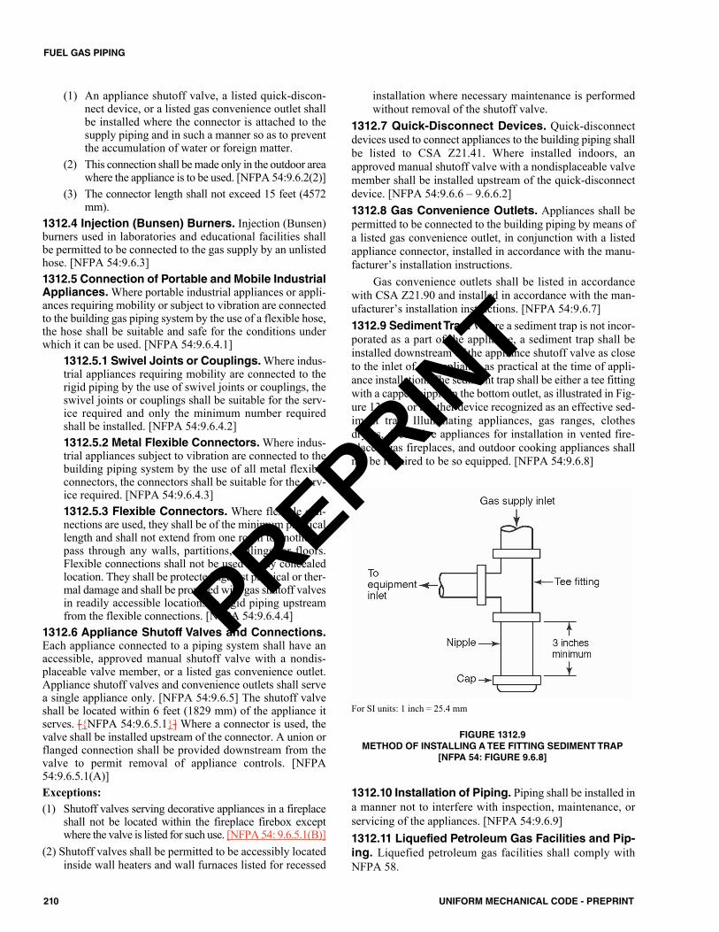
(1) An appliance shutoff valve, a listed quick-discon-nect device, or a listed gas convenience outlet shallbe installed where the connector is attached to thesupply piping and in such a manner so as to preventthe accumulation of water or foreign matter.
(2) This connection shall be made only in the outdoor areawhere the appliance is to be used. [NFPA 54:9.6.2(2)]
(3) The connector length shall not exceed 15 feet (4572mm).
1312.4 Injection (Bunsen) Burners. Injection (Bunsen)burners used in laboratories and educational facilities shallbe permitted to be connected to the gas supply by an unlistedhose. [NFPA 54:9.6.3]1312.5 Connection of Portable and Mobile IndustrialAppliances.Where portable industrial appliances or appli-ances requiring mobility or subject to vibration are connectedto the building gas piping system by the use of a flexible hose,the hose shall be suitable and safe for the conditions underwhich it can be used. [NFPA 54:9.6.4.1]
1312.5.1 Swivel Joints or Couplings. Where indus-trial appliances requiring mobility are connected to therigid piping by the use of swivel joints or couplings, theswivel joints or couplings shall be suitable for the serv-ice required and only the minimum number requiredshall be installed. [NFPA 54:9.6.4.2]1312.5.2 Metal Flexible Connectors. Where indus-trial appliances subject to vibration are connected to thebuilding piping system by the use of all metal flexibleconnectors, the connectors shall be suitable for the serv-ice required. [NFPA 54:9.6.4.3]1312.5.3 Flexible Connectors. Where flexible con-nections are used, they shall be of the minimum practicallength and shall not extend from one room to another orpass through any walls, partitions, ceilings, or floors.Flexible connections shall not be used in any concealedlocation. They shall be protected against physical or ther-mal damage and shall be provided with gas shutoff valvesin readily accessible locations in rigid piping upstreamfrom the flexible connections. [NFPA 54:9.6.4.4]
1312.6 Appliance Shutoff Valves and Connections.Each appliance connected to a piping system shall have anaccessible, approved manual shutoff valve with a nondis-placeable valve member, or a listed gas convenience outlet.Appliance shutoff valves and convenience outlets shall servea single appliance only. [NFPA 54:9.6.5] The shutoff valveshall be located within 6 feet (1829 mm) of the appliance itserves. [{NFPA 54:9.6.5.1}] Where a connector is used, thevalve shall be installed upstream of the connector. A union orflanged connection shall be provided downstream from thevalve to permit removal of appliance controls. [NFPA54:9.6.5.1(A)]Exceptions:(1) Shutoff valves serving decorative appliances in a fireplace
shall not be located within the fireplace firebox exceptwhere the valve is listed for such use. [NFPA 54: 9.6.5.1(B)]
(2) Shutoff valves shall be permitted to be accessibly locatedinside wall heaters and wall furnaces listed for recessed
installation where necessary maintenance is performedwithout removal of the shutoff valve.
1312.7 Quick-Disconnect Devices. Quick-disconnectdevices used to connect appliances to the building piping shallbe listed to CSA Z21.41. Where installed indoors, anapproved manual shutoff valve with a nondisplaceable valvemember shall be installed upstream of the quick-disconnectdevice. [NFPA 54:9.6.6 – 9.6.6.2]1312.8 Gas Convenience Outlets. Appliances shall bepermitted to be connected to the building piping by means ofa listed gas convenience outlet, in conjunction with a listedappliance connector, installed in accordance with the manu-facturer’s installation instructions.
Gas convenience outlets shall be listed in accordancewith CSA Z21.90 and installed in accordance with the man-ufacturer’s installation instructions. [NFPA 54:9.6.7]1312.9 Sediment Trap. Where a sediment trap is not incor-porated as a part of the appliance, a sediment trap shall beinstalled downstream of the appliance shutoff valve as closeto the inlet of the appliance as practical at the time of appli-ance installation. The sediment trap shall be either a tee fittingwith a capped nipple in the bottom outlet, as illustrated in Fig-ure 1312.9, or another device recognized as an effective sed-iment trap. Illuminating appliances, gas ranges, clothesdryers, decorative appliances for installation in vented fire-places, gas fireplaces, and outdoor cooking appliances shallnot be required to be so equipped. [NFPA 54:9.6.8]
1312.10 Installation of Piping. Piping shall be installed ina manner not to interfere with inspection, maintenance, orservicing of the appliances. [NFPA 54:9.6.9]1312.11 Liquefied Petroleum Gas Facilities and Pip-ing. Liquefied petroleum gas facilities shall comply withNFPA 58.
For SI units: 1 inch = 25.4 mm
FIGURE 1312.9METHOD OF INSTALLING A TEE FITTING SEDIMENT TRAP
[NFPA 54: FIGURE 9.6.8]
210 UNIFORM MECHANICAL CODE - PREPRINT
FUEL GAS PIPING
PREPRINT
1313.0 Pressure Testing, Inspection, and Purging.1313.1 Piping Installations. Prior to acceptance and ini-tial operation, all piping installations shall be visuallyinspected and pressure tested to determine that the materials,design, fabrication, and installation practices comply with therequirements of this code. [NFPA 54:8.1.1.1]
1313.1.1 Inspection Requirements. Inspection shallconsist of visual examination, during or after manufacture,fabrication, assembly, or pressure tests. [NFPA 54:8.1.1.2]1313.1.2 Repairs and Additions. Where repairs oradditions are made following the pressure test, theaffected piping shall be tested. Minor repairs and addi-tions are not required to be pressure tested, provided thatthe work is inspected and connections are tested with anoncorrosive leak-detecting fluid or other leak-detectingmethods approved by the Authority Having Jurisdiction.[NFPA 54:8.1.1.3]1313.1.3 New Branches. Where new branches areinstalled to new appliance(s), only the newly installedbranch(es) shall be required to be pressure tested. Con-nections between the new piping and the existing pipingshall be tested with a noncorrosive leak-detecting fluid orapproved leak-detecting methods. [NFPA 54:8.1.1.4]1313.1.4 Piping System. A piping system shall be testedas a complete unit or in sections. Under no circumstancesshall a valve in a line be used as a bulkhead between gas inone section of the piping system and test medium in anadjacent section, unless a double block and bleed valve sys-tem is installed. A valve shall not be subjected to the testpressure unless it can be determined that the valve, includ-ing the valve-closing mechanism, is designed to safelywithstand the pressure. [NFPA 54:8.1.1.5]1313.1.5 Regulators and Valves. Regulator andvalve assemblies fabricated independently of the pipingsystem in which they are to be installed shall be permit-ted to be tested with inert gas or air at the time of fabri-cation. [NFPA 54:8.1.1.6]1313.1.6 Test Medium. The test medium shall be air,nitrogen, carbon dioxide, or an inert gas. Oxygen shallnot be used as a test medium. [NFPA 54:8.1.2]
1313.2 Test Preparation. Test preparation shall complywith Section 1313.2.1 through Section 1313.2.6.
1313.2.1 Pipe Joints. Pipe joints, including welds,shall be left exposed for examination during the test.Exception: Covered or concealed pipe end joints thathave been previously tested in accordance with this code.[NFPA 54:8.1.3.1]1313.2.2 Expansion Joints. Expansion joints shallbe provided with temporary restraints, if required, for theadditional thrust load under test. [NFPA 54:8.1.3.2]1313.2.3 Appliances and Equipment.Appliances andequipment that are not to be included in the test shall beeither disconnected from the piping or isolated by blanks,blind flanges, or caps. Flanged joints at which blinds areinserted to blank off other equipment during the test shallnot be required to be tested. [NFPA 54:8.1.3.3]
1313.2.4 Designed for Operating Pressures Lessthan Test Pressure.Where the piping system is con-nected to appliances or equipment designed for operatingpressures of less than the test pressure, such appliancesor equipment shall be isolated from the piping system bydisconnecting them and capping the outlet(s). [NFPA54:8.1.3.4]1313.2.5 Designed for Operating Pressures Equalto or Greater than Test Pressure. Where the pipingsystem is connected to appliances or equipment designedfor operating pressures equal to or greater than the testpressure, such appliances or equipment shall be isolatedfrom the piping system by closing the individual appli-ance or equipment shutoff valve(s). [NFPA 54:8.1.3.5]1313.2.6 Safety. All testing of piping systems shall beperformed in a manner that protects the safety of employ-ees and the public during the test. [NFPA 54:8.1.3.6]
1313.3 Test Pressure. This inspection shall include an air,CO2, or nitrogen pressure test, at which time the gas pipingshall stand a pressure of not less than 10 psi (69 kPa) gaugepressure. Test pressures shall be held for a length of time sat-isfactory to the Authority Having Jurisdiction but in no caseless than 15 minutes with no perceptible drop in pressure. Forwelded piping, and for piping carrying gas at pressures inexcess of 14 inches water column (3.5 kPa) pressure, the testpressure shall be not less than 60 psi (414 kPa) and shall becontinued for a length of time satisfactory to the AuthorityHaving Jurisdiction, but in no case for less than 30 minutes.For CSST carrying gas at pressures in excess of 14 incheswater column (3.5 kPa) pressure, the test pressure shall be 30psi (207 kPa) for 30 minutes. These tests shall be made usingair, CO2, or nitrogen pressure and shall be made in the pres-ence of the Authority Having Jurisdiction. Necessary appa-ratus for conducting tests shall be furnished by the permitholder. Test gauges used in conducting test shall be in accor-dance with Section 1303.3.3.1 through Section 1303.3.3.4.1313.4 Detection of Leaks and Defects. The piping sys-tem shall withstand the test pressure specified without showingany evidence of leakage or other defects. Any reduction of testpressures as indicated by pressure gauges shall be deemed toindicate the presence of a leak unless such reduction can bereadily attributed to some other cause. [NFPA 54:8.1.5.1]
1313.4.1 Detecting Leaks. The leakage shall belocated by means of an approved gas detector, a noncor-rosive leak detection fluid, or other approved leak detec-tion methods. [NFPA 54:8.1.5.2]1313.4.2 Repair or Replace. Where leakage or otherdefects are located, the affected portion of the piping sys-tem shall be repaired or replaced and retested. [NFPA54:8.1.5.3]
1313.5 Piping System Leak Test. Leak checks using fuelgas shall be permitted in piping systems that have been pres-sure-tested in accordance with Section 1313.0. [NFPA 54:8.2.1]
1313.5.1 Turning Gas On.During the process of turn-ing gas on into a system of new gas piping, the entire sys-tem shall be inspected to determine that there are no openfittings or ends and that all valves at unused outlets areclosed and plugged or capped. [NFPA 54:8.2.2]
211UNIFORM MECHANICAL CODE - PREPRINT
FUEL GAS PIPING
PREPRINT
1313.5.2 Leak Check. Immediately after the gas isturned on into a new system or into a system that hasbeen initially restored after an interruption of service, thepiping system shall be checked for leakage. Where leak-age is indicated, the gas supply shall be shut off until thenecessary repairs have been made. [NFPA 54:8.2.3]1313.5.3 Placing Appliances and Equipment inOperation. Appliances and equipment shall not beplaced in operation until after the piping system has beenchecked for leakage in accordance with Section 1313.5.2;the piping system is purged in accordance with Section1313.6, and connections to the appliance are checked forleakage. [NFPA 54:8.2.4]
1313.6 Purging Requirements. The purging of pipingshall be in accordance with Section 1313.6.1 through Section1313.6.3. [NFPA 54:8.3]
1313.6.1 Piping Systems Required to be PurgedOutdoors. The purging of piping systems shall be inaccordance with Section 1313.6.1.1 through Section1313.6.1.4 where the piping system meets either of thefollowing:(1) The design operating gas pressure is greater than 2
psig (14 kPag).(2) The piping being purged contains one or more sec-
tions of pipe or tubing meeting the size and lengthcriteria of Table 1313.6.1. [NFPA 54:8.3.1]
1313.6.1.1 Removal from Service.Where exist-ing gas piping is opened, the section that is openedshall be isolated from the gas supply and the line pres-sure vented in accordance with Section 1313.6.1.3.Where gas piping meeting the criteria of Table1313.6.1 is removed from service, the residual fuelgas in the piping shall be displaced with an inert gas.[NFPA 54:8.3.1.1]1313.6.1.2 Placing in Operation.Where gas pip-ing containing air and meeting the criteria of Table1313.6.1 is placed in operation, the air in the pipingshall first be displaced with an inert gas. The inertgas shall then be displaced with fuel gas in accor-dance with Section 1313.6.1.3. [NFPA 54:8.3.1.2]
1313.6.1.3 Outdoor Discharge of PurgedGases. The open end of a piping system beingpressure vented or purged shall discharge directly toan outdoor location. Purging operations shall com-ply with all of the following requirements:(1) The point of discharge shall be controlled with
a shutoff valve.(2) The point of discharge shall be located at least 10
feet (3048 mm) from sources of ignition, at least10 feet (3048 mm) from building openings, and atleast 25 feet (7620 mm) from mechanical airintake openings.
(3) During discharge, the open point of dischargeshall be continuously attended and monitoredwith a combustible gas indicator that complieswith Section 1313.6.1.4.
(4) Purging operations introducing fuel gas shall bestopped when 90 percent fuel gas by volume isdetected within the pipe.
(5) Persons not involved in the purging operationsshall be evacuated from all areas within 10 feet(3048 mm) of the point of discharge. [NFPA54:8.3.1.3]
1313.6.1.4 Combustible Gas Indicator. Com-bustible gas indicators shall be listed and calibratedin accordance with the manufacturer’s instructions.Combustible gas indicators shall numerically dis-play a volume scale from 0 percent to 100 percent in1 percent or smaller increments. [NFPA 54:8.3.1.4]
1313.6.2 Piping Systems Allowed to be PurgedIndoors or Outdoors. The purging of piping systemsshall be in accordance with the provisions of Section1313.6.2.1 where the piping system meets both of thefollowing:(1) The design operating pressure is 2 psig (14 kPag) or
less.(2) The piping being purged is constructed entirely from
pipe or tubing not meeting the size and length crite-ria of Table 1313.6.1. [NFPA 54:8.3.2]1313.6.2.1 Purging Procedure. The piping sys-tem shall be purged in accordance with one or moreof the following:(1) The piping shall be purged with fuel gas and
shall discharge to the outdoors.(2) The piping shall be purged with fuel gas and
shall discharge to the indoors or outdoorsthrough an appliance burner not located in acombustion chamber. Such burner shall be pro-vided with a continuous source of ignition.
(3) The piping shall be purged with fuel gas andshall discharge to the indoors or outdoorsthrough a burner that has a continuous source ofignition and that is designed for such purpose.
TABLE 1313.6.1SIZE AND LENGTH OF PIPING[NFPA 54: TABLE 8.3.1]*
For SI units: 1 inch = 25 mm; 1 foot = 304.8 mm* CSST EHD size of 62 is equivalent to nominal 2 inches (50 mm) pipe ortubing size.
NOMINAL PIPING SIZE (inches) LENGTH OF PIPING (feet)
≥ 21⁄2 < 3 > 50≥ 3 < 4 > 30≥ 4 < 6 > 15≥ 6 < 8 > 10
≥ 8 Any length
212 UNIFORM MECHANICAL CODE - PREPRINT
FUEL GAS PIPING
PREPRINT
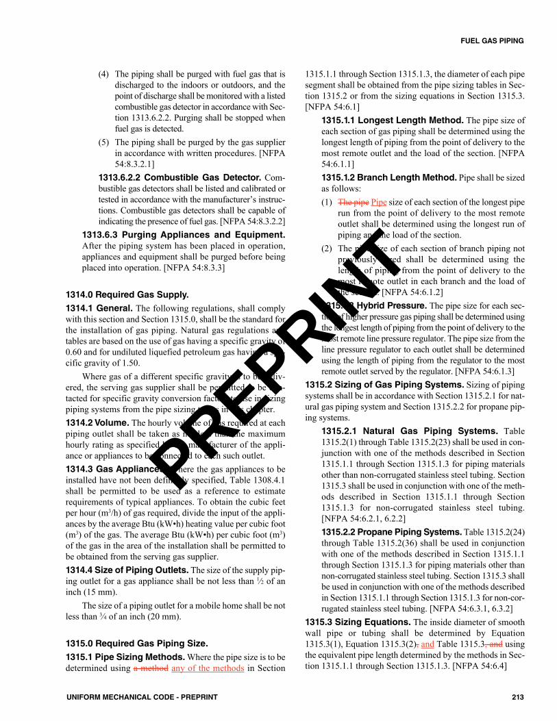
(4) The piping shall be purged with fuel gas that isdischarged to the indoors or outdoors, and thepoint of discharge shall be monitored with a listedcombustible gas detector in accordance with Sec-tion 1313.6.2.2. Purging shall be stopped whenfuel gas is detected.
(5) The piping shall be purged by the gas supplierin accordance with written procedures. [NFPA54:8.3.2.1]
1313.6.2.2 Combustible Gas Detector. Com-bustible gas detectors shall be listed and calibrated ortested in accordance with the manufacturer’s instruc-tions. Combustible gas detectors shall be capable ofindicating the presence of fuel gas. [NFPA 54:8.3.2.2]
1313.6.3 Purging Appliances and Equipment.After the piping system has been placed in operation,appliances and equipment shall be purged before beingplaced into operation. [NFPA 54:8.3.3]
1314.0 Required Gas Supply.
1314.1 General. The following regulations, shall complywith this section and Section 1315.0, shall be the standard forthe installation of gas piping. Natural gas regulations andtables are based on the use of gas having a specific gravity of0.60 and for undiluted liquefied petroleum gas having a spe-cific gravity of 1.50.
Where gas of a different specific gravity is to be deliv-ered, the serving gas supplier shall be permitted to be con-tacted for specific gravity conversion factors to use in sizingpiping systems from the pipe sizing tables in this chapter.1314.2 Volume. The hourly volume of gas required at eachpiping outlet shall be taken as not less than the maximumhourly rating as specified by the manufacturer of the appli-ance or appliances to be connected to each such outlet.1314.3 Gas Appliances. Where the gas appliances to beinstalled have not been definitely specified, Table 1308.4.1shall be permitted to be used as a reference to estimaterequirements of typical appliances. To obtain the cubic feetper hour (m3/h) of gas required, divide the input of the appli-ances by the average Btu (kW•h) heating value per cubic foot(m3) of the gas. The average Btu (kW•h) per cubic foot (m3)of the gas in the area of the installation shall be permitted tobe obtained from the serving gas supplier.1314.4 Size of Piping Outlets. The size of the supply pip-ing outlet for a gas appliance shall be not less than 1⁄2 of aninch (15 mm).
The size of a piping outlet for a mobile home shall be notless than 3⁄4 of an inch (20 mm).
1315.0 Required Gas Piping Size.
1315.1 Pipe Sizing Methods. Where the pipe size is to bedetermined using a method any of the methods in Section
1315.1.1 through Section 1315.1.3, the diameter of each pipesegment shall be obtained from the pipe sizing tables in Sec-tion 1315.2 or from the sizing equations in Section 1315.3.[NFPA 54:6.1]
1315.1.1 Longest Length Method. The pipe size ofeach section of gas piping shall be determined using thelongest length of piping from the point of delivery to themost remote outlet and the load of the section. [NFPA54:6.1.1]1315.1.2 Branch Length Method. Pipe shall be sizedas follows:(1) The pipe Pipe size of each section of the longest pipe
run from the point of delivery to the most remoteoutlet shall be determined using the longest run ofpiping and the load of the section.
(2) The pipe size of each section of branch piping notpreviously sized shall be determined using thelength of piping from the point of delivery to themost remote outlet in each branch and the load ofthe section. [NFPA 54:6.1.2]
1315.1.3 Hybrid Pressure. The pipe size for each sec-tion of higher pressure gas piping shall be determined usingthe longest length of piping from the point of delivery to themost remote line pressure regulator. The pipe size from theline pressure regulator to each outlet shall be determinedusing the length of piping from the regulator to the mostremote outlet served by the regulator. [NFPA 54:6.1.3]
1315.2 Sizing of Gas Piping Systems. Sizing of pipingsystems shall be in accordance with Section 1315.2.1 for nat-ural gas piping system and Section 1315.2.2 for propane pip-ing systems.
1315.2.1 Natural Gas Piping Systems. Table1315.2(1) through Table 1315.2(23) shall be used in con-junction with one of the methods described in Section1315.1.1 through Section 1315.1.3 for piping materialsother than non-corrugated stainless steel tubing. Section1315.3 shall be used in conjunction with one of the meth-ods described in Section 1315.1.1 through Section1315.1.3 for non-corrugated stainless steel tubing.[NFPA 54:6.2.1, 6.2.2]1315.2.2 Propane Piping Systems. Table 1315.2(24)through Table 1315.2(36) shall be used in conjunctionwith one of the methods described in Section 1315.1.1through Section 1315.1.3 for piping materials other thannon-corrugated stainless steel tubing. Section 1315.3 shallbe used in conjunction with one of the methods describedin Section 1315.1.1 through Section 1315.1.3 for non-cor-rugated stainless steel tubing. [NFPA 54:6.3.1, 6.3.2]
1315.3 Sizing Equations. The inside diameter of smoothwall pipe or tubing shall be determined by Equation1315.3(1), Equation 1315.3(2), and Table 1315.3, and usingthe equivalent pipe length determined by the methods in Sec-tion 1315.1.1 through Section 1315.1.3. [NFPA 54:6.4]
213UNIFORM MECHANICAL CODE - PREPRINT
FUEL GAS PIPING
PREPRINT
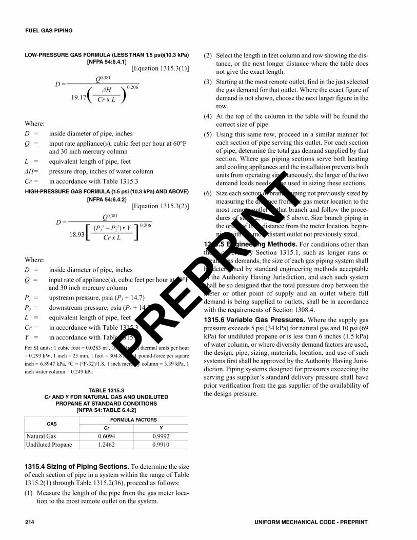
LOW-PRESSURE GAS FORMULA (LESS THAN 1.5 psi)(10.3 kPa)[NFPA 54:6.4.1]
[Equation 1315.3(1)]
Where:D = inside diameter of pipe, inchesQ = input rate appliance(s), cubic feet per hour at 60°F
and 30 inch mercury columnL = equivalent length of pipe, feetΔH= pressure drop, inches of water column Cr = in accordance with Table 1315.3HIGH-PRESSURE GAS FORMULA (1.5 psi (10.3 kPa) AND ABOVE)
[NFPA 54:6.4.2][Equation 1315.3(2)]
Where:D = inside diameter of pipe, inchesQ = input rate of appliance(s), cubic feet per hour at 60°F
and 30 inch mercury columnP1 = upstream pressure, psia (P1 + 14.7)P2 = downstream pressure, psia (P2 + 14.7)L = equivalent length of pipe, feetCr = in accordance with Table 1315.3Y = in accordance with Table 1315.3For SI units: 1 cubic foot = 0.0283 m3, 1000 British thermal units per hour= 0.293 kW, 1 inch = 25 mm, 1 foot = 304.8 mm, 1 pound-force per squareinch = 6.8947 kPa, °C = (°F-32)/1.8, 1 inch mercury column = 3.39 kPa, 1inch water column = 0.249 kPa
1315.4 Sizing of Piping Sections. To determine the sizeof each section of pipe in a system within the range of Table1315.2(1) through Table 1315.2(36), proceed as follows:(1) Measure the length of the pipe from the gas meter loca-
tion to the most remote outlet on the system.
(2) Select the length in feet column and row showing the dis-tance, or the next longer distance where the table doesnot give the exact length.
(3) Starting at the most remote outlet, find in the just selectedthe gas demand for that outlet. Where the exact figure ofdemand is not shown, choose the next larger figure in therow.
(4) At the top of the column in the table will be found thecorrect size of pipe.
(5) Using this same row, proceed in a similar manner foreach section of pipe serving this outlet. For each sectionof pipe, determine the total gas demand supplied by thatsection. Where gas piping sections serve both heatingand cooling appliances and the installation prevents bothunits from operating simultaneously, the larger of the twodemand loads needs to be used in sizing these sections.
(6) Size each section of branch piping not previously sized bymeasuring the distance from the gas meter location to themost remote outlet in that branch and follow the proce-dures of steps 2, 3, 4, and 5 above. Size branch piping inthe order of their distance from the meter location, begin-ning with the most distant outlet not previously sized.
1315.5 Engineering Methods. For conditions other thanthose covered by Section 1315.1, such as longer runs orgreater gas demands, the size of each gas piping system shallbe determined by standard engineering methods acceptableto the Authority Having Jurisdiction, and each such systemshall be so designed that the total pressure drop between themeter or other point of supply and an outlet where fulldemand is being supplied to outlets, shall be in accordancewith the requirements of Section 1308.4.1315.6 Variable Gas Pressures. Where the supply gaspressure exceeds 5 psi (34 kPa) for natural gas and 10 psi (69kPa) for undiluted propane or is less than 6 inches (1.5 kPa)of water column, or where diversity demand factors are used,the design, pipe, sizing, materials, location, and use of suchsystems first shall be approved by the Authority Having Juris-diction. Piping systems designed for pressures exceeding theserving gas supplier’s standard delivery pressure shall haveprior verification from the gas supplier of the availability ofthe design pressure.
D =Q0.381
18.93[ (P12 – P2
2) • Y ]0.206
Cr x L
TABLE 1315.3Cr AND Y FOR NATURAL GAS AND UNDILUTED
PROPANE AT STANDARD CONDITIONS[NFPA 54: TABLE 6.4.2]
GASFORMULA FACTORS
Cr Y
Natural Gas 0.6094 0.9992Undiluted Propane 1.2462 0.9910
D =Q0.381
19.17( ΔH )0.206
Cr x L
214 UNIFORM MECHANICAL CODE - PREPRINT
FUEL GAS PIPING
PREPRINT
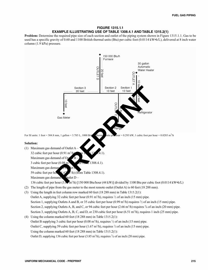
215UNIFORM MECHANICAL CODE - PREPRINT
FUEL GAS PIPING
FIGURE 1315.1.1EXAMPLE ILLUSTRATING USE OF TABLE 1308.4.1 AND TABLE 1315.2(1)
Problem: Determine the required pipe size of each section and outlet of the piping system shown in Figure 1315.1.1. Gas to beused has a specific gravity of 0.60 and 1100 British thermal units (Btu) per cubic foot (0.0114 kW•h/L), delivered at 8 inch watercolumn (1.9 kPa) pressure.
For SI units: 1 foot = 304.8 mm, 1 gallon = 3.785 L, 1000 British thermal units per hour = 0.293 kW, 1 cubic foot per hour = 0.0283 m3/h
Solution:(1) Maximum gas demand of Outlet A –
32 cubic feet per hour (0.91 m3/h) (from Table 1308.4.1).Maximum gas demand of Outlet B –3 cubic feet per hour (0.08 m3/h) (from Table 1308.4.1).Maximum gas demand of Outlet C –59 cubic feet per hour (1.67 m3/h) (from Table 1308.4.1).Maximum gas demand of Outlet D –136 cubic feet per hour (3.85 m3/h) [150 000 Btu/hour (44 kW)] divided by 1100 Btu per cubic foot (0.0114 kW•h/L)
(2) The length of pipe from the gas meter to the most remote outlet (Outlet A) is 60 feet (18 288 mm).(3) Using the length in feet column row marked 60 feet (18 288 mm) in Table 1315.2(1):
Outlet A, supplying 32 cubic feet per hour (0.91 m3/h), requires 1⁄2 of an inch (15 mm) pipe.Section 1, supplying Outlets A and B, or 35 cubic feet per hour (0.99 m3/h) requires 1⁄2 of an inch (15 mm) pipe.Section 2, supplying Outlets A, B, and C, or 94 cubic feet per hour (2.66 m3/h) requires 3⁄4 of an inch (20 mm) pipe.Section 3, supplying Outlets A, B, C, and D, or 230 cubic feet per hour (6.51 m3/h), requires 1 inch (25 mm) pipe.
(4) Using the column marked 60 feet (18 288 mm) in Table 1315.2(1):Outlet B supplying 3 cubic feet per hour (0.08 m3/h), requires 1⁄2 of an inch (15 mm) pipe.Outlet C, supplying 59 cubic feet per hour (1.67 m3/h), requires 1⁄2 of an inch (15 mm) pipe.Using the column marked 60 feet (18 288 mm) in Table 1315.2(1):Outlet D, supplying 136 cubic feet per hour (3.85 m3/h), requires 3⁄4 of an inch (20 mm) pipe.
PREPRINT
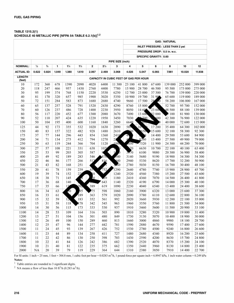
216 UNIFORM MECHANICAL CODE - PREPRINT
FUEL GAS PIPING
TABLE 1315.2(1)SCHEDULE 40 METALLIC PIPE [NFPA 54: TABLE 6.2.1(b)]1,2
GAS: NATURAL
INLET PRESSURE: LESS THAN 2 psi
PRESSURE DROP: 0.5 in. w.c.
SPECIFIC GRAVITY: 0.60
PIPE SIZE (inch)
NOMINAL: 1⁄2 3⁄4 1 11⁄4 11⁄2 2 21⁄2 3 4 5 6 8 10 12
ACTUAL ID: 0.622 0.824 1.049 1.380 1.610 2.067 2.469 3.068 4.026 5.047 6.065 7.981 10.020 11.938
LENGTH(feet)
CAPACITY IN CUBIC FEET OF GAS PER HOUR
1020304050
172118958172
360247199170151
678466374320284
1390957768657583
209014301150985873
40202760222019001680
64004400353030202680
11 3007780625053504740
23 10015 90012 70010 9009660
41 80028 70023 00019 70017 500
67 60046 50037 30031 90028 300
139 00095 50076 70065 60058 200
252 000173 000139 000119 000106 000
399 000275 000220 000189 000167 000
60708090100
6560565250
137126117110104
257237220207195
528486452424400
791728677635600
15201400130012201160
24302230208019501840
42903950367034503260
87608050749070306640
15 80014 60013 60012 70012 000
25 60023 60022 00020 60019 500
52 70048 50045 10042 30040 000
95 70088 10081 90076 90072 600
152 000139 000130 000122 000115 000
125150175200250
4440373430
9283777163
173157144134119
355322296275244
532482443412366
1020928854794704
16301480136012701120
28902610241022401980
58905330491045604050
10 6009650888082607320
17 20015 60014 40013 40011 900
35 40032 10029 50027 50024 300
64 30058 30053 60049 90044 200
102 00092 30084 90079 00070 000
300350400450500
2725232221
5753494643
10899928682
221203189177168
331305283266251
638587546512484
1020935870816771
18001650154014401360
36703370314029402780
66306100568053305030
10 7009880919086208150
22 10020 30018 90017 70016 700
40 10036 90034 30032 20030 400
63 40058 40054 30050 90048 100
550600650700750
2019181717
4139383635
7874716866
159152145140135
239228218209202
459438420403389
732699669643619
12901240118011401090
26402520241023202230
47804560436041904040
77407380707067906540
15 90015 20014 50014 00013 400
28 90027 50026 40025 30024 400
45 70043 60041 80040 10038 600
8008509009501000
1616151514
3433323130
6361595856
130126122118115
195189183178173
375363352342333
598579561545530
10601020992963937
21602090202019601910
39003780366035503460
63206110593057605600
13 00012 60012 20011 80011 500
23 60022 80022 10021 50020 900
37 30036 10035 00034 00033 100
11001200130014001500
1413121211
2827262524
5351494745
1091041009693
164156150144139
316301289277267
503480460442426
890849813781752
18101730166015901530
32803130300028802780
53205070486046704500
10 90010 400998095909240
19 80018 90018 10017 40016 800
31 40030 00028 70027 60026 600
16001700180019002000
11111010NA
2322222120
4442414039
8986848179
134130126122119
258250242235229
411398386375364
727703682662644
14801430139013501310
26802590252024402380
43404200407039603850
89208630837081307910
16 20015 70015 20014 80014 400
25 60024 80024 10023 40022 700
For SI units: 1 inch = 25 mm, 1 foot = 304.8 mm, 1 cubic foot per hour = 0.0283 m3/h, 1 pound-force per square inch = 6.8947 kPa, 1 inch water column = 0.249 kPaNotes:1 Table entries are rounded to 3 significant digits.2 NA means a flow of less than 10 ft3/h (0.283 m3/h).
PREPRINT
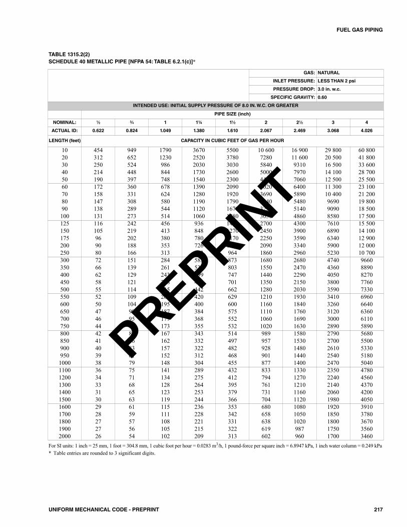
217UNIFORM MECHANICAL CODE - PREPRINT
FUEL GAS PIPING
For SI units: 1 inch = 25 mm, 1 foot = 304.8 mm, 1 cubic foot per hour = 0.0283 m3/h, 1 pound-force per square inch = 6.8947 kPa, 1 inch water column = 0.249 kPa* Table entries are rounded to 3 significant digits.
GAS: NATURAL
INLET PRESSURE: LESS THAN 2 psi
PRESSURE DROP: 3.0 in. w.c.
SPECIFIC GRAVITY: 0.60
INTENDED USE: INITIAL SUPPLY PRESSURE OF 8.0 IN. W.C. OR GREATER
PIPE SIZE (inch)
NOMINAL: 1⁄2 3⁄4 1 1¼ 11⁄2 2 21⁄2 3 4
ACTUAL ID: 0.622 0.824 1.049 1.380 1.610 2.067 2.469 3.068 4.026
LENGTH (feet) CAPACITY IN CUBIC FEET OF GAS PER HOUR
10 454 949 1790 3670 5500 10 600 16 900 29 800 60 80020 312 652 1230 2520 3780 7280 11 600 20 500 41 80030 250 524 986 2030 3030 5840 9310 16 500 33 60040 214 448 844 1730 2600 5000 7970 14 100 28 70050 190 397 748 1540 2300 4430 7060 12 500 25 50060 172 360 678 1390 2090 4020 6400 11 300 23 10070 158 331 624 1280 1920 3690 5890 10 400 21 20080 147 308 580 1190 1790 3440 5480 9690 19 80090 138 289 544 1120 1670 3230 5140 9090 18 500100 131 273 514 1060 1580 3050 4860 8580 17 500125 116 242 456 936 1400 2700 4300 7610 15 500150 105 219 413 848 1270 2450 3900 6890 14 100175 96 202 380 780 1170 2250 3590 6340 12 900200 90 188 353 726 1090 2090 3340 5900 12 000250 80 166 313 643 964 1860 2960 5230 10 700300 72 151 284 583 873 1680 2680 4740 9660350 66 139 261 536 803 1550 2470 4360 8890400 62 129 243 499 747 1440 2290 4050 8270450 58 121 228 468 701 1350 2150 3800 7760500 55 114 215 442 662 1280 2030 3590 7330550 52 109 204 420 629 1210 1930 3410 6960600 50 104 195 400 600 1160 1840 3260 6640650 47 99 187 384 575 1110 1760 3120 6360700 46 95 179 368 552 1060 1690 3000 6110750 44 92 173 355 532 1020 1630 2890 5890800 42 89 167 343 514 989 1580 2790 5680850 41 86 162 332 497 957 1530 2700 5500900 40 83 157 322 482 928 1480 2610 5330950 39 81 152 312 468 901 1440 2540 51801000 38 79 148 304 455 877 1400 2470 50401100 36 75 141 289 432 833 1330 2350 47801200 34 71 134 275 412 794 1270 2240 45601300 33 68 128 264 395 761 1210 2140 43701400 31 65 123 253 379 731 1160 2060 42001500 30 63 119 244 366 704 1120 1980 40501600 29 61 115 236 353 680 1080 1920 39101700 28 59 111 228 342 658 1050 1850 37801800 27 57 108 221 331 638 1020 1800 36701900 27 56 105 215 322 619 987 1750 35602000 26 54 102 209 313 602 960 1700 3460
TABLE 1315.2(2)SCHEDULE 40 METALLIC PIPE [NFPA 54: TABLE 6.2.1(c)]*
PREPRINT
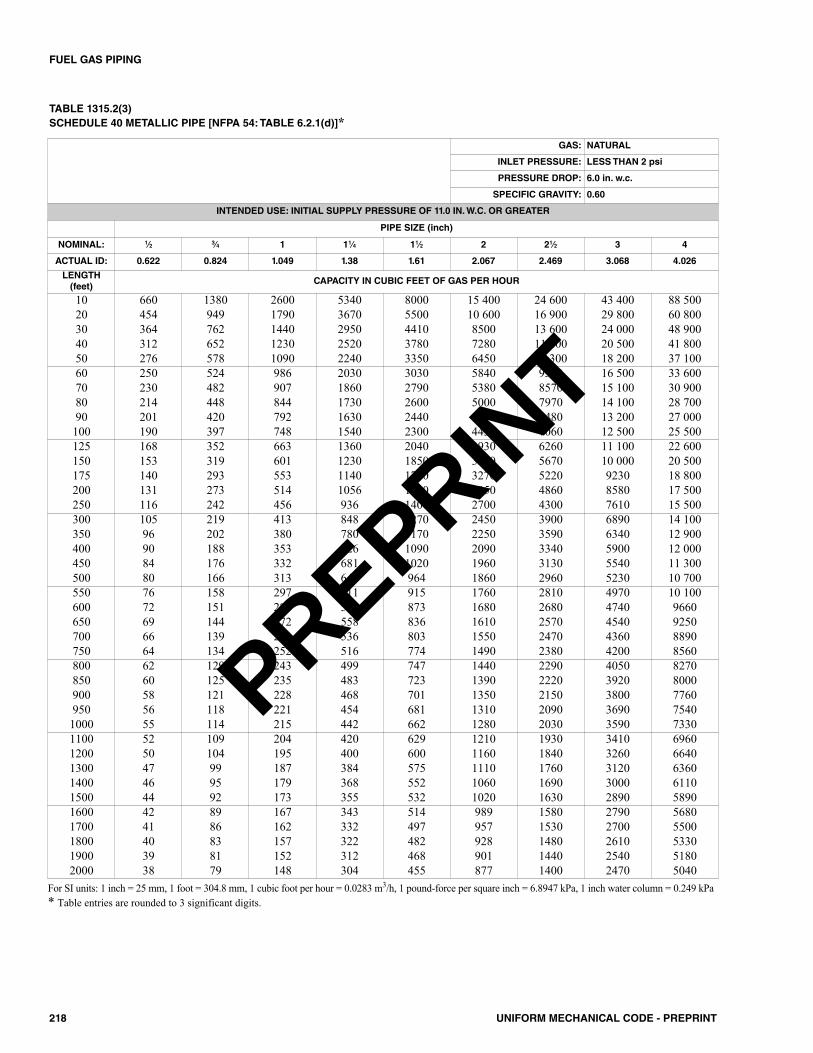
218 UNIFORM MECHANICAL CODE - PREPRINT
FUEL GAS PIPING
TABLE 1315.2(3)SCHEDULE 40 METALLIC PIPE [NFPA 54: TABLE 6.2.1(d)]*
GAS: NATURAL
INLET PRESSURE: LESS THAN 2 psi
PRESSURE DROP: 6.0 in. w.c.
SPECIFIC GRAVITY: 0.60
INTENDED USE: INITIAL SUPPLY PRESSURE OF 11.0 IN. W.C. OR GREATER
PIPE SIZE (inch)
NOMINAL: 1⁄2 3⁄4 1 11⁄4 11⁄2 2 21⁄2 3 4
ACTUAL ID: 0.622 0.824 1.049 1.38 1.61 2.067 2.469 3.068 4.026
LENGTH(feet)
CAPACITY IN CUBIC FEET OF GAS PER HOUR
10 660 1380 2600 5340 8000 15 400 24 600 43 400 88 50020 454 949 1790 3670 5500 10 600 16 900 29 800 60 80030 364 762 1440 2950 4410 8500 13 600 24 000 48 90040 312 652 1230 2520 3780 7280 11 600 20 500 41 80050 276 578 1090 2240 3350 6450 10 300 18 200 37 10060 250 524 986 2030 3030 5840 9310 16 500 33 60070 230 482 907 1860 2790 5380 8570 15 100 30 90080 214 448 844 1730 2600 5000 7970 14 100 28 70090 201 420 792 1630 2440 4690 7480 13 200 27 000100 190 397 748 1540 2300 4430 7060 12 500 25 500125 168 352 663 1360 2040 3930 6260 11 100 22 600150 153 319 601 1230 1850 3560 5670 10 000 20 500175 140 293 553 1140 1700 3270 5220 9230 18 800200 131 273 514 1056 1580 3050 4860 8580 17 500250 116 242 456 936 1400 2700 4300 7610 15 500300 105 219 413 848 1270 2450 3900 6890 14 100350 96 202 380 780 1170 2250 3590 6340 12 900400 90 188 353 726 1090 2090 3340 5900 12 000450 84 176 332 681 1020 1960 3130 5540 11 300500 80 166 313 643 964 1860 2960 5230 10 700550 76 158 297 611 915 1760 2810 4970 10 100600 72 151 284 583 873 1680 2680 4740 9660650 69 144 272 558 836 1610 2570 4540 9250700 66 139 261 536 803 1550 2470 4360 8890750 64 134 252 516 774 1490 2380 4200 8560800 62 129 243 499 747 1440 2290 4050 8270850 60 125 235 483 723 1390 2220 3920 8000900 58 121 228 468 701 1350 2150 3800 7760950 56 118 221 454 681 1310 2090 3690 75401000 55 114 215 442 662 1280 2030 3590 73301100 52 109 204 420 629 1210 1930 3410 69601200 50 104 195 400 600 1160 1840 3260 66401300 47 99 187 384 575 1110 1760 3120 63601400 46 95 179 368 552 1060 1690 3000 61101500 44 92 173 355 532 1020 1630 2890 58901600 42 89 167 343 514 989 1580 2790 56801700 41 86 162 332 497 957 1530 2700 55001800 40 83 157 322 482 928 1480 2610 53301900 39 81 152 312 468 901 1440 2540 51802000 38 79 148 304 455 877 1400 2470 5040
For SI units: 1 inch = 25 mm, 1 foot = 304.8 mm, 1 cubic foot per hour = 0.0283 m3/h, 1 pound-force per square inch = 6.8947 kPa, 1 inch water column = 0.249 kPa* Table entries are rounded to 3 significant digits.
PREPRINT

219UNIFORM MECHANICAL CODE - PREPRINT
FUEL GAS PIPING
TABLE 1315.2(4)SCHEDULE 40 METALLIC PIPE [NFPA 54: TABLE 6.2.1(e)]*
GAS: NATURAL
INLET PRESSURE: 2.0 psi
PRESSURE DROP: 1.0 psi
SPECIFIC GRAVITY: 0.60
PIPE SIZE (inch)
NOMINAL: 1⁄2 3⁄4 1 11⁄4 11⁄2 2 21⁄2 3 4
ACTUAL ID: 0.622 0.824 1.049 1.380 1.610 2.067 2.469 3.068 4.026
LENGTH(feet)
CAPACITY IN CUBIC FEET OF GAS PER HOUR
1020304050
15101070869753673
30402150176015201360
55603930321027802490
11 4008070659057105110
17 10012 100988085507650
32 90023 30019 00016 50014 700
52 50037 10030 30026 30023 500
92 80065 60053 60046 40041 500
189 000134 000109 00094 70084 700
60708090100
615569532502462
1240115010801010934
22702100197018501710
46604320404038103510
69806470605057005260
13 50012 50011 70011 00010 100
21 40019 90018 60017 50016 100
37 90035 10032 80030 90028 500
77 30071 60067 00063 10058 200
125150175200250
414372344318279
836751695642583
15301370127011701040
31402820260124102140
47004220391036103210
90608130753069606180
14 40013 00012 00011 1009850
25 50022 90021 20019 60017 400
52 10046 70043 30040 00035 500
300350400450500
253232216203192
528486452424401
945869809759717
19401790166015601470
29102670249023302210
56005150479045004250
89208210764071706770
15 80014 50013 50012 70012 000
32 20029 60027 50025 80024 400
550600650700750
182174166160154
381363348334322
681650622598576
14001330128012301180
20902000191018401770
40303850368035403410
64306130587056405440
11 40010 80010 40099709610
23 20022 10021 20020 30019 600
8008509009501000
149144139135132
311301292283275
556538522507493
11401100107010401010
17101650160015601520
32903190309030002920
52505080493047804650
92808980871084608220
18 90018 30017 80017 20016 800
11001200130014001500
125119114110106
262250239230221
468446427411396
960917878843812
14401370132012601220
27702640253024302340
44204220404038803740
78107450714068606600
15 90015 20014 60014 00013 500
16001700180019002000
10299969391
214207200195189
382370358348339
784759736715695
11801140110010701040
22602190212020602010
36103490339032903200
63806170598058105650
13 00012 60012 20011 90011 500
For SI units: 1 inch = 25 mm, 1 foot = 304.8 mm, 1 cubic foot per hour = 0.0283 m3/h, 1 pound-force per square inch = 6.8947 kPa* Table entries are rounded to 3 significant digits.
PREPRINT
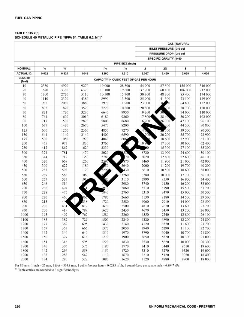
220 UNIFORM MECHANICAL CODE - PREPRINT
FUEL GAS PIPING
TABLE 1315.2(5)SCHEDULE 40 METALLIC PIPE [NFPA 54: TABLE 6.2.1(f)]*
GAS: NATURAL
INLET PRESSURE: 3.0 psi
PRESSURE DROP: 2.0 psi
SPECIFIC GRAVITY: 0.60
PIPE SIZE (inch)
NOMINAL: 1⁄2 3⁄4 1 11⁄4 11⁄2 2 21⁄2 3 4
ACTUAL ID: 0.622 0.824 1.049 1.380 1.610 2.067 2.469 3.068 4.026
LENGTH(feet)
CAPACITY IN CUBIC FEET OF GAS PER HOUR
1020304050
2350162013001110985
49203380272023202060
92706370511043803880
19 00013 10010 50089907970
28 50019 60015 70013 50011 900
54 90037 70030 30025 90023 000
87 50060 10048 30041 30036 600
155 000106 00085 40073 10064 800
316 000217 000174 000149 000132 000
60708090100
892821764717677
18701720160015001420
35203230301028202670
72206640618058005470
10 8009950926086808200
20 80019 20017 80016 70015 800
33 20030 50028 40026 70025 200
58 70054 00050 20047 10044 500
120 000110 000102 00096 10090 800
125150175200250
600544500465412
125011401050973862
23602140197018301620
48504400404037603330
72706590606056405000
14 00012 70011 70010 9009620
22 30020 20018 60017 30015 300
39 50035 70032 90030 60027 100
80 50072 90067 10062 40055 300
300350400450500
374344320300283
781719669627593
14701350126011801120
30202780259024302290
45304170387036403430
87208020746070006610
13 90012 80011 90011 20010 500
24 60022 60021 00019 70018 600
50 10046 10042 90040 20038 000
550600650700750
269257246236228
563537514494476
10601010969931897
21802080199019101840
32603110298028602760
62805990574055105310
10 0009550915087908470
17 70016 90016 20015 50015 000
36 10034 40033 00031 70030 500
8008509009501000
220213206200195
460445431419407
866838812789767
17801720167016201580
26602580250024302360
51304960481046704550
81807910767074507240
14 50014 00013 60013 20012 800
29 50028 50027 70026 90026 100
11001200130014001500
185177169162156
387369353340327
729695666640616
15001430137013101270
22402140205019701900
43204120394037903650
68906570629060405820
12 20011 60011 10010 70010 300
24 80023 70022 70021 80021 000
16001700180019002000
151146142138134
316306296288280
595576558542527
12201180115011101080
18301770172016701620
35303410331032103120
56205440527051204980
10 0009610932090508800
20 30019 60019 00018 40018 000
For SI units: 1 inch = 25 mm, 1 foot = 304.8 mm, 1 cubic foot per hour = 0.0283 m3/h, 1 pound-force per square inch = 6.8947 kPa* Table entries are rounded to 3 significant digits.
PREPRINT
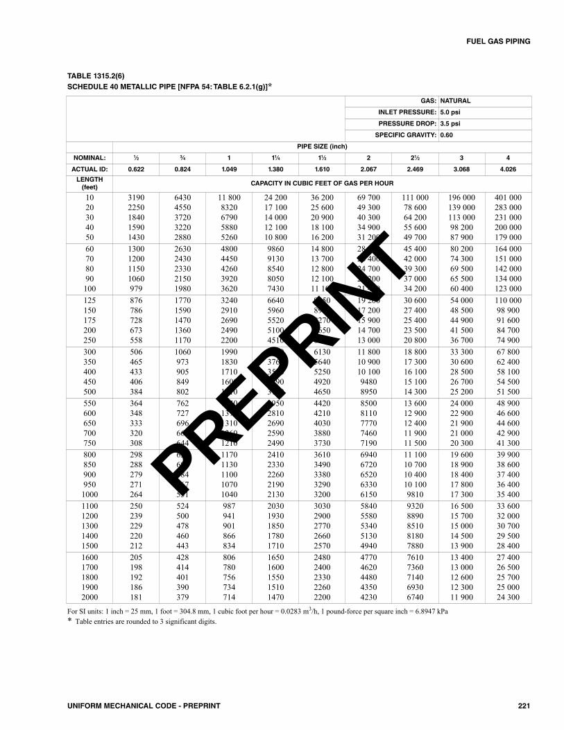
221UNIFORM MECHANICAL CODE - PREPRINT
FUEL GAS PIPING
TABLE 1315.2(6)SCHEDULE 40 METALLIC PIPE [NFPA 54: TABLE 6.2.1(g)]*
GAS: NATURAL
INLET PRESSURE: 5.0 psi
PRESSURE DROP: 3.5 psi
SPECIFIC GRAVITY: 0.60
PIPE SIZE (inch)
NOMINAL: 1⁄2 3⁄4 1 11⁄4 11⁄2 2 21⁄2 3 4
ACTUAL ID: 0.622 0.824 1.049 1.380 1.610 2.067 2.469 3.068 4.026
LENGTH(feet)
CAPACITY IN CUBIC FEET OF GAS PER HOUR
1020304050
31902250184015901430
64304550372032202880
11 8008320679058805260
24 20017 10014 00012 10010 800
36 20025 60020 90018 10016 200
69 70049 30040 30034 90031 200
111 00078 60064 20055 60049 700
196 000139 000113 00098 20087 900
401 000283 000231 000200 000179 000
60708090100
1300120011501060979
26302430233021501980
48004450426039203620
98609130854080507430
14 80013 70012 80012 10011 100
28 50026 40024 70023 20021 400
45 40042 00039 30037 00034 200
80 20074 30069 50065 50060 400
164 000151 000142 000134 000123 000
125150175200250
876786728673558
17701590147013601170
32402910269024902200
66405960552051004510
99508940827076506760
19 20017 20015 90014 70013 000
30 60027 40025 40023 50020 800
54 00048 50044 90041 50036 700
110 00098 90091 60084 70074 900
300350400450500
506465433406384
1060973905849802
19901830171016001510
40903760350032903100
61305640525049204650
11 80010 90010 10094808950
18 80017 30016 10015 10014 300
33 30030 60028 50026 70025 200
67 80062 40058 10054 50051 500
550600650700750
364348333320308
762727696669644
14401370131012601210
29502810269025902490
44204210403038803730
85008110777074607190
13 60012 90012 40011 90011 500
24 00022 90021 90021 00020 300
48 90046 60044 60042 90041 300
8008509009501000
298288279271264
622602584567551
11701130110010701040
24102330226021902130
36103490338032903200
69406720652063306150
11 10010 70010 40010 1009810
19 60018 90018 40017 80017 300
39 90038 60037 40036 40035 400
11001200130014001500
250239229220212
524500478460443
987941901866834
20301930185017801710
30302900277026602570
58405580534051304940
93208890851081807880
16 50015 70015 00014 50013 900
33 60032 00030 70029 50028 400
16001700180019002000
205198192186181
428414401390379
806780756734714
16501600155015101470
24802400233022602200
47704620448043504230
76107360714069306740
13 40013 00012 60012 30011 900
27 40026 50025 70025 00024 300
For SI units: 1 inch = 25 mm, 1 foot = 304.8 mm, 1 cubic foot per hour = 0.0283 m3/h, 1 pound-force per square inch = 6.8947 kPa* Table entries are rounded to 3 significant digits.
PREPRINT
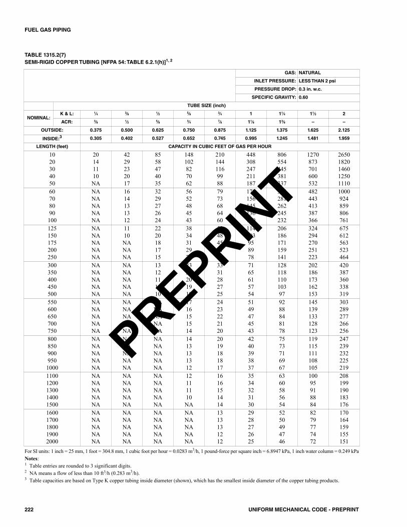
222 UNIFORM MECHANICAL CODE - PREPRINT
FUEL GAS PIPING
TABLE 1315.2(7)SEMI-RIGID COPPER TUBING [NFPA 54: TABLE 6.2.1(h)]1, 2
GAS: NATURAL
INLET PRESSURE: LESS THAN 2 psi
PRESSURE DROP: 0.3 in. w.c.
SPECIFIC GRAVITY: 0.60
TUBE SIZE (inch)
NOMINAL:K & L: 1⁄4 3⁄8 1⁄2 5⁄8 3⁄4 1 11⁄4 11⁄2 2
ACR: 3⁄8 1⁄2 5⁄8 3⁄4 7⁄8 11⁄8 13⁄8 – –
OUTSIDE: 0.375 0.500 0.625 0.750 0.875 1.125 1.375 1.625 2.125
INSIDE:3 0.305 0.402 0.527 0.652 0.745 0.995 1.245 1.481 1.959
LENGTH (feet) CAPACITY IN CUBIC FEET OF GAS PER HOUR
1020304050
20141110NA
4229232017
8558474035
148102827062
2101441169988
448308247211187
806554445381337
1270873701600532
26501820146012501110
60708090100
NANANANANA
1614131312
3229272624
5652484543
7973686460
170156145136129
306281262245232
482443413387366
1000924859806761
125150175200250
NANANANANA
1110NANANA
2220181715
3834312926
5348454137
114103958978
206186171159141
324294270251223
675612563523464
300350400450500
NANANANANA
NANANANANA
1312111110
2322201918
3331282725
7165615754
12811811010397
202186173162153
420387360338319
550600650700750
NANANANANA
NANANANANA
NANANANANA
1716151514
2423222120
5149474543
9288848178
145139133128123
303289277266256
8008509009501000
NANANANANA
NANANANANA
NANANANANA
1413131312
2019181817
4240393837
7573716967
119115111108105
247239232225219
11001200130014001500
NANANANANA
NANANANANA
NANANANANA
12111110NA
1616151414
3534323130
6360585654
10095918884
208199190183176
16001700180019002000
NANANANANA
NANANANANA
NANANANANA
NANANANANA
1313131212
2928272625
5250494746
8279777472
170164159155151
For SI units: 1 inch = 25 mm, 1 foot = 304.8 mm, 1 cubic foot per hour = 0.0283 m3/h, 1 pound-force per square inch = 6.8947 kPa, 1 inch water column = 0.249 kPaNotes: 1 Table entries are rounded to 3 significant digits.2 NA means a flow of less than 10 ft3/h (0.283 m3/h).3 Table capacities are based on Type K copper tubing inside diameter (shown), which has the smallest inside diameter of the copper tubing products.
PREPRINT
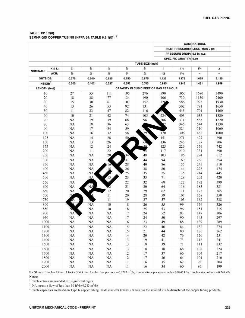
223UNIFORM MECHANICAL CODE - PREPRINT
FUEL GAS PIPING
TABLE 1315.2(8)SEMI-RIGID COPPER TUBING [NFPA 54: TABLE 6.2.1(i)]1, 2
GAS: NATURAL
INLET PRESSURE: LESS THAN 2 psi
PRESSURE DROP: 0.5 in. w.c.
SPECIFIC GRAVITY: 0.60
TUBE SIZE (inch)
NOMINAL:K & L: 1⁄4 3⁄8 1⁄2 5⁄8 3⁄4 1 11⁄4 11⁄2 2
ACR: 3⁄8 1⁄2 5⁄8 3⁄4 7⁄8 11⁄8 13⁄8 – –
OUTSIDE: 0.375 0.500 0.625 0.750 0.875 1.125 1.375 1.625 2.125
INSIDE:3 0.305 0.402 0.527 0.652 0.745 0.995 1.245 1.481 1.959
LENGTH (feet) CAPACITY IN CUBIC FEET OF GAS PER HOUR
1020304050
2718151311
5538302623
11177615347
1951341079282
276190152131116
590406326279247
1060730586502445
16801150925791701
34902400193016501460
60708090100
10NANANANA
2119181716
4239363432
7468635956
10596908479
224206192180170
403371345324306
635585544510482
13201220113010601000
125150175200250
NANANANANA
14131211NA
2826242220
5045413934
7064595548
151136125117103
271245226210186
427387356331294
890806742690612
300350400450500
NANANANANA
NANANANANA
1816151413
3128262523
4440383533
9486807571
169155144135128
266245228214202
554510474445420
550600650700750
NANANANANA
NANANANANA
1312121111
2221202019
3230292827
6864625957
122116111107103
192183175168162
399381365350338
8008509009501000
NANANANANA
NANANANANA
1010NANANA
1818171716
2625242423
5553525049
9996939088
156151147143139
326315306297289
11001200130014001500
NANANANANA
NANANANANA
NANANANANA
1515141313
2221201918
4644424139
8480767371
132126120116111
274262251241232
16001700180019002000
NANANANANA
NANANANANA
NANANANANA
1312121111
1817171616
3837363534
6866646260
1081041019895
224217210204199
For SI units: 1 inch = 25 mm, 1 foot = 304.8 mm, 1 cubic foot per hour = 0.0283 m3/h, 1 pound-force per square inch = 6.8947 kPa, 1 inch water column = 0.249 kPaNotes:1 Table entries are rounded to 3 significant digits.2 NA means a flow of less than 10 ft3/h (0.283 m3/h).3 Table capacities are based on Type K copper tubing inside diameter (shown), which has the smallest inside diameter of the copper tubing products.
PREPRINT
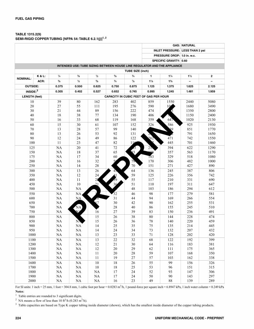
224 UNIFORM MECHANICAL CODE - PREPRINT
FUEL GAS PIPING
TABLE 1315.2(9)SEMI-RIGID COPPER TUBING [NFPA 54: TABLE 6.2.1(j)]1, 2
GAS: NATURAL
INLET PRESSURE: LESS THAN 2 psi
PRESSURE DROP: 1.0 in. w.c.
SPECIFIC GRAVITY: 0.60
INTENDED USE: TUBE SIZING BETWEEN HOUSE LINE REGULATOR AND THE APPLIANCE
TUBE SIZE (inch)
NOMINAL:K & L: 1⁄4 3⁄8 1⁄2 5⁄8 3⁄4 1 11⁄4 11⁄2 2
ACR: 3⁄8 1⁄2 5⁄8 3⁄4 7⁄8 11⁄8 13⁄8 – –
OUTSIDE: 0.375 0.500 0.625 0.750 0.875 1.125 1.375 1.625 2.125
INSIDE:3 0.305 0.402 0.527 0.652 0.745 0.995 1.245 1.481 1.959
LENGTH (feet) CAPACITY IN CUBIC FEET OF GAS PER HOUR
1020304050
3927211816
8055443833
162111897768
283195156134119
402276222190168
859590474406359
15501060853730647
24401680135011501020
50803490280024002130
60708090100
1513131211
3028262423
6157534947
10799928682
152140131122116
326300279262247
586539502471445
925851791742701
19301770165015501460
125150175200250
NANANANANA
2018171614
4137343228
7265605650
10393857970
219198183170151
394357329306271
622563518482427
1290117010801000890
300350400450500
NANANANANA
13121110NA
2624222120
4541393634
6459555148
136125117110103
245226210197186
387356331311294
806742690647612
550600650700750
NANANANANA
NANANANANA
1918171616
3231302827
4644424039
9894908683
177169162155150
279266255245236
581554531510491
8008509009501000
NANANANANA
NANANANANA
1515141413
2626252423
3836353433
8078757371
144140135132128
228220214207202
474459445432420
11001200130014001500
NANANANANA
NANANANANA
1312121111
2221202019
3230292827
6864625957
122116111107103
192183175168162
399381365350338
16001700180019002000
NANANANANA
NANANANANA
1010NANANA
1818171716
2625242423
5553525049
9996939088
156151147143139
326315306297289
For SI units: 1 inch = 25 mm, 1 foot = 304.8 mm, 1 cubic foot per hour = 0.0283 m3/h, 1 pound-force per square inch = 6.8947 kPa, 1 inch water column = 0.249 kPaNotes: 1 Table entries are rounded to 3 significant digits.2 NA means a flow of less than 10 ft3/h (0.283 m3/h).3 Table capacities are based on Type K copper tubing inside diameter (shown), which has the smallest inside diameter of the copper tubing products.
PREPRINT
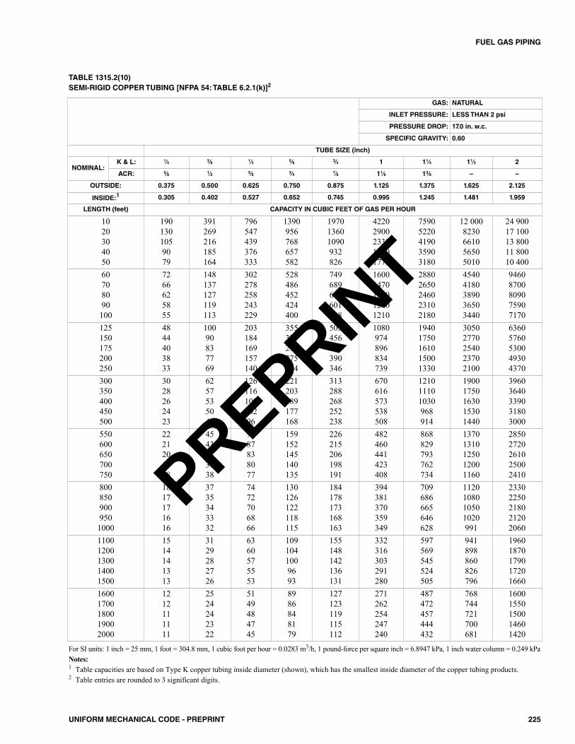
225UNIFORM MECHANICAL CODE - PREPRINT
FUEL GAS PIPING
TABLE 1315.2(10)SEMI-RIGID COPPER TUBING [NFPA 54: TABLE 6.2.1(k)]2
GAS: NATURAL
INLET PRESSURE: LESS THAN 2 psi
PRESSURE DROP: 17.0 in. w.c.
SPECIFIC GRAVITY: 0.60
TUBE SIZE (inch)
NOMINAL:K & L: 1⁄4 3⁄8 1⁄2 5⁄8 3⁄4 1 11⁄4 11⁄2 2
ACR: 3⁄8 1⁄2 5⁄8 3⁄4 7⁄8 11⁄8 13⁄8 – –
OUTSIDE: 0.375 0.500 0.625 0.750 0.875 1.125 1.375 1.625 2.125
INSIDE:1 0.305 0.402 0.527 0.652 0.745 0.995 1.245 1.481 1.959
LENGTH (feet) CAPACITY IN CUBIC FEET OF GAS PER HOUR
1020304050
1901301059079
391269216185164
796547439376333
1390956768657582
197013601090932826
42202900233019901770
75905220419035903180
12 0008230661056505010
24 90017 10013 80011 80010 400
60708090100
7266625855
148137127119113
302278258243229
528486452424400
749689641601568
16001470137012801210
28802650246023102180
45404180389036503440
94608700809075907170
125150175200250
4844403833
10090837769
203184169157140
355321296275244
503456420390346
1080974896834739
19401750161015001330
30502770254023702100
63605760530049304370
300350400450500
3028262423
6257535047
12611610810296
221203189177168
313288268252238
670616573538508
121011101030968914
19001750163015301440
39603640339031803000
550600650700750
2221201918
4543413938
9187838077
159152145140135
226215206198191
482460441423408
868829793762734
13701310125012001160
28502720261025002410
8008509009501000
1817171616
3735343332
7472706866
130126122118115
184178173168163
394381370359349
709686665646628
1120108010501020991
23302250218021202060
11001200130014001500
1514141313
3129282726
6360575553
1091041009693
155148142136131
332316303291280
597569545524505
941898860826796
19601870179017201660
16001700180019002000
1212111111
2524242322
5149484745
8986848179
127123119115112
271262254247240
487472457444432
768744721700681
16001550150014601420
For SI units: 1 inch = 25 mm, 1 foot = 304.8 mm, 1 cubic foot per hour = 0.0283 m3/h, 1 pound-force per square inch = 6.8947 kPa, 1 inch water column = 0.249 kPaNotes:1 Table capacities are based on Type K copper tubing inside diameter (shown), which has the smallest inside diameter of the copper tubing products.2 Table entries are rounded to 3 significant digits.
PREPRINT

226 UNIFORM MECHANICAL CODE - PREPRINT
FUEL GAS PIPING
TABLE 1315.2(11)SEMI-RIGID COPPER TUBING [NFPA 54: TABLE 6.2.1(l)]2
GAS: NATURAL
INLET PRESSURE: 2.0 psi
PRESSURE DROP: 1.0 psi
SPECIFIC GRAVITY: 0.60
TUBE SIZE (inch)
NOMINAL:K & L: 1⁄4 3⁄8 1⁄2 5⁄8 3⁄4 1 11⁄4 11⁄2 2
ACR: 3⁄8 1⁄2 5⁄8 3⁄4 7⁄8 11⁄8 13⁄8 – –
OUTSIDE: 0.375 0.500 0.625 0.750 0.875 1.125 1.375 1.625 2.125
INSIDE:1 0.305 0.402 0.527 0.652 0.745 0.995 1.245 1.481 1.959
LENGTH (feet) CAPACITY IN CUBIC FEET OF GAS PER HOUR
1020304050
245169135116103
506348279239212
1030708568486431
18001240993850754
25501760141012101070
54503750301025802280
98206750542046404110
15 50010 600855073106480
32 20022 20017 80015 20013 500
60708090100
9386807571
192177164154146
391359334314296
683628584548518
969891829778735
20701900177016601570
37303430319029902830
58705400503047204450
12 20011 30010 50098209280
125150175200250
6357524943
12911710810089
263238219204181
459416383356315
651590543505448
1390126011601080956
25002270209019401720
39503580329030602710
82207450685063805650
300350400450500
3936333130
8074696561
164150140131124
286263245230217
406373347326308
866797741696657
15601430133012501180
24602260210019701870
51204710438041103880
550600650700750
2827262524
5855535149
118112108103100
206196188181174
292279267256247
624595570548528
112010701030986950
17701690162015501500
36903520337032403120
8008509009501000
2322222120
4746444342
9693908885
168163158153149
239231224217211
510493478464452
917888861836813
14501400136013201280
30102920283027402670
11001200130014001500
1918181716
4038363534
8177747168
142135129124120
201192183176170
429409392376363
772737705678653
12201160111010701030
25402420232022302140
16001700180019002000
1615151414
3331303029
6664626059
116112108105102
164159154149145
350339329319310
630610592575559
994962933906881
20702000194018901830
For SI units: 1 inch = 25 mm, 1 foot = 304.8 mm, 1 cubic foot per hour = 0.0283 m3/h, 1 pound-force per square inch = 6.8947 kPaNotes: 1 Table capacities are based on Type K copper tubing inside diameter (shown), which has the smallest inside diameter of the copper tubing products.2 Table entries are rounded to 3 significant digits.
PREPRINT
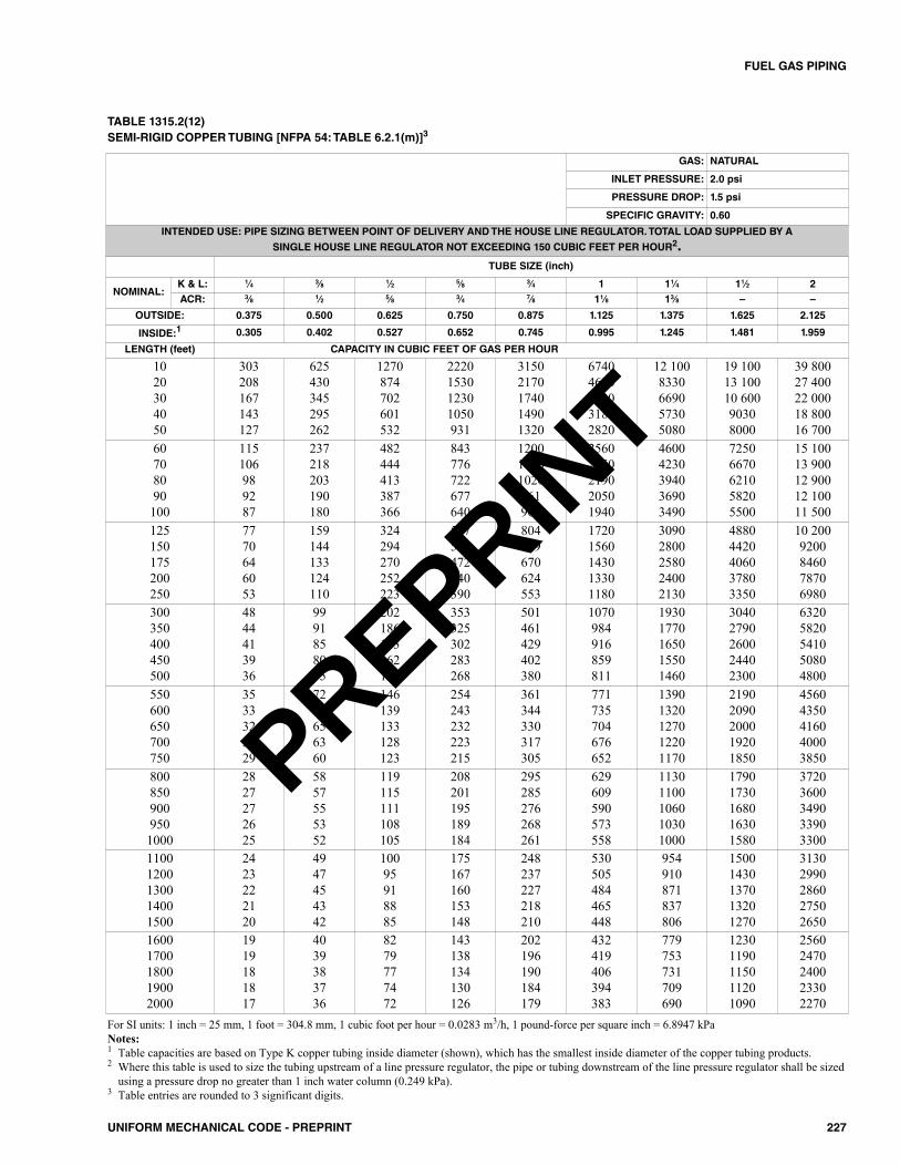
227UNIFORM MECHANICAL CODE - PREPRINT
FUEL GAS PIPING
TABLE 1315.2(12)SEMI-RIGID COPPER TUBING [NFPA 54: TABLE 6.2.1(m)]3
GAS: NATURAL
INLET PRESSURE: 2.0 psi
PRESSURE DROP: 1.5 psi
SPECIFIC GRAVITY: 0.60
INTENDED USE: PIPE SIZING BETWEEN POINT OF DELIVERY AND THE HOUSE LINE REGULATOR. TOTAL LOAD SUPPLIED BY A
SINGLE HOUSE LINE REGULATOR NOT EXCEEDING 150 CUBIC FEET PER HOUR2.TUBE SIZE (inch)
NOMINAL:K & L: 1⁄4 3⁄8 1⁄2 5⁄8 3⁄4 1 11⁄4 11⁄2 2ACR: 3⁄8 1⁄2 5⁄8 3⁄4 7⁄8 11⁄8 13⁄8 – –
OUTSIDE: 0.375 0.500 0.625 0.750 0.875 1.125 1.375 1.625 2.125
INSIDE:1 0.305 0.402 0.527 0.652 0.745 0.995 1.245 1.481 1.959
LENGTH (feet) CAPACITY IN CUBIC FEET OF GAS PER HOUR
1020304050
303208167143127
625430345295262
1270874702601532
2220153012301050931
31502170174014901320
67404630372031802820
12 1008330669057305080
19 10013 10010 60090308000
39 80027 40022 00018 80016 700
60708090100
115106989287
237218203190180
482444413387366
843776722677640
120011001020961907
25602350219020501940
46004230394036903490
72506670621058205500
15 10013 90012 90012 10011 500
125150175200250
7770646053
159144133124110
324294270252223
567514472440390
804729670624553
17201560143013301180
30902800258024002130
48804420406037803350
10 2009200846078706980
300350400450500
4844413936
9991858075
202186173162153
353325302283268
501461429402380
1070984916859811
19301770165015501460
30402790260024402300
63205820541050804800
550600650700750
3533323029
7268656360
146139133128123
254243232223215
361344330317305
771735704676652
13901320127012201170
21902090200019201850
45604350416040003850
8008509009501000
2827272625
5857555352
119115111108105
208201195189184
295285276268261
629609590573558
11301100106010301000
17901730168016301580
37203600349033903300
11001200130014001500
2423222120
4947454342
10095918885
175167160153148
248237227218210
530505484465448
954910871837806
15001430137013201270
31302990286027502650
16001700180019002000
1919181817
4039383736
8279777472
143138134130126
202196190184179
432419406394383
779753731709690
12301190115011201090
25602470240023302270
For SI units: 1 inch = 25 mm, 1 foot = 304.8 mm, 1 cubic foot per hour = 0.0283 m3/h, 1 pound-force per square inch = 6.8947 kPaNotes:1 Table capacities are based on Type K copper tubing inside diameter (shown), which has the smallest inside diameter of the copper tubing products.2 Where this table is used to size the tubing upstream of a line pressure regulator, the pipe or tubing downstream of the line pressure regulator shall be sized
using a pressure drop no greater than 1 inch water column (0.249 kPa).3 Table entries are rounded to 3 significant digits.
PREPRINT

228 UNIFORM MECHANICAL CODE - PREPRINT
FUEL GAS PIPING
TABLE 1315.2(13)SEMI-RIGID COPPER TUBING [NFPA 54: TABLE 6.2.1(n)]2
GAS: NATURAL
INLET PRESSURE: 5.0 psi
PRESSURE DROP: 3.5 psi
SPECIFIC GRAVITY: 0.60
TUBE SIZE (inch)
NOMINAL:K & L: 1⁄4 3⁄8 1⁄2 5⁄8 3⁄4 1 11⁄4 11⁄2 2
ACR: 3⁄8 1⁄2 5⁄8 3⁄4 7⁄8 11⁄8 13⁄8 – –
OUTSIDE: 0.375 0.500 0.625 0.750 0.875 1.125 1.375 1.625 2.125
INSIDE:1 0.305 0.402 0.527 0.652 0.745 0.995 1.245 1.481 1.959
LENGTH (feet) CAPACITY IN CUBIC FEET OF GAS PER HOUR
1020304050
511351282241214
1050724582498441
2140147011801010898
37502580207017701570
53203650293025102230
11 4007800627053604750
20 40014 00011 30096608560
32 20022 20017 80015 20013 500
67 10046 10037 00031 70028 100
60708090100
194178166156147
400368342321303
813748696653617
14201310122011401080
20201860173016201530
43103960369034603270
77507130664062305880
12 20011 20010 50098209270
25 50023 40021 80020 40019 300
125150175200250
13011810910190
269243224208185
547495456424376
955866796741657
1360123011301050932
29002620241022501990
52104720435040403580
82207450685063705650
17 10015 50014 30013 30011 800
300350400450500
8175696562
167154143134127
340313291273258
595547509478451
844777722678640
18001660154014501370
32502990278026102460
51204710438041103880
10 7009810912085608090
550600650700750
5856535149
121115110106102
245234224215207
429409392376362
608580556534514
13001240119011401100
23402230214020501980
36903520337032403120
76807330702067406490
8008509009501000
4846454342
9895929087
200194188182177
350339328319310
497481466452440
106010301000967940
19101850179017401690
30102910282027402670
62706070588057105560
11001200130014001500
4038373534
8379767370
169161154148143
295281269259249
418399382367353
893852816784755
16101530147014101360
25302420232022202140
52805040482046304460
16001700180019002000
3332313029
6865636260
138133129125122
241233226219213
341330320311302
729705684664646
13101270123012001160
20702000194018901830
43104170404039303820
For SI units: 1 inch = 25 mm, 1 foot = 304.8 mm, 1 cubic foot per hour = 0.0283 m3/h, 1 pound-force per square inch = 6.8947 kPaNotes: 1 Table capacities are based on Type K copper tubing inside diameter (shown), which has the smallest inside diameter of the copper tubing products.2 Table entries are rounded to 3 significant digits.
PREPRINT
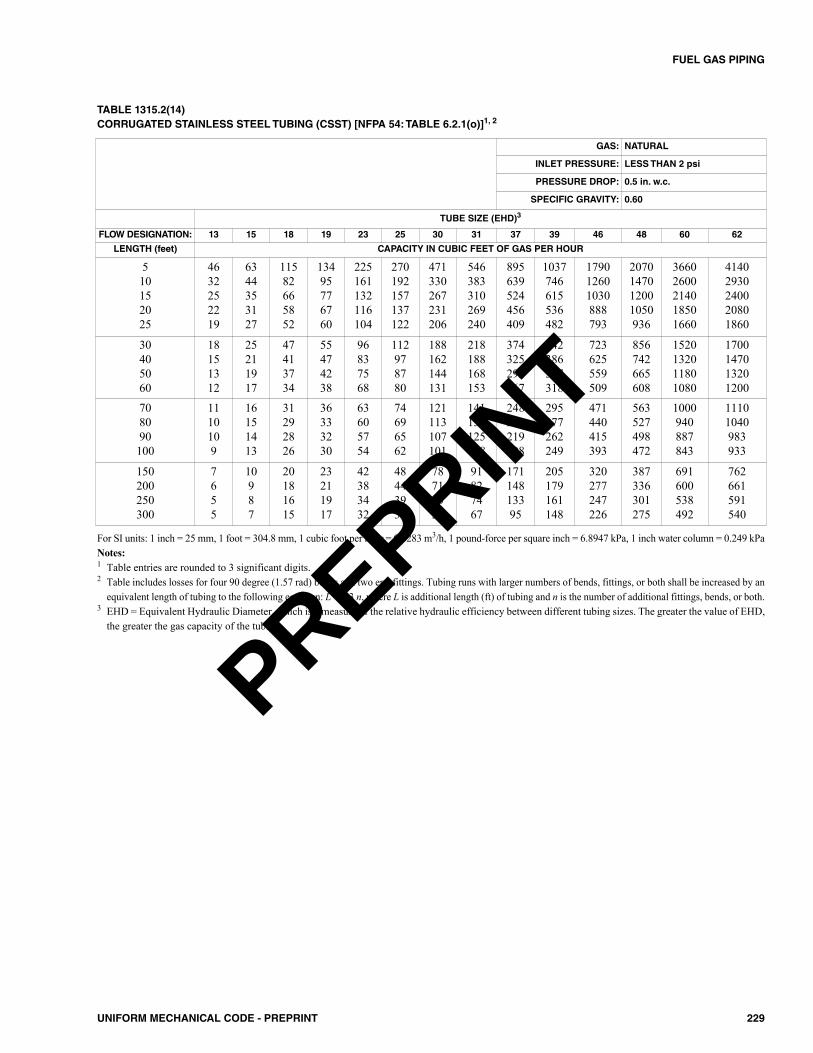
229UNIFORM MECHANICAL CODE - PREPRINT
FUEL GAS PIPING
TABLE 1315.2(14)CORRUGATED STAINLESS STEEL TUBING (CSST) [NFPA 54: TABLE 6.2.1(o)]1, 2
For SI units: 1 inch = 25 mm, 1 foot = 304.8 mm, 1 cubic foot per hour = 0.0283 m3/h, 1 pound-force per square inch = 6.8947 kPa, 1 inch water column = 0.249 kPaNotes:1 Table entries are rounded to 3 significant digits.2 Table includes losses for four 90 degree (1.57 rad) bends and two end fittings. Tubing runs with larger numbers of bends, fittings, or both shall be increased by an
equivalent length of tubing to the following equation: L = 1.3 n, where L is additional length (ft) of tubing and n is the number of additional fittings, bends, or both.3 EHD = Equivalent Hydraulic Diameter, which is a measure of the relative hydraulic efficiency between different tubing sizes. The greater the value of EHD,
the greater the gas capacity of the tubing.
GAS: NATURAL
INLET PRESSURE: LESS THAN 2 psi
PRESSURE DROP: 0.5 in. w.c.
SPECIFIC GRAVITY: 0.60
TUBE SIZE (EHD)3
FLOW DESIGNATION: 13 15 18 19 23 25 30 31 37 39 46 48 60 62
LENGTH (feet) CAPACITY IN CUBIC FEET OF GAS PER HOUR
510152025
4632252219
6344353127
11582665852
13495776760
225161132116104
270192157137122
471330267231206
546383310269240
895639524456409
1037746615536482
179012601030888793
2070147012001050936
36602600214018501660
41402930240020801860
30405060
18151312
25211917
47413734
55474238
96837568
112978780
188162144131
218188168153
374325292267
442386347318
723625559509
856742665608
1520132011801080
1700147013201200
708090100
1110109
16151413
31292826
36333230
63605754
74696562
121113107101
141132125118
248232219208
295277262249
471440415393
563527498472
1000940887843
11101040983933
150200250300
7655
10987
20181615
23211917
42383432
48443936
78716357
91827467
17114813395
205179161148
320277247226
387336301275
691600538492
762661591540
PREPRINT
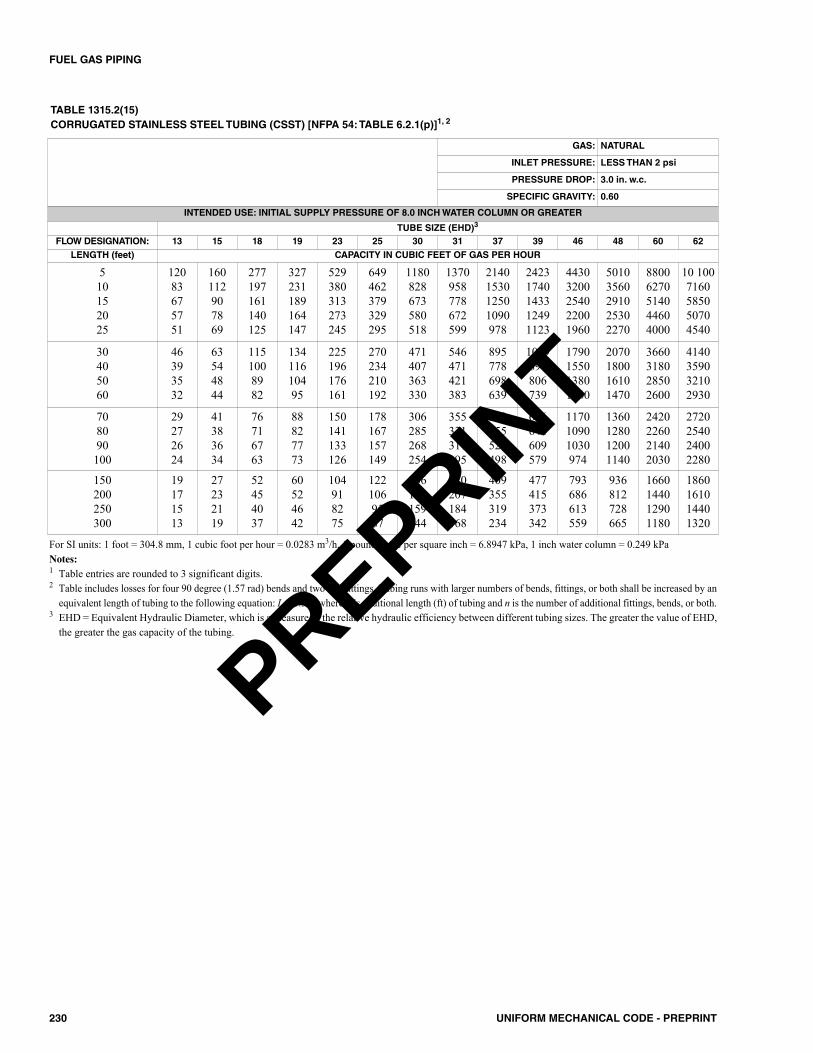
230 UNIFORM MECHANICAL CODE - PREPRINT
FUEL GAS PIPING
For SI units: 1 foot = 304.8 mm, 1 cubic foot per hour = 0.0283 m3/h, 1 pound-force per square inch = 6.8947 kPa, 1 inch water column = 0.249 kPaNotes:1 Table entries are rounded to 3 significant digits.2 Table includes losses for four 90 degree (1.57 rad) bends and two end fittings. Tubing runs with larger numbers of bends, fittings, or both shall be increased by an
equivalent length of tubing to the following equation: L = 1.3 n, where L is additional length (ft) of tubing and n is the number of additional fittings, bends, or both.3 EHD = Equivalent Hydraulic Diameter, which is a measure of the relative hydraulic efficiency between different tubing sizes. The greater the value of EHD,
the greater the gas capacity of the tubing.
GAS: NATURAL
INLET PRESSURE: LESS THAN 2 psi
PRESSURE DROP: 3.0 in. w.c.
SPECIFIC GRAVITY: 0.60
INTENDED USE: INITIAL SUPPLY PRESSURE OF 8.0 INCH WATER COLUMN OR GREATER
TUBE SIZE (EHD)3
FLOW DESIGNATION: 13 15 18 19 23 25 30 31 37 39 46 48 60 62LENGTH (feet) CAPACITY IN CUBIC FEET OF GAS PER HOUR
510152025
12083675751
160112907869
277197161140125
327231189164147
529380313273245
649462379329295
1180828673580518
1370958778672599
2140153012501090978
24231740143312491123
44303200254022001960
50103560291025302270
88006270514044604000
10 1007160585050704540
30405060
46393532
63544844
1151008982
13411610495
225196176161
270234210192
471407363330
546471421383
895778698639
1029897806739
1790155013801260
2070180016101470
3660318028502600
4140359032102930
708090100
29272624
41383634
76716763
88827773
150141133126
178167157149
306285268254
355331311295
593555524498
686644609579
117010901030974
1360128012001140
2420226021402030
2720254024002280
150200250300
19171513
27232119
52454037
60524642
104918275
1221069587
206178159144
240207184168
409355319234
477415373342
793686613559
936812728665
1660144012901180
1860161014401320
TABLE 1315.2(15)CORRUGATED STAINLESS STEEL TUBING (CSST) [NFPA 54: TABLE 6.2.1(p)]1, 2
PREPRINT
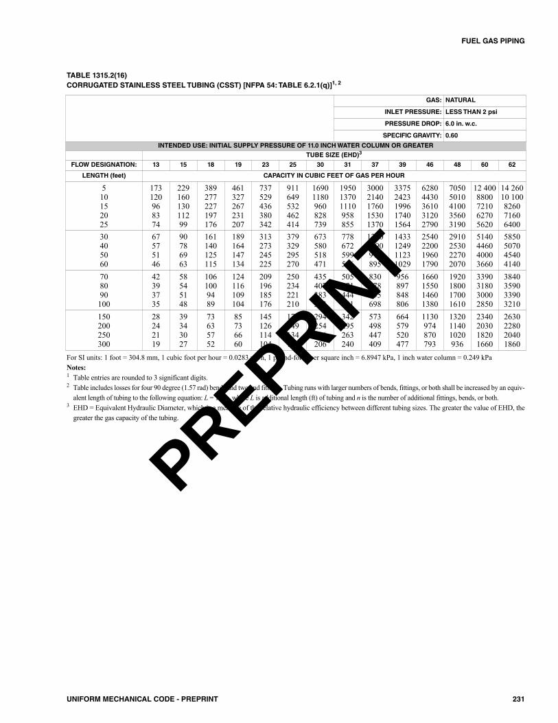
231UNIFORM MECHANICAL CODE - PREPRINT
FUEL GAS PIPING
TABLE 1315.2(16)CORRUGATED STAINLESS STEEL TUBING (CSST) [NFPA 54: TABLE 6.2.1(q)]1, 2
For SI units: 1 foot = 304.8 mm, 1 cubic foot per hour = 0.0283 m3/h, 1 pound-force per square inch = 6.8947 kPa, 1 inch water column = 0.249 kPaNotes:1 Table entries are rounded to 3 significant digits.2 Table includes losses for four 90 degree (1.57 rad) bends and two end fittings. Tubing runs with larger numbers of bends, fittings, or both shall be increased by an equiv-
alent length of tubing to the following equation: L = 1.3 n, where L is additional length (ft) of tubing and n is the number of additional fittings, bends, or both.3 EHD = Equivalent Hydraulic Diameter, which is a measure of the relative hydraulic efficiency between different tubing sizes. The greater the value of EHD, the
greater the gas capacity of the tubing.
GAS: NATURAL
INLET PRESSURE: LESS THAN 2 psi
PRESSURE DROP: 6.0 in. w.c.
SPECIFIC GRAVITY: 0.60
INTENDED USE: INITIAL SUPPLY PRESSURE OF 11.0 INCH WATER COLUMN OR GREATERTUBE SIZE (EHD)3
FLOW DESIGNATION: 13 15 18 19 23 25 30 31 37 39 46 48 60 62
LENGTH (feet) CAPACITY IN CUBIC FEET OF GAS PER HOUR
510152025
173120968374
22916013011299
389277227197176
461327267231207
737529436380342
911649532462414
16901180960828739
195013701110958855
30002140176015301370
33752423199617401564
62804430361031202790
70505010410035603190
12 4008800721062705620
14 26010 100826071606400
30405060
67575146
90786963
161140125115
189164147134
313273245225
379329295270
673580518471
778672599546
12501090978895
1433124911231029
2540220019601790
2910253022702070
5140446040003660
5850507045404140
708090100
42393735
58545148
1061009489
124116109104
209196185176
250234221210
435407383363
505471444421
830778735698
956897848806
1660155014601380
1920180017001610
3390318030002850
3840359033903210
150200250300
28242119
39343027
73635752
85736660
145126114104
172149134122
294254226206
342295263240
573498447409
664579520477
1130974870793
132011401020936
2340203018201660
2630228020401860
PREPRINT
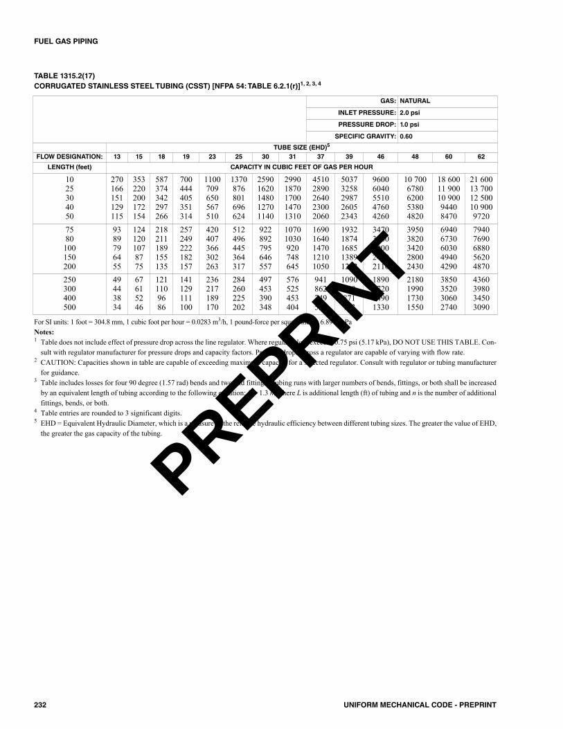
232 UNIFORM MECHANICAL CODE - PREPRINT
FUEL GAS PIPING
TABLE 1315.2(17)CORRUGATED STAINLESS STEEL TUBING (CSST) [NFPA 54: TABLE 6.2.1(r)]1, 2, 3, 4
For SI units: 1 foot = 304.8 mm, 1 cubic foot per hour = 0.0283 m3/h, 1 pound-force per square inch = 6.8947 kPaNotes:1 Table does not include effect of pressure drop across the line regulator. Where regulator loss exceeds 0.75 psi (5.17 kPa), DO NOT USE THIS TABLE. Con-
sult with regulator manufacturer for pressure drops and capacity factors. Pressure drops across a regulator are capable of varying with flow rate.2 CAUTION: Capacities shown in table are capable of exceeding maximum capacity for a selected regulator. Consult with regulator or tubing manufacturer
for guidance.3 Table includes losses for four 90 degree (1.57 rad) bends and two end fittings. Tubing runs with larger numbers of bends, fittings, or both shall be increased
by an equivalent length of tubing according to the following equation: L = 1.3 n, where L is additional length (ft) of tubing and n is the number of additionalfittings, bends, or both.
4 Table entries are rounded to 3 significant digits.5 EHD = Equivalent Hydraulic Diameter, which is a measure of the relative hydraulic efficiency between different tubing sizes. The greater the value of EHD,
the greater the gas capacity of the tubing.
GAS: NATURAL
INLET PRESSURE: 2.0 psi
PRESSURE DROP: 1.0 psi
SPECIFIC GRAVITY: 0.60
TUBE SIZE (EHD)5
FLOW DESIGNATION: 13 15 18 19 23 25 30 31 37 39 46 48 60 62
LENGTH (feet) CAPACITY IN CUBIC FEET OF GAS PER HOUR
1025304050
270166151129115
353220200172154
587374342297266
700444405351314
1100709650567510
1370876801696624
25901620148012701140
29901870170014701310
45102890264023002060
50373258298726052343
96006040551047604260
10 7006780620053804820
18 60011 90010 90094408470
21 60013 70012 50010 9009720
7580100150200
9389796455
1241201078775
218211189155135
257249222182157
420407366302263
512496445364317
922892795646557
10701030920748645
16901640147012101050
19321874168513891212
34703360300024402110
39503820342028002430
69406730603049404290
79407690688056204870
250300400500
49443834
67615246
1211109686
141129111100
236217189170
284260225202
497453390348
576525453404
941862749552
1090999871783
1890172014901330
2180199017301550
3850352030602740
4360398034503090
PREPRINT

233UNIFORM MECHANICAL CODE - PREPRINT
FUEL GAS PIPING
TABLE 1315.2(18)CORRUGATED STAINLESS STEEL TUBING (CSST) [NFPA 54: TABLE 6.2.1(s)]1, 2, 3, 4
GAS: NATURAL
INLET PRESSURE: 5.0 psi
PRESSURE DROP: 3.5 psi
SPECIFIC GRAVITY: 0.60
TUBE SIZE (EHD)5
FLOW DESIGNATION: 13 15 18 19 23 25 30 31 37 39 46 48 60 62
LENGTH (feet) CAPACITY IN CUBIC FEET OF GAS PER HOUR
1025304050
523322292251223
674420382329293
1080691632549492
1300827755654586
2000129011801030926
25301620148012801150
49203080280024202160
56603540323027902490
83005310486042303790
91405911542047274251
18 10011 40010 40089708020
19 80012 60011 50010 0008930
34 40022 00020 10017 40015 600
40 40025 60023 40020 20018 100
7580100150200
180174154124107
238230205166143
403391350287249
479463415339294
763740665548478
944915820672584
17501690151012301060
20201960174014201220
31103020271022201930
35063400305725212199
65306320565046003980
73207090635052004510
12 80012 40011 10091307930
14 80014 30012 80010 5009090
250300400500
95867466
12811610089
223204177159
263240208186
430394343309
524479416373
945860742662
1090995858766
1730159013801040
1977181315811422
3550324028002500
4040369032102870
7110650056505060
8140743064405760
For SI units: 1 foot = 304.8 mm, 1 cubic foot per hour = 0.0283 m3/h, 1 pound-force per square inch = 6.8947 kPaNotes:1 Table does not include effect of pressure drop across the line regulator. Where regulator loss exceeds 1 psi ( 7 kPa), DO NOT USE THIS TABLE. Consult with reg-
ulator manufacturer for pressure drops and capacity factors. Pressure drops across regulator are capable of varying with the flow rate.2 CAUTION: Capacities shown in table are capable of exceeding the maximum capacity of selected regulator. Consult tubing manufacturer for guidance.3 Table includes losses for four 90 degree (1.57 rad) bends and two end fittings. Tubing runs with larger numbers of bends, fittings, or both shall be increased by an equiva-
lent length of tubing to the following equation: L = 1.3 n, where L is additional length (feet) of tubing and n is the number of additional fittings, bends, or both.4 Table entries are rounded to 3 significant digits.5 EHD = Equivalent Hydraulic Diameter, which is a measure of the relative hydraulic efficiency between different tubing sizes. The greater the value of EHD, the
greater the gas capacity of the tubing.
PREPRINT
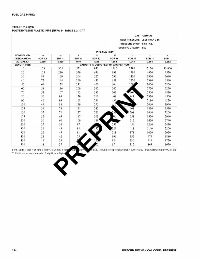
234 UNIFORM MECHANICAL CODE - PREPRINT
FUEL GAS PIPING
TABLE 1315.2(19)POLYETHYLENE PLASTIC PIPE [NFPA 54: TABLE 6.2.1(t)]*
For SI units: 1 inch = 25 mm, 1 foot = 304.8 mm, 1 cubic foot per hour = 0.0283 m3/h, 1 pound-force per square inch = 6.8947 kPa, 1 inch water column = 0.249 kPa* Table entries are rounded to 3 significant digits.
GAS: NATURAL
INLET PRESSURE: LESS THAN 2 psi
PRESSURE DROP: 0.3 in. w.c.
SPECIFIC GRAVITY: 0.60
PIPE SIZE (inch)
NOMINAL OD: 1⁄2 3⁄4 1 1 1⁄4 1 1⁄2 2 3 4DESIGNATION: SDR 9.3 SDR 11 SDR 11 SDR 10 SDR 11 SDR 11 SDR 11 SDR 11ACTUAL ID: 0.660 0.860 1.077 1.328 1.554 1.943 2.864 3.682LENGTH (feet) CAPACITY IN CUBIC FEET OF GAS PER HOUR
10 153 305 551 955 1440 2590 7170 13 90020 105 210 379 656 991 1780 4920 952030 84 169 304 527 796 1430 3950 764040 72 144 260 451 681 1220 3380 654050 64 128 231 400 604 1080 3000 580060 58 116 209 362 547 983 2720 525070 53 107 192 333 503 904 2500 483080 50 99 179 310 468 841 2330 450090 46 93 168 291 439 789 2180 4220100 44 88 159 275 415 745 2060 3990125 39 78 141 243 368 661 1830 3530150 35 71 127 221 333 598 1660 3200175 32 65 117 203 306 551 1520 2940200 30 60 109 189 285 512 1420 2740250 27 54 97 167 253 454 1260 2430300 24 48 88 152 229 411 1140 2200350 22 45 81 139 211 378 1050 2020400 21 42 75 130 196 352 974 1880450 19 39 70 122 184 330 914 1770500 18 37 66 115 174 312 863 1670
PREPRINT
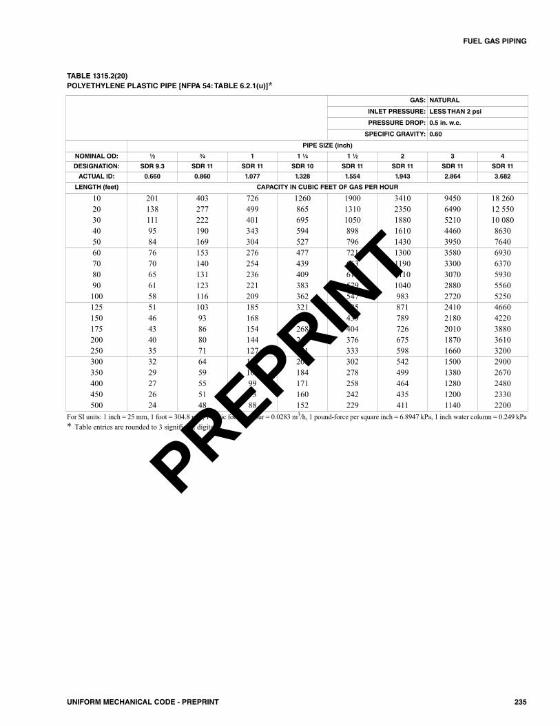
235UNIFORM MECHANICAL CODE - PREPRINT
FUEL GAS PIPING
TABLE 1315.2(20)POLYETHYLENE PLASTIC PIPE [NFPA 54: TABLE 6.2.1(u)]*
For SI units: 1 inch = 25 mm, 1 foot = 304.8 mm, 1 cubic foot per hour = 0.0283 m3/h, 1 pound-force per square inch = 6.8947 kPa, 1 inch water column = 0.249 kPa* Table entries are rounded to 3 significant digits.
GAS: NATURAL
INLET PRESSURE: LESS THAN 2 psi
PRESSURE DROP: 0.5 in. w.c.
SPECIFIC GRAVITY: 0.60
PIPE SIZE (inch)
NOMINAL OD: 1⁄2 3⁄4 1 1 1⁄4 1 1⁄2 2 3 4
DESIGNATION: SDR 9.3 SDR 11 SDR 11 SDR 10 SDR 11 SDR 11 SDR 11 SDR 11
ACTUAL ID: 0.660 0.860 1.077 1.328 1.554 1.943 2.864 3.682
LENGTH (feet) CAPACITY IN CUBIC FEET OF GAS PER HOUR
10 201 403 726 1260 1900 3410 9450 18 26020 138 277 499 865 1310 2350 6490 12 55030 111 222 401 695 1050 1880 5210 10 08040 95 190 343 594 898 1610 4460 863050 84 169 304 527 796 1430 3950 764060 76 153 276 477 721 1300 3580 693070 70 140 254 439 663 1190 3300 637080 65 131 236 409 617 1110 3070 593090 61 123 221 383 579 1040 2880 5560100 58 116 209 362 547 983 2720 5250125 51 103 185 321 485 871 2410 4660150 46 93 168 291 439 789 2180 4220175 43 86 154 268 404 726 2010 3880200 40 80 144 249 376 675 1870 3610250 35 71 127 221 333 598 1660 3200300 32 64 115 200 302 542 1500 2900350 29 59 106 184 278 499 1380 2670400 27 55 99 171 258 464 1280 2480450 26 51 93 160 242 435 1200 2330500 24 48 88 152 229 411 1140 2200
PREPRINT
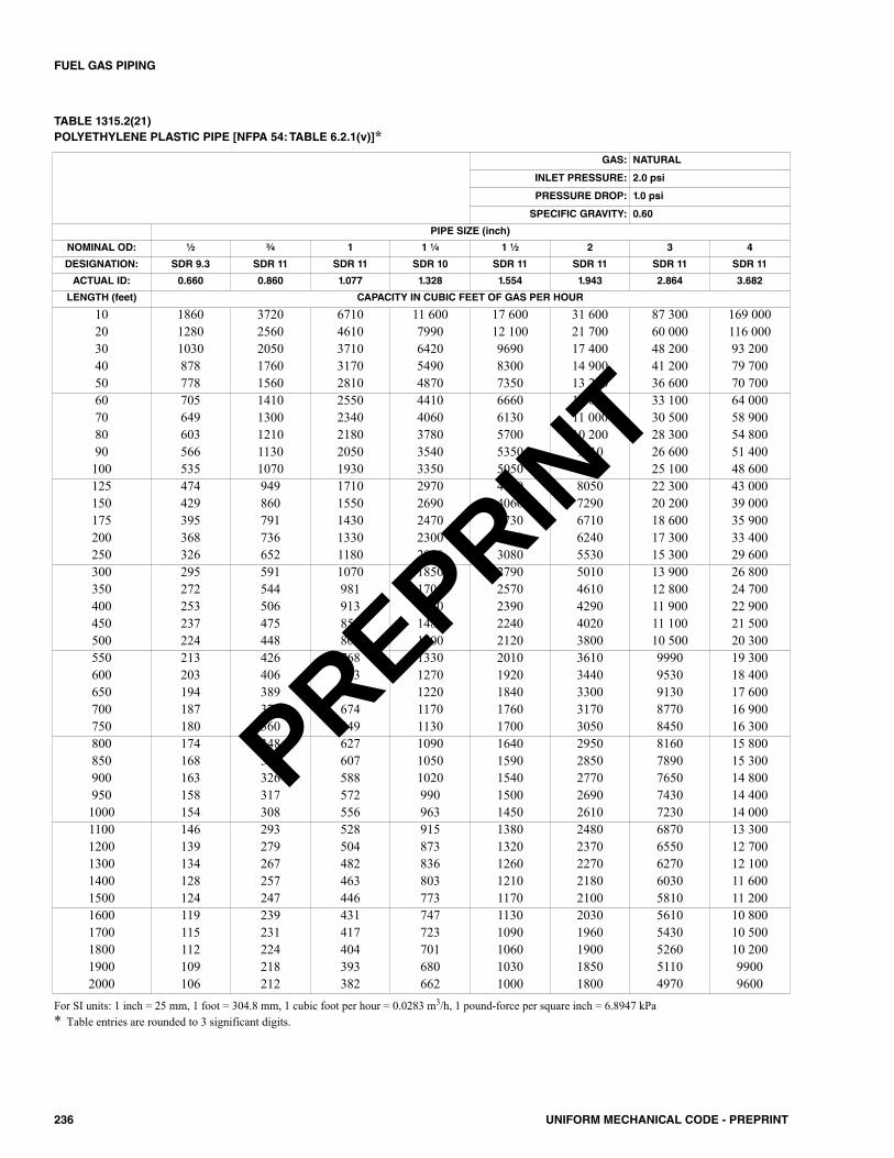
236 UNIFORM MECHANICAL CODE - PREPRINT
FUEL GAS PIPING
TABLE 1315.2(21)POLYETHYLENE PLASTIC PIPE [NFPA 54: TABLE 6.2.1(v)]*
For SI units: 1 inch = 25 mm, 1 foot = 304.8 mm, 1 cubic foot per hour = 0.0283 m3/h, 1 pound-force per square inch = 6.8947 kPa* Table entries are rounded to 3 significant digits.
GAS: NATURAL
INLET PRESSURE: 2.0 psi
PRESSURE DROP: 1.0 psi
SPECIFIC GRAVITY: 0.60
PIPE SIZE (inch)
NOMINAL OD: 1⁄2 3⁄4 1 1 1⁄4 1 1⁄2 2 3 4
DESIGNATION: SDR 9.3 SDR 11 SDR 11 SDR 10 SDR 11 SDR 11 SDR 11 SDR 11
ACTUAL ID: 0.660 0.860 1.077 1.328 1.554 1.943 2.864 3.682
LENGTH (feet) CAPACITY IN CUBIC FEET OF GAS PER HOUR
10 1860 3720 6710 11 600 17 600 31 600 87 300 169 00020 1280 2560 4610 7990 12 100 21 700 60 000 116 00030 1030 2050 3710 6420 9690 17 400 48 200 93 20040 878 1760 3170 5490 8300 14 900 41 200 79 70050 778 1560 2810 4870 7350 13 200 36 600 70 70060 705 1410 2550 4410 6660 12 000 33 100 64 00070 649 1300 2340 4060 6130 11 000 30 500 58 90080 603 1210 2180 3780 5700 10 200 28 300 54 80090 566 1130 2050 3540 5350 9610 26 600 51 400100 535 1070 1930 3350 5050 9080 25 100 48 600125 474 949 1710 2970 4480 8050 22 300 43 000150 429 860 1550 2690 4060 7290 20 200 39 000175 395 791 1430 2470 3730 6710 18 600 35 900200 368 736 1330 2300 3470 6240 17 300 33 400250 326 652 1180 2040 3080 5530 15 300 29 600300 295 591 1070 1850 2790 5010 13 900 26 800350 272 544 981 1700 2570 4610 12 800 24 700400 253 506 913 1580 2390 4290 11 900 22 900450 237 475 856 1480 2240 4020 11 100 21 500500 224 448 809 1400 2120 3800 10 500 20 300550 213 426 768 1330 2010 3610 9990 19 300600 203 406 733 1270 1920 3440 9530 18 400650 194 389 702 1220 1840 3300 9130 17 600700 187 374 674 1170 1760 3170 8770 16 900750 180 360 649 1130 1700 3050 8450 16 300800 174 348 627 1090 1640 2950 8160 15 800850 168 336 607 1050 1590 2850 7890 15 300900 163 326 588 1020 1540 2770 7650 14 800950 158 317 572 990 1500 2690 7430 14 4001000 154 308 556 963 1450 2610 7230 14 0001100 146 293 528 915 1380 2480 6870 13 3001200 139 279 504 873 1320 2370 6550 12 7001300 134 267 482 836 1260 2270 6270 12 1001400 128 257 463 803 1210 2180 6030 11 6001500 124 247 446 773 1170 2100 5810 11 2001600 119 239 431 747 1130 2030 5610 10 8001700 115 231 417 723 1090 1960 5430 10 5001800 112 224 404 701 1060 1900 5260 10 2001900 109 218 393 680 1030 1850 5110 99002000 106 212 382 662 1000 1800 4970 9600
PREPRINT
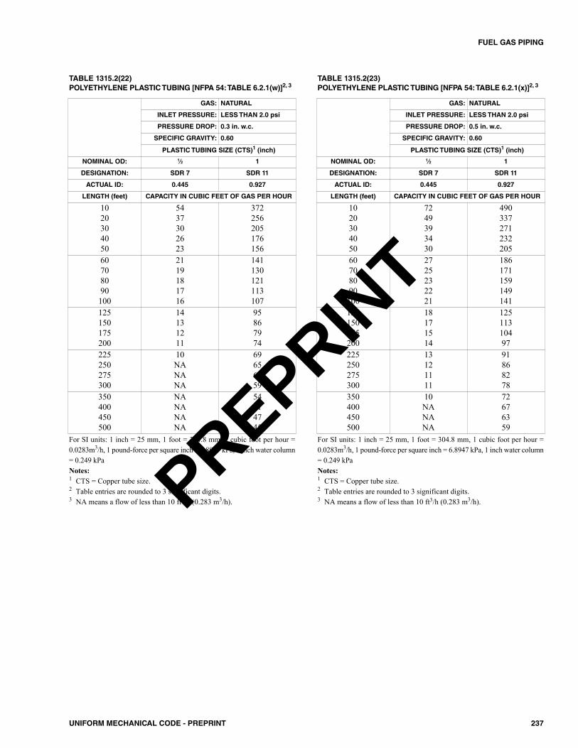
237UNIFORM MECHANICAL CODE - PREPRINT
FUEL GAS PIPING
TABLE 1315.2(22)POLYETHYLENE PLASTIC TUBING [NFPA 54: TABLE 6.2.1(w)]2, 3
TABLE 1315.2(23)POLYETHYLENE PLASTIC TUBING [NFPA 54: TABLE 6.2.1(x)]2, 3
GAS: NATURAL
INLET PRESSURE: LESS THAN 2.0 psi
PRESSURE DROP: 0.3 in. w.c.
SPECIFIC GRAVITY: 0.60
PLASTIC TUBING SIZE (CTS)1 (inch)
NOMINAL OD: 1⁄2 1
DESIGNATION: SDR 7 SDR 11
ACTUAL ID: 0.445 0.927
LENGTH (feet) CAPACITY IN CUBIC FEET OF GAS PER HOUR
1020304050
5437302623
372256205176156
60708090100
2119181716
141130121113107
125150175200
14131211
95867974
225250275300
10NANANA
69656259
350400450500
NANANANA
54514745
GAS: NATURAL
INLET PRESSURE: LESS THAN 2.0 psi
PRESSURE DROP: 0.5 in. w.c.
SPECIFIC GRAVITY: 0.60
PLASTIC TUBING SIZE (CTS)1 (inch)
NOMINAL OD: 1⁄2 1
DESIGNATION: SDR 7 SDR 11
ACTUAL ID: 0.445 0.927
LENGTH (feet) CAPACITY IN CUBIC FEET OF GAS PER HOUR
1020304050
7249393430
490337271232205
60708090100
2725232221
186171159149141
125150175200
18171514
12511310497
225250275300
13121111
91868278
350400450500
10NANANA
72676359
For SI units: 1 inch = 25 mm, 1 foot = 304.8 mm, 1 cubic foot per hour =0.0283m3/h, 1 pound-force per square inch = 6.8947 kPa, 1 inch water column= 0.249 kPaNotes:1 CTS = Copper tube size.2 Table entries are rounded to 3 significant digits.3 NA means a flow of less than 10 ft3/h (0.283 m3/h).
For SI units: 1 inch = 25 mm, 1 foot = 304.8 mm, 1 cubic foot per hour =0.0283m3/h, 1 pound-force per square inch = 6.8947 kPa, 1 inch water column= 0.249 kPaNotes:1 CTS = Copper tube size.2 Table entries are rounded to 3 significant digits.3 NA means a flow of less than 10 ft3/h (0.283 m3/h).PREPRINT
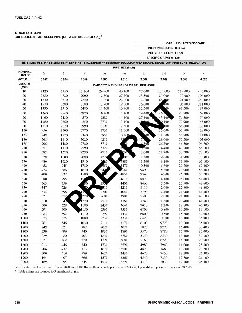
238 UNIFORM MECHANICAL CODE - PREPRINT
FUEL GAS PIPING
TABLE 1315.2(24)SCHEDULE 40 METALLIC PIPE [NFPA 54: TABLE 6.3.1(a)]*
GAS: UNDILUTED PROPANE
INLET PRESSURE: 10.0 psi
PRESSURE DROP: 1.0 psi
SPECIFIC GRAVITY: 1.50
INTENDED USE: PIPE SIZING BETWEEN FIRST STAGE (HIGH PRESSURE) REGULATOR AND SECOND STAGE (LOW PRESSURE) REGULATOR
PIPE SIZE (inch)
NOMINALINSIDE:
1⁄2 3⁄4 1 11⁄4 11⁄2 2 21⁄2 3 4
ACTUAL: 0.622 0.824 1.049 1.380 1.610 2.067 2.469 3.068 4.026
LENGTH(feet)
CAPACITY IN THOUSANDS OF BTU PER HOUR
1020304050
33202280183015701390
69504780384032802910
13 1009000722061805480
26 90018 50014 80012 70011 300
40 30027 70022 20019 00016 900
77 60053 30042 80036 60032 500
124 00085 00068 20058 40051 700
219 000150 000121 000103 00091 500
446 000306 000246 000211 000187 000
60708090100
1260116010801010956
26402430226021202000
49704570425039903770
10 2009380873081907730
15 30014 10013 10012 30011 600
29 40027 10025 20023 60022 300
46 90043 10040 10037 70035 600
82 90076 30070 90066 60062 900
169 000156 000145 000136 000128 000
125150175200250
848768706657582
17701610148013701220
33403020278025902290
68506210571053204710
10 3009300856079607060
19 80017 90016 50015 30013 600
31 50028 60026 30024 40021 700
55 70050 50046 50043 20038 300
114 000103 00094 70088 10078 100
300350400450500
528486452424400
11001020945886837
20801910178016701580
42703930365034303240
64005880547051404850
12 30011 30010 50098909340
19 60018 10016 80015 80014 900
34 70031 90029 70027 90026 300
70 80065 10060 60056 80053 700
550600650700750
380363347334321
795759726698672
15001430137013101270
30702930281027002600
46104400421040403900
88708460811077907500
14 10013 50012 90012 40012 000
25 00023 90022 80021 90021 100
51 00048 60046 60044 80043 100
8008509009501000
310300291283275
649628609592575
12201180115011101080
25102430236022902230
37603640353034303330
72407010680066006420
11 50011 20010 80010 50010 200
20 40019 80019 20018 60018 100
41 60040 30039 10037 90036 900
11001200130014001500
261249239229221
546521499480462
1030982940903870
21102020193018501790
31703020289027802680
61005820557053505160
97209270888085308220
17 20016 40015 70015 10014 500
35 00033 40032 00030 80029 600
16001700180019002000
213206200194189
446432419407395
840813789766745
17301670162015701530
25902500243023602290
49804820467045404410
79407680745072307030
14 00013 60013 20012 80012 400
28 60027 70026 90026 10025 400
For SI units: 1 inch = 25 mm, 1 foot = 304.8 mm, 1000 British thermal units per hour = 0.293 kW, 1 pound-force per square inch = 6.8947 kPa* Table entries are rounded to 3 significant digits.
PREPRINT

239UNIFORM MECHANICAL CODE - PREPRINT
FUEL GAS PIPING
TABLE 1315.2(25)SCHEDULE 40 METALLIC PIPE [NFPA 54: TABLE 6.3.1(b)]*
GAS: UNDILUTED PROPANE
INLET PRESSURE: 10.0 psi
PRESSURE DROP: 3.0 psi
SPECIFIC GRAVITY: 1.50
INTENDED USE: PIPE SIZING BETWEEN FIRST STAGE (HIGH PRESSURE) REGULATOR AND SECOND STAGE (LOW PRESSURE) REGULATOR
PIPE SIZE (inch)
NOMINALINSIDE:
1⁄2 3⁄4 1 11⁄4 11⁄2 2 21⁄2 3 4
ACTUAL: 0.622 0.824 1.049 1.380 1.610 2.067 2.469 3.068 4.026
LENGTH(feet)
CAPACITY IN THOUSANDS OF BTU PER HOUR
1020304050
58904050325027802460
12 3008460679058105150
23 20015 90012 80011 0009710
47 60032 70026 30022 50019 900
71 30049 00039 40033 70029 900
137 00094 40075 80064 90057 500
219 000150 000121 000103 00091 600
387 000266 000214 000183 000162 000
789 000543 000436 000373 000330 000
60708090100
22302050191017901690
46704300400037503540
87908090753070606670
18 10016 60015 50014 50013 700
27 10024 90023 20021 70020 500
52 10047 90044 60041 80039 500
83 00076 40071 10066 70063 000
147 000135 000126 000118 000111 000
299 000275 000256 000240 000227 000
125150175200250
15001360125011601030
31402840262024302160
59105360493045804060
12 10011 00010 10094108340
18 20016 50015 20014 10012 500
35 00031 70029 20027 20024 100
55 80050 60046 50043 30038 400
98 70089 40082 30076 50067 800
201 000182 000167 800156 100138 400
300350400450500
935860800751709
19501800167015701480
36803390315029602790
75606950647060705730
11 30010 400969090908590
21 80020 10018 70017 50016 500
34 80032 00029 80027 90026 400
61 50056 50052 60049 40046 600
125 400115 300107 300100 70095 100
550600650700750
673642615591569
14101340129012401190
26502530242023302240
54505200498047804600
81607780745071606900
15 70015 00014 40013 80013 300
25 00023 90022 90022 00021 200
44 30042 20040 50038 90037 400
90 30086 20082 50079 30076 400
8008509009501000
550532516501487
11501110108010501020
21702100203019701920
44504300417040503940
66606450625060705900
12 80012 40012 00011 70011 400
20 50019 80019 20018 60018 100
36 20035 00033 90032 90032 000
73 70071 40069 20067 20065 400
11001200130014001500
463442423406391
968923884849818
18201740167016001540
37403570342032803160
56105350512049204740
10 80010 300987094809130
17 20016 40015 70015 10014 600
30 40029 00027 80026 70025 700
62 10059 20056 70054 50052 500
16001700180019002000
378366355344335
790765741720700
14901440140013601320
30602960287027802710
45804430430041704060
88208530827080407820
14 10013 60013 20012 80012 500
24 80024 00023 30022 60022 000
50 70049 00047 60046 20044 900
For SI units: 1 inch = 25 mm, 1 foot = 304.8 mm, 1000 British thermal units per hour = 0.293 kW, 1 pound-force per square inch = 6.8947 kPa* Table entries are rounded to 3 significant digits.
PREPRINT
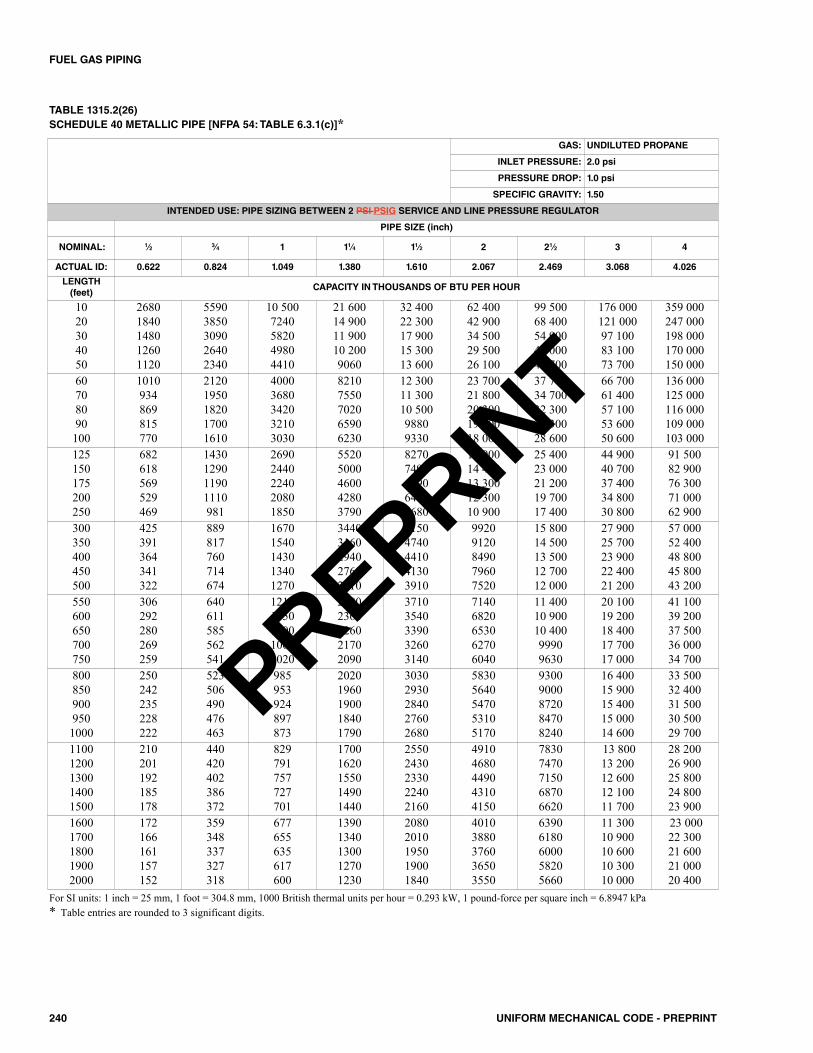
240 UNIFORM MECHANICAL CODE - PREPRINT
FUEL GAS PIPING
TABLE 1315.2(26)SCHEDULE 40 METALLIC PIPE [NFPA 54: TABLE 6.3.1(c)]*
GAS: UNDILUTED PROPANE
INLET PRESSURE: 2.0 psi
PRESSURE DROP: 1.0 psi
SPECIFIC GRAVITY: 1.50
INTENDED USE: PIPE SIZING BETWEEN 2 PSI PSIG SERVICE AND LINE PRESSURE REGULATOR
PIPE SIZE (inch)
NOMINAL: 1⁄2 3⁄4 1 11⁄4 11⁄2 2 21⁄2 3 4
ACTUAL ID: 0.622 0.824 1.049 1.380 1.610 2.067 2.469 3.068 4.026
LENGTH(feet)
CAPACITY IN THOUSANDS OF BTU PER HOUR
1020304050
26801840148012601120
55903850309026402340
10 5007240582049804410
21 60014 90011 90010 2009060
32 40022 30017 90015 30013 600
62 40042 90034 50029 50026 100
99 50068 40054 90047 00041 700
176 000121 00097 10083 10073 700
359 000247 000198 000170 000150 000
60708090100
1010934869815770
21201950182017001610
40003680342032103030
82107550702065906230
12 30011 30010 50098809330
23 70021 80020 30019 00018 000
37 70034 70032 30030 30028 600
66 70061 40057 10053 60050 600
136 000125 000116 000109 000103 000
125150175200250
682618569529469
1430129011901110981
26902440224020801850
55205000460042803790
82707490689064105680
15 90014 40013 30012 30010 900
25 40023 00021 20019 70017 400
44 90040 70037 40034 80030 800
91 50082 90076 30071 00062 900
300350400450500
425391364341322
889817760714674
16701540143013401270
34403160294027602610
51504740441041303910
99209120849079607520
15 80014 50013 50012 70012 000
27 90025 70023 90022 40021 200
57 00052 40048 80045 80043 200
550600650700750
306292280269259
640611585562541
12101150110010601020
24802360226021702090
37103540339032603140
71406820653062706040
11 40010 90010 40099909630
20 10019 20018 40017 70017 000
41 10039 20037 50036 00034 700
8008509009501000
250242235228222
523506490476463
985953924897873
20201960190018401790
30302930284027602680
58305640547053105170
93009000872084708240
16 40015 90015 40015 00014 600
33 50032 40031 50030 50029 700
11001200130014001500
210201192185178
440420402386372
829791757727701
17001620155014901440
25502430233022402160
49104680449043104150
78307470715068706620
13 80013 20012 60012 10011 700
28 20026 90025 80024 80023 900
16001700180019002000
172166161157152
359348337327318
677655635617600
13901340130012701230
20802010195019001840
40103880376036503550
63906180600058205660
11 30010 90010 60010 30010 000
23 00022 30021 60021 00020 400
For SI units: 1 inch = 25 mm, 1 foot = 304.8 mm, 1000 British thermal units per hour = 0.293 kW, 1 pound-force per square inch = 6.8947 kPa* Table entries are rounded to 3 significant digits.
PREPRINT
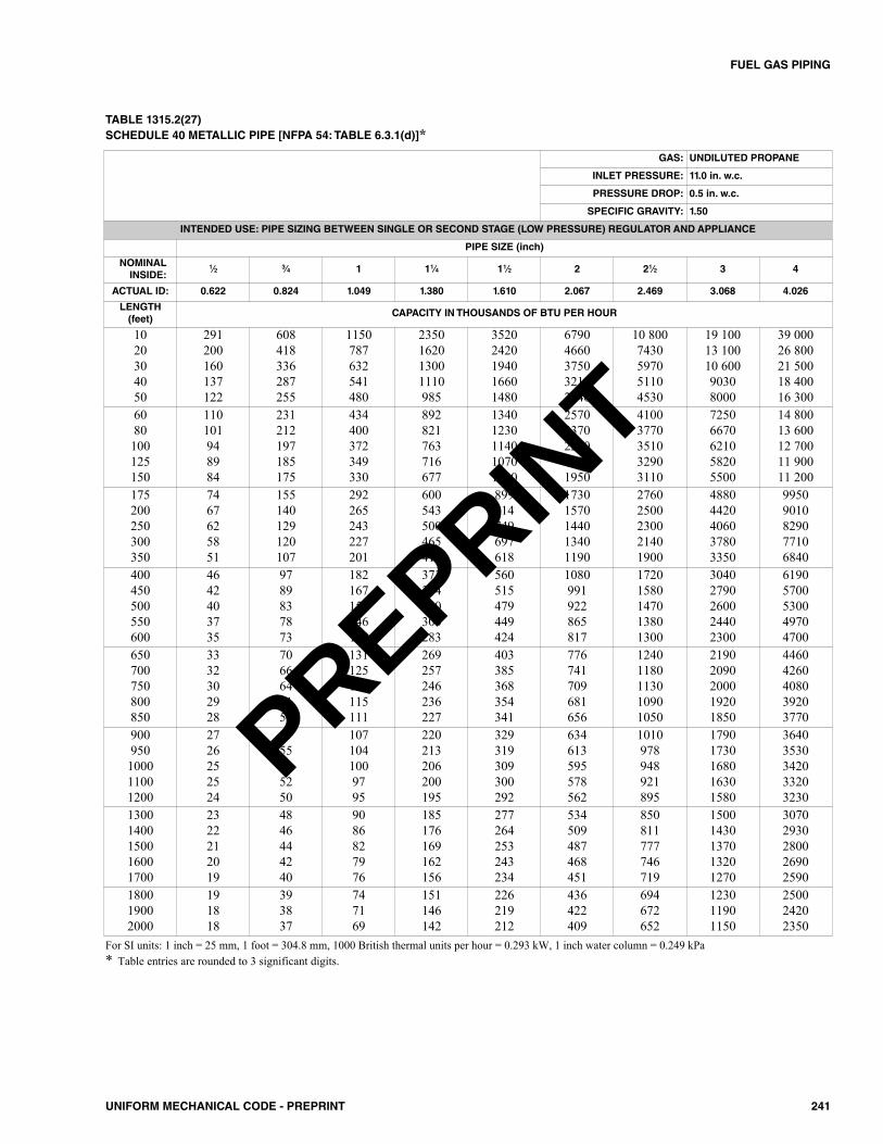
241UNIFORM MECHANICAL CODE - PREPRINT
FUEL GAS PIPING
TABLE 1315.2(27)SCHEDULE 40 METALLIC PIPE [NFPA 54: TABLE 6.3.1(d)]*
GAS: UNDILUTED PROPANE
INLET PRESSURE: 11.0 in. w.c.
PRESSURE DROP: 0.5 in. w.c.
SPECIFIC GRAVITY: 1.50
INTENDED USE: PIPE SIZING BETWEEN SINGLE OR SECOND STAGE (LOW PRESSURE) REGULATOR AND APPLIANCE
PIPE SIZE (inch)
NOMINALINSIDE:
1⁄2 3⁄4 1 11⁄4 11⁄2 2 21⁄2 3 4
ACTUAL ID: 0.622 0.824 1.049 1.380 1.610 2.067 2.469 3.068 4.026
LENGTH(feet)
CAPACITY IN THOUSANDS OF BTU PER HOUR
1020304050
291200160137122
608418336287255
1150787632541480
2350162013001110985
35202420194016601480
67904660375032102840
10 8007430597051104530
19 10013 10010 60090308000
39 00026 80021 50018 40016 300
6080100125150
110101948984
231212197185175
434400372349330
892821763716677
13401230114010701010
25702370220020701950
41003770351032903110
72506670621058205500
14 80013 60012 70011 90011 200
175200250300350
7467625851
155140129120107
292265243227201
600543500465412
899814749697618
17301570144013401190
27602500230021401900
48804420406037803350
99509010829077106840
400450500550600
4642403735
9789837873
182167156146138
373344320300283
560515479449424
1080991922865817
17201580147013801300
30402790260024402300
61905700530049704700
650700750800850
3332302928
7066646159
131125120115111
269257246236227
403385368354341
776741709681656
12401180113010901050
21902090200019201850
44604260408039203770
900950100011001200
2726252524
5755535250
1071041009795
220213206200195
329319309300292
634613595578562
1010978948921895
17901730168016301580
36403530342033203230
13001400150016001700
2322212019
4846444240
9086827976
185176169162156
277264253243234
534509487468451
850811777746719
15001430137013201270
30702930280026902590
180019002000
191818
393837
747169
151146142
226219212
436422409
694672652
123011901150
250024202350
For SI units: 1 inch = 25 mm, 1 foot = 304.8 mm, 1000 British thermal units per hour = 0.293 kW, 1 inch water column = 0.249 kPa* Table entries are rounded to 3 significant digits.
PREPRINT
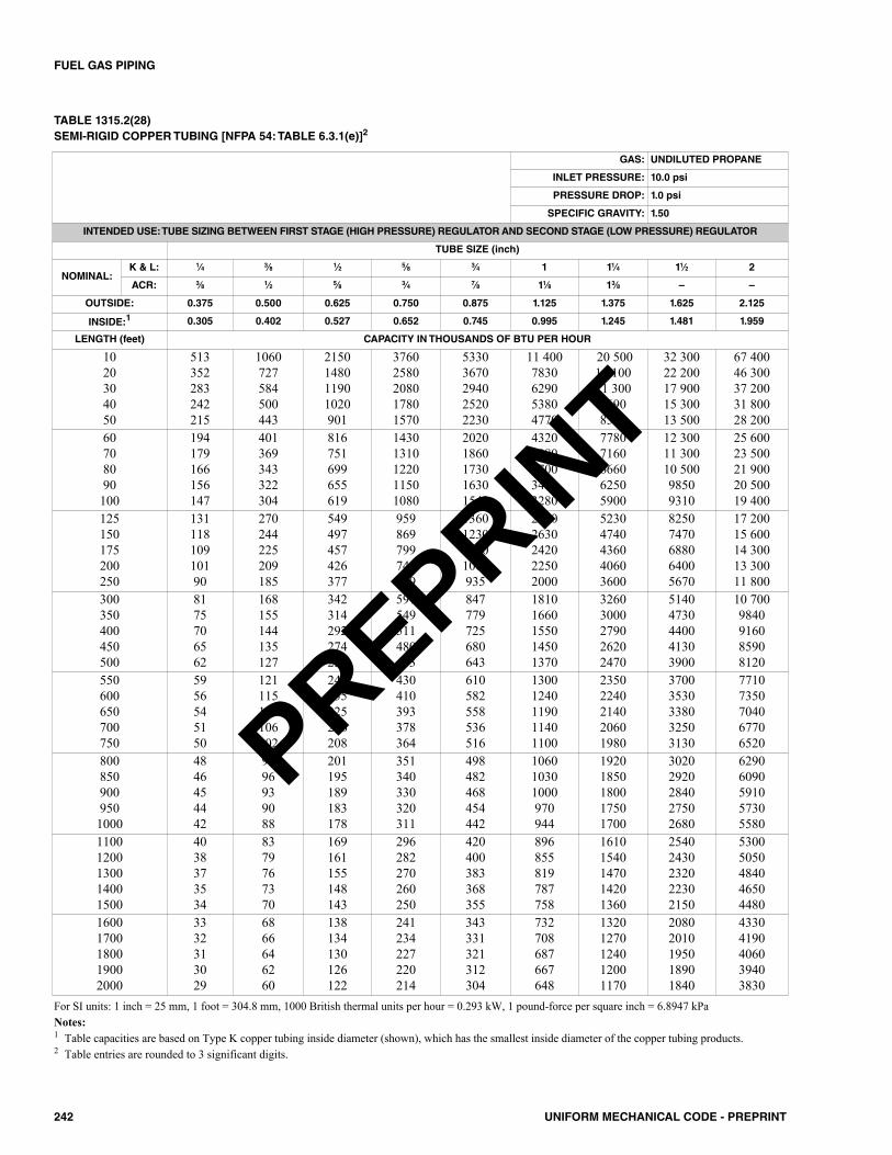
242 UNIFORM MECHANICAL CODE - PREPRINT
FUEL GAS PIPING
TABLE 1315.2(28)SEMI-RIGID COPPER TUBING [NFPA 54: TABLE 6.3.1(e)]2
For SI units: 1 inch = 25 mm, 1 foot = 304.8 mm, 1000 British thermal units per hour = 0.293 kW, 1 pound-force per square inch = 6.8947 kPaNotes:1 Table capacities are based on Type K copper tubing inside diameter (shown), which has the smallest inside diameter of the copper tubing products.2 Table entries are rounded to 3 significant digits.
GAS: UNDILUTED PROPANE
INLET PRESSURE: 10.0 psi
PRESSURE DROP: 1.0 psi
SPECIFIC GRAVITY: 1.50
INTENDED USE: TUBE SIZING BETWEEN FIRST STAGE (HIGH PRESSURE) REGULATOR AND SECOND STAGE (LOW PRESSURE) REGULATOR
TUBE SIZE (inch)
NOMINAL:K & L: 1⁄4 3⁄8 1⁄2 5⁄8 3⁄4 1 11⁄4 11⁄2 2
ACR: 3⁄8 1⁄2 5⁄8 3⁄4 7⁄8 11⁄8 13⁄8 – –
OUTSIDE: 0.375 0.500 0.625 0.750 0.875 1.125 1.375 1.625 2.125
INSIDE:1 0.305 0.402 0.527 0.652 0.745 0.995 1.245 1.481 1.959
LENGTH (feet) CAPACITY IN THOUSANDS OF BTU PER HOUR
1020304050
513352283242215
1060727584500443
2150148011901020901
37602580208017801570
53303670294025202230
11 4007830629053804770
20 50014 10011 30096908590
32 30022 20017 90015 30013 500
67 40046 30037 20031 80028 200
60708090100
194179166156147
401369343322304
816751699655619
14301310122011501080
20201860173016301540
43203980370034703280
77807160666062505900
12 30011 30010 50098509310
25 60023 50021 90020 50019 400
125150175200250
13111810910190
270244225209185
549497457426377
959869799744659
1360123011301060935
29102630242022502000
52304740436040603600
82507470688064005670
17 20015 60014 30013 30011 800
300350400450500
8175706562
168155144135127
342314292274259
597549511480453
847779725680643
18101660155014501370
32603000279026202470
51404730440041303900
10 7009840916085908120
550600650700750
5956545150
121115111106102
246235225216208
430410393378364
610582558536516
13001240119011401100
23502240214020601980
37003530338032503130
77107350704067706520
8008509009501000
4846454442
9996939088
201195189183178
351340330320311
498482468454442
106010301000970944
19201850180017501700
30202920284027502680
62906090591057305580
11001200130014001500
4038373534
8379767370
169161155148143
296282270260250
420400383368355
896855819787758
16101540147014201360
25402430232022302150
53005050484046504480
16001700180019002000
3332313029
6866646260
138134130126122
241234227220214
343331321312304
732708687667648
13201270124012001170
20802010195018901840
43304190406039403830
PREPRINT
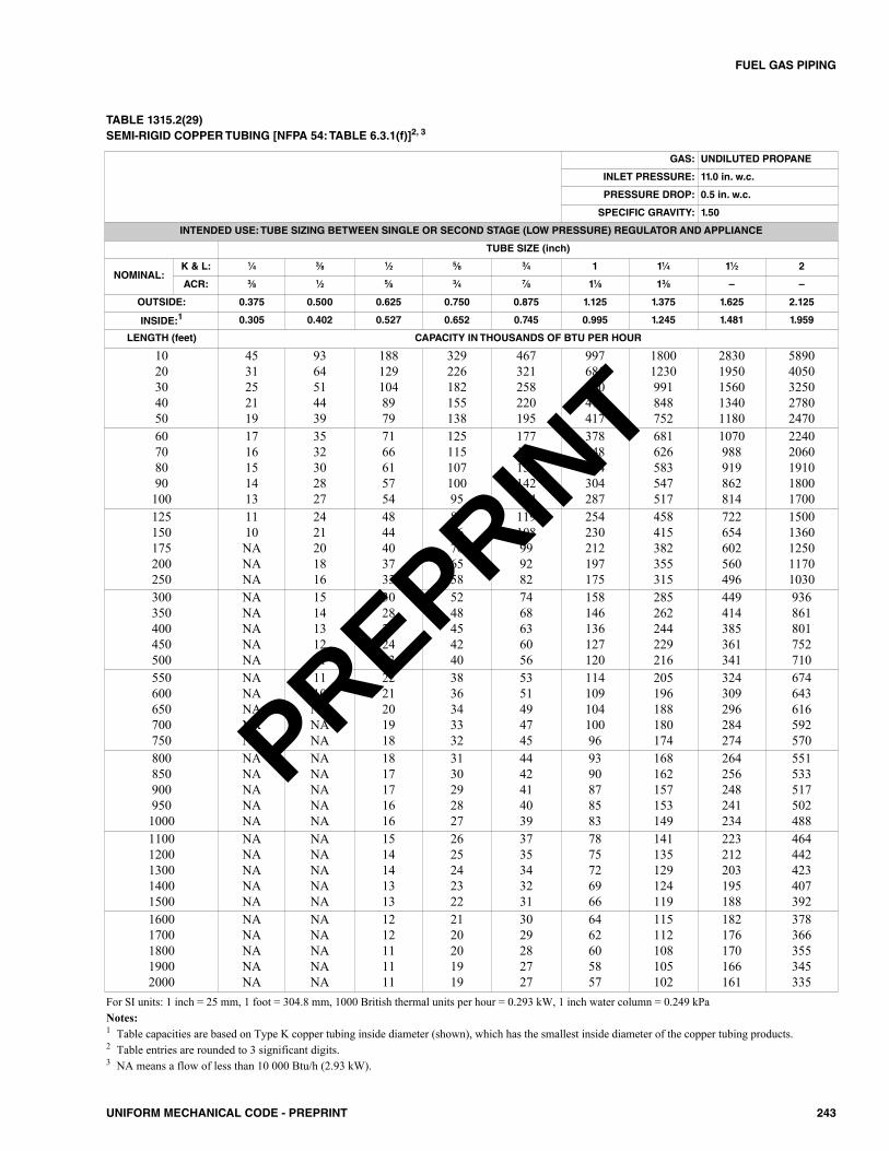
243UNIFORM MECHANICAL CODE - PREPRINT
FUEL GAS PIPING
TABLE 1315.2(29)SEMI-RIGID COPPER TUBING [NFPA 54: TABLE 6.3.1(f)]2, 3
For SI units: 1 inch = 25 mm, 1 foot = 304.8 mm, 1000 British thermal units per hour = 0.293 kW, 1 inch water column = 0.249 kPaNotes:1 Table capacities are based on Type K copper tubing inside diameter (shown), which has the smallest inside diameter of the copper tubing products.2 Table entries are rounded to 3 significant digits.3 NA means a flow of less than 10 000 Btu/h (2.93 kW).
GAS: UNDILUTED PROPANE
INLET PRESSURE: 11.0 in. w.c.
PRESSURE DROP: 0.5 in. w.c.
SPECIFIC GRAVITY: 1.50
INTENDED USE: TUBE SIZING BETWEEN SINGLE OR SECOND STAGE (LOW PRESSURE) REGULATOR AND APPLIANCE
TUBE SIZE (inch)
NOMINAL:K & L: 1⁄4 3⁄8 1⁄2 5⁄8 3⁄4 1 11⁄4 11⁄2 2
ACR: 3⁄8 1⁄2 5⁄8 3⁄4 7⁄8 11⁄8 13⁄8 – –
OUTSIDE: 0.375 0.500 0.625 0.750 0.875 1.125 1.375 1.625 2.125
INSIDE:1 0.305 0.402 0.527 0.652 0.745 0.995 1.245 1.481 1.959
LENGTH (feet) CAPACITY IN THOUSANDS OF BTU PER HOUR
1020304050
4531252119
9364514439
1881291048979
329226182155138
467321258220195
997685550471417
18001230991848752
28301950156013401180
58904050325027802470
60708090100
1716151413
3532302827
7166615754
12511510710095
177163152142134
378348324304287
681626583547517
1070988919862814
22402060191018001700
125150175200250
1110NANANA
2421201816
4844403733
8476706558
119108999282
254230212197175
458415382355315
722654602560496
15001360125011701030
300350400450500
NANANANANA
1514131211
3028262423
5248454240
7468636056
158146136127120
285262244229216
449414385361341
936861801752710
550600650700750
NANANANANA
1110NANANA
2221201918
3836343332
5351494745
11410910410096
205196188180174
324309296284274
674643616592570
8008509009501000
NANANANANA
NANANANANA
1817171616
3130292827
4442414039
9390878583
168162157153149
264256248241234
551533517502488
11001200130014001500
NANANANANA
NANANANANA
1514141313
2625242322
3735343231
7875726966
141135129124119
223212203195188
464442423407392
16001700180019002000
NANANANANA
NANANANANA
1212111111
2120201919
3029282727
6462605857
115112108105102
182176170166161
378366355345335
PREPRINT
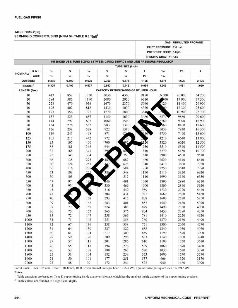
244 UNIFORM MECHANICAL CODE - PREPRINT
FUEL GAS PIPING
TABLE 1315.2(30)SEMI-RIGID COPPER TUBING [NFPA 54: TABLE 6.3.1(g)]2
For SI units: 1 inch = 25 mm, 1 foot = 304.8 mm, 1000 British thermal units per hour = 0.293 kW, 1 pound-force per square inch = 6.8947 kPaNotes:1 Table capacities are based on Type K copper tubing inside diameter (shown), which has the smallest inside diameter of the copper tubing products.2 Table entries are rounded to 3 significant digits.
GAS: UNDILUTED PROPANE
INLET PRESSURE: 2.0 psi
PRESSURE DROP: 1.0 psi
SPECIFIC GRAVITY: 1.50
INTENDED USE: TUBE SIZING BETWEEN 2 PSIG SERVICE AND LINE PRESSURE REGULATOR
TUBE SIZE (inch)
NOMINAL:K & L: 1⁄4 3⁄8 1⁄2 5⁄8 3⁄4 1 11⁄4 11⁄2 2
ACR: 3⁄8 1⁄2 5⁄8 3⁄4 7⁄8 11⁄8 13⁄8 – –
OUTSIDE: 0.375 0.500 0.625 0.750 0.875 1.125 1.375 1.625 2.125
INSIDE:1 0.305 0.402 0.527 0.652 0.745 0.995 1.245 1.481 1.959
LENGTH (feet) CAPACITY IN THOUSANDS OF BTU PER HOUR
1020304050
413284228195173
852585470402356
17301190956818725
30302080167014301270
43002950237020301800
91706310506043303840
16 50011 400912078006920
26 00017 90014 40012 30010 900
54 20037 30029 90025 60022 700
60708090100
157144134126119
323297276259245
657605562528498
11501060983922871
16301500139013101240
34803200298027902640
62705760536050304750
98809090845079307490
20 60018 90017 60016 50015 600
125150175200250
10595888272
217197181168149
442400368343304
772700644599531
1100992913849753
23402120195018101610
42103820351032702900
66406020554051504560
13 80012 50011 50010 7009510
300350400450500
6660565350
135124116109103
275253235221209
481442411386365
682628584548517
14601340125011701110
26202410225021101990
41403800354033203140
86107920737069206530
550600650700750
4745434140
9793898682
198189181174168
346330316304293
491469449431415
10501000959921888
18901800173016601600
29802840272026202520
62105920567054505250
8008509009501000
3937363534
8077757271
162157152147143
283274265258251
401388376366356
857829804781760
15401490145014101370
24302350228022202160
50704900475046204490
11001200130014001500
3231302827
6764615957
136130124120115
238227217209201
338322309296286
721688659633610
13001240119011401100
20501950187018001730
42704070390037403610
16001700180019002000
2626252423
5553515048
11110810410199
194188182177172
276267259251244
589570553537522
106010301000966940
16701620157015201480
34803370327031703090
PREPRINT

245UNIFORM MECHANICAL CODE - PREPRINT
FUEL GAS PIPING
TABLE 1315.2(31)CORRUGATED STAINLESS STEEL TUBING (CSST) [NFPA 54: TABLE 6.3.1(h)]1, 2
For SI units: 1 foot = 304.8 mm, 1000 British thermal units per hour = 0.293 kW, 1 inch water column = 0.249 kPaNotes:1 Table includes losses for four 90 degree (1.57 rad) bends and two end fittings. Tubing runs with larger numbers of bends, fittings, or both shall be increased
by an equivalent length of tubing to the following equation: L = 1.3 n, where L is additional length (ft) of tubing and n is the number of additional fittings,bends, or both.
2 Table entries are rounded to 3 significant digits.3 EHD = Equivalent Hydraulic Diameter, which is a measure of the relative hydraulic efficiency between different tubing sizes. The greater the value of EHD,
the greater the gas capacity of the tubing.
GAS: UNDILUTED PROPANE
INLET PRESSURE: 11.0 in. w.c.
PRESSURE DROP: 0.5 in. w.c.
SPECIFIC GRAVITY: 1.50
INTENDED USE: CSST SIZING BETWEEN SINGLE OR SECOND STAGE (LOW PRESSURE) REGULATOR AND APPLIANCE SHUTOFF VALVE
TUBE SIZE (EHD)3
FLOW DESIGNATION: 13 15 18 19 23 25 30 31 37 39 46 48 60 62
LENGTH (feet) CAPACITY IN THOUSANDS OF BTU PER HOUR
5101520
72503934
99695549
18112910491
211150121106
355254208183
426303248216
744521422365
863605490425
1420971775661
16381179972847
2830199016201400
3270232019001650
5780411033702930
6550464037903290
25304050
30282320
42393330
82746458
94877466
164151131118
192177153137
325297256227
379344297265
583528449397
762698610548
12501140988884
1480135011701050
2630240020901870
2940268023302080
60708090
19171515
26252322
53494544
60575250
107999490
126117109102
207191178169
241222208197
359330307286
502466438414
805745696656
961890833787
1710159014901400
1900176016501550
100150200250300
1411988
2015141211
4131282523
4736333026
8566605350
9875696157
1591231129990
186143129117107
270217183163147
393324283254234
621506438390357
746611531476434
13301090948850777
148012101050934854
PREPRINT
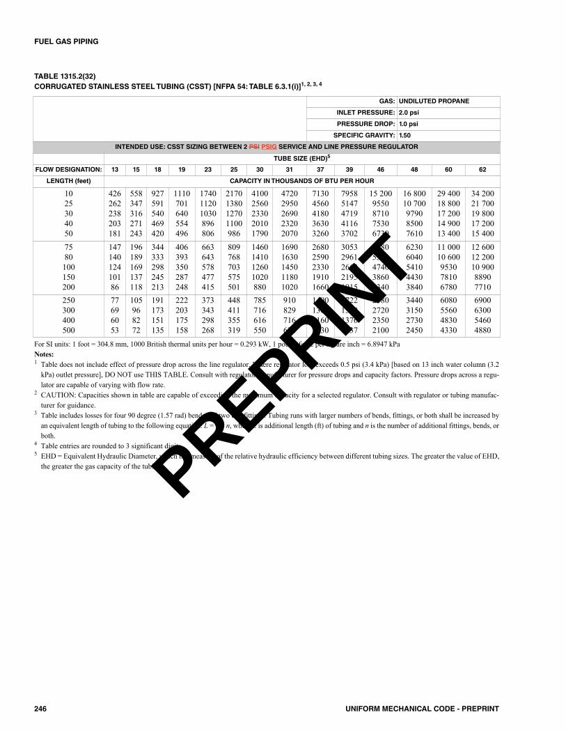
246 UNIFORM MECHANICAL CODE - PREPRINT
FUEL GAS PIPING
TABLE 1315.2(32)CORRUGATED STAINLESS STEEL TUBING (CSST) [NFPA 54: TABLE 6.3.1(i)]1, 2, 3, 4
GAS: UNDILUTED PROPANE
INLET PRESSURE: 2.0 psi
PRESSURE DROP: 1.0 psi
SPECIFIC GRAVITY: 1.50
INTENDED USE: CSST SIZING BETWEEN 2 PSI PSIG SERVICE AND LINE PRESSURE REGULATOR
TUBE SIZE (EHD)5
FLOW DESIGNATION: 13 15 18 19 23 25 30 31 37 39 46 48 60 62
LENGTH (feet) CAPACITY IN THOUSANDS OF BTU PER HOUR
1025304050
426262238203181
558347316271243
927591540469420
1110701640554496
174011201030896806
2170138012701100986
41002560233020101790
47202950269023202070
71304560418036303260
79585147471941163702
15 2009550871075306730
16 80010 700979085007610
29 40018 80017 20014 90013 400
34 20021 70019 80017 20015 400
7580100150200
14714012410186
196189169137118
344333298245213
406393350287248
663643578477415
809768703575501
1460141012601020880
16901630145011801020
26802590233019101660
30532961266221951915
54805300474038603340
62306040541044303840
11 00010 600953078106780
12 60012 20010 90088907710
250300400500
77696053
105968272
191173151135
222203175158
373343298268
448411355319
785716616550
910829716638
1490136011601030
1722157813761237
2980272023502100
3440315027302450
6080556048304330
6900630054604880
For SI units: 1 foot = 304.8 mm, 1000 British thermal units per hour = 0.293 kW, 1 pound-force per square inch = 6.8947 kPaNotes:1 Table does not include effect of pressure drop across the line regulator. Where regulator loss exceeds 0.5 psi (3.4 kPa) [based on 13 inch water column (3.2
kPa) outlet pressure], DO NOT use THIS TABLE. Consult with regulator manufacturer for pressure drops and capacity factors. Pressure drops across a regu-lator are capable of varying with flow rate.
2 CAUTION: Capacities shown in table are capable of exceeding the maximum capacity for a selected regulator. Consult with regulator or tubing manufac-turer for guidance.
3 Table includes losses for four 90 degree (1.57 rad) bends and two end fittings. Tubing runs with larger numbers of bends, fittings, or both shall be increased byan equivalent length of tubing to the following equation: L = 1.3 n, where L is additional length (ft) of tubing and n is the number of additional fittings, bends, orboth.
4 Table entries are rounded to 3 significant digits.5 EHD = Equivalent Hydraulic Diameter, which is a measure of the relative hydraulic efficiency between different tubing sizes. The greater the value of EHD,
the greater the gas capacity of the tubing. PREPRINT
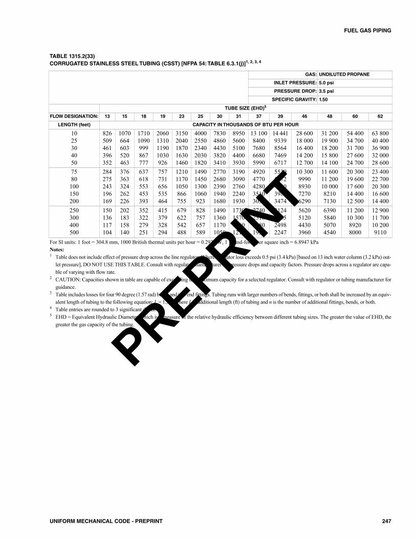
247UNIFORM MECHANICAL CODE - PREPRINT
FUEL GAS PIPING
TABLE 1315.2(33)CORRUGATED STAINLESS STEEL TUBING (CSST) [NFPA 54: TABLE 6.3.1(j)]1, 2, 3, 4
GAS: UNDILUTED PROPANE
INLET PRESSURE: 5.0 psi
PRESSURE DROP: 3.5 psi
SPECIFIC GRAVITY: 1.50
TUBE SIZE (EHD)5
FLOW DESIGNATION: 13 15 18 19 23 25 30 31 37 39 46 48 60 62
LENGTH (feet) CAPACITY IN THOUSANDS OF BTU PER HOUR
1025304050
826509461396352
1070664603520463
17101090999867777
2060131011901030926
31502040187016301460
40002550234020301820
78304860443038203410
89505600510044003930
13 1008400768066805990
14 4419339856474696717
28 60018 00016 40014 20012 700
31 20019 90018 20015 80014 100
54 40034 70031 70027 60024 700
63 80040 40036 90032 00028 600
7580100150200
284275243196169
376363324262226
637618553453393
757731656535464
121011701050866755
1490145013001060923
27702680239019401680
31903090276022401930
49204770428035103050
55395372483039833474
10 3009990893072706290
11 60011 20010 00082107130
20 30019 60017 60014 40012 500
23 40022 70020 30016 60014 400
250300400500
150136117104
202183158140
352322279251
415379328294
679622542488
828757657589
1490136011701050
1730157013601210
2740251021801950
3124286524982247
5620512044303960
6390584050704540
11 20010 30089208000
12 90011 70010 2009110
For SI units: 1 foot = 304.8 mm, 1000 British thermal units per hour = 0.293 kW, 1 pound-force per square inch = 6.8947 kPaNotes:1 Table does not include effect of pressure drop across the line regulator. Where regulator loss exceeds 0.5 psi (3.4 kPa) [based on 13 inch water column (3.2 kPa) out-
let pressure], DO NOT USE THIS TABLE. Consult with regulator manufacturer for pressure drops and capacity factors. Pressure drops across a regulator are capa-ble of varying with flow rate.
2 CAUTION: Capacities shown in table are capable of exceeding the maximum capacity for a selected regulator. Consult with regulator or tubing manufacturer forguidance.
3 Table includes losses for four 90 degree (1.57 rad) bends and two end fittings. Tubing runs with larger numbers of bends, fittings, or both shall be increased by an equiv-alent length of tubing to the following equation: L = 1.3 n, where L is additional length (ft) of tubing and n is the number of additional fittings, bends, or both.
4 Table entries are rounded to 3 significant digits.5 EHD = Equivalent Hydraulic Diameter, which is a measure of the relative hydraulic efficiency between different tubing sizes. The greater the value of EHD, the
greater the gas capacity of the tubing.
PREPRINT
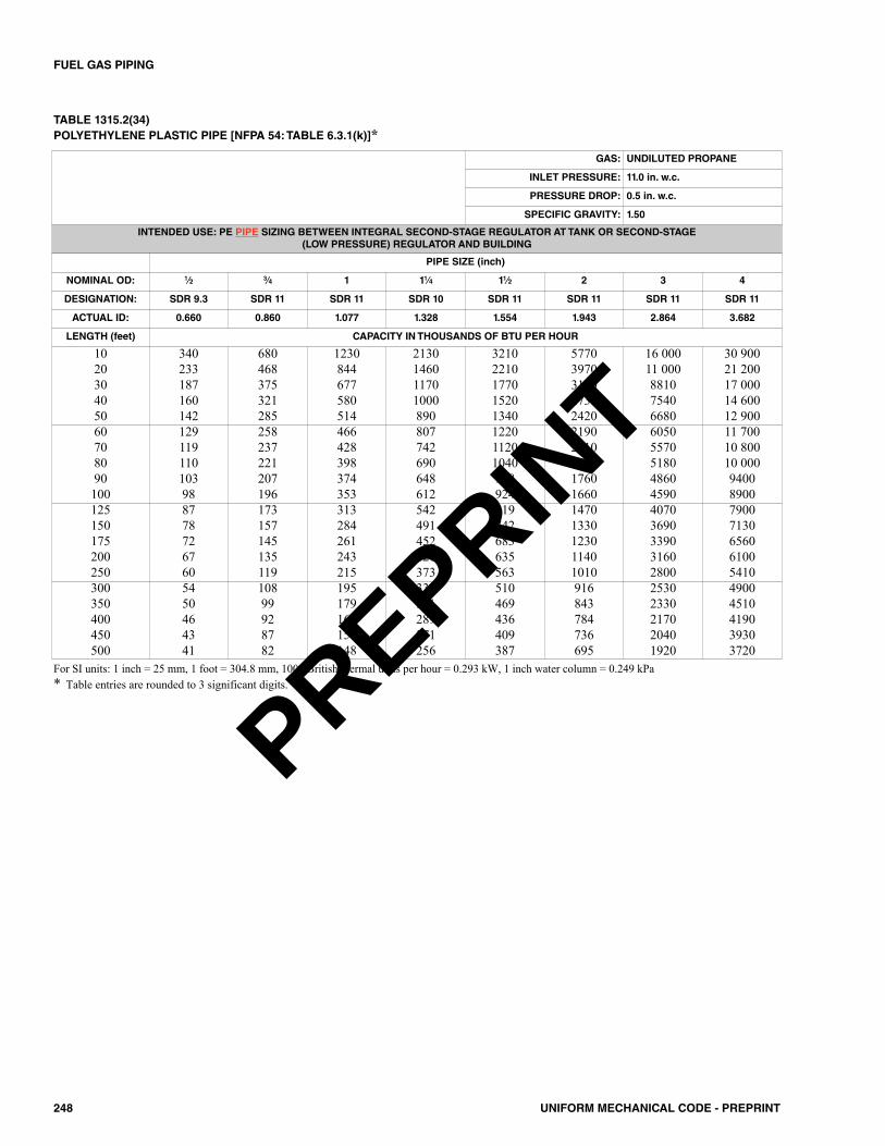
248 UNIFORM MECHANICAL CODE - PREPRINT
FUEL GAS PIPING
For SI units: 1 inch = 25 mm, 1 foot = 304.8 mm, 1000 British thermal units per hour = 0.293 kW, 1 inch water column = 0.249 kPa* Table entries are rounded to 3 significant digits.
TABLE 1315.2(34)POLYETHYLENE PLASTIC PIPE [NFPA 54: TABLE 6.3.1(k)]*
GAS: UNDILUTED PROPANE
INLET PRESSURE: 11.0 in. w.c.
PRESSURE DROP: 0.5 in. w.c.
SPECIFIC GRAVITY: 1.50
INTENDED USE: PE PIPE SIZING BETWEEN INTEGRAL SECOND-STAGE REGULATOR AT TANK OR SECOND-STAGE (LOW PRESSURE) REGULATOR AND BUILDING
PIPE SIZE (inch)
NOMINAL OD: 1⁄2 3⁄4 1 11⁄4 11⁄2 2 3 4
DESIGNATION: SDR 9.3 SDR 11 SDR 11 SDR 10 SDR 11 SDR 11 SDR 11 SDR 11
ACTUAL ID: 0.660 0.860 1.077 1.328 1.554 1.943 2.864 3.682
LENGTH (feet) CAPACITY IN THOUSANDS OF BTU PER HOUR
10 340 680 1230 2130 3210 5770 16 000 30 90020 233 468 844 1460 2210 3970 11 000 21 20030 187 375 677 1170 1770 3180 8810 17 00040 160 321 580 1000 1520 2730 7540 14 60050 142 285 514 890 1340 2420 6680 12 90060 129 258 466 807 1220 2190 6050 11 70070 119 237 428 742 1120 2010 5570 10 80080 110 221 398 690 1040 1870 5180 10 00090 103 207 374 648 978 1760 4860 9400100 98 196 353 612 924 1660 4590 8900125 87 173 313 542 819 1470 4070 7900150 78 157 284 491 742 1330 3690 7130175 72 145 261 452 683 1230 3390 6560200 67 135 243 420 635 1140 3160 6100250 60 119 215 373 563 1010 2800 5410300 54 108 195 338 510 916 2530 4900350 50 99 179 311 469 843 2330 4510400 46 92 167 289 436 784 2170 4190450 43 87 157 271 409 736 2040 3930500 41 82 148 256 387 695 1920 3720
PREPRINT
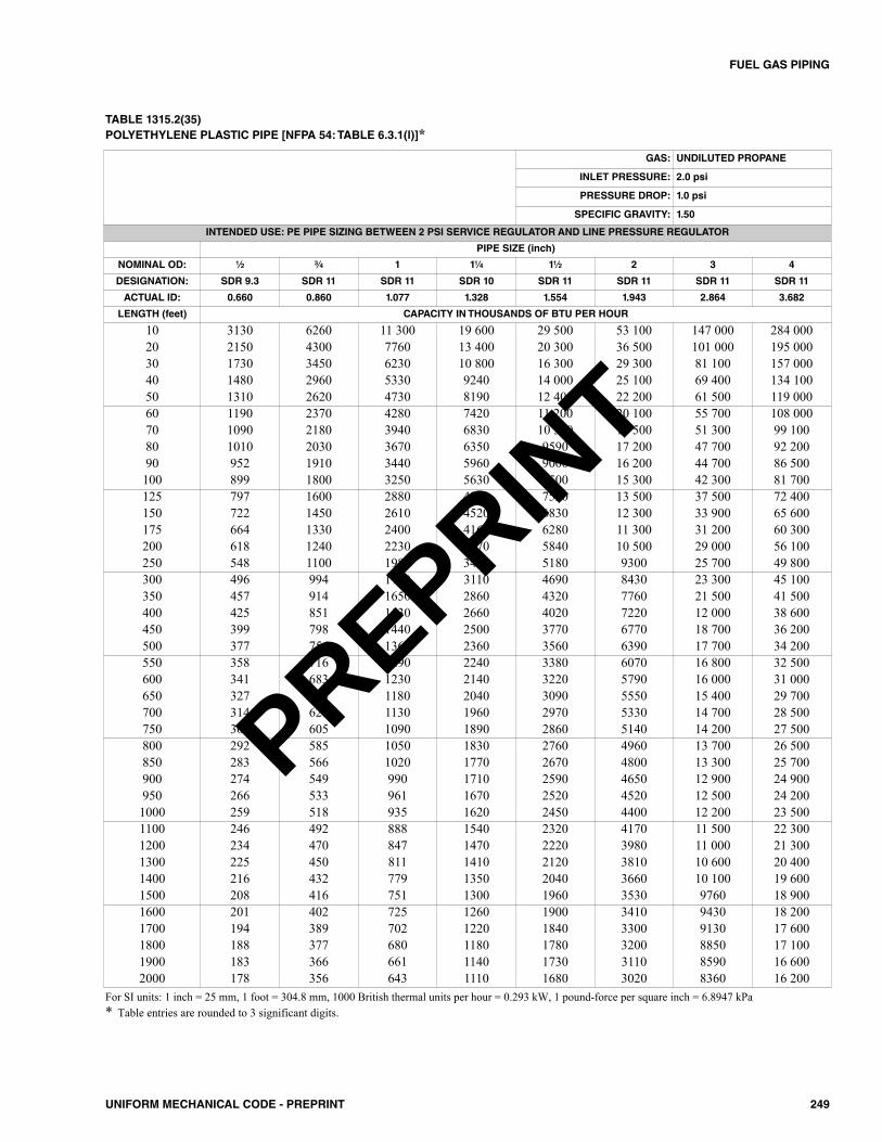
249UNIFORM MECHANICAL CODE - PREPRINT
FUEL GAS PIPING
TABLE 1315.2(35)POLYETHYLENE PLASTIC PIPE [NFPA 54: TABLE 6.3.1(l)]*
For SI units: 1 inch = 25 mm, 1 foot = 304.8 mm, 1000 British thermal units per hour = 0.293 kW, 1 pound-force per square inch = 6.8947 kPa* Table entries are rounded to 3 significant digits.
GAS: UNDILUTED PROPANE
INLET PRESSURE: 2.0 psi
PRESSURE DROP: 1.0 psi
SPECIFIC GRAVITY: 1.50
INTENDED USE: PE PIPE SIZING BETWEEN 2 PSI SERVICE REGULATOR AND LINE PRESSURE REGULATOR
PIPE SIZE (inch)
NOMINAL OD: 1⁄2 3⁄4 1 11⁄4 11⁄2 2 3 4
DESIGNATION: SDR 9.3 SDR 11 SDR 11 SDR 10 SDR 11 SDR 11 SDR 11 SDR 11
ACTUAL ID: 0.660 0.860 1.077 1.328 1.554 1.943 2.864 3.682
LENGTH (feet) CAPACITY IN THOUSANDS OF BTU PER HOUR
10 3130 6260 11 300 19 600 29 500 53 100 147 000 284 00020 2150 4300 7760 13 400 20 300 36 500 101 000 195 00030 1730 3450 6230 10 800 16 300 29 300 81 100 157 00040 1480 2960 5330 9240 14 000 25 100 69 400 134 10050 1310 2620 4730 8190 12 400 22 200 61 500 119 00060 1190 2370 4280 7420 11 200 20 100 55 700 108 00070 1090 2180 3940 6830 10 300 18 500 51 300 99 10080 1010 2030 3670 6350 9590 17 200 47 700 92 20090 952 1910 3440 5960 9000 16 200 44 700 86 500100 899 1800 3250 5630 8500 15 300 42 300 81 700125 797 1600 2880 4990 7530 13 500 37 500 72 400150 722 1450 2610 4520 6830 12 300 33 900 65 600175 664 1330 2400 4160 6280 11 300 31 200 60 300200 618 1240 2230 3870 5840 10 500 29 000 56 100250 548 1100 1980 3430 5180 9300 25 700 49 800300 496 994 1790 3110 4690 8430 23 300 45 100350 457 914 1650 2860 4320 7760 21 500 41 500400 425 851 1530 2660 4020 7220 12 000 38 600450 399 798 1440 2500 3770 6770 18 700 36 200500 377 754 1360 2360 3560 6390 17 700 34 200550 358 716 1290 2240 3380 6070 16 800 32 500600 341 683 1230 2140 3220 5790 16 000 31 000650 327 654 1180 2040 3090 5550 15 400 29 700700 314 628 1130 1960 2970 5330 14 700 28 500750 302 605 1090 1890 2860 5140 14 200 27 500800 292 585 1050 1830 2760 4960 13 700 26 500850 283 566 1020 1770 2670 4800 13 300 25 700900 274 549 990 1710 2590 4650 12 900 24 900950 266 533 961 1670 2520 4520 12 500 24 2001000 259 518 935 1620 2450 4400 12 200 23 5001100 246 492 888 1540 2320 4170 11 500 22 3001200 234 470 847 1470 2220 3980 11 000 21 3001300 225 450 811 1410 2120 3810 10 600 20 4001400 216 432 779 1350 2040 3660 10 100 19 6001500 208 416 751 1300 1960 3530 9760 18 9001600 201 402 725 1260 1900 3410 9430 18 2001700 194 389 702 1220 1840 3300 9130 17 6001800 188 377 680 1180 1780 3200 8850 17 1001900 183 366 661 1140 1730 3110 8590 16 6002000 178 356 643 1110 1680 3020 8360 16 200
PREPRINT
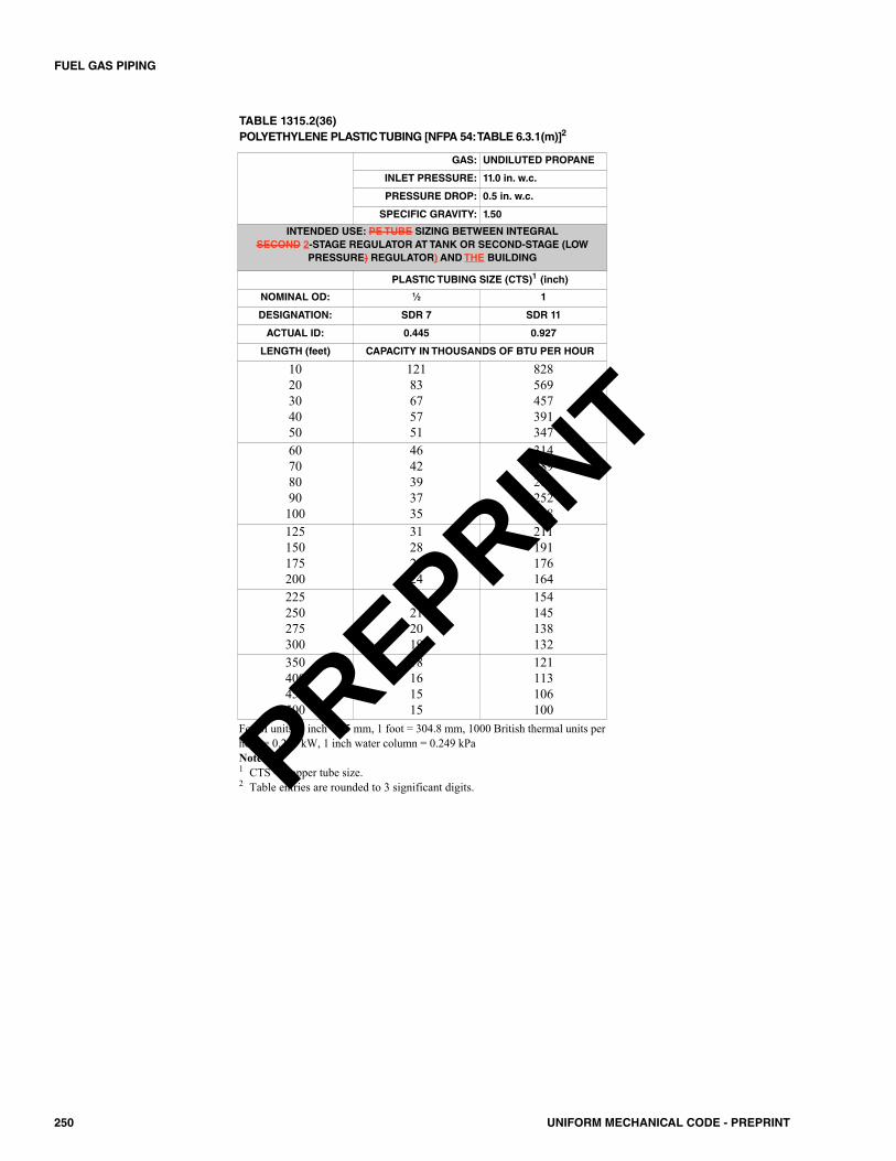
250 UNIFORM MECHANICAL CODE - PREPRINT
FUEL GAS PIPING
TABLE 1315.2(36)POLYETHYLENE PLASTIC TUBING [NFPA 54: TABLE 6.3.1(m)]2
GAS: UNDILUTED PROPANE
INLET PRESSURE: 11.0 in. w.c.
PRESSURE DROP: 0.5 in. w.c.
SPECIFIC GRAVITY: 1.50
INTENDED USE: PE TUBE SIZING BETWEEN INTEGRAL SECOND 2-STAGE REGULATOR AT TANK OR SECOND-STAGE (LOW
PRESSURE) REGULATOR) AND THE BUILDING
PLASTIC TUBING SIZE (CTS)1 (inch)
NOMINAL OD: 1⁄2 1
DESIGNATION: SDR 7 SDR 11
ACTUAL ID: 0.445 0.927
LENGTH (feet) CAPACITY IN THOUSANDS OF BTU PER HOUR
1020304050
12183675751
828569457391347
60708090100
4642393735
314289269252238
125150175200
31282624
211191176164
225250275300
22212019
154145138132
350400450500
18161515
121113106100
For SI units: 1 inch = 25 mm, 1 foot = 304.8 mm, 1000 British thermal units perhour = 0.293 kW, 1 inch water column = 0.249 kPaNotes:1 CTS = Copper tube size.2 Table entries are rounded to 3 significant digits.PREPRINT
1401.0 General.1401.1 Applicability. Except as otherwise addressed in thiscode, this chapter shall govern the installation of process pip-ing in or in conjunction with a building or structure locatedupon the premises.
1402.0 Permit.1402.1 General. It shall be unlawful to install, alter, orrepair or cause to be installed, altered, or repaired processmaterial piping without first obtaining a permit.
Permits for process piping shall show the total number ofoutlets to be provided for on each system and such otherinformation as required by the Authority Having Jurisdiction.
Fees for process piping permits are included in Table 104.5.
1403.0 Plans Required.1403.1 General. Plans, engineering calculations, diagrams,and other data shall be submitted in one or more sets witheach application for a permit. The Authority Having Juris-diction shall be permitted to require plans, computations, andspecifications to be prepared and designed by a registereddesign professional.
Where plans or other data are submitted for review, aplan review fee shall be paid, as provided in Section 104.3.2.
1404.0 Workmanship.1404.1 General. Process piping shall not be strained or bent,nor shall tanks, vessels, vats, appliances, or cabinets be sup-ported by or develop strain or stress on the piping.
1405.0 Inspections.1405.1 General. Upon completion of the installation, alter-ation, or repair of process piping, and prior to the use thereof,the Authority Having Jurisdiction shall be notified that suchpiping is ready for inspection.
Excavations required for the installation of undergroundpiping shall be kept open until such time as the piping hasbeen inspected and approved. Where such piping is coveredor concealed before such approval, it shall be exposed uponthe direction of the Authority Having Jurisdiction.1405.2 Required Inspections. The Authority HavingJurisdiction shall make the following inspections and shalleither approve that portion of the work as completed or shallnotify the permit holder wherein the same fails to be in accor-dance with this code.
1405.2.1 Rough Piping Inspection. This inspectionshall be made after process piping authorized by the per-mit has been installed and before piping has been cov-
ered or concealed. This inspection shall include a deter-mination that the piping size, material, and installationare in accordance with the requirements of this code.1405.2.2 Final Piping Inspection. This inspectionshall be made after piping authorized by the permit hasbeen installed and after portions thereof that are to be cov-ered or concealed are so concealed. This inspection shallinclude a pressure test, at which time the piping shallstand a pressure of not less than one-and-one-half timesthe maximum designed operating pressure wherehydraulic testing is conducted or 110 percent where test-ing is conducted pneumatically. Test pressures shall beheld for a length of time satisfactory to the Authority Hav-ing Jurisdiction, but in no case for less than 30 minuteswith no perceptible drop in pressure. HPM drain, waste,and vent piping shall be tested in accordance with theplumbing code. Tests shall be made in the presence of theAuthority Having Jurisdiction. Necessary apparatus forconducting tests shall be furnished by the permit holder.
1405.3 Other Inspections. In addition to the inspectionsrequired by this section, the Authority Having Jurisdictionshall be permitted to require a special inspector, as specifiedin the building code, during installation of piping systems. Incases where the work authorized was installed in accordancewith plans and specifications prepared by a registered designprofessional, the Authority Having Jurisdiction shall be per-mitted to require a final signed report stating that the workwas installed in accordance with approved plans and specifi-cations and the applicable provisions of this chapter.
1406.0 Pipe, Tubing, and Fittings.1406.1 General. Process pipe, tubing, and fittings shallcomply with ASME B31.3 and shall be installed in accor-dance with the manufacturer’s installation instructions. Mate-rials shall be rated for the operating temperatures andpressures of the system, and shall be compatible with the typeof liquid.1406.2 Hazardous Process Piping (HPP). HPP supplypiping or tubing in service corridors shall be exposed to view.HPP piping shall be identified in accordance with nationallyrecognized standards to indicate the material being trans-ported. Liquid HPP piping shall have an approved means fordirecting spilled materials to an approved containment ordrainage system.
Liquid HPP waste or drainage systems shall be installedin accordance with the plumbing code.
1406.2.1 Installation in Exit Corridors and AboveOther Occupancies. Hazardous process supply pipeshall not be located within exit corridors, within a portionof a means of egress required to be enclosed in fire-resis-tive construction, or in concealed spaces in or above
251UNIFORM MECHANICAL CODE - PREPRINT
CHAPTER 14PROCESS PIPING
PREPRINT
areas not classified as Group H Occupancies, except aspermitted by this subsection.
Hazardous production material piping and tubingshall be permitted to be installed within the spacedefined by the walls of exit corridors and the floor orroof above, or in concealed spaces above other occu-pancies in accordance with Section 1406.2.1.1 throughSection 1406.2.1.6.
1406.2.1.1 Automatic Sprinklers. Automaticsprinklers shall be installed within the space unlessthe space is less than 6 inches (152 mm) in the leastdimension.1406.2.1.2 Ventilation. Ventilation at not less than6 air changes per hour (ACH) shall be provided. Thespace shall not be used to convey air from otherareas.1406.2.1.3 Receptor. Where the piping or tubing isused to transport HPP liquids, a receptor shall beinstalled below such piping or tubing. The receptorshall be designed to collect discharge or leakage anddrain it to an approved location. The 1 hour enclo-sure shall not be used as part of the receptor.1406.2.1.4 Separation. HPP supply piping and tub-ing and HPP nonmetallic waste lines shall be sepa-rated from the exit corridor and from an occupancyother than a semi-conductor fabrication facility clas-sified as a Group H Occupancy by construction, asrequired for walls or partitions that have a fire-pro-tection rating of not less than 1 hour. Where gypsumwallboard is used, joints on the piping side of theenclosure need not be taped, provided the jointsoccur over framing members. Access openings intothe enclosure shall be protected by approved fireassemblies.1406.2.1.5 Emergency Shutoff Valves. Readilyaccessible manual or automatic remotely activatedfail-safe emergency shutoff valves shall be installedon piping and tubing other than waste lines at the fol-lowing locations:(1) At branch connections into the fabrication area.(2) At entries into exit corridors. Excess flow
valves shall be installed as required by the firecode.
1406.2.1.6 Electrical Wiring. Electrical wiringand equipment located in the piping space shall beapproved for Class I, Division 2, Hazardous Loca-tions.Exception: Occasional transverse crossing of the cor-ridors by supply piping that is enclosed within the cor-ridor need not comply with Section 1406.2.1.1 throughSection 1406.2.1.6.
1406.3 Special Requirements for HPP Gases. In addi-tion to other requirements of this section, HPP gases shallcomply with this subsection and the fire code.
1406.3.1 Special Provisions. Where HPP supply gasis carried in pressurized piping, a fail-safe system shallshut off flow due to a rupture in the piping. Where thepiping originates from outside the building, the valve shallbe located outside the building as close to the bulk sourceas practical.1406.3.2 Piping and Tubing Installation. Pipingand tubing shall be installed in accordance with approvedstandards. Supply piping for hazardous production mate-rials having a health hazard ranking of 3 or 4 shall havewelded connections throughout, unless an exhaustedenclosure is provided.Exception: Material that is incompatible with ferrouspiping shall be permitted to be installed in nonmetallicpiping with approved connections.1406.3.3 Gas-Detection System. Where hazardousproduction material gas is used or dispensed and thephysiological warning properties of the gas are at ahigher level than the accepted permissible exposure limitof the gas, a continuous gas-monitoring system shall beprovided to detect the presence of the short-term hazardcondition. Where dispensing occurs and flammable gasesor vapors are capable of being present in quantities inexcess of 25 percent of the lower explosive limit, a con-tinuous gas-monitoring system shall be connected to theemergency control station.
252 UNIFORM MECHANICAL CODE - PREPRINT
PROCESS PIPING
PREPRINT
1501.0 General.1501.1 Applicability. See Section 1203.0 and the UniformSolar, Hydronics and Geothermal Code (USHGC), publishedby the International Association of Plumbing and MechanicalOfficials. The Uniform Solar, Hydronics and GeothermalCode (USHGC) provides requirements that shall be permittedto be adopted as part of the code by the Authority HavingJurisdiction.
253UNIFORM MECHANICAL CODE - PREPRINT
CHAPTER 15SOLAR ENERGY SYSTEMS
PREPRINT

254 UNIFORM MECHANICAL CODE - PREPRINT
PREPRINT
1601.0 Stationary Fuel Cell Power Plants.1601.1 General. Fuel cell power plants with a power out-put of less than 50 kW shall be listed and installed in accor-dance with the manufacturer’s instructions. Fuel cell powerplants with a power output of greater than 50 kW shall beinstalled in accordance with NFPA 853. [NFPA 54:10.30]Stationary fuel cell power plants shall be tested in accordancewith CSA FC-1.
1602.0 Stationary Gas Engines and Generators. 1602.1 General. The installation of gas engines shall con-form to NFPA 37. [NFPA 54:10.23]1602.2 Connection to the Gas Supply Piping. Sta-tionary gas engines shall not be rigidly connected to the gassupply piping. [NFPA 54:10.23.1]1602.3 Stationary Engine Generators. Stationaryengine generators shall be tested in accordance with UL 2200,and shall be installed in accordance with NFPA 37 and themanufacturer’s installation instructions.
255UNIFORM MECHANICAL CODE - PREPRINT
CHAPTER 16STATIONARY POWER PLANTS
PREPRINT

256 UNIFORM MECHANICAL CODE - PREPRINT
PREPRINT
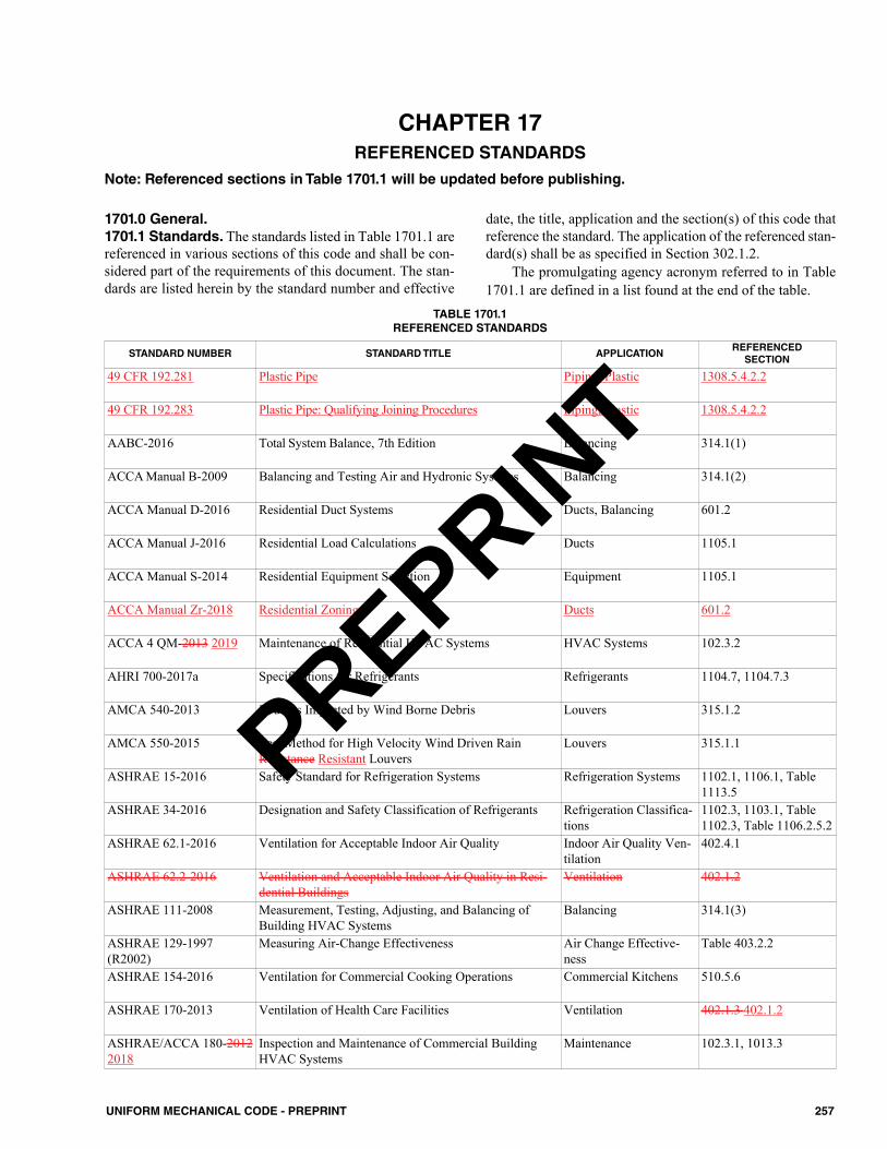
1701.0 General.1701.1 Standards. The standards listed in Table 1701.1 arereferenced in various sections of this code and shall be con-sidered part of the requirements of this document. The stan-dards are listed herein by the standard number and effective
date, the title, application and the section(s) of this code thatreference the standard. The application of the referenced stan-dard(s) shall be as specified in Section 302.1.2.
The promulgating agency acronym referred to in Table1701.1 are defined in a list found at the end of the table.
257UNIFORM MECHANICAL CODE - PREPRINT
CHAPTER 17REFERENCED STANDARDS
STANDARD NUMBER STANDARD TITLE APPLICATIONREFERENCEDSECTION
49 CFR 192.281 Plastic Pipe Piping, Plastic 1308.5.4.2.2
49 CFR 192.283 Plastic Pipe: Qualifying Joining Procedures Piping, Plastic 1308.5.4.2.2
AABC-2016 Total System Balance, 7th Edition Balancing 314.1(1)
ACCA Manual B-2009 Balancing and Testing Air and Hydronic Systems Balancing 314.1(2)
ACCA Manual D-2016 Residential Duct Systems Ducts, Balancing 601.2
ACCA Manual J-2016 Residential Load Calculations Ducts 1105.1
ACCA Manual S-2014 Residential Equipment Selection Equipment 1105.1
ACCA Manual Zr-2018 Residential Zoning Ducts 601.2
ACCA 4 QM-2013 2019 Maintenance of Residential HVAC Systems HVAC Systems 102.3.2
AHRI 700-2017a Specifications for Refrigerants Refrigerants 1104.7, 1104.7.3
AMCA 540-2013 Louvers Impacted by Wind Borne Debris Louvers 315.1.2
AMCA 550-2015 Test Method for High Velocity Wind Driven RainResistance Resistant Louvers
Louvers 315.1.1
ASHRAE 15-2016 Safety Standard for Refrigeration Systems Refrigeration Systems 1102.1, 1106.1, Table1113.5
ASHRAE 34-2016 Designation and Safety Classification of Refrigerants Refrigeration Classifica-tions
1102.3, 1103.1, Table1102.3, Table 1106.2.5.2
ASHRAE 62.1-2016 Ventilation for Acceptable Indoor Air Quality Indoor Air Quality Ven-tilation
402.4.1
ASHRAE 62.2-2016 Ventilation and Acceptable Indoor Air Quality in Resi-dential Buildings
Ventilation 402.1.2
ASHRAE 111-2008 Measurement, Testing, Adjusting, and Balancing ofBuilding HVAC Systems
Balancing 314.1(3)
ASHRAE 129-1997(R2002)
Measuring Air-Change Effectiveness Air Change Effective-ness
Table 403.2.2
ASHRAE 154-2016 Ventilation for Commercial Cooking Operations Commercial Kitchens 510.5.6
ASHRAE 170-2013 Ventilation of Health Care Facilities Ventilation 402.1.3 402.1.2
ASHRAE/ACCA 180-20122018
Inspection and Maintenance of Commercial BuildingHVAC Systems
Maintenance 102.3.1, 1013.3
TABLE 1701.1REFERENCED STANDARDS
Note: Referenced sections in Table 1701.1 will be updated before publishing.
PREPRINT
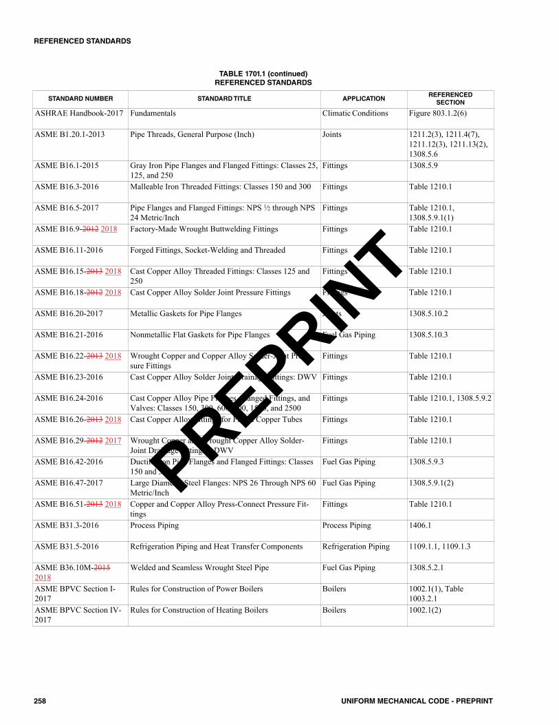
258 UNIFORM MECHANICAL CODE - PREPRINT
REFERENCED STANDARDS
STANDARD NUMBER STANDARD TITLE APPLICATIONREFERENCEDSECTION
ASHRAE Handbook-2017 Fundamentals Climatic Conditions Figure 803.1.2(6)
ASME B1.20.1-2013 Pipe Threads, General Purpose (Inch) Joints 1211.2(3), 1211.4(7),1211.12(3), 1211.13(2),1308.5.6
ASME B16.1-2015 Gray Iron Pipe Flanges and Flanged Fittings: Classes 25,125, and 250
Fittings 1308.5.9
ASME B16.3-2016 Malleable Iron Threaded Fittings: Classes 150 and 300 Fittings Table 1210.1
ASME B16.5-2017 Pipe Flanges and Flanged Fittings: NPS 1⁄2 through NPS24 Metric/Inch
Fittings Table 1210.1,1308.5.9.1(1)
ASME B16.9-2012 2018 Factory-Made Wrought Buttwelding Fittings Fittings Table 1210.1
ASME B16.11-2016 Forged Fittings, Socket-Welding and Threaded Fittings Table 1210.1
ASME B16.15-2013 2018 Cast Copper Alloy Threaded Fittings: Classes 125 and250
Fittings Table 1210.1
ASME B16.18-2012 2018 Cast Copper Alloy Solder Joint Pressure Fittings Fittings Table 1210.1
ASME B16.20-2017 Metallic Gaskets for Pipe Flanges Joints 1308.5.10.2
ASME B16.21-2016 Nonmetallic Flat Gaskets for Pipe Flanges Fuel Gas Piping 1308.5.10.3
ASME B16.22-2013 2018 Wrought Copper and Copper Alloy Solder-Joint Pres-sure Fittings
Fittings Table 1210.1
ASME B16.23-2016 Cast Copper Alloy Solder Joint Drainage Fittings: DWV Fittings Table 1210.1
ASME B16.24-2016 Cast Copper Alloy Pipe Flanges, Flanged Fittings, andValves: Classes 150, 300, 600, 900, 1500, and 2500
Fittings Table 1210.1, 1308.5.9.2
ASME B16.26-2013 2018 Cast Copper Alloy Fittings for Flared Copper Tubes Fittings Table 1210.1
ASME B16.29-2012 2017 Wrought Copper and Wrought Copper Alloy Solder-Joint Drainage Fittings – DWV
Fittings Table 1210.1
ASME B16.42-2016 Ductile Iron Pipe Flanges and Flanged Fittings: Classes150 and 300
Fuel Gas Piping 1308.5.9.3
ASME B16.47-2017 Large Diameter Steel Flanges: NPS 26 Through NPS 60Metric/Inch
Fuel Gas Piping 1308.5.9.1(2)
ASME B16.51-2013 2018 Copper and Copper Alloy Press-Connect Pressure Fit-tings
Fittings Table 1210.1
ASME B31.3-2016 Process Piping Process Piping 1406.1
ASME B31.5-2016 Refrigeration Piping and Heat Transfer Components Refrigeration Piping 1109.1.1, 1109.1.3
ASME B36.10M-20152018
Welded and Seamless Wrought Steel Pipe Fuel Gas Piping 1308.5.2.1
ASME BPVC Section I-2017
Rules for Construction of Power Boilers Boilers 1002.1(1), Table1003.2.1
ASME BPVC Section IV-2017
Rules for Construction of Heating Boilers Boilers 1002.1(2)
TABLE 1701.1 (continued)REFERENCED STANDARDS
PREPRINT
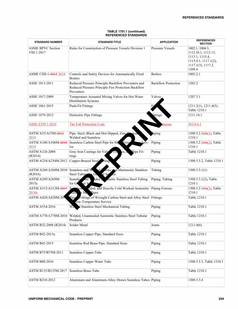
259UNIFORM MECHANICAL CODE - PREPRINT
REFERENCED STANDARDS
STANDARD NUMBER STANDARD TITLE APPLICATIONREFERENCEDSECTION
ASME BPVC SectionVIII.1-2017
Rules for Construction of Pressure Vessels Division 1 Pressure Vessels 1002.1, 1004.3,1112.10.1, 1112.13,1113.1, 1115.4,1115.4.1, 1117.1(2),1117.1(3), 1117.2,1209.4
ASME CSD-1-2015 2018 Controls and Safety Devices for Automatically FiredBoilers
Boilers 1003.2.1
ASSE 1013-2011 Reduced Pressure Principle Backflow Preventers andReduced Pressure Principle Fire Protection BackflowPreventers
Backflow Protection 1202.2
ASSE 1017-2009 Temperature Actuated Mixing Valves for Hot WaterDistribution Systems
Valves 1207.3.1
ASSE 1061-2015 Push-Fit Fittings Fittings 1211.2(1), 1211.4(5),Table 1210.1
ASSE 1079-2012 Dielectric Pipe Fittings Fittings 1211.14.1
ASSE Z359.1-2016 The Fall Protection Code Miscellaneous 303.8.4.1
ASTM A53/A53M-20122018
Pipe, Steel, Black and Hot-Dipped, Zinc-Coated,Welded and Seamless
Piping 1308.5.2.1(2)(1), Table1210.1
ASTM A106/A106M-20152018
Seamless Carbon Steel Pipe for High-Temperature Serv-ice
Piping 1308.5.2.1(3)(2), Table1210.1
ASTM A126-2004(R2014)
Gray Iron Castings for Valves, Flanges, and Pipe Fit-tings
Piping Table 1210.1
ASTM A254/A254M-2012 Copper-Brazed Steel Tubing Piping 1308.5.3.2, Table 1210.1
ASTM A268/A268M-2010(R2016)
Seamless and Welded Ferritic and Martensitic StainlessSteel Tubing for General Service
Tubing 1308.5.3.1(1)
ASTM A269/A269M-2015a
Seamless and Welded Austenitic Stainless Steel Tubingfor General Service
Piping, Tubing 1308.5.3.1(2), Table1210.1
ASTM A312/A312M-20172018a
Seamless, Welded, and Heavily Cold Worked AusteniticStainless Steel Pipes
Piping Ferrous 1308.5.2.1(1)(3), Table1210.1
ASTM A420/A420M-2016 Piping Fittings of Wrought Carbon Steel and Alloy Steelfor Low-Temperature Service
Fittings Table 1210.1
ASTM A554-2016 Welded Stainless Steel Mechanical Tubing Piping Table 1210.1
ASTM A778/A778M-2016 Welded, Unannealed Austenitic Stainless Steel TubularProducts
Piping Table 1210.1
ASTM B32-2008 (R2014) Solder Metal Joints 1211.4(6)
ASTM B42-2015a Seamless Copper Pipe, Standard Sizes Piping Table 1210.1
ASTM B43-2015 Seamless Red Brass Pipe, Standard Sizes Piping Table 1210.1
ASTM B75/B75M-2011 Seamless Copper Tube Piping Table 1210.1
ASTM B88-2016 Seamless Copper Water Tube Piping 1308.5.3.3, Table 1210.1
ASTM B135/B135M-2017 Seamless Brass Tube Piping Table 1210.1
ASTM B210-2012 Aluminum and Aluminum-Alloy Drawn Seamless Tubes Piping 1308.5.3.4
TABLE 1701.1 (continued)REFERENCED STANDARDS
PREPRINT
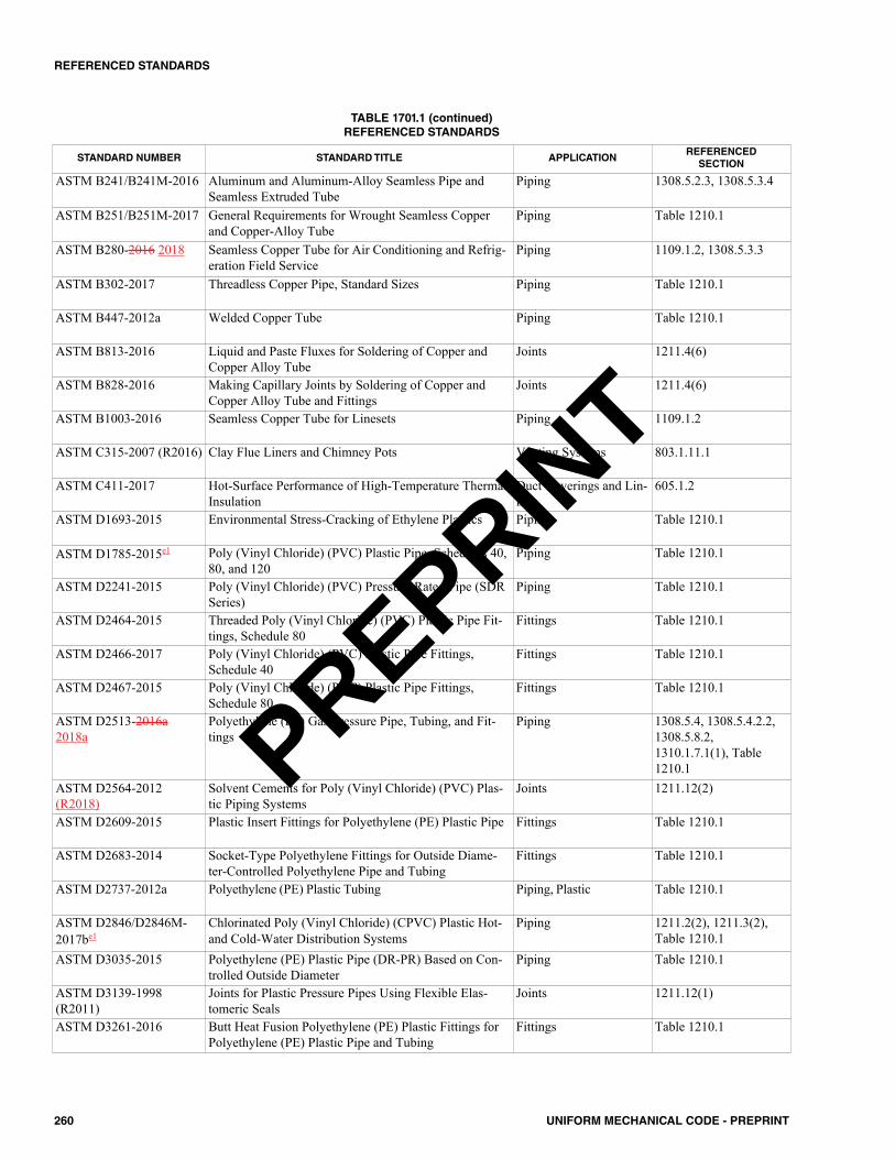
260 UNIFORM MECHANICAL CODE - PREPRINT
REFERENCED STANDARDS
STANDARD NUMBER STANDARD TITLE APPLICATIONREFERENCEDSECTION
ASTM B241/B241M-2016 Aluminum and Aluminum-Alloy Seamless Pipe andSeamless Extruded Tube
Piping 1308.5.2.3, 1308.5.3.4
ASTM B251/B251M-2017 General Requirements for Wrought Seamless Copperand Copper-Alloy Tube
Piping Table 1210.1
ASTM B280-2016 2018 Seamless Copper Tube for Air Conditioning and Refrig-eration Field Service
Piping 1109.1.2, 1308.5.3.3
ASTM B302-2017 Threadless Copper Pipe, Standard Sizes Piping Table 1210.1
ASTM B447-2012a Welded Copper Tube Piping Table 1210.1
ASTM B813-2016 Liquid and Paste Fluxes for Soldering of Copper andCopper Alloy Tube
Joints 1211.4(6)
ASTM B828-2016 Making Capillary Joints by Soldering of Copper andCopper Alloy Tube and Fittings
Joints 1211.4(6)
ASTM B1003-2016 Seamless Copper Tube for Linesets Piping 1109.1.2
ASTM C315-2007 (R2016) Clay Flue Liners and Chimney Pots Venting Systems 803.1.11.1
ASTM C411-2017 Hot-Surface Performance of High-Temperature ThermalInsulation
Duct Coverings and Lin-ings
605.1.2
ASTM D1693-2015 Environmental Stress-Cracking of Ethylene Plastics Piping Table 1210.1
ASTM D1785-2015e1 Poly (Vinyl Chloride) (PVC) Plastic Pipe, Schedules 40,80, and 120
Piping Table 1210.1
ASTM D2241-2015 Poly (Vinyl Chloride) (PVC) Pressure-Rated Pipe (SDRSeries)
Piping Table 1210.1
ASTM D2464-2015 Threaded Poly (Vinyl Chloride) (PVC) Plastic Pipe Fit-tings, Schedule 80
Fittings Table 1210.1
ASTM D2466-2017 Poly (Vinyl Chloride) (PVC) Plastic Pipe Fittings,Schedule 40
Fittings Table 1210.1
ASTM D2467-2015 Poly (Vinyl Chloride) (PVC) Plastic Pipe Fittings,Schedule 80
Fittings Table 1210.1
ASTM D2513-2016a2018a
Polyethylene (PE) Gas Pressure Pipe, Tubing, and Fit-tings
Piping 1308.5.4, 1308.5.4.2.2,1308.5.8.2,1310.1.7.1(1), Table1210.1
ASTM D2564-2012(R2018)
Solvent Cements for Poly (Vinyl Chloride) (PVC) Plas-tic Piping Systems
Joints 1211.12(2)
ASTM D2609-2015 Plastic Insert Fittings for Polyethylene (PE) Plastic Pipe Fittings Table 1210.1
ASTM D2683-2014 Socket-Type Polyethylene Fittings for Outside Diame-ter-Controlled Polyethylene Pipe and Tubing
Fittings Table 1210.1
ASTM D2737-2012a Polyethylene (PE) Plastic Tubing Piping, Plastic Table 1210.1
ASTM D2846/D2846M-2017be1
Chlorinated Poly (Vinyl Chloride) (CPVC) Plastic Hot-and Cold-Water Distribution Systems
Piping 1211.2(2), 1211.3(2),Table 1210.1
ASTM D3035-2015 Polyethylene (PE) Plastic Pipe (DR-PR) Based on Con-trolled Outside Diameter
Piping Table 1210.1
ASTM D3139-1998(R2011)
Joints for Plastic Pressure Pipes Using Flexible Elas-tomeric Seals
Joints 1211.12(1)
ASTM D3261-2016 Butt Heat Fusion Polyethylene (PE) Plastic Fittings forPolyethylene (PE) Plastic Pipe and Tubing
Fittings Table 1210.1
TABLE 1701.1 (continued)REFERENCED STANDARDS
PREPRINT
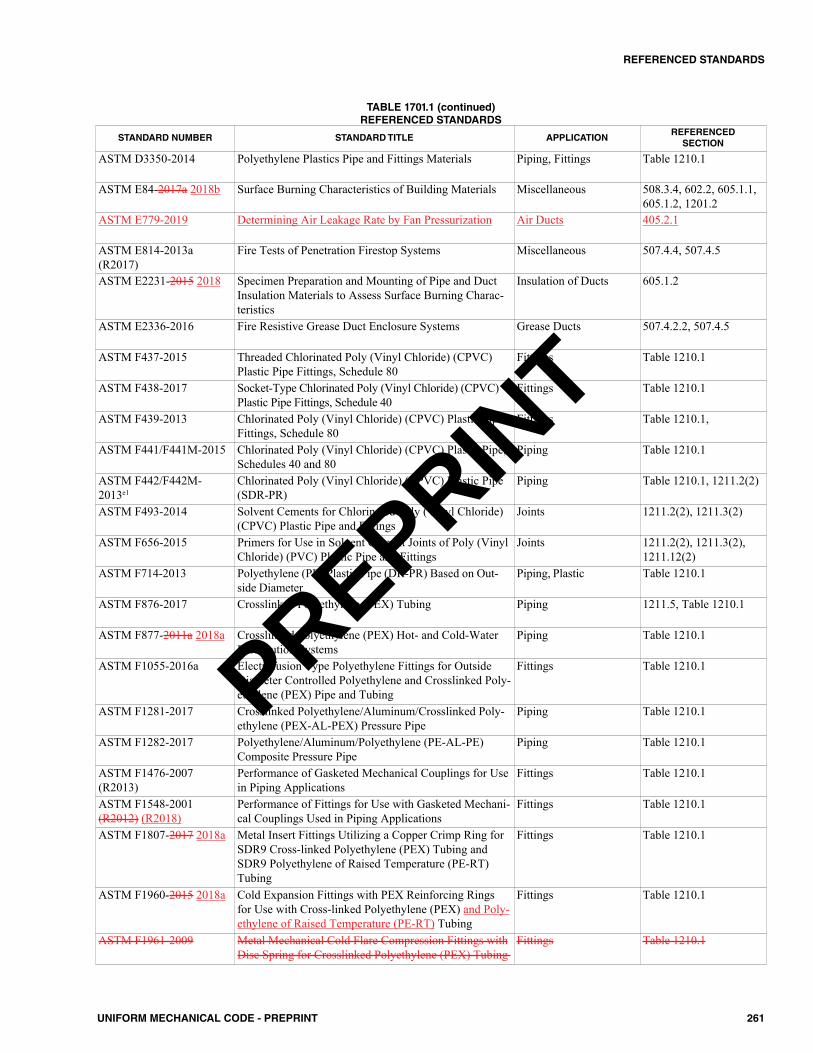
261UNIFORM MECHANICAL CODE - PREPRINT
REFERENCED STANDARDS
STANDARD NUMBER STANDARD TITLE APPLICATIONREFERENCEDSECTION
ASTM D3350-2014 Polyethylene Plastics Pipe and Fittings Materials Piping, Fittings Table 1210.1
ASTM E84-2017a 2018b Surface Burning Characteristics of Building Materials Miscellaneous 508.3.4, 602.2, 605.1.1,605.1.2, 1201.2
ASTM E779-2019 Determining Air Leakage Rate by Fan Pressurization Air Ducts 405.2.1
ASTM E814-2013a(R2017)
Fire Tests of Penetration Firestop Systems Miscellaneous 507.4.4, 507.4.5
ASTM E2231-2015 2018 Specimen Preparation and Mounting of Pipe and DuctInsulation Materials to Assess Surface Burning Charac-teristics
Insulation of Ducts 605.1.2
ASTM E2336-2016 Fire Resistive Grease Duct Enclosure Systems Grease Ducts 507.4.2.2, 507.4.5
ASTM F437-2015 Threaded Chlorinated Poly (Vinyl Chloride) (CPVC)Plastic Pipe Fittings, Schedule 80
Fittings Table 1210.1
ASTM F438-2017 Socket-Type Chlorinated Poly (Vinyl Chloride) (CPVC)Plastic Pipe Fittings, Schedule 40
Fittings Table 1210.1
ASTM F439-2013 Chlorinated Poly (Vinyl Chloride) (CPVC) Plastic PipeFittings, Schedule 80
Fittings Table 1210.1,
ASTM F441/F441M-2015 Chlorinated Poly (Vinyl Chloride) (CPVC) Plastic Pipe,Schedules 40 and 80
Piping Table 1210.1
ASTM F442/F442M-2013e1
Chlorinated Poly (Vinyl Chloride) (CPVC) Plastic Pipe(SDR-PR)
Piping Table 1210.1, 1211.2(2)
ASTM F493-2014 Solvent Cements for Chlorinated Poly (Vinyl Chloride)(CPVC) Plastic Pipe and Fittings
Joints 1211.2(2), 1211.3(2)
ASTM F656-2015 Primers for Use in Solvent Cement Joints of Poly (VinylChloride) (PVC) Plastic Pipe and Fittings
Joints 1211.2(2), 1211.3(2),1211.12(2)
ASTM F714-2013 Polyethylene (PE) Plastic Pipe (DR-PR) Based on Out-side Diameter
Piping, Plastic Table 1210.1
ASTM F876-2017 Crosslinked Polyethylene (PEX) Tubing Piping 1211.5, Table 1210.1
ASTM F877-2011a 2018a Crosslinked Polyethylene (PEX) Hot- and Cold-WaterDistribution Systems
Piping Table 1210.1
ASTM F1055-2016a Electrofusion Type Polyethylene Fittings for OutsideDiameter Controlled Polyethylene and Crosslinked Poly-ethylene (PEX) Pipe and Tubing
Fittings Table 1210.1
ASTM F1281-2017 Crosslinked Polyethylene/Aluminum/Crosslinked Poly-ethylene (PEX-AL-PEX) Pressure Pipe
Piping Table 1210.1
ASTM F1282-2017 Polyethylene/Aluminum/Polyethylene (PE-AL-PE)Composite Pressure Pipe
Piping Table 1210.1
ASTM F1476-2007(R2013)
Performance of Gasketed Mechanical Couplings for Usein Piping Applications
Fittings Table 1210.1
ASTM F1548-2001(R2012) (R2018)
Performance of Fittings for Use with Gasketed Mechani-cal Couplings Used in Piping Applications
Fittings Table 1210.1
ASTM F1807-2017 2018a Metal Insert Fittings Utilizing a Copper Crimp Ring forSDR9 Cross-linked Polyethylene (PEX) Tubing andSDR9 Polyethylene of Raised Temperature (PE-RT)Tubing
Fittings Table 1210.1
ASTM F1960-2015 2018a Cold Expansion Fittings with PEX Reinforcing Ringsfor Use with Cross-linked Polyethylene (PEX) and Poly-ethylene of Raised Temperature (PE-RT) Tubing
Fittings Table 1210.1
ASTM F1961-2009 Metal Mechanical Cold Flare Compression Fittings withDisc Spring for Crosslinked Polyethylene (PEX) Tubing
Fittings Table 1210.1
TABLE 1701.1 (continued)REFERENCED STANDARDS
PREPRINT
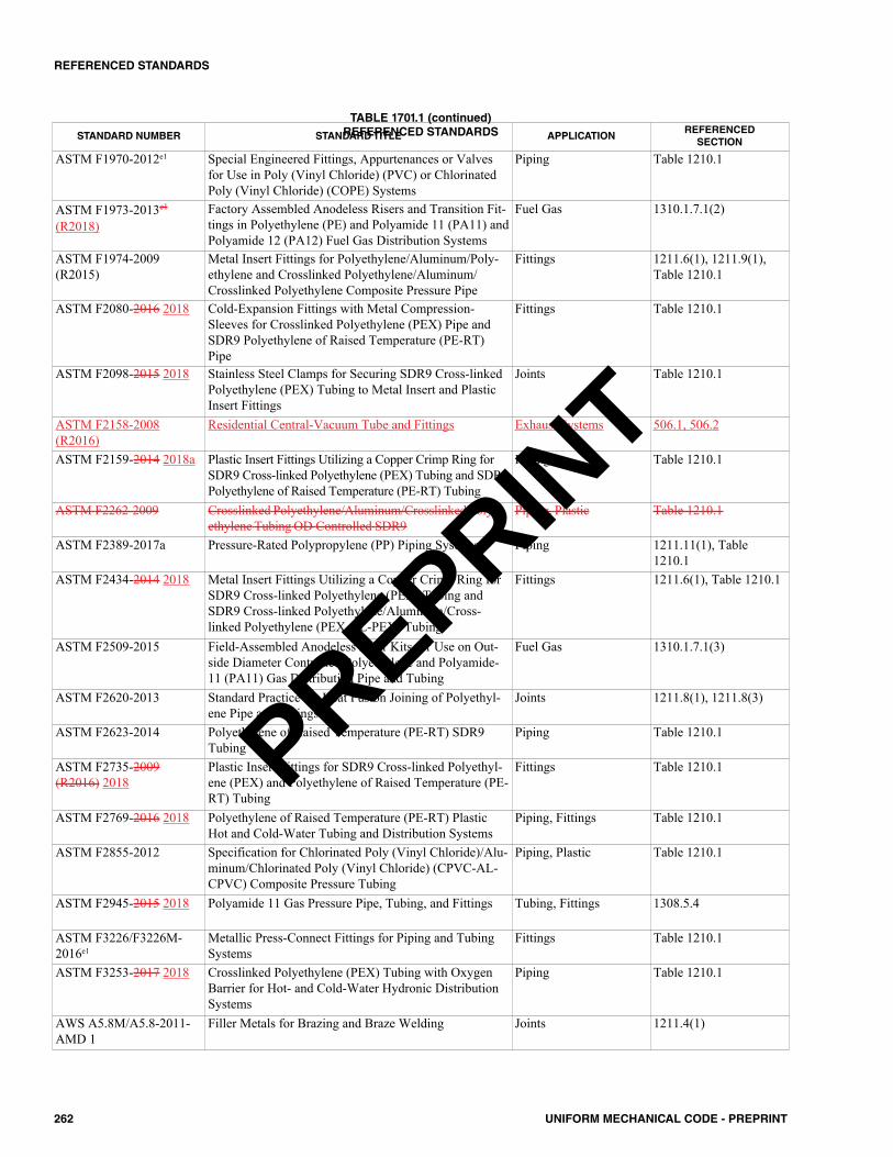
262 UNIFORM MECHANICAL CODE - PREPRINT
REFERENCED STANDARDS
STANDARD NUMBER STANDARD TITLE APPLICATIONREFERENCEDSECTION
ASTM F1970-2012e1 Special Engineered Fittings, Appurtenances or Valvesfor Use in Poly (Vinyl Chloride) (PVC) or ChlorinatedPoly (Vinyl Chloride) (COPE) Systems
Piping Table 1210.1
ASTM F1973-2013e1
(R2018)Factory Assembled Anodeless Risers and Transition Fit-tings in Polyethylene (PE) and Polyamide 11 (PA11) andPolyamide 12 (PA12) Fuel Gas Distribution Systems
Fuel Gas 1310.1.7.1(2)
ASTM F1974-2009(R2015)
Metal Insert Fittings for Polyethylene/Aluminum/Poly-ethylene and Crosslinked Polyethylene/Aluminum/Crosslinked Polyethylene Composite Pressure Pipe
Fittings 1211.6(1), 1211.9(1),Table 1210.1
ASTM F2080-2016 2018 Cold-Expansion Fittings with Metal Compression-Sleeves for Crosslinked Polyethylene (PEX) Pipe andSDR9 Polyethylene of Raised Temperature (PE-RT)Pipe
Fittings Table 1210.1
ASTM F2098-2015 2018 Stainless Steel Clamps for Securing SDR9 Cross-linkedPolyethylene (PEX) Tubing to Metal Insert and PlasticInsert Fittings
Joints Table 1210.1
ASTM F2158-2008(R2016)
Residential Central-Vacuum Tube and Fittings Exhaust Systems 506.1, 506.2
ASTM F2159-2014 2018a Plastic Insert Fittings Utilizing a Copper Crimp Ring forSDR9 Cross-linked Polyethylene (PEX) Tubing and SDR9Polyethylene of Raised Temperature (PE-RT) Tubing
Fittings Table 1210.1
ASTM F2262-2009 Crosslinked Polyethylene/Aluminum/Crosslinked Poly-ethylene Tubing OD Controlled SDR9
Piping, Plastic Table 1210.1
ASTM F2389-2017a Pressure-Rated Polypropylene (PP) Piping Systems Piping 1211.11(1), Table1210.1
ASTM F2434-2014 2018 Metal Insert Fittings Utilizing a Copper Crimp Ring forSDR9 Cross-linked Polyethylene (PEX) Tubing andSDR9 Cross-linked Polyethylene/Aluminum/Cross-linked Polyethylene (PEX-AL-PEX) Tubing
Fittings 1211.6(1), Table 1210.1
ASTM F2509-2015 Field-Assembled Anodeless Riser Kits for Use on Out-side Diameter Controlled Polyethylene and Polyamide-11 (PA11) Gas Distribution Pipe and Tubing
Fuel Gas 1310.1.7.1(3)
ASTM F2620-2013 Standard Practice for Heat Fusion Joining of Polyethyl-ene Pipe and Fittings
Joints 1211.8(1), 1211.8(3)
ASTM F2623-2014 Polyethylene of Raised Temperature (PE-RT) SDR9Tubing
Piping Table 1210.1
ASTM F2735-2009(R2016) 2018
Plastic Insert Fittings for SDR9 Cross-linked Polyethyl-ene (PEX) and Polyethylene of Raised Temperature (PE-RT) Tubing
Fittings Table 1210.1
ASTM F2769-2016 2018 Polyethylene of Raised Temperature (PE-RT) PlasticHot and Cold-Water Tubing and Distribution Systems
Piping, Fittings Table 1210.1
ASTM F2855-2012 Specification for Chlorinated Poly (Vinyl Chloride)/Alu-minum/Chlorinated Poly (Vinyl Chloride) (CPVC-AL-CPVC) Composite Pressure Tubing
Piping, Plastic Table 1210.1
ASTM F2945-2015 2018 Polyamide 11 Gas Pressure Pipe, Tubing, and Fittings Tubing, Fittings 1308.5.4
ASTM F3226/F3226M-2016e1
Metallic Press-Connect Fittings for Piping and TubingSystems
Fittings Table 1210.1
ASTM F3253-2017 2018 Crosslinked Polyethylene (PEX) Tubing with OxygenBarrier for Hot- and Cold-Water Hydronic DistributionSystems
Piping Table 1210.1
AWS A5.8M/A5.8-2011-AMD 1
Filler Metals for Brazing and Braze Welding Joints 1211.4(1)
TABLE 1701.1 (continued)REFERENCED STANDARDS
PREPRINT
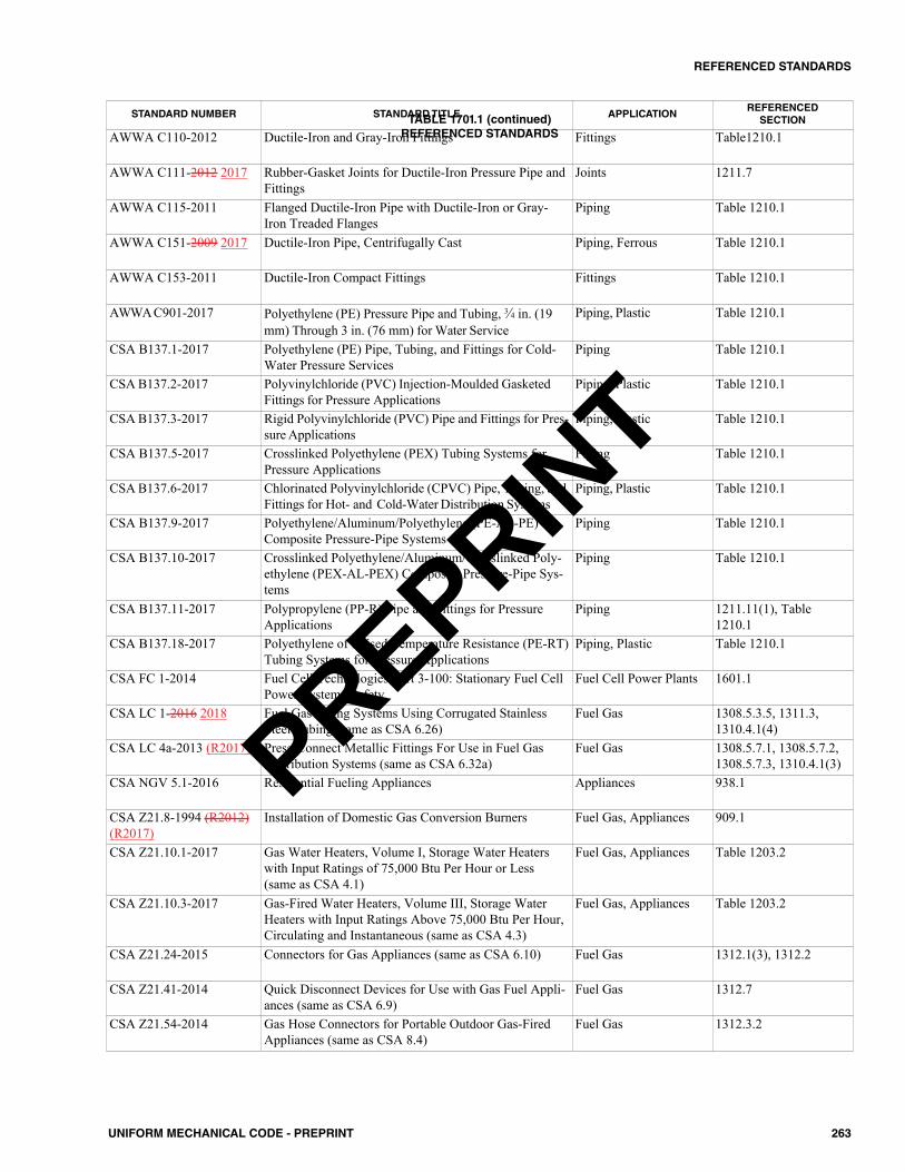
263UNIFORM MECHANICAL CODE - PREPRINT
REFERENCED STANDARDS
STANDARD NUMBER STANDARD TITLE APPLICATIONREFERENCEDSECTION
AWWA C110-2012 Ductile-Iron and Gray-Iron Fittings Fittings Table1210.1
AWWA C111-2012 2017 Rubber-Gasket Joints for Ductile-Iron Pressure Pipe andFittings
Joints 1211.7
AWWA C115-2011 Flanged Ductile-Iron Pipe with Ductile-Iron or Gray-Iron Treaded Flanges
Piping Table 1210.1
AWWA C151-2009 2017 Ductile-Iron Pipe, Centrifugally Cast Piping, Ferrous Table 1210.1
AWWA C153-2011 Ductile-Iron Compact Fittings Fittings Table 1210.1
AWWA C901-2017 Polyethylene (PE) Pressure Pipe and Tubing, 3⁄4 in. (19mm) Through 3 in. (76 mm) for Water Service
Piping, Plastic Table 1210.1
CSA B137.1-2017 Polyethylene (PE) Pipe, Tubing, and Fittings for Cold-Water Pressure Services
Piping Table 1210.1
CSA B137.2-2017 Polyvinylchloride (PVC) Injection-Moulded GasketedFittings for Pressure Applications
Piping, Plastic Table 1210.1
CSA B137.3-2017 Rigid Polyvinylchloride (PVC) Pipe and Fittings for Pres-sure Applications
Piping, Plastic Table 1210.1
CSA B137.5-2017 Crosslinked Polyethylene (PEX) Tubing Systems forPressure Applications
Piping Table 1210.1
CSA B137.6-2017 Chlorinated Polyvinylchloride (CPVC) Pipe, Tubing, andFittings for Hot- and Cold-Water Distribution Systems
Piping, Plastic Table 1210.1
CSA B137.9-2017 Polyethylene/Aluminum/Polyethylene (PE-AL-PE)Composite Pressure-Pipe Systems
Piping Table 1210.1
CSA B137.10-2017 Crosslinked Polyethylene/Aluminum/Crosslinked Poly-ethylene (PEX-AL-PEX) Composite Pressure-Pipe Sys-tems
Piping Table 1210.1
CSA B137.11-2017 Polypropylene (PP-R) Pipe and Fittings for PressureApplications
Piping 1211.11(1), Table1210.1
CSA B137.18-2017 Polyethylene of Raised Temperature Resistance (PE-RT)Tubing Systems for Pressure Applications
Piping, Plastic Table 1210.1
CSA FC 1-2014 Fuel Cell Technologies-Part 3-100: Stationary Fuel CellPower Systems-Safety
Fuel Cell Power Plants 1601.1
CSA LC 1-2016 2018 Fuel Gas Piping Systems Using Corrugated StainlessSteel Tubing (same as CSA 6.26)
Fuel Gas 1308.5.3.5, 1311.3,1310.4.1(4)
CSA LC 4a-2013 (R2017) Press-Connect Metallic Fittings For Use in Fuel GasDistribution Systems (same as CSA 6.32a)
Fuel Gas 1308.5.7.1, 1308.5.7.2,1308.5.7.3, 1310.4.1(3)
CSA NGV 5.1-2016 Residential Fueling Appliances Appliances 938.1
CSA Z21.8-1994 (R2012)(R2017)
Installation of Domestic Gas Conversion Burners Fuel Gas, Appliances 909.1
CSA Z21.10.1-2017 Gas Water Heaters, Volume I, Storage Water Heaterswith Input Ratings of 75,000 Btu Per Hour or Less(same as CSA 4.1)
Fuel Gas, Appliances Table 1203.2
CSA Z21.10.3-2017 Gas-Fired Water Heaters, Volume III, Storage WaterHeaters with Input Ratings Above 75,000 Btu Per Hour,Circulating and Instantaneous (same as CSA 4.3)
Fuel Gas, Appliances Table 1203.2
CSA Z21.24-2015 Connectors for Gas Appliances (same as CSA 6.10) Fuel Gas 1312.1(3), 1312.2
CSA Z21.41-2014 Quick Disconnect Devices for Use with Gas Fuel Appli-ances (same as CSA 6.9)
Fuel Gas 1312.7
CSA Z21.54-2014 Gas Hose Connectors for Portable Outdoor Gas-FiredAppliances (same as CSA 8.4)
Fuel Gas 1312.3.2
TABLE 1701.1 (continued)REFERENCED STANDARDS
PREPRINT
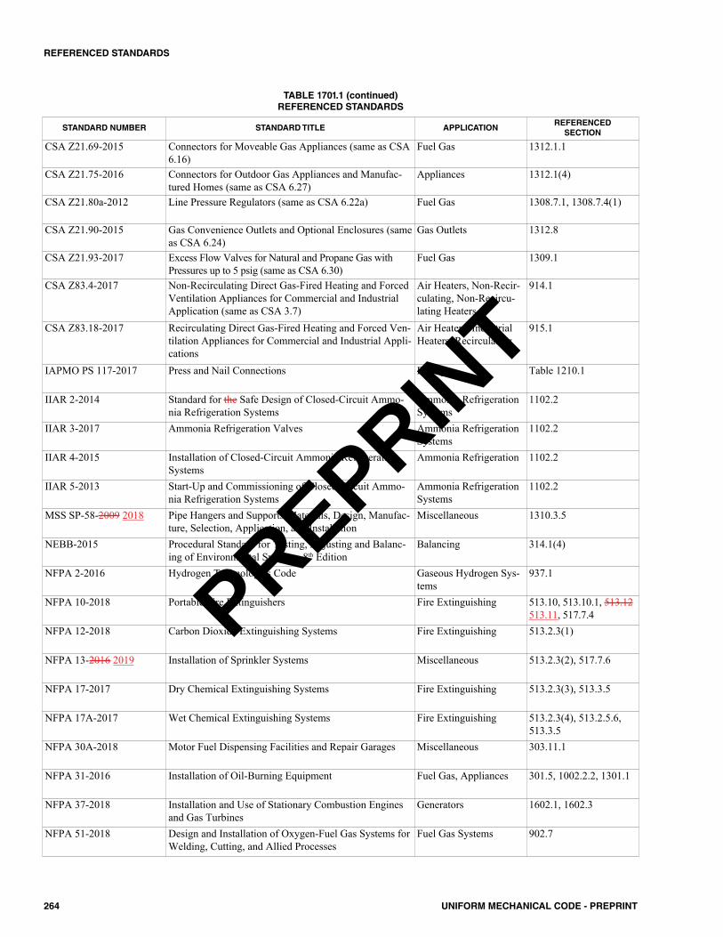
264 UNIFORM MECHANICAL CODE - PREPRINT
REFERENCED STANDARDS
STANDARD NUMBER STANDARD TITLE APPLICATIONREFERENCEDSECTION
CSA Z21.69-2015 Connectors for Moveable Gas Appliances (same as CSA6.16)
Fuel Gas 1312.1.1
CSA Z21.75-2016 Connectors for Outdoor Gas Appliances and Manufac-tured Homes (same as CSA 6.27)
Appliances 1312.1(4)
CSA Z21.80a-2012 Line Pressure Regulators (same as CSA 6.22a) Fuel Gas 1308.7.1, 1308.7.4(1)
CSA Z21.90-2015 Gas Convenience Outlets and Optional Enclosures (sameas CSA 6.24)
Gas Outlets 1312.8
CSA Z21.93-2017 Excess Flow Valves for Natural and Propane Gas withPressures up to 5 psig (same as CSA 6.30)
Fuel Gas 1309.1
CSA Z83.4-2017 Non-Recirculating Direct Gas-Fired Heating and ForcedVentilation Appliances for Commercial and IndustrialApplication (same as CSA 3.7)
Air Heaters, Non-Recir-culating, Non-Recircu-lating Heaters
914.1
CSA Z83.18-2017 Recirculating Direct Gas-Fired Heating and Forced Ven-tilation Appliances for Commercial and Industrial Appli-cations
Air Heaters, IndustrialHeaters, Recirculating
915.1
IAPMO PS 117-2017 Press and Nail Connections Fittings Table 1210.1
IIAR 2-2014 Standard for the Safe Design of Closed-Circuit Ammo-nia Refrigeration Systems
Ammonia RefrigerationSystems
1102.2
IIAR 3-2017 Ammonia Refrigeration Valves Ammonia RefrigerationSystems
1102.2
IIAR 4-2015 Installation of Closed-Circuit Ammonia RefrigerationSystems
Ammonia Refrigeration 1102.2
IIAR 5-2013 Start-Up and Commissioning of Closed Circuit Ammo-nia Refrigeration Systems
Ammonia RefrigerationSystems
1102.2
MSS SP-58-2009 2018 Pipe Hangers and Supports-Materials, Design, Manufac-ture, Selection, Application, and Installation
Miscellaneous 1310.3.5
NEBB-2015 Procedural Standard for Testing, Adjusting and Balanc-ing of Environmental Systems, 8th Edition
Balancing 314.1(4)
NFPA 2-2016 Hydrogen Technologies Code Gaseous Hydrogen Sys-tems
937.1
NFPA 10-2018 Portable Fire Extinguishers Fire Extinguishing 513.10, 513.10.1, 513.12513.11, 517.7.4
NFPA 12-2018 Carbon Dioxide Extinguishing Systems Fire Extinguishing 513.2.3(1)
NFPA 13-2016 2019 Installation of Sprinkler Systems Miscellaneous 513.2.3(2), 517.7.6
NFPA 17-2017 Dry Chemical Extinguishing Systems Fire Extinguishing 513.2.3(3), 513.3.5
NFPA 17A-2017 Wet Chemical Extinguishing Systems Fire Extinguishing 513.2.3(4), 513.2.5.6,513.3.5
NFPA 30A-2018 Motor Fuel Dispensing Facilities and Repair Garages Miscellaneous 303.11.1
NFPA 31-2016 Installation of Oil-Burning Equipment Fuel Gas, Appliances 301.5, 1002.2.2, 1301.1
NFPA 37-2018 Installation and Use of Stationary Combustion Enginesand Gas Turbines
Generators 1602.1, 1602.3
NFPA 51-2018 Design and Installation of Oxygen-Fuel Gas Systems forWelding, Cutting, and Allied Processes
Fuel Gas Systems 902.7
TABLE 1701.1 (continued)REFERENCED STANDARDS
PREPRINT
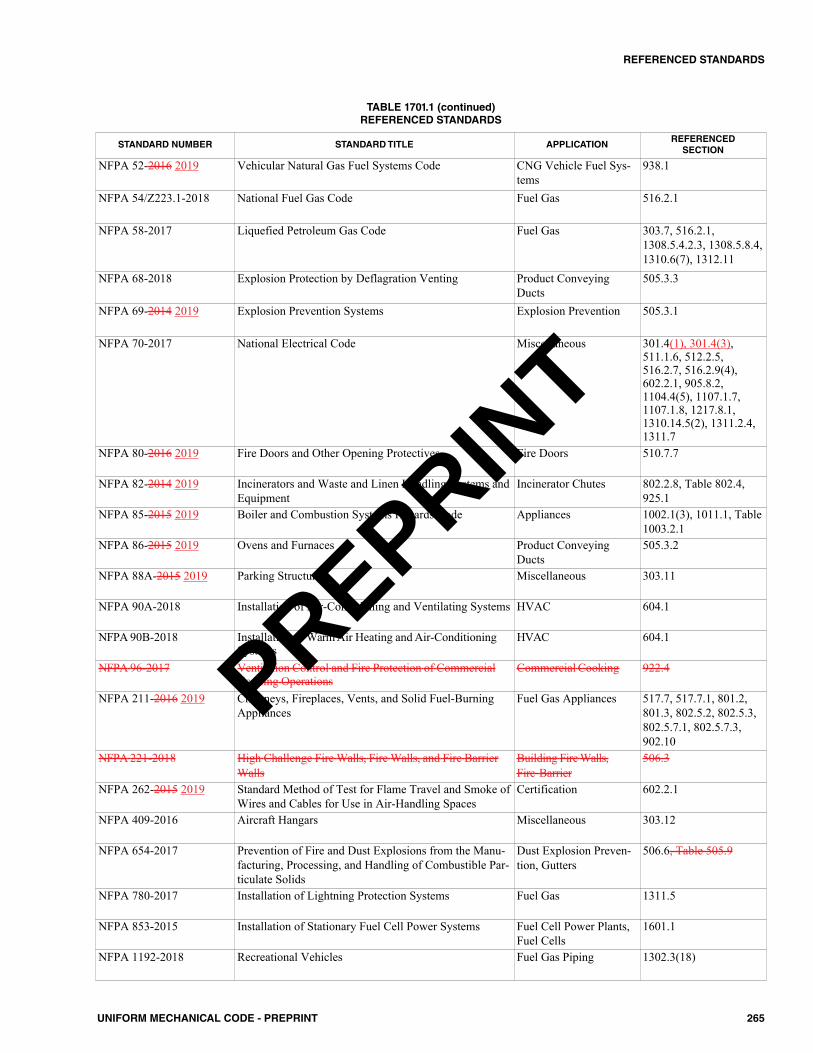
265UNIFORM MECHANICAL CODE - PREPRINT
REFERENCED STANDARDS
STANDARD NUMBER STANDARD TITLE APPLICATIONREFERENCEDSECTION
NFPA 52-2016 2019 Vehicular Natural Gas Fuel Systems Code CNG Vehicle Fuel Sys-tems
938.1
NFPA 54/Z223.1-2018 National Fuel Gas Code Fuel Gas 516.2.1
NFPA 58-2017 Liquefied Petroleum Gas Code Fuel Gas 303.7, 516.2.1,1308.5.4.2.3, 1308.5.8.4,1310.6(7), 1312.11
NFPA 68-2018 Explosion Protection by Deflagration Venting Product ConveyingDucts
505.3.3
NFPA 69-2014 2019 Explosion Prevention Systems Explosion Prevention 505.3.1
NFPA 70-2017 National Electrical Code Miscellaneous 301.4(1), 301.4(3),511.1.6, 512.2.5,516.2.7, 516.2.9(4),602.2.1, 905.8.2,1104.4(5), 1107.1.7,1107.1.8, 1217.8.1,1310.14.5(2), 1311.2.4,1311.7
NFPA 80-2016 2019 Fire Doors and Other Opening Protectives Fire Doors 510.7.7
NFPA 82-2014 2019 Incinerators and Waste and Linen Handling Systems andEquipment
Incinerator Chutes 802.2.8, Table 802.4,925.1
NFPA 85-2015 2019 Boiler and Combustion Systems Hazards Code Appliances 1002.1(3), 1011.1, Table1003.2.1
NFPA 86-2015 2019 Ovens and Furnaces Product ConveyingDucts
505.3.2
NFPA 88A-2015 2019 Parking Structures Miscellaneous 303.11
NFPA 90A-2018 Installation of Air-Conditioning and Ventilating Systems HVAC 604.1
NFPA 90B-2018 Installation of Warm Air Heating and Air-ConditioningSystems
HVAC 604.1
NFPA 96-2017 Ventilation Control and Fire Protection of CommercialCooking Operations
Commercial Cooking 922.4
NFPA 211-2016 2019 Chimneys, Fireplaces, Vents, and Solid Fuel-BurningAppliances
Fuel Gas Appliances 517.7, 517.7.1, 801.2,801.3, 802.5.2, 802.5.3,802.5.7.1, 802.5.7.3,902.10
NFPA 221-2018 High Challenge Fire Walls, Fire Walls, and Fire BarrierWalls
Building Fire Walls,Fire Barrier
506.3
NFPA 262-2015 2019 Standard Method of Test for Flame Travel and Smoke ofWires and Cables for Use in Air-Handling Spaces
Certification 602.2.1
NFPA 409-2016 Aircraft Hangars Miscellaneous 303.12
NFPA 654-2017 Prevention of Fire and Dust Explosions from the Manu-facturing, Processing, and Handling of Combustible Par-ticulate Solids
Dust Explosion Preven-tion, Gutters
506.6, Table 505.9
NFPA 780-2017 Installation of Lightning Protection Systems Fuel Gas 1311.5
NFPA 853-2015 Installation of Stationary Fuel Cell Power Systems Fuel Cell Power Plants,Fuel Cells
1601.1
NFPA 1192-2018 Recreational Vehicles Fuel Gas Piping 1302.3(18)
TABLE 1701.1 (continued)REFERENCED STANDARDS
PREPRINT
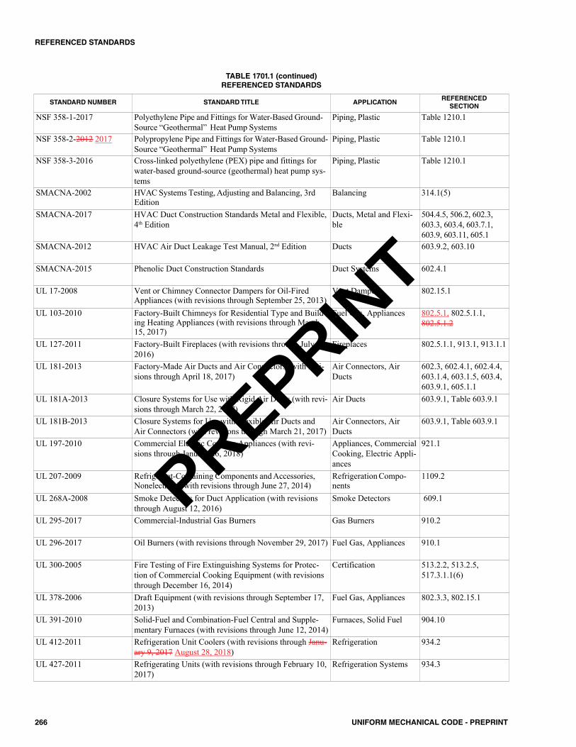
266 UNIFORM MECHANICAL CODE - PREPRINT
REFERENCED STANDARDS
STANDARD NUMBER STANDARD TITLE APPLICATIONREFERENCEDSECTION
NSF 358-1-2017 Polyethylene Pipe and Fittings for Water-Based Ground-Source “Geothermal” Heat Pump Systems
Piping, Plastic Table 1210.1
NSF 358-2-2012 2017 Polypropylene Pipe and Fittings for Water-Based Ground-Source “Geothermal” Heat Pump Systems
Piping, Plastic Table 1210.1
NSF 358-3-2016 Cross-linked polyethylene (PEX) pipe and fittings forwater-based ground-source (geothermal) heat pump sys-tems
Piping, Plastic Table 1210.1
SMACNA-2002 HVAC Systems Testing, Adjusting and Balancing, 3rdEdition
Balancing 314.1(5)
SMACNA-2017 HVAC Duct Construction Standards Metal and Flexible,4th Edition
Ducts, Metal and Flexi-ble
504.4.5, 506.2, 602.3,603.3, 603.4, 603.7.1,603.9, 603.11, 605.1
SMACNA-2012 HVAC Air Duct Leakage Test Manual, 2nd Edition Ducts 603.9.2, 603.10
SMACNA-2015 Phenolic Duct Construction Standards Duct Systems 602.4.1
UL 17-2008 Vent or Chimney Connector Dampers for Oil-FiredAppliances (with revisions through September 25, 2013)
Vent Dampers 802.15.1
UL 103-2010 Factory-Built Chimneys for Residential Type and Build-ing Heating Appliances (with revisions through March15, 2017)
Fuel Gas, Appliances 802.5.1, 802.5.1.1,802.5.1.2
UL 127-2011 Factory-Built Fireplaces (with revisions through July 27.2016)
Fireplaces 802.5.1.1, 913.1, 913.1.1
UL 181-2013 Factory-Made Air Ducts and Air Connectors (with revi-sions through April 18, 2017)
Air Connectors, AirDucts
602.3, 602.4.1, 602.4.4,603.1.4, 603.1.5, 603.4,603.9.1, 605.1.1
UL 181A-2013 Closure Systems for Use with Rigid Air Ducts (with revi-sions through March 22, 2017)
Air Ducts 603.9.1, Table 603.9.1
UL 181B-2013 Closure Systems for Use with Flexible Air Ducts andAir Connectors (with revisions through March 21, 2017)
Air Connectors, AirDucts
603.9.1, Table 603.9.1
UL 197-2010 Commercial Electric Cooking Appliances (with revi-sions through January 26, 2018)
Appliances, CommercialCooking, Electric Appli-ances
921.1
UL 207-2009 Refrigerant-Containing Components and Accessories,Nonelectrical (with revisions through June 27, 2014)
Refrigeration Compo-nents
1109.2
UL 268A-2008 Smoke Detectors for Duct Application (with revisionsthrough August 12, 2016)
Smoke Detectors 609.1
UL 295-2017 Commercial-Industrial Gas Burners Gas Burners 910.2
UL 296-2017 Oil Burners (with revisions through November 29, 2017) Fuel Gas, Appliances 910.1
UL 300-2005 Fire Testing of Fire Extinguishing Systems for Protec-tion of Commercial Cooking Equipment (with revisionsthrough December 16, 2014)
Certification 513.2.2, 513.2.5,517.3.1.1(6)
UL 378-2006 Draft Equipment (with revisions through September 17,2013)
Fuel Gas, Appliances 802.3.3, 802.15.1
UL 391-2010 Solid-Fuel and Combination-Fuel Central and Supple-mentary Furnaces (with revisions through June 12, 2014)
Furnaces, Solid Fuel 904.10
UL 412-2011 Refrigeration Unit Coolers (with revisions through Janu-ary 9, 2017 August 28, 2018)
Refrigeration 934.2
UL 427-2011 Refrigerating Units (with revisions through February 10,2017)
Refrigeration Systems 934.3
TABLE 1701.1 (continued)REFERENCED STANDARDS
PREPRINT

267UNIFORM MECHANICAL CODE - PREPRINT
REFERENCED STANDARDS
STANDARD NUMBER STANDARD TITLE APPLICATIONREFERENCEDSECTION
UL 441-2016 Gas Vents (with revisions through July 27, 2016) Fuel Gas 802.1
UL 467-2013 Grounding and Bonding Equipment Grounding and Bonding 1311.2.5
UL 471-2010 Commercial Refrigerators and Freezers (with revisionsDecember 8, 2016 through November 8, 2018)
Freezers, Refrigerators 934.1
UL 499-2014 Electric Heating Appliances (with revisions throughFebruary 23, 2017)
Kilns 931.4
UL 555-2006 Fire Dampers (with revisions through October 21, 2016) Dampers 606.2
UL 555C-2014 Ceiling Dampers (with revisions through May 1, 2017) Dampers 606.3
UL 555S-2014 Smoke Dampers (with revisions through October 27,2016)
Dampers 606.1
UL 641-2010 Type L Low-Temperature Venting Systems (with revi-sions through December 12, 2017 April 23, 2018)
Equipment 802.1
UL 651-2011 Schedule 40, 80, Type EB and A Rigid PVC Conduitand Fittings (with revisions through June 15, 2016)
Piping, Plastic 1308.5.4.1
UL 705-2017 Power Ventilators (with revisions through October 8,2018)
Power Ventilators 504.4.2.3
UL 710-2012 Exhaust Hoods for Commercial Cooking Equipment (withrevisions through March 22, 2017 June 25, 2018)
Exhaust Hoods, Hoods 507.3.1, 508.2, 508.2.1
UL 710B-2011 Recirculating Systems (with revisions through August14, 2014)
Exhaust Hoods 508.1, 513.2.2, 516.2.2,516.2.3
UL 710C-2006 Ultraviolet Radiation Systems For Use In The Ventila-tion Control of Commercial Cooking Operations
Exhaust Hoods, Hoods 508.2.1
UL 723-2008 2018 Test for Surface Burning Characteristics of BuildingMaterials (with revisions through December 21, 2017)
Miscellaneous 508.3.4, 602.2, 605.1.1,605.1.2, 1201.2
UL 726-1995 Oil-Fired Boiler Assemblies (with revisions throughOctober 9, 2013)
Fuel Gas, Appliances 1002.2.1
UL 727-2006 2018 Oil-Fired Central Furnaces (with revisions through Octo-ber 9, 2013)
Fuel Gas, Appliances 904.11
UL 729-2003 Oil-Fired Floor Furnaces (with revisions throughNovember 22, 2016)
Furnaces, Floor, OilFired Furnaces
906.13
UL 730-2003 Oil-Fired Wall Furnaces (with revisions through Novem-ber 22, 2016)
Furnaces, Wall, OilFired
907.4
UL 731-1995 2018 Oil-Fired Unit Heaters (with revisions through Novem-ber 22, 2016)
Heaters, Oil Fired 917.6
UL 737-2011 Fireplace Stoves (with revisions through August 19,2015)
Fireplace Stoves 913.2
UL 762-2013 Power Roof Ventilators for Restaurant Exhaust Appliances Ventilators 511.1
UL 778-2016 Motor Operated Water Pumps (with revisions throughOctober 20, 2017)
Pumps 1208.1
UL 791-2006 Residential Incinerators (with revisions through Novem-ber 7, 2014)
Incinerators 925.3
UL 795-2016 Commercial-Industrial Gas Heating Equipment Heating Equipment, GasFired
904.12
UL 834-2004 Heating, Water Supply, and Power Boilers - Electric(with revisions through January 10, 2018 September 24,2018)
Appliances 1002.3, Table 1203.2
UL 858-2014 Household Electric Ranges (with revisions throughNovember 1, 2017 June 4, 2018)
Electric Ranges, Ranges 920.1
TABLE 1701.1 (continued)REFERENCED STANDARDS
PREPRINT
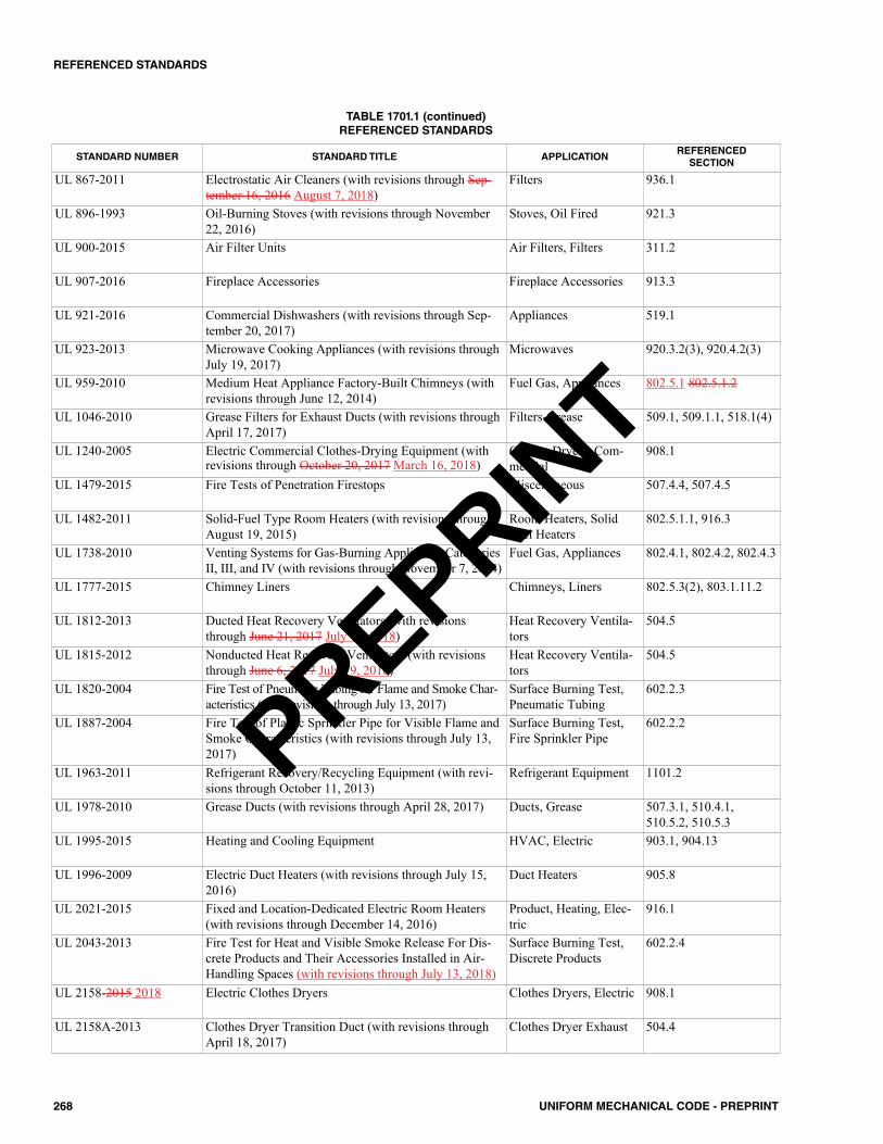
268 UNIFORM MECHANICAL CODE - PREPRINT
REFERENCED STANDARDS
STANDARD NUMBER STANDARD TITLE APPLICATIONREFERENCEDSECTION
UL 867-2011 Electrostatic Air Cleaners (with revisions through Sep-tember 16, 2016 August 7, 2018)
Filters 936.1
UL 896-1993 Oil-Burning Stoves (with revisions through November22, 2016)
Stoves, Oil Fired 921.3
UL 900-2015 Air Filter Units Air Filters, Filters 311.2
UL 907-2016 Fireplace Accessories Fireplace Accessories 913.3
UL 921-2016 Commercial Dishwashers (with revisions through Sep-tember 20, 2017)
Appliances 519.1
UL 923-2013 Microwave Cooking Appliances (with revisions throughJuly 19, 2017)
Microwaves 920.3.2(3), 920.4.2(3)
UL 959-2010 Medium Heat Appliance Factory-Built Chimneys (withrevisions through June 12, 2014)
Fuel Gas, Appliances 802.5.1 802.5.1.2
UL 1046-2010 Grease Filters for Exhaust Ducts (with revisions throughApril 17, 2017)
Filters-Grease 509.1, 509.1.1, 518.1(4)
UL 1240-2005 Electric Commercial Clothes-Drying Equipment (withrevisions through October 20, 2017 March 16, 2018)
Clothes Dryers, Com-mercial
908.1
UL 1479-2015 Fire Tests of Penetration Firestops Miscellaneous 507.4.4, 507.4.5
UL 1482-2011 Solid-Fuel Type Room Heaters (with revisions throughAugust 19, 2015)
Room Heaters, SolidFuel Heaters
802.5.1.1, 916.3
UL 1738-2010 Venting Systems for Gas-Burning Appliances CategoriesII, III, and IV (with revisions through November 7, 2014)
Fuel Gas, Appliances 802.4.1, 802.4.2, 802.4.3
UL 1777-2015 Chimney Liners Chimneys, Liners 802.5.3(2), 803.1.11.2
UL 1812-2013 Ducted Heat Recovery Ventilators (with revisionsthrough June 21, 2017 July 19, 2018)
Heat Recovery Ventila-tors
504.5
UL 1815-2012 Nonducted Heat Recovery Ventilators (with revisionsthrough June 6, 2017 July 19, 2018)
Heat Recovery Ventila-tors
504.5
UL 1820-2004 Fire Test of Pneumatic Tubing for Flame and Smoke Char-acteristics (with revisions through July 13, 2017)
Surface Burning Test,Pneumatic Tubing
602.2.3
UL 1887-2004 Fire Test of Plastic Sprinkler Pipe for Visible Flame andSmoke Characteristics (with revisions through July 13,2017)
Surface Burning Test,Fire Sprinkler Pipe
602.2.2
UL 1963-2011 Refrigerant Recovery/Recycling Equipment (with revi-sions through October 11, 2013)
Refrigerant Equipment 1101.2
UL 1978-2010 Grease Ducts (with revisions through April 28, 2017) Ducts, Grease 507.3.1, 510.4.1,510.5.2, 510.5.3
UL 1995-2015 Heating and Cooling Equipment HVAC, Electric 903.1, 904.13
UL 1996-2009 Electric Duct Heaters (with revisions through July 15,2016)
Duct Heaters 905.8
UL 2021-2015 Fixed and Location-Dedicated Electric Room Heaters(with revisions through December 14, 2016)
Product, Heating, Elec-tric
916.1
UL 2043-2013 Fire Test for Heat and Visible Smoke Release For Dis-crete Products and Their Accessories Installed in Air-Handling Spaces (with revisions through July 13, 2018)
Surface Burning Test,Discrete Products
602.2.4
UL 2158-2015 2018 Electric Clothes Dryers Clothes Dryers, Electric 908.1
UL 2158A-2013 Clothes Dryer Transition Duct (with revisions throughApril 18, 2017)
Clothes Dryer Exhaust 504.4
TABLE 1701.1 (continued)REFERENCED STANDARDS
PREPRINT
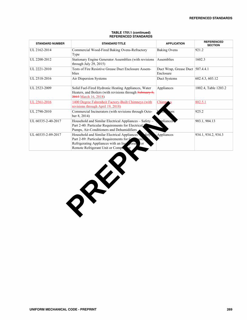
269UNIFORM MECHANICAL CODE - PREPRINT
REFERENCED STANDARDS
STANDARD NUMBER STANDARD TITLE APPLICATIONREFERENCEDSECTION
UL 2162-2014 Commercial Wood-Fired Baking Ovens-RefractoryType
Baking Ovens 921.2
UL 2200-2012 Stationary Engine Generator Assemblies (with revisionsthrough July 29, 2015)
Assemblies 1602.3
UL 2221-2010 Tests of Fire Resistive Grease Duct Enclosure Assem-blies
Duct Wrap, Grease DuctEnclosure
507.4.4.1
UL 2518-2016 Air Dispersion Systems Duct Systems 602.4.3, 603.12
UL 2523-2009 Solid Fuel-Fired Hydronic Heating Appliances, WaterHeaters, and Boilers (with revisions through February 8,2013 March 16, 2018)
Appliances 1002.4, Table 1203.2
UL 2561-2016 1400 Degree Fahrenheit Factory-Built Chimneys (withrevisions through April 19, 2018)
Chimneys 802.5.1
UL 2790-2010 Commercial Incinerators (with revisions through Octo-ber 8, 2014)
Incinerators 925.2
UL 60335-2-40-2017 Household and Similar Electrical Appliances – Safety –Part 2-40: Particular Requirements for Electrical HeatPumps, Air-Conditioners and Dehumidifiers
Appliances 903.1, 904.13
UL 60335-2-89-2017 Household and Similar Electrical Appliances – Safety –Part 2-89: Particular Requirements for CommercialRefrigerating Appliances with an Incorporated orRemote Refrigerant Unit or Compressor
Appliances 934.1, 934.2, 934.3
TABLE 1701.1 (continued)REFERENCED STANDARDS
PREPRINT
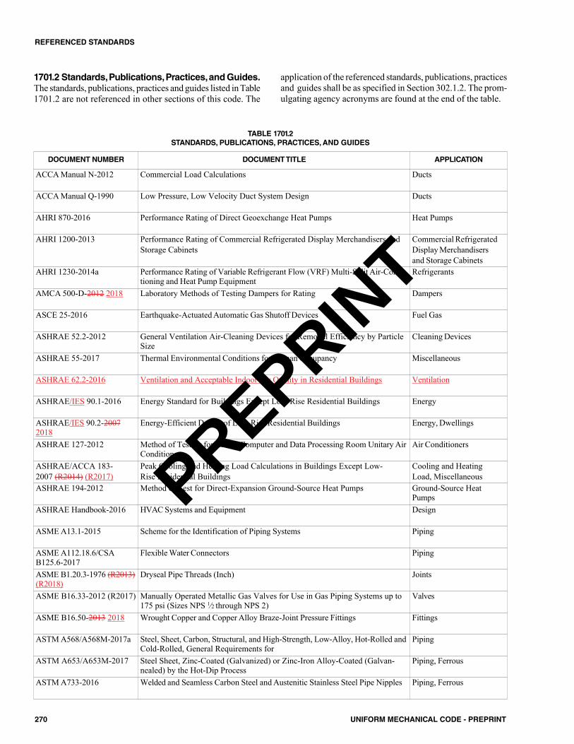
270 UNIFORM MECHANICAL CODE - PREPRINT
REFERENCED STANDARDS
TABLE 1701.2STANDARDS, PUBLICATIONS, PRACTICES,AND GUIDES
DOCUMENT NUMBER DOCUMENT TITLE APPLICATION
ACCA Manual N-2012 Commercial Load Calculations Ducts
ACCA Manual Q-1990 Low Pressure, Low Velocity Duct System Design Ducts
AHRI 870-2016 Performance Rating of Direct Geoexchange Heat Pumps Heat Pumps
AHRI 1200-2013 Performance Rating of Commercial Refrigerated Display Merchandisers andStorage Cabinets
Commercial RefrigeratedDisplay Merchandisersand Storage Cabinets
AHRI 1230-2014a Performance Rating of Variable Refrigerant Flow (VRF) Multi-Split Air-Condi-tioning and Heat Pump Equipment
Refrigerants
AMCA 500-D-2012 2018 Laboratory Methods of Testing Dampers for Rating Dampers
ASCE 25-2016 Earthquake-Actuated Automatic Gas Shutoff Devices Fuel Gas
ASHRAE 52.2-2012 General Ventilation Air-Cleaning Devices for Removal Efficiency by ParticleSize
Cleaning Devices
ASHRAE 55-2017 Thermal Environmental Conditions for Human Occupancy Miscellaneous
ASHRAE 62.2-2016 Ventilation and Acceptable Indoor Air Quality in Residential Buildings Ventilation
ASHRAE/IES 90.1-2016 Energy Standard for Buildings Except Low-Rise Residential Buildings Energy
ASHRAE/IES 90.2-20072018
Energy-Efficient Design of Low-Rise Residential Buildings Energy, Dwellings
ASHRAE 127-2012 Method of Testing for Rating Computer and Data Processing Room Unitary AirConditioners
Air Conditioners
ASHRAE/ACCA 183-2007 (R2014) (R2017)
Peak Cooling and Heating Load Calculations in Buildings Except Low-Rise Residential Buildings
Cooling and HeatingLoad, Miscellaneous
ASHRAE 194-2012 Method of Test for Direct-Expansion Ground-Source Heat Pumps Ground-Source HeatPumps
ASHRAE Handbook-2016 HVAC Systems and Equipment Design
ASME A13.1-2015 Scheme for the Identification of Piping Systems Piping
ASME A112.18.6/CSAB125.6-2017
Flexible Water Connectors Piping
ASME B1.20.3-1976 (R2013)(R2018)
Dryseal Pipe Threads (Inch) Joints
ASME B16.33-2012 (R2017) Manually Operated Metallic Gas Valves for Use in Gas Piping Systems up to175 psi (Sizes NPS 1⁄2 through NPS 2)
Valves
ASME B16.50-2013 2018 Wrought Copper and Copper Alloy Braze-Joint Pressure Fittings Fittings
ASTM A568/A568M-2017a Steel, Sheet, Carbon, Structural, and High-Strength, Low-Alloy, Hot-Rolled andCold-Rolled, General Requirements for
Piping
ASTM A653/A653M-2017 Steel Sheet, Zinc-Coated (Galvanized) or Zinc-Iron Alloy-Coated (Galvan-nealed) by the Hot-Dip Process
Piping, Ferrous
ASTM A733-2016 Welded and Seamless Carbon Steel and Austenitic Stainless Steel Pipe Nipples Piping, Ferrous
1701.2 Standards,Publications,Practices,andGuides.The standards, publications, practices and guides listed in Table1701.2 are not referenced in other sections of this code. The
application of the referenced standards, publications, practicesand guides shall be as specified in Section 302.1.2. The prom-ulgating agency acronyms are found at the end of the table.
PREPRINT
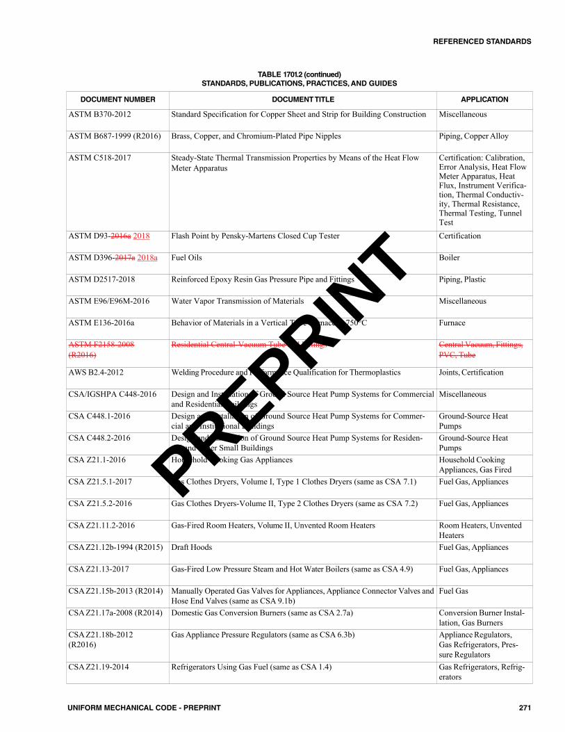
271UNIFORM MECHANICAL CODE - PREPRINT
REFERENCED STANDARDS
DOCUMENT NUMBER DOCUMENT TITLE APPLICATION
ASTM B370-2012 Standard Specification for Copper Sheet and Strip for Building Construction Miscellaneous
ASTM B687-1999 (R2016) Brass, Copper, and Chromium-Plated Pipe Nipples Piping, Copper Alloy
ASTM C518-2017 Steady-State Thermal Transmission Properties by Means of the Heat FlowMeter Apparatus
Certification: Calibration,Error Analysis, Heat FlowMeter Apparatus, HeatFlux, Instrument Verifica-tion, Thermal Conductiv-ity, Thermal Resistance,Thermal Testing, TunnelTest
ASTM D93-2016a 2018 Flash Point by Pensky-Martens Closed Cup Tester Certification
ASTM D396-2017a 2018a Fuel Oils Boiler
ASTM D2517-2018 Reinforced Epoxy Resin Gas Pressure Pipe and Fittings Piping, Plastic
ASTM E96/E96M-2016 Water Vapor Transmission of Materials Miscellaneous
ASTM E136-2016a Behavior of Materials in a Vertical Tube Furnace at 750°C Furnace
ASTM F2158-2008(R2016)
Residential Central-Vacuum Tube and Fittings Central Vacuum, Fittings,PVC, Tube
AWS B2.4-2012 Welding Procedure and Performance Qualification for Thermoplastics Joints, Certification
CSA/IGSHPA C448-2016 Design and Installation of Ground Source Heat Pump Systems for Commercialand Residential Buildings
Miscellaneous
CSA C448.1-2016 Design and Installation of Ground Source Heat Pump Systems for Commer-cial and Institutional Buildings
Ground-Source HeatPumps
CSA C448.2-2016 Design and Installation of Ground Source Heat Pump Systems for Residen-tial and Other Small Buildings
Ground-Source HeatPumps
CSA Z21.1-2016 Household Cooking Gas Appliances Household CookingAppliances, Gas Fired
CSA Z21.5.1-2017 Gas Clothes Dryers, Volume I, Type 1 Clothes Dryers (same as CSA 7.1) Fuel Gas, Appliances
CSA Z21.5.2-2016 Gas Clothes Dryers-Volume II, Type 2 Clothes Dryers (same as CSA 7.2) Fuel Gas, Appliances
CSA Z21.11.2-2016 Gas-Fired Room Heaters, Volume II, Unvented Room Heaters Room Heaters, UnventedHeaters
CSA Z21.12b-1994 (R2015) Draft Hoods Fuel Gas, Appliances
CSA Z21.13-2017 Gas-Fired Low Pressure Steam and Hot Water Boilers (same as CSA 4.9) Fuel Gas, Appliances
CSA Z21.15b-2013 (R2014) Manually Operated Gas Valves for Appliances, Appliance Connector Valves andHose End Valves (same as CSA 9.1b)
Fuel Gas
CSA Z21.17a-2008 (R2014) Domestic Gas Conversion Burners (same as CSA 2.7a) Conversion Burner Instal-lation, Gas Burners
CSA Z21.18b-2012(R2016)
Gas Appliance Pressure Regulators (same as CSA 6.3b) Appliance Regulators,Gas Refrigerators, Pres-sure Regulators
CSA Z21.19-2014 Refrigerators Using Gas Fuel (same as CSA 1.4) Gas Refrigerators, Refrig-erators
TABLE 1701.2 (continued)STANDARDS, PUBLICATIONS, PRACTICES,AND GUIDES
PREPRINT
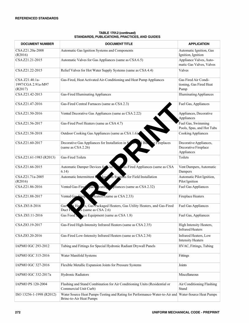
272 UNIFORM MECHANICAL CODE - PREPRINT
REFERENCED STANDARDS
DOCUMENT NUMBER DOCUMENT TITLE APPLICATION
CSA Z21.20a-2008(R2016)
Automatic Gas Ignition Systems and Components Automatic Ignition, GasIgnition, Ignition
CSA Z21.21-2015 Automatic Valves for Gas Appliances (same as CSA 6.5) Appliance Valves, Auto-matic Gas Valves, Valves
CSA Z21.22-2015 Relief Valves for Hot Water Supply Systems (same as CSA 4.4) Valves
CSA Z21.40.1a-1997/CGA 2.91a-M97(R2017)
Gas-Fired, Heat Activated Air-Conditioning and Heat Pump Appliances Gas Fired Air Condi-tioning, Gas Fired HeatPump
CSA Z21.42-2013 Gas-Fired Illuminating Appliances IlluminatingAppliances
CSA Z21.47-2016 Gas-Fired Central Furnaces (same as CSA 2.3) Fuel Gas, Appliances
CSA Z21.50-2016 Vented Decorative Gas Appliances (same as CSA 2.22) Appliances, DecorativeAppliances
CSA Z21.56-2017 Gas-Fired Pool Heaters (same as CSA 4.7) Fuel Gas, SwimmingPools, Spas, and Hot Tubs
CSA Z21.58-2018 Outdoor Cooking Gas Appliances (same as CSA 1.6) CookingAppliances
CSA Z21.60-2017 Decorative Gas Appliances for Installation in Solid-Fuel Burning Fireplaces(same as CSA 2.26)
DecorativeAppliances,Decorative FireplaceAppliances
CSA Z21.61-1983 (R2013) Gas-Fired Toilets Toilets
CSA Z21.66-2015 Automatic Damper Devices for Use with Gas-Fired Appliances (same as CSA6.14)
Vent Dampers, AutomaticDampers
CSA Z21.71a-2005(R2016)
Automatic Intermittent Pilot Ignition Systems for Field Installation Automatic Pilot Ignition,Pilot Ignition
CSA Z21.86-2016 Vented Gas-Fired Space Heating Appliances (same as CSA 2.32) Fuel Gas Appliances
CSA Z21.88-2017 Vented Gas Fireplace Heaters (same as CSA 2.33) Fireplace Heaters
CSA Z83.8-2016 Gas Unit Heaters, Gas Packaged Heaters, Gas Utility Heaters, and Gas-FiredDuct Furnaces (same as CSA 2.6)
Fuel Gas Appliances
CSA Z83.11-2016 Gas Food Service Equipment (same as CSA 1.8) Fuel Gas, Appliances
CSA Z83.19-2017 Gas-Fired High-Intensity Infrared Heaters (same as CSA 2.35) High Intensity Heaters,Infrared Heaters
CSA Z83.20-2016 Gas-Fired Low-Intensity Infrared Heaters (same as CSA 2.34) Infrared Heaters, LowIntensity Heaters
IAPMO IGC 293-2012 Tubing and Fittings for Special Hydronic Radiant Drywall Panels HVAC, Fittings, Tubing
IAPMO IGC 315-2016 Water Manifold Systems Fittings
IAPMO IGC 327-2016 Flexible Metallic Expansion Joints for Pressure Systems Joints
IAPMO IGC 332-2017a Hydronic Radiators Miscellaneous
IAPMO PS 120-2004 Flashing and Stand Combination for Air Conditioning Units (Residential orCommercial Unit Curb)
Air Conditioning FlashingStand
ISO 13256-1-1998 (R2012) Water Source Heat Pumps-Testing and Rating for Performance-Water-to-Air andBrine-to-Air Heat Pumps
Water-Source Heat Pumps
TABLE 1701.2 (continued)STANDARDS, PUBLICATIONS, PRACTICES,AND GUIDES
PREPRINT
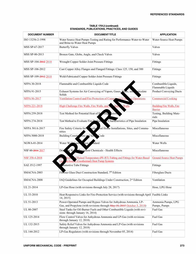
273UNIFORM MECHANICAL CODE - PREPRINT
REFERENCED STANDARDS
DOCUMENT NUMBER DOCUMENT TITLE APPLICATION
ISO 13256-2-1998 Water Source Heat Pumps-Testing and Rating for Performance-Water-to-Waterand Brine-to-Water Heat Pumps
Water-Source Heat Pumps
MSS SP-67-2017 Butterfly Valves Valves
MSS SP-80-2013 Bronze Gate, Globe, Angle, and Check Valves Valves
MSS SP-104-2012 2018 Wrought Copper Solder-Joint Pressure Fittings Fittings
MSS SP-106-2012 Cast Copper Alloy Flanges and Flanged Fittings: Class 125, 150, and 300 Fittings
MSS SP-109-2012 2018 Weld-Fabricated Copper Solder-Joint Pressure Fittings Fittings
NFPA 30-2018 Flammable and Combustible Liquids Code Combustible Liquids,Flammable Liquids
NFPA 91-2015 Exhaust Systems for Air Conveying of Vapors, Gases, Mists, and ParticulateSolids
Product Conveying Ducts
NFPA 96-2017 Ventilation Control and Fire Protection of Commercial Cooking Operations Commercial Cooking
NFPA 221-2018 High Challenge Fire Walls, Fire Walls, and Fire Barrier Walls Building Fire Walls, FireBarrier
NFPA 259-2018 Test Method for Potential Heat of Building Materials Testing, Building Mate-rials
NFPA 274-2018 Test Method to Evaluate Fire Performance Characteristics of Pipe Insulation Pipe Insulation
NFPA 501A-2017 Fire Safety Criteria for Manufactured Home Installations, Sites, and Commu-nities
Miscellaneous
NFPA 5000-2018 Building Construction and Safety Code Miscellaneous
NGWA-01-2014 Water Well Construction Standard Water Wells
NSF 60-2016 2017 Drinking Water Treatment Chemicals - Health Effects Miscellaneous
NSF 358-4-2018 Polyethylene of Raised Temperature (PE-RT) Tubing and Fittings for Water-BasedGround-Source (Geothermal) Heat Pump Systems
Ground-Source Heat Pumps
SAE J512-1997 Automotive Tube Fittings Fittings
SMACNA-2003 Fibrous Glass Duct Construction Standard, 7th Edition Fiberglass Ducts
SMACNA-2008 IAQ Guidelines for Occupied Buildings Under Construction, 2nd Edition Ventilation
UL 21-2014 LP-Gas Hose (with revisions through July 28, 2017) Hose, LPG Hose
UL 33-2010 Heat Responsive Links for Fire-Protection Service (with revisions through April14, 2015)
Fusible Links
UL 51-2013 Power-Operated Pumps and Bypass Valves for Anhydrous Ammonia, LP-Gas, and Propylene (with revisions through May 18, 2015 October 5, 2018)
Ammonia Pumps, LPGPumps, Pumps
UL 80-2007 Steel Tanks for Oil-Burner Fuels and Other Combustible Liquids (with revi-sions through January 16, 2014)
Fuel Gas
UL 125-2014 Flow Control Valves for Anhydrous Ammonia and LP-Gas (with revisionsthrough January 12, 2018)
Fuel Gas
UL 132-2015 Safety Relief Valves for Anhydrous Ammonia and LP-Gas (with revisionsthrough January 12, 2018)
Fuel Gas
UL 144-2012 LP-Gas Regulators (with revisions through November 05, 2014) Fuel Gas
TABLE 1701.2 (continued)STANDARDS, PUBLICATIONS, PRACTICES,AND GUIDES
PREPRINT
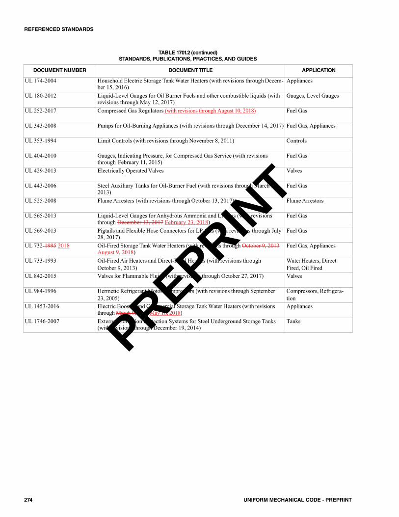
274 UNIFORM MECHANICAL CODE - PREPRINT
REFERENCED STANDARDS
DOCUMENT NUMBER DOCUMENT TITLE APPLICATION
UL 174-2004 Household Electric Storage Tank Water Heaters (with revisions through Decem-ber 15, 2016)
Appliances
UL 180-2012 Liquid-Level Gauges for Oil Burner Fuels and other combustible liquids (withrevisions through May 12, 2017)
Gauges, Level Gauges
UL 252-2017 Compressed Gas Regulators (with revisions through August 10, 2018) Fuel Gas
UL 343-2008 Pumps for Oil-Burning Appliances (with revisions through December 14, 2017) Fuel Gas, Appliances
UL 353-1994 Limit Controls (with revisions through November 8, 2011) Controls
UL 404-2010 Gauges, Indicating Pressure, for Compressed Gas Service (with revisionsthrough February 11, 2015)
Fuel Gas
UL 429-2013 Electrically Operated Valves Valves
UL 443-2006 Steel Auxiliary Tanks for Oil-Burner Fuel (with revisions through March 8,2013)
Fuel Gas
UL 525-2008 Flame Arresters (with revisions through October 13, 2017) Flame Arrestors
UL 565-2013 Liquid-Level Gauges for Anhydrous Ammonia and LP-Gas (with revisionsthrough December 13, 2017 February 23, 2018)
Fuel Gas
UL 569-2013 Pigtails and Flexible Hose Connectors for LP-Gas (with revisions through July28, 2017)
Fuel Gas
UL 732-1995 2018 Oil-Fired Storage Tank Water Heaters (with revisions through October 9, 2013August 9, 2018)
Fuel Gas, Appliances
UL 733-1993 Oil-Fired Air Heaters and Direct-Fired Heaters (with revisions throughOctober 9, 2013)
Water Heaters, DirectFired, Oil Fired
UL 842-2015 Valves for Flammable Fluids (with revisions through October 27, 2017) Valves
UL 984-1996 Hermetic Refrigerant Motor-Compressors (with revisions through September23, 2005)
Compressors, Refrigera-tion
UL 1453-2016 Electric Booster and Commercial Storage Tank Water Heaters (with revisionsthrough March 9, 2017 May 18, 2018)
Appliances
UL 1746-2007 External Corrosion Protection Systems for Steel Underground Storage Tanks(with revisions through December 19, 2014)
Tanks
TABLE 1701.2 (continued)STANDARDS, PUBLICATIONS, PRACTICES,AND GUIDES
PREPRINT
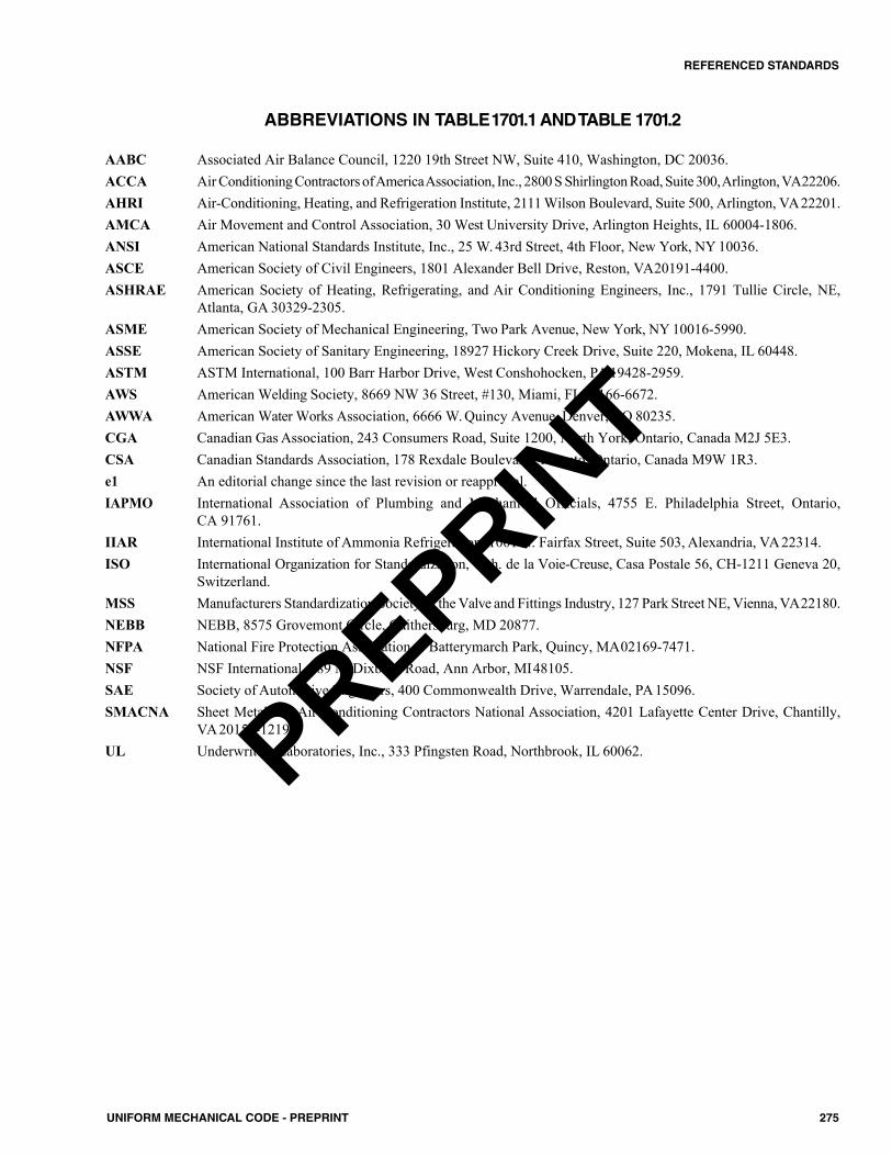
275UNIFORM MECHANICAL CODE - PREPRINT
REFERENCED STANDARDS
ABBREVIATIONS IN TABLE1701.1 AND TABLE 1701.2
AABC Associated Air Balance Council, 1220 19th Street NW, Suite 410, Washington, DC 20036.ACCA Air Conditioning Contractors ofAmericaAssociation, Inc., 2800 S Shirlington Road, Suite 300,Arlington,VA22206.AHRI Air-Conditioning, Heating, and Refrigeration Institute, 2111 Wilson Boulevard, Suite 500, Arlington, VA22201.AMCA Air Movement and Control Association, 30 West University Drive, Arlington Heights, IL 60004-1806.ANSI American National Standards Institute, Inc., 25 W. 43rd Street, 4th Floor, New York, NY 10036.ASCE American Society of Civil Engineers, 1801 Alexander Bell Drive, Reston, VA20191-4400.ASHRAE American Society of Heating, Refrigerating, and Air Conditioning Engineers, Inc., 1791 Tullie Circle, NE,
Atlanta, GA 30329-2305.ASME American Society of Mechanical Engineering, Two Park Avenue, New York, NY 10016-5990.ASSE American Society of Sanitary Engineering, 18927 Hickory Creek Drive, Suite 220, Mokena, IL 60448.ASTM ASTM International, 100 Barr Harbor Drive, West Conshohocken, PA 19428-2959.AWS American Welding Society, 8669 NW 36 Street, #130, Miami, FL 33166-6672.AWWA American Water Works Association, 6666 W. Quincy Avenue, Denver, CO 80235.CGA Canadian Gas Association, 243 Consumers Road, Suite 1200, North York, Ontario, Canada M2J 5E3.CSA Canadian Standards Association, 178 Rexdale Boulevard, Toronto, Ontario, Canada M9W 1R3.e1 An editorial change since the last revision or reapproval.IAPMO International Association of Plumbing and Mechanical Officials, 4755 E. Philadelphia Street, Ontario,
CA 91761.IIAR International Institute of Ammonia Refrigeration, 1001 N. Fairfax Street, Suite 503, Alexandria, VA 22314.ISO International Organization for Standardization, 1 ch. de la Voie-Creuse, Casa Postale 56, CH-1211 Geneva 20,
Switzerland.MSS Manufacturers Standardization Society of the Valve and Fittings Industry, 127 Park Street NE, Vienna, VA22180.NEBB NEBB, 8575 Grovemont Circle, Gaithersburg, MD 20877.NFPA National Fire Protection Association, 1 Batterymarch Park, Quincy, MA02169-7471.NSF NSF International, 789 N. Dixboro Road, Ann Arbor, MI48105.SAE Society of Automotive Engineers, 400 Commonwealth Drive, Warrendale, PA 15096.SMACNA Sheet Metal and Air Conditioning Contractors National Association, 4201 Lafayette Center Drive, Chantilly,
VA 20151-1219.UL Underwriters Laboratories, Inc., 333 Pfingsten Road, Northbrook, IL 60062.PREPRINT

276 UNIFORM MECHANICAL CODE - PREPRINT
PREPRINT
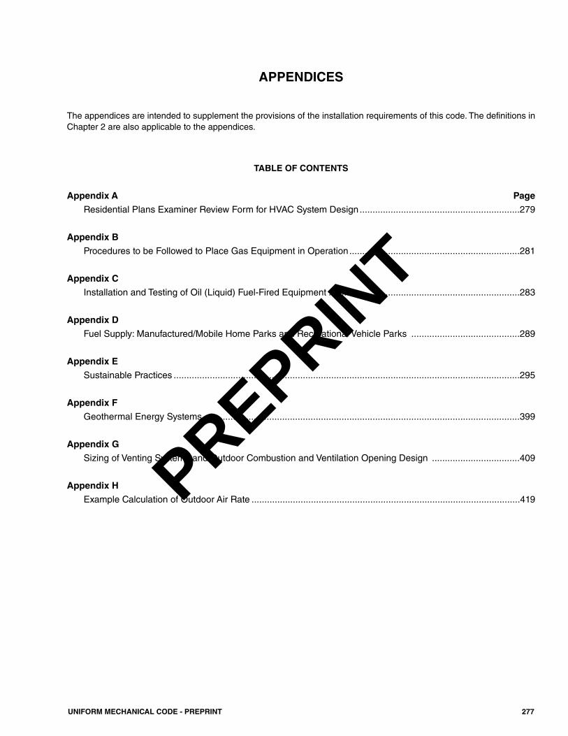
APPENDICES
The appendices are intended to supplement the provisions of the installation requirements of this code. The definitions inChapter 2 are also applicable to the appendices.
TABLE OF CONTENTS
Appendix A PageResidential Plans Examiner Review Form for HVAC System Design ..............................................................279
Appendix BProcedures to be Followed to Place Gas Equipment in Operation..................................................................281
Appendix CInstallation and Testing of Oil (Liquid) Fuel-Fired Equipment ..........................................................................283
Appendix DFuel Supply: Manufactured/Mobile Home Parks and Recreational Vehicle Parks ..........................................289
Appendix ESustainable Practices ......................................................................................................................................295
Appendix FGeothermal Energy Systems ..........................................................................................................................399
Appendix GSizing of Venting Systems and Outdoor Combustion and Ventilation Opening Design ..................................409
Appendix HExample Calculation of Outdoor Air Rate ........................................................................................................419
277UNIFORM MECHANICAL CODE - PREPRINT
PREPRINT

278 UNIFORM MECHANICAL CODE - PREPRINT
PREPRINT
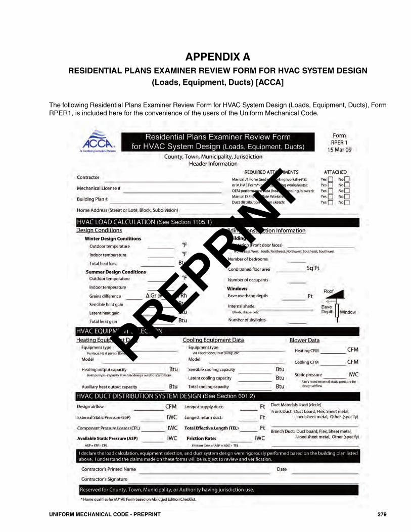
279UNIFORM MECHANICAL CODE - PREPRINT
APPENDIX ARESIDENTIAL PLANS EXAMINER REVIEW FORM FOR HVAC SYSTEM DESIGN
(Loads, Equipment, Ducts) [ACCA]
The following Residential Plans Examiner Review Form for HVAC System Design (Loads, Equipment, Ducts), FormRPER1, is included here for the convenience of the users of the Uniform Mechanical Code.
PREPRINT

280 UNIFORM MECHANICAL CODE - PREPRINT
PREPRINT
B 101.0 Adjusting the Burner Input.B 101.1 Adjusting Input. The input rate of the burner shallbe adjusted to the proper value in accordance with the appli-ance manufacturer’s instructions. Firing at a rate in excess ofthe nameplate rating shall be prohibited. The input rate can beadjusted by either changing the size of a fixed orifice, chang-ing the adjustment of an adjustable orifice, or readjusting theappliance’s gas pressure regulator outlet pressure (where aregulator is provided in the appliance). [NFPA 54:11.1.1,11.1.1.1] B 101.2 High Altitude.Gas input ratings of appliances shallbe used for elevations up to 2000 feet (610 m). The input rat-ings of appliances operating at elevations above 2000 feet(610 m), shall be reduced in accordance with one of the fol-lowing methods:(1) At the rate of 4 percent for each 1000 feet (305 m) above
sea level before selecting appropriately sized appliances.(2) As permitted by the Authority Having Jurisdiction.(3) In accordance with the manufacturer’s installation instruc-
tions. [NFPA 54:11.1.2]
B 102.0 Primary Air Adjustment.B 102.1 General. The primary air for injection (Bunsen)-type burners shall be adjusted for proper flame characteris-tics in accordance with the appliance manufacturer’sinstructions. After setting the primary air, the adjustmentmeans shall be secured in position. [NFPA 54:11.2]
B 103.0 Safety Shutoff Devices.B 103.1 General. Where a safety shutoff device is provided,it shall be checked for proper operation and adjustment inaccordance with the appliance manufacturer’s instructions.Where the device does not function properly to turn off thegas supply in the event of pilot outage or other improper oper-ation, it shall be properly serviced or replaced with a newdevice. [NFPA 54:11.3]
B 104.0 Automatic Ignition.B 104.1 General.Appliances supplied with means for auto-matic ignition shall be checked for operation within theparameters provided by the manufacturer. Any adjustmentsmade shall be in accordance with the manufacturer’s instal-lation instructions. [NFPA 54:11.4]
B 105.0 Protective Devices.B 105.1 General. Where required by the manufacturer’sinstallation instructions, all protective devices furnished withthe appliance such as a limit control, fan control to blower,
temperature and pressure relief valve, low-water cutoffdevice, or manual operating features, shall be checked foroperation within the parameters provided by the manufac-turer. Any adjustments made shall be in accordance with themanufacturer’s installation instructions. [NFPA 54:11.5]
B 106.0 Checking the Draft.B 106.1 General. Draft hood-equipped appliances shall bechecked to verify that there is no draft hood spillage after 5minutes of main burner operation. [NFPA 54:11.6]
B 107.0 Operating Instructions.B 107.1 General. Operating instructions shall be furnishedand shall be left in a prominent position near the appliancefor use by the consumer. [NFPA 54:11.7]
281UNIFORM MECHANICAL CODE - PREPRINT
APPENDIX BPROCEDURES TO BE FOLLOWED TO PLACE GAS EQUIPMENT IN OPERATION
PREPRINT

282 UNIFORM MECHANICAL CODE - PREPRINT
PREPRINT
C 101.0 General. C 101.1 Applicability. Appendix C governs the installation,testing, or repair of oil or liquid fuel burners, oil or liquid fuel-burning systems, oil or liquid fuel-burning equipment, andthe oil or liquid fuel piping systems used in connection withbuildings or structures and equipment within the propertylines of the premises.
C 102.0 Definitions.Anti-Flooding Device. A primary safety control thatcauses the flow of oil or fuel to be shut off after a rise in oilor fuel level, or after receiving excess oil or fuel, and thatoperates before the hazardous discharge of oil or fuel canoccur.Burner, Automatically Ignited.A burner equipped so thatmain burner fuel may be turned on and ignited automatically.Burner, Manually Ignited.A burner equipped, so that mainburner fuel is turned on only by hand and ignited under super-vision.Burner, Mechanical Draft Type. A burner that includes apower-driven fan, blower, or other mechanism as the primarymeans for supplying the air for combustion.Burner, Natural Draft Type.A burner that depends prima-rily on the natural draft created in the chimney or venting sys-tem to induce air required for combustion into the burner.Constant Level Valve. A device for maintaining within areservoir a constant level of oil or fuel for delivery to a burner.Control Limit. An automatic safety control that is respon-sive to changes in fluid flow or level, pressure, or temperatureand that is normally set beyond the operating range for limit-ing the operation of the controlled equipment by shutting offthe energy supply.Control Safety. Automatic interlock controls, includingrelays, switches, and other auxiliary equipment used in con-junction with them, to form a safety control system that isintended to prevent unsafe operation of the controlled equip-ment.Draft Booster. A power-operated fan, blower, or otherdevice installed in the chimney connector to increase the nat-ural draft developed in the connected chimney.Draft Regulator, Barometric. A device built into a fuel-burning appliance or made part of a chimney connector orvent connector that functions to reduce excessive draftthrough an appliance to a desired value by admitting ambientair into the appliance chimney, chimney connector, vent, orvent connector.Fuel. Natural, manufactured, or liquefied petroleum gas, ora mixture of these gases; all grades of fuel oil, wood, or anyother combustible or flammable material or any mixture ofcombustible or flammable materials.
Fuel Burner. A device used to convey the appropriate fuelinto the combustion chamber zone in close proximity to itsprimary and secondary air supply to permit a stable controlledheat release compatible with the burner design, listing, andapplicable approvals in a boiler, furnace, device or appliance.It includes but is not limited to burning oil or liquid fuel.Fuel Burner System. The fuel burner and a conveyancesystem or piping system for the purpose of introducing theappropriate fuel into the combustion chamber zone.Fuel-Burning Equipment/Appliance. An oil or fuelburner of any type including all oil or liquid fuel burners, oilor liquid fuel-fired units, dual, or multi-fuel burners and heat-ing and cooking appliances with their fuel burner system andwith their tank or fuel storage system, piping system, ventconnectors, vent flues, fans, blowers, valves, control devices,combustion air, wiring, controls, and related devices includ-ing all accessories and appurtenances for safe and properoperation of the appliance.Fuel Oil. Hydrocarbon oil as specified by ASTM D396, orthe Canadian Government Specification Board, 3-GP-28, andhaving a flashpoint of not less than 100°F (38°C).Fuel-Piping System. Method of conveying liquid, vapor,steam, gases, or slurry from one point to another, includingaccessories, appurtenances, and equipment necessary for itsproper operation.Indirect-Fired Appliance. An oil or fuel-burning appli-ance in which products of combustion (flue gasses) are notmixed in the appliance with the air or other medium beingheated.Labeled. Having attached a label, symbol, or other identi-fying mark of an organization acceptable to the AuthorityHaving Jurisdiction and concerned with product evaluationthat maintains periodic inspection of production of labeledequipment or materials and by whose labeling the manufac-turer indicates compliance with appropriate standards or per-formance in a specified manner.Premixing. A power burner in which all or nearly all of theair for combustion is mixed with the gas as primary air.Pump, Oil or Fuel Transfer. An oil or fuel pump, auto-matically or manually operated, that transfers oil or fuelthrough continuous piping from a supply tank to an oil orfuel-burning appliance or to an auxiliary tank, and that is notdesigned to stop pumping automatically in case of total break-age of the oil or fuel supply line between the pump and theappliance.Tank, Auxiliary. A tank having a capacity of not over 60gallons (227 L) listed for installation in the supply pipingbetween a burner and its main fuel supply tank. It shall bepermitted to be included as an integral part of an automaticpump or a transfer pump, or it shall be permitted to be a sep-arate tank.
283UNIFORM MECHANICAL CODE - PREPRINT
APPENDIX CINSTALLATION AND TESTING OF OIL (LIQUID) FUEL-FIRED EQUIPMENT
PREPRINT
Tank, Gravity. A supply tank from which the oil or fuel isdelivered directly to the burner by gravity.Tank, Integral.A tank that is furnished by the manufactureras an integral part of an oil or fuel-burning appliance.Tank Storage. A separate tank that is not connected to theoil or fuel-burning appliance.Tank Supply. A separate tank connected directly or by apump to the oil or fuel-burning appliance.Tank, Vacuum or Barometric.A tank not exceeding 5 gal-lons (19 L) capacity that maintains a definite level of oil orfuel in a sump or similar receptacle by barometric feed. Fuelis delivered from the sump to the burner by gravity.Valve, Manual Oil, Gas, or Fuel Shutoff. A manuallyoperated valve in a fuel line for the purpose of turning on orcompletely shutting off the fuel supply to the burner.Valve, Oil, Gas, or Fuel Control. An automatically ormanually operated device consisting essentially of a fuelvalve for controlling the fuel supply to a burner.
C 103.0 Standards and Accepted Practices.C 103.1 General. The installation, testing, and repair of oilor liquid fuel-burning equipment systems shall be in accor-dance with Section C 103.0, the standards listed in Chapter17, and other information outlined in this code such as, butnot limited to, combustion air, flue and breeching require-ments, room clearances and dimensions, and control require-ments.
C 104.0 Approval of Equipment.C 104.1 General. Oil or liquid fuel-burning equipment shallbe approved.
C 105.0 Placing Equipment in Operation.C 105.1 General. After completion of installations, theinstaller shall test safety and operating controls and ventingbefore placing the burner in service. The correct input of liq-uid fuel shall be determined, and the fuel-to-air ratio shall beset. Each oil or liquid fuel burner shall be adjusted to its inputaccording to the manufacturer’s instructions. Overrating theburners or the appliance is prohibited. The input range shallbe appropriate to the appliance:(1) For conversion burners installed in hot water (liquid)
boilers or warm air furnaces, the rate of flow of the oil orliquid fuel in British thermal units per hour (Btu/h) (kW)shall be adjusted to within plus or minus 5 percent of thedesign load, not to exceed the design rate of the appli-ance.
(2) For conversion burners installed in steam boilers, the oilor liquid fuel hourly input demand shall be adjusted tobe in accordance with the steam load requirements. Theoil or liquid fuel input demand necessitated by an over-sized boiler shall be established and added to total inputdemand.
C 106.0 Pilot Operation.C 106.1 General. Igniter or pilot flames shall be effectiveto ignite the oil or liquid fuel at the main burner or burnersand shall be adequately protected from drafts. Pilot flamesshall not become extinguished during the pilot cycle wherethe main burner or burners are turned on or off in a normalmanner either manually or by automatic controls.
C 107.0 Burner Operation.C 107.1 General. In making tests to determine compliancewith the requirements of Section C 107.1, the following careshall be exercised to prevent the accumulation of unburnedliquid fuel in the appliance that will result in an explosion orfire:(1) The flames from the burner shall ignite freely the liquid
fuel where operating at the lowest firing position.(2) Burner flames shall not flash back where the liquid fuel
is turned on or off by an automatic control mechanism.(3) Main burner flames shall ignite freely from the pilot
where the pilot flame is reduced to a minimum point thatwill actuate the pilot safety device.
(4) Where ignition is made in a normal manner, the flamewill not flash outside the appliance.
(5) Burners shall not expel liquid fuel through air openingswhere operating at prevailing pressure.
(6) Burners shall have a liquid-fuel air mixture to ensuresmooth ignition of the main burner.
C 108.0 Method of Test.C 108.1 General Test Methods. (1) The flue gas, venting, safety and operating controls of
the appliance shall be checked by the installer to ensuretheir proper and safe operation.
(2) Method of test – atmospheric, induced draft or fanassisted types.(a) The appliance shall be allowed to operate until the
stack temperature becomes stabilized, after which asample of the undiluted flue products shall be takenfrom the appliance flue outlet. The sample takenshall be analyzed for carbon monoxide, carbon diox-ide, and oxygen. Stack temperature shall be noted.
Appliance designs incorporating induced-draftassemblies require a flue gas sample to be takenahead of the draft regulator or induced draft fan.
(3) Performance standards for atmospheric type shall be pro-vided in accordance with the following:(a) Shall be not less than 75 percent efficiency as deter-
mined by flue gas analysis method at the applianceflue outlet.
(b) Carbon monoxide concentration in flue gas shall notexceed 0.04 percent.
(c) Stack temperature shall not exceed 700°F (371°C)plus ambient.
284 UNIFORM MECHANICAL CODE - PREPRINT
APPENDIX C
PREPRINT
(d) Carbon dioxide concentration shall be between 8percent and 13 percent.
(e) Oxygen concentration shall be between 4 percentand 10 percent.
(f) Smoke test shall not exceed number 2 for light oilsor number 4 for oils heavier than number 4.
(g) Draft shall comply with the burner manufacturer’sinstructions.
(4) Performance standards for induced-draft or fan-assistedtypes shall comply with the following:(a) Shall be not less than 75 percent efficiency, as deter-
mined by flue gas analysis method at appliance flueoutlet.
(b) Carbon monoxide concentration in flue gas notexceeding 0.04 percent.
(c) Stack temperature shall not exceed 700°F (371°C)plus ambient.
(d) Carbon dioxide concentration shall be between 8percent and 13 percent.
(e) Oxygen concentration shall be between 4 percentand 10 percent.
(f) Smoke test shall not exceed number 2 for light oilsor number 4 for oils heavier than number 4.
(g) Draft shall comply with the burner manufacturer’sinstructions.
Induced-draft and fan-assisted types of appli-ances require a sample be taken after the induced-draft fan that will cause oxygen figures in excess ofthe limits stated. In such cases, safe liquid fuel com-bustion ratios shall be maintained and be consistentwith approvals and listings of the appliance.
(5) Method of test – power type.(a) The appliance shall be allowed to operate until the
stack temperature becomes stabilized; after that, asample of the undiluted flue products shall be takenfrom the appliance flue outlet. The sample shall beanalyzed for carbon monoxide, carbon dioxide, andoxygen. Stack temperature shall be noted.
(6) Performance standards for power type.(a) Shall be not less than 80 percent efficiency as deter-
mined by flue gas analysis method at the applianceflue outlet.
(b) Carbon monoxide concentration in the flue gas shallnot exceed 0.04 percent.
(c) Stack temperature shall not exceed 700°F (371°C)plus ambient.
(d) Carbon dioxide concentration shall be between 8percent and 13 percent.
(e) Oxygen concentration shall be between 4 percentand 10 percent.
(f) Smoke test shall not exceed number 2 for light oilsor number 4 for oils heavier than number 4.
(g) Draft shall comply with the burner manufacturer’sinstructions.
(7) After completion of the test of newly installed oil or liq-uid fuel burner equipment as provided in this section, theinstaller shall file with the Authority Having Jurisdictioncomplete records of the test on a form approved by theAuthority Having Jurisdiction. The tag stating the dateof the test and the name of the installer shall be attachedto the appliance at the main valve.
(8) Listing and approval.(a) The concentration of oxygen in the undiluted flue
products of oil or liquid fuel burners shall in no casebe less than 3 percent nor exceed 10 percent andshall be in accordance with performance standardsand shall be consistent with the listing and approvalof the equipment.
(b) The allowable limit of carbon monoxide shall notexceed 0.04 percent.
(c) The flue gas temperature of an oil appliance, astaken on the appliance side of the draft regulator,shall not exceed applicable performance standardsand shall be consistent with the listing and approvalsof the equipment.
(9) The oxygen figures shall not apply where there is anapproved oxygen trim system on the burner that isdesigned for that use, including a low oxygen interlockwhere approved by the Authority Having Jurisdiction.
(10) Supervision shall be as follows:(a) Supervised startup shall be required to verify the
safe operation of an oil or liquid fuel burner and toprovide documentation that operation is consistentwith this code, listing, and approval. Supervisedstartup shall be required for liquid fuel burners inSection C 109.1(2), Section C 109.1(3), and SectionC 109.1(4). Supervised startup requires that the liq-uid-fuel burner shall be tested in the presence of themechanical official in a manner set forth by theAuthority Having Jurisdiction before the installationis approved. Testing shall include safety and oper-ating controls, input, flue gas analysis, and venting.Flue gas shall be tested at high, medium, and lowfires. Provisions shall be made in the system to allowa firing test in warm weather. After completion ofthe test of newly installed oil or liquid fuel burnerequipment, as provided in this section, the installershall file with the Authority Having Jurisdictioncomplete records of the test on a form approved bythe Authority Having Jurisdiction. The tag statingthe date of the test and the name of the tester shall beattached to the appliance at the main valve.
(b) Oil and liquid fuel burners of 1 000 000 Btu/h (293kW) input or more require a supervised startup inaccordance with Section C 108.1(10)(a).
(c) Installation of oxygen trim systems, modulatingdampers, or other draft control or combustiondevices require a supervised startup in accordancewith Section C 108.1(10)(a).
285UNIFORM MECHANICAL CODE - PREPRINT
APPENDIX C
PREPRINT
(d) Direct-fired heaters shall require a supervised startupin accordance with Section C 108.1(10)(a).
(11) The complete control diagram of the installation andoperating instructions shall be supplied and posted by theinstaller of the appliance.
C 109.0 Special Requirements Based on Btu/h Input.C 109.1 General. (1) Zero to 400 000 Btu/h (0 kW to 117 kW) per burner.
(a) One approved manual shutoff valve lever handle.(b) One approved fuel oil filter, installed on the supply
piping.(c) Approved automatic safety shutoff valve to provide
100 percent shutoff of all oil.(d) A flame safeguard control capable of providing 100
percent shutoff in the event of flame failure. Flamefailure response timing shall not exceed the controlmanufacturer’s instructions.
(e) Two controls, one operating and one high limit, acti-vated by temperature or pressure, as appropriate.
(f) Burners relying on mechanical means to provide airfor combustion shall have actual proof-of-air inter-lock device.
(g) Installations with dampered combustion air open-ings shall prove damper open position before trialfor burner ignition.
(h) Vent dampers and flue dampers shall be properlyinterlocked to prevent burner ignition unless safelyopen.
(2) Four hundred thousand and one to 999 999 Btu/h (117.2kW to 292.9 kW) per burner.(a) One approved manual shutoff valve lever handle.(b) One approved fuel-oil filter, installed on the supply
piping.(c) Two safety shutoff valves in series, maximum five
seconds closing time.(d) One electronic flame safeguard pilot control pro-
viding a separately supervised and proven pilot, 100percent shutoff manual reset. Flame failure responsetime shall not exceed the control manufacturer’sinstructions.
Direct-spark ignition shall be allowed whereapproved by the Authority Having Jurisdiction andwhere used on number 2 or lighter oil.
(e) Two controls, one operating and one high limit, acti-vated by temperature or pressure, as appropriate.
(f) Burners relying on mechanical means to provide airfor combustion shall have actual proof-of-air inter-lock device.
(g) Power burners shall include proven prepurge of notless than 60 seconds at high-fire damper settings.This prepurge shall occur before every burner cycle,regardless of reason.
(h) Installations with dampered combustion air open-ings shall prove damper open position before trialfor burner ignition.
(i) Vent dampers and flue dampers shall be interlockedto prevent burner ignition unless safely open.
(j) One high oil or liquid fuel-pressure interlock, resetfrom flame safeguard or manually.
(k) Where hot water or steam, one low water cutoff.(l) An atomizing medium proving switch.(m) A low oil temperature switch for oil or liquid fuel
requiring preheating.(n) A high oil temperature interlock for oil or liquid fuel
requiring preheating.(o) The burner oil pump shall automatically not operate
or rotate while the alternate fuel is firing.(p) A pressure-relief valve shall be provided between
safety shutoff valves and between pump and safetyvalves where an integral valve is used with a pump.
(q) A separate relief device is required on each transferpump.
(3) One million to 2 499 999 Btu/h (293 kW to 732 kW)input per burner.(a) One approved manual shutoff valve lever handle.(b) One approved fuel-oil filter, installed on the supply
piping.(c) Two safety shutoff valves in series with a combined
flame failure response and valve closing time not toexceed 5 seconds with strainer directly before thevalves.
(d) Programmed electronic flame safeguard includingproven low-fire start, manual reset lockout, 100 per-cent shutoff (both pilot and main burner), and a sep-arately supervised and proven pilot.
Flame-sensing systems utilizing a UV scannershall prove pilot and interrupt ignition spark prior tomain burner valves being energized.
(e) Two controls, one operating and one high limit, acti-vated by temperature or pressure.
(f) Burners relying on mechanical means to provide airfor combustion shall have actual proof-of-air inter-lock device.
(g) Power burners shall include proven prepurge of notless than 60 seconds at high-fire damper settings.This prepurge shall occur before every burner cycle,regardless of reason.
(h) Installations with dampered combustion air open-ings shall prove damper open position before trialfor burner ignition.
(i) Vent dampers and flue dampers shall be interlockedto prevent burner ignition unless safely open.
(j) One high oil or liquid fuel-pressure interlock, resetfrom flame safeguard or manually.
286 UNIFORM MECHANICAL CODE - PREPRINT
APPENDIX C
PREPRINT
(k) Where hot water or steam, two low water cutoffs.(l) An atomizing medium proving switch.(m) A low oil temperature switch for oil or liquid fuel
requiring preheating.(n) A high oil temperature interlock for oil or liquid fuel
requiring preheating.(o) The burner oil pump shall automatically not operate
or rotate while the alternate fuel is firing.(p) A pressure-relief valve shall be provided between
safety shutoff valves and between pump and safetyvalves where an integral valve is used with a pump.
(q) A separate relief device is required on each transferpump.
(r) One low oil or liquid fuel-pressure interlock, resetfrom flame safeguard or manually.
(s) Burners with automatic controls, prepurge, proof-of-closure, modulation, or postpurge shall not userelays external to the flame safeguard to accomplishthese functions.
(4) Two million five hundred thousand to 12 499 999 Btu/h(733 kW to 3663.3 kW) per burner.(a) One approved manual shutoff valve lever handle.(b) One approved fuel-oil filter, installed on the supply
piping.(c) Two safety shutoff valves in series, with a combined
flame failure response and valve closing time not toexceed 5 seconds with strainer directly before thevalves.
(d) Programmed electronic flame safeguard includingproven low-fire start, manual reset lockout, 100 per-cent shutoff (both pilot and main burner), and a sep-arately supervised and proven pilot.
Flame-sensing systems utilizing a UV scannershall prove pilot and interrupt ignition spark prior tomain burner valves being energized.
(e) Two controls, one operating and one high limit, acti-vated by temperature or pressure.
(f) Burners relying on mechanical means to provide airfor combustion shall have actual proof-of-air inter-lock device.
(g) Power burners shall include proven prepurge of notless than 60 seconds at high-fire damper settings.This prepurge shall occur before every burner cycle,regardless of reason.
(h) Installations with dampered combustion air open-ings shall prove damper open position before trialfor burner ignition.
(i) Vent dampers and flue dampers shall be interlockedto prevent burner ignition unless safely open.
(j) One high oil or liquid fuel-pressure interlock, resetfrom flame safeguard or manually.
(k) Where hot water or steam, two low water cutoffs.
(l) An atomizing medium proving switch.(m) A low oil temperature switch for oil or liquid fuel
requiring preheating.(n) A high oil temperature interlock for oil or liquid fuel
requiring preheating.(o) A separate firing rate control valve.(p) The burner oil pump shall automatically not operate
or rotate while the alternate fuel is firing.(q) A pressure-relief valve shall be provided between
safety shutoff valves and between pump and safetyvalves where an integral valve is used with a pump.
(r) A separate relief device is required on each transferpump.
(s) One low oil or liquid fuel-pressure interlock resetfrom flame safeguard or manually.
(t) Burners with automatic controls, prepurge, proof-of-closure, modulation, or postpurge shall not userelays external to the flame safeguard to accomplishthese functions.
(5) More than 12 500 000 Btu/h (3663.4 kW) per burnerinputs. These burners shall comply with the requirementsof the appropriate standards listed in Chapter 17 and thefollowing:(a) One approved manual shutoff valve lever handle.(b) One approved fuel-oil filter, installed on the supply
piping.(c) Two safety shutoff valves in series, one with proof
of closure, with a combined flame failure responseand valve closing time not to exceed 2 seconds withstrainer directly before the valves.
(d) Programmed electronic flame safeguard includingproven low-fire start, manual reset lockout, 100 per-cent shutoff (both pilot and main burner), and a sep-arately supervised and proven pilot.
Flame-sensing systems utilizing a UV scannershall prove pilot and interrupt ignition spark prior tomain burner valves being energized.
(e) Two controls, one operating and one high limit, acti-vated by temperature or pressure.
(f) Burners relying on mechanical means to provide airfor combustion shall have actual proof-of-air inter-lock device.
(g) Power burners must include proven prepurge of notless than 60 seconds at high-fire damper settings.This prepurge shall occur before every burner cycle,regardless of reason.
(h) Installations with dampered combustion air open-ings shall prove damper open position before trialfor burner ignition.
(i) Vent dampers and flue dampers shall be interlockedto prevent burner ignition unless safely open.
(j) One high oil or liquid fuel-pressure interlock; resetfrom flame safeguard or manually.
287UNIFORM MECHANICAL CODE - PREPRINT
APPENDIX C
PREPRINT
(k) A manual firing cock.(l) Where hot water or steam, two low water cut-offs.(m) An atomizing medium proving switch.(n) A low oil temperature switch for oil or liquid fuel
requiring preheating.(o) A high oil temperature interlock for oil or liquid fuel
requiring pre-heating.(p) A separate firing rate control valve.(q) The burner oil pump shall automatically not operate
or rotate while the alternate fuel is firing.(r) A pressure-relief valve shall be provided between
safety shutoff valves and between pump and safetyvalves where an integral valve is used with a pump.
(s) A separate relief device is required on each transferpump.
(t) One low oil or liquid fuel-pressure interlock, resetfrom flame safeguard or manually.
(u) Burners with automatic controls, prepurge, proof-of-closure, modulation, or postpurge shall not userelays external to the flame safeguard to accomplishthese functions.
(6) Shutoff Valve. (a) Oil or liquid fuel burner installations shall include a
non-electric shutoff valve that is held open by afusible link designed to close at 165°F (74°C),installed near the burner in the same room as theburner. This shall prevent the flow of oil or liquidfuel to the burner through the supply pipe. A checkvalve is required in the return line if the tank ishigher than the burner.
288 UNIFORM MECHANICAL CODE - PREPRINT
APPENDIX C
PREPRINT
D 101.0 Fuel Gas Piping Systems.D 101.1 General. All fuel gas piping systems serving man-ufactured homes, accessory buildings, or structures and com-munities shall be designed and constructed in accordance withany applicable provisions of NFPA 54 Chapter 13 and NFPA58. NFPA 31 shall apply to oil fuel-burning systems and shallconform to the criteria of the Authority Having Jurisdiction.[NFPA 501A:4.1.1.1– 4.1.1.2]D 101.2 Gas Supply Connections. Gas supply connec-tions at sites, where provided from an underground gas sup-ply piping system, shall be located and arranged to permitattachment to a manufactured home occupying the site. Forthe installation of liquefied petroleum gas (LP-Gas) storagesystems, the provisions of NFPA 58 shall be followed.[NFPA 501A:4.1.2.1 – 4.1.2.2]D 101.3 Location of Gas Supply Connection. The gassupply to the manufactured home shall be located within 4feet (1219 mm) of the manufactured home stand.Exception: The requirement of Section D 101.3 shall notapply to gas supply connections for manufactured homeslocated on all-weather wood, concrete, or concrete block foun-dation systems or on foundations constructed in accordancewith the local building code or, in the absence of a local code,with a recognized model building code. [NFPA 501A:4.1.3]D 101.4 Recreational Vehicle Park Fuel-Gas Equip-ment and Installations. Fuel gas equipment and installa-tions shall comply with this appendix, except as otherwisepermitted or required by this code.
D 102.0 Single and Multiple Manufactured Home SiteFuel Supply Systems.D 102.1 Underground Installation. Underground gaspiping system installations shall comply with any applicablebuilding code and Section D 102.1.1 and Section D 102.1.2.[NFPA 501A:4.2.1]
D 102.1.1 Open-Ended Gastight Conduit. Under-ground gas piping shall not be installed beneath that por-tion of a manufactured home site reserved for thelocation of a manufactured home or manufactured homeaccessory building or structure unless installed in theopen-ended gastight conduit of Section D 102.1.2.[NFPA 501A:4.2.1.1]D 102.1.2 Requirements. The open-ended gastightconduit shall conform to the requirements in the follow-ing:(1) The conduit shall be not less than Schedule 40 pipe
that is approved for underground installationbeneath buildings.
(2) The interior diameter of the conduit shall be not lessthan 1⁄2 of an inch (15 mm) larger than the outsidediameter of the gas piping.
(3) The conduit shall extend to a point not less than 4inches (102 mm) beyond the outside wall of themanufactured home or accessory building or struc-ture, and the outer ends shall not be sealed.
(4) Where the conduit terminates within a manufacturedhome or accessory building or structure, it shall beaccessible and the space between the conduit and thegas piping shall be sealed to prevent leakage of gasinto the building. [NFPA 501A:4.2.1.2– 4.2.1.2.4]
D 103.0 Manufactured Home Site Gas Shutoff Valve.D 103.1 General. Each manufactured home site shall havea listed gas shutoff valve installed upstream of the manufac-tured home site gas outlet. The gas shutoff valve shall belocated on the outlet riser at a height of not less than 6 inches(152 mm) above grade. A gas shutoff valve shall not belocated under any manufactured home. The outlet shall beequipped with a cap or plug to prevent discharge of gas when-ever the manufactured home site outlet is not connected to amanufactured home. [NFPA 501A:4.2.2.1 – 4.2.2.4]Exception: Gas shutoff valves shall conform to Section D103.1, except for manufactured homes located on foundationsconstructed in accordance with the local building code or, inthe absence of a local code, with a recognized model buildingcode. [NFPA 501A:4.2.2]
D 104.0 Gas Meters.D 104.1 Support of Meters. Where installed, gas metersshall be supported by a post or bracket placed on a firm foot-ing or other means providing equivalent support and shall notdepend on the gas outlet riser for support. [NFPA501A:4.2.3.1]D 104.2 Location of Meters. Each gas meter shall beinstalled in an accessible location and shall be provided withunions or other fittings so that the meter can be removed eas-ily and placed in an upright position. Meters shall not beinstalled in unventilated or inaccessible locations or closerthan 3 feet (914 mm) to sources of ignition. [NFPA501A:4.2.3.2.1 – 4.2.3.2.2]D 104.3 Meter Shutoff Valve or Cock. All gas meterinstallations shall be provided with shutoff valves or cockslocated adjacent to and on the inlet side of the meters. In thecase of a single meter installation utilizing an LP-Gas con-tainer, the container service valve shall be permitted to beused in lieu of the shutoff valve or cock. All gas meter instal-lations shall be provided with test tees located adjacent to andon the outlet side of the meters. [NFPA 501A:4.2.4.1 –4.2.4.3]
289UNIFORM MECHANICAL CODE - PREPRINT
APPENDIX DFUEL SUPPLY: MANUFACTURED/MOBILE HOME PARKS AND
RECREATIONAL VEHICLE PARKS
PREPRINT
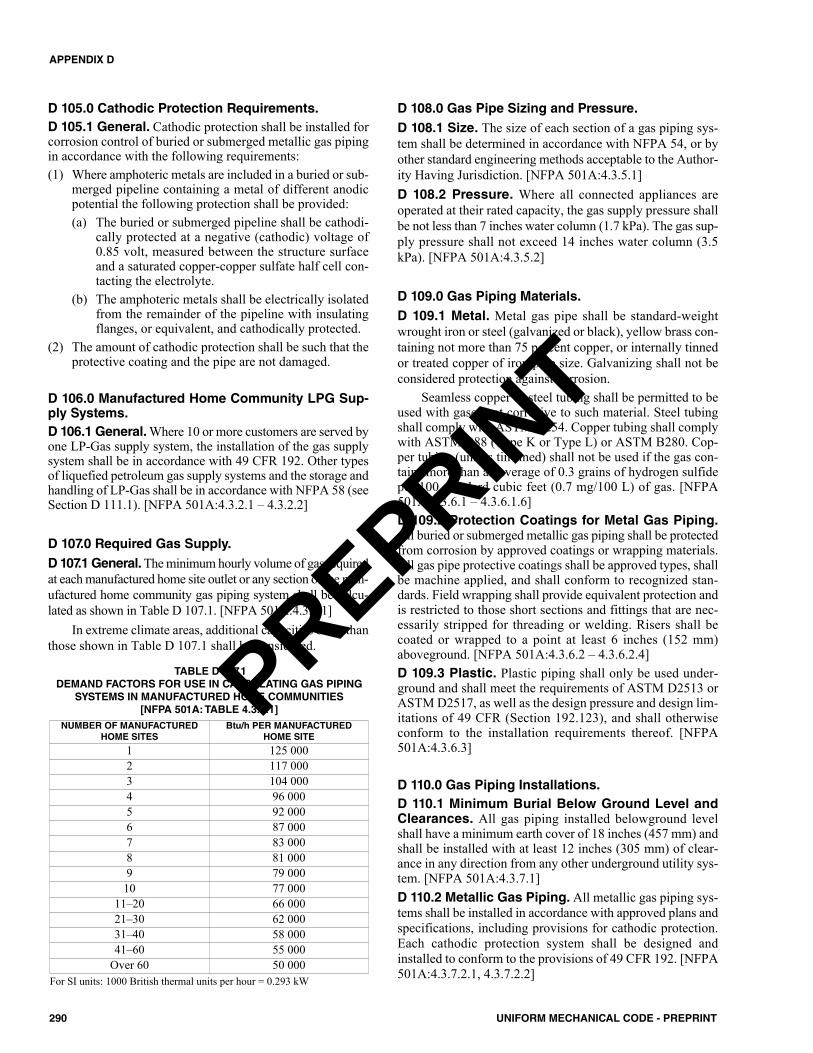
D 105.0 Cathodic Protection Requirements.D 105.1 General. Cathodic protection shall be installed forcorrosion control of buried or submerged metallic gas pipingin accordance with the following requirements:(1) Where amphoteric metals are included in a buried or sub-
merged pipeline containing a metal of different anodicpotential the following protection shall be provided:(a) The buried or submerged pipeline shall be cathodi-
cally protected at a negative (cathodic) voltage of0.85 volt, measured between the structure surfaceand a saturated copper-copper sulfate half cell con-tacting the electrolyte.
(b) The amphoteric metals shall be electrically isolatedfrom the remainder of the pipeline with insulatingflanges, or equivalent, and cathodically protected.
(2) The amount of cathodic protection shall be such that theprotective coating and the pipe are not damaged.
D 106.0 Manufactured Home Community LPG Sup-ply Systems.D 106.1 General. Where 10 or more customers are served byone LP-Gas supply system, the installation of the gas supplysystem shall be in accordance with 49 CFR 192. Other typesof liquefied petroleum gas supply systems and the storage andhandling of LP-Gas shall be in accordance with NFPA 58 (seeSection D 111.1). [NFPA 501A:4.3.2.1 – 4.3.2.2]
D 107.0 Required Gas Supply.D 107.1 General. The minimum hourly volume of gas requiredat each manufactured home site outlet or any section of the man-ufactured home community gas piping system shall be calcu-lated as shown in Table D 107.1. [NFPA 501A:4.3.4.1]
In extreme climate areas, additional capacities other thanthose shown in Table D 107.1 shall be considered.
D 108.0 Gas Pipe Sizing and Pressure.D 108.1 Size. The size of each section of a gas piping sys-tem shall be determined in accordance with NFPA 54, or byother standard engineering methods acceptable to the Author-ity Having Jurisdiction. [NFPA 501A:4.3.5.1]D 108.2 Pressure. Where all connected appliances areoperated at their rated capacity, the gas supply pressure shallbe not less than 7 inches water column (1.7 kPa). The gas sup-ply pressure shall not exceed 14 inches water column (3.5kPa). [NFPA 501A:4.3.5.2]
D 109.0 Gas Piping Materials.D 109.1 Metal. Metal gas pipe shall be standard-weightwrought iron or steel (galvanized or black), yellow brass con-taining not more than 75 percent copper, or internally tinnedor treated copper of iron pipe size. Galvanizing shall not beconsidered protection against corrosion.
Seamless copper or steel tubing shall be permitted to beused with gases not corrosive to such material. Steel tubingshall comply with ASTM A254. Copper tubing shall complywith ASTM B88 (Type K or Type L) or ASTM B280. Cop-per tubing (unless tin-lined) shall not be used if the gas con-tains more than an average of 0.3 grains of hydrogen sulfideper 100 standard cubic feet (0.7 mg/100 L) of gas. [NFPA501A:4.3.6.1 – 4.3.6.1.6]D 109.2 Protection Coatings for Metal Gas Piping.All buried or submerged metallic gas piping shall be protectedfrom corrosion by approved coatings or wrapping materials.All gas pipe protective coatings shall be approved types, shallbe machine applied, and shall conform to recognized stan-dards. Field wrapping shall provide equivalent protection andis restricted to those short sections and fittings that are nec-essarily stripped for threading or welding. Risers shall becoated or wrapped to a point at least 6 inches (152 mm)aboveground. [NFPA 501A:4.3.6.2 – 4.3.6.2.4]D 109.3 Plastic. Plastic piping shall only be used under-ground and shall meet the requirements of ASTM D2513 orASTM D2517, as well as the design pressure and design lim-itations of 49 CFR (Section 192.123), and shall otherwiseconform to the installation requirements thereof. [NFPA501A:4.3.6.3]
D 110.0 Gas Piping Installations.D 110.1 Minimum Burial Below Ground Level andClearances. All gas piping installed belowground levelshall have a minimum earth cover of 18 inches (457 mm) andshall be installed with at least 12 inches (305 mm) of clear-ance in any direction from any other underground utility sys-tem. [NFPA 501A:4.3.7.1]D 110.2 Metallic Gas Piping. All metallic gas piping sys-tems shall be installed in accordance with approved plans andspecifications, including provisions for cathodic protection.Each cathodic protection system shall be designed andinstalled to conform to the provisions of 49 CFR 192. [NFPA501A:4.3.7.2.1, 4.3.7.2.2]
290 UNIFORM MECHANICAL CODE - PREPRINT
APPENDIX D
TABLE D 107.1DEMAND FACTORS FOR USE IN CALCULATING GAS PIPING
SYSTEMS IN MANUFACTURED HOME COMMUNITIES[NFPA 501A: TABLE 4.3.4.1]
For SI units: 1000 British thermal units per hour = 0.293 kW
NUMBER OF MANUFACTUREDHOME SITES
Btu/h PER MANUFACTUREDHOME SITE
1 125 0002 117 0003 104 0004 96 0005 92 0006 87 0007 83 0008 81 0009 79 00010 77 000
11–20 66 00021–30 62 00031–40 58 00041–60 55 000
Over 60 50 000
PREPRINT
D 110.2.1 Cathodic Protection. Where the cathodicprotection system is designed to protect only the gas pipingsystem, the gas piping system shall be electrically isolatedfrom all other underground metallic systems or installa-tions. Where only the gas piping system is cathodically pro-tected against corrosion, a dielectric fitting shall be used inthe manufactured home gas connection to insulate the man-ufactured home from the underground gas piping system.[NFPA 501A:4.3.7.2.3, 4.3.7.2.4]D 110.2.2 Underground Metallic Systems. Wherea cathodic protection system is designed to provide allunderground metallic systems and installations with pro-tection against corrosion, all such systems and installa-tions shall be electrically bonded together and protectedas a whole. [NFPA 501A:4.3.7.2.5]
D 110.3 Plastic Gas Piping. Plastic gas piping shall beused underground and shall be installed with an electricallyconductive wire for locating the pipe. The wire used to locatethe plastic pipe shall be copper, not smaller in size than 18AWG, with insulation approved for direct burial. Every por-tion of a plastic gas piping system consisting of metallic pipeshall be cathodically protected against corrosion. [NFPA501A:4.3.7.3.1 – 4.3.7.3.3]D 110.4 Gas Piping System Shutoff Valve. An accessi-ble and identifiable shutoff valve controlling the flow of gasto the entire manufactured home community gas piping sys-tem shall be installed in a location acceptable to the Author-ity Having Jurisdiction and near the point of connection tothe service piping or to the supply connection of an LP-Gascontainer. [NFPA 501A:4.3.7.4]
D 111.0 Liquefied Petroleum Gas Appliances.
D 111.1 General. LP-Gas equipment shall be installed inaccordance with the applicable provisions of NFPA 58.[NFPA 501A:4.3.8]
D 112.0 Oil Supply.
D 112.1 General. The following three methods of supplyingoil to an individual manufactured home site shall be permitted:(1) Supply from an outside underground tank (see Section
D 113.6).(2) Supply from a centralized oil distribution system
designed and installed in accordance with accepted engi-neering practices and in compliance with NFPA 31.
(3) Supply from an outside aboveground tank (see Section D113.6). [NFPA 501A:4.3.9]
D 112.2 Minimum Oil Supply Tank Size. Oil supplytanks shall have a minimum capacity equal to 20 percent ofthe average annual oil consumption. [NFPA 501A:4.3.10]D 112.3 Oil Supply Connections. Oil supply connectionsat manufactured home sites, where provided from a centralizedoil distribution system, shall be located and arranged to permit
attachment to a manufactured home utilizing the stand. [NFPA501A:4.3.11.1] The installation of such facilities shall complywith the following requirements: (1) The main distribution pipeline shall be permitted to be con-
nected to a tank or tanks having an aggregate capacity notexceeding 20 000 gallons (75 708 L) at a point below theliquid level.
(2) Where this piping is so connected, a readily accessibleinternal or external shutoff valve shall be installed in thepiping as close as practicable to the tank.
(3) If external and aboveground, the shutoff valve and its tankconnections shall be made of steel.
(4) Connections between the tank(s) and the main pipelineshall be made with double swing joints or flexible connec-tors, or shall otherwise be arranged to permit the tank(s) tosettle without damaging the system.
(5) If located aboveground, the connections specified in Sec-tion D 112.3(4) shall be located within the diked area.
(6) A readily accessible and identified manual shutoff valveshall be installed either inside or outside of the structure ineach branch supply pipeline that enters a building, mobilehome, travel trailer, or other structure. If outside, the valveshall be protected from weather and damage. If inside, thevalve shall be located directly adjacent to the point at whichthe supply line enters the structure.
(7) A device shall be provided in the supply line at or ahead ofthe point where it enters the interior of the structure thatwill automatically shut off the oil supply, if the supply linebetween this device and the appliance is broken. Thisdevice shall be located on the appliance side of the manualshutoff valve required in Section D 112.3(6) and shall besolidly supported and protected from damage.
(8) Means shall be provided to limit the oil pressure at theappliance inlet to a maximum gauge pressure of 3 pound-force per square inch gauge (psig) (21 kPa). If a pressure-reducing valve is used, it shall be a type approved for theservice.
(9) A device shall be provided that will automatically shut offthe oil supply to the appliance if the oil pressure at theappliance inlet exceeds a gauge pressure of 8 psig (55 kPa).The device shall not be required under either of the fol-lowing conditions:(a) Where the distribution system is supplied from a grav-
ity tank and the maximum hydrostatic head of oil inthe tank is such that the oil pressure at the applianceinlet will not exceed a gauge pressure of 8 psig (55kPa).
(b) Where a means is provided to automatically shut offthe oil supply if the pressure-regulating device pro-vided in accordance with Section D 112.3(8) fails toregulate the pressure as required.
(10) Only appliances equipped with primary safety controlsspecifically listed for the appliance shall be connected to acentralized oil distribution system. [NFPA 31:9.2.10–9.2.15]
291UNIFORM MECHANICAL CODE - PREPRINT
APPENDIX D
PREPRINT
D 113.0 Fuel Supply Systems Installation.D 113.1 Flexible Gas Connector. Except for manufac-tured homes located on an all-weather wood, concrete, or con-crete block foundation system or on a foundation constructedin accordance with the local building code or, in the absenceof a local code, with a recognized model building code, eachgas supply connector shall be listed for outside manufacturedhome use, shall be not more than 6 feet (1829 mm) in length,and shall have a capacity rating to supply the connected load.[NFPA 501A:4.4.1]D 113.2 Use of Approved Pipe and Fittings of Exten-sion. Where it is necessary to extend a manufactured homeinlet to permit connection of the 6 foot (1829 mm) listed con-nector to the site gas outlet, the extension shall be of approvedmaterials of the same size as the manufactured home inlet andshall be adequately supported at no more than 4 foot (1219mm) intervals to the manufactured home. [NFPA 501A:4.4.2]D 113.3 Mechanical Protection.All gas outlet risers, reg-ulators, meters, valves, and other exposed equipment shall beprotected against accidental damage. [NFPA 501A:4.4.3]D 113.4 Special Rules on Atmospherically Con-trolled Regulators. Atmospherically controlled regulatorsshall be installed in such a manner that moisture cannot enterthe regulator vent and accumulate above the diaphragm.Where the regulator vent is obstructed due to snow and icingconditions, shields, hoods, or other suitable devices shall beprovided to guard against closing of the vent opening. [NFPA501A:4.4.4.1 – 4.4.4.2]D 113.5 Fuel Gas Piping Test. The manufactured homefuel gas piping system shall be tested only with air before itis connected to the gas supply. The manufactured home gaspiping system shall be subjected to a pressure test with allappliance shutoff valves in their closed positions. [NFPA501A:4.4.5]
D 113.5.1 Procedures. The fuel gas piping test shallconsist of air pressure at not less than 10 inches watercolumn or more than 14 inches water column (2.5 kPato 3.5 kPa). The fuel gas piping system shall be isolatedfrom the air pressure source and shall maintain this pres-sure for not less than 10 minutes without perceptibleleakage. Upon satisfactory completion of the fuel gaspiping test, the appliance valves shall be opened and thegas appliance connectors shall be tested with soapy wateror bubble solution while under the pressure remaining inthe piping system. Solutions used for testing for leakageshall not contain corrosive chemicals. Pressure shall bemeasured with a manometer, slope gauge, or gauge thatis calibrated in either water inch (mm) or psi (kPa) withincrements of either 1⁄10 of an inch (2.5 mm) or 1⁄10 psi(0.7 kPa) gauge, as applicable. Upon satisfactory com-pletion of the fuel gas piping test, the manufactured homegas supply connector shall be installed and the connec-tions shall be tested with soapy water or bubble solution.[NFPA 501A:4.4.5.1.1 – 4.4.5.1.6]D 113.5.2 Warning. The following warning shall besupplied to the installer:
WARNING: Do not overpressurize the fuel gas pipingsystem. Damage to valves, regulators, and appliances canoccur due to pressurization beyond the maximums spec-ified. [NFPA 501A:4.4.5.2]D 113.5.3 Vents. Gas appliance vents shall be visuallyinspected to ensure that they have not been dislodged intransit and are connected securely to the appliance.[NFPA 501A:4.4.5.3]
D 113.6 Oil Tanks. Oil tank capacities shall comply withthe following:(1) No more than one 660 gallon (2498 L) tank or two tanks
with an aggregate capacity of 660 gallons (2498 L) orless shall be connected to one oil-burning appliance.
(2) Two supply tanks, where used, shall be cross-connectedand provided with a single fill and single vent, asdescribed in NFPA 31 and shall be on a common slaband rigidly secured, one to the other.
(3) Tanks having a capacity of 660 gallons (2498 L) or lessshall be securely supported by rigid, noncombustiblesupports to prevent settling, sliding, or lifting. [NFPA501A:4.4.6]D 113.6.1 Installation. Oil supply tanks shall beinstalled in accordance with the applicable provisions ofNFPA 31. [NFPA 501A:4.4.6.1]D 113.6.2 Capacity. A tank with a capacity no largerthan 60 gallons (227 L) shall be permitted to be a DOT-5 shipping container (drum), and so marked, or a tankmeeting the provisions of UL 80. Tanks other than DOT-5 shipping containers having a capacity of not more than660 gallons (2498 L) shall meet the provisions of UL 80.Pressure tanks shall be built in accordance with SectionVIII, Pressure Vessels, of the ASME Boiler and PressureVessel Code. [NFPA 501A:4.4.6.2.1-4.4.6.2.2]D 113.6.3 Location. Tanks, as described in Section D113.6 and Section D 113.6.2, that are adjacent to build-ings shall be located not less than 10 feet (3048 mm)from a property line that is permitted to be built upon.[NFPA 501A:4.4.6.3]D 113.6.4 Vent. Tanks with a capacity no larger than 660gallons (2498 L) shall be equipped with an open vent nosmaller than 11⁄2 inch (40 mm) iron pipe size; tanks witha 500 gallon (1892 L) or less capacity shall have a vent of11⁄4 inch (32 mm) iron pipe size. [NFPA 501A:4.4.6.4]D 113.6.5 Liquid Level. Tanks shall be provided witha means of determining the liquid level. [NFPA501A:4.4.6.5]D 113.6.6 Fill Opening. The fill opening shall be a sizeand in a location that permits filling without spillage.[NFPA 501A:4.4.6.6]
D 114.0 Manufactured Home Accessory BuildingFuel Supply Systems.D 114.1 General. Fuel gas supply systems installed in amanufactured home accessory building or structure shall
292 UNIFORM MECHANICAL CODE - PREPRINT
APPENDIX D
PREPRINT
comply with the applicable provisions of NFPA 54 and NFPA58. Fuel oil supply systems shall comply with the applicableprovisions of NFPA 31. [NFPA 501A:4.5.1 – 4.5.2]
D 115.0 Community Building Fuel Supply Systemsin Manufactured Home Communities.D 115.1 Fuel Gas Piping and Equipment Installa-tions. Fuel gas piping and equipment installed within a per-manent building in a manufactured home community shallcomply with nationally recognized appliance and fuel gas pip-ing codes and standards adopted by the Authority HavingJurisdiction. Where the state or other political subdivisiondoes not assume jurisdiction, such fuel gas piping and equip-ment installations shall be designed and installed in accor-dance with the applicable provisions of NFPA 54 or NFPA58. [NFPA 501A:4.6.1.1 – 4.6.1.2]D 115.2 Oil Supply Systems in Manufactured HomeCommunities. Oil-burning equipment and installationwithin a manufactured home community shall be designedand constructed in accordance with the applicable codes andstandards adopted by the Authority Having Jurisdiction.Where the state or other political subdivision does not assumejurisdiction, such installations shall be designed and con-structed in accordance with the applicable provisions ofNFPA 31. [NFPA 501A:4.6.2.1 – 4.6.2.2]D 115.3 Oil-Burning Equipment and Installation. Oil-burning equipment and installation within a building con-structed in a manufactured home community in accordancewith the local building code or a nationally recognized build-ing code shall comply with nationally recognized codes andstandards adopted by the Authority Having Jurisdiction.Where the state or other political subdivision does not assumejurisdiction, such oil-burning equipment and installationsshall be designed and installed in accordance with the appli-cable provisions of NFPA 31. [NFPA 501A:4.6.3.1 – 4.6.3.2]D 115.4 Inspection and Tests. Inspections and tests forfuel gas piping shall be made in accordance with Chapter 1and Chapter 13 of this code.
293UNIFORM MECHANICAL CODE - PREPRINT
APPENDIX D
PREPRINT

294 UNIFORM MECHANICAL CODE - PREPRINT
PREPRINT
E 101.0 General.E 101.1 Applicability. The purpose of this appendix is toprovide a comprehensive set of technically sound provisionsthat encourage sustainable practices and works towardsenhancing the design and construction of mechanical systemsthat result in a positive long-term environmental impact. Thisappendix is not intended to circumvent the health, safety, andgeneral welfare requirements of this code.E 101.2 Definition of Terms. For the purposes of this code,the definitions shall apply to this appendix.
No attempt is made to define ordinary words, which areused in accordance with their established dictionary mean-ings, except where a word has been used loosely, and it isnecessary to define its meaning as used in this appendix toavoid misunderstanding.
The definitions of terms are arranged alphabeticallyaccording to the first word of the term.
E 201.0 Definitions.E 201.1 Cycles of Concentration for Cooling Towers.Cycles of concentration equals the specific conductance ofthe water in the cooling tower basin divided by the combinedflow-weighted average specific conductance of the makeupwater(s) to the cooling tower.E 201.2 Duct Wall Penetrations. Includes pipe, tubing,rods, and wire. Screws and other fasteners are not consideredto be ductwork penetrations.E 201.3 Energy Star. A joint program of the U.S. Environ-mental Protection Agency and the U.S. Department ofEnergy. Energy Star is a voluntary program designed to iden-tify and promote energy-efficient products and practices.E 201.4 Geothermal. Renewable energy generated bydeep-earth.E 201.5 Heating Seasonal Performance Factor(HSPF). The total heating output of a heat pump during itsnormal annual usage period for heating in British thermalunits (Btu) (kW•h) divided by the total electric energy inputduring the same period. [ASHRAE 90.1:3.2]E 201.6 Integrated Energy Efficiency Ratio (IEER). Asingle-number figure of merit expressing cooling part-loadEER efficiency for commercial unitary air-conditioning andheat pump equipment on the basis of weighted operation atvarious load capacities for the equipment. [ASHRAE 90.1:3.2]E 201.7 Integrated Part-Load Value (IPLV). A single-num-ber figure of merit based on part-load EER, COPC, or kW/kWexpressing part-load efficiency for air-conditioning and heatpump equipment on the basis of weighted operation at variousload capacities for the equipment. [ASHRAE 90.1:3.2]E 201.8 Joint, Transverse. Connections of two duct sec-tions oriented perpendicular to airflow.
E 201.9 Maintenance. The upkeep of property or equip-ment by the owner of the property in accordance with therequirements of this appendix.E 201.10 Minimum Efficiency Reporting Value(MERV). Filter minimum efficiency reporting value, inaccordance with ASHRAE 52.2.E 201.11 Multi-Occupant Spaces. Indoor spaces used forpresentations and training, including classrooms and confer-ence rooms.E 201.12 Recirculation System. A system of hot watersupply and return piping with shutoff valves, balancingvalves, circulating pumps, and a method of controlling thecirculating system.E 201.13 Seam, Longitudinal. Joints oriented in the direc-tion of airflow.E 201.14 Seasonal Energy Efficiency Ratio (SEER).The total cooling output of an air conditioner during its nor-mal annual usage period for cooling in Btu (kW•h) divided bythe total electric energy input during the same period in Btu(kW•h). [ASHRAE 90.1:3.2]
E 301.0 General Regulations.E 301.1 Installation. Mechanical systems covered by thisappendix shall be installed in accordance with this code, otherapplicable codes, and the manufacturer’s installation andoperating instructions.E 301.2 Qualifications. Where permits are required, theAuthority Having Jurisdiction shall have the authority torequire contractors, installers, or service technicians todemonstrate competency. Where determined by the Author-ity Having Jurisdiction, the contractor, installer or servicetechnician shall be licensed to perform such work.
E 302.0 Disposal of Liquid Waste.E 302.1 Disposal. It shall be unlawful for a person to cause,suffer, or permit the disposal of liquid wastes, in a place ormanner, except through and by means of an approveddrainage system, installed and maintained in accordance withthe provisions of the plumbing code.E 302.2 Connections to Plumbing System Required.Equipment and appliances, used to receive or discharge liq-uid wastes or sewage, shall be connected to the drainage sys-tem of the building or premises in accordance with therequirements of the plumbing code and this appendix.
E 303.0 Abandonment.E 303.1 General. An abandoned system or part thereof cov-ered under the scope of this appendix shall be disconnectedfrom remaining systems, drained, plugged, and capped in anapproved manner.
295UNIFORM MECHANICAL CODE - PREPRINT
APPENDIX ESUSTAINABLE PRACTICES
PREPRINT
E 401.0 Water Conservation and Efficiency.E 401.1 General. The provisions of this section establishthe means of conserving potable and nonpotable water usedin and around a building.
E 402.0 Meters.E 402.1 Required. A water meter shall be required forbuildings connected to a public water system, includingmunicipally supplied reclaimed (recycled) water. In otherthan single-family houses, multi-family structures not exceed-ing three stories above grade, and modular houses, a separatemeter or submeter shall be installed in the following loca-tions:(1) The makeup water supply to cooling towers, evaporative
condensers, and fluid coolers.(2) The makeup water supply to one or more boilers collec-
tively exceeding 1 000 000 British thermal units per hour(Btu/h) (293 kW).
(3) The water supply to a water-using process where the con-sumption exceeds 1000 gallons per day (gal/d) (0.0438L/s), except for manufacturing processes.
(4) The makeup water supply to an evaporative cooler hav-ing an air flow exceeding 30 000 cubic feet per minute(ft3/min) (14.1584 m3/s).
E 402.2 Consumption Data. A means of communicatingwater consumption data from submeters to the water con-sumer shall be provided.E 402.3 Access. Meters and submeters shall be accessible.
E 403.0 HVAC Water Use.E 403.1 Once-Through Cooling. Once-through coolingusing potable water is prohibited.E 403.2 Cooling Towers and Evaporative Coolers.Cooling towers and evaporative coolers shall be equippedwith makeup water and blow down meters, conductivity con-trollers, and overflow alarms. Cooling towers shall beequipped with efficiency drift eliminators that achieve driftreduction to 0.002 percent of the circulated water volume forcounterflow towers and 0.005 percent for cross-flow towers.E 403.3 Cooling Tower Makeup Water. Not less than 5cycles of concentration is required for air-conditioning cool-ing tower makeup water having a total hardness of less than11 grains per gallon (gr/gal) (188 mg/L) expressed as calciumcarbonate. Not less than 3.5 cycles of concentration isrequired for air-conditioning cooling tower makeup waterhaving a total hardness equal to or exceeding 11 gr/gal (188mg/L) expressed as calcium carbonate.Exception: Air-conditioning cooling tower makeup waterhaving discharge conductivity range not less than 7 gr/gal(120 mg/L) to 9 gr/gal (154 mg/L) of silica measured as sili-con dioxide.E 403.4 Evaporative Cooler Water Use. Evaporativecooling systems shall use 3.5 gallons (13.2 L) or less of waterper ton-hour (kW•h) of cooling where system controls are setto maximum water use. Water use expressed in maximum
water use per ton-hour (kW•h) of cooling, shall be marked onthe device and included in the product user manual, productinformation literature, and manufacturer’s installation instruc-tions. Water use information shall be readily available at thetime of code compliance inspection.
E 403.4.1 Overflow Alarm. Cooling systems shall beequipped with an overflow alarm to alert building own-ers, tenants, or maintenance personnel where the waterrefill valve continues to allow water to flow into thereservoir where the reservoir is full. The alarm shall havea sound pressure level rating of not less than 85 dBameasured at a distance of 10 feet (3048 mm).E 403.4.2 Automatic Pump Shut-Off. Cooling sys-tems shall automatically cease pumping water to theevaporation pads where airflow across evaporation padsceases.E 403.4.3 Cooler Reservoir Discharge. A waterquality management system (either timer or water qual-ity sensor) shall be provided. Where timers are used, thetime interval between discharge of reservoir water shallbe set to 6 or more hours of cooler operation. Wherewater quality sensors are used, the discharge of reservoirwater shall be set for 800 ppm or more of total dissolvedsolids (TDS). Continuous discharge or continuous bleedsystems shall not be installed.E 403.4.4 Discharge Water Reuse. Discharge watershall be reused where applications exist on site. Where anonpotable water source system exists on site, evapora-tive cooler discharge water shall be collected and dis-charged to the collection system.Exception: Where the reservoir water affects the qualityof the nonpotable water supply making the nonpotablewater unusable for its intended purposes.E 403.4.5 Discharge Water to Drain. Where dis-charge water is not recovered for reuse, the sump over-flow line shall not be directly connected to a drain.Where the discharge water is discharged into a sanitarydrain, an air gap of not less than 6 inches (152 mm) shallbe provided between the termination of the discharge lineand the drain opening. The discharge line shall terminatein a location that is visible to the building owner, tenants,or maintenance personnel.
E 403.5 Use of Reclaimed (Recycled) and On-SiteTreated Nonpotable Water for Cooling. Whereapproved for use by the water or wastewater utility and theAuthority Having Jurisdiction, reclaimed (recycled), or on-site treated nonpotable water shall be permitted to be used forindustrial and commercial cooling or air-conditioning.
E 403.5.1 Drift Eliminator. A drift eliminator shall beutilized in a cooling system, utilizing alternate sourcesof water, where the aerosolized water is capable of com-ing in contact with employees or members of the public.E 403.5.2 Disinfection. A biocide shall be used totreat the cooling system recirculation water where therecycled water is capable of coming in contact withemployees or members of the public.
296 UNIFORM MECHANICAL CODE - PREPRINT
APPENDIX E
PREPRINT
E 501.0 Heating, Ventilation, and Air-ConditioningSystems and Equipment – Energy Efficiency.E 501.1 Scope. The provisions of this section shall establishthe means of enhancing energy efficiency associated withmechanical systems in a building.
E 502.0 Heating, Ventilation, and Air-ConditioningLow-Rise Residential Buildings.E 502.1 General. The heating, ventilating, air-conditioning,for single-family houses, multi-family structures not exceed-ing three stories above grade, and modular houses shall be inaccordance with Section E 502.2 through Section E 502.12.The heating, ventilation, and air-conditioning system of otherbuildings shall be in accordance with Section E 503.0.E 502.2 Heating, Ventilating, and Air-ConditioningSystems and Equipment. This section shall regulate onlyequipment using single-phase electric power, air condition-ers, and heat pumps with rated cooling capacities less than 65000 British thermal units per hour (Btu/h) (19 kW), warm airfurnaces with rated heating capacities less than 225 000 Btu/h(66 kW), boilers less than 300 000 Btu/h (88 kW) input, andheating-only heat pumps with rated heating capacities lessthan 65 000 Btu/h (19 kW). [ASHRAE 90.2:6.2]
E 502.2.1 Non-Residential Type Systems andEquipment. Heating, ventilating, and air-conditioningsystems and equipment that do not fall under the require-ments of Section E 502.0 shall be in accordance with theapplicable requirements of Section E 503.0.
E 502.3 Balancing. The air distribution system design,including outlet grilles, shall provide a means for balancingthe air distribution system unless the design procedure pro-vides a system intended to operate within plus or minus 10percent of design air quantities. [ASHRAE 90.2:6.3]
E 502.3.1 Balancing Dampers. Balancing dampersshall be installed in branch ducts, and the axis of thedamper shall be installed parallel to the direction of air-flow in the main duct.
E 502.4 Ducts. Ducts shall be sized, installed, and tested inaccordance with Section E 502.4.1 through Section E 502.4.4.
E 502.4.1 Insulation for Ducts. Portions of the air dis-tribution system installed in or on buildings for heatingand cooling shall be R-8. Where the mean outdoor dew-point temperature in a month exceeds 60°F (16°C), vaporretarders shall be installed on conditioned-air supply ducts.Vapor retarders shall have a water vapor permeance notexceeding 0.5 perm [2.87 E-11 kg/(Pa•s•m2)] where testedin accordance with Procedure A in ASTM E96.
Insulation shall not be required where the ducts arewithin the conditioned space. [ASHRAE 90.2:6.4]E 502.4.2 Ducts and Register Penetrations. Joints,seams, and penetrations of duct systems shall be madeairtight by means of mastics, gasketing, or other meansin accordance with this code. Register penetrations shallbe sealed to the wall or floor assemblies. Where HVACduct penetrates a conditioned space, the duct penetrationshall be sealed to the wall or floor assembly to preventleakage into an unconditioned space.
E 502.4.3 Duct Leakage Test. For systems with aduct or air handler outside of the conditioned space, aduct leakage test shall be performed in accordance withSection E 502.4.3.1.
E 502.4.3.1 Duct Leakage Verification Test.Ductwork shall be tested to the maximum permittedleakage in 1 cubic foot per minute (ft3/min) per 100square feet [0.0001 (m3/s)/m2] of duct surface area inaccordance with SMACNA HVAC Air Duct Leak-age Test Manual. Register penetrations shall besealed during the test. The test shall be conductedwith a pressure differential of 0.1 inch water gauge(0.02 kPa) across the tested system.
E 502.4.4 Duct Sizing. Duct systems shall be sized inaccordance with ACCA Manual D or other methodsapproved by the Authority Having Jurisdiction with thevelocity in the main duct not to exceed 1000 feet perminute (ft/min) (5.08 m/s) and the velocity in the sec-ondary branch duct not to exceed 600 ft/min (3.048 m/s).
E 502.5 Insulation for Piping. HVAC system pipinginstalled to serve buildings and within buildings shall be ther-mally insulated in accordance with Table E 502.5. [ASHRAE90.2:6.5]E 502.6 Ventilation and Combustion Air. The buildingshall be designed to have the capability to provide the venti-lation air specified in Table E 502.6. Mechanical ventilationshall be calculated in accordance with Equation E 502.6.[ASHRAE 90.2:6.6.1]
(Equation E 502.6)Mechanical Ventilation = [(0.35 – Summer) × Volume] / 60
Where:Mechanical Ventilation = required mechanical ventilation
rate to supplement summer infil-tration, CFM (m3/s)
Summer = summer design infiltration rate, ACHVolume = volume of conditioned space, ft3 (m3)
E 502.6.1 Combustion Air. Combustion air for fossilfuel heating equipment shall comply with this code orwith one of the following: (1) Natural gas and propane heating equipment, NFPA
54(2) Oil heating equipment, NFPA 31(3) Solid fuel burning equipment, NFPA 211
[ASHRAE 90.2:6.6.2]E 502.7 Electric Heating Systems. Electric heating sys-tems shall be installed in accordance with the followingrequirements. [ASHRAE 90.2:6.7]
E 502.7.1 Wall, Floor, or Ceiling Electric-Resis-tance Heating. Where wall, floor, or ceiling electric-resistance heating units are used, the structure shall bezoned and heaters installed in each zone in accordance
297UNIFORM MECHANICAL CODE - PREPRINT
APPENDIX E
PREPRINT
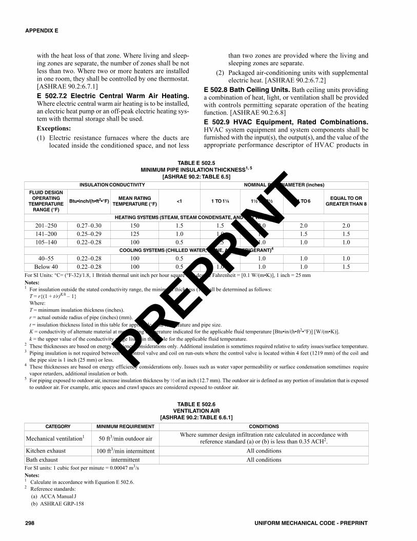
with the heat loss of that zone. Where living and sleep-ing zones are separate, the number of zones shall be notless than two. Where two or more heaters are installedin one room, they shall be controlled by one thermostat.[ASHRAE 90.2:6.7.1]E 502.7.2 Electric Central Warm Air Heating.Where electric central warm air heating is to be installed,an electric heat pump or an off-peak electric heating sys-tem with thermal storage shall be used.Exceptions:(1) Electric resistance furnaces where the ducts are
located inside the conditioned space, and not less
than two zones are provided where the living andsleeping zones are separate.
(2) Packaged air-conditioning units with supplementalelectric heat. [ASHRAE 90.2:6.7.2]
E 502.8 Bath Ceiling Units. Bath ceiling units providinga combination of heat, light, or ventilation shall be providedwith controls permitting separate operation of the heatingfunction. [ASHRAE 90.2:6.8]E 502.9 HVAC Equipment, Rated Combinations.HVAC system equipment and system components shall befurnished with the input(s), the output(s), and the value of theappropriate performance descriptor of HVAC products in
298 UNIFORM MECHANICAL CODE - PREPRINT
APPENDIX E
INSULATION CONDUCTIVITY NOMINAL PIPE DIAMETER (inches)
FLUID DESIGNOPERATING
TEMPERATURERANGE (°F)
Btu•inch/(h•ft2•°F)MEAN RATING
TEMPERATURE (°F)<1 1 TO 11⁄4 11⁄2 TO 31⁄2 4 TO 6
EQUAL TO ORGREATER THAN 8
HEATING SYSTEMS (STEAM, STEAM CONDENSATE, AND HOT WATER)2, 3
201–250 0.27–0.30 150 1.5 1.5 2.0 2.0 2.0141–200 0.25–0.29 125 1.0 1.0 1.0 1.5 1.5105–140 0.22–0.28 100 0.5 0.5 1.0 1.0 1.0
COOLING SYSTEMS (CHILLED WATER, BRINE, ANDREFRIGERANT)4
40–55 0.22–0.28 100 0.5 0.5 1.0 1.0 1.0Below 40 0.22–0.28 100 0.5 1.0 1.0 1.0 1.5
TABLE E 502.5MINIMUM PIPE INSULATION THICKNESS1, 5
[ASHRAE 90.2: TABLE 6.5]
For SI Units: °C= (°F-32)/1.8, 1 British thermal unit inch per hour square foot degree Fahrenheit = [0.1 W/(m•K)], 1 inch = 25 mmNotes:1 For insulation outside the stated conductivity range, the minimum thickness (T) shall be determined as follows:
T = r{(1 + t/r)K/k – 1} Where:T = minimum insulation thickness (inches).r = actual outside radius of pipe (inches) (mm).t = insulation thickness listed in this table for applicable fluid temperature and pipe size.K = conductivity of alternate material at mean rating temperature indicated for the applicable fluid temperature [Btu•in/(h•ft2•°F)] [W/(m•K)].k = the upper value of the conductivity range listed in this table for the applicable fluid temperature.
2 These thicknesses are based on energy efficiency considerations only. Additional insulation is sometimes required relative to safety issues/surface temperature.3 Piping insulation is not required between the control valve and coil on run-outs where the control valve is located within 4 feet (1219 mm) of the coil and
the pipe size is 1 inch (25 mm) or less.4 These thicknesses are based on energy efficiency considerations only. Issues such as water vapor permeability or surface condensation sometimes require
vapor retarders, additional insulation or both.5 For piping exposed to outdoor air, increase insulation thickness by 1⁄2 of an inch (12.7 mm). The outdoor air is defined as any portion of insulation that is exposed
to outdoor air. For example, attic spaces and crawl spaces are considered exposed to outdoor air.
TABLE E 502.6 VENTILATION AIR
[ASHRAE 90.2: TABLE 6.6.1]
CATEGORY MINIMUM REQUIREMENT CONDITIONS
Mechanical ventilation1 50 ft3/min outdoor air Where summer design infiltration rate calculated in accordance withreference standard (a) or (b) is less than 0.35 ACH2.
Kitchen exhaust 100 ft3/min intermittent All conditionsBath exhaust intermittent All conditionsFor SI units: 1 cubic foot per minute = 0.00047 m3/sNotes:1 Calculate in accordance with Equation E 502.6.2 Reference standards:
(a) ACCA Manual J(b) ASHRAE GRP-158
PREPRINT
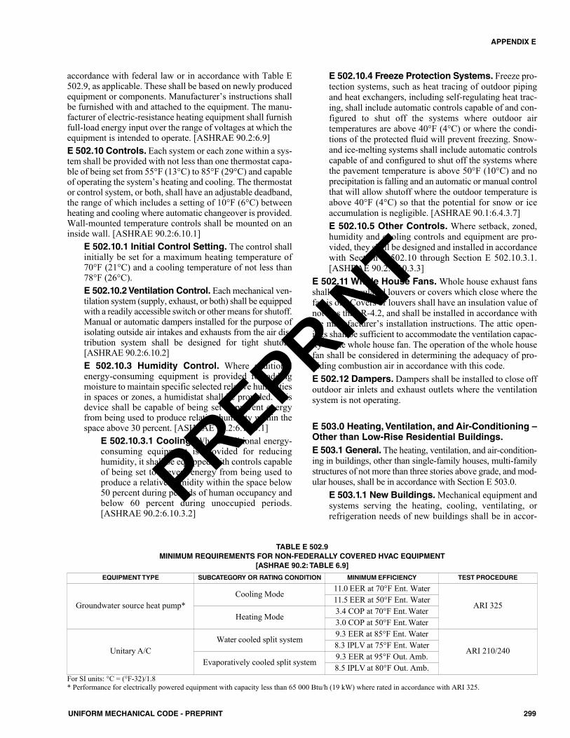
accordance with federal law or in accordance with Table E502.9, as applicable. These shall be based on newly producedequipment or components. Manufacturer’s instructions shallbe furnished with and attached to the equipment. The manu-facturer of electric-resistance heating equipment shall furnishfull-load energy input over the range of voltages at which theequipment is intended to operate. [ASHRAE 90.2:6.9]E 502.10 Controls. Each system or each zone within a sys-tem shall be provided with not less than one thermostat capa-ble of being set from 55°F (13°C) to 85°F (29°C) and capableof operating the system’s heating and cooling. The thermostator control system, or both, shall have an adjustable deadband,the range of which includes a setting of 10°F (6°C) betweenheating and cooling where automatic changeover is provided.Wall-mounted temperature controls shall be mounted on aninside wall. [ASHRAE 90.2:6.10.1]
E 502.10.1 Initial Control Setting. The control shallinitially be set for a maximum heating temperature of70°F (21°C) and a cooling temperature of not less than78°F (26°C).E 502.10.2 Ventilation Control. Each mechanical ven-tilation system (supply, exhaust, or both) shall be equippedwith a readily accessible switch or other means for shutoff.Manual or automatic dampers installed for the purpose ofisolating outside air intakes and exhausts from the air dis-tribution system shall be designed for tight shutoff.[ASHRAE 90.2:6.10.2]E 502.10.3 Humidity Control. Where additionalenergy-consuming equipment is provided for addingmoisture to maintain specific selected relative humiditiesin spaces or zones, a humidistat shall be provided. Thisdevice shall be capable of being set to prevent energyfrom being used to produce relative humidity within thespace above 30 percent. [ASHRAE 90.2:6.10.3.1]
E 502.10.3.1 Cooling. Where additional energy-consuming equipment is provided for reducinghumidity, it shall be equipped with controls capableof being set to prevent energy from being used toproduce a relative humidity within the space below50 percent during periods of human occupancy andbelow 60 percent during unoccupied periods.[ASHRAE 90.2:6.10.3.2]
E 502.10.4 Freeze Protection Systems. Freeze pro-tection systems, such as heat tracing of outdoor pipingand heat exchangers, including self-regulating heat trac-ing, shall include automatic controls capable of and con-figured to shut off the systems where outdoor airtemperatures are above 40°F (4°C) or where the condi-tions of the protected fluid will prevent freezing. Snow-and ice-melting systems shall include automatic controlscapable of and configured to shut off the systems wherethe pavement temperature is above 50°F (10°C) and noprecipitation is falling and an automatic or manual controlthat will allow shutoff where the outdoor temperature isabove 40°F (4°C) so that the potential for snow or iceaccumulation is negligible. [ASHRAE 90.1:6.4.3.7]E 502.10.5 Other Controls. Where setback, zoned,humidity and cooling controls and equipment are pro-vided, they shall be designed and installed in accordancewith Section E 502.10 through Section E 502.10.3.1.[ASHRAE 90.2:6.10.3.3]
E 502.11 Whole House Fans. Whole house exhaust fansshall have insulated louvers or covers which close where thefan is off. Covers or louvers shall have an insulation value ofnot less than R-4.2, and shall be installed in accordance withthe manufacturer’s installation instructions. The attic open-ings shall be sufficient to accommodate the ventilation capac-ity of the whole house fan. The operation of the whole housefan shall be considered in determining the adequacy of pro-viding combustion air in accordance with this code.E 502.12 Dampers. Dampers shall be installed to close offoutdoor air inlets and exhaust outlets where the ventilationsystem is not operating.
E 503.0 Heating, Ventilation, and Air-Conditioning –Other than Low-Rise Residential Buildings.E 503.1 General. The heating, ventilation, and air-condition-ing in buildings, other than single-family houses, multi-familystructures of not more than three stories above grade, and mod-ular houses, shall be in accordance with Section E 503.0.
E 503.1.1 New Buildings. Mechanical equipment andsystems serving the heating, cooling, ventilating, orrefrigeration needs of new buildings shall be in accor-
299UNIFORM MECHANICAL CODE - PREPRINT
APPENDIX E
EQUIPMENT TYPE SUBCATEGORY OR RATING CONDITION MINIMUM EFFICIENCY TEST PROCEDURE
Groundwater source heat pump*Cooling Mode
11.0 EER at 70°F Ent. Water
ARI 32511.5 EER at 50°F Ent. Water
Heating Mode3.4 COP at 70°F Ent. Water3.0 COP at 50°F Ent. Water
Unitary A/CWater cooled split system
9.3 EER at 85°F Ent. Water
ARI 210/2408.3 IPLV at 75°F Ent. Water
Evaporatively cooled split system9.3 EER at 95°F Out. Amb.8.5 IPLV at 80°F Out. Amb.
TABLE E 502.9MINIMUM REQUIREMENTS FOR NON-FEDERALLY COVERED HVAC EQUIPMENT
[ASHRAE 90.2: TABLE 6.9]
For SI units: °C = (°F-32)/1.8* Performance for electrically powered equipment with capacity less than 65 000 Btu/h (19 kW) where rated in accordance with ARI 325.
PREPRINT
dance with the requirements of this section as describedin Section E 503.2. [ASHRAE 90.1:6.1.1.1]E 503.1.2 Additions to Existing Buildings. Mechan-ical equipment and systems serving the heating, cooling,ventilating, or refrigeration needs of additions to existingbuildings shall be in accordance with the requirements ofthis section as described in Section E 503.2.Exception: Where HVACR to an addition is provided byexisting HVACR systems and equipment, such existingsystems and equipment shall not be required to be inaccordance with this appendix. A new system or equip-ment installed shall be in accordance with specificrequirements applicable to those systems and equipment.[ASHRAE 90.1:6.1.1.2]E 503.1.3 Alterations to Heating, Ventilating, Air-Conditioning, and Refrigeration in ExistingBuildings. New HVACR equipment as a direct replace-ment of existing HVACR equipment shall be in accor-dance with the following sections as applicable for theequipment being replaced:(1) Section E 503.3(2) Section E 503.4(3) Section E 503.4.6(4) Section E 503.4.6.2(5) Section E 503.4.6.3(6) Section E 503.4.6.4(7) Section E 503.4.6.8(8) Section E 503.4.6.9(9) Section E 503.4.6.11(10) Section E 503.5.1(11) Section E 503.5.3(12) Section E 503.5.3.1 E 503.5.4(13) Section E 503.5.6.1.2(14) Section E 503.5.6.2(15) Section E 503.5.6.5(16) Section E 503.5.7(17) Section E 503.5.7.2(18) Section E 503.5.8.1. [ASHRAE 90.1:6.1.1.3.1]
E 503.1.3.1 New Cooling Systems. New coolingsystems installed to serve previously uncooled spacesshall be in accordance with this section as describedin Section E 503.2. [ASHRAE 90.1:6.1.1.3.2]E 503.1.3.2 Existing Cooling Systems. Alter-ations to existing cooling systems shall not decreaseeconomizer capability unless the system is in accor-dance with Section E 503.5 through Section503.5.4.1. [ASHRAE 90.1:6.1.1.3.3]E 503.1.3.3 Ductwork. New and replacement duct-work shall comply with Section E 503.4.7.1 throughSection E 503.4.7.2.1. [ASHRAE 90.1:6.1.1.3.4]E 503.1.3.4 Piping. New and replacement pipingshall comply with Section E 503.4.7.1.
Exceptions: (1) For equipment that is being modified or
repaired but not replaced, provided that suchmodifications or repairs will not result in anincrease in the annual energy consumption ofthe equipment using the same energy type.
(2) Where a replacement or alteration of equipmentrequires extensive revisions to other systems,equipment, or elements of a building, and suchreplaced or altered equipment is a like-for-likereplacement.
(3) For a refrigerant change of existing equipment.(4) For the relocation of existing equipment.(5) For ducts and piping where there is insufficient
space or access to comply with these require-ments. [ASHRAE 90.1:6.1.1.3.5]
E 503.2 Compliance Path(s). Section E 503.0 shall beachieved in accordance with the requirements of Section E503.1.1 through Section E 503.1.3.4, Section E 503.6, Sec-tion E 503.7, and one of the following:(1) Section E 503.3 and Section E 503.3.1(2) Section E 503.4(3) Section E 503.4 and Section E 503.8 [ASHRAE 90.1:6.2.1]
E 503.2.1 Projects Using Energy Cost BudgetMethod. Projects using the energy cost budget methodin accordance with ASHRAE 90.1 shall comply withSection E 503.4, the mandatory provisions of this sec-tion, as a portion of that compliance path. [ASHRAE90.1:6.2.2]
E 503.3 Simplified Approach Option for HVAC Sys-tems. The simplified approach shall be an optional path forcompliance where the following conditions are met:(1) The building is not more than two stories in height.(2) Gross floor area is less than 25 000 square feet (2322.6 m2).(3) The HVAC system in the building is in accordance with
the requirements listed in Section E 503.3.1. [ASHRAE90.1:6.3.1] E 503.3.1 Criteria. The HVAC system shall complywith the following criteria:(1) The system serves a single HVAC zone.(2) The equipment shall comply with the variable flow
requirements of Section E 503.5.6.2.(3) Cooling (where any) shall be provided by a unitary
packaged or split-system air conditioner that is eitherair-cooled or evaporatively cooled, with efficiencythat is in accordance with the requirements shownin Table E 503.7.1(1), Table E 503.7.1(2), or TableE 503.7.1(4) for the applicable equipment category.
(4) The system shall have an air economizer in accor-dance with Section E 503.5 and Section E 503.4.6.13.
(5) Heating (where any) shall be provided by a unitarypackaged or split-system heat pump that is in accor-dance with the applicable efficiency requirementsshown in Table E 503.7.1(2) or Table E 503.7.1(4),
300 UNIFORM MECHANICAL CODE - PREPRINT
APPENDIX E
PREPRINT
a fuel-fired furnace that is in accordance with theapplicable efficiency requirements shown in Table E503.7.1(5), an electric resistance heater, or a base-board system connected to a boiler that is in accor-dance with the applicable efficiency requirementsshown in Table E 503.7.1(6).
(6) The system shall comply with the exhaust air energyrecovery requirements in accordance with Section E503.5.10.
(7) The system shall be controlled by a manualchangeover or dual setpoint thermostat.
(8) Where a heat pump equipped with auxiliary internalelectric resistance heaters is installed, controls shallbe provided that prevent supplemental heater oper-ation where the heating load is capable of being metby the heat pump alone during both steady-stateoperation and setback recovery. Supplementalheater operation shall be permitted during outdoorcoil defrost cycles. The heat pump shall be con-trolled in accordance with one of the following: (a) A digital or electronic thermostat designed for
heat pump use that energizes auxiliary heatwhere the heat pump has insufficient capacityto maintain setpoint or to warm up the space ata sufficient rate.
(b) A multistage space thermostat and an outdoorair thermostat wired to energize auxiliary heaton the last stage of the space thermostat andwhere outdoor air temperature is less than 40°F(4°C).
Exceptions: Heat Pumps that comply with the fol-lowing:(1) Have a minimum efficiency regulated by
NAECA.(2) In accordance with the requirements shown in
Table E 503.7.1(2).(3) Include all usage of internal electric resistance
heating.(9) The system controls shall not permit reheat or other
form of simultaneous heating and cooling forhumidity control.
(10) Systems serving spaces other than hotel or motelguest rooms, and other than those requiring contin-uous operation, which have both a cooling or heat-ing capacity more than 15 000 Btu/h (4.4 kW) and asupply fan motor power more than 0.75 horsepower(hp) (0.56 kW), shall be provided with a time clockthat is in accordance with the following: (a) Can start and stop the system under different
schedules for seven different day-types per week.(b) Is capable of retaining programming and time
setting during a loss of power for a period of notless than 10 hours.
(c) Includes an accessible manual override thatallows temporary operation of the system for upto 2 hours.
(d) Is capable of and configured with temperaturesetback down to 55°F (13°C) during off hours.
(e) Is capable of and configured with temperaturesetup to 90°F (32°C) during off hours.
(11) Systems serving hotel/motel guest rooms shall com-ply with Section E 503.4.6.3.5.
(12) Except for piping within manufacturer’s units,HVAC piping shall be insulated in accordance withTable E 503.7.3(1) and Table E 503.7.3(2). Insula-tion exposed to weather shall be suitable for outdoorservice, e.g., protected by aluminum, sheet metal,painted canvas, or plastic cover. Cellular foam insu-lation shall be protected as above or painted with acoating that is water retardant and provides shieldingfrom solar radiation.
(13) Ductwork and plenums shall be insulated in accor-dance with Table E 503.7.2 and shall be sealed inaccordance with Section E 503.4.7.2.
(14) Construction documents shall require a ducted sys-tem to be air balanced in accordance with industry-accepted procedures.
(15) Outdoor air intake and exhaust systems shall com-ply with Section E 503.4.6.4 through Section E503.4.6.5.
(16) Where separate heating and cooling equipmentserves the same temperature zone, thermostats shallbe interlocked to prevent simultaneous heating andcooling.
(17) Systems with a design supply air capacity more than10 000 ft3/min (4.7195 m3/s) shall have optimumstart controls.
(18) The system shall comply with the demand controlventilation requirements of Section E 503.4.6.9 andthe ventilation design requirements of Section E503.5.6.6.
(19) The system shall comply with the door switch require-ments of Section E 503.5.14. [ASHRAE 90.1:6.3.2]
E 503.3.2 Climate Zone Determination. Climatezones identified in this appendix shall be determined inaccordance with ASHRAE 90.1. For locations in theUnited States and its territories, the assigned climatezone and, where required, the assigned climate zone let-ter shall be in accordance with ASHRAE 169.Exception: Where recorded historical climatic data areavailable for a construction site, it is permitted to be usedto determine compliance where approved by the Author-ity Having Jurisdiction. [ASHRAE 90.1:5.1.4.1]
E 503.4 Mandatory Provisions. Equipment shown inTable E 503.7.1(1) through Table E 503.7.1(16) shall have aminimum performance at the specified rating conditionswhere tested in accordance with the specified test procedure.Where multiple rating conditions or performance require-ments are provided, the equipment shall satisfy the statedrequirements unless otherwise exempted by footnotes in thetable. Equipment covered under the Federal Energy PolicyAct of 1992 (EPACT) shall have no minimum efficiency
301UNIFORM MECHANICAL CODE - PREPRINT
APPENDIX E
PREPRINT
requirements for operation at minimum capacity or other thanstandard rating conditions. Equipment used to provide serv-ice water-heating functions as part of a combination systemshall satisfy the stated requirements for the appropriate spaceheating or cooling category.Tables are as follows:(1) Table E 503.7.1(1), “Electrically Operated Unitary Air
Conditioners and Condensing Units-Minimum Effi-ciency Requirements”
(2) Table E 503.7.1 (2), “Electrically Operated Unitary andApplied Heat Pumps-Minimum Efficiency Requirements”
(3) Table E 503.7.1 (3), “Water-Chilling Packages-Effi-ciency Requirements” (See Section E 503.4.1 for water-cooled centrifugal water-chilling packages that aredesigned to operate at nonstandard conditions.)
(4) Table E 503.7.1 (4), “Electrically Operated PackagedTerminal Air Conditioners, Packaged Terminal HeatPumps, Single-Package Vertical Air Conditioners, Sin-gle-Package Vertical Heat Pumps, Room Air Condition-ers, and Room Air Conditioner Heat Pumps-MinimumEfficiency Requirements”
(5) Table E 503.7.1 (5), “Warm-Air Furnaces and Combi-nation Warm-Air Furnaces/Air-Conditioning Units,Warm-Air Duct Furnaces, and Unit Heaters-MinimumEfficiency Requirements”
(6) Table E 503.7.1 (6), “Gas- and Oil-Fired Boilers-Mini-mum Efficiency Requirements”
(7) Table E 503.7.1 (7), “Performance Requirements forHeat-Rejection Equipment”
(8) Table E 503.7.1 (8), “Heat Transfer Equipment”(9) Table E 503.7.1 (9), “Electrically Operated Variable-
Refrigerant-Flow Air Conditioners- Minimum EfficiencyRequirements”
(10) Table E 503.7.1 (10), “Electrically Operated Variable-Refrigerant-Flow and Applied Heat Pumps-MinimumEfficiency Requirements”
(11) Table E 503.7.1 (11), “Air Conditioners and Condens-ing Units Serving Computer Rooms”
(12) Table E 503.7.1 (12), “Commercial Refrigerators andFreezers-Minimum Efficiency Requirements”
(13) Table E 503.7.1 (13), “Commercial Refrigeration-Mini-mum Efficiency Requirements”
(14) Table E 503.7.1 (14), “Vapor-Compression-BasedIndoor Pool Dehumidifiers-Minimum EfficiencyRequirements”
(15) Table E 503.7.1 (15), “Electrically Operated DX-DOASUnits, Single-Package and Remote Condenser, withoutEnergy Recovery-Minimum Efficiency Requirements”
(16) Table E 503.7.1 (16), “Electrically Operated DX-DOASUnits, Single-Package and Remote Condenser, withEnergy Recovery-Minimum Efficiency Requirements” All furnaces with input ratings of 225 000 Btu/h (66 kW)
or more, including electric furnaces, that are not locatedwithin the conditioned space shall have jacket losses notexceeding 0.75 percent of the input rating. Air conditionersprimarily serving computer rooms and covered by ASHRAE
127 shall comply with the requirements in Table E503.7.1(11). All other air conditioners shall meet the require-ments in Table E 503.7.1(1). [ASHRAE 90.1:6.4.1.1]
E 503.4.1 Water-Cooled Centrifugal ChillingPackages. Equipment not designed for operation inaccordance with AHRI 550/590 test conditions of44.00°F (6.67°C) leaving and 54.00°F (12.22°C) enter-ing chilled-fluid temperatures, and with 85.00°F(29.44°C) entering and 94.30°F (34.61°C) leaving con-denser-fluid temperatures, shall have maximum full-loadkW/ton (FL) and part-load rating requirements adjustedin accordance with Equation E 503.4.1(1) through Equa-tion E 503.4.1(3):FLadj = FL/Kadj [Equation E 503.4.1(1)]PLVadj = IPLV.IP/Kadj [Equation E 503.4.1(2)]Kadj = A x B [Equation E 503.4.1(3)]
Where:FL = full-load kW/ton value from Table E
503.7.1(3)FLadj = maximum full-load kW/ton rating, adjusted
for nonstandard conditionsIPLV.IP = IPLV.IP value from Table E 503.7.1(3)PLVadj = maximum NPLV rating, adjusted for non-
standard conditionsA = 0.00000014592 x (LIFT)4 - 0.0000346496
x (LIFT)3 + 0.00314196 x (LIFT)2 -0.147199 x (LIFT) + 3.93073
B = 0.0015 x LvgEvap + 0.934LIFT = LvgCond - LvgEvapLvgCond = Full-load condenser leaving fluid tempera-
ture (°F)LvgEvap = Full-load evaporator leaving temperature
(°F)
The FLadj and PLVadj values shall only be applica-ble for centrifugal chillers meeting all of the followingfull-load design ranges:(1) 36.00°F (2.22°C) ≤ LvgEvap ≤ 60.00°F (15.56°C)(2) LvgCond ≤ 115.00°F (46.11°C)(3) 20.00°F (-6.67°C) ≤ 80.00°F (26.67°C)
Manufacturers shall calculate the FLadj and PLVadjbefore determining whether to label the chiller in accor-dance with Section E 503.4.4. Chillers that are in accor-dance with ASHRAE 90.1 shall be labeled on chillers inaccordance with the scope of ASHRAE 90.1.
Centrifugal chillers designed to operate outside ofthese ranges shall not be covered under this appendix.Example: Path A, 600 ton (600 000 kg) centrifugalchiller Table E 503.7.1(3) efficiencies.F = 0.5600 kW/tonIPLV = 0.5000 kW/tonLvgCond = 91.16°F
302 UNIFORM MECHANICAL CODE - PREPRINT
APPENDIX E
PREPRINT
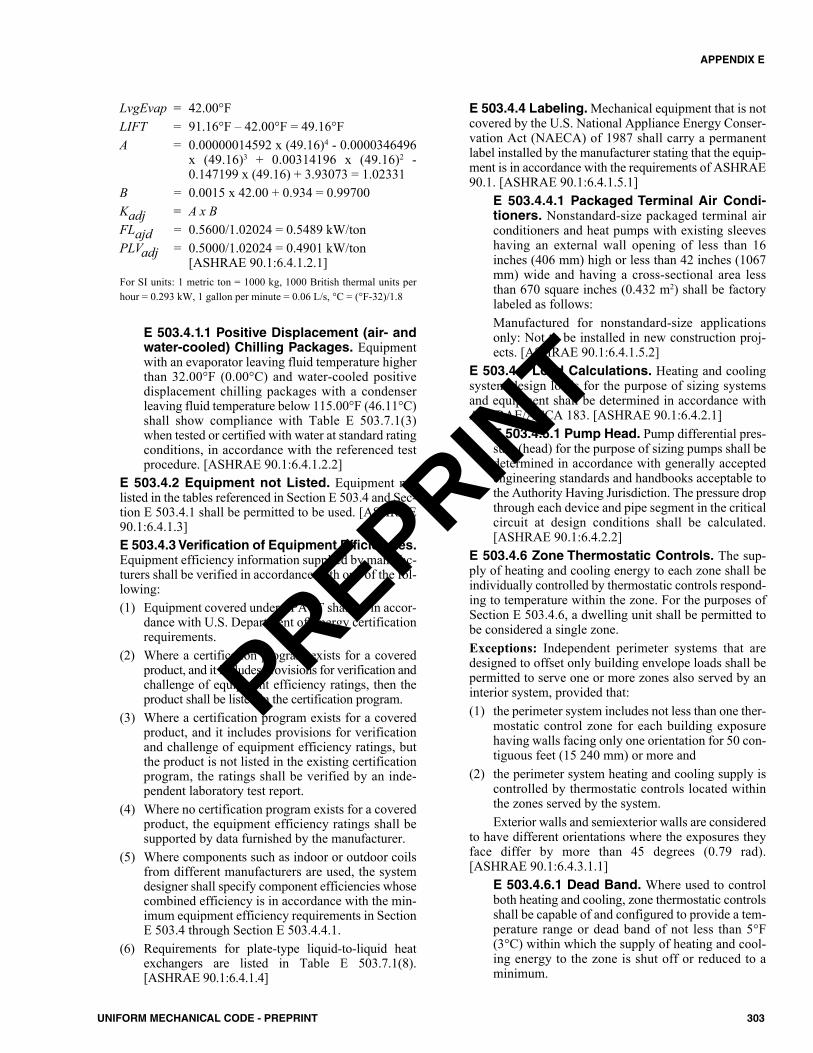
LvgEvap = 42.00°FLIFT = 91.16°F – 42.00°F = 49.16°FA = 0.00000014592 x (49.16)4 - 0.0000346496
x (49.16)3 + 0.00314196 x (49.16)2 -0.147199 x (49.16) + 3.93073 = 1.02331
B = 0.0015 x 42.00 + 0.934 = 0.99700Kadj = A x BFLajd = 0.5600/1.02024 = 0.5489 kW/tonPLVadj = 0.5000/1.02024 = 0.4901 kW/ton
[ASHRAE 90.1:6.4.1.2.1]For SI units: 1 metric ton = 1000 kg, 1000 British thermal units perhour = 0.293 kW, 1 gallon per minute = 0.06 L/s, °C = (°F-32)/1.8
E 503.4.1.1 Positive Displacement (air- andwater-cooled) Chilling Packages. Equipmentwith an evaporator leaving fluid temperature higherthan 32.00°F (0.00°C) and water-cooled positivedisplacement chilling packages with a condenserleaving fluid temperature below 115.00°F (46.11°C)shall show compliance with Table E 503.7.1(3)when tested or certified with water at standard ratingconditions, in accordance with the referenced testprocedure. [ASHRAE 90.1:6.4.1.2.2]
E 503.4.2 Equipment not Listed. Equipment notlisted in the tables referenced in Section E 503.4 and Sec-tion E 503.4.1 shall be permitted to be used. [ASHRAE90.1:6.4.1.3]E 503.4.3 Verification of Equipment Efficiencies.Equipment efficiency information supplied by manufac-turers shall be verified in accordance with one of the fol-lowing:(1) Equipment covered under EPACT shall be in accor-
dance with U.S. Department of Energy certificationrequirements.
(2) Where a certification program exists for a coveredproduct, and it includes provisions for verification andchallenge of equipment efficiency ratings, then theproduct shall be listed in the certification program.
(3) Where a certification program exists for a coveredproduct, and it includes provisions for verificationand challenge of equipment efficiency ratings, butthe product is not listed in the existing certificationprogram, the ratings shall be verified by an inde-pendent laboratory test report.
(4) Where no certification program exists for a coveredproduct, the equipment efficiency ratings shall besupported by data furnished by the manufacturer.
(5) Where components such as indoor or outdoor coilsfrom different manufacturers are used, the systemdesigner shall specify component efficiencies whosecombined efficiency is in accordance with the min-imum equipment efficiency requirements in SectionE 503.4 through Section E 503.4.4.1.
(6) Requirements for plate-type liquid-to-liquid heatexchangers are listed in Table E 503.7.1(8).[ASHRAE 90.1:6.4.1.4]
E 503.4.4 Labeling. Mechanical equipment that is notcovered by the U.S. National Appliance Energy Conser-vation Act (NAECA) of 1987 shall carry a permanentlabel installed by the manufacturer stating that the equip-ment is in accordance with the requirements of ASHRAE90.1. [ASHRAE 90.1:6.4.1.5.1]
E 503.4.4.1 Packaged Terminal Air Condi-tioners. Nonstandard-size packaged terminal airconditioners and heat pumps with existing sleeveshaving an external wall opening of less than 16inches (406 mm) high or less than 42 inches (1067mm) wide and having a cross-sectional area lessthan 670 square inches (0.432 m2) shall be factorylabeled as follows:Manufactured for nonstandard-size applicationsonly: Not to be installed in new construction proj-ects. [ASHRAE 90.1:6.4.1.5.2]
E 503.4.5 Load Calculations. Heating and coolingsystem design loads for the purpose of sizing systemsand equipment shall be determined in accordance withASHRAE/ACCA 183. [ASHRAE 90.1:6.4.2.1]
E 503.4.5.1 Pump Head. Pump differential pres-sure (head) for the purpose of sizing pumps shall bedetermined in accordance with generally acceptedengineering standards and handbooks acceptable tothe Authority Having Jurisdiction. The pressure dropthrough each device and pipe segment in the criticalcircuit at design conditions shall be calculated.[ASHRAE 90.1:6.4.2.2]
E 503.4.6 Zone Thermostatic Controls. The sup-ply of heating and cooling energy to each zone shall beindividually controlled by thermostatic controls respond-ing to temperature within the zone. For the purposes ofSection E 503.4.6, a dwelling unit shall be permitted tobe considered a single zone.Exceptions: Independent perimeter systems that aredesigned to offset only building envelope loads shall bepermitted to serve one or more zones also served by aninterior system, provided that:(1) the perimeter system includes not less than one ther-
mostatic control zone for each building exposurehaving walls facing only one orientation for 50 con-tiguous feet (15 240 mm) or more and
(2) the perimeter system heating and cooling supply iscontrolled by thermostatic controls located withinthe zones served by the system.Exterior walls and semiexterior walls are considered
to have different orientations where the exposures theyface differ by more than 45 degrees (0.79 rad).[ASHRAE 90.1:6.4.3.1.1]
E 503.4.6.1 Dead Band. Where used to controlboth heating and cooling, zone thermostatic controlsshall be capable of and configured to provide a tem-perature range or dead band of not less than 5°F(3°C) within which the supply of heating and cool-ing energy to the zone is shut off or reduced to aminimum.
303UNIFORM MECHANICAL CODE - PREPRINT
APPENDIX E
PREPRINT
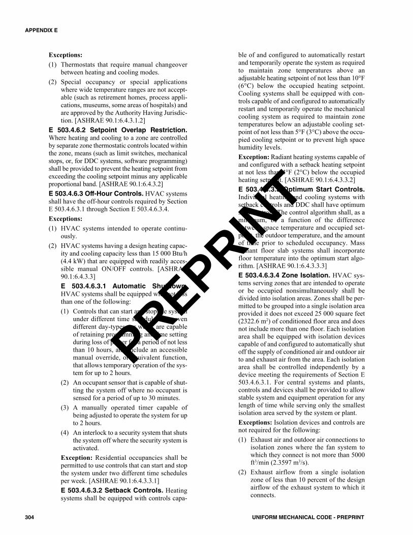
Exceptions:(1) Thermostats that require manual changeover
between heating and cooling modes.(2) Special occupancy or special applications
where wide temperature ranges are not accept-able (such as retirement homes, process appli-cations, museums, some areas of hospitals) andare approved by the Authority Having Jurisdic-tion. [ASHRAE 90.1:6.4.3.1.2]
E 503.4.6.2 Setpoint Overlap Restriction.Where heating and cooling to a zone are controlledby separate zone thermostatic controls located withinthe zone, means (such as limit switches, mechanicalstops, or, for DDC systems, software programming)shall be provided to prevent the heating setpoint fromexceeding the cooling setpoint minus any applicableproportional band. [ASHRAE 90.1:6.4.3.2]E 503.4.6.3 Off-Hour Controls. HVAC systemsshall have the off-hour controls required by SectionE 503.4.6.3.1 through Section E 503.4.6.3.4.Exceptions:(1) HVAC systems intended to operate continu-
ously.(2) HVAC systems having a design heating capac-
ity and cooling capacity less than 15 000 Btu/h(4.4 kW) that are equipped with readily acces-sible manual ON/OFF controls. [ASHRAE90.1:6.4.3.3]E 503.4.6.3.1 Automatic Shutdown.HVAC systems shall be equipped with not lessthan one of the following:(1) Controls that can start and stop the system
under different time schedules for sevendifferent day-types per week, are capableof retaining programming and time settingduring loss of power for a period of not lessthan 10 hours, and include an accessiblemanual override, or equivalent function,that allows temporary operation of the sys-tem for up to 2 hours.
(2) An occupant sensor that is capable of shut-ting the system off where no occupant issensed for a period of up to 30 minutes.
(3) A manually operated timer capable ofbeing adjusted to operate the system for upto 2 hours.
(4) An interlock to a security system that shutsthe system off where the security system isactivated.
Exception: Residential occupancies shall bepermitted to use controls that can start and stopthe system under two different time schedulesper week. [ASHRAE 90.1:6.4.3.3.1]E 503.4.6.3.2 Setback Controls. Heatingsystems shall be equipped with controls capa-
ble of and configured to automatically restartand temporarily operate the system as requiredto maintain zone temperatures above anadjustable heating setpoint of not less than 10°F(6°C) below the occupied heating setpoint.Cooling systems shall be equipped with con-trols capable of and configured to automaticallyrestart and temporarily operate the mechanicalcooling system as required to maintain zonetemperatures below an adjustable cooling set-point of not less than 5°F (3°C) above the occu-pied cooling setpoint or to prevent high spacehumidity levels.Exception: Radiant heating systems capable ofand configured with a setback heating setpointat not less than 4°F (2°C) below the occupiedheating setpoint. [ASHRAE 90.1:6.4.3.3.2]E 503.4.6.3.3 Optimum Start Controls.Individual heating and cooling systems withsetback controls and DDC shall have optimumstart controls. The control algorithm shall, as aminimum, be a function of the differencebetween space temperature and occupied set-point, the outdoor temperature, and the amountof time prior to scheduled occupancy. Massradiant floor slab systems shall incorporatefloor temperature into the optimum start algo-rithm. [ASHRAE 90.1:6.4.3.3.3]E 503.4.6.3.4 Zone Isolation. HVAC sys-tems serving zones that are intended to operateor be occupied nonsimultaneously shall bedivided into isolation areas. Zones shall be per-mitted to be grouped into a single isolation areaprovided it does not exceed 25 000 square feet(2322.6 m2) of conditioned floor area and doesnot include more than one floor. Each isolationarea shall be equipped with isolation devicescapable of and configured to automatically shutoff the supply of conditioned air and outdoor airto and exhaust air from the area. Each isolationarea shall be controlled independently by adevice meeting the requirements of Section E503.4.6.3.1. For central systems and plants,controls and devices shall be provided to allowstable system and equipment operation for anylength of time while serving only the smallestisolation area served by the system or plant.Exceptions: Isolation devices and controls arenot required for the following:(1) Exhaust air and outdoor air connections to
isolation zones where the fan system towhich they connect is not more than 5000ft3/min (2.3597 m3/s).
(2) Exhaust airflow from a single isolationzone of less than 10 percent of the designairflow of the exhaust system to which itconnects.
304 UNIFORM MECHANICAL CODE - PREPRINT
APPENDIX E
PREPRINT
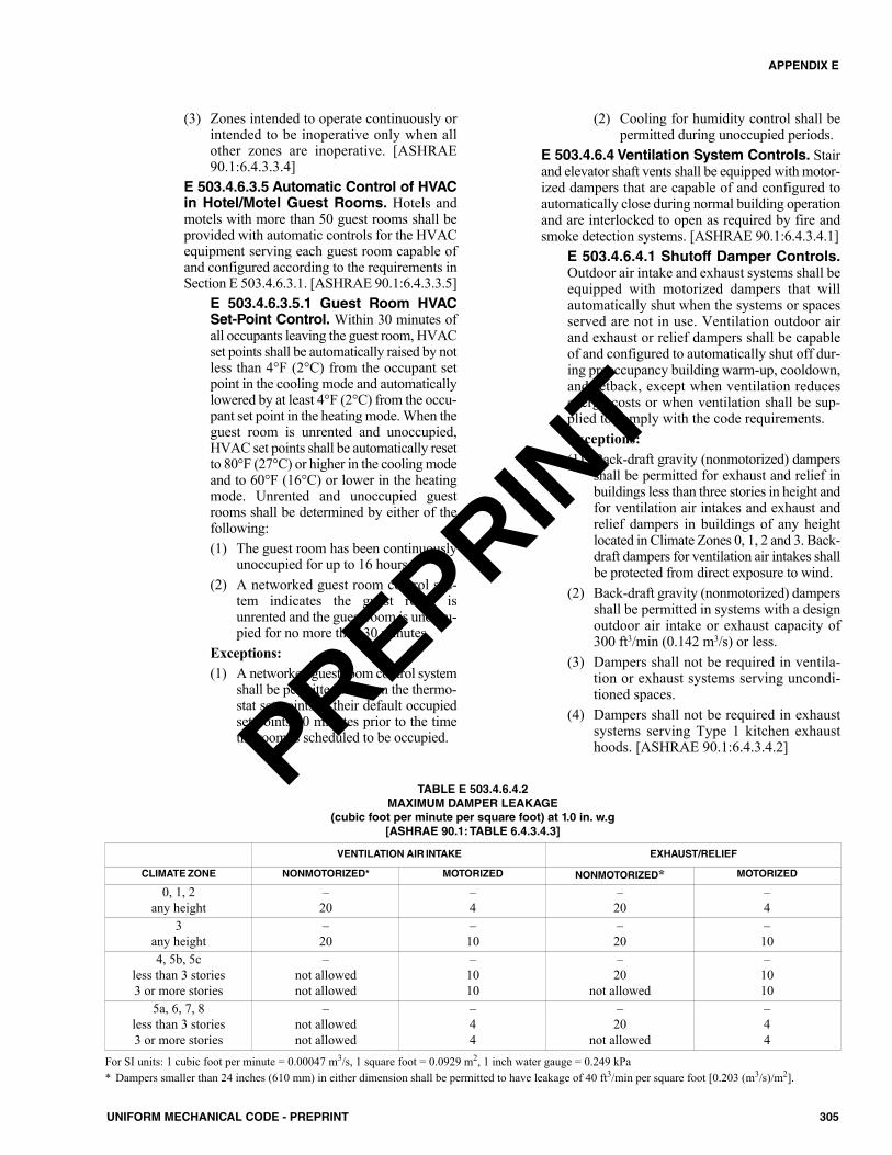
(3) Zones intended to operate continuously orintended to be inoperative only when allother zones are inoperative. [ASHRAE90.1:6.4.3.3.4]
E 503.4.6.3.5 Automatic Control of HVACin Hotel/Motel Guest Rooms. Hotels andmotels with more than 50 guest rooms shall beprovided with automatic controls for the HVACequipment serving each guest room capable ofand configured according to the requirements inSection E 503.4.6.3.1. [ASHRAE 90.1:6.4.3.3.5]
E 503.4.6.3.5.1 Guest Room HVACSet-Point Control. Within 30 minutes ofall occupants leaving the guest room, HVACset points shall be automatically raised by notless than 4°F (2°C) from the occupant setpoint in the cooling mode and automaticallylowered by at least 4°F (2°C) from the occu-pant set point in the heating mode. When theguest room is unrented and unoccupied,HVAC set points shall be automatically resetto 80°F (27°C) or higher in the cooling modeand to 60°F (16°C) or lower in the heatingmode. Unrented and unoccupied guestrooms shall be determined by either of thefollowing:(1) The guest room has been continuously
unoccupied for up to 16 hours.(2) A networked guest room control sys-
tem indicates the guest room isunrented and the guest room is unoccu-pied for no more than 30 minutes.
Exceptions:(1) A networked guest room control system
shall be permitted to return the thermo-stat set points to their default occupiedset points 60 minutes prior to the timethe room is scheduled to be occupied.
(2) Cooling for humidity control shall bepermitted during unoccupied periods.
E 503.4.6.4 Ventilation System Controls. Stairand elevator shaft vents shall be equipped with motor-ized dampers that are capable of and configured toautomatically close during normal building operationand are interlocked to open as required by fire andsmoke detection systems. [ASHRAE 90.1:6.4.3.4.1]
E 503.4.6.4.1 Shutoff Damper Controls.Outdoor air intake and exhaust systems shall beequipped with motorized dampers that willautomatically shut when the systems or spacesserved are not in use. Ventilation outdoor airand exhaust or relief dampers shall be capableof and configured to automatically shut off dur-ing preoccupancy building warm-up, cooldown,and setback, except when ventilation reducesenergy costs or when ventilation shall be sup-plied to comply with the code requirements.Exceptions:(1) Back-draft gravity (nonmotorized) dampers
shall be permitted for exhaust and relief inbuildings less than three stories in height andfor ventilation air intakes and exhaust andrelief dampers in buildings of any heightlocated in Climate Zones 0, 1, 2 and 3. Back-draft dampers for ventilation air intakes shallbe protected from direct exposure to wind.
(2) Back-draft gravity (nonmotorized) dampersshall be permitted in systems with a designoutdoor air intake or exhaust capacity of300 ft3/min (0.142 m3/s) or less.
(3) Dampers shall not be required in ventila-tion or exhaust systems serving uncondi-tioned spaces.
(4) Dampers shall not be required in exhaustsystems serving Type 1 kitchen exhausthoods. [ASHRAE 90.1:6.4.3.4.2]
305UNIFORM MECHANICAL CODE - PREPRINT
APPENDIX E
TABLE E 503.4.6.4.2MAXIMUM DAMPER LEAKAGE
(cubic foot per minute per square foot) at 1.0 in. w.g[ASHRAE 90.1: TABLE 6.4.3.4.3]
VENTILATION AIR INTAKE EXHAUST/RELIEF
CLIMATE ZONE NONMOTORIZED* MOTORIZED NONMOTORIZED* MOTORIZED
0, 1, 2any height
–20
–4
–20
–4
3any height
–20
–10
–20
–10
4, 5b, 5cless than 3 stories3 or more stories
–not allowednot allowed
–1010
–20
not allowed
–1010
5a, 6, 7, 8less than 3 stories3 or more stories
–not allowednot allowed
–44
–20
not allowed
–44
For SI units: 1 cubic foot per minute = 0.00047 m3/s, 1 square foot = 0.0929 m2, 1 inch water gauge = 0.249 kPa* Dampers smaller than 24 inches (610 mm) in either dimension shall be permitted to have leakage of 40 ft3/min per square foot [0.203 (m3/s)/m2].
PREPRINT
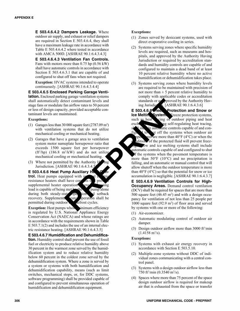
E 503.4.6.4.2 Dampers Leakage. Whereoutdoor air supply, and exhaust or relief dampersare required in Section E 503.4.6.4, they shallhave a maximum leakage rate in accordance withTable E 503.4.6.4.2 where tested in accordancewith AMCA 500D. [ASHRAE 90.1:6.4.3.4.3]E 503.4.6.4.3 Ventilation Fan Controls.Fans with motors more than 0.75 hp (0.56 kW)shall have automatic controls in accordance withSection E 503.4.6.3.1 that are capable of andconfigured to shut off fans when not required.Exception: HVAC systems intended to operatecontinuously. [ASHRAE 90.1:6.4.3.4.4]
E 503.4.6.5 Enclosed Parking Garage Venti-lation. Enclosed parking garage ventilation systemsshall automatically detect contaminant levels andstage fans or modulate fan airflow rates to 50 percentor less of design capacity, provided acceptable con-taminant levels are maintained.Exceptions:(1) Garages less than 30 000 square feet (2787.09 m2)
with ventilation systems that do not utilizemechanical cooling or mechanical heating.
(2) Garages that have a garage area to ventilationsystem motor nameplate horsepower ratio thatexceeds 1500 square feet per horsepower(ft2/hp) (186.8 m2/kW) and do not utilizemechanical cooling or mechanical heating.
(3) Where not permitted by the Authority HavingJurisdiction. [ASHRAE 90.1:6.4.3.4.5]
E 503.4.6.6 Heat Pump Auxiliary Heat Con-trol. Heat pumps equipped with internal electricresistance heaters shall have controls that preventsupplemental heater operation where the heatingload is capable of being met by the heat pump aloneduring both steady-state operation and setbackrecovery. Supplemental heater operation shall bepermitted during outdoor coil defrost cycles.Exception: Heat pumps whose minimum efficiencyis regulated by U.S. National Appliance EnergyConservation Act (NAECA) and whose ratings arein accordance with the requirements shown in TableE 503.7.1(2) and includes the use of an internal elec-tric resistance heating. [ASHRAE 90.1:6.4.3.5]E 503.4.6.7 Humidification and Dehumidifica-tion. Humidity control shall prevent the use of fossilfuel or electricity to produce relative humidity above30 percent in the warmest zone served by the humid-ification system and to reduce relative humiditybelow 60 percent in the coldest zone served by thedehumidification system. Where a zone is served bya system or systems with both humidification anddehumidification capability, means (such as limitswitches, mechanical stops, or, for DDC systems,software programming) shall be provided capable ofand configured to prevent simultaneous operation ofhumidification and dehumidification equipment.
Exceptions:(1) Zones served by desiccant systems, used with
direct evaporative cooling in series.(2) Systems serving zones where specific humidity
levels are required, such as museums and hos-pitals, and approved by the Authority HavingJurisdiction or required by accreditation stan-dards and humidity controls are capable of andconfigured to maintain a dead band of at least10 percent relative humidity where no activehumidification or dehumidification takes place.
(3) Systems serving zones where humidity levelsare required to be maintained with precision ofnot more than ± 5 percent relative humidity tocomply with applicable codes or accreditationstandards or as approved by the Authority Hav-ing Jurisdiction. [ASHRAE 90.1:6.4.3.6]
E 503.4.6.8 Freeze Protection and Snow orIce Melting Systems. Freeze protection systems,such as heat tracing of outdoor piping and heatexchangers, including self-regulating heat tracing,shall include automatic controls capable of and con-figured to shut off the systems when outdoor airtemperatures are more than 40°F (4°C) or when theconditions of the protected fluid will prevent freez-ing. Snow and ice melting systems shall includeautomatic controls capable of and configured to shutoff the systems when the pavement temperature ismore than 50°F (10°C) and no precipitation isfalling, and an automatic or manual control that willallow shutoff when the outdoor temperature is morethan 40°F (4°C) so that the potential for snow or iceaccumulation is negligible. [ASHRAE 90.1:6.4.3.7]E 503.4.6.9 Ventilation Controls for High-Occupancy Areas. Demand control ventilation(DCV) shall be required for spaces that are more than500 square feet (46.45 m2) and with a design occu-pancy for ventilation of not less than 25 people per1000 square feet (92.9 m2) of floor area and servedby systems with one or more of the following: (1) Air-economizer.(2) Automatic modulating control of outdoor air
damper.(3) Design outdoor airflow more than 3000 ft3/min
(1.4158 m3/s).Exceptions:(1) Systems with exhaust air energy recovery in
accordance with Section E 503.5.10.(2) Multiple-zone systems without DDC of indi-
vidual zones communicating with a central con-trol panel.
(3) Systems with a design outdoor airflow less than750 ft3/min (0.3540 m3/s).
(4) Spaces where more than 75 percent of the spacedesign outdoor airflow is required for makeupair that is exhausted from the space or transfer
306 UNIFORM MECHANICAL CODE - PREPRINT
APPENDIX E
PREPRINT
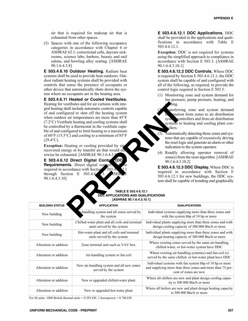
air that is required for makeup air that isexhausted from other spaces.
(5) Spaces with one of the following occupancycategories in accordance with Chapter 4 orASHRAE 62.1: correctional cells, daycare sick-rooms, science labs, barbers, beauty and nailsalons, and bowling alley seating. [ASHRAE90.1:6.4.3.8]
E 503.4.6.10 Outdoor Heating. Radiant heatsystems shall be used to provide heat outdoors. Out-door radiant heating systems shall be provided withcontrols that sense the presence of occupants orother device that automatically shuts down the sys-tem where no occupants are in the heating area.E 503.4.6.11 Heated or Cooled Vestibules.Heating for vestibules and for air curtains with inte-gral heating shall include automatic controls capableof and configured to shut off the heating systemwhen outdoor air temperatures are more than 45°F(7.2°C) Vestibule heating and cooling systems shallbe controlled by a thermostat in the vestibule capa-ble of and configured to limit heating to a maximumof 60°F (15.5°C) and cooling to a minimum of 85°F(29.4°C).Exception: Heating or cooling provided by site-recovered energy or by transfer air that would oth-erwise be exhausted. [ASHRAE 90.1:6.4.3.9]E 503.4.6.12 Direct Digital Control (DDC)Requirements. Direct digital control shall berequired in accordance with Section E 503.4.6.12.1through Section E 503.4.6.12.3. [ASHRAE90.1:6.4.3.10]
E 503.4.6.12.1 DDC Applications. DDCshall be provided in the applications and quali-fications in accordance with Table E503.4.6.12.1.Exception: DDC is not required for systemsusing the simplified approach to compliance inaccordance with Section E 503.3. [ASHRAE90.1:6.4.3.10.1]E 503.4.6.12.2 DDC Controls. Where DDCis required by Section E 503.4.6.12.1, the DDCsystem shall be capable of and configured withall of the following, as required, to provide thecontrol logic required in Section E 503.5:(1) Monitoring zone and system demand for
fan pressure, pump pressure, heating, andcooling.
(2) Transferring zone and system demandinformation from zones to air distributionsystem controllers and from air distributionsystems to heating and cooling plant con-trollers.
(3) Automatically detecting those zones and sys-tems that are capable of excessively drivingthe reset logic and generate an alarm or otherindication to the system operator.
(4) Readily allowing operator removal ofzone(s) from the reset algorithm. [ASHRAE90.1:6.4.3.10.2]
E 503.4.6.12.3 DDC Display. Where DDC isrequired in accordance with Section E503.4.6.12.1 for new buildings, the DDC sys-tem shall be capable of trending and graphically
307UNIFORM MECHANICAL CODE - PREPRINT
APPENDIX E
TABLE E 503.4.6.12.1DDC APPLICATIONS AND QUALIFICATIONS
[ASHRAE 90.1:6.4.3.10.1]
BUILDING STATUS APPLICATION QUALIFICATIONS
New building Air-handling system and all zones served bythe system
Individual systems supplying more than three zones andwith fan system bhp of 10 hp or more
New building Chilled-water plant and all coils and terminalunits served by the system
Individual plants supplying more than three zones and withdesign cooling capacity of 300 000 Btu/h or more
New building Hot-water plant and all coils and terminalunits served by the system
Individual plants supplying more than three zones and withdesign heating capacity of 300 000 Btu/h or more
Alteration or addition Zone terminal unit such as VAV box Where existing zones served by the same air-handling,chilled-water, or hot-water system have DDC
Alteration or addition Air-handling system or fan coil Where existing air-handling system(s) and fan-coil (s)served by the same chilled- or hot-water plant have DDC
Alteration or addition New air-handling system and all new zonesserved by the system
Individual systems with fan system bhp of 10 hp or moreand supplying more than three zones and more than 75 per-
cent of zones are new
Alteration or addition New or upgraded chilled-water plant Where all chillers are new and plant design cooling capac-ity is 300 000 Btu/h or more
Alteration or addition New or upgraded hot-water plant Where all boilers are new and plant design heating capacityis 300 000 Btu/h or more
For SI units: 1000 British thermal units = 0.293 kW, 1 horsepower = 0.746 kW
PREPRINT
displaying input and output points. [ASHRAE90.1:6.4.3.10.3]
E 503.4.6.13 Economizer Fault DetectionDiagnostics (FDD). Air-cooled direct-expansioncooling units listed in Tables E 503.7.1(1) and E503.7.1(2), where an air economizer is installed inaccordance with Section E 503.5, shall include afault detection and diagnostics (FDD) system com-plying with the following:(1) The following temperature sensors shall be per-
manently installed to monitor system operation:(a) Outdoor air(b) Supply air(c) Return air, where required for economizer
control(2) The system shall have the capability of dis-
playing the value of each sensor.(3) The FDD system or unit controls shall be capa-
ble of and configured to provide system statusby indicating the following:(a) Free cooling available(b) Economizer enabled(c) Compressor enabled(d) Heating enabled(e) Mixed-air low-limit cycle active
(4) The FDD system or unit controls shall have pro-visions to manually initiate each operatingmode so that the operation of compressors,economizers, fans, and the heating system canbe independently tested and verified.
(5) The FDD system shall be capable of and con-figured to detect the following faults:(a) Air temperature sensor failure/fault(b) Not economizing when the unit should be
economizing(c) Economizing when the unit should not be
economizing(d) Damper not modulating(e) Excess outdoor air
(6) The FDD system shall be capable of and config-ured to report faults to a fault management appli-cation or DDC system accessible by operating orservice personnel, or annunciated locally on zonethermostats. [ASHRAE 90.1: 6.4.3.12]
E 503.4.7 HVAC System Construction and Insu-lation. HVAC Ducts shall be constructed in accordancewith provisions contained in the SMACNA HVAC DuctConstruction Standard. HVAC system construction andinsulation shall comply with Section E 503.4.7.1 andSection E 503.4.7.2.
E 503.4.7.1 Insulation. Insulation required by thissection shall be installed in accordance with indus-try-accepted standards. These requirements shall notapply to HVAC equipment. Insulation shall be pro-
tected from damage, including that due to sunlight,moisture, equipment maintenance, and wind, but notlimited to the following:(1) Insulation exposed to weather shall be suitable
for outdoor service (e.g., protected by alu-minum, sheet metal, painted canvas, or plasticcover). Cellular foam insulation shall be pro-tected as above or painted with a coating that iswater retardant and provides shielding fromsolar radiation that is capable of causing degra-dation of the material.
(2) Insulation covering chilled-water piping, refrig-erant suction piping, or cooling ducts locatedoutside the conditioned space shall include avapor retardant located outside the insulation(unless the insulation is inherently vapor retar-dant), penetrations and joints of which shall besealed. [ASHRAE 90.1:6.4.4.1.1]E 503.4.7.1.1 Duct and Plenum Insula-tion. Supply and return ducts and plenumsinstalled as part of an HVAC air distributionsystem shall be thermally insulated in accor-dance with Table E 503.7.2.Exceptions:(1) Factory-installed plenums, casings, or
ductwork furnished as a part of HVACequipment tested and rated in accordancewith Section E 503.4 through Section E503.4.4.1.
(2) Ducts or plenums located in heated spaces,semi-heated spaces, or cooled spaces.
(3) For runouts less than 10 feet (3048 mm) inlength to air terminals or air outlets, therated R-value of insulation shall not berequired to exceed R-3.5.
(4) Backs of air outlets and outlet plenumsexposed to unconditioned or indirectly con-ditioned spaces with face areas exceeding 5square feet (0.5 m2) shall not be required toexceed R-2; those not exceeding 5 squarefeet (0.5 m2) shall not be required to beinsulated. [ASHRAE 90.1:6.4.4.1.2]
E 503.4.7.1.2 Piping Insulation. Piping shallbe thermally insulated in accordance with TableE 503.7.3(1) and Table E 503.7.3(2).Exceptions:(1) Factory-installed piping within HVAC
equipment tested and rated in accordancewith Section E 503.4 through Section E503.4.4.1.
(2) Piping that conveys fluids having a designoperating temperature range between 60°F(16°C) and 105°F (41°C), inclusive.
(3) Piping that conveys fluids that have notbeen heated or cooled through the use of
308 UNIFORM MECHANICAL CODE - PREPRINT
APPENDIX E
PREPRINT
fossil fuels or electricity (such as roof andcondensate drains, domestic cold watersupply, and natural gas piping).
(4) Where heat gain or heat loss will notincrease energy use (such as liquid refrig-erant piping).
(5) In piping 1 inch (25.4 mm) or less, insula-tion is not required for strainers, controlvalves, and balancing valves. [ASHRAE90.1:6.4.4.1.3]
E 503.4.7.1.3 Sensible Heating Panel.Thermally ineffective panel surfaces of sensibleheating panels, including U-bends and headers,shall be insulated a minimum of R-3.5. Adjacentbuilding envelope insulation counts toward thisrequirement. [ASHRAE 90.1:6.4.4.1.4]E 503.4.7.1.4 Radiant Floor Heating. Thebottom surfaces of floor structures incorporat-ing radiant heating shall be insulated with aminimum of R-3.5. Adjacent building envelopeinsulation counts toward this requirement.Exception: Heated slab-on-grade floors incor-porating radiant heating shall be in accordancewith ASHRAE 90.1. [ASHRAE 90.1:6.4.4.1.5]
E 503.4.7.2 Ductwork and Plenum Leakage.Transverse joints, longitudinal seams, and duct wallpenetrations shall be sealed. Pressure-sensitive tapeshall not be used as the primary sealant, unless it hasbeen certified to comply with UL 181A or UL 181Bby an independent testing laboratory and the tape isused in accordance with that certification. All otherconnections shall be considered transverse joints,including but not limited to spin-ins, taps, otherbranch connections, access door frames and jambs,and duct connections to equipment.Exceptions:(1) Rods that penetrate the duct wall that shall be
permitted to move in order to function properly(control rod for volume damper) shall not besealed in a fashion that prevents them fromworking properly.
(2) Spiral lock seams in a round or flat oval duct.E 503.4.7.2.1 Duct Leakage Tests. Duct-work shall be leak-tested in accordance with theSMACNA HVAC Air Duct Leakage Test Man-ual. Representative sections totaling not lessthan 20 percent of the total installed duct areashall be tested. Where the tested 20 percent failto comply with the requirements of this section,then 40 percent of the total installed duct areashall be tested. Where the tested 40 percent failto comply with the requirements of this section,then 100 percent of the total installed duct areashall be tested. Sections shall be selected by thebuilding owner or designated representative ofthe building owner. Positive pressure leakage
testing shall be permitted for negative pressureductwork. The permitted duct leakage shall benot more than the following:Lmax = CLP0.65 (Equation E 503.4.7.2.1)
Where:Lmax = maximum permitted leakage,
(ft3/min)/100 square feet [0.0001(m3/s)/m2] duct surface area.
CL = Six, duct leakage class,(ft3/min)/100 square feet [0.0001(m3/s)/m2] duct surface area at 1inch water column (0.2 kPa).
P = test pressure, which shall be equalto the design duct pressure class rat-ing, inch water column (kPa).
E 503.5 Prescriptive Path, Economizers. Cooling sys-tems shall include either an air economizer or fluid econo-mizer in accordance with Section E 503.5.1 through SectionE 503.5.4.1.Exceptions: Economizers shall not be required for the fol-lowing systems:(1) Individual fan-cooling units with a supply capacity less
than the minimum listed in Table E 503.5(1).(2) Chilled-water cooling systems without a fan or that use
induced airflow, where the total capacity of these sys-tems is less than 1 000 000 Btu/h (293 kW) in ClimateZones 0, 1B, and 2 through 4; less than 1 400 000 Btu/h(410 kW) in Climate Zones 5 through 8; or any size inClimate Zone 1A.
(3) Systems that include nonparticulate air treatment inaccordance with ASHRAE 62.1.
(4) In hospitals and ambulatory surgery centers, where morethan 75 percent of the air designed to be supplied by thesystem is to spaces that are required to be humidifiedmore than 35°F (2°C) dew-point temperature to complywith applicable codes or accreditation standards; in allother buildings, where more than 25 percent of the airdesigned to be supplied by the system is to spaces that aredesigned to be humidified more than 35°F (2°C) dew-point temperature to satisfy process needs. This excep-tion shall not apply to computer rooms.
(5) Systems that include a condenser heat recovery systemwith a minimum capacity in accordance with Section E503.5.10.1.2.
(6) Systems that serve residential spaces where the systemcapacity is less than five times the requirement listed inTable E 503.5(1).
(7) Systems that serve spaces whose sensible cooling loadat design conditions, excluding transmission and infil-tration loads, is less than or equal to transmission andinfiltration losses at an outdoor temperature of 60°F(16°C).
309UNIFORM MECHANICAL CODE - PREPRINT
APPENDIX E
PREPRINT
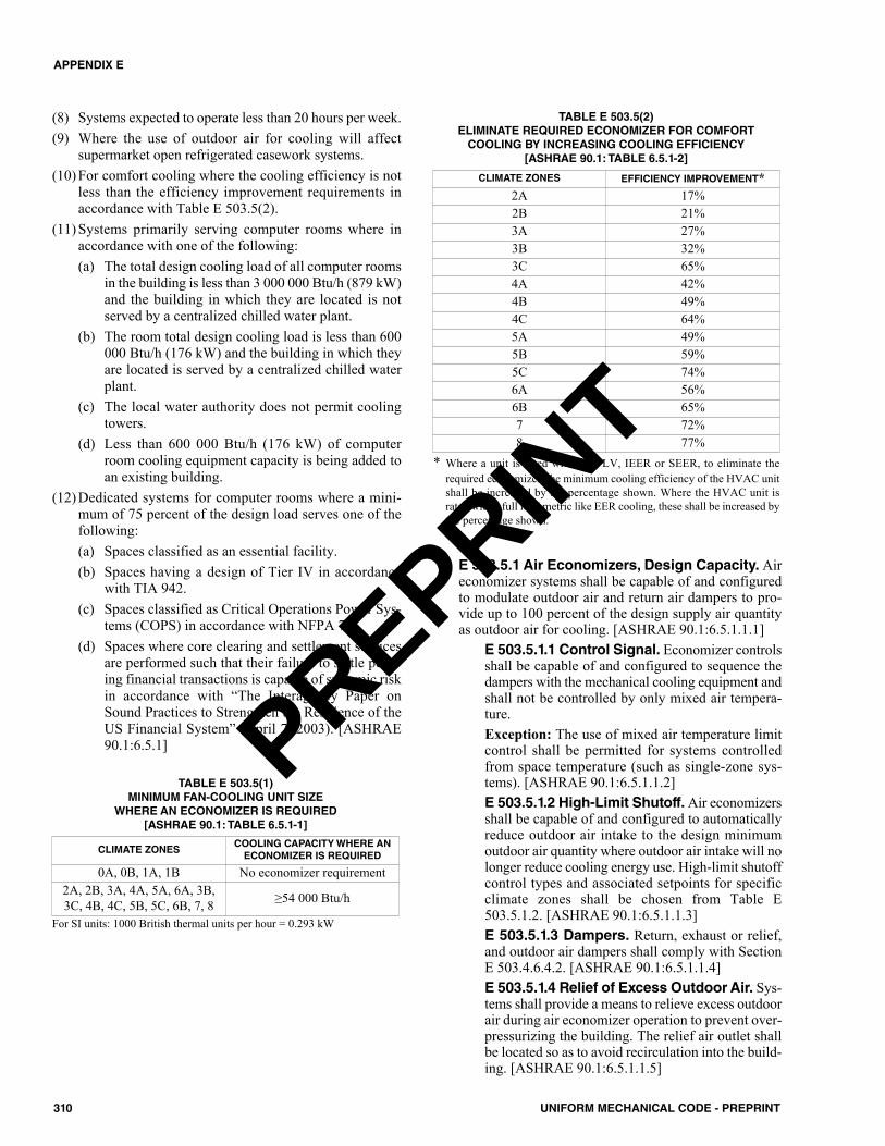
(8) Systems expected to operate less than 20 hours per week.(9) Where the use of outdoor air for cooling will affect
supermarket open refrigerated casework systems.(10) For comfort cooling where the cooling efficiency is not
less than the efficiency improvement requirements inaccordance with Table E 503.5(2).
(11) Systems primarily serving computer rooms where inaccordance with one of the following:(a) The total design cooling load of all computer rooms
in the building is less than 3 000 000 Btu/h (879 kW)and the building in which they are located is notserved by a centralized chilled water plant.
(b) The room total design cooling load is less than 600000 Btu/h (176 kW) and the building in which theyare located is served by a centralized chilled waterplant.
(c) The local water authority does not permit coolingtowers.
(d) Less than 600 000 Btu/h (176 kW) of computerroom cooling equipment capacity is being added toan existing building.
(12) Dedicated systems for computer rooms where a mini-mum of 75 percent of the design load serves one of thefollowing:(a) Spaces classified as an essential facility.(b) Spaces having a design of Tier IV in accordance
with TIA 942.(c) Spaces classified as Critical Operations Power Sys-
tems (COPS) in accordance with NFPA 70.(d) Spaces where core clearing and settlement services
are performed such that their failure to settle pend-ing financial transactions is capable of systemic riskin accordance with “The Interagency Paper onSound Practices to Strengthen the Resilience of theUS Financial System” (April 7, 2003). [ASHRAE90.1:6.5.1]
E 503.5.1 Air Economizers, Design Capacity. Aireconomizer systems shall be capable of and configuredto modulate outdoor air and return air dampers to pro-vide up to 100 percent of the design supply air quantityas outdoor air for cooling. [ASHRAE 90.1:6.5.1.1.1]
E 503.5.1.1 Control Signal. Economizer controlsshall be capable of and configured to sequence thedampers with the mechanical cooling equipment andshall not be controlled by only mixed air tempera-ture.Exception: The use of mixed air temperature limitcontrol shall be permitted for systems controlledfrom space temperature (such as single-zone sys-tems). [ASHRAE 90.1:6.5.1.1.2]E 503.5.1.2 High-Limit Shutoff. Air economizersshall be capable of and configured to automaticallyreduce outdoor air intake to the design minimumoutdoor air quantity where outdoor air intake will nolonger reduce cooling energy use. High-limit shutoffcontrol types and associated setpoints for specificclimate zones shall be chosen from Table E503.5.1.2. [ASHRAE 90.1:6.5.1.1.3]E 503.5.1.3 Dampers. Return, exhaust or relief,and outdoor air dampers shall comply with SectionE 503.4.6.4.2. [ASHRAE 90.1:6.5.1.1.4]E 503.5.1.4 Relief of Excess Outdoor Air. Sys-tems shall provide a means to relieve excess outdoorair during air economizer operation to prevent over-pressurizing the building. The relief air outlet shallbe located so as to avoid recirculation into the build-ing. [ASHRAE 90.1:6.5.1.1.5]
TABLE E 503.5(1)MINIMUM FAN-COOLING UNIT SIZE
WHERE AN ECONOMIZER IS REQUIRED [ASHRAE 90.1: TABLE 6.5.1-1]
For SI units: 1000 British thermal units per hour = 0.293 kW
CLIMATE ZONESCOOLING CAPACITY WHERE AN
ECONOMIZER IS REQUIRED
0A, 0B, 1A, 1B No economizer requirement2A, 2B, 3A, 4A, 5A, 6A, 3B,3C, 4B, 4C, 5B, 5C, 6B, 7, 8 ≥54 000 Btu/h
* Where a unit is rated with an IPLV, IEER or SEER, to eliminate therequired economizer, the minimum cooling efficiency of the HVAC unitshall be increased by the percentage shown. Where the HVAC unit israted with a full load metric like EER cooling, these shall be increased bythe percentage shown.
TABLE E 503.5(2)ELIMINATE REQUIRED ECONOMIZER FOR COMFORT
COOLING BY INCREASING COOLING EFFICIENCY [ASHRAE 90.1: TABLE 6.5.1-2]
CLIMATE ZONES EFFICIENCY IMPROVEMENT*2A 17%2B 21%3A 27%3B 32%3C 65%4A 42%4B 49%4C 64%5A 49%5B 59%5C 74%6A 56%6B 65%7 72%8 77%
310 UNIFORM MECHANICAL CODE - PREPRINT
APPENDIX E
PREPRINT
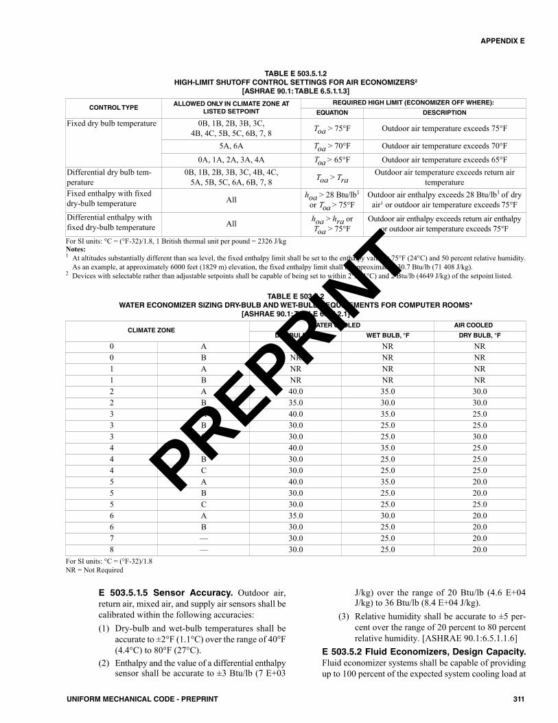
E 503.5.1.5 Sensor Accuracy. Outdoor air,return air, mixed air, and supply air sensors shall becalibrated within the following accuracies:(1) Dry-bulb and wet-bulb temperatures shall be
accurate to ±2°F (1.1°C) over the range of 40°F(4.4°C) to 80°F (27°C).
(2) Enthalpy and the value of a differential enthalpysensor shall be accurate to ±3 Btu/lb (7 E+03
J/kg) over the range of 20 Btu/lb (4.6 E+04J/kg) to 36 Btu/lb (8.4 E+04 J/kg).
(3) Relative humidity shall be accurate to ±5 per-cent over the range of 20 percent to 80 percentrelative humidity. [ASHRAE 90.1:6.5.1.1.6]
E 503.5.2 Fluid Economizers, Design Capacity.Fluid economizer systems shall be capable of providingup to 100 percent of the expected system cooling load at
311UNIFORM MECHANICAL CODE - PREPRINT
APPENDIX E
TABLE E 503.5.1.2HIGH-LIMIT SHUTOFF CONTROL SETTINGS FOR AIR ECONOMIZERS2
[ASHRAE 90.1: TABLE 6.5.1.1.3]
CONTROL TYPEALLOWED ONLY IN CLIMATE ZONE AT
LISTED SETPOINTREQUIRED HIGH LIMIT (ECONOMIZER OFF WHERE):
EQUATION DESCRIPTION
Fixed dry bulb temperature 0B, 1B, 2B, 3B, 3C, 4B, 4C, 5B, 5C, 6B, 7, 8 Toa > 75°F Outdoor air temperature exceeds 75°F
5A, 6A Toa > 70°F Outdoor air temperature exceeds 70°F
0A, 1A, 2A, 3A, 4A Toa > 65°F Outdoor air temperature exceeds 65°FDifferential dry bulb tem-perature
0B, 1B, 2B, 3B, 3C, 4B, 4C, 5A, 5B, 5C, 6A, 6B, 7, 8 Toa > Tra
Outdoor air temperature exceeds return airtemperature
Fixed enthalpy with fixeddry-bulb temperature All hoa > 28 Btu/lb1
or Toa > 75°FOutdoor air enthalpy exceeds 28 Btu/lb1 of dry
air1 or outdoor air temperature exceeds 75°FDifferential enthalpy withfixed dry-bulb temperature All hoa > hra or
Toa > 75°FOutdoor air enthalpy exceeds return air enthalpy
or outdoor air temperature exceeds 75°FFor SI units: °C = (°F-32)/1.8, 1 British thermal unit per pound = 2326 J/kgNotes:1 At altitudes substantially different than sea level, the fixed enthalpy limit shall be set to the enthalpy value at 75°F (24°C) and 50 percent relative humidity.
As an example, at approximately 6000 feet (1829 m) elevation, the fixed enthalpy limit shall be approximately 30.7 Btu/lb (71 408 J/kg).2 Devices with selectable rather than adjustable setpoints shall be capable of being set to within 2°F (1°C) and 2 Btu/lb (4649 J/kg) of the setpoint listed.
TABLE E 503.5.2WATER ECONOMIZER SIZING DRY-BULB AND WET-BULB REQUIREMENTS FOR COMPUTER ROOMS*
[ASHRAE 90.1: TABLE 6.5.1.2.1]
CLIMATE ZONEWATER COOLED AIR COOLED
DRY BULB, °F WET BULB, °F DRY BULB, °F
0 A NR NR NR0 B NR NR NR1 A NR NR NR1 B NR NR NR2 A 40.0 35.0 30.02 B 35.0 30.0 30.03 A 40.0 35.0 25.03 B 30.0 25.0 25.03 C 30.0 25.0 30.04 A 40.0 35.0 25.04 B 30.0 25.0 25.04 C 30.0 25.0 25.05 A 40.0 35.0 20.05 B 30.0 25.0 20.05 C 30.0 25.0 25.06 A 35.0 30.0 20.06 B 30.0 25.0 20.07 –– 30.0 25.0 20.08 –– 30.0 25.0 20.0
For SI units: °C = (°F-32)/1.8 NR = Not Required
PREPRINT
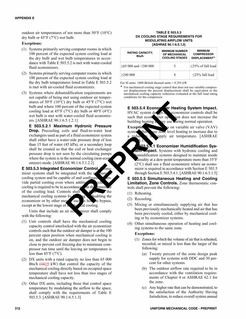
outdoor air temperatures of not more than 50°F (10°C)dry bulb or 45°F (7°C) wet bulb.Exceptions:(1) Systems primarily serving computer rooms in which
100 percent of the expected system cooling load atthe dry bulb and wet bulb temperatures in accor-dance with Table E 503.5.2 is met with water-cooledfluid economizers.
(2) Systems primarily serving computer rooms in which100 percent of the expected system cooling load atthe dry bulb temperatures listed in Table E 503.5.2is met with air-cooled fluid economizers.
(3) Systems where dehumidification requirements arenot capable of being met using outdoor air temper-atures of 50°F (10°C) dry bulb or 45°F (7°C) wetbulb and where 100 percent of the expected systemcooling load at 45°F (7°C) dry bulb or 40°F (4°C)wet bulb is met with water-cooled fluid economiz-ers. [ASHRAE 90.1:6.5.1.2.1]E 503.5.2.1 Maximum Hydronic PressureDrop. Precooling coils and fluid-to-water heatexchangers used as part of a fluid economizer systemshall either have a water-side pressure drop of lessthan 15 feet of water (45 kPa), or a secondary loopshall be created so that the coil or heat exchangerpressure drop is not seen by the circulating pumpswhere the system is in the normal cooling (non-econ-omizer) mode. [ASHRAE 90.1:6.5.1.2.2]
E 503.5.3 Integrated Economizer Control. Econo-mizer systems shall be integrated with the mechanicalcooling system and be capable of and configured to pro-vide partial cooling even where additional mechanicalcooling is required to be in accordance with the remainderof the cooling load. Controls shall not false load themechanical cooling systems by limiting or disabling theeconomizer or by other means, such as hot gas bypass,except at the lowest stage of mechanical cooling.
Units that include an air economizer shall complywith the following:(1) Unit controls shall have the mechanical cooling
capacity control interlocked with the air economizercontrols such that the outdoor air damper is at the 100percent open position when mechanical cooling ison, and the outdoor air damper does not begin toclose to prevent coil freezing due to minimum com-pressor run time until the leaving air temperature isless than 45°F (7°C).
(2) DX units with a rated capacity no less than 65 000Btu/h (1819 kW) that control the capacity of themechanical cooling directly based on occupied spacetemperature shall have not less than two stages ofmechanical cooling capacity.
(3) Other DX units, including those that control spacetemperature by modulating the airflow to the space,shall comply with the requirements of Table E503.5.3. [ASHRAE 90.1:6.5.1.3]
TABLE E 503.5.3DX COOLING STAGE REQUIREMENTS FOR
MODULATING AIRFLOW UNITS[ASHRAE 90.1:6.5.1.3]
For SI units: 1000 British thermal units = 0.293 kW* For mechanical cooling stage control that does not use variable compres-
sor displacement the percent displacement shall be equivalent to themechanical cooling capacity reduction evaluated at the full load ratingconditions for the compressor.
E 503.5.4 Economizer Heating System Impact.HVAC system design and economizer controls shall besuch that economizer operation does not increase thebuilding heating energy use during normal operation.Exception: Economizers on variable air valve (VAV)systems that cause zone level heating to increase due toa reduction in supply air temperature. [ASHRAE90.1:6.5.1.4]
E 503.5.4.1 Economizer Humidification Sys-tem Impact. Systems with hydronic cooling andhumidification systems designed to maintain insidehumidity at a dew-point temperature more than 35°F(2°C) shall use a fluid economizer where an econo-mizer is required in accordance with Section E 503.5through Section E 503.5.4.1. [ASHRAE 90.1:6.5.1.5]
E 503.5.5 Simultaneous Heating and CoolingLimitation, Zone Controls. Zone thermostatic con-trols shall prevent the following:(1) Reheating.(2) Recooling.(3) Mixing or simultaneously supplying air that has
been previously mechanically heated and air that hasbeen previously cooled, either by mechanical cool-ing or by economizer systems.
(4) Other simultaneous operation of heating and cool-ing systems to the same zone.Exceptions:(1) Zones for which the volume of air that is reheated,
recooled, or mixed is less than the larger of thefollowing:(a) Twenty percent of the zone design peak
supply for systems with DDC and 30 per-cent for other systems.
(b) The outdoor airflow rate required to be inaccordance with the ventilation require-ments of Chapter 4 or ASHRAE 62.1 forthe zone.
(c) Any higher rate that can be demonstrated, tothe satisfaction of the Authority HavingJurisdiction, to reduce overall system annual
RATING CAPACITY, Btu/h
MINIMUM NUMBER OF MECHANICAL COOLING STAGES
MINIMUM COMPRESSOR
DISPLACEMENT*
≥65 000 and <240 000 3 ≤35% of full load
≥240 000 4 ≤25% full load
312 UNIFORM MECHANICAL CODE - PREPRINT
APPENDIX E
PREPRINT
energy use by offsetting reheat/recoolenergy losses through a reduction in outdoorair intake for the system.
(d) The airflow rate required to be in accor-dance with applicable codes or accreditationstandards, such as pressure relationships orminimum air change rates.
(2) Zones with DDC that comply with the following:(a) The airflow rate in dead band between
heating and cooling does not exceed thelarger of the following:(1) Twenty percent of the zone design
peak supply rate.(2) The outdoor airflow rate required to be
in accordance with the ventilationrequirements of Chapter 4 orASHRAE 62.1 for the zone.
(3) A higher rate that can be demonstrated,to the satisfaction of the AuthorityHaving Jurisdiction, to reduce overallsystem annual energy use by offsettingreheat/recool energy losses through areduction in outdoor air intake.
(4) The airflow rate required with applica-ble codes or accreditation standards,such as pressure relationships or mini-mum air change rates.
(b) The airflow rate that is reheated, recooled,or mixed shall be less than 50 percent ofthe zone design peak supply rate.
(c) The first stage of heating consists of modu-lating the zone supply air temperature set-point up to a maximum setpoint while theairflow is maintained at the dead band flowrate.
(d) The second stage of heating consists ofmodulating the airflow rate from the deadband flow rate up to the heating maximumflow rate.
(3) Laboratory exhaust systems that comply withSection E 503.5.11.3.
(4) Zones where at least 75 percent of the energy forreheating or for providing warm air in mixingsystems is provided from site-recovered energy(including condenser heat) or site-solar energy.[ASHRAE 90.1:6.5.2.1]
E 503.5.5.1 Supply Air Temperature ReheatLimit. Where reheating is permitted in accordancewith this appendix, zones that have both supply andreturn or exhaust air openings more than 6 feet(1829 mm) above the floor shall not supply heatingair more than 20°F (11°C) above the space temper-ature setpoint.
Exceptions:(1) Laboratory exhaust systems in accordance with
Section E 503.5.11.3.(2) During preoccupancy building warm-up and
setback. [ASHRAE 90.1:6.5.2.1.1]E 503.5.5.2 Hydronic System Controls. Theheating of fluids in hydronic systems that have beenpreviously mechanically cooled and the cooling offluids that have been previously mechanicallyheated shall be limited in accordance with SectionE 503.5.5.2.1 through Section E 503.5.5.2.3.[ASHRAE 90.1:6.5.2.2]
E 503.5.5.2.1 Three-Pipe System.Hydronic systems that use a common returnsystem for both hot water and chilled watershall not be used. [ASHRAE 90.1:6.5.2.2.1]E 503.5.5.2.2 Two-Pipe Changeover Sys-tem. Systems that use a common distributionsystem to supply both heated and chilled waterare acceptable where in accordance with the fol-lowing:(1) The system is designed to allow a dead
band between changeover from one modeto the other of not less than 15°F (8°C) out-door air temperature.
(2) The system is designed to operate and isprovided with controls that will allow oper-ation in one mode for not less than 4 hoursbefore changing over to the other mode.
(3) Reset controls are provided that allow heat-ing and cooling supply temperatures at thechangeover point to be not more than 30°F(17°C) apart. [ASHRAE 90.1:6.5.2.2.2]
E 503.5.5.2.3 Hydronic (Water Loop)Heat Pump Systems. Hydronic heat pumpsconnected to a common heat pump water loopwith central devices for heat rejection (e.g.,cooling tower) and heat addition (e.g., boiler)shall have the following:(1) Controls that are capable of and configured
to provide a heat pump water supply tem-perature dead band of at least 20°F (11°C)between initiation of heat rejection andheat addition by the central devices (e.g.,tower and boiler).
(2) For climate zone 3 through zone 8, where aclosed-circuit cooling tower (fluid cooler)is used, either an automatic valve shall beinstalled to bypass all but a minimal flow ofwater around the tower (for freeze protec-tion) or low-leakage positive closuredampers shall be provided. Where an open-circuit cooling tower is used directly in theheat pump loop, an automatic valve shall beinstalled to bypass all heat pump water flowaround the tower. Where an open-circuitcooling tower is used in conjunction with a
313UNIFORM MECHANICAL CODE - PREPRINT
APPENDIX E
PREPRINT
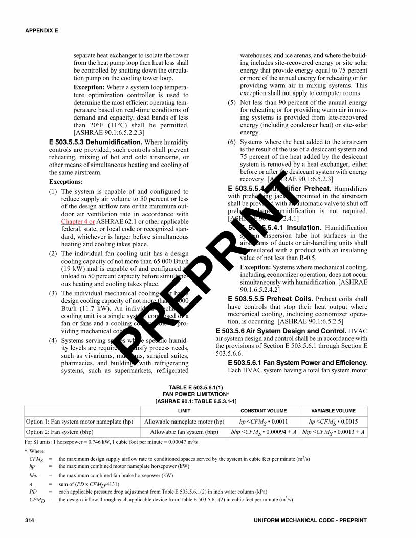
separate heat exchanger to isolate the towerfrom the heat pump loop then heat loss shallbe controlled by shutting down the circula-tion pump on the cooling tower loop.Exception: Where a system loop tempera-ture optimization controller is used todetermine the most efficient operating tem-perature based on real-time conditions ofdemand and capacity, dead bands of lessthan 20°F (11°C) shall be permitted.[ASHRAE 90.1:6.5.2.2.3]
E 503.5.5.3 Dehumidification. Where humiditycontrols are provided, such controls shall preventreheating, mixing of hot and cold airstreams, orother means of simultaneous heating and cooling ofthe same airstream.Exceptions:(1) The system is capable of and configured to
reduce supply air volume to 50 percent or lessof the design airflow rate or the minimum out-door air ventilation rate in accordance withChapter 4 or ASHRAE 62.1 or other applicablefederal, state, or local code or recognized stan-dard, whichever is larger before simultaneousheating and cooling takes place.
(2) The individual fan cooling unit has a designcooling capacity of not more than 65 000 Btu/h(19 kW) and is capable of and configured tounload to 50 percent capacity before simultane-ous heating and cooling takes place.
(3) The individual mechanical cooling unit has adesign cooling capacity of not more than 40 000Btu/h (11.7 kW). An individual mechanicalcooling unit is a single system composed of afan or fans and a cooling coil capable of pro-viding mechanical cooling.
(4) Systems serving spaces where specific humid-ity levels are required to satisfy process needs,such as vivariums, museums, surgical suites,pharmacies, and buildings with refrigeratingsystems, such as supermarkets, refrigerated
warehouses, and ice arenas, and where the build-ing includes site-recovered energy or site solarenergy that provide energy equal to 75 percentor more of the annual energy for reheating or forproviding warm air in mixing systems. Thisexception shall not apply to computer rooms.
(5) Not less than 90 percent of the annual energyfor reheating or for providing warm air in mix-ing systems is provided from site-recoveredenergy (including condenser heat) or site-solarenergy.
(6) Systems where the heat added to the airstreamis the result of the use of a desiccant system and75 percent of the heat added by the desiccantsystem is removed by a heat exchanger, eitherbefore or after the desiccant system with energyrecovery. [ASHRAE 90.1:6.5.2.3]
E 503.5.5.4 Humidifier Preheat. Humidifierswith preheating jackets mounted in the airstreamshall be provided with an automatic valve to shut offpreheat where humidification is not required.[ASHRAE 90.1:6.5.2.4.1]
E 503.5.5.4.1 Insulation. Humidificationsystem dispersion tube hot surfaces in theairstreams of ducts or air-handling units shallbe insulated with a product with an insulatingvalue of not less than R-0.5.Exception: Systems where mechanical cooling,including economizer operation, does not occursimultaneously with humidification. [ASHRAE90.1:6.5.2.4.2]
E 503.5.5.5 Preheat Coils. Preheat coils shallhave controls that stop their heat output wheremechanical cooling, including economizer opera-tion, is occurring. [ASHRAE 90.1:6.5.2.5]
E 503.5.6 Air System Design and Control. HVACair system design and control shall be in accordance withthe provisions of Section E 503.5.6.1 through Section E503.5.6.6.
E 503.5.6.1 Fan System Power and Efficiency.Each HVAC system having a total fan system motor
314 UNIFORM MECHANICAL CODE - PREPRINT
APPENDIX E
TABLE E 503.5.6.1(1)FAN POWER LIMITATION*
[ASHRAE 90.1: TABLE 6.5.3.1-1]
LIMIT CONSTANT VOLUME VARIABLE VOLUME
Option 1: Fan system motor nameplate (hp) Allowable nameplate motor (hp) hp ≤CFMS • 0.0011 hp ≤CFMS • 0.0015
Option 2: Fan system (bhp) Allowable fan system (bhp) bhp ≤CFMS • 0.00094 + A bhp ≤CFMS • 0.0013 + AFor SI units: 1 horsepower = 0.746 kW, 1 cubic foot per minute = 0.00047 m3/s
* Where:CFMS = the maximum design supply airflow rate to conditioned spaces served by the system in cubic feet per minute (m3/s)hp = the maximum combined motor nameplate horsepower (kW)
bhp = the maximum combined fan brake horsepower (kW)
A = sum of (PD x CFMD/4131)PD = each applicable pressure drop adjustment from Table E 503.5.6.1(2) in inch water column (kPa)CFMD = the design airflow through each applicable device from Table E 503.5.6.1(2) in cubic feet per minute (m3/s)
PREPRINT
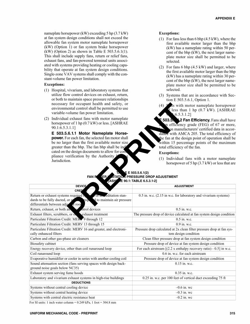
nameplate horsepower (kW) exceeding 5 hp (3.7 kW)at fan system design conditions shall not exceed theallowable fan system motor nameplate horsepower(kW) (Option 1) or fan system brake horsepower(kW) (Option 2) as shown in Table E 503.5.6.1(1).This shall include supply fans, return or relief fans,exhaust fans, and fan-powered terminal units associ-ated with systems providing heating or cooling capa-bility that operate at fan system design conditions.Single-zone VAV systems shall comply with the con-stant-volume fan power limitation.Exceptions:(1) Hospital, vivarium, and laboratory systems that
utilize flow control devices on exhaust, return,or both to maintain space pressure relationshipsnecessary for occupant health and safety, orenvironmental control shall be permitted to usevariable-volume fan power limitation.
(2) Individual exhaust fans with motor nameplatehorsepower of 1 hp (0.7 kW) or less. [ASHRAE90.1:6.5.3.1.1]E 503.5.6.1.1 Motor Nameplate Horse-power. For each fan, the selected fan motor shallbe no larger than the first available motor sizegreater than the bhp. The fan bhp shall be indi-cated on the design documents to allow for com-pliance verification by the Authority HavingJurisdiction.
Exceptions:(1) For fans less than 6 bhp (4.5 kW), where the
first available motor larger than the bhp(kW) has a nameplate rating within 50 per-cent of the bhp (kW), the next larger name-plate motor size shall be permitted to beselected.
(2) For fans 6 bhp (4.5 kW) and larger, wherethe first available motor larger than the bhp(kW) has a nameplate rating within 30 per-cent of the bhp (kW), the next larger name-plate motor size shall be permitted to beselected.
(3) Systems that are in accordance with Sec-tion E 503.5.6.1, Option 1.
(4) Fans with motor nameplate horsepowerof less than 1 hp (0.7 kW). [ASHRAE90.1:6.5.3.1.2]
E 503.5.6.1.2 Fan Efficiency. Fans shall havea fan efficiency grade (FEG) of 67 or more,based on manufacturers' certified data in accor-dance with AMCA 205. The total efficiency ofthe fan at the design point of operation shall bewithin 15 percentage points of the maximumtotal efficiency of the fan.Exceptions:(1) Individual fans with a motor nameplate
horsepower of 5 hp (3.7 kW) or less that are
315UNIFORM MECHANICAL CODE - PREPRINT
APPENDIX E
TABLE E 503.5.6.1(2)FAN POWER LIMITATION PRESSURE DROP ADJUSTMENT
[ASHRAE 90.1: TABLE 6.5.3.1-2]
DEVICE ADJUSTMENT
CREDITS
Return or exhaust systems required by code or accreditation stan-dards to be fully ducted, or systems required to maintain air pressuredifferentials between adjacent rooms
0.5 in. w.c. (2.15 in w.c. for laboratory and vivarium systems)
Return, exhaust, or both airflow control devices 0.5 in. w.c.Exhaust filters, scrubbers, or other exhaust treatment The pressure drop of device calculated at fan system design conditionParticulate Filtration Credit: MERV 9 through 12 0.5 in. w.c.Particulate Filtration Credit: MERV 13 through 15 0.9 in. w.c.Particulate Filtration Credit: MERV 16 and greater, and electroni-cally enhanced filters
Pressure drop calculated at 2x clean filter pressure drop at fan sys-tem design condition
Carbon and other gas-phase air cleaners Clean filter pressure drop at fan system design conditionBiosafety cabinet Pressure drop of device at fan system design conditionEnergy recovery device, other than coil runaround loop For each airstream [(2.2 x enthalpy recovery ratio) - 0.5] in w.c.Coil runaround loop 0.6 in. w.c. for each airstreamEvaporative humidifier or cooler in series with another cooling coil Pressure drop of device at fan system design conditionSound attenuation section (fans serving spaces with design back-ground noise goals below NC35)
0.15 in. w.c.
Exhaust system serving fume hoods 0.35 in. w.c.Laboratory and vivarium exhaust systems in high-rise buildings 0.25 in. w.c. per 100 feet of vertical duct exceeding 75 ft
DEDUCTIONS
Systems without central cooling device –0.6 in. wcSystems without central heating device –0.3 in. wcSystems with central electric resistance heat –0.2 in. wc
For SI units: 1 inch water column = 0.249 kPa, 1 foot = 304.8 mm
PREPRINT
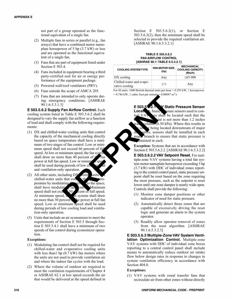
not part of a group operated as the func-tional equivalent of a single fan.
(2) Multiple fans in series or parallel (e.g., fanarrays) that have a combined motor name-plate horsepower of 5 hp (3.7 kW) or lessand are operated as the functional equiva-lent of a single fan.
(3) Fans that are part of equipment listed underSection E 503.4.
(4) Fans included in equipment bearing a thirdparty-certified seal for air or energy per-formance of the equipment package.
(5) Powered wall/roof ventilators (PRV).(6) Fans outside the scope of AMCA 205.(7) Fans that are intended to only operate dur-
ing emergency conditions. [ASHRAE90.1:6.5.3.1.3]
E 503.5.6.2 Supply Fan Airflow Control. Eachcooling system listed in Table E 503.5.6.2 shall bedesigned to vary the supply fan airflow as a functionof load and shall comply with the following require-ments:(1) DX and chilled-water cooling units that control
the capacity of the mechanical cooling directlybased on space temperature shall have a mini-mum of two stages of fan control. Low or mini-mum speed shall not exceed 66 percent of fullspeed. At low or minimum speed, the fan systemshall draw no more than 40 percent of the fanpower at full fan speed. Low or minimum speedshall be used during periods of low cooling loadand ventilation-only operation.
(2) All other units, including DX cooling units andchilled-water units that control the space tem-perature by modulating the airflow to the space,shall have modulating fan control. Minimumspeed shall not exceed 50 percent of full speed.At minimum speed, the fan system shall drawno more than 30 percent of the power at full fanspeed. Low or minimum speed shall be usedduring periods of low cooling load and ventila-tion-only operation.
(3) Units that include an air economizer to meet therequirements of Section E 503.5 through Sec-tion E 503.5.4.1 shall have a minimum of twospeeds of fan control during economizer opera-tion.
Exceptions:(1) Modulating fan control shall not be required for
chilled-water and evaporative cooling unitswith less than1 hp (0.7 kW) fan motors wherethe units are not used to provide ventilation airand where the indoor fan cycles with the load.
(2) Where the volume of outdoor air required tomeet the ventilation requirements of Chapter 4or ASHRAE 62.1 at low speed exceeds the airthat would be delivered at the speed defined in
Section E 503.5.6.2(1), or Section E503.5.6.2(2), then the minimum speed shall beselected to provide the required ventilation air.[ASHRAE 90.1:6.5.3.2.1]
E 503.5.6.2.1 VAV Static Pressure SensorLocation. Static pressure sensors used to con-trol VAV fans shall be located such that thecontroller setpoint is not more than 1.2 incheswater column (0.30 kPa). Where this results inthe sensor being located downstream of majorduct splits, sensors shall be installed in eachmajor branch to ensure that static pressure ismaintained in each.Exception: Systems that are in accordance withSection E 503.5.6.2.2. [ASHRAE 90.1:6.5.3.2.2]E 503.5.6.2.2 VAV Setpoint Reset. For mul-tiple-zone VAV systems having a total fan sys-tem motor nameplate horsepower exceeding 5 hp(3.7 kW) with DDC of individual zones report-ing to the central control panel, static pressure set-point shall be reset based on the zone requiringthe most pressure, such as the setpoint is resetlower until one zone damper is nearly wide open.Controls shall provide the following:(1) Monitor zone damper positions or other
indicator of need for static pressure.(2) Automatically detect those zones that are
capable of excessively driving the resetlogic and generate an alarm to the systemoperator.
(3) Readily allow operator removal of zonesfrom the reset algorithm. [ASHRAE90.1:6.5.3.2.3]
E 503.5.6.3 Multiple-Zone VAV System Venti-lation Optimization Control. Multiple-zoneVAV systems with DDC of individual zone boxesreporting to a central control panel shall includemeans to automatically reduce outdoor air intakeflow below design rates in response to changes insystem ventilation efficiency in accordance withSection 404.0.Exceptions:(1) VAV systems with zonal transfer fans that
recirculate air from other zones without directly
TABLE E 503.5.6.2FAN AIRFLOW CONTROL
[ASHRAE 90.1: TABLE 6.5.3.2.1]
COOLING SYSTEM TYPEFAN MOTOR SIZE,
(hp)
MECHANICALCOOLING CAPACITY,
(Btu/h)
DX cooling Any ≥65 000Chilled-water and evapo-rative cooling ≥1⁄4 Any
For SI units: 1000 British thermal units per hour = 0.293 kW, 1 horsepower= 0.746 kW, 1 cubic foot per minute = 0.00047 m3/s
316 UNIFORM MECHANICAL CODE - PREPRINT
APPENDIX E
PREPRINT
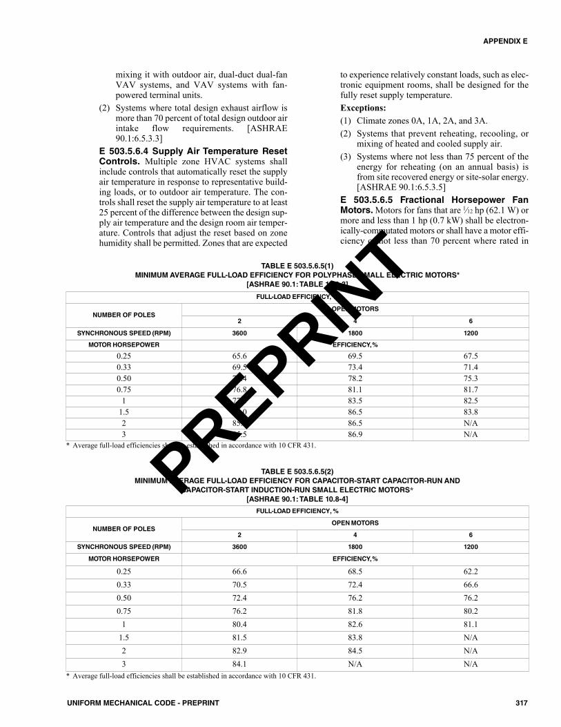
mixing it with outdoor air, dual-duct dual-fanVAV systems, and VAV systems with fan-powered terminal units.
(2) Systems where total design exhaust airflow ismore than 70 percent of total design outdoor airintake flow requirements. [ASHRAE90.1:6.5.3.3]
E 503.5.6.4 Supply Air Temperature ResetControls. Multiple zone HVAC systems shallinclude controls that automatically reset the supplyair temperature in response to representative build-ing loads, or to outdoor air temperature. The con-trols shall reset the supply air temperature to at least25 percent of the difference between the design sup-ply air temperature and the design room air temper-ature. Controls that adjust the reset based on zonehumidity shall be permitted. Zones that are expected
to experience relatively constant loads, such as elec-tronic equipment rooms, shall be designed for thefully reset supply temperature.Exceptions:(1) Climate zones 0A, 1A, 2A, and 3A.(2) Systems that prevent reheating, recooling, or
mixing of heated and cooled supply air.(3) Systems where not less than 75 percent of the
energy for reheating (on an annual basis) isfrom site recovered energy or site-solar energy.[ASHRAE 90.1:6.5.3.5]
E 503.5.6.5 Fractional Horsepower FanMotors. Motors for fans that are 1⁄12 hp (62.1 W) ormore and less than 1 hp (0.7 kW) shall be electron-ically-commutated motors or shall have a motor effi-ciency of not less than 70 percent where rated in
317UNIFORM MECHANICAL CODE - PREPRINT
APPENDIX E
TABLE E 503.5.6.5(1)MINIMUM AVERAGE FULL-LOAD EFFICIENCY FOR POLYPHASE SMALL ELECTRIC MOTORS*
[ASHRAE 90.1: TABLE 10.8-3]
FULL-LOAD EFFICIENCY, %
NUMBER OF POLESOPEN MOTORS
2 4 6
SYNCHRONOUS SPEED (RPM) 3600 1800 1200
MOTOR HORSEPOWER EFFICIENCY,%
0.25 65.6 69.5 67.50.33 69.5 73.4 71.40.50 73.4 78.2 75.30.75 76.8 81.1 81.7
1 77.0 83.5 82.51.5 84.0 86.5 83.82 85.5 86.5 N/A3 85.5 86.9 N/A
* Average full-load efficiencies shall be established in accordance with 10 CFR 431.
TABLE E 503.5.6.5(2)MINIMUM AVERAGE FULL-LOAD EFFICIENCY FOR CAPACITOR-START CAPACITOR-RUN AND
CAPACITOR-START INDUCTION-RUN SMALL ELECTRIC MOTORS*[ASHRAE 90.1: TABLE 10.8-4]
* Average full-load efficiencies shall be established in accordance with 10 CFR 431.
FULL-LOAD EFFICIENCY, %
NUMBER OF POLESOPEN MOTORS
2 4 6
SYNCHRONOUS SPEED (RPM) 3600 1800 1200
MOTOR HORSEPOWER EFFICIENCY,%
0.25 66.6 68.5 62.20.33 70.5 72.4 66.60.50 72.4 76.2 76.20.75 76.2 81.8 80.2
1 80.4 82.6 81.11.5 81.5 83.8 N/A2 82.9 84.5 N/A3 84.1 N/A N/A
PREPRINT
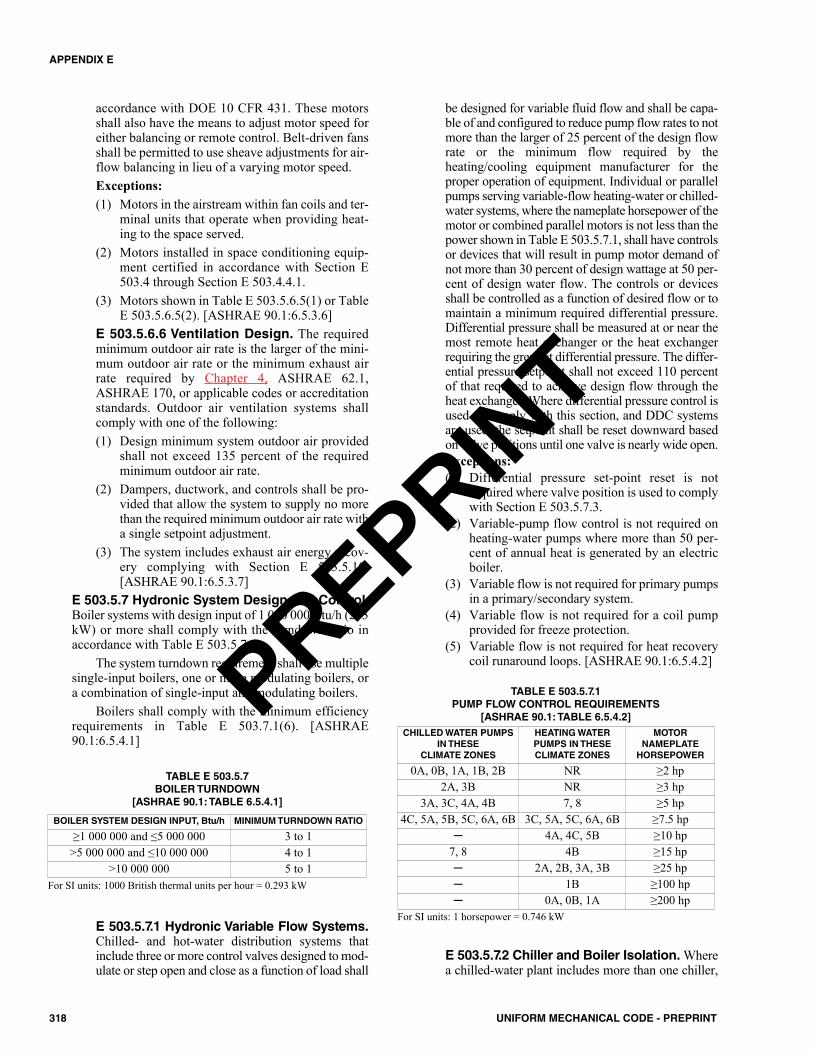
accordance with DOE 10 CFR 431. These motorsshall also have the means to adjust motor speed foreither balancing or remote control. Belt-driven fansshall be permitted to use sheave adjustments for air-flow balancing in lieu of a varying motor speed.Exceptions:(1) Motors in the airstream within fan coils and ter-
minal units that operate when providing heat-ing to the space served.
(2) Motors installed in space conditioning equip-ment certified in accordance with Section E503.4 through Section E 503.4.4.1.
(3) Motors shown in Table E 503.5.6.5(1) or TableE 503.5.6.5(2). [ASHRAE 90.1:6.5.3.6]
E 503.5.6.6 Ventilation Design. The requiredminimum outdoor air rate is the larger of the mini-mum outdoor air rate or the minimum exhaust airrate required by Chapter 4, ASHRAE 62.1,ASHRAE 170, or applicable codes or accreditationstandards. Outdoor air ventilation systems shallcomply with one of the following:(1) Design minimum system outdoor air provided
shall not exceed 135 percent of the requiredminimum outdoor air rate.
(2) Dampers, ductwork, and controls shall be pro-vided that allow the system to supply no morethan the required minimum outdoor air rate witha single setpoint adjustment.
(3) The system includes exhaust air energy recov-ery complying with Section E 503.5.10.[ASHRAE 90.1:6.5.3.7]
E 503.5.7 Hydronic System Design and Control.Boiler systems with design input of 1 000 000 Btu/h (293kW) or more shall comply with the turndown ratio inaccordance with Table E 503.5.7.
The system turndown requirement shall use multiplesingle-input boilers, one or more modulating boilers, ora combination of single-input and modulating boilers.
Boilers shall comply with the minimum efficiencyrequirements in Table E 503.7.1(6). [ASHRAE90.1:6.5.4.1]
E 503.5.7.1 Hydronic Variable Flow Systems.Chilled- and hot-water distribution systems thatinclude three or more control valves designed to mod-ulate or step open and close as a function of load shall
be designed for variable fluid flow and shall be capa-ble of and configured to reduce pump flow rates to notmore than the larger of 25 percent of the design flowrate or the minimum flow required by theheating/cooling equipment manufacturer for theproper operation of equipment. Individual or parallelpumps serving variable-flow heating-water or chilled-water systems, where the nameplate horsepower of themotor or combined parallel motors is not less than thepower shown in Table E 503.5.7.1, shall have controlsor devices that will result in pump motor demand ofnot more than 30 percent of design wattage at 50 per-cent of design water flow. The controls or devicesshall be controlled as a function of desired flow or tomaintain a minimum required differential pressure.Differential pressure shall be measured at or near themost remote heat exchanger or the heat exchangerrequiring the greatest differential pressure. The differ-ential pressure setpoint shall not exceed 110 percentof that required to achieve design flow through theheat exchanger. Where differential pressure control isused to comply with this section, and DDC systemsare used, the setpoint shall be reset downward basedon valve positions until one valve is nearly wide open.Exceptions:(1) Differential pressure set-point reset is not
required where valve position is used to complywith Section E 503.5.7.3.
(2) Variable-pump flow control is not required onheating-water pumps where more than 50 per-cent of annual heat is generated by an electricboiler.
(3) Variable flow is not required for primary pumpsin a primary/secondary system.
(4) Variable flow is not required for a coil pumpprovided for freeze protection.
(5) Variable flow is not required for heat recoverycoil runaround loops. [ASHRAE 90.1:6.5.4.2]
E 503.5.7.2 Chiller and Boiler Isolation. Wherea chilled-water plant includes more than one chiller,
TABLE E 503.5.7BOILER TURNDOWN
[ASHRAE 90.1: TABLE 6.5.4.1]
For SI units: 1000 British thermal units per hour = 0.293 kW
BOILER SYSTEM DESIGN INPUT, Btu/h MINIMUM TURNDOWN RATIO
≥1 000 000 and ≤5 000 000 3 to 1>5 000 000 and ≤10 000 000 4 to 1
>10 000 000 5 to 1
TABLE E 503.5.7.1PUMP FLOW CONTROL REQUIREMENTS
[ASHRAE 90.1: TABLE 6.5.4.2] CHILLED WATER PUMPS
IN THESE CLIMATE ZONES
HEATING WATERPUMPS IN THESE CLIMATE ZONES
MOTOR NAMEPLATE
HORSEPOWER
0A, 0B, 1A, 1B, 2B NR ≥2 hp2A, 3B NR ≥3 hp
3A, 3C, 4A, 4B 7, 8 ≥5 hp4C, 5A, 5B, 5C, 6A, 6B 3C, 5A, 5C, 6A, 6B ≥7.5 hp
─ 4A, 4C, 5B ≥10 hp7, 8 4B ≥15 hp─ 2A, 2B, 3A, 3B ≥25 hp─ 1B ≥100 hp─ 0A, 0B, 1A ≥200 hp
For SI units: 1 horsepower = 0.746 kW
318 UNIFORM MECHANICAL CODE - PREPRINT
APPENDIX E
PREPRINT
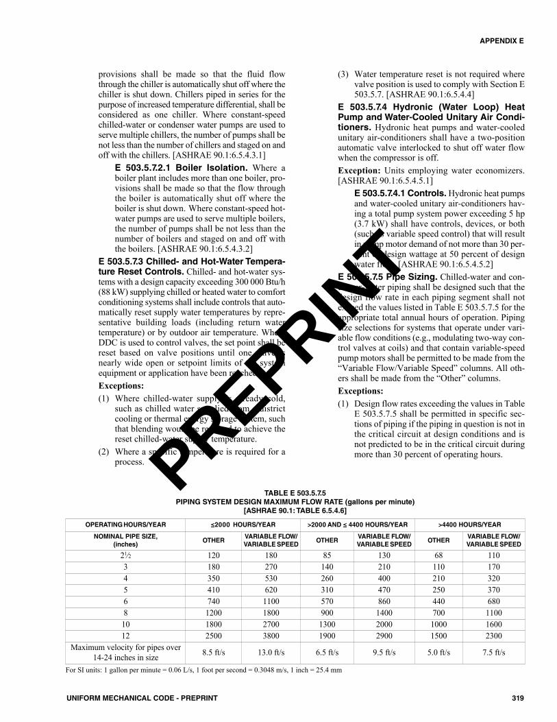
provisions shall be made so that the fluid flowthrough the chiller is automatically shut off where thechiller is shut down. Chillers piped in series for thepurpose of increased temperature differential, shall beconsidered as one chiller. Where constant-speedchilled-water or condenser water pumps are used toserve multiple chillers, the number of pumps shall benot less than the number of chillers and staged on andoff with the chillers. [ASHRAE 90.1:6.5.4.3.1]
E 503.5.7.2.1 Boiler Isolation. Where aboiler plant includes more than one boiler, pro-visions shall be made so that the flow throughthe boiler is automatically shut off where theboiler is shut down. Where constant-speed hot-water pumps are used to serve multiple boilers,the number of pumps shall be not less than thenumber of boilers and staged on and off withthe boilers. [ASHRAE 90.1:6.5.4.3.2]
E 503.5.7.3 Chilled- and Hot-Water Tempera-ture Reset Controls. Chilled- and hot-water sys-tems with a design capacity exceeding 300 000 Btu/h(88 kW) supplying chilled or heated water to comfortconditioning systems shall include controls that auto-matically reset supply water temperatures by repre-sentative building loads (including return watertemperature) or by outdoor air temperature. WhereDDC is used to control valves, the set point shall bereset based on valve positions until one valve isnearly wide open or setpoint limits of the systemequipment or application have been reached.Exceptions:(1) Where chilled-water supply is already cold,
such as chilled water supplied from a districtcooling or thermal energy storage system, suchthat blending would be required to achieve thereset chilled-water supply temperature.
(2) Where a specific temperature is required for aprocess.
(3) Water temperature reset is not required wherevalve position is used to comply with Section E503.5.7. [ASHRAE 90.1:6.5.4.4]
E 503.5.7.4 Hydronic (Water Loop) HeatPump and Water-Cooled Unitary Air Condi-tioners. Hydronic heat pumps and water-cooledunitary air-conditioners shall have a two-positionautomatic valve interlocked to shut off water flowwhen the compressor is off.Exception: Units employing water economizers.[ASHRAE 90.1:6.5.4.5.1]
E 503.5.7.4.1 Controls. Hydronic heat pumpsand water-cooled unitary air-conditioners hav-ing a total pump system power exceeding 5 hp(3.7 kW) shall have controls, devices, or both(such as variable speed control) that will resultin pump motor demand of not more than 30 per-cent of design wattage at 50 percent of designwater flow. [ASHRAE 90.1:6.5.4.5.2]
E 503.5.7.5 Pipe Sizing. Chilled-water and con-denser-water piping shall be designed such that thedesign flow rate in each piping segment shall notexceed the values listed in Table E 503.5.7.5 for theappropriate total annual hours of operation. Pipingsize selections for systems that operate under vari-able flow conditions (e.g., modulating two-way con-trol valves at coils) and that contain variable-speedpump motors shall be permitted to be made from the“Variable Flow/Variable Speed” columns. All oth-ers shall be made from the “Other” columns.Exceptions:(1) Design flow rates exceeding the values in Table
E 503.5.7.5 shall be permitted in specific sec-tions of piping if the piping in question is not inthe critical circuit at design conditions and isnot predicted to be in the critical circuit duringmore than 30 percent of operating hours.
319UNIFORM MECHANICAL CODE - PREPRINT
APPENDIX E
TABLE E 503.5.7.5PIPING SYSTEM DESIGN MAXIMUM FLOW RATE (gallons per minute)
[ASHRAE 90.1: TABLE 6.5.4.6]
OPERATING HOURS/YEAR ≤2000 HOURS/YEAR >2000 AND ≤ 4400 HOURS/YEAR >4400 HOURS/YEAR
NOMINAL PIPE SIZE,(inches)
OTHERVARIABLE FLOW/VARIABLE SPEED
OTHERVARIABLE FLOW/VARIABLE SPEED
OTHERVARIABLE FLOW/VARIABLE SPEED
21⁄2 120 180 85 130 68 1103 180 270 140 210 110 1704 350 530 260 400 210 3205 410 620 310 470 250 3706 740 1100 570 860 440 6808 1200 1800 900 1400 700 110010 1800 2700 1300 2000 1000 160012 2500 3800 1900 2900 1500 2300
Maximum velocity for pipes over14-24 inches in size 8.5 ft/s 13.0 ft/s 6.5 ft/s 9.5 ft/s 5.0 ft/s 7.5 ft/s
For SI units: 1 gallon per minute = 0.06 L/s, 1 foot per second = 0.3048 m/s, 1 inch = 25.4 mm
PREPRINT
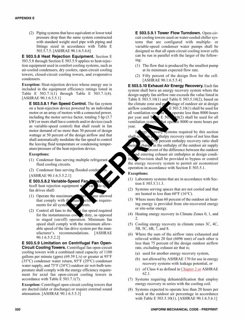
(2) Piping systems that have equivalent or lower totalpressure drop than the same system constructedwith standard weight steel pipe with piping andfittings sized in accordance with Table E503.5.7.5. [ASHRAE 90.1:6.5.4.6]
E 503.5.8 Heat Rejection Equipment. Section E503.5.8 through Section E 503.5.9 applies to heat-rejec-tion equipment used in comfort cooling systems, such asair-cooled condensers, dry coolers, open-circuit coolingtowers, closed-circuit cooling towers, and evaporativecondensers.Exception: Heat-rejection devices whose energy use isincluded in the equipment efficiency ratings listed inTable E 503.7.1(1) through Table E 503.7.1(4).[ASHRAE 90.1:6.5.5.1]
E 503.5.8.1 Fan Speed Control. The fan systemon a heat-rejection device powered by an individualmotor or an array of motors with a connected power,including the motor service factor, totaling 5 hp (3.7kW) or more shall have controls and/or devices (suchas variable-speed control) that shall result in fanmotor demand of no more than 30 percent of designwattage at 50 percent of the design airflow and thatshall automatically modulate the fan speed to controlthe leaving fluid temperature or condensing temper-ature/pressure of the heat-rejection device.Exceptions:(1) Condenser fans serving multiple refrigerant or
fluid cooling circuits.(2) Condenser fans serving flooded condensers.[ASHRAE 90.1:6.5.5.2.1]E 503.5.8.2 Variable-Speed Fan Drives. Mul-ticell heat rejection equipment with variable-speedfan drives shall:(1) Operate the maximum number of fans allowed
that comply with the manufacturer’s require-ments for all system components.
(2) Control all fans to the same fan speed requiredfor the instantaneous cooling duty, as opposedto staged (on/off) operation. Minimum fanspeed shall comply with the minimum allow-able speed of the fan drive system per the man-ufacturer’s recommendations. [ASHRAE90.1:6.5.5.2.2]
E 503.5.9 Limitation on Centrifugal Fan Open-Circuit Cooling Towers. Centrifugal fan open-circuitcooling towers with a combined rated capacity of 1100gallons per minute (gpm) (69.39 L/s) or greater at 95°F(35°C) condenser water return, 85°F (29°C) condenserwater supply, and 75°F (24°C) outdoor air wet-bulb tem-perature shall comply with the energy efficiency require-ment for axial fan open-circuit cooling towers inaccordance with Table E 503.7.1(7).Exception: Centrifugal open-circuit cooling towers thatare ducted (inlet or discharge) or require external soundattenuation. [ASHRAE 90.1:6.5.5.3]
E 503.5.9.1 Tower Flow Turndown. Open-cir-cuit cooling towers used on water-cooled chiller sys-tems that are configured with multiple- orvariable-speed condenser water pumps shall bedesigned so that all open-circuit cooling tower cellscan be run in parallel with the larger of the follow-ing:(1) The flow that is produced by the smallest pump
at its minimum expected flow rate.(2) Fifty percent of the design flow for the cell.
[ASHRAE 90.1:6.5.5.4]E 503.5.10 Exhaust Air Energy Recovery. Each fansystem shall have an energy recovery system where thedesign supply fan airflow rate exceeds the value listed inTable E 503.5.10(1) and Table E 503.5.10(2), based onthe climate zone and percentage of outdoor air at designairflow conditions. Table E 503.5.10(1) shall be used forall ventilation systems that operate less than 8000 hoursper year and Table E 503.5.10(2) shall be used for allventilation systems that operate 8000 or more hours peryear.
Energy recovery systems required by this sectionshall result in an enthalpy recovery ratio of not less than50 percent. A fifty percent enthalpy recovery ratio shallmean a change in the enthalpy of the outdoor air supplyequal to 50 percent of the difference between the outdoorair and entering exhaust air enthalpies at design condi-tions. Provision shall be provided to bypass or controlthe energy recovery system to permit air economizeroperation in accordance with Section E 503.5.1.Exceptions:(1) Laboratory systems that are in accordance with Sec-
tion E 503.5.11.3.(2) Systems serving spaces that are not cooled and that
are heated to less than 60°F (16°C).(3) Where more than 60 percent of the outdoor air heat-
ing energy is provided from site-recovered energyor site-solar energy.
(4) Heating energy recovery in Climate Zones 0, 1, and2.
(5) Cooling energy recovery in climate zones 3C, 4C,5B, 5C, 6B, 7, and 8.
(6) Where the sum of the airflow rates exhausted andrelieved within 20 feet (6096 mm) of each other isless than 75 percent of the design outdoor airflowrate, excluding exhaust air that is;(a) used for another energy recovery system,(b) not allowed by ASHRAE 170 for use in energy
recovery systems with leakage potential, or(c) of Class 4 as defined in Chapter 2 or ASHRAE
62.1.(7) Systems requiring dehumidification that employ
energy recovery in series with the cooling coil.(8) Systems expected to operate less than 20 hours per
week at the outdoor air percentage in accordancewith Table E 503.5.10(1). [ASHRAE 90.1:6.5.6.1]
320 UNIFORM MECHANICAL CODE - PREPRINT
APPENDIX E
PREPRINT
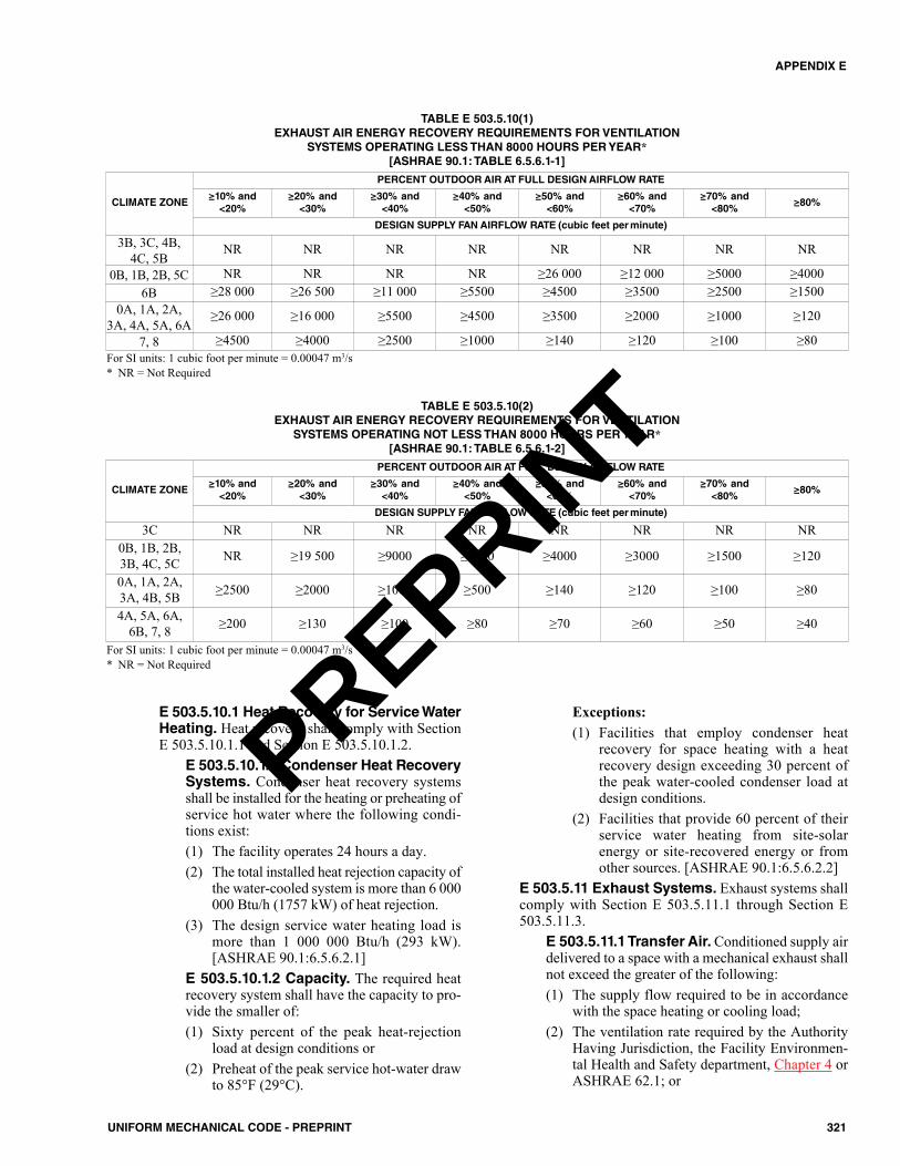
E 503.5.10.1 Heat Recovery for Service WaterHeating. Heat recovery shall comply with SectionE 503.5.10.1.1 and Section E 503.5.10.1.2.
E 503.5.10.1.1 Condenser Heat RecoverySystems. Condenser heat recovery systemsshall be installed for the heating or preheating ofservice hot water where the following condi-tions exist:(1) The facility operates 24 hours a day.(2) The total installed heat rejection capacity of
the water-cooled system is more than 6 000000 Btu/h (1757 kW) of heat rejection.
(3) The design service water heating load ismore than 1 000 000 Btu/h (293 kW).[ASHRAE 90.1:6.5.6.2.1]
E 503.5.10.1.2 Capacity. The required heatrecovery system shall have the capacity to pro-vide the smaller of:(1) Sixty percent of the peak heat-rejection
load at design conditions or(2) Preheat of the peak service hot-water draw
to 85°F (29°C).
Exceptions:(1) Facilities that employ condenser heat
recovery for space heating with a heatrecovery design exceeding 30 percent ofthe peak water-cooled condenser load atdesign conditions.
(2) Facilities that provide 60 percent of theirservice water heating from site-solarenergy or site-recovered energy or fromother sources. [ASHRAE 90.1:6.5.6.2.2]
E 503.5.11 Exhaust Systems. Exhaust systems shallcomply with Section E 503.5.11.1 through Section E503.5.11.3.
E 503.5.11.1 Transfer Air. Conditioned supply airdelivered to a space with a mechanical exhaust shallnot exceed the greater of the following:(1) The supply flow required to be in accordance
with the space heating or cooling load;(2) The ventilation rate required by the Authority
Having Jurisdiction, the Facility Environmen-tal Health and Safety department, Chapter 4 orASHRAE 62.1; or
321UNIFORM MECHANICAL CODE - PREPRINT
APPENDIX E
TABLE E 503.5.10(1)EXHAUST AIR ENERGY RECOVERY REQUIREMENTS FOR VENTILATION
SYSTEMS OPERATING LESS THAN 8000 HOURS PER YEAR*[ASHRAE 90.1: TABLE 6.5.6.1-1]
For SI units: 1 cubic foot per minute = 0.00047 m3/s* NR = Not Required
CLIMATE ZONE
PERCENT OUTDOOR AIR AT FULL DESIGN AIRFLOW RATE
≥10% and<20%
≥20% and<30%
≥30% and<40%
≥40% and<50%
≥50% and<60%
≥60% and<70%
≥70% and<80%
≥80%
DESIGN SUPPLY FAN AIRFLOW RATE (cubic feet per minute)
3B, 3C, 4B, 4C, 5B
NR NR NR NR NR NR NR NR
0B, 1B, 2B, 5C NR NR NR NR ≥26 000 ≥12 000 ≥5000 ≥40006B ≥28 000 ≥26 500 ≥11 000 ≥5500 ≥4500 ≥3500 ≥2500 ≥1500
0A, 1A, 2A,3A, 4A, 5A, 6A
≥26 000 ≥16 000 ≥5500 ≥4500 ≥3500 ≥2000 ≥1000 ≥120
7, 8 ≥4500 ≥4000 ≥2500 ≥1000 ≥140 ≥120 ≥100 ≥80
TABLE E 503.5.10(2)EXHAUST AIR ENERGY RECOVERY REQUIREMENTS FOR VENTILATION
SYSTEMS OPERATING NOT LESS THAN 8000 HOURS PER YEAR*[ASHRAE 90.1: TABLE 6.5.6.1-2]
For SI units: 1 cubic foot per minute = 0.00047 m3/s* NR = Not Required
CLIMATE ZONE
PERCENT OUTDOOR AIR AT FULL DESIGN AIRFLOW RATE
≥10% and<20%
≥20% and<30%
≥30% and<40%
≥40% and<50%
≥50% and<60%
≥60% and<70%
≥70% and<80%
≥80%
DESIGN SUPPLY FAN AIRFLOW RATE (cubic feet per minute)
3C NR NR NR NR NR NR NR NR0B, 1B, 2B, 3B, 4C, 5C NR ≥19 500 ≥9000 ≥5000 ≥4000 ≥3000 ≥1500 ≥120
0A, 1A, 2A,3A, 4B, 5B ≥2500 ≥2000 ≥1000 ≥500 ≥140 ≥120 ≥100 ≥80
4A, 5A, 6A,6B, 7, 8 ≥200 ≥130 ≥100 ≥80 ≥70 ≥60 ≥50 ≥40
PREPRINT
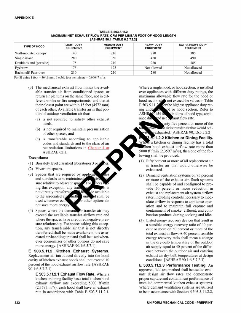
(3) The mechanical exhaust flow minus the avail-able transfer air from conditioned spaces orreturn air plenums on the same floor, not in dif-ferent smoke or fire compartments, and that attheir closest point are within 15 feet (4572 mm)of each other. Available transfer air is that por-tion of outdoor ventilation air that:(a) is not required to satisfy other exhaust
needs, (b) is not required to maintain pressurization
of other spaces, and(c) is transferable according to applicable
codes and standards and to the class of airrecirculation limitations in Chapter 4 orASHRAE 62.1.
Exceptions:(1) Biosafety level classified laboratories 3 or higher.(2) Vivarium spaces.(3) Spaces that are required by applicable codes
and standards to be maintained at positive pres-sure relative to adjacent spaces. For spaces tak-ing this exception, any transferable air that isnot directly transferred shall be made availableto the associated air-handling unit and shall beused whenever economizer or other options donot save more energy.
(4) Spaces where the demand for transfer air mayexceed the available transfer airflow rate andwhere the spaces have a required negative pres-sure relationship. For spaces taking this excep-tion, any transferable air that is not directlytransferred shall be made available to the asso-ciated air-handling unit and shall be used when-ever economizer or other options do not savemore energy. [ASHRAE 90.1:6.5.7.1]
E 503.5.11.2 Kitchen Exhaust Systems.Replacement air introduced directly into the hoodcavity of kitchen exhaust hoods shall not exceed 10percent of the hood exhaust airflow rate. [ASHRAE90.1:6.5.7.2.1]
E 503.5.11.2.1 Exhaust Flow Rate. Where akitchen or dining facility has a total kitchen hoodexhaust airflow rate exceeding 5000 ft3/min(2.3597 m3/s), each hood shall have an exhaustrate in accordance with Table E 503.5.11.2.1.
Where a single hood, or hood section, is installedover appliances with different duty ratings, themaximum allowable flow rate for the hood orhood section shall not exceed the values in TableE 503.5.11.2.1 for the highest appliance duty rat-ing under the hood or hood section. Refer toASHRAE 154 for definitions of hood type, appli-ance duty, and net exhaust flow rate.Exception: Seventy-five percent or more of thetotal replacement air is transfer air that would oth-erwise be exhausted. [ASHRAE 90.1:6.5.7.2.2]E 503.5.11.2.2 Kitchen or Dining Facility.Where a kitchen or dining facility has a totalkitchen hood exhaust airflow rate more than5000 ft3/min (2.3597 m3/s), then one of the fol-lowing shall be provided:(1) Fifty percent or more of all replacement air
is transfer air that would otherwise beexhausted.
(2) Demand ventilation systems on 75 percentor more of the exhaust air. Such systemsshall be capable of and configured to pro-vide 50 percent or more reduction inexhaust and replacement air system airflowrates, including controls necessary to mod-ulate airflow in response to appliance oper-ation and to maintain full capture andcontainment of smoke, effluent, and com-bustion products during cooking and idle.
(3) Listed energy recovery devices that result ina sensible energy recovery ratio of 40 per-cent or more on 50 percent or more of thetotal exhaust airflow. A 40 percent sensibleenergy recovery ratio shall mean a changein the dry-bulb temperature of the outdoorair supply equal to 40 percent of the differ-ence between the outdoor air and enteringexhaust air dry-bulb temperatures at designconditions. [ASHRAE 90.1:6.5.7.2.3]
E 503.5.11.2.3 Performance Testing. Anapproved field test method shall be used to eval-uate design air flow rates and demonstrateproper capture and containment performance ofinstalled commercial kitchen exhaust systems.Where demand ventilation systems are utilizedto be in accordance with Section E 503.5.11.2.2,
322 UNIFORM MECHANICAL CODE - PREPRINT
APPENDIX E
TYPE OF HOODLIGHT DUTY EQUIPMENT
MEDIUM DUTY EQUIPMENT
HEAVY DUTY EQUIPMENT
EXTRA HEAVY DUTY EQUIPMENT
Wall-mounted canopy 140 210 280 385Single island 280 350 420 490Double island (per side) 175 210 280 385Eyebrow 175 175 Not allowed Not allowedBackshelf/ Pass-over 210 210 280 Not allowed
TABLE E 503.5.11.2MAXIMUM NET EXHAUST FLOW RATE, CFM PER LINEAR FOOT OF HOOD LENGTH
[ASHRAE 90.1: TABLE 6.5.7.2.2]
For SI units: 1 foot = 304.8 mm, 1 cubic foot per minute = 0.00047 m3/s
PREPRINT
additional performance testing shall be requiredto demonstrate proper capture and containmentat minimum airflow. [ASHRAE 90.1:6.5.7.2.4]
E 503.5.11.3 Laboratory Exhaust Systems.Buildings with laboratory exhaust systems having atotal exhaust rate of more than 5000 ft3/min (2.3597m3/s) shall include not less than one of the followingfeatures:(1) VAV laboratory exhaust and room supply sys-
tems capable of and configured to reduceexhaust and makeup airflow rates, incorporate aheat recovery system to precondition makeupair from laboratory exhaust, or both, and shallbe in accordance with the following:
A+B•(E/M) ≥ 50% (Equation E 503.5.11.3)
Where:A = Percentage that the exhaust and makeup air-
flow rates are capable of being reduced fromdesign conditions.
B = Sensible energy recovery ratio.E = Exhaust airflow rate through the heat recovery
device at design conditions.M = Makeup airflow rate of the system at design
conditions.(2) VAV laboratory exhaust and room supply sys-
tems that are required to have minimum circula-tion rates to be in accordance with the codes oraccreditation standards shall be capable of andconfigured to reduce zone exhaust and makeupairflow rates to the regulated minimum circula-tion values, or the minimum required to maintainpressurization relationship requirements. Sys-tems serving nonregulated zones shall be capableof and configured to reduce exhaust and makeupairflow rates to 50 percent of the zone design val-ues, or the minimum required to maintain pres-surization relationship requirements.
(3) Direct makeup (auxiliary) air supply of 75 per-cent or more of the exhaust airflow rate, heatednot more than 2°F (1°C) below room setpoint,cooled to not less than 3°F (2°C) above roomsetpoint, no humidification added, and no simul-taneous heating and cooling are used for dehu-midification control. [ASHRAE 90.1:6.5.7.3]
E 503.5.12 Radiant Heating Systems. Radiant heat-ing shall be used when heating is required for unenclosedspaces.Exception: Loading docks equipped with air curtains.[ASHRAE 90.1:6.5.8.1]
E 503.5.12.1 Heating Enclosed Spaces. Radi-ant heating systems that are used as primary or sup-plemental heating for enclosed spaces shall be inconformance with the governing provisions of thestandard, including, but not limited to the following:
(1) Radiant hydronic ceiling or floor panels (usedfor heating or cooling).
(2) Combination or hybrid systems incorporatingradiant heating (or cooling) panels.
(3) Radiant heating (or cooling) panels used in con-junction with other systems such as VAV or ther-mal storage systems. [ASHRAE 90.1:6.5.8.2]
E 503.5.13 Hot Gas Bypass Limitation. Coolingsystems shall not use hot gas bypass or other evaporatorpressure control systems unless the system is designedwith multiple steps of unloading or continuous capacitymodulation. The capacity of the hot gas bypass shall belimited as indicated in Table E 503.5.13 for VAV unitsand single-zone VAV units. Hot-gas bypass shall not beused on constant-volume units. [ASHRAE 90.1:6.5.9]
E 503.5.14 Door Switches. Conditioned spaces withdoors, including doors with more than one-half glass,opening to the outdoors shall be provided with controlsthat when any such door is open, the following shall occur:(1) Disable mechanical heating or reset the heating set-
point to 55°F (13°C) or lower within five minutesof the door opening.
(2) Disable mechanical cooling or reset the cooling set-point to 90°F (32°C) or more within five minutes ofthe door opening. Mechanical cooling shall be per-mitted to remain enabled where outdoor air temper-ature is less than the space temperature.
Exceptions:(1) Building entries with automatic closing devices.(2) Any space without a thermostat.(3) Alterations to existing buildings.(4) Loading docks. [ASHRAE 90.1:6.5.10]
E 503.6 Submittals. The Authority Having Jurisdictionshall require submittal of compliance documentation and sup-plemental information in accordance with Section E 503.6.1through Section E 503.6.3.
E 503.6.1 Construction Details. Compliance docu-ments shall show the pertinent data and features of thebuilding, equipment, and systems in sufficient detail topermit a determination of compliance by the buildingofficial and to indicate compliance with the requirementsof this appendix. [ASHRAE 90.1:4.2.2.1]E 503.6.2 Supplemental Information. Supplemen-tal information necessary to verify compliance with thisappendix, such as calculations, worksheets, complianceforms, vendor literature, or other data, shall be made
TABLE E 503.5.13HOT GAS BYPASS LIMITATION
[ASHRAE 90.1: TABLE 6.5.9]
For SI units: 1000 British thermal units per hour = 0.293 kW
RATED CAPACITYMAXIMUM HOT GAS BYPASS
(percent of total capacity)
≤240 000 Btu/h 15%>240 000 Btu/h 10%
323UNIFORM MECHANICAL CODE - PREPRINT
APPENDIX E
PREPRINT
available where required by the Authority Having Juris-diction. [ASHRAE 90.1:4.2.2.2] E 503.6.3 Manuals. Operating and maintenance infor-mation shall be provided to the building owner. This infor-mation shall include, but not be limited to, the informationspecified in Section E 503.6.3.1, Section E 503.6.3.2, andSection E 503.6.5.2. [ASHRAE 90.1:4.2.2.3]
E 503.6.3.1 Required Information. Construc-tion documents shall require that an operating man-ual and maintenance manual be provided to thebuilding owner. The manuals shall include, at a min-imum, the following:(1) Submittal data stating equipment rating and
selected options for each piece of equipmentrequiring maintenance.
(2) Operation manuals and maintenance manualsfor each piece of equipment requiring mainte-nance. Required routine maintenance actionsshall be clearly identified.
(3) Names and addresses of not less than one qual-ified service agency.
(4) A complete narrative of how each system isintended to operate.The Authority Having Jurisdiction shall only
check to ensure that the construction documentsrequire this information to be transmitted to the ownerand should not expect copies of any of the materials.[ASHRAE 90.1:8.7.2]E 503.6.3.2 Lighting Manuals. Construction doc-uments shall require for all lighting equipment andlighting controls that an operating and maintenancemanual be provided to the building owner or the des-ignated representative of the building owner within90 days after the date of system acceptance. Thesemanuals shall include, at a minimum, the following:(1) Submittal data indicating all selected options
for each piece of lighting equipment, includingbut not limited to lamps, ballasts, drivers, andlighting controls.
(2) Operation and maintenance manuals for eachpiece of lighting equipment and lighting controlswith routine maintenance clearly identifiedincluding, as a minimum, a recommendedrelamping or cleaning program and a schedule forinspecting and recalibrating all lighting controls.
(3) A complete narrative of how each lighting con-trol system is intended to operate including rec-ommended settings. [ASHRAE 90.1:9.7.2.2]
E 503.6.4 Labeling of Material and Equipment.Materials and equipment shall be labeled in a mannerthat will allow for determination of their compliance withthe applicable provisions of this appendix. [ASHRAE90.1:4.2.3]E 503.6.5 Completion Requirements. Section E503.6.5.1 through Section E 503.6.5.4.1 are mandatoryprovisions and are necessary to comply with this appen-dix. [ASHRAE 90.1:6.7.2]
E 503.6.5.1 Drawings. Construction documentsshall require that, within 90 days after the date of sys-tem acceptance, record drawings of the actual instal-lation be provided to the building owner or thedesignated representative of the building owner.Record drawings shall include, as a minimum, thelocation and performance data on each piece of equip-ment, general configuration of duct and pipe distri-bution system including sizes, and the terminal air orwater design flow rates. [ASHRAE 90.1:6.7.2.1]E 503.6.5.2 Manuals. Construction documentsshall require that an operating manual and a mainte-nance manual be provided to the building owner orthe designated representative of the building ownerwithin 90 days after the date of system acceptance.These manuals shall be in accordance with industry-accepted standards and shall include, at a minimum,the following:(1) Submittal data stating equipment size and
selected options for each piece of equipmentrequiring maintenance.
(2) Operation manuals and maintenance manualsfor each piece of equipment and system requir-ing maintenance, except equipment not fur-nished as part of the project. Required routinemaintenance actions shall be clearly identified.
(3) Names and addresses of not less than one serv-ice agency.
(4) HVAC controls system maintenance and cali-bration information, including wiring diagrams,schematics, and control sequence descriptions.Desired or field-determined setpoints shall bepermanently recorded on control drawings atcontrol devices or, for digital control systems,in programming comments.
(5) A complete narrative of how each system isintended to operate, including suggested set-points. [ASHRAE 90.1:6.7.2.2]
E 503.6.5.3 System Balancing. Constructiondocuments shall require that HVAC systems be bal-anced in accordance with generally accepted engi-neering standards. Construction documents shallrequire that a written balance report be provided tothe building owner or the designated representativeof the building owner for HVAC systems servingzones with a total conditioned area exceeding 5000square feet (464.52 m2). [ASHRAE 90.1:6.7.2.3.1]
E 503.6.5.3.1 Air System Balancing. Airsystems shall be balanced in a manner to firstminimize throttling losses. Then, for fans withfan system power greater than 1 hp (0.7 kW),fan speed shall be adjusted to meet design flowconditions. [ASHRAE 90.1:6.7.2.3.2]E 503.6.5.3.2 Hydronic System Balanc-ing. Hydronic systems shall be proportionatelybalanced in a manner to first minimize throt-tling losses; then the pump impeller shall betrimmed or pump speed shall be adjusted tomeet design flow conditions.
324 UNIFORM MECHANICAL CODE - PREPRINT
APPENDIX E
PREPRINT
Exceptions: Impellers need not be trimmed norpump speed adjusted.(1) For pumps with pump motors of 10 hp (7.5
kW) or less.(2) Where throttling results is not greater than
5 percent of the nameplate horsepowerdraw, or 3 hp (2.2 kW), whichever isgreater, above that required where theimpeller was trimmed. [ASHRAE90.1:6.7.2.3.3]
E 503.6.5.4 System Commissioning. HVACcontrol systems shall be tested to ensure that controlelements are calibrated, adjusted, and in properworking condition. For projects larger than 50 000square feet (4645.15 m2) conditioned area, exceptwarehouses and semiheated spaces, detailed instruc-tions for commissioning HVAC systems shall beprovided by the designer in plans and specifications.[ASHRAE 90.1:6.7.2.4]
E 503.6.5.4.1 Minimum Level of Com-mission. Commissioning shall be performedfor HVAC systems in accordance with Level 1,Basic Commissioning of the SMACNA HVACSystems Commissioning Manual. (See SectionE 801.0 for additional information on HVACsystem commissioning)
E 503.7 Minimum Equipment Efficiency Tables. Theminimum efficiency requirements for equipment shall com-ply with Section E 503.7.1; duct insulation shall comply withSection E 503.7.2, and pipe insulation shall comply with Sec-tion E 503.7.3.
E 503.7.1 Minimum Efficiency RequirementListed Equipment – Standard Rating and Oper-ating Conditions. The minimum efficiency require-ments for equipment shall comply with Table E503.7.1(1) through Table E 503.7.1(16).E 503.7.2 Duct Insulation Tables. Duct insulationshall comply with Table E 503.7.2.E 503.7.3 Pipe Insulation Tables. Pipe insulationshall comply with Table E 503.7.3(1) through Table E503.7.3(2).
E 503.8 Alternative Compliance Path. HVAC systemsserving heating, cooling, or ventilation needs of a computerroom shall be in accordance with Section E 503.1, Section E503.4, Section E 503.8.1 or Section E 503.8.2, Section E503.8.3, Section E 502.7 through Section E 502.7.2, and Sec-tion E 503.7. [ASHRAE 90.1:6.6.1]
E 503.8.1 Computer Room (PUE1). The computerroom PUE1 shall be not more than the values listed inTable E 503.8.1. Hourly simulation of the proposeddesign, for purposes of calculating PUE1, shall be inaccordance with ASHRAE 90.1.Exception: The compliance path shall not be permittedfor a proposed computer room design utilizing a com-
bined heat and power system. [ASHRAE 90.1:6.6.1.1]
E 503.8.2 Computer Room (PUE0). The computerroom PUE0 is less than or equal to the values listed inTable E 503.8.1, shall be the highest value determined atoutdoor cooling design temperatures, and shall be limitedto systems only using electricity for an energy source.PUE0 shall be calculated for two conditions:(1) One hundred percent design IT equipment energy
and(2) Fifty percent design IT equipment energy.
[ASHRAE 90.1:6.6.1.2]E 503.8.3 Documentation. Documentation on the fol-lowing components shall be provided, including a break-down of energy consumption or demand:(1) IT equipment(2) Power distribution losses external to the IT equip-
ment(3) HVAC systems(4) Lighting [ASHRAE 90.1:6.6.1.3]
E 504.0 Solar Energy Systems.E 504.1 General. Solar energy systems shall be installed inaccordance with the Uniform Solar Energy and HydronicsCode (USEHC) Uniform Solar, Hydronics and GeothermalCode (USHGC).
E 601.0 Indoor Environment.E 601.1 Scope. The provisions of this section shall establishthe means of reducing the quantity of air contaminants thatare odorous, irritating, or harmful to the comfort and well-being of a building’s installers, occupants, and neighbors.
TABLE E 503.8.1POWER USAGE EFFECTIVENESS (PUE) MAXIMUM
[ASHRAE 90.1: TABLE 6.6.1]
* PUE0 and PUE1 shall not include energy for battery charging.
CLIMATE ZONE PUE*0A 1.640B 1.621A 1.611B 1.532A 1.492B 1.453A 1.413B 1.423C 1.394A 1.364B 1.384C 1.385A 1.365B 1.335C 1.366A 1.346B 1.337 1.328 1.30
325UNIFORM MECHANICAL CODE - PREPRINT
APPENDIX E
PREPRINT

E 602.0 Fireplaces.E 602.1 Requirements. A direct- vent sealed-combustiongas or sealed wood-burning fireplace, or a sealed wood stoveshall be installed. The fireplace shall comply with Section E602.1.1 and Section E 602.1.2.
E 602.1.1 Masonry or Factory-Built Fireplace.Masonry and factory-built fireplaces located in condi-tioned spaces shall be in accordance with Section E602.1.1.1 through Section E 602.1.1.3.
E 602.1.1.1 Opening Cover. Closeable metal orglass doors covering the entire opening of the fire-box shall be installed.E 602.1.1.2 Combustion Air Intake. A combus-tion air intake to draw air from the outside of thebuilding directly into the firebox, which is an area ofnot less than 6 square inches (0.004 m2) and isequipped with a readily accessible, operable, andtight-fitting damper or combustion-air control device.E 602.1.1.3 Accessible Damper Control. Theflue damper shall have a readily accessible control.Exception: Where a gas log, log lighter, or decora-tive gas appliance is installed in a fireplace, the fluedamper shall be blocked open where required by thiscode or the manufacturer’s installation instructions.
E 602.1.2 Prohibited. Continuous burning pilot lightsand the use of indoor air for cooling a firebox jacket,where the indoor air is vented to the outside of the build-ing, are prohibited.
E 603.0 Pollutant Control.E 603.1 Indoor Air Quality During Construction.Indoor air quality of a building shall be maintained in accor-dance with Section E 603.1.1 through Section E 603.1.3.
E 603.1.1 Temporary Ventilation During Con-struction. Temporary ventilation during constructionshall be provided in accordance with the following:(1) Ventilation during construction shall be achieved
through openings in the building shell using fans toproduce not less than three air changes per hour.
(2) During dust-producing operations, the supply andreturn HVAC system openings shall be protectedfrom dust in accordance with Section E 603.1.3.
(3) Where the building is occupied during demolitionor construction, ventilation shall be provided inaccordance with the Control Measures of theSMACNA IAQ Guidelines for Occupied BuildingsUnder Construction.
(4) The permanent HVAC system shall not be used dur-ing construction to condition and ventilate the build-ing within the required temperature range formaterial and equipment installation. Where required,a supplemental HVAC system shall be used duringconstruction, return air shall be equipped with filterswith a minimum efficiency reporting value (MERV)of 8, in accordance with ASHRAE 52.2, or an aver-age efficiency of 30 percent in accordance with
ASHRAE 52.2. Before occupancy, filters shall bereplaced with filters having a MERV 13 rating inaccordance with Section E 603.3.Exception: Embedded hydronics system shall bepermitted to be used to condition the building duringconstruction.
E 603.1.2 Indoor Air Quality After Construction.After construction ends and interior finishes are installed,flush-out the building to reduce contaminant concentra-tions by supplying a total outdoor air volume of 14 000cubic feet per square foot (ft3/ft2) (4267.2 m3/m2) of occu-piable building area. An internal temperature of not lessthan 60°F (16°C) and relative humidity not higher than60 percent shall be maintained during the flush-outprocess. Occupancy shall begin on condition of 3500ft3/ft2 (1066.8 m3/m2) of building area, with the remain-ing 10 500 ft3/ft2 (3200.4 m3/m2) being accomplished assoon as possible.Exception: Other means of reducing the contaminantconcentration levels shall be permitted where approvedby the Authority Having Jurisdiction.E 603.1.3 Covering of Duct Openings and Pro-tection of Mechanical Equipment During Con-struction. At the time of rough installation, or duringstorage on the construction site and until final startup ofthe heating and cooling equipment, duct and other relatedair distribution component openings shall be coveredwith tape, plastic, sheet metal, or other methods accept-able to the enforcing agency to reduce the amount of dustor debris that collects in the system.
E 603.2 Isolation of Pollutant Sources. Rooms whereactivities produce hazardous fumes or chemicals, includingcommercial kitchens, garages, janitorial or laundry rooms,and copy or printing rooms, shall be exhausted and isolatedfrom adjacent spaces in accordance with this code.E 603.3 Filters. In mechanically ventilated buildings, par-ticle filters, or air-cleaning devices shall be provided to cleanoutdoor and return air prior to its delivery to occupied spaces.The particle or air cleaner shall have a MERV of 13.Exception: A filter or air cleaning device with a lower MERVvalue shall be permitted provided it is the highest value com-mercially available for the specific equipment that is installed.E 603.4 Ozone Depletion and Global WarmingReductions. Installations of HVAC and refrigeration shallnot contain CFCs and shall be in accordance with this code.
E 604.0 Indoor Moisture Control.E 604.1 Rainwater Control. Roof drainage systems shalldischarge to a place of disposal in accordance with the plumb-ing code. Storm water shall be directed away from the building.
E 605.0 Indoor Air Quality for Low-Rise Residential.E 605.1 General. Rooms or occupied spaces within single-family homes and multifamily structures of three stories orless above grade shall be designed to have ventilation (out-door) air for occupants in accordance with Section E 605.1.1through Section E 605.1.3.2, or the applicable local code.
326 UNIFORM MECHANICAL CODE - PREPRINT
APPENDIX E
PREPRINT
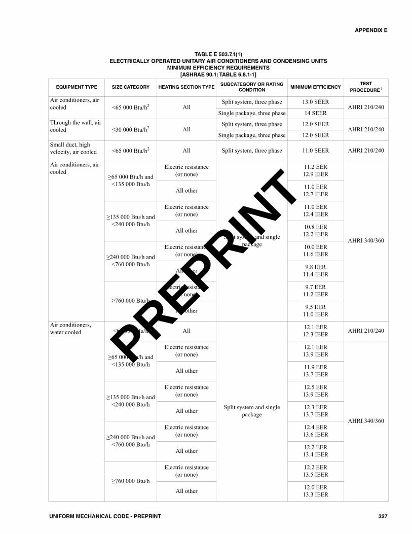
327UNIFORM MECHANICAL CODE - PREPRINT
APPENDIX E
EQUIPMENT TYPE SIZE CATEGORY HEATING SECTION TYPESUBCATEGORY OR RATING
CONDITIONMINIMUM EFFICIENCY
TESTPROCEDURE1
Air conditioners, aircooled <65 000 Btu/h2 All
Split system, three phase 13.0 SEERAHRI 210/240
Single package, three phase 14 SEERThrough the wall, aircooled ≤30 000 Btu/h2 All
Split system, three phase 12.0 SEERAHRI 210/240
Single package, three phase 12.0 SEERSmall duct, highvelocity, air cooled <65 000 Btu/h2 All Split system, three phase 11.0 SEER AHRI 210/240
Air conditioners, aircooled
≥65 000 Btu/h and<135 000 Btu/h
Electric resistance (or none)
Split system and singlepackage
11.2 EER12.9 IEER
AHRI 340/360
All other 11.0 EER12.7 IEER
≥135 000 Btu/h and<240 000 Btu/h
Electric resistance (or none)
11.0 EER12.4 IEER
All other 10.8 EER12.2 IEER
≥240 000 Btu/h and<760 000 Btu/h
Electric resistance (or none)
10.0 EER11.6 IEER
All other 9.8 EER11.4 IEER
≥760 000 Btu/h
Electric resistance (or none)
9.7 EER11.2 IEER
All other 9.5 EER11.0 IEER
Air conditioners,water cooled <65 000 Btu/h All
Split system and singlepackage
12.1 EER12.3 IEER AHRI 210/240
≥65 000 Btu/h and<135 000 Btu/h
Electric resistance (or none)
12.1 EER13.9 IEER
AHRI 340/360
All other 11.9 EER13.7 IEER
≥135 000 Btu/h and<240 000 Btu/h
Electric resistance (or none)
12.5 EER13.9 IEER
All other 12.3 EER13.7 IEER
≥240 000 Btu/h and<760 000 Btu/h
Electric resistance (or none)
12.4 EER13.6 IEER
All other 12.2 EER13.4 IEER
≥760 000 Btu/h
Electric resistance (or none)
12.2 EER13.5 IEER
All other 12.0 EER13.3 IEER
TABLE E 503.7.1(1)ELECTRICALLY OPERATED UNITARY AIR CONDITIONERS AND CONDENSING UNITS
MINIMUM EFFICIENCY REQUIREMENTS[ASHRAE 90.1: TABLE 6.8.1-1]
PREPRINT
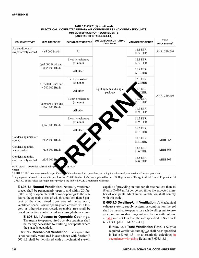
E 605.1.1 Natural Ventilation. Naturally ventilatedspaces shall be permanently open to and within 20 feet(6096 mm) of operable wall or roof openings to the out-doors, the openable area of which is not less than 5 per-cent of the conditioned floor area of the naturallyventilated space. Where openings are covered with lou-vers or otherwise obstructed, openable area shall bebased on the free unobstructed area through the opening.
E 605.1.1.1 Access to Operable Openings.The means to open required operable openings shallbe readily accessible to building occupants wherethe space is occupied.
E 605.1.2 Mechanical Ventilation. Each space thatis not naturally ventilated in accordance with Section E605.1.1 shall be ventilated with a mechanical system
capable of providing an outdoor air rate not less than 15ft3/min (0.007 m3/s) per person times the expected num-ber of occupants. Mechanical ventilation shall complywith this code.E 605.1.3 Dwelling-Unit Ventilation. A Mechanicalexhaust system, supply system, or combination thereofshall be installed to operate for each dwelling unit to pro-vide continuous dwelling-unit ventilation with outdoorair at a rate not less than the rate specified in Section E605.1.3.1. [ASHRAE 62.2:4.1]
E 605.1.3.1 Total Ventilation Rate. The totalrequired ventilation rate (Qtot) shall be as specifiedin Table E 605.1.3.1 or, alternatively, calculated inaccordance with using Equation E 605.1.3.1.
328 UNIFORM MECHANICAL CODE - PREPRINT
APPENDIX E
EQUIPMENT TYPE SIZE CATEGORY HEATING SECTION TYPESUBCATEGORY OR RATING
CONDITIONMINIMUM EFFICIENCY
TESTPROCEDURE1
Air conditioners,evaporatively cooled <65 000 Btu/h2 All
Split system and singlepackage
12.1 EER12.3 IEER AHRI 210/240
≥65 000 Btu/h and<135 000 Btu/h
Electric resistance (or none)
12.1 EER12.3 IEER
AHRI 340/360
All other 11.9 EER12.1 IEER
≥135 000 Btu/h and<240 000 Btu/h
Electric resistance (or none)
12.0 EER12.2 IERR
All other 11.8 EER12.0 IEER
≥240 000 Btu/h and<760 000 Btu/h
Electric resistance (or none)
11.9 EER12.1 IEER
All other 11.7 EER11.9 IEER
≥760 000 Btu/h
Electric resistance (or none)
11.7 EER11.9 IEER
All other 11.5 EER11.7 IEER
Condensing units, aircooled ≥135 000 Btu/h – – 10.5 EER
11.8 IEER AHRI 365
Condensing units,water cooled ≥135 000 Btu/h – – 13.5 EER
14.0 IEER AHRI 365
Condensing units,evaporatively cooled ≥135 000 Btu/h – – 13.5 EER
14.0 IEER AHRI 365
TABLE E 503.7.1(1) (continued)ELECTRICALLY OPERATED UNITARY AIR CONDITIONERS AND CONDENSING UNITS
MINIMUM EFFICIENCY REQUIREMENTS[ASHRAE 90.1: TABLE 6.8.1-1]
For SI units: 1000 British thermal units per hour = 0.293 kWNotes:1 ASHRAE 90.1 contains a complete specification of the referenced test procedure, including the referenced year version of the test procedure.2 Single-phase, air-cooled air conditioners less than 65 000 Btu/h (19 kW) are regulated by the U.S. Department of Energy Code of Federal Regulations 10
CFR 430. SEER values for single-phase products are set by the U.S. Department of Energy.
PREPRINT
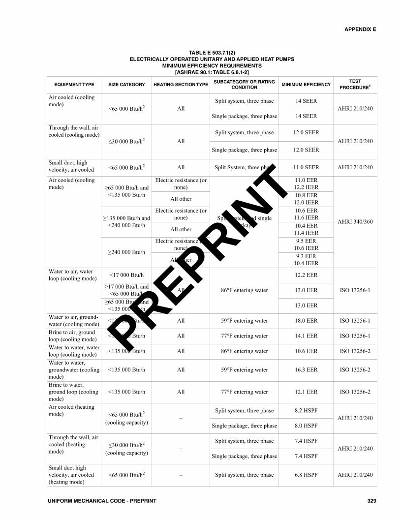
329UNIFORM MECHANICAL CODE - PREPRINT
APPENDIX E
EQUIPMENT TYPE SIZE CATEGORY HEATING SECTION TYPESUBCATEGORY OR RATING
CONDITIONMINIMUM EFFICIENCY
TEST PROCEDURE1
Air cooled (coolingmode)
<65 000 Btu/h2 AllSplit system, three phase 14 SEER
AHRI 210/240Single package, three phase 14 SEER
Through the wall, aircooled (cooling mode)
≤30 000 Btu/h2 AllSplit system, three phase 12.0 SEER
AHRI 210/240Single package, three phase 12.0 SEER
Small duct, highvelocity, air cooled <65 000 Btu/h2 All Split System, three phase 11.0 SEER AHRI 210/240
Air cooled (coolingmode) ≥65 000 Btu/h and
<135 000 Btu/h
Electric resistance (ornone)
Split system and singlepackage
11.0 EER 12.2 IEER
AHRI 340/360
All other 10.8 EER 12.0 IEER
≥135 000 Btu/h and<240 000 Btu/h
Electric resistance (ornone)
10.6 EER 11.6 IEER
All other 10.4 EER 11.4 IEER
≥240 000 Btu/h
Electric resistance (ornone)
9.5 EER 10.6 IEER
All other 9.3 EER 10.4 IEER
Water to air, waterloop (cooling mode) <17 000 Btu/h
All 86°F entering water
12.2 EER
ISO 13256-1≥17 000 Btu/h and<65 000 Btu/h 13.0 EER
≥65 000 Btu/h and<135 000 Btu/h 13.0 EER
Water to air, ground-water (cooling mode) <135 000 Btu/h All 59°F entering water 18.0 EER ISO 13256-1
Brine to air, groundloop (cooling mode) <135 000 Btu/h All 77°F entering water 14.1 EER ISO 13256-1
Water to water, waterloop (cooling mode) <135 000 Btu/h All 86°F entering water 10.6 EER ISO 13256-2
Water to water,groundwater (coolingmode)
<135 000 Btu/h All 59°F entering water 16.3 EER ISO 13256-2
Brine to water,ground loop (coolingmode)
<135 000 Btu/h All 77°F entering water 12.1 EER ISO 13256-2
Air cooled (heatingmode) <65 000 Btu/h2
(cooling capacity)–
Split system, three phase 8.2 HSPFAHRI 210/240
Single package, three phase 8.0 HSPF
Through the wall, aircooled (heatingmode)
≤30 000 Btu/h2
(cooling capacity)–
Split system, three phase 7.4 HSPFAHRI 210/240
Single package, three phase 7.4 HSPF
Small duct highvelocity, air cooled(heating mode)
<65 000 Btu/h2 – Split system, three phase 6.8 HSPF AHRI 210/240
TABLE E 503.7.1(2)ELECTRICALLY OPERATED UNITARY AND APPLIED HEAT PUMPS
MINIMUM EFFICIENCY REQUIREMENTS[ASHRAE 90.1: TABLE 6.8.1-2]
PREPRINT

(Equation E 605.1.3.1)Qtot = 0.03Afloor + 7.5(Nbr + 1)
Where:Qtot = total required ventilation rate, cubic feet
per minute (ft3/min)Afloor = dwelling unit floor area, square foot (ft2)Nbr = number of bedrooms; (not to be less than
one)For SI units: 1 cubic foot per minute = 0.00047 m3/s, 1 squarefoot = 0.0929 m2
Exceptions: Dwelling-unit mechanical ventilationsystems shall not be required where the AuthorityHaving Jurisdiction determines that window opera-tion is a locally permissible method of providingventilation and provided one or more of the follow-ing conditions is met:(1) The building has no mechanical cooling and is
located in zone 1 or 2 of the climate zone map.(2) The building is thermally conditioned for
human occupancy for less than 876 hours peryear. [ASHRAE 62.2:4.1.1]
E 605.1.3.2 Effective Annual Average Infiltra-tion Rate (Qinf). Effective Annual Average Infil-tration Rate (Qinf) shall be calculated usingEquation E 605.1.3.2:
(Equation E 605.1.3.2)Qinf (CFM) = (NL x wsf x Afloor) / (7.3)*
Where:NL = normalized leakagewsf = weather and shielding factor from ASHRAE
62.2.Afloor = floor area of residence, ft2 (m2)* Replace 7.3 with 1.44 for metric units. [ASHRAE
62.2:4.1.2(e)]E 605.1.3.3 Required Mechanical VentilationRate (Qfan). Required Mechanical VentilationRate (Qfan) shall be calculated using Equation E605.1.3.3:Qfan = Qtot – (Qinf × Aext) [Equation 605.1.3.3]
Where:Qfan = required mechanical ventilation rate, CFM
(L/s)
330 UNIFORM MECHANICAL CODE - PREPRINT
APPENDIX E
EQUIPMENT TYPE SIZE CATEGORY HEATING SECTION TYPESUBCATEGORY OR RATING
CONDITIONMINIMUM EFFICIENCY
TEST PROCEDURE1
Air cooled (heatingmode) ≥65 000 Btu/hc and
<135 000 Btu/h(cooling capacity)
–
47°F db/43°F wb outdoor air 3.3 COPH
AHRI 340/36017°F db/15°F wb outdoor air 2.25 COPH
≥135 000 Btu/hc(cooling capacity)
47°F db/43°F wb outdoor air 3.2 COPH
17°F db/15°F wb outdoor air 2.05 COPH
Water to air, waterloop (heating mode)
<135 000 Btu/h(cooling capacity) – 68°F entering water 4.3 COPH ISO 13256-1
Water to air, ground-water (heating mode)
<135 000 Btu/h(cooling capacity) – 50°F entering water 3.7 COPH ISO 13256-1
Brine to air, groundloop (heating mode)
<135 000 Btu/h(cooling capacity) – 32°F entering fluid 3.2 COPH ISO 13256-1
Water to water, waterloop (heating mode)
<135 000 Btu/h(cooling capacity) – 68°F entering water 3.7 COPH ISO 13256-2
Water to water,groundwater (heatingmode)
<135 000 Btu/h(cooling capacity) – 50°F entering water 3.1 COPH ISO 13256-2
Brine to water,ground loop (heatingmode)
<135 000 Btu/h(cooling capacity) – 32°F entering fluid 2.5 COPH ISO 13256-2
TABLE E 503.7.1(2) (continued)ELECTRICALLY OPERATED UNITARY AND APPLIED HEAT PUMPS
MINIMUM EFFICIENCY REQUIREMENTS[ASHRAE 90.1: TABLE 6.8.1-2]
For SI units: 1000 British thermal units per hour = 0.293 kW, °C = (°F-32)/1.8Notes:1 ASHRAE 90.1 contains a complete specification of the referenced test procedure, including the referenced year version of the test procedure.2 Single-phase, air-cooled heat pumps less than 65 000 Btu/h (19 kW) are regulated by the U.S. Department of Energy Code of Federal Regulations 10 CFR
430. SEER and HSPF values for single-phase products are set by the U.S. Department of Energy.
PREPRINT
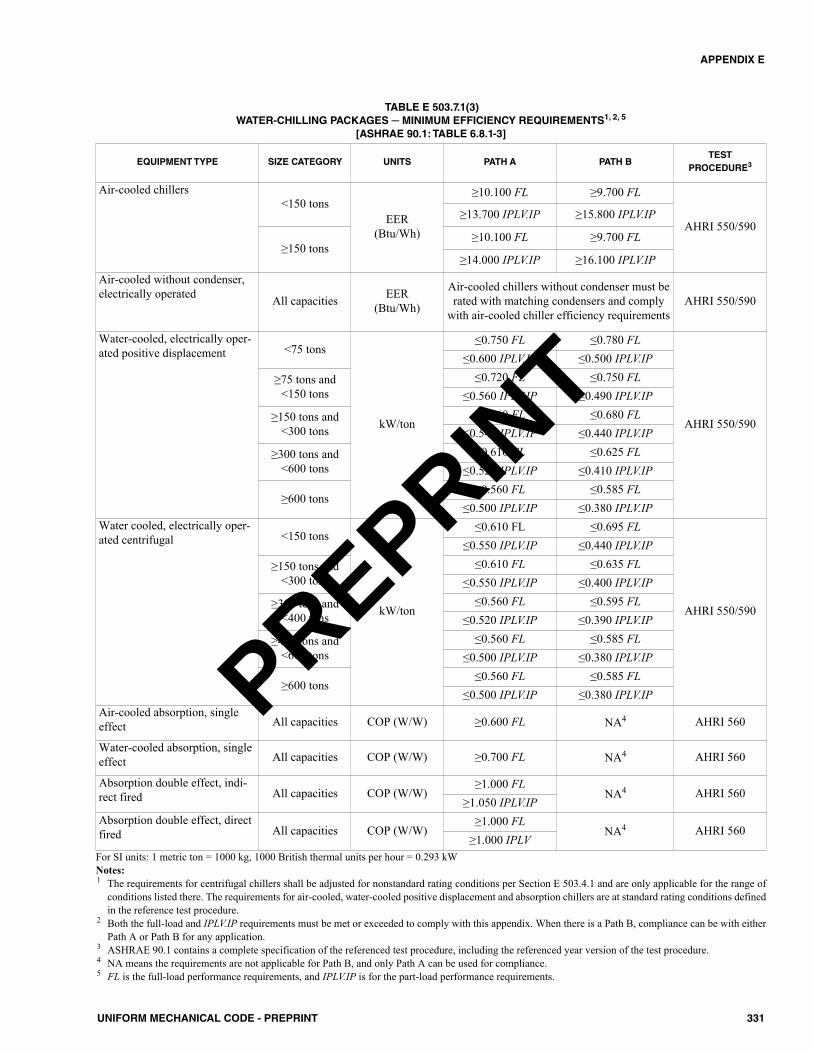
331UNIFORM MECHANICAL CODE - PREPRINT
APPENDIX E
EQUIPMENT TYPE SIZE CATEGORY UNITS PATH A PATH BTEST
PROCEDURE3
Air-cooled chillers<150 tons
EER(Btu/Wh)
≥10.100 FL ≥9.700 FL
AHRI 550/590≥13.700 IPLV.IP ≥15.800 IPLV.IP
≥150 tons≥10.100 FL ≥9.700 FL
≥14.000 IPLV.IP ≥16.100 IPLV.IPAir-cooled without condenser,electrically operated All capacities EER
(Btu/Wh)
Air-cooled chillers without condenser must berated with matching condensers and comply
with air-cooled chiller efficiency requirementsAHRI 550/590
Water-cooled, electrically oper-ated positive displacement <75 tons
kW/ton
≤0.750 FL ≤0.780 FL
AHRI 550/590
≤0.600 IPLV.IP ≤0.500 IPLV.IP
≥75 tons and<150 tons
≤0.720 FL ≤0.750 FL≤0.560 IPLV.IP ≤0.490 IPLV.IP
≥150 tons and<300 tons
≤0.660 FL ≤0.680 FL≤0.540 IPLV.IP ≤0.440 IPLV.IP
≥300 tons and<600 tons
≤0.610 FL ≤0.625 FL≤0.520 IPLV.IP ≤0.410 IPLV.IP
≥600 tons≤0.560 FL ≤0.585 FL
≤0.500 IPLV.IP ≤0.380 IPLV.IPWater cooled, electrically oper-ated centrifugal <150 tons
kW/ton
≤0.610 FL ≤0.695 FL
AHRI 550/590
≤0.550 IPLV.IP ≤0.440 IPLV.IP
≥150 tons and<300 tons
≤0.610 FL ≤0.635 FL≤0.550 IPLV.IP ≤0.400 IPLV.IP
≥300 tons and<400 tons
≤0.560 FL ≤0.595 FL≤0.520 IPLV.IP ≤0.390 IPLV.IP
≥400 tons and<600 tons
≤0.560 FL ≤0.585 FL≤0.500 IPLV.IP ≤0.380 IPLV.IP
≥600 tons≤0.560 FL ≤0.585 FL
≤0.500 IPLV.IP ≤0.380 IPLV.IPAir-cooled absorption, singleeffect All capacities COP (W/W) ≥0.600 FL NA4 AHRI 560
Water-cooled absorption, singleeffect All capacities COP (W/W) ≥0.700 FL NA4 AHRI 560
Absorption double effect, indi-rect fired All capacities COP (W/W)
≥1.000 FLNA4 AHRI 560
≥1.050 IPLV.IPAbsorption double effect, directfired All capacities COP (W/W)
≥1.000 FLNA4 AHRI 560
≥1.000 IPLV
TABLE E 503.7.1(3)WATER-CHILLING PACKAGES ─ MINIMUM EFFICIENCY REQUIREMENTS1, 2, 5
[ASHRAE 90.1: TABLE 6.8.1-3]
For SI units: 1 metric ton = 1000 kg, 1000 British thermal units per hour = 0.293 kWNotes:1 The requirements for centrifugal chillers shall be adjusted for nonstandard rating conditions per Section E 503.4.1 and are only applicable for the range of
conditions listed there. The requirements for air-cooled, water-cooled positive displacement and absorption chillers are at standard rating conditions definedin the reference test procedure.
2 Both the full-load and IPLV.IP requirements must be met or exceeded to comply with this appendix. When there is a Path B, compliance can be with eitherPath A or Path B for any application.
3 ASHRAE 90.1 contains a complete specification of the referenced test procedure, including the referenced year version of the test procedure.4 NA means the requirements are not applicable for Path B, and only Path A can be used for compliance.5 FL is the full-load performance requirements, and IPLV.IP is for the part-load performance requirements.
PREPRINT
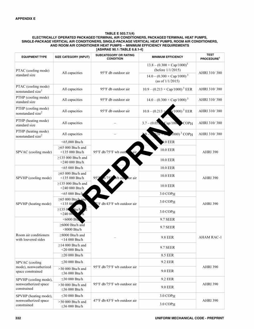
332 UNIFORM MECHANICAL CODE - PREPRINT
APPENDIX E
EQUIPMENT TYPE SIZE CATEGORY (INPUT)SUBCATEGORY OR RATING
CONDITIONMINIMUM EFFICIENCY
TEST PROCEDURE1
PTAC (cooling mode)standard size All capacities 95°F db outdoor air
13.8 – (0.300 × Cap/1000)3
(before 1/1/2015)AHRI 310/ 380
14.0 – (0.300 × Cap/1000) 3
(as of 1/1/2015)PTAC (cooling mode)nonstandard size1 All capacities 95°F db outdoor air 10.9 – (0.213 × Cap/1000) 3 EER AHRI 310/ 380
PTHP (cooling mode)standard size All capacities 95°F db outdoor air 14.0 – (0.300 × Cap/1000) 3 AHRI 310/ 380
PTHP (cooling mode)nonstandard size2 All capacities 95°F db outdoor air 10.8 – (0.213 × Cap/1000) 3 EER AHRI 310/ 380
PTHP (heating mode)standard size All capacities – 3.7 – (0.052 × Cap/1000) 3 COPH AHRI 310/ 380
PTHP (heating mode)nonstandard size2 All capacities – 2.9 – (0.026 × Cap/1000) 3 COPH AHRI 310/ 380
SPVAC (cooling mode)
<65,000 Btu/h
95°F db/75°F wb outdoor air
10.0 EER
AHRI 390≥65 000 Btu/h and
<135 000 Btu/h 10.0 EER
≥135 000 Btu/h and<240 000 Btu/h 10.0 EER
SPVHP (cooling mode)
<65 000 Btu/h
95°F db/75°F wb outdoor air
10.0 EER
AHRI 390≥65 000 Btu/h and
<135 000 Btu/h 10.0 EER
≥135 000 Btu/h and<240 000 Btu/h 10.0 EER
SPVHP (heating mode)
<65 000 Btu/h
47°F db/43°F wb outdoor air
3.0 COPH
AHRI 390≥65 000 Btu/h and
<135 000 Btu/h 3.0 COPH
≥135 000 Btu/h and<240 000 Btu/h 3.0 COPH
Room air conditionerswith louvered sides
<6000 Btu/h
–
9.7 SEER
AHAM RAC-1
≥6000 Btu/h and <8000 Btu/h 9.7 SEER
≥8000 Btu/h and <14 000 Btu/h 9.8 EER
≥14 000 Btu/h and<20 000 Btu/h 9.7 SEER
≥20 000 Btu/h 8.5 EER
SPVAC (coolingmode), nonweatherizedspace constrained
≤30 000 Btu/h95°F db/75°F wb outdoor air
9.2 EERAHRI 390>30 000 Btu/h and
≤36 000 Btu/h 9.0 EER
SPVHP (cooling mode),nonweatherized spaceconstrained
≤30 000 Btu/h95°F db/75°F wb outdoor air
9.2 EERAHRI 390>30 000 Btu/h and
≤36 000 Btu/h 9.0 EER
SPVHP (heating mode),nonweatherized spaceconstrained
≤30 000 Btu/h47°F db/43°F wb outdoor air
3.0 COPHAHRI 390>30 000 Btu/h and
≤36 000 Btu/h 3.0 COPH
TABLE E 503.7.1(4)ELECTRICALLY OPERATED PACKAGED TERMINAL AIR CONDITIONERS, PACKAGED TERMINAL HEAT PUMPS,
SINGLE-PACKAGE VERTICAL AIR CONDITIONERS, SINGLE-PACKAGE VERTICAL HEAT PUMPS, ROOM AIR CONDITIONERS, AND ROOM AIR CONDITIONER HEAT PUMPS ─ MINIMUM EFFICIENCY REQUIREMENTS
[ASHRAE 90.1: TABLE 6.8.1-4]
PREPRINT
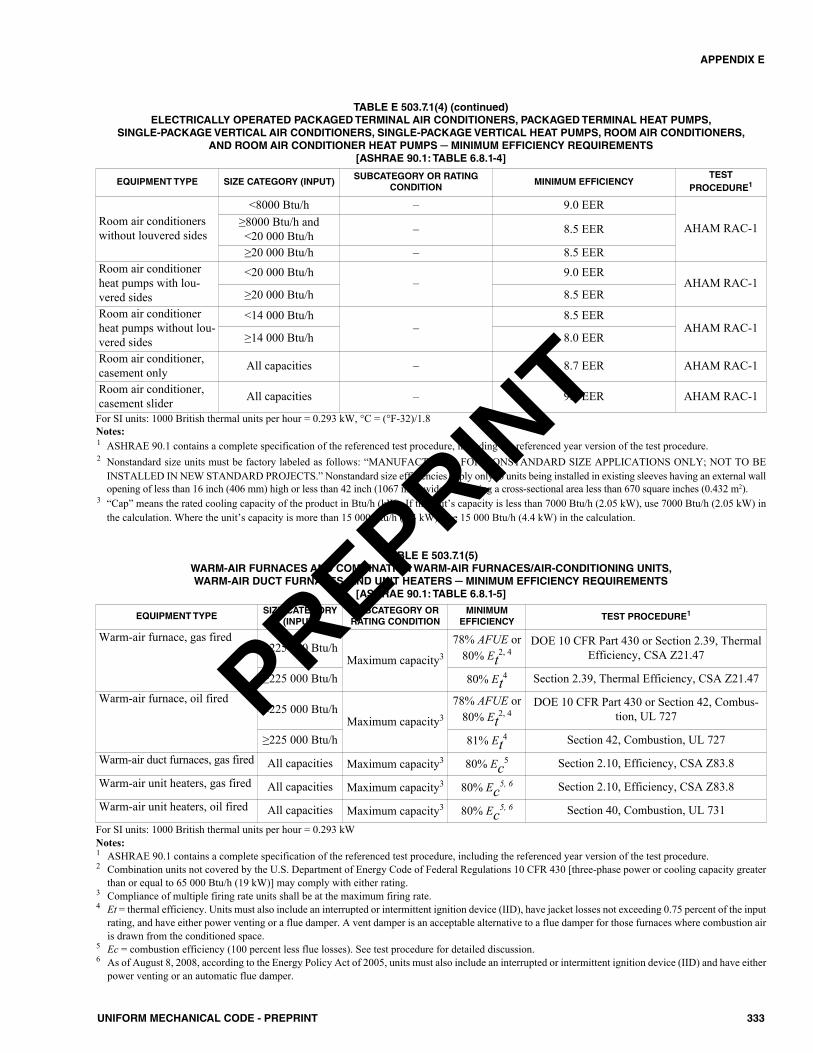
333UNIFORM MECHANICAL CODE - PREPRINT
APPENDIX E
EQUIPMENT TYPE SIZE CATEGORY (INPUT)SUBCATEGORY OR RATING
CONDITIONMINIMUM EFFICIENCY
TEST PROCEDURE1
Room air conditionerswithout louvered sides
<8000 Btu/h – 9.0 EER
AHAM RAC-1≥8000 Btu/h and <20 000 Btu/h – 8.5 EER
≥20 000 Btu/h – 8.5 EERRoom air conditionerheat pumps with lou-vered sides
<20 000 Btu/h –
9.0 EERAHAM RAC-1
≥20 000 Btu/h 8.5 EERRoom air conditionerheat pumps without lou-vered sides
<14 000 Btu/h–
8.5 EERAHAM RAC-1
≥14 000 Btu/h 8.0 EER
Room air conditioner,casement only All capacities – 8.7 EER AHAM RAC-1
Room air conditioner,casement slider All capacities – 9.5 EER AHAM RAC-1
TABLE E 503.7.1(4) (continued)ELECTRICALLY OPERATED PACKAGED TERMINAL AIR CONDITIONERS, PACKAGED TERMINAL HEAT PUMPS,
SINGLE-PACKAGE VERTICAL AIR CONDITIONERS, SINGLE-PACKAGE VERTICAL HEAT PUMPS, ROOM AIR CONDITIONERS, AND ROOM AIR CONDITIONER HEAT PUMPS ─ MINIMUM EFFICIENCY REQUIREMENTS
[ASHRAE 90.1: TABLE 6.8.1-4]
For SI units: 1000 British thermal units per hour = 0.293 kW, °C = (°F-32)/1.8Notes:1 ASHRAE 90.1 contains a complete specification of the referenced test procedure, including the referenced year version of the test procedure.2 Nonstandard size units must be factory labeled as follows: “MANUFACTURED FOR NONSTANDARD SIZE APPLICATIONS ONLY; NOT TO BE
INSTALLED IN NEW STANDARD PROJECTS.” Nonstandard size efficiencies apply only to units being installed in existing sleeves having an external wallopening of less than 16 inch (406 mm) high or less than 42 inch (1067 mm) wide and having a cross-sectional area less than 670 square inches (0.432 m2).
3 “Cap” means the rated cooling capacity of the product in Btu/h (kW). If the unit’s capacity is less than 7000 Btu/h (2.05 kW), use 7000 Btu/h (2.05 kW) inthe calculation. Where the unit’s capacity is more than 15 000 Btu/h (4.4 kW), use 15 000 Btu/h (4.4 kW) in the calculation.
EQUIPMENT TYPESIZE CATEGORY
(INPUT)SUBCATEGORY ORRATING CONDITION
MINIMUM EFFICIENCY TEST PROCEDURE1
Warm-air furnace, gas fired<225 000 Btu/h
Maximum capacity3
78% AFUE or80% Et2, 4
DOE 10 CFR Part 430 or Section 2.39, ThermalEfficiency, CSA Z21.47
≥225 000 Btu/h 80% Et4 Section 2.39, Thermal Efficiency, CSA Z21.47
Warm-air furnace, oil fired<225 000 Btu/h
Maximum capacity3
78% AFUE or80% Et2, 4
DOE 10 CFR Part 430 or Section 42, Combus-tion, UL 727
≥225 000 Btu/h 81% Et4 Section 42, Combustion, UL 727
Warm-air duct furnaces, gas fired All capacities Maximum capacity3 80% Ec5 Section 2.10, Efficiency, CSA Z83.8
Warm-air unit heaters, gas fired All capacities Maximum capacity3 80% Ec5, 6 Section 2.10, Efficiency, CSA Z83.8
Warm-air unit heaters, oil fired All capacities Maximum capacity3 80% Ec5, 6 Section 40, Combustion, UL 731
TABLE E 503.7.1(5)WARM-AIR FURNACES AND COMBINATION WARM-AIR FURNACES/AIR-CONDITIONING UNITS, WARM-AIR DUCT FURNACES, AND UNIT HEATERS ─ MINIMUM EFFICIENCY REQUIREMENTS
[ASHRAE 90.1: TABLE 6.8.1-5]
For SI units: 1000 British thermal units per hour = 0.293 kWNotes:1 ASHRAE 90.1 contains a complete specification of the referenced test procedure, including the referenced year version of the test procedure.2 Combination units not covered by the U.S. Department of Energy Code of Federal Regulations 10 CFR 430 [three-phase power or cooling capacity greater
than or equal to 65 000 Btu/h (19 kW)] may comply with either rating.3 Compliance of multiple firing rate units shall be at the maximum firing rate.4 Et = thermal efficiency. Units must also include an interrupted or intermittent ignition device (IID), have jacket losses not exceeding 0.75 percent of the input
rating, and have either power venting or a flue damper. A vent damper is an acceptable alternative to a flue damper for those furnaces where combustion airis drawn from the conditioned space.
5 Ec = combustion efficiency (100 percent less flue losses). See test procedure for detailed discussion.6 As of August 8, 2008, according to the Energy Policy Act of 2005, units must also include an interrupted or intermittent ignition device (IID) and have either
power venting or an automatic flue damper.
PREPRINT
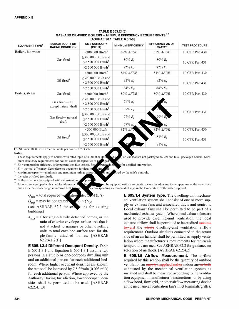
Qtot = total required ventilation rate, CFM (L/s)Qinf = may be not greater than 2/3 × Qtot(see ASHRAE 62.2 for exceptions for existingbuildings)Aext = 1 for single-family detached homes, or the
ratio of exterior envelope surface area that isnot attached to garages or other dwellingunits to total envelope surface area for sin-gle-family attached homes. [ASHRAE62.2:4.1.2(f)]
E 605.1.3.4 Different Occupant Density. TableE 605.1.3.1 and Equation E 605.1.3.1 assume twopersons in a studio or one-bedroom dwelling unitand an additional person for each additional bed-room. Where higher occupant densities are known,the rate shall be increased by 7.5 ft3/min (0.003 m3/s)for each additional person. Where approved by theAuthority Having Jurisdiction, lower occupant den-sities shall be permitted to be used. [ASHRAE62.2:4.1.3]
E 605.1.4 System Type. The dwelling-unit mechani-cal ventilation system shall consist of one or more sup-ply or exhaust fans and associated ducts and controls.Local exhaust fans shall be permitted to be part of amechanical exhaust system. Where local exhaust fans areused to provide dwelling-unit ventilation, the localexhaust airflow shall be permitted to be credited towardstoward the whole dwelling-unit ventilation airflowrequirement. Outdoor air ducts connected to the returnside of an air handler shall be permitted as supply venti-lation where manufacturer’s requirements for return airtemperature are met. See ASHRAE 62.2 for guidance onselection of methods. [ASHRAE 62.2:4.2]E 605.1.5 Airflow Measurement. The airflowrequired by this section shall be the quantity of outdoorventilation air supply, supplied and/or indoor air, or bothexhausted by the mechanical ventilation system asinstalled and shall be measured according to the ventila-tion equipment manufacturer’s instructions, or by usinga flow hood, flow grid, or other airflow measuring deviceat the mechanical ventilation fan’s inlet terminals/grilles,
334 UNIFORM MECHANICAL CODE - PREPRINT
APPENDIX E
EQUIPMENT TYPE1 SUBCATEGORY ORRATING CONDITION
SIZE CATEGORY(INPUT)
MINIMUM EFFICIENCYEFFICIENCY AS OF
3/2/2020TEST PROCEDURE
Boilers, hot water
Gas fired
<300 000 Btu/h6 82% AFUE 82% AFUE 10 CFR Part 430≥300 000 Btu/h and≤2 500 000 Btu/h4 80% Et 80% Et 10 CFR Part 431>2 500 000 Btu/h1 82% Ec 82% Ec
Oil fired5
<300 000 Btu/h7 84% AFUE 84% AFUE 10 CFR Part 430≥300 000 Btu/h and≤2 500 000 Btu/h4 82% Et 82% Et 10 CFR Part 431>2 500 000 Btu/h1 84% Ec 84% Ec
Boilers, steam Gas fired <300 000 Btu/h6 80% AFUE 80% AFUE 10 CFR Part 430
Gas fired— all,except natural draft
≥300 000 Btu/h and≤2 500 000 Btu/h4 79% Et 79% Et
10 CFR Part 431>2 500 000 Btu/h1 79% Et 79% Et
Gas fired— naturaldraft
≥300 000 Btu/h and≤2 500 000 Btu/h4 77% Et 79% Et
>2 500 000 Btu/h1 77% Et 79% Et
Oil fired5
<300 000 Btu/h 82% AFUE 82% AFUE 10 CFR Part 430≥300 000 Btu/h and≤2 500 000 Btu/h4 81% Et 81% Et 10 CFR Part 431>2 500 000 Btu/h1 81% Et 81% Et
TABLE E 503.7.1(6)GAS- AND OIL-FIRED BOILERS ─ MINIMUM EFFICIENCY REQUIREMENTS2, 3
[ASHRAE 90.1: TABLE 6.8.1-6]
For SI units: 1000 British thermal units per hour = 0.293 kWNotes:1 These requirements apply to boilers with rated input of 8 000 000 Btu/h (2343 kW) or less that are not packaged boilers and to all packaged boilers. Mini-
mum efficiency requirements for boilers cover all capacities of packaged boilers.2 Ec = combustion efficiency (100 percent less flue losses). See reference document for detailed information.3 Et = thermal efficiency. See reference document for detailed information.4 Maximum capacity—minimum and maximum ratings as provided for and allowed by the unit’s controls.5 Includes oil-fired (residual).6 Boilers shall not be equipped with a constant burning pilot light.7 A boiler not equipped with a tankless domestic water-heating coil shall be equipped with an automatic means for adjusting the temperature of the water such
that an incremental change in inferred heat load produces a corresponding incremental change in the temperature of the water supplied.
PREPRINT
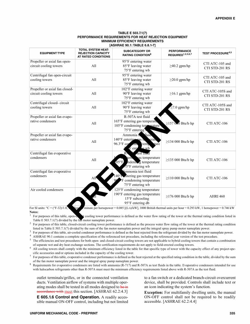
outlet terminals/grilles, or in the connected ventilationducts. Ventilation airflow of systems with multiple oper-ating modes shall be tested in all modes designed to be inaccordance with meet this section. [ASHRAE 62.2:4.3]E 605.1.6 Control and Operation. A readily acces-sible manual ON-OFF control, including but not limited
to a fan switch or a dedicated branch-circuit overcurrentdevice, shall be provided. Controls shall include text oran icon indicating the system’s function.Exception: For multifamily dwelling units, the manualON-OFF control shall not be required to be readilyaccessible. [ASHRAE 62.2:4.4]
335UNIFORM MECHANICAL CODE - PREPRINT
APPENDIX E
EQUIPMENT TYPETOTAL SYSTEM HEAT-REJECTION CAPACITYAT RATED CONDITIONS
SUBCATEGORY OR RATING CONDITION8
PERFORMANCEREQUIRED1,2,3,6,7 TEST PROCEDURE4,5
Propeller or axial fan open-circuit cooling towers All
95°F entering water85°F leaving water75°F entering wb
≥40.2 gpm/hp CTI ATC-105 and CTI STD-201 RS
Centrifugal fan open-circuitcooling towers All
95°F entering water85°F leaving water75°F entering wb
≥20.0 gpm/hp CTI ATC-105 and CTI STD-201 RS
Propeller or axial fan closed-circuit cooling towers All
102°F entering water90°F leaving water75°F entering wb
≥16.1 gpm/hp CTI ATC-105S andCTI STD-201 RS
Centrifugal closed- circuitcooling towers All
102°F entering water90°F leaving water75°F entering wb
≥7.0 gpm/hp CTI ATC-105S andCTI STD-201 RS
Propeller or axial fan evapo-rative condensers All
R-507A test fluid165°F entering gas temperature105°F condensing temperature
75°F entering wb
≥157 000 Btu/h·hp CTI ATC-106
Propeller or axial fan evapo-rative condensers All
Ammonia test fluid140°F entering gas temperature96.3°F condensing temperature
75°F entering wb
≥134 000 Btu/h·hp CTI ATC-106
Centrifugal fan evaporativecondensers All
R-507A test fluid165°F entering gas temperature105°F condensing temperature
75°F entering wb
≥135 000 Btu/h·hp CTI ATC-106
Centrifugal fan evaporativecondensers All
Ammonia test fluid140°F entering gas temperature96.3°F condensing temperature
75°F entering wb
≥110 000 Btu/h·hp CTI ATC-106
Air cooled condensers
All
125°F condensing temperature190°F entering gas temperature
15°F subcooling95°F entering db
≥176 000 Btu/h·hp AHRI 460
TABLE E 503.7.1(7)PERFORMANCE REQUIREMENTS FOR HEAT REJECTION EQUIPMENT
MINIMUM EFFICIENCY REQUIREMENTS[ASHRAE 90.1: TABLE 6.8.1-7]
For SI units: °C = (°F-32)/1.8, 1 gallon per minute per horsepower = 0.085 [(L/s)/kW], 1000 British thermal units per hour = 0.293 kW, 1 horsepower = 0.746 kWNotes:1 For purposes of this table, open-circuit cooling tower performance is defined as the water flow rating of the tower at the thermal rating condition listed in
Table E 503.7.1(7) divided by the fan motor nameplate power.2 For purposes of this table, closed-circuit cooling tower performance is defined as the process water flow rating of the tower at the thermal rating condition
listed in Table E 503.7.1(7) divided by the sum of the fan motor nameplate power and the integral spray pump motor nameplate power.3 For purposes of this table, air-cooled condenser performance is defined as the heat rejected from the refrigerant divided by the fan motor nameplate power.4 ASHRAE 90.1 contains a complete specification of the referenced test procedure, including the referenced year version of the test procedure.5 The efficiencies and test procedures for both open- and closed-circuit cooling towers are not applicable to hybrid cooling towers that contain a combination
of separate wet and dry heat exchange sections. The certification requirements do not apply to field-erected cooling towers.6 All cooling towers shall comply with the minimum efficiency listed in the table for that specific type of tower with the capacity effect of any project-spe-
cific accessories and/or options included in the capacity of the cooling tower.7 For purposes of this table, evaporative condenser performance is defined as the heat rejected at the specified rating condition in the table, divided by the sum
of the fan motor nameplate power and the integral spray pump nameplate power.8 Requirements for evaporative condensers are listed with ammonia (R-717) and R-507A as test fluids in the table. Evaporative condensers intended for use
with halocarbon refrigerants other than R-507A must meet the minimum efficiency requirements listed above with R-507A as the test fluid.
PREPRINT
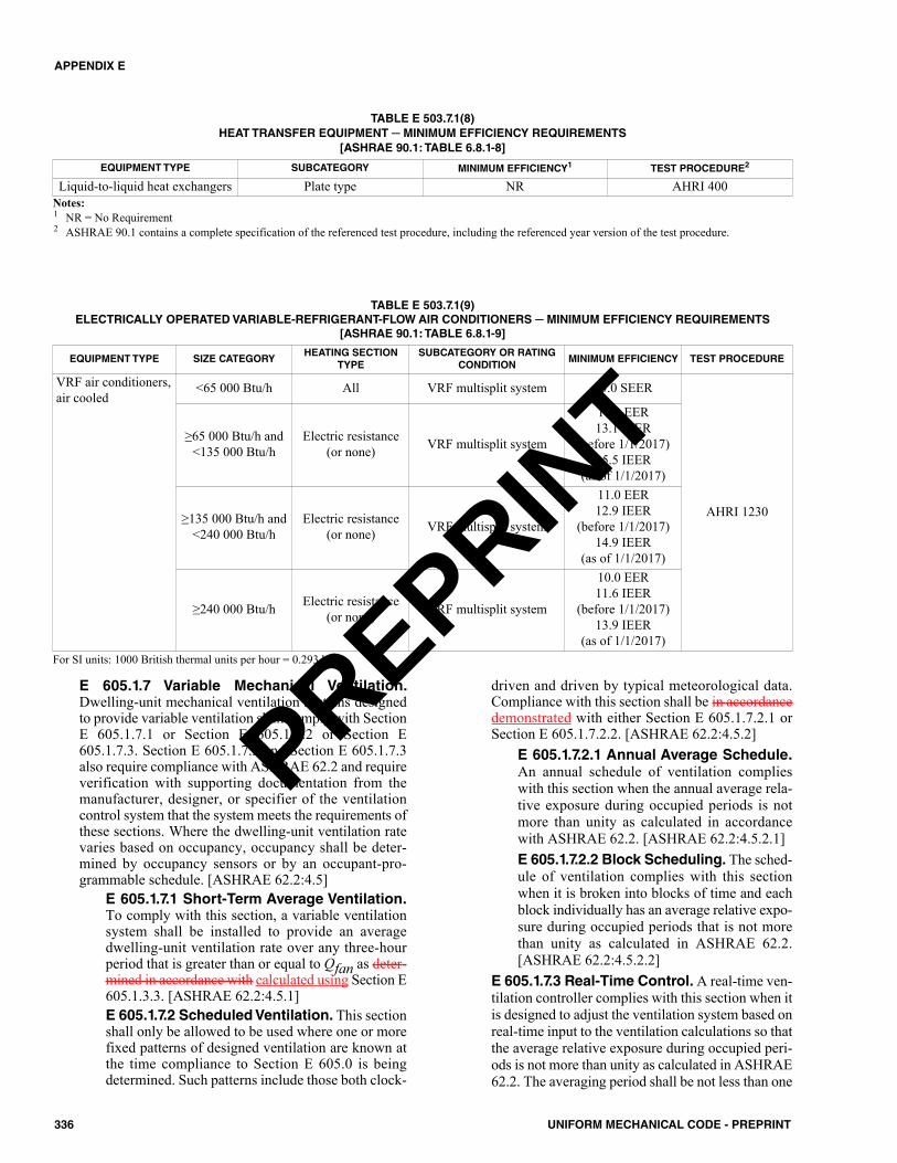
E 605.1.7 Variable Mechanical Ventilation.Dwelling-unit mechanical ventilation systems designedto provide variable ventilation shall comply with SectionE 605.1.7.1 or Section E 605.1.7.2 or Section E605.1.7.3. Section E 605.1.7.2 and Section E 605.1.7.3also require compliance with ASHRAE 62.2 and requireverification with supporting documentation from themanufacturer, designer, or specifier of the ventilationcontrol system that the system meets the requirements ofthese sections. Where the dwelling-unit ventilation ratevaries based on occupancy, occupancy shall be deter-mined by occupancy sensors or by an occupant-pro-grammable schedule. [ASHRAE 62.2:4.5]
E 605.1.7.1 Short-Term Average Ventilation.To comply with this section, a variable ventilationsystem shall be installed to provide an averagedwelling-unit ventilation rate over any three-hourperiod that is greater than or equal to Qfan as deter-mined in accordance with calculated using Section E605.1.3.3. [ASHRAE 62.2:4.5.1]E 605.1.7.2 Scheduled Ventilation. This sectionshall only be allowed to be used where one or morefixed patterns of designed ventilation are known atthe time compliance to Section E 605.0 is beingdetermined. Such patterns include those both clock-
driven and driven by typical meteorological data.Compliance with this section shall be in accordancedemonstrated with either Section E 605.1.7.2.1 orSection E 605.1.7.2.2. [ASHRAE 62.2:4.5.2]
E 605.1.7.2.1 Annual Average Schedule.An annual schedule of ventilation complieswith this section when the annual average rela-tive exposure during occupied periods is notmore than unity as calculated in accordancewith ASHRAE 62.2. [ASHRAE 62.2:4.5.2.1]E 605.1.7.2.2 Block Scheduling. The sched-ule of ventilation complies with this sectionwhen it is broken into blocks of time and eachblock individually has an average relative expo-sure during occupied periods that is not morethan unity as calculated in ASHRAE 62.2.[ASHRAE 62.2:4.5.2.2]
E 605.1.7.3 Real-Time Control. A real-time ven-tilation controller complies with this section when itis designed to adjust the ventilation system based onreal-time input to the ventilation calculations so thatthe average relative exposure during occupied peri-ods is not more than unity as calculated in ASHRAE62.2. The averaging period shall be not less than one
336 UNIFORM MECHANICAL CODE - PREPRINT
APPENDIX E
TABLE E 503.7.1(8)HEAT TRANSFER EQUIPMENT ─ MINIMUM EFFICIENCY REQUIREMENTS
[ASHRAE 90.1: TABLE 6.8.1-8]
EQUIPMENT TYPE SUBCATEGORY MINIMUM EFFICIENCY1 TEST PROCEDURE2
Liquid-to-liquid heat exchangers Plate type NR AHRI 400Notes:1 NR = No Requirement2 ASHRAE 90.1 contains a complete specification of the referenced test procedure, including the referenced year version of the test procedure.
TABLE E 503.7.1(9)ELECTRICALLY OPERATED VARIABLE-REFRIGERANT-FLOW AIR CONDITIONERS ─ MINIMUM EFFICIENCY REQUIREMENTS
[ASHRAE 90.1: TABLE 6.8.1-9]
EQUIPMENT TYPE SIZE CATEGORYHEATING SECTION
TYPESUBCATEGORY OR RATING
CONDITIONMINIMUM EFFICIENCY TEST PROCEDURE
VRF air conditioners,air cooled
<65 000 Btu/h All VRF multisplit system 13.0 SEER
AHRI 1230
≥65 000 Btu/h and<135 000 Btu/h
Electric resistance(or none) VRF multisplit system
11.2 EER13.1 IEER
(before 1/1/2017)15.5 IEER
(as of 1/1/2017)
≥135 000 Btu/h and<240 000 Btu/h
Electric resistance(or none) VRF multisplit system
11.0 EER12.9 IEER
(before 1/1/2017)14.9 IEER
(as of 1/1/2017)
≥240 000 Btu/h Electric resistance(or none) VRF multisplit system
10.0 EER11.6 IEER
(before 1/1/2017)13.9 IEER
(as of 1/1/2017)For SI units: 1000 British thermal units per hour = 0.293 kW
PREPRINT
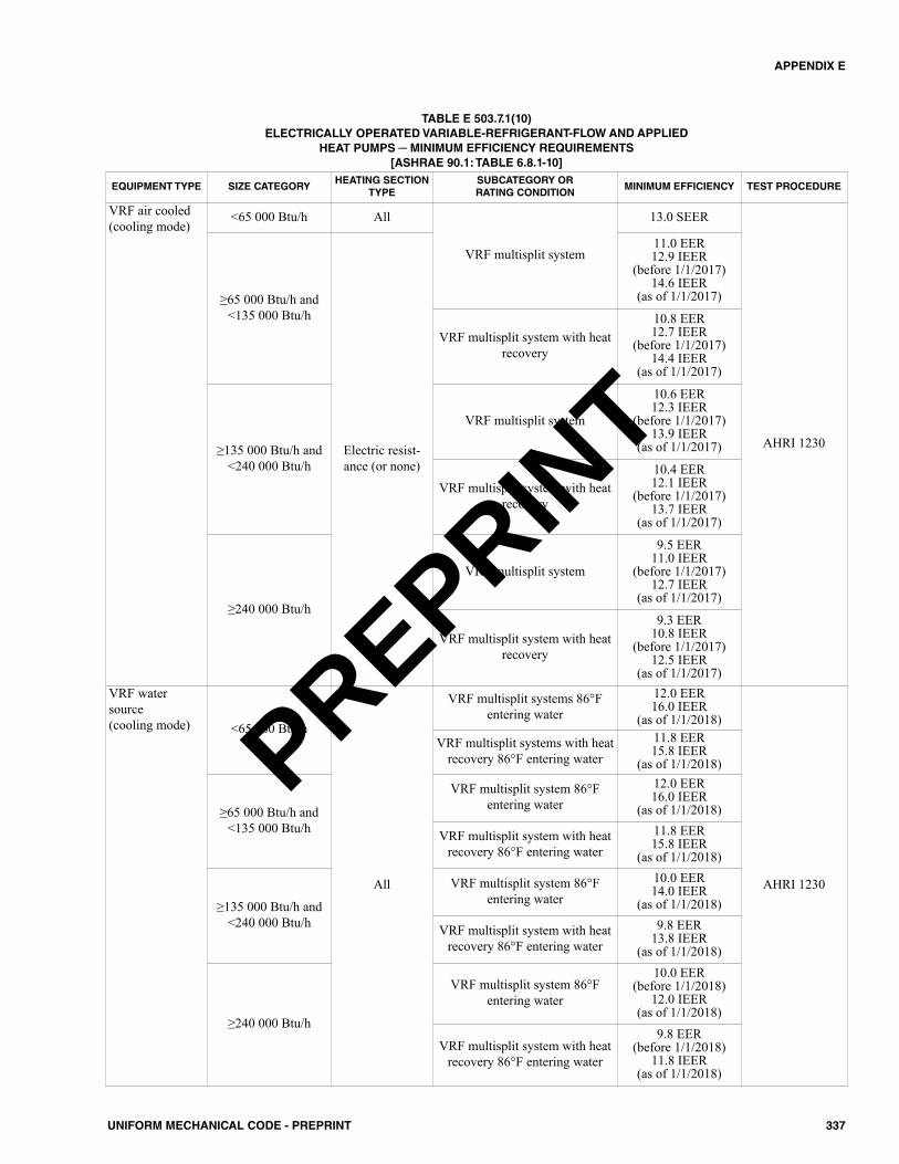
337UNIFORM MECHANICAL CODE - PREPRINT
APPENDIX E
EQUIPMENT TYPE SIZE CATEGORYHEATING SECTION
TYPESUBCATEGORY OR RATING CONDITION
MINIMUM EFFICIENCY TEST PROCEDURE
VRF air cooled(cooling mode)
<65 000 Btu/h All
VRF multisplit system
13.0 SEER
AHRI 1230
≥65 000 Btu/h and<135 000 Btu/h
Electric resist-ance (or none)
11.0 EER12.9 IEER
(before 1/1/2017)14.6 IEER
(as of 1/1/2017)
VRF multisplit system with heatrecovery
10.8 EER12.7 IEER
(before 1/1/2017)14.4 IEER
(as of 1/1/2017)
≥135 000 Btu/h and<240 000 Btu/h
VRF multisplit system
10.6 EER12.3 IEER
(before 1/1/2017)13.9 IEER
(as of 1/1/2017)
VRF multisplit system with heatrecovery
10.4 EER12.1 IEER
(before 1/1/2017)13.7 IEER
(as of 1/1/2017)
≥240 000 Btu/h
VRF multisplit system
9.5 EER11.0 IEER
(before 1/1/2017)12.7 IEER
(as of 1/1/2017)
VRF multisplit system with heatrecovery
9.3 EER10.8 IEER
(before 1/1/2017)12.5 IEER
(as of 1/1/2017)VRF watersource (cooling mode) <65 000 Btu/h
All
VRF multisplit systems 86°Fentering water
12.0 EER16.0 IEER
(as of 1/1/2018)
AHRI 1230
VRF multisplit systems with heatrecovery 86°F entering water
11.8 EER15.8 IEER
(as of 1/1/2018)
≥65 000 Btu/h and<135 000 Btu/h
VRF multisplit system 86°Fentering water
12.0 EER16.0 IEER
(as of 1/1/2018)
VRF multisplit system with heatrecovery 86°F entering water
11.8 EER15.8 IEER
(as of 1/1/2018)
≥135 000 Btu/h and<240 000 Btu/h
VRF multisplit system 86°Fentering water
10.0 EER14.0 IEER
(as of 1/1/2018)
VRF multisplit system with heatrecovery 86°F entering water
9.8 EER13.8 IEER
(as of 1/1/2018)
≥240 000 Btu/h
VRF multisplit system 86°Fentering water
10.0 EER(before 1/1/2018)
12.0 IEER(as of 1/1/2018)
VRF multisplit system with heatrecovery 86°F entering water
9.8 EER(before 1/1/2018)
11.8 IEER(as of 1/1/2018)
TABLE E 503.7.1(10)ELECTRICALLY OPERATED VARIABLE-REFRIGERANT-FLOW AND APPLIED
HEAT PUMPS ─ MINIMUM EFFICIENCY REQUIREMENTS[ASHRAE 90.1: TABLE 6.8.1-10]
PREPRINT
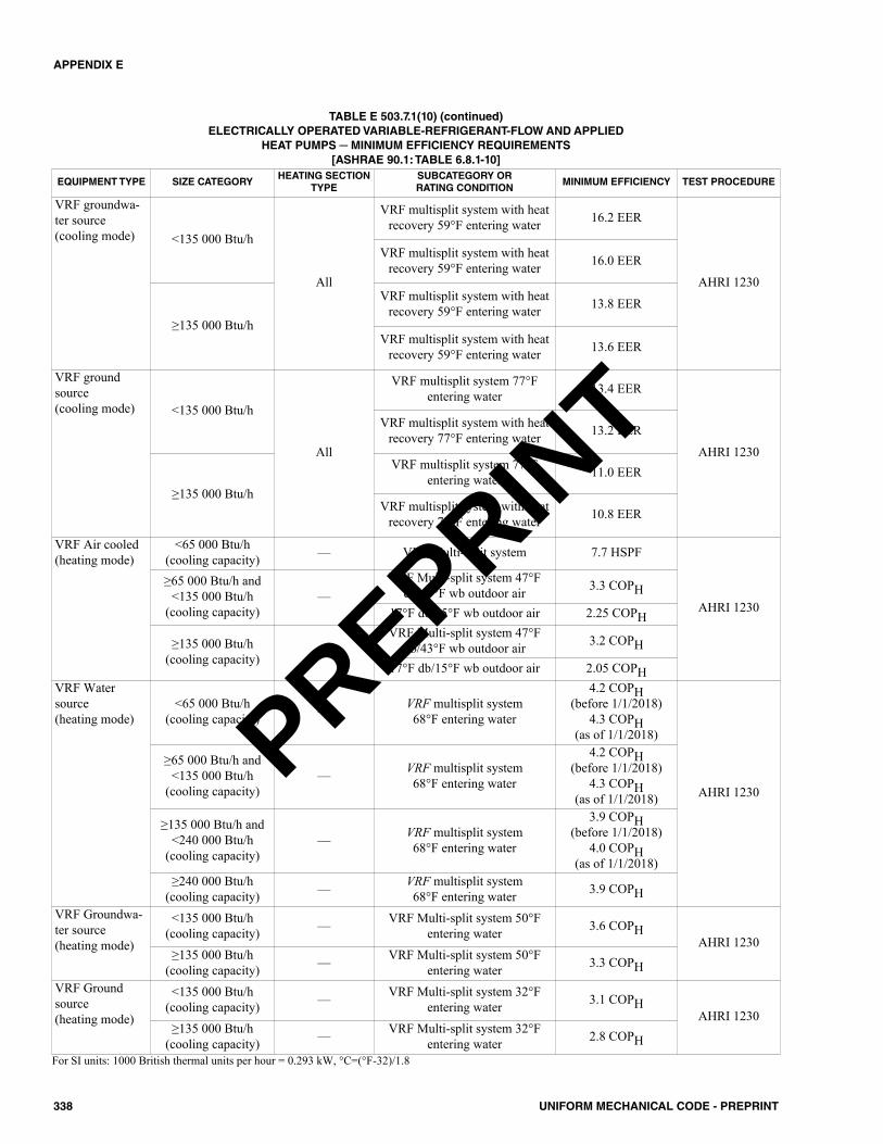
338 UNIFORM MECHANICAL CODE - PREPRINT
APPENDIX E
EQUIPMENT TYPE SIZE CATEGORYHEATING SECTION
TYPESUBCATEGORY OR RATING CONDITION
MINIMUM EFFICIENCY TEST PROCEDURE
VRF groundwa-ter source (cooling mode) <135 000 Btu/h
All
VRF multisplit system with heatrecovery 59°F entering water 16.2 EER
AHRI 1230
VRF multisplit system with heatrecovery 59°F entering water 16.0 EER
≥135 000 Btu/h
VRF multisplit system with heatrecovery 59°F entering water 13.8 EER
VRF multisplit system with heatrecovery 59°F entering water 13.6 EER
VRF groundsource (cooling mode) <135 000 Btu/h
All
VRF multisplit system 77°Fentering water 13.4 EER
AHRI 1230
VRF multisplit system with heatrecovery 77°F entering water 13.2 EER
≥135 000 Btu/h
VRF multisplit system 77°Fentering water 11.0 EER
VRF multisplit system with heatrecovery 77°F entering water 10.8 EER
VRF Air cooled(heating mode)
<65 000 Btu/h(cooling capacity) — VRF Multi-split system 7.7 HSPF
AHRI 1230
≥65 000 Btu/h and<135 000 Btu/h
(cooling capacity)—
VRF Multi-split system 47°Fdb/43°F wb outdoor air 3.3 COPH
17°F db/15°F wb outdoor air 2.25 COPH
≥135 000 Btu/h (cooling capacity) —
VRF Multi-split system 47°Fdb/43°F wb outdoor air 3.2 COPH
17°F db/15°F wb outdoor air 2.05 COPHVRF Watersource (heating mode)
<65 000 Btu/h(cooling capacity) — VRF multisplit system
68°F entering water
4.2 COPH(before 1/1/2018)
4.3 COPH(as of 1/1/2018)
AHRI 1230
≥65 000 Btu/h and<135 000 Btu/h
(cooling capacity)— VRF multisplit system
68°F entering water
4.2 COPH(before 1/1/2018)
4.3 COPH(as of 1/1/2018)
≥135 000 Btu/h and<240 000 Btu/h
(cooling capacity)— VRF multisplit system
68°F entering water
3.9 COPH(before 1/1/2018)
4.0 COPH(as of 1/1/2018)
≥240 000 Btu/h(cooling capacity) — VRF multisplit system
68°F entering water 3.9 COPHVRF Groundwa-ter source (heating mode)
<135 000 Btu/h (cooling capacity) — VRF Multi-split system 50°F
entering water 3.6 COPHAHRI 1230
≥135 000 Btu/h (cooling capacity) — VRF Multi-split system 50°F
entering water 3.3 COPHVRF Groundsource (heating mode)
<135 000 Btu/h (cooling capacity) — VRF Multi-split system 32°F
entering water 3.1 COPHAHRI 1230
≥135 000 Btu/h (cooling capacity) — VRF Multi-split system 32°F
entering water 2.8 COPH
TABLE E 503.7.1(10) (continued)ELECTRICALLY OPERATED VARIABLE-REFRIGERANT-FLOW AND APPLIED
HEAT PUMPS ─ MINIMUM EFFICIENCY REQUIREMENTS[ASHRAE 90.1: TABLE 6.8.1-10]
For SI units: 1000 British thermal units per hour = 0.293 kW, °C=(°F-32)/1.8
PREPRINT
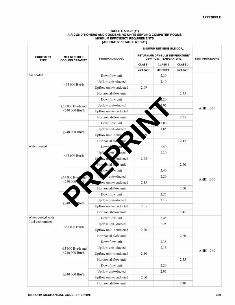
339UNIFORM MECHANICAL CODE - PREPRINT
APPENDIX E
EQUIPMENT TYPE
NET SENSIBLECOOLING CAPACITY
STANDARD MODEL
MINIMUM NET SENSIBLE COPc
TEST PROCEDURERETURN AIR DRY-BULB TEMPERATURE/
DEW-POINT TEMPERATURE
CLASS 1 CLASS 2 CLASS 3
75°F/52°F 85°F/52°F 95°F/52°F
Air cooled
<65 000 Btu/h
Downflow unit 2.30
AHRI 1360
Upflow unit─ducted 2.10
Upflow unit─nonducted 2.09
Horizontal-flow unit 2.45
≥65 000 Btu/h and<240 000 Btu/h
Downflow unit 2.20
Upflow unit─ducted 2.05
Upflow unit─nonducted 1.99
Horizontal-flow unit 2.35
≥240 000 Btu/h
Downflow unit 2.00
Upflow unit─ducted 1.85
Upflow unit─nonducted 1.79
Horizontal-flow unit 2.15Water cooled
<65 000 Btu/h
Downflow unit 2.50
AHRI 1360
Upflow unit─ducted 2.30
Upflow unit─nonducted 2.25
Horizontal-flow unit 2.70
≥65 000 Btu/h and<240 000 Btu/h
Downflow unit 2.40
Upflow unit─ducted 2.20
Upflow unit─nonducted 2.15
Horizontal-flow unit 2.60
≥240 000 Btu/h
Downflow unit 2.25
Upflow unit─ducted 2.10
Upflow unit─nonducted 2.05
Horizontal-flow unit 2.45Water cooled withfluid economizer
<65 000 Btu/h
Downflow unit 2.45
AHRI 1360
Upflow unit─ducted 2.25
Upflow unit─nonducted 2.20
Horizontal-flow unit 2.60
≥65 000 Btu/h and<240 000 Btu/h
Downflow unit 2.35
Upflow unit─ducted 2.15
Upflow unit─nonducted 2.10
Horizontal-flow unit 2.55
≥240 000 Btu/h
Downflow unit 2.20
Upflow unit─ducted 2.05
Upflow unit─nonducted 2.00
Horizontal-flow unit 2.40
TABLE E 503.7.1(11)AIR CONDITIONERS AND CONDENSING UNITS SERVING COMPUTER ROOMS
MINIMUM EFFICIENCY REQUIREMENTS[ASHRAE 90.1: TABLE 6.8.1-11]
PREPRINT
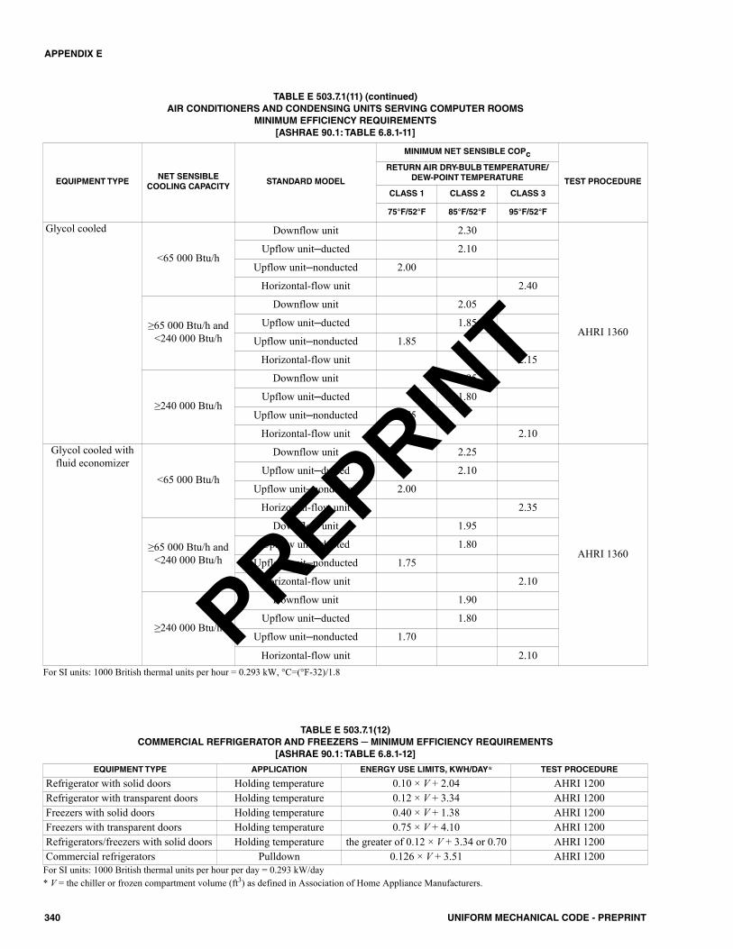
340 UNIFORM MECHANICAL CODE - PREPRINT
APPENDIX E
EQUIPMENT TYPENET SENSIBLE
COOLING CAPACITYSTANDARD MODEL
MINIMUM NET SENSIBLE COPc
TEST PROCEDURE
RETURN AIR DRY-BULB TEMPERATURE/DEW-POINT TEMPERATURE
CLASS 1 CLASS 2 CLASS 3
75°F/52°F 85°F/52°F 95°F/52°F
Glycol cooled
<65 000 Btu/h
Downflow unit 2.30
AHRI 1360
Upflow unit─ducted 2.10
Upflow unit─nonducted 2.00
Horizontal-flow unit 2.40
≥65 000 Btu/h and<240 000 Btu/h
Downflow unit 2.05
Upflow unit─ducted 1.85
Upflow unit─nonducted 1.85
Horizontal-flow unit 2.15
≥240 000 Btu/h
Downflow unit 1.95
Upflow unit─ducted 1.80
Upflow unit─nonducted 1.75
Horizontal-flow unit 2.10Glycol cooled withfluid economizer
<65 000 Btu/h
Downflow unit 2.25
AHRI 1360
Upflow unit─ducted 2.10
Upflow unit─nonducted 2.00
Horizontal-flow unit 2.35
≥65 000 Btu/h and<240 000 Btu/h
Downflow unit 1.95
Upflow unit─ducted 1.80
Upflow unit─nonducted 1.75
Horizontal-flow unit 2.10
≥240 000 Btu/h
Downflow unit 1.90
Upflow unit─ducted 1.80
Upflow unit─nonducted 1.70
Horizontal-flow unit 2.10
TABLE E 503.7.1(11) (continued)AIR CONDITIONERS AND CONDENSING UNITS SERVING COMPUTER ROOMS
MINIMUM EFFICIENCY REQUIREMENTS[ASHRAE 90.1: TABLE 6.8.1-11]
For SI units: 1000 British thermal units per hour = 0.293 kW, °C=(°F-32)/1.8
TABLE E 503.7.1(12)COMMERCIAL REFRIGERATOR AND FREEZERS ─ MINIMUM EFFICIENCY REQUIREMENTS
[ASHRAE 90.1: TABLE 6.8.1-12]
For SI units: 1000 British thermal units per hour per day = 0.293 kW/day* V = the chiller or frozen compartment volume (ft3) as defined in Association of Home Appliance Manufacturers.
EQUIPMENT TYPE APPLICATION ENERGY USE LIMITS, KWH/DAY* TEST PROCEDURE
Refrigerator with solid doors Holding temperature 0.10 × V + 2.04 AHRI 1200Refrigerator with transparent doors Holding temperature 0.12 × V + 3.34 AHRI 1200Freezers with solid doors Holding temperature 0.40 × V + 1.38 AHRI 1200Freezers with transparent doors Holding temperature 0.75 × V + 4.10 AHRI 1200Refrigerators/freezers with solid doors Holding temperature the greater of 0.12 × V + 3.34 or 0.70 AHRI 1200Commercial refrigerators Pulldown 0.126 × V + 3.51 AHRI 1200
PREPRINT
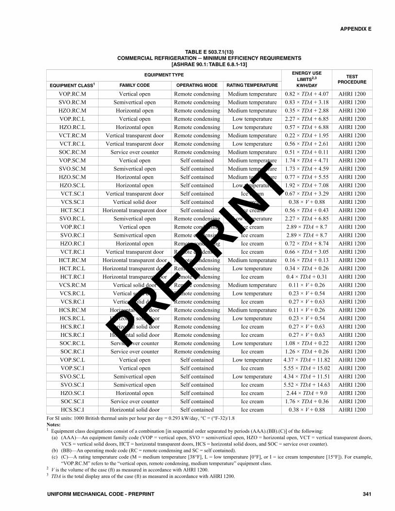
341UNIFORM MECHANICAL CODE - PREPRINT
APPENDIX E
TABLE E 503.7.1(13)COMMERCIAL REFRIGERATION ─ MINIMUM EFFICIENCY REQUIREMENTS
[ASHRAE 90.1: TABLE 6.8.1-13]
EQUIPMENT TYPE ENERGY USE LIMITS2,3
KWH/DAY
TEST PROCEDURE
EQUIPMENT CLASS1 FAMILY CODE OPERATING MODE RATING TEMPERATURE
VOP.RC.M Vertical open Remote condensing Medium temperature 0.82 × TDA + 4.07 AHRI 1200SVO.RC.M Semivertical open Remote condensing Medium temperature 0.83 × TDA + 3.18 AHRI 1200HZO.RC.M Horizontal open Remote condensing Medium temperature 0.35 × TDA + 2.88 AHRI 1200VOP.RC.L Vertical open Remote condensing Low temperature 2.27 × TDA + 6.85 AHRI 1200HZO.RC.L Horizontal open Remote condensing Low temperature 0.57 × TDA + 6.88 AHRI 1200VCT.RC.M Vertical transparent door Remote condensing Medium temperature 0.22 × TDA + 1.95 AHRI 1200VCT.RC.L Vertical transparent door Remote condensing Low temperature 0.56 × TDA + 2.61 AHRI 1200SOC.RC.M Service over counter Remote condensing Medium temperature 0.51 × TDA + 0.11 AHRI 1200VOP.SC.M Vertical open Self contained Medium temperature 1.74 × TDA + 4.71 AHRI 1200SVO.SC.M Semivertical open Self contained Medium temperature 1.73 × TDA + 4.59 AHRI 1200HZO.SC.M Horizontal open Self contained Medium temperature 0.77 × TDA + 5.55 AHRI 1200HZO.SC.L Horizontal open Self contained Low temperature 1.92 × TDA + 7.08 AHRI 1200VCT.SC.I Vertical transparent door Self contained Ice cream 0.67 × TDA + 3.29 AHRI 1200VCS.SC.I Vertical solid door Self contained Ice cream 0.38 × V + 0.88 AHRI 1200HCT.SC.I Horizontal transparent door Self contained Ice cream 0.56 × TDA + 0.43 AHRI 1200SVO.RC.L Semivertical open Remote condensing Low temperature 2.27 × TDA + 6.85 AHRI 1200VOP.RC.I Vertical open Remote condensing Ice cream 2.89 × TDA + 8.7 AHRI 1200SVO.RC.I Semivertical open Remote condensing Ice cream 2.89 × TDA + 8.7 AHRI 1200HZO.RC.I Horizontal open Remote condensing Ice cream 0.72 × TDA + 8.74 AHRI 1200VCT.RC.I Vertical transparent door Remote condensing Ice cream 0.66 × TDA + 3.05 AHRI 1200
HCT.RC.M Horizontal transparent door Remote condensing Medium temperature 0.16 × TDA + 0.13 AHRI 1200HCT.RC.L Horizontal transparent door Remote condensing Low temperature 0.34 × TDA + 0.26 AHRI 1200HCT.RC.I Horizontal transparent door Remote condensing Ice cream 0.4 × TDA + 0.31 AHRI 1200
VCS.RC.M Vertical solid door Remote condensing Medium temperature 0.11 × V + 0.26 AHRI 1200VCS.RC.L Vertical solid door Remote condensing Low temperature 0.23 × V + 0.54 AHRI 1200VCS.RC.I Vertical solid door Remote condensing Ice cream 0.27 × V + 0.63 AHRI 1200
HCS.RC.M Horizontal solid door Remote condensing Medium temperature 0.11 × V + 0.26 AHRI 1200HCS.RC.L Horizontal solid door Remote condensing Low temperature 0.23 × V + 0.54 AHRI 1200HCS.RC.I Horizontal solid door Remote condensing Ice cream 0.27 × V + 0.63 AHRI 1200HCS.RC.I Horizontal solid door Remote condensing Ice cream 0.27 × V + 0.63 AHRI 1200SOC.RC.L Service over counter Remote condensing Low temperature 1.08 × TDA + 0.22 AHRI 1200SOC.RC.I Service over counter Remote condensing Ice cream 1.26 × TDA + 0.26 AHRI 1200VOP.SC.L Vertical open Self contained Low temperature 4.37 × TDA + 11.82 AHRI 1200VOP.SC.I Vertical open Self contained Ice cream 5.55 × TDA + 15.02 AHRI 1200SVO.SC.L Semivertical open Self contained Low temperature 4.34 × TDA + 11.51 AHRI 1200SVO.SC.I Semivertical open Self contained Ice cream 5.52 × TDA + 14.63 AHRI 1200HZO.SC.I Horizontal open Self contained Ice cream 2.44 × TDA + 9.0 AHRI 1200SOC.SC.I Service over counter Self contained Ice cream 1.76 × TDA + 0.36 AHRI 1200HCS.SC.I Horizontal solid door Self contained Ice cream 0.38 × V + 0.88 AHRI 1200
For SI units: 1000 British thermal units per hour per day = 0.293 kW/day, °C = (°F-32)/1.8Notes:1 Equipment class designations consist of a combination [in sequential order separated by periods (AAA).(BB).(C)] of the following:
(a) (AAA)—An equipment family code (VOP = vertical open, SVO = semivertical open, HZO = horizontal open, VCT = vertical transparent doors,VCS = vertical solid doors, HCT = horizontal transparent doors, HCS = horizontal solid doors, and SOC = service over counter).
(b) (BB)—An operating mode code (RC = remote condensing and SC = self contained).(c) (C)—A rating temperature code (M = medium temperature [38°F], L = low temperature [0°F], or I = ice cream temperature [15°F]). For example,
“VOP.RC.M” refers to the “vertical open, remote condensing, medium temperature” equipment class.2 V is the volume of the case (ft) as measured in accordance with AHRI 1200.3 TDA is the total display area of the case (ft) as measured in accordance with AHRI 1200.
PREPRINT
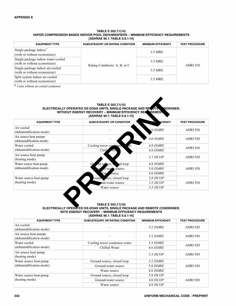
342 UNIFORM MECHANICAL CODE - PREPRINT
APPENDIX E
EQUIPMENT TYPE SUBCATEGORY OR RATING CONDITION MINIMUM EFFICIENCY TEST PROCEDURE
Single package indoor*
(with or without economizer)
Rating Conditions: A, B, or C
3.5 MRE
AHRI 910
Single package indoor water-cooled (with or without economizer) 3.5 MRE
Single package indoor air-cooled (with or without economizer) 3.5 MRE
Split system indoor air-cooled (with or without economizer) 3.5 MRE
TABLE E 503.7.1(14)VAPOR COMPRESSION BASED INDOOR POOL DEHUMIDIFIERS – MINIMUM EFFICIENCY REQUIREMENTS
[ASHRAE 90.1: TABLE 6.8.1-14]
* Units without air-cooled condenser
EQUIPMENT TYPE SUBCATEGORY OR CONDITION MINIMUM EFFICIENCY TEST PROCEDURE
Air cooled (dehumidification mode) – 4.0 ISMRE AHRI 920
Air source heat pumps (dehumidification mode) – 4.0 ISMRE AHRI 920
Water cooled (dehumidification mode)
Cooling tower condenser water 4.9 ISMREAHRI 920
Chilled Water 6.0 ISMREAir source heat pump (heating mode) – 2.7 ISCOP AHRI 920
Water source heat pump (dehumidification mode)
Ground source, closed loop 4.8 ISMREAHRI 920Ground-water source 5.0 ISMRE
Water source 4.0 ISMREWater source heat pump (heating mode)
Ground source, closed loop 2.0 ISCOPAHRI 920Ground-water source 3.2 ISCOP
Water source 3.5 ISCOP
TABLE E 503.7.1(15)ELECTRICALLY OPERATED DX-DOAS UNITS, SINGLE-PACKAGE AND REMOTE CONDENSER,
WITHOUT ENERGY RECOVERY – MINIMUM EFFICIENCY REQUIREMENTS[ASHRAE 90.1: TABLE 6.8.1-15]
EQUIPMENT TYPE SUBCATEGORY OR RATING CONDITION MINIMUM EFFICIENCY TEST PROCEDURE
Air cooled (dehumidification mode) – 5.2 ISMRE AHRI 920
Air source heat pumps (dehumidification mode) – 5.2 ISMRE AHRI 920
Water cooled (dehumidification mode)
Cooling tower condenser water 5.3 ISMREAHRI 920
Chilled Water 6.6 ISMREAir source heat pump (heating mode) – 3.3 ISCOP AHRI 920
Water source heat pump (dehumidification mode)
Ground source, closed loop 5.2 ISMREAHRI 920Ground-water source 5.8 ISMRE
Water source 4.8 ISMREWater source heat pump (heating mode)
Ground source, closed loop 3.8 ISCOPAHRI 920Ground-water source 4.0 ISCOP
Water source 4.8 ISCOP
TABLE E 503.7.1(16)ELECTRICALLY OPERATED DX-DOAS UNITS, SINGLE PACKAGE AND REMOTE CONDENSER,
WITH ENERGY RECOVERY – MINIMUM EFFICIENCY REQUIREMENTS[ASHRAE 90.1: TABLE 6.8.1-16]
PREPRINT
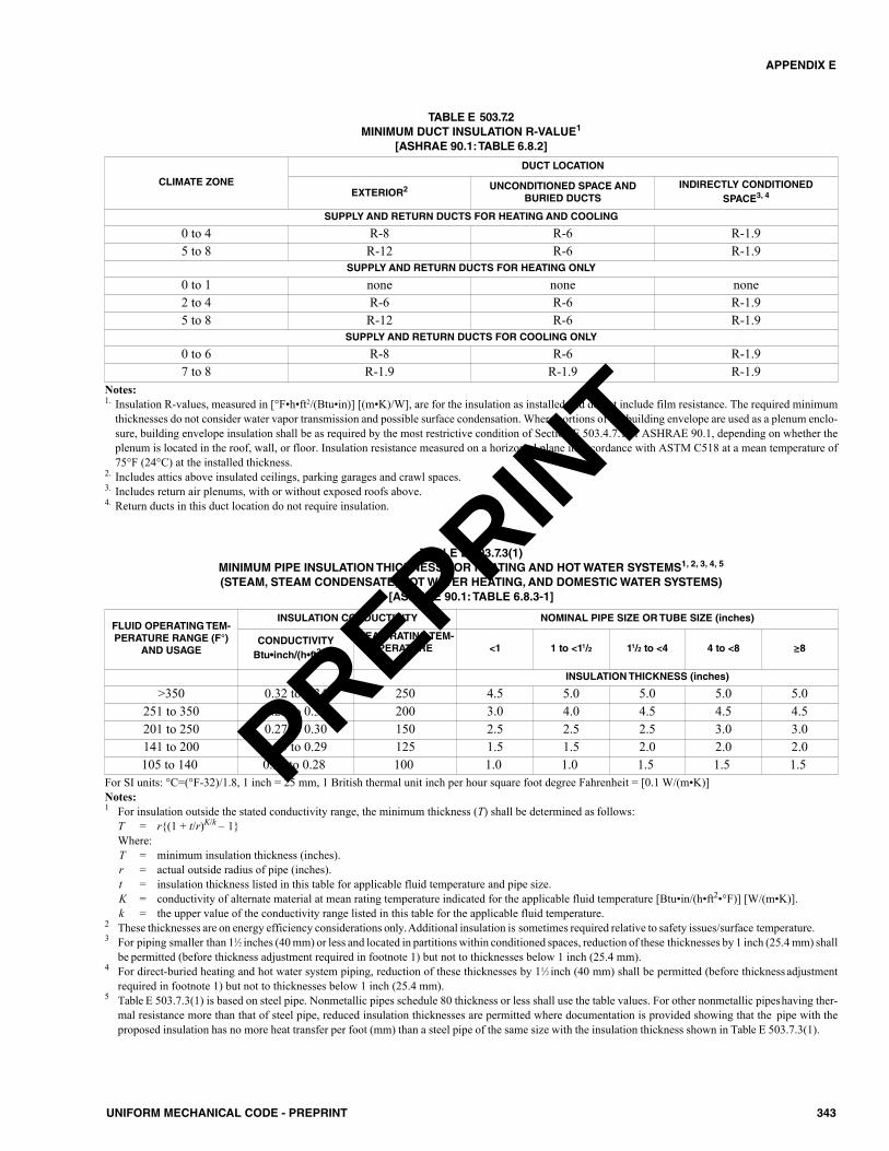
343UNIFORM MECHANICAL CODE - PREPRINT
APPENDIX E
CLIMATE ZONE
DUCT LOCATION
EXTERIOR2 UNCONDITIONED SPACE ANDBURIED DUCTS
INDIRECTLY CONDITIONED SPACE3, 4
SUPPLY AND RETURN DUCTS FOR HEATING AND COOLING
0 to 4 R-8 R-6 R-1.95 to 8 R-12 R-6 R-1.9
SUPPLY AND RETURN DUCTS FOR HEATING ONLY
0 to 1 none none none2 to 4 R-6 R-6 R-1.95 to 8 R-12 R-6 R-1.9
SUPPLY AND RETURN DUCTS FOR COOLING ONLY
0 to 6 R-8 R-6 R-1.97 to 8 R-1.9 R-1.9 R-1.9
Notes:1. Insulation R-values, measured in [°F•h•ft2/(Btu•in)] [(m•K)/W], are for the insulation as installed and do not include film resistance. The required minimum
thicknesses do not consider water vapor transmission and possible surface condensation. Where portions of the building envelope are used as a plenum enclo-sure, building envelope insulation shall be as required by the most restrictive condition of Section E 503.4.7.1 or ASHRAE 90.1, depending on whether theplenum is located in the roof, wall, or floor. Insulation resistance measured on a horizontal plane in accordance with ASTM C518 at a mean temperature of75°F (24°C) at the installed thickness.
2. Includes attics above insulated ceilings, parking garages and crawl spaces.3. Includes return air plenums, with or without exposed roofs above.4. Return ducts in this duct location do not require insulation.
TABLE E 503.7.2MINIMUM DUCT INSULATION R-VALUE1
[ASHRAE 90.1:TABLE 6.8.2]
For SI units: °C=(°F-32)/1.8, 1 inch = 25 mm, 1 British thermal unit inch per hour square foot degree Fahrenheit = [0.1 W/(m•K)]Notes:1 For insulation outside the stated conductivity range, the minimum thickness (T) shall be determined as follows:
T = r{(1 + t/r)K/k – 1} Where:T = minimum insulation thickness (inches).r = actual outside radius of pipe (inches).t = insulation thickness listed in this table for applicable fluid temperature and pipe size.K = conductivity of alternate material at mean rating temperature indicated for the applicable fluid temperature [Btu•in/(h•ft2•°F)] [W/(m•K)].k = the upper value of the conductivity range listed in this table for the applicable fluid temperature.
2 These thicknesses are on energy efficiency considerations only.Additional insulation is sometimes required relative to safety issues/surface temperature.3 For piping smaller than 11⁄2 inches (40 mm) or less and located in partitions within conditioned spaces, reduction of these thicknesses by 1 inch (25.4 mm) shall
be permitted (before thickness adjustment required in footnote 1) but not to thicknesses below 1 inch (25.4 mm).4 For direct-buried heating and hot water system piping, reduction of these thicknesses by 11⁄2 inch (40 mm) shall be permitted (before thickness adjustment
required in footnote 1) but not to thicknesses below 1 inch (25.4 mm).5 Table E 503.7.3(1) is based on steel pipe. Nonmetallic pipes schedule 80 thickness or less shall use the table values. For other nonmetallic pipeshaving ther-
mal resistance more than that of steel pipe, reduced insulation thicknesses are permitted where documentation is provided showing that the pipe with theproposed insulation has no more heat transfer per foot (mm) than a steel pipe of the same size with the insulation thickness shown in Table E 503.7.3(1).
FLUID OPERATING TEM-PERATURE RANGE (F°)
AND USAGE
INSULATION CONDUCTIVITY NOMINAL PIPE SIZE OR TUBE SIZE (inches)
CONDUCTIVITYBtu•inch/(h•ft2•°F)
MEAN RATING TEM-PERATURE
°F<1 1 to <11/2 11/2 to <4 4 to <8 ≥8
INSULATION THICKNESS (inches)
>350 0.32 to 0.34 250 4.5 5.0 5.0 5.0 5.0251 to 350 0.29 to 0.32 200 3.0 4.0 4.5 4.5 4.5201 to 250 0.27 to 0.30 150 2.5 2.5 2.5 3.0 3.0141 to 200 0.25 to 0.29 125 1.5 1.5 2.0 2.0 2.0105 to 140 0.22 to 0.28 100 1.0 1.0 1.5 1.5 1.5
TABLE E 503.7.3(1)MINIMUM PIPE INSULATION THICKNESS FOR HEATING AND HOT WATER SYSTEMS1, 2, 3, 4, 5
(STEAM, STEAM CONDENSATE, HOT WATER HEATING, AND DOMESTIC WATER SYSTEMS)[ASHRAE 90.1: TABLE 6.8.3-1]
PREPRINT
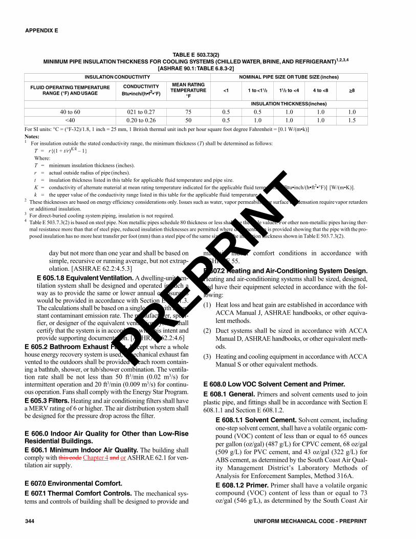
day but not more than one year and shall be based onsimple, recursive or running average, but not extrap-olation. [ASHRAE 62.2:4.5.3]
E 605.1.8 Equivalent Ventilation. A dwelling-unit ven-tilation system shall be designed and operated in such away as to provide the same or lower annual exposure aswould be provided in accordance with Section E 605.1.3.The calculations shall be based on a single zone with a con-stant contaminant emission rate. The manufacturer, speci-fier, or designer of the equivalent ventilation system shallcertify that the system is in accordance with this intent andprovide supporting documentation. [ASHRAE 62.2:4.6]
E 605.2 Bathroom Exhaust Fans. Except where a wholehouse energy recovery system is used, a mechanical exhaust fanvented to the outdoors shall be provided in each room contain-ing a bathtub, shower, or tub/shower combination. The ventila-tion rate shall be not less than 50 ft3/min (0.02 m3/s) forintermittent operation and 20 ft3/min (0.009 m3/s) for continu-ous operation. Fans shall comply with the Energy Star Program.E 605.3 Filters. Heating and air conditioning filters shall havea MERV rating of 6 or higher. The air distribution system shallbe designed for the pressure drop across the filter.
E 606.0 Indoor Air Quality for Other than Low-RiseResidential Buildings.E 606.1 Minimum Indoor Air Quality. The building shallcomply with this code Chapter 4 and or ASHRAE 62.1 for ven-tilation air supply.
E 607.0 Environmental Comfort.E 607.1 Thermal Comfort Controls. The mechanical sys-tems and controls of building shall be designed to provide and
maintain indoor comfort conditions in accordance withASHRAE 55.E 607.2 Heating and Air-Conditioning System Design.Heating and air-conditioning systems shall be sized, designed,and have their equipment selected in accordance with the fol-lowing:(1) Heat loss and heat gain are established in accordance with
ACCA Manual J, ASHRAE handbooks, or other equiva-lent methods.
(2) Duct systems shall be sized in accordance with ACCAManual D, ASHRAE handbooks, or other equivalent meth-ods.
(3) Heating and cooling equipment in accordance with ACCAManual S or other equivalent methods.
E 608.0 Low VOC Solvent Cement and Primer.E 608.1 General. Primers and solvent cements used to joinplastic pipe, and fittings shall be in accordance with Section E608.1.1 and Section E 608.1.2.
E 608.1.1 Solvent Cement. Solvent cement, includingone-step solvent cement, shall have a volatile organic com-pound (VOC) content of less than or equal to 65 ouncesper gallon (oz/gal) (487 g/L) for CPVC cement, 68 oz/gal(509 g/L) for PVC cement, and 43 oz/gal (322 g/L) forABS cement, as determined by the South Coast Air Qual-ity Management District’s Laboratory Methods ofAnalysis for Enforcement Samples, Method 316A.E 608.1.2 Primer. Primer shall have a volatile organiccompound (VOC) content of less than or equal to 73oz/gal (546 g/L), as determined by the South Coast Air
344 UNIFORM MECHANICAL CODE - PREPRINT
APPENDIX E
For SI units: °C = (°F-32)/1.8, 1 inch = 25 mm, 1 British thermal unit inch per hour square foot degree Fahrenheit = [0.1 W/(m•k)]Notes:1 For insulation outside the stated conductivity range, the minimum thickness (T) shall be determined as follows:
T = r{(1 + t/r)K/k – 1} Where:T = minimum insulation thickness (inches).r = actual outside radius of pipe (inches).t = insulation thickness listed in this table for applicable fluid temperature and pipe size.K = conductivity of alternate material at mean rating temperature indicated for the applicable fluid temperature [Btu•inch/(h•ft2•°F)] [W/(m•K)].k = the upper value of the conductivity range listed in this table for the applicable fluid temperature.
2 These thicknesses are based on energy efficiency considerations only. Issues such as water, vapor permeability, or surface condensation requirevapor retardersor additional insulation.
3 For direct-buried cooling system piping, insulation is not required.4 Table E 503.7.3(2) is based on steel pipe. Non metallic pipes schedule 80 thickness or less shall use the table values. For other non-metallic pipes having ther-
mal resistance more than that of steel pipe, reduced insulation thicknesses are permitted where documentation is provided showing that the pipe with the pro-posed insulation has no more heat transfer per foot (mm) than a steel pipe of the same size with the insulation thickness shown in Table E 503.7.3(2).
INSULATION CONDUCTIVITY NOMINAL PIPE SIZE OR TUBE SIZE (inches)
FLUID OPERATING TEMPERATURERANGE (°F) AND USAGE
CONDUCTIVITY
Btu•inch/(h•f2•°F)
MEAN RATINGTEMPERATURE
°F<1 1 to <11/2 11/2 to <4 4 to <8 ≥8
INSULATION THICKNESS(inches)
40 to 60 021 to 0.27 75 0.5 0.5 1.0 1.0 1.0<40 0.20 to 0.26 50 0.5 1.0 1.0 1.0 1.5
TABLE E 503.7.3(2)MINIMUM PIPE INSULATION THICKNESS FOR COOLING SYSTEMS (CHILLED WATER, BRINE, AND REFRIGERANT)1,2,3,4
[ASHRAE 90.1:TABLE 6.8.3-2]
PREPRINT
345UNIFORM MECHANICAL CODE - PREPRINT
APPENDIX E
Quality Management District’s Laboratory Methods ofAnalysis for Enforcement Samples, Method 316A.
E 701.0 Installer Qualifications.E 701.1 Scope. The provisions of this section address min-imum qualifications of installers of mechanical systems cov-ered within the scope of this appendix.
E 702.0 Qualifications.E 702.1 General. Where permits are required, the Author-ity Having Jurisdiction shall have the authority to require con-tractors, installers, or service technicians to demonstratecompetency. Where determined by the Authority HavingJurisdiction, the contractor, installer, or service technicianshall be licensed to perform such work.
Part I
E 801.0 Heating, Ventilation, and Air ConditioningSystems Commissioning.E 801.1 Applicability. The provisions of this section applyto the commissioning of commercial and institutional HVACsystems.
E 802.0 Commissioning.E 802.1 Commissioning Requirements. HVAC com-missioning shall be included in the design and constructionprocesses of the project to verify that the HVAC systems andcomponents meet the owner’s project requirements and inaccordance with this appendix. Commissioning shall be per-formed in accordance with this appendix by personnel trainedand certified in commissioning by a nationally recognizedorganization. Commissioning requirements shall include thefollowing:(1) Owner’s project requirements(2) Basis of design(3) Commissioning measures shown in the construction doc-
uments(4) Commissioning plan(5) Functional performance(6) Testing(7) Post construction documentation and training(8) Commissioning report
HVAC systems and components covered by this appen-dix as well as process equipment and controls, and renewableenergy systems shall be included in the scope of the com-missioning requirements.E 802.2 Owner’s Project Requirements (OPR). The per-formance goals and requirements of the HVAC system shallbe documented before the design phase of the project begins.This documentation shall include not less than the following:(1) Environmental and sustainability goals
(2) Energy efficiency goals(3) Indoor environmental quality requirements(4) Equipment and systems performance goals(5) Building occupant and O&M personnel expectationsE 802.3 Basis of Design (BOD). A written explanation ofhow the design of the HVAC system meets the owner’s proj-ect requirements shall be completed at the design phase of thebuilding project, and updated as necessary during the designand construction phases. The basis of design document shallcover not less than the following systems:(1) Heating, ventilation, air conditioning (HVAC) systems
and controls(2) Water heating systems(3) Renewable energy systemsE 802.4 Commissioning Plan. A commissioning planshall be completed to document the approach to how the proj-ect will be commissioned, and shall be started during thedesign phase of the building project. The commissioning planshall include not less than the following:(1) General project information(2) Commissioning goals(3) Systems to be commissioned. Plans to test systems and
components shall include not less than the following:(a) A detailed explanation of the original design intent.(b) Equipment and systems to be tested, including the
extent of tests.(c) Functions to be tested.(d) Conditions under which the test shall be performed.(e) Measurable criteria for acceptable performance.
(4) Commissioning team information.(5) Commissioning process activities, schedules, and
responsibilities. Plans for the completion of commis-sioning requirements listed in Section E 802.5 throughSection E 802.7 shall be included.
E 802.5 Functional Performance Testing. Functionalperformance tests shall demonstrate the correct installationand operation of each component, system, and system-to-sys-tem interface in accordance with the approved plans and spec-ifications. Functional performance testing reports shallcontain information addressing each of the building compo-nents tested, the testing methods utilized, and readings andadjustments made.E 802.6 Post Construction Documentation and Train-ing. A system manual and systems operations training arerequired.
E 802.6.1 Systems Manual. Documentation of theoperational aspects of the HVAC system shall be com-pleted within the systems manual and delivered to thebuilding owner and facilities operator. The systems man-ual shall include not less than the following:(1) Site information, including facility description, his-
tory, and current requirements.(2) Site contact information.
PREPRINT
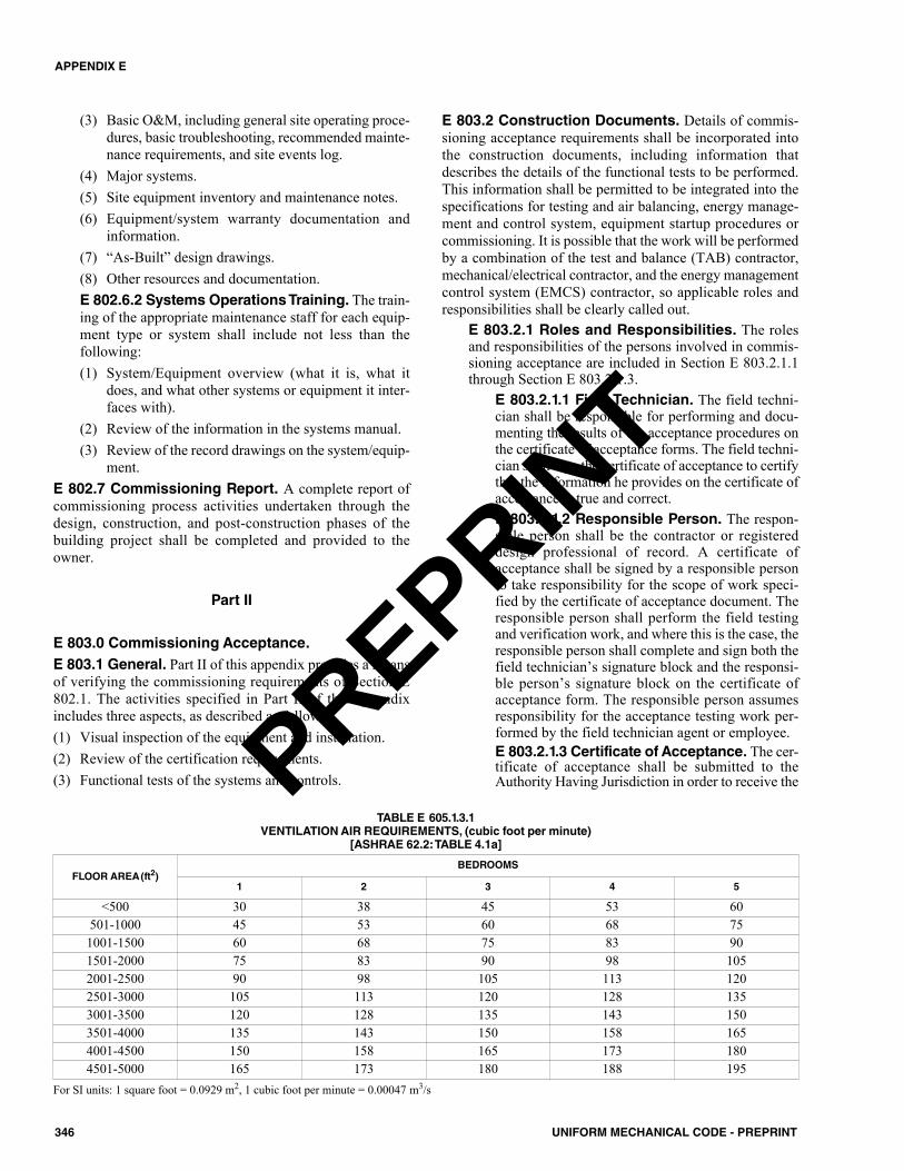
346 UNIFORM MECHANICAL CODE - PREPRINT
APPENDIX E
(3) Basic O&M, including general site operating proce-dures, basic troubleshooting, recommended mainte-nance requirements, and site events log.
(4) Major systems.(5) Site equipment inventory and maintenance notes.(6) Equipment/system warranty documentation and
information.(7) “As-Built” design drawings.(8) Other resources and documentation.E 802.6.2 Systems Operations Training. The train-ing of the appropriate maintenance staff for each equip-ment type or system shall include not less than thefollowing:(1) System/Equipment overview (what it is, what it
does, and what other systems or equipment it inter-faces with).
(2) Review of the information in the systems manual.(3) Review of the record drawings on the system/equip-
ment.E 802.7 Commissioning Report. A complete report ofcommissioning process activities undertaken through thedesign, construction, and post-construction phases of thebuilding project shall be completed and provided to theowner.
Part II
E 803.0 Commissioning Acceptance.E 803.1 General. Part II of this appendix provides a meansof verifying the commissioning requirements of Section E802.1. The activities specified in Part II of this appendixincludes three aspects, as described as follows:(1) Visual inspection of the equipment and installation.(2) Review of the certification requirements.(3) Functional tests of the systems and controls.
E 803.2 Construction Documents. Details of commis-sioning acceptance requirements shall be incorporated intothe construction documents, including information thatdescribes the details of the functional tests to be performed.This information shall be permitted to be integrated into thespecifications for testing and air balancing, energy manage-ment and control system, equipment startup procedures orcommissioning. It is possible that the work will be performedby a combination of the test and balance (TAB) contractor,mechanical/electrical contractor, and the energy managementcontrol system (EMCS) contractor, so applicable roles andresponsibilities shall be clearly called out.
E 803.2.1 Roles and Responsibilities. The rolesand responsibilities of the persons involved in commis-sioning acceptance are included in Section E 803.2.1.1through Section E 803.2.1.3.
E 803.2.1.1 Field Technician. The field techni-cian shall be responsible for performing and docu-menting the results of the acceptance procedures onthe certificate of acceptance forms. The field techni-cian shall sign the certificate of acceptance to certifythat the information he provides on the certificate ofacceptance is true and correct.E 803.2.1.2 Responsible Person. The respon-sible person shall be the contractor or registereddesign professional of record. A certificate ofacceptance shall be signed by a responsible personto take responsibility for the scope of work speci-fied by the certificate of acceptance document. Theresponsible person shall perform the field testingand verification work, and where this is the case, theresponsible person shall complete and sign both thefield technician’s signature block and the responsi-ble person’s signature block on the certificate ofacceptance form. The responsible person assumesresponsibility for the acceptance testing work per-formed by the field technician agent or employee.E 803.2.1.3 Certificate of Acceptance. The cer-tificate of acceptance shall be submitted to theAuthority Having Jurisdiction in order to receive the
For SI units: 1 square foot = 0.0929 m2, 1 cubic foot per minute = 0.00047 m3/s
FLOOR AREA(ft2)BEDROOMS
1 2 3 4 5
<500 30 38 45 53 60501-1000 45 53 60 68 751001-1500 60 68 75 83 901501-2000 75 83 90 98 1052001-2500 90 98 105 113 1202501-3000 105 113 120 128 1353001-3500 120 128 135 143 1503501-4000 135 143 150 158 1654001-4500 150 158 165 173 1804501-5000 165 173 180 188 195
TABLE E 605.1.3.1VENTILATION AIR REQUIREMENTS, (cubic foot per minute)
[ASHRAE 62.2:TABLE 4.1a]
PREPRINT
final certificate of occupancy. The Authority Hav-ing Jurisdiction shall not release a final certificate ofoccupancy unless the submitted certificate of accept-ance demonstrates that the specified systems andequipment have been shown to be performing inaccordance with the applicable acceptance require-ments. The Authority Having Jurisdiction has theauthority to require the field technician and respon-sible person to demonstrate competence, to its satis-faction. Certificate of acceptance forms are locatedin Section E 806.0.
E 804.0 Commissioning Tests.E 804.1 General. Functional tests shall be performed onnew equipment and systems installed in either new construc-tion or retrofit applications in accordance with this section.The appropriate certificate of acceptance form along witheach specific test shall be completed and submitted to theAuthority Having Jurisdiction before a final occupancy per-mit can be granted.E 804.2 Tests. Functional testing shall be performed on thedevices and systems listed in this section. The functional testresults are documented using the applicable certificate ofacceptance forms shown in parenthesis and located in Sec-tion E 806.0. The functional tests shall be performed in accor-dance with Section E 805.0 using the following forms:(1) Minimum ventilation controls for constant and variable
air volume systems (Form MECH-2A).(2) Zone temperature and scheduling controls for constant
volume, single-zone, unitary air conditioner and heatpump systems (Form MECH-3A).
(3) Duct leakage on a subset of small single-zone systemsdepending on the ductwork location (Form MECH-4A).
(4) Air economizer controls for economizers that are not fac-tory installed and tested (Form MECH-5A).
(5) Demand-controlled ventilation control systems (FormMECH-6A).
(6) Supply fan variable flow controls (Form MECH-7A).(7) Valve leakage for hydronic variable flow systems and
isolation valves on chillers and boilers in plants withmore than one chiller or boiler being served by the sameprimary pumps through a common header (FormMECH-8A).
(8) Supply water temperature reset control strategies pro-grammed into the building automation system for watersystems (e.g., chilled, hot, or condenser water) (FormMECH-9A).
(9) Hydronic variable flow controls on a water system wherethe pumps are controlled by variable frequency drives(e.g., chilled and hot water systems; water-loop heatpump systems) (Form MECH-10A).
(10) Automatic demand shed control (Form MECH-11A)(11) Fault detection and diagnostic for DX units (Form
MECH-12A).(12) Automatic fault detection and diagnostic systems
(AFDD) (Form MECH-13A).
(13) Distributed energy storage DEC/DX AC systems (FormMECH-14A).
(14) Thermal energy storage (TES) systems (Form MECH-15A).
E 804.3 Acceptance Process. The functional testingprocess shall comply with Section E 804.3.1 through SectionE 804.3.4.
E 804.3.1 Plan Review. The installing contractor, reg-istered design professional of record, owner’s agent, orthe person responsible for certification of the acceptancetesting on the certificate of acceptance (responsible per-son) shall review the plans and specifications to ensurethat they are in accordance with the acceptance require-ments. This is typically done prior to signing a certifi-cate of compliance.E 804.3.2 Construction Inspection. The installingcontractor, registered design professional of record,owner’s agent, or the person responsible for certificationof the acceptance testing on the certificate of acceptance(responsible person) shall perform a construction inspec-tion prior to testing to ensure that the equipment that isinstalled is capable of complying with the requirementsof this appendix and is calibrated. The installation ofassociated systems and equipment necessary for propersystem operation is required to be completed prior to thetesting.E 804.3.3 Acceptance Testing. One or more fieldtechnicians shall perform the acceptance testing; identifyperformance deficiencies; ensure that they are corrected;and where necessary, repeat the acceptance proceduresuntil the specified systems and equipment are performingin accordance with the acceptance requirements. Thefield technician who performs the testing shall sign thecertificate of acceptance to certify the information hasbeen provided to document the results of the acceptanceprocedures is true and correct.
The responsible person shall review the test resultsfrom the acceptance requirement procedures provided bythe field technician and sign the certificate of acceptanceto certify compliance with the acceptance requirements.The responsible person shall be permitted to perform thefield technician’s responsibilities, and shall then sign thefield technician declaration on the certificate of accept-ance to certify that the information on the form is trueand correct.E 804.3.4 Certificate of Occupancy. The AuthorityHaving Jurisdiction shall not issue the final certificate ofoccupancy until required certificates of acceptance aresubmitted. Copies of completed, signed certificates ofacceptance are required to be posted, or made availablewith the permit(s), and shall be made available to theAuthority Having Jurisdiction.
E 805.0 HVAC System Tests.E 805.1 Variable Air Volume Systems (Form MECH-2A). This test ensures that adequate outdoor air ventilation isprovided through the variable air volume air handling unit at
347UNIFORM MECHANICAL CODE - PREPRINT
APPENDIX E
PREPRINT
two representative operating conditions. The test consists ofmeasuring outdoor air values at maximum flow and at or nearminimum flow. The test verifies that the minimum volumeof outdoor air is introduced to the air handling unit where thesystem is in occupied mode at these two conditions of supplyairflow. This test shall be performed in conjunction with sup-ply fan variable flow controls test procedures to reduce theoverall system testing time as both tests use the same two con-ditions of airflow for their measurements.
E 805.1.1 Test Procedure. The procedure for per-forming a functional test for variable air volume systemsshall be in accordance with Section E 805.1.1.1 and Sec-tion E 805.1.1.2.
E 805.1.1.1 Construction Inspection. Prior tofunctional testing, verify and document that the sys-tem controlling outside airflow is calibrated eitherin the field or factory.E 805.1.1.2 Functional Testing. The functionaltesting shall be in accordance with the followingsteps:Step 1: Where the system has an outdoor air econo-mizer, force the economizer high limit to disableeconomizer control (e.g., for a fixed drybulb highlimit, lower the setpoint below the current outdoorair temperature).Step 2: Adjust supply airflow to either the sum ofthe minimum zone airflows or 30 percent of the totaldesign airflow. Verify and document the following:(1) Measured outside airflow reading is within 10
percent of the total ventilation air called for inthe certificate of compliance.
(2) OSA controls stabilize within 5 minutes.Step 3: Adjust supply airflow to achieve design air-flow. Verify and document the following:(1) Measured outside airflow reading is within 10
percent of the total ventilation air called for inthe certificate of compliance.
(2) OSA controls stabilize within 5 minutes.Step 4: Restore system to “as-found” operating con-ditions.
E 805.1.2 Acceptance Criteria. System controllingoutdoor air flow shall be calibrated in the field or at thefactory.
Measured outdoor airflow reading shall be within 10percent of the total value found on the certificate of com-pliance under the following conditions:(1) Minimum system airflow.(2) Thirty percent of total design flow design supply air-
flow.E 805.2 Constant Volume Systems (Form MECH-2A).The purpose of this test is to ensure that adequate outdoor airventilation is provided through the constant volume air han-dling unit to the spaces served under operating conditions.The intent of this test is to verify that the minimum volume ofoutdoor air is introduced to the air handling unit during typi-cal space occupancy.
E 805.2.1 Test Procedure. The procedure for per-forming a functional test for constant air volume systemsshall be in accordance with Section E 805.2.1.1 and Sec-tion E 805.2.1.2.
E 805.2.1.1 Construction Inspection. Prior tofunctional testing, verify and document the following:(1) Minimum position is marked on the outside air
damper.(2) The system has means of maintaining the min-
imum outdoor air damper position.E 805.2.1.2 Functional Testing. Where the sys-tem has an outdoor air economizer, force the econ-omizer to the minimum position and stop outside airdamper modulation (e.g., for a fixed drybulb highlimit, lower the setpoint below the current outdoorair temperature).
E 805.2.2 Acceptance Criteria. The system has ameans of maintaining the minimum outdoor air damperposition. The minimum damper position is marked onthe outdoor air damper. The measured outside airflowreading shall be within 10 percent of the total ventilationair called for in the certificate of compliance.
E 805.3 Constant Volume, Single-Zone, Unitary AirConditioner and Heat Pumps Systems Acceptance(Form MECH-3A). The purpose of this test is to verify theindividual components of a constant volume, single-zone,unitary air conditioner and heat pump system function cor-rectly; including: thermostat installation and programming,supply fan, heating, cooling, and damper operation.
E 805.3.1 Test Procedure. The procedure for per-forming a functional test for constant volume, single-zone, unitary air conditioner and heat pump systems shallbe in accordance with Section E 805.3.1.1 and Section E805.3.1.2.
E 805.3.1.1 Construction Inspection. Prior tofunctional testing, verify and document the follow-ing:(1) Thermostat is located within the space-condi-
tioning zone that is served by the HVAC sys-tem.
(2) Thermostat shall be in accordance with temper-ature adjustment and dead band requirements.
(3) Occupied, unoccupied, and holiday schedulesshall be programmed per the facility’s sched-ule.
(4) Preoccupancy purge is programmed.E 805.3.1.2 Functional Testing. The functionaltesting shall be in accordance with the followingsteps:Step 1: Disable economizer and demand controlventilation systems (where applicable).Step 2: Simulate a heating demand during the occu-pied condition. Verify and document the following:(1) Supply fan operates continually.(2) The unit provides heating.(3) No cooling is provided by the unit.
348 UNIFORM MECHANICAL CODE - PREPRINT
APPENDIX E
PREPRINT
(4) Outside air damper is at minimum position.Step 3: Simulate operation in the dead band duringoccupied condition. Verify and document the fol-lowing:(1) Supply fan operates continually.(2) Neither heating nor cooling is provided by the
unit.(3) Outside air damper is at minimum position.Step 4: Simulate cooling demand during occupiedcondition. Lock out economizer (where applicable).Verify and document the following:(1) Supply fan operates continually.(2) The unit provides cooling.(3) No heating is provided by the unit.(4) Outside air damper is at minimum position.Step 5: Simulate operation in the dead band duringunoccupied mode. Verify and document the follow-ing:(1) Supply fan is off.(2) Outside air damper is fully closed.(3) Neither heating nor cooling is provided by the
unit.Step 6: Simulate heating demand during unoccupiedconditions. Verify and document the following:(1) Supply fan is on (either continuously or cycling).(2) Heating is provided by the unit.(3) No cooling is provided by the unit.(4) Outside air damper is either closed or at mini-
mum position.Step 7: Simulate cooling demand during unoccupiedcondition. Lock out economizer (where applicable).Verify and document the following:(1) Supply fan is on (either continuously or
cycling).(2) Cooling is provided by the unit.(3) No heating is provided by the unit.(4) Outside air damper is either closed or at mini-
mum position.Step 8: Simulate manual override during unoccupiedcondition. Verify and document the following:(1) System operates in “occupied” mode.(2) System reverts to “unoccupied” mode where
manual override time period expires.Step 9: Restore economizer and demand controlventilation systems (where applicable), and removesystem overrides initiated during the test.
E 805.3.2 Acceptance Criteria. Thermostat is locatedwithin the space-conditioning zone that is served by therespective HVAC system. The thermostat shall complywith temperature adjustment and dead band require-ments. Occupied, unoccupied, and holiday schedulesshall be programmed per the facility’s schedule. Preoc-cupancy purge is programmed in accordance with therequirements.
E 805.4 Air Distribution Systems (Form MECH-4A).The purpose of this test is to verify duct work associated withnon-exempt constant volume, single-zone, HVAC units (e.g.,air conditioners, heat pumps, and furnaces) meet the mate-rial, installation, and insulation R-values and leakage require-ments outlined in this appendix. This test is required forsingle-zone units serving less than 5000 square feet (464.52m2) of floor area where 25 percent or more of the duct surfacearea is in one of the following spaces:(1) Outdoors.(2) In a space directly under a roof where the U-factor of the
roof is greater than the U-factor of the ceiling.(3) In a space directly under a roof with fixed vents or open-
ings to the outside or unconditioned spaces.(4) In an unconditioned crawl space.(5) In other unconditioned spaces.
This test applies to both new duct systems and to exist-ing duct systems being extended or the space conditioningsystem is altered by the installation or replacement of spaceconditioning equipment, including: replacement of the airhandler; outdoor condensing unit of a split system air condi-tioner or heat pump; cooling or heating coil; or the furnaceheat exchanger. Existing duct systems do not have to be testedwhere they are insulated or sealed with asbestos.
E 805.4.1 Test Procedure. The procedure for per-forming a functional test for air distribution systems shallbe in accordance with Section E 805.4.1.1 and Section E805.4.1.2.
E 805.4.1.1 Construction Inspection. Prior tofunctional testing, verify and document the follow-ing:(1) Duct connections shall comply with the require-
ments of this appendix and this code.(2) Flexible ducts are not compressed.(3) Ducts are fully accessible for testing.(4) Joints and seams are properly sealed in accor-
dance with the requirements of this appendix.(5) Insulation R-Values shall comply with the min-
imum requirements of this appendix.E 805.4.1.2 Functional Testing. Perform ductleakage test in accordance with Section E503.4.7.2.1.
E 805.4.2 Acceptance Criteria. Flexible ducts are notcompressed or constricted. Duct connections shall com-ply with the requirements of this appendix and this code(new ducts only). Joints and seams are properly sealedin accordance with the requirements of this appendix andthis code (new ducts only). Duct R-values shall complywith the minimum requirements of this appendix (newducts only). Insulation is protected from damage andsuitable for outdoor usage where applicable (new ductsonly). The leakage shall not exceed the rate in accor-dance with Section E 503.4.7.2.
E 805.5 Air Economizer Controls Acceptance (FormMECH-5A). The purpose of functionally testing an air econ-omizer cycle is to verify that an HVAC system uses outdoor
349UNIFORM MECHANICAL CODE - PREPRINT
APPENDIX E
PREPRINT
air to satisfy space cooling loads where outdoor air conditionsare acceptable. There are two types of economizer controls;stand-alone packages and DDC controls. The stand-alonepackages are commonly associated with small unitary rooftopHVAC equipment, and DDC controls are typically associatedwith built-up or large packaged air handling systems. Testprocedures for both economizer control types are provided.
For units with economizers that are factory installed andcertified operational by the manufacturer to economizer qual-ity control requirements, the in-field economizer functionaltests do not have to be conducted. A copy of the manufac-turer’s certificate shall be attached to the Form MECH-5A.However, the construction inspection, including compliancewith high-temperature lockout temperature setpoint, shall becompleted regardless of whether the economizer is field orfactory installed.
E 805.5.1 Test Procedure. The procedure for per-forming a functional test for air economizer controls shallcomply with Section E 805.5.1.1 and Section E805.5.1.2.
E 805.5.1.1 Construction Inspection. Prior tofunctional testing, verify and document the follow-ing:(1) Economizer lockout setpoint is in accordance
with this appendix.(2) Economizer lockout control sensor is located to
prevent false readings.(3) System is designed to provide up to 100 percent
outside air without over-pressurizing the build-ing.
(4) For systems with DDC controls lockout sen-sor(s) are either factory calibrated or field cali-brated.
(5) For systems with non-DDC controls, manufac-turer’s startup and testing procedures areapplied.
E 805.5.1.2 Functional Testing. The functionaltesting shall be in accordance with the following steps:Step 1: Disable demand control ventilation systems(where applicable).Step 2: Enable the economizer, and simulate a cool-ing demand large enough to drive the economizerfully open. Verify and document the following:(1) Economizer damper is 100 percent opened and
return air damper is 100 percent closed.(2) Where applicable, verify that the economizer
remains 100 percent open where the coolingdemand can no longer be met by the econo-mizer alone.
(3) Applicable fans and dampers operate asintended to maintain building pressure.
(4) The unit heating is disabled.Step 3: Disable the economizer and simulate a cool-ing demand. Verify and document the following:(1) Economizer damper shall close to its minimum
position.
(2) Applicable fans and dampers shall operate asintended to maintain building pressure.
(3) The unit heating is disabled.Step 4: Simulate a heating demand, and set the econ-omizer so that it is capable of operating (e.g., actualoutdoor air conditions are below lockout setpoint).Verify the economizer is at minimum position.Step 5: Restore demand control ventilation systems(where applicable) and remove system overrides ini-tiated during the test.
E 805.5.2 Acceptance Criteria. Air economizer con-trols acceptance criteria shall be as follows:(1) Where the economizer is factory installed and certi-
fied, a valid factory certificate is required for accept-ance. No additional equipment tests are necessary.
(2) Air economizer lockout setpoint is in accordancewith this appendix. Outside sensor location accu-rately reads true outdoor air temperature and is notaffected by exhaust air or other heat sources.
(3) Sensors are located to achieve the desired control.(4) During economizer mode, the outdoor air damper
shall modulate open to a maximum position andreturn air damper to 100 percent closed.
(5) The outdoor air damper is 100 percent open beforemechanical cooling is enabled and for units 75 000Btu/h (22 kw) and larger remains at 100 percentopen while mechanical cooling is enabled (econo-mizer integration where used for compliance).
(6) Where the economizer is disabled, the outdoor airdamper closes to a minimum position; the returndamper modulates 100 percent open, and mechani-cal cooling remains enabled.
E 805.6 Demand-Controlled Ventilation SystemsAcceptance (Form MECH-6A). The purpose of this test isto verify that systems required to employ demand-controlledventilation shall be permitted to vary outside ventilation flowrates based on maintaining interior carbon dioxide (CO2) con-centration setpoints. Demand-controlled ventilation refers toan HVAC system’s ability to reduce outdoor air ventilationflow below design values where the space served is at lessthan design occupancy. Carbon dioxide is a good indicator ofoccupancy load and is the basis used for modulating ventila-tion flow rates.
E 805.6.1 Test Procedure. The procedure for per-forming a functional test for demand-control ventilation(DVC) systems shall be in accordance with Section E805.6.1.1 and Section E 805.6.1.2.
E 805.6.1.1 Construction Inspection. Prior tofunctional testing, verify and document the follow-ing:(1) Carbon dioxide control sensor is factory cali-
brated or field-calibrated in accordance withthis appendix.
(2) The sensor is located in the high-density spacebetween 3 feet (914 mm) and 6 feet (1829 mm)above the floor or at the anticipated level of theoccupants’ heads.
350 UNIFORM MECHANICAL CODE - PREPRINT
APPENDIX E
PREPRINT

(3) DCV control setpoint is at or below the carbondioxide concentration permitted by this appen-dix.
E 805.6.1.2 Functional Testing. The functionaltesting shall be in accordance with the followingsteps:Step 1: Disable economizer controls.Step 2: Simulate a signal at or slightly above the car-bon dioxide concentration setpoint required by thisappendix. Verify and document the following:(1) For single zone units, outdoor air damper mod-
ulates open to satisfy the total ventilation aircalled for in the certificate of compliance.
(2) For multiple zone units, either outdoor airdamper or zone damper modulate open to sat-isfy the zone ventilation requirements.
Step 3: Simulate signal well below the carbon diox-ide setpoint. Verify and document the following:(1) For single zone units, outdoor air damper mod-
ulates to the design minimum value.(2) For multiple zone units, either outdoor air
damper or zone damper modulate to satisfy thereduced zone ventilation requirements.
Step 4: Restore economizer controls and removesystem overrides initiated during the test.Step 5: With controls restored, apply carbon diox-ide calibration gas at a concentration slightly abovethe setpoint to the sensor. Verify that the outdoor airdamper modulates open to satisfy the total ventila-tion air called for in the certificate of compliance.
E 805.6.2 Acceptance Criteria. Demand-controlledventilation systems acceptance criteria shall be as fol-lows:(1) Each carbon dioxide sensor is factory calibrated
(with calibration certificate) or field calibrated.(2) Each carbon dioxide sensor is wired correctly to the
controls to ensure proper control of the outdoor airdamper.
(3) Each carbon dioxide sensor is located correctlywithin the space 1 foot (305 mm) to 6 feet (1829mm) above the floor.
(4) Interior carbon dioxide concentration setpoint is notmore than 600 parts per million (ppm) plus outdoorair carbon dioxide value where dynamically meas-ured or not more than 1000 ppm where no OSA sen-sor is provided.
(5) A minimum OSA setting is provided where the sys-tem is in occupied mode in accordance with thisappendix regardless of space carbon dioxide read-ings.
(6) A maximum OSA damper position for DCV controlshall be established in accordance with this appen-dix, regardless of space carbon dioxide readings.
(7) The outdoor air damper shall modulate open wherethe carbon dioxide concentration within the spaceexceeds setpoint.
(8) The outdoor air damper modulates closed (towardminimum position) where the carbon dioxide con-centration within the space is below setpoint.
E 805.7 Supply Fan Variable Flow Controls (FormMECH-7A). The purpose of this test is to ensure that the sup-ply fan in a variable air volume application modulates to meetsystem airflow demand. In most applications, the individualVAV boxes serving each space will modulate the amount ofair delivered to the space based on heating and coolingrequirements. As a result, the total supply airflow providedby the central air handling unit shall vary to maintain suffi-cient airflow through each VAV box. Airflow shall be con-trolled using a variable frequency drive (VFD) to modulatesupply fan speed and vary system airflow. The most commonstrategy for controlling the VFD is to measure and maintainstatic pressure within the duct.
E 805.7.1 Test Procedure. The procedure for per-forming a functional test for supply fan variable controlsshall be in accordance with Section E 805.7.1.1 and Sec-tion E 805.7.1.2.
E 805.7.1.1 Construction Inspection. Prior tofunctional testing, verify and document the follow-ing:(1) Supply fan controls modulate to increase capac-
ity.(2) Supply fan maintains discharge static pressure
within plus or minus 10 percent of the currentoperating set point.
(3) Supply fan controls stabilize within a 5 minuteperiod.
E 805.7.1.2 Functional Testing. The functionaltesting shall be in accordance with the followingsteps:Step 1: Simulate demand for design airflow. Verifyand document the following:(1) Supply fan controls modulate to increase capac-
ity.(2) Supply fan maintains discharge static pressure
within plus or minus 10 percent of the currentoperating set point.
(3) Supply fan controls stabilize within a 5 minuteperiod.
Step 2: Simulate demand for minimum airflow. Ver-ify and document the following:(1) Supply fan controls modulate to decrease
capacity.(2) Current operating setpoint has decreased (for
systems with DDC to the zone level).(3) Supply fan maintains discharge static pressure
within plus or minus 10 percent of the currentoperating setpoint.
(4) Supply fan controls stabilize within a 5 minuteperiod.
Step 3: Restore system to correct operating condi-tions.
351UNIFORM MECHANICAL CODE - PREPRINT
APPENDIX E
PREPRINT
E 805.7.2 Acceptance Criteria. Supply fan variableflow controls acceptance criteria shall be as follows:(1) Static pressure sensor(s) is factory calibrated (with
calibration certificate) or field calibrated.(2) For systems without DDC controls to the zone level,
the pressure sensor setpoint is less than one-third ofthe supply fan design static pressure.
(3) For systems with DDC controls with VAV boxesreporting to the central control panel, the pressuresetpoint is reset by zone demand (box damper posi-tion or a trim and respond algorithm).
At full flow:(1) Supply fan maintains discharge static pressure
within plus or minus 10 percent of the current oper-ating control static pressure setpoint.
(2) Supply fan controls stabilizes within a 5 minuteperiod.
(3) At minimum flow (not less than 30 percent of totaldesign flow).
(4) Supply fan controls modulate to decrease capacity.(5) Current operating setpoint has decreased (for sys-
tems with DDC to the zone level).(6) Supply fan maintains discharge static pressure
within plus or minus 10 percent of the current oper-ating setpoint.
E 805.8 Valve Leakage (Form MECH-8A). The purposeof this test is to ensure that control valves serving variableflow systems are designed to withstand the pump pressureover the full range of operation. Valves with insufficient actu-ators will lift under certain conditions causing water to leakthrough and loss of control. This test applies to the variableflow systems, chilled and hot-water variable flow systems,chiller isolation valves, boiler isolation valves, and water-cooled air conditioner and hydronic heat pump systems.
E 805.8.1 Test Procedure. The procedure for per-forming a functional test for valve leakage shall be inaccordance with Section E 805.8.1.1 and Section E805.8.1.2.
E 805.8.1.1 Construction Inspection. Prior tofunctional testing, verify and document the valveand piping arrangements were installed in accor-dance with the design drawings.E 805.8.1.2 Functional Testing. The functionaltesting shall be in accordance with the followingsteps:Step 1: For each pump serving the distribution sys-tem, dead head the pumps using the discharge iso-lation valves at the pumps. Document the following:(1) Record the differential pressure across the pumps.(2) Verify that this is within 5 percent of the sub-
mittal data for the pump.Step 2: Reopen the pump discharge isolation valves.Automatically close valves on the systems beingtested. Where three-way valves are present, close offthe bypass line. Verify and document the following:
(1) The valves automatically close.(2) Record the pressure differential across the
pump.(3) Verify that the pressure differential is within 5
percent of the reading from Step 1 for the pumpthat is operating during the valve test.
Step 3: Restore system to correct operating condi-tions.
E 805.8.2 Acceptance Criteria. System has no flowwhere coils are closed and the pump is turned on.
E 805.9 Supply Water Temperature Reset Controls(Form MECH-9A). The purpose of this test is to ensure thatboth the chilled water and hot water supply temperatures areautomatically reset based on either building loads or outdoorair temperature, as indicated in the control sequences. ManyHVAC systems are served by central chilled and heating hotwater plants. The supply water operating temperatures shallmeet peak loads where the system is operating at design con-ditions. As the loads vary, the supply water temperatures shallbe permitted to be adjusted to satisfy the new operating con-ditions. The chilled water supply temperature shall be per-mitted to be raised as the cooling load decreases, and heatinghot water supply temperature shall be permitted to be low-ered as the heating load decreases.
This requirement applies to chilled and hot water sys-tems that are not designed for variable flow, and that have adesign capacity greater than or equal to 500 000 Btu/h (147kW).
E 805.9.1 Test Procedure. The procedure for per-forming a functional test for supply water temperaturereset controls shall be in accordance with Section E805.9.1.1 and Section E 805.9.1.2.
E 805.9.1.1 Construction Inspection. Prior tofunctional testing, verify and document the supplywater temperature sensors shall be either factory orfield calibrated.E 805.9.1.2 Functional Testing. The functionaltesting shall be in accordance with the followingsteps: Step 1: Change reset control variable to its maxi-mum value. Verify and document the following:(1) Chilled or hot water temperature setpoint is
reset to appropriate value.(2) Actual supply temperature changes to meet set-
point.(3) Verify that supply temperature is within 2 per-
cent of the control setpoint.Step 2: Change reset control variable to its minimumvalue. Verify and document the following:(1) Chilled or hot water temperature setpoint is
reset to appropriate value.(2) Actual supply temperature changes to meet set-
point.(3) Verify that supply temperature is within 2 per-
cent of the control setpoint.
352 UNIFORM MECHANICAL CODE - PREPRINT
APPENDIX E
PREPRINT
Step 3: Restore reset control variable to automaticcontrol. Verify and document the following:(1) Chilled or hot water temperature setpoint is
reset to appropriate value.(2) Actual supply temperature changes to meet set-
point.(3) Verify that supply temperature is within 2 per-
cent of the control setpoint.E 805.9.2 Acceptance Criteria. The supply watertemperature sensors are either factory calibrated (withcalibration certificates) or field-calibrated. Sensor per-formance shall comply with the specifications. The sup-ply water reset is operational.
E 805.10 Hydronic System Variable Flow Controls(Form MECH-10A). The purpose of this test is to ensurethat hydronic variable flow chilled water and water-loop heatpump systems with circulating pumps larger than 5 hp (3.7kW) vary system flow rate by modulating pump speed usinga variable frequency drive (VFD) or equivalent. As the loadswithin the building fluctuate, control valves modulate theamount of water passing through each coil and add or removethe desired amount of energy from the air stream to satisfythe load. In the case of water-loop heat pumps, each two-waycontrol valve associated with a heat pump will be closedwhere that unit is not operating. As each control valve mod-ulates, the pump variable frequency drive (VFD) respondsaccordingly to meet system water flow requirements. This isnot required on heating hot water systems with variable flowdesigns or for condensing water serving water cooled chillers.
E 805.10.1 Test Procedure. The procedure for per-forming a functional test for hydronic system variableflow controls shall be in accordance with Section E805.10.1.1 and Section E 805.10.1.2.
E 805.10.1.1 Construction Inspection. Prior tofunctional testing, verify and document the pressuresensors are either factory or field calibrated.E 805.10.1.2 Functional Testing. The functionaltesting shall comply with the following steps:Step 1: Open control valves to increase water flow tonot less than 90 percent design flow. Verify and doc-ument the following:(1) Pump speed increases.(2) System pressure is either within plus or minus
5 percent of current operating setpoint, or thepressure is below the setpoint, and the pumpsare operating at 100 percent speed.
(3) System operation shall stabilize within 5 min-utes after test procedures are initiated.
Step 2: Modulate control valves to reduce waterflow to 50 percent of the design flow or less, but notlower than the pump minimum flow. Verify anddocument the following:(1) Pump speed decrease.(2) Current operating setpoint has decreased (for
systems with DDC to the zone level).
(3) Current operating setpoint has not increased(for all other systems).
(4) System pressure is within 5 percent of currentoperating setpoint.
(5) System operation stabilizes within 5 minutesafter test procedures are initiated.
E 805.10.2 Acceptance Criteria. The differentialpressure sensor is either factory calibrated (with calibra-tion certificates) or field calibrated. The pressure sensorshall be located at or near the most remote HX or controlvalve. The setpoint system controls shall stabilize.
E 805.11 Automatic Demand Shed Control (FormMECH-11A). The purpose of this test is to ensure that thecentral demand shed sequences have been properly pro-grammed into the DDC system.
E 805.11.1 Test Procedure. The procedure for per-forming a functional test for automatic demand shed con-trols shall be in accordance with Section E 805.11.1.1and Section E 805.11.1.2.
E 805.11.1.1 Construction Inspection. Prior tofunctional testing, verify and document that theEMCS interface enables activation of the centraldemand shed controls.E 805.11.1.2 Functional Testing. The functionaltesting shall comply with the following steps:Step 1: Engage the global demand shed system. Ver-ify and document the following:(1) That the cooling setpoint in noncritical spaces
increases by the proper amount.(2) That the cooling setpoint in critical spaces do
not change.Step 2: Disengage the global demand shed system.Verify and document the following:(1) That the cooling setpoint in noncritical spaces
return to their original values.(2) That the cooling setpoint in critical spaces do
not change.E 805.11.2 Acceptance Criteria. The control systemchanges the setpoints of noncritical zones on activationof a single central hardware or software point thenrestores the initial setpoints where the point is released.
E 805.12 Fault Detection and Diagnostics (FDD) forPackaged Direct-Expansion (DX) Units (FormMECH-12A). The purpose of this test is to verify proper faultdetection and reporting for automated fault detection anddiagnostics systems for packaged units. Automated FDD sys-tems ensure proper equipment operation by identifying anddiagnosing common equipment problems such as improperrefrigerant charge, low airflow, or faulty economizer opera-tion. Qualifying FDD systems receive a compliance creditwhere using the performance approach. A system that doesnot meet the eligibility requirements shall be permitted to beinstalled, but no compliance credit will be given.
E 805.12.1 Test Procedure. The procedure for per-forming a functional test for fault detection and diag-
353UNIFORM MECHANICAL CODE - PREPRINT
APPENDIX E
PREPRINT
nostics (FDD) for packaged direct-expansion (DX) unitsshall be in accordance with Section E 805.12.1.1 andSection E 805.12.1.2.
E 805.12.1.1 Construction Inspection. Prior tofunctional testing, verify and document that the FDDhardware is installed on equipment by the manufac-turer, and that equipment make and model includefactory-installed FDD hardware that match theinformation indicated on copies of the manufac-turer’s cut sheets and on the plans and specifications.
This procedure applies to fault detection anddiagnostics (FDD) system for direct-expansionpackaged units containing the following features:(1) The unit shall include a factory-installed econ-
omizer and shall limit the economizer deadband to not more than 2°F (-17°C).
(2) The unit shall include direct-drive actuators onoutside air and return air dampers.
(3) The unit shall include an integrated economizerwith either differential drybulb or differentialenthalpy control.
(4) The unit shall include a low temperature lock-out on the compressor to prevent coil freeze-upor comfort problems.
(5) Outside air and return air dampers shall havemaximum leakage rates in accordance to thisappendix.
(6) The unit shall have an adjustable expansioncontrol device such as a thermostatic expansionvalve (TXV).
(7) To improve the ability to troubleshoot chargeand compressor operation, a high-pressurerefrigerant port will be located on the liquidline. A low-pressure refrigerant port will belocated on the suction line.
(8) The following sensors shall be permanentlyinstalled to monitor system operation, and thecontroller shall have the capability of displayingthe value of each parameter:(a) Refrigerant suction pressure(b) Refrigerant suction temperature(c) Liquid line pressure(d) Liquid line temperature(e) Outside air temperature(f) Outside air relative humidity(g) Return air temperature(h) Return air relative humidity(i) Supply air temperature(j) Supply air relative humidity
The controller will provide system statusby indicating the following conditions:(1) Compressor enabled(2) Economizer enabled
(3) Free cooling available(4) Mixed air low limit cycle active(5) Heating enabled
The unit controller shall have the capabil-ity to manually initiate each operating mode sothat the operation of compressors, economizers,fans, and heating system can be independentlytested and verified.
E 805.12.1.2 Functional Testing. The functionaltesting shall be in accordance with the followingsteps:Step 1: Test low airflow condition by replacing the
existing filter with a dirty filter or appropri-ate obstruction.
Step 2: Verify that the fault detection and diagnos-tics system reports the fault.
Step 3: Verify that the system is able to verify thecorrect refrigerant charge.
Step 4: Calibrate outside air, return air, and supplyair temperature sensors.
E 805.12.2 Acceptance Criteria. The system is ableto detect a low airflow condition and report the fault. Thesystem is able to detect where refrigerant charge is lowor high and the fault is reported.
E 805.13 Automatic Fault Detection Diagnostics(FDD) for Air Handling Units (AHU) and Zone Termi-nal Units (Form MECH-13A). The purpose of this test isto verify that the system detects common faults in air han-dling units and terminal units. FDD systems for air handlingunits and zone terminal units require DDC controls to thezone level. Successful completion of this test provides a com-pliance credit where using the performance approach. AnFDD system that does not pass this test shall be permitted tobe installed, but no compliance credit will be given.
E 805.13.1 Test Procedure. The procedure for per-forming a functional test for automatic fault detectiondiagnostics (FDD) for Air Handling Units and Zone Ter-minal Units shall be in accordance with Section E805.13.1.1.
E 805.13.1.1 Functional Testing. The functionaltesting shall be in accordance with Section E805.13.1.1.1 and Section E 805.13.1.1.2.
E 805.13.1.1.1 Functional Testing for AirHandling Units. The functional testing ofAHU with FDD controls shall be in accordancewith the following steps:Step 1: Sensor drift/failure:(1) Disconnect outside air temperature sensor
from unit controller.(2) Verify that the FDD system reports a fault.(3) Connect OAT sensor to the unit controller.(4) Verify that FDD indicates normal system
operation.Step 2: Damper/actuator fault:
354 UNIFORM MECHANICAL CODE - PREPRINT
APPENDIX E
PREPRINT
(1) From the control system workstation, com-mand the mixing box dampers to full open(100 percent outdoor air).
(2) Disconnect power to the actuator and ver-ify that a fault is reported at the controlworkstation.
(3) Reconnect power to the actuator and com-mand the mixing box dampers to full open.
(4) Verify that the control system does notreport a fault.
(5) From the control system workstation, com-mand the mixing box dampers to a full-closed position (0 percent outdoor air).
(6) Disconnect power to the actuator and ver-ify that a fault is reported at the controlworkstation.
(7) Reconnect power to the actuator and com-mand the dampers closed.
(8) Verify that the control system does notreport a fault during normal operation.
Step 3: Valve/actuator fault:(1) From the control system workstation, com-
mand the heating and cooling coil valvesto full open or closed, then disconnectpower to the actuator and verify that a faultis reported at the control workstation.
Step 4: Inappropriate simultaneous heating,mechanical cooling, and economizing or allfunctions:(1) From the control system workstation, over-
ride the heating coil valve and verify that afault is reported at the control workstation.
(2) From the control system workstation, over-ride the cooling coil valve and verify that afault is reported at the control workstation.
(3) From the control system workstation, over-ride the mixing box dampers and verifythat a fault is reported at the control work-station.
E 805.13.1.1.2 Functional Testing forZone Terminal Units. The functional testingof one of each type of terminal unit (VAV box)in the project not less than 5 percent of the ter-minal boxes shall be in accordance with the fol-lowing steps:Step 1: Sensor drift/failure:(1) Disconnect the tubing to the differential
pressure sensor of the VAV box.(2) Verify that control system detects and
reports the fault.(3) Reconnect the sensor and verify proper
sensor operation.(4) Verify that the control system does not
report a fault.
Step 2: Damper/actuator fault:(1) Damper stuck open.
(a) Command the damper to full open(room temperature above setpoint).
(b) Disconnect the actuator to the damper.(c) Adjust the cooling setpoint so that the
room temperature is below the coolingsetpoint to command the damper to theminimum position. Verify that thecontrol system reports a fault.
(d) Reconnect the actuator and restore tonormal operation.
(2) Damper stuck closed.(a) Set the damper to the minimum posi-
tion.(b) Disconnect the actuator to the damper.(c) Set the cooling setpoint below the
room temperature to simulate a call forcooling. Verify that the control systemreports a fault.
(d) Reconnect the actuator and restore tonormal operation.
Step 3: Valve/actuator fault (for systems withhydronic reheat):(1) Command the reheat coil valve to full
open.(2) Disconnect power to the actuator. Set the
heating setpoint temperature to be lowerthan the current space temperature, to com-mand the valve closed. Verify that the faultis reported at the control workstation.
(3) Reconnect the actuator and restore normaloperation.
Step 4: Feedback loop tuning fault (unstable air-flow):(1) Set the integral coefficient of the box con-
troller to a value 50 times the current value.(2) The damper cycles continuously and air-
flow is unstable. Verify that the controlsystem detects and reports the fault.
(3) Reset the integral coefficient of the con-troller to the original value to restore nor-mal operation.
Step 5: Disconnected inlet duct:(1) From the control system workstation, com-
mand the damper to full closed; then dis-connect power to the actuator, and verifythat a fault is reported at the control work-station.
E 805.13.2 Acceptance Criteria. The system is ableto detect common faults with air-handling units, such asa sensor failure, a failed damper, an actuator, or animproper operating mode.
355UNIFORM MECHANICAL CODE - PREPRINT
APPENDIX E
PREPRINT
The system is able to detect and report commonfaults with zone terminal units, such as a failed damper,an actuator, or a control tuning issue.
E 805.14 Distributed Energy Storage DX AC System(Form MECH-14A). The purpose of this test is to verify theproper operation of distributed energy storage DX systems.Distributed energy systems (DES) reduce peak demand byoperating during off-peak hours and storing cooling, usuallyin the form of ice. During peak cooling hours the ice is meltedto avoid compressor operation. The system typically consistsof a water tank containing refrigerant coils that cool the waterand convert it to ice. As with a standard direction expansion(DX) air conditioner, the refrigerant is compressed in a com-pressor and then cooled in an air-cooled condenser. The liq-uid refrigerant then is directed through the coils in the watertank to make ice or to air handler coils to cool the building.This applies to constant or variable volume, direct expansion(DX) systems with distributed energy storage (DES/DXAC).
E 805.14.1 Test Procedure. The procedure for per-forming a functional test for distributed energy storageDX AC systems shall be in accordance with Section E805.14.1.1 through Section E 805.14.1.3.
E 805.14.1.1 Construction Inspection. Prior tofunctional testing, verify and document the follow-ing:(1) The water tank is filled to the proper level.(2) The water tank is sitting on a foundation with
adequate structural strength.(3) The water tank is insulated and the top cover is
in place.(4) The DES/DXAC is installed correctly (e.g.,
refrigerant piping, etc.).(5) Verify that the correct model number is
installed and configured.E 805.14.1.2 Functional Testing. The functionaltesting shall be in accordance with the followingsteps:Step 1: Simulate cooling load during daytime period(e.g., by setting time schedule to include actual timeand placing thermostat cooling setpoint below actualtemperature). Verify and document the following:(1) Supply fan operates continually.(2) Where the DES/DXAC has cooling capacity,
DES/DXAC shall run to meet the coolingdemand (in ice melt mode).
(3) Where the DES/DXAC has no ice and there isa call for cooling, the DES/DXAC shall run indirect cooling mode.
Step 2: Simulate no cooling load during daytimecondition. Verify and document the following:(1) Supply fan operates in accordance with the
facility thermostat or control system.(2) The DES/DXAC and the condensing unit do
not run.
Step 3: Simulate no cooling load during morningshoulder time period. Verify and document the fol-lowing:(1) The DES/DXAC is idle.Step 4: Simulate a cooling load during morningshoulder time period. Verify and document the fol-lowing:(1) The DES/DXAC runs in direct cooling mode.E 805.14.1.3 Calibrating Controls. Set theproper time and date in accordance with the manu-facturer’s instructions for approved installers.
E 805.14.2 Acceptance Criteria. Distributed energystorage DXAC system acceptance criteria shall be as fol-lows:(1) Verify night time ice making operation.(2) Verify that tank discharges during on-peak cooling
periods.(3) Verify that the compressor does not run and the tank
does not discharge where there is no cooling demandduring on-peak periods.
(4) Verify that the system does not operate during amorning shoulder period where there is no coolingdemand.
(5) Verify that the system operates in direct mode (withcompressor running) during the morning shouldertime period.
E 805.15 Thermal Energy Storage (TES) System(Form MECH-15A). The purpose of this test is to verify theproper operation of thermal energy storage (TES) systems.TES systems reduce energy consumption during peakdemand periods by shifting energy consumption to nighttime.Operation of the thermal energy storage compressor duringthe night produces cooling energy which is stored in the formof cooled fluid or ice in tanks. During peak cooling hours thethermal storage is used for cooling to prevent the need forchiller operation. This section is limited to the following typesof TES systems: (1) Chilled water storage(2) Ice-on-coil(3) Ice harvester(4) Brine(5) Ice-slurry(6) Eutectic salt(7) Clathrate hydrate slurry (CHS)
E 805.15.1 Test Procedure. The procedure for per-forming a functional test for thermal energy storage(TES) system shall be in accordance with Section E805.15.1.1 and Section E 805.15.1.2.
E 805.15.1.1 Construction Inspection. Prior tofunctional testing, verify and document the follow-ing for the chiller and storage tank:(1) Chiller:
(a) Brand and Model(b) Type (centrifugal, reciprocating, other)
356 UNIFORM MECHANICAL CODE - PREPRINT
APPENDIX E
PREPRINT
(c) Capacity (tons) (SIZE)(d) Starting efficiency (kW/ton) at beginning
of ice production (COMP - kW/TON -START)
(e) Ending efficiency (kW/ton) at end of iceproduction (COMP - kW/TON/END)
(f) Capacity reduction (percent/°F) (PER –COMP - REDUCT/F)
(g) Verify that the efficiency of the chillermeets or exceeds the requirements of Sec-tion E 501.0.
(2) Storage Tank:(a) Storage type (TES-TYPE)(b) Number of tanks (SIZE)(c) Storage capacity per tank (ton-hours)
(SIZE)(d) Storage rate (tons) (COOL – STORE -
RATE)(e) Discharge rate (tons) (COOL – SUPPLY -
RATE)(f) Auxiliary power (watts) (PUMPS + AUX -
kW)(g) Tank area (CTANK – LOSS - COEFF)(h) Tank insulation (R-Value) (CTANK –
LOSS – COEFF)(3) TES System:
(a) The TES system is one of the above eligi-ble systems.
(b) Initial charge rate of the storage tanks(tons).
(c) Final charge rate of the storage tank (tons).(d) Initial discharge rate of the storage tanks
(tons).(e) Final discharge rate of the storage tank
(tons).(f) Charge test time (hrs).(g) Discharge test time (hrs).(h) Tank storage capacity after charge (ton-
hrs).(i) Tank storage capacity after discharge (ton-
hrs).(j) Tank standby storage losses (UA).(k) Initial chiller efficiency (kW/ton) during
charging.(l) Final chiller efficiency (kW/ton) during
charging.E 805.15.1.2 Functional Testing. The functionaltesting shall be in accordance with the followingsteps:Step 1: Verify that the TES system and the chilledwater plant is controlled and monitored by an energymanagement system (EMS).
Step 2: Force the time to be between 9:00 p.m. and9:00 a.m., and simulate a partial or no charge of thetank. Simulate no cooling load by setting the indoortemperature setpoint(s) higher than the ambient tem-perature.
Where the tank is full or nearly full of ice, itshall be permitted to adjust the control settings forthis test. In some cases, the control system will notpermit the chiller to start the ice-making processunless a portion of the ice has been melted. The con-trols designer shall be permitted to use an inventorymeter (a 4-20 mA sensor that indicates water level)to determine whether or not ice-making can com-mence (e.g., not allow ice-making unless the inven-tory meter signal is less than 17 mA). Where this isthe case, this limit can be reset to 20 mA during test-ing to allow ice making to occur.
Verify that the TES system starts charging(storing energy). This shall be checked by verifyingflow and inlet and outlet temperatures of the storagetank, or directly by reading an inventory meterwhere the system has one.Step 3: Force the time to be between 6:00 p.m. and9:00 p.m., and simulate a partial charge on the tank.Simulate a cooling load by setting the indoor tem-perature setpoint lower than the ambient tempera-ture. Verify that the TES system starts discharging.This shall be checked by observing tank inlet andoutlet temperatures and system flow, or directly byreading an inventory meter where the system hasone. Where the system has no charge, verify that thesystem will still attempt to meet the load throughstorage.Step 4: Force the time to be between noon and 6:00p.m., and simulate a cooling load by lowering theindoor air temperature setpoint below the ambienttemperature. Verify that the tank starts dischargingand the compressor is off.Step 5: Force the time to be between 9:00 a.m. tonoon, and simulate a cooling load by lowering theindoor air temperature setpoint below the ambienttemperature. Verify that the tank does not dischargeand the cooling load is met by the compressor.Step 6: Force the time to be between 9:00 p.m. and9:00 a.m. and simulate a full tank charge. This canbe done in a couple of ways: (1) By changing the inventory sensor limit that
indicates tank capacity to the energy manage-ment system so that it indicates a full tank.
(2) By resetting the coolant temperature that indi-cates a full charge to a higher temperature thanthe current tank leaving temperature. Verify thatthe tank charging is stopped.
Step 7: Force the time to be between noon and 6:00p.m. and simulate no cooling load by setting theindoor temperature setpoint above the ambient tem-perature. Verify that the tank does not discharge andthe compressor is off.
357UNIFORM MECHANICAL CODE - PREPRINT
APPENDIX E
PREPRINT
E 805.15.2 Acceptance Criteria. Thermal energystorage (TES) system acceptance criteria shall be as fol-lows:(1) Verify that the system is able to charge the storage
tank during off-peak periods where there is no cool-ing load.
(2) Verify that tank discharges during on-peak coolingperiods.
(3) Verify that the compressor does not run and the tankdoes not discharge where there is no cooling demandduring on-peak periods.
(4) Verify that the system does not operate during amorning shoulder period where there is no coolingdemand.
(5) Verify that the system operates in direct mode (withcompressor running) during the morning shouldertime period.
E 806.0 Certificate of Acceptance Forms.E 806.1 General. This section includes the certificate ofacceptance forms referenced in Section E 804.0 and SectionE 805.0.
358 UNIFORM MECHANICAL CODE - PREPRINT
APPENDIX E
PREPRINT
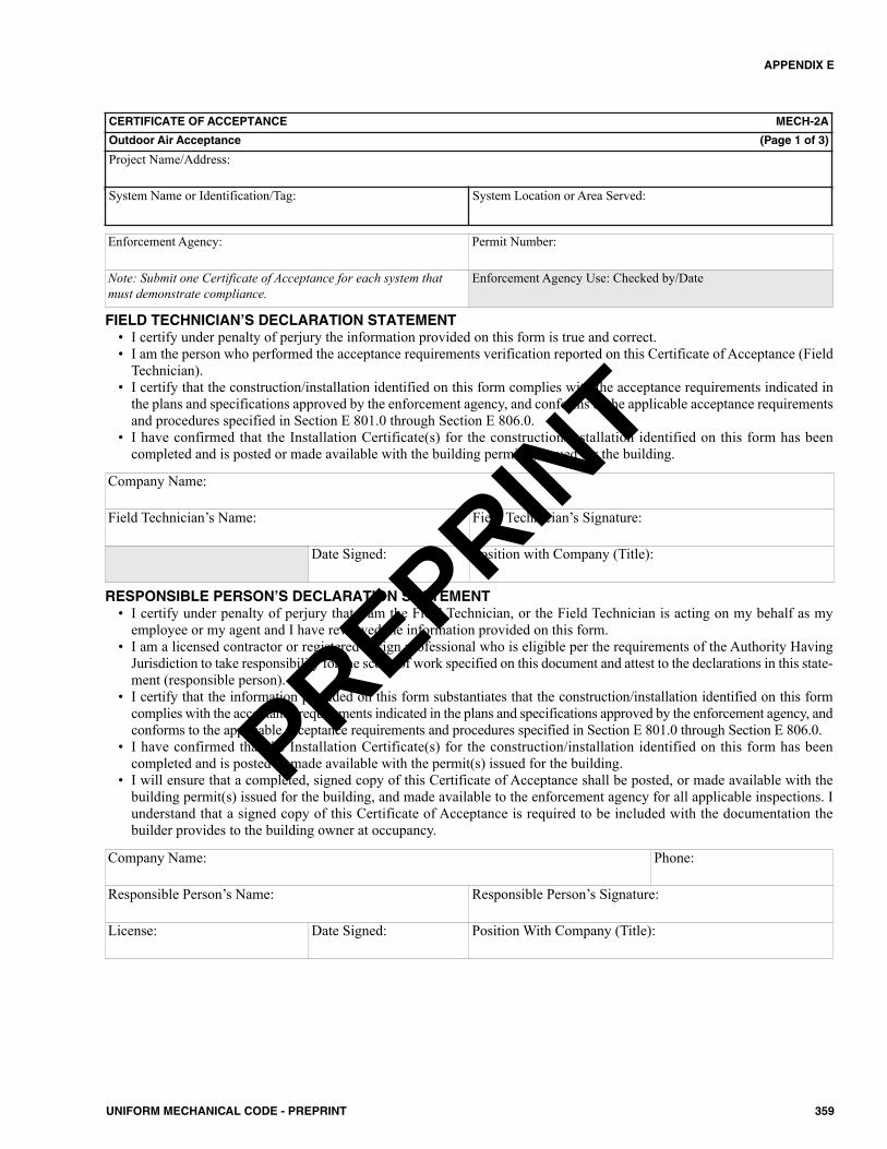
APPENDIX E
359UNIFORM MECHANICAL CODE - PREPRINT
CERTIFICATE OF ACCEPTANCE MECH-2A
Outdoor Air Acceptance (Page 1 of 3)
Project Name/Address:
System Name or Identification/Tag: System Location or Area Served:
Enforcement Agency: Permit Number:
Note: Submit one Certificate of Acceptance for each system thatmust demonstrate compliance.
Enforcement Agency Use: Checked by/Date
FIELD TECHNICIAN’S DECLARATION STATEMENT• I certify under penalty of perjury the information provided on this form is true and correct.• I am the person who performed the acceptance requirements verification reported on this Certificate of Acceptance (Field
Technician).• I certify that the construction/installation identified on this form complies with the acceptance requirements indicated in
the plans and specifications approved by the enforcement agency, and conforms to the applicable acceptance requirementsand procedures specified in Section E 801.0 through Section E 806.0.
• I have confirmed that the Installation Certificate(s) for the construction/installation identified on this form has beencompleted and is posted or made available with the building permit(s) issued for the building.
Company Name:
Field Technician’s Name: Field Technician’s Signature:
Date Signed: Position with Company (Title):
RESPONSIBLE PERSON’S DECLARATION STATEMENT• I certify under penalty of perjury that I am the Field Technician, or the Field Technician is acting on my behalf as my
employee or my agent and I have reviewed the information provided on this form.• I am a licensed contractor or registered design professional who is eligible per the requirements of the Authority Having
Jurisdiction to take responsibility for the scope of work specified on this document and attest to the declarations in this state-ment (responsible person).
• I certify that the information provided on this form substantiates that the construction/installation identified on this formcomplies with the acceptance requirements indicated in the plans and specifications approved by the enforcement agency, andconforms to the applicable acceptance requirements and procedures specified in Section E 801.0 through Section E 806.0.
• I have confirmed that the Installation Certificate(s) for the construction/installation identified on this form has beencompleted and is posted or made available with the permit(s) issued for the building.
• I will ensure that a completed, signed copy of this Certificate of Acceptance shall be posted, or made available with thebuilding permit(s) issued for the building, and made available to the enforcement agency for all applicable inspections. Iunderstand that a signed copy of this Certificate of Acceptance is required to be included with the documentation thebuilder provides to the building owner at occupancy.
Company Name: Phone:
Responsible Person’s Name: Responsible Person’s Signature:
License: Date Signed: Position With Company (Title):
PREPRINT
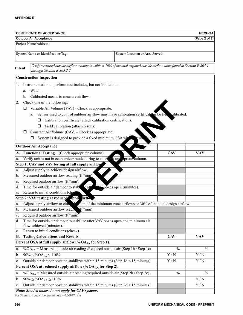
APPENDIX E
360 UNIFORM MECHANICAL CODE - PREPRINT
CERTIFICATE OF ACCEPTANCE MECH-2A
Outdoor Air Acceptance (Page 2 of 3)
Project Name/Address:
System Name or Identification/Tag: System Location or Area Served:
Verify measured outside airflow reading is within ± 10% of the total required outside airflow value found in Section E 805.1through Section E 805.2.2Intent:
Construction Inspection
1. Instrumentation to perform test includes, but not limited to:a. Watch.b. Calibrated means to measure airflow.
2. Check one of the following: Variable Air Volume (VAV) - Check as appropriate:
a. Sensor used to control outdoor air flow must have calibration certificate or be field calibrated. Calibration certificate (attach calibration certification). Field calibration (attach results).
Constant Air Volume (CAV) - Check as appropriate: System is designed to provide a fixed minimum OSA when the unit is on.
Outdoor Air Acceptance
A. Functional Testing. (Check appropriate column) CAV VAVa. Verify unit is not in economizer mode during test - check appropriate column.Step 1: CAV and VAV testing at full supply airflow.a. Adjust supply to achieve design airflow.b. Measured outdoor airflow reading (ft3/min).c. Required outdoor airflow (ft3/min).d. Time for outside air damper to stabilize after VAV boxes open (minutes).e. Return to initial conditions (check).Step 2: VAV testing at reduced supply airflow.a. Adjust supply airflow to either the sum of the minimum zone airflows or 30% of the total design airflow.b. Measured outdoor airflow reading (ft3/min).c. Required outdoor airflow (ft3/min).d. Time for outside air damper to stabilize after VAV boxes open and minimum air
flow achieved (minutes).e. Return to initial conditions (check).B. Testing Calculations and Results. CAV VAVPercent OSA at full supply airflow (%OAFA for Step 1).
a. %OAFA = Measured outside air reading /Required outside air (Step 1b / Step 1c) % %b. 90% ≤ %OAFA ≤ 110% Y / N Y / Nc. Outside air damper position stabilizes within 15 minutes (Step 1d < 15 minutes) Y / N Y / NPercent OSA at reduced supply airflow (%OARA for Step 2).a. %OARA = Measured outside air reading/required outside air (Step 2b / Step 2c). % %b. 90% ≤ %OARA ≤ 110%. Y / Nc. Outside air damper position stabilizes within 15 minutes (Step 2d < 15 minutes). Y / NNote: Shaded boxes do not apply for CAV systems.
For SI units: 1 cubic foot per minute = 0.00047 m3/s
PREPRINT
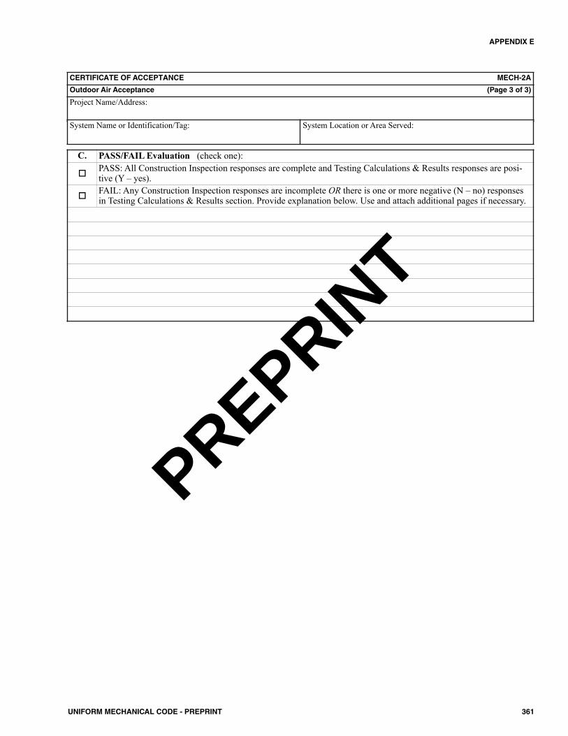
APPENDIX E
361UNIFORM MECHANICAL CODE - PREPRINT
CERTIFICATE OF ACCEPTANCE MECH-2A
Outdoor Air Acceptance (Page 3 of 3)
Project Name/Address:
System Name or Identification/Tag: System Location or Area Served:
C. PASS/FAIL Evaluation (check one):
PASS: All Construction Inspection responses are complete and Testing Calculations & Results responses are posi-tive (Y – yes).
FAIL: Any Construction Inspection responses are incomplete OR there is one or more negative (N – no) responsesin Testing Calculations & Results section. Provide explanation below. Use and attach additional pages if necessary.
PREPRINT
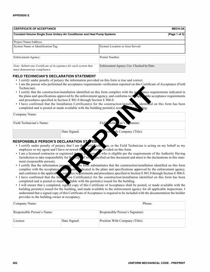
APPENDIX E
362 UNIFORM MECHANICAL CODE - PREPRINT
CERTIFICATE OF ACCEPTANCE MECH-3A
Constant Volume Single Zone Unitary Air Conditioner and Heat Pump Systems (Page 1 of 3)
Project Name/Address:System Name or Identification/Tag: System Location or Area Served:
Enforcement Agency: Permit Number:
Note: Submit one Certificate of Acceptance for each system thatmust demonstrate compliance.
Enforcement Agency Use: Checked by/Date
FIELD TECHNICIAN’S DECLARATION STATEMENT• I certify under penalty of perjury the information provided on this form is true and correct.• I am the person who performed the acceptance requirements verification reported on this Certificate of Acceptance (Field
Technician).• I certify that the construction/installation identified on this form complies with the acceptance requirements indicated in
the plans and specifications approved by the enforcement agency, and conforms to the applicable acceptance requirementsand procedures specified in Section E 801.0 through Section E 806.0.
• I have confirmed that the Installation Certificate(s) for the construction/installation identified on this form has beencompleted and is posted or made available with the building permit(s) issued for the building.
Company Name:
Field Technician’s Name: Field Technician’s Signature:
Date Signed: Position with Company (Title):
RESPONSIBLE PERSON’S DECLARATION STATEMENT• I certify under penalty of perjury that I am the Field Technician, or the Field Technician is acting on my behalf as my
employee or my agent and I have reviewed the information provided on this form.• I am a licensed contractor or registered design professional who is eligible per the requirements of the Authority Having
Jurisdiction to take responsibility for the scope of work specified on this document and attest to the declarations in this state-ment (responsible person).
• I certify that the information provided on this form substantiates that the construction/installation identified on this formcomplies with the acceptance requirements indicated in the plans and specifications approved by the enforcement agency,and conforms to the applicable acceptance requirements and procedures specified in Section E 801.0 through Section E 806.0.
• I have confirmed that the Installation Certificate(s) for the construction/installation identified on this form has beencompleted and is posted or made available with the permit(s) issued for the building.
• I will ensure that a completed, signed copy of this Certificate of Acceptance shall be posted, or made available with thebuilding permit(s) issued for the building, and made available to the enforcement agency for all applicable inspections. Iunderstand that a signed copy of this Certificate of Acceptance is required to be included with the documentation the builderprovides to the building owner at occupancy.
Company Name: Phone:
Responsible Person’s Name: Responsible Person’s Signature:
License: Date Signed: Position With Company (Title):
PREPRINT
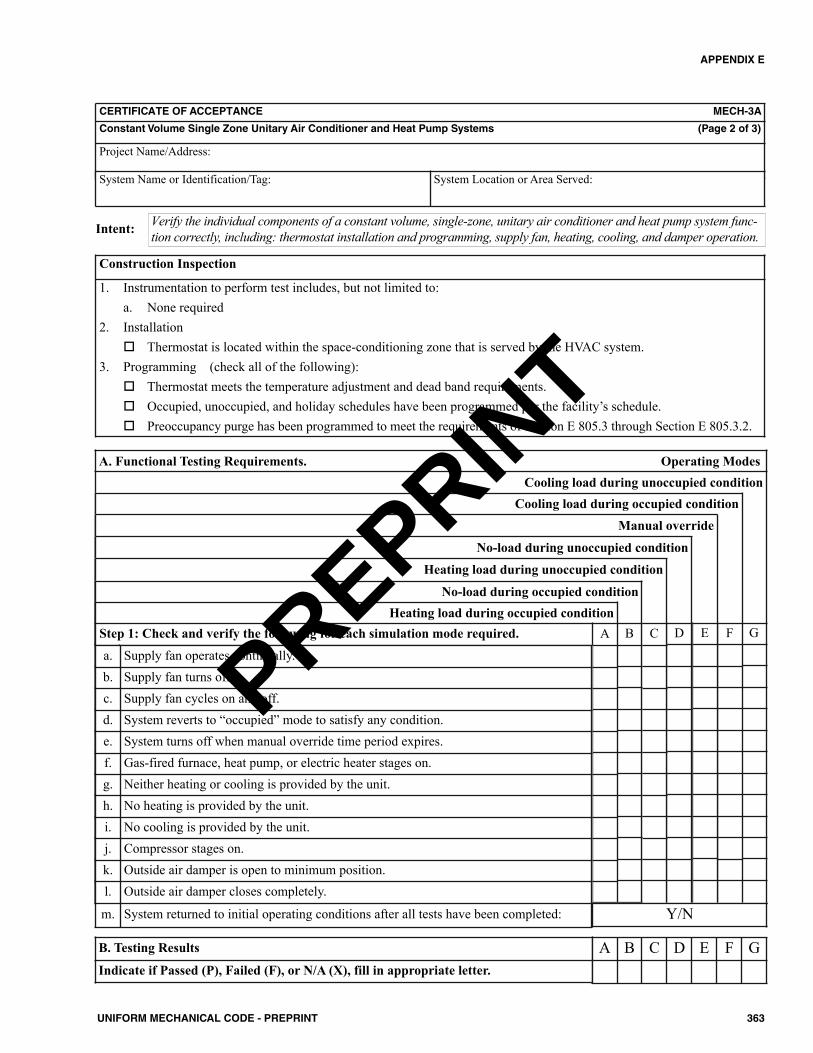
APPENDIX E
363UNIFORM MECHANICAL CODE - PREPRINT
CERTIFICATE OF ACCEPTANCE MECH-3A
Constant Volume Single Zone Unitary Air Conditioner and Heat Pump Systems (Page 2 of 3)
Project Name/Address:
System Name or Identification/Tag: System Location or Area Served:
Verify the individual components of a constant volume, single-zone, unitary air conditioner and heat pump system func-tion correctly, including: thermostat installation and programming, supply fan, heating, cooling, and damper operation.Intent:
Construction Inspection
1. Instrumentation to perform test includes, but not limited to:a. None required
2. Installation Thermostat is located within the space-conditioning zone that is served by the HVAC system.
3. Programming (check all of the following): Thermostat meets the temperature adjustment and dead band requirements. Occupied, unoccupied, and holiday schedules have been programmed per the facility’s schedule. Preoccupancy purge has been programmed to meet the requirements of Section E 805.3 through Section E 805.3.2.
A. Functional Testing Requirements. Operating ModesCooling load during unoccupied condition
G
Cooling load during occupied condition
F
Manual override
E
No-load during unoccupied condition
D
Heating load during unoccupied condition
C
No-load during occupied condition
BHeating load during occupied condition
Step 1: Check and verify the following for each simulation mode required. Aa. Supply fan operates continually.b. Supply fan turns off.c. Supply fan cycles on and off.d. System reverts to “occupied” mode to satisfy any condition.e. System turns off when manual override time period expires.f. Gas-fired furnace, heat pump, or electric heater stages on.g. Neither heating or cooling is provided by the unit.h. No heating is provided by the unit.i. No cooling is provided by the unit.j. Compressor stages on.k. Outside air damper is open to minimum position.l. Outside air damper closes completely.
m. System returned to initial operating conditions after all tests have been completed: Y/N
B. Testing Results
Indicate if Passed (P), Failed (F), or N/A (X), fill in appropriate letter.A B C D E F G
PREPRINT
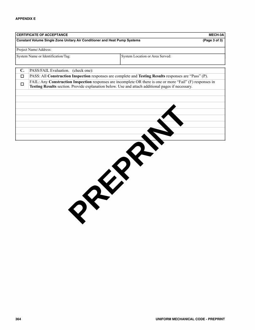
APPENDIX E
364 UNIFORM MECHANICAL CODE - PREPRINT
CERTIFICATE OF ACCEPTANCE MECH-3A
Constant Volume Single Zone Unitary Air Conditioner and Heat Pump Systems (Page 3 of 3)
Project Name/Address:
System Name or Identification/Tag: System Location or Area Served:
C. PASS/FAIL Evaluation. (check one): PASS: All Construction Inspection responses are complete and Testing Results responses are “Pass” (P).
FAIL: Any Construction Inspection responses are incomplete OR there is one or more “Fail” (F) responses inTesting Results section. Provide explanation below. Use and attach additional pages if necessary.
PREPRINT

APPENDIX E
365UNIFORM MECHANICAL CODE - PREPRINT
CERTIFICATE OF ACCEPTANCE MECH-4A
Air Distribution Systems Acceptance (Page 1 of 3)
Project Name/Address:
System Name or Identification/Tag: System Location or Area Served:
Enforcement Agency: Permit Number:
Note: Submit one Certificate of Acceptance for each system thatmust demonstrate compliance.
Enforcement Agency Use: Checked by/Date
FIELD TECHNICIAN’S DECLARATION STATEMENT• I certify under penalty of perjury the information provided on this form is true and correct.• I am the person who performed the acceptance requirements verification reported on this Certificate of Acceptance (Field
Technician).• I certify that the construction/installation identified on this form complies with the acceptance requirements indicated in
the plans and specifications approved by the enforcement agency, and conforms to the applicable acceptance requirementsand procedures specified in Section E 801.0 through Section E 806.0.
• I have confirmed that the Installation Certificate(s) for the construction/installation identified on this form has beencompleted and is posted or made available with the building permit(s) issued for the building.
Company Name:
Field Technician’s Name: Field Technician’s Signature:
Date Signed: Position with Company (Title):
RESPONSIBLE PERSON’S DECLARATION STATEMENT• I certify under penalty of perjury that I am the Field Technician, or the Field Technician is acting on my behalf as my
employee or my agent and I have reviewed the information provided on this form.• I am a licensed contractor or registered design professional who is eligible per the requirements of the Authority Having
Jurisdiction to take responsibility for the scope of work specified on this document and attest to the declarations in this state-ment (responsible person).
• I certify that the information provided on this form substantiates that the construction/installation identified on this formcomplies with the acceptance requirements indicated in the plans and specifications approved by the enforcement agency, andconforms to the applicable acceptance requirements and procedures specified in Section E 801.0 through Section E 806.0.
• I have confirmed that the Installation Certificate(s) for the construction/installation identified on this form has beencompleted and is posted or made available with the permit(s) issued for the building.
• I will ensure that a completed, signed copy of this Certificate of Acceptance shall be posted, or made available with thebuilding permit(s) issued for the building, and made available to the enforcement agency for all applicable inspections. Iunderstand that a signed copy of this Certificate of Acceptance is required to be included with the documentation the builderprovides to the building owner at occupancy.
Company Name: Phone:
Responsible Person’s Name: Responsible Person’s Signature:
License: Date Signed: Position With Company (Title):
PREPRINT
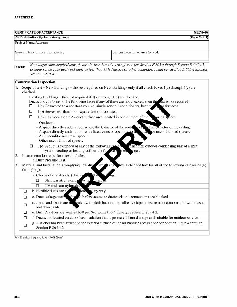
APPENDIX E
366 UNIFORM MECHANICAL CODE - PREPRINT
CERTIFICATE OF ACCEPTANCE MECH-4A
Air Distribution Systems Acceptance (Page 2 of 3)
Project Name/Address:
System Name or Identification/Tag: System Location or Area Served:
Construction Inspection1. Scope of test – New Buildings – this test required on New Buildings only if all check boxes 1(a) through 1(c) are
checked.Existing Buildings – this test required if 1(a) through 1(d) are checked.Ductwork conforms to the following (note if any of these are not checked, then this test is not required): 1(a) Connected to a constant volume, single zone air conditioners, heat pumps, or furnaces. 1(b) Serves less than 5000 square feet of floor area. 1(c) Has more than 25% duct surface area located in one or more of the following spaces.
– Outdoors.– A space directly under a roof where the U-factor of the roof is greater than U-factor of the ceiling.– A space directly under a roof with fixed vents or openings to the outside or unconditioned spaces.– An unconditioned crawl space.– Other unconditioned spaces.
1(d) A duct is extended or any of the following replaced: air handler, outdoor condensing unit of a splitsystem, cooling or heating coil, or the furnace heat exchanger.
2. Instrumentation to perform test includes:a. Duct Pressure Test.
3. Material and Installation. Complying new duct systems shall have a checked box for all of the following categories (a)through (g):
a. Choice of drawbands. (check one of the following) Stainless steel worm-drive hose clamps. UV-resistant nylon duct ties.
b. Flexible ducts are not constricted in any way. c. Duct leakage tests performed before access to ductwork and connections are blocked.
d. Joints and seams are not sealed with cloth back rubber adhesive tape unless used in combination with mastic
and drawbands. e. Duct R-values are verified R-8 per Section E 805.4 through Section E 805.4.2. f. Ductwork located outdoors has insulation that is protected from damage and suitable for outdoor service.
g. A sticker has been affixed to the exterior surface of the air handler access door per Section E 805.4 through
Section E 805.4.2.
New single zone supply ductwork must be less than 6% leakage rate per Section E 805.4 through Section E 805.4.2,existing single zone ductwork must be less than 15% leakage or other compliance path per Section E 805.4 throughSection E 805.4.2.
Intent:
For SI units: 1 square foot = 0.0929 m2
PREPRINT

APPENDIX E
367UNIFORM MECHANICAL CODE - PREPRINT
CERTIFICATE OF ACCEPTANCE MECH-4A
Air Distribution Systems Acceptance (Page 3 of 3)
Project Name/Address:
System Name or Identification/Tag: System Location or Area Served:
Air Distribution System Leakage Diagnostic.The installing contractor must pressure test every new HVAC systems that meet the requirements of Section E 805.4 throughSection E 805.4.2 and every retrofit to existing HVAC systems that meet the requirements of Section E 805.4 through SectionE 805.4.2.RATED FAN FLOW (applies to all systems) Measured Values1. Cooling capacity or for heating only units heating capacity.
(a) Cooling capacity (for all units but heating only units) in tons.(b) Heating capacity (for heating only units) kBtu/h.
2. Fan flow calculation(a) Cooling capacity in tons [ (Line # 1a) x 400 ft3/min/ton].(b) Heating only cap. kBtu/h [ (Line # 1b) x 21.7 ft3/min/kBtu/h].
3. Total calculated supply fan flow 2(a) or 2(b) ft3/min.
NEW CONSTRUCTION OR ENTIRE NEW DUCT SYSTEM ALTERATION:Duct pressurization test results (ft3/min @ 25 Pa).
4. Enter tested leakage flow in ft3/min: P P
5. Pass if leakage percentage ≤6%: [(Line #4) / (Line #3)] x 100 % Pass FailALTERATIONS: Pre-existing duct system with duct alteration and/or HVAC equipment change-out.6. Enter tested leakage flow (cubic feet per minute): Pre-test of existing duct system
prior to duct system alteration, equipment change-out, or both.7. Enter tested leakage flow (cubic feet per minute): Final test of new duct system or
altered duct system for duct system alteration, equipment change-out, or both.TEST OR VERIFICATION STANDARDS: For altered duct system and/or HVAC equipment change-out use one ofthe following three tests or verification standards for compliance:8. Pass if leakage percentage <15%
[ (Line # 7) / (Line # 3)] x 100 % Pass Fail
9. Pass if leakage reduction percentage >60%Leakage reduction = [1 - [ (Line#7) / (Line#6)] } x 100 % Pass Fail
10. Pass if all accessible leaks are sealed as confirmed by visual inspection and verifica-tion by HERS rater (sampling rate 100%). % Pass Fail
Pass if One of Lines #8 through #10 pass Pass FailFor SI units: 1000 British thermal units per hour = 0.293 kW, 1 cubic foot per minute = 0.00047 m3/s, 1 metric ton = 1000 kg
PREPRINT

APPENDIX E
368 UNIFORM MECHANICAL CODE - PREPRINT
\CERTIFICATE OF ACCEPTANCE MECH-5A
Air Economizer Controls Acceptance (Page 1 of 3)
Project Name/Address:
System Name or Identification/Tag: System Location or Area Served:
Enforcement Agency: Permit Number:
Note: Submit one Certificate of Acceptance for each system thatmust demonstrate compliance.
Enforcement Agency Use: Checked by/Date
FIELD TECHNICIAN’S DECLARATION STATEMENT• I certify under penalty of perjury the information provided on this form is true and correct.• I am the person who performed the acceptance requirements verification reported on this Certificate of Acceptance (Field
Technician).• I certify that the construction/installation identified on this form complies with the acceptance requirements indicated in
the plans and specifications approved by the enforcement agency, and conforms to the applicable acceptance requirementsand procedures specified in Section E 801.0 through Section E 806.0.
• I have confirmed that the Installation Certificate(s) for the construction/installation identified on this form has beencompleted and is posted or made available with the building permit(s) issued for the building.
Company Name:
Field Technician’s Name: Field Technician’s Signature:
Date Signed: Position with Company (Title):
RESPONSIBLE PERSON’S DECLARATION STATEMENT• I certify under penalty of perjury that I am the Field Technician, or the Field Technician is acting on my behalf as my
employee or my agent and I have reviewed the information provided on this form.• I am a licensed contractor or registered design professional who is eligible per the requirements of the Authority Having
Jurisdiction to take responsibility for the scope of work specified on this document and attest to the declarations in this state-ment (responsible person).
• I certify that the information provided on this form substantiates that the construction/installation identified on this formcomplies with the acceptance requirements indicated in the plans and specifications approved by the enforcement agency, andconforms to the applicable acceptance requirements and procedures specified in Section E 801.0 through Section E 806.0.
• I have confirmed that the Installation Certificate(s) for the construction/installation identified on this form has beencompleted and is posted or made available with the permit(s) issued for the building.
• I will ensure that a completed, signed copy of this Certificate of Acceptance shall be posted, or made available with thebuilding permit(s) issued for the building, and made available to the enforcement agency for all applicable inspections. Iunderstand that a signed copy of this Certificate of Acceptance is required to be included with the documentation the builderprovides to the building owner at occupancy.
Company Name: Phone:
Responsible Person’s Name: Responsible Person’s Signature:
License: Date Signed: Position With Company (Title):
PREPRINT
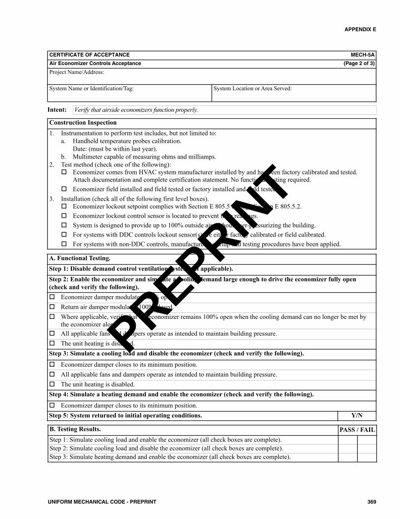
APPENDIX E
369UNIFORM MECHANICAL CODE - PREPRINT
CERTIFICATE OF ACCEPTANCE MECH-5A
Air Economizer Controls Acceptance (Page 2 of 3)
Project Name/Address:
System Name or Identification/Tag: System Location or Area Served:
Construction Inspection1. Instrumentation to perform test includes, but not limited to:
a. Handheld temperature probes calibration.Date: (must be within last year).
b. Multimeter capable of measuring ohms and milliamps.2. Test method (check one of the following):
Economizer comes from HVAC system manufacturer installed by and has been factory calibrated and tested.Attach documentation and complete certification statement. No functional testing required.
Economizer field installed and field tested or factory installed and field tested.3. Installation (check all of the following first level boxes).
Economizer lockout setpoint complies with Section E 805.5 through Section E 805.5.2. Economizer lockout control sensor is located to prevent false readings. System is designed to provide up to 100% outside air without over-pressurizing the building. For systems with DDC controls lockout sensor(s) are either factory calibrated or field calibrated. For systems with non-DDC controls, manufacturer’s startup and testing procedures have been applied.
Verify that airside economizers function properly.Intent:
A. Functional Testing.Step 1: Disable demand control ventilation systems (if applicable).Step 2: Enable the economizer and simulate a cooling demand large enough to drive the economizer fully open(check and verify the following). Economizer damper modulates 100% open. Return air damper modulates 100% closed. Where applicable, verify that the economizer remains 100% open when the cooling demand can no longer be met by
the economizer alone. All applicable fans and dampers operate as intended to maintain building pressure. The unit heating is disabled.Step 3: Simulate a cooling load and disable the economizer (check and verify the following).
Economizer damper closes to its minimum position. All applicable fans and dampers operate as intended to maintain building pressure. The unit heating is disabled.Step 4: Simulate a heating demand and enable the economizer (check and verify the following).
Economizer damper closes to its minimum position.Step 5: System returned to initial operating conditions. Y/N
B. Testing Results. PASS / FAILStep 1: Simulate cooling load and enable the economizer (all check boxes are complete).Step 2: Simulate cooling load and disable the economizer (all check boxes are complete).Step 3: Simulate heating demand and enable the economizer (all check boxes are complete).
PREPRINT
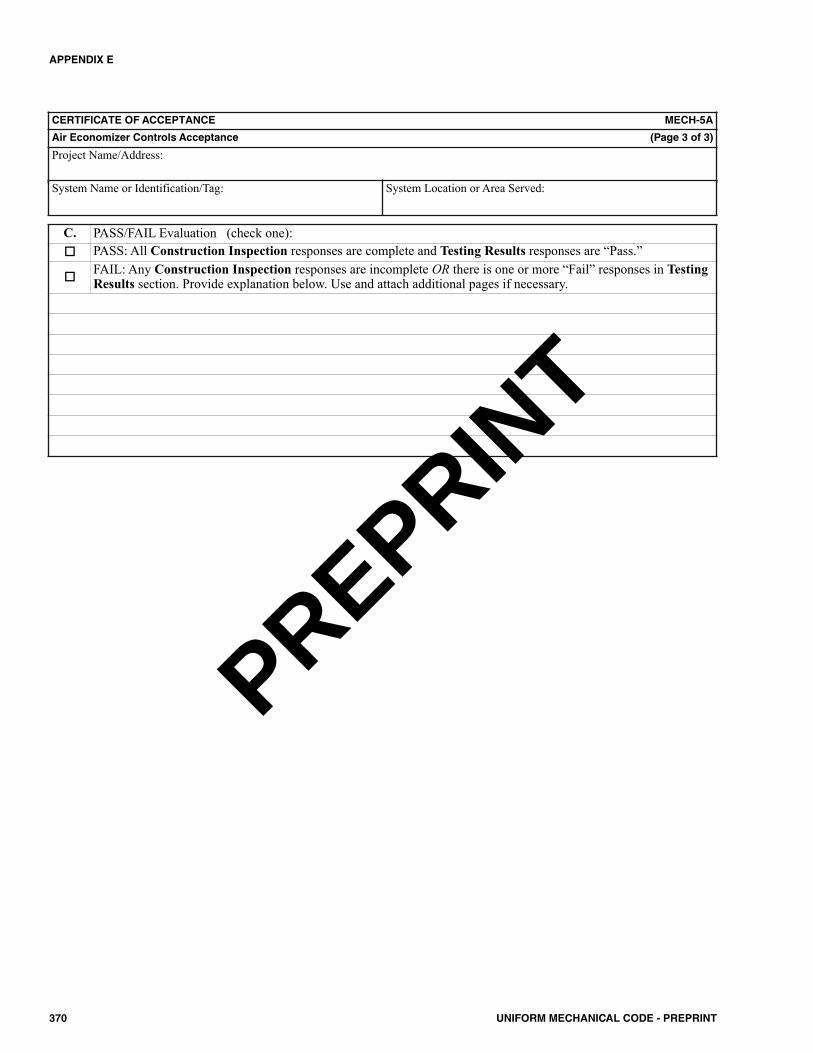
APPENDIX E
370 UNIFORM MECHANICAL CODE - PREPRINT
C. PASS/FAIL Evaluation (check one): PASS: All Construction Inspection responses are complete and Testing Results responses are “Pass.”
FAIL: Any Construction Inspection responses are incomplete OR there is one or more “Fail” responses in TestingResults section. Provide explanation below. Use and attach additional pages if necessary.
CERTIFICATE OF ACCEPTANCE MECH-5A
Air Economizer Controls Acceptance (Page 3 of 3)
Project Name/Address:
System Name or Identification/Tag: System Location or Area Served:
PREPRINT

APPENDIX E
371UNIFORM MECHANICAL CODE - PREPRINT
CERTIFICATE OF ACCEPTANCE MECH-6A
Demand Control Ventilation Systems Acceptance (Page 1 of 3)
Project Name/Address:
System Name or Identification/Tag: System Location or Area Served:
Enforcement Agency: Permit Number:
Note: Submit one Certificate of Acceptance for each system thatmust demonstrate compliance.
Enforcement Agency Use: Checked by/Date
FIELD TECHNICIAN’S DECLARATION STATEMENT• I certify under penalty of perjury the information provided on this form is true and correct.• I am the person who performed the acceptance requirements verification reported on this Certificate of Acceptance (Field
Technician).• I certify that the construction/installation identified on this form complies with the acceptance requirements indicated in
the plans and specifications approved by the enforcement agency, and conforms to the applicable acceptance requirementsand procedures specified in Section E 801.0 through Section E 806.0.
• I have confirmed that the Installation Certificate(s) for the construction/installation identified on this form has beencompleted and is posted or made available with the building permit(s) issued for the building.
Company Name:
Field Technician’s Name: Field Technician’s Signature:
Date Signed: Position with Company (Title):
RESPONSIBLE PERSON’S DECLARATION STATEMENT• I certify under penalty of perjury that I am the Field Technician, or the Field Technician is acting on my behalf as my
employee or my agent and I have reviewed the information provided on this form.• I am a licensed contractor or registered design professional who is eligible per the requirements of the Authority Having
Jurisdiction to take responsibility for the scope of work specified on this document and attest to the declarations in this state-ment (responsible person).
• I certify that the information provided on this form substantiates that the construction/installation identified on this formcomplies with the acceptance requirements indicated in the plans and specifications approved by the enforcement agency, andconforms to the applicable acceptance requirements and procedures specified in Section E 801.0 through Section E 806.0.
• I have confirmed that the Installation Certificate(s) for the construction/installation identified on this form has beencompleted and is posted or made available with the permit(s) issued for the building.
• I will ensure that a completed, signed copy of this Certificate of Acceptance shall be posted, or made available with thebuilding permit(s) issued for the building, and made available to the enforcement agency for all applicable inspections. Iunderstand that a signed copy of this Certificate of Acceptance is required to be included with the documentation the builderprovides to the building owner at occupancy.
Company Name: Phone:
Responsible Person’s Name: Responsible Person’s Signature:
License: Date Signed: Position With Company (Title):
PREPRINT
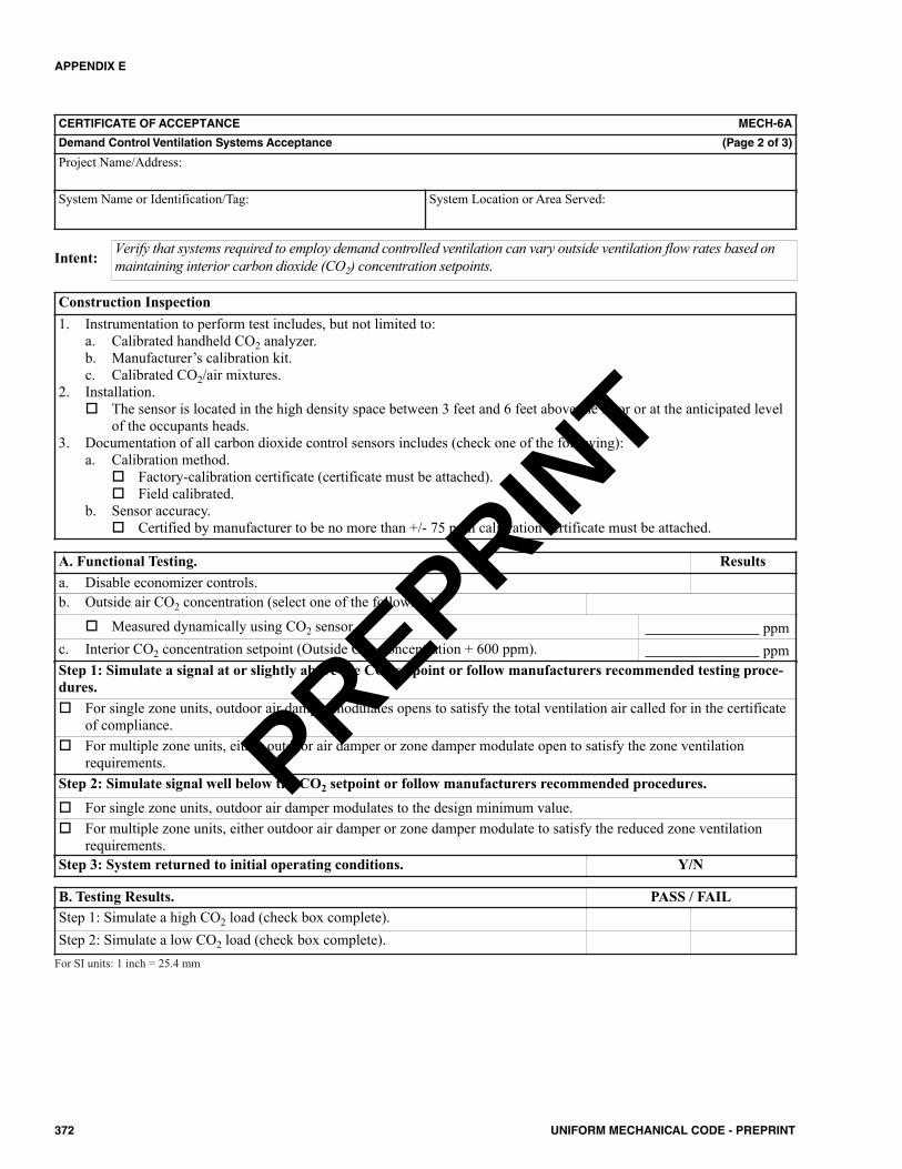
APPENDIX E
372 UNIFORM MECHANICAL CODE - PREPRINT
CERTIFICATE OF ACCEPTANCE MECH-6A
Demand Control Ventilation Systems Acceptance (Page 2 of 3)
Project Name/Address:
System Name or Identification/Tag: System Location or Area Served:
Construction Inspection1. Instrumentation to perform test includes, but not limited to:
a. Calibrated handheld CO2 analyzer.b. Manufacturer’s calibration kit.c. Calibrated CO2/air mixtures.
2. Installation. The sensor is located in the high density space between 3 feet and 6 feet above the floor or at the anticipated level
of the occupants heads.3. Documentation of all carbon dioxide control sensors includes (check one of the following):
a. Calibration method. Factory-calibration certificate (certificate must be attached). Field calibrated.
b. Sensor accuracy. Certified by manufacturer to be no more than +/- 75 ppm calibration certificate must be attached.
Verify that systems required to employ demand controlled ventilation can vary outside ventilation flow rates based onmaintaining interior carbon dioxide (CO2) concentration setpoints.Intent:
A. Functional Testing. Resultsa. Disable economizer controls.b. Outside air CO2 concentration (select one of the following).
Measured dynamically using CO2 sensor. ppmc. Interior CO2 concentration setpoint (Outside CO2 concentration + 600 ppm). ppmStep 1: Simulate a signal at or slightly above the CO2 setpoint or follow manufacturers recommended testing proce-dures. For single zone units, outdoor air damper modulates opens to satisfy the total ventilation air called for in the certificate
of compliance. For multiple zone units, either outdoor air damper or zone damper modulate open to satisfy the zone ventilation
requirements.Step 2: Simulate signal well below the CO2 setpoint or follow manufacturers recommended procedures. For single zone units, outdoor air damper modulates to the design minimum value. For multiple zone units, either outdoor air damper or zone damper modulate to satisfy the reduced zone ventilation
requirements.Step 3: System returned to initial operating conditions. Y/N
B. Testing Results. PASS / FAILStep 1: Simulate a high CO2 load (check box complete).Step 2: Simulate a low CO2 load (check box complete).
For SI units: 1 inch = 25.4 mm
PREPRINT
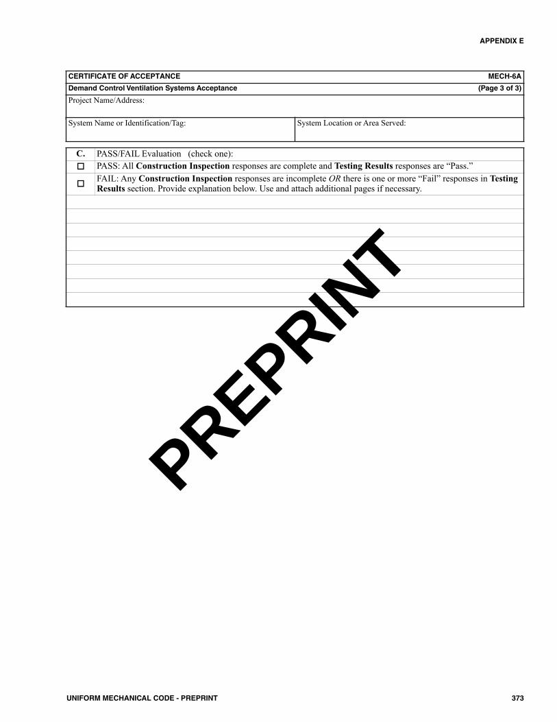
APPENDIX E
373UNIFORM MECHANICAL CODE - PREPRINT
C. PASS/FAIL Evaluation (check one): PASS: All Construction Inspection responses are complete and Testing Results responses are “Pass.”
FAIL: Any Construction Inspection responses are incomplete OR there is one or more “Fail” responses in TestingResults section. Provide explanation below. Use and attach additional pages if necessary.
CERTIFICATE OF ACCEPTANCE MECH-6A
Demand Control Ventilation Systems Acceptance (Page 3 of 3)
Project Name/Address:
System Name or Identification/Tag: System Location or Area Served:
PREPRINT
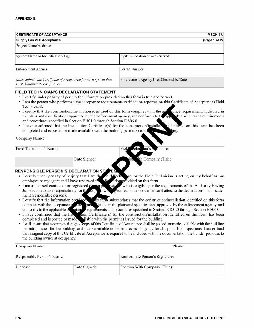
APPENDIX E
374 UNIFORM MECHANICAL CODE - PREPRINT
CERTIFICATE OF ACCEPTANCE MECH-7A
Supply Fan VFD Acceptance (Page 1 of 2)
Project Name/Address:
System Name or Identification/Tag: System Location or Area Served:
Enforcement Agency: Permit Number:
Note: Submit one Certificate of Acceptance for each system thatmust demonstrate compliance.
Enforcement Agency Use: Checked by/Date
FIELD TECHNICIAN’S DECLARATION STATEMENT• I certify under penalty of perjury the information provided on this form is true and correct.• I am the person who performed the acceptance requirements verification reported on this Certificate of Acceptance (Field
Technician).• I certify that the construction/installation identified on this form complies with the acceptance requirements indicated in
the plans and specifications approved by the enforcement agency, and conforms to the applicable acceptance requirementsand procedures specified in Section E 801.0 through Section E 806.0.
• I have confirmed that the Installation Certificate(s) for the construction/installation identified on this form has beencompleted and is posted or made available with the building permit(s) issued for the building.
Company Name:
Field Technician’s Name: Field Technician’s Signature:
Date Signed: Position with Company (Title):
RESPONSIBLE PERSON’S DECLARATION STATEMENT• I certify under penalty of perjury that I am the Field Technician, or the Field Technician is acting on my behalf as my
employee or my agent and I have reviewed the information provided on this form.• I am a licensed contractor or registered design professional who is eligible per the requirements of the Authority Having
Jurisdiction to take responsibility for the scope of work specified on this document and attest to the declarations in this state-ment (responsible person).
• I certify that the information provided on this form substantiates that the construction/installation identified on this formcomplies with the acceptance requirements indicated in the plans and specifications approved by the enforcement agency, andconforms to the applicable acceptance requirements and procedures specified in Section E 801.0 through Section E 806.0.
• I have confirmed that the Installation Certificate(s) for the construction/installation identified on this form has beencompleted and is posted or made available with the permit(s) issued for the building.
• I will ensure that a completed, signed copy of this Certificate of Acceptance shall be posted, or made available with the buildingpermit(s) issued for the building, and made available to the enforcement agency for all applicable inspections. I understandthat a signed copy of this Certificate of Acceptance is required to be included with the documentation the builder provides tothe building owner at occupancy.
Company Name: Phone:
Responsible Person’s Name: Responsible Person’s Signature:
License: Date Signed: Position With Company (Title):
PREPRINT
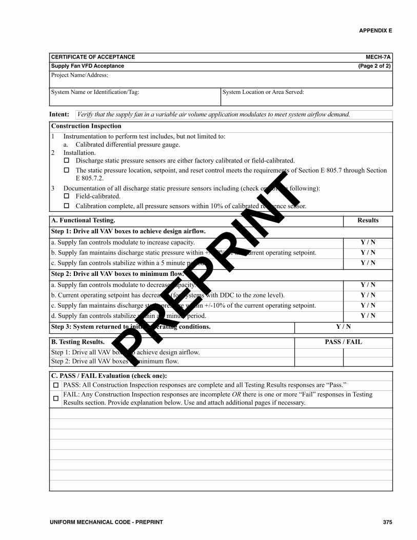
APPENDIX E
375UNIFORM MECHANICAL CODE - PREPRINT
CERTIFICATE OF ACCEPTANCE MECH-7A
Supply Fan VFD Acceptance (Page 2 of 2)
Project Name/Address:
System Name or Identification/Tag: System Location or Area Served:
Verify that the supply fan in a variable air volume application modulates to meet system airflow demand.Intent:
Construction Inspection1 Instrumentation to perform test includes, but not limited to:
a. Calibrated differential pressure gauge.2 Installation.
Discharge static pressure sensors are either factory calibrated or field-calibrated. The static pressure location, setpoint, and reset control meets the requirements of Section E 805.7 through Section
E 805.7.2.3 Documentation of all discharge static pressure sensors including (check one of the following):
Field-calibrated. Calibration complete, all pressure sensors within 10% of calibrated reference sensor.
A. Functional Testing. ResultsStep 1: Drive all VAV boxes to achieve design airflow.a. Supply fan controls modulate to increase capacity. Y / Nb. Supply fan maintains discharge static pressure within +/-10% of the current operating setpoint. Y / Nc. Supply fan controls stabilize within a 5 minute period. Y / NStep 2: Drive all VAV boxes to minimum flow.a. Supply fan controls modulate to decrease capacity. Y / Nb. Current operating setpoint has decreased (for systems with DDC to the zone level). Y / Nc. Supply fan maintains discharge static pressure within +/-10% of the current operating setpoint. Y / Nd. Supply fan controls stabilize within a 5 minute period. Y / NStep 3: System returned to initial operating conditions. Y / N
B. Testing Results. PASS / FAILStep 1: Drive all VAV boxes to achieve design airflow.Step 2: Drive all VAV boxes to minimum flow.
C. PASS / FAIL Evaluation (check one): PASS: All Construction Inspection responses are complete and all Testing Results responses are “Pass.”
FAIL: Any Construction Inspection responses are incomplete OR there is one or more “Fail” responses in TestingResults section. Provide explanation below. Use and attach additional pages if necessary.
PREPRINT

APPENDIX E
376 UNIFORM MECHANICAL CODE - PREPRINT
CERTIFICATE OF ACCEPTANCE MECH-8A
Valve Leakage Test (Page 1 of 2)
Project Name/Address:
System Name or Identification/Tag: System Location or Area Served:
Enforcement Agency: Permit Number:
Note: Submit one Certificate of Acceptance for each system thatmust demonstrate compliance.
Enforcement Agency Use: Checked by/Date
FIELD TECHNICIAN’S DECLARATION STATEMENT• I certify under penalty of perjury the information provided on this form is true and correct.• I am the person who performed the acceptance requirements verification reported on this Certificate of Acceptance (Field
Technician).• I certify that the construction/installation identified on this form complies with the acceptance requirements indicated in
the plans and specifications approved by the enforcement agency, and conforms to the applicable acceptance requirementsand procedures specified in Section E 801.0 through Section E 806.0.
• I have confirmed that the Installation Certificate(s) for the construction/installation identified on this form has beencompleted and is posted or made available with the building permit(s) issued for the building.
Company Name:
Field Technician’s Name: Field Technician’s Signature:
Date Signed: Position with Company (Title):
RESPONSIBLE PERSON’S DECLARATION STATEMENT• I certify under penalty of perjury that I am the Field Technician, or the Field Technician is acting on my behalf as my
employee or my agent and I have reviewed the information provided on this form.• I am a licensed contractor or registered design professional who is eligible per the requirements of the Authority Having
Jurisdiction to take responsibility for the scope of work specified on this document and attest to the declarations in this state-ment (responsible person).
• I certify that the information provided on this form substantiates that the construction/installation identified on this formcomplies with the acceptance requirements indicated in the plans and specifications approved by the enforcement agency, andconforms to the applicable acceptance requirements and procedures specified in Section E 801.0 through Section E 806.0.
• I have confirmed that the Installation Certificate(s) for the construction/installation identified on this form has beencompleted and is posted or made available with the permit(s) issued for the building.
• I will ensure that a completed, signed copy of this Certificate of Acceptance shall be posted, or made available with thebuilding permit(s) issued for the building, and made available to the enforcement agency for all applicable inspections. Iunderstand that a signed copy of this Certificate of Acceptance is required to be included with the documentation the builderprovides to the building owner at occupancy.
Company Name: Phone:
Responsible Person’s Name: Responsible Person’s Signature:
License: Date Signed: Position With Company (Title):
PREPRINT
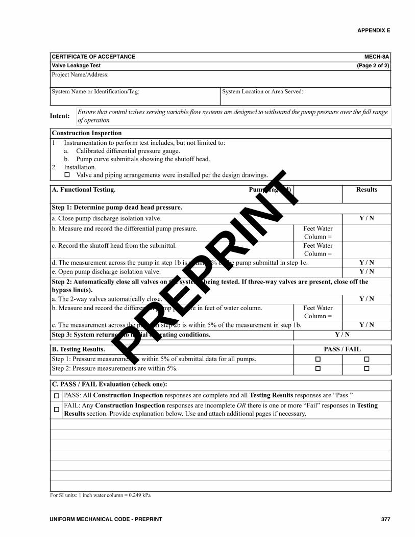
APPENDIX E
377UNIFORM MECHANICAL CODE - PREPRINT
A. Functional Testing. Pump Tag (Id) Results
Step 1: Determine pump dead head pressure.a. Close pump discharge isolation valve. Y / Nb. Measure and record the differential pump pressure. Feet Water
Column =c. Record the shutoff head from the submittal. Feet Water
Column =d. The measurement across the pump in step 1b is within 5% of the pump submittal in step 1c. Y / Ne. Open pump discharge isolation valve. Y / NStep 2: Automatically close all valves on the systems being tested. If three-way valves are present, close off thebypass line(s).a. The 2-way valves automatically close. Y / Nb. Measure and record the differential pump pressure in feet of water column. Feet Water
Column =c. The measurement across the pump in step 2b is within 5% of the measurement in step 1b. Y / NStep 3: System returned to initial operating conditions. Y / N
CERTIFICATE OF ACCEPTANCE MECH-8A
Valve Leakage Test (Page 2 of 2)
Project Name/Address:
System Name or Identification/Tag: System Location or Area Served:
Ensure that control valves serving variable flow systems are designed to withstand the pump pressure over the full rangeof operation.Intent:
Construction Inspection1 Instrumentation to perform test includes, but not limited to:
a. Calibrated differential pressure gauge.b. Pump curve submittals showing the shutoff head.
2 Installation. Valve and piping arrangements were installed per the design drawings.
B. Testing Results. PASS / FAILStep 1: Pressure measurement is within 5% of submittal data for all pumps. Step 2: Pressure measurements are within 5%.
C. PASS / FAIL Evaluation (check one):
PASS: All Construction Inspection responses are complete and all Testing Results responses are “Pass.”
FAIL: Any Construction Inspection responses are incomplete OR there is one or more “Fail” responses in TestingResults section. Provide explanation below. Use and attach additional pages if necessary.
For SI units: 1 inch water column = 0.249 kPa
PREPRINT

APPENDIX E
378 UNIFORM MECHANICAL CODE - PREPRINT
CERTIFICATE OF ACCEPTANCE MECH-9A
Supply Water Temperature Reset Controls Acceptance (Page 1 of 2)
Project Name/Address:
System Name or Identification/Tag: System Location or Area Served:
Enforcement Agency: Permit Number:
Note: Submit one Certificate of Acceptance for each system thatmust demonstrate compliance.
Enforcement Agency Use: Checked by/Date
FIELD TECHNICIAN’S DECLARATION STATEMENT• I certify under penalty of perjury the information provided on this form is true and correct.• I am the person who performed the acceptance requirements verification reported on this Certificate of Acceptance (Field
Technician).• I certify that the construction/installation identified on this form complies with the acceptance requirements indicated in
the plans and specifications approved by the enforcement agency, and conforms to the applicable acceptance requirementsand procedures specified in Section E 801.0 through Section E 806.0.
• I have confirmed that the Installation Certificate(s) for the construction/installation identified on this form has beencompleted and is posted or made available with the building permit(s) issued for the building.
Company Name:
Field Technician’s Name: Field Technician’s Signature:
Date Signed: Position with Company (Title):
RESPONSIBLE PERSON’S DECLARATION STATEMENT• I certify under penalty of perjury that I am the Field Technician, or the Field Technician is acting on my behalf as my
employee or my agent and I have reviewed the information provided on this form.• I am a licensed contractor or registered design professional who is eligible per the requirements of the Authority Having
Jurisdiction to take responsibility for the scope of work specified on this document and attest to the declarations in this state-ment (responsible person).
• I certify that the information provided on this form substantiates that the construction/installation identified on this formcomplies with the acceptance requirements indicated in the plans and specifications approved by the enforcement agency, andconforms to the applicable acceptance requirements and procedures specified in Section E 801.0 through Section E 806.0.
• I have confirmed that the Installation Certificate(s) for the construction/installation identified on this form has beencompleted and is posted or made available with the permit(s) issued for the building.
• I will ensure that a completed, signed copy of this Certificate of Acceptance shall be posted, or made available with thebuilding permit(s) issued for the building, and made available to the enforcement agency for all applicable inspections. Iunderstand that a signed copy of this Certificate of Acceptance is required to be included with the documentation the builderprovides to the building owner at occupancy.
Company Name: Phone:
Responsible Person’s Name: Responsible Person’s Signature:
License: Date Signed: Position With Company (Title):
PREPRINT
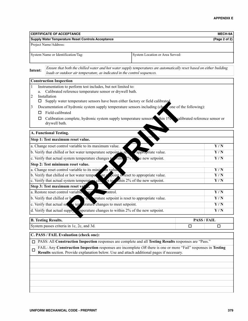
APPENDIX E
379UNIFORM MECHANICAL CODE - PREPRINT
CERTIFICATE OF ACCEPTANCE MECH-9A
Supply Water Temperature Reset Controls Acceptance (Page 2 of 2)
Project Name/Address:
System Name or Identification/Tag: System Location or Area Served:
Ensure that both the chilled water and hot water supply temperatures are automatically reset based on either buildingloads or outdoor air temperature, as indicated in the control sequences.Intent:
Construction Inspection1 Instrumentation to perform test includes, but not limited to:
a. Calibrated reference temperature sensor or drywell bath.2 Installation
Supply water temperature sensors have been either factory or field calibrated.3 Documentation of hydronic system supply temperature sensors including (check one of the following):
Field-calibrated Calibration complete, hydronic system supply temperature sensors within 1% of calibrated reference sensor or
drywell bath.
A. Functional Testing.Step 1: Test maximum reset value.a. Change reset control variable to its maximum value. Y / Nb. Verify that chilled or hot water temperature setpoint is reset to appropriate value. Y / Nc. Verify that actual system temperature changes to within 2% of the new setpoint. Y / NStep 2: Test minimum reset value.a. Change reset control variable to its minimum value. Y / Nb. Verify that chilled or hot water temperature setpoint is reset to appropriate value. Y / Nc. Verify that actual system temperature changes to within 2% of the new setpoint. Y / NStep 3: Test maximum reset value.a. Restore reset control variable to automatic control. Y / Nb. Verify that chilled or hot water temperature setpoint is reset to appropriate value. Y / Nc. Verify that actual supply temperature changes to meet setpoint. Y / Nd. Verify that actual supply temperature changes to within 2% of the new setpoint. Y / N
B. Testing Results. PASS / FAILSystem passes criteria in 1c, 2c, and 3d.
C. PASS / FAIL Evaluation (check one):
PASS: All Construction Inspection responses are complete and all Testing Results responses are “Pass.”
FAIL: Any Construction Inspection responses are incomplete OR there is one or more “Fail” responses in TestingResults section. Provide explanation below. Use and attach additional pages if necessary.
PREPRINT

APPENDIX E
380 UNIFORM MECHANICAL CODE - PREPRINT
CERTIFICATE OF ACCEPTANCE MECH-10A
Hydronic System Variable Flow Control Acceptance (Page 1 of 3)
Project Name/Address:
System Name or Identification/Tag: System Location or Area Served:
Enforcement Agency: Permit Number:
Note: Submit one Certificate of Acceptance for each system thatmust demonstrate compliance.
Enforcement Agency Use: Checked by/Date
FIELD TECHNICIAN’S DECLARATION STATEMENT• I certify under penalty of perjury the information provided on this form is true and correct.• I am the person who performed the acceptance requirements verification reported on this Certificate of Acceptance (Field
Technician).• I certify that the construction/installation identified on this form complies with the acceptance requirements indicated in
the plans and specifications approved by the enforcement agency, and conforms to the applicable acceptance requirementsand procedures specified in Section E 801.0 through Section E 806.0.
• I have confirmed that the Installation Certificate(s) for the construction/installation identified on this form has beencompleted and is posted or made available with the building permit(s) issued for the building.
Company Name:
Field Technician’s Name: Field Technician’s Signature:
Date Signed: Position with Company (Title):
RESPONSIBLE PERSON’S DECLARATION STATEMENT• I certify under penalty of perjury that I am the Field Technician, or the Field Technician is acting on my behalf as my
employee or my agent and I have reviewed the information provided on this form.• I am a licensed contractor or registered design professional who is eligible per the requirements of the Authority Having
Jurisdiction to take responsibility for the scope of work specified on this document and attest to the declarations in this state-ment (responsible person).
• I certify that the information provided on this form substantiates that the construction/installation identified on this formcomplies with the acceptance requirements indicated in the plans and specifications approved by the enforcement agency, andconforms to the applicable acceptance requirements and procedures specified in Section E 801.0 through Section E 806.0.
• I have confirmed that the Installation Certificate(s) for the construction/installation identified on this form has beencompleted and is posted or made available with the permit(s) issued for the building.
• I will ensure that a completed, signed copy of this Certificate of Acceptance shall be posted, or made available with thebuilding permit(s) issued for the building, and made available to the enforcement agency for all applicable inspections. Iunderstand that a signed copy of this Certificate of Acceptance is required to be included with the documentation the builderprovides to the building owner at occupancy.
Company Name: Phone:
Responsible Person’s Name: Responsible Person’s Signature:
License: Date Signed: Position With Company (Title):
PREPRINT
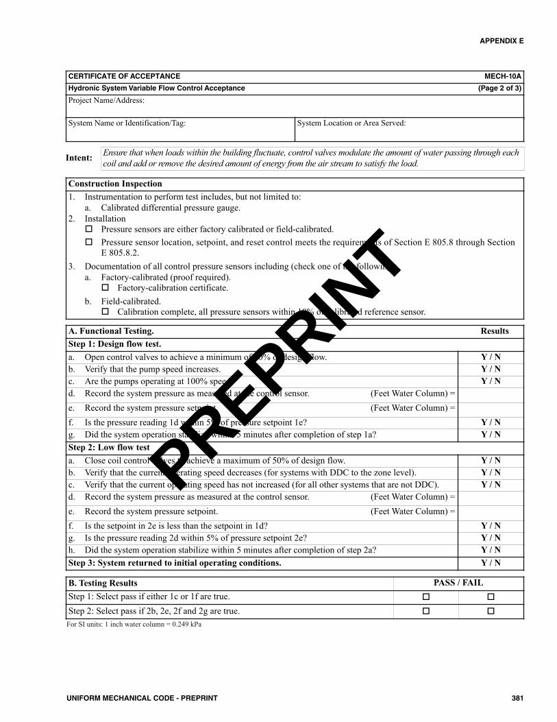
APPENDIX E
381UNIFORM MECHANICAL CODE - PREPRINT
CERTIFICATE OF ACCEPTANCE MECH-10A
Hydronic System Variable Flow Control Acceptance (Page 2 of 3)
Project Name/Address:
System Name or Identification/Tag: System Location or Area Served:
Ensure that when loads within the building fluctuate, control valves modulate the amount of water passing through eachcoil and add or remove the desired amount of energy from the air stream to satisfy the load.Intent:
Construction Inspection1. Instrumentation to perform test includes, but not limited to:
a. Calibrated differential pressure gauge.2. Installation
Pressure sensors are either factory calibrated or field-calibrated. Pressure sensor location, setpoint, and reset control meets the requirements of Section E 805.8 through Section
E 805.8.2.3. Documentation of all control pressure sensors including (check one of the following):
a. Factory-calibrated (proof required). Factory-calibration certificate.
b. Field-calibrated. Calibration complete, all pressure sensors within 10% of calibrated reference sensor.
A. Functional Testing. ResultsStep 1: Design flow test.a. Open control valves to achieve a minimum of 90% of design flow. Y / Nb. Verify that the pump speed increases. Y / Nc. Are the pumps operating at 100% speed? Y / Nd. Record the system pressure as measured at the control sensor. (Feet Water Column) =e. Record the system pressure setpoint. (Feet Water Column) =f. Is the pressure reading 1d within 5% of pressure setpoint 1e? Y / Ng. Did the system operation stabilize within 5 minutes after completion of step 1a? Y / NStep 2: Low flow testa. Close coil control valves to achieve a maximum of 50% of design flow. Y / Nb. Verify that the current operating speed decreases (for systems with DDC to the zone level). Y / Nc. Verify that the current operating speed has not increased (for all other systems that are not DDC). Y / Nd. Record the system pressure as measured at the control sensor. (Feet Water Column) =e. Record the system pressure setpoint. (Feet Water Column) =f. Is the setpoint in 2e is less than the setpoint in 1d? Y / Ng. Is the pressure reading 2d within 5% of pressure setpoint 2e? Y / Nh. Did the system operation stabilize within 5 minutes after completion of step 2a? Y / NStep 3: System returned to initial operating conditions. Y / N
B. Testing Results PASS / FAILStep 1: Select pass if either 1c or 1f are true.
Step 2: Select pass if 2b, 2e, 2f and 2g are true. For SI units: 1 inch water column = 0.249 kPa
PREPRINT

APPENDIX E
382 UNIFORM MECHANICAL CODE - PREPRINT
CERTIFICATE OF ACCEPTANCE MECH-10A
Hydronic System Variable Flow Control Acceptance (Page 3 of 3)
Project Name/Address:
System Name or Identification/Tag: System Location or Area Served:
C. PASS / FAIL Evaluation (check one):
PASS: All Construction Inspection responses are complete and all Testing Results responses are “Pass.”
FAIL: Any Construction Inspection responses are incomplete OR there is one or more “Fail” responses in TestingResults section. Provide explanation below. Use and attach additional pages if necessary.
PREPRINT
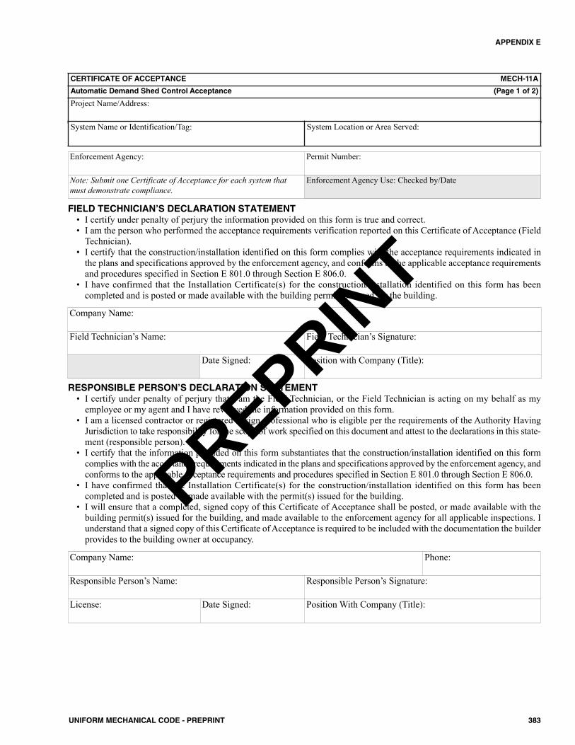
APPENDIX E
383UNIFORM MECHANICAL CODE - PREPRINT
CERTIFICATE OF ACCEPTANCE MECH-11A
Automatic Demand Shed Control Acceptance (Page 1 of 2)
Project Name/Address:
System Name or Identification/Tag: System Location or Area Served:
Enforcement Agency: Permit Number:
Note: Submit one Certificate of Acceptance for each system thatmust demonstrate compliance.
Enforcement Agency Use: Checked by/Date
FIELD TECHNICIAN’S DECLARATION STATEMENT• I certify under penalty of perjury the information provided on this form is true and correct.• I am the person who performed the acceptance requirements verification reported on this Certificate of Acceptance (Field
Technician).• I certify that the construction/installation identified on this form complies with the acceptance requirements indicated in
the plans and specifications approved by the enforcement agency, and conforms to the applicable acceptance requirementsand procedures specified in Section E 801.0 through Section E 806.0.
• I have confirmed that the Installation Certificate(s) for the construction/installation identified on this form has beencompleted and is posted or made available with the building permit(s) issued for the building.
Company Name:
Field Technician’s Name: Field Technician’s Signature:
Date Signed: Position with Company (Title):
RESPONSIBLE PERSON’S DECLARATION STATEMENT• I certify under penalty of perjury that I am the Field Technician, or the Field Technician is acting on my behalf as my
employee or my agent and I have reviewed the information provided on this form.• I am a licensed contractor or registered design professional who is eligible per the requirements of the Authority Having
Jurisdiction to take responsibility for the scope of work specified on this document and attest to the declarations in this state-ment (responsible person).
• I certify that the information provided on this form substantiates that the construction/installation identified on this formcomplies with the acceptance requirements indicated in the plans and specifications approved by the enforcement agency, andconforms to the applicable acceptance requirements and procedures specified in Section E 801.0 through Section E 806.0.
• I have confirmed that the Installation Certificate(s) for the construction/installation identified on this form has beencompleted and is posted or made available with the permit(s) issued for the building.
• I will ensure that a completed, signed copy of this Certificate of Acceptance shall be posted, or made available with thebuilding permit(s) issued for the building, and made available to the enforcement agency for all applicable inspections. Iunderstand that a signed copy of this Certificate of Acceptance is required to be included with the documentation the builderprovides to the building owner at occupancy.
Company Name: Phone:
Responsible Person’s Name: Responsible Person’s Signature:
License: Date Signed: Position With Company (Title):
PREPRINT
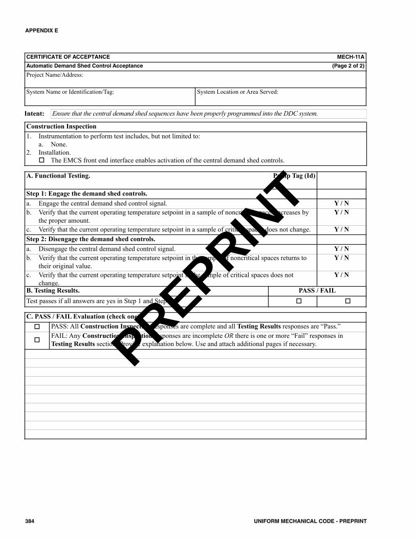
APPENDIX E
384 UNIFORM MECHANICAL CODE - PREPRINT
CERTIFICATE OF ACCEPTANCE MECH-11A
Automatic Demand Shed Control Acceptance (Page 2 of 2)
Project Name/Address:
System Name or Identification/Tag: System Location or Area Served:
Ensure that the central demand shed sequences have been properly programmed into the DDC system.Intent:
Construction Inspection1. Instrumentation to perform test includes, but not limited to:
a. None.2. Installation.
The EMCS front end interface enables activation of the central demand shed controls.
A. Functional Testing. Pump Tag (Id)
Step 1: Engage the demand shed controls.a. Engage the central demand shed control signal. Y / Nb. Verify that the current operating temperature setpoint in a sample of noncritical spaces increases by
the proper amount.Y / N
c. Verify that the current operating temperature setpoint in a sample of critical spaces does not change. Y / NStep 2: Disengage the demand shed controls.a. Disengage the central demand shed control signal. Y / Nb. Verify that the current operating temperature setpoint in the sample of noncritical spaces returns to
their original value.Y / N
c. Verify that the current operating temperature setpoint in the sample of critical spaces does notchange.
Y / N
Step 3: System returned to initial operating conditions. Y / NB. Testing Results. PASS / FAILTest passes if all answers are yes in Step 1 and Step 2.
C. PASS / FAIL Evaluation (check one): PASS: All Construction Inspection responses are complete and all Testing Results responses are “Pass.”
FAIL: Any Construction Inspection responses are incomplete OR there is one or more “Fail” responses inTesting Results section. Provide explanation below. Use and attach additional pages if necessary.PREPRINT

APPENDIX E
385UNIFORM MECHANICAL CODE - PREPRINT
CERTIFICATE OF ACCEPTANCE MECH-12A
Fault Detection and Diagnostics (FDD) for Packaged Direct-Expansion Units (Page 1 of 3)
Project Name/Address:
System Name or Identification/Tag: System Location or Area Served:
Enforcement Agency: Permit Number:
Note: Submit one Certificate of Acceptance for each system thatmust demonstrate compliance.
Enforcement Agency Use: Checked by/Date
FIELD TECHNICIAN’S DECLARATION STATEMENT• I certify under penalty of perjury the information provided on this form is true and correct.• I am the person who performed the acceptance requirements verification reported on this Certificate of Acceptance (Field
Technician).• I certify that the construction/installation identified on this form complies with the acceptance requirements indicated in
the plans and specifications approved by the enforcement agency, and conforms to the applicable acceptance requirementsand procedures specified in Section E 801.0 through Section E 806.0.
• I have confirmed that the Installation Certificate(s) for the construction/installation identified on this form has beencompleted and is posted or made available with the building permit(s) issued for the building.
Company Name:
Field Technician’s Name: Field Technician’s Signature:
Date Signed: Position with Company (Title):
RESPONSIBLE PERSON’S DECLARATION STATEMENT• I certify under penalty of perjury that I am the Field Technician, or the Field Technician is acting on my behalf as my
employee or my agent and I have reviewed the information provided on this form.• I am a licensed contractor or registered design professional who is eligible per the requirements of the Authority Having
Jurisdiction to take responsibility for the scope of work specified on this document and attest to the declarations in this state-ment (responsible person).
• I certify that the information provided on this form substantiates that the construction/installation identified on this formcomplies with the acceptance requirements indicated in the plans and specifications approved by the enforcement agency, andconforms to the applicable acceptance requirements and procedures specified in Section E 801.0 through Section E 806.0.
• I have confirmed that the Installation Certificate(s) for the construction/installation identified on this form has beencompleted and is posted or made available with the permit(s) issued for the building.
• I will ensure that a completed, signed copy of this Certificate of Acceptance shall be posted, or made available with thebuilding permit(s) issued for the building, and made available to the enforcement agency for all applicable inspections. Iunderstand that a signed copy of this Certificate of Acceptance is required to be included with the documentation the builderprovides to the building owner at occupancy.
Company Name: Phone:
Responsible Person’s Name: Responsible Person’s Signature:
License: Date Signed: Position With Company (Title):
PREPRINT
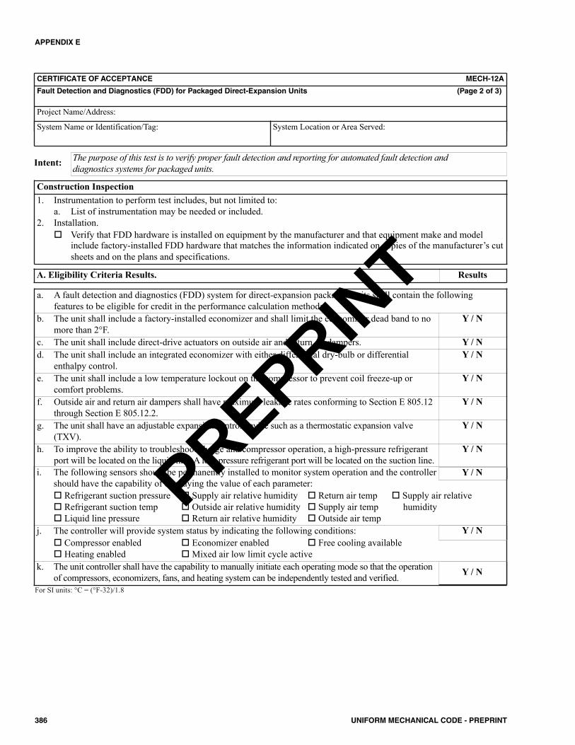
APPENDIX E
386 UNIFORM MECHANICAL CODE - PREPRINT
CERTIFICATE OF ACCEPTANCE MECH-12A
Fault Detection and Diagnostics (FDD) for Packaged Direct-Expansion Units (Page 2 of 3)
Project Name/Address:
System Name or Identification/Tag: System Location or Area Served:
The purpose of this test is to verify proper fault detection and reporting for automated fault detection anddiagnostics systems for packaged units.Intent:
Construction Inspection1. Instrumentation to perform test includes, but not limited to:
a. List of instrumentation may be needed or included.2. Installation.
Verify that FDD hardware is installed on equipment by the manufacturer and that equipment make and modelinclude factory-installed FDD hardware that matches the information indicated on copies of the manufacturer’s cutsheets and on the plans and specifications.
A. Eligibility Criteria Results. Results
a. A fault detection and diagnostics (FDD) system for direct-expansion packaged units shall contain the followingfeatures to be eligible for credit in the performance calculation method:
b. The unit shall include a factory-installed economizer and shall limit the economizer dead band to nomore than 2°F.
Y / N
c. The unit shall include direct-drive actuators on outside air and return air dampers. Y / Nd. The unit shall include an integrated economizer with either differential dry-bulb or differential
enthalpy control.Y / N
e. The unit shall include a low temperature lockout on the compressor to prevent coil freeze-up orcomfort problems.
Y / N
f. Outside air and return air dampers shall have maximum leakage rates conforming to Section E 805.12through Section E 805.12.2.
Y / N
g. The unit shall have an adjustable expansion control device such as a thermostatic expansion valve(TXV).
Y / N
h. To improve the ability to troubleshoot charge and compressor operation, a high-pressure refrigerantport will be located on the liquid line. A low-pressure refrigerant port will be located on the suction line.
Y / N
i. The following sensors should be permanently installed to monitor system operation and the controller should have the capability of displaying the value of each parameter: Refrigerant suction pressure Supply air relative humidity Return air temp Supply air relative Refrigerant suction temp Outside air relative humidity Supply air temp humidity Liquid line pressure Return air relative humidity Outside air temp
j. The controller will provide system status by indicating the following conditions: Compressor enabled Economizer enabled Free cooling available Heating enabled Mixed air low limit cycle active
k. The unit controller shall have the capability to manually initiate each operating mode so that the operationof compressors, economizers, fans, and heating system can be independently tested and verified.
Y / N
Y / N
Y / N
For SI units: °C = (°F-32)/1.8
PREPRINT
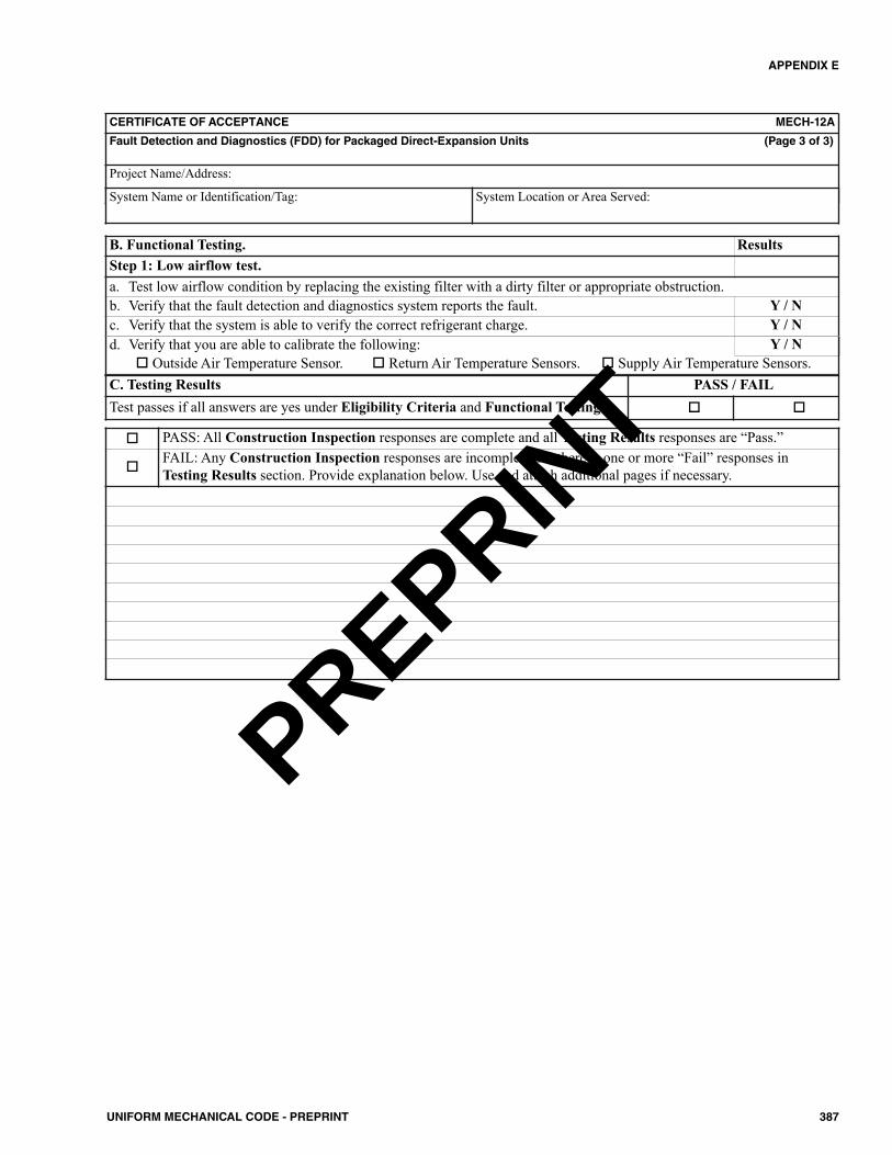
APPENDIX E
387UNIFORM MECHANICAL CODE - PREPRINT
CERTIFICATE OF ACCEPTANCE MECH-12A
Fault Detection and Diagnostics (FDD) for Packaged Direct-Expansion Units (Page 3 of 3)
Project Name/Address:
System Name or Identification/Tag: System Location or Area Served:
B. Functional Testing. ResultsStep 1: Low airflow test.a. Test low airflow condition by replacing the existing filter with a dirty filter or appropriate obstruction.b. Verify that the fault detection and diagnostics system reports the fault. Y / Nc. Verify that the system is able to verify the correct refrigerant charge. Y / Nd. Verify that you are able to calibrate the following:
Outside Air Temperature Sensor. Return Air Temperature Sensors. Supply Air Temperature Sensors.Y / N
C. Testing Results PASS / FAILTest passes if all answers are yes under Eligibility Criteria and Functional Testing.
PASS: All Construction Inspection responses are complete and all Testing Results responses are “Pass.”
FAIL: Any Construction Inspection responses are incomplete OR there is one or more “Fail” responses inTesting Results section. Provide explanation below. Use and attach additional pages if necessary.
PREPRINT
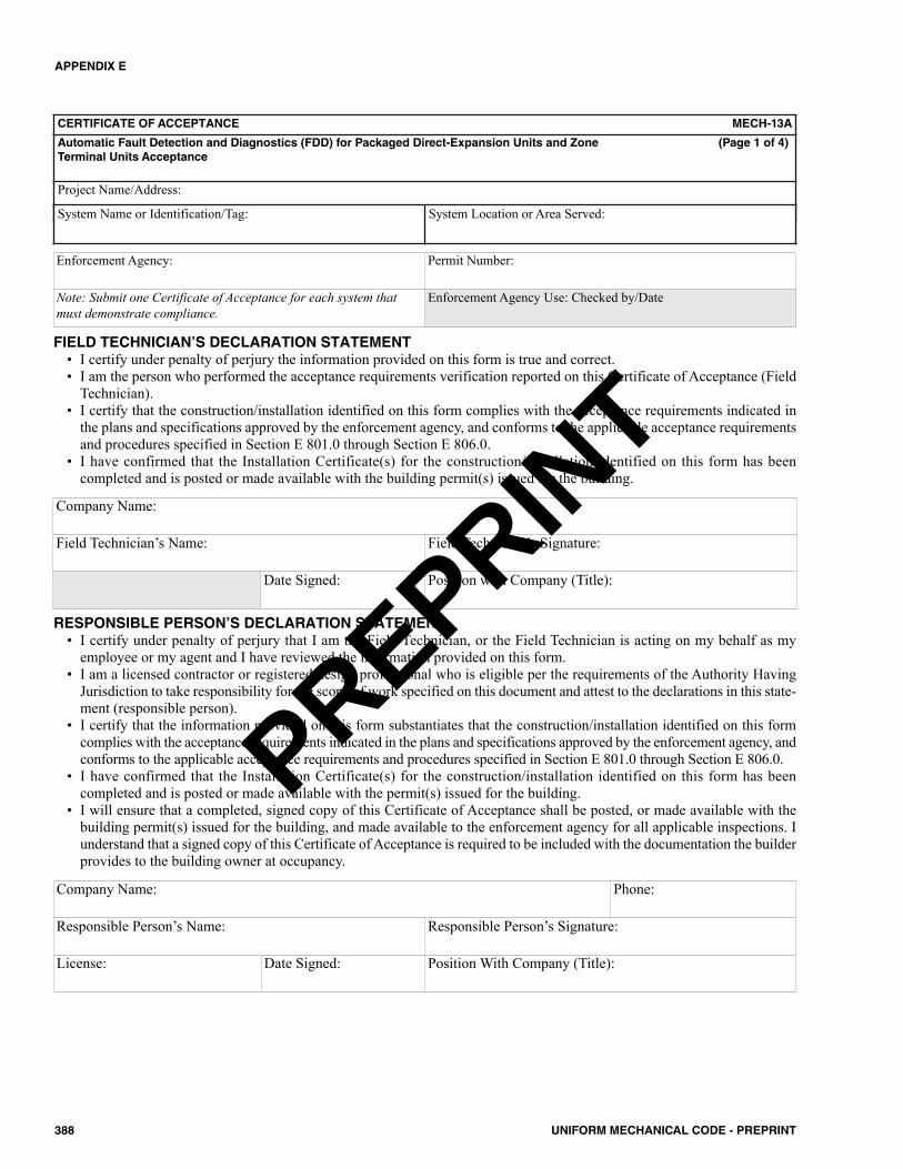
APPENDIX E
388 UNIFORM MECHANICAL CODE - PREPRINT
CERTIFICATE OF ACCEPTANCE MECH-13A
Automatic Fault Detection and Diagnostics (FDD) for Packaged Direct-Expansion Units and Zone (Page 1 of 4)Terminal Units Acceptance
Project Name/Address:
System Name or Identification/Tag: System Location or Area Served:
Enforcement Agency: Permit Number:
Note: Submit one Certificate of Acceptance for each system thatmust demonstrate compliance.
Enforcement Agency Use: Checked by/Date
FIELD TECHNICIAN’S DECLARATION STATEMENT• I certify under penalty of perjury the information provided on this form is true and correct.• I am the person who performed the acceptance requirements verification reported on this Certificate of Acceptance (Field
Technician).• I certify that the construction/installation identified on this form complies with the acceptance requirements indicated in
the plans and specifications approved by the enforcement agency, and conforms to the applicable acceptance requirementsand procedures specified in Section E 801.0 through Section E 806.0.
• I have confirmed that the Installation Certificate(s) for the construction/installation identified on this form has beencompleted and is posted or made available with the building permit(s) issued for the building.
Company Name:
Field Technician’s Name: Field Technician’s Signature:
Date Signed: Position with Company (Title):
RESPONSIBLE PERSON’S DECLARATION STATEMENT• I certify under penalty of perjury that I am the Field Technician, or the Field Technician is acting on my behalf as my
employee or my agent and I have reviewed the information provided on this form.• I am a licensed contractor or registered design professional who is eligible per the requirements of the Authority Having
Jurisdiction to take responsibility for the scope of work specified on this document and attest to the declarations in this state-ment (responsible person).
• I certify that the information provided on this form substantiates that the construction/installation identified on this formcomplies with the acceptance requirements indicated in the plans and specifications approved by the enforcement agency, andconforms to the applicable acceptance requirements and procedures specified in Section E 801.0 through Section E 806.0.
• I have confirmed that the Installation Certificate(s) for the construction/installation identified on this form has beencompleted and is posted or made available with the permit(s) issued for the building.
• I will ensure that a completed, signed copy of this Certificate of Acceptance shall be posted, or made available with thebuilding permit(s) issued for the building, and made available to the enforcement agency for all applicable inspections. Iunderstand that a signed copy of this Certificate of Acceptance is required to be included with the documentation the builderprovides to the building owner at occupancy.
Company Name: Phone:
Responsible Person’s Name: Responsible Person’s Signature:
License: Date Signed: Position With Company (Title):
PREPRINT
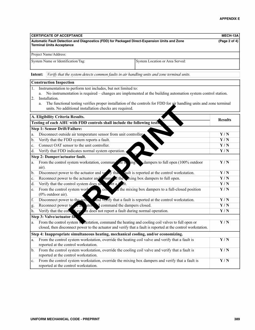
APPENDIX E
389UNIFORM MECHANICAL CODE - PREPRINT
CERTIFICATE OF ACCEPTANCE MECH-13A
Automatic Fault Detection and Diagnostics (FDD) for Packaged Direct-Expansion Units and Zone (Page 2 of 4)Terminal Units Acceptance
Project Name/Address:
System Name or Identification/Tag: System Location or Area Served:
Verify that the system detects common faults in air handling units and zone terminal units.Intent:
Construction Inspection1. Instrumentation to perform test includes, but not limited to:
a. No instrumentation is required – changes are implemented at the building automation system control station.2. Installation.
a. The functional testing verifies proper installation of the controls for FDD for air handling units and zone terminalunits. No additional installation checks are required.
Step 1: Sensor Drift/Failure:a. Disconnect outside air temperature sensor from unit controller. Y / Nb. Verify that the FDD system reports a fault. Y / Nc. Connect OAT sensor to the unit controller. Y / Nd. Verify that FDD indicates normal system operation. Y / NStep 2: Damper/actuator fault.a. From the control system workstation, command the mixing box dampers to full open (100% outdoor
air).Y / N
b. Disconnect power to the actuator and verify that a fault is reported at the control workstation. Y / Nc. Reconnect power to the actuator and command the mixing box dampers to full open. Y / Nd. Verify that the control system does not report a fault. Y / Ne. From the control system workstation, command the mixing box dampers to a full-closed position
(0% outdoor air).Y / N
f. Disconnect power to the actuator and verify that a fault is reported at the control workstation. Y / Ng. Reconnect power to the actuator and command the dampers closed. Y / Nh. Verify that the control system does not report a fault during normal operation. Y / NStep 3: Valve/actuator fault.a. From the control system workstation, command the heating and cooling coil valves to full open or
closed, then disconnect power to the actuator and verify that a fault is reported at the control workstation.Y / N
Step 4: Inappropriate simultaneous heating, mechanical cooling, and/or economizing.a. From the control system workstation, override the heating coil valve and verify that a fault is
reported at the control workstation.Y / N
b. From the control system workstation, override the cooling coil valve and verify that a fault isreported at the control workstation.
Y / N
c. From the control system workstation, override the mixing box dampers and verify that a fault isreported at the control workstation.
Y / N
A. Eligibility Criteria Results.Results
Testing of each AHU with FDD controls shall include the following tests:
PREPRINT
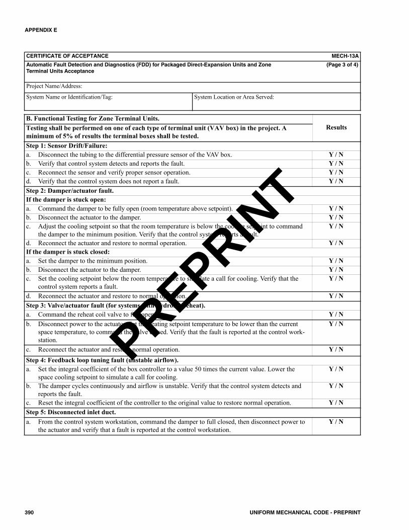
APPENDIX E
390 UNIFORM MECHANICAL CODE - PREPRINT
CERTIFICATE OF ACCEPTANCE MECH-13A
Automatic Fault Detection and Diagnostics (FDD) for Packaged Direct-Expansion Units and Zone (Page 3 of 4)Terminal Units Acceptance
Project Name/Address:
System Name or Identification/Tag: System Location or Area Served:
Step 1: Sensor Drift/Failure:a. Disconnect the tubing to the differential pressure sensor of the VAV box. Y / Nb. Verify that control system detects and reports the fault. Y / Nc. Reconnect the sensor and verify proper sensor operation. Y / Nd. Verify that the control system does not report a fault. Y / NStep 2: Damper/actuator fault.If the damper is stuck open:a. Command the damper to be fully open (room temperature above setpoint). Y / Nb. Disconnect the actuator to the damper. Y / Nc. Adjust the cooling setpoint so that the room temperature is below the cooling setpoint to command
the damper to the minimum position. Verify that the control system reports a fault.Y / N
d. Reconnect the actuator and restore to normal operation. Y / NIf the damper is stuck closed:a. Set the damper to the minimum position. Y / Nb. Disconnect the actuator to the damper. Y / Nc. Set the cooling setpoint below the room temperature to simulate a call for cooling. Verify that the
control system reports a fault.Y / N
d. Reconnect the actuator and restore to normal operation. Y / NStep 3: Valve/actuator fault (for systems with hydronic reheat).a. Command the reheat coil valve to full open. Y / Nb. Disconnect power to the actuator. Set the heating setpoint temperature to be lower than the current
space temperature, to command the valve closed. Verify that the fault is reported at the control work-station.
Y / N
c. Reconnect the actuator and restore normal operation. Y / NStep 4: Feedback loop tuning fault (unstable airflow).a. Set the integral coefficient of the box controller to a value 50 times the current value. Lower the
space cooling setpoint to simulate a call for cooling.Y / N
b. The damper cycles continuously and airflow is unstable. Verify that the control system detects andreports the fault.
Y / N
c. Reset the integral coefficient of the controller to the original value to restore normal operation. Y / NStep 5: Disconnected inlet duct.a. From the control system workstation, command the damper to full closed, then disconnect power to
the actuator and verify that a fault is reported at the control workstation.Y / N
B. Functional Testing for Zone Terminal Units.ResultsTesting shall be performed on one of each type of terminal unit (VAV box) in the project. A
minimum of 5% of results the terminal boxes shall be tested.
PREPRINT
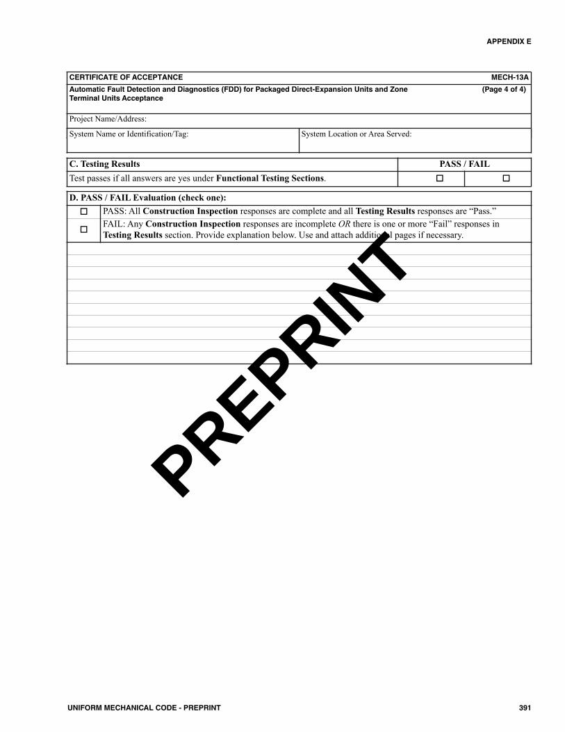
APPENDIX E
391UNIFORM MECHANICAL CODE - PREPRINT
CERTIFICATE OF ACCEPTANCE MECH-13A
Automatic Fault Detection and Diagnostics (FDD) for Packaged Direct-Expansion Units and Zone (Page 4 of 4)Terminal Units Acceptance
Project Name/Address:
System Name or Identification/Tag: System Location or Area Served:
C. Testing Results PASS / FAILTest passes if all answers are yes under Functional Testing Sections.
D. PASS / FAIL Evaluation (check one): PASS: All Construction Inspection responses are complete and all Testing Results responses are “Pass.”
FAIL: Any Construction Inspection responses are incomplete OR there is one or more “Fail” responses inTesting Results section. Provide explanation below. Use and attach additional pages if necessary.
PREPRINT
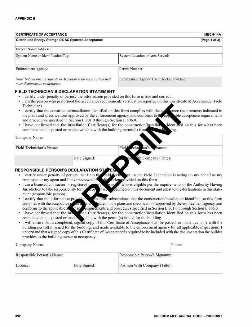
APPENDIX E
392 UNIFORM MECHANICAL CODE - PREPRINT
CERTIFICATE OF ACCEPTANCE MECH-14A
Distributed Energy Storage DX AC Systems Acceptance (Page 1 of 3)
Project Name/Address:
System Name or Identification/Tag: System Location or Area Served:
Enforcement Agency: Permit Number:
Note: Submit one Certificate of Acceptance for each system thatmust demonstrate compliance.
Enforcement Agency Use: Checked by/Date
FIELD TECHNICIAN’S DECLARATION STATEMENT• I certify under penalty of perjury the information provided on this form is true and correct.• I am the person who performed the acceptance requirements verification reported on this Certificate of Acceptance (Field
Technician).• I certify that the construction/installation identified on this form complies with the acceptance requirements indicated in
the plans and specifications approved by the enforcement agency, and conforms to the applicable acceptance requirementsand procedures specified in Section E 801.0 through Section E 806.0.
• I have confirmed that the Installation Certificate(s) for the construction/installation identified on this form has beencompleted and is posted or made available with the building permit(s) issued for the building.
Company Name:
Field Technician’s Name: Field Technician’s Signature:
Date Signed: Position with Company (Title):
RESPONSIBLE PERSON’S DECLARATION STATEMENT• I certify under penalty of perjury that I am the Field Technician, or the Field Technician is acting on my behalf as my
employee or my agent and I have reviewed the information provided on this form.• I am a licensed contractor or registered design professional who is eligible per the requirements of the Authority Having
Jurisdiction to take responsibility for the scope of work specified on this document and attest to the declarations in this state-ment (responsible person).
• I certify that the information provided on this form substantiates that the construction/installation identified on this formcomplies with the acceptance requirements indicated in the plans and specifications approved by the enforcement agency, andconforms to the applicable acceptance requirements and procedures specified in Section E 801.0 through Section E 806.0.
• I have confirmed that the Installation Certificate(s) for the construction/installation identified on this form has beencompleted and is posted or made available with the permit(s) issued for the building.
• I will ensure that a completed, signed copy of this Certificate of Acceptance shall be posted, or made available with thebuilding permit(s) issued for the building, and made available to the enforcement agency for all applicable inspections. Iunderstand that a signed copy of this Certificate of Acceptance is required to be included with the documentation the builderprovides to the building owner at occupancy.
Company Name: Phone:
Responsible Person’s Name: Responsible Person’s Signature:
License: Date Signed: Position With Company (Title):
PREPRINT
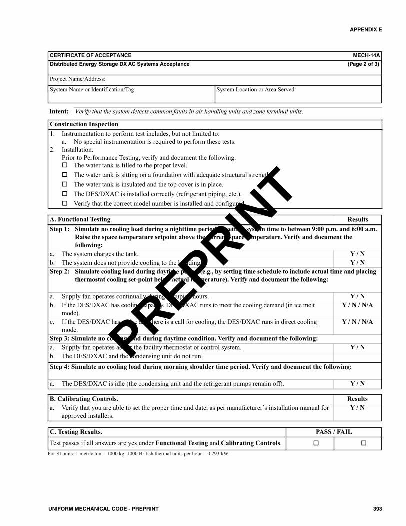
APPENDIX E
393UNIFORM MECHANICAL CODE - PREPRINT
For SI units: 1 metric ton = 1000 kg, 1000 British thermal units per hour = 0.293 kW
CERTIFICATE OF ACCEPTANCE MECH-14A
Distributed Energy Storage DX AC Systems Acceptance (Page 2 of 3)
Project Name/Address:
System Name or Identification/Tag: System Location or Area Served:
Verify that the system detects common faults in air handling units and zone terminal units.Intent:
Construction Inspection1. Instrumentation to perform test includes, but not limited to:
a. No special instrumentation is required to perform these tests.2. Installation.
Prior to Performance Testing, verify and document the following: The water tank is filled to the proper level. The water tank is sitting on a foundation with adequate structural strength. The water tank is insulated and the top cover is in place. The DES/DXAC is installed correctly (refrigerant piping, etc.). Verify that the correct model number is installed and configured.
C. Testing Results. PASS / FAIL
Test passes if all answers are yes under Functional Testing and Calibrating Controls.
Step 1: Simulate no cooling load during a nighttime period by setting system time to between 9:00 p.m. and 6:00 a.m.Raise the space temperature setpoint above the current space temperature. Verify and document thefollowing:
a. The system charges the tank. Y / Nb. The system does not provide cooling to the building. Y / NStep 2: Simulate cooling load during daytime period (e.g., by setting time schedule to include actual time and placing
thermostat cooling set-point below actual temperature). Verify and document the following:
a. Supply fan operates continually during occupied hours. Y / Nb. If the DES/DXAC has cooling capacity, DES/DXAC runs to meet the cooling demand (in ice melt
mode).Y / N / N/A
c. If the DES/DXAC has no ice and there is a call for cooling, the DES/DXAC runs in direct coolingmode.
Y / N / N/A
Step 3: Simulate no cooling load during daytime condition. Verify and document the following:a. Supply fan operates as per the facility thermostat or control system. Y / Nb. The DES/DXAC and the condensing unit do not run.Step 4: Simulate no cooling load during morning shoulder time period. Verify and document the following:
a. The DES/DXAC is idle (the condensing unit and the refrigerant pumps remain off). Y / N
A. Functional Testing Results
B. Calibrating Controls. Resultsa. Verify that you are able to set the proper time and date, as per manufacturer’s installation manual for
approved installers.Y / N
PREPRINT

APPENDIX E
394 UNIFORM MECHANICAL CODE - PREPRINT
PASS: All Construction Inspection responses are complete and all Testing Results responses are “Pass.”
FAIL: Any Construction Inspection responses are incomplete OR there is one or more “Fail” responses inTesting Results section. Provide explanation below. Use and attach additional pages if necessary.
CERTIFICATE OF ACCEPTANCE MECH-14A
Distributed Energy Storage DX AC Systems Acceptance (Page 3 of 3)
Project Name/Address:
System Name or Identification/Tag: System Location or Area Served:
PREPRINT

CERTIFICATE OF ACCEPTANCE MECH-15A
Thermal Energy Storage (TES) System Acceptance (Page 1 of 3)
Project Name/Address:
System Name or Identification/Tag: System Location or Area Served:
Enforcement Agency: Permit Number:
Note: Submit one Certificate of Acceptance for each system thatmust demonstrate compliance.
Enforcement Agency Use: Checked by/Date
FIELD TECHNICIAN’S DECLARATION STATEMENT• I certify under penalty of perjury the information provided on this form is true and correct.• I am the person who performed the acceptance requirements verification reported on this Certificate of Acceptance (Field
Technician).• I certify that the construction/installation identified on this form complies with the acceptance requirements indicated in
the plans and specifications approved by the enforcement agency, and conforms to the applicable acceptance requirementsand procedures specified in Section E 801.0 through Section E 806.0.
• I have confirmed that the Installation Certificate(s) for the construction/installation identified on this form has beencompleted and is posted or made available with the building permit(s) issued for the building.
Company Name:
Field Technician’s Name: Field Technician’s Signature:
Date Signed: Position with Company (Title):
RESPONSIBLE PERSON’S DECLARATION STATEMENT• I certify under penalty of perjury that I am the Field Technician, or the Field Technician is acting on my behalf as my
employee or my agent and I have reviewed the information provided on this form.• I am a licensed contractor or registered design professional who is eligible per the requirements of the Authority Having
Jurisdiction to take responsibility for the scope of work specified on this document and attest to the declarations in this state-ment (responsible person).
• I certify that the information provided on this form substantiates that the construction/installation identified on this formcomplies with the acceptance requirements indicated in the plans and specifications approved by the enforcement agency, andconforms to the applicable acceptance requirements and procedures specified in Section E 801.0 through Section E 806.0.
• I have confirmed that the Installation Certificate(s) for the construction/installation identified on this form has beencompleted and is posted or made available with the permit(s) issued for the building.
• I will ensure that a completed, signed copy of this Certificate of Acceptance shall be posted, or made available with thebuilding permit(s) issued for the building, and made available to the enforcement agency for all applicable inspections. Iunderstand that a signed copy of this Certificate of Acceptance is required to be included with the documentation the builderprovides to the building owner at occupancy.
Company Name: Phone:
Responsible Person’s Name: Responsible Person’s Signature:
License: Date Signed: Position With Company (Title):
APPENDIX E
395UNIFORM MECHANICAL CODE - PREPRINT
PREPRINT
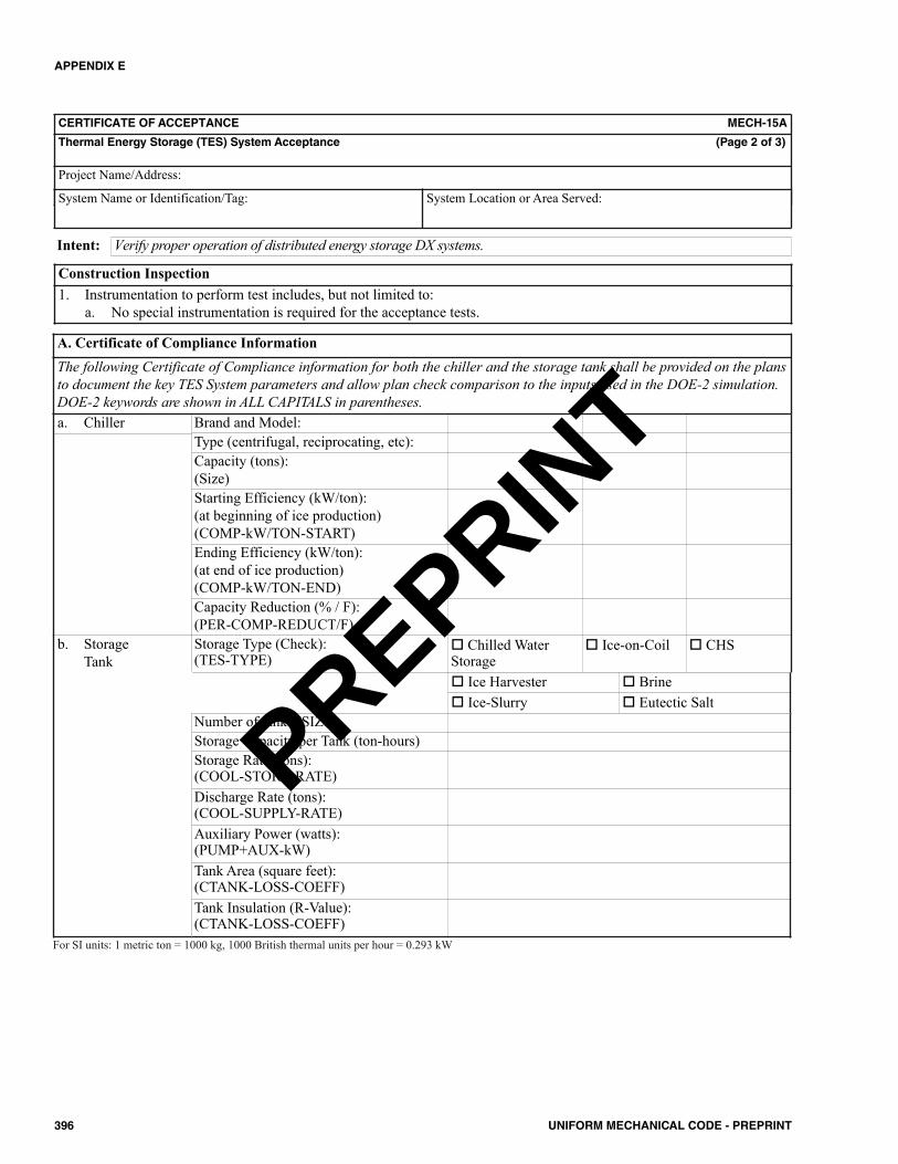
APPENDIX E
396 UNIFORM MECHANICAL CODE - PREPRINT
CERTIFICATE OF ACCEPTANCE MECH-15A
Thermal Energy Storage (TES) System Acceptance (Page 2 of 3)
Project Name/Address:
System Name or Identification/Tag: System Location or Area Served:
Verify proper operation of distributed energy storage DX systems.Intent:
Construction Inspection1. Instrumentation to perform test includes, but not limited to:
a. No special instrumentation is required for the acceptance tests.
Brand and Model:Type (centrifugal, reciprocating, etc):Capacity (tons):(Size)Starting Efficiency (kW/ton):(at beginning of ice production)(COMP-kW/TON-START)Ending Efficiency (kW/ton):(at end of ice production)(COMP-kW/TON-END)Capacity Reduction (% / F):(PER-COMP-REDUCT/F)Storage Type (Check):(TES-TYPE)
Chilled WaterStorage
Ice-on-Coil CHS
a. Chiller
Ice Harvester Brine Ice-Slurry Eutectic Salt
Number of tanks (SIZE)Storage Capacity per Tank (ton-hours)Storage Rate (tons):(COOL-STORE-RATE)Discharge Rate (tons):(COOL-SUPPLY-RATE)Auxiliary Power (watts):(PUMP+AUX-kW)Tank Area (square feet):(CTANK-LOSS-COEFF)Tank Insulation (R-Value):(CTANK-LOSS-COEFF)
b. StorageTank
A. Certificate of Compliance InformationThe following Certificate of Compliance information for both the chiller and the storage tank shall be provided on the plansto document the key TES System parameters and allow plan check comparison to the inputs used in the DOE-2 simulation.DOE-2 keywords are shown in ALL CAPITALS in parentheses.
For SI units: 1 metric ton = 1000 kg, 1000 British thermal units per hour = 0.293 kW
PREPRINT
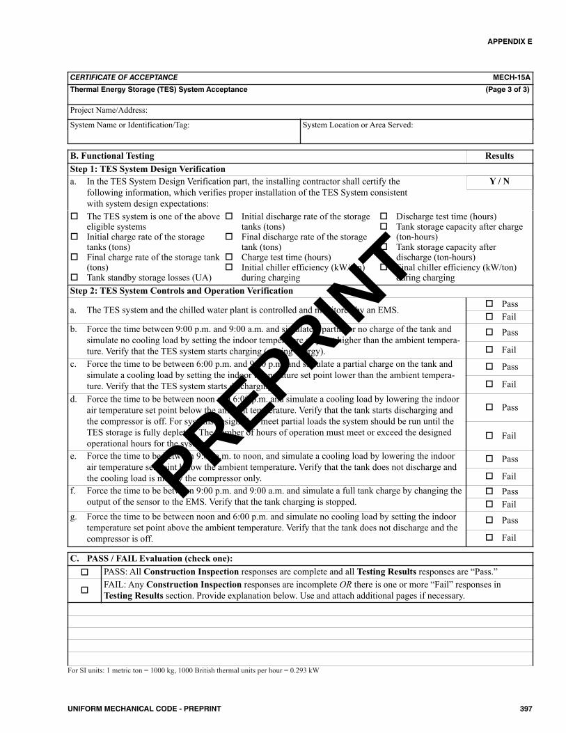
APPENDIX E
397UNIFORM MECHANICAL CODE - PREPRINT
CERTIFICATE OF ACCEPTANCE MECH-15A
Thermal Energy Storage (TES) System Acceptance (Page 3 of 3)
Project Name/Address:
System Name or Identification/Tag: System Location or Area Served:
B. Functional Testing ResultsStep 1: TES System Design Verificationa. In the TES System Design Verification part, the installing contractor shall certify the
following information, which verifies proper installation of the TES System consistent with system design expectations:
The TES system is one of the aboveeligible systems
Initial charge rate of the storagetanks (tons)
Final charge rate of the storage tank(tons)
Tank standby storage losses (UA)
Initial discharge rate of the storagetanks (tons)
Final discharge rate of the storagetank (tons)
Charge test time (hours) Initial chiller efficiency (kW/ton)
during charging
Discharge test time (hours) Tank storage capacity after charge
(ton-hours) Tank storage capacity after
discharge (ton-hours) Final chiller efficiency (kW/ton)
during charging
Y / N
Step 2: TES System Controls and Operation Verification
a. The TES system and the chilled water plant is controlled and monitored by an EMS. Pass Fail
b. Force the time between 9:00 p.m. and 9:00 a.m. and simulate a partial or no charge of the tank andsimulate no cooling load by setting the indoor temperature setpoint higher than the ambient tempera-ture. Verify that the TES system starts charging (storing energy).
Pass
Failc. Force the time to be between 6:00 p.m. and 9:00 p.m. and simulate a partial charge on the tank and
simulate a cooling load by setting the indoor temperature set point lower than the ambient tempera-ture. Verify that the TES system starts discharging.
Pass
Faild. Force the time to be between noon and 6:00 p.m. and simulate a cooling load by lowering the indoor
air temperature set point below the ambient temperature. Verify that the tank starts discharging andthe compressor is off. For systems designed to meet partial loads the system should be run until theTES storage is fully depleted. The number of hours of operation must meet or exceed the designedoperational hours for the system.
Pass
Fail
e. Force the time to be between 9:00 a.m. to noon, and simulate a cooling load by lowering the indoorair temperature set point below the ambient temperature. Verify that the tank does not discharge andthe cooling load is met by the compressor only.
Pass
Failf. Force the time to be between 9:00 p.m. and 9:00 a.m. and simulate a full tank charge by changing the
output of the sensor to the EMS. Verify that the tank charging is stopped. Pass Fail
g. Force the time to be between noon and 6:00 p.m. and simulate no cooling load by setting the indoortemperature set point above the ambient temperature. Verify that the tank does not discharge and thecompressor is off.
Pass
Fail
C. PASS / FAIL Evaluation (check one): PASS: All Construction Inspection responses are complete and all Testing Results responses are “Pass.”
FAIL: Any Construction Inspection responses are incomplete OR there is one or more “Fail” responses inTesting Results section. Provide explanation below. Use and attach additional pages if necessary.
For SI units: 1 metric ton = 1000 kg, 1000 British thermal units per hour = 0.293 kW
PREPRINT

398 UNIFORM MECHANICAL CODE - PREPRINT
PREPRINT
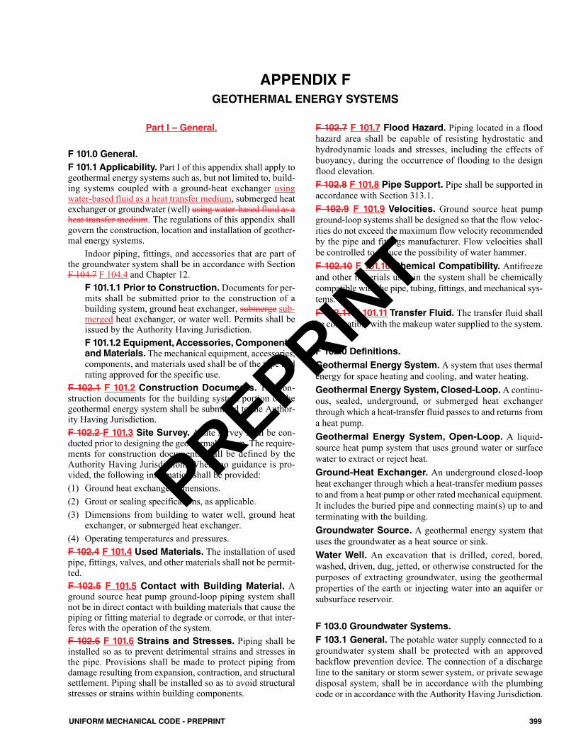
Part I – General.
F 101.0 General.F 101.1 Applicability. Part I of this appendix shall apply togeothermal energy systems such as, but not limited to, build-ing systems coupled with a ground-heat exchanger usingwater-based fluid as a heat transfer medium, submerged heatexchanger or groundwater (well) using water-based fluid as aheat transfer medium. The regulations of this appendix shallgovern the construction, location and installation of geother-mal energy systems.
Indoor piping, fittings, and accessories that are part ofthe groundwater system shall be in accordance with SectionF 104.7 F 104.4 and Chapter 12.
F 101.1.1 Prior to Construction. Documents for per-mits shall be submitted prior to the construction of abuilding system, ground heat exchanger, submerge sub-merged heat exchanger, or water well. Permits shall beissued by the Authority Having Jurisdiction.F 101.1.2 Equipment, Accessories, Components,and Materials. The mechanical equipment, accessories,components, and materials used shall be of the type andrating approved for the specific use.
F 102.1 F 101.2 Construction Documents. The con-struction documents for the building system portion of thegeothermal energy system shall be submitted to the Author-ity Having Jurisdiction.F 102.2 F 101.3 Site Survey. A site survey shall be con-ducted prior to designing the geothermal system. The require-ments for construction documents shall be defined by theAuthority Having Jurisdiction. Where no guidance is pro-vided, the following information shall be provided: (1) Ground heat exchanger dimensions.(2) Grout or sealing specifications, as applicable.(3) Dimensions from building to water well, ground heat
exchanger, or submerged heat exchanger.(4) Operating temperatures and pressures.F 102.4 F 101.4 Used Materials. The installation of usedpipe, fittings, valves, and other materials shall not be permit-ted.F 102.5 F 101.5 Contact with Building Material. Aground source heat pump ground-loop piping system shallnot be in direct contact with building materials that cause thepiping or fitting material to degrade or corrode, or that inter-feres with the operation of the system.F 102.6 F 101.6 Strains and Stresses. Piping shall beinstalled so as to prevent detrimental strains and stresses inthe pipe. Provisions shall be made to protect piping fromdamage resulting from expansion, contraction, and structuralsettlement. Piping shall be installed so as to avoid structuralstresses or strains within building components.
F 102.7 F 101.7 Flood Hazard. Piping located in a floodhazard area shall be capable of resisting hydrostatic andhydrodynamic loads and stresses, including the effects ofbuoyancy, during the occurrence of flooding to the designflood elevation.F 102.8 F 101.8 Pipe Support. Pipe shall be supported inaccordance with Section 313.1.F 102.9 F 101.9 Velocities. Ground source heat pumpground-loop systems shall be designed so that the flow veloc-ities do not exceed the maximum flow velocity recommendedby the pipe and fittings manufacturer. Flow velocities shallbe controlled to reduce the possibility of water hammer.F 102.10 F 101.10 Chemical Compatibility. Antifreezeand other materials used in the system shall be chemicallycompatible with the pipe, tubing, fittings, and mechanical sys-tems.F 102.11 F 101.11 Transfer Fluid. The transfer fluid shallbe compatible with the makeup water supplied to the system.
F 102.0 Definitions.Geothermal Energy System. A system that uses thermalenergy for space heating and cooling, and water heating.Geothermal Energy System, Closed-Loop.A continu-ous, sealed, underground, or submerged heat exchangerthrough which a heat-transfer fluid passes to and returns froma heat pump.Geothermal Energy System, Open-Loop. A liquid-source heat pump system that uses ground water or surfacewater to extract or reject heat.Ground-Heat Exchanger. An underground closed-loopheat exchanger through which a heat-transfer medium passesto and from a heat pump or other rated mechanical equipment.It includes the buried pipe and connecting main(s) up to andterminating with the building.Groundwater Source. A geothermal energy system thatuses the groundwater as a heat source or sink.Water Well. An excavation that is drilled, cored, bored,washed, driven, dug, jetted, or otherwise constructed for thepurposes of extracting groundwater, using the geothermalproperties of the earth or injecting water into an aquifer orsubsurface reservoir.
F 103.0 Groundwater Systems.F 103.1 General. The potable water supply connected to agroundwater system shall be protected with an approvedbackflow prevention device. The connection of a dischargeline to the sanitary or storm sewer system, or private sewagedisposal system, shall be in accordance with the plumbingcode or in accordance with the Authority Having Jurisdiction.
399UNIFORM MECHANICAL CODE - PREPRINT
APPENDIX FGEOTHERMAL ENERGY SYSTEMS
PREPRINT
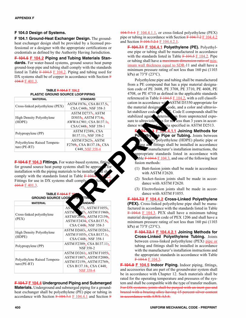
F 104.0 Design of Systems.F 104.1 Ground-Heat Exchanger Design. The ground-heat exchanger design shall be provided by a licensed pro-fessional or a designer with the appropriate certifications orcredentials as defined by the Authority Having Jurisdiction.F 104.5 F 104.2 Piping and Tubing Materials Stan-dards. For water-based systems, ground source heat pumpground-loop pipe and tubing shall comply with the standardslisted in Table F 104.5 F 104.2. Piping and tubing used forDX systems shall be of copper in accordance with Section F104.8 F 401.3.
F 104.6 F 104.3 Fittings. For water-based systems, fittingsfor ground source heat pump systems shall be approved forinstallation with the piping materials to be installed, and shallcomply with the standards listed in Table F 104.6 F 104.3.Fittings for use in DX systems shall comply with Section F104.8 F 401.3.
F 104.7 F 104.4 Underground Piping and SubmergedMaterials. Underground and submerged piping for a ground-heat exchanger shall be polyethylene (PE) pipe or tubing inaccordance with Section F 104.7.1 F 104.4.1 and Section F
104.7.1.1 F 104.4.1.1, or cross-linked polyethylene (PEX)pipe or tubing in accordance with Section F 104.7.2 F 104.4.2and Section F 104.7.2.1 F 104.4.2.1.
F 104.7.1 F 104.4.1 Polyethylene (PE). Polyethyl-ene pipe or tubing shall be manufactured in accordancewith the standards listed in Table F 104.5 F 104.2. Pipeor tubing shall have a maximum dimension ratio of min-imum wall thickness equal to SDR-11 and shall have aminimum pressure rating of not less than 160 psi (1103kPa) at 73°F (23°C).
Polyethylene pipe and tubing shall be manufacturedfrom a PE compound that has a pipe material designa-tion code of PE 3608, PE 3708, PE 3710, PE 4608, PE4708, or PE 4710 as defined in the applicable standardsreferenced in Table F 104.5 F 104.2, with a cell classifi-cation in accordance with ASTM D3350 appropriate forthe material designation code, and a color and ultravio-let stabilizer code of C or E. Code E compounds shall bestabilized against deterioration from unprotected expo-sure to ultraviolet rays for not less than 3 years in accor-dance with the test criteria specified in ASTM D2513.
F 104.7.1.1 F 104.4.1.1 Joining Methods forPolyethylene Pipe or Tubing. Joints betweenhigh density polyethylene (HDPE) plastic pipe ortubing and fittings shall be installed in accordancewith the manufacturer’s installation instructions, theappropriate standards listed in accordance withTable F 104.6 F 104.3, and one of the following heatfusion methods:(1) Butt-fusion joints shall be made in accordance
with ASTM F2620.(2) Socket-fusion joints shall be made in accor-
dance with ASTM F2620.(3) Electrofusion joints shall be made in accor-
dance with ASTM F1055.F 104.7.2 F 104.4.2 Cross-Linked Polyethylene(PEX). Cross-linked polyethylene pipe shall be manu-factured in accordance with the standards listed in TableF 104.6 F 104.3. PEX shall have a minimum tubingmaterial designation code of PEX 1206 and shall have aminimum pressure rating of not less than 160 psi (1103kPa) at 73°F (23°C).
F 104.7.2.1 F 104.4.2.1 Joining Methods forCross-Linked Polyethylene Tubing. Jointsbetween cross-linked polyethylene (PEX) pipe ortubing and fittings shall be installed in accordancewith the manufacturer’s installation instructions andthe appropriate standards in accordance with TableF 104.6 F 104.3.
F 104.9 F 104.5 Indoor Piping. Indoor piping, fittings,and accessories that are part of the groundwater system shallbe in accordance with Chapter 12. Such materials shall berated for the operating temperature and pressures of the sys-tem and shall be compatible with the type of transfer medium.For DX systems, joints shall be purged with an inert gas andbrazed with a brazing alloy having 15 percent silver contentin accordance with AWS A5.8.
MATERIAL STANDARD
Cross-linked polyethylene (PEX) ASTM F876;, CSA B137.5;,CSA C448;, NSF 358-3
High Density Polyethylene(HDPE)
ASTM D2737;, ASTMD3035;, ASTM F714;,
AWWAC901; CSA B137.1;,CSA C448;, NSF 358-1
Polypropylene (PP) ASTM F2389;, CSAB137.11;, NSF 358-2
Polyethylene Raised Tempera-ture (PE-RT)
ASTM F2623;, ASTMF2769;, CSA B137.18;, CSA
C448, NSF 358-4
TABLE F 104.5 F 104.2PLASTIC GROUND SOURCE LOOPPIPING
MATERIAL STANDARD
Cross-linked polyethylene(PEX)
ASTM F877;, ASTM F1055;,ASTM F1807;, ASTM F1960;,ASTMF2080;, ASTM F2159;,ASTM F2434;, CSA B137.5;,
CSA C448;, NSF 358-3
High Density Polyethylene(HDPE)
ASTM D2683;, ASTM D3261;,ASTM F1055;, CSA B137.1;,
CSA C448;, NSF 358-1
Polypropylene (PP) ASTM F2389;, CSA B137.11;,NSF 358-2
Polyethylene Raised Tempera-ture(PE-RT)
ASTM D3261;, ASTM F1055;,ASTM F1807;, ASTM F2080;,ASTM F2159;, ASTM F2769;,
CSA B137.18;, CSA C448;NSF 358-4
TABLE F 104.6 F 104.3GROUND SOURCE LOOP PIPE FITTINGS
400 UNIFORM MECHANICAL CODE - PREPRINT
APPENDIX F
PREPRINT
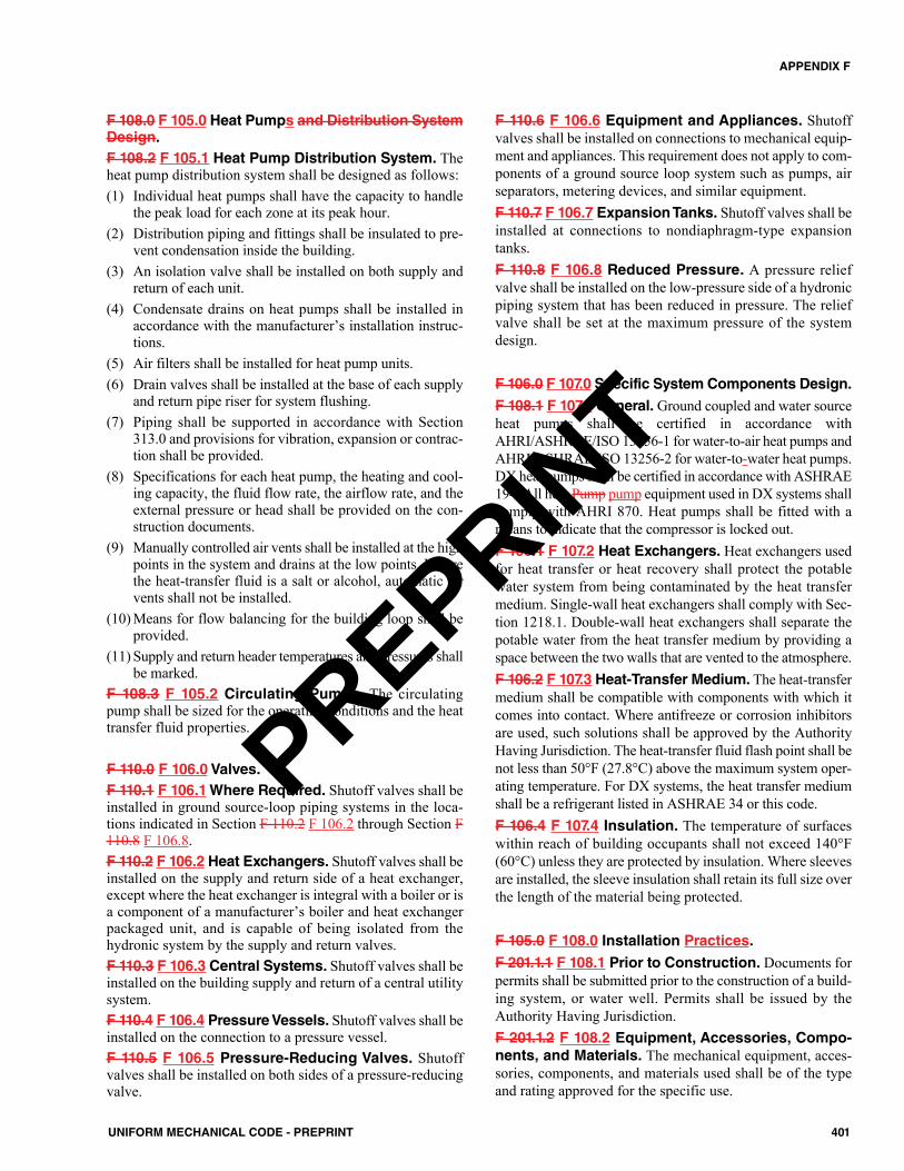
F 108.0 F 105.0 Heat Pumps and Distribution SystemDesign.F 108.2 F 105.1 Heat Pump Distribution System. Theheat pump distribution system shall be designed as follows:(1) Individual heat pumps shall have the capacity to handle
the peak load for each zone at its peak hour.(2) Distribution piping and fittings shall be insulated to pre-
vent condensation inside the building.(3) An isolation valve shall be installed on both supply and
return of each unit.(4) Condensate drains on heat pumps shall be installed in
accordance with the manufacturer’s installation instruc-tions.
(5) Air filters shall be installed for heat pump units.(6) Drain valves shall be installed at the base of each supply
and return pipe riser for system flushing.(7) Piping shall be supported in accordance with Section
313.0 and provisions for vibration, expansion or contrac-tion shall be provided.
(8) Specifications for each heat pump, the heating and cool-ing capacity, the fluid flow rate, the airflow rate, and theexternal pressure or head shall be provided on the con-struction documents.
(9) Manually controlled air vents shall be installed at the highpoints in the system and drains at the low points. Wherethe heat-transfer fluid is a salt or alcohol, automatic airvents shall not be installed.
(10) Means for flow balancing for the building loop shall beprovided.
(11) Supply and return header temperatures and pressures shallbe marked.
F 108.3 F 105.2 Circulating Pumps. The circulatingpump shall be sized for the operating conditions and the heattransfer fluid properties.
F 110.0 F 106.0 Valves.F 110.1 F 106.1Where Required. Shutoff valves shall beinstalled in ground source-loop piping systems in the loca-tions indicated in Section F 110.2 F 106.2 through Section F110.8 F 106.8.F 110.2 F 106.2 Heat Exchangers. Shutoff valves shall beinstalled on the supply and return side of a heat exchanger,except where the heat exchanger is integral with a boiler or isa component of a manufacturer’s boiler and heat exchangerpackaged unit, and is capable of being isolated from thehydronic system by the supply and return valves.F 110.3 F 106.3 Central Systems. Shutoff valves shall beinstalled on the building supply and return of a central utilitysystem.F 110.4 F 106.4 Pressure Vessels. Shutoff valves shall beinstalled on the connection to a pressure vessel.F 110.5 F 106.5 Pressure-Reducing Valves. Shutoffvalves shall be installed on both sides of a pressure-reducingvalve.
F 110.6 F 106.6 Equipment and Appliances. Shutoffvalves shall be installed on connections to mechanical equip-ment and appliances. This requirement does not apply to com-ponents of a ground source loop system such as pumps, airseparators, metering devices, and similar equipment.F 110.7 F 106.7 Expansion Tanks. Shutoff valves shall beinstalled at connections to nondiaphragm-type expansiontanks.F 110.8 F 106.8 Reduced Pressure. A pressure reliefvalve shall be installed on the low-pressure side of a hydronicpiping system that has been reduced in pressure. The reliefvalve shall be set at the maximum pressure of the systemdesign.
F 106.0 F 107.0 Specific System Components Design.F 108.1 F 107.1 General. Ground coupled and water sourceheat pumps shall be certified in accordance withAHRI/ASHRAE/ISO 13256-1 for water-to-air heat pumps andAHRI/ASHRAE/ISO 13256-2 for water-to-water heat pumps.DX heat pumps shall be certified in accordance with ASHRAE194. All heat Pump pump equipment used in DX systems shallcomply with AHRI 870. Heat pumps shall be fitted with ameans to indicate that the compressor is locked out.F 106.1 F 107.2 Heat Exchangers. Heat exchangers usedfor heat transfer or heat recovery shall protect the potablewater system from being contaminated by the heat transfermedium. Single-wall heat exchangers shall comply with Sec-tion 1218.1. Double-wall heat exchangers shall separate thepotable water from the heat transfer medium by providing aspace between the two walls that are vented to the atmosphere.F 106.2 F 107.3 Heat-Transfer Medium. The heat-transfermedium shall be compatible with components with which itcomes into contact. Where antifreeze or corrosion inhibitorsare used, such solutions shall be approved by the AuthorityHaving Jurisdiction. The heat-transfer fluid flash point shall benot less than 50°F (27.8°C) above the maximum system oper-ating temperature. For DX systems, the heat transfer mediumshall be a refrigerant listed in ASHRAE 34 or this code.F 106.4 F 107.4 Insulation. The temperature of surfaceswithin reach of building occupants shall not exceed 140°F(60°C) unless they are protected by insulation. Where sleevesare installed, the sleeve insulation shall retain its full size overthe length of the material being protected.
F 105.0 F 108.0 Installation Practices.
F 201.1.1 F 108.1 Prior to Construction. Documents forpermits shall be submitted prior to the construction of a build-ing system, or water well. Permits shall be issued by theAuthority Having Jurisdiction.F 201.1.2 F 108.2 Equipment, Accessories, Compo-nents, and Materials. The mechanical equipment, acces-sories, components, and materials used shall be of the typeand rating approved for the specific use.
401UNIFORM MECHANICAL CODE - PREPRINT
APPENDIX F
PREPRINT
F 201.2 F 108.3 Construction Documents. The con-struction documents for the building system portion of thegeothermal energy system shall be submitted to the Author-ity Having Jurisdiction.F 201.3 F 108.4 Site survey Survey requirementsRequirements. The site survey shall identify the physicallimitations of the land area, including its extent, structures,existing wells of all types, proximity of other existing groundsource heat pump systems, pavements, trees, grading, ponds,waterways, easements, overhead and underground services,septic systems, any identified septic repair areas, utility ofrights of way, and any other elements that could affect anopen- loop configuration.
Permission shall be obtained from any adjoining prop-erty owner(s), as evidenced by the registration and approvalof a formal easement that meets requirements of the author-ity having jurisdiction. It shall be received prior to the instal-lation of any open-loop system that will extend into, cross, orinterfere with the equipment or rights-of-way of utilities,jurisdictions, and other property owners.
The site survey shall include a subsurface investigationthat meets the requirements for an open-loop heat exchanger.F 201.4 F 108.5 Subsurface investigation Investiga-tion.A subsurface investigation shall be performed in accor-dance with Section F 201.4.1 F 108.6 as determined by theregistered design professional conducting the site survey.F 201.4.1 F 108.6 Subsurface Conditions. The waterwell logs and other geological records shall be used to antic-ipate the subsurface conditions of the aquifer and its potentialsupply of fresh water, multiple aquifers, saltwater intrusions,contaminated soils and groundwater, hazardous gases, andany interference with neighboring water wells and groundsource heat exchangers.
Geological issues such as permafrost conditions andbuilding stability shall be considered when reviewing avail-able records.F 104.2 F 108.7 Ground-Heat Exchanger InstallationPractices. A ground-heat exchanger system shall beinstalled as follows:(1) Outside piping or tubing located within 5 feet (1524 mm)
of any wall or structure shall be continuously insulatedwith insulation that has a minimum R-5 value. Such pipeor tubing installed under the slab or basement floors shallbe insulated within 5 feet (1524 mm) from the structureto the exterior point of exit from the slab.
(2) Freeze protection shall be provided where the design ofthe ground heat exchanger system would permit the heat-transfer medium to freeze.
(3) Horizontal piping shall be installed not less than 12inches (305 mm) below the frost line.
(4) Submerged heat exchangers shall be protected from dam-age and shall be securely fastened to the bottom of thelake or pond, or other approved submerged structure.
(5) A minimum separation distance shall be maintainedbetween the potable water intake and the submerged heatexchanger system in accordance with the Authority Hav-ing Jurisdiction.
(6) Vertical and horizontal ground-heat exchangers shallmaintain the following setbacks:(a) Ten feet (3048 mm) horizontally from a pressure-
tested sewer lateral into a building.(b) Twenty feet (6096 mm) horizontally from a non-
pressure tested sewer lateral into a building.(c) Three feet (914 mm) horizontally from buried utili-
ties such as electrical, gas, or water.(d) Fifty feet (15 240 mm) from a water well.(e) Fifty feet (15 240 mm) from a septic tank and 100
feet (30 480 mm) from a subsurface sewage leach-ing field.
(f) One hundred feet (30 480 mm) from a spring; or atdistances specified by the Authority Having Juris-diction.
(7) Wells and boreholes shall be sealed in accordance withthe Authority Having Jurisdiction. Where grout isrequired, it shall be applied in a single continuous oper-ation from the bottom of the borehole by pumpingthrough a tremie pipe.
F 105.1 F 108.8 Trenching, Excavation, and Backfill.Prior to excavation, trenching, or drilling, buried utilities,drainage, water, and irrigation systems shall be located. Priorto excavation, trenching, or drilling, the contractor, and ownershall agree in writing to site restoration requirements and sub-mit to the Authority Having Jurisdiction for approval. Prior toany excavation, trenching, or drilling, all buried utilitiesincluding drainage and irrigation systems shall be located andflagged by the appropriate utility and ground source heatpump system contractor representative.F 105.2 F 108.9 Trenches, Tunneling, and Driving.Trenches shall comply with Section 317.1. Tunneling anddriving shall comply with Section 317.2.F 105.3 F 108.10 Excavations and Open Trenches.Excavations required to be made for the installation of pipingor tubing shall be in accordance with Section 317.3. Piping ortubing shall be supported to maintain its alignment and pre-vent sagging. Piping in the ground shall be laid on a firm bedfor its entire length; where other support is otherwise pro-vided, it shall be approved in accordance with Section 302.0.Piping or tubing shall be backfilled after an inspection inaccordance with Section 317.4.F 105.4 F 108.11 Protection of Piping, Materials, andStructures. Piping and tubing passing under or throughwalls shall be protected from breakage in accordance withSection 316.1. Piping and tubing shall be installed in accor-dance with Section 316.2 to provide for expansion, contrac-tion, and structural settlement. An electrically continuouscorrosion-resistant tracer wire (not less than AWG 14) or tapeshall be buried with the plastic pipe to facilitate locating. Oneend shall be brought aboveground at a building wall or riser.F 105.5 F 108.12 Sleeves. In exterior walls, annular spacebetween sleeves and pipes shall be sealed and made water-tight and shall not be subject to a load from building con-struction in accordance with Section 316.7 through Section316.7.2.
402 UNIFORM MECHANICAL CODE - PREPRINT
APPENDIX F
PREPRINT
F 105.6 F 108.13 Steel Nail Plates. Steel nail plates shallbe installed for plastic and copper piping penetrating framingmembers to within 1 inch (25.4 mm) of the exposed framingin accordance with Section 316.6.F 106.3 F 108.14 On Site Storage. Exterior piping shallbe fitted with end caps and protected from freezing, UV radi-ation, corrosion, and degradation. For DX systems, copperpiping and fittings shall be stored to prevent physical dam-age, contamination, and each pipe or tubing shall be pressur-ized with an inert gas and sealed with a cap.F 108.4 F 108.15 Heat Pump and Distribution SystemInstallation. The heat pump and distribution system shallbe installed in accordance with the system’s design, with thiscode, and the manufacturer’s installation instructions.F 105.7 F 108.16 Pressurizing During Installation.Ground source heat pump ground loop piping to be embeddedin concrete shall be pressure tested prior to pouring concrete.During pouring, the pipe shall be maintained at the proposedoperating pressure.F 203.0 F 108.17 Horizontal Geothermal Piping fromExtraction Wells and to Injection Wells - Materialsand Methods. Horizontal geothermal piping shall be inaccordance with Section F 108.17.1 through Section F108.18.8.
F 203.1 F 108.17.1 Piping material Material. Pip-ing materials and joining methods for horizontal pipingfrom extraction wells and to injection wells the ground-heat exchanger shall in accordance with Section F 104.5F 104.2, Section F 104.6 F 104.3, Section F 104.7 F104.4, Section F 104.8 F 401.3 and Section F 104.9 F104.5.F 203.1.1 F 108.17.2 Dissimilar Materials. Transi-tion fittings between dissimilar materials shall be insideor accessible.F 203.1.2 F 108.17.3 Protection of Piping. Pipespassing through walls shall be sleeved and sealed inaccordance with Section 316.0.
F 203.2 F 108.18Trenches, Excavation, and Backfilled.Excavation for horizontal piping shall comply with Section F203.2.1 F 108.18.1 through Section F 203.2.8 F 108.18.8, Sec-tion F 105.1 F 108.8 through Section F 105.4 F 108.11, and inaccordance with requirements of the Authority Having Juris-diction. Prior to any excavation, trenching, or drilling, all buriedutilities including drainage, and irrigation systems shall belocated and flagged by the appropriate utility and groundsource heat pump system contractor representative.
F 203.2.1 F 108.18.1 Trenches. Trenches for under-ground piping or tubing shall be excavated in accordancewith the setbacks setback requirements in Section F201.5 F 301.4.F 203.2.2 F 108.18.2 Buried Systems. Buried open-loop system piping, shall be installed not less than 3.3feet (1006 mm) below the finished grade.F 203.2.3 F 108.18.3 Pipe Installation. Piping inhorizontal trenches shall be embedded with not less than
6 inches (152 mm) of inert granular material above andbelow, or in accordance with the Authority Having Juris-diction and project specifications.
Horizontal piping trenching shall be backfilled withapproved material and shall be compacted.F 203.2.4 F 108.18.4 Separation. The horizontal pip-ing shall be separated from fluid-based on-site servicesservice systems to prevent excessive short-circuiting heattransfer between such systems.F 203.2.5 F 108.18.5 Insulation. Insulation shall beprovided on the piping where there is close proximity ofall site services to prevent thermal interference betweenfluid-based on-site service systems.F 203.2.6 F 108.18.6 Pipe Bends. Sharp bending ofpipe shall be prevented or approved elbow fitting shall beused with a bend-radius in accordance with the manu-facturer’s installation instructions.F 203.2.7 F 108.18.7 Closed Cell Insulation.Buried horizontal open-loop system pipes passing paral-lel within 5 feet (1524 mm) of a wall, structure, or waterpipe shall be insulated with R2 R-2 minimum closed cellinsulation.F 203.2.8 F 108.18.8 Tracer Markings. Means shallbe provided for underground detection or utility locationof the buried pipe system. This shall include, but is notlimited to metallic detectable tape, with a thickness ofnot less than 11/64 of an inch (4.4 mm) and width of 6inches (152 mm).
This warning marking shall be permanent, conspicu-ous and resistant to the environmental conditions and shallbe placed within 1 foot to 2 feet (305 mm to 610 mm) ontop of the horizontal piping of the heat exchanger instal-lation.
F 109.0 System Start-Up.F 109.1 General. The following requirements shall be ver-ified prior to system start-up.(1) Piping shall be cleaned, flushed, and purged.(2) DX systems shall be pressurized using nitrogen for not
less than 1 hour. There shall be no allowable variance tothe test pressure after being corrected for ambient tem-perature changes during the test. The test pressure shallnot exceed 150 psig (1034 kPa) when pressure testingthe compressor unit and indoor system components.
(32) The ground heat exchanger and building piping shall becleaned, flushed, and, where required, shall be filled withthe heat transfer fluid medium. The ground loop systemshall be tested at the design flow rate(s) and differentialpressure(s) recorded. Where the actual pressure change atdesign flow is more than +/- 10 percent of the designflow pressure drop, the cause shall be identified and cor-rective action taken.
(43) A method for the removal of air and a method for addingheat transfer fluid (where necessary) shall be provided.
403UNIFORM MECHANICAL CODE - PREPRINT
APPENDIX F
PREPRINT

(54) The heat pumps shall be operational and adjustmentsshall be made in accordance with the manufacturer’sinstallation instructions.
(65) All necessary additional flow tests of the ground heatexchanger shall be completed prior to heat pump start-up.
(76) Ground heat exchanger and building piping, valves, andoperating controls, shall be set, adjusted, and operating asrequired.
(87) The system shall be labeled at the loop charging valveswith a permanent-type label, indicating the type of heattransfer fluid used. Where antifreeze is used, the labelsshall indicate the antifreeze type and concentration.
(9) DX systems shall have permanent type labels installedand affixed on the compressor unit with the refrigeranttype and quantity.
(108) Supply and return lines, as well as associated isola-tion valves from individual boreholes or water wells,shall be identified and tagged.
(11) For DX systems, refrigerant liquid and vapor lines fromthe loop system shall be identified and tagged.
(129) Supply and return lines on submerged systems shallbe identified in an approved manner, at the point of entryto a surface water resource.
F 109.2 Operation and Maintenance Manual.An oper-ation and maintenance manual for the geothermal systemshall be provided to the owner. The manual shall includeinformation on required testing and maintenance of the sys-tem. Training shall be provided on the system’s operation,maintenance requirements, and on the content of the opera-tion and maintenance manual. The operation and maintenancemanual shall contain a layout of the ground-heat exchangerand building loop.F 109.3 Labeling and Marking. Ground source heat pumpground-loop system piping shall be marked with tape, metaltags, or other methods where it enters a building. The mark-ing shall indicate the following words: “GROUND SOURCEHEAT PUMP-LOOP SYSTEM.” The marking shall indicateantifreeze used in the system by name and concentration.F 205.0 System Start-Up and Delivery.F 205.1 F 109.4 Documentation. The ground source heatpump system as-built installation drawings and instructionsshall be provided to the building owner or designated agent.F 205.2 F 109.5 Maintenance. The periodic maintenancerequired, in accordance with the design requirements, shallbe provided and be made available to the owner or designatedagent.F 205.3 F 109.6 Records. The ground source heat pumpsystem construction documents shall be provided to theowner.F 205.4 F 109.7 System Start-Up. System startup shall bein accordance with CSA C448.1, CSA C448.2, and Section F206.0 F 109.0.F 205.5 F 109.8 Contaminants. Particulate contaminantsshall be removed from the indoor piping system prior to ini-tial start-up.
F 102.3 F 110.0 Decommissioning and Abandon-ment. Prior to the abandonment or decommissioning of aground-heat exchanger, submerged heat exchanger or groundwater (well) the owner shall obtain the necessary permitsfrom the Authority Having Jurisdiction.F 110.1 General. Decommissioning of geothermal systemsshall comply with CSA C448. Prior to the abandonment ordecommissioning of geothermal systems, the owner shallobtain the necessary permits from the Authority Having Juris-diction.
Part I II Closed-Loop Systems.
F 201.0 General.F 201.1 Applicability. Part II of this chapter shall apply togeothermal energy systems such as, but not limited to, build-ing systems coupled with a closed-loop systems using water-based fluid as a heat transfer medium.F 201.2 Piping and Tubing. Piping and tubing for closed-loop systems shall be in accordance Section F 104.2 andTable F 104.2.F 201.3 Borehole Piping and Tubing. Borehole pipingor tubing for vertical and horizontally drilled closed-loop sys-tems shall have a minimum wall thickness equal to SDR-11and shall have a minimum pressure rating of not less than 160psi (1103 kPa) at 73°F (23°C).F 201.4 Underground Fittings. Underground fittings forclosed loop systems shall be in accordance with Section F104.3 and Table F 104.3.F 104.3 F 201.5Verification. For closed-loop systems, thesystem shall be flushed of debris and purged of air after com-pletion of the entire ground-heat exchanger. Flow rates andpressure drops shall be compared to calculated values toassure no blockage or kinking of the pipe. A report shall besubmitted to the owner to confirm that the loop flow is inaccordance with the construction documents.
For direct exchange (DX) systems, each u-bend shall betested and proved tight with an inert gas at not less than 315psi (2172 kPa) and maintained for 15 minutes without pres-sure drop. The pressure reading after tremie grouting of theboreholes shall be maintained in the ground heat exchangerfor not less than 2 hours, in accordance with CSA C448.F 104.4 F 201.6 Vertical Bores. Vertical bores shall bedrilled to a depth to provide complete insertion of the u-bendpipe to its specified depth. The borehole diameter shall besized for the installation and placement of the heat exchangeu-bend and the tremie used to place the grouting material.CSA C448 shall be used for vertical loop depth and boreholediameter sizing guidance. The u-bend joint and pipe shall bevisually inspected for integrity in accordance with the manu-facturer’s installation instructions. The u-bend joint and pipeshall be pressurized to not less than 100 psi (689 kPa), not toexceed the pressure rating of the pipe at the test temperature,for 1 hour to check for leaks before insertion into the bore-hole.
404 UNIFORM MECHANICAL CODE - PREPRINT
APPENDIX F
PREPRINT
F 104.4.1 F 201.6.1 Backfill. Bentonite grout and ther-mally-enhanced bentonite grout, where used to seal andbackfill each borehole, shall comply with NSF 60. Bore-holes shall be backfilled in accordance with the Author-ity Having Jurisdiction.F 104.4.2 F 201.6.2 U-Bends and Header Head-ers. Headers, u-bends and ground loop pipes shall bepressure-tested in accordance with CSA C448, or asrequired by the Authority Having Jurisdiction. Beforetesting, heat fusion joints shall be cooled to ambient tem-perature. Mechanical joints shall be completely assem-bled. Flushing and purging to remove air and debris shallbe completed before testing. The assembly shall be filledwith water (or water/antifreeze solution) and purged at aminimum flow rate of 2 feet per second (0.6 m/s) toremove air, but not more than the maximum flow veloc-ity recommended by the pipe and fittings manufacturer toremove debris.
F 104.4.2.1 F 201.6.2.1Test Pressure. The max-imum test pressure shall be 1.5 times the systemdesign pressure, as determined by Section F104.4.2.3 F 201.6.2.3, or Section F 104.4.2.4 F201.6.2.4, not to exceed 100 psi (689 kPa). Compo-nents or devices with lower pressure-ratings than thepipe shall be protected from excessive pressure dur-ing testing by removing or isolating from the testsection.Exception: Where lower pressure-rated componentsor devices cannot be removed or isolated from the testsection, the maximum test pressure shall not exceedthe pressure rating of the component or device.F 104.4.2.2 F 201.6.2.2Testing Procedure. Thetest section and the test liquid shall be at the sametemperature. The test section shall be filled with liq-uid and purged of air. The test section shall bebrought to the specified test pressure. Test pressureshall be maintained for 4 hours, with make-up fluidadded as needed. The test pressure shall be reducedby 10 psi (69 kPa) and monitored for 1 hour with noaddition of pressure or make-up fluid. A passing testis indicated where after a period of 1 hour no visualleakage is observed, and pressure remains equal toor greater than 95 percent of the original pressure.F 104.4.2.3 F 201.6.2.3 Calculation of StaticPressure (Water). For water, the static pressureapplied shall be equivalent to 0.43 psig (2.96 kPa)per foot (305 mm) of elevation.F 104.4.2.4 F 201.6.2.4 Calculation of StaticPressure (Other Fluids). For fluids of differentdensity, the static pressure shall be calculated usingthe density of the system fluid.
F 107.0 F 202.0 Ground-Heat Exchanger Testing.F 107.1 F 202.1 Testing. Pressure-testing of the ground-heat exchanger shall be performed in accordance with thetesting method in Section F 104.4 F 201.6.
F 202.2 Individual Loop Pressure Testing. Individualloop testing shall be performed as required by the AuthorityHaving Jurisdiction.F 202.3 Field Pressure Testing – Final. The ground heatexchanger and building piping shall be cleaned, flushed, and,where required, shall be filled with the heat transfer fluidmedium. The ground loop system shall be tested at the designflow rate(s) and differential pressure(s) recorded. Where theactual pressure change at design flow is more than +/- 10 per-cent of the design flow pressure drop, the cause shall be iden-tified, and corrective action taken.F 202.4 Field Flow Testing – Final. Final field flow test-ing shall be performed as required by the Authority HavingJurisdiction.
F 206.0 Decommissioning and Abandonment.F 206.1 General. Prior to the abandonment or decommis-sioning of an open-loop system, the owner shall obtain thenecessary permits from the Authority Having Jurisdiction.
Part II III – Open-Loop Systems.
F 201.0 F 301.0 General.F 201.1 F 301.1 Applicability. Part II III of this appendixshall apply to geothermal energy systems such as, but not lim-ited to, building systems coupled with a groundwater (well)or surface water open loop using water-based fluid as a heattransfer medium. The regulations of this appendix shall gov-ern the construction, location and installation of geothermalenergy systems.
Indoor piping, fittings, and accessories that are part ofthe groundwater system shall be in accordance with SectionF 104.7 F 104.4 and Chapter 12.F 103.1.1 F 301.2 Test Wells. Test wells drilled to investi-gate subsurface conditions shall provide details of the ground-water location, chemical and physical characteristics, rockstrata, and temperature profiles. The number of test wellsshall be determined in accordance with the Authority HavingJurisdiction. Each test well shall be tested for flow rate for aperiod of not less than 24 hours. Water samples shall be col-lected in accordance with the NGWA-01 from each well toestablish existing water quality levels are approved forgroundwater system use. Water samples shall be analyzed forstandard drinking water, fecal and coliform content, bacterialiron, nitrate, dissolved minerals, pH, hardness, and other com-pounds in accordance with NGWA-01 or in accordance withthe Authority Having Jurisdiction. Wells shall be tested forwater production and recovery. Monitoring wells shall be pro-tected, and marked to allow for monitoring of ground tem-perature, groundwater levels, and groundwater quality.F 103.1.2 F 301.3 Installation of Water Wells. Water sup-ply, recharge wells, and pumping equipment shall behydraulically tested, sealed, and grouted in accordance withapproved well construction practices and submitted to theAuthority Having Jurisdiction for approval. Wells shall be
405UNIFORM MECHANICAL CODE - PREPRINT
APPENDIX F
PREPRINT
tested for water production and recovery, water quality beforefinal system design. Wells shall be disinfected upon comple-tion in accordance with NGWA-01 or in accordance with theAuthority Having Jurisdiction. A copy of the water qualitytest results and the log of well construction in accordance withNGWA-01 shall be provided to the owner.F 201.5 F 301.4 Setbacks. Open loop ground-heatexchangers shall maintain the following minimum setbacks orat distances specified by the Authority Having Jurisdiction:(a) Ten feet (3048 mm) horizontally from a pressure-tested
sewer lateral into a building.(b) Twenty feet (6096 mm) horizontally from a non-pressure
tested sewer lateral into a building.(c) Three feet (914 mm) horizontally from buried utilities
such as electrical, gas, or water.(d) Fifty feet (15 240 mm) from a water well.(e) Fifty feet (15 240 mm) from a septic tank and 100 feet
(30 480 mm) from a subsurface sewage leaching field.(f) One hundred feet (30 480 mm) from a spring.
F 202.0 F 302.0 Open Ground Water Systems.F 202.1 F 302.1 General. The installation and use of waterwells shall be in accordance with the Authority Having Juris-diction. The water well records shall include well logs, pump-ing tests, and aquifer information.F 202.2 F 302.2 Open-Loop Water Well Drilling Logs.The water well drilling logs shall include the following:(1) The subsurface stratigraphy.(2) The aquifer type and conditions such as, but not limited
to, confined, unconfined, flowing and depth.(3) The drilling method used and the penetration speed.(4) The presence of substances known to have a potential
risk to health and safety shall be documented in the drilllogs and the property owner shall be advised of thepotential risk to health and safety.
F 202.3 F 302.3 Design Considerations. A groundwa-ter heat pump system shall be designed by a registered designprofessional. Due design consideration shall be given to thefollowing:(1) Where multiple heat pumps or fan coils are connected to
a common water loop, a diversified building design loadshall be use used to design a ground water heat pump.
(2) The water supply well(s) and injection wells, or waterdischarge system, shall be capable of being operated atsustainable pumping rates that exceed the maximumdaily requirements without causing an adverse impact toexisting or future offsite uses of groundwater or surfacewater bodies.
(3) The water temperature and the quality and chemicalcomposition of the water resource are in accordance withthe system manufacturer’s recommendations.
(4) The groundwater and surface water resources shall beprotected by returning water to the source aquifer or anaquifer with the same water quality, or a surface waterbody.
(5) The return capacity of the injection, or surface waterbody discharge system, shall be suitable under winterconditions.
(6) The temperature of the return water shall have no adversethermal impacts on offsite existing or future uses ofgroundwater, or on surface water bodies, in accordancewith the requirements of the Authority Having Jurisdiction.
(7) Pressure gauges shall be provided to aid in start-up andmonitoring of the system during operation;.
(8) The ability to switch over operation of supply and returnwells for 100 percent standby, redevelopment, cleaningof wells, and the thermal balancing of the ground andaquifer shall be provided.
(9) There shall be no adverse effects on the quality and quan-tity of offsite existing or future users of groundwater, inaccordance with the requirements of the Authority Hav-ing.
F 202.4 F 302.4Water Wells and Injection Wells. Waterwells and injection wells for groundwater heat pump systemsshall be installed and tested by a registered designed profes-sional who is qualified to drill wells that comply with therequirements of the Authority Having Jurisdiction.
Water supply wells and injection wells shall be devel-oped in accordance with NGWA-01.F 202.5 F 302.5 Testing and Sampling. Pumping testsand water sampling shall be done as required by the regis-tered design professional.F 202.6 F 302.6 Disinfection. Water wells shall be disin-fected upon completion in accordance with requirements ofthe Authority Having Jurisdiction and NGWA-01.
F 204.0 F 303.0 Testing and Verification.F 204.1 F 303.1 Pumping Test. Water supply wells andinjection wells shall undergo a stop and start pumping test todemonstrate the sand-free yield.F 204.2 F 303.2 Retesting.Where sediment is present, theproblem shall be corrected and the test shall be repeated untilacceptable results are obtained.F 204.3 F 303.3 Variable Rate Pump Test. The operat-ing conditions of the water supply wells and injection wellsshall be evaluated and verify verified with a variable ratepumping.F 204.4 F 303.4 Constant Rate Pump Test. The sustain-able well yield, aquifer coefficients, and zones of influenceson the groundwater flow requirements shall be confirmed witha constant rate-pumping test. The constant rate-pumping testshall be done on the water supply and injection wells at ratesand duration durations as specified by the registered designeddesign professional.F 204.5 F 303.5 Water Level Monitoring. Water levelsshall be monitored in the pumping well and observation wellsduring pumping and recovery periods. The monitoring timeintervals shall be as specified by the registered designeddesign professional.
406 UNIFORM MECHANICAL CODE - PREPRINT
APPENDIX F
PREPRINT
F 204.6 F 303.6 Injection Wells. Injection testing shall beperformed on water wells that are designated to be used asinjection wells at rates specified by the registered designeddesign professional. The results of the drilling and pumpingtests shall be provided to the owner or the owner’s represen-tative and provided in accordance with requirements of theAuthority Having Jurisdiction.F 204.7 F 303.7 Re-Injected Water. The water quality ofre-injected water into the earth shall comply with the require-ments of the Authority Having Jurisdiction.
Part IV – Direct Exchange (DX) Systems.
F 401.0 Direct Exchange (DX) Systems.F 401.1 General. The installation and use of DirectExchange (DX) wells shall be in accordance with the Author-ity Having Jurisdiction. The DX well records shall includewell logs, pressure tests, and aquifer information.F 401.2 Applicability. Part IV of this chapter shall apply togeothermal energy systems such as, but not limited to, build-ing systems coupled with a DX closed loop using refrigerantas a heat transfer medium. The regulations of this Chaptershall govern the construction, location and installation ofgeothermal energy systems.
Indoor piping, fittings, and accessories that are part ofthe ground source system shall be in accordance with SectionF 104.5 and Chapter 12.F 104.8 F 401.3 DX Systems. Copper pipe and tubinginstalled for DX systems shall be manufactured in accordancewith ASTM B280 and copper fittings in accordance withASME B16.22. Joints shall be purged with an inert gas andbrazed with a brazing alloy having 15 percent silver contentin accordance with AWS A5.8. Underground piping and tub-ing shall have a cathodic protection system installed.F 107.2 F 401.4 DX System Testing. For DX systems,each loop shall be tested with an inert gas at not less than 315psi (2172 kPa) for not less than 15 minutes without pressuredrop. The pressure reading after grouting of the boreholesshall be maintained in the ground-heat exchanger for not lessthan 2 hours. For direct exchange (DX) systems, each u-bendshall be tested and proved tight with an inert gas at not lessthan 315 psi (2172 kPa) and maintained for 15 minutes with-out pressure drop. The pressure reading after tremie groutingof the boreholes shall be maintained in the ground heatexchanger for not less than 2 hours, in accordance with CSAC448.F 401.5 Indoor Piping. For DX systems, joints shall bepurged with an inert gas and brazed with a brazing alloy hav-ing 15 percent silver content in accordance with AWS A5.8.F 401.6 On Site Storage. For DX systems, copper pipingand fittings shall be stored to prevent physical damage, con-tamination, and each pipe or tubing shall be pressurized withan inert gas and sealed with a cap.F 401.7 System Start-Up. DX system start-up shall be inaccordance with Section F 109.1 and the following:
(1) DX systems shall be pressurized using nitrogen for notless than 1 hour. There shall be no allowable variance tothe test pressure after being corrected for ambient tem-perature changes during the test. The test pressure shallnot exceed 150 psig (1034 kPa) when pressure testingthe compressor unit and indoor system components.
(2) DX systems shall have permanent type labels installedand affixed on the compressor unit with the refrigeranttype and quantity.
(3) For DX systems, refrigerant liquid and vapor lines fromthe loop system shall be identified and tagged.
F 401.8 DX Piping. DX Piping should be installed in accor-dance with approved plans and specifications, including pro-visions for cathodic protection.
407UNIFORM MECHANICAL CODE - PREPRINT
APPENDIX F
PREPRINT

408 UNIFORM MECHANICAL CODE - PREPRINT
PREPRINT
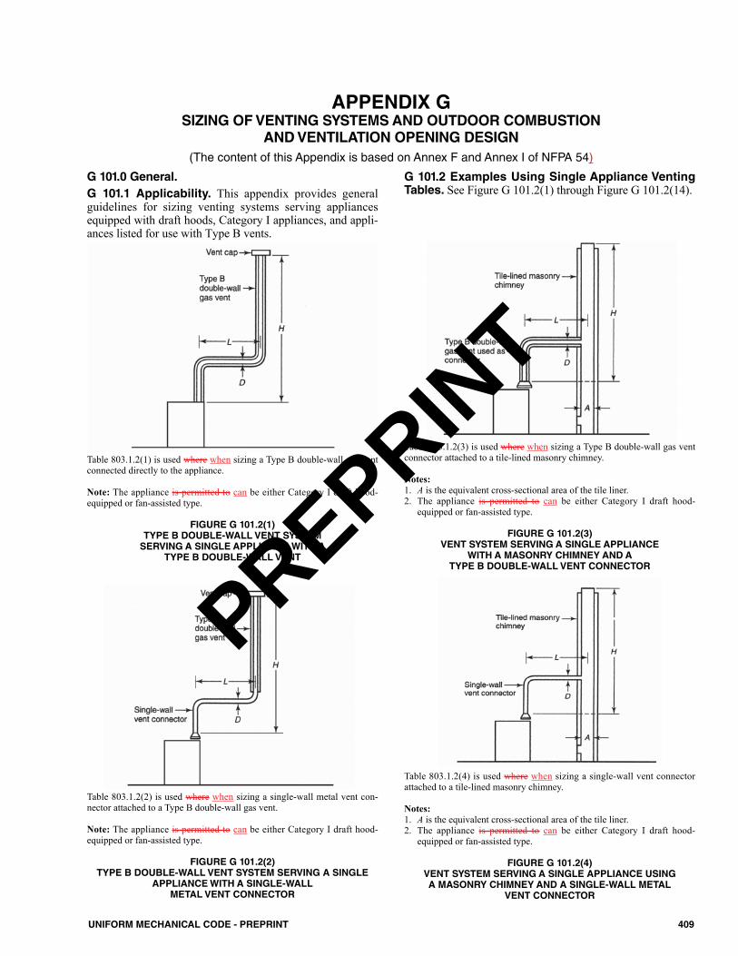
409UNIFORM MECHANICAL CODE - PREPRINT
APPENDIX G SIZING OF VENTING SYSTEMS AND OUTDOOR COMBUSTION
AND VENTILATION OPENING DESIGN(The content of this Appendix is based on Annex F and Annex I of NFPA 54)
Table 803.1.2(1) is used where when sizing a Type B double-wall gas ventconnected directly to the appliance.
Note: The appliance is permitted to can be either Category I draft hood-equipped or fan-assisted type.
FIGURE G 101.2(1)TYPE B DOUBLE-WALL VENT SYSTEMSERVING A SINGLE APPLIANCE WITH A
TYPE B DOUBLE-WALL VENT
Table 803.1.2(3) is used where when sizing a Type B double-wall gas ventconnector attached to a tile-lined masonry chimney.
Notes:1. A is the equivalent cross-sectional area of the tile liner.2. The appliance is permitted to can be either Category I draft hood-
equipped or fan-assisted type.
FIGURE G 101.2(3)VENT SYSTEM SERVING A SINGLE APPLIANCE
WITH A MASONRY CHIMNEY AND ATYPE B DOUBLE-WALL VENT CONNECTOR
Table 803.1.2(2) is used where when sizing a single-wall metal vent con-nector attached to a Type B double-wall gas vent.
Note: The appliance is permitted to can be either Category I draft hood-equipped or fan-assisted type.
FIGURE G 101.2(2)TYPE B DOUBLE-WALL VENT SYSTEM SERVING A SINGLE
APPLIANCE WITH A SINGLE-WALLMETAL VENT CONNECTOR
Table 803.1.2(4) is used where when sizing a single-wall vent connectorattached to a tile-lined masonry chimney.
Notes:1. A is the equivalent cross-sectional area of the tile liner.2. The appliance is permitted to can be either Category I draft hood-
equipped or fan-assisted type.
FIGURE G 101.2(4)VENT SYSTEM SERVING A SINGLE APPLIANCE USING A MASONRY CHIMNEY AND A SINGLE-WALL METAL
VENT CONNECTOR
G 101.0 General.G 101.1 Applicability. This appendix provides generalguidelines for sizing venting systems serving appliancesequipped with draft hoods, Category I appliances, and appli-ances listed for use with Type B vents.
G 101.2 Examples Using Single Appliance VentingTables. See Figure G 101.2(1) through Figure G 101.2(14).
PREPRINT

410 UNIFORM MECHANICAL CODE - PREPRINT
APPENDIX G
Asbestos cement Type B or single-wall metal vent serving a single drafthood-equipped appliance. [See Table 803.1.2(5)]
FIGURE G 101.2(5)ASBESTOS CEMENT TYPE B OR SINGLE-WALL METAL VENT SYSTEM SERVING A SINGLE DRAFT HOOD-EQUIPPED APPLIANCE
Table 803.2(1) is used where when sizing Type B double-wall gas vent con-nectors attached to a Type B double-wall common vent.
Note: Each appliance is permitted to can be either Category I draft hood-equipped or fan-assisted type.
FIGURE G 101.2(6)VENT SYSTEM SERVING TWO OR MORE
APPLIANCES WITH TYPE B DOUBLE-WALL VENT ANDTYPE B DOUBLE-WALL VENT CONNECTORS
Table 803.2(2) is used where when sizing single-wall vent connectorsattached to a Type B double-wall common vent.
Note: Each appliance is permitted to can be either Category I draft hood-equipped or fan-assisted type.
FIGURE G 101.2(7)VENT SYSTEM SERVING TWO OR MORE
APPLIANCES WITH TYPE B DOUBLE-WALL VENT AND SINGLE-WALL METAL VENT CONNECTORS
Table 803.2(3) is used where when sizing Type B double-wall vent connec-tors attached to a tile-lined masonry chimney.
Notes:1. A is the equivalent cross-sectional area of the tile liner.2. The Each appliance is permitted to can be either Category I draft hood-
equipped or fan-assisted type.
FIGURE G 101.2(8)MASONRY CHIMNEY SERVING TWO OR MORE APPLIANCES WITH TYPE B DOUBLE-WALL
VENT CONNECTORS
PREPRINT
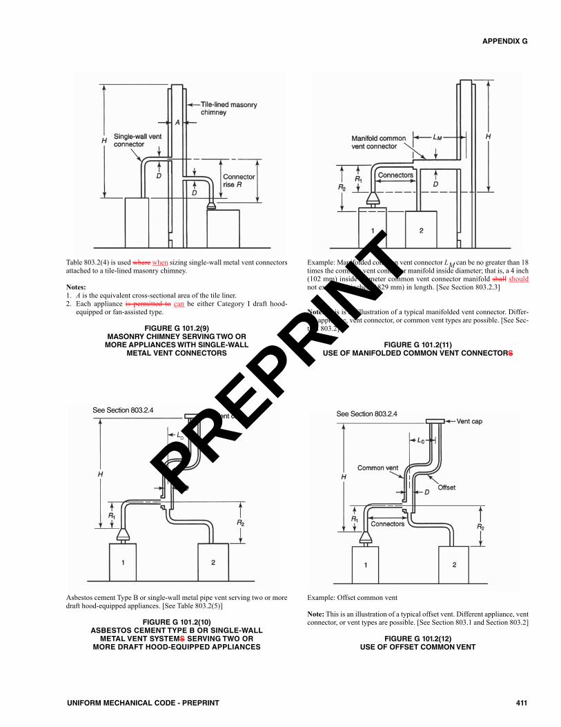
411UNIFORM MECHANICAL CODE - PREPRINT
APPENDIX G
Table 803.2(4) is used where when sizing single-wall metal vent connectorsattached to a tile-lined masonry chimney.
Notes:1. A is the equivalent cross-sectional area of the tile liner.2. Each appliance is permitted to can be either Category I draft hood-
equipped or fan-assisted type.
FIGURE G 101.2(9)MASONRY CHIMNEY SERVING TWO ORMORE APPLIANCES WITH SINGLE-WALL
METAL VENT CONNECTORS
Asbestos cement Type B or single-wall metal pipe vent serving two or moredraft hood-equipped appliances. [See Table 803.2(5)]
FIGURE G 101.2(10)ASBESTOS CEMENT TYPE B OR SINGLE-WALL METAL VENT SYSTEMS SERVING TWO OR
MORE DRAFT HOOD-EQUIPPED APPLIANCES
Example: Manifolded common vent connector LM can be no greater than 18times the common vent connector manifold inside diameter; that is, a 4 inch(102 mm) inside diameter common vent connector manifold shall shouldnot exceed 72 inches (1829 mm) in length. [See Section 803.2.3]
Note: This is an illustration of a typical manifolded vent connector. Differ-ent appliance, vent connector, or common vent types are possible. [See Sec-tion 803.2]
FIGURE G 101.2(11)USE OF MANIFOLDED COMMON VENT CONNECTORS
See Section 803.2.4
Example: Offset common vent
Note: This is an illustration of a typical offset vent. Different appliance, ventconnector, or vent types are possible. [See Section 803.1 and Section 803.2]
FIGURE G 101.2(12)USE OF OFFSET COMMON VENT
See Section 803.2.4
PREPRINT
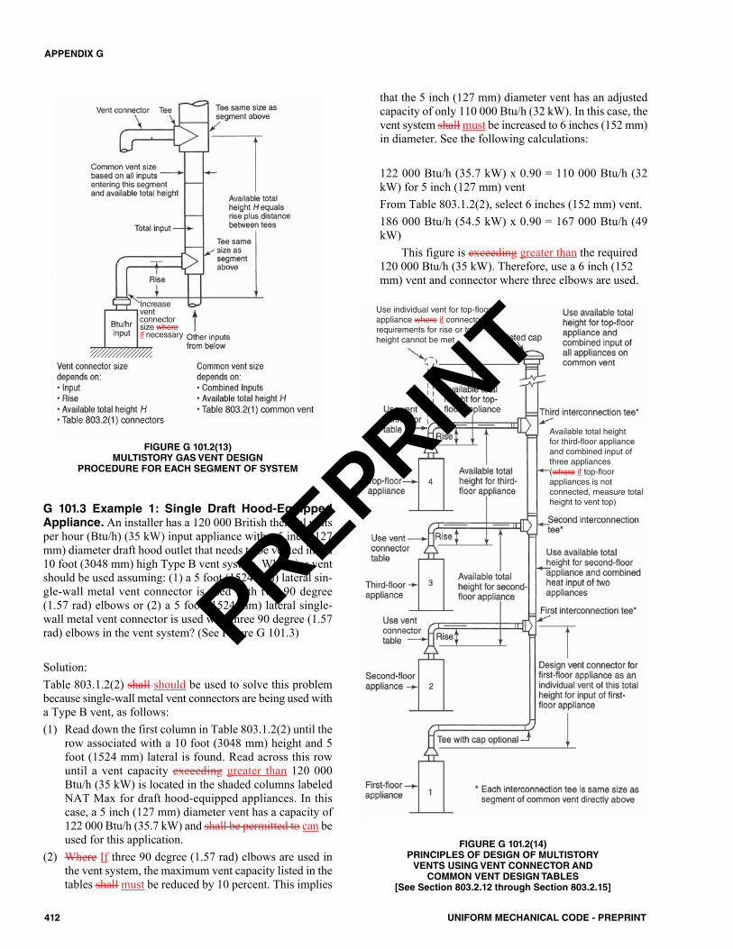
G 101.3 Example 1: Single Draft Hood-EquippedAppliance. An installer has a 120 000 British thermal unitsper hour (Btu/h) (35 kW) input appliance with a 5 inch (127mm) diameter draft hood outlet that needs to be vented into a10 foot (3048 mm) high Type B vent system. What size ventshould be used assuming: (1) a 5 foot (1524 mm) lateral sin-gle-wall metal vent connector is used with two 90 degree(1.57 rad) elbows or (2) a 5 foot (1524 mm) lateral single-wall metal vent connector is used with three 90 degree (1.57rad) elbows in the vent system? (See Figure G 101.3)
Solution:Table 803.1.2(2) shall should be used to solve this problembecause single-wall metal vent connectors are being used witha Type B vent, as follows:(1) Read down the first column in Table 803.1.2(2) until the
row associated with a 10 foot (3048 mm) height and 5foot (1524 mm) lateral is found. Read across this rowuntil a vent capacity exceeding greater than 120 000Btu/h (35 kW) is located in the shaded columns labeledNAT Max for draft hood-equipped appliances. In thiscase, a 5 inch (127 mm) diameter vent has a capacity of122 000 Btu/h (35.7 kW) and shall be permitted to can beused for this application.
(2) Where If three 90 degree (1.57 rad) elbows are used inthe vent system, the maximum vent capacity listed in thetables shall must be reduced by 10 percent. This implies
that the 5 inch (127 mm) diameter vent has an adjustedcapacity of only 110 000 Btu/h (32 kW). In this case, thevent system shall must be increased to 6 inches (152 mm)in diameter. See the following calculations:
122 000 Btu/h (35.7 kW) x 0.90 = 110 000 Btu/h (32kW) for 5 inch (127 mm) ventFrom Table 803.1.2(2), select 6 inches (152 mm) vent.186 000 Btu/h (54.5 kW) x 0.90 = 167 000 Btu/h (49kW)
This figure is exceeding greater than the required120 000 Btu/h (35 kW). Therefore, use a 6 inch (152mm) vent and connector where three elbows are used.
412 UNIFORM MECHANICAL CODE - PREPRINT
APPENDIX G
FIGURE G 101.2(13)MULTISTORY GAS VENT DESIGN
PROCEDURE FOR EACH SEGMENT OF SYSTEM
FIGURE G 101.2(14)PRINCIPLES OF DESIGN OF MULTISTORYVENTS USING VENT CONNECTOR AND COMMON VENT DESIGN TABLES
[See Section 803.2.12 through Section 803.2.15]
Increaseventconnectorsize whereif necessary
Use individual vent for top-floorappliance where if connectorrequirements for rise or totalheight cannot be met
Available total heightfor third-floor applianceand combined input ofthree appliances(where if top-floorappliances is notconnected, measure totalheight to vent top)
PREPRINT
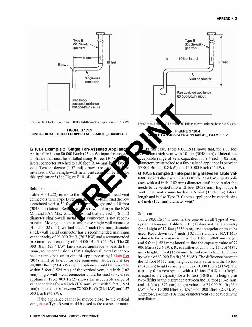
G 101.4 Example 2: Single Fan-Assisted Appliance.An installer has an 80 000 Btu/h (23.4 kW) input fan-assistedappliance that must be installed using 10 feet (3048 mm) oflateral connector attached to a 30 foot (9144 mm) high Type Bvent. Two 90-degree (1.57 rad) elbows are needed for theinstallation. Can a single-wall metal vent connector be used forthis application? (See Figure F 101.4)
Solution:Table 803.1.2(2) refers to the use of single-wall metal ventconnectors with Type B vent. In the first column find the rowassociated with a 30 foot (9144 mm) height and a 10 foot(3048 mm) lateral. Read across this row, looking at the FANMin and FAN Max columns, to find that a 3 inch (76 mm)diameter single-wall metal vent connector is not recom-mended. Moving to the next larger size single-wall connector[4 inch (102 mm)] we find that a 4 inch (102 mm) diametersingle-wall metal connector has a recommended minimumvent capacity of 91 000 Btu/h (26.7 kW) and a recommendedmaximum vent capacity of 144 000 Btu/h (42 kW). The 80000 Btu/h (23.4 kW) fan-assisted appliance is outside thisrange, so the conclusion is that a single-wall metal vent con-nector cannot be used to vent this appliance using 10 foot feet(3048 mm) of lateral for the connector. However, if the80,000 Btu/h (23.4 kW) input appliance could be moved towithin 5 feet (1524 mm) of the vertical vent, a 4 inch (102mm) single-wall metal connector could be used to vent theappliance. Table 803.1.2(2) shows the acceptable range ofvent capacities for a 4 inch (102 mm) vent with 5 feet (1524mm) of lateral to be between 72 000 Btu/h (21.1 kW) and 157000 Btu/h (46 kW).
If the appliance cannot be moved closer to the verticalvent, then a Type B vent could be used as the connector mate-
rial. In this case, Table 803.1.2(1) shows that, for a 30 foot(9144 mm) high vent with 10 feet (3048 mm) of lateral, theacceptable range of vent capacities for a 4 inch (102 mm)diameter vent attached to a fan-assisted appliance is between37 000 Btu/h (10.8 kW) and 150 000 Btu/h (44 kW).G 101.5 Example 3: Interpolating Between Table Val-ues. An installer has an 80 000 Btu/h (23.4 kW) input appli-ance with a 4 inch (102 mm) diameter draft hood outlet thatneeds to be vented into a 12 foot (3658 mm) high Type Bvent. The vent connector has a 5 foot (1524 mm) laterallength and is also Type B. Can this appliance be vented usinga 4 inch (102 mm) diameter vent?
Solution:Table 803.1.2(1) is used in the case of an all Type B Ventsystem. However, Table 803.1.2(1) does not have an entryfor a height of 12 feet (3658 mm), and interpolation must beused. Read down the 4 inch (102 mm) diameter NAT Maxcolumn to the row associated with a 10 foot (3048 mm) heightand 5 foot (1524 mm) lateral to find the capacity value of 77000 Btu/h (22.6 kW). Read further down to the 15 foot (4572mm) height, 5 foot (1524 mm) lateral row to find the capac-ity value of 87 000 Btu/h (25.5 kW). The difference betweenthe 15 foot (4572 mm) height capacity value and the 10 foot(3048 mm) height capacity value is 10 000 Btu/h (3 kW). Thecapacity for a vent system with a 12 foot (3658 mm) heightis equal to the capacity for a 10 foot (3048 mm) height plustwo-fifths of the difference between the 10 foot (3048 mm)and 15 foot (4572 mm) height values, or 77 000 Btu/h (22.6kW) + 2⁄5 x 10 000 Btu/h (3 kW) = 81 000 Btu/h (23.7 kW).Therefore, a 4 inch (102 mm) diameter vent can be used in theinstallation.
413UNIFORM MECHANICAL CODE - PREPRINT
APPENDIX G
For SI units: 1 foot = 304.8 mm, 1000 British thermal units per hour = 0.293 kW
FIGURE G 101.3SINGLE DRAFT HOOD-EQUIPPED APPLIANCE – EXAMPLE 1
For SI units: 1 foot = 304.8 mm, 1000 British thermal units per hour = 0.293 kW
FIGURE G 101.4SINGLE FAN-ASSISTED APPLIANCE – EXAMPLE 2
PREPRINT
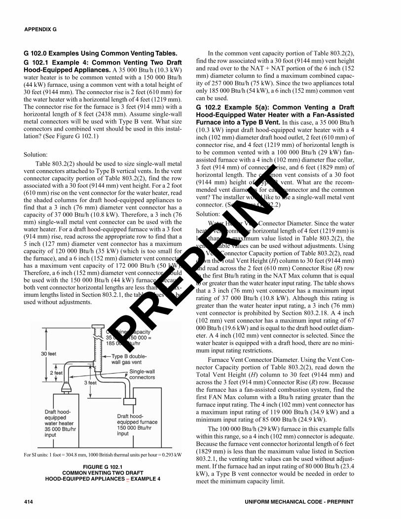
G 102.0 Examples Using Common Venting Tables.G 102.1 Example 4: Common Venting Two DraftHood-Equipped Appliances. A 35 000 Btu/h (10.3 kW)water heater is to be common vented with a 150 000 Btu/h(44 kW) furnace, using a common vent with a total height of30 feet (9144 mm). The connector rise is 2 feet (610 mm) forthe water heater with a horizontal length of 4 feet (1219 mm).The connector rise for the furnace is 3 feet (914 mm) with ahorizontal length of 8 feet (2438 mm). Assume single-wallmetal connectors will be used with Type B vent. What sizeconnectors and combined vent should be used in this instal-lation? (See Figure G 102.1)
Solution:Table 803.2(2) should be used to size single-wall metal
vent connectors attached to Type B vertical vents. In the ventconnector capacity portion of Table 803.2(2), find the rowassociated with a 30 foot (9144 mm) vent height. For a 2 foot(610 mm) rise on the vent connector for the water heater, readthe shaded columns for draft hood-equipped appliances tofind that a 3 inch (76 mm) diameter vent connector has acapacity of 37 000 Btu/h (10.8 kW). Therefore, a 3 inch (76mm) single-wall metal vent connector can be used with thewater heater. For a draft hood-equipped furnace with a 3 foot(914 mm) rise, read across the appropriate row to find that a5 inch (127 mm) diameter vent connector has a maximumcapacity of 120 000 Btu/h (35 kW) (which is too small forthe furnace), and a 6 inch (152 mm) diameter vent connectorhas a maximum vent capacity of 172 000 Btu/h (50 kW).Therefore, a 6 inch (152 mm) diameter vent connector shouldbe used with the 150 000 Btu/h (44 kW) furnace. Becauseboth vent connector horizontal lengths are less than the max-imum lengths listed in Section 803.2.1, the table values can beused without adjustments.
In the common vent capacity portion of Table 803.2(2),find the row associated with a 30 foot (9144 mm) vent heightand read over to the NAT + NAT portion of the 6 inch (152mm) diameter column to find a maximum combined capac-ity of 257 000 Btu/h (75 kW). Since the two appliances totalonly 185 000 Btu/h (54 kW), a 6 inch (152 mm) common ventcan be used.G 102.2 Example 5(a): Common Venting a DraftHood-Equipped Water Heater with a Fan-AssistedFurnace into a Type B Vent. In this case, a 35 000 Btu/h(10.3 kW) input draft hood-equipped water heater with a 4inch (102 mm) diameter draft hood outlet, 2 feet (610 mm) ofconnector rise, and 4 feet (1219 mm) of horizontal length isto be common vented with a 100 000 Btu/h (29 kW) fan-assisted furnace with a 4 inch (102 mm) diameter flue collar,3 feet (914 mm) of connector rise, and 6 feet (1829 mm) ofhorizontal length. The common vent consists of a 30 foot(9144 mm) height of Type B vent. What are the recom-mended vent diameters for each connector and the commonvent? The installer would like to use a single-wall metal ventconnector. (See Figure G 102.2)Solution:
Water Heater Vent Connector Diameter. Since the waterheater vent connector horizontal length of 4 feet (1219 mm) isless than the maximum value listed in Table 803.2(2), theventing table values can be used without adjustments. Usingthe Vent Connector Capacity portion of Table 803.2(2), readdown the Total Vent Height (H) column to 30 feet (9144 mm)and read across the 2 feet (610 mm) Connector Rise (R) rowto the first Btu/h rating in the NAT Max column that is equalto or greater than the water heater input rating. The table showsthat a 3 inch (76 mm) vent connector has a maximum inputrating of 37 000 Btu/h (10.8 kW). Although this rating isgreater than the water heater input rating, a 3 inch (76 mm)vent connector is prohibited by Section 803.2.18. A 4 inch(102 mm) vent connector has a maximum input rating of 67000 Btu/h (19.6 kW) and is equal to the draft hood outlet diam-eter. A 4 inch (102 mm) vent connector is selected. Since thewater heater is equipped with a draft hood, there are no mini-mum input rating restrictions.
Furnace Vent Connector Diameter. Using the Vent Con-nector Capacity portion of Table 803.2(2), read down theTotal Vent Height (H) column to 30 feet (9144 mm) andacross the 3 feet (914 mm) Connector Rise (R) row. Becausethe furnace has a fan-assisted combustion system, find thefirst FAN Max column with a Btu/h rating greater than thefurnace input rating. The 4 inch (102 mm) vent connector hasa maximum input rating of 119 000 Btu/h (34.9 kW) and aminimum input rating of 85 000 Btu/h (24.9 kW).
The 100 000 Btu/h (29 kW) furnace in this example fallswithin this range, so a 4 inch (102 mm) connector is adequate.Because the furnace vent connector horizontal length of 6 feet(1829 mm) is less than the maximum value listed in Section803.2.1, the venting table values can be used without adjust-ment. If the furnace had an input rating of 80 000 Btu/h (23.4kW), a Type B vent connector would be needed in order tomeet the minimum capacity limit.
414 UNIFORM MECHANICAL CODE - PREPRINT
APPENDIX G
For SI units: 1 foot = 304.8 mm, 1000 British thermal units per hour = 0.293 kW
FIGURE G 102.1COMMON VENTING TWO DRAFT
HOOD-EQUIPPED APPLIANCES – EXAMPLE 4
PREPRINT
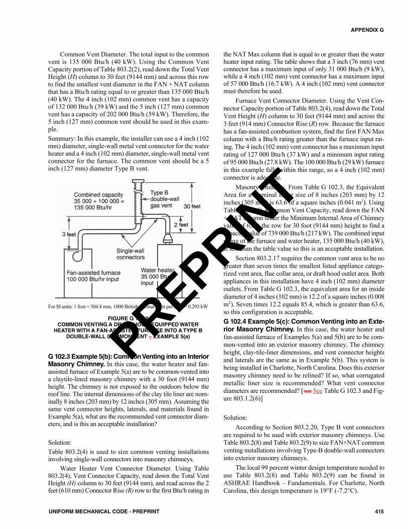
Common Vent Diameter. The total input to the commonvent is 135 000 Btu/h (40 kW). Using the Common VentCapacity portion of Table 803.2(2), read down the Total VentHeight (H) column to 30 feet (9144 mm) and across this rowto find the smallest vent diameter in the FAN + NAT columnthat has a Btu/h rating equal to or greater than 135 000 Btu/h(40 kW). The 4 inch (102 mm) common vent has a capacityof 132 000 Btu/h (39 kW) and the 5 inch (127 mm) commonvent has a capacity of 202 000 Btu/h (59 kW). Therefore, the5 inch (127 mm) common vent should be used in this exam-ple.Summary: In this example, the installer can use a 4 inch (102mm) diameter, single-wall metal vent connector for the waterheater and a 4 inch (102 mm) diameter, single-wall metal ventconnector for the furnace. The common vent should be a 5inch (127 mm) diameter Type B vent.
G 102.3 Example 5(b): Common Venting into an InteriorMasonry Chimney. In this case, the water heater and fan-assisted furnace of Example 5(a) are to be common-vented intoa claytile-lined masonry chimney with a 30 foot (9144 mm)height. The chimney is not exposed to the outdoors below theroof line. The internal dimensions of the clay tile liner are nom-inally 8 inches (203 mm) by 12 inches (305 mm). Assuming thesame vent connector heights, laterals, and materials found inExample 5(a), what are the recommended vent connector diam-eters, and is this an acceptable installation?
Solution:Table 803.2(4) is used to size common venting installationsinvolving single-wall connectors into masonry chimneys.
Water Heater Vent Connector Diameter. Using Table803.2(4), Vent Connector Capacity, read down the Total VentHeight (H) column to 30 feet (9144 mm), and read across the 2feet (610 mm) Connector Rise (R) row to the first Btu/h rating in
the NAT Max column that is equal to or greater than the waterheater input rating. The table shows that a 3 inch (76 mm) ventconnector has a maximum input of only 31 000 Btu/h (9 kW),while a 4 inch (102 mm) vent connector has a maximum inputof 57 000 Btu/h (16.7 kW). A 4 inch (102 mm) vent connectormust therefore be used.
Furnace Vent Connector Diameter. Using the Vent Con-nector Capacity portion of Table 803.2(4), read down the TotalVent Height (H) column to 30 feet (9144 mm) and across the3 feet (914 mm) Connector Rise (R) row. Because the furnacehas a fan-assisted combustion system, find the first FAN Maxcolumn with a Btu/h rating greater than the furnace input rat-ing. The 4 inch (102 mm) vent connector has a maximum inputrating of 127 000 Btu/h (37 kW) and a minimum input ratingof 95 000 Btu/h (27.8 kW). The 100 000 Btu/h (29 kW) furnacein this example falls within this range, so a 4 inch (102 mm)connector is adequate.
Masonry Chimney. From Table G 102.3, the EquivalentArea for a Nominal Liner size of 8 inches (203 mm) by 12inches (305 mm) is 63.6 of a square inches (0.041 m2). UsingTable 803.2(4), Common Vent Capacity, read down the FAN+ NAT column under the Minimum Internal Area of Chimneyvalue of 63 to the row for 30 foot (9144 mm) height to find acapacity value of 739 000 Btu/h (217 kW). The combined inputrating of the furnace and water heater, 135 000 Btu/h (40 kW),is less than the table value so this is an acceptable installation.
Section 803.2.17 requires the common vent area to be nogreater than seven times the smallest listed appliance catego-rized vent area, flue collar area, or draft hood outlet area. Bothappliances in this installation have 4 inch (102 mm) diameteroutlets. From Table G 102.3, the equivalent area for an insidediameter of 4 inches (102 mm) is 12.2 of a square inches (0.008m2). Seven times 12.2 equals 85.4, which is greater than 63.6,so this configuration is acceptable.G 102.4 Example 5(c): Common Venting into an Exte-rior Masonry Chimney. In this case, the water heater andfan-assisted furnace of Examples 5(a) and 5(b) are to be com-mon-vented into an exterior masonry chimney. The chimneyheight, clay-tile-liner dimensions, and vent connector heightsand laterals are the same as in Example 5(b). This system isbeing installed in Charlotte, North Carolina. Does this exteriormasonry chimney need to be relined? If so, what corrugatedmetallic liner size is recommended? What vent connectordiameters are recommended? [see See Table G 102.3 and Fig-ure 803.1.2(6)]
Solution:According to Section 803.2.20, Type B vent connectors
are required to be used with exterior masonry chimneys. UseTable 803.2(8) and Table 803.2(9) to size FAN+NAT commonventing installations involving Type-B double-wall connectorsinto exterior masonry chimneys.
The local 99 percent winter design temperature needed touse Table 803.2(8) and Table 803.2(9) can be found inASHRAE Handbook – Fundamentals. For Charlotte, NorthCarolina, this design temperature is 19°F (-7.2°C).
For SI units: 1 foot = 304.8 mm, 1000 British thermal units per hour = 0.293 kW
FIGURE G 102.2 COMMON VENTING A DRAFT HOOD-EQUIPPED WATERHEATER WITH A FAN-ASSISTED FURNACE INTO A TYPE B
DOUBLE-WALL COMMON VENT – EXAMPLE 5(a)
415UNIFORM MECHANICAL CODE - PREPRINT
APPENDIX G
PREPRINT
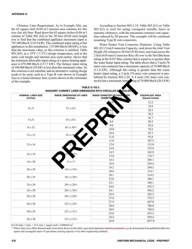
Chimney Liner Requirement. As in Example 5(b), usethe 63 square inch (0.04 m2) internal area columns for thissize clay tile liner. Read down the 63 square inches (0.04 m2)column of Table 803.2(8) to the 30 foot (9144 mm) heightrow to find that the combined appliance maximum input is747 000 Btu/h (218.9 kW). The combined input rating of theappliances in this installation, 135 000 Btu/h (40 kW), is lessthan the maximum value, so this criterion is satisfied. Table803.2(9), at a 19°F (-7.2°C) design temperature, and at thesame vent height and internal area used earlier, shows thatthe minimum allowable input rating of a space-heating appli-ance is 470 000 Btu/h (137.7 kW). The furnace input ratingof 100 000 Btu/h (29 kW) is less than this minimum value. Sothis criterion is not satisfied, and an alternative venting designneeds to be used, such as a Type B vent shown in Example5(a) or a listed chimney liner system shown in the remainderof the example.
According to Section 803.2.19, Table 803.2(1) or Table803.2(2) is used for sizing corrugated metallic liners inmasonry chimneys, with the maximum common vent capac-ities reduced by 20 percent. This example will be continuedassuming Type B vent connectors.
Water Heater Vent Connector Diameter. Using Table803.2(1) Vent Connector Capacity, read down the total VentHeight (H) column to 30 feet (9144 mm), and read across the2 feet (610 mm) Connector Rise (R) row to the first Btu/hourrating in the NAT Max column that is equal to or greater thanthe water heater input rating. The table shows that a 3 inch (76mm) vent connector has a maximum capacity of 39 000 Btu/h(11.4 kW). Although this rating is greater than the waterheater input rating, a 3 inch (76 mm) vent connector is pro-hibited by Section 803.2.20. A 4 inch (102 mm) vent con-nector has a maximum input rating of 70 000 Btu/h (20.5 kW)
416 UNIFORM MECHANICAL CODE - PREPRINT
APPENDIX G
NOMINAL LINER SIZE(Inches)
INSIDE DIMENSIONS OF LINER(Inches)
INSIDE DIAMETER OR EQUIVALENTDIAMETER (Inches)
EQUIVALENT AREA(Square Inches)
4 x 8 21⁄2 x 61⁄2
4.0 12.25.0 19.66.0 28.37.0 38.3
8 x 8 63⁄4 x 63⁄47.4 42.78.0 50.3
8 x 12 61⁄2 x 101⁄29.0 63.610.0 78.5
12 x 12 93⁄4 x 93⁄410.4 83.311.0 95.0
12 x 16 91⁄2 x 131⁄211.8 107.512.0 113.014.0 153.9
16 x 16 131⁄4 x 131⁄414.5 162.915.0 176.7
16 x 20 13 x 1716.2 206.118.0 254.4
20 x 20 163⁄4 x 163⁄418.2 260.220.0 314.1
20 x 24 161⁄2 x 201⁄220.1 314.222.0 380.1
24 x 24 201⁄4 x 201⁄422.1 380.124.0 452.3
24 x 28 201⁄4 x 241⁄4 24.1 456.2
28 x 28 241⁄4 x 241⁄426.4 543.327.0 572.5
30 x 30 251⁄2 x 251⁄227.9 607.030.0 706.8
30 x 36 251⁄2 x 311⁄230.9 749.933.0 855.3
36 x 36 311⁄2 x 311⁄234.4 929.436.0 1017.9
TABLE G 102.3MASONRY CHIMNEY LINER DIMENSIONS WITH CIRCULAR EQUIVALENTS*
For SI units, 1 inch. = 25.4 mm, 1 square inch = 0.000645 m2
* Where liner sizes differ dimensionally from those shown in this table, equivalent diameters shall be permitted to can be determined from published tables forsquare and rectangular ducts of equivalent carrying capacity or by other engineering methods.
PREPRINT
and is equal to the draft hood outlet diameter. A 4 inch (102mm) vent connector is selected.
Furnace Vent Connector Diameter. Using Table803.2(1), Vent Connector Capacity, read down the total VentHeight (H) column to 30 feet (9144 mm), and read across the3 feet (914 mm) Connector Rise (R) row to the first Btu/h rat-ing in the FAN MAX column that is equal to or greater thanthe furnace input rating. The 100 000 Btu/h (29 kW) furnacein this example falls within this range, so a 4 inch (102 mm)connector is adequate.
Chimney Liner Diameter. The total input to the commonvent is 135 000 Btu/h (40 kW). Using the Common VentCapacity portion of Table 803.2(1), read down the total VentHeight (H) column to 30 feet (9144 mm) and across this rowto find the smallest vent diameter in the FAN + NAT columnthat has a Btu/h rating greater than 135 000 Btu/h (40 kW).The 4 inch (102 mm) common vent has a capacity of 138 000Btu/h (40.4 kW). Reducing the maximum capacity by 20 per-cent results in a maximum capacity for a 4 inch (102 mm)corrugated liner of 110 000 Btu/h (32 kW), less than the totalinput of 135 000 Btu/h (40 kW). So a larger liner is needed.The 5 inch (127 mm) common vent capacity listed in Table803.2(1) is 210 000 Btu/h (62 kW), and after reducing by 20percent is 168 000 Btu/h (49.2 kW). Therefore, a 5 inch (127mm) corrugated metal liner should be used in this example.Single Wall Connectors. Once it has been established thatrelining the chimney is necessary, Type B double-wall ventconnectors are not specifically required. This example couldbe redone using Table 803.2(2) for single-wall vent connec-tors. For this case, the vent connector and liner diameterswould be the same as found for Type B double-wall connec-tors.
G 103.0 Example of Combination Indoor and Out-door Combustion Air Opening Design. Determine therequired combination of indoor and outdoor combustion airopening sizes for the following appliance installation exam-ple.
Example Installation: A fan-assisted furnace and a draft hood-equipped water heater with the following inputs are located ina 15 foot by 30 foot (4572 mm by 9144 mm) basement with an8 foot (2438 mm) ceiling. No additional indoor spaces can beused to help meet the appliance combustion air needs.Fan-Assisted Furnace Input: 100 000 Btu/h (29 kW)Draft Hood-Equipped Water Heater Input: 40 000 Btu/h (11.7kW)
Solution:(1) Determine the total available room volume.
Appliance room volume.15 feet by 30 feet (4572 mm by 9144 mm) with an 8 foot(2438 mm) ceiling = 3600 cubic feet (101.94 m3)
(2) Determine the total required volume. The Standard Method to determine combustion air isused to calculate the required volume.The combined input for the appliances located in thebasement is calculated as follows:100 000 Btu/h (29 kW) + 40 000 Btu/h (11.7 kW) = 140000 Btu/h (41 kW)The Standard Method requires that the required volumebe determined based on 50 cubic feet per 1000 Btu/h(4.83 m3/kW).Using Table G 103.0 the required volume for a 140 000Btu/h (41 kW) water heater is 7000 cubic feet (198.22m3).
Conclusion: The indoor volume is insufficient to supply combustion airsince the total of 3600 cubic feet (101.94 m3) does not meetthe required volume of 7000 cubic feet (198.22 m3). There-fore, additional combustion air must be provided from theoutdoors.
(3) Determine the ratio of the available volume to therequired volume:
(4) Determine the reduction factor to be used to reduce thefull outdoor air opening size to the minimum requiredbased on ratio of indoor spaces:
1.00 – 0.51 (from Step 3) = 0.49
(5) Determine the single outdoor combustion air openingsize as though all combustion air is to come from out-doors. In this example, the combustion air openingdirectly communicates with the outdoors:
(6) Determine the minimum outdoor combustion air open-ing area:
Outdoor opening area = 0.49 (from Step 4) x 47 squareinches (0.03 m2)
= 23 square inches (0.01 m2)Section 701.7.3(3) requires the minimum dimension of theair opening should not be less than 3 inches (76 mm).
3600 cubic feet = 0.517000 cubic feet
417UNIFORM MECHANICAL CODE - PREPRINT
APPENDIX G
140 000 Btu/h = 47 square inches (0.03 m2)3000 British thermal unitsper square inch (Btu/in2)
PREPRINT
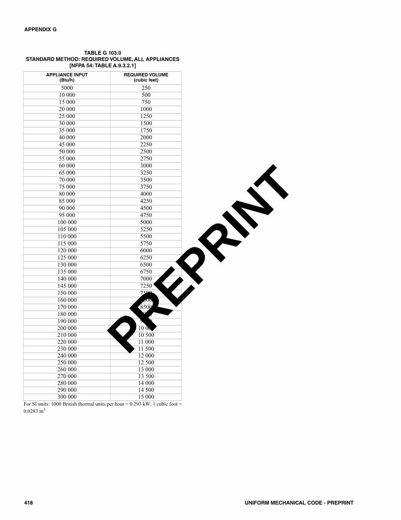
418 UNIFORM MECHANICAL CODE - PREPRINT
APPENDIX G
APPLIANCE INPUT(Btu/h)
REQUIRED VOLUME(cubic feet)
5000 25010 000 50015 000 75020 000 100025 000 125030 000 150035 000 175040 000 200045 000 225050 000 250055 000 275060 000 300065 000 325070 000 350075 000 375080 000 400085 000 425090 000 450095 000 4750100 000 5000105 000 5250110 000 5500115 000 5750120 000 6000125 000 6250130 000 6500135 000 6750140 000 7000145 000 7250150 000 7500160 000 8000170 000 8500180 000 9000190 000 9500200 000 10 000210 000 10 500220 000 11 000230 000 11 500240 000 12 000250 000 12 500260 000 13 000270 000 13 500280 000 14 000290 000 14 500300 000 15 000
For SI units: 1000 British thermal units per hour = 0.293 kW, 1 cubic foot =0.0283 m3
TABLE G 103.0STANDARD METHOD: REQUIRED VOLUME, ALL APPLIANCES
[NFPA 54: TABLE A.9.3.2.1]
PREPRINT
H 101.0 Example Calculation of Outdoor Air Rate.H 101.1 Example Calculation. Determine the outdoor airrate required for a single zone AC unit serving an interior2000 square feet (185.81 m2) conference/meeting room witha design occupancy of 100 people. The system supplies andreturns air from the ceiling. (See Chapter 4 of this code forguidelines)
Solution:In accordance with Table 403.2.2, the zone air distributioneffectiveness is 1.0 since the system supplies cooling onlyfrom the ceiling. Using the rates from Table 402.1 for a con-ference/meeting room, the minimum system outdoor air rateis calculated to be:
(Equation H 101.1)
= 620 cubic feet per minute (ft3/min)
Where:Az = zone floor area: the net occupiable floor area of
the zone in square feet.Pz = zone population: The largest number of people
expected to occupy the zone during typical usage.Where the number of people expected to occupythe zone fluctuates, Pz shall be permitted to be esti-mated based on averaging approaches described inSection 403.6.1. Where Pz cannot be accuratelypredicted during design, it shall be estimated basedon the zone floor area and the default occupantdensity in accordance with Table 402.1.
Rp = outdoor airflow rate required per person in accor-dance with Table 402.1.
Ra = outdoor airflow rate required per unit area in accor-dance with Table 402.1.
Ez = zone air distribution effectiveness in accordancewith Table 403.2.2.
For SI units: 1 square foot = 0.0929 m2, 1 cubic foot per minute = 0.00047 m3/s
419UNIFORM MECHANICAL CODE - PREPRINT
APPENDIX HEXAMPLE CALCULATION OF OUTDOOR AIR RATE
RpPz + RaAzEz
Vot =
5 x 100 + 0.06 x 20001.0
=
PREPRINT

420 UNIFORM MECHANICAL CODE - PREPRINT
PREPRINT
– A –ABSORPTION SYSTEM
Cooling system . . . . . . . . . . . . . . . . . . . . . . . Chapter 11Duct system . . . . . . . . . . . . . . . . . . . . . . . . . . Chapter 6
ABSORPTION UNITDefinition. . . . . . . . . . . . . . . . . . . . . . . . . . . . . . . . 203.0Labeling. . . . . . . . . . . . . . . . . . . . . . . . . . . . . . . . . 307.4
ACCEPTED ENGINEERING PRACTICE. . . . . . . . . . . . . . . . . . . . . . . . . . . 203.0, 309.1
ACCESS PANELSDefinition. . . . . . . . . . . . . . . . . . . . . . . . . . . . . . . . 203.0Ducts connected toduct furnaces . . . . . . . . . . . . . . . . . . . . . . . . . . 905.3
Exhaust systems,commercial kitchen . . . . . . . . . . . . . 510.1.5, 510.3.1,
510.3.6, 510.3.6.1,514.4.8, 514.4.9
ACCESSIBILITY FORInspections . . . . . . . . . . . . . . . . . . . . . . . . . . . . . . 105.1Service . . . . . . . . . . . . . . . . . . . . . . . . . . . . . . . . . 304.0
ACCESSIBILITY OFAppliances and equipment . . . . . . . . . . . . . . . . . 304.1,
304.3, 304.4Appliances and equipmenton roof . . . . . . . . . . . . . . . . . . . . . . . . . . . . . . . . 304.3
Boilers . . . . . . . . . . . . . . . . . . . . . . . . . . . . . . . . . 1010.0Cleanouts. . . . . . . . . . . . . . . . . . . . . . . . . . . . . 802.5.10Draft hoods. . . . . . . . . . . . . . . . . . . . . . . . . . . . 802.12.5Drips, fuel gas piping . . . . . . . . . . . . . . . . . . . . 1310.8.1Evaporative coolers. . . . . . . . . . . . . . . . . . . . . . . . 933.3Fire dampers. . . . . . . . . . . . . . . . . . . . . . . . . . . . . 605.5Floor furnace. . . . . . . . . . . . . . . . . . . . . . . . . . . . . 906.8Fuel gas meters . . . . . . . . . . . . . . . . . 1308.6.1, D 104.2Fuel gas piping . . . . . . . . . . . . . . . . . . . . . . . 1310.2.2.1Fuel gas pressure regulators . . . . . . . . . . . . . .1308.7.2,
1310.4.1Grease filters. . . . . . . . . . . . . . . . . . . . . . . . . . 509.2.3.2Lapped flanges . . . . . . . . . . . . . . . . . . . . . . 1308.5.10.6Motors and fans, exhaust systems . . . . . . . . . . . . 503.1Refrigeration equipment . . . . . . . . . . . . . . . . . . . 1105.3Smoke dampers . . . . . . . . . . . . . . . . . . . . . . . . . . 605.5
ACCESSIBLEDefinition. . . . . . . . . . . . . . . . . . . . . . . . . . . . . . . . 203.0Easily, definition . . . . . . . . . . . . . . . . . . . . . . . . . . . 207.0Readily, definition . . . . . . . . . . . . . . . . . . . . . . . . . 203.0
ADMINISTRATION . . . . . . . . . . . . . . . . . . . . . . . . Chapter 1AIR
Classification. . . . . . . . . . . . . . . . . . . . . . . . . . . . . 403.9Combustion . . . . . . . . . . . . . . . . . (see Combustion Air)Dilution. . . . . . . . . . . . . . . . . . . . . . . . . . . . 203.0, 701.1,
802.6.3.1, 902.12Ducts . . . . . . . . . . . . . . . . . . . . . . . . . . . . . . (see Ducts)Economizer . . . . . . . . . . . . . . . . . (see Economizer, air)Filters. . . . . . . . . . . . . . . . . . . . . . . . . . . (see Filters, air)Furnace . . . . . . . . . . . . . . . . . (see Furnaces, warm air)Heaters. . . . . . . . . . . . . . . . . . . . . . . . . (see Heater, air)Makeup . . . . . . . . . . . . . . . . . . . . . . . . . . . 203.0, 403.7,
504.1, 504.4.1, 511.3,517.1.3, 517.6.1, 517.6.2,701.3, 931.5.4, 1106.7
Moving Systems. . . . . . . . . . . . . . . . . . . . . 203.0, 608.1Outside . . . . . . . . . . . . . . . . . . . . . . . 203.0, 311.1, 311.3Pollution controldevices. . . . . . . . . . . . . . . . . . 203.0, 512.3.1, 512.3.2
Recirculation . . . . . . . . . . . . . . . . . 403.7, 403.9, 512.3.2Replacement . . . . . . . . . . . . . . . . . . . (see Air, makeup)Return. . . . . . . . . . . . . . . . . . . 203.0, 311.1, 311.3, 311.4Supply . . . . . . . . . . . . . . 203.0, Chapter 4, 914.5, 915.5Ventilation. . . . . . . . . . . . . . . . . . . . . . . . . . . . Chapter 4
AIR CONDITIONEDDefinition. . . . . . . . . . . . . . . . . . . . . . . . . . . . . . . . 203.0
AIR CONDITIONINGCoils. . . . . . . . . . . . . . . . . . . . . . . . . . . . . . . . . . 903.2.6Gas fired type . . . . . . . . . . . . . . . . . . . . . . . . . . . . 903.2Refrigerant port protection . . . . . . . . . . . . . . . . . 1105.11System test . . . . . . . . . . . . . . . . . . . . . . . . . . . . E 805.0System water use . . . . . . . . . . . . . . . . . . . . . . . E 403.0
AIR-HANDLING UNITDefinition. . . . . . . . . . . . . . . . . . . . . . . . . . . . . . . . 203.0Ducts . . . . . . . . . . . . . . . . . . . . . . . . . . . . . . . Chapter 6System test . . . . . . . . . . . . . . . . . . . . . . . . . . . . E 805.0
AIR, EXHAUSTDefinition. . . . . . . . . . . . . . . . . . . . . . . . . . . . . . . . 203.0Openings . . . . . . . . . . . . . . . . . . . . . . . . . . . . . . 305.2.2
ALTERNATE MATERIALS AND METHODSCONSTRUCTION EQUIVALENCY . . . . . . . . . . . . . . 302.2
ALTERNATIVE ENGINEERING DESIGNDesign approval . . . . . . . . . . . . . . . . . . . . . . . . . 302.3.4Design document. . . . . . . . . . . . . . . . . . . . . . . . 302.3.3Design review . . . . . . . . . . . . . . . . . . . . . . . . . . 302.3.5
421UNIFORM MECHANICAL CODE - PREPRINT
INDEXNote: Contents and Section numbers will be updated before publishing.
© 2018 International Association of Plumbing and Mechanical Officials. All rights reserved.The copyright in this index is separate and distinct from the copyright in the document that it indexes. The licensing provisionsset forth for the document are not applicable to this index. This index may not be reproduced in whole or in part by any meanswithout the express written permission of IAPMO.
PREPRINT
Inspection and testing . . . . . . . . . . . . . . . . . . . . 302.3.6Permit application . . . . . . . . . . . . . . . . . . . . . . . 302.3.1Technical data . . . . . . . . . . . . . . . . . . . . . . . . . . 302.3.2
AMMONIA. . . . . . . . . . . . . . . . . . . . . . . . . . . 1102.1, 1104.4,1102.2, 1102.3, 1106.2, Table 1102.3
ANCHORAGE OFAppliances . . . . . . . . . . . . . . . . . . . . . . . . . . . . . . 303.4Boilers and pressure vessels . . . . . . . . . . . . . . . . 1001.5Cooling towers. . . . . . . . . . . . . . . . . . . . . . . . . . . 1120.0Evaporative condensers . . . . . . . . . . . . . . . . . . . 1120.0Fluid coolers . . . . . . . . . . . . . . . . . . . . . . . . . . . . 1120.0Refrigeration equipment and piping . . . . . . . . . . . . . . . . . . . . . . . . . . . . 1105.2
ANODELESS RISER . . . . . . . . . . . . . . . . 203.0, 1308.5.4.2APPEALS . . . . . . . . . . . . . . . . . . . . . . . . . . . . . . . . . . . 107.0APPLIANCE FLUE OUTLET
Definition. . . . . . . . . . . . . . . . . . . . . . . . . . . . . . . . 203.0APPLIANCES
Access to . . . . . . . . . . . . . . . . . . . . . . . . . . . . . . .304.0Air filter . . . . . . . . . . . . . . . . . . . . . . . . . . . . . . . . .936.0Approval of . . . . . . . . . . . . . . . . . . . . . . . . . . . . . . .301.2Clearance . . . . . . . . . . . . . . . .303.3, 303.10, 303.10.1,
Table 303.10.1, Table 802.7.3.3Closed combustionsolid-fuel-burning, definition . . . . . . . . . . . . . . . 205.0
Clothes dryers . . . . . . . . . . . . . . . . . (see Clothes dryer)Cooking . . . . . . . . . . . . . . . . . . . . . 517.2–517.2.2, 517.7,
517.7.2, 517.8, 517.8.1, 920.0, 921.0, 923.0
Decorative, vented . . . . . . . . . . . . . . 224.0, 911.0, 932.0Definition. . . . . . . . . . . . . . . . . . . . . . . . . . . . . . . . 203.0Direct vent. . . . . . . . . . . . . . . . . 206.0, 802.2.6, 802.8.2Downdraft . . . . . . . . . . . . . . . . . . . . . . . . . . . . . . . 518.0Electric cooling . . . . . . . . . . . . . . . . . . . . . . . . . . . 307.3Electric heating. . . . . . . . . . . . . . . . . . . . . . 207.0, 307.2,
903.1, 905.8Fan-assisted combustion . . . . . . . . . . 203.0, 802.6.2.1,
802.10.2Floor furnaces . . . . . . . . . (see Furnaces, floor furnace)Food service. . . . . . . . . . . . . . . . . . . . . . . . 918.0, 919.0Heating . . . . . . . . . . . . . . . . . . . . . . . . . . . . . . . . . 306.1Household cooking . . . . . . . . . . . . . . . . . . . . . . . . 920.0Illuminating . . . . . . . . . . . . . . . . . . 924.0, Table 924.2.1In attics . . . . . . . . . . . . . . . . . . . . . . . . . . 304.4–304.4.4In garages . . . . . . . . . . . . . . . . . . 305.1, 305.1.1, 905.7In manufactured housing . . . . . . . . . . . . . . . . . . . 930.0In under-floor spaces . . . . . . . . . . . . . . . 304.4–304.4.4Kilns. . . . . . . . . . . . . . . . . . . . . . . . . . . . . . . . . . . . 931.0Labeling of . . . . . . . . . . . . . . . . . . . . . . . . . . . . . . . 307.0Listed . . . . . . . . . . . . . . . . . . . . . . . . . . . . . . . . . . 303.1Location of . . . . . . . . . . . . . . . . . . . . . . . . . . . . . . 305.0Low-heat . . . . . . . . . . . . . . . . . . . . . . . . . . . 203.0, 801.2 Medium-heat. . . . . . . . . . . . . . . . . . . . . . . . 203.0, 801.2 Movement of . . . . . . . . . . . . . . . . . . . . . . . . . . . . . 303.5
Oil-burning . . . . . . . . . . . . . . . . . 301.5, 904.12, 906.13, 907.4, 917.6, 921.3
Open-top broiler units . . . . . . . . . . . . (see Broiler units)Outdoor cooking . . . . . . . . . . . . . . . . . . . . . . . . . . 923.0Pit location . . . . . . . . . . . . . . . . . . . . . . . . . . . . .303.13Protection againstflood damage . . . . . . . . . . . . . . . . . . . . . . . . . . 305.2
Range . . . . . . . . . . . . . . . . . . . . . . . 920.1, 921.1, 921.3Refrigeration . . . . . . . . . . . . . . . . . . . . . . . . . . . . . 934.0Refrigerators . . . . . . . . . . . . . . . . . . (see Refrigerators)Room heaters. . . . . . . . . . . . . . . . . . (see Heater, room)Solid-fuel burning . . . . . . 902.10, 904.11, 916.3, 1002.4Unit heaters . . . . . . . . . . . . . . . . . . . . . . . . (see Heater)Unlisted . . . . . . . . . . . . . . . . . . . . . . . . . . 303.3, 303.10Venting of . . . . . . . . . . . . . . . . . . . . . . . . . . . . Chapter 8
APPROVEDDefinition. . . . . . . . . . . . . . . . . . . . . . . . . . . . . . . . 203.0
APPROVED TESTING AGENCYDefinition. . . . . . . . . . . . . . . . . . . . . . . . . . . . . . . . 203.0
ATTIC INSTALLATIONSAppliances . . . . . . . . . . . . . . . . . . . . . . . 304.4–304.4.4
AUTHORITY HAVING JURISDICTIONAuthority to disconnectof gas piping . . . . . . . . . . . . . . . . . . . . . . . . . . 1306.0
Authority to render gas service . . . . . . . . . . . . . . 1305.0Condemn equipment. . . . . . . . . . . . . . . . . . . . . . . 106.6Connection approval . . . . . . . . . . . . . . . . . . . . . . . 105.4Cooperation of otherofficials and officers . . . . . . . . . . . . . . . . . . . . . . 103.1
Definition. . . . . . . . . . . . . . . . . . . . . . . . . . . . . . . . 203.0Deputize . . . . . . . . . . . . . . . . . . . . . . . . . . . . . . . . 103.1Disconnect utilities inemergencies, to . . . . . . . . . . . . . . . . . . . . . . . . . 106.5
Inspections . . . . . . . . . . . . . . . . . . . . . . . . 105.0, 1013.0Issues permits. . . . . . . . . . . . . . . . . . . . . . . . . . . . 104.4Liability . . . . . . . . . . . . . . . . . . . . . . . . . . . . . . . . . 103.2Limitations of authority. . . . . . . . . . . . . . . . . . . . . . 107.2Powers and duties. . . . . . . . . . . . . . . . . . . . . . . . . 103.0Right of entry. . . . . . . . . . . . . . . . . . . . . . . . . . . . . 103.4Stop orders . . . . . . . . . . . . . . . . . . . . . . . . . . . . . . 106.4Temporary connection . . . . . . . . . . . . . . . 105.4, 1307.1Testing. . . . . . . . . . . . . . . . . . . . . . . . . . . 105.3, 302.2.1
AUTOMATIC CONTROL DEVICES . . . . . . . . . . . . . . . . . . . . . . . . 306.0
AUTOMATIC, BOILERS . . . . . . . . . . . . . . . (see Boiler types, automatic)
AZEOTROPEAllowable quantities . . . . . . . . . . . . . . . . . . Table 1102.3Definition. . . . . . . . . . . . . . . . . . . . . . . . . . . . . . . . 203.0
– B –BAFFLE PLATE . . . . . . . . . . . . . . . . . . . . 204.0, 509.2.2.1,
509.2.2.2, 509.2.2.3
422 UNIFORM MECHANICAL CODE - PREPRINT
INDEX
PREPRINT
BALANCING, HVAC . . . . . . . . . . . . . . . . . . . 314.0, E 502.3E 503.6.5.3–E 503.6.5.3.2
BLEED LINES . . . . . . . . . . . . . . . . . . . . . . . . . . . . . . 902.16BOARD OF APPEALS . . . . . . . . . . . . . . . . . . . . . . . . . 107.0BOILER
Definition. . . . . . . . . . . . . . . . . . . . . . . . . . . . . . . . 204.0General requirements. . . . . . . . . . . . . . . . . . Chapter 10In hydronic systems . . . . . . . . . . . . . . . . . . . . . . . 1207.2Mounting of . . . . . . . . . . . . . . . . . . . . . . 1001.5, 1001.5.1Operation and maintenance . . . . . . . . . . . . . . . . 1014.0Room . . . . . . . . . . . . . . . . . . . . . . . . . . . . 204.0, 1001.2Venting of . . . . . . . . . . . . . . . . . . . . . . . . . . . . . . . 1001.6
BOILER TYPESAutomatic . . . . . . . . . . . . . . . . . . . . . . . 203.0, 1003.2.1,
Table 1003.2.1Central heating. . . . . . . . . . . . . . . . . . . . . . 303.2, 904.0Condensing . . . . . . . . . . . . . . . . . . . . . . . . . . . 1207.2.1Electric . . . . . . . . . . . . . . . . . . . . . . . . . . . . . . . . 1002.3High-pressure, definition . . . . . . . . . . . . . . . . . . . . 204.0Low-pressure hot-water-heating,definition . . . . . . . . . . . . . . . . . . . . . . . . . . . . . . 214.0
Low-pressure steam-heating,definition . . . . . . . . . . . . . . . . . . . . . . . . . . . . . . 214.0
Miniature Boiler. . . . . . . . . . . . . . . . . . . . . 215.0, 1013.4Noncondensing. . . . . . . . . . . . . . . . . . . . . . . . . 1207.2.2Oil burning. . . . . . . . . . . . . . . . . . . . . . . . . . . . . . 1002.2Power . . . . . . . . . . . . . . . . . . . . . . . . . . . 1010.2, 1013.4Solid fuel . . . . . . . . . . . . . . . . . . . . . . . . . . . . . . . 1002.4Steam and hot water . . . . . . . . . . . . . . . . . . . . . . 904.4,
904.5, 904.6, 904.9,1010.3, 1010.4
BONDING CONDUCTOROR JUMPER . . . . . . . . . . . . . . . . . . . . . . . . . . .204.0, 1311.0
BRAZED JOINTS . . . . . . . . . .(see Joints and connections)BREECHING
Definition. . . . . . . . . . . . . . . . . . . . . . . . . . . . . . . . 204.0BRINE . . . . . . . . . . . . . . . . . . . . . . . . . . . . . . 1109.9, 1116.5BROILER UNITS
Open top unit . . . . . . . . . . . . . . . . . . . . . . . . . . . . 922.0BUILDING CODE
Definition. . . . . . . . . . . . . . . . . . . . . . . . . . . . . . . . 204.0BUILDING OFFICIAL
Definition. . . . . . . . . . . . . . . . . . . . . . . . . . . . . . . . 204.0BUILDING STRUCTURAL MEMBERS . . . . . . 316.9, 902.8BURNER ASSEMBLIES . . . . . . . . . . . . . . . . . . . . . . . 910.0BURNER, CONVERSION . . . . . . . . . . . . . . . . . . . . . . 909.1
– C –CAS NUMBER
Definition. . . . . . . . . . . . . . . . . . . . . . . . . . . . . . . . 205.0CENTRAL HEATING PLANT
Definition. . . . . . . . . . . . . . . . . . . . . . . . . . . . . . . . 205.0CHIMNEY . . . . . . . . . . . . . . . . . . . . . . . . . . . . . . . . . .802.5
Cleanouts . . . . . . . . . . . . . . . . . . . .802.5.7.2, 802.5.10Decorative shrouds . . . . . . . . . . . . .802.5.1.1, 802.5.4.3Definition . . . . . . . . . . . . . . . . . . . . . . . . . . . . . . . .205.0Existing . . . . . . . . . . . . . . . . . . . . . . . .802.5.7, 802.5.7.3Factory-built . . . . . . . . . . . . . . . . . . . . . . . . . . .802.5.1Masonry . . . . . . . . . . . . . . . . . . . . . . . . . . . . . . .802.5.3Metal . . . . . . . . . . . . . . . . . . . . . . . . . . . . . . . . .802.5.2Size . . . . . . . . . . . . . . . . . . . . . . . . . . . . . . . . . .802.5.5Support . . . . . . . . . . . . . . . . . . . . . . . . . . . . . . .802.5.9Termination . . . . . . . . . . . . . . . . . . . . . . . . . . . .802.5.4
CHIMNEY CLASSIFICATIONSHigh-heat appliances-type . . . . . . . . . . . . . . . . . . 205.0Low-heat appliances-type. . . . . . . . . . . . . . . . . . . 205.0Medium-heatappliances-type . . . . . . . . . . . . . . . . . . . . . . . . . 205.0
Residential appliances-type . . . . . . . . . . . . . . . . . . 205.0CHLORINATED POLYVINYL CHLORIDE (CPVC) PIPE OR TUBINGGround source loop. . . . . . . . . . . . . . . . . Table E 505.5,
Table E 505.6Hydronics . . . . . . . . . . . . . . . . . . . 1210.0, Table 1210.1Joining and connections . . . . . . (see Joints and connections)
CIRCULATORS . . . . . . . . . . . . . . . . . . . . . . . . . . . . . 1208.0CLASSIFICATION OF
Air . . . . . . . . . . . . . . . . . . . . . . . . . . . . . . . . . . . . . 403.9Chimney, definition . . . . . . . . . . . . . . . . . . . . . . . . 205.0Occupancy, definition. . . . . . . . . . . . . . . . . . . . . . . 217.0Product-conveying ducts . . . . . . . . . . . . . . . . . . . . 505.8Refrigerants. . . . . . . . . . . . . . . . . . . . . . . . . . . . . 1103.1Refrigeration systems . . . . . . . . . . . . . . . . . . . . . 1103.2
CLEARANCES FORAir-conditioning appliances,gas type . . . . . . . . . . . . . . . . . 903.2.3, Table 904.2.2
Air heaters . . . . . . . . . . . . . . . . . . . . . . . . . 914.4, 915.4Appliances. . . . . . . . . . . . . . . . 303.3, 303.10, 303.10.1,
304.1, 304.3.1.1, 516.2.1, 701.6.2, Table 303.10.1
Boilers. . . . . . . . . . . . . . . . . . . . . . . . . . . . 303.2, 904.2, 1010.0, Table 904.2
Broilers units . . . . . . . . . . . . . . . . . . . . . . . . . . . . . 922.3 Clothes dryers, gas type . . . . . . . . . . . . . . . . . . 908.2.1Connectors. . . . . . . . . . . . . . . 802.10.4, Table 303.10.1,
Table 802.7.3.3Cooking appliances . . . . . . . . . . . . . . 920.3.1, 920.3.2,
920.4.2, 920.4.3, 923.2Decorative appliances. . . . . . . . . . . . . . . . . . . . . . 923.2Draft hoods and controls . . . . . . . . . . . . . . . . . 802.12.6Ducts, clothes dryer . . . . . . . . . . . . . . . . . . . . 504.4.3.1Ducts, commercial kitchenexhaust . . . . . . . . . . . . . . . . . . . . . . . .507.4, 507.4.1,
507.4.6.3, 510.7.3, 510.9.1, 510.9.2
Ducts, furnaces. . . . . . . . . . . . . . . . . . . . . . . . . . . 905.1
423UNIFORM MECHANICAL CODE - PREPRINT
INDEX
PREPRINT
Ducts, product conveying,exhaust . . . . . . . . . . . . . . . . . . . . . . . . . . . . . . 506.10,
Equipment on roofs . . . . . . . . . . . . . . . . 303.8, 303.8.4, 304.2, 304.3.1.1
Fans, commercialkitchen exhaust . . . . . . . . . . . . . . . . . . . . . . . . 510.7.3
Floor furnace. . . . . . . . . . . . . . . . . . . . . . . 906.7, 906.11Food service appliances . . . . . . . . 918.1, 918.2, 919.1,
919.2, 919.3Furnaces, central heating . . . . . . . . . . 904.2, 904.3.1.2,
Table 904.2.2Gas-fired toilets. . . . . . . . . . . . . . . . . . . . . . . . . . . 929.1Gas fireplaces . . . . . . . . . . . . . . . . . . . . . . . . . . . . 912.2Grease removal devices,commercial kitchen exhaust . . . . . . . . . . . 507.4, 507.4.1
Hoods . . . . . . . . . . . . . . . . . . . 506.10.2, 507.4, 507.4.1, 507.4.2.3, 507.4.2.1, 507.4.2.3, 931.5.5
Illuminating appliances . . . . . . . . . . . . . . . 924.1, 924.2,924.2.1, Table 924.2.1
Infrared heaters. . . . . . . . . . . . . . . . . . . . . . . . . . . 926.2Kilns . . . . . . . . . . . . . . . . . . . . . . . . . . . 931.5.1, 931.5.5Piping, fuel gas . . . . . . . . . . . . . . . . . . . . . . . . . D 110.1Piping, hydronics . . . . . . . . . . . . . . . . . . . . . . . . . 1221.6Pool heaters. . . . . . . . . . . . . . . . . . . . . . . . . . . . . . 927.2Prohibited use . . . . . . . . . . . . . . . . . . . . . . 512.1, 701.12Reduction of . . . . . . . . . . . . . . . . . . . . 506.11, 506.10.4,
506.11.6, 507.4.2, 507.4.2.1, 507.4.2.3, 507.4.3.3
Refrigerators . . . . . . . . . . . . . . . . . . . . . . . . . . . . . 928.1Room heaters. . . . . . . . . . . . . . . . . . . . . . . . . . . 916.2.3Seepage pans. . . . . . . . . . . . . . . . . . . . . . . . . . . . 906.9Unit heaters . . . . . . . . . . . . . . . . . . . . . . . 917.2, 917.2.1Unlisted appliances . . . . . . . . . . . . . . . . . 303.3, 303.10
CLOSE COMBUSTIBLE CONSTRUCTIONDefinition. . . . . . . . . . . . . . . . . . . . . . . . . . . . . . . . 205.0
CLOSET OR ALCOVE INSTALLATIONSAir conditioners . . . . . . . . . . . . . . . . . . . . . . . . . 903.2.5Central heating furnaces and boilers. . . . . . . . . . . . . . . . 303.2, 904.1
Clothes dryers . . . . . . . . . . . . . . . . . . . 504.4.1, 908.2.1CLOTHES DRYER
Clearance . . . . . . . . . . . . . . . . . . . . . 504.4.3.1, 908.2.1Commercial use . . . . . . . . . . . . . . . . . . . . . . . . . 504.4.3Common exhaust. . . . . . . . . . . . . . . . . . . . . . . . 504.4.4Definition. . . . . . . . . . . . . . . . . . . . . . . . . . . . . . . . 205.0Domestic type . . . . . . . . . . . . . . . . . . . . . 504.4, 504.4.2Electric type . . . . . . . . . . . . . . . . . . . . . . . . . . . . . 908.1Exhaust duct . . . . . . . . . . . . . 504.4, 504.4.2, 504.4.2.1,
504.4.2.2, 504.4.3For multiple family use . . . . . . . . . . . . . . . . . . . . 908.2.3For public use . . . . . . . . . . . . . . . . . . . . . . . . . . 908.2.3Makeup air . . . . . . . . . . . . . . . . . . . . . . . . 504.4.1, 701.3Shutoff devices. . . . . . . . . . . . . . . . . . . . . . . . . . 908.2.3Termination . . . . . . . . . . . . . . . . . . . . . . . 502.2.1, 504.4
Transition ducts. . . . . . . . . . . . . . . . . . . . . . . . 504.4.2.2Type 1 . . . . . . . . . . . . . . . . . . . . . . . . . . 205.0, 504.4.1,
504.4.2, 908.2.1Type 2 . . . . . . . . . . . . . . . . . . 205.0, 504.4.3.1, 908.2.1Unlisted . . . . . . . . . . . . . . . . . . . . . . . . . . . . . . . 908.2.1
CODEDefinition. . . . . . . . . . . . . . . . . . . . . . . . . . . . . . . . 205.0
COMBUSTIBLE CONSTRUCTION, CLOSEDDefinition. . . . . . . . . . . . . . . . . . . . . . . . . . . . . . . . 205.0
COMBUSTIBLE CONSTRUCTION, OPENDefinition . . . . . . . . . . . . . . . . . . . . . . . . . . . . . . . . 217.0
COMBUSTIBLE MATERIALDefinition. . . . . . . . . . . . . . . . . . . . . . . . . . . . . . . . 205.0
COMBUSTIBLE MATERIAL, LIMITEDDefinition . . . . . . . . . . . . . . . . . . . . . . . . . . . . . . . . 214.0
COMBUSTION AIRDefinition. . . . . . . . . . . . . . . . . . . . . . . . . . . . . . . . 205.0Duct . . . . . . . . . . . . . . . . . . . . . . . . . . . . . 701.11, 701.12General requirements . . . . . . . . . . . . . . . . . . Chapter 7
COMBUSTION AIR FORBoilers, low pressure,installed in closets . . . . . . . . . . . . . . . . . . . . . . . 904.1
Engineered installations. . . . . . . . . . . . . . . . . . . . . 701.8Fireplaces . . . . . . . . . . . . . . . . . . . . . . . . . . . . . . . 912.3Fossil fuel heating equipment. . . . . . . . . . . . . E 502.6.1Furnaces, central heating . . . . . . . . . . . . . . 904.1, 907.3
COMBUSTION AIR FROMBedroom or bathroom. . . . . . . . . . . . . . . . . . . . . . 902.2Chimneys and vents . . . . . . . . . . . . . . . . . . . 802.5.11.1Combination, indoor and outdoor . . . . . . . 701.7, F 103.0Indoors. . . . . . . . . . . . . . . . . . . . . . . . . . . . . . . . . . 701.4Louvers, grilles and screens . . . . . . . . . . . . . . . . 701.10Mechanical supply . . . . . . . . . . . . . . . . . . . . . . . . . 701.9Outdoors . . . . . . . . . . . . . . . . . . . . . . . . . . . . . . . . 701.6Refrigeration machinery rooms . . . . . . . . . . . . . . 1106.5
COMMERCIAL FOOD HEAT-PROCESSING EQUIPMENTDefinition. . . . . . . . . . . . . . . . . . . . . . . . . . . . . . . . 205.0
COMPRESSORDefinition. . . . . . . . . . . . . . . . . . . . . . . . . . . . . . . . 205.0Flammable gas-air mixture . . . . . . . . . . . . . . 1310.14.1,
1310.14.5Positive displacement . . . . . . . . . . 205.0, 1111.2, 1112.2,Refrigeration system . . . . . . . . . . . . . . . 1105.2, 1105.3,
1105.6, 1111.2, 1112.2CONCEAL SPACES
Definition. . . . . . . . . . . . . . . . . . . . . . . . . . . . . . . . 205.0Fuel gas piping in . . . . . . . . . . . . . . . . . . . . . . . 1310.3.1Hazardous process piping in . . . . . . . . . . . . . . 1406.2.1Lighting units in commercial kitchen hoods . . . . . . . . 512.2.3, 512.2.4
Used as ducts . . . . . . . . . . . . . . . . . . . . . . . . . . . . 602.1CONDENSATE
Cleanouts for condensate drain . . . . . . . . . . . . . 310.3.1
424 UNIFORM MECHANICAL CODE - PREPRINT
INDEX
PREPRINT
Control . . . . . . . . . . . . . . . . . . . . . . . . . . 310.2, 1105.10Definition. . . . . . . . . . . . . . . . . . . . . . . . . . . . . . . . 205.0From air conditioning equipment . . . . . . . . 310.1, 310.2, 310.5
From air cooling coils . . . . . . . . . . . . . . . . 310.2, 1105.7From appliances . . . . . . . . . . . . . . . . . . . . . . . . . . 310.4From category I andcategory III appliances . . . . . . . . . . . 802.8.3, 802.9.1
From category II andcategory IV appliances . . . . . . . . . . . . 802.8.3, 802.9
From fuel gas piping . . . . . . . . . . . . . . 1310.8, 1310.8.1From noncategorizedappliances . . . . . . . . . . . . . . . . . . . . . . 802.8.3, 802.9
From refrigeration coils . . . . . . . . . . . . . . . . . . . . . 904.8Point of discharge . . . . . . . . . . . . . . . . . . . . . . . . . 310.5Pumps . . . . . . . . . . . . . . . . . . . . . . . . . . . . . . . . 310.1.1Waste pipe sizing . . . . . . . . . . . . . . . 310.3, Table 310.3
CONDENSERDefinition. . . . . . . . . . . . . . . . . . . . . . . . . . . . . . . . 205.0
CONDENSING APPLIANCEDefinition. . . . . . . . . . . . . . . . . . . . . . . . . . . . . . . . 205.0
CONDENSING UNITDefinition. . . . . . . . . . . . . . . . . . . . . . . . . . . . . . . . 205.0
CONDITIONED SPACEDefinition. . . . . . . . . . . . . . . . . . . . . . . . . . . . . . . . 205.0
CONFINED SPACEDefinition. . . . . . . . . . . . . . . . . . . . . . . . . . . . . . . . 205.0
CONFLICT BETWEEN CODES . . . . . . . . . . . . . . . . . 102.1CONNECTORS
Appliances, category I . . . . . . . . . . . . . . . . . . . . 802.10,802.10.1–802.10.12.1,
Table 802.10.1.3Appliances, category II, III, and IV . . . . . . . . . . . 802.11Appliance fuel connector. . . . . . . . . . . . . 203.0, 1312.1,
1312.1.1, 1312.3, 1312.5.2, 1312.5.3
Boilers . . . . . . . . . . . . . . . . . . . . . . . . . . Table 802.7.3.3Chimney . . . . . . . . . . . . . . . 205.0, 802.5.5, 802.10.1.3,
Table 303.10.1, Table 802.10.1.3Clearances . . . . . . . . . . . . . . . . . . . . . . Table 303.10.1,
Table 802.7.3.3Flexible connectors . . . . . . . . . . . . . . . . . . . . . 510.9.1.1,
1312.5.2, 1312.5.3Gas vent . . . . . . . . . . . . . . . . . 224.0, 802.2, 802.3.3.3,
802.5.5, 802.7.4.1,802.10—802.10.12.1,802.11, 803.2–803.2.3,
803.2.11, 803.2.14,803.2.21 803.2.23,
Table 303.10.1, Table 802.7.3.3,Table 802.10.1.3, Table 803.2.1
Incinerators . . . . . . . . . . . . . . . . . . . . . Table 802.10.1.3Multiple appliances . . . . . . . . . . . . . . . . . . . . . . . . 803.2
CONSTRUCTION DOCUMENTSDefinitions . . . . . . . . . . . . . . . . . . . . . . . . . . . . . . . 205.0 For Permits . . . . . . . . . . . . . . . . . . . . . . . 103.3, 104.3.1
CONTAINERS FORGrease . . . . . . . . . . . . . . . . . . . . . . . . . . . . . . 509.2.4.1Liquid petroleum gas (LP-Gas) . . . . . . . . . . . . . D 104.3Oil tanks . . . . . . . . . . . . . . . . . . . . . . . . . . . . . D 113.6.2Refrigerants . . . . . . . . . . (see Refrigerants, containers)
CONTINUOUS ENCLOSURE. . . . . . . . . . . . . . 205.0, 510.7COOLING
Air system . . . . . . . . . . . . . . . . . . . . . . . . . . . . . . . 311.0Coil . . . . . . . . . . . . . . . . . . . . . . . . . . . . . . . . . . . . 904.9Evaporative cooling system . . . . . . . . . . . . 207.0, 933.0System, definition . . . . . . . . . . . . . . . . . . . . . . . . . 205.0Towers . . . . . . . . . . . . . . . . . . . . . . . Chapter 11 (Part II)Unit . . . . . . . . . . . . . . . . . . . . . . . . . . . . . . 205.0, 904.9
COPPER OR COPPER ALLOY PIPE AND TUBING. . . . . . . . . . . . . . . . . . . 1211.3
CORRUGATED STAINLESS STEEL TUBING (CSST)Bonding of . . . . . . . . . . . . . . . . . . . . . . . . . . . . . . 1311.2Definition. . . . . . . . . . . . . . . . . . . . . . . . . . . . . . . . 205.0Support . . . . . . . . . . . . . . . . . . . . . . . . . . . . . 1310.2.4.1Test pressure. . . . . . . . . . . . . . . . . . . . . . . . . . . . 1313.3
CREMATORIESFactory built . . . . . . . . . . . . . . . . . . . . . . . . . . . . . 926.2
CROSS-LINKED POLYETHYLENE (PEX) PIPING OR TUBINGDefinition . . . . . . . . . . . . . . . . . . . . . . . . . . . . . . . . 218.0Ground source loop . . . . . . . . . . . . . . . . Table E 505.5,
Table E 505.6Hydronics . . . . . . . . . . . . . . . . . . . 1210.0, Table 1210.1,
Table 1220.2.1Joining and connections. . . . . . . . . . . . . . . . (see Joints
and connections)Oxygen diffusion . . . . . . . . . . . . . . . . . . . . . . . . . 1210.4
CROSS-LINKED POLYETHYLENE-ALUMINUM-CROSSLINKED POLYETHYLENE (PEX-AL-PEX) PIPING OR TUBING
Definition . . . . . . . . . . . . . . . . . . . . . . . . . . . . . . . . 218.0Hydronics . . . . . . . . . . . . . . . . . . . 1210.0, Table 1210.1Joining and connections. . . . . . . . . . . . . . . . (see Joints
and connections)
– D –DAMPERS
Automatically operated. . . . . . . . . . . . . . . . . . . . 802.15,802.15.1, E 502.10.2
Backdraft . . . . . . . . . . . . . . . . . . . 504.1.1, 504.4, 1106.7Balancing. . . . . . . . . . . . . . . . . . . . . . . . . . . . .E 502.3.1Ceiling radiation . . . . . . . . . . . . . . . . . . . . . 205.0, 605.3Chimney, free opening area . . . . . . . . . . . . . Table 911.2Combination fire and smoke . . . . . . . . . . . . . . . . . 205.0Definition. . . . . . . . . . . . . . . . . . . . . . . . . . . . . . . . 206.0Economizers . . . . . . . . . . . . . . . . . . . . . . . . E 503.5.1.1
425UNIFORM MECHANICAL CODE - PREPRINT
INDEX
PREPRINT
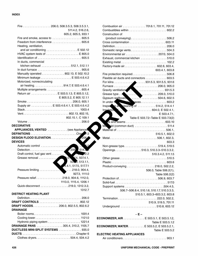
Fire . . . . . . . . . . . . . . . . . 206.0, 508.3.5.3, 508.3.5.3.1,511.4.2, 516.2.6,
605.2, 605.5, 933.1Fire and smoke, access to . . . . . . . . . . . . . . . . . . 605.5Freedom from interference . . . . . . . . . . . . . . . . . . 605.6Heating, ventilation,and air conditioning . . . . . . . . . . . . . . . . . . . E 502.12
HVAC system tests of . . . . . . . . . . . . . . . . . . . . E 805.0Identification of . . . . . . . . . . . . . . . . . . . . . . . . . . . 605.5In ducts, commercial kitchen exhaust . . . . . . . . . . . . . . . . . . 512.1, 512.1.1
In duct furnace . . . . . . . . . . . . . . . . . . . . . . . . . . . 905.6Manually operated . . . . . . . . . . . . . . 802.13, E 502.10.2Minimum leakage . . . . . . . . . . . . . . . . . . . E 503.4.6.4.2Motorized, nonrecirculating air heating. . . . . . . . . . . . . . . . . . 914.7, E 503.4.6.4.1
Multiple arrangements . . . . . . . . . . . . . . . . . . . . . 605.4Return air . . . . . . . . . . . . . . . . E 503.5.1.3, E 805.5.1.2,
E 805.5.2, E 805.12.1.1Smoke . . . . . . . . . . . . . . . . . . . . . . . . . . . . 206.0, 605.1Supply air . . . . . . . . . . . . . E 503.4.6.4.1, E 503.4.6.4.2Stack . . . . . . . . . . . . . . . . . . . . . . . . . . . . . . . . . . 1003.4Vent . . . . . . . . . . . . . . . . . . . . . . . . . . . . 802.13, 802.15,
802.15.1, C 109.1Volume . . . . . . . . . . . . . . . . . . . . . . . . . . . . . . . . . 206.0
DECORATIVE APPLIANCES, VENTED . . . . . . . . . . . . (see Appliances)
DEFINITIONS . . . . . . . . . . . . . . . . . . . . . . . . . . . . Chapter 2DESIGN FLOOD ELEVATION . . . . . . . . . . . . . . . . . . . 206.0DEVICES
Automatic control . . . . . . . . . . . . . . . . . . . . . . . . . 306.0Detection. . . . . . . . . . . . . . . . . . . . . . . . . 206.0, 514.2.3Draft control, fuel gas vent . . . . . . . . . . . . . . . . 802.12.2Grease removal . . . . . . . . . . . . . . 209.0, 507.4, 507.4.1,
509.0, 513.1.1,514.4.1, 517.5, 517.7.1
Pressure limiting . . . . . . . . . . . . . . . . . . . . 218.0, 904.4, 927.3, 1111.0
Pressure relief . . . . . . . . . . . . . . . . 218.0, 904.6, 1112.0,1113.0, 1115.4, 1206.1
Quick-disconnect . . . . . . . . . . . . . . . . . 219.0, 1312.3.2, 1312.7
DISTRICT HEATING PLANTDefinition. . . . . . . . . . . . . . . . . . . . . . . . . . . . . . . . 206.0
DRAFT CONTROLS . . . . . . . . . . . . . . . . . . . . . . . . . 802.12DRAFT HOODS. . . . . . . . . . . . . . . . 206.0, 802.5.5, 802.6.2DRAINAGE
Boiler rooms. . . . . . . . . . . . . . . . . . . . . . . . . . . . . 1001.4Cooling tower . . . . . . . . . . . . . . . . . . . . . . . . . . . . 1121.0Hydronic piping system . . . . . . . . . . . . . . . . . . . . 1221.4
DRAINAGE PANS . . . . . . . . . . . . . . . . 305.4, 310.2, 1105.7DUCTLESS MINI-SPLIT SYSTEMS . . . . . . . . . . . . . . 935.0DUCTS . . . . . . . . . . . . . . . . . . . . . . . . . . . . . . . . . Chapter 6
Clothes dryers. . . . . . . . . . . . . . . . . . . . . 504.4, 504.4.2
Combustion air . . . . . . . . . . . . . . 701.6.1, 701.11, 701.12Combustibles within . . . . . . . . . . . . . . . . . . . . . . . 602.2Construction of(product conveying) . . . . . . . . . . . . . . . . . . . . . . 506.2
Cross contamination . . . . . . . . . . . . . . . . . . . . . . 603.11Definition. . . . . . . . . . . . . . . . . . . . . . . . . . . . . . . . 206.0Domestic range vents . . . . . . . . . . . . . . . . . . . . . . 504.3Environmental air . . . . . . . . . . . . . . . . . . . . 207.0, 504.0Exhaust, commercial kitchen . . . . . . . . . . . . . . . . 510.0Existing metal . . . . . . . . . . . . . . . . . . . . . . . . . . . . 102.2Factory-made air . . . . . . . . . . . . . . . . . . . . 602.6, 603.4,
603.4.1, 603.8Fire protection required . . . . . . . . . . . . . . . . . . . . . 506.8Flexible air ducts and connectors . . . . . . . . . . . . . 603.5For kilns . . . . . . . . . . . . . . . . . . . 931.5.3, 931.5.5, 931.6Furnace . . . . . . . . . . . . . . . . . . . . . . . . . . . 206.0, 905.0Gravity ventilation. . . . . . . . . . . . . . . . . . . . . . . . 931.5.3Grease type . . . . . . . . . . . . . . . . . . . . . . . . 209.0, 510.0Gypsum wallboard . . . . . . . . . . . . . . . . . . . 504.6, 602.5In under floor or crawl spaces. . . . . . . . . . . . . . . . 603.2Inspection and cleaning of . . . . . . . . . . . 514.2, 514.4.1Insulation of . . . . . . . . . . . . . . . . . . . . 604.0, E 502.4.1,
E 503.4.7.1,Table E 503.7.2–Table E 503.7.3(2)
Joints and seams . . . . . . . . . . . . . . . . . . . . . . . . 603.10Manifold (common duct) . . . . . . . . . . . . . . . . . . . . 511.4Material of . . . . . . . . . . . . . . . . . . . . . . . . . . . . . . 506.1,
510.5.1, 602.0Metal . . . . . . . . . . . . . . . . . . . . . . . . . . . . . 506.1, 602.3,
603.3Non-grease type. . . . . . . . . . . . . . . . . . . . . 519.4, 519.5Openings . . . . . . . . . . . . . . . . 510.3, 510.3.3–510.3.3.2,
510.3.4.2, 511.1.5Other grease . . . . . . . . . . . . . . . . . . . . . . . . . . . . . 510.5Plastic . . . . . . . . . . . . . . . . . . . . . . . . . . . . . . . . . . 603.6Product-conveying . . . . . . . . . . . . . . . . . 218.0, 502.2.2,
506.0, Table 506.2(1), Table 506.2(2)
Protection of . . . . . . . . . . . . . . . . . . . . . . . . 506.9, 603.7Solid-fuel . . . . . . . . . . . . . . . . . . . . . . . . . . . . . . . . 517.0Support systems . . . . . . . . . . . . . . . . . . . . . . . .504.4.5,
506.7–506.8.4, 510.1.6, 510.1.7, 510.3.3.3, 510.5.1, 603.3–603.3.2, 603.8
Termination . . . . . . . . . . . . . . . . . . . . . . . . 222.0, 502.2, 510.9, 519.5, 701.11
Underground . . . . . . . . . . . . . . . . . . . . . . 510.8, 603.12
– E –ECONOMIZER, AIR . . . . . . . . . . . . . E 503.5.1, E 503.5.1.2,
Table E 503.5.1.2ECONOMIZER, WATER. . . . . . . . . . E 503.5.2, E 503.5.2.1,
Table E 503.5.2ELECTRIC HEATING APPLIANCES
Air conditioners . . . . . . . . . . . . . . . . . . . . . . . . . . . 903.1
426 UNIFORM MECHANICAL CODE - PREPRINT
INDEX
PREPRINT
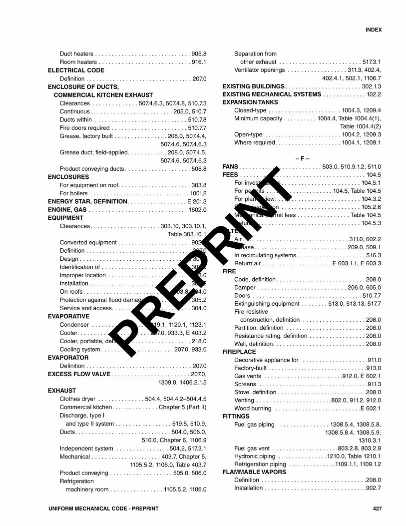
Duct heaters . . . . . . . . . . . . . . . . . . . . . . . . . . . . . 905.8Room heaters . . . . . . . . . . . . . . . . . . . . . . . . . . . . 916.1
ELECTRICAL CODEDefinition . . . . . . . . . . . . . . . . . . . . . . . . . . . . . . . . 207.0
ENCLOSURE OF DUCTS, COMMERCIAL KITCHEN EXHAUSTClearances . . . . . . . . . . . . . . 507.4.6.3, 507.4.8, 510.7.3Continuous. . . . . . . . . . . . . . . . . . . . . . . . . 205.0, 510.7Ducts within . . . . . . . . . . . . . . . . . . . . . . . . . . . . 510.7.8Fire doors required . . . . . . . . . . . . . . . . . . . . . . . 510.7.7Grease, factory built . . . . . . . . . . . . . . . . 208.0, 507.4.4,
507.4.6, 507.4.6.3Grease duct, field-applied. . . . . . . . . . . . 208.0, 507.4.5,
507.4.6, 507.4.6.3Product conveying ducts . . . . . . . . . . . . . . . . . . . . 505.8
ENCLOSURESFor equipment on roof. . . . . . . . . . . . . . . . . . . . . . 303.8For boilers . . . . . . . . . . . . . . . . . . . . . . . . . . . . . . 1001.2
ENERGY STAR, DEFINITION. . . . . . . . . . . . . . . . . . E 201.3ENGINE, GAS . . . . . . . . . . . . . . . . . . . . . . . . . . . . . . 1602.0EQUIPMENT
Clearances . . . . . . . . . . . . . . . . . . . . . 303.10, 303.10.1, Table 303.10.1
Converted equipment . . . . . . . . . . . . . . . . . . . . . . 902.3Definition . . . . . . . . . . . . . . . . . . . . . . . . . . . . . . . . 207.0Design . . . . . . . . . . . . . . . . . . . . . . . . . . . . . . . . . . 301.3Identification of . . . . . . . . . . . . . . . . . . . . . . . . . . . 303.6Improper location . . . . . . . . . . . . . . . . . . . . . . . . . 308.0Installation. . . . . . . . . . . . . . . . . . . . . . . . . . . . . . . 303.2On roofs . . . . . . . . . . . . . . . . . . . . . . . . . . . 303.8, 304.0Protection against flood damage. . . . . . . . . . . . . . 305.2Service and access. . . . . . . . . . . . . . . . . . . . . . . . 304.0
EVAPORATIVECondenser . . . . . . . . . . . . . . . . . 1119.1, 1120.1, 1123.1Cooler. . . . . . . . . . . . . . . . . . . . . . 207.0, 933.3, E 403.2Cooler, portable, definition . . . . . . . . . . . . . . . . . . 218.0Cooling system . . . . . . . . . . . . . . . . . . . . . . 207.0, 933.0
EVAPORATORDefinition . . . . . . . . . . . . . . . . . . . . . . . . . . . . . . . . 207.0
EXCESS FLOW VALVE . . . . . . . . . . . . . . . . . . . . . . . . 207.0,1309.0, 1406.2.1.5
EXHAUSTClothes dryer . . . . . . . . . . . . . . 504.4, 504.4.2–504.4.5Commercial kitchen. . . . . . . . . . . . . . Chapter 5 (Part II)Discharge, type I and type II system . . . . . . . . . . . . . . . . . 519.5, 510.9,
Ducts. . . . . . . . . . . . . . . . . . . . . . . . . . . . . 504.0, 506.0, 510.0, Chapter 6, 1106.9
Independent system . . . . . . . . . . . . . . . . 504.2, 517.3.1Mechanical . . . . . . . . . . . . . . . . . . . . . 403.7, Chapter 5,
1105.5.2, 1106.0, Table 403.7Product conveying . . . . . . . . . . . . . . . . . . . 505.0, 506.0Refrigeration machinery room . . . . . . . . . . . . . . . . 1105.5.2, 1106.0
Separation from other exhaust . . . . . . . . . . . . . . . . . . . . . . . . . 517.3.1
Ventilator openings . . . . . . . . . . . . . . . . . . 311.3, 402.4, 402.4.1, 502.1, 1106.7
EXISTING BUILDINGS . . . . . . . . . . . . . . . . . . . . . . . 302.1.3EXISTING MECHANICAL SYSTEMS . . . . . . . . . . . . . 102.2EXPANSION TANKS
Closed-type . . . . . . . . . . . . . . . . . . . . . . 1004.3, 1209.4Minimum capacity . . . . . . . . . . 1004.4, Table 1004.4(1),
Table 1004.4(2)Open-type . . . . . . . . . . . . . . . . . . . . . . . 1004.2, 1209.3Where required. . . . . . . . . . . . . . . . . . . . 1004.1, 1209.1
– F –FANS . . . . . . . . . . . . . . . . . . . . . . . . . 503.0, 510.9.1.2, 511.0FEES . . . . . . . . . . . . . . . . . . . . . . . . . . . . . . . . . . . . . . 104.5
For investigations . . . . . . . . . . . . . . . . . . . . . . . . 104.5.1For permits . . . . . . . . . . . . . . . . . . . . 104.5, Table 104.5For plan review. . . . . . . . . . . . . . . . . . . . . . . . . . 104.3.2For re-inspection . . . . . . . . . . . . . . . . . . . . . . . . 105.2.6Mechanical permit fees . . . . . . . . . . . . . . . . Table 104.5Refunds . . . . . . . . . . . . . . . . . . . . . . . . . . . . . . . 104.5.3
FILTERSAir . . . . . . . . . . . . . . . . . . . . . . . . . . . . . . . . 311.0, 602.2Grease . . . . . . . . . . . . . . . . . . . . . . . . . . . . 209.0, 509.1In recirculating systems. . . . . . . . . . . . . . . . . . . . . 516.3Return air . . . . . . . . . . . . . . . . . . . . . E 603.1.1, E 603.3
FIRECode, definition . . . . . . . . . . . . . . . . . . . . . . . . . . . 208.0Damper . . . . . . . . . . . . . . . . . . . . . . . . . . . 206.0, 605.0Doors . . . . . . . . . . . . . . . . . . . . . . . . . . . . . . . . . 510.7.7Extinguishing equipment . . . . . . . . 513.0, 513.13, 517.7Fire-resistive construction, definition . . . . . . . . . . . . . . . . . . . 208.0
Partition, definition . . . . . . . . . . . . . . . . . . . . . . . . 208.0Resistance rating, definition . . . . . . . . . . . . . . . . . 208.0Wall, definition. . . . . . . . . . . . . . . . . . . . . . . . . . . . 208.0
FIREPLACEDecorative appliance for . . . . . . . . . . . . . . . . . . . .911.0Factory-built . . . . . . . . . . . . . . . . . . . . . . . . . . . . . .913.0Gas vents . . . . . . . . . . . . . . . . . . . . . . . .912.0, E 602.1Screens . . . . . . . . . . . . . . . . . . . . . . . . . . . . . . . . .911.3Stove, definition . . . . . . . . . . . . . . . . . . . . . . . . . . .208.0Venting . . . . . . . . . . . . . . . . . . . . . . .802.0, 911.2, 912.0Wood burning . . . . . . . . . . . . . . . . . . . . . . . . . .E 602.1
FITTINGSFuel gas piping . . . . . . . . . . . . . . . 1308.5.4, 1308.5.8,
1308.5.8.4, 1308.5.9, 1310.3.1
Fuel gas vent . . . . . . . . . . . . . . . . . . . .803.2.8, 803.2.9Hydronic piping . . . . . . . . . . . . . . .1210.0, Table 1210.1Refrigeration piping . . . . . . . . . . . . . .1109.1.1, 1109.1.2
FLAMMABLE VAPORSDefinition . . . . . . . . . . . . . . . . . . . . . . . . . . . . . . . .208.0Installation . . . . . . . . . . . . . . . . . . . . . . . . . . . . . . .902.7
427UNIFORM MECHANICAL CODE - PREPRINT
INDEX
PREPRINT
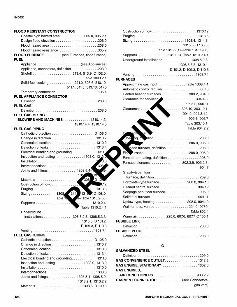
FLOOD RESISTANT CONSTRUCTIONCoastal high hazard area . . . . . . . . . . . .205.0, 305.2.1Design flood elevation . . . . . . . . . . . . . . . . . . . . . .206.0Flood hazard area . . . . . . . . . . . . . . . . . . . . . . . . .208.0Flood hazard resistance . . . . . . . . . . . . . . . . . . . .305.2
FLOOR FURNACE . . . . . . . . .(see Furnaces, floor furnace)FUEL
Appliance . . . . . . . . . . . . . . . . . . . . . .(see Appliances)Appliance, connectors, definition . . . . . . . . . . . . .203.0Shutoff . . . . . . . . . . . . . . . . . . . . .513.4, 513.9, C 102.0,
Table 1003.2.1Solid-fuel cooking . . . . . . . . . . . . .221.0, 508.6, 510.10,
511.1, 511.5, 513.13, 517.0Temporary connection . . . . . . . . . . . . . . . . . . . . . .105.4
FUEL APPLIANCE CONNECTORDefinition. . . . . . . . . . . . . . . . . . . . . . . . . . . . . . . . 203.0
FUEL GASDefinition. . . . . . . . . . . . . . . . . . . . . . . . . . . . . . . . 208.0
FUEL GAS MIXING BLOWERS AND MACHINES . . . . . . . . . . . . . . 1310.14.3,
1310.14.4, 1310.14.5FUEL GAS PIPING
Cathodic protection . . . . . . . . . . . . . . . . . . . . . . D 105.0Change in direction . . . . . . . . . . . . . . . . . . . . . . . 1310.7 Concealed location . . . . . . . . . . . . . . . . . . . . . . . 1310.3Detection of leaks . . . . . . . . . . . . . . . . . . . . . . . . 1313.4Electrical bonding and grounding. . . . . . . . . . . . . 1311.0Inspection and testing . . . . . . . . . . . . . . 1303.0, 1313.0Installation . . . . . . . . . . . . . . . . . . . . . . . . . . . . . . 1310.0Interconnections . . . . . . . . . . . . . . . . . . . . . . . . . 1308.3 Joints and fittings . . . . . . . . . . . . . . 1308.5.4–1308.5.9,
1313.2.1, 1313.2.2Materials . . . . . . . . . . . . . . . . . . . . . . . . 1308.5, D 109.0Obstruction of flow. . . . . . . . . . . . . . . . . . . . . . . 1310.12Purging . . . . . . . . . . . . . . . . . . . . . . . . . . . . . . . . 1313.6Sizing . . . . . . . . . . . . . 1308.4, 1314.0, 1315.0, D 108.0,
Table 1315.2(1)–Table 1315.2(36)Supports . . . . . . . . . . . . . . . . . . . . . . . . . . . . . 1310.2.4,
Table 1310.2.4.1Underground installations . . . . . . . . . . . . . . 1308.5.2.3, 1308.5.3.3,
1310.0, D 101.2, D 109.3, D 110.3
Venting . . . . . . . . . . . . . . . . . . . . . . . . . . . . . . . 1308.7.4FUEL GAS TUBING
Cathodic protection . . . . . . . . . . . . . . . . . . . . . . D 105.0Change in direction . . . . . . . . . . . . . . . . . . . . . . . 1310.7Concealed location . . . . . . . . . . . . . . . . . . . . . . . 1310.3Detection of leaks . . . . . . . . . . . . . . . . . . . . . . . . 1313.4Electrical bonding and grounding. . . . . . . . . . . . . 1311.0Inspection and testing . . . . . . . . . . . . . . 1303.0, 1313.0Installation . . . . . . . . . . . . . . . . . . . . . . . . . . . . . . 1310.0Interconnections . . . . . . . . . . . . . . . . . . . . . . . . . 1308.3 Joints and fittings . . . . . . . . . . . . . . 1308.5.4–1308.5.9,
1313.2.1, 1313.2.2Materials . . . . . . . . . . . . . . . . . . . . . . . . 1308.5, D 109.0
Obstruction of flow. . . . . . . . . . . . . . . . . . . . . . . 1310.12Purging . . . . . . . . . . . . . . . . . . . . . . . . . . . . . . . . 1313.6Sizing . . . . . . . . . . . . . . . . . . . . . . . . . . 1308.4, 1314.1,
1315.0, D 108.0, Table 1315.2(1)–Table 1315.2(36)
Supports. . . . . . . . . . . . . . . . 1310.2.4, Table 1310.2.4.1Underground installations . . . . . . . . . . . . . . 1308.5.2.3,
1308.5.3.3, 1310.1,D 101.2, D 109.3, D 110.3
Venting . . . . . . . . . . . . . . . . . . . . . . . . . . . . . . . 1308.7.4FURNACES
Approximate gas input . . . . . . . . . . . . . . Table 1308.4.1Automatic control required. . . . . . . . . . . . . . . . . . . 607.6Central heating furnaces . . . . . . . . . . . . . . 303.2, 904.0Clearance for servicing . . . . . . . . . . . . . . . . . . . 304.4.3,
905.8.2, 906.11Clearances . . . . . . . . . . . . . . . . . . . . . 303.10, 303.10.1,
904.2, 904.3.1.2, 905.1, 906.7,
Table 303.10.1, Table 904.2.2
Downflow-type,heating, definition . . . . . . . . . . . . . . . . . . . . . . .208.0
Duct furnace . . . . . . . . . . . . . . . . . . . . . . .206.0, 905.0Enclosed furnace, definition . . . . . . . . . . . . . . . . .208.0Floor furnace . . . . . . . . . . . . . . . . . . . . . . .208.0, 906.0Forced-air heating, definition . . . . . . . . . . . . . . . . .208.0Furnace plenums . . . . . . . . . . . . . . . .802.3.5, 903.2.3,
904.7Gravity-type, floor furnace, definition . . . . . . . . . . . . . . . . . . . . . . . 209.0
Horizontal-type furnace . . . . . . . . . . . . . . 208.0, 904.10Oil-fired central furnace. . . . . . . . . . . . . . . . . . . . 904.12Seepage pan, floor furnace . . . . . . . . . . . . . . . . . 906.9Solid fuel furnace . . . . . . . . . . . . . . . . . . . . . . . . 904.11Upflow-type, heating . . . . . . . . . . . . . . . . 208.0, 904.10Wall furnace, vented . . . . . . . . . . . . . . . . . 224.0, 907.0,
Table 802.4Warm air . . . . . . . . . . . . . . . 225.0, 607.6, 607.7, C 105.1
FUSIBLE LINKDefinition. . . . . . . . . . . . . . . . . . . . . . . . . . . . . . . . 208.0
FUSIBLE PLUGDefinition. . . . . . . . . . . . . . . . . . . . . . . . . . . . . . . . 208.0
– G –GALVANIZED STEEL
Definition. . . . . . . . . . . . . . . . . . . . . . . . . . . . . . . . 209.0GAS CONVENIENCE OUTLET . . . . . . . . . . . . . . . . . 1312.8GAS ENGINE, STATIONARY . . . . . . . . . . . . . . . . . . 1602.0GAS ENGINES,AIR CONDITIONERS . . . . . . . . . . . . . . . . . . . . . . 903.2.2
GAS VENT CONNECTOR . . . . . . . . . . . . . (see Connectors, gas vent)
428 UNIFORM MECHANICAL CODE - PREPRINT
INDEX
PREPRINT
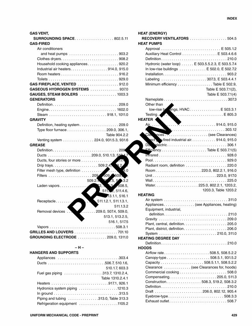
GAS VENT,SURROUNDING SPACE . . . . . . . . . . . . . . . . . . . 802.5.11
GAS-FIREDAir conditionersand heat pumps . . . . . . . . . . . . . . . . . . . . . . . . 903.2
Clothes dryers. . . . . . . . . . . . . . . . . . . . . . . . . . . . 908.2Household cooking appliances . . . . . . . . . . . . . . . 920.2Industrial air heaters. . . . . . . . . . . . . . . . . . 914.0, 915.0Room heaters . . . . . . . . . . . . . . . . . . . . . . . . . . . . 916.2Toilets . . . . . . . . . . . . . . . . . . . . . . . . . . . . . . . . . . 929.0
GAS FIREPLACE, VENTED . . . . . . . . . . . . . . . . . . . . 912.0GASEOUS HYDROGEN SYSTEMS . . . . . . . . . . . . . . 937.0GAUGES, STEAM BOILERS . . . . . . . . . . . . . . . . . . 1003.3GENERATORS
Definition. . . . . . . . . . . . . . . . . . . . . . . . . . . . . . . . 209.0Engine. . . . . . . . . . . . . . . . . . . . . . . . . . . . . . . . . 1602.0Steam . . . . . . . . . . . . . . . . . . . . . . . . . . . . 918.1, 1011.0
GRAVITYDefinition, heating system. . . . . . . . . . . . . . . . . . . 209.0Type floor furnace . . . . . . . . . . . . . . . . . . . 209.0, 306.1,
Table 904.2.2Venting system . . . . . . . . . . . . . . . 224.0, 931.5.3, 931.6
GREASEDefinition. . . . . . . . . . . . . . . . . . . . . . . . . . . . . . . . 209.0Ducts . . . . . . . . . . . . . . . . . . . . . 209.0, 510.1.3, 510.1.7Ducts, four stories or more . . . . . . . . . . . . . . . . . 517.4.2Drip trays. . . . . . . . . . . . . . . . . . . . . . 509.2.4, 509.2.4.1Filter mesh type, definition . . . . . . . . . . . . . . . . . . 209.0Filters . . . . . . . . . . . . . . . . . . . . . 209.0, 509.1, 509.2.3,
509.2.4, 509.2.5, 516.3.2Laden vapors. . . . . . . . . . . . . . . . 507.2, 508.3.1, 508.5,
511.2.2, 511.4.6,513.1.1, 516.1
Receptacle . . . . . . . . . . . . . . . . . . . . 511.1.2.1, 511.1.3.1,511.1.3.2
Removal devices . . . . . . . . . . . . . . 209.0, 507.4, 509.0,513.1, 513.2.5,516.1, 517.5
Vapors . . . . . . . . . . . . . . . . . . . . . . . . . . . . . . . . 508.3.1GRILLES AND LOUVERS . . . . . . . . . . . . . . . . . . . . . 701.10GROUNDING ELECTRODE . . . . . . . . . . . . . . 209.0, 1311.0
– H –HANGERS AND SUPPORTS
Appliances . . . . . . . . . . . . . . . . . . . . . . . . . . . . . .303.4Ducts . . . . . . . . . . . . . . . . . . . . . . . . . . . .506.7, 510.1.6,
510.1.7, 603.3Fuel gas piping . . . . . . . . . . . . . . . . . . .313.7, 1310.2.4,
Table 1310.2.4.1Heaters . . . . . . . . . . . . . . . . . . . . . . . . . . . .917.1, 926.1Hydronics system piping . . . . . . . . . . . . . . . . . . .1210.3In ground . . . . . . . . . . . . . . . . . . . . . . . . . . . . . . . .313.5Piping and tubing . . . . . . . . . . . . . . .313.0, Table 313.3Refrigeration equipment . . . . . . . . . . . . . . . . . . .1105.2
HEAT (ENERGY) RECOVERY VENTILATORS . . . . . . . . . . . . . . . . . . 504.5
HEAT PUMPSApproval . . . . . . . . . . . . . . . . . . . . . . . . . . . . . E 505.1.2Auxiliary Heat Control . . . . . . . . . . . . . . . . . E 503.4.6.6Definition . . . . . . . . . . . . . . . . . . . . . . . . . . . . . . . . 210.0Hydronic (water loop) . . . . . . E 503.5.5.2.3, E 503.5.7.4In low-rise buildings . . . . . . . . . . . . . E 502.0, E 502.7.2Installation. . . . . . . . . . . . . . . . . . . . . . . . . . . . . . . 903.2Labeling . . . . . . . . . . . . . . . . . . . . . . 307.3, E 503.4.4.1Minimum efficiency . . . . . . . . . . . . . . . . . Table E 502.9,
Table E 503.7.1(2), Table E 503.7.1(4)
Nameplate . . . . . . . . . . . . . . . . . . . . . . . . . . . . . . . 307.3Other thanlow-rise buildings, HVAC. . . . . . . . . . . . . . . E 503.3.1
Testing . . . . . . . . . . . . . . . . . . . . . . . . . . . . . . . . E 805.3HEATER
Air. . . . . . . . . . . . . . . . . . . . . . . . . . . . . . . . 914.0, 915.0Aircraft hangars . . . . . . . . . . . . . . . . . . . . . . . . . . 303.12Clearances . . . . . . . . . . . . . . . . . . . . . (see Clearances)Direct gas-fired industrial air. . . . . . . . . . . . 914.0, 915.0Duct, electric . . . . . . . . . . . . . . . . . . . . . . . . . . . . . 306.1Efficiency . . . . . . . . . . . . . . . . . . . . . . Table E 503.7.1(5)Infrared . . . . . . . . . . . . . . . . . . . . . . . . . . . . . . . . . 928.0Pool. . . . . . . . . . . . . . . . . . . . . . . . . . . . . . . . . . . . 929.0Radiant room, definition . . . . . . . . . . . . . . . . . . . . 220.0Room . . . . . . . . . . . . . . . . . . . . . . 220.0, 802.2.1, 916.0Unit . . . . . . . . . . . . . . . . . . . . . . . . . . . . . . . 223.0, 917.0Wall . . . . . . . . . . . . . . . . . . . . . . . . . . . . . . . . . . . . 225.0Water. . . . . . . . . . . . . . . . . . . . . 225.0, 802.2.1, 1203.2,
1203.3, Table 1203.2HEATING
Air system . . . . . . . . . . . . . . . . . . . . . . . . . . . . . . . 311.0Appliances. . . . . . . . . . . . . . . (see Appliances, heating)Equipment, industrial,definition. . . . . . . . . . . . . . . . . . . . . . . . . . . . . . . 211.0
Gravity . . . . . . . . . . . . . . . . . . . . . . . . . . . . . . . . . 209.0Plant, central, definition. . . . . . . . . . . . . . . . . . . . . 205.0Plant, district, definition. . . . . . . . . . . . . . . . . . . . . 206.0System . . . . . . . . . . . . . . . . . . . . . . . . . . . . 210.0, 311.0
HEATING DEGREE DAYDefinition . . . . . . . . . . . . . . . . . . . . . . . . . . . . . . . . 210.0
HOODSAirflow rate . . . . . . . . . . . . . . . . . . . . . . 508.5, 508.5.2.2Canopy-type . . . . . . . . . . . . . . . . . . . . . 508.5.1, 931.5.2Capacity . . . . . . . . . . . . . . . . . . . . . 508.5.1.1, 508.5.2.2Clearance . . . . . . . . . . . . . (see Clearances for, hoods)Commercial cooking . . . . . . . . . . . . . . . . . . . . . . . 508.0Compensating. . . . . . . . . . . . . . . . . . . . . . . 205.0, 511.3Construction. . . . . . . . . . . . . . . . . 508.3, 519.2, 508.3.2Definition . . . . . . . . . . . . . . . . . . . . . . . . . . . . . . . . 210.0Draft . . . . . . . . . . . . . . . . . . . . . . . 206.0, 802.12, 905.4Eyebrow-type . . . . . . . . . . . . . . . . . . . . . . . . . . . 508.3.3Exhaust outlet . . . . . . . . . . . . . . . . . . . . . . . . . . . . 508.7
429UNIFORM MECHANICAL CODE - PREPRINT
INDEX
PREPRINT
Fixed baffle . . . . . . . . . . . . . . . . . . . . . . . 210.0, 513.2.5For dishwashing machines. . . . . . . . . . . . . 519.1, 519.3For kilns . . . . . . . . . . . . . . . . . . . . . . . . . . . . . . . 931.5.2Grease removal devices in . . . . . . . . . . . . . . . . . . 509.0Inspection and cleaning . . . . . . . . . 514.2, 514.3, 514.4Insulation . . . . . . . . . . . . . . . . . . . . . . . . . . . . . . 508.3.4Integrated supply-air plenums . . . . . . . . . . . . . . 508.3.5Labeling . . . . . . . . . . . . . . . . . . . . . . . . . . . . . . . 508.5.3Location . . . . . . . . . . . . . . . . . . . . . . . . . . . . . . . . 508.1Noncanopy-type. . . . . . . . . . . . . . . . . . . . . . . . . 508.5.2Product conveying . . . . . . . . . . . . . . . . . . . . . . . . 505.11Seams, joints and penetration . . . . . . . . . . . . . . 508.3.1Size. . . . . . . . . . . . . . . . . . . . . . . . . . . . . . . . . . . . 508.5Solid-fuel. . . . . . . . . . . . . . . . . . . . . . . . . . . 508.6, 517.3Type I . . . . . . . . . . . . . . . . . . . . . . . . . . . . . 210.0, 508.3Type II. . . . . . . . . . . . . . . . . . . . . . . . . . . . . 210.0, 519.2Ultraviolet . . . . . . . . . . . . . . . . . . . . . . . . . . . . . . 508.2.1Ventilating . . . . . . . . . . . . . . . . . . . . . . 802.2.1, 802.2.4,
802.3.4, 802.12, 922.3HOT PLATES . . . . . . . . . . . . . . . . . . . . . . . . . . 919.1–919.3, HYDRONIC SPACE HEATING . . . . . . . . . . . . . . . . . 1215.0HYDRONICS . . . . . . . . . . . . . . . . . . . . . . . . . . . . Chapter 12
Auxiliary systems . . . . . . . . . . . . . . . . . . . . . . . . 1220.0Appliances and equipment . . . . . . . . . . . . . . . . . 1207.0Boilers . . . . . . . . . . . . . . . . . . 1207.2, 1207.2.1, 1207.2.2Circulators . . . . . . . . . . . . . . . . . . . . . . . . . . . . . . 1208.0Clearance . . . . . . . . . . . . . . . . . . . . . . . . . . . . . . 1221.6Definition . . . . . . . . . . . . . . . . . . . . . . . . . . . . . . . . 210.0Embedded piping and joints . . . . . . . . . . . . . . . . 1221.2Expansion tanks . . . . . . . . . . . . . . . . . . . . . . . . . 1209.0Hangers and supports. . . . . . . . . . . . . . . . . . . . . 1210.3Heat sources . . . . . . . . . . . . . . . . . . . . . . . . . . . 1203.1Heat transfer medium . . . . . . . . . . . . . . . . . . . . . 1215.5Identification of piping . . . . . . . . . . . . . . . . . . . . . 1204.0Installation . . . . . . . . . . . . . . . . . . . . . . . 1205.0, 1221.0Insulation . . . . . . . . . . . . . . . 1201.2, 1220.2.5, 1217.5.2Joints and connections . . . . . . . . . . . . . . . . . . . . 1211.0Materials . . . . . . . . . . . . . . . . . . . . 1210.0, Table 1210.1Protection of potable water supply . . . . . . . . . . . 1202.0Radiant heating and cooling . . . . . . . . . . . . . . . . 1217.0Snow melt systems . . . . . . . . . . . . . . 1220.2, 1220.2.1,
1217.5.2, Table 1220.2.1Safety devices. . . . . . . . . . . . . . . . . . . . . . . . . . . 1206.0Steam systems . . . . . . . . . . . . . . . . . . . . . . . . . . 1216.0Testing . . . . . . . . . . . . . . . . . . . . . . . . . . 1205.2, 1221.3Water heaters . . . . . . . . . . . . . . . . . . . . 1203.2, 1203.3,
1207.3, Table 1203.2
– I –IDLH
Definition, . . . . . . . . . . . . . . . . . . . . . . . . . . . . . . . . 211.0Refrigeration . . . . . . . . . . . . . . . . . . . . . . . . . . 1106.2.2
INCINERATORSCommercial and industrial type . . . . . . . . . . . . . . . . . . . . . . . . . . 925.0
Fume . . . . . . . . . . . . . . . . . . . . . . . . . . . . . 208.0, 512.3Residential . . . . . . . . . . . . . . . . . . . . . . . . . . . . . . 925.3
INDUSTRIAL HEATING EQUIPMENTDefinition . . . . . . . . . . . . . . . . . . . . . . . . . . . . . . . . 211.0
INSANITARY LOCATIONDefinition . . . . . . . . . . . . . . . . . . . . . . . . . . . . . . . . 211.0
INSPECTIONSChimneys . . . . . . . . . . . . . . . . . . . . . . . 802.5.6, 802.5.7Commercial kitchenexhaust system, schedule of . . . . . . . . . . Table 514.3
Evaporative cooler . . . . . . . . . . . . . . . . . . . . . . . . 933.3Fire-extinguishing equipment . . . . . . . . . . . . . . . . 514.2Fuel gas piping. . . . . . . . . . . . . . . . . . . . . . . . . . 1303.0,
1304.0, 1313.1Reinspections . . . . . . . . . . . . . . . . . . . . . . . . . . 105.2.6Requests . . . . . . . . . . . . . . . . . . . . . . . . . . . . . . 105.2.3
INSTALLATIONS OFAppliances in manufactured housing . . . . . . . . . . 930.0Appliances in garages. . . . . . . . . . . . . . . . . . . . . . 305.1Appliances in repair garages . . . . . . . . . . . . . . 303.11.1Ducts. . . . . . . . . . . . . . . . . . . . . . . . . . . . 510.5.3, 603.0Equipment and appliances . . . . . . . . . . . . . . . . . . 303.0Gas piping . . . . . . . . . . . . . . . . . . . . . . . 1310.0, 1310.2,
1310.9, 1312.10Overhead heaters incommercial garagesand aircraft hangars. . . . . . . . . . . . . . . 905.7, 926.4
INSULATION OFDucts. . . . . . . . . . . . . . . . . . . . . . . . . 506.11.2, 506.11.3,
604.0, E 502.4.1,E 503.4.7,
Table E 503.7.2,Hoods . . . . . . . . . . . . . . . . . . . . . . . . . . . . . . . . 508.3.4Hydronic systems . . . . . . . . . . . . . . . . . . . . . . . . 1205.0HVAC system piping . . . . . . . . . . . . . . . . . . . . . E 502.5,
E 503.4.7.1.2,Table E 502.5,
Table E 503.7.3(1)INTERLOCK
Air heater . . . . . . . . . . . . . . . . . . . . . . . . . . . . . . . 914.7Cooking equipmentventilation . . . . . . . . . . . . . . . . . . . . . . 517.1.3, 517.6.2
Definition . . . . . . . . . . . . . . . . . . . . . . . . . . . . . . . . 211.0Exhaust. . . . . . . . . . . . . . . . . . . . . . . . . . . . . . . . . 503.1Gas mixing machines . . . . . . . . . . . . . . . . . . . 1310.14.5Inspection of safety . . . . . . . . . . . . . . . . . . . . . . 516.6.4Mechanical air supply . . . . . . . . . . . . . . . . . . . . . 701.9.2Motorized louvers . . . . . . . . . . . . . . . . . . . . . . . 701.10.2Recirculating systems . . . . . . . . . . . . . . . . . . . . . . 516.3Stack dampers . . . . . . . . . . . . . . . . . . . . . . . . . . 1003.4
– J –JOINTS AND CONNECTIONS . . . . . . . . . . . . . . . . . 1109.2,
1109.8, 1211.0, 1308.5.8–1308.5.10.6, E 506.0
430 UNIFORM MECHANICAL CODE - PREPRINT
INDEX
PREPRINT

Brazed joint . . . . . . . . . . . . . . . . . . . . . . . 212.0, 1211.3Copper or copper alloy pipe or tubing . . . . . . . 1109.2, 1211.3, 1211.14.1
CPVC piping . . . . . . . . . . . . . . . . . . . . . 1211.2, E 506.7Embedded piping and joints . . . . . . . . . . . . . . . . 1221.2Expansion joint. . . . . . . . . . . . . . . . . . . . . . . . . 1313.2.2Flared. . . . . . . . . . . . . . . . . . . . . . . . . . . . 212.0, 1211.3,
1308.5.8.3, 1308.5.8.4Mechanical joint . . . . . . . . . . . . . . 212.0, 1109.7, 1211.5,
1211.6,1211.7, 1211.8,
1211.11, 1211.12,1308.5.9.3, E 506.5,
E 506.10.2PE pipe or tubing . . . . . . . . . . . . . . . . . . 1211.7, E 506.9PE-AL-PE pipe or tubing . . . . . . . . . . . . . . . . . . . 1211.8PE-RT piping or tubing. . . . . . . . . . . . . 1211.9, E 506.11PEX pipe or tubing. . . . . . . . . . . . . . . . . 1211.5, E 506.8PEX-AL-PEX pipe or tubing . . . . . . . . . . . . . . . . . 1211.6Plastic piping, joints, and fittings . . . . . . . . . . . 1211.14.2PP piping or tubing. . . . . . . . . . . . . . . 1211.10, E 506.10Press-Connect, definition . . . . . . . . . . . . . . . . . . . 212.0PVC piping . . . . . . . . . . . . . . . . . . . . . 1211.11, E 506.12Soldered joint . . . . . . . . . . 212.0, E 506.8.2, E 506.11.2Solvent cement plastic pipe. . . . . . . . . . . . . . . . . . . . . 1211.2, 1211.11,
E 506.7.2, E 506.12.1Steel pipe or tubing . . . . . . . . . . . . . . . . 1109.2, 1211.12Threaded joint . . . . . . . . . . . . . . . . . . . . 1211.2, 1211.12,
E 506.7.1, E 506.12.2Various materials . . . . . . . . . . . . . . . . . 1211.13, E 506.2Welded joint. . . . . . . . . . . . . . . . . . . . . . . 212.0, 1211.12Welded joint (thermoplastic) . . . . . . . . . . . . . . . E 506.6
JUMPER, BONDINGDefinition. . . . . . . . . . . . . . . . . . . . . . . . . . . . . . . . 204.0Fuel gas piping. . . . . . . . . . . . . . . . . . . . . . . . . . . 1311.2
– K –KILNS, SMALL CERAMICS . . . . . . . . . . . . . . . . . . . . 931.0KITCHEN HOODS, COMMERCIAL . . . . . . . . . . . . . . 508.0
– L –LABELED
Definition . . . . . . . . . . . . . . . . . . . . . . . . . . . . . . . . 214.0LABELS AND INSTRUCTIONS
For appliances . . . . . . . . . . . . . . . . . . . . . . . . . . . . 307.0For heating appliances . . . . . . . . . . . . . . . . . . . . . 307.0For hydronic systems . . . . . . . . . . . . . . . . . . . . . 1204.0For refrigerating systems . . . . . . . . . . . . . . . . . . . 1115.0For type I hoods. . . . . . . . . . . . . . . . . . . . . . . . . 508.5.3
LADDER, PERMANENT . . . . . . . . . . . . . . . . . . . . 304.3.1.2LEAKS
Fuel gas . . . . . . . . . . . . . . . . . . . . . . . . . 1313.4, 1313.5LOWER FLAMMABILITY LIMIT (LFL)
Definition . . . . . . . . . . . . . . . . . . . . . . . . . . . . . . . . 214.0
Product conveying ducts . . . . . . . . . . . . . . 505.1, 505.3Refrigeration . . . . . . . . . . . . . . . . . . . 1104.4, 1106.2.5.2
LINE CONTACT INSTALLATIONDefinition . . . . . . . . . . . . . . . . . . . . . . . . . . . . . . . . 214.0
LIQUEFIED PETROLEUM GAS (LPG)Automatic control devices . . . . . . . . . . . . . . . . . . . 306.0Definition . . . . . . . . . . . . . . . . . . . . . . . . . . . . . . . . 214.0Gas Facilities . . . . . . . . . . . . . . . . . . . . . 214.0, 1312.11Shutoff devices. . . . . . . . . . . . . . . . . . . . . . . . . . D 110.4Supply connections . . . . . . . . . . . . . . . D 101.2, D 106.1
LISTEDDefinition . . . . . . . . . . . . . . . . . . . . . . . . . . . . . . . . 214.0
LISTING AGENCYDefinition . . . . . . . . . . . . . . . . . . . . . . . . . . . . . . . . 214.0
LOCATION OFAppliances in garages . . . . . . . . 305.1.1, 305.1.2, 905.7Appliances subject tomechanical damage . . . . . . . . . . . . . . . . . . . . 305.1.1
Boilers, central heating . . . . . . . . . . . . . . . . . . . . . 904.1Draft hoods and controls . . . . . . . . . . . . . 802.12, 905.4Evaporative cooling systems. . . . . . . . . . . . . . . . . 933.2Pool heaters. . . . . . . . . . . . . . . . . . . . . . . . . . . . . . 927.1Refrigerating equipment . . . . . . . . . . . . . . . . . . . 1106.1Wall furnaces. . . . . . . . . . . . . . . . . . . . . . . . . . . . . 907.2
LOUVERS . . . . . . . . . . . . . . . . . . . . . . . . . . . . . . . . . . 315.0LOUVERS, GRILLES,AND SCREENS . . . . . . . . . . . . . . . . . . . . . . . . . . . 701.10
LOW-PRESSURE HOT-WATER-HEATING BOILERDefinition . . . . . . . . . . . . . . . . . . . . . . . . . . . . . . . . 214.0
LOW-PRESSURE STEAM-HEATING BOILERDefinition . . . . . . . . . . . . . . . . . . . . . . . . . . . . . . . . 214.0
LOW-WATER CUTOFF . . . . . . . . . . . . . . . . . . . . . . . 1008.0
– M –MACHINERY
Definition . . . . . . . . . . . . . . . . . . . . . . . . . . . . . . . . 215.0MACHINERY ROOM, REFRIGERATION
Equipment and controls in . . . . . . . . . . . . . . . . . . 1108.0Detectors and alarms . . . . . . . . . . . . . . . . . . 1106.2.2.1Ventilation of . . . . . . . . . . . . . . . . . . . 1106.2.3, 1106.2.4Where required . . . . . . . . . . . . . . . . . . . . . . . . . . 1106.0
MAKEUP AIR . . . . . . . . . . . . . . . . . . . . . . (see Air, Makeup)MARKING . . . . . . . . . . . . . . . . . . . . . . . . . . . . . . . . . 302.1.1MASONRY, CHIMNEYS. . . . . . . . . (see Chimney, masonry)MATERIALS
Alternate . . . . . . . . . . . . . . . . . . . . . . . . . . . . . . . . 302.2For construction ofhoods . . . . . . . . . . . . . . . . . . . . . . . . . . . . . . . . 508.3
For piping, containers, and valves ofrefrigeration systems . . . . . . . . . . . . . . . . . . . . 1109.1
For ducts . . . . . . . . . . . . . . . . . . . 506.1, 510.5.1, 602.0For fuel piping. . . . . . . . . . . . . . . . . . . . 1308.0, D 109.0For piping, tubingand fittings hydronics . . . . . . . . . 1210.0, Table 1210.1
For vent connectors. . . . . . . . . . . 802.10.1.1–802.10.1.4
431UNIFORM MECHANICAL CODE - PREPRINT
INDEX
PREPRINT
MECHANICALCombustion air supply. . . . . . . . . . . . . . . 701.9, E 502.6Exhaust system. . . . . . . . . . . . . . . . . . . . . . . . . . . 505.1Ventilating system . . . . . . . . . . . . . . . . . . . . . . . . 402.3,
1106.8, E 502.6,E 605.1.2, Table E 502.6
MECHANICAL EXHAUSTING FORBathrooms . . . . . . . . . . . . . . . . . . . . . . . . . . . . . E 605.2Low-rise residential dwelling . . . . . . . . . . . . . . E 605.1.3Product conveying. . . . . . . . . . . . . . . . . . . . . . . . . 505.0Refrigeration . . . . . . . . . . . . . . . . . . . . 1105.5.2, 1106.0,
MECHANICAL JOINTS. . . . . . . . . . . . . . . . . . . . (see Jointsand connections)
MECHANICAL PERMIT FEE . . . . . . . . . 104.5, Table 104.5MECHANICAL SYSTEMS
Application to existing . . . . . . . . . . . . . . . . . . . . . . 102.2In elevator shaft. . . . . . . . . . . . . . . . . . . . . . . . . . . 305.3
METALChimneys . . . . . . . . . . . . . . . . . . . . . . . . . . . . . . 802.5.2Ducts. . . . . . . . . . . . . . . . . . . . . . . . 506.1, 602.3, 603.3
METER, GAS. . . . . . . . . . . . . . . . . . . . . . . . 1308.6, D 104.0METHODS OF CONSTRUCTION,ALTERNATES . . . . . . . . . . . . . . . . . . . . . . . . . . . . . 302.2
MINIMUM REQUIREMENTSPurpose of Code . . . . . . . . . . . . . . . . . . . . . . . . . . 101.3
MINIMUM STANDARDS . . . . . . . . . . . . . . . . . . . . . . . 302.1MOBILE HOME PARKSFUEL GAS EQUIPMENTAND INSTALLATION. . . . . . . . . . . . . . . . . . . . . D 101.1
MOTORS, FANS, AND FILTERS . . . . . . . . . . . . . . . . . 503.0MULTIPLE-ZONE SYSTEM. . . . . . . . . . . . . . . . . . . . . 404.0
– N –NATURAL VENTILATION
Definition . . . . . . . . . . . . . . . . . . . . . . . . . . . . . . . . 216.0Floor area to be ventilated . . . . . . . . . . . . . . . . . 402.2.1Indoor air quality for low-rise residential buildings . . . . . . . . . . . . . E 605.1
Location and size openings . . . . . . . . . . . . . . . . 402.2.2Refrigeration systems . . . . . . . . . . . . . . . . . . . . . 1106.3Systems . . . . . . . . . . . . . . . . . . . . . . . . . 402.2, 402.2.1
NONCOMBUSTIBLE MATERIALDefinition . . . . . . . . . . . . . . . . . . . . . . . . . . . . . . . . 216.0
NON-GREASE DUCTS . . . . . . . . . . . . . . . . . . . . . . . . 519.4
– O –OCCUPATION CLASSIFICATION
Definition . . . . . . . . . . . . . . . . . . . . . . . . . . . . . . . . 217.0OIL BURNING BOILERS . . . . . . . . . . . . . (see Boiler types,
oil burning)OPEN TOP BROILER UNIT . . . . . . . . . . . . . . . . . . . . 922.0OPENINGS
Air heaters. . . . . . . . . . . . . . . . . . . . . . . . . . . . . . . 914.7Attics . . . . . . . . . . . . . . . . . . . . . . . . . . . . . . . . E 502.11
Ducts. . . . . . . . . . . . . . . . . . . . . . . 506.6, 510.1.4, 510.3Exhaust and intake . . . . . . . . . . . . . . . . . 305.2.2, 926.3For access . . . . . . . . . . . . . . . . . . . . . . . 506.3, 510.1.4,
514.1.2, 1406.2.1.4For combustion air. . . . . . . . . . . . . . . . . . 701.6, C 109.1Furnaces. . . . . . . . . . . . . . . . . . . . . . . . . . . . . . . . 906.8Illuminating appliances . . . . . . . . . . . . . . . . . . . . . 924.4Ratproofing . . . . . . . . . . . . . . . . . . . . . . . . . . . . . 316.10Relief. . . . . . . . . . . . . . . . . . . . . . . . . . . . . . . . . . . 914.7Screens . . . . . . . . . . . . . . . . . . . . . . . . . . 402.4, 802.1.2Ventilation . . . . . . . . . . . . 402.2.1, 402.2.1.1, 402.2.1.2,
402.2.1.3, 402.2.1.4, 402.2.2,402.2.3, 802.1.2, 802.10.3,
1105.5.1, 1106.3,E 605.1.1
OUTDOOR AIR RATECalculation . . . . . . . . . . . . . . . . . . . . . . . . . Appendix G
OUTLETSAppliance flue . . . . . . . . . . . . . . . . . . . . . . . . . . . 203.0,
802.10.5, 803.1.1Draft hood . . . . . . . . . . . . 802.10.2.1, 802.10.5, 803.1.1Exhaust. . . . . . . . . . . . . . . . . . . . . . . . . . . . . . . . . 508.7Fuel gas piping . . . . . . . . . . . . . 1305.2, 1306.3, 1310.9,
1312.8, 1314.4OVER PRESSURE PROTECTION
Fuel gas piping. . . . . . . . . . . . . . . . . . . 1308.7.1, 1310.6OVERHEAD HEATERS
In garages. . . . . . . . . . . . . . . . . . . . . . . . . . . . . . . 926.4
– P –PENALTIES. . . . . . . . . . . . . . . . . . . . . . . . . . . . 106.2, 106.3PERMISSIBLE EXPOSURE LIMIT (PEL)Definition . . . . . . . . . . . . . . . . . . . . . . . . . . . . . . . . 218.0
PERMITSApplication. . . . . . . . . . . . . . . . . . . . . . . . . 103.3, 104.3,
302.3.1, 1402.0Construction documents . . . . . . . . . . . . . . . . . . 104.3.1Exempt . . . . . . . . . . . . . . . . . . . . . . . . . . . . . . . . . 104.2Expiration . . . . . . . . . . . . . . . . . . . . . . . . . . . . . . 104.4.3Fees . . . . . . . . . . . . . . . . . . . . . . . . . 104.5, Table 104.5For alteration . . . . . . . . . . . . . . . . . . . . . . . . . . . . . 104.1Inspection . . . . . . . . . . . . . . . . . . . . . . . . . . . . . . . 105.0Investigation fees . . . . . . . . . . . . . . . . . . . . . . . . 104.5.2Issuance . . . . . . . . . . . . . . . . . . . . . . . . . . . . . . . . 104.4Mechanical systems . . . . . . . . . . . . . . . . . . . . . . . 104.0Retention of plans . . . . . . . . . . . . . . . . . . . . . . . 104.4.6Suspension or revocation of. . . . . . . . . . . . . . . . 104.4.5To operate boiler orpressure vessel . . . . . . . . . . . . . . . . . . . . . . . . 1013.2
Validity . . . . . . . . . . . . . . . . . . . . . . . . . . . . . . . . 104.4.2Work without . . . . . . . . . . . . . . . . . . . . . . . . . . . 104.5.1
PERMITS AND INSPECTIONS . . . . . . . . . . . . 104.0, 105.0, 302.3.1, 302.3.6
432 UNIFORM MECHANICAL CODE - PREPRINT
INDEX
PREPRINT
PILOTBoilers. . . . . . . . . . . . . . . . . . . . . . . . . . . 1006.1, 1007.1,
C 106.0, C 107.0Continuous, definition . . . . . . . . . . . . . . . . . . . . . . 205.0Definition . . . . . . . . . . . . . . . . . . . . . . . . . . . . . . . . 218.0Intermittent, definition. . . . . . . . . . . . . . . . . . . . . . . 211.0Interrupted, definition . . . . . . . . . . . . . . . . . . . . . . . 211.0
PIPINGFuel gas . . . . . . . . . . . . . . . . . . . . . . . . . 1308.0, 1310.0Hangers and supports . . . . . . . . . . . . . . . 313.0, 1105.2,
1109.6, 1210.3, 1310.2.4, 1310.2.4.1,
Table 313.3, Table 1310.2.4.1Hydronics . . . . . . . . . . . . . . . . . . . 1210.0, Table 1210.1Identification . . . . . . . . . . . . . . . . . . . . . 1109.10, 1204.0Joints and connections. . . . . . . . . . . . . . . . . (see Joints
and connections)Protection of . . . . . . . . . . . . . . . . . . . . . 316.0, 1109.4.1,
1310.1.3, 1310.1.4Trenching, excavation, and backfill . . . . . . . . . . . . . . . . . . . . . . . . . . . . . 317.0
Underground . . . . . . . . . . . . . 1109.5, 1109.5.1, 1310.1.6PIPING TYPES
Double-wall . . . . . . . . . . . . . . . . . . . . . Table 803.1.2(1), Table 803.1.2(2),
Table 803.2(1), Table 803.2(2)Single-wall metal . . . . . . . . . . . . 802.7, Table 803.1.2(5)
PLANSApproval by Authority Having Jurisdiction . . . . . . . . . . . . . . . . . . . . . . . 104.3
Retention of . . . . . . . . . . . . . . . . . . . . . . . . . . . . 104.4.6Review fees . . . . . . . . . . . . . . . . . . . . . . . . . . . . 104.3.2
PLENUMSApplicability . . . . . . . . . . . . . . . . . . . . . . . . . . . . . . 601.1Closure systems . . . . . . . . . . . . . . . . . . . . . . . . . 603.10Combustibles within . . . . . . . . . . . . . . . . . . . . . . . 602.2Definition . . . . . . . . . . . . . . . . . . . . . . . . . . . . . . . . 218.0Furnace. . . . . . . . . . . . . . . . . . . . . . . . 802.3.5, 903.2.3,
903.2.5, 904.2, 904.7Heating and cooling system . . . . . . . . 604.1, E 503.3.1Hood . . . . . . . . . . . . . . . . . . . . . . . . . . . . . . . . . 516.6.3Insulation . . . . . . . . . . . . . . . . . . . . . . . . . . E 503.4.7.1.1Leakage . . . . . . . . . . . . . . . . . . . . . . . . . . E 503.4.7.2.1Material . . . . . . . . . . . . . . . . . . . . . . . . . . . . . . . . . 602.1Metal . . . . . . . . . . . . . . . . . . . . . . . . . . . . . . . . . . . 602.3Serving type II hoods . . . . . . . . . . . . . . . . . . . . . 510.1.7Supply-air . . . . . . . . . . . . . . . . . . . . . 508.3.5, 508.3.5.3,
508.3.5.3.3, 607.0, E 503.4.7.1.1
Use of under-floor as supply plenum . . . . . . . . . . . 607.0Where dampers are required . . . . . . . . . . . . . . . . 701.12
PLUMBING CODEDefinition . . . . . . . . . . . . . . . . . . . . . . . . . . . . . . . . 218.0
POLYETHYLENE (PE) PIPE OR TUBINGDefinition . . . . . . . . . . . . . . . . . . . . . . . . . . . . . . . . 218.0Fuel gas . . . . . . . . . . . . . . . . . . . . . . . . . . . . . 1308.5.4,
Table 1315.2(19)–Table 1315.2(23), Table 1315.2(34)–Table 1315.2(36)
Hydronics . . . . . . . . . . . . . . . . . . . 1210.0, Table 1210.1Joining and connections . . . . . . . . . . . . . . . . . . . . (see Joints
and connections)POLYETHYLENE-ALUMINUM-POLYETHYLENE (PE-AL-PE) PIPE OR TUBING
Definition . . . . . . . . . . . . . . . . . . . . . . . . . . . . . . . . 218.0Ground source loop . . . . . Table E 505.5, Table E 505.6Hydronics . . . . . . . . . . . . . . . . . . . 1210.0, Table 1210.1Joining and connections. . . . . . . . . . . . . . . . (see Joints
and connections)POLYETHYLENE OF RAISED TEMPERATURE (PE-RT) PIPE OR TUBING
Definition . . . . . . . . . . . . . . . . . . . . . . . . . . . . . . . . 218.0Ground source loop . . . . . . . . . . . . . . . . Table E 505.5,
Table E 505.6Hydronics . . . . . . . . . . . . . . . . . . . . . . . . . . . . . . 1210.0,
Table 1210.1, Table 1220.2.1Joining and connections. . . . . . . . . . . . . . . . (see Joints
and connections)Oxygen diffusion . . . . . . . . . . . . . . . . . . . . . . . . . 1210.4
POLYPROPYLENE (PP) PIPE OR TUBINGDefinition . . . . . . . . . . . . . . . . . . . . . . . . . . . . . . . . 218.0Ground source loop . . . . . . . . . . . . . . . . Table E 505.5,
Table E 505.6Hydronics . . . . . . . . . . . . . . . . . . . 1210.0, Table 1210.1Joining and connections. . . . . . . . . . . . . . . . (see Joints
and connections)POLYVINYL CHLORIDE (PVC) PIPE OR TUBING
Definition . . . . . . . . . . . . . . . . . . . . . . . . . . . . . . . . 218.0Ground source loop . . . . . Table E 505.5, Table E 505.6Hydronics . . . . . . . . . . . . . . . . . . . 1210.0, Table 1210.1
PORTABLECooling unit . . . . . . . . . . . . . . . . . . . . . . . . 104.2, 218.0Evaporative cooler . . . . . . . . . . . . . . . . . . . 104.2, 218.0Fire extinguishers . . . . . . . . . . . . . . . . . . . 513.2, 513.11Heating appliance . . . . . . . . . . . . . . . . . . . 104.2, 218.0Ventilating equipment . . . . . . . . . . . . . . . . . 104.2, 218.0
POSITIVE DISPLACEMENT COMPRESSORRefrigeration . . . . . . . . . . . . . . . . . . . . . . . . . . . . 1112.2
POWER BOILER PLANTDefinition . . . . . . . . . . . . . . . . . . . . . . . . . . . . . . . . 218.0
PRESSUREDesign, definition . . . . . . . . . . . . . . . . . . . . . . . . . 218.0Field test, definition . . . . . . . . . . . . . . . . . . . . . . . . 218.0Imposing element, definition . . . . . . . . . . . . . . . . . 218.0Limiting devices. . . . . . . . . . . . . . . . . . . . . 218.0, 904.4,
927.3, 1111.0, 1308.7.6Relief devices . . . . . . . . . . . . . . . . 218.0, 904.6, 1112.0,
1113.0, 1115.4, C 109.1
433UNIFORM MECHANICAL CODE - PREPRINT
INDEX
PREPRINT
Tanks . . . . . . . . . . . . . . . . . . . . . . . . . . . . . . . D 113.6.2Test, definition . . . . . . . . . . . . . . . . . . . . . . . . . . . . 218.0Vessel . . . . . . . . . . . . . . . . . . . . . . . .218.0, Chapter 10,
1113.0, 1117.0Vessel, refrigerant . . . . . . . . . . . . .218.0, 1113.0, 1117.0
PRESSURE-RELIEF VALVEDefinition. . . . . . . . . . . . . . . . . . . . . . . . . . . . . . . . 224.0Discharge . . . . . . . . . . 1005.2, 1112.10, 1112.11, 1206.2Hydronics . . . . . . . . . . . . . . . . . . . . . . . 1206.0, E 507.8Pressure vessels . . . . . . . . . . . . . . . . . . 1005.0, 1113.0,Refrigeration system. . . . . 1111.2, 1112.0, 1113.0, 1115.4Steam and hot water boilers (low pressure) . . . . . . . . . . . . . . . 904.6
PROTECTIONFire . . . . . . . . . . . . . . . . . . . . .506.8, 507.4.3.1, 510.3.7,
512.3.1, 513.2.1, 516.2.3,516.5, 1108.1, 1406.2.1.4
Overpressure . . . . . . . . . . . . . . . . . . . . .1308.8, 1310.6Personnel . . . . . . . . . . . . . . . . . . . . . . . . . . . . . . . .301.6Piping, materials, and structures . . . . . . . . . . . . . .316.0
PURGEDefinition . . . . . . . . . . . . . . . . . . . . . . . . . . . . . . . .218.0Fuel gas . . . . . . . . . . . . . . . . . . . . . . . . . . . . . . . .1313.6
– R –RADIANT HEATING AND COOLING . . . . . . . . . . . . .1217.0RADIANT ROOM HEATER
Definition . . . . . . . . . . . . . . . . . . . . . . . . . . . . . . . .220.0RANGE
Commercial . . . . . . . . . . . . . . . . . . . . . . . . . . . . . .921.1Domestic . . . . . . . . . . . . . . . . . . . . . . . . . .504.3, 920.0Oil burning . . . . . . . . . . . . . . . . . . . . . . . . . . . . . . .921.3Ventilation of . . . . . . . . . . . . . . . . . . . . . . . . . . . . .504.3
RATPROOFING . . . . . . . . . . . . . . . . . . . . . . . . . . . . .316.10RECIRCULATING SYSTEMS
Definition . . . . . . . . . . . . . . . . . . . . . . . . . . . . . . . .220.0Exhaust . . . . . . . . . . . . . . . . . . . . . . . . . . . . . . . . .516.0Labeling . . . . . . . . . . . . . . . . . . . . . . . .516.2.4, 516.2.5Listing . . . . . . . . . . . . . . . . . . .516.2.2, 516.2.5, 516.2.9Ventilation . . . . . . . . . . . . . . . . . . . . . . . . . . . . . . .403.5
REFRIGERANTSAmmonia . . . . . . . . . . . . . . . . . . . . . . . .1102.1, 1104.4,
1104.5, 1106.1.4, 1106.5, 1106.0, 1114.1,
Table 1102.3, Table E 503.7.1(7)Amount of . . . . . . . . . . . . . . . . . . . . . . . . . . . . . .1104.2Applications for human comfort . . . . . . . . . . . . . .1104.6Azeotrope, definition . . . . . . . . . . . . . . . . . . . . . . .203.0Changing of . . . . . . . . . . . . . . . . . . . . . . . . . . . . .1104.8Classification of . . . . . . . . . . . . . . . . . . . . . . . . . .1103.0Concentration limit . . . . . . . . . . . . . . . . . . . . . . . .1104.2Containers . . . . . . . . . . . . . . . . . . . . . . . . . . . . . .1109.0Emergency purge . . . . . . . . . . . . . . . . . . . . . . . .1106.0Flammable . . . . . . . . . . . . . . . . . . . . . . . . . . . . . .1104.5In institutional occupancies . . . . . . . . . . . . . . . . .1104.3
In nonindustrial occupancies . . . . . . . . . . . . . . . .1104.6Parts in ducts. . . . . . . . . . . . . . . . . . . . . . . . . . . . 1106.9Piping . . . . . . . . . . . . . . . . . . . . . . . . . . . . . . . . . 1109.0Port protection . . . . . . . . . . . . . . . . . . . . . . . . . . 1105.11Pressure vessel . . . . . . . . . . . . . . . 218.0, 1113.0, 1117.0Purity . . . . . . . . . . . . . . . . . . . . . . . . . . . . . . . . . . 1104.7Mixing of . . . . . . . . . . . . . . . . . . . . . . . . . . . . . . 1104.7.4Reclaimed . . . . . . . . . . . . . . . . . . . . . . . 220.0, 1104.7.3Recovered . . . . . . . . . . . . . . . . . . . . . . . 220.0, 1104.7.1Recovery . . . . . . . . . . . . . . . . . . . . . . . . . . . . . . . 1101.2Recycled . . . . . . . . . . . . . . . . . . . . . . . . 220.0, 1104.7.2Refrigerant designation, definition . . . . . . . . . . . . 220.0Requirements for . . . . . . . . . . . . . . . . . . . . . . . . . 1104.0Safety classification, definition . . . . . . . . . . . . . . . 220.0Storage of . . . . . . . . . . . . . . . . . . . . . . . . . . . . . 1105.12Types used. . . . . . . . . . . . . 1102.3, 1104.7, Table 1102.3Zeotropic, definition. . . . . . . . . . . . . . . . . . . . . . . . 228.0
REFRIGERATION EQUIPMENTAccess. . . . . . . . . . . . . . . . . . . . . . . . . . . . . . . . . 1105.3Coils . . . . . . . . . . . . . . . . . 310.6, 903.2.6, 904.8, 905.6Controls . . . . . . . . . . . . . . . . . . . . . . . . . . . . . . . . 1108.0Identification. . . . . . . . . . . . . . . . . . . . . . . . . . . . . 1115.0Illumination andservice receptacles . . . . . . . . . . . . . . . . . . . . . 1105.4
Location of . . . . . . . . . . . . . . . . . . . . . . . 1104.2, 1105.0Refrigeration recovery . . . . . . . . . . . . . . . . . . . . . 1101.2Supports and anchorage. . . . . . . . . . . . . . . . . . . 1105.2Testing of . . . . . . . . . . . . . . . . . . . . 1116.0, Table 1116.2Valves . . . . . . . . . . . . . . . . . . . . . . . . . . . . . (see Valves,
for refrigeration systems)REFRIGERATION MACHINERY ROOMS . . . . . . . . . . . 220.0, 1106.0, 1115.3
REFRIGERATION SPACESConcentration limit. . . . . . . 1102.3, 1104.2, Table 1102.3Industrial occupancies. . . . . . . . . . . . . . . . . . . . . 1104.4Institutional occupancies . . . . . . . . . . . . . . . . . . . 1104.3Nonconnecting spaces . . . . . . . . . . . . . . . . . . . 1104.2.2Refrigerated spaces . . . . . . . . . . . . . . . . . . . . . . 1104.4Ventilated spaces . . . . . . . . . . . . . . . . . . . . . . . 1104.2.3Volume calculation . . . . . . . . . . . . . . . . . . . . . . 1104.2.1
REFRIGERATION SYSTEM CLASSIFICATIONDefinition . . . . . . . . . . . . . . . . . . . . . . . . . . . . . . . . 220.0High-probability systems. . . . . . . . . . . . . . . . . . 1103.2.1Higher flammability refrigerants. . . . . . . . . . . . . . 1103.3Low-probability . . . . . . . . . . . . . . . . . . . . . . . . . 1103.2.2
REFRIGERATION SYSTEMSAbsorption . . . . . . . . . . . . . . . . . . . . . . . . . 220.0, 307.4Appliances . . . . . . . . . . . . . . . . . . . . . . . . . . . . . . 934.0Attic . . . . . . . . . . . . . . . . . . . . . . . . . . . . . 1105.3, 1105.9Classification of . . . . . . . . . . . . . . . . . . . . . . . . . . 1103.2Condensation . . . . . . . . . . . . . . . . . . . . . . 310.6, 1105.7,
1105.10, 1109.9Containing hazardous fluids . . . . . . . . . . . . . . . . 1125.0Defrost. . . . . . . . . . . . . . . . . . . . . . . . . . 1105.8, 1105.10Discharge piping. . . . . . . . . . . . 1112.10, 1112.11, 1114.1
434 UNIFORM MECHANICAL CODE - PREPRINT
INDEX
PREPRINT
Duct furnaces used with . . . . . . . . . . . . . . . . . . . . 905.6Electrical . . . . . . . . . . . . . . . . . . . . . . . . . . . . . . . 1108.2Emergency shut-off . . . . . . . . . . . . . . . . . . . . . . . 1108.3Flaring device . . . . . . . . . . . . . . . . . . . . . 1114.1–1114.3High probability. . . . . . . . . . . . . . . . . . . . . . . . . 1103.2.1Highside, definition . . . . . . . . . . . . . . . . . . . . . . . . 210.0Human comfort . . . . . . . . . . . . . . . . . . . . . . . . . . 1105.1Labeling. . . . . . . . . . . . . . . . . . . . . . 307.3, 307.4, 1115.3Low probability . . . . . . . . . . . . . . . . . . . . . . . . . 1103.2.2Lowside, definition. . . . . . . . . . . . . . . . . . . . . . . . . 214.0Machinery room. . . . . . . . . . . . . . . . . . . . 220.0, 1106.0,
1107.0, 1115.3Maintenance and operation . . . . . . . . . . . . . . . . . 1118.0Mechanical. . . . . . . . . . . . . . . . . . . . . . . . . 220.0, 934.3Mechanical system, definition . . . . . . . . . . . . . . . . 220.0Mechanical ventilation . . . . . . . . . . . . . . . . . . . . . 1107.0Permissible . . . . . . . . . . . . . . . . . . . . . . . . Table 1104.1Pressure-limiting devices . . . . . . . . . . . . . . . . . . . 1111.0Pressure-relief devices . . . . . . . . . . . . . . 1112.0, 1112.9,
1112.10, 1112.111113.4, 1113.5,
1115.4, Table 1113.5Probability . . . . . . . . . . . . . . . 1103.2, 1103.2.1, 1103.2.2Protection frommechanical damage . . . . . . . . . . . . . . . . . . . 1109.4.1
Requirements for . . . . . . . . . . . . . . . . . . . . . . . . . 1104.0Self-contained mechanical refrigeration systems . . . . . . . . . . . . . . . . . . . . . 934.3
Self-contained refrigerators and freezers . . . . . . . . . . . . . . . . . . . . . . . . . . . 934.1
Unit coolers. . . . . . . . . . . . . . . . . . . . . . . . . . . . . . 934.2Ventilation of room . . . . . . . . . . . . . . . . . . 1105.5, 1107.0
REFRIGERATORSClearance . . . . . . . . . . . . . . . . . . . . . . . . . . . . . . . 928.0Factory-built . . . . . . . . . . . . . . . . . . . . . . . . . . . . . 934.1Ventilating kit. . . . . . . . . . . . . . . . . . . . . . . . . . . . . 928.2
REGULATOR VENT PIPING . . . . . . . . . . . . . . . . 1308.5.4.1REGULATORS
Combustion . . . . . . . . . . . . . . . . . . . . . . . . . . . . . 1009.0Gas appliance. . . . . . . . . . . . . . . . . . . . . . . . . . . . 924.5Gas-pressure regulators . . . . . . . . . . . . . . . . . . . 1007.0Vent piping . . . . . . . . . . . . . . . . . . . . . . . . . . 1308.5.4.1
RISER HEAT PIPEDefinition. . . . . . . . . . . . . . . . . . . . . . . . . . . . . . . . 220.0
ROOFTOP TERMINATIONSChimneys. . . . . . . . . . . . . . . . . . . . . . . 802.5.4, 802.7.2,
803.1.10, 803.2.20Fans . . . . . . . . . . . . . . . . . . . . . . . . . . . . . . . . . 511.1.3.1Gas vents . . . . . . . . . . . . . . . . . . . . . . 802.6.1, 802.7.2,
803.1.10, 803.2.20ROOM HEATERS . . . . . . . . . . . . . . . . . . . . . . . 220.0, 916.0ROOM
Bathroom and laundry . . . . . . . . . . . . . . . . . . . . . 504.6Boiler. . . . . . . . . . . . . . . . . . . . . . . . . . . . . 204.0, 303.2,
1001.2, 1001.4
Equipment . . . . . . . . . . . . . . . . . . . . . . . . 303.2, 305.1.3HPM storage . . . . . . . . . . . . . . . . . . . . . . . . . . . . . 210.0Machinery . . . . . . . . . . . . . . . . . . . . . . . . 1106.0, 1107.0,
1108.0, 1115.3Used for ventilation . . . . . . . . . . . . . . . . . . . . . . 402.2.2
RUPTURE MEMBERS . . . . . . . . . . . . . . . 220.0, 1112.10.1, 1112.11.1, 1112.13,1113.3, 1115.4.1
– S –SEDIMENT TRAPS . . . . . . . . . . . . . . . . . . 1310.8.2, 1312.9SEEPAGE PAN . . . . . . . . . . . . . . . . . . . . . . . . . . . . . . 906.9SELF-CONTAINED . . . . . . . . . . . . . . . . . . . . . 221.0, 517.1.2SHAFT
Definition . . . . . . . . . . . . . . . . . . . . . . . . . . . . . . . . 221.0Fuel gas piping . . . . . . . . . . . . . . . . . . . . . . . . . 1310.2.3Refrigeration systems . . . . . . . . . . . . . . 305.3, 1109.4.1Ventilation system . . . . . . . . . . . . . . . . . . . . E 503.4.6.4
SHAFT ENCLOSUREDefinition . . . . . . . . . . . . . . . . . . . . . . . . . . . . . . . . 221.0
SHUTOFFAutomatic . . . . . . . . . . . . . . . . . . . . . . . . . . . . . . . 608.0Fuel . . . . . . . . . . . . . . . . . . . . . . . . . . . . . . 513.4, 513.9,
C 102.0, Table 1003.2.1SMOKE DAMPERS . . . . . . . . . . . . . . . . . . . . . 206.0, 605.0SMOKE DETECTORS . . . . . . . . . . . . . . . . . . . 221.0, 608.0SNOWMELT SYSTEMS . . . . . . . . . . . . . . 1220.2, 1220.2.1,
1217.5.2, Table 1220.2.1SOLID-FUEL
Boilers . . . . . . . . . . . . . . . . . . . . . . . . . . . . . . . . . 1002.4Burning appliances . . . . . . . . . . . . . . . . . . . . . . . 902.10Chimney, combination gas- and solid-fuel . . . . . . . . . . . . . . . . . . . . 802.5.8.2
Furnace . . . . . . . . . . . . . . . . . . . . . . . . . . . . . . . . 904.11Room heaters . . . . . . . . . . . . . . . . . . . . . . . . . . . . 916.3Venting. . . . . . . . . . . . . . . . . . . . . . . . . . . . . . . . . . 801.3
SPARK ARRESTERSDefinition . . . . . . . . . . . . . . . . . . . . . . . . . . . . . . . . 221.0Solid-cooking operations. . . . . . . . . . . . . . . . . . . 517.1.6
SPECIFIC APPLIANCES,INSTALLATION OF . . . . . . . . . . . . . . . . . . . . . . Chapter 9
STANDARDSDefinition . . . . . . . . . . . . . . . . . . . . . . . . . . . . . . . . 221.0General . . . . . . . . . . . . . . . . . . . . . . . . . . 301.2, 302.1.2Fire-extinguishing systems. . . . . . . . . . . . . . . . . 513.2.2Fuel gas piping. . . . . . . . . . . . . . . . . . . . . . . . . . D 115.1Hydronics . . . . . . . . . . . . . 1203.2, 1207.3, Table 1210.1Oil-or liquid-fuelburning equipment . . . . . . . . . . . . . . . . . . . . . C 103.0
Referenced. . . . . . . . . . . . . . . . . . . . . . . . . . Chapter 17Steam and hot water boilers . . . . . . . . . . . . . . . . 1002.0
STATIONARYEngine generators. . . . . . . . . . . . . . . . . . . . . . . . 1602.0Fuel Cell Power Plant . . . . . . . . . . . . . . . . 221.0, 1601.0Gas Engines . . . . . . . . . . . . . . . . . . . . . . . . . . . .1602.0
SUPPORT AND HANGERS . . . . . . . . . .313.0, Table 313.3
435UNIFORM MECHANICAL CODE - PREPRINT
INDEX
PREPRINT
SUSTAINABLE PRACTICES . . . . . . . . . . . . . . .Appendix ESWITCHES, ELECTRICAL SUPPLY LINE . . . . . . .903.2.7
– T –TANKLESS WATER HEATERS . . . . . . . . . . . . . . . . .1203.3TERMINATION
Chimneys . . . . . . . . . . . . . . . . . . . . .802.5.4, 802.5.4.2Environmental air ducts . . . . . . . . . . . . . . . . . . .502.2.1Exhaust duct systems, commercial kitchen . . . . . . . . . . . . . . . . .510.9, 519.5
Exhaustducts, clothes dryer . . . . . . . . . . . . . . . . . . . . . .504.4
Gas vents . . . . . . . . . . . . . . . . . . . . . . . .802.6, 802.6.1,802.6.1.3, 802.6.1.4,
802.7.2, 802.8, 802.8.2Product conveying ducts . . . . . . . . . . . . . . . . . .502.2.2Type I hood exhaust system . . . . . . . . . . . . . . . . .510.9Type II hood exhaust system . . . . . . . . . . . . . . . . .519.5
TESTINGOf boilers . . . . . . . . . . . . . . . . . . . . . . . . .1012.1, 1013.0Of ducts . . . . . . . . . . . . . . . . . . . . . . . . . . . . . . . .602.2Of exhaust systems . . . . . . . . . . . . . . . . . . . . . . . .514.0Of fuel-gas piping . . . . . . . . . . . . . . . . . . .105.3, 1313.0Of hood assemblies . . . . . . . . . . . . . . . . . . . . . . .508.2Of insulating materials . . . . . . . . . . . . . .508.3.4, 602.2Of louvers . . . . . . . . . . . . . . . . . . . . . . .315.1.1, 315.1.2Of recirculating systems . . . . . . . . . . .516.2.2, 516.2.5,
516.6.4Of refrigerating equipment . . . . . . . . . . . .105.3, 1114.3,
1116.0Of safety interlocks . . . . . . . . . . . . . . . . . . . . . . .516.6.4Required by the AuthorityHaving Jurisdiction . . . . . . . . . . . . . . . . . . . . .302.2.1
THERMAL RECOVERY UNITDefinition . . . . . . . . . . . . . . . . . . . . . . . . . . . . . . . .222.0
TOILETS, GAS FIRED . . . . . . . . . . . . . .929.0, Table 802.4TYPES OF
Chimneys . . . . . . . . . . . . . . . . . . . . . . . .(see Chimney)
– U –UNCONSTITUTIONAL . . . . . . . . . . . . . . . . . . . . . . . . .101.4UNDER-FLOOR SPACE . . . . . . . . . . . . . . . . . .304.4, 607.0UNIT HEATER . . . . . . . . . . . . . . . . . . . . . . . . .223.0, 917.0,
Table E 503.7.1(5)UNSAFE EQUIPMENT . . . . . . . . . . . . . . . . . . . . . . . .102.5UNUSUALLY TIGHT CONSTRUCTION
Definition . . . . . . . . . . . . . . . . . . . . . . . . . . . . . . . .223.0
– V –VALIDITY OF PERMITS . . . . . . . . . . . . . . . . . . . . . .104.4.2VALVE TYPES
Bleed lines for diaphragm-type . . . . . . . . . . . . . .902.16Companion or block, definition . . . . . . . . . . . . . . .224.0Pressure relief . . . . . . . . . . . . . . . . . . . . . .224.0, 904.6,
927.3, 1112.0, 1113.0, 1115.4, C 109.1
Safety or relief . . . . . . . . . . . . .1005.0, 1009.0, C 109.1Shutoff . . . . . . . . . .904.6, 1006.0, 1308.12, 1310.9.1.1,
1310.11, 1312.3.1, 1312.3.2, 1312.5.3, 1312.6, 1406.2.1.5,C 109.1, D 103.0, D 104.3,
D 110.4, D 112.3Stop . . . . . . . . . . . . . . . . . . . . . . . . . . . . .224.0, 1112.6
VALVESFor fuel gas piping . . . . . . . . . . . .1308.5.1, 1308.5.8.4,
1308.10.1, 1308.12, 1309.1,13102.2.1, 1310.9.1.1, 1310.11, 1310.14.6, 1312.3.1, 1312.3.2,
1312.5.3, 1312.6, 1312.9,1313.1.4, 1313.1.5,
D 103.0, D 104.3, D 110.4,D 112.3, D 113.3
For hydronics . . . . . . . . . . . . . . . . . . . . . . . . . . . .1212.0For mobile home parks . . . .D 103.0, D 104.3, D 110.4,
D 112.3, D 113.3For recreational vehicle park . . . . . . .D 103.0, D 104.3,
D 110.4, D 112.3, D 113.3For refrigeration systems . . . . . . . . . . . .1105.3, 1109.0,
1110.0, 1112.6, 1112.9, 1113.6
VENTAppliances not requiring vents . . . . . . . . . . . . . .802.2.1Caps . . . . . . . . . . . . . . . . . . . . . . . .802.6.1.5, 802.7.4.3 Clearance . . . . . . . . . . . . . . . . . . . . . . . . . . . .802.7.3.4,
Table 303.10.1,Table 802.7.3.3
Dampers . . . . . . . . . . . . . . . . .802.13, 802.15, 802.15.1Direct vent . . . . . . . . . . . . . . . . . . . . . . . . . . . . .802.2.6General requirements . . . . . . . . . . . . . . . . . . . . . .802.0Insulation shield . . . . . . . . . . . . . . . . . . . . . . . .802.6.1.7Integral . . . . . . . . . . . . . . . . . . . . . . . . . . . . . . . .802.2.7Listing . . . . . . . . . . . . . . . . . . . . . . . . . . . . . . . . . .802.1Mechanical draft . . . . . . . . . . . . . . . .802.3.3–802.3.3.5Obstruction of flow . . . . . . . . . . . . . . . . . . . . . . .802.14Plastic piping . . . . . . . . . . . . . . . . . . . . . . . . . . .802.4.1Special . . . . . . . . . . . . . . . . . . . . . . . . . . . . . . . .802.4.3Termination . . . . . . . . . . . . . . . . . . . .802.6.1–802.6.1.6,
802.7.2, 802.8Wall penetration . . . . . . . . . . . . . . . . . . . . . . . . . .802.8
VENT, ATTIC . . . . . . . . . . . . . . . . . . .802.10.1.1, 802.10.1.2VENT, GAS . . . . . . . . . . . . . . .224.0, 802.4, 802.6, 802.6.2,
802.6.2.1, 802.6.2.2VENT, GAS CONNECTORS . . . . . . . . . . .(see Connectors,
gas vent)VENT DAMPERS . . . . . . . . . . . . . . . . . . . . .(see Dampers)VENT SIZING
Category I appliances . . . . . . . . . . . . .802.6.2.1, 803.0Multiple appliances . . . . . . . . . . . . . . . . . . . . . . .803.2,
Table 803.2(1)–Table 803.2(9)
436 UNIFORM MECHANICAL CODE - PREPRINT
INDEX
PREPRINT

Multistory . . . . . . . . . . . . . . . . . . . . .802.6.3, 802.6.3.2, 803.2.16
Single appliance . . . . . . . .802.7.4.1, 802.10.2.1, 803.1,Table 803.1.2(1)–Table 803.1.2(6)
VENTEDDecorative appliances . . . . . . . . . . . . . . . .224.0, 911.0,
Table 802.4, Table 911.2Equipment notrequired to be . . . . . . . . . . . . . . . . . . . . . . . . .802.2.1
Fireplaces . . . . . . . . . . . . . .912.0, E 602.0, Table 911.2,Table 1308.4.1
Wall furnace . . . . . . . . . . . . . .224.0, 907.1, Table 802.4VENTED APPLIANCE CATEGORIES
Category I . . . . . . . . . . . . . . . . . . . . . . . .224.0, 701.1.1,802.6.2.1, 802.6.3, 802.9.1,
802.10, 802.10.1.1,802.10.3.2, 803.0,
Appendix F, Table 802.4, Table 803.1.2(1)–Table 803.1.2(4),
Table 803.2(1)–Table 803.2(4)Category II . . . . . . . . . . . . . . . . . . . . .224.0, 802.6.2.3,
802.9, 802.11, Table 802.4Category III . . . . . . . . . . . . . . . . . . . . .224.0, 802.6.2.3,
802.9.1, Table 802.4Category IV. . . . . . . . . . . . . . . . . . . . . 224.0, 802.6.2.3,
802.9, 802.11, Table 802.4VENTILATED SPACES . . . . . . . . . . . . . . . . . . . . . . 802.2.5VENTILATING
Ceiling . . . . . . . . . . . . . . . . . . . . . . . . . . . . 224.0, 606.0Equipment . . . . . . . . . . . . . . . . . . . . . . 513.4.2, 514.1.2Hoods . . . . . . . . . . . . . . . . . . . . . . . . . 802.2.4, 802.3.4,
920.4.2, 922.3Kits for use in refrigerators . . . . . . . . . . . . . . . . . . 928.2Portable, equipment, definition . . . . . . . . . . . . . . . 218.0
VENTILATIONAir class and recirculation . . . . . . . . . . . . . . . . . . . 403.9Mechanical . . . . . . . . . . . . . . . . . . . . . . . . . . . . . . 402.2Multiple zone systems. . . . . . . . . . . . . . . . . . . . . . 404.0Natural . . . . . . . . . . . . . . . . . . 402.2, 402.2.1, E 605.1.1Obstructions of . . . . . . . . . . . . . . . . . . . . . . . . . . 802.14Parking garages . . . . . . . . . . . . . . . . . . 403.7.1, 403.7.2Rates . . . . . . . . . . . . . . . . . . . . . . . . 403.0, Table 402.1
VENTILATORS, HEAT(ENERGY) RECOVERY . . . . . . . . . . . . . . . . 210.0, 504.5
VENTING COLLARDefinition. . . . . . . . . . . . . . . . . . . . . . . . . . . . . . . . 224.0
VENTING SELECTION TABLESExterior masonry chimney. . . . . . . . . . Table 803.1.2(6),
Table 803.2(6),Table 803.2(7),Table 803.2(8),Table 803.2(9)
Masonry Chimneys . . . . . . . . . . . . . . . Table 803.1.2(3),Table 803.1.2(4),Table 803.2(3),Table 803.2(4)
Single appliances . . . Table 803.1.2(1)–Table 803.1.2(6)Single-wall metal pipe or type Basbestos cement vent . . . . . . . . . . Table 803.1.2(5),
Table 803.2(5)Two or more appliances . . . . . . . . . Table 803.2(1)–Table 803.2(9)
Type B double-wall gas vent . . . . . . . . . . . . . . . . . . . . . . Table 803.1.2(1),
Table 803.1.2(2),Table 803.2(1),Table 803.2(2)
VIBRATION ISOLATORS. . . . . . . . . . . . . . . . . 602.7, 1001.5VOLUME DAMPERS
Definition. . . . . . . . . . . . . . . . . . . . . . . . . . . . . . . . 206.0
– W –WALL
Furnace . . . . . . . . . . . . . . . . . . . . . . . . . . . . . . . . . 907.0Furnace, vented, definition . . . . . . . . . . . . . . . . . . 224.0Heater, definition . . . . . . . . . . . . . . . . . . . . . . . . . . 225.0Terminations . . . . . . . . . . . . . . . . . . . 510.9.2, 802.6.1.3
WARM AIR FURNACEDefinition. . . . . . . . . . . . . . . . . . . . . . . . . . . . . . . . 225.0Heating systems . . . . . . . . . . . . . . . . . . . . . . . . . . 311.0Located in under-floor spaces . . . . . . . . . . . . . . . . 607.0
WATER HEATERSAccepted standards . . . . . . . . . . . . . . . . 1203.2, 1207.3,
Table 1203.2Drain pans . . . . . . . . . . . . . . . . . . . . . . . . . . . . . . 305.4Dual purpose . . . . . . . . . . . . . . . . . . . . . 1203.2, 1207.3,
Table 1203.2For space heating and cooling . . . . . . . . . . . . . . . . 1203.2, Table 1203.2
Tankless . . . . . . . . . . . . . . . . . . . . . . . . . . . . . . .1203.3WELD, CONTINUOUS
Definition . . . . . . . . . . . . . . . . . . . . . . . . . . . . . . . .205.0Joints . . . . . . . . . . . . . . . . . . . . . . . . . . . .212.0, 1211.12Pressure Vessels . . . . . . . . . . . . . . . . . . . . . . . . .1003.5Welded duct connections . . . . . . . . . . . . . . . .510.5.3.2
WORKMANSHIP . . . . . . . . . . . . . . . . . . . . . . . . . . . . .309.0
437UNIFORM MECHANICAL CODE - PREPRINT
INDEX
PREPRINT

438 UNIFORM MECHANICAL CODE - PREPRINT
PREPRINT


