Embed Size (px)
Citation preview

Remo
te I/O
Cata
logue
201
4
Electronic interface technology
Remote I/OCatalogue 2014Let’s connect.

Remote I/O2014
Smooth machine start-upthanks to wirelessly integrated remote I/O systems
Your I/O technology can be smoothly integrated in your usual engineering system with modules which adapt to your individual circumstances and are quick to get up and running.
Whether you opt for the IP 67 version directly on the panel or in the cabinet in an IP 20 housing, I/O systems from Weidmüller enable wireless integration in existing programming environments. Intelligent functions mean you are ready instantly.
With your practical equipment, our remote I/O systems optimise your machines and processes. Let‘s connect
A.1
B.1
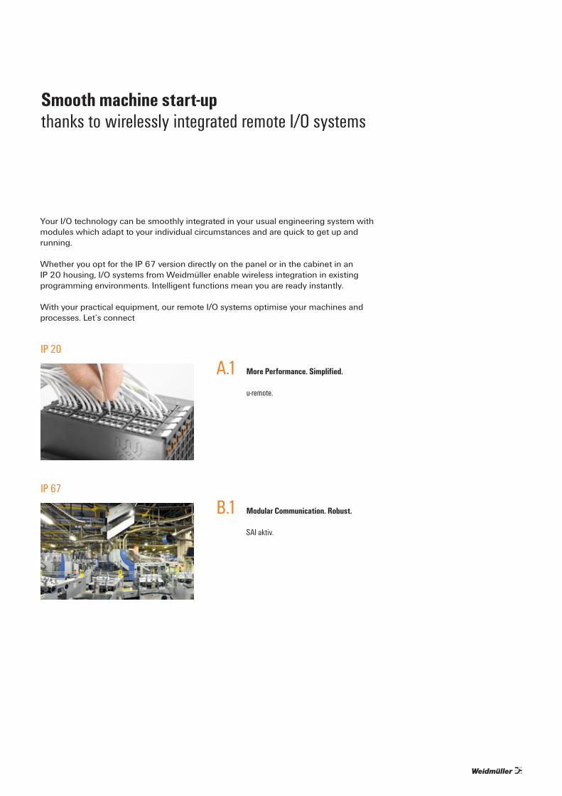
More Performance. Simplified.
u-remote.
Modular Communication. Robust.
SAI aktiv.
IP 20
IP 67
A
IP 20
1477120000 – 2014
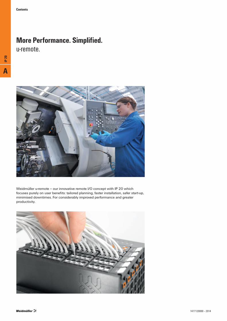
More Performance. Simplified.u-remote.
Weidmüller u-remote – our innovative remote I/O concept with IP 20 which focuses purely on user benefits: tailored planning, faster installation, safer start-up, minimised downtimes. For considerably improved performance and greater productivity.
Contents

Contents
IP 20
IP 20 u-remote A.2
Introduction A.6
Field bus coupler A.8
Digital input modules A.16
Digital output modules A.24
Digital counter modules A.34
Pulse width modulation modules A.39
Analogue input modules A.42
Temperature modules A.46
Analogue output modules A.50
Power-feed modules A.52
Modules for functional safety A.56
Accessories A.60
System overview A.64
A
IP 20
A.11477120000 – 2014

Introduction
Weidmüller u-remote – the innovative remote I/O concept with IP 20 which focuses purely on user benefits: tailored planning, faster installation, safer start-up, minimised downtimes. For considerably improved performance and greater productivity. Reduce the size of your cabinets with u-remote, thanks to the narrow design and the need for fewer power-feed modules. Our u-remote technology also offers tool-free assembly, while the modular design and integrated web server speed up installation, both in the cabinet and machine. Status LEDs on the channel and each u-remote module enable reliable diagnosis and rapid service.
This and many other amazing ideas boost the availability of your machines and systems. And ensure smooth processes too. From planning to operation.
Our u-remote can do it all - More Performance. Simplified.
More Performance. Simplified.u-remote.
Speed things up with modularityThe modular structure of u-remote ensures rapid start-up and simple service. The compact design enables intuitive handling which reduces wiring mistakes and therefore lessens the start-up times for machines and systems. u-remote speeds up the replacement of electronics without the need to alter wiring during maintenance work, so improving system availability.
A
IP 20
A.2 1477120000 – 2014
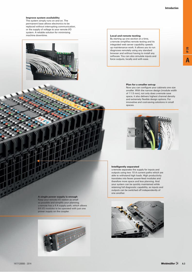
A single power supply is enough Keep your remote I/O station as small as possible and simplify your planning. u-remote has a 4 A supply path, which allows 64 I/O modules to be operated with just one power supply on the coupler.
Intelligently separatedu-remote separates the supply for inputs and outputs using two 10 A current paths which are able to withstand high loads. High productivity translates into fewer power-feed modules and therefore more space and less planning. And your system can be quickly maintained while retaining full diagnostic capability, as inputs and outputs can be switched off independently of one another.
Introduction
Plan for a smaller set-upNow you can configure your cabinets one size smaller. With the narrow design (module width of 11.5 mm), not only does u-remote save space, it also delivers highest channel density and extremely flexible design options. For innovative and cost-saving solutions in small spaces.
Improve system availabilityThe system simply runs on and on. The permanent base allows electronics to be replaced without interrupting communication, or the supply of voltage to your remote I/O system. A reliable solution for minimising machine downtime. Local and remote testing
By starting up one section at a time, u-remote simplifies remote testing and its integrated web server capability speeds up maintenance work. It allows you to run diagnoses remotely using any standard browser and without having to install any software. You can also simulate inputs and force outputs, locally and with ease. A
IP 20
A.31477120000 – 2014

More Performance. Simplified.u-remote.
Introduction
Extremely fast with huge power reservesThe u-remote has outstanding electronic performance, with the high-speed system bus achieving up to 256 DI/DOs in 20 μs. u-remote offers an extremely fast response time and precise mapping of processes in the system, with up to 1024 I/O channels per station, as well as huge power reserves for future use.
One glance and you can see everything going onClear assignment of status and diagnosis has never been this simple. With one LED on the channel and status displays on each module, you can easily see all you need on u-remote. The technician can see and rectify errors without delay. Indispensable benefits for a safe start-up and rapid system maintenance.
Keeping it simpleThe u-remote modules can be released without any tools and their sequence can be changed. For faster machine maintenance and simple system modification.
A
IP 20
A.4 1477120000 – 2014
Introduction
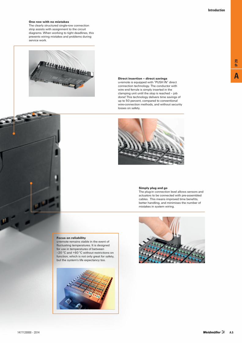
Simply plug and goThe plug-in connection level allows sensors and actuators to be connected with pre-assembled cables. This means improved time benefits, better handling, and minimises the number of mistakes in system wiring.
One row with no mistakesThe clearly structured single-row connection strip assists with assignment to the circuit diagrams. When working to tight deadlines, this prevents wiring mistakes and problems during service work.
Direct insertion – direct savingsu-remote is equipped with “PUSH IN” direct connection technology. The conductor with wire end ferrule is simply inserted in the clamping unit until the stop is reached – job done! This technology delivers time savings of up to 50 percent, compared to conventional wire-connection methods, and without security losses on safety.
Focus on reliabilityu-remote remains stable in the event of fluctuating temperatures. It is designed for use in temperatures of between –20 °C and +60 °C without restrictions on function, which is not only great for safety, but the system's life expectancy too.
A
IP 20
A.51477120000 – 2014

Introduction
More Performance. Simplified.u-remote.
Let’s connect.
A
IP 20
A.6 1477120000 – 2014

Introduction
u-remote from Weidmüller is the reliable interface between field bus and field level in automation. The modular system is based on various components: a field bus coupler, up to 64 I/O modules, optional power-feed modules and a wealth of accessories, such as markers and terminating elements.
The field bus coupler is the central link between the various field bus standards and the u-remote system bus. At the same time, up to 64 I/O modules are supplied via its integrated power contacts. The well-engineered technology of the connection system enables 2 x 10 A to be supplied for the input and output modules and the system voltage to be fully supplied through the field bus coupler.Every field bus coupler provides direct access to the u-remote system via a web server without additional software having to be installed. This means that the system can be parameterised and its configuration checked. Inputs and outputs can also be checked or influenced. The connection may take the form of an Ethernet-based field bus or micro USB.The u-remote field bus couplers are integrated in the standard simple manner. The corresponding development environments of the control systems and the device description files available online, e.g. GSD, ESD or XML, can be used to easily perform the necessary settings.
The modularly structured I/O modules are unique in that they allow the sensor and actuator wiring to be designed in both a robust and plug-in manner. This allows the electronics to be replaced at any time even with permanent wiring without downstream I/O module operations being affected. This achieves an invaluable time saving, in terms of both wiring inaccessible cabinets and rapidly replacing sensors. Thanks to the “PUSH IN” technology for up to 1.5 mm2, in their narrowest form of 11.5 mm, the modularly structured u-remote I/O modules can be used for all sensor and actuator connections with a very high connection density. A clear status and diagnosis display on the connection also ensures rapid and precise checks for individual sensors and actuators.
IP 20
A
IP 20
A.71477120000 – 2014

Field bus coupler
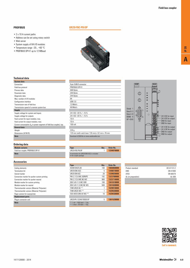
In automation technology, the PROFIBUS-DP standard enables the controlled incorporation of sensors and actuators via one central control unit. The UR20-FBC-PB-DP field bus coupler is a PROFIBUS-DP-V1 participant certified by the Profibus user organisation. With options for connecting up to 64 u-remote participants, it serves as the head module for the u-remote system bus. The PROFIBUS-DP coupler has a Sub-D plug-in connector and supports all services according to the DP-V1 specification. Two rotary coding switches are used to address individual PROFIBUS participants.
The coupler can be activated with a system-independent web server application via the USB service interface. All information, such as diagnoses, status values and parameters, can therefore be read out. All connected inputs can also be simulated or outputs set. The initial system power supply is already integrated in the field bus coupler. Power is supplied via two 4-pin connectors, separated into the input and output current paths.
Since the PROFIBUS-DP products from Weidmüller make full use of all the latest technological possibilities, such as GSD files and diagnosis messages, they actively support your application in the most important tasks – from engineering and commissioning fault diagnosis.
More Performance. Simplified.
PROFIBUS field bus couplerDP-V1; Web server tool; Sub-D connection
µC8xUSB
DC
DC
System-bus
USYS
UIN
UOUT
Sub-D
System-bus
System-bus
USYS
UIN
UIN
UOUT
UOUT
24 V
/10
A Inp
ut
24V/10A Output
Internal from the control card
UR20 PROFIBUS coupler
Block diagram UR20-FBC-PB-DP
A
IP 20
A.8 1477120000 – 2014
Field bus coupler
PROFIBUS
• 2 x 10 A current paths• Address can be set using rotary switch• Web server• System supply of 64 I/O modules• Temperature range –20… +60 °C• PROFIBUS DP-V1 up to 12 MBaud
Technical dataSystem dataConnectionField bus protocolProcess dataParameter dataDiagnostic dataMax. number of I/O modulesConfiguration interfaceTransmission rate of field busTransmission speed of u-remote system busSupplySupply voltage for system and inputsSupply voltage for outputsFeed current for input modules, max.Feed current for output modules, max.Current consumption (IIN in power segment of field bus coupler), typ.General dataWeightDimensions (H/W/D)Note
Ordering dataModule variantsField bus coupler, PROFIBUS DP-V1Note
Accessories
Coding elementsTermination kitSwivel markerConnection marker for pusher custom printingConnection marker for pusher neutralModule marker for custom printingModule marker for neutralThermotransfer version (Material: Polyester)Thermotransfer version (Material: Polyester)Paper version for LaserprinterReplacement partsPlug-in connector unitNote
9-pin SUB-D connectorPROFIBUS DP-V1488 Bytes244 Bytes244 Bytes64USB 2.012 Mbit/s48 Mbit/s
24 V DC +20 % / –15 %24 V DC +20 % / –15 %10 A10 A100 mA
220 g 120 mm (with catch lever 128 mm) x 52 mm x 76 mmDownload of GSD-file on www.weidmueller.com
Type Qty. Order No.UR20-FBC-PB-DP 1 1334870000A termination kit (UR20-EBK-ACC) is included in the coupler package
Type Qty. Order No.KOSM BHZ5.00 100 1483050000UR20-EBK-ACC 5 1346610000UR20-SM-ACC 20 1339920000PM 2.7/2.6 MC SDRVPE 192 1323700000PM 2.7/2.6 MC NE WS 960 1323710000DEK 5/8-11.5 MC SDR 100 1341610000DEK 5/8-11.5 MC NE WS 500 1341630000THM UR20 GE *1) 1 1429910000THM UR20 WS *1) 1 1429420000ESO UR20 DIN A4 WS *2) 10 1429430000
UR20-PK-1334870000-SP 5 1361520000*1) 1 roll = 1000 label = 1 Qty.*2) 1 sheet = 60 label = 1 Qty.
UR20-FBC-PB-DP
Let’s connect.
Product standard IEC 61131-2 EMC EN 61000 ATEX EN 60079 UL (in preparation) UL 508
A
IP 20
A.91477120000 – 2014
Field bus coupler
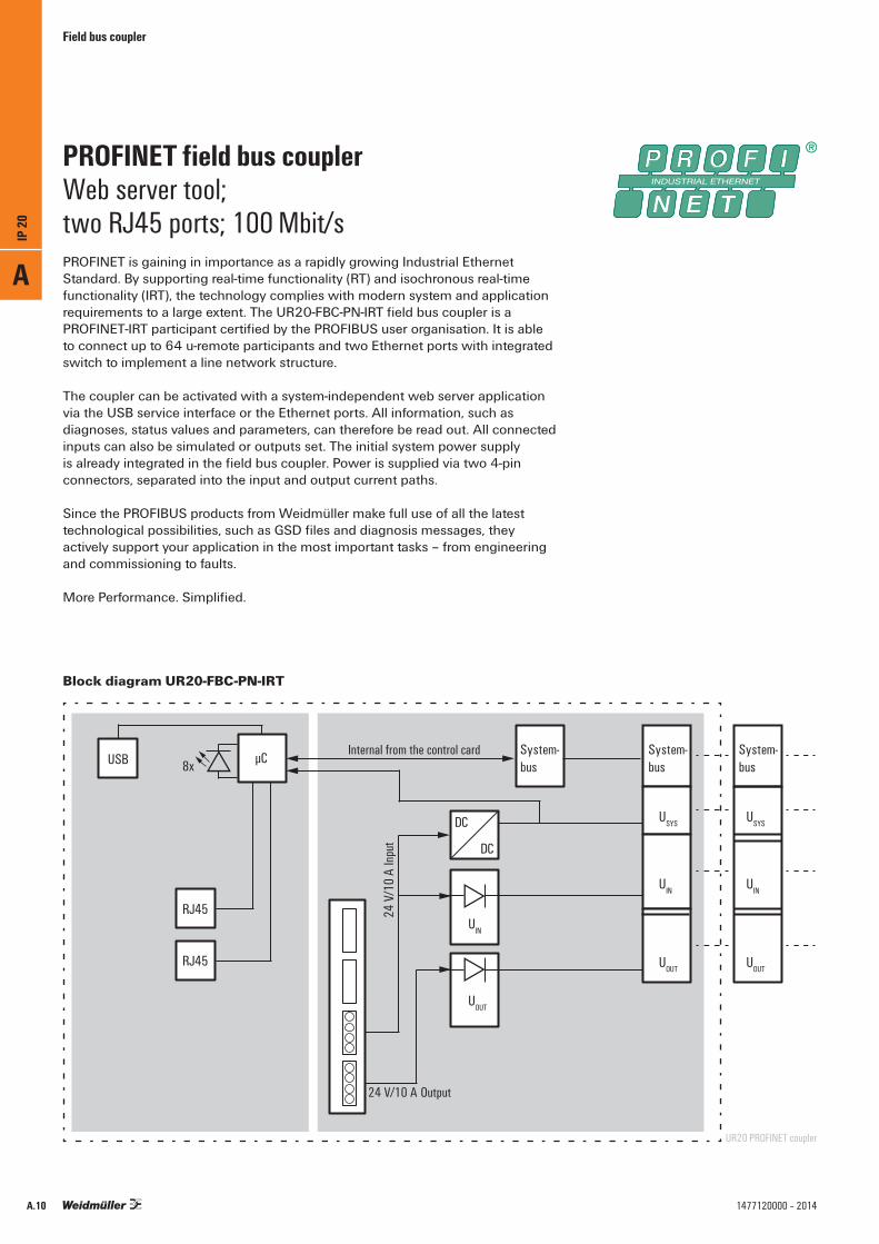
PROFINET is gaining in importance as a rapidly growing Industrial Ethernet Standard. By supporting real-time functionality (RT) and isochronous real-time functionality (IRT), the technology complies with modern system and application requirements to a large extent. The UR20-FBC-PN-IRT field bus coupler is a PROFINET-IRT participant certified by the PROFIBUS user organisation. It is able to connect up to 64 u-remote participants and two Ethernet ports with integrated switch to implement a line network structure.
The coupler can be activated with a system-independent web server application via the USB service interface or the Ethernet ports. All information, such as diagnoses, status values and parameters, can therefore be read out. All connected inputs can also be simulated or outputs set. The initial system power supply is already integrated in the field bus coupler. Power is supplied via two 4-pin connectors, separated into the input and output current paths.
Since the PROFIBUS products from Weidmüller make full use of all the latest technological possibilities, such as GSD files and diagnosis messages, they actively support your application in the most important tasks – from engineering and commissioning to faults.
More Performance. Simplified.
PROFINET field bus couplerWeb server tool; two RJ45 ports; 100 Mbit/s
24 V
/10
A Inp
ut
24 V/10 A Output
Internal from the control cardµC8xSystem-bus
USYS
UIN
UOUT
RJ45
USB
RJ45
System-bus
USYS
UIN
UOUT
DC
DC
System-bus
UIN
UOUT
UR20 PROFINET coupler
Block diagram UR20-FBC-PN-IRT
A
IP 20
A.10 1477120000 – 2014

PROFINET
• 2 x 10 A current paths• Web server• System supply of 64 I/O modules• Temperature range –20… +60 °C• PROFINET IRT/RT capable• PROFINET diagnosis • LLDP – Neighborhood detection
Technical dataSystem dataConnectionField bus protocolProcess dataParameter dataDiagnostic dataFast startupMax. number of I/O modulesConfiguration interfaceTransmission rate of field busTransmission speed of u-remote system busSupplySupply voltage for system and inputsSupply voltage for outputsFeed current for input modules, max.Feed current for output modules, max.Current consumption (IIN in power segment of field bus coupler), typ.General dataWeightDimensions (H/W/D)Note
Ordering dataModule variantsField bus coupler, PROFINET IRTNote
Accessories
Coding elementsTermination kitSwivel markerConnection marker for pusher custom printingConnection marker for pusher neutralModule marker for custom printingModule marker for neutralThermotransfer version (Material: Polyester)Thermotransfer version (Material: Polyester)Paper version for LaserprinterReplacement partsPlug-in connector unitNote
2 x RJ-45PROFINET IRT1.024 Bytes1.485 Bytes1.485 Bytesyes64USB 2.0100 Mbit/s48 Mbit/s
24 V DC +20 % / –15 %24 V DC +20 % / –15 %10 A10 A116 mA
220 g120 mm (with catch lever 128 mm) x 52 mm x 76 mmDownload of GSD-file on www.weidmueller.com
Type Qty. Order No.UR20-FBC-PN-IRT 1 1334880000A termination kit (UR20-EBK-ACC) is included in the coupler package
Type Qty. Order No.KOSM BHZ5.00 100 1483050000UR20-EBK-ACC 5 1346610000UR20-SM-ACC 20 1339920000PM 2.7/2.6 MC SDR 192 1323700000PM 2.7/2.6 MC NE WS 960 1323710000DEK 5/8-11.5 MC SDR 100 1341610000DEK 5/8-11.5 MC NE WS 500 1341630000THM UR20 GE *1) 1 1429910000THM UR20 WS *1) 1 1429420000ESO UR20 DIN A4 WS *2) 10 1429430000
UR20-PK-1334880000-SP 5 1484120000*1) 1 roll = 1000 label = 1 Qty.*2) 1 sheet = 60 label = 1 Qty.
UR20-FBC-PN-IRT
Field bus coupler
Product standard IEC 61131-2 EMC EN 61000 ATEX EN 60079 UL (in preparation) UL 508
Let’s connect.
A
IP 20
A.111477120000 – 2014

Field bus coupler
EtherCAT is a popular field bus standard for systems with stringent time requirements. The UR20-FBC-EC field bus coupler is an EtherCAT participant certified by the EtherCAT Technology Group. With options for connecting up to 64 u-remote participants, it serves as the head module for the u-remote system bus. The EtherCAT coupler has two Ethernet ports with integrated switch for implementing a line network structure.
The coupler can be activated with a system-independent web server application via the USB service interface or the Ethernet ports. All information, such as diagnoses, status values and parameters, can therefore be read out. All connected inputs can also be simulated or outputs set. The system's initial power supply is already integrated in the field bus coupler. Power is supplied via two 4-pin connectors, separated into the input and output current paths.
Since the EtherCAT products from Weidmüller make full use of all the latest technological possibilities, such as use of XML files, they actively support your application in the most important tasks – from engineering and commissioning to fault diagnosis.
More Performance. Simplified.
EtherCAT field bus couplerWeb server tool; two RJ45 ports; 10/100 Mbit/s
24 V
/10
A Inp
ut
24 V/10 A Output
Internal from the control card System-bus
USYS
UIN
UOUT
System-bus
USYS
UIN
UOUT
µC8x
RJ45
USB
RJ45
UR20 EtherCAT coupler
DC
DC
System-bus
UIN
UOUT
Block diagram UR20-FBC-EC
A
IP 20
A.12 1477120000 – 2014

EtherCAT
• 2 x 10 A current paths• Web server• System supply of 64 I/O modules• Temperature range –20… +60 °C• Various EtherCAT services
Technical dataSystem dataConnectionField bus protocolProcess dataParameter dataDiagnostic dataMax. number of modulesConfiguration interfaceTransmission rate of field busTransmission speed of u-remote system busSupplySupply voltage for system and inputsSupply voltage for outputsFeed current for input modules, max.Feed current for output modules, max.Current consumption (IIN in power segment of field bus coupler), typ.General dataWeightDimensions (H/W/D)Note
Ordering dataModule variantsField bus coupler, EtherCATNote
Accessories
Coding elementsTermination kitSwivel markerConnection marker for pusher custom printingConnection marker for pusher neutralModule marker for custom printingModule marker for neutralThermotransfer version (Material: Polyester)Thermotransfer version (Material: Polyester)Paper version for LaserprinterReplacement partsPlug-in connector unitNote
2 x RJ-45EtherCAT8 kBytes1.024 Bytes1.024 Bytes64USB 2.0100 Mbit/s48 Mbit/s
24 V DC +20 % / –15 %24 V DC +20 % / –15 %10 A10 A130 mA
220 g120 mm (with catch lever 128 mm) x 52 mm x 76 mmDownload of ESI-file on www.weidmueller.com
Type Qty. Order No.UR20-FBC-EC 1 1334910000A termination kit (UR20-EBK-ACC) is included in the coupler package
Type Qty. Order No.KOSM BHZ5.00 100 1483050000UR20-EBK-ACC 5 1346610000UR20-SM-ACC 20 1339920000PM 2.7/2.6 MC SDR 192 1323700000PM 2.7/2.6 MC NE WS 960 1323710000DEK 5/8-11.5 MC SDR 100 1341610000DEK 5/8-11.5 MC NE WS 500 1341630000THM UR20 GE *1) 1 1429910000THM UR20 WS *1) 1 1429420000ESO UR20 DIN A4 WS *2) 10 1429430000
UR20-PK-1334910000-SP 5 1484440000*1) 1 roll = 1000 label = 1 Qty.*2) 1 sheet = 60 label = 1 Qty.
UR20-FBC-EC
Field bus coupler
Product standard IEC 61131-2 EMC EN 61000 ATEX EN 60079 UL (in preparation) UL 508
Let’s connect.
A
IP 20
A.131477120000 – 2014

Field bus coupler
System safety around the globe is provided by the Modbus-TCP version, which is stated in IEC 61158 as an Industrial Ethernet Standard. The UR20-FBC-MOD-TCP from Weidmüller is a field bus coupler designed in accordance with IEC 61158. With options for connecting up to 64 u-remote participants, it serves as the head module for the u-remote system bus.
The coupler can be activated with a system-independent web server application via the USB service interface or the Ethernet ports. All information, such as diagnoses, status values and parameters, can therefore be read out. All connected inputs can also be simulated or outputs set. The system's initial power supply is already integrated in the field bus coupler. Power is supplied via two 4-pin connectors, separated into the input and output current paths.
Since the Modbus-TCP products from Weidmüller make full use of all the latest technological possibilities, such as diagnosis options, they actively support your application in the most important tasks – from engineering and commissioning to fault diagnosis.
More Performance. Simplified.
Modbus-TCP field bus couplerWeb server tool; two RJ45 ports; 10/100 Mbit/s
24 V
/10
A Inp
ut
24 V/10 A Output
Internal from the control card System-bus
USYS
UIN
UOUT
System-bus
USYS
UIN
UOUT
µC8x
RJ45
USB
RJ45
UR20 Modbus-TCP coupler
DC
DC
System-bus
UIN
UOUT
Block diagram UR20-FBC-MOD-TCP
A
IP 20
A.14 1477120000 – 2014

Field bus coupler
Modbus-TCP
• 2 x 10 A current paths• Various Modbus services• Web server• System supply of 64 I/O modules• Temperature range –20… +60 °C
Technical dataSystem dataConnectionField bus protocolProcess dataParameter dataDiagnostic dataMax. number of modulesConfiguration interfaceTransmission rate of field busTransmission speed of u-remote system busSupplySupply voltage for system and inputsSupply voltage for outputsFeed current for input modules, max.Feed current for output modules, max.Current consumption (IIN in power segment of field bus coupler), typ.General dataWeightDimensions (H/W/D)
Ordering dataModule variantsField bus coupler, Modbus TCPNote
Accessories
Coding elementsTermination kitSwivel markerConnection marker for pusher custom printingConnection marker for pusher neutralModule marker for custom printingModule marker for neutralThermotransfer version (Material: Polyester)Thermotransfer version (Material: Polyester)Paper version for LaserprinterReplacement partsPlug-in connector unitNote
2 x RJ-45Modbus TCP8 kBytes1.024 Bytes1.024 Bytes64USB 2.0100 Mbit/s48 Mbit/s
24 V DC +20 % / –15 %24 V DC +20 % / –15 %10 A10 A112 mA
220 g120 mm (with catch lever 128 mm) x 52 mm x 76 mm
Type Qty. Order No.UR20-FBC-MOD-TCP 1 1334930000A termination kit (UR20-EBK-ACC) is included in the coupler package
Type Qty. Order No.KOSM BHZ5.00 100 1483050000UR20-EBK-ACC 5 1346610000UR20-SM-ACC 20 1339920000PM 2.7/2.6 MC SDR 192 1323700000PM 2.7/2.6 MC NE WS 960 1323710000DEK 5/8-11.5 MC SDR 100 1341610000DEK 5/8-11.5 MC NE WS 500 1341630000THM UR20 GE *1) 1 1429910000THM UR20 WS *1) 1 1429420000ESO UR20 DIN A4 WS *2) 10 1429430000
UR20-PK-1334930000-SP 5 1484130000*1) 1 roll = 1000 label = 1 Qty.*2) 1 sheet = 60 label = 1 Qty.
UR20-FBC-MOD-TCP
Product standard IEC 61131-2 EMC EN 61000 ATEX EN 60079 UL (in preparation) UL 508
Let’s connect.
A
IP 20
A.151477120000 – 2014
Digital input modules
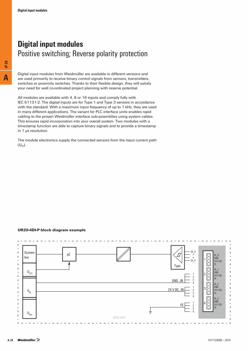
Digital input modules from Weidmüller are available in different versions and are used primarily to receive binary control signals from sensors, transmitters, switches or proximity switches. Thanks to their flexible design, they will satisfy your need for well co-ordinated project planning with reserve potential.
All modules are available with 4, 8 or 16 inputs and comply fully with IEC 61131-2. The digital inputs are for Type 1 and Type 3 sensors in accordance with the standard. With a maximum input frequency of up to 1 kHz, they are used in many different applications. The variant for PLC interface units enables rapid cabling to the proven Weidmüller interface sub-assemblies using system cables. This ensures rapid incorporation into your overall system. Two modules with a timestamp function are able to capture binary signals and to provide a timestamp in 1 μs resolution.
The module electronics supply the connected sensors from the input current path (UIN).
Digital input modulesPositive switching; Reverse polarity protection
DI_0••
DI_3
1234
1234
1234
DI_1GND24 V DCFE
DI_0GND24 V DCFE
DI_2GND24 V DCFE
DI_3GND24 V DCFE
Type
System-bus
USYS
UIN
UOUT
µC
24 V DC⎽IN
GND⎽IN
FE
1
2
3
4
UR20 4DI-P
UR20-4DI-P block diagram example
A
IP 20
A.16 1477120000 – 2014

Digital input modules
4DI-P
• 4 digital inputs for sensors such as transmitters, switches and proximity sensors
• Positive switching• Reverse polarity protection• 2-wire, 3-wire, 3-wire+FE connection• Input filter can be set channel by channel• Integrated sensor supply• Types 1 and 3 acc. to IEC 61131-2
Technical dataSystem dataInterfaceTransmission rate of system busGalvanic isolationSupplyVoltage supplyCurrent consumption (IIN in power segment of field bus coupler), typ.Current consumption (IIN in the respective power segment)Digital inputsNumberInput TypeInput filterInput voltage, lowInput voltage, highSensor supplySensor connectionReverse polarity protectionModule diagnosisIndividual channel diagnosisGeneral dataWeightDimensions (H/W/D)
Ordering dataModule variantsDigital input module, 4 channels
Accessories
Coding elementsTermination kitSwivel markerConnection marker for pusher custom printingConnection marker for pusher neutralModule marker for custom printingModule marker for neutralThermotransfer version (Material: Polyester)Thermotransfer version (Material: Polyester)Paper version for LaserprinterReplacement partsElectronics moduleBasic modulePlug-in connector unitNote
u-remote system bus48 Mbit/syes, DC 500 V between current paths
24 V DC +20 % / –15 % via the system bus8 mA< 12 mA + sensor feed
4Types 1 and 3, IEC 61131-2adjustable, up to 40 ms< 5 V> 11 Vyes2-wire, 3-wire, 3-wire+FEyesyesno
87 g120 mm (with catch lever 128 mm) x 11,5 mm x 76 mm
Type Qty. Order No.UR20-4DI-P 1 1315170000
Type Qty. Order No.KOSM BHZ5.00 100 1483050000UR20-EBK-ACC 5 1346610000UR20-SM-ACC 20 1339920000PM 2.7/2.6 MC SDR 192 1323700000PM 2.7/2.6 MC NE WS 960 1323710000DEK 5/8-11.5 MC SDR 100 1341610000DEK 5/8-11.5 MC NE WS 500 1341630000THM UR20 GE *1) 1 1429910000THM UR20 WS *1) 1 1429420000ESO UR20 DIN A4 WS *2) 10 1429430000
UR20-EM-1315170000-SP 1 1346640000UR20-BM-SP 5 1350930000UR20-PK-1315170000-SP 5 1346440000*1) 1 roll = 1000 label = 1 Qty.*2) 1 sheet = 60 label = 1 Qty.
UR20-4DI-P
Product standard IEC 61131-2 EMC EN 61000 ATEX EN 60079 UL (in preparation) UL 508
Let’s connect.
1
2
3
4
2
1
3
4
1
2
3
4
2
4
3
1
2
4
3
1
4DI·P
1
2
3
4
2
1
3
4
1
2
3
4
2
4
3
1
2
4
3
1
4DI·P
1
2
3
4
2
1
3
4
1
2
3
4
2
4
3
1
2
4
3
1
4DI·P
DI0GND
24 V DCFE
DI1GND
24 V DCFE
DI2GND
24 V DCFE
DI3GND
24 V DCFE
24 V DC
DI0
24 V DC
DI1
24 V DC
DI2
24 V DC
DI3
24 V DC
DI0
24 V DC
DI1
24 V DC
DI2
24 V DC
DI3GND
GND
GND
GND
A
IP 20
A.171477120000 – 2014
Digital input modules
Technical dataSystem dataInterfaceTransmission rate of system busGalvanic isolationSupplyVoltage supplyCurrent consumption (IIN in power segment of field bus coupler), typ.Current consumption (IIN in the respective power segment)Digital inputsNumberInput TypeInput filterInput voltage, lowInput voltage, highSensor supplySensor connectionReverse polarity protectionModule diagnosisIndividual channel diagnosisGeneral dataWeightDimensions (H/W/D)
Ordering dataModule variantsDigital input module, 8 channels, 2-wire
Accessories
Coding elementsTermination kitSwivel markerConnection marker for pusher custom printingConnection marker for pusher neutralModule marker for custom printingModule marker for neutralThermotransfer version (Material: Polyester)Thermotransfer version (Material: Polyester)Paper version for LaserprinterReplacement partsElectronics moduleBasic modulePlug-in connector unitNote
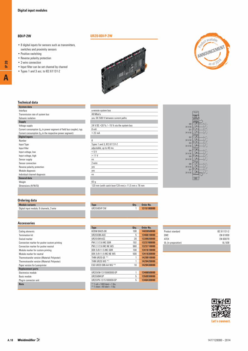
u-remote system bus48 Mbit/syes, DC 500 V between current paths
24 V DC +20 % / –15 % via the system bus8 mA< 22 mA
8Types 1 and 3, IEC 61131-2adjustable, up to 40 ms< 5 V> 11 Vno2-wireyesyesno
83 g120 mm (with catch lever128 mm) x 11,5 mm x 76 mm
Type Qty. Order No.UR20-8DI-P-2W 1 1315180000
Type Qty. Order No.KOSM BHZ5.00 100 1483050000UR20-EBK-ACC 5 1346610000UR20-SM-ACC 20 1339920000PM 2.7/2.6 MC SDR 192 1323700000PM 2.7/2.6 MC NE WS 960 1323710000DEK 5/8-11.5 MC SDR 100 1341610000DEK 5/8-11.5 MC NE WS 500 1341630000THM UR20 GE *1) 1 1429910000THM UR20 WS *1) 1 1429420000ESO UR20 DIN A4 WS *2) 10 1429430000
UR20-EM-1315080000-SP 1 1346650000UR20-BM-SP 5 1350930000UR20-PK-1315180000-SP 5 1346430000*1) 1 roll = 1000 label = 1 Qty.*2) 1 sheet = 60 label = 1 Qty.
UR20-8DI-P-2W8DI-P-2W
• 8 digital inputs for sensors such as transmitters, switches and proximity sensors
• Positive switching• Reverse polarity protection• 2-wire connection• Input filter can be set channel by channel• Types 1 and 3 acc. to IEC 61131-2
Produc
t available
as of 2014
Product standard IEC 61131-2 EMC EN 61000 ATEX EN 60079 UL (in preparation) UL 508
ANNOUNCEMENT
Let’s connect.
1
2
3
4
2
1
3
4
1
2
3
4
2
4
3
1
2
4
3
1
8DI·P-2W
DI024 V DC
DI124 V DC
DI224 V DC
DI324 V DC
DI424 V DC
DI524 V DC
DI624 V DC
DI724 V DC
A
IP 20
A.18 1477120000 – 2014
Digital input modules
Technical dataSystem dataInterfaceTransmission rate of system busGalvanic isolationSupplyVoltage supplyCurrent consumption (IIN in power segment of field bus coupler), typ.Current consumption (IIN in the respective power segment)Digital inputsNumberInput TypeInput filterInput voltage, lowInput voltage, highSensor supplySensor connectionReverse polarity protectionModule diagnosisIndividual channel diagnosisGeneral dataWeightDimensions (H/W/D)
Ordering dataModule variantsDigital input module, 8 channels, 3-wire
Accessories
Coding elementsTermination kitSwivel markerConnection marker for pusher custom printingConnection marker for pusher neutralModule marker for custom printingModule marker for neutralThermotransfer version (Material: Polyester)Thermotransfer version (Material: Polyester)Paper version for LaserprinterReplacement partsElectronics moduleBasic modulePlug-in connector unitNote
u-remote system bus48 Mbit/syes, DC 500 V between current paths
24 V DC +20 % / –15 % via the system bus8 mA< 22 mA + sensor feed
8Types 1 and 3, IEC 61131-2adjustable, up to 40 ms< 5 V> 11 Vyes2-wire, 3-wireyesyesno
83 g120 mm (with catch lever128 mm) x 11,5 mm x 76 mm
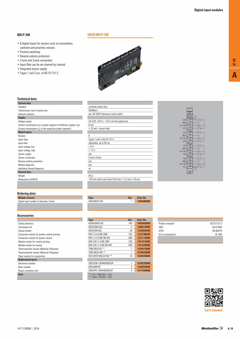
Type Qty. Order No.UR20-8DI-P-3W 1 1394400000
Type Qty. Order No.KOSM BHZ5.00 100 1483050000UR20-EBK-ACC 5 1346610000UR20-SM-ACC 20 1339920000PM 2.7/2.6 MC SDR 192 1323700000PM 2.7/2.6 MC NE WS 960 1323710000DEK 5/8-11.5 MC SDR 100 1341610000DEK 5/8-11.5 MC NE WS 500 1341630000THM UR20 GE *1) 1 1429910000THM UR20 WS *1) 1 1429420000ESO UR20 DIN A4 WS *2) 10 1429430000
UR20-EM-1394400000-SP 1 1434220000UR20-BM-SP 5 1350930000UR20-PK-1394400000-SP 5 1411430000*1) 1 roll = 1000 label = 1 Qty.*2) 1 sheet = 60 label = 1 Qty.
UR20-8DI-P-3W8DI-P-3W
• 8 digital inputs for sensors such as transmitters, switches and proximity sensors
• Positive switching• Reverse polarity protection• 2-wire and 3-wire connection• Input filter can be set channel by channel• Integrated sensor supply• Types 1 and 3 acc. to IEC 61131-2
Product standard IEC 61131-2 EMC EN 61000 ATEX EN 60079 UL (in preparation) UL 508
Let’s connect.
8DI-P-3W
1
2
3
4
2
1
3
4
1
2
3
4
2
4
3
1
2
4
3
1
DI0GND
24 V DCDI1
DI2GND
24 V DCDI3
DI4GND
24 V DCDI5
DI6GND
24 V DCDI7
A
IP 20
A.191477120000 – 2014

Digital input modules
Technical dataSystem dataInterfaceTransmission rate of system busGalvanic isolationSupplyVoltage supplyCurrent consumption (IIN in power segment of field bus coupler), typ.Current consumption (IIN in the respective power segment)Digital inputsNumberInput TypeInput filterInput voltage, lowInput voltage, highSensor supplySensor connectionReverse polarity protectionModule diagnosisIndividual channel diagnosisGeneral dataWeightDimensions (H/W/D)
Ordering dataModule variantsDigital input module, 16 channels
Accessories
Coding elementsTermination kitSwivel markerConnection marker for pusher custom printingConnection marker for pusher neutralModule marker for custom printingModule marker for neutralThermotransfer version (Material: Polyester)Thermotransfer version (Material: Polyester)Paper version for LaserprinterReplacement partsElectronics moduleBasic modulePlug-in connector unitNote
u-remote system bus48 Mbit/syes, DC 500 V between current paths
24 V DC +20 % / –15 % via the system bus8 mA< 42 mA
16Types 1 and 3, IEC 61131-23 ms< 5 V> 11 Vno1-wireyesyesno
87 g120 mm (with catch lever128 mm) x 11,5 mm x 76 mm
Type Qty. Order No.UR20-16DI-P 1 1315200000
Type Qty. Order No.KOSM BHZ5.00 100 1483050000UR20-EBK-ACC 5 1346610000UR20-SM-ACC 20 1339920000PM 2.7/2.6 MC SDR 192 1323700000PM 2.7/2.6 MC NE WS 960 1323710000DEK 5/8-11.5 MC SDR 100 1341610000DEK 5/8-11.5 MC NE WS 500 1341630000THM UR20 GE *1) 1 1429910000THM UR20 WS *1) 1 1429420000ESO UR20 DIN A4 WS *2) 10 1429430000
UR20-EM-1315200000-SP 1 1346680000UR20-BM-SP 5 1350930000UR20-PK-1315200000-SP 5 1346400000*1) 1 roll = 1000 label = 1 Qty.*2) 1 sheet = 60 label = 1 Qty.
UR20-16DI-P16DI-P
• 16 digital inputs• Positive switching• Reverse polarity protection• 1-wire connection• Permanently set input filter, 3 ms• Types 1 and 3 acc. to IEC 61131-2
Product standard IEC 61131-2 EMC EN 61000 ATEX EN 60079 UL (in preparation) UL 508
Let’s connect.
1
2
3
4
2
1
3
4
1
2
3
4
2
4
3
1
2
4
3
1
16DI·P 24 V DC
DI0DI1DI2DI3
DI4DI5DI6DI7
DI8DI9
DI10DI11
DI12DI13DI14DI15
A
IP 20
A.20 1477120000 – 2014

Digital input modules
Technical dataSystem dataInterfaceTransmission rate of system busGalvanic isolationSupplyVoltage supplyCurrent consumption (IIN in power segment of field bus coupler), typ.Current consumption (IIN external)Digital inputsNumberInput TypeInput filterInput voltage, lowInput voltage, highSensor supplySensor connectionReverse polarity protectionModule diagnosisIndividual channel diagnosisGeneral dataWeightDimensions (H/W/D)
Ordering dataModule variantsDigital input module, 16 channels, PLC interface
Accessories
Coding elementsTermination kitSwivel markerConnection marker for pusher custom printingConnection marker for pusher neutralModule marker for custom printingModule marker for neutralThermotransfer version (Material: Polyester)Thermotransfer version (Material: Polyester)Paper version for LaserprinterReplacement partsElectronics moduleBasic modulePlug-in connector unitPLC interface elementNote
u-remote system bus48 Mbit/syes, DC 500 V between current paths
24 V DC +20 % / –15 % via the system bus8 mA< 42 mA
16Types 1 and 3, IEC 61131-23 ms< 5 V> 11 VexternalPLC interfaceyesyesno
73 g120 mm (with catch lever128 mm) x 11,5 mm x 76 mm
Type Qty. Order No.UR20-16DI-P-PLC-INT 1 1315210000
Type Qty. Order No.KOSM BHZ5.00 100 1483050000UR20-EBK-ACC 5 1346610000UR20-SM-ACC 20 1339920000PM 2.7/2.6 MC SDR 192 1323700000PM 2.7/2.6 MC NE WS 960 1323710000DEK 5/8-11.5 MC SDR 100 1341610000DEK 5/8-11.5 MC NE WS 500 1341630000THM UR20 GE *1) 1 1429910000THM UR20 WS *1) 1 1429420000ESO UR20 DIN A4 WS *2) 10 1429430000
UR20-EM-1315210000-SP 1 1346690000UR20-BM-SP 5 1350930000UR20-PK-1315210000-SP 5 1346590000RS 16IO 1W H S 1 9445700000*1) 1 roll = 1000 label = 1 Qty.*2) 1 sheet = 60 label = 1 Qty.
UR20-16DI-P-PLC-INT16DI-P-PLC-INT
• 16 digital inputs• Positive switching• Reverse polarity protection• For connecting a PLC interface element• Permanently set input filter, 3 ms• Types 1 and 3 acc. to IEC 61131-2
Product standard IEC 61131-2 EMC EN 61000 ATEX EN 60079 UL (in preparation) UL 508
Let’s connect.
42
1
3
4
16DI·P
16 x DI
0 1
2 34 56 78 9
10 1112 1314 15
24 V DC24 V DC
GNDGND
19
1
A
IP 20
A.211477120000 – 2014

Technical dataSystem dataInterfaceTransmission rate of system busGalvanic isolationSupplyVoltage supplyCurrent consumption (IIN in power segment of field bus coupler), typ.Current consumption (IIN in the respective power segment)Digital InputsNumberInput TypeInput filterInput voltage, lowInput voltage, highSensor supplySensor connectionReverse polarity protectionModule diagnosisIndividual channel diagnosisData width TimestampResolution TimestampGeneral dataWeightDimensions (H/W/D)
Ordering dataModule variantsDigital input module, 2 channels, Timestamp
Accessories
Coding elementsTermination kitSwivel markerConnection marker for pusher custom printingConnection marker for pusher neutralModule marker for custom printingModule marker for neutralThermotransfer version (Material: Polyester)Thermotransfer version (Material: Polyester)Paper version for LaserprinterReplacement partsElectronics moduleBasic modulePlug-in connector unitNote
u-remote system bus48 Mbit/syes, DC 500 V between current paths
24 V DC +20 % / –15 % via the system bus8 mA< 10 mA + sensor feed
2Type 1 und 3, IEC 61131-2adjustable, up to 40 ms< 5 V> 11 Vyes2-wire, 3-wire, 3-wire+FEyesyesno16 Bit1 µs
83 g120 mm (with catch lever 128 mm) x 11.5 mm x 76 mm
Type Qty. Order No.UR20-2DI-P-TS 1 1460140000
Type Qty. Order No.KOSM BHZ5.00 100 1483050000UR20-EBK-ACC 5 1346610000UR20-SM-ACC 20 1339920000PM 2.7/2.6 MC SDR 192 1323700000PM 2.7/2.6 MC NE WS 960 1323710000DEK 5/8-11.5 MC SDR 100 1341610000DEK 5/8-11.5 MC NE WS 500 1341630000THM UR20 GE *1) 1 1429910000THM UR20 WS *1) 1 1429420000ESO UR20 DIN A4 WS *2) 10 1429430000
UR20-EM-1460140000-SP 1 1463690000UR20-BM-SP 5 1350930000UR20-PK-1460140000-SP 5 1484110000*1) 1 roll = 1000 label = 1 Qty.*2) 1 sheet = 60 label = 1 Qty.
UR20-2DI-P-TS
1
2
3
4
2
1
3
4
2
4
3
1
2DI·TS
1
2
3
4
2
1
3
4
2
4
3
1
2DI·TS
1
2
3
4
2
1
3
4
2
4
3
1
2DI·TS
DI0GND
24 V DCFE
DI1GND
24 V DCFE
24 V DC
DI0
24 V DC
DI1
24 V DC
DI0
24 V DC
DI1GND
GND
2DI-P-TS
• 2 digital inputs for sensors such as transmitters, switches and proximity sensors
• Positive switching• 2-wire, 3-wire, 3-wire+FE connection• Input filter can be set channel by channel• Types 1 and 3 acc. to IEC 61131-2• 1 µs Timestamp resolution
Let’s connect.
Digital input modules
Product standard IEC 61131-2 EMC EN 61000 ATEX EN 60079 UL (in preparation) UL 508
A
IP 20
A.22 1477120000 – 2014

Technical dataSystem dataInterfaceTransmission rate of system busGalvanic isolationSupplyVoltage supplyCurrent consumption (IIN in power segment of field bus coupler), typ.Current consumption (IIN in the respective power segment)Digital InputsNumberInput TypeInput filterInput voltage, lowInput voltage, highSensor supplySensor connectionReverse polarity protectionModule diagnosisIndividual channel diagnosisData width TimestampResolution TimestampGeneral dataWeightDimensions (H/W/D)
Ordering dataModule variantsDigital input module, 4 channels, Timestamp
Accessories
Coding elementsTermination kitSwivel markerConnection marker for pusher custom printingConnection marker for pusher neutralModule marker for custom printingModule marker for neutralThermotransfer version (Material: Polyester)Thermotransfer version (Material: Polyester)Paper version for LaserprinterReplacement partsElectronics moduleBasic modulePlug-in connector unitNote
u-remote system bus48 Mbit/syes, DC 500 V between current paths
24 V DC +20 % / –15 % via the system bus8 mA< 10 mA + sensor feed
4Types 1 and 3, IEC 61131-2adjustable, up to 40 ms< 5 V> 11 Vyes2-wire, 3-wire, 3-wire+FEyesyesno16 Bit1 µs
87 g120 mm (with catch lever 128 mm) x 11.5 mm x 76 mm
Type Qty. Order No.UR20-4DI-P-TS 1 1460150000
Type Qty. Order No.KOSM BHZ5.00 100 1483050000UR20-EBK-ACC 5 1346610000UR20-SM-ACC 20 1339920000PM 2.7/2.6 MC SDR 192 1323700000PM 2.7/2.6 MC NE WS 960 1323710000DEK 5/8-11.5 MC SDR 100 1341610000DEK 5/8-11.5 MC NE WS 500 1341630000THM UR20 GE *1) 1 1429910000THM UR20 WS *1) 1 1429420000ESO UR20 DIN A4 WS *2) 10 1429430000
UR20-EM-1460150000-SP 1 1463680000UR20-BM-SP 5 1350930000UR20-PK-1460150000-SP 5 1484430000*1) 1 roll = 1000 label = 1 Qty.*2) 1 sheet = 60 label = 1 Qty.
UR20-4DI-P-TS
1
2
3
4
2
1
3
4
1
2
3
4
2
4
3
1
2
4
3
1
4DI·TS
1
2
3
4
2
1
3
4
1
2
3
4
2
4
3
1
2
4
3
1
4DI·TS
1
2
3
4
2
1
3
4
1
2
3
4
2
4
3
1
2
4
3
1
4DI·TS
DI0GND
24 V DCFE
DI1GND
24 V DCFE
DI2GND
24 V DCFE
DI3GND
24 V DCFE
24 V DC
DI0
24 V DC
DI1
24 V DC
DI2
24V DC
DI3
24 V DC
DI0
24 V DC
DI1
24 V DC
DI2
24 V DC
DI3GND
GND
GND
GND
4DI-P-TS
• 4 digital inputs for sensors such as transmitters, switches and proximity sensors
• Positive switching• 2-wire, 3-wire, 3-wire+FE connection• Input filter can be set channel by channel• Types 1 and 3 acc. to IEC 61131-2• 1 µs Timestamp resolution
Digital input modules
Product standard IEC 61131-2 EMC EN 61000 ATEX EN 60079 UL (in preparation) UL 508
Let’s connect.
A
IP 20
A.231477120000 – 2014

Digital output modules
Digital output modules are available in the following variants: 4DO, 8DO with 2-wire technology, 16DO with or without PLC interface connection. They are used primarily for incorporating decentralised actuators. All outputs are designed for DC-13 actuators acc. to DIN EN 60947-5-1 and IEC 61131-2 specifications. Just like the digital input modules, frequencies of up to 1 kHz are possible. Maximum system safety is ensured by protecting the outputs. This consists of an automatic restart following a short-circuit. Clearly recognisable LEDs also signal the status of the entire module as well as individual channels.
In addition to the standard applications of the digital output modules, the portfolio also includes special variants, such as the 4RO-SSR module for rapidly switching applications. Fitted with solid state technology, 0.5 A is available for each output. Furthermore, there is also the 4RO-CO relay module for power-intensive applications. This is equipped with four change-over contacts, optimised for a switching voltage of 277 V AC and designed for a switching current of 6 A. To serve negative switching requirements there is a parameterisable version of the 4DO Module.
The module electronics supply the connected actuators from the output current path (UOUT).
Digital output modulesPositive switching; short-circuit-proof; up to 3-wire+FE
UR20-4DO-P block diagram example
DO_0••
DO_3
1234
1234
1234
DO_1GND24 V DCFE
DO_0GND24 V DCFE
DO_2GND24 V DCFE
DO_3GND24 V DCFE
System-bus
USYS
UIN
UOUT
µC
24 V DC⎽OUT
FE
GND⎽OUT
1
2
3
4
UR20 4DO-P
A
IP 20
A.24 1477120000 – 2014

Digital output modules
Technical dataSystem dataInterfaceTransmission rate of system busGalvanic isolationSupplyVoltage supplyCurrent consumption (IIN in power segment of field bus coupler), typ.Current consumption (IOUT in the respective power segment)Digital outputsNumberType of loadResponse time, highResponse time, lowOutput current per channel, max.Output current per module, max.Switching frequency max. Resistive load (min. 47 Ω) Inductive load (DC 13) Lamp load (12 W)Actuator connectionShort-circuit-proofNon reactivModule diagnosisIndividual channel diagnosisShut-down energy (inductive)Response time of protective circuit (current limitation)General dataWeightDimensions (H/W/D)
Ordering dataModule variantsDigital output module, 4 channels
Accessories
Coding elementsTermination kitSwivel markerConnection marker for pusher custom printingConnection marker for pusher neutralModule marker for custom printingModule marker for neutralThermotransfer version (Material: Polyester)Thermotransfer version (Material: Polyester)Paper version for LaserprinterReplacement partsElectronics moduleBasic modulePlug-in connector unitNote
u-remote system bus48 Mbit/syes, DC 500 V between current paths
24 V DC +20 % / –15 % via the system bus8 mA10 mA + load
4ohmic, inductive, lamp load100 µs250 µs0.5 A2 A
1 kHz*)1 kHz2-wire, 3-wire, 3-wire+FEthermalyesyesno150 mJ / channel< 100 µs (ambient temperature dependent)
86 g120 mm (with catch lever128 mm) x 11,5 mm x 76 mm
Type Qty. Order No.UR20-4DO-P 1 1315220000*) For this and additional technical data, please refer to the manual available at
www.weidmueller.de or scan the QR code below.
Type Qty. Order No.KOSM BHZ5.00 100 1483050000UR20-EBK-ACC 5 1346610000UR20-SM-ACC 20 1339920000PM 2.7/2.6 MC SDR 192 1323700000PM 2.7/2.6 MC NE WS 960 1323710000DEK 5/8-11.5 MC SDR 100 1341610000DEK 5/8-11.5 MC NE WS 500 1341630000THM UR20 GE *1) 1 1429910000THM UR20 WS *1) 1 1429420000ESO UR20 DIN A4 WS *2) 10 1429430000
UR20-EM-1315220000-SP 1 1346700000UR20-BM-SP 5 1350930000UR20-PK-1315220000-SP 5 1483960000*1) 1 roll = 1000 label = 1 Qty.*2) 1 sheet = 60 label = 1 Qty.
UR20-4DO-P4DO-P
• 4 digital outputs• Can be loaded up to 0.5 A per channel• Short-circuit-proof • 2-wire, 3-wire, 3-wire+FE connection• Positive switching• DC-13 load• IEC 61131-2 compliant
Product standard IEC 61131-2 EMC EN 61000 ATEX EN 60079 UL (in preparation) UL 508
Let’s connect.
1
2
3
4
2
1
3
4
1
2
3
4
2
4
3
1
2
4
3
1
4DO·P
1
2
3
4
2
1
3
4
1
2
3
4
2
4
3
1
2
4
3
1
4DO·P
1
2
3
4
2
1
3
4
1
2
3
4
2
4
3
1
2
4
3
1
4DO·P
DO0GND
24 V DCFE
DO1GND
24 V DCFE
DO2GND
24 V DCFE
DO3GND
24 V DCFE
DO3
DO2
DO1
DO0
GND
GND
GND
GND
24 V DC
DO3
DO2
DO1
DO0
GND
GND
GND
GND
24 V DC
24 V DC
24 V DC
A
IP 20
A.251477120000 – 2014
Digital output modules
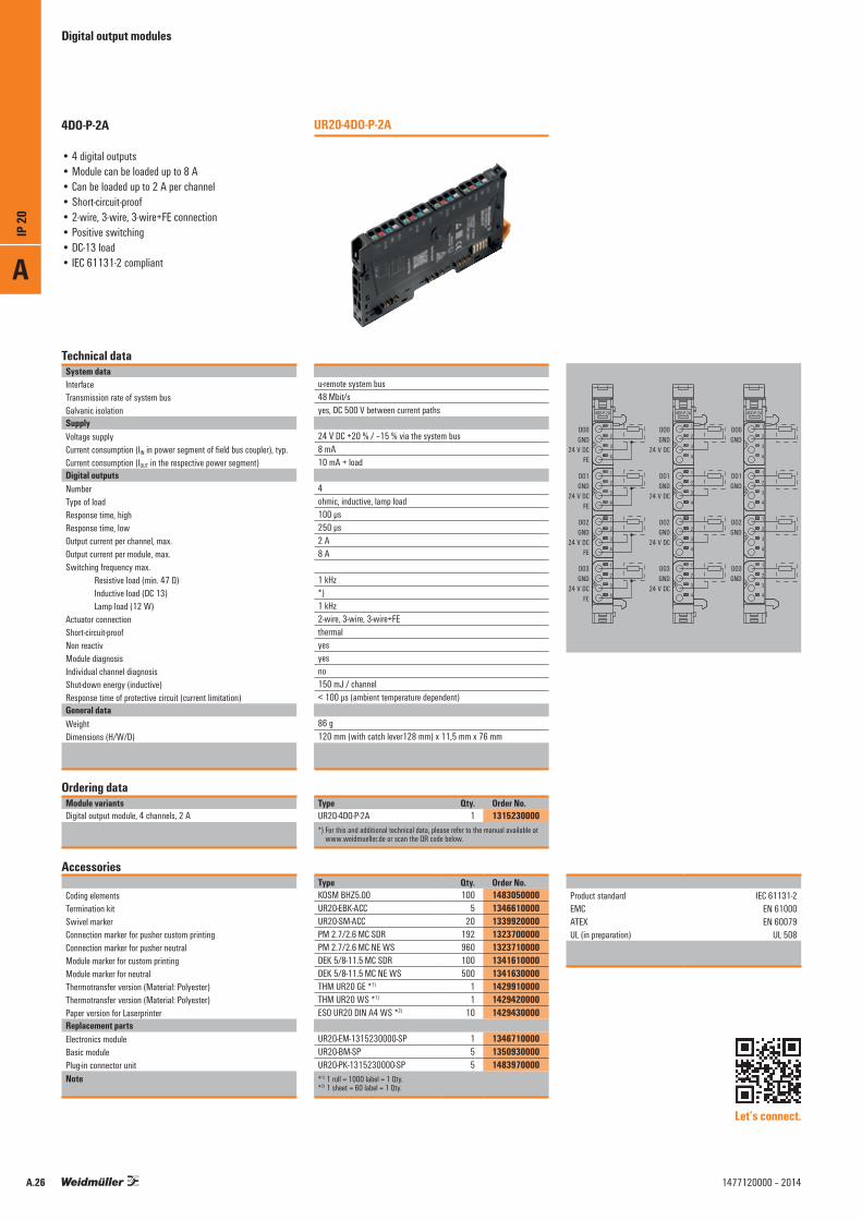
Technical dataSystem dataInterfaceTransmission rate of system busGalvanic isolationSupplyVoltage supplyCurrent consumption (IIN in power segment of field bus coupler), typ.Current consumption (IOUT in the respective power segment)Digital outputsNumberType of loadResponse time, highResponse time, lowOutput current per channel, max.Output current per module, max.Switching frequency max. Resistive load (min. 47 Ω) Inductive load (DC 13) Lamp load (12 W)Actuator connectionShort-circuit-proofNon reactivModule diagnosisIndividual channel diagnosisShut-down energy (inductive)Response time of protective circuit (current limitation)General dataWeightDimensions (H/W/D)
Ordering dataModule variantsDigital output module, 4 channels, 2 A
Accessories
Coding elementsTermination kitSwivel markerConnection marker for pusher custom printingConnection marker for pusher neutralModule marker for custom printingModule marker for neutralThermotransfer version (Material: Polyester)Thermotransfer version (Material: Polyester)Paper version for LaserprinterReplacement partsElectronics moduleBasic modulePlug-in connector unitNote
u-remote system bus48 Mbit/syes, DC 500 V between current paths
24 V DC +20 % / –15 % via the system bus8 mA10 mA + load
4ohmic, inductive, lamp load100 µs250 µs2 A8 A
1 kHz*)1 kHz2-wire, 3-wire, 3-wire+FEthermalyesyesno150 mJ / channel< 100 µs (ambient temperature dependent)
86 g120 mm (with catch lever128 mm) x 11,5 mm x 76 mm
Type Qty. Order No.UR20-4DO-P-2A 1 1315230000*) For this and additional technical data, please refer to the manual available at
www.weidmueller.de or scan the QR code below.
Type Qty. Order No.KOSM BHZ5.00 100 1483050000UR20-EBK-ACC 5 1346610000UR20-SM-ACC 20 1339920000PM 2.7/2.6 MC SDR 192 1323700000PM 2.7/2.6 MC NE WS 960 1323710000DEK 5/8-11.5 MC SDR 100 1341610000DEK 5/8-11.5 MC NE WS 500 1341630000THM UR20 GE *1) 1 1429910000THM UR20 WS *1) 1 1429420000ESO UR20 DIN A4 WS *2) 10 1429430000
UR20-EM-1315230000-SP 1 1346710000UR20-BM-SP 5 1350930000UR20-PK-1315230000-SP 5 1483970000*1) 1 roll = 1000 label = 1 Qty.*2) 1 sheet = 60 label = 1 Qty.
UR20-4DO-P-2A4DO-P-2A
• 4 digital outputs• Module can be loaded up to 8 A• Can be loaded up to 2 A per channel• Short-circuit-proof• 2-wire, 3-wire, 3-wire+FE connection• Positive switching• DC-13 load• IEC 61131-2 compliant
Product standard IEC 61131-2 EMC EN 61000 ATEX EN 60079 UL (in preparation) UL 508
Let’s connect.
1
2
3
4
2
1
3
4
1
2
3
4
2
4
3
1
2
4
3
1
4DO·P-2A
1
2
3
4
2
1
3
4
1
2
3
4
2
4
3
1
2
4
3
1
4DO·P-2A
1
2
3
4
2
1
3
4
1
2
3
4
2
4
3
1
2
4
3
1
4DO·P-2A
DO0GND
24 V DCFE
DO1GND
24 V DCFE
DO2GND
24 V DCFE
DO3GND
24 V DCFE
DO3
DO2
DO1
DO0
GND
GND
GND
GND
24 V DC
DO3
DO2
DO1
DO0
GND
GND
GND
GND
24 V DC
24 V DC
24 V DC
A
IP 20
A.26 1477120000 – 2014
Digital output modules
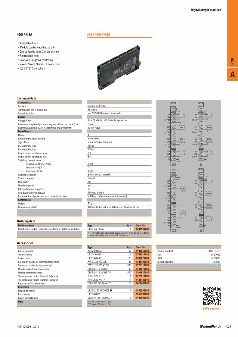
Technical dataSystem dataInterfaceTransmission rate of system busGalvanic isolationSupplyVoltage supplyCurrent consumption (IIN in power segment of field bus coupler), typ.Current consumption (IOUT in the respective power segment)Digital InputsNumberPositive or negative switchingType of loadResponse time, highResponse time, lowOutput current per channel, max.Output current per module, max.Switching frequency max. Resistive load (min. 47 Ohm) Inductive load (DC 13) Lamp load (12 W)Actuator connectionShort-circuit-proofNon reactivModule diagnosisIndividual channel diagnosisShut-down energy (inductive)Response time of protective circuit (current limitation)General dataWeightDimensions (H/W/D)
Ordering dataModule variantsDigital output module, 4 channels, positively or negatively switching
Accessories
Coding elementsTermination kitSwivel markerConnection marker for pusher custom printingConnection marker for pusher neutralModule marker for custom printingModule marker for neutralThermotransfer version (Material: Polyester)Thermotransfer version (Material: Polyester)Paper version for LaserprinterErsatzteileElectronics moduleBasic modulePlug-in connector unitNote
u-remote system bus48 Mbit/syes, DC 500 V between current paths
24 V DC +20 % / –15 % via the system bus8 mA10 mA + load
4parameteriseohmic, inductive, lamp load100 µs250 µs2 A8 A
1 kHz*)1 kHz2-wire, 3-wire, 3-wire+FEthermalyesyesno150 mJ / channel< 100 µs (ambient temperature dependent)
87 g120 mm (with catch lever 128 mm) x 11.5 mm x 76 mm
Type Qty. Order No.UR20-4DO-PN-2A 1 1394420000*) For this and additional technical data, please refer to the manual available at
www.weidmueller.de or scan the QR code below.
Type Qty. Order No.KOSM BHZ5.00 100 1483050000UR20-EBK-ACC 5 1346610000UR20-SM-ACC 20 1339920000PM 2.7/2.6 MC SDR 192 1323700000PM 2.7/2.6 MC NE WS 960 1323710000DEK 5/8-11.5 MC SDR 100 1341610000DEK 5/8-11.5 MC NE WS 500 1341630000THM UR20 GE *1) 1 1429910000THM UR20 WS *1) 1 1429420000ESO UR20 DIN A4 WS *2) 10 1429430000
UR20-EM-1394420000-SP 1 1480950000UR20-BM-SP 5 1350930000UR20-PK-1394420000-SP 5 1483980000*1) 1 roll = 1000 label = 1 Qty.*2) 1 sheet = 60 label = 1 Qty.
UR20-4DO-PN-2A4DO-PN-2A
• 4 digital outputs• Module can be loaded up to 8 A• Can be loaded up to 2 A per channel• Short-circuit-proof• Positive or negative switching• 2-wire, 3-wire, 3-wire+FE connection• IEC 61131-2 compliant
Let’s connect.
Product standard IEC 61131-2 EMC EN 61000 ATEX EN 60079 UL (in preparation) UL 508
1
2
3
4
2
1
3
4
1
2
3
4
2
4
3
1
2
4
3
1
DO0GND
24 V DCFE
DO1GND
24 V DCFE
DO2GND
24 V DCFE
DO3GND
24 V DCFE
1
2
3
4
2
1
3
4
1
2
3
4
2
4
3
1
2
4
3
1
4DO·PN-2A4DO·PN-2A
24 V DC
DO3
DO2
DO1
DO0
GND
GND
GND
GND
24 V DC
24 V DC
24 V DC
1
2
3
4
2
1
3
4
1
2
3
4
2
4
3
1
2
4
3
1
4DO·P-2A
DO3
DO2
DO1
DO0
GND
GND
GND
GND1
2
3
4
2
1
3
4
1
2
3
4
2
4
3
1
2
4
3
1
4DO·P-2A
DO0GND
24 V DCFE
DO1GND
24 V DCFE
DO2GND
24 V DCFE
DO3GND
24 V DCFE
M
M
A
IP 20
A.271477120000 – 2014

Digital output modules
Technical dataSystem dataInterfaceTransmission rate of system busGalvanic isolationSupplyVoltage supplyCurrent consumption (IIN in power segment of field bus coupler), typ.Current consumption (IOUT in the respective power segment)Digital outputsNumberType of loadResponse time, highResponse time, lowOutput current per channel, max.Output current per module, max.Switching frequency max. Resistive load (min. 47 Ω) Inductive load (DC 13) Lamp load (12 W)Actuator connectionShort-circuit-proofNon reactivModule diagnosisIndividual channel diagnosisShut-down energy (inductive)Response time of protective circuit (current limitation)General dataWeightDimensions (H/W/D)
Ordering dataModule variantsDigital output module, 8 channels
Accessories
Coding elementsTermination kitSwivel markerConnection marker for pusher custom printingConnection marker for pusher neutralModule marker for custom printingModule marker for neutralThermotransfer version (Material: Polyester)Thermotransfer version (Material: Polyester)Paper version for LaserprinterReplacement partsElectronics moduleBasic modulePlug-in connector unitNote
u-remote system bus48 Mbit/syes, DC 500 V between current paths
24 V DC +20 % / –15 % via the system bus8 mA15 mA + load
8ohmic, inductive, lamp load100 µs250 µs0.5 A4 A
1 kHz*)1 kHz2-wirethermalyesyesno150 mJ / channel< 100 µs (ambient temperature dependent)
87 g120 mm (with catch lever128 mm) x 11,5 mm x 76 mm
Type Qty. Order No.UR20-8DO-P 1 1315240000*) For this and additional technical data, please refer to the manual available at
www.weidmueller.de or scan the QR code below.
Type Qty. Order No.KOSM BHZ5.00 100 1483050000UR20-EBK-ACC 5 1346610000UR20-SM-ACC 20 1339920000PM 2.7/2.6 MC SDR 192 1323700000PM 2.7/2.6 MC NE WS 960 1323710000DEK 5/8-11.5 MC SDR 100 1341610000DEK 5/8-11.5 MC NE WS 500 1341630000THM UR20 GE *1) 1 1429910000THM UR20 WS *1) 1 1429420000ESO UR20 DIN A4 WS *2) 10 1429430000
UR20-EM-1315240000-SP 1 1346720000UR20-BM-SP 5 1350930000UR20-PK-1315240000-SP 5 1346410000*1) 1 roll = 1000 label = 1 Qty.*2) 1 sheet = 60 label = 1 Qty.
UR20-8DO-P8DO-P
• 8 digital outputs• Can be loaded up to 0.5 A per channel• Short-circuit-proof• 2-wire connection• Positive switching• DC-13 load• IEC 61131-2 compliant
Product standard IEC 61131-2 EMC EN 61000 ATEX EN 60079 UL (in preparation) UL 508
Let’s connect.
1
2
3
4
2
1
3
4
1
2
3
4
2
4
3
1
2
4
3
1
8DO·P
DO0GNDDO1GND
DO2GNDDO3GND
DO4GNDDO5GND
DO6GNDDO7GND
A
IP 20
A.28 1477120000 – 2014
Digital output modules
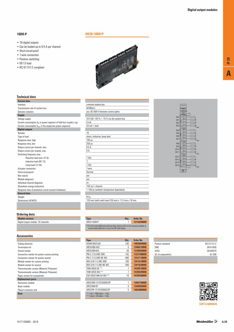
Technical dataSystem dataInterfaceTransmission rate of system busGalvanic isolationSupplyVoltage supplyCurrent consumption (IIN in power segment of field bus coupler), typ.Current consumption (IOUT in the respective power segment)Digital outputsNumberType of loadResponse time, highResponse time, lowOutput current per channel, max.Output current per module, max.Switching frequency max. Resistive load (min. 47 Ω) Inductive load (DC 13) Lamp load (12 W)Actuator connectionShort-circuit-proofNon reactivModule diagnosisIndividual channel diagnosisShut-down energy (inductive)Response time of protective circuit (current limitation)General dataWeightDimensions (H/W/D)
Ordering dataModule variantsDigital output module, 16 channels
Accessories
Coding elementsTermination kitSwivel markerConnection marker for pusher custom printingConnection marker for pusher neutralModule marker for custom printingModule marker for neutralThermotransfer version (Material: Polyester)Thermotransfer version (Material: Polyester)Paper version for LaserprinterReplacement partsElectronics moduleBasic modulePlug-in connector unitNote
u-remote system bus48 Mbit/syes, DC 500 V between current paths
24 V DC +20 % / –15 % via the system bus8 mA20 mA + load
16ohmic, inductive, lamp load100 µs250 µs0.5 A8 A
1 kHz*)1 kHz1-wirethermalyesyesno150 mJ / channel< 100 µs (ambient temperature dependent)
83 g120 mm (with catch lever128 mm) x 11,5 mm x 76 mm
Type Qty. Order No.UR20-16DO-P 1 1315250000*) For this and additional technical data, please refer to the manual available at
www.weidmueller.de or scan the QR code below.
Type Qty. Order No.KOSM BHZ5.00 100 1483050000UR20-EBK-ACC 5 1346610000UR20-SM-ACC 20 1339920000PM 2.7/2.6 MC SDR 192 1323700000PM 2.7/2.6 MC NE WS 960 1323710000DEK 5/8-11.5 MC SDR 100 1341610000DEK 5/8-11.5 MC NE WS 500 1341630000THM UR20 GE *1) 1 1429910000THM UR20 WS *1) 1 1429420000ESO UR20 DIN A4 WS *2) 10 1429430000
UR20-EM-1315250000-SP 1 1346730000UR20-BM-SP 5 1350930000UR20-PK-1315250000-SP 5 1483990000*1) 1 roll = 1000 label = 1 Qty.*2) 1 sheet = 60 label = 1 Qty.
UR20-16DO-P16DO-P
• 16 digital outputs• Can be loaded up to 0.5 A per channel• Short-circuit-proof• 1-wire connection• Positive switching• DC-13 load• IEC 61131-2 compliant
Product standard IEC 61131-2 EMC EN 61000 ATEX EN 60079 UL (in preparation) UL 508
Let’s connect.
1
2
3
4
2
1
3
4
1
2
3
4
2
4
3
1
2
4
3
1
16DO·P
GND
GND
GND
GND
DO0DO1DO2DO3
DO4DO5DO6DO7
DO8DO9
DO10DO11
DO12DO13DO14DO15
A
IP 20
A.291477120000 – 2014
Digital output modules
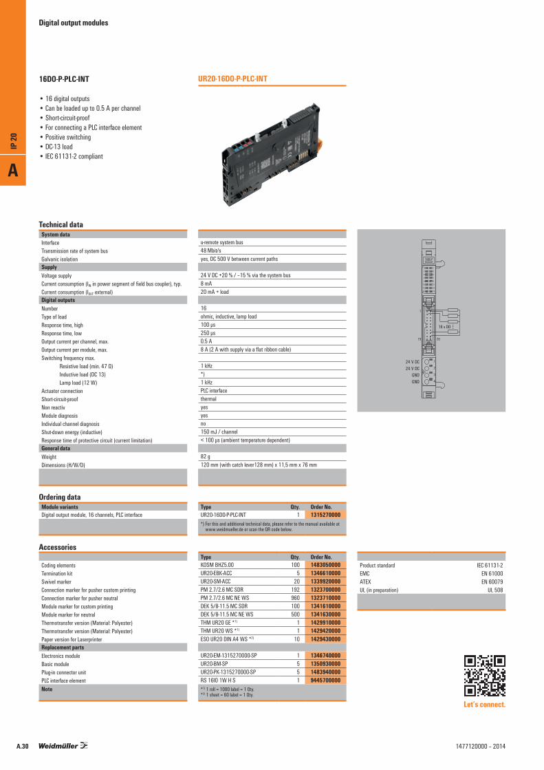
Technical dataSystem dataInterfaceTransmission rate of system busGalvanic isolationSupplyVoltage supplyCurrent consumption (IIN in power segment of field bus coupler), typ.Current consumption (IOUT external)Digital outputsNumberType of loadResponse time, highResponse time, lowOutput current per channel, max.Output current per module, max.Switching frequency max. Resistive load (min. 47 Ω) Inductive load (DC 13) Lamp load (12 W)Actuator connectionShort-circuit-proofNon reactivModule diagnosisIndividual channel diagnosisShut-down energy (inductive)Response time of protective circuit (current limitation)General dataWeightDimensions (H/W/D)
Ordering dataModule variantsDigital output module, 16 channels, PLC interface
Accessories
Coding elementsTermination kitSwivel markerConnection marker for pusher custom printingConnection marker for pusher neutralModule marker for custom printingModule marker for neutralThermotransfer version (Material: Polyester)Thermotransfer version (Material: Polyester)Paper version for LaserprinterReplacement partsElectronics moduleBasic modulePlug-in connector unitPLC interface elementNote
u-remote system bus48 Mbit/syes, DC 500 V between current paths
24 V DC +20 % / –15 % via the system bus8 mA20 mA + load
16ohmic, inductive, lamp load100 µs250 µs0.5 A8 A (2 A with supply via a flat ribbon cable)
1 kHz*)1 kHzPLC interfacethermalyesyesno150 mJ / channel< 100 µs (ambient temperature dependent)
82 g120 mm (with catch lever128 mm) x 11,5 mm x 76 mm
Type Qty. Order No.UR20-16DO-P-PLC-INT 1 1315270000*) For this and additional technical data, please refer to the manual available at
www.weidmueller.de or scan the QR code below.
Type Qty. Order No.KOSM BHZ5.00 100 1483050000UR20-EBK-ACC 5 1346610000UR20-SM-ACC 20 1339920000PM 2.7/2.6 MC SDR 192 1323700000PM 2.7/2.6 MC NE WS 960 1323710000DEK 5/8-11.5 MC SDR 100 1341610000DEK 5/8-11.5 MC NE WS 500 1341630000THM UR20 GE *1) 1 1429910000THM UR20 WS *1) 1 1429420000ESO UR20 DIN A4 WS *2) 10 1429430000
UR20-EM-1315270000-SP 1 1346740000UR20-BM-SP 5 1350930000UR20-PK-1315270000-SP 5 1483940000RS 16IO 1W H S 1 9445700000*1) 1 roll = 1000 label = 1 Qty.*2) 1 sheet = 60 label = 1 Qty.
UR20-16DO-P-PLC-INT16DO-P-PLC-INT
• 16 digital outputs• Can be loaded up to 0.5 A per channel• Short-circuit-proof• For connecting a PLC interface element• Positive switching• DC-13 load• IEC 61131-2 compliant
Product standard IEC 61131-2 EMC EN 61000 ATEX EN 60079 UL (in preparation) UL 508
Let’s connect.
16 x DO
42
1
3
4
16DO·P
0 1
2 34 56 78 9
10 1112 1314 15
24 V DC24 V DC
GNDGND
2019
1
A
IP 20
A.30 1477120000 – 2014

Digital output modules
Technical dataSystem dataInterfaceTransmission rate of system busGalvanic isolationSupplyVoltage supplyCurrent consumption (IIN in power segment of field bus coupler), typ.Current consumption (IOUT in the respective power segment)Digital outputsNumberTypeResponse time, highResponse time, lowOutput current per channel, max.Output current per module, max.Switching frequency max.Short-circuit-proofNon reactivSwitching voltage max.Module diagnosisIndividual channel diagnosisGeneral dataWeightDimensions (H/W/D)
Ordering dataModule variantsDigital output module, 4 channels, SSR
Accessories
Coding elementsTermination kitSwivel markerConnection marker for pusher custom printingConnection marker for pusher neutralModule marker for custom printingModule marker for neutralThermotransfer version (Material: Polyester)Thermotransfer version (Material: Polyester)Paper version for LaserprinterReplacement partsElectronics moduleBasic modulePlug-in connector unitNote
u-remote system bus48 Mbit/syes, DC 500 V between current paths
24 V DC +20 % / –15 % via the system bus8 mA< 15 mA
4SSR /Triacmax. 20 ms, zero-crossing-detectionmax. 20 ms, zero-crossing-detection0.5 A2 A40 Hznoyes277 V AC *)
yesno
83 g120 mm (with catch lever128 mm) x 11,5 mm x 76 mm
Type Qty. Order No.UR20-4RO-SSR-255 1 1315540000*) For this and additional technical data, please refer to the manual available at
www.weidmueller.de or scan the QR code below.
Type Qty. Order No.KOSM BHZ5.00 100 1483050000UR20-EBK-ACC 5 1346610000UR20-SM-ACC 20 1339920000PM 2.7/2.6 MC SDR 192 1323700000PM 2.7/2.6 MC NE WS 960 1323710000DEK 5/8-11.5 MC SDR 100 1341610000DEK 5/8-11.5 MC NE WS 500 1341630000THM UR20 GE *1) 1 1429910000THM UR20 WS *1) 1 1429420000ESO UR20 DIN A4 WS *2) 10 1429430000
UR20-EM-1315540000-SP 1 1347120000UR20-BM-SP 5 1350930000UR20-PK-1315540000-SP 5 1484000000*1) 1 roll = 1000 label = 1 Qty.*2) 1 sheet = 60 label = 1 Qty.
UR20-4RO-SSR-2554RO-SSR-255
• 4 digital outputs• Can be loaded up to 0.5 A per channel• Solid-state relay
Product standard IEC 61131-2 EMC EN 61000 ATEX EN 60079 UL (in preparation) UL 508
Let’s connect.
1
2
3
4
2
1
3
4
1
2
3
4
2
4
3
1
2
4
3
1
4RO·SSR
230 V ~ max.
230 V ~ max.
230 V ~ max.
230 V ~ max.
N.O.0
COM0
N.O.1
COM1
N.O.2
COM2
N.O.3
COM3
A
IP 20
A.311477120000 – 2014
Digital output modules
Technical dataSystem dataInterfaceTransmission rate of system busGalvanic isolationSupplyVoltage supplyCurrent consumption (IIN in power segment of field bus coupler), typ.Current consumption (IOUT in the respective power segment)Digital outputsNumberTypeResponse time, highResponse time, lowOutput current per channel, max.Output current per module, max.Switching frequency max.Short-circuit-proofNon reactivSwitching voltage max.Module diagnosisIndividual channel diagnosisGeneral dataWeightDimensions (H/W/D)
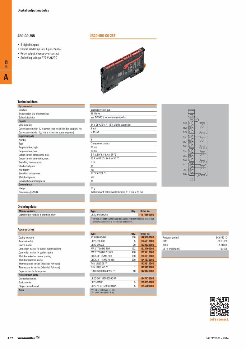
Ordering dataModule variantsDigital output module, 4 channels, relay
Accessories
Coding elementsTermination kitSwivel markerConnection marker for pusher custom printingConnection marker for pusher neutralModule marker for custom printingModule marker for neutralThermotransfer version (Material: Polyester)Thermotransfer version (Material: Polyester)Paper version for LaserprinterReplacement partsElectronics moduleBasic modulePlug-in connector unitNote
u-remote system bus48 Mbit/syes, DC 500 V between current paths
24 V DC +20 % / –15 % via the system bus8 mA< 15 mA
4Change-over contact20 ms20 ms5 A at 60 °C / 6 A at 55 °C20 A at 60 °C / 24 A at 55 °C5 Hznoyes277 V AC/DC *)
yesno
83 g120 mm (with catch lever128 mm) x 11,5 mm x 76 mm
Type Qty. Order No.UR20-4RO-CO-255 1 1315550000*) For this and additional technical data, please refer to the manual available at
www.weidmueller.de or scan the QR code below.
Type Qty. Order No.KOSM BHZ5.00 100 1483050000UR20-EBK-ACC 5 1346610000UR20-SM-ACC 20 1339920000PM 2.7/2.6 MC SDR 192 1323700000PM 2.7/2.6 MC NE WS 960 1323710000DEK 5/8-11.5 MC SDR 100 1341610000DEK 5/8-11.5 MC NE WS 500 1341630000THM UR20 GE *1) 1 1429910000THM UR20 WS *1) 1 1429420000ESO UR20 DIN A4 WS *2) 10 1429430000
UR20-EM-1315550000-SP 1 1347130000UR20-BM-SP 5 1350930000UR20-PK-1315550000-SP 5 1346500000*1) 1 roll = 1000 label = 1 Qty.*2) 1 sheet = 60 label = 1 Qty.
UR20-4RO-CO-255
1
2
3
4
2
1
3
4
1
2
3
4
2
4
3
1
2
4
3
1
4RO·CO255
COM0
N.C.1
N.C.0
COM1
N.C.2
COM2
N.C.3
COM3
N.O.0
N.O.1
N.O.2
N.O.3
≃
≃
≃
≃
4RO-CO-255
• 4 digital outputs• Can be loaded up to 6 A per channel• Relay output, change-over contact• Switching voltage 277 V AC/DC
Let’s connect.
Product standard IEC 61131-2 EMC EN 61000 ATEX EN 60079 UL (in preparation) UL 508
A
IP 20
A.32 1477120000 – 2014

A
IP 20
A.331477120000 – 2014
Digital counter modules
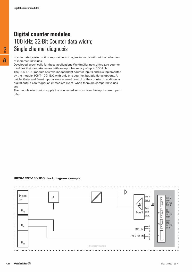
In automated systems, it is impossible to imagine industry without the collection of incremental values. Developed specifically for these applications Weidmüller now offers two counter modules that can take values with an input frequency of up to 100 kHz.The 2CNT-100 module has two independent counter inputs and is supplemented by the module 1CNT-100-1DO with only one counter, but additional options. A Latch-, Gate- and Reset input allows external control of the counter. In addition, a digital output can trigger an immediate event, when there are compared values set.The module electronics supply the connected sensors from the input current path (UIN).
Digital counter modules100 kHz; 32-Bit Counter data width; Single channel diagnosis
123
123
24 V DC⎽IN
GND⎽IN
CH0 A
CH0 B
DO
Latch
GATE
LatchGND24 V DCGATE
CH0 AGND24 V DCCH0 B
DOGND24 V DCReset
Type 3
µC1
2
3
4
Reset
UR20-1CNT-100-1DO
System-bus
USYS
UIN
UOUT
UR20-1CNT-100-1DO block diagram example
A
IP 20
A.34 1477120000 – 2014

Digital counter modules
Technical dataSystem dataInterfaceTransmission rate of system busGalvanic isolationSupplyVoltage supplyCurrent consumption (IIN in power segment of field bus coupler), typ.Current consumption (IIN in the respective power segment)Digital InputsNumber of counter inputsTypeInput filterInput voltage, lowInput voltage, highSensor feedSensor connectionReverse polarity protectionModule diagnosisSingle channel diagnosisInput current per channel, max.Counter data widthInput frequency, max.Counter frequency, max.Latch-, Gate-, Reset-inputOperation modeGeneral dataWeightDimensions (H/W/D)
Ordering dataModule variantsDigital counter module, 1 channel, 100 kHz
Accessories
Coding elementsTermination kitSwivel markerConnection marker for pusher custom printingConnection marker for pusher neutralModule marker for custom printingModule marker for neutralThermotransfer version (Material: Polyester)Thermotransfer version (Material: Polyester)Paper version for LaserprinterReplacement partsElectronics moduleBasic modulePlug-in connector unitNote
u-remote system bus48 Mbit/syes, DC 500 V between current paths
24 V DC +20 % / –15 % via the system bus8 mA35 mA
1incremental encoderadjustable up to 1 ms< 5 V> 11 Vyes2- and 3-wireyesyesyes3.5 mA32 Bit100 kHz400 kHzyesImpulse / direction / 1-, 2-, 4-times
87 g120 mm (with catch lever 128 mm) x 11.5 mm x 76 mm
Type Qty. Order No.UR20-1CNT-100-1DO 1 1315570000
Type Qty. Order No.KOSM BHZ5.00 100 1483050000UR20-EBK-ACC 5 1346610000UR20-SM-ACC 20 1339920000PM 2.7/2.6 MC SDR 192 1323700000PM 2.7/2.6 MC NE WS 960 1323710000DEK 5/8-11.5 MC SDR 100 1341610000DEK 5/8-11.5 MC NE WS 500 1341630000THM UR20 GE *1) 1 1429910000THM UR20 WS *1) 1 1429420000ESO UR20 DIN A4 WS *2) 10 1429430000
UR20-EM-1315570000-SP 1 1347140000UR20-BM-SP 5 1350930000UR20-PK-1315570000-SP 5 1346520000*1) 1 roll = 1000 label = 1 Qty.*2) 1 sheet = 60 label = 1 Qty.
UR20-1CNT-100-1DO1CNT-100-1DO
• Latch-, Gate- and Reset input• Counter data width 32-Bit• Maximum input frequency 100 kHz• Operation mode impulse, direction, 1-, 2- or 4-times • Sensor feed• Input filter adjustable up to 1 ms• One digital output
Product standard IEC 61131-2 EMC EN 61000 ATEX EN 60079 UL (in preparation) UL 508
Let’s connect.
A
IP 20
A.351477120000 – 2014
Digital counter modules
Technical dataSystem dataInterfaceTransmission rate of system busGalvanic isolationSupplyVoltage supplyCurrent consumption (IIN in power segment of field bus coupler), typ.Current consumption (IIN in the respective power segment)Digital InputsNumber of counter inputsTypeInput filterInput voltage, lowInput voltage, highSensor feedSensor connectionReverse polarity protectionModule diagnosisSingle channel diagnosisInput current per channel, max. Counter data widthInput frequency, max.Counter frequency, max.Operation modeGeneral dataWeightDimensions (H/W/D)
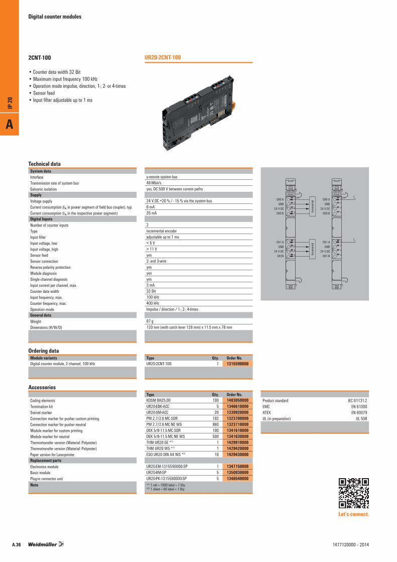
Ordering dataModule variantsDigital counter module, 2 channel, 100 kHz
Accessories
Coding elementsTermination kitSwivel markerConnection marker for pusher custom printingConnection marker for pusher neutralModule marker for custom printingModule marker for neutralThermotransfer version (Material: Polyester)Thermotransfer version (Material: Polyester)Paper version for LaserprinterReplacement partsElectronics moduleBasic modulePlug-in connector unitNote
u-remote system bus48 Mbit/syes, DC 500 V between current paths
24 V DC +20 % / - 15 % via the system bus8 mA35 mA
2incremental encoderadjustable up to 1 ms< 5 V> 11 Vyes2- and 3-wireyesyesyes3 mA32 Bit100 kHz400 kHzImpulse / direction / 1-, 2-, 4-times
87 g120 mm (with catch lever 128 mm) x 11.5 mm x 76 mm
Type Qty. Order No.UR20-2CNT-100 1 1315590000
Type Qty. Order No.KOSM BHZ5.00 100 1483050000UR20-EBK-ACC 5 1346610000UR20-SM-ACC 20 1339920000PM 2.7/2.6 MC SDR 192 1323700000PM 2.7/2.6 MC NE WS 960 1323710000DEK 5/8-11.5 MC SDR 100 1341610000DEK 5/8-11.5 MC NE WS 500 1341630000THM UR20 GE *1) 1 1429910000THM UR20 WS *1) 1 1429420000ESO UR20 DIN A4 WS *2) 10 1429430000
UR20-EM-1315590000-SP 1 1347150000UR20-BM-SP 5 1350930000UR20-PK-1315590000-SP 5 1346540000*1) 1 roll = 1000 label = 1 Qty.*2) 1 sheet = 60 label = 1 Qty.
UR20-2CNT-100
1
2
3
4
2
1
3
4
2
4
3
1
2CNT100
1
2
3
4
2
1
3
4
2
4
3
1
2CNT100
CH0 AGND
24 V DCCH0 B
CH1 AGND
24 V DCCH1B
Increm
enta
lInc
remen
tal
CH0 Afin
GND24 V DC
CH0 B
CH1 AGND
24 V DCCH1 B
fin
2CNT-100
• Counter data width 32 Bit• Maximum input frequency 100 kHz• Operation mode impulse, direction, 1-, 2- or 4-times • Sensor feed• Input filter adjustable up to 1 ms
Let’s connect.
Product standard IEC 61131-2 EMC EN 61000 ATEX EN 60079 UL (in preparation) UL 508
A
IP 20
A.36 1477120000 – 2014

A
IP 20
A.371477120000 – 2014

Pulse width modulation modules
As part of the new u-remote system, Weidmüller provides a specialised solution for controlling small motors with current requirements of 0.5 A to 2 A which can also be used to control valve flaps. Here, not only can the switching frequencies be set up to 40 kHz, the push/pull output levels can also be used for motor activation, for example, to change direction of rotation. As with all modules in the u-remote system, the characteristics are outstanding – from the modular design and interchangeable electronics to the removable and plug-in terminal strip.
The module electronics supply the connected actuators from the output current path (UOUT).
Pulse width modulation modulesFrequency can be adjusted up to 40 kHz; short-circuit-proof; two PWM outputs
UR20-2PWM-PN-0.5A block diagram example
GND
PWM0
PWM1
1
2
1
2
1
2
PWM0GND24 V DCFE
PWM1GND24 V DCFE
System-bus
USYS
UIN
UOUT
µC
24 V DC⎽OUT
GND⎽OUT
FE
1
3
UR20-2PWM-PN-0.5A
A
IP 20
A.38 1477120000 – 2014

Pulse width modulation modules
Technical dataSystem dataInterfaceTransmission rate of system busGalvanic isolationSupplyVoltage supplyCurrent consumption (IIN in power segment of field bus coupler), typ.Current consumption (IOUT in the respective power segment)Digital outputsNumberTypeResolutionAccuracyResponse time, highResponse time, lowOutput current per channel, max.Output current per module, max.Switching frequency max. Resistive load (min. 47 Ω) Inductive load (DC 13) Lamp load (12 W)Actuator connectionShort-circuit-proofModule diagnosisIndividual channel diagnosisNon reactivPulse duty factorGeneral dataWeightDimensions (H/W/D)
Ordering dataModule variantsDigital output module, PWM, 2 channels, 0.5 A
Accessories
Coding elementsTermination kitSwivel markerConnection marker for pusher custom printingConnection marker for pusher neutralModule marker for custom printingModule marker for neutralThermotransfer version (Material: Polyester)Thermotransfer version (Material: Polyester)Paper version for LaserprinterReplacement partsElectronics moduleBasic modulePlug-in connector unitNote
u-remote system bus48 Mbit/syes, DC 500 V between current paths
24 V DC +20 % / –15 % via the system bus8 mA40 mA + Load
2PWM push/pull output stage32 Bit1 Bit< 100 ns< 100 ns0.5 A1 A
static, 6 Hz to 40 kHzstatic, 6 Hz to 40 kHzstatic, 6 Hz to 40 kHzyesyesyesnoyes0 - 100 % push/pull or push parameterisable
77 g120 mm (with catch lever128 mm) x 11,5 mm x 76 mm
Type Qty. Order No.UR20-2PWM-PN-0.5A 1 1315600000
Type Qty. Order No.KOSM BHZ5.00 100 1483050000UR20-EBK-ACC 5 1346610000UR20-SM-ACC 20 1339920000PM 2.7/2.6 MC SDR 192 1323700000PM 2.7/2.6 MC NE WS 960 1323710000DEK 5/8-11.5 MC SDR 100 1341610000DEK 5/8-11.5 MC NE WS 500 1341630000THM UR20 GE *1) 1 1429910000THM UR20 WS *1) 1 1429420000ESO UR20 DIN A4 WS *2) 10 1429430000
UR20-EM-1315600000-SP 1 1347180000UR20-BM-SP 5 1350930000UR20-PK-1315600000-SP 5 1484010000*1) 1 roll = 1000 label = 1 Qty.*2) 1 sheet = 60 label = 1 Qty.
UR20-2PWM-PN-0.5A2PWM-PN-0.5A
• 2 pulse width modulation module outputs• Can be loaded up to 0.5 A per channel• Short-circuit-proof• Push/pull output• Maximum 40 kHz output frequency (adjustable)
Product standard IEC 61131-2 EMC EN 61000 ATEX EN 60079 UL (in preparation) UL 508
Let’s connect.
1
2
3
4
2
1
3
4
2
4
3
1
2PWM
PWM0GND
24 V DCFE
PWM1GND
24 V DCFE
A
IP 20
A.391477120000 – 2014
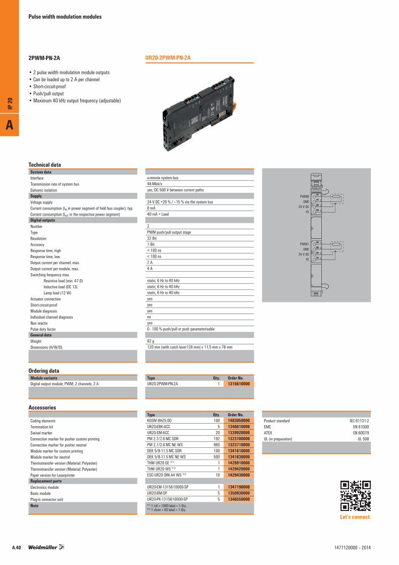
Pulse width modulation modules
Technical dataSystem dataInterfaceTransmission rate of system busGalvanic isolationSupplyVoltage supplyCurrent consumption (IIN in power segment of field bus coupler), typ.Current consumption (IOUT in the respective power segment)Digital outputsNumberTypeResolutionAccuracyResponse time, highResponse time, lowOutput current per channel, max.Output current per module, max.Switching frequency max. Resistive load (min. 47 Ω) Inductive load (DC 13) Lamp load (12 W)Actuator connectionShort-circuit-proofModule diagnosisIndividual channel diagnosisNon reactivPulse duty factorGeneral dataWeightDimensions (H/W/D)
Ordering dataModule variantsDigital output module, PWM, 2 channels, 2 A
Accessories
Coding elementsTermination kitSwivel markerConnection marker for pusher custom printingConnection marker for pusher neutralModule marker for custom printingModule marker for neutralThermotransfer version (Material: Polyester)Thermotransfer version (Material: Polyester)Paper version for LaserprinterReplacement partsElectronics moduleBasic modulePlug-in connector unitNote
u-remote system bus48 Mbit/syes, DC 500 V between current paths
24 V DC +20 % / –15 % via the system bus8 mA40 mA + Load
2PWM push/pull output stage32 Bit1 Bit< 100 ns< 100 ns2 A4 A
static, 6 Hz to 40 kHzstatic, 6 Hz to 40 kHzstatic, 6 Hz to 40 kHzyesyesyesnoyes0 - 100 % push/pull or push parameterisable
82 g120 mm (with catch lever128 mm) x 11,5 mm x 76 mm
Type Qty. Order No.UR20-2PWM-PN-2A 1 1315610000
Type Qty. Order No.KOSM BHZ5.00 100 1483050000UR20-EBK-ACC 5 1346610000UR20-SM-ACC 20 1339920000PM 2.7/2.6 MC SDR 192 1323700000PM 2.7/2.6 MC NE WS 960 1323710000DEK 5/8-11.5 MC SDR 100 1341610000DEK 5/8-11.5 MC NE WS 500 1341630000THM UR20 GE *1) 1 1429910000THM UR20 WS *1) 1 1429420000ESO UR20 DIN A4 WS *2) 10 1429430000
UR20-EM-1315610000-SP 1 1347190000UR20-BM-SP 5 1350930000UR20-PK-1315610000-SP 5 1346550000*1) 1 roll = 1000 label = 1 Qty.*2) 1 sheet = 60 label = 1 Qty.
UR20-2PWM-PN-2A2PWM-PN-2A
• 2 pulse width modulation module outputs• Can be loaded up to 2 A per channel• Short-circuit-proof• Push/pull output• Maximum 40 kHz output frequency (adjustable)
Product standard IEC 61131-2 EMC EN 61000 ATEX EN 60079 UL (in preparation) UL 508
Let’s connect.
1
2
3
4
2
1
3
4
2
4
3
1
2PWM-2A
PWM0GND
24 V DC
PWM1GND
24 V DC
FE
FE
A
IP 20
A.40 1477120000 – 2014

A
IP 20
A.411477120000 – 2014
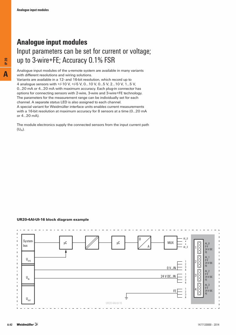
Analogue input modules
Analogue input modules of the u-remote system are available in many variants with different resolutions and wiring solutions.Variants are available in a 12- and 16-bit resolution, which record up to 4 analogue sensors with +/-10 V, +/-5 V, 0...10 V, 0...5 V, 2...10 V, 1...5 V, 0...20 mA or 4...20 mA with maximum accuracy. Each plug-in connector has options for connecting sensors with 2-wire, 3-wire and 3-wire+FE technology. The parameters for the measurement range can be individually set for each channel. A separate status LED is also assigned to each channel.A special variant for Weidmüller interface units enables current measurements with a 16-bit resolution at maximum accuracy for 8 sensors at a time (0...20 mA or 4...20 mA).
The module electronics supply the connected sensors from the input current path (UIN).
Analogue input modulesInput parameters can be set for current or voltage; up to 3-wire+FE; Accuracy 0.1% FSR
UR20-4AI-UI-16 block diagram example
AI_0••
AI_3
AI_10 V24 V DCFE
AI_00 V24 V DCFE
AI_20 V24 V DCFE
AI_30 V24 V DCFE
System-bus
USYS
UIN
UOUTUR20 4AI-UI-16
µC µC MUX1
2
3
4
24 V DC⎽IN
0 V⎽IN
FE
1234
1234
1234
A
D
A
IP 20
A.42 1477120000 – 2014
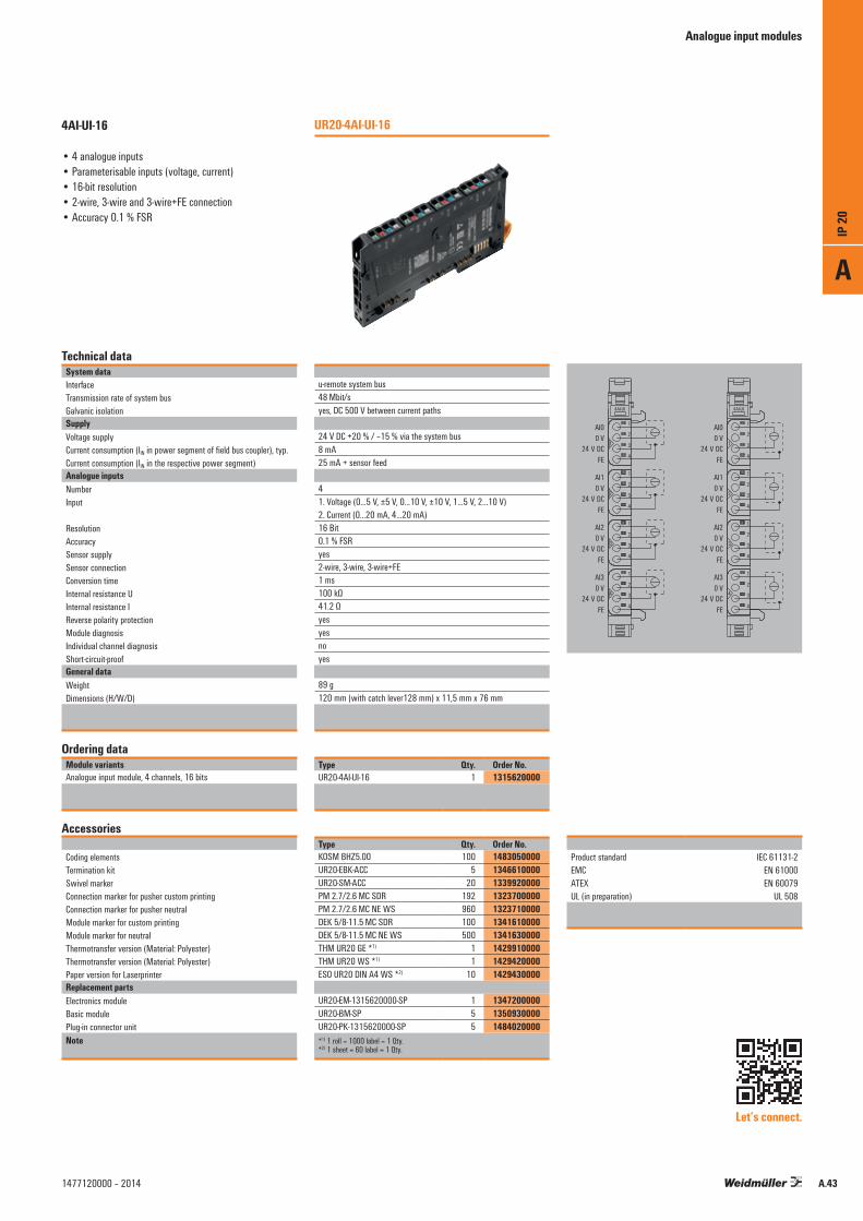
Analogue input modules
Technical dataSystem dataInterfaceTransmission rate of system busGalvanic isolationSupplyVoltage supplyCurrent consumption (IIN in power segment of field bus coupler), typ.Current consumption (IIN in the respective power segment)Analogue inputsNumberInput
ResolutionAccuracySensor supplySensor connectionConversion timeInternal resistance UInternal resistance IReverse polarity protectionModule diagnosisIndividual channel diagnosisShort-circuit-proofGeneral dataWeightDimensions (H/W/D)
Ordering dataModule variantsAnalogue input module, 4 channels, 16 bits
Accessories
Coding elementsTermination kitSwivel markerConnection marker for pusher custom printingConnection marker for pusher neutralModule marker for custom printingModule marker for neutralThermotransfer version (Material: Polyester)Thermotransfer version (Material: Polyester)Paper version for LaserprinterReplacement partsElectronics moduleBasic modulePlug-in connector unitNote
u-remote system bus48 Mbit/syes, DC 500 V between current paths
24 V DC +20 % / –15 % via the system bus8 mA25 mA + sensor feed
41. Voltage (0…5 V, ±5 V, 0…10 V, ±10 V, 1…5 V, 2…10 V)2. Current (0…20 mA, 4…20 mA)16 Bit0.1 % FSRyes2-wire, 3-wire, 3-wire+FE1 ms100 kΩ41.2 Ωyesyesnoyes
89 g120 mm (with catch lever128 mm) x 11,5 mm x 76 mm
Type Qty. Order No.UR20-4AI-UI-16 1 1315620000
Type Qty. Order No.KOSM BHZ5.00 100 1483050000UR20-EBK-ACC 5 1346610000UR20-SM-ACC 20 1339920000PM 2.7/2.6 MC SDR 192 1323700000PM 2.7/2.6 MC NE WS 960 1323710000DEK 5/8-11.5 MC SDR 100 1341610000DEK 5/8-11.5 MC NE WS 500 1341630000THM UR20 GE *1) 1 1429910000THM UR20 WS *1) 1 1429420000ESO UR20 DIN A4 WS *2) 10 1429430000
UR20-EM-1315620000-SP 1 1347200000UR20-BM-SP 5 1350930000UR20-PK-1315620000-SP 5 1484020000*1) 1 roll = 1000 label = 1 Qty.*2) 1 sheet = 60 label = 1 Qty.
UR20-4AI-UI-164AI-UI-16
• 4 analogue inputs• Parameterisable inputs (voltage, current)• 16-bit resolution• 2-wire, 3-wire and 3-wire+FE connection• Accuracy 0.1 % FSR
Product standard IEC 61131-2 EMC EN 61000 ATEX EN 60079 UL (in preparation) UL 508
Let’s connect.
4AI-UI
1
2
3
4
2
1
3
4
1
2
3
4
2
4
3
1
2
4
3
1
4AI-UI
1
2
3
4
2
1
3
4
1
2
3
4
2
4
3
1
2
4
3
1
AI00 V
24 V DCFE
AI10 V
24 V DCFE
AI20 V
24 V DCFE
AI30 V
24 V DCFE
AI00 V
24 V DCFE
AI10 V
24 V DCFE
AI20 V
24 V DCFE
AI30 V
24 V DCFE
A
IP 20
A.431477120000 – 2014

Analogue input modules
Technical dataSystem dataInterfaceTransmission rate of system busGalvanic isolationSupplyVoltage supplyCurrent consumption (IIN in power segment of field bus coupler), typ.Current consumption (IIN in the respective power segment)Analogue inputsNumberInput
ResolutionAccuracySensor supplySensor connectionConversion timeInternal resistance UInternal resistance IReverse polarity protectionModule diagnosisIndividual channel diagnosisShort-circuit-proofGeneral dataWeightDimensions (H/W/D)
Ordering dataModule variantsAnalogue input module, 4 channels, 12 bits
Accessories
Coding elementsTermination kitSwivel markerConnection marker for pusher custom printingConnection marker for pusher neutralModule marker for custom printingModule marker for neutralThermotransfer version (Material: Polyester)Thermotransfer version (Material: Polyester)Paper version for LaserprinterReplacement partsElectronics moduleBasic modulePlug-in connector unitNote
u-remote system bus48 Mbit/syes, DC 500 V between current paths
24 V DC +20 % / –15 % via the system bus8 mA25 mA + sensor feed
41. Voltage (0…5 V, ±5 V, 0…10 V, ±10 V, 1…5 V, 2…10 V)2. Current (0…20 mA, 4…20 mA)12 Bit0,25 % FSRyes2-wire, 3-wire, 3-wire+FE1 ms100 kΩ41.2 Ωyesyesnoyes
87 g120 mm (with catch lever128 mm) x 11,5 mm x 76 mm
Type Qty. Order No.UR20-4AI-UI-12 1 1394390000
Type Qty. Order No.KOSM BHZ5.00 100 1483050000UR20-EBK-ACC 5 1346610000UR20-SM-ACC 20 1339920000PM 2.7/2.6 MC SDR 192 1323700000PM 2.7/2.6 MC NE WS 960 1323710000DEK 5/8-11.5 MC SDR 100 1341610000DEK 5/8-11.5 MC NE WS 500 1341630000THM UR20 GE *1) 1 1429910000THM UR20 WS *1) 1 1429420000ESO UR20 DIN A4 WS *2) 10 1429430000
UR20-EM-1394390000-SP 1 1434230000UR20-BM-SP 5 1350930000UR20-PK-1394390000-SP 5 1484030000*1) 1 roll = 1000 label = 1 Qty.*2) 1 sheet = 60 label = 1 Qty.
UR20-4AI-UI-124AI-UI-12
• 4 analogue inputs• Parameterisable inputs (voltage, current)• 12-bit resolution• 2-wire, 3-wire and 3-wire+FE connection• Accuracy 0.25 % FSR
Product standard IEC 61131-2 EMC EN 61000 ATEX EN 60079 UL (in preparation) UL 508
Let’s connect.
1
2
3
4
2
1
3
4
1
2
3
4
2
4
3
1
2
4
3
1
4AI-UI-12
1
2
3
4
2
1
3
4
1
2
3
4
2
4
3
1
2
4
3
1
AI00 V
24 V DCFE
AI10 V
24 V DCFE
AI20 V
24 V DCFE
AI30 V
24 V DCFE
AI00 V
↑U, I
↑U, I
↑U, I
↑U, I
FE
AI10 V
24 V DCFE
AI20 V
24 V DCFE
AI30 V
24 V DCFE
↑I
↑I
↑I
↑I
4AI-UI-12
A
IP 20
A.44 1477120000 – 2014
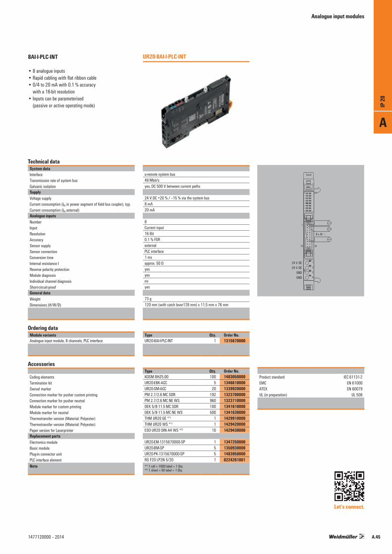
Analogue input modules
Technical dataSystem dataInterfaceTransmission rate of system busGalvanic isolationSupplyVoltage supplyCurrent consumption (IIN in power segment of field bus coupler), typ.Current consumption (IIN external)Analogue inputsNumberInputResolutionAccuracySensor supplySensor connectionConversion timeInternal resistance IReverse polarity protectionModule diagnosisIndividual channel diagnosisShort-circuit-proofGeneral dataWeightDimensions (H/W/D)
Ordering dataModule variantsAnalogue input module, 8 channels, PLC interface
Accessories
Coding elementsTermination kitSwivel markerConnection marker for pusher custom printingConnection marker for pusher neutralModule marker for custom printingModule marker for neutralThermotransfer version (Material: Polyester)Thermotransfer version (Material: Polyester)Paper version for LaserprinterReplacement partsElectronics moduleBasic modulePlug-in connector unitPLC interface elementNote
u-remote system bus48 Mbit/syes, DC 500 V between current paths
24 V DC +20 % / –15 % via the system bus8 mA20 mA
8Current input16 Bit0.1 % FSRexternalPLC interface1 msapprox. 50 Ωyesyesnoyes
73 g120 mm (with catch lever128 mm) x 11,5 mm x 76 mm
Type Qty. Order No.UR20-8AI-I-PLC-INT 1 1315670000
Type Qty. Order No.KOSM BHZ5.00 100 1483050000UR20-EBK-ACC 5 1346610000UR20-SM-ACC 20 1339920000PM 2.7/2.6 MC SDR 192 1323700000PM 2.7/2.6 MC NE WS 960 1323710000DEK 5/8-11.5 MC SDR 100 1341610000DEK 5/8-11.5 MC NE WS 500 1341630000THM UR20 GE *1) 1 1429910000THM UR20 WS *1) 1 1429420000ESO UR20 DIN A4 WS *2) 10 1429430000
UR20-EM-1315670000-SP 1 1347250000UR20-BM-SP 5 1350930000UR20-PK-1315670000-SP 5 1483950000RS F20 LP2N 5/20 1 0224261001*1) 1 roll = 1000 label = 1 Qty.*2) 1 sheet = 60 label = 1 Qty.
UR20-8AI-I-PLC-INT8AI-I-PLC-INT
• 8 analogue inputs• Rapid cabling with flat ribbon cable• 0/4 to 20 mA with 0.1 % accuracy
with a 16-bit resolution• Inputs can be parameterised
(passive or active operating mode)
Product standard IEC 61131-2 EMC EN 61000 ATEX EN 60079 UL (in preparation) UL 508
Let’s connect.
. . .
42
1
3
4
8AI·I
01234567
2019
1
24 V DC24 V DC
GNDGND
8 x AI
A
IP 20
A.451477120000 – 2014

Temperature modules
The recording of resistance temperature and thermocoupler sensors is indispensable for many applications. The 4-channel input modules from Weidmüller are designed for all common thermal elements and resistance temperature sensors. With an accuracy of 0.2 % of the measurement range end value and a resolution of 16 bits, cable breaks and instances of the limit value being exceeded or falling below are detected by means of individual channel diagnosis. Additional features such as an automatic 50-Hz to 60-Hz suppression or external as well as internal cold-junction compensation, as are available with the TC module, round off the scope of function.
The module electronics supply the connected sensors from the input current path (UIN).
Temperature modulesAvailable for TC and RTD; 16-bit resolution; 50/60 Hz suppression
UR20-4AI-TC-DIAG block diagram example
MUX
CJC_1 + TC_1 +TC_1 –CJC_1 –
CJC_0 + TC_0 +TC_0 –CJC_0 –
CJC_2+ TC_2 +TC_2 –CJC_2 –
CJC_3 + TC_3 +TC_3 –CJC_3 –
1
2
3
4
DC
DC
µC µC
CJCIntern
System-bus
USYS
UIN
UOUTUR20 4AI-TC-DIAG
A
D
A
IP 20
A.46 1477120000 – 2014
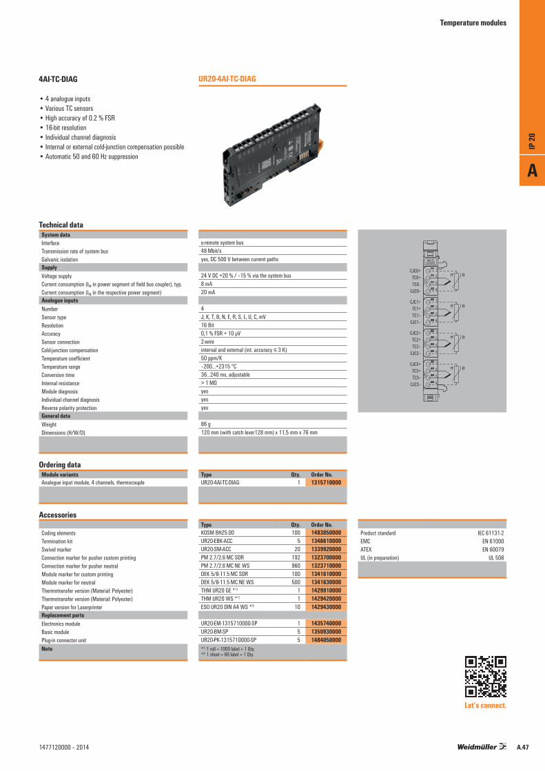
Temperature modules
Technical dataSystem dataInterfaceTransmission rate of system busGalvanic isolationSupplyVoltage supplyCurrent consumption (IIN in power segment of field bus coupler), typ.Current consumption (IIN in the respective power segment)Analogue inputsNumberSensor typeResolutionAccuracySensor connectionCold-junction compensationTemperature coefficientTemperature rangeConversion timeInternal resistanceModule diagnosisIndividual channel diagnosisReverse polarity protectionGeneral dataWeightDimensions (H/W/D)
Ordering dataModule variantsAnalogue input module, 4 channels, thermocouple
Accessories
Coding elementsTermination kitSwivel markerConnection marker for pusher custom printingConnection marker for pusher neutralModule marker for custom printingModule marker for neutralThermotransfer version (Material: Polyester)Thermotransfer version (Material: Polyester)Paper version for LaserprinterReplacement partsElectronics moduleBasic modulePlug-in connector unitNote
u-remote system bus48 Mbit/syes, DC 500 V between current paths
24 V DC +20 % / –15 % via the system bus8 mA20 mA
4J, K, T, B, N, E, R, S, L, U, C, mV16 Bit0,1 % FSR + 10 μV2-wireinternal and external (int. accuracy ≤ 3 K)50 ppm/K –200…+2315 °C36...240 ms, adjustable> 1 MΩyesyesyes
86 g120 mm (with catch lever128 mm) x 11,5 mm x 76 mm
Type Qty. Order No.UR20-4AI-TC-DIAG 1 1315710000
Type Qty. Order No.KOSM BHZ5.00 100 1483050000UR20-EBK-ACC 5 1346610000UR20-SM-ACC 20 1339920000PM 2.7/2.6 MC SDR 192 1323700000PM 2.7/2.6 MC NE WS 960 1323710000DEK 5/8-11.5 MC SDR 100 1341610000DEK 5/8-11.5 MC NE WS 500 1341630000THM UR20 GE *1) 1 1429910000THM UR20 WS *1) 1 1429420000ESO UR20 DIN A4 WS *2) 10 1429430000
UR20-EM-1315710000-SP 1 1435740000UR20-BM-SP 5 1350930000UR20-PK-1315710000-SP 5 1484050000*1) 1 roll = 1000 label = 1 Qty.*2) 1 sheet = 60 label = 1 Qty.
UR20-4AI-TC-DIAG4AI-TC-DIAG
• 4 analogue inputs• Various TC sensors• High accuracy of 0.2 % FSR• 16-bit resolution • Individual channel diagnosis• Internal or external cold-junction compensation possible• Automatic 50 and 60 Hz suppression
Product standard IEC 61131-2 EMC EN 61000 ATEX EN 60079 UL (in preparation) UL 508
Let’s connect.
1
2
3
4
2
1
3
4
1
2
3
4
2
4
3
1
2
4
3
1
4AI·TC
J
J
J
J
CJC0+TC0+TC0–
CJC0–
CJC1+TC1+TC1–
CJC1–
CJC2+TC2+TC2–
CJC2–
CJC3+TC3+TC3–
CJC3–
A
IP 20
A.471477120000 – 2014
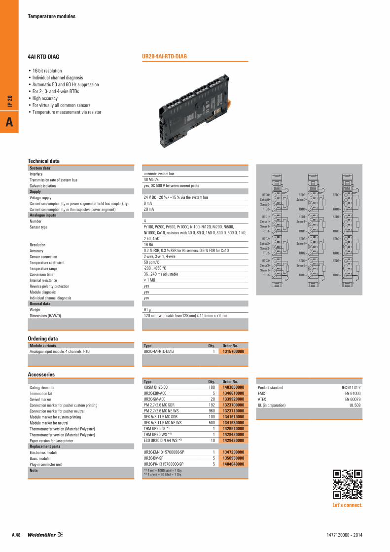
Temperature modules
Technical dataSystem dataInterfaceTransmission rate of system busGalvanic isolationSupplyVoltage supplyCurrent consumption (IIN in power segment of field bus coupler), typ.Current consumption (IIN in the respective power segment)Analogue inputsNumberSensor type
ResolutionAccuracySensor connectionTemperature coefficientTemperature rangeConversion timeInternal resistanceReverse polarity protectionModule diagnosisIndividual channel diagnosisGeneral dataWeightDimensions (H/W/D)
Ordering dataModule variantsAnalogue input module, 4 channels, RTD
Accessories
Coding elementsTermination kitSwivel markerConnection marker for pusher custom printingConnection marker for pusher neutralModule marker for custom printingModule marker for neutralThermotransfer version (Material: Polyester)Thermotransfer version (Material: Polyester)Paper version for LaserprinterReplacement partsElectronics moduleBasic modulePlug-in connector unitNote
u-remote system bus48 Mbit/syes, DC 500 V between current paths
24 V DC +20 % / –15 % via the system bus8 mA20 mA
4Pt100, Pt200, Pt500, Pt1000, Ni100, Ni120, Ni200, Ni500, Ni1000, Cu10, resistors with 40 Ω, 80 Ω, 150 Ω, 300 Ω, 500 Ω, 1 kΩ, 2 kΩ, 4 kΩ16 Bit0.2 % FSR, 0.3 % FSR for Ni sensors, 0.6 % FSR for Cu102-wire, 3-wire, 4-wire50 ppm/K-200...+850 °C36…240 ms adjustable> 1 MΩyesyesyes
91 g120 mm (with catch lever128 mm) x 11,5 mm x 76 mm
Type Qty. Order No.UR20-4AI-RTD-DIAG 1 1315700000
Type Qty. Order No.KOSM BHZ5.00 100 1483050000UR20-EBK-ACC 5 1346610000UR20-SM-ACC 20 1339920000PM 2.7/2.6 MC SDR 192 1323700000PM 2.7/2.6 MC NE WS 960 1323710000DEK 5/8-11.5 MC SDR 100 1341610000DEK 5/8-11.5 MC NE WS 500 1341630000THM UR20 GE *1) 1 1429910000THM UR20 WS *1) 1 1429420000ESO UR20 DIN A4 WS *2) 10 1429430000
UR20-EM-1315700000-SP 1 1347290000UR20-BM-SP 5 1350930000UR20-PK-1315700000-SP 5 1484040000*1) 1 roll = 1000 label = 1 Qty.*2) 1 sheet = 60 label = 1 Qty.
UR20-4AI-RTD-DIAG4AI-RTD-DIAG
• 16-bit resolution • Individual channel diagnosis• Automatic 50 and 60 Hz suppression• For 2-, 3- and 4-wire RTDs• High accuracy• For virtually all common sensors• Temperature measurement via resistor
Product standard IEC 61131-2 EMC EN 61000 ATEX EN 60079 UL (in preparation) UL 508
Let’s connect.
1
2
3
4
2
1
3
4
1
2
3
4
2
4
3
1
2
4
3
1
4AI·RTD
1
2
3
4
2
1
3
4
1
2
3
4
2
4
3
1
2
4
3
1
4AI·RTD
1
2
3
4
2
1
3
4
1
2
3
4
2
4
3
1
2
4
3
1
4AI·RTD
RTD0+Sense0+Sense0–
RTD0–
RTD1+Sense1+Sense1–
RTD1–
RTD2+Sense2+Sense2–
RTD2–
RTD3+Sense3+Sense3–
RTD3– RTD3–
RTD3+
RTD2–
RTD2+
RTD1–
RTD1+
RTD0–
RTD0+
RTD3–
RTD3+
RTD2–
RTD2+
RTD1–
RTD1+
RTD0–
RTD0+
Sense3+
Sense2+
Sense1+
Sense0+
A
IP 20
A.48 1477120000 – 2014

A
IP 20
A.491477120000 – 2014

Analogue output module
The analogue output module controls up to 4 analogue actuators with +/-10 V, +/-5 V, 0...10 V, 0...5 V, 2...10 V, 1...5 V, 0...20 mA or 4...20 mA with an accuracy of 0.05 % of the measurement range end value. An actuator with 2- or 4-wire technology can be connected to each plug-in connector. The outputs are defined channel by channel using parameterisation. A separate status LED is assigned to each channel.
The outputs are supplied from the output current path (UOUT).
Analogue output module2- or 4-wire connection; 16-bit resolution; 4 outputs
Block diagram UR20-4AO-UI-16
16 Bit
System-bus
USYS
UIN
UOUT
µC µCA
D
A
D
A
D
A
D
DC
DC
UR20 4AO-UI-16
AO1 + Sense1 +Sense1 –AO1 –
AO0 + Sense0 +Sense0 –AO0 –
AO2 + Sense2 +Sense2 –AO2 –
AO3 + Sense3 +Sense3 –AO3 –
1
2
3
4
A
IP 20
A.50 1477120000 – 2014

Analogue output module
Technical dataSystem dataInterfaceTransmission rate of system busGalvanic isolationSupplyVoltage supplyCurrent consumption (IIN in power segment of field bus coupler), typ.Current consumption (IOUT in the respective power segment)Analogue outputsNumberOutput
Response timeResolutionAccuracyLoad resistance, voltage output
Load resistance, current outputActuator connection
Temperature coefficientMax. error between T min. and T max.MonotonicityCrosstalk between the channelsRepeat accuracyOutput wavinessModule diagnosisReplacement valuesGeneral dataWeightDimensions (H/W/D)
Ordering dataModule variantsAnalogue output module, 4 channels, 16 Bit
Accessories
Coding elementsTermination kitSwivel markerConnection marker for pusher custom printingConnection marker for pusher neutralModule marker for custom printingModule marker for neutralThermotransfer version (Material: Polyester)Thermotransfer version (Material: Polyester)Paper version for LaserprinterReplacement partsElectronics moduleBasic modulePlug-in connector unitNote
u-remote system bus48 Mbit/syes, DC 500 V between current paths
24 V DC +20 % / –15 % via the system bus8 mA85 mA
41. Voltage (0…5 V, 0…10 V, 1…5 V, 2…10 V, ±5 V)2. Current (0…20 mA or 4…20 mA)1 ms for 4 channels16 Bit±0.1 % FSR max., 0.05 % FSR typ.> 1 kΩ (at > 50 °C ambient temperature max. sum of sensor current = 25 mA)< 600 Ω2-wire (current and voltage),3- and 4-wire (voltage), (2-wire: automatic detection)20 ppm Voltage / 31 ppm current measurement / °K220 ppm FSRyes0,001 % FSR< 1 mV effectivelymax. 0.001 %yesyes
83 g120 mm (with catch lever128 mm) x 11,5 mm x 76 mm
Type Qty. Order No.UR20-4AO-UI-16 1 1315680000
Type Qty. Order No.KOSM BHZ5.00 100 1483050000UR20-EBK-ACC 5 1346610000UR20-SM-ACC 20 1339920000PM 2.7/2.6 MC SDR 192 1323700000PM 2.7/2.6 MC NE WS 960 1323710000DEK 5/8-11.5 MC SDR 100 1341610000DEK 5/8-11.5 MC NE WS 500 1341630000THM UR20 GE *1) 1 1429910000THM UR20 WS *1) 1 1429420000ESO UR20 DIN A4 WS *2) 10 1429430000
UR20-EM-1315680000-SP 1 1347270000UR20-BM-SP 5 1350930000UR20-PK-1315680000-SP 5 1484070000*1) 1 roll = 1000 label = 1 Qty.*2) 1 sheet = 60 label = 1 Qty.
UR20-4AO-UI-164AO-UI-16
• 4 analogue outputs• Outputs can be parameterised by channel
(voltage, current)• 16-bit resolution• 2- and 4-wire connection• Accuracy typ. 0.05 % FSR• Replacement values can be set per channel• Non reactiv• Short-circuit-proof
Product standard IEC 61131-2 EMC EN 61000 ATEX EN 60079 UL (in preparation) UL 508
Let’s connect.
1
2
3
4
2
1
3
4
1
2
3
4
2
4
3
1
2
4
3
1
4AO-UI
1
2
3
4
2
1
3
4
1
2
3
4
2
4
3
1
2
4
3
1
4AO-UI
AO0+Sense0+Sense0–
AO0–
AO1+Sense1+Sense1–
AO1–
AO2+Sense2+Sense2–
AO2–
AO3+Sense3+Sense3–
AO3– AO3–
AO3+
AO2–
AO2+
AO1–
AO1+
AO0–
AO0+
A
IP 20
A.511477120000 – 2014
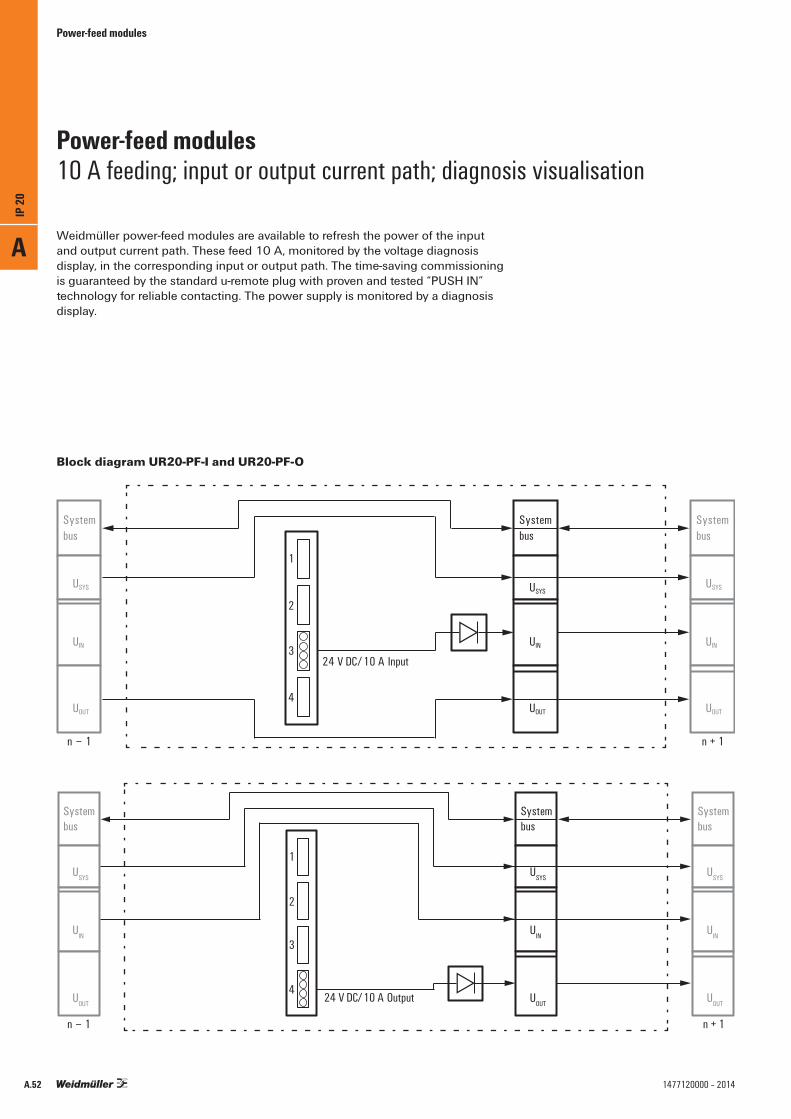
Power-feed modules
Weidmüller power-feed modules are available to refresh the power of the input and output current path. These feed 10 A, monitored by the voltage diagnosis display, in the corresponding input or output path. The time-saving commissioning is guaranteed by the standard u-remote plug with proven and tested “PUSH IN” technology for reliable contacting. The power supply is monitored by a diagnosis display.
Power-feed modules10 A feeding; input or output current path; diagnosis visualisation
Block diagram UR20-PF-I and UR20-PF-O
A
IP 20
A.52 1477120000 – 2014
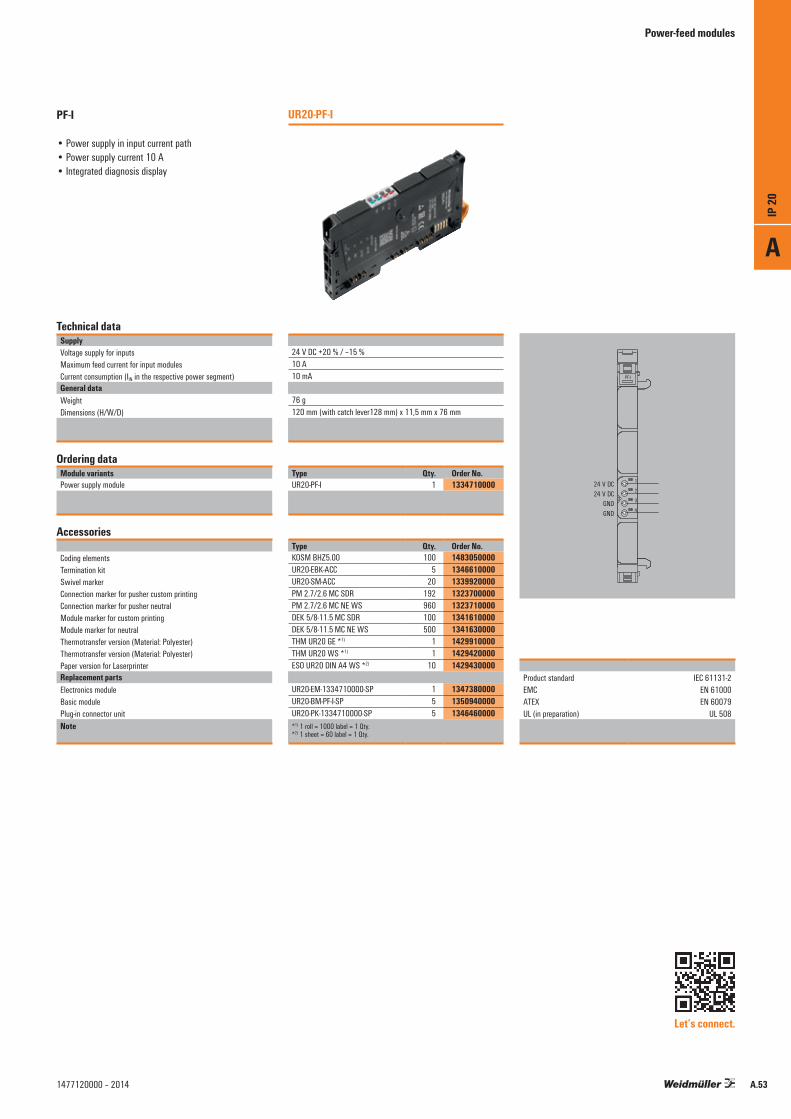
Power-feed modules
Technical dataSupplyVoltage supply for inputsMaximum feed current for input modulesCurrent consumption (IIN in the respective power segment)General dataWeightDimensions (H/W/D)
Ordering dataModule variantsPower supply module
Accessories
Coding elementsTermination kitSwivel markerConnection marker for pusher custom printingConnection marker for pusher neutralModule marker for custom printingModule marker for neutralThermotransfer version (Material: Polyester)Thermotransfer version (Material: Polyester)Paper version for LaserprinterReplacement partsElectronics moduleBasic modulePlug-in connector unitNote
24 V DC +20 % / –15 %10 A10 mA
76 g120 mm (with catch lever128 mm) x 11,5 mm x 76 mm
Type Qty. Order No.UR20-PF-I 1 1334710000
Type Qty. Order No.KOSM BHZ5.00 100 1483050000UR20-EBK-ACC 5 1346610000UR20-SM-ACC 20 1339920000PM 2.7/2.6 MC SDR 192 1323700000PM 2.7/2.6 MC NE WS 960 1323710000DEK 5/8-11.5 MC SDR 100 1341610000DEK 5/8-11.5 MC NE WS 500 1341630000THM UR20 GE *1) 1 1429910000THM UR20 WS *1) 1 1429420000ESO UR20 DIN A4 WS *2) 10 1429430000
UR20-EM-1334710000-SP 1 1347380000UR20-BM-PF-I-SP 5 1350940000UR20-PK-1334710000-SP 5 1346460000*1) 1 roll = 1000 label = 1 Qty.*2) 1 sheet = 60 label = 1 Qty.
UR20-PF-IPF-I
• Power supply in input current path• Power supply current 10 A• Integrated diagnosis display
Product standard IEC 61131-2 EMC EN 61000 ATEX EN 60079 UL (in preparation) UL 508
PF-I
32
4
3
124 V DC24 V DC
GNDGND
Let’s connect.
A
IP 20
A.531477120000 – 2014

Power-feed modules
Technical dataSupplyVoltage supply for outputsMaximum feed current for output modulesCurrent consumption (IOUT in the respective power segment)General dataWeightDimensions (H/W/D)
Ordering dataModule variantsPower supply module
Accessories
Coding elementsTermination kitSwivel markerConnection marker for pusher custom printingConnection marker for pusher neutralModule marker for custom printingModule marker for neutralThermotransfer version (Material: Polyester)Thermotransfer version (Material: Polyester)Paper version for LaserprinterReplacement partsElectronics moduleBasic modulePlug-in connector unitNote
24 V DC +20 % / –15 %10 A10 mA
76 g120 mm (with catch lever128 mm) x 11,5 mm x 76 mm
Type Qty. Order No.UR20-PF-O 1 1334740000
Type Qty. Order No.KOSM BHZ5.00 100 1483050000UR20-EBK-ACC 5 1346610000UR20-SM-ACC 20 1339920000PM 2.7/2.6 MC SDR 192 1323700000PM 2.7/2.6 MC NE WS 960 1323710000DEK 5/8-11.5 MC SDR 100 1341610000DEK 5/8-11.5 MC NE WS 500 1341630000THM UR20 GE *1) 1 1429910000THM UR20 WS *1) 1 1429420000ESO UR20 DIN A4 WS *2) 10 1429430000
UR20-EM-1334740000-SP 1 1347420000UR20-BM-PF-O-SP 5 1350950000UR20-PK-1334740000-SP 5 1346480000*1) 1 roll = 1000 label = 1 Qty.*2) 1 sheet = 60 label = 1 Qty.
UR20-PF-OPF-O
• Power supply in output current path• Power supply current 10 A• Integrated diagnosis display
Product standard IEC 61131-2 EMC EN 61000 ATEX EN 60079 UL (in preparation) UL 508
PF-O
42
4
3
124 V DC24 V DC
GNDGND
Let’s connect.
A
IP 20
A.54 1477120000 – 2014

A
IP 20
A.551477120000 – 2014

Modules for functional safety
Safety technology is of central importance in the automation industry and machine construction. When attempting to reduce risks and avoid putting people and the environment in danger, you need solutions which satisfy stringent requirements and statutory specifications. The safety modules of the u-remote system have key features such as emergency stop circuits and wire breakage/short-circuit detection. They satisfy all SIL 3 requirements according to IEC 62061 and EN ISO 13849-1, Category 4, PL e and support the safe operation of your system.
By safely shutting down the downstream output modules, the safety modules attain maximum safety with optimum control. All input sensors are independently supplied via separate voltage paths and report the current machine status to the control unit. The restart is either performed in manual mode or using the autostart function.Safety modules from Weidmüller also cut maintenance and service times and improve your response times in an emergency – thanks to a concept of maximum transparency, e.g. using OSSD output.
The module electronics supply the connected actuators from the output current path (UOUT).
Modules for functional safetySIL 3; OSSD output; wire breakage and short-circuit detection
EmergencyStop
Start
System-bus
USYS
UIN
UOUT
µC
µC µC
24 V DC⎽OSSD
GND
Safe
DC
DC
1
2
3
4
Start1Start2Autostart1Autostart2
Safety0.0Safety0.1Safety0.2Safety0.3
24 V DC_OSSD24 V DC InputGND
Type 3
UR20 PF-O-1DI-SIL
UR20-PF-O-1DI-SIL block diagram example
A
IP 20
A.56 1477120000 – 2014
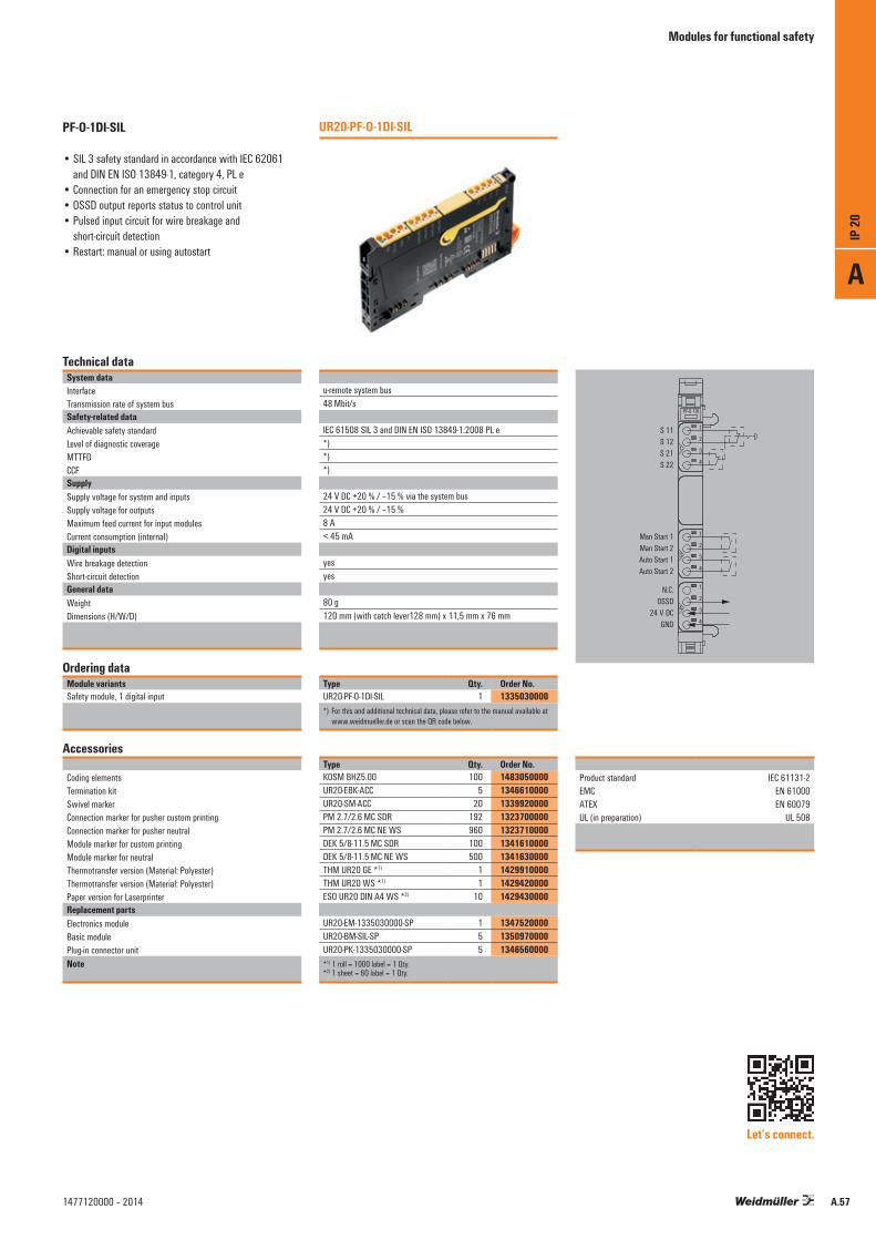
Modules for functional safety
Technical dataSystem dataInterfaceTransmission rate of system busSafety-related dataAchievable safety standardLevel of diagnostic coverageMTTFDCCFSupplySupply voltage for system and inputsSupply voltage for outputsMaximum feed current for input modulesCurrent consumption (internal)Digital inputsWire breakage detectionShort-circuit detectionGeneral dataWeightDimensions (H/W/D)
Ordering dataModule variantsSafety module, 1 digital input
Accessories
Coding elementsTermination kitSwivel markerConnection marker for pusher custom printingConnection marker for pusher neutralModule marker for custom printingModule marker for neutralThermotransfer version (Material: Polyester)Thermotransfer version (Material: Polyester)Paper version for LaserprinterReplacement partsElectronics moduleBasic modulePlug-in connector unitNote
u-remote system bus48 Mbit/s
IEC 61508 SIL 3 and DIN EN ISO 13849-1:2008 PL e*)*)*)
24 V DC +20 % / –15 % via the system bus24 V DC +20 % / –15 %8 A< 45 mA
yesyes
80 g120 mm (with catch lever128 mm) x 11,5 mm x 76 mm
Type Qty. Order No.UR20-PF-O-1DI-SIL 1 1335030000*) For this and additional technical data, please refer to the manual available at
www.weidmueller.de or scan the QR code below.
Type Qty. Order No.KOSM BHZ5.00 100 1483050000UR20-EBK-ACC 5 1346610000UR20-SM-ACC 20 1339920000PM 2.7/2.6 MC SDR 192 1323700000PM 2.7/2.6 MC NE WS 960 1323710000DEK 5/8-11.5 MC SDR 100 1341610000DEK 5/8-11.5 MC NE WS 500 1341630000THM UR20 GE *1) 1 1429910000THM UR20 WS *1) 1 1429420000ESO UR20 DIN A4 WS *2) 10 1429430000
UR20-EM-1335030000-SP 1 1347520000UR20-BM-SIL-SP 5 1350970000UR20-PK-1335030000-SP 5 1346560000*1) 1 roll = 1000 label = 1 Qty.*2) 1 sheet = 60 label = 1 Qty.
UR20-PF-O-1DI-SILPF-O-1DI-SIL
• SIL 3 safety standard in accordance with IEC 62061 and DIN EN ISO 13849-1, category 4, PL e
• Connection for an emergency stop circuit• OSSD output reports status to control unit• Pulsed input circuit for wire breakage and
short-circuit detection• Restart: manual or using autostart
Product standard IEC 61131-2 EMC EN 61000 ATEX EN 60079 UL (in preparation) UL 508
Let’s connect.
1
3
4
2
1
3
4
2
4
3
1
2
4
3
1
PF-O 1DI
S 11S 12S 21S 22
Man Start 1Man Start 2Auto Start 1Auto Start 2
N.C.OSSD
24 V DCGND
A
IP 20
A.571477120000 – 2014
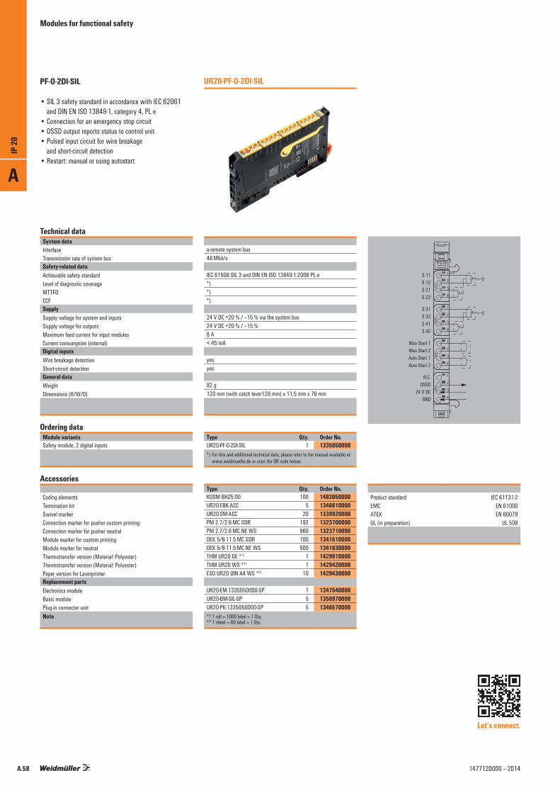
Modules for functional safety
Technical dataSystem dataInterfaceTransmission rate of system busSafety-related dataAchievable safety standardLevel of diagnostic coverageMTTFDCCFSupplySupply voltage for system and inputsSupply voltage for outputsMaximum feed current for input modulesCurrent consumption (internal)Digital inputsWire breakage detectionShort-circuit detectionGeneral dataWeightDimensions (H/W/D)
Ordering dataModule variantsSafety module, 2 digital inputs
Accessories
Coding elementsTermination kitSwivel markerConnection marker for pusher custom printingConnection marker for pusher neutralModule marker for custom printingModule marker for neutralThermotransfer version (Material: Polyester)Thermotransfer version (Material: Polyester)Paper version for LaserprinterReplacement partsElectronics moduleBasic modulePlug-in connector unitNote
u-remote system bus48 Mbit/s
IEC 61508 SIL 3 and DIN EN ISO 13849-1:2008 PL e*)*)*)
24 V DC +20 % / –15 % via the system bus24 V DC +20 % / –15 %8 A< 45 mA
yesyes
82 g120 mm (with catch lever128 mm) x 11,5 mm x 76 mm
Type Qty. Order No.UR20-PF-O-2DI-SIL 1 1335050000*) For this and additional technical data, please refer to the manual available at
www.weidmueller.de or scan the QR code below.
Type Qty. Order No.KOSM BHZ5.00 100 1483050000UR20-EBK-ACC 5 1346610000UR20-SM-ACC 20 1339920000PM 2.7/2.6 MC SDR 192 1323700000PM 2.7/2.6 MC NE WS 960 1323710000DEK 5/8-11.5 MC SDR 100 1341610000DEK 5/8-11.5 MC NE WS 500 1341630000THM UR20 GE *1) 1 1429910000THM UR20 WS *1) 1 1429420000ESO UR20 DIN A4 WS *2) 10 1429430000
UR20-EM-1335050000-SP 1 1347540000UR20-BM-SIL-SP 5 1350970000UR20-PK-1335050000-SP 5 1346570000*1) 1 roll = 1000 label = 1 Qty.*2) 1 sheet = 60 label = 1 Qty.
UR20-PF-O-2DI-SILPF-O-2DI-SIL
• SIL 3 safety standard in accordance with IEC 62061 and DIN EN ISO 13849-1, category 4, PL e
• Connection for an emergency stop circuit• OSSD output reports status to control unit• Pulsed input circuit for wire breakage
and short-circuit detection• Restart: manual or using autostart
Product standard IEC 61131-2 EMC EN 61000 ATEX EN 60079 UL (in preparation) UL 508
Let’s connect.
1
2
3
4
2
1
3
4
1
2
3
4
2
4
3
1
2
4
3
1
PF-O 2DI
S 11S 12S 21S 22
S 31S 32S 41S 42
Man Start 1Man Start 2Auto Start 1Auto Start 2
N.C.OSSD
24 V DCGND
A
IP 20
A.58 1477120000 – 2014
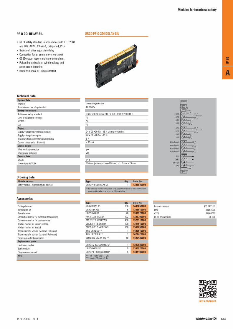
Modules for functional safety
Technical dataSystem dataInterfaceTransmission rate of system busSafety-related dataAchievable safety standardLevel of diagnostic coverageMTTFDCCFSupplySupply voltage for system and inputsSupply voltage for outputsMaximum feed current for input modulesCurrent consumption (internal)Digital inputsWire breakage detectionShort-circuit detectionGeneral dataWeightDimensions (H/W/D)
Ordering dataModule variantsSafety module, 2 digital inputs, delayed
Accessories
Coding elementsTermination kitSwivel markerConnection marker for pusher custom printingConnection marker for pusher neutralModule marker for custom printingModule marker for neutralThermotransfer version (Material: Polyester)Thermotransfer version (Material: Polyester)Paper version for LaserprinterReplacement partsElectronics moduleBasic modulePlug-in connector unitNote
u-remote system bus48 Mbit/s
IEC 61508 SIL 3 and DIN EN ISO 13849-1:2008 PL e*)*)*)
24 V DC +20 % / –15 % via the system bus24 V DC +20 % / –15 %8 A< 45 mA
yesyes
84 g120 mm (with catch lever128 mm) x 11,5 mm x 76 mm
Type Qty. Order No.UR20-PF-O-2DI-DELAY-SIL 1 1335040000*) For this and additional technical data, please refer to the manual available at
www.weidmueller.de or scan the QR code below.
Type Qty. Order No.KOSM BHZ5.00 100 1483050000UR20-EBK-ACC 5 1346610000UR20-SM-ACC 20 1339920000PM 2.7/2.6 MC SDR 192 1323700000PM 2.7/2.6 MC NE WS 960 1323710000DEK 5/8-11.5 MC SDR 100 1341610000DEK 5/8-11.5 MC NE WS 500 1341630000THM UR20 GE *1) 1 1429910000THM UR20 WS *1) 1 1429420000ESO UR20 DIN A4 WS *2) 10 1429430000
UR20-EM-1335040000-SP 1 1347530000UR20-BM-SIL-SP 5 1350970000UR20-PK-1335040000-SP 5 1484100000*1) 1 roll = 1000 label = 1 Qty.*2) 1 sheet = 60 label = 1 Qty.
UR20-PF-O-2DI-DELAY-SILPF-O-2DI-DELAY-SIL
• SIL 3 safety standard in accordance with IEC 62061 and DIN EN ISO 13849-1, category 4, PL e
• Switch-off after adjustable delay• Connection for an emergency stop circuit• OSSD output reports status to control unit • Pulsed input circuit for wire breakage and
short-circuit detection• Restart: manual or using autostart
Product standard IEC 61131-2 EMC EN 61000 ATEX EN 60079 UL (in preparation) UL 508
Let’s connect.
1
2
3
4
2
1
3
4
1
2
3
4
2
4
3
1
2
4
3
1
PF-O 2DI
S 11S 12S 21S 22
S 31S 32S 41S 42
Man Start 1Man Start 2Auto Start 1Auto Start 2
SS1OSSD
24 V DCGND
A
IP 20
A.591477120000 – 2014

Accessories
A wide range of accessory modules is provided for the individual requirements of machine and plant construction. Various potential distribution modules are available for directly supplying sensors with 2-wire, 3-wire or 3-wire+FE connection technology from the remote I/O system. These provide 16 “PUSH IN” potential points and supply your application with each auxiliary potential available. An empty module, where the system bus and voltage supply are looped through, allows you to plan expansion slots in a system and to start these up without any interruptions if required.
AccessoriesPotential distribution modules; system accessories
UR20-16AUX-O block diagram example
24 V DC24 V DC24 V DC24 V DC
24 V DC24 V DC24 V DC24 V DC
24 V DC24 V DC24 V DC24 V DC
24 V DC24 V DC24 V DC24 V DC
System-bus
USYS
UIN
UOUT
24V DC⎽OUT
1
2
3
4
24 V DC_1••••••••••••••
24 V DC_16
UR20 16AUX-O
A
IP 20
A.60 1477120000 – 2014

Accessories
Technical dataSupplyVoltage supplyGeneral dataWeightDimensions (H/W/D)
Ordering dataModule variantsPotential distribution module
Accessories
Coding elementsTermination kitSwivel markerConnection marker for pusher custom printingConnection marker for pusher neutralModule marker for custom printingModule marker for neutralThermotransfer version (Material: Polyester)Thermotransfer version (Material: Polyester)Paper version for LaserprinterReplacement partsElectronics module
Basic modulePlug-in connector unit
Note
Product standard IEC 61131-2 EMC EN 61000 ATEX EN 60079 UL (in preparation) UL 508
24 V DC +20 % / –15 % via Input- or output path / FE
84 g120 mm (with catch lever128 mm) x 11,5 mm x 76 mm
Type Qty. Order No.UR20-16AUX-I 1 1334770000UR20-16AUX-O 1 1334780000UR20-16AUX-FE 1 1334790000UR20-16AUX-GND-I 1 1334800000UR20-16AUX-GND-O 1 1334810000
Type Qty. Order No.KOSM BHZ5.00 100 1483050000UR20-EBK-ACC 5 1346610000UR20-SM-ACC 20 1339920000PM 2.7/2.6 MC SDR 192 1323700000PM 2.7/2.6 MC NE WS 960 1323710000DEK 5/8-11.5 MC SDR 100 1341610000DEK 5/8-11.5 MC NE WS 500 1341630000THM UR20 GE *1) 1 1429910000THM UR20 WS *1) 1 1429420000ESO UR20 DIN A4 WS *2) 10 1429430000
UR20-EM-1334770000-SP 1 1347450000UR20-EM-1334780000-SP 1 1347470000UR20-EM-1334790000-SP 1 1347480000UR20-EM-1334800000-SP 1 1347490000UR20-EM-1334810000-SP 1 1347500000UR20-BM-SP 5 1350930000UR20-PK-1334770000-SP 5 1346450000UR20-PK-1334790000-SP 5 1346490000UR20-PK-1334800000-SP 5 1346470000UR20-PK-1334780000-SP 5 1484080000UR20-PK-1334810000-SP 5 1484090000*1) 1 roll = 1000 label = 1 Qty.*2) 1 sheet = 60 label = 1 Qty.
UR20-16AUXAUX
• Distribution of the various potentials• Actuator and sensor supply• 16 “PUSH IN” potential contacts
1
2
3
4
2
1
3
4
1
2
3
4
2
4
3
1
2
4
3
1
AUX-O
24 V DC24 V DC24 V DC24 V DC
24 V DC24 V DC24 V DC24 V DC
24 V DC24 V DC24 V DC24 V DC
24 V DC24 V DC24 V DC24 V DC
Let’s connect. Let’s connect. Let’s connect. Let’s connect. Let’s connect.
16AUX-I 16AUX-FE16AUX-O 16AUX-GND-I 16AUX GND-O
A
IP 20
A.611477120000 – 2014

Accessories
Technical dataGeneral dataWeightDimensions (H/W/D)
Ordering dataModule variantsEmpty module
Accessories
Coding elementsTermination kitSwivel markerConnection marker for pusher custom printingConnection marker for pusher neutralModule marker for custom printingModule marker for neutralThermotransfer version (Material: Polyester)Thermotransfer version (Material: Polyester)Paper version for LaserprinterReplacement partsElectronics moduleBasic modulePlug-in connector unitNote
Ordering dataModule variantsTermination kit
70 g120 mm (with catch lever128 mm) x 11,5 mm x 76 mm
Type Qty. Order No.UR20-ES 1 1315770000
Type Qty. Order No.KOSM BHZ5.00 100 1483050000UR20-EBK-ACC 5 1346610000UR20-SM-ACC 20 1339920000PM 2.7/2.6 MC SDR 192 1323700000PM 2.7/2.6 MC NE WS 960 1323710000DEK 5/8-11.5 MC SDR 100 1341610000DEK 5/8-11.5 MC NE WS 500 1341630000THM UR20 GE *1) 1 1429910000THM UR20 WS *1) 1 1429420000ESO UR20 DIN A4 WS *2) 10 1429430000
UR20-EM-1315770000-SP 1 1347370000UR20-BM-SP 5 1350930000UR20-PK-1315770000-SP 5 1346510000*1) 1 roll = 1000 label = 1 Qty.*2) 1 sheet = 60 label = 1 Qty.
Type Qty. Order No.UR20-EBK-ACC 5 1346610000
UR20-ES
UR20-EBK
Empty module
• Forwarding of system bus and voltage paths• Space for subsequent expansion• Basis for all I/O modules
Termination kit
• Includes an end plate and two end brackets
Product standard IEC 61131-2 EMC EN 61000 ATEX EN 60079 UL (in preparation) UL 508
Let’s connect.
A
IP 20
A.62 1477120000 – 2014

Accessories
Individual components
It goes without saying that Weidmüller also allows you to swap defective parts. The three-part modules can therefore be ordered as individual components.
Ordering data spare partsProduct Best.-Nr.UR20-FBC-PB-DP 1334870000UR20-FBC-PN-IRT 1334880000UR20-FBC-EC 1334910000UR20-FBC-MOD 1334930000UR20-4DI-P 1315170000UR20-8DI-P-2W 1315180000UR20-8DI-P-3W 1394400000UR20-16DI-P 1315200000UR20-16DI-P-PLC-INT 1315210000UR20-2DI-P-TS 1460140000UR20-4DI-P-TS 1460150000UR20-4DO-P 1315220000UR20-4DO-P-2A 1315230000UR20-4DO-PN-2A 1394420000UR20-8DO-P 1315240000UR20-16DO-P 1315250000UR20-16DO-P-PLC-INT 1315270000UR20-4RO-SSR-255 1315540000UR20-4RO-CO-255 1315550000UR20-1CNT-100-1DO 1315570000UR20-2CNT-100 1315590000UR20-2PWM-PN-0.5A 1315600000UR20-2PWM-PN-2A 1315610000UR20-4AI-UI-16 1315620000UR20-4AI-UI-12 1394390000UR20-8AI-I-PLC-INT 1315670000UR20-4AI-TC-DIAG 1315710000UR20-4AI-RTD-DIAG 1315700000UR20-4AO-UI-16 1315680000UR20-PF-I 1334710000UR20-PF-O 1334740000UR20-PF-O-1DI-SIL 1335030000UR20-PF-O-2DI-SIL 1335050000UR20-PF-O-2DI-DELAY-SIL 1335040000UR20-16AUX-I 1334770000UR20-16AUX-O 1334780000UR20-16AUX-FE 1334790000UR20-16AUX-GND-I 1334800000UR20-16AUX-GND-O 1334810000UR20-ES 1315770000Note
Plug-in connector unit Order No.UR20-PK-1334870000-SP 1361520000UR20-PK-1334880000-SP 1484120000UR20-PK-1334910000-SP 1484440000UR20-PK-1334930000-SP 1484130000UR20-PK-1315170000-SP 1346440000UR20-PK-1315180000-SP 1346430000UR20-PK-1394400000-SP 1411430000UR20-PK-1315200000-SP 1346400000UR20-PK-1315210000-SP 1346590000UR20-PK-1460140000-SP 1484110000UR20-PK-1460150000-SP 1484430000UR20-PK-1315220000-SP 1483960000UR20-PK-1315230000-SP 1483970000UR20-PK-1394420000-SP 1483980000UR20-PK-1315240000-SP 1346410000UR20-PK-1315250000-SP 1483990000UR20-PK-1315270000-SP 1483940000UR20-PK-1315540000-SP 1484000000UR20-PK-1315550000-SP 1346500000UR20-PK-1315570000-SP 1346520000UR20-PK-1315590000-SP 1346540000UR20-PK-1315600000-SP 1484010000UR20-PK-1315610000-SP 1346550000UR20-PK-1315620000-SP 1484020000UR20-PK-1394390000-SP 1484030000UR20-PK-1315670000-SP 1483950000UR20-PK-1315710000-SP 1484050000UR20-PK-1315700000-SP 1484040000UR20-PK-1315680000-SP 1484070000UR20-PK-1334710000-SP 1346460000UR20-PK-1334740000-SP 1346480000UR20-PK-1335030000-SP 1346560000UR20-PK-1335050000-SP 1346570000UR20-PK-1335040000-SP 1484100000UR20-PK-1334770000-SP 1346450000UR20-PK-1334780000-SP 1484080000UR20-PK-1334790000-SP 1346490000UR20-PK-1334800000-SP 1346470000UR20-PK-1334810000-SP 1484090000UR20-PK-1315770000-SP 1346510000All Plug-in connector units: Qty. = 5
Electronic module Order No.
UR20-EM-1315170000-SP 1346640000UR20-EM-1315080000-SP 1346650000UR20-EM-1394400000-SP 1434220000UR20-EM-1315200000-SP 1346680000UR20-EM-1315210000-SP 1346690000UR20-EM-1460140000-SP 1463690000UR20-EM-1460150000-SP 1463680000UR20-EM-1315220000-SP 1346700000UR20-EM-1315230000-SP 1346710000UR20-EM-1394420000-SP 1480950000UR20-EM-1315240000-SP 1346720000UR20-EM-1315250000-SP 1346730000UR20-EM-1315270000-SP 1346740000UR20-EM-1315540000-SP 1347120000UR20-EM-1315550000-SP 1347130000UR20-EM-1315570000-SP 1347140000UR20-EM-1315590000-SP 1347150000UR20-EM-1315600000-SP 1347180000UR20-EM-1315610000-SP 1347190000UR20-EM-1315620000-SP 1347200000UR20-EM-1394390000-SP 1434230000UR20-EM-1315670000-SP 1347250000UR20-EM-1315710000-SP 1435740000UR20-EM-1315700000-SP 1347290000UR20-EM-1315680000-SP 1347270000UR20-EM-1334710000-SP 1347370000UR20-EM-1334740000-SP 1347420000UR20-EM-1335030000-SP 1347520000UR20-EM-1335050000-SP 1347540000UR20-EM-1335040000-SP 1347530000UR20-EM-1334770000-SP 1347450000UR20-EM-1334780000-SP 1347470000UR20-EM-1334790000-SP 1347480000UR20-EM-1334800000-SP 1347490000UR20-EM-1334810000-SP 1347500000UR20-EM-1315770000-SP 1347370000All electronic modules: Qty. = 1
Basic module Order No.
UR20-BM-SP 1350930000UR20-BM-SP 1350930000UR20-BM-SP 1350930000UR20-BM-SP 1350930000UR20-BM-SP 1350930000UR20-BM-SP 1350930000UR20-BM-SP 1350930000UR20-BM-SP 1350930000UR20-BM-SP 1350930000UR20-BM-SP 1350930000UR20-BM-SP 1350930000UR20-BM-SP 1350930000UR20-BM-SP 1350930000UR20-BM-SP 1350930000UR20-BM-SP 1350930000UR20-BM-SP 1350930000UR20-BM-SP 1350930000UR20-BM-SP 1350930000UR20-BM-SP 1350930000UR20-BM-SP 1350930000UR20-BM-SP 1350930000UR20-BM-SP 1350930000UR20-BM-SP 1350930000UR20-BM-SP 1350930000UR20-BM-SP 1350930000UR20-BM-PF-I-SP 1350940000UR20-BM-PF-O-SP 1350950000UR20-BM-SIL-SP 1350970000UR20-BM-SIL-SP 1350970000UR20-BM-SIL-SP 1350970000UR20-BM-SP 1350930000UR20-BM-SP 1350930000UR20-BM-SP 1350930000UR20-BM-SP 1350930000UR20-BM-SP 1350930000UR20-BM-SP 1350930000All basic modules: Qty. = 5
A
IP 20
A.631477120000 – 2014

System overview
1. What field bus are you using?Bus Type Order No. PagePROFIBUS UR20-FBC-PB-DP 1334870000 A.9PROFINET UR20-FBC-PN-IRT 1334880000 A.11EtherCAT UR20-FBC-EC 1334910000 A.13Modbus UR20-FBC-MOD 1334930000 A.15
System overview
Below you will find assistance for putting together your system. Please note the maximum number of 64 active modules and the packaging units for the accessories! More detailed technical data and product descriptions can be found here in the catalogue in the corresponding chapter.
At the bottom right-hand side of this page, you will find assistance for supplying the current paths.
2. What signals do you want to process?Digital inputs Order No. PageUR20-4DI-P 1315170000 A.17UR20-8DI-P-2W 1315180000 A.18UR20-8DI-P-3W 1394400000 A.19UR20-16DI-P 1315200000 A.20UR20-16DI-P-PLC-INT 1315210000 A.21UR20-2DI-P-TS 1460140000 A.22UR20-4DI-P-TS 1460150000 A.23UR20-1CNT-100-1DO 1315570000 A.35UR20-2CNT-100 1315590000 A.36Digital outputs PageUR20-4DO-P 1315220000 A.25UR20-4DO-2A 1315230000 A.26UR20-4DO-PN-2A 1394420000 A.27UR20-8DO-P 1315240000 A.28UR20-16DO-P 1315250000 A.29UR20-16DO-P-PLC-INT 1315270000 A.30UR20-4RO-SSR-255 1315540000 A.31UR20-4RO-CO-255 1315550000 A.32UR20-PWM-0.5A 1315600000 A.39UR20-2PWM-2A 1315610000 A.40Analogue inputs PageUR20-4AI-UI-16 1315620000 A.43UR20-4AI-UI-12 1394390000 A.44UR20-8AI-I-PLC-INT 1315670000 A.45UR20-4AI-RTD-DIAG 1315700000 A.48UR20-4AI-TC-DIAG 1315710000 A.47Analogue outputs PageUR20-4AO-UI 1315680000 A.51Further functional modules PageUR20-PF-O-1DI-SIL 1335030000 A.57UR20-PF-O-2DI-SIL 1335050000 A.58UR20-PF-O-2DI-DELAY-SIL 1335040000 A.59
A
IP 20
A.64 1477120000 – 2014
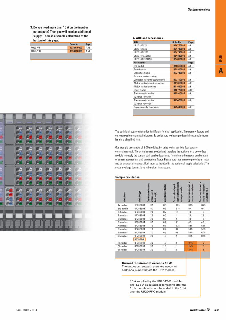
The additional supply calculation is different for each application. Simultaneity factors and current requirement must be known. To assist you, we have produced the example shown here in a simplified form.
Our example uses a row of 8-DO modules, i.e. units which can hold four actuator connections each. The actual current needed and therefore the position for a power-feed module to supply the current path can be determined from the mathematical combination of current requirement and simultaneity factor. Please note that u-remote provides an input and an output current path. Both must be included in the additional supply calculation. The system voltage doesn't have to be taken into account.
Sample calculation
Mod
ule no
.
Mod
ule ty
pe
Curre
nt re
quire
ment
of
conn
ecte
d de
vices
(A)
Simu
ltane
ity fa
ctor
Curre
nt fol
lowing
cal-
culat
ion of
simu
ltane
ity
facto
r per
modu
le
Curre
nt re
quire
ment
of
syst
em –
cumu
lative
Curre
nt re
quire
ment
of
syst
em –
cumu
lative
wi
th U
R20-P
F-O1st module UR20-8DO-P 0.5 0.5 0.25 0.25 0.252nd module UR20-8DO-P 0.3 0.5 0.15 0.4 0.43rd module UR20-8DO-P 2.0 0.7 1.4 1.8 1.84th module UR20-8DO-P 2.0 0.5 1 2.8 2.8
5th module UR20-8DO-P 2.0 0.3 2 4.8 4.8 6th module UR20-8DO-P 0.5 0.2 0.1 4.9 4.9 7th module UR20-8DO-P 1.0 0.1 0.75 5.65 5.65 8th module UR20-8DO-P 1.0 0.2 0.2 5.85 5.85 9th module UR20-8DO-P 1.2 0.5 0.6 6.45 6.45 10th module UR20-8DO-P 2.0 1.0 2 8.45 8.45
UR20-PF-O11th module UR20-8DO-P 2.0 1.0 2 10.45 212th module UR20-8DO-P 3.0 1.0 1 11.45 313th module UR20-8DO-P 2.0 1.0 2 13.45 5
4. AUX and accessoriesAUX Order No. PageUR20-16AUX-I 1334770000 A.61UR20-16AUX-O 1334780000 A.61UR20-16AUX-FE 1334790000 A.61UR20-16AUX-GND-I 1334800000 A.61UR20-16AUX-GND-O 1334810000 A.61Accessories PageEnd bracket 1346610000 A.61Swivel marker 1339920000 A.61Connection marker for pusher custom printing
1323700000 A.61
Connection marker for pusher neutral 1323710000 A.61Module marker for custom printing 1341610000 A.61Module marker for neutral 1341630000 A.61Empty module 1315770000 A.62Thermotransfer version (Material: Polyester)
1429910000 A.61
Thermotransfer version (Material: Polyester)
1429420000 A.61
Paper version for Laserprinter 1429430000 A.61
3. Do you need more than 10 A on the input or output path? Then you will need an additional supply! There is a sample calculation at the bottom of this page.
Order No. PageUR20-PF-I 1334710000 A.53UR20-PF-O 1334740000 A.54
System overview
Current requirement exceeds 10 A! The output current path therefore needs an additional supply before the 11th module.
10 A supplied by the UR20-PF-O module. The 1.55 A calculated as remaining after the 10th module must not be added to the 10 A after the UR20-PF-O module!
A
IP 20
A.651477120000 – 2014

Contents
Modular Communication. Robust.SAI Active.
When constructing machines and plants, sensors and actuators have to be connected to the control unit such that all these signals can be collected locally using fieldbuses.The SAI Active product family solves this problem by means of IP 67 protected encapsulation at the very point where the sensors and actuators are located. In the variants with a sub-bus system, this is done very flexibly and in a wide range of applications.
B
IP 67
1477120000 – 2014

Contents
IP 67
IP 67 Introduction B.2
Quick select – SAI Active B.6
SAI Active Universal – Overview B.8
SAI Active Universal – PROFIBUS-DP B.10
SAI Active Universal – CANopen B.14
SAI Active Universal – DeviceNet™ B.18
SAI Active Universal Pro – Overview B.22
SAI Active Universal Pro B.24
B
IP 67
B.11477120000 – 2014

Efficient engineeringDirect incorporation and configuration in the standard PLC engineering systems (such as Step 7, RS-Logix, CX-Configurator, MELSEC, ...)
Rapid fault rectificationRapid definition of causes in the event of faults by providing extended diagnostic data to the control unit and on the device itself.
Introduction
In both machine and plant construction, sensors and actuators from the entire machine have to be connected to the control unit. Depending on the machine, the reach, but also the volume of these signals may be very large so that fieldbuses and IO systems can be used to collect the signals locally. The SAI Active product family solves this problem by means of IP 67 protected encapsulation at the very point where the sensors and actuators are located. In the variants with a sub-bus system and wireless sub-bus system, this is done very flexibly and in a wide range of applications.Direct incorporation in the SYS programming environment, rapid definition of causes in the event of faults and a very narrow and lightweight design are the characteristics which make this system unique on the market.
Remote I/O system in class of protection IP 67 for SAI Active familyFlexible sensor/actuator coupling to control systems in IP 67 area in industrial environment
B
IP 67
B.2 1477120000 – 2014
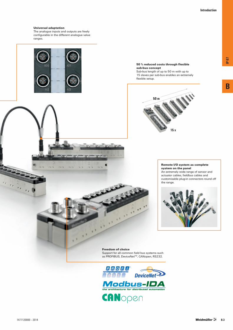
Universal adaptationThe analogue inputs and outputs are freely configurable in the different analogue value ranges.
Introduction
Freedom of choiceSupport for all common field bus systems such as PROFIBUS, DeviceNetTM, CANopen, RS232.
50 % reduced costs through flexible sub-bus conceptSub-bus length of up to 50 m with up to 15 slaves per sub-bus enables an extremely flexible setup.
15 x
50 m
Remote I/O system as complete system on the panelAn extremely wide range of sensor and actuator cables, fieldbus cables and customisable plug-in connectors round off the range.
B
IP 67
B.31477120000 – 2014

Challenging production tasks present you with motion and distributionWe present SAI for a secure processing of your sensor and actuator signalsLet’s connect.
Introduction
Complex production processes mean that you have to co-ordinate lots of individual processing stages. Numerous sensors and actuators throughout the production facility are connected with the central control system. And in many cases, you have to bridge huge distances and process a large number of different signals.
Weidmüller‘s SAI Active product range equips you for this production process chain in a practical way. Thanks to IP 67-rated encapsulation, the remote I/O systems can be positioned directly where sensors and actuators are active. The SAI-PRO variants with sub-bus system or SAI Wireless also greatly increase your flexibility: the sub-bus system SAI-PRO can be extended to a length of up to 50 m with up to 15 modules. Up to 120 inputs or outputs are therefore possible on one fieldbus node.
Various versions of encapsulated SAI cables make the sensors and actuators accessible. You can also route fieldbus cables straight from the switch cabinet with the energy supply lines using modular, heavy-duty plug-in connectors of the RockStar® concept. This allows you to integrate several stages of production into your production facility with just one single module.
Other benefits of the SAI family include a direct interface to your PLC programming environment and precise error analyses with visual status display. Let’s connect.
B
IP 67
B.4 1477120000 – 2014

Introduction
Remote I/O IP 67 SAI Active
• Efficient engineering by direct integration into standard PLC system engineering
• Rapid identification of failure causes by providing enhanced diagnostic data
• 50 % cost reduction by flexible sub-bus concept• Analogue inputs and outputs have
freely configurable analog value
Sensor Actuator Cabling
• Broad range of leadership qualities• Free attachable connectors with
screw connection up to crimp versions• Customised versions and lengths from 1 piece• 360 degree shielding• Many types from stock
B
IP 67
B.51477120000 – 2014
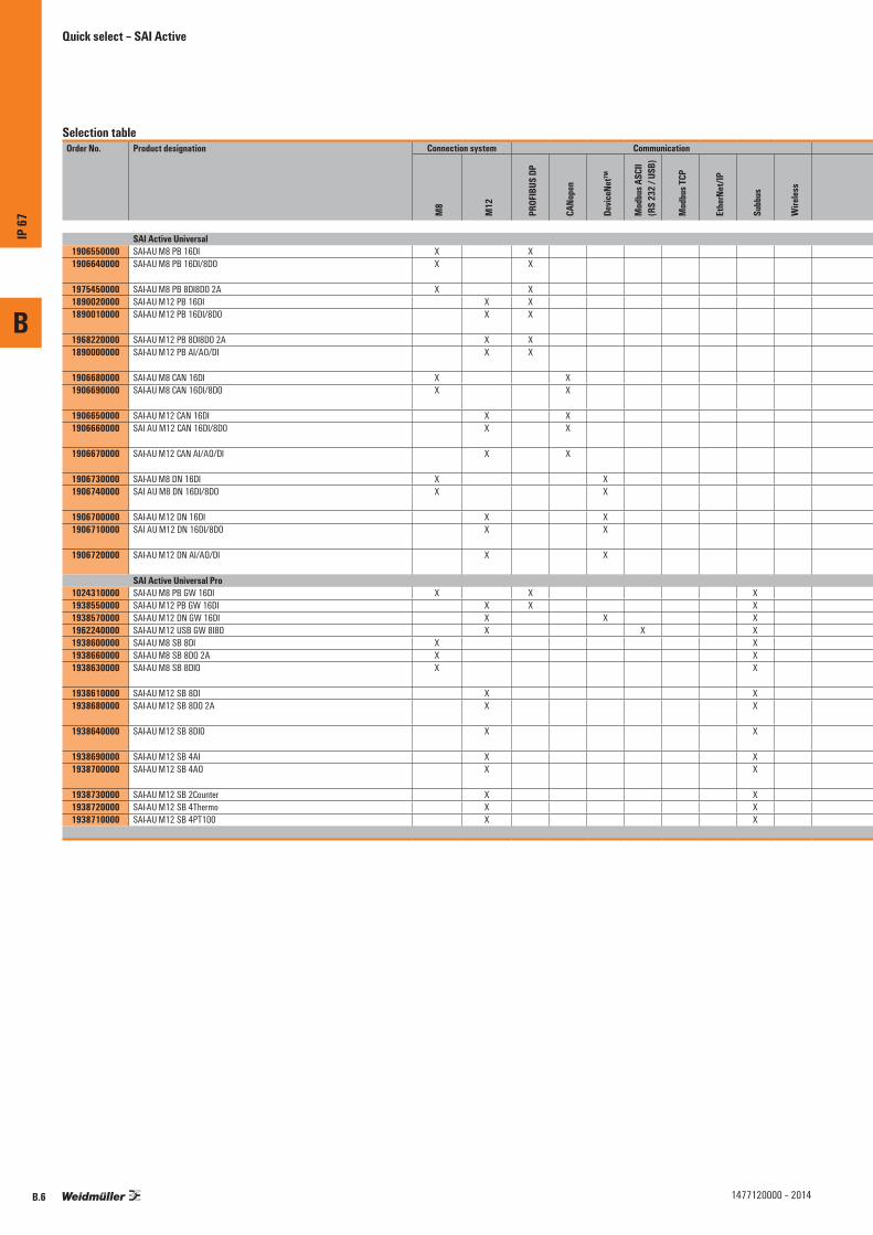
Selection tableOrder No. Product designation Connection system Communication Inputs Outputs
Supp
ly vo
ltage
feed
circ
uits
Special characteristics Page
M8
M12
PROF
IBUS
DP
CANo
pen
Devic
eNet
™
Mod
bus A
SCII
(RS
232 /
USB
)
Mod
bus T
CP
Ethe
rNet
/IP
Subb
us
Wire
less
Digit
al
Analo
gue
Coun
ter
TC RTD
Digit
al
Outp
ut cu
rrent
Analo
gue
Outp
ut ra
nge
SAI Active Universal1906550000 SAI-AU M8 PB 16DI X X 16 2 B.101906640000 SAI-AU M8 PB 16DI/8DO X X max.. 16, min. 8
(can be configured)max.. 8, min. 0
(can be configured)0.5 A 4 - Max. I/O channels = 16 B.10
1975450000 SAI-AU M8 PB 8DI8DO 2A X X 8 8 2 A 4 - Max. total current, output = 8 A B.101890020000 SAI-AU M12 PB 16DI X X 16 2 B.101890010000 SAI-AU M12 PB 16DI/8DO X X max. 16, min. 8
(can be configured)max. 8, min. 0
(can be configured)0.5 A 1 - Max. I/O channels = 16 B.10
1968220000 SAI-AU M12 PB 8DI8DO 2A X X 8 8 2 A 2 - Max. total current, output = 8 A B.101890000000 SAI-AU M12 PB AI/AO/DI X X 4 4 2 -10…+10 V, 0…+10 V,
0…20 mA, 4…20 mA2 B.11
1906680000 SAI-AU M8 CAN 16DI X X 16 2 B.141906690000 SAI-AU M8 CAN 16DI/8DO X X max. 16, min. 8
(can be configured)max. 8, min. 0
(can be configured)0.5 A 4 - Max. I/O channels = 16 B.14
1906650000 SAI-AU M12 CAN 16DI X X 16 2 B.141906660000 SAI AU M12 CAN 16DI/8DO X X max. 16, min. 8
(can be configured)max. 8, min. 0
(can be configured)0.5 A 4 - Max. I/O channels = 16 B.14
1906670000 SAI-AU M12 CAN AI/AO/DI X X 4 4 2 -10…+10 V, 0…+10 V, 0…20 mA, 4…20 mA
2 B.15
1906730000 SAI-AU M8 DN 16DI X X 16 2 B.181906740000 SAI AU M8 DN 16DI/8DO X X max. 16, min. 8
(can be configured)max. 8, min. 0
(can be configured)0.5 A 4 - Max. I/O channels = 16 B.18
1906700000 SAI-AU M12 DN 16DI X X 16 2 B.181906710000 SAI AU M12 DN 16DI/8DO X X max. 16, min. 8
(can be configured)max. 8, min. 0
(can be configured)0.5 A 4 - Max. I/O channels = 16 B.18
1906720000 SAI-AU M12 DN AI/AO/DI X X 4 4 2 -10…+10 V, 0…+10 V, 0…20 mA, 4…20 mA
2 B.19
SAI Active Universal Pro1024310000 SAI-AU M8 PB GW 16DI X X X 16 2 B.241938550000 SAI-AU M12 PB GW 16DI X X X 16 2 B.241938570000 SAI-AU M12 DN GW 16DI X X X 16 2 B.261962240000 SAI-AU M12 USB GW 8I8O X X X 8 8 0.5 A 2 B.281938600000 SAI-AU M8 SB 8DI X X 8 B.301938660000 SAI-AU M8 SB 8DO 2A X X 8 2 A 2 - Max. total current, output = 8 A B.301938630000 SAI-AU M8 SB 8DIO X X max. 8, min. 0
(can be configured)max. 8, min. 0
(can be configured)0.5 A 2 - Max. I/O channels = 8
- Max. total current, output = 4 AB.30
1938610000 SAI-AU M12 SB 8DI X X 8 B.301938680000 SAI-AU M12 SB 8DO 2A X X 8 2 A 2 - Max. I/O channels = 8
- Max. total current, output = 4 AB.30
1938640000 SAI-AU M12 SB 8DIO X X max. 8, min. 0(can be configured)
max. 8, min. 0(can be configured)
0.5 A 2 - Max. I/O channels = 8 B.30
1938690000 SAI-AU M12 SB 4AI X X 4 B.311938700000 SAI-AU M12 SB 4AO X X 4 -10…+10 V, 0…+10 V,
0…20 mA, 4…20 mAB.31
1938730000 SAI-AU M12 SB 2Counter X X 2 2 B.321938720000 SAI-AU M12 SB 4Thermo X X 4 B.331938710000 SAI-AU M12 SB 4PT100 X X 4 B.34
Quick select – SAI Active
B
IP 67
B.6 1477120000 – 2014
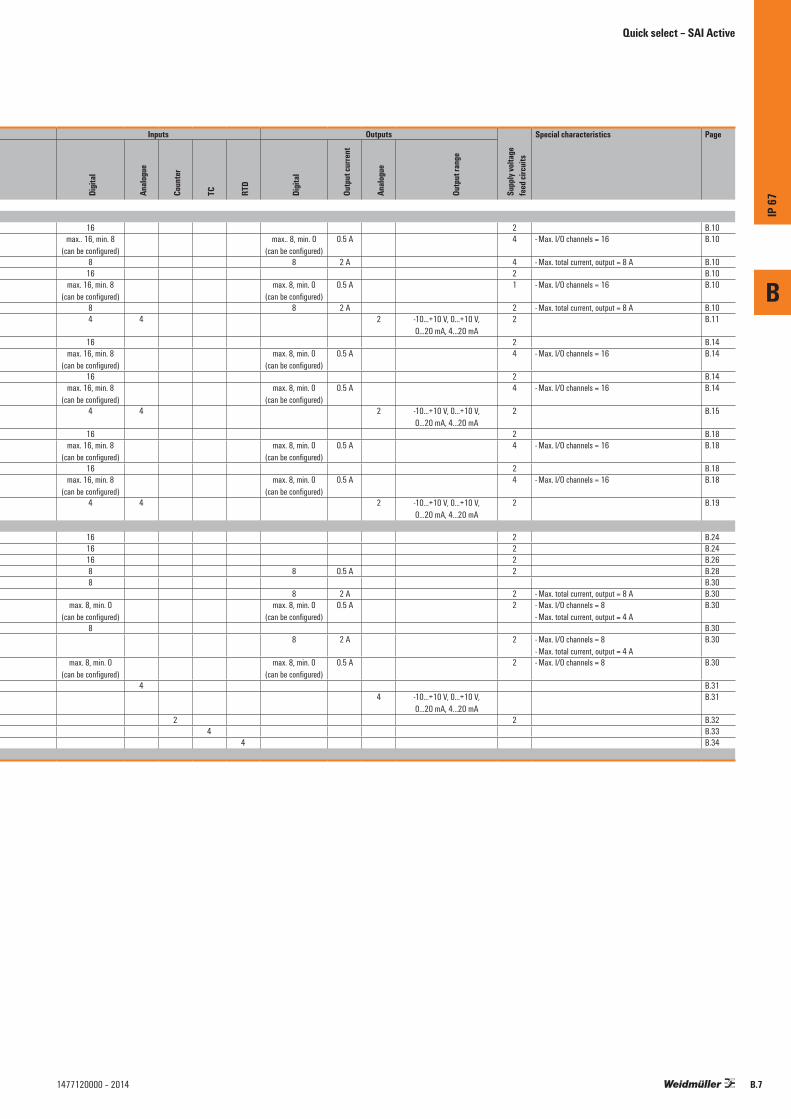
Selection tableOrder No. Product designation Connection system Communication Inputs Outputs
Supp
ly vo
ltage
feed
circ
uits
Special characteristics Page
M8
M12
PROF
IBUS
DP
CANo
pen
Devic
eNet
™
Mod
bus A
SCII
(RS
232 /
USB
)
Mod
bus T
CP
Ethe
rNet
/IP
Subb
us
Wire
less
Digit
al
Analo
gue
Coun
ter
TC RTD
Digit
al
Outp
ut cu
rrent
Analo
gue
Outp
ut ra
nge
SAI Active Universal1906550000 SAI-AU M8 PB 16DI X X 16 2 B.101906640000 SAI-AU M8 PB 16DI/8DO X X max.. 16, min. 8
(can be configured)max.. 8, min. 0
(can be configured)0.5 A 4 - Max. I/O channels = 16 B.10
1975450000 SAI-AU M8 PB 8DI8DO 2A X X 8 8 2 A 4 - Max. total current, output = 8 A B.101890020000 SAI-AU M12 PB 16DI X X 16 2 B.101890010000 SAI-AU M12 PB 16DI/8DO X X max. 16, min. 8
(can be configured)max. 8, min. 0
(can be configured)0.5 A 1 - Max. I/O channels = 16 B.10
1968220000 SAI-AU M12 PB 8DI8DO 2A X X 8 8 2 A 2 - Max. total current, output = 8 A B.101890000000 SAI-AU M12 PB AI/AO/DI X X 4 4 2 -10…+10 V, 0…+10 V,
0…20 mA, 4…20 mA2 B.11
1906680000 SAI-AU M8 CAN 16DI X X 16 2 B.141906690000 SAI-AU M8 CAN 16DI/8DO X X max. 16, min. 8
(can be configured)max. 8, min. 0
(can be configured)0.5 A 4 - Max. I/O channels = 16 B.14
1906650000 SAI-AU M12 CAN 16DI X X 16 2 B.141906660000 SAI AU M12 CAN 16DI/8DO X X max. 16, min. 8
(can be configured)max. 8, min. 0
(can be configured)0.5 A 4 - Max. I/O channels = 16 B.14
1906670000 SAI-AU M12 CAN AI/AO/DI X X 4 4 2 -10…+10 V, 0…+10 V, 0…20 mA, 4…20 mA
2 B.15
1906730000 SAI-AU M8 DN 16DI X X 16 2 B.181906740000 SAI AU M8 DN 16DI/8DO X X max. 16, min. 8
(can be configured)max. 8, min. 0
(can be configured)0.5 A 4 - Max. I/O channels = 16 B.18
1906700000 SAI-AU M12 DN 16DI X X 16 2 B.181906710000 SAI AU M12 DN 16DI/8DO X X max. 16, min. 8
(can be configured)max. 8, min. 0
(can be configured)0.5 A 4 - Max. I/O channels = 16 B.18
1906720000 SAI-AU M12 DN AI/AO/DI X X 4 4 2 -10…+10 V, 0…+10 V, 0…20 mA, 4…20 mA
2 B.19
SAI Active Universal Pro1024310000 SAI-AU M8 PB GW 16DI X X X 16 2 B.241938550000 SAI-AU M12 PB GW 16DI X X X 16 2 B.241938570000 SAI-AU M12 DN GW 16DI X X X 16 2 B.261962240000 SAI-AU M12 USB GW 8I8O X X X 8 8 0.5 A 2 B.281938600000 SAI-AU M8 SB 8DI X X 8 B.301938660000 SAI-AU M8 SB 8DO 2A X X 8 2 A 2 - Max. total current, output = 8 A B.301938630000 SAI-AU M8 SB 8DIO X X max. 8, min. 0
(can be configured)max. 8, min. 0
(can be configured)0.5 A 2 - Max. I/O channels = 8
- Max. total current, output = 4 AB.30
1938610000 SAI-AU M12 SB 8DI X X 8 B.301938680000 SAI-AU M12 SB 8DO 2A X X 8 2 A 2 - Max. I/O channels = 8
- Max. total current, output = 4 AB.30
1938640000 SAI-AU M12 SB 8DIO X X max. 8, min. 0(can be configured)
max. 8, min. 0(can be configured)
0.5 A 2 - Max. I/O channels = 8 B.30
1938690000 SAI-AU M12 SB 4AI X X 4 B.311938700000 SAI-AU M12 SB 4AO X X 4 -10…+10 V, 0…+10 V,
0…20 mA, 4…20 mAB.31
1938730000 SAI-AU M12 SB 2Counter X X 2 2 B.321938720000 SAI-AU M12 SB 4Thermo X X 4 B.331938710000 SAI-AU M12 SB 4PT100 X X 4 B.34
Quick select – SAI Active
B
IP 67
B.71477120000 – 2014

SAI Active Universal – Overview
SAI Active Universal
Compact, basic versions of the Remote I/O system with IP 67 protection
The SAI Active Universal consists of basic, compact designed variants that include a variety of modules for digital and analogue inputs and outputs. The housing has a sturdy construction in compliance with strict industrial requirements. It is resistant against aggressive materials, vibration, shock, temperature, water and dust.
The high quality connection system uses conventional, standardised M8 and M12 connectors with standards-compliant coding. They ensure a reliable wiring process with less risk of errors. Two M12 connections for the fieldbus allow for a continuous bus installation without any additional T-distributor. The functional earth connection is automatically created when installing on a metallic earthed base.
B
IP 67
B.8 1477120000 – 2014

SAI Active Universal – Overview
4 independent voltage circuits
The modules can be supplied with up to four different voltage potentials. The module voltage can be simultaneously used for the inputs. In addition, up to three feed points are available for outputs; these can be switched off individually depending on the application requirements. Plug in cross connectors can be used to merge voltage potentials on the module.
Efficient diagnostics and status alerts
The status of the I/Os is shown directly on the module using arrow icons. The arrows point to the label and the plug in position. Up to seven status LEDs are available for displaying additional information about the power supply, fieldbus status and group diagnostics. The information is simultaneously transmitted to the controller unit via the bus system.
Freedom of choice
Total compliance with many industrial fieldbus standards: this permits integration with all conventional controllers so that the modules can be used in practically all applications. SAI Active Universal supports PROFIBUS-DP, CANopen, DeviceNet™ communication protocols.
A wide variety of variants
All SAI Active modules with digital inputs or digital outputs are optionally available with standard M8 or M12 connection systems. For modules in the 16DI/8DO series, the configuration can be customised to fit the application so that anywhere between 16DI to 8DI/8DO can be used. Output cables with up to 2 A per channel are used to connect almost any load. Analogue modules can be configured flexibly for the current of voltage outputs.
M8Analog
DigitalM12
B
IP 67
B.91477120000 – 2014
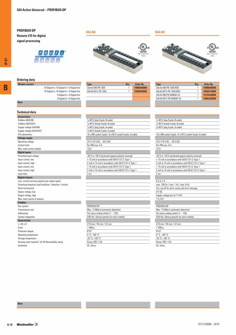
B
IP 67
B.10 1477120000 – 2014
PROFIBUS-DP Remote I/O for digital signal processing
SAI-AU
Ordering dataModule variants
16 Digital In; 16 Digital In / 8 Digital Out16 Digital In; 16 Digital In / 8 Digital Out
8 Digital In / 8 Digital Out8 Digital In / 8 Digital Out
Note
Type Qty. Order No.SAI-AU M8 PB 16DI 1 1906550000SAI-AU M12 PB 16DI 1 1890020000
Technical dataConnectionsFieldbus (BUS-IN)Fieldbus (BUS-OUT)Supply voltage (AUX-IN)Supply voltage (AUX-OUT)I/O connections Voltage supplyOperating voltageContact loadMax. total current moduleDigital inputsPermitted input voltageInput current, lowInput current, highInput current, lowInput current, highInput filterDigital outputsmax. current-carrying capacity per output signalSwitching frequency load (resistive / inductive / inrush)Short-circuit-proofOutput voltage, lowOutput voltage, highMax. total current of outputs FieldbusBus systemTransmission rateAddressingSystem integration General dataL x W x HEarthProtection degreeOperating temperatureStorage temperatureHousing main material / UL 94 flammability ratingCertificate
1x M12 plug 5-pole, B-coded1x M12 female 5-pole, B-coded1x M12 plug 5-pole, A-coded 1x M12 female 5-pole, A-coded 16 x M8 socket 3-pole / 8 x M12 socket 5-pole, A-coded
24 V (18 V DC ... 30 V DC)Per PIN max. 4 A10 A
-30 V to +30 V (protected against polarity reversal)< 15 mA in accordance with EN 61131-2 Type 12 mA to 15 mA in accordance with EN 61131-2 Type 1< 15 mA in accordance with EN 61131-2 Type 12 mA to 15 mA in accordance with EN 61131-2 Type 13 ms
PROFIBUS-DPMax. 12 Mbit/s (automatic detection)Via rotary coding switch (1 – 126)GSD file (Device-specific for each module)
210 mm / 54 mm / 32 mm < 400 gIP 670 °C...+60 °C-25 °C...+85 °CPocan, PBT / V-0CE, cULus
Note
SAI-AU
Type Qty. Order No.SAI-AU M8 PB 16DI/8DO 1 1906640000SAI-AU M12 PB 16DI/8DO 1 1890010000SAI-AU M8 PB 8DI8DO 2A 1 1975450000SAI-AU M12 PB 8DI8DO 2A 1 1968220000
1x M12 plug 5-pole, B-coded1x M12 female 5-pole, B-coded2x M12 plug 5-pole, A-coded
16 x M8 socket 3-pole / 8 x M12 socket 5-pole, A-coded
24 V (18 V DC ... 30 V DC)Per PIN max. 4 A10 A
-30 V to +30 V (protected against polarity reversal)< 15 mA in accordance with EN 61131-2 Type 12 mA to 15 mA in accordance with EN 61131-2 Type 1< 15 mA in accordance with EN 61131-2 Type 12 mA to 15 mA in accordance with EN 61131-2 Type 13 ms
0.5 A, 2 Amax. 100 Hz / max. 1 Hz / max. 8 HzYes, cut-off for short circuit and error message0 V DCSupply voltage less 0.7 V DC7 A, 8 A
PROFIBUS-DPMax. 12 Mbit/s (automatic detection)Via rotary coding switch (1 – 126)GSD file (Device-specific for each module)
210 mm / 54 mm / 32 mm < 400 gIP 670 °C...+60 °C-25 °C...+85 °CPocan, PBT / V-0CE, cULus
SAI Active Universal – PROFIBUS-DP
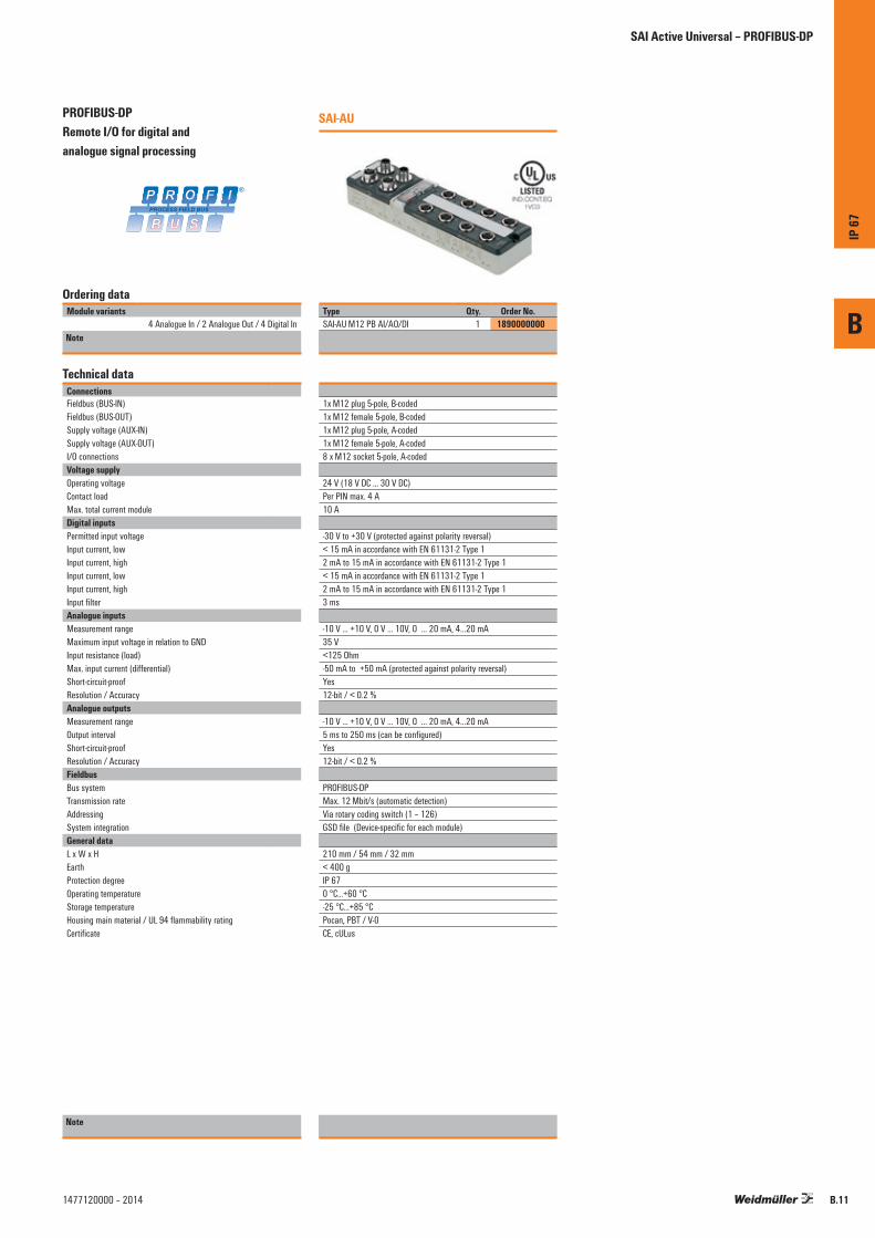
B
IP 67
B.111477120000 – 2014
PROFIBUS-DP Remote I/O for digital and analogue signal processing
SAI-AU
Ordering dataModule variants
4 Analogue In / 2 Analogue Out / 4 Digital InNote
Type Qty. Order No.SAI-AU M12 PB AI/AO/DI 1 1890000000
Technical dataConnectionsFieldbus (BUS-IN)Fieldbus (BUS-OUT)Supply voltage (AUX-IN)Supply voltage (AUX-OUT)I/O connectionsVoltage supplyOperating voltageContact loadMax. total current moduleDigital inputsPermitted input voltageInput current, lowInput current, highInput current, lowInput current, highInput filterAnalogue inputsMeasurement rangeMaximum input voltage in relation to GNDInput resistance (load)Max. input current (differential)Short-circuit-proofResolution / AccuracyAnalogue outputsMeasurement rangeOutput intervalShort-circuit-proofResolution / AccuracyFieldbusBus systemTransmission rateAddressingSystem integration General dataL x W x HEarthProtection degreeOperating temperatureStorage temperatureHousing main material / UL 94 flammability ratingCertificate
1x M12 plug 5-pole, B-coded1x M12 female 5-pole, B-coded1x M12 plug 5-pole, A-coded 1x M12 female 5-pole, A-coded 8 x M12 socket 5-pole, A-coded
24 V (18 V DC ... 30 V DC)Per PIN max. 4 A10 A
-30 V to +30 V (protected against polarity reversal)< 15 mA in accordance with EN 61131-2 Type 12 mA to 15 mA in accordance with EN 61131-2 Type 1< 15 mA in accordance with EN 61131-2 Type 12 mA to 15 mA in accordance with EN 61131-2 Type 13 ms
-10 V ... +10 V, 0 V ... 10V, 0 … 20 mA, 4…20 mA35 V<125 Ohm-50 mA to +50 mA (protected against polarity reversal)Yes12-bit / < 0.2 %
-10 V ... +10 V, 0 V ... 10V, 0 … 20 mA, 4…20 mA5 ms to 250 ms (can be configured)Yes12-bit / < 0.2 %
PROFIBUS-DPMax. 12 Mbit/s (automatic detection)Via rotary coding switch (1 – 126)GSD file (Device-specific for each module)
210 mm / 54 mm / 32 mm < 400 gIP 670 °C...+60 °C-25 °C...+85 °CPocan, PBT / V-0CE, cULus
Note
SAI Active Universal – PROFIBUS-DP
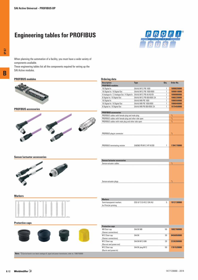
Engineering tables for PROFIBUS
SAI Active Universal – PROFIBUS-DP
When planning the automation of a facility, you must have a wide variety of components available. These engineering tables list all the components required for wiring up the SAI Active modules.
PROFIBUS modules
PROFIBUS accessories
Sensor/actuator accessories
Markers
Protective caps
Ordering dataDescription Type Qty. Order No.PROFIBUS modules16 Digital In SAI-AU M12 PB 16DI 1 189002000016 Digital In / 8 Digital Out SAI-AU M12 PB 16DI/8DO 1 18900100004 Analogue In / 2 Analogue Out / 4 Digital In SAI-AU M12 PB AI/AO/DI 1 18900000008 Digital In / 8 Digital Out SAI-AU M12 PB 8DI/8DO 2A 1 196822000016 Digital In SAI-AU M8 PB 16DI 1 190655000016 Digital In / 8 Digital Out SAI-AU M8 PB 16DI/8DO 1 19066400008 Digital In / 8 Digital Out SAI-AU M8 PB 8DI/8DO 2A 1 1975450000
PROFIBUS accessoriesPROFIBUS cables with female plug and male plug *)PROFIBUS cables with female plug and other side open *)PROFIBUS cables with male plug and other side open *)
PROFIBUS plug-in connector *)
PROFIBUS terminating resistor SAIEND PB M12 4P B-COD 1 1784770000
Sensor/actuator accessoriesSensor-actuator cables *)
Sensor-actuator plugs *)
MarkersSemi-transparent markers for PrintJet printing
ESG 8/13.5/43.3 SAI AU 5 1912130000
Protective capsM8 Dust cap (Sensor connections)
SAI-SK M8 50 1802760000
M12 Dust cap (Sensor connections)
SAI-SK 30 9456050000
M12 Dust cap (Bus-out and power-out)
SAI-SK-M12-UNI 20 2330260000
M12 Dust cap (Bus-in and power-in)
SAI-SK plug M12 50 1781520000
Note: *) Can be found in our latest catalogue 8, signal and power transmission, order no. 1366750000
B
IP 67
B.12 1477120000 – 2014

B
IP 67
B.131477120000 – 2014

B
IP 67
B.14 1477120000 – 2014
CANopen Remote I/O for digital signal processing
SAI-AU
Ordering dataModule variants
16 Digital In; 16 Digital In / 8 Digital Out16 Digital In; 16 Digital In / 8 Digital Out
Note
Type Qty. Order No.SAI-AU M8 CAN 16DI 1 1906680000SAI-AU M12 CAN 16DI 1 1906650000
Technical dataConnectionsFieldbus (BUS-IN)Fieldbus (BUS-OUT)Supply voltage (AUX-IN)Supply voltage (AUX-OUT)I/O connections Voltage supplyOperating voltageContact loadMax. total current moduleDigital inputsPermitted input voltageInput current, lowInput current, highInput current, lowInput current, highInput filterDigital outputsmax. current-carrying capacity per output signalSwitching frequency load (resistive / inductive / inrush)Short-circuit-proofOutput voltage, lowOutput voltage, highMax. total current of outputs FieldbusBus systemTransmission rateAddressingSystem integration General dataL x W x HEarthProtection degreeOperating temperatureStorage temperatureHousing main material / UL 94 flammability ratingCertificate
1x M12 plug 5-pole, A-coded1x M12 female 5-pole, A-coded1x M12 plug 5-pole, A-coded 1x M12 female 5-pole, A-coded 16 x M8 socket 3-pole / 8 x M12 socket 5-pole, A-coded
24 V (18 V DC ... 30 V DC)Per PIN max. 4 A8 A
-30 V to +30 V (protected against polarity reversal)< 15 mA in accordance with EN 61131-2 Type 12 mA to 15 mA in accordance with EN 61131-2 Type 1< 15 mA in accordance with EN 61131-2 Type 12 mA to 15 mA in accordance with EN 61131-2 Type 13 ms
CANopenMax. 1 Mbit/s (automatic detection)Via rotary coding switch (1 – 127)EDS file (Device-specific for each module)
210 mm / 54 mm / 32 mm < 400 gIP 670 °C...+60 °C-25 °C...+85 °CPocan, PBT / V-0CE, cULus
Note
SAI-AU
Type Qty. Order No.SAI-AU M8 CAN 16DI/8DO 1 1906690000SAI-AU M12 CAN 16DI/8DO 1 1906660000
1x M12 plug 5-pole, A-coded1x M12 female 5-pole, A-coded2x M12 plug 5-pole, A-coded
16 x M8 socket 3-pole / 8 x M12 socket 5-pole, A-coded
24 V (18 V DC ... 30 V DC)Per PIN max. 4 A8 A
-30 V to +30 V (protected against polarity reversal)< 15 mA in accordance with EN 61131-2 Type 12 mA to 15 mA in accordance with EN 61131-2 Type 1< 15 mA in accordance with EN 61131-2 Type 12 mA to 15 mA in accordance with EN 61131-2 Type 13 ms
0.5 A, 2 Amax. 100 Hz / max. 1 Hz / max. 8 HzYes, cut-off for short circuit and error message0 V DCSupply voltage less 0.7 V DC7 A, 8 A
CANopenMax. 1 Mbit/s (automatic detection)Via rotary coding switch (1 – 127)EDS file (Device-specific for each module)
210 mm / 54 mm / 32 mm < 400 gIP 670 °C...+60 °C-25 °C...+85 °CPocan, PBT / V-0CE, cULus
SAI Active Universal – CANopen

B
IP 67
B.151477120000 – 2014
CANopen Remote I/O for digital and analogue signal processing
SAI-AU
Ordering dataModule variants
4 Analogue In / 2 Analogue Out / 4 Digital InNote
Type Qty. Order No.SAI-AU M12 CAN AI/AO/DI 1 1906670000
Technical dataConnectionsFieldbus (BUS-IN)Fieldbus (BUS-OUT)Supply voltage (AUX-IN)Supply voltage (AUX-OUT)I/O connections Voltage supplyOperating voltageContact loadMax. total current moduleDigital inputsPermitted input voltageInput current, lowInput current, highInput current, lowInput current, highInput filterDigital outputsmax. current-carrying capacity per output signalSwitching frequency load (resistive / inductive / inrush)Short-circuit-proofOutput voltage, lowOutput voltage, highMax. total current of outputs FieldbusBus systemTransmission rateAddressingSystem integration General dataL x W x HEarthProtection degreeOperating temperatureStorage temperatureHousing main material / UL 94 flammability ratingCertificate
1x M12 plug 5-pole, A-coded1x M12 female 5-pole, A-coded1x M12 plug 5-pole, A-coded 1x M12 female 5-pole, A-coded
24 V (18 V DC ... 30 V DC)Per PIN max. 4 A8 A
-30 V to +30 V (protected against polarity reversal)< 15 mA in accordance with EN 61131-2 Type 12 mA to 15 mA in accordance with EN 61131-2 Type 1< 15 mA in accordance with EN 61131-2 Type 12 mA to 15 mA in accordance with EN 61131-2 Type 13 ms
CANopenMax. 1 Mbit/s (automatic detection)Via rotary coding switch (1 – 127)EDS file (Device-specific for each module)
210 mm / 54 mm / 32 mm < 400 gIP 670 °C...+60 °C-25 °C...+85 °CPocan, PBT / V-0CE, cULus
Note
SAI Active Universal – CANopen

Engineering tables for CANopen
SAI Active Universal – CANopen
When planning the automation of a facility, you must have a wide variety of components available. These engineering tables list all the components required for wiring up the SAI Active modules.
CANopen modules
CANopen accessories
Sensor/actuator accessories
Markers
Protective caps
Ordering dataDescription Type Qty. Order No.CANopen modules16 Digital In SAI-AU M12 CAN 16DI 1 190665000016 Digital In / 8 Digital Out SAI AU M12 CAN 16DI/8DO 1 19066600004 Analogue In / 2 Analogue Out / 4 Digital In SAI-AU M12 CAN AI/AO/DI 1 190667000016 Digital In SAI-AU M8 CAN 16DI 1 190668000016 Digital In / 8 Digital Out SAI-AU M8 CAN 16DI/8DO 1 1906690000
CANopen accessoriesCANopen cables with female plug and male plug *)CANopen cables with female plug and other side open *)CANopen cables with male plug and other side open *)
CANopen plug-in connector *)
CANopen terminating resistor SAIEND CAN-M12 5P A-COD 1 1784760000
Sensor/actuator accessoriesSensor-actuator cables *)
Sensor-actuator plugs *)
MarkersSemi-transparent markers for PrintJet printing
ESG 8/13.5/43.3 SAI AU 5 1912130000
Protective capsM8 Dust cap (Sensor connections)
SAI-SK M8 50 1802760000
M12 Dust cap (Sensor connections)
SAI-SK 30 9456050000
M12 Dust cap (Bus-out and power-out)
SAI-SK-M12-UNI 20 2330260000
M12 Dust cap (Bus-in and power-in)
SAI-SK plug M12 50 1781520000
Note: *) Can be found in our latest catalogue 8, signal and power transmission, order no. 1366750000
B
IP 67
B.16 1477120000 – 2014

B
IP 67
B.171477120000 – 2014

B
IP 67
B.18 1477120000 – 2014
DeviceNetTM Remote I/O for digital signal processing
SAI-AU
Ordering dataModule variants
16 Digital In; 16 Digital In / 8 Digital Out16 Digital In; 16 Digital In / 8 Digital Out
Note
Type Qty. Order No.SAI-AU M8 DN 16DI 1 1906730000SAI-AU M12 DN 16DI 1 1906700000
Technical dataConnectionsFieldbus (BUS-IN)Fieldbus (BUS-OUT)Supply voltage (AUX-IN)Supply voltage (AUX-OUT)I/O connections Voltage supplyOperating voltageContact loadMax. total current moduleDigital inputsPermitted input voltageInput current, lowInput current, highInput current, lowInput current, highInput filterDigital outputsmax. current-carrying capacity per output signalSwitching frequency load (resistive / inductive / inrush)Short-circuit-proofOutput voltage, lowOutput voltage, highMax. total current outputsFieldbusBus systemTransmission rateAddressingSystem integration General dataL x W x HEarthProtection degreeOperating temperatureStorage temperatureHousing main material / UL 94 flammability ratingCertificate
1x M12 plug 5-pole, A-coded1x M12 female 5-pole, A-coded1x M12 plug 5-pole, A-coded 1x M12 female 5-pole, A-coded 16 x M8 socket 3-pole / 8 x M12 socket 5-pole, A-coded
24 V (18 V DC ... 30 V DC)Per PIN max. 4 A8 A
-30 V to +30 V (protected against polarity reversal)< 15 mA in accordance with EN 61131-2 Type 12 mA to 15 mA in accordance with EN 61131-2 Type 1< 15 mA in accordance with EN 61131-2 Type 12 mA to 15 mA in accordance with EN 61131-2 Type 13 ms
DeviceNet™Max. 500 kBit/s (automatic detection)Via rotary coding switch (0 – 63)EDS file (Device-specific for each module)
210 mm / 54 mm / 32 mm < 400 gIP 670 °C...+60 °C-25 °C...+85 °CPocan, PBT / V-0CE, cULus
Note
SAI-AU
Type Qty. Order No.SAI-AU M8 DN 16DI/8DO 1 1906740000SAI-AU M12 DN 16DI/8DO 1 1906710000
1x M12 plug 5-pole, A-coded1x M12 female 5-pole, A-coded2x M12 plug 5-pole, A-coded
16 x M8 socket 3-pole / 8 x M12 socket 5-pole, A-coded
24 V (18 V DC ... 30 V DC)Per PIN max. 4 A8 A
-30 V to +30 V (protected against polarity reversal)< 15 mA in accordance with EN 61131-2 Type 12 mA to 15 mA in accordance with EN 61131-2 Type 1< 15 mA in accordance with EN 61131-2 Type 12 mA to 15 mA in accordance with EN 61131-2 Type 13 ms
0.5 A, 2 Amax. 100 Hz / max. 1 Hz / max. 8 HzYes, cut-off for short circuit and error message0 V DCSupply voltage less 0.7 V DC7 A
DeviceNet™Max. 500 kBit/s (automatic detection)Via rotary coding switch (0 – 63)EDS file (Device-specific for each module)
210 mm / 54 mm / 32 mm < 400 gIP 670 °C...+60 °C-25 °C...+85 °CPocan, PBT / V-0CE, cULus
SAI Active Universal – DeviceNetTM
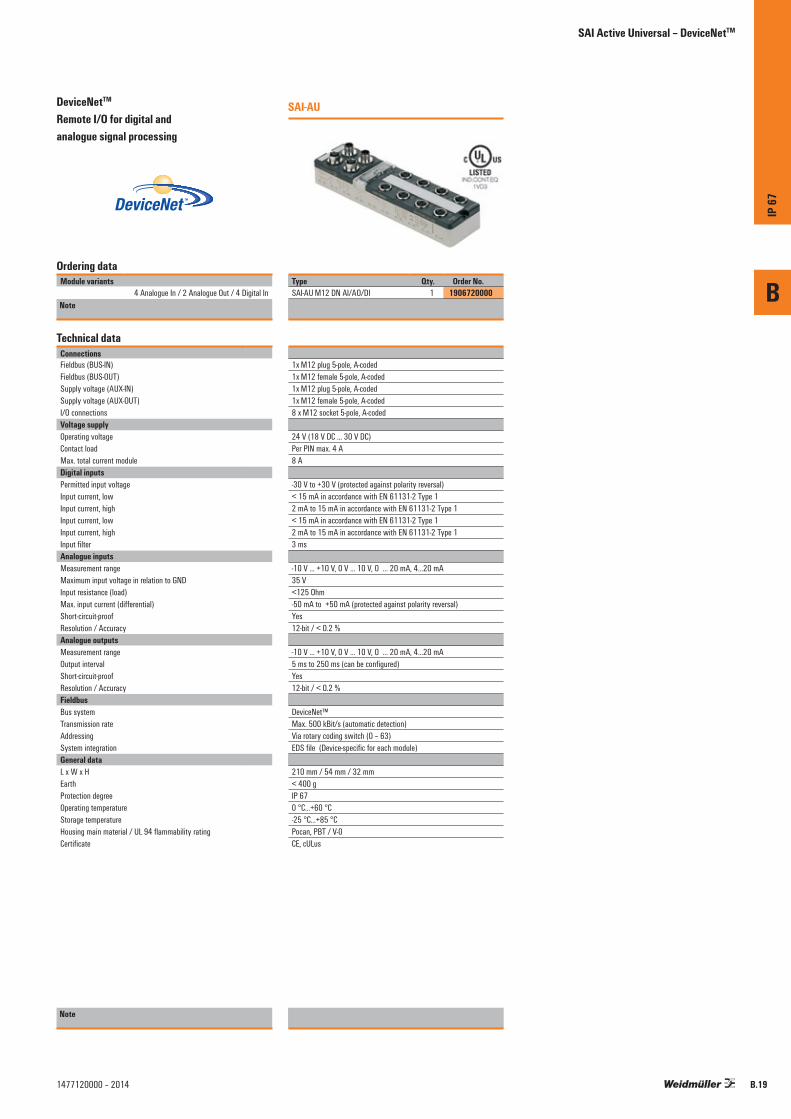
B
IP 67
B.191477120000 – 2014
DeviceNetTM Remote I/O for digital and analogue signal processing
SAI-AU
Ordering dataModule variants
4 Analogue In / 2 Analogue Out / 4 Digital InNote
Type Qty. Order No.SAI-AU M12 DN AI/AO/DI 1 1906720000
Technical dataConnectionsFieldbus (BUS-IN)Fieldbus (BUS-OUT)Supply voltage (AUX-IN)Supply voltage (AUX-OUT)I/O connectionsVoltage supplyOperating voltageContact loadMax. total current moduleDigital inputsPermitted input voltageInput current, lowInput current, highInput current, lowInput current, highInput filterAnalogue inputsMeasurement rangeMaximum input voltage in relation to GNDInput resistance (load)Max. input current (differential)Short-circuit-proofResolution / AccuracyAnalogue outputsMeasurement rangeOutput intervalShort-circuit-proofResolution / AccuracyFieldbusBus systemTransmission rateAddressingSystem integration General dataL x W x HEarthProtection degreeOperating temperatureStorage temperatureHousing main material / UL 94 flammability ratingCertificate
1x M12 plug 5-pole, A-coded1x M12 female 5-pole, A-coded1x M12 plug 5-pole, A-coded 1x M12 female 5-pole, A-coded 8 x M12 socket 5-pole, A-coded
24 V (18 V DC ... 30 V DC)Per PIN max. 4 A8 A
-30 V to +30 V (protected against polarity reversal)< 15 mA in accordance with EN 61131-2 Type 12 mA to 15 mA in accordance with EN 61131-2 Type 1< 15 mA in accordance with EN 61131-2 Type 12 mA to 15 mA in accordance with EN 61131-2 Type 13 ms
-10 V ... +10 V, 0 V ... 10 V, 0 … 20 mA, 4…20 mA35 V<125 Ohm-50 mA to +50 mA (protected against polarity reversal)Yes12-bit / < 0.2 %
-10 V ... +10 V, 0 V ... 10 V, 0 … 20 mA, 4…20 mA5 ms to 250 ms (can be configured)Yes12-bit / < 0.2 %
DeviceNet™Max. 500 kBit/s (automatic detection)Via rotary coding switch (0 – 63)EDS file (Device-specific for each module)
210 mm / 54 mm / 32 mm < 400 gIP 670 °C...+60 °C-25 °C...+85 °CPocan, PBT / V-0CE, cULus
Note
SAI Active Universal – DeviceNetTM

Engineering tables for DeviceNet™
SAI Active Universal – DeviceNet™
When planning the automation of a facility, you must have a wide variety of components available. These engineering tables list all the components required for wiring up the SAI Active modules.
DeviceNet™ modules
DeviceNet™ accessories
Sensor/actuator accessories
Markers
Protective caps
Ordering dataDescription Type Qty. Order No.DeviceNet™ modules16 Digital In SAI-AU M12 DN 16DI 1 190670000016 Digital In / 8 Digital Out SAI-AU M12 DN 16DI/8DO 1 19067100004 Analogue In / 2 Analogue Out / 4 Digital In SAI-AU M12 DN AI/AO/DI 1 190672000016 Digital In SAI-AU M8 DN 16DI 1 190673000016 Digital In / 8 Digital Out SAI-AU M8 DN 16DI/8DO 1 1906740000
DeviceNet™ accessoriesDeviceNet™ cables with female plug and male plug *)DeviceNet™ cables with female plug and other side open *)DeviceNet™ cables with male plug and other side open *)
DeviceNet™ plug-in connector *)
DeviceNet™ terminating resistor SAIEND CAN-M12 5P A-COD 1 1784760000
Sensor/actuator accessoriesSensor-actuator cables *)
Sensor-actuator plugs *)
MarkersSemi-transparent markers for PrintJet printing
ESG 8/13.5/43.3 SAI AU 5 1912130000
Protective capsM8 Dust cap (Sensor connections)
SAI-SK M8 50 1802760000
M12 Dust cap (Sensor connections)
SAI-SK 30 9456050000
M12 Dust cap (Bus-out and power-out)
SAI-SK-M12-UNI 20 2330260000
M12 Dust cap (Bus-in and power-in)
SAI-SK plug M12 50 1781520000
Note: *) Can be found in our latest catalogue 8, signal and power transmission, order no. 1366750000
B
IP 67
B.20 1477120000 – 2014

B
IP 67
B.211477120000 – 2014

SAI Active Universal Pro – Overview
SAI Active Universal Pro
Professional versions of the Remote I/O System featuring IP 67 protection
The modules in the SAI Active Universal Pro systems provide additional I/O and functional modules for more versatile topologies. The extension modules come in a compact, space-saving design. They can also be mounted on the side because of the additional drilled holes in the side of the housing. Up to 15 extension modules can be connected over a distance of 50 metres using a shielded, standard M8 sensor cable and the SAI fieldbus module.
In addition to the digital input and output modules, we also offer counter unit modules, thermal modules, RTD modules and analogue modules. The digital input and output modules are also available in M8 and M12 variants. The analogue modules and functional modules are available with M12 connections. Markers are included with every SAI Active module for labelling the I/O channels and the entire device. These markers can be printed on using the PrintJet system from Weidmüller.
B
IP 67
B.22 1477120000 – 2014

SAI Active Universal Pro – Overview
Cost-effective Subbus system
Subbus modules are wired up using conventional, shielded, standard M8 sensor cables. Thus there is no need for expensive custom cables. The extension modules enable versatile expansion and minimise the costs associated with the fieldbus interface. The modules do not, however, detract from the performance of the fieldbus system.
Integration with an industrial PC
Weidmüller offers an SAI Active Universal Pro module with USB and RS232 interfaces especially for controllers or industrial PCs without any fieldbus connection. A driver is used to set up the connection; communication is based on the standard Modbus ASCII format. All available extension modules can be used on these components and can be accessed via the controller.
Simplified installation
The modules have a compact, space-saving design with additional holes drilled on the side of the housing: this allows them to be installed in a quick and versatile manner. All SAI Active modules with digital inputs or digital outputs are optionally available with standard M8 or M12 connection systems. The outputs are short-circuit-proof and protected against polarity reversal.
Efficient engineering
All Pro-System modules are described in the standardised fieldbus specific device description files. They can be integrated into any controller unit and corresponding engineering system regardless of the particular manufacturer. The configuration (whether for the input, DESINA input, or output) is carried out without any additional software. Any user can configure directly from the engineering system.
B
IP 67
B.231477120000 – 2014

B
IP 67
B.24 1477120000 – 2014
Gateway modules with digital inputs
SAI-AU GW
Ordering dataModule variants
16 Digital InNote
Type Qty. Order No.SAI-AU M12 PB GW 16DI 1 1938550000
Technical dataConnectionsFieldbus (BUS-IN)Fieldbus (BUS-OUT)Supply voltage (AUX-IN)Connection to Subbus (SUB-OUT)I/O connectionsVoltage supplyOperating voltageContact loadMax. total current moduleDigital inputsPermitted input voltageInput current, lowInput current, highInput current, lowInput current, highInput filterFieldbusBus systemTransmission rateAddressingSystem integrationGeneral dataL x W x HEarthProtection degreeOperating temperatureStorage temperatureHousing main material / UL 94 flammability ratingCertificate
1x M12 plug 5-pole, B-coded1x M12 female 5-pole, B-coded1x M12 plug 5-pole, A-coded 1 x M8 female 4-pole, A-coded8 x M12 socket 5-pole, A-coded
24 V (18 V DC ... 30 V DC)Per PIN max. 4 A8 A
-30 V to +30 V (protected against polarity reversal)< 15 mA in accordance with EN 61131-2 Type 12 mA to 15 mA in accordance with EN 61131-2 Type 1< 15 mA in accordance with EN 61131-2 Type 12 mA to 15 mA in accordance with EN 61131-2 Type 11 ms, 3 ms, 5 ms, 10 ms, Configurable
PROFIBUS-DPMax. 12 Mbit/s (automatic detection)Via rotary coding switch (1 – 126)GSD file
210 mm / 54 mm / 32 mm< 350 gIP 670 °C...+60 °C-25 °C...+85 °CPocan, PBT / V-0CE, cULus
Note
SAI-AU GW
Type Qty. Order No.SAI-AU M8 PB GW 16DI 1 1024310000
1x M12 plug 5-pole, B-coded1x M12 female 5-pole, B-coded1x M12 plug 5-pole, A-coded 1 x M8 female 4-pole, A-coded16x M8 female 3-pole
24 V (18 V DC ... 30 V DC)Per PIN max. 4 A8 A
-30 V to +30 V (protected against polarity reversal)< 15 mA in accordance with EN 61131-2 Type 12 mA to 15 mA in accordance with EN 61131-2 Type 1< 15 mA in accordance with EN 61131-2 Type 12 mA to 15 mA in accordance with EN 61131-2 Type 11 ms, 3 ms, 5 ms, 10 ms, Configurable
PROFIBUS-DPMax. 12 Mbit/s (automatic detection)Via rotary coding switch (1 – 126)GSD file
210 mm / 54 mm / 32 mm< 350 gIP 670 °C...+60 °C-25 °C...+85 °CPocan, PBT / V-0CE, cULus
SAI Active Universal Pro

Engineering tables for PROFIBUS
SAI Active Universal Pro
When planning the automation of a facility, you must have a wide variety of components available. These engineering tables list all the components required for wiring up the SAI Active modules.
PROFIBUS modules
PROFIBUS accessories
Subbus cables / terminating resistor
Sensor/actuator accessories
Markers
Protective caps
Ordering dataDescription Type Qty. Order No.PROFIBUS modulesPROFIBUS Gateway M12 SAI-AU M12 PB GW 16DI 1 1938550000PROFIBUS Gateway M8 SAI-AU M8 PB GW 16DI 1 1024310000Subbus module SAI-AU M12 SB 8DI 1 1938610000Subbus module SAI-AU M12 SB 8DI/8DO 1 1938640000Subbus module SAI-AU M8 SB 8DI 1 1938600000Subbus module SAI-AU M8 SB 8DI/8DO 1 1938630000Subbus module SAI-AU M12 SB AI 1 1938690000Subbus module SAI-AU M12 SB AO 1 1938700000Subbus module SAI-AU M12 SB PT100 1 1938710000Subbus module SAI-AU M12 SB Thermo 1 1938720000Subbus module SAI-AU M12 SB Zähler 1 1938730000Subbus module SAI-AU M8 SB 8DO 2A 1 1938660000Subbus module SAI-AU M12 SB 8DO 2A 1 1938680000PROFIBUS accessoriesPROFIBUS cables with female plug and male plug *)PROFIBUS cables with female plug and other side open *)PROFIBUS cables with male plug and other side open *)
PROFIBUS plug-in connector *)
PROFIBUS terminating resistor SAIEND PB M12 4P B-COD 1 1784770000
Subbus cables / terminating resistorSubbus cables *)
Subbus terminating resistor SAIEND CAN M8 4P 1 1955340000
Sensor/actuator accessoriesSensor-actuator cables *)
Sensor-actuator plugs *)
MarkersSemi-transparent markers for PrintJet printing
ESG 8/13.5/43.3 SAI AU 5 1912130000
Protective capsM8 Dust cap (Sensor connections)
SAI-SK M8 50 1802760000
M12 Dust cap (Sensor connections)
SAI-SK 30 9456050000
M12 Dust cap (Bus-out and power-out)
SAI-SK-M12-UNI 20 2330260000
M12 Dust cap (Bus-in and power-in)
SAI-SK plug M12 50 1781520000
Note: *) Can be found in our latest catalogue 8, signal and power transmission, order no. 1366750000
B
IP 67
B.251477120000 – 2014
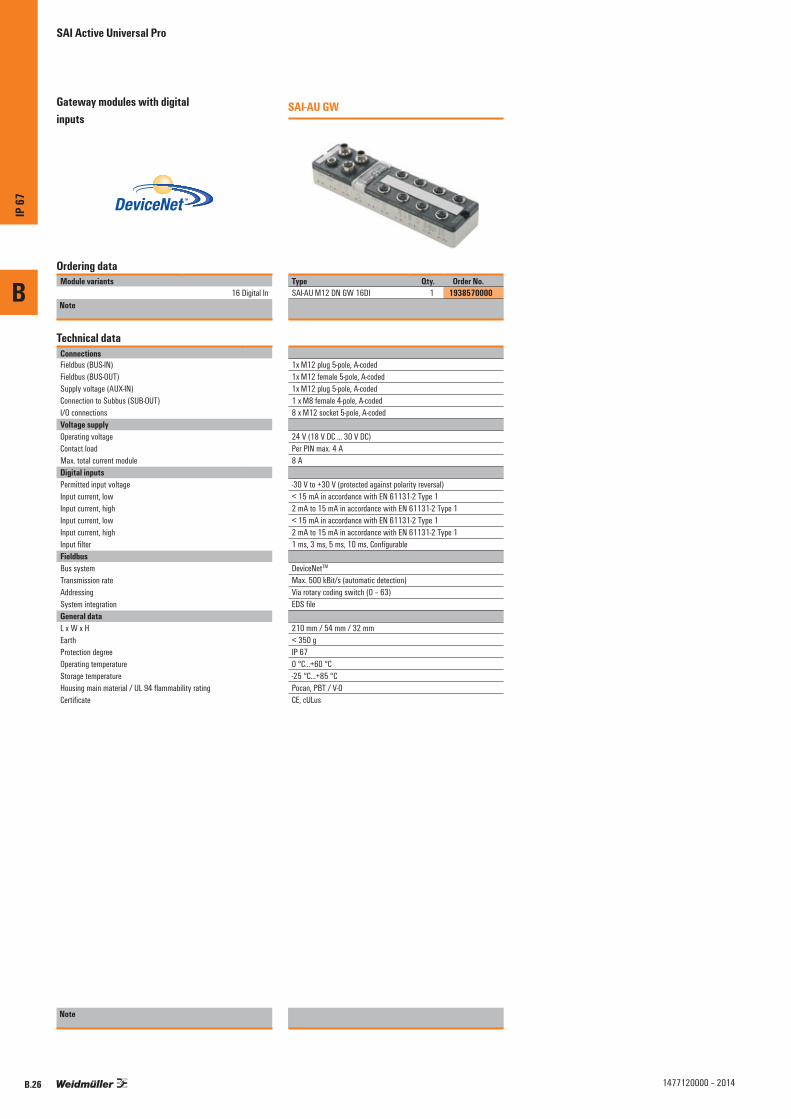
B
IP 67
B.26 1477120000 – 2014
Gateway modules with digital inputs
SAI-AU GW
Ordering dataModule variants
16 Digital InNote
Type Qty. Order No.SAI-AU M12 DN GW 16DI 1 1938570000
Technical dataConnectionsFieldbus (BUS-IN)Fieldbus (BUS-OUT)Supply voltage (AUX-IN)Connection to Subbus (SUB-OUT)I/O connectionsVoltage supplyOperating voltageContact loadMax. total current moduleDigital inputsPermitted input voltageInput current, lowInput current, highInput current, lowInput current, highInput filterFieldbusBus systemTransmission rateAddressingSystem integrationGeneral dataL x W x HEarthProtection degreeOperating temperatureStorage temperatureHousing main material / UL 94 flammability ratingCertificate
1x M12 plug 5-pole, A-coded1x M12 female 5-pole, A-coded1x M12 plug 5-pole, A-coded 1 x M8 female 4-pole, A-coded8 x M12 socket 5-pole, A-coded
24 V (18 V DC ... 30 V DC)Per PIN max. 4 A8 A
-30 V to +30 V (protected against polarity reversal)< 15 mA in accordance with EN 61131-2 Type 12 mA to 15 mA in accordance with EN 61131-2 Type 1< 15 mA in accordance with EN 61131-2 Type 12 mA to 15 mA in accordance with EN 61131-2 Type 11 ms, 3 ms, 5 ms, 10 ms, Configurable
DeviceNetTM
Max. 500 kBit/s (automatic detection)Via rotary coding switch (0 – 63)EDS file
210 mm / 54 mm / 32 mm< 350 gIP 670 °C...+60 °C-25 °C...+85 °CPocan, PBT / V-0CE, cULus
Note
SAI Active Universal Pro
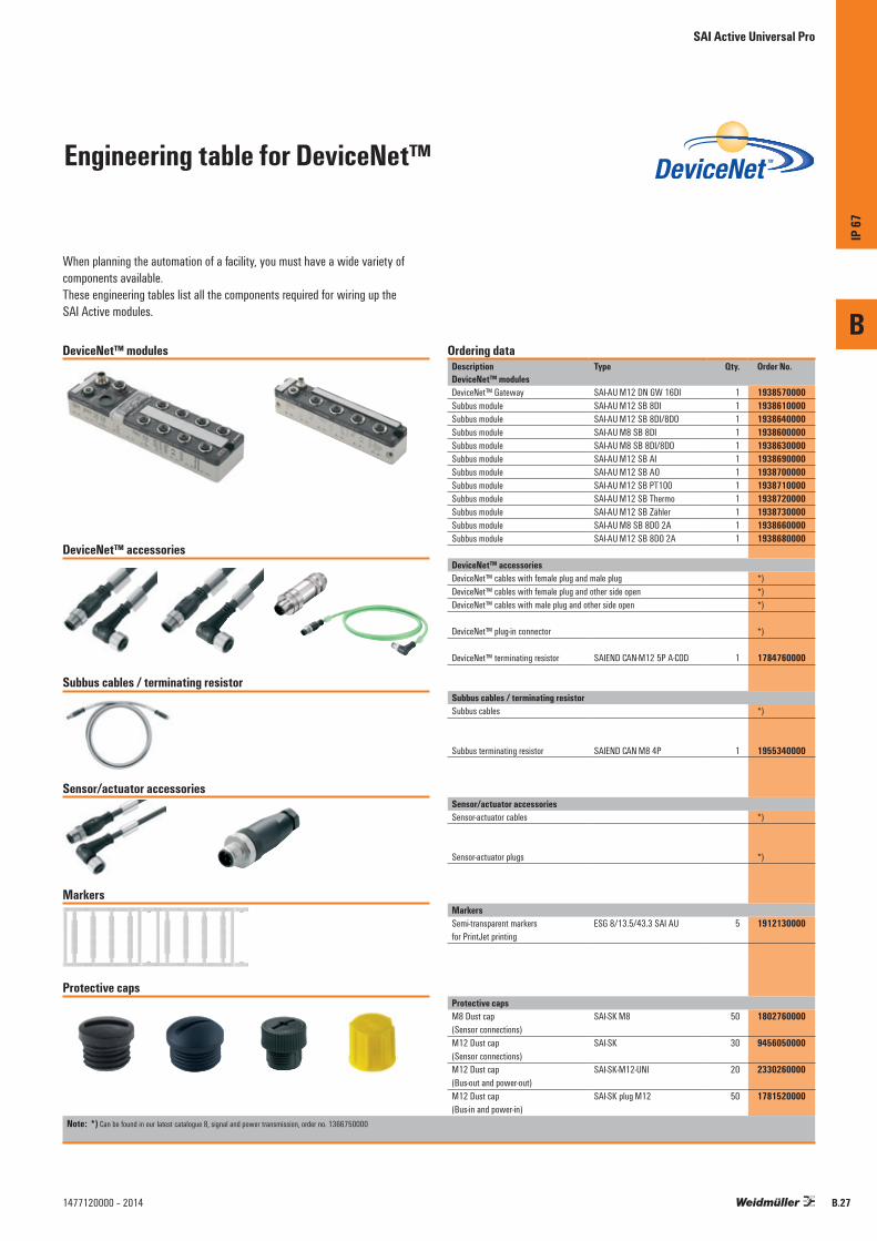
Engineering table for DeviceNet™
SAI Active Universal Pro
When planning the automation of a facility, you must have a wide variety of components available. These engineering tables list all the components required for wiring up the SAI Active modules.
DeviceNet™ modules
DeviceNet™ accessories
Subbus cables / terminating resistor
Sensor/actuator accessories
Markers
Protective caps
Ordering dataDescription Type Qty. Order No.DeviceNet™ modulesDeviceNet™ Gateway SAI-AU M12 DN GW 16DI 1 1938570000Subbus module SAI-AU M12 SB 8DI 1 1938610000Subbus module SAI-AU M12 SB 8DI/8DO 1 1938640000Subbus module SAI-AU M8 SB 8DI 1 1938600000Subbus module SAI-AU M8 SB 8DI/8DO 1 1938630000Subbus module SAI-AU M12 SB AI 1 1938690000Subbus module SAI-AU M12 SB AO 1 1938700000Subbus module SAI-AU M12 SB PT100 1 1938710000Subbus module SAI-AU M12 SB Thermo 1 1938720000Subbus module SAI-AU M12 SB Zähler 1 1938730000Subbus module SAI-AU M8 SB 8DO 2A 1 1938660000Subbus module SAI-AU M12 SB 8DO 2A 1 1938680000
DeviceNet™ accessoriesDeviceNet™ cables with female plug and male plug *)DeviceNet™ cables with female plug and other side open *)DeviceNet™ cables with male plug and other side open *)
DeviceNet™ plug-in connector *)
DeviceNet™ terminating resistor SAIEND CAN-M12 5P A-COD 1 1784760000
Subbus cables / terminating resistorSubbus cables *)
Subbus terminating resistor SAIEND CAN M8 4P 1 1955340000
Sensor/actuator accessoriesSensor-actuator cables *)
Sensor-actuator plugs *)
MarkersSemi-transparent markers for PrintJet printing
ESG 8/13.5/43.3 SAI AU 5 1912130000
Protective capsM8 Dust cap (Sensor connections)
SAI-SK M8 50 1802760000
M12 Dust cap (Sensor connections)
SAI-SK 30 9456050000
M12 Dust cap (Bus-out and power-out)
SAI-SK-M12-UNI 20 2330260000
M12 Dust cap (Bus-in and power-in)
SAI-SK plug M12 50 1781520000
Note: *) Can be found in our latest catalogue 8, signal and power transmission, order no. 1366750000
B
IP 67
B.271477120000 – 2014
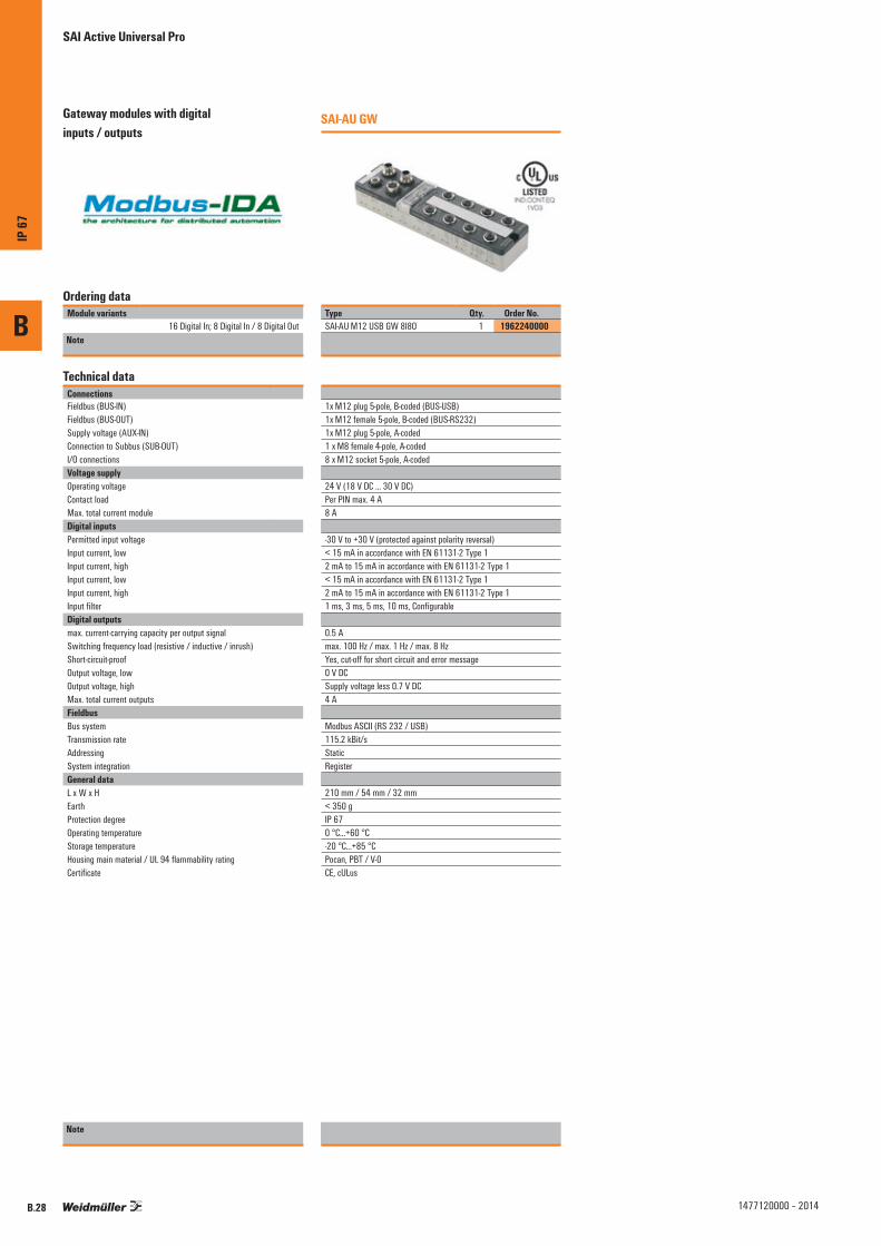
B
IP 67
B.28 1477120000 – 2014
Gateway modules with digital inputs / outputs
SAI-AU GW
Ordering dataModule variants
16 Digital In; 8 Digital In / 8 Digital OutNote
Type Qty. Order No.SAI-AU M12 USB GW 8I8O 1 1962240000
Technical dataConnectionsFieldbus (BUS-IN)Fieldbus (BUS-OUT)Supply voltage (AUX-IN)Connection to Subbus (SUB-OUT)I/O connectionsVoltage supplyOperating voltageContact loadMax. total current moduleDigital inputsPermitted input voltageInput current, lowInput current, highInput current, lowInput current, highInput filterDigital outputsmax. current-carrying capacity per output signalSwitching frequency load (resistive / inductive / inrush)Short-circuit-proofOutput voltage, lowOutput voltage, highMax. total current outputsFieldbusBus systemTransmission rateAddressingSystem integrationGeneral dataL x W x HEarthProtection degreeOperating temperatureStorage temperatureHousing main material / UL 94 flammability ratingCertificate
1x M12 plug 5-pole, B-coded (BUS-USB)1x M12 female 5-pole, B-coded (BUS-RS232)1x M12 plug 5-pole, A-coded 1 x M8 female 4-pole, A-coded8 x M12 socket 5-pole, A-coded
24 V (18 V DC ... 30 V DC)Per PIN max. 4 A8 A
-30 V to +30 V (protected against polarity reversal)< 15 mA in accordance with EN 61131-2 Type 12 mA to 15 mA in accordance with EN 61131-2 Type 1< 15 mA in accordance with EN 61131-2 Type 12 mA to 15 mA in accordance with EN 61131-2 Type 11 ms, 3 ms, 5 ms, 10 ms, Configurable
0.5 Amax. 100 Hz / max. 1 Hz / max. 8 HzYes, cut-off for short circuit and error message0 V DCSupply voltage less 0.7 V DC4 A
Modbus ASCII (RS 232 / USB)115.2 kBit/sStaticRegister
210 mm / 54 mm / 32 mm< 350 gIP 670 °C...+60 °C-20 °C...+85 °CPocan, PBT / V-0CE, cULus
Note
SAI Active Universal Pro
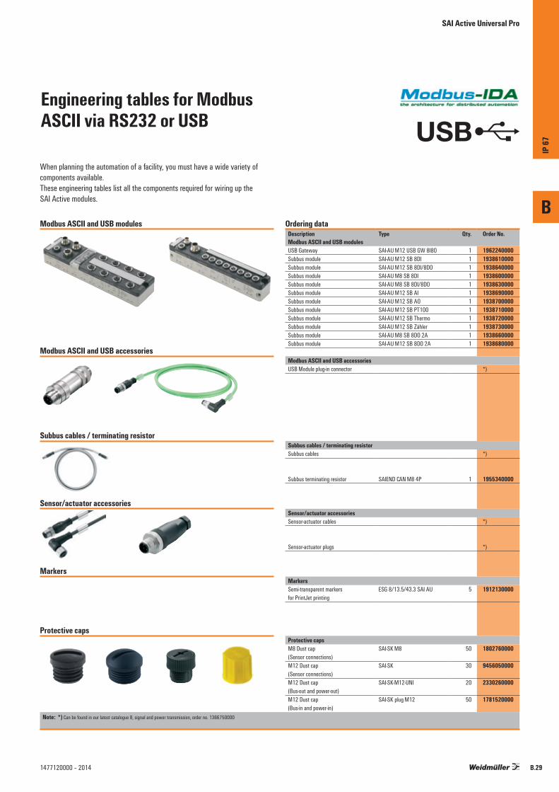
Engineering tables for ModbusASCII via RS232 or USB
SAI Active Universal Pro
When planning the automation of a facility, you must have a wide variety of components available. These engineering tables list all the components required for wiring up the SAI Active modules.
Modbus ASCII and USB modules
Modbus ASCII and USB accessories
Subbus cables / terminating resistor
Sensor/actuator accessories
Markers
Protective caps
Ordering dataDescription Type Qty. Order No.Modbus ASCII and USB modulesUSB Gateway SAI-AU M12 USB GW 8I8O 1 1962240000Subbus module SAI-AU M12 SB 8DI 1 1938610000Subbus module SAI-AU M12 SB 8DI/8DO 1 1938640000Subbus module SAI-AU M8 SB 8DI 1 1938600000Subbus module SAI-AU M8 SB 8DI/8DO 1 1938630000Subbus module SAI-AU M12 SB AI 1 1938690000Subbus module SAI-AU M12 SB AO 1 1938700000Subbus module SAI-AU M12 SB PT100 1 1938710000Subbus module SAI-AU M12 SB Thermo 1 1938720000Subbus module SAI-AU M12 SB Zähler 1 1938730000Subbus module SAI-AU M8 SB 8DO 2A 1 1938660000Subbus module SAI-AU M12 SB 8DO 2A 1 1938680000
Modbus ASCII and USB accessoriesUSB Module plug-in connector *)
Subbus cables / terminating resistorSubbus cables *)
Subbus terminating resistor SAIEND CAN M8 4P 1 1955340000
Sensor/actuator accessoriesSensor-actuator cables *)
Sensor-actuator plugs *)
MarkersSemi-transparent markers for PrintJet printing
ESG 8/13.5/43.3 SAI AU 5 1912130000
Protective capsM8 Dust cap (Sensor connections)
SAI-SK M8 50 1802760000
M12 Dust cap (Sensor connections)
SAI-SK 30 9456050000
M12 Dust cap (Bus-out and power-out)
SAI-SK-M12-UNI 20 2330260000
M12 Dust cap (Bus-in and power-in)
SAI-SK plug M12 50 1781520000
USB
Note: *) Can be found in our latest catalogue 8, signal and power transmission, order no. 1366750000
B
IP 67
B.291477120000 – 2014

B
IP 67
B.30 1477120000 – 2014
Subbus modules with digital inputs/outputs
SAI-AU Digital
Ordering dataModule variants
8 Digital In; 8 Digital In / 8 Digital Out8 Digital In; 8 Digital In / 8 Digital Out
8 Digital Out 2A8 Digital Out 2A
Note
Type Qty. Order No.SAI-AU M8 SB 8DI 1 1938600000SAI-AU M12 SB 8DI 1 1938610000
Technical dataConnectionsSupply voltage (AUX-IN)Connection to Subbus (SUB-IN)Connection to Subbus (SUB-OUT)I/O connectionsVoltage supplyOperating voltageContact loadMax. total current moduleDigital inputsPermitted input voltageInput current, lowInput current, highInput current, lowInput current, highInput filterSeparation of potentials to module electronicsDigital outputsmax. current-carrying capacity per output signalSeparation of potentials to module electronicsSwitching frequency, resistive loadSwitching frequency, inductive loadSwitching frequency, lamp loadShort-circuit-proofOutput voltage, lowOutput voltage, highMax. total current outputsFieldbusBus systemAddressingSystem integrationGeneral dataL x W x HEarthProtection degreeOperating temperatureStorage temperatureHousing main material / UL 94 flammability ratingCertificate
1 x M8 plug 4-pole, A-coded1 x M8 female 4-pole, A-coded4 x M12 female, 5-pole A-coded
24 V (18 V DC ... 30 V DC)
-30 V to +30 V (protected against polarity reversal)< 15 mA in accordance with EN 61131-2 Type 12 mA to 15 mA in accordance with EN 61131-2 Type 1< 15 mA in accordance with EN 61131-2 Type 12 mA to 15 mA in accordance with EN 61131-2 Type 11 ms, 3 ms, 5 ms, 10 ms, Configurable none
Subbusautomaticautomatic
155 mm / 30 mm / 32 mm< 200 gIP 670 °C...+60 °C-25 °C...+85 °CPocan, PBT / 5VACE, cULus
Note
SAI-AU Digital
Type Qty. Order No.SAI-AU M8 SB 8DIO 1 1938630000SAI-AU M12 SB 8DIO 1 1938640000SAI-AU M8 SB 8DO 2A 1 1938660000SAI-AU M12 SB 8DO 2A 1 1938680000
1x M12 plug 5-pole, A-coded1 x M8 plug 4-pole, A-coded1 x M8 female 4-pole, A-coded4 x M12 female, 5-pole A-coded
24 V (18 V DC ... 30 V DC)Per PIN max. 4 A8 A
-30 V to +30 V (protected against polarity reversal)< 15 mA in accordance with EN 61131-2 Type 12 mA to 15 mA in accordance with EN 61131-2 Type 1< 15 mA in accordance with EN 61131-2 Type 12 mA to 15 mA in accordance with EN 61131-2 Type 11 ms, 3 ms, 5 ms, 10 ms, Configurable none
2 Anonemax. 100 Hzmax. 1 Hzmax. 8 HzYes, cut-off for short circuit and error message0 V DCSupply voltage less 0.7 V DC4 A
Subbusautomaticautomatic
180 mm / 30 mm / 32 mm< 200 gIP 670 °C...+60 °C-25 °C...+85 °CPocan, PBT / 5VACE, cULus
SAI Active Universal Pro
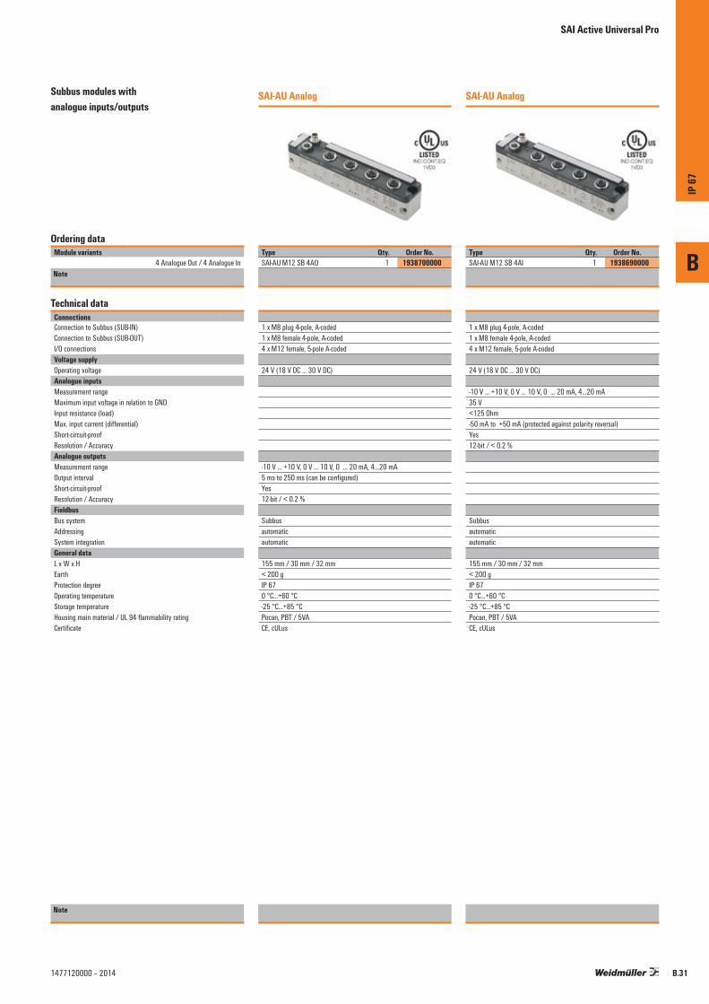
B
IP 67
B.311477120000 – 2014
Subbus modules with analogue inputs/outputs
SAI-AU Analog
Ordering dataModule variants
4 Analogue Out / 4 Analogue InNote
Type Qty. Order No.SAI-AU M12 SB 4AO 1 1938700000
Technical dataConnectionsConnection to Subbus (SUB-IN)Connection to Subbus (SUB-OUT)I/O connectionsVoltage supplyOperating voltageAnalogue inputsMeasurement rangeMaximum input voltage in relation to GNDInput resistance (load)Max. input current (differential)Short-circuit-proofResolution / AccuracyAnalogue outputsMeasurement rangeOutput intervalShort-circuit-proofResolution / AccuracyFieldbusBus systemAddressingSystem integrationGeneral dataL x W x HEarthProtection degreeOperating temperatureStorage temperatureHousing main material / UL 94 flammability ratingCertificate
1 x M8 plug 4-pole, A-coded1 x M8 female 4-pole, A-coded4 x M12 female, 5-pole A-coded
24 V (18 V DC ... 30 V DC)
-10 V ... +10 V, 0 V ... 10 V, 0 … 20 mA, 4…20 mA5 ms to 250 ms (can be configured)Yes12-bit / < 0.2 %
Subbusautomaticautomatic
155 mm / 30 mm / 32 mm< 200 gIP 670 °C...+60 °C-25 °C...+85 °CPocan, PBT / 5VACE, cULus
Note
SAI-AU Analog
Type Qty. Order No.SAI-AU M12 SB 4AI 1 1938690000
1 x M8 plug 4-pole, A-coded1 x M8 female 4-pole, A-coded4 x M12 female, 5-pole A-coded
24 V (18 V DC ... 30 V DC)
-10 V ... +10 V, 0 V ... 10 V, 0 … 20 mA, 4…20 mA35 V<125 Ohm-50 mA to +50 mA (protected against polarity reversal)Yes12-bit / < 0.2 %
Subbusautomaticautomatic
155 mm / 30 mm / 32 mm< 200 gIP 670 °C...+60 °C-25 °C...+85 °CPocan, PBT / 5VACE, cULus
SAI Active Universal Pro

B
IP 67
B.32 1477120000 – 2014
SAI-AU Counter
Ordering dataModule variants
2 counter inputs / 2 gate outputsNote
Type Qty. Order No.SAI-AU M12 SB 2Counter 1 1938730000
Technical dataConnectionsSupply voltage (AUX-IN)Connection to Subbus (SUB-IN)Connection to Subbus (SUB-OUT)I/O connectionsVoltage supplyOperating voltageContact loadMax. total current moduleFunctional inputsCounting breadthSwitching frequencyNumber of inputsFieldbusBus systemAddressingSystem integrationGeneral dataL x W x HEarthProtection degreeOperating temperatureStorage temperatureHousing main material / UL 94 flammability ratingCertificate
1x M12 plug 5-pole, A-coded1 x M8 plug 4-pole, A-coded1 x M8 female 4-pole, A-coded4 x M12 female, 5-pole A-coded
24 V (18 V DC ... 30 V DC)Per PIN max. 4 A8 A
32 Bit100 kHz2 x enables, 2 x counters, 2 x count directions
Subbusautomaticautomatic
180 mm / 30 mm / 32 mm< 200 gIP 670 °C...+60 °C-25 °C...+85 °CPocan, PBT / 5VACE, cULus
Note
SAI Active Universal Pro
Subbus modules with functional inputs

B
IP 67
B.331477120000 – 2014
SAI-AU Thermo
Ordering dataModule variants
4 thermal inputsNote
Type Qty. Order No.SAI-AU M12 SB 4Thermo 1 1938720000
Technical dataConnectionsConnection to Subbus (SUB-IN)Connection to Subbus (SUB-OUT)I/O connectionsVoltage supplyOperating voltageFunctional inputsSensorTemperature rangeResolutionConversion timeMeasurement errorInput filtercold junction compensationFieldbusBus systemAddressingSystem integrationGeneral dataL x W x HEarthProtection degreeOperating temperatureStorage temperatureHousing main material / UL 94 flammability ratingCertificate
1 x M8 plug 4-pole, A-coded1 x M8 female 4-pole, A-coded4 x M12 female, 5-pole A-coded
24 V (18 V DC ... 30 V DC)
Types J, K, L, B, E, N, R, S, T, U: mV readingsTypical for sensor, Preset Type K, -100 °C to 1,370 °C0.1 °C per digit250 ms (can be configured to 70 ms)< ± 0.5 % (of measuring range limit)ConfigurableExternal PT1000 connection on pins 1 and 3 (GND)
Subbusautomaticautomatic
155 mm / 30 mm32 mm< 200 gIP 670 °C...+60 °C-25 °C...+85 °CPocan, PBT / 5VACE, cULus
Note
SAI Active Universal Pro
Subbus modules with functional inputs

B
IP 67
B.34 1477120000 – 2014
SAI-AU PT100
Ordering dataModule variants
4 PT100 inputsNote
Type Qty. Order No.SAI-AU M12 SB 4PT100 1 1938710000
Technical dataConnectionsConnection to Subbus (SUB-IN)Connection to Subbus (SUB-OUT)I/O connectionsVoltage supplyOperating voltageFunctional inputsSensor
ResolutionConversion timeMeasurement errorInput filterMeasurement range for PT sensorsMeasurement range for Ni sensorsResistance measurementPotentiometerMeasurement currentFieldbusBus systemAddressingSystem integrationGeneral dataL x W x HEarthProtection degreeOperating temperatureStorage temperatureHousing main material / UL 94 flammability ratingCertificate
1 x M8 plug 4-pole, A-coded1 x M8 female 4-pole, A-coded4 x M12 female, 5-pole A-coded
24 V (18 V DC ... 30 V DC)
N100, N1000, N120, PT100, PT1000, PT200, PT300, PT500, Potentiometer connection, Resistance measurement0.1 °C per digit250 ms (can be configured to 65 ms)< ± 1 °CConfigurable-200 °C … + 850 °C-60 °C … +250 °Cmax. 4000 Ohm100 to 4000 Ω (three-wire connection)Typically 0.5 mA
Subbusautomaticautomatic
155 mm / 30 mm / 32 mm< 200 gIP 670 °C...+60 °C-25 °C...+85 °CPocan, PBT / 5VACE, cULus
Note
SAI Active Universal Pro
Subbus modules with functional inputs

B
IP 67
B.351477120000 – 2014

Accessories for sensor cables
Sensor Cables u-remote
Weidmüller is also offering the required sensor and actuator cables as a supplement to the new, innovative u-remote system. Generally, there are two different courses of action for cabling. • Circular plug cables assembled on one end • Cables assembled on both ends with u-remote plug-in
connectors already connectedTo make things easier to understand, only the M8 and M12 cables have been shown in this diagram. Actuator cables can also be found in catalogue 8.
The PUR cable used here is black, halogen-free and suitable for dragline cable carriers. The PVC cable is suitable for dragline cable carriers Further technical details are available in catalogue 8.The minimum order quantity for each type of cable is 1 unit. This means that sample parts and the demand for replacement parts are also easy to manage.
S A I L - U R P M 8 W - 3 L 1.5 UL = metal nut cable
V = PVC-PVCU = PUR halogen free
UGE = PUR halogen free, yellowT = welding spark resistant
L = LED
cable length1,5 m3,0 m5,0 m
10,0 mX m
M12M8
G = straightW = angled
345C = closerO = opener
URP = u-remote connector PUSH INURZ = u-remote twin connector
number of polesa coded
female
Description code exampleStandard cable lengths
The cable lengths listed under order data are all 1.5 m. To order any other standard cable lengths, simply change the last four numbers in the order number.Additional lengths can be supplied at the request of the customer.
Order dataType Length Order No.
1.5 m xxxxxx01503.0 m xxxxxx03005.0 m xxxxxx0500
10.0 m xxxxxx1000
B
IP 67
B.36 1477120000 – 2014
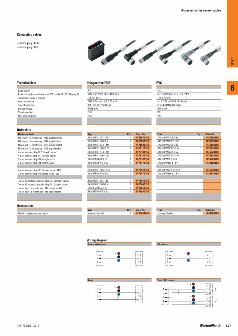
Accessories for sensor cables
Connecting cables
u-remote plug / M12u-remote plug / M8
Technical data
Rated currentRated voltage (in accordance with VDE standard 0110 ISO group C)Temperature range of housingCore cross-sectionType of protectionContact surfaceSheath materialWire core insulation
Order dataModule variantsNO contact / u-remote plug - M12 straight socketNO contact / u-remote plug - M12 angled socketNC contact / u-remote plug - M12 straight socketNC contact / u-remote plug - M12 angled socket4-pin / u-remote plug - M12 straight socket4-pin / u-remote plug - M12 angled socket3-pin / u-remote plug - M8 straight socket3-pin / u-remote plug - M8 angled socket
4-pin / u-remote plug - M12 angled socket - LED3-pin / u-remote plug - M8 angled socket - LED
Twin / NO contact / u-remote plug - M12 straight socketTwin / NO contact / u-remote plug - M12 angled socketTwin / 3-pin / u-remote plug - M8 straight socketTwin / 3-pin / u-remote plug - M8 angled socket
Accessories
M8/M12 cable gland tool torque
Halogen-free PUR
4 AM12: 250 V/M8: 60 V / LED: 24 V–25 to +85 °CM12: 0.34 mm²/ M8: 0.25 mm²IP 67/68 (M12/M8 head)Gold-platedPURPUR
Type Qty. Order No.SAIL-URPM12G-C-1.5U 1 1475070150SAIL-URPM12W-C-1.5U 1 1475080150SAIL-URPM12G-O-1.5U 1 1475090150SAIL-URPM12W-O-1.5U 1 1475120150SAIL-URPM12G-4-1.5U 1 1475130150SAIL-URPM12W-4-1.5U 1 1475140150SAIL-URPM8G-3-1.5U 1 1475160150SAIL-URPM8W-3-1.5U 1 1475170150
SAIL-URPM12W-2L-1.5U 1 1475450150SAIL-URPM8W-2L-1.5U 1 1475470150
SAIL-URZM12G-C-1.5U 1 1475030150SAIL-URZM12W-C-1.5U 1 1475040150SAIL-URZM8G-3-1.5U 1 1475050150SAIL-URZM8W-3-1.5U 1 1475060150
Type Qty. Order No.Screwty®-Set-DM 1 1920000000
PVC
4 AM12: 250 V/M8: 60 V / LED: 24 V–25 to +85 °CM12: 0.34 mm²/ M8: 0.25 mm²IP 67/68 (M12/M8 head)Gold-platedPVCPVC
Type Qty. Order No.SAIL-URPM12G-C-1.5V 1 1475280000SAIL-URPM12W-C-1.5V 1 1475290000SAIL-URPM12G-O-1.5V 1 1475300000SAIL-URPM12W-O-1.5V 1 1475310000SAIL-URPM12G-4-1.5V 1 1475320000SAIL-URPM12W-4-1.5V 1 1475330000SAIL-URPM8G-3-1.5V 1 1475340000SAIL-URPM8W-3-1.5V 1 1475350000
SAIL-URPM12W-2L-1.5V 1 1475500150SAIL-URPM8W-2L-1.5V 1 1475510150
Type Qty. Order No.Screwty®-Set-DM 1 1920000000
Wiring diagram3-pin / NO contact
312
143
+
–
NC contact
312
143
+
–
4-pin
3124
1432
Twin / NO contact
124
3143
143
1
2
+
–
+
–
CABL
E OU
TLET
CABL
E OU
TLET
B
IP 67
B.371477120000 – 2014

Accessories for sensor cables
M12 cables with connector at one end only 3-pin
143
+
–
4-pin
1432
+
–
Technical data
Rated currentRated voltage (in accordance with VDE standard 0110 ISO group C)Temperature range of housingCore cross-sectionType of protectionContact surfaceSheath materialWire core insulation
Order dataModule variantsPVC M12 straight socket Halogen-free PUR M12 straight socketYellow halogen-free PUR M12 straight socketHalogen-free PUR M12 straight socket, resistant to welding beads
PVC M12 angled socketHalogen-free PUR M12 angled socketYellow halogen-free PUR M12 angled socketHalogen-free PUR M12 angled socket, resistant to welding beads
Accessories
M8/M12 cable gland tool torque
4 A 250 V–25 to +85 °C0.34 mm²IP 67/68Gold-platedPURPUR
Type Qty. Order No.SAIL-M12BG-3-1.5V 1 1925570150SAIL-M12BG-3-1.5U 1 9457820150SAIL-M12BG-3-1.5UGE 1 1092910150SAIL-M12BG-3-1.5T 1 1968590150
SAIL-M12BW-3-1.5V 1 1925630150SAIL-M12BW-3-1.5U 1 9457320150SAIL-M12BW-3-1.5UGE 1 1092940150SAIL-M12BW-3-1.5T 1 1968560150
Type Qty. Order No.Screwty®-Set-DM 1 1920000000
4 A 250 V–25 to +85 °C0.34 mm²IP 67/68Gold-platedPVCPVC
Type Qty. Order No.SAIL-M12BG-4-1.5V 1 1925580150SAIL-M12BG-4-1.5U 1 9457730150SAIL-M12BG-4-1.5UGE 1 1092920150SAIL-M12BG-4-1.5T 1 1968580150
SAIL-M12BW-4-1.5V 1 1925640150SAIL-M12BW-4-1.5U 1 9457740150SAIL-M12BW-4-1.5UGE 1 1092960150SAIL-M12BW-4-1.5T 1 1968570150
Type Qty. Order No.Screwty®-Set-DM 1 1920000000
B
IP 67
B.38 1477120000 – 2014

Accessories for sensor cables
M8 cables with connector at one end only 3-pin
143
+
–
4-pin
1432
+
–
Technical data
Rated currentRated voltage (in accordance with VDE standard 0110 ISO group C)Temperature range of housingCore cross-sectionType of protectionContact surfaceSheath materialWire core insulation
Ordering dataModule variantsPVC M8 straight socketHalogen-free PUR M8 straight socketYellow halogen-free PUR M8 straight socket
PVC M8 angled socketHalogen-free PUR M8 angled socketYellow halogen-free PUR M8 angled socket
Accessories
M8/M12 cable gland tool torque
4 A60 V–25 to +85 °C0.25 mm²IP 67/68Gold-platedPURPUR
Type Qty. Order No.SAIL-M8BG-3-1.5V 1 1927240150SAIL-M8BG-3-1.5U 1 9457450150SAIL-M8BG-3-1.5UGE 1 1093190150
SAIL-M8BW-3-1.5V 1 1927320150SAIL-M8BW-3-1.5U 1 9457380150SAIL-M8BW-3-1.5UGE 1 1093220150
Type Qty. Order No.Screwty®-Set-DM 1 1920000000
4 A30 V–25 to +85 °C0.25 mm²IP 67/68Gold-platedPVCPVC
Type Qty. Order No.SAIL-M8BG-4-1.5V 1 1927260150SAIL-M8BG-4-1.5U 1 9457850150SAIL-M8BG-4-1.5UGE 1 1093200150
SAIL-M8BW-4-1.5V 1 1927340150SAIL-M8BW-4-1.5U 1 9456150150SAIL-M8BW-4-1.5UGE 1 1093240150
Type Qty. Order No.Screwty®-Set-DM 1 1920000000
B
IP 67
B.391477120000 – 2014

Accessories for sensor cables
M12/M8 cables with connector at one end onlyWith LED
3-pin / 2 LEDs
14
3
yellow green
+
–
4-pin / 2 LEDs
14
32
yellow green
+
–
Technical data
Rated currentRated voltage (in accordance with VDE standard 0110 ISO group C)Temperature range of housingCore cross-sectionType of protectionContact surfaceSheath materialWire core insulation
Order dataModule variantsPVC M12 angled socketHalogen-free PUR M12 angled socketYellow halogen-free PUR M12 angled socketHalogen-free PUR M12 angled socket, resistant to welding beads
PVC M8 angled socketHalogen-free PUR M8 angled socketYellow halogen-free PUR M8 angled socket
Accessories
M8/M12 cable gland tool torque
4 A24 V–25 to +85 °CM12: 0.34 mm²/ M8: 0.25 mm²IP 67/68Gold-platedPURPUR
Type Qty. Order No.SAIL-M12BW-3L1.5V 1925460150SAIL-M12BW-3L1.5U 9457800150SAIL-M12BW-3L1.5UGE 1114880150SAIL-M12BW-3L1.5T 1004330150
SAIL-M8BW-3L1.5V 1927350150SAIL-M8BW-3L1.5U 9457460150SAIL-M8BW-3L1.5UGE 1093210150
Type Qty. Order No.Screwty®-Set-DM 1 1920000000
4 A24 V–25 to +85 °CM12: 0.34 mm²/ M8: 0.25 mm²IP 67/68Gold-platedPURPUR
Type Qty. Order No.SAIL-M12BW-4-2L1.5V 1925470150SAIL-M12BW-4-2L1.5U 9456380150SAIL-M12BW-4-2L1.5UGE 1092950150SAIL-M12BW-4-2L1.5T 1007000150
SAIL-M8BW-4L1.5V 1927360150SAIL-M8BW-4L1.5U 1906400150SAIL-M8BW-4L1.5UGE 1093230150
Type Qty. Order No.Screwty®-Set-DM 1 1920000000
B
IP 67
B.40 1477120000 – 2014
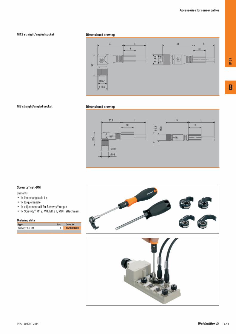
M12 straight/angled socket
M8 straight/angled socket
Dimensioned drawing
37
18 18
44
32
L
Ø 14.6
Ø 14
.6
M12x1
M12
x1
L
Dimensioned drawing
27.4
18 18
32
19.7
L
Ø 9.9Ø
9.9
M8x1
M8x
1
L
Accessories for sensor cables
Ordering dataType Qty. Order No.Screwty®-Set-DM 1 1920000000
Screwty® set -DMContents: • 1x interchangeable bit• 1x torque handle• 1x adjustment aid for Screwty® torque• 1x Screwty® M12, M8, M12 F, M8 F attachment
B
IP 67
B.411477120000 – 2014

B
IP 67
B.42 1477120000 – 2014

X.1
X
1477120000 – 2014
Inde
x
Index
Index Index Type X.2
Index Order No. X.4
Addresses worldwide X.6
Contents

X.2
X
1477120000 – 2014
Type Order No. Page Type Order No. Page Type Order No. Page
Inde
x / Ty
pe
DDEK 5/8-11.5 MC NE WS 2,7542,7542,7542A.61DEK 5/8-11.5 MC SDR 2,7542,7542,7542A.61
EESG 8/13.5/43.3 SAI AU 2,7542,7542,7542B.12ESO UR20 DIN A4 WS 2,7542,7542,7542A.61
KKOSM BHZ5.00 2,7542,7542,7542A.61
PPM 2.7/2.6 MC NE WS 2,7542,7542,7542A.61PM 2.7/2.6 MC SDR 2,7542,7542,7542A.61
RRS 16IO 1W H S 2,7542,7542,7542A.21RS F20 LP2N 5/20 2,7542,7542,7542A.45
SSAI-AU M12 CAN 16DI 2,7542,7542,7542, B.6SAI-AU M12 CAN 16DI/8DO 2,7542,7542,7542, B.6SAI-AU M12 CAN AI/AO/DI 2,7542,7542,7542, B.6SAI-AU M12 DN 16DI 2,7542,7542,7542, B.6SAI-AU M12 DN 16DI/8DO 2,7542,7542,7542, B.6SAI-AU M12 DN AI/AO/DI 2,7542,7542,7542, B.6SAI-AU M12 DN GW 16DI 2,7542,7542,7542, B.6SAI-AU M12 PB 16DI 2,7542,7542,7542, B.6SAI-AU M12 PB 16DI/8DO 2,7542,7542,7542, B.6SAI-AU M12 PB 8DI8DO 2A 2,7542,7542,7542, B.6SAI-AU M12 PB AI/AO/DI 2,7542,7542,7542, B.6SAI-AU M12 PB GW 16DI 2,7542,7542,7542, B.6SAI-AU M12 SB 2Counter 2,7542,7542,7542, B.6SAI-AU M12 SB 4AI 2,7542,7542,7542, B.6SAI-AU M12 SB 4AO 2,7542,7542,7542, B.6SAI-AU M12 SB 4PT100 2,7542,7542,7542, B.6SAI-AU M12 SB 4Thermo 2,7542,7542,7542, B.6SAI-AU M12 SB 8DI 2,7542,7542,7542, B.6SAI-AU M12 SB 8DIO 2,7542,7542,7542, B.6SAI-AU M12 SB 8DO 2A 2,7542,7542,7542, B.6SAI-AU M12 USB GW 8I8O 2,7542,7542,7542, B.6SAI-AU M8 CAN 16DI 2,7542,7542,7542, B.6SAI-AU M8 CAN 16DI/8DO 2,7542,7542,7542, B.6SAI-AU M8 DN 16DI 2,7542,7542,7542, B.6SAI-AU M8 DN 16DI/8DO 2,7542,7542,7542, B.6SAI-AU M8 PB 16DI 2,7542,7542,7542, B.6SAI-AU M8 PB 16DI/8DO 2,7542,7542,7542, B.6SAI-AU M8 PB 8DI8DO 2A 2,7542,7542,7542, B.6SAI-AU M8 PB GW 16DI 2,7542,7542,7542, B.6SAI-AU M8 SB 8DI 2,7542,7542,7542, B.6SAI-AU M8 SB 8DIO 2,7542,7542,7542, B.6SAI-AU M8 SB 8DO 2A 2,7542,7542,7542, B.6SAI-SK M8 2,7542,7542,7542B.12SAI-SK Stecker M12 2,7542,7542,7542B.12SAI-SK-M12 2,7542,7542,7542B.12SAI-SK-M12-UNI 2,7542,7542,7542B.12SAIEND CAN M8 4P 2,7542,7542,7542B.25SAIEND CAN-M12 5P A-COD 2,7542,7542,7542B.16SAIEND PB M12 4P B-COD 2,7542,7542,7542B.12SAIL-M12BG-3-1.5T 2,7542,7542,7542B.38SAIL-M12BG-3-1.5U 2,7542,7542,7542B.38SAIL-M12BG-3-1.5UGE 2,7542,7542,7542B.38SAIL-M12BG-3-1.5V 2,7542,7542,7542B.38SAIL-M12BG-4-1.5T 2,7542,7542,7542B.38SAIL-M12BG-4-1.5U 2,7542,7542,7542B.38SAIL-M12BG-4-1.5UGE 2,7542,7542,7542B.38SAIL-M12BG-4-1.5V 2,7542,7542,7542B.38SAIL-M12BW-3-1.5T 2,7542,7542,7542B.38SAIL-M12BW-3-1.5U 2,7542,7542,7542B.38SAIL-M12BW-3-1.5UGE 2,7542,7542,7542B.38SAIL-M12BW-3-1.5V 2,7542,7542,7542B.38SAIL-M12BW-3L1.5T 2,7542,7542,7542B.40SAIL-M12BW-3L1.5U 2,7542,7542,7542B.40SAIL-M12BW-3L1.5UGE 2,7542,7542,7542B.40SAIL-M12BW-3L1.5V 2,7542,7542,7542B.40SAIL-M12BW-4-1.5T 2,7542,7542,7542B.38SAIL-M12BW-4-1.5U 2,7542,7542,7542B.38SAIL-M12BW-4-1.5UGE 2,7542,7542,7542B.38SAIL-M12BW-4-1.5V 2,7542,7542,7542B.38SAIL-M12BW-4-2L1.5T 2,7542,7542,7542B.40SAIL-M12BW-4-2L1.5U 2,7542,7542,7542B.40SAIL-M12BW-4-2L1.5UGE 2,7542,7542,7542B.40SAIL-M12BW-4-2L1.5V 2,7542,7542,7542B.40SAIL-M8BG-3-1.5U 2,7542,7542,7542B.39SAIL-M8BG-3-1.5UGE 2,7542,7542,7542B.39SAIL-M8BG-3-1.5V 2,7542,7542,7542B.39SAIL-M8BG-4-1.5U 2,7542,7542,7542B.39SAIL-M8BG-4-1.5UGE 2,7542,7542,7542B.39SAIL-M8BG-4-1.5V 2,7542,7542,7542B.39SAIL-M8BW-3-1.5U 2,7542,7542,7542B.39SAIL-M8BW-3-1.5UGE 2,7542,7542,7542B.39SAIL-M8BW-3-1.5V 2,7542,7542,7542B.39SAIL-M8BW-3L1.5U 2,7542,7542,7542B.40
SAIL-M8BW-3L1.5UGE 2,7542,7542,7542B.40SAIL-M8BW-3L1.5V 2,7542,7542,7542B.40SAIL-M8BW-4-1.5U 2,7542,7542,7542B.39SAIL-M8BW-4-1.5UGE 2,7542,7542,7542B.39SAIL-M8BW-4-1.5V 2,7542,7542,7542B.39SAIL-M8BW-4L1.5U 2,7542,7542,7542B.40SAIL-M8BW-4L1.5UGE 2,7542,7542,7542B.40SAIL-M8BW-4L1.5V 2,7542,7542,7542B.40SAIL-URPM12G-4-1.5U 2,7542,7542,7542B.37SAIL-URPM12G-4-X.XV 2,7542,7542,7542B.37SAIL-URPM12G-C-1.5U 2,7542,7542,7542B.37SAIL-URPM12G-C-X.XV 2,7542,7542,7542B.37SAIL-URPM12G-O-1.5U 2,7542,7542,7542B.37SAIL-URPM12G-O-X.XV 2,7542,7542,7542B.37SAIL-URPM12W-2L-1.5U 2,7542,7542,7542B.37SAIL-URPM12W-2L-1.5V 2,7542,7542,7542B.37SAIL-URPM12W-4-1.5U 2,7542,7542,7542B.37SAIL-URPM12W-4-X.XV 2,7542,7542,7542B.37SAIL-URPM12W-C-1.5U 2,7542,7542,7542B.37SAIL-URPM12W-C-X.XV 2,7542,7542,7542B.37SAIL-URPM12W-O-1.5U 2,7542,7542,7542B.37SAIL-URPM12W-O-X.XV 2,7542,7542,7542B.37SAIL-URPM8G-3-1.5U 2,7542,7542,7542B.37SAIL-URPM8G-C-X.XV 2,7542,7542,7542B.37SAIL-URPM8W-2L-1.5U 2,7542,7542,7542B.37SAIL-URPM8W-2L-1.5V 2,7542,7542,7542B.37SAIL-URPM8W-3-1.5U 2,7542,7542,7542B.37SAIL-URPM8W-C-X.XV 2,7542,7542,7542B.37SAIL-URZM12G-C-1.5U 2,7542,7542,7542B.37SAIL-URZM12W-C-1.5U 2,7542,7542,7542B.37SAIL-URZM8G-3-1.5U 2,7542,7542,7542B.37SAIL-URZM8W-3-1.5U 2,7542,7542,7542B.37Screwty Set -DM 2,7542,7542,7542B.37
TTHM UR20 GE 2,7542,7542,7542A.61THM UR20 WS 2,7542,7542,7542A.61
UUR20 PK 1315570000 2,7542,7542,7542A.63UR20 PK 1334870000 2,7542,7542,7542A.63UR20-16AUX-FE 2,7542,7542,7542A.61UR20-16AUX-GND-I 2,7542,7542,7542A.61UR20-16AUX-GND-O 2,7542,7542,7542A.61UR20-16AUX-I 2,7542,7542,7542A.61UR20-16AUX-O 2,7542,7542,7542A.61UR20-16DI-P 2,7542,7542,7542A.20UR20-16DI-P-PLC-INT 2,7542,7542,7542A.21UR20-16DO-P 2,7542,7542,7542A.29UR20-16DO-P-PLC-INT 2,7542,7542,7542A.30UR20-1CNT-100-1DO 2,7542,7542,7542A.35UR20-2CNT-100 2,7542,7542,7542A.36UR20-2DI-P-TS 2,7542,7542,7542A.22UR20-2PWM-PN-0.5A 2,7542,7542,7542A.39UR20-2PWM-PN-2A 2,7542,7542,7542A.40UR20-4AI-RTD-DIAG 2,7542,7542,7542A.48UR20-4AI-TC-DIAG 2,7542,7542,7542A.47UR20-4AI-UI-12 2,7542,7542,7542A.44UR20-4AI-UI-16 2,7542,7542,7542A.43UR20-4AO-UI-16 2,7542,7542,7542A.51UR20-4DI-P 2,7542,7542,7542A.17UR20-4DI-P-TS 2,7542,7542,7542A.23UR20-4DO-P 2,7542,7542,7542A.25UR20-4DO-P-2A 2,7542,7542,7542A.26UR20-4DO-PN-2A 2,7542,7542,7542A.27UR20-4RO-CO-255 2,7542,7542,7542A.32UR20-4RO-SSR-255 2,7542,7542,7542A.31UR20-8AI-I-PLC-INT 2,7542,7542,7542A.45UR20-8DI-P-2W 2,7542,7542,7542A.18UR20-8DI-P-3W 2,7542,7542,7542A.19UR20-8DO-P 2,7542,7542,7542A.28UR20-BM-PF-I-SP 2,7542,7542,7542A.63UR20-BM-PF-O-SP 2,7542,7542,7542A.63UR20-BM-SIL-SP 2,7542,7542,7542A.63UR20-EBK-ACC 2,7542,7542,7542A.61UR20-EBK-ACC 2,7542,7542,7542A.62UR20-EM-1315170000-SP 2,7542,7542,7542A.63UR20-EM-1315200000-SP 2,7542,7542,7542A.63UR20-EM-1315210000-SP 2,7542,7542,7542A.63UR20-EM-1315220000-SP 2,7542,7542,7542A.63UR20-EM-1315230000-SP 2,7542,7542,7542A.63UR20-EM-1315240000-SP 2,7542,7542,7542A.63UR20-EM-1315250000-SP 2,7542,7542,7542A.63UR20-EM-1315270000-SP 2,7542,7542,7542A.63UR20-EM-1315540000-SP 2,7542,7542,7542A.63UR20-EM-1315550000-SP 2,7542,7542,7542A.63UR20-EM-1315570000-SP 2,7542,7542,7542A.63UR20-EM-1315590000-SP 2,7542,7542,7542A.63UR20-EM-1315600000-SP 2,7542,7542,7542A.63UR20-EM-1315610000-SP 2,7542,7542,7542A.63UR20-EM-1315620000-SP 2,7542,7542,7542A.63UR20-EM-1315670000-SP 2,7542,7542,7542A.63UR20-EM-1315680000-SP 2,7542,7542,7542A.63UR20-EM-1315700000-SP 2,7542,7542,7542A.63UR20-EM-1315710000-SP 2,7542,7542,7542A.63UR20-EM-1315770000-SP 2,7542,7542,7542A.63UR20-EM-1334740000-SP 2,7542,7542,7542A.63
UR20-EM-1334770000-SP 2,7542,7542,7542A.63UR20-EM-1334780000-SP 2,7542,7542,7542A.63UR20-EM-1334790000-SP 2,7542,7542,7542A.63UR20-EM-1334800000-SP 2,7542,7542,7542A.63UR20-EM-1334810000-SP 2,7542,7542,7542A.63UR20-EM-1335030000-SP 2,7542,7542,7542A.63UR20-EM-1335040000-SP 2,7542,7542,7542A.63UR20-EM-1335050000-SP 2,7542,7542,7542A.63UR20-EM-1394390000-SP 2,7542,7542,7542A.63UR20-EM-1394400000-SP 2,7542,7542,7542A.63UR20-EM-1394400000-SP 2,7542,7542,7542A.63UR20-EM-1394420000-SP 2,7542,7542,7542A.63UR20-EM-1460140000-SP 2,7542,7542,7542A.63UR20-EM-1460150000-SP 2,7542,7542,7542A.63UR20-ES 2,7542,7542,7542A.62UR20-FBC-EC 2,7542,7542,7542A.13UR20-FBC-MOD 2,7542,7542,7542A.15UR20-FBC-PB-DP 2,7542,7542,7542, A.9UR20-FBC-PN-IRT 2,7542,7542,7542A.11UR20-PF-I 2,7542,7542,7542A.53UR20-PF-O 2,7542,7542,7542A.54UR20-PF-O-1DI-SIL 2,7542,7542,7542A.57UR20-PF-O-2DI-DELAY-SIL 2,7542,7542,7542A.59UR20-PF-O-2DI-SIL 2,7542,7542,7542A.58UR20-PK-1315170000-SP 2,7542,7542,7542A.63UR20-PK-1315180000-SP 2,7542,7542,7542A.63UR20-PK-1315200000-SP 2,7542,7542,7542A.63UR20-PK-1315210000-SP 2,7542,7542,7542A.63UR20-PK-1315220000-SP 2,7542,7542,7542A.63UR20-PK-1315230000-SP 2,7542,7542,7542A.63UR20-PK-1315240000-SP 2,7542,7542,7542A.63UR20-PK-1315250000-SP 2,7542,7542,7542A.63UR20-PK-1315270000-SP 2,7542,7542,7542A.63UR20-PK-1315540000-SP 2,7542,7542,7542A.63UR20-PK-1315550000-SP 2,7542,7542,7542A.63UR20-PK-1315570000-SP 2,7542,7542,7542A.63UR20-PK-1315590000-SP 2,7542,7542,7542A.63UR20-PK-1315600000-SP 2,7542,7542,7542A.63UR20-PK-1315610000-SP 2,7542,7542,7542A.63UR20-PK-1315620000-SP 2,7542,7542,7542A.63UR20-PK-1315670000-SP 2,7542,7542,7542A.63UR20-PK-1315680000-SP 2,7542,7542,7542A.63UR20-PK-1315700000-SP 2,7542,7542,7542A.63UR20-PK-1315710000-SP 2,7542,7542,7542A.63UR20-PK-1315770000-SP 2,7542,7542,7542A.63UR20-PK-1334710000-SP 2,7542,7542,7542A.63UR20-PK-1334740000-SP 2,7542,7542,7542A.63UR20-PK-1334770000-SP 2,7542,7542,7542A.63UR20-PK-1334780000-SP 2,7542,7542,7542A.63UR20-PK-1334790000-SP 2,7542,7542,7542A.63UR20-PK-1334800000-SP 2,7542,7542,7542A.63UR20-PK-1334810000-SP 2,7542,7542,7542A.63UR20-PK-1334880000-SP 2,7542,7542,7542A.63UR20-PK-1334910000-SP 2,7542,7542,7542A.63UR20-PK-1334930000-SP 2,7542,7542,7542A.63UR20-PK-1335030000-SP 2,7542,7542,7542A.63UR20-PK-1335040000-SP 2,7542,7542,7542A.63UR20-PK-1335050000-SP 2,7542,7542,7542A.63UR20-PK-1394390000-SP 2,7542,7542,7542A.63UR20-PK-1394400000-SP 2,7542,7542,7542A.63UR20-PK-1394420000-SP 2,7542,7542,7542A.63UR20-PK-1460140000-SP 2,7542,7542,7542A.63UR20-PK-1460150000-SP 2,7542,7542,7542A.63UR20-SM-ACC 2,7542,7542,7542A.61
X.3
X
1477120000 – 2014
Order No. Type Page Order No. Type Page Order No. Type Page Order No. Type Page
Inde
x / O
rder
No.
0220000000 RS F20 LP2N 5/20 A.45
1000000000 SAIL-M12BW-3L1.5T B.40 SAIL-M12BW-4-2L1.5T B.40
1020000000 SAI-AU M8 PB GW 16DI B.6
1090000000 SAIL-M12BG-3-1.5UGE B.38 SAIL-M12BG-4-1.5UGE B.38 SAIL-M12BW-3-1.5UGE B.38 SAIL-M12BW-4-2L1.5UGE B.40 SAIL-M12BW-4-1.5UGE B.38 SAIL-M8BG-3-1.5UGE B.39 SAIL-M8BG-4-1.5UGE B.39 SAIL-M8BW-3L1.5UGE B.40 SAIL-M8BW-3-1.5UGE B.39 SAIL-M8BW-4L1.5UGE B.40 SAIL-M8BW-4-1.5UGE B.39
1110000000 SAIL-M12BW-3L1.5UGE B.40
1310000000 UR20-4DI-P A.17 UR20-8DI-P-2W A.18 UR20-16DI-P A.20 UR20-16DI-P-PLC-INT A.21 UR20-4DO-P A.25 UR20-4DO-P-2A A.26 UR20-8DO-P A.28 UR20-16DO-P A.29 UR20-16DO-P-PLC-INT A.30 UR20-4RO-SSR-255 A.31 UR20-4RO-CO-255 A.32 UR20-1CNT-100-1DO A.35 UR20-2CNT-100 A.36 UR20-2PWM-PN-0.5A A.39 UR20-2PWM-PN-2A A.40 UR20-4AI-UI-16 A.43 UR20-8AI-I-PLC-INT A.45 UR20-4AO-UI-16 A.51 UR20-4AI-RTD-DIAG A.48 UR20-4AI-TC-DIAG A.47 UR20-ES A.62
1320000000 PM 2.7/2.6 MC SDR A.61 PM 2.7/2.6 MC NE WS A.61
1330000000 UR20-PF-I A.53 UR20-PF-O A.54 UR20-16AUX-I A.61 UR20-16AUX-O A.61 UR20-16AUX-FE A.61 UR20-16AUX-GND-I A.61 UR20-16AUX-GND-O A.61 UR20-FBC-PB-DP A.9 UR20-FBC-PN-IRT A.11 UR20-FBC-EC A.13 UR20-FBC-MOD A.15 UR20-PF-O-1DI-SIL A.57 UR20-PF-O-2DI-DELAY-SIL A.59 UR20-PF-O-2DI-SIL A.58 UR20-SM-ACC A.61
1340000000 DEK 5/8-11.5 MC SDR A.61 DEK 5/8-11.5 MC NE WS A.61 UR20-PK-1315200000-SP A.63 UR20-PK-1315240000-SP A.63 UR20-PK-1315180000-SP A.63 UR20-PK-1315170000-SP A.63 UR20-PK-1334770000-SP A.63 UR20-PK-1334710000-SP A.63 UR20-PK-1334800000-SP A.63 UR20-PK-1334740000-SP A.63 UR20-PK-1334790000-SP A.63 UR20-PK-1315550000-SP A.63 UR20-PK-1315770000-SP A.63 UR20-PK-1315570000-SP A.63 UR20-PK-1315590000-SP A.63 UR20-PK-1315610000-SP A.63 UR20-PK-1335030000-SP A.63 UR20-PK-1335050000-SP A.63 UR20-PK-1315210000-SP A.63
UR20-EBK-ACC A.61 UR20-EBK-ACC A.62 UR20-EM-1315170000-SP A.63 UR20-EM-1394400000-SP A.63 UR20-EM-1315200000-SP A.63 UR20-EM-1315210000-SP A.63 UR20-EM-1315220000-SP A.63 UR20-EM-1315230000-SP A.63 UR20-EM-1315240000-SP A.63 UR20-EM-1315250000-SP A.63 UR20-EM-1315270000-SP A.63 UR20-EM-1315540000-SP A.63 UR20-EM-1315550000-SP A.63 UR20-EM-1315570000-SP A.63 UR20-EM-1315590000-SP A.63 UR20-EM-1315600000-SP A.63 UR20-EM-1315610000-SP A.63 UR20-EM-1315620000-SP A.63 UR20-EM-1315670000-SP A.63 UR20-EM-1315680000-SP A.63 UR20-EM-1315700000-SP A.63 UR20-EM-1315770000-SP A.63 UR20-EM-1334740000-SP A.63 UR20-EM-1334770000-SP A.63 UR20-EM-1334780000-SP A.63 UR20-EM-1334790000-SP A.63 UR20-EM-1334800000-SP A.63 UR20-EM-1334810000-SP A.63 UR20-EM-1335030000-SP A.63 UR20-EM-1335040000-SP A.63 UR20-EM-1335050000-SP A.63
1350000000 UR20 PK 1315570000 A.63 UR20-BM-PF-I-SP A.63 UR20-BM-PF-O-SP A.63 UR20-BM-SIL-SP A.63
1360000000 UR20 PK 1334870000 A.63
1390000000 UR20-4AI-UI-12 A.44 UR20-8DI-P-3W A.19 UR20-4DO-PN-2A A.27
1410000000 UR20-PK-1394400000-SP A.63
1420000000 THM UR20 WS A.61 ESO UR20 DIN A4 WS A.61 THM UR20 GE A.61
1430000000 UR20-EM-1394400000-SP A.63 UR20-EM-1394390000-SP A.63 UR20-EM-1315710000-SP A.63
1460000000 UR20-2DI-P-TS A.22 UR20-4DI-P-TS A.23 UR20-EM-1460150000-SP A.63 UR20-EM-1460140000-SP A.63
1470000000 SAIL-URZM12G-C-1.5U B.37 SAIL-URZM12W-C-1.5U B.37 SAIL-URZM8G-3-1.5U B.37 SAIL-URZM8W-3-1.5U B.37 SAIL-URPM12G-C-1.5U B.37 SAIL-URPM12W-C-1.5U B.37 SAIL-URPM12G-O-1.5U B.37 SAIL-URPM12W-O-1.5U B.37 SAIL-URPM12G-4-1.5U B.37 SAIL-URPM12W-4-1.5U B.37 SAIL-URPM8G-3-1.5U B.37 SAIL-URPM8W-3-1.5U B.37 SAIL-URPM12G-C-X.XV B.37 SAIL-URPM12W-C-X.XV B.37 SAIL-URPM12G-O-X.XV B.37 SAIL-URPM12W-O-X.XV B.37 SAIL-URPM12G-4-X.XV B.37 SAIL-URPM12W-4-X.XV B.37 SAIL-URPM8G-C-X.XV B.37 SAIL-URPM8W-C-X.XV B.37 SAIL-URPM12W-2L-1.5U B.37 SAIL-URPM8W-2L-1.5U B.37 SAIL-URPM12W-2L-1.5V B.37 SAIL-URPM8W-2L-1.5V B.37
1480000000 UR20-EM-1394420000-SP A.63 KOSM BHZ5.00 A.61 UR20-PK-1315270000-SP A.63 UR20-PK-1315670000-SP A.63 UR20-PK-1315220000-SP A.63 UR20-PK-1315230000-SP A.63 UR20-PK-1394420000-SP A.63 UR20-PK-1315250000-SP A.63 UR20-PK-1315540000-SP A.63 UR20-PK-1315600000-SP A.63 UR20-PK-1315620000-SP A.63 UR20-PK-1394390000-SP A.63 UR20-PK-1315700000-SP A.63 UR20-PK-1315710000-SP A.63 UR20-PK-1315680000-SP A.63 UR20-PK-1334780000-SP A.63 UR20-PK-1334810000-SP A.63 UR20-PK-1335040000-SP A.63 UR20-PK-1460140000-SP A.63 UR20-PK-1334880000-SP A.63 UR20-PK-1334930000-SP A.63 UR20-PK-1460150000-SP A.63 UR20-PK-1334910000-SP A.63
1780000000 SAI-SK Stecker M12 B.12 SAIEND CAN-M12 5P A-COD B.16 SAIEND PB M12 4P B-COD B.12
1800000000 SAI-SK M8 B.12
1890000000 SAI-AU M12 PB AI/AO/DI B.6 SAI-AU M12 PB 16DI/8DO B.6 SAI-AU M12 PB 16DI B.6
1900000000 SAIL-M8BW-4L1.5U B.40 SAI-AU M8 PB 16DI B.6 SAI-AU M8 PB 16DI/8DO B.6 SAI-AU M12 CAN 16DI B.6 SAI-AU M12 CAN 16DI/8DO B.6 SAI-AU M12 CAN AI/AO/DI B.6 SAI-AU M8 CAN 16DI B.6 SAI-AU M8 CAN 16DI/8DO B.6 SAI-AU M12 DN 16DI B.6 SAI-AU M12 DN 16DI/8DO B.6 SAI-AU M12 DN AI/AO/DI B.6 SAI-AU M8 DN 16DI B.6 SAI-AU M8 DN 16DI/8DO B.6
1910000000 ESG 8/13.5/43.3 SAI AU B.12
1920000000 Screwty Set -DM B.37 SAIL-M12BW-3L1.5V B.40 SAIL-M12BW-4-2L1.5V B.40 SAIL-M12BG-3-1.5V B.38 SAIL-M12BG-4-1.5V B.38 SAIL-M12BW-3-1.5V B.38 SAIL-M12BW-4-1.5V B.38 SAIL-M8BG-3-1.5V B.39 SAIL-M8BG-4-1.5V B.39 SAIL-M8BW-3-1.5V B.39 SAIL-M8BW-4-1.5V B.39 SAIL-M8BW-3L1.5V B.40 SAIL-M8BW-4L1.5V B.40
1930000000 SAI-AU M12 PB GW 16DI B.6 SAI-AU M12 DN GW 16DI B.6 SAI-AU M8 SB 8DI B.6 SAI-AU M12 SB 8DI B.6 SAI-AU M8 SB 8DIO B.6 SAI-AU M12 SB 8DIO B.6 SAI-AU M8 SB 8DO 2A B.6 SAI-AU M12 SB 8DO 2A B.6 SAI-AU M12 SB 4AI B.6 SAI-AU M12 SB 4AO B.6 SAI-AU M12 SB 4PT100 B.6 SAI-AU M12 SB 4Thermo B.6 SAI-AU M12 SB 2Counter B.6
1950000000 SAIEND CAN M8 4P B.25
1960000000 SAI-AU M12 USB GW 8I8O B.6 SAI-AU M12 PB 8DI8DO 2A B.6 SAIL-M12BW-3-1.5T B.38 SAIL-M12BW-4-1.5T B.38 SAIL-M12BG-4-1.5T B.38 SAIL-M12BG-3-1.5T B.38
1970000000 SAI-AU M8 PB 8DI8DO 2A B.6
2330000000 SAI-SK-M12-UNI B.12
9440000000 RS 16IO 1W H S A.21
9450000000 SAI-SK-M12 B.12 SAIL-M8BW-4-1.5U B.39 SAIL-M12BW-4-2L1.5U B.40 SAIL-M12BW-3-1.5U B.38 SAIL-M8BW-3-1.5U B.39 SAIL-M8BG-3-1.5U B.39 SAIL-M8BW-3L1.5U B.40 SAIL-M12BG-4-1.5U B.38 SAIL-M12BW-4-1.5U B.38 SAIL-M12BW-3L1.5U B.40 SAIL-M12BG-3-1.5U B.38 SAIL-M8BG-4-1.5U B.39

X.4
X
1477120000 – 2014
United Arab EmiratesWeidmuller Middle East FZE Warehouse Q3-79 SAIF-Zone P.O. BOX 8591 Sharjah Tel +971 65572723 Fax +971 65572724 [email protected]
AngolaPlease contactPhambili Interface (Pty) Ltd.South Africa.
ArgentinaCPI SA Bauness 2660 C1431DOF Buenos Aires Tel +54 11 4523 8008 Fax +54 11 4522 0546 [email protected] www.cpi.com.ar
AustriaWeidmüller GmbH IZ NOE Süd Straße 2b, Obj M 59 2355 Wiener Neudorf Tel +43 2236 67080 Fax +43 2236 6708-899 [email protected] www.weidmueller.com
AustraliaWeidmüller Pty. Ltd. PO BOX 6944 Huntingwood 2148 Huntingwood Drive 43 Huntingwood NSW 2148 Tel +61 2 9671 9999 Fax +61 2 9671 9911 [email protected] www.weidmuller.com.au
AzerbaijanRepresentative Office Rashad Mahmudov Demirchi Tower, 4th floor 37, Khojali ave. AZ 1025 Baku Tel +994 12 488 80 36 Fax +994 12 488 80 37 [email protected]
Bosnia and HerzegovinaBH ES ELEKTROSISTEM d.o.o. Palih boraca 104 78000 Banja Luka Tel +387 51 420-340 Fax +387 51 420-341 [email protected] www.elektrosistem.ba
BIG electric d.o.o Mladena Stojanovića 117A 78000 Banja Luka Tel +387 51926277 Fax +387 51926277 [email protected] www.bigelectric.ba
or Please contact our Representative OfficeWeidmüller Interface GmbH & Co. KGSerbia.
BelgiumWeidmüller Benelux B. V. Mechelsesteenweg 519 bus 6 en 7 1930 Nossegem Tel +32 2 752 40 70 Fax +32 2 751 36 06 [email protected] www.weidmueller.be
BulgariaWeid-Bul EOOD Bul. „Kliment Ohridski“ 13 1756 Sofia Tel +359 2 963 2560 Fax +359 2 963 1098 [email protected] www.weidbul.com
BahrainKhayber Trading Company P.O Box 1976 Manama Tel +973 720747 Fax +973 720331 [email protected]
BR BrazilWeidmuller Conexel do Brasil Conexões Elétricas Ltda. R. Garcia Lorca, 176 - V. Paulicéia São Bernardo do Campo, São Paulo 09695-900 Tel +55 (11) 4366-9600 Fax +55 (11) 4362-1677 [email protected] www.weidmueller.com.br
BW BotswanaPlease contactPhambili Interface (Pty) Ltd.South Africa.
BY BelarusTECHNIKON Ltd. Nezavisimosti pr. 177-9 220125 Minsk Tel +375 17 393-11-77 Fax +375 17 3930080 [email protected]
CA CanadaW Interconnections Canada Inc. 10 Spy Court Markham Ontario L3R 5H6 Tel +1 (905) 475-1507 Ext. 9836 Fax +1 (905) 475-2798 [email protected] www.weidmuller.ca
CG CongoPlease contactPhambili Interface (Pty) Ltd.South Africa.
CH SwitzerlandWeidmüller Schweiz AG Rundbuckstraße 2 8212 Neuhausen am Rheinfall SH Tel +41 52 674 07 07 Fax +41 52 674 07 08 [email protected] www.weidmueller.ch
CL ChileATS - INTECH María Luisa Santander 0475 Santiago Providencia 7500859 Tel +56 2 341 1271 Fax +56 2 341 1275 [email protected] www.atsintech.com
CPI CHILE LTDA Av. Presidente Frei Montalva 6001, 47 complejo el cortijo Santiago - Conchali Tel +562 963 8440 Fax +562 963 8440 [email protected] www.cpichile.cl
CN ChinaWeidmüller Interface (Shanghai) Co. Ltd. 100 Yutong Road 25 F, BM Intercontinental Business Center 200070 Shanghai Tel +86 21-22195008 Fax +86 21-22195009 [email protected] www.cnweidmuller.com
CO ColombiaAutomatización Avanzada S. A. Carrera 97 No., 24 c - 23 Bodega 4 110911 Bogotá-D.C. Tel +57 (1) 547-8510 Fax +57 (1) 422-3044 [email protected] www.automatizacionavanzada.com
CR Costa RicaELVATRON S. A. la Uruca 400 Norte Banco Costa Rica San Jose Costa Rica Tel +506 2961-060 Fax +506 5200-609 [email protected] www.elvatron.com
CZ Czech RepublicWeidmüller s.r.o. Lomnického 5/1705 140 00 Praha 4 Tel +420 244 001 400 Fax +420 244 001 499 [email protected] www.weidmueller.cz
DE GermanyWeidmüller GmbH & Co. KG Ohmstraße 9 32758 Detmold Postfach 30 54 32720 Detmold Tel +49 5231 1428-0 Fax +49 5231 1428-116 [email protected] www.weidmueller.de
DK DenmarkWeidmüller Danmark Vallensbækvej 18A 2605 Brøndby Tel +45 27747800 [email protected] www.weidmuller.dk
EC EcuadorElsystec S. A., Electricidad Sistemas y Tecnología Vasco de Contreras N35-251 y Mañosca Quito - Pichincha Tel +593 22456510 Fax +593 22456755 [email protected]
EE EstoniaSoots Interface OÜ Pärnu mnt 142 11317 Tallinn Tel +372 609 6933 Fax +372 609 6933 [email protected] www.sootsinterface.ee
or Please contact our Representative OfficeWeidmüller Interface GmbH & Co. KGLatvia.
EG EgyptStandard Electric (OMEGA) 87, Mohamed Farid Street Heliopolis Cairo Tel +20 2 642 2977 Fax +20 2 642 2955 [email protected]
ES SpainWeidmüller, S. A. Narcis Monturiol 11-13, Pol. Ind. Sudoeste 08960 Sant Just Desvern - Barcelona Tel +34 934 803 386 Fax +34 933 718 055 [email protected] www.weidmuller.es
FI FinlandWeidmüller Suomi, Weidmüller Aktiebolagetin sivuliike Koy Plaza Vivace Äyritie 8C FI 01510 Vantaa Tel +358 20 7351300 Fax +358 800 114 667 [email protected] www.weidmuller.fi
FR FranceWeidmüller E. U. R. L. 12, Chaussée Jules César BP 263 Osny 95523 Cergy-Pontoise Cedex Tel +33 1 34 24 55 00 Fax +33 1 34 24 55 01 [email protected]
GB Great BritainWeidmüller Ltd. Centurion Court Office, Meridian East, Meridian Business Park Klippon House Leicester LE19 1TP Tel +44 116 282 3470 Fax +44 116 289 3582 [email protected] www.weidmuller.co.uk
GE GeorgiaPlease contact our Representative OfficeRashad MahmudovAzerbaijan.
GR GreeceG.A. Solutions Ippokratous 11 Metamorfosi 144 52 Athen Tel +30 210 2823233 Fax +30 210 2823233 [email protected] www.weidmuller.gr
GT GuatemalaPrestelectro, Prestegard Electro, S.A. Avenida Petapa 44-22, Zona 12 Guatemala City Tel +502 2442-3346 Fax +502 2476-8945 [email protected]
HK Hong KongWeidmuller (Hong Kong) Limited Co. Ltd. Unit 1617, Metropolis Tower No. 10 Metropolis Drive, Hunghom, Kowloon Tel +852 3154 8088 Fax +852 31548099 [email protected]
HR CroatiaElektroPARTNER d.o.o. Slavonska avenija 24/6 HR-10000 Zagreb Tel +385 (1) 6184 793 Fax +385 (1) 6184 795 [email protected] www.elektropartner.hr
HU HungaryWeidmüller Kereskedelmi Kft. Budapest Gubacsi út 6. 1097 Tel +36 1 382 7700 Fax +36 1 382 7701 [email protected] www.weidmueller.hu
ID IndonesiaPT. Nego Electrindo Ruko Mega Grosir Cempaka Mas Blok I No. 20 – 22 Jakarta 10640 Tel +62 21 42882255 Fax +62 21 42882266 [email protected]
IE IrelandPlease contactWeidmüller Ltd.Great Britain.
IL IsraelA. U. Shay Ltd. 23/25, Embar Street 49222 Petach-Tikva P.O. Box 1 00 49 49222 Petach-Tikva Tel +972 3-923-3601 Fax +972 3-923-4601 [email protected] www.uriel-shay.com
ATEKA Ltd. 4, Ha Tavor lane Industrial area Segula 49691 Petach-Tikva P.O. Box 4710 Petach-Tikva Tel +972 73-200-1311 Fax +972 3-924 4245 [email protected] www.ateka.co.il
IN IndiaRepresentative Office Weidmüller Electronics India Pvt. Ltd. 12th Lane North Avenue, Opp Joggers Park, Kalyani Nagar, Pune 411 006 Tel +91 20-41290090 [email protected] www.weidmueller.com
IS IcelandSamey Automation Center Lyngas 13 210 Garoabaer Tel +354 510 5200 Fax +354 5 10 5201 [email protected] www.samey.is
IT ItalyWeidmüller S. r.l. Via Albert Einstein 4 20092 Cinisello Balsamo Milano Tel +39 02 660681 Fax +39 02 6124945 [email protected] www.weidmuller.it
JM JamaicaPlease contactW Interconnections Inc.United States.
JO JordanTrans Jordan for Electro PO Box 33 06 07 Amman Tel +962 6 533 2020 Fax +962 6 533 5800 [email protected]
JP JapanNihon Weidmüller Co. Ltd. Sphere Tower Tennoz 2-2-8 Higashi-Shinagawa, Shinagawa-ku Tokyo 140-0002 Tel +81 3 6711 5300 Fax +81 3 6711 5333 [email protected] www.weidmuller.co.jp
KE KenyaPlease contactPhambili Interface (Pty) Ltd.South Africa.
KR KoreaWeidmuller Korea Co. Ltd. 6F Seokyoung B/D 242-54, Nonhyun-dong, Gangnam-gu Seoul 135-830 Tel +82 2-516-0003 Fax +82 2-516-0090 [email protected] www.weidmuller.co.kr
KZ KazakhstanRepresentative Office Weidmüller Business Center Rixos Almaty Hotel, 4 floor 506/99, Seifullina Avenue Almaty 050012 [email protected] www.weidmueller.kz
LT LithuaniaELEKTROS IRANGA Tinklu g. 29 a LT-5319 Panevezys Tel +370 (45) 582 828 Fax +370 (45) 582 727 [email protected]
or Please contact our Representative OfficeWeidmüller Interface GmbH & Co. KGLatvia.
LU LuxembourgPlease contactWeidmüller Benelux B. V.Netherlands.
LV LatviaSIA Abi4 Daugavgrivas 31b Riga, LV-1007 Tel +371 674 70999 Fax +371 674 65637 [email protected]
Representative Office Weidmüller Interface GmbH & Co. KG Udens str. 12-118 Riga, LV-1007 Tel +371 29254766 Fax +371 676 24562 [email protected] www.weidmueller.com
MD MoldovaBERHORD A & D srl 79/1, str. Milescu Spartaru MD-2075 Chisinau Moldova Tel +373 (22) 815002 Fax +373 (22) 815007 [email protected] www.ad.berhord.com
Addresses worldwideLet’s connect.
AE
AO
AR
AT
AU
AZ
BA
BE
BG
BH
Addr
esse
s wor
ldwide

X.5
X
1477120000 – 2014
United Arab EmiratesWeidmuller Middle East FZE Warehouse Q3-79 SAIF-Zone P.O. BOX 8591 Sharjah Tel +971 65572723 Fax +971 65572724 [email protected]
AngolaPlease contactPhambili Interface (Pty) Ltd.South Africa.
ArgentinaCPI SA Bauness 2660 C1431DOF Buenos Aires Tel +54 11 4523 8008 Fax +54 11 4522 0546 [email protected] www.cpi.com.ar
AustriaWeidmüller GmbH IZ NOE Süd Straße 2b, Obj M 59 2355 Wiener Neudorf Tel +43 2236 67080 Fax +43 2236 6708-899 [email protected] www.weidmueller.com
AustraliaWeidmüller Pty. Ltd. PO BOX 6944 Huntingwood 2148 Huntingwood Drive 43 Huntingwood NSW 2148 Tel +61 2 9671 9999 Fax +61 2 9671 9911 [email protected] www.weidmuller.com.au
AzerbaijanRepresentative Office Rashad Mahmudov Demirchi Tower, 4th floor 37, Khojali ave. AZ 1025 Baku Tel +994 12 488 80 36 Fax +994 12 488 80 37 [email protected]
Bosnia and HerzegovinaBH ES ELEKTROSISTEM d.o.o. Palih boraca 104 78000 Banja Luka Tel +387 51 420-340 Fax +387 51 420-341 [email protected] www.elektrosistem.ba
BIG electric d.o.o Mladena Stojanovića 117A 78000 Banja Luka Tel +387 51926277 Fax +387 51926277 [email protected] www.bigelectric.ba
or Please contact our Representative OfficeWeidmüller Interface GmbH & Co. KGSerbia.
BelgiumWeidmüller Benelux B. V. Mechelsesteenweg 519 bus 6 en 7 1930 Nossegem Tel +32 2 752 40 70 Fax +32 2 751 36 06 [email protected] www.weidmueller.be
BulgariaWeid-Bul EOOD Bul. „Kliment Ohridski“ 13 1756 Sofia Tel +359 2 963 2560 Fax +359 2 963 1098 [email protected] www.weidbul.com
BahrainKhayber Trading Company P.O Box 1976 Manama Tel +973 720747 Fax +973 720331 [email protected]
BR BrazilWeidmuller Conexel do Brasil Conexões Elétricas Ltda. R. Garcia Lorca, 176 - V. Paulicéia São Bernardo do Campo, São Paulo 09695-900 Tel +55 (11) 4366-9600 Fax +55 (11) 4362-1677 [email protected] www.weidmueller.com.br
BW BotswanaPlease contactPhambili Interface (Pty) Ltd.South Africa.
BY BelarusTECHNIKON Ltd. Nezavisimosti pr. 177-9 220125 Minsk Tel +375 17 393-11-77 Fax +375 17 3930080 [email protected]
CA CanadaW Interconnections Canada Inc. 10 Spy Court Markham Ontario L3R 5H6 Tel +1 (905) 475-1507 Ext. 9836 Fax +1 (905) 475-2798 [email protected] www.weidmuller.ca
CG CongoPlease contactPhambili Interface (Pty) Ltd.South Africa.
CH SwitzerlandWeidmüller Schweiz AG Rundbuckstraße 2 8212 Neuhausen am Rheinfall SH Tel +41 52 674 07 07 Fax +41 52 674 07 08 [email protected] www.weidmueller.ch
CL ChileATS - INTECH María Luisa Santander 0475 Santiago Providencia 7500859 Tel +56 2 341 1271 Fax +56 2 341 1275 [email protected] www.atsintech.com
CPI CHILE LTDA Av. Presidente Frei Montalva 6001, 47 complejo el cortijo Santiago - Conchali Tel +562 963 8440 Fax +562 963 8440 [email protected] www.cpichile.cl
CN ChinaWeidmüller Interface (Shanghai) Co. Ltd. 100 Yutong Road 25 F, BM Intercontinental Business Center 200070 Shanghai Tel +86 21-22195008 Fax +86 21-22195009 [email protected] www.cnweidmuller.com
CO ColombiaAutomatización Avanzada S. A. Carrera 97 No., 24 c - 23 Bodega 4 110911 Bogotá-D.C. Tel +57 (1) 547-8510 Fax +57 (1) 422-3044 [email protected] www.automatizacionavanzada.com
CR Costa RicaELVATRON S. A. la Uruca 400 Norte Banco Costa Rica San Jose Costa Rica Tel +506 2961-060 Fax +506 5200-609 [email protected] www.elvatron.com
CZ Czech RepublicWeidmüller s.r.o. Lomnického 5/1705 140 00 Praha 4 Tel +420 244 001 400 Fax +420 244 001 499 [email protected] www.weidmueller.cz
DE GermanyWeidmüller GmbH & Co. KG Ohmstraße 9 32758 Detmold Postfach 30 54 32720 Detmold Tel +49 5231 1428-0 Fax +49 5231 1428-116 [email protected] www.weidmueller.de
DK DenmarkWeidmüller Danmark Vallensbækvej 18A 2605 Brøndby Tel +45 27747800 [email protected] www.weidmuller.dk
EC EcuadorElsystec S. A., Electricidad Sistemas y Tecnología Vasco de Contreras N35-251 y Mañosca Quito - Pichincha Tel +593 22456510 Fax +593 22456755 [email protected]
EE EstoniaSoots Interface OÜ Pärnu mnt 142 11317 Tallinn Tel +372 609 6933 Fax +372 609 6933 [email protected] www.sootsinterface.ee
or Please contact our Representative OfficeWeidmüller Interface GmbH & Co. KGLatvia.
EG EgyptStandard Electric (OMEGA) 87, Mohamed Farid Street Heliopolis Cairo Tel +20 2 642 2977 Fax +20 2 642 2955 [email protected]
ES SpainWeidmüller, S. A. Narcis Monturiol 11-13, Pol. Ind. Sudoeste 08960 Sant Just Desvern - Barcelona Tel +34 934 803 386 Fax +34 933 718 055 [email protected] www.weidmuller.es
FI FinlandWeidmüller Suomi, Weidmüller Aktiebolagetin sivuliike Koy Plaza Vivace Äyritie 8C FI 01510 Vantaa Tel +358 20 7351300 Fax +358 800 114 667 [email protected] www.weidmuller.fi
FR FranceWeidmüller E. U. R. L. 12, Chaussée Jules César BP 263 Osny 95523 Cergy-Pontoise Cedex Tel +33 1 34 24 55 00 Fax +33 1 34 24 55 01 [email protected]
GB Great BritainWeidmüller Ltd. Centurion Court Office, Meridian East, Meridian Business Park Klippon House Leicester LE19 1TP Tel +44 116 282 3470 Fax +44 116 289 3582 [email protected] www.weidmuller.co.uk
GE GeorgiaPlease contact our Representative OfficeRashad MahmudovAzerbaijan.
GR GreeceG.A. Solutions Ippokratous 11 Metamorfosi 144 52 Athen Tel +30 210 2823233 Fax +30 210 2823233 [email protected] www.weidmuller.gr
GT GuatemalaPrestelectro, Prestegard Electro, S.A. Avenida Petapa 44-22, Zona 12 Guatemala City Tel +502 2442-3346 Fax +502 2476-8945 [email protected]
HK Hong KongWeidmuller (Hong Kong) Limited Co. Ltd. Unit 1617, Metropolis Tower No. 10 Metropolis Drive, Hunghom, Kowloon Tel +852 3154 8088 Fax +852 31548099 [email protected]
HR CroatiaElektroPARTNER d.o.o. Slavonska avenija 24/6 HR-10000 Zagreb Tel +385 (1) 6184 793 Fax +385 (1) 6184 795 [email protected] www.elektropartner.hr
HU HungaryWeidmüller Kereskedelmi Kft. Budapest Gubacsi út 6. 1097 Tel +36 1 382 7700 Fax +36 1 382 7701 [email protected] www.weidmueller.hu
ID IndonesiaPT. Nego Electrindo Ruko Mega Grosir Cempaka Mas Blok I No. 20 – 22 Jakarta 10640 Tel +62 21 42882255 Fax +62 21 42882266 [email protected]
IE IrelandPlease contactWeidmüller Ltd.Great Britain.
IL IsraelA. U. Shay Ltd. 23/25, Embar Street 49222 Petach-Tikva P.O. Box 1 00 49 49222 Petach-Tikva Tel +972 3-923-3601 Fax +972 3-923-4601 [email protected] www.uriel-shay.com
ATEKA Ltd. 4, Ha Tavor lane Industrial area Segula 49691 Petach-Tikva P.O. Box 4710 Petach-Tikva Tel +972 73-200-1311 Fax +972 3-924 4245 [email protected] www.ateka.co.il
IN IndiaRepresentative Office Weidmüller Electronics India Pvt. Ltd. 12th Lane North Avenue, Opp Joggers Park, Kalyani Nagar, Pune 411 006 Tel +91 20-41290090 [email protected] www.weidmueller.com
IS IcelandSamey Automation Center Lyngas 13 210 Garoabaer Tel +354 510 5200 Fax +354 5 10 5201 [email protected] www.samey.is
IT ItalyWeidmüller S. r.l. Via Albert Einstein 4 20092 Cinisello Balsamo Milano Tel +39 02 660681 Fax +39 02 6124945 [email protected] www.weidmuller.it
JM JamaicaPlease contactW Interconnections Inc.United States.
JO JordanTrans Jordan for Electro PO Box 33 06 07 Amman Tel +962 6 533 2020 Fax +962 6 533 5800 [email protected]
JP JapanNihon Weidmüller Co. Ltd. Sphere Tower Tennoz 2-2-8 Higashi-Shinagawa, Shinagawa-ku Tokyo 140-0002 Tel +81 3 6711 5300 Fax +81 3 6711 5333 [email protected] www.weidmuller.co.jp
KE KenyaPlease contactPhambili Interface (Pty) Ltd.South Africa.
KR KoreaWeidmuller Korea Co. Ltd. 6F Seokyoung B/D 242-54, Nonhyun-dong, Gangnam-gu Seoul 135-830 Tel +82 2-516-0003 Fax +82 2-516-0090 [email protected] www.weidmuller.co.kr
KZ KazakhstanRepresentative Office Weidmüller Business Center Rixos Almaty Hotel, 4 floor 506/99, Seifullina Avenue Almaty 050012 [email protected] www.weidmueller.kz
LT LithuaniaELEKTROS IRANGA Tinklu g. 29 a LT-5319 Panevezys Tel +370 (45) 582 828 Fax +370 (45) 582 727 [email protected]
or Please contact our Representative OfficeWeidmüller Interface GmbH & Co. KGLatvia.
LU LuxembourgPlease contactWeidmüller Benelux B. V.Netherlands.
LV LatviaSIA Abi4 Daugavgrivas 31b Riga, LV-1007 Tel +371 674 70999 Fax +371 674 65637 [email protected]
Representative Office Weidmüller Interface GmbH & Co. KG Udens str. 12-118 Riga, LV-1007 Tel +371 29254766 Fax +371 676 24562 [email protected] www.weidmueller.com
MD MoldovaBERHORD A & D srl 79/1, str. Milescu Spartaru MD-2075 Chisinau Moldova Tel +373 (22) 815002 Fax +373 (22) 815007 [email protected] www.ad.berhord.com
Addresses worldwideLet’s connect.
AE
AO
AR
AT
AU
AZ
BA
BE
BG
BH
ME MontenegroPlease contact our Representative OfficeWeidmüller Interface GmbH & Co. KGSerbia.
MG MadagascarPlease contactPhambili Interface (Pty) Ltd.South Africa.
MK MacedoniaELEKTRO - SMK dooel UL. III Makedonska brigada b.b. 1000 Skopje Tel +389 22460295 Fax +389 22460298 [email protected]
or Please contact our Representative OfficeWeidmüller Interface GmbH & Co. KGSerbia.
MT MaltaE. S. S., Electrical Supplies & Services Ltd. 104 J. Sciberras Str. Hamrun HMR 08 Tel +356 21255777 Fax +356 21255999 [email protected]
MU MauritiusMubelo Electrical Ltd. Office 26, Gateway building, St Jean Road Quatre Bornes Mauritius Tel +230 4670989 Fax +230 4654051 [email protected]
MW MalawiPlease contactPhambili Interface (Pty) Ltd.South Africa.
MX MexicoW Interconnections S. A. DE C. V. Blvd. Hermanos Serdán 698, Col. San Rafael Oriente 72029 Puebla Tel +52 (222) 268 6227 Fax +52 (222) 286 6242 [email protected]
MY MalaysiaConnect Plus Technology Sdn Bhd No. 43, Jalan PJS 11/22, Bandar Sunway 46150 Petaling Jaya Selangor Darul Ehsan Tel +60 3 5633 7363 Fax +60 3 5633 6562 [email protected] www.cptech.com.my
MZ MozambiquePlease contactPhambili Interface (Pty) Ltd.South Africa.
NA NamibiaPlease contactPhambili Interface (Pty) Ltd.South Africa.
NG NigeriaPlease contactPhambili Interface (Pty) Ltd.South Africa.
NL NetherlandsWeidmüller Benelux B. V. Franciscusweg 221 1216 SE Hilversum P.O. Box 1505 1200 BM Hilversum Tel +31 35 626 12 61 Fax +31 35 623 20 44 [email protected] www.weidmuller.nl
NO NorwaySivilingeniør J.F. Knudtzen AS Billlingstadsletta 97 1396 Billingstad PO Box 160 1378 Nesbru Tel +47 66 98 33 50 Fax +47 66 98 09 55 [email protected] www.jfknudtzen.no
NZ New ZealandCuthbert S. Steward Ltd. 27 Te Puni Street Petone PO Box 38496 Wellington Mail Centre 5054 Tel (04) 568 6156 Fax (04) 568 6056 [email protected]
Cuthbert S. Steward Ltd 4 Fred Thomas Drive Aon Building, Ground Floor, South Entry Takapuna PO Box 100 338 North Shore City 0745 Tel (09) 489 1751 Fax (09) 489 1752 [email protected]
OM OmanDAN INTERNATIONAL LLC. Ghala St. 111 BP 2901 Seeb Tel +968 5036 77 Fax +968 5037 55 [email protected]
PE PeruIMPEXINCA S.A.C. Calle Ortiz de Zevallos No. 105, Urb. San Antonio 18 Lima, Miraflores Tel +51 1 447 5608 [email protected] www.impexinca.pe
J & W CIA. S. A. Calle 6 Mz. D Lte. 23, Urb. Ind. Grimanesa 01 Callao Tel +51 1 572 2539 Fax +51 1 572 0152 [email protected] www.jwcia.com
PH PhilippinesEnclosure Systems Specialists Inc. 2276 Don Chino Roces Avenue Extension Room 103/105 Narra Building 1231 Makati City Tel +63 2 813 8580 Fax +63 2 813 8596 [email protected] www.enclosuresystemsph.com
PK PakistanKana Controls (Pak) Apartment No. 33 C III, Chenab Block, Allama Iqbal Town Lahore Tel +92 42 5419948 Fax +92 42 5422895 [email protected] www.kanapak.com
PL PolandWeidmüller Sp. z. o. o. ul. Ogrodowa 58 00-876 Warszawa Tel +48 22 510 09 40 Fax +48 22 510 09 41 [email protected] www.weidmuller.pl
PR Puerto RicoPlease contactW Interconnections Inc.United States.
PT PortugalWeidmüller Sistemas de Interface S. A. Estrada Outeiro Polima, R. Augusto Dias da Silva, Lote B - Esct. 2 São Domingos de Rana 2785-515 Abóboda Tel +351 214 459 191 Fax +351 214 455 871 [email protected] www.weidmuller.pt
PY ParaguayPlease contactCPI SAArgentina.
RO RomaniaRepresentative Office Weidmüller Interface GmbH & Co. KG Ionescu Crum Street, No. 1, 1st Tower, 1st Floor, Office 4 500446 Brasov - Brasov Business Park Tel +40 (268) 446 222 Fax +40 (268) 446 224 [email protected] www.weidmueller.com
RS SerbiaES-YU Elektrosistem d.o.o. Pariske komune 41 Novi Beograd 11070 Novi Beograd Tel +381 113018660 Fax +381 112693608 [email protected] www.elektrosistem.co.rs
Representative Office Weidmüller Interface GmbH & Co. KG Ustanicka 189, III sprat lokal 7a 11050 Beograd Tel +381 112885274 Fax +381 112885274 [email protected]
RU RussiaOOO Weidmüller Warshavskoye highway, 25 A, bld. 6 Moskau 117105 Tel +7 (495) 771-69-40 Fax +7 (495) 771-69-41 [email protected] www.weidmueller.ru
SA Saudi ArabiaPlease contactWeidmuller Middle East FZEUnited Arab Emirates.
SE SwedenWeidmüller AB Axel Danielssons väg 271 BOX 31025 SE-200 49 Malmö Tel +46 77-143 00 44 Fax +46 40-37 48 60 [email protected] www.weidmuller.se
SG SingaporeWeidmüller Pte. Ltd. 70 Bendemeer Road # 04-03 Luzerne Building Singapore 339940 Tel +65 6841 5311 Fax +65 6841 5377 [email protected] www.weidmuller.com.sg
SI SloveniaElektrospoji d. o. o. Stegne 25 SI- 1000 Ljubljana Osrednjeslovenska Tel +386 1 511 3810 Fax +386 1 511 1604 [email protected] www.elektrospoji.si
SK SlovakiaELEKTRIS s.r.o. Elektrárenská 1 831 04 Bratislava Tel +421 2/4920 0113 Fax +421 2/4920 0119 [email protected]
SV El SalvadorPrestegard Electro 11 Avenida Norte No. 240 Edificio Salazar No. 2 San Salvador Tel +503 2271 1690 Fax +503 2221 3851 [email protected]
SY SyriaPlease contactWeidmuller Middle East FZEUnited Arab Emirates.
SZ SwazilandPlease contactPhambili Interface (Pty) Ltd.South Africa.
TH ThailandPisanu Engineering Co. Ltd. Kwang Dingaeng, Khet Dingaeng 800/2 Soi Trakulsuk, Asoke-dindaeng Road Dindaeng, Bangkok 10400 Tel +66 2 248 2896 Fax +66 2 642 9220 [email protected] www.pisanu.co.th
Representative Office Weidmüller Pte. Ltd. 37/F, Sathorn Square Building 98 North Sathorn Road Bangkok, Silom Bangrak 10500 Tel +66 2 105 6300 Fax +662 105 6301 [email protected]
TN TunisiaPlease contactWeidmüller E. U. R. L.France.
TR TurkeyWeidmüller Elektronik Ticaret Ltd. Sirketi Kavacik Mah. Orhan Veli Kanik Caddesi 9/1 34810 Beykoz / Istanbul Tel +90 (216) 537 10 70 Fax +90 (216) 537 10 77 [email protected] www.weidmuller.com.tr
TW TaiwanWeidmuller (Hong Kong) Limited No. 3, Lane 89, ChaungYang N. Rd 24148 SanChuang City, Taipei Tel +886 921 949 751 [email protected]
TZ TanzaniaPlease contactPhambili Interface (Pty) Ltd.South Africa.
UA UkraineLLC WM UKRAINE Levanevskogo str. 6 Kiev 03058 Tel +38 044 490 32 48 Fax +38 044 490 32 49 [email protected] wm-ua.com.ua/
TEKO INTERFACE Lomonosova Str. 73 g Kiev 03022 Tel +380 (44) 374 06 40 Fax +380 (44) 374 06 42 [email protected] www.tekointerface.com.ua
US United StatesW Interconnections Inc. 821 Southlake Boulevard Richmond Virginia 23236 Tel +1 (804) 794-2877 Fax +1 (804) 379-2593 [email protected] www.weidmuller.com
UZ Republic of UzbekistanPlease contact our Representative OfficeWeidmüllerKazakhstan.
VN VietnamAUMI Industrial Equipment & Automation Company Limited E1, La Thanh Hotel 218 Doi Can Street Lieu Giai Ward, Ba Dinh District Hanoi City Tel +84 4 37628601 Fax +84 4 62661391 [email protected] www.aumi.com.vn
Representative Office Weidmüller Pte. Ltd. Level 16 Saigon Tower Building 29 Le Duan Street District 1 Ho Chi Minh Tel +848 3520 7717 Fax +848 3520 7604 [email protected]
ZA South AfricaPhambili Interface (Pty) Ltd. PO Box 193 1609 Johannesburg, Edenvale 5 Bundo Road, Sebenza 1610 Johannesburg Tel +27 (11) 4521930 Fax +27 (11) 4526455 [email protected] www.weidmuller.co.za
ZM ZambiaPlease contactPhambili Interface (Pty) Ltd.South Africa.
ZW ZimbabwePlease contactPhambili Interface (Pty) Ltd.South Africa.
Sales company
Representation abroad
without representation abroad
All Weidmüller addresses as well as your local contacts can be found on the internet on www.weidmueller.com/countries
Let’s connect.
Addr
esse
s wor
ldwide

X.6
X
1477120000 – 2014
Inde
x
We cannot guarantee that there are no mistakes in thepublications or software provided by us to the customer for thepurpose of making orders. We try our best to quickly correcterrors in our printed media.
All orders are based on our general terms of delivery, which canbe reviewed on the websites of our group companies where youplace your order. On demand we can also send the general termsof delivery to you.


Remo
te I/O
Cata
logue
201
4
Weidmüller – Your partner in Industrial Connectivity
As experienced experts we support our customers and partners around the worldwith products, solutions and services in the industrial environment of power,signal and data. We are at home in their industries and markets and know thetechnological challenges of tomorrow. We are therefore continuously developinginnovative, sustainable and useful solutions for their individual needs. Together weset standards in Industrial Connectivity.
Your local Weidmüller partner canbe found on our website:www.weidmueller.com/countries
Weidmüller Interface GmbH & Co. KGKlingenbergstraße 1632758 Detmold, GermanyT +49 5231 14-0F +49 5231 [email protected] Order number: 1477120000/10/2013/SMMD
Made in Germany