Embed Size (px)
Citation preview
GE.14-
Agreement
Concerning the adoption of uniform technical prescriptions
for wheeled vehicles, equipment and parts which can be fitted
and/or be used on wheeled vehicles and the conditions for reciprocal
recognition of approvals granted on the basis of these prescriptions*
(Revision 2, including the amendments which entered into force on 16 October 1995)
_________
Addendum 12-H: Regulation No. 13-H
Revision 3
Incorporating all valid text up to:
Supplement 12 to the original version of the Regulation - Date of entry into force: 28 October 2011
Corrigendum 1 to Revision 2 of the Regulation - Date of entry into force: 16 November 2011
Corrigendum 2 to Revision 2 of the Regulation - Date of entry into force: 14 March 2012
Supplement 13 to the original version of the Regulation - Date of entry into force: 13 April 2012
Supplement 14 to the original version of the Regulation - Date of entry into force: 27 January 2013
Corrigendum 3 to Revision 2 of the Regulation – (Erratum by the secretariat)
Supplement 15 to the original version of the Regulation - Date of entry into force: 13 February 2014
Uniform provisions concerning the approval of passenger cars with
regard to braking
___________
UNITED NATIONS
* Former title of the Agreement: Agreement Concerning the Adoption of Uniform Conditions of
Approval and Reciprocal Recognition of Approval for Motor Vehicle Equipment and Parts, done at
Geneva on 20 March 1958.
E/ECE/324/Rev.2/Add.12H/Rev.3−E/ECE/TRANS/505/Rev.2/Add.12H/Rev.3
24 February 2014

E/ECE/324/Rev.2/Add.12H/Rev.3
E/ECE/TRANS/505/Rev.2/Add.12H/Rev.3
3
Regulation No. 13-H
Uniform provisions concerning the approval of passenger cars with regard to braking
Contents
Page
Regulation
1. Scope ................................................................................................................................................ 5
2. Definitions ........................................................................................................................................ 5
3. Application for approval .................................................................................................................. 9
4. Approval ......................................................................................................................................... 10
5. Specifications ................................................................................................................................... 11
6. Tests ................................................................................................................................................. 24
7. Modification of vehicle type or braking system and extension of approval ..................................... 24
8. Conformity of production ................................................................................................................. 24
9. Penalties for non-conformity of production ..................................................................................... 25
10. Production definitively discontinued ................................................................................................ 25
11. Names and addresses of Technical Services responsible for conducting approval tests,
and of Type Approval Authorities .................................................................................................... 25
12. Transitional provisions ..................................................................................................................... 25
Annexes
1 Communication ................................................................................................................................ 27
Appendix - List of vehicle data for the purpose of regulation No. 90 approvals ............................. 31
2 Arrangements of approval marks ..................................................................................................... 32
3 Braking tests and performance of braking systems .......................................................................... 33
Appendix - Procedure for monitoring the state of battery charge .................................................... 41
4 Provisions relating to energy sources and energy storage devices (energy accumulators) .............. 42
5 Distribution of braking among the axles of vehicles ........................................................................ 44
Appendix 1 - Wheel-lock sequence test procedure .......................................................................... 47
Appendix 2 - Torque wheel test procedure ...................................................................................... 49
6 Test requirements for vehicles fitted with anti-lock systems ........................................................... 52
Appendix 1 - Symbols and definitions ............................................................................................. 58
Appendix 2 - Utilisation of adhesion ............................................................................................... 60
Appendix 3 - Performance on differing adhesion surfaces .............................................................. 63
Appendix 4 - Method of selection of the low adhesion surface ....................................................... 64
E/ECE/324/Rev.2/Add.12H/Rev.3
E/ECE/TRANS/505/Rev.2/Add.12H/Rev.3
4
7 Inertia dynamometer test method for brake linings .......................................................................... 65
8 Special requirements to be applied to the safety aspects of complex electronic vehicle
control systems ................................................................................................................................. 68
9 Electronic stability control systems and brake assist systems .......................................................... 73
Appendix 1 - Use of the dynamic stability simulation ..................................................................... 89
Appendix 2 - Dynamic stability simulation tool and its validation .................................................. 90
Appendix 3 - Vehicle stability function simulation tool test report ................................................. 92
Appendix 4 - Method for determination of FABS and aABS ................................................................ 93
Appendix 5 - Data processing for the BAS ..................................................................................... 95
E/ECE/324/Rev.2/Add.12H/Rev.3
E/ECE/TRANS/505/Rev.2/Add.12H/Rev.3
5
1. Scope
1.1. This Regulation applies to the braking of vehicles of categories M1 and N1.1
1.2 This Regulation does not cover:
1.2.1. Vehicles with a design speed not exceeding 25 km/h;
1.2.2. Vehicles fitted for invalid drivers.
2. Definitions
For the purposes of this Regulation,
2.1. "Approval of a vehicle" means the approval of a vehicle type with regard to
braking.
2.2. "Vehicle type" means a category of vehicles which do not differ in such
essential respects as:
2.2.1. The maximum mass, as defined in paragraph 2.11. below;
2.2.2. The distribution of mass among the axles;
2.2.3. The maximum design speed;
2.2.4. A different type of braking equipment, with more particular reference to the
presence or otherwise of equipment for braking a trailer or any presence of
electric braking system;
2.2.5. The engine type;
2.2.6. The number and ratios of gears;
2.2.7. The final drive ratios;
2.2.8. The tyre dimensions.
2.3. "Braking equipment" means the combination of parts whose function is
progressively to reduce the speed of a moving vehicle or bring it to a halt, or
to keep it stationary if it is already halted; these functions are specified in
paragraph 5.1.2. below. The equipment consists of the control, the
transmission, and the brake proper.
2.4. "Control" means the part actuated directly by the driver to furnish to the
transmission the energy required for braking or controlling it. This energy
may be the muscular energy of the driver, or energy from another source
controlled by the driver, or a combination of these various kinds of energy.
2.5. "Transmission" means the combination of components comprised between
the control and the brake and linking them functionally. The transmission
1 This Regulation offers an alternative set of requirements for category N1 vehicles to those contained
in Regulation No. 13. Contracting Parties that apply both Regulation No. 13 and this Regulation
recognize approvals to either Regulation as equally valid. M1 and N1 categories of vehicles are
defined in the Consolidated Resolution on the Construction of Vehicles (R.E.3.), document
ECE/TRANS/WP.29/78/Rev.3, para. 2 -
www.unece.org/trans/main/wp29/wp29wgs/wp29gen/wp29resolutions.html
E/ECE/324/Rev.2/Add.12H/Rev.3
E/ECE/TRANS/505/Rev.2/Add.12H/Rev.3
6
may be mechanical, hydraulic, pneumatic, electric or mixed. Where the
braking power is derived from or assisted by a source of energy independent
of the driver, the reserve of energy in the system is likewise part of the
transmission.
The transmission is divided into two independent functions: the control
transmission and the energy transmission. Whenever the term "transmission"
is used alone in this Regulation, it means both the "control transmission" and
the "energy transmission":
2.5.1. "Control transmission" means the combination of the components of the
transmission which control the operation of the brakes, including the control
function and the necessary reserve(s) of energy;
2.5.2. "Energy transmission" means the combination of the components which
supply to the brakes the necessary energy for their function, including the
reserve(s) of energy necessary for the operation of the brakes.
2.6. "Brake" means the part in which the forces opposing the movement of the
vehicle develop. It may be a friction brake (when the forces are generated by
friction between two parts of the vehicle moving relatively to one another);
an electrical brake (when the forces are generated by electro-magnetic action
between two parts of the vehicle moving relatively to but not in contact with
one another); a fluid brake (when the forces are generated by the action of a
fluid situated between two parts of the vehicle moving relatively to one
another); or an engine brake (when the forces are derived from an artificial
increase in the braking action, transmitted to the wheels, of the engine).
2.7. "Different types of braking equipment" means equipment which differ in such
essential respects as:
2.7.1. Components having different characteristics;
2.7.2. A component made of materials having different characteristics, or a
component differing in shape or size;
2.7.3. A different assembly of the components.
2.8. "Component of the braking equipment" means one of the individual parts
which, when assembled, constitutes the braking equipment.
2.9. "Progressive and graduated braking" means braking during which, within
the normal operating range of the device, and during actuation of the brakes
(see paragraph 2.16. below):
2.9.1. The driver can at any moment increase or decrease the braking force by
acting on the control;
2.9.2. The braking force varies proportionally as the action on the control
(monotonic function);
2.9.3. The braking force can be easily regulated with sufficient precision.
2.10. "Laden vehicle" means, except where otherwise stated, a vehicle so laden as
to attain its "maximum mass".
2.11. "Maximum mass" means the maximum mass stated by the vehicle
manufacturer to be technically permissible (this mass may be higher than the
"permissible maximum mass" laid down by the national administration).
E/ECE/324/Rev.2/Add.12H/Rev.3
E/ECE/TRANS/505/Rev.2/Add.12H/Rev.3
7
2.12. "The distribution of mass among the axles" means the distribution of the
effect of the gravity on the mass of the vehicle and/or its contents among the
axles.
2.13. "Wheel/axle load" means the vertical static reaction (force) of the road
surface in the contact area on the wheel/wheels of the axle.
2.14. "Maximum stationary wheel/axle load" means the stationary wheel/axle load
achieved under the condition of the laden vehicle.
2.15. "Hydraulic braking equipment with stored energy" means a braking
equipment where energy is supplied by a hydraulic fluid under pressure,
stored in one or more accumulator(s) fed from one or more pressure pump(s),
each fitted with a means of limiting the pressure to a maximum value. This
value shall be specified by the manufacturer.
2.16. "Actuation" means both application and release of the control.
2.17. "Electric regenerative braking" means a braking system which, during
deceleration, provides for the conversion of vehicle kinetic energy into
electrical energy.
2.17.1. "Electric regenerative braking control" means a device which modulates the
action of the electric regenerative braking system;
2.17.2. "Electric regenerative braking system of category A" means an electric
regenerative braking system which is not part of the service braking system;
2.17.3. "Electric regenerative braking system of category B" means an electric
regenerative braking system which is part of the service braking system;
2.17.4. "Electric state of charge" means the instantaneous ratio of electric quantity of
energy stored in the traction battery relative to the maximum quantity of
electric energy which could be stored in this battery;
2.17.5. "Traction battery" means an assembly of accumulators constituting the
storage of energy used for powering the traction motor(s) of the vehicle.
2.18. "Phased braking" is a means which may be used where two or more sources
of braking are operated from a common control, whereby one source may be
given priority by phasing back the other source(s) so as to make increased
control movement necessary before they begin to be brought into operation.
2.19. "Nominal value" definitions for braking reference performance are required
to put a value on the transfer function of the braking system, relating output
to input for vehicles individually.
2.19.1. "Nominal value" is defined as the characteristic which can be demonstrated at
type approval and which relates the braking rate of the vehicle on its own to
the level of the braking input variable.
2.20. "Automatically commanded braking" means a function within a complex
electronic control system where actuation of the braking system(s) or brakes
of certain axles is made for the purpose of generating vehicle retardation with
or without a direct action of the driver, resulting from the automatic
evaluation of on-board initiated information.
2.21. "Selective braking" means a function within a complex electronic control
system where actuation of individual brakes is made by automatic means in
which vehicle retardation is secondary to vehicle behaviour modification.
E/ECE/324/Rev.2/Add.12H/Rev.3
E/ECE/TRANS/505/Rev.2/Add.12H/Rev.3
8
2.22. "Braking signal": logic signal indicating brake activation as specified in
paragraph 5.2.22. of this Regulation.
2.23. "Emergency braking signal": logic signal indicating emergency braking as
specified in paragraph 5.2.23. of this Regulation.
2.24. "Ackerman steer angle" means the angle whose tangent is the wheelbase
divided by the radius of the turn at a very low speed.
2.25. "Electronic Stability Control System" or "ESC System" means a system that
has all of the following attributes:
2.25.1. That improves vehicle directional stability by at least having the ability to
automatically control individually the braking torques of the left and right
wheels on each axle2 to induce a correcting yaw moment based on the
evaluation of actual vehicle behaviour in comparison with a determination of
vehicle behaviour demanded by the driver;
2.25.2. That is computer controlled with the computer using a closed-loop algorithm
to limit vehicle oversteer and to limit vehicle understeer based on the
evaluation of actual vehicle behaviour in comparison with a determination of
vehicle behaviour demanded by the driver;
2.25.3. That has a means to determine directly the value of the vehicle's yaw rate and
to estimate its side-slip or side-slip derivative with respect to time;
2.25.4. That has a means to monitor driver steering inputs; and
2.25.5. That has an algorithm to determine the need, and a means to modify
propulsion torque, as necessary, to assist the driver in maintaining control of
the vehicle.
2.26. "Lateral acceleration" means the component of the acceleration vector of a
point in the vehicle perpendicular to the vehicle x axis (longitudinal) and
parallel to the road plane.
2.27. "Oversteer" means a condition in which the vehicle's yaw rate is greater than
the yaw rate that would occur at the vehicle's speed as a result of the
Ackerman steer angle.
2.28. "Side-slip or side-slip angle" means the arctangent of the ratio of the lateral
velocity to the longitudinal velocity of the centre of gravity of the vehicle.
2.29. "Understeer" means a condition in which the vehicle's yaw rate is less than
the yaw rate that would occur at the vehicle's speed as a result of the
Ackerman steer angle.
2.30. "Yaw rate" means the rate of change of the vehicle's heading angle measured
in degrees/second of rotation about a vertical axis through the vehicle's centre
of gravity.
2.31. "Peak braking coefficient (PBC)": means the measure of tyre to road surface
friction based on the maximum deceleration of a rolling tyre.
2.32. "Common space" means an area on which more than one tell-tale, indicator,
identification symbol, or other message may be displayed but not
simultaneously.
2 An axle group shall be treated as a single axle and dual wheels shall be treated as a single wheel.
E/ECE/324/Rev.2/Add.12H/Rev.3
E/ECE/TRANS/505/Rev.2/Add.12H/Rev.3
9
2.33. "Static stability factor" means one-half the track width of a vehicle divided
by the height of its center of gravity, also expressed as SSF = T/2H, where:
T = track width (for vehicles with more than one track width the average is
used; for axles with dual wheels, the outer wheels are used when calculating
"T") and H = height of the center of gravity of the vehicle.
2.34. "Brake Assist System (BAS)" means a function of the braking system that
deduces an emergency braking event from a characteristic of the driver's
brake demand and, under such conditions:
(a) Assists the driver to deliver the maximum achievable braking rate; or
(b) Is sufficient to cause full cycling of the Anti-lock Braking System.
2.34.1. "Category A Brake Assist System" means a system which detects an
emergency braking condition based primarily3 on the brake pedal force
applied by the driver;
2.34.2. "Category B Brake Assist System" means a system which detects an
emergency braking condition based primarily3 on the brake pedal speed
applied by the driver;
2.35. "Identification code" identifies the brake discs or brake drums covered by the
braking system approval according to this regulation. It contains at least the
manufacturer's trade name or trademark and an identification number.
3. Application for approval
3.1. The application for approval of a vehicle type with regard to braking shall be
submitted by the vehicle manufacturer or by his duly accredited
representative.
3.2. It shall be accompanied by the under-mentioned documents in triplicate and
by the following particulars:
3.2.1. A description of the vehicle type with regard to the items specified in
paragraph 2.2. above. The numbers and/or symbols identifying the vehicle
type and the engine type shall be specified;
3.2.2. A list of the components, duly identified, constituting the braking equipment;
3.2.3. A diagram of assembled braking equipment and an indication of the position
of its components on the vehicle;
3.2.4. Detailed drawings of each component to enable it to be easily located and
identified.
3.3. A vehicle, representative of the vehicle type to be approved, shall be
submitted to the Technical Service conducting the approval tests.
3 As declared by the vehicle manufacturer.

E/ECE/324/Rev.2/Add.12H/Rev.3
E/ECE/TRANS/505/Rev.2/Add.12H/Rev.3
10
4. Approval
4.1. If the vehicle type submitted for approval pursuant to this Regulation meets
the requirements of paragraphs 5. and 6. below, approval of that vehicle type
shall be granted.
4.2. An approval number shall be assigned to each type approved, its first two
digits shall indicate the series of amendments incorporating the most recent
major technical amendments made to the Regulation at the time of issue of
the approval. The same Contracting Party shall not assign the same number to
the same vehicle type equipped with another type of braking equipment, or to
another vehicle type.
4.3. Notice of approval or of refusal of approval of a vehicle type pursuant to this
Regulation shall be communicated to the Parties to the Agreement which
apply this Regulation by means of a form conforming to the model in
Annex 1 to this Regulation and of a summary of the information contained in
the documents referred to in paragraphs 3.2.1. to 3.2.4. above, the drawings
supplied by the applicant for approval being in a format not exceeding A4
(210 x 297 mm), or folded to that format, and on an appropriate scale.
4.4. There shall be affixed, conspicuously and in a readily accessible place
specified on the approval form, to every vehicle conforming to a vehicle type
approved under this Regulation, an international approval mark consisting of:
4.4.1. A circle surrounding the letter "E" followed by the distinguishing number of
the country which has granted approval4, and of
4.4.2. The number of this Regulation, followed by the letter "R", a dash and the
approval number to the right of the circle prescribed in paragraph 4.4.1.
above.
4.4.3. In the case of a vehicle complying with the Electronic Stability Control and
Brake Assist System requirements of Annex 9 to this Regulation, the
additional letters "ESC" shall be placed immediately to the right of the letter
'R' mentioned in paragraph 4.4.2. above.
4.4.4. In the case of vehicles complying with the Vehicle Stability Function
requirements of Annex 21 to Regulation No. 13 and the Brake Assist System
requirements of Annex 9 to this Regulation, the additional letters "VSF" shall
be placed immediately to the right of the letter 'R' mentioned in
paragraph 4.4.2. above.
4.5. If the vehicle conforms to a vehicle type approved under one or more other
Regulations, annexed to the Agreement, in the country which has granted
approval under this Regulation, the symbol prescribed in paragraph 4.4.1.
above, need not be repeated; in such a case, the Regulation and approval
numbers and the additional symbols of all the regulations under which
approval has been granted in the country which has granted approval under
this Regulation shall be placed in vertical columns to the right of the symbol
prescribed in paragraph 4.4.1. above.
4 The distinguishing numbers of the Contracting Parties to the 1958 Agreement are reproduced in
Annex 3 to the Consolidated Resolution on the Construction of Vehicles (R.E.3), document
ECE/TRANS/WP.29/78/Rev. 3, Annex 3-
www.unece.org/trans/main/wp29/wp29wgs/wp29gen/wp29resolutions.html
E/ECE/324/Rev.2/Add.12H/Rev.3
E/ECE/TRANS/505/Rev.2/Add.12H/Rev.3
11
4.6. The approval mark shall be clearly legible and be indelible.
4.7. The approval mark shall be placed close to or on the vehicle data plate.
4.8. Annex 2 to this Regulation gives examples of arrangements of approval
marks.
5. Specifications
5.1. General
5.1.1. Braking equipment
5.1.1.1. The braking equipment shall be so designed, constructed and fitted as to
enable the vehicle in normal use, despite the vibration to which it may be
subjected, to comply with the provisions of this Regulation.
5.1.1.2. In particular, the braking equipment shall be so designed, constructed and
fitted as to be able to resist the corroding and ageing phenomena to which it
is exposed.
5.1.1.3. Brake linings shall not contain asbestos.
5.1.1.4. The effectiveness of the braking equipment shall not be adversely affected by
magnetic or electrical fields. (This shall be demonstrated by compliance with
Regulation No. 10, 02 series of amendments.)
5.1.1.5. A failure detection signal may interrupt momentarily (< 10 ms) the demand
signal in the control transmission, provided that the braking performance is
thereby not reduced.
5.1.2. Functions of the braking equipment
The braking equipment defined in paragraph 2.3. of this Regulation shall
fulfil the following functions:
5.1.2.1. Service braking system
The service braking system shall make it possible to control the movement of
the vehicle and to halt it safely, speedily and effectively, whatever its speed
and load, on any up or down gradient. It shall be possible to graduate this
braking action. The driver shall be able to achieve this braking action from
his driving seat without removing his hands from the steering control.
5.1.2.2. Secondary braking system
The secondary braking system shall make it possible by application of the
service brake control to halt the vehicle within a reasonable distance in the
event of failure of the service braking system. It shall be possible to graduate
this braking action. The driver shall be able to obtain this braking action from
his driving seat without removing his hands from the steering control. For the
purposes of these provisions it is assumed that not more than one failure of
the service braking system can occur at one time.
E/ECE/324/Rev.2/Add.12H/Rev.3
E/ECE/TRANS/505/Rev.2/Add.12H/Rev.3
12
5.1.2.3. Parking braking system
The parking braking system shall make it possible to hold the vehicle
stationary on an up or down gradient even in the absence of the driver, the
working parts being then held in the locked position by a purely mechanical
device. The driver shall be able to achieve this braking action from his
driving seat.
5.1.3. The requirements of Annex 8 shall be applied to the safety aspects of all
complex electronic vehicle control systems which provide or form part of the
control transmission of the braking function included those which utilize the
braking system(s) for automatically commanded braking or selective braking.
However, systems or functions, which use the braking system as the means of
achieving a higher level objective, are subject to Annex 8 only insofar as they
have a direct effect on the braking system. If such systems are provided, they
shall not be deactivated during type approval testing of the braking system.
5.1.4. Provisions for the periodic technical inspection of braking systems
5.1.4.1. It shall be possible to assess the wear condition of the components of the
service brake that are subject to wear e.g. friction linings and drums/discs (in
the case of drums or discs, wear assessment may not necessarily be carried
out at the time of periodic technical inspection). The method by which this
may be realized is defined in paragraphs 5.2.11.2. of this Regulation.
5.1.4.2. It shall be possible to verify, in a frequent and simple way, the correct
operational status of those complex electronic systems which have control
over braking. If special information is needed, this shall be made freely
available.
5.1.4.2.1. Where the operational status is indicated to the driver by warning signals, as
specified in this Regulation, it shall be possible at a periodic technical
inspection to confirm the correct operational status by visual observation of
the warning signals following a power-on.
5.1.4.2.2. At the time of type approval, the means implemented to protect against
simple unauthorized modification of the operation to the verification means
chosen by the manufacturer (e.g. warning signal) shall be confidentially
outlined. Alternatively, this protection requirement is fulfilled when a
secondary means of checking the correct operational status is available.
5.1.4.3. It shall be possible to generate maximum braking forces under static
conditions on a rolling road or roller brake tester.
5.2. Characteristics of braking systems
5.2.1. The set of braking systems with which a vehicle is equipped shall satisfy the
requirements laid down for service, secondary and parking braking systems.
5.2.2. The systems providing service, secondary and parking braking may have
common components so long as they fulfil the following conditions:
5.2.2.1. There shall be at least two controls, independent of each other and readily
accessible to the driver from his normal driving position. Every brake control
shall be designed such that it returns to the fully off position when released.
This requirement shall not apply to a parking brake control when it is
mechanically locked in an applied position;
E/ECE/324/Rev.2/Add.12H/Rev.3
E/ECE/TRANS/505/Rev.2/Add.12H/Rev.3
13
5.2.2.2. The control of the service braking system shall be independent of the control
of the parking braking system;
5.2.2.3. The effectiveness of the linkage between the control of the service braking
system and the different components of the transmission systems shall not be
liable to diminish after a certain period of use;
5.2.2.4. The parking braking system shall be so designed that it can be actuated when
the vehicle is in motion. This requirement may be met by the actuation of the
vehicle's service braking system, even partially, by means of an auxiliary
control;
5.2.2.5. Without prejudice to the requirements of paragraph 5.1.2.3. of this
Regulation, the service braking system and the parking braking system may
use common components in their transmission(s), provided that in the event
of a failure in any part of the transmission(s) the requirements for secondary
braking are still ensured;
5.2.2.6. In the event of breakage of any component other than the brakes (as defined in
paragraph 2.6. above) and the components referred to in paragraph 5.2.2.10.
below, or of any other failure of the service braking system (malfunction,
partial or total exhaustion of an energy reserve), that part of the service braking
system which is not affected by the failure, shall be able to bring the vehicle to
a halt in the conditions prescribed for secondary braking;
5.2.2.7. If service braking is ensured by the action of the driver's muscular energy
assisted by one or more energy reserves, secondary braking shall, in the event
of failure of that assistance, be capable of being ensured by the driver's
muscular energy assisted by the energy reserves, if any, which are unaffected
by the failure, the force applied to the service brake control not exceeding the
prescribed maximum;
5.2.2.8. If the service braking force and transmission depend exclusively on the use,
controlled by the driver, of an energy reserve, there shall be at least two
completely independent energy reserves, each provided with its own
transmission, likewise independent; each of them may act on the brakes of
only two or more wheels so selected as to be capable of ensuring by
themselves the prescribed degree of secondary braking without endangering
the stability of the vehicle during braking; in addition, each of the aforesaid
energy reserves shall be equipped with a warning device as defined in
paragraph 5.2.14. below;
5.2.2.9. If the service braking force and transmission depend exclusively on the use of
an energy reserve, one energy reserve for the transmission is deemed to be
sufficient, provided that the prescribed secondary braking is ensured by the
action of the driver's muscular energy acting on the service brake control and
the requirements of paragraph 5.2.5. below are met;
5.2.2.10. Certain parts, such as the pedal and its bearing, the master cylinder and its
piston or pistons, the control valve, the linkage between the pedal and the
master cylinder or the control valve, the brake cylinders and their pistons, and
the lever-and-cam assemblies of brakes, shall not be regarded as liable to
breakage if they are amply dimensioned, are readily accessible for
maintenance, and exhibit safety features at least equal to those prescribed for
other essential components (such as the steering linkage) of the vehicle. Any
such part as aforesaid whose failure would make it impossible to brake the
vehicle with a degree of effectiveness at least equal to that prescribed for

E/ECE/324/Rev.2/Add.12H/Rev.3
E/ECE/TRANS/505/Rev.2/Add.12H/Rev.3
14
secondary braking shall be made of metal or of a material with equivalent
characteristics and shall not undergo notable distortion in normal operation of
the braking systems.
5.2.3. The failure of a part of a hydraulic transmission system shall be signalled to
the driver by a device comprising a red tell-tale signal lighting up before or
upon application of a differential pressure of not more than 15.5 bar between
the active and failed brake equipment, measured at the master cylinder outlet
and remaining lit as long as the failure persists and the ignition (start) switch
is in the "On" (run) position. However, a device comprising a red tell-tale
signal lighting up when the fluid in the reservoir is below a certain level
specified by the manufacturer is permitted. The tell-tale signal shall be visible
even by daylight; the satisfactory condition of the signal shall be easily
verifiable by the driver from the driver's seat. The failure of a component of
the device shall not entail total loss of the braking equipment's effectiveness.
Application of the parking brake shall also be indicated to the driver. The
same tell-tale signal may be used.
5.2.4. Where use is made of energy other than the muscular energy of the driver,
there need not be more than one source of such energy (hydraulic pump, air
compressor, etc.), but the means by which the device constituting that source
is driven shall be as safe as practicable.
5.2.4.1. In the event of failure in any part of the transmission of a braking system, the
feed to the part not affected by the failure shall continue to be ensured if
required for the purpose of halting the vehicle with the degree of
effectiveness prescribed for secondary braking. This condition shall be met
by means of devices which can easily be actuated when the vehicle is
stationary, or by automatic means.
5.2.4.2. Furthermore, storage devices located down-circuit of this device shall be such
that in the case of a failure in the energy supply after four full-stroke
actuations of the service brake control, under the conditions prescribed in
paragraph 1.2. of Annex 4 to this Regulation, it is still possible to halt the
vehicle at the fifth application, with the degree of effectiveness prescribed for
secondary braking.
5.2.4.3. However, for hydraulic braking systems with stored energy, these provisions
can be considered to be met provided that the requirements of paragraph 1.3.
of Annex 4 to this Regulation, are satisfied.
5.2.5. The requirements of paragraphs 5.2.2., 5.2.3. and 5.2.4. above shall be met
without the use of any automatic device of a kind such that its ineffectiveness
might pass unnoticed through the fact that parts normally in a position of rest
come into action only in the event of failure in the braking system.
5.2.6. The service braking system shall act on all wheels of the vehicle and shall
distribute its action appropriately among the axles.
5.2.7. In the case of vehicles equipped with electric regenerative braking systems of
category B, the braking input from other sources of braking, may be suitably
phased to allow the electric regenerative braking system alone to be applied,
provided that both the following conditions are met:
5.2.7.1. Intrinsic variations in the torque output of the electrical regenerative braking
system (e.g. as a result of changes in the electric state of charge in the
traction batteries) are automatically compensated by appropriate variation in
E/ECE/324/Rev.2/Add.12H/Rev.3
E/ECE/TRANS/505/Rev.2/Add.12H/Rev.3
15
the phasing relationship as long as the requirements5 of one of the following
annexes to this Regulation are satisfied:
Annex 3, paragraph 1.3.2., or
Annex 6, paragraph 5.3. (including the case with the electric motor engaged),
and
Wherever necessary, to ensure that braking rate 3/ remains related to the
driver's braking demand, having regard to the available tyre/road adhesion,
braking shall automatically be caused to act on all wheels of the vehicle.
5.2.8. The action of the service braking system shall be distributed between the
wheels of one and the same axle symmetrically in relation to the longitudinal
median plane of the vehicle.
Compensation and functions, such as anti-lock, which may cause deviations
from this symmetrical distribution shall be declared.
5.2.8.1. Compensation by the electric control transmission for deterioration or defect
within the braking system shall be indicated to the driver by means of the
yellow warning signal specified in paragraph 5.2.21.1.2. below. This
requirement shall apply for all conditions of loading when compensation
exceeds the following limits:
5.2.8.1.1. A difference in transverse braking pressures on any axle:
(a) Of 25 per cent of the higher value for vehicle decelerations 2 m/sec2,
(b) A value corresponding to 25 per cent at 2 m/sec2 for decelerations
below this rate.
5.2.8.1.2. An individual compensating value on any axle:
(a) 50 per cent of the nominal value for vehicle decelerations 2 m/sec2,
(b) A value corresponding to 50 per cent of the nominal value at 2 m/sec2
for decelerations below this rate.
5.2.8.2. Compensation as defined above, is permitted only when the initial brake
application is made at vehicle speeds greater than 10 km/h.
5.2.9. Malfunctions of the electric control transmission shall not apply the brakes
contrary to the driver's intentions.
5.2.10. The service, secondary and parking braking systems shall act on braking
surfaces connected to the wheels through components of adequate strength.
Where braking torque for a particular axle or axles is provided by both a
friction braking system and an electrical regenerative braking system of
category B, disconnection of the latter source is permitted, providing that the
friction braking source remains permanently connected and able to provide
the compensation referred to in paragraph 5.2.7.1. above.
However, in the case of short disconnection transients, incomplete
compensation is accepted, but within 1s, this compensation shall have
attained at least 75 per cent of its final value.
5 The Type Approval Authority, which is to grant approval, shall have the right to check the service
braking system by additional vehicle test procedures.

E/ECE/324/Rev.2/Add.12H/Rev.3
E/ECE/TRANS/505/Rev.2/Add.12H/Rev.3
16
Nevertheless, in all cases, the permanently connected friction braking source
shall ensure that both the service and secondary braking systems continue to
operate with the prescribed degree of effectiveness.
Disconnection of the braking surfaces of the parking braking system shall be
permitted only on condition that the disconnection is controlled exclusively
by the driver from his driving seat, by a system incapable of being brought
into action by a leak.
5.2.11. Wear of the brakes shall be capable of being easily taken up by means of a
system of manual or automatic adjustment. In addition, the control and the
components of the transmission and of the brakes shall possess a reserve of
travel and, if necessary, suitable means of compensation such that, when the
brakes become heated, or the brake linings have reached a certain degree of
wear, effective braking is ensured without immediate adjustment being
necessary.
5.2.11.1. Wear adjustment shall be automatic for the service brakes. Automatic wear
adjustment devices shall be such that after heating followed by cooling of the
brakes, effective braking is still ensured. In particular the vehicle shall remain
capable of normal running after the tests conducted in accordance with
Annex 3, paragraph 1.5. (Type-I test).
5.2.11.2. Checking the wear of the service brake friction components
5.2.11.2.1. It shall be possible to easily assess this wear on service brake linings from the
outside or underside of the vehicle, without the removal of the wheels, by the
provision of appropriate inspection holes or by some other means. This may
be achieved by utilizing simple standard workshop tools or common
inspection equipment for vehicles.
Alternatively, a sensing device per wheel (twin wheels are considered as a
single wheel), which will warn the driver at his driving position when lining
replacement is necessary, is acceptable. In the case of an optical warning, the
yellow warning signal specified in paragraph 5.2.21.1.2. below may be used.
5.2.11.2.2. Assessment of the wear condition of the friction surfaces of brake discs or
drums may only be performed by direct measurement of the actual
component or examination of any brake disc or drum wear indicators, which
may necessitate some level of disassembly. Therefore, at the time of type
approval, the vehicle manufacturer shall define the following:
(a) The method by which wear of the friction surfaces of drums and discs
may be assessed, including the level of disassembly required and the
tools and process required to achieve this.
(b) Information defining the maximum acceptable wear limit at the point
at which replacement becomes necessary.
This information shall be made freely available, e.g. vehicle handbook or
electronic data record.
5.2.12. In hydraulic-transmission braking systems, the filling ports of the fluid
reservoirs shall be readily accessible; in addition, the receptacles containing
the reserve fluid shall be so designed and constructed that the level of the
reserve fluid can be easily checked without the receptacles having to be
opened, and the minimum total reservoir capacity is equivalent to the fluid
displacement resulting when all the wheel cylinders or calliper pistons
serviced by the reservoirs move from a new lining, fully retracted position to
E/ECE/324/Rev.2/Add.12H/Rev.3
E/ECE/TRANS/505/Rev.2/Add.12H/Rev.3
17
a fully worn, fully applied position. If these latter conditions are not fulfilled,
the red warning signal specified in paragraph 5.2.21.1.1. below shall draw the
driver's attention to any fall in the level of reserve fluid liable to cause a
failure of the braking system.
5.2.13. The type of fluid to be used in hydraulic transmission braking systems shall
be identified by the symbol in accordance with Figure 1 or 2 of Standard
ISO 9128:2006 and the appropriate DOT marking (e.g. DOT 3). The symbol
and the marking shall be affixed in a visible position in indelible form within
100 mm of the filling ports of the fluid reservoirs; additional information may
be provided by the manufacturer.
5.2.14. Warning device
5.2.14.1. Any vehicle fitted with a service brake actuated from an energy reservoir
shall, where the prescribed secondary braking performance cannot be
obtained by means of this brake without the use of the stored energy, be
provided with a warning device, giving an optical or acoustic signal when the
stored energy, in any part of the system, falls to a value at which without re-
charging of the reservoir and irrespective of the load conditions of the
vehicle, it is possible to apply the service brake control a fifth time after four
full-stroke actuations and obtain the prescribed secondary braking
performance (without faults in the service brake transmission device and with
the brakes adjusted as closely as possible). This warning device shall be
directly and permanently connected to the circuit. When the engine is running
under normal operating conditions and there are no faults in the braking
system, as is the case in type approval tests, the warning device shall give no
signal except during the time required for charging the energy reservoir(s)
after start-up of the engine. The red warning signal specified in
paragraph 5.2.21.1.1. below shall be used as the optical warning signal.
5.2.14.2. However, in the case of vehicles which are only considered to comply with
the requirements of paragraph 5.2.4.1. of this Regulation by virtue of meeting
the requirements of paragraph 1.3. of Annex 4 to this Regulation, the warning
device shall consist of an acoustic signal in addition to an optical signal.
These devices need not operate simultaneously, provided that each of them
meets the above requirements and the acoustic signal is not actuated before
the optical signal. The red warning signal specified in paragraph 5.2.21.1.1.
below shall be used as the optical warning signal.
5.2.14.3. This acoustic device may be rendered inoperative while the parking brake is
applied and/or, at the choice of the manufacturer, in the case of automatic
transmission the selector is in the "Park" position.
5.2.15. Without prejudice to the requirements of paragraph 5.1.2.3. above, where an
auxiliary source of energy is essential to the functioning of a braking system,
the reserve of energy shall be such as to ensure that, if the engine stops or in
the event of a failure of the means by which the energy source is driven, the
braking performance remains adequate to bring the vehicle to a halt in the
prescribed conditions. In addition, if the muscular effort applied by the driver
to the parking braking system is reinforced by a servo device, the actuation of
parking braking shall be ensured in the event of a failure of the servo device,
if necessary by using a reserve of energy independent of that normally
supplying the servo device. This reserve of energy may be that intended for
the service braking system.
E/ECE/324/Rev.2/Add.12H/Rev.3
E/ECE/TRANS/505/Rev.2/Add.12H/Rev.3
18
5.2.16. The pneumatic/hydraulic auxiliary equipment shall be supplied with energy
in such a way that during its operation the prescribed deceleration values can
be reached and that even in the event of damage to the source of energy the
operation of the auxiliary equipment cannot cause the reserves of energy
feeding the braking systems to fall below the level indicated in
paragraph 5.2.14. above.
5.2.17. In the case of a motor vehicle equipped to tow a trailer with electric service
brakes, the following requirements shall be met:
5.2.17.1. The power supply (generator and battery) of the motor vehicle shall have a
sufficient capacity to provide the current for an electric braking system. With
the engine running at the idling speed recommended by the manufacturer and
all electrical devices supplied by the manufacturer as standard equipment of
the vehicle switched on, the voltage in the electrical lines shall at maximum
current consumption of the electrical braking system (15 A) not fall below
the value of 9.6 V measured at the connection. The electrical lines shall not
be capable of short circuiting even when overloaded;
5.2.17.2. In the event of a failure in the motor vehicle's service braking system, where
that system consists of at least two independent units, the unit or units not
affected by the failure shall be capable of partially or fully actuating the
brakes of the trailer;
5.2.17.3. The use of the stop-lamp switch and circuit for actuating the electrical
braking system is permissible only if the actuating line is connected in
parallel with the stop-lamp and the existing stop-lamp switch and circuit are
capable of taking the extra load.
5.2.18. Additional requirements for vehicles equipped with electric regenerative
braking systems.
5.2.18.1. Vehicles fitted with an electric regenerative braking system of category A.
5.2.18.1.1. The electric regenerative braking shall only be activated by the accelerator
control and/or the gear neutral position.
5.2.18.2. Vehicles fitted with an electric regenerative braking system of category B.
5.2.18.2.1. It shall not be possible to disconnect, partially or totally, one part of the
service braking system other than by automatic means. This should not be
construed as a departure from the requirements of paragraph 5.2.10. above;
5.2.18.2.2. The service braking system shall have only one control device;
5.2.18.2.3. The service braking system shall not be adversely affected by the
disengagement of the motor(s) or by the gear ratio used;
5.2.18.2.4. If the operation of the electric component of braking is ensured by a relation
established between information coming from the control of the service brake
and the braking force to the wheels which of it results, a failure of this
relation leading to the non-respect of the prescriptions of distribution of
braking among the axles (Annex 5 or 6, which is applicable) shall be warned
to the driver by an optical warning signal at the latest when the control is
actuated and having to remain lit as long as this defect exists and that the
switch of "contact" is in the position "Go".
5.2.18.3. For vehicles fitted with an electric regenerative braking system of either
category, all the relevant prescriptions shall apply except
paragraph 5.2.18.1.1. above. In this case, the electric regenerative braking
E/ECE/324/Rev.2/Add.12H/Rev.3
E/ECE/TRANS/505/Rev.2/Add.12H/Rev.3
19
may be actuated by the accelerator control and/or the gear neutral position.
Additionally, the action on the service braking control shall not reduce the
above braking effect generated by the release of the accelerator control.
5.2.18.4. The operation of the electric braking shall not be adversely affected by
magnetic or electric fields.
5.2.18.5. For vehicles equipped with an anti-lock device, the anti-lock device shall
control the electric braking system.
5.2.18.6. The state of charge of the traction batteries is determined by the method set
out in Appendix 1 to Annex 3 to this Regulation.6
5.2.19. Special additional requirements for the electric transmission of the parking
braking system:
5.2.19.1. In the case of a failure within the electric transmission, any unintended
actuation of the parking braking system shall be prevented;
5.2.19.2. In the case of an electrical failure in the control or a break in the wiring
within the electric control transmission between the control and the ECU
directly connected with it, excluding the energy supply, it shall remain
possible to apply the parking braking system from the driver's seat and
thereby be capable of holding the laden vehicle stationary on an 8 per cent up
or down gradient. Alternatively, in this case, an automatic actuation of the
parking brake is allowed when the vehicle is stationary, provided that the
above performance is achieved and, once applied, the parking brake remains
engaged independently of the status of the ignition (start) switch. In this
alternative, the parking brake shall be automatically released as soon as the
driver starts to set the vehicle in motion again. The engine/manual
transmission or the automatic transmission (park position) may be used to
achieve or assist in achieving the above performance.
5.2.19.2.1. A break in the wiring within the electrical transmission, or an electrical
failure in the control of the parking braking system shall be signalled to the
driver by the yellow warning signal specified in paragraph 5.2.21.1.2. When
caused by a break in the wiring within the electrical control transmission of
the parking braking system, this yellow warning signal shall be signalled as
soon as the break occurs.
In addition, such an electrical failure in the control or break in the wiring
external to the electronic control unit(s) and excluding the energy supply
shall be signalled to the driver by flashing the red warning signal specified in
paragraph 5.2.21.1.1. as long as the ignition (start) switch is in the "On" (run)
position including a period of not less than 10 seconds thereafter and the
control is in the "On" (activated) position.
However, if the parking braking system detects correct clamping of the
parking brake, the flashing of the red warning signal may be suppressed and
the non-flashing red signal shall be used to indicate "parking brake applied".
6 By agreement with the Technical Service, state of charge assessment will not be required for vehicles,
which have an on-board energy source for charging the traction batteries and the means for regulating
their state of charge.
E/ECE/324/Rev.2/Add.12H/Rev.3
E/ECE/TRANS/505/Rev.2/Add.12H/Rev.3
20
Where actuation of the parking brake is normally indicated by a separate red
warning signal, satisfying all the requirements of paragraph 5.2.21.2. below,
this signal shall be used to satisfy the above requirement for a red signal.
5.2.19.3. Auxiliary equipment may be supplied with energy from the electric
transmission of the parking braking system provided that the supply of
energy is sufficient to allow the actuation of the parking braking system in
addition to the vehicle electrical load under non-fault conditions. In addition,
where the energy reserve is also used by the service braking system, the
requirements of paragraph 5.2.20.6. below shall apply.
5.2.19.4. After the ignition/start switch which controls the electrical energy for the
braking equipment has been switched off and/or the key removed, it shall
remain possible to apply the parking braking system, whereas releasing shall
be prevented.
5.2.20. Special additional requirements for service braking systems with electric
control transmission:
5.2.20.1. With the parking brake released, the service braking system shall be able to
fulfil the following requirements:
(a) With the propulsion system on/off control in the ''On'' (''Run'')
position, generate a static total braking force at least equivalent to that
required by the Type-0 test for service braking performance as
prescribed in paragraph 2.1. of Annex 3 to this Regulation,
(b) During the first 60 seconds after the propulsion system on/off control
has been deactivated to the ''Off'' or ''Lock'' position and/or the ignition
key has been removed, three brake applications shall generate a static
total braking force at least equivalent to that required by the Type-0
test for service braking performance as prescribed in paragraph 2.1. of
Annex 3 to this Regulation, and
(c) After the period mentioned above, or as from the fourth brake
application within the 60 second period, whichever occurs first,
generate a static total braking force at least equivalent to that required
by the Type-0 test for secondary braking performance as prescribed in
paragraph 2.2. of Annex 3 to this Regulation.
It should be understood that sufficient energy is available in the energy
transmission of the service braking system.
5.2.20.2. In the case of a single temporary failure ( 40 ms) within the electric control
transmission, excluding its energy supply, (e.g. non-transmitted signal or data
error) there shall be no distinguishable effect on the service braking
performance.
5.2.20.3. A failure within the electric control transmission,7 not including its energy
reserve, that affects the function and performance of systems addressed in
this Regulation shall be indicated to the driver by the red or yellow warning
signal specified in paragraphs 5.2.21.1.1. and 5.2.21.1.2. below, respectively,
7 Until uniform test procedures have been agreed, the manufacturer shall provide the Technical Service
with an analysis of potential failures within the control transmission and their effects. This
information shall be subject to discussion and agreement between the Technical Service and the
vehicle manufacturer.
E/ECE/324/Rev.2/Add.12H/Rev.3
E/ECE/TRANS/505/Rev.2/Add.12H/Rev.3
21
as appropriate. When the prescribed service braking performance can no
longer be achieved (red warning signal), failures resulting from a loss of
electrical continuity (e.g. breakage, disconnection) shall be signalled to the
driver as soon as they occur, and the prescribed secondary braking
performance shall be fulfilled by operating the service braking control in
accordance with paragraph 2.2. of Annex 3 to this Regulation.
5.2.20.4. In the event of a failure of the energy source of the electric control
transmission, starting from the nominal value of the energy level, the full
control range of the service braking system shall be guaranteed after twenty
consecutive full stroke actuations of the service braking control. During the
test, the braking control shall be fully applied for 20 seconds and released for
5 seconds on each actuation. It should be understood that during the above
test sufficient energy is available in the energy transmission to ensure full
actuation of the service braking system. This requirement shall not be
construed as a departure from the requirements of Annex 4.
5.2.20.5. When the battery voltage falls below a value nominated by the manufacturer
at which the prescribed service braking performance can no longer be
guaranteed and/or which precludes at least two independent service braking
circuits from each achieving the prescribed secondary braking performance,
the red warning signal specified in paragraph 5.2.21.1.1. below shall be
activated. After the warning signal has been activated, it shall be possible to
apply the service braking control and obtain at least the secondary
performance prescribed in paragraph 2.2. of Annex 3 to this Regulation. It
should be understood that sufficient energy is available in the energy
transmission of the service braking system.
5.2.20.6. If auxiliary equipment is supplied with energy from the same reserve as the
electric control transmission, it shall be ensured that, with the engine running
at a speed not greater than 80 per cent of the maximum power speed, the
supply of energy is sufficient to fulfil the prescribed deceleration values by
either provision of an energy supply which is able to prevent discharge of this
reserve when all auxiliary equipment is functioning or by automatically
switching off pre-selected parts of the auxiliary equipment at a voltage above
the critical level referred to in paragraph 5.2.20.5. above of this Regulation
such that further discharge of this reserve is prevented. Compliance may be
demonstrated by calculation or by a practical test. This paragraph does not
apply to vehicles where the prescribed deceleration values can be reached
without the use of electrical energy.
5.2.20.7. If the auxiliary equipment is supplied with energy from the electric control
transmission, the following requirements shall be fulfilled:
5.2.20.7.1. In the event of a failure in the energy source, whilst the vehicle is in motion,
the energy in the reservoir shall be sufficient to actuate the brakes when the
control is applied;
5.2.20.7.2. In the event of a failure in the energy source, whilst the vehicle is stationary
and the parking braking system applied, the energy in the reservoir shall be
sufficient to actuate the lights even when the brakes are applied.
5.2.21. The general requirements for optical warning signals whose function is to
indicate to the driver certain specified failures (or defects) within the braking
equipment of the motor vehicle, are set out in the following sub-paragraphs.
Other than as described in paragraph 5.2.21.5. below, these signals shall be
used exclusively for the purposes prescribed by this Regulation.
E/ECE/324/Rev.2/Add.12H/Rev.3
E/ECE/TRANS/505/Rev.2/Add.12H/Rev.3
22
5.2.21.1. Motor vehicles shall be capable of providing optical brake failure and defect
warning signals, as follows:
5.2.21.1.1. A red warning signal, indicating failures defined elsewhere in this Regulation
within the vehicle braking equipment which preclude achievement of the
prescribed service braking performance and/or which preclude the
functioning of at least one of two independent service braking circuits;
5.2.21.1.2. Where applicable, a yellow warning signal indicating an electrically detected
defect within the vehicle braking equipment, which is not indicated by the red
warning signal described in paragraph 5.2.21.1.1. above.
5.2.21.2. The warning signals shall be visible, even by daylight; the satisfactory
condition of the signals shall be easily verifiable by the driver from the
driver's seat; the failure of a component of the warning devices shall not
entail any loss of the braking system's performance.
5.2.21.3. Except where stated otherwise:
5.2.21.3.1. A specified failure or defect shall be signalled to the driver by the above-
mentioned warning signal(s) not later than on actuation of the relevant
braking control;
5.2.21.3.2. The warning signal(s) shall remain displayed as long as the failure/defect
persists and the ignition (start) switch is in the "On" (run) position; and
5.2.21.3.3. The warning signal shall be constant (not flashing).
5.2.21.4. The warning signal(s) mentioned above shall light up when the electrical
equipment of the vehicle (and the braking system) is energised. With the
vehicle stationary, the braking system shall verify that none of the specified
failures or defects are present before extinguishing the signals. Specified
failures or defects which should activate the warning signals mentioned
above, but which are not detected under static conditions, shall be stored
upon detection and be displayed at start-up and at all times when the ignition
(start) switch is in the "On" (run) position, as long as the failure or defect
persists.
5.2.21.5. Non specified failures (or defects), or other information concerning the
brakes and/or running gear of the power-driven vehicle, may be indicated by
the yellow signal specified in paragraph 5.2.21.1.2. above, provided that all
the following conditions are fulfilled:
5.2.21.5.1. The vehicle is stationary;
5.2.21.5.2. After the braking equipment is first energised and the signal has indicated
that, following the procedures detailed in paragraph 5.2.21.4. above, no
specified failures (or defects) have been identified; and
5.2.21.5.3. Non-specified faults or other information shall be indicated only by the
flashing of the warning signal. However, the warning signal shall be
extinguished by the time when the vehicle first exceeds 10 km/h.
5.2.22. Generation of a braking signal to illuminate stop lamps.
5.2.22.1. Activation of the service braking system by the driver shall generate a signal
that will be used to illuminate the stop lamps.
E/ECE/324/Rev.2/Add.12H/Rev.3
E/ECE/TRANS/505/Rev.2/Add.12H/Rev.3
23
5.2.22.2. Activation of the service braking system by "automatically commanded
braking" shall generate the signal mentioned above. However, when the
retardation generated is less than 0.7 m/s2, the signal may be suppressed.
8
5.2.22.3. Activation of part of the service braking system by "selective braking" shall
not generate the signal mentioned above.9
5.2.22.4. Electric regenerative braking systems as defined in paragraph 2.17. of this
Regulation, which produce a retarding force upon release of the accelerator
control, shall generate the signal mentioned above according to the following
provisions:
Vehicle decelerations Signal generation
≤ 0.7 m/s² The signal shall not be generated
> 0.7 m/s² and ≤ 1.3 m/s² The signal may be generated
> 1.3 m/s² The signal shall be generated
In all cases the signal shall be de-activated at the latest when the deceleration
has fallen below 0.7 m/s².8
5.2.23. When a vehicle is equipped with the means to indicate emergency braking,
activation and de-activation of the emergency braking signal shall only be
generated by the application of the service braking system when the
following conditions are fulfilled: 8
5.2.23.1. The signal shall not be activated when the vehicle deceleration is below
6 m/s² but it may be generated at any deceleration at or above this value, the
actual value being defined by the vehicle manufacturer.
The signal shall be de-activated at the latest when the deceleration has fallen
below 2.5 m/s².
5.2.23.2. The following conditions may also be used:
(a) The signal may be generated from a prediction of the vehicle
deceleration resulting from the braking demand respecting the
activation and de-activation thresholds defined in paragraph 5.2.23.1.
above;
or
(b) The signal may be activated at a speed above 50 km/h when the
antilock system is fully cycling (as defined in paragraph 2. of
Annex 6).
The signal shall be deactivated when the antilock system is no longer fully
cycling.
5.2.24. Subject to the requirements of paragraphs 12.1. to 12.2. of this Regulation,
any vehicle fitted with an ESC system complying with the definition of
paragraph 2.25. above shall meet the equipment, performance and test
requirements contained in Part A of Annex 9 to this Regulation.
8 At the time of type approval, compliance with this requirement shall be confirmed by the vehicle
manufacturer.
9 During a "selective braking" event, the function may change to "automatically commanded braking".

E/ECE/324/Rev.2/Add.12H/Rev.3
E/ECE/TRANS/505/Rev.2/Add.12H/Rev.3
24
5.2.24.1. As an alternative to the requirement of paragraph 5.2.24. above, vehicles of
categories M1 and N1 with a mass in running order > 1,735 kg may be
equipped with a vehicle stability function which includes roll-over control
and directional control and meets the technical requirements of Annex 21 to
Regulation No. 13.
5.2.25. Power-driven vehicles of category M1 and N1 equipped with temporary-use
spare wheels/tyres shall satisfy the relevant technical requirements of
Annex 3 to Regulation No. 64.
6. Tests
Braking tests which the vehicles submitted for approval are required to
undergo, and the braking performance required, are described in Annex 3 to
this Regulation.
7. Modification of vehicle type or braking system and extension of approval
7.1. Every modification of the vehicle type or of its braking system shall be
notified to the Type Approval Authority which approved the vehicle type.
That Authority may then either:
7.1.1. Consider that the modifications made are unlikely to have an appreciable
adverse effect and that in any case the vehicle still meets the requirements; or
7.1.2. Require a further report from the Technical Service responsible for carrying
out the tests.
7.2. Notice of confirmation, extension, or refusal of approval shall be
communicated by the procedure specified in paragraph 4.3. above, to the
Parties to the Agreement which apply this Regulation.
7.3. The Type Approval Authority issuing the extension of approval shall assign a
series of numbers to each communication form drawn up for such an
extension.
8. Conformity of production
The conformity of production procedures shall comply with those set out in
the Agreement, Appendix 2 (E/ECE/324-E/ECE/TRANS/505/Rev.2) with the
following requirements:
8.1. A vehicle approved to this Regulation shall be so manufactured as to conform
to the type approved by meeting the requirements set forth in paragraph 5.
above.
8.2. The Type Approval Authority which has granted type approval may at any
time verify the conformity control methods applied in each production
facility. The normal frequency of these verifications shall be once every two
years.
E/ECE/324/Rev.2/Add.12H/Rev.3
E/ECE/TRANS/505/Rev.2/Add.12H/Rev.3
25
9. Penalties for non-conformity of production
9.1. The approval granted in respect of a vehicle type pursuant to this Regulation
may be withdrawn if the requirements laid down in paragraph 8.1. above are
not complied with.
9.2. If a Contracting Party to the Agreement which applies this Regulation
withdraws an approval it has previously granted, it shall forthwith so notify
the other Contracting Parties applying this Regulation by means of a copy of
the communication form conforming to the model in Annex 1 to this
Regulation.
10. Production definitively discontinued
If the holder of the approval completely ceases to manufacture a type of
vehicle approved in accordance with this Regulation, he shall so inform the
Type Approval Authority which granted the approval. Upon receiving the
relevant communication, that Authority shall inform thereof the other Parties
to the Agreement applying this Regulation by means of copies of a
communication form conforming to the model in Annex 1 to this Regulation.
11. Names and addresses of the Technical Services conducting approval tests, and of Type Approval Authorities
The Parties to the Agreement applying this Regulation shall communicate to the
United Nations secretariat the names and addresses of the Technical Services
responsible for conducting approval tests and of the Type Approval Authorities
which grant approval and to which forms, certifying approval or extension or
refusal or withdrawal of approval, issued in other countries, are to be sent.
12. Transitional provisions
12.1. As from 1 November 2011, Contracting Parties applying this Regulation may
refuse to grant national or regional type approval if the vehicle type does not
meet the requirements of this Regulation as amended by Supplement 9 or
Supplement 10 or Supplement 11 and is not fitted with an Electronic Stability
Control System and a Brake Assist System, both meeting the requirements of
Annex 9 to this Regulation.
12.2. As from 1 November 2013, Contracting Parties applying this Regulation may
refuse first national registration of a vehicle which does not meet the
requirements of this Regulation as amended by Supplement 9 or
Supplement 10 or Supplement 11 and is not fitted with an Electronic Stability
Control System and a Brake Assist System, both meeting the requirements of
Annex 9 to this Regulation.
12.3. As from the official date of entry into force of the Supplement 11
(30 January 2011) to the original version of this Regulation, no Contracting
Party applying this Regulation shall refuse to grant ECE approval under this
Regulation as amended by Supplement 11.
E/ECE/324/Rev.2/Add.12H/Rev.3
E/ECE/TRANS/505/Rev.2/Add.12H/Rev.3
26
12.4. Contracting Parties applying this Regulation shall continue to grant approvals
to those types of vehicles which comply with the requirements of this
Regulation as amended by Supplement 10 to the original version of this
Regulation during the 36 months period which follows the date of entry into
force of Supplement 11.
12.5 Contracting Parties applying this Regulation shall continue to grant approvals
to those types of vehicles which comply with the requirements of this
Regulation as amended by Supplement 6 to the original version of this
Regulation.
12.6. As from the official date of entry into force of the Supplement 12 to the
original version of this Regulation, no Contracting Party applying this
Regulation shall refuse to grant approval under this Regulation as amended
by Supplement 12 to the original version of this Regulation.
12.7. Contracting Parties applying this Regulation shall continue to grant approvals
to those types of vehicles which comply with the requirements of this
Regulation as amended by Supplement 11 to the original version of this
Regulation during the 12 month period which follows the date of entry into
force of supplement 12 to the original version of this Regulation.
12.8. Contracting Parties applying this Regulation shall not refuse to grant
extensions of approval according to this Regulation as amended by
Supplement 11 to the original version of this Regulation.

E/ECE/324/Rev.2/Add.12H/Rev.3
E/ECE/TRANS/505/Rev.2/Add.12H/Rev.3
Annex 1
27
Annex 1
Communication*
(Maximum format: A4 (210 x 297 mm))
1
Concerning:2 Approval granted
Approval extended
Approval refused
Approval withdrawn
Production definitively discontinued
of a vehicle type with regard to braking, pursuant to Regulation No. 13-H
Approval No. . ................................ Extension No. ..............................
1. Trade name or mark of the vehicle .........................................................................
2. Vehicle type ...........................................................................................................
3. Manufacturer's name and address ..........................................................................
4. If applicable, name and address of manufacturer's representative .........................
................................................................................................................................
5. Mass of vehicle ......................................................................................................
5.1. Maximum mass of vehicle .....................................................................................
5.2. Minimum mass of vehicle ......................................................................................
6. Distribution of mass of each axle (maximum value) ..............................................
7. Make and type of brake linings, discs and drums:
7.1. Brake linings
7.1.1. Brake linings tested to all relevant prescriptions of Annex 3 .................................
7.1.2. Alternative brake linings tested in Annex 7 ...........................................................
* At the request of (an) applicant(s) for Regulation No. 90 approval, the information shall be provided
by the Type Approval Authority as contained in Appendix 1 to this annex. However, this information
shall not be provided for purposes other than Regulation No. 90 approvals.
1 Distinguishing number of the country which has granted/extended/refused/withdrawn approval (see
provisions in the Regulation).
2 Strike out what does not apply.
issued by : Name of administration:
......................................
......................................
......................................
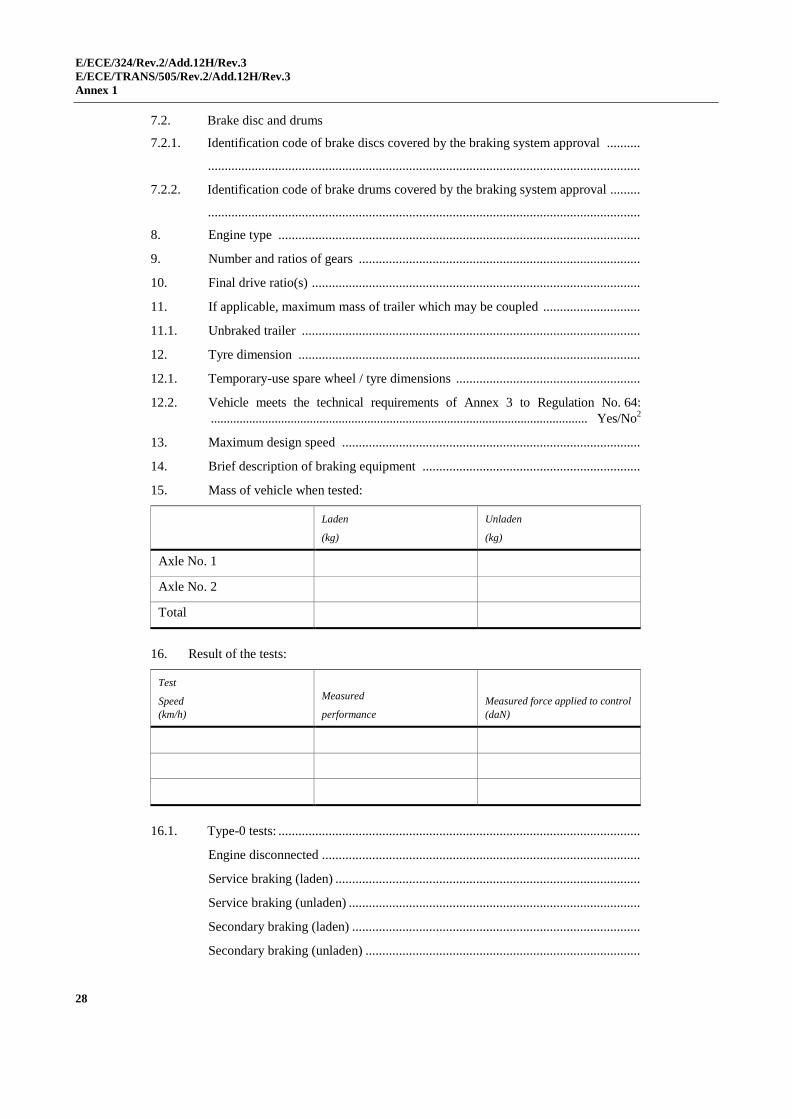
E/ECE/324/Rev.2/Add.12H/Rev.3
E/ECE/TRANS/505/Rev.2/Add.12H/Rev.3
Annex 1
28
7.2. Brake disc and drums
7.2.1. Identification code of brake discs covered by the braking system approval ..........
.................................................................................................................................
7.2.2. Identification code of brake drums covered by the braking system approval .........
.................................................................................................................................
8. Engine type ............................................................................................................
9. Number and ratios of gears ....................................................................................
10. Final drive ratio(s) ..................................................................................................
11. If applicable, maximum mass of trailer which may be coupled .............................
11.1. Unbraked trailer .....................................................................................................
12. Tyre dimension ......................................................................................................
12.1. Temporary-use spare wheel / tyre dimensions .......................................................
12.2. Vehicle meets the technical requirements of Annex 3 to Regulation No. 64:
...................................................................................................................... Yes/No2
13. Maximum design speed .........................................................................................
14. Brief description of braking equipment .................................................................
15. Mass of vehicle when tested:
Laden
(kg)
Unladen
(kg)
Axle No. 1
Axle No. 2
Total
16. Result of the tests:
Test
Speed
(km/h)
Measured
performance
Measured force applied to control
(daN)
16.1. Type-0 tests: ............................................................................................................
Engine disconnected ...............................................................................................
Service braking (laden) ...........................................................................................
Service braking (unladen) .......................................................................................
Secondary braking (laden) ......................................................................................
Secondary braking (unladen) ..................................................................................
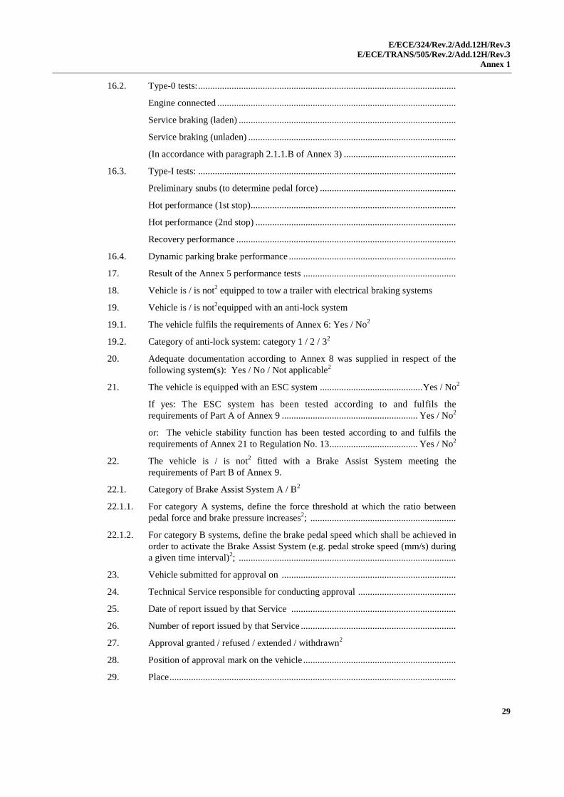
E/ECE/324/Rev.2/Add.12H/Rev.3
E/ECE/TRANS/505/Rev.2/Add.12H/Rev.3
Annex 1
29
16.2. Type-0 tests: ............................................................................................................
Engine connected ....................................................................................................
Service braking (laden) ...........................................................................................
Service braking (unladen) .......................................................................................
(In accordance with paragraph 2.1.1.B of Annex 3) ...............................................
16.3. Type-I tests: ............................................................................................................
Preliminary snubs (to determine pedal force) .........................................................
Hot performance (1st stop)......................................................................................
Hot performance (2nd stop) ....................................................................................
Recovery performance ............................................................................................
16.4. Dynamic parking brake performance ......................................................................
17. Result of the Annex 5 performance tests ................................................................
18. Vehicle is / is not2 equipped to tow a trailer with electrical braking systems
19. Vehicle is / is not2equipped with an anti-lock system
19.1. The vehicle fulfils the requirements of Annex 6: Yes / No2
19.2. Category of anti-lock system: category 1 / 2 / 32
20. Adequate documentation according to Annex 8 was supplied in respect of the
following system(s): Yes / No / Not applicable2
21. The vehicle is equipped with an ESC system ........................................... Yes / No2
If yes: The ESC system has been tested according to and fulfils the
requirements of Part A of Annex 9 ......................................................... Yes / No2
or: The vehicle stability function has been tested according to and fulfils the
requirements of Annex 21 to Regulation No. 13 ..................................... Yes / No2
22. The vehicle is / is not2 fitted with a Brake Assist System meeting the
requirements of Part B of Annex 9.
22.1. Category of Brake Assist System A / B2
22.1.1. For category A systems, define the force threshold at which the ratio between
pedal force and brake pressure increases2; .............................................................
22.1.2. For category B systems, define the brake pedal speed which shall be achieved in
order to activate the Brake Assist System (e.g. pedal stroke speed (mm/s) during
a given time interval)2; ...........................................................................................
23. Vehicle submitted for approval on .........................................................................
24. Technical Service responsible for conducting approval .........................................
25. Date of report issued by that Service .....................................................................
26. Number of report issued by that Service .................................................................
27. Approval granted / refused / extended / withdrawn2
28. Position of approval mark on the vehicle ................................................................
29. Place ........................................................................................................................

E/ECE/324/Rev.2/Add.12H/Rev.3
E/ECE/TRANS/505/Rev.2/Add.12H/Rev.3
Annex 1
30
30. Date .........................................................................................................................
31. Signature .................................................................................................................
32. The summary referred to in paragraph 4.3. of this Regulation is annexed to this
communication
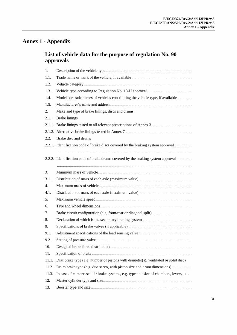
E/ECE/324/Rev.2/Add.12H/Rev.3
E/ECE/TRANS/505/Rev.2/Add.12H/Rev.3
Annex 1 - Appendix
31
Annex 1 - Appendix
List of vehicle data for the purpose of regulation No. 90 approvals
1. Description of the vehicle type .....................................................................................
1.1. Trade name or mark of the vehicle, if available ............................................................
1.2. Vehicle category ...........................................................................................................
1.3. Vehicle type according to Regulation No. 13-H approval ............................................
1.4. Models or trade names of vehicles constituting the vehicle type, if available ..............
1.5. Manufacturer’s name and address .................................................................................
2. Make and type of brake linings, discs and drums:
2.1. Brake linings
2.1.1. Brake linings tested to all relevant prescriptions of Annex 3 .......................................
2.1.2. Alternative brake linings tested in Annex 7 .................................................................
2.2. Brake disc and drums
2.2.1. Identification code of brake discs covered by the braking system approval ................
......................................................................................................................................
2.2.2. Identification code of brake drums covered by the braking system approval ...............
......................................................................................................................................
3. Minimum mass of vehicle .............................................................................................
3.1. Distribution of mass of each axle (maximum value) ....................................................
4. Maximum mass of vehicle ............................................................................................
4.1. Distribution of mass of each axle (maximum value) ....................................................
5. Maximum vehicle speed ...............................................................................................
6. Tyre and wheel dimensions ...........................................................................................
7. Brake circuit configuration (e.g. front/rear or diagonal split) .......................................
8. Declaration of which is the secondary braking system .................................................
9. Specifications of brake valves (if applicable) ...............................................................
9.1. Adjustment specifications of the load sensing valve .....................................................
9.2. Setting of pressure valve ...............................................................................................
10. Designed brake force distribution .................................................................................
11. Specification of brake ...................................................................................................
11.1. Disc brake type (e.g. number of pistons with diameter(s), ventilated or solid disc)
11.2. Drum brake type (e.g. duo servo, with piston size and drum dimensions)....................
11.3. In case of compressed air brake systems, e.g. type and size of chambers, levers, etc.
12. Master cylinder type and size ........................................................................................
13. Booster type and size ....................................................................................................

E/ECE/324/Rev.2/Add.12H/Rev.3
E/ECE/TRANS/505/Rev.2/Add.12H/Rev.3
Annex 2
32
Annex 2
Arrangements of approval marks
Model A
(See paragraph 4.4. of this Regulation)
a = 8 mm min.
The above approval mark affixed to a vehicle shows that the vehicle type concerned
has, with regard to braking, been approved in the United Kingdom (E 11) pursuant to
Regulation No. 13-H under approval number 002439. The first two digits of the approval
number indicate that the approval was granted in accordance with the requirements of
Regulation No. 13-H in its original form. The additional marking "ESC" indicates that the
vehicle meets the Electronic Stability Control and Brake Assist System requirements of
Annex 9 to this Regulation.
Model B
(See paragraph 4.5. of this Regulation)
a
2
a = 8 mm min.
The above approval mark affixed to a vehicle shows that the vehicle type concerned
has been approved in the United Kingdom (E 11) pursuant to Regulations Nos. 13-H and
24.1 (In the case of the latter Regulation the corrected absorption coefficient is 1.30 m-1
).
The approval numbers indicate that, at the dates when the respective approvals were given,
Regulation No. 13-H was in its original form and Regulation No. 24 included the 02 series
of amendments.
1 This number is given merely as an example.
13HRESC-002439 ¯a/3
E11
a a
3
13-H 002439
24 1.30 021628
a 3
a 3
a
2
a
2

E/ECE/324/Rev.2/Add.12H/Rev.3
E/ECE/TRANS/505/Rev.2/Add.12H/Rev.3
Annex 3
33
Annex 3
Braking tests and performance of braking systems
1. Braking tests
1.1. General
1.1.1. The performance prescribed for braking systems is based on the stopping
distance and the mean fully developed deceleration. The performance of a
braking system shall be determined by measuring the stopping distance in
relation to the initial speed of the vehicle and/or by measuring the mean fully
developed deceleration during the test.
1.1.2. The stopping distance shall be the distance covered by the vehicle from the
moment when the driver begins to actuate the control of the braking system
until the moment when the vehicle stops; the initial speed shall be the speed
at the moment when the driver begins to actuate the control of the braking
system; the initial speed shall not be less than 98 per cent of the prescribed
speed for the test in question.
The mean fully developed deceleration (dm) shall be calculated as the
deceleration averaged with respect to distance over the interval vb to ve ,
according to the following formula:
)s-(s25.92
v-v=d
be
2
e
2
b
m
Where:
vo = initial vehicle speed in km/h,
vb = vehicle speed at 0.8 vo in km/h,
ve = vehicle speed at 0.1 vo in km/h,
sb = distance travelled between vo and vb in metres,
se = distance travelled between vo and ve in metres.
The speed and distance shall be determined using instrumentation having an
accuracy of ±1 per cent at the prescribed speed for the test. The dm may be
determined by other methods than the measurement of speed and distance; in
this case, the accuracy of the dm shall be within ±3 per cent.
1.2. For the approval of any vehicle, the braking performance shall be measured
during road tests conducted in the following conditions:
1.2.1. The vehicle's condition as regards mass shall be as prescribed for each type of
test and be specified in the test report;
1.2.2. The test shall be carried out at the speeds prescribed for each type of test; if
the maximum design speed of a vehicle is lower than the speed prescribed for
a test, the test shall be performed at the vehicle's maximum speed;
1.2.3. During the tests, the force applied to the brake control in order to obtain the
prescribed performance shall not exceed the maximum force laid down;
1.2.4. The road shall have a surface affording good adhesion, unless specified
otherwise in the relevant annexes;
E/ECE/324/Rev.2/Add.12H/Rev.3
E/ECE/TRANS/505/Rev.2/Add.12H/Rev.3
Annex 3
34
1.2.5. The tests shall be performed when there is no wind liable to affect the results;
1.2.6. At the start of the tests, the tyres shall be cold and at the pressure prescribed
for the load actually borne by the wheels when the vehicle is stationary;
1.2.7. The prescribed performance shall be obtained without locking of the wheels at
speeds exceeding 15 km/h, without deviation of the vehicle from a 3.5 m wide
lane, without exceeding a yaw angle of 15° and without abnormal vibrations;
1.2.8. For vehicles powered completely or partially by an electric motor (or
motors), permanently connected to the wheels, all tests shall be carried out
with these motor(s) connected;
1.2.9. For vehicles as described in paragraph 1.2.8. above, fitted with an electric
regenerative braking system of category A, behaviour tests shall be carried
out on a track with a low adhesion coefficient (as defined in paragraph 5.2.2.
of Annex 6) at a speed equal to 80 per cent of the maximum speed but not
exceeding 120 km/h, to check that stability is retained.
1.2.9.1. Moreover, for vehicles fitted with an electric regenerative braking system of
category A, transient conditions as gear changes or accelerator control release
shall not affect the behaviour of the vehicle in condition described in
paragraph 1.2.9. above;
1.2.10. In the tests provided in paragraphs 1.2.9. and 1.2.9.1. above wheel locking is
not allowed. However, steering correction is permitted if the angular rotation
of the steering control is within 120° during the initial 2 seconds and not
more than 240° in all;
1.2.11. For a vehicle with electrically actuated service brakes powered from traction
batteries (or an auxiliary battery) which receive(s) energy only from an
independent external charging system, these batteries shall, during braking
performance testing, be at an average of not more than 5 per cent above that
state of charge at which the brake failure warning prescribed in
paragraph 5.2.20.5. of this Regulation is required to be given.
If this warning is given, the batteries may receive some recharge during the
tests, to keep them in the required state of charge range.
1.3. Behaviour of the vehicle during braking
1.3.1. In braking tests, and in particular in those at high speed, the general
behaviour of the vehicle during braking shall be checked.
1.3.2. Behaviour of the vehicle during braking on a road on which adhesion is
reduced shall meet the relevant requirements of Annex 5 and/or Annex 6 to
this Regulation.
1.3.2.1. In the case of a braking system according to paragraph 5.2.7. of this
Regulation where the braking for a particular axle (or axles) is comprised of
more than one source of braking torque, and any individual source can be
varied with respect to the other(s), the vehicle shall satisfy the requirements
of Annex 5, or alternatively, Annex 6 under all relationships permitted by its
control strategy.1
1 The manufacturer shall provide the Technical Service with the family of braking curves permitted by
the automatic control strategy. These curves may be verified by the Technical Service.

E/ECE/324/Rev.2/Add.12H/Rev.3
E/ECE/TRANS/505/Rev.2/Add.12H/Rev.3
Annex 3
35
1.4. Type-0 test (ordinary performance test with cold brakes)
1.4.1. General
1.4.1.1. The average temperature of the service brakes on the hottest axle of the
vehicle, measured inside the brake linings or on the braking path of the disc
or drum, is between 65 and 100 °C prior to any brake application.
1.4.1.2. The test shall be conducted in the following conditions:
1.4.1.2.1. The vehicle shall be laden, the distribution of its mass among the axles being
that stated by the manufacturer; where provision is made for several
arrangements of the load on the axles the distribution of the maximum mass
among the axles shall be such that the mass on each axle is proportional to
the maximum permissible mass for each axle;
1.4.1.2.2. Every test shall be repeated on the unladen vehicle; there may be, in addition
to the driver, a second person on the front seat who is responsible for noting
the results of the test;
1.4.1.2.3. In the case of a vehicle equipped with an electric regenerative braking
system, the requirements depend on the category of this system:
Category A. Any separate electric regenerative braking control which is
provided, shall not be used during the Type-0 tests.
Category B. The contribution of the electric regenerative braking system to
the braking force generated shall not exceed that minimum level guaranteed
by the system design.
This condition is deemed to be satisfied if the state of charge of the batteries is
in one of the following conditions:
(a) At the maximum charge level recommended by the manufacturer, as
listed in the vehicle specification;
(b) At a level not less than 95 per cent of the full charge level, where the
manufacturer has made no specific recommendation;
(c) At a maximum level resulting from automatic charge control on the
vehicle; or
(d) When the tests are conducted without a regenerative braking
component regardless of the state of charge of the batteries.
1.4.1.2.4. The limits prescribed for minimum performance, both for tests with the
vehicle unladen and for tests with the vehicle laden, shall be those laid down
hereunder; the vehicle shall satisfy both the prescribed stopping distance and
the prescribed mean fully developed deceleration, but it may not be necessary
to actually measure both parameters;
1.4.1.2.5. The road shall be level; unless otherwise specified each test may comprise up
to six stops including any needed for familiarization.
1.4.2. Type-0 test with engine disconnected, service braking in accordance with
paragraph 2.1.1.(A) of this annex.
The test shall be carried out at the speed prescribed, the figures prescribed in
this connection being subject to a certain margin of tolerance. The minimum
performance prescribed shall be attained.
1.4.3. Type-0 test with engine connected, service braking in accordance with
paragraph 2.1.1.(B) of this annex.
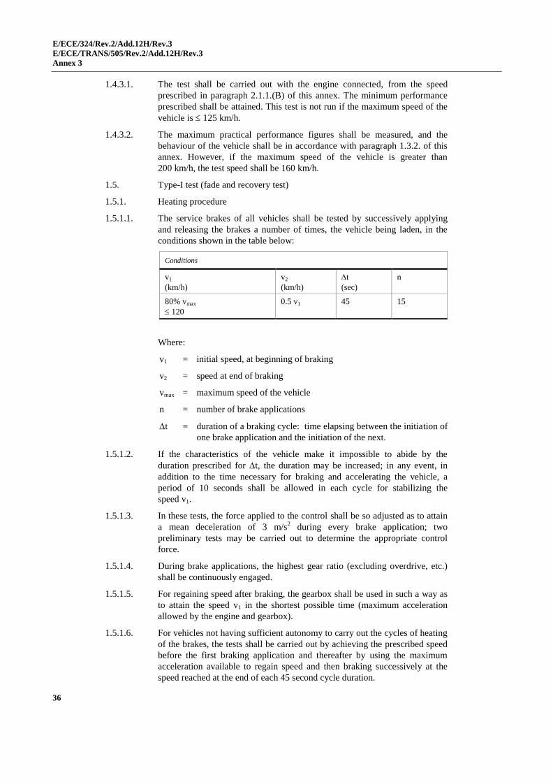
E/ECE/324/Rev.2/Add.12H/Rev.3
E/ECE/TRANS/505/Rev.2/Add.12H/Rev.3
Annex 3
36
1.4.3.1. The test shall be carried out with the engine connected, from the speed
prescribed in paragraph 2.1.1.(B) of this annex. The minimum performance
prescribed shall be attained. This test is not run if the maximum speed of the
vehicle is 125 km/h.
1.4.3.2. The maximum practical performance figures shall be measured, and the
behaviour of the vehicle shall be in accordance with paragraph 1.3.2. of this
annex. However, if the maximum speed of the vehicle is greater than
200 km/h, the test speed shall be 160 km/h.
1.5. Type-I test (fade and recovery test)
1.5.1. Heating procedure
1.5.1.1. The service brakes of all vehicles shall be tested by successively applying
and releasing the brakes a number of times, the vehicle being laden, in the
conditions shown in the table below:
Conditions
v1
(km/h)
v2
(km/h)
t
(sec)
n
80% vmax
120
0.5 v1 45 15
Where:
v1 = initial speed, at beginning of braking
v2 = speed at end of braking
vmax = maximum speed of the vehicle
n = number of brake applications
t = duration of a braking cycle: time elapsing between the initiation of
one brake application and the initiation of the next.
1.5.1.2. If the characteristics of the vehicle make it impossible to abide by the
duration prescribed for t, the duration may be increased; in any event, in
addition to the time necessary for braking and accelerating the vehicle, a
period of 10 seconds shall be allowed in each cycle for stabilizing the
speed v1.
1.5.1.3. In these tests, the force applied to the control shall be so adjusted as to attain
a mean deceleration of 3 m/s2 during every brake application; two
preliminary tests may be carried out to determine the appropriate control
force.
1.5.1.4. During brake applications, the highest gear ratio (excluding overdrive, etc.)
shall be continuously engaged.
1.5.1.5. For regaining speed after braking, the gearbox shall be used in such a way as
to attain the speed v1 in the shortest possible time (maximum acceleration
allowed by the engine and gearbox).
1.5.1.6. For vehicles not having sufficient autonomy to carry out the cycles of heating
of the brakes, the tests shall be carried out by achieving the prescribed speed
before the first braking application and thereafter by using the maximum
acceleration available to regain speed and then braking successively at the
speed reached at the end of each 45 second cycle duration.
E/ECE/324/Rev.2/Add.12H/Rev.3
E/ECE/TRANS/505/Rev.2/Add.12H/Rev.3
Annex 3
37
1.5.1.7. For vehicles equipped with an electric regenerative braking system of
category B, the condition of the vehicle batteries at the start of the test, shall
be such that the braking force contribution provided by the electric
regenerative braking system does not exceed the minimum guaranteed by the
system design. This requirement is deemed to be satisfied if the batteries are
at one of the state of charge conditions as listed in paragraph 1.4.1.2.3. above.
1.5.2. Hot performance
1.5.2.1. At the end of the Type-I test (described in paragraph 1.5.1. of this annex) the
hot performance of the service braking system shall be measured in the same
conditions (and in particular at a mean control force no greater than the mean
force actually used) as for the Type-0 test with the engine disconnected (the
temperature conditions may be different).
1.5.2.2. This hot performance shall not be less than 752 per cent of that prescribed,
nor less than 60 per cent of the figure recorded in the Type-0 test with the
engine disconnected.
1.5.2.3. For vehicles fitted with an electric regenerative braking system of category
A, during brake applications, the highest gear shall be continuously engaged
and the separate electric braking control, if any, not used.
1.5.2.4. In the case of vehicles equipped with an electric regenerative braking system
of category B, having carried out the heating cycles according to
paragraph 1.5.1.6. of this annex, the hot performance test shall be carried out
at the maximum speed which can be reached by the vehicle at the end of the
brake heating cycles, unless the speed specified in paragraph 2.1.1.(A) of this
annex can be reached.
For comparison, a later Type-0 test with cold brakes shall be repeated from
this same speed and with a similar electric regenerative braking contribution,
as set by an appropriate state of battery charge, as was available during the
hot performance test.
Following the recovery process and test, further reconditioning of the linings
shall be permitted before the test is made to compare this second cold
performance with that achieved in the hot test, against the criteria of
paragraphs 1.5.2.2. or 1.5.2.5. of this annex.
The tests may be conducted without a regenerative braking component. In
this case, the requirement on the state of charge of the batteries is not
applicable.
1.5.2.5. In the case of a vehicle which satisfies the 60 per cent requirement specified
in paragraph 1.5.2.2. of this annex, but which cannot comply with the 752 per
cent requirement of paragraph 1.5.2.2. of this annex, a further hot
performance test may be carried out using a control force not exceeding that
specified in paragraph 2. of this annex. The results of both tests shall be
entered in the report.
1.5.3. Recovery procedure
Immediately after the hot performance test, make four stops from 50 km/h
with the engine connected, at a mean deceleration of 3 m/s2. Allow an
interval of 1.5 km between the start of successive stops. Immediately after
2 This corresponds to a stopping distance of 0.1 v + 0.0080 v2 and a mean fully developed deceleration
of 4.82 m/s2.
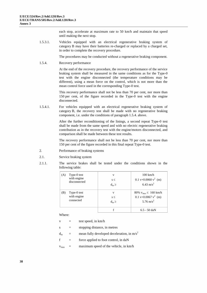
E/ECE/324/Rev.2/Add.12H/Rev.3
E/ECE/TRANS/505/Rev.2/Add.12H/Rev.3
Annex 3
38
each stop, accelerate at maximum rate to 50 km/h and maintain that speed
until making the next stop.
1.5.3.1. Vehicles equipped with an electrical regenerative braking system of
category B may have their batteries re-charged or replaced by a charged set,
in order to complete the recovery procedure.
The procedures may be conducted without a regenerative braking component.
1.5.4. Recovery performance
At the end of the recovery procedure, the recovery performance of the service
braking system shall be measured in the same conditions as for the Type-0
test with the engine disconnected (the temperature conditions may be
different), using a mean force on the control, which is not more than the
mean control force used in the corresponding Type-0 test.
This recovery performance shall not be less than 70 per cent, nor more than
150 per cent, of the figure recorded in the Type-0 test with the engine
disconnected.
1.5.4.1. For vehicles equipped with an electrical regenerative braking system of
category B, the recovery test shall be made with no regenerative braking
component, i.e. under the conditions of paragraph 1.5.4. above.
After the further reconditioning of the linings, a second repeat Type-0 test
shall be made from the same speed and with no electric regenerative braking
contribution as in the recovery test with the engine/motors disconnected, and
comparison shall be made between these test results.
The recovery performance shall not be less than 70 per cent, nor more than
150 per cent of the figure recorded in this final repeat Type-0 test.
2. Performance of braking systems
2.1. Service braking system
2.1.1. The service brakes shall be tested under the conditions shown in the
following table:
(A) Type-0 test with engine disconnected
v
s
dm
100 km/h
0.1 v+0.0060 v2 (m)
6.43 m/s2
(B) Type-0 test
with engine
connected
v
s
dm
80% vmax 160 km/h
0.1 v+0.0067 v2 (m)
5.76 m/s2
f 6.5 - 50 daN
Where:
v = test speed, in km/h
s = stopping distance, in metres
dm = mean fully developed deceleration, in m/s2
f = force applied to foot control, in daN
vmax = maximum speed of the vehicle, in km/h

E/ECE/324/Rev.2/Add.12H/Rev.3
E/ECE/TRANS/505/Rev.2/Add.12H/Rev.3
Annex 3
39
2.1.2. In the case of a motor vehicle authorized to tow an unbraked trailer, the
minimum Type-0 performance of the combination shall not be less
than 5.4 m/s2 in both the laden and unladen conditions.
The combination performance shall be verified by calculations referring to
the maximum braking performance actually achieved by the motor vehicle
alone (laden) during the Type-0 test with the engine disconnected, using the
following formula (no practical tests with a coupled unbraked trailer are
required):
RM
M
MR+M P+P
P•d=d
Where:
dM+R = calculated mean fully developed deceleration of the motor
vehicle when coupled to an unbraked trailer, in m/s2
dM = maximum mean fully developed deceleration of the motor
vehicle alone achieved during the Type-0 test with engine
disconnected, in m/s2
PM = mass of the motor vehicle (laden)
PR = maximum mass of an unbraked trailer which may be coupled,
as declared by the motor vehicle manufacturer.
2.2. Secondary braking system
2.2.1. The performance of the secondary braking system shall be tested by the
Type-0 test with the engine disconnected from an initial vehicle speed of
100 km/h and a force applied to the service brake control not less than
6.5 daN and not exceeding 50 daN.
2.2.2. The secondary braking system shall give a stopping distance not exceeding
the following value:
0.1 v + 0.0158 v2 (m)
and a mean fully developed deceleration not less than 2.44 m/s2
(corresponding to the second term of the above formula).
2.2.3. The secondary braking effectiveness test shall be conducted by simulating the
actual failure conditions in the service braking system.
2.2.4. For vehicles employing electric regenerative braking systems, the braking
performance shall additionally be checked under the two following failure
conditions:
2.2.4.1. For a total failure of the electric component of the service braking output.
2.2.4.2. In the case where the failure condition causes the electric component to
deliver its maximum braking force.
2.3. Parking braking system
2.3.1. The parking braking system shall be capable of holding the laden vehicle
stationary on a 20 per cent up or down gradient.
2.3.2. On vehicles to which the coupling of a trailer is authorized, the parking
braking system of the motor vehicle shall be capable of holding the
combination of vehicles stationary on a 12 per cent up or down gradient.

E/ECE/324/Rev.2/Add.12H/Rev.3
E/ECE/TRANS/505/Rev.2/Add.12H/Rev.3
Annex 3
40
2.3.3. If the control device is manual, the force applied to it shall not exceed
40 daN.
2.3.4. If it is a foot control device, the force exerted on the control shall not exceed
50 daN.
2.3.5. A parking braking system which has to be actuated several times before it
attains the prescribed performance is admissible.
2.3.6. To check compliance with the requirement specified in paragraph 5.2.2.4. of
this Regulation, a Type-0 test shall be carried out, with the engine
disconnected, at an initial test speed of 30 km/h. The mean fully developed
deceleration on application of the control of the parking brake system and the
deceleration immediately before the vehicle stops, shall not be less than
1.5 m/s2. The test shall be carried out with the laden vehicle. The force
exerted on the braking control device shall not exceed the specified values.
3. Response time
3.1. Where a vehicle is equipped with a service braking system which is totally or
partially dependent on a source of energy other than the muscular effort of
the driver, the following requirements shall be satisfied:
3.1.1. In an emergency manoeuvre, the time elapsing between the moment when the
control device begins to be actuated and the moment when the braking force
on the least favourable placed axle reaches the level corresponding to the
prescribed performance shall not exceed 0.6 seconds;
3.1.2. In the case of vehicles fitted with hydraulic braking systems, the
requirements of paragraph 3.1.1. above are considered to be satisfied if, in an
emergency manoeuvre, the deceleration of the vehicle or the pressure at the
least favourable brake cylinder, reaches a level corresponding to the
prescribed performance within 0.6 seconds.
E/ECE/324/Rev.2/Add.12H/Rev.3
E/ECE/TRANS/505/Rev.2/Add.12H/Rev.3
Annex 3 - Appendix
41
Annex 3 - Appendix
Procedure for monitoring the state of battery charge
This procedure is applicable to vehicle batteries used for traction and
regenerative braking.
The procedure requires the use of a bi-directional DC Watt-hour meter or a
bi-directional DC Ampere-hour meter.
Procedure
1.1. If the batteries are new or have been subject to extended storage, they shall be
cycled as recommended by the manufacturer. A minimum 8-hour soak period
at ambient temperature shall be allowed after completion of cycling.
1.2. A full charge shall be established using the manufacturer's recommended
charging procedure.
1.3. When the braking tests of paragraphs 1.2.11., 1.4.1.2.3., 1.5.1.6., 1.5.1.7. and
1.5.2.4. of Annex 3 are conducted the watt-hours consumed by the traction
motors and supplied by the regenerative braking system shall be recorded as
a running total which shall then be used to determine the state of charge
existing at the beginning or end of a particular test.
1.4. To replicate a level of state of charge in the batteries for comparative tests,
such as those of paragraph 1.5.2.4. of Annex 3, the batteries shall be either
recharged to that level or charged to above that level and discharged into a
fixed load at approximately constant power until the required state of charge
is reached. Alternatively, for vehicles with battery powered electric traction
only, the state of charge may be adjusted by running the vehicle. Tests
conducted with a battery partially charged at their start shall be commenced
as soon as possible after the desired state of charge has been reached.
E/ECE/324/Rev.2/Add.12H/Rev.3
E/ECE/TRANS/505/Rev.2/Add.12H/Rev.3
Annex 4
42
Annex 4
Provisions relating to energy sources and energy storage devices (energy accumulators)
Hydraulic braking systems with stored energy
1. Capacity of energy storage devices (energy accumulators)
1.1. General
1.1.1. Vehicles on which the braking equipment requires the use of stored energy
provided by hydraulic fluid under pressure shall be equipped with energy
storage devices (energy accumulators) of a capacity meeting the requirements
of paragraphs 1.2. or 1.3. of this annex;
1.1.2. However, the energy storage devices shall not be required to be of a
prescribed capacity if the braking system is such that in the absence of any
energy reserve it is possible with the service brake control to achieve a
braking performance at least equal to that prescribed for the secondary
braking system;
1.1.3. In verifying compliance with the requirements of paragraphs 1.2., 1.3. and
2.1. of this annex, the brakes shall be adjusted as closely as possible and, for
paragraph 1.2. of this annex, the rate of full-stroke actuations shall be such as
to provide an interval of at least 60 seconds between each actuation.
1.2. Vehicles equipped with a hydraulic braking system with stored energy shall
meet the following requirements:
1.2.1. After eight full-stroke actuations of the service brake control, it shall still be
possible to achieve, on the ninth application, the performance prescribed for
the secondary braking system.
1.2.2. Testing shall be performed in conformity with the following requirements:
1.2.2.1. Testing shall commence at a pressure that may be specified by the
manufacturer but is not higher than the cut-in pressure;1
1.2.2.2. The energy storage device(s) shall not be fed; in addition, any energy storage
device(s) for auxiliary equipment shall be isolated.
1.3. Vehicles equipped with a hydraulic braking system with stored energy which
cannot meet the requirements of paragraph 5.2.4.1. of this Regulation shall be
deemed to satisfy that paragraph if the following requirements are met:
1.3.1. After any single transmission failure it shall still be possible after eight full-
stroke actuations of the service brake control, to achieve, at the ninth
application, at least the performance prescribed for the secondary braking
system.
1.3.2. Testing shall be performed in conformity with the following requirements:
1 The initial energy level shall be stated in the approval document.
E/ECE/324/Rev.2/Add.12H/Rev.3
E/ECE/TRANS/505/Rev.2/Add.12H/Rev.3
Annex 4
43
1.3.2.1. With the energy source stationary or operating at a speed corresponding to
the engine idling speed, any transmission failure may be induced. Before
inducing such a failure, the energy storage device(s) shall be at a pressure
that may be specified by the manufacturer but not exceeding the cut-in
pressure;
1.3.2.2. The auxiliary equipment and its energy storage devices, if any, shall be
isolated.
2. Capacity of hydraulic fluid energy sources
2.1. The energy sources shall meet the requirements set out in the following
paragraphs.
2.1.1. Definitions
2.1.1.1. "p1" represents the maximum system operational pressure (cut-out pressure)
in the energy storage device(s) specified by the manufacturer.
2.1.1.2. "p2" represents the pressure after four full-stroke actuations with the service
brake control, starting at p1, without having fed the energy storage device(s).
2.1.1.3. "t" represents the time required for the pressure to rise from p2 to p1 in the
energy storage device(s) without application of the brake control.
2.1.2. Conditions of measurement
2.1.2.1. During the tests to determine the time t, the feed rate of the energy source
shall be that obtained when the engine is running at the speed corresponding
to its maximum power or at the speed allowed by the over-speed governor.
2.1.2.2. During the test to determine the time t, energy storage device(s) for auxiliary
equipment shall not be isolated other than automatically.
2.1.3. Interpretation of results
2.1.3.1. In the case of all vehicles, the time t shall not exceed 20 seconds.
3. Characteristics of warning devices
With the engine stationary and commencing at a pressure that may be
specified by the manufacturer but does not exceed the cut-in pressure, the
warning device shall not operate following two full-stroke actuations of the
service brake control.
E/ECE/324/Rev.2/Add.12H/Rev.3
E/ECE/TRANS/505/Rev.2/Add.12H/Rev.3
Annex 5
44
Annex 5
Distribution of braking among the axles of vehicles
1. General
Vehicles which are not equipped with an anti-lock system as defined in
Annex 6 to this Regulation shall meet all the requirements of this annex. If a
special device is used, this shall operate automatically.
2. Symbols
i = axle index (i = 1, front axle;
i = 2, rear axle)
Pi = normal reaction of road surface on axle i under static conditions
Ni = normal reaction of road surface on axle i under braking
Ti = force exerted by the brakes on axle i under normal braking
conditions on the road
fi = Ti/Ni , adhesion utilized by axle i 1
J = deceleration of the vehicle
g = acceleration due to gravity : g = 9.81 m/s2
z = braking rate of vehicle = J/g
P = mass of vehicle
h = height of centre of gravity specified by the manufacturer and
agreed by the Technical Services conducting the approval test
E = wheelbase
k = theoretical coefficient of adhesion between tyre and road
3. Requirements
3.1.(A) For all states of load of the vehicle, the adhesion utilization curve of the rear
axle shall not be situated above that for the front axle:2
for all braking rates between 0.15 and 0.8:
3.1.(B) For k values between 0.2 and 0.82:
z 0.1 + 0.7 (k - 0.2) (see diagram 1 of this annex)
1 "Adhesion utilisation curves" of a vehicle means curves showing, for specified load conditions, the
adhesion utilized by each axle i plotted against the braking rate of the vehicle.
2 The provisions of paragraph 3.1. do not affect the requirements of Annex 3 to this Regulation relating
to the braking performance. However, if, in tests made under the provisions of paragraph 3.1., braking
performances are obtained which are higher than those prescribed in Annex 3, the provisions relating
to the adhesion utilization curves shall be applied within the areas of diagram 1 of this annex defined
by the straight lines k = 0.8 and z = 0.8.
E/ECE/324/Rev.2/Add.12H/Rev.3
E/ECE/TRANS/505/Rev.2/Add.12H/Rev.3
Annex 5
45
3.2. In order to verify the requirements of paragraph 3.1. of this annex, the
manufacturer shall provide the adhesion utilization curves for the front and
rear axles calculated by the formulae:
g•P•E
h•z+P
T=
N
T=f
1
1
1
1
1
g•P•E
h•z-P
T=
N
T=f
2
2
2
2
2
The curves shall be plotted for both the following load conditions:
3.2.1. Unladen, in running order with the driver on board;
3.2.2. Laden; where provision is made for several possibilities of load distribution,
the one whereby the front axle is the most heavily laden shall be the one
considered;
3.2.3. For vehicles fitted with an electric regenerative braking system of category B,
where the electric regenerative braking capacity is influenced by the electric
state of charge, the curves shall be plotted by taking account of the electric
braking component under the minimal and maximum conditions of delivered
braking force. This requirement is not applicable if the vehicle is equipped
with an anti-lock device which controls the wheels connected to the electric
braking then the requirements of Annex 6 to this Regulation shall apply.
4. Requirements to be met in case of failure of the braking distribution system
When the requirements of this annex are fulfilled by means of a special
device (e.g. controlled mechanically by the suspension of the vehicle), it shall
be possible, in the event of the failure of its control, (e.g. by disconnecting
the control linkage), to stop the vehicle under the conditions of the Type-0
test with the engine disconnected to give a stopping distance not exceeding
0.1 v + 0.0100 v2 (m) and a mean fully developed deceleration not less than
3.86 m/s2.
5. Vehicle testing
During the type-approval testing of a vehicle, the technical inspection
authority shall verify conformity with the requirements contained in the
present annex, by carrying out the following tests:
5.1. Wheel-lock sequence test (see Appendix 1)
If the wheel-lock sequence test confirms that the front wheels lock before or
simultaneously with the rear wheels, conformity with paragraph 3. of this
annex has been verified and testing is complete.
5.2. Additional tests
If the wheel-lock sequence test indicates that the rear wheels lock before the
front wheels, then the vehicle:
(a) Will be subjected to additional testing, as follows:
(i) Additional wheel-lock sequence tests; and/or
(ii) Torque wheel tests (see Appendix 2) to determine brake factors
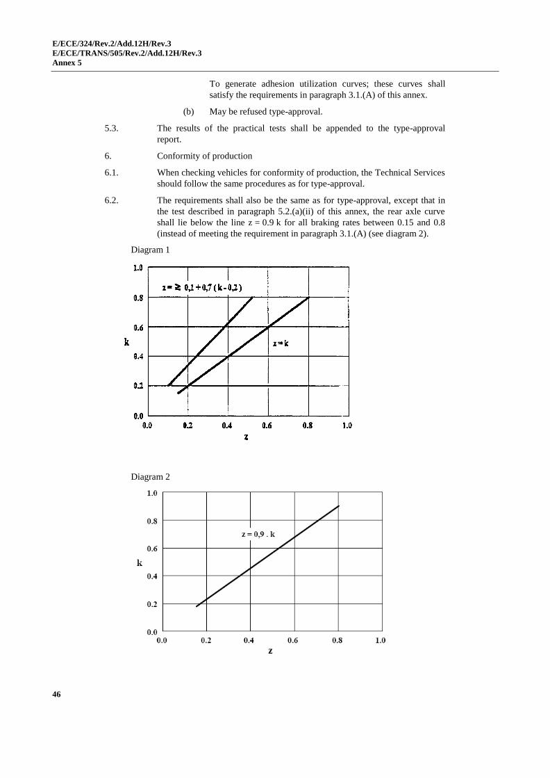
E/ECE/324/Rev.2/Add.12H/Rev.3
E/ECE/TRANS/505/Rev.2/Add.12H/Rev.3
Annex 5
46
To generate adhesion utilization curves; these curves shall
satisfy the requirements in paragraph 3.1.(A) of this annex.
(b) May be refused type-approval.
5.3. The results of the practical tests shall be appended to the type-approval
report.
6. Conformity of production
6.1. When checking vehicles for conformity of production, the Technical Services
should follow the same procedures as for type-approval.
6.2. The requirements shall also be the same as for type-approval, except that in
the test described in paragraph 5.2.(a)(ii) of this annex, the rear axle curve
shall lie below the line z = 0.9 k for all braking rates between 0.15 and 0.8
(instead of meeting the requirement in paragraph 3.1.(A) (see diagram 2).
Diagram 1
Diagram 2
E/ECE/324/Rev.2/Add.12H/Rev.3
E/ECE/TRANS/505/Rev.2/Add.12H/Rev.3
Annex 5 - Appendix 1
47
Annex 5 - Appendix 1
Wheel-lock sequence test procedure
1. General information
(a) The purpose of this test is to ensure that lockup of both front wheels
occurs at a lower deceleration rate than the lockup of both rear wheels
when tested on road surfaces on which wheel lockup occurs at braking
rates between 0.15 and 0.8.
(b) A simultaneous lockup of the front and rear wheels refers to the
condition when the time interval between the lockup of the last
(second) wheel on the rear axle and the last (second) wheel on the
front axle is 0.1 seconds for vehicle speeds 30 km/h.
2. Vehicle conditions
(a) Vehicle load: Laden and unladen
(b) Transmission position: Engine disconnected
3. Test conditions and procedures
(a) Initial brake temperature: Between 65 °C and 100 °C average on the
hottest axle.
(b) Test speed: 65 km/h for a braking rate 0.50;
100 km/h for a braking rate 0.50.
(c) Pedal force:
(i) Pedal force is applied and controlled by a skilled driver or by a
mechanical brake pedal actuator.
(ii) Pedal force is increased at a linear rate such that the first axle
lockup occurs no less than one-half (0.5) second and no more
than one and one-half (1.5) seconds after the initial application
of the pedal.
(iii) The pedal is released when the second axle locks, or when the
pedal force reaches l kN, or 0.1 seconds after the first lockup,
whichever occurs first.
(d) Wheel lockup: Only wheel lockups above a vehicle speed of 15 km/h
are considered.
(e) Test surface: This test is conducted on road test surfaces on which
wheel lockup occurs at braking rates between 0.15 and 0.8.
(f) Data to be recorded: The following information shall be automatically
recorded in phase continuously throughout each test run such that
values of the variables can be cross referenced in real time:
(i) Vehicle speed;
(ii) Instantaneous vehicle braking rate (e.g. by differentiation of
vehicle speed);
(iii) Brake pedal force (or hydraulic line pressure);
E/ECE/324/Rev.2/Add.12H/Rev.3
E/ECE/TRANS/505/Rev.2/Add.12H/Rev.3
Annex 5 - Appendix 1
48
(iv) Angular velocity at each wheel.
(g) Each test run shall be repeated once to confirm the wheel lockup
sequence: if one of these two results indicates a failure to comply, then
a third test run under the same conditions will be decisive.
4. Performance requirements
(a) Both rear wheels shall not reach a locked condition prior to both front
wheels being locked - at vehicle braking rates between 0.15 and 0.8.
(b) If, when tested to the procedure specified above, and at vehicle
braking rates between 0.15 and 0.8 the vehicle meets one of the
following criteria, then it passes this wheel lockup sequence
requirement:
(i) No wheels lock;
(ii) Both wheels on the front axle and one or no wheels on the rear
axle lock;
(iii) Both axles simultaneously lock.
(c) If wheel lockup commences at a braking rate less than 0.15 and more
than 0.8 then the test is invalid and should be repeated on a different
road surface.
(d) If, either laden or unladen, at a braking rate between 0.15 and 0.8 both
wheels on the rear axle and one or no wheels on the front axle lock,
then it fails the wheel lockup sequence test. In this latter case, the
vehicle shall be submitted to the 'torque wheels' test procedure to
determine the objective brake factors for calculation of the adhesion
utilization curves.
E/ECE/324/Rev.2/Add.12H/Rev.3
E/ECE/TRANS/505/Rev.2/Add.12H/Rev.3
Annex 5 - Appendix 2
49
Annex 5 - Appendix 2
Torque wheel test procedure
1. General information
The purpose of this test is to measure the brake factors and thus determine the
adhesion utilization of the front and rear axles over a range of braking rates
between 0.15 and 0.8.
2. Vehicle conditions
(a) Vehicle load: Laden and unladen
(b) Transmission position: Engine disconnected
3. Test conditions and procedures
(a) Initial brake temperature: Between 65 °C and 100 °C average on the
hottest axle.
(b) Test speeds: 100 km/h and 50 km/h.
(c) Pedal force: Pedal force is increased at a linear rate between 100 and
150 N/sec for the 100 km/h test speed, or between 100 and 200 N/sec
for the 50 km/h test speed, until the first axle locks or until a pedal
force of 1 kN is reached, whichever occurs first.
(d) Brake cooling: Between brake applications, the vehicle is driven at
speeds up to 100 km/h until the initial brake temperature specified in
paragraph 3.(a) above is reached.
(e) Number of runs: With the vehicle unladen, run five stops from a speed
of 100 km/h and five stops from a speed of 50 km/h, while alternating
between the two test speeds after each stop. With the vehicle laden,
repeat the five stops at each test speed while alternating between the
two test speeds.
(f) Test surface: This test is conducted on a road test surface affording
good adhesion.
(g) Data to be recorded: The following information shall be automatically
recorded in phase continuously throughout each test run such that
values of the variables can be cross referenced in real time:
(i) Vehicle speed
(ii) Brake pedal force
(iii) Angular velocity of each wheel
(iv) Brake torque at each wheel
(v) Hydraulic line pressure in each brake circuit, including transducers
on at least one front wheel and one rear wheel downstream of any
operative proportioning or pressure limiting valve(s)
(vi) Vehicle deceleration.
(h) Sample rate: All data acquisition and recording equipment shall
support a minimum sample rate of 40 Hz on all channels.
E/ECE/324/Rev.2/Add.12H/Rev.3
E/ECE/TRANS/505/Rev.2/Add.12H/Rev.3
Annex 5 - Appendix 2
50
(i) Determination of front versus rear brake pressure: Determine the front
versus rear brake pressure relationship over the entire range of line
pressures. Unless the vehicle has a variable brake proportioning
system, this determination is made by static tests. If the vehicle has a
variable brake proportioning system, dynamic tests are run with the
vehicle both laden and unladen. Fifteen snubs from 50 km/h are made
for each of the two load conditions, using the same initial conditions
specified in this appendix.
4. Data reduction
(a) The data from each brake application prescribed in paragraph 3.(e)
above is filtered using a five-point, on-centre moving average for each
data channel.
(b) For each brake application prescribed in paragraph 3.(e) above,
determine the slope (brake factor) and pressure axis intercept (brake
hold-off pressure) of the linear least squares equation best describing
the measured torque output at each braked wheel as a function of
measured line pressure applied at the same wheel. Only torque output
values obtained from data collected when the vehicle deceleration is
within the range of 0.15 g to 0.80 g are used in the regression analysis.
(c) Average the results of paragraph (b) above to calculate the average
brake factor and brake hold-off pressure for all brake applications for
the front axle.
(d) Average the results of paragraph (b) above to calculate the average
brake factor and brake hold-off pressure for all brake applications for
the rear axle.
(e) Using the relationship between front and rear brake line pressure
determined in paragraph 3.(i) above and the dynamic tyre rolling
radius, calculate the braking force at each axle as a function of front
brake line pressure.
(f) Calculate the braking rate of the vehicle as a function of the front
brake line pressure using the following equation:
Where
z = braking rate at a given front brake line pressure
T1, T2 = braking forces at the front and rear axles
respectively, corresponding to the same front brake
line pressure
P = vehicle mass
g•P
T+T=z 21

E/ECE/324/Rev.2/Add.12H/Rev.3
E/ECE/TRANS/505/Rev.2/Add.12H/Rev.3
Annex 5 - Appendix 2
51
(g) Calculate the adhesion utilized at each axle as a function of braking
rate using the following formulae:
The symbols are defined in paragraph 2. of this annex.
(h) Plot f1 and f2 as a function of z, for both laden and unladen load
conditions. These are the adhesion utilization curves for the vehicle,
which shall satisfy the requirements in paragraph 5.2.(a)(ii) of this
annex (or, in the case of Conformity of Production checks, these
curves shall satisfy the requirements in paragraph 6.2. of this annex).
E
g•P•h•z+P
T=f
1
1
1
E
g•P•h•z-P
T=f
2
2
2
E/ECE/324/Rev.2/Add.12H/Rev.3
E/ECE/TRANS/505/Rev.2/Add.12H/Rev.3
Annex 6
52
Annex 6
Test requirements for vehicles fitted with anti-lock systems
1. General
1.1. This annex defines the required braking performance for road vehicles fitted
with anti-lock systems.
1.2. The anti-lock systems known at present comprise a sensor or sensors, a
controller or controllers and a modulator or modulators. Any device of a
different design which may be introduced in the future, or where an anti-lock
braking function is integrated into another system, shall be deemed to be an
anti-lock braking system within the meaning of this annex and Annex 5 to
this Regulation, if it provides performance equal to that prescribed by this
annex.
2. Definitions
2.1. An "anti-lock system" is a part of a service braking system which
automatically controls the degree of slip, in the direction of rotation of the
wheel(s), on one or more wheels of the vehicle during braking.
2.2. "Sensor" means a component designed to identify and transmit to the
controller the conditions of rotation of the wheel(s) or the dynamic conditions
of the vehicle.
2.3. "Controller" means a component designed to evaluate the data transmitted by
the sensor(s) and to transmit a signal to the modulator.
2.4. "Modulator" means a component designed to vary the braking force(s) in
accordance with the signal received from the controller.
2.5. "Directly controlled wheel" means a wheel whose braking force is modulated
according to data provided at least by its own sensor.1
2.6. "Indirectly controlled wheel" means a wheel whose braking force is
modulated according to data provided by the sensor(s) of other wheel(s).1
2.7. "Full cycling" means that the anti-lock system is repeatedly modulating the
brake force to prevent the directly controlled wheels from locking. Brake
applications where modulation only occurs once during the stop shall not be
considered to meet this definition.
3. Types of anti-lock systems
3.1. A vehicle is deemed to be equipped with an anti-lock system within the
meaning of paragraph 1. of Annex 5 to this Regulation, if one of the
following systems is fitted:
1 Anti-lock systems with select-high control are deemed to include both directly and indirectly
controlled wheels; in systems with select-low control, all sensed wheels are deemed to be directly
controlled wheels.
E/ECE/324/Rev.2/Add.12H/Rev.3
E/ECE/TRANS/505/Rev.2/Add.12H/Rev.3
Annex 6
53
3.1.1. Category 1 anti-lock system
A vehicle equipped with a category 1 anti-lock system shall meet all the
requirements of this annex.
3.1.2. Category 2 anti-lock system
A vehicle equipped with a category 2 anti-lock system shall meet all the
requirements of this annex, except those of paragraph 5.3.5. below.
3.1.3. Category 3 anti-lock system
A vehicle equipped with a category 3 anti-lock system shall meet all the
requirements of this annex, except those of paragraphs 5.3.4. and 5.3.5.
below. On such vehicles, any individual axle which does not include at least
one directly controlled wheel shall fulfil the conditions of adhesion utilization
and the wheel-locking sequence of Annex 5 to this Regulation, instead of the
adhesion utilization requirements prescribed in paragraph 5.2. of this annex.
However, if the relative positions of the adhesion utilization curves do not
meet the requirements of paragraph 3.1. of Annex 5 to this Regulation, a
check shall be made to ensure that the wheels on at least one of the rear axles
do not lock before those of the front axle or axles under the conditions
prescribed in paragraph 3.1. of Annex 5 to this Regulation, with regard to the
braking rate and the load respectively. These requirements may be checked
on high- and low-adhesion road surfaces (about 0.8 and 0.3 maximum) by
modulating the service braking control force.
4. General requirements
4.1. Any electrical failure or sensor anomaly that affects the system with respect
to the functional and performance requirements in this annex, including those
in the supply of electricity, the external wiring to the controller(s), the
controller(s)2 and the modulator(s) shall be signalled to the driver by a
specific optical warning signal. The yellow warning signal specified in
paragraph 5.2.21.1.2. of this Regulation shall be used for this purpose.
4.1.1. Sensor anomalies, which cannot be detected under static conditions, shall be
detected not later than when the vehicle speed exceed 10 km/h.3 However, to
prevent erroneous fault indication when a sensor is not generating a vehicle
speed output, due to non-rotation of a wheel, verification may be delayed but
detected not later than when the vehicle speed exceeds 15 km/h.
4.1.2. When the anti-lock braking system is energized with the vehicle stationary,
electrically controlled pneumatic modulator valve(s) shall cycle at least once.
4.2. In the event of a single electrical functional failure which only affects the
anti-lock function, as indicated by the above-mentioned yellow warning
signal, the subsequent service braking performance shall not be less than
80 per cent of the prescribed performance according to the Type-0 test with
the engine disconnected. This corresponds to a stopping distance of
0.1 v + 0.0075 v2 (m) and a mean fully developed deceleration of 5.15 m/s
2.
2 The manufacturer shall provide the Technical Service with documentation relating to the controller(s)
which follows the format set out in Annex 8.
3 The warning signal may light up again while the vehicle is stationary, provided that it is extinguished
before the vehicle speed reaches 10 km/h or 15 km/h, as appropriate, when no defect is present.

E/ECE/324/Rev.2/Add.12H/Rev.3
E/ECE/TRANS/505/Rev.2/Add.12H/Rev.3
Annex 6
54
4.3. The operation of the anti-lock system shall not be adversely affected by
magnetic or electrical fields.4 (This shall be demonstrated by compliance with
Regulation No. 10, 02 series of amendments).
4.4. A manual device may not be provided to disconnect or change the control
mode5 of the anti-lock system.
5. Special provisions
5.1. Energy consumption
Vehicles equipped with anti-lock systems shall maintain their performance
when the service braking control device is fully applied for long periods.
Compliance with this requirement shall be verified by means of the following
tests:
5.1.1. Test procedure
5.1.1.1. The initial energy level in the energy storage device(s) shall be that specified
by the manufacturer. This level shall be at least such as to ensure the
efficiency prescribed for service braking when the vehicle is laden. The
energy storage device(s) for pneumatic auxiliary equipment shall be isolated.
5.1.1.2. From an initial speed of not less than 50 km/h, on a surface with a coefficient
of adhesion of 0.36 or less, the brakes of the laden vehicle shall be fully
applied for a time t, during which time the energy consumed by the indirectly
controlled wheels shall be taken into consideration and all directly controlled
wheels shall remain under control of the anti-lock system.
5.1.1.3. The vehicle's engine shall then be stopped or the supply to the energy
transmission storage device(s) cut off.
5.1.1.4. The service braking control shall then be fully actuated four times in
succession with the vehicle stationary.
5.1.1.5. When the brakes are applied for the fifth time, it shall be possible to brake the
vehicle with at least the performance prescribed for secondary braking of the
laden vehicle.
5.1.2. Additional requirements
5.1.2.1. The coefficient of adhesion of the road surface shall be measured with the
vehicle under test, by the method described in paragraph 1.1. of Appendix 2
to this annex.
5.1.2.2. The braking test shall be conducted with the engine disconnected and idling,
and with the vehicle laden.
4 Until uniform test procedures have been agreed, the manufacturers shall provide the Technical
Services with their test procedures and results.
5 It is understood that devices changing the control mode of the anti-lock system are not subject to
paragraph 4.4. of this annex if in the changed control mode condition all requirements to the category
of anti-lock systems, with which the vehicle is equipped, are fulfilled.
6 Until such test surfaces become generally available, tyres at the limit of wear, and higher values up
to 0.4 may be used at the discretion of the Technical Service. The actual value obtained and the type
of tyres and surface shall be recorded.
E/ECE/324/Rev.2/Add.12H/Rev.3
E/ECE/TRANS/505/Rev.2/Add.12H/Rev.3
Annex 6
55
5.1.2.3. The braking time t shall be determined by the formula:
7
v=t
max
(but not less than 15 seconds)
where t is expressed in seconds and vmax represents the maximum design
speed of the vehicle expressed in km/h, with an upper limit of 160 km/h.
5.1.2.4. If the time t cannot be completed in a single braking phase, further phases
may be used, up to a maximum of four in all.
5.1.2.5. If the test is conducted in several phases, no fresh energy shall be supplied
between the phases of the test.
From the second phase, the energy consumption corresponding to the initial
brake application may be taken into account, by subtracting one full brake
application from the four full applications prescribed in paragraph 5.1.1.4.
(and 5.1.1.5. and 5.1.2.6.) of this annex for each of the second, third and
fourth phases used in the test prescribed in paragraph 5.1.1. of this annex as
applicable.
5.1.2.6. The performance prescribed in paragraph 5.1.1.5. of this annex shall be
deemed to be satisfied if, at the end of the fourth application, with the vehicle
stationary, the energy level in the storage device(s) is at or above that
required for secondary braking with the laden vehicle.
5.2. Utilization of adhesion
5.2.1. The utilization of adhesion by the anti-lock system takes into account the
actual increase in braking distance beyond the theoretical minimum. The anti-
lock system shall be deemed to be satisfactory when the condition ε ≥ 0.75 is
satisfied, where ε represents the adhesion utilized, as defined in
paragraph 1.2. of Appendix 2 to this annex.
5.2.2. The adhesion utilization shall be measured on road surfaces with a
coefficient of adhesion of 0.36 or less, and of about 0.8 (dry road), with an
initial speed of 50 km/h. To eliminate the effects of differential brake
temperatures it is recommended that zAL be determined prior to the
determination of k.
5.2.3. The test procedure to determine the coefficient of adhesion (k) and the
formulae for calculation of the adhesion utilization () shall be those laid
down in Appendix 2 to this annex.
5.2.4. The utilization of adhesion by the anti-lock system shall be checked on
complete vehicles equipped with anti-lock systems of categories 1 or 2. In the
case of vehicles equipped with category 3 anti-lock systems, only the axle(s)
with at least one directly controlled wheel shall satisfy this requirement.
5.2.5. The condition 0.75 shall be checked with the vehicle both laden and
unladen.7
7 Until a uniform test procedure is established, the tests required by this paragraph may have to be
repeated for vehicles equipped with electrical regenerative braking systems, in order to determine the
effect of different braking distribution values provided by automatic functions on the vehicle.

E/ECE/324/Rev.2/Add.12H/Rev.3
E/ECE/TRANS/505/Rev.2/Add.12H/Rev.3
Annex 6
56
The laden test on the high adhesion surface may be omitted if the prescribed
force on the control device does not achieve full cycling of the anti-lock
system.
For the unladen test, the control force may be increased up to 100 daN if no
cycling is achieved with its full force value.8 If 100 daN is insufficient to
make the system cycle, then this test may be omitted.
5.3. Additional checks
The following additional checks shall be carried out with the engine
disconnected, with the vehicle laden and unladen:
5.3.1. The wheels directly controlled by an anti-lock system shall not lock when the
full force8 is suddenly applied on the control device, on the road surfaces
specified in paragraph 5.2.2. of this annex, at an initial speed of v = 40 km/h
and at a high initial speed v = 0.8 vmax 120 km/h;9
5.3.2. When an axle passes from a high-adhesion surface (kH) to a low-adhesion
surface (kL), where kH 0.5 and kH / kL 2,10 with the full force8 applied on
the control device, the directly controlled wheels shall not lock. The running
speed and the instant of applying the brakes shall be so calculated that, with
the anti-lock system fully cycling on the high-adhesion surface, the passage
from one surface to the other is made at high and at low speed, under the
conditions laid down in paragraph 5.3.1.;9
5.3.3. When a vehicle passes from a low-adhesion surface (kL) to a high-adhesion
surface (kH) where kH 0.5 and kH / kL 2,10
with the full force8 applied on
the control device, the deceleration of the vehicle shall rise to the appropriate
high value within a reasonable time and the vehicle shall not deviate from its
initial course. The running speed and the instant of applying the brake shall
be so calculated that, with the anti-lock system fully cycling on the low-
adhesion surface, the passage from one surface to the other occurs at
approximately 50 km/h;
5.3.4. The provisions of this paragraph shall only apply to vehicles equipped with
anti-lock systems of categories 1 or 2. When the right and left wheels of the
vehicle are situated on surfaces with differing coefficients of adhesion (kH
and kL), where kH 0.5 and kH / kL 2,10
the directly controlled wheels shall
not lock when the full force 8/ is suddenly applied on the control device at a
speed of 50 km/h;
5.3.5. Furthermore, laden vehicles equipped with anti-lock systems of category 1
shall, under the conditions of paragraph 5.3.4. of this annex satisfy the
prescribed braking rate in Appendix 3 to this annex;
8 "Full force" means the maximum force laid down in Annex 3 to this Regulation; a higher force may
be used if required to activate the anti-lock system.
9 The purpose of these tests is to check that the wheels do not lock and that the vehicle remains stable;
it is not necessary, therefore, to make complete stops and bring the vehicle to a halt on the low-
adhesion surface.
10 kH is the high-adhesion surface coefficient
kL is the low-adhesion surface coefficient
kH and kL are measured as laid down in Appendix 2 to this annex.

E/ECE/324/Rev.2/Add.12H/Rev.3
E/ECE/TRANS/505/Rev.2/Add.12H/Rev.3
Annex 6
57
5.3.6. However, in the tests provided in paragraphs 5.3.1., 5.3.2., 5.3.3., 5.3.4. and
5.3.5. of this annex, brief periods of wheel-locking shall be allowed.
Furthermore, wheel-locking is permitted when the vehicle speed is less
than 15 km/h; likewise, locking of indirectly controlled wheels is permitted at
any speed, but stability and steerability shall not be affected and the vehicle
shall not exceed a yaw angle of 15° or deviate from a 3.5 m wide lane;
5.3.7. During the tests provided in paragraphs 5.3.4. and 5.3.5. of this annex,
steering correction is permitted, if the angular rotation of the steering control
is within 120° during the initial 2 seconds, and not more than 240° in all.
Furthermore, at the beginning of these tests the longitudinal median plane of
the vehicle shall pass over the boundary between the high- and low-adhesion
surfaces and during these tests no part of the outer tyres shall cross this
boundary.7
E/ECE/324/Rev.2/Add.12H/Rev.3
E/ECE/TRANS/505/Rev.2/Add.12H/Rev.3
Annex 6 - Appendix 1
58
Annex 6 - Appendix 1
Symbols and definitions
Symbol Definitions
E wheelbase
the adhesion utilized of the vehicle: quotient of the maximum braking rate with the anti-lock system operative (zAL) and the coefficient of adhesion (k)
i the - value measured on axle i (in the case of a motor vehicle with a category 3 anti-lock system)
H the - value on the high-adhesion surface
L the - value on the low-adhesion surface
F force ( N )
Fdyn normal reaction of road surface under dynamic conditions with the anti-lock system operative
Fidyn Fdyn on axle i in case of power-driven vehicles
Fi normal reaction of road surface on axle i under static conditions
FM total normal static reaction of road surface on all wheels of power-driven vehicle
FMnd1 total normal static reaction of road surface on the unbraked and non-driven
axles of the power-driven vehicle
FMd1 total normal static reaction of road surface on the unbraked and driven axles
of the power-driven vehicle
FWM1 0.01 FMnd + 0.015 FMd
g acceleration due to gravity (9.81 m/s2)
h height of centre of gravity specified by the manufacturer and agreed by the Technical Service conducting the approval test
k coefficient of adhesion between tyre and road
kf k - factor of one front axle
kH k - value determined on the high-adhesion surface
ki k - value determined on axle i for a vehicle with a category 3 anti-lock system
kL k - value determined on the low-adhesion surface
klock value of adhesion for 100 per cent slip
1 FMnd and FMd in case of two-axled motor vehicles: these symbols may be simplified to corresponding
Fi - symbols.

E/ECE/324/Rev.2/Add.12H/Rev.3
E/ECE/TRANS/505/Rev.2/Add.12H/Rev.3
Annex 6 - Appendix 1
59
Symbol Definitions
kM k - factor of the power-driven vehicle
kpeak maximum value of the curve "adhesion versus slip"
kr k - factor of one rear axle
P mass of individual vehicle (kg)
R ratio of kpeak to klock
t time interval (s)
tm mean value of t
tmin minimum value of t
z braking rate
zAL braking rate z of the vehicle with the anti-lock system operative
zm mean braking rate
zmax maximum value of z
zMALS zAL of the power-driven vehicle on a "split surface"

E/ECE/324/Rev.2/Add.12H/Rev.3
E/ECE/TRANS/505/Rev.2/Add.12H/Rev.3
Annex 6 - Appendix 2
60
Annex 6 - Appendix 2
Utilisation of adhesion
1. Method of measurement
1.1. Determination of the coefficient of adhesion (k)
1.1.1. The coefficient of adhesion (k) shall be determined as the quotient of the
maximum braking forces without locking the wheels and the corresponding
dynamic load on the axle being brakes.
1.1.2. The brakes shall be applied on only one axle of the vehicle under test, at an
initial speed of 50 km/h. The braking forces shall be distributed between the
wheels of the axle to reach maximum performance. The anti-lock system
shall be disconnected, or inoperative, between 40 km/h and 20 km/h.
1.1.3. A number of tests at increments of line pressure shall be carried out to
determine the maximum braking rate of the vehicle (zmax). During each test, a
constant input force shall be maintained and the braking rate will be
determined by reference to the time taken (t) for the speed to reduce from 40
km/h to 20 km/h using the formula:
t
0.566=z
zmax is the maximum value of z; t is in seconds.
1.1.3.1. Wheel lock may occur below 20 km/h.
1.1.3.2. Starting from the minimum measured value of t, called tmin , then select three
values of t comprised within tmin and 1.05 tmin and calculate their arithmetical
mean value tm ,
then calculate: m
m t
0.566=z
If it is demonstrated that for practical reasons the three values defined above
cannot be obtained, then the minimum time tmin may be utilized. However,
the requirements of paragraph 1.3. shall still apply.
1.1.4. The braking forces shall be calculated from the measured braking rate and the
rolling resistance of the unbraked axle which is equal to 0.015 and 0.010 of
the static axle load for a driven axle and a non-driven axle, respectively.
1.1.5. The dynamic load on the axle shall be that given by the formulae in Annex 5
to this Regulation.
1.1.6. The value of k shall be rounded to three decimal places.
1.1.7. Then, the test will be repeated for the other axle(s) as defined in
paragraphs 1.1.1. to 1.1.6. above.

E/ECE/324/Rev.2/Add.12H/Rev.3
E/ECE/TRANS/505/Rev.2/Add.12H/Rev.3
Annex 6 - Appendix 2
61
1.1.8. For example, in the case of a two-axle rear-wheel drive vehicle, with the front
axle (1) being braked, the coefficient of adhesion (k) is given by:
g•P•z•E
h+F
0.015F-g•P•z=k
m1
2m
f
The other symbols (P, h, E) are defined in Annex 5 to this Regulation.
1.1.9. One coefficient will be determined for the front axle kf and one for the rear
axle kr.
1.2. Determination of the adhesion utilized ()
1.2.1. The adhesion utilized () is defined as the quotient of the maximum braking
rate with the anti-lock system operative (zAL) and the coefficient of adhesion (
kM ) i.e.,
M
AL
k
z=ε
1.2.2. From an initial vehicle speed of 55 km/h, the maximum braking rate (zAL)
shall be measured with full cycling of the anti-lock braking system and based
on the average value of three tests, as in paragraph 1.1.3. of this appendix,
using the time taken for the speed to reduce from 45 km/h to 15 km/h,
according to the following formula:
m
AL t
0.849=z
1.2.3. The coefficient of adhesion kM shall be determined by weighting with the
dynamic axle loads.
g•P
F•k+F•k=k
rdynrfdynf
M
where:
g•P•z•E
h+F=F ALffdyn
g•P•z•E
h-F=F ALrrdyn
1.2.4. The value of shall be rounded to two decimal places.
1.2.5. In the case of a vehicle equipped with an anti-lock system of categories 1 or
2, the value of zAL will be based on the whole vehicle, with the anti-lock
system in operation, and the adhesion utilized () is given by the same
formula quoted in paragraph 1.2.1. of this appendix.
E/ECE/324/Rev.2/Add.12H/Rev.3
E/ECE/TRANS/505/Rev.2/Add.12H/Rev.3
Annex 6 - Appendix 2
62
1.2.6. In the case of a vehicle equipped with an anti-lock system of category 3, the
value of zAL will be measured on each axle which has at least one directly
controlled wheel. For example, for a two-axle rear-wheel drive vehicle with
an anti-lock system acting only on the rear axle (2), the adhesion utilized ()
is given by:
g)•P•z•E
h-(Fk
0.010F-g•P•z=
AL22
1AL
2ε
This calculation shall be made for each axle having at least one directly
controlled wheel.
1.3. If > 1.00, the measurements of coefficients of adhesion shall be repeated. A
tolerance of 10% is accepted.
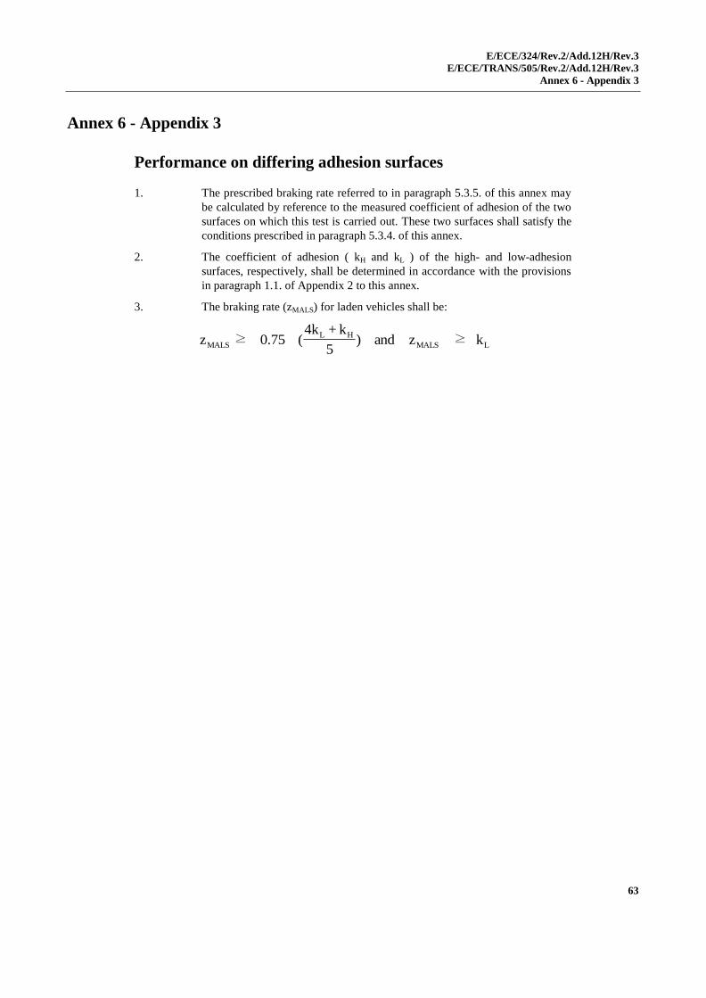
E/ECE/324/Rev.2/Add.12H/Rev.3
E/ECE/TRANS/505/Rev.2/Add.12H/Rev.3
Annex 6 - Appendix 3
63
Annex 6 - Appendix 3
Performance on differing adhesion surfaces
1. The prescribed braking rate referred to in paragraph 5.3.5. of this annex may
be calculated by reference to the measured coefficient of adhesion of the two
surfaces on which this test is carried out. These two surfaces shall satisfy the
conditions prescribed in paragraph 5.3.4. of this annex.
2. The coefficient of adhesion ( kH and kL ) of the high- and low-adhesion
surfaces, respectively, shall be determined in accordance with the provisions
in paragraph 1.1. of Appendix 2 to this annex.
3. The braking rate (zMALS) for laden vehicles shall be:
LMALS
HL
MALS k≥zand)5
k+4k(0.75≥z
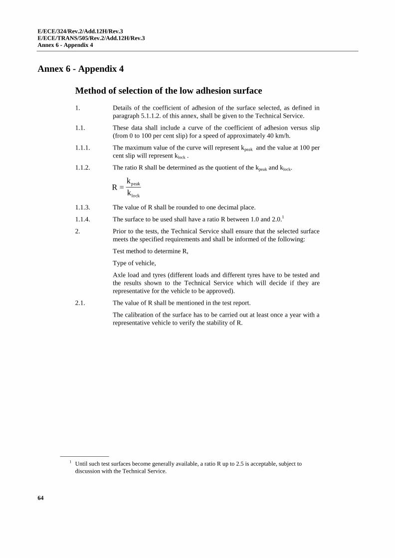
E/ECE/324/Rev.2/Add.12H/Rev.3
E/ECE/TRANS/505/Rev.2/Add.12H/Rev.3
Annex 6 - Appendix 4
64
Annex 6 - Appendix 4
Method of selection of the low adhesion surface
1. Details of the coefficient of adhesion of the surface selected, as defined in
paragraph 5.1.1.2. of this annex, shall be given to the Technical Service.
1.1. These data shall include a curve of the coefficient of adhesion versus slip
(from 0 to 100 per cent slip) for a speed of approximately 40 km/h.
1.1.1. The maximum value of the curve will represent kpeak and the value at 100 per
cent slip will represent klock .
1.1.2. The ratio R shall be determined as the quotient of the kpeak and klock.
lock
peak
k
k=R
1.1.3. The value of R shall be rounded to one decimal place.
1.1.4. The surface to be used shall have a ratio R between 1.0 and 2.0.1
2. Prior to the tests, the Technical Service shall ensure that the selected surface
meets the specified requirements and shall be informed of the following:
Test method to determine R,
Type of vehicle,
Axle load and tyres (different loads and different tyres have to be tested and
the results shown to the Technical Service which will decide if they are
representative for the vehicle to be approved).
2.1. The value of R shall be mentioned in the test report.
The calibration of the surface has to be carried out at least once a year with a
representative vehicle to verify the stability of R.
1 Until such test surfaces become generally available, a ratio R up to 2.5 is acceptable, subject to
discussion with the Technical Service.

E/ECE/324/Rev.2/Add.12H/Rev.3
E/ECE/TRANS/505/Rev.2/Add.12H/Rev.3
Annex 7
65
Annex 7
Inertia dynamometer test method for brake linings
1. General
1.1. The procedure described in this annex may be applied in the event of a
modification of vehicle type resulting from the fitting of brake linings of
another type to vehicles which have been approved in accordance with this
Regulation.
1.2. The alternative types of brake linings shall be checked by comparing their
performance with that obtained from the brake linings with which the vehicle
was equipped at the time of approval and conforming to the components
identified in the relevant information document, a model of which is given in
Annex 1 to this Regulation.
1.3. The Technical Authority responsible for conducting approval tests may at its
discretion require comparison of the performance of the brake linings to be
carried out in accordance with the relevant provisions contained in Annex 3
to this Regulation.
1.4. Application for approval by comparison shall be made by the vehicle
manufacturer or by his duly accredited representative.
1.5. In the context of this annex "vehicle" shall mean the vehicle type approved
according to this Regulation and for which it is requested that the comparison
shall be considered satisfactory.
2. Test equipment
2.1. A dynamometer having the following characteristics shall be used for the
tests:
2.1.1. It shall be capable of generating the inertia required by paragraph 3.1. of this
annex, and have the capacity to meet the requirements prescribed by
paragraph 1.5. of Annex 3 to this Regulation with respect to the Type-I fade
test;
2.1.2. The brakes fitted shall be identical with those of the original vehicle type
concerned;
2.1.3. Air cooling, if provided, shall be in accordance with paragraph 3.4. of this
annex;
2.1.4. The instrumentation for the test shall be capable of providing at least the
following data;
2.1.4.1. A continuous recording of disc or drum rotational speed;
2.1.4.2. Number of revolutions completed during a stop, to resolution not greater than
one eighth of a revolution;
2.1.4.3. Stop time;
2.1.4.4. A continuous recording of the temperature measured in the centre of the path
swept by the lining or at mid-thickness of the disc or drum or lining;
2.1.4.5. A continuous recording of brake application control line pressure or force;
E/ECE/324/Rev.2/Add.12H/Rev.3
E/ECE/TRANS/505/Rev.2/Add.12H/Rev.3
Annex 7
66
2.1.4.6. A continuous recording of brake output torque.
3. Test conditions
3.1. The dynamometer shall be set as close as possible, with 5 per cent tolerance,
to the rotary inertia equivalent to that part of the total inertia of the vehicle
braked by the appropriate wheel(s) according to the following formula:
I = M R2
Where:
I = rotational inertia (kgm2 )
R = dynamic tyre rolling radius (m)
M = that part of the maximum mass of the vehicle braked by the
appropriate wheel(s). In the case of a single-ended
dynamometer, this part shall be calculated from the design
braking distribution when deceleration corresponds to the
appropriate value given in row (A) of the table under
paragraph 2.1.1. of Annex 3 to this Regulation.
3.2. The initial rotational speed of the inertia dynamometer shall correspond to the
linear speed of the vehicle as prescribed in row (A) of the table under
paragraph 2.1.1. of Annex 3 to this Regulation and shall be based on the
dynamic rolling radius of the tyre.
3.3. Brake linings shall be at least 80 per cent bedded and shall not have exceeded
a temperature of 180 °C during the bedding procedure, or alternatively, at the
vehicle manufacturer's request, be bedded in accordance with his
recommendations.
3.4. Cooling air may be used, flowing over the brake in a direction perpendicular
to its axis of rotation. The velocity of the cooling air flowing over the brake
shall be not greater than 10 km/h. The temperature of the cooling air shall be
the ambient temperature.
4. Test procedure
4.1. Five sample sets of the brake lining shall be subjected to the comparison test;
they shall be compared with five sets of linings conforming to the original
components identified in the information document concerning the first
approval of the vehicle type concerned.
4.2. Brake lining equivalence shall be based on a comparison of the results
achieved using the test procedures prescribed in this annex and in accordance
with the following requirements.
4.3. Type-O cold performance test
4.3.1. Three brake applications shall be made when the initial temperature is below
100 °C. The temperature shall be measured in accordance with the provisions
of paragraph 2.1.4.4. of this annex.
4.3.2. Brake applications shall be made from an initial rotational speed equivalent
to that given in row (A) of the table under paragraph 2.1.1. of Annex 3 to this
Regulation, and the brake shall be applied to achieve a mean torque
equivalent to the deceleration prescribed in that paragraph. In addition, tests
shall also be carried out at several rotational speeds, the lowest being
E/ECE/324/Rev.2/Add.12H/Rev.3
E/ECE/TRANS/505/Rev.2/Add.12H/Rev.3
Annex 7
67
equivalent to 30 per cent of the maximum speed of the vehicle and the
highest being equivalent to 80 per cent of that speed.
4.3.3. The mean braking torque recorded during the above cold performance tests
on the linings being tested for the purpose of comparison shall, for the same
input measurement, be within the test limits 15 per cent of the mean braking
torque recorded with the brake linings conforming to the component
identified in the relevant application for vehicle type approval.
4.4. Type-I test (fade test)
4.4.1. Heating procedure
4.4.1.1. Brake linings shall be tested according to the procedure given in
paragraph 1.5.1. of Annex 3 to this Regulation.
4.4.2. Hot performance
4.4.2.1. On completion of the tests required under paragraph 4.4.1. of this annex, the
hot braking performance test specified in paragraph 1.5.2. of Annex 3 to this
Regulation shall be carried out.
4.4.2.2. The mean braking torque recorded during the above hot performance tests on
the linings being tested for the purpose of comparison shall, for the same
input measurement, be within the test limits 15 per cent of the mean braking
torque recorded with the brake linings conforming to the component
identified in the relevant application for vehicle type approval.
5. Inspection of brake linings
Brake linings shall be visually inspected on completion of the above tests to
check that they are in satisfactory condition for continued use in normal
service.
E/ECE/324/Rev.2/Add.12H/Rev.3
E/ECE/TRANS/505/Rev.2/Add.12H/Rev.3
Annex 8
68
Annex 8
Special requirements to be applied to the safety aspects of complex electronic vehicle control systems
1. General
This annex defines the special requirements for documentation, fault strategy
and verification with respect to the safety aspects of Complex Electronic
Vehicle Control Systems (definition 2.3. below) as far as this Regulation is
concerned.
This annex may also be called, by special paragraphs in this Regulation, for
safety related functions which are controlled by electronic system(s).
This annex does not specify the performance criteria for "The System" but
covers the methodology applied to the design process and the information
which shall be disclosed to the Technical Service, for type approval purposes.
This information shall show that "The System" respects, under normal and
fault conditions, all the appropriate performance requirements specified
elsewhere in this Regulation.
2. Definitions
For the purposes of this annex,
2.1. "Safety concept" is a description of the measures designed into the system,
for example within the electronic units, so as to address system integrity and
thereby ensure safe operation even in the event of an electrical failure.
The possibility of a fall-back to partial operation or even to a back-up system
for vital vehicle functions may be a part of the safety concept.
2.2. "Electronic control system" means a combination of units, designed to co-
operate in the production of the stated vehicle control function by electronic
data processing.
Such systems, often controlled by software, are built from discrete functional
components such as sensors, electronic control units and actuators and
connected by transmission links. They may include mechanical, electro-
pneumatic or electro-hydraulic elements.
"The System", referred to herein, is the one for which type approval is being
sought.
2.3. "Complex electronic vehicle control systems" are those electronic control
systems which are subject to a hierarchy of control in which a controlled
function may be over-ridden by a higher level electronic control
system/function.
A function which is over-ridden becomes part of the complex system.
2.4. "Higher-level control" systems/functions are those which employ additional
processing and/or sensing provisions to modify vehicle behaviour by
commanding variations in the normal function(s) of the vehicle control system.
E/ECE/324/Rev.2/Add.12H/Rev.3
E/ECE/TRANS/505/Rev.2/Add.12H/Rev.3
Annex 8
69
This allows complex systems to automatically change their objectives with a
priority which depends on the sensed circumstances.
2.5. "Units" are the smallest divisions of system components which will be
considered in this annex, since these combinations of components will be
treated as single entities for purposes of identification, analysis or
replacement.
2.6. "Transmission links" are the means used for inter-connecting distributed units
for the purpose of conveying signals, operating data or an energy supply.
This equipment is generally electrical but may, in some part, be mechanical,
pneumatic, hydraulic or optical.
2.7. "Range of control" refers to an output variable and defines the range over
which the system is likely to exercise control.
2.8. "Boundary of functional operation" defines the boundaries of the external
physical limits within which the system is able to maintain control.
3. Documentation
3.1. Requirements
The manufacturer shall provide a documentation package which gives access
to the basic design of "The System" and the means by which it is linked to
other vehicle systems or by which it directly controls output variables.
The function(s) of "The System" and the safety concept, as laid down by the
manufacturer, shall be explained.
Documentation shall be brief, yet provide evidence that the design and
development has had the benefit of expertise from all the system fields which
are involved.
For periodic technical inspections, the documentation shall describe how the
current operational status of "The System" can be checked.
3.1.1. Documentation shall be made available in 2 parts:
(a) The formal documentation package for the approval, containing the
material listed in paragraph 3. (with the exception of that of
paragraph 3.4.4.) which shall be supplied to the Technical Service at
the time of submission of the type approval application. This will be
taken as the basic reference for the verification process set out in
paragraph 4. of this annex.
(b) Additional material and analysis data of paragraph 3.4.4., which shall
be retained by the manufacturer, but made open for inspection at the
time of type approval.
3.2. Description of the functions of "The System"
A description shall be provided which gives a simple explanation of all the
control functions of "The System" and the methods employed to achieve the
objectives, including a statement of the mechanism(s) by which control is
exercised.
3.2.1. A list of all input and sensed variables shall be provided and the working
range of these defined.
E/ECE/324/Rev.2/Add.12H/Rev.3
E/ECE/TRANS/505/Rev.2/Add.12H/Rev.3
Annex 8
70
3.2.2. A list of all output variables which are controlled by "The System" shall be
provided and an indication given, in each case, of whether the control is
direct or via another vehicle system. The range of control (paragraph 2.7.
above) exercised on each such variable shall be defined.
3.2.3. Limits defining the boundaries of functional operation (paragraph 2.8. above)
shall be stated where appropriate to system performance.
3.3. System layout and schematics
3.3.1. Inventory of components
A list shall be provided, collating all the units of "The System" and
mentioning the other vehicle systems which are needed to achieve the control
function in question.
An outline schematic showing these units in combination, shall be provided
with both the equipment distribution and the interconnections made clear.
3.3.2. Functions of the units
The function of each unit of "The System" shall be outlined and the signals
linking it with other Units or with other vehicle systems shall be shown. This
may be provided by a labelled block diagram or other schematic, or by a
description aided by such a diagram.
3.3.3. Interconnections
Interconnections within "The System" shall be shown by a circuit diagram for
the electrical transmission links, by an optical-fiber diagram for optical links,
by a piping diagram for pneumatic or hydraulic transmission equipment and
by a simplified diagrammatic layout for mechanical linkages.
3.3.4. Signal flow and priorities
There shall be a clear correspondence between these transmission links and
the signals carried between units.
Priorities of signals on multiplexed data paths shall be stated, wherever
priority may be an issue affecting performance or safety as far as this
Regulation is concerned.
3.3.5. Identification of units
Each unit shall be clearly and unambiguously identifiable (e.g. by marking
for hardware and marking or software output for software content) to provide
corresponding hardware and documentation association.
Where functions are combined within a single Unit or indeed within a single
computer, but shown in multiple blocks in the block diagram for clarity and
ease of explanation, only a single hardware identification marking shall be
used.
The manufacturer shall, by the use of this identification, affirm that the
equipment supplied conforms to the corresponding document.
3.3.5.1. The identification defines the hardware and software version and, where the
latter changes such as to alter the function of the unit as far as this Regulation
is concerned, this identification shall also be changed.

E/ECE/324/Rev.2/Add.12H/Rev.3
E/ECE/TRANS/505/Rev.2/Add.12H/Rev.3
Annex 8
71
3.4. Safety concept of the manufacturer
3.4.1. The manufacturer shall provide a statement which affirms that the strategy
chosen to achieve "The System" objectives will not, under non-fault
conditions, prejudice the safe operation of systems which are subject to the
prescriptions of this Regulation.
3.4.2. In respect of software employed in "The System", the outline architecture
shall be explained and the design methods and tools used shall be identified.
The manufacturer shall be prepared, if required, to show some evidence of
the means by which they determined the realisation of the system logic,
during the design and development process.
3.4.3. The Manufacturer shall provide the technical authorities with an explanation
of the design provisions built into "The System" so as to generate safe
operation under fault conditions. Possible design provisions for failure in
"The System" are for example:
(a) Fall-back to operation using a partial system.
(b) Change-over to a separate back-up system.
(c) Removal of the high level function.
In case of a failure, the driver shall be warned for example by warning signal
or message display. When the system is not deactivated by the driver, e.g. by
turning the Ignition (run) switch to "off", or by switching off that particular
function if a special switch is provided for that purpose, the warning shall be
present as long as the fault condition persists.
3.4.3.1. If the chosen provision selects a partial performance mode of operation under
certain fault conditions, then these conditions shall be stated and the resulting
limits of effectiveness defined.
3.4.3.2. If the chosen provision selects a second (back-up) means to realise the
vehicle control system objective, the principles of the change-over
mechanism, the logic and level of redundancy and any built in back-up
checking features shall be explained and the resulting limits of back-up
effectiveness defined.
3.4.3.3. If the chosen provision selects the removal of the higher level function, all
the corresponding output control signals associated with this function shall be
inhibited, and in such a manner as to limit the transition disturbance.
3.4.4. The documentation shall be supported, by an analysis which shows, in
overall terms, how the system will behave on the occurrence of any one of
those specified faults which will have a bearing on vehicle control
performance or safety.
This may be based on a Failure Mode and Effect Analysis (FMEA), a Fault
Tree Analysis (FTA) or any similar process appropriate to system safety
considerations.
The chosen analytical approach(es) shall be established and maintained by
the manufacturer and shall be made open for inspection by the Technical
Service at the time of the type approval.
E/ECE/324/Rev.2/Add.12H/Rev.3
E/ECE/TRANS/505/Rev.2/Add.12H/Rev.3
Annex 8
72
3.4.4.1. This documentation shall itemise the parameters being monitored and shall
set out, for each fault condition of the type defined in paragraph 3.4.4. above,
the warning signal to be given to the driver and/or to service/technical
inspection personnel.
4. Verification and test
4.1. The functional operation of "The System", as laid out in the documents
required in paragraph 3., shall be tested as follows:
4.1.1. Verification of the function of "The System"
As the means of establishing the normal operational levels, verification of the
performance of the vehicle system under non-fault conditions shall be
conducted against the manufacturer's basic benchmark specification unless
this is subject to a specified performance test as part of the approval
procedure of this or another Regulation.
4.1.2. Verification of the safety concept of paragraph 3.4. of this annex.
The reaction of "The System" shall, at the discretion of the type approval
authority, be checked under the influence of a failure in any individual unit
by applying corresponding output signals to electrical units or mechanical
elements in order to simulate the effects of internal faults within the unit.
The verification results shall correspond with the documented summary of
the failure analysis, to a level of overall effect such that the safety concept
and execution are confirmed as being adequate.
E/ECE/324/Rev.2/Add.12H/Rev.3
E/ECE/TRANS/505/Rev.2/Add.12H/Rev.3
Annex 9
73
Annex 9
Electronic stability control and brake assist systems
Part A. Requirements for electronic stability control systems, where fitted
1. General requirements
Vehicles equipped with an ESC system shall meet the functional requirements
specified in paragraph 2. and the performance requirements in paragraph 3.
under the test procedures specified in paragraph 4. and under the test conditions
specified in paragraph 5. of this part of this annex.
2. Functional requirements
Each vehicle to which this annex applies shall be equipped with an electronic
stability control system that:
2.1. Is capable of applying braking torques individually to all four wheels1 and has a
control algorithm that utilizes this capability;
2.2. Is operational over the full speed range of the vehicle, during all phases of
driving including acceleration, coasting, and deceleration (including braking),
except:
2.2.1. When the driver has disabled ESC;
2.2.2. When the vehicle speed is below 20 km/h;
2.2.3. While the initial start-up self test and plausibility checks are completed, not to
exceed 2 minutes when driven under the conditions of paragraph 5.10.2.;
2.2.4. When the vehicle is being driven in reverse.
2.3. Remains capable of activation even if the antilock braking system or traction
control system is also activated.
3. Performance requirements
During each test performed under the test conditions of paragraph 4. and the test
procedure of paragraph 5.9., the vehicle with the ESC system engaged shall
satisfy the directional stability criteria of paragraphs 3.1. and 3.2., and it shall
satisfy the responsiveness criterion of paragraph 3.3. during each of those tests
conducted with a commanded steering wheel2 angle of 5A or greater but limited
as per paragraph 5.9.4., where A is the steering wheel angle computed in
paragraph 5.6.1.
Where a vehicle has been physically tested in accordance with paragraph 4., the
compliance of versions or variants of that same vehicle type may be
demonstrated by a computer simulation, which respects the test conditions of
1 An axle group shall be treated as a single axle and dual wheels shall be treated as a single wheel.
2 The text in this annex assumes that the vehicle steering is controlled by means of a steering wheel.
Vehicles using other types of steering control may also be approved to this annex provided the
manufacturer is able to demonstrate to the Technical Service that the performance requirements of
this annex can be met using equivalent steering inputs to the steering inputs stipulated under
paragraph 5. of this part.
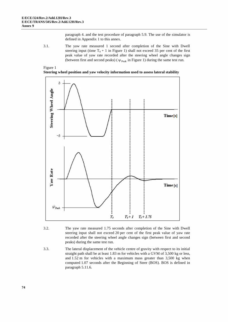
E/ECE/324/Rev.2/Add.12H/Rev.3
E/ECE/TRANS/505/Rev.2/Add.12H/Rev.3
Annex 9
74
paragraph 4. and the test procedure of paragraph 5.9. The use of the simulator is
defined in Appendix 1 to this annex.
3.1. The yaw rate measured 1 second after completion of the Sine with Dwell
steering input (time T0 + 1 in Figure 1) shall not exceed 35 per cent of the first
peak value of yaw rate recorded after the steering wheel angle changes sign
(between first and second peaks) ( Peak in Figure 1) during the same test run.
Figure 1
Steering wheel position and yaw velocity information used to assess lateral stability
3.2. The yaw rate measured 1.75 seconds after completion of the Sine with Dwell
steering input shall not exceed 20 per cent of the first peak value of yaw rate
recorded after the steering wheel angle changes sign (between first and second
peaks) during the same test run.
3.3. The lateral displacement of the vehicle centre of gravity with respect to its initial
straight path shall be at least 1.83 m for vehicles with a GVM of 3,500 kg or less,
and 1.52 m for vehicles with a maximum mass greater than 3,500 kg when
computed 1.07 seconds after the Beginning of Steer (BOS). BOS is defined in
paragraph 5.11.6.
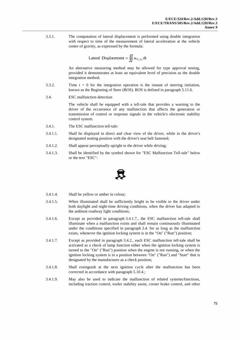
E/ECE/324/Rev.2/Add.12H/Rev.3
E/ECE/TRANS/505/Rev.2/Add.12H/Rev.3
Annex 9
75
3.3.1. The computation of lateral displacement is performed using double integration
with respect to time of the measurement of lateral acceleration at the vehicle
centre of gravity, as expressed by the formula:
An alternative measuring method may be allowed for type approval testing,
provided it demonstrates at least an equivalent level of precision as the double
integration method.
3.3.2. Time t = 0 for the integration operation is the instant of steering initiation,
known as the Beginning of Steer (BOS). BOS is defined in paragraph 5.11.6.
3.4. ESC malfunction detection
The vehicle shall be equipped with a tell-tale that provides a warning to the
driver of the occurrence of any malfunction that affects the generation or
transmission of control or response signals in the vehicle's electronic stability
control system.
3.4.1. The ESC malfunction tell-tale:
3.4.1.1. Shall be displayed in direct and clear view of the driver, while in the driver's
designated seating position with the driver's seat belt fastened;
3.4.1.2. Shall appear perceptually upright to the driver while driving;
3.4.1.3. Shall be identified by the symbol shown for "ESC Malfunction Tell-tale" below
or the text "ESC":
3.4.1.4. Shall be yellow or amber in colour;
3.4.1.5. When illuminated shall be sufficiently bright to be visible to the driver under
both daylight and night-time driving conditions, when the driver has adapted to
the ambient roadway light conditions;
3.4.1.6. Except as provided in paragraph 3.4.1.7., the ESC malfunction tell-tale shall
illuminate when a malfunction exists and shall remain continuously illuminated
under the conditions specified in paragraph 3.4. for as long as the malfunction
exists, whenever the ignition locking system is in the "On" ("Run") position;
3.4.1.7. Except as provided in paragraph 3.4.2., each ESC malfunction tell-tale shall be
activated as a check of lamp function either when the ignition locking system is
turned to the "On" ("Run") position when the engine is not running, or when the
ignition locking system is in a position between "On" ("Run") and "Start" that is
designated by the manufacturer as a check position;
3.4.1.8. Shall extinguish at the next ignition cycle after the malfunction has been
corrected in accordance with paragraph 5.10.4.;
3.4.1.9. May also be used to indicate the malfunction of related systems/functions,
including traction control, trailer stability assist, corner brake control, and other
dtaent DisplacemLateral .G.Cy
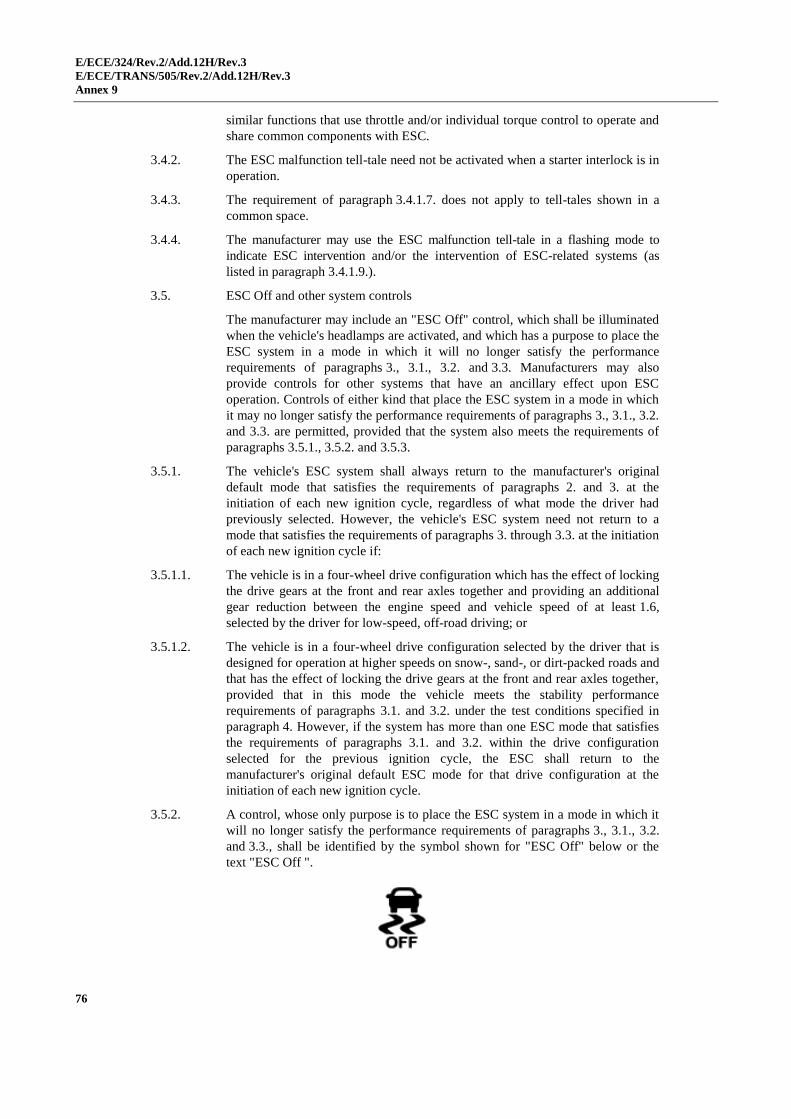
E/ECE/324/Rev.2/Add.12H/Rev.3
E/ECE/TRANS/505/Rev.2/Add.12H/Rev.3
Annex 9
76
similar functions that use throttle and/or individual torque control to operate and
share common components with ESC.
3.4.2. The ESC malfunction tell-tale need not be activated when a starter interlock is in
operation.
3.4.3. The requirement of paragraph 3.4.1.7. does not apply to tell-tales shown in a
common space.
3.4.4. The manufacturer may use the ESC malfunction tell-tale in a flashing mode to
indicate ESC intervention and/or the intervention of ESC-related systems (as
listed in paragraph 3.4.1.9.).
3.5. ESC Off and other system controls
The manufacturer may include an "ESC Off" control, which shall be illuminated
when the vehicle's headlamps are activated, and which has a purpose to place the
ESC system in a mode in which it will no longer satisfy the performance
requirements of paragraphs 3., 3.1., 3.2. and 3.3. Manufacturers may also
provide controls for other systems that have an ancillary effect upon ESC
operation. Controls of either kind that place the ESC system in a mode in which
it may no longer satisfy the performance requirements of paragraphs 3., 3.1., 3.2.
and 3.3. are permitted, provided that the system also meets the requirements of
paragraphs 3.5.1., 3.5.2. and 3.5.3.
3.5.1. The vehicle's ESC system shall always return to the manufacturer's original
default mode that satisfies the requirements of paragraphs 2. and 3. at the
initiation of each new ignition cycle, regardless of what mode the driver had
previously selected. However, the vehicle's ESC system need not return to a
mode that satisfies the requirements of paragraphs 3. through 3.3. at the initiation
of each new ignition cycle if:
3.5.1.1. The vehicle is in a four-wheel drive configuration which has the effect of locking
the drive gears at the front and rear axles together and providing an additional
gear reduction between the engine speed and vehicle speed of at least 1.6,
selected by the driver for low-speed, off-road driving; or
3.5.1.2. The vehicle is in a four-wheel drive configuration selected by the driver that is
designed for operation at higher speeds on snow-, sand-, or dirt-packed roads and
that has the effect of locking the drive gears at the front and rear axles together,
provided that in this mode the vehicle meets the stability performance
requirements of paragraphs 3.1. and 3.2. under the test conditions specified in
paragraph 4. However, if the system has more than one ESC mode that satisfies
the requirements of paragraphs 3.1. and 3.2. within the drive configuration
selected for the previous ignition cycle, the ESC shall return to the
manufacturer's original default ESC mode for that drive configuration at the
initiation of each new ignition cycle.
3.5.2. A control, whose only purpose is to place the ESC system in a mode in which it
will no longer satisfy the performance requirements of paragraphs 3., 3.1., 3.2.
and 3.3., shall be identified by the symbol shown for "ESC Off" below or the
text "ESC Off ".
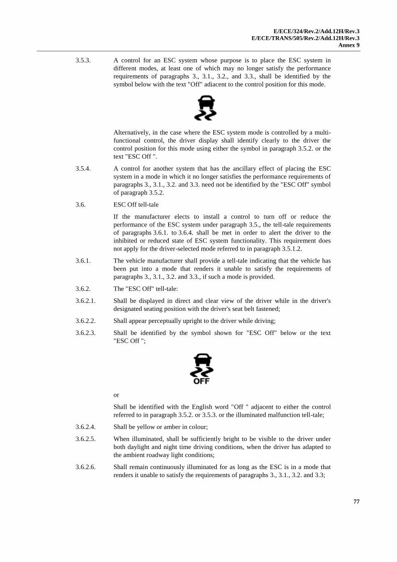
E/ECE/324/Rev.2/Add.12H/Rev.3
E/ECE/TRANS/505/Rev.2/Add.12H/Rev.3
Annex 9
77
3.5.3. A control for an ESC system whose purpose is to place the ESC system in
different modes, at least one of which may no longer satisfy the performance
requirements of paragraphs 3., 3.1., 3.2., and 3.3., shall be identified by the
symbol below with the text "Off" adjacent to the control position for this mode.
Alternatively, in the case where the ESC system mode is controlled by a multi-
functional control, the driver display shall identify clearly to the driver the
control position for this mode using either the symbol in paragraph 3.5.2. or the
text "ESC Off ".
3.5.4. A control for another system that has the ancillary effect of placing the ESC
system in a mode in which it no longer satisfies the performance requirements of
paragraphs 3., 3.1., 3.2. and 3.3. need not be identified by the "ESC Off" symbol
of paragraph 3.5.2.
3.6. ESC Off tell-tale
If the manufacturer elects to install a control to turn off or reduce the
performance of the ESC system under paragraph 3.5., the tell-tale requirements
of paragraphs 3.6.1. to 3.6.4. shall be met in order to alert the driver to the
inhibited or reduced state of ESC system functionality. This requirement does
not apply for the driver-selected mode referred to in paragraph 3.5.1.2.
3.6.1. The vehicle manufacturer shall provide a tell-tale indicating that the vehicle has
been put into a mode that renders it unable to satisfy the requirements of
paragraphs 3., 3.1., 3.2. and 3.3., if such a mode is provided.
3.6.2. The "ESC Off" tell-tale:
3.6.2.1. Shall be displayed in direct and clear view of the driver while in the driver's
designated seating position with the driver's seat belt fastened;
3.6.2.2. Shall appear perceptually upright to the driver while driving;
3.6.2.3. Shall be identified by the symbol shown for "ESC Off" below or the text
"ESC Off ";
or
Shall be identified with the English word "Off " adjacent to either the control
referred to in paragraph 3.5.2. or 3.5.3. or the illuminated malfunction tell-tale;
3.6.2.4. Shall be yellow or amber in colour;
3.6.2.5. When illuminated, shall be sufficiently bright to be visible to the driver under
both daylight and night time driving conditions, when the driver has adapted to
the ambient roadway light conditions;
3.6.2.6. Shall remain continuously illuminated for as long as the ESC is in a mode that
renders it unable to satisfy the requirements of paragraphs 3., 3.1., 3.2. and 3.3;
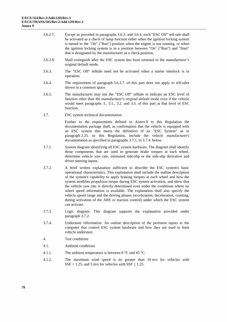
E/ECE/324/Rev.2/Add.12H/Rev.3
E/ECE/TRANS/505/Rev.2/Add.12H/Rev.3
Annex 9
78
3.6.2.7. Except as provided in paragraphs 3.6.3. and 3.6.4. each "ESC Off" tell-tale shall
be activated as a check of lamp function either when the ignition locking system
is turned to the "On" ("Run") position when the engine is not running, or when
the ignition locking system is in a position between "On" ("Run") and "Start"
that is designated by the manufacturer as a check position.
3.6.2.8. Shall extinguish after the ESC system has been returned to the manufacturer’s
original default mode.
3.6.3. The "ESC Off" telltale need not be activated when a starter interlock is in
operation.
3.6.4. The requirement of paragraph 3.6.2.7. of this part does not apply to tell-tales
shown in a common space.
3.6.5. The manufacturer may use the "ESC Off" telltale to indicate an ESC level of
function other than the manufacturer’s original default mode even if the vehicle
would meet paragraphs 3., 3.1., 3.2. and 3.3. of this part at that level of ESC
function.
3.7. ESC system technical documentation
Further to the requirements defined in Annex 8 to this Regulation the
documentation package shall, as confirmation that the vehicle is equipped with
an ESC system that meets the definition of an "ESC System" as in
paragraph 2.25. to this Regulation, include the vehicle manufacturer's
documentation as specified in paragraphs 3.7.1. to 3.7.4. below.
3.7.1. System diagram identifying all ESC system hardware. The diagram shall identify
those components that are used to generate brake torques at each wheel,
determine vehicle yaw rate, estimated side-slip or the side-slip derivative and
driver steering inputs.
3.7.2. A brief written explanation sufficient to describe the ESC system's basic
operational characteristics. This explanation shall include the outline description
of the system's capability to apply braking torques at each wheel and how the
system modifies propulsion torque during ESC system activation, and show that
the vehicle yaw rate is directly determined even under the conditions where no
wheel speed information is available. The explanation shall also specify the
vehicle speed range and the driving phases (acceleration, deceleration, coasting,
during activation of the ABS or traction control) under which the ESC system
can activate.
3.7.3. Logic diagram. This diagram supports the explanation provided under
paragraph 3.7.2.
3.7.4. Understeer information. An outline description of the pertinent inputs to the
computer that control ESC system hardware and how they are used to limit
vehicle understeer.
4. Test conditions
4.1. Ambient conditions
4.1.1. The ambient temperature is between 0 °C and 45 °C.
4.1.2. The maximum wind speed is no greater than 10 m/s for vehicles with
SSF > 1.25, and 5 m/s for vehicles with SSF ≤ 1.25.
E/ECE/324/Rev.2/Add.12H/Rev.3
E/ECE/TRANS/505/Rev.2/Add.12H/Rev.3
Annex 9
79
4.2. Road test surface
4.2.1. Tests are conducted on a dry, uniform, solid-paved surface. Surfaces with
irregularities and undulations, such as dips and large cracks, are unsuitable.
4.2.2. The road test surface has a nominal3 peak braking coefficient (PBC) of 0.9,
unless otherwise specified, when measured using either:
4.2.2.1. The American Society for Testing and Materials (ASTM) E1136 standard
reference test tyre, in accordance with ASTM Method E1337-90, at a speed
of 40 mph; or
4.2.2.2. The k-test method specified in Appendix 2 to Annex 6 of this Regulation.
4.2.3. The test surface has a consistent slope between level and 1 per cent.
4.3. Vehicle conditions
4.3.1. The ESC system is enabled for all testing.
4.3.2. Vehicle mass. The vehicle is loaded with the fuel tank filled to at least 90 per
cent of capacity, and a total interior load of 168 kg comprised of the test driver,
approximately 59 kg of test equipment (automated steering machine, data
acquisition system and the power supply for the steering machine), and ballast as
required to make up for any shortfall in the weight of test drivers and test
equipment. Where required, ballast shall be placed on the floor behind the
passenger front seat or if necessary in the front passenger foot well area. All
ballast shall be secured in a way that prevents it from becoming dislodged during
testing.
4.3.3. Tyres. The tyres are inflated to the vehicle manufacturer's recommended cold
inflation pressure(s) e.g. as specified on the vehicle's placard or the tyre inflation
pressure label. Tubes may be installed to prevent tyre de-beading.
4.3.4. Outriggers. Outriggers may be used for testing if deemed necessary for test
drivers' safety. In this case, the following applies for vehicles with a Static
Stability Factor (SSF) ≤ 1.25:
4.3.4.1. Vehicles with a mass in running order under 1,588 kg shall be equipped with
"lightweight" outriggers. Lightweight outriggers shall be designed with a
maximum mass of 27 kg and a maximum roll moment of inertia of 27 kg∙m2.
4.3.4.2. Vehicles with a mass in running order between 1,588 kg and 2,722 kg shall be
equipped with "standard" outriggers. Standard outriggers shall be designed with
a maximum mass of 32 kg and a maximum roll moment of inertia of 35.9 kg∙m2.
4.3.4.3. Vehicles with a mass in running order equal to or greater than 2,722 kg shall be
equipped with "heavy" outriggers. Heavy outriggers shall be designed with a
maximum mass of 39 kg and a maximum roll moment of inertia of 40.7 kg∙m2.
4.3.5. Automated steering machine. A steering robot programmed to execute the
required steering pattern shall be used in paragraphs 5.5.2., 5.5.3., 5.6. and 5.9.
The steering machine shall be capable of supplying steering torques between 40
to 60 Nm. The steering machine shall be able to apply these torques when
operating with steering wheel velocities up to 1,200 degrees per second.
3 The "nominal" value is understood as being the theoretical target value.
E/ECE/324/Rev.2/Add.12H/Rev.3
E/ECE/TRANS/505/Rev.2/Add.12H/Rev.3
Annex 9
80
5. Test Procedure
5.1. Inflate the vehicles' tyres to the manufacturer's recommended cold inflation
pressure(s) e.g. as provided on the vehicle's placard or the tyre inflation pressure
label.
5.2. Tell-tale bulb check. With the vehicle stationary and the ignition locking system
in the "Lock" or "Off" position, switch the ignition to the "On" ("Run") position
or, where applicable, the appropriate position for the lamp check. The ESC
malfunction tell-tale shall be illuminated as a check of lamp function, as
specified in paragraph 3.4.1.7., and if equipped, the "ESC Off" tell-tale shall also
be illuminated as a check of lamp function, as specified in paragraph 3.6.2.7. The
tell-tale bulb check is not required for a tell-tale shown in a common space as
specified in paragraphs 3.4.3. and 3.6.4.
5.3. "ESC Off" control check. For vehicles equipped with an "ESC Off" control, with
the vehicle stationary and the ignition locking system in the "Lock" or "Off"
position, switch the ignition locking system to the "On" ("Run") position.
Activate the "ESC Off" control and verify that the "ESC Off" tell-tale is
illuminated, as specified in paragraph 3.6.2. Turn the ignition locking system to
the "Lock" or "Off" position. Again, switch the ignition locking system to the
"On" ("Run") position and verify that the "ESC Off" tell-tale has extinguished
indicating that the ESC system has been restored as specified in paragraph 3.5.1.
5.4. Brake conditioning
Condition the vehicle brakes in the manner described in paragraphs 5.4.1.
to 5.4.4.
5.4.1. Ten stops are performed from a speed of 56 km/h, with an average deceleration
of approximately 0.5g.
5.4.2. Immediately following the series of ten 56 km/h stops, three additional stops are
performed from 72 km/h at higher deceleration.
5.4.3. When executing the stops in paragraph 5.4.2., sufficient force is applied to the
brake pedal to bring the vehicle's antilock braking system (ABS) into operation
for a majority of each braking event.
5.4.4. Following completion of the final stop in 5.4.2., the vehicle is driven at a speed
of 72 km/h for five minutes to cool the brakes.
5.5. Tyre Conditioning
Condition the tyres using the procedure of paragraphs 5.5.1. to 5.5.3. to wear
away mould sheen and achieve operating temperature immediately before
beginning the test runs of paragraphs 5.6. and 5.9.
5.5.1. The test vehicle is driven around a circle 30 meters in diameter at a speed that
produces a lateral acceleration of approximately 0.5 to 0.6g for three clockwise
laps followed by three anticlockwise laps.
5.5.2. Using a sinusoidal steering pattern at a frequency of 1 Hz, a peak steering wheel
angle amplitude corresponding to a peak lateral acceleration of 0.5 to 0.6g, and a
vehicle speed of 56 km/h, the vehicle is driven through four passes
performing 10 cycles of sinusoidal steering during each pass.
5.5.3. The steering wheel angle amplitude of the final cycle of the final pass shall be
twice that of the other cycles. The maximum time permitted between each of the
laps and passes is five minutes.
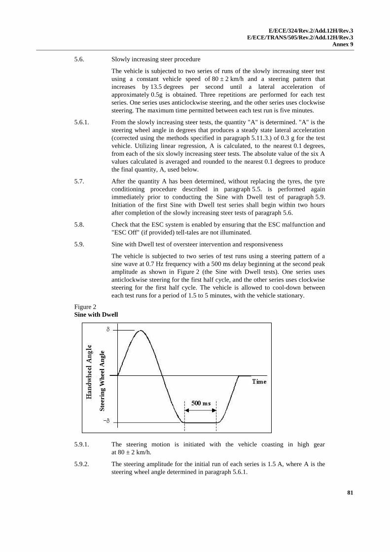
E/ECE/324/Rev.2/Add.12H/Rev.3
E/ECE/TRANS/505/Rev.2/Add.12H/Rev.3
Annex 9
81
5.6. Slowly increasing steer procedure
The vehicle is subjected to two series of runs of the slowly increasing steer test
using a constant vehicle speed of 80 ± 2 km/h and a steering pattern that
increases by 13.5 degrees per second until a lateral acceleration of
approximately 0.5g is obtained. Three repetitions are performed for each test
series. One series uses anticlockwise steering, and the other series uses clockwise
steering. The maximum time permitted between each test run is five minutes.
5.6.1. From the slowly increasing steer tests, the quantity "A" is determined. "A" is the
steering wheel angle in degrees that produces a steady state lateral acceleration
(corrected using the methods specified in paragraph 5.11.3.) of 0.3 g for the test
vehicle. Utilizing linear regression, A is calculated, to the nearest 0.1 degrees,
from each of the six slowly increasing steer tests. The absolute value of the six A
values calculated is averaged and rounded to the nearest 0.1 degrees to produce
the final quantity, A, used below.
5.7. After the quantity A has been determined, without replacing the tyres, the tyre
conditioning procedure described in paragraph 5.5. is performed again
immediately prior to conducting the Sine with Dwell test of paragraph 5.9.
Initiation of the first Sine with Dwell test series shall begin within two hours
after completion of the slowly increasing steer tests of paragraph 5.6.
5.8. Check that the ESC system is enabled by ensuring that the ESC malfunction and
"ESC Off" (if provided) tell-tales are not illuminated.
5.9. Sine with Dwell test of oversteer intervention and responsiveness
The vehicle is subjected to two series of test runs using a steering pattern of a
sine wave at 0.7 Hz frequency with a 500 ms delay beginning at the second peak
amplitude as shown in Figure 2 (the Sine with Dwell tests). One series uses
anticlockwise steering for the first half cycle, and the other series uses clockwise
steering for the first half cycle. The vehicle is allowed to cool-down between
each test runs for a period of 1.5 to 5 minutes, with the vehicle stationary.
Figure 2
Sine with Dwell
5.9.1. The steering motion is initiated with the vehicle coasting in high gear
at 80 ± 2 km/h.
5.9.2. The steering amplitude for the initial run of each series is 1.5 A, where A is the
steering wheel angle determined in paragraph 5.6.1.
Ste
erin
g W
hee
l A
ng
le
E/ECE/324/Rev.2/Add.12H/Rev.3
E/ECE/TRANS/505/Rev.2/Add.12H/Rev.3
Annex 9
82
5.9.3. In each series of test runs, the steering amplitude is increased from run to run,
by 0.5 A, provided that no such run will result in a steering amplitude greater
than that of the final run specified in paragraph 5.9.4.
5.9.4. The steering amplitude of the final run in each series is the greater of 6.5 A
or 270 degrees, provided the calculated magnitude of 6.5 A is less than or equal
to 300 degrees. If any 0.5 A increment, up to 6.5 A, is greater than 300 degrees,
the steering amplitude of the final run shall be 300 degrees.
5.9.5. Upon completion of the two series of test runs, post processing of yaw rate and
lateral acceleration data is done as specified in paragraph 5.11.
5.10. ESC malfunction detection
5.10.1. Simulate one or more ESC malfunction(s) by disconnecting the power source to
any ESC component, or disconnecting any electrical connection between ESC
components (with the vehicle power off). When simulating an ESC malfunction,
the electrical connections for the tell-tale lamp(s) and/or optional ESC system
control(s) are not to be disconnected.
5.10.2. With the vehicle initially stationary and the ignition locking system in the
"Lock" or "Off" position, switch the ignition locking system to the "Start"
position and start the engine. Drive the vehicle forward to obtain a vehicle speed
of 48 ± 8 km/h. 30 seconds, at the latest, after the engine has been started and
within the next two minutes at this speed, conduct at least one left and one right
smooth turning manoeuvre without losing directional stability and one brake
application. Verify that the ESC malfunction indicator illuminates in accordance
with paragraph 3.4. by the end of these manoeuvres.
5.10.3. Stop the vehicle, switch the ignition locking system to the "Off" or "Lock"
position. After a five-minute period, switch the vehicle's ignition locking system
to the "Start" position and start the engine. Verify that the ESC malfunction
indicator again illuminates to signal a malfunction and remains illuminated as
long as the engine is running or until the fault is corrected.
5.10.4. Switch the ignition locking system to the "Off" or "Lock" position. Restore the
ESC system to normal operation, switch the ignition system to the "Start"
position and start the engine. Re-perform the manoeuvre described in
paragraph 5.10.2. and verify that the tell-tale has extinguished within this time or
immediately afterwards.
5.11. Post data processing – calculations for performance metrics
Yaw rate and lateral displacement measurements and calculations shall be
processed utilizing the techniques specified in paragraphs 5.11.1. to 5.11.8.
5.11.1. Raw steering wheel angle data is filtered with a 12-pole phaseless Butterworth
filter and a cut-off frequency of 10 Hz. The filtered data is then zeroed to remove
sensor offset utilizing static pre-test data.
5.11.2. Raw yaw rate data is filtered with a 12-pole phaseless Butterworth filter and a
cut-off frequency of 6 Hz. The filtered data is then zeroed to remove sensor
offset utilizing static pre-test data.
5.11.3. Raw lateral acceleration data is filtered with a 12-pole phaseless Butterworth
filter and a cut-off frequency of 6 Hz. The filtered data is then zeroed to remove
sensor offset utilizing static pre-test data. The lateral acceleration data at the
vehicle centre of gravity is determined by removing the effects caused by vehicle
body roll and by correcting for sensor placement via the use of coordinate
E/ECE/324/Rev.2/Add.12H/Rev.3
E/ECE/TRANS/505/Rev.2/Add.12H/Rev.3
Annex 9
83
transformation. For data collection, the lateral accelerometer shall be located as
close as possible to the position of the vehicle's longitudinal and lateral centres
of gravity.
5.11.4. Steering wheel velocity is determined by differentiating the filtered steering
wheel angle data. The steering wheel velocity data is then filtered with a
moving 0.1 second running average filter.
5.11.5. Lateral acceleration, yaw rate and steering wheel angle data channels are zeroed
utilizing a defined "zeroing range". The methods used to establish the zeroing
range are defined in paragraphs 5.11.5.1. and 5.11.5.2.
5.11.5.1. Using the steering wheel rate data calculated using the methods described in
paragraph 5.11.4., the first instant that the steering wheel rate exceeds 75 deg/sec
is identified. From this point, steering wheel rate shall remain greater
than 75 deg/sec for at least 200 ms. If the second condition is not met, the next
instant that the steering wheel rate exceeds 75 deg/sec is identified and
the 200 ms validity check applied. This iterative process continues until both
conditions are ultimately satisfied.
5.11.5.2. The "zeroing range" is defined as the 1.0 second time period prior to the instant the
steering wheel rate exceeds 75 deg/sec (i.e., the instant the steering wheel velocity
exceeds 75 deg/sec defines the end of the "zeroing range").
5.11.6. The Beginning of Steer (BOS) is defined as the first instance when the filtered
and zeroed steering wheel angle data reaches -5 degrees (when the initial
steering input is anticlockwise) or +5 degrees (when the initial steering input is
clockwise) after a time defining the end of the "zeroing range." The value for
time at the BOS is interpolated.
5.11.7. The Completion of Steer (COS) is defined as the time the steering wheel angle
returns to zero at the completion of the Sine with Dwell steering manoeuvre. The
value for time at the zero degree steering wheel angle is interpolated.
5.11.8. The second peak yaw rate is defined as the first local yaw rate peak produced by
the reversal of the steering wheel. The yaw rates at 1.000 and 1.750 seconds after
COS are determined by interpolation.
5.11.9. Determine lateral velocity by integrating corrected, filtered and zeroed lateral
acceleration data. Zero lateral velocity at the BOS point. Determine lateral
displacement by integrating zeroed lateral velocity. Zero lateral displacement at
the BOS point. The lateral displacement measurement is made at 1.07 seconds
after BOS point and is determined by interpolation.
Part B. Special requirements to be applied to brake assist systems, where fitted
1. General
The following requirements apply to vehicles fitted with Brake Assist Systems
(BAS) as defined in paragraph 2.34. of this Regulation and declared in the
Communication of Annex 1, paragraph 22. of this Regulation.
In addition to the requirements of this annex, Brake Assist Systems shall also be
subject to any relevant requirements contained elsewhere within this Regulation.
In addition to the requirements of this annex, vehicles with BAS shall also be
equipped with ABS in accordance with Annex 6.

E/ECE/324/Rev.2/Add.12H/Rev.3
E/ECE/TRANS/505/Rev.2/Add.12H/Rev.3
Annex 9
84
1.1. General performance characteristics for category "A" BAS systems
When an emergency condition has been sensed by a relative high pedal force, the
additional pedal force to cause full cycling of the ABS shall be reduced
compared to the pedal force required without the BAS system in operation.
Compliance with this requirement is demonstrated if the provisions of
paragraphs 3.1. to 3.3. of this part of this annex are met.
1.2. General performance characteristics for category "B" BAS systems
When an emergency condition has been sensed, at least by a very fast application
of the pedal, the BAS system shall raise the pressure to deliver the maximum
achievable braking rate or cause full cycling of the ABS.
Compliance with this requirement is demonstrated if the provisions of
paragraphs 4.1. to 4.3. of this part are met.
2. General test requirements
2.1. Variables
Whilst performing the tests described in part B of this annex, the following
variables shall be measured:
2.1.1. Brake pedal force, Fp ;
2.1.2. Vehicle velocity, vx ;
2.1.3. Vehicle deceleration, ax ;
2.1.4. Brake temperature, Td ;
2.1.5. Brake pressure, P, where applicable;
2.1.6. Brake pedal speed, vp, measured at the centre of the pedal plate or at a position
on the pedal mechanism where the displacement is proportional to the
displacement at the centre of the pedal plate allowing simple calibration of the
measurement.
2.2. Measuring equipment
2.2.1. The variables listed in paragraph 2.1. of this part shall be measured by means of
appropriate transducers. Accuracy, operating ranges, filtering techniques, data
processing and other requirements are described in ISO Standard 15037-1: 2006.
2.2.2. Accuracy of pedal force and disc temperature measurements shall be as follows:
Variable range system
Typical operating range of the
transducers
Recommended maximum recording
errors
Pedal force 0 to 2,000 N ±10 N
Brake temperature 0 – 1,000 °C ±5 °C
Brake pressure* 0 – 20 MPa* ±100 kPa*
* Applicable as specified in paragraph 3.2.5.
2.2.3. Details on analogue and digital data processing of the BAS test procedures are
described in Appendix 5 to this annex. A sampling rate for data acquisition of at
least 500 Hz is required.
2.2.4. Alternative measuring methods to those referred to in paragraph 2.2.3. may be
allowed, provided they demonstrate at least an equivalent level of precision.
E/ECE/324/Rev.2/Add.12H/Rev.3
E/ECE/TRANS/505/Rev.2/Add.12H/Rev.3
Annex 9
85
2.3. Test conditions
2.3.1. Test vehicle loading condition: The vehicle shall be unladen. There may be, in
addition to the driver, a second person on the front seat who is responsible for
noting the results of the tests.
2.3.2. Braking tests shall be carried out on a dry surface affording good adhesion.
2.4. Test method
2.4.1. The tests as described in paragraphs 3. and 4. of this part shall be carried out
from a test speed of 100 ± 2 km/h. The vehicle shall be driven at the test speed in
a straight line.
2.4.2. The average temperature of the brakes shall be in accordance with
paragraph 1.4.1.1. of Annex 3.
2.4.3. For the tests the reference time, t0, is defined as the moment when the brake
pedal force reaches 20 N.
Note: For vehicles equipped with a brake system assisted by an energy source,
the applied pedal force necessary depends on the energy level that exists in the
energy storage device. Therefore, sufficient energy level shall be ensured at the
beginning of the test.
3. Assessment of the presence of a category "A" BAS
A category "A" BAS shall meet the test requirements contained in
paragraphs 3.1. and 3.2.
3.1. Test 1: Reference test to determine FABS and aABS.
3.1.1. The reference values FABS and aABS shall be determined in accordance with the
procedure described in Appendix 4 to this annex.
3.2. Test 2: For activation of BAS
3.2.1. Once an emergency braking condition has been detected, systems sensitive to
pedal force shall show a significant increase in the ratio of:
(a) Brake line pressure to brake pedal force, where permitted by
paragraph 3.2.5.; or
(b) Vehicle deceleration to brake pedal force.
3.2.2. The performance requirements for a category "A" BAS are met if a specific
brake application characteristic can be defined that exhibits a decrease of
between 40 per cent and 80 per cent in required brake pedal force for (FABS - FT)
compared to (FABS extrapolated - FT).
3.2.3. FT and aT are threshold force and threshold deceleration as shown in Figure 1.
The values of FT and aT shall be supplied to the Technical Service at the time of
submission of the type-approval application. The value of aT shall be
between 3.5 m/s² and 5.0 m/s².

E/ECE/324/Rev.2/Add.12H/Rev.3
E/ECE/TRANS/505/Rev.2/Add.12H/Rev.3
Annex 9
86
Figure 1a
Pedal force characteristic needed in order to achieve maximum deceleration with
category "A" BAS
3.2.4. A straight line is drawn from the origin through the point FT, aT (as shown in
Figure 1a). The value of brake pedal force "F", at the point of intersection
between this line and a horizontal line defined by a=aABS, is defined
as FABS, extrapolated:
T
ABSTedextrapolat,ABS
a
aFF
3.2.5. As an alternative, which can be selected by the manufacturer, in the case of
vehicles of category N1, or M1 derived from those N1 vehicles, with a gross
vehicle mass GVM > 2,500 kg, the pedal force figures for FT, FABS,min, FABS,max
and FAB,extrapolated may be derived from the brake line pressure response
characteristic instead of the vehicle deceleration characteristic. This shall be
measured as the brake pedal force is increasing.
3.2.5.1. The pressure, at which ABS cycling commences, shall be determined by making
five tests from 100 ± 2 km/h in which the brake pedal is applied up to the level
which produces ABS operation and the five pressures at which this occurs as
determined from front wheel pressure records, shall be recorded and the mean
value obtained as PABS.
3.2.5.2. The threshold pressure PT shall be stated by the manufacturer and correspond to a
deceleration in the range of 2.5 - 4.5 m/s2.
3.2.5.3. Figure 1b shall be constructed in the manner set out in paragraph 3.2.4., but
using line pressure measurements to define the parameters set out in
paragraph 3.2.5. of this part where:
T
ABSTedextrapolat,ABS
P
PFF
Dec
eler
ati
on
, a
Brake Pedal force, F
aT
aABS
FT FABS, min
Between 3.5 and 5.0 m/s2
FABS, max FABS, extrapolated
-40 % -80 %
FAbs
0 % -100 %
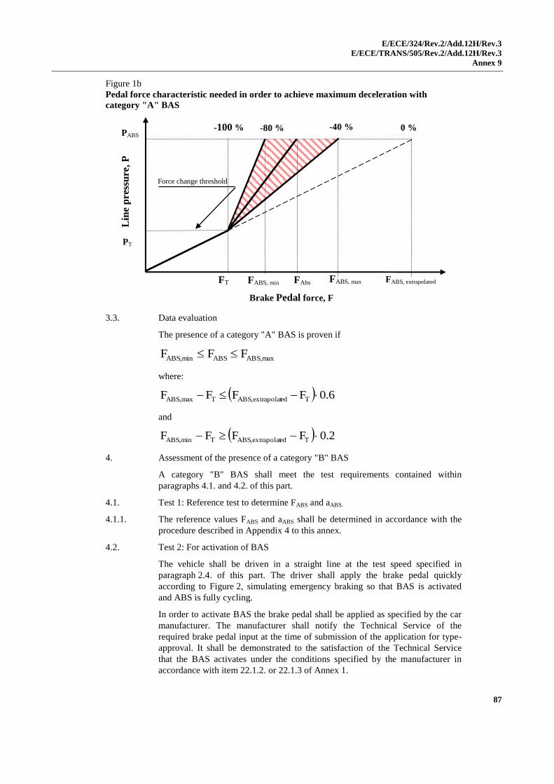
E/ECE/324/Rev.2/Add.12H/Rev.3
E/ECE/TRANS/505/Rev.2/Add.12H/Rev.3
Annex 9
87
Figure 1b
Pedal force characteristic needed in order to achieve maximum deceleration with
category "A" BAS
3.3. Data evaluation
The presence of a category "A" BAS is proven if
max,ABSABSmin,ABS FFF
where:
6.0FFFF Tedextrapolat,ABSTmax,ABS
and
2.0FFFF Tedextrapolat,ABSTmin,ABS
4. Assessment of the presence of a category "B" BAS
A category "B" BAS shall meet the test requirements contained within
paragraphs 4.1. and 4.2. of this part.
4.1. Test 1: Reference test to determine FABS and aABS.
4.1.1. The reference values FABS and aABS shall be determined in accordance with the
procedure described in Appendix 4 to this annex.
4.2. Test 2: For activation of BAS
The vehicle shall be driven in a straight line at the test speed specified in
paragraph 2.4. of this part. The driver shall apply the brake pedal quickly
according to Figure 2, simulating emergency braking so that BAS is activated
and ABS is fully cycling.
In order to activate BAS the brake pedal shall be applied as specified by the car
manufacturer. The manufacturer shall notify the Technical Service of the
required brake pedal input at the time of submission of the application for type-
approval. It shall be demonstrated to the satisfaction of the Technical Service
that the BAS activates under the conditions specified by the manufacturer in
accordance with item 22.1.2. or 22.1.3 of Annex 1.
Lin
e p
ress
ure
, P
Brake Pedal force, F
PT
PABS
FT FABS, min
Force change threshold
FABS, max FABS, extrapolated
-40 % -80 %
FAbs
0 % -100 %
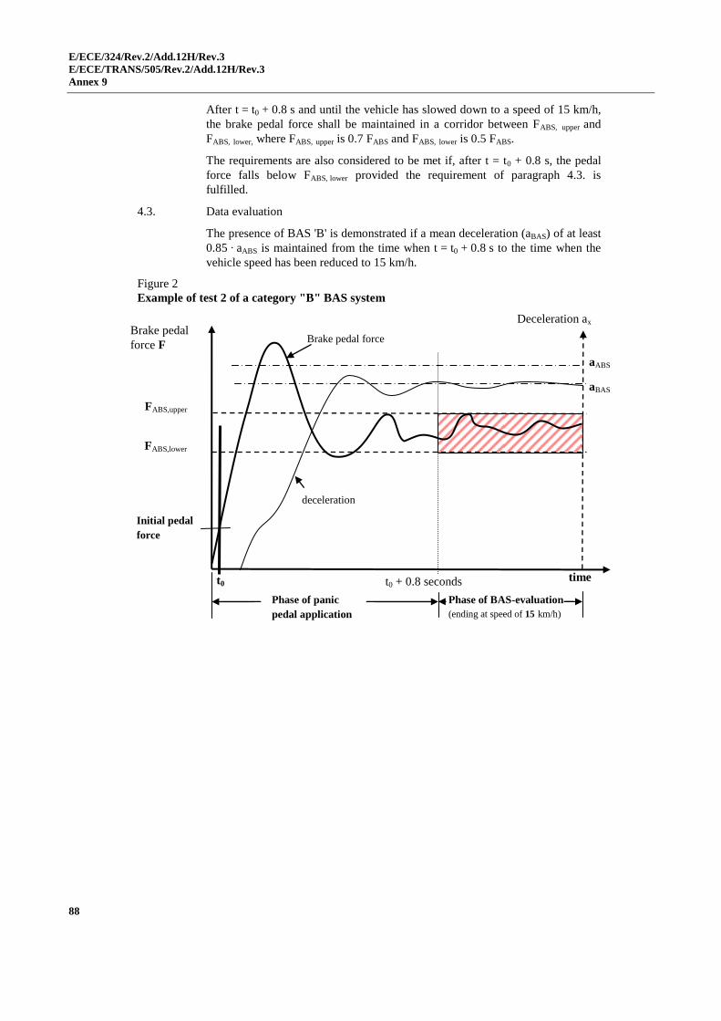
E/ECE/324/Rev.2/Add.12H/Rev.3
E/ECE/TRANS/505/Rev.2/Add.12H/Rev.3
Annex 9
88
After t = t0 + 0.8 s and until the vehicle has slowed down to a speed of 15 km/h,
the brake pedal force shall be maintained in a corridor between FABS, upper and
FABS, lower, where FABS, upper is 0.7 FABS and FABS, lower is 0.5 FABS.
The requirements are also considered to be met if, after t = t0 + 0.8 s, the pedal
force falls below FABS, lower provided the requirement of paragraph 4.3. is
fulfilled.
4.3. Data evaluation
The presence of BAS 'B' is demonstrated if a mean deceleration (aBAS) of at least
0.85 ∙ aABS is maintained from the time when t = t0 + 0.8 s to the time when the
vehicle speed has been reduced to 15 km/h.
Figure 2
Example of test 2 of a category "B" BAS system
Brake pedal force
time
deceleration
Brake pedal
force F
Deceleration ax
Phase of panic
pedal application
Phase of BAS-evaluation
(ending at speed of 15 km/h)
aABS
aBAS
t0
FABS,upper
FABS,lower
Initial pedal
force
t0 + 0.8 seconds
E/ECE/324/Rev.2/Add.12H/Rev.3
E/ECE/TRANS/505/Rev.2/Add.12H/Rev.3
Annex 9 - Appendix 1
89
Annex 9 - Appendix 1
Use of the dynamic stability simulation
The effectiveness of the electronic stability control system may be determined by
computer simulation.
1. Use of the simulation
1.1. The vehicle stability function shall be demonstrated by the vehicle manufacturer
to the Type Approval Authority or Technical Service by simulating the dynamic
manoeuvres of paragraph 5.9. of Part A of Annex 9.
1.2. The simulation shall be a means whereby the vehicle stability performance shall
be demonstrated with:
(a) The yaw rate, one second after completion of the Sine with Dwell
steering input (time T0 + 1);
(b) The yaw rate, 1.75 seconds after completion of the Sine with Dwell
steering input;
(c) The lateral displacement of the vehicle centre of gravity with respect
to its initial straight path.
1.3. The simulation shall be carried out with a validated modelling and simulation
tool and using the dynamic manoeuvres of paragraph 5.9. of Part A of Annex 9
under the test conditions of paragraph 4. of Annex 9.
The method by which the simulation tool is validated is given in Appendix 2 to
this annex.
E/ECE/324/Rev.2/Add.12H/Rev.3
E/ECE/TRANS/505/Rev.2/Add.12H/Rev.3
Annex 9 - Appendix 2
90
Annex 9 - Appendix 2
Dynamic stability simulation tool and its validation
1. Specification of the simulation tool
1.1. The simulation method shall take into account the main factors which influence
the directional and roll motion of the vehicle. A typical model may include the
following vehicle parameters in an explicit or implicit form:
(a) Axle/wheel;
(b) Suspension;
(c) Tyre;
(d) Chassis/vehicle body;
(e) Power train/driveline, if applicable;
(f) Brake system;
(g) Pay load.
1.2. The Vehicle Stability Function shall be added to the simulation model by means
of:
(a) A subsystem (software model) of the simulation tool; or
(b) The electronic control box in a hardware-in-the-loop configuration.
2. Validation of the simulation tool
2.1. The validity of the applied modelling and simulation tool shall be verified by
means of comparisons with practical vehicle tests. The tests utilised for the
validation shall be the dynamic manoeuvres of paragraph 5.9. of Part A of
Annex 9.
During the tests, the following motion variables, as appropriate, shall be
recorded or calculated in accordance with ISO 15037 Part 1:2005: General
conditions for passenger cars or Part 2:2002: General conditions for heavy
vehicles and buses (depending on the vehicle category):
(a) Steering-wheel angle (H);
(b) Longitudinal velocity (vX);
(c) Sideslip angle () or lateral velocity (vY);(optional);
(d) Longitudinal acceleration (aX); (optional);
(e) Lateral acceleration (aY);
(f) Yaw velocity (d/dt);
(g) Roll velocity (d/dt);
(h) Pitch velocity (d/dt);
(i) Roll angle ();
(j) Pitch angle ().
E/ECE/324/Rev.2/Add.12H/Rev.3
E/ECE/TRANS/505/Rev.2/Add.12H/Rev.3
Annex 9- Appendix 2
91
2.2. The objective is to show that the simulated vehicle behaviour and operation of
the vehicle stability function is comparable with that seen in practical vehicle
tests.
2.3. The simulator shall be deemed to be validated when its output is comparable to
the practical test results produced by a given vehicle type during the dynamic
manoeuvres of paragraph 5.9. of Part A of Annex 9. The relationship of
activation and sequence of the vehicle stability function in the simulation and in
the practical vehicle test shall be the means of making the comparison.
2.4. The physical parameters that are different between the reference vehicle and
simulated vehicle configurations shall be modified accordingly in the simulation.
2.5. A simulator test report shall be produced, a model of which is defined in
Appendix 3 to this annex, and a copy attached to the vehicle approval report.
E/ECE/324/Rev.2/Add.12H/Rev.3
E/ECE/TRANS/505/Rev.2/Add.12H/Rev.3
Annex 9 - Appendix 3
92
Annex 9 - Appendix 3
Vehicle stability function simulation tool test report
Test Report Number: ...............................................................................................................
1. Identification
1.1. Name and address of the simulation tool manufacturer .....................................
1.2. Simulation tool identification: name/model/number (hardware and software) .
...........................................................................................................................
2. Scope of application
2.1. Vehicle type: ......................................................................................................
2.2. Vehicle configurations: ......................................................................................
3. Verifying vehicle test
3.1. Description of vehicle(s): ..................................................................................
3.1.1. Vehicle(s) identification: make/model/VIN ......................................................
3.1.2. Vehicle description, including suspension/wheels, engine and drive line,
braking system(s), steering system, with name/model/number identification: ..
...........................................................................................................................
3.1.3. Vehicle data used in the simulation (explicit):...................................................
3.2. Description of location(s), road/test area surface conditions, temperature and
date(s): ...............................................................................................................
3.3. Results with the vehicle stability function switched on and off, including the
motion variables referred to in Annex 9, Appendix 2, paragraph 2.1. as
appropriate: ........................................................................................................
4. Simulation results
4.1. Vehicle parameters and the values used in the simulation that are not taken
from the actual test vehicle (implicit): ...............................................................
4.2. Yaw stability and lateral displacement according to paragraphs 3.1. to 3.3. of
Part A of Annex 9:
5. This test has been carried out and the results reported in accordance with
Appendix 2 of Annex 9 to Regulation No. 13-H, as last amended by the
Supplement 7.
Technical Service conducting the test1 .............................................................
Signed: …………………….. Date: ..……………………
Approval Authority1 ……………………………………....…………………..
Signed: ……………………. Date: …..…………………
1 To be signed by different persons if the Technical Service and the Approval Authority is the same
organization.
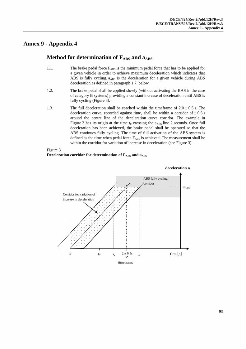
E/ECE/324/Rev.2/Add.12H/Rev.3
E/ECE/TRANS/505/Rev.2/Add.12H/Rev.3
Annex 9 - Appendix 4
93
Annex 9 - Appendix 4
Method for determination of FABS and aABS
1.1. The brake pedal force FABS is the minimum pedal force that has to be applied for
a given vehicle in order to achieve maximum deceleration which indicates that
ABS is fully cycling. aABS is the deceleration for a given vehicle during ABS
deceleration as defined in paragraph 1.7. below.
1.2. The brake pedal shall be applied slowly (without activating the BAS in the case
of category B systems) providing a constant increase of deceleration until ABS is
fully cycling (Figure 3).
1.3. The full deceleration shall be reached within the timeframe of 2.0 ± 0.5 s. The
deceleration curve, recorded against time, shall be within a corridor of ± 0.5 s
around the centre line of the deceleration curve corridor. The example in
Figure 3 has its origin at the time t0 crossing the aABS line 2 seconds. Once full
deceleration has been achieved, the brake pedal shall be operated so that the
ABS continues fully cycling. The time of full activation of the ABS system is
defined as the time when pedal force FABS is achieved. The measurement shall be
within the corridor for variation of increase in deceleration (see Figure 3).
Figure 3
Deceleration corridor for determination of FABS and aABS
deceleration a
time[s]
ABS fully cycling
corridor
Corridor for variation of
increase in deceleration
timeframe
2 ± 0.5s
aABS
t0 1s
t0
aABS
2 ±
0.5s
timef
rame
Corrid
or for
variati
on of
increa
se in
decele
ration
ABS
fully
cyclin
g
corrid
E/ECE/324/Rev.2/Add.12H/Rev.2
E/ECE/TRANS/505/Rev.2/Add.12H/Rev.2
Annex 9 - Appendix 4
94
1.4. Five tests meeting the requirements of paragraph 1.3. above shall be carried out.
For each of these valid tests the vehicle deceleration shall be plotted as a
function of the recorded brake pedal force. Only data recorded at speeds above
15 km/h shall be taken for the calculations described in the following paragraphs.
1.5. For the determination of aABS and FABS, a low pass filter of 2 Hz for vehicle
deceleration as well as pedal force shall be applied.
1.6. The five individual "deceleration versus brake pedal force" curves are averaged
by calculating the mean deceleration of the five individual "deceleration vs.
brake pedal force" curves at increments of 1 N pedal force. The result is the
mean deceleration versus brake pedal force curve, which will be referred to as
the "maF curve" in this appendix.
1.7. The maximum value for the vehicle deceleration is determined from the "maF
curve" and is named as "amax".
1.8. All values of the "maF curve" that are above 90 per cent of this deceleration
value "amax" are averaged. This value of "a" is the deceleration "aABS" referred to
in this annex.
1.9. The minimum force on the pedal (FABS) sufficient to achieve the deceleration
aABS is defined as the value of F corresponding to a= aABS on the maF curve.
E/ECE/324/Rev.2/Add.12H/Rev.3
E/ECE/TRANS/505/Rev.2/Add.12H/Rev.3
Annex 9 - Appendix 5
95
Annex 9 - Appendix 5
Data processing for the BAS
(paragraph 2.2.3. of Part B of Annex 9)
1. Analogue data processing
The bandwidth of the entire, combined transducer/recording system shall be no
less than 30 Hz.
In order to execute the necessary filtering of signals, low-pass filters with order 4
or higher shall be employed. The width of the pass band (from 0 Hz to frequency
fo at -3 dB) shall not be less than 30 Hz. Amplitude errors shall be less
than ±0.5 per cent in the relevant frequency range of 0 Hz to 30 Hz. All analogue
signals shall be processed with filters having sufficiently similar phase
characteristics to ensure that time delay differences due to filtering lie within the
required accuracy for time measurement.
Note: During analogue filtering of signals with different frequency contents,
phase shifts can occur. Therefore, a data processing method, as described in
paragraph 2. of this appendix, is preferable.
2. Digital data processing
2.1. General consideration
Preparation of analogue signals includes consideration of filter amplitude
attenuation and sampling rate to avoid aliasing errors, and filter phase lags and
time delays. Sampling and digitising considerations include pre-sampling
amplification of signals to minimize digitising errors; number of bits per sample;
number of samples per cycle; sample and hold amplifiers; and time-wise spacing
of samples. Considerations for additional phaseless digital filtering include
selection of pass bands and stop bands and the attenuation and allowable ripple
in each; and correction of filter phase lags. Each of these factors shall be
considered in order to achieve a relative overall data acquisition accuracy
of ±0.5 per cent.
2.2. Aliasing errors
In order to avoid uncorrectable aliasing errors, the analogue signals shall be
appropriately filtered before sampling and digitising. The order of the filters used
and their pass band shall be chosen according to both the required flatness in the
relevant frequency range and the sampling rate.
The minimum filter characteristics and sampling rate shall be such that:
(a) Within the relevant frequency range of 0 Hz to fmax = 30 Hz the
attenuation is less than the resolution of the data acquisition system;
and
(b) At one-half the sampling rate (i.e. the Nyquist or "folding" frequency)
the magnitudes of all frequency components of signal and noise are
reduced to less than the system resolution.
For 0.05 per cent resolution the filter attenuation shall be less than 0.05 per cent
in the frequency range between 0 and 30 Hz, and the attenuation shall be greater
E/ECE/324/Rev.2/Add.12H/Rev.3
E/ECE/TRANS/505/Rev.2/Add.12H/Rev.3
Annex 9 - Appendix 5
96
than 99.95 per cent at all frequencies greater than one-half the sampling
frequency.
Note: For a Butterworth filter the attenuation is given by:
n2
fmax
2
0
f1
1A
and n2
f
2
0
Nf1
1A
Where:
n is the order to filter;
fmax is the relevant frequency range (30 Hz);
fo is the filter cut-off frequency;
fN is the Nyquist or "folding" frequency.
For a fourth order filter
for A = 0.9995: fo = 2.37 ∙ fmax
for A = 0.0005: fS, = 2 ∙ (6.69 ∙ fo), where fS, is the sampling
frequency = 2 ∙ fN.
2.3. Filter phase shifts and time delays for anti-aliasing filtering
Excessive analogue filtering shall be avoided, and all filters shall have
sufficiently similar phase characteristics to ensure that time delay differences are
within the required accuracy for the time measurement. Phase shifts are
especially significant when measured variables are multiplied together to form
new variables, because while amplitudes multiply, phase shifts and associated
time delays add. Phase shifts and time delays are reduced by increasing fo.
Whenever equations describing the pre-sampling filters are known, it is practical
to remove their phase shifts and time delays by simple algorithms performed in
the frequency domain.
Note: In the frequency range in which the filter amplitude characteristics remain
flat, the phase shift Φ of a Butterworth filter can be approximated by
Φ = 81 ∙ (f/f0) degrees for second order
Φ = 150 ∙ (f/f0) degrees for fourth order
Φ = 294 ∙ (f/f0) degrees for eighth order
The time delay for all filter orders is: t = (Φ/360) ∙ (1/f0)
2.4. Data sampling and digitising
At 30 Hz the signal amplitude changes by up to 18 per cent per millisecond. To
limit dynamic errors caused by changing analogue inputs to 0.1 per cent,
sampling or digitising time shall be less than 32 μs. All pairs or sets of data
samples to be compared shall be taken simultaneously or over a sufficiently short
time period.
2.5. System requirements
The data system shall have a resolution of 12 bits (±0.05 per cent) or more and
an accuracy of ±0.1 per cent (2 lbs). Anti-aliasing filters shall be of order 4 or
higher and the relevant data range fmax shall be 0 Hz to 30 Hz.
E/ECE/324/Rev.2/Add.12H/Rev.3
E/ECE/TRANS/505/Rev.2/Add.12H/Rev.3
Annex 9 - Appendix 5
97
For fourth order filters the pass-band frequency fo (from 0 Hz to frequency fo)
shall be greater than 2.37 ∙ fmax if phase errors are subsequently adjusted in digital
data processing, and greater than 5 ∙ fmax otherwise. For fourth order filters the
data sampling frequency fs shall be greater than 13.4 ∙ fo.