Embed Size (px)
Citation preview
C H A P T E R16RECONFIGURABLE RETINA-LIKE
PREPROCESSING PLATFORM FOR
CORTICAL VISUAL
NEUROPROSTHESESSamuel Romero, Francisco J. Pelayo, Christian A. Morillas,
Antonio Martınez, and Eduardo Fernandez
16.1 INTRODUCTION
Most of the sensory information we perceive comes from our eyes. We rely on this sense to
perform almost every daily task, such as driving, walking, grasping objects, and so on.
Blindness deprives millions of individuals of receiving an enormous amount of precious
information on color, distances, shapes, motion, textures, and so on. A number of research
groups around the world aim to reach a remedy and restore vision to blind people. The
developments of intracortical arrays of electrodes pave the way for direct electrical stimu-
lation of the visual areas of the brain. This chapter presents an approach to feed these
electrodes with visual information and to automatically translate image sequences into
the neural language of the primary visual cortex.
16.2 HUMAN VISUAL PATHWAY AND BLINDNESS
The human visual system is a complex structure composed of several processing stages
that lead from the reception of light at the eye to the production of visual sensations
at the brain. This chain of processing steps is known as the “visual pathway.” This path
includes the eyeball with the retina, the optic nerve, the lateral geniculate nucleus, and
the cortical primary and higher visual areas in the brain.
The human eye acts as a camera, regulating the amount of light and focusing to get a
sharp projection of the image on the retina. The retina transduces light into electrochemi-
cal neural signals but also performs additional processing and information compression of
the images before sending them to the visual centers of the brain. The retina, as described
first by Ramon y Cajal, is organized into layers of specialized neurons.
The first layer corresponds to the photoreceptors (rods and cones), responsible for
translating luminance and color into electrochemical potentials. Several layers of retinal
horizontal, bipolar and ganglion cells, among others, collect the output of photoreceptors.
The output of neighboring groups of photoreceptors, called the receptive field, is
Handbook of Neural Engineering. Edited by Metin AkayCopyright # 2007 The Institute of Electrical and Electronics Engineers, Inc.
267

connected to a ganglion cell. The number of photoreceptors converging into a ganglion
cell varies from just one at the fovea to a large number at the periphery of the
retina. This leads to high resolution of the perceived image at its center. Most of these
cells respond to the contrast of activity between the center and the surround of its
receptive field.
So the retina not only functions in the simple transduction from light and color into
neural signals but also performs different spatiotemporal locally computed functions and
information compression before sending the signals to the brain through the optic nerve.
This processing includes color contrast enhancing, motion detection, and edge highlight-
ing. The retina cells convey the signals obtained at about 125 million photoreceptors into
about one million fibers of the optic nerve.
Finally, the nerve converges with the brain at the lateral geniculate nucleus and then
reaches the primary visual area located at the occipital region of the brain cortex. This is
the starting point for further high-level processing in other areas, such as the recognition of
shapes, faces, evaluation of motion, and so on.
A detailed explanation of the organization of the visual pathways can be found, for
example, in [1, 2].
There are a huge number of causes of dysfunction in sight, provoked by illnesses
or by accidents. The number of totally blind individuals rises to about 45 million
people worldwide. The amount grows to 180 million persons with some other vision
impairments [3].
16.3 APPROACHES FOR SIGHT RESTORATION:CURRENT RESEARCH ON VISUAL PROSTHESES
At the writing of this chapter, a number of research groups worldwide are facing the
problem of blindness. The variety of proposed solutions corresponds with the multiplicity
of causes of this illness.
Not every proposed solution is suitable for each patient. Blindness is the result of
damage or malfunction of at least one of the stages comprised by the visual pathway,
ranging from the cornea to the visual areas of the occipital lobe of the brain.
Some of these prosthetic approaches, as mentioned in [4], are the following:
. Retinal Implants: Inserting a device over (epiretinal) or under (subretinal) the retina
that would provide electrical stimulation of the retina cells. These prostheses require
a good functioning of, at least, the optic nerve.
. Optic Nerve Implants: Again requires functional optic nerve and is still in the early
developmental stage. Difficult surgical access and very limited image resolution
with the available electrodes are two important drawbacks of this approach.
. Cortical Implants: Direct electrical stimulation of the visual areas of the brain, by
external planar electrodes or by penetrating intracortical electrodes. This is the
only solution for patients with unrecoverable retinas or optic nerves.
Some other attempts are biological studies on gene therapy [4] or translation of visual
information into some other good working sense, such as the “Seeing with Sound”
project [5].
The decision on which approach is the most adequate is controversial, especially due
to the still primitive knowledge about the coding of information by the brain and to the
difficulties of ensuring long-term functioning with useful image resolution.
268 CHAPTER 16 NEUROPROSTHESES PREPROCESSING PLATFORM FOR CORTICAL VISUAL
16.4 ELECTRICAL STIMULATION OF BRAIN
With some precedents, Luigi Galvani carried out the first neural electrical stimulation
experiment in 1781. He attached the leg of a frog to an electrical machine, and the injec-
tion of electrical current caused violent muscular contractions. After a number of other
discoveries on bioelectromagnetism, some researchers, such as Hubel [1] and Brindley
and Lewin [6], contributed to the development of electrical stimulation and registering
of cortical visual neurons, helping to extend the application of electricity not only to
motor tissues but also to sensory perception.
The success of artificial cochleas encouraged research groups worldwide to use
these devices for visual prostheses, although the amount of information handled by the
eyes is far more complex and extensive. This way, the first experiments on direct electrical
stimulation of the visual cortex led to the perception of phosphenes by blind individuals.
William Dobelle [7] created a prosthesis that stimulates the cortex with a set of planar,
wired surface electrodes. This is the only known experience with long-term implantation
of cortical prostheses in humans. Although it produced some rudimentary vision, it pre-
sented important disadvantages: low spatial resolution between phosphenes and the
need for high currents with undesirable effects.
The Utah Electrode Array, another prosthetic device developed by the research team
led by Richard Normann [4], is able to simultaneously register or stimulate 100 electrodes
in a small surface. In this case, the electrodes are penetrating the cortex, so less current is
needed to elicit phosphene perception, making this option safer. However, this device has
not been tested in chronic human implants.
In [4], Norman exposes as disadvantages of the cortical approach the absence of
retinal processing, a poor visuotopic organization, and problems in representing multiple
features in the primary visual cortex (color, ocular dominance, motion, lines).
In this chapter, we describe an architecture for a system that complements the cor-
tical approach, aiming to overcome some of the above-mentioned problems. Such a
system makes the cortical approach one of the most attractive for sight restoration.
The Utah Electrode Array is showing to be a promising solution for delivering elec-
trical signals to the cortex of the brain, but a higher level of abstraction is also needed to
decide how, when, and where these signals should be delivered to the proper electrode.
This way, the approach is extended beyond just a problem of biocompatible interfaces
between electrical devices and the cerebral tissue, extending the problem to an information
and coding level. This device is intended to provide the translation between the visual
expression of the world in terms of color and brightness and the neural language of
spikes for complex stimuli, beyond the phosphene.
16.5 COMPUTATIONAL MODEL OF RETINA ANDSYSTEM REQUIREMENTS
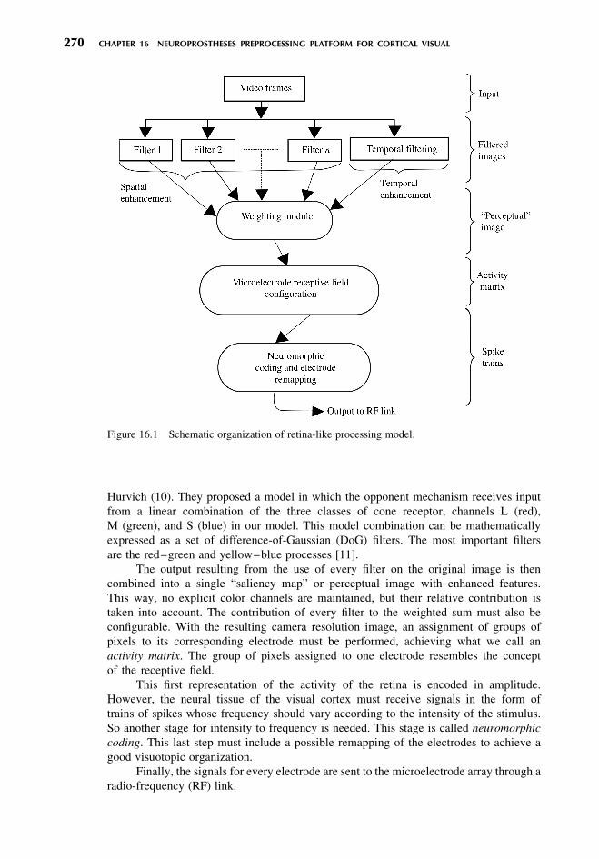
From a computational point of view, the retina is regarded in our model as a set of
parametric filters, each one highlighting a specific feature of the image, such as color
contrast, illumination intensity, and so on. This set of filters corresponds to the represen-
tation of different functionalities of the cell layers of the retina, as described in [8, 9]
(see Fig. 16.1).
Most of the filters in our retina model operate with different color channels as its
input. The opponent-color theory is based on the investigations by Jameson and
16.5 COMPUTATIONAL MODEL OF RETINA AND SYSTEM REQUIREMENTS 269
Hurvich (10). They proposed a model in which the opponent mechanism receives input
from a linear combination of the three classes of cone receptor, channels L (red),
M (green), and S (blue) in our model. This model combination can be mathematically
expressed as a set of difference-of-Gaussian (DoG) filters. The most important filters
are the red–green and yellow–blue processes [11].
The output resulting from the use of every filter on the original image is then
combined into a single “saliency map” or perceptual image with enhanced features.
This way, no explicit color channels are maintained, but their relative contribution is
taken into account. The contribution of every filter to the weighted sum must also be
configurable. With the resulting camera resolution image, an assignment of groups of
pixels to its corresponding electrode must be performed, achieving what we call an
activity matrix. The group of pixels assigned to one electrode resembles the concept
of the receptive field.
This first representation of the activity of the retina is encoded in amplitude.
However, the neural tissue of the visual cortex must receive signals in the form of
trains of spikes whose frequency should vary according to the intensity of the stimulus.
So another stage for intensity to frequency is needed. This stage is called neuromorphic
coding. This last step must include a possible remapping of the electrodes to achieve a
good visuotopic organization.
Finally, the signals for every electrode are sent to the microelectrode array through a
radio-frequency (RF) link.
Figure 16.1 Schematic organization of retina-like processing model.
270 CHAPTER 16 NEUROPROSTHESES PREPROCESSING PLATFORM FOR CORTICAL VISUAL
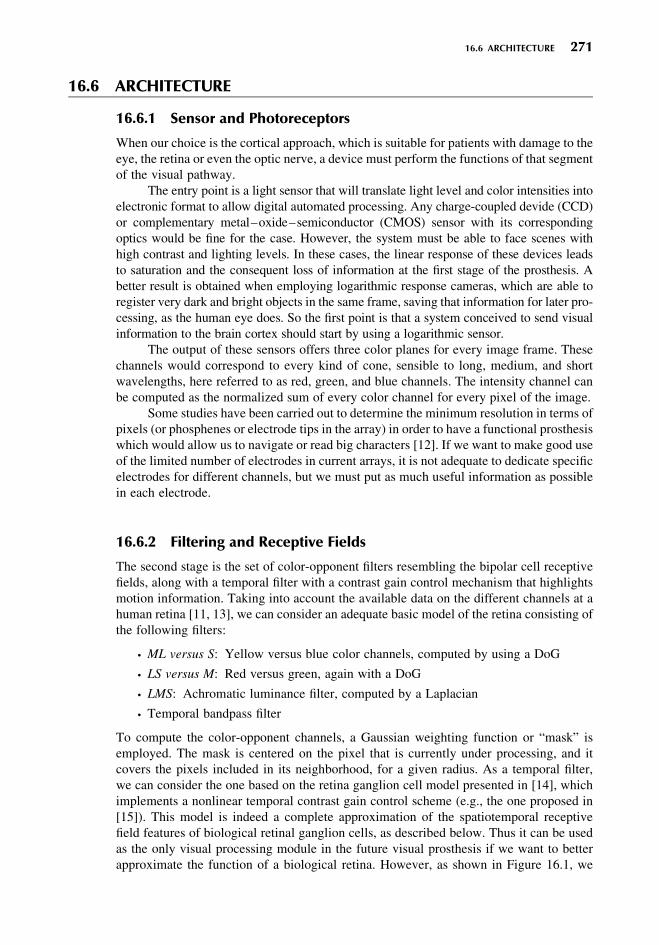
16.6 ARCHITECTURE
16.6.1 Sensor and Photoreceptors
When our choice is the cortical approach, which is suitable for patients with damage to the
eye, the retina or even the optic nerve, a device must perform the functions of that segment
of the visual pathway.
The entry point is a light sensor that will translate light level and color intensities into
electronic format to allow digital automated processing. Any charge-coupled devide (CCD)
or complementary metal–oxide–semiconductor (CMOS) sensor with its corresponding
optics would be fine for the case. However, the system must be able to face scenes with
high contrast and lighting levels. In these cases, the linear response of these devices leads
to saturation and the consequent loss of information at the first stage of the prosthesis. A
better result is obtained when employing logarithmic response cameras, which are able to
register very dark and bright objects in the same frame, saving that information for later pro-
cessing, as the human eye does. So the first point is that a system conceived to send visual
information to the brain cortex should start by using a logarithmic sensor.
The output of these sensors offers three color planes for every image frame. These
channels would correspond to every kind of cone, sensible to long, medium, and short
wavelengths, here referred to as red, green, and blue channels. The intensity channel can
be computed as the normalized sum of every color channel for every pixel of the image.
Some studies have been carried out to determine the minimum resolution in terms of
pixels (or phosphenes or electrode tips in the array) in order to have a functional prosthesis
which would allow us to navigate or read big characters [12]. If we want to make good use
of the limited number of electrodes in current arrays, it is not adequate to dedicate specific
electrodes for different channels, but we must put as much useful information as possible
in each electrode.
16.6.2 Filtering and Receptive Fields
The second stage is the set of color-opponent filters resembling the bipolar cell receptive
fields, along with a temporal filter with a contrast gain control mechanism that highlights
motion information. Taking into account the available data on the different channels at a
human retina [11, 13], we can consider an adequate basic model of the retina consisting of
the following filters:
. ML versus S: Yellow versus blue color channels, computed by using a DoG
. LS versus M: Red versus green, again with a DoG
. LMS: Achromatic luminance filter, computed by a Laplacian
. Temporal bandpass filter
To compute the color-opponent channels, a Gaussian weighting function or “mask” is
employed. The mask is centered on the pixel that is currently under processing, and it
covers the pixels included in its neighborhood, for a given radius. As a temporal filter,
we can consider the one based on the retina ganglion cell model presented in [14], which
implements a nonlinear temporal contrast gain control scheme (e.g., the one proposed in
[15]). This model is indeed a complete approximation of the spatiotemporal receptive
field features of biological retinal ganglion cells, as described below. Thus it can be used
as the only visual processing module in the future visual prosthesis if we want to better
approximate the function of a biological retina. However, as shown in Figure 16.1, we
16.6 ARCHITECTURE 271
combine the output of the temporal filter with those produced by the spatial-only ones. In
this way, temporal changes as those produced by motion onsets are highlighted in the result-
ing feature map (the “perceptual image”), but we avoid having the output vanish for static
visual stimulus as it occurs in an actual retina.
According to the description in [15], the temporal filtering module computes the
temporal-enhanced (TE) images as the product, for each point r ¼ (x, y) in the image, of
a modulation factor g(r, t) by the convolution of the stimulus s and a kernel function K(r, t):
TE(r, t) ¼ g(r, t)½K(r, t) � s(r, t � d(t))� (16:1)
where d(t) . 0 is the response latency.
The model assumes space–time separability in such a way that the kernel function
K(r, t) can be decomposed into different spatial (KS) and temporal (Kt) functions as
follows [14, 15]:
K(r, t) ¼ KS(r)Kt(t) (16:2)
KS(r) ¼gþ
2ps2þ
e�r2=(2s2
þ) �g�
2ps2�e�r
2=(2s2�)
(16:3)
Kt(t) ¼ d(t)� aH(t)e�at (16:4)
The spatial kernel is modeled as a DoG, with gþ and g2 determining the relative weights
of center and surround, respectively; sþ and bsþ (with b . 1) are their diameters. In the
temporal function, Eq. (16.4), H denotes the Heaviside step function and a21 is the decay
time constant of the response.
The modulation factor in Eq. (16.1) implements a contrast gain control feedback
loop, since it is obtained as a nonlinear function of a low-pass temporal filtered version
of TE [14, 15].
Once all the filters are applied and combined into a single perceptual image, the
system proceeds to a reduction in spatial resolution, grouping the values of neighboring
pixels to obtain the activity level at each electrode. The size of the receptive field
varies depending on the location at the retina. Usually, the value for the electrode is the
average of the pixels on its receptive field.
16.6.3 Neural Pulse Coding and Visuotopic Remapping
The activity matrix representing remarkable perceptual features of the input image is
encoded in amplitude. Before sending this information to the cortex, a translation into
the neural language expected by the brain is required.
Neurons represent activity values in the form of spike trains, in which the amount of
spikes and its frequency encode the level of activity incoming to the neuron. A known
model of this cell is the leaky integrate-and-fire spiking neuron. Further references on
these models can be found in [16].
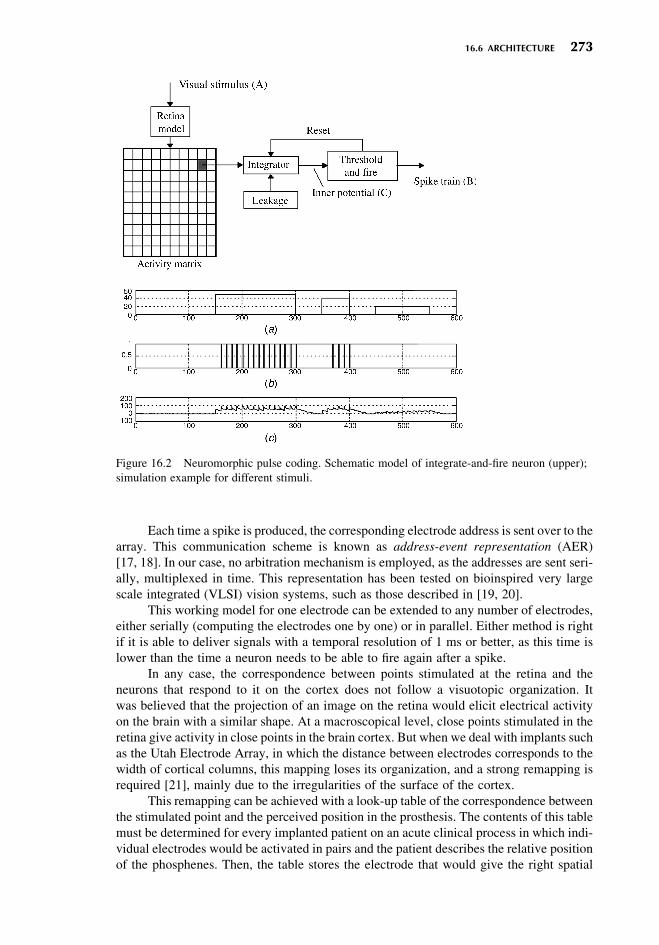
In the digital implementation we have proposed for this model [8], the activity level
incoming to the neuron is accumulated until a threshold is reached. In that moment, a spike
is issued and the neuron potential returns to a resting value. Additionally, the accumulated
potential drops slowly due to a leakage, so that in the absence of inputs the activity of the
neuron decays. For simplicity in digital implementation, we have adopted a linear decay
for the leakage term.
The expected response is shown in Figure 16.2, in which high-sustained stimuli give
out a longer spike train and low stimuli may not get the neuron to reach its threshold and no
spike is issued to the corresponding electrode.
272 CHAPTER 16 NEUROPROSTHESES PREPROCESSING PLATFORM FOR CORTICAL VISUAL
Each time a spike is produced, the corresponding electrode address is sent over to the
array. This communication scheme is known as address-event representation (AER)
[17, 18]. In our case, no arbitration mechanism is employed, as the addresses are sent seri-
ally, multiplexed in time. This representation has been tested on bioinspired very large
scale integrated (VLSI) vision systems, such as those described in [19, 20].
This working model for one electrode can be extended to any number of electrodes,
either serially (computing the electrodes one by one) or in parallel. Either method is right
if it is able to deliver signals with a temporal resolution of 1 ms or better, as this time is
lower than the time a neuron needs to be able to fire again after a spike.
In any case, the correspondence between points stimulated at the retina and the
neurons that respond to it on the cortex does not follow a visuotopic organization. It
was believed that the projection of an image on the retina would elicit electrical activity
on the brain with a similar shape. At a macroscopical level, close points stimulated in the
retina give activity in close points in the brain cortex. But when we deal with implants such
as the Utah Electrode Array, in which the distance between electrodes corresponds to the
width of cortical columns, this mapping loses its organization, and a strong remapping is
required [21], mainly due to the irregularities of the surface of the cortex.
This remapping can be achieved with a look-up table of the correspondence between
the stimulated point and the perceived position in the prosthesis. The contents of this table
must be determined for every implanted patient on an acute clinical process in which indi-
vidual electrodes would be activated in pairs and the patient describes the relative position
of the phosphenes. Then, the table stores the electrode that would give the right spatial
Figure 16.2 Neuromorphic pulse coding. Schematic model of integrate-and-fire neuron (upper);
simulation example for different stimuli.
16.6 ARCHITECTURE 273
position with respect to the reference electrode, thus providing a translation from retina
pulse addresses to electrode addresses.
16.6.4 Wireless Link
The train of events is sent to the electrode matrix implanted on the cerebral cortex.
Commonly, percutaneous connectors have been employed to gain electrical access to
the prosthesis. However, this connection is not desirable for chronic implants due to the
risks of infections and a possible psychological rejection.
Ideally, the bond to send data and energy to the prosthesis should be made through a
wireless RF link. This link would send energy through induction coils and the data follow-
ing a protocol able to indicate the electrode to which an event must be sent and some other
information related to the waveform. This information should be transmitted in real time
so that even serial scanning of the electrodes would result in simultaneous perception in
terms of biological response times.
This RF link would be useful not only for stimulation but also for registering the
activity on the visual cortex and would relate that activity recordings to controlled
stimuli, which will help in understanding the encoding of complex images on the brain.
Efforts on the development of RF links for electrode arrays are being carried out by
several researchers [22–24].
16.6.5 Electrode Stimulation
The final interface with the cortical visual area of the brain is an array of penetrating
microelectrodes. Previous approaches, such as Dobelle’s prosthesis, used planar platinum
electrodes. However, it has been demonstrated that the current needed to elicit the percep-
tion of phosphenes through a single electrode is 10 times smaller when using penetrating
electrodes than with planar surface contacts. This fact reduces power consumption, heat
dissipation, and some undesirable effects of having relatively high currents injected on
the brain.
The Utah Electrode Array, developed by the research team of Richard Normann, is
one of the best options for a cortical implant. It is a silicon base with 100 penetrating
electrodes. A detailed description of the array has been made in [4].
These kinds of devices, in which a limited bandwidth channel must deliver
information to a large number of electrodes, require demultiplexation and a number of
digital-to-analog converters (DACs) to stimulate every point in time.
There are some other devices, such as the electrode arrays fabricated at Michigan
[22]. The number of electrodes in the array is only 64, but a wireless communication
system is integrated on it.
16.7 CORTIVIS PROJECT
The architecture described here is being applied to a prosthetic device under development
in a European project. This initiative, named CORTIVIS [25] (Cortical Visual Neuro-
prosthesis for the Blind, ref. QLK6-CT2001-00279), has as its main goal to produce a
wireless, portable device to stimulate the visual cortex by using an array of penetrating
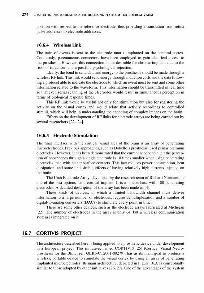
implanted microelectrodes. Its main architecture, depicted in Figure 16.3, is conceptually
similar to those adopted by other initiatives [26, 27]. One of the advantages of the system
274 CHAPTER 16 NEUROPROSTHESES PREPROCESSING PLATFORM FOR CORTICAL VISUAL
being developed by the CORTIVIS consortium is that every stage of the prosthesis is
reconfigurable in every parameter. The goal of CORTIVIS is to obtain:
. A tunning workbench to adjust and refine retina models in acute and chronic
implants, for both stimulation and registering
. A wireless reconfigurable device with a configuration that can be altered even after
implantation, avoiding further surgery
. A higher computational layer able to automatically translate a continuous stream of
video into a set of spike events and electrode addresses in order to feed the wireless
implanted array of microelectrodes
. Additional knowledge on suitability of patients, implant adjustment and training
procedures, long-term chronic implant studies, and so on
To ease and accelerate the development, we are progressively moving from a full
software implementation model to a fully hardware real-time portable chip. We are imple-
menting the retina model on field-programmable gate array (FPGA) circuits, which makes
the development of prototypes less expensive and faster, allowing reprogramming of the
circuit. The FPGA circuits allow the implementation and testing of complex digital
designs without the fabrication process and costs of other technologies such as a
custom ASIC chip (application-specific integrated circuit).
At the current development stage, the software model is able to accept as input either
continuous video streams from a web cam (optionally, these streams can be saved), video
files, or static image files. The gain of each color plane, corresponding to the photo-
receptor, can be adjusted.
This software allows building and testing very different retina models, as the user is
able to add new filters and vary multiple parameters.
The filters (Gaussians and DoGs, Laplacian of Gaussians, and so on) can be defined
over the incoming color and intensity channels or even over the output of previously
designed filters. This way, a chain of filters can be specified.
The system also allows any mathematical expression taking already defined filters as
operands. This high degree of flexibility makes this platform a useful tool to test and
compare retina models.
With respect to the definition of receptive fields, the user can select fixed and
variable size and shape to determine which neighboring pixels contribute to a specific
electrode, as can be seen in Figure 16.4. The options offered are:
. Circular (fixed or variable radius)
. Elliptical
. Square
. Rectangular
Figure 16.3 Main blocks of CORTIVIS Project prosthesis, including a camera, a retina-like fil-
tering and encoding block, a radio frequency transmitter (tx), the corresponding receiver (rx) and
D/A converter, and the microelectric array to interface the neural tissue of the visual cortex.
16.7 CORTIVIS PROJECT 275
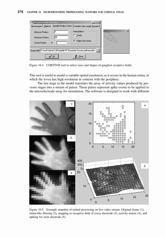
This tool is useful to model a variable spatial resolution, as it occurs in the human retina, in
which the fovea has high resolution in contrast with the periphery.
The last stage in the model translates the array of activity values produced by pre-
vious stages into a stream of pulses. These pulses represent spike events to be applied to
the microelectrode array for stimulation. The software is designed to work with different
Figure 16.4 CORTIVIS tool to select sizes and shapes of ganglion receptive fields.
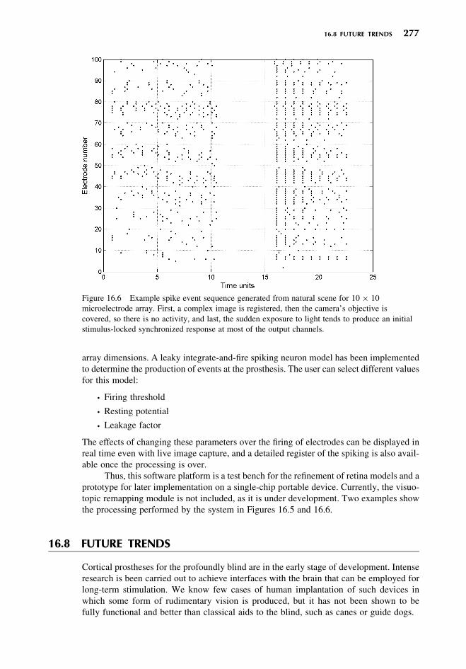
Figure 16.5 Example snapshot of retinal processing on live video stream. Original frame (1),
retina-like filtering (2), mapping to receptive field of every electrode (3), activity matrix (4), and
spiking for each electrode (5).
276 CHAPTER 16 NEUROPROSTHESES PREPROCESSING PLATFORM FOR CORTICAL VISUAL
array dimensions. A leaky integrate-and-fire spiking neuron model has been implemented
to determine the production of events at the prosthesis. The user can select different values
for this model:
. Firing threshold
. Resting potential
. Leakage factor
The effects of changing these parameters over the firing of electrodes can be displayed in
real time even with live image capture, and a detailed register of the spiking is also avail-
able once the processing is over.
Thus, this software platform is a test bench for the refinement of retina models and a
prototype for later implementation on a single-chip portable device. Currently, the visuo-
topic remapping module is not included, as it is under development. Two examples show
the processing performed by the system in Figures 16.5 and 16.6.
16.8 FUTURE TRENDS
Cortical prostheses for the profoundly blind are in the early stage of development. Intense
research is been carried out to achieve interfaces with the brain that can be employed for
long-term stimulation. We know few cases of human implantation of such devices in
which some form of rudimentary vision is produced, but it has not been shown to be
fully functional and better than classical aids to the blind, such as canes or guide dogs.
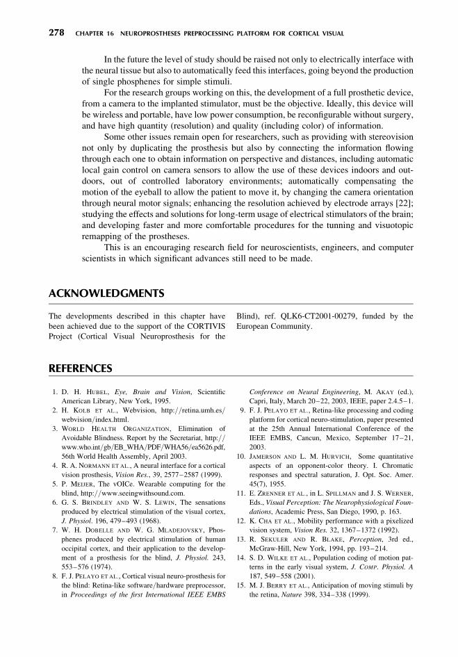
Figure 16.6 Example spike event sequence generated from natural scene for 10 � 10
microelectrode array. First, a complex image is registered, then the camera’s objective is
covered, so there is no activity, and last, the sudden exposure to light tends to produce an initial
stimulus-locked synchronized response at most of the output channels.
16.8 FUTURE TRENDS 277
In the future the level of study should be raised not only to electrically interface with
the neural tissue but also to automatically feed this interfaces, going beyond the production
of single phosphenes for simple stimuli.
For the research groups working on this, the development of a full prosthetic device,
from a camera to the implanted stimulator, must be the objective. Ideally, this device will
be wireless and portable, have low power consumption, be reconfigurable without surgery,
and have high quantity (resolution) and quality (including color) of information.
Some other issues remain open for researchers, such as providing with stereovision
not only by duplicating the prosthesis but also by connecting the information flowing
through each one to obtain information on perspective and distances, including automatic
local gain control on camera sensors to allow the use of these devices indoors and out-
doors, out of controlled laboratory environments; automatically compensating the
motion of the eyeball to allow the patient to move it, by changing the camera orientation
through neural motor signals; enhancing the resolution achieved by electrode arrays [22];
studying the effects and solutions for long-term usage of electrical stimulators of the brain;
and developing faster and more comfortable procedures for the tunning and visuotopic
remapping of the prostheses.
This is an encouraging research field for neuroscientists, engineers, and computer
scientists in which significant advances still need to be made.
ACKNOWLEDGMENTS
The developments described in this chapter have
been achieved due to the support of the CORTIVIS
Project (Cortical Visual Neuroprosthesis for the
Blind), ref. QLK6-CT2001-00279, funded by the
European Community.
REFERENCES
1. D. H. HUBEL, Eye, Brain and Vision, Scientific
American Library, New York, 1995.
2. H. KOLB ET AL., Webvision, http://retina.umh.es/
webvision/index.html.
3. WORLD HEALTH ORGANIZATION, Elimination of
Avoidable Blindness. Report by the Secretariat, http://
www.who.int/gb/EB_WHA/PDF/WHA56/ea5626.pdf,
56th World Health Assembly, April 2003.
4. R. A. NORMANN ET AL., A neural interface for a cortical
vision prosthesis, Vision Res., 39, 2577–2587 (1999).
5. P. MEIJER, The vOICe. Wearable computing for the
blind, http://www.seeingwithsound.com.
6. G. S. BRINDLEY AND W. S. LEWIN, The sensations
produced by electrical stimulation of the visual cortex,
J. Physiol. 196, 479–493 (1968).
7. W. H. DOBELLE AND W. G. MLADEJOVSKY, Phos-
phenes produced by electrical stimulation of human
occipital cortex, and their application to the develop-
ment of a prosthesis for the blind, J. Physiol. 243,
553–576 (1974).
8. F. J. PELAYO ET AL., Cortical visual neuro-prosthesis for
the blind: Retina-like software/hardware preprocessor,
in Proceedings of the first International IEEE EMBS
Conference on Neural Engineering, M. AKAY (ed.),
Capri, Italy, March 20–22, 2003, IEEE, paper 2.4.5–1.
9. F. J. PELAYO ET AL., Retina-like processing and coding
platform for cortical neuro-stimulation, paper presented
at the 25th Annual International Conference of the
IEEE EMBS, Cancun, Mexico, September 17–21,
2003.
10. JAMERSON AND L. M. HURVICH, Some quantitative
aspects of an opponent-color theory. I. Chromatic
responses and spectral saturation, J. Opt. Soc. Amer.
45(7), 1955.
11. E. ZRENNER ET AL., in L. SPILLMAN and J. S. WERNER,
Eds., Visual Perception: The Neurophysiological Foun-
dations, Academic Press, San Diego, 1990, p. 163.
12. K. CHA ET AL., Mobility performance with a pixelized
vision system, Vision Res. 32, 1367–1372 (1992).
13. R. SEKULER AND R. BLAKE, Perception, 3rd ed.,
McGraw-Hill, New York, 1994, pp. 193–214.
14. S. D. WILKE ET AL., Population coding of motion pat-
terns in the early visual system, J. COMP. Physiol. A
187, 549–558 (2001).
15. M. J. BERRY ET AL., Anticipation of moving stimuli by
the retina, Nature 398, 334–338 (1999).
278 CHAPTER 16 NEUROPROSTHESES PREPROCESSING PLATFORM FOR CORTICAL VISUAL

16. W. GERSTNER AND W. KISTLER, Spiking Neuron
Models. Single Neurons, Populations, Plasticity,
Cambridge University Press, Cambridge, 2002.
17. M. MAHOWALD, VLSI analogs of neural visual proces-
sing: A synthesis of form and function, Ph.D. Thesis,
Computational and Neural Systems, California Institute
of Technology (1992).
18. A. MORTARA AND E. A. VITTOZ, A communication
architecture tailored for analog VLSI networks: Intrin-
sic performance and limitations, IEEE Trans. Neural
Networks 5(3), May (1994).
19. K. A. BOAHEN, Point-to-point connectivity between
neuromorphic chips using Address-Events, IEEE
Trans. Circuits Syst. II 47(5), 416–434 (2000).
20. P. VENIER ET AL., An integrated cortical layer for orien-
tation enhancement, IEEE J. Solid State Circuits, 32(2):
177–186. (1997).
21. R. A. NORMANN ET AL., Representations and dynamics
of representations of simple visual stimuli by ensembles
of neurons in cat visual cortex studied with a microelec-
trode array, in Proceedings of the First International
IEEE EMBS Conference on Neural Engineering, M.
AKAY, (ed.), Capri, Italy, March 20–22, 2003, IEEE,
paper 2.0.1–1.
22. M. GHOVANLOO ET AL., Toward a button-sized
1024-site wireless cortical microstimulating array, in
Proceedings of the First International IEEE EMBS
Conference on Neural Engineering, M. AKAY,
(ed.), Capri, Italy, March 20–22, 2003, IEEE, paper
2.3.4–3.
23. G. J. SUANING AND N. H. LOVELL, CMOS neurostimu-
lation system with 100 electrodes and radio frequency
telemetry, in Proceedings of the IEEE EMBS Confer-
ence on Biomedical Research on the 3rd Millennium,
Victoria, Australia, February 22–23, 1999.
24. M. R. SHAH ET AL., A transcutaneous power and data link
for neuroprosthetic applications, in Proceedings of the
15th Annu. Int. Conf. IEEE EMBS San Diego, pp.
1357–1358, October 28–31, 1993.
25. http://cortivis.umh.es.
26. INTRACORTICAL VISUAL PROSTHESIS, Prosthe-
sis Research Laboratory, Illinois Institute of Technol-
ogy, http://www.iit.edu/�npr/intro.html.
27. J. F. HARVEY ET AL., Visual cortex stimulation proto-
type based on mixed-signal technology devices, Int
paper presented at the International Functional Electri-
cal Stimulation Society Conference (IFESS’99),
Sandai (Japan), August 1999.
REFERENCES 279


