Embed Size (px)
Citation preview

lable at ScienceDirect
Vacuum 109 (2014) 216e222
Contents lists avai
Vacuum
journal homepage: www.elsevier .com/locate/vacuum
Pulsed vacuum and etching systems: Theoretical designconsiderations for a pulsed vacuum system and its application to XeF2etching of Si
Arash Kheyraddini Mousavi a, Khawar Abbas a, Mirza Mohammad Mahbube Elahi b,Edidson Lima a, Stephen Moya a, Joseph Daniel Butner a, Denise Pi~non c, Adeeko Benga d,Behnam Kheyraddini Mousavi b, Zayd Chad Leseman a, *
a University of New Mexico, Department of Mechanical Engineering, Albuquerque, NM 87131, USAb University of New Mexico, Dept. of Electrical & Computer Engineering, Albuquerque, NM 87131, USAc University of New Mexico, Dept. of Chemical and Nuclear Engineering, Albuquerque, NM 87131, USAd University of Texas e San Antonio, Dept. of Mechanical Engineering, San Antonio, TX 78249, USA
a r t i c l e i n f o
Article history:Received 27 January 2014Received in revised form24 July 2014Accepted 24 July 2014Available online 1 August 2014
Keywords:Pulsed vacuumCalibrationXeF2 etchingAnalytical modelingDynamic modeling
* Corresponding author.E-mail address: [email protected] (Z.C. Leseman
http://dx.doi.org/10.1016/j.vacuum.2014.07.0280042-207X/© 2014 Elsevier Ltd. All rights reserved.
a b s t r a c t
Rekindled interest has developed in pulsed vacuum systems due to their use for Xenon Difluoride (XeF2)etching systems and their usefulness in the fabrication of MEMS and nanostructures. Despite numerousapplications of pulsed vacuum systems, little information is available in the literature on their designconsiderations. In this paper mathematical models and their experimental verification are presented forvarious important design considerations of pulsed vacuum systems. Control of the chambers' pressuresand pulse durations are typically the most important design considerations for processes involvingpulsed vacuum systems. Pressure sensors give the exact pressure, but accurate chamber volumes areunknown. Thus a methodology is developed for accurate determination of chamber volumes thatinvolves the introduction of a calibrated volume into a chamber. Then it is demonstrated that allowing aknown pressure and volume of gas to move between two chambers leads to accurate temporal control ofthe chambers' pressures. Furthermore, by varying chambers' volumes, configurations, pressures, and theconductances between the chambers it is shown that the pulse duration could be accurately controlled.Though the model and demonstrations are presented in the context of a pulsed XeF2 etching system, theyare general and useful for all pulsed vacuum systems.
© 2014 Elsevier Ltd. All rights reserved.
1. Introduction
The use of pulsed vacuum systems is widespread across variousmanufacturing and processing industries. They are used innumerous industries such as poultry meat and fruit processing/treatments [1,2] and sterilization of medical equipment [3] as wellas nanotechnology [4e12]. Despite being used in commercial ap-plications since at least the 1960's not much information is avail-able in the literature on the considerations for designing a pulsedvacuum system. Their more recent use for semiconductor andMEMS device manufacture has brought renewed attention topulsed vacuum systems. In this work, the design of pulsed vacuumsystems is thoroughly studied. During the process of designing and
).
employing the pulsed vacuum system a method for calibration of avacuum systems volume is described and how the system is usedfor plasma-less dry etching of Si using Xenon Diflouride (XeF2).
XeF2 was first used to etch silicon in 1978 [13]. Etchingwith XeF2has many advantages over traditional silicon etching techniquessuch as: high selectivity, fast etch rates, isotropic etching, sponta-neous etching at room temperature, and has been shown to beuseful in the fabrication of MEMS devices [13e15]. Liquid etchantscan cause MEMS failure through stiction [4,16e21] and plasmaetches can damage them due to ion implantation and tempera-tures. Plasma etching processes are also limited in their selectivity.The XeF2 etching process removes these complications and helpslead to higher yields in MEMS production [13]. High selectivity hasbeen observed for many metals and masking materials, includingSi3N4, SiC, SiO [13], W, Al, TiN, Cr [5], Au, SiO2, and photoresists [6].XeF2 can also be used to etch metals like molybdenum, titanium[13], and nickel [7]. Although several custom pulsed XeF2 systems

A.K. Mousavi et al. / Vacuum 109 (2014) 216e222 217
have been developed in the past [5,22] and some are also availablecommercially [23,24], to the best knowledge of the authors' thediscussions have always been restricted to the etch characteristicsand rate dependencies and not on the design characteristics of thesystem itself. In this paper the authors' present mathematicalmodels and design considerations for a recently developed pulsedXeF2 vacuum system and compare the analytical results to exper-imental results. Even though the models and the concepts pre-sented in this paper were developed for pulsed XeF2 etching systemthey hold true for any pulsed vacuum system.
2. System design
The simplified schematic diagram of pulsed XeF2 etching systemdeveloped for this study is presented in Fig. 1. Logic for the finalconfiguration is presented in subsequent sections. The system iscomprised of four stainless steel chambers connected in series andisolated from each other via computer controlled pneumatic valvesand a scroll pump.
XeF2 is a white, crystalline chemical first synthesized in 1963[25] that sublimates at vapor pressures below 3.8 Torr [26]. XeF2crystals are stored in the ‘source chamber’ and vacuum is pulled toobtain XeF2 gas; alternatively the source chamber can be replacedby a gas bottle of anhydrous XeF2 or any other chemical process gas(or liquid that evaporates at similar pressures) if required. Theremaining three chambers namely: the ‘etching chamber’, the‘expansion chamber’ and the ‘dump chamber’ are all instrumentedwith the 0e10 Torr pressure sensors that provide accurate pressuremeasurements and real time feedback for a custom written com-puter software to automatically control the etching processes byoperating isolation valves. The Baratron pressure sensors used havea 0.001% error of Full Scale. The expansion chamber is installedbetween the source and the etching chambers and allows a knownpressure of XeF2 to be metered into the etching chamber.
The etching chamber is themain chamber of this system and theentire system is built around controlling and maintaining theintroduction and withdrawal of the charge gas from this chamber.Samples to be etched are placed in this chamber. Its lid is sealed
Fig. 1. Schematic and picture of pulsed vacuum system used in this work.
with a Viton O-ring and is held closed by vacuum. The lid allowsaccess into the etching chamber for sample placement andremoval. It also has a provision for the installation of etch depthmonitoring via clear glass view port in real time. The dumpchamber is a large volume kept under vacuum that enables rapidwithdrawal of charge gas (and etch products) from the etchingchamber. With the exception of the source chamber, all otherchambers can be vented individually by the direct introduction ofnitrogen gas. The source chamber is vented through the expansionchamber when required. This was designed intentionally to pre-vent diluting the XeF2 with nitrogen by accidental venting of sourcechamber.
During pulsed etching, the expansion chamber is isolated fromthe source and etching chambers and its pressure is lowered to thebase pressure (approximately 10 mTorr for the scroll pump). Theexpansion chamber is then opened to the source chamber via apneumatically controlled valve, and XeF2 sublimates into theexpansion chamber. The valve to the source chamber is then closedwhen the expansion chamber reaches the desired pressure, and theetching chamber is brought to the base pressure of the system andagain isolated from the pump. The pneumatically controlled valvebetween the expansion chamber and etching chamber is thenopened for a short period of time, allowing a charge of gas to flowinto the etching chamber until it achieves the desired etchingpressure. This valve is then closed and the system waits for a user-defined etch pulse duration (normally ~60 s or longer) before thepneumatically controlled valve between the etching chamber anddump chamber is opened to remove or quickly ‘dump’ the gascharge into the dump chamber. The valve between the scroll pumpand the dump chamber is always kept opened. The cycle is iteratedfor a user-defined number of cycles known as pulses.
The base pressure of the system is approximately 10 mTorr, thusthe subsequent analyses are relevant to a system operating in themedium vacuum range (i.e. >1 mTorr). With additional consider-ations the proceeding analyses can be used for high vacuum andultra-high vacuum systems. Examples of these additional consid-erations are: outgassing from surfaces, gettering of introduced gason the surfaces, regurgitation (backstreaming) of the pump(s), andhow the gas interacts with the pressure measurement equipment.Finally, catalyzation of surfaces could occur when using reactivegases thereby altering pressure vales. In order to avoid these issuesN2 was used in this work.
3. Determination of system volumes
Accurate determination and calibration of chamber volumes areextremely important for the experimental verification of anymathematical formulation involving gases at known pressures inchambers with finite volumes. Most real life chambers are not exactrectangles or cylinders as normally depicted in the literature, theyare shaped with ease of manufacturing and assembly in mind. Alsothe existence of input and output ports, tubing lines, nooks, crev-ices and volumes occupied by the chucks or sample clamps makesthe accurate determination of chamber volume by dimensionalmeasurements nearly impossible. Addition of water or any otherliquid into a vacuum based system is typically impractical. It mayintroduce contamination into the system, damage valves or elec-tronics, and trapped gases in the liquid may introduce additionalerror. More sophisticated techniques for volume measurement ofvacuum systems are needed [27]. In this section a novel experi-mental method for the accurate determination of chamber volumesis introduced. The method is traceable to the calibration standardsof length and volume. Though used to calibrate the volume of thepulsed vacuum system this simple method can be used to calibrateany vacuum system.

A.K. Mousavi et al. / Vacuum 109 (2014) 216e222218
Consider a system of two unknown volumes connected to eachother via a valve that can isolate them from each other. For pulsedvacuum systems, such as one described in the previous section (seeFig. 1), Volume 1 (V1) could represent the volume of etchingchamber and Volume 2 (V2) could represent the volume ofexpansion chamber. Assuming that the etching chamber has beenpumped down to the base pressure and the expansion chamber isfilled with a gas at some known pressure P2 such that the pressureP1 ≪ P2, then the following conditions will describe this state of thesystem.
State 1:
P1¼0; V1¼unknown; n1¼0; T1¼300K;P2¼P2ðknownÞ; V2¼unknown; n1¼n ðunknownÞ; T2¼300K;
where P, V, n and T are the pressure, volume, number of moles of gasand gas temperature, respectively. A subscript of 1 indicates theetching chamber and 2 indicates the expansion chamber. Theequation for the state of the system is given by the ideal gas law:
P2V2 � nRT ¼ 0 (1)
where R is the ideal gas constant. Now assume that the valveisolating the two systems is opened and gas is allowed to fill theetching chamber (V1). After the system has achieved equilibriumthe new state of the system is:
State 2:
P1¼Pf�known
�; V1¼unknown; n1¼nV1=ðV1þV2Þ; T1¼300K;
P2¼Pf�known
�; V2¼unknown; n2¼nV2=ðV1þV2Þ; T2¼300K;
where Pf is the final pressure of the gas in both the chambers and ismeasured from the pressure gages attached to the chambers. Notethat the processes here are considered to be isothermal. This stateof the system can be described by:
Pf ðV1 þ V2Þ � nRT ¼ 0 (2)
From Eqs. (1) and (2) it is clear that we have two equations andthree unknowns (V1, V2 and n). In order to solve the system anotherequation is required. This can be achieved by adding a solid block ofknown volume (V0) to the etching chamber (V1) and therebyreducing the volume of the etching chamber by V0. An alternativecould be to add a known volume (additional chamber) to the sys-tem thus increasing the volume rather than reducing it. When theexpansion chamber is filled with the same pressure P2 as previouslyand the isolation valve is opened the system attains a new equi-librium pressure P0f and the state of the system now is:
State 3:
P1 ¼ P0f�known
�; V1 ¼ unknown; n1 ¼ nðV1 � V0Þ=ðV1 � V0 þ V
P2 ¼ P0f�known
�; V2 ¼ unknown; n1 ¼ nV2=ðV1 � V0 þ V2Þ;
In this state the system can now be described by:
P0f ðV1 � V0 þ V2Þ � nRT ¼ 0 (3)
Eqs. (1)e(3) can now be solved by forward elimination andbackward substitution to obtain all the three unknowns:
n ¼ V0
RT
1Pf
� 1P
0f
!
V2 ¼�RTP2
�n
V1 ¼ V0 � V2 þ RT
P0f
!n
(4)
The method described in the earlier paragraphs of this sectionand the corresponding equations are now used to calibrate thevarious chambers of the custom built pulsed XeF2 system withconfiguration in Fig. 1. The experiment was repeated at variouspressures with two different known volume blocks (V0) and eachtime the volume for etching chamber (V1) and expansion chamber(V2) were determined. Fig. 2 is an example of data obtained usingthis methodology.
Fig. 2 plots volume versus the initial pressure in the expansionchamber. The data that falls on the lower line is for the etchingchamber, V1, and the upper line is for the expansion chamber, V2.The volume calibration experiments have been done in two setseach set with two different volumes for V0. In each set the volumecalibration has been performed at 20 different initial pressures ofthe expansion chamber. All 40 experiments result in similar valuesfor the chamber volumes. Error bars for the data are smaller thanthe data itself. The horizontal lines in Fig. 2 are a fit through eachset of 40 data points. The volume of the etching chamber isdetermined to be 14.13 L and that of the expansion chamber is15.12 L.
Measuring the physical volume of the system chambers andimplementing the methodology on yet another vacuum systemallowed for further verification of the methodology. For example,the expansion and etching chamber volumes were measured usingcalipers and their volumes were found to be 15.14 L and 14.69 L,respectively. These values are 0.1% lower and 4% higher than theirrespective calibrated values that were given in the last paragraph.The expansion chamber's measured volume was closer becausefewer measurements were made to determine its overall volumethan for the etching chamber. Clearly, performing more measure-ment propagates additional error. The method described in thispaper is superior due to its accuracy and because one does not haveto disassemble a vacuum system and measure each individualpiece. Furthermore, a common method of measuring volumes is topour a liquid into the volume in question; for many vacuum sys-tems this method can be destructive or at least not preferable to thedry method described in this paper. Two other vacuum systemswere tested with this calibration technique. Similar results werefound; the method described in this paper is relatively more ac-curate and easier than other methods.
2Þ; T1 ¼ 300 K;
T2 ¼ 300 K;

Fig. 2. Volume calibration for V1 (circles) and V2 (rectangles).
A.K. Mousavi et al. / Vacuum 109 (2014) 216e222 219
Using the method described above, the authors have been ableto accurately measure multiple volumes of vacuum chambers.Since the length and volume standard can be applied to determinethe exact volume of V0 thus this method is traceable to the NationalInstitute of Standards and Technology (NIST).
4. Accurate pulse duration
Accuratemodeling and control of the pulse duration for a pulsedvacuum system is very important. In a pulsed gas system the gas islet into the process chamber (etching chamber in this case) byopening the inlet isolation valve until the chamber has reached adesired process pressure over a period of time Dtstart. At this pointthe valve is closed and this pressure is maintained for a certainperiod of time (pulse duration Dtrxn). Finally, opening the outletisolation valve allows for the system to return to its base pressureover a period of time Dtfinish. This process is repeated several timesto obtain the desired number of pulses.
For a pulsed XeF2 etching system, the sample placed in theetching chamber will begin etching as soon as the gas is let into thechamber, even before it has reached the desired pressure. Etchingwill continue until the last of the gas is evacuated from the chamberlong after the pressure of the chamber has dropped down from thedesired value. In order to control the etching process and determineetch rates under various conditions; it is important that the sam-ples are etched for a ‘known’ amount of time (Dtrxn) under ‘known’conditions. This implies; havingDtrxn[Dtstart and Dtrxn[Dtfinish.Even though Dtrxn is user defined both Dtstart and Dtfinish aredependent on the design of the overall system.
In order to formulate a mathematical model that can be used todesign these parameters the system is bifurcated into two sub-systems. Subsystem 1 is used to describe a set of conditions whenthe gas is let into the etching chamber from the expansion chamber(Section 4.1) whereas Subsystem 2 is used to describe a set ofconditions when the gas is evacuated from the etching chamber(Section 4.2). In other words Subsystems 1 and 2 are used to modelthe beginning and the end of a single pulse, respectively. Isothermalassumptions are used for both scenarios.
4.1. Pulse release to etching chamber
The expansion chamber contains gas at some known pressureP1, whereas the etching chamber is completely evacuated, P2 ¼ 0.The volume for both the chambers is known, measured by themethod described in the previous section. The isolation valve
between the two chambers is then opened and gas is allowed toflow from the expansion chamber into the etching chamber.Mathematically this system can be described as:
for t <0 P1V1 ¼ nRT
for t ¼ 0�P1 ¼ Pi1P2 ¼ 0
for t ¼ ∞ P∞ðV2 þ V1Þ ¼ nRT
(5)
where Pi1 is the initial pressure in the expansion chamber and P∞ isthe pressure in both the expansion and etching chamber after thesystem has come to equilibrium. From the conservation of mass therelationship between changes in number of moles of the chamberas (6)
_n1 ¼ � _n2 (6)
The conductance of the tubing connecting the chambers con-trols the rate of mass transfer between them. This is shownmathematically in (7), where C is the conductance of the tubingconnecting the etching chamber to the expansion chamber.
8>><>>:
_n1 ¼ � CRT
ðP1 � P2Þ
_n2 ¼ CRT
ðP1 � P2Þ(7)
The rate of change of the pressures is controlled by the change inthe number of moles in each chamber as shown in (8).
8>><>>:
_n1 ¼ V1
RTdP1dt
_n2 ¼ V2
RTdP2dt
(8)
Combining Eqs. (7) and (8) the differential equations governingthe pressure of the chambers are found as:8>>><>>>:
_P1 ¼ � CV1
ðP1 � P2Þ
_P2 ¼ CV2
ðP1 � P2Þ(9)
in which R is the ideal gas constant and T is the absolute temper-ature of the gas. The system of linearly coupled differential equa-tions of (9), can be solved as:8>>>>>>>>>><>>>>>>>>>>:
P1 ¼ V1Pi1
V2 þ V1
1þ V2
V1e�C
�1
V2þ 1
V1
�t!
P2 ¼ V1Pi1
V2 þ V1
1� e
�C
�1
V2þ 1
V1
�t! (10)
From (10) the time constant for Subsystem 1 is:
t ¼ 1
C�
1V2
þ 1V1
� (11)
Eq. (11) shows that the time constant for the system is afunction of both the system conductance and the chamber vol-ume. By judiciously choosing the system's volumes and conduc-tances the time constant for the pulse rise can be designed. Fig. 3compares the modeled rise and fall of the etching and expansionchambers with the experimental results from the actual system.
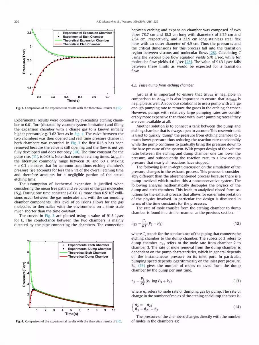
Fig. 3. Comparison of the experimental results with the theoretical results of (10).
A.K. Mousavi et al. / Vacuum 109 (2014) 216e222220
Experimental results were obtained by evacuating etching cham-ber to 0.01 Torr (dictated by vacuum system limitation) and fillingthe expansion chamber with a charge gas to a known initiallyhigher pressure, e.g. 3.62 Torr as in Fig. 4. The valve between thetwo chambers was then opened and real time pressure change inboth chambers was recorded. In Fig. 3 the first 0.15 s has beenremoved because the valve is still opening and the flow is not yetfully developed and does not obey (10). The time constant for thepulse rise, (11), is 0.08 s. Note that common etching times, Dtrxn, inthe literature commonly range between 30 and 60 s. Makingt < 0.3 s ensures that for common conditions etching chamber'spressure rise accounts for less than 1% of the overall etching timeand therefore accounts for a negligible portion of the actualetching time.
The assumption of isothermal expansion is justified whenconsidering the mean free path and velocities of the gas molecules(N2). During one time constant (~0.08 s), more than 0.5*105 colli-sions occur between the gas molecules and with the surroundingchamber components. This level of collisions allows for the gasmolecules to thermalize with the environment on a time scalemuch shorter than the time constant.
The curves in Fig. 3 are plotted using a value of 91.3 L/secfor C. The conductance between the two chambers is mainlydictated by the pipe connecting the chambers. The connection
Fig. 4. Comparison of the experimental results with the theoretical results of (16).
between etching and expansion chamber was composed of twopipes 78.7 cm and 15.2 cm long with diameters of 3.75 cm and2.54 cm, respectively, and a 22.9 cm long stainless steel flexhose with an outer diameter of 4.9 cm. Thus the pressures andthe critical dimensions for this process fall into the transitionregion between viscous and molecular flows [28]. Calculating Cusing the viscous pipe flow equation yields 570 L/sec, while formolecular flow yields 4.6 L/sec [28]. The value of 91.3 L/sec fallsbetween these limits as would be expected for a transitionflow.
4.2. Pulse dump from etching chamber
Just as it is important to ensure that Dtstart is negligible incomparison to Dtrxn it is also important to ensure that Dtfinish isnegligible as well. An obvious solution is to use a pumpwith a largeenough pumping rate to remove the gases in the etching chamber.However, pumps with relatively large pumping rates are consid-erably more expensive than those with lower pumping rates if theyare even available at all.
Another solution is to connect a tank between the pump andetching chamber that is always open to vacuum. This reservoir tankis used to quickly ‘dump’ the pressure from etching chamber to amuch lower pressure thus reducing the reaction rate considerablywhile the pump continues to gradually bring the pressure down tothe base pressure of the system. With proper design of the volumeratio between the etching and dump chamber one can lower thepressure, and subsequently the reaction rate, to a low enoughpressure that nearly all reactions have stopped.
The following is an in-depth discussion on the simulation of thepressure changes in the exhaust process. This process is consider-ably different than the aforementioned process because there is apump involved which makes this a nonconservative system. Thefollowing analysis mathematically decouples the physics of thedump and etch chambers. This leads to analytical closed form so-lutions for the exhaust process that allows for easier interpretationof the physics involved. In particular the design is discussed interms of the time constants for the processes.
The rate of mole transfer from the etching chamber to dumpchamber is found in a similar manner as the previous section.
_n23 ¼ CLRT
ðP2 � P3Þ (12)
where CL stands for the conductance of the piping that connects theetching chamber to the dump chamber. The subscript 3 refers todump chamber. _n23 refers to the mole rate from chamber 2 tochamber 3. The rate of mole removal from the dump chamber isdependent on the pump characteristics, which in general dependson the instantaneous pressure on its inlet port. In particular,pumping speed depends logarithmically on the inlet port pressure.Eq. (13) gives the number of moles removed from the dumpchamber by the pump per unit time.
_np ¼ P3RT
ðk1 log P3 þ k2Þ (13)
where _np refers to mole rate of dumping gas by pump. The rate ofchange in the number ofmoles of the etching and dump chamber is:
�_n2 ¼ � _n23_n3 ¼ _n23 � _np
(14)
The pressure of the chambers changes directly with the numberof moles in the chambers as:

A.K. Mousavi et al. / Vacuum 109 (2014) 216e222 221
8>><>>:
_n2 ¼ V2
RT_P2
V3 _(15)
_n3 ¼RT
P3
From 14&15, the system of differential equations describing thepressure of the chambers is obtained:
8>>><>>>:
_P2 ¼ �CLV2
ðP2 � P3Þ
_P3 ¼ CLV3
ðP2 � P3Þ �P3V3
ðk1 log P3 þ k2Þ(16)
This system of differential equations is solvable only by nu-merical methods.
Experimental results for the constructed system are comparedwith the theoretical simulation in Fig. 4. Agreement between thesimulation and experimental results is achieved by finding theproper values of the pipe conductance, CL, and the parameters ofthe pump k1 and k2 using numerical optimization algorithms toachieve proper fit by minimizing the RMS Error. Note that in a lessthan a few hundred milliseconds the pressure of the etchingchamber and dump tank are the same. At this point it is as if thedump chamber does not exist, it behaves as a line with a conduc-tance. This fact allows for the problem to broken into two analyti-cally solvable problems.
One can introduce two time constants to further study theexhaust process that subsequently divides the physics of theproblem into two steps. In the first step the chambers are con-nected to each other (before the two pressures meet) and in thesecond step the pump lowers the pressure of the two connectedchambers (after the two pressures meet). Since the pump is notplaying a considerable role in the first step and the pressure dif-ference between chambers is ignorable in the second step the twostages can be considered independent to a good approximation.The ignorable pressure difference between chambers makes itpossible to replace the two chambers in the second step with asingle chamber of equivalent volume. This results in the coupling ofthe equations in (16) allowing for theoretical closed form solutions.Although this solution is for a special case the closed form solutionobtained allows a deeper understanding of effect of different pa-rameters in the physics of the problem and also allows an easiermethod to optimize the chamber designs to reach desired timeconstants for each step.
Subsystem 2 describes the set of conditions for the end of asingle pulse, i.e. controls Dtfinish. Subsystem 2 can be further dividedinto two subsystems namely Subsystem 2a and Subsystem 2b. InSubsystem 2a the chambers reach the same pressure after the valveopens. In Subsystem 2b the two chambers are considered as asingle hybrid dump chamber, which is pumped down to systembase pressure. Subsystem 2a is a mass conserving system while 2bis not.
Continuity for Subsystem 2a yield results similar to Eqs.(9)e(11):
8>>><>>>:
_P*2 ¼ �CL
V2
�P*2 � P*3
�
_P*3 ¼ CL
V3
�P*2 � P*3
� (17)
which can be solved as
8>>>>>>>>>><>>>>>>>>>>:
P*2 ¼ Pi2V2 þ V3
V2 þ V3e
�CL�1V2
þ 1V3
�t!
P*3 ¼ Pi2V2
V2 þ V3
1� e
�CL�1V2
þ 1V3
�t! (18)
with a time constant of:
ta ¼ 1
CL
�1V2
þ 1V3
� (19)
For Subsystem 2b the pressure changes over time can be foundby combining the etch and dump chamber into one volume:
_P*3 ¼ P*3
V3 þ V2
�k1 log P*3 þ k2
�(20)
The following physical observation makes (20) much simpler tosolve and the solution more understandable. As time approachesinfinity the flow rate of the pump approaches zero which means atthe limit,
0 ¼ � P∞V3 þ V2
ðk1 Log P∞ þ k2Þ (21)
where P∞ is the ultimate pressure of the vacuum pump. Solving(21) for k2 we find:
k2 ¼ �k1 Log P∞ (22)
Applying (22) to (20) leads to:
_P*3 ¼ � k1P*3
V3 þ V2log
P*3P∞
(23)
which can be solved as
P*3P∞
¼�P0P∞
�exp
�� k1 t
V ln 10
�(24)
where P0 ¼ ðV2=ðV2 þ V3ÞÞPi2 is the final pressure of Subsystem 2aexpressed as a function of the initial pressure in etch chamber, andV ¼ V3 þ V2. The time constant of Subsystem 2b is:
tb ¼ V ln 10k1
ln
0BB@1þ 1
�1þ ln�
P0P∞
�1CCA (25)
In an ideal design P0 is designed to be much lower than Pi2. Thislowers the etch rate considerably in a short period of timewhen thevalve to dump chamber opens. It is desirable that the pump evac-uates the exhaust gasses immediately as well, but since the price ofa pump increases drastically with pump flow rate this is not usuallypractical. The pump constant k1 and k2 are fixed for each pump butproper determination of the time constants using (24) allowsproper choice of pump to fit the expected pumping rate for thesystem.
Again, the goal is to have ta that is approximately 1% or less thana typical pulse duration (30e60 s). From Fig. 4 ta is 0.42 s, which isapproximately 1% of a typical etch's duration. A pumpwith a higher

A.K. Mousavi et al. / Vacuum 109 (2014) 216e222222
flow rate will provide a shorter tb, which reduces the time toeliminate the gases remaining within the vacuum chamber.
A final note about using Eqs. (16) and (25). When designing asystem and using these equations in order to attain proper limitsfor the behavior of Eqs. (16) and (25) range of values for k1 and k2should be attained from the manufacturer when possible. As aresult of this work it was determined that k1 varied by 28% and k2by 82% as compared to the manufacturer's manual.
5. Summary and conclusions
Dynamic models have been presented for various stages ofpulsed vacuum processing. In particular, the case of XeF2 etching ofSi was examined. It was determined that the chambers' pressuresand pulse durations were the most important parameters involvedin this type of pulsed vacuum processing. Therefore, the developedmathematical models focused on the temporal variation of pres-sure in the associated chambers.
Closed form solutions for the systems of differential equationsmodeling the temporal variations of pressure (gas flow), werederived. These solutions are valid for situations where pump ratesare generally lower than the conductances of associated pipes,connections, and valves that account for the majority of vacuumsystems. Eqs. (10), (18), and (24) can be used to study the pressureas a function of time as gases move from one chamber to another.While Eqs. (11), (19), and (25) represent the time constants fordifferent portions of the system. The time constants can be used togain general insight intowhich parameters control the introductionand removal of gases from the pulsed vacuum system allowing foroptimization of system parameters to meet pulse duration con-straints. In this paper the time constants for filling and emptying apulse was designed and shown to take less than 1% of typicaletching durations of XeF2 etching of Si.
Experimental validation was given for the developed equations.However, validation was only possible knowing the exact volumesof the chambers involved. A chamber's pressure is readily available;the exact volumes of the chambers are not. Thus a new method-ology for the accurate calibration of vacuum system volumes wasdeveloped in which a calibrated volume was introduced into avacuum chamber while a series of pressures are measured.
Acknowledgments
Experiments performed were supported by the Office of BasicEnergy Sciences, Division of Materials Sciences and EngineeringExperimental Program to Stimulate Competitive Research (EPSCoR)under Award# DE - FG02 - 10ER46720. DP acknowledges supportfrom the National Science Foundation, USA e Nano UndergraduateEducation program Award 1042062.
References
[1] Deumier F, Bohuon P, Trystram G, Saber N, Collignan A. Pulsed vacuum briningof poultry meat: experimental study on the impact of vacuum cycles on masstransfer. J Food Eng Jun. 2003;58(1):75e83.
[2] Deng Y, Zhao Y. Effect of pulsed vacuum and ultrasound osmopretreatmentson glass transition temperature, texture, microstructure and calcium
penetration of dried apples (Fuji). LWT e Food Sci Technol Nov. 2008;41(9):1575e85.
[3] Darmady EM, Drewett SE, Hughes KEA. Survey on prevacuum high-pressuresteam sterilizers. J Clin Pathol Mar. 1964;17(2):126e9.
[4] Wu YB, Ding GF, Wang J, Zhang CC, Wang H. Fabrication of low-stress low-stiffness leveraged cantilever beam for bistable mechanism. MicroelectronEng Nov. 2010;87(11):2035e41.
[5] P. B. Chu, J. T. Chen, R. Yeh, G. Lin, J. C. P. Huang, B. A. Warneke, and et al,“Controlled pulse-etching with xenon difluoride,” in Proceedings of interna-tional solid state sensors and actuators conference (Transducers '97), vol. 1,pp. 665e668.
[6] Muthukumaran P, Stiharu I, Bhat R. Gas-phase xenon difluoride etching ofmicrosystems fabricated through the Mitel 1.5-mu m CMOS process. Can JElectr Comput Eng Can GENIE Electr Inf Jan. 2000;25(1):35e41.
[7] Stevens AAE, Beijerinck HCW. Surface roughness in XeF2 etching of a-Si/c-Si(100). J Vac Sci Technol A Vac Surfaces Film Dec. 2005;23(1):126.
[8] Karbassian F, Mousavi BK, Rajabali S, Talei R, Mohajerzadeh S, Asl-Soleimani E.Formation of luminescent silicon nanowires and porous silicon by metal-assisted electroless etching. J Electron Mater Feb. 2014;43(4):1271e9.
[9] Baghbani Parizi K, Peyvast N, Kheyraddini Mousavi B, Mohajerzadeh S,Fathipour M. Schottky barrier nano-MOSFET with an asymmetrically oxidizedsource/drain structure. Solid State Electron Jan. 2010;54(1):48e51.
[10] Mousavi A, Atwater M, Mousavi B, Jalalpour M, Taha M, Leseman Z. Me-chanical and electrical characterization of entangled networks of carbonnanofibers. Materials (Basel) Jun. 2014;7(6):4845e53.
[11] Atwater MA, Mousavi AK, Leseman ZC, Phillips J. Direct synthesis and char-acterization of a nonwoven structure comprised of carbon nanofibers. CarbonN Y Jun. 2013;57:363e70.
[12] Alipour Skandani A, Masghouni N, Case SW, Leo DJ, Al-Haik M. Enhancedvibration damping of carbon fibers-ZnO nanorods hybrid composites. ApplPhys Lett Aug. 2012;101(7):073111.
[13] Winters HF, Coburn JW. The etching of silicon with XeF2 vapor. Appl Phys LettAug. 1979;34(1):70.
[14] Ibbotson DE, Flamm DL, Mucha JA, Donnelly VM. Comparison of XeF2 and F-atom reactions with Si and SiO2. Appl Phys Lett Jun. 1984;44(12):1129.
[15] Ibbotson DE, Mucha JA, Flamm DL, Cook JM. Plasmaless dry etching of siliconwith fluorine-containing compounds. J Appl Phys Nov. 1984;56(10):2939.
[16] Kashamolla MR, Mousavi AK, Leseman ZC. Mode I and mixed mode I and IImeasurements for stiction failed MEMS devices. In: Micro and nano systems,parts A and B, vol. 12; 2009. p. 25e31.
[17] Leseman ZC, Carlson SP, Mackin TJ. Experimental measurements of the strainenergy release rate for stiction-failed microcantilevers using a single-cantilever beam peel test. J Microelectromech Syst Feb. 2007;16(1):38e43.
[18] Leseman ZC, Koppaka SB, Mackin TJ. A fracture mechanics description ofstress-wave repair in stiction-failed microcantilevers: theory and experi-ments. J Microelectromech Syst Aug. 2007;16(4):904e11. http://dx.doi.org/10.1109/JMEMS.2006.883571.
[19] Mousavi AK, Kashamolla MR, Leseman ZC. Improved model for the adhesionof mcantilevers: theory and experiments. J Micromechanics MicroengineeringNov. 2013;23(11):115011.
[20] Mousavi AK, Alaie S, Kashamolla MR, Leseman ZC. Nonlinear approach forstrain energy release rate in micro cantilevers. In: Micro and nano systems,vol. 10; 2010. p. 51e6.
[21] Kashamolla MR, Goettler DF, Mousavi AK, Leseman ZC. Mode II measurementsfor stiction failed MEMS devices. In: Micro and nano systems, vol. 10; 2010.p. 63e9.
[22] Chan IWT, Brown KB, Lawson RPW, Robinson AM, Strembicke D. Gas phasepulse etching of silicon for MEMS with xenon difluoride. In: Engineering so-lutions for the next millennium. 1999 IEEE Canadian conference on electricaland computer engineering (Cat. No. 99TH8411), vol. 3. p. 1637e42.
[23] SPTS Technologies [online]. Available: http://www.spts.com/products/xef2-release-etch/X4.
[24] SAMCO [online]. Available: http://www.samcointl.com/products/01_etching/04_others/vpe-4f.php.
[25] Hyman HH. Noble-gas compounds. Chicago: University of Chicago Press;1963.
[26] Dagata JA. Chemical processes involved in the etching of silicon by xenondifluoride. J Vac Sci Technol B Microelectron Nanom Struct Sep. 1987;5(5):1495.
[27] Setina J, Erjavec B. Volume determination of a vacuum vessel by pressure risemethod. In: Proc. of XIX IMEKO world congress, fundamental and appliedmetrology, vol. D; 2009. p. 2096e8.
[28] Ohring M. Materials science of thin films. 2nd ed. Academic Press; 2001.p. 794.


