Embed Size (px)
Citation preview

User Guide PTP 850E
System Release 10.9

phn-3963_008v000
Accuracy While reasonable efforts have been made to assure the accuracy of this document, Cambium Networks assumes no liability resulting from any inaccuracies or omissions in this document, or from use of the information obtained herein. Cambium reserves the right to make changes to any products described herein to improve reliability, function, or design, and reserves the right to revise this document and to make changes from time to time in content hereof with no obligation to notify any person of revisions or changes. Cambium does not assume any liability arising out of the application or use of any product, software, or circuit described herein; neither does it convey license under its patent rights or the rights of others. It is possible that this publication may contain references to, or information about Cambium products (machines and programs), programming, or services that are not announced in your country. Such references or information must not be construed to mean that Cambium intends to announce such Cambium products, programming, or services in your country. Copyrights This document, Cambium products, and 3rd Party software products described in this document may include or describe copyrighted Cambium and other 3rd Party supplied computer programs stored in semiconductor memories or other media. Laws in the United States and other countries preserve for Cambium, its licensors, and other 3rd Party supplied software certain exclusive rights for copyrighted material, including the exclusive right to copy, reproduce in any form, distribute and make derivative works of the copyrighted material. Accordingly, any copyrighted material of Cambium, its licensors, or the 3rd Party software supplied material contained in the Cambium products described in this document may not be copied, reproduced, reverse engineered, distributed, merged or modified in any manner without the express written permission of Cambium. Furthermore, the purchase of Cambium products shall not be deemed to grant either directly or by implication, estoppel, or otherwise, any license under the copyrights, patents or patent applications of Cambium or other 3rd Party supplied software, except for the normal non-exclusive, royalty free license to use that arises by operation of law in the sale of a product. Restrictions Software and documentation are copyrighted materials. Making unauthorized copies is prohibited by law. No part of the software or documentation may be reproduced, transmitted, transcribed, stored in a retrieval system, or translated into any language or computer language, in any form or by any means, without prior written permission of Cambium. License Agreements The software described in this document is the property of Cambium and its licensors. It is furnished by express license agreement only and may be used only in accordance with the terms of such an agreement. High Risk Materials Cambium and its supplier(s) specifically disclaim any express or implied warranty of fitness for any high risk activities or uses of its products including, but not limited to, the operation of nuclear facilities, aircraft navigation or aircraft communication systems, air traffic control, life support, or weapons systems (“High Risk Use”). Any High Risk is unauthorized, is made at your own risk and you shall be responsible for any and all losses, damage or claims arising out of any High Risk Use.
© 2019 Cambium Networks Limited. All Rights Reserved.

phn-3963_008v000 Page i
Contents
About This User Guide ........................................................................................................................................... 1 Contacting Cambium Networks ...................................................................................................................... 2 Purpose ........................................................................................................................................................... 3 Cross references .............................................................................................................................................. 3 Feedback ......................................................................................................................................................... 3
Problems and warranty .......................................................................................................................................... 4 Reporting problems ......................................................................................................................................... 4 Repair and service ........................................................................................................................................... 4 Hardware warranty ......................................................................................................................................... 4
Security advice ........................................................................................................................................................ 5 Warnings, cautions, and notes ............................................................................................................................... 6
Warnings ......................................................................................................................................................... 6 Cautions ........................................................................................................................................................... 6 Notes ............................................................................................................................................................... 6
Caring for the environment .................................................................................................................................... 7 In EU countries ................................................................................................................................................ 7 In non-EU countries ......................................................................................................................................... 7
Chapter 1: Introduction .................................................................................................................................. 1-1 System Overview ................................................................................................................................................ 1-2
Configuration Tips ....................................................................................................................................... 1-2 PTP 850E ...................................................................................................................................................... 1-3 PoE Injector Overview ................................................................................................................................. 1-3 The Web-Based Element Management System .......................................................................................... 1-3
Reference Guide to Web EMS Menu Structure ................................................................................................ 1-10 Chapter 2: Getting Started .............................................................................................................................. 2-1
Assigning IP Addresses in the Network ............................................................................................................... 2-2 Establishing a Connection ................................................................................................................................... 2-3 PC Setup .............................................................................................................................................................. 2-4 Logging on ........................................................................................................................................................... 2-6 Changing Your Password..................................................................................................................................... 2-7 Performing Quick Platform Setup ....................................................................................................................... 2-9 Configuring In-Band Management .................................................................................................................... 2-12 Changing the Management IP Address ............................................................................................................. 2-13 Configuring the Activation Key ......................................................................................................................... 2-15
Activation Key Overview ........................................................................................................................... 2-15 Viewing the Activation Key Status Parameters ......................................................................................... 2-16 Entering the Activation Key ....................................................................................................................... 2-17

Contents
phn-3963_008v000 Page ii
To activate demo mode: ........................................................................................................................... 2-17 Activation Key Reclaim .............................................................................................................................. 2-17 Displaying a List of Activation-Key-Enabled Features ............................................................................... 2-18
Setting the Time and Date (Optional) ............................................................................................................... 2-23 Enabling the Interfaces (Interface Manager) .................................................................................................... 2-25 Configuring the Radio (MRMC) Script(s) ........................................................................................................... 2-27
Radio Profiles............................................................................................................................................. 2-30 Configuring the Radio Parameters .................................................................................................................... 2-31 Creating Service(s) for Traffic............................................................................................................................ 2-34
Chapter 3: Configuration Guide ...................................................................................................................... 3-1 Configuring a Link Using the Quick Configuration Wizard .................................................................................. 3-1
Configuring a 1+0 Link Using the Quick Configuration Wizard.................................................................... 3-1 Chapter 4: Unit Management ......................................................................................................................... 4-1
Defining the IP Protocol Version for Initiating Communications ........................................................................ 4-2 Configuring the Remote Unit’s IP Address .......................................................................................................... 4-3
Changing the Subnet of the Remote IP Address ......................................................................................... 4-4 Configuration SNMP ........................................................................................................................................... 4-5 Configuring Trap Managers ................................................................................................................................ 4-8 Installing and Configuring an FTP or SFTP Server ............................................................................................. 4-11 Configuring the Internal Ports for FTP or SFTP ................................................................................................. 4-14 Upgrading the Software .................................................................................................................................... 4-15
Viewing Current Software Versions .......................................................................................................... 4-15 Software Upgrade Overview ..................................................................................................................... 4-16 Downloading and Installing Software........................................................................................................ 4-16 Downloading Software Via HTTP or HTTPS ............................................................................................... 4-17 Downloading Software Via FTP or SFTP .................................................................................................... 4-18 Installing Software ..................................................................................................................................... 4-21 Configuring a Timed Installation ............................................................................................................... 4-22
Backing Up and Restoring Configurations......................................................................................................... 4-24 Configuration Management Overview ...................................................................................................... 4-24 Viewing Current Backup Files .................................................................................................................... 4-24 Setting the Configuration Management Parameters ................................................................................ 4-25 Exporting a Configuration File ................................................................................................................... 4-28 Importing a Configuration File .................................................................................................................. 4-28 Deleting a Configuration File ..................................................................................................................... 4-29 Backing Up the Current Configuration ...................................................................................................... 4-29 Restoring a Saved Configuration ............................................................................................................... 4-29 Editing CLI Scripts ...................................................................................................................................... 4-30
Setting the Unit to the Factory Default Configuration ...................................................................................... 4-31 Performing a Hard (Cold) Reset ........................................................................................................................ 4-32 Configuring Unit Parameters ............................................................................................................................ 4-33 Configuring NTP ................................................................................................................................................ 4-35

Contents
phn-3963_008v000 Page iii
Displaying Unit Inventory.................................................................................................................................. 4-37 Defining a Login Banner .................................................................................................................................... 4-38
Chapter 5: Radio Configuration ...................................................................................................................... 5-1 Viewing the Radio Status and Settings ............................................................................................................... 5-2 Configuring the Remote Radio Parameters ........................................................................................................ 5-4 Configuring and Viewing Radio PMs and Statistics ............................................................................................. 5-6
Configuring BER Thresholds and Displaying Current BER ............................................................................ 5-6 Displaying MRMC Status ............................................................................................................................. 5-7 Displaying MRMC PMs .............................................................................................................................. 5-10 Displaying and Clearing Defective Block Counters .................................................................................... 5-11 Displaying Signal Level PMs and Configuring Signal Level PM Thresholds ................................................ 5-12 Displaying Modem BER (Aggregate) PMs .................................................................................................. 5-14 Displaying MSE PMs and Configuring MSE PM Thresholds ....................................................................... 5-16
Chapter 6: Ethernet Services and Interfaces ................................................................................................... 6-1 Configuring Ethernet Service(s) .......................................................................................................................... 6-2
Ethernet Services Overview ........................................................................................................................ 6-2 General Guidelines for Provisioning Ethernet Services ............................................................................... 6-3 The Ethernet Services Page ......................................................................................................................... 6-3 Adding an Ethernet Service ......................................................................................................................... 6-4 Editing a Service .......................................................................................................................................... 6-6 Deleting a Service ........................................................................................................................................ 6-6 Enabling, Disabling, or Deleting Multiple Services ...................................................................................... 6-6 Viewing Service Details ............................................................................................................................... 6-7 Configuring Service Points ........................................................................................................................... 6-7
Setting the MRU Size and the S-VLAN Ethertype .............................................................................................. 6-20 Configuring Ethernet Interfaces ........................................................................................................................ 6-21 Configuring Automatic State Propagation and Link Loss Forwarding ............................................................... 6-24 Viewing Ethernet PMs and Statistics ................................................................................................................ 6-27
RMON Statistics ......................................................................................................................................... 6-27 Egress CoS Statistics .................................................................................................................................. 6-28 Port TX Statistics ........................................................................................................................................ 6-30 Port RX Statistics ....................................................................................................................................... 6-33
Chapter 7: Quality of Service (QoS) ................................................................................................................ 7-1 QoS Overview ..................................................................................................................................................... 7-2 Configuring Classification .................................................................................................................................... 7-4
Classification Overview ............................................................................................................................... 7-4 Configuring Ingress Path Classification on a Logical Interface .................................................................... 7-5 Modifying the C-VLAN 802.1Q UP and CFI Bit Classification Table ............................................................. 7-7 Modifying the S-VLAN 802.1 UP and DEI Bit Classification Table ................................................................ 7-9 Modifying the DSCP Classification Table ................................................................................................... 7-10 Modifying the MPLS EXP Bit Classification Table ...................................................................................... 7-11
Configuring Policers (Rate Metering) ................................................................................................................ 7-13

Contents
phn-3963_008v000 Page iv
Policer (Rate Metering) Overview ............................................................................................................. 7-13 Configuring Policer Profiles ....................................................................................................................... 7-13 Assigning Policers to Interfaces ................................................................................................................. 7-16 Configuring the Ingress and Egress Byte Compensation ........................................................................... 7-21
Configuring Marking ......................................................................................................................................... 7-22 Marking Overview ..................................................................................................................................... 7-22 Enabling Marking ....................................................................................................................................... 7-22 Modifying the 802.1Q Marking Table ....................................................................................................... 7-22 Modifying the 802.1AD Marking Table ..................................................................................................... 7-24
Configuring WRED ............................................................................................................................................. 7-25 WRED Overview ........................................................................................................................................ 7-25 Configuring WRED Profiles ........................................................................................................................ 7-25 Assigning WRED Profiles to Queues .......................................................................................................... 7-28
Configuring Egress Shaping ............................................................................................................................... 7-29 Egress Shaping Overview ........................................................................................................................... 7-29 Configuring Queue Shaper Profiles ........................................................................................................... 7-29 Assigning a Queue Shaper Profile to a Queue ........................................................................................... 7-31
Configuring Scheduling ..................................................................................................................................... 7-34 Scheduling Overview ................................................................................................................................. 7-34 Configuring Priority Profiles ...................................................................................................................... 7-34 Configuring WFQ Profiles .......................................................................................................................... 7-38 Assigning a Priority Profile to an Interface ................................................................................................ 7-40 Assigning a WFQ Profile to an Interface .................................................................................................... 7-40
Configuring and Displaying Queue-Level PMs .................................................................................................. 7-42 Chapter 8: Synchronization............................................................................................................................. 8-1
Configuring the Sync Source ............................................................................................................................... 8-2 Viewing the Sync Source Status .................................................................................................................. 8-2 Adding a Sync Source .................................................................................................................................. 8-3 Editing a Sync Source................................................................................................................................... 8-4 Deleting a Sync Source ................................................................................................................................ 8-5
Configuring the Outgoing Clock and SSM Messages .......................................................................................... 8-6 Chapter 9: Access Management and Security ................................................................................................. 9-1
Configuring the General Access Control Parameters .......................................................................................... 9-2 Configuring the Password Security Parameters .................................................................................................. 9-4 Configuring the Session Timeout ........................................................................................................................ 9-5 Configuring Users ................................................................................................................................................ 9-6
User Configuration Overview ...................................................................................................................... 9-6 Configuring User Profiles ............................................................................................................................. 9-6 Configuring Users ........................................................................................................................................ 9-9
Configuring X.509 CSR Certificates and HTTPS ................................................................................................. 9-12 Generating a Certificate Signing Request (CSR) File .................................................................................. 9-12 Downloading a Certificate ......................................................................................................................... 9-14

Contents
phn-3963_008v000 Page v
Blocking Telnet Access ...................................................................................................................................... 9-16 Uploading the Security Log ............................................................................................................................... 9-17 Uploading the Configuration Log ...................................................................................................................... 9-19
Chapter 10: Alarm Management and Troubleshooting ................................................................................ 10-1 Viewing Current Alarms .................................................................................................................................... 10-2 Viewing Alarm Statistics .................................................................................................................................... 10-4 Viewing and Saving the Event Log .................................................................................................................... 10-5 Editing Alarm Text and Severity | Disabling Alarms and Event ........................................................................ 10-7
Displaying Alarm Information ................................................................................................................... 10-7 Viewing the Probable Cause and Corrective Actions for an Alarm Type ................................................... 10-8 Editing an Alarm Type and Disabling Alarms and Events .......................................................................... 10-8 Setting Alarms to their Default Values ...................................................................................................... 10-9
Configuring Voltage Alarm Thresholds and Displaying Voltage PMs .............................................................. 10-10 Uploading Unit Info ......................................................................................................................................... 10-13 Performing Diagnostics ................................................................................................................................... 10-16
Performing Radio Loopback .................................................................................................................... 10-16 Performing Ethernet Loopback ............................................................................................................... 10-17 Configuring Service OAM (SOAM) Fault Management (FM) ................................................................... 10-17
Chapter 11: Web EMS Utilities ..................................................................................................................... 11-1 Restarting the HTTP Server ............................................................................................................................... 11-2 Calculating an ifIndex ........................................................................................................................................ 11-2 Displaying, Searching, and Saving a list of MIB Entities .................................................................................... 11-4
Chapter 12: Getting Started (CLI) ................................................................................................................. 12-1 General (CLI) ..................................................................................................................................................... 12-2 Establishing a Connection (CLI) ......................................................................................................................... 12-2
PC Setup (CLI) ............................................................................................................................................ 12-2 Logging On (CLI) ................................................................................................................................................ 12-3 General CLI Commands ..................................................................................................................................... 12-4 Changing Your Password (CLI) .......................................................................................................................... 12-5 Configuring In-Band Management (CLI) ........................................................................................................... 12-6 Changing the Management IP Address (CLI) ..................................................................................................... 12-7 Configuring the Activation Key (CLI) ................................................................................................................. 12-9
Activation Key Overview (CLI) ................................................................................................................... 12-9 Viewing the Activation Key Status Parameters (CLI) ................................................................................. 12-9 Entering the Activation Key (CLI) ............................................................................................................. 12-10 Activating a Demo Activation Key (CLI) ................................................................................................... 12-10 Displaying a List of Activation-Key-Enabled Features (CLI) ..................................................................... 12-10
Setting the Time and Date (Optional) (CLI) ..................................................................................................... 12-11 Setting the Daylight Savings Time (CLI) ................................................................................................... 12-12
Enabling the Interfaces (CLI) ........................................................................................................................... 12-13 Configuring the Radio (MRMC) Script(s) (CLI) ................................................................................................. 12-15
Displaying Available MRMC Scripts (CLI) ................................................................................................. 12-15

Contents
phn-3963_008v000 Page vi
Assigning an MRMC Script to a Radio Carrier (CLI) ................................................................................. 12-16 Configuring the Radio Parameters (CLI) .......................................................................................................... 12-18
Entering Radio View (CLI) ........................................................................................................................ 12-18 Muting and Unmuting a Radio (CLI) ........................................................................................................ 12-18 Configuring the Transmit (TX) Frequency (CLI) ....................................................................................... 12-19 Configuring the Transmit (TX) Level (CLI) ................................................................................................ 12-19 Enabling ACM with Adaptive Transmit Power (CLI) ................................................................................ 12-19
Configuring the RSL Threshold Alarm (CLI) ..................................................................................................... 12-21 Creating Service(s) for Traffic (CLI) ................................................................................................................. 12-22
Chapter 13: Unit Management (CLI) ........................................................................................................... 13-23 Defining the IP Protocol Version for Initiating Communications (CLI) ............................................................ 13-24 Configuring the Remote Unit’s IP Address (CLI).............................................................................................. 13-25
Configuring the Remote Radio's IP Address in IPv4 format (CLI) ............................................................ 13-25 Configuring the Remote Radio's IP Address in IPv6 format (CLI) ............................................................ 13-26
Configuring SNMP (CLI) ................................................................................................................................... 13-27 Configuring Basic SNMP Settings (CLI) .................................................................................................... 13-27 Configuring SNMPv3 (CLI) ....................................................................................................................... 13-28 Displaying the SNMP Settings (CLI) ......................................................................................................... 13-29 Configuring Trap Managers (CLI) ............................................................................................................. 13-30
Configuring the Internal Ports for FTP or SFTP (CLI) ....................................................................................... 13-32 Upgrading the Software (CLI) .......................................................................................................................... 13-33
Software Upgrade Overview (CLI) ........................................................................................................... 13-33 Viewing Current Software Versions (CLI) ................................................................................................ 13-33 Configuring a Software Download (CLI) .................................................................................................. 13-34 Downloading a Software Package (CLI) ................................................................................................... 13-35 Installing and Upgrading Software (CLI) .................................................................................................. 13-36
Backing Up and Restoring Configurations (CLI) .............................................................................................. 13-37 Configuration Management Overview (CLI) ............................................................................................ 13-37 Setting the Configuration Management Parameters (CLI) ...................................................................... 13-38 Backing up and Exporting a Configuration File (CLI)................................................................................ 13-39 Importing and Restoring a Configuration File (CLI) ................................................................................. 13-40 Editing CLI Scripts (CLI) ............................................................................................................................ 13-40
Setting the Unit to the Factory Default Configuration (CLI) ........................................................................... 13-42 Performing a Hard (Cold) Reset (CLI) .............................................................................................................. 13-43 Resetting the Remote Unit (CLI) ..................................................................................................................... 13-44 Configuring Unit Parameters (CLI) .................................................................................................................. 13-45 Configuring NTP (CLI) ...................................................................................................................................... 13-46 Displaying Unit Inventory (CLI) ....................................................................................................................... 13-46
Chapter 14: Radio Configuration (CLI) .......................................................................................................... 14-1 Viewing and Configuring the Remote Radio Parameters (CLI) ......................................................................... 14-2
Displaying Communication Status with the Remote Radio (CLI) ............................................................... 14-2 Displaying Remote Radio’s Location (CLI) ................................................................................................. 14-2

Contents
phn-3963_008v000 Page vii
Muting and Unmuting the Remote Radio (CLI) ......................................................................................... 14-2 Displaying the Remote Radio’s RX Level (CLI) ........................................................................................... 14-3 Configuring the Remote Radio’s TX Level (CLI) ......................................................................................... 14-3 Displaying the Remote Unit’s Most Severe Alarm (CLI) ............................................................................ 14-3
Configuring and Viewing Radio PMs and Statistics (CLI) ................................................................................... 14-4 Displaying General Modem Status and Defective Block PMs (CLI) ........................................................... 14-4 Displaying Excessive BER (Aggregate) PMs (CLI) ....................................................................................... 14-4 Displaying BER Level and Configuring BER Parameters (CLI) ..................................................................... 14-6 Configuring RSL Thresholds (CLI) ............................................................................................................... 14-7 Configuring TSL Thresholds (CLI) ............................................................................................................... 14-7 Displaying RSL and TSL Levels (CLI)............................................................................................................ 14-8 Configuring the Signal Level Threshold (CLI) ............................................................................................. 14-9 Configuring the MSE Thresholds and Displaying the MSE PMs (CLI) ....................................................... 14-10 Displaying ACM PMs (CLI)........................................................................................................................ 14-12
Chapter 15: Ethernet Services and Interfaces (CLI) ....................................................................................... 15-1 Configuring Ethernet Services (CLI)................................................................................................................... 15-2
Ethernet Services Overview (CLI) .............................................................................................................. 15-2 General Guidelines for Provisioning Ethernet Services (CLI) ..................................................................... 15-2 Defining Services (CLI) ............................................................................................................................... 15-3 Configuring Service Points (CLI) ................................................................................................................. 15-8 Defining the MAC Address Forwarding Table for a Service (CLI)............................................................. 15-24
Setting the MRU Size and the S-VLAN Ethertype (CLI) .................................................................................... 15-28 Configuring the S-VLAN Ethertype (CLI) .................................................................................................. 15-28 Configuring the C-VLAN Ethertype (CLI) .................................................................................................. 15-29 Configuring the MRU (CLI) ....................................................................................................................... 15-29
Configuring Ethernet Interfaces (CLI) ............................................................................................................. 15-29 Entering Interface View (CLI) ................................................................................................................... 15-30 Displaying the Operational State of the Interfaces in the Unit (CLI) ....................................................... 15-31 Viewing Interface Attributes (CLI) ........................................................................................................... 15-31 Configuring an Interface’s Media Type (CLI) ........................................................................................... 15-32 Configuring an Interface’s Speed and Duplex State (CLI) ........................................................................ 15-32 Configuring an Interface’s Auto Negotiation State (CLI) ......................................................................... 15-33 Configuring an Interface’s IFG (CLI) ......................................................................................................... 15-33 Configuring an Interface’s Preamble (CLI) ............................................................................................... 15-34 Adding a Description for the Interface (CLI) ............................................................................................ 15-34
Configuring Automatic State Propagation and Link Loss Forwarding (CLI) ..................................................... 15-36 Viewing Ethernet PMs and Statistics (CLI) ...................................................................................................... 15-40
Displaying RMON Statistics (CLI) ............................................................................................................. 15-40 Configuring Ethernet Port PMs and PM Thresholds (CLI) ....................................................................... 15-41 Displaying Ethernet Port PMs (CLI) ......................................................................................................... 15-42 Clearing Ethernet Port PMs (CLI) ............................................................................................................. 15-45
Chapter 16: Quality of Service (QoS) (CLI) .................................................................................................... 16-1

Contents
phn-3963_008v000 Page viii
Configuring Classification (CLI).......................................................................................................................... 16-2 Classification Overview (CLI) ..................................................................................................................... 16-2 Configuring Ingress Path Classification on a Logical Interface (CLI) .......................................................... 16-2 Configuring VLAN Classification and Override (CLI) .................................................................................. 16-3 Configuring 802.1p Classification (CLI) ...................................................................................................... 16-4 Configuring DSCP Classification (CLI) ......................................................................................................... 16-5 Configuring MPLS Classification (CLI) ........................................................................................................ 16-8 Configuring 802.1p Classification (CLI) .................................................................................................... 16-10 Configuring a Default CoS (CLI) ............................................................................................................... 16-14 Configuring Ingress Path Classification on a Service Point (CLI) .............................................................. 16-14 Configuring Ingress Path Classification on a Service (CLI) ....................................................................... 16-14
Configuring Policers (Rate Metering) (CLI)...................................................................................................... 16-15 Overview of Rate Metering (Policing) (CLI) ............................................................................................. 16-15 Configuring Rate Meter (Policer) Profiles (CLI) ....................................................................................... 16-15 Displaying Rate Meter Profiles (CLI) ........................................................................................................ 16-17 Deleting a Rate Meter Profile (CLI) .......................................................................................................... 16-17 Attaching a Rate Meter (Policer) to an Interface (CLI) ............................................................................ 16-17 Configuring the Line Compensation Value for a Rate Meter (Policer) (CLI) ............................................ 16-24
Configuring Marking (CLI) ............................................................................................................................... 16-26 Marking Overview (CLI) ........................................................................................................................... 16-26 Configuring Marking Mode on a Service Point (CLI) ................................................................................ 16-26 Marking Table for C-VLAN UP Bits (CLI) ................................................................................................... 16-27 Marking Table for S-VLAN UP Bits (CLI) ................................................................................................... 16-29
Configuring WRED (CLI)................................................................................................................................... 16-31 WRED Overview (CLI) .............................................................................................................................. 16-31 Configuring WRED Profiles (CLI) .............................................................................................................. 16-31 Assigning a WRED Profile to a Queue (CLI) ............................................................................................. 16-33
Configuring Shapers (CLI) ................................................................................................................................ 16-35 Overview of Egress Shaping (CLI) ............................................................................................................ 16-35 Configuring Egress Line Compensation for Shaping (CLI) ........................................................................ 16-37
Configuring Scheduling (CLI) ........................................................................................................................... 16-38 Overview of Egress Scheduling (CLI)........................................................................................................ 16-38 Configuring Queue Priority (CLI).............................................................................................................. 16-38 Configuring Interface Priority Profiles (CLI) ............................................................................................. 16-39 Attaching a Priority Profile to an Interface (CLI) ..................................................................................... 16-42 Configuring Weighted Fair Queuing (WFQ) (CLI) .................................................................................... 16-43
Displaying Egress Statistics (CLI) ..................................................................................................................... 16-47 Displaying Queue-Level PMs (CLI) ........................................................................................................... 16-47 Displaying Service Bundle-Level PMs (CLI) .............................................................................................. 16-48
Chapter 17: Synchronization (CLI) ................................................................................................................ 17-1 Changing the ETSI/ANSI Mode (CLI) .................................................................................................................. 17-2 Configuring the Sync Source (CLI) ..................................................................................................................... 17-3

Contents
phn-3963_008v000 Page ix
Configuring an Ethernet Interface as a Synchronization Source (CLI) ....................................................... 17-4 Configuring a Radio Interface as a Synchronization Source (CLI) .............................................................. 17-5
Configuring the Outgoing Clock (CLI) ................................................................................................................ 17-8 Configuring SSM Messages (CLI) ..................................................................................................................... 17-10 Displaying Synchronization Status and Parameters (CLI)................................................................................ 17-11
Chapter 18: Access Management and Security (CLI) ..................................................................................... 18-1 Configuring the General Access Control Parameters (CLI)................................................................................ 18-2
Configuring the Inactivity Timeout Period (CLI) ........................................................................................ 18-2 Configuring Blocking Upon Login Failure (CLI) .......................................................................................... 18-2 Configuring Blocking of Unused Accounts (CLI) ........................................................................................ 18-3
Configuring the Password Security Parameters (CLI) ....................................................................................... 18-5 Configuring Password Aging (CLI) .............................................................................................................. 18-5 Configuring Password Strength Enforcement (CLI) ................................................................................... 18-5 Forcing Password Change Upon First Login (CLI) ...................................................................................... 18-6 Displaying the System Password Settings (CLI) ......................................................................................... 18-7
Configuring Users (CLI) ...................................................................................................................................... 18-8 User Configuration Overview (CLI) ............................................................................................................ 18-8 Configuring User Profiles (CLI) ................................................................................................................... 18-8 Configuring User Accounts (CLI) .............................................................................................................. 18-10
Configuring X.509 CSR Certificates and HTTPS (CLI) ....................................................................................... 18-12 Generating a Certificate Signing Request (CSR) File (CLI) ........................................................................ 18-12 Downloading a Certificate (CLI) ............................................................................................................... 18-14 Enabling HTTPS (CLI) ................................................................................................................................ 18-15
Configuring HTTPS Cipher Hardening (CLI) ..................................................................................................... 18-17 Blocking Telnet Access (CLI) ............................................................................................................................ 18-18 Uploading the Security Log (CLI) ..................................................................................................................... 18-19 Uploading the Configuration Log (CLI) ............................................................................................................ 18-21
Chapter 19: Alarm Management and Troubleshooting (CLI)......................................................................... 19-1 Viewing Current Alarms (CLI) ............................................................................................................................ 19-2 Viewing the Event Log (CLI) .............................................................................................................................. 19-3 Editing Alarm Text and Severity (CLI) ................................................................................................................ 19-4
Displaying Alarm Information (CLI) ........................................................................................................... 19-4 Editing an Alarm Type (CLI) ....................................................................................................................... 19-4 Setting Alarms to their Default Values (CLI) .............................................................................................. 19-5
Configuring a Timeout for Trap Generation (CLI) ............................................................................................. 19-6 Configuring Voltage Alarm Thresholds and Displaying Voltage PMs (CLI) ........................................................ 19-7 Uploading Unit Info (CLI) ................................................................................................................................... 19-9 Activating the Radio Logger (CLI) .................................................................................................................... 19-12 Performing Diagnostics (CLI) ........................................................................................................................... 19-13
Performing Radio Loopback (CLI) ............................................................................................................ 19-13 Performing Ethernet Loopback (CLI) ....................................................................................................... 19-13 Configuring Service OAM (SOAM) Fault Management (FM) (CLI) ........................................................... 19-14

Contents
phn-3963_008v000 Page x
SOAM Overview (CLI) .............................................................................................................................. 19-15 Configuring MDs (CLI) .............................................................................................................................. 19-15 Configuring MA/MEGs (CLI) .................................................................................................................... 19-16 Configuring MEPs (CLI) ............................................................................................................................ 19-19
Working in CW Mode (Single or Dual Tone) (CLI) ........................................................................................... 19-30 Chapter 20: Maintenance ............................................................................................................................. 20-1
Temperature Ranges ......................................................................................................................................... 20-2 Troubleshooting Tips ................................................................................................................................. 20-2
PTP 850E Connector Pin-outs ........................................................................................................................... 20-3 P2 (Eth 1) – MGT/PoE GbE Electrical Interface (RJ-45) ............................................................................. 20-4 P3 (Eth 2) GbE Optical Interface (SFP) ....................................................................................................... 20-4 P4 (Eth 3, Eth 4, Eth 5, Eth 6) 40 GbE Optical Interface (QSFP) ................................................................. 20-4 P5 (Eth 7) 10G Optical Interface (SFP+) ..................................................................................................... 20-4 Protection/XPIC Port ................................................................................................................................. 20-5 RSL Interface .............................................................................................................................................. 20-5
PTP 850E LEDs ................................................................................................................................................... 20-6 P2 MGT/PoE GbE Electrical Interface (RJ-45) LEDs ................................................................................... 20-6 P4/Eth3-7 40G Optical Interface (QSFP) LEDs ........................................................................................... 20-6 P5/Eth7 10G Optical Interface (SFP+) LEDs ............................................................................................... 20-6 Status LED .................................................................................................................................................. 20-6 Protection LED ........................................................................................................................................... 20-7
PoE Injector Pin-outs and LEDs – Standard PoE ................................................................................................ 20-8 PoE Injector Pin-outs and LEDs – Standard PoE ........................................................................................ 20-8 PoE Injector LEDs – Standard PoE ............................................................................................................. 20-9
PoE Injector Pin-outs and LEDs – Passive PoE................................................................................................. 20-11 PoE Injector Pin-outs and LEDs – Passive PoE ......................................................................................... 20-11 PoE Injector LEDs – Passive PoE .............................................................................................................. 20-11
Chapter 21: Alarms List .............................................................................................................................. 21-12 Glossary .................................................................................................................................................................. I

Contents
phn-3963_008v000 Page xi
List of Figures Figure 1 Main Web EMS Page ....................................................................................................................................................... 1-4 Figure 2 Displaying a Representation of the Front Panel .............................................................................................................. 1-4 Figure 3 Main Web EMS Page with Representation of Front Panel .............................................................................................. 1-5 Figure 4 Related Pages Drop-Down List ........................................................................................................................................ 1-6 Figure 5 Related Pages Drop-Down List ......................................................................................................................................... 1-6 Figure 6 Unit Summary Page ......................................................................................................................................................... 1-7 Figure 7 Unit Summary Page – Customizing Columns .................................................................................................................. 1-7 Figure 8 Radio Summary Page ...................................................................................................................................................... 1-8 Figure 9 Radio Summary Page- Customizing Columns .................................................................................................................. 1-9 Figure 10 Internet Protocol Properties Window ........................................................................................................................... 2-5 Figure 11 Login Page ..................................................................................................................................................................... 2-6 Figure 12 Change User Password Page ......................................................................................................................................... 2-7 Figure 13 Quick Configuration – Platform Setup Page .................................................................................................................. 2-9 Figure 14 Quick Configuration– Platform Setup Summary Page ................................................................................................. 2-11 Figure 15 Local Networking Configuration Page – In-Band Management ................................................................................... 2-12 Figure 16 Local Networking Configuration Page ......................................................................................................................... 2-13 Figure 17 Activation Key Configuration Page .............................................................................................................................. 2-16 Figure 18 Activation Key Overview Page ..................................................................................................................................... 2-18 Figure 19 Time Services Page ....................................................................................................................................................... 2-23 Figure 20 Interface Manager Page .............................................................................................................................................. 2-25 Figure 21 Interface Manager – Edit Page .................................................................................................................................... 2-26 Figure 22 Multiple Selection Operation Section (Interface Manager Page)................................................................................ 2-26 Figure 23 MRMC Symmetrical Scripts Page ................................................................................................................................ 2-27 Figure 24 MRMC Symmetrical Scripts Page – Configuration ....................................................................................................... 2-28 Figure 25 Radio Parameters Page ................................................................................................................................................ 2-32 Figure 26 1+0 Quick Configuration Wizard – Page 1 ..................................................................................................................... 3-1 Figure 27 1+0 Quick Configuration Wizard – Page 2 ..................................................................................................................... 3-2 Figure 28 1+0 Quick Configuration Wizard – Page 3 ...................................................................................................................... 3-3 Figure 29 1+0 Quick Configuration Wizard – Page 4 ...................................................................................................................... 3-4 Figure 30 1+0 Quick Configuration Wizard – Page 5 ...................................................................................................................... 3-5 Figure 31 1+0 Quick Configuration Wizard – Page 5 (In Band Management = Yes) ....................................................................... 3-5 Figure 32 1+0 Quick Configuration Wizard – Page 6 (Summary Page) ........................................................................................... 3-6 Figure 33 Local Networking Configuration Page ........................................................................................................................... 4-2 Figure 34 Remote Networking Configuration Page....................................................................................................................... 4-3 Figure 35 SNMP Parameters Page ................................................................................................................................................ 4-5 Figure 36 V3 Users Page................................................................................................................................................................ 4-6 Figure 37 V3 Users - Add Page ...................................................................................................................................................... 4-7 Figure 38 Trap Managers Page ..................................................................................................................................................... 4-8 Figure 39 Trap Managers - Edit Page ............................................................................................................................................ 4-9 Figure 40 FileZilla Server User Configuration .............................................................................................................................. 4-12 Figure 41 FileZilla Server Shared Folder Setup ............................................................................................................................ 4-13 Figure 42 FTP Port Page .............................................................................................................................................................. 4-14 Figure 43 Versions Page .............................................................................................................................................................. 4-15 Figure 44 Download & Install Page – HTTP/ HTTPS Download – No File Selected ...................................................................... 4-17

Contents
phn-3963_008v000 Page xii
Figure 45 Download & Install page – HTTP/ HTTPS Download – File Selected ........................................................................... 4-18 Figure 46 Download & Install Page - FTP .................................................................................................................................... 4-18 Figure 47 FTP Parameters Page .................................................................................................................................................. 4-20 Figure 48 Install parameters Page. .............................................................................................................................................. 4-23 Figure 49 Install parameters page- Software Management Timer. ............................................................................................ 4-23 Figure 50 Backup Files Page ........................................................................................................................................................ 4-25 Figure 51 Configuration Management Page ............................................................................................................................... 4-26 Figure 52 FTP Parameters Page .................................................................................................................................................. 4-26 Figure 53: Chassis Configuration Page ......................................................................................................................................... 4-31 Figure 54 Unit Parameters Page ................................................................................................................................................. 4-33 Figure 55 NTP Configuration Page .............................................................................................................................................. 4-35 Figure 56 Inventory Page ............................................................................................................................................................ 4-37 Figure 57 Login Banner Page........................................................................................................................................................ 4-38 Figure 59 Radio Parameters Page ................................................................................................................................................. 5-2 Figure 61 Remote Radio Parameters Page .................................................................................................................................... 5-4 Figure 74 Radio BER Thresholds Page ........................................................................................................................................... 5-7 Figure 76 MRMC Status Page ........................................................................................................................................................ 5-7 Figure 77 MRMC PM Report Page .............................................................................................................................................. 5-10 Figure 78 Counters Page ............................................................................................................................................................. 5-11 Figure 81 Signal Level PM Report Page ....................................................................................................................................... 5-12 Figure 82 Signal Level Thresholds Configuration - Edit Page ...................................................................................................... 5-13 Figure 83 Aggregate PM Report Page ......................................................................................................................................... 5-14 Figure 84 MSE PM Report Page .................................................................................................................................................. 5-16 Figure 85 Modem MSE Thresholds Configuration – Edit Page .................................................................................................... 5-17 Figure 93 Ethernet Services Page .................................................................................................................................................. 6-3 Figure 94 Ethernet Services - Add page ........................................................................................................................................ 6-5 Figure 95 Multiple Selection Operation Section (Ethernet Services) ............................................................................................ 6-7 Figure 96 Ethernet Service Points Page ........................................................................................................................................ 6-9 Figure 97 Ethernet Service Points Page – Ingress Attributes ...................................................................................................... 6-12 Figure 98 Ethernet Service Points Page – Egress Attributes ....................................................................................................... 6-13 Figure 99 Ethernet Service Points - Add Page ............................................................................................................................. 6-16 Figure 100 Attached VLAN List Page ........................................................................................................................................... 6-17 Figure 101 Attached VLAN List - Add Page .................................................................................................................................. 6-18 Figure 102 Ethernet General Configuration Page ....................................................................................................................... 6-20 Figure 103 Physical Interfaces Page ............................................................................................................................................ 6-21 Figure 104 Physical Interfaces - Edit Page ................................................................................................................................... 6-22 Figure 105 Automatic State Propagation Page ............................................................................................................................ 6-25 Figure 106 Automatic State Propagation - Add Page ................................................................................................................... 6-25 Figure 107 RMON Page ............................................................................................................................................................... 6-27 Figure 108 RMON Page – Hiding and Displaying Columns .......................................................................................................... 6-27 Figure 109 Egress Cos Statistics Page .......................................................................................................................................... 6-29 Figure 110 Egress CoS Statistics – Edit Page ............................................................................................................................... 6-29 Figure 111 Ethernet Port TX PM Report Page ............................................................................................................................. 6-30 Figure 112 Ethernet PM Port Admin Page .................................................................................................................................. 6-32 Figure 113 Ethernet Port Tx Threshold Page .............................................................................................................................. 6-33 Figure 114: Ethernet Port RX PM Report Page ............................................................................................................................ 6-34

Contents
phn-3963_008v000 Page xiii
Figure 115 Ethernet PM Port Admin Page ................................................................................................................................... 6-35 Figure 116 Ethernet Port Rx Threshold Page .............................................................................................................................. 6-35 Figure 117 QoS Block Diagram ...................................................................................................................................................... 7-2 Figure 118 Logical Interfaces Page ................................................................................................................................................ 7-5 Figure 119 Logical Interfaces - Edit Page....................................................................................................................................... 7-6 Figure 120 802.1Q Classification Page .......................................................................................................................................... 7-8 Figure 121 802.1Q Classification - Edit Page ................................................................................................................................. 7-8 Figure 122 802.1AD Classification Page ........................................................................................................................................ 7-9 Figure 123 802.1Q Classification - Edit Page ................................................................................................................................. 7-9 Figure 124 DSCP Classification Page ........................................................................................................................................... 7-10 Figure 125 DSCP Classification - Edit Page .................................................................................................................................. 7-10 Figure 126 MPLS Classification Page ........................................................................................................................................... 7-11 Figure 127 MPLS Classification - Edit Page .................................................................................................................................. 7-12 Figure 131 Policer Profile Page ................................................................................................................................................... 7-14 Figure 132 Policer Profile - Add Page .......................................................................................................................................... 7-14 Figure 133 Logical Interfaces – Policers Page – Unicast Policer (Default) ................................................................................... 7-16 Figure 134 Logical Interfaces – Policers Page – Multicast Policer ............................................................................................... 7-17 Figure 109: Logical Interfaces – Policers Page – Multicast Policer ............................................................................................... 7-18 Figure 110: Logical Interfaces – Policers Page – Unknown Multicast Policer .............................................................................. 7-19 Figure 135 Logical Interfaces – Policers Page – Broadcast Policer .............................................................................................. 7-19 Figure 136 Logical Interfaces – Policers Page – Ethertype Policer .............................................................................................. 7-20 Figure 137 802.1Q Marking Page ................................................................................................................................................ 7-23 Figure 138 802.1Q Marking - Edit Page ....................................................................................................................................... 7-23 Figure 139 802.1AD Marking Page .............................................................................................................................................. 7-24 Figure 140 802.1AD Marking - Edit Page..................................................................................................................................... 7-24 Figure 141 WRED Profile Page .................................................................................................................................................... 7-26 Figure 142 WRED Profile - Add Page ........................................................................................................................................... 7-26 Figure 143 Logical Interfaces – WRED Page ................................................................................................................................ 7-28 Figure 120: Logical Interfaces – WRED - Edit Page ....................................................................................................................... 7-28 Figure 145 Queue Shaper Profile Page ....................................................................................................................................... 7-30 Figure 146 Queue Shaper Profile – Add Page ............................................................................................................................. 7-30 Figure 149 Logical Interfaces – Shaper – Egress Queue Shaper .................................................................................................. 7-32 Figure 150 Logical Interfaces – Egress Queue Shaper Configuration – Add Page ....................................................................... 7-32 Figure 153 Scheduler Priority Profile Page .................................................................................................................................. 7-35 Figure 154 Scheduler Priority Profile – Add Page ....................................................................................................................... 7-36 Figure 155 Scheduler WFQ Profile Page ..................................................................................................................................... 7-38 Figure 156 Scheduler WFQ Profile – Add Page ........................................................................................................................... 7-39 Figure 157 Logical Interfaces – Scheduler – Egress Port Scheduling Priority .............................................................................. 7-40 Figure 158 Logical Interfaces – Scheduler – Egress Port Scheduling WFQ .................................................................................. 7-41 Figure 159 Egress CoS PM Configuration Page ............................................................................................................................ 7-43 Figure 160 Egress CoS PM Configuration – Add Page .................................................................................................................. 7-44 Figure 161 Egress CoS PM Page ................................................................................................................................................... 7-45 Figure 182 Sync Source Page ........................................................................................................................................................ 8-2 Figure 183 Sync Source – Add Page .............................................................................................................................................. 8-3 Figure 184 Outgoing Clock Page ................................................................................................................................................... 8-7 Figure 185 Outgoing Clock – Edit Page ......................................................................................................................................... 8-7

Contents
phn-3963_008v000 Page xiv
Figure 189 Access Control General Configuration Page ................................................................................................................ 9-2 Figure 190 Access Control User Accounts - Edit Page ................................................................................................................... 9-3 Figure 191 Access Control Password Management Page ............................................................................................................. 9-4 Figure 192 Protocols Control Page ................................................................................................................................................ 9-5 Figure 193 Access Control User Profiles Page ............................................................................................................................... 9-7 Figure 194 Access Control User Profiles - Add Page ..................................................................................................................... 9-8 Figure 195 Access Control User Accounts Page ............................................................................................................................ 9-9 Figure 196 Access Control User Accounts - Add Page ................................................................................................................. 9-10 Figure 218 Security Certificate Request Page ............................................................................................................................. 9-13 Figure 219 FTP Parameters Page (Security Certificate Request) ................................................................................................. 9-14 Figure 220 Security Certification Download and Install Page ..................................................................................................... 9-14 Figure 221 FTP Parameters Page (Security Certification Download & Install) ............................................................................ 9-15 Figure 222 Protocols Control Page ............................................................................................................................................... 9-16 Figure 223 Security Log Upload Page .......................................................................................................................................... 9-17 Figure 224 FTP Parameters Page (Security Log Upload) ............................................................................................................. 9-18 Figure 225 Configuration Log Upload Page ................................................................................................................................. 9-19 Figure 226 Configuration Log Upload Page ................................................................................................................................. 9-20 Figure 227 Current Alarms Page ................................................................................................................................................. 10-2 Figure 228 Current Alarms - View Page ...................................................................................................................................... 10-2 Figure 229 Alarm Statistics Page ................................................................................................................................................. 10-4 Figure 230 Event Log ................................................................................................................................................................... 10-5 Figure 231 Alarm Configuration Page ......................................................................................................................................... 10-7 Figure 232 Alarm Configuration Page – Expanded ...................................................................................................................... 10-8 Figure 233 Alarm Configuration - Edit Page ................................................................................................................................ 10-9 Figure 234 Voltage Alarm Configuration Page ........................................................................................................................... 10-10 Figure 235 Voltage Alarm Configuration – Edit Page ................................................................................................................. 10-11 Figure 236 Voltage PM Report Page .......................................................................................................................................... 10-11 Figure 237 Unit Info Page.......................................................................................................................................................... 10-13 Figure 238 Radio Loopbacks Page ............................................................................................................................................. 10-16 Figure 240 Logical Interfaces – Loopback Page ......................................................................................................................... 10-17 Figure 241 SOAM MD Page ....................................................................................................................................................... 10-19 Figure 242 SOAM MD Page ....................................................................................................................................................... 10-19 Figure 243 SOAM MA/MEG Page .............................................................................................................................................. 10-20 Figure 244 SOAM MA/MEG – Add Page ................................................................................................................................... 10-21 Figure 245 MEP List Page .......................................................................................................................................................... 10-23 Figure 246 Add MEP Page ......................................................................................................................................................... 10-24 Figure 247 SOAM MEP Page ..................................................................................................................................................... 10-24 Figure 248 Add SOAM MEP Wizard – Page 1 ............................................................................................................................ 10-25 Figure 249 Add SOAM MEP Wizard – Page 2 ............................................................................................................................ 10-25 Figure 250 Add SOAM MEP Wizard –Summary Page ................................................................................................................ 10-26 Figure 251 SOAM MEP - Edit Page ............................................................................................................................................ 10-28 Figure 252 SOAM MEP DB Table ............................................................................................................................................... 10-29 Figure 253 MEP Last Invalid CCMS Page ................................................................................................................................... 10-30 Figure 254 SOAM MEP Loopback Page ..................................................................................................................................... 10-32 Figure 255 Restart HTTP Page ...................................................................................................................................................... 11-2 Figure 256 ifIndex Calculator Page .............................................................................................................................................. 11-3

Contents
phn-3963_008v000 Page xv
Figure 257 MIB Reference Table Page ......................................................................................................................................... 11-4 Figure 258 PTP 850E Interfaces ................................................................................................................................................... 20-3 Figure 187: RSL Pins ..................................................................................................................................................................... 20-5 Figure 188: PoE Injector Connectors ............................................................................................................................................ 20-8

Contents
phn-3963_008v000 Page xvi
List of Tables Table 1 Web EMS Menu Hierarchy – Platform Menu .......................................................................................................................................... 1-10 Table 2 Web EMS Menu Hierarchy – Faults Menu ................................................................................................................................................. 1-11 Table 3 Web EMS Menu Hierarchy – Radio Menu ................................................................................................................................................. 1-12 Table 4 Web EMS Menu Hierarchy – Ethernet Menu ........................................................................................................................................... 1-12 Table 5 Web EMS Menu Hierarchy – Sync Menu .................................................................................................................................................... 1-14 Table 6 Web EMS Menu Hierarchy – Quick Configuration Menu ................................................................................................................... 1-15 Table 7 Web EMS Menu Hierarchy – Utilities Menu ............................................................................................................................................. 1-15 Table 8 PTP 850 Web EMS Menu Hierarchy ........................................................................................................................................................... 2-16 Table 9 Activation Key-Enabled-Features Table Parameters ......................................................................................................................... 2-18 Table 10 Activation Key-Enabled-Features Description .................................................................................................................................... 2-19 Table 11 Time Services Parameters ............................................................................................................................................................................. 2-24 Table 12 MRMC Symmetrical Scripts Page Parameters ..................................................................................................................................... 2-29 Table 13 Available Radio Profiles – PTP 850E ....................................................................................................................................................... 2-30 Table 14 SNMP V3 Authentication Parameters ........................................................................................................................................................ 4-7 Table 15 Trap Manager Parameters ............................................................................................................................................................................... 4-9 Table 16 Versions Page Columns .................................................................................................................................................................................. 4-15 Table 17 Download & Install Status Parameters ................................................................................................................................................... 4-22 Table 18 Backup Files Page Columns .......................................................................................................................................................................... 4-25 Table 19 Unit Parameters ................................................................................................................................................................................................. 4-33 Table 20 NTP Status Parameters .................................................................................................................................................................................. 4-35 Table 21 Radio Status Parameters .................................................................................................................................................................................. 5-3 Table 22 Remote Radio Parameters ............................................................................................................................................................................... 5-4 Table 23 MRMC Status Parameters................................................................................................................................................................................. 5-9 Table 24 MRMC PMs............................................................................................................................................................................................................ 5-10 Table 25 Signal Level PMs ................................................................................................................................................................................................ 5-12 Table 26 Signal Level Thresholds ................................................................................................................................................................................. 5-14 Table 27 Modem BER (Aggregate) PMs ..................................................................................................................................................................... 5-14 Table 28 Modem MSE PMs ............................................................................................................................................................................................... 5-16 Table 29 Ethernet Services Page Parameters ............................................................................................................................................................ 6-4 Table 30 General Service Point Attributes .................................................................................................................................................................. 6-9 Table 31 Attached Interface Types .............................................................................................................................................................................. 6-11 Table 32 Service Point Ingress Attributes ................................................................................................................................................................ 6-12 Table 33 Service Point Egress Attributes .................................................................................................................................................................. 6-13 Table 34 VLAN Classification Parameters ................................................................................................................................................................ 6-18 Table 35 Physical Interface Status Parameters ...................................................................................................................................................... 6-23 Table 36 Ethernet TX Port PMs...................................................................................................................................................................................... 6-30 Table 37 Ethernet RX Port PMs ..................................................................................................................................................................................... 6-34 Table 38 Logical Interface Classification Parameters ............................................................................................................................................ 7-6 Table 39 Policer Profile Parameters ............................................................................................................................................................................ 7-15 Table 40 Queue Shaper Profile Parameters .............................................................................................................................................................. 7-31 Table 56 Sync Source Parameters ................................................................................................................................................................................... 8-3 Table 57 Alarm Information ............................................................................................................................................................................................ 10-3 Table 58 Event Log Information .................................................................................................................................................................................... 10-5 Table 59 Alarm Configuration Page Parameters ................................................................................................................................................... 10-7 Table 60 Voltage PMs .........................................................................................................................................................................................................10-12 Table 61 SOAM MA/MEG Configuration Parameters ........................................................................................................................................10-21

Contents
phn-3963_008v000 Page xvii
Table 62 SOAM MA/MEG Status Parameters ........................................................................................................................................................10-23 Table 63 SOAM MEP Parameters ................................................................................................................................................................................10-26 Table 64 SOAM MEP DB Table Parameters ............................................................................................................................................................10-29 Table 66 IP Address (IPv4) CLI Parameters ............................................................................................................................................................ 12-7 Table 67 IP Address (IPv6) CLI Parameters ............................................................................................................................................................ 12-8 Table 68 Local Time Configuration CLI Parameters ..........................................................................................................................................12-11 Table 69: Daylight Savings Time CLI Parameters ................................................................................................................................................12-12 Table 70 Interface Configuration CLI Parameters ..............................................................................................................................................12-13 Table 56: MRMC Script CLI Parameters ....................................................................................................................................................................12-15 Table 57: MRMC Script Assignation to Radio Carrier CLI Parameters ......................................................................................................12-16 Table 83 Remote Unit IP Address (IPv4) CLI Parameters ..............................................................................................................................13-25 Table 84 Remote Unit IP Address (IPv6) CLI Parameters ..............................................................................................................................13-26 Table 85 Basic SNMP CLI Parameters.......................................................................................................................................................................13-27 Table 86 SNMPv3 CLI Parameters ..............................................................................................................................................................................13-28 Table 87 Trap Managers CLI Parameters ...............................................................................................................................................................13-30 Table 88 Software Download CLI Parameters ......................................................................................................................................................13-34 Table 89 Configuration Management CLI Parameters .....................................................................................................................................13-38 Table 90 Configuration Backup and Restore CLI Parameters.......................................................................................................................13-39 Table 91 Configuration Import and Restore CLI Parameters .......................................................................................................................13-40 Table 92 Unit Parameters CLI Parameters .............................................................................................................................................................13-45 Table 93 NTP CLI Parameters ......................................................................................................................................................................................13-46 Table 94 Remote Radio Mute/Unmute CLI Parameters ..................................................................................................................................... 14-2 Table 95 Remote Radio TX Level CLI Parameters ................................................................................................................................................ 14-3 Table 99 Aggregate PMs (CLI) ........................................................................................................................................................................................ 14-5 Table 100 Excessive BER CLI Parameters ................................................................................................................................................................ 14-7 Table 101 RSL Thresholds CLI Parameters ............................................................................................................................................................. 14-7 Table 102 TSL Thresholds CLI Parameters .............................................................................................................................................................. 14-8 Table 103 RSL and TSL PMs (CLI) ................................................................................................................................................................................. 14-9 Table 104 Signal Level Threshold CLI Parameters ............................................................................................................................................14-10 Table 105 MSE CLI Parameters ...................................................................................................................................................................................14-10 Table 106 MSE PMs (CLI) ...............................................................................................................................................................................................14-12 Table 109 ACM PMs (CLI) ................................................................................................................................................................................................14-13 Table 110 Adding Ethernet Service CLI Parameters ........................................................................................................................................... 15-3 Table 111 Entering Ethernet Service View CLI Parameters ............................................................................................................................ 15-4 Table 112 Displaying Ethernet Service Details CLI Parameters .................................................................................................................... 15-5 Table 113 Ethernet Service Operational State CLI Parameters ..................................................................................................................... 15-6 Table 114 Ethernet Service CoS Mode CLI Parameters ..................................................................................................................................... 15-6 Table 115 Ethernet Service EVC CLI Parameters .................................................................................................................................................. 15-7 Table 116 Deleting Ethernet Service CLI Parameters......................................................................................................................................... 15-8 Table 117 Service Points per Service Type .............................................................................................................................................................. 15-8 Table 118 Service Point Types per Interface .......................................................................................................................................................... 15-9 Table 119 Legal Service Point – Interface Type Combinations per Interface – SAP and SNP .......................................................15-10 Table 120 Legal Service Point – Interface Type Combinations per Interface – Pipe and MNG ....................................................15-11 Table 121 Add Service Point CLI Parameters .......................................................................................................................................................15-13 Table 122 Enable/Disable Broadcast Frames CLI Parameters ....................................................................................................................15-16 Table 123 Service Point CoS Preservation CLI Parameters ...........................................................................................................................15-17 Table 124 Service Point Enable/Disable Flooding CLI Parameters ...........................................................................................................15-18 Table 125 C-VLAN CoS Preservation Mode CLI Parameters..........................................................................................................................15-19

Contents
phn-3963_008v000 Page xviii
Table 126 C-VLAN Preservation CLI Parameters ................................................................................................................................................15-19 Table 127 S-VLAN CoS Preservation CLI Parameters .......................................................................................................................................15-21 Table 128 Service Bundle CLI Parameters .............................................................................................................................................................15-22 Table 129 VLAN Bundle to Service Point CLI Parameters ..............................................................................................................................15-23 Table 130 Display Service Point Attributes CLI Parameters .........................................................................................................................15-23 Table 131 Delete Service Point Attributes CLI Parameters ...........................................................................................................................15-24 Table 132 MAC Address Forwarding Table Maximum Size CLI Parameters .........................................................................................15-24 Table 133 MAC Address Forwarding Table Aging Time CLI Parameters ................................................................................................15-25 Table 134 Adding Static Address to MAC Address Forwarding Table CLI Parameters....................................................................15-25 Table 135 Enabling MAC Address Learning CLI Parameters ........................................................................................................................15-27 Table 136 Configure S-VLAN Ethertype CLI Parameters ................................................................................................................................15-28 Table 137 Configure MRU CLI Parameters.............................................................................................................................................................15-29 Table 138 Entering Interface View CLI Parameters ..........................................................................................................................................15-30 Table 139 Interface Media Type CLI Parameters ................................................................................................................................................15-32 Table 140 Interface Speed and Duplex State CLI Parameters.......................................................................................................................15-32 Table 141 Interface Auto Negotiation State CLI Parameters ........................................................................................................................15-33 Table 142 Interface IFG CLI Parameters .................................................................................................................................................................15-34 Table 143 Interface Preamble CLI Parameters ....................................................................................................................................................15-34 Table 144 Interface Description CLI Parameters ................................................................................................................................................15-34 Table 146: Automatic State Propagation to an Ethernet Port CLI Parameters .............................................................................................15-37 Table 147 RMON Statistics CLI Parameters ...........................................................................................................................................................15-41 Table 148 Port PM Thresholds CLI Parameters...................................................................................................................................................15-41 Table 149 Ethernet Port PMs ........................................................................................................................................................................................15-43 Table 150 VLAN Classification and Override CLI Parameters ........................................................................................................................ 16-3 Table 151 802.1p Trust Mode CLI Parameters ...................................................................................................................................................... 16-5 Table 156 Trust Mode for DSCP CLI Parameters .................................................................................................................................................. 16-6 Table 157 DSCP Classification Table Default Values ........................................................................................................................................... 16-6 Table 158 Modify DSCP Classification Table CLI Parameters ......................................................................................................................... 16-8 Table 159 Trust Mode for MPLS CLI Parameters .................................................................................................................................................. 16-9 Table 160 MPLS EXP Bit Classification Table Default Values .......................................................................................................................... 16-9 Table 161 MPLS EXP Bit Classification Table Modification CLI Parameters ........................................................................................... 16-9 Table 123: 802.1p Trust Mode CLI Parameters ....................................................................................................................................................16-11 Table 124: C-VLAN 802.1 UP and CFI Bit Classification Table Default Values .......................................................................................16-12 Table 125: C-VLAN 802.1 UP and CFI Bit Classification Table CLI Parameters.....................................................................................16-12 Table 126: S-VLAN 802.1 UP and DEI Bit Classification Table Default Values ......................................................................................16-13 Table 127: S-VLAN 802.1 UP and DEI Bit Classification Table CLI Parameters ....................................................................................16-13 Table 162 Default CoS CLI Parameters ....................................................................................................................................................................16-14 Table 163 Rate Meter Profile CLI Parameters ......................................................................................................................................................16-15 Table 164 Assigning Rate Meter for Unicast Traffic CLI Parameters ........................................................................................................16-19 Table 131: Assigning Rate Meter for Unknown Unicast Traffic CLI Parameters ..................................................................................16-19 Table 165 Assigning Rate Meter for Multicast Traffic CLI Parameters ....................................................................................................16-21 Table 133: Assigning Rate Meter for Multicast Traffic CLI Parameters ....................................................................................................16-21 Table 166 Assigning Rate Meter for Broadcast Traffic CLI Parameters...................................................................................................16-23 Table 167 Assigning Rate Meter per Ethertype CLI Parameters .................................................................................................................16-24 Table 168 Assigning Line Compensation Value for Rate Meter CLI Parameters .................................................................................16-25 Table 170 Marking Mode on Service Point CLI Parameters ..........................................................................................................................16-26 Table 171 Marking Table for C-VLAN UP Bits ......................................................................................................................................................16-28 Table 172 802.1q CoS and Color to UP and CFI Bit Mapping Table CLI Parameters .........................................................................16-28

Contents
phn-3963_008v000 Page xix
Table 173 802.1ad UP Marking Table (S-VLAN) .................................................................................................................................................16-29 Table 174 802.1ad UP Marking Table (S-VLAN) CLI Parameters ...............................................................................................................16-30 Table 175 WRED Profile CLI Parameters ................................................................................................................................................................16-32 Table 176 Assigning WRED Profile to Queue CLI Parameters ......................................................................................................................16-33 Table 178 Attaching Shaper Profile to Queue CLI Parameters .....................................................................................................................16-36 Table 181 Egress Line Compensation for Shaping CLI Parameters ...........................................................................................................16-37 Table 182 Interface Priority Profile Example .......................................................................................................................................................16-38 Table 183 Interface Priority Profile CLI Parameters .........................................................................................................................................16-40 Table 184 Interface Priority Sample Profile Parameters ................................................................................................................................16-41 Table 185 Attaching Priority Profile to Interface CLI Parameters..............................................................................................................16-42 Table 186 WFQ Profile Example .................................................................................................................................................................................16-43 Table 187 WFQ Profile CLI Parameters ...................................................................................................................................................................16-44 Table 188 WFQ Sample Profile Parameters ..........................................................................................................................................................16-44 Table 189 Attaching WFQ Profile to Interface CLI Parameters ....................................................................................................................16-45 Table 190 Egress Queue Level PMs CLI Parameters .........................................................................................................................................16-47 Table 191 Egress Service Bundle Level PMs CLI Parameters .......................................................................................................................16-48 Table 198 Sync Source Ethernet CLI Parameters ................................................................................................................................................. 17-5 Table 199 Sync Source Radio CLI Parameters ........................................................................................................................................................ 17-6 Table 200 Outgoing Clock CLI Parameters ............................................................................................................................................................... 17-8 Table 203 Inactivity Timeout Period CLI Parameters ........................................................................................................................................ 18-2 Table 204 Blocking Upon Login Failure CLI Parameters................................................................................................................................... 18-3 Table 205 Blocking Unused Accounts CLI Parameters ...................................................................................................................................... 18-4 Table 206 Password Aging CLI Parameters ............................................................................................................................................................. 18-5 Table 207 Password Strength Enforcement CLI Parameters .......................................................................................................................... 18-6 Table 208 Force Password Change on First Time Login CLI Parameters ................................................................................................. 18-6 Table 209 User Profile CLI Parameters ...................................................................................................................................................................... 18-9 Table 210 User Profile Access Protocols CLI Parameters ................................................................................................................................. 18-9 Table 211 User Accounts CLI Parameters ..............................................................................................................................................................18-11 Table 214 CSR Generation and Upload CLI Parameters ..................................................................................................................................18-13 Table 215 Certificate Download and Install CLI Parameters ........................................................................................................................18-15 Table 216 Security Log CLI Parameters ..................................................................................................................................................................18-19 Table 217 Configuration Log CLI Parameters .......................................................................................................................................................18-21 Table 218 Editing Alarm Text and Severity CLI Parameters ........................................................................................................................... 19-4 Table 219 Restoring Alarms to Default CLI Parameters .................................................................................................................................... 19-5 Table 220 Uploading Unit Info CLI Parameters ..................................................................................................................................................... 19-9 Table 221 Radio Loopback CLI Parameters ...........................................................................................................................................................19-13 Table 222 Ethernet Loopback CLI Parameters ....................................................................................................................................................19-14 Table 223 Maintenance Domain CLI Parameters................................................................................................................................................19-16 Table 224 SOAM MEG CLI Configuration Parameters ......................................................................................................................................19-17 Table 225 MEP CLI Configuration Parameters .....................................................................................................................................................19-21 Table 226 MEP and Remote MEP Status Parameters (CLI) ...........................................................................................................................19-23 Table 227 Loopback CLI Parameters ........................................................................................................................................................................19-28 Table 228 CW Mode CLI Parameters ........................................................................................................................................................................19-30 Table 181: PTP 850E MGT Interface - RJ-45/ Pinouts ......................................................................................................................................... 20-4 Table 182: PoE Injector PoE Port - RJ-45 Pinouts.................................................................................................................................................. 20-8 Table 183: PoE Injector RJ-45 Data Port Supporting 10/100/1000Base-T .............................................................................................. 20-9

phn-3963_008v000 Page 1
About This User Guide
This document explains how to configure and operate a PTP 850E system. This document applies to software version 10.9
The PTP 850 system is a modular system with a wide variety of configuration options. Not all configurations are described in this manual.
This guide covers the following sections of PTP 850E:
• Introduction
• Web EMS configuration
• CLI Configuration
• Maintenance
• Appendices
This guide contains the following Chapters:
• Chapter 1: Introduction
• Chapter 2: Getting Started
• Chapter 3: Configuration Guide
• Chapter 4: Unit Management
• Chapter 5: Radio Configuration
• Chapter 6: Ethernet Services and Interfaces
• Chapter 7: Quality of Service (QoS)
• Chapter 8: Synchronization
• Chapter 9: Access Management and Security
• Chapter 10: Alarm Management and Troubleshooting
• Chapter 11: Web EMS Utilities
• Chapter 12: Getting Started (CLI)
• Chapter 13: Unit Management (CLI)
• Chapter 14: Radio Configuration (CLI)
• Chapter 15: Ethernet Services and Interfaces (CLI)
• Chapter 16: Quality of Service (QoS) (CLI)
• Chapter 17: Synchronization (CLI)
• Chapter 18: Access Management and Security (CLI)
• Chapter 19: Alarm Management and Troubleshooting (CLI)
• Chapter 23: Maintenance
• Chapter 24: Alarms List

About This User Guide Problems and warranty
phn-3963_008v000 Page 2
Contacting Cambium Networks
Support website: https://support.cambiumnetworks.com
Main website: http://www.cambiumnetworks.com
Sales enquiries: [email protected]
Support enquiries: https://support.cambiumnetworks.com
Repair enquiries https://support.cambiumnetworks.com
Telephone number list: http://www.cambiumnetworks.com/support/contact-support
Address: Cambium Networks Limited, Unit B2, Linhay Business Park, Eastern Road Ashburton, United Kingdom, TQ13 7UP

About This User Guide Problems and warranty
phn-3963_008v000 Page 3
Purpose Cambium Networks Point-To-Point (PTP) documents are intended to instruct and assist personnel in the operation, installation and maintenance of the Cambium Networks PTP equipment and ancillary devices. It is recommended that all personnel engaged in such activities be properly trained.
Cambium Networks disclaims all liability whatsoever, implied or express, for any risk of damage, loss or reduction in system performance arising directly or indirectly out of the failure of the customer, or anyone acting on the customer's behalf, to abide by the instructions, system parameters, or recommendations made in this document.
Cross references References to external publications are shown in italics. Other cross references, emphasized in blue text in electronic versions, are active links to the references.
This document is divided into numbered chapters that are divided into sections. Sections are not numbered, but are individually named at the top of each page, and are listed in the table of contents.
Feedback We appreciate feedback from the users of our documents. This includes feedback on the structure, content, accuracy, or completeness of our documents. Send feedback to [email protected].

About This User Guide Problems and warranty
phn-3963_008v000 Page 4
Problems and warranty
Reporting problems If any problems are encountered when installing or operating this equipment, follow this procedure to investigate and report:
1 Search this document and the software release notes of supported releases.
2 Visit the support website.
3 Ask for assistance from the Cambium Networks product supplier.
4 Gather information from affected units, such as any available diagnostic downloads.
5 Escalate the problem by emailing or telephoning support.
Repair and service If unit failure is suspected, obtain details of the Return Material Authorization (RMA) process from the support website.
Hardware warranty Cambium Networks’s standard hardware warranty is for one (1) year from date of shipment from Cambium Networks or a Cambium distributor. Cambium Networks warrants that hardware will conform to the relevant published specifications and will be free from material defects in material and workmanship under normal use and service. Cambium shall within this time, at its own option, either repair or replace the defective product within thirty (30) days of receipt of the defective product. Repaired or replaced product will be subject to the original warranty period but not less than thirty (30) days.
To register PTP products or activate warranties, visit the support website. For warranty assistance, contact the reseller or distributor.
Caution
Using non-Cambium parts for repair could damage the equipment or void warranty. Contact Cambium for service and repair instructions.
Portions of Cambium equipment may be damaged from exposure to electrostatic discharge. Use precautions to prevent damage.

About This User Guide Security advice
phn-3963_008v000 Page 5
Security advice
Cambium Networks systems and equipment provide security parameters that can be configured by the operator based on their particular operating environment. Cambium recommends setting and using these parameters following industry recognized security practices. Security aspects to be considered are protecting the confidentiality, integrity, and availability of information and assets. Assets include the ability to communicate, information about the nature of the communications, and information about the parties involved.
In certain instances Cambium makes specific recommendations regarding security practices, however the implementation of these recommendations and final responsibility for the security of the system lies with the operator of the system.

About This User Guide Warnings, cautions, and notes
phn-3963_008v000 Page 6
Warnings, cautions, and notes
The following describes how warnings and cautions are used in this document and in all documents of the Cambium Networks document set.
Warnings Warnings precede instructions that contain potentially hazardous situations. Warnings are used to alert the reader to possible hazards that could cause loss of life or physical injury. A warning has the following format:
Warning
Warning text and consequence for not following the instructions in the warning.
Cautions Cautions precede instructions and are used when there is a possibility of damage to systems, software, or individual items of equipment within a system. However, this damage presents no danger to personnel. A caution has the following format:
Caution
Caution text and consequence for not following the instructions in the caution.
Notes A note means that there is a possibility of an undesirable situation or provides additional information to help the reader understand a topic or concept. A note has the following format:
Note
Note text.

About This User Guide Caring for the environment
phn-3963_008v000 Page 7
Caring for the environment
The following information describes national or regional requirements for the disposal of Cambium Networks supplied equipment and for the approved disposal of surplus packaging.
In EU countries The following information is provided to enable regulatory compliance with the European Union (EU) directives identified and any amendments made to these directives when using Cambium equipment in EU countries.
Disposal of Cambium equipment European Union (EU) Directive 2002/96/EC Waste Electrical and Electronic Equipment (WEEE)
Do not dispose of Cambium equipment in landfill sites. For disposal instructions, refer to http://www.cambiumnetworks.com/support
Disposal of surplus packaging Do not dispose of surplus packaging in landfill sites. In the EU, it is the individual recipient’s responsibility to ensure that packaging materials are collected and recycled according to the requirements of EU environmental law.
In non-EU countries In non-EU countries, dispose of Cambium equipment and all surplus packaging in accordance with national and regional regulations.

phn-3963_008v000 Page 1-1
Chapter 1: Introduction
This section includes:
• System Overview
• Configuration tips
• The Web-Based Element Management System
• Reference Guide to Web EMS Menu Structure
This user manual provides instructions for configuring and operating the following systems:
• Configuration Tips
• PTP 850E
Each of these systems can be used with a PoE (PoE Injector Overview).
Wherever applicable, the manual notes the specific distinctions between these products. The manual also notes when specific features are only applicable to certain products and not others.

Chapter 1: Introduction System Overview
phn-3963_008v000 Page 1-2
System Overview
Configuration Tips This section describes common issues and how to avoid them.
Ethernet Port configuration • The Ethernet ports of a PTP 850E are not enabled by default in a new unit. You must manually enable the
Ethernet port or ports in order for the unit to process Ethernet traffic. See Enabling the Interfaces (Interface Manager)
• For RJ-45 ports, it is recommended to enable Auto-Negotiation for both the local port and its peer in order to obtain optimal performance.
• For SFP ports, it is recommended to disable Auto-Negotiation.
• For instructions, see Configuring Ethernet Interfaces.
SyncE Interface Configuration • When configuring a Sync source or outgoing clock on an Ethernet interface, the Media Type of the interface
must be RJ-45 or SFP, not Auto-Type. See Synchronization.
In-Band Management • In order to use in-band management with an external switch, it must be supported on the external switch.
• When configuring in-band management, be sure to tag the management traffic to avoid overflow of the CPU.
• For instructions on configuring in-band management on the PTP 850E, see Configuring in-Band Management.
Link Aggregation
• If you are configuring LAG with an external switch, the switch must support LAG. For instructions on configuring LAG, see Configuring Link Aggregation (LAG) and LACP.
Software Upgrade • When upgrading software via HTTP, make sure the software package is not unzipped. For instructions, see
Upgrading the Software.
Configuration Management and Backup Restoration • Configuration files can only be copied to the same PTP 850 hardware type with the same part number as the
unit from which they were originally saved. For example, a PTP 850E configuration file can only be restored to a PTP 850E with the same part number as the unit from which it was saved.

Chapter 1: Introduction System Overview
phn-3963_008v000 Page 1-3
PTP 850E PTP 850E is a versatile high capacity backhaul Ethernet system which operates in the E-band (71-76 GHz, 81-86 GHz). Its light weight and small footprint make it versatile for many different applications. Thanks to its small footprint, low power consumption, and simple installation, PTP 850E can be installed in many different types of remote outdoor locations.
PTP 850E operates over 250, 500, 1000 and 2000 MHz channels to deliver up to 20 Gbps of Ethernet throughput in several system configurations.
For a full description of the PTP 850E, including supported features and specifications, refer to the Technical Description for PTP 850E.
PoE Injector Overview The PoE injector box is designed to offer a single cable solution for connecting both data and the DC power supply to the PTP 850E. To do so, the PoE injector combines 48VDC input and GbE signals via a standard CAT5E cable using a proprietary design.
The PoE injector can be ordered with a DC feed protection and with +24VDC support, as well as EMC surge protection for both indoor and outdoor installation options. It can be mounted on poles, walls, or inside racks.
Two models of the PoE Injector are available:
• N000082L022A PTP 820 PoE Injector all outdoor, redundant DC input, +24VDC support
• N000082L164A PTP 820C INDOOR AC POE INJECTOR, 90W
The Web-Based Element Management System This section includes:
• Introduction to the Web EMS
• Web EMS Page Layout
• Unit Summary Page
• Radio Summary Page
Introduction to the Web EMS The Element Management System (Web EMS) is an HTTP web-based element manager that enables the operator to perform configuration operations and obtain statistical and performance information related to the system, including:
• Configuration Management – Enables you to view and define configuration data.
• Fault Monitoring – Enables you to view active alarms.
• Performance Monitoring – Enables you to view and clear performance monitoring values and counters.
• Diagnostics and Maintenance – Enables you to define and perform loop back tests and software updates.
• Security Configuration – Enables you to configure security features.

Chapter 1: Introduction System Overview
phn-3963_008v000 Page 1-4
• User Management – Enables you to define users and user groups. The Web EMS opens to a page that summarizes the key unit parameters. The next page, when scrolling down the Web EMS main menu, summarizes the key radio parameters. See Unit Summary Page and Radio Summary Page.
A Web-Based EMS connection to the unit can be opened using a Web browser (Internet Explorer, Mozilla Firefox, or Google Chrome). The Web-Based EMS uses a graphical interface.
The Web-Based EMS shows the actual unit configuration and provides easy access to any interface. A wide range of configuration, testing, and system monitoring tasks can be performed through the Web EMS.
Note
The alarms and system configuration details shown in this manual do not necessarily represent actual parameters and values on a fully operating PTP 850E system. Some of the pages and tasks described in this Manual may not be available to all users, based on the actual system configuration, activation key, and other details.
Web EMS Page Layout Each Web EMS page includes the following sections:
• The left section of the page displays the Web EMS menu tree:
o Click to display the sub-options under a menu item.
o Click to hide the sub-options under a menu item.
• The main section of the page provides the page's basic functionality.
Figure 1 Main Web EMS Page
Optionally, you can display a representation of the PTP 850 front panel by clicking either the arrow in the center or the arrow at the right of the bottom toolbar.
Figure 2 Displaying a Representation of the Front Panel

Chapter 1: Introduction System Overview
phn-3963_008v000 Page 1-5
Figure 3 Main Web EMS Page with Representation of Front Panel

Chapter 1: Introduction System Overview
phn-3963_008v000 Page 1-6
Related Pages Drop-Down List Certain pages include a Related Pages drop-down list on the upper right of the main section of the page. You can navigate to a page related to the current page by selecting the page from this list.
Figure 4 Related Pages Drop-Down List
Export to CSV Option Certain pages include an Export to CSV button on the lower right of the main section of the page. Click Export to CSV to save the data on the page to a .csv file.
Figure 5 Related Pages Drop-Down List

Chapter 1: Introduction System Overview
phn-3963_008v000 Page 1-7
Unit Summary Page The Unit Summary page is the first page that appears when you log into the Web EMS. It gathers the unit parameters, current alarms and unit inventory information on a single page for quick viewing.
Figure 6 Unit Summary Page
The Unit Summary page includes:
• Unit Parameters – Basic unit parameters such as the current software version, unit temperature, and voltage input level. For additional information, see Configuring Unit Parameters.
• Current Alarms – All alarms currently raised on the unit. For additional information, see Viewing Current Alarms.
The Unit Summary page can be customized to include only specific columns and tables. This enables you to hide information you do not need in order to focus on the information that is most relevant.
To hide a specific section of the Unit Summary page, click the section title. To display a section that has been hidden, click the section title again.
To customize which columns appear in a section, click next to the section title. A list of columns is displayed. Select only the columns you want to display and click again.
Note
When one or more columns are hidden, the icon turns white ( ).
Figure 7 Unit Summary Page – Customizing Columns

Chapter 1: Introduction System Overview
phn-3963_008v000 Page 1-8
Radio Summary Page The Radio Summary page gathers the key link and radio parameters on a single page for quick viewing. To display the Radio Summary page, select Radio Summary from the Web EMS main menu.
Figure 8 Radio Summary Page
The Radio Summary page includes:
• Link Status – Link status per radio carrier, including whether or not the link is Up, groups to which the link is assigned (such as LAG, XPIC, protection, and/or Multi-Carrier ABC), and the IP address (both IPv4 and IPv6) of the remote carrier. For additional information, see Configuring the Radio Parameters.
• Radio Information – The TX and RX frequencies, frequency separation, and channel bandwidth on which the link is operating. For additional information, see Configuring the Radio Parameters.
• Remote Radio Parameters – Key information about the status of the remote carrier. For additional information, see Configuring the Remote Radio Parameters.
• Radio Transmitter – Mute status, maximum and operational TX level, modulation, and bit rate. For additional information, see Configuring the Radio Parameters.
• Radio Receiver – Receiver PMs and statistics, including defective blocks, modem MSE, and RX level, modulation, and bit rate. For additional information, see Configuring the Radio Parameters and Configuring the Radio (MRMC) Script(s).
The Radio Summary page can be customized to include only specific columns and tables. This enables you to hide information you do not need in order to focus on the information that is most relevant.
To hide a specific section of the Radio Summary page, click the section title. To display a section that has been hidden, click the section title again.
To customize which columns, appear in a section, click next to the section title. A list of columns is displayed. Select only the columns you want to display and click again.
Note
When one or more columns are hidden, the icon turns white ( ).

Chapter 1: Introduction System Overview
phn-3963_008v000 Page 1-9
Figure 9 Radio Summary Page- Customizing Columns

Chapter 1: Introduction Reference Guide to Web EMS Menu Structure
phn-3963_008v000 Page 1-10
Reference Guide to Web EMS Menu Structure
The following table shows the Web EMS menu hierarchy, with links to the sections in this document that provide instructions for the relevant menu item.
Note
Some menu items are only available if the relevant activation key or feature is enabled.
Table 1 Web EMS Menu Hierarchy – Platform Menu
Sub-Menus For Further Information
Shelf Management > Chassis Configuration Performing a Hard (Cold) Reset
Setting the Unit to the Factory Default Configuration
Interfaces > Interface Manager Enabling the Interfaces (Interface Manager)
Interfaces > SFP Planned for future release.
Management > Unit Parameters Configuring Unit Parameters
Management > NTP Configuration Configuring NTP
Management > Time Services Setting the Time and Date (Optional)
Management > Inventory Displaying Unit Inventory
Management > Unit Info Uploading Unit Info
Management > Login Banner Defining a Login Banner
Management > Networking > Local Configuring In-Band Management
Changing the Management IP Address
Defining the IP Protocol Version for Initiating Communications
Management > Networking > Remote Configuring the Remote Unit’s IP Address
Management > SNMP > SNMP Parameters Configuring SNMP
Management > SNMP > Trap Managers Configuring Trap Managers
Management > SNMP > V3 Users Configuring SNMP
Software > Versions Viewing Current Software Versions
Software > Download & Install Downloading and Installing Software
Configuring a Timed Installation
Configuration > Timer Parameters Planned for future release.
Configuration > Backup Files Viewing Current Backup Files
Configuration > Configuration Management Backing Up and Restoring Configurations
Activation Key > Activation Key Configuration Configuring the Activation Key

Chapter 1: Introduction Reference Guide to Web EMS Menu Structure
phn-3963_008v000 Page 1-11
Sub-Menus For Further Information
Activation Key > Activation Key Overview Displaying a List of Activation-Key-Enabled Features
Security > General > Configuration Planned for future release.
Security > General > Security Log Upload Uploading the Security Log
Security > General > Configuration Log Upload Uploading the Configuration Log
Security > X.509 Certificate > CSR Configuring X.509 CSR Certificates and HTTPS
Security > X.509 Certificate > Download & Install Configuring X.509 CSR Certificates and HTTPS
Security > Access Control > General Configuring the General Access Control Parameters
Security > Access Control > User Profiles Configuring User Profiles
Security > Access Control > User Accounts Configuring Users
Security > Access Control > Password Management
Configuring the Password Security Parameters
Security > Access Control > Change Password Changing Your Password
Security > Access Control > Radius > Radius Configuration
Planned for future release.
Security > Access Control > Radius > Radius Users Planned for future release.
Security > Protocols Control Configuring the Session Timeout
Blocking Telnet Access
PM & Statistics > SFP Planned for future release.
PM & Statistics > Voltage Configuring Voltage Alarm Thresholds and Displaying Voltage PMs
Table 2 Web EMS Menu Hierarchy – Faults Menu
Sub-Menus For Further Information
Current alarms Viewing Current Alarms
Alarm Statistics Viewing Alarm Statistics
Event Log Viewing and Saving the Event Log
Alarm Configuration Editing Alarm Text and Severity and Disabling Alarms and Events
Voltage Alarm Configuration Configuring Voltage Alarm Thresholds

Chapter 1: Introduction Reference Guide to Web EMS Menu Structure
phn-3963_008v000 Page 1-12
Table 3 Web EMS Menu Hierarchy – Radio Menu
Sub-Menus For Further Information
Radio Parameters Configuring the Radio Parameters
Remote Radio Parameters Configuring the Remote Radio Parameters
Radio BER Thresholds Configuring BER Thresholds and Displaying Current BER
Ethernet Interface > Configuration Planned for future release.
Ethernet Interface > Counters Planned for future release.
MRMC > Symmetrical Scripts > ETSI Configuring the Radio (MRMC) Script(s)
MRMC > Symmetrical Scripts > FCC Configuring the Radio (MRMC) Script(s)
MRMC > MRMC Status Displaying MRMC Status
PM & Statistics > Counters Displaying and Clearing Defective Block Counters
PM & Statistics > Signal Level Displaying Signal Level PMs
PM & Statistics > Aggregate Displaying Modem BER (Aggregate) PMs
PM & Statistics > MSE Displaying MSE PMs
PM & Statistics > MRMC Displaying MRMC PMs
PM & Statistics > Traffic > Capacity/Throughput Planned for future release.
PM & Statistics > Traffic > Utilization Planned for future release.
PM & Statistics > Traffic > Frame error rate Planned for future release.
Diagnostics > Loopback Performing Radio Loopback
Table 4 Web EMS Menu Hierarchy – Ethernet Menu
Sub-Menus For Further Information
General Configuration Setting the MRU Size and the S-VLAN Ethertype
Services Configuring Ethernet Service(s)
Interfaces > Physical Interfaces Configuring Ethernet Interfaces
Interfaces > Logical Interfaces Configuring Ingress Path Classification on a Logical Interface
Assigning Policers to Interfaces
Configuring the Ingress and Egress Byte Compensation
Assigning WRED Profiles to Queues
Assigning a Queue Shaper Profile to a Queue
Assigning a Priority Profile to an Interface
Assigning a WFQ Profile to an Interface
Performing Ethernet Loopback
Interfaces > ASP & LLF Configuring Automatic State Propagation and Link Loss Forwarding

Chapter 1: Introduction Reference Guide to Web EMS Menu Structure
phn-3963_008v000 Page 1-13
Sub-Menus For Further Information
PM & Statistics > RMON RMON Statistics
PM & Statistics > Port TX Port TX Statistics
PM & Statistics > Port RX Port RX Statistics
PM & Statistics > Egress CoS Statistics Egress CoS Statistics
PM & Statistics > Egress CoS PM > Configuration Configuring and Displaying Queue-Level PMs
PM & Statistics > Egress CoS PM > Egress CoS PM Configuring and Displaying Queue-Level PMs
QoS > Classification > 802.1Q Modifying the C-VLAN 802.1Q UP and CFI Bit Classification Table
QoS > Classification > 802.1AD Modifying the S-VLAN 802.1 UP and DEI Bit Classification Table
QoS > Classification > DSCP Modifying the DSCP Classification Table
QoS > Classification > MPLS Modifying the MPLS EXP Bit Classification Table
QoS > Policer > Policer Profile Configuring Policer Profiles
QoS > Marking > 802.1Q Modifying the 802.1Q Marking Table
QoS > Marking > 802.1AD Modifying the 802.1AD Marking Table
QoS > WRED > WRED Profile Configuring WRED
QoS > Shaper > Queue Profiles Configuring Queue Shaper Profiles
QoS > Scheduler > Priority Profiles Configuring Priority Profiles
QoS > Scheduler > WFQ Profiles Configuring WFQ Profiles
Protocols > Bandwidth Notification Planned for future release.
Protocols > LLDP > Remote Management Planned for future release.
Protocols > LLDP > Advanced > Configuration > Parameters
Planned for future release.
Protocols > LLDP > Advanced > Configuration > Port Configuration
Planned for future release.
Protocols > LLDP > Advanced > Configuration > Destination Address
Planned for future release.
Protocols > LLDP > Advanced > Configuration > Management TLV
Planned for future release.
Protocols > LLDP > Advanced > Remote System > Management
Planned for future release.
Protocols > LLDP > Advanced > Remote System > Remote Table
Planned for future release.
Protocols > LLDP > Advanced > Local System > Parameters
Planned for future release.

Chapter 1: Introduction Reference Guide to Web EMS Menu Structure
phn-3963_008v000 Page 1-14
Sub-Menus For Further Information
Protocols > LLDP > Advanced > Local System > Port Planned for future release.
Protocols > LLDP > Advanced > Local System > Management
Planned for future release.
Protocols > LLDP > Advanced > Statistic > General Planned for future release.
Protocols > LLDP > Advanced > Statistic > Port TX Planned for future release.
Protocols > LLDP > Advanced > Statistic > Port RX Planned for future release.
Protocols > SOAM > MD Configuring Service OAM (SOAM) Fault Management (FM)
Protocols > SOAM > MA/MEG Configuring Service OAM (SOAM) Fault Management (FM)
Protocols > SOAM > MEP Configuring Service OAM (SOAM) Fault Management (FM)
Protocols > LACP > Aggregation Planned for future release.
Protocols > LACP > Port > Status Planned for future release.
Protocols > LACP > Port > Statistics Planned for future release.
Protocols > LACP > Port > Debug Planned for future release.
Interfaces > Groups > LAG Planned for future release.
Table 5 Web EMS Menu Hierarchy – Sync Menu
Sub-Menus For Further Information
SyncE Regenerator Planned for future release.
Sync Source Configuring the Sync Source
Outgoing Clock Configuring the Outgoing Clock and SSM Messages
1588 > General Configuration Planned for future release.
1588 > Transparent Clock Planned for future release.
1588 > Boundary Clock > Clock Parameters > Default
Planned for future release.
1588 > Boundary Clock > Clock Parameters > Advanced
Planned for future release.
1588 > Boundary Clock > Port Parameters Planned for future release.
1588 > Boundary Clock > Port Statistics Planned for future release.

Chapter 1: Introduction Reference Guide to Web EMS Menu Structure
phn-3963_008v000 Page 1-15
Table 6 Web EMS Menu Hierarchy – Quick Configuration Menu
Sub-Menus For Further Information
From CeraPlan Planned for future release.
Platform Setup Performing Quick Platform Setup
PIPE > Single Carrier Configuring a 1+0 Link Using the Quick Configuration Wizard
Table 7 Web EMS Menu Hierarchy – Utilities Menu
Sub-Menus For Further Information
Restart HTTP Restarting the HTTP Server
ifIndex Calculator Calculating an ifIndex
MIB Reference Guide Displaying, Searching, and Saving a list of MIB Entities

phn-3963_008v000 Page 2-1
Chapter 2: Getting Started
This section includes:
• Assigning IP Addresses in the Network
• Establishing a Connection
• Logging on
• Changing Your Password
• Performing Quick Platform Setup
• Configuring In-Band Management
• Changing the Management IP Address
• Configuring the Activation Key
• Setting the Time and Date (Optional)
• Enabling the Interfaces (Interface Manager)
• Configuring the Radio (MRMC) Script(s)
• Radio Parameters

Chapter 2: Getting Started Assigning IP Addresses in the Network
phn-3963_008v000 Page 2-2
Assigning IP Addresses in the Network
Before connection over the radio hop is established, it is of high importance that you assign the PTP 850E unit a dedicated IP address, according to an IP plan for the total network. See Changing the Management IP Address.
By default, a new PTP 850E unit has the following IP settings:
• IP address: 192.168.1.1
• Subnet mask: 255.255.255.0
Caution
If the connection over the link is established with identical IP addresses, an IP address conflict will occur and remote connection may be lost.

Chapter 2: Getting Started Establishing a Connection
phn-3963_008v000 Page 2-3
Establishing a Connection
Connect the PTP 850E unit to a PC by means of a Twisted Pair cable. The cable is connected to the MGT port on the PTP 850E and to the LAN port on the PC. Refer to the Installation Guide for the type of unit you are connecting for cable connection instructions.

Chapter 2: Getting Started PC Setup
phn-3963_008v000 Page 2-4
PC Setup
To obtain contact between the PC and the PTP 850E unit, it is necessary to configure an IP address on the PC within the same subnet as the PTP 850E unit. The default PTP 850E IP address is 192.168.1.1. Set the PC address to e.g. 192.168.1.10 and subnet mask to 255.255.255.0. Note the initial settings before changing.
Note
The PTP 850E IP address, as well as the password, should be changed before operating the system. See Changing the Management IP Address and Changing Your Password.
1. Select Control Panel > All Control Panel Items > Network and Sharing Center.
2. Click Change the adapter settings.
3. Select Local Area Connection > Properties > Internet Protocol Version 4 (TCP/IP), and set the following parameters: o IP address: 192.168.1.10 o Subnet mask 255.255.255.0 o No default gateway
4. Click OK to apply the settings.

Chapter 2: Getting Started PC Setup
phn-3963_008v000 Page 2-5
Figure 10 Internet Protocol Properties Window

Chapter 2: Getting Started Logging on
phn-3963_008v000 Page 2-6
Logging on
1. Open an Internet browser (Internet Explorer or Mozilla Firefox).
2. Enter the default IP address “192.168.1.1” in the Address Bar. The Login page opens.
Figure 11 Login Page
3. In the Login window, enter the following:
o User Name: admin o Password: admin
4. Click Apply.

Chapter 2: Getting Started Changing Your Password
phn-3963_008v000 Page 2-7
Changing Your Password
It is recommended to change your default Admin password as soon as you have logged into the system.
In addition to the Admin password, there is an additional password protected user account, “root user”, which is configured in the system. The root user password and instructions for changing this password are available from Cambium Networks Customer Support. It is strongly recommended to change this password.
To change your password:
1. Select Platform > Security > Access Control > Change Password. The Change User Password page opens.
Figure 12 Change User Password Page
2. In the Old password field, enter the current password. For example, upon initial login, enter the default
password (admin).
3. In the New password field, enter a new password. If Enforce Password Strength is activated (see Configuring the Password Security Parameters), the password must meet the following criteria: o Password length must be at least eight characters. o Password must include characters of at least three of the following character types: lower case letters,
upper case letters, digits, and special characters. For purposes of meeting this requirement, upper case letters at the beginning of the password and digits at the end of the password are not counted.
o A password cannot be repeated within five changes of the password.
4. Click Apply.

Chapter 2: Getting Started Changing Your Password
phn-3963_008v000 Page 2-8
In addition to the Admin password, there is an additional password protected user account, “root user”, which is configured in the system. The root user password and instructions for changing this password are available from Cambium Networks Customer Support. It is strongly recommended to change this password.

Chapter 2: Getting Started Performing Quick Platform Setup
phn-3963_008v000 Page 2-9
Performing Quick Platform Setup
The Platform Setup page in the Web EMS centralizes the main configurable items from several Web EMS pages in a single location:
• Unit Parameters (Name, Contact Person, Location, Longitude, and Latitude)
• IPv4 Address, Subnet Mask, and Default Gateway
• NTP Enable/Disable
• Demo Activation Key Enable/Disable
• SNMP Parameters
These items enable you to configure the basic platform parameters quickly, in a single Web EMS page. Combined with the quick link configuration wizards, this enables you to configure a new link in the field quickly and efficiently, to the point where the link is up and functioning and any necessary advanced configurations can be performed remotely without the need to physically access the PTP 850E unit.
To use the Platform Setup page:
1. Select Quick Configuration > Platform Setup. The Quick Configuration – Platform Setup page opens.
Figure 13 Quick Configuration – Platform Setup Page
1. The Unit Parameters section is optional. For details on each field, see Configuring Unit Parameters.

Chapter 2: Getting Started Performing Quick Platform Setup
phn-3963_008v000 Page 2-10
2. In the IPv4 Address section, configure the unit’s management IP address, subnet mask, and, optionally, a default gateway. If you want to use an IPv6 address, see Changing the Management IP Address.
3. In the Date & Time section, you can enable Network Time Protocol (NTP). NTP distributes Coordinated Universal Time (UTC) throughout the system, using a jitter buffer to neutralize the effects of variable latency. If you select Enable, the NTP version and NTP server IP address fields are also displayed, enabling you to configure the NTP parameters. For details on these fields, see Configuring NTP.
4. In the Activation Key section, you can enable or disable Demo mode in the Demo admin field. Demo mode enables all features for 60 days. When demo mode expires, the most recent valid activation key goes into effect. The 60-day period is only counted when the system is powered up. 10 days before demo mode expires, an alarm is raised indicating that demo mode is about to expire. If you set Demo admin to Disable, the Activation Key field is displayed. Enter a valid activation key in this field. For a full explanation of activation keys, see Configuring the Activation Key.
5. In the SNMP Parameters section, you can set whether to enable or disable SNMP monitoring in the Admin
field, and set the SNMP Read Community and SNMP Write Community. For a full explanation of SNMP parameters, see Configuring SNMP.

Chapter 2: Getting Started Performing Quick Platform Setup
phn-3963_008v000 Page 2-11
6. Click Finish. The Selection Summary page opens. To go back and change any of the parameters, click Back. To implement the new parameters, click Submit.
Figure 14 Quick Configuration– Platform Setup Summary Page

Chapter 2: Getting Started Configuring In-Band Management
phn-3963_008v000 Page 2-12
Configuring In-Band Management
You can configure in-band management in order to manage the unit remotely via its radio and/or Ethernet interfaces.
Note
Before configuring in-band management, it is recommended to review the configuration recommendations for in-band management listed inConfiguration Tips.
Each PTP 850E unit includes a pre-defined management service with Service ID 1025. The management service is a multipoint service that connects the two local management ports and the network element host CPU in a single service. In order to enable in-band management, you must add at least one service point to the management service, in the direction of the remote site or sites from which you want to access the unit for management.
Note
In order to use in-band management, it must be supported on the external switch.
For instructions on adding service points, see Configuring Service Points. After adding service points, you must enable in-band management. To enable in-band management:
1. Select Platform > Management > Networking > Local. The Local Networking Configuration page opens.
Figure 15 Local Networking Configuration Page – In-Band Management
2. In the In-Band Admin field, select Enable. 3. Click Apply underneath the In-Band Admin field.

Chapter 2: Getting Started Changing the Management IP Address
phn-3963_008v000 Page 2-13
Changing the Management IP Address
Related Topics:
• Configuring In-Band Management
• Defining the IP Protocol Version for Initiating Communications
• Configuring the Remote Unit’s IP Address
To change the management IP address of the local unit:
1. Select Platform > Management > Networking > Local. The Local Networking Configuration page opens. IP address configuration is performed in the IP Configuration area of the page.
Figure 16 Local Networking Configuration Page
2. Optionally, in the Name field, enter a name for the unit.
3. Optionally, in the Description field, enter descriptive information about the unit.
4. In the IPv4 address field, enter an IP address for the unit. You can enter the address in IPv4 format in this field, and/or in IPv6 format in the IPv6 Address field. The unit will receive communications whether they are sent to its IPv4 address or its IPv6 address.
5. If you entered an IPv4 address, in the IPv4 Subnet mask field, enter the subnet mask.
6. Optionally, in the IPv4 Default gateway field, enter the default gateway address.
7. Optionally, in the IPv6 Address field, enter an IPv6 address for the unit. You can enter the address in IPv6 format in this field, and/or in IPv4 format in the IPv4 IP Address field. The unit will receive communications whether they are sent to its IPv4 address or its IPv6 address.

Chapter 2: Getting Started Changing the Management IP Address
phn-3963_008v000 Page 2-14
8. If you entered an IPv6 address, enter the IPv6 prefix length in the IPv6 Prefix-Length field.
9. Optionally, if you entered an IPv6 address, enter the default gateway in IPv6 format in the IPv6 Default Gateway field.
10. Click Apply.

Chapter 2: Getting Started Configuring the Activation Key
phn-3963_008v000 Page 2-15
Configuring the Activation Key
This section includes:
• Activation Key Overview
• Viewing the Activation Key Status Parameters
• Entering the Activation Key
• Activating a Demo Activation Key
• Displaying a List of Activation-Key-Enabled FeaturesActivation Key Overview
PTP 850 offers a pay-as-you-grow concept in which future capacity growth and additional functionality can be enabled with activation keys. Each device contains a single unified activation key cipher.
New PTP 850 units are delivered with a default activation key that enables you to manage and configure the unit. Additional feature and capacity support requires you to enter an activation key cipher in the Activation Key Configuration page. Contact your vendor to obtain your activation key cipher.
Note
To obtain an activation key cipher, you may need to provide the unit’s serial number. You can display the serial number in the Web EMS Inventory page. See Displaying Unit Inventory.
Activation Key Overview PTP 850E offers a pay-as-you-grow concept in which future capacity growth and additional functionality can be enabled with activation keys. Each device contains a single unified activation key cipher.
New PTP 850E units are delivered with a default activation key that enables you to manage and configure the unit. Additional feature and capacity support requires you to enter an activation key cipher in the Activation Key Configuration page. Contact your vendor to obtain your activation key cipher.
Note
To obtain an activation key cipher, you may need to provide the unit’s serial number. You can display the serial number in the Web EMS Inventory page. See Displaying Unit Inventory.
Each required feature and capacity should be purchased with an appropriate activation key. It is not permitted to enable features that are not covered by a valid activation key. In the event that the activation-key-enabled capacity and feature set is exceeded, an Activation Key Violation alarm occurs and the Web EMS displays a yellow background and an activation key violation warning. After a 48-hour grace period, all other alarms are hidden until the capacity and features in use are brought within the activation key’s capacity and feature set.
In order to clear the alarm, you must configure the system to comply with the activation key that has been loaded in the system. The system automatically checks the configuration to ensure that it complies with the activation-key-enabled features and capacities. If no violation is detected, the alarm is cleared.
When entering sanction state, the system configuration remains unchanged, even after power cycles. However, the alarms remain hidden until an appropriate activation key is entered or the features and capacities are re-configured to be within the parameters of the current activation key.

Chapter 2: Getting Started Configuring the Activation Key
phn-3963_008v000 Page 2-16
Demo mode is available, which enables all features for 60 days. When demo mode expires, the most recent valid activation key goes into effect. The 60-day period is only counted when the system is powered up. 10 days before demo mode expires, an alarm is raised indicating that demo mode is about to expire.
Viewing the Activation Key Status Parameters To display the current activation key status parameters:
1. Select Platform > Activation Key > Activation Key Configuration. The Activation Key Configuration page opens.
Figure 17 Activation Key Configuration Page
Table 8 PTP 850 Web EMS Menu Hierarchy
Parameter Definition
Type Displays the current activation key type.
Validation number Displays a random, system-generated validation number.
Date code Displays a date code used for validation of the current activation key cipher.
Violation runtime counter (hours)
In the event of an Activation Key Violation alarm, this field displays the number of hours remaining in the 48-hour activation key violation grace period.

Chapter 2: Getting Started Configuring the Activation Key
phn-3963_008v000 Page 2-17
Parameter Definition
Sanction state If an Activation Key Violation alarm has occurred, and the 48-hour activation key violation grace period has expired without the system having been brought into conformance with the activation-key-enabled capacity and feature set, Yes appears in this field to indicate that the system is in an Activation Key Violation sanction state. All other alarms are hidden until the capacity and features in use are brought within the activation-key-enabled capacity and feature set.
Entering the Activation Key 1. To enter a new activation key:
2. Select Platform > Activation Key > Activation Key Configuration. The Activation Key Configuration page opens (Figure 17).
3. Enter the activation key cipher you have received from the vendor in the Activation Key field. The activation key cipher is a string that enables all features and capacities that have been purchased for the unit.
4. Click Apply.
If the activation key cipher is not legal (e.g., a typing mistake or an invalid serial number), an Activation Key Loading Failure event is sent to the Event Log. When a legal activation key cipher is entered, an Activation Key Loaded Successfully event is sent to the Event Log.
Activating a Demo Activation Key
To activate demo mode: 1. Select Platform > Activation Key > Activation Key Configuration. The Activation Key Configuration page opens
(Figure 18).
2. In the Demo admin field, select Enable.
3. Click Apply.
The Demo timer field displays the number of hours that remain before the demo activation key expires.
Activation Key Reclaim If it is necessary to deactivate an PTP 850E device, whether to return it for repairs or for any other reason, the device’s activation key can be reclaimed for a credit that can be applied to activation keys for other devices.
Where the customer has purchased upgrade activation keys, credit is given for the full feature or capacity, not for each individual upgrade. For example, if the customer purchased two capacity activation keys for 300M and later purchased one upgrade activation key to 350M, credit is given as if the customer had purchased one activation key for 350M and one activation key for 300M.

Chapter 2: Getting Started Configuring the Activation Key
phn-3963_008v000 Page 2-18
Displaying a List of Activation-Key-Enabled Features To display the status of activation key coverage for features and capacities in the PTP 850:
1. Select Platform > Activation Key > Activation Key Overview. The Activation Key Overview page opens.
Figure 18 Activation Key Overview Page
The Activation Key Overview page displays the activation-key-enabled features and capacities for the PTP 850, and indicates the activation key status of each feature according to the activation key currently implemented in the unit.
Note
Some of the features listed in the Activation Key Overview page may not be supported in the currently installed software version.
Table 9 Activation Key-Enabled-Features Table Parameters
Parameter Definition
Feature ID A unique ID that identifies the feature.
Feature name The name of the feature.
Feature Description A description of the feature.
Activation key-enabled feature usage
Indicates whether the activation-key-enabled feature is actually being used.
Activation key-enabled feature credit
Indicates whether the feature is allowed under the activation key that is currently installed in the unit.
Activation key violation status
Indicates whether the system configuration violates the currently installed activation key with respect to this feature.

Chapter 2: Getting Started Configuring the Activation Key
phn-3963_008v000 Page 2-19
Table 10 Activation Key-Enabled-Features Description
Activation Key Name Description
Services Mode Enables a number of Ethernet services, depending on the type of activation key:
• Smart-Pipe –Smart Pipe (L1) services only (unlimited) and a single management service.
• Edge-CET Node – Up to 8 services (all supported service types).
• Agg-Lvl-1-CET-Node – Up to 64 services (all supported service types).
• Agg-Lvl-2-CET-Node – Up to 1024 services (all supported service types).
Any CET activation key also enables the following:
• A GbE traffic port in addition to the port provided by the default activation key, for a total of 2 GbE traffic ports.
• Full QoS for all services including basic queue buffer management (fixed queues buffer size limit, tail-drop only) and eight queues per port, no H-QoS.
Number of Services Indicates how many services are allowed according to the Services Mode activation key, and how many are actually configured on the device.
H-QoS Not relevant in the current release.
Network Resiliency Not relevant for PTP 850E.
Ethernet OAM – Fault Management
Enables Connectivity Fault Management (FM) per Y.1731 (CET mode only).
Ethernet OAM – Performance Monitoring
Not relevant in the current release.
LACP Not relevant in the current release.
Sync Unit Enables the G.8262 synchronization unit. This activation key is required in order to provide end-to-end synchronization distribution on the physical layer. This activation key is also required to use SyncE.
IEEE 1588 Transparent Clock
Not relevant in the current release.
IEEE 1588 Ordinary Clock (quantity)
Not relevant in the current release.
IEEE 1588 Boundary Clock Not relevant in the current release.
Main Card Redundancy Not relevant for PTP 850E.
TDM Pseudowire Not relevant for PTP 850E.
Frame cut-through Not relevant in the current release.
Secured Management Enables secure management protocols (SSH, HTTPS, SFTP, SNMPv3, and RADIUS).
FE traffic ports (quantity) Displays the number of FE traffic ports allowed under the current activation key.
GbE traffic ports (quantity) Displays the number of GbE traffic ports allowed under the current activation key.

Chapter 2: Getting Started Configuring the Activation Key
phn-3963_008v000 Page 2-20
Activation Key Name Description
10GbE traffic ports (quantity)
Displays the number of 10G traffic ports allowed under the current activation key.
ACM (quantity) Displays the number of radio carriers that are allowed to use ACM under the current activation key.
Narrow CHBW 1.75MHz script (quantity)
Not relevant for PTP 850E.
Header De-Duplication (quantity)
Not relevant in the current release.
XPIC (quantity) Not relevant in the current release.
Multi-Carrier ABC (quantity) Not relevant for PTP 850E.
MIMO Not relevant for PTP 850E.
SD Not relevant for PTP 850E.
ASD Not relevant for PTP 850E.
AFR 1+0 (quantity) Not relevant for PTP 850E.
ACMB Adaptive BW Displays the number of radio carriers for which there is permission to use ACMB, which enables the use of radio profiles 1 and 2.
Payload Encryption AES-256 (quantity)
Not relevant in the current release.
Second core activation Not relevant for PTP 850E.
Second core activation for RFU-D
Not relevant for PTP 850E.
Second core activation for HP
Not relevant for PTP 850E.
Second modem activation Not relevant for PTP 850E.
RFU port activation key Not relevant for PTP 850E.
Radio capacity level 1 Displays the number of radio carriers for which there is permission to use up to 10 Mbps. This is the default level, so every radio carrier on the device has this capacity level.
Radio capacity level 2 Displays the number of radio carriers for which there is permission to use up to 50 Mbps.
Radio capacity level 3 Displays the number of radio carriers for which there is permission to use up to 100 Mbps.
Radio capacity level 4 Displays the number of radio carriers for which there is permission to use up to 150 Mbps.
Radio capacity level 5 Displays the number of radio carriers for which there is permission to use up to 200 Mbps.

Chapter 2: Getting Started Configuring the Activation Key
phn-3963_008v000 Page 2-21
Activation Key Name Description
Radio capacity level 6 Displays the number of radio carriers for which there is permission to use up to 225 Mbps.
Radio capacity level 7 Displays the number of radio carriers for which there is permission to use up to 250 Mbps.
Radio capacity level 8 Displays the number of radio carriers for which there is permission to use up to 300 Mbps.
Radio capacity level 9 Displays the number of radio carriers for which there is permission to use up to 350 Mbps.
Radio capacity level 10 Displays the number of radio carriers for which there is permission to use up to 400 Mbps.
Radio capacity level 11 Displays the number of radio carriers for which there is permission to use up to 450 Mbps.
Radio capacity level 12 Displays the number of radio carriers for which there is permission to use up to 500 Mbps.
Radio capacity level 13 Displays the number of radio carriers for which there is permission to use up to 650 Mbps.
Radio capacity level 14 Displays the number of radio carriers for which there is permission to use up to 1000 Mbps.
Radio capacity level 15 Displays the number of radio carriers for which there is permission to use up to 1600 Mbps.
Radio capacity level 16 Displays the number of radio carriers for which there is permission to use up to 2000 Mbps.
Radio capacity level 17 Displays the number of radio carriers for which there is permission to use up to 2500 Mbps.
Radio capacity level 18 Displays the number of radio carriers for which there is permission to use up to 3000 Mbps.
Radio capacity level 19 Displays the number of radio carriers for which there is permission to use up to 4000 Mbps.
Radio capacity level 20 Displays the number of radio carriers for which there is permission to use up to 5000 Mbps.
Radio capacity level 21 Displays the number of radio carriers for which there is permission to use up to 6000 Mbps.
Radio capacity level 22 Displays the number of radio carriers for which there is permission to use up to 7000 Mbps.
Radio capacity level 23 Displays the number of radio carriers for which there is permission to use up to 8000 Mbps.
Radio capacity level 24 Displays the number of radio carriers for which there is permission to use up to 9000 Mbps.

Chapter 2: Getting Started Configuring the Activation Key
phn-3963_008v000 Page 2-22
Activation Key Name Description
Radio capacity level 25 Displays the number of radio carriers for which there is permission to use up to 10000 Mbps.
Auto State Propagation and LLF
Enables the use of Link Loss Forwarding (LLF) with Automatic State Propagation (ASP). Without the activation key, only one LLF ID can be configured. This means that only one ASP pair can be configured per radio interface or radio group.
Enhanced Multi-Carrier ABC (quantity)
Not relevant in the current release.

Chapter 2: Getting Started Setting the Time and Date (Optional)
phn-3963_008v000 Page 2-23
Setting the Time and Date (Optional)
Related Topics:
• Configuring NTP
PTP 850E uses the Universal Time Coordinated (UTC) standard for time and date configuration. UTC is a more updated and accurate method of date coordination than the earlier date standard, Greenwich Mean Time (GMT).
Every PTP 850E unit holds the UTC offset and daylight savings time information for the location of the unit. Each management unit presenting the information uses its own UTC offset to present the information in the correct time.
Note
If the unit is powered down, the time and date are saved for 96 hours (four days). If the unit remains powered down for longer, the time and date may need to be reconfigured.
To display and configure the UTC parameters:
1. Select Platform > Management > Time Services. The Time Services page opens.
Figure 19 Time Services Page
2. Configure the fields listed in Table 11 Time Services Parameters.

Chapter 2: Getting Started Setting the Time and Date (Optional)
phn-3963_008v000 Page 2-24
3. Click Apply.
Table 11 Time Services Parameters
Parameter Definition
Date & Time Configuration
UTC Date and Time The UTC date and time.
Local Current Date and Time
Read-only. The calculated local date and time, based on the local clock, Universal Time Coordinated (UTC), and Daylight Savings Time (DST) configurations.
Offset from GMT UTC Offset Hours The required hours offset (positive or negative) relative to GMT. This is used to offset the clock relative to GMT, according to the global meridian location.
UTC Offset Minutes The required minutes offset (positive or negative) relative to GMT. This is used to offset the clock relative to GMT, according to the global meridian location.
Daylight Saving Start Time
Month The month when Daylight Savings Time begins.
Day The date in the month when Daylight Savings Time begins.
Daylight Saving End Time
Month The month when Daylight Savings Time ends.
Day The date in the month when Daylight Savings Time ends.
DST Offset (Hours) The required offset, in hours, for Daylight Savings Time. Only positive offset is supported.

Chapter 2: Getting Started Enabling the Interfaces (Interface Manager)
phn-3963_008v000 Page 2-25
Enabling the Interfaces (Interface Manager)
By default:
• Ethernet traffic interfaces are disabled and must be manually enabled.
• The Ethernet management interface is enabled.
• Radio interfaces are enabled.
Note
In release 10.6, only Ethernet Slot 1, Port 7 is supported, along with the radio and management interfaces. In release 10.9, Ethernet Slot 1, Ports 3 through 7 are supported.
The QSFP port (Port 4), is displayed as follows.
• In a 4x1/10G configuration the QSFP port can provide four Ethernet interfaces: Eth3, Eth4, Eth 5, and Eth6. In this configuration, a QSFP transceiver is attached to the QSFP port, and an MPO-MPO cable is connected between the transceiver and a splitter on the other side of the link. The splitter splits the traffic between four Ethernet cables connecting the splitter to the customer equipment.
To enable or disable interfaces:
1. Select Platform > Management > Interface Manager. The Interface Manager page opens, displaying all of the system's traffic and management interfaces.
Figure 20 Interface Manager Page
If an alarm is currently raised on an interface, an alarm icon appears to the left of the interface location. For example, in Figure 20, an alarm is raised on the Radio interface. To display details about the alarm or alarms in tooltip format, hover the mouse over the alarm icon.
To enable or disable an individual interface:
1. Select the interface in the Interface Manager table.
2. Click Edit. The Interface Manager – Edit page opens.

Chapter 2: Getting Started Enabling the Interfaces (Interface Manager)
phn-3963_008v000 Page 2-26
Figure 21 Interface Manager – Edit Page
3. In the Admin status field, select Up to enable the interface or Down to disable the interface.
4. Click Apply, then Close.
To enable or disable multiple interfaces:
1. Select the interfaces in the Interface Manager table or select all the interfaces by selecting the check box in the top row.
2. In the Multiple Selection Operation section underneath the Interface Manager Table, select Admin status – Up or Admin status – Down.
Figure 22 Multiple Selection Operation Section (Interface Manager Page)
3. Click Apply.
Note
The Operational Status field displays the current, actual operational state of the interface (Up or Down).

Chapter 2: Getting Started Configuring the Radio (MRMC) Script(s)
phn-3963_008v000 Page 2-27
Configuring the Radio (MRMC) Script(s)
Related Topics:
• Displaying MRMC Status
Multi-Rate Multi-Constellation (MRMC) radio scripts define how the radio utilizes its available capacity. Each script is a pre-defined collection of configuration settings that specify the radio’s transmit and receive levels, link modulation, channel spacing, and bit rate. Scripts apply uniform transmit and receive rates that remain constant regardless of environmental impact on radio operation.
Note
The list of available scripts reflects activation-key-enabled features. Only scripts within your activation-key-enabled capacity will be displayed.
To display the MRMC scripts and their basic parameters and select a script:
1. Select one of the following, depending on the regulatory framework in which you are operating: o To display ETSI scripts, select Radio > MRMC > Symmetrical Scripts > ETSI. o To display ANSI (FCC) scripts, select Radio > MRMC > Symmetrical Scripts > FCC.
The MRMC Symmetrical Scripts page opens. For a description of the parameters displayed in the MRMC Symmetrical Scripts page, see Configuring the Radio (MRMC) Scripts (s).
Note
For detailed information on the exact scripts and profiles available per channel and configuration, refer to the Release Notes for the release version you are using.
Figure 23 MRMC Symmetrical Scripts Page
2. In the Select Radio Interface field, select the slot for which you want to configure the script.

Chapter 2: Getting Started Configuring the Radio (MRMC) Script(s)
phn-3963_008v000 Page 2-28
3. Click Configure Script. A separate MRMC Symmetrical Scripts page opens similar to the page shown below.
Figure 24 MRMC Symmetrical Scripts Page – Configuration
4. In the MRMC Script operational mode field, select the ACM mode: Fixed or Adaptive. o Fixed ACM mode applies constant Tx and Rx rates. However, unlike regular scripts, with a Fixed ACM
script you can specify a maximum profile to inhibit inefficient transmission levels. o In Adaptive ACM mode, Tx and Rx rates are dynamic. An ACM-enabled radio system automatically
chooses which profile to use according to the channel fading conditions. If you select Adaptive, two fields are displayed enabling you to select minimum and maximum ACM profiles.
5. Define the script profile or profiles o If you selected Fixed ACM mode, select the ACM profile in the MRMC Script profile field. o If you selected Adaptive ACM mode, select the maximum and minimum ACM profiles in the MRMC Script
maximum profile and the MRMC Script minimum profile fields.
6. Click Apply.
Note
Changing the script resets the radio interface and affects traffic. Changing the maximum or minimum profile does not reset the radio interface.

Chapter 2: Getting Started Configuring the Radio (MRMC) Script(s)
phn-3963_008v000 Page 2-29
Table 12 MRMC Symmetrical Scripts Page Parameters
Parameter Definition
Script ID A unique ID assigned to the script in the system.
Channel Bandwidth (MHz) The script's channel bandwidth (channel spacing).
Occupied Bandwidth (MHz) The script's occupied bandwidth.
Script Name The name of the script.
ACM Support Indicates whether the script supports ACM. All PTP 850E scripts support ACM.
Supported QAM MRMC Symmetrical Scripts Main Page only: Displays the range of modulation levels, in QAM, supported by the script.
Bit Rate (Mbps) MRMC Symmetrical Scripts Main Page only: Displays the range of bit rates, in Mbps, supported by the script.
Symmetry MRMC Symmetrical Scripts Configuration Page only: Indicates that the script is symmetrical (Normal). Only symmetrical scripts are supported in the current release.
Standard MRMC Symmetrical Scripts Configuration Page only: Indicates whether the script is compatible with ETSI or FCC (ANSI) standards, or both.
MRMC Script operational mode MRMC Symmetrical Scripts Configuration Page only: The ACM mode: Fixed or Adaptive.
• Fixed ACM mode applies constant TX and RX rates. However, unlike regular scripts, with a Fixed ACM script you can specify a maximum profile to inhibit inefficient transmission levels.
• In Adaptive ACM mode, TX and RX rates are dynamic. An ACM-enabled radio system automatically chooses which profile to use according to the channel fading conditions.
MRMC Script profile MRMC Symmetrical Scripts Configuration Page, Fixed ACM mode only: The profile in which the system will operate.
MRMC Script maximum profile MRMC Symmetrical Scripts Configuration Page, Adaptive ACM mode only: The maximum profile for the script. For example, if you select a maximum profile of 5, the system will not climb above profile 5, even if channel fading conditions allow it.
MRMC Script minimum profile MRMC Symmetrical Scripts Configuration Page, Adaptive ACM mode only: The minimum profile for the script. For example, if you select a minimum profile of 3, the system will not go below profile 3 regardless of the channel fading conditions. The minimum profile cannot be greater than the maximum profile, but it can be equal to it.
Note: The default minimum profile is 2.

Chapter 2: Getting Started Configuring the Radio (MRMC) Script(s)
phn-3963_008v000 Page 2-30
Radio Profiles Profiles 0 and 1 require a special activation key (SL-ACMB). These profiles are used with ACMB, which is an enhancement of ACM that provides further flexibility to mitigate fading at BPSK by reducing the channel spacing to one half or one quarter of the original channel bandwidth when fading conditions make this appropriate.
Note
Profiles 0 and 1 are not supported in release 10.6.
Table 13 Available Radio Profiles – PTP 850E
Profile Modulation Script 5703 (250 MHz)
Script 5704 (500 MHz)
Script 5706 (1000 MHz)
Script 5710 (2000 MHz)
Profile 0 BPSK – ¼ channel spacing Yes Yes Yes Yes
Profile 1 BPSK – ½ channel spacing Yes Yes Yes Yes
Profile 2 BPSK – full channel spacing Yes Yes Yes Yes
Profile 3 4 QAM Yes Yes Yes Yes
Profile 4 8 QAM Yes Yes Yes Yes
Profile 5 16 QAM Yes Yes Yes Yes
Profile 6 32 QAM Yes Yes Yes Yes
Profile 7 64 QAM Yes Yes Yes Yes
Profile 8 128 QAM Yes Yes Yes Yes
Profile 9 256 QAM Yes Yes Yes No
Profile 10 512 QAM Yes Yes No No
Profile 11 1024 QAM Yes No No No

Chapter 2: Getting Started Configuring the Radio Parameters
phn-3963_008v000 Page 2-31
Configuring the Radio Parameters
In order to establish a radio link, you must:
1. Verify that the radio is muted (the TX Mute Status should be On).
2. Configure the radio frequencies.
Note:
Even if you are using the default frequencies, it is mandatory to actually configure the frequencies.
3. Configure the TX level.
4. Click Apply to apply these configurations.
Note:
If you are using the default values and did not change any other parameters on the Radio Parameters page, the Apply button will be grayed out. To activate the Apply button, change any parameter on the page, then change it back to the desired value.
5. Set TX Mute to Unmute.
6. Click Apply to apply the unmute.
7. Verify that the radio is unmuted (the TX Mute Status should be Off).
You can do these tasks, perform other radio configuration tasks, and display the radio parameters in the Radio Parameters page.
To configure the radio parameters: 1. Select Radio > Radio Parameters. The Radio Parameters page opens.

Chapter 2: Getting Started Configuring the Radio Parameters
phn-3963_008v000 Page 2-32
Figure 25 Radio Parameters Page
2. For multi-carrier units, select the carrier in the Radio table and click Edit. A separate Radio Parameters page opens.
i. In the TX Frequency (MHz) field, set the transmission radio frequency in MHz. ii. i In the RX Frequency (MHz) field, set the received radio frequency in MHz.
iii. ii Click Apply. The system automatically calculates and displays the frequency separation in the Frequency Separation (MHz) field, based on the configured TX and RX frequencies.
iv. iii Optionally, select Set also remote unit to apply the frequency settings to the remote unit as well as the local unit.
Note:
Release 10.6 does not support the ability to configure the remote frequency settings.
3. Set the other radio parameters in the Configuration parameters section: i. i To mute the TX output of the radio carrier, select Mute in the TX Mute field. To unmute the TX
output of the radio carrier, select Unmute. To configure a timed mute, select Mute with Timer. If you select Mute with Timer, an additional field appears: Mute timeout (minutes). This field defines a timer for the mute, in minutes (1-1440). When the timer expires, the mute automatically ends. This provides a fail-safe mechanism for maintenance operations that eliminates the possibility of accidently leaving the radio muted after the maintenance has been completed. By default, the timer is 10 minutes.

Chapter 2: Getting Started Configuring the Radio Parameters
phn-3963_008v000 Page 2-33
Note:
In contrast to an ordinary mute, a timed mute is not persistent. This means that if the unit is reset, the radio is not muted when the unit comes back online, even if the timer had not expired.
ii. In the TX Level (dBm) field, enter the desired TX signal level (TSL). The range of values depends on the frequency and RFU type. When Adaptive TX power admin is configured to Enable, this field determines the maximum TX level, as described below.
iii. In the Link ID field, enter a unique link identifier from 1 to 65535. The Link ID identifies the link, in order to distinguish it from other links. If the Link ID is not the same at both sides of the link, a Link ID Mismatch alarm is raised.
iv. The Adaptive TX power admin field enables or disables Adaptive TX Power. When Adaptive TX Power is enabled, the radio adjusts its TX power dynamically based on the current modulation. When the modulation is at a high level, the TX power is adjusted to the level required with the high modulation. If the modulation goes down to a lower level, the TX power increases to compensate for the lower modulation. The TX level configured in the TX Level (dBm) field determines the maximum TX level, but the actual TX level as shown in the Operational TX Level (dBm) field can be expected to be lower when the radio is operating at high modulations requiring less TX power. To enable Adaptive TX power, select Enable. The Adaptive TX power operational status field should now indicate Up to indicate that the feature is fully functional.
Note:
Adaptive TX Power only operates when the MRMC script is configured to Adaptive mode. If the script is configured to Fixed mode (or Adaptive mode with the Minimum and Maximum Profile set to the same value), you can set Adaptive TX Power to Enable, but the Adaptive TX power operational status field will indicate Down. Adaptive TX Power is not supported with release 10.6.
v. In the RSL degradation alarm field, select Enable if you want the unit to generate an alarm in the event that the RSL falls beneath the threshold defined in the RSL degradation threshold field. The range of values is -99 to 0. By default, the alarm is disabled, with a default degradation threshold of -68 dBm. The RSL degradation alarm is alarm ID 1610, Radio Receive Signal Level is below the configured threshold. The alarm is cleared when the RSL goes above the configured threshold. The alarm is masked if the radio interface is disabled, the radio does not exist, or a communication-failure alarm (Alarm ID #1703) is raised.

Chapter 2: Getting Started Creating Service(s) for Traffic
phn-3963_008v000 Page 2-34
Note:
The RSL Connector Source field is not relevant for PTP 850E.
Creating Service(s) for Traffic In order to pass traffic through the PTP 850E, you must configure Ethernet traffic services. For configuration instructions, see Configuring Ethernet Service(s).

phn-3963_008v000 Page 3-1
Chapter 3: Configuration Guide
This section includes:
• Configuring a Link Using the Quick Configuration Wizard
Configuring a Link Using the Quick Configuration Wizard The Web EMS provides wizards to configure radio links. The wizards guide you through configuration of the basic radio parameters and services necessary to establish a working pipe link. The following link types can be configured with the Quick Configuration wizard:
• 1+0 – Configures a 1+0 radio link consisting of a user-selected Ethernet and radio interface connected. This link passes traffic between the radio and Ethernet interfaces via a point-to-point pipe service. See Configuring a 1+0 Link Using the Quick Configuration Wizard.
Because the Quick Configuration wizard creates Pipe links, you cannot add an interface to a link using the Quick Configuration wizard if any service points are attached to the interface prior to configuring the link. See Deleting a Service Point.
Configuring a 1+0 Link Using the Quick Configuration Wizard To configure a 1+0 link using the Quick Configuration wizard:
1. Select Quick Configuration > PIPE > Single Carrier > 1+0. Page 1 of the 1+0 Quick Configuration wizard opens.
Figure 26 1+0 Quick Configuration Wizard – Page 1

Chapter 3: Configuration Guide Configuring a Link Using the Quick Configuration Wizard
phn-3963_008v000 Page 3-2
2. In the PIPE Type field, select the Attached Interface type for the service that will connect the radio and Ethernet interfaces. Options are: o dot1q – All C-VLANs and untagged frames are classified into the service. o s-tag – All S-VLANs and untagged frames are classified into the service.
Note
For a full explanation of Ethernet Services, service types, and attached interface types, see Configuring Ethernet Service(s).
3. In the Ethernet Interface field, select an Ethernet interface for the link.
4. lick Next. Page 2 of the 1+0 Quick Configuration wizard opens
Figure 27 1+0 Quick Configuration Wizard – Page 2
5. In the Radio Interface field, select Radio: Slot 1, Port 1. 6. Click Next. Page 3 of the 1+0 Quick Configuration wizard opens.

Chapter 3: Configuration Guide Configuring a Link Using the Quick Configuration Wizard
phn-3963_008v000 Page 3-3
Figure 28 1+0 Quick Configuration Wizard – Page 3

Chapter 3: Configuration Guide Configuring a Link Using the Quick Configuration Wizard
phn-3963_008v000 Page 3-4
7. In the TX Frequency (MHz) field, set the transmission radio frequency in MHz. 8. In the RX Frequency (MHz) field, set the received radio frequency in MHz. 9. In the TX Level (dBm) field, enter the desired TX signal level (TSL). The range of values depends on the
frequency and RFU type. 10. To mute the TX output of the radio, select Mute in the TX mute field. To unmute the TX output of the radio,
select Unmute. 11. Click Next. Page 4 of the 1+0 Quick Configuration wizard opens.
Figure 29 1+0 Quick Configuration Wizard – Page 4
12. In the Script ID field, select the MRMC script you want to assign to the radio. For a full explanation of choosing
an MRMC script, see Configuring the Radio (MRMC) Script(s). 1 In the Operational Mode field, select the ACM mode: Adaptive or Fixed.
o In Adaptive ACM mode, TX and RX rates are dynamic. An ACM-enabled radio system automatically chooses which profile to use according to the channel fading conditions.
o Fixed ACM mode applies constant TX and RX rates. However, unlike regular scripts, with a Fixed ACM script you can specify a maximum profile to inhibit inefficient transmission levels.
2 Do one of the following: o If you selected Adaptive in the Operational Mode field, the following two fields are displayed: o Maximum profile – Enter the maximum profile for the script. See Configuring the Radio (MRMC) Script(s). o Minimum profile – Enter the minimum profile for the script. See Configuring the Radio (MRMC) Script(s).
Note
The default minimum profile is 2.
o If you selected Fixed in the Operational Mode field, the next field is Profile. Select the ACM profile for the radio in the Profile field.
3 Click Next. Page 5 of the 1+0 Quick Configuration wizard opens.

Chapter 3: Configuration Guide Configuring a Link Using the Quick Configuration Wizard
phn-3963_008v000 Page 3-5
Figure 30 1+0 Quick Configuration Wizard – Page 5
4 In the In Band Management field, select Yes to configure in-band management, or No if you do not need in-band management. If you select Yes, the Management VLAN field appears.
Figure 31 1+0 Quick Configuration Wizard – Page 5 (In Band Management = Yes)
5 If you selected Yes in the In Band Management field, select the management VLAN in the Management VLAN field.
6 If you want to use the Ethernet interface as well as the radio interface for in-band management, select In Band includes Ethernet interface.
7 Click Finish. Page 6 of the 1+0 Quick Configuration wizard opens. This page displays the parameters you have selected for the link.

Chapter 3: Configuration Guide Configuring a Link Using the Quick Configuration Wizard
phn-3963_008v000 Page 3-6
Figure 32 1+0 Quick Configuration Wizard – Page 6 (Summary Page)
8 To complete configuration of the link, click Submit. If you want to go back and change any of the parameters, click Back. After you click Submit, the unit is reset.

Chapter 4: Unit Management Configuring a Link Using the Quick Configuration Wizard
phn-3963_008v000 Page 4-1
Chapter 4: Unit Management
This section includes:
• Defining the IP Protocol Version for Initiating Communications
• Configuring the Remote Unit’s IP Address
• Configuration SNMP
• Configuring Trap Managers
• Installing and Configuring an FTP or SFTP Server
• Configuring the Internal Ports for FTP or SFTP
• Upgrading the Software
• Backing Up and Restoring Configurations
• Setting the Unit to the Factory Default Configuration
• Performing a Hard (Cold) Reset
• Configuring Unit Parameters
• Configuring NTP
• Displaying Unit Inventory
Related topics:
• Setting the Time and Date (Optional)
• Enabling the Interfaces (Interface Manager)
• Uploading Unit Info
• Changing the Management IP Address

Chapter 4: Unit Management Defining the IP Protocol Version for Initiating Communications
phn-3963_008v000 Page 4-2
Defining the IP Protocol Version for Initiating Communications
You can specify which IP protocol the unit will use when initiating communications, such as downloading software, sending traps, pinging, or exporting configurations. The options are IPv4 or IPv6.
To set the IP protocol version of the local unit:
1. Select Platform > Management > Networking > Local. The Local Networking Configuration page opens.
Figure 33 Local Networking Configuration Page
2. In the IP address Family field, select the IP protocol the unit will use when initiating communications. The
options are IPv4 or IPv6.

Chapter 4: Unit Management Configuring the Remote Unit’s IP Address
phn-3963_008v000 Page 4-3
Configuring the Remote Unit’s IP Address
You can configure the IP address of a remote unit.
To configure the IP address of a remote unit:
1. Select Platform > Management > Networking > Remote. The Remote Networking Configuration page opens.
Figure 34 Remote Networking Configuration Page
2. In the Remote IPv4 address field, enter an IPv4 address for the remote unit. You can enter the address in IPv4
format in this field, and/or in IPv6 format in the IPv6 Address field. The remote unit will receive communications whether they are sent to its IPv4 address or its IPv6 address.
3. In the Remote Subnet mask field, enter the subnet mask of the remote radio. 4. Optionally, in the Remote default gateway field, enter the default gateway address for the remote radio. 5. Optionally, in the Remote IPv6 Address field, enter an IPv6 address for the remote unit. You can enter the
address in IPv6 format in this field, and/or in IPv4 format in the Remote IPv4 Address field. The unit will receive communications whether they are sent to its IPv4 address or its IPv6 address.
6. If you entered an IPv6 address, enter the IPv6 prefix length in the Remote IPv6 Prefix-Length field. 7. Optionally, if you entered an IPv6 address, enter the default gateway in IPv6 format in the Remote IPv6
Default Gateway field. 8. Click Apply.

Chapter 4: Unit Management Configuring the Remote Unit’s IP Address
phn-3963_008v000 Page 4-4
Changing the Subnet of the Remote IP Address If you wish to change the Remote IPv4 Address to a different subnet:
1. Change the address of the Remote Default Gateway to 0.0.0.0.
2. Click Apply.
3. Set the Remote IPv4 Address as desired, and the Remote Default Gateway as desired.
Similarly, if you wish to change the Remote IPv6 Address to a different subnet:
1. Change the address of the Remote IPv6 Default Gateway to 0:0:0:0:0:0:0:0.
2. Click Apply.
3. Set the Remote IPv6 Address as desired, and the Remote IPv6 Default Gateway as desired.

Chapter 4: Unit Management Configuration SNMP
phn-3963_008v000 Page 4-5
Configuration SNMP
PTP 850E support SNMP v1, V2c, and v3. You can set community strings for access to PTP 850 units.
PTP 850E support the following MIBs:
• RFC-1213 (MIB II).
• RMON MIB.
• Proprietary MIB.
Access to the unit is provided by making use of the community and context fields in SNMPv1 and SNMPv2c/SNMPv3, respectively.
To configure SNMP:
1. Select Platform > Management > SNMP > SNMP Parameters. The SNMP Parameters page opens.
Figure 35 SNMP Parameters Page
2. In the Admin field, select Enable to enable SNMP monitoring, or Disable to disable SNMP monitoring.
Note
The Operational Status field indicates whether SNMP monitoring is currently active (Up) or inactive (Down).

Chapter 4: Unit Management Configuration SNMP
phn-3963_008v000 Page 4-6
3. In the SNMP Read Community field, enter the community string for the SNMP read community.
4. In the SNMP Write Community field, enter the community string for the SNMP write community
5. In the SNMP Trap Version field, select V1, V2, or V3 to specify the SNMP version.
Note
The SNMP MIB Version field displays the current SNMP MIB version the unit is using.
6. In the V1V2 Blocked field, select Yes if you want to block SNMPv1 and SNMPv2 access so that only SNMPv3 access will be enabled.
7. Click Apply.
If you are using SNMPv3, you must also configure SNMPv3 users. SNMPv3 security parameters are configured per SNMPv3 user.
To add an SNMP user:
1. Select Platform > Management SNMP > V3 Users. The V3 Users page opens.
Figure 36 V3 Users Page
2. Click Add. The V3 Users - Add page opens.

Chapter 4: Unit Management Configuration SNMP
phn-3963_008v000 Page 4-7
Figure 37 V3 Users - Add Page
3. Configure the SNMP V3 Authentication parameters, as described below.
4. Click Apply, then Close.
Table 14 SNMP V3 Authentication Parameters
Parameter Definition
User Name Enter the SNMPv3 user name.
Password Enter a password for SNMPv3 authentication. The password must be at least eight characters.
Authentication Algorithm Select an authentication algorithm for the user. Options are:
• None
• SHA
• MD5
Encryption (Privacy) Mode Select an encryption (privacy) protocol for the user. Options are:
• None
• DES
• AES
Access Mode Select an access permission level for the user. Options are:
• Read Write User
• Read Only User
.

Chapter 4: Unit Management Configuring Trap Managers
phn-3963_008v000 Page 4-8
Configuring Trap Managers
You can configure trap forwarding parameters by editing the Trap Managers table. Each line in the Trap Managers table displays the setup for a manager defined in the system.
To configure trap managers:
1. Select Platform > Management SNMP > Trap Managers. The Trap Managers page opens.
Figure 38 Trap Managers Page
2. Select a trap manager and click Edit. The Trap Managers Edit page opens.

Chapter 4: Unit Management Configuring Trap Managers
phn-3963_008v000 Page 4-9
Figure 39 Trap Managers - Edit Page
3. Configure the trap manager parameters, as described in Table 21 Trap Manager Parameters.
4. Click Apply, then Close.
Table 15 Trap Manager Parameters
Parameter Definition
IPv4 Address If the IP address family is configured to be IPv4, enter the destination IPv4 address. Traps will be sent to this IP address. See Defining the IP Protocol Version for Initiating Communications.
IPv6 Address If the IP address family is configured to be IPv6, enter the destination IPv6 address. Traps will be sent to this IP address. See Defining the IP Protocol Version for Initiating Communications.
Description • Enter a description of the trap manager (optional).
Admin • Select Enable or Disable to enable or disable the selected trap manager.
Community • Enter the community string for the SNMP read community.
Port • Enter the number of the port through which traps will be sent.
Heartbeat Period • Enter the interval, in minutes, between each heartbeat trap.
CLLI • Enter a Common Language Location Identifier (CLLI). The CLLI is free text that will be sent with the trap. You can enter up to 100 characters.

Chapter 4: Unit Management Configuring Trap Managers
phn-3963_008v000 Page 4-10
Parameter Definition
V3 User Name If the SNMP Trap version selected in Figure 100 SNMP Parameters Page page is V3, enter the name of a V3 user defined in the system.
To view or define a V3 user, use the Figure 101 V3 Users Page page.
Note: Make sure that an identical V3 user is also defined on the manager's side.

Chapter 4: Unit Management Installing and Configuring an FTP or SFTP Server
phn-3963_008v000 Page 4-11
Installing and Configuring an FTP or SFTP Server
Several tasks, such as software upgrade (except when performed using HTTP or HTTPS) and configuration backup, export, and import, require the use of FTP or SFTP. The PTP 850 can function as an FTP or SFTP client. If you wish to use FTP/SFTP, you must install FTP/SFTP server software on the PC or laptop you are using.
Note
For FTP, it is recommended to use FileZilla_Server software that can be downloaded from the web (freeware). For SFTP, it is recommended to use SolarWinds SFTP/SFCP server (freeware).
If you are using IPv6 to perform the operation, make sure to use FileZilla version 0.9.38 or higher to ensure IPv6 support. If you are using another type of FTP or SFTP server, make sure the application version supports IPv6.
To install and configure FTP or SFTP server software on the PC or laptop:
1. Create a user and (optional) password on the FTP/SFTP server. For example, in FileZilla Server, perform the following:
From the Edit menu, select Users.
I. In the Users window, click Add.
II. In the Add user account window, enter a user name and click OK.
III. In the Users window, select Enable account and, optionally, select Password and enter a password.
IV. In the Users window, click OK.

Chapter 4: Unit Management Installing and Configuring an FTP or SFTP Server
phn-3963_008v000 Page 4-12
Figure 40 FileZilla Server User Configuration
2. Create a shared FTP/SFTP folder on the PC or laptop you are using to perform the software upgrade (for
example, C:\FTPServer).
3. In the FTP/SFTP server, set up the permissions for the shared FTP/SFTP folder. For example, in FileZilla Server:
I. From the Edit menu, select Users.
II. In the Users window, select Shared folders.
III. Underneath the Shared folders section, click Add and browse for your shared FTP folder.
IV. Select the folder and click OK.
V. In the Shared folders section, select your shared FTP folder.
VI. In the Files and Directories sections, select all of the permissions.
VII. Click Set as home directory to make the Shared folder the root directory for your FTP server
VIII. Click OK to close the Users window.

Chapter 4: Unit Management Installing and Configuring an FTP or SFTP Server
phn-3963_008v000 Page 4-13
Figure 41 FileZilla Server Shared Folder Setup

Chapter 4: Unit Management Configuring the Internal Ports for FTP or SFTP
phn-3963_008v000 Page 4-14
Configuring the Internal Ports for FTP or SFTP By default, the following PTP 850 ports are used for FTP and SFTP when the PTP 850 unit is acting as an FTP or SFTP client (e.g., software downloads, configuration file backup and restore operations):
• FTP – 21
• SFTP – 22
You can change either or both of these ports from the following pages:
• Platform > Software > Download & Install
• Platform > Configuration > Configuration Management
• Platform > Security > General > Security Log Upload
• Platform > Security > General > Configuration Log Upload
• Platform > Security > X.509 Certificate > CSR
• Platform > Security > X.509 Certificate > Download & Install
From any of these pages, click FTP Port. The FTP Port page opens.
Figure 42 FTP Port Page
Edit the File transfer port number for FTP and or SFTP and click Apply.

Chapter 4: Unit Management Upgrading the Software
phn-3963_008v000 Page 4-15
Upgrading the Software
PTP 850 software and firmware releases are provided in a single bundle that includes software and firmware for all components in the system. Software is first downloaded to the system, then installed. After installation, a reset is automatically performed on all components whose software was upgraded.
This section includes:
• Viewing Current Software Versions
• Software Upgrade Overview
• Downloading and Installing Software
• Configuring a Timed Installation
Viewing Current Software Versions To display a list of software packages currently installed and running on the system modules:
1. Select Platform > Software > Versions. The Versions page opens. For a description of the information provided in the Versions page, see Table 15 Versions Page Columns.
Figure 43 Versions Page
Table 16 Versions Page Columns
Parameter Definition
Package Name The name of the software package.
Target Device The specific component on which the software runs.
Running Version The software version currently running on the component.
Installed Version The software version currently installed for the component. If the installed version is not already the running version, it will become the running version after the next reset takes place.

Chapter 4: Unit Management Upgrading the Software
phn-3963_008v000 Page 4-16
Parameter Definition
Downloaded Version The version, if any, that has been downloaded from the server but not yet installed. Upon installation, this version will become the Installed Version.
Reset Type The level of reset required by the component in order for the Installed Version to become the Active Version. A cold (hard) reset powers down and powers back up the component. A warm (soft) reset simply reboots the software or firmware in the component.
Software Upgrade Overview The PTP 850 software installation process includes the following steps:
1. Download – The files required for the installation or upgrade are downloaded from a remote server.
2. Installation – The downloaded software and firmware files are installed in all modules and components of the PTP 850 that are currently running an older version.
3. Reset – The PTP 850 is restarted in order to boot the new software and firmware versions.
Software and firmware releases are provided in a single bundle that includes software and firmware for all components in the system. When you download a software bundle, the system verifies the validity of the bundle. The system also compares the files in the bundle to the files currently installed in the PTP 850 and its components, so that only files that need to be updated are actually downloaded. A message is displayed for each file that is actually downloaded.
Note
When downloading an older version, all files in the bundle may be downloaded, including files that are already installed.
Software bundles can be downloaded via HTTP, HTTPS, FTP or SFTP. After the software download is complete, you can initiate the installation.
Note
Before performing a software upgrade, it is important to verify that the system date and time are correct. See Setting the Time and Date (Optional).
When upgrading a node with unit protection, upgrade the standby unit first, followed by the active unit.
Downloading and Installing Software You can download software using HTTP, HTTPS, FTP or SFTP.
When downloading software via HTTPS or HTTPS, the PTP 850E functions as the server, and you can download the software directly to the PTP 850E unit.

Chapter 4: Unit Management Upgrading the Software
phn-3963_008v000 Page 4-17
When downloading software via FTP or SFTP, the PTP 850E functions as an FTP or SFTP client. You must install FTP or SFTP server software on the PC or laptop you are using to perform the software upgrade. For details, see Installing and Configuring an FTP or SFTP Server.
Downloading Software Via HTTP or HTTPS To download and install a new software version using HTTP or HTTPS:
1. Before performing a software upgrade, it is important to verify that the system date and time are correct. See Setting the Time and Date (Optional).
2. In the PTP 850’s Web EMS, select Platform > Software > Download & Install. The Download & Install page opens.
Figure 44 Download & Install Page – HTTP/ HTTPS Download – No File Selected
3. Select HTTP
4. Click Choose File. A browser window opens.
5. Navigate to the directory in which the software file is located and selected the file. The selected file must be a ZIP file.
6. Click Open. The file name of the selected file appears in the File Name field.

Chapter 4: Unit Management Upgrading the Software
phn-3963_008v000 Page 4-18
Figure 45 Download & Install page – HTTP/ HTTPS Download – File Selected
7. Click Download. The download begins. You can view the status of the download in the Download Status field.
Note
To Discontinue the download process, Click Abort.
8. Once the download has been completed, verify that the version you want to install has been downloaded. You can check the downloaded version for each component by viewing the Downloaded Version column in the Versions page. See Viewing Current Software versions.
Downloading Software Via FTP or SFTP To download and install a new software version using FTP or SFTP:
1. Before performing a software upgrade, it is important to verify that the system date and time are correct. See Setting the Time and Date (Optional).
2. Install and configure FTP or SFTP server software on the PC or laptop you are using to perform the software upgrade, as described in Installing and Configuring an FTP or SFTP Server.
3. Unzip the new software package for PTP 850 into your shared FTP or SFTP folder.
4. In the PTP 850’s Web EMS, select Platform > Software > Download & Install. The Download & Install page opens.
5. Select FTP.
Figure 46 Download & Install Page - FTP

Chapter 4: Unit Management Upgrading the Software
phn-3963_008v000 Page 4-19
6. Click FTP Parameters to view the FTP Parameters page.

Chapter 4: Unit Management Upgrading the Software
phn-3963_008v000 Page 4-20
Figure 47 FTP Parameters Page
7. In the File Transfer Protocol field, select the file transfer protocol you want to use (FTP or SFTP).
8. In the Username field, enter the user name you configured in the FTP server.
9. In the password field, enter the password you configured in the FTP server. If you did not configure a password for your FTP/SFTP user, simply leave this field blank.
10. If the IP address family is configured to be IPv4, enter the IPv4 address of the PC or laptop you are using as the FTP/SFTP server in the Server IPv4 address field. See Defining the IP Protocol Version for Initiating Communications.
11. If the IP address family is configured to be IPv6, enter the IPv6 address of the PC or laptop you are using as the FTP/SFTP server in the Server IPv6 Address field. See Defining the IP Protocol Version for Initiating Communications.
12. In the Path field, enter the directory path from which you are downloading the files. Enter the path relative to the FTP user's home directory, not the absolute path. If the location is the home directory, it should be left empty. If the location is a sub-folder under the home directory, specify the folder name. If the shared folder is "C:\", this parameter can be left empty or populated with "//".
13. Click Apply to save your settings, and Close to close the FTP Parameters page.
14. Click Download. The download begins. You can view the status of the download in the Download Status field of the Download & Install page. See Table 16 Download & Install Status Parameters.
15. Once the download has been completed, verify that the version you want to install has been downloaded. You can check the downloaded version for each component by viewing the Downloaded Version column in the Versions page. See Viewing Current Software Versions.

Chapter 4: Unit Management Upgrading the Software
phn-3963_008v000 Page 4-21
Installing Software
Note
For Instructions on how to configure a timed installation, see Configuring a Timed Installation.
To Install software:
1. Download the software version you want to install. See Downloading and installing Software.
2. Select Platform > Software > Download & Install. The Download & Install page opens. (Figure 111).
3. Click Install. The installation begins. You can view the status of the installation in the Download & Install - Status Parameters section of the Download & Install Download & Install page. See Table 16 Download & Install Status Parameters.
Upon completion of the installation, the system performs an automatic reset.
Note
• DO NOT reboot the unit during the software installation process. As soon as the process is successfully completed, the unit will reboot itself.
• Sometimes the installation process can take up to 30 minutes.
• Only in the event that software installation was not successfully finished and more than 30 minutes have passed can the unit be rebooted..

Chapter 4: Unit Management Upgrading the Software
phn-3963_008v000 Page 4-22
Table 17 Download & Install Status Parameters
Parameter Definition
Download status The status of any pending software download. Possible values are:
• Ready – The default value, which appears when no download is in progress.
• Verifying download files – The system is verifying the files to be downloaded.
• Download in progress – The download files have been verified, and the download is in progress.
If an error occurs during the download, an appropriate error message is displayed in this field.
When the download is complete, one of the following status indications appears:
• Download Success
• Download Failure
• All components already found in the system
When the system is reset, the Download Status returns to Ready.
Download progress Displays the progress of the current software download.
Install status The status of any pending software installation. Possible values are:
• Ready – The default value, which appears when no installation is in progress.
• Verifying installation files – The system is verifying the files to be installed.
• Installation in progress – The installation files have been verified, and the installation is in progress.
If an error occurs during the installation, an appropriate error message is displayed in this field.
When the installation is complete, one of the following status indications appears:
• Installation Success
• Installation Partial Success
• Installation Failure
• incomplete-sw-version
When the system is reset, the Installation Status returns to Ready.
Install progress Displays the progress of the current software installation.
Configuring a Timed Installation You can schedule a timed (deferred) software installation to take place at any time within 24 hours after you configure the installation.
To schedule a timed software installation:
1. Download the software version you want to install. See Downloading and Installing Software.
2. Select Platform > Software > Download & Install. The Download & Install page opens.
3. Click Install Parameters. The Install Parameters page opens.

Chapter 4: Unit Management Upgrading the Software
phn-3963_008v000 Page 4-23
Figure 48 Install parameters Page.
4. Select Yes in the Timed Installation field.
5. Click Apply. The Software Management timer field appears.
Figure 49 Install parameters page- Software Management Timer.
6. In the Software management timer field, enter the amount of time, in hours and minutes, you want to defer
the installation. For example, inFigure 116, the timer is set for two hours after the timer was configured (02:00).
7. Click Apply, then Close to close the Install Parameters page.

Chapter 4: Unit Management Backing Up and Restoring Configurations
phn-3963_008v000 Page 4-24
Backing Up and Restoring Configurations
You can import and export PTP 850 configuration files. This enables you to copy the system configuration to multiple PTP 850 units. You can also backup and save configuration files.
Configuration files can only be copied between units of the same type, i.e., PTP 850E to PTP 850E to PTP 850E.
This section includes:
• Configuration Management Overview
• Viewing Current Backup Files
• Setting the Configuration Management Parameters
• Exporting a Configuration File
• Importing a Configuration File
• Deleting a Configuration File
• Backing Up the Current Configuration
• Restoring a Saved Configuration
• Editing CLI Scripts
Configuration Management Overview System configuration files consist of a zip file that contains three components:
• A binary configuration file used by the system to restore the configuration.
• A text file which enables users to examine the system configuration in a readable format. The file includes the value of all system parameters at the time of creation of the backup file.
• An additional text file which enables you to write CLI scripts in order to make desired changes in the backed-up configuration. This file is executed by the system after restoring the configuration.
The system provides three restore points to manage different configuration files. Each restore point contains a single configuration file. Files can be added to the restore points by creating backups of the current system state or by importing them from an external server. For example, you may want to use one restore point to keep a last good configuration, another to import changes from an external server, and the third to store the current configuration.
You can apply a configuration file to the system from any of the restore points.
Viewing Current Backup Files The system provides three restore points to manage different configuration files. Each restore point contains a single configuration file. Files can be added to the restore points by creating backups of the current system state or by importing them from an external server. For example, you may want to use one restore point to keep a last good configuration, another to import changes from an external server, and the third to store the current configuration.
To display the configuration files currently saved at the system restore points:

Chapter 4: Unit Management Backing Up and Restoring Configurations
phn-3963_008v000 Page 4-25
1. Select Platform > Configuration > Backup Files. The Backup Files page opens. For a description of the information provided in the Backup Files page, see Table 17 Backup Files Page Columns.
Figure 50 Backup Files Page
Table 18 Backup Files Page Columns
Parameter Definition
File number A number from 1 to 3 that identifies the restore point.
Original system type The type of unit from which the backup configuration file was created.
Software version The software version of the unit from which the backup configuration file was created.
Time of creation The time and date on which the configuration file was created.
Original IP address The IP address of the unit from which the configuration file was created.
System ID The System ID, if any, of the unit from which the configuration file was created. This is taken from the Name field in the Unit Parameters page. See Configuring Unit Parameters.
Valid Reserved for future use.
Setting the Configuration Management Parameters When importing and exporting configuration files, the PTP 850 functions as an FTP or SFTP client. You must install FTP or SFTP server software on the PC or laptop you are using to perform the import or export. For details, see Installing and Configuring an FTP or SFTP Server.

Chapter 4: Unit Management Backing Up and Restoring Configurations
phn-3963_008v000 Page 4-26
Before importing or exporting a configuration file, you must perform the following steps:
1. Verify that the system date and time are correct. See Setting the Time and Date (Optional).
2. Install and configure an FTP server on the PC or laptop you are using to perform the import or export. See Installing and Configuring an FTP or SFTP Server.
3. In the PTP 850E Web EMS, select Platform > Configuration > Configuration Management. The Configuration Management page opens.
Figure 51 Configuration Management Page
4. Click FTP Parameters to display the FTP Parameters page.
Figure 52 FTP Parameters Page
5. In the File transfer protocol field, select the file transfer protocol you want to use (FTP or SFTP). 6. In the Username field, enter the user name you configured in the FTP server. 7. In the Password field, enter the password you configured in the FTP server. If you did not configure a
password for your FTP user, simply leave this field blank. 8. If the IP address family is configured to be IPv4, enter the IPv4 address of the PC or laptop you are using as the
FTP server in the Server IP address field. See Defining the IP Protocol Version for Initiating Communications.

Chapter 4: Unit Management Backing Up and Restoring Configurations
phn-3963_008v000 Page 4-27
9. If the IP address family is configured to be IPv6, enter the IPv6 address of the PC or laptop you are using as the FTP server in the Server IPv6 Address field. See Defining the IP Protocol Version for Initiating Communications.
10. In the Path field, enter the location of the file you are downloading or uploading. If the location is the root shared folder, it should be left empty. If the location is a sub-folder under the root shared folder, specify the folder name. If the shared folder is "C:\", this parameter can be left empty or populated with "//".
11. In the File name field, enter the name of the file you are importing, or the name you want to give the file you are exporting.
Note
You must add the suffix .zip to the file name. Otherwise, the file import may fail. You can export the file using any name, then add the suffix .zip manually.
12. Click Apply, then Close, to save the FTP parameters and return to the Configuration Management page
13. In the File number field, select from three system restore points: o When you import a configuration file, the file is saved to the selected restore point, and overwrites
whichever file was previously held in that restore point. o When you export a configuration file, the file is exported from the selected restore point. o When you back up the current configuration, the backup configuration file is saved to the selected restore
point, and overwrites whichever file was previously held in that restore point. o When you restore a configuration, the configuration file in the selected restore point is the file that is
restored.
Note
The Timed installation field is reserved for future use.
14. Click Apply to save your settings.

Chapter 4: Unit Management Backing Up and Restoring Configurations
phn-3963_008v000 Page 4-28
Exporting a Configuration File You can export a saved configuration file from one of the system's three restore points to a PC or laptop.
To export a configuration file:
1. Verify that you have followed all the steps in Setting the Configuration Management Parameters.
2. Select Platform > Configuration > Configuration Management. The Configuration Management page opens (Figure 116).
3. In the File Number field, select the restore point from which you want to export the file.
4. Click Apply to save your settings.
5. Click Export. The export begins. You can view the status of the export in the File Transfer status field in the Export/Import file status section. Possible values are: o Ready – The default value, which appears when no import or export is in progress. o File-in-Transfer – The file export is in progress. o If an error occurs during the import or export, an appropriate error message is displayed in this field.
When the import or export is complete, one of the following status indications appears: o Succeeded o Failure
The next time the system is reset, the File Transfer status field returns to Ready.
Importing a Configuration File You can import a saved configuration file from a PC or laptop to one of the system's three restore points.
To import a configuration file:
1. Verify that you have followed all the steps in Setting the Configuration Management Parameters.
2. Select Platform > Configuration > Configuration Management. The Configuration Management page opens (Figure 116).
3. In the File Number field, select the restore point to which you want to import the file.
4. Click Apply to save your settings.
5. Click Import. The import begins. You can view the status of the import in the File Transfer status field in the Export/Import file status section. Possible values are: o Ready – The default value, which appears when no import or export is in progress. o File-in-Transfer – The file import is in progress. o If an error occurs during the import or export, an appropriate error message is displayed in this field.
When the import or export is complete, one of the following status indications appears: o Succeeded o Failure
The next time the system is reset, the File Transfer status field returns to Ready.
After importing the configuration file, you can apply the configuration by restoring the file from the restore point to which you saved it. See Restoring a Saved Configuration.

Chapter 4: Unit Management Backing Up and Restoring Configurations
phn-3963_008v000 Page 4-29
Deleting a Configuration File You can delete a saved configuration file from any of the system's three restore points:
To delete a configuration file:
1. Select Platform > Configuration > Configuration Management. The Configuration Management page opens (Figure 116).
2. In the File Number field, select the restore point that holds the configuration file you want to delete.
3. Click Delete. The file is deleted.
Backing Up the Current Configuration You can back up the current configuration file to one of the system's three restore points.
To back up a configuration file:
1. Select Platform > Configuration > Configuration Management. The Configuration Management page opens (Figure 116).
2. In the File Number field, select the restore point to which you want to back up the file. If another configuration file is already saved to that restore point, it will be overwritten by the file you back up.
3. Click Backup. The backup begins. You can view the status of the backup in the Backup file creation status field. Possible values in the status field are: o Ready – The default value, which appears when no backup is in progress. o Generating file – The system is verifying the files to be backed up.
If an error occurs during the backup, an appropriate error message is displayed in this field.
When the backup is complete, one of the following status indications appears: o Succeeded o Failure
The next time the system is reset, the Backup file creation status field returns to Ready.
Restoring a Saved Configuration You can replace the current configuration with any configuration file saved to one of the system's three restore points by restoring the configuration file from the restore point.
To restore a configuration file:
1. Select Platform > Configuration > Configuration Management. The Configuration Management page opens (Figure 116 Configuration Management Page).
2. In the File Number field, select the restore point that holds the configuration you want to restore.
3. Click Restore. The configuration restoration begins. You can view the status of the restoration in the Configuration restore status field.
Note
While a configuration restoration is taking place, no user can make any changes to the configuration. All system configuration parameters are read-only during the configuration restoration.

Chapter 4: Unit Management Backing Up and Restoring Configurations
phn-3963_008v000 Page 4-30
Editing CLI Scripts The configuration file package includes a text file that enables you to write CLI scripts in a backed-up configuration that are executed after restoring the configuration.
To edit a CLI script:
1. Back up the current configuration to one of the restore points. See Backing Up the Current Configuration.
2. Export the configuration from the restore point to a PC or laptop. See Exporting a Configuration File.
3. On the PC or laptop, unzip the file Configuration_files.zip.
4. Edit the cli_script.txt file using clish commands, one per line.
5. Save and close the cli_script.txt file, and add it back into the Configuration_files.zip file.
6. Import the updated Configuration_files.zip file back into the unit. See Importing a Configuration File.
7. Restore the imported configuration file. See Restoring a Saved Configuration. The unit is automatically reset. During initialization, the CLI script is executed, line by line.
Note
If any specific command in the CLI script requires reset, the unit is reset when that that command is executed. During initialization following the reset, execution of the CLI script continues from the following command.

Chapter 4: Unit Management Setting the Unit to the Factory Default Configuration
phn-3963_008v000 Page 4-31
Setting the Unit to the Factory Default Configuration
You can restore the unit to its factory default configuration, while retaining the unit’s IP address settings and logs.
To restore the factory default settings: 1. Select Platform > Shelf Management > Chassis Configuration. The Chassis Configuration page opens.
Figure 53: Chassis Configuration Page 2. Click Set to Factory Default. The unit is restored to its factory default settings. This does not change the unit's
IP address.

Chapter 4: Unit Management Performing a Hard (Cold) Reset
phn-3963_008v000 Page 4-32
Performing a Hard (Cold) Reset
To initiate a hard (cold) reset on the unit: 1. Select Platform > Shelf Management > Chassis Configuration. The Chassis Configuration page opens
(Figure 53). 2. Click Reset. 3. A prompt appears asking if you want to proceed with the reset. Click Yes to initiate the reset.
The unit is reset.

Chapter 4: Unit Management Configuring Unit Parameters
phn-3963_008v000 Page 4-33
Configuring Unit Parameters
To view and configure system information:
1. Select Platform > Management > Unit Parameters. The Unit Parameters page opens.
2. Table 25 describes the fields in the Unit Parameters page.
Figure 54 Unit Parameters Page
Table 19 Unit Parameters
Parameter Definition
Name A name for the unit (optional, up to 128 characters). This name appears at the top of every Web EMS page.
Description Descriptive information about the unit. This information is used for debugging, and should include information such as the unit type.
System up time The time since the system was last reinitialized.
Contact person The name of the person to be contacted if and when a problem with the system occurs (optional).
Location The actual physical location of the node or agent (optional).

Chapter 4: Unit Management Configuring Unit Parameters
phn-3963_008v000 Page 4-34
Parameter Definition
Longitude The unit's longitude coordinates.
Latitude The unit's latitude coordinates.
Web Language Enables you to select the language in which the Web EMS is displayed. In release 10.9, the following languages are available: • English (default) • Russian
Measurement format The type of measurement you want the system to use: Metric or Imperial.
Unit Temperature The current temperature of the unit. If the unit temperature goes lower than -40°C or higher than 90°C, the unit raises an extreme temperature alarm (Alarm ID 25). This alarm is cleared when the unit temperature rises above -37°C or goes below 87°C.
Voltage input (Volt) The voltage input of the unit.
User Comment A free text field for any information you want to record (up to 500 characters).

Chapter 4: Unit Management Configuring NTP
phn-3963_008v000 Page 4-35
Configuring NTP
PTP 850E supports Network Time Protocol (NTP). NTP distributes Coordinated Universal Time (UTC) throughout the system, using a jitter buffer to neutralize the effects of variable latency.
To view and configure the NTP Parameters:
1. Select Platform > Management > NTP Configuration. The NTP Configuration page opens.
Figure 55 NTP Configuration Page
2. In the NTP Admin field, select Enable.
3. In the NTP version field, select the NTP version you want to use. Options are NTPv3 and NTPv4. NTPv4 provides interoperability with NTPv3 and with SNTP.
4. In the NTP server IP address field, enter the IP address of the NTP server.
5. Click Apply.
Table 20 describes the status parameters that appear in the NTP Configuration page.
Table 20 NTP Status Parameters

Chapter 4: Unit Management Configuring NTP
phn-3963_008v000 Page 4-36
Parameter Definition
Poll interval Displays the interval used by the NTP client to maintain synchronization with the current NTP server.
Sync on NTP server IP address
Displays the IP address of the remote NTP server on which the NTP client is currently locked.
Client lock status Indicates if the NTP client is locked on a remote NTP server. Possible values are:
• LOCK – The NTP client is locked on the remote server.
• LOCAL – The NTP client is locked on the local system clock (free running clock).
• N/A – The NTP client is not locked on any clock.

Chapter 4: Unit Management Displaying Unit Inventory
phn-3963_008v000 Page 4-37
Displaying Unit Inventory
To view the unit's part number and serial number:
Select Platform > Management > Inventory. The Inventory page opens, showing the unit's part number and serial number.
Figure 56 Inventory Page

Chapter 4: Unit Management Defining a Login Banner
phn-3963_008v000 Page 4-38
Defining a Login Banner
You can define a login banner of up to 2,000 bytes. This banner will appear every time a user establishes a connection with the Web EMS. The banner appears before the login prompt, so that users will always see the login banner and must manually close the banner before logging in to the Web EMS.
To define a login banner:
1 Select Platform > Management > Login Banner. The Login Banner page opens.
Figure 57 Login Banner Page
2 Enter a text message of up to 2,000 bytes. 3 To display a test banner as it will appear to users, click Test Banner. 4 Click Apply.

phn-3963_008v000 Page 5-1
Chapter 5: Radio Configuration
This section includes:
• Viewing the Radio Status and Settings
• Configuring the Remote Radio Parameters
• Configuring and Viewing Radio PMs and Statistics
Related topics:
• Configuring the Radio Parameters
• Configuring the Radio (MRMC) Script(s)
• Configuring the Remote Radio Parameters

Chapter 5: Radio Configuration Viewing the Radio Status and Settings
phn-3963_008v000 Page 5-2
Viewing the Radio Status and Settings
You can configure the radios and display the radio parameters in the Radio Parameters page.
Note
For instructions how to configure the radio parameters, see Configuring the Radio Parameters.
To display the radio parameters:
1. Select Radio > Radio Parameters. The Radio Parameters page opens.
Figure 58 Radio Parameters Page

Chapter 5: Radio Configuration Viewing the Radio Status and Settings
phn-3963_008v000 Page 5-3
Table 30 lists and describes the parameters displayed in the Status parameters section of the Radio Parameters page. The configurable parameters are described in Configuring the Radio Parameters.
Table 21 Radio Status Parameters
Parameter Description
Type The RF module type.
XPIC Support Reserved for future use.
Radio Interface operational status
Indicates whether the carrier is operational (Up) or not operational (Down).
Operational TX Level (dBm) The actual TX signal level (TSL) of the carrier (in dBm).
RX Level (dBm) The actual measured RX signal level (RSL) of the carrier (in dBm).
Modem MSE (dB) The MSE (Mean Square Error) of the RX signal, measured in dB. A value of 0 means that the modem is not locked.
Modem XPI (dB) The XPI (Cross Polarization Interference) level, measured in dB.
Defective Blocks The number of defective radio blocks that have been counted. Click Clear Counter to reset this counter.
TX Mute Status Indicates whether radio transmission is muted.
Adaptive TX power operational status
Indicates whether Adaptive TX power is currently operational.
Temperature The internal temperature of the unit.
TX Frequency The configured TX radio frequency (MHz). The TX radio frequency is configured in the Frequency control (Local) section of the Radio Parameters page. See Configuring the Radio Parameters.
RX Frequency The configured RX radio frequency (MHz). The RX radio frequency is configured in the Frequency control (Local) section of the Radio Parameters page. See Configuring the Radio Parameters.
Frequency Separation The frequency separation, based on the configured TX and RX frequencies.

Chapter 5: Radio Configuration Configuring the Remote Radio Parameters
phn-3963_008v000 Page 5-4
Configuring the Remote Radio Parameters
You can view and configure the parameters of the carrier or carriers at the remote side of the link in the Remote Radio Parameters page.
To display the remote radio parameters:
1. Select Radio > Remote Radio Parameters. The Remote Radio Parameters page opens.
Note
Release 10.6 does not support the ability to configure remote parameters.
Figure 59 Remote Radio Parameters Page
2. Configure the remote radio parameters. For a description of these parameters, see Table 31 Remote Radio
Parameters.
3. Click Apply.
To reset the remote unit, click Reset Remote Unit.
Table 22 Remote Radio Parameters
Parameter Definition
Radio Location Read-only. Identifies the carrier.
Remote Radio Location Read-only. Identifies the location of the remote radio.
Local Remote Channel Operational Status
Read-only. The operational status of the local-remote channel.
Remote Receiver Signal Level Read-only. The Rx level of the remote radio, in dBm.
Remote Most Severe Alarm Read-only. The level of the most severe alarm currently active on the remote unit.
Remote Tx Output Level Set the remote unit's Tx output level (in dBm).

Chapter 5: Radio Configuration Configuring the Remote Radio Parameters
phn-3963_008v000 Page 5-5
Parameter Definition
Remote Radio Mute To mute the TX output of the remote radio, select On. To unmute the TX output of the remote radio, select Off.
Remote IP Address The IPv4 IP address of the remote unit.
Remote IPv6 Address The IPv6 IP address of the remote unit.

Chapter 5: Radio Configuration Configuring and Viewing Radio PMs and Statistics
phn-3963_008v000 Page 5-6
Configuring and Viewing Radio PMs and Statistics
This section includes:
• Configuring BER Thresholds and Displaying Current BER
• Displaying MRMC Status
• Displaying MRMC PMs
• Displaying and Clearing Defective Block Counters
• Displaying Signal Level PMs and Configuring Signal Level PM Thresholds
• Displaying Modem BER (Aggregate) PMs
• Displaying MSE PMs and Configuring MSE PM Thresholds
•
Note
The Radio > PM & Statistics > Diversity and Radio > PM & Statistics > Combined pages are reserved for future use.
Configuring BER Thresholds and Displaying Current BER You can configure PM thresholds, BER thresholds, and Excessive BER Administration. This enables you to define the levels at which certain PMs are counted, such as the number of seconds in which the configured threshold RX and TX levels are exceeded. This also enables you to define the levels at which certain alarms are triggered.
• Signal level PM thresholds, such as RX and TX level thresholds, are configured from the Signal Level PM Report page. See Displaying Signal Level PMs and Configuring Signal Level PM Thresholds.
• MSE PM Thresholds are configured from the MSE PM Report page. See Displaying MSE PMs and Configuring MSE PM Thresholds.

Chapter 5: Radio Configuration Configuring and Viewing Radio PMs and Statistics
phn-3963_008v000 Page 5-7
You can also display the current BER level.
To configure the BER thresholds and Excessive BER Administration, and display current BER levels
1. Select Radio > Radio BER Thresholds. The Radio BER Thresholds page opens. The current BER level is displayed, per radio, in the Radio BER column.
Figure 60 Radio BER Thresholds Page
2. In the Excessive BER admin field, select Enable to enable excessive BER administration or Disable to disable
excessive BER administration. Excessive BER administration determines whether or not excessive BER is propagated as a fault and considered a system event. For example, if excessive BER administration is enabled, excessive BER can trigger a protection switchover and can cause a synchronization source to go into a failure status. Excessive BER administration is enabled or disabled for the entire unit rather than for specific radios.
3. In the Excessive BER Threshold field, select the level above which an excessive BER alarm is issued for errors detected over the radio link.
4. In the Signal Degrade BER Threshold field, select the level above which a Signal Degrade alarm is issued for errors detected over the radio link.
5. Click Apply, then Close.
Displaying MRMC Status Related Topics:
• Configuring the Radio (MRMC) Script(s)
To display the current modulation and bit rate per radio:
1. Select Radio > MRMC > MRMC Status. The MRMC Status page opens.
Figure 61 MRMC Status Page

Chapter 5: Radio Configuration Configuring and Viewing Radio PMs and Statistics
phn-3963_008v000 Page 5-8
Table 23 describes the MRMC status parameters.
Note
To display the same parameters for an individual radio in a separate page, select the radio in the MRMC script status table and click Edit.

Chapter 5: Radio Configuration Configuring and Viewing Radio PMs and Statistics
phn-3963_008v000 Page 5-9
Table 23 MRMC Status Parameters
Parameter Definition
Radio Location Displays the location of the radio.
Operational MRMC Script ID The current MRMC script.
Script Name The name of the script.
Script Standard Indicates whether the script is compatible with ETSI or FCC (ANSI) standards, or both.
MRMC Script operational mode
The ACM mode: Fixed or Adaptive.
• Fixed ACM mode applies constant TX and RX rates. However, unlike regular scripts, with a Fixed ACM script you can specify a maximum profile to inhibit inefficient transmission levels.
• In Adaptive ACM mode, TX and RX rates are dynamic. An ACM-enabled radio system automatically chooses which profile to use according to the channel fading conditions.
MRMC Script profile Fixed ACM mode only: The profile in which the system will operate.
MRMC Script maximum profile
Adaptive ACM mode only: The maximum profile for the script. For example, if you select a maximum profile of 5, the system will not climb above profile 5, even if channel fading conditions allow it.
MRMC Script minimum profile
Adaptive ACM mode only: The minimum profile for the script. For example, if you select a minimum profile of 3, the system will not go below profile 3 regardless of the channel fading conditions. The minimum profile cannot be greater than the maximum profile, but it can be equal to it. Note: The default minimum profile is 2.
Adaptive Tx Power Admin Enables or disables Adaptive TX Power. When Adaptive TX Power is enabled, the radio adjusts its TX power dynamically based on the current modulation. When the modulation is at a high level, the TX power is adjusted to the level required with the high modulation. If the modulation goes down to a lower level, the TX power increases to compensate for the lower modulation. The TX level configured in the TX Level (dBm) field of the Radio Parameters page determines the maximum TX level, but the actual TX level as shown in the Operational TX Level (dBm) field of the Radio Parameters page can be expected to be lower when the radio is operating at high modulations requiring less TX power. See Configuring the Radio Parameters.
TX profile The current TX profile.
TX QAM The current TX modulation.
TX bit-rate The current TX bit-rate (Mbps).
RX profile The current RX profile.
RX QAM The current RX modulation.
RX bit-rate The current RX bit-rate (Mbps).

Chapter 5: Radio Configuration Configuring and Viewing Radio PMs and Statistics
phn-3963_008v000 Page 5-10
Displaying MRMC PMs Related Topics:
• Configuring the Radio (MRMC) Script(s)
To display Multi-Rate Multi-Constellation PMs, including information on ACM profile fluctuations per interval per radio:
1. Select Radio > PM & Statistics > MRMC. The MRMC PM Report page opens.
Figure 62 MRMC PM Report Page
2. In the Interval Type field:
• To display reports in 15-minute intervals, select 15 minutes.
• To display reports in daily intervals, select 24 hours.
Table 24 describes the MRMC PMs.
Note
To display the same parameters for a specific interval in a separate page, select the interval in the MRMC PM table and click View.
Table 24 MRMC PMs
Parameter Definition
Interval For 24-hour intervals, displays the date of the interval. For 15-minute intervals, displays the date and ending time of the interval.
Min profile Displays the minimum ACM profile that was measured during the interval.
Max profile Displays the maximum ACM profile that was measured during the interval.

Chapter 5: Radio Configuration Configuring and Viewing Radio PMs and Statistics
phn-3963_008v000 Page 5-11
Parameter Definition
Min bitrate Displays the minimum total radio throughput (Mbps) delivered during the interval.
Max bitrate Displays the maximum total radio throughput (Mbps) delivered during the interval.
Integrity Indicates whether the values received at the time and date of the measured interval are reliable. An x in the column indicates that the values are not reliable due to a possible power surge or power failure that occurred at that time.
Displaying and Clearing Defective Block Counters The Counters page displays the number of blocks in which errors were detected. The larger the amount, the poorer the radio link quality.
To display the number of blocks in which errors were detected per radio:
1. Select Radio > PM & Statistics > Counters. The Counters page opens.
Figure 63 Counters Page
2. To clear the counters, click Clear Counters.

Chapter 5: Radio Configuration Configuring and Viewing Radio PMs and Statistics
phn-3963_008v000 Page 5-12
Displaying Signal Level PMs and Configuring Signal Level PM Thresholds To display signal level PMs per radio:
1. Select Radio > PM & Statistics > Signal Level. The Signal Level PM report page opens.
Figure 64 Signal Level PM Report Page
2. In the Interval Type field:
o To display reports in 15-minute intervals, select 15 minutes. o To display reports in daily intervals, select 24 hours.
Table 25 describes the Signal Level PMs.
Note
To display the same parameters for a specific interval in a separate page, select the interval in the RF PM table and click View.
Table 25 Signal Level PMs
Parameter Definition
Interval For 24-hour intervals, displays the date of the interval. For 15-minute intervals, displays the date and ending time of the interval.
Max TSL (dBm) The maximum TSL (Transmit Signal Level) that was measured during the interval.
Min TSL (dBm) The minimum TSL (Transmit Signal Level) that was measured during the interval.
Max RSL (dBm) The maximum RSL (Received Signal Level) that was measured during the interval.
Min RSL (dBm) The minimum RSL (Received Signal Level) that was measured during the interval.

Chapter 5: Radio Configuration Configuring and Viewing Radio PMs and Statistics
phn-3963_008v000 Page 5-13
Parameter Definition
TSL exceed threshold seconds
The number of seconds the measured TSL exceeded the threshold during the interval. TSL thresholds are configured in the Radio Thresholds page. See Configuring BER Thresholds and Displaying Current BER
RSL exceed threshold1 seconds
The number of seconds the measured RSL exceeded RSL threshold 1 during the interval. RSL thresholds are configured in the Radio Thresholds page. See Configuring BER Thresholds and Displaying Current BER.
RSL exceed threshold2 seconds
The number of seconds the measured RSL exceeded RSL threshold 2 during the interval. RSL thresholds are configured in the Radio Thresholds page. See Configuring BER Thresholds and Displaying Current BER
Integrity Indicates whether the values received at the time and date of the measured interval are reliable. An x in the column indicates that the values are not reliable due to a possible power surge or power failure that occurred at that time.
To set the Signal Level PM thresholds, click Thresholds. The Signal Level Thresholds Configuration – Edit Page opens. Set the thresholds, described in Table 36, and click Apply.
Figure 65 Signal Level Thresholds Configuration - Edit Page

Chapter 5: Radio Configuration Configuring and Viewing Radio PMs and Statistics
phn-3963_008v000 Page 5-14
Table 26 Signal Level Thresholds
Parameter Definition
RX Level Threshold 1 (dBm)
Specify the threshold for counting exceeded seconds if the RSL is below this level.
RX Level Threshold 2 (dBm)
Specify a second threshold for counting exceeded seconds if the RSL is below this level.
TX Level Threshold (dBm) Specify the threshold for counting exceeded seconds if the TSL is below this level.
Displaying Modem BER (Aggregate) PMs To display modem BER (Bit Error Rate) PMs per radio:
1. Select Radio > PM & Statistics > Aggregate. The Aggregate PM report page opens.
Figure 66 Aggregate PM Report Page
2. In the Interval Type field:
o To display reports in 15-minute intervals, select 15 minutes. o To display reports in daily intervals, select 24 hours.
Table 27 describes the Modem BER (Aggregate) PMs.
Note
To display the same parameters for a specific interval in a separate page, select the interval in the Modem BER PM table and click View.
Table 27 Modem BER (Aggregate) PMs

Chapter 5: Radio Configuration Configuring and Viewing Radio PMs and Statistics
phn-3963_008v000 Page 5-15
Parameter Definition
Interval For 24-hour intervals, displays the date of the interval. For 15-minute intervals, displays the date and ending time of the interval.
ES Displays the number of seconds in the measuring interval during which errors occurred.
SES Displays the number of severe error seconds in the measuring interval.
UAS Displays the Unavailable Seconds value of the measured interval. The value can be between 0 and 900 seconds (15 minutes).
BBE Displays the number of background block errors during the measured interval.
Integrity Indicates whether the values received at the time and date of the measured interval are reliable. An x in the column indicates that the values are not reliable due to a possible power surge or power failure that occurred at that time.

Chapter 5: Radio Configuration Configuring and Viewing Radio PMs and Statistics
phn-3963_008v000 Page 5-16
Displaying MSE PMs and Configuring MSE PM Thresholds To display modem MSE (Minimum Square Error) PMs per radio:
1. Select Radio > PM & Statistics > MSE. The MSE PM report page opens.
Figure 67 MSE PM Report Page
2. In the Interval Type field:
o To display reports in 15-minute intervals, select 15 minutes. o To display reports in daily intervals, select 24 hours.
Table 28 describes the Modem MSE PMs.
Note
To display the same parameters for a specific interval in a separate page, select the interval in the Modem MSE PM table and click View.
Table 28 Modem MSE PMs
Parameter Definition
Interval For 24-hour intervals, displays the date of the interval. For 15-minute intervals, displays the date and ending time of the interval.
Min MSE (dB) Displays the minimum MSE in dB, measured during the interval. A 0 in this field and an X in the Integrity field may also indicate that the modem was unlocked during the entire interval.
Max MSE (dB) Displays the maximum MSE in dB, measured during the interval. A 0 in this field and an X in the Integrity field may also indicate that the modem was unlocked.

Chapter 5: Radio Configuration Configuring and Viewing Radio PMs and Statistics
phn-3963_008v000 Page 5-17
Parameter Definition
Exceed threshold seconds Displays the number of seconds the MSE exceeded the MSE PM threshold during the interval. The MSE PM is configured in the Radio Thresholds page. See Configuring BER Thresholds AND Displaying Cureent BER.
Integrity Indicates whether the values received at the time and date of the measured interval are reliable. An x in the column indicates that the values are not reliable due to a possible power surge or power failure that occurred at that time. An X and a 0 value in the Max MSE field may also indicate that the modem was unlocked.
To set the Modem MSE PM thresholds, click Thresholds. The Modem MSE Thresholds Configuration– Edit Page opens. For each radio, specify the modem MSE (Mean Square Error) threshold for calculating MSE Exceed Threshold seconds, and click Apply.
Figure 68 Modem MSE Thresholds Configuration – Edit Page

phn-3963_008v000 Page 6-1
Chapter 6: Ethernet Services and Interfaces
This section includes:
• Configuring Ethernet Service(s)
• Setting the MRU Size and the S-VLAN Ethertype
• Configuring Ethernet Interfaces
• Configuring Automatic State Propagation and Link Loss Forwarding.
• Viewing Ethernet PMs and Statistics
Related topics:
• Quality of Service (QoS)
• Performing Ethernet Loopback

Chapter 6: Ethernet Services and Interfaces Configuring Ethernet Service(s)
phn-3963_008v000 Page 6-2
Configuring Ethernet Service(s)
This section includes:
• Ethernet Services Overview
• General Guidelines for Provisioning Ethernet Services
• The Ethernet Services Page
• Adding an Ethernet Service
• Editing a Service
• Deleting a Service
• Enabling, Disabling, or Deleting Multiple Services
• Viewing Service Details
• Configuring Service Points
Ethernet Services Overview Users can define up to 64 Ethernet services. Each service constitutes a virtual bridge that defines the connectivity between logical ports in the PTP 850 network element.
This version of PTP 850 supports the following service types:
• Multipoint (MP)
• Point-to-Point (P2P)
• Management (MNG)
Note
In release 10.6, only P2P and MNG services are supported. In release 10.9, Multipoint services are also supported.
In addition to user-defined services, PTP 850 contains a pre-defined management service (Service ID 1025). By default, this service is operational.
Note
You can use the management service for in-band management. For instructions on configuring in-band management, see Configuring In-Band Management.
A service point is a logical entity attached to a physical or logical interface. Service points define the movement of frames through the service. Each service point includes both ingress and egress attributes. A Point-to-Point or Multipoint service can hold up to 32 service points. A Management service can hold up 30 service points.
For a more detailed overview of PTP 850's service-oriented Ethernet switching engine, refer to the Technical Description for the PTP 850.

Chapter 6: Ethernet Services and Interfaces Configuring Ethernet Service(s)
phn-3963_008v000 Page 6-3
General Guidelines for Provisioning Ethernet Services When provisioning Ethernet services, it is recommended to follow these guidelines:
• Use the same Service ID for all service fragments along the path of the service.
• Do not re-use the same Service ID within the same region. A region is defined as consisting of all PTP 850 devices having Ethernet connectivity between them.
• Use meaningful EVC IDs.
• Give the same EVC ID (service name) to all service fragments along the path of the service.
• Do not reuse the same EVC ID within the same region.
It is recommended to follow these guidelines for creating service points:
• Always use SNP service points on NNI ports and SAP service points on UNI ports.
• For each logical interface associated with a specific service, there should never be more than a single service point.
• The transport VLAN ID should be unique per service within a single region. That is, no two services should use the same transport VLAN ID.
The Ethernet Services Page The Ethernet Services page is the starting point for defining Ethernet services on the PTP 850.
To open the Ethernet Services page:
1. Select Ethernet > Services. The Ethernet Services page opens.
Figure 69 Ethernet Services Page

Chapter 6: Ethernet Services and Interfaces Configuring Ethernet Service(s)
phn-3963_008v000 Page 6-4
Table 29 Ethernet Services Page Parameters
Parameter Definition
Services ID A unique ID for the service.
Service Type The service type:
• MP – Multipoint
• P2P – Point-to-Point
• MNG – Management
Note: In release 10.6, only P2P and MNG services are supported. In release 10.9, MP services are also supported.
Service sub type Indicates the type of service (Ethernet).
EVC ID The Ethernet Virtual Connection (EVC) ID. This parameter does not affect the network element’s behavior, but is used by the NMS for topology management.
EVC description The Ethernet Virtual Connection (EVC) description. This parameter does not affect the network element’s behavior, but is used by the NMS for topology management.
Admin Indicates whether the service is enabled (Operational) or disabled (Reserved). You can configure services for later use by defining the service as Reserved. In Reserved mode, the service occupies system resources but is unable to transmit and receive data.
Adding an Ethernet Service To add an Ethernet service:
1. Select Ethernet > Services. The Ethernet Services page opens (Figure 93).
2. In the Ethernet Services page, click Add. The Ethernet Services – Add page opens.

Chapter 6: Ethernet Services and Interfaces Configuring Ethernet Service(s)
phn-3963_008v000 Page 6-5
Figure 70 Ethernet Services - Add page
3. In the Service ID field, select a unique ID for the service. You can choose any unused value from 1 to 1024.
Once you have added the service, you cannot change the Service ID. Service ID 1025 is reserved for a pre-defined management service.
4. In the Service Type field, select the service type: o MP – Multipoint o MNG – Management o P2P – Point-to-Point
5. Optionally, in the EVC ID field, enter an Ethernet Virtual Connection (EVC) ID (up to 20 characters). This parameter does not affect the network element’s behavior, but is used by the NMS for topology management.
6. Optionally, in the EVC Description field, enter a text description of the service (up to 64 characters). This parameter does not affect the network element’s behavior, but is used by the NMS for topology management.
7. In the Admin field, select one of the following options: o Operational - The service is functional. o Reserved - The service is disabled until this parameter is changed to Operational. In this mode, the service
occupies system resources but is unable to receive and transmit data.
8. In the MAC table size field, enter the maximum MAC address table size for the service. The MAC address table is a source MAC address learning table used to forward frames from one service point to another. You can select a value from 16 to 131,072, in multiples of 16. This maximum only applies to dynamic, not static, MAC address table entries.
Note
Additional configuration of the MAC address table can be performed via the CLI. See Defining the MAC Address Forwarding Table for a Service.

Chapter 6: Ethernet Services and Interfaces Configuring Ethernet Service(s)
phn-3963_008v000 Page 6-6
9. In the Default CoS field, enter a default Class of Service (CoS) value (0-7). This value is assigned to frames at the service level if CoS Mode is set to Default-CoS. Otherwise, this value is not used, and frames retain whatever CoS value they were assigned at the service point or logical interface level.
10. In the CoS Mode field, select one of the following options. This parameter determines whether or not frames passing through the service have their CoS modified at the service level. The CoS determines the priority queue to which frames are assigned. o Default CoS – Frames passing through the service are assigned the default CoS defined above. This CoS
value overrides whatever CoS may have been assigned at the service point or interface level. o Preserve-SP-COS-Decision – The CoS of frames passing through the service is not modified by the service's
default CoS.
11. Click Apply, then Close to close the Ethernet Services - Add page.
12. Add service points. You must add service points to the service in order for the service to carry traffic. See Configuring Service Points.
Editing a Service To edit a service:
1. Select Ethernet > Services. The Ethernet Services page opens (Figure 93).
2. Select the service in the Service Configuration Table.
3. In the Ethernet Services page, click Edit. The Ethernet Services - Edit page opens.
4. This page is identical to the Ethernet Services - Add page (Figure 94). You can edit any parameter that can be configured in the Add page, except the Service ID.
Deleting a Service Before deleting a service, you must first delete any service points attached to the service.
To delete a service:
1. Delete all service points attached to the service you wish to delete, as described in Deleting a Service Point.
2. Select Ethernet > Services. The Ethernet Services page opens (Figure 93).
3. Select the service in the Ethernet Service Configuration Table.
4. Click Delete. The service is deleted.
Enabling, Disabling, or Deleting Multiple Services To enable, disable, or delete multiple services:
1. Select Ethernet > Services. The Ethernet Services page opens (Figure 93).
2. Select the services in the Ethernet Services Configuration table, or select all the services by selecting the check box in the top row. o To enable the selected services, in the Multiple Selection Operation section underneath the Ethernet
Services Configuration Table, select Operational and click Apply.

Chapter 6: Ethernet Services and Interfaces Configuring Ethernet Service(s)
phn-3963_008v000 Page 6-7
o To disable the selected services, in the Multiple Selection Operation section underneath the Ethernet Services Configuration Table, select Reserved and click Apply.
o To delete the selected services, select Delete underneath the Ethernet Services Configuration Table. Before deleting a service, you must delete any service points attached to the service, as described in Deleting a Service Point.
Figure 71 Multiple Selection Operation Section (Ethernet Services)
Note
When setting multiple services to Reserve state, make sure to avoid setting the management service to Reserve state.
When setting multiple services to Reserve state, make sure to avoid setting the management service to Reserve state
Viewing Service Details To view the full service parameters:
1. Select Ethernet > Services. The Ethernet Services page opens (Figure 93).
2. Select the service in the Ethernet Services Configuration table.
3. In the Ethernet Services page, click Service Details. The Ethernet Services – Service Details page opens. The Service Details page contains the same fields as the Add page (Figure 93). However, in the Service Details page, these fields are read-only.
Configuring Service Points This section includes:
• Ethernet Services Points Overview
• The Ethernet Service Points Page
• Adding a Service Point
• Editing a Service Point
• Deleting a Service Point
• Attaching VLANs
Ethernet Services Points Overview Service points are logical interfaces within a service. A service point is a logical entity attached to a physical or logical interface. Service points define the movement of frames through the service. Each service point includes both ingress and egress attributes.

Chapter 6: Ethernet Services and Interfaces Configuring Ethernet Service(s)
phn-3963_008v000 Page 6-8
Each service point for a Point-to-Point or Multipoint service can be either a Service Access Point (SAP) or a Service Network Point (SNP). A Point-to-Point service can also use Pipe service points.
• An SAP is equivalent to a UNI in MEF terminology and defines the connection of the user network with its access points. SAPs are used for Point-to-Point and Multipoint traffic services.
• An SNP is equivalent to an NNI or E-NNI in MEF terminology and defines the connection between the network elements in the user network. SNPs are used for Point-to-Point and Multipoint traffic services.
• A Pipe service point is used to create traffic connectivity between two ports in a port-based manner (Smart Pipe). In other words, all the traffic from one port passes to the other port.
Management services utilize Management (MNG) service points.
A Point-to-Point or Multipoint service can hold up to 32 service points. A management service can hold up to 30 service points.
The Ethernet Service Points Page The Ethernet Service Points page is the starting point for configuring Ethernet service points.
To open the Ethernet Service Points page:
1. Select Ethernet > Services. The Ethernet Services page opens (Figure 93).
2. Select the relevant service in the Ethernet Services Configuration table.
3. Click Service Points. The Ethernet Service Points page opens.

Chapter 6: Ethernet Services and Interfaces Configuring Ethernet Service(s)
phn-3963_008v000 Page 6-9
Figure 72 Ethernet Service Points Page
You can choose to display the following sets of attributes by selecting the appropriate button above the SP Attributes table:
• General – See Ethernet Service Points – General SP Attributes Table
• Ingress – See 2. Ethernet Service Points – Ingress Attributes
• Egress – See 3. Ethernet Service Points – Egress Attributes
To return to the Ethernet Services page at any time, click Back to Services table at the top of the Ethernet Service Points page.
1. Ethernet Service Points – General SP Attributes Table The General SP Attributes table is shown in Figure 160 Ethernet Service Points Page. Table 44 describes the parameters displayed in the General SP Attributes table.
Table 30 General Service Point Attributes
Parameter Definition
Service point ID This ID is unique within the service. For Point-to-Point and Multipoint services, the range of values is 1-32. For Management services, the range of values is 1-30.
When adding a service point, you can select a service point ID from the available options in the Service point ID drop-down list in the Ethernet Service Points – Add page. Once you have added the service point, you cannot change the service point ID.
Service point name A descriptive name for the service point (optional). The Service Point Name can be up to 20 characters.

Chapter 6: Ethernet Services and Interfaces Configuring Ethernet Service(s)
phn-3963_008v000 Page 6-10
Parameter Definition
Service point type The service point type. Options are:
• SAP – Service Access Point.
• SNP – Service Network Point.
• MNG – Management service point.
• PIPE – Pipe service point.
The following rules apply to the mixing of different types of service points on a single logical interface:
You cannot configure both SAPs and SNPs on the same logical interface.
• You can configure both SAPs or SNPs on the same logical interface as a MNG service point.
• If you configure a Pipe service point on an interface, you cannot configure an SAP, SNP, or another Pipe service point on the same interface. You can, however, configure an MNG service point on the same interface.
• You cannot configure more than one MNG service point on a single logical interface.
• Once you have added the service point, you cannot change this parameter.
Interface location The physical or logical interface on which the service point is located. Once you have added the service point, you cannot change this parameter.
Attached interface type The encapsulation type (Ethertype) for frames entering the service point. Once you have added the service point, you cannot change this parameter.
The Attached Interface Type determines which frames enter the service via this service point, based on the frame’s VLAN tagging. Since more than one service point may be associated with a single interface, frames are assigned to the earliest defined service point in case of conflict.
For a list of available Attached Interface Types, the types of frames to which each one applies, and the service point types for which each one is available, see Table 35.
C-Vlan encapsulation The C-VLAN classified into the service point. Options are 1-4094, Untagged, or N.A. (Not Applicable). Once you have added the service point, you cannot change this parameter.
If you selected Bundle-C in the Attached Interface Type field, select Untagged or N.A. You can then add multiple C-VLANs via the Attach VLAN option. See Attaching VLANs.

Chapter 6: Ethernet Services and Interfaces Configuring Ethernet Service(s)
phn-3963_008v000 Page 6-11
Parameter Definition
S-Vlan encapsulation The S-VLAN classified into the service point. Options are 1-4094, Untagged, or N.A. (Not Applicable). Once you have added the service point, you cannot change this parameter.
If you selected Bundle-S in the Attached Interface Type field, select the S-VLAN value to classify into the service point (1-4094), or select Untagged. You can then add multiple C-VLANs via the Attach VLAN option. See Attaching VLANs.
Table 45 describes the available Attached Interface Types.
Table 31 Attached Interface Types
Attached Interface Type Types of Frames Available for Service Point Types
dot1q A single C-VLAN is classified into the service point.
All
s-tag A single S-VLAN is classified into the service point.
SNP, PIPE, and MNG
Bundle-C A set of C-VLANs is classified into the service point.
SAP
Bundle-S A single S-VLAN and a set of C-VLANs are classified into the service point.
SAP
All-to-One All C-VLANs and untagged frames that enter the interface are classified into the service point.
SAP
Q-in-Q A single S-VLAN and C-VLAN combination is classified into the service point.
SAP and MNG
2. Ethernet Service Points – Ingress Attributes Select Ingress in the Ethernet Service Points page to display the Ethernet Service Points – Ingress Attributes table. Table 46 describes the parameters displayed in the Ingress SP Attributes table.

Chapter 6: Ethernet Services and Interfaces Configuring Ethernet Service(s)
phn-3963_008v000 Page 6-12
Figure 73 Ethernet Service Points Page – Ingress Attributes
Table 32 Service Point Ingress Attributes
Parameter Definition
Service point ID This ID is unique within the service. For Point-to-Point and Multipoint services, the range of values is 1-32. For Management services, the range of values is 1-30.
Service point name A descriptive name for the service point (optional). The Service Point Name can be up to 20 characters.
Service point type The service point type. Options are:
• SAP – Service Access Point.
• SNP – Service Network Point.
• MNG – Management service point.
• PIPE – Pipe service point.
Learning admin Determines whether MAC address learning for incoming frames is enabled (Enable) or disabled (Disable). When enabled, the service point learns the source MAC addresses of incoming frames and adds them to a MAC address forwarding table.
Allow flooding Determines whether incoming frames with unknown MAC addresses are forwarded to other service points via flooding. Select Allow to allow flooding or Disable to disable flooding.
Allow broadcast Indicates whether frames with a broadcast destination MAC address are allowed to ingress the service via this service point. Select Allow to allow broadcast or Disable to disable broadcast.

Chapter 6: Ethernet Services and Interfaces Configuring Ethernet Service(s)
phn-3963_008v000 Page 6-13
Parameter Definition
CoS Mode Indicates how the service point handles the CoS of frames that pass through the service point. Options are:
• sp-def-cos – The service point re-defines the CoS of frames that pass through the service point, according to the Default CoS (below). This decision can be overwritten on the service level.
• Interface-Decision – The service point preserves the CoS decision made at the interface level. The decision can still be overwritten at the service level.
• PCL – Reserved for future use.
• TCAM – Reserved for future use.
Default CoS The default CoS. If the CoS Mode is sp-def-cos, this is the CoS assigned to frames that pass through the service point. This decision can be overwritten at the service level. Possible values are 0 to 7.
Split horizon group Reserved for future use.
3. Ethernet Service Points – Egress Attributes Select Egress in the Ethernet Service Points page to display the Ethernet Service Points – Egress Attributes table. Table 47 `describes the parameters displayed in the General SP Attributes table.
Figure 74 Ethernet Service Points Page – Egress Attributes
Table 33 Service Point Egress Attributes
Parameter Definition
Service point ID This ID is unique within the service. For Point-to-Point and Multipoint services, the range of values is 1-32. For Management services, the range of values is 1-30.
Service point name A descriptive name for the service point (optional). The Service Point Name can be up to 20 characters.

Chapter 6: Ethernet Services and Interfaces Configuring Ethernet Service(s)
phn-3963_008v000 Page 6-14
Parameter Definition
Service point type The service point type. Options are:
• SAP – Service Access Point.
• SNP – Service Network Point.
• MNG – Management service point.
• PIPE – Pipe service point.
C-Vlan CoS preservation Determines whether the original C-VLAN CoS value is preserved or restored for frames egressing from the service point.
If C-VLAN CoS preservation is enabled, the C-VLAN CoS value of frames egressing the service point is the same as the value when the frame entered the service.
If C-VLAN CoS preservation is disabled, the C-VLAN CoS value of frames egressing the service point is set at whatever value might have been re-assigned by the interface, service point, or service, or whatever value results from marking.
C-Vlan preservation Determines whether the original C-VLAN ID is preserved or restored for frames egressing from the service point.
If C-VLAN preservation is enabled, the C-VLAN ID of frames egressing the service point is the same as the C-VLAN ID when the frame entered the service.
If C-VLAN preservation is disabled, the C-VLAN ID of frames egressing the service point is set at whatever value might have been re-assigned by the interface, service point, or service, or whatever value results from marking
S-Vlan CoS preservation Determines whether the original S-VLAN CoS value is preserved or restored for frames egressing from the service point.
If S-VLAN CoS preservation is enabled, the S-VLAN CoS value of frames egressing the service point is the same as the value when the frame entered the service.
If S-VLAN CoS preservation is disabled, the C-VLAN CoS value of frames egressing the service point is set at whatever value might have been re-assigned by the interface, service point, or service, or whatever value results from marking
S-Vlan preservation Read-only. Indicates whether the original S-VLAN ID is preserved or restored for frames egressing from the service point.
If S-VLAN preservation is enabled, the S-VLAN ID of frames egressing the service point is the same as the S-VLAN ID when the frame entered the service.
If S-VLAN preservation is disabled, the S-VLAN ID of frames egressing the service point is set at whatever value might have been re-assigned by the interface, service point, or service, or whatever value results from marking

Chapter 6: Ethernet Services and Interfaces Configuring Ethernet Service(s)
phn-3963_008v000 Page 6-15
Parameter Definition
Marking admin Determines whether re-marking of the outer VLAN (C-VLAN or S-VLAN) of tagged frames that pass through the service point is enabled.
If Marking admin is set to Enable, and CoS preservation for the relevant outer VLAN is set to Disable, the SAP re-marks the C-VLAN or S-VLAN 802.1p UP bits of egress frames according to the calculated CoS and Color, and the user-configurable 802.1Q and 802.1AD marking tables. You can configure these tables by selecting Ethernet > QoS > Marking from the menu on the left side of the Web EMS.
If Marking admin and CoS preservation for the relevant outer VLAN are both set to Enable, re-marking is not performed.
If Marking admin and CoS preservation for the relevant outer VLAN are both set to Disable, re-marking is applied, but only according to the values defined for Green frames in the 802.1Q and 802.1AD marking tables.
Service Bundle ID This can be used to assign one of the available service bundles from the H-QoS hierarchy queues to the service point. This enables you to personalize the QoS egress path. Permitted values are 1-63.
Adding a Service Point To add a service point:
1. Select Ethernet > Services. The Ethernet Services page opens (Figure 93).
2. Select the relevant service in the Ethernet Services Configuration table.
3. Click Service Points. The Ethernet Service Points page opens (Figure 96).
4. Select the relevant service point in the Ethernet Services Points – General SP Attributes table.
5. Click Add. The Ethernet Service Points – Add page opens.

Chapter 6: Ethernet Services and Interfaces Configuring Ethernet Service(s)
phn-3963_008v000 Page 6-16
Figure 75 Ethernet Service Points - Add Page
6. Configure the service point attributes, as described in Table 44, Table 46, and Table 47.
Note
Optionally, you can select from a list of pre-defined service point options in the Pre defined options field at the top of the Ethernet Service Points - Add page. The system automatically populates the remaining service point parameters according to the system-defined parameters. However, you can manually change these parameter values. The pre-defined options are customized to the type of service to which you are adding the service point.

Chapter 6: Ethernet Services and Interfaces Configuring Ethernet Service(s)
phn-3963_008v000 Page 6-17
7. Click Apply, then Close.
Editing a Service Point To edit a service point:
1. Select Ethernet > Services. The Ethernet Services page opens (Figure 93).
2. Select the relevant service in the Ethernet Services Configuration table.
3. Click Service Points. The Ethernet Service Points page opens (Figure 96).
4. Select the relevant service point in the Ethernet Services Points – General SP Attributes table.
5. Click Edit. The Ethernet Service Points– Edit page opens. The Ethernet Service Points – Edit page is similar to the Ethernet Service Points - Add page (Figure 99). You can edit any parameter that can be configured in the Add Service Point page, except Service Point ID, Service Point Type, and the General SP Attributes.
6. Edit the service point attributes, as described in Table 44, Table 46, and Table 47.
7. Click Apply, then Close.
Deleting a Service Point You can only delete a service point with an Attached Interface Type of Bundle-C or Bundle-S if no VLANs are attached to the service point. See Attaching VLANs.
To delete a service point:
1. Select Ethernet > Services. The Ethernet Services page opens (Figure 93).
2. Select the relevant service in the Ethernet Services Configuration table.
3. Click Service Points. The Ethernet Service Points page opens (Figure 96).
4. Select the relevant service point in the Ethernet Services Points – General SP Attributes table.
5. Click Delete. The service point is deleted.
Attaching VLANs When the Attached Interface Type for a service point is set to Bundle-C or Bundle-S, you can add multiple C-VLANs to the service point.
To add multiple C-VLANs:
1. Select Ethernet > Services. The Ethernet Services page opens (Figure 93).
2. Select the relevant service in the Ethernet Services Configuration table.
3. Click Service Points. The Ethernet Service Points page opens (Figure 96).
4. Select the relevant service point in the Ethernet Services Points – General SP Attributes table.
5. Click Attached VLAN. The Attached VLAN List page opens.
Figure 76 Attached VLAN List Page

Chapter 6: Ethernet Services and Interfaces Configuring Ethernet Service(s)
phn-3963_008v000 Page 6-18
6. Click Add. The Attached VLAN List - Add page opens.
Figure 77 Attached VLAN List - Add Page
7. Configure the VLAN Classification parameters, described in Table 48.
8. Click Apply, then Close.
Table 34 VLAN Classification Parameters
Parameter Definition
Interface Location Read-only. The physical or logical interface on which the service point is located.
Service ID Read-only. The ID of the service to which the service point belongs.
Service Point ID Read-only. The ID of the service point.
C-Vlan Encapsulation Select the C-VLAN you want to add to the service point.

Chapter 6: Ethernet Services and Interfaces Configuring Ethernet Service(s)
phn-3963_008v000 Page 6-19
Parameter Definition
S-Vlan Encapsulation Read-only.
If the Attached Interface Type for the service point is Bundle-S, this field displays the S-VLAN encapsulation selected when the service point was created.
If the Attached Interface Type for the service point is Bundle-C, this field is inactive.
CoS Overwrite Valid If you want to assign a specific CoS and Color to frames with the C-VLAN or S-VLAN defined in the C-VLAN Encapsulation field, select true. This CoS and Color values defined below override the CoS and Color decisions made at the interface level. However, if the service point or service are configured to apply their own CoS and Color decisions, those decisions override the decision made here.
CoS Value If CoS Overwrite Valid is set to true, the CoS value defined in this field is applied to frames with the C-VLAN defined in the C-VLAN Encapsulation field. This CoS overrides the CoS decision made at the interface level. However, if the service point or service are configured to apply their own CoS, that decision overrides the decision made here.
If CoS Overwrite Valid is set to false, this parameter has no effect.
Color If CoS Overwrite Valid is set to true, the Color value defined in this field is applied to frames with the C-VLAN defined in the C-VLAN Encapsulation field. This Color overrides the Color decision made at the interface level. However, if the service point or service are configured to apply their own Color, that decision overrides the decision made here.
If CoS Overwrite Valid is set to false, this parameter has no effect.
To edit a VLAN Classification table entry, select the entry in the VLAN Classification table and click Edit. You can edit all the fields that can be configured in the Attached VLAN List – Add page, except the C-VLAN Encapsulation field.
To delete a VLAN Classification table entry, select the entry in the VLAN Classification table and click Delete.

Chapter 6: Ethernet Services and Interfaces Setting the MRU Size and the S-VLAN Ethertype
phn-3963_008v000 Page 6-20
Setting the MRU Size and the S-VLAN Ethertype
To configure the size of the MRU (Maximum Receive Unit) and the S-VLAN Ethertype:
1. Select Ethernet > General Configuration. The Ethernet General Configuration page opens.
Figure 78 Ethernet General Configuration Page
2. In the MRU field, enter the global size (in bytes) of the Maximum Receive Unit (MRU). Permitted values are 64
to 9612. The default value is 2000. Frames that are larger than the global MRU will be discarded.
3. In the S VLAN Ether type field, select the S-VLAN Ethertype. This defines the ethertype recognized by the system as the S-VLAN ethertype. Options are: 0x8100, 0x88A8, 0x9100, and 0x9200. The default value is 0x88A8.
Note
The C-VLAN Ethertype is set at 0x8100 and cannot be modified.
4. Click Apply.

Chapter 6: Ethernet Services and Interfaces Configuring Ethernet Interfaces
phn-3963_008v000 Page 6-21
Configuring Ethernet Interfaces
Related Topics:
• Enabling the Interfaces (Interface Manager)
• Performing Ethernet Loopback
• Configuring Ethernet Service(s)
• Quality of Service (QoS)
The PTP 850’s switching fabric distinguishes between physical interfaces and logical interfaces. Physical and logical interfaces serve different purposes in the switching fabric. In some cases, a physical interface corresponds to a logical interface on a one-to-one basis. For some features, such as LAG, a group of physical interfaces can be joined into a single logical interface.
The basic interface characteristics, such as media type, port speed, duplex, and auto-negotiation, are configured for the physical interface via the Physical Interfaces page. Ethernet services, QoS, and OAM characteristics are configured on the logical interface level.
To configure the physical interface parameters:
1. Select Ethernet > Interfaces > Physical Interfaces. The Physical Interfaces page opens.
Figure 79 Physical Interfaces Page
If an alarm is currently raised on an interface, an alarm icon appears to the left of the interface location. For example, in Figure 80, an alarm is raised on the Radio interface. To display details about the alarm or alarms in tooltip format, hover the mouse over the alarm icon.
Note
In release 10.6, only Ethernet Slot 1, Port 7 and Radio Slot 1, Port 1 are supported. In release 10.9, Ethernet Slot 1, Ports 3 through 7 are supported.

Chapter 6: Ethernet Services and Interfaces Configuring Ethernet Interfaces
phn-3963_008v000 Page 6-22
The QSFP port (Port 4) is displayed as follows.
• In a 4x1/10G configuration the QSFP port can provide four Ethernet interfaces: Eth3, Eth4, Eth 5, and Eth6. In this configuration, a QSFP transceiver is attached to the QSFP port, and an MPO-MPO cable is connected between the transceiver and a splitter on the other side of the link. The splitter splits the traffic between four Ethernet cables connecting the splitter to the customer equipment.
7. Select the interface you want to configure and click Edit. The Physical Interfaces - Edit page opens.
Figure 80 Physical Interfaces - Edit Page
8. Optionally, in the Description field, enter a description of the interface.
9. In the Media type field, select the physical interface layer 1 media type. Options are: o Auto-Type – NA. o RJ45 – An electrical (RJ-45) Ethernet interface. o SFP – An optical (SFP) Ethernet interface. o Radio – A radio interface.
10. In the Auto negotiation field, select On to enable or Off to disable Auto-Negotiation. When the Media-Type is Radio, Auto Negotiation is always Off.
11. In the Speed field, select the maximum speed of the interface. Options are: o Ethernet RJ-45 interfaces –100 and 1000. o Ethernet SFP interfaces – Only 1000is supported. o Ethernet SFP+ and QSFP interfaces – Only 1000 and 10000 are supported. o Radio interfaces – The parameter is read-only and set by the system to 1000FD.
Note
In release 10.6 and 10.9, Ethernet Slot 1 Port 7 only supports 10000 Mbps.

Chapter 6: Ethernet Services and Interfaces Configuring Ethernet Interfaces
phn-3963_008v000 Page 6-23
To use an SFP+ interface in 10000 Mbps mode, the third-party switch must be running Pause Frame Flow Control, as defined in IEEE 802.3x. It is also recommended to configure shapers on the third-party switch so as to limit the packet flow from the switch to the PTP 850E unit to 2.5 Gbps.
After changing the speed of an SFP+ interface, you must reset the unit in order for the change to take effect.
12. In the Duplex field, select the interface's duplex setting (Full-Duplex or Half-Duplex). Only Full-Duplex is available in this release.
13. Click Apply, then Close.
Table 49 describes the status parameters that appear in the Physical Interfaces page.
Table 35 Physical Interface Status Parameters
Parameter Definition
Interface location The location of the interface.
Operational Status Indicates whether the interface is currently operational (Up) or non-operational (Down).
Admin Status Indicates whether the interface is currently enabled (Up) or disabled (Down). You can enable or disable an interface from the Interface Manager page. See Enabling the Interfaces (Interface Manager).
Actual port speed Displays the actual speed of the interface for the link as agreed by the two sides of the link after the auto negotiation process.
Actual port duplex Displays the actual duplex status of the interface for the link as agreed by the two sides of the link after the auto negotiation process.

Chapter 6: Ethernet Services and Interfaces Configuring Automatic State Propagation and Link Loss Forwarding
phn-3963_008v000 Page 6-24
Configuring Automatic State Propagation and Link Loss Forwarding
Automatic state propagation enables propagation of radio failures back to the Ethernet port. You can also configure Automatic State Propagation to close the Ethernet port based on a radio failure at the remote carrier.
Automatic state propagation is configured as pairs of interfaces. Each interface pair includes one Monitored Interface and one Controlled Interface. You can create multiple pairs using the same monitored interface and multiple controlled interfaces.
The Monitored Interface is a radio interface, or a radio protection or Multi-Carrier ABC group. The Controlled Interface is an Ethernet interface or LAG. An Ethernet interface can only be assigned to one Monitored interface.
Each Controlled Interface is assigned an LLF ID. If ASP trigger by remote fault is enabled on the remote side of the link, the ASP state of the Controlled Interface is propagated to the Controlled Interface with the same LLF ID at the remote side of the link. This means if ASP is triggered locally, it is propagated to the remote side of the link, but only to Controlled Interfaces with LLF IDs that match the LLF IDs of the affected Controlled Interfaces on the local side of the link.
Note
LLF requires an activation key (SL-LLF). Without this activation key, only LLF ID 1 is available.
The following events in the Monitored Interface trigger ASP:
• Radio LOF
• Radio Excessive BER
• Remote Radio LOF
• Remote Excessive BER
• Remove LOC
The user can also configure the ASP pair so that Radio LOF, Radio Excessive BER, or loss of the Ethernet connection at the remote side of the link will also trigger ASP.
In addition, ASP is triggered if the Controlled Interface is a LAG, and the physical interfaces that belong to the LAG are set to Admin = Down in the Interface Manager.
When a triggering event takes place:
• If the Controlled Interface is an electrical GbE port, the port is closed.
• If the Controlled Interface is an optical GbE port, the port is muted.
The Controlled Interface remains closed or muted until all triggering events are cleared.
In addition, when a local triggering event takes place, the ASP mechanism sends an indication to the remote side of the link. Even when no triggering event has taken place, the ASP mechanism sends periodic update messages indicating that no triggering event has taken place.

Chapter 6: Ethernet Services and Interfaces Configuring Automatic State Propagation and Link Loss Forwarding
phn-3963_008v000 Page 6-25
A trigger delay time can be configured, so that when a triggering event takes place, the ASP mechanism does not propagate the event until this delay time has elapsed. A trigger delay from 0 to 10,000 ms can be set per LLD ID. The delay time must be configured via CLI. See Configuring Automatic State Propogation and Link Loss Forwarding (CLI).
It is recommended to configure both ends of the link to the same Automatic State Propagation configuration.
To configure an Automatic State Propagation interface pair:
1. Select Ethernet > Interfaces > Automatic State Propagation. The Automatic State Propagation page opens.
Figure 81 Automatic State Propagation Page
2. Click Add. The Automatic State Propagation - Add page opens.
Figure 82 Automatic State Propagation - Add Page
3. In the Controlled Ethernet interface field, select an interface that will be disabled upon failure of the
Monitored Radio Interface, defined below.
4. In the Monitored Radio interface field, select the Monitored Radio Interface. The Controlled Ethernet Interface, defined above, is disabled upon a failure indication on the Monitored Radio Interface.
5. In the ASP admin field, select Enable to enable Automatic State Propagation on the interface pair, or Disable to disable Automatic State Propagation on the pair.

Chapter 6: Ethernet Services and Interfaces Configuring Automatic State Propagation and Link Loss Forwarding
phn-3963_008v000 Page 6-26
6. Optionally, in theASP trigger by remote fault field, select Enable if you want to configure the system to disable the Controlled Ethernet Interface upon a radio failure at the remote side of the link from the Monitored Radio Interface. ASP events will only be propagated to Controlled Interfaces with LLF IDs that match LLF IDs of affected Controlled Interfaces at the other side of the link.
7. Optionally, in the ASP CSF mode admin field, select Enable or Disable to enable or disable Client Signal Failure (CSF) mode. In CSF mode, the ASP mechanism does not physically shut down the Controlled Interface when ASP is triggered. Instead, the ASP mechanism sends a failure indication message (a CSF message). The CSF message is used to propagate the failure indication to external equipment.
8. In the ASP LLF ID field, select an ID for Link Loss Forwarding (LLF). When ASP trigger by remote fault is set to Enable, ASP events at the other side of the link are propagated to Controlled Interfaces with LLF IDs that match the LLF IDs of affected Controlled Interfaces at the other side of the link. LLF IDs are unique per Monitored Interface. That is, if LLF ID 1 has been used for a Controlled Interface that is grouped with radio interface 1, that ID cannot be used again for another Controlled Interface grouped fixed radio interface 1. However, it can be used for Controlled Interface grouped with radio interface 2. You can select an LLF ID between 1 and 30.
9. Repeat this procedure to assign additional Controlled Interfaces to the Monitored Interface, or to set up additional ASP pair with other interfaces. Controlled Interfaces can only be assigned to one ASP pair. Monitored Interfaces can be assigned to multiple ASP pairs.
To edit an Automatic State Propagation interface pair:
1. Select the interface pair in the Automatic state propagation configuration table.
2. Click Edit. The Automatic State Propagation – Edit page opens. The Edit page is similar to the Add page (Figure 170), but the Controlled Ethernet Interface and Monitored Radio Interface parameters are read-only.
To delete an Automatic State Propagation interface pair:
1. Select the interface pair in the Automatic state propagation configuration table.
2. Click Delete. The interface pair is removed from the Automatic state propagation configuration table.
To delete multiple interface pairs:
1. Select the interface pairs in the Automatic state propagation configuration table or select all the interfaces by selecting the check box in the top row.
2. Click Delete. The interface pairs are removed from the Automatic state propagation configuration table.

Chapter 6: Ethernet Services and Interfaces Viewing Ethernet PMs and Statistics
phn-3963_008v000 Page 6-27
Viewing Ethernet PMs and Statistics
PTP 850 stores and displays statistics in accordance with RMON and RMON2 standards. You can display various peak TX and RX rates (per second) and average TX and RX rates (per second), both in bytes and in packets, for each measured time interval. You can also display the number of seconds in the interval during which TX and RX rates exceeded the configured threshold.
This section includes:
• RMON Statistics
• Port TX Statistics
• Port RX Statistics
RMON Statistics To view and reset RMON statistics:
1. Select Ethernet > PM & Statistics > RMON. The RMON page opens.
Figure 83 RMON Page
• To clear the statistics, click Clear All at the bottom of the page.
• To refresh the statistics, click Refresh at the bottom of the page.
Each column in the RMON page displays RMON statistics for one of the unit’s interfaces. To hide or display columns:
1. Click the arrow next to the table title (Interface Physical Port RMON Statistics).
2. Mark the interfaces you want to display and clear the interfaces you do not want to display.
Figure 84 RMON Page – Hiding and Displaying Columns

Chapter 6: Ethernet Services and Interfaces Viewing Ethernet PMs and Statistics
phn-3963_008v000 Page 6-28
Note
If you click the table title itself, all columns are hidden. To un-hide the columns, click the table title again.
Egress CoS Statistics You can display packet egress statistics per CoS value. For each CoS value, the following statistics are displayed per Color (Green and Yellow):
• Number of packets transmitted
• Number of packets dropped
• Number of bytes transmitted
• Number of bytes dropped
Note
Transmitted bits per second are not supported in the current release.
To display egress CoS statistics:
1. Select Ethernet > PM & Statistics > Egress CoS Statistics. The Egress CoS Statistics page opens.

Chapter 6: Ethernet Services and Interfaces Viewing Ethernet PMs and Statistics
phn-3963_008v000 Page 6-29
Figure 85 Egress Cos Statistics Page
2. In the Show Service bundle ID field, select 1.
Note
Service Bundles are bundles of queues, grouped together in order to configure common egress characteristics for specific services. In the current release, only Service Bundle 1 is supported.
By default, the egress CoS statistics are cumulative. That is, they are not automatically cleared. You can set each individual CoS number to be cleared whenever the Egress CoS Statistics page is opened by changing the Clear on read value to Yes.
1. To change the clear on read value, select the CoS number in the CoS queue index column and click Edit. The Egress CoS Statistics – Edit page opens.
Figure 86 Egress CoS Statistics – Edit Page
2. In the Clear on read field, select Yes to have statistics for the CoS value cleared every time you open the page.

Chapter 6: Ethernet Services and Interfaces Viewing Ethernet PMs and Statistics
phn-3963_008v000 Page 6-30
3. Click Apply.
Port TX Statistics The Ethernet Port TX PM report page displays PMs that measure various peak transmission rates (per second) and average transmission rates (per second), both in bytes and in packets, for each measured time interval.
The page also displays the number of seconds in the interval during which transmission rates exceeded the configured threshold.
This section includes:
• Displaying Ethernet Port TX PMs
• Enabling or Disabling Gathering of Port TX PM Statistics per Interface
• Setting the Ethernet Port TX Threshold
Displaying Ethernet Port TX PMs To display Ethernet Port TX PMs:
1. Select Ethernet > PM & Statistics > Port TX. The Ethernet Port TX PM Report page opens.
Figure 87 Ethernet Port TX PM Report Page
2. In the Interface field, select the interface for which you want to display PMs.
3. In the Interval Type field: o To display reports for the past 24 hours, in 15 minute intervals, select 15 minutes. o To display reports for the past month, in daily intervals, select 24 hours.
Table 50 describes the Ethernet TX port PMs.
Table 36 Ethernet TX Port PMs
Parameter Definition
Interval For 24-hour intervals, displays the date of the interval. For 15-minute intervals, displays the date and ending time of the interval.
Peak... Average... bytes... Packets...
Various peak transmission rates (per second) and average transmission rates (per second), both in bytes and in packets, for each measured time interval.

Chapter 6: Ethernet Services and Interfaces Viewing Ethernet PMs and Statistics
phn-3963_008v000 Page 6-31
Parameter Definition
TX bytes Layer 1 exceed threshold (sec)
The number of seconds the TX bytes exceeded the specified threshold during the interval. For instructions on setting the threshold, see Setting the Ethernet Port TX Threshold.
Invalid data flag Indicates whether the values received during the measured interval are valid. An x in the column indicates that the values are not valid (for example, because of a power surge or power failure that occurred during the interval).
To clear the PMs, click Clear All.

Chapter 6: Ethernet Services and Interfaces Viewing Ethernet PMs and Statistics
phn-3963_008v000 Page 6-32
Enabling or Disabling Gathering of Port TX PM Statistics per Interface To select the interfaces for which to gather and display Port TX PMs:
1. In the Ethernet Port TX PM Report page, click PM Admin. The Ethernet PM Port Admin page opens.
Figure 88 Ethernet PM Port Admin Page
2. Select the interface.
3. Click Enable Port PM or Disable Port PM to enable or disable the gathering of Port TX PMs on the selected interface.
4. Click Close.

Chapter 6: Ethernet Services and Interfaces Viewing Ethernet PMs and Statistics
phn-3963_008v000 Page 6-33
Setting the Ethernet Port TX Threshold The TX bytes Layer 1 exceed threshold (sec) column shows, for each interval, the number of seconds the TX bytes exceeded the specified threshold during the interval:
To view and set this threshold:
1. In the Ethernet Port TX PM Report page, click Threshold. The Ethernet Port Tx Threshold page opens.
Figure 89 Ethernet Port Tx Threshold Page
2. Enter a threshold, between 0 and 4294967295.
3. Click Apply, then Close.
Port RX Statistics The Ethernet Port RX PM report page displays PMs that measure various peak transmission rates (per second) and average RX rates (per second), both in bytes and in packets, for each measured time interval.
The page also displays the number of seconds in the interval during which RX rates exceeded the configured threshold.
This section includes:
• Displaying Ethernet Port RX PMs
• Enabling or Disabling Gathering of Port RX PM Statistics per Interface
• Setting the Ethernet Port RX Threshold
Displaying Ethernet Port RX PMs To display Ethernet Port RX PMs:
1. Select Ethernet > PM & Statistics > Port RX. The Ethernet Port RX PM Report page opens.

Chapter 6: Ethernet Services and Interfaces Viewing Ethernet PMs and Statistics
phn-3963_008v000 Page 6-34
Figure 90: Ethernet Port RX PM Report Page
2. In the Interface field, select the interface for which you want to display PMs.
3. In the Interval Type field: o To display reports for the past 24 hours, in 15 minute intervals, select 15 minutes. o To display reports for the past month, in daily intervals, select 24 hours.
Table 51 describes the Ethernet RX port PMs.
Table 37 Ethernet RX Port PMs
Parameter Definition
Interval For 24-hour intervals, displays the date of the interval. For 15-minute intervals, displays the date and ending time of the interval.
Peak... Average... bytes... Packets...
Various peak transmission rates (per second) and average RX rates (per second), both in bytes and in packets, for each measured time interval.
RX bytes Layer 1 exceed threshold (sec)
The number of seconds the RX bytes exceeded the specified threshold during the interval. For instructions on setting the threshold, see Setting the Ethernet Port RX Threshold.
Invalid data flag Indicates whether the values received during the measured interval are valid. An x in the column indicates that the values are not valid (for example, because of a power surge or power failure that occurred during the interval).
To clear the PMs, click Clear All.
Enabling or Disabling Gathering of Port RX PM Statistics per Interface To select the interfaces for which to gather and display Port RX PMs:
1. In the Ethernet Port RX PM Report page, click PM Admin. The Ethernet PM Port Admin page opens.
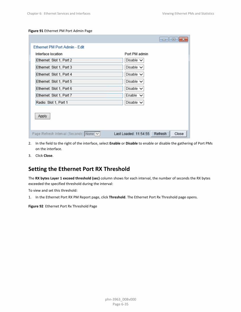
Chapter 6: Ethernet Services and Interfaces Viewing Ethernet PMs and Statistics
phn-3963_008v000 Page 6-35
Figure 91 Ethernet PM Port Admin Page
2. In the field to the right of the interface, select Enable or Disable to enable or disable the gathering of Port PMs
on the interface.
3. Click Close.
Setting the Ethernet Port RX Threshold The RX bytes Layer 1 exceed threshold (sec) column shows for each interval, the number of seconds the RX bytes exceeded the specified threshold during the interval:
To view and set this threshold:
1. In the Ethernet Port RX PM Report page, click Threshold. The Ethernet Port Rx Threshold page opens.
Figure 92 Ethernet Port Rx Threshold Page

Chapter 6: Ethernet Services and Interfaces Viewing Ethernet PMs and Statistics
phn-3963_008v000 Page 6-36
2. For each interface, you can enter a threshold, in bytes per second, between 0 and 4294967295.
3. Click Apply, then Close.

Chapter 7: Quality of Service (QoS) Viewing Ethernet PMs and Statistics
phn-3963_008v000 Page 7-1
Chapter 7: Quality of Service (QoS)
This section includes:
• QoS Overview
• Configuring Classification
• Configuring Policers (Rate Metering)
• Configuring Marking
• Configuring WRED
• Configuring Egress Shaping
• Configuring Scheduling
• Configuring and Displaying Queue-Level PMs

Chapter 7: Quality of Service (QoS) QoS Overview
phn-3963_008v000 Page 7-2
QoS Overview
Quality of Service (QoS) deals with the way frames are handled within the switching fabric. QoS is required in order to deal with many different network scenarios, such as traffic congestion, packet availability, and delay restrictions.
PTP 850’s personalized QoS enables operators to handle a wide and diverse range of scenarios. PTP 850’s smart QoS mechanism operates from the frame’s ingress into the switching fabric until the moment the frame egresses via the destination port.
QoS capability is very important due to the diverse topologies that exist in today’s network scenarios. These can include, for example, streams from two different ports that egress via single port, or a port-to-port connection that holds hundreds of services. In each topology, a customized approach to handling QoS will provide the best results.
Figure 117 shows the basic flow of PTP 850’s QoS mechanism. Traffic ingresses (left to right) via the Ethernet or radio interfaces, on the “ingress path.” Based on the services model, the system determines how to route the traffic. Traffic is then directed to the most appropriate output queue via the “egress path.”
Figure 93 QoS Block Diagram
(Optional)
Egress
PortScheduler/
Shaper
Standard QoS/ H-QoS
Queue Manager
Marker
(Optional)
Egress
PortScheduler/
Shaper
Standard QoS/ H-QoS
Queue Manager
Marker
(Optional)
Egress
PortScheduler/
Shaper
Standard QoS/ H-QoS
Queue Manager
Marker
CET/Pipe Services
Rate Limit(Policing)Classifier
(Optional)
Ingress
Port
Rate Limit(Policing)Classifier
(Optional)
Ingress
Port
Rate Limit(Policing)Classifier
(Optional)
Ingress
Port
GE/Radio
GE/Radio
GE/Radio
GE/Radio
GE/Radio
GE/Radio
The ingress path consists of the following QoS building blocks:
• Ingress Classifier – A hierarchical mechanism that deals with ingress traffic on three different levels: interface, service point, and service. The classifier determines the exact traffic stream and associates it with the appropriate service. It also calculates an ingress frame CoS and Color. CoS and Color classification can be performed on three levels, according to the user’s configuration.
• Ingress Rate Metering – A hierarchical mechanism that deals with ingress traffic on three different levels: interface, service point, and service point CoS. The rate metering mechanism enables the system to measure the incoming frame rate on different levels using a TrTCM standard MEF rate meter, and to determine whether to modify the color calculated during the classification stage.
Note
Ingress rate meters can be configure per service point or per service point CoS, but not on both.

Chapter 7: Quality of Service (QoS) QoS Overview
phn-3963_008v000 Page 7-3
The egress path consists of the following QoS building blocks:
• Queue Manager – This is the mechanism responsible for managing the transmission queues, utilizing smart WRED per queue and per packet color (Green or Yellow).
• Scheduling and Shaping – A hierarchical mechanism that is responsible for scheduling the transmission of frames from the transmission queues, based on priority among queues, Weighted Fair Queuing (WFQ) in bytes per each transmission queue, and eligibility to transmit based on required shaping on several different levels (per queue, per service bundle, and per port).
• Marker – This mechanism provides the ability to modify priority bits in frames based on the calculated CoS and Color.
For a more detailed description of QoS in the PTP 850, refer to the Technical Description for the PTP 850 product type you are using.

Chapter 7: Quality of Service (QoS) Configuring Classification
phn-3963_008v000 Page 7-4
Configuring Classification
The hierarchical classifier consists of the following levels:
• Logical interface-level classification
• Service point-level classification
• Service level classification
This section explains how to configure classification at the logical interface level.
• For instructions how to configure classification at the service point level, see 2. Ethernet Service Points – Ingress Attributes.
• For instructions how to configure classification at the service level, see Adding an Ethernet Service.
This section includes:
• Classification Overview
• Configuring Ingress Path Classification on a Logical Interface
• Modifying the C-VLAN 802.1Q UP and CFI Bit Classification Table
• Modifying the S-VLAN 802.1 UP and DEI Bit Classification Table
• Modifying the DSCP Classification Table
• Modifying the MPLS EXP Bit Classification Table
In addition to the procedures described in this section, you can specify a specific CoS and Color for a specific VLAN ID. This is the highest classification priority on the logical interface level, and overrides any other classification criteria at the logical interface level. Classification by VLAN ID can only be configured via CLI. See Configuring VLAN Classification and Override (CLI).
Classification Overview PTP 850 supports a hierarchical classification mechanism. The classification mechanism examines incoming frames and determines their CoS and Color. The benefit of hierarchical classification is that it provides the ability to “zoom in” or “zoom out”, enabling classification at higher or lower levels of the hierarchy. The nature of each traffic stream defines which level of the hierarchical classifier to apply, or whether to use several levels of the classification hierarchy in parallel.
Classification takes place on the logical interface level according to the following priorities:
• VLAN ID (CLI-only – see Configuring VLAN Classification and Override (CLI))
• 802.1p bits
• DSCP bits (only considered if MPLS is not present, regardless of trust setting)
• MPLS EXP field
• Default interface CoS
PTP 850 performs the classification on each frame ingressing the system via the logical interface. Classification is performed step by step from the highest priority to the lowest priority classification method. Once a match is found, the classifier determines the CoS and Color decision for the frame for the logical interface-level.

Chapter 7: Quality of Service (QoS) Configuring Classification
phn-3963_008v000 Page 7-5
For example, if the frame is an untagged IP Ethernet frame, a match will not be found until the third priority level (DSCP). The CoS and Color values defined for the frame’s DSCP value will be applied to the frame.
You can disable some of these classification methods by configuring them as un-trusted. For example, if 802.1p classification is configured as un-trusted for a specific interface, the classification mechanism does not perform classification by UP bits. This is useful, for example, if classification is based on DSCP priority bits.
If no match is found at the logical interface level, the default CoS is applied to incoming frames at this level. In this case, the Color of the frame is assumed to be Green.
Configuring Ingress Path Classification on a Logical Interface This section explains how to configure the classification criteria per each logical interface. The following sections explain how to modify the classification tables per bit type.
To configure the classification criteria for a logical interface:
1. Select Ethernet > Interfaces > Logical Interfaces. The Logical Interfaces page opens.
Figure 94 Logical Interfaces Page
2. Select the interface you want to configure and click Edit. The Logical Interfaces - Edit page opens.

Chapter 7: Quality of Service (QoS) Configuring Classification
phn-3963_008v000 Page 7-6
Figure 95 Logical Interfaces - Edit Page
3. Configure the parameters described in Table 52.
4. Click Apply, then Close.
Note
The Ingress byte compensation and Egress byte compensation fields are described in Configuring the Ingress and Egress Byte Compensation.
Table 38 Logical Interface Classification Parameters
Parameter Definition
Trust VLAN UP bits Select the interface's trust mode for user priority (UP) bits:
Trust – The interface performs QoS and color classification according to UP and CFI/DEI bits according to user-configurable tables for 802.1q UP bits (C-VLAN frames) or 802.1AD UP bits (S-VLAN frames). VLAN UP bit classification has priority over DSCP and MPLS classification, so that if a match is found with the UP bit of the ingressing frame, DSCP values and MPLS bits are not considered.
Un-Trust – The interface does not consider 802.1 UP bits during classification.

Chapter 7: Quality of Service (QoS) Configuring Classification
phn-3963_008v000 Page 7-7
Parameter Definition
Trust DSCP Select the interface's trust mode for DSCP:
Trust – The interface performs QoS and color classification according to a user-configurable table for DSCP to CoS and color classification. DSCP classification has priority over MPLS classification, so that if a match is found with the DSCP value of the ingressing frame, MPLS bits are not considered.
Un-Trust – The interface does not consider DSCP during classification.
Trust MPLS Select the interface's trust mode for MPLS bits:
Trust – The interface performs QoS and color classification according to a user-configurable table for MPLS EXP to CoS and color classification.
Un-Trust – The interface does not consider MPLS bits during classification.
Default port CoS Select the default CoS value for frames passing through the interface (0 to 7). This value can be overwritten on the service point and service level.
Ingress Byte Compensation
See Configuring the Ingress and Egress Byte Compensation.
Egress Byte Compensation See Configuring the Ingress and Egress Byte Compensation.
Interface Mode Reserved for future use.
Modifying the C-VLAN 802.1Q UP and CFI Bit Classification Table To modify the classification criteria for 802.1Q User Priority (UP) bits:
1. Select Ethernet > QoS > Classification > 802.1Q. The 802.1Q Classification page opens.

Chapter 7: Quality of Service (QoS) Configuring Classification
phn-3963_008v000 Page 7-8
Figure 96 802.1Q Classification Page
2. Select the row you want to modify and click Edit. The 802.1Q Classification – Edit page opens.
Figure 97 802.1Q Classification - Edit Page
3. Modify the parameters you want to change:
o 802.1Q UP – Read-only. The User Priority (UP) bit to be mapped. o 802.1Q CFI – Read-only. The CFI bit to be mapped. o 802.1Q CoS – The CoS assigned to frames with the designated UP and CFI. o 802.1Q Color – The Color assigned to frames with the designated UP and CFI.

Chapter 7: Quality of Service (QoS) Configuring Classification
phn-3963_008v000 Page 7-9
4. Click Apply, then Close.
Modifying the S-VLAN 802.1 UP and DEI Bit Classification Table
To modify the classification criteria for 802.1AD User Priority (UP) bits:
1. Select Ethernet > QoS > Classification > 802.1AD. The 802.1AD Classification page opens.
Figure 98 802.1AD Classification Page
2. Select the row you want to modify and click Edit. The 802.1AD Classification - Edit page opens.
Figure 99 802.1Q Classification - Edit Page

Chapter 7: Quality of Service (QoS) Configuring Classification
phn-3963_008v000 Page 7-10
3. Modify the parameters you want to change: o 802.1AD UP – Read-only. The User Priority (UP) bit to be mapped. o 802.1ADQ DEI – Read-only. The DEI bit to be mapped. o 802.1AD CoS – The CoS assigned to frames with the designated UP and DEI. o 802.1AD Color – The Color assigned to frames with the designated UP and DEI.
4. Click Apply, then Close.
Modifying the DSCP Classification Table You can configure the classification criteria for Differentiated Service Code Point (DSCP) priority values. The DSCP is a 6-bit length field inside the IP datagram header carrying priority information. Classification by DSCP can be used for untagged frames, as well as 802.1Q tagged or provider VLAN tagged frames.
To modify the classification criteria for DSCPs:
1. Select Ethernet > QoS > Classification > DSCP. The DSCP Classification page opens.
Figure 100 DSCP Classification Page
2. Select the row you want to modify and click Edit. The DSCP Classification - Edit page opens.
Figure 101 DSCP Classification - Edit Page

Chapter 7: Quality of Service (QoS) Configuring Classification
phn-3963_008v000 Page 7-11
3. Modify the parameters you want to change:
o DSCP – Read-only. The DSCP value to be mapped. o Binary – Read-only. The binary representation of the DSCP value. o Description – Read-only. The description of the DSCP value. o CoS – The CoS assigned to frames with the designated DSCP value. o Color – The Color assigned to frames with the designated DSCP value.
4. Click Apply, then Close.
Modifying the MPLS EXP Bit Classification Table MPLS bits are used to provide QoS capabilities by utilizing the bits set in the MPLS labels. Classification by MPLS bits is supported in both untagged and 802.1Q provider-tagged frames.
To modify the classification criteria for MPLS EXP bits:
1. Select Ethernet > QoS > Classification > MPLS. The MPLS Classification page opens.
Figure 102 MPLS Classification Page

Chapter 7: Quality of Service (QoS) Configuring Classification
phn-3963_008v000 Page 7-12
2. Select the row you want to modify and click Edit. The MPLS Classification - Edit page opens.
Figure 103 MPLS Classification - Edit Page
3. Modify the parameters you want to change:
o MPLS EXP – Read-only. The MPLS (experimental) bit to be mapped. o CoS – The CoS assigned to frames with the designated MPLS EXP value. o Color – The Color assigned to frames with the designated MPLS EXP value.
4. Click Apply, then Close.

Chapter 7: Quality of Service (QoS) Configuring Policers (Rate Metering)
phn-3963_008v000 Page 7-13
Configuring Policers (Rate Metering)
This section includes:
• Policer (Rate Metering) Overview
• Configuring Policer Profiles
• Assigning Policers to Interfaces
• Configuring the Ingress and Egress Byte Compensation
Policer (Rate Metering) Overview The PTP 850 switching fabric supports hierarchical policing on the logical interface level. You can define up to 250 rate meter (policer) profiles.
Note
Policing on the service point level, and the service point and CoS level, is planned for future release.
PTP 850's policer mechanism is based on a dual leaky bucket mechanism (TrTCM). The policers can change a frame’s color and CoS settings based on CIR/EIR + CBS/EBS, which makes the policer mechanism a key tool for implementing bandwidth profiles and enabling operators to meet strict SLA requirements.
The output of the policers is a suggested color for the inspected frame. Based on this color, the queue management mechanism decides whether to drop the frame or to pass it to the queue.
Configuring Policer Profiles This section includes:
• Adding a Policer Profile
• Editing a Policer Profile
• Deleting a Policer Profile
Adding a Policer Profile To add a policer profile:
1. Select Ethernet > QoS > Policer > Policer Profile. The Policer Profile page opens.

Chapter 7: Quality of Service (QoS) Configuring Policers (Rate Metering)
phn-3963_008v000 Page 7-14
Figure 104 Policer Profile Page
2. Click Add. The Policer Profile - Add page opens.
Figure 105 Policer Profile - Add Page
3. Configure the profile’s parameters. See Table 53 Policer Profile Parameters for a description of the policer
profile parameters.
4. Click Apply, then Close.

Chapter 7: Quality of Service (QoS) Configuring Policers (Rate Metering)
phn-3963_008v000 Page 7-15
Table 39 Policer Profile Parameters
Parameter Definition
Profile ID A unique ID for the policer profile. You can choose from any unused value from 1 to 250. Once you have added the profile, you cannot change the Profile ID.
Description A description of the policer profile.
Policer type Read-only. The type of policer. Always set to MEF-TRTCM.
CIR Enter the Committed Information Rate (CIR) for the policer, in bits per second. Permitted values are 0, or 64,000 through 1,000,000,000 bps. If the value is 0, all incoming CIR traffic is dropped.
CBS Enter the Committed Burst Rate (CBR) for the policer, in Kbytes. Permitted values are 2 through 128 Kbytes.
EIR Enter the Excess Information Rate (EIR) for the policer, in bits per second. Permitted values are 0, or 64,000 through 1,000,000,000 bps. If the value is 0, all incoming EIR traffic is dropped.
EBS Enter the Excess Burst Rate (EBR) for the policer, in Kbytes. Permitted values are 2 through 128 Kbytes.
Color mode Select how the policer treats packets that ingress with a CFI or DEI field set to 1 (yellow). Options are:
Color Aware – All packets that ingress with a CFI/DEI field set to 1 (yellow) are treated as EIR packets, even if credits remain in the CIR bucket.
Color Blind – All ingress packets are treated as green regardless of their CFI/DEI value. A color-blind policer discards any former color decisions.
Coupling flag Select Enable or Disable. When enabled, frames that ingress as yellow may be converted to green when there are no available yellow credits in the EIR bucket. Coupling Flag is only relevant in Color Aware mode.
Editing a Policer Profile To edit a policer profile, select the profile in the Police Profile table and click Edit. The Policer Profile Table Edit page opens.
The Policer Profile Table - Edit page is identical to the Policer Profile Table - Add page (Figure 132). You can edit any parameter that can be configured in the Policer Profile Table Add page, except the Profile ID.
Deleting a Policer Profile You cannot delete a policer profile that is attached to a logical interface. You must first remove the profile from the logical interface, then delete the profile. See Assigning Policers to Interfaces.
To delete a policer profile, select the profile in the Police Profile table and click Delete. The profile is deleted.

Chapter 7: Quality of Service (QoS) Configuring Policers (Rate Metering)
phn-3963_008v000 Page 7-16
To delete multiple policer profiles:
1. Select the profiles in the Policer Profile table or select all the profiles by selecting the check box in the top row.
2. Click Delete. The profiles are deleted.
Assigning Policers to Interfaces To assign policers to a logical interface:
1. Select Ethernet > Interfaces > Logical Interfaces. The Logical Interfaces page opens (Figure 118).
2. Select the interface in the Ethernet Logical Port Configuration table and click Policers. The Policers page opens.
Figure 106 Logical Interfaces – Policers Page – Unicast Policer (Default)
For a logical interface, you can assign policers to the following traffic flows:
• Unicast Policer
• Unknown Unicast Policer
• Multicast Policer
• Unknown Multicast Policer
• Broadcast Policer
• Ethertype Policers
Assigning Unicast Policers To assign a policer for unicast traffic to a logical interface:
1. Select Ethernet > Interfaces > Logical Interfaces. The Logical Interfaces page opens (Figure 118).

Chapter 7: Quality of Service (QoS) Configuring Policers (Rate Metering)
phn-3963_008v000 Page 7-17
2. Select the interface in the Ethernet Logical Port Configuration Table and click Policers. The Policers page opens. By default, the Policers page opens to the Unicast Policer table (Figure 133).
3. In the Policer profile field, select a profile from the policer profiles defined in the system. The Policer profile drop-down list includes the ID and description of all defined profiles.
4. In the Unicast admin field, select Enable to enable policing on unicast traffic flows from the logical interface, or Disable to disable policing on unicast traffic flows from the logical interface.
5. Click Apply.
Assigning Multicast Policers To assign a policer for multicast traffic to a logical interface:
1. Select Ethernet > Interfaces > Logical Interfaces. The Logical Interfaces page opens (Figure 118).
2. Select the interface in the Ethernet Logical Port Configuration table and click Policers. The Policers page opens. By default, the Policers page opens to the Unicast Policer table (Figure 133).
3. Select Multicast Policer. The Multicast Policer table appears.
Figure 107 Logical Interfaces – Policers Page – Multicast Policer
4. In the Policer profile field, select a profile from the policer profiles defined in the system. The Policer profile
drop-down list includes the ID and description of all defined profiles.
5. In the Multicast admin field, select Enable to enable policing on multicast traffic flows from the logical interface, or Disable to disable policing on multicast traffic flows from the logical interface.
6. Click Apply.

Chapter 7: Quality of Service (QoS) Configuring Policers (Rate Metering)
phn-3963_008v000 Page 7-18
Assigning Multicast Policers To assign a policer for multicast traffic to a logical interface:
1 Select Ethernet > Interfaces > Logical Interfaces. The Logical Interfaces page opens (Figure 118). 2 Select the interface in the Ethernet Logical Port Configuration table and click Policers. The Policers page opens.
By default, the Policers page opens to the Unicast Policer table (Figure 133). 3 Select Multicast Policer. The Multicast Policer table appears.
Figure 108: Logical Interfaces – Policers Page – Multicast Policer 4 In the Policer profile field, select a profile from the policer profiles defined in the system. The Policer profile
drop-down list includes the ID and description of all defined profiles. 5 In the Multicast admin field, select Enable to enable policing on multicast traffic flows from the logical
interface, or Disable to disable policing on multicast traffic flows from the logical interface. 6 Click Apply.

Chapter 7: Quality of Service (QoS) Configuring Policers (Rate Metering)
phn-3963_008v000 Page 7-19
Assigning Unknown Multicast Policers Unknown multicast packets are multicast packets with unknown destination MAC addresses. To assign a policer for unknown multicast traffic to a logical interface:
1 Select Ethernet > Interfaces > Logical Interfaces. The Logical Interfaces page opens (Figure 118). 2 Select the interface in the Ethernet Logical Port Configuration table and click Policers. The Policers page opens.
By default, the Policers page opens to the Unicast Policer table (Figure 133). 3 Select Unknown Multicast Policer. The Unknown Multicast Policer table appears.
Figure 109: Logical Interfaces – Policers Page – Unknown Multicast Policer 4 In the Policer profile field, select a profile from the policer profiles defined in the system. The Policer profile
drop-down list includes the ID and description of all defined profiles. 5 In the Unknown multicast admin field, select Enable to enable policing on unknown multicast traffic flows
from the logical interface, or Disable to disable policing on unknown multicast traffic flows from the logical interface.
6 Click Apply.
Assigning Broadcast Policers To assign a policer for broadcast traffic to a logical interface:
1. Select Ethernet > Interfaces > Logical Interfaces. The Logical Interfaces page opens (Figure 118).
2. Select the interface in the Ethernet Logical Port Configuration table and click Policers. The Policers page opens. By default, the Policers page opens to the Unicast Policer table (Figure 133).
3. Select Broadcast Policer. The Broadcast Policer table appears.
Figure 110 Logical Interfaces – Policers Page – Broadcast Policer

Chapter 7: Quality of Service (QoS) Configuring Policers (Rate Metering)
phn-3963_008v000 Page 7-20
4. In the Policer profile field, select a profile from the policer profiles defined in the system. The Policer profile
drop-down list includes the ID and description of all defined profiles.
5. In the Broadcast admin field, select Enable to enable policing on broadcast traffic flows from the logical interface, or Disable to disable policing on broadcast traffic flows from the logical interface.
6. Click Apply.
Assigning Ethertype Policers You can define up to three policers per Ethertype value.
To assign a policer to an Ethertype:
1. Select Ethernet > Interfaces > Logical Interfaces. The Logical Interfaces page opens (Figure 118).
2. Select the interface in the Ethernet Logical Port Configuration Table and click Policers. The Policers page opens. By default, the Policers page opens to the Unicast Policer table (Figure 133).
3. Select Ethertype type 1 Policer. The Ethertype type 1 Policer table appears.
Figure 111 Logical Interfaces – Policers Page – Ethertype Policer

Chapter 7: Quality of Service (QoS) Configuring Policers (Rate Metering)
phn-3963_008v000 Page 7-21
4. In the Ethertype 1 profile field, select a profile from the policer profiles defined in the system. The Ethertype 1
profile drop-down list includes the ID and description of all defined profiles.
5. In the Ethertype 1 user value field, enter the Ethertype value to which you want to apply this policer. The field length is 4 nibbles (for example, 0x0806 - ARP).
6. In the Ethertype 1 admin field, select Enable to enable policing on the logical interface for the specified ethertype, or Disable to disable policing on the logical interface for the specified ethertype.
7. Click Apply.
8. To assign policers to additional Ethertypes, select Ethertype type 2 Policer and Ethertype type 3 Policer and repeat the steps above.
Configuring the Ingress and Egress Byte Compensation You can define the ingress and egress byte compensation value per logical interface. The policer attached to the interface uses these values to compensate for Layer 1 non-effective traffic bytes.
To define the ingress byte compensation value for a logical interface:
1. Select Ethernet > Interfaces > Logical Interfaces. The Logical Interfaces page opens (Figure 182).
2. Select the interface you want to configure and click Edit. The Logical Interfaces - Edit page opens (Figure 183).
3. In the Ingress byte compensation field, enter the ingress byte compensation value, in bytes. Permitted values are 0 to 32 bytes. The default value is 20 bytes.
4. In the Egress byte compensation field, enter the egress byte compensation value, in bytes. Permitted values are 0 to 32 bytes. The default value is 0 bytes. Only even values are permitted.
5. Click Apply, then Close.

Chapter 7: Quality of Service (QoS) Configuring Marking
phn-3963_008v000 Page 7-22
Configuring Marking This section includes:
• Marking Overview
• Enabling Marking
• Modifying the 802.1Q Marking Table
• Modifying the 802.1AD Marking Table
Marking Overview When enabled, PTP 850's marking mechanism modifies each frame’s 802.1p UP bit and CFI/DEI bits according to the classifier decision. The CFI/DEI (color) field is modified according to the classifier and policer decision. The color is first determined by a classifier and may be later overwritten by a policer. Green color is represented by a CFI/DEI value of 0, and Yellow color is represented by a CFI/DEI value of 1. Marking is performed on egress frames that are VLAN-tagged.
The marking is performed according to global mapping tables that describe the 802.1p UP bits and the CFI bits (for C-VLAN tags) or DEI bits (for S VLAN tags). The marking bit in the service point egress attributes determines whether the frame is marked as green or according to the calculated color.
Note
The calculated color is sent to the queue manager regardless of whether the marking bit is set.
Regular marking is only performed when:
• The outer frame is S-VLAN, and S-VLAN CoS preservation is disabled, or
• The outer frame is C-VLAN, and C-VLAN CoS preservation is disabled.
If marking and CoS preservation for the relevant outer VLAN are both disabled, special marking is applied. Special marking means that marking is performed, but only according to the values defined for Green frames in the 802.1Q and 802.1AD marking tables.
When marking is performed, the C-VLAN or S-VLAN 802.1p UP bits are re-marked according to the calculated CoS and color, and the mapping table for C-VLAN or S-VLAN.
Enabling Marking Marking is enabled and disabled on the service point level. See 3. Ethernet Service Points – Egress Attributes.
Modifying the 802.1Q Marking Table The 802.1Q Marking table enables you to modify the CoS to UP and CFI bit mapping that is implemented when marking is enabled.
To modify the 802.1Q Marking table:

Chapter 7: Quality of Service (QoS) Configuring Marking
phn-3963_008v000 Page 7-23
1. Select Ethernet > QoS > Marking > 802.1Q. The 802.1Q Marking page opens. Each row in the 802.1Q Marking page represents a CoS and color combination.
Figure 112 802.1Q Marking Page
2. Select the row you want to modify and click Edit. The 802.1Q Marking - Edit page opens.
Figure 113 802.1Q Marking - Edit Page
3. Enter the new 802.1Q UP and 802.1Q CFI values.
4. Click Apply, then Close.

Chapter 7: Quality of Service (QoS) Configuring Marking
phn-3963_008v000 Page 7-24
Modifying the 802.1AD Marking Table The 802.1AD Marking table enables you to modify the CoS to UP and DEI bit mapping that is implemented when marking is enabled.
To modify the 802.1AD Marking table:
1. Select Ethernet > QoS > Marking > 802.1AD. The 802.1AD Marking page opens. Each row in the 802.1AD Marking page represents a CoS and color combination.
Figure 114 802.1AD Marking Page
2. Select the row you want to modify and click Edit. The 802.1AD Marking - Edit page opens.
Figure 115 802.1AD Marking - Edit Page
3. Enter the new 802.1AD UP and 802.1AD DEI values.
4. Click Apply, then Close.

Chapter 7: Quality of Service (QoS) Configuring WRED
phn-3963_008v000 Page 7-25
Configuring WRED
This section includes:
• WRED Overview
• Configuring WRED Profiles
• Assigning WRED Profiles to Queues
WRED Overview Weighted Random Early Detection (WRED) enables differentiation between higher and lower priority traffic based on CoS. You can define up to 30 WRED profiles. Each profile contains a green traffic curve and a yellow traffic curve. This curve describes the probability of randomly dropping frames as a function of queue occupancy.
The system also includes two pre-defined read-only profiles. These profiles are assigned profile IDs 31 and 32.
• Profile number 31 defines a tail-drop curve and is configured with the following values: o 100% Yellow traffic drop after 64kbytes occupancy. o 100% Green traffic drop after 128kbytes occupancy. o Yellow maximum drop is 100% o Green maximum drop is 100%
• Profile number 32 defines a profile in which all will be dropped. It is for internal use and should not be applied to traffic.
A WRED profile can be assigned to each queue. The WRED profile assigned to the queue determines whether or not to drop incoming packets according to the occupancy of the queue. As the queue occupancy grows, the probability of dropping each incoming frame increases as well. As a consequence, statistically more TCP flows will be restrained before traffic congestion occurs.
Configuring WRED Profiles This section includes:
• Adding a WRED Profile
• Editing a WRED Profile
• Deleting a WRED Profile
Adding a WRED Profile To add a WRED profile:
1. Select Ethernet > QoS > WRED > WRED Profile. The WRED Profile page opens.

Chapter 7: Quality of Service (QoS) Configuring WRED
phn-3963_008v000 Page 7-26
Figure 116 WRED Profile Page
2. Click ADD. The WRED Profile - Add page opens, with default values displayed.
Figure 117 WRED Profile - Add Page
3. In the WRED Profile ID field, select a unique ID to identify the profile. Permitted values are 1-30.
4. In the Green curve min point field, enter the minimum throughput of green packets for queues with this profile, in Kbytes (0-8192). When this value is reached, the system begins dropping green packets in the queue.
5. In the Green curve max point field, enter the maximum throughput of green packets for queues with this profile, in Kbytes (0-8192). When this value is reached, all green packets in the queue are dropped.
6. In the Green curve max drop ratio field, enter the maximum percentage (1-100) of dropped green packets for queues with this profile.
7. In the Yellow curve min point field, enter the minimum throughput of yellow packets for queues with this profile, in Kbytes (0-8192). When this value is reached, the system begins dropping yellow packets in the queue.

Chapter 7: Quality of Service (QoS) Configuring WRED
phn-3963_008v000 Page 7-27
8. In the Yellow curve max point field, enter the maximum throughput of yellow packets for queues with this profile, in Kbytes (0-8192). After this value is reached, all yellow packets in the queue are dropped.
9. In the Yellow curve max drop ratio field, enter the maximum percentage (1-100) of dropped yellow packets for queues with this profile.
10. Click Apply, then Close.
Editing a WRED Profile To edit a WRED profile:
1. Select Ethernet > QoS > WRED > WRED Profile. The WRED Profile page opens ().
2. Select the profile you want to edit and click Edit. The WRED Profile – Edit page opens. This page is similar to the WRED Profile – Add page (Figure 203). You can edit any parameter except the WRED Profile ID.
3. Modify the profile.
4. Click Apply, then Close.
Deleting a WRED Profile You cannot delete a WRED profile that is assigned to a queue. You must first remove the WRED profile from the queue, then delete the WRED profile. See Assigning WRED Profiles to Queues.
To delete a WRED profile, select the profile in the WRED Profile Configuration table (Figure 202) and click Delete. The profile is deleted.
To delete multiple WRED profiles:
1. Select the profiles in the WRED Profile Configuration table or select all the profiles by selecting the check box in the top row.
2. Click Delete. The profiles are deleted.

Chapter 7: Quality of Service (QoS) Configuring WRED
phn-3963_008v000 Page 7-28
Assigning WRED Profiles to Queues To assign a WRED profile to a queue:
1. Select Ethernet > Interfaces > Logical Interfaces. The Logical Interfaces page opens (Figure 182).
2. Select an interface in the Ethernet Logical Port Configuration table and click WRED. The WRED page opens.
Figure 118 Logical Interfaces – WRED Page
3. Select a CoS Queue ID and click Edit. The Logical Interfaces – WRED – Edit page opens.
Figure 119: Logical Interfaces – WRED - Edit Page 4. In the Profile ID field, select the WRED profile you want to assign to the selected queue. 5. Click Apply, then Close.

Chapter 7: Quality of Service (QoS) Configuring Egress Shaping
phn-3963_008v000 Page 7-29
Configuring Egress Shaping This section includes:
• Egress Shaping Overview
• Configuring Queue Shaper Profiles
• Assigning a Queue Shaper Profile to a Queue
Egress Shaping Overview Egress shaping determines the traffic profile for each queue. PTP 850E can perform queue shaping on the queue level, using dual leaky bucket shaping. On the queue level, you can configure up to 31 single leaky bucket shaper profiles. If no profile is attached to the queue, no egress shaping is performed on that queue.
Configuring Queue Shaper Profiles This section includes:
• Adding a Queue Shaper Profile
• Editing a Queue Shaper Profile
• Deleting a Queue Shaper Profile
Adding a Queue Shaper Profile To add a queue shaper profile:
1. Select Ethernet > QoS > Shaper > Queue Profiles. The Queue Shaper Profile page opens.

Chapter 7: Quality of Service (QoS) Configuring Egress Shaping
phn-3963_008v000 Page 7-30
Figure 120 Queue Shaper Profile Page
2. Click Add. The Queue Shaper – Add page opens, with default values displayed.
Figure 121 Queue Shaper Profile – Add Page
3. Configure the profile’s parameters. See Table Queue Shaper Profile Parameters for a description of the queue
shaper profile parameters.
4. Click Apply, then Close.
Note
EIR and EBS are only relevant for policers assigned to logical interfaces.

Chapter 7: Quality of Service (QoS) Configuring Egress Shaping
phn-3963_008v000 Page 7-31
Table 40 Queue Shaper Profile Parameters
Parameter Definition
Profile ID A unique ID for the queue shaper profile. You can choose any unused value from 1 to 32. Once you have added the profile, you cannot change the Profile ID.
Description A description of the queue shaper profile.
CIR Enter the Committed Information Rate (CIR) for the policer, in Kbits per second. Permitted values are 0-40000000 kbps (40 Gbps). If the value is 0, all incoming CIR traffic is dropped. Granularity is 81 kbps. The default value is 40000000 kbps.
CBS Enter the Committed Burst Rate (CBR) for the policer, in Kbytes. Permitted values are 1-63 KB. The default value is 16 KB.
EIR Enter the Excess Information Rate (EIR) for the policer, in Kbits per second. Permitted values are 0-40000000 kbps (40 Gbps). If the value is 0, all incoming EIR traffic is dropped. Granularity is 162 kbps. The default value is 40000000 kbps.
EBS Enter the Excess Burst Rate (EBR) for the policer, in Kbytes. Permitted values are 1-512 KB. The default value is 16 KB.
Editing a Queue Shaper Profile To edit a queue shaper profile:
1. Select Ethernet > QoS > Shaper > Queue Profiles. The Queue Shaper Profile page opens (Figure 206).
2. Select the profile you want to edit and click Edit. The Queue Shaper Profile – Edit page opens. This page is similar to the Queue Shaper Profile – Add page (Figure 207). You can edit any parameter except the Profile ID.
3. Modify the profile.
4. Click Apply, then Close.
Deleting a Queue Shaper Profile You cannot delete a queue shaper profile that is assigned to a queue. You must first remove the profile from the queue, then delete the profile. See Assigning a Queue Shaper Profile to a Queue.
To delete a queue shaper profile, select the profile in the Queue Shaper Profiles Configuration table (Figure 145) and click Delete. The profile is deleted.
To delete multiple queue shaper profiles:
1. Select the profiles in the Queue Shaper Profiles Configuration table or select all the profiles by selecting the check box in the top row.
2. Click Delete. The profiles are deleted.
Assigning a Queue Shaper Profile to a Queue To assign a queue shaper profile to a queue:
1. Select Ethernet > Interfaces > Logical Interfaces. The Logical Interfaces page opens (Figure 118).

Chapter 7: Quality of Service (QoS) Configuring Egress Shaping
phn-3963_008v000 Page 7-32
2. Select an interface in the Ethernet Logical Port Configuration table and click Shaper. The Logical Interfaces – Shaper page opens, with the Egress Queue Shaper Configuration table open by default. All queue shaper profiles defined in the system are listed in the table.
Figure 122 Logical Interfaces – Shaper – Egress Queue Shaper
3. Click Add. The Egress Queue Shaper Configuration – Add page opens.
Figure 123 Logical Interfaces – Egress Queue Shaper Configuration – Add Page
Note
In this release, only one service bundle (Service Bundle ID 1) is supported.
4. In the CoS queue ID field, select the CoS queue ID of the queue to which you want to assign the shaper. Queues are numbered according to CoS value, from 0 to 7.
5. In the Profile ID field, select from a list of configured queue shaper profiles. See Configuring Queue Shaper Profiles.
6. In the Shaper Admin field, select Enable to enable egress queue shaping for the selected queue, or Disable to disable egress queue shaping for the selected queue.

Chapter 7: Quality of Service (QoS) Configuring Egress Shaping
phn-3963_008v000 Page 7-33
7. Click Apply, then Close.
To assign a different queue shaper profile to a queue:
1. Select Ethernet > Interfaces > Logical Interfaces. The Logical Interfaces page opens (Figure 118).
2. Select an interface in the Ethernet Logical Port Configuration table and click Shaper. The Logical Interfaces – Shaper page opens, with the Egress Queue Shaper Configuration table open by default (Figure 149).
3. Select an interface in the Ethernet Logical Port Configuration table and click Shaper. The Logical Interfaces – Shaper page opens, with the Egress Queue Shaper Configuration table open by default (Figure 149).
4. Select the row you want to edit and click Edit. The Egress Queue Shaper Configuration – Edit page opens. This page is similar to the Egress Queue Shaper Configuration – Add page (Figure 150).
5. To assign a different egress queue shaper profile, select the profile in the Profile ID field.
6. To enable or disable egress queue shaping for the selected queue, select Enable to enable egress queue shaping for the queue, or Disable to disable egress queue shaping for the queue.
7. Click Apply, then Close.

Chapter 7: Quality of Service (QoS) Configuring Scheduling
phn-3963_008v000 Page 7-34
Configuring Scheduling
This section includes:
• Scheduling Overview
• Configuring Priority Profiles
• Configuring WFQ Profiles
• Assigning a Priority Profile to an Interface
• Assigning a WFQ Profile to an Interface
Scheduling Overview Scheduling determines the priority among the queues. PTP 850 provides a unique hierarchical scheduling model that includes four priorities, with Weighted Fair Queuing (WFQ) within each priority, and shaping per port and per queue.
The scheduler scans the queues and determines which queue is ready to transmit. If more than one queue is ready to transmit, the scheduler determines which queue transmits first based on:
• Queue Priority – A queue with higher priority is served before lower-priority queues.
• Weighted Fair Queuing (WFQ) – If two or more queues have the same priority and are ready to transmit, the scheduler transmits frames from the queues based on a WFQ algorithm that determines the ratio of frames per queue based on a predefined weight assigned to each queue.
Configuring Priority Profiles Scheduling priority profiles determine the queue priority. Each profile contains eight CoS-based priorities, corresponding to eight queues in an interface to which the profile is assigned. You can configure up to eight priority profiles. A ninth profile, Profile ID 9, is pre-configured. You can configure Green priorities from 4 (highest) to 1 (lowest). An additional four Yellow priority profiles are defined automatically.
This section includes:
• Adding a Scheduler Priority Profile
• Editing a Service Scheduler Priority Profile
• Deleting a Scheduler Priority Profile
Adding a Scheduler Priority Profile To add a scheduler priority profile:
1. Select Ethernet > QoS > Scheduler > Priority Profiles. The Scheduler Priority Profile page opens.

Chapter 7: Quality of Service (QoS) Configuring Scheduling
phn-3963_008v000 Page 7-35
Figure 124 Scheduler Priority Profile Page
2. Click Add. The Scheduler Priority Profile – Add page opens, with default values displayed.

Chapter 7: Quality of Service (QoS) Configuring Scheduling
phn-3963_008v000 Page 7-36
Figure 125 Scheduler Priority Profile – Add Page
3. In the Profile ID field, select a unique Profile ID between 1 and 8.
4. For each CoS value, enter the Green priority, from 4 (highest) to 1 (lowest) (1-4). This priority is applied to Green frames with that CoS egressing a queue to which the profile is assigned.
5. Optionally, you can enter a description of up to 20 characters in the field to the right of each CoS value.
6. Click Apply, then Close.
Note
The Yellow priority values are assigned automatically by the system.
Editing a Service Scheduler Priority Profile To edit a scheduler priority profile:
1. Select Ethernet > QoS > Scheduler > Priority Profiles. The Scheduler Priority Profile page opens (Figure 153).

Chapter 7: Quality of Service (QoS) Configuring Scheduling
phn-3963_008v000 Page 7-37
2. Select the profile you want to edit and click Edit. The Scheduler Priority Profile – Edit page opens. This page is similar to the Scheduler Priority Profile – Add page (Figure 154). You can edit any parameter except the Profile ID.
3. Modify the profile.
4. Click Apply, then Close.
Deleting a Scheduler Priority Profile To delete a scheduler priority profile, select the profile in the Scheduler Priority Profiles page (Figure 153) and click Delete. The profile is deleted.
To delete multiple scheduler priority profiles:
1. Select the profiles in the Scheduler Priority Profiles page or select all the profiles by selecting the check box in the top row.
2. Click Delete. The profiles are deleted.

Chapter 7: Quality of Service (QoS) Configuring Scheduling
phn-3963_008v000 Page 7-38
Configuring WFQ Profiles WFQ profiles determine the relative weight per queue. Each profile contains eight CoS-based weight values, corresponding to eight queues in an interface to which the profile is assigned. You can configure up to five WFQ profiles. A sixth profile, Profile ID 1, is pre-configured.
This section includes:
• Adding a WFQ Profile
• Editing a WFQ Priority Profile
• Deleting a WFQ Profile
Adding a WFQ Profile To add a WFQ profile:
1. Select Ethernet > QoS > Scheduler > WFQ Profiles. The Scheduler WFQ Profile page opens.
Figure 126 Scheduler WFQ Profile Page
2. Click Add. The Scheduler WFQ Profile – Add page opens, with default values displayed.

Chapter 7: Quality of Service (QoS) Configuring Scheduling
phn-3963_008v000 Page 7-39
Figure 127 Scheduler WFQ Profile – Add Page
3. In the Profile ID field, select a unique Profile ID between 2 and 7. Profile ID 1 is used for a pre-defined WFQ
profile.
4. For each CoS value, enter the weight for that CoS, from 1 to 20.
5. Click Apply, then Close.
Editing a WFQ Priority Profile To edit a scheduler WFQ profile:
1. Select Ethernet > QoS > Scheduler > WFQ Profiles. The Scheduler WFQ Profile page opens (Figure 155).
2. Select the profile you want to edit and click Edit. The Scheduler WFQ Profile – Edit page opens. This page is similar to the Scheduler WFQ Profile – Add page (Figure 145). You can edit any parameter except the Profile ID.
3. Modify the profile.
4. Click Apply, then Close.

Chapter 7: Quality of Service (QoS) Configuring Scheduling
phn-3963_008v000 Page 7-40
Deleting a WFQ Profile To delete a scheduler WFQ profile, select the profile in the Scheduler WFQ Profiles page (Figure 155) and click Delete. The profile is deleted.
To delete multiple scheduler WFQ profiles:
1. Select the profiles in the Scheduler WFQ Profiles page or select all the profiles by selecting the check box in the top row.
2. Click Delete. The profiles are deleted.
Assigning a Priority Profile to an Interface To assign a priority profile to an interface:
1. Select Ethernet > Interfaces > Logical Interfaces. The Logical Interfaces page opens (Figure 118).
2. Select an interface in the Ethernet Logical Port Configuration table and click Scheduler. The Logical Interfaces – Scheduler page opens, with the Egress Port Scheduling Priority Configuration – Edit page open by default.
Figure 128 Logical Interfaces – Scheduler – Egress Port Scheduling Priority
3. In the Profile ID field, select from a list of configured scheduling priority profiles. See Configuring Priority
Profiles.
4. Click Apply, then Close.
Assigning a WFQ Profile to an Interface To assign a WFQ profile to an interface:

Chapter 7: Quality of Service (QoS) Configuring Scheduling
phn-3963_008v000 Page 7-41
1. Select Ethernet > Interfaces > Logical Interfaces. The Logical Interfaces page opens (Figure 182).
2. Select an interface in the Ethernet Logical Port Configuration table and click Scheduler. The Logical Interfaces – Scheduler page opens, with the Egress Port Scheduling Priority Configuration – Edit page open by default (Figure 218).
3. Select Egress Port Scheduling WFQ. The Egress Port Scheduling WFQ Configuration – Edit page opens.
Figure 129 Logical Interfaces – Scheduler – Egress Port Scheduling WFQ
4. In the Profile ID field, select from a list of configured scheduling priority profiles. See Configuring WFQ Profiles.
5. Click Apply, then Close.

Chapter 7: Quality of Service (QoS) Configuring and Displaying Queue-Level PMs
phn-3963_008v000 Page 7-42
Configuring and Displaying Queue-Level PMs
PTP 850 devices support advanced traffic PMs per CoS queue and service bundle. For each logical interface, you can configure thresholds for Green and Yellow traffic per queue. You can then display the following PMs for 15-minute and 24-hour intervals, per queue and color:
• Maximum bytes passed per second
• Minimum bytes passed per second • Average bytes passed per second • Maximum bytes dropped per second • Minimum bytes dropped per second • Average bytes dropped per second • Maximum packets passed per second • Minimum packets passed per second
• Average packets passed per second • Maximum packets dropped per second • Minimum packets dropped per second • Average packets dropped per second • Seconds bytes per second were over the configured threshold per interval
These PMs are available for any type of logical interface, including groups. To activate collection of these PMs, the user must add a PM collection rule on a logical interface and service bundle and set the relevant thresholds per CoS and Color. When the PM is configured on a group, queue traffic PMs are recorded for the group and not for the individual interfaces that belong to the group.
One collection rule is available per interface.
PMs for queue traffic are saved for 30 days, after which they are removed from the database. It is important to note that they are not persistent, which means they are not saved in the event of unit reset.

Chapter 7: Quality of Service (QoS) Configuring and Displaying Queue-Level PMs
phn-3963_008v000 Page 7-43
To configure queue-level PMs:
1 Select Ethernet > PM & Statistics > Egress CoS PM > Configuration. The Egress CoS PM Configuration page opens.
Figure 130 Egress CoS PM Configuration Page 2 Click Add. The Egress CoS PM Configuration – Add page opens.

Chapter 7: Quality of Service (QoS) Configuring and Displaying Queue-Level PMs
phn-3963_008v000 Page 7-44
Figure 131 Egress CoS PM Configuration – Add Page 3 In the Interface Location field, select the interface for which you want to configure the collection rule. 4 In the Service Bundle field, select a service bundle (1-6). 5 In the Admin field, select Enable to enable the collection rule. 6 Enter the Green and Yellow thresholds for each CoS, in bytes (0-4294967295). 7 Click Apply. 8 Repeat these steps to configure collection rules for additional interfaces. To display queue-level PMs:
1 Select Ethernet > PM & Statistics > Egress CoS PM > Egress CoS PM. The Egress CoS PM page opens.

Chapter 7: Quality of Service (QoS) Configuring and Displaying Queue-Level PMs
phn-3963_008v000 Page 7-45
Figure 132 Egress CoS PM Page The Integrity column indicates whether the values received at the time and date of the measured interval are valid. An X in the column indicates that the values are invalid. This can occur for a number of reasons, including but not limited to a disconnected cable, a missing SFP module, muting of a radio interface, and an operational status of Down.

Chapter 8: Synchronization Configuring and Displaying Queue-Level PMs
phn-3963_008v000 Page 8-1
Chapter 8: Synchronization
This section includes:
• Configuring the Sync Source
• Configuring the Outgoing Clock and SSM Messages

Chapter 8: Synchronization Configuring the Sync Source
phn-3963_008v000 Page 8-2
Configuring the Sync Source
Note
To configure a sync source on which the sync source Quality parameter must be set according to ANSI specifications and you must change the ETSI/ANSI mode to ANSI before configuring the sync source. See Changing the ETSI/ANSI Mode (CLI).
Note that the Quality parameter is not supported in release 10.6. It is supported in release 10.9.
Frequency signals can be taken by the system from Ethernet and radio interfaces.
The reference frequency may also be conveyed to external equipment through different interfaces. For instructions how to configure the outgoing clock, see Configuring the Outgoing Clock and SSM Messages.
Frequency is distributed by configuring the following parameters in each node:
• System Synchronization Sources – These are the interfaces from which the frequency is taken and distributed to other interfaces. Up to 16 sources can be configured in each node. A revertive timer can be configured. For each interface, you must configure: o Priority (1-16) – No two synchronization sources can have the same priority. o Quality – The quality level applied to the selected synchronization source. This enables the system to
select the source with the highest quality as the current synchronization source.
• Each unit determines the current active clock reference source interface: o The interface with the highest available quality is selected. o From among interfaces with identical quality, the interface with the highest priority is selected.
When configuring the Sync source, the Sync mode must be set to its default setting of automatic. To display the current Sync mode, enter the following CLI command in root view:
root> platform sync mode show
If the Sync mode is set to pipe, you must set it to automatic by entering the following CLI command in root view:
root> platform sync mode set automatic
When configuring an Ethernet interface as a Sync source, the Media Type of the interface must be RJ45 or SFP, not Auto-Type.
Viewing the Sync Source Status To view the current sync source and its quality:
1 Select Sync > Sync Source. The Sync Source page opens.
Figure 133 Sync Source Page

Chapter 8: Synchronization Configuring the Sync Source
phn-3963_008v000 Page 8-3
Table 41 Sync Source Parameters
Parameter Definition
System Reference Quality The quality of the current synchronization source interface. A value of DNU indicates that no synchronization source interfaces are currently defined.
Current Active Sync Source The currently active system synchronization source interface.
Sync Clock Unit Status The status of the unit’s Sync E mechanism.
Sync Interface Displays the interface that is configured as a synchronization source.
Sync Interface Quality Displays the quality level assigned to this synchronization source. This enables the system to select the source with the highest quality as the current synchronization source.
If the Sync Interface Quality is set to Automatic, the quality is determined by the received SSMs. If no valid SSM messages are received or in case of interface failure (such as LOS, LOC, LOF), the quality becomes "Failure." SSM must be enabled on the remote interface in order for the interface to receive SSM messages. For instructions how to enable SSM, see Configuring the Outgoing Clock and SSM Messages.
Sync Interface Priority Displays the priority assigned to this synchronization source.
Sync Interface Quality Status
Displays the current actual synchronization quality of the interface.
Adding a Sync Source To add a synchronization source:
1 In the Sync Source page (Figure 182), click Add. The Sync Source – Add page opens.
Figure 134 Sync Source – Add Page

Chapter 8: Synchronization Configuring the Sync Source
phn-3963_008v000 Page 8-4
2 In the Sync Interface field, select the interface you want to define as a synchronization source. You can
select from the following interface types: o Ethernet interfaces o Radio interface
Note
In order to select an Ethernet interface, you must first specify the media type for this interface. See Configuring Ethernet Interfaces.
3 In the Sync Interface Quality field, select the quality level applied to the selected synchronization source. This enables the system to select the source with the highest quality as the current synchronization source. o If the Sync Interface Quality is set to Automatic, the quality is determined by the received SSMs. If no
valid SSM messages are received or in case of interface failure (such as LOS, LOC, LOF), the quality becomes Failure. SSM must be enabled on the remote interface in order for the interface to receive SSM messages. For instructions how to enable SSM, see Configuring the Outgoing Clock and SSM Messages.
o If the Sync Interface Quality is set to a fixed value, then the quality status becomes Failure upon interface failure (such as LOS, LOC, LOF).
4 In the Sync Interface Priority field, select the priority of this synchronization source relative to other synchronization sources configured in the unit (1-16). You cannot assign the same priority to more than one synchronization source. Once a priority value has been assigned, it no longer appears in the Sync Interface Priority dropdown list.
5 Click Apply, then Close.
Editing a Sync Source To edit a synchronization source:
1 In the Sync Source page (Figure 182), click Edit. The Sync Source – Edit page opens.

Chapter 8: Synchronization Configuring the Sync Source
phn-3963_008v000 Page 8-5
2 Edit the parameters, as defined above. You can edit all the parameters except Sync Interface, which is read-only.
3 Click Apply, then Close.
Deleting a Sync Source To delete a synchronization source:
1 Select the synchronization source in the Sync Source page (Figure 182).
2 Click Delete. The synchronization source is deleted.

Chapter 8: Synchronization Configuring the Outgoing Clock and SSM Messages
phn-3963_008v000 Page 8-6
Configuring the Outgoing Clock and SSM Messages
In the Outgoing Clock page, you can view and configure the following synchronization settings per interface:
• The interface's clock source (outgoing clock).
• For radio interfaces, the synchronization radio channel (used for interoperability).
• SSM message administration.
Note
SSM message administration is not supported in release 10.6. It is supported in release 10.9.
In order to provide topological resiliency for synchronization transfer, PTP 850E implements the passing of SSM messages over the radio interfaces. SSM timing in PTP 850E complies with ITU-T G.781.
In addition, the SSM mechanism provides reference source resiliency, since a network may have more than one source clock. The following are the principles of operation:
• At all times, each source interface has a “quality status” which is determined as follows: o If quality is configured as fixed, then the quality status becomes “failure” upon interface failure (such as
LOS, LOC, LOF). o If quality is automatic, then the quality is determined by the received SSMs. If no valid SSM messages are
received or in case of interface failure (such as LOS, LOC, LOF), the quality becomes "failure.
• Each unit holds a parameter which indicates the quality of its reference clock. This is the quality of the current synchronization source interface.
• The reference source quality is transmitted through SSM messages to all relevant radio interfaces.
• In order to prevent loops, an SSM with quality “Do Not Use” is sent from the active source interface (both radio and Ethernet)
In order for an interface to transmit SSM messages, SSM must be enabled on the interface. By default, SSM is disabled on all interfaces.
When configuring the outgoing clock and SSM administration, the Sync mode must be set to its default setting of automatic. To display the current Sync mode, enter the following CLI command in root view:
root> platform sync mode show
If the Sync mode is set to pipe, you must set it to automatic by entering the following CLI command in root view:
root> platform sync mode set automatic
To configure the outgoing clock on an Ethernet interface, the Media Type of the interface must be RJ45 or SFP, not Auto-Type. To view and configure the Media Type of an Ethernet interface, see Configuring Ethernet Interfaces.
To view and configure the synchronization parameters of the unit’s interfaces:
1 Select Sync > Outgoing Clock. The Outgoing Clock page opens.

Chapter 8: Synchronization Configuring the Outgoing Clock and SSM Messages
phn-3963_008v000 Page 8-7
Figure 135 Outgoing Clock Page
2 Select the interface you want to configure and click Edit. The Outgoing Clock – Edit page opens.
Figure 136 Outgoing Clock – Edit Page
3 In the Outgoing clock source field, select the interface's synchronization source. Options are: o Local Clock – The interface uses its internal clock as its synchronization source. o System Clock – Default value. The interface uses the system clock as its synchronization source. o Source Interface – Reserved for future use. o Time Loop – Reserved for future use.
4 In Sync Radio Channel field, use the default value of 0.
5 In the SSM Admin field, select On or Off to enable or disable SSM for the interface. By default, SSM is disabled on all interfaces.
Note
In release 10.6, only Off is supported for SSM Admin.

Chapter 9: Access Management and Security Configuring the Outgoing Clock and SSM Messages
phn-3963_008v000 Page 9-1
Chapter 9: Access Management and Security
This section includes:
• Configuring the General Access Control Parameters
• Configuring the Password Security Parameters
• Configuring the Session Timeout
• Configuring Users
• Configuring X.509 CSR Certificates
• Blocking Telnet Access
• Uploading the Security Log
• Uploading the Configuration Log
Related topics:
• Changing Your Password

Chapter 9: Access Management and Security Configuring the General Access Control Parameters
phn-3963_008v000 Page 9-2
Configuring the General Access Control Parameters
To avoid unauthorized login to the system, PTP 850 automatically blocks users upon a configurable number of failed login attempts. You can also configure PTP 850 to block users that have not logged into the unit for a defined number of days.
To configure the blocking criteria:
1. Select Platform > Security > Access Control > General. The Access Control General Configuration page opens.
Figure 137 Access Control General Configuration Page
2. In the Failure login attempts to block user field, select the number of failed login attempts that will trigger
blocking. If a user attempts to login to the system with incorrect credentials this number of times consecutively, the user will temporarily be prevented from logging into the system for the time period defined in the Blocking period field. Valid values are 1-10. The default value is 3.
3. In the Blocking period (Minutes) field, enter the length of time, in minutes, that a user is prevented from logging into the system after the defined number of failed login attempts. Valid values are 1-60. The default value is 5.
4. In the Unused account period for blocking (Days) field, you can configure a number of days after which a user is prevented from logging into the system if the user has not logged in for the configured number of days. Valid values are 0, or 30-90. If you enter 0, this feature is disabled. The default value is 0.
5. Click Apply.

Chapter 9: Access Management and Security Configuring the General Access Control Parameters
phn-3963_008v000 Page 9-3
Once a user is blocked, you can unblock the user from the User Accounts page. To unblock a user:
1. Select Platform > Security > Access Control > User Accounts. The Access Control User Accounts page opens (Figure 195).
2. Select the user and click Edit. The Access Control User Accounts - Edit page opens.
Figure 138 Access Control User Accounts - Edit Page
3. In the Blocked field, select No.
4. Click Apply, then Close.

Chapter 9: Access Management and Security Configuring the Password Security Parameters
phn-3963_008v000 Page 9-4
Configuring the Password Security Parameters
To configure enhanced security requirements for user passwords:
1. Select Platform > Security > Access Control > Password Management. The Access Control Password Management page opens.
Figure 139 Access Control Password Management Page
2. In the Enforce password strength field, select Yes or No. When Yes is selected:
o Password length must be at least eight characters. o Password must include characters of at least three of the following character types: lower case letters,
upper case letters, digits, and special characters. For purposes of meeting this requirement, upper case letters at the beginning of the password and digits at the end of the password are not counted.
o A password cannot be repeated within five changes in password.
3. In the Password change for first login field, select Yes or No. When Yes is selected, the system requires the user to change his or her password the first time the user logs in.
4. In the Password aging (Days) field, select the number of days that user passwords will remain valid from the first time the user logs into the system. You can enter 20-90, or No Aging. If you select No Aging, password aging is disabled and passwords remain valid indefinitely.
5. Click Apply.

Chapter 9: Access Management and Security Configuring the Session Timeout
phn-3963_008v000 Page 9-5
Configuring the Session Timeout
By default, there is a 10 minute session timeout. If you do not perform any activity on the system for the period of time defined as the session timeout, the user session times out and you will have to log in to the system again.
To modify the session timeout:
1. Select Platform > Security > Protocols Control. The Protocols Control page opens.
Figure 140 Protocols Control Page
2. In the Session timeout (Minutes) field, select a session timeout, in minutes, from 1 to 60.
Note
For information about the Telnet Admin field, see Blocking Telnet Access.
3. Click Apply.

Chapter 9: Access Management and Security Configuring Users
phn-3963_008v000 Page 9-6
Configuring Users
This section includes:
• User Configuration Overview
• Configuring User Profiles
• Configuring Users
Related topics:
• Changing Your Password
User Configuration Overview User configuration is based on the Role-Based Access Control (RBAC) model. According to the RBAC model, permissions to perform certain operations are assigned to specific roles. Users are assigned to particular roles, and through those role assignments acquire the permissions to perform particular system functions.
In the PTP 850 GUI, these roles are called user profiles. Up to 50 user profiles can be configured. Each profile contains a set of privilege levels per functionality group, and defines the management protocols (access channels) that can be used to access the system by users to whom the user profile is assigned.
The system parameters are divided into the following functional groups:
• Security
• Management
• Radio
• TDM
• Ethernet
• Synchronization
A user profile defines the permitted access level per functionality group. For each functionality group, the access level is defined separately for read and write operations. The following access levels can be assigned:
• None – No access to this functional group.
• Normal – The user has access to parameters that require basic knowledge about the functional group.
• Advanced – The user has access to parameters that require advanced knowledge about the functional group, as well as parameters that have a significant impact on the system as a whole, such as restoring the configuration to factory default settings.
Configuring User Profiles User profiles enable you to define system access levels. Each user must be assigned a user profile. Each user profile contains a detailed set of read and write permission levels per functionality group.
The system includes a number of pre-defined user profiles. You can edit these profiles, and add user profiles. Together, the system supports up to 50 user profiles.

Chapter 9: Access Management and Security Configuring Users
phn-3963_008v000 Page 9-7
To add a user profile:
1. Select Platform > Security > Access Control > User Profiles. The Access Control User Profiles page opens.
Figure 141 Access Control User Profiles Page
2. Click Add. The Access Control User Profiles - Add page opens.

Chapter 9: Access Management and Security Configuring Users
phn-3963_008v000 Page 9-8
Figure 142 Access Control User Profiles - Add Page
3. In the Profile field, enter a name for the profile. The profile name can include up to 49 characters. Once you
have created the user profile, you cannot change its name.
Note
The Usage counter field displays the number of users to whom the user profile is assigned.
4. In the Permitted access channels row, select the access channels the user will be permitted to use to access the system.
5. For each functionality group, select one of these options for write level and read level. All users with this profile will be assigned these access levels: o None o Normal o Advanced
6. Click Apply, then Close.
To view a user profile, click + next to the profile you want to view.
To edit a user profile, select the profile and click Edit. You can edit all of the profile parameters except the profile name.
To delete a user profile, select the profile and click Delete.
Note
You cannot delete a user profile if the profile is assigned to any users.

Chapter 9: Access Management and Security Configuring Users
phn-3963_008v000 Page 9-9
Configuring Users You can configure up to 2,000 users. Each user has a user name, password, and user profile. The user profile defines a set of read and write permission levels per functionality group. See Configuring User Profiles.
To add a new user:
1. Select Platform > Security > Access Control > User Accounts. The Access Control User Accounts page opens.
Figure 143 Access Control User Accounts Page
2. Click Add. The Access Control User Profiles - Add page opens.

Chapter 9: Access Management and Security Configuring Users
phn-3963_008v000 Page 9-10
Figure 144 Access Control User Accounts - Add Page
3. In the User name field, enter a user name for the user. The user name can be up to 32 characters.
4. In the Profile field, select a User Profile. The User Profile defines the user’s access levels for functionality groups in the system. See Configuring User Profiles.
5. In the Password field, enter a password for the user. If Enforce Password Strength is activated (see Configuring the Password Security Parameters), the password must meet the following criteria: o Password length must be at least eight characters. o Password must include characters of at least three of the following character types: lower case letters,
upper case letters, digits, and special characters. For purposes of meeting this requirement, upper case letters at the beginning of the password and digits at the end of the password are not counted.
o The last five passwords you used cannot be reused.
6. In the Blocked field, you can block or unblock the user. Selecting Yes blocks the user. You can use this option to block a user temporarily, without deleting the user from the system. If you set this option to Yes while the user is logged into the system, the user will be automatically logged out of the system within 30 seconds.
Note
Users can also be blocked by the system automatically. You can unblock the user by selecting No in the Blocked field. See Configuring the General Access Control Parameters.
7. Optionally, in the Expiration date field, you can configure the user to remain active only until a defined date. After that date, the user automatically becomes inactive. To set an expiration date, click the calendar icon and select a date, or enter a date in the format dd-mm-yyyy.
In addition to the configurable parameters described above, the Access Control User Accounts page displays the following information for each user:
o Login Status – Indicates whether the user is currently logged into the system. o Last Logout – The date and time the user most recently logged out of the system.

Chapter 9: Access Management and Security Configuring Users
phn-3963_008v000 Page 9-11
To edit a user’s account details, select the user and click Edit. You can edit all of the user account parameters except the User name and password.
To add a user, click Add.
To delete a user, select the user and click Delete.

Chapter 9: Access Management and Security Configuring X.509 CSR Certificates and HTTPS
phn-3963_008v000 Page 9-12
Configuring X.509 CSR Certificates and HTTPS
The web interface protocol for accessing PTP 850 can be configured to HTTP (default) or HTTPS. It cannot be set to both at the same time.
Before setting the protocol to HTTPS, you must:
1. Create and upload a CSR file. See Generating a Certificate Signing Request (CSR) File.
2. Download the certificate to the PTP 850 and install the certificate. See Downloading a Certificate.
3. Enable HTTPS. This must be performed via CLI. See Enabling HTTPS (CLI).
When uploading a CSR and downloading a certificate, the PTP 850 functions as an SFTP client. You must install SFTP server software on the PC or laptop you are using to perform the upload or download. For details, see Installing and Configuring an FTP or SFTP Server.
Note
For these operations, SFTP must be used.
Generating a Certificate Signing Request (CSR) File To generate a Certificate Signing Request (CSR) file:
1. Select Platform > Security > X.509 Certificate > CSR. The Security Certificate Request page opens.

Chapter 9: Access Management and Security Configuring X.509 CSR Certificates and HTTPS
phn-3963_008v000 Page 9-13
Figure 145 Security Certificate Request Page
2. In the Common Name field, enter the fully–qualified domain name for your web server. You must enter the
exact domain name.
3. In the Organization field, enter the exact legal name of your organization. Do not abbreviate.
4. In the Organization Unit field, enter the division of the organization that handles the certificate.
5. In the Locality field, enter the city in which the organization is legally located.
6. In the State field, enter the state, province, or region in which the organization is located. Do not abbreviate.
7. In the Country field, enter the two-letter ISO abbreviation for your country (e.g., US).
8. In the Email field, enter an e-mail address that can be used to contact your organization.
9. In the File Format field, select the PEM file format. Note that the DER file format is planned for future release.
Note
In this version, only PEM is supported.
10. Click Apply to save your settings.
11. Click FTP Parameters to display the FTP Parameters page.

Chapter 9: Access Management and Security Configuring X.509 CSR Certificates and HTTPS
phn-3963_008v000 Page 9-14
Figure 146 FTP Parameters Page (Security Certificate Request)
12. In the Username field, enter the user name you configured in the SFTP server.
13. In the Password field, enter the password you configured in the SFTP server. If you did not configure a password for your SFTP user, simply leave this field blank.
14. In the Path field, enter the directory path to which you are uploading the CSR. Enter the path relative to the SFTP user's home directory, not the absolute path. If the location is the home directory, it should be left empty. If the location is a sub-folder under the home directory, specify the folder name. If the shared folder is "C:\", this parameter can be left empty or populated with "//".
15. In the File name field, enter the name you want to give to the exported CSR.
16. If the IP address family is configured to be IPv4, enter the IPv4 address of the PC or laptop you are using as the SFTP server in the Server IPV4 address field. See Defining the IP Protocol Version for Initiating Communications.
17. If the IP address family is configured to be IPv6, enter the IPv6 address of the PC or laptop you are using as the SFTP server in the Server IPv6 address field. See Defining the IP Protocol Version for Initiating Communications.
18. Click Apply, then Close, to save the FTP parameters and return to the Security Log Upload page.
19. Click Generate & Upload. The file is generated and uploaded.
The CSR Status field displays the status of any pending CSR generation and upload. Possible values are: o Ready – The default value, which appears when CSR generation and upload is in progress. o File-in-transfer – The upload operation is in progress. o Success – The file has been successfully uploaded. o Failure – The file was not successfully uploaded.
The CSR Percentage field displays the progress of any current CSR upload operation.
Downloading a Certificate To download a certificate:
1. Select Platform > Security > X.509 Certificate > Download & Install. The Security Certification Download and Install page opens.
Figure 147 Security Certification Download and Install Page

Chapter 9: Access Management and Security Configuring X.509 CSR Certificates and HTTPS
phn-3963_008v000 Page 9-15
2. Click FTP Parameters to display the FTP Parameters page
Figure 148 FTP Parameters Page (Security Certification Download & Install)
3. In the User name for logging field, enter the user name you configured in the SFTP server.
4. In the User password to server field, enter the password you configured in the SFTP server. If you did not configure a password for your SFTP user, simply leave this field blank.
5. In the Path field, enter the directory path from which you are uploading the certificate. Enter the path relative to the SFTP user’s home directory, not the absolute path. If the location is the home directory, it should be left empty. If the location is a sub-folder under the home directory, specify the folder name. If the shared folder is "C:\", this parameter can be left empty or populated with "//".

Chapter 9: Access Management and Security Blocking Telnet Access
phn-3963_008v000 Page 9-16
6. In the File Name field, enter the certificate’s file name in the SFTP server.
7. If the IP address family is configured to be IPv4, enter the IPv4 address of the PC or laptop you are using as the SFTP server in the Server IPV4 address field. See Defining the IP Protocol Version for Initiating Communications.
8. If the IP address family is configured to be IPv6, enter the IPv6 address of the PC or laptop you are using as the SFTP server in the Server IPv6 address field. See Defining the IP Protocol Version for Initiating Communications.
9. Click Apply to save your settings.
10. Click Download. The certificate is downloaded.
11. Click Install. The certificate is installed on the PTP 850.
Blocking Telnet Access You can block telnet access to the unit. By default, telnet access is not blocked.
To block telnet access: 1 Select Platform > Security > Protocols Control. The Protocols Control page opens.
Figure 149 Protocols Control Page
2 In the Telnet Admin field, select Disable to block telnet access. By default, telnet access is enabled (Enable). 3 Click Apply.

Chapter 9: Access Management and Security Uploading the Security Log
phn-3963_008v000 Page 9-17
Uploading the Security Log
The security log is an internal system file which records all changes performed to any security feature, as well as all security related events.
When uploading the security log, the PTP 850 functions as an FTP or SFTP client. You must install FTP or SFTP server software on the PC or laptop you are using to perform the import or export. For details, see Installing and Configuring an FTP or SFTP Server.
To upload the security log:
1. Install and configure an FTP server on the PC or laptop you are using to perform the upload. See Installing and Configuring an FTP or SFTP Server.
2. Select Platform > Security > General > Security Log Upload. The Security Log Upload page opens.
Figure 150 Security Log Upload Page
3. Click FTP Parameters to display the FTP Parameters page.

Chapter 9: Access Management and Security Uploading the Security Log
phn-3963_008v000 Page 9-18
Figure 151 FTP Parameters Page (Security Log Upload)
4. In the File transfer protocol field, select the file transfer protocol you want to use (FTP or SFTP).
5. In the Username field, enter the user name you configured in the FTP server.
6. In the Password field, enter the password you configured in the FTP server. If you did not configure a password for your FTP user, simply leave this field blank.
7. If the IP address family is configured to be IPv4, enter the IPv4 address of the PC or laptop you are using as the FTP server in the Server IPV4 address field. See Defining the IP Protocol Version for Initiating Communications.
8. If the IP address family is configured to be IPv6, enter the IPv6 address of the PC or laptop you are using as the FTP server in the Server IPv6 address field. See Defining the IP Protocol Version for Initiating Communications.
9. In the Path field, enter the directory path to which you are uploading the files. Enter the path relative to the FTP user's home directory, not the absolute path. If the location is the home directory, it should be left empty. If the location is a sub-folder under the home directory, specify the folder name. If the shared folder is "C:\", this parameter can be left empty or populated with "//".
10. In the File name field, enter the name you want to give to the exported security log.
11. Click Apply, then Close to save the FTP parameters and return to the Security Log Upload page.
12. Click Upload. The upload begins.
The File transfer operation status field displays the status of any pending security log upload. Possible values are: o Ready – The default value, which appears when no file transfer is in progress. o File-in-transfer – The upload operation is in progress. o Success – The file has been successfully uploaded. o Failure – The file was not successfully uploaded. o The File transfer progress field displays the progress of any current security log upload operation.

Chapter 9: Access Management and Security Uploading the Configuration Log
phn-3963_008v000 Page 9-19
Uploading the Configuration Log
The configuration log lists actions performed by users to configure the system. This file is mostly used for security, to identify suspicious user actions. It can also be used for troubleshooting.
When uploading the configuration log, the PTP 850 functions as an FTP or SFTP client. You must install FTP or SFTP server software on the PC or laptop you are using to perform the upload. For details, see Installing and Configuring an FTP or SFTP Server.
To upload the configuration log:
1. Install and configure an FTP server on the PC or laptop you are using to perform the upload. See Installing and Configuring an FTP or SFTP Server.
2. Select Platform > Security > General > Configuration Log Upload. The Configuration Log Upload page opens.
Figure 152 Configuration Log Upload Page
3. Click FTP Parameters to display the FTP Parameters page.

Chapter 9: Access Management and Security Uploading the Configuration Log
phn-3963_008v000 Page 9-20
Figure 153 Configuration Log Upload Page
4. In the File transfer protocol field, select the file transfer protocol you want to use (FTP or SFTP).
5. In the Username field, enter the user name you configured in the FTP server.
6. In the Password field, enter the password you configured in the FTP server. If you did not configure a password for your FTP user, simply leave this field blank.
7. If the IP address family is configured to be IPv4, enter the IPv4 address of the PC or laptop you are using as the FTP server in the Server IPV4 address field. See Defining the IP Protocol Version for Initiating Communications.
8. If the IP address family is configured to be IPv6, enter the IPv6 address of the PC or laptop you are using as the FTP server in the Server IPv6 address field. See Defining the IP Protocol Version for Initiating Communications.
9. In the Path field, enter the directory path to which you are uploading the files. Enter the path relative to the FTP user's home directory, not the absolute path. If the location is the home directory, it should be left empty. If the location is a sub-folder under the home directory, specify the folder name. If the shared folder is "C:\", this parameter can be left empty or populated with "//".
10. In the File Name field, enter the name you want to give to the exported configuration log.
Note
The directory path and fie name, together, cannot be more than:
If the IP address family is configured to be IPv4: 236 characters If the IP address family is configured to be IPv6: 220 characters
11. Click Apply, and Close to save the FTP parameters and return to the Configuration Log Upload page.
12. Click Upload. The upload begins.
The File transfer operation status field displays the status of any pending configuration log upload. Possible values are:
o Ready – The default value, which appears when no file transfer is in progress. o File-in-transfer – The upload operation is in progress. o Success – The file has been successfully uploaded. o Failure – The file was not successfully uploaded. o The File transfer progress field displays the progress of any current configuration log upload operation.

Chapter 10: Alarm Management and Troubleshooting Uploading the Configuration Log
phn-3963_008v000 Page 10-1
Chapter 10: Alarm Management and Troubleshooting
This section includes:
• Viewing Current Alarms
• Viewing Alarm Statistics
• Viewing and Savin the Event Log
• Editing Alarm Text and Severity and Disabling Alarms and Events
• Configuring Voltage Alarm Thresholds and Displaying Voltage PMs
• Uploading Unit Info
• Performing Diagnostics
Note
CW mode, used to transmit a single or dual frequency tones for debugging purposes, can be configured using the CLI. See Working in CW Mode (Single or Dual Tone) (CLI). You can configure a 30-second wait time after an alarm is cleared in the system before the alarm is actually reported as being cleared. This prevents traps flooding the NMS in the event that some external condition causes the alarm to be raised and cleared continuously. By default, the timeout for trap generation is disabled. It can be enabled and disabled via CLI. See Configuring a Timeout for Trap Generation (CLI).

Chapter 10: Alarm Management and Troubleshooting Viewing Current Alarms
phn-3963_008v000 Page 10-2
Viewing Current Alarms
To display a list of current alarms in the unit:
1. Select Faults > Current Alarms. The Current Alarms page opens. The Current Alarms page displays current alarms in the unit. Each row in the Current Alarms table describes an alarm and provides basic information about the alarm. For a description of the information provided in the Current Alarms page, see Table 57.
Figure 154 Current Alarms Page
2. To view more detailed information about an alarm, click + at the beginning of the row or select the alarm and
click View.
Figure 155 Current Alarms - View Page

Chapter 10: Alarm Management and Troubleshooting Viewing Current Alarms
phn-3963_008v000 Page 10-3
Table 42 Alarm Information
Parameter Definition
Sequence Number (#) A unique sequence number assigned to the alarm by the system.
Time The date and time the alarm was triggered.
Severity The severity of the alarm. In the Current Alarms table, the severity is indicated by a symbol. You can display a textual description of the severity by holding the cursor over the symbol.
Note: You can edit the severity of alarm types in the Alarm Configuration page. See Editing Alarm Text and Severity.
Description A system-defined description of the alarm.
User Text Additional text that has been added to the system-defined description of the alarm by users.
Note: You can add user text to alarms in the Alarm Configuration page. See Editing Alarm Text and Severity.
Origin The module that generated the alarm.
Probable Cause This field only appears in the Current Alarms - View page. One or more possible causes of the alarm, to be used for troubleshooting.
Corrective Actions This field only appears in the Current Alarms - View page. One or more possible corrective actions to be taken in troubleshooting the alarm.
Alarm ID A unique ID that identifies the alarm type.

Chapter 10: Alarm Management and Troubleshooting Viewing Alarm Statistics
phn-3963_008v000 Page 10-4
Viewing Alarm Statistics
To display a summary of alarms per module and per interface:
1. Select Faults > Alarm Statistics. The Alarm Statistics page opens.
Figure 156 Alarm Statistics Page
The Alarm Statistics page displays the number of current alarms per severity level for each module, interface, and virtual interface (such as Multi-Carrier ABC groups) in the unit. Only modules and interfaces for which one or more alarms are currently raised are listed in the Alarm Statistics page.

Chapter 10: Alarm Management and Troubleshooting Viewing and Saving the Event Log
phn-3963_008v000 Page 10-5
Viewing and Saving the Event Log
The Event Log displays a list of current and historical events and information about each event.
To display the Event Log:
1. Select Faults > Event Log. The Event Log opens. For a description of the information provided in the Event Log, see Table 58 Event Log Information.
2. To export the Event Log to a CSV file, click Export to CSV in the lower right corner of the Event Log page.
Figure 157 Event Log
Table 43 Event Log Information
Parameter Definition
Time The date and time the event was triggered.
Sequence Number (#) A unique sequence number assigned to the event by the system.
Severity The severity of the event. In the Event Log table, the severity is indicated by a symbol. You can display a textual description of the severity by holding the cursor over the symbol.
Note: You can edit the severity of event types in the Alarm Configuration page. See Editing Alarm Text and Severity.
State Indicates whether the event is currently raised or has been cleared.
Description A system-defined description of the event.

Chapter 10: Alarm Management and Troubleshooting Viewing and Saving the Event Log
phn-3963_008v000 Page 10-6
Parameter Definition
User Text Additional text that has been added to the system-defined description of the event by users.
Note: You can add user text to events in the Alarm Configuration page. See Editing Alarm Text and Severity.
Origin The module that generated the event.

Chapter 10: Alarm Management and Troubleshooting Editing Alarm Text and Severity | Disabling Alarms and Event
phn-3963_008v000 Page 10-7
Editing Alarm Text and Severity | Disabling Alarms and Event
You can view a list of alarm types, edit the severity level assigned to individual alarm types, and add additional descriptive text to individual alarm types.
This section includes:
• Displaying Alarm Information
• Viewing the Probable Cause and Corrective Actions for an Alarm Type
• Editing an Alarm Type and Disabling Alarms and Events
• Setting Alarms to their Default Values
Displaying Alarm Information To view the list of alarms defined in the system:
1. Select Faults > Alarm Configuration. The Alarm Configuration page opens. For a description of the information provided in the Alarm Configuration page, see Table 59 Alarm Configuration Page Parameters.
Figure 158 Alarm Configuration Page
Table 44 Alarm Configuration Page Parameters
Parameter Definition
Sequence Number (#) A unique sequence number assigned to the row by the system.
Alarm ID A unique ID that identifies the alarm type.

Chapter 10: Alarm Management and Troubleshooting Editing Alarm Text and Severity | Disabling Alarms and Event
phn-3963_008v000 Page 10-8
Parameter Definition
Severity The severity assigned to the alarm type. You can edit the severity in the Alarm Configuration – Edit page. See Editing an Alarm Type.
Description A system-defined description of the alarm.
Additional Text Additional text that has been added to the system-defined description of the alarm by users. You can edit the text in the Alarm Configuration – Edit page. See Editing an Alarm Type.
Service Affecting Indicates whether the alarm is considered by the system to be service-affecting (on) or not (off).
Viewing the Probable Cause and Corrective Actions for an Alarm Type Most alarm types include a system-defined probable cause and suggested corrective actions. To view an alarm type's probable cause and corrective actions, click + on the left side of the alarm type's row in the Alarm Configuration page. The Probable Cause and Corrective Actions appear underneath the alarm type's row, as shown below. If there is no +, that means no Probable Cause and Corrective Actions are defined for the alarm type.
Figure 159 Alarm Configuration Page – Expanded
Editing an Alarm Type and Disabling Alarms and Events You can change the severity of an alarm type, and add additional text to the alarm type’s description.
You can also choose to disable selected alarms and events. Any alarm or event can be disabled, so that no indication of the alarm is displayed, and no traps are sent for the alarm.
If you disable an alarm that is currently raised, the alarm is treated as if it has been cleared. If an alarm that has been disabled is enabled while it is in a raised state, the alarm is treated as if it has just been raised when it is enabled.
If a timeout for trap generation is configured, and a disabled alarm is enabled while the alarm is raised, the timeout count begins to run when the alarm is enabled. If an alarm is disabled while raised, the timeout count begins to run upon disabling the alarm, and an alarm cleared trap is sent when the timeout expires.

Chapter 10: Alarm Management and Troubleshooting Editing Alarm Text and Severity | Disabling Alarms and Event
phn-3963_008v000 Page 10-9
To change the severity of an alarm type and add additional text to the alarm type's description:
1. Select the alarm type in the Alarm Configuration page (Figure 231).
2. Click Edit. The Alarm Configuration - Edit page opens.
Figure 160 Alarm Configuration - Edit Page
3. Modify the Severity and/or Additional Text fields.
4. Click Apply, then Close.
Setting Alarms to their Default Values To set all alarms to their default severity levels and text descriptions, click Set All to Default in the Alarm Configuration page (Figure 231).

Chapter 10: Alarm Management and Troubleshooting Configuring Voltage Alarm Thresholds and Displaying Voltage PMs
phn-3963_008v000 Page 10-10
Configuring Voltage Alarm Thresholds and Displaying Voltage PMs
You can configure undervoltage and overvoltage alarm thresholds and display voltage PMs.
The default thresholds for PTP 850E are:
• Undervoltage Raise Threshold: 32V • Undervoltage Clear Threshold: 34V • Overvoltage Raise Threshold: 60V • Overvoltage Clear Threshold: 58V
These thresholds determine when the following alarms are raised and cleared:
• Alarm #32000: Under voltage • Alarm #32001: Over voltage
To configure voltage alarm thresholds:
1 Select Faults > Voltage Alarm Configuration. The Voltage Alarm Configuration page opens.
Note
You can also open the Voltage Alarm Configuration page by selecting Platform > PM & Statistics > Voltage and clicking Thresholds.
Figure 161 Voltage Alarm Configuration Page

Chapter 10: Alarm Management and Troubleshooting Configuring Voltage Alarm Thresholds and Displaying Voltage PMs
phn-3963_008v000 Page 10-11
2 Click Edit. The Voltage Alarm Configuration – Edit page opens.
Figure 162 Voltage Alarm Configuration – Edit Page 3 Select the thresholds you want in the Undervoltage clear threshold (V), Undervoltage raise threshold (V),
Overvoltage clear threshold (V), and Overvoltage raise threshold (V) fields. The configurable values for these thresholds are 0-100V.
4 Click Apply. To display voltage PMs:
1. Select Platform > PM & Statistics > Voltage. The Voltage PM Report page opens.
Figure 163 Voltage PM Report Page 2. In the Interface field, select the power input for which to display PMs. 3. In the Interval Type field:
• To display reports for the past 24 hours, in 15 minute intervals, select 15 minutes.

Chapter 10: Alarm Management and Troubleshooting Configuring Voltage Alarm Thresholds and Displaying Voltage PMs
phn-3963_008v000 Page 10-12
• To display reports for the past month, in daily intervals, select 24 hours.
Table 45 Voltage PMs
Parameter Definition
Interval For 24-hour intervals, displays the date of the interval. For 15-minute intervals, displays the date and ending time of the interval.
Minimum Voltage (V) The lowest voltage during the measured period.
Maximum Voltage (V) The highest voltage during the measured period.
Undervoltage Seconds The number of seconds the unit was in an undervoltage state during the measured period.
Overvoltage Seconds The number of seconds the unit was in an overvoltage state during the measured period.
Integrity Indicates whether the values received at the time and date of the measured interval are reliable. An x in the column indicates that the values are not reliable due to a possible power surge or power failure that occurred during the interval.

Chapter 10: Alarm Management and Troubleshooting Uploading Unit Info
phn-3963_008v000 Page 10-13
Uploading Unit Info
You can generate a Unit Information file, which includes technical data about the unit. This file can be uploaded and forwarded to customer support, at their request, to help in analyzing issues that may occur.
When uploading a Unit Information file, the PTP 850 functions as an FTP or SFTP client. You must install FTP or SFTP server software on the PC or laptop you are using to perform the upload. For details, see Installing and Configuring an FTP or SFTP Server.
Note
For troubleshooting, it is important that an updated configuration file be included in Unit Info files that are sent to customer support. To ensure that an up-to-date configuration file is included, it is recommended to back up the unit’s configuration before generating the Unit Info file.
To generate and upload a Unit Information file:
1. Install and configure an FTP server on the PC or laptop you are using to perform the upload. See Installing and Configuring an FTP or SFTP Server.
2. Select Platform > Management > Unit Info. The Unit Info page opens.
Figure 164 Unit Info Page
3. Click FTP Parameters to display the FTP Parameters page.

Chapter 10: Alarm Management and Troubleshooting Uploading Unit Info
phn-3963_008v000 Page 10-14
4. In the File transfer protocol field, select the file transfer protocol you want to use (FTP or SFTP).
5. In the Username in server field, enter the user name you configured in the FTP server.
6. In the Password in server field, enter the password you configured in the FTP server. If you did not configure a password for your FTP user, simply leave this field blank.
7. If the IP address family is configured to be IPv4, enter the IPv4 address of the PC or laptop you are using as the FTP server in the Server IPv4 address field. See Defining the IP Protocol Version for Initiating Communications.
8. If the IP address family is configured to be IPv6, enter the IPv6 address of the PC or laptop you are using as the FTP server in the IPv6 Server Address field. See Defining the IP Protocol Version for Initiating Communications.
9. In the Path field, enter the directory path to which you are uploading the file. Enter the path relative to the FTP user's home directory, not the absolute path. If the location is the home directory, it should be left empty. If the location is a sub-folder under the home directory, specify the folder name. If the shared folder is "C:\", this parameter can be left empty or populated with "//".
10. In the File Name field, enter the name you want to give to the exported Unit Information file.
11. Click Apply to save your settings.
12. Click Create to create the Unit Information file. The following fields display the status of the file creation process: o Unit Info File creation status – Displays the file creation status. You must wait until the status is Success
to upload the file. Possible values are: o Ready – The default value, which appears when no file is being created. o Generating File – The file is being generated. o Success – The file has been successfully created. You may now upload the file. o Failure – The file was not successfully created. o Unit Info File creation progress – Displays the progress of the current Unit Information file creation
operation.
13. Click Export. The upload begins. The following fields display the status of the upload process: o File File transfer status – Displays the status of any pending Unit Information file upload. Possible values
are: o Ready – The default value, which appears when no file transfer is in progress.

Chapter 10: Alarm Management and Troubleshooting Uploading Unit Info
phn-3963_008v000 Page 10-15
o File-in-transfer – The upload operation is in progress. o Success – The file has been successfully uploaded. o Failure – The file was not successfully uploaded.
If you try to export the file before it has been created, the following error message appears: Error #3-Invalid set value.
If this occurs, wait about two minutes then click Export again. o File transfer progress – Displays the progress of the current Unit Information file upload operation.

Chapter 10: Alarm Management and Troubleshooting Performing Diagnostics
phn-3963_008v000 Page 10-16
Performing Diagnostics
This section includes:
• Performing Radio Loopback
• Performing Ethernet Loopback
• Configuring Service OAM (SOAM) Fault Management (FM)
Performing Radio Loopback
Note
To perform radio loopback, the radio must be set to its maximum TX power.
To perform loopback on a radio:
1. Select Radio > Diagnostics > Loopback. The Radio Loopbacks page opens.
Figure 165 Radio Loopbacks Page
2. In the Loopback timeout (minutes) field, enter the timeout, in minutes, for automatic termination of the
loopback (0-1440). A value of 0 indicates that there is no timeout. 3. In the RF loopback field, select On.
Note
IF Loopback is planned for future release.
4. Click Apply.

Chapter 10: Alarm Management and Troubleshooting Performing Diagnostics
phn-3963_008v000 Page 10-17
Performing Ethernet Loopback Ethernet loopbacks can be performed on any logical Ethernet interface except a LAG. When Ethernet loopback is enabled on an interface, the system loops back all packets ingressing the interface. This enables loopbacks to be performed over the link from other points in the network.
To perform Ethernet loopback:
1. Select Ethernet > Interfaces > Logical Interfaces. The Logical Interfaces page opens (Figure 118).
2. Select an interface in the Ethernet Logical Port Configuration table and click Loopback. The Logical Interfaces – Loopback page opens.
Figure 166 Logical Interfaces – Loopback Page
3. In the Ethernet loopback admin field, select Enable to enable Ethernet loopback on the logical interface, or
Disable to disable Ethernet loopback on the logical interface.
4. In the Ethernet loopback duration (sec) field, enter the loopback duration time (in seconds).
5. In the Swap MAC address admin field, select whether to swap DA and SA MAC addresses during the loopback. Swapping addresses prevents Ethernet loops from occurring. It is recommended to enable MAC address swapping if LLDP is enabled.
6. Click Apply to initiate the loopback.
Configuring Service OAM (SOAM) Fault Management (FM) This section includes:
• SOAM Overview
• Configuring MDs
• Configuring MA/MEGs
• Configuring MEPs

Chapter 10: Alarm Management and Troubleshooting Performing Diagnostics
phn-3963_008v000 Page 10-18
• Displaying Remote MEPs
• Displaying Last Invalid CCMS
SOAM Overview The Y.1731 standards and the MEF-30 specifications define Service OAM (SOAM). SOAM is concerned with detecting, isolating, and reporting connectivity faults spanning networks comprising multiple LANs, including LANs other than IEEE 802.3 media.
Y.1731 Ethernet FM (Fault Management) consists of three protocols that operate together to aid in fault management:
• Continuity check
• Link trace
• Loopback
Note
Link trace is planned for future release.
PTP 850 utilizes these protocols to maintain smooth system operation and non-stop data flow.
The following are the basic building blocks of FM:
• MD (Maintenance Domain) – An MD defines the management space on a network, typically owned and operated by a single entity, for which connectivity faults are managed via SOAM.
• MA/MEG (Maintenance Association/Maintenance Entity Group) – An MA/MEG contains a set of MEPs or MIPs.
• MEP (MEG End Points) – Each MEP is located on a service point of an Ethernet service at the boundary of the MEG. By exchanging CCMs (ContinuityCheck Messages), local and remote MEPs have the ability to detect the network status, discover the MAC address of the remote unit/port where the peer MEP is defined, and identify network failures.
• MIP (MEG Intermediate Points) – Similar to MEPs, but located inside the MEG and can only respond to, not initiate, CCM messages.
• CCM (Continuity Check Message) – MEPs in the network exchange CCMs with their peers at defined intervals. This enables each MEP to detect loss of connectivity or failure in the remote MEP.
Configuring MDs In the current release, you can define one MD, with an MD Format of None.
To add an MD:
1. Select Ethernet > Protocols > SOAM > MD. The SOAM MD page opens.

Chapter 10: Alarm Management and Troubleshooting Performing Diagnostics
phn-3963_008v000 Page 10-19
Figure 167 SOAM MD Page
2. Click Add. The SOAM MD – Add page opens.
Figure 168 SOAM MD Page
3. In the MD Name field, enter an identifier for the MD (up to 43 alphanumeric characters). The MD Name
should be unique over the domain.
4. In the MD Format field, select None.
Note
Support for MDs with the MD format Character String is planned for future release. In this release, the software enables you to configure such MDs, but they have no function.
5. In the MD Level field, select the maintenance level of the MD (1-7). The maintenance level ensures that the CFM frames for each domain do not interfere with each other. Where domains are nested, the encompassing domain must have a higher level than the domain it encloses. The maintenance level is carried in all CFM frames that relate to that domain. The MD Level must be the same on both sides of the link.

Chapter 10: Alarm Management and Troubleshooting Performing Diagnostics
phn-3963_008v000 Page 10-20
Note
In the current release, the MD level is not relevant to the SOAM functionality.
6. Click Apply, then Close.
The MHF (MIP) Creation field displays the contents of MHF format included in the CCMs sent in this MD (in the current release, this is MHF none and MHF default).
The Sender TLV Content field displays the contents of TLVs included in the CCMs sent in this MD (in the current release, this is only Send ID Chassis).
Configuring MA/MEGs You can configure up to 64 MEP pairs per network element:
• Fast MEGs have a CCM interval of 1 second.
• Slow MEGs have a CCM interval of 10 seconds, 1 minute, or 10 minutes.
You can configure up to 1024 Slow MEPs and up to 256 Fast MEPs per network element. You can configure up to 348 Slow Local MEPs (a local MEP in a Slow MEG) and up to 64 Fast Local MEPs (a local MEP in a Fast MEG) per network element.
To add a MEG:
1. Select Ethernet > Protocols > SOAM > MA/MEG. The SOAM MA/MEG page opens.
Figure 169 SOAM MA/MEG Page
2. Click Add MEG. The SOAM MA/MEG – Add page opens.

Chapter 10: Alarm Management and Troubleshooting Performing Diagnostics
phn-3963_008v000 Page 10-21
Figure 170 SOAM MA/MEG – Add Page
3. Configure the fields described in Table 63.
4. Click Apply, then Close.
Table 62 describes the status (read-only) fields in the SOAM MA/MEG Component table.
Table 46 SOAM MA/MEG Configuration Parameters
Parameter Definition
MD (ID, Name) Select the MD to which you are assigning the MEP.
MA/MEG short name Enter a name for the MEG (up to 44 alphanumeric characters).

Chapter 10: Alarm Management and Troubleshooting Performing Diagnostics
phn-3963_008v000 Page 10-22
Parameter Definition
MEG Level Select a MEG level (0-7). The MEG level must be the same for MEGs on both sides of the link. Higher levels take priority over lower levels.
If MEGs are nested, the OAM flow of each MEG must be clearly identifiable and separable from the OAM flows of the other MEGs. In cases where the OAM flows are not distinguishable by the Ethernet layer encapsulation itself, the MEG level in the OAM frame distinguishes between the OAM flows of nested MEGs.
Eight MEG levels are available to accommodate different network deployment scenarios. When customer, provider, and operator data path flows are not distinguishable based on means of the Ethernet layer encapsulations, the eight MEG levels can be shared among them to distinguish between OAM frames belonging to nested MEGs of customers, providers and operators. The default MEG level assignment among customer, provider, and operator roles is:
The customer role is assigned MEG levels 6 and 7.
The provider role is assigned MEG levels 3 through 5.
The operator role is assigned MEG levels: 0 through 2.
The default MEG level assignment can be changed via a mutual agreement among customer, provider, and/or operator roles.
The number of MEG levels used depends on the number of nested MEs for which the OAM flows are not distinguishable based on the Ethernet layer encapsulation.
CCM Interval The interval at which CCM messages are sent within the MEG. Options are:
1 second (default)
10 seconds
1 minute
10 minutes
It takes a MEP 3.5 times the CCM interval to determine a change in the status of its peer MEP. For example, if the CCM interval is 1 second, a MEP will detect failure of the peer 3.5 seconds after it receives the first CCM failure message. If the CCM interval is 10 minutes, the MEP will detect failure of the peer 35 minutes after it receives the first CCM failure message.
Service ID Select an Ethernet service to which the MEG belongs. You must define the service and add service points before you configure the MEG.

Chapter 10: Alarm Management and Troubleshooting Performing Diagnostics
phn-3963_008v000 Page 10-23
Parameter Definition
MHF (MIP) Creation Determines whether MIPs are created on the MEG. Options are:
• MHF none – No MIPs are created. • MHF default – MIPs are created automatically on any service point in the
MEG’s Ethernet service. • MHF explicit – MIPs are created on the service points of the MEG when a
lower-level MEP exists on the service point. This option is usually used when the operator’s domain is encompassed by another domain.
MHF defer – No MIPs are created. Not used in the current release.
Table 47 SOAM MA/MEG Status Parameters
Parameter Definition
MA/MEG Name Format Reserved for future use. In the current release, this is Char String only.
Tx Sender ID TLV content Reserved for future use. Sender ID TLV is not transmitted.
Port Status TLV TX Reserved for future use. No Port Status TLV is transmitted in the CCM frame.
Interface Status TLV TX Reserved for future use. No Interface Status TLV is transmitted in the CCM frame.
MEP List Lists all local and remote MEPs that have been defined for the MEG.
Configuring MEPs Each MEP is attached to a service point in an Ethernet service. The service and service point must be configured before you configure the MEP. See Configuring Ethernet Service(s).
Each MEP inherits the same VLAN, C-VLAN, or S-VLAN configuration as the service point on which it resides. See Configuring Service Points (CLI).Configuring Service Points
In order to set the VLAN used by CCM/LBM/LTM if the service point is defined ambiguously (for example PIPE, Bundle-C, Bundle-S, or All-to-One), the service point’s C-VLAN/S-VLAN parameter should not be set to N.A.
To configure a MEP, you must:
1. Add MEPs to the relevant MA/MEG. In this stage, you add both local and remote MEPs. The only thing you define at this point is the MEP ID. See 1. Adding Local and Remote MEPs.
2. Configure the local MEPs. At this point, you determine which MEPs are local MEPs. The system automatically defines the other MEPs you configured in the previous step as remote MEPs. See 2. Configuring the Local MEPs.
3. Enable the Local MEPs. See 3. Enabling Local MEPs.
Adding Local and Remote MEPs To add a MEP to the MA/MEG:
1. In the SOAM MA/MEG page, select a MA/MEG and click MEP List. The MEP List page opens.
Figure 171 MEP List Page

Chapter 10: Alarm Management and Troubleshooting Performing Diagnostics
phn-3963_008v000 Page 10-24
2. Click Add. The Add MEP page opens. Figure 172 Add MEP Page
3. In the MEP ID field, enter a MEP ID (1-8191).
4. Click Apply, then Close.
Configuring the Local MEPs Once you have added local and remote MEPs, you must define the MEPs and determine which are the local MEPs:
1. Select Ethernet > Protocols > SOAM > MEP. The SOAM MEP page opens. Table 65 lists and describes the parameters displayed in the SOAM MEP page.
Figure 173 SOAM MEP Page

Chapter 10: Alarm Management and Troubleshooting Performing Diagnostics
phn-3963_008v000 Page 10-25
Note
To display MEPs belonging to a specific MEG, select the MEG in the Filter by MA/MEG field near the top of the SOAM MEP page. To display all MEPs configured for the unit, select All.
2. Click Add. Page 1 of the Add SOAM MEP wizard opens.
Figure 174 Add SOAM MEP Wizard – Page 1
3. In the MEG Name field, select an MA/MEG.
4. Click Next. Page 2 of the Add SOAM MEP wizard opens.
Figure 175 Add SOAM MEP Wizard – Page 2

Chapter 10: Alarm Management and Troubleshooting Performing Diagnostics
phn-3963_008v000 Page 10-26
5. In the Direction field, select Up or Down.
6. In the MEP ID field, select a MEP ID from the list of MEPs you have added to the selected MEG.
7. In the Service Point field, select the service point on which you want to place the MEP.
8. Click Finish. The Add SOAM MEP wizard displays the parameters you have selected.
Figure 176 Add SOAM MEP Wizard –Summary Page
9. Verify that you want to submit the displayed parameters and click Submit.
Table 48 SOAM MEP Parameters
Parameter Definition
MD (ID, Name) AnThe MD ID and name are automatically generated by the system.
MA/MEG (ID, Name) AnThe MA/MEG ID and name are automatically generated by the system.

Chapter 10: Alarm Management and Troubleshooting Performing Diagnostics
phn-3963_008v000 Page 10-27
Parameter Definition
MEP ID The MEP ID.
Interface Location The interface on which the service point associated with the MEP is located.
SP ID The service point ID.
MEP Direction In this release, onlyUp or Down is supported.
MEP Fault Notification State
The initial Indicates the status of the defect SOAM state machine. Possible values are:
• Fng Reset – Initial state.
• Fng Defect – Transient state when a defect is detected.
• Fng Defect Reported – The defect state is steady (stable).
• Fng Defect Clearing – Transient state when a defect is in the process of being cleared.
Fng Defect Cleared – The defect has been cleared (Transient state).
MEP ActiveConnectivity Status
Indicates whether a MEP can exchange PDU (CCM, Loopback, LTR) with its remote MEP. A MEP with some defect or an inactive MEP cannot exchange PDUs. Possible values are:
• inactive – At least one of the MEPremote MEPs is enabled (True).in rMEPFailed status (not discovered).
• active – All remote MEPs are discovered correctly and have an rMEPOk status.
MEP Active Indicates whether the MEP is enabled (True) or disabled (False).
MEP CCM TX Enable Indicates whether the MEP is sending CCMs (True/False).
CCM and LTM Priority The p-bit included in CCMs and/or LTM frames sent by this MEP (0 to 7).
MEP Defects Reserved for future use.Indicates if a defect has been detected by the MEP level.
RMEP List Once you have configured at least one local MEP, all other MEPs that you have added but not configured as local MEPs are displayed here, and are considered to be remote MEPs.
Enabling Local MEPs Once you have added a MEP and defined it as a local MEP, you must enable the MEP.
To enable a MEP:
1. In the SOAM MEP page (Figure 247), select the MEP you want to enable.
2. Click Edit. The SOAM MEP - Edit page opens.

Chapter 10: Alarm Management and Troubleshooting Performing Diagnostics
phn-3963_008v000 Page 10-28
Figure 177 SOAM MEP - Edit Page
3. In the MEP Active field, select True.
4. In the MEP CCM TX Enable field, select True.
5. In the CCM and LTM Priority field, select the p-bit that will be included in CCMs sent by this MEP (0 to 7). It is recommended to select 7.
6. Click Apply, then Close.
Displaying Remote MEPs To display a list of remote MEPs (RMEPs) and their parameters:
1. Select Ethernet > Protocols > SOAM > MEP. The SOAM MEP page opens (Figure 247).
2. Select a MEP and click RMEP List. The SOAM MEP DB table is displayed.

Chapter 10: Alarm Management and Troubleshooting Performing Diagnostics
phn-3963_008v000 Page 10-29
Figure 178 SOAM MEP DB Table
Table 64 lists and describes the parameters displayed in the SOAM MEP DB table. To return to the SOAM MEP page, click Back to MEP.
Table 49 SOAM MEP DB Table Parameters
Parameter Definition
RMEP ID The remote MEP ID.
RMEP Operational State The operational state of the remote MEP.
RMEP Last rx CCM MAC Address
The MAC Address of the interface on which the remote MEP is located.
RMEP Last CCM OK or Fail Timestamp
The timestamp marked by the remote MEP indicated the most recent CCM OK or failure it recorded. If none, this field indicates the amount of time since SOAM was activated.
RMEP Last rx CCM RDI Indication
Displays the state of the RDI (Remote Defect Indicator) bit in the most recent CCM received by the remote MEP. If none, displays False.
RMEP Last rx CCM Port Status TLV
The Port Status TLV in the most recent CCM received from the remote MEP. Reserved for future use.
RMEP Last rx CCM Interface Status TLV
Displays the operational status of the interface on which the remote MEP has been defined.
RMEP Last rx CCM Chassis ID Format
Displays the MAC addressformat of the remote unit.chassis (always the MAC address).
RMEP Last rx CCM Chassis ID
Reserved for future use.Displays the MAC address of the remote chassis.
Displaying Last Invalid CCMS To display the entire frame of the last CCM error message and the last CCM cross-connect error message received by a specific local MEP:
1. Select Ethernet > Protocols > SOAM > MEP. The SOAM MEP page opens (Figure 302).

Chapter 10: Alarm Management and Troubleshooting Performing Diagnostics
phn-3963_008v000 Page 10-30
2. Select a MEP and click Last Invalid CCMS. The MEP Last Invalid CCMS page opens.
Figure 179 MEP Last Invalid CCMS Page
The Last RX error CCM message field displays the frame of the last CCM that contains an error message received by the MEP.
The Last RX Xcon fault message field displays the frame of the last CCM that contains a cross-connect error message received by the MEP.
Note
A cross-connect error occurs when a CCM is received from a remote MEP that has not been defined locally.
Configuring MIPs with MHF Default If you configure a MEG with the MHF default option, MIPS are created automatically on all service points of the service to which the MEG is attached. These MIPs cannot be displayed in the Web EMS, but can be displayed via CLI. See Displaying MEP and Remote MEP Attributes (CLI). Creating MIPs is subject to the following limitations:
• Once you have created a MEG that contains MIPS, i.e., a MEG with the MHF default attribute, you cannot create a MEG with the MHF none attribute on the same or higher level on the same Ethernet Service. However, you can create MEGs with the MHF none attribute on the same service on lower levels then the MEG with the MHF default attribute.
• MEPs cannot be attached to a MEG with the MHF default attribute.
• The Ethernet service and service points must already be defined before creating the MEG with the MHF default attribute in order for MIPs to be created on the service points.
To configure MEGs with MIPs: 1 Create a MEG with the MHF none attribute on the intended Ethernet service. See Configuring MA/MEGs. 2 Select the MEG and click Edit. The SOAM MA/MEG – Edit page opens. 3 In the MIP Creation field, select MHF Default. 4 Click Apply, then Close.

Chapter 10: Alarm Management and Troubleshooting Performing Diagnostics
phn-3963_008v000 Page 10-31
Performing Loopback To perform loopback on a MEP: 1. In the SOAM MEP page (Figure 247), select the MEP on which you want to perform the loopback.
2. Click Loopback. The SOAM MEP – Loopback page opens.

Chapter 10: Alarm Management and Troubleshooting Performing Diagnostics
phn-3963_008v000 Page 10-32
Figure 180 SOAM MEP Loopback Page
3. In the Loopback Destination area, select from the following options: o MEP ID – If you select MEP ID, you must enter the MEP ID of the MEP on the interface to which you
want to perform the loopback in the Loopback Messages Destination MEP ID field. If you select MEP ID, the loopback will only be activated if CCMs have already been received from the MEP. For this reason, it is recommended to initiate loopback via MAC address.

Chapter 10: Alarm Management and Troubleshooting Performing Diagnostics
phn-3963_008v000 Page 10-33
o MAC Address (default) – If you select MAC Address, you must enter the MAC address of the interface to which you want to send the loopback in the Loopback Messages Destination MAC Address. If you are not sure what the interface’s MAC address is, you can get it from the Interface Manager by selecting Platform > Management > Interface Manager.
4. In the Loopback messages to be transmitted field, select the number of loopback messages to transmit (0 – 1024). If you select 0, loopback will not be performed.
5. In the Loopback Messages Interval field, select the interval (in seconds) between each loopback message (0.1 – 60). You can select in increments of 1/10 second. However, the lowest possible interval is 1 second. If you select a smaller interval, the actual interval will still be 1 second.
6. In the Loopback Messages Frame Size field, select the frame size for the loopback messages (64 – 1516). Note that for tagged frames, the frame size will be slightly larger than the selected frame size.
7. In the Loopback Messages Priority field, select a value (0 – 7) for the priority bit for tagged frames.
8. In the Drop Enable field, choose the value of the DEI field for tagged loopback frames (True or False). The default value is False.
9. In the Loopback Messages Data Pattern Type field, select the type of data pattern to be sent in an OAM PDU Data TLV. Options are All Zeros and All Ones. The default value is All Zeros.
10. Click Apply to begin the loopback. The Loopback session state field displays the status of the loopback: o SOAM Loopback Complete – The loopback has been successfully completed. o SOAM Loopback Stopped – The loopback has been manually stopped. o SOAM Loopback Failed – The loopback failed. o SOAM Loopback Active – The loopback is currently active. o SOAM Loopback Inactive – No loopback has been initiated.
The remote interface will answer and the loopback session will be completed if either of the following is true:
• A remote MEP has been defined on the destination interface.
• A MIP has been defined on the destination interface. See Configuring MIPs with MHF Default.
Note
To manually stop a loopback, you must use the CLI. Enter the following command in root view: root> ethernet soam loopback stop meg-id <meg-id> mep-id <mep-id>

Chapter 11: Web EMS Utilities Performing Diagnostics
phn-3963_008v000 Page 11-1
Chapter 11: Web EMS Utilities
This section includes:
• Restarting the HTTP Server
• Calculating an ifIndex
• Displaying, Searching, and Saving a list of MIB Entities

Chapter 11: Web EMS Utilities Calculating an ifIndex
phn-3963_008v000 Page 11-2
Restarting the HTTP Server
To restart the unit’s HTTP server:
1 Select Utilities > Restart HTTP. The Restart HTTP page opens.
Figure 181 Restart HTTP Page
2 Click Restart. The system prompts you for confirmation.
3 Click OK. The HTTP server is restarted, and all HTTP sessions are ended. After a few seconds, the Web EMS prompts you to log in again.
Calculating an ifIndex The ifIndex calculator enables you to:
• Calculate the ifIndex for any object in the system.
• Determine the object represented by any valid ifIndex.
To use the ifIndex calculator:
1 Select Utilities > ifCalculator. The ifIndex Calculator page opens.

Chapter 11: Web EMS Utilities Calculating an ifIndex
phn-3963_008v000 Page 11-3
Figure 182 ifIndex Calculator Page
• If you have an ifIndex and you want to determine which hardware item in the unit it represents, enter the
number in the ifIndex number field and click Calculate Index to name. A description of the object appears in the Result field.
• To determine the ifIndex of a hardware item in the unit, such as an interface, card, or slot, select the object type in the Functional Type field, select the Slot and Port (if relevant), and click Calculate Name to Index. The object’s ifIndex appears in the Result field.

Chapter 11: Web EMS Utilities Displaying, Searching, and Saving a list of MIB Entities
phn-3963_008v000 Page 11-4
Displaying, Searching, and Saving a list of MIB Entities
To display a list of entities in the PTP 850 private MIB:
1 Select Utilities > ifCalculator. The ifIndex Calculator page opens.
Figure 183 MIB Reference Table Page
Note
Some of the entities listed in the Table may not be relevant to the particular unit you are using. This may occur because of activation key restrictions, minor differences between hardware types, or simply because a certain feature is not used in a particular configuration.
• To search for a text string, enter the string in the Search field and press <Enter>. Items that contain the string are displayed in yellow. Searches are not case-sensitive.
• To save the MIB Reference Table as a .csv file, click Save to File.

Chapter 12: Getting Started (CLI) Displaying, Searching, and Saving a list of MIB Entities
phn-3963_008v000 Page 12-1
Chapter 12: Getting Started (CLI)
This section includes:
• General (CLI)
• Establishing a Connection (CLI)
• Logging On (CLI)
• General CLI Commands
• Changing Your Password (CLI)
• Mate Management Access (IP Forwarding) (CLI)

Chapter 12: Getting Started (CLI) Establishing a Connection (CLI)
phn-3963_008v000 Page 12-2
General (CLI)
Before connection over the radio hop is established, it is of high importance that you assign to the PTP 850 unit a dedicated IP address, according to an IP plan for the total network. See Changing the Management IP Address (CLI).
By default, a new PTP 850 unit has the following IP settings:
• IP address: 192.168.1.1
• Subnet mask: 255.255.255.0
Caution
If the connection over the link is established with identical IP addresses, an IP address conflict will occur and remote connection to the element on the other side of the link may be lost.
Establishing a Connection (CLI) Connect the PTP 850 unit to a PC by means of a Twisted Pair cable. The cable is connected to the MGT port on the PTP 850 and to the LAN port on the PC. Refer to the Installation Guide for the type of unit you are connecting for cable connection instructions.
Note
The PTP 850 IP address, as well as the password, should be changed before the system is set in operation. See Changing the Management IP Address (CLI) and Changing Your Password (CLI).
PC Setup (CLI) To obtain contact between the PC and the PTP 850 unit, it is necessary to have an IP address on the PC within the same subnet as the PTP 850 unit. The default PTP 850 IP address is 192.168.1.1. Set the PC address to e.g. 192.168.1.10 and subnet mask to 255.255.255.0. Note the initial settings before changing.
Note
The PTP 850 IP address, as well as the password, should be changed before operating the system is set in operation. See Changing the Management IP Address (CLI) and Changing Your Password (CLI).

Chapter 12: Getting Started (CLI) Logging On (CLI)
phn-3963_008v000 Page 12-3
Logging On (CLI)
Use a telnet connection to manage the PTP 850 via CLI. You can use any standard telnet client, such as PuTTy or ZOC Terminal. Alternatively, you can simply use the telnet <ip address> command from the CMD window of your PC or laptop.
The default IP address of the unit is 192.168.1.1. Establish a telnet connection to the unit using the default IP address.
When you have connected to the unit, a login prompt appears. For example:
login:
At the prompt, enter the default login user name: admin
A password prompt appears. Enter the default password: admin
The root prompt appears. For example:
login: admin
Password:
Wind River Linux glibc_cgl (cgl) 4.1 CE.1.0
Last login: Mon Apr 13 11:27:02 on console
Wind River Linux glibc_cgl (cgl) 4.1 CE.1.0
PTP 850E
root>

Chapter 12: Getting Started (CLI) General CLI Commands
phn-3963_008v000 Page 12-4
General CLI Commands
To display all command levels available from your current level, press <TAB> twice. For example, if you press <TAB> twice at the root level, the following is displayed:
root>
auto-state-propagation ethernet exit multi-carrier-abc
platform quit radio radio-groups
switch-back switch-to wait
Some of these are complete commands, such as quit and exit. Others constitute the first word or phrase for a series of commands, such as ethernet and radio.
Similarly, if you enter the word “platform” and press <TAB> twice, the first word or phrase of every command that follows platform is displayed:
root> platform
activation-key configuration if-manager management
security software status
sync unit-info unit-info-file
root> platform
To auto-complete a command, press <TAB> once.
Use the up and down arrow keys to navigate through recent commands.
Use the ? key to display a list of useful commands and their definitions.
At the prompt, or at any point in entering a command, enter the word help to display a list of available commands. If you enter help at the prompt, a list of all commands is displayed. If you enter help after entering part of a command, a list of commands that start with
the portion of the command you have already entered is displayed.
To scroll up and down a list, use the up and down arrow keys.
To end the list and return to the most recent prompt, press the letter q.

Chapter 12: Getting Started (CLI) Changing Your Password (CLI)
phn-3963_008v000 Page 12-5
Changing Your Password (CLI)
It is recommended to change your default Admin password as soon as you have logged into the system.
In addition to the Admin password, there is an additional password protected user account, “root user”, which is configured in the system. The root user password and instructions for changing this password are available from Cambium Networks Customer Support. It is strongly recommended to change this password.
To change your password, enter the following command in root view:
root> platform security access-control password edit own-password
The system will prompt you to enter your existing password. The system will then prompt you to enter the new password.
If Enforce Password Strength is activated, the password must meet the following criteria:
• Password length must be at least eight characters.
• Password must include characters of at least three of the following character types: lower case letters, upper case letters, digits, and special characters. For purposes of meeting this requirement, upper case letters at the beginning of the password and digits at the end of the password are not counted.
• A password cannot be repeated within five changes in password.
See Configuring the Password Security Parameters (CLI).

Chapter 12: Getting Started (CLI) Configuring In-Band Management (CLI)
phn-3963_008v000 Page 12-6
Configuring In-Band Management (CLI)
In Release 10.9, in-band management must be enabled via the Web EMS. See Configuring In-Band Management (CLI).

Chapter 12: Getting Started (CLI) Changing the Management IP Address (CLI)
phn-3963_008v000 Page 12-7
Changing the Management IP Address (CLI)
Related Topics:
• Defining the IP Protocol Version for Initiating Communications (CLI)
• Configuring the Remote Unit’s IP Address (CLI)
You can enter the unit's address in IPv4 format and/or in IPv6 format. The unit will receive communications whether they were sent to its IPv4 address or its IPv6 address.
To set the unit's IP address in IPv4 format, enter the following command in root view to configure the IP address, subnet mask, and default gateway:
root> platform management ip set ipv4-address <ipv4-address> subnet
<subnet> gateway <gateway> name <name> description <name>
Table 50 IP Address (IPv4) CLI Parameters
Parameter Input Type Permitted Values Description
ipv4-address Dotted decimal format. Any valid IPv4 address. The IP address for the unit.
subnet Dotted decimal format. Any valid subnet mask. The subnet mask for the unit.
gateway Dotted decimal format. Any valid IPv4 address. The default gateway for the unit (optional).
name Text String. Enter a name (optional).
description Text String. Enter a description (optional).
To set the unit's IP address in IPv6 format, enter the following command in root view to configure the IP address, subnet mask, and default gateway:
root> platform management ip set ipv6-address <ipv6-address> prefix-
length <prefix-length> gateway <gateway>
Note
It is recommended not to configure addresses of type FE:80::/64 (Link Local addresses) because traps are not sent for these addresses.

Chapter 12: Getting Started (CLI) Changing the Management IP Address (CLI)
phn-3963_008v000 Page 12-8
Table 51 IP Address (IPv6) CLI Parameters
Parameter Input Type Permitted Values Description
ipv6-address Eight groups of four hexadecimal digits separated by colons.
Any valid IPv6 address. The IP address for the unit.
prefix-length Number. 1-128 The prefix-length for the unit.
gateway Eight groups of four hexadecimal digits separated by colons.
Any valid IPv6 address. The default gateway for the unit (optional).
Examples The command below sets the following parameters:
• IPv4 Address - 192.168.1.160
• Subnet Mask – 255.255.0.0
• Default Gateway – 192.168.1.100
root> platform management ip set ipv4-address 192.168.1.160 subnet
255.255.0.0 gateway 192.168.1.100
The command below sets the following parameters:
• IPv6 Address - FE80:0000:0000:0000:0202:B3FF:FE1E:8329
• Prefix length – 64
• Default Gateway - FE80:0000:0000:0000:0202:B3FF:FE1E:8329
root> platform management ip set ipv6-address
FE80:0000:0000:0000:0202:B3FF:FE1E:8329 prefix-length 64 gateway
FE80:0000:0000:0000:0202:B3FF:FE1E:8329

Chapter 12: Getting Started (CLI) Configuring the Activation Key (CLI)
phn-3963_008v000 Page 12-9
Configuring the Activation Key (CLI)
This section includes:
• Activation Key Overview (CLI)
• Viewing the Activation Key Status Parameters (CLI)
• Entering the Activation Key (CLI)
• Activating a Demo Activation Key (CLI)
• Displaying a List of Activation-Key-Enabled Features (CLI)
Activation Key Overview (CLI) PTP 850 offers a pay-as-you-grow concept in which future capacity growth and additional functionality can be enabled with activation keys. For purposes of the activation keys, each PTP 850 chassis is considered a distinct device, regardless of which cards are included in the chassis. Each device contains a single unified activation key cipher.
New PTP 850 units are delivered with a default activation key that enables you to manage and configure the unit. Additional feature and capacity support requires you to enter an activation key. Contact your vendor to obtain your activation key cipher.
Each required feature and capacity should be purchased with an appropriate activation key. It is not permitted to enable features that are not covered by a valid activation key. In the event that the activation-key-enabled capacity and feature set is exceeded, an Activation Key Violation alarm occurs and the Web EMS displays a yellow background and an activation key violation warning. After a 48-hour grace period, all other alarms are hidden until the capacity and features in use are brought within the activation key’s capacity and feature set.
In order to clear the alarm, you must configure the system to comply with the activation key that has been loaded in the system. The system automatically checks the configuration to ensure that it complies with the activation-key-enabled features and capacities. If no violation is detected, the alarm is cleared.
When entering sanction state, the system configuration remains unchanged, even after power cycles. However, the alarms remain hidden until an appropriate activation key is entered or the features and capacities are re-configured to be within the parameters of the current activation key.
A demo activation key is available that enables all features for 60 days. When the demo activation key expires, the most recent valid activation key goes into effect. The 60-day period is only counted when the system is powered up. Ten days before the demo activation key expires, an alarm is raised indicating that the demo activation key is about to expire.
Viewing the Activation Key Status Parameters (CLI) To display information about the currently installed activation key, enter the following command in root view:
root> platform activation-key show all

Chapter 12: Getting Started (CLI) Configuring the Activation Key (CLI)
phn-3963_008v000 Page 12-10
Entering the Activation Key (CLI) To enter the activation key, enter the following command in root view.
root> platform activation-key set key string <key string>
If the activation key is not legal (e.g., a typing mistake or an invalid serial number), an Activation Key Loading Failure event is sent to the Event Log. When a legal activation key is entered, an Activation Key Loaded Successfully event is sent to the Event Log. To set the default activation key, enter the following command in root view:
root> platform activation-key set key string “Default Activation Key”
Note: Make sure to enter the command using the exact syntax above, including the spaces and quotation marks, or an error will be returned.
Activating a Demo Activation Key (CLI) To activate the demo activation key, enter the following command in root view:
root> platform activation-key set demo admin enable
To display the current status of the demo activation key, enter the following command in root view:
root> platform activation-key show demo status
Displaying a List of Activation-Key-Enabled Features (CLI) To display a list of features that your current activation key supports, and usage information about these features, enter the following command in root view:
root> platform activation-key show usage all
To display a list of the radio capacities that your current activation key supports and their usage information, enter the following command in root view:
root> platform activation-key show usage radio

Chapter 12: Getting Started (CLI) Setting the Time and Date (Optional) (CLI)
phn-3963_008v000 Page 12-11
Setting the Time and Date (Optional) (CLI)
Related Topics:
• Configuring NTP (CLI)
PTP 850E uses the Universal Time Coordinated (UTC) standard for time and date configuration. UTC is a more updated and accurate method of date coordination than the earlier date standard, Greenwich Mean Time (GMT).
Every PT 850E unit holds the UTC offset and daylight savings time information for the location of the unit. Each management unit presenting the information uses its own UTC offset to present the information with the correct time.
Note
If the unit is powered down, the time and date are saved for 96 hours (four days). If the unit remains powered down for longer, the time and date may need to be reconfigured.
To set the UTC time, enter the following command in root view:
root> platform management time-services utc set date-and-time <date-and-
time>
To set the local time offset relative to UTC, enter the following command in root view:
root> platform management time-services utc set offset hours-offset
<hours-offset> minutes-offset <minutes-offset>
To display the local time configurations, enter the following command in root view:
root> platform management time-services show status
Table 52 Local Time Configuration CLI Parameters
Parameter Input Type Permitted Values Description
date-and-time
Number dd-mm-yyyy,hh:mm:ss
where:
dd = date
mm = month
yyyy= year
hh = hour
mm = minutes
ss = seconds
Sets the UTC time.
hours-offset Number -12 – 13 The required hours offset (positive or negative) relative to GMT. This is used to offset the clock relative to GMT, according to the global meridian location.
minutes-offset Number 0 – 59 The required minutes relative to GMT. This is used to offset the clock relative to GMT, according to the global meridian location.

Chapter 12: Getting Started (CLI) Setting the Time and Date (Optional) (CLI)
phn-3963_008v000 Page 12-12
The following command sets the GMT date and time to January 30, 2014, 3:07 pm and 58 seconds:
root> platform management time-services utc set date-and-time 30-01-
2014,15:07:58
The following command sets the GMT offset to 13 hours and 32 minutes:
root> platform management time-services utc set offset hours-offset 13
minutes-offset 32
Setting the Daylight Savings Time (CLI) To set the daylight savings time parameters, enter the following command in root view:
root> platform management time-services daylight-savings-time set start-
date-month <start-date-month> start-date-day <start-date-day> end-date-
month <end-date-month> end-date-day <end-date-day> offset <offset>
Table 53: Daylight Savings Time CLI Parameters
Parameter Input Type Permitted Values Description
start-date-month
Number 1 – 12 The month when Daylight Savings Time begins.
start-date-day Number 1 – 31 The date in the month when Daylight Savings Time begins.
end-date-month
Number 1 – 12 The month when Daylight Savings Time ends.
end-date-day Number 1 – 31 The date in the month when Daylight Savings Time ends.
offset Number 0 – 23 The required offset, in hours, for Daylight Savings Time. Only positive offset is supported.
The following command configures daylight savings time as starting on May 30 and ending on October 1, with an offset of 20 hours.
root> platform management time-services daylight-savings-time set start-
date-month 5 start-date-day 30 end-date-month 10 end-date-day 1 offset 20

Chapter 12: Getting Started (CLI) Enabling the Interfaces (CLI)
phn-3963_008v000 Page 12-13
Enabling the Interfaces (CLI)
By default:
• Ethernet traffic interfaces are disabled and must be manually enabled.
• The Ethernet management interface is enabled.
• Radio interfaces are enabled.
Note
In release 10.6, only Ethernet Slot 1, Port 7 is supported, along with the radio and management interfaces. In release 10.9, Ethernet Slot 1, Ports 3 through 7 are supported.
The QSFP port (Port 4), is displayed as follows.
• In a 4x1/10G configuration the QSFP port can provide four Ethernet interfaces: Eth3, Eth4, Eth 5, and Eth6. In this configuration, a QSFP transceiver is attached to the QSFP port, and an MPO-MPO cable is connected between the transceiver and a splitter on the other side of the link. The splitter splits the traffic between four Ethernet cables connecting the splitter to the customer equipment.
To enable or disable an interface, enter the following command in root view:
root> platform if-manager set interface-type <interface-type> slot <slot>
port <port> admin <admin>
To display the status of all the interfaces in the unit, enter the following command in root view:
root> platform if-manager show interfaces
Table 54 Interface Configuration CLI Parameters
Parameter Input Type Permitted Values Description
interface-type Variable ethernet
radio
ethernet – an Ethernet traffic interface.
radio – a radio interface.
slot Number Ethernet: 1
Radio in PTP 850E or PTP 850E: 2
The slot on which the interface is located.
port Number GbE 1: 1
GbE 2: 2
GbE 3: 3
Radio Carrier 1: 1
Radio Carrier 2 (PTP 850E only): 2
The specific interface you want to enable or disable.
admin Variable up
down
Enter up to enable the interface or down to disable the interface.

Chapter 12: Getting Started (CLI) Enabling the Interfaces (CLI)
phn-3963_008v000 Page 12-14
The following command enables Ethernet port 7:
root> platform if-manager set interface-type ethernet slot 1 port 7 admin
up
The following command enables radio interface:
root> platform if-manager set interface-type radio slot 1 port 1 admin up
The following command disables the radio interface:
root> platform if-manager set interface-type radio slot 1 port 1 admin
down
The following command disables the management interface:
root> platform if-manager set interface-type management slot 1 port 1
admin down

Chapter 12: Getting Started (CLI) Configuring the Radio (MRMC) Script(s) (CLI)
phn-3963_008v000 Page 12-15
Configuring the Radio (MRMC) Script(s) (CLI)
Multi-Rate Multi-Constellation (MRMC) radio scripts define how the radio utilizes its available capacity. Each script is a pre-defined collection of configuration settings that specify the radio’s transmit and receive levels, link modulation, channel spacing, and bit rate. Scripts apply uniform transmit and receive rates that remain constant regardless of environmental impact on radio operation.
Note
The list of available scripts reflects activation-key-enabled features. Only scripts within your activation-key-enabled capacity will be displayed.
Displaying Available MRMC Scripts (CLI) To display all scripts that are available for a specific radio carrier in your unit:
Use the following command to enter radio view:
root> radio slot 1 port 1
Enter the following command in radio view:
radio[1/1]>mrmc script show script-type <script-type> acm-support <acm-
support>
Note: The list of available scripts reflects activation-key-enabled features. Only scripts within your activation-key-enabled capacity will be displayed.
Table 55: MRMC Script CLI Parameters
Parameter Input Type Permitted Values
Description
script-type Variable Normal asymmetrical
Determines the type of scripts to be displayed:
• normal – Scripts for symmetrical bandwidth. • asymmetrical – Scripts for asymmetrical bandwidth. Note: Asymmetrical scripts are not supported in this release.
acm-support Boolean Yes no
Determines whether to display scripts that support Adaptive Coding Modulation (ACM). In ACM mode, a range of profiles determines Tx and Rx rates. This allows the radio to modify its transmit and receive levels in response to environmental conditions.
The following command displays available symmetrical (normal) scripts:

Chapter 12: Getting Started (CLI) Configuring the Radio (MRMC) Script(s) (CLI)
phn-3963_008v000 Page 12-16
radio [1/1]>mrmc script show script-type normal acm-support yes
Script |Script-Name
ID# |
----------------------------------------------------
<5703> |mdN_A250250N_5_5703
<5704> |mdN_A500500N_5_5704
<5706> |mdN_A10001000N_5_5706
<5710> |mdN_A20002000N_5_5710
----------------------------------------------------
radio [1/1]>
Assigning an MRMC Script to a Radio Carrier (CLI) Once you have a list of valid scripts, you can assign a script to the radio carrier. The command syntax differs depending on whether you are assigning a script with ACM support or a script without ACM support.
Note
When you enter a command to change the script, a prompt appears informing you that changing the script will reset the unit and affect traffic. To continue, enter yes. Changing the maximum or minimum profile does not reset the radio interface.
To assign a script with ACM enabled, enter the following command in radio view:
radio[1/1]> mrmc set acm-support script-id <script-id> modulation
adaptive max-profile <max-profile> min-profile <min-profile>
To assign a script without ACM enabled, enter the following command in radio view:
radio[1/1]> mrmc set acm-support script-id <script-id> modulation fixed
profile <profile>
To display the current MRMC script configuration, enter the following command in radio view:
radio[1/1]> mrmc show script-configuration
Table 56: MRMC Script Assignation to Radio Carrier CLI Parameters
Parameter Input Type Permitted Values Description script-id Number See Table 14. The ID of the script you want to assign
to the radio carrier.
modulation Variable adaptive fixed
Determines whether ACM is enabled (adaptive) or disabled (fixed).
max-profile Number See Table 14. Adaptive ACM mode only: The maximum profile for the script. For example, if you select a maximum profile of 5, the system will not climb above profile 5, even if channel fading conditions allow it.

Chapter 12: Getting Started (CLI) Configuring the Radio (MRMC) Script(s) (CLI)
phn-3963_008v000 Page 12-17
Parameter Input Type Permitted Values Description min-profile Number See Table 14. Adaptive ACM mode only: The
minimum profile for the script. For example, if you select a minimum profile of 3, the system will not go below profile 3 regardless of the channel fading conditions. The minimum profile cannot be greater than the maximum profile, but it can be equal to it.
If you do not include this parameter in the command, the minimum profile is set at the default value of 2.
profile Number See Table 14. Fixed ACM mode only: The profile in which the system will operate
Note
For a list and description of available profiles, see Radio Profiles. Note that Profiles 0 and 1 require a special activation key (SL-ACMB). These profiles are used with ACMB, which is an enhancement of ACM that provides further flexibility to mitigate fading at BPSK by reducing the channel spacing to one half or one quarter of the original channel bandwidth when fading conditions make this appropriate.
The following command assigns MRMC script ID 5703, with ACM enabled, a minimum profile of 3, and a maximum profile of 9, to the radio carrier:
radio[1/1]>mrmc set acm-support script-id 5703 modulation adaptive max-
profile 9 min-profile 3
The following command assigns MRMC script ID 5704, with ACM disabled and a profile of 5, to the radio carrier:
radio[1/1]>mrmc set acm-support script-id 5704 modulation fixed profile 5
The following command assigns MRMC script ID 5710, with ACM enabled, minimum profile of 2, and a maximum profile of 8, to the radio carrier:
radio[1/1]>mrmc set acm-support script-id 5710 modulation max-profile 8
min-profile 2

Chapter 12: Getting Started (CLI) Configuring the Radio Parameters (CLI)
phn-3963_008v000 Page 12-18
Configuring the Radio Parameters (CLI)
In order to establish a radio link, you must:
• Enter radio view.
• Verify that the radio is muted (the Mute Status should be On).
• Configure the radio frequencies.
Note
Even if you are using the default frequencies, it is mandatory to actually configure the frequencies.
• Configure the TX level.
• Set Mute Admin to Off.
• Verify that the radio is unmuted (the Mute Status should be Off).
Entering Radio View (CLI) To view and configure radio parameters, you must first enter the radio’s view level in the CLI.
To enter a radio’s view level, enter the following command in root view:
root> radio slot <slot> port <port>
The following prompt appears:
radio[1/1]>
Muting and Unmuting a Radio (CLI) To mute or unmute the radio, enter the following command:
radio[x/x]>rf mute set admin <admin>
To configure a timed mute, enter the following command in radio view:
radio[1/1]> rf mute set admin on-with-timer timeout-value <1-1440>
When the timer expires, the radio is automatically unmuted. A timed mute provides a fail-safe mechanism for maintenance operations that eliminates the possibility of accidently leaving the radio muted after the maintenance has been completed. By default, the timer is 10 minutes.
Note
In contrast to an ordinary mute, a timed mute is not persistent. This means that if the unit is reset, the radio is not muted when the unit comes back online, even if the timer had not expired.
To display the mute status of a radio, enter the following command in radio view:
radio[1/1]>rf mute show status
The following command mutes the radio:
radio[1/1]>rf mute set admin on

Chapter 12: Getting Started (CLI) Configuring the Radio Parameters (CLI)
phn-3963_008v000 Page 12-19
The following command unmutes the radio:
radio[1/1]>rf mute set admin off
The following command configures a timed mute. This mute will automatically expire in 30 minutes.
radio[1/1]> rf mute set admin on-with-timer timeout-value 30
Configuring the Transmit (TX) Frequency (CLI) To set the transmit (TX) frequency of a radio, enter the following command in radio view. This command includes an option to set the remote RX frequency in parallel:
radio[1/1]>rf set tx-frequency <0-4294967295> local-remote
<enable|disable>
Note: CeraOS 10.6 does not support the ability to set the remote RX frequency.
The following command sets the TX frequency of the radio in an PTP 850E unit to 71000000 KHz, and sets the RX frequency of the remote unit to the same value.
radio[1/1]> rf set tx-frequency 71000000 local-remote enable
The following command sets the TX frequency of the radio in an PTP 850E unit to 71000000 KHz, but does not set the RX frequency of the remote unit.
radio[1/1]> rf set rx-frequency 71000000 local-remote disable
Configuring the Transmit (TX) Level (CLI) To set the transmit (TX) level of a radio, enter the following command in radio view:
radio[1/1]>rf set tx-level <-50-50>
To display the maximum transmit (TX) level of a radio, enter the following command in radio view:
radio[1/1]>rf show max-tx-level
The following command sets the TX level of the radio to 10 dBm:
radio[1/1]>rf set tx-level 10
When Adaptive TX power is enabled, this command determines the maximum TX level, as described in Enabling ACM with Adaptive Transmit Power (CLI).
Enabling ACM with Adaptive Transmit Power (CLI) When Adaptive TX Power is enabled, the radio adjusts its TX power dynamically based on the current modulation. When the modulation is at a high level, the TX power is adjusted to the level required with the high modulation. If the modulation goes down to a lower level, the TX power increases to compensate for the lower modulation. The TX level configured by the rf set tx-level command determines the maximum TX level, but the actual TX level as shown in the Operational TX Level (dBm) field can be expected to be lower when the radio is operating at high modulations requiring less TX power.
To enable Adaptive TX Power, enter the following command in radio view:
radio[1/1]>rf adaptive-power admin enable
To disable Adaptive TX Power for a radio, enter the following command in radio view:
radio[1/1]>rf adaptive-power admin disable

Chapter 12: Getting Started (CLI) Configuring the Radio Parameters (CLI)
phn-3963_008v000 Page 12-20
To display whether Adaptive TX Power is enabled, enter the following command in radio view:
radio[1/1]>rf adaptive-power show status
The output of this command is:
radio [x/x]>rf adaptive-power show status
RF adaptive power admin status: [enable/disable]
RF adaptive power operational status: [up/down]
RF adaptive power operational status: Up means the feature is enabled and fully functional for that radio link.
Note
Adaptive TX Power only operates when the MRMC script is configured to Adaptive mode. If the script is configured to Fixed mode (or Adaptive mode with the Minimum and Maximum Profile set to the same value), you can set adaptive-power to enable, but the adaptive power operational status will be down.

Chapter 12: Getting Started (CLI) Configuring the RSL Threshold Alarm (CLI)
phn-3963_008v000 Page 12-21
Configuring the RSL Threshold Alarm (CLI)
You can enable an alarm to be triggered in the event that the RSL falls beneath a defined threshold. This alarm is alarm ID 1610, Radio Receive Signal Level is below the configured threshold. By default, the alarm is disabled.
To enable the RSL threshold alarm, enter the following command in radio view:
radio[x/x]> rf rsl-degradation set admin enable
To disable the RSL threshold alarm, enter the following command in radio view:
radio[x/x]> rf rsl-degradation set admin disable
To set the threshold of the RSL threshold alarm, enter the following command in radio view:
radio[x/x]> rf rsl-degradation set threshold <-99-0>
The default threshold is -68 dBm.
To display the current alarm configuration, enter the following command in radio view:
radio[x/x]> rf rsl-degradation show status
The following commands enable the RSL threshold alarm for radio carrier 1 and set the threshold to -55 dBm.
root> radio slot 2 port 1
radio [2/1]>rf rsl-degradation set admin enable
radio [2/1]>rf rsl-degradation set threshold -55
radio [2/1]>rf rsl-degradation show status
RSL degradation alarm admin: enable
RSL degradation threshold: -55
radio [2/1]>
The alarm is cleared when the RSL goes above the configured threshold. The alarm is masked if the radio interface is disabled, the radio does not exist, or a communication-failure alarm (Alarm ID #1703) is raised.

Chapter 12: Getting Started (CLI) Creating Service(s) for Traffic (CLI)
phn-3963_008v000 Page 12-22
Creating Service(s) for Traffic (CLI)
In order to pass traffic through the PTP 850, you must configure Ethernet traffic services. For configuration instructions, see Configuring Ethernet Services (CLI).

Chapter 13: Unit Management (CLI) Creating Service(s) for Traffic (CLI)
phn-3963_008v000 Page 13-23
Chapter 13: Unit Management (CLI)
This section includes:
• Defining the IP Protocol Version for Initiating Communications (CLI)
• Configuring the Remote Unit’s IP Address (CLI)
• Configuring SNMP (CLI)
• Configuring the Internal Ports for FTP or SFTP (CLI)
• Upgrading the Software (CLI)
• Backing Up and Restoring Configurations (CLI)
• Setting the Unit to the Factory Default Configuration (CLI)
• Performing a Hard (Cold) Reset (CLI)
• Configuring Unit Parameters (CLI)
• Configuring NTP (CLI)
• Displaying Unit Inventory (CLI)
Related topics:
• Setting the Time and Date (Optional) (CLI)
• Uploading Unit Info (CLI)
• Changing the Management IP Address (CLI)

Chapter 13: Unit Management (CLI) Defining the IP Protocol Version for Initiating Communications (CLI)
phn-3963_008v000 Page 13-24
Defining the IP Protocol Version for Initiating Communications (CLI)
You can specify which IP protocol the unit will use when initiating communications, such as downloading software, sending traps, pinging, or exporting configurations. The options are IPv4 or IPv6.
To define which IP protocol the unit will use when initiating communications, enter the following command in root view:
root> platform management ip set ip-address-family <ipv4|ipv6>
To show the IP protocol version the unit will use when initiating communications, enter the following command in root view:
root> platform management ip show ip-address-family

Chapter 13: Unit Management (CLI) Configuring the Remote Unit’s IP Address (CLI)
phn-3963_008v000 Page 13-25
Configuring the Remote Unit’s IP Address (CLI)
You can configure the remote unit’s IP address, subnet mask and default gateway in IPv4 format and/or in IPv6 format. The remote unit will receive communications whether they were sent to its IPv4 address or its IPv6 address.
Note
Release 10.6 does not support the ability to configure the remote IP address.
Configuring the Remote Radio's IP Address in IPv4 format (CLI) To set the remote radio’s IP Address, enter the following command in radio view:
radio[x/x]>remote-unit set ip-address <ipv4-address>
To display the remote radio’s IP Address, enter the following command in radio view:
radio[x/x]>remote-unit show ip-address
To set the remote radio’s subnet mask, enter the following command in radio view:
radio[x/x]>remote-unit set subnet-mask IP <subnet-mask>
To display the remote radio’s subnet mask, enter the following command in radio view:
radio[x/x]>remote-unit show subnet-mask
To set the remote radio’s default gateway, enter the following command in radio view:
radio[x/x]>remote-unit set default-gateway IP <ipv4-address>
To display the remote radio’s default gateway, enter the following command in radio view:
radio[x/x]>remote-unit show default-gateway
Table 57 Remote Unit IP Address (IPv4) CLI Parameters
Parameter Input Type Permitted Values Description
ipv4-address Dotted decimal format. Any valid IPv4 address. Sets the default gateway or IP address of the remote radio.
subnet-mask Dotted decimal format. Any valid subnet mask. Sets the subnet mask of the remote radio.
The following command sets the default gateway of the remote radio as 192.168.1.20:
radio[1/1]>remote-unit set default-gateway IP 192.168.1.20
The following commands set the IP address of the remote radio as 192.168.1.1, with a subnet mask of 255.255.255.255.
radio[1/1]>remote-unit set ip-address 192.168.1.1
radio[1/1]>remote-unit set subnet-mask IP 255.255.255.255

Chapter 13: Unit Management (CLI) Configuring the Remote Unit’s IP Address (CLI)
phn-3963_008v000 Page 13-26
Configuring the Remote Radio's IP Address in IPv6 format (CLI) To set the remote radio’s IP Address, enter the following command in radio view:
radio[x/x]>remote-unit set ip-address-ipv6 <ipv6-address>
To display the remote radio’s IP Address, enter the following command in radio view:
radio[x/x]>remote-unit show ip-address-ipv6
To set the remote radio’s prefix length , enter the following command in radio view:
radio[x/x]>remote-unit set prefix-length <prefix-length >
To display the remote radio’s prefix-length, enter the following command in radio view:
radio[x/x]>remote-unit show prefix-length To set the remote radio’s default gateway, enter the following command in radio view:
radio[x/x]>remote-unit set default-gateway-ipv6 IPv6 <ipv6-address>
To display the remote radio’s default gateway, enter the following command in radio view:
radio[x/x]>remote-unit show default-gateway-ipv6
Table 58 Remote Unit IP Address (IPv6) CLI Parameters
Parameter Input Type Permitted Values Description
ipv6-address Eight groups of four hexadecimal digits separated by colons.
Any valid IPv6 address. Sets the default gateway or IP address of the remote radio.
prefix-length Number 1-128 Sets the prefix length of the remote radio.
It should be different for each RADIUS client.
The following command sets the default gateway of the remote radio as The following command sets the default gateway of the remote radio as FE80:0000:0000:0000:0202:B3FF:FE1E:8329:
radio[1/1]>remote-unit set default-gateway-ipv6 IPv6
FE80:0000:0000:0000:0202:B3FF:FE1E:8329
The following commands set the IP address of the remote radio as FE80:0000:0000:0000:0202:B3FF:FE1E:8329, with a prefix length of 64:
radio[1/1]>remote-unit set ip-address-ipv6
FE80:0000:0000:0000:0202:B3FF:FE1E:8329
radio[1/1]>remote-unit set prefix-length 64

Chapter 13: Unit Management (CLI) Configuring SNMP (CLI)
phn-3963_008v000 Page 13-27
Configuring SNMP (CLI)
PTP 850 supports SNMP v1, V2c, and v3. You can set community strings for access to PTP 850 units.
PTP 850Eupports the following MIBs:
• RFC-1213 (MIB II).
• RMON MIB.
• Proprietary MIB.
Access to the unit is provided by making use of the community and context fields in SNMPv1 and SNMPv2c/SNMPv3, respectively.
This section includes:
• Configuring Basic SNMP Settings (CLI)
• Configuring SNMPv3 (CLI)
• Displaying the SNMP Settings (CLI)
• Configuring Trap Managers (CLI)
Configuring Basic SNMP Settings (CLI) To enable SNMP, enter the following command in root view:
root> platform security protocols-control snmp admin set <admin>
To specify the SNMP version, enter the following command in root view:
root> platform security protocols-control snmp version set <version>
To specify the SNMP read and write communities, enter the following command in root view:
root> platform security protocols-control snmpv1v2 set read-community
<read-community> write-community <write-community>
Table 59 Basic SNMP CLI Parameters
Parameter Input Type Permitted Values Description
admin Variable enable
disable
Select enable to enable SNMP monitoring, or disable to disable SNMP monitoring.
version Variable v1
v2
v3
Specifies the SNMP version.
read-community
Text String Any valid SNMP read community.
The community string for the SNMP read community.
write-community
Text String Any valid SNMP write community.
The community string for the SNMP write community.

Chapter 13: Unit Management (CLI) Configuring SNMP (CLI)
phn-3963_008v000 Page 13-28
The following commands enable SNMP v2 on the unit, and set the read community to “public” and the write community to “private”:
root> platform security protocols-control snmp admin set enable
root> platform security protocols-control snmp version set v2
root> platform security protocols-control snmpv1v2 set read-community
public write-community private
Configuring SNMPv3 (CLI) The following commands are relevant for SNMPv3.
To block SNMPv1 and SNMPv2 access so that only SNMPv3 access will be enabled, enter the following command in root view:
root> platform security protocols-control snmp v1v2-block set <set-block>
To add an SNMPv3 user, enter the following command in root view:
root> platform security protocols-control snmp v3-authentication add v3-
user-name <v3-user-name> v3-user-password <v3-user-password> v3-security-
mode <v3-security-mode> v3-encryption-mode <v3-encryption-mode> v3-auth-
algorithm <v3-auth-algorithm> v3-access-mode <v3-access-mode>
To remove an SNMP v3 user, enter the following command in root view:
root> platform security protocols-control snmp v3-authentication remove
v3-user-name <v3-user-name>
To display all SNMP v3 users and their authentication parameters, enter the following command in root view:
root> platform security protocols-control snmp v3-authentication show
Table 60 SNMPv3 CLI Parameters
Parameter Input Type Permitted Values Description
set-block Variable yes
no
yes – SNMPv1 and SNMPv2 access is blocked.
no – SNMPv1 and SNMPv2 access is not blocked.
v3-user-name Text String A SNMPv3 user name.
v3-user-password
Text String Must be at least eight characters.
An SNMPv3 user password.
v3-security-mode
Variable authNoPriv
authPriv
noAuthNoPriv
Defines the security mode to be used for this user.

Chapter 13: Unit Management (CLI) Configuring SNMP (CLI)
phn-3963_008v000 Page 13-29
Parameter Input Type Permitted Values Description
v3-encryption-mode
Variable None
DES
AES
Defines the encryption (privacy) protocol to be used for this user.
v3-auth-algorithm
Variable None
SHA
MD5
Defines the authentication algorithm to be used for this user.
v3-access-mode
Variable readWrite
readOnly
Defines the access permission level for this user.
The following commands enable SNMP v2 on the unit, and set the read community to “public” and the write community to “private”:
root> platform security protocols-control snmp admin set enable
root> platform security protocols-control snmp version set v2
root> platform security protocols-control snmpv1v2 set read-community
public write-community private
The following commands enable SNMP v3 on the unit, block SNMP v1 and SNMP v2 access, and define an SNMPv3 user with User Name=Geno, Password=abcdefgh, security mode authPriv, encryption mode DES, authentication algorithm SHA, and read-write access:
root> platform security protocols-control snmp admin set enable
root> platform security protocols-control snmp version set v3
root> platform security protocols-control snmp v1v2-block set yes
root> platform security protocols-control snmp v3-authentication add v3-
user-name geno v3-user-password abcdefgh v3-security-mode authPriv v3-
encryption-mode DES v3-auth-algorithm SHA v3-access-mode readWrite
Displaying the SNMP Settings (CLI) To display the general SNMP parameters, enter the following command in root view:
root> platform security protocols-control snmp show-all
To display all SNMP v3 users and their authentication parameters, enter the following command in root view:
root> platform security protocols-control snmp v3-authentication show
To display the current MIB version used in the system, enter the following command in root view:
root> platform security protocols-control snmp show-mib-version
To display details about the current MIB version used in the system, enter the following command in root view:
root> platform security protocols-control snmp show-mib-version-table
To display the SNMP read and write communities, enter the following command in root view:
root> platform security protocols-control snmpv1v2 show

Chapter 13: Unit Management (CLI) Configuring SNMP (CLI)
phn-3963_008v000 Page 13-30
Configuring Trap Managers (CLI) To display the current SNMP trap manager settings, enter the following command in root view:
root> platform security protocols-control snmp trap-manager show
To modify the settings of an SNMP trap manger, enter the following command in root view:
root> platform security protocols-control snmp trap-manager set manager-
id <manager-id> manager-admin <manager-admin> manager-ipv4 <manager-ipv4>
manager-ipv6<manager-ipv6> manager-port <manager-port> manager-community
<manager-community> manager-v3-user <manager-v3-user> manager-description
<manager-description>
To enable an SNMP trap manger without modifying its parameters, enter the following command in root view:
root> platform security protocols-control snmp trap-manager admin
manager-id <manager-id> manager-admin <manager-admin>
To specify the number of minutes between heartbeat traps, enter the following command in root view:
root> platform security protocols-control snmp trap-manager heartbeat
manager-id <manager-id> manager-heartbeat <manager-heartbeat>
Table 61 Trap Managers CLI Parameters
Parameter Input Type Permitted Values Description
manager-id Number. 1 – 4 Enter the Manager ID of the trap manager you want to modify.
manager-admin
Variable. enable
disable
Enter enable or disable to enable or disable the trap manager.
manager-ipv4 Dotted decimal format.
Any valid IPv4 address. If the IP protocol selected in platform management ip set ip-address-family is IPv4, enter the destination IPv4 address. Traps will be sent to this IP address.
manager-ipv6 Eight groups of four hexadecimal digits separated by colons.
Any valid IPv6 address. If the IP protocol selected in platform management ip set ip-address-family is IPv6, enter the destination IPv6 address. Traps will be sent to this IP address.
manager-port Number. 70 – 65535 Enter the number of the port through which traps will be sent.
manager-community
Text String. Any valid SNMP read community.
Enter the community string for the SNMP read community.

Chapter 13: Unit Management (CLI) Configuring SNMP (CLI)
phn-3963_008v000 Page 13-31
Parameter Input Type Permitted Values Description
manager-v3-user
Text String. The name of a V3 user defined in the system.
If the SNMP Trap version selected in platform security protocols-control snmp version set is V3, enter the name of a V3 user defined in the system.
Note: Make sure that an identical V3 user is also defined on the manager's side
manager-description
Text String. Enter a description of the trap manager (optional).
manager-heartbeat
Number. 0 – 1440 Specifies the number of minutes between heartbeat traps. If you enter 0, no heartbeat traps will be sent.
Note: To reduce unnecessary traffic, heartbeat traps are only sent if no other trap was sent during the Heartbeat Period.
The following commands enable trap manager 2, and assign it IP address 192.168.1.250, port 164, and community “private”, with a heartbeat of 12 minutes.
root> platform security protocols-control snmp trap-manager set manager-
id 2 manager-admin enable manager-ip 192.168.1.250 manager-port 164
manager-community private manager-description text
root> platform security protocols-control snmp trap-manager heartbeat
manager-id 2 manager-heartbeat 12

Chapter 13: Unit Management (CLI) Configuring the Internal Ports for FTP or SFTP (CLI)
phn-3963_008v000 Page 13-32
Configuring the Internal Ports for FTP or SFTP (CLI) By default, the following PTP 850 ports are used for FTP and SFTP when the PTP 850 unit is acting as an FTP or SFTP client (e.g., software downloads, configuration file backup and restore operations):
• FTP – 21
• SFTP – 22
To change the port for either protocol, enter the following command in root view:
root> platform management file-transfer port-config protocol <ftp|sftp>
port-number <0-65535>
To display the ports that are currently configured for FTP and SFTP, enter the following command in root view:
root> platform management file-transfer port-show
These ports are configured globally, rather than per specific operation.
The following sequence of commands displays the current (default) FTP and SFTP port settings, changes the FTP port to 125 and the SFTP port to 126, and shows the new FTP and SFTP port settings.
root>platform management file-transfer port-show
Port config table:
==================
File transfer File transfer port
protocol number
=====================================
ftp 21
sftp 22
root> platform management file-transfer port-config protocol ftp port-
number 125
root> platform management file-transfer port-config protocol sftp port-
number 126
root>platform management file-transfer port-show
Port config table:
==================
File transfer File transfer port
protocol number
=====================================
ftp 125
sftp 126
root>

Chapter 13: Unit Management (CLI) Upgrading the Software (CLI)
phn-3963_008v000 Page 13-33
Upgrading the Software (CLI)
PTP 850 software and firmware releases are provided in a single bundle that includes software and firmware for all components in the system. Software is first downloaded to the system, then installed. After installation, a reset is automatically performed on all components whose software was upgraded.
This section includes:
• Software Upgrade Overview (CLI)
• Viewing Current Software Versions (CLI)
• Configuring a Software Download (CLI)
• Downloading a Software Package (CLI)
• Installing and Upgrading Software (CLI)
Software Upgrade Overview (CLI) The PTP 850 software installation process includes the following steps:
1. Download – The files required for the installation or upgrade are downloaded from a remote server.
2. Installation – The downloaded software and firmware files are installed in all modules and components of the PTP 850 that are currently running an older version.
3. Reset – The PTP 850 is restarted in order to boot the new software and firmware versions.
Software and firmware releases are provided in a single bundle that includes software and firmware for all components in the system. When you download a software bundle, the system verifies the validity of the bundle. The system also compares the files in the bundle to the files currently installed in the PTP 850 and its components, so that only files that need to be updated are actually downloaded. A message is displayed for each file that is actually downloaded.
Note
When downloading an older version, all files in the bundle may be downloaded, including files that are already installed.
Software bundles can be downloaded via HTTP, HTTPS, FTP or SFTP. After the software download is complete, you can initiate the installation.
Note
Before performing a software upgrade, it is important to verify that the system date and time are correct. See Setting the Time and Date (Optional) (CLI).
When upgrading a node with unit protection, upgrade the standby unit first, then the active unit.
Viewing Current Software Versions (CLI) To display all current software versions, enter the following command in root view:
root> platform software show versions

Chapter 13: Unit Management (CLI) Upgrading the Software (CLI)
phn-3963_008v000 Page 13-34
Configuring a Software Download (CLI) You can download software using HTTP, HTTPS, FTP, or SFTP.
When downloading software via HTTP or HTTPS, the PTP 850 functions as the server, and you can download the software directly to the PTP 850 unit.
Note
HTTP/HTTPS software download is only supported using the Web EMS. For instructions, see Downloading and Installing Software.
When downloading software, the IDU functions as an FTP or SFTP client. You must install FTP or SFTP server software on the PC or laptop you are using to perform the software upgrade. For details, see Installing and Configuring an FTP or SFTP Server.
To set the file transfer protocol you want to use (FTP or SFTP), enter the following command:
root> platform software download version protocol <ftp|sftp>
If the IP protocol selected in platform management ip set ip-address-family is IPv4, enter the following command:
root> platform software download channel server set server-ip <server-
ipv4> directory <directory> username <username> password <password>
If the IP protocol selected in platform management ip set ip-address-family is IPv6, enter the following command:
root> platform software download channel server-ipv6 set server-ip
<server-ipv6> directory <directory> username <username> password
<password>
To display the software download channel configuration, enter one of the following commands:
root> platform software download channel server show
root> platform software download channel server-ipv6 show
Table 62 Software Download CLI Parameters
Parameter Input Type Permitted Values Description
server-ipv4 Dotted decimal format.
Any valid IPv4 address. The IPv4 address of the PC or laptop you are using as the FTP server.
server-ipv6 Eight groups of four hexadecimal digits separated by colons.
Any valid IPv6 address. The IPv6 address of the PC or laptop you are using as the FTP server.

Chapter 13: Unit Management (CLI) Upgrading the Software (CLI)
phn-3963_008v000 Page 13-35
Parameter Input Type Permitted Values Description
directory Text String. The directory path from which you are downloading the files. Enter the path relative to the FTP user's home directory, not the absolute path. To leave the path blank, enter //. If the location is the home directory, it should be left empty. If the location is a sub-folder under the home directory, specify the folder name. If the shared folder is "C:\", this parameter can be left empty or populated with "//".
server-username
Text String. The user name you configured in the FTP server.
server-password
Text String. The password you configured in the FTP server. If you did not configure a password for your FTP user, simply omit this parameter.
The following command configures a download from IP address 192.168.1.242, in the directory “current”, with user name “anonymous” and password “12345.”
root> platform software download channel server set server-
ip 192.168.1.242 directory \current username anonymous password 12345
Downloading a Software Package (CLI) To initiate a software download, enter the following command in root view:
root> platform software download version protocol ftp
The following prompt appears:
You are about to perform a software management operation. This may cause
a system reset.
Are you sure? (yes/no)
Enter Yes at the prompt. When the prompt appears again, enter the following command to check the download status:
root> platform software download status show
Once the following message appears, proceed with the installation:
DOWNLOAD VERSION status: download success, process percentage: 100

Chapter 13: Unit Management (CLI) Upgrading the Software (CLI)
phn-3963_008v000 Page 13-36
Installing and Upgrading Software (CLI) To install or upgrade the software, enter the following command in root view after downloading the software bundle:
root> platform software install version
If you wish to delay the start of installation, enter instead the following command. The time you enter in HH:MM format is the amount of time to delay until the start of the installation process:
root> platform software install version timer-countdown <hh:mm>
The following prompt appears:
Software version to be installed:
Are you sure? (yes/no)
To display the status of a software installation or upgrade, enter the following command:
root> platform software install status show
Important Notes:
• DO NOT reboot the unit during software installation process. As soon as the process is successfully completed, the unit will reboot itself.
• Sometimes the installation process can take up to 30 minutes.
• Only in the event that software installation was not successfully finished and more than 30 minutes have passed can the unit be rebooted.
If you configured delayed installation, you can do any of the following:
• Abort the current delayed installation. To do so, enter the following command:
root> platform software install abort-timer
• Show the time left until the installation process begins. To do so, enter the following command:
root> platform software install time-to-install
• Show the original timer as configured for a delayed installation. To do so, enter the following command:
root> platform software install show-time

Chapter 13: Unit Management (CLI) Backing Up and Restoring Configurations (CLI)
phn-3963_008v000 Page 13-37
Backing Up and Restoring Configurations (CLI)
You can import and export PTP 850 configuration files. This enables you to copy the system configuration to multiple PTP 850 units. You can also backup and save configuration files.
Configuration files can only be copied between units of the same type, i.e., PTP 850E to PTP 850E to PTP 850E.
Note that you can also write CLI scripts that will automatically execute a series of commands when the configuration file is restored. For information, refer to Editing CLI Scripts (CLI).
This section includes:
• Configuration Management Overview (CLI)
• Setting the Configuration Management Parameters (CLI)
• Backing up and Exporting a Configuration File (CLI)
• Importing and Restoring a Configuration File (CLI)
• Editing CLI Scripts (CLI)
Configuration Management Overview (CLI) System configuration files consist of a zip file that contains three components:
• A binary configuration file used by the system to restore the configuration.
• A text file which enables users to examine the system configuration in a readable format. The file includes the value of all system parameters at the time of creation of the backup file.
• An additional text file which enables you to write CLI scripts in order to make desired changes in the backed-up configuration. This file is executed by the system after restoring the configuration.
The system provides three restore points to manage different configuration files. Each restore point contains a single configuration file. Files can be added to the restore points by creating backups of the current system state or by importing them from an external server. For example, you may want to use one restore point to keep a last good configuration, another to import changes from an external server, and the third to store the current configuration.
You can apply a configuration file to the system from any of the restore points.
You must configure from 1 to 3 restore points:
• When you import a configuration file, the file is saved to the selected restore point, and overwrites whichever file was previously held in that restore point.
• When you export a configuration file, the file is exported from the selected restore point.
• When you backup the current configuration, the backup configuration file is saved to the selected restore point, and overwrites whichever file was previously held in that restore point.
• When you restore a configuration, the configuration file in the selected restore point is the file that is restored.

Chapter 13: Unit Management (CLI) Backing Up and Restoring Configurations (CLI)
phn-3963_008v000 Page 13-38
Setting the Configuration Management Parameters (CLI) When importing and exporting configuration files, the PTP 850 functions as an FTP or SFTP client. You must install FTP or SFTP server software on the PC or laptop you are using to perform the import or export. For details, see Installing and Configuring an FTP or SFTP Server.
Note
Before importing or exporting a configuration file, you must verify that the system date and time are correct. See Setting the Time and Date (Optional) (CLI).
To set the FTP or SFTP parameters for configuration file import and export, enter one of the following commands in root view:
• If the IP protocol selected in platform management ip set ip-address-family is IPv4, enter the following command:
root> platform configuration channel server set ip-address <server-ipv4>
directory <directory> filename <filename> username <username> password
<password>
• If the IP protocol selected in platform management ip set ip-address-family is IPv6, enter the following command:
root> platform configuration channel server-ipv6 set ip-address <server-
ipv6> directory <directory> filename <filename> username <username>
password <password>
To set the file transfer protocol you want to use (FTP or SFTP), enter the following command:
root>platform configuration channel set protocol <ftp|sftp>
To display the FTP channel parameters for importing and exporting configuration files, enter one of the following commands in root view:
root> platform configuration channel server show
root> platform configuration channel server-ipv6 show
Table 63 Configuration Management CLI Parameters
Parameter Input Type
Permitted Values Description
server-ipv4 Dotted decimal format.
Any valid IPv4 address.
The IPv4 address of the PC or laptop you are using as the FTP server.
server-ipv6 Eight groups of four hexadecimal digits separated by colons.
Any valid IPv6 address.
The IPv6 address of the PC or laptop you are using as the FTP server.

Chapter 13: Unit Management (CLI) Backing Up and Restoring Configurations (CLI)
phn-3963_008v000 Page 13-39
Parameter Input Type
Permitted Values Description
directory Text String. The location of the file you are downloading or uploading. If the location is the root shared folder, it should be left empty. If the location is a sub-folder under the root shared folder, specify the folder name. If the shared folder is "C:\", this parameter can be left empty or populated with "//".
filename Text String. The name of the file you are importing, or the name you want to give the file you are exporting.
Note: You must add the suffix .zip to the file name. Otherwise, the file import may fail. You can export the file using any name, then add the suffix .zip manually.
username Text String. The user name you configured in the FTP server.
password Text String. The password you configured in the FTP server. If you did not configure a password for your FTP user, simply omit this parameter.
The following command configures the FTP channel for configuration file import and export to IP address 192.168.1.99, in the directory “current”, with file name “version_8_backup.zip”, user name “anonymous”, and password “12345.”
root> platform configuration channel server set server-ip 192.168.1.99
directory \current filename version_8_backup.zip username anonymous
password 12345
Backing up and Exporting a Configuration File (CLI) To save the current configuration as a backup file to one of the restore points, enter the following command in root view:
root> platform configuration configuration-file add <restore-point>
To export a configuration from a restore point to the external server location, enter the following command in root view:
root> platform configuration configuration-file export <restore-point>
Table 64 Configuration Backup and Restore CLI Parameters
Parameter Input Type Permitted Values Description
restore-point Variable restore-point-1
restore-point-2
restore-point-3
Identifies the restore point to or from which to perform the backup operation.

Chapter 13: Unit Management (CLI) Backing Up and Restoring Configurations (CLI)
phn-3963_008v000 Page 13-40
The following commands save the current configuration as a configuration at Restore Point 1, and export the file to the external server location:
root> platform configuration configuration-file add restore-point-1
root> platform configuration configuration-file export restore-point-1
Importing and Restoring a Configuration File (CLI) You can import a configuration file from an external PC or laptop to one of the restore points. Once you have imported the file, you can restore the configuration. Restoring a saved configuration does not change the unit’s FIPS mode.
Note
In order to import a configuration file, you must configure the FTP channel parameters and restore points, as described in Setting the Configuration Management Parameters and Backing up and Exporting a Configuration File.
To import a configuration file, enter the following command in root view:
root> platform configuration configuration-file import <restore-point>
To restore a configuration from a restore point to become the active configuration file, enter the following command in root view:
root> platform configuration configuration-file restore <restore-point>
Table 65 Configuration Import and Restore CLI Parameters
Parameter Input Type Permitted Values Description
restore-point Variable restore-point-1
restore-point-2
restore-point-3
Identifies the restore point to or from which to perform the backup operation.
The following commands import a configuration file from an external PC or laptop to Restore Point 2 on the PTP 850, and restore the file to be the system configuration file for the PTP 850:
root> platform configuration configuration-file import restore-point-2
root> platform configuration configuration-file restore restore-point-2
Editing CLI Scripts (CLI) The configuration file package includes a text file that enables you to write CLI scripts in a backed-up configuration that are executed after restoring the configuration.
To edit a CLI script:
1. Back up the current configuration to one of the restore points. See Backing up and Exporting a Configuration File (CLI).

Chapter 13: Unit Management (CLI) Backing Up and Restoring Configurations (CLI)
phn-3963_008v000 Page 13-41
2. Export the configuration from the restore point to a PC or laptop. See Backing up and Exporting a Configuration File (CLI).
3. On the PC or laptop, unzip the file Configuration_files.zip.
4. Edit the cli_script.txt file using clish commands, one per line.
5. Save and close the cli_script.txt file, and add it back into the Configuration_files.zip file.
6. Import the updated Configuration_files.zip file back into the unit. See Importing and Restoring a Configuration File (CLI).
7. Restore the imported configuration file. See Importing and Restoring a Configuration File (CLI). The unit is automatically reset. During initialization, the CLI script is executed, line by line.
Note
If any specific command in the CLI script requires reset, the unit is reset when that that command is executed. During initialization following the reset, execution of the CLI script continues from the following command.

Chapter 13: Unit Management (CLI) Setting the Unit to the Factory Default Configuration (CLI)
phn-3963_008v000 Page 13-42
Setting the Unit to the Factory Default Configuration (CLI)
To restore the unit to its factory default configuration, while retaining the unit’s IP address settings and logs, enter the following commands in root view:
root> platform management set-to-default
The following prompt appears:
WARNING: All database and configuration will be lost, unit will be
restart.
Are you sure? (yes/no):yes
At the prompt, type yes.
Note
This does not change the unit’s IP address or FIPS configuration.

Chapter 13: Unit Management (CLI) Performing a Hard (Cold) Reset (CLI)
phn-3963_008v000 Page 13-43
Performing a Hard (Cold) Reset (CLI)
To initiate a hard (cold) reset on the unit, enter the following command in root view:
root> platform management chassis reset
The following prompt appears:
You are about to reset the shelf
Are you sure? :(yes/no):
Enter yes. The unit is reset.

Chapter 13: Unit Management (CLI) Resetting the Remote Unit (CLI)
phn-3963_008v000 Page 13-44
Resetting the Remote Unit (CLI)
To initiate a hard (cold) reset on the remote unit, go to radio view and enter the following command:
radio [1/1]>remote-unit reset unit
The following prompt appears:
Are you sure you want to reset the remote unit
Are you sure? (yes/no):
Enter yes. The unit is reset.

Chapter 13: Unit Management (CLI) Configuring Unit Parameters (CLI)
phn-3963_008v000 Page 13-45
Configuring Unit Parameters (CLI)
You can view and configure system information:
To configure a name for the unit, enter the following command in root view:
root> platform management system-name set name <name>
To define a location for the unit, enter the following command in root view:
root> platform management system-location set name <name>
To define a contact person for questions pertaining to the unit, enter the following command in root view:
root> platform management system-contact set name <name>
To define the unit's latitude coordinates, enter the following command in root view:
root> platform management system-latitude set <latitude>
To define the unit's longitude coordinates, enter the following command in root view:
root> platform management system-longitude set <longitude>
To define the type of measurement unit you want the system to use, enter the following command in root view:
root> platform management set unit_measure_format <unit_measure_format>
To display the type of measurement unit used by the system, enter the following command in root view:
root> platform management show unit_measure_format
Table 66 Unit Parameters CLI Parameters
Parameter Input Type Permitted Values Description
name Text Up to 64 characters. Defines the name of the unit.
latitude Text Up to 256 characters. Defines the latitude coordinates of the unit.
longitude Text Up to 256 characters. Defines the longitude coordinates of the unit.
unit_measure_format
Variable metric
imperial
Defines the measurement units of the unit.
The following commands configure a name, location, contact person, latitude coordinates, longitude coordinates, and units of measurements for the PTP 850:
root> platform management system-name set name "My-System-Name"
root> platform management system-location set name "My-System-Location"
root> platform management system-contact set name "John Doe"
root> platform management system-latitude set 40
root> platform management system-longitude set 73
root> platform management set unit_measure_format metric

Chapter 13: Unit Management (CLI) Displaying Unit Inventory (CLI)
phn-3963_008v000 Page 13-46
Configuring NTP (CLI)
PTP 850 supports Network Time Protocol (NTP). NTP distributes Coordinated Universal Time (UTC) throughout the system, using a jitter buffer to neutralize the effects of variable latency.
To configure NTP, enter the following command in root view:
root> platform management ntp set admin <admin> ntp-version <ntp-version>
ntp-server-ip-address-1 <ntp-server-ip-address>
To display the current NTP configuration, enter the following command in root view:
root> platform management ntp show status
Table 67 NTP CLI Parameters
Parameter Input Type Permitted Values Description
admin Variable. enable
disable
Enter enable or disable to enable or disable the NTP server.
ntp-version Variable. v3
v4
Enter the NTP version you want to use. NTPv4 provides interoperability with NTP v3 and with SNTP.
ntp-server-ip-address
Dotted decimal format.
Any valid IP address. Enter the IP address of the NTP server.
The following command enables NTP, using NTP v4, and sets the IP address of the NTP server as 62.90.139.210.
root> platform management ntp set admin enable ntp-version ntpv4 ntp-
server-ip-address-1
Displaying Unit Inventory (CLI) To view inventory information, such as the part number and serial number of the unit hardware, enter the following command in root view:
root> platform management inventory show-info
For example:
root> platform management inventory show info
System information:
card-name : PTP 850
Subtype : 350
part number : 22-0001-0|
serial number : F493606212

Chapter 13: Unit Management (CLI) Displaying Unit Inventory (CLI)
phn-3963_008v000 Page 13-47
company name : Cambium Networks
product name : AODU DC, All-outdoor, dual radio carriers in one product
product description : AODU DC, All-outdoor, dual radio carriers in one
product
root>

Chapter 14: Radio Configuration (CLI) Displaying Unit Inventory (CLI)
phn-3963_008v000 Page 14-1
Chapter 14: Radio Configuration (CLI)
This section includes:
• Viewing and Configuring the Remote Radio Parameters (CLI)
• Configuring and Viewing Radio PMs and Statistics (CLI)
Related topics:
• Entering Radio View (CLI)
• Muting and Unmuting a Radio (CLI)
• Configuring the Transmit (TX) Level (CLI)
• Configuring the Transmit (TX) Frequency (CLI)
• Configuring the Radio (MRMC) Script(s) (CLI)
Note
For convenience, this User Guide generally shows the radio prompt as radio[1/1]>.

Chapter 14: Radio Configuration (CLI) Viewing and Configuring the Remote Radio Parameters (CLI)
phn-3963_008v000 Page 14-2
Viewing and Configuring the Remote Radio Parameters (CLI)
This section includes:
• Displaying Communication Status with the Remote Radio (CLI)
• Displaying the Remote Radio’s Link ID (CLI)
• Muting and Unmuting the Remote Radio (CLI)
• Displaying the Remote Radio’s RX Level (CLI)
• Configuring the Remote Radio’s TX Level (CLI)
• Configuring Remote ATPC (CLI)
Related topics:
• Configuring the Remote Unit’s IP Address (CLI)
Displaying Communication Status with the Remote Radio (CLI) To display the communication status with the remote radio, enter the following command:
radio[x/x]>remote-unit communication status show
Displaying Remote Radio’s Location (CLI) To display the remote radio’s slot ID (location in the chassis), enter the following command in radio view. The slot ID of the remote radio will generally be 1, unless there is no communication with the remote unit. In that case, it will be -1.
radio[1/1]>remote-unit show slot-id
Muting and Unmuting the Remote Radio (CLI) To mute or unmute the remote radio, enter the following command in radio view:
radio[x/x]>remote-unit mute set admin <admin>
To display the mute status of the remote radio, enter the following command in radio view:
radio[x/x]>remote-unit mute show status
Table 68 Remote Radio Mute/Unmute CLI Parameters
Parameter Input Type Permitted Values Description
admin Variable on
off
Mutes (on) or unmutes (off) the remote unit.

Chapter 14: Radio Configuration (CLI) Viewing and Configuring the Remote Radio Parameters (CLI)
phn-3963_008v000 Page 14-3
The following command mutes the remote radio:
radio[2/1]>remote-unit mute set admin on
The following command unmutes the remote radio:
radio[2/1]>remote-unit mute set admin off
Displaying the Remote Radio’s RX Level (CLI) To display the remote radio’s RX level, enter the following command in radio view:
radio[x/x]>remote-unit show rx-level
Configuring the Remote Radio’s TX Level (CLI) To set the transmit (TX) level of the remote radio, enter the following command in radio view:
radio[x/x]>remote-unit set tx-level <tx-level>
To display the transmit (TX) level of the remote radio, enter the following command in radio view:
radio[x/x]>remote-unit show tx-level
Table 69 Remote Radio TX Level CLI Parameters
Parameter Input Type Permitted Values Description
tx-level Number Depends on the frequency and unit type.
The desired TX signal level (TSL), in dBm.
The following command sets the TX level of the remote radio to 10 dBm:
radio[2/1]>remote-unit set tx-level 10
Displaying the Remote Unit’s Most Severe Alarm (CLI) To display the most severe alarm currently raised in the unit, enter the following command in radio view:
radio[x/x]>remote-unit show most-severe-alarm

Chapter 14: Radio Configuration (CLI) Configuring and Viewing Radio PMs and Statistics (CLI)
phn-3963_008v000 Page 14-4
Configuring and Viewing Radio PMs and Statistics (CLI)
This section includes:
• Displaying General Modem Status and Defective Block PMs (CLI)
• Displaying Excessive BER (Aggregate) PMs (CLI)
• Displaying BER Level and Configuring BER Parameters (CLI)
• Configuring RSL Thresholds (CLI)
• Configuring TSL Thresholds (CLI)
• Displaying RSL and TSL Levels (CLI)
• Configuring the Signal Level Threshold (CLI)
• Configuring the MSE Thresholds and Displaying the MSE PMs (CLI)
• Displaying ACM PMs (CLI)
Displaying General Modem Status and Defective Block PMs (CLI)
To display the general status of the modem, enter the following command in radio view:
radio[x/x]>modem show status
The following is a sample output of the modem show status command:
MSE[db]: -99.00
Defective Blocks count: 0
Current Tx profile: 0
Current Tx QAM: 4
Current Tx rate(Kbps): 43389
Current Rx profile: 0
Current Rx QAM: 4
Current Rx rate(Kbps): 43389
A value of 0 in the MSE (Db) field means that the modem is not locked.
To clear all radio PMs in the system, enter the following command in root view:
root> radio pm clear all
To clear defective blocks counters for a radio, enter the following command in radio view:
radio[x/x]>modem clear counters
Displaying Excessive BER (Aggregate) PMs (CLI) You can display modem BER (Bit Error Rate) PMs in either 15-minute or daily intervals.

Chapter 14: Radio Configuration (CLI) Configuring and Viewing Radio PMs and Statistics (CLI)
phn-3963_008v000 Page 14-5
To display modem BER PMs in 15-minute intervals, enter the following command in radio view:
radio [x/x]>framer pm-aggregate show interval 15min
The following is a partial sample output of the framer pm-aggregate show interval 15min command:
radio [2/1]>framer pm-aggregate show interval 15min
Modem BER PM table:
===================
Interval Integrity ES SES UAS BBE
===========================================================
0 1 0 0 333 0
1 1 0 0 900 0
2 1 0 0 900 0
3 1 0 0 900 0
4 1 0 0 900 0
5 1 0 0 900 0
6 1 0 0 900 0
7 1 0 0 900 0
8 1 0 0 900 0
radio [2/1]>
To display modem BER PMs in daily intervals, enter the following command:
radio [x/x]>framer pm-aggregate show interval 24hr
The following is a sample output of the framer pm-aggregate show interval 24hr command:
radio [2/1]>framer pm-aggregate show interval 24hr
Modem BER PM table:
===================
Interval Integrity ES SES UAS BBE
===============================================================
0 1 0 0 53843 0
4 1 0 0 37061 0
5 1 0 0 4034 0
6 1 0 0 85971 0
8 1 0 0 46171 0
11 1 0 0 24184 0
15 1 0 0 85978 0
17 1 0 0 54979 0
radio [2/1]>
Table 70 Aggregate PMs (CLI)
Parameter Description
Interval The number of the interval: 1-30 for daily PM reports, and 1-96 for 15 minute PM reports.

Chapter 14: Radio Configuration (CLI) Configuring and Viewing Radio PMs and Statistics (CLI)
phn-3963_008v000 Page 14-6
Parameter Description
Integrity
Indicates whether the values received at the time and date of the measured interval are reliable. "1" in the column indicates that the values are not reliable due to a possible power surge or power failure that occurred at that time.
ES Indicates the number of seconds in the measuring interval during which errors occurred.
SES Indicates the number of severe error seconds in the measuring interval.
UAS Indicates the Unavailable Seconds value of the measured interval. The value can be between 0 and 900 seconds (15 minutes).
BBE Indicates the number of background block errors during the measured interval.
Displaying BER Level and Configuring BER Parameters (CLI) To display the current BER level, enter the following command:
radio [x/x]>modem show ber
The excessive-ber parameter determines whether or not excessive BER is propagated as a fault and considered a system event. For example, if excessive-ber is enabled, excessive BER can trigger a protection switchover.
To enable or disable Excessive BER Admin, enter the following command in root view:
root> radio excessive-ber set admin <admin>
To display the current setting for excessive-ber, enter the following command in root view:
root> radio excessive-ber show admin
To set the level above which an excessive BER alarm is issued for errors detected over the radio link, enter the following command:
radio [x/x]>modem excessive-ber set threshold <threshold>
To display the excessive BER threshold, enter the following command:
radio [x/x]>modem excessive-ber show threshold

Chapter 14: Radio Configuration (CLI) Configuring and Viewing Radio PMs and Statistics (CLI)
phn-3963_008v000 Page 14-7
Table 71 Excessive BER CLI Parameters
Parameter Input Type Permitted Values Description
admin Variable enable
disable
Enables or disables propagation of excessive BER as a fault.
threshold Variable 1e -3 1e -4 1e -5
The level above which an excessive BER alarm is issued for errors detected over the radio link.
The following command enables excessive-ber:
root> radio excessive-ber set admin enable
The following command sets the excessive BER threshold to 1e-5:
radio [2/1]>modem excessive-ber set threshold 1e-5
Configuring RSL Thresholds (CLI) You can set two RSL (RX Signal Level) thresholds. The number of seconds during which the RSL exceeds these thresholds are counted as RSL Exceed Threshold Seconds. See Displaying RSL and TSL Levels (CLI).
To set the RSL thresholds, enter the following command:
radio [x/x]>rf pm-rsl set threshold1 <threshold1> threshold2 <threshold2>
Table 72 RSL Thresholds CLI Parameters
Parameter Input Type Permitted Values Description
threshold1 Number -75 - -15 The first RSL threshold (dBm).
threshold2 Number -75 - -15 The second RSL threshold (dBm).
The following command sets the RSL thresholds to -30 dBm and -60 dBm, respectively.
radio [2/1]>rf pm-rsl set threshold1 -30 threshold2 -60
Configuring TSL Thresholds (CLI) The number of seconds during which the TX Signal Level exceeds the TSL threshold are counted as TSL Exceed Threshold Seconds. See Displaying RSL and TSL Levels (CLI).
To set the TSL threshold, enter the following command:
radio [x/x]>rf pm-tsl set threshold -15

Chapter 14: Radio Configuration (CLI) Configuring and Viewing Radio PMs and Statistics (CLI)
phn-3963_008v000 Page 14-8
Table 73 TSL Thresholds CLI Parameters
Parameter Input Type Permitted Values Description
threshold Number -10 - 34 The TSL threshold (dBm).
The following command sets the TSL threshold to 10 dBm:
radio [2/1]>rf pm-tsl set threshold 10
Displaying RSL and TSL Levels (CLI) You can display the RSL (RX Signal Level) and TSL (TX Signal Level) PMs in either 15-minute or daily intervals.
To display RSL and TSL PMs in 15-minute intervals, enter the following command:
radio [x/x]>rf pm-rsl-tsl show interval 15min
To display RSL and TSL PMs in daily intervals, enter the following command:
radio [x/x]>rf pm-rsl-tsl show interval 24hr
The following is the output format of the rf pm-rsl-tsl show commands:

Chapter 14: Radio Configuration (CLI) Configuring and Viewing Radio PMs and Statistics (CLI)
phn-3963_008v000 Page 14-9
Table 74 RSL and TSL PMs (CLI)
Parameter Description
Interval The number of the interval: 1-30 for daily PM reports, and 1-96 for 15 minute PM reports.
Integrity Indicates whether the values received at the time and date of the measured interval are reliable. "1" in the column indicates that the values are not reliable due to a possible power surge or power failure that occurred at that time.
Min RSL (dBm) The minimum RSL (Received Signal Level) that was measured during the interval.
Max RSL (dBm) The maximum RSL (Received Signal Level) that was measured during the interval.
Min TSL (dBm) The minimum TSL (Transmit Signal Level) that was measured during the interval.
Max TSL (dBm) The maximum TSL (Transmit Signal Level) that was measured during the interval.
TSL exceed threshold seconds
The number of seconds the measured TSL exceeded the threshold during the interval. See Configuring TSL Thresholds (CLI).
RSL exceed threshold1 seconds
The number of seconds the measured RSL exceeded RSL threshold 1 during the interval. See Configuring RSL Thresholds (CLI).
RSL exceed threshold2 seconds
The number of seconds the measured RSL exceeded RSL threshold 2 during the interval. See Configuring RSL Thresholds (CLI).
Configuring the Signal Level Threshold (CLI) To set the BER (Bit Error Rate) level above which a Signal Degrade alarm is issued for errors detected over the radio link, enter the following command:
radio [x/x]>modem signal-degrade set threshold 1e-7
To display the Signal Degrade BER threshold, enter the following command:
radio [x/x]>modem signal-degrade show threshold

Chapter 14: Radio Configuration (CLI) Configuring and Viewing Radio PMs and Statistics (CLI)
phn-3963_008v000 Page 14-10
Table 75 Signal Level Threshold CLI Parameters
Parameter Input Type Permitted Values Description
threshold Variable 1e -6
1e -7
1e -8
1e -9
1e -10
The BER level above which a Signal Degrade alarm is issued for errors detected over the radio link.
The following command sets the Signal Degrade threshold at 1e-7:
radio [2/1]>modem signal-degrade set threshold 1e-7
Configuring the MSE Thresholds and Displaying the MSE PMs (CLI) To configure the MSE (Mean Square Error) threshold, enter the following command:
radio [x/x]>modem set mse-exceed threshold <threshold>
To display the currently configured MSE threshold, enter the following command:
radio [x/x]>modem show threshold-mse-exceed
Table 76 MSE CLI Parameters
Parameter Input Type Permitted Values Description
threshold Number -99 - -1 The MSE threshold.
To display MSE (Mean Square Error) PMs in 15-minute intervals, enter the following command:
radio [x/x]>modem pm-mse show interval 15min
The following is a partial sample output of the modem pm-mse show interval 15min command:

Chapter 14: Radio Configuration (CLI) Configuring and Viewing Radio PMs and Statistics (CLI)
phn-3963_008v000 Page 14-11
radio [2/1]>modem pm-mse show interval 15min
Modem MSE PM Table:
===================
Interval Integrity Min MSE (dB) Max MSE (dB) Exceed
threshold
seconds
===============================================================
0 1 0.00 0.00 708
1 1 0.00 0.00 900
2 1 0.00 0.00 900
3 1 0.00 0.00 900
4 1 0.00 0.00 900
5 1 0.00 0.00 900
6 1 0.00 0.00 900
7 1 0.00 0.00 900
8 1 0.00 0.00 900
9 1 0.00 0.00 900
10 1 0.00 0.00 900
radio [2/1]>
To display MSE (Mean Square Error) PMs in daily intervals, enter the following command:
radio [x/x]>modem pm-mse show interval 24hr
The following is sample output of the modem pm-mse show interval 24hr command:
radio [2/1]>modem pm-mse show interval 24hr
Modem MSE PM Table:
===================
Interval Integrity Min MSE (dB) Max MSE (dB) Exceed
threshold
seconds
===============================================================
0 1 0.00 0.00 63745
4 1 0.00 0.00 37062
5 1 0.00 0.00 3495
6 1 0.00 0.00 85976
8 1 0.00 0.00 46173
11 1 0.00 0.00 24185
15 1 0.00 0.00 85988
17 1 0.00 0.00 54981
radio [2/1]>modem

Chapter 14: Radio Configuration (CLI) Configuring and Viewing Radio PMs and Statistics (CLI)
phn-3963_008v000 Page 14-12
Table 77 MSE PMs (CLI)
Parameter Description
Interval The number of the interval: 1-30 for daily PM reports, and 1-96 for 15 minute PM reports.
Integrity Indicates whether the values received at the time and date of the measured interval are reliable. "1" in the column indicates that the values are not reliable due to a possible power surge or power failure that occurred at that time. A 1 and a 0 value in the Max MSE field may also indicate that the modem was unlocked.
Min MSE (dB) Indicates the minimum MSE in dB, measured during the interval. A 0 in this field and a 1 in the Integrity field may also indicate that the modem was unlocked during the entire interval.
Max MSE (dB) Indicates the maximum MSE in dB, measured during the interval. A 0 in this field and a 1 in the Integrity field may also indicate that the modem was unlocked.
Exceed Threshold Seconds
Indicates the number of seconds the MSE exceeded the MSE PM threshold during the interval.
The following command sets the MSE threshold to -30:
radio [2/1]>modem set mse-exceed threshold -30
Displaying ACM PMs (CLI) To display ACM PMs in 15-minute intervals, enter the following command:
radio [x/x]>mrmc pm-acm show interval 15min
The following is a partial sample output of the modem pm-acm show interval 15min command:
radio [2/1]>mrmc pm-acm show interval 15min

Chapter 14: Radio Configuration (CLI) Configuring and Viewing Radio PMs and Statistics (CLI)
phn-3963_008v000 Page 14-13
MRMC PM Table:
==============
Interval Integrity Min profile Max profile Min bitrate Max bitrate
============================================================================
0 1 0 0 43389 43389
1 1 0 0 43389 43389
2 1 0 0 43389 43389
3 1 0 0 43389 43389
4 1 0 0 43389 43389
5 1 0 0 43389 43389
6 1 0 0 43389 43389
7 1 0 0 43389 43389
8 1 0 0 43389 43389
9 1 0 0 43389 43389
10 1 0 0 43389 43389
radio [2/1]>
To display ACM PMs in daily intervals, enter the following command:
radio [x/x]>mrmc pm-acm show interval 24hr
The following is sample output of the modem pm-acm show interval 24hr command:
radio [2/1]>mrmc pm-acm show interval 24hr
MRMC PM Table:
==============
Interval Integrity Min profile Max profile Min bitrate Max bitrate
===========================================================================
0 1 0 0 43389 43389
4 1 0 0 43389 43389
5 1 0 0 43389 43389
6 1 0 0 43389 43389
8 1 0 0 43389 43389
11 1 0 0 43389 43389
15 1 0 0 43389 43389
17 1 0 0 43389 43389
radio [2/1]>
Table 78 ACM PMs (CLI)
Parameter Description
Interval The number of the interval: 1-30 for daily PM reports, and 1-96 for 15 minute PM reports.
Integrity Indicates whether the values received at the time and date of the measured interval are reliable. "1" in the column indicates that the values are not reliable due to a possible power surge or power failure that occurred at that time.

Chapter 14: Radio Configuration (CLI) Configuring and Viewing Radio PMs and Statistics (CLI)
phn-3963_008v000 Page 14-14
Parameter Description
Min profile Indicates the minimum ACM profile that was measured during the interval.
Max profile Indicates the maximum ACM profile that was measured during the interval.
Min bitrate Indicates the minimum total radio throughput (Mbps), delivered during the interval.
Max bitrate Indicates the maximum total radio throughput (Mbps), delivered during the interval.

Chapter 15: Ethernet Services and Interfaces (CLI) Configuring and Viewing Radio PMs and Statistics (CLI)
phn-3963_008v000 Page 15-1
Chapter 15: Ethernet Services and Interfaces (CLI)
This section includes:
• Configuring Ethernet Services (CLI)
• Setting the MRU Size and the S-VLAN Ethertype (CLI)
• Configuring Ethernet Interfaces (CLI)
• Configuring Automatic State Propagation and Link Loss Forwarding (CLI)
• Viewing Ethernet PMs and Statistics (CLI)
Related topics:
• Quality of Service (QoS) (CLI)
• Performing Ethernet Loopback (CLI)

Chapter 15: Ethernet Services and Interfaces (CLI) Configuring Ethernet Services (CLI)
phn-3963_008v000 Page 15-2
Configuring Ethernet Services (CLI)
This section includes:
• Ethernet Services Overview (CLI)
• General Guidelines for Provisioning Ethernet Services (CLI)
• Defining Services (CLI)
• Configuring Service Points (CLI)
• Defining the MAC Address Forwarding Table for a Service (CLI)
Ethernet Services Overview (CLI) Users can define up to 64 Ethernet services. Each service constitutes a virtual bridge that defines the connectivity between logical ports in the PTP 850 network element.
This version of PTP 850 supports the following service types:
• Multipoint (MP)
• Point-to-Point (P2P)
• Management (MNG)
Note
In release 10.6, only P2P and MNG services are supported. In release 10.9, Multipoint services are also supported.
In addition to user-defined services, PTP 850 contains a pre-defined management service (Service ID 257). By default, this service is operational.
Note
You can use the management service for in-band management. For instructions on configuring in-band management, see Mate Management Access (IP Forwarding) (CLI)
A service point is a logical entity attached to a physical or logical interface. Service points define the movement of frames through the service. Each service point includes both ingress and egress attributes. A Point-to-Point or Multipoint service can hold up to 32 service points. A Management service can hold up 30 service points.
For a more detailed overview of the PTP 850 service-oriented Ethernet switching engine, refer to the Technical Description for the PTP 850 product type you are using.
General Guidelines for Provisioning Ethernet Services (CLI) When provisioning Ethernet services, it is recommended to follow these guidelines:
• Use the same Service ID for all service fragments along the path of the service.
• Do not re-use the same Service ID within the same region. A region is defined as consisting of all PTP 850 devices having Ethernet connectivity between them.

Chapter 15: Ethernet Services and Interfaces (CLI) Configuring Ethernet Services (CLI)
phn-3963_008v000 Page 15-3
• Use meaningful EVC IDs.
• Give the same EVC ID (service name) to all service fragments along the path of the service.
• Do not reuse the same EVC ID within the same region.
It is recommended to follow these guidelines for creating service points:
• Always use SNP service points on NNI ports and SAP service points on UNI ports.
• For each logical interface associated with a specific service, there should never be more than a single service point.
• The transport VLAN ID should be unique per service within a single region. That is, no two services should use the same transport VLAN ID.
Defining Services (CLI) Use the commands described in the following sections to define a service and its parameters. After defining the service, you must add service points to the service in order for the service to carry traffic.
Adding a Service (CLI) To add a service, enter the following command in root view:
root> ethernet service add type <service type> sid <sid> admin <service
admin mode> evc-id <evc-id> description <evc-description>
Table 79 Adding Ethernet Service CLI Parameters
Parameter Input Type Permitted Values Description
service type Variable p2p
mp
Defines the service type:
p2p - Point-to-Point
mp - Multipoint
sid Number Any unused value from 1-256
A unique ID for the service. Once you have added the service, you cannot change the Service ID. Service ID 257 is reserved for a pre-defined management service.
service admin mode
Variable Operational
reserved
The administrative state of the service:
operational - The service is functional.
reserved - The service is disabled until this parameter is changed to operational. In this mode, the service occupies system resources but is unable to receive and transmit data.
evc-id Text String Up to 20 characters.
Defines an Ethernet Virtual Connection (EVC) ID. This parameter does not affect the network element’s behavior, but is used by the NMS for topology management.

Chapter 15: Ethernet Services and Interfaces (CLI) Configuring Ethernet Services (CLI)
phn-3963_008v000 Page 15-4
Parameter Input Type Permitted Values Description
evc-description
Text String Up to 64 characters.
A text description of the service. This parameter does not affect the network element’s behavior, but is used by the NMS for topology management.
The following command adds a Multipoint service with Service ID 18.
root> ethernet service add type mp sid 18 admin operational evc-id Ring_1
description east_west
The following command adds a Point-to-Point service with Service ID 10.
root> ethernet service add type p2p sid 10 admin operational evc-id
Ring_1 description east_west
These services are immediately enabled, although service points must be added to the services in order for the services to carry traffic.
Entering Service View (CLI) To view service details and set the service’s parameters, you must enter the service’s view level in the CLI.
To enter a service’s view level:
root> ethernet service sid <sid>
Table 80 Entering Ethernet Service View CLI Parameters
Parameter Input Type Permitted Values Description
sid Number Any unused value from 1-256
A unique ID for the service. Once you have added the service, you cannot change the Service ID. Service ID 257 is reserved for a pre-defined management service.
The following command enters service view for the service with Service ID 10:
root> ethernet service sid 10
The following prompt appears:
service[10]>
Showing Service Details (CLI) To display the attributes of a service, go to service view for the service and enter the following command:
service[SID]>service info show
For example:
service[1]>service info show

Chapter 15: Ethernet Services and Interfaces (CLI) Configuring Ethernet Services (CLI)
phn-3963_008v000 Page 15-5
service info:
service id: 1
service type: p2p
service admin: operational
Maximal MAC address learning entries: 131072
default cos: 0
cos mode: preserve-sp-cos-decision
EVC id: N.A.
EVC description: N.A.
split horizon group: disable
configured multicast grouping: no
service[1]>
To display the attributes of a service and its service points, go to service view for the service and enter the following command:
service[SID]>service detailed-info show
For example:
To display a list of service points and their attributes, enter the following command in root view:
root>ethernet service show info sid <sid>
Table 81 Displaying Ethernet Service Details CLI Parameters
Parameter Input Type Permitted Values Description
sid Number Any defined Service ID.
None
For example:
Configuring a Service’s Operational State (CLI) To change the operational state of a service, go to service view for the service and enter the following command:
service[SID]>service admin set <service admin mode>
To display a service’s admin mode, go to service view for the service and enter the following command:

Chapter 15: Ethernet Services and Interfaces (CLI) Configuring Ethernet Services (CLI)
phn-3963_008v000 Page 15-6
Service[SID]> service admin show state
Table 82 Ethernet Service Operational State CLI Parameters
Parameter Input Type Permitted Values Description
service admin mode
Variable Operational
reserved
The administrative state of the service:
operational - The service is functional.
reserved - The service is disabled until this parameter is changed to Operational. In this mode, the service occupies system resources but is unable to receive and transmit data.
The following command sets Service 10 to be operational:
service[10]>service admin set operational
Configuring a Service’s CoS Mode and Default CoS (CLI) The CoS mode determines whether or not frames passing through the service have their CoS modified at the service level. The CoS determines the priority queue to which frames are assigned.
The CoS of frames traveling through a service can be modified on the interface level, the service point level, and the service level. The service level is the highest priority, and overrides CoS decisions made at the interface and service point levels. Thus, by configuring the service to apply a CoS value to frames in the service, you can define a single CoS for all frames traveling through the service.
To set a service’s CoS mode, go to service view for the service and enter the following command:
service[SID]>service cos-mode set cos-mode <cos-mode>
If the CoS mode is set to default-cos, you must define the Default CoS. Use the following command to define the Default CoS:
service[SID]>service default-cos set cos <cos>
Table 83 Ethernet Service CoS Mode CLI Parameters
Parameter Input Type Permitted Values Description
cos-mode Variable default-cos
preserve-sp-cos-decision
default cos - Frames passing through the service are assigned the default CoS defined below. This CoS value overrides whatever CoS may have been assigned at the service point or interface level. preserve-sp-cos-decision - The CoS of frames passing through the service is not modified by the service.
cos Number 0 – 7 This value is assigned to frames at the service level if cos-mode is set to default-cos. Otherwise, this value is not used, and frames retain whatever CoS value they were assigned at the service point or logical interface level.

Chapter 15: Ethernet Services and Interfaces (CLI) Configuring Ethernet Services (CLI)
phn-3963_008v000 Page 15-7
The following commands configure Service 10 to assign a CoS value of 7 to frames traversing the service:
service[10]>service cos-mode set cos-mode default-cos
service[10]>service default-cos set cos 7
The following command configures Service 10 to preserve the CoS decision made at the interface or service point level for frames traveling through the service:
service[10]>service cos-mode set cos-mode preserve-sp-cos-decision
Configuring a Service’s EVC ID and Description (CLI) To add or change the EVC ID of a service, go to service view for the service and enter the following command:
service[SID]>service evcid set <evcid>
To display a service’s EVC ID, go to service view for the service and enter the following command:
service[SID]>service evcid show
To add or change the EVC description of a service, go to service view for the service and enter the following command:
service[SID]>service description set <evc description>
To display a service’s EVC description, go to service view for the service and enter the following command:
service[SID]>service description show
Table 84 Ethernet Service EVC CLI Parameters
Parameter Input Type Permitted Values Description
evcid Text String Up to 20 characters.
Defines an Ethernet Virtual Connection (EVC) ID. This parameter does not affect the network element’s behavior, but is used by the NMS for topology management.
evc description
Text String Up to 64 characters.
A text description of the service. This parameter does not affect the network element’s behavior, but is used by the NMS for topology management.
The following commands add the EVC ID "East_West" and the EVC description "Line_to_Radio" to Service 10:
service[10]>service evcid set East_West
service[10]>service description set Line_to_Radio
Deleting a Service (CLI) Before deleting a service, you must first delete any service points attached to the service (refer to Deleting a Service Point (CLI)).
Use the following command to delete a service:
root>ethernet service delete sid <sid>
Use the following command to delete a range of services:
root>ethernet service delete sid <sid> to <sid>

Chapter 15: Ethernet Services and Interfaces (CLI) Configuring Ethernet Services (CLI)
phn-3963_008v000 Page 15-8
Table 85 Deleting Ethernet Service CLI Parameters
Parameter Input Type Permitted Values Description
sid Number Any defined Service ID.
The Service ID.
The following command deletes Service 10:
root>ethernet service delete sid 10
The following command deletes Services 10 through 15:
root>ethernet service delete sid 10 to 15
Configuring Service Points (CLI) This section includes:
• Service Points Overview (CLI)
• Service Point Classification (CLI)
• Adding a Service Point (CLI)
• Configuring Service Point Ingress Attributes (CLI)
• Configuring Service Point Egress Attributes (CLI)
• Displaying Service Point Attributes (CLI)
• Deleting a Service Point (CLI)
Service Points Overview (CLI) Service points are logical interfaces within a service. A service point is a logical entity attached to a physical or logical interface. Service points define the movement of frames through the service. Each service point includes both ingress and egress attributes.
Each service point for a Point-to-Point or Multipoint service can be either a Service Access Point (SAP) or a Service Network Point (SNP). A Point-to-Point service can also use Pipe service points.
• An SAP is equivalent to a UNI in MEF terminology and defines the connection of the user network with its access points. SAPs are used for Point-to-Point and Multipoint traffic services.
• An SNP is equivalent to an NNI or E-NNI in MEF terminology and defines the connection between the network elements in the user network. SNPs are used for Point-to-Point and Multipoint traffic services.
• A Pipe service point is used to create traffic connectivity between two ports in a port-based manner (Smart Pipe). In other words, all the traffic from one port passes to the other port.
Management services utilize Management (MNG) service points.
A Point-to-Point or Multipoint service can hold up to 32 service points. A management service can hold up to 30 service points.
Table 117 summarizes the service point types available per service type.
Table 86 Service Points per Service Type

Chapter 15: Ethernet Services and Interfaces (CLI) Configuring Ethernet Services (CLI)
phn-3963_008v000 Page 15-9
Service Point Type
MNG SAP SNP Pipe
Service Type
Management Yes No No No
Point-to-Point No Yes Yes Yes
Multipoint No Yes Yes No
Table 118 shows which service point types can co-exist on the same interface.
Table 87 Service Point Types per Interface
MNG SAP SNP Pipe
MNG Only one MNG SP is allowed per interface.
Yes Yes Yes
SAP Yes Yes No No
SNP Yes No Yes No
PIPE Yes No No Only one Pipe SP is allowed per interface.
Service Point Classification (CLI) This section includes:
• Overview of Service Point Classification (CLI)
• SAP Classification (CLI)
• SNP Classification (CLI)
• Pipe Service Point Classification (CLI)
• MNG Service Point Classification (CLI)
Overview of Service Point Classification (CLI) Service points connect the service to the network element interfaces. It is crucial that the network element have a means to classify incoming frames to the proper service point. This classification process is implemented by means of a parsing encapsulation rule for the interface associated with the service point. This rule is called the Interface Type, and is based on a key consisting of:
• The Interface ID of the interface through which the frame entered.
• The frame’s C-VLAN and/or S-VLAN tags.
The Interface Type provides a definitive mapping of each arriving frame to a specific service point in a specific service. Since more than one service point may be associated with a single interface, frames are assigned to the earliest defined service point in case of conflict.

Chapter 15: Ethernet Services and Interfaces (CLI) Configuring Ethernet Services (CLI)
phn-3963_008v000 Page 15-10
SAP Classification (CLI) SAPs can be used with the following Interface Types:
• All to one – All C-VLANs and untagged frames that enter the interface are classified to the same service point.
• Dot1q – A single C-VLAN is classified to the service point.
• QinQ – A single S-VLAN and C-VLAN combination is classified to the service point.
• Bundle C-Tag – A set of multiple C-VLANs is classified to the service point.
• Bundle S-Tag – A single S-VLAN and a set of multiple C-VLANs are classified to the service point.
SNP Classification (CLI) SNPs can be used with the following Attached Interface Types:
• Dot1q – A single C-VLAN is classified to the service point.
• S-Tag – A single S-VLAN is classified to the service point.
Pipe Service Point Classification (CLI) Pipe service points can be used with the following Attached Interface Types:
• Dot1q – All C-VLANs and untagged frames that enter the interface are classified to the same service point.
• S-Tag – All S-VLANs and untagged frames that enter the interface are classified to the same service point.
MNG Service Point Classification (CLI) Management service points can be used with the following Interface Types:
• Dot1q – A single C-VLAN is classified to the service point.
• S-Tag – A single S-VLAN is classified to the service point.
• QinQ – A single S-VLAN and C-VLAN combination is classified to the service point.
Table 119 and Table 120 show which service point – Interface Type combinations can co-exist on the same interface.
Table 88 Legal Service Point – Interface Type Combinations per Interface – SAP and SNP
SP Type SAP SNP
SP Type
Attached Interface Type
802.1q Bundle-C
Bundle-S
All to One Q in Q
802.1q S-Tag
SAP 802.1q Yes Yes No No No No No
Bundle-C Yes Yes No No No No No
Bundle-S No No Yes No Yes No No
All to One No No No Only 1 All to
One SP Allowed
No No No
Q in Q No No Yes No Yes No No
SNP 802.1q No No No No No Yes No

Chapter 15: Ethernet Services and Interfaces (CLI) Configuring Ethernet Services (CLI)
phn-3963_008v000 Page 15-11
SP Type SAP SNP
SP Type
Attached Interface Type
802.1q Bundle-C
Bundle-S
All to One Q in Q
802.1q S-Tag
S-Tag No No No No No No Yes
Pipe 802.1q No No No No No No No
S-Tag No No No No No No No
MNG 802.1q Yes Yes No No No Yes No
Q in Q No No Yes No Yes No No
S-Tag No No No No No No Yes
Table 89 Legal Service Point – Interface Type Combinations per Interface – Pipe and MNG
SP Type Pipe MNG
SP Type
Attached Interface Type
802.1q S-Tag 802.1q Q in Q S-Tag
SAP 802.1q No No Yes No No
Bundle-C No No Yes No No
Bundle-S No No No Yes No
All to One No No No No No
Q in Q No No No Yes No
SNP 802.1q No No Yes No No
S-Tag No No No No Yes
Pipe 802.1q Only one Pipe SP Allowed
No Yes No No
S-Tag No Only one
Pipe SP Allowed
No No Yes
MNG 802.1q Yes No Only 1 MNG SP Allowed
No No
Q in Q No No No Only 1 MNG
SP Allowed No
S-Tag No Yes No No Only 1 MNG
SP Allowed

Chapter 15: Ethernet Services and Interfaces (CLI) Configuring Ethernet Services (CLI)
phn-3963_008v000 Page 15-12
Adding a Service Point (CLI) The command syntax for adding a service point depends on the interface type of the service point. The interface type determines which frames enter the service via this service point.
To add a service point with an All-to-One interface type, go to service view for the service and enter the following command:
service[SID]>sp add sp-type <sp-type> int-type all-to-one spid <sp-id>
[interface|group] <interface|group> slot <slot> port <port> sp-name <sp-
name>
To add a service point with a Dot1q interface type, go to service view for the service and enter the following command:
service[SID]>sp add sp-type <sp-type> int-type dot1q spid <sp-id>
[interface|group] <interface|group> slot <slot> port <port> vlan <vlan>
sp-name <sp-name>
To add a service point with an S-Tag interface type, go to service view for the service and enter the following command:
service[SID]>sp add sp-type <sp-type> int-type s-tag spid <sp-id>
[interface|group] <interface|group> slot <slot> port <port> vlan <vlan>
sp-name <sp-name>
To add a service point with a Bundle-C interface type, go to service view for the service and enter the following command:
service[SID]>sp add sp-type <sp-type> int-type bundle-c spid <sp-id>
[interface|group] <interface|group> slot <slot> port <port> sp-name <sp-
name>
To add a service point with a Bundle-S interface type, go to service view for the service and enter the following command:
service[SID]>sp add sp-type <sp-type> int-type bundle-s spid <sp-id>
[interface|group] <interface|group> slot <slot> port <port> [outer-
vlan <outer-vlan>|vlan <vlan>] sp-name <sp-name>
Note: In SAP service points, use the parameter outer-vlan. In SP service points, use the parameter vlan.
To add a service point with a Q-in-Q interface type, go to service view for the service and enter the following command:
service[SID]>sp add sp-type <sp-type> int-type qinq spid <sp-id>
[interface|group] <interface|group> slot <slot> port <port> outer-
vlan <outer-vlan> inner-vlan <inner-vlan> sp-name <sp-name>
To add a Pipe service point, go to service view for the service and enter the following command:
service[SID]>sp add sp-type pipe int-type <int-type> spid <sp-id>
[interface|group] <interface|group> slot <slot> port <port> sp-name <sp-
name>

Chapter 15: Ethernet Services and Interfaces (CLI) Configuring Ethernet Services (CLI)
phn-3963_008v000 Page 15-13
Table 90 Add Service Point CLI Parameters
Parameter Input Type Permitted Values Description
sp-type Variable sap
snp
pipe
mng
SAP - Service Access Point
SNP - Service Network Point
PIPE - Pipe service point
MNG - Management service point
int-type Variable all-to-one
dot1q
s-tag
bundle-c-tag
bundle-s-tag
qinq
Determines which frames enter the service via this service point, based on the frame's VLAN tagging. Since more than one service point may be associated with a single interface, frames are assigned to the earliest defined service point in case of conflict.
all-to-one - All C-VLANs and untagged frames that enter the interface are classified to the service point. Only valid for SAP service point types.
dot1q - A single C-VLAN is classified to the service point. Valid for all service point types.
s-tag - A single S- VLAN is classified to the service point. Valid for SNP and MNG service point types.
bundle-c-tag - A set of multiple C-VLANs is classified to the service point. Only valid for SAP service point types.
bundle-s-tag - A single S-VLAN and a set of multiple C-VLANs are classified to the service point. Only valid for SAP service point types.
qinq - A single S-VLAN and C-VLAN combination is classified to the service point. Valid for SAP and MNG service point types.
sp-id Number 1-32 for P2P and MP services.
1-30 for MNG services.
This ID is unique within the service.
interface Variable eth
radio
The Interface type for the service point:
eth - An Ethernet interface.
radio - A radio interface.
When you are defining the service point on a group, such as a LAG, use the group parameter instead of the interface parameter.

Chapter 15: Ethernet Services and Interfaces (CLI) Configuring Ethernet Services (CLI)
phn-3963_008v000 Page 15-14
Parameter Input Type Permitted Values Description
group Variable rp1
rp2
rp3
rp4
lag1
lag2
lag3
lag4
mc-abc1
mc-abc2
mc-abc3
mc-abc4
When you are defining the service point on an HSB group (rp1 - rp-4), a LAG (lag1 - lag4), or a Multi-Carrier ABC group (mc-abc1 - mc-abc4), use this parameter instead of the interface parameter to identify the group. The group must be defined before you add the service point.
Note: Multi-Carrier ABC and HSB protection are only relevant for PTP 850E units.
slot Number Ethernet: 1
Radio: 2
port Number For an Ethernet interface: 1-3
For a radio interface in PTP 850E units: 1-2
For a radio interface in PTP 850E: 1
The port or radio carrier on which the service point is located.
vlan Number or Variable
1-4094 (except 4092 which is reserved for the default management service), or Untagged
Defines the VLAN classified to the service point.
This parameter should not be included for service points with an interface type of bundle-C-tag. For instructions on attaching a bundled VLAN, refer to Attaching a VLAN Bundle to a Service Point (CLI).
This parameter is also not relevant for:
Service points with an interface type of qinq and all-to-one.
Pipe service points.
outer-vlan Number 1-4094 (except 4092, which is reserved for the default management service), or Untagged
Defines the S-VLAN classified to the service point.
This parameter is only relevant for service points with the interface type bundle-s-tag or qinq.

Chapter 15: Ethernet Services and Interfaces (CLI) Configuring Ethernet Services (CLI)
phn-3963_008v000 Page 15-15
Parameter Input Type Permitted Values Description
inner-vlan Number 1-4094 (except 4092, which is reserved for the default management service), or Untagged
Defines the C-VLAN classified to the service point.
This parameter is only relevant for service points with the interface type qinq.
sp-name Text string Up to 20 characters.
A descriptive name for the service point (optional).
The following command adds an SAP service point with Service Point ID 10 to Service 37, with interface type dot1q. This service point is located on radio carrier 1. VLAN ID 100 is classified to this service point.
service[37]>sp add sp-type sap int-type dot1q spid 10 interface radio
slot 2 port 1 vlan 100 sp-name Radio
The following command adds an SAP service point with Service Point ID 10 to Service 37, with interface type bundle-s-tag. This service point is located on radio carrier 2 in a PTP 850E unit. S-VLAN 100 is classified to the service point.
service[37]>sp add sp-type sap int-type bundle-s-tag spid 10 interface
radio slot 2 port 2 outer-vlan 100 sp-name Radio
The following command adds an SAP service point with Service Point ID 10 to Service 37, with interface type qinq. This service point is located on radio carrier 2 in a PTP 850E unit. S-VLAN 100 and C-VLAN 200 are classified to the service point.
service[37]>sp add sp-type sap int-type qinq spid 10 interface radio slot
2 port 2 outer-vlan 100 inner-vlan 200 sp-name Radio
The following command adds an SAP service point with Service Point ID 10 to Service 37, with interface type all-to-one. This service point is located on radio carrier 1. All traffic entering the system from that port is classified to the service point.
service[37]>sp add sp-type sap int-type all-to-one spid 10 interface
radio slot 2 port 1 sp-name "all-to-one"
The following command adds an SNP service point with Service Point ID 10 to Service 37, with interface type s-tag. This service point is located on radio carrier 1. S-VLAN 100 is classified to the service point.
service[37]>sp add sp-type snp int-type s-tag spid 10 interface radio
slot 2 port 1 vlan 100 sp-name Radio
The following command adds an SAP service point with Service Point ID 7 to Service 36, with interface type dot1q. This service point is connected to HSB group 1 (rp1). VLAN ID 100 is classified to the service point.
service[36]>sp add sp-type sap int-type dot1q spid 7 group rp1 vlan 100
sp-name test1
The following command adds a Pipe service point with Service Point ID 1 to Service 1, with interface type dot1q. This service point is connected to Eth1.
service[1]>sp add sp-type pipe int-type dot1q spid 1 interface eth slot 1
port 1 sp-name pipe_dot1q

Chapter 15: Ethernet Services and Interfaces (CLI) Configuring Ethernet Services (CLI)
phn-3963_008v000 Page 15-16
The following commands create a Smart Pipe service between Eth1 and radio carrier 1. This service carries S-VLANs and untagged frames between the two interfaces:
root> ethernet service add type p2p sid 10 admin operational evc-id test
description east_west
root>
root> ethernet service sid 10
service[10]>
service[10]>sp add sp-type pipe int-type s-tag spid 1 interface eth slot
1 port 1 sp-name test1
service[10]>
service[10]>sp add sp-type pipe int-type s-tag spid 2 interface radio
slot 2 port 1 sp-name test2
service[10]>
Configuring Service Point Ingress Attributes (CLI) A service point’s ingress attributes are attributes that operate upon frames ingressing via the service point. This includes how the service point handles the CoS of ingress frames and how the service point forwards frames to their next destination within the service.
This section includes:
• Enabling and Disabling Broadcast Frames (CLI)
• CoS Preservation and Modification on a Service Point (CLI)
• Enabling and Disabling Flooding (CLI)
Enabling and Disabling Broadcast Frames (CLI) To determine whether frames with a broadcast destination MAC address are allowed to ingress the service via this service point, go to service view for the service and enter the following command:
service[SID]>sp broadcast set spid <sp-id> state <state>
Table 91 Enable/Disable Broadcast Frames CLI Parameters
Parameter Input Type Permitted Values Description
sp-id Number 1-32 for P2P and MP services.
1-30 for MNG services.
The Service Point ID.
state Variable allow
disable
Determines whether frames with a broadcast destination MAC address are allowed to ingress the service via this service point.

Chapter 15: Ethernet Services and Interfaces (CLI) Configuring Ethernet Services (CLI)
phn-3963_008v000 Page 15-17
The following command allows frames with a broadcast destination MAC address to ingress Service 37 via Service Point 1.
service[37]>sp broadcast set spid 1 state allow
The following command prevents frames with a broadcast destination MAC address from ingressing Service 37 via Service Point 1.
service[37]>sp broadcast set spid 1 state disable
CoS Preservation and Modification on a Service Point (CLI) The CoS of frames traversing a service can be modified on the logical interface, service point, and service level. The service point can override the CoS decision made at the interface level. The service, in turn, can modify the CoS decision made at the service point level.
To determine whether the service point modifies CoS decisions made at the interface level, go to service view for the service and enter the following command:
service[SID]> sp cos-mode set spid <sp-id> mode <cos mode>
If you set cos-mode to sp-def-cos, you must then configure a default CoS. This CoS is applied to frames that ingress the service point, but can be overwritten at the service level. To configure the default CoS, go to service view for the service and enter the following command:
service[SID]>sp sp-def-cos set spid <sp-id> cos <cos>
Table 92 Service Point CoS Preservation CLI Parameters
Parameter Input Type Permitted Values Description
sp-id Number 1-32 for P2P and MP services.
1-30 for MNG services.
The Service Point ID.
cos mode Variable sp-def-cos
interface-decision
sp-def-cos - The service point re-defines the CoS of frames that pass through the service point, according to the Default CoS (below). This decision can be overwritten on the service level.
interface-decision - The service point preserves the CoS decision made at the interface level. This decision can still be overwritten at the service level.
cos Number 0 – 7 If cos-mode is sp-def-cos, this is the CoS assigned to frames that pass through the service point. This decision can be overwritten on the service level.
The following commands configure Service Point 1 in Service 37 to apply a CoS value of 5 to frames that ingress the service point:
service[37]>sp cos-mode set spid 1 mode sp-def-cos
service[37]>sp sp-def-cos set spid 1 cos 5

Chapter 15: Ethernet Services and Interfaces (CLI) Configuring Ethernet Services (CLI)
phn-3963_008v000 Page 15-18
The following command configures Service Point 1 in Service 37 to preserve the CoS decision made at the interface level for frames that ingress the service point:
service[37]>sp cos-mode set spid 1 mode interface-decision
Enabling and Disabling Flooding (CLI) The ingress service point for a frame can forward the frame within the service by means of flooding or dynamic MAC address learning in the service. To enable or disable forwarding by means of flooding for a service point, go to service view for the service and enter the following command:
service[SID]>sp flooding set spid <sp-id> state <flooding state>
Table 93 Service Point Enable/Disable Flooding CLI Parameters
Parameter Input Type Permitted Values Description
sp-id Number 1-32 for P2P and MP services.
1-30 for MNG services.
The Service Point ID.
state Variable Allow
disable
Determines whether incoming frames with unknown MAC addresses are forwarded to other service points via flooding.
The following command configures Service Point 1 in Service 37 to flood incoming frames with unknown MAC addresses to other service points:
service[37]>sp flooding set spid 1 state allow
The following command configures Service Point 1 in Service 37 not to flood incoming frames with unknown MAC addresses to other service points:
service[37]>sp flooding set spid 1 state disable
Configuring Service Point Egress Attributes (CLI) A service point’s egress attributes are attributes that operate upon frames ingressing via the service point. This includes VLAN preservation and marking attributes.
This section includes:
• Configuring VLAN and CoS Preservation (CLI)
• Configuring Service Bundles (CLI)
• Attaching a VLAN Bundle to a Service Point (CLI)
Configuring VLAN and CoS Preservation (CLI) CoS and VLAN preservation determines whether the CoS and/or VLAN IDs of frames egressing the service via the service point are restored to the values they had when the frame entered the service.
This section includes:

Chapter 15: Ethernet Services and Interfaces (CLI) Configuring Ethernet Services (CLI)
phn-3963_008v000 Page 15-19
• Configuring C-VLAN CoS Preservation (CLI)
• Configuring C-VLAN Preservation (CLI)
• Configuring S-VLAN CoS Preservation (CLI)
Configuring C-VLAN CoS Preservation (CLI) To configure CoS preservation for C-VLAN-tagged frames, go to service view for the service and enter the following command:
service[SID]>sp cvlan-cos-preservation-mode set spid <sp-id> mode <c-
vlan cos preservation mode>
Table 94 C-VLAN CoS Preservation Mode CLI Parameters
Parameter Input Type Permitted Values Description
sp-id Number 1-32 for P2P and MP services.
1-30 for MNG services.
The Service Point ID.
c-vlan cos preservation mode
Variable enable
disable
Select enable or disable to determine whether the original C-VLAN CoS value is preserved or restored for frames egressing the service point.
enable - the C-VLAN CoS value of frames egressing the service point is the same as the value when the frame entered the service.
disable - the C-VLAN CoS value of frames egressing the service point is set at whatever value might have been re-assigned by the interface, service point, or service, or whatever value results from marking (see Configuring Marking (CLI)).
The following command enables C-VLAN CoS preservation for Service Point 1 on Service 37:
service[37]>sp cvlan-cos-preservation-mode set spid 1 mode enable
The following command disables C-VLAN CoS preservation for Service Point 1 on Service 37:
service[37]>sp cvlan-cos-preservation-mode set spid 1 mode disable
Configuring C-VLAN Preservation (CLI) To configure VLAN preservation for C-VLAN-tagged frames, go to service view for the service and enter the following command:
service[SID]>sp cvlan-preservation-mode set spid <sp-id> mode <c-
vlan preservation mode>
Table 95 C-VLAN Preservation CLI Parameters

Chapter 15: Ethernet Services and Interfaces (CLI) Configuring Ethernet Services (CLI)
phn-3963_008v000 Page 15-20
Parameter Input Type Permitted Values Description
sp-id Number 1-32 for P2P and MP services.
1-30 for MNG services.
The Service Point ID.
c-vlan preservation mode
Variable enable
disable
Determines whether the original C-VLAN ID is preserved or restored for frames egressing from the service point.
enable - The C-VLAN ID of frames egressing the service point is the same as the C-VLAN ID when the frame entered the service.
disable - The C-VLAN ID of frames egressing the service point is set at whatever value might have been re-assigned by the interface, service point, or service, or whatever value results from marking (see Configuring Marking (CLI)).
The following command enables C-VLAN preservation for Service Point 1 on Service 37:
service[37]>sp cvlan-preservation-mode set spid 1 mode enable
The following command disables C-VLAN preservation for Service Point 1 on Service 37:
service[37]>sp cvlan-preservation-mode set spid 1 mode disable
Configuring S-VLAN CoS Preservation (CLI) To configure CoS preservation for S-VLAN-tagged frames, go to service view for the service and enter the following command:
service[SID]>sp svlan-cos-preservation-mode set spid <sp-id> mode <s-
vlan cos preservation mode>

Chapter 15: Ethernet Services and Interfaces (CLI) Configuring Ethernet Services (CLI)
phn-3963_008v000 Page 15-21
Table 96 S-VLAN CoS Preservation CLI Parameters
Parameter Input Type Permitted Values Description
sp-id Number 1-32 for P2P and MP services.
1-30 for MNG services.
The Service Point ID.
s-vlan cos preservation mode
Variable enable
disable
Select enable or disable to determine whether the original S-VLAN CoS value is preserved or restored for frames egressing the service point.
enable - the S-VLAN CoS value of frames egressing the service point is the same as the value when the frame entered the service.
disable - the S-VLAN CoS value of frames egressing the service point is set at whatever value might have been re-assigned by the interface, service point, or service, or whatever value results from marking (see Configuring Marking (CLI)).
The following command enables S-VLAN CoS preservation for Service Point 1 on Service 37:
service[37]>sp svlan-cos-preservation-mode set spid 1 mode enable
The following command disables S-VLAN CoS preservation for Service Point 1 on Service 37:
service[37]>sp svlan-cos-preservation-mode set spid 1 mode disable
Configuring Service Bundles (CLI) You can use service bundles to personalize common sets of egress queue attributes that can be applied to multiple service points. In this version only one service bundle is supported. To assign a service point to a service bundle, go to service view for the service and enter the following command:
service[SID]>sp egress-service-bundle set spid 1 service-bundle-id
<service-bundle-id>

Chapter 15: Ethernet Services and Interfaces (CLI) Configuring Ethernet Services (CLI)
phn-3963_008v000 Page 15-22
Table 97 Service Bundle CLI Parameters
Parameter Input Type Permitted Values Description
sp-id Number 1-32 for P2P and MP services.
1-30 for MNG services.
The Service Point ID.
service-bundle-id
Number 1 – 63
Note: In the current release, only Service Bundle 1 is supported.
The service bundle assigned to the service point.
The following command assigns Service Bundle 1 to Service Point 1 in Service 37.
service[37]>sp egress-service-bundle set spid 1 service-bundle-id 1
Attaching a VLAN Bundle to a Service Point (CLI) For service points with an interface type of bundle-C-tag or bundle-S-tag, you must classify a group of VLANs (VLAN Bundle) to the service point. To classify a VLAN Bundle to a bundle-c-tag or bundle s-tag service point, go to service view for the service and enter the following command:
service[SIP]>sp bundle cvlan attach spid <sp-id> vlan <vlan> to-vlan <to-
vlan>
To remove a VLAN Bundle from a bundle-c-tag or bundle-s-tag service point, go to service view for the service and enter the following command:
service[SIP]>sp bundle cvlan remove spid <sp-id> vlan <vlan> to-vlan <to-
vlan>
To remove untagged frames from a bundle-c-tag or bundle s-tag service point, go to service view for the service and enter the following command:
service[SIP]>sp bundle remove untagged spid <sp-id>
To display a service point’s attributes, including the VLANs classified to a bundle service point, go to service view for the service to which the service point belongs and enter the following command:
service[SID]>sp service-point-info show spid <sp-id>

Chapter 15: Ethernet Services and Interfaces (CLI) Configuring Ethernet Services (CLI)
phn-3963_008v000 Page 15-23
Table 98 VLAN Bundle to Service Point CLI Parameters
Parameter Input Type Permitted Values Description
sp-id Number 1-32 for P2P and MP services.
1-30 for MNG services.
The Service Point ID.
vlan Number 1-4094 (except 4092, which is reserved for the default management service)
The C-VLAN at the beginning of the range of the VLAN Bundle.
to-vlan Number 1-4094 (except 4092, which is reserved for the default management service)
The C-VLAN at the end of the range of the VLAN Bundle.
The following command classifies C-VLANs 100 through 200 to Service Point 1 in Service 37:
service[37]>sp bundle cvlan attach spid 1 vlan 100 to-vlan 200
The following command removes C-VLANs 100 through 200 from Service Point 1 in Service 37:
service[37]>sp bundle cvlan remove spid 1 vlan 100 to-vlan 200
Displaying Service Point Attributes (CLI) To display a service point’s attributes, go to service view for the service to which the service point belongs and enter the following command:
service[SID]>sp service-point-info show spid <sp-id>
Table 99 Display Service Point Attributes CLI Parameters
Parameter Input Type Permitted Values Description
sp-id Number 1-32 for P2P and MP services.
1-30 for MNG services.
The Service Point ID.
The following command displays the attributes of Service Point 1 in Service 37:
service[37]>sp service-point-info show spid 1
Deleting a Service Point (CLI) You can only delete a service point if no VLAN bundles are attached to the service point. This is only relevant if the interface type of the service point is bundle-c-tag or bundle-s-tag. For more information, refer to Attaching a VLAN Bundle to a Service Point (CLI).
To delete a service point from a service, go to service view for the service and enter the following command:
service[SID]>sp delete spid <sp-id>

Chapter 15: Ethernet Services and Interfaces (CLI) Configuring Ethernet Services (CLI)
phn-3963_008v000 Page 15-24
Table 100 Delete Service Point Attributes CLI Parameters
Parameter Input Type Permitted Values Description
sp-id Number 1-32 for P2P and MP services.
1-30 for MNG services.
The Service Point ID.
The following command deletes Service Point 10 from Service 37:
service[37]>sp delete spid 10
Defining the MAC Address Forwarding Table for a Service (CLI) This section includes:
• MAC Address Forwarding Table Overview (CLI)
• Setting the Maximum Size of the MAC Address Forwarding Table (CLI)
• Setting the MAC Address Forwarding Table Aging Time (CLI)
• Adding a Static MAC Address to the Forwarding Table (CLI)
• Displaying the MAC Address Forwarding Table (CLI)
• Flushing the MAC Address Forwarding Table (CLI)
• Enabling MAC Address Learning on a Service Point (CLI)
MAC Address Forwarding Table Overview (CLI) PTP 850 performs MAC address learning per service. PTP 850 can learn up to 131,072 MAC addresses.
If necessary due to security issues or resource limitations, you can limit the size of the MAC address forwarding table. The maximum size of the MAC address forwarding table is configurable per service in granularity of 16 entries.
When a frame arrives via a specific service point, the learning mechanism checks the MAC address forwarding table for the service to which the service point belongs to determine whether that MAC address is known to the service. If the MAC address is not found, the learning mechanism adds it to the table.
In parallel with the learning process, the forwarding mechanism searches the service’s MAC forwarding table for the frame’s MAC address. If a match is found, the frame is forwarded to the service point associated with the MAC address. If not, the frame is flooded to all service points in the service.
Setting the Maximum Size of the MAC Address Forwarding Table (CLI) To limit the size of the MAC address forwarding table for a specific service, go to service view for the service and enter the following command:
service[SID]>service mac-limit-value set <mac limit>
Table 101 MAC Address Forwarding Table Maximum Size CLI Parameters

Chapter 15: Ethernet Services and Interfaces (CLI) Configuring Ethernet Services (CLI)
phn-3963_008v000 Page 15-25
Parameter Input Type Permitted Values Description
mac limit Number 16 to 131,072, in multiples of 16
The maximum MAC address table size for the service. This maximum only applies to dynamic, not static, MAC address table entries.
The following command limits the number of dynamic MAC address forwarding table entries for Service 10 to 128:
service[10]>service mac-limit-value set 128
Setting the MAC Address Forwarding Table Aging Time (CLI) You can configure a global aging time for dynamic entries in the MAC address forwarding table. Once this aging time expires for a specific table entry, the entry is erased from the table.
To set the global aging time for the MAC address forwarding table, enter the following command:
root> ethernet service learning-ageing-time set time <time>
To display the global aging time for the MAC address forwarding table, enter the following command:
root> ethernet service learning-ageing-time show
Table 102 MAC Address Forwarding Table Aging Time CLI Parameters
Parameter Input Type Permitted Values Description
time Number 15 - 3825 The global aging time for the MAC address forwarding table, in seconds.
The following command sets the global aging time to 2500 seconds:
root> ethernet service learning-ageing-time set time 2500
Adding a Static MAC Address to the Forwarding Table (CLI) You can add static entries to the MAC forwarding table. The global aging timer does not apply to static entries, and they are not counted with respect to the maximum size of the MAC address forwarding table. It is the responsibility of the user not to use all the entries in the table if the user also wants to utilize dynamic MAC address learning.
To add a static MAC address to the MAC address forwarding table, go to service view for the service to which you want to add the MAC address and enter the following command:
service[SID]>service mac-learning-table set-static-
mac <static mac> spid <sp-id>
To delete a static MAC address from the MAC address forwarding table, go to service view for the service from which you want to delete the MAC address and enter the following command:
service[SID]>service mac-learning-table del-static-
mac <static mac> spid <sp-id>
Table 103 Adding Static Address to MAC Address Forwarding Table CLI Parameters

Chapter 15: Ethernet Services and Interfaces (CLI) Configuring Ethernet Services (CLI)
phn-3963_008v000 Page 15-26
Parameter Input Type Permitted Values Description
static mac Six groups of two hexadecimal digits
The MAC address.
sp-id Number 1-32 The Service Point ID of the service point associated with the MAC address.
The following command adds MAC address 00:11:22:33:44:55 to the MAC address forwarding table for Service 10, and associates the MAC address with Service Point ID 1 on Service 10:
service[10]>service mac-learning-table set-static-
mac 00:11:22:33:44:55 spid 1
The following command deletes MAC address 00:11:22:33:44:55, associated with Service Point 1, from the MAC address forwarding table for Service 10:
service[10]>service mac-learning-table del-static-
mac 00:11:22:33:44:55 spid 1
Displaying the MAC Address Forwarding Table (CLI) You can display the MAC address forwarding table for an interface, a service, or for the entire unit.
To display the MAC address forwarding table for a service, go to service view for the service and enter the following command:
service[SID]>service mac-learning-table show
To display the MAC address forwarding table for an interface, go to interface view for the interface and enter the following command:
eth type xxx[x/x]>mac-learning-table show
To display the MAC address forwarding table for the entire unit, enter the following command:
root> ethernet generalcfg mac-learning-table show
Example To display the MAC address forwarding table for GbE 1, enter the following commands:
root> ethernet interfaces eth slot 1 port 1
eth type eth[1/1]>mac-learning-table show
Flushing the MAC Address Forwarding Table (CLI) You can perform a global flush on the MAC address forwarding table. This erases all dynamic entries for all services. Static entries are not erased.

Chapter 15: Ethernet Services and Interfaces (CLI) Configuring Ethernet Services (CLI)
phn-3963_008v000 Page 15-27
Note
The ability to flush the MAC address forwarding table per-service and per-interface is planned for future release.
To perform a global flush of the MAC address forwarding table, enter the following command:
root> ethernet service mac-learning-table set global-flush
Enabling MAC Address Learning on a Service Point (CLI) You can enable or disable MAC address learning for specific service points. By default, MAC learning is enabled.
To enable or disable MAC address learning for a service point, go to service view for the service and enter the following command:
service[SID]>sp learning-state set spid <sp-id> learning <learning>
Table 104 Enabling MAC Address Learning CLI Parameters
Parameter Input Type Permitted Values Description
sp-id Number 1-32 The Service Point ID of the service point associated with the MAC address.
learning Variable Enable
disable
Select enable or disable to enable or disable MAC address learning for frames that ingress via the service point.
When enabled, the service point learns the source MAC addresses of incoming frames and adds them to the MAC address forwarding table.
The following command enables MAC address learning for Service Point 1 on Service 37:
service[37]>sp learning-state set spid 1 learning enable
The following command disables MAC address learning for Service Point 1 on Service 37:
service[37]>sp learning-state set spid 1 learning disable

Chapter 15: Ethernet Services and Interfaces (CLI) Setting the MRU Size and the S-VLAN Ethertype (CLI)
phn-3963_008v000 Page 15-28
Setting the MRU Size and the S-VLAN Ethertype (CLI)
The following parameters are configured globally for the PTP 850 switch:
• S- VLAN Ethertype – Defines the ethertype recognized by the system as the S-VLAN ethertype.
• C-VLAN Ethertype – Defines the ethertype recognized by the system as the C-VLAN ethertype. PTP 850 supports 0x8100 as the C-VLAN ethertype.
• MRU – The maximum segment size defines the maximum receive unit (MRU) capability and the maximum transmit capability (MTU) of the system. You can configure a global MRU for the system.
Note
The MTU is determined by the receiving frame and editing operation on the frame.
This section includes:
• Configuring the S-VLAN Ethertype (CLI)
• Configuring the C-VLAN Ethertype (CLI)
• Configuring the MRU (CLI)
Configuring the S-VLAN Ethertype (CLI) To configure the S-VLAN Ethertype, enter the following command in root view:
root> ethernet generalcfg ethertype set svlan-value <ethertype>
To display the system S-VLAN ethertype, enter the following command in root view:
root> ethernet generalcfg ethertype show svlan
Table 105 Configure S-VLAN Ethertype CLI Parameters
Parameter Input Type Permitted Values Description
ethertype Hexadecimal 0x8100
0x88a8
0x9100
0x9200
Defines the ethertype recognized by the system as the S-VLAN ethertype.
Example For example, the following command sets the system S-VLAN ethertype to 0x88a8:
root> ethernet generalcfg ethertype set svlan-value 0x88a8

Chapter 15: Ethernet Services and Interfaces (CLI) Configuring Ethernet Interfaces (CLI)
phn-3963_008v000 Page 15-29
Configuring the C-VLAN Ethertype (CLI) The system C-VLAN Ethertype is set by the system as 0x8100.
To display the system C-VLAN ethertype, enter the following command in root view:
root> ethernet generalcfg ethertype show cvlan
Configuring the MRU (CLI) To define the global size (in bytes) of the Maximum Receive Unit (MRU), enter the following command in root view:
root> ethernet generalcfg mru set size <size>
To display the system MRU, enter the following command in root view:
root> ethernet generalcfg mru show
Table 106 Configure MRU CLI Parameters
Parameter Input Type Permitted Values Description
size Number 64 to 9612 Defines the global size (in bytes) of the Maximum Receive Unit (MRU). Frames that are larger than the global MRU will be discarded.
Example For example, the following command sets the system MRU to 9612:
root> ethernet generalcfg mru set size 9612
Configuring Ethernet Interfaces (CLI) Related Topics:
• Enabling the Interfaces (CLI)
• Performing Ethernet Loopback (CLI)
• Configuring Ethernet Services (CLI)
• Quality of Service (QoS) (CLI)
P-20's switching fabric distinguishes between physical interfaces and logical interfaces. Physical and logical interfaces serve different purposes in the switching fabric. In some cases, a physical interface corresponds to a logical interface on a one-to-one basis. For some features, such as LAG, a group of physical interfaces can be joined into a single logical interface.
The basic interface characteristics, such as media type, port speed, duplex, and auto-negotiation, are configured on the physical interface level. Ethernet services, QoS, and OAM characteristics are configured on the logical interface level.

Chapter 15: Ethernet Services and Interfaces (CLI) Configuring Ethernet Interfaces (CLI)
phn-3963_008v000 Page 15-30
Note
You cannot change the configuration of the Management interface. By default, the Management interface has the following configuration: • Auto negotiation ON • Full Duplex • RJ45 - 100Mbps
This section includes:
• Entering Interface View (CLI)
• Displaying the Operational State of the Interfaces in the Unit (CLI)
• Viewing Interface Attributes (CLI)
• Configuring an Interface’s Media Type (CLI)
• Configuring an Interface’s Speed and Duplex State (CLI)
• Configuring an Interface’s Auto Negotiation State (CLI)
• Configuring an Interface’s IFG (CLI)
• Configuring an Interface’s Preamble (CLI)
• Adding a Description for the Interface (CLI)
Entering Interface View (CLI) To view interface details and set the interface’s parameters, you must enter the interface’s view level in the CLI.
Use the following command to enter an Ethernet interface’s view level:
root> ethernet interfaces eth slot <slot> port <port>
Use the following command to enter the radio interface’s view level:
root> ethernet interfaces radio slot <slot> port <port>
Use the following command to enter the view level of a group, such as a Multi-Carrier ABC group, an HSB protection group, or a LAG:
root> ethernet interfaces group <group>
Table 107 Entering Interface View CLI Parameters
Parameter Input Type Permitted Values Description
slot Number 1
port Number Ethernet: 1-7 Radio: 1
The port number of the interface.
Note
In release 10.6, only Ethernet 7 is supported, along with the radio interface. In release 10.9, Ethernet Slot 1, Ports 4 through 7 are also supported.

Chapter 15: Ethernet Services and Interfaces (CLI) Configuring Ethernet Interfaces (CLI)
phn-3963_008v000 Page 15-31
The QSFP port (Port 4), is displayed as follows.
• In a 4x1/10G configuration the QSFP port can provide four Ethernet interfaces: Eth3, Eth4, Eth 5, and Eth6. In this configuration, a QSFP transceiver is attached to the QSFP port, and an MPO-MPO cable is connected between the transceiver and a splitter on the other side of the link. The splitter splits the traffic between four Ethernet cables connecting the splitter to the customer equipment.
The following command enters interface view for Ethernet 7:
root> ethernet interfaces eth slot 1 port 7
The following prompt appears:
eth type eth [1/7]>
The following command enters interface view for the radio interface:
root> ethernet interfaces radio slot 1 port 1
The following prompt appears:
radio [1/1]>
Note
For simplicity, the examples in the following sections show the prompt for an Ethernet interface.
Displaying the Operational State of the Interfaces in the Unit (CLI) To display a list of all interfaces in the unit and their operational states, enter the following command:
root> platform if-manager show interfaces
The following is a sample output of this command:
Viewing Interface Attributes (CLI) To display an interface’s attributes, go to interface view for the interface and enter the following command:
eth type eth [1/x]>summary show

Chapter 15: Ethernet Services and Interfaces (CLI) Configuring Ethernet Interfaces (CLI)
phn-3963_008v000 Page 15-32
To display an interface’s current operational state (up or down), go to interface view for the interface and enter the following command:
eth type eth [1/x]>operational state show
The following command shows the attributes of Eth 7:
eth type eth [1/7]>summary show
The following command shows the operational state of Eth 7:
eth type eth [1/7]>operational state show
Configuring an Interface’s Media Type (CLI) The Media Type attribute defines the physical interface Layer 1 media type. Permitted values are RJ-45 and SFP.
Note
In release 10.6, only Ethernet Slot 1, Port 7 and Radio Slot 1, Port 1 are supported. Ethernet 7 is an SFP+ interface. In release 10.9, Ethernet Slot 1, Ports 3 through 7 are supported.
To configure an Ethernet interface’s Media Type, go to interface view for the interface and enter the following command:
eth type eth [x/x]>media-type state set <media type>
Table 108 Interface Media Type CLI Parameters
Parameter Input Type Permitted Values Description
media type Variable rj45
sfp
Select the physical interface layer 1 media type:
RJ45 - An electrical (RJ-45) Ethernet interface.
SFP - An optical (SFP) Ethernet interface.
Configuring an Interface’s Speed and Duplex State (CLI) To configure an Ethernet interface’s maximum speed and duplex state, go to interface view for the interface and enter the following command:
eth type eth [x/x]>speed-and-duplex state set <speed-and-duplex state>
Table 109 Interface Speed and Duplex State CLI Parameters

Chapter 15: Ethernet Services and Interfaces (CLI) Configuring Ethernet Interfaces (CLI)
phn-3963_008v000 Page 15-33
Parameter Input Type Permitted Values Description
speed-and-duplex state
Variable '10hd'
'10fd'
'100hd'
'100fd'
'1000fd'
‘10000fd’
This parameter sets the maximum speed and the duplex state of the interface. For RJ-45 interfaces, any of the permitted values except 10000fd can be configured. For SFP interfaces, only '1000fd' is supported.
Note: In relase 10.6, only Ethernet 7 (SFP+) is supported. In release 10.9, Ethernet Slot 1, Ports 4 through 7 are also supported.
Note
To use an SFP+ interface in 10G mode, the third-party switch must be running Pause Frame Flow Control, as defined in IEEE 802.3x. It is also recommended to configure shapers on the third-party switch so as to limit the packet flow from the switch to the PTP 850E unit to 2.5 Gbps.
After changing the speed of an SFP+ interface to or from 10000fd, you must reset the unit in order for the change to take effect.
Configuring an Interface’s Auto Negotiation State (CLI) To configure an Ethernet interface’s auto-negotiation state, go to interface view for the interface and enter the following command:
eth type eth [x/x]>autoneg state set <autoneg state>
Table 110 Interface Auto Negotiation State CLI Parameters
Parameter Input Type Permitted Values Description
autoneg state Variable On
off
Enables or disables auto-negotiation on the physical interface.
The following command enables auto negotiation for GbE 2:
eth type eth [1/2]>autoneg state set on
Configuring an Interface’s IFG (CLI) The IFG attribute represents the physical port Inter-frame gap. Although you can modify the IFG field length, it is strongly recommended not to modify the default value of 12 bytes without a thorough understanding of how the modification will impact traffic.
To configure an Ethernet interface’s IFG, go to interface view for the interface and enter the following command:

Chapter 15: Ethernet Services and Interfaces (CLI) Configuring Ethernet Interfaces (CLI)
phn-3963_008v000 Page 15-34
eth type eth [x/x]>ifg set <ifg>
Table 111 Interface IFG CLI Parameters
Parameter Input Type Permitted Values Description
ifg Number 6 - 15 Sets the interface’s IFG (in bytes).
The following command sets the ifg for GbE 1 to 12:
eth type eth [1/1]>ifg set 12
The following displays the currently configured ifg for GbE 1:
eth type eth [1/1]>ifg get
Configuring an Interface’s Preamble (CLI) Although you can modify an Ethernet interface’s preamble, it is strongly recommended not to modify the default value of 8 bytes without a thorough understanding of how the modification will impact traffic.
To configure an Ethernet interface’s preamble, go to interface view for the interface and enter the following command:
eth type eth [x/x]>preamble set <preamble>
Table 112 Interface Preamble CLI Parameters
Parameter Input Type Permitted Values Description
preamble Number 6 - 15 Sets the interface’s preamble (in bytes).
The following command sets the preamble for GbE 1 to 8:
eth type eth [1/1]>preamble set 8
The following command displays the current preamble for GbE 1:
eth type eth [1/1]>preamble get
Adding a Description for the Interface (CLI) You can add a text description for an interface. To add a description, go to interface view for the interface and enter the following command:
eth type eth [x/x]>description set <description>
To delete a description, go to interface view for the interface and enter the following command:
eth type eth [x/x]>description delete
To display an interface’s description, go to interface view for the interface and enter the following command:
eth type eth [x/x]>description show
Table 113 Interface Description CLI Parameters

Chapter 15: Ethernet Services and Interfaces (CLI) Configuring Ethernet Interfaces (CLI)
phn-3963_008v000 Page 15-35
Parameter Input Type Permitted Values Description
description Text String Up to 40 characters Adds a text description to the interface.
The following command adds the description “Line” to GbE 1:
eth type eth [1/1]>description set Line

Chapter 15: Ethernet Services and Interfaces (CLI) Configuring Automatic State Propagation and Link Loss Forwarding (CLI)
phn-3963_008v000 Page 15-36
Configuring Automatic State Propagation and Link Loss Forwarding (CLI)
Automatic state propagation enables propagation of radio failures back to the Ethernet port. You can also configure Automatic State Propagation to close the Ethernet port based on a radio failure at the remote carrier.
Automatic state propagation is configured as pairs of interfaces. Each interface pair includes one Monitored Interface and one Controlled Interface.
Automatic state propagation is configured as pairs of interfaces. Each interface pair includes one Monitored Interface and one Controlled Interface. You can create multiple pairs using the same Monitored Interface and multiple Controlled Interfaces.
The Monitored Interface is a radio interface, a radio protection, or Multi-Carrier ABC group. The Controlled Interface is an Ethernet interface or LAG. An Ethernet interface can only be assigned to one Monitored interface.
Each Controlled Interface is assigned an LLF ID. If ASP trigger by remote fault is enabled on the remote side of the link, the ASP state of the Controlled Interface is propagated to the Controlled Interface with the same LLF ID at the remote side of the link. This means if ASP is triggered locally, it is propagated to the remote side of the link, but only to Controlled Interfaces with LLF IDs that match the LLF IDs of the affected Controlled Interfaces on the local side of the link.
Note
LLF requires an activation key. Without this activation key, only LLF ID 1 is available. See Configuring the Activation Key (CLI).
The following events in the Monitored Interface trigger ASP:
• Radio LOF
• Radio Excessive BER
• Remote Radio LOF
• Remote Excessive BER
• Remove LOC
The user can also configure the ASP pair so that Radio LOF, Radio Excessive BER, or loss of the Ethernet connection at the remote side of the link will also trigger ASP.
In addition, ASP is triggered if the Controlled Interface is a LAG, and the physical interfaces that belong to the LAG are set to Admin = Down in the Interface Manager. When a triggering event takes place:
• If the Controlled Interface is an electrical GbE port, the port is closed.
• If the Controlled Interface is an optical GbE port, the port is muted.
The Controlled Interface remains closed or muted until all triggering events are cleared.

Chapter 15: Ethernet Services and Interfaces (CLI) Configuring Automatic State Propagation and Link Loss Forwarding (CLI)
phn-3963_008v000 Page 15-37
In addition, when a local triggering event takes place, the ASP mechanism sends an indication to the remote side of the link. Even when no triggering event has taken place, the ASP mechanism sends periodic update messages indicating that no triggering event has taken place.
A trigger delay time can be configured, so that when a triggering event takes place, the ASP mechanism does not propagate the event until this delay time has elapsed. A trigger delay from 0 to 10,000 ms can be set per LLD ID.
Note
It is recommended to configure both ends of the link to the same Automatic State Propagation configuration.
To configure propagation of a radio interface failure to an Ethernet port, use the following command:
root> auto-state-propagation add eth-port-to-radio eth-slot 1 eth-port
<eth-port> radio-slot 1 radio-port 1 llf-id <llf-id>
To enable automatic state propagation on an Ethernet port, determine whether remote interface failures are also propagated, enable ASP Management Safe (CSF) mode (optional), and set a trigger delay (optional), use the following command:
root> auto-state-propagation configure eth-port eth-slot 1 eth-port <eth-
port> asp-admin <asp-admin> remote-fault-trigger-admin <remote-fault-
trigger-admin> csf-mode-admin <csf-mode-admin> trigger-delay <trigger-
delay> llf-id <llf-id>
Note
In this command, the llf-id command is used optionally to change the LLF ID of the Ethernet port.
To delete automatic state propagation on an Ethernet port, use the following command:
root> auto-state-propagation delete eth-port eth-slot 1 eth-port <eth-
port>
To display all automatic state propagation configurations on the unit, use the following command:
root> auto-state-propagation show-config all
To display the automatic state propagation configuration for a specific Ethernet port, use the following command:
root> auto-state-propagation show-config eth-port eth-slot <eth-slot>
eth-port <eth-port>
Table 114: Automatic State Propagation to an Ethernet Port CLI Parameters
Parameter Input Type Permitted Values Description
eth-port Number 3-7 The interface to which you want to propagate faults from the selected radio or group.

Chapter 15: Ethernet Services and Interfaces (CLI) Configuring Automatic State Propagation and Link Loss Forwarding (CLI)
phn-3963_008v000 Page 15-38
Parameter Input Type Permitted Values Description llf-id Number 1-31 An ID for Link Loss Forwarding (LLF).
When remote-fault-trigger-admin is set to enable, ASP events at the other side of the link are propagated to Controlled Interfaces with LLF IDs that match the LLF IDs of affected Controlled Interfaces at the other side of the link. LLF IDs are unique per Monitored Interface. That is, if LLF ID 1 has been used for a Controlled Interface that is grouped with radio interface 1, that ID cannot be used again for another Controlled Interface grouped with radio interface 1. However, it can be used for Controlled Interface grouped with radio interface 2.
asp-admin Variable enable disable
Enables or disables automatic state propagation on the Ethernet interface.
remote-fault-trigger-admin
Variable enable disable
Determines whether faults on the remote radio interface or group are propagated to the local Ethernet interface.
csf-mode-admin Variable enable disable
Enables or disables ASP Management Safe (CSF) mode. In ASP Management Safe mode, the ASP mechanism does not physically shut down the Controlled Interface when ASP is triggered. Instead, the ASP mechanism sends a failure indication message. This message is used to propagate the failure indication to external equipment.
trigger-delay Number 0-10000 Sets a trigger delay time, in milliseconds. When a triggering event takes place, the ASP mechanism does not propagate the event until this delay time has elapsed. By default, the trigger-delay is 0 (no delay time). In XPIC configurations, it is recommended to configure a trigger-delay of 100 ms.
The following commands configure and enable automatic state propagation to propagate faults from radio interface 1 to Ethernet ports 1 and 2, and from radio interface 2 to Ethernet port 3. CSF mode is disabled. Faults on the remote carrier are propagated to the local Ethernet ports as follows:

Chapter 15: Ethernet Services and Interfaces (CLI) Configuring Automatic State Propagation and Link Loss Forwarding (CLI)
phn-3963_008v000 Page 15-39
o A failure on the remote side of the link is propagated to any of local Ethernet ports 3 or 4 that share an LLF ID with an Ethernet interface in an ASP pair with the remote radio.
o The trigger delay for Ethernet port 3 is 100 ms. There is no trigger delay for Ethernet port 4.
root> auto-state-propagation add eth-port-to-radio eth-slot 1 eth-port 1
radio-slot 2 radio-port 1 llf-id 1
root> auto-state-propagation add eth-port-to-radio eth-slot 1 eth-port 2
radio-slot 2 radio-port 2 llf-id 2
root> auto-state-propagation configure eth-port eth-slot 1 eth-port 1
asp-admin enable remote-fault-trigger-admin enable csf-mode-admin disable
trigger-delay 100
root> auto-state-propagation configure eth-port eth-slot 1 eth-port 2
asp-admin enable remote-fault-trigger-admin enable csf-mode-admin disable
trigger-delay 5000
root> auto-state-propagation add eth-port-to-radio eth-slot 1 eth-port 3
radio-slot 1 radio-port 2 llf-id 1
root> auto-state-propagation configure eth-port eth-slot 1 eth-port 3
asp-admin enable remote-fault-trigger-admin enable csf-mode-admin disable

Chapter 15: Ethernet Services and Interfaces (CLI) Viewing Ethernet PMs and Statistics (CLI)
phn-3963_008v000 Page 15-40
Viewing Ethernet PMs and Statistics (CLI)
PTP 850 stores and displays statistics in accordance with RMON and RMON2 standards. You can display various peak TX and RX rates (in seconds) and average TX and RX rates (in seconds), both in bytes and in packets, for each measured time interval. You can also display the number of seconds in the interval during which TX and RX rates exceeded the configured threshold.
This section includes:
• Displaying RMON Statistics (CLI)
• PTP 850E stores and displays statistics in accordance with RMON and RMON2 standards. To display RMON statistics for a physical interface, go to interface view for the interface and enter the following command:
eth type eth [1/x]>rmon statistics show clear-on-read <clear-on-read>
layer-1 <layer-1>
Table 113: Interface Statistics (RMON) CLI Parameters
Parameter Input Type Permitted Values Description clear-on-read Boolean yes
no If you enter yes, the statistics are cleared once you display them.
layer-1 Boolean yes no
yes – Statistics are represented as Layer 1 statistics, including preamble and IFG.
no – Statistics are represented as Layer 2 statistics.
The following commands enter interface view for Eth 7, and clear the statistics after displaying them.
root> ethernet interfaces eth slot 1 port 7
eth type eth [1/7]>rmon statistics show clear-on-read yes layer-1 yes
The following commands enter interface view for radio carrier 1, and display statistics for the interface, without clearing the statistics.
root> ethernet interfaces radio slot 1 port 1
eth type radio[1/1]>rmon statistics show clear-on-read no layer-1 no
• Configuring Ethernet Port PMs and PM Thresholds (CLI)
• Displaying Ethernet Port PMs (CLI)
• Clearing Ethernet Port PMs (CLI)
Displaying RMON Statistics (CLI) PTP 850E stores and displays statistics in accordance with RMON and RMON2 standards.
To display RMON statistics for a physical interface, go to interface view for the interface and enter the following command:

Chapter 15: Ethernet Services and Interfaces (CLI) Viewing Ethernet PMs and Statistics (CLI)
phn-3963_008v000 Page 15-41
To display RMON statistics for a physical interface, go to interface view for the interface and enter the following command:
eth type eth [x/x]>rmon statistics show clear-on-read <clear-on-read>
layer-1 <layer-1>
Table 115 RMON Statistics CLI Parameters
Parameter Input Type Permitted Values Description
clear-on-read Boolean yes
no
If you enter yes, the statistics are cleared once you display them.
layer-1 Boolean yes
no
yes – Statistics are represented as Layer 1 statistics, including preamble and IFG.
no – Statistics are represented as Layer 2 statistics.
The following commands bring you to interface view for Ethernet port 1, and clears the statistics after displaying them.
root> ethernet interfaces eth slot 1 port 1
eth type eth [1/1]>rmon statistics show clear-on-read yes layer-1 yes
The following commands bring you to interface view for radio interface 2, without clearing the statistics.
root> ethernet interfaces radio slot 2 port 1
eth type radio[2/2]>rmon statistics show clear-on-read no layer-1 no
Configuring Ethernet Port PMs and PM Thresholds (CLI) To enable the gathering of PMs for an Ethernet interface, go to interface view for the interface and enter the following command:
eth type eth [x/x]> pm set admin <enable|disable>
You can configure thresholds and display the number of seconds these thresholds were exceeded during a specified interval.
To configure interface PM thresholds, go to interface view for the interface and enter the following command:
eth type eth [x/x]> pm set thresholds rx-layer1-rate-threshold <0-
4294967295> tx-layer1-rate-threshold <0-4294967295>
To display whether or not PM gathering is enabled for an Ethernet interface, as well as the configured thresholds, go to interface view for the interface and enter the following command:
eth type eth [x/x]> pm show configuration
Table 116 Port PM Thresholds CLI Parameters
Parameter Input Type Permitted Values Description
rx-layer1-rate-thershold
Number 0-4294967295 The exceed threshold for port RX PMs, in bytes per second.

Chapter 15: Ethernet Services and Interfaces (CLI) Viewing Ethernet PMs and Statistics (CLI)
phn-3963_008v000 Page 15-42
Parameter Input Type Permitted Values Description
tx-layer1-rate-thershold
Number 0-4294967295 The exceed threshold for port TX PMs, in bytes per second.
The following commands bring you to interface view for Ethernet port 1, enable PM gathering, and set the thresholds for RX and TX PMs at 850,000,000 bytes per second:
root> ethernet interfaces eth slot 1 port 1
eth type eth [1/1]>pm set admin enable
eth type eth [1/1]>pm set thresholds rx-layer1-rate-threshold 850000000
tx-layer1-rate-threshold 850000000
Displaying Ethernet Port PMs (CLI)
Note
The port PM results may be several pages long. Remember: To view the next results page, press the space bar. To end the list and return to the most recent prompt, press the letter q.
To display RX packet PMs in 15-minute intervals, go to interface view for the interface and enter the following command:
eth type eth [x/x]> pm show rx-packets interval 15min
To display RX packet PMs in 24-hour intervals, go to interface view for the interface and enter the following command:
eth type eth [x/x]> pm show rx-packets interval 24hr
To display RX broadcast packet PMs in 15-minute intervals, go to interface view for the interface and enter the following command:
eth type eth [x/x]> pm show rx-bcast-packets interval 15min
To display RX broadcast packet PMs in 24-hour intervals, go to interface view for the interface and enter the following command:
eth type eth [x/x]> pm show rx-bcast-packets interval 24hr
To display RX multicast packet PMs in 15-minute intervals, go to interface view for the interface and enter the following command:
eth type eth [x/x]> pm show rx-mcast-packets interval 15min
To display RX multicast packet PMs in 24-hour intervals, go to interface view for the interface and enter the following command:
eth type eth [x/x]> pm show rx-mcast-packets interval 24hr
To display Layer 1 RX PMs, in bytes per second, in 15-minute intervals, go to interface view for the interface and enter the following command:
eth type eth [x/x]> pm show rx-bytes-layer1 interval 15min
To display Layer 1 RX PMs, in bytes per second, in 24-hour intervals, go to interface view for the interface and enter the following command:

Chapter 15: Ethernet Services and Interfaces (CLI) Viewing Ethernet PMs and Statistics (CLI)
phn-3963_008v000 Page 15-43
eth type eth [x/x]> pm show rx-bytes-layer1 interval 24hr
To display Layer 2 RX PMs, in bytes per second, in 15-minute intervals, go to interface view for the interface and enter the following command:
eth type eth [x/x]> pm show rx-bytes-layer2 interval 15min
To display Layer 2 RX PMs, in bytes per second, in 24-hour intervals, go to interface view for the interface and enter the following command:
eth type eth [x/x]> pm show rx-bytes-layer2 interval 24hr
To display TX packet PMs in 15-minute intervals, go to interface view for the interface and enter the following command:
eth type eth [x/x]> pm show tx-packets interval 15min
To display TX packet PMs in 24-hour intervals, go to interface view for the interface and enter the following command:
eth type eth [x/x]> pm show tx-packets interval 24hr
To display TX broadcast packet PMs in 15-minute intervals, go to interface view for the interface and enter the following command:
eth type eth [x/x]> pm show tx-bcast-packets interval 15min
To display TX broadcast packet PMs in 24-hour intervals, go to interface view for the interface and enter the following command:
eth type eth [x/x]> pm show tx-bcast-packets interval 24hr
To display TX multicast packet PMs in 15-minute intervals, go to interface view for the interface and enter the following command:
eth type eth [x/x]> pm show tx-mcast-packets interval 15min
To display TX multicast packet PMs in 24-hour intervals, go to interface view for the interface and enter the following command:
eth type eth [x/x]> pm show tx-mcast-packets interval 24hr
To display Layer 1 TX PMs, in bytes per second, in 15-minute intervals, go to interface view for the interface and enter the following command:
eth type eth [x/x]> pm show tx-bytes-layer1 interval 15min
To display Layer 1 TX PMs, in bytes per second, in 24-hour intervals, go to interface view for the interface and enter the following command:
eth type eth [x/x]> pm show tx-bytes-layer1 interval 24hr
To display Layer 2 TX PMs, in bytes per second, in 15-minute intervals, go to interface view for the interface and enter the following command:
eth type eth [x/x]> pm show tx-bytes-layer2 interval 15min
To display Layer 2 TX PMs, in bytes per second, in 24-hour intervals, go to interface view for the interface and enter the following command:
eth type eth [x/x]> pm show tx-bytes-layer2 interval 24hr
Table 117 Ethernet Port PMs

Chapter 15: Ethernet Services and Interfaces (CLI) Viewing Ethernet PMs and Statistics (CLI)
phn-3963_008v000 Page 15-44
Parameter Definition
Interval For 24-hour intervals, displays the date of the interval. For 15-minute intervals, displays the date and ending time of the interval.
Invalid data flag Indicates whether the values received during the measured interval are valid. An x in the column indicates that the values are not valid (for example, because of a power surge or power failure that occurred during the interval).
Peak RX Packets The peak rate of RX packets per second for the measured time interval.
Average RX Packets The average rate of RX packets per second for the measured time interval.
Peak RX Broadcast Packets The peak rate of RX broadcast packets per second for the measured time interval.
Average RX Broadcast Packets
The average rate of RX broadcast packets per second for the measured time interval.
Peak RX Multicast Packets The peak rate of RX multicast packets per second for the measured time interval.
Average RX Multicast Packets
The average rate of RX multicast packets per second for the measured time interval.
Peak RX Bytes in Layer1 The peak RX rate, in bytes per second, for the measured time interval (including preamble and IFG).
Average RX Bytes in Layer1
The average RX rate, in bytes per second, for the measured time interval (including preamble and IFG).
RX Bytes Layer1 Exceed Threshold (sec)
The number of seconds during the measured time interval that the RX rate exceeded the configured threshold.
Peak RX Bytes in Layer2 The peak RX rate, in bytes per second, for the measured time interval (excluding preamble and IFG).
Average RX Bytes in Layer2
The average RX rate, in bytes per second, for the measured time interval (excluding preamble and IFG).
Peak TX Packets The peak rate of TX packets per second for the measured time interval.
Average TX Packets The average rate of TX packets per second for the measured time interval.
Peak TX Broadcast Packets The peak rate of TX broadcast packets per second for the measured time interval.
Average TX Broadcast Packets
The average rate of TX broadcast packets per second for the measured time interval.
Peak TX Multicast Packets The peak rate of TX multicast packets per second for the measured time interval.

Chapter 15: Ethernet Services and Interfaces (CLI) Viewing Ethernet PMs and Statistics (CLI)
phn-3963_008v000 Page 15-45
Parameter Definition
Average TX Multicast Packets
The average rate of TX multicast packets per second for the measured time interval.
Peak TX Bytes in Layer1 The peak TX rate, in bytes per second, for the measured time interval (including preamble and IFG).
Average TX Bytes in Layer1 The average TX rate, in bytes per second, for the measured time interval (including preamble and IFG).
TX Bytes Layer1 Exceed Threshold (sec)
The number of seconds during the measured time interval that the TX rate exceeded the configured threshold.
Peak TX Bytes in Layer2 The peak TX rate, in bytes per second, for the measured time interval (excluding preamble and IFG).
Average TX Bytes in Layer2 The average TX rate, in bytes per second, for the measured time interval (excluding preamble and IFG).
Clearing Ethernet Port PMs (CLI) To clear all PMs for an Ethernet interface, go to interface view for the interface and enter the following command:
eth type eth [x/x]> pm clear-all

Chapter 16: Quality of Service (QoS) (CLI) Viewing Ethernet PMs and Statistics (CLI)
phn-3963_008v000 Page 16-1
Chapter 16: Quality of Service (QoS) (CLI)
This section includes:
• Configuring Classification (CLI)
• Configuring Policers (Rate Metering) (CLI)
• Configuring Marking (CLI)
• Configuring WRED (CLI)
• Configuring Shapers (CLI)
• Configuring Scheduling (CLI)
• Displaying Egress Statistics (CLI)

Chapter 16: Quality of Service (QoS) (CLI) Configuring Classification (CLI)
phn-3963_008v000 Page 16-2
Configuring Classification (CLI)
This section includes:
• Classification Overview (CLI)
• Configuring Ingress Path Classification on a Logical Interface (CLI)
• Configuring VLAN Classification and Override (CLI)
• Configuring 802.1p Classification (CLI)
• Configuring DSCP Classification (CLI)
• Configuring MPLS Classification (CLI)
• Configuring a Default CoS (CLI)
• Configuring Ingress Path Classification on a Service Point (CLI)
• Configuring Ingress Path Classification on a Service (CLI)
Classification Overview (CLI) PTP 850 supports a hierarchical classification mechanism. The classification mechanism examines incoming frames and determines their CoS and Color. The benefit of hierarchical classification is that it provides the ability to “zoom in” or “zoom out”, enabling classification at higher or lower levels of the hierarchy. The nature of each traffic stream defines which level of the hierarchical classifier to apply, or whether to use several levels of the classification hierarchy in parallel.
The hierarchical classifier consists of the following levels:
• Logical interface-level classification
• Service point-level classification
• Service level classification
Configuring Ingress Path Classification on a Logical Interface (CLI) Logical interface-level classification enables you to configure classification on a single interface or on a number of interfaces grouped tougher, such as a LAG group.
The classifier at the logical interface level supports the following classification methods, listed from highest to lowest priority. A higher level classification method supersedes a lower level classification method:
• VLAN ID
• 802.1p bits.
• DSCP values.
• MPLS EXP field.
• Default CoS

Chapter 16: Quality of Service (QoS) (CLI) Configuring Classification (CLI)
phn-3963_008v000 Page 16-3
PTP 850 performs the classification on each frame ingressing the system via the logical interface. Classification is performed step by step from the highest priority to the lowest priority classification method. Once a match is found, the classifier determines the CoS and Color decision for the frame for the logical interface-level.
For example, if the frame is an untagged IP Ethernet frame, a match will not be found until the third priority level (DSCP). The CoS and Color values defined for the frame’s DSCP value will be applied to the frame. You can disable some of these classification methods by configuring them as un-trusted. For example, if 802.1p classification is configured as un-trusted for a specific interface, the classification mechanism does not perform classification by UP bits. This is useful, for example, if classification is based on DSCP priority bits.
If no match is found at the logical interface level, the default CoS is applied to incoming frames at this level. In this case, the Color of the frame is assumed to be Green.
Configuring VLAN Classification and Override (CLI) You can specify a specific CoS and Color for a specific VLAN ID. In the case of double-tagged frames, the match must be with the frame’s outer VLAN. Permitted values are CoS 0 to 7 and Color Green or Yellow per VLAN ID. This is the highest classification priority on the logical interface level, and overrides any other classification criteria at the logical interface level.
To configure CoS and Color override based on VLAN ID, go to interface view for the interface and enter the following command:
eth type eth [x/x]>vlan-cos-override set outer-vlan-id <outer-vlan-id>
inner-vlan-id <inner-vlan-id> use-cos <use-cos> use-color <use-color>
To display configured VLAN-based CoS and Color override values, go to interface view for the interface and enter the following command:
eth type eth [x/x]>vlan-cos-override show outer-vlan-id <outer-vlan-id>
inner-vlan-id <inner-vlan-id>
To delete a set of VLAN-based CoS and Color override values, go to interface view for the interface and enter the following command:
eth type eth [x/x]>vlan-cos-override delete outer-vlan-id <outer-vlan-id>
inner-vlan-id <inner-vlan-id>
Table 118 VLAN Classification and Override CLI Parameters
Parameter Input Type Permitted Values Description
outer-vlan-id Number 1 – 4094 (except 4092, which is reserved for the default management service)
For double-tagged frames, the S-VLAN value mapped to the CoS and Color values defined in the command.
For single-tagged frames, the VLAN value mapped to the CoS and Color values defined in the command.

Chapter 16: Quality of Service (QoS) (CLI) Configuring Classification (CLI)
phn-3963_008v000 Page 16-4
Parameter Input Type Permitted Values Description
inner-vlan-id Number 1 – 4094 (except 4092, which is reserved for the default management service)
Optional. Include this parameter when you want to map double-tagged frames to specific CoS and Color values. When this parameter is included in the command, both the S-VLAN and the C-VLAN IDs must match the configured outer-vlan-id and inner-vlan-id values, respectively, in order for the defined CoS and Color values to be applied to the frame.
use-cos Number 0 – 7 The CoS value applied to matching frames.
use-color Variable green
yellow
The Color applied to matching frames.
The following command configures the classification mechanism on GbE 1 to override the CoS and Color values of frames with S-VLAN ID 10 and C-VLAN ID 30 with a CoS value of 6 and a Color value of Green:
eth type eth [1/1]>vlan-cos-override set outer-vlan-id 10 inner-vlan-id
30 use-cos 6 use-color green
The following command configures the classification mechanism on GbE 2 to override the CoS and Color values of frames with VLAN ID 20 with a CoS value of 5 and a Color value of Green:
eth type eth [1/2]>vlan-cos-override set outer-vlan-id 20 use-cos 5 use-
color green
The following command displays the CoS and Color override values for frames that ingress on GbE 1, with S-VLAN ID 10 and C-VLAN ID 20:
eth type eth [1/1]>vlan-cos-override show outer-vlan-id 10 inner-vlan-id
20
The following command displays all CoS and Color override values for frames that ingress on GbE 2:
eth type eth [1/2]>vlan-cos-override show all
The following command deletes the VLAN to CoS and Color override mapping for frames that ingress on GbE 1, with S-VLAN ID 10 and C-VLAN ID 20:
eth type eth [1/1]>vlan-cos-override delete outer-vlan-id 10 inner-vlan-
id 20
Configuring 802.1p Classification (CLI) When 802.1p classification is set to Trust mode, the interface performs QoS and Color classification according to user-configurable tables for 802.1q UP bit (C-VLAN frames) or 802.1AD UP bit (S-VLAN frames) to CoS and Color classification.
This section includes:
• Configuring Trust Mode for 802.1p Classification (CLI)
• Modifying the DSCP Classification Table (CLI)

Chapter 16: Quality of Service (QoS) (CLI) Configuring Classification (CLI)
phn-3963_008v000 Page 16-5
Configuring Trust Mode for 802.1p Classification (CLI) To define the trust mode for 802.1p classification, go to interface view for the interface and enter the following command:
eth type eth [x/x]>classification set 802.1p <802.1p>
Note
If you change the trust mode for DSCP, the trust mode for MPLS is automatically changed to the same setting.
To display the trust mode for 802.1p classification, go to interface view for the interface and enter the following command:
eth type eth [x/x]>classification show 802.1p state
Table 119 802.1p Trust Mode CLI Parameters
Parameter Input Type Permitted Values Description
802.1p Variable trust
un-trust
Enter the interface's trust mode for user priority (UP) bits:
trust – The interface performs QoS and color classification according to UP and CFI/DEI bits according to user-configurable tables for 802.1q UP bits (C-VLAN frames) or 802.1AD UP bits (S-VLAN frames). VLAN UP bit classification has priority over DSCP and MPLS classification, so that if a match is found with the UP bit of the ingressing frame, DSCP values and MPLS bits are not considered.
un-trust – The interface does not consider 802.1 UP bits during classification.
The following command enables 802.1p trust mode for GbE 1:
eth type eth [1/1]>classification set 802.1p trust
The following command disables 802.1p trust mode for GbE 1:
eth type eth [1/1]>classification set 802.1p un-trust
Configuring DSCP Classification (CLI) When DSCP classification is set to Trust mode, the interface performs QoS and Color classification according to a user-configurable DSCP to CoS and Color classification table. 802.1p classification has priority over DSCP Trust Mode, so that if a match is found on the 802.1p level, DSCP is not considered.
This section includes:
• Configuring Trust Mode for DSCP Classification (CLI)
• Modifying the DSCP Classification Table (CLI)

Chapter 16: Quality of Service (QoS) (CLI) Configuring Classification (CLI)
phn-3963_008v000 Page 16-6
Configuring Trust Mode for DSCP Classification (CLI) To define the trust mode for DSCP classification, go to interface view for the interface and enter the following command:
eth type eth [x/x]>classification set ip-dscp <ip-dscp>
To display the trust mode for DSCP classification, go to interface view for the interface and enter the following command:
eth type eth [x/x]>classification show 802.1p state
Table 120 Trust Mode for DSCP CLI Parameters
Parameter Input Type Permitted Values Description
ip-dscp Variable trust
un-trust
Select the interface's trust mode for DSCP classification:
trust – The interface performs QoS and color classification according to a user-configurable table for DSCP to CoS and color classification. DSCP classification has priority over MPLS classification, so that if a match is found with the DSCP value of the ingressing frame, MPLS bits are not considered.
un-trust – The interface does not consider DSCP during classification.
The following command enables DSCP trust mode for GbE 1:
eth type eth [1/1]>classification set ip-dscp trust
The following command disables DSCP trust mode for GbE 1:
eth type eth [1/1]>classification set ip-dscp un-trust
Modifying the DSCP Classification Table (CLI) The following table shows the default values for the DSCP classification table.
Table 121 DSCP Classification Table Default Values
DSCP DSCP (bin) Description CoS (Configurable) Color (Configurable)
0 (default) 000000 BE (CS0) 0 Green
10 001010 AF11 1 Green
12 001100 AF12 1 Yellow
14 001110 AF13 1 Yellow
18 010010 AF21 2 Green
20 010100 AF22 2 Yellow
22 010110 AF23 2 Yellow

Chapter 16: Quality of Service (QoS) (CLI) Configuring Classification (CLI)
phn-3963_008v000 Page 16-7
DSCP DSCP (bin) Description CoS (Configurable) Color (Configurable)
26 011010 AF31 3 Green
28 011100 AF32 3 Yellow
30 011110 AF33 3 Yellow
34 100010 AF41 4 Green
36 100100 AF42 4 Yellow
38 100110 AF43 4 Yellow
46 101110 EF 7 Green
8 001000 CS1 1 Green
16 010000 CS2 2 Green
24 011000 CS3 3 Green
32 100000 CS4 4 Green
40 101000 CS5 5 Green
48 110000 CS6 6 Green
56 111000 CS7 7 Green
51 110011 DSCP_51 6 Green
52 110100 DSCP_52 6 Green
54 110110 DSCP_54 6 Green
56 111000 CS7 7 Green
To modify the DSCP classification table, enter the following command:
root> ethernet qos dscp-mapping-tbl set dscp <dscp> cos <cos> color
<color>
To display the DSCP classification table, enter the following command:
root> ethernet qos dscp-mapping-tbl show

Chapter 16: Quality of Service (QoS) (CLI) Configuring Classification (CLI)
phn-3963_008v000 Page 16-8
Table 122 Modify DSCP Classification Table CLI Parameters
Parameter Input Type Permitted Values Description
dscp Number Valid DSCP values. Refer to the DSCP column in the table above.
The DSCP value to be mapped.
cos Number 0 – 7 The CoS assigned to frames with the designated DSCP value.
color Variable green
yellow
The Color assigned to frames with the designated DSCP value.
Example The following command maps frames with DSCP value of 10 to CoS 1 and Green color:
root> ethernet qos dscp-mapping-tbl set dscp 10 cos 1 color green
Configuring MPLS Classification (CLI) When MPLS classification is set to Trust mode, the interface performs QoS and Color classification according to a user-configurable MPLS EXP bit to CoS and Color classification table. Both 802.1p and DSCP classification have priority over MPLS Trust Mode, so that if a match is found on either the 802.1p or DSCP levels, MPLS bits are not considered.
This section includes:
• Configuring Trust Mode for MPLS Classification (CLI)
• Modifying the MPLS EXP Bit Classification Table (CLI)
Configuring Trust Mode for MPLS Classification (CLI) To define the trust mode for MPLS classification, go to interface view for the interface and enter the following command:
eth type eth [x/x]>classification set mpls <mpls>
Note
If you change the trust mode for MPLS, the trust mode for DSCP is automatically changed to the same setting.
To display the trust mode for MPLS classification, go to interface view for the interface and enter the following command:
eth type eth [x/x]>classification show mpls state

Chapter 16: Quality of Service (QoS) (CLI) Configuring Classification (CLI)
phn-3963_008v000 Page 16-9
Table 123 Trust Mode for MPLS CLI Parameters
Parameter Input Type Permitted Values Description
mpls Variable Trust
un-trust
Select the interface's trust mode for MPLS bits:
trust – The interface performs QoS and color classification according to a user-configurable table for MPLS EXP to CoS and color classification.
un-trust – The interface does not consider MPLS bits during classification.
The following command enables MPLS trust mode for GbE 1:
eth type eth [1/1]>classification set mpls trust
The following command disables MPLS trust mode for GbE 1:
eth type eth [1/1]>classification set mpls un-trust
Modifying the MPLS EXP Bit Classification Table (CLI) The following table shows the default values for the MPLS EXP bit classification table.
Table 124 MPLS EXP Bit Classification Table Default Values
MPLS EXP bits CoS (Configurable) Color (Configurable)
0 0 Yellow
1 1 Green
2 2 Yellow
3 3 Green
4 4 Yellow
5 5 Green
6 6 Green
7 7 Green
To modify the MPLS EXP bit classification table, enter the following command:
root> ethernet qos mpls-exp-bits-mapping-tbl set mpls-exp <mpls-exp> cos
<cos> color <color>
To display the MPLS EXP bit classification table, enter the following command:
root> ethernet qos mpls-mapping-tbl show
Table 125 MPLS EXP Bit Classification Table Modification CLI Parameters

Chapter 16: Quality of Service (QoS) (CLI) Configuring Classification (CLI)
phn-3963_008v000 Page 16-10
Parameter Input Type Permitted Values Description
mpls-exp Number 0 – 7 The MPLS EXP bit to be mapped.
cos Number 0 – 7 The CoS assigned to frames with the designated MPLS EXP bit value.
color Variable green
yellow
The Color assigned to frames with the designated MPLS EXP bit value.
The following command maps frames with MPLS EXP bit value of 4 to CoS 4 and Yellow color:
root> ethernet qos mpls-exp-bits-mapping-tbl set mpls-exp 4 cos 4 color
yellow
Configuring 802.1p Classification (CLI) When 802.1p classification is set to Trust mode, the interface performs QoS and Color classification according to user-configurable tables for 802.1q UP bit (C-VLAN frames) or 802.1AD UP bit (S-VLAN frames) to CoS and Color classification.
This section includes:
• Configuring Trust Mode for 802.1p Classification (CLI) • Modifying the C-VLAN 802.1 UP and CFI Bit Classification Table (CLI) • Modifying the S-VLAN 802.1 UP and DEI Bit Classification Table (CLI)
Configuring Trust Mode for 802.1p Classification (CLI) To define the trust mode for 802.1p classification, go to interface view for the interface and enter the following command:
eth type eth [1/x]>classification set 802.1p <802.1p>
To display the trust mode for 802.1p classification, go to interface view for the interface and enter the following command:
eth type eth [1/x]>classification show 802.1p state

Chapter 16: Quality of Service (QoS) (CLI) Configuring Classification (CLI)
phn-3963_008v000 Page 16-11
Table 126: 802.1p Trust Mode CLI Parameters
Parameter Input Type Permitted Values
Description
802.1p Variable trust
un-trust Enter the interface's trust mode for user priority (UP) bits:
• trust – The interface performs QoS and color classification according to UP and CFI/DEI bits according to user-configurable tables for 802.1q UP bits (C-VLAN frames) or 802.1AD UP bits (S-VLAN frames). MPLS and DSCP classification have priority over 802.1p classification, so that if a match is found on the MPLS or DSCP level, 802.1p bits are not considered.
• un-trust – The interface does not consider 802.1 UP bits during classification.
The following command enables 802.1p trust mode for Eth 7:
eth type eth [1/7]>classification set 802.1p trust
The following command disables 802.1p trust mode for GbE 1:
eth type eth [1/7]>classification set 802.1p un-trust

Chapter 16: Quality of Service (QoS) (CLI) Configuring Classification (CLI)
phn-3963_008v000 Page 16-12
Modifying the C-VLAN 802.1 UP and CFI Bit Classification Table (CLI) The following table shows the default values for the C-VLAN 802.1 UP and CFI bit classification table.
Table 127: C-VLAN 802.1 UP and CFI Bit Classification Table Default Values
802.1 UP CFI CoS (configurable) Color (configurable)
0 0 0 Green
0 1 0 Yellow
1 0 1 Green
1 1 1 Yellow
2 0 2 Green
2 1 2 Yellow
3 0 3 Green
3 1 3 Yellow
4 0 4 Green
4 1 4 Yellow
5 0 5 Green
5 1 5 Yellow
6 0 6 Green
6 1 6 Yellow
7 0 7 Green
7 1 7 Yellow To modify the C-VLAN 802.1 UP and CFI bit classification table, enter the following command:
root> ethernet qos 802.1q-up-bits-mapping-tbl set 802.1p <802.1p> cfi
<cfi> cos <cos> color <color>
To display the C-VLAN 802.1 UP and CFI bit classification table, enter the following command:
root> ethernet qos 802.1q-up-bits-mapping-tbl show
Table 128: C-VLAN 802.1 UP and CFI Bit Classification Table CLI Parameters
Parameter Input Type
Permitted Values Description
802.1p Number 0 – 7 The User Priority (UP) bit to be mapped.
cfi Number 0 – 1 The CFI bit to be mapped.
cos Number 0 – 7 The CoS assigned to frames with the designated UP and CFI.
color Variable Green yellow
The Color assigned to frames with the designated UP and CFI.

Chapter 16: Quality of Service (QoS) (CLI) Configuring Classification (CLI)
phn-3963_008v000 Page 16-13
The following command maps frames with an 802.1p UP bit value of 1 and a CFI bit value of 0 to CoS 1 and Green color:
root> ethernet qos 802.1q-up-bits-mapping-tbl set 802.1p 1 cfi 0 cos 1
color green
Modifying the S-VLAN 802.1 UP and DEI Bit Classification Table (CLI) The following table shows the default values for the S-VLAN 802.1 UP and DEI bit classification table.
Table 129: S-VLAN 802.1 UP and DEI Bit Classification Table Default Values
802.1 UP DEI CoS (Configurable) Color (Configurable)
0 0 0 Green
0 1 0 Yellow
1 0 1 Green
1 1 1 Yellow
2 0 2 Green
2 1 2 Yellow
3 0 3 Green
3 1 3 Yellow
4 0 4 Green
4 1 4 Yellow
5 0 5 Green
5 1 5 Yellow
6 0 6 Green
6 1 6 Yellow
7 0 7 Green
7 1 7 Yellow To modify the S-VLAN 802.1 UP and DEI bit classification table, enter the following command:
root> ethernet qos 802.1ad-up-bits-mapping-tbl set 802.1p <802.1p> dei
<dei> cos <cos> color <color>
To display the S-VLAN 802.1 UP and CFI bit classification table, enter the following command:
root> ethernet qos 802.1ad-up-bits-mapping-tbl show
Table 130: S-VLAN 802.1 UP and DEI Bit Classification Table CLI Parameters
Parameter Input Type Permitted Values Description
802.1p Number 0 – 7 The User Priority (UP) bit to be mapped.
dei Number 0 - 1 The DEI bit to be mapped.

Chapter 16: Quality of Service (QoS) (CLI) Configuring Classification (CLI)
phn-3963_008v000 Page 16-14
Parameter Input Type Permitted Values Description
cos Number 0 – 7 The CoS assigned to frames with the designated UP and CFI.
color Variable green yellow
The Color assigned to frames with the designated UP and CFI.
The following command maps frames with an 802.1ad UP bit value of 7 and a DEI bit value of 0 to CoS 7 and Green color:
root> ethernet qos 802.1ad-up-bits-mapping-tbl set 802.1p 7 dei 0 cos 7
color green
Configuring a Default CoS (CLI) You can define a default CoS value for frames passing through the interface. This value can be overwritten on the service point and service level. The Color is assumed to be Green.
To define a default CoS value for an interface, go to interface view for the interface and enter the following command:
eth type eth [x/x]>classification set default-cos <default-cos>
To display the default CoS value for an interface, go to interface view for the interface and enter the following command:
eth type eth [x/x]>classification show default-cos
Table 131 Default CoS CLI Parameters
Parameter Input Type Permitted Values Description
default-cos Number 0 – 7 Enter the default CoS value for frames passing through the interface. This value can be overwritten on the service point and service level.
The following command sets the default CoS for GbE 1 as 7:
eth type eth [1/1]>classification set default-cos 7
Configuring Ingress Path Classification on a Service Point (CLI) For instruction on configuring ingress path classification on a service point, see CoS Preservation and Modification on a Service Point (CLI).
Configuring Ingress Path Classification on a Service (CLI) For instruction on configuring ingress path classification on a service, see Configuring a Service’s CoS Mode and Default CoS (CLI).

Chapter 16: Quality of Service (QoS) (CLI) Configuring Policers (Rate Metering) (CLI)
phn-3963_008v000 Page 16-15
Configuring Policers (Rate Metering) (CLI)
This section includes:
• Overview of Rate Metering (Policing) (CLI)
• Configuring Rate Meter (Policer) Profiles (CLI)
• Displaying Rate Meter Profiles (CLI)
• Deleting a Rate Meter Profile (CLI)
• Attaching a Rate Meter (Policer) to an Interface (CLI)
• Configuring the Line Compensation Value for a Rate Meter (Policer) (CLI)
Overview of Rate Metering (Policing) (CLI) The PTP 850 switching fabric supports hierarchical policing on the logical interface level. You can define up to 250 rate meter (policer) profiles.
Note
Policing on the service point level, and the service point and CoS level, is planned for future release.
The PTP 850's policer mechanism is based on a dual leaky bucket mechanism (TrTCM). The policers can change a frame’s color and CoS settings based on CIR/EIR + CBS/EBS, which makes the policer mechanism a key tool for implementing bandwidth profiles and enabling operators to meet strict SLA requirements.
The output of the policers is a suggested color for the inspected frame. Based on this color, the queue management mechanism decides whether to drop the frame or to pass it to the queue.
Configuring Rate Meter (Policer) Profiles (CLI) To add a rate meter (policer) profile, enter the following command:
root> ethernet qos rate-meter add profile-id <profile-id> cir <cir> cbs
<cbs> eir <eir> ebs <ebs> color-mode <color-mode> coupling-flag
<coupling-flag> rate-meter-profile-name <rate-meter-profile-name>
To edit an existing rate meter (policer) profile, enter the following command:
root> ethernet qos rate-meter edit profile-id <profile-id> cir <cir> cbs
<cbs> eir <eir> ebs <ebs> color-mode <color-mode> coupling-flag
<coupling-flag> rate-meter-profile-name <rate-meter-profile-name>
Table 132 Rate Meter Profile CLI Parameters

Chapter 16: Quality of Service (QoS) (CLI) Configuring Policers (Rate Metering) (CLI)
phn-3963_008v000 Page 16-16
Parameter Input Type Permitted Values Description
profile-id Number 1 – 250 A unique ID for the rate meter (policer) profile.
cir Number 0, or 64,000 - 1,000,000,000
The Committed Information Rate (CIR) defined for the rate meter (policer), in bits per second.
If the value is 0, all incoming CIR traffic is dropped.
cbs Number 0 - 128 The Committed Burst Rate (CBR) for the rate meter (policer), in Kbytes.
eir Number 0, or 64,000 - 1,000,000,000
The Excess Information Rate (EIR) for the rate meter (policer), in bits per second.
If the value is 0, all incoming EIR traffic is dropped.
ebs Number 0 - 128 The Excess Burst Rate (EBR) for the rate meter (policer), in Kbytes.
color-mode Variable color-blind
color-aware
Determines how the rate meter (policer) treats frames that ingress with a CFI or DEI field set to 1 (yellow). Options are:
color aware – All frames that ingress with a CFI/DEI field set to 1 (yellow) are treated as EIR frames, even if credits remain in the CIR bucket.
color blind – All ingress frames are treated as green regardless of their CFI/DEI value. A color-blind policer discards any former color decisions.
coupling-flag Variable enable
disable
When enabled, frames that ingress as yellow may be converted to green when there are no available yellow credits in the EIR bucket. Only relevant in color-aware mode.
rate-meter-profile-name
Text string Up to 20 characters. A description of the rate meter (policer) profile.
The following command creates a rate meter (policer) profile with Profile ID 50, named “64k.”
root> ethernet qos rate-meter add profile-id 50 cir 64000 cbs 5 eir 64000
ebs 5 color-mode color-blind coupling-flag disable rate-meter-profile-
name 64k
This profile includes the following parameters:
• CIR – 64,000 bps

Chapter 16: Quality of Service (QoS) (CLI) Configuring Policers (Rate Metering) (CLI)
phn-3963_008v000 Page 16-17
• CBS – 5 Kbytes
• EIR – 64,000 bps
• EBS – 5 Kbytes
• Color Blind mode
• Coupling Flag disabled
The following command edits the rate meter (policer) profile with Profile ID 50, and changes its name to “256 kBytes.”
root> ethernet qos rate-meter edit profile-id 50 cir 128000 cbs 5 eir
128000 ebs 5 color-mode color-aware coupling-flag enable rate-meter-
profile-name 256 kBytes
This edited profile includes the following parameters:
• CIR – 128,000 bps
• CBS – 5 Kbytes
• EIR – 128,000 bps
• EBS – 5 Kbytes
• Color Aware mode
• Coupling Flag enabled
Displaying Rate Meter Profiles (CLI) You can display all configured rate meter (policer) profiles or a specific profile.
To display a specific profile, enter the following command:
root> ethernet qos rate-meter show profile-id <profile-id>
To display all configured profiles, enter the following command:
root> ethernet qos rate-meter show profile-id all
The following command displays the parameters of Rate Meter Profile 50:
root> ethernet qos rate-meter show profile-id 50
Deleting a Rate Meter Profile (CLI) You cannot delete a rate meter (policer) profile that is attached to a logical interface. You must first remove the profile from the logical interface, then delete the profile.
To delete a rate meter (policer) profile, use the following command:
root> ethernet qos rate-meter delete profile-id <profile-id>
The following command deletes Rate Meter Profile 50:
root> ethernet qos rate-meter delete profile-id 50
Attaching a Rate Meter (Policer) to an Interface (CLI) On the logical interface level, you can assign rate meter (policer) profiles as follows:

Chapter 16: Quality of Service (QoS) (CLI) Configuring Policers (Rate Metering) (CLI)
phn-3963_008v000 Page 16-18
• Per frame type (unicast, multicast, and broadcast)
• Per frame ethertype
This section includes:
• Assigning a Rate Meter (Policer) for Unicast Traffic (CLI)
• Assigning a Rate Meter (Policer) for Multicast Traffic (CLI)
• Assigning a Rate Meter (Policer) for Broadcast Traffic (CLI)
• Assigning a Rate Meter (Policer) per Ethertype (CLI)
Assigning a Rate Meter (Policer) for Unicast Traffic (CLI) To assign a rate meter (policer) profile for unicast traffic to the interface, go to interface view for the interface and enter the following command:
eth type eth [x/x]>rate-meter unicast add capability admin-state <admin-
state> profile-id <profile-id>
To change the rate meter (policer) profile for unicast traffic, go to interface view for the interface and enter the following command:
eth type eth [x/x]>rate-meter unicast edit admin-state <admin-state>
profile-id <profile-id>
To display the current unicast rate meter (policer) profile for an interface, go to interface view for the interface and enter the following command:
eth type eth [x/x]>rate-meter unicast show configuration
To delete the rate meter (policer) profile for unicast traffic, go to interface view for the interface and enter the following command:
eth type eth [x/x]>rate-meter unicast delete

Chapter 16: Quality of Service (QoS) (CLI) Configuring Policers (Rate Metering) (CLI)
phn-3963_008v000 Page 16-19
Table 133 Assigning Rate Meter for Unicast Traffic CLI Parameters
Parameter Input Type Permitted Values Description
admin-state Variable enable
disable
Enables or disables rate metering on unicast traffic flows from the logical interface.
profile-id Number 1 – 250 Select from the rate meter profiles defined in the system.
The following command assigns Rate Meter Profile 1 to unicast traffic on GbE 1, and enables rate metering on the port:
eth type eth [1/1]>rate-meter unicast add capability admin-state enable
profile-id 1
The following command changes the rate meter (policer) profile for unicast traffic on GbE 1 to 4:
eth type eth [1/1]>rate-meter unicast edit admin-state enable profile-id
4
ssigning a Rate Meter (Policer) for Unknown Unicast Traffic (CLI) Unknown unicast packets are unicast packets with unknown destination MAC addresses To assign a rate meter (policer) profile for unknown unicast traffic to the interface, go to interface view for the interface and enter the following command:
eth type eth [1/x]>rate-meter unknown-unicast add capability admin-state
<admin-state> profile-id <profile-id>
To change the rate meter (policer) profile for unicast traffic, go to interface view for the interface and enter the following command:
eth type eth [1/x]>rate-meter unknown-unicast edit admin-state <admin-
state> profile-id <profile-id>
To display the current unicast rate meter (policer) profile for an interface, go to interface view for the interface and enter the following command:
eth type eth [1/x]>rate-meter unknown-unicast show configuration
To delete the rate meter (policer) profile for unicast traffic, go to interface view for the interface and enter the following command:
eth type eth [1/x]>rate-meter unknown-unicast delete
Table 134: Assigning Rate Meter for Unknown Unicast Traffic CLI Parameters
Parameter Input Type
Permitted Values Description
admin-state Variable enable
disable Enables or disables rate metering on unknown unicast traffic flows from the logical interface.
profile-id Number 1 – 250 Select from the rate meter profiles defined in the system.
The following command assigns Rate Meter Profile 1 to unknown unicast traffic on Eth 7, and enables rate metering on the port:

Chapter 16: Quality of Service (QoS) (CLI) Configuring Policers (Rate Metering) (CLI)
phn-3963_008v000 Page 16-20
eth type eth [1/7]>rate-meter unknown-unicast add capability admin-state
enable profile-id 1
The following command changes the rate meter (policer) profile for unknown unicast traffic on Eth 7 to 4:
eth type eth [1/7]>rate-meter unknown-unicast edit admin-state enable
profile-id 4
Assigning a Rate Meter (Policer) for Multicast Traffic (CLI) To assign a rate meter (policer) profile for multicast traffic to the interface, go to interface view for the interface and enter the following command:
eth type eth [x/x]>rate-meter multicast add capability admin-state
<admin-state> profile-id <profile-id>
To change the rate meter (policer) profile for multicast traffic, go to interface view for the interface and enter the following command:
eth type eth [x/x]>rate-meter multicast edit admin-state <admin-state>
profile-id <profile-id>
To display the current multicast rate meter (policer) profile for an interface, go to interface view for the interface and enter the following command:
eth type eth [x/x]>rate-meter multicast show configuration
To delete the rate meter (policer) profile for multicast traffic, go to interface view for the interface and enter the following command:
eth type eth [x/x]>rate-meter multicast delete

Chapter 16: Quality of Service (QoS) (CLI) Configuring Policers (Rate Metering) (CLI)
phn-3963_008v000 Page 16-21
Table 135 Assigning Rate Meter for Multicast Traffic CLI Parameters
Parameter Input Type Permitted Values Description
admin-state Variable enable
disable
Enables or disables rate metering on multicast traffic flows from the logical interface.
profile-id Number 1 – 250 Select from the rate meter profiles defined in the system.
The following command assigns Rate Meter Profile 1 to multicast traffic on GbE 1, and enables rate metering on the port.
eth type eth [1/1]>rate-meter multicast add capability admin-state enable
profile-id 1
The following command changes the rate meter (policer) profile for multicast traffic on GbE 1 to 4:
eth type eth [1/1]>rate-meter multicast edit admin-state enable profile-
id 4
Assigning a Rate Meter (Policer) for Unknown Multicast Traffic (CLI) Unknown multicast packets are multicast packets with unknown destination MAC addresses. To assign a rate meter (policer) profile for unknown multicast traffic to the interface, go to interface view for the interface and enter the following command:
eth type eth [1/x]>rate-meter unknown-multicast add capability admin-
state <admin-state> profile-id <profile-id>
To change the rate meter (policer) profile for multicast traffic, go to interface view for the interface and enter the following command:
eth type eth [1/x]>rate-meter unknown-multicast edit admin-state <admin-
state> profile-id <profile-id>
To display the current multicast rate meter (policer) profile for an interface, go to interface view for the interface and enter the following command:
eth type eth [1/x]>rate-meter unknown-multicast show configuration
To delete the rate meter (policer) profile for multicast traffic, go to interface view for the interface and enter the following command:
eth type eth [1/x]>rate-meter unknown-multicast delete
Table 136: Assigning Rate Meter for Multicast Traffic CLI Parameters
Parameter Input Type Permitted Values Description
admin-state Variable enable
disable Enables or disables rate metering on unknown multicast traffic flows from the logical interface.
profile-id Number 1 – 250 Select from the rate meter profiles defined in the system.
The following command assigns Rate Meter Profile 1 to unknown multicast traffic on Eth 7, and enables rate metering on the port.

Chapter 16: Quality of Service (QoS) (CLI) Configuring Policers (Rate Metering) (CLI)
phn-3963_008v000 Page 16-22
eth type eth [1/7]>rate-meter unknown-multicast add capability admin-
state enable profile-id 1
The following command changes the rate meter (policer) profile for unknown multicast traffic on Eth 7 to 4:
eth type eth [1/7]>rate-meter unknown-multicast edit admin-state enable
profile-id 4
Assigning a Rate Meter (Policer) for Broadcast Traffic (CLI) To assign a rate meter (policer) profile for broadcast traffic to the interface, go to interface view for the interface and enter the following command:
eth type eth [x/x]>rate-meter broadcast add capability admin-state
<admin-state> profile-id <profile-id>
To change the rate meter (policer) profile for broadcast traffic, go to interface view for the interface and enter the following command:
eth type eth [x/x]>rate-meter broadcast edit admin-state <admin-state>
profile-id <profile-id>
To display the current broadcast rate meter (policer) settings for an interface, go to interface view for the interface and enter the following command:
eth type eth [x/x]>rate-meter broadcast show configuration
To delete the rate meter (policer) profile for broadcast traffic, go to interface view for the interface and enter the following command:
eth type eth [x/x]>rate-meter broadcast delete

Chapter 16: Quality of Service (QoS) (CLI) Configuring Policers (Rate Metering) (CLI)
phn-3963_008v000 Page 16-23
Table 137 Assigning Rate Meter for Broadcast Traffic CLI Parameters
Parameter Input Type Permitted Values Description
admin-state Variable enable
disable
Enables or disables rate metering on broadcast traffic flows from the logical interface.
profile-id Number 1 – 250 Select from the rate meter profiles defined in the system.
The following command assigns Profile 1 to broadcast traffic on GbE 1, and enables rate metering on the port.
eth type eth [1/1]>rate-meter broadcast add capability admin-state enable
profile-id 1
The following command changes the rate meter (policer) profile for broadcast traffic on GbE 1 to 4:
eth type eth [1/1]>rate-meter broadcast edit admin-state enable profile-
id 4
Assigning a Rate Meter (Policer) per Ethertype (CLI) You can define up to three policers per Ethertype value.
To assign a rate meter (policer) profile for a specific Ethertype to an interface, go to interface view for the interface and enter the following command:
eth type eth [x/x]>rate-meter <ethertype#> add capability ethertype-value
<ethertype-value> admin-state <admin-state> profile-id <profile-id>
To change the rate meter (policer) profile for a specific Ethertype, go to interface view for the interface and enter the following command:
eth type eth [x/x]>rate-meter <ethertype#> edit ethertype-value
<ethertype-value> admin-state <admin-state> profile-id <profile-id>
To display the current Ethertype rate meter (policer) settings for an interface, go to interface view for the interface and enter the following commands:
eth type eth [x/x]>rate-meter ethertype1 show configuration
eth type eth [x/x]>rate-meter ethertype2 show configuration
eth type eth [x/x]>rate-meter ethertype3 show configuration
To delete the rate meter (policer) profile for an Ethertype, go to interface view for the interface and enter one or more of the following commands:
eth type eth [x/x]>rate-meter ethertype1 delete
eth type eth [x/x]>rate-meter ethertype2 delete
eth type eth [x/x]>rate-meter ethertype3 delete

Chapter 16: Quality of Service (QoS) (CLI) Configuring Policers (Rate Metering) (CLI)
phn-3963_008v000 Page 16-24
Table 138 Assigning Rate Meter per Ethertype CLI Parameters
Parameter Input Type Permitted Values Description
ethertype# Variable ethertype1
ethertype2
ethertype3 I
Identifies which of three possible policer-per-Ethertype combinations you are defining.
ethertype-value
Hexadecimal 1-65535 Identifies the Ethertype to which the profile applies.
admin-state Variable enable
disable
Enables or disables policing on broadcast traffic flows from the logical interface.
profile-id Number 1 – 250 Select from the policer profiles defined in the system. For instructions on defining rate meter (policer) profiles, refer to Configuring Rate Meter (Policer) Profiles (CLI).
The following commands assign Rate Meter Profiles 1, 2, and 3 to Ethertypes 0x8000, 0x8100, and 0x9100, respectively, on GbE 1, and enable rate metering on the port.
eth type eth [1/1]>rate-meter ethertype1 add capability ethertype-value
0x8000 admin-state enable profile-id 1
eth type eth [1/1]>rate-meter ethertype2 add capability ethertype-value
0x8100 admin-state enable profile-id 2
eth type eth [1/1]>rate-meter ethertype3 add capability ethertype-value
0x9100 admin-state enable profile-id 3
The following commands change the rate meter (policer) profiles assigned in the examples above to 4, 5, and 6, respectively.
eth type eth [1/1]>rate-meter ethertype1 edit ethertype-value 0x8000
admin-state enable profile-id 4
eth type eth [1/1]>rate-meter ethertype2 edit ethertype-value 0x8100
admin-state enable profile-id 5
eth type eth [1/1]>rate-meter ethertype3 edit ethertype-value 0x9100
admin-state enable profile-id 6
Configuring the Line Compensation Value for a Rate Meter (Policer) (CLI) A rate meter can measure CIR and EIR at Layer 1 or Layer 2 rates. Layer 1 capacity is equal to Layer 2 capacity plus 20 additional bytes for each frame due to the preamble and Inter Frame Gap (IFG). In most cases, the preamble and IFG equals 20 bytes, but other values are also possible. Line compensation defines the number of bytes to be added to each frame for purposes of CIR and EIR calculation. When Line Compensation is 20, the rate meter operates as Layer 1. When Line Compensation is 0, the rate meter operates as Layer 2. This parameter is very important to users that want to distinguish between Layer 1 and Layer 2 traffic.

Chapter 16: Quality of Service (QoS) (CLI) Configuring Policers (Rate Metering) (CLI)
phn-3963_008v000 Page 16-25
To configure the rate meter (policer) line compensation value for an interface, go to interface view for the interface and enter the following command:
eth type eth [x/x]>rate-meter-compensation-value set <value>
To display the rate meter (policer) line compensation value for an interface, go to interface view for the interface and enter the following command:
eth type eth [x/x]>rate-meter-compensation-value get
Table 139 Assigning Line Compensation Value for Rate Meter CLI Parameters
Parameter Input Type Permitted Values Description
value Number 0 – 32 Policers attached to the interface use this value to compensate for Layer 1 non-effective traffic bytes.
The following command sets the line compensation value for policers attached to GbE 1 to 20:
eth type eth [1/1]>rate-meter-compensation-value set 20

Chapter 16: Quality of Service (QoS) (CLI) Configuring Marking (CLI)
phn-3963_008v000 Page 16-26
Configuring Marking (CLI)
This section includes:
• Marking Overview (CLI)
• Configuring Marking Mode on a Service Point (CLI)
• Marking Table for C-VLAN UP Bits (CLI)
• Marking Table for S-VLAN UP Bits (CLI)
Marking Overview (CLI) When enabled, PTP 850’s marking mechanism modifies each frame’s 802.1p UP bit and CFI/DEI bits according to the classifier decision. The CFI/DEI (color) field is modified according to the classifier and policer decision. The color is first determined by a classifier and may be later overwritten by a policer. Green color is represented by a CFI/DEI value of 0, and Yellow color is represented by a CFI/DEI value of 1. Marking is performed on egress frames that are VLAN-tagged.
The marking is performed according to global marking tables that describe the 802.1p UP bits and the CFI bits (for C-VLAN tags) or DEI bits (for S VLAN tags). The marking mode attribute in the service point egress attributes determines whether the frame is marked as Green or Yellow according to the calculated color.
Note
The calculated color is sent to the queue manager regardless of whether the marking bit is set.
Regular marking is only performed when:
• The outer frame is S-VLAN, and S-VLAN CoS preservation is disabled
• The outer frame is C-VLAN, and C-VLAN CoS preservation is disabled
If marking and CoS preservation for the relevant outer VLAN are both disabled, special marking is applied. Special marking means that marking is performed, but only according to the values defined for Green frames in the 802.1Q and 802.1AD marking tables.
When marking is performed, the C-VLAN or S-VLAN 802.1p UP bits are re-marked according to the calculated CoS and Color.
Configuring Marking Mode on a Service Point (CLI) To enable or disable marking mode on a service point, go to service view for the service and enter the following command:
service[SID]>sp marking set spid <sp-id> mode <mode>
Table 140 Marking Mode on Service Point CLI Parameters

Chapter 16: Quality of Service (QoS) (CLI) Configuring Marking (CLI)
phn-3963_008v000 Page 16-27
Parameter Input Type Permitted Values Description
sp-id Number 1-32 for P2P and MP services.
1-30 for MNG services.
The Service Point ID.
mode Variable enable
disable
Determines whether re-marking of the outer VLAN (C-VLAN or S-VLAN) of tagged frames that pass through the service point is enabled.
If mode is set to enable, and CoS preservation for the relevant outer VLAN is set to disable, the service point re-marks the C-VLAN or S-VLAN 802.1p UP bits of egress frames according to the calculated CoS and Color, and the user-configurable 802.1Q and 802.1AD marking tables.
If mode is set to enable and CoS preservation for the relevant outer VLAN is also set to enable, re-marking is not performed.
If mode is set to disable and CoS preservation for the relevant outer VLAN is also set to disable, re-marking is applied, but only according to the values defined for Green frames in the 802.1Q and 802.1AD marking tables.
For information about configuring CoS Preservation, refer to CoS Preservation and Modification on a Service Point (CLI).
Examples The following command enables marking mode on Service Point 3 on Service 2:
service[2]>sp marking set spid 3 mode enable
The following command disables marking mode on Service Point 3 on Service 2:
service[2]>sp marking set spid 3 mode disable
Marking Table for C-VLAN UP Bits (CLI) When marking is performed, the following table is used by the marker to decide which CoS and Color to use as the egress CoS and Color bits for C-VLAN-tagged frames.

Chapter 16: Quality of Service (QoS) (CLI) Configuring Marking (CLI)
phn-3963_008v000 Page 16-28
Table 141 Marking Table for C-VLAN UP Bits
CoS Color 802.1q (Configurable) CFI Color (Configurable)
0 Green 0 0
0 Yellow 0 1
1 Green 1 0
1 Yellow 1 1
2 Green 2 0
2 Yellow 2 1
3 Green 3 0
3 Yellow 3 1
4 Green 4 0
4 Yellow 4 1
5 Green 5 0
5 Yellow 5 1
6 Green 6 0
6 Yellow 6 1
7 Green 7 0
7 Yellow 7 1
To modify the 802.1q CoS and Color to UP and CFI bit mapping table, enter the following command in root view:
root> ethernet qos 802.1q-up-bits-marking-tbl set cos <cos> color <color>
802.1p <802.1p> cfi <cfi>
To display the 802.1q CoS and Color to UP and CFI bit mapping table, enter the following command in root view:
root> ethernet qos 802.1q-up-bits-marking-tbl show
Table 142 802.1q CoS and Color to UP and CFI Bit Mapping Table CLI Parameters
Parameter Input Type Permitted Values Description
cos Number 0 – 7 The CoS value to be mapped.
color Variable green
yellow
The Color to be mapped.
802.1p Number 0 – 7 The UP bit value assigned to matching frames.
cfi Number 0 – 1 The CFI bit value assigned to matching frames.

Chapter 16: Quality of Service (QoS) (CLI) Configuring Marking (CLI)
phn-3963_008v000 Page 16-29
Example The following command maps CoS 0, Green, to 802.1p UP bit 0, and CFI bit 0:
root> ethernet qos 802.1q-up-bits-marking-tbl set cos 0 color green
802.1p 0 cfi 0
Marking Table for S-VLAN UP Bits (CLI) When marking is performed, the following table is used by the marker to decide which CoS and Color to use as the egress CoS and Color bits for S-VLAN-tagged frames.
Table 143 802.1ad UP Marking Table (S-VLAN)
CoS Color 802.1ad UP (Configurable) DEI Color (Configurable)
0 Green 0 0
0 Yellow 0 1
1 Green 1 0
1 Yellow 1 1
2 Green 2 0
2 Yellow 2 1
3 Green 3 0
3 Yellow 3 1
4 Green 4 0
4 Yellow 4 1
5 Green 5 0
5 Yellow 5 1
6 Green 6 0
6 Yellow 6 1
7 Green 7 0
7 Yellow 7 1
To modify the 802.1ad CoS and Color to UP and DEI bit mapping table, enter the following command in root view:
root> ethernet qos 802.1ad-up-bits-marking-tbl set cos <cos> color
<color> 802.1p <802.1p> dei <dei>
To display the 802.1q CoS and Color to UP and CFI bit mapping table, enter the following command in root view:
root> ethernet qos 802.1ad-up-bits-marking-tbl show

Chapter 16: Quality of Service (QoS) (CLI) Configuring Marking (CLI)
phn-3963_008v000 Page 16-30
Table 144 802.1ad UP Marking Table (S-VLAN) CLI Parameters
Parameter Input Type Permitted Values Description
cos Number 0 – 7 The CoS value to be mapped.
color Variable green
yellow
The Color to be mapped.
802.1p Number 0 – 7 The UP bit value assigned to matching frames.
dei Number 0 – 1 The DEI bit value assigned to matching frames.
Example The following command marks CoS 5, Yellow, to 802.1p UP bit 5, and DEI bit 1:
root> ethernet qos 802.1ad-up-bits-marking-tbl set cos 5 color yellow
802.1p 5 dei 1

Chapter 16: Quality of Service (QoS) (CLI) Configuring WRED (CLI)
phn-3963_008v000 Page 16-31
Configuring WRED (CLI)
This section includes:
• WRED Overview (CLI)
• Configuring WRED Profiles (CLI)
• Assigning a WRED Profile to a Queue (CLI)
WRED Overview (CLI) Weighted Random Early Detection (WRED) enables differentiation between higher and lower priority traffic based on CoS. You can define up to 30 WRED profiles. Each profile contains a green traffic curve and a yellow traffic curve. These curves describe the probability of randomly dropping frames as a function of queue occupancy.
The system also includes two pre-defined read-only profiles. These profiles are assigned WRED profile IDs 31 and 32.
• Profile number 31 defines a tail-drop curve and is configured with the following values: o 100% Yellow traffic drop after 64kbytes occupancy. o 100% Green traffic drop after 128kbytes occupancy. o Yellow maximum drop is 100% o Green maximum drop is 100%
• Profile number 32 defines a profile in which all will be dropped. It is for internal use and should not be applied to traffic.
A WRED profile can be assigned to each queue. The WRED profile assigned to the queue determines whether or not to drop incoming frames according to the occupancy of the queue. As the queue occupancy grows, the probability of dropping each incoming frame increases as well. As a consequence, statistically more TCP flows will be restrained before traffic congestion occurs.
Configuring WRED Profiles (CLI) To configure a WRED profile, enter the following command in root view:
root> ethernet qos wred-profile-tbl add profile-id <profile-id> green-
min-threshold <green-min-threshold> green-max-threshold <green-max-
threshold> green-max-drop <green-max-drop> yellow-min-threshold <yellow-
min-threshold> yellow-max-threshold <yellow-max-threshold> yellow-max-
drop <yellow-max-drop>
To edit an existing WRED profile, enter the following command in root view:
root> ethernet qos wred-profile-tbl edit profile-id <profile-id> green-
min-threshold <green-min-threshold> green-max-threshold <green-max-
threshold> green-max-drop <green-max-drop> yellow-min-threshold <yellow-
min-threshold> yellow-max-threshold <yellow-max-threshold> yellow-max-
drop <yellow-max-drop>
To display a WRED profile, enter the following command in root view:

Chapter 16: Quality of Service (QoS) (CLI) Configuring WRED (CLI)
phn-3963_008v000 Page 16-32
root> ethernet qos wred-profile-tbl show profile-id <profile-id>
To delete a WRED profile, enter the following command in root view:
root> ethernet qos wred-profile-tbl delete profile-id <profile id>
You cannot delete a WRED profile that is assigned to a queue. You must first remove the WRED profile from the queue by replacing it with a different WRED profile. You can then delete the WRED profile.
Note
Each queue always has a WRED profile assigned to it. By default, WRED Profile 31 is assigned to every queue until a different profile is assigned.
Table 145 WRED Profile CLI Parameters
Parameter Input Type Permitted Values Description
profile-id Number 1 - 30 A unique ID to identify the profile.
green-min-threshold
Number 0 - 8192 The minimum throughput of green frames for queues with this profile, in Kbytes. When this value is reached, the system begins dropping green frames in the queue.
green-max-threshold
Number 0 - 8192 The maximum throughput of green frames for queues with this profile, in Kbytes. When this value is reached, all green frames in the queue are dropped.
green-max-drop
Number 1 - 100 The maximum percentage of dropped green frames for queues with this profile.
yellow-min-threshold
Number 0 - 8192 The minimum throughput of yellow frames for queues with this profile, in Kbytes. When this value is reached, the system begins dropping yellow frames in the queue.
yellow-max-threshold
Number 0 - 8192 The maximum throughput of yellow frames for queues with this profile, in Kbytes. After this value is reached, all yellow frames in the queue are dropped.
yellow-max-drop
Number 1 - 100 The maximum percentage of dropped yellow frames for queues with this profile.
Examples The following command adds a WRED profile.
root> ethernet qos wred-profile-tbl add profile-id 2 green-min-threshold
8000 green-max-threshold 8000 green-max-drop 100 yellow-min-threshold
8000 yellow-max-threshold 8000 yellow-max-drop 100

Chapter 16: Quality of Service (QoS) (CLI) Configuring WRED (CLI)
phn-3963_008v000 Page 16-33
The new profile has the following parameters:
• profile-id – 2
• green-min-threshold – 8000 Kbytes
• green-max-threshold – 8000 Kbytes
• green-max-drop – 100%
• yellow-min-threshold – 8000 Kbytes
• yellow-max-threshold – 8000 Kbytes
• yellow-max-drop – 100%
The following command edits the WRED profile created by the previous command:
root> ethernet qos wred-profile-tbl edit profile-id 2 green-min-threshold
8000 green-max-threshold 8000 green-max-drop 100 yellow-min-threshold
4000 yellow-max-threshold 4000 yellow-max-drop 100
The edited profile has the following parameters:
• green-min-threshold – 8000 Kbytes
• green-max-threshold – 8000 Kbytes
• green-max-drop – 100%
• yellow-min-threshold – 4000 Kbytes
• yellow-max-threshold –4000 Kbytes
• yellow-max-drop – 100%
Assigning a WRED Profile to a Queue (CLI) To assign a WRED profile to a queue, go to interface view for the interface and enter the following command:
eth type eth [x/x]> wred set service-bundle-id <service-bundle-id> cos
<cos> profile-id <profile-id>
To display the WRED profile assigned to a queue, go to interface view for the interface and enter the following command:
eth type eth [x/x]> wred show profile-id service-bundle-id <service-
bundle-id> cos <cos>
Table 146 Assigning WRED Profile to Queue CLI Parameters
Parameter Input Type Permitted Values Description
service-bundle-id
Number 1 – 63
Note: In the current release, only Service Bundle 1 is supported.
Assigns the WRED profile to a Service Bundle. Service Bundles are bundles of queues, grouped together in order to configure common egress characteristics for specific services.
cos Number 0 – 7 Assigns the WRED profile to a queue in the designated service bundle.
profile-id Number 1 – 32 A unique ID that identifies the profile.

Chapter 16: Quality of Service (QoS) (CLI) Configuring WRED (CLI)
phn-3963_008v000 Page 16-34
Examples The following command assigns WRED Profile 2 to the CoS 0 queue in Service Bundle 1, on GbE 1:
eth type eth [1/1]> wred set service-bundle-id 1 cos 0 profile-id 2
The following command displays the WRED profile assigned to the CoS 0 queue in Service Bundle 1, on GbE 1:
eth type eth [1/1]> wred show profile-id service-bundle-id 1 cos 0

Chapter 16: Quality of Service (QoS) (CLI) Configuring Shapers (CLI)
phn-3963_008v000 Page 16-35
Configuring Shapers (CLI)
This section includes:
• Overview of Egress Shaping (CLI)
• Configuring Egress Line Compensation for Shaping (CLI)
Overview of Egress Shaping (CLI) Egress shaping determines the traffic profile for each queue. PTP 850 performs egress shaping on the following levels:
• Queue level – Single leaky bucket shaping
• Service Bundle level – Dual leaky bucket shaping
Note
Single leaky bucket shaping on the interface level is planned for future release.
You can configure up to 32 single leaky bucket queue shaper profiles. The CIR value can be set to the following values:
• 16,000 – 32,000,000 bps – granularity of 16,000 bps
• 32,000,000 – 131,008,000 bps – granularity of 64,000 bps
Note
You can enter any value within the permitted range. Based on the value you enter, the software automatically rounds off the setting according to the granularity. If you enter a value below the lowest granular value (except 0), the software adjusts the setting to the minimum.
You can attach one of the configured queue shaper profiles to each priority queue. If no profile is attached to the queue, no egress shaping is performed on that queue.
This section includes:
• Configuring Queue Shaper Profiles (CLI)
• Attaching a Shaper Profile to a Queue (CLI)
Configuring Queue Shaper Profiles (CLI) In release 10.9, you must use the Web EMS to add and edit queue shaper profiles. See Configuring Queue Shaper Profiles.
To display the parameters of a queue shaper profile, enter the following command in root view:

Chapter 16: Quality of Service (QoS) (CLI) Configuring Shapers (CLI)
phn-3963_008v000 Page 16-36
root> ethernet qos queue-shaper-profile-tbl-broadband show profile-id
<profile-id>
To delete a queue shaper profile, enter the following command in root view:
root> ethernet qos queue-shaper-profile-tbl-broadband delete profile-id
<profile id>
You cannot delete a queue shaper profile if it is attached to a queue. You must first remove the profile from the queue. You can then delete the profile.
Attaching a Shaper Profile to a Queue (CLI) You can attach one of the configured queue shaper profiles to each priority queue. If no profile is attached to the queue, no egress shaping is performed on that queue. Shapers are attached to queues based on the logical interface and service bundle to which the queue belongs, and the queue’s CoS value.
To attach a queue shaper profile to a queue, go to interface view for the interface and enter the following command:
eth type eth [x/x]> queue-shaper add capability service-bundle-id
<service-bundle-id> cos <cos> admin-state <admin-state> profile-id
<profile-id>
To change the queue shaper profile attached to a queue, go to interface view for the interface and enter the following command:
eth type eth [x/x]> queue-shaper edit service-bundle-id <service-bundle-
id> cos <cos> admin-state <admin-state> profile-id <profile-id>
To display the queue shaper profile attached to a queue, go to interface view for the interface and enter the following command:
eth type eth [x/x]> queue-shaper show configuration service-bundle-id
<service-bundle-id> cos <cos>
To remove a queue shaper profile from a queue, go to interface view for the interface and enter the following command:
eth type eth [x/x]> queue-shaper delete service-bundle-id <service-
bundle-id> cos <cos>
Table 147 Attaching Shaper Profile to Queue CLI Parameters
Parameter Input Type Permitted Values Description
service-bundle-id
Number 1 – 63
Note: In the current release, only Service Bundle 1 is supported.
The service bundle to which you are attaching the queue shaper profile.
cos Number 0 – 7 The CoS queue ID of the queue to which you want to assign the shaper. Queues are numbered according to CoS value.

Chapter 16: Quality of Service (QoS) (CLI) Configuring Shapers (CLI)
phn-3963_008v000 Page 16-37
Parameter Input Type Permitted Values Description
admin-state Variable enable
disable
Select enable to enable egress queue shaping on the queue, or disable to disable egress queue shaping on the queue. If you set shaping to disable, the shaper profile remains attached to the queue, but does not affect traffic.
profile-id Number 1 – 32 Enter the ID of one of the configured queue shaper profiles.
The following command adds Queue Shaper Profile 5 to queues with CoS 0, on Service Bundle 1, on GbE 1, and enables shaping on these queues.
eth type eth [1/1]> queue-shaper add capability service-bundle-id 1 cos 0
admin-state enable profile-id 5
The following command changes the Queue Shaper Profile assigned in the previous command to Queue Shaper Profile 2:
eth type eth [1/1]> queue-shaper edit service-bundle-id 1 cos 0 admin-
state enable profile-id 2
Configuring Egress Line Compensation for Shaping (CLI) You can configure a line compensation value for all the shapers under a specific logical interface. This value is used to compensate for Layer 1 non-effective traffic bytes on egress.
To set the egress line compensation value, go to interface view for the interface and enter the following command:
eth type eth [x/x]>shaping-compensation-value set <value>
To display the egress line compensation value, go to interface view for the interface and enter the following command:
eth type eth [x/x]>shaping-compensation-value get
Table 148 Egress Line Compensation for Shaping CLI Parameters
Parameter Input Type Permitted Values Description
value Number 0 – 26 (even numbers only)
Shapers attached to the interface use this value to compensate for Layer 1 non-effective traffic bytes on egress.
The following command sets the egress line compensation value to 0 on GbE 1:
eth type eth [1/1]>shaping-compensation-value set 0

Chapter 16: Quality of Service (QoS) (CLI) Configuring Scheduling (CLI)
phn-3963_008v000 Page 16-38
Configuring Scheduling (CLI)
This section includes:
• Overview of Egress Scheduling (CLI)
• Configuring Queue Priority (CLI)
• Configuring Interface Priority Profiles (CLI)
• Attaching a Priority Profile to an Interface (CLI)
• Configuring Weighted Fair Queuing (WFQ) (CLI)
Overview of Egress Scheduling (CLI) Egress scheduling is responsible for transmission from the priority queues. PTP 850 uses a unique algorithm with a hierarchical scheduling model over the three levels of the egress path that enables compliance with SLA requirements.
The scheduler scans all the queues over all the service bundles, per interface, and determines which queue is ready to transmit. If more than one queue is ready to transmit, the scheduler determines which queue transmits first based on:
• Queue Priority – A queue with higher priority is served before lower-priority queues.
• Weighted Fair Queuing (WFQ) – If two or more queues have the same priority and are ready to transmit, the scheduler transmits frames from the queues based on a WFQ algorithm that determines the ratio of frames per queue based on a predefined weight assigned to each queue.
Configuring Queue Priority (CLI) A priority profile defines the exact order for serving the eight priority queues in a single service bundle. When you attach a priority profile to an interface, all the service bundles under the interface inherit the profile.
The priority mechanism distinguishes between two states of the service bundle:
• Green State – Committed state
• Yellow state – Best effort state
Green State refers to any time when the service bundle rate is below the user-defined CIR. Yellow State refers to any time when the service bundle is above the user-defined CIR but below the PIR.
You can define up to four Green priority profiles, from 4 (highest) to 1 (lowest). An additional four Yellow priority profiles are defined automatically and cannot be changed or edited.
The following table provides a sample of an interface priority profile. This profile is also used as the default interface priority profile.
Table 149 Interface Priority Profile Example

Chapter 16: Quality of Service (QoS) (CLI) Configuring Scheduling (CLI)
phn-3963_008v000 Page 16-39
Profile ID (1-9)
CoS Green Priority (user defined)
Yellow Priority (read only) Description
0 1 1 Best Effort
1 2 1 Data Service 4
2 2 1 Data Service 3
3 2 1 Data Service 2
4 2 1 Data Service 1
5 3 1 Real Time 2 (Video with large buffer)
6 3 1 Real Time 1 (Video with small buffer)
7 4 4 Management (Sync, PDUs, etc.)
When the service bundle state is Green (committed state), the service bundle priorities are as defined in the Green Priority column. When the service bundle state is Yellow (best effort state), the service bundle priorities are system-defined priorities shown in the Yellow Priority column.
Note
CoS 7 is always marked with the highest priority and cannot be changed or edited, no matter what the service bundle state is, since it is assumed that only high priority traffic will be tunneled via CoS 7.
The system supports up to nine interface priority profiles. Profiles 1 to 8 are defined by the user, while profile 9 is the pre-defined read-only default interface priority profile.
Configuring Interface Priority Profiles (CLI) To define an interface priority profile, enter the following command in root view:
root> ethernet qos port-priority-profile-tbl add profile-id <profile-id>
cos0-priority <cos0-priority> description <description> cos1-priority
<cos1-priority> description <description> cos2-priority <cos2-priority>
description <description> cos3-priority <cos3-priority> description
<description> cos4-priority <cos4-priority> description <description>
cos5-priority <cos5-priority> description <description> cos6-priority
<cos6-priority> description <description> cos7-priority <cos7-priority>
description <description>
To edit an existing interface priority profile, enter the following command in root view:

Chapter 16: Quality of Service (QoS) (CLI) Configuring Scheduling (CLI)
phn-3963_008v000 Page 16-40
root> ethernet qos port-priority-profile-tbl edit profile-id <profile-id>
cos0-priority <cos0-priority> description <description> cos1-priority
<cos1-priority> description <description> cos2-priority <cos2-priority>
description <description> cos3-priority <cos3-priority> description
<description> cos4-priority <cos4-priority> description <description>
cos5-priority <cos5-priority> description <description> cos6-priority
<cos6-priority> description <description> cos7-priority <cos7-priority>
description <description>
To display the parameters of an interface priority profile, enter the following command in root view:
root> ethernet qos port-priority-profile-tbl show profile-id <profile-id>
To delete an interface priority profile, enter the following command in root view:
root> ethernet qos port-priority-profile-tbl delete profile-id <profile-
id>
You can only delete an interface priority profile if the profile is not attached to any interface.
Table 150 Interface Priority Profile CLI Parameters
Parameter Input Type
Permitted Values Description
profile-id Number 1 – 8 A unique ID to identify the profile.
cos0-priority Number 1 – 4 The Green priority for the CoS 0 queue, from 4 (highest) to 1 (lowest). This priority is applied to Green frames with CoS 0 egressing the service bundle to which the profile is assigned.
description Text String Up to 20 characters.
A description of the priority level.
cos1-priority Number 1 – 4
The Green priority for the CoS 1 queue, from 4 (highest) to 1 (lowest). This priority is applied to Green frames with CoS 1 egressing the service bundle to which the profile is assigned.
cos2-priority Number 1 – 4 The Green priority for the CoS 2 queue, from 4 (highest) to 1 (lowest). This priority is applied to Green frames with CoS 2 egressing the service bundle to which the profile is assigned.
cos3-priority Number 1 – 4 The Green priority for the CoS 3 queue, from 4 (highest) to 1 (lowest). This priority is applied to Green frames with CoS 3 egressing the service bundle to which the profile is assigned.
cos4-priority Number 1 – 4 The Green priority for the CoS 4 queue, from 4 (highest) to 1 (lowest). This priority is applied to Green frames with CoS 4 egressing the service bundle to which the profile is assigned.

Chapter 16: Quality of Service (QoS) (CLI) Configuring Scheduling (CLI)
phn-3963_008v000 Page 16-41
Parameter Input Type
Permitted Values Description
cos5-priority Number 1 – 4 The Green priority for the CoS 5 queue, from 4 (highest) to 1 (lowest). This priority is applied to Green frames with CoS 5 egressing the service bundle to which the profile is assigned.
cos6-priority Number 1 – 4 The Green priority for the CoS 6 queue, from 4 (highest) to 1 (lowest). This priority is applied to Green frames with CoS 6 egressing the service bundle to which the profile is assigned.
cos7-priority Number 1 – 4 The Green priority for the CoS 7 queue, from 4 (highest) to 1 (lowest). This priority is applied to Green frames with CoS 7 egressing the service bundle to which the profile is assigned.
Example The following command configures a priority profile with Profile ID 1.
root> ethernet qos port-priority-profile-tbl add profile-id 1 cos0-
priority 1 description c0_p1 cos1-priority 1 description c1_p1 cos2-
priority 1 description c2_p1 cos3-priority 2 description c3_p2 cos4-
priority 2 description c4_p2 cos5-priority 3 description c5_p3 cos6-
priority 4 description c6_p4 cos7-priority 4 description c7_p4
This profile has the parameters listed in the following table.
Table 151 Interface Priority Sample Profile Parameters
CoS Green Priority (user defined)
Yellow Priority (read only)
Description
0 1 1 c0_p1
1 1 1 c1_p1
2 1 1 c2_p1
3 2 1 c3_p2
4 2 1 c4_p2
5 3 1 c5_p3
6 4 1 c6_p4
7 4 4 c7_p4
The following command edits the profile you created in the previous command so that CoS 6 queues have a Green priority of 3 instead of 4, and a description of “c6_p3”.

Chapter 16: Quality of Service (QoS) (CLI) Configuring Scheduling (CLI)
phn-3963_008v000 Page 16-42
root> ethernet qos port-priority-profile-tbl edit profile-id 1 cos0-
priority 1 description c0_p1 cos1-priority 1 description c1_p1 cos2-
priority 1 description c2_p1 cos3-priority 2 description c3_p2 cos4-
priority 2 description c4_p2 cos5-priority 3 description c5_p3 cos6-
priority 3 description c6_p3 cos7-priority 4 description c7_p4
Attaching a Priority Profile to an Interface (CLI) To attach a priority profile to an interface, go to interface view for the interface and enter the following command:
eth type eth [x/x]> priority set profile-id <profile-id>
To display which priority profile is attached to an interface, go to interface view for the interface and enter the following command:
eth type eth [x/x]> port-priority show profile-id
Table 152 Attaching Priority Profile to Interface CLI Parameters
Parameter Input Type
Permitted Values Description
profile-id Number 1 – 9 Enter the ID of one of the configured logical interface priority profiles.
Examples The following command attaches Interface Priority Profile 3 to GbE 1:
eth type eth [1/1]> priority set profile-id 3
The following is a sample output from the port-priority show profile-id command:
eth type eth [1/1]>port-priority show profile-id
Profile ID: 9
CoS Priority Priority Description
(When queue is green) (When queue is yellow)
0 1 1 best effort
1 2 1 data service
2 2 1 data service
3 2 1 data service
4 2 1 data service
5 3 1 real time
6 3 1 real time
7 4 4 management
eth type eth [1/1]>

Chapter 16: Quality of Service (QoS) (CLI) Configuring Scheduling (CLI)
phn-3963_008v000 Page 16-43
Configuring Weighted Fair Queuing (WFQ) (CLI) This section includes:
• Overview of WFQ (CLI)
• Configuring a WFQ Profile (CLI)
• Attaching a WFQ Profile to an Interface (CLI)
Overview of WFQ (CLI) The scheduler serves the queues based on their priority, but when two or more queues have data to transmit and their priority is the same, the scheduler uses Weighted Fair Queuing (WFQ) to determine the priorities within each priority. WFQ defines the transmission ratio, in bytes, between the queues. All the service bundles under the interface inherit the WFQ profile attached to the interface.
The system supports up to six WFQ interface profiles. Profile ID 1 is a pre-defined read-only profile, and is used as the default profile. Profiles 2 to 6 are user-defined profiles.
The following table provides an example of a WFQ profile.
Table 153 WFQ Profile Example
Profile ID (1-7)
CoS Queue Weight (Green) Queue Weight (Yellow – not visible to users, and cannot be edited)
0 20 20
1 20 20
2 20 20
3 20 20
4 20 20
5 20 20
6 20 20
7 20 20
You can attach one of the configured interface WFQ profiles to each interface. By default, the interface is assigned Profile ID 1, the pre-defined system profile.
Configuring a WFQ Profile (CLI) To define a WFQ profile, enter the following command in root view:

Chapter 16: Quality of Service (QoS) (CLI) Configuring Scheduling (CLI)
phn-3963_008v000 Page 16-44
root> ethernet qos wfq-weight-profile-tbl add profile-id <profile.id>
cos0-weight <cos0-weight> cos1-weight <cos1-weight> cos2-weight <cos2-
weight> cos3-weight <cos3-weight> cos4-weight <cos4-weight> cos5-weight
<cos5-weight> cos6-weight <cos6-weight> cos7-weight <cos7-weight>
To edit an existing WFQ profile, enter the following command in root view:
root> ethernet qos wfq-weight-profile-tbl edit profile-id <profile.id>
cos0-weight <cos0-weight> cos1-weight <cos1-weight> cos2-weight <cos2-
weight> cos3-weight <cos3-weight> cos4-weight <cos4-weight> cos5-weight
<cos5-weight> cos6-weight <cos6-weight> cos7-weight <cos7-weight>
To display the parameters of a WFQ profile, enter the following command in root view:
root> ethernet qos wfq-weight-profile-tbl show profile-id <profile-id>
To delete a WFQ profile, enter the following command in root view:
root> ethernet qos wfq-weight-profile-tbl delete profile-id <profile-id>
You can only delete WFQ profile if the profile is not attached to any interface.
Table 154 WFQ Profile CLI Parameters
Parameter Input Type
Permitted Values Description
profile-id Number 2 – 6 A unique ID to identify the profile.
cos0-weight Number 1 - 20 The relative weight for the CoS 0 queue.
cos1- weight Number 1 - 20 The relative weight for the CoS 1 queue.
cos2- weight Number 1 - 20 The relative weight for the CoS 2 queue.
cos3- weight Number 1 - 20 The relative weight for the CoS 3 queue.
cos4- weight Number 1 - 20 The relative weight for the CoS 4 queue.
cos5- weight Number 1 - 20 The relative weight for the CoS 5 queue.
cos6- weight Number 1 - 20 The relative weight for the CoS 6 queue.
cos7- weight Number 1 - 20 The relative weight for the CoS 7 queue.
Examples The following command configures a WFQ profile with Profile ID 2.
root> ethernet qos wfq-weight-profile-tbl add profile-id 2 cos0-weight 15
cos1-weight 15 cos2-weight 15 cos3-weight 15 cos4-weight 15 cos5-weight
15 cos6-weight 15 cos7-weight 20
This profile has the parameters listed in the following table. Note that the yellow queue weight is constant and cannot be changed. This means that all best effort traffic (yellow) will always have the same weight, regardless of CoS.
Table 155 WFQ Sample Profile Parameters

Chapter 16: Quality of Service (QoS) (CLI) Configuring Scheduling (CLI)
phn-3963_008v000 Page 16-45
CoS Queue Weight (Green) Queue Weight (Yellow – not visible to users, and cannot be edited)
0 15 20
1 20 20
2 20 20
3 20 20
4 20 20
5 20 20
6 20 20
7 20 20
The following command edits the profile you created in the previous command so that CoS 6 queues have a weight of 20 instead of 15:
root> ethernet qos wfq-weight-profile-tbl edit profile-id 2 cos0-weight
15 cos1-weight 15 cos2-weight 15 cos3-weight 15 cos4-weight 15 cos5-
weight 15 cos6-weight 20 cos7-weight 20
Attaching a WFQ Profile to an Interface (CLI) To attach a WFQ profile to an interface, go to interface view for the interface and enter the following command:
eth type eth [x/x]> port-wfq set profile-id <profile-id>
To display which WFQ profile is attached to an interface, go to interface view for the interface and enter the following command:
eth type eth [x/x]> port-wfq show profile-id
Table 156 Attaching WFQ Profile to Interface CLI Parameters
Parameter Input Type
Permitted Values Description
profile-id Number 1 – 6 Enter the ID of one of the configured WFQ profiles.
Examples The following command assigns WFQ Profile 3 to GbE 1:
eth type eth [1/1]> port-wfq set profile-id 3
The following is a sample display for the port-wfq show profile-id command:
eth type eth [1/1]>port-wfq show profile-id
Profile ID: 1

Chapter 16: Quality of Service (QoS) (CLI) Configuring Scheduling (CLI)
phn-3963_008v000 Page 16-46
CoS Queue Weight
(Green)
0 20
1 20
2 20
3 20
4 20
5 20
6 20
7 20
eth type eth [1/1]>

Chapter 16: Quality of Service (QoS) (CLI) Displaying Egress Statistics (CLI)
phn-3963_008v000 Page 16-47
Displaying Egress Statistics (CLI)
PTP 850 collects egress PMs at the queue level and the service bundle level.
Displaying Queue-Level PMs (CLI) PTP 850 supports the following counters per queue at the queue level:
• Transmitted Green Packets (64 bits counter)
• Transmitted Green Bytes (64 bits counter)
• Transmitted Green Bits per Second (32 bits counter)
• Dropped Green Packets (64 bits counter)
• Dropped Green Bytes (64 bits counter)
• Transmitted Yellow Packets (64 bits counter)
• Transmitted Yellow Bytes (64 bits counter)
• Transmitted Yellow Bits per Second (32 bits counter)
• Dropped Yellow Packets (64 bits counter)
• Dropped Yellow Bytes (64 bits counter)
To display queue-level PMs, enter interface view for the interface and enter the following command:
eth type eth [x/x]> tm-queue show statistics service-bundle-id <service-
bundle-id> cos <cos> clear-on-read <clear-on-read> layer-1 <layer-1>
To clear queue-level PMs for a specific service bundle, enter interface view for the interface and enter the following command:
eth type eth [x/x]> tm-queue clear statistics service-bundle-id <service-
bundle-id>
Table 157 Egress Queue Level PMs CLI Parameters
Parameter Input Type
Permitted Values Description
service-bundle-id
Number 1 – 63
Note: In the current release, only Service Bundle 1 is supported.
The service bundle for which you want to display PMs.
cos Number 0 - 7 The queue for which you want to display PMs.
clear-on-read Boolean yes
no
If you enter yes, the statistics are cleared once you display them.

Chapter 16: Quality of Service (QoS) (CLI) Displaying Egress Statistics (CLI)
phn-3963_008v000 Page 16-48
Parameter Input Type
Permitted Values Description
layer-1 Boolean yes
no
yes – Statistics are represented as Layer 1 statistics, including preamble and IFG.
no – Statistics are represented as Layer 2 statistics.
The following command displays PMs for the CoS 0 queue in Service Bundle 1, on GbE 2. The PMs are cleared after they are displayed.
eth type eth [1/2]> tm-queue show statistics service-bundle-id 1 cos 0
clear-on-read yes layer-1 yes
The following command clears PMs for all queues in Service Bundle 1, on GbE 2.
eth type eth [1/2]> tm-queue clear statistics service-bundle-id 1
Displaying Service Bundle-Level PMs (CLI) PTP 850 supports the following counters per service bundle at the service bundle level:
• Transmitted Green Packets (64 bits counter)
• Transmitted Green Bytes (64 bits counter)
• Transmitted Green Bits per Second (32 bits counter)
• Dropped Green Packets (64 bits counter)
• Dropped Green Bytes (64 bits counter)
• Transmitted Yellow Packets (64 bits counter)
• Transmitted Yellow Bytes (64 bits counter)
• Transmitted Yellow Bits per Second (32 bits counter)
• Dropped Yellow Packets (64 bits counter)
• Dropped Yellow Bytes (64 bits counter)
To display service bundle-level PMs, enter interface view for the interface and enter the following command:
eth type eth [x/x]> tm-service-bundle show statistics service-bundle-id
<service-bundle-id> clear-on-read <clear-on-read> layer-1 <layer-1>
To clear service bundle-level PMs for all service bundles on an interface, enter interface view for the interface and enter the following command:
eth type eth [x/x]> tm-service-bundle clear statistics
Table 158 Egress Service Bundle Level PMs CLI Parameters

Chapter 16: Quality of Service (QoS) (CLI) Displaying Egress Statistics (CLI)
phn-3963_008v000 Page 16-49
Parameter Input Type
Permitted Values Description
service-bundle-id
Number 1 – 63
Note: In the current release, only Service Bundle 1 is supported.
The service bundle for which you want to display PMs.
clear-on-read Boolean yes
no
If you enter yes, the statistics are cleared once you display them.
layer-1 Boolean yes
no
yes – Statistics are represented as Layer 1 statistics, including preamble and IFG.
no – Statistics are represented as Layer 2 statistics.
Examples The following command displays service bundle PMs for Service Bundle 1, on GbE 1. The PMs are cleared after they are displayed.
eth type eth [1/1]> tm-service-bundle show statistics service-bundle-id 1
clear-on-read yes layer-1 yes

Chapter 17: Synchronization (CLI) Displaying Egress Statistics (CLI)
phn-3963_008v000 Page 17-1
Chapter 17: Synchronization (CLI)
This section includes:
• Changing the ETSI/ANSI Mode (CLI)
• Configuring the Sync Source (CLI)
• Configuring the Outgoing Clock (CLI)
• Configuring SSM Messages (CLI)

Chapter 17: Synchronization (CLI) Changing the ETSI/ANSI Mode (CLI)
phn-3963_008v000 Page 17-2
Changing the ETSI/ANSI Mode (CLI)
By default, PTP 850 units are set to ETSI mode. No mode change is necessary to configure an MRMC script, even if an FCC (ANSI) script is used. However, to configure a sync source on which the sync source Quality parameter must be set according to ANSI specifications. You must change the ETSI/ANSI mode to ANSI before configuring the sync source.
To change the ETSI/ANSI mode, enter the following command in root view:
root> platform management set interfaces-standard <ansi|etsi>
The following command changes the ETSI/ANSI mode from the default value of ETSI to ANSI mode:
root> platform management set interfaces-standard ansi
To display the current ETSI/ANSI mode, enter the following command in root view:
root> platform management show interfaces-standard
Changing the ETSI/ANSI mode does not require unit reset.

Chapter 17: Synchronization (CLI) Configuring the Sync Source (CLI)
phn-3963_008v000 Page 17-3
Configuring the Sync Source (CLI)
Note
To configure a sync source on which the sync source Quality parameter must be set according to ANSI specifications, change the ETSI/ANSI mode to ANSI before configuring the sync source. See Changing the ETSI/ANSI Mode (CLI).
Note that the Quality parameter is not supported in CeraOS 10.6. It is supported in release 10.9.
Frequency signals can be taken by the system from Ethernet and radio interfaces. The reference frequency may also be conveyed to external equipment through different interfaces.
Frequency is distributed by configuring the following parameters in each node:
• System Synchronization Sources – These are the interfaces from which the frequency is taken and distributed to other interfaces. Up to 16 sources can be configured in each node. A revertive timer can be configured. For each interface, you must configure: o Priority (1-16) – No two synchronization sources can have the same priority. o Quality – The quality level applied to the selected synchronization source. This enables the system to
select the source with the highest quality as the current synchronization source.
• Each unit determines the current active clock reference source interface: o The interface with the highest available quality is selected. o From among interfaces with identical quality, the interface with the highest priority is selected.
When configuring the Sync source, the Sync mode must be set to its default setting of automatic. To display the current Sync mode, enter the following CLI command in root view:
root> platform sync mode show
If the Sync mode is set to pipe, you must set it to automatic by entering the following CLI command in root view:
root> platform sync mode set automatic
When configuring an Ethernet interface as a Sync source, the Media Type of the interface must be rj45 or sfp, not auto-type. To view and configure the Media Type of an Ethernet interface, see Configuring an Interface’s Media Type (CLI). This section includes:
• Configuring an Ethernet Interface as a Synchronization Source (CLI)
• Configuring a Radio Interface as a Synchronization Source (CLI)

Chapter 17: Synchronization (CLI) Configuring the Sync Source (CLI)
phn-3963_008v000 Page 17-4
Configuring an Ethernet Interface as a Synchronization Source (CLI)
Note
In order to select an Ethernet interface, you must first specify the media type for this interface. See Configuring Ethernet Services (CLI).
To configure an Ethernet interface as a synchronization source, enter the following command in root view:
root> platform sync source add eth-interface slot <slot> port <port>
priority <priority> quality <quality>
To edit the parameters of an existing Ethernet interface synchronization source, enter the following command in root view:
root> platform sync source edit eth-interface slot <slot> port <port>
priority <priority> quality <quality>
To remove an Ethernet interface as a synchronization source, enter the following command in root view:
root> platform sync source remove eth-interface slot <slot> port <port>

Chapter 17: Synchronization (CLI) Configuring the Sync Source (CLI)
phn-3963_008v000 Page 17-5
Table 159 Sync Source Ethernet CLI Parameters
Parameter Input Type Permitted Values Description
slot Number 1
port Number 1-3 The interface to be configured as a synchronization source.
priority Number 1 – 16 The priority of this synchronization source relative to other synchronization sources configured in the unit.
quality Variable For ETSI systems: • automatic • prc • ssu-a • ssu-b • g813.8262
For ANSI (FCC) systems: • automatic
• prs
• stratum-2
• transit-node
• stratum-3e
• stratum-3
• smc
• unknown
The quality level applied to the selected synchronization source. This enables the system to select the source with the highest quality as the current synchronization source. If the quality is set to automatic, then the quality is determined by the received SSMs. If no valid SSM messages are received or in case of interface failure (such as LOS, LOC, LOF), the quality becomes "failure."
SSM must be enabled on the remote interface in order for the interface to receive SSM messages.
If the quality is configured to a fixed value, then the quality status becomes “failure” upon interface failure (such as LOS, LOC, LOF).
The following command configures Ethernet port 2 as a synchronization source with priority = 8, and quality = automatic:
root> platform sync source add eth-interface slot 1 port 2 priority 8
quality automatic
The following command changes the priority of this synchronization source to 6:
root> platform sync source edit eth-interface slot 1 port 2 priority 6
The following command removes this synchronization source:
root> platform sync source remove eth-interface slot 1 port 2
Configuring a Radio Interface as a Synchronization Source (CLI) To configure a radio interface as a synchronization source, enter the following command in root view:

Chapter 17: Synchronization (CLI) Configuring the Sync Source (CLI)
phn-3963_008v000 Page 17-6
root> platform sync source add radio-interface slot <slot> port <port>
radio-channel <radio-channel> priority <priority> quality <quality>
To edit the parameters of an existing radio interface synchronization source, enter the following command in root view:
root> platform sync source edit radio-interface slot <slot> port <port>
radio-channel <radio-channel> priority <priority> quality <quality>
To remove a radio interface as a synchronization source, enter the following command in root view:
root> platform sync source remove radio-interface slot <slot> port <port>
radio-channel <radio-channel>
Table 160 Sync Source Radio CLI Parameters
Parameter Input Type Permitted Values Description
slot Number 2
port Number 1-2
radio-channel Number 0 – 85 Must be set to 0.
priority Number 1 – 16 The priority of this synchronization source relative to other synchronization sources configured in the unit.
quality Variable For ETSI systems: • automatic • prc • ssu-a • ssu-b • g813.8262
For ANSI (FCC) systems: • automatic
• prs
• stratum-2
• transit-node
• stratum-3e
• stratum-3
• smc
• unknown
The quality level applied to the selected synchronization source. This enables the system to select the source with the highest quality as the current synchronization source. If the quality is set to automatic, then the quality is determined by the received SSMs. If no valid SSM messages are received or in case of interface failure (such as LOS, LOC, LOF), the quality becomes "failure."
SSM must be enabled on the remote interface in order for the interface to receive SSM messages.
The following command configures radio interface 1 as a synchronization source with priority = 16, and quality = automatic:
root> platform sync source add radio-interface slot 2 port 1 radio-
channel 0 priority 16 quality automatic

Chapter 17: Synchronization (CLI) Configuring the Sync Source (CLI)
phn-3963_008v000 Page 17-7
The following command changes the priority of this synchronization source to 14:
root> platform sync source edit radio-interface slot 2 port 1 radio-
channel 0 priority 14
The following command removes this synchronization source:
root> platform sync source remove radio-interface slot 2 port 1 radio-
channel 0

Chapter 17: Synchronization (CLI) Configuring the Outgoing Clock (CLI)
phn-3963_008v000 Page 17-8
Configuring the Outgoing Clock (CLI)
For each interface, you can choose between using the system clock or the interface’s internal clock as its synchronization source. By default, interfaces use the system clock.
When configuring the outgoing clock, the Sync mode must be set to its default setting of automatic. To display the current Sync mode, enter the following command in root view:
root> platform sync mode show
If the Sync mode is set to pipe, you must set it to automatic by entering the following command in root view:
root> platform sync mode set automatic
;
To set the interface clock for a radio interface, enter the following command in root view:
root> platform sync interface-clock set radio-interface slot <slot> port
<port> radio-channel <radio-channel> source <source>
To set the interface clock for an Ethernet interface, enter the following command in root view:
root> platform sync interface-clock set eth-interface slot <slot> port
<port> source <source>
Note
To configure the interface clock on an Ethernet interface, the Media Type of the interface must be rj45 or sfp, not auto-type. To view and configure the Media Type of an Ethernet interface, see Configuring Ethenet Interfaces (CLI).
Table 161 Outgoing Clock CLI Parameters
Parameter Input Type Permitted Values Description
slot Number ethernet: 1 radio: 2
port Number ethernet: 1-3 radio: 1-2
The port number of the interface.
radio-channel Number 0 – 84 The radio-channel configured for the synchronization source.
source Variable system-clock local-clock
system-clock – The interface uses the system clock as its synchronization source.
local-clock – The interface uses its internal clock as its synchronization source.

Chapter 17: Synchronization (CLI) Configuring the Outgoing Clock (CLI)
phn-3963_008v000 Page 17-9
The following command sets the clock source for radio interface 2 to its internal clock:
root> platform sync interface-clock set radio-interface slot 2 port 2
radio-channel 0 source local-clock
The following command sets the clock source for Ethernet port 2 to the system clock:
root> platform sync interface-clock set eth-interface slot 1 port 2
source system-clock

Chapter 17: Synchronization (CLI) Configuring SSM Messages (CLI)
phn-3963_008v000 Page 17-10
Configuring SSM Messages (CLI)
In order to provide topological resiliency for synchronization transfer, PTP 850E implements the passing of SSM messages over the Ethernet and radio interfaces. SSM timing in PTP 850E complies with ITU-T G.781.
In addition, the SSM mechanism provides reference source resiliency, since a network may have more than one source clock.
The following are the principles of operation:
• At all times, each source interface has a “quality status” which is determined as follows: o If quality is configured as fixed, then the quality status becomes “failure” upon interface failure (such as
LOS, LOC, LOF). o If quality is automatic, then the quality is determined by the received SSMs. If no valid SSM messages are
received or in case of interface failure (such as LOS, LOC, LOF), the quality becomes "failure."
• Each unit holds a parameter which indicates the quality of its reference clock. This is the quality of the current synchronization source interface.
• The reference source quality is transmitted through SSM messages to all relevant radio interfaces.
• In order to prevent loops, an SSM with quality “Do Not Use” is sent from the active source interface (both radio and Ethernet).
In order for an interface to transmit SSM messages, SSM must be enabled on the interface. By default, SSM is disabled on all interfaces.
When configuring SSM, the Sync mode must be set to its default setting of automatic. To display the current Sync mode, enter the following command in root view:
root> platform sync mode show
If the Sync mode is set to pipe, you must set it to automatic by entering the following command in root view:
root> platform sync mode set automatic
To enable SSM on a radio interface, enter the following command in root view:
root> platform sync ssm admin radio-interface slot <slot> port <port>
admin on
To disable SSM on a radio interface, enter the following command in root view:
root> platform sync ssm admin radio-interface slot <slot> port <port>
admin off
To enable SSM on an Ethernet interface, enter the following command in root view:
root> platform sync ssm admin eth-interface slot <slot> port <port> admin
on
To disable SSM on an Ethernet interface, enter the following command in root view:
root> platform sync ssm admin eth-interface slot <slot> port <port> admin
off
The following command enables SSM on radio interface 2:
root> platform sync ssm admin radio-interface slot 2 port 2 admin on

Chapter 17: Synchronization (CLI) Displaying Synchronization Status and Parameters (CLI)
phn-3963_008v000 Page 17-11
The following command enables SSM on Ethernet port 1:
root> platform sync ssm admin eth-interface slot 1 port 1 admin on
Displaying Synchronization Status and Parameters (CLI)
To display the synchronization sources configured in the system, enter the following command in root view:
root> platform sync source config show
The following is a sample synchronization source display output:
number of configured sources = 4
|============================================================|
| Slot | Port | Type | Instance | Priority | Quality |
|============================================================|
| 1 | 7 | Ethernet | | 11 | automatic |
|------------------------------------------------------------|
| 1 | 1 | Radio | | 6 | automatic |
|------------------------------------------------------------|
To display the synchronization source status, enter the following command in root view:
root> platform sync source status show
The following is a sample synchronization source status display output:
To display the current system reference clock quality, enter the following command in root view:
root> platform sync source show-reference-clock-quality
To display the current synchronization configuration of the unit’s interfaces, enter the following command in root view:
root> platform sync interface config show
The following is a sample interface synchronization configuration display output:

Chapter 17: Synchronization (CLI) Displaying Synchronization Status and Parameters (CLI)
phn-3963_008v000 Page 17-12
To display the current system clock status, enter the following command in root view:
root> platform sync clu-state show
The following is a sample system clock status display output:
CLU is in Free-running mode

Chapter 18: Access Management and Security (CLI) Displaying Synchronization Status and Parameters (CLI)
phn-3963_008v000 Page 18-1
Chapter 18: Access Management and Security (CLI)
This section includes:
• Configuring the General Access Control Parameters (CLI)
• Configuring the Password Security Parameters (CLI)
• Configuring Users (CLI)
• Configuring X.509 CSR Certificates and HTTPS (CLI)
• Configuring HTTPS Cipher Hardening (CLI)
• Blocking Telnet Access (CLI)
• Uploading the Security Log (CLI)
• Uploading the Configuration Log (CLI)
Related Topics:
• Logging On (CLI)

Chapter 18: Access Management and Security (CLI) Configuring the General Access Control Parameters (CLI)
phn-3963_008v000 Page 18-2
Configuring the General Access Control Parameters (CLI)
To avoid unauthorized login to the system, the following parameters should be set:
• Inactivity Timeout
• Blocking access due to login failures
• Blocking unused accounts
This section includes:
• Configuring the Inactivity Timeout Period (CLI)
• Configuring Blocking Upon Login Failure (CLI)
• Configuring Blocking of Unused Accounts (CLI)
Configuring the Inactivity Timeout Period (CLI) A system management session automatically times out after a defined period (in minutes) with no user activity. To configure the session timeout period, enter the following command in root view:
root> platform security protocols-control session inactivity-timeout set
<inactivity-timeout>
To display the currently configured session timeout period, enter the following command in root view:
root> platform security protocols-control session inactivity-timeout show
Table 162 Inactivity Timeout Period CLI Parameters
Parameter Input Type Permitted Values Description
inactivity-timeout
Number 1 - 60 The session inactivity timeout period (in minutes).
The following command sets the session inactivity timeout period to 30 minutes:
root> platform security protocols-control session inactivity-timeout set
30
Configuring Blocking Upon Login Failure (CLI) Upon a configurable number of failed login attempts, the system blocks the user from logging in for a configurable number of minutes.
To configure the number of failed login attempts that will temporarily block the user from logging into the system, enter the following command in root view:
root> platform security access-control block-failure-login attempt set
<attempt>

Chapter 18: Access Management and Security (CLI) Configuring the General Access Control Parameters (CLI)
phn-3963_008v000 Page 18-3
To define the period (in minutes) for which a user is blocked after the configured number of failed login attempts, enter the following command in root view:
root> platform security access-control block-failure-login period set
<period>
To display the current failed login attempt blocking parameters, enter the following command in root view:
root> platform security access-control block-failure-login show
Table 163 Blocking Upon Login Failure CLI Parameters
Parameter Input Type Permitted Values Description
attempt Number 1 - 10 If a user attempts to login to the system with incorrect credentials this number of times consecutively, the user will temporarily be prevented from logging into the system for the time period defined by the platform security access-control block-failure-login period set command.
period Number 1 - 60 The duration of time, in minutes, that a user is prevented from logging into the system after the defined number of failed login attempts.
The following commands configure a blocking period of 45 minutes for users that perform 5 consecutive failed login attempts:
root> platform security access-control block-failure-login attempt set 5
root> platform security access-control block-failure-login period set 45
Configuring Blocking of Unused Accounts (CLI) You can configure a number of days after which a user is prevented from logging into the system if the user has not logged in for the configured number of days. You can also manually block a specific user.
To configure the blocking of unused accounts period, enter the following command in root view:
root> platform security access-control block-unused-account period set
<period>
Once the user is blocked, you can use the following command to unblock the user:
root> platform security access-control user-account block user-name
<user-name> block no
To manually block a specific user, enter the following command in root view:
root> platform security access-control user-account block user-name
<user-name> block yes
To display the currently configured blocking of unused account period, enter the following command in root view:
root> platform security access-control block-unused-account show

Chapter 18: Access Management and Security (CLI) Configuring the General Access Control Parameters (CLI)
phn-3963_008v000 Page 18-4
Table 164 Blocking Unused Accounts CLI Parameters
Parameter Input Type Permitted Values Description
period Number 0, 30 - 90 The number of days after which a user is prevented from logging into the system if the user has not logged in for the configured number of days. If you enter 0, this feature is disabled.
user-name Text String Any valid user name. The name of the user being blocked or unblocked.
The following command configures the system to block any user that does not log into the system for 50 days:
root> platform security access-control block-unused-account period set 50
The following commands block, then unblock, a user with the user name John_Smith:
root> platform security access-control user-account block user-name
John_Smith block yes
root> platform security access-control user-account block user-name
John_Smith block no

Chapter 18: Access Management and Security (CLI) Configuring the Password Security Parameters (CLI)
phn-3963_008v000 Page 18-5
Configuring the Password Security Parameters (CLI)
You can configure enhanced security requirements for user passwords.
This section includes:
• Configuring Password Aging (CLI)
• Configuring Password Strength Enforcement (CLI)
• Forcing Password Change Upon First Login (CLI)
• Displaying the System Password Settings (CLI)
Configuring Password Aging (CLI) Passwords remain valid from the first time the user logs into the system for the number of days (20-90) set by this command. If you set this parameter to 0, password aging is disabled, and passwords remain valid indefinitely.
To configure password aging, enter the following command in root view:
root> platform security access-control password aging set <password
aging>
Table 165 Password Aging CLI Parameters
Parameter Input Type Permitted Values Description
password aging
Number 0, 20 - 90 The number of days that user passwords will remain valid from the first time the user logs into the system.
Example The following command sets the password aging time to 60 days:
root> platform security access-control password aging set 60
Configuring Password Strength Enforcement (CLI) To set password strength enforcement, enter the following command in root view:
root> platform security access-control password enforce-strength set
<enforce-strength>

Chapter 18: Access Management and Security (CLI) Configuring the Password Security Parameters (CLI)
phn-3963_008v000 Page 18-6
Table 166 Password Strength Enforcement CLI Parameters
Parameter Input Type Permitted Values Description
password aging
Number 0, 20 - 90 The number of days that user passwords will remain valid from the first time the user logs into the system.
enforce-strength
Boolean Yes
no
When yes is selected:
Password length must be at least eight characters.
Password must include characters of at least three of the following character types: lower case letters, upper case letters, digits, and special characters. For purposes of meeting this requirement, upper case letters at the beginning of the password and digits at the end of the password are not counted.
The last five password you used cannot be reused.
Example The following command enables password strength enforcement:
root> platform security access-control password enforce-strength set yes
Forcing Password Change Upon First Login (CLI) To determine whether the system requires users to change their password the first time they log into the system, enter the following command in root view.
root> platform security access-control password first-login set <first-
login>
To require users to change their password the first time they log in, enter the following command in root view:
root> platform security access-control password first-login set yes
Table 167 Force Password Change on First Time Login CLI Parameters
Parameter Input Type Permitted Values Description
first-login Boolean Yes
no
When yes is selected, the system requires users to change their password the first time they log in.

Chapter 18: Access Management and Security (CLI) Configuring the Password Security Parameters (CLI)
phn-3963_008v000 Page 18-7
Displaying the System Password Settings (CLI) Use the following command to display the system password settings:
root> platform security access-control password show-all

Chapter 18: Access Management and Security (CLI) Configuring Users (CLI)
phn-3963_008v000 Page 18-8
Configuring Users (CLI)
This section includes:
• User Configuration Overview (CLI)
• Configuring User Profiles (CLI)
• Configuring User Accounts (CLI)
Related topics:
• Logging On (CLI)
User Configuration Overview (CLI) User configuration is based on the Role-Based Access Control (RBAC) model. According to the RBAC model, permissions to perform certain operations are assigned to specific roles. Users are assigned to particular roles, and through those role assignments acquire the permissions to perform particular system functions.
In the PTP 850 GUI, these roles are called user profiles. Up to 50 user profiles can be configured. Each profile contains a set of privilege levels per functionality group, and defines the management protocols (access channels) that can be used to access the system by users to whom the user profile is assigned.
The system parameters are divided into the following functional groups:
• Security
• Management
• Radio
• TDM
• Ethernet
• Synchronization
A user profile defines the permitted access level per functionality group. For each functionality group, the access level is defined separately for read and write operations. The following access levels can be assigned:
• None – No access to this functional group.
• Normal – The user has access to parameters that require basic knowledge about the functional group.
• Advanced – The user has access to parameters that require advanced knowledge about the functional group, as well as parameters that have a significant impact on the system as a whole, such as restoring the configuration to factory default settings.
Configuring User Profiles (CLI) User profiles enable you to define system access levels. Each user must be assigned a user profile. Each user profile contains a detailed set of read and write permission levels per functionality group.
The system includes a number of pre-defined user profiles. You can edit these profiles, and add user profiles. Together, the system supports up to 50 user profiles.
To create a new user profile with default settings, enter the following command:

Chapter 18: Access Management and Security (CLI) Configuring Users (CLI)
phn-3963_008v000 Page 18-9
root> platform security access-control profile add name <profile-name>
To edit the settings of a user profile, enter the following command:
root> platform security access-control profile edit group name <profile-
name> group <group> write-lvl <write-lvl> read-lvl <read-lvl>
Table 168 User Profile CLI Parameters
Parameter Input Type Permitted Values Description
profile--name Text String Up to 49 characters The name of the user profile.
group Variable security
management
radio
ethernet
sync
The functionality group for which you are defining access levels.
write-lvl Variable none
normal
advanced
The read level for the functionality group.
read-lvl Variable none
normal
advanced
The read level for the functionality group.
Example The following commands create a user profile called “operator” and give users to whom this profile is assigned normal write privileges for all system functionality and advanced read privileges for all functionality except security features.
root> platform security access-control profile add name operator
root> platform security access-control profile edit group name operator
group security write-lvl normal read-lvl normal group management write-
lvl normal read-lvl advanced group radio write-lvl normal read-
lvl advanced group ethernet write-lvl normal read-lvl advanced group sync
write-lvl normal read-lvl advanced
Limiting Access Protocols for a User Profile (CLI)
The user profile can limit the access channels that users with the user profile can use to access the system. By default, a user profile includes all access channels.
Use the following command to limit the protocols users with this user profile can use to access the system.
root> platform security access-control profile edit mng-channel name
<profile-name> channel-type <channel-type> allowed <allowed>
Table 169 User Profile Access Protocols CLI Parameters

Chapter 18: Access Management and Security (CLI) Configuring Users (CLI)
phn-3963_008v000 Page 18-10
Parameter Input Type Permitted Values Description
profile--name Text String Up to 49 characters The name of the user profile.
profile-name Text String Up to 49 characters The name of the user profile.
channel-type Variable Serial
Web
NMS
Telnet
SSH
The access channel type allowed or disallowed by the command for users with this user profile.
allowed Boolean yes
no
yes – Users with this user profile can access the access channel type defined in the preceding parameter.
no - Users with this user profile cannot access the access channel type defined in the preceding parameter.
Example The following command prevents users with the user profile “operator” from accessing the system via NMS:
root> platform security access-control profile edit mng-channel name
operator channel-type NMS allowed no
Configuring User Accounts (CLI) You can configure up to 2,000 users. Each user has a user name, password, and user profile. The user profile defines a set of read and write permission levels per functionality group (see Configuring User Profiles (CLI)).
To create a new user account, enter the following command:
root> platform security access-control user-account add user-name <user-
name> profile-name <profile-name> expired-date <expired-date>
When you create a new user account, the system will prompt you to enter a default password. If Enforce Password Strength is activated (refer to Configuring Password Strength Enforcement (CLI)), the password must meet the following criteria:
• Password length must be at least eight characters.
• Password must include characters of at least three of the following character types: lower case letters, upper case letters, digits, and special characters. For purposes of meeting this requirement, upper case letters at the beginning of the password and digits at the end of the password are not counted.
• The last five password you used cannot be reused.
To block or unblock a user account, enter the following command:
root> platform security access-control user-account block user-name
<user-name> block <block>
To change a user account's expiration date, enter the following command:

Chapter 18: Access Management and Security (CLI) Configuring Users (CLI)
phn-3963_008v000 Page 18-11
root> platform security access-control user-account edit expired-date
user-name <user-name> expired-date <expired-date>
To change a user account's profile, enter the following command:
root> platform security access-control user-account edit profile-name
user-name <user-name> profile-name <profile name>
To delete a user account, enter the following command:
root> platform security access-control user-account delete user-name
<user-name>
To display all user accounts configured on the unit and their settings, including whether the user is currently logged in and the time of the user's last logout, enter the following command:
root> platform security access-control user-account show
To display the settings of a specific user account, enter the following command:
root> platform security access-control user-account show user-name <user-
name>
Table 170 User Accounts CLI Parameters
Parameter Input Type Permitted Values Description
user-name Text String Up to 32 characters The name of the user profile.
profile name Text String Up to 49 characters The name of the User Profile you want to assign to the user. The User Profile defines the user’s access permissions per functionality group.
expired-date Date Use the format: YYYY-MM-DD
Optional. The date on which the user account will expire. On this date, the user automatically becomes inactive.
block Variable yes
no
yes - blocks the account.
no - unblocks the account.
Example The following command creates a user account named Tom_Jones, with user profile “operator”. This user’s account expires on February 1, 2014.
root> platform security access-control user-account add user-name
Tom_Jones profile-name operator expired-date 2014-02-01

Chapter 18: Access Management and Security (CLI) Configuring X.509 CSR Certificates and HTTPS (CLI)
phn-3963_008v000 Page 18-12
Configuring X.509 CSR Certificates and HTTPS (CLI)
The web interface protocol for accessing PTP 850 can be configured to HTTP (default) or HTTPS. It cannot be set to both at the same time.
Before setting the protocol to HTTPS, you must:
1 Create and upload a CSR file. See Generating a Certificate Signing Request (CSR) File (CLI).
2 Download the certificate to the PTP 850 and install the certificate. See Downloading a Certificate (CLI).
3 Enable HTTPS. See Enabling HTTPS (CLI).
When uploading a CSR and downloading a certificate, the PTP 850 functions as an SFTP client. You must install SFTP server software on the PC or laptop you are using to perform the upload or download. For details, see Installing and Configuring an FTP or SFTP Server.
Note
For these operations, SFTP must be used.
This section includes:
• Generating a Certificate Signing Request (CSR) File (CLI)
• Downloading a Certificate (CLI)
• Enabling HTTPS (CLI)
• Generating a Certificate Signing Request (CSR) File (CLI)
Generating a Certificate Signing Request (CSR) File (CLI) To set the CSR parameters, enter the following command in root view:
root> platform security csr-set-parameters common-name <common-name>
country <country> state <state> locality <locality> organization
<organization> org-unit <org-unit> email <email> file-format <file-
format>
To display the currently-configured CSR parameters, enter the following command in root view:
root> platform security csr-show-parameters
If the IP address family is configured to be IPv4, enter the following command in root view to configure the SFTP server parameters for the CSR file upload:
root> platform security csr-set-server-parameters server-ipv4 <server-
ipv4> server-path <server-path> filename <filename> server-username
<username> server-password <password>
If the IP address family is configured to be IPv6, enter the following command in root view to configure the SFTP server parameters for the CSR file upload:
root> platform security csr-set-server-parameters server-ipv6 <server-
ipv6> server-path <server-path> filename <filename> server-username
<username> server-password <password>
To display the currently-configured SFTP parameters for CSR upload, enter the following command in root view:

Chapter 18: Access Management and Security (CLI) Configuring X.509 CSR Certificates and HTTPS (CLI)
phn-3963_008v000 Page 18-13
root> platform security csr-show-server-parameters
To generate and upload a CSR, enter the following command in root view:
root> platform security csr-generate-and-upload
To display the status of a pending CSR generation and upload operation, enter the following command in root view:
root> platform security csr-generate-and-upload-show-status
Table 171 CSR Generation and Upload CLI Parameters
Parameter Input Type Permitted Values Description
common name
String The fully–qualified domain name for your web server. You must enter the exact domain name.
country String The two-letter ISO abbreviation for your country (e.g., US)
state String The state, province, or region in which the organization is located. Do not abbreviate.
locality String The city in which the organization is legally located.
organization String The exact legal name of your organization. Do not abbreviate.
org-unit String The division of the organization that handles the certificate.
email String An e-mail address that can be used to contact your organization.
file-format Variable PEM
DER
The file format of the CSR. In this version, only PEM is supported.
server-ipv4 Dotted decimal format.
Any valid IPv4 IP address.
The IPv4 address of the PC or laptop you are using as the SFTP server.
server-ipv6 Eight groups of four hexadecimal digits separated by colons.
Any valid IPv6 address. The IPv6 address of the PC or laptop you are using as the SFTP server.

Chapter 18: Access Management and Security (CLI) Configuring X.509 CSR Certificates and HTTPS (CLI)
phn-3963_008v000 Page 18-14
Parameter Input Type Permitted Values Description
server-path Text String The directory path to which you are uploading the CSR. Enter the path relative to the SFTP user's home directory, not the absolute path.If the location is the home directory, it should be left empty. If the location is a sub-folder under the home directory, specify the folder name. If the shared folder is "C:\", this parameter can be left empty or populated with "//".
filename Text String The name you want to give the CSR.
username Text String The user name for the SFTP session.
password Text String The password for the SFTP session. To configure the SFTP settings without a password, simply omit this parameter.
Downloading a Certificate (CLI) If the IP address family is configured to be IPv4, enter the following command in root view to configure the SFTP server parameters for downloading a certificate:
root> platform security certificate-set-download-parameters server-ipv4
<server-ipv4> server-path <server-path> filename <filename> server-
username <username> server-password <password>
If the IP address family is configured to be IPv6, enter the following command in root view to configure the SFTP server parameters for downloading a certificate:
root> platform security certificate-set-download-parameters server-ipv6 <
server-ipv6> server-path <server-path> filename <filename> server-
username <username> server-password <password>
To display the currently-configured SFTP parameters for downloading a certificate, enter the following command in root view:
root> platform security certificate-show-download-parameters
To download a certificate, enter the following command in root view:
root> platform security certificate-download
To display the status of a pending certificate download, enter the following command in root view:
root> platform security certificate-download-show-status
To install a certificate, enter the following command in root view:
root> platform security certificate-install

Chapter 18: Access Management and Security (CLI) Configuring X.509 CSR Certificates and HTTPS (CLI)
phn-3963_008v000 Page 18-15
Table 172 Certificate Download and Install CLI Parameters
Parameter Input Type Permitted Values Description
server-ipv4
Dotted decimal format.
Any valid IPv4 IP address.
The IPv4 address of the PC or laptop you are using as the SFTP server.
server-ipv6 Eight groups of four hexadecimal digits separated by colons.
Any valid IPv6 address. The IPv6 address of the PC or laptop you are using as the SFTP server.
server-path Text String The directory path from which you are downloading the certificate. Enter the path relative to the SFTP user's home directory, not the absolute path. If the location is the home directory, it should be left empty. If the location is a sub-folder under the home directory, specify the folder name. If the shared folder is "C:\", this parameter can be left empty or populated with "//".
filename Text String The certificate’s file name in the SFTP server.
username Text String The user name for the SFTP session.
password Text String The password for the SFTP session. To configure the SFTP settings without a password, simply omit this parameter.
Enabling HTTPS (CLI) By default, HTTP is used by PTP 850 as its web interface protocol.
To change the protocol to HTTPS, enter the following command in root view:
root> platform security url-protocol-set url-protocol https
Note
Make sure you have installed a valid certificate in the PTP 850 before changing the web interface protocol to HTTPS. Failure to do this may prevent users from accessing the Web EMS.
To change the protocol back to HTTP, enter the following command in root view:

Chapter 18: Access Management and Security (CLI) Configuring X.509 CSR Certificates and HTTPS (CLI)
phn-3963_008v000 Page 18-16
root> platform security url-protocol-set url-protocol http
To display which protocol is currently enabled, enter the following command in root view:
root> platform security url-protocol-show

Chapter 18: Access Management and Security (CLI) Configuring HTTPS Cipher Hardening (CLI)
phn-3963_008v000 Page 18-17
Configuring HTTPS Cipher Hardening (CLI)
You can configure the PTP 850E to operate in HTTPS strong mode. In HTTPS strong mode, SSLv3, TLSv1.0, and TLSv1.1 are disabled completely and only certain ciphers are supported in TLSv1.2.
For a list of supported HTTPS ciphers, including an indication of which ciphers are supported in HTTPS strong mode, refer to Annex B – Supported Ciphers for Secured Communication Protocols in the Release Notes for the CeraOS version you are using.
To set HTTPS strong mode, enter the following command:
root> platform security https-ciphers-hardening-level-set level strong
To set HTTPS normal mode, enter the following command:
root> platform security https-ciphers-hardening-level-set level normal
Note: The default HTTP cipher mode is normal.
To display the current HTTPS cipher mode, enter the following command:
root> platform security https-ciphers-hardening-level-show

Chapter 18: Access Management and Security (CLI) Blocking Telnet Access (CLI)
phn-3963_008v000 Page 18-18
Blocking Telnet Access (CLI)
You can block telnet access to the unit. By default, telnet access is not blocked.
To block telnet access, enter the following command:
root> platform security protocols-control telnet admin set disable
To unblock telnet access, enter the following command:
root> platform security protocols-control telnet admin set enable
To display whether telnet is currently allowed (enable) or blocked (disable), enter the following command:
root> platform security protocols-control telnet show
Note
When you block telnet, any current telnet sessions are immediately disconnected.

Chapter 18: Access Management and Security (CLI) Uploading the Security Log (CLI)
phn-3963_008v000 Page 18-19
Uploading the Security Log (CLI)
The security log is an internal system file which records all changes performed to any security feature, as well as all security related events.
In order to read the security log, you must upload the log to an FTP or SFTP server. PTP 850 works with any standard FTP or SFTP server. For details, see Installing and Configuring an FTP or SFTP Server.
Before uploading the security log, you must install and configure the FTP server on the laptop or PC from which you are performing the download. See Installing and Configuring an FTP or SFTP Server.
To set the FTP parameters for security log upload, enter the following command in root view:
root> platform security file-transfer set server-path <server-path> file-
name <file-name> ip-address <ip-address> protocol <protocol> username
<username> password <password>
To display the FTP channel parameters for uploading the security log, enter the following command in root view:
root> platform security file-transfer show configuration
To upload the security log to your FTP server, enter the following command in root view:
root> platform security file-transfer operation set upload-security-log
To display the progress of a current security log upload operation, enter the following command in root view:
root> platform security file-transfer show operation
To display the result of the most recent current security log upload operation, enter the following command in root view:
root> platform security file-transfer show status
Table 173 Security Log CLI Parameters
Parameter Input Type Permitted Values Description
server-path Text String The directory path to which you are uploading the security log. Enter the path relative to the FTP user's home directory, not the absolute path. If the location is the home directory, it should be left empty. If the location is a sub-folder under the home directory, specify the folder name. If the shared folder is "C:\", this parameter can be left empty or populated with "//".
file-name Text String The name you want to give the file you are uploading.
ip-address Dotted decimal format.
Any valid IP address. The IP address of the FTP server.

Chapter 18: Access Management and Security (CLI) Uploading the Security Log (CLI)
phn-3963_008v000 Page 18-20
Parameter Input Type Permitted Values Description
protocol Variable ftp
sftp
username Text String The user name for the FTP or SFTP session.
password Text String The password for the FTP or SFTP session. To configure the FTP settings without a password, simply omit this parameter.
Example The following commands configure an FTP channel for security log upload to IP address 192.168.1.80, in the directory “current”, with file name “security_log_Oct8.zip”, user name “anonymous”, and password “12345”, and initiate the upload:
root> platform security file-transfer set server-path \current file-name
security_log_Oct8.zip ip-address 192.168.1.80 protocol ftp username
anonymous password 12345
root> platform security file-transfer operation set upload-security-log

Chapter 18: Access Management and Security (CLI) Uploading the Configuration Log (CLI)
phn-3963_008v000 Page 18-21
Uploading the Configuration Log (CLI)
The configuration log lists actions performed by users to configure the system. This file is mostly used for security, to identify suspicious user actions. It can also be used for troubleshooting.
In order to upload the configuration log, you must install an FTP or SFTP server on the laptop or PC from which you are performing the upload. PTP 850 works with any standard FTP or SFTP server. For details, see Installing and Configuring an FTP or SFTP Server.
To set the FTP or SFTP parameters for configuration log export, enter the following command in root view:
root> platform security configuration-log-upload-params set path <path>
file-name <file-name> ip-address <ip-address> protocol <protocol>
username <username> password <password>
To display the FTP or SFTP parameters for configuration log export, enter the following command in root view:
root> platform security configuration-log-upload-params show
To export the configuration log, enter the following command in root view:
root> platform security configuration-log upload
To display the status of a configuration log export operation, enter the following command in root view
root> platform security configuration-log-upload-status show
Table 174 Configuration Log CLI Parameters
Parameter Input Type Permitted Values Description
path Text String The directory path to which you are exporting the configuration log. Enter the path relative to the FTP user's home directory, not the absolute path. If the location is the home directory, it should be left empty. If the location is a sub-folder under the home directory, specify the folder name. If the shared folder is "C:\", this parameter can be left empty or populated with "//".

Chapter 18: Access Management and Security (CLI) Uploading the Configuration Log (CLI)
phn-3963_008v000 Page 18-22
Parameter Input Type Permitted Values Description
file-name Text String The name you want to give the file you are exporting.
Note: You must add the suffix .zip to the file name. Otherwise, the file import may fail. You can export the file using any name, then add the suffix .zip manually. For example: UnitInfo.zip
If the Unit Information file is exported several times consecutively, the file itself will not be replaced. Instead, the filename will be updated by time stamp. For example: UnitInfo.zip.11-05-14 03-31-04
ip-address Dotted decimal format.
Any valid IP address. The IP address of the PC or laptop you are using as the FTP or SFTP server.
protocol Variable ftp
sftp
The file transfer protocol.
username Text String The user name for the FTP or SFTP session.
password Text String The password for the FTP or SFTP session. To configure the FTP or SFTP settings without a password, simply omit this parameter.
Note
The path and fie name, together, cannot be more than:
If the IP address family is configured to be IPv4: 236 characters If the IP address family is configured to be IPv6: 220 characters
Examples The following commands configure an FTP channel for configuration log export to IP address 192.168.1.99, in the directory “current”, with file name “cfg_log”, user name “anonymous”, and password “12345.”
root> platform security configuration-log-upload-params set path \file-
name cfg_log ip-address 192.168.1.99 protocol ftp username anonymous
password 12345
root> platform unit-info channel set protocol frp
The following command exports the configuration log to the external server location:

Chapter 18: Access Management and Security (CLI) Uploading the Configuration Log (CLI)
phn-3963_008v000 Page 18-23
root> platform security configuration-log upload

Chapter 19: Alarm Management and Troubleshooting (CLI) Uploading the Configuration Log (CLI)
phn-3963_008v000 Page 19-1
Chapter 19: Alarm Management and Troubleshooting (CLI)
This section includes:
• Viewing Current Alarms (CLI)
• Viewing the Event Log (CLI)
• Editing Alarm Text and Severity (CLI)
• Configuring a Timeout for Trap Generation (CLI)
• Configuring Voltage Alarm Thresholds and Displaying Voltage PMs (CLI)
• Uploading Unit Info (CLI)
• Activating the Radio Logger (CLI)
• Performing Diagnostics (CLI)
• Working in CW Mode (Single or Dual Tone) (CLI)

Chapter 19: Alarm Management and Troubleshooting (CLI) Viewing Current Alarms (CLI)
phn-3963_008v000 Page 19-2
Viewing Current Alarms (CLI)
To display all alarms currently raised on the unit, enter the following command in root view:
root> platform status current-alarm show module unit
To display the most severe alarm currently raised in the unit, enter the following command in root view:
root> platform status current-alarm show most-severe-alarm module unit

Chapter 19: Alarm Management and Troubleshooting (CLI) Viewing the Event Log (CLI)
phn-3963_008v000 Page 19-3
Viewing the Event Log (CLI)
The Event Log displays a list of current and historical events and information about each event.
To display the event log, enter the following command in root view:
root> platform status event-log show module unit
To clear the event log, enter the following command in root view:
root> platform status event-log clear module unit

Chapter 19: Alarm Management and Troubleshooting (CLI) Editing Alarm Text and Severity (CLI)
phn-3963_008v000 Page 19-4
Editing Alarm Text and Severity (CLI)
You can view a list of alarm types, edit the severity level assigned to individual alarm types, and add additional descriptive text to individual alarm types.
This section includes:
• Displaying Alarm Information (CLI)
• Editing an Alarm Type (CLI)
• Setting Alarms to their Default Values (CLI)
Displaying Alarm Information (CLI) To display a list of all alarm types and their severity levels and descriptions, enter the following command in root view:
root> platform status alarm-management show alarm-id all
Editing an Alarm Type (CLI) To edit an alarm type’s severity level, enter the following command in root view:
root> platform status alarm-management set alarm-id <alarm-id> severity-
level <severity-level>
To add descriptive information to an alarm type, enter the following command in root view:
root> platform status alarm-management set alarm-id <alarm-id>
additional-text <additional-text>
Table 175 Editing Alarm Text and Severity CLI Parameters
Parameter Input Type Permitted Values Description
alarm-id Number All valid alarm type IDs, depending on system configuration
Enter the unique Alarm ID that identifies the alarm type.
severity-level Variable indeterminate
critical
major
minor
warning
The severity of the alarm, as displayed to users.
additional-text Text String 255 characters An additional text description of the alarm type.

Chapter 19: Alarm Management and Troubleshooting (CLI) Editing Alarm Text and Severity (CLI)
phn-3963_008v000 Page 19-5
Example The following command changes the severity level of alarm type 401 (Ethernet Loss of Carrier) to minor:
root> platform status alarm-management set alarm-id 401 severity-level
minor
Setting Alarms to their Default Values (CLI) To restore an alarm type’s severity level and description to their default values, enter the following command in root view:
root> platform status alarm-management set alarm-id <alarm-id> restore
default
To restore the severity levels and descriptions of all alarm types to their default values, enter the following command in root view:
root> platform status alarm-management set all default
Table 176 Restoring Alarms to Default CLI Parameters
Parameter Input Type Permitted Values Description
alarm-id Number All valid alarm type IDs, depending on system configuration
Enter the unique Alarm ID that identifies the alarm type.
Example The following command restores alarm type 401 (Ethernet Loss of Carrier) to its default severity level:
root> platform status alarm-management set alarm-id 401 restore default

Chapter 19: Alarm Management and Troubleshooting (CLI) Configuring a Timeout for Trap Generation (CLI)
phn-3963_008v000 Page 19-6
Configuring a Timeout for Trap Generation (CLI)
You can configure a wait time of up to 120 seconds after an alarm is cleared in the system before the alarm is actually reported as being cleared. This prevents traps flooding the NMS in the event that some external condition causes the alarm to be raised and cleared continuously.
This means that when the alarm is cleared, the alarm continues to be displayed and no clear alarm trap is sent until the timeout period is finished.
The timeout for trap generation can be configured via CLI. By default, the timeout is 10 seconds.
Note
If the unit is upgraded from an earlier version to System Release 10.0 or higher, the timeout retains its previous value until it is changed. That means if it was never configured, it retains its previous default value of 0. If the unit is set to its factory default configuration, the timeout is set to 10 seconds.
To configure the timeout (in seconds) for trap generation, enter the following command in root view:
root> platform status alarm-management alarm-stabilization-set time <0-120>
To disable the timeout for trap generation, enter the following command in root view:
root> platform status alarm-management alarm-stabilization-set time 0
To display the current trap generation timeout, enter the following command in root view:
root> platform status alarm-management alarm-stabilization-show
The following command sets a trap generation timeout of 60 seconds:
root> platform status alarm-management alarm-stabilization-set time 60

Chapter 19: Alarm Management and Troubleshooting (CLI) Configuring Voltage Alarm Thresholds and Displaying Voltage PMs (CLI)
phn-3963_008v000 Page 19-7
Configuring Voltage Alarm Thresholds and Displaying Voltage PMs (CLI)
You can configure undervoltage and overvoltage alarm thresholds.
The default thresholds for PTP 850E are:
• Undervoltage Raise Threshold: 36V
• Undervoltage Clear Threshold: 38V
• Overvoltage Raise Threshold: 60V
• Overvoltage Clear Threshold: 58V These thresholds determine when the following alarms are raised and cleared:
• Alarm #32000: Under voltage
• Alarm #32001: Over voltage To display the current thresholds, enter the following command in root view.
root> platform management voltage thresholds show
To change the threshold for raising an undervoltage alarm, enter the following command in root view:
root> platform management undervoltage set raise-threshold <0-100>
To change the threshold for clearing an undervoltage alarm, enter the following command in root view:
root> platform management undervoltage set clear-threshold <0-100>
To change the threshold for raising an overvoltage alarm, enter the following command in root view:
root> platform management overvoltage set raise-threshold <0-100>
To change the threshold for clearing an overvoltage alarm, enter the following command in root view:
root> platform management overvoltage set clear-threshold <0-100>
You can display voltage PMs that indicate, per 15-minute and 24-hour periods:
• The number of seconds the unit was in an undervoltage state during the measured period.
• The number of seconds the unit was in an overvoltage state during the measured period.
• The lowest voltage during the measured period.
• The highest voltage during the measured period. To display voltage PMs, enter the following command in root view:
root> platform management voltage pm show pm-interval-type
<all|15min|24hr>

Chapter 19: Alarm Management and Troubleshooting (CLI) Configuring Voltage Alarm Thresholds and Displaying Voltage PMs (CLI)
phn-3963_008v000 Page 19-8
For example:
The Integrity column indicates whether the PM is valid:
• 0 indicates a valid entry.
1 indicates an invalid entry. This can be caused by a power surge or power failure that occurred during the interval.

Chapter 19: Alarm Management and Troubleshooting (CLI) Uploading Unit Info (CLI)
phn-3963_008v000 Page 19-9
Uploading Unit Info (CLI)
You can generate a unit information file, which includes technical data about the unit. This file can be forwarded to customer support, at their request, to help in analyzing issues that may occur.
Note
For troubleshooting, it is important that an updated configuration file be included in Unit Info files that are sent to customer support. To ensure that an up-to-date configuration file is included, it is recommended to back up the unit’s configuration before generating the Unit Info file.
In order to export a unit information file, you must install an FTP or SFTP server on the laptop or PC from which you are performing the upload. PTP 850 works with any standard FTP or SFTP server. For details, see Installing and Configuring an FTP or SFTP Server.
To set the FTP or SFTP parameters for unit information file export, enter one of the following commands in root view. If the IP protocol selected in platform management ip set ip-address-family is IPv4, enter the destination IPv4 address. If the selected IP protocol is IPv6, enter the destination IPv6 address.
root> platform unit-info channel server set ip-address <server-ipv4>
directory <directory> filename <filename> username <username> password
<password>
root> platform unit-info channel server-ipv6 set ip-address <server-ipv6>
directory <directory> filename <filename> username <username> password
<password>
To set the protocol for unit information file export, enter the following command in root view.
root> platform unit-info channel set protocol <protocol>
To display the FTP or SFTP parameters for unit information file export, enter one of the following commands in root view:
root> platform unit-info-file channel show
root> platform unit-info-file channel-ipv6 show
To create a unit information file based on the current state of the system, enter the following command in root view:
root> platform unit-info-file create
To export the unit information file you just created, enter the following command in root view:
root> platform unit-info-file export
To display the status of a unit information file export operation, enter the following command in root view
root> platform unit-info-file status show
Table 177 Uploading Unit Info CLI Parameters

Chapter 19: Alarm Management and Troubleshooting (CLI) Uploading Unit Info (CLI)
phn-3963_008v000 Page 19-10
Parameter Input Type Permitted Values Description
server-ipv4 Dotted decimal format.
Any valid IPv4 address. The IPv4 address of the PC or laptop you are using as the FTP or SFTP server.
server-ipv6 Eight groups of four hexadecimal digits separated by colons.
Any valid IPv6 address. The IPv6 address of the PC or laptop you are using as the FTP or SFTP server.
directory Text String The directory path to which you are exporting the unit information file. Enter the path relative to the FTP or SFTP user's home directory, not the absolute path. If the location is the home directory, it should be left empty. If the location is a sub-folder under the home directory, specify the folder name. If the shared folder is "C:\", this parameter can be left empty or populated with "//".
filename Text String The name you want to give the file you are exporting.
Note: You must add the suffix .zip to the file name. Otherwise, the file import may fail. You can export the file using any name, then add the suffix .zip manually.
username Text String The user name for the FTP or SFTP session.
password Text String The password for the FTP or SFTP session. To configure the FTP or SFTP settings without a password, simply omit this parameter.
protocol Variable ftp
sftp
The file transfer protocol.
The following commands configure an FTP or SFTP channel for configuration log export to IP address 192.168.1.99, in the directory “current”, with file name “cfg_log”, user name “anonymous”, and password “12345.”

Chapter 19: Alarm Management and Troubleshooting (CLI) Uploading Unit Info (CLI)
phn-3963_008v000 Page 19-11
root> platform security configuration-log-upload-params set path \\ file-
name cfg_log ip-address 192.168.1.99 protocol ftp username anonymous
password 12345
root> platform unit-info channel set protocol ftp
The following commands create a unit information file and export the file to the external server location:
root> platform unit-info-file create
root> platform unit-info-file export
Example The following commands configures an FTP channel for unit information file export to IP address 192.168.1.99, in the directory “current”, with file name “version_8_backup.zip”, user name “anonymous”, and password “12345.”
root> platform unit-info channel server set ip-address 192.168.1.99
directory \current filename version_8_backup.zip username anonymous
password 12345
root> platform unit-info channel set protocol ftp
The following commands create a unit information file and export the file to the external server location:
root> platform unit-info-file create
root> platform unit-info-file export

Chapter 19: Alarm Management and Troubleshooting (CLI) Activating the Radio Logger (CLI)
phn-3963_008v000 Page 19-12
Activating the Radio Logger (CLI) The Radio Logger, when it is activated, gathers technical data about the radio and its operation. By default, the Radio Logger is inactive. It should only be activated by technical support personnel, or by the customer upon request of Customer Support team. Data gathered by the Radio Logger is added to the Unit Info file, which can be exported from the unit and sent to Customer Support upon their request. See Uploading Unit Info (CLI).
Note: In order to conserve CPU resources, do not activate the Radio Logger unless it is necessary for unit diagnostic purposes, and do not leave it active longer than necessary.
To activate the Radio Logger, enter the following command in root view:
root> logger start logger-type radio logger-duration <1-1440> slot1 1
port1 1 slot2 2 port2 2
The logger-duration parameter is set in minutes. The following command activates the logger for 40 minutes:
root> logger start logger-type radio logger-duration 40 slot1 2 port1 1
To display whether the Radio Logger is currently active, enter the following command in root view:
root> logger get status logger-type radio
For example, the following display indicates the Radio Logger has been set on both carriers for 20 minutes, and that the Logger is set to run for an additional 1191 seconds:
root> logger get status logger-type radio
Logger status:
Logger duration(in minutes): 20
Logger time left(in seconds): 1191
Active instances list:
Slot 1 Port 1
root>
To stop the Radio Logger manually, enter the following command in root view:
root> logger stop logger-type radio
To delete all data that has been saved by the Radio Logger, enter the following command in root view:
root> logger delete logger files<logger-type>.
Important Note: Whenever you activate the Radio Logger, any previous Radio Logger results are deleted.

Chapter 19: Alarm Management and Troubleshooting (CLI) Performing Diagnostics (CLI)
phn-3963_008v000 Page 19-13
Performing Diagnostics (CLI)
This section includes:
• Performing Radio Loopback (CLI)
• Performing Ethernet Loopback (CLI)
Performing Radio Loopback (CLI) You can perform loopback on a radio.
To set the timeout for a radio loopback, enter the following command:
radio[x/x]> radio loopbacks-timeout set duration <duration>
To display the radio loopback timeout, enter the following command:
radio[x/x]>radio loopbacks-timeout show
To activate an RF loopback, enter the following command:
radio[x/x]>rf loopback-rf set admin <admin>
Table 178 Radio Loopback CLI Parameters
Parameter Input Type Permitted Values Description
duration Number 0 – 1440 The timeout, in minutes, for automatic termination of a loopback. A value of 0 indicates that there is no timeout.
admin Variable on
off
Set on to initiate an RF loopback.
Examples The following commands initiate an RF loopback on radio carrier 1 with a timeout of two minutes:
radio[2/1]> radio loopbacks-timeout set duration 2
radio[2/1]>rf loopback-rf set admin on
Performing Ethernet Loopback (CLI) Ethernet loopbacks can be performed on any logical Ethernet interface except a LAG. When Ethernet loopback is enabled on an interface, the system loops back all packets ingressing the interface. This enables loopbacks to be performed over the link from other points in the network.
To configure loopback on an Ethernet interface, go to interface view for the interface and enter the following command:
eth type eth[x/x]> loopback admin <loopback-admin-state>

Chapter 19: Alarm Management and Troubleshooting (CLI) Performing Diagnostics (CLI)
phn-3963_008v000 Page 19-14
To configure the loopback duration time, go to interface view for the interface and enter the following command:
eth type eth[x/x]> loopback set duration <loopback-duration>
You can select whether to swap DA and SA MAC addresses during the loopback. Swapping addresses prevents Ethernet loops from occurring. It is recommended to enable MAC address swapping if LLDP is enabled. To configure MAC address swapping, go to interface view for the interface and enter the following command:
eth type eth[x/x]> loopback swap-mac-address admin <MAC_swap-admin-state>
To view loopback status, go to interface view for the interface and enter the following command:
eth type eth[x/x]> loopback status show
Table 179 Ethernet Loopback CLI Parameters
Parameter Input Type Permitted Values Description
loopback-admin-state
Variable enable
disable
Enter enable to enable Ethernet loopback on the interface, or disable to disable Ethernet loopback on the interface.
loopback-duration
Number 1 - 900 The loopback duration time, in seconds.
MAC_swap-admin-state
Variable enable
disable
Enter enable to enable MAC address swapping, or disable to disable MAC address swapping.
Examples The following command enables Ethernet loopback on Ethernet interface 2.
eth type eth [1/2]> loopback admin enable
The following command sets the loopback duration time to 900 seconds.
eth type eth [1/2]> loopback set duration 900
The following command enables MAC address swapping during the loopback.
eth type eth [1/2]> loopback swap-mac-address admin enable
The following command displays Ethernet port loopback status.
eth type eth [1/2]> loopback status show
Configuring Service OAM (SOAM) Fault Management (FM) (CLI) This section includes:
• SOAM Overview (CLI)
• Configuring MDs (CLI)

Chapter 19: Alarm Management and Troubleshooting (CLI) Performing Diagnostics (CLI)
phn-3963_008v000 Page 19-15
• Configuring MA/MEGs (CLI)
• Configuring MEPs (CLI)
• Displaying MEP and Remote MEP Attributes (CLI)
• Displaying Detailed MEP Error Information (CLI)
• Performing Loopback (CLI)
SOAM Overview (CLI) The Y.1731 standard and the MEF-30 specifications define Service OAM (SOAM). SOAM is concerned with detecting, isolating, and reporting connectivity faults spanning networks comprising multiple LANs, including LANs other than IEEE 802.3 media.
Y.1731 Ethernet FM (Fault Management) consists of three protocols that operate together to aid in fault management:
• Continuity check
• Link trace
• Loopback
Note
Link trace is planned for future release.
PTP 850 utilizes these protocols to maintain smooth system operation and non-stop data flow.
The following are the basic building blocks of FM:
• MD (Maintenance Domain) – An MD defines the management space on a network, typically owned and operated by a single entity, for which connectivity faults are managed via SOAM.
• MA/MEG (Maintenance Association/Maintenance Entity Group) – An MA/MEG contains a set of MEPs or MIPs.
• MEP (MEG End Points) – Each MEP is located on a service point of an Ethernet service at the boundary of the MEG. By exchanging CCMs (Continuity Check Messages), local and remote MEPs have the ability to detect the network status, discover the MAC address of the remote unit/port where the peer MEP is defined, and identify network failures.
• MIP –(MEG Intermediate Points) – Similar to MEPs, but located inside the MEG and can only respond to, not initiate, CCM messages.
• CCM (Continuity Check Message) – MEPs in the network exchange CCMs with their peers at defined intervals. This enables each MEP to detect loss of connectivity or failure in the remote MEP.
Configuring MDs (CLI) In the current release, you can define one MD, with an MD Format of None.
To add an MD, enter the following command in root view:

Chapter 19: Alarm Management and Troubleshooting (CLI) Performing Diagnostics (CLI)
phn-3963_008v000 Page 19-16
root> ethernet soam md create md-id <md-id> md-format none md-name <md-
name> md-level <md-level>
Note
Support for MDs with the MD format Character String is planned for future release. In this release, the software enables you to configure such MDs, but they have no functionality.
The following command creates MD 5, named TR-988 with maintenance level 5.
root> ethernet soam md create md-id 5 md-format none md-name TR-988 md-
level 5
To delete an MD, enter the following command in root view. Before deleting an MD, you must delete any MA/MEG associated with the MD.
root> ethernet soam md delete md-id <md-id>
To display a list of MDs and their attributes, enter the following command in root view:
root> ethernet soam md show
Table 180 Maintenance Domain CLI Parameters
Parameter Input Type Permitted Values Description
md-id Number 1-4294967295
md-name String Up to 43 alphanumeric characters.
An identifier for the MD. The MD Name should be unique over the domain.
md-level Number 0-7 The maintenance level of the MD. The maintenance level ensures that the CFM frames for each domain do not interfere with each other. Where domains are nested, the encompassing domain must have a higher level than the domain it encloses. The maintenance level is carried in all CFM frames that relate to that domain. The maintenance level must be the same on both sides of the link.
Note: In the current release, the maintenance level is not relevant to the SOAM functionality.
Configuring MA/MEGs (CLI) You can configure up to 1280 MEGs per network element. MEGs are classified as Fast MEGs or Slow MEGs according to the CCM interval (see Table 226):
• Fast MEGs have a CCM interval of 1 second.
• Slow MEGs have a CCM interval of 10 seconds, 1 minute, or 10 minutes.
You can configure up to 64 MEP pairs per network element.
To add an MA/MEG, enter the following command in root view:

Chapter 19: Alarm Management and Troubleshooting (CLI) Performing Diagnostics (CLI)
phn-3963_008v000 Page 19-17
root> ethernet soam meg create meg-id <meg-id> meg-fmt charString meg-
name <meg-name> meg-level <meg-level> service-id <0-4095>
Note
In the current release, charString is the only available MEG name format.
The following command creates MEG ID 1, named FR-10, with MEG level 4, assigned to Ethernet service 20.
root> ethernet soam meg create meg-id 1 meg-fmt charString meg-name FR-10
meg-level 4 service-id 20
To set the interval at which CCM messages are sent within the MEG, enter the following command in root view:
root> ethernet soam meg ccm-interval set meg-id <meg-id> ccm <ccm>
The following command sets an interval of one second between CCM messages for MEG 1.
root> ethernet soam meg ccm-interval set meg-id 1 ccm interval1s
To determine whether MIPs are created on the MEG, enter the following command in root view:
root> ethernet soam meg mip set meg-id <meg-id> mhf <1-
4|defMHFnone|defMHFdefault|defMHFexplicit|defMHFdefer>
The following command creates MIPs on any service point in the MEG:
root> ethernet soam meg mip set meg-id 1 mhf defMHFdefault
To delete a MEG, enter the following command in root view:
root> ethernet soam meg delete <meg-id> ccm <ccm>
Note
To can only delete a MEG if no MEPs or MIPs are attached to the MEP.
To display a list of all MEGs configured on the unit, enter the following command in root view:
root> ethernet soam meg show
To display MEG attributes, including the number of MEPS, local MEPS, and MIPs attached to the MEG, enter the following command in root view:
root> ethernet soam meg attributes show meg-id <meg-id>
Table 181 SOAM MEG CLI Configuration Parameters
Parameter Input Type Permitted Values Description
meg-id Number 1-4294967295 Enter an ID for the MEG.
meg-name String Up to 44 alphanumeric characters
A name to identify the MEG.

Chapter 19: Alarm Management and Troubleshooting (CLI) Performing Diagnostics (CLI)
phn-3963_008v000 Page 19-18
Parameter Input Type Permitted Values Description
meg-level Number 0-7 The MEG level must be the same for MEGs on both sides of the link. Higher levels take priority over lower levels.
If MEGs are nested, the OAM flow of each MEG must be clearly identifiable and separable from the OAM flows of the other MEGs. In cases where the OAM flows are not distinguishable by the Ethernet layer encapsulation itself, the MEG level in the OAM frame distinguishes between the OAM flows of nested MEGs.
Eight MEG levels are available to accommodate different network deployment scenarios. When customer, provider, and operator data path flows are not distinguishable based on means of the Ethernet layer encapsulations, the eight MEG levels can be shared among them to distinguish between OAM frames belonging to nested MEGs of customers, providers and operators. The default MEG level assignment among customer, provider, and operator roles is:
The customer role is assigned MEG levels 6 and 7
The provider role is assigned MEG levels 3 through 5
The operator role is assigned MEG levels: 0 through 2
The default MEG level assignment can be changed via a mutual agreement among customer, provider, and/or operator roles.
The number of MEG levels used depends on the number of nested MEs for which the OAM flows are not distinguishable based on the Ethernet layer encapsulation.
service-id Number 0-4095 Assign the MEG to an Ethernet service. You must define the service before you configure the MEG.

Chapter 19: Alarm Management and Troubleshooting (CLI) Performing Diagnostics (CLI)
phn-3963_008v000 Page 19-19
Parameter Input Type Permitted Values Description
ccm Variable interval1s interval10s interval1min interval10min
interval1s – One second (default) interval10s – 10 seconds interval1min – One minute interval10min – 10 minutes
It takes a MEP 3.5 times the CCM interval to determine a change in the status of its peer MEP. For example, if the CCM interval is 1 second, a MEP will detect failure of the peer 3.5 seconds after it receives the first CCM failure message. If the CCM interval is 10 minutes, the MEP will detect failure of the peer 35 minutes after it receives the first CCM failure message.
mhf Variable defMHFnone defMHFdefault defMHFexplicit defMHFdefer
Determines whether MIPs are created on the MEG. Options are:
defMHFnone – No MIPs are created. defMHFdefault – MIPs are created on any service point in the MEG. defMHFexplicit – MIPs are created on the service points of the MEG when a lower-level MEP exists on the service point. This option is usually used when the operator’s domain is encompassed by another domain. defMHFdefer – No MIPs are created.
Configuring MEPs (CLI) Each MEP is attached to a service point in an Ethernet service. The service and service point must be configured before you configure the MEP. See Configuring Ethernet Services (CLI).
Each MEP inherits the same VLAN, C-VLAN, or S-VLAN configuration as the service point on which it resides. See Configuring Service Points (CLI).
In order to set the VLAN used by CCM/LBM/LTM if the service point is defined ambiguously (for example PIPE, Bundle-C, Bundle-S, or All-to-One), the service point’s C-VLAN/S-VLAN parameter should not be set to N.A.
To configure a MEP, you must:
1 Add MEPs to the relevant MA/MEG. In this stage, you add both local and remote MEPs. The only thing you define at this point is the MEP ID. See Adding Local and Remote MEPs (CLI).
2 Configure the local MEPs. At this point, you determine which MEPs are local MEPs. The system automatically defines the other MEPs you configured in the previous step as remote MEPs. See Configuring the Local MEPs (CLI).
3 Enable the Local MEPs. See Enabling Local MEPs (CLI).

Chapter 19: Alarm Management and Troubleshooting (CLI) Performing Diagnostics (CLI)
phn-3963_008v000 Page 19-20
Adding Local and Remote MEPs (CLI) To add a MEP, enter the following command in root view:
root> ethernet soam meg mep add meg-id <meg-id> mep-id <mep-id>
The following command adds MEP 25 on MEG 2.
root> ethernet soam meg mep add meg-id 2 mep-id 25
To remove a MEP, enter the following command in root view:
root> ethernet soam meg mep remove meg-id <meg-id> mep-id <mep-id>
The following command removes MEP 25 from MEG 2.
root> ethernet soam meg mep remove meg-id 2 mep-id 25
To display a list of all MEPs that belong to a specific MEG, enter the following command in root view:
root> ethernet soam meg mep show meg-id <meg-id>
Configuring the Local MEPs (CLI) Once you have added local and remote MEPs, you must configure the MEPs and determine which are the local MEPs.
To make a defined MEP a local MEP, you must assign the MEP to a service point on the Ethernet service on which the MEG resides.
To assign a MEP to a service point, enter the following command in root view:
root> ethernet soam mep create meg-id <meg-id> mep-id <mep-id> sp-id <sp-
id> mep-dir <mep-dir>
The following command assigns MEP 35 on MEG 2 to Service Point 3 on the service on which MEG 2 resides.
root> ethernet soam mep create meg-id 2 mep-id 35 sp-id 3 mep-dir down
To change a MEP from a local to a remote MEP, enter the following command in root view:
root> ethernet soam mep delete meg-id <meg-id> mep-id <mep-id>
The following command changes MEP 35 from a local to a remote MEP.
root> ethernet soam mep delete meg-id 2 mep-id 35
To display a list of local MEPs for a specific MEG, enter the following command in root view:
root> ethernet soam meg local-mep show meg-id <meg-id>
For example:

Chapter 19: Alarm Management and Troubleshooting (CLI) Performing Diagnostics (CLI)
phn-3963_008v000 Page 19-21
Enabling Local MEPs (CLI) Once you have added a MEP and defined it as a local MEP, you must enable the MEP by setting the MEP to Active, enabling CCM messages from the MEP, and assigning a CCM-LTM priority to the MEP.
To set a MEP to Active, enter the following command in root view:
root> ethernet soam mep active set meg-id <meg-id> mep-id <mep-id> mep-
active <mep-active>
The following command sets MEP 35 on MEG 2 to Active.
root> ethernet soam mep active set meg-id 2 mep-id 35 mep-active true
To enable or disable the sending of CCM messages on a MEP, enter the following command in root view:
root> ethernet soam mep ccm-enable set meg-id <meg-id> mep-id <mep-id>
enabled <ccm-enabled>
The following command assigns enables CCM messages for MEP 35 on MEG 2.
root> ethernet soam mep ccm-enable set meg-id 2 mep-id 35 enabled true
To set a MEP’s CCM-LTM priority, enter the following command in root view:
root> ethernet soam mep ccm-ltm-prio set meg-id <meg-id> mep-id <mep-id>
ccm-ltm-priority <ccm-ltm-priority>
The following command sets the CCM-LTM priority of MEP 35 in MEG 2 to 5.
root> ethernet soam mep ccm-ltm-prio set meg-id 2 mep-id 35 ccm-ltm-
priority 5
Table 182 MEP CLI Configuration Parameters
Parameter Input Type Permitted Values Description
meg-id Number 1-4294967295 Enter an ID for the MEG.
mep-id Number 1-8191 A name to identify the MEG.
sp-id Number 0-32 The Service Point ID of the service point to which you want to assign the MEP.
mep-dir Variable up down
The MEP direction.

Chapter 19: Alarm Management and Troubleshooting (CLI) Performing Diagnostics (CLI)
phn-3963_008v000 Page 19-22
Parameter Input Type Permitted Values Description
ccm-enabled Variable true false
true – CCM messages are enabled on the MEP. false – CCM messages are disabled on the MEP.
ccm-ltm-priority
Number 0-7 The p-bit included in CCMs sent by this MEP.
mep-active Variable true false
true – The MEP is Active. false – The MEP is Inactive.
Displaying MEP and Remote MEP Attributes (CLI) To display the attributes of a specific MEP, enter the following command in root view:
root> ethernet soam mep configuration general show meg-id <meg-id <meg-
id> mep-id <mep-id>
For example:
To display a list of remote MEPs (RMEPs) and their parameters per MEG and local MEP, enter the following command in root view:
root> ethernet soam mep rmep list show meg-id <meg-id <meg-id> mep-id
<mep-id>
For example:

Chapter 19: Alarm Management and Troubleshooting (CLI) Performing Diagnostics (CLI)
phn-3963_008v000 Page 19-23
To display a list of remote MEPs (RMEPs) and their parameters per MEG and local MEP, enter the following command in root view:
root> ethernet soam mep rmep show meg-id meg-id < meg-id <meg-id> mep-id
<mep-id> rmep-id <rmep-id>
For example:
Table 183 MEP and Remote MEP Status Parameters (CLI)
Parameter Description
MD Parameters
MD ID The MD ID.
MD Name The MD name (44 characters).
MD Format The MD format (None).

Chapter 19: Alarm Management and Troubleshooting (CLI) Performing Diagnostics (CLI)
phn-3963_008v000 Page 19-24
Parameter Description
MD Level The maintenance level of the MD (0-7).
MEG Parameters
MA ID The MA/MEG ID.
Format charString in the current release.
Name The MA/MEG name (43 characters).
Level The MEG Level (0-7).
Service The Service ID of the Ethernet service to which the MEG belongs.
CCM Interval The interval at which CCM messages are sent within the MEG.
Number of MEPs The number of MEPs that belong to the MEG.
Number of Local MEPs The number of local MEPs that belong to the MEG.
Number of MIPs The number of MIPs that belong to the MEG.
SOAM MEP Table Parameters
MEP ID The MEP ID.
Interface Location The interface on which the service point associated with the MEP is located.
MEP Direction Up or Down.
MEP Active Indicates whether the MEP is enabled (true) or disabled (false).
MEP CCM TX Enable Indicates whether the MEP is configured to send CCMs (true or false).
CCM and LTM Priority The p-bit included in CCMs sent by the MEP (0-7).
MEP MAC Address The MAC address of the service point associated with the MEP.
MEP Lowest priority fault alarm
The lowest defect priority that can trigger alarm generation. Defects with a lower priority will not trigger alarms.
MEP Alarm on time The amount of time that defects must be present before an alarm is generated, in msec intervals (250-1000).
MEP Alarm Clear Time The amount of time that defects must be absent before an alarm is cleared, msec intervals (250-1000).
Sequence errors CCM Frames
The number of out-of-sequence CCM messages received.
CCM Messages TX The number of transmitted CCM messages.
RMEP Parameters
MepId The MEP ID of the local MEP paired with the remote MEP.
Rmep Id The remote MEP ID.

Chapter 19: Alarm Management and Troubleshooting (CLI) Performing Diagnostics (CLI)
phn-3963_008v000 Page 19-25
Parameter Description
operState The operational state of the remote MEP.
OKorFail Time The timestamp marked by the remote MEP indicating the most recent CCM OK or failure it recorded. If none, this field indicates the amount of time, in msec intervals, since SOAM was activated.
MAC The MAC Address of the interface on which the remote MEP is located.
Rdi Displays the state of the RDI (Remote Defect Indicator) bit in the most recent CCM received by the remote MEP:
• True – RDI was received in the last CCM.
• False – No RDI was received in the last CCM.
Port Status The Port Status TLV in the most recent CCM received from the remote MEP.
Reserved for future use.
Interface Status The Interface Status TLV in the most recent CCM received from the remote MEP. Indicates the operational status of the interface (Up or Down).
Chassis ID Format Displays the address format of the remote chassis (in the current release, MAC Address).
Chassis ID Displays the MAC Address of the remote chassis.
Mng Addr Domain Displays the BASE MAC address of the remote unit (the unit on which the remote MEP resides).,
Displaying Detailed MEP Error Information (CLI) To display the entire frame of the last CCM error message and the last CCM cross-connect error message received by a specific local MEP, along with other detailed information, enter the following command in root view:
root> ethernet soam mep status general show meg-id <meg-id> mep-id <mep-
id> detailed yes
For example:

Chapter 19: Alarm Management and Troubleshooting (CLI) Performing Diagnostics (CLI)
phn-3963_008v000 Page 19-26
To display the same information without the last RX error CCM and fault messages, enter the following command in root view:
root> ethernet soam mep status general show meg-id <meg-id> mep-id <mep-
id> detailed no
The Last RX error CCM message field displays the frame of the last CCM that contains an error received by the MEP.
The Last RX Xcon fault message field displays the frame of the last CCM that contains a cross-connect error received by the MEP.
Note
A cross-connect error occurs when a CCM is received from a remote MEP that has not been defined locally.
Performing Loopback (CLI) To set the interval between loopback message transmissions in a loopback session, enter the following command in root view:
root> ethernet soam loopback interval set meg-id <meg-id> mep-id <mep-id>
interval <0-60000>
For example, the following command sets the loopback interval for MEP 25 on MEG 1 to 5 seconds:
root> ethernet soam loopback interval set meg-id 1 mep-id 25 interval
5000
To set the loopback message frame size and data pattern, enter the following command in root view:
root> ethernet soam loopback data set meg-id <meg-id> mep-id <mep-id>
size <size> pattern <pattern>

Chapter 19: Alarm Management and Troubleshooting (CLI) Performing Diagnostics (CLI)
phn-3963_008v000 Page 19-27
For example, the following command sets the loopback frame size to 128 and the pattern to zero for MEP 25 on MEG 1 to 5 seconds:
root> ethernet soam loopback data set meg-id 1 mep-id 25 size 128 pattern
zeroPattern
To set the loopback priority bit size and drop-enable parameters, enter the following command in root view:
root> ethernet soam loopback prio set meg-id <meg-id> mep-id <mep-id>
prio <priority> drop <drop>
For example, the following command sets a priority bit size of 5 and enables frame dropping for MEP 25 on MEG 1 to 5 seconds:
root> ethernet soam loopback prio set meg-id 1 mep-id 25 prio 5 drop true
To set the loopback destination by MAC address, set the number of loopback messages to transmit and the interval between messages, and initiate the loopback, enter the following command in root view:
root> ethernet soam loopback send meg-id <meg-id> mep-id <mep-id> dest-
mac-addr <dest-mac-addr> tx-num <tx-num> tx-interval <interval>
For example, the following command initiates a loopback session with the interface having MAC address 00:0A:25:38:09:4B. The session is configured to send 100 loopback messages at six-second intervals.
root> ethernet soam loopback send meg-id 1 mep-id 25 dest-mac-addr
00:0A:25:38:09:4B tx-num 100 tx-interval 6000
To set the loopback destination by MEP ID, set the number of loopback messages to transmit and the interval between messages, and initiate the loopback, enter the following command in root view:
root> ethernet soam loopback send meg-id <meg-id> mep-id <mep-id> dest-
mep-id <dest-mac-addr> tx-num <tx-num> tx-interval <interval>
For example, the following command initiates a loopback session with the interface having MAC address 00:0A:25:38:09:4B. The session is configured to send 100 loopback messages at six-second intervals.
root> ethernet soam loopback send meg-id 1 mep-id 25 dest-mac-addr
00:0A:25:38:09:4B tx-num 100 tx-interval 6000
Note
If you initiate the loopback via MEP ID, the loopback will only be activated if CCMs have already been received from the MEP. For this reason, it is recommended to initiate loopback via MAC address.
To display the loopback attributes of a MEP, enter the following command in root view:
root> ethernet soam loopback config show meg-id <meg-id> mep-id <mep-id>
For example:

Chapter 19: Alarm Management and Troubleshooting (CLI) Performing Diagnostics (CLI)
phn-3963_008v000 Page 19-28
To stop a loopback that is already in progress, enter the following command in root view:
root> ethernet soam loopback stop meg-id <meg-id> mep-id <mep-id>
Table 184 Loopback CLI Parameters
Parameter Input Type Permitted Values Description
meg-id Number 1-4294967295 The MEG ID of the MEG on which the loopback is being configured or run.
mep-id Number 1-8191 The MEP ID of the MEP on which the loopback is being configured or run.
interval Number 0-60000 The interval (in ms) between each loopback message. Note that the granularity for this parameter is 100 ms. If you enter a number that is not in multiples of 100, the value will be rounded off to the next higher multiple of 100. Also, the lowest interval is 1000 ms (1 second). If you enter a smaller value, it will be rounded up to 1000 ms.
size Number 64-1518 The frame size for the loopback messages. Note that for tagged frames, the frame size will be slightly larger than the selected frame size.
pattern Variable zeroPattern onesPattern
The type of data pattern to be sent in an OAM PDU Data TLV.
priority Number 0-7 The priority bit for tagged frames.
drop Boolean true false
true – Frame dropping is enabled. false – Frame dropping is disabled.
dest-mac-addr Six groups of two hexadecimal digits
The MAC address of the interface to which you want to send the loopback. If you are not sure what the interface’s MAC address is, you can get it from the Interface Manager by entering the platform if-manager show interfaces command in root view.
dest-mep-id Number 1-8191 The MEP ID of the interface to which you want to send the loopback.
tx-num Number 0-1024 The number of loopback messages to transmit. If you enter 0, loopback will not be performed.
To display loopback results, enter the following command in root
view:root> ethernet soam loopback status show meg-id <meg-id> mep-id
<mep-id>
The following is a sample output for this command on MEG ID 127, MEP ID 1.

Chapter 19: Alarm Management and Troubleshooting (CLI) Performing Diagnostics (CLI)
phn-3963_008v000 Page 19-29

Chapter 19: Alarm Management and Troubleshooting (CLI) Working in CW Mode (Single or Dual Tone) (CLI)
phn-3963_008v000 Page 19-30
Working in CW Mode (Single or Dual Tone) (CLI)
CW mode enables you to transmit a single or dual frequency tones, for debugging purposes.
To work in CW mode, enter the following command:
radio[x/x] modem tx-source set admin enable
Once you are in CW mode, you can choose to transmit in a single tone or two tones.
To transmit in a single tone, enter the following command in radio view:
radio[x/x] modem tx-source set mode one-tone freq-shift <freq-shift>
To transmit two tones, enter the following command in radio view:
radio[x/x] modem tx-source set mode two-tone freq-shift <freq-shift>
freq-shift2 <freq-shift>
To exit CW mode, enter the following command:
radio[x/x] modem tx-source set admin disable
Table 185 CW Mode CLI Parameters
Parameter Input Type Permitted Values Description
freq-shift Number 0-7000 Enter the frequency you want to transmit, in KHz.
The following commands set a single-tone transmit frequency of 5050 KHz on radio interface 1, then exit CW mode and return the interface to normal operation:
root> radio slot 2 port 1
radio[2/1] modem tx-source set admin enable
radio[2/1] radio[x/x] modem tx-source set mode one-tone freq-shift 5050
radio[2/1] modem tx-source set admin disable

Chapter 20: Maintenance Working in CW Mode (Single or Dual Tone) (CLI)
phn-3963_008v000 Page 20-1
Chapter 20: Maintenance
This section includes:
• Temperature Ranges
• Troubleshooting Tips
• PTP 850E Connector Pin-outs

Chapter 20: Maintenance Temperature Ranges
phn-3963_008v000 Page 20-2
Temperature Ranges
The following are the permissible unit temperature ranges for PTP 850E.
• -33°C to 55° – Temperature range for continuous operating temperature with high reliability.
• -45°C to 60°C – Temperature range for exceptional temperatures, tested successfully, with limited margins.
To display the current unit temperature, see Configuring Unit Parameters.
• The permissible IDU humidity range is 5%RH to 100%RH
Troubleshooting Tips • If during or right after a software upgrade the message Your session has expired, please login again appears
and you cannot log in, it is recommended to refresh the Web EMS page (F5) after completion of the upgrade. If pressing F5 does not help, clear the browser’s cache by pressing Ctrl+Shift+Delete.

Chapter 20: Maintenance PTP 850E Connector Pin-outs
phn-3963_008v000 Page 20-3
PTP 850E Connector Pin-outs
The PTP 850E has an optical SFP cage, an optical SFP/SFP+ cage, and a QSFP cage for traffic and one RJ-45 port for management and PoE.
For power, the PTP 850E has a DC power interface (-48V) (P1). Optionally, when used in all-outdoor configurations, the PTP 850E can also receive PoE power from a Ceragon-approved PoE injector via P2, an RJ-45 port that is also used for management.
Power redundancy can be achieved by using both a DC power input and a passive PoE injector simultaneously. The PTP 850E monitors both power feeds and uses the best power source at any given moment.
Figure 184 PTP 850E Interfaces
DC Power Interface
MGMT1 GE/PoE
(RJ-45)
Multiband Interface
(SFP)
4x1/10GE or 1x40GE
(QSFP)
1GE/10GE(SFP+)
Protection/XPIC
P1 P2 P3 P4 P5 P6
• Port 1 – Power Interface (-48V)
• Port 2 (MNG 1/Eth 1): o Electric: 10/100/1000Base-T RJ-45 o Management port (no traffic) o PoE
• Port 3 (Eth 2): o SFP cage which supports SFP standard o 1/2.5GE MultiBand port (user-configurable)
• Port 4 (Eth 3, Eth 4, Eth 5, Eth 6): o QSFP cage which supports QSFP standard o 4x1G/10G or 1x40GE Eth traffic (user configurable) o Option for SFP+ (1x10GE) with adaptor
• Port 5 (Eth 7): o SFP cage which supports SFP+ standard o 10GE Eth traffic
• Port 6:

Chapter 20: Maintenance PTP 850E Connector Pin-outs
phn-3963_008v000 Page 20-4
o External Connection – Reserved for future use.
Note
Only Port 5 is supported for traffic in CeraOS 10.6. 10.9 adds support for Port 4 in 4x10Gbps and 1x1Gbps configurations.
• Antenna Port – Ceragon proprietary flange (flange compliant with UG385/U)
• RSL interface – DVM interface to enable voltage measurement for RSL indication. The RSL measurement is performed using standard DVM testing probes. To access the RSL interface, the user must remove the port’s cover and insert the DVM plugs into the sockets, according to the polarization markings.
• Grounding screw
P2 (Eth 1) – MGT/PoE GbE Electrical Interface (RJ-45) Table 186: PTP 850E MGT Interface - RJ-45/ Pinouts
Pin no. Description
1 BI_DA+ (Bi-directional pair +A)
2 BI_DA- (Bi-directional pair -A)
3 BI_DB+ (Bi-directional pair +B)
4 BI_DC+ (Bi-directional pair +C)
5 BI_DC- (Bi-directional pair -C)
6 BI_DB- (Bi-directional pair -B)
7 BI_DD+ (Bi-directional pair +D)
8 BI_DD- (Bi-directional pair -D)
P3 (Eth 2) GbE Optical Interface (SFP) Support for P3 is planned for future release.
P4 (Eth 3, Eth 4, Eth 5, Eth 6) 40 GbE Optical Interface (QSFP) P4 (QSFP) is a QSFP cage which supports the QSFP standard. With a QSFP to SFP adaptor, it also supports the SFP and SFP+ standards. Port 4 supports 4x1/10Gbps configurations.
P5 (Eth 7) 10G Optical Interface (SFP+) Eth1 is an SFP cage that supports the SFP+ standard. Eth 7 is supported for 10G Ethernet traffic only.

Chapter 20: Maintenance PTP 850E Connector Pin-outs
phn-3963_008v000 Page 20-5
Protection/XPIC Port This port is reserved for future use.
RSL Interface PTP 850E uses a two-pin connection to measure the RSL level using standard voltmeter test leads:
Figure 185: RSL Pins

Chapter 20: Maintenance PTP 850E LEDs
phn-3963_008v000 Page 20-6
PTP 850E LEDs The PTP 850E provides the following LEDs to indicate the status of the unit's interfaces, and the unit as a whole:
• P2 MGT/PoE GbE Electrical Interface (RJ-45) LEDs
• P4/Eth3-7 40G Optical Interface (QSFP) LED
• P5/Eth7 10G Optical Interface (SFP+) LEDs
• Status LED
• Protection LED
P2 MGT/PoE GbE Electrical Interface (RJ-45) LEDs There are two LEDs next to the MGT interface, a Green LED to the left of the interface and an Orange LED to the right of the interface.
The Orange LED indicates the interface's Admin and cable connection status, and whether there is traffic on the interface:
• Off - Admin is Disabled or no cable is connected to the interface.
• Green - Admin is Enabled and a cable is connected to the interface.
• Blinking Green - Admin is Enabled and a cable is connected to the interface, and there is traffic on the interface.
The Green LED is not functional in this release.
P4/Eth3-7 40G Optical Interface (QSFP) LEDs The LED for this port is not operational in Release 10.9.
P5/Eth7 10G Optical Interface (SFP+) LEDs Eth1 is an SFP cage that supports regular SFP and SFP+.
There is one Green LED to the left of the interface. The LED is for Eth7 and indicates the interface's Admin and cable connection status, and whether there is traffic on the interface:
• Off - Admin is Disabled or no cable is connected to the interface.
• Green - Admin is Enabled and a cable is connected to the interface.
• Blinking Green - Admin is Enabled and a cable is connected to the interface, and there is traffic on the interface.
Note
The LED does not indicate traffic on the interface (Blinking Green) in 10G mode.
Status LED The Status LED indicates the status of the main board:
• Off – The power is off.
• Red – The unit is initializing.

Chapter 20: Maintenance PTP 850E LEDs
phn-3963_008v000 Page 20-7
• Red Blinking - The power is on, and one or more major or critical alarms are raised.
• Green - The power is on, the unit is up, the radio is up, and no major or critical alarms are raised.
Protection LED Reserved for future use.

Chapter 20: Maintenance PoE Injector Pin-outs and LEDs – Standard PoE
phn-3963_008v000 Page 20-8
PoE Injector Pin-outs and LEDs – Standard PoE
Figure 186: PoE Injector Connectors
PoE Injector Pin-outs and LEDs – Standard PoE This section applies to the standard PoE Injector units with the following marketing models:
• PoE_Inj_AO_2DC_24V_48V
• PoE_Inj_AO
PoE Port Table 187: PoE Injector PoE Port - RJ-45 Pinouts
Pin no. Description
1 BI_DA+ (Bi-directional pair +A)
2 BI_DA- (Bi-directional pair -A)
3 BI_DB+ (Bi-directional pair +B)
4 BI_DC+ (Bi-directional pair +C)
5 BI_DC- (Bi-directional pair -C)
6 BI_DB- (Bi-directional pair -B)
7 BI_DD+ (Bi-directional pair +D)
8 BI_DD- (Bi-directional pair -D)

Chapter 20: Maintenance PoE Injector Pin-outs and LEDs – Standard PoE
phn-3963_008v000 Page 20-9
Data Port Table 188: PoE Injector RJ-45 Data Port Supporting 10/100/1000Base-T
Pin no. Description
1 BI_DA+ (Bi-directional pair +A)
2 BI_DA- (Bi-directional pair -A)
3 BI_DB+ (Bi-directional pair +B)
4 BI_DC+ (Bi-directional pair +C)
5 BI_DC- (Bi-directional pair -C)
6 BI_DB- (Bi-directional pair -B)
7 BI_DD+ (Bi-directional pair +D)
8 BI_DD- (Bi-directional pair -D)
DC One or two DC ports, depending on the PoE Injector model:
Two models of the PoE Injector are available:
• PoE_Inj_AO_2DC_24V_48V – Includes two DC power ports with power input ranges of ±(18-60)V each.
• PoE_Inj_AO – Includes one DC power port (DC Power Port #1), with a power input range of ±(40-60)V. These ports are UL-60950 compliant, with a 2-pin connector.
PoE Injector LEDs – Standard PoE • PWR1 (Bi-color LED)
o Green – Power available on PWR1 DC input o Off – No power is available on PWR1 DC input.
• PWR2 (Bi-color LED) o Green – Power available on PWR2 DC input, o Off – No power is available on PWR2 DC input.
• PoE (Tri -color LED) o Orange – No load is detected o Green – Providing in-line power o Blinking Red – Invalid/over-load o Off – no power to the injector unit.
Radio LED The Radio LED indicates the status of the radio link:
• Off – The radio is off.

Chapter 20: Maintenance PoE Injector Pin-outs and LEDs – Standard PoE
phn-3963_008v000 Page 20-10
• Green - The power is on, and all carriers are operational (up).
• Orange - A signal degrade condition exists in at least one carrier.
• Red - A loss of frame (LOF) or excessive BER condition exists in at least one carrier.

Chapter 20: Maintenance PoE Injector Pin-outs and LEDs – Passive PoE
phn-3963_008v000 Page 20-11
PoE Injector Pin-outs and LEDs – Passive PoE
This section applies the passive PoE used with power redundancy. The marketing model of this PoE is: AC_POE_STD_PWR_INDOOR
PoE Injector Pin-outs and LEDs – Passive PoE RJ-45 output pinout: 3,4,5,6 (+) and 1,2,7,8 (-)
AC Input Specifications AC Input Voltage Rating: 100VAC to 240VAC
AC Input Voltage Range: 90VAC to 264VAC
AC Input Current: 2.5A (rms) Max 90 VAC at Full Load 1.2A (rms) Max 240VAC at Full Load
AC Input Frequency: 47Hz to 63Hz
ACInput Inrush Current: 50A Max @115VAC at Full Load 75A Max @230VAC at Full Load
DC Output Specifications DC Output Voltage: +57-54VDC (+56V Nominal)
Output Power: 90W Maximum
PoE Injector LEDs – Passive PoE Blue Solid: Power Good/Power Out

Chapter 21: Alarms List PoE Injector Pin-outs and LEDs – Passive PoE
phn-3963_008v000 Page 21-12
Chapter 21: Alarms List
The following table lists all alarms used in the PTP 850 products.
Alarm ID Type Description Severity Probable Cause Corrective Action Notes
10 Alarm Framer digital loopback Warning User enabled framer digital loopback.
Disable framer digital loopback.
25 Alarm Unit Temperature is out of system specified limits.
Warning
28 Event Unit warm reset. Indeterminate
29 Event Unit reset. Warning
30 Alarm POE input voltage is too low Warning
31 Event Change Remote request was sent
Major (1)
32 Event Protection switchover due to remote request
Major (1)
33 Alarm Protection-MIMO-misconfigurtion- alarm
Major Unit redundancy and MIMO 4X4 can not operate simultaneously
100 Alarm LAG is not fully functional - LAG Degraded.
Major
101 Alarm LAG operational state is down Critical
102 Alarm Loopback is active Major Ethernet loopback is active. Wait till loopback timeout expires or disable loopback.

Chapter 21: Alarms List PoE Injector Pin-outs and LEDs – Passive PoE
phn-3963_008v000 Page 21-13
Alarm ID Type Description Severity Probable Cause Corrective Action Notes
103 Alarm Slot X port XX is mirrored to slot Y port YY
Minor Mirroring is enabled by user configuration.
Disable mirroring.
120 Alarm Port speed mismatch Major System reset is required after the port speed was changed
150 Alarm Interface is down due to automatic state propagation.
Major
Failure of the radio interface which is monitored for automatic state propagation causes automatic shutdown of the controlled interface.
Check adjacent radio interface for failure conditions that caused automatic state propagation.
200 Alarm Protection communication is down
Major
Mate unit is absent/failure.
Protection cable is disconnected.
Unit failure.
1. Check existence of mate unit.
2. Check protection cable connection between units.
3. Reset mate unit.
4. Replace mate unit.
201 Alarm Protection in Lockout State Major
202 Event Protection switchover due to local failure
Major
203 Alarm Mate does not exist Major Mate does not exist or cable unplugged.
204 Alarm HSB insufficient configuration Critical External Protection configured both with HSB.
Remove External Protection and HSB configuration.
307 Event TDM interface is up Warning
308 Event TDM interface is up Warning
401 Alarm Ethernet Loss of Carrier Major Cable disconnected.
Defective cable.
1. Check connection of cable
2. Replace cable.

Chapter 21: Alarms List PoE Injector Pin-outs and LEDs – Passive PoE
phn-3963_008v000 Page 21-14
Alarm ID Type Description Severity Probable Cause Corrective Action Notes
407 Event Ethernet interface is up Warning
408 Event Ethernet interface is down Warning
601 Alarm Radio excessive BER Major
1. Fade in the link.
2. Defective IF cable.
3. Fault in RFU.
4. Fault in RMC (Radio Modem Card).
1. Check link performance.
2. Check IF cable and replace if required.
3. Replace RFU.
4. Replace RMC (Radio Modem Card).
602 Alarm Link ID mismatch Major Link ID is not the same at both sides of link
Configure same Link ID for both sides of link
603 Alarm Radio loss of frame Critical
1. Fade in the link.
2. Defective IF cable.
3. Fault in RFU.
4. Fault in RMC (Radio Modem Card).
5. Different radio scripts at both ends of the link.
1. Check link performance.
2. Check IF cable and replace if required.
3. Replace RFU.
4. Replace RMC (Radio Modem Card).
5. Make sure same script is loaded at both ends of the link.
604 Alarm Radio signal degrade Minor
1. Fade in the link.
2. Defective IF cable.
3. Fault in RFU.
4. Fault in RMC (Radio Modem Card).
1. Check link performance.
2. Check IF cable and replace if required.
3. Replace RFU.
4. Replace RMC (Radio Modem Card).
605 Event Radio interface is up Warning

Chapter 21: Alarms List PoE Injector Pin-outs and LEDs – Passive PoE
phn-3963_008v000 Page 21-15
Alarm ID Type Description Severity Probable Cause Corrective Action Notes
606 Event Radio interface is down Warning
801 Alarm Corrupted inventory file Warning The inventory file is corrupted 1. Reset the system.
2. Reinstall the software.
802 Alarm Inventory file not found Warning The inventory file is missing 1. Reset the system.
2. Reinstall the software.
803 Alarm SFP port RX power level is below the rx power level low threshold
Warning
1. Remote SFP port Tx laser power is too low.
2. Fiber length is too long or fiber type doesn't fit the installed SFP.
1. Verify remote SFP Tx laser power is within range.
2. Check fiber type and length fit the installed SFP. If not, replace it with an appropriate one.
804 Alarm SFP port RX power level is above the rx power level high threshold
Warning Remote SFP Tx power is too high.
Add attenuator on Rx side
805 Alarm SFP port TX power level is below the tx power level low threshold
Warning SFP transmit laser power is too low
Check laser Bias current. If it is too low, replace SFP.
806 Alarm SFP port TX power level is above the tx power level high threshold
Warning SFP laser Tx power is too high.
Check laser Bias current and laser temperature values. If either of them is too high, replace SFP.
901 Alarm Demo license is active Warning Demo license has been activated by the user
Disable the demo license
902 Event Demo license is expired Warning
903 Event Demo license is started Warning
904 Event Demo license is stopped Warning

Chapter 21: Alarms List PoE Injector Pin-outs and LEDs – Passive PoE
phn-3963_008v000 Page 21-16
Alarm ID Type Description Severity Probable Cause Corrective Action Notes
905 Event License key loading failure Major
906 Event License key loaded successfully Warning
907 Alarm License violation Critical
The current configuration does not match the licensed feature set.
48 hours after a "license violation" alarm is raised, sanction mode is activated in which all alarms except the license violation alarm are cleared and no new alarms are raised.
1. Get the list of features' configurations that are violated via the "license information report".
2. Install a new license that allows the use of all required features.
908 Alarm Demo license is about to expire Major Demo license allowed period is about to end within 10 days
Disable the demo license and install a new valid one
910 Alarm License signature failure Major License key validation has failed due to invalid product serial number
Replace the IDU
911 Event License violation sanction is enforced
Major
913 Alarm License components are missing or corrupted
Major Essential internal license components are missing or corrupted.
Reinstall software
1002 Alarm Radio protection configuration mismatch
Major The configuration between the radio protection members is not aligned
Apply a copy-to-mate command to copy the configuration from the required radio to the other one
1006 Event Radio protection switchover - reason
Warning Protection decision machine initiated switchover due to local failure or user command
Check the system for local failures

Chapter 21: Alarms List PoE Injector Pin-outs and LEDs – Passive PoE
phn-3963_008v000 Page 21-17
Alarm ID Type Description Severity Probable Cause Corrective Action Notes
1007 Alarm Radio protection no mate Major Radio protection function is missing radio module, module defected or disabled
1. Add radio module.
14. Replace a defective existing radio module.
15. Make sure all radio interfaces are enabled.
1008 Event Remote switchover request was sent - reason
Warning
1009 Alarm Rdadio protection lockout command is on.
Major The user has issued a lockout command
Clear the lockout command
1010 Event Ethernet interface Group protection switchover
Warning
1. LOC event on an Ethernet interface.
16. Protection group member was disabled or pulled out of the shelf.
1. Check the system for local failures.
17. Check external equipment.
1011 Alarm Interface protection lockout is on
Major 1. The user has issued a lockout
command 1. Clear the lockout command
1012 Alarm Interface protection no mate: mate interface is missing or disabled
Major Interface protection function is missing interface module, module defected or diabled
1. Add interface module.
18. Replace a defective existing interface module.
19. Make sure all interface interfaces are enabled.
1102 Event Software installation status: Warning
1105 Event New version installed Warning A software version has been installed but system has not been reset.

Chapter 21: Alarms List PoE Injector Pin-outs and LEDs – Passive PoE
phn-3963_008v000 Page 21-18
Alarm ID Type Description Severity Probable Cause Corrective Action Notes
1111 Event User approved download of software version file
Warning
1112 Event Software download status: Warning
1113 Event Missing components: Warning
1114 Event Incomplete file set; missing components
Warning Software bundle is missing components.
Get a complete software bundle
1150 Event Configuration file backup generation started
Warning User command
1151 Event Configuration file backup created
Warning Backup file creation finished successfully
1152 Event Failure in configuration file backup generation
Warning System failed in attempt to create backup configuration file
1153 Event Configuration successfully restored from file backup
Warning Configuration restore finished successfully
1154 Event Failure in configuration restoring from backup file
Warning System failed in attempt to restore configuration from backup file
1. Configuration file system type mismatch
2. Invalid or corrupted configuration file
1155 Event Configuration restore operation cancelled
Warning
Restore operation cancelled because of user command or execution of another configuration management operation
Try again
1156 Event User issued command for transfer of configuration file
Warning User command
1157 Event Configuration file transfer successful
Warning Configuration file transfer successful

Chapter 21: Alarms List PoE Injector Pin-outs and LEDs – Passive PoE
phn-3963_008v000 Page 21-19
Alarm ID Type Description Severity Probable Cause Corrective Action Notes
1158 Event Configuration file transfer failure
Warning 1. Communications failure.
2. File not found in server
1. Mark sure protocol details are properly configured.
2. Make sure file exists.
1159 Event Configuration file transfer in progress
Warning File transfer started
1163 Event CLI configuration script activation started
Warning User command
1164 Event CLI Configuration script executed successfully
Warning
1165 Event CLI Configuration script failed Warning
1. Syntax Error.
2. Error returned by system during runtime
Verify script in the relevant line, and run again.
Note that script may assume pre-existing configuration.
1166 Event Unit info file transfer status: Warning
1167 Event Unit info file creation status: Warning
1169 Event Configuration restore operation started
Warning Restore operation started because of user command
1201 Alarm Modem firmware file not found Critical Modem file is missing 1. Download software package.
2. Reset the system.
1202 Alarm Modem firmware was not loaded successfully
Critical
1. Modem firmware file is corrupted.
2. System failure.
1. Download software package.
2. Reset the system.
1203 Event Modem watch-dog reset event Warning
1301 Alarm Radio MRMC script LUT file is corrupted
Critical Damaged radio MRMC script LUT file
Download the specific radio MRMC script LUT file

Chapter 21: Alarms List PoE Injector Pin-outs and LEDs – Passive PoE
phn-3963_008v000 Page 21-20
Alarm ID Type Description Severity Probable Cause Corrective Action Notes
1302 Alarm Radio MRMC script LUT file is not found
Critical Missing radio MRMC script LUT file Download the specific radio MRMC script LUT file
1304 Alarm Radio MRMC script modem file is corrupted
Critical Damaged radio MRMC script modem file
Download the specific radio MRMC script LUT file
1305 Alarm Radio MRMC script modem file is not found
Critical Missing radio MRMC script modem file
Download the specific radio MRMC script LUT file
1308 Alarm Radio MRMC file is corrupted Critical Damaged radio MRMC script LUT file
Download the specific radio MRMC script LUT file
1309 Alarm Radio MRMC RFU file is not found
Major Missing radio MRMC RFU file Download the specific radio MRMC script LUT file
1312 Alarm Radio MRMC script loading failed
Major Damaged hardware module Replace the radio hardware module
1401 Alarm Incompatible RFU TX calibration
Major RFU calibration tables require SW upgrade
Upgrade IDU SW
1501 Alarm Remote communication failure Critical Fade in the link Check the link performance
1601 Alarm IF loopback Warning User enabled IF loopback Disable IF loopback
1602 Alarm IF synthesizer is unlocked. Critical
1. Extreme temperature condition.
2. HW failure.
1. Check installation.
2. Reset the RMC (Radio Modem Card) module.
3. Replace the RMC (Radio Modem Card).

Chapter 21: Alarms List PoE Injector Pin-outs and LEDs – Passive PoE
phn-3963_008v000 Page 21-21
Alarm ID Type Description Severity Probable Cause Corrective Action Notes
1610 Alarm Radio Receive Signal Level is below the configured threshold
Warning
RSL is very low due to:
1. Weather conditions, obstruction in antenna line of sight, antennae alignment.
2. Configured threshold needs to be adjusted.2.
1. Check for obstruction in link path.
2. Check the antennae alignment and link planning.
3. Recalculate the Path Loss and set the threshold accordingly.
4. Check link settings - Tx Power and Tx Frequency.
5. Hardware problem.
1651 Alarm
ATPC overridden: Tx level has been equal to the Max Tx level for a longer time than allowed
Warning
Actual transmitted signal level has been at its maximum value for longer than allowed. This is probably caused by a configuration error or link planning error.
Correct the transmission levels. The alarm will be cleared only upon manual clearing.
1697 Alarm Radio Unit extreme temperature
Warning
1. Installation conditions
20. Defective RFU
1. Check installation conditions
21. Verify operation as per products specs
22. Replace RFU
1698 Alarm Radio unit input voltage is too low
Warning 1. Power supply output to low.
23. Power cable to RFU
1. Check power supply
24. Replace cable.
1699 Alarm Radio unit input voltage is too high
Warning Power supply output too high 1. Check power supply
1700 Alarm Radio unit not aligned to IDU Critical
1. FW alignment interrupted, power disruption, ODU cable malfunction.
25. Damaged ODU.
1. Reinitiate FW download by disable/ enable the corresponding port.
26. Replace RFU

Chapter 21: Alarms List PoE Injector Pin-outs and LEDs – Passive PoE
phn-3963_008v000 Page 21-22
Alarm ID Type Description Severity Probable Cause Corrective Action Notes
1701 Alarm Cable open Major Cable is not connected to RMC (Radio Modem Card) or RFU
1. Check IF cable and connectors. 2. Verify that the N-Type
connector inner pin is not spliced.
3. Replace RMC (Radio Modem Card).
4. Replace RFU.
1702 Alarm Cable short Major Physical short at the IF cable
1. Check IF cable and connectors.
2. Verify that the N-Type connector inner pin is not spliced.
3. Replace RMC (Radio Modem Card).
4. Replace RFU.
1703 Alarm RFU communication failure Warning
1. Defective IF cable. 2. IF cable not connected
properly. 3. Defective RMC (Radio Modem
Card). 4. Defective RFU.
5. RFU software download in progress.
1. Check IF cable and connectors.
2. Verify that N-Type connector inner pin is not spliced.
3. Replace RMC (Radio Modem Card).
4. Replace RFU.
For a high power RF Unit:
1. Check BMA connector on OCB
2. Check BMA connector on RFU.
1704 Alarm RFU delay calibration failure 1 Warning Defective RFU
1. Reset the RMC (Radio Modem Card) / RFU.
2. Replace RFU.
1705 Alarm RFU delay calibration failure 2 Warning Calibration cannot be completed due to notch detection
Enter delay calibration value manually.

Chapter 21: Alarms List PoE Injector Pin-outs and LEDs – Passive PoE
phn-3963_008v000 Page 21-23
Alarm ID Type Description Severity Probable Cause Corrective Action Notes
1706 Alarm RFU extreme temperature Warning 1. Installation conditions.
2. Defective RFU.
1. Check installation conditions.
2. Verify operation as per product's specs.
3. Replace RFU.
1707 Alarm RFU is incompatible with ABC configuration
Warning
1. The RFU type does not support the type of multi-carrier ABC the user has configured
Replace the RFU with an RFU type that supports the configured Multi-Carrier ABC type.
1708 Event RFU frequency was set automatically
Warning Defective RFU
1. Check if problem repeats and if errors/alarms reported.
2. Replace RFU.
1709 Alarm RFU hardware failure 1 Critical Defective RFU. Replace RFU.
1710 Alarm RFU hardware failure 2 Critical Defective RFU. Replace RFU.
1711 Alarm Low IF signal to RFU Major
IF cable connection.
Defective RFU.
Defective RMC (Radio Modem Card).
1. Check IF cable connectors.
2. Verify that N-Type connector inner pin is not spliced.
3. Replace RMC (Radio Modem Card).
4. Replace RFU.
1712 Alarm Low IF signal from RFU Warning Low RX IF signal (140 MHz) from RFU.
1. Check IF cable and connectors.
2. Verify that N-Type connector inner pin is not spliced.
3. Replace RMC (Radio Modem Card).
4. Replace RFU.

Chapter 21: Alarms List PoE Injector Pin-outs and LEDs – Passive PoE
phn-3963_008v000 Page 21-24
Alarm ID Type Description Severity Probable Cause Corrective Action Notes
1713 Alarm RFU PA extreme temperature Warning 1. Installation conditions.
2. Defective RFU.
1. Check installation conditions.
2. Replace RFU.
1721 Event RFU reset Major
1722 Alarm RFU loopback is active Major User has activated RFU loopback. Disable RFU loopback.
1723 Event RFU mode changed to Combined
Indeterminate
1724 Event RFU mode changed to Diversity Indeterminate
1725 Event RFU mode changed to Main Indeterminate
1726 Alarm RFU power supply failure Major At least one of the RFU's power supply voltages is too low.
Replace RFU.
1727 Alarm RFU RX level out of range Warning RSL is very low, link is down.
1. Check antenna alignment & link planning.
2. Check link settings (TX power, TX frequency).
3. Check antenna connections.
4. Replace local/remote RFU.
1728 Alarm RFU RX level path1 out of range Warning
1. Improper installation.
2. Fading event.
3. Defective RFU.
1. Check that the fault is not due to rain/multi-path fading or lack of LOS.
2. Check link settings (TX power, TX frequency).
3. Check antenna alignment.
4. Check antenna connections.
5. Replace local/remote RFU.

Chapter 21: Alarms List PoE Injector Pin-outs and LEDs – Passive PoE
phn-3963_008v000 Page 21-25
Alarm ID Type Description Severity Probable Cause Corrective Action Notes
1729 Alarm RFU RX level path2 out of range Warning
1. Improper installation.
2. Fading event.
3. Defective RFU.
Check that the fault is not due to rain/multi-path fading or lack of LOS.
Check link settings (TX power, TX frequency).
Check antenna alignment.
Check antenna connections.
Replace local/remote RFU.
1730 Alarm Radio unit communication failure
Critical
1. Defective RFU cable
27. RFU cable not connected properly
28. Defective RIC (Radio Interface card.)
29. Defective RFU.
30. RFU initialization in progress.
31. RFU powered off.
1. Check RFU power supply.
2. Check RFU cable and connectors
3. Replace RIC (Radio Interface card)
4. Replace RFU
1731 Alarm Power supply cable open Major Power is enabled but consumption is lower than threshold
1. Check ETH cable and connectors
2. Verify RFU is connected
3. If RFU is connected with an optical cable, disable power interface.

Chapter 21: Alarms List PoE Injector Pin-outs and LEDs – Passive PoE
phn-3963_008v000 Page 21-26
Alarm ID Type Description Severity Probable Cause Corrective Action Notes
1732 Alarm Power supply cable short Major
1. Power is enabled but consumption reached the threshold.
2. Physical short at the ETH cable.
1. Check ETH cable and connectors
2. Replace RIC (Radio Interface Card)
3. Replace RFU
4. If RFU is connected with an optical cable, disable power interface.
1733 Alarm RFU synthesizer unlocked Major At least one of the RFU synthesizers is unlocked
Replace RFU.
In XPIC mode, replace mate RFU as well.
1734 Alarm RFU TX level out of range Minor Defective RFU (the RFU cannot transmit the requested TX power)
Replace RFU.
Intermediate solution - reduce TX power.
1735 Alarm RFU TX Mute Warning RFU Transmitter muted by user Unmute the RFU transmitter
1736 Alarm IDU SW does not support this type of RFU
Major IDC SW does not support the RFU Upgrade IDC SW
1737 Event Card was extracted from slot Warning Card was extracted from slot NA
1738 Alarm Card is in Failure state Major Card is down as a result of card failure
1. Reset Card.
Check if slot was disabled.
1739 Alarm FPGA Firmware file not found Critical There is no FPGA file found on the Main Board for the card on the slot
NA
1740 Alarm Download card firmware has failed
Major Firmware download was unsuccessful.
1. Reset Card.
2. Download software package.
Try to insert another Card.

Chapter 21: Alarms List PoE Injector Pin-outs and LEDs – Passive PoE
phn-3963_008v000 Page 21-27
Alarm ID Type Description Severity Probable Cause Corrective Action Notes
1741 Event Card was inserted to slot Warning Card was inserted to slot NA
1742 Alarm Card is in interconnection failure state
Major Card is down as a result of card interconnection failure
1. Reset Card.
Check if the slot was disabled.
1743 Alarm Expected Card is missing in slot Major 1. Card is missing.
Expected Card Type configured on empty slot.
1. Insert Expected Card.
Clear Expected Card Type.
1744 Alarm This Card type is not supported in this slot
Major The card is not on the Allowed Card Types list for this slot.
1. Reset.
Insert Card belongs to Allowed Card Types list.
1745 Event Card operational state is Down Indeterminate Card state was change to Down state
NA
1746 Event Card operational state is Up Indeterminate Card state was change to Up state NA
1747 Event Card operational state is Up with Alarms
Indeterminate Card state was change to Up state but with Alarms indication
NA
1748 Alarm Unexpected Card Type in slot Minor Expected card type is different than the actual card type
1. Insert Expected Card.
Change Expected Card Type.
1749 Event Slot was Disabled Indeterminate The user Disabled slot NA
1750 Event Slot was Enabled Indeterminate The user Enabled slot NA
1751 Event Card on slot was Reset Indeterminate The user Reset slot NA
1752 Event FAN Card was extracted from slot
Warning FAN Card was extracted from slot
1753 Event FAN failure Major
1754 Event FAN Card was inserted to slot Warning FAN Card was inserted to slot

Chapter 21: Alarms List PoE Injector Pin-outs and LEDs – Passive PoE
phn-3963_008v000 Page 21-28
Alarm ID Type Description Severity Probable Cause Corrective Action Notes
1755 Alarm FAN Card is missing in slot Critical 1. FAN Card is missing.
Slot enabled when empty.
1. Insert FAN Card.
Disable slot.
1756 Alarm Extreme Temperature Major System Temperature not in allowed range.
NA
1757 Alarm FAN Card is in Failure state Major FAN Card is in Failure state Change FAN Card
1758 Event Power Supply was extracted from slot
Warning Power Supply was extracted from slot
1759 Event Power Supply was inserted to slot
Warning Power Supply was inserted to slot.
1760 Alarm Power Supply is missing in slot Major 1. Power Supply is missing.
Slot enabled when empty.
1. Insert Power Supply.
Disable slot.
1761 Alarm Over voltage Major System Power Voltage higher than allowed.
NA
1762 Alarm Under voltage Major System Power Voltage Lower than allowed.
NA
1763 Alarm The Main board firmware is not found
Warning
1764 Alarm Download Main Board firmware has failed
Major Firmware download was unsuccessful.
1. Reset board.
2. Download software package.
Try to insert another board.
1765 Event Main Board was reset Warning
1766 Event RFU installation failure Warning 1. Unsupported RFU type.
2. IDU-RFU communications problem.
RFU failure.
1. Make sure RFU is supported by SW version.
2. Check IDU-RFU cable.
Replace RFU.
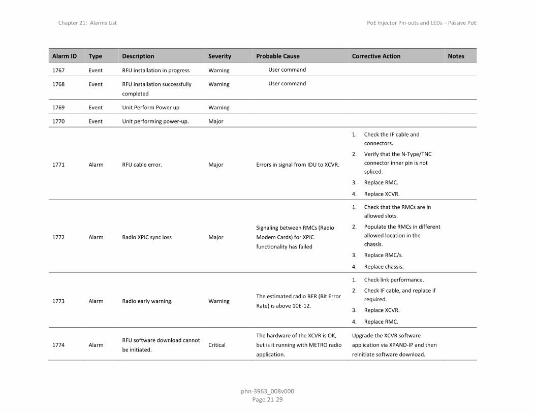
Chapter 21: Alarms List PoE Injector Pin-outs and LEDs – Passive PoE
phn-3963_008v000 Page 21-29
Alarm ID Type Description Severity Probable Cause Corrective Action Notes
1767 Event RFU installation in progress Warning User command
1768 Event RFU installation successfully completed
Warning User command
1769 Event Unit Perform Power up Warning
1770 Event Unit performing power-up. Major
1771 Alarm RFU cable error. Major Errors in signal from IDU to XCVR.
1. Check the IF cable and connectors.
2. Verify that the N-Type/TNC connector inner pin is not spliced.
3. Replace RMC.
4. Replace XCVR.
1772 Alarm Radio XPIC sync loss Major Signaling between RMCs (Radio Modem Cards) for XPIC functionality has failed
1. Check that the RMCs are in allowed slots.
2. Populate the RMCs in different allowed location in the chassis.
3. Replace RMC/s.
4. Replace chassis.
1773 Alarm Radio early warning. Warning The estimated radio BER (Bit Error Rate) is above 10E-12.
1. Check link performance.
2. Check IF cable, and replace if required.
3. Replace XCVR.
4. Replace RMC.
1774 Alarm RFU software download cannot be initiated.
Critical The hardware of the XCVR is OK, but is it running with METRO radio application.
Upgrade the XCVR software application via XPAND-IP and then reinitiate software download.

Chapter 21: Alarms List PoE Injector Pin-outs and LEDs – Passive PoE
phn-3963_008v000 Page 21-30
Alarm ID Type Description Severity Probable Cause Corrective Action Notes
1775 Alarm RFU software download is not possible.
Critical Wrong type of XCVR, the XCVR hardware is METRO.
Replace the XCVR
1776 Alarm RMC hardware failure. Major RMC hardware failure of the clock distributor.
Replace the RMC.
1780 Event MRMC running script is deleted Warning New installed software package does not include the running MRMC radio script
Make sure the required software package include the running MRMC radio script.
Download and install the correct software package.
1781 Event MRMC running script is updated
Warning New installed software package does has an updated version of the running MRMC radio script
Reset the radio carrier to reacquire the new updated MRMC radio script
1782 Alarm 2.5Gbps mismatch configuration
Warning The card can not function outside of an ABC group in 2.5Gbps mode.
Add the card to an ABC group, or change the Slot Section to 1Gbps.
1783 Alarm Radio remote fault indication (RFI)
Minor
1790 Alarm Hardware failure Critical An internal hardware failure has been detected by the system.
Replace the card or unit reporting the hardware failure.
1800 Alarm T3 sync interface Loss of Carrier Major 1. Cable disconnected.
Defective cable.
1. Check connection of the cable.
Replace the cable.
2001 Alarm TDM-LIC has rebooted and is not in service now
Major 1. Recent TDM-LIC card reset;
System malfunction.
1. Wait for card to reboot.
Reset the TDM-LIC card.
2002 Alarm TDM-LIC configuration mismatch
Major 1. Recent warm reset of TDM-LIC;
System malfunction.
Power cycle the TDM-LIC.

Chapter 21: Alarms List PoE Injector Pin-outs and LEDs – Passive PoE
phn-3963_008v000 Page 21-31
Alarm ID Type Description Severity Probable Cause Corrective Action Notes
2003 Alarm Loss of Signal (LOS) on TDM-LIC's front panel clock port
Major 1. Line is not properly connected.
External equipment is faulty.
1. Reconnect line.
2. Check line cables.
3. Check external equipment.
Power cycle the TDM-LIC.
2004 Alarm Communication with TDM-LIC is disrupted in Host-Card direction
Minor System malfunction Reset the TDM-LIC.
2005 Alarm TDM-LIC hardware failure Major System malfunction Reset the TDM-LIC.
2006 Alarm No communication with TDM-LIC
Major System malfunction Reset the TDM-LIC.
2007 Alarm Jitter-buffer-overrun alarm on TDM service
Major Something wrong on TDM service synchronization
Check TDM service configuration
2008 Alarm Late-frame alarm on TDM service
Warning Something wrong on TDM service
Check TDM service configuration
2009 Alarm Loss-of-frames alarm on TDM service
Major Failure along the network path of TDM service
Check network or configuration for errors in the network transport side of the service
2010 Alarm Malformed-frames alarm on TDM service
Major 1. Payload size does not correspond to the defined value.
Mismatch in PT value in RTP header (if used)
Check TDM service configuration
2011 Alarm Misconnection alarm on TDM service
Major Stray packets with wrong RTP configurations are received and dropped.
Check TDM service configuration

Chapter 21: Alarms List PoE Injector Pin-outs and LEDs – Passive PoE
phn-3963_008v000 Page 21-32
Alarm ID Type Description Severity Probable Cause Corrective Action Notes
2012 Alarm Alarm Indication Signal (AIS) on TDM-LIC TDM port
Major 1. Line is not properly connected.
External equipment is faulty.
1. Reconnect line.
2. Check line cables.
Check external equipment.
2013 Alarm Loss Of Frame (LOF) on TDM-LIC TDM port
Major 1. Line is not properly connected.
External equipment is faulty.
2014 Alarm Loss Of Multi-Frame (LOMF) on TDM-LIC TDM port
Major 1. Line is not properly connected.
External equipment is faulty.
1. Reconnect line.
2. Check line cables.
Check external equipment.
2015 Alarm Loopback on TDM-LIC TDM port
Warning 1. Line is not properly connected.
External equipment is faulty.
1. Reconnect line.
2. Check line cables.
Check external equipment.
2016 Alarm Loss Of Signal (LOS) on TDM-LIC TDM port
Major 1. Line is not properly connected.
2. Cable is faulty.
3. External equipment is faulty.
Defective TDM-LIC.
1. Reconnect line.
2. Check line cables.
Check external equipment.
2017 Alarm Remote Alarm Indication (RAI) on TDM-LIC TDM port
Minor 1. Line is not properly connected.
External equipment is faulty.
1. Reconnect line.
2. Check line cables.
Check external equipment.
2018 Alarm E1/DS1 Unexpected signal on TDM-LIC TDM port
Warning 1. Port is disabled.
Line is connected to a disabled port.
1. Enable relevant port.
Disconnect cable from relevant port.
2021 Event SSM received pattern change was discovered
Warning No action is required.

Chapter 21: Alarms List PoE Injector Pin-outs and LEDs – Passive PoE
phn-3963_008v000 Page 21-33
Alarm ID Type Description Severity Probable Cause Corrective Action Notes
2022 Alarm Excessive BER on TDM-LIC STM1/OC3 port
Major 1. Line is not properly connected.
External equipment is faulty.
1. Reconnect line.
2. Check line cables.
3. Check external equipment.
Power cycle the TDM-LIC.
2023 Alarm Loss Of Frame (LOF) on TDM-LIC STM1/OC3 port
Major 1. Line is not properly connected.
External equipment is faulty.
1. Reconnect line.
2. Check line cables.
3. Check external equipment.
Power cycle the TDM-LIC.
2024 Alarm Loopback on TDM-LIC STM1/OC3 port
Warning 1. Line is not properly connected.
External equipment is faulty.
1. Reconnect line.
2. Check line cables.
3. Check external equipment.
Power cycle the TDM-LIC.
2025 Alarm Loss Of Signal (LOS) on TDM-LIC STM1/OC3 port
Critical 1. Line is not properly connected.
External equipment is faulty.
1. Reconnect line.
2. Check line cables.
3. Check external equipment.
Power cycle the TDM-LIC.
2026 Alarm SFP is muted on TDM-LIC STM1/OC3 port
Warning
2027 Alarm SFP absent in TDM-LIC STM1/OC3 port
Critical 1. SFP is not properly installed.
SFP is faulty.
1. Install SFP properly.
Replace the card.
2028 Alarm SFP failure on TDM-LIC STM1/OC3 port
Critical 1. SFP is not properly installed.
SFP is faulty.
1. Install SFP properly.
Replace the card.
2029 Alarm SFP transmit failure on TDM-LIC STM1/OC3 port
Critical 1. SFP is not properly installed.
SFP is faulty.
1. Install SFP properly.
Replace the card.

Chapter 21: Alarms List PoE Injector Pin-outs and LEDs – Passive PoE
phn-3963_008v000 Page 21-34
Alarm ID Type Description Severity Probable Cause Corrective Action Notes
2030 Alarm Signal Degrade on TDM-LIC STM1/OC3 port
Minor 1. Line is not properly connected.
2. SFP is not properly installed.
3. SFP is faulty.
External equipment is faulty
1. Install SFP properly.
2. Reconnect line.
3. Check line cables.
4. Check external equipment.
Power cycle the TDM-LIC.
2031 Alarm J0 Trace Identifier Mismatch on TDM-LIC STM1/OC3 port
Minor 1. J0 misconfiguration.
2. Line is not properly connected.
3. SFP is not properly installed.
External equipment is faulty.
1. Make sure expected and received J0 match.
2. Install SFP properly.
3. Reconnect line.
4. Check line cables.
5. Check external equipment.
Power cycle the TDM-LIC.
2032 Event SSM pattern received on TDM-LIC STM1/OC3 port changed
Warning
2033 Alarm Alarm Indication Signal (AIS) on TDM-LIC VC12/VT1.5
Minor 1. Line is not properly connected.
External equipment is faulty.
1. Reconnect line.
2. Check line cables.
3. Check external equipment.
Power cycle the TDM-LIC.
2034 Alarm Excessive BER on TDM-LIC VC12/VT1.5
Minor 1. Line is not properly connected.
External equipment is faulty.
1. Reconnect line.
2. Check line cables.
3. Check external equipment.
Power cycle the TDM-LIC.
2035 Alarm Loopback on TDM-LIC VC12/VT1.5
Warning 1. Line is not properly connected.
External equipment is faulty.
1. Reconnect line.
2. Check line cables.
3. Check external equipment.
Power cycle the TDM-LIC.

Chapter 21: Alarms List PoE Injector Pin-outs and LEDs – Passive PoE
phn-3963_008v000 Page 21-35
Alarm ID Type Description Severity Probable Cause Corrective Action Notes
2036 Alarm Payload Mismatch Path (PLM) received on TDM-LIC VC12/VT1.5
Minor 1. Line is not properly connected.
External equipment is faulty.
1. Reconnect line.
2. Check line cables.
3. Check external equipment.
Power cycle the TDM-LIC.
2037 Alarm Remote Defect Indication (RDI) received on TDM-LIC VC12/VT1.5
Minor 1. Line is not properly connected.
External equipment is faulty.
1. Reconnect line.
2. Check line cables.
3. Check external equipment.
Power cycle the TDM-LIC.
2038
Alarm Signal Label Mismatch (SLM) received on TDM-LIC VC12/VT1.5
Minor 1. J2 misconfiguration.
2. Line is not properly connected.
External equipment is faulty.
1. Make sure expected and receive J2 match.
2. Reconnect line.
3. Check line cables.
4. Check external equipment.
Power cycle the TDM-LIC.
2039 Alarm Signal Degrade on TDM-LIC VC12/VT1.5
Minor 1. Line is not properly connected.
External equipment is faulty.
1. Reconnect line.
2. Check line cables.
3. Check external equipment.
Power cycle the TDM-LIC.
2040 Alarm Unequipped on TDM-LIC VC12/VT1.5
Minor 1. Line is not properly connected.
External equipment is faulty.
1. Reconnect line.
2. Check line cables.
3. Check external equipment.
Power cycle the TDM-LIC.
2041 Alarm TDM-LIC card protection configuration mismatch
Major The configuration between the TDM-LIC card protection members is not aligned
Apply a copy-to-mate command to copy the configuration from the required TDM-LIC to the other one

Chapter 21: Alarms List PoE Injector Pin-outs and LEDs – Passive PoE
phn-3963_008v000 Page 21-36
Alarm ID Type Description Severity Probable Cause Corrective Action Notes
2042 Alarm TDM-LIC card protection group lockout command is on
Minor The user has issued a lockout command
Clear the lockout command
2043 Alarm A member of TDM-LIC card protection group is missing
Minor TDM-LIC card is not installed in the shelf
Install the missing TDM-LIC card
2044 Event TDM-LIC card protection switch over, priority
Warning 1. LOS alarm on a STM1 interface of the TDM-LIC card protection group member;
A TDM-LIC card protection group member was disabled or pulled out of the shelf
1. Check line cables.
Check external equipment.
2045 Alarm Loss Of Pointer (LOP) received on TDM-LIC VC12/VT1.5
Minor 1. Line is not properly connected.
External equipment is faulty.
1. Reconnect line.
2. Check line cables.
3. Check external equipment.
Power cycle the TDM-LIC.
2046 Event Path protection switch on TDM service
Minor 1. Failure along service primary path.
User command.
1. Check errors along primary path
Check local service configuration.
2047 Event Path protection revertive switch on TDM service
Minor Primary path has been operational for the duration of the defined WTR time
-
2100 Alarm Loss of Signal on Line Interface (LOS) on STM-1/OC-3 port.
Critical
1. Line is not properly connected.
2. External equipment is faulty.
1. Reconnect line.
2. Check line cables.
3. Check external equipment.
2101 Alarm Loss of Frame on Line Interface (LOF) on STM-1/OC-3 port.
Major
1. Line is not properly connected.
2. External equipment is faulty.
1. Reconnect line.
2. Check line cables.
3. Check external equipment.

Chapter 21: Alarms List PoE Injector Pin-outs and LEDs – Passive PoE
phn-3963_008v000 Page 21-37
Alarm ID Type Description Severity Probable Cause Corrective Action Notes
2102 Alarm Alarm Indication Signal on Line Interface (MS-AIS/AIS-L) received.
Minor
1. Line is not properly connected.
2. External equipment is faulty.
1. Reconnect line.
2. Check line cables.
3. Check external equipment.
2103 Alarm Remote Defect Indication on Line Interface (MS-RDI/RDI-L) received.
Minor External equipment is faulty. Check external equipment.
2104 Alarm Loss of STM-1/OC-3 Frame on Radio Interface.
Major
1. All channels in Multi Carrier ABC group are down.
2. Incorrect configuration on remote side.
1. Check link performance.
2. Check radio alarms for channel.
3. Check configuration.
2105 Alarm MS-AIS/AIS-L on Radio Interface detected.
Minor
1. Remote STM-1/OC-3 signal is missing (LOS/LOF/MS-AIS/AIS-L on remote STM-1/OC-3 interface).
2. STM-1/OC-3 Channel removed due to reduced radio capacity on remote side.
Check remote equipment.
2106 Alarm MS-RDI/RDI-L on Radio Interface detected.
Minor External equipment is faulty. Check remote equipment.
2107 Alarm Loopback Warning Looping. Remove looping.
2108 Alarm STM-1/OC-3 Channel Removed alarm (due to reduced radio capacity).
Warning 1. Reduced capacity.
2. Fading
1. Check link performance.
2. Check radio alarms for channel.
2109 Alarm PBRS insertion. Warning PRBS insertion on STM-1/OC-3 card.
Remove PRBS insertion.
2110 Alarm SFP absent on STM-1/OC-3 port.
Critical 1. SFP is not properly installed.
2. SFP is faulty.
1. Install SFP properly.
2. Replace the card.

Chapter 21: Alarms List PoE Injector Pin-outs and LEDs – Passive PoE
phn-3963_008v000 Page 21-38
Alarm ID Type Description Severity Probable Cause Corrective Action Notes
2111 Alarm SFP Transmit Failure on STM-1/OC-3 port.
Critical SFP is faulty.
1. Replace SFP or insert SFP if it is not inserted correctly.
2. Replace the card.
2112 Alarm SFP is muted on STM-1/OC-3 port.
Warning SFP is muted by configuration. Remove muting.
2113 Alarm STM-1/OC-3 Channel Removed alarm (due to reduced radio capacity).
Warning 1. Reduced capacity.
2. Fading.
1. Check link performance.
2. Check radio alarms for channel.
2114 Alarm STM-1/OC-3 Channel Removed alarm (due to reduced radio capacity).
Warning 1. Reduced capacity.
2. Fading.
1. Check link performance.
2. Check radio alarms for channel.
2115 Alarm STM-1/OC-3 Channel Removed alarm (due to reduced radio capacity).
Warning 1. Reduced capacity.
2. Fading.
1. Check link performance.
2. Check radio alarms for channel.
2116 Alarm STM-1/OC-3 Channel Removed alarm (due to reduced radio capacity).
Warning 1. Reduced capacity.
2. Fading.
1. Check link performance.
2. Check radio alarms for channel.
2117 Alarm STM-1/OC-3 Channel Removed alarm (due to reduced radio capacity).
Warning 1. Reduced capacity.
2. Fading.
1. Check link performance.
2. Check radio alarms for channel.
2118 Alarm STM-1/OC-3 Channel Removed alarm (due to reduced radio capacity).
Warning 1. Reduced capacity.
2. Fading.
1. Check link performance.
2. Check radio alarms for channel.
2119 Alarm STM-1/OC-3 Channel Removed alarm (due to reduced radio capacity).
Warning 1. Reduced capacity.
2. Fading.
1. Check link performance.
2. Check radio alarms for channel.

Chapter 21: Alarms List PoE Injector Pin-outs and LEDs – Passive PoE
phn-3963_008v000 Page 21-39
Alarm ID Type Description Severity Probable Cause Corrective Action Notes
2200 Alarm Multi Carrier ABC LOF. Critical All channels in Multi Carrier ABC group are down.
1. Check link performance on all radio channels in Multi Carrier ABC group.
2. Check radio alarms for channels in Multi Carrier ABC group.
3. Check configuration of Multi Carrier ABC group.
2201 Alarm Multi Carrier ABC bandwidth is below the threshold
Major
1. One of the radio channels in the Multi Carrier ABC group has a lower capacity than expected
2. Minimum bandwidth threshold configuration is wrong
1. Check link performance on all radio channels in Multi Carrier ABC group
2. Check radio alarms for channels in Multi Carrier ABC group
3. Check configuration of Multi Carrier ABC group Minimum bandwidth threshold
2203 Alarm LVDS RX Error Slot 2. Major Hardware failure between RMC and TCC cards.
1. Replace RMC.
2. Replace TCC.
3. Replace chassis.
2204 Alarm LVDS RX Error Slot 3. Major Hardware failure between RMC and TCC cards.
1. Replace RMC.
2. Replace TCC.
3. Replace chassis.
2205 Alarm LVDS RX Error Slot 4. Major Hardware failure between RMC and TCC cards.
1. Replace RMC.
2. Replace TCC.
3. Replace chassis.

Chapter 21: Alarms List PoE Injector Pin-outs and LEDs – Passive PoE
phn-3963_008v000 Page 21-40
Alarm ID Type Description Severity Probable Cause Corrective Action Notes
2206 Alarm LVDS RX Error Slot 5. Major Hardware failure between RMC and TCC cards.
1. Replace RMC.
2. Replace TCC.
3. Replace chassis.
2207 Alarm LVDS RX Error Slot 6. Major Hardware failure between RMC and TCC cards.
1. Replace RMC.
2. Replace TCC.
3. Replace chassis.
2208 Alarm LVDS RX Error Slot 7. Major Hardware failure between RMC and TCC cards.
1. Replace RMC.
2. Replace TCC.
3. Replace chassis.
2209 Alarm LVDS RX Error Slot 8. Major Hardware failure between RMC and TCC cards.
1. Replace RMC.
2. Replace TCC.
3. Replace chassis.
2210 Alarm LVDS RX Error Slot 9. Major Hardware failure between RMC and TCC cards.
1. Replace RMC.
2. Replace TCC.
3. Replace chassis.
2211 Alarm LVDS RX Error Slot 10. Major Hardware failure between RMC and TCC cards.
1. Replace RMC.
2. Replace TCC.
3. Replace chassis.
2212 Alarm LVDS RX Error Slot 12. Major Hardware failure between RMC and TCC cards.
1. Replace RMC.
2. Replace TCC.
3. Replace chassis.
2219 Alarm Multi Carrier ABC Channel Id Mismatch Ch1.
Warning Configuration failure. Compare Channel ID configuration with remote side.
2220 Alarm Multi Carrier ABC Channel Id Mismatch Ch2.
Warning Configuration failure. Compare Channel ID configuration with remote side.

Chapter 21: Alarms List PoE Injector Pin-outs and LEDs – Passive PoE
phn-3963_008v000 Page 21-41
Alarm ID Type Description Severity Probable Cause Corrective Action Notes
2221 Alarm Multi Carrier ABC Channel Id Mismatch Ch3.
Warning Configuration failure. Compare Channel ID configuration with remote side.
2222 Alarm Multi Carrier ABC Channel Id Mismatch Ch4.
Warning Configuration failure. Compare Channel ID configuration with remote side.
2223 Alarm Multi Carrier ABC Channel Id Mismatch Ch5.
Warning Configuration failure. Compare Channel ID configuration with remote side.
2224 Alarm Multi Carrier ABC Channel Id Mismatch Ch6.
Warning Configuration failure. Compare Channel ID configuration with remote side.
2225 Alarm Multi Carrier ABC Channel Id Mismatch Ch7.
Warning Configuration failure. Compare Channel ID configuration with remote side.
2226 Alarm Multi Carrier ABC Channel Id Mismatch Ch8.
Warning Configuration failure. Compare Channel ID configuration with remote side.
2235 Alarm Multi Carrier ABC Channel Id Manual Disabled Ch1.
Warning Admin state for channel is down. Enable admin state for channel.
2236 Alarm Multi Carrier ABC Channel Id Manual Disabled Ch2.
Warning Admin state for channel is down. Enable admin state for channel.
2237 Alarm Multi Carrier ABC Channel Id Manual Disabled Ch3.
Warning Admin state for channel is down. Enable admin state for channel.
2238 Alarm Multi Carrier ABC Channel Id Manual Disabled Ch4.
Warning Admin state for channel is down. Enable admin state for channel.
2239 Alarm Multi Carrier ABC Channel Id Manual Disabled Ch5.
Warning Admin state for channel is down. Enable admin state for channel.
2240 Alarm Multi Carrier ABC Channel Id Manual Disabled Ch6.
Warning Admin state for channel is down. Enable admin state for channel.

Chapter 21: Alarms List PoE Injector Pin-outs and LEDs – Passive PoE
phn-3963_008v000 Page 21-42
Alarm ID Type Description Severity Probable Cause Corrective Action Notes
2241 Alarm Multi Carrier ABC Channel Id Manual Disabled Ch7.
Warning Admin state for channel is down. Enable admin state for channel.
2242 Alarm Multi Carrier ABC Channel Id Manual Disabled Ch8.
Warning Admin state for channel is down. Enable admin state for channel.
2300 Alarm Protection configuration mismatch!
Major The configuration between the protected devices is not aligned.
Apply copy-to-mate command to copy the configuration from the required device to the other one.
All
2301 Event Copy to mate started Indeterminate The copy-to-mate command has just begun!
This is a notification All
2302 Event Copy to mate completed Indeterminate The copy-to-mate command was completed.
This is a notification All
3000 Event Chassis was reset Warning User issued a command to reset the chassis.
Wait until the reset cycle is ended and the system is up and running.
3001 Alarm Reset chassis to activate front panel Ethernet ports
Warning Front panel Ethernet ports cannot work when slot 12 is configured in 10Gbps mode.
Reset chassis.
3002 Alarm Front panel Ethernet port cannot function in current configured capacity mode
Warning Front panel Ethernet port cannot work in a mode other than 1Gbps.
Configure the relevant capacity mode to 1 Gbps mode.
3003 Alarm Multi Carrier ABC group is not functional in current configured capacity mode
Warning Multi Carrier ABC group does not support the configured capacity mode.
Configure the relevant capacity mode to 1 Gbps mode.
3004 Alarm Multi Carrier ABC group is not functional in current configured capacity mode until chassis is reset
Warning Multi Carrier ABC group capacity mode is different than the configured capacity mode.
Reset chassis.

Chapter 21: Alarms List PoE Injector Pin-outs and LEDs – Passive PoE
phn-3963_008v000 Page 21-43
Alarm ID Type Description Severity Probable Cause Corrective Action Notes
4000 Alarm Card has one or more HW failures
Critical One or more HW faults. Replace card.
4001 Alarm Card can not function in 2.5Gbps mode.
Warning The user set an expected card that does not support 2.5Gbps.
Change the Slot Section to 1Gbps.
4002 Alarm Card is not functional until chassis is reset
Warning Slot is not in 10Gbps mode. Reset chassis.
5000 Event User blocked due to consecutive failure login
Indeterminate User blocked due to consecutive failure login
The user should wait few minutes until it account will be unblock
5001 Alarm ERPI is either in protection state or forced protection state
Minor Either user "force switch" command or one of the ring links has failed
Either clear force command or recover the link
5002 Alarm More than a single RPL is configured in a ring
Warning User configuration Reconfigure the RPL
5003 Event LLDP topology change Warning New neighbor None
5004 Event Security log upload started Indeterminate Security log upload started
5005 Event Security log upload failed Indeterminate Security log upload failed
5006 Event Security log upload succeeded Indeterminate Security log upload succeeded
5010 Alarm System is in sync force mode state
Warning
5011 Event The sync-source quality level was changed
Major
5012 Alarm System Synchronization Reference in Holdover Mode
Critical
5013 Event System Sync reference-to quality has change changed
Major

Chapter 21: Alarms List PoE Injector Pin-outs and LEDs – Passive PoE
phn-3963_008v000 Page 21-44
Alarm ID Type Description Severity Probable Cause Corrective Action Notes
5014 Alarm The pipe interface clock-source in signal-interface table is not system-clock
Major
5015 Alarm The pipe is missing an edge interface
Major
5016 Alarm Pipe interface operational state is down
Major
5017 Alarm Pipe is invalid Major
5018 Alarm 1588TC is not operational Major System Failure Reboot the unit
5030 soam-connectivity-failure
A connectivity failure in MA/MEG
Minor Specific defect dependent: User configuration , connectivity loss.
Reconfigure the RPL.
5031 soam-def-error-failure
Error CCM received Major Invalid CCMs has been received Check the link in the traffic path (1)
5032 soam-def-mac-failure
Remote mep MAC status not up
Minor Remote MEP’s associated MAC is reporting an error status
Check remote MEP's MAC status (1)
5033 soam-def-rdi-failure
Mep Rdi received Minor Remote Defect indication has been received from remote MEP
Check the SOAM configurations (1)
5034 soam-remote-ccm-failure
Remote mep CCMs are not received
Major The MEP is not receiving CCMs from at least one of the remote MEPs
Check that all remote MEPs are configured or enbaled
(1)

Chapter 21: Alarms List PoE Injector Pin-outs and LEDs – Passive PoE
phn-3963_008v000 Page 21-45
Alarm ID Type Description Severity Probable Cause Corrective Action Notes
5035 soam-def-xcon-failure
Cross Connect CCM received Major CCM from another MAID or lower MEG level have been received
Check MA/MEG and MEP configurations
(1)
5036 Event 1588-BC port state changed Warning
5037 Event 1588-BC BMCA has been updated.
Warning
5038 Event 1588-BC outputs are squelched. Warning
5039 Event 1588-BC parent dataset has changed.
Warning
5040 Event 1588-BC UTC offset value changed.
Warning
5041 Event 1588-BC one of the leap seconds flags have changed.
Warning
5042 Event 1588-BC message interval change detected.
Warning
5043 Alarm 1588-BC announce message rate is below expected.
Major Misconfiguration of the peer system.
Check the configuration of the peer system.
5044 Alarm 1588-BC sync message rate is below expected.
Major Misconfiguration of the peer system.
Check the configuration of the peer system.
5045 Alarm 1588-BC delay request message rate is below expected.
Major Misconfiguration of the peer system.
Check the configuration of the peer system.
5046 Alarm 1588-BC performance is degraded due to loss of system clock reference.
Critical Loss of system clock reference. Restore the system clock synchronization to a PRC-traceable source.

Chapter 21: Alarms List PoE Injector Pin-outs and LEDs – Passive PoE
phn-3963_008v000 Page 21-46
Alarm ID Type Description Severity Probable Cause Corrective Action Notes
5100 Alarm Master key mismatch cross over the link
Critical Master Key was not set correctly. Verify the Master Key. (1)
5101 Alarm No Master Key set, default value used
Warning Crypto module has been enabled, but no Master Key has been loaded.
Set the Master Key. (1)
5102 Alarm Payload Encryption failure Critical 1. Radio LOF on Tx/Rx direction. 2. The session key does not
match across the link.
3. The AES admin setting does not match across the link.
1. Validate the MSE on both sides of the link.
2. Validate the session key on both sides of the link.
3. Validate the AES admin setting on both sides of the link.
(1)
5104 Event Key Exchange Protocol progress, Traffic has been blocked
Indeterminate (1)
5105 Event Key Exchange Protocol initiated by remote side
Indeterminate (1)
5106 Event Key Zeroization command executed
Indeterminate (1)
5107 Alarm FIPS Bypass Self-Test failed Critical Disk failure (1)
5108 Alarm Power On Self-Test Failed Critical System failure Reboot the unit. (1)
5109 Alarm Main board is not FIPS certified Critical Main Board used is not FIPS certified
Use a FIPS-certified TCC.
5110 Alarm Radio card is not FIPS certified Major Radio Card used is not FIPS certified
Use a FIPS-certified RMC.
5111 Alarm Radio crypto module fail Critical FIPS Radio Encryption Self-Test failed
Use different FIPS supported radio card

Chapter 21: Alarms List PoE Injector Pin-outs and LEDs – Passive PoE
phn-3963_008v000 Page 21-47
Alarm ID Type Description Severity Probable Cause Corrective Action Notes
5112 Alarm Radiuo encryption not supported
Major No Payload Encryption Activation Key inserted
Insert suitable Activation Key and reboot the unit
5030 Alarm A connectivity failure in MA/MEG
Minor Specific defect dependent: User configuration , connectivity loss.
Reconfigure the RPL.
30007 Event Clock source sharing failure Critical
1. Faulty coaxial cable between master and slave RFUs.
2. Hardware failure in Master RFU.
3. Hardware failure in Slave RFU.
1. Try re-initiation of MIMO. If still fails:
2. Replace faulty coaxial cable and reset Master RFU.
3. Replace faulty RFU.
(2)
31000 Alarm Insufficient conditions for MIMO
Critical
1. Insufficient conditions for MIMO.
2. Hardware failure.
1. Make sure all cables between master and slave are connected (MIMO 4x4 only).
2. Replace faulty units and check that cables are plugged.
(2)
31003 Alarm Unsuitable hardware for MIMO Critical
1. Unsuitable hardware for MIMO operation requirements.
2. Dual carrier RFUs (MIMO 2x2 and 4x4).
3. RFUs with MIMO bus interface (MIMO 4x4).
4. Clock source sharing capability (MIMO 4x4).
Make sure both RFUs are compatible for MIMO operation.
(2)

Chapter 21: Alarms List PoE Injector Pin-outs and LEDs – Passive PoE
phn-3963_008v000 Page 21-48
Alarm ID Type Description Severity Probable Cause Corrective Action Notes
31004 Alarm Unsuitable software configuration for MIMO
Critical
1. Not all MIMO carriers are set to same radio script or script is not compatible for MIMO.
2. Radio TX and RX frequency is not identical on all MIMO carriers.
3. XPIC or Multi radio or ATPC features are enabled.
1. Load same MIMO compatible radio script to all MIMO carriers.
2. Set same TX and RX frequency on all MIMO carriers.
3. Disable XPIC, Multi radio and ATPC on all MIMO carriers.
(2)
31005 Alarm Clock source sharing cable unplugged
Critical
1. Faulty coaxial cable between master and slave RFUs
2. Mate does not exist
1. Replace faulty coaxial cable and reset Master RFU.
2. Replace faulty RFU. (2)
31100 Alarm Radio script is incompatible to AMCC
Critical MRMC Script selected does not support AMCC Group type/subtype
Set AFR Script in both Agg1 & Agg2 carriers
31101 Alarm Inconsistent MRMC script between members
Critical All members of a group must be configured to the same MRMC Script
Set the members to the appropriate MRMC script
31102 Alarm Inconsistent radio frequency Critical Radio TX/RX frequency is not identical on all AMCC carriers
Set same radio TX/RX frequency on all AMCC carriers
31103 Alarm Agg 1 failed Bring-up procedure Critical Agg1 did not complete Bring-up successfully
Drop both Agg1 & Agg2 into single carrier mode (Pre-Init)
31104 Alarm Invalid ACM configuration Critical AMCC member have been set to fixed profile
Set AMCC member to adaptive ACM profiles
5100 Alarm Master key mismatch cross over the link
Critical Master Key was not set correctly. Verify the Master Key. (1)
5101 Alarm No Master Key set, default value used
Warning Crypto module has been enabled, but no Master Key has been loaded.
Set the Master Key. (1)

Chapter 21: Alarms List PoE Injector Pin-outs and LEDs – Passive PoE
phn-3963_008v000 Page 21-49
Alarm ID Type Description Severity Probable Cause Corrective Action Notes
5102 Alarm Payload REncryption failure Critical 1. Radio LOF on Tx/Rx direction.
2. The session key does not match across the link.
3. The AES admin setting does not match across the link.
1. Validate the MSE on both sides of the link.
2. Validate the session key on both sides of the link.
3. Validate the AES admin setting on both sides of the link.
(1)
5103 Event Key Exchange Protocol successfully finished
Indeterminate (1)
5104 Event Key Exchange Protocol initiated Indeterminate (1)
5105 Event Key Exchange Protocol initiated
by remote side Indeterminate (1)
5106 Event Key Zeroization command
executed Indeterminate (1)
5107 Alarm FIPS Bypass Self-Test failed Critical Disk failure (1)
5108 Alarm Power On Self-Test Failed Critical System failure Reboot the unit. (1)
5033 Alarm Communications Critical Radio script is incompatible to AMCC
Set AFR Script in both Agg1 & Agg2 carriers (1)
5034 Alarm Communications Critical Inconsistent MRMC script between members
Set the members to the appropriate MRMC script (1)
5035 Alarm Communications Critical Inconsistent radio frequency Set same radio TX/RX frequency on all AMCC carriers (1)
5100 Alarm Communications Critical Agg 1 failed Bring-up procedure Drop both Agg1 & Agg2 into single carrier mode (Pre-Init) (1)
5101 Alarm Communications Critical Invalid ACM configuration Set AMCC member to adaptive ACM profiles (1)

Chapter 21: Alarms List PoE Injector Pin-outs and LEDs – Passive PoE
phn-3963_008v000 Page 21-50
(1) Supported by PTP 850E
(2) Supported by PTP 850E only

phn-3963_008v000 Page I
Glossary
Term Definition
A
ABC Adaptive Bandwidth Control
ABN Adaptive Bandwidth Notification
AC Alternating Current
ACAP Adjacent Channel Alternate Polarization
ACCP Adjacent Channel Co-Polarization
ACM Adaptive Coded Modulation
ACR Adaptive Clock Recovery
AES Advanced Encryption Standard
AFR Advanced Frequency Reuse
AGC Automatic Gain Control
AIS Alarm Indicating Signal
ALC Automatic Level Control
AMCC Advanced Multi-Carrier Configuration
ANSI American National Standards Institute
ASIC Application Specified Integrated Circuit
ATPC Automatic Transmit Power Control
AUX Auxiliary Unit
B
BB Baseband
BBS Baseband Switching
BER Bit Error Rate
BLSR Bidirectional Line Switch Ring
BPDU Bridge Protocol Data Units
BWA Broadband Wireless Access
C

phn-3963_008v000 Page II
Term Definition
CBS Committed Burst Size
CCDP Co-Channel Dual Polarization
CCITT Comité Consultatif International de Télégraph et des Télécommunications (ITU)
CET Carrier-Ethernet Transport
CFM Connectivity Fault Management
CIR Committed Information Rate
CLI Command Line Interface
Clk Clock
CODEC Coder/Decoder
CoS Class of Service
D
DA Destination Address
DC Direct Current
DCB Diversity Circulator Block
DCC Data Communication Channel
DXC Digital Cross Connect
DSCP Differentiated Services Code Point
E
EBS Excess Burst Size
EIR Excess Information Rate
EMC Electromagnetic Compatibility
EOW Engineering Order Wire
EPROM Erasable Programmable Read Only Memory
ESD Electrostatic Discharge
ESE Electrical SFP Electrical
ESP Electrical SFP SFP+ 10G
ESS Electrical SFP SFP
ETSI European Telecommunications Standards Institute
F
FCC Federal Communications Commission

phn-3963_008v000 Page III
Term Definition
FCS Frame Check Sequence
FTP File Transfer Protocol
G
GbE Gigabit Ethernet
GFP Generic Framing Procedure (Procedure for mapping of Ethernet traffic over a transport network)
GND Ground
GRE Generic Routing Encapsulation
GTP GPRS Tunneling Protocol
H
HBER High Bit Error Rate
HDLC High-level Data Link Control
HF High Frequency (3-30 MHz)
HSB Hot-Standby
HTTP Hypertext Transfer Protocol
HTTPS Secured Hypertext Transfer Protocol
I
IDC Indoor Controller
IF Intermediate Frequency
IFC IF Combining
ISO International Organization for Standardization
ITU International Telecom. Union
ITU-R International Telecom. Union (former CCIR)
ITU-T International Telecom. Union (former CCITT)
IVM Inventory Module
L
LACP Link Aggregation Control Protocol
LAG Link Aggregation Group
LAN Local Area Network
LBER Low Bit Error Rate

phn-3963_008v000 Page IV
Term Definition
LCAS Link Capacity Adjustment Scheme
LED Light Emitting Diode
LIU Line Interface Unit
LLDP Link Layer Discovery Protocol
LLF Link Loss Forwarding
LMS License Management System
LO Local Oscillator
LOC Loss of Carrier
LOF Loss of Frame
LOS Loss of Signal
LSI Large Scale Integration
LTE Long-Term Evolution
M
MAID Maintenance Association Identifier
MPLS Multi Protocol Label Switching
MSP Multiplex Section Protection
MUX Multiplexer
N
NE Network Element
NMS Network Management System
NTP Network Time Protocol
O
OAM Operation Administration & Maintenance (Protocols)
OCB Outdoor Circulator Box
OHC OverHead Connections
OMT Orthogonal Mode Transducer
OOF Out of Frame
OPEX Operational Expenditure
P
PBB-TE Provider Backbone Bridge Traffic Engineering

phn-3963_008v000 Page V
Term Definition
PBS Peak Burst Rate
PC Personal Computer
PCB Printed Circuit Board
PDV Packed Delay Variation
PIR Peak Information Rate
PLL Phase Locked Loop
PM Performance Monitoring
PN Provider Network
PROM Programmable Read Only Memory
PSN Packet Switched Network
PTP Precision Timing Protocol
PWR Power
Q
QoE Quality of Experience
QoS Quality of Service
R
RBAC Role Based Access Control
RCVR Receiver
RDI Reverse Defect Indication
RF Radio Frequency
RIP Routing Information Protocol
RMON Ethernet Statistics
RPS Radio Protection Switching
RSL Received Signal Level
RSSI Received Signal Strength Indicator
RSTP Rapid Spanning Tree Protocol
S
SAP Service Access Point
SDH Synchronous Digital Hierarchy
SDWRR Shaped Deficit Weighted Round Robin

phn-3963_008v000 Page VI
Term Definition
SETS Synchronous Equipment Timing Source
SFTP Secure FTP
SLA Service Level Agreements
SNCP Simple Network Connection Protection
SNMP Simple Network Management Protocol
SNP Service Network Point
SNR Signal to Noise Ratio
SNTP Simple Network Time Protocol
SOH Section OverHead (ETSI)
SONET Synchronous Optical NETwork
SP Service Point
SSH Secured Shell (Protocol)
SSM Synchronization Status Message
STP Spanning Tree Protocol
SyncE Synchronous Ethernet
SVCE Service Channel Equipment
T
TC Traffic Class
TIM Trace Identifier Mismatch
TOH Transport OverHead (ANSI)
TOS Type Of Service
V
VC Virtual Container
VCO Voltage Controlled Oscillator
VCXO Voltage Controlled crystal Oscillator
VLSI Very Large Scale of Integration
W
WAN Wide Area Network
Web EMS Web-Based Element Management System
WFQ Weighted Fair Queue

phn-3963_008v000 Page VII
Term Definition
WG Waveguide
WRED Weighted Random Early Detection
WRR Weighted Round Robin
X
XCVR Transceiver (Transmitter/Receiver)
XMTR Transmitter
XO Crystal Oscillator
XPD Cross Polar Differentiation
XPI Cross Polariztion Isolation
XPIC Cross Polarization Interference Cancellation


