Embed Size (px)
Citation preview
Project Manual
Rock County Courthouse Security System Upgrade and Replacement Janesville, Wisconsin
February 6, 2017 Bid Documents Mead & Hunt No. 2880000.156650.02
Rock County Courthouse Security System Upgrade and Replacement Project Title Page 2880000.156650.02 00 01 01 - 1
SECTION 00 01 01 PROJECT TITLE PAGE
PROJECT: ROCK COUNTY COURTHOUSE SECURITY SYSTEM UPGRADE AND REPLACEMENT 51 S. Main Janesville, WI 53545 OWNER: ROCK COUNTY FACILITIES MANAGEMENT 51 South Main Street Janesville, WI 53545 ENGINEER: MEAD & HUNT 10700 West Research Drive, Suite 155 Wauwatosa, WI 53226 Phone: (262)790-0232
* * *

PAGE INTENTIONALLY LEFT BLANK
Rock County Courthouse Security System Upgrade and Replacement Seals Page 2880000.156650.02 00 01 07 - 1
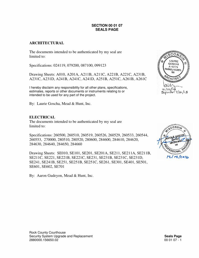
SECTION 00 01 07 SEALS PAGE
ARCHITECTURAL
The documents intended to be authenticated by my seal are
limited to:
Specifications: 024119, 079200, 087100, 099123
Drawing Sheets: A010, A201A, A211B, A211C, A221B, A221C, A231B,
A231C, A231D, A241B, A241C, A241D, A251B, A251C, A261B, A261C
I hereby disclaim any responsibility for all other plans, specifications, estimates, reports or other documents or instruments relating to or intended to be used for any part of the project.
By: Laurie Goscha, Mead & Hunt, Inc.
ELECTRICAL
The documents intended to be authenticated by my seal are
limited to:
Specifications: 260500, 260510, 260519, 260526, 260529, 260533, 260544,
260553, 270000, 280510, 280520, 280600, 284600, 284610, 284620,
284630, 284640, 284650, 284660
Drawing Sheets: SE010, SE101, SE201, SE201A, SE211, SE211A, SE211B,
SE211C, SE221, SE221B, SE221C, SE231, SE231B, SE231C, SE231D,
SE241, SE241B, SE251, SE251B, SE251C, SE261, SE301, SE401, SE501,
SE601, SE602, SE701
By: Aaron Gudeyon, Mead & Hunt, Inc.

PAGE INTENTIONALLY LEFT BLANK
Rock County Courthouse Security System Upgrade and Replacement Table of Contents 2880000.156650.02 00 01 10 - 1
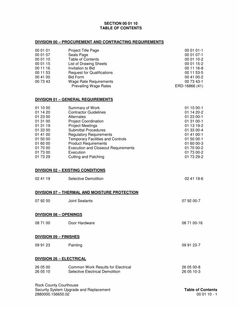
SECTION 00 01 10 TABLE OF CONTENTS
DIVISION 00 – PROCUREMENT AND CONTRACTING REQUIREMENTS
00 01 01 Project Title Page 00 01 01-1 00 01 07 Seals Page 00 01 07-1 00 01 10 Table of Contents 00 01 10-2 00 01 15 List of Drawing Sheets 00 01 15-2 00 11 16 Invitation to Bid 00 11 16-8 00 11 53 Request for Qualifications 00 11 53-5 00 41 00 Bid Form 00 41 00-2 00 73 43 Wage Rate Requirements 00 73 43-1 Prevailing Wage Rates ERD-16866 (41) DIVISION 01 – GENERAL REQUIREMENTS
01 10 00 Summary of Work 01 10 00-1 01 14 20 Contractor Guidelines 01 14 20-2 01 23 00 Alternates 01 23 00-1 01 31 00 Project Coordination 01 31 00-1 01 31 19 Project Meetings 01 13 19-2 01 33 00 Submittal Procedures 01 33 00-4 01 41 00 Regulatory Requirements 01 41 00-1 01 50 00 Temporary Facilities and Controls 01 50 00-1 01 60 00 Product Requirements 01 60 00-3 01 70 00 Execution and Closeout Requirements 01 70 00-2 01 73 00 Execution 01 73 00-2 01 73 29 Cutting and Patching 01 73 29-2 DIVISION 02 – EXISTING CONDITIONS
02 41 19 Selective Demolition 02 41 19-6 DIVISION 07 – THERMAL AND MOISTURE PROTECTION
07 92 00 Joint Sealants 07 92 00-7 DIVISION 08 – OPENINGS
08 71 00 Door Hardware 08 71 00-16 DIVISION 09 – FINISHES
09 91 23 Painting 09 91 23-7 DIVISION 26 – ELECTRICAL
26 05 00 Common Work Results for Electrical 26 05 00-8 26 05 10 Selective Electrical Demolition 26 05 10-3

Rock County Courthouse Security System Upgrade and Replacement Table of Contents 2880000.156650.02 00 01 10 - 2
26 05 19 Low Voltage Electrical Power Conductors and Cables 26 05 19-5 26 05 26 Grounding and Bonding for Electrical Systems 26 05 26-2 26 05 29 Hangers and Supports for Electrical Systems 26 05 29-4 26 05 33 Raceway and Boxes for Electrical Systems 26 05 33-6 26 05 44 Sleeves and Sleeve Seals for Electrical Raceways & Cabling 26 05 44-2 26 05 53 Identification for Electrical Systems 26 05 53-4
DIVISION 27 – COMMUNICATIONS
27 00 00 Communications Cable and Equipment 27 00 00-18 DIVISION 28 – ELECTRONIC SAFETY AND SECURITY
28 05 10 Sequencing of Security Electronics Work 28 05 10-2 28 05 20 Security System Racks and Enclosures 28 05 20-3 28 06 00 Security Control Point Schedule 28 06 00-12 28 46 00 Security System General Requirements 28 46 00-12 28 46 10 Security System Control and Monitoring 28 46 10-34 28 46 20 Security System Network Switches 28 46 20-7 28 46 30 Door Control Intercom System 28 46 30-5 28 46 40 Card Access System 28 46 40-20 28 46 50 Duress Alarm System 28 46 50-2 28 46 60 Video Surveillance System 28 46 60-18
* * *

Rock County Courthouse Security System Upgrade and Replacement List of Drawing Sheets 2880000.156650.02 00 01 15 - 1
SECTION 00 01 15 LIST OF DRAWING SHEETS
The following List of Drawings bound separately from the Project Manual comprise the Drawings as referenced in the Bidding Documents and the Contract Documents.
The arrangement, numbering, titling and location of the Drawings within a bound set shall not control the Contractor in dividing the work among Subcontractors or in establishing the extent of Work to be performed by any trade.
DRAWING NO. DRAWING TITLE
GENERAL T1 Title Sheet ARCHITECTURAL A010 Schedules, Symbols and Abbreviations A201A Basement – Area A A211B First Floor Plan – Area B A211C First Floor Plan – Area C A221B Second Floor Plan – Area B A221C Second Floor Plan – Area C A231B Third Floor Plan – Area B A231C Third Floor Plan – Area C A231D Third Floor Plan – Area D A241B Fourth Floor Plan – Area B A241C Fourth Floor Plan – Area C A241D Fourth Floor Plan – Area D A251B Fifth Floor Plan – Area B A251C Fifth Floor Plan – Area C A261B Roof & Penthouse Floor Plan – Area B A261C Roof & Penthouse Floor Plan – Area C SECURITY ELECTRONICS SE010 Symbols and Abbreviations SE011 Camera Schedule SE101 Security Electronics - Site Plan SE201 Security Electronics – Basement Overall Plan SE201A Security Electronics - Basement – Area A SE211 Security Electronics – First Floor Overall Plan SE211A Security Electronics – First Floor Plan – Area A SE211B Security Electronics - First Floor Plan – Area B SE211C Security Electronics - First Floor Plan – Area C SE221 Security Electronics – Second Floor Overall Plan SE221B Security Electronics - Second Floor Plan – Area B SE221C Security Electronics - Second Floor Plan – Area C SE231 Security Electronics – Third Floor Overall Plan SE231B Security Electronics - Third Floor Plan – Area B SE231C Security Electronics - Third Floor Plan – Area C SE231D Security Electronics - Third Floor Plan – Area D SE241 Security Electronics – Fourth Floor Overall Plan SE241B Security Electronics - Fourth Floor Plan – Area B

Rock County Courthouse Security System Upgrade and Replacement List of Drawing Sheets 2880000.156650.02 00 01 15 - 2
SE241C Security Electronics - Fourth Floor Plan – Area C SE241D Security Electronics - Fourth Floor Plan – Area D SE251 Security Electronics – Fifth Floor Overall Plan SE251B Security Electronics - Fifth Floor Plan – Area B SE251C Security Electronics - Fifth Floor Plan – Area C SE261 Security Electronics – Roof & Penthouse Overall Plan SE261B Security Electronics - Roof & Penthouse Floor Plan – Area B SE261C Security Electronics - Roof & Penthouse Floor Plan – Area C SE301 Security Electronics - Enlarged Plans – Control Rooms SE401 Security Electronics – Enlarged Plans – Equipment Rooms SE402 Security Electronics – Enlarged Plans – Equipment Rooms SE501 Security Electronics – Security Details SE601 Security Electronics - Security Riser Diagrams SE701 Security Electronics - Lock Wiring Diagrams
* * *

Rock County Courthouse Security System Upgrade and Replacement Invitation to Bid 2880000.156650.02 00 11 16 - 1
ROCK COUNTY, WISCONSIN PURCHASING DIVISION FINANCE DIRECTOR FAX (608) 757-5539 PHONE (608) 757-5517
#2017-25 INVITATION TO BID
ROCK COUNTY COURTHOUSE SECURITY SYSTEM UPGRADE AND REPLACEMENT - REBID
FOR ROCK COUNTY FACILITIES MANAGEMENT
JANESVILLE, WISCONSIN
Bids due in Rock County Purchasing Division by: March 1, 2017 – 1:30 p.m. (local time)
Bids received after this date and time will be rejected.
Bids must remain in effect 90 days from due date.
Address Bid to: Jodi Millis, Purchasing Manager Rock County Courthouse Purchasing Division 51 S. Main Street Janesville WI. 53545
***MARK SEALED ENVELOPE: #2017-25 COURTHOUSE SECURITY SYSTEM UPGRADE AND REPLACEMENT - REBID ***
Rock County reserves the right to accept or reject any or all bids; to waive any technicality or error in any bid or part therein, and to accept the same or combinations, in whole or in part, whichever is deemed to be in the best interest of Rock County.
Contracts are awarded to the lowest, most qualified, responsible and responsive bidder on the basis of the base bid and full consideration of any or all alternatives, as may be in the best interest of Rock County. In determining the award of contract, Rock County will consider the scope of the work involved, timeliness of delivery, competency of bidder, bidder’s ability to render satisfactory service, and past performance. If two or more bidders submit identical bids, Rock County will make award to bidder of its choice and such decision will be final.

Rock County Courthouse Security System Upgrade and Replacement Invitation to Bid 2880000.156650.02 00 11 16 - 2
INSTRUCTIONS FOR BIDS The bidder is required to submit two (2) copies (one original marked as such and one copy) of their bid in a sealed envelope marked ITB #2017-25 to Jodi Millis, Financial Services Purchasing Division, 51 South Main, Janesville, WI 53545. All bids must be received by 1:30 p.m. (local time), March 1, 2017. Any bid submitted after this date and time will be rejected. Vendors are responsible for ensuring that the above office receives their bid before the deadline. No faxed or electronic bids will be accepted. Bid "packets" must be clearly labeled with vendor name, return address, bid title, date and the name of the vendor's primary contact for bid questions. Bids shall be signed with named printed below signature. Where Bidder is a Corporation, Bid must be signed with the legal name of the Corporation followed by the legal signature of an officer authorized to bind the Corporation to contract. SITE TOURS Contractors wishing to tour the site may do so by appointment only. Contact Brent Sutherland, Facilities Management Director at 608-757-5527 or by e-mail at [email protected] to schedule a site visit. INQUIRIES All questions concerning this Invitation to Bid must be submitted in writing to Jodi Millis. Questions must be received by 12:00 noon (local time), February 17, 2017. Questions received after this date and time will not be answered. Questions may be faxed to (608) 757-5539 or e-mailed to [email protected]. If necessary, answers to questions will be provided to all specification holders in the form of an addendum. Addendum will include a list of each question received and Rock County’s response. ADDENDA All changes in or interpretations of the Bidding Documents prior to bid opening will be made by written addenda issued by Rock County to each recipient of the Bidding Documents on record. All addenda will be issued no later than 72 hours prior to bid opening. All addenda or notice of addenda will be posted on Rock County’s website, www.co.rock.wi.us. VENDOR SUPPLIED DOCUMENTATION AND MATERIALS All vendor-supplied materials, including the vendor's bid, become the property of Rock County. We will work with vendors to meet their confidentiality requirements, provided that they are within reason. All vendor confidential material must have each page clearly marked as confidential. Rock County’s determination to treat matters as public or confidential under the Wisconsin Open Records Law shall be final.
Rock County Courthouse Security System Upgrade and Replacement Invitation to Bid 2880000.156650.02 00 11 16 - 3
BID AND PRESENTATION COSTS Rock County will not be liable in any way for any costs incurred by the offerors in the presentation of their bid in response to this Invitation to Bid nor for the presentation of their bid and/or participation in any discussions or negotiations. COMPLIANCE WITH INVITATION TO BID Bids submitted must be in strict compliance with the Invitation to Bid. Failure to comply with all provisions on the ITB may result in disqualification. PROJECTED TIMETABLE
Issue Invitation to Bid 02/06/2017 Legal Notice 02/09/2017
Qualification Statement Due 02/17/2017 – 12:00 noon Requests for Substitutions Due 02/17/2017 – 12:00 noon Questions Due 02/17/2017 – 12:00 noon
Amendments Issued by 02/23/2017 – 5:00 p.m. Bids Due 03/01/2017 – 1:30 p.m. Evaluation of Bids 03/01/2017 – 03/21/2017 General Service Committee Approval 03/21/2017 County Board Approval 03/23/2017 Contract Execution 03/24/2017 Vendors not involved in the final selection process will be notified in writing. The above schedule is for informational purposes only and is in no way binding upon Rock County. QUALIFICATION STATEMENT Bidders are required to complete and submit the Bidder’s Qualification Statement enclosed in the Bid Documents no later than 12:00 noon, February 17, 2017. Bidders will be notified no later than 5:00 p.m., February 23, 2017, if they are deemed not qualified to bid on this project. BID SECURITY – REQUIRED
Make Bid Security payable to Rock County, Wisconsin, in the amount of five (5) percent of the Bid Sum. Security shall either be certified check or bid bond issued by surety licensed to conduct business in the State of Wisconsin. The successful Bidder's security will be retained until he/she has signed a Contract and furnished the required payment and performance bonds. Rock County will retain the security of all Bidders until the successful bidder enters into Contract or until 45 days after bid opening, whichever is shorter. If any Bidder refuses to enter into a Contract, Rock County will retain Bid Security as liquidated damages, but not as a penalty. Submit Bid Security with Bid.

Rock County Courthouse Security System Upgrade and Replacement Invitation to Bid 2880000.156650.02 00 11 16 - 4
PERFORMANCE BOND AND LABOR AND MATERIALS PAYMENT BOND -REQUIRED
The successful Contractor shall furnish a Performance Bond and Labor and Materials Payment Bond each in the amount of 100% of the Contract Sum. All such bonds shall be issued by a surety company licensed to do business in the State of Wisconsin. Contractor shall pay all premiums. Deliver said bonds to Rock County no later than the date of execution of the contract. Failure or neglecting to deliver said bonds as specified, shall be considered as having abandoned the Contract, and the Bid Security will be retained as liquidated damages. SUBSTITUTIONS When substitutions are bid, they must be identified by manufacturer, stock number, and other descriptive information to establish equivalencies. Rock County shall be the sole judge of equivalency. Requests for approval of substitutions must be received no later than 12:00 Noon on February 17, 2017. Acceptable substitutions will be approved in an Addendum issued to all Bidders of record and posted on Rock County’s website. SUBCONTRACTOR LIST A list of subcontractors is not required with Bid. However, to be considered for contractor award, Bidders must submit the names of subcontractors to Owner within 48 hours of bid opening. IMPLIED REQUIREMENTS Products and services that are not specifically addressed in this Invitation to Bid, but which are necessary to provide functional capabilities proposed by the offeror, must be included in the bid. EXAMINATION Carefully examine the Bid Documents and the project site to obtain first-hand knowledge of the existing conditions. Each Bidder, by submitting its bid, represents that the Bidder has examined the Bid Documents, and has become familiar with the local conditions under which the work is to be performed. Bidders will not be entitled to extra payments or contract time extensions for conditions which could have been determined by carefully examining the site and the Bidding Documents.
Copies of standard references in the Project Manual are available for review at the Architect’s office.

Rock County Courthouse Security System Upgrade and Replacement Invitation to Bid 2880000.156650.02 00 11 16 - 5
NON-DISCRIMINATION
In connection with the performance of work under this contract, the contractor agrees not to discriminate against any employee or applicant for employment because of age, race, religion, color, handicap, sex, physical condition, developmental disability as defined in s.51.01 (5)(a), sexual orientation, national origin, or military service as defined in §111.355(1), Wis. Stats. This provision shall include, but not be limited to the following: employment, upgrading, demotion, or transfer; recruitment or recruitment advertising; layoff or termination; rates of pay or other forms of compensation; and selection for training, including apprenticeship. The contractor further agrees to take affirmative action to ensure equal employment opportunities. The contractor agrees to post in conspicuous places, available for employees and applicants for employment, notices to be provided by the contracting officer setting forth the provisions of the non-discrimination clause (Wisconsin Statutes S.16.765 (2). INDEMNIFICATION The contractor to perform services for Rock County shall indemnify, hold harmless, and defend Rock County, its officers, agents, and employees from any and all liability including claims, demands, losses, costs, damages and expenses of any kind and description or damage to person or property arising out of or in connection with or occurring during the course of any agreement between the contractor and Rock County where such liability is founded upon or grows out of the acts or omissions of any agents or employees of the contractor. INSURANCE REQUIREMENTS The Contractor further agrees that in order to protect itself and County it will at all times during the term of this agreement keep in force and effect worker's compensation, comprehensive general, and auto liability insurance policies by a company or companies authorized to do business in Wisconsin with limits of: Personal and bodily injury Per person $1,000,000 Per accident $2,000,000 Property damage: Each Occurrence $500,000 Aggregate $500,000 Coverage shall apply as primary with County named as an added insured. Contractor shall furnish satisfactory proof of insurance to County prior to the date of Contract Execution, or commencing work for the County. PROOF OF COMPETENCY OF BIDDER Any Bidder may be required to furnish evidence satisfactory to Rock County that the Bidder and proposed subcontractors have sufficient means, expertise, financial ability, and experience in the types of work bid to assure completion of the Contract in a satisfactory manner.

Rock County Courthouse Security System Upgrade and Replacement Invitation to Bid 2880000.156650.02 00 11 16 - 6
DEBARMENT The Contractor certifies through signing their Bid that neither the Contractor nor any of its principals are debarred, suspended, proposed for debarment or declared ineligible by any federal department or agency. In addition, the Contractor shall notify Rock County within five business days in writing by registered mail if the Contractor or its principals receive a designation from the federal government that they are debarred, suspended, proposed for debarment, or declared ineligible by a federal agency. MODIFICATION AND WITHDRAWAL Bids may not be modified after submittal. Bidders may withdraw Bids at any time before the Bid opening, but may not resubmit them. No Bid may be withdrawn or modified after the Bid opening except where the award of Contracts has been delayed for more than 45 days from the day of the Bid opening. DEVIATION AND EXCEPTIONS Deviations and exceptions from terms, conditions, or specifications will be described fully under the bidder’s letterhead, signed, and attached to the Bid. In the absence of such statements, the bid will be accepted as in strict compliance with all terms, conditions, and specifications and the bidder shall be held liable. DISQUALIFICATION Rock County reserves the right to disqualify Bids, before and after opening upon evidence of collusion with the intent to defraud or other illegal practices upon the part of the Bidder. REQUEST FOR CLARIFICATION All requests by Rock County for clarification of bids will be in writing. Such requests shall not alter the offeror’s pricing information contained in its bid. QUANTITIES Quantities shown within the Invitation to Bid are based upon estimated needs. The County reserves the right to increase or decrease quantities to meet actual needs or availability of funds. AWARD Award will not be made to any Bidder in default of a Contract with Rock County, or to any Bidder having as its agent or employee, any individual previously in default or guilty of misrepresentation.

Rock County Courthouse Security System Upgrade and Replacement Invitation to Bid 2880000.156650.02 00 11 16 - 7
NOTICE TO PROCEED Written notice of award to successful Bidder shall be in the form of a Purchase order from Rock County mailed or delivered to the address shown on the Bid and will be considered sufficient notice of acceptance of Bid, intent to award the Contract, and "Notice to Proceed" with the work. COMPLETION DATE Provide a start and finish date on the Bid Form in which your Company could complete this project if awarded as indicated. CANCELLATION Rock County reserves the right to cancel a purchasing contract in whole or in part without penalty due to the non-appropriation of funds or for failure of the contractor to comply with terms, conditions, and specifications of the contract. Any dispute arising as to quality and quantity is subject to arbitration as provided in Chapter 788, Wisconsin Statutes. APPLICABLE LAW All contracts are governed under the laws of the State of Wisconsin and are made at Rock County, Wisconsin, and venue for any legal action to enforce the terms of the agreement will be in Rock County Circuit Court. ASSIGNMENT No right or duty in whole or in part by the contractor under any purchasing contract may be assigned or delegated without the written consent of Rock County. GUARANTEED DELIVERY Failure of the contractor to adhere to the delivery schedule that is specified or to promptly replace rejected materials renders the contractor liable for all costs in excess of contract price if alternate procurement is necessary. Excess costs include administrative costs. PATENTS By accepting a contract or purchase order from Rock County, the vendor or contractor guarantees that the sale or use of the items or goods being provided will not infringe any United States patent, and covenants that it will at its own expense defend every suit which may be brought against Rock County, (provided that such party is promptly notified of such suit, and all papers therein are delivered to it) for any alleged infringement of any patent by reason of the sale or use of such article or articles, and agrees that it will pay all costs, damages and profits recoverable in such suit. The party selling to Rock County guarantees that the items or goods being provided were manufactured in accordance with applicable federal labor laws.

Rock County Courthouse Security System Upgrade and Replacement Invitation to Bid 2880000.156650.02 00 11 16 - 8
QUALITY LEVEL Unless otherwise indicated in the Invitation to Bid, all materials shall be first quality. Items which are used, obsolete, or which have been discontinued are unacceptable without prior written approval by Rock County. SAFETY REQUIREMENTS Materials, equipment and supplies provided to the County must comply fully with all safety requirements that are set forth by the Wisconsin Administrative Code, Rules of the Industrial Commission on Safety, and all applicable OSHA standards. When furnishing toxic or hazardous materials as defined in sub-part “Z” of the U. S. Occupational Safety and Health Standards, the contractor must furnish OSHA Form 20, “Material Safety and Data Sheet”, for each item provided. Further, during the course of performing the service necessary to satisfy the requirements of any Invitation to Bid, the contractor is fully liable for public and private protection while work is in progress or at any site exposed as a potential hazard. Contractor must provide warning devices and/or signs, which must be prominently installed and displayed, and be fully in compliance with safety regulations. TAXES Rock County is exempt from the payment of all federal excise taxes, registration no. 41407 (For tax-free transactions under Chapter 32 of the Internal Revenue Code. The certificate of exemption is on file with the District Attorney, U. S. Treasury Department, Internal Revenue Service, Milwaukee, Wisconsin). Rock County is exempt from Wisconsin State and Local taxes on its purchases except Wisconsin excise tax as the Wisconsin Department of Revenue does not issue state exempt numbers to Counties per Wisconsin Statute 77.54 (9) (a). Contractors performing construction activities are required to pay state user tax on the cost of materials which they purchase. Rock County is required to pay an excise tax on Wisconsin beer, liquor, wine, cigarettes, tobacco products, motor vehicle fuel engine oil and aviation fuel. OWNER PURCHASE – ACT 126 Gov. Scott Walker has signed into law Senate Bill (SB) 227 on Dec. 16, 2015, allowing contractors to purchase construction materials on behalf of certain tax-exempt clients without paying Wisconsin sales or use tax. The law applies to construction material contracts signed beginning Jan. 1, 2016. The new exemption applies to contracts with a Wisconsin county, city, village, municipality, school district, city or county hospital, and local sewer and water districts. It also covers real property construction jobs with religious, charitable, educational, and other nonprofit organizations that are themselves exempt under Wisconsin’s statutes. The bill excludes highway, street, and road projects from the scope of the sales and use tax exemption.
Rock County Courthouse Security System Upgrade and Replacement Request for Qualifications 2880000.156650.02 00 11 53 - 1
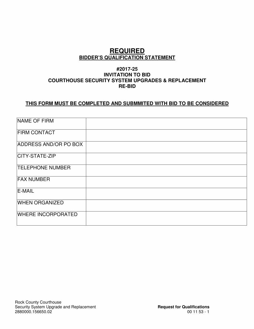
REQUIRED BIDDER’S QUALIFICATION STATEMENT
#2017-25
INVITATION TO BID COURTHOUSE SECURITY SYSTEM UPGRADES & REPLACEMENT
RE-BID
THIS FORM MUST BE COMPLETED AND SUBMMITED WITH BID TO BE CONSIDERED
NAME OF FIRM
FIRM CONTACT
ADDRESS AND/OR PO BOX
CITY-STATE-ZIP
TELEPHONE NUMBER
FAX NUMBER
WHEN ORGANIZED
WHERE INCORPORATED

Rock County Courthouse Security System Upgrade and Replacement Request for Qualifications 2880000.156650.02 00 11 53 - 2
Has your firm ever defaulted on any contract or failed to complete any work awarded to you?
YES NO
Have any of your contracts resulted in lawsuits?
YES NO
Has your firm or any member thereof, while performing work of the nature to which is being bid, ever filed bankruptcy?
YES NO
Does your firm possess all technical qualifications and resources, including equipment, personnel, and financial resources, necessary to perform the work required for this project?
YES NO
Does your firm possess all valid, effective licenses, registrations or certificates required by federal, state, county or local law, but not limited to, those for any type of trade work or specialty work?
YES NO
Does your firm maintain a substance abuse policy for employees?
YES NO
Will all employees assigned to this work have been through a safety training program within the last year?
YES NO
Has your firm committed a willful violation of federal, state, or local government safety laws determined by a final decision of a court or government agency authority?
YES NO
All employees assigned to this work will have to pass a Rock County Law Enforcement Background Check. Will your firm pre-screen these employees before they are submitted for a County Law Enforcement Background Check?
YES NO
Has your firm had any type of business contracting or trade license, certification or registration revoked or suspended?
YES NO
Has your firm been debarred by any federal, state or local government agency?
YES NO
Rock County Courthouse Security System Upgrade and Replacement Request for Qualifications 2880000.156650.02 00 11 53 - 3
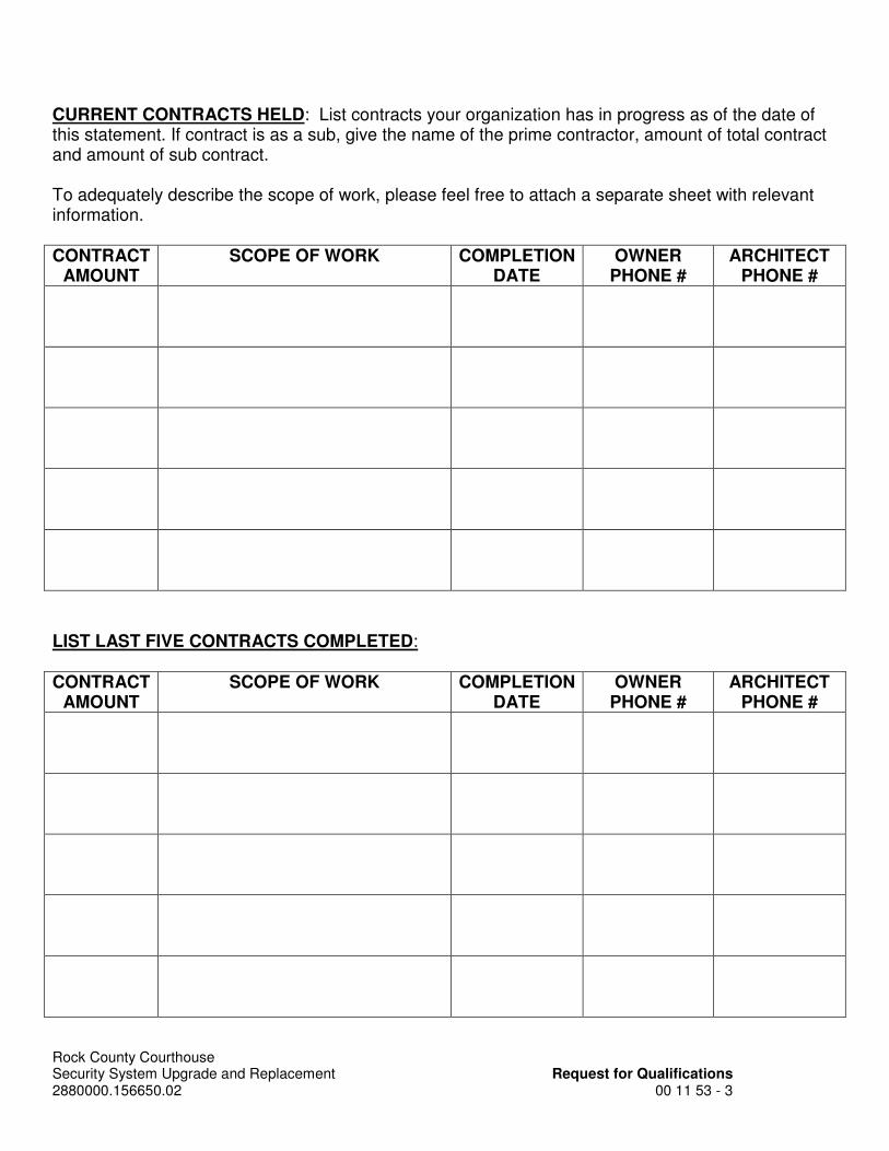
CURRENT CONTRACTS HELD: List contracts your organization has in progress as of the date of this statement. If contract is as a sub, give the name of the prime contractor, amount of total contract and amount of sub contract. To adequately describe the scope of work, please feel free to attach a separate sheet with relevant information. CONTRACT
AMOUNT SCOPE OF WORK COMPLETION
DATE OWNER
PHONE # ARCHITECT
PHONE #
LIST LAST FIVE CONTRACTS COMPLETED: CONTRACT
AMOUNT SCOPE OF WORK COMPLETION
DATE OWNER
PHONE # ARCHITECT
PHONE #

Rock County Courthouse Security System Upgrade and Replacement Request for Qualifications 2880000.156650.02 00 11 53 - 4
In order for a bidder to be considered for an award of Contract, the County shall be satisfied that the bidder meets the following requirements:
• Has completed at least one (1) project of at least fifty percent (50%) of size, or value of work being bid.
• Said project shall have been of the scope and type currently being bid as outlined in the Specifications of this Project Manual.
CONTRACT AMOUNT
SCOPE OF WORK COMPLETION DATE
OWNER PHONE #
ARCHITECT PHONE #
To adequately describe the scope of work, please feel free to attach a separate sheet with relevant information. Do you have any objection to our inquiring about any or all of the projects Yes□ No□ listed above? If yes, describe the circumstances: ___________________________________________________________ __________ _____ Will an on-site, skilled superintendent or foreman capable of Yes□ No□ executing the work under the Contract be assigned to this project? Will this skilled superintendent or foreman actually be entrusted with Yes□ No□ executing the work under the Contract? If no, please explain: ____________________________________________________________ ______________________________________________________________ _ _ List the training and experience of the superintendent or foreman: _______________________________________________________________________ __ _________________________________________________________________ ________
Rock County Courthouse Security System Upgrade and Replacement Request for Qualifications 2880000.156650.02 00 11 53 - 5
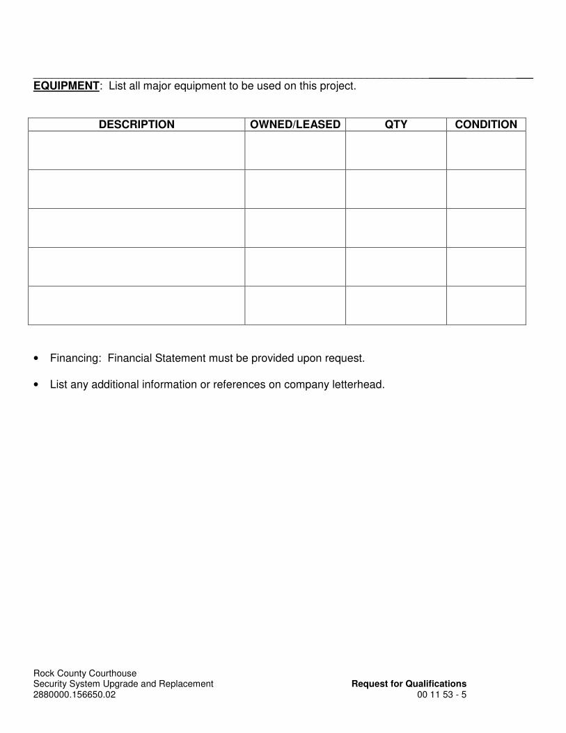
________________________________________________________________ ________ EQUIPMENT: List all major equipment to be used on this project.
DESCRIPTION OWNED/LEASED QTY CONDITION
• Financing: Financial Statement must be provided upon request.
• List any additional information or references on company letterhead.

PAGE INTENTIONALLY LEFT BLANK

Rock County Courthouse Security System Upgrade and Replacement Bid Form 2880000.156650.02 00 41 00 - 1
ROCK COUNTY, WISCONSIN PURCHASING DIVISION FINANCIAL SERVICES FAX (608) 757-5539
PHONE (608) 757-5517
#2017-25 INVITATION TO BID
ROCK COUNTY COURTHOUSE SECURITY SYSTEM UPGRADE AND REPLACEMENT - REBID
FOR ROCK COUNTY FACILITIES MANAGEMENT
JANESVILLE, WISCONSIN
BID FORM TO: County of Rock Financial Services Purchasing Division 51 South Main Street Janesville WI 53545 I (We) (A Corporation) (A Partnership) (An Individual) A Bona Fide Prime Bidder, have received the specifications prepared by Rock County for the above referenced project. I (We) have also received Addenda Nos. , and have included their provisions in this Bid. I (We) have examined the Specification Documents noted above, and agree to enter into and execute a contract, if awarded, on the basis of this Bid. BASE BID $ ALTERNATIVE BIDS Alternative Bids are more fully described in Section 01 23 00 of the Specifications. All Prime Bidders must indicate the stipulated sum to be added to or deducted from their Base Bid or indicate "no change". A "no bid" entry, or failure to enter a sum will be considered a "no change" to the Base Bid.

Rock County Courthouse Security System Upgrade and Replacement Bid Form 2880000.156650.02 00 41 00 - 2
ALTERNATIVE BID NO. 1 – Provide lump sum price to provide security electronic upgrades in the front and back parking structures as noted on the Drawings. If the Owner elects to accept this alternative, add to or deduct from my (our) Base Bid the stipulated sum of ____________________________________________Dollars($__________________________). ALTERNATIVE BID NO. 2 – Provide lump sum price to provide video surveillance monitors at Courtroom Bailiff Stations as noted on the Drawings. If the Owner elects to accept this alternative, add to or deduct from my (our) Base Bid the stipulated sum of ____________________________________________Dollars($__________________________). Estimated Start Date: , 2017 Estimated Completion Date: , 2017 List any deviations or additional information to your bid on company letterhead. Bid prepared by: Signature Print Name & Title Company: Address: Phone Number: Fax Number: E-Mail Address:

Rock County Courthouse Security System Upgrade and Replacement Wage Rate Requirements 2880000.156650.02 00 73 43 - 1
SECTION 00 73 43 WAGE RATE REQUIREMENTS
PART 1 - GENERAL
Please see the attached Prevailing Wage Rates for this project.
PART 2 - PRODUCTS
Not used.
PART 3 - EXECUTION
Not used.
END OF SECTION
ERD-16866 (R. 06/2013)
State of Wisconsin Department of Workforce Development Equal Rights Division
DEPARTMENTAL ORDER
ISSUE DATE: PROJECT:
PROJECT OWNER: REQUESTER:
ADDITIONAL CONTACT:
The department received an application for prevailing wage rate determination for the above-captioned project. The department conducted a survey to determine the prevailing wage rate for the trade(s) or occupation(s) needed to complete the project. The survey’s findings appear in the attached project determination. If you believe that the wage rate for any trade or occupation does not accurately reflect the prevailing wage rate in the city, village or town where the project is located, you may ask the department to conduct an administrative review of such wage rate. You must submit this request in writing within 30 days from the date indicated above. Additionally, your request must include wage rate information from at least three similar projects in the city, village or town where the proposed project is located and on which some work has been performed by the contested trade(s) during the current survey period and was previously considered by the department in issuing the attached determination. See DWD 290.10 of the Wisconsin Administrative Code and either s. 66.0903(3)(br), Stats., or s. 103.49(3)(c), Stats., for a complete explanation of the administrative review process. Enclosures
It is hereby ordered that the prevailing wage rates set forth in the attached project determination shall only be applicable to the above referenced project. This order is a FINAL ORDER of the department unless a timely request for an administrative review is filed with the department. ISSUED BY:
Equal Rights Division Labor Standards Bureau
Construction Wage Standards Section P.O. Box 8928, Madison, WI 53708-8928
(608)266-6861
Web Site: http://dwd.wisconsin.gov/er/
BRENT SUTHERLAND, FACILITIES MANAGEMENT DIRECTORROCK COUNTY515 MAIN ST.JANESVILLE, WI 53545
BRENT SUTHERLAND, FACILITIES MANAGEMENT DIRECTORROCK COUNTY515 MAIN ST.JANESVILLE, WI 53545
NOTE: The Requester must provide a copy of this ProjectDetermination and enclosures to the Project Owner and AdditionalContact.
10/18/2016
COURTHOUSE SECURITY PROJECTJANESVILLE CITY, ROCK COUNTY, WIDetermination No. 201602520

COURTHOUSE SECURITY PROJECT
Contractors are responsible for correctly classifying their workers. Either call the Department ofWorkforce Development (DWD) with trade or classification questions or consult DWD’s Dictionary ofOccupational Classifications & Work Descriptions on the DWD website at:dwd.wisconsin.gov/er/prevailing_wage_rate/Dictionary/dictionary_main.htm.
Time and one-half must be paid for all hours worked:- over 10 hours per day on prevailing wage projects- over 40 hours per calendar week- Saturday and Sunday- on all of the following holidays: January 1; the last Monday in May; July 4;
the 1st Monday in September; the 4th Thursday in November; December25;
- The day before if January 1, July 4 or December 25 falls on a Saturday;- The day following if January 1, July 4 or December 25 falls on a Sunday.
Apply the time and one-half overtime calculation to whichever is higher between the Hourly Basic Ratelisted on this project determination or the employee's regular hourly rate of pay. Add any applicablePremium or DOT Premium to the Hourly Basic Rate before calculating overtime.
A DOT Premium (discussed below) may supersede this time and one-half requirement.
When a specific trade or occupation requires a future increase, you MUST add the full hourly increaseto the "TOTAL" on the effective date(s) indicated for the specific trade or occupation.
If indicated for a specific trade or occupation, the full amount of such pay MUST be added to the"HOURLY BASIC RATE OF PAY" indicated for such trade or occupation, whevenever such pay isapplicable.
This premium only applies to highway and bridge projects owned by the Wisconsin Department ofTransportation and to the project type heading "Airport Pavement or State Highway Construction." DONOT apply the premium calculation under any other project type on this determination.
Pay apprentices a percentage of the applicable journeyperson's hourly basic rate of pay and hourlyfringe benefit contributions specified in this determination. Obtain the appropriate percentage fromeach apprentice’s contract or indenture.
Subjourney wage rates may be available for some of the trades or occupations indicated below withthe exception of laborers, truck drivers and heavy equipment operators. Any employer interested inusing a subjourney classification on this project MUST complete Form ERD-10880 and request theapplicable wage rate from the Department of Workforce Development PRIOR to using the subjourneyworker on this project.
PREVAILING WAGE RATE DETERMINATIONIssued by the State of Wisconsin
Department of Workforce DevelopmentPursuant to s. 66.0903, Wis. Stats.
Issued On: 10/18/2016
DETERMINATION NUMBER: 201602520
EXPIRATION DATE: Prime Contracts MUST Be Awarded or Negotiated On Or Before4/16/2017. If NOT, You MUST Reapply.
PROJECT NAME:
PROJECT LOCATION: JANESVILLE CITY, ROCK COUNTY, WI
CONTRACTING AGENCY: ROCK COUNTY
CLASSIFICATION:
OVERTIME:
FUTURE INCREASE:
PREMIUM PAY:
DOT PREMIUM:
APPRENTICES:
SUBJOURNEY:
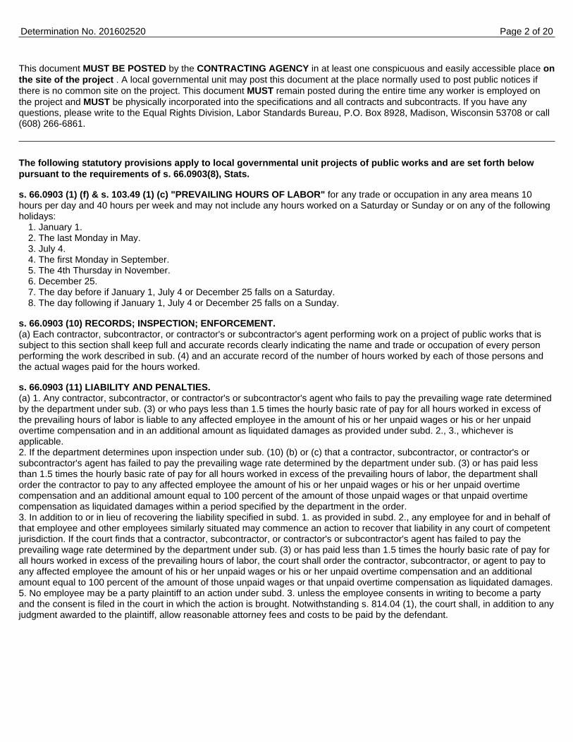
This document MUST BE POSTED by the CONTRACTING AGENCY in at least one conspicuous and easily accessible place onthe site of the project . A local governmental unit may post this document at the place normally used to post public notices ifthere is no common site on the project. This document MUST remain posted during the entire time any worker is employed onthe project and MUST be physically incorporated into the specifications and all contracts and subcontracts. If you have anyquestions, please write to the Equal Rights Division, Labor Standards Bureau, P.O. Box 8928, Madison, Wisconsin 53708 or call(608) 266-6861.
The following statutory provisions apply to local governmental unit projects of public works and are set forth belowpursuant to the requirements of s. 66.0903(8), Stats.
s. 66.0903 (1) (f) & s. 103.49 (1) (c) "PREVAILING HOURS OF LABOR" for any trade or occupation in any area means 10hours per day and 40 hours per week and may not include any hours worked on a Saturday or Sunday or on any of the followingholidays:
1. January 1.2. The last Monday in May.3. July 4.4. The first Monday in September.5. The 4th Thursday in November.6. December 25.7. The day before if January 1, July 4 or December 25 falls on a Saturday.8. The day following if January 1, July 4 or December 25 falls on a Sunday.
s. 66.0903 (10) RECORDS; INSPECTION; ENFORCEMENT.(a) Each contractor, subcontractor, or contractor's or subcontractor's agent performing work on a project of public works that issubject to this section shall keep full and accurate records clearly indicating the name and trade or occupation of every personperforming the work described in sub. (4) and an accurate record of the number of hours worked by each of those persons andthe actual wages paid for the hours worked.
s. 66.0903 (11) LIABILITY AND PENALTIES.(a) 1. Any contractor, subcontractor, or contractor's or subcontractor's agent who fails to pay the prevailing wage rate determinedby the department under sub. (3) or who pays less than 1.5 times the hourly basic rate of pay for all hours worked in excess ofthe prevailing hours of labor is liable to any affected employee in the amount of his or her unpaid wages or his or her unpaidovertime compensation and in an additional amount as liquidated damages as provided under subd. 2., 3., whichever isapplicable.2. If the department determines upon inspection under sub. (10) (b) or (c) that a contractor, subcontractor, or contractor's orsubcontractor's agent has failed to pay the prevailing wage rate determined by the department under sub. (3) or has paid lessthan 1.5 times the hourly basic rate of pay for all hours worked in excess of the prevailing hours of labor, the department shallorder the contractor to pay to any affected employee the amount of his or her unpaid wages or his or her unpaid overtimecompensation and an additional amount equal to 100 percent of the amount of those unpaid wages or that unpaid overtimecompensation as liquidated damages within a period specified by the department in the order.3. In addition to or in lieu of recovering the liability specified in subd. 1. as provided in subd. 2., any employee for and in behalf ofthat employee and other employees similarly situated may commence an action to recover that liability in any court of competentjurisdiction. If the court finds that a contractor, subcontractor, or contractor's or subcontractor's agent has failed to pay theprevailing wage rate determined by the department under sub. (3) or has paid less than 1.5 times the hourly basic rate of pay forall hours worked in excess of the prevailing hours of labor, the court shall order the contractor, subcontractor, or agent to pay toany affected employee the amount of his or her unpaid wages or his or her unpaid overtime compensation and an additionalamount equal to 100 percent of the amount of those unpaid wages or that unpaid overtime compensation as liquidated damages.5. No employee may be a party plaintiff to an action under subd. 3. unless the employee consents in writing to become a partyand the consent is filed in the court in which the action is brought. Notwithstanding s. 814.04 (1), the court shall, in addition to anyjudgment awarded to the plaintiff, allow reasonable attorney fees and costs to be paid by the defendant.
Determination No. 201602520 Page 2 of 20

Includes sheltered enclosures with walk-in access for the purpose of housing persons, employees, machinery,equipment or supplies and non-sheltered work such as canals, dams, dikes, reservoirs, storage tanks, etc. A shelteredenclosure need not be "habitable" in order to be considered a building. The installation of machinery and/or equipment,both above and below grade level, does not change a project's character as a building. On-site grading, utility work andlandscaping are included within this definition. Residential buildings of four (4) stories or less, agricultural buildings,parking lots and driveways are NOT included within this definition.
Fringe Benefits Must Be Paid On All Hours Worked
CODE TRADE OR OCCUPATION OF PAY BENEFITS TOTAL
Acoustic Ceiling Tile InstallerFuture Increase(s):
Add $1.42/hr on 6/1/2016.
Boilermaker
Bricklayer, Blocklayer or StonemasonFuture Increase(s):
Add $1.45 on 06/06/2016Premium Increase(s):
DOT PREMIUM: Pay two times the hourly basic rate onSunday, New Year’s Day, Memorial Day, IndependenceDay, Labor Day, Thanksgiving Day & Christmas Day.
Cabinet InstallerFuture Increase(s):
Add $1.42/hr on 6/1/2016.
CarpenterFuture Increase(s):
Add $1.42/hr on 6/1/2016.Premium Increase(s):
DOT PREMIUM: Pay two times the hourly basic rate onSunday, New Year's Day, Memorial Day, IndependenceDay, Labor Day, Thanksgiving Day & Christmas Day.
Carpet Layer or Soft Floor CovererFuture Increase(s):
Add $1.42/hr on 6/1/2016.
Cement FinisherFuture Increase(s):
Add $1.45 on 05/31/2016
Drywall Taper or Finisher
ElectricianPremium Increase(s):
DOT PREMIUM: Pay two times the hourly basic rate onSunday, New Year’s Day, Memorial Day, IndependenceDay, Labor Day, Thanksgiving Day & Christmas Day.
Elevator Constructor
Fence Erector
Determination No. 201602520
BUILDING OR HEAVY CONSTRUCTION
SKILLED TRADES
HOURLY HOURLYBASIC RATE FRINGE
$ $ $
101 33.02 17.12 50.14
102 33.35 28.29 61.64
103 32.90 19.99 52.89
104 33.02 17.12 50.14
105 33.02 17.12 50.14
106 33.02 17.12 50.14
107 33.47 17.85 51.32
108 27.00 16.65 43.65
109 31.90 18.47 50.37
110 46.05 27.09 73.14
111 19.27 7.67 26.94
Page 3 of 20
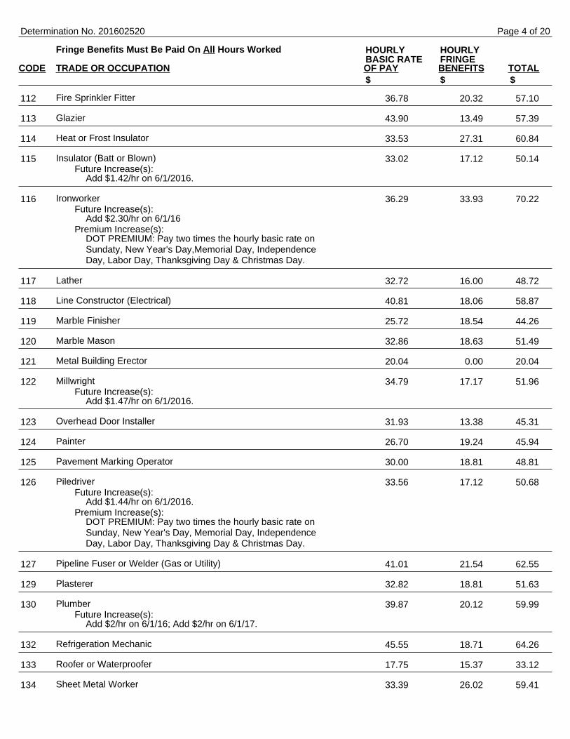
Fringe Benefits Must Be Paid On All Hours Worked
CODE TRADE OR OCCUPATION OF PAY BENEFITS TOTAL
Fire Sprinkler Fitter
Glazier
Heat or Frost Insulator
Insulator (Batt or Blown)Future Increase(s):
Add $1.42/hr on 6/1/2016.
IronworkerFuture Increase(s):
Add $2.30/hr on 6/1/16Premium Increase(s):
DOT PREMIUM: Pay two times the hourly basic rate onSundaty, New Year's Day,Memorial Day, IndependenceDay, Labor Day, Thanksgiving Day & Christmas Day.
Lather
Line Constructor (Electrical)
Marble Finisher
Marble Mason
Metal Building Erector
MillwrightFuture Increase(s):
Add $1.47/hr on 6/1/2016.
Overhead Door Installer
Painter
Pavement Marking Operator
PiledriverFuture Increase(s):
Add $1.44/hr on 6/1/2016.Premium Increase(s):
DOT PREMIUM: Pay two times the hourly basic rate onSunday, New Year's Day, Memorial Day, IndependenceDay, Labor Day, Thanksgiving Day & Christmas Day.
Pipeline Fuser or Welder (Gas or Utility)
Plasterer
PlumberFuture Increase(s):
Add $2/hr on 6/1/16; Add $2/hr on 6/1/17.
Refrigeration Mechanic
Roofer or Waterproofer
Sheet Metal Worker
Determination No. 201602520
HOURLY HOURLYBASIC RATE FRINGE
$ $ $
112 36.78 20.32 57.10
113 43.90 13.49 57.39
114 33.53 27.31 60.84
115 33.02 17.12 50.14
116 36.29 33.93 70.22
117 32.72 16.00 48.72
118 40.81 18.06 58.87
119 25.72 18.54 44.26
120 32.86 18.63 51.49
121 20.04 0.00 20.04
122 34.79 17.17 51.96
123 31.93 13.38 45.31
124 26.70 19.24 45.94
125 30.00 18.81 48.81
126 33.56 17.12 50.68
127 41.01 21.54 62.55
129 32.82 18.81 51.63
130 39.87 20.12 59.99
132 45.55 18.71 64.26
133 17.75 15.37 33.12
134 33.39 26.02 59.41
Page 4 of 20
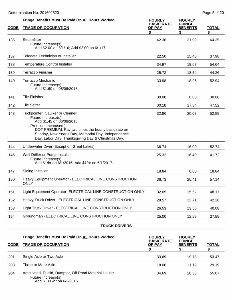
Fringe Benefits Must Be Paid On All Hours Worked
CODE TRADE OR OCCUPATION OF PAY BENEFITS TOTAL
SteamfitterFuture Increase(s):
Add $2.00 on 6/1/16; Add $2.00 on 6/1/17
Teledata Technician or Installer
Temperature Control Installer
Terrazzo Finisher
Terrazzo MechanicFuture Increase(s):
Add $1.60 on 06/06/2016
Tile Finisher
Tile Setter
Tuckpointer, Caulker or CleanerFuture Increase(s):
Add $1.45 on 06/06/2016Premium Increase(s):
DOT PREMIUM: Pay two times the hourly basic rate onSunday, New Year’s Day, Memorial Day, IndependenceDay, Labor Day, Thanksgiving Day & Christmas Day.
Underwater Diver (Except on Great Lakes)
Well Driller or Pump InstallerFuture Increase(s):
Add $1/hr on 6/1/2016; Add $1/hr on 6/1/2017.
Siding Installer
Heavy Equipment Operator - ELECTRICAL LINE CONSTRUCTIONONLY
Light Equipment Operator -ELECTRICAL LINE CONSTRUCTION ONLY
Heavy Truck Driver - ELECTRICAL LINE CONSTRUCTION ONLY
Light Truck Driver - ELECTRICAL LINE CONSTRUCTION ONLY
Groundman - ELECTRICAL LINE CONSTRUCTION ONLY
Fringe Benefits Must Be Paid On All Hours Worked
CODE TRADE OR OCCUPATION OF PAY BENEFITS TOTAL
Single Axle or Two Axle
Three or More Axle
Articulated, Euclid, Dumptor, Off Road Material HaulerFuture Increase(s):
Add $1.60/hr on 6/3/2016.
Determination No. 201602520
HOURLY HOURLYBASIC RATE FRINGE
$ $ $
135 42.36 21.99 64.35
137 22.50 15.48 37.98
138 34.97 19.67 54.64
139 25.72 18.54 44.26
140 33.98 18.96 52.94
141 30.00 0.00 30.00
142 30.18 17.34 47.52
143 32.86 20.03 52.89
144 36.74 16.00 52.74
146 25.32 16.40 41.72
147 18.84 0.00 18.84
150 36.73 20.41 57.14
151 32.65 15.52 48.17
152 28.57 13.71 42.28
153 26.53 13.55 40.08
154 25.00 12.55 37.55
TRUCK DRIVERS
HOURLY HOURLYBASIC RATE FRINGE
$ $ $
201 33.69 19.78 53.47
203 18.00 11.19 29.19
204 34.69 20.38 55.07
Page 5 of 20
Fringe Benefits Must Be Paid On All Hours Worked
CODE TRADE OR OCCUPATION OF PAY BENEFITS TOTAL
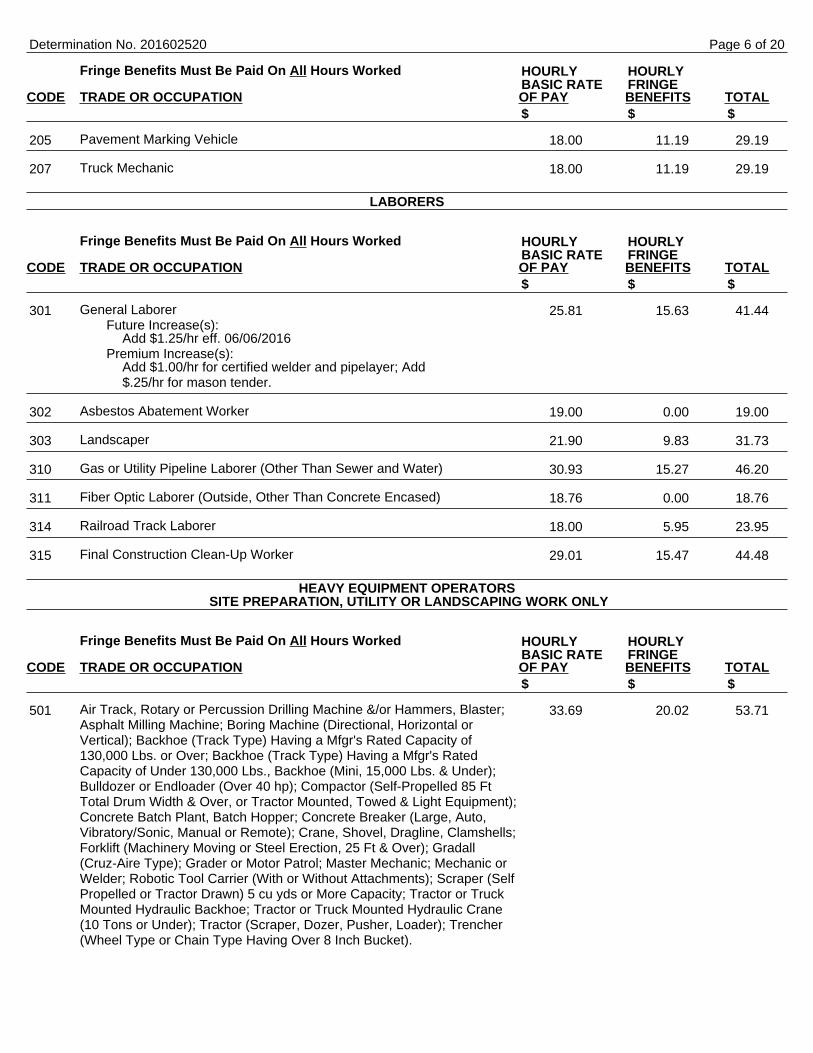
Pavement Marking Vehicle
Truck Mechanic
Fringe Benefits Must Be Paid On All Hours Worked
CODE TRADE OR OCCUPATION OF PAY BENEFITS TOTAL
General LaborerFuture Increase(s):
Add $1.25/hr eff. 06/06/2016Premium Increase(s):
Add $1.00/hr for certified welder and pipelayer; Add$.25/hr for mason tender.
Asbestos Abatement Worker
Landscaper
Gas or Utility Pipeline Laborer (Other Than Sewer and Water)
Fiber Optic Laborer (Outside, Other Than Concrete Encased)
Railroad Track Laborer
Final Construction Clean-Up Worker
Fringe Benefits Must Be Paid On All Hours Worked
CODE TRADE OR OCCUPATION OF PAY BENEFITS TOTAL
Air Track, Rotary or Percussion Drilling Machine &/or Hammers, Blaster;Asphalt Milling Machine; Boring Machine (Directional, Horizontal orVertical); Backhoe (Track Type) Having a Mfgr's Rated Capacity of130,000 Lbs. or Over; Backhoe (Track Type) Having a Mfgr's RatedCapacity of Under 130,000 Lbs., Backhoe (Mini, 15,000 Lbs. & Under);Bulldozer or Endloader (Over 40 hp); Compactor (Self-Propelled 85 FtTotal Drum Width & Over, or Tractor Mounted, Towed & Light Equipment);Concrete Batch Plant, Batch Hopper; Concrete Breaker (Large, Auto,Vibratory/Sonic, Manual or Remote); Crane, Shovel, Dragline, Clamshells;Forklift (Machinery Moving or Steel Erection, 25 Ft & Over); Gradall(Cruz-Aire Type); Grader or Motor Patrol; Master Mechanic; Mechanic orWelder; Robotic Tool Carrier (With or Without Attachments); Scraper (SelfPropelled or Tractor Drawn) 5 cu yds or More Capacity; Tractor or TruckMounted Hydraulic Backhoe; Tractor or Truck Mounted Hydraulic Crane(10 Tons or Under); Tractor (Scraper, Dozer, Pusher, Loader); Trencher(Wheel Type or Chain Type Having Over 8 Inch Bucket).
Determination No. 201602520
HOURLY HOURLYBASIC RATE FRINGE
$ $ $
205 18.00 11.19 29.19
207 18.00 11.19 29.19
LABORERS
HOURLY HOURLYBASIC RATE FRINGE
$ $ $
301 25.81 15.63 41.44
302 19.00 0.00 19.00
303 21.90 9.83 31.73
310 30.93 15.27 46.20
311 18.76 0.00 18.76
314 18.00 5.95 23.95
315 29.01 15.47 44.48
HEAVY EQUIPMENT OPERATORS SITE PREPARATION, UTILITY OR LANDSCAPING WORK ONLY
HOURLY HOURLYBASIC RATE FRINGE
$ $ $
501 33.69 20.02 53.71
Page 6 of 20
Fringe Benefits Must Be Paid On All Hours Worked
CODE TRADE OR OCCUPATION OF PAY BENEFITS TOTAL
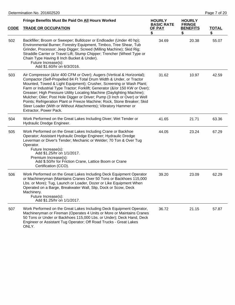
Backfiller; Broom or Sweeper; Bulldozer or Endloader (Under 40 hp);Environmental Burner; Forestry Equipment, Timbco, Tree Shear, TubGrinder, Processor; Jeep Digger; Screed (Milling Machine); Skid Rig;Straddle Carrier or Travel Lift; Stump Chipper; Trencher (Wheel Type orChain Type Having 8 Inch Bucket & Under).
Future Increase(s):Add $1.60/hr on 6/3/2016.
Air Compressor (&/or 400 CFM or Over); Augers (Vertical & Horizontal);Compactor (Self-Propelled 84 Ft Total Drum Width & Under, or TractorMounted, Towed & Light Equipment); Crusher, Screening or Wash Plant;Farm or Industrial Type Tractor; Forklift; Generator (&/or 150 KW or Over);Greaser; High Pressure Utility Locating Machine (Daylighting Machine);Mulcher; Oiler; Post Hole Digger or Driver; Pump (3 Inch or Over) or WellPoints; Refrigeration Plant or Freeze Machine; Rock, Stone Breaker; SkidSteer Loader (With or Without Attachments); Vibratory Hammer orExtractor, Power Pack.
Work Performed on the Great Lakes Including Diver; Wet Tender orHydraulic Dredge Engineer.
Work Performed on the Great Lakes Including Crane or BackhoeOperator; Assistant Hydraulic Dredge Engineer; Hydraulic DredgeLeverman or Diver's Tender; Mechanic or Welder; 70 Ton & Over TugOperator.
Future Increase(s):Add $1.25/hr on 1/1/2017.
Premium Increase(s):Add $.50/hr for Friction Crane, Lattice Boom or CraneCertification (CCO).
Work Performed on the Great Lakes Including Deck Equipment Operatoror Machineryman (Maintains Cranes Over 50 Tons or Backhoes 115,000Lbs. or More); Tug, Launch or Loader, Dozer or Like Equipment WhenOperated on a Barge, Breakwater Wall, Slip, Dock or Scow, DeckMachinery.
Future Increase(s):Add $1.25/hr on 1/1/2017.
Work Performed on the Great Lakes Including Deck Equipment Operator,Machineryman or Fireman (Operates 4 Units or More or Maintains Cranes50 Tons or Under or Backhoes 115,000 Lbs. or Under); Deck Hand, DeckEngineer or Assistant Tug Operator; Off Road Trucks - Great LakesONLY.
Determination No. 201602520
HOURLY HOURLYBASIC RATE FRINGE
$ $ $
502 34.69 20.38 55.07
503 31.62 10.97 42.59
504 41.65 21.71 63.36
505 44.05 23.24 67.29
506 39.20 23.09 62.29
507 36.72 21.15 57.87
Page 7 of 20

Fringe Benefits Must Be Paid On All Hours Worked
CODE TRADE OR OCCUPATION OF PAY BENEFITS TOTAL
Boring Machine (Directional); Crane, Tower Crane, Pedestal Tower orDerrick, With or Without Attachments, With a Lifting Capacity of Over 100Tons, Self-Erecting Tower Crane With a Lifting Capacity of Over 4,000Lbs., Crane With Boom Dollies; Crane, Tower Crane, Pedestal Tower orDerrick, With Boom, Leads &/or Jib Lengths Measuring 176 Ft or Over;Master Mechanic.
Future Increase(s):Add $1.60/hr on 6/3/2016.
Premium Increase(s):Add $.50/hr for >200 Ton; Add $1/hr at 300 Ton; Add$1.50/hr at 400 Ton; Add $2/hr at 500 Ton & Over.
Backhoe (Track Type) Having a Mfgr's Rated Capacity of 130,000 Lbs. orOver; Boring Machine (Horizontal or Vertical); Caisson Rig; Crane, TowerCrane, Portable Tower, Pedestal Tower or Derrick, With or WithoutAttachments, With a Lifting Capacity of 100 Tons or Under, Self-ErectingTower Crane With A Lifting Capacity Of 4,000 Lbs. & Under; Crane, TowerCrane, Portable Tower, Pedestal Tower or Derrick, With Boom, Leads&/or Jib Lengths Measuring 175 Ft or Under; Pile Driver; Versi Lifts,Tri-Lifts & Gantrys (20,000 Lbs. & Over).
Future Increase(s):Add $1.60/hr on 6/3/2016.
Premium Increase(s):Add $.25/hr for all >45 Ton lifting capacity cranes.
Backhoe (Track Type) Having a Mfgr.'s Rated Capacity of Under 130,000Lbs., Backhoe (Mini, 15,000 Lbs. & Under); Concrete Bump Cutter,Grinder, Planing or Grooving Machine; Concrete Laser/Screed; ConcretePaver (Slipform); Concrete Pump (Over 46 Meter), Concrete Conveyor(Rotec or Bidwell Type); Concrete Slipform Placer Curb & Gutter Machine;Concrete Spreader & Distributor; Dredge (NOT Performing Work on theGreat Lakes); Forklift (Machinery Moving or Steel Erection, 25 Ft & Over);Gradall (Cruz-Aire Type); Hydro-Blaster (10,000 PSI or Over); MillingMachine; Skid Rig; Traveling Crane (Bridge Type).
Determination No. 201602520
HEAVY EQUIPMENT OPERATORS EXCLUDING SITE PREPARATION, UTILITY, PAVING LANDSCAPING WORK
HOURLY HOURLYBASIC RATE FRINGE
$ $ $
508 37.67 20.38 58.05
509 36.42 20.38 56.80
510 27.47 7.35 34.82
Page 8 of 20

Fringe Benefits Must Be Paid On All Hours Worked
CODE TRADE OR OCCUPATION OF PAY BENEFITS TOTAL
Air, Track, Rotary or Percussion Drilling Machine &/or Hammers, Blaster;Bulldozer or Endloader (Over 40 hp); Compactor (Self-Propelled 85 FtTotal Drum Width & Over, or Tractor Mounted, Towed & Light Equipment);Concrete Pump (46 Meter & Under), Concrete Conveyor (Rotec or BidwellType); Crane (Carry Deck, Mini) or Truck Mounted Hydraulic Crane (10Tons or Under); Environmental Burner; Gantrys (Under 20,000 Lbs.);Grader or Motor Patrol; High Pressure Utility Locating Machine(Daylighting Machine); Manhoist; Material or Stack Hoist; Mechanic orWelder; Railroad Track Rail Leveling Machine, Tie Placer, Extractor,Tamper, Stone Leveler or Rehabilitation Equipment; Roller (Over 5 Ton);Scraper (Self Propelled or Tractor Drawn) 5 cu yd or More Capacity;Screed (Milling Machine); Sideboom; Straddle Carrier or Travel Lift; Tiningor Curing Machine; Tractor (Scraper, Dozer, Pusher, Loader); Tractor orTruck Mounted Hydraulic Backhoe; Tractor or Truck Mounted HydraulicCrane (10 Tons or Under); Trencher (Wheel Type or Chain Type HavingOver 8-Inch Bucket).
Future Increase(s):Add $1.60/hr on 6/3/2016.
Backfiller; Broom or Sweeper; Bulldozer or Endloader (Under 40 hp);Compactor (Self-Propelled 84 Ft Total Drum Width & Under, or TractorMounted, Towed & Light Equipment); Concrete Batch Plant, BatchHopper; Concrete Breaker (Large, Auto, Vibratory/Sonic, Manual orRemote); Concrete Conveyor System; Concrete Finishing Machine (RoadType); Fireman (Pile Driver & Derrick NOT Performing Work on the GreatLakes); Grout Pump; Hoist (Tugger, Automatic); Industrial Locomotives;Jeep Digger; Lift Slab Machine; Mulcher; Roller (Rubber Tire, 5 Ton orUnder); Screw or Gypsum Pumps; Stabilizing or Concrete Mixer(Self-Propelled or 14S or Over); Stump Chipper; Trencher (Wheel Type orChain Type Having 8-Inch Bucket & Under); Winches & A-Frames.
Future Increase(s):Add $1.60/hr on 6/3/2016.
Air Compressor (&/or 400 CFM or Over); Air, Electric or Hydraulic JackingSystem; Augers (Vertical & Horizontal); Boatmen (NOT Performing Workon the Great Lakes); Boiler (Temporary Heat); Crusher, Screening orWash Plant; Elevator; Farm or Industrial Type Tractor; Fireman (AsphaltPlant NOT Performing Work on the Great Lakes); Forklift; Generator (&/or150 KW or Over); Greaser; Heaters (Mechanical); Loading Machine(Conveyor); Oiler; Post Hole Digger or Driver; Prestress Machine; Pump(3 Inch or Over) or Well Points; Refrigeration Plant or Freeze Machine;Robotic Tool Carrier (With or Without Attachments); Rock, Stone Breaker;Skid Steer Loader (With or Without Attachments); Vibratory Hammer orExtractor, Power Pack.
Future Increase(s):Add $1.60/hr on 6/3/2016.
Gas or Utility Pipeline, Except Sewer & Water (Primary Equipment).Future Increase(s):
Add $1/hr on 5/30/2016.
Gas or Utility Pipeline, Except Sewer & Water (Secondary Equipment).
Fiber Optic Cable Equipment
Determination No. 201602520
HOURLY HOURLYBASIC RATE FRINGE
$ $ $
511 34.69 20.38 55.07
512 32.62 20.38 53.00
513 31.99 20.38 52.37
514 37.04 22.44 59.48
515 33.82 20.30 54.12
516 26.00 3.86 29.86
Page 9 of 20
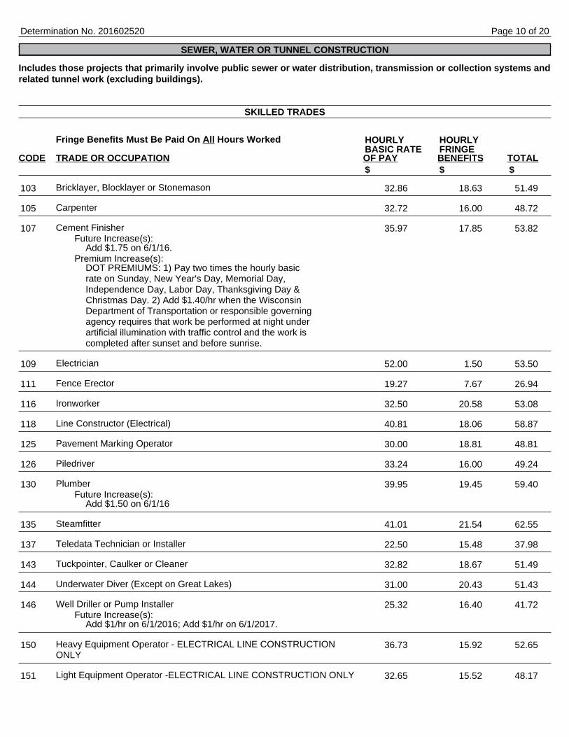
Includes those projects that primarily involve public sewer or water distribution, transmission or collection systems andrelated tunnel work (excluding buildings).
Fringe Benefits Must Be Paid On All Hours Worked
CODE TRADE OR OCCUPATION OF PAY BENEFITS TOTAL
Bricklayer, Blocklayer or Stonemason
Carpenter
Cement FinisherFuture Increase(s):
Add $1.75 on 6/1/16.Premium Increase(s):
DOT PREMIUMS: 1) Pay two times the hourly basicrate on Sunday, New Year's Day, Memorial Day,Independence Day, Labor Day, Thanksgiving Day &Christmas Day. 2) Add $1.40/hr when the WisconsinDepartment of Transportation or responsible governingagency requires that work be performed at night underartificial illumination with traffic control and the work iscompleted after sunset and before sunrise.
Electrician
Fence Erector
Ironworker
Line Constructor (Electrical)
Pavement Marking Operator
Piledriver
PlumberFuture Increase(s):
Add $1.50 on 6/1/16
Steamfitter
Teledata Technician or Installer
Tuckpointer, Caulker or Cleaner
Underwater Diver (Except on Great Lakes)
Well Driller or Pump InstallerFuture Increase(s):
Add $1/hr on 6/1/2016; Add $1/hr on 6/1/2017.
Heavy Equipment Operator - ELECTRICAL LINE CONSTRUCTIONONLY
Light Equipment Operator -ELECTRICAL LINE CONSTRUCTION ONLY
Determination No. 201602520
SEWER, WATER OR TUNNEL CONSTRUCTION
SKILLED TRADES
HOURLY HOURLYBASIC RATE FRINGE
$ $ $
103 32.86 18.63 51.49
105 32.72 16.00 48.72
107 35.97 17.85 53.82
109 52.00 1.50 53.50
111 19.27 7.67 26.94
116 32.50 20.58 53.08
118 40.81 18.06 58.87
125 30.00 18.81 48.81
126 33.24 16.00 49.24
130 39.95 19.45 59.40
135 41.01 21.54 62.55
137 22.50 15.48 37.98
143 32.82 18.67 51.49
144 31.00 20.43 51.43
146 25.32 16.40 41.72
150 36.73 15.92 52.65
151 32.65 15.52 48.17
Page 10 of 20
Fringe Benefits Must Be Paid On All Hours Worked
CODE TRADE OR OCCUPATION OF PAY BENEFITS TOTAL
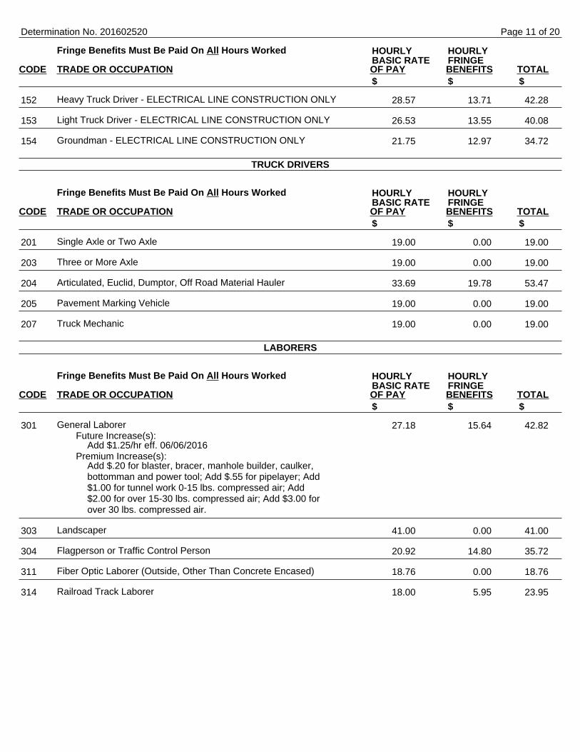
Heavy Truck Driver - ELECTRICAL LINE CONSTRUCTION ONLY
Light Truck Driver - ELECTRICAL LINE CONSTRUCTION ONLY
Groundman - ELECTRICAL LINE CONSTRUCTION ONLY
Fringe Benefits Must Be Paid On All Hours Worked
CODE TRADE OR OCCUPATION OF PAY BENEFITS TOTAL
Single Axle or Two Axle
Three or More Axle
Articulated, Euclid, Dumptor, Off Road Material Hauler
Pavement Marking Vehicle
Truck Mechanic
Fringe Benefits Must Be Paid On All Hours Worked
CODE TRADE OR OCCUPATION OF PAY BENEFITS TOTAL
General LaborerFuture Increase(s):
Add $1.25/hr eff. 06/06/2016Premium Increase(s):
Add $.20 for blaster, bracer, manhole builder, caulker,bottomman and power tool; Add $.55 for pipelayer; Add$1.00 for tunnel work 0-15 lbs. compressed air; Add$2.00 for over 15-30 lbs. compressed air; Add $3.00 forover 30 lbs. compressed air.
Landscaper
Flagperson or Traffic Control Person
Fiber Optic Laborer (Outside, Other Than Concrete Encased)
Railroad Track Laborer
Determination No. 201602520
HOURLY HOURLYBASIC RATE FRINGE
$ $ $
152 28.57 13.71 42.28
153 26.53 13.55 40.08
154 21.75 12.97 34.72
TRUCK DRIVERS
HOURLY HOURLYBASIC RATE FRINGE
$ $ $
201 19.00 0.00 19.00
203 19.00 0.00 19.00
204 33.69 19.78 53.47
205 19.00 0.00 19.00
207 19.00 0.00 19.00
LABORERS
HOURLY HOURLYBASIC RATE FRINGE
$ $ $
301 27.18 15.64 42.82
303 41.00 0.00 41.00
304 20.92 14.80 35.72
311 18.76 0.00 18.76
314 18.00 5.95 23.95
Page 11 of 20
Fringe Benefits Must Be Paid On All Hours Worked
CODE TRADE OR OCCUPATION OF PAY BENEFITS TOTAL
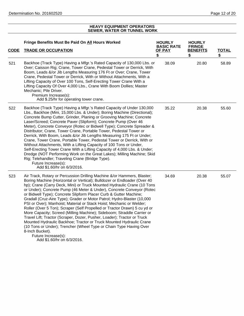
Backhoe (Track Type) Having a Mfgr.'s Rated Capacity of 130,000 Lbs. orOver; Caisson Rig; Crane, Tower Crane, Pedestal Tower or Derrick, WithBoom, Leads &/or Jib Lengths Measuring 176 Ft or Over; Crane, TowerCrane, Pedestal Tower or Derrick, With or Without Attachments, With aLifting Capacity of Over 100 Tons, Self-Erecting Tower Crane With aLifting Capacity Of Over 4,000 Lbs., Crane With Boom Dollies; MasterMechanic; Pile Driver.
Premium Increase(s):Add $.25/hr for operating tower crane.
Backhoe (Track Type) Having a Mfgr.'s Rated Capacity of Under 130,000Lbs., Backhoe (Mini, 15,000 Lbs. & Under); Boring Machine (Directional);Concrete Bump Cutter, Grinder, Planing or Grooving Machine; ConcreteLaser/Screed; Concrete Paver (Slipform); Concrete Pump (Over 46Meter), Concrete Conveyor (Rotec or Bidwell Type); Concrete Spreader &Distributor; Crane, Tower Crane, Portable Tower, Pedestal Tower orDerrick, With Boom, Leads &/or Jib Lengths Measuring 175 Ft or Under;Crane, Tower Crane, Portable Tower, Pedestal Tower or Derrick, With orWithout Attachments, With a Lifting Capacity of 100 Tons or Under,Self-Erecting Tower Crane With a Lifting Capacity of 4,000 Lbs. & Under;Dredge (NOT Performing Work on the Great Lakes); Milling Machine; SkidRig; Telehandler; Traveling Crane (Bridge Type).
Future Increase(s):Add $1.60/hr on 6/3/2016.
Air Track, Rotary or Percussion Drilling Machine &/or Hammers, Blaster;Boring Machine (Horizontal or Vertical); Bulldozer or Endloader (Over 40hp); Crane (Carry Deck, Mini) or Truck Mounted Hydraulic Crane (10 Tonsor Under); Concrete Pump (46 Meter & Under), Concrete Conveyor (Rotecor Bidwell Type); Concrete Slipform Placer Curb & Gutter Machine;Gradall (Cruz-Aire Type); Grader or Motor Patrol; Hydro-Blaster (10,000PSI or Over); Manhoist; Material or Stack Hoist; Mechanic or Welder;Roller (Over 5 Ton); Scraper (Self Propelled or Tractor Drawn) 5 cu yd orMore Capacity; Screed (Milling Machine); Sideboom; Straddle Carrier orTravel Lift; Tractor (Scraper, Dozer, Pusher, Loader); Tractor or TruckMounted Hydraulic Backhoe; Tractor or Truck Mounted Hydraulic Crane(10 Tons or Under); Trencher (Wheel Type or Chain Type Having Over8-Inch Bucket).
Future Increase(s):Add $1.60/hr on 6/3/2016.
Determination No. 201602520
HEAVY EQUIPMENT OPERATORS SEWER, WATER OR TUNNEL WORK
HOURLY HOURLYBASIC RATE FRINGE
$ $ $
521 38.09 20.80 58.89
522 35.22 20.38 55.60
523 34.69 20.38 55.07
Page 12 of 20

Fringe Benefits Must Be Paid On All Hours Worked
CODE TRADE OR OCCUPATION OF PAY BENEFITS TOTAL
Backfiller; Broom or Sweeper; Bulldozer or Endloader (Under 40 hp);Compactor (Self-Propelled 85 Ft Total Drum Width & Over, or TractorMounted, Towed & Light Equipment); Concrete Batch Plant, BatchHopper; Concrete Breaker (Large, Auto, Vibratory/Sonic, Manual orRemote); Concrete Conveyor System; Concrete Finishing Machine (RoadType); Environmental Burner; Fireman (Pile Driver & Derrick NOTPerforming Work on the Great Lakes); Forestry Equipment, Timbco, TreeShear, Tub Grinder, Processor; Hoist (Tugger, Automatic); Grout Pump;Jeep Digger; Lift Slab Machine; Mulcher; Power Subgrader; Pump (3 Inchor Over) or Well Points; Robotic Tool Carrier (With or WithoutAttachments); Roller (Rubber Tire, 5 Ton or Under); Screw or GypsumPumps; Stabilizing or Concrete Mixer (Self-Propelled or 14S or Over);Stump Chipper; Tining or Curing Machine; Trencher (Wheel Type or ChainType Having 8-Inch Bucket & Under); Winches & A-Frames.
Air Compressor (&/or 400 CFM or Over); Air, Electric or Hydraulic JackingSystem; Augers (Vertical & Horizontal); Compactor (Self-Propelled 84 FtTotal Drum Width & Under, or Tractor Mounted, Towed & LightEquipment); Crusher, Screening or Wash Plant; Farm or Industrial TypeTractor; Fireman (Asphalt Plant NOT Performing Work on the GreatLakes); Generator (&/or 150 KW or Over); Heaters (Mechanical); HighPressure Utility Locating Machine (Daylighting Machine); Loading Machine(Conveyor); Post Hole Digger or Driver; Refrigeration Plant or FreezeMachine; Rock, Stone Breaker; Skid Steer Loader (With or WithoutAttachments); Vibratory Hammer or Extractor, Power Pack.
Boiler (Temporary Heat); Forklift; Greaser; Oiler.
Work Performed on the Great Lakes Including Diver; Wet Tender orHydraulic Dredge Engineer.
Work Performed on the Great Lakes Including 70 Ton & Over TugOperator; Assistant Hydraulic Dredge Engineer; Crane or BackhoeOperator; Hydraulic Dredge Leverman or Diver's Tender; Mechanic orWelder.
Work Performed on the Great Lakes Including Deck Equipment Operatoror Machineryman (Maintains Cranes Over 50 Tons or Backhoes 115,000Lbs. or More); Tug, Launch or Loader, Dozer or Like Equipment WhenOperated on a Barge, Breakwater Wall, Slip, Dock or Scow, DeckMachinery.
Work Performed on the Great Lakes Including Deck Equipment Operator;Machineryman or Fireman (Operates 4 Units or More or Maintains Cranes50 Tons or Under or Backhoes 115,000 Lbs. or Under), Deck Hand, DeckEngineer or Assistant Tug Operator; Off Road Trucks - Great LakesONLY.
Determination No. 201602520
HOURLY HOURLYBASIC RATE FRINGE
$ $ $
524 33.69 21.75 55.44
525 30.19 20.94 51.13
526 30.99 19.78 50.77
527 41.65 21.71 63.36
528 41.65 21.71 63.36
529 36.72 21.15 57.87
530 36.72 21.15 57.87
Page 13 of 20
Includes roads, streets, alleys, trails, bridges, paths, racetracks, parking lots and driveways (except residential oragricultural), public sidewalks or other similar projects (excluding projects awarded by the Wisconsin Department ofTransportation).
Fringe Benefits Must Be Paid On All Hours Worked
CODE TRADE OR OCCUPATION OF PAY BENEFITS TOTAL
Bricklayer, Blocklayer or Stonemason
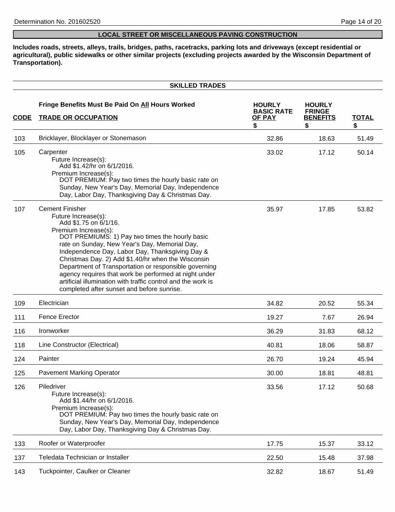
CarpenterFuture Increase(s):
Add $1.42/hr on 6/1/2016.Premium Increase(s):
DOT PREMIUM: Pay two times the hourly basic rate onSunday, New Year's Day, Memorial Day, IndependenceDay, Labor Day, Thanksgiving Day & Christmas Day.
Cement FinisherFuture Increase(s):
Add $1.75 on 6/1/16.Premium Increase(s):
DOT PREMIUMS: 1) Pay two times the hourly basicrate on Sunday, New Year's Day, Memorial Day,Independence Day, Labor Day, Thanksgiving Day &Christmas Day. 2) Add $1.40/hr when the WisconsinDepartment of Transportation or responsible governingagency requires that work be performed at night underartificial illumination with traffic control and the work iscompleted after sunset and before sunrise.
Electrician
Fence Erector
Ironworker
Line Constructor (Electrical)
Painter
Pavement Marking Operator
PiledriverFuture Increase(s):
Add $1.44/hr on 6/1/2016.Premium Increase(s):
DOT PREMIUM: Pay two times the hourly basic rate onSunday, New Year's Day, Memorial Day, IndependenceDay, Labor Day, Thanksgiving Day & Christmas Day.
Roofer or Waterproofer
Teledata Technician or Installer
Tuckpointer, Caulker or Cleaner
Determination No. 201602520
LOCAL STREET OR MISCELLANEOUS PAVING CONSTRUCTION
SKILLED TRADES
HOURLY HOURLYBASIC RATE FRINGE
$ $ $
103 32.86 18.63 51.49
105 33.02 17.12 50.14
107 35.97 17.85 53.82
109 34.82 20.52 55.34
111 19.27 7.67 26.94
116 36.29 31.83 68.12
118 40.81 18.06 58.87
124 26.70 19.24 45.94
125 30.00 18.81 48.81
126 33.56 17.12 50.68
133 17.75 15.37 33.12
137 22.50 15.48 37.98
143 32.82 18.67 51.49
Page 14 of 20
Fringe Benefits Must Be Paid On All Hours Worked
CODE TRADE OR OCCUPATION OF PAY BENEFITS TOTAL
Underwater Diver (Except on Great Lakes)
Heavy Equipment Operator - ELECTRICAL LINE CONSTRUCTIONONLY
Light Equipment Operator -ELECTRICAL LINE CONSTRUCTION ONLY
Heavy Truck Driver - ELECTRICAL LINE CONSTRUCTION ONLY
Light Truck Driver - ELECTRICAL LINE CONSTRUCTION ONLY
Groundman - ELECTRICAL LINE CONSTRUCTION ONLY
Fringe Benefits Must Be Paid On All Hours Worked
CODE TRADE OR OCCUPATION OF PAY BENEFITS TOTAL
Single Axle or Two Axle
Three or More Axle
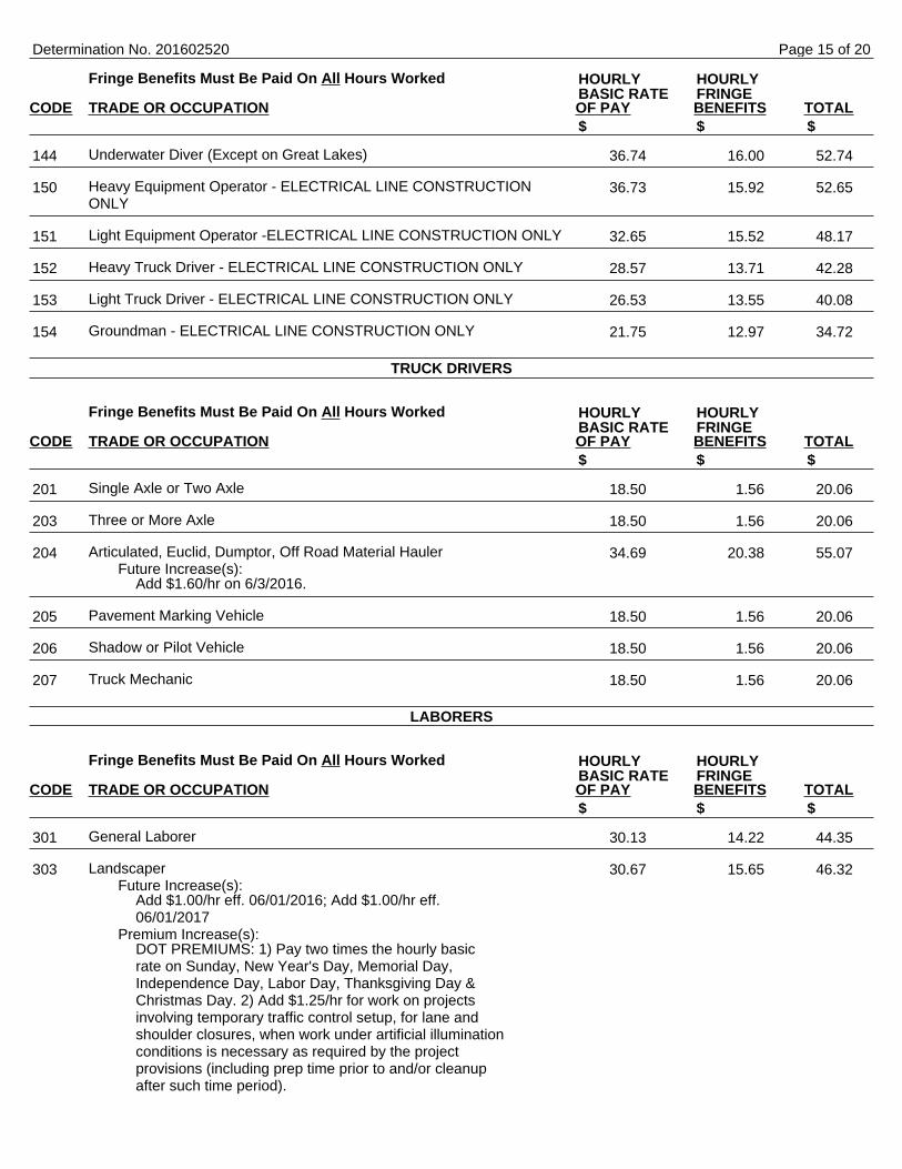
Articulated, Euclid, Dumptor, Off Road Material HaulerFuture Increase(s):
Add $1.60/hr on 6/3/2016.
Pavement Marking Vehicle
Shadow or Pilot Vehicle
Truck Mechanic
Fringe Benefits Must Be Paid On All Hours Worked
CODE TRADE OR OCCUPATION OF PAY BENEFITS TOTAL
General Laborer
LandscaperFuture Increase(s):
Add $1.00/hr eff. 06/01/2016; Add $1.00/hr eff.06/01/2017
Premium Increase(s):DOT PREMIUMS: 1) Pay two times the hourly basicrate on Sunday, New Year's Day, Memorial Day,Independence Day, Labor Day, Thanksgiving Day &Christmas Day. 2) Add $1.25/hr for work on projectsinvolving temporary traffic control setup, for lane andshoulder closures, when work under artificial illuminationconditions is necessary as required by the projectprovisions (including prep time prior to and/or cleanupafter such time period).
Determination No. 201602520
HOURLY HOURLYBASIC RATE FRINGE
$ $ $
144 36.74 16.00 52.74
150 36.73 15.92 52.65
151 32.65 15.52 48.17
152 28.57 13.71 42.28
153 26.53 13.55 40.08
154 21.75 12.97 34.72
TRUCK DRIVERS
HOURLY HOURLYBASIC RATE FRINGE
$ $ $
201 18.50 1.56 20.06
203 18.50 1.56 20.06
204 34.69 20.38 55.07
205 18.50 1.56 20.06
206 18.50 1.56 20.06
207 18.50 1.56 20.06
LABORERS
HOURLY HOURLYBASIC RATE FRINGE
$ $ $
301 30.13 14.22 44.35
303 30.67 15.65 46.32
Page 15 of 20
Fringe Benefits Must Be Paid On All Hours Worked
CODE TRADE OR OCCUPATION OF PAY BENEFITS TOTAL
Flagperson or Traffic Control Person
Fiber Optic Laborer (Outside, Other Than Concrete Encased)
Railroad Track Laborer
Fringe Benefits Must Be Paid On All Hours Worked
CODE TRADE OR OCCUPATION OF PAY BENEFITS TOTAL
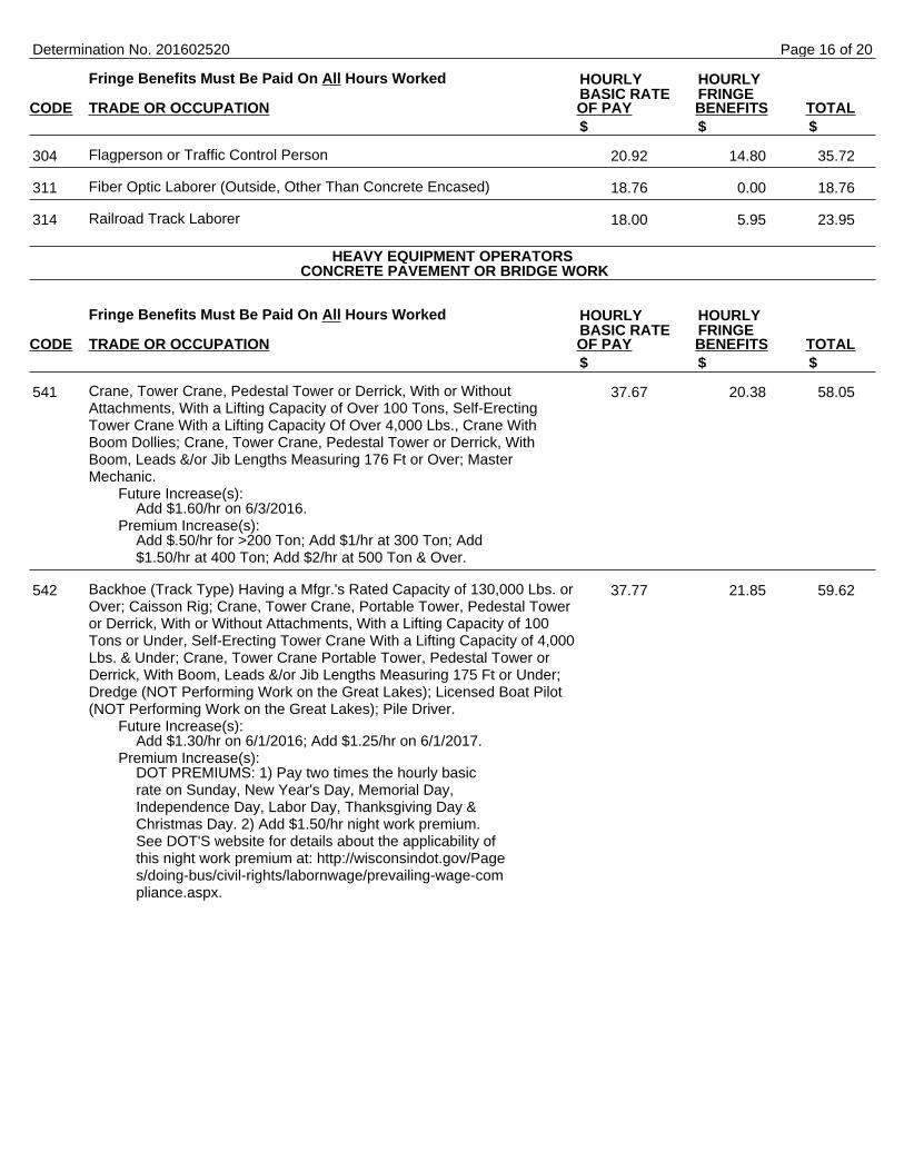
Crane, Tower Crane, Pedestal Tower or Derrick, With or WithoutAttachments, With a Lifting Capacity of Over 100 Tons, Self-ErectingTower Crane With a Lifting Capacity Of Over 4,000 Lbs., Crane WithBoom Dollies; Crane, Tower Crane, Pedestal Tower or Derrick, WithBoom, Leads &/or Jib Lengths Measuring 176 Ft or Over; MasterMechanic.
Future Increase(s):Add $1.60/hr on 6/3/2016.
Premium Increase(s):Add $.50/hr for >200 Ton; Add $1/hr at 300 Ton; Add$1.50/hr at 400 Ton; Add $2/hr at 500 Ton & Over.
Backhoe (Track Type) Having a Mfgr.'s Rated Capacity of 130,000 Lbs. orOver; Caisson Rig; Crane, Tower Crane, Portable Tower, Pedestal Toweror Derrick, With or Without Attachments, With a Lifting Capacity of 100Tons or Under, Self-Erecting Tower Crane With a Lifting Capacity of 4,000Lbs. & Under; Crane, Tower Crane Portable Tower, Pedestal Tower orDerrick, With Boom, Leads &/or Jib Lengths Measuring 175 Ft or Under;Dredge (NOT Performing Work on the Great Lakes); Licensed Boat Pilot(NOT Performing Work on the Great Lakes); Pile Driver.
Future Increase(s):Add $1.30/hr on 6/1/2016; Add $1.25/hr on 6/1/2017.
Premium Increase(s):DOT PREMIUMS: 1) Pay two times the hourly basicrate on Sunday, New Year's Day, Memorial Day,Independence Day, Labor Day, Thanksgiving Day &Christmas Day. 2) Add $1.50/hr night work premium.See DOT'S website for details about the applicability ofthis night work premium at: http://wisconsindot.gov/Pages/doing-bus/civil-rights/labornwage/prevailing-wage-compliance.aspx.
Determination No. 201602520
HOURLY HOURLYBASIC RATE FRINGE
$ $ $
304 20.92 14.80 35.72
311 18.76 0.00 18.76
314 18.00 5.95 23.95
HEAVY EQUIPMENT OPERATORS CONCRETE PAVEMENT OR BRIDGE WORK
HOURLY HOURLYBASIC RATE FRINGE
$ $ $
541 37.67 20.38 58.05
542 37.77 21.85 59.62
Page 16 of 20
Fringe Benefits Must Be Paid On All Hours Worked
CODE TRADE OR OCCUPATION OF PAY BENEFITS TOTAL
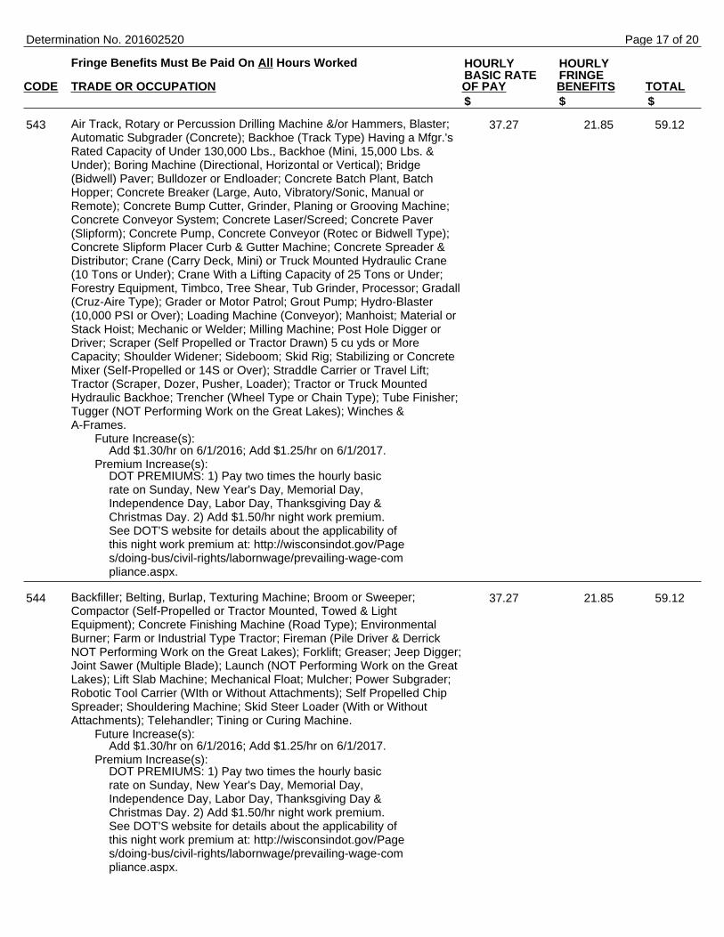
Air Track, Rotary or Percussion Drilling Machine &/or Hammers, Blaster;Automatic Subgrader (Concrete); Backhoe (Track Type) Having a Mfgr.'sRated Capacity of Under 130,000 Lbs., Backhoe (Mini, 15,000 Lbs. &Under); Boring Machine (Directional, Horizontal or Vertical); Bridge(Bidwell) Paver; Bulldozer or Endloader; Concrete Batch Plant, BatchHopper; Concrete Breaker (Large, Auto, Vibratory/Sonic, Manual orRemote); Concrete Bump Cutter, Grinder, Planing or Grooving Machine;Concrete Conveyor System; Concrete Laser/Screed; Concrete Paver(Slipform); Concrete Pump, Concrete Conveyor (Rotec or Bidwell Type);Concrete Slipform Placer Curb & Gutter Machine; Concrete Spreader &Distributor; Crane (Carry Deck, Mini) or Truck Mounted Hydraulic Crane(10 Tons or Under); Crane With a Lifting Capacity of 25 Tons or Under;Forestry Equipment, Timbco, Tree Shear, Tub Grinder, Processor; Gradall(Cruz-Aire Type); Grader or Motor Patrol; Grout Pump; Hydro-Blaster(10,000 PSI or Over); Loading Machine (Conveyor); Manhoist; Material orStack Hoist; Mechanic or Welder; Milling Machine; Post Hole Digger orDriver; Scraper (Self Propelled or Tractor Drawn) 5 cu yds or MoreCapacity; Shoulder Widener; Sideboom; Skid Rig; Stabilizing or ConcreteMixer (Self-Propelled or 14S or Over); Straddle Carrier or Travel Lift;Tractor (Scraper, Dozer, Pusher, Loader); Tractor or Truck MountedHydraulic Backhoe; Trencher (Wheel Type or Chain Type); Tube Finisher;Tugger (NOT Performing Work on the Great Lakes); Winches &A-Frames.
Future Increase(s):Add $1.30/hr on 6/1/2016; Add $1.25/hr on 6/1/2017.
Premium Increase(s):DOT PREMIUMS: 1) Pay two times the hourly basicrate on Sunday, New Year's Day, Memorial Day,Independence Day, Labor Day, Thanksgiving Day &Christmas Day. 2) Add $1.50/hr night work premium.See DOT'S website for details about the applicability ofthis night work premium at: http://wisconsindot.gov/Pages/doing-bus/civil-rights/labornwage/prevailing-wage-compliance.aspx.
Backfiller; Belting, Burlap, Texturing Machine; Broom or Sweeper;Compactor (Self-Propelled or Tractor Mounted, Towed & LightEquipment); Concrete Finishing Machine (Road Type); EnvironmentalBurner; Farm or Industrial Type Tractor; Fireman (Pile Driver & DerrickNOT Performing Work on the Great Lakes); Forklift; Greaser; Jeep Digger;Joint Sawer (Multiple Blade); Launch (NOT Performing Work on the GreatLakes); Lift Slab Machine; Mechanical Float; Mulcher; Power Subgrader;Robotic Tool Carrier (WIth or Without Attachments); Self Propelled ChipSpreader; Shouldering Machine; Skid Steer Loader (With or WithoutAttachments); Telehandler; Tining or Curing Machine.
Future Increase(s):Add $1.30/hr on 6/1/2016; Add $1.25/hr on 6/1/2017.
Premium Increase(s):DOT PREMIUMS: 1) Pay two times the hourly basicrate on Sunday, New Year's Day, Memorial Day,Independence Day, Labor Day, Thanksgiving Day &Christmas Day. 2) Add $1.50/hr night work premium.See DOT'S website for details about the applicability ofthis night work premium at: http://wisconsindot.gov/Pages/doing-bus/civil-rights/labornwage/prevailing-wage-compliance.aspx.
Determination No. 201602520
HOURLY HOURLYBASIC RATE FRINGE
$ $ $
543 37.27 21.85 59.12
544 37.27 21.85 59.12
Page 17 of 20
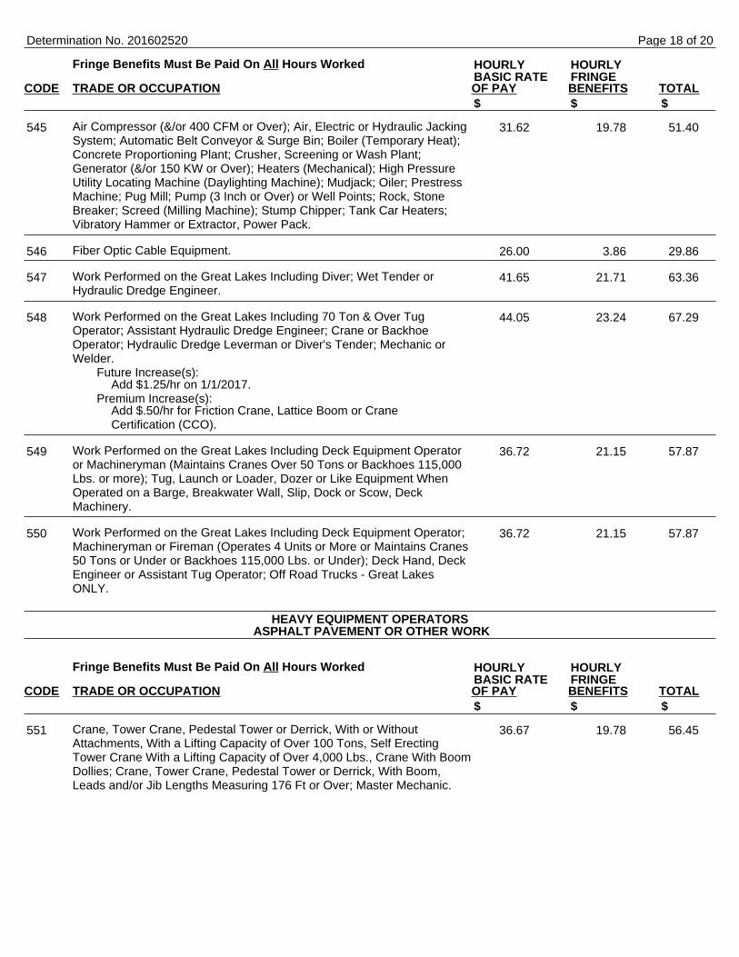
Fringe Benefits Must Be Paid On All Hours Worked
CODE TRADE OR OCCUPATION OF PAY BENEFITS TOTAL
Air Compressor (&/or 400 CFM or Over); Air, Electric or Hydraulic JackingSystem; Automatic Belt Conveyor & Surge Bin; Boiler (Temporary Heat);Concrete Proportioning Plant; Crusher, Screening or Wash Plant;Generator (&/or 150 KW or Over); Heaters (Mechanical); High PressureUtility Locating Machine (Daylighting Machine); Mudjack; Oiler; PrestressMachine; Pug Mill; Pump (3 Inch or Over) or Well Points; Rock, StoneBreaker; Screed (Milling Machine); Stump Chipper; Tank Car Heaters;Vibratory Hammer or Extractor, Power Pack.
Fiber Optic Cable Equipment.
Work Performed on the Great Lakes Including Diver; Wet Tender orHydraulic Dredge Engineer.
Work Performed on the Great Lakes Including 70 Ton & Over TugOperator; Assistant Hydraulic Dredge Engineer; Crane or BackhoeOperator; Hydraulic Dredge Leverman or Diver's Tender; Mechanic orWelder.
Future Increase(s):Add $1.25/hr on 1/1/2017.
Premium Increase(s):Add $.50/hr for Friction Crane, Lattice Boom or CraneCertification (CCO).
Work Performed on the Great Lakes Including Deck Equipment Operatoror Machineryman (Maintains Cranes Over 50 Tons or Backhoes 115,000Lbs. or more); Tug, Launch or Loader, Dozer or Like Equipment WhenOperated on a Barge, Breakwater Wall, Slip, Dock or Scow, DeckMachinery.
Work Performed on the Great Lakes Including Deck Equipment Operator;Machineryman or Fireman (Operates 4 Units or More or Maintains Cranes50 Tons or Under or Backhoes 115,000 Lbs. or Under); Deck Hand, DeckEngineer or Assistant Tug Operator; Off Road Trucks - Great LakesONLY.
Fringe Benefits Must Be Paid On All Hours Worked
CODE TRADE OR OCCUPATION OF PAY BENEFITS TOTAL
Crane, Tower Crane, Pedestal Tower or Derrick, With or WithoutAttachments, With a Lifting Capacity of Over 100 Tons, Self ErectingTower Crane With a Lifting Capacity of Over 4,000 Lbs., Crane With BoomDollies; Crane, Tower Crane, Pedestal Tower or Derrick, With Boom,Leads and/or Jib Lengths Measuring 176 Ft or Over; Master Mechanic.
Determination No. 201602520
HOURLY HOURLYBASIC RATE FRINGE
$ $ $
545 31.62 19.78 51.40
546 26.00 3.86 29.86
547 41.65 21.71 63.36
548 44.05 23.24 67.29
549 36.72 21.15 57.87
550 36.72 21.15 57.87
HEAVY EQUIPMENT OPERATORS ASPHALT PAVEMENT OR OTHER WORK
HOURLY HOURLYBASIC RATE FRINGE
$ $ $
551 36.67 19.78 56.45
Page 18 of 20
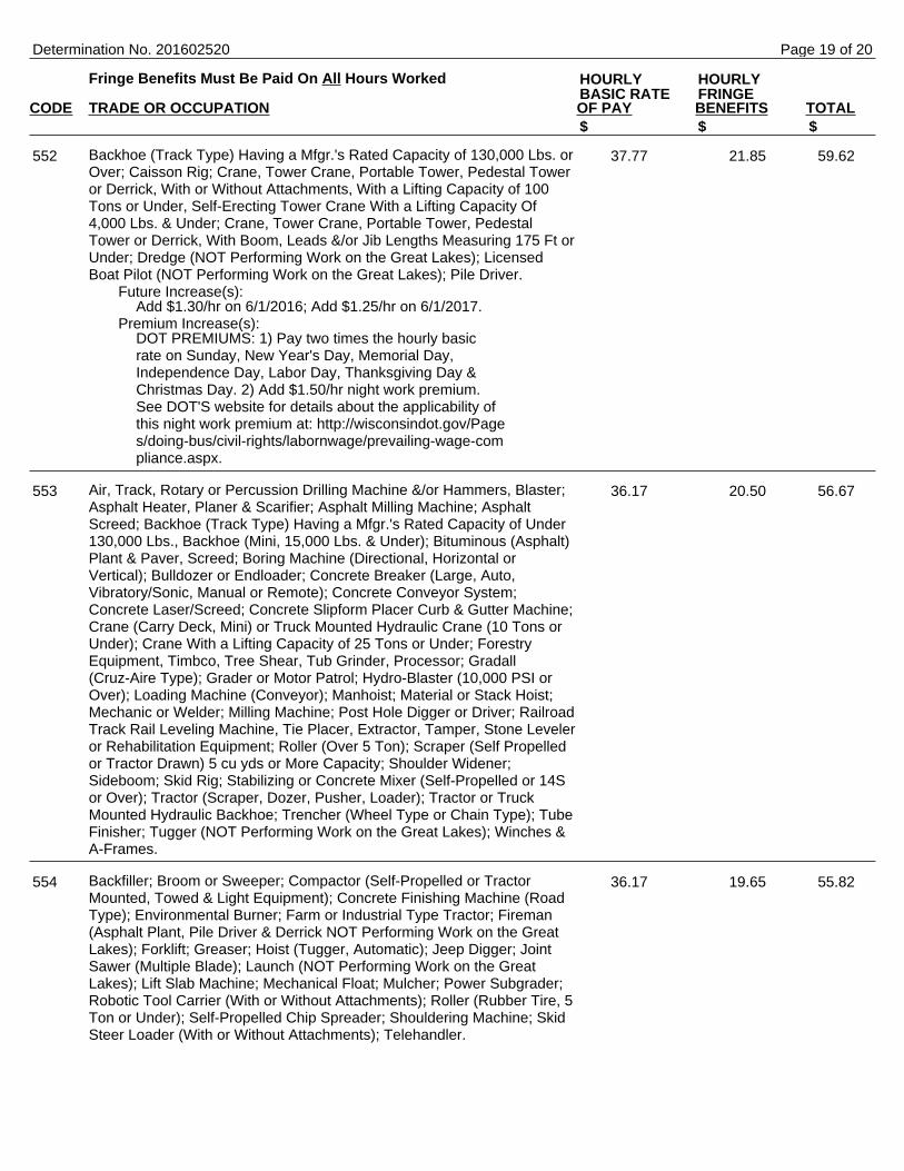
Fringe Benefits Must Be Paid On All Hours Worked
CODE TRADE OR OCCUPATION OF PAY BENEFITS TOTAL
Backhoe (Track Type) Having a Mfgr.'s Rated Capacity of 130,000 Lbs. orOver; Caisson Rig; Crane, Tower Crane, Portable Tower, Pedestal Toweror Derrick, With or Without Attachments, With a Lifting Capacity of 100Tons or Under, Self-Erecting Tower Crane With a Lifting Capacity Of4,000 Lbs. & Under; Crane, Tower Crane, Portable Tower, PedestalTower or Derrick, With Boom, Leads &/or Jib Lengths Measuring 175 Ft orUnder; Dredge (NOT Performing Work on the Great Lakes); LicensedBoat Pilot (NOT Performing Work on the Great Lakes); Pile Driver.
Future Increase(s):Add $1.30/hr on 6/1/2016; Add $1.25/hr on 6/1/2017.
Premium Increase(s):DOT PREMIUMS: 1) Pay two times the hourly basicrate on Sunday, New Year's Day, Memorial Day,Independence Day, Labor Day, Thanksgiving Day &Christmas Day. 2) Add $1.50/hr night work premium.See DOT'S website for details about the applicability ofthis night work premium at: http://wisconsindot.gov/Pages/doing-bus/civil-rights/labornwage/prevailing-wage-compliance.aspx.
Air, Track, Rotary or Percussion Drilling Machine &/or Hammers, Blaster;Asphalt Heater, Planer & Scarifier; Asphalt Milling Machine; AsphaltScreed; Backhoe (Track Type) Having a Mfgr.'s Rated Capacity of Under130,000 Lbs., Backhoe (Mini, 15,000 Lbs. & Under); Bituminous (Asphalt)Plant & Paver, Screed; Boring Machine (Directional, Horizontal orVertical); Bulldozer or Endloader; Concrete Breaker (Large, Auto,Vibratory/Sonic, Manual or Remote); Concrete Conveyor System;Concrete Laser/Screed; Concrete Slipform Placer Curb & Gutter Machine;Crane (Carry Deck, Mini) or Truck Mounted Hydraulic Crane (10 Tons orUnder); Crane With a Lifting Capacity of 25 Tons or Under; ForestryEquipment, Timbco, Tree Shear, Tub Grinder, Processor; Gradall(Cruz-Aire Type); Grader or Motor Patrol; Hydro-Blaster (10,000 PSI orOver); Loading Machine (Conveyor); Manhoist; Material or Stack Hoist;Mechanic or Welder; Milling Machine; Post Hole Digger or Driver; RailroadTrack Rail Leveling Machine, Tie Placer, Extractor, Tamper, Stone Leveleror Rehabilitation Equipment; Roller (Over 5 Ton); Scraper (Self Propelledor Tractor Drawn) 5 cu yds or More Capacity; Shoulder Widener;Sideboom; Skid Rig; Stabilizing or Concrete Mixer (Self-Propelled or 14Sor Over); Tractor (Scraper, Dozer, Pusher, Loader); Tractor or TruckMounted Hydraulic Backhoe; Trencher (Wheel Type or Chain Type); TubeFinisher; Tugger (NOT Performing Work on the Great Lakes); Winches &A-Frames.
Backfiller; Broom or Sweeper; Compactor (Self-Propelled or TractorMounted, Towed & Light Equipment); Concrete Finishing Machine (RoadType); Environmental Burner; Farm or Industrial Type Tractor; Fireman(Asphalt Plant, Pile Driver & Derrick NOT Performing Work on the GreatLakes); Forklift; Greaser; Hoist (Tugger, Automatic); Jeep Digger; JointSawer (Multiple Blade); Launch (NOT Performing Work on the GreatLakes); Lift Slab Machine; Mechanical Float; Mulcher; Power Subgrader;Robotic Tool Carrier (With or Without Attachments); Roller (Rubber Tire, 5Ton or Under); Self-Propelled Chip Spreader; Shouldering Machine; SkidSteer Loader (With or Without Attachments); Telehandler.
Determination No. 201602520
HOURLY HOURLYBASIC RATE FRINGE
$ $ $
552 37.77 21.85 59.62
553 36.17 20.50 56.67
554 36.17 19.65 55.82
Page 19 of 20
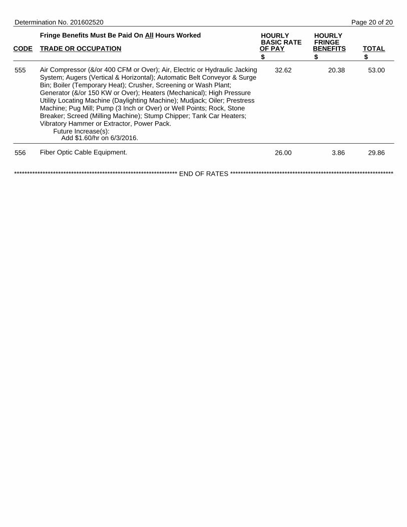
Fringe Benefits Must Be Paid On All Hours Worked
CODE TRADE OR OCCUPATION OF PAY BENEFITS TOTAL
Air Compressor (&/or 400 CFM or Over); Air, Electric or Hydraulic JackingSystem; Augers (Vertical & Horizontal); Automatic Belt Conveyor & SurgeBin; Boiler (Temporary Heat); Crusher, Screening or Wash Plant;Generator (&/or 150 KW or Over); Heaters (Mechanical); High PressureUtility Locating Machine (Daylighting Machine); Mudjack; Oiler; PrestressMachine; Pug Mill; Pump (3 Inch or Over) or Well Points; Rock, StoneBreaker; Screed (Milling Machine); Stump Chipper; Tank Car Heaters;Vibratory Hammer or Extractor, Power Pack.
Future Increase(s):Add $1.60/hr on 6/3/2016.
Fiber Optic Cable Equipment.
Determination No. 201602520
HOURLY HOURLYBASIC RATE FRINGE
$ $ $
555 32.62 20.38 53.00
556 26.00 3.86 29.86
*************************************************************** END OF RATES ***************************************************************
Page 20 of 20


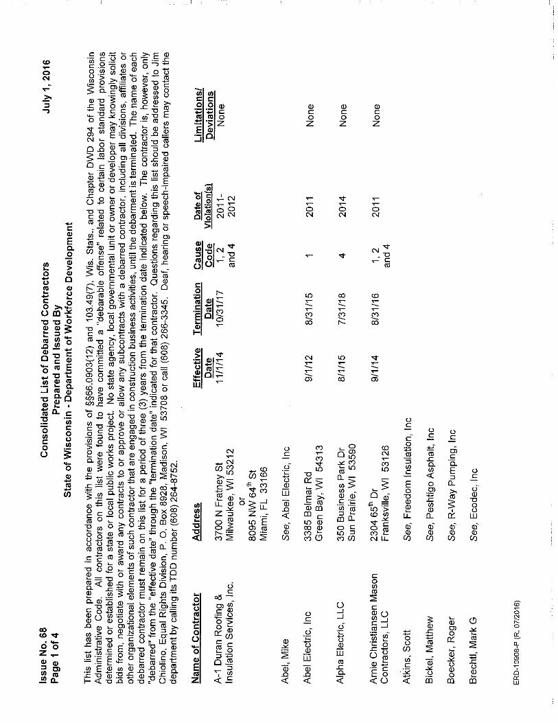
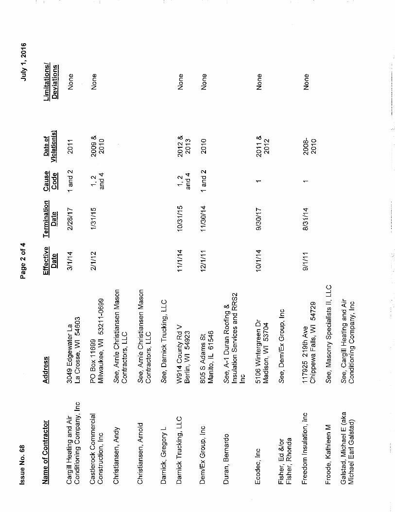
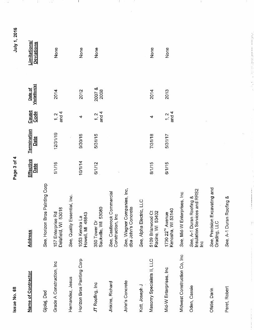
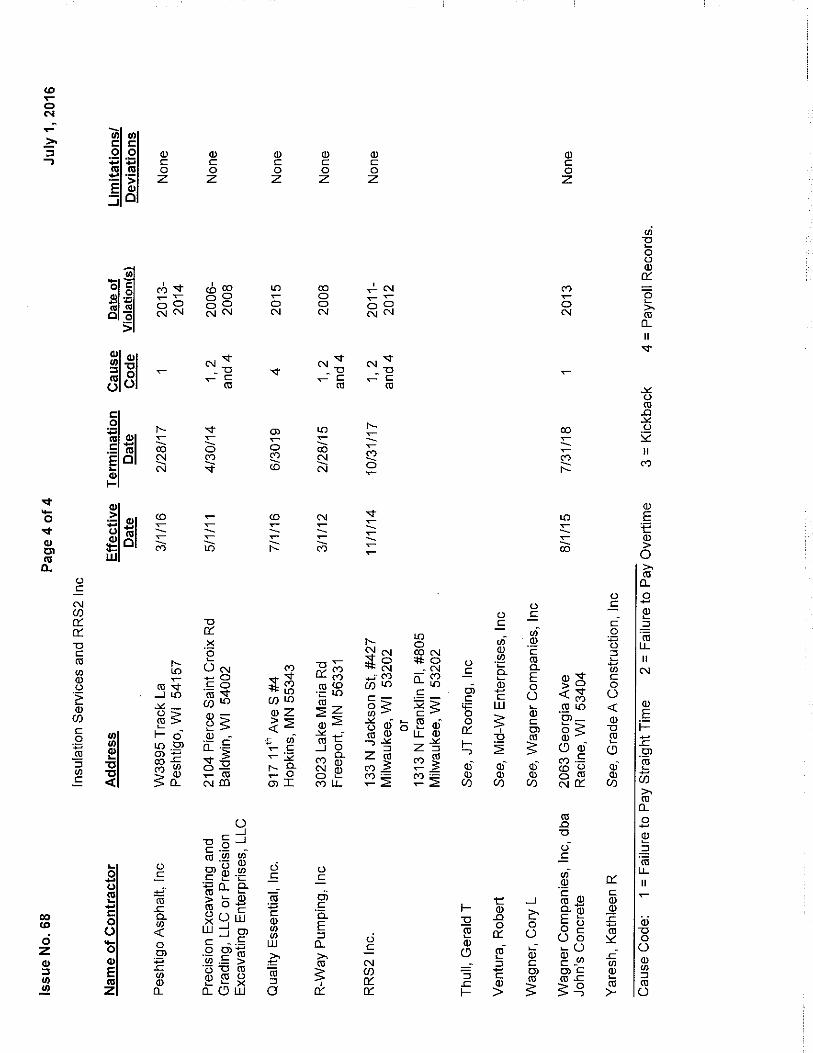


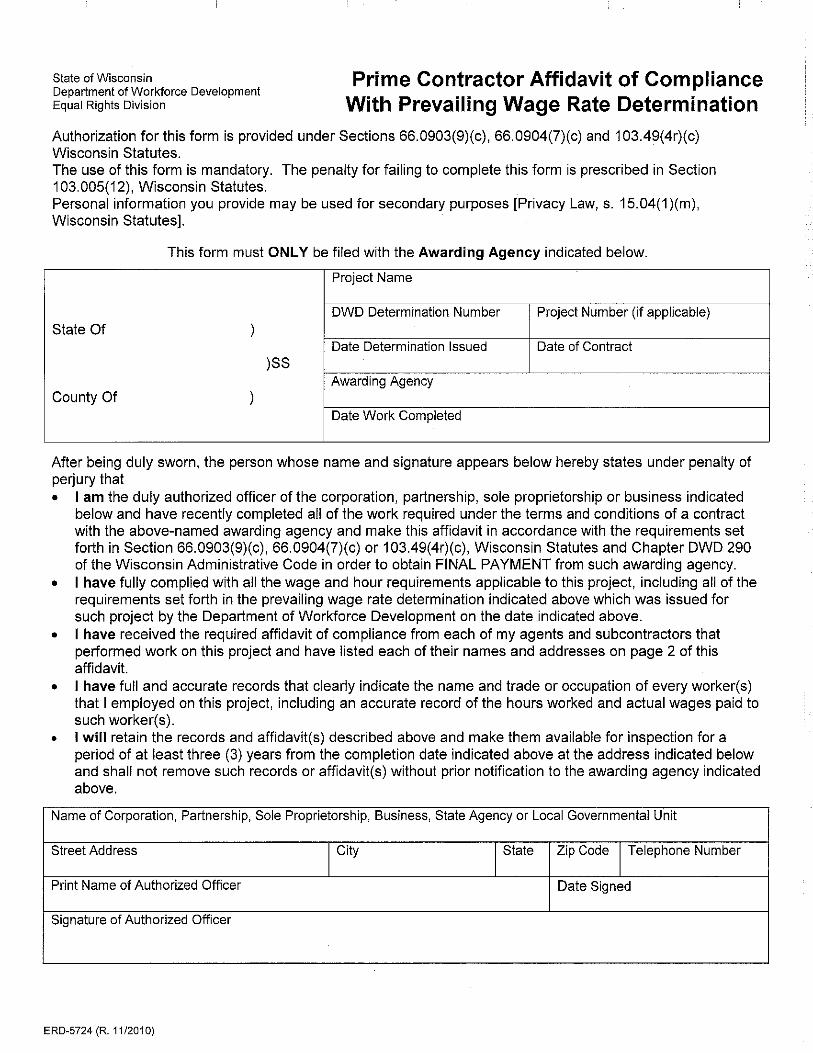

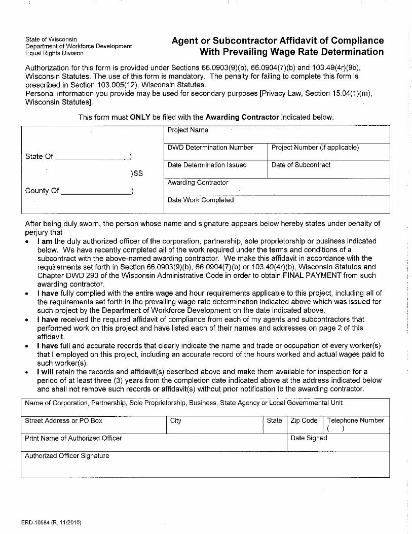


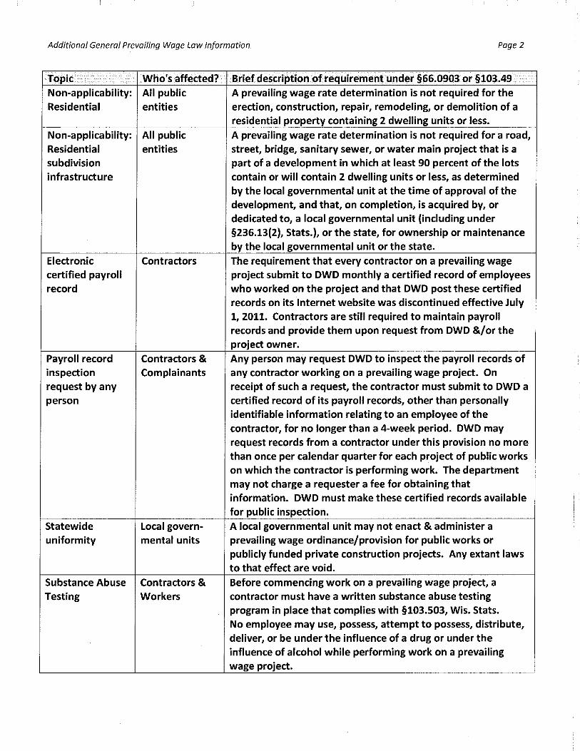
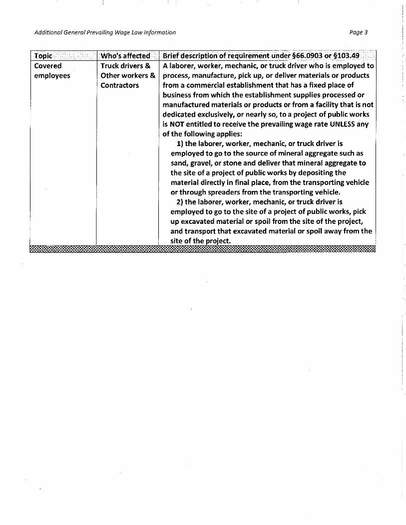
Rock County Courthouse Security System Upgrade and Replacement Summary of Work 2880000.156650.02 01 10 00 - 1
SECTION 01 10 00 SUMMARY OF WORK
PART 1 - GENERAL
1.01 WORK COVERED BY CONTRACT DOCUMENTS
A. The Work of this Contract comprises the upgrade and expansion of the existing security system.
1.02 OWNER FURNISHED ITEMS
A. Replacement millwork at Security Workstation A041.
1.03 OWNER OCCUPANCY
A. The Contractor shall note that this is a functional justice facility. The Owner will continue to occupy the building for court and County activity. Cooperate with the Owners in all construction operations to minimize interference and conflict with the use of the premises by the Owners. The Contractor is responsible for maintaining access to exits to provide safe egress for building occupants at all times.
1.04 DELIVERY AND STORAGE
A. The Contractor will be responsible for providing the necessary equipment to receive and off-load deliveries on site.
B. Exterior storage is not allowed. All materials must be stored either inside the building within an area designated by the Owner or in an exterior lockable container.
END OF SECTION

PAGE INTENTIONALLY LEFT BLANK

Rock County Courthouse Security System Upgrade and Replacement Contractor Guidelines 2880000.156650.02 01 14 20 - 1
SECTION 01 14 20 CONTRACTOR GUIDELINES
PART 1 - GENERAL
1.01 BACKGROUND CHECKS
A. Background checks will be performed on all Contractors performing work with secure areas of the Rock County Courthouse.
B. No labor personnel will be allowed on site without prior clearance by the Owner.
C. The Contractor will be responsible for coordinating background checks of all labor parties in advance of their arrival with the Owner.
D. The Contractor will be responsible for coordinating background checks of new labor personnel with the Owner within a minimum of 48 hours in advance of their arrival.
E. The Owner will not be held responsible for lost time or wages for labor personnel not cleared within 48 hours in advance of their arrival.
1.02 CONTRACTOR GUIDELINES
A. Contractors working in the holding areas must sign-in with Rock County Sheriff’s Department upon arrival to the facility. Contractors must sign-out with Rock County Sheriff’s Department upon leaving the facility.
B. Rock County Sheriff’s Department will check-in all equipment and tools for all work performed in the holding areas. All equipment and tools must be checked-out by Rock County Sheriff’s Department as items are removed from the facility. In the event that equipment or tools are missing, the contractors will not be allowed to leave the facility until all items are accounted for.
C. Contractors working in inmate areas will be briefed on inmate confidentiality, security procedures and their responsibilities under the Prison Rape Elimination Act.
D. Contractors will be taken to Master Control and introduced to officers of the Rock County Sheriff’s Department. Rock County Sheriff’s Department will be notified of where contract personnel will be working.
E. Tools and materials shall not be left unattended at anytime. Tools and materials can be used by inmates to harm themselves or others. In the event an items is discovered to be missing (tools, materials, etc.) it is the Contractor’s responsibility to notify Rock County Sheriff’s Department immediately. A minimal amount of secure storage is available for storage of tools and materials.
F. Contractors must leave any unnecessary tools or personal belongings in their vehicles. Do not provide smoking materials, matches or money to any inmate.
G. All construction material and salvage material shall be removed from the facility or secured at the end of each day.
H. Contractors are asked that they do not work at the facility if they are ill with something contagious

Rock County Courthouse Security System Upgrade and Replacement Contractor Guidelines 2880000.156650.02 01 14 20 - 2
I. All contractors are expected to leave work areas in conditions; such that the area can be occupied area can be occupied immediately upon leaving the area. Brooms, dustpans, and mops will be provided for clean up.
J. Smoking is prohibited inside County buildings.
K. The Rock County Sheriff’s Department will supply an escort for work in occupied holding areas. If there is a change in the schedule, 48 hour notice would be appreciated.
L. Any Contractor employee, or group of employees, inside the inmate occupied area of the jail must be in the presence of one of the two assigned escorts at all times. It will not be required to have escort present when working non-inmate occupied areas.
1.03 OWNER DISMISSAL
A. The Owner reserves the right at any time to dismiss from the premises any Contractor or construction personnel that do not uphold the requirements of this Section.
B. The Owner shall not be held liable for any lost time, wages, or impacts to the construction schedule by any Contractor or construction personnel dismissed for failure to uphold the requirements of this Section.
END OF SECTION
Rock County Courthouse Security System Upgrade and Replacement Alternates 2880000.156650.02 01 23 00 - 1
SECTION 01 23 00 ALTERNATES
PART 1 - GENERAL
1.01 ALTERNATE NO. 1
A. Provide lump sum price to provide security electronic upgrades in the front and back parking structures as noted on the Drawings.
1.02 ALTERNATE NO. 2
A. Provide lump sum price to provide video surveillance monitors at Courtroom Bailiff Stations as noted on the Drawings.
PART 2 - ALTERNATE SELECTION
2.01 PRECEDENCE
A. The County of Rock reserves the right to select Alternate Bids as deemed as necessary based on project budget and Owner requirements. Selection of Alternate bids chosen or rejected under the full discretion of the Owner.
END OF SECTION

PAGE INTENTIONALLY LEFT BLANK

Rock County Courthouse Security System Upgrade and Replacement Project Coordination 2880000.156650.02 01 31 00 - 1
SECTION 01 31 00 PROJECT COORDINATION
PART 1 - GENERAL
1.01 REQUIREMENTS INCLUDED
A. The Contractor shall assume and take responsible charge of the place of the project and shall coordinate the work of each Subcontractor to complete the project in an orderly and timely manner.
B. The Contractor shall coordinate the work of his own employees, expedite his work to assure compliance with schedules, coordinate his work with that of Subcontractors and work by the Owner.
1.02 COORDINATION PROCEDURES
A. Cooperate with the Owner, Engineer and all other persons of all trades engaged in the work in such a manner and to such extent as will best facilitate the work of each and the prompt completion of the work.
B. Order materials and let subcontracts promptly and schedule and expedite work so as to avoid delay.
C. The Contractor shall bring to the immediate attention of the Owner and Engineer, any conflict relative to coordinating the work of the subcontractors.
D. Notify the Owner and Engineer of any unforeseen conditions found in the field.
E. The Contractor shall note that this is an operational justice facility. The Owner will continue to occupy the building for normal court and county duties. Cooperate with the Owners in all construction operations to minimize interference and conflict with the use of the premises by the Owners. The Contractor is responsible for maintaining access to exits to provide safe egress for building occupants.
1.03 EXAMINATION OF DOCUMENTS
A. The Drawings show the general arrangement, quantity, extent and location of the work. The specifications describe the materials, systems, standards and quality required for the work. Examine the Drawings and the Specifications applicable to the Contract. Bring to the attention of the Engineer any questions with regard to the intent of these documents, in a timely manner prior to commencing with the Work.
END OF SECTION

PAGE INTENTIONALLY LEFT BLANK

Rock County Courthouse Security System Upgrade and Replacement Project Meetings 2880000.156650.02 01 31 19 - 1
SECTION 01 31 19 PROJECT MEETINGS
PART 1 - GENERAL
1.01 MEETINGS
A. The Contractor will administer weekly project meetings and shall: 1. Prepare agenda for meetings. 2. Distribute written notice of each meeting four days in advance of meeting
date. 3. Make physical arrangements for meetings. 4. Preside at meetings. 5. Record the minutes including significant proceedings and decisions. 6. Reproduce and distribute copies of minutes within three days after each
meeting: a. To participants in the meetings. b. To parties affected by decisions made at the meetings.
B. Project meetings may be held weekly during periods of high activity.
C. Representatives of Contractors, Subcontractors and suppliers attending meetings shall be qualified and authorized to act on behalf of the entity each represents.
D. Owner’s Representative will attend meetings to ascertain that Work is expedited consistent with Contract Documents and construction schedules.
1.02 PRE-CONSTRUCTION MEETING
A. Soon after award of Contract and prior to the start of construction, each Contractor shall attend a pre-construction conference with representatives of the Owner and A/E. This meeting will be scheduled by the Engineer.
B. Requirements for contract administration and construction operations will be defined for participants.
C. Time, date and place of the conference will be determined by the Owner’s Representative.
D. The pre-construction meeting shall be attended by the Owner, Engineer, Prime Contractors' Superintendents, and Others as appropriate.
E. Suggested meeting agenda shall be: 1. Distribution and discussion of:
a. List of major subcontractors and suppliers. 2. Projected Construction Schedules.
a. Critical work sequencing. b. Major equipment deliveries and priorities. c. Project Phasing
3. Project Coordination. a. Designation of responsible personnel.
4. Adequacy of distribution of Contract Documents. 5. Procedures for maintaining use of premises:
a. Parking b. Job Trailers

Rock County Courthouse Security System Upgrade and Replacement Project Meetings 2880000.156650.02 01 31 19 - 2
c. Office, Work and Storage Areas d. Owner's Requirements
6. Construction facilities, controls and construction aids. 7. Temporary utilities. 8. Safety and first-aid procedures. 9. Fabrication area 10. Security procedures. 11. Housekeeping procedures.
1.03 PROGRESS MEETINGS
A. Project meetings will be held at the project site by the Engineer's representative for the purpose of coordinating and expediting the Work progress.
B. Meetings will be scheduled by the Prime Contractor with timely notification of all Contractors.
C. The progress meeting shall be attended by the Engineer, Prime Contractors, Owner, Subcontractors as appropriate to the agenda and suppliers as appropriate to the agenda.
D. Suggested meeting agenda shall be: 1. Review and approval of minutes of previous meeting. 2. Review of work progress since previous meeting. 3. Field observations, problems and conflicts. 4. Problems which impede Construction Schedule. 5. Review of off-site fabrication and delivery schedules. 6. Corrective measures and procedures to regain projected schedule. 7. Revisions to Construction Schedule. 8. Progress and schedule during succeeding work period. 9. Coordination of schedules. 10. Review submittal schedules and expedite as required. 11. Maintenance of quality standards. 12. Pending changes and substitutions. 13. Review proposed changes for:
a. Effect on Construction Schedule and on completion date. b. Effect on other contracts of the Project c. Other business.
END OF SECTION

Rock County Courthouse Security System Upgrade and Replacement Submittal Procedures 2880000.156650.02 01 33 00 - 1
SECTION 01 33 00 SUBMITTAL PROCEDURES
PART 1 - GENERAL
1.01 GENERAL
A. Refer to General Conditions for basic requirements for all submittals.
B. Refer to technical specifications for all submittals required.
1.02 PROGRESS SCHEDULE
A. Contractor shall submit copies of the project construction schedule to the Owner and Engineer for approval within 10 days after award of contract.
B. Include in schedule: 1. Breakdown of work activities, segmented as necessary to allow monitoring
of progress of the work during construction. 2. Order of work necessary to meet time for completion. 3. Breakdown of the work of Subcontractors scheduled in cooperation with the
Contractor's work. 4. Space for the additional display of actual performance on the schedule.
C. After necessary revisions and approval by the Owner, provide one copy of the project construction schedule to each subcontractor, one copy to the Owner, one copy to the university, and one copy to the Engineer.
D. Upon request of the Engineer, update the schedule to reflect changes required by actual conditions and indicate actual work completed. Show changes occurring since previous submission of schedule such as: 1. Major changes in scope; 2. Activities modified since previous submission; 3. Revised projections of progress and completion; 4. Other identifiable changes.
E. At the Contractor's option he may submit a CPM or PERT project schedule containing all information required by this section.
F. The Contractor shall submit a progress report at the end of each billing period using the construction schedule described.
G. This report should indicate the actual progress for items of work completed as compared to that scheduled.
H. Where work is not performed according to the construction schedule, a short narrative should be written describing the cause of delay and intended action to remedy the delay.
I. When the work performed is not meeting the construction schedule, the Engineer may request that the Contractor increase the labor and equipment being furnished in order to meet the schedule. Should the Contractor choose not to follow the Engineer's request he shall provide a written submittal explaining how the schedule is to be met without an increase in labor and equipment.

Rock County Courthouse Security System Upgrade and Replacement Submittal Procedures 2880000.156650.02 01 33 00 - 2
1.03 SUBCONTRACTOR AND MATERIALS LIST
A. The subcontractor and major material suppliers list shall be submitted prior to awarding of the contract.
B. The Owner will promptly review list and indicate in writing approval or disapproval of subcontractors and materials. Resubmit revised list upon disapproval of any item until such time as approval of all items has been obtained from the Owner.
C. Use of unspecified or unapproved materials and equipment will not be permitted.
D. Certificate of payment may be withheld by the Engineer until complete approval of subcontractors and materials list has been obtained.
1.04 SCHEDULE OF VALUES
A. Within 10 days after award of the contract, the Contractor shall submit to the Engineer a schedule of values of the various portions of the work, including quantities if required by the Engineer, aggregating the total contract sum, divided so as to facilitate payments to Subcontractors.
B. Prepare a schedule of values in such form and supported by such substantiating data as the Engineer may require. Each item in the schedule of values shall include its proper share of overhead and profit. This schedule when approved by the Engineer shall be used only as a basis for the Contractor's applications for payment.
C. Certificate of payment may be withheld by the Engineer until receipt of schedule of values in an acceptable form has been submitted.
1.05 SUBMITTAL REQUIREMENTS
A. Schedule submittals at least 15 working days before the time that reviewed and approved submittals will be needed.
B. Submit all shop drawings, product data and samples to the Engineer.
C. Accompany submittals with transmittal letter containing the date, project title and number, Contractor's name and address, the quantity of items submitted, notifications of any deviations from contract documents, the section of work and other pertinent data.
1.06 SHOP DRAWINGS
A. Shop drawings are drawings, diagrams, illustrations, schedules, performance charts, brochures and other data which are prepared by the Contractor or any Subcontractor, manufacturer, supplier or distributor and which illustrate some portion of the work.
B. When shop drawings consist of illustrations, performance charts, brochures or other data in printed form, submit four copies for review. Increase the number of copies where so stated in the technical specifications.
C. Identify with project number, name of project, Engineer, Contractor, fabricator, specification section number and detail number(s) to which drawing pertains. Date and number each sheet of shop drawings consecutively. Provide open space 3" x 5" for Engineer's stamp on each drawing.
D. Provide all supporting data to show compliance with specifications.

Rock County Courthouse Security System Upgrade and Replacement Submittal Procedures 2880000.156650.02 01 33 00 - 3
E. Shop drawings must be original. No reproductions of Engineer's drawings will be accepted.
F. All shop drawings shall be reviewed, stamped and approved by appropriate Contractor prior to Engineer's review. All shop drawings which are not stamped by the Contractor will be returned by Engineer unchecked.
G. Check and note all errors on shop drawings prior to submitting to Engineer. At the time of submission the Contractor shall inform the Engineer in writing of any deviation in the shop drawings from the requirements of the contract documents.
H. By approving and submitting shop drawings, the Contractor thereby represents that he has determined and verified all field measurements, field construction criteria, materials, catalog numbers and similar data or will do so, and that he has checked and coordinated each shop drawing with the requirements of the work and of the contract documents.
I. Engineer will review shop drawings with reasonable promptness, make necessary notations and return to Contractor for correction by supplier or fabricator. The Engineer will review and approve shop drawings only for conformance with the design concept of the project and with the information given in the contract documents. The Engineer's approval of a separate item shall not indicate approval of an assembly in which the item functions.
J. The Contractor shall make any corrections required by the Engineer and shall resubmit the required number of corrected copies until approved. The Contractor shall direct specific attention in writing or on resubmitted shop drawings to revisions other than the corrections requested by the Engineer on previous submissions.
K. After correction, supplier or fabricator shall provide prints of all shop drawings to the Contractor as required for distribution and use.
L. Original submissions returned "disapproved" shall be resubmitted as originally required and approval obtained prior to furnishing copies for distribution.
M. Shop drawings used at site must bear approval stamp of both the Engineer and Contractor.
N. Shop drawing approvals do not constitute a waiver of detailed or specified requirements of the drawings and specifications.
O. No portion of the work requiring a shop drawing submission shall be commenced until the submission has been approved by the Engineer. All such portions of the work shall be in accordance with approved shop drawings.
P. At completion of all work prior to final payment furnish Owner with one unused copy of all approved shop drawings, manufacturer's brochures, diagrams or similar material used in execution of the work. Refer to Section 01 70 00.
1.07 SAMPLES
A. Samples are physical examples furnished by the Contractor to illustrate materials, equipment or workmanship, and to establish standards by which the work will be judged.
B. Submit in duplicate.

Rock County Courthouse Security System Upgrade and Replacement Submittal Procedures 2880000.156650.02 01 33 00 - 4
C. Identify with project number, name of project, Engineer, Contractor, fabricator and specification section reference.
D. Provide samples of sufficient size to permit an accurate appraisal of color, texture, finish, workmanship and other characteristics.
E. Submit supporting data and specifications showing compliance with specifications.
F. Submit samples with shop drawings when both are required.
G. Maintain at site one approved sample properly identified of each product of material for which samples are required.
1.08 MATERIAL COLORS AND FINISHES
A. Within 15 days after receipt of approval by the Engineer of the list of Subcontractors on the project, secure and supply to the Engineer color cards, finish samples and other information for all items requiring a color or finish selection.
B. Advise Engineer of any deadlines for color or finish selections that may be necessary to insure delivery of materials on schedule.
1.09 RECORD DRAWINGS
A. The Contractor shall provide and maintain in proper order, in good, clean condition, in field office at the project site, one complete set of prints of all drawings.
B. On this set with red pencil or ink, neatly inscribe all changes in work
C. At time of final acceptance and prior to final payment present these corrected prints to the Owner through the Engineer. Note all data and changes on these record drawings in sufficient detail, clarity and provide information necessary for preparation of "as-built" drawings.
1.10 GUARANTEES, WARRANTIES AND CERTIFICATES
A. Submit all guarantees, warranties and certificates to the Engineer prior to final payment.
B. Refer to section 01 70 00.
1.11 OPERATING AND MAINTENANCE INSTRUCTIONS
A. Submit all operating and maintenance instructions to the Engineer prior to final payment.
B. Refer to Section 01 70 00.
END OF SECTION
Rock County Courthouse Security System Upgrade and Replacement Regulatory Requirements 2880000.156650.02 01 41 00 - 1
SECTION 01 41 00 REGULATORY REQUIREMENTS
PART 1 - GENERAL
1.01 PROCEDURES
A. Give all notices and comply in full with all applicable standards, requirements, rules, regulations, code statutes, ordinances, etc. of municipal, county and state governments. Owner's and Contractor's insurance companies, local utilities and labor regulations relating to the performance of the work, the protection of adjacent property and the maintenance of passage ways, guard fences or other protective facilities.
B. Work shall comply with the General Orders on Safety in Construction as issued by the Department of Industry, Labor and Human Relations.
C. Exercise precaution at all times for the protection of persons (including employees) and property. Observe the safety provisions of applicable laws, building and construction codes. Machinery, equipment and all hazards shall be guarded or eliminated in accordance with safety provisions of the Manual of Accident Prevention in Construction, published by the Associated General Contractors of America.
D. Promptly notify the Owner and Engineer of any variances of the drawings or specifications with that of any Federal, State or local law, code, rule or regulations. Upon such notification, the Engineer will arrange correction of variance to comply with applicable law, code, rule or regulation at no additional cost to the Contractor.
E. If the Contractor performs any work knowing it to be contrary to such laws, ordinances, rules and regulations he shall assume full responsibility therefore and shall bear all costs attributable thereto.
F. Refer to sections of the work for referenced codes, standards, tests, etc. applicable to the work.
1.02 TAXES
A. Pay all sales, consumer, use and other similar taxes required by law, including but not limited to the unemployment, FICA, State, Federal and local municipality sales, excise and manufacturer's taxes. If the tax laws are subsequently amended by legislation during the life of the contract, the contract will be adjusted to reflect the net change caused by such amendment.
1.03 PERMITS, FEES AND LICENSES
A. Secure and pay all fees for all permits, governmental and utility approvals and licenses necessary for the proper execution and completion of the work, which are applicable at the time the bids are received.
B. Each Contractor shall furnish Owner with copies of all required permits and certificates of inspection applicable to his work.
END OF SECTION

PAGE INTENTIONALLY LEFT BLANK

SECTION 01 50 00 TEMPORARY FACILITES AND CONTROLS
Rock County Courthouse Temporary Security System Upgrade and Replacement Facilities and Controls 2880000.156650.02 01 50 00 - 1
PART 1 - GENERAL
1.01 MAINTENANCE OF EXISTING SERVICE
A. The building will be continuously occupied during the construction period. Special efforts shall be made to avoid interference with building functions. Consult with the Owner prior to turning off services so that Owner can advise as to most suitable time for the necessary interruptions. All such work and interruptions to services shall be performed at times which are approved by the Owner.
1.02 TEMPORARY FACILITIES
A. TEMPORARY FACILITIES 1. Project Sign: No individual advertising signs, plaques or credits, temporary or permanent,
will be permitted on the building or premises except the name of the Contractor on his office or material shed.
2. Explosives: Use of explosives for any purpose is prohibited. 3. First Aid: The Contractor shall provide temporary first aid facilities on the site.
1.03 CONTROLS
A. PARKING 1. No parking facilities will be provided for employees of any Contractor on site. 2. Parking will be made available at no cost to contractors in the designated public parking
lot on an as available basis. 3. Do not obstruct existing service drives and parking lots with equipment, materials or
vehicles except as specifically noted in this section. Keep accessible for Owner's use at all times.
B. SECURITY 1. The Contractor shall provide for the security of materials and equipment stored at the site.
Material and equipment shall not be stored in areas which the Owner continues to use. The Contractor may store equipment and materials in areas in which he is working.
C. SPECIAL CONTROLS 1. Noise Control: The Contractor shall confine his hours of operations to those required by
State, County and City laws and ordinances. Noise levels shall be held to a minimum considering the nature of the work.
2. Restroom Control: The Contractor shall be permitted to responsibly use Owner’s onsite toilet facilities. This privilege may be withheld if the facilities are left excessively soiled or abused in any way.
3. Power Control: Onsite electrical service may be used by contractors at no charge. Any necessary alterations of building’s electrical systems for contractor’s temporary use will be at the expense of the contractor and Retain or delete this article in all Sections of Project Manual.
END OF SECTION

PAGE INTENTIONALLY LEFT BLANK

Rock County Courthouse Security System Upgrade and Replacement Product Requirements 2880000.156650.02 01 60 00 - 1
SECTION 01 60 00 PRODUCT REQUIREMENTS
PART 1 - GENERAL
1.01 GENERAL
A. All materials, equipment and other items incorporated in the work of this project must be new and both materials and workmanship of best grade of their respective kinds.
B. To assure ready availability of materials, parts or components for repair, replacement or future expansion purposes, all materials, equipment and related components must be obtained from sources which maintain a regular, domestic stock.
1.02 LABOR AND MATERIALS
A. Material and equipment incorporated into the work shall conform to applicable specifications and standards, and comply with size, make, type and quality specified.
B. Manufactured and Fabricated Products:
C. Design, fabricate and assemble in accordance with the best engineering and shop practices.
D. Manufacturer like parts of duplicate units to standard sizes and gauges to be interchangeable.
E. Two or more items of the same kind by the same manufacturer shall be identical.
F. Products shall be suitable for service conditions.
G. Do not use material or equipment for any purpose other than that for which it is designed or is specified.
H. Unless otherwise provided in the contract documents, provide and pay for all labor, materials, equipment, tools, construction equipment and machinery, water, heat, utilities, transportation and other facilities and services necessary for the proper execution and completion of the work, whether temporary or permanent and whether or not incorporated or to be incorporated in the work.
I. At all times enforce strict discipline and good order among your employees and do not employ on the work any unfit person or anyone not skilled in the task assigned to him.
1.03 REUSE OF EXISTING MATERIAL
A. Except as specifically indicated or specified, materials removed shall not be used in the completed work.
B. For material specifically indicated or specified to be reused in the work use special care in removal, handling, storage and reinstallation. Arrange transportation, storage and handling of products for such work.
Rock County Courthouse Security System Upgrade and Replacement Product Requirements 2880000.156650.02 01 60 00 - 2
1.04 MANUFACTURER'S INSTRUCTIONS
A. When contract documents require that installation of work shall comply with manufacturer's printed instructions, obtain and distribute copies of such instructions to parties involved in the installation including two copies to the Engineer prior to installation.
B. Maintain one set of complete instructions at the job site during installation and until completion.
C. Handle, install, connect, clean, condition and adjust products in strict accordance with such instructions and in conformity with specified requirements. Should job conditions or specified requirements conflict with manufacturer's instructions, consult with Engineer or Owner for further instructions.
D. Do not proceed with work without clear instructions.
1.05 TRANSPORTATION AND HANDLING
A. Arrange deliveries of products in accordance with construction schedules, coordinate to avoid conflict with work and conditions at the site.
B. Provide protection against damage for all materials during delivery to and storage at the site.
C. Handling of all materials and equipment shall be such as will prevent damage to such materials and/or equipment.
D. Deliver products in undamaged condition, in manufacturer's original containers or packaging with identifying labels intact and legible.
E. Immediately upon delivery, inspect shipments to assure compliance with requirements of Contract Documents and approved submittals, and that products are properly protected and undamaged.
F. Provide equipment and personnel to handle products by methods to prevent soiling or damage to products by packaging.
G. Replace or repair to the satisfaction of the Owner all items damaged because of failure of the Contractor to properly protect during transportation and handling whether on or off the project site.
1.06 STORAGE AND PROTECTION
A. Protect all materials, work and equipment against damage at all times.
B. Store products in accordance with manufacturer's instructions with seals and labels intact and legible.
C. Store products subject to damage by the elements in weathertight enclosures.
D. Maintain temperatures and humidity within the ranges required by manufacturer's instructions.
E. Store fabricated products above the ground on blocking or skids, prevent soiling or staining. Cover products which are subject to deterioration with impervious sheet coverings, provide adequate ventilation to avoid condensation.
Rock County Courthouse Security System Upgrade and Replacement Product Requirements 2880000.156650.02 01 60 00 - 3
F. Arrange storage in a manner to provide easy access for inspection. Make periodic inspections of stored products to assure that products are maintained under specified conditions and free from damage or deterioration.
G. Protection After Installation: Provide substantial coverings as necessary to protect installed products from damage from weather or subsequent construction operations. Remove when no longer needed.
1.07 PRODUCT OPTIONS
A. For products specified only by reference standard, select any product meeting that standard.
B. For products specified by naming several products or manufacturers, select any one of the products or manufacturers named which complies with the specifications.
C. For products specified by naming only one product and manufacturer, there is no option.
D. After the list of major products proposed to be used has been submitted, should a listed product be discontinued, revised or changed from what is specified, the Contractor shall submit a separate request for each product supported with complete data, with drawings and samples as appropriate including: Comparison of qualities of the proposed substitutions with that specified; changes required in other elements of the work because of the substitution; effect on the schedule construction; cost data comparing the proposed substitution with the product specified; any required license fees or royalties or availability of maintenance service and source of replacement materials. The Owner shall be the judge of the acceptability of the proposed substitution.
END OF SECTION

PAGE INTENTIONALLY LEFT BLANK
Rock County Courthouse Execution and Security System Upgrade and Replacement Closeout Requirements 2880000.156650.02 01 70 00 - 1
SECTION 01 70 00 EXECUTION AND CLOSEOUT REQUIREMENTS
PART 1 - GENERAL
1.01 CLEANING UP
A. The Contractor shall keep premises free of accumulation of surplus materials and rubbish resulting from construction operations. Remove all rubbish from premises; no burning of rubbish on premises will be allowed.
B. Accomplish rubbish removal daily. Keep interior of building free at all times of unattended combustible rubbish.
C. Remove all tools, equipment, scaffolding and temporary facilities immediately when no longer required for execution of the work.
D. The Contractor shall "broom-clean" in the area of work as construction progresses to eliminate dirt and trash accumulation and maintain proper project cleanliness.
E. Immediately prior to final inspection the Contractor shall additionally: 1. Clean all surfaces to condition acceptable for immediate occupancy by the
Owner. 2. Remove all marks, stains, fingerprints, paint droppings and other foreign
matter from all finished items. 3. Clean and polish all hardware.
F. The Contractor shall leave the work clean in all respects, ready for use and occupancy by the Owner without additional work.
1.02 GUARANTEES, BONDS AND AFFIDAVITS
A. Submit all written guarantees, bond and affidavits required to the Owner through the Engineer prior to final payment.
B. Guarantees shall extend the full period of the required guarantee period after: 1. Replacement of work found defective during guarantee period at any time
after substantial completion. 2. Repair of inoperative items or adjustments to proper working condition of
items not operating properly at time of inspection at substantial completion. 3. Completion of work not completed at time of substantial completion.
C. Items of equipment or material bearing a guarantee of the manufacturer or supplier longer than required by these specifications shall not serve to release the manufacturer or supplier from their obligation to repair or replace such items within the limits of their guarantee after expiration of guarantees required by these specifications.
1.03 RECORD DRAWINGS
A. Required prior to final payment. Refer to Section 01 33 00. Submit to Owner through Engineer.
Rock County Courthouse Execution and Security System Upgrade and Replacement Closeout Requirements 2880000.156650.02 01 70 00 - 2
1.04 SHOP DRAWINGS
A. Refer to Section 01 33 00.
1.05 INSPECTIONS
A. SUBSTANTIAL COMPLETION 1. Work of the Contractor shall be substantially complete and inspection
requested in writing to the Engineer.
B. FINAL COMPLETION 1. All work shall be complete when written notice requesting final inspection is
submitted to the Engineer. At time scheduled for final inspection by the Engineer, the Contractor shall provide all required submittals to the Owner through the Engineer.
1.06 TESTS
A. Complete all tests required to prove actual operating performance of materials and systems incorporated into the project.
B. Submit reports of all findings to the A/E prior to final payment.
1.07 MAINTENANCE AND OPERATING INSTRUCTIONS
A. Prior to final payment submit to the Owner through the Engineer, maintenance information for all systems provided under the contract.
B. Refer to sections of technical specifications for special requirements affecting the submission of all instructions and other information required.
C. Contractor to provide training to select Rock County administrative and maintenance staff.
1.08 CERTIFICATE OF COMPLIANCE
A. Refer to Section 01 33 00.
END OF SECTION
Rock County Courthouse Security System Upgrade and Replacement Execution 2880000.156650.02 01 73 00 - 1
SECTION 01 73 00 EXECUTION
PART 1 - GENERAL
1.01 DEMOLITION AND SYSTEM REPLACEMENTS
A. Demolition and system replacements may be done during normal business hours when the following rules and regulations are adhered to. All weekly work schedules must be submitted to and approved by Rock County Facilities Management.
B. All existing CCTV equipment to be removed and replaced shall be turned over to the Owner, including camera housings and equipment.
1.02 MATERIAL DELIVERIES
A. All deliveries must be made to the Contractors job trailer.
B. Deliveries of major equipment must be scheduled with the Owner’s Representative.
C. Delivery and work vehicles are not allowed to park in delivery areas or outside ramps unless prior approval is given by Rock County.
D. Any weekend deliveries must be scheduled with Rock County Facilities Management a minimum of three (3) business days prior to delivery.
1.03 CONSTRUCTION/DEMOLTION MATERIAL REMOVAL
A. The Contractor/subcontractor must make arrangements with Rock County Facilities Management to obtain a dumpster for the discarded materials. The dumpster must not interfere with the operation of the loading dock’s or Rock County’s access to building. All dumpster arrangements must meet with the approval of the building’s Chief Engineer prior to arrival.
1.04 CONTRACTOR MOBILIZATION
A. The contractor shall comply with the requirements of Rock County Facilities Management procedures for mobilization of workers. Coordinate with Owner all requirements for pre-screening of workers, inventorying of tools, access to site, and other operational/procedural requirements of working in an occupied facility.
1.05 BUILDING PROTECTION
A. Any hallways in common areas must be protected to prevent damage in the following manner: 1. Carpet runners (supplied by Contractor) must be used. 2. Wall corners, doors, and wallpaper must be protected when moving large
objects through the area. 3. Masonite must be put down on all heavily-used areas to protect the floors. 4. Extension cords must be secured when run across any traffic areas.
B. When high dust occurs as a result of work, dust shields must be installed by the Contractor.
C. The Contractor is responsible for daily/nightly clean-up or the work space and common areas.

Rock County Courthouse Security System Upgrade and Replacement Execution 2880000.156650.02 01 73 00 - 2
D. Hallways must remain free of obstacles, and fire exits must remain clear.
1.06 BUILDING EMERGENCIES
A. All contractors must comply with the building’s Fire & Life Safety System Evacuation Program.
1.07 CONDUCT
A. Professional conduct is required at all times while on the premises.
B. Personal radios are not allowed.
C. Rock County Facilities Management reserves the right to deny access to the building to a contractor due to disregard of Rules and Regulations.
1.08 NO SMOKING POLICY
A. Smoking is prohibited on the grounds and buildings associated with this facility except in designated areas.
PART 2 - PRODUCTS
A. Not used.
PART 3 - EXECUTION
A. Not used.
END OF SECTION

Rock County Courthouse Cutting Security System Upgrade and Replacement and Patching 2880000.156650.02 01 73 29 - 1
SECTION 01 73 29 CUTTING AND PATCHING
PART 1 - GENERAL
1.01 REQUIREMENTS INCLUDED
A. The Contractor shall be responsible for all cutting, patching, or fitting of the work as required to make its several parts fit together as shown or reasonably implied by the drawings or specifications to complete the Work or to: 1. Uncover portions of the work to provide for installation of ill-timed work; 2. Remove and replace defective work; 3. Remove and replace work not conforming to requirements of contract
documents; 4. Remove samples of installed work as specified for testing; 5. Install specified work in existing construction.
B. Do not endanger any installed work by cutting or altering work or any part of it.
C. Do not cut or alter existing precast plank or topping without written consent of the Engineer.
1.02 SUBMITTALS
A. Prior to cutting which may affect structural safety of project, submit written notice to Engineer requesting consent to proceed with cutting including: 1. Description of affected work; 2. Necessity for cutting; 3. Affect on other work or structural integrity of project; 4. Description of proposed work, indicating scope of cutting and patching; 5. Subcontractor to execute work, products proposed to be used and extent of
refinishing 6. Alternatives to cutting and patching.
B. Prior to cutting and patching done on instruction of Engineer, submit cost estimate.
C. Submit written notice to Engineer designating time work will be uncovered to provide for observation.
1.03 PAYMENT FOR COSTS
A. Costs caused by ill-timed or defective work, or work not conforming to contract documents, including costs for additional services of Engineer, shall be paid by party responsible for ill-timed, rejected or non-conforming work.
B. Work done on written instructions of Engineer, other than defective or non-conforming work, shall be paid by Owner.
1.04 MATERIALS
A. Comply with specifications and standards for each specific product involved.

Rock County Courthouse Cutting Security System Upgrade and Replacement and Patching 2880000.156650.02 01 73 29 - 2
1.05 INSPECTION
A. Inspect existing conditions of project including elements subject to damage or to movement during cutting and patching.
B. After uncovering work inspect conditions affecting installation of products or performance of work.
C. Report questionable conditions to Engineer in writing. Do not proceed with work until Engineer has provided further instructions.
1.06 PREPARATION
A. Provide adequate temporary support as necessary to assure structural value or integrity of affected portion of work.
B. Provide devices and methods to protect other portions of project from damage.
C. Provide protection from elements for that portion of the project which may be exposed by cutting and patching work and maintain all areas free from water.
1.07 PERFORMANCE
A. Execute cutting and demolition by methods which will prevent damage to other work and will provide proper surfaces to receive installation of repairs.
B. Execute fitting and adjustment of products to provide a finished installation to comply with specified products, functions, tolerances and finishes.
C. Restore work which has been cut or removed. Install new products to provide completed work in accord with requirements of contract documents.
D. Fit work tightly to pipes, sleeves, ducts, conduit and other penetrations through surfaces. Firestop wall or floor fire separation penetrations.
E. Refinish entire surfaces as necessary to provide an even finish to match adjacent finishes.
F. For continuous surfaces, refinish to nearest intersection. For an assembly, refinish entire unit.
G. Install flashing or caulk to provide weathertight seal where required.
END OF SECTION

SECTION 02 41 19 SELECTIVE DEMOLITION
Rock County Courthouse Security System Upgrade and Replacement Selective Demolition 2880000.156650.02 02 41 19 - 1
PART 1 - GENERAL
1.01 RELATED DOCUMENTS
A. Drawings and general provisions of the Contract, including General and Supplementary Conditions and Division 01 Specification Sections, apply to this Section.
1.02 SUMMARY
A. Section Includes:
1. Demolition and removal of selected portions of existing electronics 2. Salvage of existing electronics to be reused or recycled.
B. Related Requirements:
1. Section 01 10 00 "Summary" for restrictions on the use of the premises, Owner-occupancy requirements, and phasing requirements.
2. Section 01 73 00 "Execution" for cutting and patching procedures.
1.03 DEFINITIONS
A. Remove: Detach items from existing construction and legally dispose of them off-site unless indicated to be removed and salvaged or removed and reinstalled.
B. Remove and Salvage: Carefully detach from existing construction, in a manner to prevent damage, and deliver to Owner ready for reuse.
C. Remove and Reinstall: Detach items from existing construction, prepare for reuse, and reinstall where indicated.
D. Existing to Remain: Existing items of construction that are not to be permanently removed and that are not otherwise indicated to be removed, removed and salvaged, or removed and reinstalled.
1.04 MATERIALS OWNERSHIP
A. Unless otherwise indicated, demolition waste becomes property of Contractor.
B. Demolition of existing electronics to be turned over to Owner upon request.
1.05 PREINSTALLATION MEETINGS
A. Predemolition Conference: Conduct conference at Project site.
1. Inspect and discuss condition of construction to be selectively demolished. 2. Review structural load limitations of existing structure.

SECTION 02 41 19 SELECTIVE DEMOLITION
Rock County Courthouse Security System Upgrade and Replacement Selective Demolition 2880000.156650.02 02 41 19 - 2
3. Review and finalize selective demolition schedule and verify availability of materials, demolition personnel, equipment, and facilities needed to make progress and avoid delays.
4. Review requirements of work performed by other trades that rely on substrates exposed by selective demolition operations.
5. Review areas where existing construction is to remain and requires protection.
1.06 INFORMATIONAL SUBMITTALS
A. Proposed Protection Measures: Submit report, including drawings, that indicates the measures proposed for protecting individuals and property, for environmental protection, for dust control and, for noise control. Indicate proposed locations and construction of barriers.
B. Schedule of Selective Demolition Activities: Indicate the following:
1. Detailed sequence of selective demolition and removal work, with starting and ending dates for each activity. Ensure Owner's on-site operations are uninterrupted.
2. Interruption of utility services. Indicate how long utility services will be interrupted. 3. Coordination for shutoff, capping, and continuation of utility services. 4. Use of elevator and stairs. 5. Coordination of Owner's continuing occupancy of portions of existing building and of
Owner's partial occupancy of completed Work.
C. Inventory: Submit a list of items to be removed and salvaged and deliver to Owner prior to start of demolition.
D. Predemolition Photographs or Video: Submit before Work begins.
E. Warranties: Documentation indicated that existing warranties are still in effect after completion of selective demolition.
1.07 CLOSEOUT SUBMITTALS
A. Inventory: Submit a list of items that have been removed and salvaged.
B. Landfill Records: Indicate receipt and acceptance of hazardous wastes by a landfill facility licensed to accept hazardous wastes.
1.08 FIELD CONDITIONS
A. Owner will occupy portions of building immediately adjacent to selective demolition area. Conduct selective demolition so Owner's operations will not be disrupted.
B. Conditions existing at time of inspection for bidding purpose will be maintained by Owner as far as practical.
C. Notify Architect of discrepancies between existing conditions and Drawings before proceeding with selective demolition.
D. Hazardous Materials: It is not expected that hazardous materials will be encountered in the Work.
SECTION 02 41 19 SELECTIVE DEMOLITION
Rock County Courthouse Security System Upgrade and Replacement Selective Demolition 2880000.156650.02 02 41 19 - 3
1. If suspected hazardous materials are encountered, do not disturb; immediately notify Architect and Owner. Hazardous materials will be removed by Owner under a separate contract.
E. Storage or sale of removed items or materials on-site is not permitted.
F. Utility Service: Maintain existing utilities indicated to remain in service and protect them against damage during selective demolition operations.
1. Maintain fire-protection facilities in service during selective demolition operations.
1.09 WARRANTY
A. Notify warrantor on completion of selective demolition, and obtain documentation verifying that existing system has been inspected and warranty remains in effect. Submit documentation at Project closeout.
PART 2 - PRODUCTS
2.01 PEFORMANCE REQUIREMENTS
A. Regulatory Requirements: Comply with governing EPA notification regulations before beginning selective demolition. Comply with hauling and disposal regulations of authorities having jurisdiction.
B. Standards: Comply with ANSI/ASSE A10.6 and NFPA 241.
PART 3 - EXECUTION
3.01 EXAMINATION
A. Verify that utilities have been disconnected and capped before starting selective demolition operations.
B. Review record documents of existing construction provided by Owner. Owner does not guarantee that existing conditions are same as those indicated in record documents.
C. Survey existing conditions and correlate with requirements indicated to determine extent of selective demolition required.
D. When unanticipated mechanical, electrical, or structural elements that conflict with intended function or design are encountered, investigate and measure the nature and extent of conflict. Promptly submit a written report to Architect.
E. Perform an engineering survey of condition of building to determine whether removing any element might result in structural deficiency or unplanned collapse of any portion of structure or adjacent structures during selective building demolition operations.

SECTION 02 41 19 SELECTIVE DEMOLITION
Rock County Courthouse Security System Upgrade and Replacement Selective Demolition 2880000.156650.02 02 41 19 - 4
1. Perform surveys as the Work progresses to detect hazards resulting from selective demolition activities.
2. Steel Tendons: Locate tensioned steel tendons and include recommendations for de-tensioning.
F. Survey of Existing Conditions: Record existing conditions by use of measured drawings. 1. Inventory and record the condition of items to be removed and salvaged. Provide
photographs of conditions that might be misconstrued as damage caused by salvage operations.
2. Before selective demolition or removal of existing building elements that will be reproduced or duplicated in final Work, make permanent record of measurements, materials, and construction details required to make exact reproduction.
3.02 UTILITY SERVICES AND MECHANICAL/ELECTRICAL SYSTEMS
A. Existing Services/Systems to Remain: Maintain services/systems indicated to remain and protect them against damage.
1. Comply with requirements for existing services/systems interruptions specified in Section 01 10 00 "Summary."
B. Existing Services/Systems to Be Removed, Relocated, or Abandoned: Locate, identify, disconnect, and seal or cap off indicated utility services and mechanical/electrical systems serving areas to be selectively demolished. 1. Arrange to shut off indicated utilities with utility companies. 2. If services/systems are required to be removed, relocated, or abandoned, provide
temporary services/systems that bypass area of selective demolition and that maintain continuity of services/systems to other parts of building.
3. Disconnect, demolish, and remove fire-suppression systems, plumbing, and HVAC systems, equipment, and components indicated to be removed. a. Equipment to Be Removed: Disconnect and cap services and remove equipment. b. Equipment to Be Removed and Reinstalled: Disconnect and cap services and
remove, clean, and store equipment; when appropriate, reinstall, reconnect, and make equipment operational.
c. Equipment to Be Removed and Salvaged: Disconnect and cap services and remove equipment and deliver to Owner.
3.03 PREPARATION
A. Site Access and Temporary Controls: Conduct selective demolition and debris-removal operations to ensure minimum interference with roads, streets, walks, walkways, and other adjacent occupied and used facilities.
1. Comply with requirements for access and protection specified in Section 01 50 00 "Temporary Facilities and Controls."
B. Temporary Facilities: Provide temporary barricades and other protection required to prevent injury to people and damage to adjacent buildings and facilities to remain.
1. Provide protection to ensure safe passage of people around selective demolition area and to and from occupied portions of building.

SECTION 02 41 19 SELECTIVE DEMOLITION
Rock County Courthouse Security System Upgrade and Replacement Selective Demolition 2880000.156650.02 02 41 19 - 5
2. Provide temporary weather protection, during interval between selective demolition of existing construction on exterior surfaces and new construction, to prevent water leakage and damage to structure and interior areas.
3. Protect walls, ceilings, floors, and other existing finish work that are to remain or that are exposed during selective demolition operations.
4. Cover and protect furniture, furnishings, and equipment that have not been removed. 5. Comply with requirements for temporary enclosures, dust control, heating, and cooling
specified in Section 01 50 00 "Temporary Facilities and Controls."
3.04 SELECTIVE DEMOLITION, GENERAL
A. General: Demolish and remove existing construction only to the extent required by new construction and as indicated. Use methods required to complete the Work within limitations of governing regulations and as follows:
1. Proceed with selective demolition systematically, from higher to lower level. Complete selective demolition operations above each floor or tier before disturbing supporting members on the next lower level.
2. Neatly cut openings and holes plumb, square, and true to dimensions required. Use cutting methods least likely to damage construction to remain or adjoining construction. Use hand tools or small power tools designed for sawing or grinding, not hammering and chopping, to minimize disturbance of adjacent surfaces. Temporarily cover openings to remain.
3. Cut or drill from the exposed or finished side into concealed surfaces to avoid marring existing finished surfaces.
4. Do not use cutting torches until work area is cleared of flammable materials. At concealed spaces, such as duct and pipe interiors, verify condition and contents of hidden space before starting flame-cutting operations. Maintain portable fire-suppression devices during flame-cutting operations.
5. Maintain adequate ventilation when using cutting torches. 6. Remove decayed, vermin-infested, or otherwise dangerous or unsuitable materials and
promptly dispose of off-site. 7. Remove structural framing members and lower to ground by method suitable to avoid
free fall and to prevent ground impact or dust generation. 8. Locate selective demolition equipment and remove debris and materials so as not to
impose excessive loads on supporting walls, floors, or framing. 9. Dispose of demolished items and materials promptly.
B. Removed and Salvaged Items:
1. Clean salvaged items. 2. Pack or crate items after cleaning. Identify contents of containers. 3. Store items in a secure area until delivery to Owner. 4. Transport items to Owner's storage area designated by Owner. 5. Protect items from damage during transport and storage.
C. Removed and Reinstalled Items:
1. Clean and repair items to functional condition adequate for intended reuse. 2. Pack or crate items after cleaning and repairing. Identify contents of containers. 3. Protect items from damage during transport and storage. 4. Reinstall items in locations indicated. Comply with installation requirements for new
materials and equipment. Provide connections, supports, and miscellaneous materials necessary to make item functional for use indicated.

SECTION 02 41 19 SELECTIVE DEMOLITION
Rock County Courthouse Security System Upgrade and Replacement Selective Demolition 2880000.156650.02 02 41 19 - 6
D. Existing Items to Remain: Protect construction indicated to remain against damage and soiling during selective demolition. When permitted by Architect, items may be removed to a suitable, protected storage location during selective demolition and cleaned and reinstalled in their original locations after selective demolition operations are complete.
3.05 DISPOSAL OF DEMOLISHED MATERIALS
A. General: Except for items or materials indicated to be reused, salvaged, reinstalled, or otherwise indicated to remain Owner's property, remove demolished materials from Project site and legally dispose of them in an EPA-approved landfill.
1. Do not allow demolished materials to accumulate on-site. 2. Remove and transport debris in a manner that will prevent spillage on adjacent surfaces
and areas. 3. Remove debris from elevated portions of building by chute, hoist, or other device that will
convey debris to grade level in a controlled descent.
B. Burning: Do not burn demolished materials.
C. Disposal: Transport demolished materials off Owner's property and legally dispose of them.
3.06 CLEANING
A. Clean adjacent structures and improvements of dust, dirt, and debris caused by selective demolition operations. Return adjacent areas to condition existing before selective demolition operations began.
3.07 SELECTIVE DEMOLITION SCHEDULE
A. Existing Items to Be Removed: as indicated on the Drawings.
B. Existing Items to Be Removed and Salvaged: as indicated on the Drawings.
C. Existing Items to Be Removed and Reinstalled: as indicated on the Drawings.
D. Existing Items to Remain: as indicated on the Drawings.
END OF SECTION

SECTION 07 92 00 JOINT SEALANTS
Rock County Courthouse Security System Upgrade and Replacement Joint Sealants 2880000.156650.02 07 92 00 - 1
PART 1 - GENERAL
1.01 RELATED DOCUMENTS
A. Drawings and general provisions of the Contract, including General and Supplementary Conditions and Division 01 Specification Sections, apply to this Section.
1.02 SUMMARY
A. This Section includes joint sealants for the following applications, including those specified by reference to this Section:
1. Joints between exterior cameras and adjoining walls. 2. Other joints as indicated.
1.03 PERFORMANCE REQUIREMENTS
A. Provide elastomeric joint sealants that establish and maintain watertight and airtight continuous joint seals without staining or deteriorating joint substrates.
B. Provide joint sealants for interior applications that establish and maintain airtight and water-resistant continuous joint seals without staining or deteriorating joint substrates.
1.04 SUBMITTALS
A. Product Data: For each joint-sealant product indicated.
B. Samples for Initial Selection: Manufacturer's color charts consisting of strips of cured sealants showing the full range of colors available for each product exposed to view.
C. Samples for Verification: For each type and color of joint sealant required, provide Samples with joint sealants in 1/2-inch- (13-mm-) wide joints formed between two 6-inch- (150-mm-) long strips of material matching the appearance of exposed surfaces adjacent to joint sealants.
D. Product Certificates: For each type of joint sealant and accessory, signed by product manufacturer.
E. Product Test Reports: Based on comprehensive testing of product formulations performed by a qualified testing agency, indicating that sealants comply with requirements.
1.05 QUALITY ASSURANCE
A. Source Limitations: Obtain each type of joint sealant through one source from a single manufacturer.
B. Product Testing: Obtain test results for "Product Test Reports" Paragraph in "Submittals" Article from a qualified testing agency based on testing current sealant formulations within a 36-month period preceding the Notice to Proceed with the Work.
C. Preinstallation Conference: Conduct conference at Project site to comply with requirements in Division 1 Section "Project Management and Coordination."

SECTION 07 92 00 JOINT SEALANTS
Rock County Courthouse Security System Upgrade and Replacement Joint Sealants 2880000.156650.02 07 92 00 - 2
1.06 PROJECT CONDITIONS
A. Do not proceed with installation of joint sealants under the following conditions:
1. When ambient and substrate temperature conditions are outside limits permitted by joint-sealant manufacturer or are below 40 deg F (5 deg C).
2. When joint substrates are wet. 3. Where joint widths are less than those allowed by joint-sealant manufacturer for applications
indicated. 4. Contaminants capable of interfering with adhesion have not yet been removed from joint
substrates.
PART 2 - PRODUCTS
2.01 MANUFACTURERS
A. Products: Subject to compliance with requirements, provide one of the products listed in other Part 2 articles.
2.02 MATERIALS, GENERAL
A. Compatibility: Provide joint sealants, backings, and other related materials that are compatible with one another and with joint substrates under conditions of service and application, as demonstrated by sealant manufacturer, based on testing and field experience.
B. Colors of Exposed Joint Sealants: As selected by Architect from manufacturer's full range.
2.03 ELASTOMERIC JOINT SEALANTS
A. Elastomeric Sealants: Comply with ASTM C 920 and other requirements indicated for each liquid-applied chemically curing sealant specified, including those referencing ASTM C 920 classifications for type, grade, class, and uses related to exposure and joint substrates.
B. Single-Component Neutral-Curing Silicone Sealant:
1. Products:
a. Dow Corning Corporation; 791. b. GE Silicones; SilPruf NB SCS9000. c. Pecora Corporation; 865. d. Tremco; Spectrem 3.
2. Type and Grade: S (single component) and NS (nonsag). 3. Class: As indicated. 4. Use Related to Exposure: As indicated; NT (nontraffic). 5. Uses Related to Joint Substrates:
a. As applicable to joint substrates indicated, O.
1) Ceramic tile 2) Plastic laminate to gypsum drywall/ CMU at backsplashes
SECTION 07 92 00 JOINT SEALANTS
Rock County Courthouse Security System Upgrade and Replacement Joint Sealants 2880000.156650.02 07 92 00 - 3
C. Sealant Contractor's Option: At the sealant contractor's option, urethane sealants (nonsag and/or pourable) may be single- or multi-component. However, the sealant systems used must meet the Use Classification of the joints being sealed.
D. Nonsag Urethane Sealant - Multicomponent:
1. Products:
a. Pecora Corporation; Dynatrol II. b. Tremco; Dymeric 240. c. Sika Corporation, Inc.; Sikaflex - 2c NS TG. d. Sonneborn, Division of ChemRex Inc.; NP 2.
2. Type and Grade: M (multicomponent) and NS (nonsag). 3. Class: As indicated. 4. Uses Related to Exposure: As indicated. 5. Uses Related to Joint Substrates:
a. M - masonry b. G - glass c. A - aluminum d. And, as applicable to joint substrates indicated, O.
1) Color anodic aluminum 2) Aluminum coated with a high-performance coating 3) Galvanized steel 4) Brick 5) Ceramic tile
E. Nonsag Urethane Sealant - Single-Component:
1. Products:
a. Sika Corporation, Inc.; Sikaflex - 1a. b. Sonneborn, Division of ChemRex Inc.; Ultra. c. Pecora Corporation; Dynatrol I-XL. d. Tremco; Vulkem 921.
2. Type and Grade: S (single component) and NS (nonsag). 3. Class: As indicated. 4. Uses Related to Exposure: As indicated. 5. Uses Related to Joint Substrates:
a. M - masonry b. G - glass c. A - aluminum d. And, as applicable to joint substrates indicated, O.
1) Color anodic aluminum 2) Aluminum coated with a high-performance coating 3) Galvanized steel 4) Brick 5) Ceramic tile

SECTION 07 92 00 JOINT SEALANTS
Rock County Courthouse Security System Upgrade and Replacement Joint Sealants 2880000.156650.02 07 92 00 - 4
F. Pourable Urethane Sealant - Multicomponent:
1. Products:
a. Meadows, W. R., Inc.; POURTHANE. b. Pacific Polymers, Inc.;
Elasto-Thane 227 High Shore Type I (Self Leveling). c. Pecora Corporation; Urexpan NR-200. d. Polymeric Systems Inc.; PSI-270SL. e. Schnee-Morehead, Inc.; Permathane SM 7201. f. Tremco; Vulkem 245. g. Pecora Corporation; Dynatrol II-SG. h. Sika Corporation, Inc.; Sikaflex - 2c SL. i. Sonneborn, Division of ChemRex Inc.; SL 2.
2. Type and Grade: M (multicomponent) and P (pourable). 3. Class: As indicated. 4. Use Related to Exposure: As indicated. 5. Uses Related to Joint Substrates:
a. M - masonry b. G - glass c. A - aluminum d. And, as applicable to joint substrates indicated, O.
1) Color anodic aluminum 2) Aluminum coated with a high-performance coating 3) Galvanized steel 4) Brick 5) Ceramic tile
G. Pourable Urethane Sealant - Single-Component:
1. Products:
a. Sika Corporation, Inc.; Sikaflex - 1CSL. b. Sonneborn, Division of ChemRex Inc.; SL 1. c. Tremco; Vulkem Nova 45 SSL. d. Bostik Findley; Chem-Calk 950. e. Pecora Corporation; Urexpan NR-201. f. Polymeric Systems Inc.; Flexiprene 952.
2. Type and Grade: S (single component) and P (pourable). 3. Class: As indicated. 4. Uses Related to Exposure: As indicated. 5. Uses Related to Joint Substrates:
a. M - masonry b. G - glass c. A - aluminum d. And, as applicable to joint substrates indicated, O.
1) Color anodic aluminum 2) Aluminum coated with a high-performance coating
SECTION 07 92 00 JOINT SEALANTS
Rock County Courthouse Security System Upgrade and Replacement Joint Sealants 2880000.156650.02 07 92 00 - 5
3) Galvanized steel 4) Brick 5) Ceramic tile
2.04 LATEX JOINT SEALANTS
A. Latex Joint Sealant: Acrylic latex or siliconized acrylic latex, ASTM C 834, Type OP, Grade NF.
1. Products: Subject to compliance with requirements, available products that may be incorporated into the Work include, but are not limited to, the following:
a. BASF Building Systems; Sonolac. b. Bostik, Inc.; Chem-Calk 600. c. Pecora Corporation; AC-20+. d. Schnee-Morehead, Inc.; SM 8200. e. Tremco Incorporated; Tremflex 834.
2. Uses Related to Joint Substrates:
a. Specific application for use with Moisture-Resistant Sheathing Board b. And, as applicable to joint substrates indicated, O.
2.05 JOINT-SEALANT BACKING
A. General: Provide sealant backings of material and type that are nonstaining; are compatible with joint substrates, sealants, primers, and other joint fillers; and are approved for applications indicated by sealant manufacturer based on field experience and laboratory testing.
B. Cylindrical Sealant Backings: ASTM C 1330, Type C (closed-cell material with a surface skin), and of size and density to control sealant depth and otherwise contribute to producing optimum sealant performance:
C. Bond-Breaker Tape: Polyethylene tape or other plastic tape recommended by sealant manufacturer for preventing sealant from adhering to rigid, inflexible joint-filler materials or joint surfaces at back of joint where such adhesion would result in sealant failure. Provide self-adhesive tape where applicable.
2.06 MISCELLANEOUS MATERIALS
A. Primer: Material recommended by joint-sealant manufacturer where required for adhesion of sealant to joint substrates indicated.
B. Cleaners for Nonporous Surfaces: Chemical cleaners acceptable to manufacturers of sealants and sealant backing materials, free of oily residues or other substances capable of staining or harming joint substrates and adjacent nonporous surfaces in any way, and formulated to promote optimum adhesion of sealants to joint substrates.
C. Masking Tape: Nonstaining, nonabsorbent material compatible with joint sealants and surfaces adjacent to joints.
PART 3 - EXECUTION
3.01 EXAMINATION
SECTION 07 92 00 JOINT SEALANTS
Rock County Courthouse Security System Upgrade and Replacement Joint Sealants 2880000.156650.02 07 92 00 - 6
A. Examine joints indicated to receive joint sealants, with Installer present, for compliance with requirements for joint configuration, installation tolerances, and other conditions affecting joint-sealant performance.
B. Proceed with installation only after unsatisfactory conditions have been corrected.
3.02 PREPARATION
A. Surface Cleaning of Joints: Clean out joints immediately before installing joint sealants to comply with joint-sealant manufacturer's written instructions and the following requirements:
1. Remove all foreign material from joint substrates that could interfere with adhesion of joint
sealant, including dust, paints (except for permanent, protective coatings tested and approved for sealant adhesion and compatibility by sealant manufacturer), old joint sealants, oil, grease, waterproofing, water repellents, water, surface dirt, and frost.
2. Clean porous joint substrate surfaces by brushing, grinding, blast cleaning, mechanical abrading, or a combination of these methods to produce a clean, sound substrate capable of developing optimum bond with joint sealants. Remove loose particles remaining after cleaning operations above by vacuuming or blowing out joints with oil-free compressed air.
3. Remove laitance and form-release agents from concrete. 4. Clean nonporous surfaces with chemical cleaners or other means that do not stain, harm
substrates, or leave residues capable of interfering with adhesion of joint sealants.
B. Joint Priming: Prime joint substrates, where recommended in writing by joint-sealant manufacturer. Apply primer to comply with joint-sealant manufacturer's written instructions. Confine primers to areas of joint-sealant bond; do not allow spillage or migration onto adjoining surfaces.
C. Masking Tape: Use masking tape where required to prevent contact of sealant with adjoining surfaces that otherwise would be permanently stained or damaged by such contact or by cleaning methods required to remove sealant smears. Remove tape immediately after tooling without disturbing joint seal.
3.03 INSTALLATION OF JOINT SEALANTS
A. General: Comply with joint-sealant manufacturer's written installation instructions for products and applications indicated, unless more stringent requirements apply.
B. Sealant Installation Standard: Comply with recommendations in ASTM C 1193 for use of joint sealants as applicable to materials, applications, and conditions indicated.
C. Seal space between backsplash and wall with sealant.
D. Install sealant backings of type indicated to support sealants during application and at position required to produce cross-sectional shapes and depths of installed sealants relative to joint widths that allow optimum sealant movement capability.
1. Do not leave gaps between ends of sealant backings. 2. Do not stretch, twist, puncture, or tear sealant backings. 3. Remove absorbent sealant backings that have become wet before sealant application and
replace them with dry materials.
E. Install bond-breaker tape behind sealants where sealant backings are not used between sealants and backs of joints.

SECTION 07 92 00 JOINT SEALANTS
Rock County Courthouse Security System Upgrade and Replacement Joint Sealants 2880000.156650.02 07 92 00 - 7
F. Install sealants using proven techniques that comply with the following and at the same time backings are installed:
1. Place sealants so they directly contact and fully wet joint substrates. 2. Completely fill recesses in each joint configuration. 3. Produce uniform, cross-sectional shapes and depths relative to joint widths that allow optimum
sealant movement capability.
G. Tooling of Nonsag Sealants: Immediately after sealant application and before skinning or curing begins, tool sealants according to requirements specified below to form smooth, uniform beads of configuration indicated; to eliminate air pockets; and to ensure contact and adhesion of sealant with sides of joint.
1. Remove excess sealant from surfaces adjacent to joints. 2. Use tooling agents that are approved in writing by sealant manufacturer and that do not discolor
sealants or adjacent surfaces. 3. Provide concave joint configuration per Figure 5A in ASTM C 1193, unless otherwise indicated.
3.04 CLEANING
A. Clean off excess sealant or sealant smears adjacent to joints as the Work progresses by methods and with cleaning materials approved in writing by manufacturers of joint sealants and of products in which joints occur.
3.05 PROTECTION
A. Protect joint sealants during and after curing period from contact with contaminating substances and from damage resulting from construction operations or other causes so sealants are without deterioration or damage at time of Substantial Completion. If, despite such protection, damage or deterioration occurs, cut out and remove damaged or deteriorated joint sealants immediately so installations with repaired areas are indistinguishable from original work.
END OF SECTION

PAGE INTENTIONALLY LEFT BLANK

SECTION 08 71 00 DOOR HARDWARE
Rock County Courthouse Security System Upgrade and Replacement Door Hardware 2880000.156650.02 08 71 00 - 1
PART 1 - GENERAL
1.1 RELATED DOCUMENTS
A. Drawings and general provisions of the Contract, including General and Supplementary Conditions and Division 1 Specification Sections, apply to this Section.
1.2 SUMMARY
A. This Section includes the following:
1. Commercial door hardware for the following:
a. Swinging doors. b. Other doors to the extent indicated.
2. Cylinders for doors specified in other Sections.
B. Related Sections: 1. Division 26 Sections for connections to electrical power system and for low-voltage wiring
work. 2. Division 28 Section "Card Access System" for access control devices installed at door
openings and furnished as part of a security access system. 3. Division 28 Section "Security System Control and Monitoring" for detection devices
installed at door openings and furnished as part of an intrusion detection system.
C. Products furnished, but not installed, under this Section include the following. Coordinating, purchasing, delivering, and scheduling remain requirements of this Section.
1.3 SUBMITTALS
A. Product Data: Include installation details, material descriptions, dimensions of individual components and profiles, and finishes.
B. Shop Drawings: Details of electrified and access control hardware, indicating the following:
1. System Block Wiring Diagrams: Detail wiring for power, signal, and control systems and differentiate between manufacturer-installed and field-installed wiring. Include the following for each unique electrified opening:
a. Point-to-point system wiring and riser diagrams. b. Elevation diagram of each door. c. Operational description.
C. Door Hardware Schedule: Prepared by or under the supervision of supplier, detailing fabrication and assembly of door hardware, as well as procedures and diagrams. Coordinate the final Door Hardware Schedule with doors, frames, and related work to ensure proper size, thickness, hand, function, and finish of door hardware.

SECTION 08 71 00 DOOR HARDWARE
Rock County Courthouse Security System Upgrade and Replacement Door Hardware 2880000.156650.02 08 71 00 - 2
1. Format: Comply with scheduling sequence and vertical format in DHI's "Sequence and Format for the Hardware Schedule."
2. Organization: Organize the Door Hardware Schedule into door hardware sets indicating complete designations of every item required for each door or opening.
a. Organize door hardware sets in same order as in the Door Hardware Sets at the end of Part 3. Submittals that do not follow the same format and order as the Door Hardware Sets will be rejected and subject to resubmission.
3. Content: Include the following information:
a. Type, style, function, size, label, hand, and finish of each door hardware item. b. Manufacturer of each item. c. Fastenings and other pertinent information. d. Location of door hardware set, cross-referenced to Drawings, both on floor plans
and in door and frame schedule. e. Explanation of abbreviations, symbols, and codes contained in schedule. f. Mounting locations for door hardware. g. Door and frame sizes and materials. h. Description of each electrified door hardware function, including location,
sequence of operation, and interface with other building control systems.
1) Sequence of Operation: Include description of component functions including, but not limited to, the following situations: normal secured/unsecured state of door; authorized access; authorized egress; unauthorized access; unauthorized egress; fire alarm and loss of power conditions.
4. Submittal Sequence: Submit the final Door Hardware Schedule at earliest possible date, particularly where approval of the Door Hardware Schedule must precede fabrication of other work that is critical in the Project construction schedule. Include Product Data, Samples, Shop Drawings of other work affected by door hardware, and other information essential to the coordinated review of the Door Hardware Schedule.
D. Keying Schedule: Prepared under the supervision of the Owner, separate schedule detailing final keying instructions for locksets and cylinders in writing. Include keying system explanation, door numbers, key set symbols, hardware set numbers and special instructions. Owner to approve submitted keying schedule prior to the ordering of permanent cylinders.
E. Maintenance Data: For each type of door hardware to include in maintenance manuals specified in Division 1. Upon completion of construction and building turnover, furnish two (2) complete maintenance manuals to the owner. Manuals to include the following items:
1. Approved hardware schedule, catalog cuts and keying schedule. 2. Furnish keying bitting list in paper and electronic format by registered mail directly to
facility manager owner. 3. Hardware installation and adjustment instructions. 4. Manufacturer’s written warranty information. 5. Wiring diagrams, elevation drawings and operational descriptions for all electronic
openings.

SECTION 08 71 00 DOOR HARDWARE
Rock County Courthouse Security System Upgrade and Replacement Door Hardware 2880000.156650.02 08 71 00 - 3
1.4 QUALITY ASSURANCE
A. Door Hardware Installer Qualifications: An experienced and factory trained Installer who has completed both standard and electrified builders hardware and integrated access control installations similar in material, design, and extent to that indicated for this Project and whose work has resulted in construction with a record of successful in-service performance.
B. Door Hardware Supplier Qualifications: Door hardware supplier with warehousing facilities in Project's vicinity which is not more then a half day of travel from the jobsite and who employs a qualified Architectural Hardware Consultant or equivalent experience available during the course of the Work to consult with Contractor, Architect, and Owner about door hardware and keying. Supplier recognized by manufacturers to be a direct factory-authorized distributor of the specified hardware products. Supplier is required to be available for onsite meetings with one days notice regarding issues that arise with opening functions, installation, keying, on-site warehousing, trouble shooting of products, and final punch out related issues.
1. Scheduling Responsibility: Preparation of door hardware and keying schedules.
C. Architectural Hardware Consultant Qualifications: A person who is currently certified by the Door and Hardware Institute as an Architectural Hardware Consultant (AHC) and who is experienced in providing consulting services for door hardware installations that are comparable in material, design, and extent to that indicated for this Project.
D. Source Limitations: Obtain each type and variety of aluminum, steel and wood door hardware from the same single source manufacturer and supplier, unless otherwise indicated.
1. Furnish electrified door hardware from the same manufacturer as mechanical door hardware, unless otherwise indicated. Electrified modifications or enhancements made to a source manufacturer's product line by a secondary or third party source will not be accepted.
2. Furnish standard door hardware, electrified door hardware and access control door hardware as a single sourced package from the same qualified supplier.
3. Furnish exterior door hardware from the same manufactures as the interior door hardware, no deviations will be allowed.
E. Regulatory Requirements: Comply with provisions of the following:
1. Where indicated to comply with accessibility requirements, comply with “Americans with Disabilities Act” (ADA), "Accessibility Guidelines for Buildings and Facilities (ADAAG)," ANSI A117.1, and “Texas Accessibility Standards” (TAS) as follows:
a. Handles, Pulls, Latches, Locks, and other Operating Devices: Shape that is easy to grasp with one hand and does not require tight grasping, tight pinching, or twisting of the wrist.
b. Door Closers: Comply with the following maximum opening-force requirements indicated: 1) Interior Hinged Doors: 5 lbf applied perpendicular to door. 2) Fire Doors: Minimum opening force allowable by authorities having
jurisdiction.
c. Thresholds: Not more than 1/2 inch high. Bevel raised thresholds with a slope of not more than 1:2.
2. NFPA 101: Comply with the following for means of egress doors:

SECTION 08 71 00 DOOR HARDWARE
Rock County Courthouse Security System Upgrade and Replacement Door Hardware 2880000.156650.02 08 71 00 - 4
a. Latches, Locks, and Exit Devices: Not more than 15 lbf to release the latch. Locks shall not require the use of a key, tool, or special knowledge for operation.
b. Thresholds: Not more than 1/2 inch high.
3. International Building Code (2006).
F. Fire-Rated Door Assemblies: Furnish door hardware for assemblies complying with NFPA 80 that are listed and labeled by a testing and inspecting agency acceptable to authorities having jurisdiction, for fire ratings indicated, based on testing according to NFPA 252 (neutral pressure at 40" above sill) or UL-10C.
1. Test Pressure: Positive pressure labeling.
G. Low energy power operator installer qualifications: Local certified ASSA ABLOY Power Operator Preferred Installer required for both the installation and maintenance of the operator units specified for this project. Install and maintain low energy operators in accordance with ANSI 156.19, ANSI 117.1, NFPA 101 and local applicable codes.
1.5 DELIVERY, STORAGE, AND HANDLING
A. One complete shipment of door hardware as detailed in approved Door Hardware Schedule Shop Drawings to be inventoried on site and upon receipt of material is secure in lock-up room furnished with shelving for door hardware. Do not store electronic access control hardware, software or accessories at Project site without prior authorization and climate controlled facility, failure to do so will void electronic warranties.
B. Tag each item or package separately with identification related to the final Door Hardware Schedule, and include basic installation instructions with each item or package.
C. Deliver permanent keys, cylinders, cores, access control credentials, electronic key software with loaded bitting and key records per cylinder, and related accessories directly to Owner via registered mail or overnight package service. Instructions for delivery to the Owner shall be established at the "Keying Conference". Hardware Supplier must be a regional supplier to address owner questions and concerns relating to keying issues that arise as project close-out.
1.6 COORDINATION
A. Templates: Door Hardware Supplier to furnish and distribute to the parties involved for templating for doors, frames, and other work specified to be factory prepared for installing standard, electrified and access control door hardware. Check Shop Drawings of other work to confirm that adequate provisions are made for locating and installing hardware to comply with indicated requirements.
B. Access Control and Electrical Connections: Door Hardware supplier with door and frame supplier to coordinate the layout and installation of scheduled electrified door hardware with required connections to source power junction boxes, power supplies and security products.
C. Keying Conference: Door Hardware Supplier to conduct keying conference to comply with requirements in Division 1 Section "Project Meetings." Keying conference to incorporate the following criteria into the final keying schedule document prior to any material being ordered:
1. Function of building, purpose of each area and degree of security required.

SECTION 08 71 00 DOOR HARDWARE
Rock County Courthouse Security System Upgrade and Replacement Door Hardware 2880000.156650.02 08 71 00 - 5
2. Plans for existing and future key system expansion. 3. Review all lock and exit device functions when reviewing keying requirements. 4. Requirements for key control system. 5. Installation of permanent keys and cylinder cores. 6. Address the requirements for delivery of keys. 7. Address keying and cylinder stamping (identification) as required by owner or owner
representative. 8. Establish method of submitting electronic format of keying systems and diagram and to
be produced and furnished by Hardware Supplier.
D. Pre-Installation Conference: Hardware Supplier to conduct conference at Project site attended by representatives of Door Hardware Manufacturers, Hardware Installers, Owner Representative and General Contractor to review proper hardware installation methods and the procedures for receiving and handling hardware. On site training should not be less then four hours of on-site training by qualified Hardware Supplier and Manufactures. At completion of installation and final walk through, furnish written certification that hardware items were applied according to conference recommendations and to finish hardware specifications.
E. Existing Conditions: Door Hardware Supplier is responsible for coordination with existing conditions and hardware specified in Hardware Sets. The hardware specified in the Hardware Sets are to be considered the intent of applicable products for a complete opening solution as required by the use and functions of the opening. The Hardware Sets specified are to be considered the base bid, upon review of existing conditions and where as items specified in the Hardware Sets will not comply with existing conditions, the supplier shall address the concerns and propose solutions to the contractor and architect in writing. Existing conditions field verification shall be done prior to submitting shop drawings with recommendations included in shop drawings. No deviations will be acceptable, supplier shall include the cost of trip charges to the site for verification. Any unforeseen conditions will be considered for proposal request.
1.7 WARRANTY
A. General Warranty: Special warranties specified in this Article shall not deprive Owner of other rights Owner may have under other provisions of the Contract Documents and shall be in addition to, and run concurrent with, other warranties made by Contractor under requirements of the Contract Documents.
B. Special Warranty: Written warranty, executed by manufacturer agreeing to repair or replace components of standard, electrified hardware and access control hardware that fails in materials or workmanship within specified warranty period. Failures include, but are not limited to, the following:
1. Structural failures including excessive deflection, cracking, or breakage. 2. Faulty operation of the hardware. 3. Deterioration of metals, metal finishes, and other materials beyond normal weathering.
C. Warranty Period: Two year from date of Substantial Completion, unless otherwise indicated.
D. Special Warranty Periods:
1. Five years for mortise locksets. 2. Five years for exit devices. 3. Ten years for manual door closers. 4. Two years for electromechanical door hardware. 5. Five years for Thresholds, Door Sweeps, Gasketing, Perimeter Weatherstripping.

SECTION 08 71 00 DOOR HARDWARE
Rock County Courthouse Security System Upgrade and Replacement Door Hardware 2880000.156650.02 08 71 00 - 6
E. Extended Warranty: As requested by either the Owner or Architect furnish a separate optional extended warranty and maintenance contract for access control system and power assist
operated openings. Version upgrades and "fix" releases to the software, beyond the general
warranty time period, are available at no extra charge only if the end user is under a valid
extended warranty and maintenance contract.
1.8 MAINTENANCE SERVICE
A. Maintenance Tools and Instructions: Furnish a complete set of specialized tools and maintenance instructions as needed for Owner's continued adjustment, maintenance, and removal and replacement of door hardware.
B. Maintenance Service: Beginning at Substantial Completion, furnish six months' full maintenance by skilled employees of door hardware and integrated access control systems suppliers and installers. Include quarterly preventive maintenance, repair or replacement of worn or defective components, lubrication, cleaning, and adjusting as required for proper door opening operation. Furnish parts and supplies as used in the manufacture and installation of original products.
PART 2 - PRODUCTS
2.1 SCHEDULED DOOR HARDWARE
A. General: Furnish door hardware for each door to comply with requirements in this Section and the Door Hardware Schedule at the end of Part 3.
1. Door Hardware Sets: Furnish quantity, item, size, finish or color indicated for named products listed in Hardware Sets or approved equal.
2. Sequence of Operation: Furnish electrified and access control hardware function, sequence of operation, and interface with other building control systems indicated.
B. Designations: Requirements for design, grade, function, finish, size, and other distinctive qualities of each type of door hardware are indicated in the Door Hardware Schedule at the end of Part 3. Products are identified by using door hardware designations, as follows:
1. Named Manufacturer's Products: Product designation and manufacturer are listed for each door hardware type required for the purpose of establishing requirements. Manufacturers' names are abbreviated in the Door Hardware Schedule. (Source manufacturer listed in boldface).
2.2 ELECTRIFIED LOCKS
A. Manufacturers: Subject to same compliance standards and requirements as mechanical locksets, furnish products by one of the following:
B. Electromagnetic Locks: Electromagnetic locks shall be heavy duty, surface mounted type conforming to ANSI A156.23, Grade 1 with a minimum holding force of 1,200 lbs... Locks shall be capable of either 12 or 24 voltage and be UL listed for use on fire rated door assemblies. Electronics are to be fully sealed against tampering and allow exterior weatherproof

SECTION 08 71 00 DOOR HARDWARE
Rock County Courthouse Security System Upgrade and Replacement Door Hardware 2880000.156650.02 08 71 00 - 7
applications. Regardless if specified in hardware sets furnish complete mounting brackets and housings. Furnish magnetic locks with easy mounting block for simple and ease of installation and removal of magnetic lock. Furnish magnetic locks with integral LED indicator, Bond Sensor and Door Position Sensor. Power supply to be by the same manufacturer as the lock with combined products having unlimited lifetime warranty.
C. All magnetic locks equipped with mechanical keyed bypass feature.
1. Concealed Mount Electromagnetic Locks (Fail Safe): a. Dynalock - 2280 Series. b. Approved Equal
2.3 ACCESSORIES FOR PAIRS OF DOORS
A. Manufacturers: Subject to compliance with requirements, furnish products by one of the following:
1. Coordinators: a. Rockwood Manufacturing (RO). b. Trimco Manufacturing (TR).
2.4 POWER SUPPLIES
A. Power Supplies: Furnish Nationally Recognized Testing Laboratory Listed 12VDC or 24VDC (field selectable) filtered and regulated power supplies. Modular unit in NEMA ICS 6, Type 4 enclosure. Furnish the least number of units, at the appropriate amperage level, sufficient to exceed the required total draw for the specified electrified hardware and access control equipment. Third party listed and labeled for use with fire alarm systems. Power supply shall be furnished with a minimum of four (4) 4 Amp/hour batteries providing battery back up. An integral battery charging circuit shall be standard. Furnish key locking cover to prevent tampering. Furnish all control boards and relay panels to sufficiently operate the opening as described and intended per hardware sets. Subject to compliance with requirements, furnish products by one of the following:
1. Boxed Power Supplies:
a. Securitron Door Controls (SE) - BPS Series. b. Approved Equal
2.5 ELECTRIC DOOR ACCESSORIES:
A. Electric Door Hardware Cords: Furnish electric transfer wiring with standardized plug connectors to accommodate up to twelve (12) wires. Connectors plug directly to through-door wiring harnesses for connection to electric locking devices and power supplies. Furnish sufficient number of concealed wires to accommodate electric function of specified hardware. Furnish a connector for through-door electronic locking devices and another one for hinge to junction box above the opening. Wire nut connections are not acceptable at low voltage electrified hardware. Determine the length required for each electrified hardware component for the door type, size and construction, minimum of two per electrified door:
1. McKinney: Inner Door Cord 3 inches: QC-C003P

SECTION 08 71 00 DOOR HARDWARE
Rock County Courthouse Security System Upgrade and Replacement Door Hardware 2880000.156650.02 08 71 00 - 8
2. McKinney: Inner Door Cord 3 foot door: QC-C206P 3. McKinney: Inner Door Cord 4 foot door: QC-C306P 4. McKinney: Inner Door Cord 15 feet: QC-C1500P 5. McKinney: Hinge to Junction Panel 15 feet: QC-C1500P 6. Furnish one each of the following tools as part of the base bid contract:
a. McKinney: Electrical Connecting Kit: QC-R001 b. McKinney: Hand Tool for Connectors: QC-R003
B. Push-Button Switches: Industrial grade momentary or alternate contact, back-lighted push buttons with stainless-steel switch enclosures. 12/24 VDC bi-color illumination suitable for either flush or surface mounting. Furnish cylinder as required for complete operation, regardless if specified in Hardware Sets.
1. Manufacturer/Model:
a. Securitron (SE) – PB2 Single Gang Series – Wall Mount Locations b. Securitron (SE) – EEB Narrow Jamb Series – Mullion Mount Locations c. Approved Equal
C. Request-to-Exit Motion Sensor: Request-to-Exit Sensors motion detectors specifically designed for detecting exiting through a door from the secure area to a non-secure area. Include built-in timers (up to 60 second adjustable timing), door monitor with sounder alert, internal vertical pointability coverage, 12VDC or 24VDC power and selectable relay trigger with fail safe/fail secure modes.
1. Manufacturer/Model:
a. Securitron (SE) - XMS Series b. Approved Equal
D. Magnetic Door Position Switch: 1. Manufacturer/Model:
a. GE Security/Sentrol – 1076 Series 1) Built-in door indicator switch/magnetic reed switch 2) Actuated magnet recessed into the door edge 3) Switch unit recessed into the door frame 4) 24VDC electrical requirement 5) Single Pole, Double Throw
b. Approved Equal
2.6 FABRICATION
A. Fasteners: Furnish door hardware manufactured to comply with published templates generally prepared for machine, wood, and sheet metal screws. Furnish screws according to manufacturers recognized installation standards for application intended.
1. Furnish manufactures templated and approved stainless steel screws and fasteners for stainless steel hardware specified in the hardware sets.
B. Mounting Accessories: Furnish drop plates, filler brackets, extended length screws, through bolts, and accessories for complete mounting with door, frame, light kits, applied molding and

SECTION 08 71 00 DOOR HARDWARE
Rock County Courthouse Security System Upgrade and Replacement Door Hardware 2880000.156650.02 08 71 00 - 9
special applications as part of the base bid with complete installation per manufactures recommendations.
1. In healthcare facilities install surface mount magnetic locks on the pull side of the doors when specified in hardware sets and located on openings in corridors. Furnish all mounting brackets with finish and beauty covers.
2.7 FINISHES
A. Standard: Comply with BHMA A156.18.
B. Furnish quality of finish, including thickness of plating or coating (if any), composition, hardness, and other qualities complying with manufacturer's standards, but in no case less than specified by referenced standards for the applicable units of hardware.
C. Protect mechanical finishes on exposed surfaces from damage by applying a strippable and temporary protective covering before shipping to jobsite.
D. Finishes on locksets, latchsets and exit devices to incorporate an FDA recognized antimicrobial coating (MicroShield™) listed for use on medical and food preparation equipment that will suppress the growth and spread of a broad range of bacteria, algae, fungus, mold and mildew.
E. Furnish clear powder coat finish at exit devices located on exterior openings such as gates and at pool exit doors.
F. BHMA Designations: Comply with base material and finish requirements indicated by the following:
1. BHMA 600: Primed for painting, over steel base metal. 2. BHMA 605: Bright brass, clear coated, over brass base metal. 3. BHMA 606: Satin brass, clear coated, over brass base metal. 4. BHMA 609: Satin brass, blackened, satin relieved, clear coated, over brass base metal. 5. BHMA 611: Bright bronze, clear coated, over bronze base metal. 6. BHMA 612: Satin bronze, clear coated, over bronze base metal. 7. BHMA 613: Dark-oxidized satin bronze, oil rubbed, over bronze base metal. 8. BHMA 618: Bright nickel plated, clear coated, over brass or bronze base metal. 9. BHMA 619: Satin nickel plated, clear coated, over brass or bronze base metal. 10. BHMA 622: Flat black coated, over brass or bronze base metal. 11. BHMA 623: Light-oxidized statuary bronze, clear coated, over bronze base metal. 12. BHMA 624: Dark-oxidized statuary bronze, clear coated, over bronze base metal. 13. BHMA 625: Bright chromium plated over nickel, over brass or bronze base metal. 14. BHMA 626: Satin chromium plated over nickel, over brass or bronze base metal. 15. BHMA 627: Satin aluminum, clear coated, over aluminum base metal. 16. BHMA 628: Satin aluminum, clear anodized, over aluminum base metal. 17. BHMA 629: Bright stainless steel, over stainless-steel base metal. 18. BHMA 630: Satin stainless steel, over stainless-steel base metal. 19. BHMA 651: Bright chromium plated over nickel, over steel base metal. 20. BHMA 652: Satin chromium plated over nickel, over steel base metal. 21. BHMA 689: Aluminum painted, over any base metal. 22. BHMA 690: Dark bronze painted, over any base metal. 23. BHMA 691: Light bronze painted, over any base metal. 24. BHMA 717: Bright aluminum, uncoated; aluminum base metal. 25. BHMA 718: Satin aluminum, uncoated; aluminum base metal. 26. BHMA 722: Dark-oxidized bronze, oil rubbed, over architectural bronze base metal.
SECTION 08 71 00 DOOR HARDWARE
Rock County Courthouse Security System Upgrade and Replacement Door Hardware 2880000.156650.02 08 71 00 - 10
PART 3 - EXECUTION
3.1 EXAMINATION
A. Examine doors and frames, with Installer present, for compliance with requirements for installation tolerances, labeled fire door assembly construction, wall and floor construction, and other conditions affecting performance.
B. Examine roughing-in for electrical source power to verify actual locations of wiring connections before electrified door hardware installation.
C. Proceed with installation only after unsatisfactory conditions have been corrected.
D. Notify architect of any discrepancies or conflicts between the door schedule, door types, drawings and scheduled hardware. Proceed only after such discrepancies or conflicts have been resolved in writing.
3.2 PREPARATION
A. Steel Doors and Frames: Comply with ANSI/DHI A115 series.
B. Wood Doors: Comply with ANSI/DHI A115-W series.
C. Electrified Openings: Furnish steel doors and frames and wood doors prepared to receive electrified hardware connections specified in Door Hardware Sets without additional modification.
3.3 INSTALLATION
A. Mounting Heights: Mount door hardware units at heights indicated in following applicable publications, unless specifically indicated or required to comply with governing regulations:
1. Standard Steel Doors and Frames: DHI's "Recommended Locations for Architectural Hardware for Standard Steel Doors and Frames."
2. Custom Steel Doors and Frames: DHI's "Recommended Locations for Builders' Hardware for Custom Steel Doors and Frames."
3. Wood Doors: DHI WDHS.3, "Recommended Locations for Architectural Hardware for Wood Flush Doors."
B. Install each door hardware item to comply with manufacturer's written instructions. Where cutting and fitting are required to install door hardware onto or into surfaces that are later to be painted or finished in another way, coordinate removal, storage, and reinstallation of surface protective trim units with finishing work specified in Division 9 Sections. Do not install surface-mounted items until finishes have been completed on substrates involved.
C. Furnish and coordinate concealed wood blocking for wall mount stops as detailed in Door
Hardware Schedule.
D. Thresholds: Set thresholds for exterior and acoustical doors in full bed of sealant complying with requirements specified in Division 7 Section "Joint Sealants."

SECTION 08 71 00 DOOR HARDWARE
Rock County Courthouse Security System Upgrade and Replacement Door Hardware 2880000.156650.02 08 71 00 - 11
3.4 FIELD QUALITY CONTROL
A. The Contractor shall comply with AIA A201 1997 section 3.3.1 which reads as follows: “The Contractor shall be solely responsible for and have control over construction means, methods, techniques, sequences and procedures and for coordinating all portions of the Work under the Contract, unless the contract Documents give other specific instructions concerning these matters.”
B. Field Inspection: Supplier and Door Hardware Manufacturer will perform a final inspection of installed door hardware and state in report whether work complies with or deviates from requirements, including whether door hardware is properly installed, operating and adjusted.
1. Access Control System Consultant will inspect integrated electronic and access control hardware and state in report whether installed work complies with or deviates from requirements, including whether electronic and access control hardware is properly installed and performing according to system operational descriptions.
a. Inspection: Verify that units and controls are properly installed, connected, and labeled and that interconnecting wires and terminals are identified.
b. Pre-testing: Program and adjust the system and pretest all components, wiring, and functions to verify they conform to specified requirements. Replace malfunctioning or damaged items with new items.
c. Acceptance Test Schedule: Schedule tests after pre-testing has been successfully completed and system has been in normal functional operation for at least 2 weeks.
d. Retest: Correct deficiencies identified by tests and observations and retest until specified requirements are met.
3.5 ADJUSTING
A. Initial Adjustment: Adjust and check each operating item of door hardware and each door to ensure proper operation or function of every unit. Replace units that cannot be adjusted to operate as intended. Adjust door control devices to compensate for final operation of heating and ventilating equipment and to comply with referenced accessibility requirements.
1. Door Closers: Adjust sweep period so that, from an open position of 70 degrees, the door will take at least 3 seconds to move to a point 3 inches from the latch, measured to the leading edge of the door.
B. Six-Month Adjustment: Approximately six months after date of Substantial Completion, during the Warranty period, the installer shall perform the following:
1. Examine and readjust each item of door hardware as necessary to ensure function of doors, door hardware, and electrified door hardware.
2. Consult with and instruct Owner's personnel on recommended maintenance procedures. 3. Replace door hardware items that have deteriorated or failed due to faulty design,
materials, or installation of door hardware units.
3.6 CLEANING AND PROTECTION
A. Clean adjacent surfaces soiled by door hardware installation.
SECTION 08 71 00 DOOR HARDWARE
Rock County Courthouse Security System Upgrade and Replacement Door Hardware 2880000.156650.02 08 71 00 - 12
B. Clean operating items as necessary to restore proper finish. Furnish final protection and maintain conditions that ensure door hardware is without damage or deterioration at time of owner occupancy.
3.7 DEMONSTRATION
A. Engage a factory-authorized service representative to train Owner's maintenance personnel to adjust, operate, and maintain door hardware and door hardware finishes.
3.8 DOOR HARDWARE SETS
A. See the following pages for Door Hardware Sets.
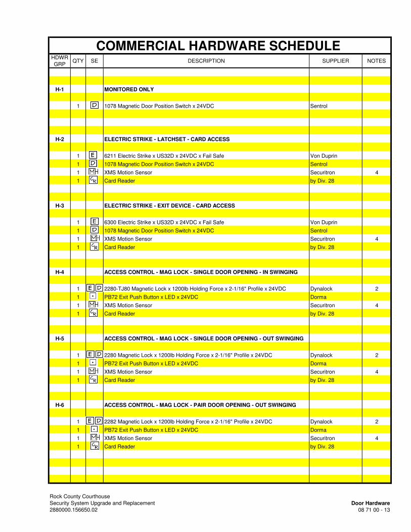
COMMERCIAL HARDWARE SCHEDULE HDWR
GRPQTY SE DESCRIPTION SUPPLIER NOTES
H-1 MONITORED ONLY
1 1078 Magnetic Door Position Switch x 24VDC Sentrol
H-2 ELECTRIC STRIKE - LATCHSET - CARD ACCESS
1 6211 Electric Strike x US32D x 24VDC x Fail Safe Von Duprin
1 1078 Magnetic Door Position Switch x 24VDC Sentrol
1 XMS Motion Sensor Securitron 4
1 Card Reader by Div. 28
H-3 ELECTRIC STRIKE - EXIT DEVICE - CARD ACCESS
1 6300 Electric Strike x US32D x 24VDC x Fail Safe Von Duprin
1 1078 Magnetic Door Position Switch x 24VDC Sentrol
1 XMS Motion Sensor Securitron 4
1 Card Reader by Div. 28
H-4 ACCESS CONTROL - MAG LOCK - SINGLE DOOR OPENING - IN SWINGING
1 2280-TJ80 Magnetic Lock x 1200lb Holding Force x 2-1/16" Profile x 24VDC Dynalock 2
1 PB72 Exit Push Button x LED x 24VDC Dorma
1 XMS Motion Sensor Securitron 4
1 Card Reader by Div. 28
H-5 ACCESS CONTROL - MAG LOCK - SINGLE DOOR OPENING - OUT SWINGING
1 2280 Magnetic Lock x 1200lb Holding Force x 2-1/16" Profile x 24VDC Dynalock 2
1 PB72 Exit Push Button x LED x 24VDC Dorma
1 XMS Motion Sensor Securitron 4
1 Card Reader by Div. 28
H-6 ACCESS CONTROL - MAG LOCK - PAIR DOOR OPENING - OUT SWINGING
1 2282 Magnetic Lock x 1200lb Holding Force x 2-1/16" Profile x 24VDC Dynalock 2
1 PB72 Exit Push Button x LED x 24VDC Dorma
1 XMS Motion Sensor Securitron 4
1 Card Reader by Div. 28
Rock County Courthouse
Security System Upgrade and Replacement Door Hardware
2880000.156650.02 08 71 00 - 13
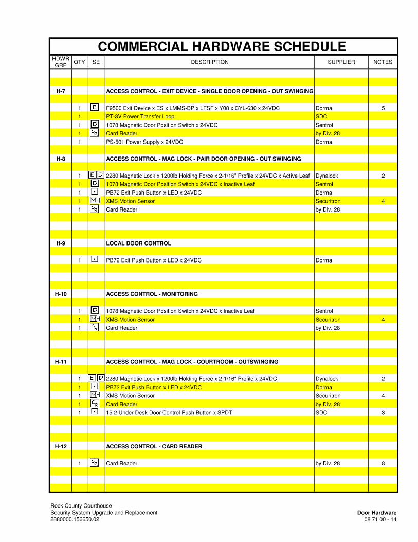
COMMERCIAL HARDWARE SCHEDULE HDWR
GRPQTY SE DESCRIPTION SUPPLIER NOTES
H-7 ACCESS CONTROL - EXIT DEVICE - SINGLE DOOR OPENING - OUT SWINGING
1 F9500 Exit Device x ES x LMMS-BP x LFSF x Y08 x CYL-630 x 24VDC Dorma 5
1 PT-3V Power Transfer Loop SDC
1 1078 Magnetic Door Position Switch x 24VDC Sentrol
1 Card Reader by Div. 28
1 PS-501 Power Supply x 24VDC Dorma
H-8 ACCESS CONTROL - MAG LOCK - PAIR DOOR OPENING - OUT SWINGING
1 2280 Magnetic Lock x 1200lb Holding Force x 2-1/16" Profile x 24VDC x Active Leaf Dynalock 2
1 1078 Magnetic Door Position Switch x 24VDC x Inactive Leaf Sentrol
1 PB72 Exit Push Button x LED x 24VDC Dorma
1 XMS Motion Sensor Securitron 4
1 Card Reader by Div. 28
H-9 LOCAL DOOR CONTROL
1 PB72 Exit Push Button x LED x 24VDC Dorma
H-10 ACCESS CONTROL - MONITORING
1 1078 Magnetic Door Position Switch x 24VDC x Inactive Leaf Sentrol
1 XMS Motion Sensor Securitron 4
1 Card Reader by Div. 28
H-11 ACCESS CONTROL - MAG LOCK - COURTROOM - OUTSWINGING
1 2280 Magnetic Lock x 1200lb Holding Force x 2-1/16" Profile x 24VDC Dynalock 2
1 PB72 Exit Push Button x LED x 24VDC Dorma
1 XMS Motion Sensor Securitron 4
1 Card Reader by Div. 28
1 15-2 Under Desk Door Control Push Button x SPDT SDC 3
H-12 ACCESS CONTROL - CARD READER
1 Card Reader by Div. 28 8
Rock County Courthouse
Security System Upgrade and Replacement Door Hardware
2880000.156650.02 08 71 00 - 14

COMMERCIAL HARDWARE SCHEDULE HDWR
GRPQTY SE DESCRIPTION SUPPLIER NOTES
H-13 ACCESS CONTROL - MAG LOCK - SINGLE DOOR OPENING - OUT SWINGING
1 2280 Magnetic Lock x 1200lb Holding Force x 2-1/16" Profile x 24VDC Dynalock 2
1 PB72 Exit Push Button x LED x 24VDC Dorma
1 XMS Motion Sensor Securitron 4
1 Card Reader by Div. 28
1 99L-BE-F-06 RIM Exit Device x 626 Von Durprin 6
H-14 MONITORING - ROOF HATCH
1 1045 Magnetic Door Position Switch Sentrol
H-15 EXIT DEVICE - SINGLE DOOR OPENING - OUT SWINGING
1 F9500 Exit Device x ES x LMMS-BP x LFSF x Y08 x CYL-630 x 24VDC Dorma 5
1 PT-3V Power Transfer Loop SDC
1 1078 Magnetic Door Position Switch x 24VDC Sentrol
1 PS-501 Power Supply x 24VDC Dorma
H-16 SPARE PARTS
3 2280 Magnetic Lock x 1200lb Holding Force x 2-1/16" Profile x 24VDC Dynalock
3 2280-TJ80 Magnetic Lock x 1200lb Holding Force x 2-1/16" Profile x 24VDC Dynalock
3 6211 Electric Strike x US32D x 24VDC x Fail Secure Von Duprin
6 PB72 Exit Push Button x LED x 24VDC Dorma
6 XMS Motion Sensor Securitron
6 1078 Magnetic Door Position Switch x 24VDC Sentrol
H-17 DOOR POSITION MONITOR - OVERHEAD DOOR
1 2300 Magnetic Door Position Switch x 24VDC Sentrol 7
Rock County Courthouse
Security System Upgrade and Replacement Door Hardware
2880000.156650.02 08 71 00 - 15

Rock County Courthouse Security System Upgrade and Replacement Door Hardware 2880000.156650.02 08 71 00 - 16
COMMERCIAL HARDWARE GENERAL NOTES 1. Contractor to provide inspection from certified UL inspector at all existing fire doors modified with new
commercial hardware. UL inspector to confirm that new fire-rated hardware has been installed according to UL standards and that the fire-label on the existing fire-rated door opening remains valid. Provide final UL inspection report to A/E for their file.
2. All electrified hardware to be fail safe unless noted otherwise.
3. All electrified hardware to integrated with fire alarm system noted otherwise. Provide all conduit,
cable and fire alarm control modules as required. Program door control with existing fire alarm
control panel. Doors to open in a fire condition for free egress both directions unless noted
otherwise. Fire alarm integration not required at access controlled exterior doors.
4. Equip all maglocks with local mechanical key release (shutoff) capabilities.
5. All hardware shown in this schedule installed on existing non-fire-rated Openings.
COMMERCIAL HARDWARE SCHEDULE NOTES 1. Provide (1) new magnetic lock each door. 2. Retrofit existing latchset to passage set function. 3. Push button used by Judge to lock entry door to Courtroom. 4. Mount motion sensor to side of door as recommended by manufacturer. Coordinate electrical rough-
in requirements with Div. 26 Electrical Contractor. 5. Contractor to demo existing exit device. Rework existing door as required to receive new hardware
as specified. Patch/paint all holes as applicable. Match existing finishes. 6. Rework existing door as required to receive new exit device.. 7. Contractor to rework existing overhead door as required to receive new hardware as specified.
END OF SECTION

SECTION 09 91 23 PAINTING
Rock County Courthouse Security System Upgrade and Replacement Painting 2880000.156650.02 09 91 23 - 1
PART 1 - GENERAL
1.01 RELATED DOCUMENTS
A. Drawings and general provisions of the Contract, including General and Supplementary Conditions and Division 01 Specification Sections, apply to this Section.
1.02 SUMMARY
A. This Section includes surface preparation and field painting of exposed exterior and interior items and surfaces.
1. Work of this Section includes surface preparation, priming, and finish coats specified in
this Section. Surfaces which have shop priming and surface treatment specified in other Sections that is in satisfactory condition, need only the required surface preparation (cleaning) and two finish coats, unless specifically noted otherwise.
B. Paint exposed surfaces, except where these Specifications indicate that the surface or material is not to be painted or is to remain natural. If an item or a surface is not specifically mentioned, paint the item or surface the same as similar adjacent materials or surfaces. If a color of finish is not indicated, Architect will select from standard colors and finishes available.
1. Painting includes field painting of exposed bare and covered pipes and ducts (including color coding), hangers, exposed steel and iron supports, and surfaces of mechanical and electrical equipment which have been factory primed but do not have a factory-applied final finish.
C. Do not paint prefinished items, finished metal surfaces, operating parts, and labels.
1. Prefinished items include the following factory-finished components:
a. Architectural woodwork and casework. b. Metal lockers. c. Finished mechanical and electrical equipment. d. Light fixtures. e. Distribution cabinets.
2. Finished metal surfaces include the following:
a. Anodized aluminum. b. Stainless steel. c. Chromium plate. d. Copper and copper alloys. e. Bronze and brass.
3. Operating parts include moving parts of operating equipment and the following:
a. Valve and damper operators. b. Linkages. c. Sensing devices. d. Motor and fan shafts.

SECTION 09 91 23 PAINTING
Rock County Courthouse Security System Upgrade and Replacement Painting 2880000.156650.02 09 91 23 - 2
4. Labels: Do not paint over UL, FMG, or other code-required labels or equipment name, identification, performance rating, or nomenclature plates.
1.03 SUBMITTALS
A. Product Data: For each paint system indicated. Include primers.
1. Material List: An inclusive list of required coating materials. Indicate each material and cross-reference specific coating, finish system, and application. Identify each material by manufacturer's catalog number and general classification.
2. Manufacturer's Information: Manufacturer's technical information, including label analysis and instructions for handling, storing, and applying each coating material.
B. Samples for Verification: For each color and material to be applied, with texture to simulate actual conditions, on representative Samples of the actual substrate.
1. Provide a list of materials and applications for each coat of each Sample. Label each
Sample for location and application.
1.04 QUALITY ASSURANCE
A. Applicator Qualifications: A firm or individual experienced in applying paints and coatings similar in material, design, and extent to those indicated for this Project, whose work has resulted in applications with a record of successful in-service performance.
B. Source Limitations: Obtain primers for each coating system from the same manufacturer as the finish coats.
1.05 DELIVERY, STORAGE, AND HANDLING
A. Deliver materials to Project site in manufacturer's original, unopened packages and containers bearing manufacturer's name and label and the following information:
1. Product name or title of material. 2. Product description (generic classification or binder type). 3. Manufacturer's stock number and date of manufacture. 4. Contents by volume, for pigment and vehicle constituents. 5. Thinning instructions. 6. Application instructions. 7. Color name and number. 8. VOC content.
B. Store materials not in use in tightly covered containers in a well-ventilated area at a minimum ambient temperature of 45 deg F. Maintain storage containers in a clean condition, free of foreign materials and residue.
1. Protect from freezing. Keep storage area neat and orderly. Remove oily rags and waste daily. Take necessary measures to ensure that workers and work areas are protected from fire and health hazards resulting form handling, mixing, and application.
1.06 PROJECT CONDITIONS
A. Apply waterborne paints only when temperatures of surfaces to be painted and surrounding air are between 50 and 90 deg F.

SECTION 09 91 23 PAINTING
Rock County Courthouse Security System Upgrade and Replacement Painting 2880000.156650.02 09 91 23 - 3
B. Apply solvent-thinned paints only when temperatures of surfaces to be painted and surrounding air are between 45 and 95 deg F.
C. Do not apply paint in snow, rain, fog, or mist; or when relative humidity exceeds 85 percent; or at temperatures less than 5 deg F above the dew point; or to damp or wet surfaces.
1. Painting may continue during inclement weather if surfaces and areas to be painted are enclosed and heated within temperature limits specified by manufacturer during application and drying periods.
PART 2 - PRODUCTS
2.01 MANUFACTURERS
A. Products: Subject to compliance with requirements, provide one of the products listed in the Finish Schedule on the Drawings.
B. Manufacturers' Names: Shortened versions (shown in parentheses) of the following manufacturers' names are used in other Part 2 articles:
1. Iowa Paint Manufacturing Co. Inc. (IPM) 2. Benjamin Moore & Co. (Moore). 3. ICI Dulux/ Devoe Coatings (ICI). 4. PPG Industries, Inc. (Pittsburgh). 5. Pratt & Lambert, Inc. (P & L) 6. Sherwin-Williams Co. (S-W). 7. Kwal Paint (Kwal)
2.02 PAINT MATERIALS, GENERAL
A. Material Compatibility: Provide primers, and finish-coat materials that are compatible with one another and with the substrates indicated under conditions of service and application, as demonstrated by manufacturer based on testing and field experience.
B. Material Quality: Provide manufacturer's best-quality paint material of the various coating types specified that are factory formulated and recommended by manufacturer for application indicated. Paint-material containers not displaying manufacturer's product identification will not be acceptable.
C. Colors: Match existing colors. If required, provide custom colors to match existing colors.
PART 3 - EXECUTION
3.01 EXAMINATION
A. Examine substrates, areas, and conditions, with Applicator present, for compliance with requirements for paint application. Comply with procedures specified in PDCA P4.
1. Proceed with paint application only after unsatisfactory conditions have been corrected and surfaces receiving paint are thoroughly dry.
SECTION 09 91 23 PAINTING
Rock County Courthouse Security System Upgrade and Replacement Painting 2880000.156650.02 09 91 23 - 4
2. Start of painting will be construed as Applicator's acceptance of surfaces and conditions within a particular area.
B. Coordination of Work: Review other Sections in which primers are provided to ensure compatibility of the total system for various substrates. On request, furnish information on characteristics of finish materials to ensure use of compatible primers.
1. Notify Architect about anticipated problems when using the materials specified over substrates primed by others.
3.02 PREPARATION
A. Remove hardware and hardware accessories, plates, machined surfaces, lighting fixtures, and similar items already installed that are not to be painted. If removal is impractical or impossible because of size or weight of the item, provide surface-applied protection before surface preparation and painting.
1. After completing painting operations in each space or area, reinstall items removed using workers skilled in the trades involved.
B. Cleaning: Before applying paint or other surface treatments, clean substrates of substances that could impair bond of the various coatings. Remove oil and grease before cleaning.
1. Schedule cleaning and painting so dust and other contaminants from the cleaning process will not fall on wet, newly painted surfaces.
C. Surface Preparation: Clean and prepare surfaces to be painted according to manufacturer's written instructions for each particular substrate condition and as specified.
1. Provide barrier coats over incompatible primers or remove and reprime. 2. Cementitious Materials: Prepare concrete, concrete unit masonry, cement plaster, and
mineral-fiber-reinforced cement panel surfaces to be painted. Remove efflorescence, chalk, dust, dirt, grease, oils, and release agents. Roughen as required to remove glaze. If hardeners or sealers have been used to improve curing, use mechanical methods of surface preparation.
a. Use abrasive blast-cleaning methods if recommended by paint manufacturer. b. Determine alkalinity and moisture content of surfaces by performing appropriate
tests. If surfaces are sufficiently alkaline to cause the finish paint to blister and burn, correct this condition before application. Do not paint surfaces if moisture content exceeds that permitted in manufacturer's written instructions.
c. Clean concrete floors to be painted with a 5 percent solution of muriatic acid or other etching cleaner. Flush the floor with clean water to remove acid, neutralize with ammonia, rinse, allow to dry, and vacuum before painting.
3. Wood: Clean surfaces of dirt, oil, and other foreign substances with scrapers, mineral spirits, and sandpaper, as required. Sand surfaces exposed to view smooth and dust off.
a. Scrape and clean small, dry, seasoned knots, and apply a thin coat of white shellac or other recommended knot sealer before applying primer. After priming, fill holes and imperfections in finish surfaces with putty or plastic wood filler. Sand smooth when dried.
b. If transparent finish is required, backprime with spar varnish.

SECTION 09 91 23 PAINTING
Rock County Courthouse Security System Upgrade and Replacement Painting 2880000.156650.02 09 91 23 - 5
D. Material Preparation: Mix and prepare paint materials according to manufacturer's written instructions.
1. Maintain containers used in mixing and applying paint in a clean condition, free of foreign materials and residue.
2. Stir material before application to produce a mixture of uniform density. Stir as required during application. Do not stir surface film into material. If necessary, remove surface film and strain material before using.
3. Use only thinners approved by paint manufacturer and only within recommended limits.
3.03 APPLICATION
A. Apply paint according to manufacturer's written instructions. Use applicators and techniques best suited for substrate and type of material being applied.
1. Paint colors, surface treatments, and finishes are indicated in the paint schedules. 2. Do not paint over dirt, rust, scale, grease, moisture, scuffed surfaces, or conditions
detrimental to formation of a durable paint film. 3. Provide finish coats that are compatible with primers used. 4. The term "exposed surfaces" includes areas visible when permanent or built-in fixtures,
grilles, convector covers, covers for finned-tube radiation, and similar components are in place. Extend coatings in these areas, as required, to maintain system integrity and provide desired protection.
B. Scheduling Painting: Apply first coat to surfaces that have been cleaned, pretreated, or otherwise prepared for painting as soon as practicable after preparation and before subsequent surface deterioration.
1. The number of coats and film thickness required are the same regardless of application method. Do not apply succeeding coats until previous coat has cured as recommended by manufacturer. If sanding is required to produce a smooth, even surface according to manufacturer's written instructions, sand between applications.
2. Omit primer over metal surfaces that have been shop primed and touchup painted. 3. If undercoats, stains, or other conditions show through final coat of paint, apply
additional coats until paint film is of uniform finish, color, and appearance. Give special attention to ensure that edges, corners, crevices, welds, and exposed fasteners receive a dry film thickness equivalent to that of flat surfaces.
4. Allow sufficient time between successive coats to permit proper drying. Do not recoat surfaces until paint has dried to where it feels firm, and does not deform or feel sticky under moderate thumb pressure, and until application of another coat of paint does not cause undercoat to lift or lose adhesion.
C. Application Procedures: Apply paints and coatings by brush, roller, spray, or other applicators according to manufacturer's written instructions.
1. Brushes: Use brushes best suited for type of material applied. Use brush of appropriate size for surface or item being painted.
2. Rollers: Use rollers of carpet, velvet-back, or high-pile sheep's wool as recommended by manufacturer for material and texture required.
3. Spray Equipment: Use airless spray equipment with orifice size as recommended by manufacturer for material and texture required.
D. Minimum Coating Thickness: Apply paint materials no thinner than manufacturer's recommended spreading rate to achieve dry film thickness indicated. Provide total dry film thickness of the entire system as recommended by manufacturer.
SECTION 09 91 23 PAINTING
Rock County Courthouse Security System Upgrade and Replacement Painting 2880000.156650.02 09 91 23 - 6
E. Electrical Work: Painting of electrical work is limited to items exposed in equipment rooms and occupied spaces.
F. Prime Coats: Before applying finish coats, apply a prime coat, as recommended by manufacturer, to material that is required to be painted or finished and that has not been prime coated by others. Recoat primed and sealed surfaces where evidence of suction spots or unsealed areas in first coat appears, to ensure a finish coat with no burn-through or other defects due to insufficient sealing.
G. Pigmented (Opaque) Finishes: Completely cover surfaces as necessary to provide a smooth, opaque surface of uniform finish, color, appearance, and coverage. Cloudiness, spotting, holidays, laps, brush marks, runs, sags, ropiness, or other surface imperfections will not be acceptable.
H. Completed Work: Match existing conditions for color, texture, and coverage. Remove, refinish, or repaint work not complying with requirements.
3.04 CLEANING
A. Cleanup: At the end of each workday, remove empty cans, rags, rubbish, and other discarded paint materials from Project site.
1. After completing painting, clean glass and paint-spattered surfaces. Remove spattered paint by washing and scraping without scratching or damaging adjacent finished surfaces.
3.05 PROTECTION
A. Protect work of other trades, whether being painted or not, against damage from painting. Correct damage by cleaning, repairing or replacing, and repainting, as approved by Architect.
B. Provide "Wet Paint" signs to protect newly painted finishes. After completing painting operations, remove temporary protective wrappings provided by others to protect their work.
1. After work of other trades is complete, touch up and restore damaged or defaced painted surfaces. Comply with procedures specified in PDCA P1.
3.06 INTERIOR PAINT SCHEDULE
A. FM - Interior Ferrous Metal
1. FM - SGALK - Interior Semigloss Alkyd Paint System: Provide 2 finish coats of Semigloss alkyd enamel over a primer.
a. FM - SGALK Interior Semigloss Alkyd Enamel: Factory-formulated semigloss alkyd enamel for interior application.
1) ICI; 1516-XXXX Ultra-Hide Alkyd Semi-Gloss Interior Wall &
Trim Enamel: Applied at a dry film thickness of not less than 1.7 mils.
2) IPM; Synex Semi Gloss Alkyd Enamel #302: Applied at a dry film thickness of not less than 2 mils.
3) Kwal: 4600 Accu-Pro Alkyd Semi Gloss: Applied at a dry film thickness of not less than 1.7 mils.
SECTION 09 91 23 PAINTING
Rock County Courthouse Security System Upgrade and Replacement Painting 2880000.156650.02 09 91 23 - 7
4) Moore; Moorcraft Super Spec Alkyd Semi-Gloss Enamel No. 271: Applied at a dry film thickness of not less than 1.4 mils.
5) Pittsburgh; 6-1110 Series SpeedHide Interior Enamel Wall & Trim Semi-Gloss Oil: Applied at a dry film thickness of not less than 1.4 mils.
6) P & L; S-8800 Pro-Hide Gold Alkyd Semi-Gloss: Applied at a dry film thickness of not less than 1.5mils.
7) S-W; ProMar 200 Interior Alkyd Semi-Gloss Enamel B34W200 Series: Applied at a dry film thickness of not less than 1.7 mils.
END OF SECTION

PAGE INTENTIONALLY LEFT BLANK

Rock County Courthouse Common work Results Security System Upgrade and Replacement for Electrical 2880000.156650.02 26 05 00 - 1
SECTION 26 05 00 COMMON WORK RESULTS FOR ELECTRICAL
PART 1 - GENERAL
1.1 RELATED DOCUMENTS
A. Drawings and general provisions of the Contract, including General and Supplementary Conditions and Division 01 Specification Sections, apply to this Section.
1.2 SUMMARY
A. Section Includes:
1. Electrical equipment coordination and installation. 2. Access panels 3. Common electrical installation requirements.
1.3 DEFINITIONS
A. Code. National, State and Local Electrical codes including OSHA requirements.
B. Concealed, Exterior Installations: Concealed from view and protected from weather conditions and physical contact by building occupants but subject to outdoor ambient temperatures. Examples include installations within unheated shelters.
C. Concealed, Interior Installations: Concealed from view and protected from physical contact by building occupants. Examples include above ceilings and in chases.
D. Exposed, Exterior Installations: Exposed to view outdoors or subject to outdoor ambient temperatures and weather conditions. Examples include rooftop locations.
E. Exposed, Interior Installations: Exposed to view indoors. Examples include finished occupied spaces and mechanical equipment rooms.
F. Finished Spaces: Spaces other than mechanical and electrical equipment rooms, furred spaces, pipe chases, unheated spaces immediately below roof, spaces above ceilings, unexcavated spaces, crawlspaces, and tunnels.
G. Home Run: The portion of a branch circuit between the serving panelboard and the first electrical outlet, lighting fixture, or other electrical load connected to the circuit.
H. Low voltage: 50 to 600 volts.
I. Provide. Furnish, install and wire ready for service.
J. Signal voltage. NEC class 1, 2, or 3 remote control, signaling, or power limited circuits.
Rock County Courthouse Common work Results Security System Upgrade and Replacement for Electrical 2880000.156650.02 26 05 00 - 2
1.4 SCOPE
A. Drawings and Specifications form complementary requirements; provide work specified and not shown, and work shown and not specified as though explicitly required by both. Although work may not be specifically shown or specified, provide supplementary or miscellaneous items, appurtenances, devices and materials obviously necessary for a sound, secure and complete installation.
B. It is the intent that these Specifications and associated Drawings establish minimum requirements for products and equipment with the intent to provide electrical service, distribution and systems finished, tested and ready for operation. Incidental detail that is not shown or specified, but necessary for proper installation and operation shall be included in the work and in these Contractor's estimates, the same as if specified. Locations of all equipment and material shall be adjusted at no extra cost to the Owner, to accommodate the work interferences anticipated and/or encountered. Prior to installation, determine the exact route and location of each raceway and piece of equipment to minimize conflicts with other trades.
C. Information and components shown on riser diagrams but not shown on plans, and vice versa, shall be provided as if expressly required on both.
D. It is the requirement of these Contract Documents to have the contractors provide systems and components that are fully complete, operational and suitable for the intended use. There may be situations in the documents where insufficient information exists to precisely describe a certain component or subsystem, or the routing of a component or its coordination with other building elements. In cases such as this, where the Contractor has failed to notify the Engineer of the situation in accordance with Paragraph (A) above, the Contractor shall include in their bid the specific components or subsystems with all parts necessary for the intended use, fully complete and operational, and installed in workmanlike manner either concealed or exposed per the design intent.
1.5 MODIFICATIONS IN LAYOUT
A. Drawings are intended to outline the scope of work required and are not intended to be installation drawings. Drawings are not intended to be absolutely precise; they are not intended to specify or to show every offset, fitting, and component nor do they show the exact routings. The purpose of the drawings is to indicate a systems concept, the main components of the systems, and the approximate geometrical relationships. Based on the systems concept, the main components, and the approximate geometrical relationships, the contractor shall provide all other components and materials necessary to make the systems fully complete and operational, nor do they show the exact routings and locations needed to coordinate with structure and other trades.
B. Unless specifically stated to the contrary, no measurement of an electric drawing derived by scaling shall be used as a dimension to work by. Dimensions noted on the electric drawings are subject to measurements of adjacent and previously completed work. Measurements shall be performed prior to the actual installation of equipment.
C. Prior to installation of visible material and equipment (including access panels) in finished spaces, review as-built conditions for desired locations and where not definitely indicated, request information from Engineer.
D. Check Contract Documents, as well as, Submittals and Shop Drawings of all subcontractors to verify and coordinate spaces in which work of Divisions 27 and 28 will be installed.

Rock County Courthouse Common work Results Security System Upgrade and Replacement for Electrical 2880000.156650.02 26 05 00 - 3
E. Make reasonable modifications in layout and components needed to prevent conflict with work of other trades. Systems shall be run parallel with or perpendicular to major architectural and structural building elements.
F. Where conflicts or potential conflicts exist and engineering guidance is desired, submit sketch of proposed resolution to Engineer for review and approval.
1.6 COORDINATION
A. Coordinate arrangement, mounting, and support of equipment and raceways:
1. To maintain maximum headroom; all piping, duct, conduit and associated components to be as tight as possible to underside of structure to provide for ease of disconnecting the equipment with minimum interference to other installations.
2. To allow right of way for piping installed at required slope. 3. To allow connecting raceways and cables to be clear of obstructions and of the working
and access space of other equipment.
1.7 RECORD DOCUMENTS
A. Record Drawings are specified in Division 01 Section "Project Record Documents."
B. The Contractor shall keep a detailed up-to-date record, of the manner and location in which installations are actually made, indexing each feeder, pull box and protective device. Record documents are to reflect all changes in work including change orders, field directives, addenda from bid set of Contract Documents, request for information responses, etc. Upon completion of the project, the contractor shall modify the project electronic drawing and specification files to incorporate this information. Modified documents shall be turned over to the Owner in both electronic and hard paper copy formats. Record drawings shall also include:
1. Locations of buried conduit or similar items. Include buried depth. 2. Field changes of dimension or detail. 3. Details not on original contract drawings. 4. Changes to circuit numbers. 5. Junction box locations and conduit runs, with trade sizes indicated, for lighting, power,
and electrical systems installed. 6. Final panel schedules on drawings matching construction document drawing size.
1.8 MAINTENANCE MANUALS AND OPERATING INSTRUCTIONS
A. Obtain at time of purchase of equipment, three copies of operation, lubrication and maintenance manuals for all items. Assemble literature in a coordinated manual using loose leaf sheets in a three ring binder(s). Manual shall contain names and addresses of manufacturers and local representatives who stock or furnish repair parts for items or equipment.
B. The manuals shall include the following and shall have an index of contents and tabs for each Specification Section and each piece of equipment specified in that Section and be provided in the order listed below, per Specification Section.
1. Copies of all approved submittals/shop drawings.

Rock County Courthouse Common work Results Security System Upgrade and Replacement for Electrical 2880000.156650.02 26 05 00 - 4
2. Manufacturer's operating and maintenance instructions and parts lists of all items or equipment. Where manufacturer's data includes several types or models, the applicable type or model shall be clearly designated.
3. Startup and shutdown procedures. 4. Test records. 5. Wiring diagrams. 6. Lubrication instructions detailing type of lubricant, amount, and intervals recommended
by manufacturer for each item of equipment. 7. Owner's written acknowledgement of satisfactory completion of instruction period.
C. Furnish three copies of manuals to Engineer for approval and distribution to Owner. Deliver manuals no less than 30 days prior to acceptance of equipment to permit Owner's personnel to become familiar with equipment and operation prior to acceptance.
D. Operating instructions: Upon completion of installation or when Owner accepts portions of building and equipment for operational use, instruct Owner's operating personnel in any or all parts of all systems. Factory-trained personnel shall perform instructions.
E. Submittal Procedure and Format
1. This Paragraph supplements Division 1. 2. Submittal Cover Sheet
a. Submittal data for each product shall include a copy of the following cover sheet completely filled out. Incomplete or incorrect cover sheet submittal shall constitute reason for rejection.
b. Shop drawings/submittals shall be submitted according to applicable specification section’s requirements with a separate cover sheet completed for each product, rather than one cover sheet for multiple products, whether or not supplied by one manufacturer or vendor.
3. Shop Drawings showing layouts of systems shall contain sufficient plans, elevations, sections, details and schematics to describe work clearly. They shall be 1/4 inches = 1 foot 0 inch scale unless specified otherwise.
4. Shop drawings and submittals showing manufacturer's product data shall contain detailed dimensional drawings, accurate and complete description of materials of construction, manufacturer's published performance characteristics and capacity ratings (performance data, alone, is not acceptable), electrical requirements and wiring diagrams. Drawings shall clearly indicate location (terminal block or wire number), voltage and function for all field terminations, and other information necessary to demonstrate compliance with all requirements of Contract Documents.
5. Provide shop drawing submittals showing details of piping connections to ALL equipment. If connection details are not submitted and connections are found to be installed incorrectly in the field, this contractor shall reinstall them within the original contract price.
6. Shop drawings for different systems and equipment shall be bound separately by specification section as indicated above and not bound by manufacturer. Each separate submittal shall have its own transmittal and cover letter. Submittals which contain different specification section systems bound together shall be returned un-reviewed for re-submittal.
1.9 QUALITY ASSURANCE
A. Acceptable Manufacturers
1. The Engineer’s design for each product is based on the manufacturer listed in the schedule or shown on the drawings. In Part 2 of some technical specifications, other
Rock County Courthouse Common work Results Security System Upgrade and Replacement for Electrical 2880000.156650.02 26 05 00 - 5
manufacturers are listed as being acceptable. The listing of a manufacturer as acceptable does not imply automatic approval. It is the sole responsibility of the Contractor to ensure that any submittals made are for products that meet or exceed the specifications included herein. These are acceptable only if, as a minimum, they:
a. Meet all performance criteria listed in the schedules and outlined in the specification.
b. Have identical operating characteristics to those called for in the specification. For example, a two-stroke diesel generator will not be acceptable if a four-stroke model is specified.
c. Fit within the available space it was designed for, including space for maintenance and component removal, with no modification to either the space or the product. Clearances to walls, ceilings and other equipment will be at least equal to those shown on the design drawings. The fact that a manufacturer’s name appears as acceptable shall not be taken to mean that the Engineer has determined that the manufacturer’s products will fit within the available space - this determination is solely the responsibility of the contractor.
d. Products must adhere to all architectural considerations including but not limited to: being of the same color as the product scheduled or specified, fitting within architectural enclosures and details, and for diffusers, lighting and plumbing fixtures - being the same size and of the same physical appearance as scheduled or specified products.
B. All equipment shall be labeled or listed by the National Board of Underwriters Laboratories (U.L.) or other recognized listing/testing agency where such labeling or listing exists for such material.
C. All electrical components, devices and accessories shall be listed and labeled as defined in NFPA 70, Article 100, by a testing agency acceptable to authorities having jurisdiction, and marked for intended use. Skid-mounted or packaged assemblies shall be listed and labeled as an assembly, not just the individual components.
1.10 DELIVERY, STORAGE, AND HANDLING
A. Protect equipment/materials from damage during shipping, storage, handling and installation. Delivery equipment/materials to the site in manufacturer’s original, unopened containers and packaging, with labels clearly indicating manufacturer and material.
B. The Contractor shall provide for enclosed storage, when equipment/materials are stored on-site and prior to building “dry-in”, to prevent any damage resulting from inclement weather or construction traffic. Specialties shall not be stored outdoors.
C. Equipment/materials, stored or installed, found to be damaged shall be replaced with new by the Contractor, to the satisfaction of the Owner and at no additional expense. Do not store equipment with PVC material with exposure to direct sunlight.

Rock County Courthouse Common work Results Security System Upgrade and Replacement for Electrical 2880000.156650.02 26 05 00 - 6
PART 2 - PRODUCTS
2.1 CEILING ACCESS AND ACCESS PANELS
A. Access panels are generally not shown on the drawings, but they are required to be provided by Contractor. Access panel shall be painted to match existing wall/ceiling color.
B. Access panels shall be of size required to provide adequate access to equipment. Minimum size shall be 12” X 12” for hand access or 24” X 24” for body access. Minimum 16 gauge frame, not less than 18 gauge hinged door panel. Door locks shall be screwdriver operated for panels in general location applications and shall be key locked for public area applications.
C. Panels shall include concealed hinges, cam type locking devices, and shall have a frame border type necessary for the particular wall or ceiling construction in which they are installed. Access panels shall be flush mounted, recessed frame type units. Access panels shall be prime coated steel, for field painting for general applications and stainless steel for use in toilet rooms, shower rooms, and similar wet locations.
D. Access panels shall have same fire rating classification as surface penetrated. Rated access panels must have U.L. Label.
PART 3 - EXECUTION
3.1 PRE-BID SITE VISIT
A. Before submitting bid, visit and carefully examine site to identify existing conditions and difficulties that will affect work of this division. No extra payment will be allowed for additional work caused by unfamiliarity with site conditions that are visible or readily construed by an experienced observer.
B. Contractor shall visit job site to familiarize himself with the specific location of the new equipment installations in existing areas, to ensure there is adequate access for the installation of equipment. All entries, pathways, corridors, stairwells, etc., that may be used to install equipment shall be investigated. All existing conditions and potential obstructions that may impede access and installation shall be addressed prior to equipment purchasing/ordering.
C. The documentation of existing conditions was derived from As-Built documents and are in part unverified. Actual existing conditions shall be verified prior to commencement of work.
3.2 COMMON REQUIREMENTS FOR ELECTRICAL INSTALLATION
A. Comply with NECA 1 – Standard Practices for Good Workmanship in Electrical Contracting.
B. Measure indicated mounting heights to bottom of unit for suspended items and to center of unit for wall-mounting items.
C. Headroom Maintenance: If mounting heights or other location criteria are not indicated, arrange and install components and equipment to provide maximum possible headroom consistent with these requirements.

Rock County Courthouse Common work Results Security System Upgrade and Replacement for Electrical 2880000.156650.02 26 05 00 - 7
D. Equipment: Install to facilitate service, maintenance, and repair or replacement of components of both electrical equipment and other nearby installations. Connect in such a way as to facilitate future disconnecting with minimum interference with other items in the vicinity.
E. Right of Way: Give to piping systems installed at a required slope.
F. Apply firestopping to penetrations of fire-rated floor and wall assemblies for electrical installations to restore original fire-resistance rating of assembly.
3.3 FIREPROOFING:
A. Clips, hangers, clamps, supports and other attachments to surfaces to be fireproofed shall be installed, insofar as possible, prior to start of spray fiber work.
B. Piping and other items which would interfere with proper application of fireproofing shall be installed after completion of spray fiber work.
C. Patching and repairing of fireproofing due to cutting or damaging to fireproofing during course of work specified under this Section shall be performed by installer of fireproofing and paid for by trade responsible for damage and shall not constitute grounds for extra cost to Owner.
3.4 PAINTING
A. Furnish one can of aerosol-free touch-up paint for each different color factory finish which is to be the final finished surface of the product.
3.5 CLEANING
A. Cleaning shall be performed prior to equipment being energized.
B. Raceways
1. General:
a. Cover all raceway openings prior to the installation of conductors to prevent dirt, moisture, and other debris from entering the raceways.
b. Before pulling conductors, swab out all raceways to remove any debris that may have entered raceways during construction or during storage.
c. When external surfaces of raceways or enclosures are rusted, clean and restore surfaces to original condition.
2. Equipment
a. After completion of work but prior to turning equipment over to the Owner, clean the exterior surfaces to be free from concrete residue, dirt, paint residue, etc.
b. All dirt, drywall dust, and all other foreign matter shall be blown from, wiped away, or vacuumed from all equipment, enclosures, junction boxes, and pullboxes.
c. Thoroughly clean equipment of all stains, paint spots, dirt, and dust. Remove all temporary labels not used for instruction or operation and remove all visible trade labels.

Rock County Courthouse Common work Results Security System Upgrade and Replacement for Electrical 2880000.156650.02 26 05 00 - 8
END OF SECTION

Rock County Courthouse Selective Security System Upgrade and Replacement Electrical Demolition 2880000.156650.02 26 05 10 - 1
SECTION 26 05 10 SELECTIVE ELECTRICAL DEMOLITION
PART 1 - GENERAL
1.1 RELATED DOCUMENTS
A. Drawings and general provisions of the Contract, including General and Supplementary Conditions and Division 01 Specification Sections, apply to this Section.
1.2 SUMMARY
A. Section includes:
1. Disconnection of existing electrical and fire alarm devices and associated wiring.
1.3 JOB CONDITIONS
A. Perform all demolition as needed to accomplish new work.
B. Do not rely solely on electrical drawings to determine extent of general construction demolition. Refer to architectural demolition plans for the exact extent of general construction demolition required by this contract.
C. This Contractor is responsible for all charges, fees etc. incurred as a result of the electrical portion of the demolition.
D. Prior to demolition or alteration of structures, the following shall be accomplished:
1. Review available record documents of the existing construction. Owner does not guarantee that existing conditions are same as those indicated in record documents.
2. Coordinate sequencing with Owner and other Contractors. 3. Coordinate means to separate construction zones from non-renovated zones to prevent
the spread of dust, fumes and debris. 4. Coordinate means to provide exhaust and makeup air to maintain the construction zone
at an adequate negative pressure to contain all construction dust and fumes. 5. Except as noted otherwise, remove from the premises, all materials and equipment
removed in the demolition work. 6. Survey and record condition of existing facilities to remain in place that may be affected
by demolition operations. After demolition operations are completed, survey conditions again and restore existing facilities to their pre-demolition condition, at no additional cost to Owner.
PART 2 - PRODUCTS Not used.
PART 3 - EXECUTION

Rock County Courthouse Selective Security System Upgrade and Replacement Electrical Demolition 2880000.156650.02 26 05 10 - 2
3.1 PREPARATION
A. Survey existing conditions and correlate with requirements indicated to determine the extent of selective demolition required.
B. Refer to demolition drawings of other trades. Where control panels, and other loads that have an electrical connection are being removed, include the disconnection and removal of associated electrical feeds, circuits, and loose control equipment in this contract.
C. Protect existing work to remain in place, to be reused, or to remain property of Owner.
D. Protect existing services and utilities.
3.2 DEMOLITION AND EXTENSION OF EXISTING ELECTRICAL AND FIRE ALARM WORK
A. Beginning of demolition means installer accepts existing conditions.
B. Any existing services or equipment not shown on the drawings and which are logically expected to be continued in service and which may be interrupted or disturbed during construction, shall be reconnected in an approved manner. Provide temporary power connections, lighting, controls, etc., as needed to prevent interruption of service to occupied areas caused by demolition operations. In addition, any conduit, wiring, fixtures, or equipment which may require relocation or rerouting as a result of construction, shall be considered a part of the work of this section and shall be done by this Contractor with no additional compensation, provided that the referenced relocation is discernable from the pre-bid review of the site, and associated documents.
C. Verify that abandoned wiring and equipment serve only abandoned facilities.
D. Report discrepancies to Engineer before disturbing existing installation.
E. De-energize, disconnect, demolish, and remove electrical/fire alarm systems, equipment, raceways, wiring, and components indicated to be removed.
F. indicated or specified to be removed. In general, all empty raceways and associated supporting devices shall be removed back to nearest active junction box, panelboard, switchboard, panel cabinet, or other similar enclosure.
G. Conductors to be Removed: Unless specifically stated elsewhere, all un-terminated conductors shall be de-energized, and all de-energized conductors shall be removed back to source.
H. Equipment to be Removed: De-energize, disconnect associated raceways and wiring, and remove equipment.
I. Any unused conduit openings in junction boxes, panelboards, switchboards, panel cabinets, pull boxes, or other similar enclosures shall be covered in a code approved manner.
J. Outlet boxes being abandoned in existing walls shall have opening patched to match existing wall finish. Blank covers are not acceptable.
K. Maintain access to existing electrical installations that remain active. Modify installation or provide access panel as appropriate.

Rock County Courthouse Selective Security System Upgrade and Replacement Electrical Demolition 2880000.156650.02 26 05 10 - 3
L. Maintain continuity of circuits that remain in service.
M. During the demolition and alterations, the fire alarm system shall remain active. If fire alarm system cannot remain active, a fire watch shall be provided by the electrical contractor during system outage.
N. The fire alarm zone serving smoke detectors in the smoke compartment where work is occurring may be disconnected when work is taking place to avoid false alarms. Zone shall be reconnected at end of each work day. Smoke detectors shall be protected to keep dust and dirt from entering sensing chamber. All smoke detectors within the smoke compartment where work is occurring shall be cleaned upon completion of work within that area.
3.3 CLEANING AND REPAIR
A. Clean existing materials and equipment which remain or are to be reused. Report damage or defects to Engineer
B. If equipment to remain is damaged in appearance or is unserviceable, remove damaged or unserviceable portions and replace with new products of equal capacity and quality.
C. Repair adjacent construction and finishes damage during demolition and extension work.
END OF SECTION

PAGE INTENTIONALLY LEFT BLANK

Rock County Courthouse Low-Voltage Electrical Security System Upgrade and Replacement Power Conductors and Cables 2880000.156650.02 26 05 19 - 1
SECTION 26 05 19 LOW-VOLTAGE ELECTRICAL POWER CONDUCTORS AND CABLES
PART 1 - GENERAL
1.1 RELATED DOCUMENTS
A. Drawings and general provisions of the Contract, including General and Supplementary Conditions and Division 01 Specification Sections, apply to this Section.
1.2 SUMMARY
A. This Section includes the following:
1. Building wires and cables rated 600 V and less. 2. Connectors, splices, and terminations rated 600 V and less.
1.3 ACTION SUBMITTALS
A. Product Data: For each type of product indicated.
1.4 INFORMATIONAL SUBMITTALS
A. Field quality-control test reports.
1.5 QUALITY ASSURANCE
A. Electrical Components, Devices, and Accessories: Listed and labeled as defined in NFPA 70, Article 100, by a testing agency acceptable to authorities having jurisdiction, and marked for intended use.
B. Comply with NFPA 70.
1.6 PROJECT CONDITIONS
A. Wire and cable routing where shown on Drawings is approximate unless dimensioned. Route wire and cable as required to meet Project Conditions.
B. Where wire and cable routing is not shown, and destination only is indicated, determine exact routing and lengths required.

Rock County Courthouse Low-Voltage Electrical Security System Upgrade and Replacement Power Conductors and Cables 2880000.156650.02 26 05 19 - 2
PART 2 - PRODUCTS
2.1 CONDUCTORS AND CABLES
A. Available Manufacturers: Subject to compliance with requirements, manufacturers offering products that may be incorporated into the Work include, but are not limited to, the following: 1. American Insulated Wire Corp. 2. General Cable Corporation. 3. Senator Wire & Cable Company. 4. Southwire Company.
B. Copper Conductors: Comply with NEMA WC 70. Aluminum not permitted.
C. Conductor Insulation: Comply with NEMA WC 70 for Types THHN/THWN, XHHW-2 and SO.
2.2 CONNECTORS AND SPLICES
A. Available Manufacturers: Subject to compliance with requirements, manufacturers offering products that may be incorporated into the Work include, but are not limited to, the following:
1. AFC Cable Systems, Inc. 2. Hubbell Power Systems, Inc. 3. O-Z/Gedney; EGS Electrical Group LLC. 4. 3M; Electrical Products Division. 5. Tyco Electronics Corp. 6. Thomas & Betts.
B. Description: Factory-fabricated connectors and splices of size, ampacity rating, material, type, and class for application and service indicated.
C. Spring wire connectors: Corrosion-resistant, live-action spring in insulated shell, rated 105°C.
D. Connectors and lugs: Circumferential compression (non-indenter) type.
PART 3 - EXECUTION
3.1 CONDUCTOR MATERIAL APPLICATIONS
A. Branch Circuits:
1. Conductor: Copper. Stranded for No. 10 AWG and smaller; stranded for No. 8 AWG and larger.
2. Insulation: Type THHN/THWN insulation for branch circuits #2 AWG and smaller.
B. Use stranded conductor, No. 14 minimum for control wiring.

Rock County Courthouse Low-Voltage Electrical Security System Upgrade and Replacement Power Conductors and Cables 2880000.156650.02 26 05 19 - 3
3.2 CONDUCTOR INSULATION AND MULTICONDUCTOR CABLE APPLICATIONS AND WIRING METHODS
A. Exposed Branch Circuits, Including in Crawlspaces: Single conductors in raceway.
B. Branch Circuits Concealed above Ceilings, in Walls, and Partitions: Single conductors in raceway.
C. Class 1 Control Circuits: Single conductors in raceway.
D. Class 2 Control Circuits: Single conductors in raceway.
3.3 INSTALLATION OF CONDUCTORS AND CABLES
A. Conceal cables in finished walls, above ceilings, and in floors, unless otherwise indicated.
B. Use manufacturer-approved pulling compound or lubricant where necessary; compound used must not deteriorate conductor or insulation. Do not exceed manufacturer's recommended maximum pulling tensions and sidewall pressure values.
C. Use pulling means, including fish tape, cable, rope, and basket-weave wire/cable grips, that will not damage cables or raceway.
D. Install exposed conduits parallel and perpendicular to surfaces of exposed structural members, and follow surface contours where possible.
E. Neatly train and lace wiring inside boxes and equipment.
F. Support cables according to Division 26 Section "Hangers and Supports for Electrical Systems."
G. Identify and color-code conductors and cables according to Division 26 Section "Identification for Electrical Systems."
3.4 BRANCH CIRCUIT REQUIREMENTS
A. Do not use wire smaller than No. 12 AWG (unless otherwise noted) for branch circuit wiring. All 20 amp, 120 volt branch circuit homeruns (to panelboard) serving equipment shall be No. 10 AWG minimum to first outlet or light fixture.
B. Size home runs for 120V branch circuits based on the overall circuit length to the furthest outlet. The following requirements shall be followed:
1. 0 to 100 ft. circuit length: Size home run at #10 AWG minimum to first outlet. 2. 101 to 150 ft. circuit length: Size home run at #8 AWG minimum to first outlet. 3. 151 to 250 ft. circuit length: Size home run at #6 AWG minimum to first outlet. 4. For other branch circuits, size conductors so that voltage drop does not exceed 3%.
C. All 120 volt branch circuits shall have a dedicated neutral conductor for each circuit.
D. The plans show a circuit number for each device or light. This is done for clarity. No more than three 120V circuits shall be allowed in a single home run raceway.

Rock County Courthouse Low-Voltage Electrical Security System Upgrade and Replacement Power Conductors and Cables 2880000.156650.02 26 05 19 - 4
3.5 CONNECTIONS
A. Tighten electrical connectors and terminals according to manufacturer's published torque-tightening values. If manufacturer's torque values are not indicated, use those specified in UL 486A and UL 486B.
B. Make splices and taps that are compatible with conductor material and that possess equivalent or better mechanical strength and insulation ratings than unspliced conductors.
C. Clean conductor surfaces before installing lugs and connectors.
D. Make splices, taps, and terminations to carry full ampacity of conductors with no perceptible temperature rise.
E. Use insulated spring wire connectors with plastic caps for copper conductor splices and taps, 8 AWG and smaller.
F. Where oversized conductors are called for (due to voltage drop, etc.) provide/install lugs as required to match conductors, or provide/install splice box, and splice to reduce conductor size to match lug size.
3.6 EQUIPMENT WIRING
A. Obtain manufacturer's wiring diagrams of electrical equipment furnished with equipment and do not proceed to wire equipment without this information.
3.7 SLEEVE AND SLEEVE-SEAL INSTALLATION FOR ELECTRICAL PENETRATIONS
A. Install sleeves and sleeve seals at penetrations of exterior, floor and wall assemblies.
3.8 FIRESTOPPING
A. Apply firestopping to electrical penetrations of fire-rated floor and wall assemblies to restore original fire-resistance rating of assembly.
3.9 FIELD QUALITY CONTROL
A. Perform tests and inspections and prepare test reports.
B. Tests and Inspections:
1. Visual and Mechanical Inspection
a. Compare cable data with drawing and specifications b. Inspect exposed sections of cables for physical damage and correct connection in
accordance with single-line diagram. c. Inspect bolted electrical connections for high resistance. Verify tightness of
accessible bolted electrical connections by calibrated torque-wrench method in accordance with manufacturer’s published data.
d. Inspect compression-applied connectors for correct cable match and indentation.

Rock County Courthouse Low-Voltage Electrical Security System Upgrade and Replacement Power Conductors and Cables 2880000.156650.02 26 05 19 - 5
e. Inspect for correct contractor identification and phase arrangements. f. Inspect jacket insulation and condition.
END OF SECTION

PAGE INTENTIONALLY LEFT BLANK

Rock County Courthouse Grounding and Bonding Security System Upgrade and Replacement for Electrical Systems 2880000.156650.02 26 05 26 - 1
SECTION 26 05 26 GROUNDING AND BONDING FOR ELECTRICAL SYSTEMS
PART 1 - GENERAL
1.1 RELATED DOCUMENTS
A. Drawings and general provisions of the Contract, including General and Supplementary Conditions and Division 01 Specification Sections, apply to this Section.
1.2 SUMMARY
A. This Section includes methods and materials for grounding systems and equipment.
1.3 QUALITY ASSURANCE
A. Testing Agency Qualifications: Member company of NETA or an NRTL.
1. Testing Agency's Field Supervisor: Currently certified by NETA to supervise on-site testing.
B. Electrical Components, Devices, and Accessories: Listed and labeled as defined in NFPA 70, Article 100 by a testing agency acceptable to authorities having jurisdiction, and marked for intended use.
C. Comply with UL 467 for grounding and bonding materials and equipment.
PART 2 - PRODUCTS
2.1 CONDUCTORS
A. Insulated Conductors: Copper or tinned-copper wire or cable insulated for 600 V unless otherwise required by applicable Code or authorities having jurisdiction.
PART 3 - EXECUTION
3.1 APPLICATIONS
A. Conductors: Install stranded, copper conductor.
3.2 EQUIPMENT GROUNDING
A. Install insulated equipment grounding conductors with all branch circuits. Terminate each end on suitable lug, bus or bushing.
Rock County Courthouse Grounding and Bonding Security System Upgrade and Replacement for Electrical Systems 2880000.156650.02 26 05 26 - 2
3.3 INSTALLATION
A. Install Products in accordance with manufacturer's instructions and NECA 331.
3.4 TERMINATIONS AND CONNECTIONS
A. Make terminations and connections so galvanic action or electrolysis possibility is minimized. Select connectors, connection hardware, conductors, and connection methods so metals in direct contact will be galvanically compatible.
B. Equipment Grounding Conductor Terminations: For No. 8 AWG and larger, use pressure-type grounding lugs. No. 10 AWG and smaller grounding conductors may be terminated with winged pressure-type connectors.
3.5 LABELING
A. Comply with requirements in Division 26 Section "Identification for Electrical Systems" Article for instruction signs. The label or its text shall be green.
B. Install labels at the telecommunications bonding conductor and grounding equalizer and at the grounding electrode conductor where exposed.
1. Label Text: "If this connector or cable is loose or if it must be removed for any reason, notify the facility manager."
3.6 FIELD QUALITY CONTROL
A. Tests and Inspections:
1. Inspect physical and mechanical condition. Verify tightness of accessible, bolted, electrical connections with a calibrated torque wrench according to manufacturer's written instructions.
B. Grounding system will be considered defective if it does not pass tests and inspections.
C. Prepare test and inspection reports.
END OF SECTION
Rock County Courthouse Hangars and Supports for Security System Upgrade and Replacement Electrical Systems 2880000.156650.02 26 05 29 - 1
SECTION 26 05 29 HANGERS AND SUPPORTS FOR ELECTRICAL SYSTEMS
PART 1 - GENERAL
1.1 RELATED DOCUMENTS
A. Drawings and general provisions of the Contract, including General and Supplementary Conditions and Division 01 Specification Sections, apply to this Section.
1.2 SUMMARY
A. This Section includes the following:
1. Hangers and supports for electrical equipment and systems.
1.3 DEFINITIONS
A. EMT: Electrical metallic tubing.
1.4 QUALITY ASSURANCE
A. Comply with NFPA 70.
PART 2 - PRODUCTS
2.1 SUPPORT, ANCHORAGE, AND ATTACHMENT COMPONENTS
A. Steel Slotted Support Systems: Comply with MFMA-4, factory-fabricated components for field assembly.
1. Available Manufacturers: Subject to compliance with requirements, manufacturers offering products that may be incorporated into the Work include, but are not limited to, the following: a. Cooper B-Line, Inc.; a division of Cooper Industries. b. ERICO International Corporation. c. Thomas & Betts Corporation. d. Unistrut; Tyco International, Ltd. e. Hilti Inc.
2. Metallic Coatings: Hot-dip galvanized after fabrication and applied according to MFMA-4. 3. Channel Dimensions: Selected for applicable load criteria. 4. Fittings and Accessories: Products of channel and angle manufacturer and designed for
use with those items. 5. Fitting and Accessory Materials: Same as channels and angles, except metal items may
be stainless steel. 6. Rated Strength: Selected to suit applicable load criteria.
Rock County Courthouse Hangars and Supports for Security System Upgrade and Replacement Electrical Systems 2880000.156650.02 26 05 29 - 2
B. Raceway and Cable Supports: As described in NECA 1 and NECA 101.
C. Conduit and Cable Support Devices: Steel and malleable-iron hangers, clamps, and associated fittings, designed for types and sizes of raceway or cable to be supported.
D. Raceway and Cable Supports: As described in NECA 1 and NECA 101.
E. Mounting, Anchoring, and Attachment Components: Items for fastening electrical items or their supports to building surfaces include the following:
1. Power-Actuated Fasteners: Threaded-steel stud, for use in hardened portland cement concrete, steel, or wood, with tension, shear, and pullout capacities appropriate for supported loads and building materials where used. Approval from structural engineer shall be obtained prior to the use of power-actuated fasteners.
a. Available Manufacturers: Subject to compliance with requirements, manufacturers offering products that may be incorporated into the Work include, but are not limited to, the following:
1) Hilti Inc. 2) ITW Ramset/Red Head; a division of Illinois Tool Works, Inc. 3) MKT Fastening, LLC. 4) Simpson Strong-Tie Co., Inc.; Masterset Fastening Systems Unit.
2. Mechanical-Expansion Anchors: Insert-wedge-type, zinc-coated steel, for use in hardened portland cement concrete with tension, shear, and pullout capacities appropriate for supported loads and building materials in which used.
a. Available Manufacturers: Subject to compliance with requirements, manufacturers offering products that may be incorporated into the Work include, but are not limited to, the following:
1) Cooper B-Line, Inc.; a division of Cooper Industries. 2) Empire Tool and Manufacturing Co., Inc. 3) Hilti Inc. 4) ITW Ramset/Red Head; a division of Illinois Tool Works, Inc. 5) MKT Fastening, LLC.
3. Concrete Inserts: Steel or malleable-iron, slotted support system units similar to MSS Type 18; complying with MFMA-4 or MSS SP-58.
4. Clamps for Attachment to Steel Structural Elements: MSS SP-58, type suitable for attached structural element.
5. Through Bolts: Structural type, hex head, and high strength. Comply with ASTM A 325. 6. Toggle Bolts: All-steel springhead type. 7. Hanger Rods: Galvanized threaded steel.

Rock County Courthouse Hangars and Supports for Security System Upgrade and Replacement Electrical Systems 2880000.156650.02 26 05 29 - 3
PART 3 - EXECUTION
3.1 APPLICATION
A. Comply with NECA 1 and NECA 101 for application of hangers and supports for electrical equipment and systems except if requirements in this Section are stricter and except where support spacing requirements exceed NFPA 70 requirements.
B. Maximum Support Spacing and Minimum Hanger Rod Size for Raceway: Space supports for EMT, IMC, and RMC as required by NFPA 70. Minimum rod size shall be 1/4 inch in diameter.
C. Multiple Raceways or Cables: Install trapeze-type supports fabricated with steel slotted support system, sized so capacity can be increased by at least 25 percent in future without exceeding specified design load limits.
1. Secure raceways and cables to these supports with two-bolt conduit clamps for conduits 1-¼ inch and larger, single-bolt conduit clamps for conduits 1 inch and smaller and as approved by an agency acceptable to the authority having jurisdiction.
3.2 SUPPORT INSTALLATION
A. Comply with NECA 1 and NECA 101 for installation requirements except as specified in this Article.
B. Strength of Support Assemblies: Where not indicated, select sizes of components so strength will be adequate to carry present and future static loads within specified loading limits. Minimum static design load used for strength determination shall be weight of supported components plus 200 lb.
C. Mounting and Anchorage of Surface-Mounted Equipment and Components: Anchor and fasten electrical items and their supports to building structural elements by the following methods unless otherwise indicated by code:
1. To Wood: Fasten with lag screws or through bolts. 2. To Masonry: Approved toggle-type bolts on hollow masonry units and expansion anchor
fasteners on solid masonry units. 3. To Existing Concrete: Expansion anchor fasteners. 4. Instead of expansion anchors, powder-actuated driven threaded studs provided with lock
washers and nuts may be used in existing standard-weight concrete 4 inches thick or greater. Do not use for anchorage to lightweight-aggregate concrete or for slabs less than 4 inches thick.
5. To Steel: Welded threaded studs complying with AWS D1.1/D1.1M, with lock washers and nuts; Beam clamps (MSS Type 19, 21, 23, 25, or 27) complying with MSS SP-69
6. To Light Steel: Sheet metal screws. 7. Items Mounted on Hollow Walls and Nonstructural Building Surfaces: Mount cabinets, ,
control enclosures, pull and junction boxes and other devices on slotted-channel racks attached to substrate.
D. Drill holes for expansion anchors in concrete at locations and to depths that avoid reinforcing bars.
E. Do not fasten supports to pipes, ducts, mechanical equipment, and conduit.

Rock County Courthouse Hangars and Supports for Security System Upgrade and Replacement Electrical Systems 2880000.156650.02 26 05 29 - 4
F. Fabricate supports from structural steel or steel channel. Rigidly weld members or use hexagon head bolts to present neat appearance with adequate strength and rigidity. Use spring lock washers under all nuts.
G. Install surface mounted cabinets with minimum of four anchors.
3.3 PAINTING
A. Touchup: Comply with requirements in Division 09 painting Sections for cleaning and touchup painting of field welds, bolted connections, and abraded areas of shop paint on miscellaneous metal.
B. Galvanized Surfaces: Clean welds, bolted connections, and abraded areas and apply galvanizing-repair paint to comply with ASTM A 780.
END OF SECTION
Rock County Courthouse Raceways and Boxes for Security System Upgrade and Replacement Electrical Systems 2880000.156650.02 26 05 33 - 1
SECTION 26 05 33 RACEWAYS AND BOXES FOR ELECTRICAL SYSTEMS
PART 1 - GENERAL
1.1 RELATED DOCUMENTS
A. Drawings and general provisions of the Contract, including General and Supplementary Conditions and Division 01 Specification Sections, apply to this Section.
1.2 SUMMARY
A. This Section includes raceways, fittings, boxes, enclosures, and cabinets for electrical wiring.
1.3 DEFINITIONS
A. EMT: Electrical metallic tubing.
1.4 QUALITY ASSURANCE
A. Listing and Labeling: Conduits, tubing, and fittings shall be listed and labeled as defined in NFPA 70, Article 100, by a qualified testing agency, and marked for intended location and application.
PART 2 - PRODUCTS
2.1 METAL CONDUITS, TUBING, AND FITTINGS
A. Manufacturers: Subject to compliance with requirements, manufacturers offering products that may be incorporated into the Work include, but are not limited to, the following:
1. AFC Cable Systems, Inc. 2. Allied Tube & Conduit; a Tyco International Ltd. Co. 3. O-Z/Gedney; a brand of EGS Electrical Group. 4. Robroy Industries. 5. Southwire Company. 6. Thomas & Betts Corporation.
B. EMT: Comply with ANSI C80.3 and UL 797.
C. Fittings for Metal Conduit: Comply with NEMA FB 1 and UL 514B. 1. Fittings for EMT: Steel insulated throat, set-screw or compression type (Die-cast fittings
will not be accepted). 2. Expansion Fittings: PVC or steel to match conduit type, complying with UL 651, rated for
environmental conditions where installed, and including flexible external bonding jumper.

Rock County Courthouse Raceways and Boxes for Security System Upgrade and Replacement Electrical Systems 2880000.156650.02 26 05 33 - 2
2.2 METAL WIREWAYS AND AUXILIARY GUTTERS
A. Manufacturers: Subject to compliance with requirements, manufacturers offering products that may be incorporated into the Work include, but are not limited to, the following:
1. Cooper B-Line, Inc. 2. Hoffman; a Pentair company. 3. Mono-Systems, Inc. 4. Square D; a brand of Schneider Electric.
B. Description: Sheet metal sized and shaped as indicated, NEMA 250, Type 1 for indoor, dry locations.
C. Fittings and Accessories: Include couplings, offsets, elbows, expansion joints, adapters, hold-down straps, end caps, and other fittings to match and mate with wireways as required for complete system.
D. Wire way Covers: Hinged type for Type 1 wireways.
E. Finish: Manufacturer's standard enamel finish.
2.3 SURFACE RACEWAYS
A. Manufacturers: Subject to compliance with requirements, manufacturers offering products that may be incorporated into the Work include, but are not limited to, the following:
a. Hubbell
b. Wiremold / Legrand.
B. Surface Metal Raceways: Galvanized steel with snap-on covers. Manufacturer's standard enamel finish in color selected by Engineer.
2.4 BOXES, ENCLOSURES, AND CABINETS
A. Manufacturers: Subject to compliance with requirements, manufacturers offering products that may be incorporated into the Work include, but are not limited to, the following:
1. Cooper Technologies Company; Cooper Crouse-Hinds. 2. Hoffman; a Pentair company. 3. Hubbell Incorporated; Killark Division. 4. O-Z/Gedney; a brand of EGS Electrical Group. 5. RACO; a Hubbell Company. 6. Robroy Industries. 7. Thomas & Betts Corporation. 8. Wiremold / Legrand.
B. General Requirements: Boxes, enclosures, and cabinets installed in wet locations shall be listed for use in wet locations. Weatherproof outlets shall utilize a use stainless steel or cadmium plated malleable iron box suitable for flush mounting.
C. Sheet Metal Outlet and Device Boxes: Galvanized Steel. Comply with NEMA OS 1 and UL 514A.

Rock County Courthouse Raceways and Boxes for Security System Upgrade and Replacement Electrical Systems 2880000.156650.02 26 05 33 - 3
D. Sheet Metal Pull and Junction Boxes: NEMA OS 1.
PART 3 - EXECUTION
3.1 RACEWAY APPLICATION
A. Indoors: Apply raceway products as specified below, unless otherwise indicated:
1. Exposed, Not Subject to Physical Damage: EMT. 2. Concealed above Ceilings and in Interior Walls and Partitions: EMT. 3. Boxes and Enclosures: NEMA 250, Type 1, except use NEMA 250, Type 3R in damp or
wet locations.
B. Minimum Raceway Size: 1. Minimum conduit size shall be ½” except for conduit homeruns to panelboards, minimum
size shall be ¾” .
C. Raceway Fittings: Compatible with raceways and suitable for use and location.
3.2 INSTALLATION
A. Comply with NECA 1 and NECA 101 for installation requirements except where requirements on Drawings or in this article are stricter. Comply with NFPA 70 limitations for types of raceways allowed in specific occupancies and number of floors.
B. Keep raceways at least 12 inches away from parallel runs of flues and steam or hot-water pipes. Install horizontal raceway runs above water and steam piping.
C. Conduit routing is not shown on drawings. Provide and route as required to complete wiring system.
D. Complete raceway installation before starting conductor installation.
E. Comply with requirements in Division 26 Section "Hangers and Supports for Electrical Systems" for hangers and supports.
F. Install no more than the equivalent of three 90-degree bends in any conduit run except for control wiring conduits, for which fewer bends are allowed. Support within 12 inches of changes in direction.
G. Conceal conduit within finished walls, above ceilings, and floors unless otherwise indicated. Install conduits parallel or perpendicular to building lines.
H. Support conduit within 12 inches of enclosures to which attached.
I. Stub-ups to Above Recessed Ceilings:
1. Use EMT for raceways. 2. Use conduit bushings or insulated fitting at conduit ends not terminated in hubs or to an
enclosure.

Rock County Courthouse Raceways and Boxes for Security System Upgrade and Replacement Electrical Systems 2880000.156650.02 26 05 33 - 4
J. Install raceways square to the enclosure and terminate at enclosures with locknuts. Install locknuts hand tight plus 1/4 turn more.
K. Do not rely on locknuts to penetrate nonconductive coatings on enclosures. Remove coatings in the locknut area prior to assembling conduit to enclosure to assure a continuous ground path.
L. Cut conduit perpendicular to the length. For conduits 2-inch trade size and larger, use roll cutter or a guide to make cut straight and perpendicular to the length.
M. Install pull wires in empty raceways. Use polypropylene or monofilament plastic line with not less than 200-lb tensile strength. Leave at least 12 inches of slack at each end of pull wire. Cap underground raceways designated as spare above grade alongside raceways in use.
N. Install raceway sealing fittings at suitable, approved, and accessible locations and fill them with listed sealing compound. For concealed raceways, install each fitting in a flush steel box with a blank cover plate having a finish similar to that of adjacent plates or surfaces. Install raceway sealing fittings at the following points:
1. Where conduits pass from warm to cold locations, such as boundaries of refrigerated spaces.
2. Where otherwise required by NFPA 70.
O. Conduit Routing:
1. Arrange conduit to maintain headroom and present neat appearance. 2. Route exposed conduit parallel with and perpendicular to walls and other building
architectural and structural elements. 3. Route conduits above accessible ceilings to clear access openings. 4. Maintain adequate clearance between conduit and piping of other trades. 5. Maintain 12 inches clearance between conduit and surfaces with temperatures exceeding
104 deg F.
P. Cut conduit square using saw or pipecutter; de-burr cut ends.
Q. Use conduit bodies to make sharp changes in direction, as around beams.
R. Provide suitable fittings to accommodate expansion and deflection where conduit crosses control expansion joints.
S. Use suitable caps to protect installed conduit against entrance of dirt and moisture.
T. Termination of Conduit Stubs: 1. Above Floor: Use conduit bushing. 2. Signal Systems: Use conduit bushing.
3.3 DEVICE BOX INSTALLATION
A. Location of devices as shown on drawings is approximate, and exact location shall be verified and shall be determined by:
1. Construction or code requirements. 2. Conflict with equipment of other trades. 3. Equipment manufacturer's drawings.
Rock County Courthouse Raceways and Boxes for Security System Upgrade and Replacement Electrical Systems 2880000.156650.02 26 05 33 - 5
4. As dimensioned on interior or architectural elevations/plans as long as in compliance with all applicable codes.
B. All device boxes shall be mounted flush with wall surface unless noted otherwise.
C. Use plaster rings for all concealed work except for masonry boxes; depth of rings as required to reach finished surface.
D. Do not fasten boxes to ceiling support wires and support boxes independently of conduit.
E. Inaccessible Ceiling Areas: Install outlet and junction boxes no more than 6 inches from ceiling access panel or from removable recessed luminaire.
F. Conflict with millwork, tack boards, etc. Coordinate locations of devices with existing furniture. Contractor shall review installation area for roughing-in boxes and conduit. Any conflicts shall be noted and addressed by an RFI requesting direction as to resolution. Adjusting box locations due to such conflicts shall be at no additional compensation.
G. Minor modification in the location of devices is considered incidental up to a distance of 10 feet with no additional compensation, providing necessary instructions are given prior to roughing in of outlet.
H. Device boxes may be installed in vertical fire resistive assemblies classified as fire/smoke and smoke partitions without affecting the fire classification, provided such openings do not exceed 16 square inchesand they are located per applicable U.L. assembly. All clearances between such device boxes and the gypsum board must be completely filled with joint compound or other approved materials. The wall must be built around outlets of a larger size so as to not interfere with the integrity of the wall rating. The aggregate surface area of the boxes shall not exceed 100 square inches per 100 square feet. Boxes located on opposite sides of walls or partitions shall be separated by a horizontal distance of 24 inches or by providing listed putty pads around both boxes. The metallic device boxes shall be securely fastened to the studs and the opening in the wallboard facing shall be cut so that the clearance between the box and the wallboard does not exceed 1/8 inch.
I. Do not install boxes back to back or through wall. Offset outlet boxes on opposite sides of wall a minimum of 12 inches or on opposite sides of stud in partition walls. Where back to back boxes cannot be avoided, provide gypsum board between boxes.
3.4 SLEEVE AND SLEEVE-SEAL INSTALLATION FOR ELECTRICAL PENETRATIONS
A. Install sleeves and sleeve seals at penetrations of exterior floor and wall assemblies. Comply with requirements in Division 26 Section "Sleeves and Sleeve Seals for Electrical Raceways and Cabling."
3.5 FIRESTOPPING
A. Install firestopping at penetrations of fire-rated floor and wall assemblies.
3.6 PROTECTION
A. Protect coatings, finishes, and cabinets from damage and deterioration.

Rock County Courthouse Raceways and Boxes for Security System Upgrade and Replacement Electrical Systems 2880000.156650.02 26 05 33 - 6
1. Repair damage to galvanized finishes with zinc-rich paint recommended by manufacturer.
END OF SECTION

Rock County Courthouse Sleeves and Sleeve Seals for Security System Upgrade and Replacement Electrical Raceways and Cabling 2880000.156650.02 26 05 44 - 1
SECTION 26 05 44 SLEEVES AND SLEEVE SEALS FOR ELECTRICAL RACEWAYS AND CABLING
PART 1 - GENERAL
1.1 RELATED DOCUMENTS
A. Drawings and general provisions of the Contract, including General and Supplementary Conditions and Division 01 Specification Sections, apply to this Section.
1.2 SUMMARY
A. Section Includes:
1. Sleeves for raceway and cable penetration of non-fire-rated construction walls and floors. 2. Grout. 3. Silicone sealants.
PART 2 - PRODUCTS
2.1 SLEEVES
A. Wall Sleeves:
1. Steel Pipe Sleeves: ASTM A 53/A 53M, Type E, Grade B, Schedule 40, zinc coated, plain ends.
B. Sleeves for Conduits Penetrating Non-Fire-Rated Gypsum Board Assemblies: Galvanized-steel sheet; 0.0239-inch minimum thickness; round tube closed with welded longitudinal joint, with tabs for screw-fastening the sleeve to the board.
C. Sleeves for Rectangular Openings:
1. Material: Galvanized sheet steel. 2. Minimum Metal Thickness:
a. For sleeve cross-section rectangle perimeter less than 50 inches and with no side larger than 16 inches, thickness shall be 0.052 inch.
b. For sleeve cross-section rectangle perimeter 50 inches or more and one or more sides larger than 16 inches, thickness shall be 0.138 inch.
2.2 GROUT
A. Description: Nonshrink; recommended for interior and exterior sealing openings in non-fire-rated walls or floors.
B. Standard: ASTM C 1107/C 1107M, Grade B, post-hardening and volume-adjusting, dry, hydraulic-cement grout.

Rock County Courthouse Sleeves and Sleeve Seals for Security System Upgrade and Replacement Electrical Raceways and Cabling 2880000.156650.02 26 05 44 - 2
C. Design Mix: 5000-psi, 28-day compressive strength.
D. Packaging: Premixed and factory packaged.
PART 3 - EXECUTION
3.1 SLEEVE INSTALLATION FOR NON-FIRE-RATED ELECTRICAL PENETRATIONS
A. Comply with NECA 1.
B. Comply with NEMA VE 2 for cable tray and cable penetrations.
C. Sleeves for Conduits Penetrating Above-Grade Non-Fire-Rated Concrete and Masonry-Unit Floors and Walls:
1. Interior Penetrations of Non-Fire-Rated Walls and Floors:
a. Seal annular space between sleeve and raceway or cable, using joint sealant appropriate for size, depth, and location of joint.
b. Seal space outside of sleeves with mortar or grout. Pack sealing material solidly between sleeve and wall so no voids remain. Tool exposed surfaces smooth; protect material while curing.
2. Use pipe sleeves unless penetration arrangement requires rectangular sleeved opening. 3. Size pipe sleeves to provide 1/4-inch annular clear space between sleeve and raceway
or cable unless sleeve seal is to be installed. 4. Install sleeves for wall penetrations unless core-drilled holes or formed openings are
used. Install sleeves during erection of walls. Cut sleeves to length for mounting flush with both surfaces of walls. Deburr after cutting.
D. Sleeves for Conduits Penetrating Non-Fire-Rated Gypsum Board Assemblies:
1. Use circular metal sleeves unless penetration arrangement requires rectangular sleeved opening.
2. Seal space outside of sleeves with approved joint compound for gypsum board assemblies.
END OF SECTION

Rock County Courthouse Identification for Security System Upgrade and Replacement Electrical Systems 2880000.156650.02 26 05 53 - 1
SECTION 26 05 53 IDENTIFICATION FOR ELECTRICAL SYSTEMS
PART 1 - GENERAL
1.1 RELATED DOCUMENTS
A. Drawings and general provisions of the Contract, including General and Supplementary Conditions and Division 01 Specification Sections, apply to this Section.
1.2 SUMMARY
A. This Section includes the following:
1. Identification for raceways. 2. Identification of power and control cables. 3. Identification for conductors.
1.3 QUALITY ASSURANCE
A. Comply with ANSI A13.1 and IEEE C2.
B. Comply with NFPA 70.
C. Comply with 29 CFR 1910.144 and 29 CFR 1910.145.
D. Comply with ANSI Z535.4 for safety signs and labels.
E. Adhesive-attached labeling materials, including label stocks, laminating adhesives, and inks used by label printers, shall comply with UL 969.
1.4 COORDINATION
A. Coordinate identification names, abbreviations, colors, and other features with requirements in the Contract Documents, Shop Drawings, manufacturer's wiring diagrams, and the Operation and Maintenance Manual, and with those required by codes, standards, and 29 CFR 1910.145. Use consistent designations throughout Project.
B. Coordinate installation of identifying devices with completion of covering and painting of surfaces where devices are to be applied.
C. Coordinate installation of identifying devices with location of access panels and doors.
D. Install identifying devices before installing acoustical ceilings and similar concealment.

Rock County Courthouse Identification for Security System Upgrade and Replacement Electrical Systems 2880000.156650.02 26 05 53 - 2
PART 2 - PRODUCTS
2.1 CONDUCTOR IDENTIFICATION MATERIALS
A. Color-Coding Conductor Tape: Colored, self-adhesive vinyl tape not less than 3 mils thick by 1 to 2 inches wide.
B. Marker Tapes: Vinyl or vinyl-cloth, self-adhesive wraparound or tubing type, with circuit identification legend machine printed by thermal transfer or equivalent process. 1. Power Circuits: Branch circuit number indicated on drawings including neutral conductor. 2. Control Circuits: Control wire number indicated on schematic and interconnection
diagrams on shop drawings.
2.2 CABLE TIES
A. General-Purpose Cable Ties: Fungus inert, self extinguishing, one piece, self locking, Type 6/6 nylon.
1. Minimum Width: 3/16 inch. 2. Tensile Strength at 73 deg F, According to ASTM D 638: 12,000 psi. 3. Temperature Range: Minus 40 to plus 185 deg F. 4. Color: Black except where used for color-coding.
B. UV-Stabilized Cable Ties: Fungus inert, designed for continuous exposure to exterior sunlight, self extinguishing, one piece, self locking, Type 6/6 nylon.
1. Minimum Width: 3/16 inch. 2. Tensile Strength at 73 deg F, According to ASTM D 638: 12,000 psi. 3. Temperature Range: Minus 40 to plus 185 deg F. 4. Color: Black.
C. Plenum-Rated Cable Ties: Self extinguishing, UV stabilized, one piece, self locking.
1. Minimum Width: 3/16 inch. 2. Tensile Strength at 73 deg F, According to ASTM D 638: 7000 psi. 3. UL 94 Flame Rating: 94V-0. 4. Temperature Range: Minus 50 to plus 284 deg F. 5. Color: Black.
PART 3 - EXECUTION
3.1 INSTALLATION
A. Verify identity of each item before installing identification products.
B. Location: Install identification materials and devices at locations for most convenient viewing without interference with operation and maintenance of equipment.
C. Apply identification devices to surfaces that require finish after completing finish work.
Rock County Courthouse Identification for Security System Upgrade and Replacement Electrical Systems 2880000.156650.02 26 05 53 - 3
D. Self-Adhesive Identification Products: Clean surfaces before application, using materials and methods recommended by manufacturer of identification device.
E. Attach signs and plastic labels that are not self-adhesive type with mechanical fasteners appropriate to the location and substrate.
F. Cable Ties: For attaching tags. Use general-purpose type, except as listed below:
1. Indoors and Outdoors: UV-stabilized nylon. 2. In Spaces Handling Environmental Air: Plenum rated.
G. Painted Identification: Comply with requirements in Division 09 painting Sections for surface preparation and paint application.
3.2 IDENTIFICATION REQUIREMENTS
A. Colors for Raceways for Low Voltage Systems:
1. Paint all junction boxes, junction box covers, and conduit fittings using color code legend. 2. Legend:
a. Fire Alarm System – Red b. Access Control System - Purple c. Telecommunications System (Voice/Data) - White
3. If existing color coding is different than indicated above, match existing color coding.
B. Power-Circuit Conductor Identification, 600 V or Less: For conductors in panelboards, pull and junction boxes, use color-coding conductor tape to identify the phase.
1. Color-Coding for Phase and Voltage Level Identification, 600 V or Less: Use colors listed below for ungrounded service feeder and branch-circuit conductors and neutral and ground conductors.
a. Color shall be factory applied or field applied for sizes larger than No. 8 AWG, if authorities having jurisdiction permit.
b. Colors for 208/120-V Circuits:
1) Phase A: Black. 2) Phase B: Red. 3) Phase C: Blue. 4) Neutral: White. 5) Ground: Green.
2. Field-Applied, Color-Coding Conductor Tape: Apply in half-lapped turns for a minimum distance of 6 inches from terminal points and in boxes where splices or taps are made. Apply last two turns of tape with no tension to prevent possible unwinding. Locate bands to avoid obscuring factory cable markings.
C. At each junction box, the covers on junction boxes and pull boxes in areas that are not to be painted shall be marked with “Indelible Markers” to indicate the circuit number(s) of conductors in the box. In areas where exposed conduit and junction boxes are to be painted, indicate circuit number(s) of conductors in the box on the inside cover of the box.

Rock County Courthouse Identification for Security System Upgrade and Replacement Electrical Systems 2880000.156650.02 26 05 53 - 4
D. Identify each conductor with its circuit number or other designation indicated on Drawings.
E. Identify neutrals with its associated circuit number(s).
F. Install conductor markers at all new connections and terminations and existing connections and terminations, modified or altered.
G. Adhesive labels and nameplates are not acceptable.
3.3 PANELBOARD CIRCUIT DIRECTORIES
A. Where new circuits are added to existing panelboards or existing circuits deleted, provide new typewritten panelboard circuit directory with added circuits identified and deleted circuits indicated as ‘spare’. Circuit identification shall indicate room and equipment being served.
END OF SECTION

Rock County Courthouse Communications Security System Upgrade and Replacement Cable and Equipment 2880000.156650.02 27 00 00 - 1
SECTION 27 00 00 COMMUNICATIONS CABLE AND EQUIPMENT
PART 1 - GENERAL
1.01 SCOPE
A. This section describes the products and execution requirements relating to furnishing and installation of Telecommunications Cabling and Termination Components and related sub-systems as part of a Structured Cabling System to support IP based video surveillance system at the Rock County Courthouse. Inter-building, Vertical (Backbone), and Horizontal (Station) cabling comprised of Copper, and Fiber Optic Cabling are covered under this document.
B. All cable throughout the facility must be plenum-rated.
1.02 RELATED WORK
A. Applicable provisions of Division 01 govern work under this Section.
B. Section 26 05 00 – General Electrical Provisions
C. Section 26 05 26 - Grounding
D. Section 26 05 29 – Supporting Devices
E. Section 26 05 33.1 – Electrical Boxes
1.03 REGULATORY REFERENCES
A. All work and materials shall conform in every detail to the rules and requirements of the National Fire Protection Association, the Wisconsin Electrical Code and present manufacturing standards.
B. All materials shall be listed by UL and shall bear the UL label. If UL has no published standards for a particular item, then other national independent testing standards shall apply and such items shall bear those labels. Where UL has an applicable system listing and label, the entire system shall be so labeled.
C. Other applicable standards are as follows: 1. ANSI/IEEE C2 - National Electrical Safety Code 2. NFPA 70- 2005 - National Electrical Code 3. DILHR Chapter 16 - Wisconsin Electrical Code 4. TIA/EIA Standards 526-14A (OFSPT-14A), 568B.2 (Category 6), 568B.3,
569A, 606A, and 607 5. IEEE/ANSI 142-1982 - Recommended Practice for Grounding of Industrial
and Commercial Power Systems.
1.04 DESIGN INTENT
A. The Horizontal (Station) Cabling System is based on the installation of 4-Pair Unshielded Twisted Pair (UTP) DATA Category 6 Copper Cables. The cables shall be installed from the Standard Information Outlet (SIO) in the work area to the Telecommunications Room (TR) or Equipment Room (ER) serving that area and terminated as specified in this document.

Rock County Courthouse Communications Security System Upgrade and Replacement Cable and Equipment 2880000.156650.02 27 00 00 - 2
B. Station cables shall be installed in conduit, and cable tray. Outlets shall be mounted flush on a wall-mounted box, and surface mount jacks. Information Outlet locations are to be identified on Project Drawings.
C. At the Main Equipment Room (HS24) Data terminations shall be mounted in freestanding equipment cabinets. In the telecommunications Rooms, data and fiber optic terminations shall be in wall-mounted equipment racks.
D. All cables and related termination, support and grounding hardware, bonding, shall be furnished, installed, wired, tested, labeled, and documented by the Contractor, as detailed in the following section[s].
E. The Contractor shall provide all labor and materials necessary to construct the system as described herein. This includes - but is not limited to - furnishing and installing cable, cable supports, racking and termination components, termination, testing, labeling and documentation.
1.05 WORK SEQUENCE
A. During the construction period, coordinate telecommunications schedule and operations with the owner (Rock County Courthouse).
1.06 SUBMITTALS
A. Under the provisions of Section 26 05 00 and Division 01, prior to the start of work the Contractor shall submit: 1. six (6) sets of Manufacturer’s Data covering all products proposed
indicating construction, materials, ratings and all other parameters identified in Part 2 (Products) below.
2. manufacturer’s installation instructions, and 3. Submittals should be grouped to include complete documentation of
related systems, products and accessories in a single submittal. Where applicable, dimensions should be marked in units to match those specified.
B. Submittals shall be original catalog sheets, photocopies, or electronic format (ADOBE Portable Document format “.pdf”) thereof. Facsimile (fax) sheets shall not be accepted.
C. Work shall not proceed without the Engineer’s approval of the submitted items.
D. If materials are furnished as specified no further qualifications is necessary, except for items requiring shop drawings. However, if the Contractor wishes to substitute another manufacturer and/or catalog number, the following information in triplicate shall be submitted to the Engineer: 1. A complete description of the material which the contractor proposes to
substitute (shop drawings, illustrations, catalog data, performance characteristics, etc.) and the reason for the substitution identifying any benefit to the Owner.
E. The Contractor shall receive approval from the Engineer on all substitutions of material. No substituted materials shall be installed except by written approval from the Engineer.
1.07 PROJECT RECORD DOCUMENTS
A. Submit and record documents under provisions of 26 05 00.
B. Accurately record exact sizes, locations and quantities of cables.

Rock County Courthouse Communications Security System Upgrade and Replacement Cable and Equipment 2880000.156650.02 27 00 00 - 3
1.08 QUALITY ASSURANCE
A. The manufacturer shall be a company specializing in communication cable and/or accessories with a minimum of five years documented experience in producing cable and/or accessories similar to those specified below.
B. The contractor shall have been in this line of business for a minimum of five (5) years and completed four (4) jobs of the magnitude specified in the following sections.
C. The installing contractor shall have at a minimum one (1) Certified Installer trained to the latest industry standards to ensure the most reliable installation available. The Certified Installer shall have been trained by a company that offers a minimum fifteen (15) year system warranty.
1.09 DRAWINGS
A. It shall be understood that the electrical and telecommunication details and drawings provided with the specification package are diagrammatic. They are included to show the intent of the specifications and to aid the Contractor in bidding the job. The Contractor shall make allowance in the bid proposal to cover whatever work is required to comply with the intent of the plans and specifications.
B. The Contractor shall verify all dimensions at the site and be responsible for their accuracy.
C. Prior to submitting the bid, the Contractor shall call the attention of the Engineer to any materials or apparatus the Contractor believes to be inadequate and to any necessary items of work omitted, within ten (10) days prior to the Bid Due Date.
PART 2 - PRODUCTS
2.01 HORIZONTAL MEDIA (STATION CABLES)
A. General 1. The Horizontal (Station) Cable System is based on the installation of Un-
shielded Twisted Pair (UTP) DATA Category 6 copper cables to install from the work area to the wiring hub locations(s). Refer to the Floor plan Drawings(s) which identify the location of the wiring hubs and Standard Information Outlets (SIO) locations.
2. Data Station Cables shall be constructed of individually twisted pairs with 24-AWG insulated solid copper conductors.
3. All Cables and Termination hardware shall be technically compliant with and installed in accordance with the referenced TIA/EIA documents.
4. All cables shall be suitable for installation in the environment defined and shall meet a CMP/OFNP rating (or approved substitutes as defined by the 2005 NEC).
5. Cables shall be Underwriters Laboratory (UL) listed, comply with Article 800 (Communications Circuits) of the National Electrical Code and shall meet the specifications of NEMA (low loss), UL 444, and ICEA.
6. Pairs of all 4-pair cables shall be unshielded and shall be identified by a banded color code in which conductor insulation is marked with a dominant color and banded with a contrasting color. By pair number, the pair colors or dominant band are:
Rock County Courthouse Communications Security System Upgrade and Replacement Cable and Equipment 2880000.156650.02 27 00 00 - 4
a. Pair 1: Tip - White/Blue; Ring - Blue (or Blue/White) b. Pair 2: Tip - White/Orange; Ring - Orange (or Orange/White) c. Pair 3: Tip - White/Green; Ring - Green (or Green/White) d. Pair 4: Tip - White/Brown; Ring - Brown (or Brown/White)
B. Horizontal Data (Copper) 1. All horizontal Data Station Cables shall terminate on modular Patch Panels
in their respective Telecommunications Rooms (TR) or Equipment Room (ER) as specified on the drawings.
2. All cables, termination components and support hardware shall be furnished, tested, installed and wired by the Contractor.
3. Transmission characteristics of the Data Station Cables shall meet full Category 6 performance criteria as defined by the referenced TIA/EIA documents. Refer to the Execution Section which details the required performance criteria of the completed Link of which the Cable is a part.
4. IMPORTANT: Cable and Termination Components (Jack, Patch Panel, Wiring Blocks) are specified to function as a System. The compatibility of the Cable to be installed with the proposed termination components shall be recognized and documented by the Termination Component Manufacturer.
5. The jacket color for Data cables shall be Orange. 6. Cable shall be packaged in a way that minimizes tangling and kinking of
the cable during installation. Examples are open reels or packages that incorporate a rotating reel.
2.02 INFORMATION OUTLET
A. Station cables shall each be terminated at their designated workstation location in the connector types described in the sub-sections below. Included are modular jacks (Data). These connector assemblies shall snap into a mounting frame and exit flush. The combined assembly is referred to as the Standard Information Outlet (SIO).
B. SIO mounting configurations shall be as follows: 1. Flush where existing boxes are in place 2. All data jacks shall exit the faceplate flush.
C. The Telecommunications Outlet Frame shall accommodate: 1. a minimum of four (4) Modular Jacks, when installed on a ceiling-mounted
assembly 2. the outlet frame shall incorporate a mechanism for adjusting the surface
plate to a plumb position
D. Multiple Jacks - identified in close proximity on the drawings (and not separated by a physical barrier) - may be combined in a single assembly. The contractor shall be responsible for determining the optimum compliant configuration based on the products proposed and documenting these in the as-built records.
E. The same orientation and positioning of Jacks and Connectors shall be utilized throughout the installation. Prior to installation, the Contractor shall submit the proposed configuration for each SIO type for review by the Engineer.
F. Where stand-alone "Data" only Jacks are identified, the SIO Frame shall be configured as to allow for the addition of one (1) additional jack (Data) to be installed to supplement each such jack as defined by this project. The installation of these supplemental Jacks IS NOT part of this project.

Rock County Courthouse Communications Security System Upgrade and Replacement Cable and Equipment 2880000.156650.02 27 00 00 - 5
G. Any unused jack positions shall be fitted with a removable blank inserted into the opening.
H. Data Jacks 1. Data jacks shall be an 8-pin Modular Jack. Coordinate to match existing. 2. The interface between the jack and the station cable shall be insulation
displacement type contact. Termination components shall be designed to maintain the cable's pair twists as closely as possible to the point of mechanical termination
3. Data Jacks shall be pinned TIA-568B with the pairs as follows: a. b. TIA-568B: Pair 1 - Pins 5 & 4 c. Pair 2 - Pins 1 & 2 d. Pair 3 - Pins 3 & 6 e. Pair 4 - Pins 7 & 8
4. Transmission characteristics of the Data Jack shall be as required to meet the TIA/EIA Category 6 performance criteria. Refer to the Execution Section which details the required performance criteria of the completed Link of which the Jacks are a part.
5. The Jack shall be UL verified and listed. 6. Jack contacts shall have a minimum of 50 micro-inches of gold plating. 7. The color of the Data Jack shall be Orange. Where used for another
application a color unique from the data jack shall be used. Alternately, a color-coded Bezel or Icon may be used to identify the Data Jack.
2.03 DATA PATCH PANEL
A. Manufacturer: 1. Comscope 2. Uniprise
B. Data cabling shall be terminated at the Main Equipment Room on panels incorporating Modular Jacks meeting the specifications for the Telecommunications Outlet detailed in the Section above.
C. At the Main Equipment Room, all panels shall be rack mounted.
D. The Data Patch Panel shall consist of a Modular to insulation displacement type contact system. Modular jacks shall meet the specifications detailed above (NON-KEYED 8-pin).
E. The single patch panel configuration shall provide 48 ports in a 2 RU panel. Panels which are modular shall be fully populated (all ports occupied by jacks).
F. The Patch Panel blocks shall have the ability to seat and cut 8 conductors (4 pairs) at a time and shall have the ability of terminating 22- through 26-gauge plastic insulated, solid and stranded copper conductors. Data blocks shall be designed to maintain the cable's pair twists as closely as possible to the point of mechanical termination.
G. The Data Patch Panel as a system (including jack, cable interface and intermediate components) must maintain Category 6 performance per the referenced TIA/EIA documents. All pair combinations must be considered, with the worst-case measurement being the basis for compliance.

Rock County Courthouse Communications Security System Upgrade and Replacement Cable and Equipment 2880000.156650.02 27 00 00 - 6
H. Panels shall incorporate cable support and/or strain relief mechanisms to secure the horizontal cables at the termination block and to insure that all manufacturers minimum bend radius specifications are adhered to.
I. The Patch Panel shall have color coded designation strips to identify cable count.
J. Transmission performance shall be maintained by the Data Patch Panel as a system (including jack, cable interface and intermediate components).
2.04 EQUIPMENT CABINET
A. Equipment Cabinets (wall mount) 1. Where identified on the drawings, wall mounted equipment cabinets shall
house all termination components installed under this contract. 2. The cabinets shall be constructed of painted 16-gauge Steel. 3. The cabinet shall incorporate multiple knock-outs for cable access. 4. The Door shall be solid and lockable. The door shall be able to be flipped
from side to side so that it can be opened from either the right or the left side. The lock shall come with 2 keys for every cabinet installed and the same key shall be useable for all cabinets installed. Louvers for cooling shall be located on the side of the cabinet and a grille shall be provided on the bottom for a cooling fan should it be necessary in the future.
5. The cabinet shall be at least 24-inches in width. Hardware mounting depth (from front of channel upright to side or bottom panel) shall be 18-inches (minimum). The cabinet shall have a load-bearing capacity of 200 -lbs or greater.
6. Each cabinet shall be supplied with a minimum of twelve (12) releasable (e.g. "hook & loop") cable support ties and shall be supplied with a supply of spare screws (minimum of 12).
7. The cabinet shall have a provision for mounting a power outlet inside the cabinet. The outlet shall be wired by the electrical contractor.
8. Acceptable examples of the wall mount equipment cabinets are Chatsworth, part number 11901-X24.
B. Jumper Management 1. Rack shall be equipped with Vertical and Horizontal Jumper Management
Hardware in the form of rings and guides, as to allow an orderly routing of twisted pair, optical fiber and coaxial jumpers from the patch panels to the customer provided network equipment. a. Each rack shall be supplied with a minimum of twelve (12)
releasable (e.g. "hook & loop") cable support ties.
2.05 FIBER-OPTIC CABLING Multi-mode Optical Fibers (50-micron core) LASER-Optimized Fiber Type Multi-mode; doped silica core surrounded by a concentric glass cladding. ISO/IEC type OM3
Fiber shall be meet requirements of TIA-492AAAC Detail Specification
for 850 nm LASER-Optimized, 50/125 µm, Class 1a Graded-Index Multimode Optical Fibers.
Fiber Coating Diameter 250 µm (nominal) primary coating; 900 µm (nominal) secondary coating where tight buffer cable design is specified.
All coatings shall be mechanically strippable without damaging the optical fiber.

Rock County Courthouse Communications Security System Upgrade and Replacement Cable and Equipment 2880000.156650.02 27 00 00 - 7
Attenuation (max. @ 23±5 °C; Backbone): @ 850 nm 3.0 dB/km @ 1300 nm 1.0 “
Bandwidth (min.):
OFL 1500-MHz*km @ 850 nm; 500 MHz*km @ 1300 nm EMB 2000-MHz*km @ 850 nm
No multi-mode optical fiber shall show a point discontinuity greater than 0.2 dB at the specified wavelengths. Such a discontinuity or any discontinuity showing a reflection at that point shall be cause for rejection of that fiber by the Owner.
2.06 FIBER-OPTIC CONNECTORS The Optical Connector shall be LC duplex-type. The connector ferrule shall be ceramic or glass-in-ceramic. The optical fiber within the connector ferrule shall be secured with an adhesive or mechanical process to prevent pistoning and other movement of the fiber strand. The use of connector designs that feature a pre-cleaved fiber stub and factory polished connector assembly are acceptable. Acceptable means for mating the cabled fiber with the fiber stub include mechanical and fusion splice methods.
The Connector Body shall be a Composite material. The attenuation per mated pair shall not exceed the following values:
Multimode 0.5 dB (individual); 0.3 dB (average)
These values shall hold throughout the Cable System. Connectors shall sustain a minimum of 200 mating cycles per EIA/TIA-455-21 without violating specifications.
The connector shall meet the mechanical performance criteria of the applicable EIA/TIA-455 Fiber Optic Test Procedures (FOTP). Color of Connector Body or strain-relief boot shall indicate fiber type as follows:
Multimode (50-micron; LASER-optimized) OM3 – Aqua
Multi-mode only (if applicable): Connector End-Face finish shall be a high-performance, spherically polished design (e.g. Ultra Physical Contact; UPC). Reflectance shall be -25 dB or better when mated with a patch-cord made up of connectors of comparable design. Enclosure and Coupling Panels All terminated fibers shall be mated to Duplex LC. Couplers shall be mounted on a panel that, in turn, snaps into the enclosure. The proposed enclosure shall be designed to accommodate a changing variety of connector types. Color of Connector Coupling (all except ST-type) shall indicate fiber type as follows:
Rock County Courthouse Communications Security System Upgrade and Replacement Cable and Equipment 2880000.156650.02 27 00 00 - 8
Multimode (50-micron; LASER-optimized) OM3 – Aqua
Fiber Optic Patch Panels shall be rack-mounted. Fiber Optic Patch Panel enclosure shall be sized to accommodate the total fiber count to be installed at each location as defined in the specifications and drawings - including those not terminated (if applicable). Unit height shall be 2 RU minimum to simplify access. Fiber Optic Patch Panel shall be enclosed assemblies affording protection to the cable subassemblies and to the terminated ends. The enclosures shall incorporate a hinged or retractable front cover designed to protect the connector couplings and fiber optic jumpers. The patch panel enclosure shall provide for strain relief of incoming cables and shall incorporate radius control mechanisms to limit bending of the fiber to the manufacturer’s recommended minimums or 1.2”, whichever is larger. Access to the inside of the patch panel enclosure during installation shall be from the front and/or rear. Panels that require any disassembly of the cabinet to gain entry will not be accepted. All Fiber Optic Patch Panels shall provide protection to both the “facilities” and “user” side of the coupling. The patch panel enclosure shall be configured to require front access only when patching. The incoming cables (e.g. Backbone, Riser, etc.) shall not be accessible from the patching area of the panel. The enclosure shall provide a physical barrier to access of such cables.
PART 3 - EXECUTION
3.01 GENERAL
A. Counts of the cables to be supplied are detailed on the Project Drawings and below. Contractor shall furnish and install all cables, connectors and equipment as shown on drawings and as specified above. It shall be noted that all cables shall be installed in continuous lengths from endpoint to endpoint. No splices shall be allowed.
B. Refer to Project Drawings which indicate the cable routes to follow and the termination location(s)
C. It is the contractor's responsibility to survey the site and include all necessary costs to perform the installation as specified. This includes any modifications required to route and conceal horizontal distribution wiring.
D. Beginning installation means contractor accepts existing conditions.
E. Contractor shall furnish all required installation tools to facilitate cable pulling without damage to the cable jacket. Such equipment is to include, but not limited to, sheaves, winches, cable reels, cable reel jacks, duct entrance tunnels, pulling tension gauge and similar devices. All equipment shall be of substantial construction to allow steady progress once pulling has begun. Makeshift devices, which may move or wear in a manner to pose a hazard to the cable, shall not be used. 1. All cable shall be pulled by hand unless installation conditions require
mechanical assistance. Where mechanical assistance is used, care shall be taken to insure that the maximum tensile load for the cable as defined

Rock County Courthouse Communications Security System Upgrade and Replacement Cable and Equipment 2880000.156650.02 27 00 00 - 9
by the manufacturer is not exceeded. This may be in the form of continuous monitoring of pulling tension, use of a “break-away” or other approved method.
2. The contractor will be responsible for identifying and reporting to the Site Coordinator(s) any existing damage to walls, flooring, tiles and furnishings in the work area prior to start of work. All damage to interior spaces caused by the installation of cable, raceway or other hardware must be repaired by the Contractor. Repairs must match preexisting color and finish of walls, floors and ceilings. Any contractor-damaged ceiling tiles are to be replaced by the contractor to match color, size, style and texture.
F. Where unacceptable conditions are found, the Contractor shall bring this to the attention of the construction supervisor immediately. A written resolution will follow to determine the appropriate action to be taken.
G. Qualified personnel utilizing state-of-the-art equipment and techniques shall complete all installation work. During pulling operation an adequate number of workers shall be present to allow cable observation at all points of duct entry and exit as well as the feed cable and operate pulling machinery.
H. Cable pulling shall be done in accordance with cable manufacturer’s recommendations and ANSI/IEEE C2 standards. Manufacturer’s recommendations shall be a part of the cable submittal. Recommended pulling tensions and pulling bending radius shall not be exceeded. Any cable bent or kinked to radius less than recommended dimension shall not be installed. If any installed cable is kinked to a radius less than recommended dimension it shall be replaced by the contractor with no additional cost to the project.
I. All wiring shall be run “free-air”, in conduit, in a secured metal raceway or in modular furniture as designated on the floor plan(s). All cable shall be free of tension at both ends.
J. Avoid abrasion and other damage to cables during installation.
K. Pulling Lubricant may be used to ease pulling tensions. Lubricant shall be of a type that is non-injurious to the cable jacket and other materials used. Lubricant shall not harden or become adhesive with age.
L. The Cable system will be tested and documented upon completion of the installation as defined in the Section below.
M. A pull cord (nylon; 1/8” minimum) shall be co-installed with all cable installed in any conduit.
N. Should it be found by the Engineer, that the materials or any portion thereof, furnished and installed under this contract, fail to comply with the specifications and drawings, with the respect or regard to the quality, amount of value of materials, appliances or labor used in the work, it shall be rejected and replaced by the Contractor and all work distributed by changes necessitated in consequence of said defects or imperfections shall be made good at the Contractor's expense.
3.02 SYSTEM TOPOLOGY AND CABLE SIZE REQUIREMENTS
A. Backbone Cabling (Riser & Tie) 1. Backbone Cables shall be installed to link telecommunications rooms
including:
Rock County Courthouse Communications Security System Upgrade and Replacement Cable and Equipment 2880000.156650.02 27 00 00 - 10
a. Main Equipment Room (Room 125) 1) The following details the requirements relating to each cable
type. b. Station Cabling
1) Information Outlets cables with copper media (Data UTP) shall be located as detailed on the Project Drawings.
2) The Bidder in determining materials quantities and routing should utilize these documents.
3) Station Cabling on each Floor shall be routed to the Telecommunications Room (TR) on that floor or to the designated TR if on another floor.
4) Station cables shall be run to the Information Outlet from the Telecommunications Room serving each area in conduit, free-air above drop ceiling, in cable tray and/or in modular furniture.
5) The maximum station cable drop length for Data UTP (Category 6) shall not exceed 295-feet (90-meters) in order to meet data communications performance specifications. This length is measured from the termination panel in the wiring closet to the outlet and must include any slack required for the installation and termination. The Contractor is responsible for installing station cabling in a fashion as to avoid unnecessarily long runs. Any area that cannot be reached within the above constraints should be identified and reported to the Engineer prior to installation. Changes to the plan shall be approved by the Engineer. All cables shall be installed splice-free unless otherwise specified.
6) Avoid abrasion and other damage to cables during installation. Damaged cables shall be replaced at the contractor’s expense.
7) All cable shall be free of tension at both ends. In cases where the cable must bear some stress, Kellom grips may be used to spread the strain over a longer length of cable.
8) Where installed free-air, installation shall consider the following:
a) Cable shall run at right angles and be kept clear of other trades work.
b) Cables shall be supported according to code utilizing "J-" or "Bridal-type" mounting rings anchored to ceiling concrete, piping supports or structural steel beams. Rings shall be designed to maintain cables bend to larger than the minimum bend radius (typically 4 x cable diameter).
c) Supports shall be spaced at a maximum 4-foot interval unless limited by building construction. If cable "sag" at mid-span exceeds 6-inches, another support shall be used.
d) Cable shall never be laid directly on the ceiling grid or attached in any manner to the ceiling grid wires.
e) Cables shall not be attached to existing cabling, plumbing or steam piping, ductwork, ceiling supports or electrical or communications conduit.
9) Manufacturer’s minimum bend radius specifications shall be observed in all instances.
10) Care should be taken in the use of cable ties to secure and anchor the station cabling. Ties should not be over tightened as to compress the cable jacket. No sharp burrs
Rock County Courthouse Communications Security System Upgrade and Replacement Cable and Equipment 2880000.156650.02 27 00 00 - 11
should remain where excess length of the cable tie has been cut.
11) Cable sheaths shall be protected from damage from sharp edges. Where a cable passes over a sharp edge, a bushing or grommet shall be used to protect the cable.
12) A coil of 4 feet in each cable shall be placed in the ceiling at the last support (e.g. J-Hook, Bridal Ring, etc.) before the cables enter a fishable wall, conduit, surface raceway or box. These "service loops" shall be secured at the last cable support before the cable leaves the ceiling and shall be coiled from 100% to 200% of the cable recommended minimum bend radius.
13) To reduce or eliminate EMI, the following minimum
separation distances from ≤480V Power lines shall be adhered to:
a) Twelve (12) inches from power lines of <5-kVa. b) Eighteen (18) inches from high voltage lighting
(including fluorescent). c) Thirty-nine (39) inches from power lines of 5-kVa or
greater. d) Fourty-seven (47) inches from transformers and
motors. 14) All openings shall be sleeved and firestopped per prevailing
code requirements upon completion of cable installation. 15) IMPORTANT: Within the room in which Data Cabling is to be
terminated, Hook and Loop (e.g. “Velcro”) ties only shall be used from room entry to the point of termination. This is to facilitate the addition of future cables. Use of Cable ties prohibited. Provide Velcro ties only.
B. Information Outlet 1. General
a. Information Outlets shall be surface mounted jacks in above ceiling locations. Where there are information outlets in open areas, cabling shall installed in conduit and surface mounted boxes.
b. Any outlets to be added where these conditions are not met shall be positioned at a height matching that of existing services or as directed otherwise by the Site Coordinator and the Engineer. Nominal height (from finished floor to center line of Outlet) in new installation shall be as follows: 1) Standard Data Outlet: Mounted on or in ceiling
3.03 CABLE TERMINATION
A. General 1. At the Telecommunications Rooms, all Data Cables shall be positioned on
termination hardware in sequence of the Outlet I.D. starting with the lowest number. Exceptions to the sequencing of terminations is allowed only with the permission of the project manager and A/E.
2. Termination Hardware (Blocks and Patch Panels) Positioning and Layout must be reviewed and approved by the Engineer prior to construction. The review does not exempt the Contractor from meeting any of the requirements stated in this document.

Rock County Courthouse Communications Security System Upgrade and Replacement Cable and Equipment 2880000.156650.02 27 00 00 - 12
B. Cable Termination - Data UTP 1. Data Patch Panels shall be designed and installed in a fashion as to allow
future station cabling to be terminated on the panel without disruption to existing connections.
2. Data Patch panels shall be sized to accommodate a minimum of 20% growth in the quantity of stations relative to the initial installation.
3. At Information Outlets and Data Patch Panels, the installer shall insure that the twists in each cable pair are preserved to within 0.5-inch of the termination for Data cables. The cable jacket shall be removed only to the extent required to make the termination.
C. Equipment Cabinet (Free Standing) 1. Equipment cabinets shall be furnished and installed in the following
quantities: a. Main Eqpt. Room (Rm. 125) one (1)
2. The Contractor shall assemble and level the cabinet as recommended by the manufacturer.
3. Spaces for future cabinets are shown on the drawings and shall be maintained by this contractor.
4. All hardware and equipment is to be mounted between 18" and 79" above floor level. This is to afford easy access and, in the case of the lower limit, prevent damage to the components. Positioning of hardware should be reviewed and approved by the Engineer and Site Coordinator(s) prior to installation.
5. The rack(s) shall be grounded to the Telecommunications Ground Bussbar (TGB) using a #6 AWG (or larger) insulated stranded copper conductor (GREEN jacket or GREEN jacket with one or more yellow stripes). (See NEC 2002, section 250.119.)
D. Equipment Cabinet (wall mount) 1. Equipment cabinets shall be furnished and installed in the following
quantities: a. Main Eqpt. Room (Rm. 125) zero (0)
2. The Contractor shall install the cabinets on the wall as designed by the manufacturer. The cabinets shall be level.
3. Spaces for future cabinets are shown on the drawings and shall be maintained by this contractor.
4. All hardware and equipment is to be mounted between 18" and 79" above floor level. This is to afford easy access and, in the case of the lower limit, prevent damage to the components. Positioning of hardware should be reviewed and approved by the Engineer and Site Coordinator(s) prior to installation.
5. The rack(s) shall be grounded to the Telecommunications Ground Bussbar (TGB) using a #6 AWG (or larger) insulated stranded copper conductor (GREEN jacket or GREEN jacket with one or more yellow stripes).
E. Identification and Labeling 1. Station Cable and Termination Components:
a. Individual labels shall be placed on all Telecommunications Outlets, Data Patch Panels, and cables. This is inclusive of each, data, or fiber optic outlet, or any configuration thereof, as identified on the drawings.
b. Each component shall be clearly labeled using a code identifying each information outlet location throughout the facility. The project documents identify the numbering at each outlet location. Each media type shall be numbered separately.
Rock County Courthouse Communications Security System Upgrade and Replacement Cable and Equipment 2880000.156650.02 27 00 00 - 13
1) Naming convention should be Room Number, Patch Panel, then port.
2) Example: Room 126 Patch Panel A Port number 4 “126A04”
c. Telecommunications Outlets are to be labeled 1) on the cover of the assembly and 2) on each cable terminated at that location.
d. All new outlet faceplates shall incorporate recessed label holders and shall be fitted with clear plastic covers. Where no such label holders are present on existing to remain outlets, the faceplate labels shall be protected with a clear over-laminate.
e. Labels shall be White background with Black lettering. Lettering size shall be as large as practicable (up to 16-point) to fit properly on the outlet label. No lettering shall be smaller than 12-point.
f. Copper Data and Fiber Optic Patch Panels shall be labeled identifying Outlet ID. Modular Jacks and/or Fiber Couplers shall be positioned in sequence of Outlet ID. Fiber Panels shall also be labeled with the fiber number. Fibers shall be sequenced in order per the manufacturer’s color code.
g. Each Station Cable shall be labeled within 4-inches of the cable end at the Data Patch Panel, and Information Outlet.
3.04 COMMUNICATION BACKBONE, RISER AND TIE CABLE LABELING
A. All fiber optic backbone cables shall be identified AT BOTH ENDS with a designation that identifies where the opposite end of the same cable terminates (e.g. Equipment Room or Telecommunications Closet I.D.). In addition, labeling of all fiber optic cables shall include the number of fibers in the cable.
B. Each fiber optic termination panel shall be clearly labeled indicating the destination of the cable(s) and the fiber number of each fiber position. The cable identifiers are to be secured to (1) the side and (2) the front cover of the panel enclosure.
C. Work by Owner 1. NONE.
D. Cooperation 1. The Contractor shall cooperate with other trades in locating work in a
proper manner. Should it be necessary to raise or lower or move longitudinally any part of the work to better fit the general installation, such work shall be done at no extra cost to the owner, provided such decision is reached prior to actual installation. The Contractor shall check the location of electrical outlets with respect to other installations before installing.
3.05 TESTING AND ACCEPTANCE
A. General 1. The contractor is responsible to perform acceptance tests as indicated
below for each sub-system (e.g. backbone, station, etc.) as it is completed 2. All tests shall be documented and submitted to the Engineer. 3. The Contractor is responsible for supplying all equipment and personnel
necessary to conduct the acceptance tests. Prior to testing, the Contractor shall provide a summary of the proposed test plan for each cable type including equipment to use used, set-up, test frequencies or wavelengths,

Rock County Courthouse Communications Security System Upgrade and Replacement Cable and Equipment 2880000.156650.02 27 00 00 - 14
results format, etc. The method of testing shall be approved by the Engineer.
4. The Contractor shall visually inspect all cabling and termination points to insure that they are complete and conform to the wiring pattern defined herein. The contractor shall provide the Engineer with a written certification that this inspection has been made
5. The Contractor shall conduct acceptance testing according to a schedule coordinated with the construction manager. Representatives of the Owner may be in attendance to witness the test procedures. The contractor shall provide a minimum of one (1) week advance notice to the Engineer as to allow for such participation. The notification shall include a written description of the proposed conduct of the tests including copies of blank test result sheets to be used.
6. IMPORTANT: Failure to provide the above information shall be grounds for the Owner/Engineer to reject any and all Documentation of Results on related testing and to require a repeat of the affected test.
7. Tests related to connected equipment of others shall only be done with the permission and presence of Contractor involved. The Contractor shall ascertain that testing only as required to prove the wiring connections are correct.
8. The Contractor shall provide test results and describe the conduct of the tests including the date of the tests, the equipment used and the procedures followed. At the request of the Engineer, the contractor shall provide copies of the original test results.
9. All cabling shall be 100% fault free unless noted otherwise. If any cable is found to be outside the specification defined herein, that cable and the associated termination(s) shall be replaced at the expense of the contractor. The applicable tests shall then be repeated.
10. Should it be found by the Engineer that the materials or any portion thereof furnished and installed under this contract fail to comply with the specifications and drawings, with the respect or regard to the quality, amount of value of materials, appliances or labor used in the work, it shall be rejected and replaced by the Contractor and all work distributed by changes necessitated in consequence of said defects or imperfections shall be made good at the Contractor's expense.
B. Data Station Cabling (Category 6) 1. Testing shall be from the Jack at the SIO to the Data Patch Panel at the TR
on which the cables are terminated. When the SIO is located on/in the wall behind modular furniture, a patch cord may be inserted into the SIO to allow the furniture to be returned to its normal location. Cat 6 cable testing, in this case, will be done with the patch cord. The cabling must pass all Cat 6 TIA requirements.
2. Horizontal “Station” cables shall be free of shorts within the pairs, and be verified for continuity, pair validity and polarity, and Wire Map (Conductor Position on the Modular Jack). Any defective, split or mis-positioned pairs must be identified and corrected.
3. Testing of the Cabling Systems rated at TIA Category 6 shall be performed to confirm proper functioning and performance.
C. Category 6 Performance Testing 1. "In addition to the above, Performance Testing shall be performed on all
cables. Testing of the Transmission Performance of station cables (Category 6) shall include the following: a. Length b. Attenuation c. Pair to Pair NEXT Loss (new limits)

Rock County Courthouse Communications Security System Upgrade and Replacement Cable and Equipment 2880000.156650.02 27 00 00 - 15
d. PSNEXT Loss e. Pair to Pair ELFEXT Loss (Equal Level Far End Cross-talk) f. PSELFEXT Loss g. Propagation Delay h. Delay Skew i. Return Loss
2. Cables shall be tested to the maximum frequency defined by the standards covering that performance category. Transmission Performance Testing shall be performed using a test instrument designed for testing to the specified frequencies. Test records shall verify "PASS" on each cable and display the specified parameters - comparing test values with standards based "templates" integral to the unit.
3. Category 6 testing shall be per ANSI/TIA/EIA 568B.2 Permanent Link test configurations and ANSI/TIA/EIA 568B.2 Category 6.
4. The maximum length of station cable shall not exceed 90 meters which allows 10 meters for equipment and patch cables. Worst case performance at 20°C, based on a Horizontal Cable length of 90 meters and Equipment Cord length of 4 meters, shall be as follows: a. Category 6 Test Parameters:
Category 6 Cable Permanent Link Test TIA/EIA
568B.2-1 TIA/EIA 568B.2-1
TIA/EIA 568B.2-1
TIA/EIA 568B.2-1
TIA/EIA 568B.2-1
TIA/EIA 568B.2-1
Insertion Loss NEXT PSNEXT ELFEXT PSELFEXT Return Loss Frequency Attenuation Worst Pair to
Pair Worst Case Loss
Worst Pair to Pair Loss
Loss
MHz Max. dB dB dB DB dB dB
1.00 1.9 65.0 62.0 64.2 61.2 19.1 4.00 3.5 64.1 61.8 52.1 49.1 21.0 8.00 5.0 59.4 57.0 46.1 43.1 21.0 10.00 5.5 57.8 55.5 44.2 41.2 21.0 16.00 7.0 54.6 52.2 40.1 37.1 20.0 20.00 7.9 53.1 50.7 38.2 35.2 19.5 25.00 8.9 51.5 49.1 36.2 33.2 19.0 31.25 10.0 50.0 47.5 34.3 31.3 18.5 62.50 14.4 45.1 42.7 28.3 25.3 16.0 100.00 18.6 41.8 39.3 24.2 21.2 14.0 200.00 27.4 36.9 34.3 18.2 15.2 11.0 250.00 31.1 35.3 32.7 16.2 13.2 10.0
D. Propagation Delay 1. The maximum propagation delay determined in accordance with the
ANSI/TIA/EIA –568B.2 for a Permanent Link configuration shall be less than 498-ns measured at 10MHz. (Note: In determining the permanent link propagation delay, the propagation delay contribution of connecting hardware is assumed to not exceed 2.5 ns from 1 MHz to 100MHz).
E. Delay Skew 2. For all frequencies from 1 MHz to 250 MHz, Category 6 cable propagation
delay skew shall not exceed 44ns/100m at 20 degrees C, 40 degrees C, and 60 degrees C. In addition, the propagation delay skew between all pairs shall not vary more than +/- 10ns from the measured value at 20 degrees C when measured at 40 degrees C and 60 degrees C. Compliance shall be determined using a minimum 100m of cable.
3. In the event results of the tests are not satisfactory, the Contractor shall make adjustments, replacement and changes as are necessary, and shall
Rock County Courthouse Communications Security System Upgrade and Replacement Cable and Equipment 2880000.156650.02 27 00 00 - 16
then repeat the test or tests which disclosed faulty or defective material, equipment or installation method, and shall make additional tests as the Engineer deems necessary at no additional expense to the project or user agency.
3.06 DOCUMENTATION
A. General 1. Upon completion of the installation, the contractor shall provide three (3)
full Documentation Sets to the Engineer for approval. Documentation shall include the items detailed in the sub-sections below.
2. Documentation of Test Results shall be submitted in electronic form. Electronic documents may be submitted on CD-ROM for review and distribution. Where documentation provided in electronic form requires unique software (other than an MS-Word™ compatible Word Processor or MS-Excel™ spreadsheet) for viewing test results, the Contractor shall provide along with the above documentation, one (1) licensed copy of such software. The software shall run on a MICROSOFT Windows-based personal computer supplied by the Owner.
3. Documentation shall be submitted within ten (10) working days of the completion of each testing phase (e.g. subsystem, cable type, area, floor, etc.). This is inclusive of all test result and draft as-built drawings. Draft drawings may include annotations done by hand. Machine generated (final) copies of all drawings shall be submitted within 30 working days of the completion of each testing phase.
4. The Engineer may request that a 10% random field re-test be conducted on the cable system at no additional cost to verify documented findings. Tests shall be a repeat of those defined above. If findings contradict the documentation submitted by the Contractor, additional testing can be requested to the extent determined necessary by the Engineer, including a 100% re-test. This re-test shall be at no additional cost to the Owner.
B. Test Data – Fiber-Optic Media General The fibers utilized in the installed cable shall be traceable to the manufacturer. Upon request by the Owner, provide cable manufacturer’s test report for each reel of cable provided. These test reports shall include:
a) Manufacturer’s on the reel attenuation test results at the specified wavelengths for each optical fiber of each reel prior to shipment from the manufacturer.
b) On-the-reel Bandwidth performance as tested at the factory.
Tests Prior to Installation At Contractor discretion and at no additional cost to the Owner, Contractor may perform tests deemed necessary by the Contractor to ensure integrity of any Owner furnished optical fiber. Tests may range from a simple "flashlight test" to an OTDR of each optical fiber of each cable reel prior to installation. Upon request, the contractor shall supply this test data to the Engineer prior to installation.
Tests After Installation Upon completion of cable installation and termination, test Fiber Optic cabling to include:
Optical Attenuation (“Insertion Loss” Method)

Rock County Courthouse Communications Security System Upgrade and Replacement Cable and Equipment 2880000.156650.02 27 00 00 - 17
Verification of Link Integrity (OTDR)
Optical Attenuation Testing Measure Optical Attenuation on all terminated optical fibers in both directions of transmission using the “Insertion Loss” method. Measurement shall be inclusive of the optical connectors and couplings installed at the system endpoints. 1 to 5 meters (3.3 to 16.4 ft)
Multi-mode fibers shall be tested in accordance with the EIA/TIA 526-
14A, Method B at 850±30 nm.
Attenuation of optical fibers (all fiber types) shall not exceed the values calculated at follows:
Multimode fiber where cable length ≤ 300-meters and includes no splices – 2.0 dB
Cable > 300-meters or any cable containing splices – 2*C+L*F+S dB; Where C is the maximum allowable Connector Loss (in dB), L is the length of the run (in kilometers) and F is the maximum allowable fiber loss (in dB/km). S is the total splice loss (# of splices * max. attenuation per splice).
OTDR Testing Document all fibers - even those that are left un-terminated (if applicable) - in one direction of transmission using an Optical Time Domain Reflectometer (OTDR).
Test multimode fibers at 850 nm (nominal).
The OTDR(s) shall incorporate high-resolution optics optimized for viewing of short cable sections. Set Pulse Width to shortest width usable and still obtain clean trace.
Use access jumpers of adequate length to allow viewing of the entire length of the cable, including the connectors at the launch and receive end.
OTDR traces revealing a point discontinuity greater than 0.2 dB in a multi-mode fiber, at any of the tested wavelengths or any discontinuity showing a reflection at that point shall be a valid basis for rejection of that fiber by the Owner. The installation of that cable shall be reviewed in an effort to remove any external stress that may be causing the fault. If such efforts do not remove the fault, that cable and the associated terminations shall be replaced at the expense of the contractor.
C. Test Data - Copper Media 1. Test results shall include a record of test frequencies, cable type,
conductor pair and cable (or Outlet) I.D., measurement direction, test equipment type, model and serial number, date, reference setup, and crew member name(s).
2. Printouts generated for each cable by the wire test instrument (e.g. Fluke) shall be submitted as part of the documentation package. The contractor shall furnish this information in electronic form on CD-ROM.
Rock County Courthouse Communications Security System Upgrade and Replacement Cable and Equipment 2880000.156650.02 27 00 00 - 18
3.07 AS-BUILT CONSTRUCTION DRAWINGS
A. Drawings included with the specifications set shall be modified by the contractor to denote as-built information.
B. The drawings are to include cable routes and outlet locations. Outlet locations shall be identified by their sequential number as defined elsewhere in this document. Numbering, icons and drawing conventions used shall be consistent throughout all documentation provided.
C. The A/E Consultant shall provide floor plans in paper and electronic (".dwg", AutoCAD rel. 2009) formats on which as-built construction information can be added. These documents will be modified accordingly by the contractor to denote as-built information as defined above and returned to the Consultant for acceptance. This information shall be supplied to the Consultant/Engineer no later than four (4) weeks prior to the scheduled occupancy of the affected floors.
D. The Contractors shall annotate the base drawings and return to the A/E in hard copy (same plot size as originals) and electronic (AutoCAD rel. 2009) form.
E. Each drawing submitted by the Contractor as part of the Project Documentation shall be identified as an "As-built" drawing and include the following (1) The Contractor name and/or logo (2) The date of the drawing.
F. All fonts, color, layer, Model Space/Paper Space conventions established in the base drawings shall be retained by the Contractor in preparation of the As-built drawings.
G. Prior to generation of the drawings, the Contractor shall provide a sample file and test plot to the Engineer for review and approval.
H. All documentation, including hard copy and electronic forms shall become the property of Rock County Courthouse.
3.08 WARRANTY
A. This Contractor shall guarantee all materials, equipment, etc., two (2) years from date of substantial completion of this work. In the case of data cabling the contractor shall furnish complete Category 6 system warranty consisting of no less than fifteen (15) years. This guarantee shall include all labor, material and travel time. In the case of multi-mode fiber cabling the contractor shall furnish a complete system warranty consisting of no less than fifteen (15) years. See Division 01, GENERAL CONDITIONS, and GENERAL REQUIREMENTS - Guarantee Documents for further requirements.
END OF SECTION

Rock County Courthouse Sequencing of Security System Upgrade and Replacement Security Electronics Work 2880000.156650.02 28 05 10 - 1
SECTION 28 05 10 SEQUENCING OF SECURITY ELECTRONICS WORK
PART 1 - GENERAL
1.01 RELATED REQUIREMENTS
A. Applicable requirements of Division 00 and Division 01 shall govern work in this section.
1.02 JOB CONDITIONS
A. The existing buildings security alarm, communication and video surveillance systems shall remain in service during construction. Outages and interruptions in these systems shall be held to a minimum and shall be done at a time convenient to the Owner. The time of all outages shall be scheduled with the Owner and all other trades affected by the outage at least ten working days in advance. All work shall be scheduled at periods and times acceptable to the Owner.
1.03 COORDINATION WITH OWNER
A. The Owner realizes the difficult nature in replacing the systems and maintaining security operations and will cooperate with the Contractor in accommodating system outages. The Security Contractor is responsible for producing a schedule of events with his subcontractors, the Owner and Engineer to establish a sequence by which system replacement can be done with as little disruption as possible. The schedule of events shall include the following: 1. Area or areas affected by the scheduled event. 2. Systems affected by the event. 3. Time duration for the event.
B. The Security Contractor shall attempt to keep system outages confined to individual systems where possible and also confined to individual areas, such as Intake, Housing, etc. The Security Contractor along with the Owner and Engineer will work closely to establish a priority list identifying which systems can be disconnected and at what times during the day.
C. In coordinating the installation of new systems to replace the existing, the Owner will make arrangements for one or more of the following:
D. The addition of corrections staff to secure areas where systems may be turned off. 1. Movement of juveniles to vacate certain areas of the building during construction. 2. Supply radios to corrections staff to maintain security communications. 3. Adjustments to schedules for other functions that will occur in the building, i.e.
visiting.
PART 2 - PRODUCTS
A. Not used.

Rock County Courthouse Sequencing of Security System Upgrade and Replacement Security Electronics Work 2880000.156650.02 28 05 10 - 2
PART 3 - EXECUTION
3.01 REMOVAL
A. Provide temporary wiring to any system that is to remain in operation during system replacement and whose power would be interrupted as a result of replacement.
B. Remove electrical and security equipment released from service as a result of system replacement or as indicated on drawings.
C. Do not reuse removed electrical and security equipment except as specifically directed on the drawings.
D. Where the plans require existing equipment to be removed or relocated, removal shall include all equipment associated with the device. Associated equipment shall include but not be limited to power supplies, relays, interface boards, de-energized conductors, etc. In instances where a device is removed but active conductors remain in the backbox and the box is mounted in a wall which is remaining, the backbox may remain and a blank coverplate provided. If removal of the box is specifically indicated on the plans the active conductors shall be intercepted at convenient, accessible locations and rerouted to allow existing box to be removed.
3.02 DISPOSAL
A. Dispose of equipment that is removed unless specifically indicated on the drawings.
B. Raceway, conductors, and supporting devices shall become the property of Rock County Courthouse and shall be removed from the site and disposed of by the Contractor.
C. The Contractor shall review the systems with the Owner to determine the status of all other equipment to be removed during system replacement. All equipment that is to be salvaged for reuse by the Owner shall be removed by the Contractor and transported to a owner designated storage area on the site. The Owner shall be responsible for removal of salvaged equipment from the storage area.
D. Contractor, at his option, may install new conductors in existing raceways provided that the raceways are in place and are properly sized and supported. Existing conduits that are removed from their existing location shall not be reinstalled.
E. Cables in conduit to be abandoned and not reused will be removed from the conduit, conduit shall remain. Cables abandoned and not reused located exposed above ceilings shall be removed.
END OF SECTION
Rock County Courthouse Security System Security System Upgrade and Replacement Racks and Enclosures 2880000.156650.02 28 05 20 - 1
SECTION 28 05 20 SECURITY SYSTEM EQUIPMENT RACKS AND ENCLOSURES
PART 1 - GENERAL
1.01 SCOPE
A. Prefabricated metal equipment racks for security controls as detailed on the Drawings and as specified herein.
1.02 RELATED WORK
A. Section 28 46 00 - Security System General Requirements
B. Section 28 46 10 – Security System Control and Monitoring
C. Section 28 46 20 – Security System Network Switches
D. Section 28 46 30 - Door Control Intercom System
E. Section 28 46 40 – Card Access System
F. Section 28 46 50 – Duress Alarm System
G. Section 28 46 60 – Video Surveillance System
1.03 SUBMITTALS
A. Prepare submittals in accord with the requirements of specification Section 28 46 00 and include the following information: 1. Manufacturers catalog specification cuts and printed descriptive literature on all
components outlined in this specification. Each component shall be clearly identified with options marked or highlighted.
PART 2 - PRODUCTS
2.01 EQUIPMENT RACKS – FREESTANDING
A. Provide freestanding self-supporting equipment racks for all security equipment (PLC’s, relays, power supplies and video equipment) for the following equipment racks as indicated on the drawings: 1. PLC-A 2. PLC-B 3. PLC-C 4. VSS-ER
B. The rack assembly shall be welded construction 14 gauge steel with 11 gauge mounting rails drilled and tapped for 10-32 thread on universal 19” wide equipment space and EIA hole vertical spacing shall be adjustable from front to rear.
C. Depth as required to accommodate the equipment contained within. Equipment rooms have been designed assuming a double sided 30” deep X 25” wide rack module. The racks are wider to accommodate additional cable pulling space.

Rock County Courthouse Security System Security System Upgrade and Replacement Racks and Enclosures 2880000.156650.02 28 05 20 - 2
Racks shall be sized to accommodate all equipment, termination and cabling space. All doors will be closed and locked when installation is complete.
D. The front and rear doors shall be formed and reinforced with vertical center support channel. A spring hinge for rear door removal and a three-point chrome-locking handle shall be provided. Rear door and sides shall be louvered and removable for access to equipment. Provide all racks with cooling fans.
E. Rear door and sides shall be louvered and removable for access to equipment.
F. Provide blank fillers for unused mounting spaces.
G. Provide multi-outlet plug strips as required for the rack mounted equipment.
2.02 MILLWORK MOUNTED PC COOLING FANS
A. SEC to provide cooling fans in new millwork units at Officer Workstations as shown on Architectural Drawings under Alternate Bid No. 3.
B. Mount cooling fan on cabinet side and exhaust towards officer leg space.
C. Provide all mounting hardware as required for millwork application.
D. Provide two 4.7” 50cfm flush mounted whisper fan per officer station similar to Lowell Manufacturing LWF-195-2 (3RU).
2.03 ACCEPTABLE MANUFACTURERS
A. AMCO
B. Emcor
C. Home
D. Middle Atlantic Products
E. Winsted
PART 3 - EXECUTION
3.01 PRE-INSTALLATION
A. Prior to delivery of equipment racks, the SEC Contractor shall visit the site to review conditions under which the racks are to be installed. Equipment racks shall not be installed until the room is: 1. Free of construction dust, swept and mopped. 2. Final painted. 3. Adequate ventilation and/or air conditioning (permanent building system
or temporary) is installed. 4. Adequate lighting (permanent building or temporary) is installed. 5. Room is secured either temporarily or using permanent doors.
3.02 INSTALLATION
A. Field verify actual dimensions for suitability of placement of equipment. Notify engineer of any discrepancies or conflicts prior to the ordering of equipment racks or consoles.
Rock County Courthouse Security System Security System Upgrade and Replacement Racks and Enclosures 2880000.156650.02 28 05 20 - 3
B. EQUIPMENT RACK MOUNTING: 1. Equipment shall be arranged in the rack, according to the following
considerations: a. Usage - Equipment which will require adjustment or will be manually
operated and/or adjusted shall be placed at a height which is convenient to an operator, from a standing position at the rack.
b. Cooling - Equipment shall be arranged in a manner, which allows proper cooling of the equipment – allow space and vented blank rack plates between the amplifiers and other equipment within the rack. Maintain a minimum of 1RU between all powered, heat producing equipment.
c. Center of Gravity – In order to minimize movement / accidental tipping of the rack, heavy equipment, and equipment requiring minimal operator interaction shall be placed in the lower portion of the rack
d. Appearance - Black-finish equipment mounting screws, which are specifically designed for mounting of equipment into rack cabinets, shall be used wherever they will be visible from the front of the rack.
e. Plain blank plates shall be furnished, as needed, in order to fill-in all open spaces within the front face of the equipment rack
f. Vented and perforated blank plates shall be provided, as needed, in order to ensure adequate cooling of the rack-mounted equipment.
3.03 GROUNDING
A. Ground each rack section to the reference ground bus in the security electronics equipment room. Provide a grounding lug for each section and extend #10 AWG green equipment ground conductors from each section.
B. The SEC contractor shall provide ground busses in their sections and ground all electronic equipment as required by their installation
3.04 CLEANING AND FINAL INSPECTION
A. After the equipment racks are installed and terminated they shall be cleaned inside and out. Remove all debri within or on top of the racks, i.e. cut ends of cable ends or tye-wraps, papers, etc. Vacuum clean all interiors and equipment using a brush attachment.
B. Rack mounted equipment with internal fans with filters or screens shall be cleaned and all surface dust removed from electronics components.
C. Final inspect all terminations are securely fastened and all plug-in power supplies are secured to their receptacles with tye-wraps.
END OF SECTION

PAGE INTENTIONALLY LEFT BLANK
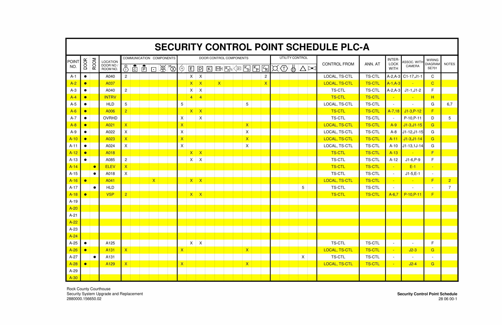
SECURITY CONTROL POINT SCHEDULE PLC-A
POINT
NO.CONTROL FROM ANN. AT
INTER-
LOCK
WITH
ASSOC. WITH
CAMERA
WIRING
DIAGRAM
SE701
NOTES
A-1 • A040 2 X X 2 LOCAL, TS-CTL TS-CTL A-2,A-3 C1-17,J1-1 C
A-2 • A037 X X X X LOCAL, TS-CTL TS-CTL A-1,A-3 - C
A-3 • A040 2 X X TS-CTL TS-CTL A-2,A-3 J1-1,J1-2 F
A-4 • INTRV 4 4 TS-CTL TS-CTL - - H
A-5 • HLD 5 5 5 LOCAL, TS-CTL TS-CTL - - G 6,7
A-6 • A006 2 X X TS-CTL TS-CTL A-7,18 J1-3,P-12 F
A-7 • OVRHD X X TS-CTL TS-CTL - P-10,P-11 D 5
A-8 • A021 X X X LOCAL, TS-CTL TS-CTL A-9 J1-3,J1-15 G
A-9 • A022 X X X LOCAL, TS-CTL TS-CTL A-8 J1-12,J1-15 G
A-10 • A023 X X X LOCAL, TS-CTL TS-CTL A-11 J1-3,J1-14 G
A-11 • A024 X X X LOCAL, TS-CTL TS-CTL A-10 J1-13,1J-14 G
A-12 • A018 X X TS-CTL TS-CTL A-13 - F
A-13 • A085 2 X X TS-CTL TS-CTL A-12 J1-6,P-9 F
A-14 • ELEV X TS-CTL TS-CTL - E-1 -
A-15 • A018 X TS-CTL TS-CTL - J1-5,E-1 -
A-16 • A041 X X X LOCAL, TS-CTL TS-CTL - - F 2
A-17 • HLD 5 TS-CTL TS-CTL - - - 7
A-18 • VSP 2 X X TS-CTL TS-CTL A-6,7 P-10,P-11 F
A-19
A-20
A-21
A-22
A-23
A-24
A-25 • A125 X X TS-CTL TS-CTL - - F
A-26 • A131 X X X LOCAL, TS-CTL TS-CTL - J2-3 G
A-27 • A131 X TS-CTL TS-CTL - - -
A-28 • A129 X X X LOCAL, TS-CTL TS-CTL - J2-4 G
A-29
A-30
Rock County Courthouse
Security System Upgrade and Replacement Security Control Point Schedule
2880000.156650.02 28 06 00-1
DOOR CONTROL COMPONENTSCOMMUNICATION COMPONENTS UTILITY CONTROL
LOCATIONDOOR NO / ROOM NO.
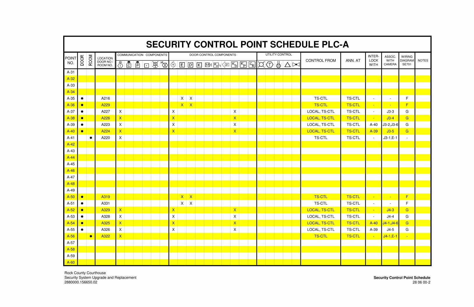
SECURITY CONTROL POINT SCHEDULE PLC-A
POINT
NO.CONTROL FROM ANN. AT
INTER-
LOCK
WITH
ASSOC.
WITH
CAMERA
WIRING
DIAGRAM
SE701
NOTES
A-31
A-32
A-33
A-34
A-35 • A216 X X TS-CTL TS-CTL - - F
A-36 • A229 X X TS-CTL TS-CTL - - F
A-37 • A227 X X X LOCAL, TS-CTL TS-CTL - J3-3 G
A-38 • A226 X X X LOCAL, TS-CTL TS-CTL - J3-4 G
A-39 • A223 X X X LOCAL, TS-CTL TS-CTL A-40 J3-2,J3-6 G
A-40 • A224 X X X LOCAL, TS-CTL TS-CTL A-39 J3-5 G
A-41 • A220 X TS-CTL TS-CTL - J3-1,E-1 -
A-42
A-43
A-44
A-45
A-46
A-47
A-48
A-49
A-50 • A319 X X TS-CTL TS-CTL - - F
A-51 • A331 X X TS-CTL TS-CTL - - F
A-52 • A329 X X X LOCAL, TS-CTL TS-CTL - J4-3 G
A-53 • A328 X X X LOCAL, TS-CTL TS-CTL - J4-4 G
A-54 • A325 X X X LOCAL, TS-CTL TS-CTL A-40 J4-1,J4-6 G
A-55 • A326 X X X LOCAL, TS-CTL TS-CTL A-39 J4-5 G
A-56 • A322 X TS-CTL TS-CTL - J4-1,E-1 -
A-57
A-58
A-59
A-60
Rock County Courthouse
Security System Upgrade and Replacement Security Control Point Schedule
2880000.156650.02 28 06 00-2
DOOR CONTROL COMPONENTSCOMMUNICATION COMPONENTS UTILITY CONTROL
LOCATIONDOOR NO / ROOM NO.

SECURITY CONTROL POINT SCHEDULE PLC-B
POINT
NO.CONTROL FROM ANN. AT
INTER-
LOCK
WITH
ASSOC.
WITH
CAMERA
WIRING
DIAGRAM
SE701
NOTES
B-1 • SB01 2 2 2 X LOCAL, TS-CTL TS-CTL - - C 3
B-2
B-3
B-4 • OVERHD X TIMER, TS-CTL TS-CTL - - D
B-5 • SB00B X - TS-CTL - - A
B-6 • SB00A X - TS-CTL - - A
B-7 • OVERHD X TIMER, TS-CTL TS-CTL - - D
B-8
B-9
B-10
B-11
B-12
B-13
B-14
B-15 • OVERHD X X X 2 LOCAL, TS-CTL TS-CTL - X2 D 5
B-16 • OVERHD X X 2 LOCAL, TS-CTL TS-CTL - P9,P10 D 5
B-17 • A002 X X X X LOCAL, TS-CTL TS-CTL - - E 2,4
B-18 • A003 X X X X LOCAL, TS-CTL TS-CTL - - E 2,4
B-19 • ELEV X LOCAL, TS-CTL TS-CTL - C1-2,E2 -
B-20 • ELEV X X LOCAL, TS-CTL TS-CTL - E2 -
B-21 • A049C X - TS-CTL - C1-1,C1-2 A
B-22 • A049A X X X TS-CTL TS-CTL - - C 3
B-23 • A049B X X X X LOCAL, TS-CTL TS-CTL - - C 3
B-24 • A081 X X X X LOCAL, TS-CTL TS-CTL - - C 4
B-25 • A064 X - TS-CTL - C1-3 -
B-26 • A066 X 2 2 X X LOCAL, TS-CTL TS-CTL - - E 2,4
B-27 • A065 X X X X LOCAL, TS-CTL TS-CTL - - C 4
B-28 • A047 X - TS-CTL - C1-6,C1-7 -
B-29 • A051 X X X X LOCAL, TS-CTL TS-CTL - - C 4
B-30
Rock County Courthouse
Security System Upgrade and Replacement Security Control Point Schedule
2880000.156650.02 28 06 00-3
DOOR CONTROL COMPONENTSCOMMUNICATION COMPONENTS UTILITY CONTROL
LOCATIONDOOR NO / ROOM NO.
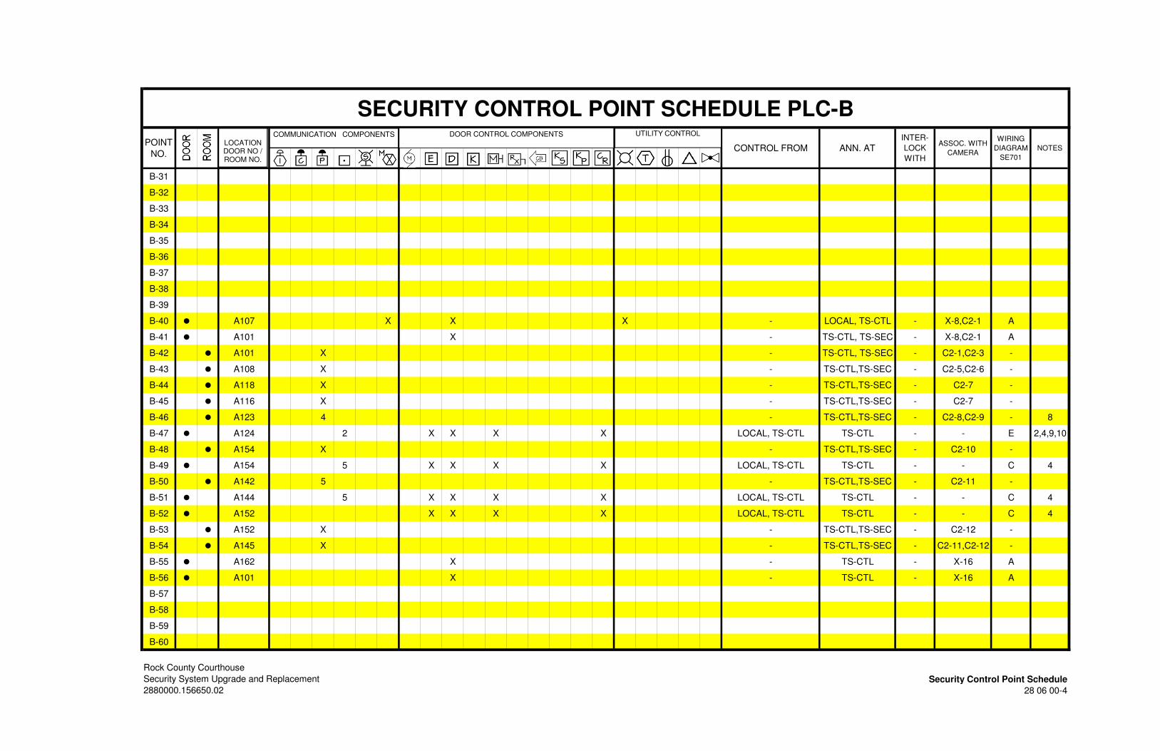
SECURITY CONTROL POINT SCHEDULE PLC-B
POINT
NO.CONTROL FROM ANN. AT
INTER-
LOCK
WITH
ASSOC. WITH
CAMERA
WIRING
DIAGRAM
SE701
NOTES
B-31
B-32
B-33
B-34
B-35
B-36
B-37
B-38
B-39
B-40 • A107 X X X - LOCAL, TS-CTL - X-8,C2-1 A
B-41 • A101 X - TS-CTL, TS-SEC - X-8,C2-1 A
B-42 • A101 X - TS-CTL, TS-SEC - C2-1,C2-3 -
B-43 • A108 X - TS-CTL,TS-SEC - C2-5,C2-6 -
B-44 • A118 X - TS-CTL,TS-SEC - C2-7 -
B-45 • A116 X - TS-CTL,TS-SEC - C2-7 -
B-46 • A123 4 - TS-CTL,TS-SEC - C2-8,C2-9 - 8
B-47 • A124 2 X X X X LOCAL, TS-CTL TS-CTL - - E 2,4,9,10
B-48 • A154 X - TS-CTL,TS-SEC - C2-10 -
B-49 • A154 5 X X X X LOCAL, TS-CTL TS-CTL - - C 4
B-50 • A142 5 - TS-CTL,TS-SEC - C2-11 -
B-51 • A144 5 X X X X LOCAL, TS-CTL TS-CTL - - C 4
B-52 • A152 X X X X LOCAL, TS-CTL TS-CTL - - C 4
B-53 • A152 X - TS-CTL,TS-SEC - C2-12 -
B-54 • A145 X - TS-CTL,TS-SEC - C2-11,C2-12 -
B-55 • A162 X - TS-CTL - X-16 A
B-56 • A101 X - TS-CTL - X-16 A
B-57
B-58
B-59
B-60
Rock County Courthouse
Security System Upgrade and Replacement Security Control Point Schedule
2880000.156650.02 28 06 00-4
DOOR CONTROL COMPONENTSCOMMUNICATION COMPONENTS UTILITY CONTROL
LOCATIONDOOR NO / ROOM NO.

SECURITY CONTROL POINT SCHEDULE PLC-B
POINT
NO.CONTROL FROM ANN. AT
INTER-
LOCK
WITH
ASSOC.
WITH
CAMERA
WIRING
DIAGRAM
SE701
NOTES
B-61
B-62
B-63
B-64
B-65 • A204 X - TS-CTL - C3-2 A
B-66 • A207 X X X X LOCAL, TS-CTL TS-CTL - - C 4
B-67 • A215 2 X X X X LOCAL, TS-CTL TS-CTL - - E 2,4,9,10
B-68 • A214 3 - TS-CTL,TS-SEC - C3-4,C3-5 -
B-69 • A238 3 - TS-CTL,TS-SEC - C3-6,C3-7 -
B-70 • A239 2 X X X X LOCAL, TS-CTL TS-CTL - - E 2,4,9,10
B-71 • A243 X X X X LOCAL, TS-CTL TS-CTL - - C 4
B-72 • A204 X - TS-CTL - C3-3 A
B-73
B-74
B-75
B-76
B-77
B-78
B-79
B-80 • A305 X - TS-CTL - C4-2 A
B-81 • A308 X X X X LOCAL, TS-CTL TS-CTL - - C 4
B-82 • A316 2 X X X X LOCAL, TS-CTL TS-CTL - - E 2,4,9,10
B-83 • A315 3 - TS-CTL,TS-SEC - C4-4,C4-5 -
B-84 • A339 3 - TS-CTL,TS-SEC - C4-6,C4-7 -
B-85 • A340 2 X X X X LOCAL, TS-CTL TS-CTL - - E 2,4,9,10
B-86 • A344 X X X X LOCAL, TS-CTL TS-CTL - - C 4
B-87 • A305 X - TS-CTL - C4-3 A
B-88
B-89
B-90
Rock County Courthouse
Security System Upgrade and Replacement Security Control Point Schedule
2880000.156650.02 28 06 00-5
DOOR CONTROL COMPONENTSCOMMUNICATION COMPONENTS UTILITY CONTROL
LOCATIONDOOR NO / ROOM NO.
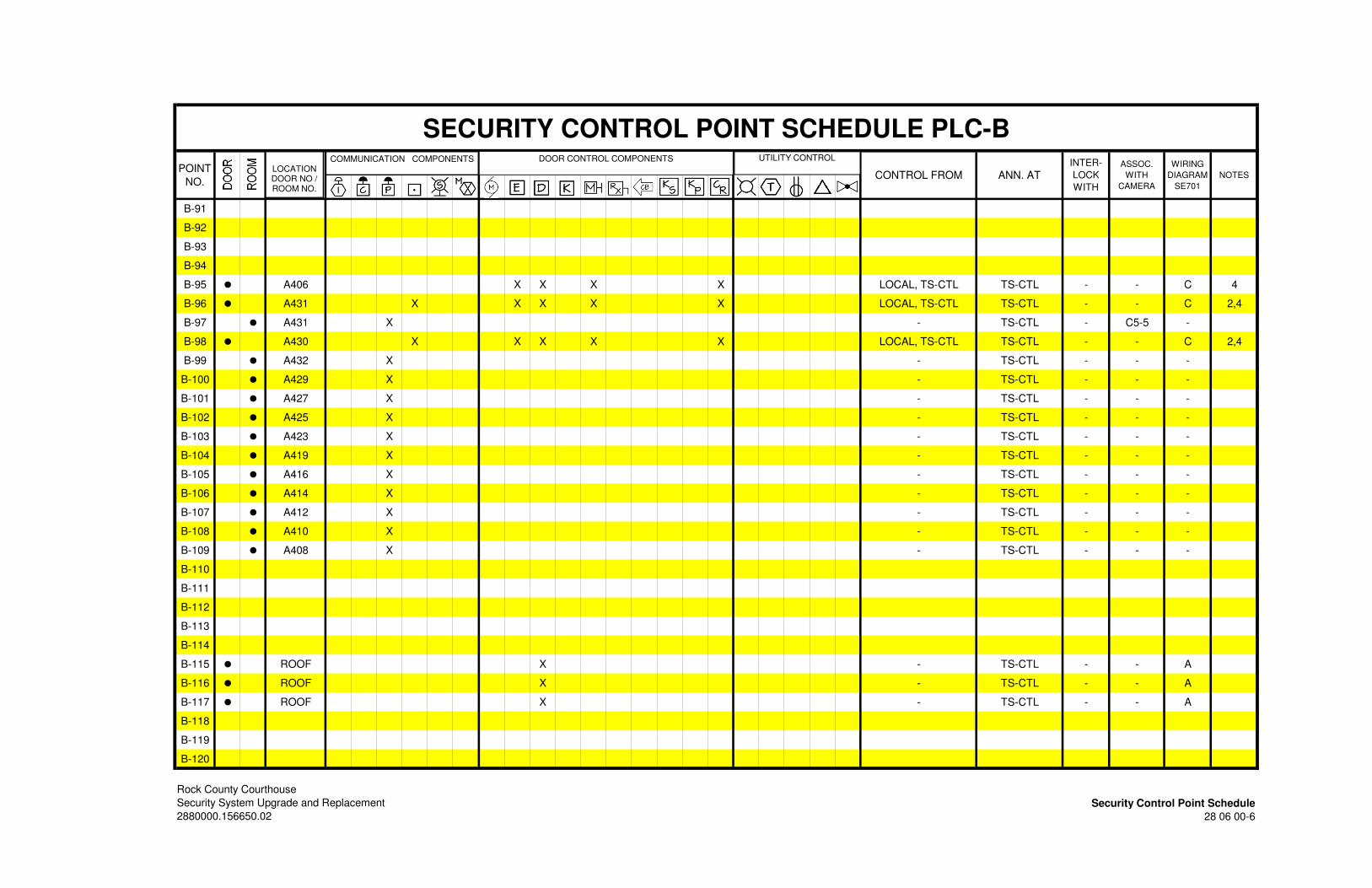
SECURITY CONTROL POINT SCHEDULE PLC-B
POINT
NO.CONTROL FROM ANN. AT
INTER-
LOCK
WITH
ASSOC.
WITH
CAMERA
WIRING
DIAGRAM
SE701
NOTES
B-91
B-92
B-93
B-94
B-95 • A406 X X X X LOCAL, TS-CTL TS-CTL - - C 4
B-96 • A431 X X X X X LOCAL, TS-CTL TS-CTL - - C 2,4
B-97 • A431 X - TS-CTL - C5-5 -
B-98 • A430 X X X X X LOCAL, TS-CTL TS-CTL - - C 2,4
B-99 • A432 X - TS-CTL - - -
B-100 • A429 X - TS-CTL - - -
B-101 • A427 X - TS-CTL - - -
B-102 • A425 X - TS-CTL - - -
B-103 • A423 X - TS-CTL - - -
B-104 • A419 X - TS-CTL - - -
B-105 • A416 X - TS-CTL - - -
B-106 • A414 X - TS-CTL - - -
B-107 • A412 X - TS-CTL - - -
B-108 • A410 X - TS-CTL - - -
B-109 • A408 X - TS-CTL - - -
B-110
B-111
B-112
B-113
B-114
B-115 • ROOF X - TS-CTL - - A
B-116 • ROOF X - TS-CTL - - A
B-117 • ROOF X - TS-CTL - - A
B-118
B-119
B-120
Rock County Courthouse
Security System Upgrade and Replacement Security Control Point Schedule
2880000.156650.02 28 06 00-6
DOOR CONTROL COMPONENTSCOMMUNICATION COMPONENTS UTILITY CONTROL
LOCATIONDOOR NO / ROOM NO.
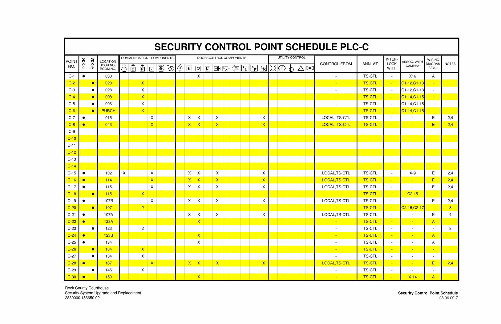
SECURITY CONTROL POINT SCHEDULE PLC-C
POINT
NO.CONTROL FROM ANN. AT
INTER-
LOCK
WITH
ASSOC. WITH
CAMERA
WIRING
DIAGRAM
SE701
NOTES
C-1 • 033 X - TS-CTL - X16 A
C-2 • 028 X - TS-CTL - C1-12,C1-13 -
C-3 • 028 X - TS-CTL - C1-12,C1-13 -
C-4 • 008 X - TS-CTL - C1-14,C1-15 -
C-5 • 006 X - TS-CTL - C1-14,C1-15 -
C-6 • PURCH X - TS-CTL - C1-14,C1-15
C-7 • 015 X X X X X LOCAL, TS-CTL TS-CTL - - E 2,4
C-8 • 043 X X X X X LOCAL, TS-CTL TS-CTL - - E 2,4
C-9
C-10
C-11
C-12
C-13
C-14
C-15 • 102 X X X X X X LOCAL,TS-CTL TS-CTL - X-9 E 2,4
C-16 • 114 X X X X X LOCAL,TS-CTL TS-CTL - - E 2,4
C-17 • 115 X X X X X LOCAL,TS-CTL TS-CTL - - E 2,4
C-18 • 115 X - TS-CTL - C2-15 -
C-19 • 107B X X X X X LOCAL,TS-CTL TS-CTL - - E 2,4
C-20 • 107 2 - TS-CTL - C2-16,C2-17 - 8
C-21 • 107A X X X X LOCAL,TS-CTL TS-CTL - - E 4
C-22 • 123A X - TS-CTL - - A
C-23 • 123 2 - TS-CTL - - - 8
C-24 • 123B X - TS-CTL - - A
C-25 • 134 X - TS-CTL - - A
C-26 • 134 X - TS-CTL - - -
C-27 • 134 X - TS-CTL - - -
C-28 • 167 X X X X X LOCAL,TS-CTL TS-CTL - - E 2,4
C-29 • 145 X - TS-CTL - - -
C-30 • 150 X - TS-CTL - X-14 A
Rock County Courthouse
Security System Upgrade and Replacement Security Control Point Schedule
2880000.156650.02 28 06 00-7
DOOR CONTROL COMPONENTSCOMMUNICATION COMPONENTS UTILITY CONTROL
LOCATIONDOOR NO / ROOM NO.
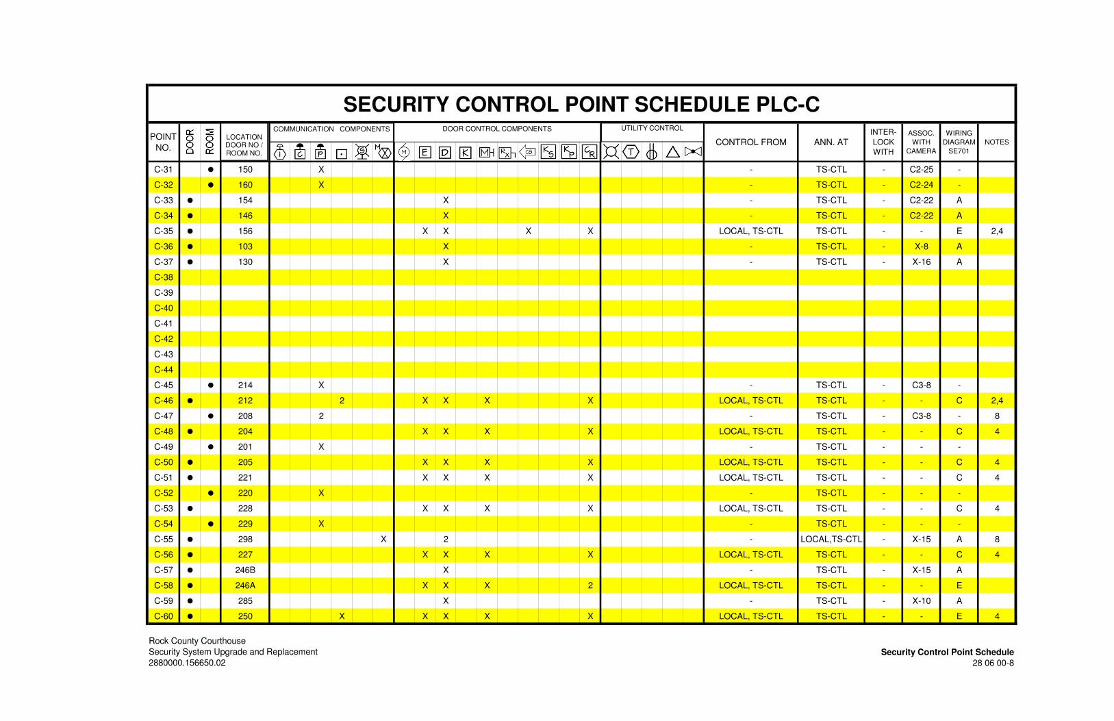
SECURITY CONTROL POINT SCHEDULE PLC-C
POINT
NO.CONTROL FROM ANN. AT
INTER-
LOCK
WITH
ASSOC.
WITH
CAMERA
WIRING
DIAGRAM
SE701
NOTES
C-31 • 150 X - TS-CTL - C2-25 -
C-32 • 160 X - TS-CTL - C2-24 -
C-33 • 154 X - TS-CTL - C2-22 A
C-34 • 146 X - TS-CTL - C2-22 A
C-35 • 156 X X X X LOCAL, TS-CTL TS-CTL - - E 2,4
C-36 • 103 X - TS-CTL - X-8 A
C-37 • 130 X - TS-CTL - X-16 A
C-38
C-39
C-40
C-41
C-42
C-43
C-44
C-45 • 214 X - TS-CTL - C3-8 -
C-46 • 212 2 X X X X LOCAL, TS-CTL TS-CTL - - C 2,4
C-47 • 208 2 - TS-CTL - C3-8 - 8
C-48 • 204 X X X X LOCAL, TS-CTL TS-CTL - - C 4
C-49 • 201 X - TS-CTL - - -
C-50 • 205 X X X X LOCAL, TS-CTL TS-CTL - - C 4
C-51 • 221 X X X X LOCAL, TS-CTL TS-CTL - - C 4
C-52 • 220 X - TS-CTL - - -
C-53 • 228 X X X X LOCAL, TS-CTL TS-CTL - - C 4
C-54 • 229 X - TS-CTL - - -
C-55 • 298 X 2 - LOCAL,TS-CTL - X-15 A 8
C-56 • 227 X X X X LOCAL, TS-CTL TS-CTL - - C 4
C-57 • 246B X - TS-CTL - X-15 A
C-58 • 246A X X X 2 LOCAL, TS-CTL TS-CTL - - E
C-59 • 285 X - TS-CTL - X-10 A
C-60 • 250 X X X X X LOCAL, TS-CTL TS-CTL - - E 4
Rock County Courthouse
Security System Upgrade and Replacement Security Control Point Schedule
2880000.156650.02 28 06 00-8
DOOR CONTROL COMPONENTSCOMMUNICATION COMPONENTS UTILITY CONTROL
LOCATIONDOOR NO / ROOM NO.
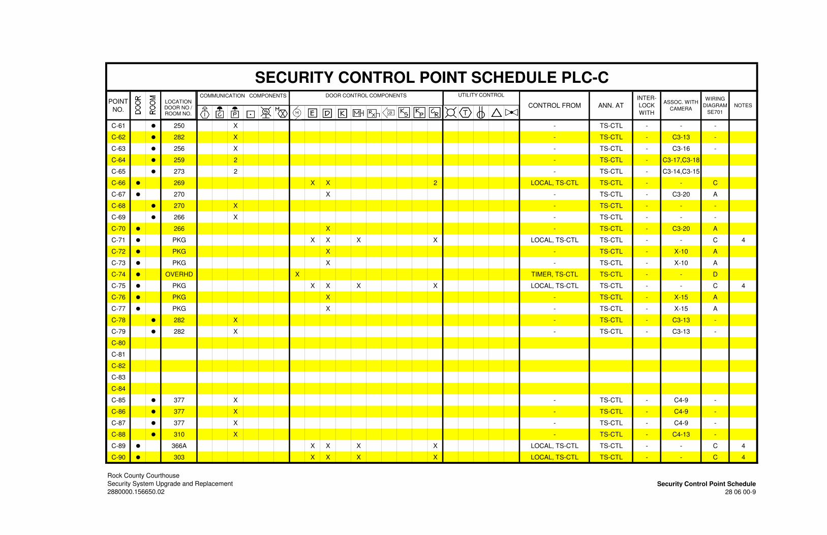
SECURITY CONTROL POINT SCHEDULE PLC-C
POINT
NO.CONTROL FROM ANN. AT
INTER-
LOCK
WITH
ASSOC. WITH
CAMERA
WIRING
DIAGRAM
SE701
NOTES
C-61 • 250 X - TS-CTL - - -
C-62 • 282 X - TS-CTL - C3-13 -
C-63 • 256 X - TS-CTL - C3-16 -
C-64 • 259 2 - TS-CTL - C3-17,C3-18
C-65 • 273 2 - TS-CTL - C3-14,C3-15
C-66 • 269 X X 2 LOCAL, TS-CTL TS-CTL - - C
C-67 • 270 X - TS-CTL - C3-20 A
C-68 • 270 X - TS-CTL - - -
C-69 • 266 X - TS-CTL - - -
C-70 • 266 X - TS-CTL - C3-20 A
C-71 • PKG X X X X LOCAL, TS-CTL TS-CTL - - C 4
C-72 • PKG X - TS-CTL - X-10 A
C-73 • PKG X - TS-CTL - X-10 A
C-74 • OVERHD X TIMER, TS-CTL TS-CTL - - D
C-75 • PKG X X X X LOCAL, TS-CTL TS-CTL - - C 4
C-76 • PKG X - TS-CTL - X-15 A
C-77 • PKG X - TS-CTL - X-15 A
C-78 • 282 X - TS-CTL - C3-13 -
C-79 • 282 X - TS-CTL - C3-13 -
C-80
C-81
C-82
C-83
C-84
C-85 • 377 X - TS-CTL - C4-9 -
C-86 • 377 X - TS-CTL - C4-9 -
C-87 • 377 X - TS-CTL - C4-9 -
C-88 • 310 X - TS-CTL - C4-13 -
C-89 • 366A X X X X LOCAL, TS-CTL TS-CTL - - C 4
C-90 • 303 X X X X LOCAL, TS-CTL TS-CTL - - C 4
Rock County Courthouse
Security System Upgrade and Replacement Security Control Point Schedule
2880000.156650.02 28 06 00-9
DOOR CONTROL COMPONENTSCOMMUNICATION COMPONENTS UTILITY CONTROL
LOCATIONDOOR NO / ROOM NO.
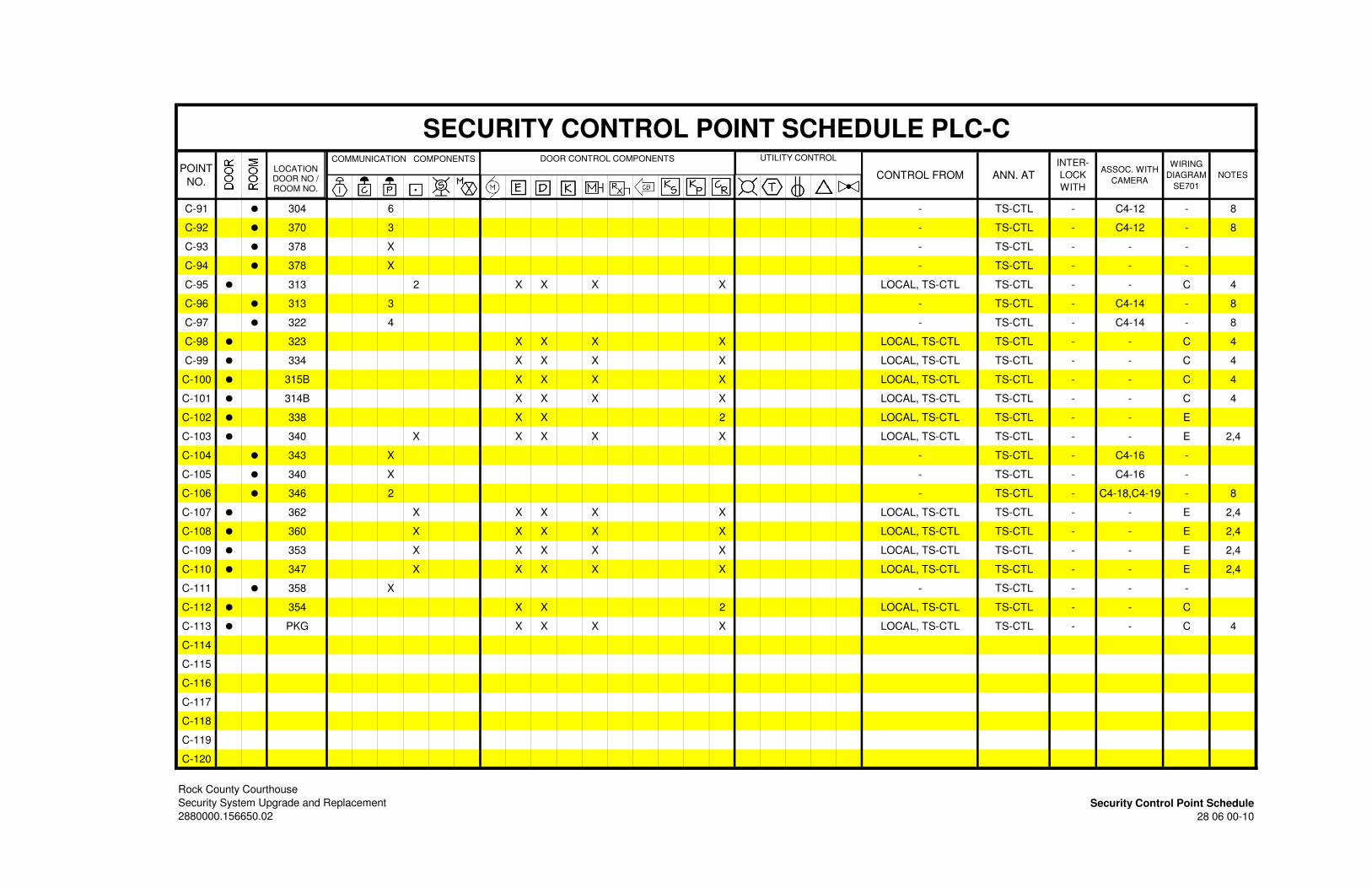
SECURITY CONTROL POINT SCHEDULE PLC-C
POINT
NO.CONTROL FROM ANN. AT
INTER-
LOCK
WITH
ASSOC. WITH
CAMERA
WIRING
DIAGRAM
SE701
NOTES
C-91 • 304 6 - TS-CTL - C4-12 - 8
C-92 • 370 3 - TS-CTL - C4-12 - 8
C-93 • 378 X - TS-CTL - - -
C-94 • 378 X - TS-CTL - - -
C-95 • 313 2 X X X X LOCAL, TS-CTL TS-CTL - - C 4
C-96 • 313 3 - TS-CTL - C4-14 - 8
C-97 • 322 4 - TS-CTL - C4-14 - 8
C-98 • 323 X X X X LOCAL, TS-CTL TS-CTL - - C 4
C-99 • 334 X X X X LOCAL, TS-CTL TS-CTL - - C 4
C-100 • 315B X X X X LOCAL, TS-CTL TS-CTL - - C 4
C-101 • 314B X X X X LOCAL, TS-CTL TS-CTL - - C 4
C-102 • 338 X X 2 LOCAL, TS-CTL TS-CTL - - E
C-103 • 340 X X X X X LOCAL, TS-CTL TS-CTL - - E 2,4
C-104 • 343 X - TS-CTL - C4-16 -
C-105 • 340 X - TS-CTL - C4-16 -
C-106 • 346 2 - TS-CTL - C4-18,C4-19 - 8
C-107 • 362 X X X X X LOCAL, TS-CTL TS-CTL - - E 2,4
C-108 • 360 X X X X X LOCAL, TS-CTL TS-CTL - - E 2,4
C-109 • 353 X X X X X LOCAL, TS-CTL TS-CTL - - E 2,4
C-110 • 347 X X X X X LOCAL, TS-CTL TS-CTL - - E 2,4
C-111 • 358 X - TS-CTL - - -
C-112 • 354 X X 2 LOCAL, TS-CTL TS-CTL - - C
C-113 • PKG X X X X LOCAL, TS-CTL TS-CTL - - C 4
C-114
C-115
C-116
C-117
C-118
C-119
C-120
Rock County Courthouse
Security System Upgrade and Replacement Security Control Point Schedule
2880000.156650.02 28 06 00-10
DOOR CONTROL COMPONENTSCOMMUNICATION COMPONENTS UTILITY CONTROL
LOCATIONDOOR NO / ROOM NO.
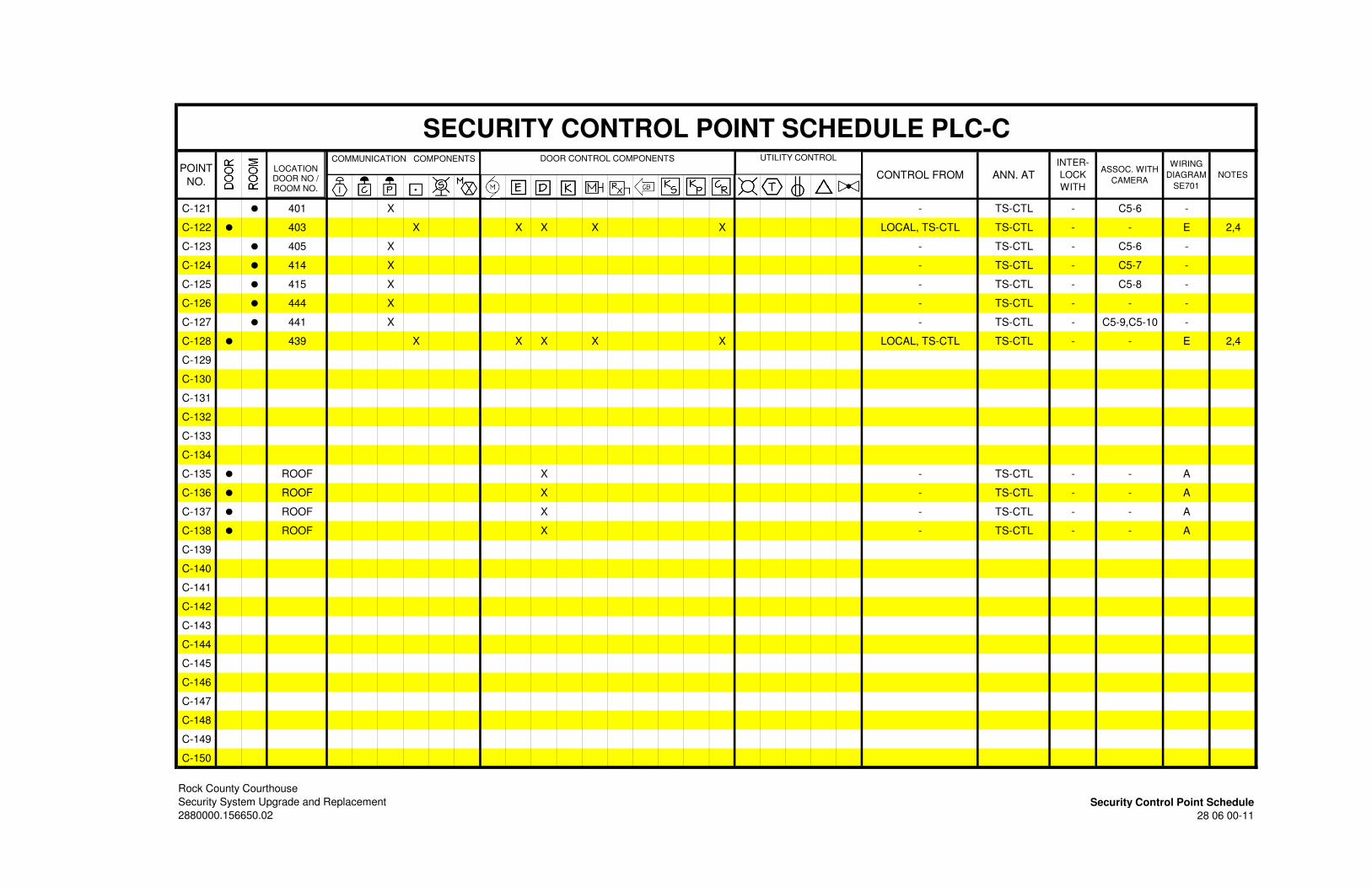
SECURITY CONTROL POINT SCHEDULE PLC-C
POINT
NO.CONTROL FROM ANN. AT
INTER-
LOCK
WITH
ASSOC. WITH
CAMERA
WIRING
DIAGRAM
SE701
NOTES
C-121 • 401 X - TS-CTL - C5-6 -
C-122 • 403 X X X X X LOCAL, TS-CTL TS-CTL - - E 2,4
C-123 • 405 X - TS-CTL - C5-6 -
C-124 • 414 X - TS-CTL - C5-7 -
C-125 • 415 X - TS-CTL - C5-8 -
C-126 • 444 X - TS-CTL - - -
C-127 • 441 X - TS-CTL - C5-9,C5-10 -
C-128 • 439 X X X X X LOCAL, TS-CTL TS-CTL - - E 2,4
C-129
C-130
C-131
C-132
C-133
C-134
C-135 • ROOF X - TS-CTL - - A
C-136 • ROOF X - TS-CTL - - A
C-137 • ROOF X - TS-CTL - - A
C-138 • ROOF X - TS-CTL - - A
C-139
C-140
C-141
C-142
C-143
C-144
C-145
C-146
C-147
C-148
C-149
C-150
Rock County Courthouse
Security System Upgrade and Replacement Security Control Point Schedule
2880000.156650.02 28 06 00-11
DOOR CONTROL COMPONENTSCOMMUNICATION COMPONENTS UTILITY CONTROL
LOCATIONDOOR NO / ROOM NO.
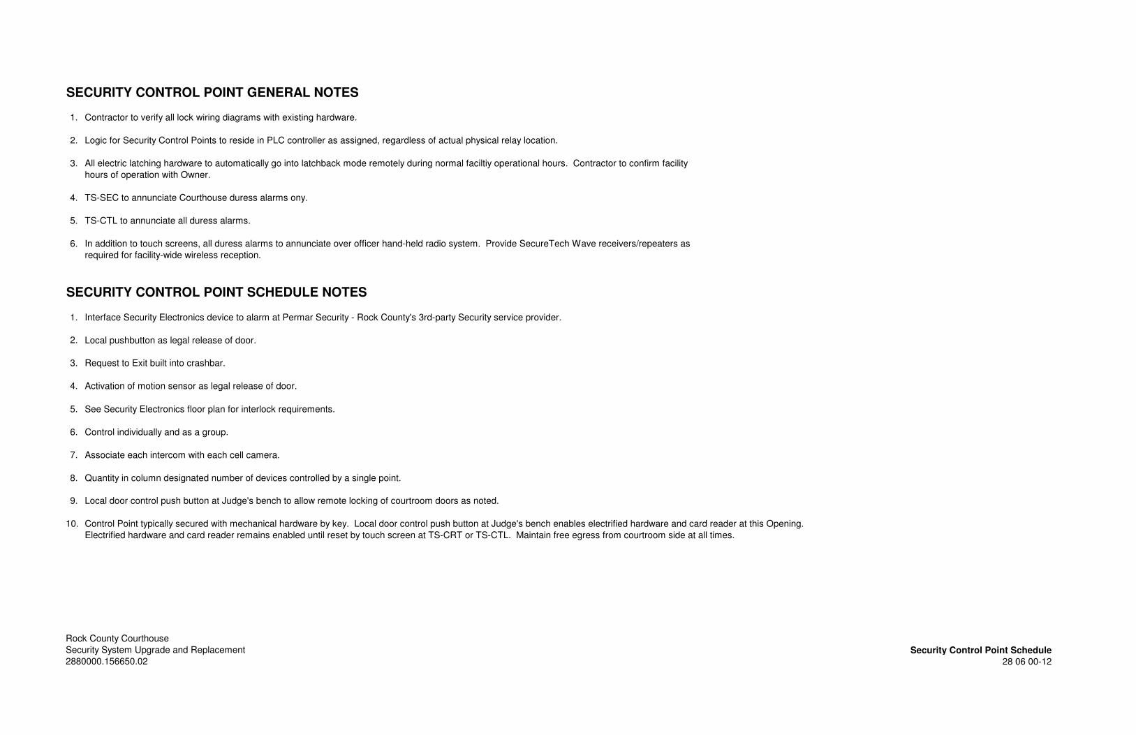
SECURITY CONTROL POINT GENERAL NOTES
1. Contractor to verify all lock wiring diagrams with existing hardware.
2. Logic for Security Control Points to reside in PLC controller as assigned, regardless of actual physical relay location.
3. All electric latching hardware to automatically go into latchback mode remotely during normal faciltiy operational hours. Contractor to confirm facility
hours of operation with Owner.
4. TS-SEC to annunciate Courthouse duress alarms ony.
5. TS-CTL to annunciate all duress alarms.
6. In addition to touch screens, all duress alarms to annunciate over officer hand-held radio system. Provide SecureTech Wave receivers/repeaters as
required for facility-wide wireless reception.
SECURITY CONTROL POINT SCHEDULE NOTES
1. Interface Security Electronics device to alarm at Permar Security - Rock County's 3rd-party Security service provider.
2. Local pushbutton as legal release of door.
3. Request to Exit built into crashbar.
4. Activation of motion sensor as legal release of door.
5. See Security Electronics floor plan for interlock requirements.
6. Control individually and as a group.
7. Associate each intercom with each cell camera.
8. Quantity in column designated number of devices controlled by a single point.
9. Local door control push button at Judge's bench to allow remote locking of courtroom doors as noted.
10. Control Point typically secured with mechanical hardware by key. Local door control push button at Judge's bench enables electrified hardware and card reader at this Opening.
Electrified hardware and card reader remains enabled until reset by touch screen at TS-CRT or TS-CTL. Maintain free egress from courtroom side at all times.
Rock County Courthouse
Security System Upgrade and Replacement Security Control Point Schedule
2880000.156650.02 28 06 00-12
Rock County Courthouse Security System Security System Upgrade and Replacement General Requirements 2880000.156650.02 28 46 00 - 1
SECTION 28 46 00 SECURITY SYSTEM GENERAL REQUIREMENTS
PART 1 - GENERAL
1.01 SCOPE
A. The work under this section shall be included with the work of Division 28 46 00 “Security Electronics Contract” and be considered a part of a singular contract. The Contractor shall be referred to in this specification and on the drawings as the Division 28 SEC (Security Electronics Contractor).
B. A single SEC Contractor shall perform the entire work of this Section. This Contractor shall be regularly engaged in the installation and service of correctional grade electronic security systems including the following: 1. Section 28 05 20 – Security System Equipment Racks and Enclosures 2. Section 28 46 10 - Security Control and Monitoring System 3. Section 28 46 20 – Security System Network Switches 4. Section 28 46 30 – Door Control Intercom System 5. Section 28 46 40 – Card Access System 6. Section 28 46 50 – Duress Alarm System 7. Section 28 46 60 – Video Surveillance System
C. The SEC Contractor shall assign a Project Manager as the sole responsible contact person for coordination purposes during the duration of the project. The Project Manager shall be a technically qualified full time employee of the SEC Contractor.
D. It is mandatory that the minimum given specifications be strictly adhered to, so as to provide a high level of quality and the design objectives. There shall be no substitutions allowed that have not been approved by addendum.
E. Specification Section 28 06 00 includes a Security Control Point Schedule for each programmable logic controller location. The schedule indicates the security control, monitoring, communication and video call-up points associated for each PLC along with the primary control and monitoring location. The primary controls and monitoring locations may be transferred to other locations as described in the Contract Documents.
1.02 RELATED WORK
A. Section 26 05 00 – General Electrical Provisions
B. Section 28 05 10 – Sequencing of Security Electronics Work
C. Section 28 05 20 - Security System Racks and Enclosures
D. Section 28 46 10 – Security Control and Monitoring System
E. Section 28 46 20 –Voice Communication System
F. Section 28 46 30 – Card Access System
G. Section 28 46 40 – Duress Alarm System
H. Section 28 46 50 – Video Surveillance System

Rock County Courthouse Security System Security System Upgrade and Replacement General Requirements 2880000.156650.02 28 46 00 - 2
1.03 BIDDER QUALIFICATIONS
A. Bidders shall assign a project manager as the sole responsible contact for coordination purposes for the duration of the project. The project manager shall have at least 5 years experience in detention construction, and be a technically qualified full time employee of the bidding contractor.
B. Bidders must have the capability to provide equipment in full and strict compliance of provisions of this specification. It is mandatory that the minimum given specifications be strictly adhered to, so as to provide a high level of quality to the design objectives. There shall be no substitutions allowed that have not been pre-approved by addendum.
C. Bidders shall have access to necessary equipment, organizational capacity and technical competence to perform work properly and expeditiously.
D. Bidders shall employ qualified, experienced, factory trained installers to perform the work. The A/E reserves the right to contact specified manufacturers and confirm that the bidder is an established and authorized reseller of detention equipment.
E. Bidders shall have a minimum 10 years experience providing integrated PLC-based non-proprietary security systems as specified.
F. It is essential that bidders have an established record of successfully completed pro-jects. The criteria used to evaluate whether a project has been successfully completed includes: 1. Contracts completed in accordance with plans and specifications. 2. Work completed within the time constraints of the project. 3. Fulfillment of guarantee requirements as specified in the contract documents.
1.04 ACCEPTABLE PRE-APPROVED SEC CONTRACTORS
A. Accurate Controls, Inc. – Ripon, WI
B. SGTS, Inc. – Verona, WI
C. Sierra Detention Systems – Golden, CO
D. Secured Automation Systems – Indianapolis, IN
E. Trentech - Montgomery, AL
1.05 QUALIFICATION REQUIREMENTS
A. Contractors seeking approval to bid as an SEC shall submit the following qualification data to the Architect at least 7 days prior to the bid date or the date of the last published addendum. Upon approval, the prospective SEC will be listed by addendum. Verbal approval is unacceptable. Bids received from unapproved contractors will not be considered.
B. Upon receipt of qualification data, the A/E will make an investigation to determine the ability of the SEC to perform the work. The A/E reserves the right to request additional information as deemed necessary for the determination process. Prospective contractors seeking approval to bid as an SEC shall provide the following minimum information: 1. Submit evidence that the SEC has been actively engaged in the installation of
security electronics systems under this specification for a minimum of 10 years.

Rock County Courthouse Security System Security System Upgrade and Replacement General Requirements 2880000.156650.02 28 46 00 - 3
Furnish a list of 5 projects in size, type and value of that being bid. The minimum period of operation for each project shall be 12 months. List of completed projects shall include the following: a. Name and location of installation. b. Value of contact and scope of work provided. c. Date of Owner occupancy. d. Name and telephone number of Owner's representative. e. Name and telephone number of Construction Manager or General
Contractor. f. Name and telephone number of Architect's project manager.
2. Submit evidence of financial and bonding capability. Provide the following information from the bonding agent: a. Name, address, phone number of bonding company with point of
contact. b. Advise the total overall bonding capacity of the SEC and the maximum
limit of bonding capacity per job. c. State how much work by the SEC is currently bonded. d. Provide a letter from the bonding company stating that a 100% payment
and performance bond will be provided if the SEC is awarded the contract.
e. The financial and bonding information must state that the SEC has a minimum 110% capacity over and above the value of the bid package as assigned by the A/E.
f. The financial and bonding information must list all outstanding bid bonds, the value of each outstanding bid, and % certainty that the SEC will be awarded the contract for all outstanding bids requiring a bond.
3. Owner and A/E reserve the right to disqualify manufacturers, equipment suppliers, and contractors who do not strictly comply with requirements of this section or product substitution procedures called for in this section and Div. 01. Grounds for disqualification shall exist if it is determined that the information submitted is inaccurate, or in the opinion of the Architect, does not satisfy the pre-qualification requirements.
4. Any bid from a General Contractor that does not include the name of a pre-qualified SEC in the appropriate space provided on the bid form will be automatically rejected.
1.06 SERVICE REQUIREMENTS
A. The SEC Contractor supplying the equipment shall show satisfactory evidence, upon request, that he maintains a fully equipped local service organization capable of furnishing adequate inspection and service to the systems, including replacement parts. The service organization shall be capable of a minimum 4 hour on site response time. The SEC Contractor shall be prepared to offer a service contract for the mainte-nance of the systems after the guarantee period. The subcontractor shall produce evidence that he has had a fully experienced and established service organization for at least five years and proven satisfactory installations during that time.
B. On-the-premises service, parts and labor is to be provided during normal working hours at no cost to the Owner, for a period of 12 months from the date of final acceptance.
C. On-the-premises service must also be made available at other than normal working hours, and shall be charged by the manufacturer service representative at current labor rates.
D. The SEC Contractor shall maintain engineering and service departments capable of rendering advice regarding installation and final adjustment of the systems.
Rock County Courthouse Security System Security System Upgrade and Replacement General Requirements 2880000.156650.02 28 46 00 - 4
E. The Engineer reserves the right to request and have furnished to him any additional information he requires determining the SEC Contractor's ability to complete the work. Such additional information shall be supplied with no additional costs incurred by the Owner.
1.07 SUBMITTALS
A. The SEC shall submit shop drawings for products in their scope of work in a composite submittal format. Equipment product submittals shall be bound in three ring binders with index tabs identified for each specification section. A complete equipment list of all components shall be located first in the binder with separate headings of each specification section. Submittals will not be deemed complete unless they contain the following components in their entirety: 1. SECTION 28 05 20– SECURITY SYSTEM EQUIPMENT RACKS & ENCLOSURES
a. Security System Cabinets, Racks and Enclosures Catalog Cuts 2. SECTION 28 46 10 – SECURITY CONTROL AND MONITORING SYSTEM
a. Security System Shop Drawings b. Security Control and Monitoring System Catalog Cuts c. Uninterruptible Power Supply Calculations
3. SECTION 28 46 20 – SECURITY NETWORK SWITCHES a. Security Network Switch Catalog Cuts
4. SECTION 28 46 30 – VOICE COMMUNICATION SYSTEM a. Voice Communication System Catalog Cuts
5. SECTION 28 46 40 – CARD ACCESS SYSTEM a. Card Access System Catalog Cuts
6. SECTION 28 46 50 – DURESS ALARM SYSTEM a. Duress Alarm System Catalog Cuts
7. SECTION 28 46 60 – VIDEO SURVEILLANCE SYSTEM a. Video Surveillance System Catalog Cuts
8. SECTION 28 46 70 – VIDEO INTERROGATION SYSTEM a. Video Interrogation System Catalog Cuts
1.08 SOFTWARE DEVELOPMENT REVIEW
A. Software will be reviewed and approved in three review stages.
B. PRE-REVIEW 1. Submit for review and approval color copies of graphic screens on minimum 8.5”
X11” paper. The screens shall be actual copies of the proposed screen views. The Engineer and Owner will review and return with recommended changes prior to development of review one. Descriptive area nomenclature will be added to correspond to the actual descriptions the Owner intends to use for the various areas of the building.
C. REVIEW ONE 1. The first review shall take place not less than 6 months prior to the projects
scheduled substantial completion date. The first review shall demonstrate the customized software of the Security Control System (SS) including; graphical representations of all areas of control, all specified integration’s, control of specified devices, and graphic operational control.

Rock County Courthouse Security System Security System Upgrade and Replacement General Requirements 2880000.156650.02 28 46 00 - 5
2. The SEC Contractor will provide a complete, operational training/demonstration unit including monitor, computer, trackball and software during the first review. The graphic control will display the controls, on full color-graphic screens, for the subject facility to help the end users make decisions concerning the graphic integration screen layout, and device placement. The software will demonstrate all the features that are specified for the subject facility. The software will present a library of all graphical icons in full color.
3. The SEC Contractor will provide a set of full size; color drawings representing the actual screens that will be used on the control monitors. Every screen will be drawn to scale. These screen drawings will depict a minimum of the following features: a. Overall building layout and design of facility. b. Appropriate (zoomed into) area screens. c. The area screens will be drawn to represent the control officers view and true
orientation. 4. The SEC Contractor will demonstrate the graphic control system, review the
software and answer questions regarding operations. The SEC Contractor will participate in the end user review of the software.
5. All software review comments, modifications and changes shall be consolidate into a single document and returned to the SEC Contractor within 15 days of the review. The SEC Contractor will incorporate the changes in to the graphic control system for presentation at the second review.
6. The software review meeting shall be held at the Architect’s office, General Contractor’s office, jobsite or a location to be determined. All parties are responsible for their own travel costs and expenses to, from and for the duration of the meeting. The meeting will require time as necessary to complete, but shall not exceed 2 business days in length.
D. REVIEW TWO 1. The second review shall take place not less than 3 months prior to the projects
scheduled substantial completion date. This demonstration will consist of a fully functional simulation of all software-controlled devices specified for the facility. The software shall also provide a sample of each operational alarm including audio annunciation of alarms.
2. All end user comments, modifications and directed changes from the first software review shall have been incorporated into the second software review.
3. The SEC Contractor will demonstrate the graphic control system, review software and answer end user questions regarding graphic control operations. The SEC Contractor shall participate in the second software review.
4. All software review comments, modifications and changes shall be consolidated into a single document and returned to the SEC Contractor within 15 days of the review. The SEC Contractor will incorporate the changes in to the graphic control system.
5. The SEC shall arrange for the software review meeting number 2 to be held at the SEC’s manufacturing facility. This review meeting shall not exceed 8 hours in length and shall be attended by 5 staff members as selected by the Owner. It will be the responsibility of the SEC to make necessary travel arrangements including the costs of travel, food, and lodging. Expenses for additional staff members will be paid by the Owner.
1.09 OPERATIONS AND MAINTENANCE MANUALS
A. The Contractor shall provide 3 complete sets, in hard cover binders, of maintenance and operating instructions for the security electronic systems.

Rock County Courthouse Security System Security System Upgrade and Replacement General Requirements 2880000.156650.02 28 46 00 - 6
B. The first tab shall include the following: 1. A warranty statement signed by the integrators legal representative for the
company with the warranty start date (based upon Architects signed certificate of substantial completion).
2. Procedures for obtaining warranty work with any company forms required for request of warranty work.
3. Contact information for normal and emergency service. 4. A listing of hourly rates for warranty work including normal and emergency service
and the integrators designated times for each.
C. The manuals shall include a material guide that shall contain the replacement part numbers and description of all components used. System components shall be in separate index tabs for each section as described in the specifications. Each index tab shall be followed by a complete equipment list of all components for the section with a part description and the actual catalog number required for the replacement part, chassis, module or kit.
D. See General Requirements Division 01 for additional requirements.
1.10 PROJECT CLOSEOUT
A. The SEC Contractor shall provide all programming on CD disk and all source code, IP addresses and passwords for the completed systems prior to final payment. All systems are to be the property of the Owner and shall not restrict the Owner from obtaining third party service from vendors other than the original installer after the warranty period. 1. Included in the source code submittal shall be a certified letter from the software
manufacturer stating that all software developed to run the system has not been developed outside the platform of the software manufacturer.
B. The SEC Contractor shall include all costs in their bid for a full-time presence on site during the first week of start-up after Owner occupancy. This requirement shall include a minimum of five 8-hour days for 1 technician. The purpose of this requirement is for trouble shooting and training that occurs during the first full week of occupancy once the security electronic system is fully exercised.
PART 2 - PRODUCTS
2.01 EQUIPMENT STANDARDS
A. A complete Security System consisting of all the individual systems as shown and specified is required. These are largely functional specifications in order to maintain competitive bidding; however, it is expected that the minimum given specification shall be strictly adhered to so as to provide a high level of quality and the design objectives. Equivalent manufacturers and products shall be in strict accordance with this specification.
B. It is the responsibility of the SEC Contractor to verify the completeness of the drawings, specifications and schedules and the suitability of devices to meet the intent of the specifications. Any additional equipment, accessories or incidentals required, whether or not specifically mentioned herein, shall be provided by the Contractor without claim for additional payment, it being understood that a complete operational system is required.

Rock County Courthouse Security System Security System Upgrade and Replacement General Requirements 2880000.156650.02 28 46 00 - 7
C. All materials and equipment shall be new and unused. Unless specifically approved by the Engineer, all materials and equipment in the system shall be the standard design or model ordinarily supplied as a product item by manufacturers regularly engaged in the production of such equipment. They shall be the manufacturer's latest standard designs current at the time of delivery, modified only to the extent necessary to comply with the requirements of these specifications. Where two or more units of the same class of equipment are required, such units shall be the standard products of a single manufacturer, but individual classes of compatible equipment may be the products of different manufacturers. Manufacturers shall be established in the industry so that prompt and continued service and delivery of spare parts may be assured.
D. Temperature Ratings: All indoor components in heated areas shall be capable of full operation in relative humidity up to 90% and temperatures from 35° F. to 120° F. All outdoor components shall be capable of full operation in humidities and temperatures hereinafter specified.
E. All fasteners for equipment junction boxes, control panel covers, etc. shall be security type to be compatible with those specified in Section 11 20 00 - Security Fasteners.
F. All components that comprise the various systems shall be UL listed where a UL listing exists for that component.
2.02 MAINTAINABILITY
A. Devices and equipment shall be designed and constructed to facilitate modular, unitized, component replacement to the maximum extent feasible without compromising the resistance to defeat capability of the system. The design shall incorporate solid-state components to the maximum extent feasible. Like units, assemblies, sub-assemblies and replaceable parts shall be interchangeable as complete items.
2.03 CABLING AND TERMINATIONS
A. Cabling shall be continuous and shall not be spliced between the field-mounted device and the receiving equipment (i.e. VSS wiring shall be run from the camera to the switcher without splices, door wiring shall be run from the door to the door control panel without splices). Intermediate termination points within a wire run would be considered a wire splice. Where intermediate termination points are required, pullboxes shall include terminal strips permanently labeled with the numbering scheme per the SEC Contractors recommendations.
B. All system wiring shall be color coded with labeling and coding as submitted and approved by shop drawing. Color coding and tagging shall be maintained throughout the system at all accessible locations to the cabling.
C. All cabling exiting a building underground or in or below slabs on grade shall be UL listed for wet location in accordance with the National Electrical Code.
2.04 ELECTRICAL AND STAND-BY POWER SUPPLY REQUIREMENTS
A. Emergency power will be provided by the Division 26 Electrical Contractor from existing emergency power panelboards.
B. The Div. 28 SEC shall be responsible for providing desk and rack mounted UPS systems as required to power all Security Electronics Equipment. All security systems
Rock County Courthouse Security System Security System Upgrade and Replacement General Requirements 2880000.156650.02 28 46 00 - 8
shall be connected to uninterruptible power supplies. 120 volt connections are indicated on the Division 26 Electrical Drawings. 1. Contractor responsible for providing local rack mounted UPS’s at each Security
Electronic equipment room. Size UPS for a 15 minute capacity for all Security Electronic equipment within. All power for UPS’s to be fed from existing emergency circuits. Provide additional circuits, conduit and cabling where required.
2. Contractor responsible for providing desk mounted UPS’s at each Touch Screen Workstation. Size UPS for a 15 minute capacity for all touch screens and video monitors provided at that location. All power for UPS’s to be fed from existing emergency circuits. Provide additional circuits, conduit and cabling where required.
C. Contractor responsible for providing UPS calculations as required to confirm desk and rack mounted UPS’s have been sized appropriately.
PART 3 - EXECUTION
3.01 WORK IN OTHER SECTIONS
A. The division of responsibility regarding work to be done by the Division 26 Electrical Contractor and work to be done by the Division 28 SEC Contractor shall be in accordance with the following:
B. The following work shall be the sole responsibility of the Division 28 SEC Contractor: 1. Coordination of doorframes and hardware with Division 08 and 11 in which
equipment is provided that is associated with the security control system. 2. Attendance at an on-site security hardware review meeting with the Engineer,
Owner and Architect. 3. Furnishing of control panels, PC touch screen controllers, relay boards,
processing units, sound/intercom amplifiers, video equipment, power supplies and other major control or communication equipment associated with the SEC systems. Refer to the systems drawings which identify the various field devices, terminal cabinets, and control panels provided by the SEC Contractor.
4. Preparation of SEC shop drawings, maintenance manuals, wiring diagrams and other submittals required by the individual SEC system specification sections.
5. Tests, balancing, trouble shooting, adjustments and other similar work as may be required to insure complete operating SEC systems. Actual work shall be performed by the equipment and manufacturer's factory authorized personnel in conjunction with the SEC Contractor.
6. All security system-training sessions required by these specifications. 7. Any and all warranty work associated with the building security system. 8. Any other work associated with the SEC systems, which due to its technical
nature shall logically be performed by the SEC Contractor.
C. The following work shall be the responsibility of the Division 26 Electrical Contractor: 1. Coordination of door frames and hardware with Division 08 and 11 and the
required conduit entries thereto. 2. Attendance at an on-site security hardware review meeting with the Engineer,
Owner and Architect. 3. Receiving, inspecting and placement of equipment racks, termination panels and
relay panels. 4. Provide raceways, pullboxes, wireways, field device electrical boxes and wiring for
the various security electronics systems as specified.

Rock County Courthouse Security System Security System Upgrade and Replacement General Requirements 2880000.156650.02 28 46 00 - 9
5. Termination of all field devices including electric locks, door operators, door position indicator and jamb switches, keyswitches, pushbuttons, intercoms, call buttons, duress alarm devices, cameras and monitors, etc. which comprise the security control system and at the head end equipment of all systems.
6. Refer to the security systems drawings which identify the various field devices, terminal cabinets, equipment racks and control panels associated with the raceway and wiring to be provided by the Division 28 SEC Contactor for installation by the Division 26 Electrical Contractor.
7. Refer to the system riser diagrams on the drawings and the individual system specifications, which identify the cable and conduit requirements.
8. The Division 26 Electrical Contractor shall note that the riser diagrams are diagrammatic only and do not show specific routings of conduits. Actual routing of conduits is to be determined by the Division 26 Electrical Contractor with consideration to the actual construction conditions. Any additional pull boxes, junction boxes and conduit required to extend cabling from one location to another as dictated by the building physical structure shall be provided by the Division 26 Electrical Contractor.
9. Refer to the electronics equipment room layouts which depict the equipment to be furnished and installed by Division 26 Electrical Contractor.
10. Terminal cabinets and equipment racks being furnished by the SEC Contractor shall be installed by the Division 26 Electrical Contractor including the nipple conduits between adjacent panels or conduit stubs to overhead cable tray, as required. The Division 26 Electrical Contractor shall verify actual terminal panel size and nipple conduit size requirements with the SEC Contractor prior to installation.
11. Cables shall be identified at both ends with system identifications and location identifications. Utilize a color scheme of wiring, which will identify the intended use of each conductor on systems with multiple single strand conductors (i.e. door controls). Coordinate this requirement with the SEC Contractor. Refer to Division 26 for electrical Identification requirements.
12. The Division 26 Electrical Contractor is responsible for the replacement of cables or conductors found defective when tested for connection by the SEC Contractor.
D. In coordinating the SEC work with the Division 26 Electrical Contractor, the SEC Contractor shall bear in mind that the wiring and conduit requirements called for in the construction documents are based on the requirements of a single manufacturer and may or may not be adequate for the equipment actually being furnished. The conduit and wiring indicated on the drawings or in the specifications shall be considered minimum requirements. Additional wiring, conduit, or other work required due to the use of different manufacturers or as dictated by the SEC Contractor for complete systems shall be arranged and paid for by the Division 28 SEC Contractor.
3.02 ON-SITE COORDINATION
A. The SEC Contractor’s Project Manager shall make periodic site visits to review the installation by the Division 26 Electrical Contractor. Prior to start of construction, the SEC shall make arrangements and meet with the Division 26 Electrical Contractor to coordinate installation requirements for all security systems. The coordination shall include, but not limited to, the following: 1. Conduit requirements including minimum size and minimum radius bends. 2. Cabling and wire requirements including types, sizes, color-coding and labeling
(per the security submittal requirements) 3. Field device box requirements including type, size and mounting heights. 4. Pull box requirements. 5. Equipment rack dimensions and shipping splits. 6. Equipment rack cable pulling clearances.

Rock County Courthouse Security System Security System Upgrade and Replacement General Requirements 2880000.156650.02 28 46 00 - 10
7. Equipment rack installation and entry conduit nipple sizes, quantities and locations.
8. Cable pulling requirements for equipment racks. 9. Placement of all ceiling mounted devices. 10. Termination and cable identification requirements including any color coding
schemes. 11. Installation details for cameras, monitors, touch screen stations and other
equipment.
B. The SEC Contractor shall visit the site once every other month until on-site to perform the start-up and installation. A report will be provided for each visit describing the work in progress, the work completed to date and the work to remain. The report shall also include a description of any changes that were discussed or directions given to the Electrical Contractor and any installation that does not meet the requirements of the SEC Contractors installation requirements. This report shall be forwarded to the construction team (Architect, General Contractor, and the Security Electronics Consultant).
3.03 FIELD DEVICE INSTALLATION
A. Field devices (intercoms, card readers, local electric key switches, etc) are shown on the drawing locations diagrammatically and shall not be used for dimensioning of final location. Devices intended for communication or control of door locations shall be final located by the Division 26 Electrical Contractor at locations most convenient to staff for the door location. Multiple devices (i.e. intercoms and card readers) at door locations shall be mounted adjacent to one another. Door locations with card readers on both sides of the door shall not be mounted back to back on a common wall to avoid the card reader reading through the wall and indicating a false accept.
3.04 MAINTENANCE AND OTHER MANUALS
A. The SEC Contractor shall maintain a file specific to this project which shall include all security system maintenance manuals, approved shop drawings and other pertinent information. This file shall be maintained for a period of time consistent with the length of time the equipment provided is in actual service. Documents shall be of such a nature that may be reproduced to replace similar documents in possession of the Owner.
3.05 ACCEPTANCE TESTS
A. The SEC Contractor shall be responsible for conducting tests to determine systems conformance to requirements of the specifications. Tests shall be conducted in the presence of the Engineer or his authorized representative who may suspend or discontinue the tests at any time performance is considered unsatisfactory. Resumption of testing will cover untested elements and any replaced elements. The SEC Contractor shall furnish all test personnel, test instruments and equipment of the accuracy necessary to perform the test. Arrangements for testing must be made with the Engineer at least two weeks before the proposed testing date. The User's technician or other personnel shall also be present during testing.
B. The following security systems shall be individually scheduled and tested by the SEC Contractor: 1. Section 28 46 10 - Security Control and Monitoring System 2. Section 28 46 20 – Security System Network Switches 3. Section 28 46 30 - Voice Communication System 4. Section 28 46 40 – Card Access System

Rock County Courthouse Security System Security System Upgrade and Replacement General Requirements 2880000.156650.02 28 46 00 - 11
5. Section 28 46 50 – Duress Alarm System 6. Section 28 46 60 – Video Surveillance System 7. Section 28 46 70 – Video Interrogation System
C. The SEC Contractor shall submit all test procedures and test data forms for approval in the same manner as submittals for approval. At a minimum, these test procedures shall include the following for each security system outlined for testing: 1. A step-by-step outline of the test sequence to be followed, showing a test of
every function of the equipment or system to be tested and demonstration of compliance to the contract documents.
2. A description of the expected operation, output and test result. 3. A data form to be used to record all quantitative results obtained during the test.
The SEC Contractor shall document the test results. A certified copy of each test result shall be submitted by the SEC Contractor to the Engineer within two weeks following the completion of the test.
4. A description of any special equipment, set-up, manpower or conditions required for the test.
D. If a hardware or software unit is modified as a result of a failure during any test or demonstration, a report shall be prepared by the SEC Contractor and delivered to the Engineer. The complete written report shall describe the nature of the failure and the corrective action taken.
E. While the system(s) are in test, major changes to the hardware or software shall not be permitted. Minor corrections of detected flaws are permitted. Major corrections shall be conducted by the Contractor during non-testing periods. When the Contractor has completed major corrections and again deems that all system operations are in compliance with the contract documents, the Contractor may request a re-test.
F. The request for a re-test shall be in writing and the re-test shall not begin any earlier than 10 days after the end of the initial test.
G. The SEC Contractor shall be required to reimburse the Owner for all cost incurred (including but not limited to Consultant costs) for all re-tests beyond the first re-test. The SEC Contractor shall responsible for all system equipment during testing.
H. The SEC Contractor shall reproduce the Security Control Point Schedule and revise to include all addendum items and User or Engineer requested changes during construction. Each point will be tested and upon satisfactory testing shall be dated and initialed by the SEC Contractor project manager.
I. The SEC Contractor shall verify the operation of all electric locks, sliding door operators, gates, door position and jamb switches. Record any malfunctions in operation or monitoring of door hardware that require mechanical adjustments. Submit the list of doors with hardware problems to the Division 11 Detention Equipment Contractor, the Architect, Owners field representatives and the SEC Engineer.
J. Upon completion of testing, the SEC Contractor shall submit written certification that all points of security have been tested and all incompletions or malfunctions listed with explanation of when and how these corrections will be complete.
K. Refer to the individual specification sections for additional testing requirements.

Rock County Courthouse Security System Security System Upgrade and Replacement General Requirements 2880000.156650.02 28 46 00 - 12
3.06 TRAINING
A. The SEC Contractor shall conduct group and/or individual training sessions, as required by the Owner, for the proper operation and maintenance of all security systems outlined in Section 28 46 00. The SEC Contractor shall provide a minimum 40 hours of training time during normal business hours. Training sessions shall be arranged with the Owner’s representative and shall include 3 training sessions at 8 hours each or a schedule as agreed upon with the Owner.
B. The following security systems shall be individually scheduled for training by the SEC Contractor: 1. Section 28 46 10 - Security Control and Monitoring System 2. Section 28 46 20 – Security System Network Switches 3. Section 28 46 30 - Voice Communication System 4. Section 28 46 40 – Card Access System 5. Section 28 46 50 – Duress Alarm System 6. Section 28 46 60 – Video Surveillance System 7. Section 28 46 70 – Video Interrogation System
C. The SEC Contractor shall record all training and instructional sessions on DVD format disk. Provide a separate disk for each system and label for the system demonstrated and turnover to the Owner.
3.07 GUARANTEES
A. See Div. 00 - General Conditions.
B. During the guarantee period, the SEC Contractor shall provide for quarterly service and maintenance calls by technically qualified personnel without additional charge. Calls shall be at least eight hours at the site and shall be prearranged at least two weeks prior with the Owner. These service and maintenance calls shall be in addition to any warranty required service calls and shall commence every 3 months after the date of final acceptance by the Owner.
C. On emergency requests for service on critical security equipment during the guarantee period the SEC Contractor shall guarantee a maximum of four-hour response time at no extra cost to the Owner, providing the calls were required due to failure or malfunction of the equipment.
D. All test adjustments or replacements shall be made in the presence of Owner's technician, or other person designated by the Owner’s superintendent. Upon comple-tion of each call a report will be provided to clearly indicate any replacements or adjustments and any evidence of tampering.
E. Contractor and equipment manufacturers shall guarantee an Electromagnetic (RFI) Compatibility Test has been conducted on all equipment installed under Contract. Any equipment found to be susceptible to RFI shall be modified or replaced for a period of one year without cost to Owner.
F. Batteries shall have a standard pro-rated one-year guarantee.
END OF SECTION

Rock County Courthouse Security System Security System Upgrade and Replacement Control and Monitoring 2880000.156650.02 28 46 10 - 1
SECTION 28 46 10 SECURITY SYSTEM CONTROL AND MONITORING
PART 1 - GENERAL
1.01 SCOPE
A. This section describes the requirements for the personal computer graphic controllers (security touch screens) and programmable logic controllers (PLC’s) to be located in the building. The touch screens with their associated PC’s and PLC controllers shall provide the integrated microprocessing backbone for the "Security Control System" referred to in these specifications and drawings as the Security Electronics System (SES).
B. The various control and monitoring functions to be achieved by the SES system are described in this specification. Refer to specification Section 28 06 00 - Security Control Point Schedule.
C. The programmable logic controllers along with the associated power supplies, relays and input/output interfaces, amplifiers and intercom relays are located in equipment racks in the buildings, i.e. PLC-A.
D. The security control system includes control panels with remote input/output PLC communication modules and relays for door control, voice communication, EMNS and fire alarm annunciation circuits.
E. Control functions to be initiated by the SES system are described elsewhere in these specifica-tions and on the drawings. Functions to be controlled by the SES include, but are not limited to: 1. Door Monitoring
a. Interface between electric door locks and touch screens. b. Interface between Video Surveillance System alarm inputs and monitors outputs. c. Interface between touch screens. d. Interface between duress alarms and touch screens. e. Other controls as described elsewhere in these documents.
F. The Contractor shall provide all labor and materials necessary to provide a dedicated security network utilizing new cable to provide a complete and working system. All equipment, cables and related hardware shall be furnished, installed, tested, labeled, and documented by the Contractor as specified.
G. Basic Electrical Requirements are applicable to all Division 28 sections. This section includes information common to two or more technical specification sections or items that are of a general nature, not conveniently fitting into other technical sections. Included in this section are the following topics:
H. The SEC Contractor as described in Section 28 46 00 shall provide all work and equipment described in this Section.
1.02 RELATED WORK
A. Section 26 05 00 – General Electrical Provisions
B. Section 28 05 20 – Security System Equipment Racks and Enclosures
C. Section 28 46 00 - Security System General Requirements

Rock County Courthouse Security System Security System Upgrade and Replacement Control and Monitoring 2880000.156650.02 28 46 10 - 2
D. Section 28 46 20 – Security System Network Switches
E. Section 28 46 30 – Door Control Intercom System
F. Section 28 46 40 – Card Access System
G. Section 28 46 50 – Duress Alarm System
H. Section 28 46 60 – Video Surveillance System
1.03 SUBMITTALS
A. Prepare submittals in accord with the requirements of specification section 28 46 00 and include the following information: 1. Security System Shop Drawings. Provide shop drawings that contain the following
minimum requirements: a. Floor plan drawings showing all equipment and device locations with proposed
conduit wiring, pullbox and junction box locations. b. Fabrication drawings of all security system component panels and equipment as
outlined for all security systems indentified under Section 28 46 00. c. Rack layouts of all equipment mounted in wall mounted or freestanding equipment
racks. d. Point-to-Point wiring diagrams of circuits for all systems from the field and panel
mounted devices to the associated termination points. The diagrams shall show wiring of components and all connections to be made. Terminal connections in the equipment shall be numbered to correspond to the diagrams for use in making connections. Diagrams shall be coordinated so that terminal numbering, circuit designation and equipment or device designations are the same on all drawings. Differentiate between manufacturer-installed and field-installed wiring.
e. Camera mounting details specific to location and point by point termination drawings for all video surveillance equipment.
f. Wiring diagrams of the actual electric locks, door position indicator and jamb switches being provided for the project.
2. Manufacturers catalog specification cuts and printed descriptive literature on all security system components outlined in this specification. Each component shall be clearly identified where cut sheets have multiple equipment listings.
3. Uninterruptible power supply calculations for coordination of load with rack and desktop mounted UPS’s provided by Div. 28.
1.04 SUBMITTALS
A. Prepare submittals in accord with the requirements of specification Section 28 46 00 and include the following information: 1. Manufacturers catalog specification cuts and printed descriptive literature on all
components outlined in this specification. Each component shall be clearly identified with options marked or highlighted.
1.05 REGULATORY REFERENCES
A. All work and materials shall conform in every detail to the rules and requirements of the National Fire Protection Association, the Wisconsin Electrical Code and present manufacturing standards.
B. All materials shall be listed by UL and shall bear the UL label. If UL has no published standards for a particular item, then other national independent testing standards shall apply

Rock County Courthouse Security System Security System Upgrade and Replacement Control and Monitoring 2880000.156650.02 28 46 10 - 3
and such items shall bear those labels. Where UL has an applicable system listing and label, the entire system shall be so labeled.
C. Other applicable standards are as follows: 1. ANSI/IEEE C2 - National Electrical Safety Code 2. NFPA 70-2005 - National Electrical Code 3. TIA/EIA Standards 568-B, 606A 4. IEEE 802.3 Standards for Ethernet
PART 2 - PRODUCTS
2.01 GENERAL FUNCTIONAL DESCRIPTION
A. The SES shall control and monitor all security functions of the facility. Additionally, stored programming within the PLC shall operationally perform all user control requests and alarming. Touch screens shall be integrated to the PLC’s and allow the user to control, monitor and display all security system devices. Included in the system shall be robust data archiving and report generation of security system activities.
B. The SES shall be a distributed fault tolerant network. Alarm conditions, communication failure or CPU failures shall not affect other PLC’s or Touch screens on the network.
C. Design of the SS shall be as an open architecture Supervisory, Control and Data Acquisition (SCADA) system. The system shall be comprised of standard off-the-shelf components manufactured for multiple industrial automation applications. Proprietary security components, systems or software shall not be acceptable.
D. All control and monitoring logic and any system management programming shall be programmed within the touch screen software program and not within any encrypted or DLL (Dynamic Link Libraries) applications. If it is determined that the SEC Contractor used these methods, the software program shall be completely redeveloped with non-proprietary programming methods at the SEC Contractors expense.
2.02 PERSONAL COMPUTER GRAPHIC CONTROLLER (TOUCH SCREEN) SOFTWARE
A. The touch screen software shall be a standard off-the-shelf SCADA system that is distributed worldwide for such automation systems. The touch screen software manufacturer shall have produced a product line of SCADA related software for at least ten years. The touch screen manufacturer must provide Internet support of its products including on-line software updates and technical support.
B. The software shall be supplied as a complete package. No additional software should be required to configure or run all the features of the system. Systems comprising a collection of software from various manufactures (other than the computer operating system) will not be considered.
C. The software shall be a 64-bit packaged product operating on the Microsoft Windows 10 platform. The software shall exhibit strong compliance with Microsoft’s Windows Open Systems Architecture (WOSA) standards, such as in its use of dialog boxes and menus.
D. All configuration changes shall be capable of being made on-line, while the system is operating. Data definitions, operator displays, etc. shall be capable of being modified, added or deleted without having to interrupt the data acquisition.

Rock County Courthouse Security System Security System Upgrade and Replacement Control and Monitoring 2880000.156650.02 28 46 10 - 4
E. Documentation - The system shall provide complete user documentation, including examples of how to operate the various modules within the system. The documentation must be in electronic format, HTML based with the ability to search for topics by keyword or search or specific text.
F. An on-line "help" facility, based upon Windows standard Hypertext, shall provide useful, context-sensitive information on the operation of the package.
G. Approved Manufacturers (Windows 10 version for each): 1. Wonderware 2. No Equal
H. Data Handling Capabilities 1. No programming, compiling or linking shall be required to configure the system. The
database tags must be configurable on-line. The process database containing the current value of the data, or tag list, shall be memory-resident and of a design that is appropriate for real-time monitoring and control functions.
2. The software shall provide pre-emptive multitasking to ensure that common Windows actions do not interfere with I/O communications, processing of data, alarming, and the integrity of the real-time and historical data. These common Windows actions include moving a window with a mouse, opening a file, accessing the hard disk, or printing a graphic display. The software shall be written fully 64-bit so that it runs native in the Windows 10 operating system. Emulation using 16-bit software code is not permitted.
I. Database Tag Configuration 1. Various input/output hardware assignments, as well as processing functions, shall be
assigned to named tags or “function blocks". Multiple tags can be tied together to perform more complex functions. During the configuration process, the program shall be capable of checking the tag structures for correct linkages, appropriate names, and so on.
2. The scan-processing program shall also be capable of detecting and handling configuration errors at run-time. Any errors encountered shall generate messages to the user.
3. The user shall be able to perform tag configuration (adding, modifying, deleting, and viewing) in several ways, as follows:
a. Directly from the graphics editor, so that tags can be configured as graphics are developed.
b. Via an interactive spreadsheet-style database builder program that uses a fill-in-the-blank menu methodology. The database builder program shall provide the following editing functions: 1) Cut/Copy/Paste tags 2) Duplicate tags 3) Generate multiple tags from a given pattern 4) Sort tags 5) Query tags 6) Display tags in user-configurable formats
c. Via the importation of a CSV text file developed in another program as input for tag creation. The database builder program shall also be able to export the current tag listing for modification by the external program.
4. For methods 2 and 3 above, the development of the database tags shall be completely independent of the creation of graphics displays. Use of a programming language, such as Visual Basic, C or a C-like language, shall not be required.
5. The database has to allow for editing from a graphic editor, from within the building of a graphic operator screen, or from within a VBA script. The database editing must be able to be accessed locally or across the network. A node shall have the ability to edit a database on another node while online.
Rock County Courthouse Security System Security System Upgrade and Replacement Control and Monitoring 2880000.156650.02 28 46 10 - 5
J. Database Tag Types 1. Functions shall be available in the database to support the following tag types:
a. Analog Input b. Analog Output c. Boolean Logic, the operators must include:
1) OR 2) AND 3) EQUAL 4) NOT EQUAL 5) NOT 6) XOR 7) NAND 8) parentheses
d. Digital Input e. Digital Output f. Text - This function reads or writes text of up to eighty (80) characters from or to a
device. g. Timer - This tag performs a counting operation. It counts in either the up or down
direction, from a pre-set value to a target value. Upon reaching the target or time-out condition, a contact may be closed. This tag also supports conditional next block processing. It shall time up to one (1) year. The timer may be started, stopped, reset or resumed based on a sensed condition or operator command.
h. Totalizer - This tag-type maintains a floating point total for values passed to it from other database tags.
K. Tag Attributes 1. Each tag will have a tag name of up to 30 characters. The name shall be alphanumeric.
All other application programs will use this tagname as their sole reference to the data element assigned.
2. For tags assigned to actual hardware points, they shall also contain fields for: Hardware device name, Hardware address, Hardware specific parameters and Signal conditioning requirements.
L. I/O Device Communications 1. The system must support communication with a variety of external input/output (I/O)
devices. The devices that can be interfaced to the system must include: Programmable logic controllers, Intelligent single-loop controllers, Card access readers, Analog-to-digital converters and Remote I/O. The system must be capable of supporting up to four (4) different types of device communications drivers and up to eight (8) serial ports simultaneously.
M. Driver Configuration 1. The communications driver shall be configurable on-line. When supported by the I/O
device (typically programmable controllers), block transfers (the ability to acquire multiple variables in one communications request) must be provided. The block sizes and poll times must be individually adjustable by the user. Supported block transfer times vary depending upon the I/O device, but shall be able to run as fast as the I/O device can transfer data. Alternatively, exception-based processing may be optionally selected. In some cases, the vendor may provide support for the use of unsolicited messages, if supported by the I/O device.
2. The hardware address format that the user enters at configuration time will correspond with the address format employed by the I/O hardware vendor.
3. The use of Microsoft Windows Dynamic Data Exchange (DDE) for device communications shall be supported by the vendor. However, the use of DDE shall be limited to communications with low-throughput devices, such as barcode readers and scales. It shall

Rock County Courthouse Security System Security System Upgrade and Replacement Control and Monitoring 2880000.156650.02 28 46 10 - 6
not be permitted for use with PLC's or other similar devices. A DLL or OPC Server will be used for PLC communication.
N. Diagnostics 1. The system will provide a diagnostic program capable of running on-line or off-line that can
monitor message rates from the communication program. The diagnostic will display the number of new messages, retries, time-outs, and any occurrences of error.
2. For serial drivers, a built-in datascope shall be provided. This datascope function shall allow the user to observe the messages being sent between the computer and the I/O device.
3. Include the requirements and operational characteristics for a hardware and software solution whose purpose is to provide a “more than reasonably” secure connection between the owner provided network connection and the security network. The security network shall include the Ethernet-based PLC System communications and graphical user interface (GUI) control system communications. The Secure Gateway System (SGS) includes:
a. Firewall Appliance(s) b. Remote support accessibility
4. Provide all labor, equipment, materials, and supervision to install, program, calibrate, adjust, document, and test the total system as required herein and on the drawings.
5. Provide a full integrated and seamless Secure Gateway System, offering a “more than reasonably” secure network against unauthorized access from outside the security intranet.
6. The SEC shall take on all liability for unauthorized access to the PLC Ethernet network, if this specification is not strictly adhered to.
7. The Secure Gateway System shall have the following system features and software requirements to allow for security, remote support, and future flexibility.
a. Using a firewall appliance the SGS shall prohibit all traffic from entering the security network from the owner network, the Internet, or any other networks. This shall include prohibiting VPN connections.
b. The SGS shall provide for security from unauthorized access to the SMS and shall prevent direct access to other parts of the Security Automation System including PLCs and Graphical User Interface Stations.
c. When connected to the Internet for the purposes of remote support, the SGS shall allow for authorized access to the SMS via an SSL connection using 128-bit or greater encryption.
d. The SGS shall have additional security features such intrusion detection, IP address filtering, denial of service filtering, and IP address lockout.
e. The SGS shall provide detailed auditing and logging. f. The SGS hardware and software shall be upgradeable to allow for changes in
protection technologies. g. The owner shall be responsible for upgrades, training, and support after the warranty
period. 8. Provide all necessary equipment for an operational SGS, consisting of, but not limited to
the following. Note: Hubs, switches and routers alone shall not be acceptable. a. VPN / Firewall Appliance minimum requirements
1) 8-Port Fast Ethernet Switch (at least 2 PoE) 2) Unlimited Users 3) 3 VLANs 4) SSL and IPSec VPN 5) 3DES/AES Encryption 6) At least 150 Mbps Firewall Throughput 7) At least 100 Mbps VPN Throughput 8) At least 10,000 Concurrent Sessions 9) At least 25 IPsec VPN Clients 10) Active Standby and Redundant ISP Support 11) Network Address Translation (NAT)

Rock County Courthouse Security System Security System Upgrade and Replacement Control and Monitoring 2880000.156650.02 28 46 10 - 7
12) Port Address Translation (PAT) 13) RADIUS and LDAP Support 14) Terminal and Web Based Administration 15) FIPS 140-2 Level 2 Certification
9. All access to County LAN must be pre-approved with County IT prior to construction.
O. Stand-alone Operation 1. The software shall be capable of performing all desired functions, data acquisition,
graphics, alarming, reporting, etc.
P. Graphics Capabilities 1. The graphics package must provide a means of creating and displaying color object-
oriented graphic displays that will be used by the operator to monitor and control the process. Real-time values being read from the field devices shall be capable of being displayed in a variety of user-configurable formats.
2. Graphic displays shall be standard Microsoft Windows files and shall be able to be stored on the system disk, a floppy diskette, virtual (RAM) disk or file server, based on user-entered selections. There shall be no limit (other than physical disk size) to the number of displays that can be developed and accessed on-line.
3. The development and runtime graphics packages must both be multi-document architecture applications.
4. Support for displays larger than the size of the monitor shall be provided. If used, scroll bars shall be provided to allow the user to move to other areas of the display.
5. The graphic screens need to be based on objects and not individual pixels. The object graphics will consist of an image and image attributes, such as size, color, and position that will define the properties of the object. The user will use tools; menus and dialog boxes to change object properties. An object is defined as anything that can be created with drawing tools from within the package or an image imported into the package. All properties, events, and methods of the object must be exposed to the system.
Q. Graphic Creation 1. The system shall provide an interactive object-oriented editor or workspace that allows
creation of graphic displays using a pointing device (for example, a mouse). 2. A facility shall be provided that quickly toggles, via a mouse click or hot-key, between the
graphic building and graphic runtime modes to speed display animation verification during the development process.
3. The software must be designed with the ability to make changes to the graphics while the system is running. Shutting down the system shall not be required to make changes.
4. Browser -Once an object is created, the object needs to automatically be placed on a tree similar to the browser in Microsoft’s Internet Explorer.
5. Properties Window - A properties window, exposing all properties for an object must live on the workspace. The properties window must support edit functions for any object selected. Object Duplication - Object properties must be passed when an object is copied. Copying should be able to occur from the tree browser or workspace. All properties must be passed on to the duplicated object and the name properties must automatically get changed.
6. Tile & Cascade - Graphic screens that are opened in configuration mode must support tiling and cascading. Tiling must have horizontal and vertical support and no overlapping when the graphic screens are viewed in the manor. The only limit on the number of graphic screens opened at one time is by the amount or Ram in the PC. Cascading is defined as a method to staggered pictures so they can be selected from their title bar.
7. Graphic Sizing - Size will be based on logical units; not pixels and any logical unit may be used. Graphic screen design at one resolution must be able to run at a different resolution. A full screen option as well as the ability to add sizing borders to any graphic screen must be supported. Also graphic screens must have an option to enable the screen to always be on top and a title bar enabled / disabled option.

Rock County Courthouse Security System Security System Upgrade and Replacement Control and Monitoring 2880000.156650.02 28 46 10 - 8
8. Active X Support -The graphic screens must be an active X document and have the ability to have third party active X OCX, controls dropped in. The system must be capable of containing any control that is placed onto a graphic screen.
9. If a third party control crashes or misbehaves the system must be able to shut down the control while the graphic screen, system and PC remains running. Running third party controls out of the process is not a suitable requirement for the protection.
10. Touch screens to display Owner provided door/room names and numbers. SEC to coordinate with Owner.
R. Color Support 1. The graphics package shall provide support for an unlimited choice of colors with 256
colors supported at any one time. The user shall have the ability to create, save, and restore custom color palettes. Each color must have an associated so users can selected from the color the name of the color.
S. Graphic Toolbox 1. The system must provide configurable toolboxes that the graphics developer can customize
as to what tools it contains and their position in the toolboxes. 2. The Toolboxes must be a Window where its shape, size and location can easily be
changed with the mouse. 3. Toolboxes shall contain a method, like the ToolTips within Microsoft Word, to describe the
function of each tool when the mouse cursor is positioned on a particular tool. 4. Once configured, the state of the toolboxes shall be automatically saved when the drawing
session is completed. It shall be returned to that same condition when the next drawing session is started.
5. Users must have the ability to define their own buttons.
T. Graphic Animation 1. Each display must have the ability to dynamically update elements in the picture. Defining
the method for dynamic update shall be determined by a point and click operation. 2. A pre-defined list of dynamic link elements that shall include the following:
a. Data Link - Displays alphanumeric values (numeric values may be displayed in whole number/decimal or scientific notation)
b. Time Link - Displays current time c. Date Link - Displays current date d. System Information Link - Displays diagnostic information e. Alarm Summary Link - Displays current alarm information f. Pushbutton Link - Executes a Command Language script g. Multi-pen Chart Link - see below h. OLE objects - Display a third part OLE object
U. Graphic Refresh Rate 1. The refresh rate shall be user-definable on a per object basis with the fastest rate being fifty
(50) milliseconds, although it is recognized that achieving this performance is dependent upon the overall system configuration.
V. Reusing Graphic Objects 1. A method shall be provided for allowing graphics objects or groups of objects to be re-used
easily. It shall allow the developer to insert native language prompts that request appropriate tag or other animation information whenever the object or grouped object is reused in another graphic display. These objects, either single or grouped, shall be intelligent, Windows wizard-like objects, so that it is possible, for example, to have a single prompt request and substitute:
a. A single tag name into multiple dynamic properties within the object

Rock County Courthouse Security System Security System Upgrade and Replacement Control and Monitoring 2880000.156650.02 28 46 10 - 9
b. Multiple attributes (current value, high alarm limit, tag name, etc.) from a single tag into multiple dynamic properties within the object
c. Text into the object d. Parameters within command language sequences
2. A library of these objects shall be included with the standard product.
W. Support Microsoft Excel and Word Documents 1. Microsoft Excel and Word documents must be able to live within a graphic screen. The
documents will run within the graphic, not as an external call. The Microsoft Excel or Word toolbars will get inserted as part of the graphic toolbars for editing.
X. Documenting Graphic Displays 1. Printing of graphic displays in color and black and white shall be supported via the standard
Microsoft Windows 10 Print Manager in both the graphics development and runtime environments.
Y. Operator Entry Methods 1. There shall be provided a flexible, Microsoft Windows 10 standard methodology of operator
interaction with the system.
Z. Operator Action Tracking 1. The system shall print a descriptive message with a time stamp and user ID on the alarm
printer or to an alarm file (if so configured) whenever any of the following events occur: a. Alarm acknowledgment b. Data entry into a tag c. Reloading a database file d. Saving a database file e. Restarting the system
AA. Multimedia Capability 1. Support for standard Windows 10 multimedia capabilities, including audio and video, shall
be provided.
BB. Alarm Message Handling 1. The system shall be capable of detecting alarm conditions based on the states and values
of the various sensed variables. The alarm conditions shall be detected even if the variables causing alarms are not currently on the display. Alarms will be used to report potentially harmful security situations requiring a response. Typically when a process value exceeds the pre-defined limits.
2. Alarm Types a. Analog input or alarm variables shall have the following alarm types:
1) High 2) Low 3) Time rate-of-change 4) Bad input from I/O 5) Alarm Disable 6) Off Scan 7) Deadband
b. Digital input variables shall have the following alarm types: 1) None 2) Change of state 3) Open 4) Close
CC. Alarm Priorities and Filters

Rock County Courthouse Security System Security System Upgrade and Replacement Control and Monitoring 2880000.156650.02 28 46 10 - 10
1. The system shall support at least 3 alarm priorities for each alarm type: High, Medium and Low. A filtering mechanism shall be provided so that the operator can adjust the system alarm priority. The handling shall be as follows:
a. If priority level is: Then messages will be sent to alarm destinations for tags with: 1) Low High, medium, and low alarm priorities 2) Medium High and medium alarm priorities 3) High High alarm priorities
2. Special alarm messages (such as I/O failure) shall be non-maskable and shall always print. 3. Messages 4. Messaging enabling and disabling must be controlled at the block level. The system must
be able to send messages based on the following events. a. An operator b. A Process Database Event Occurs c. A system-Level event occurs
5. In addition to alarms, the following type of blocks must be able to generate messages that report to any transactions to and from the hardware:
a. Digital Input b. Digital Output c. Digital Register d. Analog Output e. Analog Register f. Text
DD. System Messages 1. System messages are messages that will provide information about completed tasks and
errors. System Messages will be occur on: a. A database finishes loading. b. The state of a network session changes. c. An I/O/ driver detects an error. d. Start-ups. e. Database block errors. f. Run-time or system errors.
2. System errors will be viewed by a pop up message viewer. The viewer should allow users the following configuration:
a. Show all entries or just new ones. b. Maximize on next new entry. c. Clear, and exit. d. Disable the viewer from popping up.
EE. Alarm Areas 1. In order to logically divide a process into smaller units, the system shall allow for unlimited,
named individual alarm areas to be defined. These alarm areas must be definable on an individual tag level. All alarm areas must be accessible by each tag and the system must support multiple alarm areas per tag.
2. Alarm areas are used to determine which destinations receive each alarm. The method of alarm distribution over a network must be session-based in order to guarantee alarm distribution and reception. Broadcasting of alarms on the network shall not be permitted.
3. Each alarm block must be able to support an area where you can associate a graphic screen for the alarm.
FF. Alarm Destinations 1. The system shall provide a means for placing an alarm message in one or more of the
following locations: a. Alarm summary display b. Alarm printer
Rock County Courthouse Security System Security System Upgrade and Replacement Control and Monitoring 2880000.156650.02 28 46 10 - 11
c. Alarm message file on disk d. Alarm history window (first-in, first-out scrolling window on the display)
2. The system shall allow either COM1, COM2, LPT1 or LPT2 to be the alarm printer. The use of multiple alarm printers shall be supported to allow routing of alarms from different alarm areas to different printers.
3. Alarm messages shall be independently user-configurable as to what information is provided and its sequence within the message. The following shall be available choices:
a. Time of the alarm b. Name of the tag causing the alarm c. Alarm condition code d. Engineering units value when the alarm occurred e. Descriptor text assigned to the tag f. Engineering units of the tag g. Directly to a relational database
4. Also, the user shall be able to specify the length of the alarm queue for each destination.
GG. Time Stamping 1. A time stamp must be included with every alarm or message. This time stamp will indicate
the time and date that the alarm or message was generated. Time stamping must be supported from the local computer time, OPC server time, or process hardware’s clock.
HH. Alarm Notification and Acknowledgment 1. When a new alarm condition is detected, an alarm message will be generated. 2. If the alarm condition code text for the block is on the current display, then the text will flash
until the alarm is acknowledged. Alarm acknowledgment will be performed from the operator's keyboard or with the mouse and shall require no more than one keystroke or mouse click.
3. The system must be capable of "freezing" the highest alarm status value on the display until acknowledgment is made. Once acknowledgment is made, the system will display the current alarm status text.
4. The software shall provide built-in capabilities to support the following: a. Remote acknowledgment. This shall allow, for example, a button to be depressed by
the operator, which closes a digital tag and acknowledges one or more alarm conditions, as configured by the user.
b. Alarm suspension. This shall allow the user to specify digital tags, that when closed, cause alarms not to be generated for one or more alarm conditions. This is useful, for example, during the start-up phase of a project to avoid nuisance alarms.
c. Re-alarm time. This shall allow the system to re-generate an alarm after a user-configurable amount of time, should the alarm condition still exist.
d. Delay time. This shall allow the user to specify a period of time for which an alarm condition must remain before an alarm is generated. This is useful, for example, if certain actions may cause a temporary, but acceptable, fluctuation beyond alarm limits and the generation of alarms is not desired.
e. Close contact on alarm. This shall allow the user to specify digital tags that become closed when certain alarm conditions occur. These contacts can then be used to take actions, such as sounding a horn or initiating a sequence of instructions. Also, the user can specify the conditions under which these digital tags are re-opened, including the following: 1) When the alarm is acknowledged 2) When the alarm is cleared 3) When the alarm is acknowledged and cleared 4) Never (it must be re-opened by a different function)
5. Messages shall be able to be designated as “events-only”. These will be distributed to alarm destinations, but shall not require acknowledgment.

Rock County Courthouse Security System Security System Upgrade and Replacement Control and Monitoring 2880000.156650.02 28 46 10 - 12
II. Alarm Summary Display 1. The system must offer an alarm summary display as a pre-defined, customizable, OCX,
dynamic link within the graphics package. This alarm summary display must show a list of the pending alarms in the system. As new alarms are detected, entries are made to the display list. As the alarm conditions clear, the entries are removed from the list.
2. In addition to being able to configure the placement of the information (tag name, current value, descriptor, time of alarm, and alarm status), the user shall be able to specify the color codes to be used to indicate the various alarm conditions.
3. Alarms can be acknowledged from the alarm summary display either individually (by clicking on an alarm acknowledgment field) or for all alarms in the queue.
4. The alarm summary display must provide sorting and filtering capabilities. The user shall be able to filter on node name, alarm area(s), alarm status and alarm priority. The user must be able to sort on time, tag, alarm area, alarm priority and alarm status. The user must be able to display field or fields about the alarm block in a column format and do complex filtering.
JJ. Archiving and Reporting 1. The system must provide a facility for automatically collecting, storing and recalling data.
Recalled data will be made available to a report generation program and to user-written programs.
KK. Data Access 1. The system shall provide an open architecture that allows interaction with other programs.
It must provide a mechanism for other programs to access individual data elements and fields (such as the high alarm limit of an analog input) within data elements in real time. File transfer mechanics is not acceptable; the access must be direct to the memory-resident database.
2. The following shall be supported: a. ODBC. The system shall support Open Database Connectivity (ODBC) for sharing
data from its database to any other ODBC complaint database through SQL queries, via an ODBC dynamic-link library (DLL) driver. At a minimum the database shall support communication to Microsoft Access, SQL Server, and Oracle.
b. OLE for Process Control (OPC). The system shall be both an OPC clients for communicating to any OPC complaint server as well as an OPC server to serve data to any OPC complaint client.
c. Visual Basic for Applications (VBA). The system must have VBA embedded as part of the development environment. VBA support will be used for pre built scripts & custom scripts. It must also support search and replace and the ability to copy all forms modules and scripts from one object to the next.
d. OCX or Active X. The system must support the ability to have any third party OCX (Active X control) placed into its container. All third party controls must have the right to behave like any object created by the system. Also the system must contain any bad or misbehaving OCX or Active X control and be able to shutdown the control without shutting down the graphic picture, system, or Node.
e. DDE. The system must support Microsoft standard Dynamic Data Exchange (DDE) Server and Client functionality to share data with other DDE-aware applications.
LL. On-Line Tutorial 1. An interactive on-line tutorial shall be provided as part of the software to teach the basic
operations of the system, including graphics and tag development. The tutorial shall demonstrate the configuration operations using interactive on-screen instructions.
Rock County Courthouse Security System Security System Upgrade and Replacement Control and Monitoring 2880000.156650.02 28 46 10 - 13
2.03 PERSONAL COMPUTER GRAPHIC CONTROLLER (TOUCH SCREEN) HARDWARE
A. Each touch screen shall be comprised of a personal computer system. Provide a tower type floor mounted case. The touch screen shall also be simultaneously mouse driven. The hardware configuration shall be in accordance to the touch screen software manufacturer recommendations, the performance requirements and minimum hardware requirements outlined herein: 1. Hard disk Storage: Sized to accommodate touch screen software including: runtime and
development programming, project files, operating system, utility files and database configuration files. Additionally, the disk shall be sized to allow for one gigabyte (1Gb) of database archive storage.
2. Hard disk back-up capabilities: Removable media, CD’s sized to back-up the complete hard disk with no more than three media (i.e. 3 CD’s). User accessible back-up and retrieval software.
3. Compact Disk Drive: Speed as required by touch screen software manufacturer. 4. PLC interface hardware: Hardware capable of interfacing touch screen to corresponding
PLC using copper media and operating at a minimum data communications speed of 56K bits/sec.
5. Random Access Memory (RAM): Sufficient memory to ensure instant access and display of user interface screens, 2 gigabytes minimum. (It shall take less than 1 second to display a screen and update all screen parameters when switching between views).
6. Communication Ports: As necessary to support all functions of the touch screen. Printing shall be via a parallel port. Minimum of one parallel and two serial ports.
7. Graphics microprocessor: SVGA and a 100% IBM-compatible, 24-bit, Pixel resolution to be 1024X768 with a minimum of 256 colors displayed concurrently.
8. Sound card: High-resolution sound card to provide stereo sound annunciation to external speakers.
9. External speakers. 10. Desktop microphone with push-to-talk switch. 11. Monitor: Touch screens shall be of the analog capacitive technology with 1024 touch points
resolution. Linearity shall be less than +/- 1% error with a drift offset of no worse than +/- .5% anywhere on the screen. Mean Time Between Failures (MTBF per MIL-HANDBOOK-217D) for the controller shall be greater than 176,000 hours and a touch life in any one location of 20 million touches. Connection from the touch screen to the PC computer shall be bi-directional asynchronous RS-232C with data rates selectable from 110-19,200 baud. The touch screen software driver shall be Windows 10 (or newer) compliant with the ability to exchange data with other Windows applications using the Dynamic Data Exchange (DDE) interface protocol. The touch screen driver shall allow the touch area to activate upon release from the touch screen. Provide a minimum 18” (viewable) high resolution color flat panel LCD monitor, dot pitch shall be 0.28” maximum. Provide 24” wide screen flat screen touch screens monitors were required. See detail A/SE5.1. All touch screens shall be enabled for activation upon release of touch. Program touch screens with 3 viewports of live video call up as shown on riser diagram A/SE5.4.
12. Point Device: The system shall include a heavy-duty optical mouse such that the operator may choose between operation through the touch screen or the mouse. Both shall be active at all times.
13. Keyboard
2.04 TOUCH SCREEN ADDRESSING
A. General 1. Provide a touch screen sized to accommodate the interfaced PLC I/O points and functional
operations required at each of the following locations:

Rock County Courthouse Security System Security System Upgrade and Replacement Control and Monitoring 2880000.156650.02 28 46 10 - 14
Floor Room Location Designation TOUCH SCREEN Address
First A041 Jail Master Control TS-CTL
Second A106 Court Security TS-SEC
2.05 USER INTERFACE TOUCH SCREEN DEVELOPMENT
A. Each touch screen shall incorporate custom user interface screens specific to this project that allow the user to control, monitor and display all PLC I/O functions. Individual touch screens shall display graphic floor plans of the individual touch screens coverage area. Alarms, events or intercom calls shall be graphically displayed on the designated touch screens in accordance with these specifications.
B. User friendly intuitive icons shall be developed for all devices that require control and/or monitoring by the user. Door control unlock functions shall require a two-step operation by the user for normal door unlock. This two-step operation shall consist of a function selection and then a selection of the location. The function to lock a door shall be a single step operation.
C. An icon halo box shall be used which will appear when the operator’s mouse is in the icon field of detection. This is required to assist the operator in verifying selection of the correct icon.
D. The ergonomic design of the user screens shall be such that daily operations shall be accomplished via the touch screen or pointing device only. Use of the touch screen keyboard will not be necessary except for administration functions. Once the system is setup, programmed and fully tested, the keyboards shall be removed and turned over to the Owner.
E. An exception-based strategy shall be applied to the development of all touch screens. Colors utilized in the screen development shall be neutral gray in nature. Alarms, events and intercom calls shall be exceptions to the screen and shall be highlighted to call the operator’s attention. Color schemes for categories of activities (exceptions) shall be developed (i.e. intercoms or signal calls green, door alarms red, etc.). Color schemes may be used for other areas of the screens not involved with the operation of floor plan functions (i.e. intercom incoming call tally, global functions described in this specification).
2.06 DUAL OPERATOR INTERFACE SCREENS
A. Touch screens in Facilities Maintenance are to be fully independently operational and include the functions as described in this specification. Functions for intercom and camera call-up shall operate independently. Response to intercom calls and video call-up at one touch screen shall not affect the operation of the other touch screen.
B. Reponses to alarms shall be capable of being silenced and reset at either station. Changes in status of alarms (doors, duress alarms, etc.) shall appear on both touch screens such that both stations are aware of the change in status.
2.07 CONTROL TRANSFER
A. The Facilities Maintenance touch screens shall incorporate all touch screens in the facility including control and status of all devices and voice communications regardless of which touch screen has primary control of these devices. The Security Control Point Schedule includes only the primary control locations. When the primary control touch screen location is active the device icons at the Facilities Maintenance touch screens will appear with the device icons as sunken or recessed. Screens, which are not part of the Facilities Maintenance normal screen coverage area (i.e. Housing Control), shall be password protected to allow monitoring of other
Rock County Courthouse Security System Security System Upgrade and Replacement Control and Monitoring 2880000.156650.02 28 46 10 - 15
touch screens to prevent inadvertent control. Control shall be possible by entry of a valid password.
B. Shutdown of all touch screens at locations other than Facilities Maintenance either by operator input or activation of hardwired duress alarm at the touch screen designated area shall automatically transfer control of these areas to Facilities Maintenance. When this occurs, these device icons shall appear the same as the device icons associated with the Facilities Maintenance touch screens. Facilities Maintenance shall reinitiate control of the affected touch screen after the duress alarm has been reset.
C. Each touch screen shall have the graphic floor plan orientation to match the operator’s physical operating location in the building.
2.08 SPECIFIC GRAPHIC REPRESENTATIONS
A. With all systems as described in this specification and in the function in their normal state, the graphic floor plans and icon functions shall be neutral gray. Each touch screen floor plan layouts shall be graphically represented to depict the operator’s actual position on the floor plan. Each screen will also include descriptive nomenclature to describe areas of the floor plans such as “MAINTENANCE”, ADMINISTRATION”, etc. to assist the operator in orienting themselves to the physical location.
B. For multi-story facilities provide an arrow on the screens to take you from lower level to upper level and from upper level to lower level.
C. Screens will be reviewed for layout in software pre-review process specified elsewhere in this specification.
2.09 USER INTERFACE SCREENS – GLOBAL FUNCTIONS
A. The following functions shall be incorporated into each touch screen:
B. CLOCK 1. Each touch screen shall display the time of day in one corner of the screen. The clock shall
have the ability to display 12 or 24-hour format, user selectable throughout the systems utilities function.
C. Door Maintenance 1. Selecting this icon shall display the door cycle dialog box, which shall contain a list of all
doors in the maintenance group. Each door will have its cycle operation counted and stored. A door cycle alarm will be generated when a door reaches its cycle limit. The door must be reset in the maintenance program at this time, or it will continue to alarm at each door cycle. The door cycle quantity alarm shall be user selectable. The SS Contractor shall set the initial quantity based upon the recommendation of the actual locks to be installed. The following functions shall be provided:
2. Open the list by selecting the down arrow in the door field, and then select a door in the list.
3. Select (read) to display the current cycle count. Select reset to reset the count cycle to 0. 4. Select (all door report) to print a report of all doors and their cycle counts. Select (reset all)
to reset all door cycle counts to 0.
D. Alarm Summary Screen 1. Each touch screen shall have the ability of switching to a touch screen specific alarm
summary screen. All alarms specific to that touch screen shall be displayed on the alarm summary screen. Alarms shall be color coded according to the state and priority of the alarm including; acknowledged alarms, unacknowledged alarms and alarms that have
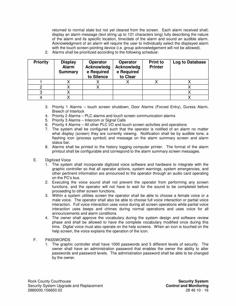
Rock County Courthouse Security System Security System Upgrade and Replacement Control and Monitoring 2880000.156650.02 28 46 10 - 16
returned to normal state but not yet cleared from the screen. Each alarm received shall; display an alarm message (text string up to 131 characters long) fully describing the nature of the alarm and its specific location, time/date of the alarm and sound an audible alarm. Acknowledgment of an alarm will require the user to individually select the displayed alarm with the touch screen pointing device (i.e. group acknowledgement will not be allowed).
2. Alarms shall be prioritized according to the following schedule:
Priority Display Alarm
Summary
Operator Acknowledge Required to Silence
Operator Acknowledge Required
to Clear
Print to Printer
Log to Database
1 X X X X X
2 X X X
3 X X
4 X X
3. Priority 1 Alarms – touch screen shutdown, Door Alarms (Forced Entry), Duress Alarm, Breech of Interlock
4. Priority 2 Alarms – PLC alarms and touch screen communication alarms 5. Priority 3 Alarms – Intercom or Signal Calls 6. Priority 4 Alarms – All other PLC I/O and touch screen activities and operations 7. The system shall be configured such that the operator is notified of an alarm no matter
what display (screen) they are currently viewing. Notification shall be by audible tone, a flashing icon (process symbol) and message on the alarm summary screen and alarm status bar.
8. Alarms shall be printed to the history logging computer printer. The format of the alarm printout shall be configurable and correspond to the alarm summary screen messages.
E. Digitized Voice 1. The system shall incorporate digitized voice software and hardware to integrate with the
graphic controller so that all operator actions, system warnings, system emergencies, and other pertinent information are announced to the operator through an audio card operating on the PC's bus.
2. Executing the voice sound shall not prevent the operator from performing any screen functions, and the operator will not have to wait for the sound to be completed before proceeding to other screen functions.
3. Within a system utilities screen the operator shall be able to choose a female voice or a male voice. The operator shall also be able to choose full voice interaction or partial voice interaction. Full voice interaction uses voice during all screen operations while partial voice interaction uses beeps and chimes during normal operations and uses voice for all announcements and alarm conditions.
4. The owner shall approve the vocabulary during the system design and software review phase and shall be allowed to have the complete vocabulary modified once during this time. Digital voice must also operate on the help screens. When an icon is touched on the help screen, the voice explains the operation of the icon.
F. PASSWORDS 1. The graphic controller shall have 1000 passwords and 5 different levels of security. The
owner shall have an administration password that enables the owner the ability to alter passwords and password levels. The administration password shall be able to be changed by the owner.

Rock County Courthouse Security System Security System Upgrade and Replacement Control and Monitoring 2880000.156650.02 28 46 10 - 17
2.10 FUNCTION DESCRIPTIONS
A. The graphic controllers are only an operator interface to the system. No control logic is allowed in the graphic computer. All control logic is to be through the PLC. Graphic controllers must be able to control the same points and be able to be integrated into the same control system.
B. FUNCTIONS - The graphic controllers consist of a combination of annunciate and function icons. The icons are: 1. DOOR CONTROL 2. DOOR CONTROL INDICATORS 3. GROUP UNLOCK 4. HOLD OPEN 5. STAFF ACCESS 6. ISOLATE DOOR 7. COMMUNICATE 8. SIGNAL CALL 9. VIDEO 10. VIDEO GROUP 11. HIDDEN FUNCTION 12. STATUS AND NAVIGATION MAP 13. PENDING LIST 14. ACTIVE STATION TEXT 15. CALL DISCONNECT 16. LOSS OF POWER 17. CONTROLLER DISABLE 18. SILENCE 19. RESET 20. LOG ON/OFF 21. DOOR NUMBER DISPLAY 22. WORKFLOW
C. Function icons shall operate as follows: 1. DOOR CONTROL
a. Selecting the DOOR icon without a menu active will result in the act of locking (electric or pneumatic locks) or closing (electrically or pneumatically operated sliding) the door. UNLOCK, HOLD OPEN, STOP and ISOLATE are menu functions that act with two keystrokes to make the door operate. Two-keystroke operation for unlocking a door is critical so that doors cannot accidentally be unlocked. The keystrokes required for opening an overhead, sliding, or swinging door is the same. The officer will first select the UNLOCK icon in the DOOR CONTROL menu area which will cause the digital voice message to announce "unlock"; then within 3 seconds, select the DOOR icon on the touch screen at the location of the door and the digital voice message will announce the actual name of the door as defined by the owner. The door will become unlocked. Other doors may be commanded to become unlocked by selecting other DOOR icons within 3 seconds of the first. After 3 seconds of no icon DOOR selections, or when another menu function is selected, or the RESET icon is selected, the UNLOCK (or other command) cancels. After the door has unlocked for a specified amount of time, it will then relock automatically.
b. To stop the motion of a sliding, or overhead, door, the officer will select the STOP icon and the DOOR location icon.
c. Logicshall be included in the PLC program so that sliding doors must be secured for a sufficient amount of time or the activation to open the sliding door has sufficient amount of time to avoid a switch bounce problem. This time duration must have the ability to be adjusted through software.

Rock County Courthouse Security System Security System Upgrade and Replacement Control and Monitoring 2880000.156650.02 28 46 10 - 18
2. DOOR CONTROL INDICATORS a. Each door control door control icon shall have a graphical representation of the door.
If the door is a swing type door it shall depict the door swing open or closed. If it is a sliding type door it shall depict the door as secure, mid-travel or fully open.
b. There shall be separate and distinct graphic representations using a combination of icon movements and/or color changes according to the following conditions:
1) Door is closed and secured (normally gray/gray). 2) Door is powered open but the lock status switch, bolt position switch and the
door position switch are still indicating the door is secure (red/white). 3) Door is shown open when the door is powered and opened (red/red). 4) Door is shown open when the door is not powered but is open (gray/red). 5) Door is violated or manually mechanically opened (flashing red/flashing red)
c. Detailed explanations shall be included in the shop drawing submittal for review of this function.
d. The SMS shall record all group unlock, relock or alarm activities. 3. GROUP UNLOCK
a. There will be an individual GROUP UNLOCK icon for each housing pod or sub-pod. Group unlock may apply to swing doors or sliding doors. Selecting the GROUP UNLOCK icon is a two-icon operation for unlocking (opening) a group of doors. Two-icon function is critical so that groups of doors cannot accidentally be unlocked. The officer will first select the UNLOCK icon in the DOOR CONTROL menu area which will cause the digital voice message to announce "unlock"; then within 3 seconds, select the GROUP UNLOCK icon on the graphic at the location of the pod or sub-pod, the digital voice message will announce the actual name of the pod or sub-pod as defined by the owner. The doors will unlock all cells in the associated pod or sub-pod, three at a time at three seconds intervals. Other pods or sub-pods may be commanded to be group unlocked by selecting other GROUP UNLOCK icons within 3 seconds of the previous. After 3 seconds of no icon GROUP UNLOCK selections, or when another menu function is selected, or the RESET icon is selected, the GROUP UNLOCK cancels. After the doors have unlocked for a specified amount of time, it will then relock automatically.
b. Individual doors can be bypassed for this function by using the ISOLATE DOOR FUNCTION described below.
c. Logic shall be included in the PLC program so that sliding doors must be secured for a sufficient amount of time or the activation to open the sliding door has sufficient amount of time to avoid a switch bounce problem. This time duration must have the ability to be adjusted through software.
d. The SMS shall record all group unlock activities. 4. HOLD OPEN
a. This feature will unlock the door and keep it electrically unlocked until the officer selects the DOOR icon only which will relock the door and return it to normal operation. Other doors can be selected for HOLD OPEN within 3 seconds of the first selection. After 3 seconds of no selections the HOLD OPEN command cancels. When in the HOLD OPEN function an “X” will be placed though the icon to alert the operator of this condition.
b. The SMS shall record all doors in the hold open position and return to normal. 5. STAFF ACCESS
a. Doors with electrically operated keyswitches or card readers for local staff control in addition to being controlled by the touch screen can be enabled or disabled at the scheduled touch screen. The key switch or card reader is enabled when the operator first selects STAFF ACCESS and then selects the door icon within 3 seconds. Other doors can be selected for staff access within 3 seconds of the first selection. After 3 seconds of no selections the staff access command cancels. In the enabled condition, for swing doors, the key switch is turned to the right, momentarily; the associated door unlocks and then relocks after 3 seconds. For sliding doors, the key
Rock County Courthouse Security System Security System Upgrade and Replacement Control and Monitoring 2880000.156650.02 28 46 10 - 19
switch is turned left (to close) right (to open). When the door location is selected for staff access, the door icon will have a graphic representation of a key symbol through it. Violations shall continue to be annunciated as described in door control indicators above. Repeating the process will reverse the condition.
b. The SMS shall record all doors in the staff access positions and return to normal. 6. ISOLATE DOOR
a. Electrically controlled doors, or doors that are also controlled by field mounted local card readers, key switches or pushbuttons can be isolated such that they cannot be opened from the local card reader, key switch or pushbutton. The officer first selects ISOLATE DOOR and then selects the DOOR icon depicting the door to isolate. Other doors may be commanded to become isolated by selecting other DOOR icon within 3 seconds of the first. After 3 seconds of no isolate door selections, the ISOLATE command cancels. Repeating the process on an isolated door reverses the condition and returns the door to normal.
b. The DOOR icon will have a yellow "X" marked through it indicating that the door cannot be unlocked by the local device. Violations and the door status representation will still be shown.
c. Attempting to unlock an isolated door will cause the digital voice to announce, "Function not allowed. Door is isolated."
d. The SMS shall record all isolated door positions and return to normal. 7. COMMUNICATE
a. Establishing audio communications from the touch screen is accomplished by selecting the COMMUNICATIONS icon at the location of the intercom station. There shall be a COMMUNICATIONS icon for each intercom station. The audio is now connected to the remote station and the COMMUNICATIONS icon is green. The video of camera/s viewing that area are now shown on the INTERCOM CALL-UP MONITOR(S), and audio is established; while the camera symbols that cover that intercom station are now green. If no camera is viewing that location, audio will be connected without video. Repeating the operation will cancel the call. Connecting to another station will automatically cancel the previous connection. Canceling the intercom call or connecting to another station shall return the camera icon gray. Selecting the SELECT TO TALK on the desktop microphone allows the officer to talk to the station.
b. The COMMUNICATIONS icon is used to show the state of the intercom call. If the call icon, located on the intercom station, is selected, and the call has not been acknowledged, the COMMUNICATIONS icon flashes green and the digital voice will sound a digitized telephone ring until the call is connected or the SILENCE icon is selected.
c. If the call has been answered, the COMMUNICATIONS icon will be solid green, and all cameras called up to follow the intercom will be solid green. If another call is incoming while the first is being serviced, that COMMUNICATIONS icon flashes and the digital voice will softly annunciate an incoming call.
d. The SMS shall record all intercom call activity, including when the call was placed and answered.
8. SIGNAL CALL a. This function is used to draw the operator attention to a door location where no
intercom or video exists. Each location will be graphically displayed by an icon depicting a program bell. When not active the icon is gray. When the call button is depressed at the remote location, the icon shall flash green and an audible bell tone shall sound at the touch screen station. The icon can be silenced by selecting SILENCE function, which will turn the icon solid green. The icon is returned to normal by RESET function.
9. VIDEO a. Each camera icon shall include the camera number as designated on the drawings or
as required by the termination equipment. PTZ camera icons shall include either a

Rock County Courthouse Security System Security System Upgrade and Replacement Control and Monitoring 2880000.156650.02 28 46 10 - 20
set of arrows indicating the cameras ability to pan or include the designation “PTZ” to distinguish controllable cameras differently than fixed cameras.
b. This function is independent of the communications icon function and requires a separate matrix output.
c. Establishing video communications from the control panel is accomplished by selecting the VIDEO icon. Selecting the VIDEO icon on the graphic panel at the location of the camera will cause the icon to be solid blue and the camera image to be displayed on a VIDEO SELECTION MONITOR. Selecting that VIDEO icon again will cancel the video and return the icon to its gray state. Selecting a different VIDEO icon will cause that camera to be active and will cancel any others cameras that are active.
d. Operation of PTZ cameras is accomplished through the desktop video controller. e. The SMS shall record all video selection activities.
10. VIDEO GROUP a. There shall be a vertical column of icons along the left side of the touch screens for
PC-MA and PC-MB to allow the operator to call up several cameras associated with specific areas outside of their normal control area of the building. These icons shall be permanent to the screen. See the Camera Schedule and VSS Configuration Diagram on the drawings.
b. Selecting the icon for the designated area will cause the matrix switcher to select those cameras as outputs to the designated monitor via multiplexer output. The icon shall turn yellow and remain until deselected.
11. HIDDEN FUNCTION a. Selecting the HIDDEN FUNCTIONS icon will take the operator to a separate screen
for on/off control of lighting circuits, television and receptacle power circuits, water solenoid valves and inmate telephone circuits. This function reduces the quantity of icons being displayed for purposes of communication and door control. The HIDDEN FUNCTION will cancel and the normal operating screen will appear in three seconds if no on/off control functions are performed. The HIDDEN FUNCTION will cancel if an alarm condition is initiated from a filed device, automatically returning to the normal operating screen.
b. in the on position. 12. STATUS AND NAVIGATION MAP
a. A portion of each screen (approximately 4" wide by 2" high without obstructing the floor plan) shall be allocated and used for the purpose of making screen movement tasks easy for the operator. This window shall contain the whole building and be located on every screen. All screens shall be accessible with one touch of the site plan such that any screen can be accessed from any other screen with just one touch of a screen's outlined area on the site plan. Each control screen shall be graphically outlined on the depicted map.
b. Selecting an outlined area of the site plan shall cause the touch screen controller to go directly to the screen that controls the touched area. The area on the site plan that represents the current screen shall be highlighted in white so that the operator knows exactly what screen is active in relation to the whole facility. A distinctive audible sound shall annunciate when this action is performed. The other areas shall be gray unless pending calls or alarms are active.
c. When calls are pending from areas other than the current screen, and these calls are defined to be answered at a particular touch screen station, then the area of the call shall flash green and gray on the site plan. If both an alarm and a pending call are active at the same time in an area, then the respective area shall flash red and green.
d. When alarms are active from areas other than the current screen, then the area of the alarm shall flash red and gray on the site plan. If both an alarm and a pending call are active at the same time in an area, then the respective area shall flash red and green.

Rock County Courthouse Security System Security System Upgrade and Replacement Control and Monitoring 2880000.156650.02 28 46 10 - 21
e. Touch screens are allowed access to only certain screens. The site plan shall display the current user's available screens in contrast with the whole site plan. Selecting the inaccessible parts of the site plan shall result in a message and the digital voice stating "Access not allowed. Enter a password for access."
13. PENDING LIST a. The list of 5 incoming pending calls designated for the particular touch screen station
shall show the owner-assigned text names for the oldest 5 pending calls that have not been answered and in the order that they were initiated. As a call is answered, it shall be removed from the list and the list shall be automatically updated with any new incoming calls. Calls can be answered out of sequence if desired by the operator.
14. ACTIVE STATION TEXT a. Any call that is active shall be displayed in this area with the owner-assigned text
name for the station that is active. 15. CALL DISCONNECT
a. When this icon is selected, the active intercom call is disconnected. Associated cameras on call-up monitors are turned off and their icons return to gray.
16. LOSS OF POWER a. When the loss of AC power is detected and the PLC reverts to UPS or emergency
power, an indication labeled EMERGENCY POWER shall flash and the alarm shall sound.
17. CONTROLLER DISABLE a. Selecting this icon will immediately disable all functions of this panel. The SS shall
record to disk all panel disable activities. The panel shall be reinitiated at Facilities Maintenance PC-MA.
18. SILENCE a. Selecting this icon will silence the audible annunciators used to indicate a violated
door, staff station request, or any other alarm. The SS shall record to disk all panel silence activities.
19. RESET a. Selecting this icon will cancel any door violation condition and/or any active menu.
RESET does not affect communications calls. The SS shall record to disk all panel-reset activities.
20. LOG ON/OFF a. Activation of a touch screen location shall occur using a card reader and valid card.
The cards shall be the same cards as assigned to operators for the Card Access System described in Section 17463 – Card Access System. Attempting to log on by presenting a card to a touch screen that is already active shall result in a voice announcement “TOUCH SCREEN ACTIVE”.
b. Presenting a valid card for a non-active touch screen shall cause a graphic representation of a standard PC keyboard to appear on top of the graphically displayed area. The user is to key in their login password. The login identification of the user logged into the touch screen shall be displayed next to the digital clock on the touch screen. In addition, all touch screens shall display the users logged on at each touch screen in the SS. Establishing, changing and maintaining user logins and passwords are functions performed by users identified as supervisors.
c. To log off the operator selects their login identification on the screen which creates a pop-up window with a “YES” or “NO” icon. Selecting the YES icon logs the operator off the system.
d. Each log on attempt (valid or not valid) and log off shall be recorded to the SMS. 21. DOOR NUMBER DISPLAY
a. The touch screens shall have the ability to display either the architectural assigned door numbers or the Owner’s assigned door numbers. This function will be accessible from the SYSTEM UTILITIES FUNCTION. The selection of door number

Rock County Courthouse Security System Security System Upgrade and Replacement Control and Monitoring 2880000.156650.02 28 46 10 - 22
preference will be controlled globally so that all touch screens display the selected preference.
22. WORKFLOW a. There shall be workflow instructions that are presented to the operator when an event
is displayed on the GUI monitor. b. These workflow instructions can be tied to any even to the Touch Screen. c. These workflow instructions can be created and modified using the Touch Screen
software.
2.11 TOUCH SCREEN SECURITY MANAGEMENT
A. The touch screen software shall provide a user-based security system. Each touch screen must allow for the creation of users with certain rights and/or privileges. These rights must include the ability to run any combination or all of the applications in the touch screen system. The ability to allow or disallow user access to control devices or switch into selective screens shall be supported.
B. Groups of users, such as Operators, Supervisors and Administrators shall be created and granted rights. All users assigned to a group obtain the rights of the group, although they are still tracked by the system by their individual ID. Individual members of a group may also be assigned additional rights.
C. As part of the touch screen development, the proposed security structure shall be presented to the Owner for review and approval. Security structuring and format for each individual touch screen shall be presented. The Owner reserves the right to change security levels during the touch screen development stage. 1. The touch screen security management system must support a tie to Windows 10 security. 2. When user-based security is enabled, an audit trail will be generated in the system that will
tag every operator action with a user identification (ID) and shall be stored to the touch screen database.
3. Systems that use a level-based security methodology shall not be acceptable. 4. The following functions must be supported within the security application:
a. Enable/Disable user-based security b. Define users, passwords and login names c. Define groups to which users may belong d. Define security path(s) e. Define user and/or group rights/privileges f. Define security area names g. Define system auto-start user
5. The ability to “lock” an operator or other user into the runtime graphics environment shall be provided. Specifically, disabling any combination of the following shall be supported:
a. Starting other applications. b. Switching to other applications that may be running. c. Exiting from the system. d. Restarting the computer using <Ctrl><Alt><Delete>. e. Opening unauthorized graphic screens. f. Closing the current graphic screens. g. Using the system menu. h. Switching to the configuration environment. i. Accessing the system tree.
6. The system shall allow for a login timeout setting for each user account. This variable setting will logout an operator when the time interval expires.
7. The system shall support manual login and logout as well as automatic login.

Rock County Courthouse Security System Security System Upgrade and Replacement Control and Monitoring 2880000.156650.02 28 46 10 - 23
2.12 SYSTEM UTILITIES
A. Each touch screen shall have the ability of switching to a touch screen specific utility screen. This screen will be limited to operators with a valid supervisory log-in and password. This screen shall be menu driven and will consist of, but not be limited to, the following functions: 1. Touch Screen Security Management 2. Date and Time configuration. 3. Pointing Device configuration 4. Printer Test 5. Intercom Auto Tour time sequence 6. Door number display 7. Additionally, from this screen system administrators with a valid administrator log-in and
password will be allowed access to the touch screen Development Software.
2.13 ARCHIVING
A. Each individual touch screen shall automatically collect, store and recall all PLC and touch screen I/O data. The status of each I/O point (local PLC and touch screen) shall be stored to the database every time the I/O point changes state. All entries to the database shall include a user intuitive descriptor, time/date stamp and state. The state of the I/O status shall be descriptive (i.e. door Open/Closed) not simply on/off. When applicable, the entries to the database shall include the user identification (i.e. alarm acknowledged by user ‘name’).
B. Data stored within the database shall be stored in Windows-compatible files for exportation and report generation. Separate database files shall be capable of being copied (exported) to the removal storage media provided with the touch screen. The system must support third part applications for ODBC queries. Recalled data from the database shall be made available to a report generation program and to user-written programs.
C. Separate database files shall be created each day, one continuous database will not be acceptable.
D. A mechanism for on-line maintenance and automatic purging of files must also be provided.
2.14 HISTORY LOGGING COMPUTER (HLC)
A. The History Logging Computer shall log security commands made within the university as they happen. Provide facility administrators the ability to monitor and review all operational aspects of the Security Automation System and its operations. The intent is that by recording all actions of the system, it shall provide owners with greater liability protection and accountability.
B. The HLC shall have the following software requirements to allow for seamless control and future flexibility.
C. Data Logging 1. The integrator shall provide a SMS system with a single point for logging, recording, report
generation and backup. Distributed databases are not acceptable. 2. The SMS shall be capable of processing 100,000 transactions per day (minimum). 3. The SMS shall be capable of communication to multiple PLCs over Ethernet.
D. Audio Logging 1. The SMS shall have the ability to record the audio conversations from each control stations
simultaneously to the SMS hard disk as a WAV or MP3. 2. Each audio recording shall include; Time/Date, Touch screen user, Touch screen station,
and field intercom station.

Rock County Courthouse Security System Security System Upgrade and Replacement Control and Monitoring 2880000.156650.02 28 46 10 - 24
3. The transaction log shall provide an automated link for every intercom call for the officer to recall the audio clip. The SMS shall replay the audio file without preventing or degrading any data logging function or live audio clips from being recorded.
4. Provide Play, Stop, Pause, Fast Forward and Reverse functions for audio playback. 5. Provide hard disk space on the SMS sufficient to record telephone quality (8 bit, 11 kHz
minimum) for 500 channel-hours (one channel per Touch screen) of audio online. Provide the ability to save an audio file to separate media for long term storage.
6. Provide audio playback ability to the subnet for Administration Viewing & Retrieval PCs as defined in Section 17462.
7. Provide the necessary hardware for every intercom to be recorded with this system.
E. Archiving & System Management 1. The database shall be able to contain up to 5 million transactions prior to the need to
archive data. 2. Automatic archives shall be user configurable for frequencies of daily, weekly, monthly,
quarterly, semi-annual, or yearly. In addition, the user shall be able to select the day of the week or month to create the archives.
3. When performing an archive, the user shall be able to select to archive only, archive and delete the archived events from the database, or delete only. The user shall also have the option to perform the same action on audio files.
4. Archived events shall be viewable in an identical format as the original SMS, using the standard SMS application. The sorting, searching, and reporting generating functionality shall be identical to the standard SMS application as well.
5. The system shall notify the user when the transaction register reaches a user definable limit to allow for data archiving. If the database reaches the user defined limit, an automatic archive will be performed so that current logging will not be affected.
6. The user shall have the ability to set an expiration date for all archives stored on the SMS computer. Archives that have reached their expiration dates shall be deleted automatically to create additional hard drive space.
7. The system shall notify the user when the hard drive reaches a user definable percentage of free hard drive space. If the hard drive reaches the user defined limit, the oldest audio and archives shall be deleted automatically so that current logging will not be affected.
8. The user shall have the ability to perform a full database backup.
F. System Features 1. The History Logging Computer (HLC) performs several valuable functions, but is not an
essential component of any operational control system. It shall be configured as follows: a. The HLC is an IBM type personal computer connected via Ethernet to the PLC
controller. b. The HLC receives alarm and transactions from the PLC within 500 milliseconds of
the occurrence. The HLC shall record Time/Date, Device, Device Action, and user the name of the user performing the action for all transactions and alarms. Transactions & Alarms include, but are not limited to: 1) The HLC shall record to disk all door openings, closings, unlocking, relockings,
secure actions, door position, lock status, violations, violation silencing, violation resetting, interlock violations, and resetting of interlock violations.
2) ISOLATED doors are reported by the SMS during daily reports. Changing the state of ISOLATED doors is recorded to disk by the SMS.
3) Doors with STAFF ACCESS granted are reported by the SMS during daily reports. Changing the state of STAFF ACCESS doors is recorded to disk by the SMS.
4) All interlock override activities. 5) The SMS records any intercom call activity, including when the call was placed
and answered. 6) Every intercom pushbutton press.

Rock County Courthouse Security System Security System Upgrade and Replacement Control and Monitoring 2880000.156650.02 28 46 10 - 25
7) All communications ISOLATE activities. 8) All touch screen disable activities. 9) All touch screen silence activities. 10) All touch screen reset activities. 11) All duress activities. 12) All video activities. 13) All utilities activities. 14) All PLC system faults. 15) All Touch screen login/logout activities.
c. All transactions (action codes), alarms and status are continually outputted from the PLC. The PLC shall be able to service this data management activity and continually control all other devices specified elsewhere in this specification without any additional delay in system throughput.
d. The HLC will provide preventative maintenance functions by continually counting operations of all devices.
2. The HLC operates in a MICROSOFT WINDOWS environment and provides the following features:
a. If multiple Touch screen stations and/or Graphic control panels are provided, the SMS shall be capable of recording all events of all stations and panels.
b. Transactions sent to screen, disk or printer are time and date stamped. Line by line printing shall contain line numbers, such that physical cutting and pasting is impossible. Any printed reports shall also contain this protection.
c. Provide a Microsoft compliant database for storage of system transactions as well as BLOB’s (binary large objects like audio and video files).
d. Provide password protection to prevent modifications to the database system. e. All reports/searches shall take less than five minutes to generate for the most
intensive retrieval. f. The database shall be able to contain up to 5 million transactions prior to the need to
archive data. The system shall allow the user to perform backups in 600MB sections to facilitate backup to CD-RW. Archived data shall be viewable, in an identical format as the original SMS, from the CD without the need to install any additional software. All data on the CD shall be able to be sorted, searched, reports generated and printed directly from the CD.
g. The system shall notify the user when the transaction register is 85% of the maximum to allow for data archival. If the database reaches it maximum, logging will not be effected. Instead, an automated deletion of the oldest 600MB of data will be purged to allow new data to be saved.
h. The database reports shall include the option to export the data to a comma separated file (.csv) to be used by owner provided software.
3. The HLC will include a complete comprehensive relational database report utility, accessible via a pull down menu. All reports are titled, time and data stamped, and contain anti-cut and paste line numbering. It shall be possible to easily select reports to show the history of any device or group of devices between specified times and dates.
4. The DAILY REPORT will print to screen or paper the list of states during the day by event occurrence of all controlled devices, alarms, isolations and conditions. The report is programmable to the desires of the owner. Consultation with the owner during the training period will determine the content of this report.
5. The HISTORICAL REPORT allows the operator to select any and all transaction types, alarms, time changes and any other system functions as described in the specifications, and is done by defining a start date and time and a stop date and time. The computer will search any applicable matching occurrences and print either to the screen or printer as a report; thus allowing searching for:
6. Specific time periods. a. Specific transaction types. b. Specific locations.

Rock County Courthouse Security System Security System Upgrade and Replacement Control and Monitoring 2880000.156650.02 28 46 10 - 26
c. Any combination of the above. d. Specific keywords.
7. HLC Client: a. Provide client software which will be provided for the owner to install on up to 5
owner supplied PCs to allow the viewing of all transactions, generate reports, playback audio, and allow search capabilities. Connection to SMS will be over a dedicated Ethernet connection from the SMS computer to the owner supplied PCs on the Security Automation System secure intranet.
b. Provide the ability for clients to backup/archive the event log database, to view data from any archived database, including CD-ROMs, and export reports to a .csv format.
c. Provide ability to add, delete, and modify users for the touch screen login validation. d. Provide the ability to assign users access to specific touch screen stations. e. Provide the ability for users to login via a touch screen proximity reader or user name
and password. f. Provide a fully integrated, Windows based, on-line help system. g. Provide a fully integrated Web based client which shall allow access to the HLC
database, through password protection, via a commercially available browser application. The Web based client shall allow the viewing of all transactions, generate all reports, playback transaction audio MP3 files, allow searches and printing to local printers.
8. Hardware configuration 9. The following minimum equipment is required:
a. Intel I3 based computer running at 1GHZ clock speed. b. Operator interface shall be controlled by Microsoft Windows 10 with lockout of all
other functions except by special keystroke and password access. c. Enhanced 101 key keyboard. d. 19" LCD flat screen monitor. e. Optical wheel mouse. f. 16GB of RAM. g. 250 Gigabyte, 7200rpm hard drive or greater to provide specified storage. h. 600DPI HP Laserjet printer. i. Serial ports as required. j. 8x4x64 CD-RW drive. k. Two 100BaseT NICs.
G. The HLC shall provide continuous audio recording of all intercoms and speakers in the security electronics system.
2.15 PROGRAMMABLE LOGIC CONTROLLERS (PLC’S)
A. ACCEPTABLE MANUFACTURERS 1. Allen-Bradley 2. General Electric/Fanuc 3. Omron 4. Schneider Electric
B. GENERAL 1. High reliability, integration of functionality, software flexibility and ease of maintenance shall
be the primary criteria for PLC system selection. To achieve this end the following specification shall be strictly adhered to.
2. Each PLC shall be a standard industrial grade product designed for high reliability. The PLC shall be manufactured by a company that has produced a product line of compatible PLC's for at least fifteen years
3. The PLC manufacturer must guarantee the availability of spare parts for a period of 10 years.

Rock County Courthouse Security System Security System Upgrade and Replacement Control and Monitoring 2880000.156650.02 28 46 10 - 27
4. The PLC’s shall be configured as direct digital controllers without dependency on a central processing unit or central software package. Loss of communications to and form the communications network shall in no way affect the operation of the local graphic controller associated with its local PLC. Failure or loss of any PLC shall not affect the operation of any other PLC.
5. The PLC CPUs shall be software based utilizing RAM and EEPROM such that any future changes in alarm reporting, interlock schedules or control functions will be accomplished by a software change only not requiring any rewiring or addition of equipment. Software flexibility is mandatory, discrete circuit door control is not acceptable.
6. PLC output boards shall not be allowed to directly drive electric locks, sliding doors or any other function with either a surge current or continuous duty current or more than 500 milli-amps. Output boards shall drive relays as described herein.
7. Each monitored swing door shall have two separate and distinct monitored points. Monitoring a swing door with a single secure/unsecure point is unacceptable. Swing doors with electric locks shall be monitored for separate points for lock bolt status and for door position status.
8. Initiation of unlocking/locking, opening/closing or doors shall have maximum time duration of 1 second, from time of initiation from the control panel or graphic controller to movement of the door device. This time duration shall appear to be imperceptible by the operator.
9. All PLC to PLC communication shall utilize a fiber optic backbone. 10. All PLC’s shall communicate with the Security Control System (SS) and touch screen. All
PLC operations and I/O states shall be continuously communicated to the associated touch screen.
11. Provide programmable logic controllers (PLC's) sized to accommodate the inputs/outputs and functional operations required at each of the following locations:
Floor Room Location Designation PLC Address
1 A020 Storage/Maintenance PLC-A
1 A088 Comm PLC-B
1 043 PBX Room PLC-C
C. PLC CENTRAL PROCESSING UNIT (CPU) 1. The PLC CPU program shall functionally execute all system control commands and
operations. The CPU program shall be specific to the local PLC control area and shall be stored in battery-backed static RAM memory. Additionally, the CPU program shall be stored in EEPROM located on the CPU. The CPU shall automatically execute the EEPROM program if a RAM program fault is detected by the CPU. RAM and EEPROM shall be sized sufficiently to meet the functional requirements of this security system plus 25% memory for future expansion.
2. CPU RAM and EEPROM shall be programmable through the use of a portable personal computer. CPU program execution shall not be halted during uploads to the personal computer.
3. PLC CPU scan times shall be as follows: Program Scan Time/Kword shall be less than 0.6ms and I/O scan time per rack shall be less than 11ms at 57.6K bit/s.
4. Each PLC CPU shall have a minimum of four independent communication ports capable of supporting the following functions: one Ethernet communication to other system PLC's (minimum speed of 50K bit/s), two inter-PLC communication ports (i.e. DH+, MODBUS+ - minimum speed of 50K bit/s) to the security management system graphic controller and diagnostic/development terminal and one remote I/O port for communication to remote I/O racks. The PLC shall be capable of communicating via a Peer-to-Peer communication strategy with other system CPUs (PLC and PC). No PLC shall be considered a “CENTRAL” PLC (CPU) to the system.

Rock County Courthouse Security System Security System Upgrade and Replacement Control and Monitoring 2880000.156650.02 28 46 10 - 28
5. The PLC CPU shall be hardware lockable in the “RUN” mode. Selection of PLC CPU “PROGRAM” or “NONE – RUN” modes shall be via a mechanical key at the CPU locations.
6. The PLC CPU programming software shall be capable of supporting ladder-logic, function block, SFC and structured-text programming. Advanced instruction sets including file handling, sequencer, diagnostic, shift register, immediate I/O and program control instructions shall also be supported.
7. For diagnostic purposes, the CPU program shall be capable of Forced Values for all I/O. 8. The PLC CPU shall provide real-time health and status information to the user.
Diagnostics must run during system start-up and during system run-time. The CPU program shall be designed to provide fault response to a fault before the security system goes down.
D. INPUT/OUTPUT MODULES AND RACKS 1. Each PLC shall be equipped with a sufficient quantity of input and output (I/O) modules and
associated back-plane racks to provide the described functionality. Provide at least 10% spares of each type of module at each PLC location for future expansion (i.e. If 16 input modules and 16 output modules are provided for a PLC location, two additional input and output modules shall be provided in the I/O rack).
2. PLC input cards shall be optically isolated and capable of accepting input signal voltages of 24 volts AC or DC. Each input point of the card shall have a corresponding LED indicator, which illuminates when the associated input is at zero voltage potential.
3. PLC output cards shall be capable of source switching all designated control devices (multiple voltage or application output cards will not be acceptable). Each output point of the card shall have a corresponding LED indicator, which illuminates when the associated output is energized.
4. All I/O modules (including spares) shall be rack mounted in the corresponding PLC I/O back-plane rack. Each rack shall be supplied with a rack mounted power supply capable of supplying all I/O modules and the PLC CPU. Spare capacity shall be designed into the power supply to account for future I/O modules outlined herein.
5. Provide chassis mounted I/O modules.
E. REMOTE INPUT/OUTPUT (I/O) CONTROLLERS 1. Provide remote I/O controllers for utility control panels RC/A and RC/B as indicated on the
drawings. 2. Remote I/O controllers shall provide sufficient points for the required controls and
monitoring at the remote location. The remote I/O controllers shall include the required interface modules for the communication bus at the PLC. Power for the remote I/O shall be derived from the power supply feeding the PLC equipment racks. The communications bus to PLC’s shall utilize copper or fiber optic data transmission.
3. The remote I/O controllers shall be mounted in a NEMA 1 hinged cover termination box. The I/O module shall directly interface to the lighting control panel interface module as a dry contact for control of power circuits. The lighting control panel shall control power circuits from the interface module via relays and power supplies in their panel.
F. PLC EQUIPMENT RACKS 1. All PLC equipment shall be mounted in a freestanding rack. PLC I/O racks, power
supplies, I/O modules, CPUs and interface relays shall be rigidly mounted and labeled within the rack. All equipment mounted within the rack shall be easily accessible for service and/or replacement.
2. All wiring within the rack shall be placed in covered wire molding wire ways. AC and DC wiring shall be separated by independent wire ways. Wire ways shall be sized for 40% wire fill. A minimum space of two inches shall be maintained between all cabinet mounted equipment and wire ways.
3. The rack shall also be fan cooled and ventilated in accordance to the PLC manufacturers cooling requirements.

Rock County Courthouse Security System Security System Upgrade and Replacement Control and Monitoring 2880000.156650.02 28 46 10 - 29
4. All rack mounted equipment shall be labeled with a rigid, two color laminated, plastic nameplate identifying the piece of equipment. The labels shall be permanently affixed to the rack with screws or rivets.
5. Refer to Section 28 05 00 – Security System Racks and Enclosures.
2.16 MECHANICAL RELAYS
A. Light duty relays and similar devices shall have dust covers which protect against fouling by dust or other material which may adversely affect their normal operation. All mechanical plug-in relays shall be equal to Potter-Brumfield KUP Series with contact rated 10 amps. All relays shall be of the plug-in type with LED status indication and individual fuses. Relays for control of motor-operated locks and sliding doors shall be horsepower rated for the device it controls.
B. Relays shall be DIN-rail mounted for easy replacement and shall be individually fused with LED indicator showing the status of each relay. In the group, gang or emergency release modes of operation the relays shall be controlled by the local PLC such that no more than three doors are operated at a time on a single circuit and the doors shall be released or closed in groups of size in three second intervals; this function is to be automatic and controlled via the PLC. 1. Relays for control of motor-operated locks and sliding doors shall be horsepower rated for
the device it controls. 2. Relays for intercom control shall be hermetically sealed designed for audio circuits 3. Relays interfaced to control AC power circuits shall be rated 20 ampere at 120 or 277 VAC
and MOV protected to prevent induction currents. a. Provide Panasonic WR61613K-84 series relays as required for utility control.
Rockwell Automation 700-HG push-pull power relays unacceptable. b. Size relay for 277V or 120V circuits. c. All utility control relays to be equipped with local on/off status indicators/switches d. Maintain separation of 24V low voltage control and 277/120V line voltage power
wiring as required by NEC. 4. Relays for telephone control circuits shall be four-pole. Coordinate requirements with
Owner’s telephone system vendor. These relays shall be located in the PLC equipment racks.
5. Provide relays required for complete remote elevator control. Interface with existing elevator control relays. Provide remote relay cabinets in elevator equipment rooms as shown on the Drawings.
6. Use of electronic control boards for door control unacceptable.
2.17 DOOR CONTROL POWER SUPPLIES
A. Provide regulated DC power supplies for the control and operation of electro-magnetic locks, electric strikes, detention pneumatic and/or motor-operated and electric solenoid locks. Power supplies shall be 120 volt AC input and 24 volt DC output, Class II, with a maximum +/- 10% voltage fluctuation.
B. Coordinate and verify all lock power requirements with Division 08 and 11 for the actual hardware manufacturer being supplied. Power supplies shall be sized as recommended by the manufacturer with 10% spare capacity at each door control power supply location.
C. Where the functional requirements dictate that one control function (emergency group release) is to open multiple doors, the opening (as for electrically operated doors) or unlocking (as for electrically operated door locks) of doors shall be sequentially staggered at a maximum of three at a time so as to minimize the power supply required for the electric locks or operators.

Rock County Courthouse Security System Security System Upgrade and Replacement Control and Monitoring 2880000.156650.02 28 46 10 - 30
2.18 MISCELLANEOUS POWER SUPPLIES
A. Miscellaneous plug-in power supplies shall be strapped to their receptacle with tie-wraps or secured to the receptacle cover plate if the power supply includes a mounting tab with screw. This is to prevent the power supply from loosening over time or from being accidentally disconnected.
2.19 LOCAL PUSHBUTTON DOOR CONTROL
A. Selected doors with local pushbutton door control as indicated on the Drawings and scheduled will be interfaced to the PLC controller as a valid input. This input will unlock the door and prevent an alarm condition to occur at the monitoring touch screen/s. 1. Wall mounted: Basis of Design – Quam CIB2 2. Desk Mounted: Basis of Design – SDC 15-2
2.20 SECURITY NETWORK COMPONENTS
A. LAN Switch 1. Redundant LAN switches for the security network shall be provided with layer 3 switches
to provide separation between the various networks operational in Rock County. 2. LAN switches shall be powered by 24VDC. Any variation in the power requirements shall
be the responsibility of this contractor to coordinate with other trades. 3. Provide a network that shall include redundant connections between the PLC system,
video graphic interfaces, audio system, camera system, and other integration system CPU.
4. This network shall be a high speed, fault tolerant, self healing, Ethernet industrial communication network. It shall be a 1 gigabit star topology network using fiber optic media as required and be in compliance with IEEE 802.3. All switches shall be managed.
5. Network switches shall be capable of providing wireless access points as add on modules.
6. Door Control and Data Network a. Manufacturer/Series:
1) Phoenix Contact MMS Series 2) Hewlett Packard 1910 Series 3) Hirschmann Mice Series 4) Cisco 3750 Series
7. Video Surveillance Network
a. Manufacturer/Series: 1) Cisco 3750 Series (with redundant power supplies) 2) Hewlett Packard 1910 Series
B. Media Converters 1. Media converters for network switches will be provided by the SEC. The media
converters shall be installed and made operational by this contractor
C. Fiber Optic Patch Cables 1. The Fiber Optic patch cables shall be 50/125-micron multi-mode fiber utilizing tight buffer
construction. The fiber optic patch cables shall be minimum 1.5 meters in length. 2. Fiber Optic jumpers shall incorporate Ceramic or Metallic tipped LC type connectors on
one end to match the fiber optic cabling installed under section 27 00 00. Connectors to owner provided equipment shall be as required to connect to equipment. Connectors used in fiber optic patch cables shall meet requirements set forth in the Fiber Optic section of section 27 00 00.

Rock County Courthouse Security System Security System Upgrade and Replacement Control and Monitoring 2880000.156650.02 28 46 10 - 31
3. Channels in duplex patch cables shall be of equal length. 4. Cables shall be aqua in color. 5. The contractor shall provide thirty 30 Fiber optic Patch Cables (duplex).
D. Cat 6 Patch Cables 1. The copper patch cables provided under this contract shall be four pair, category 6 rated
cables. Each cable shall be performance tested for conformance to the TIA/EIA-568-B standards for category 6.
2. Cables shall be terminated in RJ45 plugs on each end of the cable. 3. These cables shall be minimum 2 meters in length. The length of these cables shall be
sufficient to route the cable through existing cable managers. 4. Cables shall be green in color. 5. Contractor shall supply sufficient cat 6 patch cables to connect all cameras, Network
video recorders, storage devices and miscellaneous equipment to provide a complete and working system.
2.21 POE POWER INJECTOR
A. MANUFACTURERS: 1. Veracity 2. Pelco 3. Or Approved Equal
B. MINIMUM REQUIREMENTS: 1. The device shall meet the demanding data rate and power requirements of the attached
IP cameras with high-quality streaming video capabilities. 2. The device shall meet the IEEE 802.3af standard for detection, connection,
disconnection, and fault protection. 3. The device shall be compatible with 10/100Base-T systems and systems up to 1000
Mbps.
2.22 API INTEGRATION
A. An application programming interface (API) is provided for the security network. The API provides programmatic access to the network-connected components managed by the security network.
B. Communication between the security network takes place through the TCP/IP networking protocol. The API is invoked by POSTing an HTTP message to the web server on the network controller.
C. The API supports commands for:
1. Pinging the security network system to determine its health, and retrieving the current version of the API from the server.
2. Adding, modifying, deleting, and retrieving time specifications and time specification groups.
a. Adding, modifying, and deleting portals and portal groups, and retrieving
information about a specific portal group.
b. Requesting events from the Activity Log that occurred within a specified time period. These events are returned from the API in the CSV Export report format.

Rock County Courthouse Security System Security System Upgrade and Replacement Control and Monitoring 2880000.156650.02 28 46 10 - 32
2.23 LIGHTNING PROTECTION
A. All communications and data equipment control, sensor and data cabling shall be protected against induced surges. Surge protection shall be provided on all circuit ends that meet the IEEE 772 surge withstand capability test and the electrical transient tests an established in UL 365-1985. Fuses shall not be used for surge protection.
B. All power connections including low voltage power supplies and direct-wired or plug-in 120VAC power connections for all system components shall be equipped with lightning suppression devices. All communications, data and power lightning devices shall be bonded to building grounding system in accordance with Article 250 of the National Electrical Code.
C. Provide a dedicated no. 6 AWG insulated ground copper conductor from building ground to all security equipment rooms, security control equipment panels and control rooms. Connect all lightning protection devices and security equipment non-current carrying metal parts to grounding conductor in accordance with Article 250 of the National Electrical Code.
2.24 SPARE PARTS
A. To facilitate ease of maintenance provide spare equipment as follows: 1. One Input cards of each type used on the project. 2. One Output cards of each type used on the project. 3. Fabricated relay board, if used, one of each kind. 4. Provide 5 spare relays of each type used on the project. 5. Two PLC CPU fuses for each CPU supplied. 6. Two PLC power supplies. 7. Ten I/O fuses.
B. Provide spare equipment in static resistant packaging and turn over to the Owner's designated maintenance supervisor. A signed document demonstrating proof of receipt shall be delivered to the Architect prior to receiving final retainage.
PART 3 - EXECUTION
3.01 INSTALLATION REQUIREMENTS
A. Contractor shall furnish and install all cables, connectors and equipment as shown on drawings and as specified.
B. Refer to Project Drawings that indicate the equipment location within each building.
C. It is the contractor’s responsibility to survey the site and include all necessary costs to perform the installation as specified.
D. Beginning installation means contractor accepts existing conditions.
E. Where unacceptable conditions are found, the Contractor shall bring this to the attention of the construction supervisor immediately. A written resolution will follow to determine the appropriate action to be taken.
F. If any installed cable is kinked to a radius less than recommended dimension the contractor shall replace it at no additional cost to the project.
G. The system will be tested and documented upon completion of the installation as defined in the Section below.

Rock County Courthouse Security System Security System Upgrade and Replacement Control and Monitoring 2880000.156650.02 28 46 10 - 33
3.02 COOPERATION
A. The Contractor shall cooperate with other vendors and County personnel in locating work in a proper manner. Should it be necessary to raise or lower or move longitudinally any part of the work to better fit the general installation, such work shall be done at no extra cost to the County, provided such decision is reached prior to actual installation.
3.03 COORDINATION
A. Verify exact lock control and wiring requirements with actual equipment being supplied.
3.04 TESTING AND ACCEPTANCE
A. This Contractor shall conduct tests to determine system conformance to requirements of this specification. Tests shall be conducted in the presence of the Engineer or his authorized representative who may suspend or discontinue the tests at any time performance is considered unsatisfactory. Resumption of testing will cover untested elements and any replaced elements. This contractor shall furnish test instruments and equipment of the accuracy necessary to perform the test. Arrangements for testing must be made with the Engineer at least two weeks before the proposed testing date. The institution's technician shall also be present during testing.
B. Testing shall verify function and operation of all relays, switches, door locks and indicator lights for proper function including the verification of all interlock, emergency group release and staggered release sequencing.
C. Contractor shall maintain a running list of all doors determined to be mechanically defect in operation. Submit list to the General Contractor, the Div. 11 - Detention Equipment Contractor and the Security Electronics Consultant.
D. The SEC shall visually inspect all equipment to insure that they are complete and conform to the requirements defined herein. The contractor shall provide the Engineer with a written certification that this inspection has been made
E. The SEC shall conduct acceptance testing according to a schedule coordinated with the Owner. Representatives of the Owner may be in attendance to witness the test procedures. The contractor shall provide a minimum of one (1) week advance notice to the Engineer as to allow for such participation. The notification shall include a written description of the proposed conduct of the tests including copies of blank test result sheets to be used.
F. IMPORTANT: Failure to provide the above information shall be grounds for the Owner/Engineer to reject any and all Documentation of Results on related testing and to require a repeat of the affected test.
G. Tests related to connected equipment of others shall only be done with the permission and presence of others involved.
H. Should it be found by the Engineer that the materials or any portion thereof furnished and installed under this contract fail to comply with the specifications and drawings, with the respect or regard to the quality, amount of value of materials, appliances or labor used in the work, it shall be rejected and replaced by the Contractor and all work distributed by changes necessitated in consequence of said defects or imperfections shall be made good at the Contractor's expense.

Rock County Courthouse Security System Security System Upgrade and Replacement Control and Monitoring 2880000.156650.02 28 46 10 - 34
3.05 DOCUMENTATION
A. Upon completion of the installation, the contractor shall provide 3 full Documentation Sets to the Engineer for approval. Documentation shall include the items detailed below. 1. Connection matrix showing fiber strands used to activate LAN on existing cable plant
B. All documentation, including hard copy and electronic forms shall become the property of the County.
3.06 WARRANTY
A. The SEC shall guarantee all materials, equipment, etc. for 1 year from date of substantial completion of this work. This guarantee shall include all labor, material and travel time. See Division 01 - GENERAL CONDITIONS, and Division 00 - GENERAL REQUIREMENTS - Guarantee Documents for further requirements.
3.07 WIRING
A. All wiring shall be in conduit. Refer to the security system wiring legends and riser diagrams on the drawings.
B. All wiring shall be in conduit by Division 26 in accordance with the requirements of Section 26 13 00 – Raceway and Boxes.
C. Wiring for locks and doors is indicated on the Drawings.
D. All power wiring for 24 volt or 120 volt sliding door gates, doors or locks shall have a separate green equipment ground conductor.
E. All wiring for status indicators of electric locks and the control and status of pneumatic doors shall utilize 18 AWG multi-conductor cable under a common outer jacket and shall be installed in common raceways and equipment’s enclosures with other conductors for locking devices within the limitations defined by Article 725-15 of the National Electrical Code for Class 2.
F. Wiring for electro-mechanical lock control will be No. 14 AWG-CU THHN/THWN.
G. Refer to the Security Control Point Schedule for reference to lock types and the lock wiring diagrams on the drawings for wiring requirements.
H. All conductors shall be stranded copper.
END OF SECTION

Rock County Courthouse Security System Security System Upgrade and Replacement Network Switches 2880000.156650.02 28 46 20 - 1
SECTION 28 46 20 SECURITY SYSTEM NETWORK SWITCHES
PART 1 - GENERAL
1.01 SCOPE
A. Applicable provisions of Division 01 shall govern all work under this Section.
B. All equipment described in this section shall be provided by the SEC Contractor as described in Section 28 46 00.
C. This section describes the products and execution requirements relating to furnishing and installing network equipment and related sub-systems as part of a dedicated security network for the new Video Surveillance System for this project. Electronic equipment as well as passive components is covered under this document.
D. Contractor is to provide and install a complete and working dedicated LAN for this project utilizing new cable to provide a complete and working system. All equipment, cables and related hardware shall be furnished, installed, tested, labeled, and documented by the Contractor, as detailed in the following sections.
E. Basic Electrical Requirements are applicable to all Division 28 sections. This section includes information common to two or more technical specification sections or items that are of a general nature, not conveniently fitting into other technical sections.
1.02 RELATED WORK
A. Section 26 05 00 – General Electrical Provisions
B. Section 28 05 20 – Security System Equipment Racks and Enclosures
C. Section 28 46 00 - Security System General Requirements
D. Section 28 46 10 – Security System Control and Monitoring
E. Section 28 46 20 – Security System Network Switches
F. Section 28 46 30 – Door Control Intercom System
G. Section 28 46 40 – Card Access System
H. Section 28 46 60 – Video Surveillance System
1.03 REGULATORY REFERENCES
A. All work and materials shall conform in every detail to the rules and requirements of the National Fire Protection Association, the Wisconsin Electrical Code and present manufacturing standards.
B. All materials shall be listed by UL and shall bear the UL label. If UL has no published standards for a particular item, then other national independent testing standards shall apply and such items shall bear those labels. Where UL has an applicable system listing and label, the entire system shall be so labeled.
C. Other applicable standards are as follows:

Rock County Courthouse Security System Security System Upgrade and Replacement Network Switches 2880000.156650.02 28 46 20 - 2
1. ANSI/IEEE C2 - National Electrical Safety Code 2. NFPA 70-2005 - National Electrical Code 3. TIA/EIA Standards 568-B, 606A 4. IEEE 802.3 Standards for Ethernet
1.04 WORK SEQUENCE
A. During the construction period, coordinate schedule and operations with Rock County General Services and Rock County Sheriff’s Department.
B. For additional information pertaining to the sequencing of the work refer to Article 13 of the General Conditions.
C. Installation shall be sequenced to accommodate the Owner's occupancy requirements. See Division 01, General Conditions (Work Sequence).
1.05 SUBMITTALS
A. Prepare submittals in accord with the requirements of specification Section 28 46 00 and include the following information: 1. Manufacturers catalog specification cuts and printed descriptive literature on all
components outlined in this specification. Each component shall be clearly identified with options marked or highlighted.
B. Submittals shall be original catalog sheets or photocopies thereof. Facsimile (fax) sheets shall not be accepted.
C. Work shall not proceed without the Engineer’s approval of the submitted items.
D. If materials are furnished as specified no further qualifications is necessary, except for items requiring shop drawings. However, if the Contractor wishes to substitute another manufacturer and/or catalog number, the following information in triplicate shall be submitted to the Engineer: 1. A complete description of the material which the contractor proposes to substitute
(shop drawings, illustrations, catalog data, performance characteristics, etc.) and the reason for the substitution identifying any benefit to the Owner.
E. The Contractor shall receive approval from the Engineer on all substitutions of material. No substituted materials shall be installed except by written approval from the Engineer.
1.06 PROJECT RECORD DOCUMENTS
A. Submit record documents under per Div. 01 General Requirements.
B. Accurately record exact sizes, locations and quantities of equipment.
1.07 QUALITY ASSURANCE
A. The manufacturer shall be a company specializing in LAN equipment with a minimum of five years documented experience in producing LAN equipment similar to those specified below.
B. The SEC shall have been in this line of business for a minimum of 5 years and completed 4 jobs of the magnitude specified in the following sections.

Rock County Courthouse Security System Security System Upgrade and Replacement Network Switches 2880000.156650.02 28 46 20 - 3
1.08 DELIVERY, STORAGE AND HANDLING
A. Deliver products to and receive products at the site under provisions of Division 01 - General Requirements.
1.09 DRAWINGS
A. It shall be understood that the Network Equipment details and drawings provided with the specification package are diagrammatic. They are included to show the intent of the specifications and to aid the Contractor in bidding the job. The Contractor shall make allowance in the bid proposal to cover whatever work is required to comply with the intent of the plans and specifications.
B. The Contractor shall verify all conditions at the site and be responsible for their accuracy.
C. Prior to submitting the bid, the Contractor shall call the attention of the Engineer to any materials or apparatus the Contractor believes to be inadequate and to any necessary items of work omitted, within 10 days prior to the bid due date.
1.10 ALARM INTEGRATION
A. Provide remote monitoring of status of each individual security network switch by City IT personnel.
B. Program security network switches to provide SNMP E-Mail alert to County IT manager upon activation of failure or alarm status.
C. Provide conduit/cabling to existing Owner’s administrative network switch as required for E-mail alert integration.
D. Coordinate administrative network integration with City IT manager.
PART 2 - PRODUCTS
2.01 NETWORK COMPONENTS
A. LAN SWITCH 1. Redundant LAN switches for the security network shall be provided with layer 3
switches to provide separation between the various networks operational in the Rock County Courthouse. LAN switches shall be powered by 24VDC or 120VAC. Any variation in the power requirements shall be the responsibility of this contractor to coordinate with other trades.
2. Provide a network that shall include redundant connections between the PLC
system, video graphic interfaces, audio system, camera system, and other integration system CPU.
3. This network shall be a high speed, fault tolerant, self healing, Ethernet industrial
communication network. It shall be a 1 gigabit star topology network using fiber optic media as required and be in compliance with IEEE 802.3. All switches shall be managed.
4. Network switches shall be capable of providing wireless access points as add on
modules.

Rock County Courthouse Security System Security System Upgrade and Replacement Network Switches 2880000.156650.02 28 46 20 - 4
5. Provide PoE power on switch ports where applicable.
B. DOOR CONTROL, CARD ACCESS AND DURESS ALARM NETWORK 1. Manufacturer/Series:
a. Phoenix Contact MMS Series b. Hewlett-Packard 3800 Series c. Hirschmann Mice Series d. Cisco 3850 Series
C. VIDEO SURVEILLANCE NETWORK - CORE SWITCH 1. Manufacturer/Series:
a. Cisco 3850 Series b. Hewlett-Packard 3800 Series
D. VIDEO SURVEILLANCE NETWORK - EDGE SWITCH 1. Manufacturer/Series:
a. Cisco 2960X Series b. Hewlett-Packard 2920 Series
E. MEDIA CONVERTERS 1. Media converters for network switches will be provided by the SEC. The media
converters shall be installed and made operational by this contractor
F. FIBER OPTIC PATCH CABLES 1. The Fiber Optic patch cables shall be 50/125-micron multi mode fiber utilizing tight
buffer construction. The fiber optic patch cables shall be minimum 1.5 meters in length.
2. Fiber Optic jumpers shall incorporate Ceramic or Metallic tipped LC type connectors on one end to match the fiber optic cabling installed under section 27 00 00. Connectors to owner provided equipment shall be as required to connect to equipment. Connectors used in fiber optic patch cables shall meet requirements set forth in the Fiber Optic section of section 27 00 00.
3. Channels in duplex patch cables shall be of equal length.
4. Cables shall be aqua in color.
5. The contractor shall provide thirty 30 Fiber optic Patch Cables (duplex).
G. CAT 6 PATCH CABLES 1. The copper patch cables provided under this contract shall be four pair, category 6
rated cables. Each cable shall be performance tested for conformance to the TIA/EIA-568-B standards for category 6.
2. Cables shall be terminated in RJ45 plugs on each end of the cable.
3. These cables shall be minimum 2 meters in length. The length of these cables shall be sufficient to route the cable through existing cable managers.
4. Cables shall be green in color.
5. Cables shall be snagless.

Rock County Courthouse Security System Security System Upgrade and Replacement Network Switches 2880000.156650.02 28 46 20 - 5
6. Contractor shall supply sufficient cat 5e patch cables to connect all cameras, Network video recorders, storage devices and miscellaneous equipment to provide a complete and working system.
2.02 POE POWER INJECTOR
A. MANUFACTURERS 1. Veracity 2. Pelco 3. Approved Equal
B. MINIMUM REQUIREMENTS 1. The device shall meet the demanding data rate and power requirements of the
attached IP cameras with high-quality streaming video capabilities.
2. The device shall meet the IEEE 802.3af standard for detection, connection, disconnection, and fault protection.
3. The device shall be compatible with 10/100 Base-T systems and systems up to
1000 Mbps.
2.03 API INTEGRATION
A. An application programming interface (API) is provided for the security network. The API provides programmatic access to the network-connected components managed by the security network.
B. Communication between the security network takes place through the TCP/IP networking protocol. The API is invoked by POSTing an HTTP message to the web server on the network controller.
C. The API supports commands for: 1. Pinging the security network system to determine its health, and retrieving the
current version of the API from the server.
2. Adding, modifying, deleting, and retrieving time specifications and time specification groups.
3. Adding, modifying, and deleting portals and portal groups, and retrieving information
about a specific portal group.
4. Requesting events from the Activity Log that occurred within a specified time
period. These events are returned from the API in the CSV Export report format.
PART 3 - EXECUTION
3.01 INSTALLATION REQUIREMENTS
A. Contractor shall furnish and install all cables, connectors and equipment as shown on drawings and as specified.
B. Refer to Project Drawings that indicate the equipment location within each building.
C. It is the contractor’s responsibility to survey the site and include all necessary costs to perform the installation as specified.

Rock County Courthouse Security System Security System Upgrade and Replacement Network Switches 2880000.156650.02 28 46 20 - 6
D. Beginning installation means contractor accepts existing conditions.
E. Where unacceptable conditions are found, the Contractor shall bring this to the attention of the construction supervisor immediately. A written resolution will follow to determine the appropriate action to be taken.
F. If any installed cable is kinked to a radius less than recommended dimension the contractor shall replace it at no additional cost to the project.
G. The system will be tested and documented upon completion of the installation as defined in the Section below.
3.02 COOPERATION
A. The Contractor shall cooperate with other vendors and County personnel in locating work in a proper manner. Should it be necessary to raise or lower or move longitudinally any part of the work to better fit the general installation, such work shall be done at no extra cost to the County, provided such decision is reached prior to actual installation.
3.03 TESTING AND ACCEPTANCE
A. The contractor is responsible to perform acceptance tests as indicated below for each sub-system (e.g. backbone, station, etc.) as it is completed.
B. The SEC shall visually inspect all equipment to insure that they are complete and conform to the requirements defined herein. The contractor shall provide the Engineer with a written certification that this inspection has been made.
C. The SEC shall conduct acceptance testing according to a schedule coordinated with the Owner. Representatives of the Owner may be in attendance to witness the test procedures. The contractor shall provide a minimum of one (1) week advance notice to the Engineer as to allow for such participation. The notification shall include a written description of the proposed conduct of the tests including copies of blank test result sheets to be used.
D. IMPORTANT: Failure to provide the above information shall be grounds for the Owner/Engineer to reject any and all Documentation of Results on related testing and to require a repeat of the affected test.
E. Tests related to connected equipment of others shall only be done with the permission and presence of others involved.
F. Should it be found by the Engineer that the materials or any portion thereof furnished and installed under this contract fail to comply with the specifications and drawings, with the respect or regard to the quality, amount of value of materials, appliances or labor used in the work, it shall be rejected and replaced by the Contractor and all work distributed by changes necessitated in consequence of said defects or imperfections shall be made good at the Contractor's expense.
3.04 DOCUMENTATION
A. Upon completion of the installation, the contractor shall provide 3 full Documentation Sets to the Engineer for approval. Documentation shall include the items detailed below: 1. Connection matrix showing fiber strands used to activate LAN on existing cable
plant

Rock County Courthouse Security System Security System Upgrade and Replacement Network Switches 2880000.156650.02 28 46 20 - 7
2. All documentation, including hard copy and electronic forms shall become the property of the County.
3.05 WARRANTY
A. The SEC shall guarantee all materials, equipment, etc. for 1 year from date of Substantial Completion of the Work. This guarantee shall include all labor, material and travel time. See Division 01 General Requirements.
END OF SECTION

PAGE INTENTIONALLY LEFT BLANK
Rock County Courthouse Door Control Security System Upgrade and Replacement Intercom System 2880000.156650.02 28 46 30 - 1
SECTION 28 46 30 DOOR CONTROL INTERCOM SYSTEM
PART 1 - GENERAL
1.01 SCOPE
A. This section describes the requirements for a door control intercom system as an integral part of the security control processing equipment.
B. The SEC Contractor as described in Section 28 46 00 shall provide all work and equipment described in this Section.
1.02 RELATED WORK
A. Section 26 05 00 – Common Work Results for Electrical
B. Section 28 05 20 – Security System Equipment Racks and Enclosures
C. Section 28 46 00 - Security System General Requirements
D. Section 28 46 10 – Security System Control and Monitoring
E. Section 28 46 20 – Security System Network Switches
F. Section 28 46 40 – Card Access System
G. Section 28 46 50 – Duress Alarm System
H. Section 28 46 60 – Video Surveillance System
PART 2 - PRODUCTS
2.01 DESCRIPTION
A. Individual call buttons or call buttons mounted on remote intercom stations shall interface call icons of SES touch screens to speaker/microphones, ceiling speakers and push-to-talk switches. The system shall integrate to the PLC/touch screen system via Ethernet communication protocol.
B. The system shall utilize digital audio technology for door control intercom, cell intercom, and dayroom sound monitoring (two-way) and sound threshold monitoring.
2.02 DUAL OPERATED CONTROL STATIONS
A. The audio busses for TS-CCA and TS-CCB shall be independent of each other including the interface to the video surveillance system camera call-up function. Each touch screen shall have the ability to take intercoms and have the cameras to their assigned monitors without affecting the operation of the other. Provide separate “audio follows video” interfaces.
Rock County Courthouse Door Control Security System Upgrade and Replacement Intercom System 2880000.156650.02 28 46 30 - 2
2.03 CENTRAL EXCHANGE INTERCOM SYSTEM
A. The SEC Contractor shall be certified by the manufacturer of the system selected by the SEC Contractor. A letter shall be submitted to the Engineer from the manufacturer that describes the certification level attained and a description of the certification levels available. The installer of this equipment (actual SS Contractor assemblers and programmers assigned to this project) shall have been certified within the last 5 years.
B. Acceptable Manufacturers: 1. Harding Instruments DXL 2. Jeron Spectrum 430/460
C. The following specifications are based upon Harding Instruments to establish functionality and level of quality.
D. DIGITAL COMMUNICATION CONTROLLERS (DCC’s) 1. Digital Communication Controllers and Digital Communication Expanders
are to be interconnected to form an intercom exchange capable of independent local operation from each Security System touch screen location. System capacity is to be increased by connecting up to four Digital Communication Expanders to each DCC. Each DCC and DCE is capable of 32 intercom stations each.
2. Multiple DCC’s are to be networked together via digital audio trunks and Ethernet data networks to form larger systems. Each DCC is to include as required: a. Process Control Card (PCC) b. Central control Card (MCC) c. Station Control Cards (SCC’s) d. Internal PCI card. e. Front panel keypad/display for system setup and maintenance.
3. Process Control Cards are to contain: a. System configuration and data, control exchange operations and
switching, and provide exchange network ports. b. USB network ports for exchange expansion. c. Ethernet network ports for system expansion and external control
by touch screen computers. d. Fiber optic or copper digital audio trunk ports. Two serial ports. e. An internal modem for transmitting and receiving data over a
telephone line. 4. Central control Cards to include:
a. Ports for any combination of two intercom or telephone set master stations.
b. Two line level audio inputs with status and control. c. Two line level audio outputs with status and control. d. Convert incoming audio signals to digital format and outgoing
signals to analog format. e. Intercom master station audio, press-to-talk and hook switch status
transmitted over two single shielded pair cables with wiring supervision to detect open circuit and short circuit faults.
f. Telephone set master station functions all transmitted over a single wiring pair.
5. Station Control Cards: a. Each provides sixteen half-duplex intercom station ports which can
be employed in adjacent pairs for full duplex devices (handsets).
Rock County Courthouse Door Control Security System Upgrade and Replacement Intercom System 2880000.156650.02 28 46 30 - 3
b. Provide an interface for intercom stations. Units to convert incoming audio signals to digital format and outgoing signals to analog format.
c. Each card interfaces with 16 half-duplex channels. Each channel includes a separate audio power amplifier for non-blocking call operation and sixteen (16) independent software controlled volume settings.
d. Audio and switch functions on generic Intercom station control cards to be transmitted on separate wiring pairs.
E. DIGITAL COMMUNICATION EXPANDERS (DCE’s) 1. Digital Communication Expanders to provide master station and intercom
features similar to the DCC’s to facilitate exchange expansion. Each DCE to include a slave Process Control Card (PCC) without exchange control or network functions, a Central control Card (MCC), two Station Control Cards (SCC’s).
F. DIGITAL ADMINISTRATIVE PHONE INTERFACE 1. Provide interface as required to integrate door control intercom system with
existing Owners administrative digital phone system. 2. Equip system with capability for Owner to make calls using their existing
administrative phone system to individual inmate cells. 3. Equip system with capability for Owner to make facility-wide paging
through the door control intercom system from their existing administrative phone system.
G. ADMINISTRATION SOFTWARE 1. Administrator Software to function on a standard PC to support system
configuration, diagnostics, maintenance, and logging but not be required for system operation.
2. Administrator Software to employ Windows features including views of system tree structure, tables of devices, screens for system settings and adjustments, and tables of operational data. a. Configuration features to include: b. Creation of overall system architecture. c. Creation of multiple device templates. d. Copy and paste functions with auto-numbering and auto-
assignment to create device schedules. e. Configuration error detection and alerts. f. Device naming and call routing functions. g. Device setting and performance functions.
3. Diagnostic and Maintenance features to include: a. Verification of system configuration and installation, system
networks, device connections and system operation. b. Diagnostics via modem or Ethernet ports.
4. Logging features to include: a. Display of system activity with filtering options. b. Search by time and date, search by device and search by
parameter.
H. INTERCOM STATION BOARDS 1. Intercom station boards are to be used to interface generic intercom
stations and loudspeakers to system station audio boards for two-way door control intercom or audio monitoring.
2. Units are to include microphone preamplifier, line supervision electronics, multiplexing electronics, and loudspeaker transformer. Units are to include pigtail and switch options as required for each location.
Rock County Courthouse Door Control Security System Upgrade and Replacement Intercom System 2880000.156650.02 28 46 30 - 4
I. AUDIO TRANSFORMER BOARDS 1. Provide audio transformer boards as required to accommodate existing 8
ohm intercom speakers. 2. Existing intercom stations do not include 25 volt local transformers. Equip
audio head end system with matching 25 volt transformers for each existing intercom station.
J. TOUCH SCREEN INTERCOM MASTER STATIONS 1. Touch screen intercom master stations to consist of audio interface module
and desktop loudspeaker/mic module. 2. Audio interface to consist of:
a. Network and power supply interface, audio amplification and processing module, network and operating status LED’s.
b. External microphone interface with phantom power capability. c. External loudspeaker interface. d. Telephone handset and press-to-talk switch interfaces. e. Headset jack.
3. Desktop loudspeaker/mic unit is to include compact, slim line bottom plate with stainless steel face, and rubber shock isolation mounting feet. Unit to include 12 inch, black, slim line electret gooseneck microphone, front mounted loudspeaker and front mounted rotary volume control.
2.04 REMOTE INTERCOM STATIONS – INTERIOR
A. Door frame mounted intercom stations shall be designed for mounting in standard 2-gang outlet box. Faceplates to be constructed of 11-gauge brushed stainless with internal steel offset grille to restrict inserting objects through speaker grille. Attachment screws shall be security types in compliance with Section 11 20 00 - Security Fasteners.
B. Each intercom station is to incorporate an internal loudspeaker of the mylar cone type to resist damage from soil and sprays, a microphone preamplifier and function multiplexing circuitry board. One intercom call pushbutton is to be provided on each station. Pushbuttons are to be single piece stainless steel construction and are backstopped to prevent excessive travel. Switch to have positive tactile action with 1 million-operation lifetime. Pushbuttons are to be software assignable for placement of call requests.
C. All intercom station functions to be transmitted over a single shielded pair cable.
D. Assembly shall be able to withstand damage caused from physical abuse, moisture, corrosion, dust, vibration and temperature extremes from 150 degree F. to –10 degree F.
E. Stations shall mount on a standard 2 gang, 3½” deep box.
F. All intercom stations shall be as manufactured by Quam, catalog no. CIS4/25.
2.05 NON-AUDIO CALL STATIONS
A. Wall mounted non-audio call stations shall be designed for mounting in standard 1-gang outlet box. Pushbuttons are to be single piece stainless steel construction and are backstopped to prevent excessive travel mounted to a faceplates constructed of 11-gauge brushed stainless steel. Pushbuttons are to be software assignable for placement of call requests. Attachment screws shall be security types in compliance with Section 11 20 00 - Security Fasteners.
Rock County Courthouse Door Control Security System Upgrade and Replacement Intercom System 2880000.156650.02 28 46 30 - 5
2.06 SPARE PARTS
A. Provide the following spare parts: 1. 1 interior and 1 exterior intercom station. 2. 1 vandalproof speaker and baffle.
PART 3 - EXECUTION
3.01 WIRING
A. All wiring shall be installed in conduit in accordance with the requirements of Div. 26 – Electrical.
3.02 COORDINATION
A. Coordinate the installation of the elevator intercom with the elevator supplier. Provide a template for the intercom station and turn over to the elevator installer along with the intercom station. The intercom station shall be installed in the elevator cab by the elevator supplier. Cabling for the intercom is provided by the elevator installer.
3.03 INSTALLATION
A. Selected intercom stations will be mounted in detention security doorframes others will mount in wall boxes. The various locations are indicated on the drawings as “F’ for door frame mounted or “W” for wall mounted. Intercoms mounted in 2 gang boxes can mount vertically or horizontally to accommodate mounting in doorframe.
B. Install vehicle loop detector in strict accordance with manufacturer’s instructions. Contractor shall note that this will require coordination with the concrete pour of the vehicle sally port slab.
C. Coordinate opening, backbox and conduit routing requirements with detention frames where required.
D. Identify wiring at both ends with adhesive labels.
E. All exposed fasteners shall utilize security screws in compliance with Section 11 20 00 – Security Fasteners.
3.04 ADJUSTMENTS
A. Demonstrate the volume levels of the door control intercom system with the Owner and adjust to the Owners satisfaction.
B. Test each intercom for audibility. Intercoms shall be clear of any hum or hiss caused by ground shield conditions and stray currents.
END OF SECTION

PAGE INTENTIONALLY LEFT BLANK

Rock County Courthouse Security System Upgrade and Replacement Card Access System 2880000.156650.02 28 46 40 - 1
SECTION 28 46 40 CARD ACCESS SYSTEM
PART 1 - GENERAL
1.01 SCOPE
A. This specification is for a security card access control system that shall perform the following: 1. Access control 2. Alarm monitoring 3. Reporting functions 4. Security management functions 5. ID badge printing and integrated database 6. Interface to the security controls of SES specified in Section 28 46 00.
B. The SEC contractor as described in Section 28 46 00 shall provide all work and equipment of this Section.
C. The SEC Contractor shall include all necessary labor; tools, equipment, and ancillary materials required to furnish and install a complete and operational card access control and alarm monitoring system.
D. Basic System Requirements: 1. Proximity card design 2. Card access integrated with existing facility badging system 3. Traditional power for the locking devices – See Section 28 46 10.
1.02 RELATED WORK
A. Section 26 05 00 – General Electrical Provisions
B. Section 28 05 20 – Security System Equipment Racks and Enclosures
C. Section 28 46 00 - Security System General Requirements
D. Section 28 46 10 – Security System Control and Monitoring
E. Section 28 46 20 – Security System Network Switches
F. Section 28 46 30 – Door Control Intercom System
G. Section 28 46 50 – Duress Alarm System
H. Section 28 46 60 – Video Surveillance System
1.03 QUALITY ASSURANCE
A. Manufacturer of products defined in this section must have: 1. 10 years experience in manufacturing and servicing of access management
systems.
B. Equipment shall comply with the following standards and codes: 1. NEC Compliance: All electrical wiring work shall comply with NEC. 2. NEMA Compliance: Electrical equipment shall comply with applicable portions of
NEMA.
Rock County Courthouse Security System Upgrade and Replacement Card Access System 2880000.156650.02 28 46 40 - 2
3. FCC Emissions: All assemblies shall be in compliance with FCC emission standards.
4. Microprocessor based controller: Part 15, Subpart F, Class A. 5. Digital proximity Card Reading Sensors: Part 15, Subpart F. 6. UL 294 Standard for Access Control System Units 7. UL-1012 and CSA: All power supplies shall be in compliance with Underwriters
Laboratories standard 1012 and CSA standards for power supplies.
C. The SS Contractor upon completion of the work shall provide the Owner and Engineer with the following: 1. Complete information and drawings describing and depicting the entire System
as installed, including all information necessary for maintaining, troubleshooting and/or expanding the System at a future date.
2. Complete documentation of System testing. 3. Certification that the entire System has been inspected and tested, is installed
entirely in accordance with the applicable codes, standards, manufacturer's recommendations and UL listings, and is in proper working order.
1.04 APPROVED SOFTWARE MANUFACTURERS
A. Indenticard Systems Inc.
B. No equal
1.05 APPROVED HARDWARE MANUFACTURERS
A. Mercury Security Corporation – Long Beach, CA
B. No known equal
1.06 SUBMITTALS
A. Prepare submittals in accord with the requirements of specification Section 28 46 00 and include the following information: 1. Manufacturers catalog specification cuts and printed descriptive literature on all
components outlined in this specification. Each component shall be clearly identified with options marked or highlighted.
PART 2 - PRODUCTS
2.01 SYSTEM DESCRIPTION
A. The Card Access Control System shall include, but not limited to the following: 1. Wall mounted central controllers. 2. Digital proximity card reading sensors. 3. Monitor inputs 4. Relay outputs 5. Request to exit devices 6. Wiring, power supplies, switches and ancillary equipment.
B. The Card Access Control System within the building shall consist of IP-based controllers, proximity card readers, controller software, host hardware and software and accessories. To accommodate growth and to facilitate implementation of future technologies, the system components shall utilize open-architecture.

Rock County Courthouse Security System Upgrade and Replacement Card Access System 2880000.156650.02 28 46 40 - 3
C. A single-system database shall maintain both cardholder records for creating custom photo identification badges, as well as access system information and all programming parameters.
D. The system shall control access entry to the building as shown on the drawings and selected areas using proximity cards. The system shall be capable of supporting multiple access control technologies at each door.
E. Restrict Access of individual cardholders by time of day, day of week and specific points of entry via system software.
F. Unlock Doors: to building and selected areas automatically for a scheduled period of time throughout the day allowing free access and egress without the use of a card and avoiding the generation of an alarm condition on the access control system.
2.02 GENERAL
A. The security management system shall be implemented through network appliance architecture with a minimum two-tiered modular hardware hierarchy and embedded three-tier software architecture.
B. The network appliance shall be capable of running on an existing TCP/IP network and shall be accessible, configurable, and manageable from any network-connected PC with a browser.
C. Browser access for configuration and administration of the system shall be possible from a PC on the same subnet, through routers and gateways from other subnets, and from the Internet. Control and management of the system shall therefore be geographically independent.
D. Security of the data communicated over the network to and from the browser, network controller, and nodes is protected by encryption (SSL 128-bit) and authentication (SHA-1).
E. The top hardware tier is the network controller. Embedded on the Network Controller are an operating system, a web server, security application software, and the database of personnel and system activity.
F. The middle hardware tier is the network node. The network node shall make and manage access control decisions with data provided by the network controller, and it shall manage the communication between the network controller and Application blades connected to the system’s inputs, outputs, and readers. This modular design makes it possible, even during network downtime, for the system to continue to manage access control and store system activity logs. When network connectivity is re-established, the system activity logs are automatically re-integrated.
G. The bottom hardware tier is the Application Blades. Four unique Application blades shall be available: 1. Access Control Blade: shall support two readers, four supervised inputs,
and four relay outputs. 2. Alarm Input Blade: shall support eight supervised inputs. 3. Relay Output Blade: shall support eight relay outputs. 4. Temperature Blade: shall support eight analog temperature sensor inputs.
H. The security management system shall integrate, within a browser interface, access control, alarm monitoring, video monitoring, and temperature monitoring applications. These applications shall be embedded in a three-tier software architecture.

Rock County Courthouse Security System Upgrade and Replacement Card Access System 2880000.156650.02 28 46 40 - 4
I. The database tier shall use PostgreSQL. PostgreSQL is a full featured, high performance database management system that supports ODBC. This shall provide a small footprint, low administration, and high reliability relational database that is embedded without requiring the use of a separate PC server.
J. The web server tier shall be based on an Apache™ embedded web server. This shall provide a graphically rich security management application through a standard web browser.
K. The security application software tier contains the business logic. This application shall also be embedded on the network device and requires no additional memory or processing power.
L. Software design runs within an embedded Linux operating system and shall require no client-side software other than a web browser.
M. All equipment and materials used shall be standard components, regularly manufactured, and regularly utilized in the manufacturer’s system.
N. All security management systems and components shall have been thoroughly tested and proven in actual use.
O. All security management systems and components shall be provided with an explicit manufacturer warranty of one year for software and two years for hardware.
2.03 OVERALL SYSTEM CAPABILITY
A. The security management system shall meet the requirements of business and government access control systems. The system shall monitor and control facility access, and shall perform alarm monitoring, camera and video monitoring, communications loss monitoring, and temperature monitoring. The system shall also maintain a database of system activity, personnel access control information, and system user passwords and user role permissions. The system shall be controlled from a web browser and require no software installation or client licenses. The system shall provide control and access to users on Local Area Networks (LAN), Wide Area Networks (WAN), wireless networks, and the Internet. The system shall provide email and/or text message alerts for all alarm conditions and threats.
B. Widget Desktop: The security management system shall provide a widget-based user interface that enables users to create custom monitoring layouts by selecting and arranging widgets on a desktop. Each widget shall provide easy access to a frequently used function—allowing users to, for example, view an activity log, a camera view, or real-time web content. System administrators can save custom layouts for subsequent call up by users, who can then arrange the widgets as desired on their desktops. The administrator shall determine which widgets are available in a layout and the extent to which users can customize the layout.
C. System Partitioning: The system administrator shall have the ability to divide the system into partitions, allowing subsets of the overall population and/or resources to be managed separately. 1. From the default Master partition, one or more additional partitions can be
created. 2. Each partition shall contain some number of administrators, card holders with
their credentials, and resources. 3. When performing administrative functions, the administrator of a partition shall
have the ability to affect only the cardholders and resources in that partition.
Rock County Courthouse Security System Upgrade and Replacement Card Access System 2880000.156650.02 28 46 40 - 5
However, resources can be shared across partitions through the mapping of access levels from one partition to another.
4. System partitioning shall have a precision feature that allows administrators in one or more partitions to view and perform edit functions on person records that belong to another partition.
D. The security management system shall provide the following Access Control capabilities: 1. Integrated photo ID creation capability with video verification. 2. User interface secured access under encrypted password control. 3. System-wide timed anti-passback function. 4. Regional anti-passback with mustering and roll call functions. 5. Region occupancy counting and control. 6. “First-in-unlock” rule enforcement. 7. Multiple access levels and cards per person. 8. 128-bit card support for Weigand card readers. 9. Detailed time specifications. 10. Simultaneous support for multiple card data formats. 11. Access privileges variable by threat level. 12. Scheduled portal unlock by time and threat level. 13. Card format decoder quickly discovers unknown card formats. 14. Card enrollment by reader or keyboard. 15. Compatibility with various input devices, including biometric readers. 16. Activation/expiration date/time by person with one minute resolution. 17. Access level disable for immediate lockdown. 18. Use of Threat Levels to alter security system behavior globally. 19. Multiple holiday schedules. 20. Timed unlock schedules. 21. Scheduled actions for arming inputs, activating outputs, and locking and
unlocking portals. 22. Card enrollment reader support. 23. Counted-use access control. 24. Dual-reader portal support. 25. Wiegand Reader support. 26. Magnetic-stripe reader support with cards using ABA Track 2 format for up to 200
bits. 27. Wiegand keypad PIN support for 4-digit or 6-digit PINs. 28. 8-bit and 4-bit burst keypad support for 4-digit or 6-digit PINs. 29. Integration with supported alarm panels. 30. Optional storage and recall of ID photos and personal/emergency data. 31. Up to 60,000 person records.
E. The security management system shall provide the following Monitoring capabilities: 1. Common alarm panel integration for disarm on access, and arm on egress. 2. Integrated alarm monitoring and event management with alarm panels. 3. Support for the direct viewing of IP cameras. 4. Integrated real-time IP, DVR, and NVR systems with stored video replay for
events. 5. Provides alarms on video loss, video motion detection, and video restore events. 6. Virtual inputs for video loss and building-occupancy-limits-exceeded. 7. Provides alarms on communication loss and temperature variation. 8. Support for the creation of custom sets of alarm event actions. 9. Provides the ability to record video and link to video for alarm events. 10. Available video control and playback through the user interface. 11. Provides the ability to assign threat levels to various alarms according to severity. 12. Provides the ability to select up to 20 levels of priority for event actions.

Rock County Courthouse Security System Upgrade and Replacement Card Access System 2880000.156650.02 28 46 40 - 6
13. Support for electronic supervision of alarm inputs. 14. Support for the use of output relays for enabling circuits under alarm event
control. 15. A monitoring desktop that integrates video, system activity logs, floor plans, ID
photos, 16. and alarm notifications. 17. Support for the creation of unlimited customized monitoring layouts through the
use of widgets. 18. Graphic floor plans with active icons of security system resources. 19. System user permissions to grant whole or partial access to system resources,
commands, and personal data. 20. Secure access to the user interface under encrypted password control 21. Delivery of alerts via browsers, email, and text messages.
F. The security management system shall provide the following Video Management capabilities: 1. Real-time video monitoring displays, including unlimited cameras simultaneously. 2. Playback of event-related video. 3. Video switching and video widget pop-ups based on access activity or event
activation. 4. Integrated alarm inputs from the video management system. 5. Digital playback of video events. 6. Linking of video and events based on triggers provided by the security
management system or video system. 7. Support for multiple DVR and NVR systems. 8. Multiple pre-programmed supported cameras. 9. Recall of photo ID and real-time image for comparison. 10. Monitoring and control through a web browser interface. 11. System user permissions to grant whole or partial access to system cameras and
video resources.
G. The security management system shall provide the following Security Database capabilities: 1. Maintain data of system activity, personnel access control information, system
user passwords and custom user role permissions for whole or partial access to system resources and data.
2. Partitions: It shall be possible to partition the system to create independent, virtual security management systems for multiple populations.
3. Support for the sharing of access levels and user privileges across partitions in a system.
4. Built-in Open Database Connectivity (ODBC) compliant database for personal data.
5. LDAP integration for single-user logon authentication. 6. Up to 60,000 person records. 7. Network-secure API for external application integration. 8. Extensive and easy to use custom report generator. 9. User-defined data fields in personnel records. 10. Record recall by vehicle tag, name, or card. 11. ODBC compliant Database. 12. An API for adding to, deleting from, and modifying the database. 13. Storage of system user passwords and permissions. 14. Storage and recall of ID photos and emergency personal information. 15. Pre-defined reports on system configuration, system activity history, and people. 16. English-based query language for instant custom reports.
Rock County Courthouse Security System Upgrade and Replacement Card Access System 2880000.156650.02 28 46 40 - 7
17. Custom report writer interface that allows the interactive creation of custom reports.
18. Reports may be saved for later reuse. No third party software (such as Crystal Reports) shall be necessary.
19. Periodic backup to on-board flash ROM and optional network attached storage (NAS), including FTP servers.
20. Periodic archive creation for historical custom reporting and improved on-board database performance.
21. Email and text messaging (SMS) alert notifications.
2.04 HARDWARE REQUIREMENTS
A. HARDWARE PACKAGING REQUIREMENTS 1. The security management system shall have various hardware enclosures and
configurations available to support different installation requirements. Enclosures shall be available for wall or rack mounting. The wall-mount enclosures shall have a lock requiring a key, and a cabinet door tamper switch.
2. The Wall-Mount enclosure supports one solid-state network controller/Node blade or a standalone Network Node blade and seven Application blades. The dimensions are: 17" (432 mm) H x 15" (381 mm) W x 6.75" (171.5 mm) D.
3. The 4U Rack-Mount enclosure supports one solid-state network controller/Node blade or a standalone Network Node blade and seven Application blades. The dimensions are: 19" (483 mm) W x 7" (178 mm) H (4U) x 15" (381 mm) D.
4. The solid-state controllers shall be powered by either 100-240V AC at 50-60 Hz, or by 12VDC at 3 amps. Power must come from a separate circuit with an isolated earth ground. If AC power is supplied it must be connected to the internal power supply. If DC power is supplied the internal power supply shall be bypassed. It shall be possible to backup power supplied to the security management system with an Uninterruptible Power Supply (UPS). It shall also be possible to place within the wall-mount enclosure an SLA battery backup sufficient for an orderly shutdown in case of external power loss.
B. NETWORK CONTROLLER, NODE, and APPLICATION BLADE SPECIFICATIONS 1. Solid-state network controller: All Application blades shall receive 12VDC power
via the ribbon cable bus directly from the Node on the controller. The solid-state controllers shall be powered by either 100-240V AC at 50-60 Hz, or by 12VDC at 3 amps. a. Network Nodes Supported: 32 b. RAM: 128 MB c. Processor: Intel®IXP425 d. Flash ROM: 48 MB e. Compact Flash Memory: 2 GB f. Operating Temperature 32°to 122° F (0° to 50° C)
2. Access Control blade: The access control blade shall receive power via the ribbon cable bus directly from the Node Blade. The access blade shall supply up to 400 milliamps of power to one reader or 200 milliamps of power to each of two readers. a. 7-pin reader connectors 2 b. Maximum reader wire length 500 feet (152 m) (18 AWG
twisted, shielded) c. Power available to readers 400 milliamps d. 2-pin supervised input connectors 4 e. Maximum input wire length 2000 feet (610 m) (22 AWG
twisted, shielded) f. 3-pin relay output connectors 4 g. Maximum output wire length Determined by the peripheral
device
Rock County Courthouse Security System Upgrade and Replacement Card Access System 2880000.156650.02 28 46 40 - 8
3. Input blade: The input blade shall receive power via the ribbon cable bus directly from the Node Blade. It shall support a wide variety of input supervision types including normally-open circuit and normally-closed circuits, and zero, one or two resistor configurations. a. 2-pin supervised input connectors 8 b. Maximum input wire length 2000 feet (610 m) (22 AWG
twisted, shielded) 4. Output blade: The output blade shall receive power via the ribbon cable bus
directly from the Node Blade. Both normally-open circuit and normally-closed circuit output devices shall be supported. The relay outputs shall support any output devices that operate on the following maximum electrical ratings: 30 Volts DC or AC, 2.5 Amps inductive or 5.0 Amps non-inductive. a. 3-pin relay output connectors 8 b. Maximum output wire length 2000 feet (610 m) (22 AWG
twisted, shielded) 5. Temperature blade: The temperature blade shall receive power via the ribbon
cable bus directly from the Node Blade. a. 2-pin analog temperature inputs 8 b. Maximum temperature wire length 1000 feet (305 m) (18 AWG twisted,
shielded)
C. VIDEO MANAGEMENT INTEGRATION 1. General: The security management system shall support the integration of Digital
Video Recorders (DVR) supporting analog video cameras and Network Video Recorders (NVR). This integration shall allow the viewing of live streaming video in the browser interface and recorded video playback. Viewing live streaming video shall require the Java™ 2 Runtime Environment version 1.4.2 or version 5.0.
2. Events in the alarm subsystem can initiate video recording. Video motion detection, camera up and camera down messages from the VMS can initiate alarms.
3. It shall be possible to monitor DVR and NVR cameras in the same views as IP cameras. VMS events shall be logged in the system activity log. It shall be possible to view recorded video of events from the Activity Log.
4. Integrated DVR/NVR Systems: a. Exacq – exacqVision
5. OVID: Open Video Interface API: a. This specification defines an API to implement the integration of video
surveillance systems with the security management system. b. The OVID API shall allow users to monitor and control one or more
video servers along with their associated video cameras, to augment the physical security devices (door locks, card readers, etc.) controlled by the security management system.
c. The integrated system shall be controlled through a web browser user interface which presents an integrated view of both the security management system and the video surveillance system.
d. LDAP: It shall be possible to configure and Active Directory Server with the security management system.
e. This shall provide single user-login capability. f. Password rules and authentication will be governed by the LDAP
server.
D. API INTEGRATION 1. An application programming interface (API) is provided for the security
management system. The API provides programmatic access to the network-connected components managed by the security management system.
Rock County Courthouse Security System Upgrade and Replacement Card Access System 2880000.156650.02 28 46 40 - 9
a. Communication between the security management system and another application takes place through the TCP/IP networking protocol. The API is invoked by POSTing an HTTP message to the web server on the network controller.
b. The security management system database includes a table of “people” whose records act as container objects for attributes attached to people in real life. People are mapped to access levels, which specify access privileges—and to access cards, whose credentials are used for access control.
c. Access levels are entered into the system using the normal web user interface for the security management system. People and credentials may be entered into the system either through the web user interface or through the API.
d. The API supports commands for: 1) Adding, modifying, removing, and retrieving data about a person,
and retrieving information about one or more people based on various search criteria.
2) Adding, modifying, and removing credentials, and retrieving a list of the names of defined card formats.
3) Adding, modifying, and deleting access levels, and retrieving a list of the valid access levels in the system.
4) Pinging the security management system to determine its health, and retrieving the current version of the API from the server.
5) Retrieving a history of access activity, either for all users or for a particular access card.
6) Adding, modifying, and removing threat levels and threat level groups, and setting the threat level in the system.
7) Retrieving a list of portals and associated card readers defined for the security management system.
8) Adding, modifying, deleting, and retrieving time specifications and time specification groups.
9) Adding, modifying, and deleting holidays, and returning a list of holiday keys or a specific holiday.
10) Adding, modifying, deleting readers and reader groups, and returning a list of reader group keys or information for a specific reader group.
11) Adding, modifying, and deleting portals and portal groups, and retrieving information about a specific portal group.
12) Requesting events from the Activity Log that occurred within a specified time period. These events are returned from the API in the CSV Export report format.
E. CERTIFICATIONS 1. UL 294 listed. 2. ISO 9000 listed.
2.05 BADGING SYSTEM – MAIN SUBSCRIBER WORKSTATION
F. The software shall provide Image Capture, Video Enhancement and File Photo Recall allowing photos of cardholders to be captured electronically using a digital video camera. It shall be possible to digitally store the photo in any bitmap format with the associated cardholder record. It shall be possible to view cardholder’s picture from any system workstation if user rights allow. Control buttons and tabs shall provide display of dialogue boxes for feature activation and video capture setup as follows: 1. Image Capture Button - shall display the video capture menu. This window
shall provide for complete setup and preview of selected images and list
Rock County Courthouse Security System Upgrade and Replacement Card Access System 2880000.156650.02 28 46 40 - 10
the file tabs required capturing images. The image capture screen shall provide the user with a Take Picture button for easy system operation. The software shall also provide a preview mode of all photos and allow for continuous or at start-up modes of operations. The user shall also have the capability to Take and incorporate any previewed photo for the same setup screen. The Tabs shall be defined as:
2. Single Shot Tab - shall allow the user to preview an image from either a digital camera either at start-up or continuous at a rate of an image every 2 seconds. Take Picture Button shall capture the desired image and provide for additional image enhancement screens. The software shall provide image cropping and an Image Enhancement feature as part of the Image Capture module. Enhancement control shall include: contrast, brightness, saturation, hue, sharpness, gamma and RGB color schemes.
3. Camera Tab – shall allow the operator to access images that are stored in a digital camera. The operator shall have the capability to Load, Refresh, Erase or Cancel any or all images.
4. Setup Tab – shall allow the operator to: setup communications between the computer and digital camera, set the desired resolution, activate the LCD of the digital camera, set orientation of image, set camera flash, set shutter speed of camera and erase all unwanted stored images.
5. Info Tab – shall display all camera identification information, pictures in camera system, camera setup, and power indications.
6. File Capture Button – shall allow the operator to import an image file in any bitmap format from a file or directory external to the picfile.
7. Delete Button – shall allow the system user to delete the displayed image. 8. Edit Button – shall allow user to edit the stored image location.
G. The system software shall provide ID badge printing using the same cardholder database as the access system. Systems requiring duplicate data entry shall be unacceptable. The system shall allow the cardholder’s picture, once captured, to be merged with graphics and variable data to produce a color or black and white photo ID badge. Utilities within software shall allow the user to select either vertical or horizontal badges of credit card or data collection card sizes, bitmap designs, pictures, fixed or variable database text as part of the badge design. The software shall be capable of producing badges on thermal or PVC media. Printing of badges shall be accomplished from the cardholder record as follows: 1. Print Button - shall open the card selection window. From this screen, the
operator shall have the capability to print all cards from the selected CDF file.
2. Force Print Button - shall allow the operator to print the badge immediately whether or not the number of badges per sheet of media is filled. The software shall allow selection of which cards shall be printed on a sheet.
3. Queue Button – shall allow the operator to send a badge design to the buffer to be printed later.
4. Search Tab – shall allow the system operator to search by user defined criteria. A pull-down list shall provide all search parameters and operators for selection by the user. The search tab shall allow the sorting of cardholders by card number or cardholder name. The results of all searches shall be displayed on the lower portion of the display window and shall allow the operator to double left click on the appropriate result line to view the cardholder information. A window shall be located on the main display screen to preview photos of selected cardholders. Old cardholder numbers that have been reassigned, shall be displayed in red until the old record is deleted from the system.
5. Block Tab – shall allow the system operator to add or delete blocks of cards. The display screen shall allow the operator to select the start and
Rock County Courthouse Security System Upgrade and Replacement Card Access System 2880000.156650.02 28 46 40 - 11
stop numbers for any sequence as well as any Time Zone, Reader Groups, expiration dates, relay control and anti-passback functions.
6. Data Page Tab – shall allow the system operator to create, delete or edit custom cardholder information pages. The operator shall have the capability to design a complete page by simply selecting any field from the cardholder table in the database and dropping them on the page. The custom page shall appear as a tabbed page in the cardholder’s record.
7. Data Table Tab – shall allow the system operator to add, delete or edit custom data fields in the cardholder table of the system database. The software shall have the ability to rename and resize each field entry and save existing data into the edited field.
H. The system software shall have the capability to design and create individual badge designs. The design module shall allow the system operator to create and save any number of cards by incorporating drag and drop graphical interface. The card design toolbox shall provide the following Control Buttons for designing the badge: 1. Card Type Button – shall allow the user the capability to select the card
size, vertical and horizontal starting offsets, and card count for the selected card definition. The design window shall also allow for selecting the location of the magnetic stripe as well as the slot location as a visual aid to the card designer. The software shall also provide the user the capability to select dual sided printing. The system user shall also have the capability to select the card background color, vertical or horizontal card layouts, card rotation, card definitions and preview the design before saving. The software shall allow for on-screen printer selection by a drop-down list that displays all installed print drivers with a minimum of five selectable printers.
2. Pic Button – allows the user to place a picture frame on the badge. It shall be possible to edit the picture parameters by double clicking on the picture with the left mouse button and entering the new criteria. By using the mouse, the user shall have the capability to drag the picture to the desired location on the badge. The user shall have the capability to rotate the image, select the color and width for an inside border around the picture, and adjust the image brightness.
3. Fixed Text Button - shall allow the user to place fixed text that will remain the same on all badges printed with the badge design. It shall be possible to select any font used in Windows for the fixed text insertion. The text, in addition to font style and size, shall be adjustable in font color, location, rotation, and background color. If a background is incorporated, it shall be selectable as transparent or opaque.
4. Variable Text Button – shall allow the user to place text fields from the cardholder’s database on the ID badges allowing information entered in the cardholder record to be printed on the card. The appropriate dialogue boxes shall provide selection of the cardholder data field, field length, alignment, and best-fit text. The software shall allow the selection of font type, font style, font size as well as text color, text background and color. The display window shall provide an add button allowing the user to select field information such as card number, time zones, reader groups, anti-passback, etc, and insert the information automatically on the card. Manual insertion of database information into the variable text fields shall be unacceptable.
5. Bitmap Button - shall allow the user to select different bitmap designs dependant on the setup of on-screen operators. The user shall have the ability to set criteria for all bitmap logic parameters and determine the result of each logical function. The criteria for the bitmap logic inserts shall include, but not be limited to: a. Card number

Rock County Courthouse Security System Upgrade and Replacement Card Access System 2880000.156650.02 28 46 40 - 12
b. Reader groups c. Time zones d. Keypads e. Pin numbers f. Relays g. Expiration dates h. Anti-passback i. Time/date j. System activity
I. The user shall have the ability to select the location, area, size, and rotation of the bitmap selected as well as the background color. The system shall provide the operator the ability to use bitmap logic based upon information within the database without use of a programming language, script file language, or any similar type language to accomplish automatic badge view and printing functions. The system shall enable the end-user to easily accomplish badge design(s). The system software shall allow the user to un-select bitmap designs by a simple mouse click.
J. Bar Coding Button – shall allow the user to insert barcodes as part of the card design. Data for each barcode shall be selected from a drop-down list and shall include system database fields, constants or be a combination. The user shall have the capability to select the field length, right-left-no padding as well as the padding characters. The software shall also allow the user to select the position, rotation, ratio, height, size and readability of the barcode string. The system software shall support the following barcodes: 1. UPCA 2. UPCE 11 digit 3. EAN/JAN 8 and 13 4. Code 39 5. 2 and 5 digit supplemental 6. Interleaved 2 of 5 7. Extended Code 39 8. Codabar 9. Code 128 Auto 10. PostNet 11. Plessey 12. Code 93 13. Extended 93 14. UCC 128 15. HIBC 16. PDF417 17. UPCE-0 18. UPCE-1 19. Code 128 A 20. Code 128 B 21. Code 128 C
K. Card Encoding Button – shall allow the user to interface with a PVC printer or computer-driven external encoder. The software shall allow for encoding of up to three tracks or any combination depending on the system.
L. Save Button - shall allow saving the badge design. It shall be possible to save an unlimited number of badge designs. Systems that do not provide multiple badge designs are unacceptable.
Rock County Courthouse Security System Upgrade and Replacement Card Access System 2880000.156650.02 28 46 40 - 13
M. Display Grid Button – shall allow the user to display a grid in the card design window for alignment of card objects. This design tool shall have a snap-to-grid feature enabling quick alignment. The size and visibility of the grid pattern shall be selected by the user.
N. Open Button - shall allow the system user to choose which badge design will be used for printing.
O. Save Button – shall allow the user to save card designs and assign names using *.cdf formats.
P. Exit Button – shall allow the user to return to the main screen.
Q. The software shall support Photo Recall by left clicking on a cardholder event displayed on a transaction screen. Automatic Photo Recall shall provide the operator with a view of cardholder photos in real time as they present their cards to system readers. The cardholder name and reader location shall also be displayed with each photo. The number of picture frames displayed on the screen shall be adjustable by the system operator from a properties menu. The Photo Recall shall automatically display the number of images selected by the user and continue the display on a FIFO basis when the maximum photos are displayed. Filters may be assigned to the Automatic Photo Recall screen to allow selection of the cardholders’ pictures that are displayed and for what doors.
R. The system software shall provide the system administrator with the capability to download all system setup parameters and databases to remote system panels. The system administrator shall have the capability to select all or individual parameters to be downloaded as well as the selection of remote panels requiring the download information. The download display windows shall notify the system administrator when download has been completed. The software shall provide for networking capability of remote panels. The software shall provide the ability to communicate with system panels over a data network using either Ethernet or Token Ring data link protocol. The software shall allow the user to perform all of the same functions as that of a hardwired remote panel.
S. The system software shall provide the user with a filters module for filtering information displayed on a transaction screen, printed to a transaction printer and for cardholder images displayed in the Automatic Photo Recall screen. The filters module shall be capable of creating and storing an unlimited number of filters. It shall be possible to construct filters for any or all system events, and to associate the filter with any or all points and point types in the system as required. The system shall still have the capability to record all transactions in the history even if filters are installed.”
2.05 SYSTEM REPORTING
A. System report generation shall be available for alarm setup, alarm groups, cardholders, system history, holidays, reader setup, reader groups, relay setup, relay groups, and time zones. The software shall provide the user the capability to print reports to screen or to a local or network printer. When print to screen is selected, the generated report shall have a menu bar that will allow the user to scroll to the next or a previous page, go directly to the first or last page, print the report, export the report in a selectable format and destination, and zoom on the report page. The cardholder and history reports shall provide the user with the ability to select and or modify search filters for customized reports. The system report window shall have the following selectable reports: 1. Alarm Setup – shall allow the user to view on the screen or print setup of
selected alarm inputs listed by computer, port, panel, and point name where the
Rock County Courthouse Security System Upgrade and Replacement Card Access System 2880000.156650.02 28 46 40 - 14
alarm point is connected. The report shall also specify the shunt time, assigned time zone, point reporting, links, and any sound or graphic files that are linked to the point.
2. Alarm Groups – shall allow the user to view or print all alarm groups enabled on the system. The groups shall be sorted by group name in alphabetical order and list the computer, port, panel and points in each group. Any time zone assignment made to a group shall also be displayed. The report shall aid the user in determining the overall system software setup.
3. Cardholder – shall allow the user to select individual fields incorporated within the cardholder record as search filters to conduct a search and print either on screen or to a printer all information found in the search. The user also has the ability to sort this information in either ascending or descending order. The cardholder report window must have the capability to select filters in order to customize the report to meet the user needs. The filters shall include, but not be limited to, reporting fields consisting of: card number, expiration dates, active or inactive status, time zones, reader groups, picture files, relays, and cardholder names. The filter search SQL shall allow the user to select the search operator and the field value. The filter search shall also include anti-passback information and the user shall be allowed to incorporate customized fields in the search parameters. The software shall allow the user to save selected SQL’s in memory for easy recall. The user shall have the capability to combine multiple search statements to provide a final selected report.
4. History – shall allow the user to search the history files of all events and produce a report either on-screen or to a printer. The user shall have the capability to customize the history report by the filters located in drop-down lists. The filters described for a customized search shall include:
5. Time and date – shall allow the user to select the starting and stopping time and date for a single search. The user shall also have the capability to select the start, stop times for a single day search or the start, and stop times for a multi-day search report.
6. Search filters – shall allow the user to limit the search to specified parameters. The search SQL shall allow the user to select the search operator and the field value for each search and save the SQL for easy recall. It shall be possible to construct unlimited multiple criteria SQL statements for precise report results. Systems not capable of constructing unlimited multiple criteria SQL statements shall be unacceptable. The report shall allow the user to select and incorporate transactions, readers, alarms, and relay points in the search.
7. Record sorting – shall allow the user to select the order of the report fields and determine the report in either ascending or descending order. The program shall allow the user to select any or all of the filters and to sort in any order using Date, Time, Card Number, or Cardholder.
B. The software shall provide the user with the ability to archive all history reports. The system shall provide a drop-down calendar for selection of month, day and year.
C. Holidays– shall allow the user to view or print all holidays enabled on the system. The holiday number, date and holiday name shall appear on the report.
D. Reader Setup – shall allow the user to view or print the programming setup of all active readers. The user shall have the capability to select individual or all readers to customize the report. The computer, port, panel, and reader names shall also be included in the report.
E. Reader Groups – shall allow the user to view or print all reader groups enabled on the system. The group reports shall be sorted by group name in alphabetical order and list the computer, port, and panel for each group. The report shall offer the user a detailed description for each reader and its function in the system software.
Rock County Courthouse Security System Upgrade and Replacement Card Access System 2880000.156650.02 28 46 40 - 15
F. Relay Setup – shall allow the user to view or print the programming setup of all enabled relays on the system. The relays shall be sorted by computer, port, and panel and listed in alphabetical order. The relay name, time zone, pulse time, link relay, link action and first card unlock shall also be included in this report.
G. Relay Groups – shall allow the user to view or print all enable relay groups on the system. The groups shall be sorted by group name in alphabetical order and list the computer, port, and panel for each group.
H. Time Zone – shall allow the operator to print or view all time zones enabled on the system. The report shall list the time zone ID and name as well as the start and stop time, days of operations, and if holiday operation is in effect. The reports shall also list if the zone is linked to another time zone.
I. The system software shall provide the capability to archive system event history and run reports on archived files. The history management module shall display the date and time of the newest and oldest events in the history file and the ability to select the first and last event to be archived. It shall be possible to delete the events from the history file as the archive is performed, freeing up hard drive space for storage of new system activity. The desired storage location shall be entered as a data path in the file field. An Archive Reports Module shall provide the ability to select the desired data source of archived history and structure a report exactly as the system history report module provides.
J. The software shall have the ability to print all individual transactions in real time to any locally connected printer. The software shall allow the system operator to select any transaction filter that is set in the system and apply it to the transaction print. The operator shall be able to set the column width for date, time, cardholder, point, panel, and transaction.
K. The system software shall supply an on-line help menu to the user. The help files shall be available from the main menu and shall include information for all operation and setup system procedures. The user shall have the capability to print any of the help files for later review.
2.06 PROXIMITY ENTRY DEVICE (COMMERICAL-GRADE CARD READER STATIONS)
A. Provide HID multi-class readers capable of reading standard 125Khz Prox Cards and i-Class cards. 1. Provide single gang readers at wall mounted locations. 2. Provide mullion mounted readers and mullion mount locations.
2.07 LONG RANGE READERS (VEHICLE SALLYPORT READER STATIONS)
A. Card readers shall be Nedap Indentification Systems wall or pedestal mounted to an electrical box as provided by manufacturer. 1. Manufacturer: Nedap Identification Systems
500 West Main Street, Suite 301 Branson, MO 65616 USA Phone: +1 417.339.7368 | Fax: +1 417.337.8889 Web: www.nedapidentification.com E-mail: [email protected]
2. Models: a. Reader - Transit Standard PS270 (Part number 9875220) b. Vehicle Tags – Compact Tag, Heavy Duty Tag, Window Button, Prox-
Booster Tag. Provide a total of 24 window buttons for Owner use.

Rock County Courthouse Security System Upgrade and Replacement Card Access System 2880000.156650.02 28 46 40 - 16
3. Description: a. The long range vehicle identification system (“vehicle ID system”) shall
communicate via 2.45 GHZ microwave radio and consist of a controller with a built-in antenna and remote tags (“tags”).
b. The vehicle ID system shall permit automatic identification of compatible tags from distances up to 10 meters (33 ft) with traveling speeds up to 200 km/h (125 mph).
c. The identification lobe of the vehicle ID system’s reader “reader” shall be a directional beam, offering precise determination of the detection area.
2.08 EXIT DEVICES
A. REX LOCKS 1. Selected doors as scheduled to be card access entry/free-exiting shall be
provided with REX switches built into the door hardware. Refer to security control point schedules and wiring diagrams on the drawings.
B. DOOR RELEASE PUSHBUTTONS 1. Provide momentary contact pushbutton mounted below counter or desktop as
shown on the drawings. Provide Potter Cat. No. HUB-T surface mounted pushbutton switch. Feed from flush box mounted at 18” AFF with #18/2 conductor cable attached to bottom of counter or desktop with cable supports and tye-wraps.
C. EXIT PUSHBAR DEVICES 1. Push bar exit devices and electric hinges are provided by builder’s hardware
supplier. SS Contractor is to interface to card access system for legal release of door lock. These devices include an electric door hinge for routing of signal switch from exit push bar to controller. These door locations will receive power from local power supplies provided with the door hardware.
2.09 ACCESS CONTROL HARDWARE POWER SUPPLIES
A. Provide centralized power supplies where indicated on the drawings for electric locks and strikes. Power supplies shall have the following: 1. NEMA 1 enclosure with hinged and lockable cover. 2. Master on/off input power switch. 3. 120VAC input and 24VDC secondary output rated at 10 ampere. 4. Output shall have a maximum voltage fluctuation of +/- 10%. 5. Sixteen individual power outputs. Each with a resettable circuit breaker or
replaceable fuse and surge protection shall individually protect each electric lock output.
6. On-board battery backup.
B. Centralized power supplies shall be as manufactured by AlarmSaf or Altronix.
2.10 ACCESS CARD DEVELOPMENT SYSTEM
A. Integrate card access expansion printer, camera and badging system.
2.12 PROXIMITY CARDS
B. The card shall be capable of having individual photo identification, multi-color custom graphics and permanently marked numbers printed directly onto both sides. The card shall be made of robust ABS plastic to provide maximum protection for the circuitry inside and provide minimal flexing which could cause damage to the card.

Rock County Courthouse Security System Upgrade and Replacement Card Access System 2880000.156650.02 28 46 40 - 17
C. Standard cards provided for this project shall be equivalent to HID Corporation, i-Class, and shall incorporate the following features: 1. Cards shall be provided in a standard credit card (CR-80) Size. 2. With the specified Standard Proximity Card Reader Heads, the read range
associated with this type of card shall be approximately 3-8 inches. 3. Cards shall be blank on both sides, except for the card number, printed on
the card. 4. Numbering sequence shall be 0001 to 0100. A site code, providing added
security against a duplicate card number from a cardholder of another system gaining access, shall be assigned by the manufacturer and included in the numbering scheme of all cards.
5. The manufacturer shall pre-encode each card with an industry-standard, 26-Bit, non-proprietary format, and shall permanently print the pre-encoded number on each card. The number printed on the card shall match the factory-encoded proximity number. The site code shall not appear on the card. Conversion charts, which match the encoded number with the printed number, shall be unacceptable.
6. Cards shall operate properly, within the range of -50° F to 160° F (-45° C
to 70° C).
D. Prior to ordering/shipping the devices, the Contractor shall discuss the various options and desired printed card format(s), including those which are available but are not listed in this specification, with the Owner. If any custom artwork, other features, or accessories (clips, card pouches, straps, lanyards, etc.) are to be provided with the cards, a price for the addition of such added features shall be provided.
E. Provide a total of 400 cards.
2.13. PROXIMITIY KEYFOBS
F. The keyfob shall be constructed of an ultrasonically welded ABS plastic shell and require no battery for operation, supports format to 85 bits with over 137 billion codes.
G. Keyfobs provided for this project shall be equivalent to HID Corporation i-Class.
H. Provide 400 keyfobs.
2.11 ACCESS CARD DEVELOPMENT SYSTEM
A. A complete photo access card development system shall be provided. This system shall allow for the production of photo access cards at the facility. The system shall be provided with the following:
B. PRINTER 1. The printer shall be capable of producing multicolor identification cards on
PVC or polyester card media. The printer shall be capable of printing in three colors (yellow, magenta, cyan (YMC)), four colors (yellow, magenta, cyan, black (YMCK)) and/or four colors with overlay capabilities (YMCKO). The resolution shall be 300 dpi (11.8 dots/mm), and the printer shall be capable of edge-to-edge printing. The dual printer feed hoppers shall be able to accommodate a total of 200 card blanks of 0.030-inch (0.762-mm) thickness. The printer shall be able to print on plain plastic blanks, on card media incorporating a magnetic stripe or smart cards that meet standard chip-position requirements. The printer shall also permit the application of a

Rock County Courthouse Security System Upgrade and Replacement Card Access System 2880000.156650.02 28 46 40 - 18
clear or holographic overlaminate onto the card as part of the printing process.
2. The printer shall include the following security features: a. Capability of printing a transparent security image viewable only under
certain conditions onto the printed cards b. Ability to restrict access to the printer by requiring that a custom access
card be inserted into the printer for the printer to operate c. Lockable card feed hopper
3. It shall be possible to connect the printer to the controlling PC via a parallel input, IEEE 1284-compliant interface; an optional serial interface; or an optional USB interface.
4. The printer shall be a Fargo DTC515-LC Direct-To-Card Card Printer with Card Lamination Module or approved equal.
C. DIGITAL CAMERA AND TRIPOD 1. Canon A-80 or equal by Pentax or Nikon.
Provide a portable tripod equal to a Slik Cat. No. SDV-30 3-Way panhead photo/video tripod with quick release shoe.
PART 3 - EXECUTION
3.01 COORDINATION
A. Coordinate relay configuration required to perform the operations as described in Specification Section 28 50 10 with the locks provided in Section 08 70 00 – Finish Hardware (Builder’s Hardware) and Section 11 19 20 - Detention Equipment Hardware.
B. Review details on the drawings for card readers to be recessed in the walls for locations vulnerable to cart traffic.
3.02 INSTALLATION
A. The Division 26 Electrical Contractor shall make all necessary wiring connections to external devices and equipment.
3.03 WIRING
A. All wiring to be in conduit. Verify the exact wiring requirements necessary for the actual equipment being supplied. Wiring specified and shown on drawings is for minimum bidding purposes only.
B. Reader: Twisted, shielded 22 AWG (6 conductor) Maximum distance: 500 feet (152 meters).
C. Inputs (Door Contact & REX) : Twisted, shielded 22 AWG Maximum distance: 2000 feet (610 meters).
D. Outputs (Locking Mechanism): Twisted, shielded 22 AWG Maximum distance: 2000 feet (610 meters). Outputs support any output devices that operate on the following maximum electrical ratings: 30 Volts DC or AC, 2.5 Amps inductive or 5.0 Amps non-inductive.
E. Cabling between control panels and from control panel to system communications fiber optic converter shall be Cat 6. Maximum length shall not exceed 300 feet.

Rock County Courthouse Security System Upgrade and Replacement Card Access System 2880000.156650.02 28 46 40 - 19
F. Cables by Belden or Alpha are acceptable.
3.04 ON-SITE COMMISSIONING
A. The manufacturer shall provide direct participation in the On-Site Commissioning (OSC) activity of the new system, in conjunction with the SS Contractor. The OSC will provide for initial programming of all users.
B. The OSC shall provide the SS Contractor with the manufacturer’s expertise on installing, configuring and commissioning the system to the customer’s specific requirements; and to provide on-site training on system operation and administration.
C. On-site factory training shall be available for system administrators, operators and other qualified personnel.
D. The OSC shall include the following: 1. Hardware set-up and test. 2. Communication configuration and test. 3. Preventative maintenance and troubleshooting training for the systems integrator. 4. End-user training. 5. Database configuration and build assistance. 6. Access Card production training.
E. SS contractor Assisted Preparation: 1. Data Requirements. 2. Operators & privileges. 3. Access Hardware. 4. Sensors. 5. Monitor Points. 6. Keyholders. 7. Keyholders security codes. 8. Maps. 9. Prepare room for system installation. 10. Receive equipment.
F. System Installation: 1. Install security management hardware. 2. Factory and dealer On-Site Commissioning. 3. Initial startup and verification. 4. Data Entry. 5. Data Entry listing & verification.
G. Verify Installation: 1. Connect access control hardware to security management system. 2. Download data and verify correct operation. 3. Testing total access and management system. 4. Sample Reports. 5. Daily Operation and Monitoring. 6. Dealer deliver “as built” drawings.
3.05 DOCUMENTATION
A. Accurate “as built” drawings shall be furnished by the SEC Contractor to aid the owner in programming. These should indicate the door(s) controlled by each lock output; the monitoring points for the door controlled area, and any relay outputs or special inputs into the system.

Rock County Courthouse Security System Upgrade and Replacement Card Access System 2880000.156650.02 28 46 40 - 20
B. The SEC Contractor shall supply operating and maintenance manuals to aid the owner in the programming of the system.
END OF SECTION

Rock County Courthouse Security System Upgrade and Replacement Duress Alarm System 2880000.156650.02 28 46 50 - 1
SECTION 28 46 50 DURESS ALARM SYSTEM
PART 1 - GENERAL
1.01 SCOPE
A. This system interfaces with the security control system to perform the designed functions utilizing inputs and outputs of the PLC’s.
B. All equipment described in this section shall be provided by the SEC Contractor as described in Section 28 46 00.
1.02 RELATED WORK
A. Section 26 05 00 – General Electrical Provisions
B. Section 28 05 20 – Security System Equipment Racks and Enclosures
C. Section 28 46 00 - Security System General Requirements
D. Section 28 46 10 – Security System Control and Monitoring
E. Section 28 46 20 – Security System Network Switches
F. Section 28 46 30 – Door Control Intercom System
G. Section 28 46 40 – Card Access System
H. Section 28 46 60 – Video Surveillance System
1.03 SUBMITTALS
A. Prepare submittals in accord with the requirements of specification Section 28 46 00 and include the following information: 1. Manufacturers catalog specification cuts and printed descriptive literature on all
components outlined in this specification. Each component shall be clearly identified with options marked or highlighted.
PART 2 - PRODUCTS
2.01 SYSTEM DESCRIPTION – DURESS ALARMS
A. The duress alarm system consists of the following: 1. Hardwired wall mounted pushbuttons. 2. Hardwired and concealed below counter or desk mounted pushbuttons.
B. Duress alarms are monitored directly to the PLC in the courthouse and alarm at the touch screen control stations in the jail and court security. Annunciation of these alarms occurs as alarming icons on the security touch screens at the local security stations and central control. Each location shall be individually depicted on the touch screens. All actions shall be recorded on the SS system.
Rock County Courthouse Security System Upgrade and Replacement Duress Alarm System 2880000.156650.02 28 46 50 - 2
2.02 HARDWIRED DEVICES
A. Wall mounted – Basis of Design - Allen-Bradley 800T illuminated red mushroom head, momentary contact switch, mounted to a single gang, 12 gauge stainless steel cover plate. When the switch is depressed the internal light shall illuminate indicating to the operator that the signal has been received at the alarming station. This signal shall be an output from the PLC and not a function of the wring at the switch.
B. Desk mounted – Basis of Design - Sentrol No. 3045.
2.03 OFFICER HAND-HELD RADIO INTEGRATION
A. Radio Integration – Basis of Design – SecureTech Wave Wireless Duress Alarm System. All hard-wired duress alarms shall annunciate at the touch screen and through the officer hand-held radio system. Locate receivers/repeaters as required to dispatch RF signals to officer hand-held radios located throughout the facility. This signal shall be an output from the PLC and not a function of the wring at the switch.
Radio Integration – Basis of Design – SecureTech Wave
B. All duress stations on this project are hardwired. Activation of duress button to send signal to PLC for annunciation at touch screen. In addition to sending annunciation to touch screen, PLC to also send signal to SecureTech Wave headend equipment for broadcast over existing hand-held officer radio system.
2.04 SPARE PARTS
A. Provide the following spare parts: 1. 1 wall mounted device. 2. 1 concealed desktop type.
PART 3 - EXECUTION
3.01 INSTALLATION
A. For hardwired devices at desk locations, provide a single gang box mounted at 18” AFF with 3/8” center hole coverplate and allow 6’ of flexible connection to underside of desk. Use cable tie base fasteners screwed to the walls and underside of the counter or desk. See drawings for detail. Verify exact placement at desks and counters with Owner.
3.02 WIRING
A. Refer to the drawings for wiring requirements.
3.03 IDENTIFICATION
A. Identify wiring at both ends with adhesive labels.
3.04 TESTING
A. Test operation of each device and receiver location for correct operation.
END OF SECTION

Rock County Courthouse Video Security System Upgrade and Replacement Surveillance System 2880000.156650.02 28 46 60 - 1
SECTION 28 46 60 VIDEO SURVEILLANCE SYSTEM
PART 1 - GENERAL
1.01 SCOPE
A. This section describes the products and execution requirements relating to furnishing and installing a complete Video Surveillance System (VSS). The VSS shall be inclusive of all related sub-systems required to provide the storage, monitoring and transport of the images/data acquired from the cameras located with Rock County Courthouse. Active and passive equipment shall be provided as required to complete the system.
B. The SEC as described in Section 28 46 00 shall provide all work and equipment described in this Section.
C. Applicable provisions of Division 01 shall govern the Work of this Section.
D. SEC Contractor is to provide and install a complete and working VSS. All equipment, cables and related hardware shall be furnished, installed, tested, labeled, and documented by the SEC Contractor, as detailed in the following sections.
E. The SEC Contractor shall furnish all materials, labor and any engineering services necessary to provide complete and professionally installed systems in excellent working order as described herein. Laborers shall be specialized and experienced in security installations of type and size described in the Contract Documents.
F. This installation shall provide cameras, monitors and equipment at the locations indicated on the Drawings, and as required for a fully functional VSS. All associated cabling must be provided and included in the SEC Contractor’s proposal. The Drawings provided show the design intent and are to be used as a guide for installation.
G. The SEC Contractor shall provide any additional items not specifically mentioned herein, necessary to meet system requirements as specified, without claim for additional payment. Such items may include hardware, transformers, control modules, and other devices for proper installation, interface, integration, and functionality.
H. Basic Electrical Requirements are applicable to all Division 28 sections. This section includes information common to two or more technical specification sections or items that are of a general nature, not conveniently fitting into other technical sections.
I. Basic System Requirements; 1. H.264 for Live Viewing and Recording 2. 1080p Resolution – Digital Cameras 3. Camera Live View at 30 ips 4. Recorded Video at 15 ips 5. NVR shall Record Video 24/7 for 120 Days 6. NVR shall have Raid 5 for Recovery Hard Drive Loss
1.02 RELATED WORK
A. Section 26 05 00 – General Electrical Provisions
B. Section 28 05 20 – Security System Equipment Racks and Enclosures
C. Section 28 46 00 - Security System General Requirements

Rock County Courthouse Video Security System Upgrade and Replacement Surveillance System 2880000.156650.02 28 46 60 - 2
D. Section 28 46 10 – Security System Control and Monitoring
E. Section 28 46 20 – Security System Network Switches
F. Section 28 46 30 – Door Control Intercom System
G. Section 28 46 40 – Card Access System
H. Section 28 46 50 – Duress Alarm System
1.03 REGULATORY REFERENCES
A. All work and materials shall conform in every detail to the rules and requirements of the National Fire Protection Association, the Wisconsin Electrical Code and present manufacturing standards.
B. All materials shall be listed by UL and shall bear the UL label. If UL has no published standards for a particular item, then other national independent testing standards shall apply and such items shall bear those labels. Where UL has an applicable system listing and label, the entire system shall be so labeled.
C. Other applicable standards are as follows: 1. ANSI/IEEE C2 - National Electrical Safety Code 2. NFPA 70-2005 - National Electrical Code 3. IEEE 802.3 Standards for Ethernet
1.04 WORK SEQUENCE
A. During the construction period, coordinate schedule and operations with Rock County Courthouse, Rock County General Services, and the A/E.
B. For additional information pertaining to the sequencing of the work refer to Article 13 of the General Conditions.
C. Installation shall be sequenced to accommodate the Owner's occupancy requirements. See Division 01, General Conditions (Work Sequence).
1.05 SUBMITTALS
A. Prepare submittals in accord with the requirements of specification Section 28 46 00 and include the following information: 1. Manufacturers catalog specification cuts and printed descriptive literature on all
components outlined in this specification. Each component shall be clearly identified with options marked or highlighted.
1.06 PROJECT RECORD DOCUMENTS
A. Submit and record documents per the requirements of Div. 01.
B. Accurately record exact sizes, locations and quantities of equipment.
1.07 QUALITY ASSURANCE
A. The manufacturer shall be a company specializing in IP Video equipment with a minimum of 5 years documented experience in producing IP Video equipment similar to those specified below.
B. Installer Qualifications:

Rock County Courthouse Video Security System Upgrade and Replacement Surveillance System 2880000.156650.02 28 46 60 - 3
1. The Video Surveillance System Installer shall be licensed and shall meet all applicable regulations. The SEC shall be a firm normally employed in the low voltage and video cabling industry.
2. The SEC must be certified by the manufacturer of the products, adhere to the engineering, installation and testing procedures and utilize the authorized manufacturer components and distribution channels.
3. The SEC shall be certified by the manufacturing company in all aspects of design, installation and testing of the products described herein. Each Contractor shall furnish with their submittal, a letter from the manufacturer indicating they are a dealer in good standing.
4. The SEC shall be experienced in all aspects of this work and shall be required to demonstrate direct experience on recent systems of similar type and size. The Contractor shall own and maintain tools and equipment necessary for successful installation and testing of video surveillance distribution systems and have personnel who are adequately trained in the use of such tools and equipment. A resume of qualifications shall be submitted with the SEC Contractor’s proposal indicating the following: a. A list of five recently completed projects using the product proposed of
similar type and size with contact names and telephone numbers for each. b. A list of test equipment proposed for use in verifying the installed integrity
of metallic cable systems on this project. c. A technical resume of experience for the SEC Contractor’s Project
Manager and on-site installation supervisor who shall be assigned to this project.
d. A list of technical product training attended by the SEC Contractor’s personnel that shall install the video surveillance system shall be submitted.
e. Any subcontractor who shall assist the SEC in performance of this work shall have the same training and certification as the SEC Contractor.
1.08 DELIVERY, STORAGE AND HANDLING
A. Deliver products to and receive products at the site under provisions of Division 01, General Requirements.
1.09 DRAWINGS
A. It shall be understood that the VSS details and drawings provided with the specification package are diagrammatic. They are included to show the intent of the specifications and to aid the SEC Contractor in bidding the job. The Contractor shall make allowance in the bid proposal to cover whatever work is required to comply with the intent of the plans and specifications.
B. The SEC shall verify all conditions at the site and be responsible for their accuracy.
C. Prior to submitting the bid, the SEC shall call the attention of the Engineer to any materials or apparatus the Contractor believes to be inadequate and to any necessary items of work omitted, within 10 days prior to the bid due date.
PART 2 - PRODUCTS
2.01 SYSTEM DESCRIPTION
A. Refer to the Camera Schedule and VSS configuration diagrams shown on the drawings.

Rock County Courthouse Video Security System Upgrade and Replacement Surveillance System 2880000.156650.02 28 46 60 - 4
B. Operator controls shall consist of desktop keypad controllers with common control of cameras as scheduled via touchpad call-up, joystick operation of pan/tilt and spring return switches for iris, zoom and focus.
C. Master Control will consist of dual operator touch screen control stations each identical in regards to video monitoring and control.
2.02 TOUCH SCREEN CALL-UP
A. Multiplexed monitors shall be interfaced to PLC outputs to the multiplexer alarm inputs to call cameras to full screen when the camera icon is selected on the touch screen. The camera will appear on the monitor associated with the camera to full screen and remain until the icon is deselected which will return the monitor view to multiplexed.
2.03 PRESET POSITIONING
A. Refer to the camera schedule on the drawings. Selected cameras are to be programmed for preset positioning in response to an intercom call selection or door alarm.
B. Where cameras are scheduled to preset position to the listed location, the cameras shall automatically pan/tilt/zoom to the location and latch until called up for manual control or by reset and acknowledge of the intercom call or door alarm. Cameras shall return to a default position to be selected by the Owner. Coordinate with the Owner for the selected default view.
2.04 NVR ARCHIVING SERVER (RACK MOUNTED)
A. Manufacturers 1. Intransa 2. Supermicro 3. HP 4. Dell 5. Pivot3
B. Minimum Requirements: 1. 6 Core Intel® Xeon® Processor 2.66 GHz, 16MB cache with 128Gb of RAM 2. Two (2) serial ports. 3. 10/100/1000 MBPS Ethernet NIC. 4. Hard disks sized as required in conjunction with additional NVR Archiving
modular storage expansion units as required for the storage of up to 64 cameras at 15fps with a 4CIF 704x576 resolution for 120 days per camera input plus 25% expansion per unit.
5. License agreement for all applicable software. 6. Redundancy
a. The unit shall support a fault tolerant hard drive and redundant database architecture through the utilization of a Redundant Array of Independent Disks (RAID). It shall allow for normal operations with minimal downtime to occur in the event that the database server fails.
b. The Contractor shall furnish and install a level 5 SCSI RAID, hot swappable. The RAID unit shall provide data striping at the byte level and also stripe error correction information with excellent performance and good fault tolerance. The Contractor shall supply hard drives where required via SCSI format.
c. The system shall support a redundant array of multiple independent hard disk drives RAID that provide high performance and fault tolerance. The RAID array shall appear to the host computer as a single storage unit.
Rock County Courthouse Video Security System Upgrade and Replacement Surveillance System 2880000.156650.02 28 46 60 - 5
d. RAID level 5 includes disk striping at the block level and parity. The administrator shall be able to replace the failed drive without taking the security system down. The array software shall rebuild the lost data from parity information stored on the other drives in the array.
e. Provide RAID management software for physical and logical supervision of the RAID Subsystem. The RAID management software shall, at a minimum, report logical disk errors, Physical disk errors, Power supply failures, over temperature, SCSI interface failure.
7. Clone computers built by the Contractor shall not be acceptable. Computers shall be fully compatible and endorsed by Video Management Software provider.
8. NVR to Record Video 24/7 for 120 days. 9. NVR shall have Raid 5 for Recovery after hard drive loss 10. Camera Live View at 30 ips 11. Camera Recorded Video at 15 ips on motion only.
2.05 NVR ARCHIVING MODULAR STORAGE EXPANSION (RACK MOUNTED)
A. Manufacturers: 1. Intransa 2. Supermicro 3. HP 4. Dell 5. Pivot3
B. Minimum Requirements: 1. Capacity as required for SAS hot swappable hard disks sized as required in
conjunction with NVR Archiving Server units as required for the storage of up to 64 cameras at 15fps with a 1080p digital resolution (4CIF 704x576 analog resolution) for 120 days per camera input plus 25% expansion per unit.
2. The NVR shall be sized to accommodate 120 days of usable (not net) storage at 1080P, 15FPS, using a data rate of 2300kbps assuming 50% motion. For PTZ cameras operating at 4CIF (704x480) the assumptions should be 800kbps, 15fps, using a data rate of 800kbps assuming 50% motion.”
3. License agreement for all applicable software. 4. Redundancy
a. The unit shall support a fault tolerant hard drive and redundant database architecture through the utilization of a Redundant Array of Independent Disks (RAID). It shall allow for normal operations with minimal downtime to occur in the event that the database server fails.
b. The Contractor shall furnish and install a level 5 SCSI RAID, hot swappable. The RAID unit shall provide data striping at the byte level and also stripe error correction information with excellent performance and good fault tolerance. The Contractor shall supply hard drives where required via SCSI format.
c. The system shall support a redundant array of multiple independent hard disk drives RAID that provide high performance and fault tolerance. The RAID array shall appear to the host computer as a single storage unit.
d. RAID level 5 includes disk striping at the block level and parity. The administrator shall be able to replace the failed drive without taking the security system down. The array software shall rebuild the lost data from parity information stored on the other drives in the array.
e. Provide RAID management software for physical and logical supervision of the RAID Subsystem. The RAID management software shall, at a minimum, report logical disk errors, Physical disk errors, Power supply failures, over temperature, SCSI interface failure.
5. Clone computers built by the Contractor shall not be acceptable. Computers shall be fully compatible and endorsed by Video Management Software provider.

Rock County Courthouse Video Security System Upgrade and Replacement Surveillance System 2880000.156650.02 28 46 60 - 6
2.06 NVR VIDEO MANAGEMENT SERVER (RACK MOUNTED)
A. Manufacturers: 1. Intransa 2. Supermicro 3. HP 4. Dell
B. Minimum Requirements: 1. 6 Core Intel® Xeon® Processor 2.66 GHz, 16MB cache with 128Gb of RAM 2. Two (2) serial ports. 3. 10/100/1000 MBPS Ethernet NIC. 4. One (1) TB hard disk. 5. License agreement for all applicable software. 6. Redundancy
a. The unit shall support a fault tolerant hard drive and redundant database architecture through the utilization of a Redundant Array of Independent Disks (RAID). It shall allow for normal operations with minimal downtime to occur in the event that the database server fails.
b. The Contractor shall furnish and install a level 5 SCSI RAID, hot swappable. The RAID unit shall provide data striping at the byte level and also stripe error correction information with excellent performance and good fault tolerance. The Contractor shall supply hard drives where required via SCSI format.
c. The system shall support a redundant array of multiple independent hard disk drives RAID that provide high performance and fault tolerance. The RAID array shall appear to the host computer as a single storage unit.
d. RAID level 5 includes disk striping at the block level and parity. The administrator shall be able to replace the failed drive without taking the security system down. The array software shall rebuild the lost data from parity information stored on the other drives in the array.
e. Provide RAID management software for physical and logical supervision of the RAID Subsystem. The RAID management software shall, at a minimum, report logical disk errors, Physical disk errors, Power supply failures, over temperature, SCSI interface failure.
7. Clone computers built by the Contractor shall not be acceptable. Computers shall be fully compatible and endorsed by Video Management Software provider.
2.07 POE POWER INJECTOR
A. Manufacturers: 1. Veracity 2. Pelco 3. Or Approved Equal
B. Minimum Requirements: 1. The device shall meet the demanding data rate and power requirements of the
attached IP cameras with high-quality streaming video capabilities. 2. The device shall meet the IEEE 802.3af standard for detection, connection,
disconnection, and fault protection. 3. The device shall be compatible with 10/100Base-T systems and systems up to
1000 Mbps.
2.08 ETHERNET OVER COAX CONVERTER
A. Manufacturers: 1. Veracity

Rock County Courthouse Video Security System Upgrade and Replacement Surveillance System 2880000.156650.02 28 46 60 - 7
2. Gefen 3. Or Approved Equal
B. Minimum requirements: 1. The device shall Supports up to 200 Mbps data transmission rate. 2. Rj-45 port 3. Coaxial port
2.09 VIDEO MANAGEMENT SOFTWARE
A. Manufacturers 1. Bosch 2. No Equal
B. Minimum Requirements: 1. Latest version of associated software required for a fully functional system. 2. The VMS shall allow for failover of cameras in the event of the failure of a NVR
Archiving Server.
2.10 DVI ENCODER DECODER
A. Manufacturers: 1. Contec 2. Or Approved Equal
B. Minimum Requirements: 1. The Display Graphics Distribution System transmitter shall convert the VGA input
image signals into LAN packet signals before transmitting them. 2. The Display Graphics Distribution System receiver shall convert received LAN
packets into VGA image signals in order to transfer them to the monitor(s). 3. Receiver and transmitter units shall utilize static IP address.
2.11 ANALOG TO IP ENCODER
A. Manufacturers: 1. Axis 2. Bosch 3. Mango 4. Verint
B. Minimum requirements: 1. H.264 compression at 4CIF on all streams. 2. Multicasting or dual stream to achieve 30fps for live view and simultaneous 15fps
for recording per input 3. 8 to 16 coaxial ports 4. Auto-sensing 10/100/1000 Base-T connector (RJ45) 5. The DVS shall support the following IP protocols: RTP/IP, UDP/IP, TCP/IP,
multicast IP, DNS, NTP, HTTP, HTTPS and DHCP client. 6. Interface support for attached PTZ cameras to allow full control via Video
Management Software 7. Fully compatible with Video Management Software.
2.12 REMOTE VIEWING STATION (RACK MOUNTED)
A. Manufacturers: 1. HP 2. Dell

Rock County Courthouse Video Security System Upgrade and Replacement Surveillance System 2880000.156650.02 28 46 60 - 8
3. Or Approved Equal
B. Minimum Requirements: 1. 3.33 GHz processor with 4GB of RAM. 2. Two (2) serial ports. 3. 10/100/1000 MBPS Ethernet NIC. 4. DVD/CD-read/write drive. 5. One hundred and twenty (120) GB hard disk. 6. License agreement for all applicable software. 7. Two dual head video cards to accommodate 4 monitors with VGA output
connectors.
C. Video Management client software shall be installed on the unit.
D. Clone computers built by the Contractor shall not be acceptable. Computers shall be fully compatible and endorsed by Video Management Software provider.
E. Provide patch cords as required for network connection to local switch, video VGA, mouse and keyboard.
2.13 REMOTE WORKSTATION
A. Manufacturers: 1. HP 2. Dell 3. Or Approved Equal
B. Minimum requirements: 1. 3.33 GHz processor with 16GB of RAM. 2. Two (2) serial ports. 3. 10/100/1000 MBPS Ethernet NIC. 4. DVD/CD-read/write drive. 5. 1TB hard disk storage
a. Up to (3) 2.5 inch SATA solid state drives 0.9TB 6. License agreement for all applicable software. 7. Video card with VGA, HDMI, DVI output connector
a. 1GB – PCI Express 2.0 x 16 low profile DVI 8. Mouse. 9. Full function keyboard. 10. Audio sound card and speakers.
C. Video surveillance client software shall be installed on the unit.
D. Clone computers built by the Contractor shall not be acceptable. Computers shall be fully compatible and endorsed by the Video Management Software provider.
E. Provide patch cords as required for network connection to local switch, video VGA, mouse and keyboard.
2.14 MONITORS
A. Color flat panel TFT/LCD monitor with swivel base for horizontal and vertical viewing adjustment, on screen display for setup and adjustment of monitor parameters and built-in power supply. The monitors shall have a protective glass filter.
B. MONITOR (size as scheduled) 1. Viewable image size: 23” or 52” (nominal) 2. Aspect ratio: 16 x 9

Rock County Courthouse Video Security System Upgrade and Replacement Surveillance System 2880000.156650.02 28 46 60 - 9
3. Pixel Pitch: 0.294mm 4. Interface: Digital 5. Resolution: 1080p 6. Brightness: 300cd/m2 7. Display Colors: 16.7 million 8. Response Time: 8ms 9. Viewing angle: 120H X 110V
C. SEC to provide monitors with HDMI input.
2.15 MONITOR MOUNTS
A. Wall Mounted 1. Manufacturers
a. Peerless ST635 Series b. or approved equal
2. Universal mount for 52” flat screen 3. One touch tilt allows tilt adjustment of +/- 5° to 15° without the use of tools 4. Desired tilt angle can be locked in place if needed.
2.16 FIXED DOME IP CAMERA
A. Manufacturers: 1. Axis 2. Bosch 3. Pelco 4. Samsung 5. Sony 6. Panasonic
B. Minimum Requirements: 1. H.264*+ Compression at 1080P on all streams 2. Multicast or dual stream to achieve 30fps for live view and simultaneous 15fps for
recording 3. Minimum Illumination (3200K, scene reflectivity 89%, F1.2) at 30 IRE of 0.017lx
in color and .0057lx in monochrome with no frame integration 4. 1/3” CMOS HD Sensor 5. Vari-focal motorized zoom/focus lens, 2.8-12mm 6. Exterior cameras equipped with auto-focus capabilities 7. 120dB Dynamic Range 8. Automatic and Manual White Balance 9. Automatic Gain Control (AGC) 10. Backlight Compensation 11. Electronic Shutter operating in the range of 1/30 and 1/150,000 second 12. The camera shall support both fixed IP addresses and dynamically assigned IP
addresses 13. Provide the ability to control network traffic by limiting the maximum bandwidth to
a selected value 14. Support Quality of Service (QoS) to be able to prioritize traffic 15. The camera shall be equipped with one 100BASE-TX Fast Ethernet port, using a
standard RJ-45 socket and shall support auto sensing of network speed. 16. Manufactured with an all-metal vandal resistant body and clear vandal resistant
dome. 17. Camera and dome must have an IK10 impact resistance 18. Optional “smoke” or tinted vandal resistant cover (IK10) 19. IP66 and NEMA4 rating 20. Thermostatically operated heater with selectable on/off.

Rock County Courthouse Video Security System Upgrade and Replacement Surveillance System 2880000.156650.02 28 46 60 - 10
21. The camera enclosure shall provide the ability to adjust the camera modules angle with at least +/- 180 degree horizontal, +/- 90 degree vertical, and +/-180 degree rotation wile maintaining an image that is not interfered with by the camera housing.
22. Power over Ethernet according to IEEE 802.3AF for indoor or outdoor use. 23. Maximum 7.2 Watts. 24. Temperature rating –40 to 140 degrees F 25. Temperature rating: 26. SDXC or SDHC microSD card compatibility 27. Fully compatible with Video Management Software. 28. ONVIF S compatible 29. Weathertight for indoor or outdoor use. 30. All metal vandal resistant housing.
2.17 PTZ IP CAMERA
A. Manufacturers: 1. Axis 2. Bosch 3. Pelco 4. Samsung 5. Sony 6. Panasonic
B. Minimum Requirements: 1. H.264 compression at 1080p on all streams. 2. Multicasting or dual stream to achieve 30fps for live view and simultaneous 15fps
for recording. 3. IP66 compliant 4. 1/4” CCD sensor 5. 18x optical zoom lens 6. Wide Dynamic Range 7. Automatic and Manual White Balance 8. Automatic Gain Control (AGC) 9. Backlight compensation 10. Electronic shutter operating in the range 1/60 and 1/100,000 second (NTSC) 11. The camera shall support both fixed IP addresses and dynamically assigned IP
addresses provided by a Dynamic Host Control Protocol (DHCP) server. 12. Provide the ability to control network traffic by limiting the maximum bandwidth to
a selected value. 13. Support Quality of Service (QoS) to be able to prioritize traffic. 14. The camera shall be equipped with one 100BASE-TX Fast Ethernet-port, using a
standard RJ-45 socket and shall support auto sensing of network speed. 15. Clear transparent vandal resistant cover 16. Optional “smoke” or tinted vandal resistant cover 17. Outdoor applications shall have IP66 and NEMA4 rating 18. Thermostat, integrated heaters and fans inside the enclosure (outdoor version)
19. Be equipped with accurate high-speed pan-tilt functionality with 360° endless pan range.
20. 24VAC – 14W indoor, up to 52W outdoor 21. POE+ IEEE 802.03at for indoor models.
22. Indoor -0°C to +50°C (32°F to +122°F)
23. Outdoor Continuous -40°C to +50°C (-40°F to +122°F) 24. SD Card compatibility. 25. Fully compatible with Video Management Software provider. 26. Weathertight for indoor or outdoor use. 27. All metal vandal resistant housing.

Rock County Courthouse Video Security System Upgrade and Replacement Surveillance System 2880000.156650.02 28 46 60 - 11
2.18 FIXED 180°SURROUND VISION CAMERA
A. Panoramic Camera:
1. Requirements
a. Integrated (4) 2 megapixel cameras, IR corrected lenses, day/night switchers, and IP66 dome. Provide optional heater/blower kit.
2. Manufacturers
a. Aercont AV12186DN b. Pelco Optera 180° Panoramic 12MPX IP
2.19 FIXED 360°SURROUND VISION CAMERA
A. Panoramic Camera:
1. Requirements
a. Integrated (4) 2 megapixel cameras, IR corrected lenses, day/night switchers, and IP66 dome. Provide optional heater/blower kit.
2. Manufacturers
a. Aercont AV12366DN b. Pelco Optera 270° Panoramic 12MPX IP
2.20 FIXED MAXIMUM SECURITY CORNER MOUNT CELL IP CAMERA
A. Manufacturers: 1. Bosch NCN-90022-F1 2. Or Approved Equal
B. Minimum Requirements: 1. All metal vandal resistant housing. 2. Indoor, Corner Mount Applications 3. All-Steel Construction 4. No Exposed Mounting Hardware 5. Lexan® viewing window 6. Each housing shall have tamper resistant screws, the Contractor shall provide
the Owner with a tool to remove the tamper resistant screws allowing them to service the housing themselves.
2.21 STARLIGHT CAMERA
A. Manufacturers: 1. Bosch Flexidome IP Starlight 6000VR 2. Or Approved Equal
B. Minimum Requirements: 1. Starlight sensitivity: minimum 3200K, reflectivity 89%, 1/25, F1.2, 30IRE 2. High Dynamic Range: 120 db WDR 3. Resolution: 1080P
2.22 SD MEMORY CARD
A. Manufacturers: 1. Kingston 2. Scandisk 3. Sony 4. Or Approved Equal
B. Minimum Requirements: 1. 16GB Class 6
Rock County Courthouse Video Security System Upgrade and Replacement Surveillance System 2880000.156650.02 28 46 60 - 12
2. Compatible with provided IP cameras
2.23 FIELD OF VIEW
A. Field-of-View determination by the SEC Contractor as necessary for fixed camera locations shall be performed at no additional cost to provide the view desired by the Owner. SEC Contractor shall coordinate all final camera views and locations with Owner for final approval.
2.24 CAMERA POWER SUPPLIES
A. Provide centralized rack mounted power supplies. Power supplies shall have the following: 1. 120VAC input and 28VAC secondary 2. 10 ampere, 280VA rated output (at 28VAC) 3. Output shall have a maximum voltage fluctuation of +/- 10% 4. 16 outputs with replaceable fuse and surge protection shall individually protect
each camera output. Each output shall have LED. 5. Power supply shall maintain camera synchronization. 6. Supplies shall be sized with 10% spare secondary camera outputs. 7. UL Listed 2004.
B. Centralized power supplies shall be as manufactured by AlarmSaf or Altronix.
C. Coordinate with Division 26 that all camera power supplies are fed from the same power phase to avoid interference to camera switching. 1. LAN Switch 2. LAN switches will be provided under Division 28.
2.25 SURGE PROTECTION
A. All exterior cameras shall have surge protection on both their video and data terminations to guard against induced transients. The suppressors shall be equal to Transtector CCTV-PTZ or equal by Ditek.
2.26 SPARE PARTS
A. Provide the following spare parts: 1. 1 - PTZ camera module with camera 2. 1 - Fixed camera module with camera 3. 2 - Video output and one video input card. 4. 2 – RAID 5 hot swappable disk drives for video storage servers.
PART 3 - EXECUTION
3.01 INSTALLATION REQUIREMENTS
A. SEC Contractor shall furnish and install all cables, connectors and equipment as shown on drawings and as specified.
B. Refer to Project Drawings that indicate the equipment location within the building.
C. It is the SEC Contractor’s responsibility to survey the site and include all necessary costs to perform the installation as specified.
D. Beginning installation means SEC Contractor accepts existing conditions.

Rock County Courthouse Video Security System Upgrade and Replacement Surveillance System 2880000.156650.02 28 46 60 - 13
E. Where unacceptable conditions are found, the SEC Contractor shall bring this to the attention of the construction supervisor immediately. A written resolution will follow to determine the appropriate action to be taken.
F. The system will be tested and documented upon completion of the installation as specified.
3.02 COOPERATION
A. The SEC Contractor shall cooperate with other vendors and County personnel in locating work in a proper manner. Should it be necessary to raise or lower or move longitudinally any part of the work to better fit the general installation, such work shall be done at no extra cost to Rock County Courthouse, provided such decision is reached prior to actual installation.
3.03 WIRING
A. All wiring shall be in conduit in accordance with Section 26 05 00 - General Electrical Provisions, Section 26 05 33 – Conduits and Section 26 05 33.1 - Electrical Boxes.
B. Refer to system wiring notes and riser diagrams on drawings.
C. All coaxial cables used within the VSS shall consist of 100% copper center conductor, and 95% copper braid. Coaxial cables with copper-plated steel center conductors shall be unacceptable.
D. All connectors used on coaxial cables shall be of the crimp-on or soldered type, and shall be properly sized for the cable on which they are installed. Crimp-On connectors shall be applied using the connector manufacturer’s recommended crimping tools. Type “F” connectors and barrels shall be acceptable for splices. However, splices in coaxial cables shall be minimized, and shall only occur within labeled junction boxes, which shall be identified on the as-built drawings. Twist-on type connectors shall be unacceptable.
E. All wire, cable, and wiring methods shall comply with applicable portions of NFPA-100 (NEC), 1999 Edition.
3.04 INSTALLATION
A. CAMERAS 1. All cameras and monitors are to be installed as per the manufacturer
requirements. 2. Verify with Owner the camera descriptions to be displayed on each monitor. 3. All camera locations shall be reviewed with the Engineer and Owner for the
intended view of each camera. 4. Inspect areas to receive camera to insure suitability of application. Contact
Engineer for any conflict that may present itself. 5. Cameras installed within the ceiling tile or grid shall be provided with appropriate
reinforcement, as recommended by the camera manufacturer (for integrated housing/camera/lens units) or by the housing manufacturer (for component systems, where the housing, camera, and lens are separate units). Under no circumstances shall such cameras be suspended from the ceiling tile material alone. Sagging ceiling tiles, caused by the improperly supported weight of such cameras shall be unacceptable.
6. Cameras indicated to be mounted in the corners of vestibule and sally ports shall be mounted as close as possible to the corner of the room for maximum view of the room.

Rock County Courthouse Video Security System Upgrade and Replacement Surveillance System 2880000.156650.02 28 46 60 - 14
7. Electrical connections to exterior cameras shall be made by means of NEMA rated, weatherproof junction boxes and conduit terminations.
8. Seal-tite flexible conduits, with suitable fittings, shall be utilized where connections will need to be flexible (such as where movable parapet mounts are used for service access).
9. Where raceways penetrate exterior walls, the point of penetration shall be sealed internally, around the wiring, in order to prevent formation and collection of condensation.
10. Any exposed, outdoor cables shall be of a listed Ultraviolet-Resistant type, which will not deteriorate over time when continually exposed to sunlight and temperature extremes. Such cables, if used, shall terminate to the camera housing and/or raceways via weatherproof gland fittings.
B. MONITOR MOUNTING: 1. Brackets used for ceiling or wall mount of monitors shall be installed within strict
conformance with the bracket manufacturer’s instructions.
C. EQUIPMENT RACK MOUNTING: 1. Provide freestanding equipment racks in accordance with Section 28 50 50 –
Equipment Racks. 2. Equipment shall be arranged in the rack, according to the following
considerations: 3. Usage - Equipment (Monitors, Servers and NVRs), which will be manually
operated/ adjusted, shall be placed at a height which is convenient to an operator, from a standing position at the rack. a. Cooling - Equipment shall be arranged in a manner, which allows proper
cooling of the equipment – allow space/vented blank rack plates between the amplifiers and other equipment within the rack.
b. Center of Gravity – In order to minimize movement / accidental tipping of the rack, heavy equipment, and equipment requiring minimal operator interaction shall be placed in the lower portion of the rack
c. Appearance - Black-finish equipment mounting screws, which are specifically designed for mounting of equipment into rack cabinets, shall be used wherever they will be visible from the front of the rack.
d. Plain blank plates shall be furnished, as needed, in order to fill-in all open spaces within the front face of the equipment rack
e. Vented/perforated blank plates shall be provided, as needed, in order to ensure adequate cooling of the rack-mounted equipment
3.05 ADJUSTMENT
A. All camera views shall be reviewed with the Owner and the Engineer and adjusted as required by contractor to the satisfaction of both.
3.06 SYSTEM PROGRAMMMING
A. The contractor shall do all system setup and programming of all control equipment included, but not limited to the following: 1. Camera titles - Camera titles shall be reviewed and approved by the User.
Review each components titling capability with the User prior to the development of the title list. Camera titles shall be consistent throughout the system at all monitor locations.
2. Programming of the virtual matrix switcher. – Review call-up camera arrangements.
3. Programming of the network video recorder. - Review functionality and features with the User. Setup camera record rates and program for motion sensing

Rock County Courthouse Video Security System Upgrade and Replacement Surveillance System 2880000.156650.02 28 46 60 - 15
record with preset and post alarm time duration. Cameras with preset to door alarms shall record at a higher rate when in alarm.
4. All PTZ cameras with preset positions shall be programmed for a default position. These cameras will setup to return to a default position upon a user adjustable time delay of no control activity. Review the default parameter settings and camera positions with the Owner.
3.07 IDENTIFICATION
A. Cables associated with cameras and monitors shall be clearly and permanently labeled with the camera or monitor number, with which they are associated.
3.08 TESTING AND ACCEPTANCE
A. Completely test and adjust all camera locations to ensure complete operation of the system. Test all preset alarm positioning in response to door alarms and intercom calls.
B. The SEC Contractor is responsible to perform acceptance tests as indicated below for each sub-system (e.g. backbone, station, etc.) as it is completed.
C. The SEC Contractor shall visually inspect all equipment to insure that they are complete and conform to the requirements defined herein. The SEC Contractor shall provide the Engineer with a written certification that this inspection has been made.
D. The SEC Contractor shall conduct acceptance testing according to a schedule coordinated with the Owner. Representatives of the Owner may be in attendance to witness the test procedures. The SEC Contractor shall provide a minimum of one (1) week advance notice to the Engineer as to allow for such participation. The notification shall include a written description of the proposed conduct of the tests including copies of blank test result sheets to be used.
E. IMPORTANT: Failure to provide the above information shall be grounds for the Owner/Engineer to reject any and all Documentation of Results on related testing and to require a repeat of the affected test.
F. Tests related to connected equipment of others shall only be done with the permission and presence of others involved.
G. Should it be found by the Engineer that the materials or any portion thereof furnished and installed under this contract fail to comply with the specifications and drawings, with the respect or regard to the quality, amount of value of materials, appliances or labor used in the work, it shall be rejected and replaced by the SEC Contractor and all work distributed by changes necessitated in consequence of said defects or imperfections shall be made good at the SEC Contractor's expense.
3.09 DOCUMENTATION
A. Upon completion of the installation, the SEC Contractor shall provide 3 full Documentation Sets to the Engineer for approval. Documentation shall include the items detailed below. 1. As-built floor plans detailing the location of cameras as well as the name
associated with the camera as programmed into the system 2. The as-built plans shall be incorporated into the VSS to be used as the map for
calling up cameras.
B. All documentation, including hard copy and electronic forms shall become the property of Rock County. All passwords, programs, source codes and installation media is the

Rock County Courthouse Video Security System Upgrade and Replacement Surveillance System 2880000.156650.02 28 46 60 - 16
property of Rock County and shall be provided to the County as part of the documentation package.
3.10 CLEANING
A. Clean CCTV system components, including camera-housing windows, lenses, and monitor screens, using methods and materials recommended by manufacturer.
3.11 END USER TRAINING
A. Engage a factory-authorized service representative to train Owner's maintenance personnel to adjust, operate, and maintain television equipment.
B. Train Owner's maintenance personnel on procedures and schedules for troubleshooting, servicing, and maintaining equipment.
C. Demonstrate methods of determining optimum alignment and adjustment of components and settings for system controls.
D. Review data in maintenance manuals. Refer to Division 1 Section "Contract Closeout."
E. Schedule training with Owner, through Architect, with at least seven days advance notice.
F. Conduct a minimum of six hours training including daily operations as well as periodic tasks required to keep the system functioning at a high level.
3.12 SYSTEM ACCEPTANCE
A. Final acceptance testing of the Work will be conducted by the Engineer and Owner.
B. Prior to any final acceptance testing, the SEC Contractor shall submit two sets of preliminary (draft) Record Drawings to the Architect. The preliminary Record Drawings are to be used by the Engineer to conduct the system final test.
C. Conduct a complete test of the entire Video Surveillance System and provide the Engineer with a written report on the results of that test.
D. Fully complete the checklist prior to the burn-in test of the Video Surveillance System. The checklist shall accompany the written certification to the Engineer that the installed complete Video Surveillance System has been calibrated, tested, and is fully functional as specified herein.
E. Following completion of the initial testing and correction of any noted deficiencies, conduct a five day burn-in test. The intent of the burn-in test shall be to prove the Video Surveillance System by placing it in near real operating conditions. During this period the Video Surveillance System shall be fully functional and programmed such that all points, interfaces, controls, reports, messages, prompts, etc. can be exercised and validated. Record and correct any system anomaly, deficiency, or failure noted during this period. Scheduling of the final acceptance test shall be based on a review of the results of this burn-in test.
F. Prior to the final acceptance test, coordinate with the Owner for security related construction clean up and patch work requirements. Security equipment closets and similar areas should be free of accumulation of waste materials or rubbish caused by operations under the Contract. At completion of the Work, remove all waste materials, rubbish, the SEC Contractor’s and it’s subcontractors’ tools, construction equipment, machinery and all surplus materials.

Rock County Courthouse Video Security System Upgrade and Replacement Surveillance System 2880000.156650.02 28 46 60 - 17
G. Upon written notification from the SEC Contractor that the Video Surveillance System is completely installed, integrated and operational, and the burn-in testing completed, the Owner will conduct a final acceptance test of the entire system.
H. During the course of the final acceptance test by the Owner, the SEC Contractor shall be responsible for demonstrating that, without exception, the completed and integrated system complies with the contract requirements. All physical and functional requirements of the project shall be demonstrated and shown. This demonstration will begin by comparing “as built” conditions of the Video Surveillance System to requirements outlined in the Specification, item by item. Following the Specification compliance review, all Video Surveillance System headend equipment will be evaluated.
I. In order to sufficiently demonstrate the Security Camera System’s functionality, the console operator on duty and his/her superior may be requested to perform certain daily operations inherent to the Security Camera System. These operations may include, but not be limited to the following: 1. Responding to alarms. 2. CCTV camera call-up on various monitors. 3. Manipulation of PTZ cameras. 4. Retrieval of archived video. 5. Creating a CD from archived video.
J. As all of these operations depend heavily on the training outlined within the Specification, the SEC Contractor shall have completed all of the required training prior to initiation of the final acceptance test.
K. Following the Video Surveillance System headend equipment and console review, the installation of all field devices will be inspected. This field inspection will weigh heavily on the general neatness and quality of installation, complete functionality of each individual device, and mounting and backbox requirements compliance.
L. All equipment shall be on and fully operational during any and all testing procedures. Provide all personnel, equipment, and supplies necessary to perform all site testing. A manufacturer’s representative may be present on site to answer any questions that may be beyond the technical capability of the SEC Contractor’s employees, if the SEC Contractor so elects or by specific request of the Engineer or Owner, at no charge to the Engineer or Owner.
M. The Engineer retains the right to suspend and/or terminate testing at any time when the system fails to perform as specified. In the event that it becomes necessary to suspend the test, all of the Owner’s/Engineer’s fees and expenses related to the suspended test will be deducted from the SEC Contractor’s retainage. Furthermore, in the event it becomes necessary to suspend the test, the SEC Contractor shall work diligently to complete/repair all outstanding items to the condition specified in the Specification and as indicated on the security drawings. The SEC Contractor shall supply the Engineer with a detailed completion schedule outlining phase by phase completion dates and a tentative date for a subsequent punch list retest. During the final acceptance test, no adjustments, repairs or modifications to the system will be conducted without the permission of the Engineer.
3.13 ON SITE ASSISTANCE
A. Occupancy Adjustments: When requested by Owner within one year of date of Substantial Completion, provide on-site assistance in tuning and adjusting the system to suit actual occupied conditions and to optimize performance. Provide up to two adjustments at Project site for this purpose, without additional cost.

Rock County Courthouse Video Security System Upgrade and Replacement Surveillance System 2880000.156650.02 28 46 60 - 18
3.14 WARRANTY
A. This SEC Contractor shall guarantee all materials, equipment, etc. for 2 years from date of substantial completion of this work. This guarantee shall include all labor, material and travel time. See Division 01, GENERAL CONDITIONS, and GENERAL REQUIREMENTS - Guarantee Documents for further requirements.
END OF SECTION


