Embed Size (px)
Citation preview
Programmable Multimode Quantum Networks
Seiji Armstrong1,2,3, Jean-Francois Morizur1,4, Jiri Janousek1,2, Boris
Hage 1,2, Nicolas Treps4, Ping Koy Lam 2 and Hans-A. Bachor11ARC Centre of Excellence for Quantum-Atom Optics,
The Australian National University, Canberra, ACT 0200, Australia2Centre for Quantum Computation and Communication Technology,
Department of Quantum Science, The Australian National University, Canberra, ACT 0200, Australia3Department of Applied Physics, School of Engineering,
The University of Tokyo, 7-3-1 Hongo, Bunkyo-ku, Tokyo 113-8656, Japan4Laboratoire Kastler Brossel, Universite Pierre et Marie Curie Paris 6, ENS, CNRS, Paris, France
Entanglement between large numbers of quan-tum modes1 is the quintessential resource forquantum information processing2,3 and future ap-plications such as the quantum internet4. Con-ventionally the generation of multimode entangle-ment in optics requires complex layouts of beam-splitters and phase shifters in order to transformthe input modes in to entangled modes. Thesenetworks need substantial modification for everynew set of entangled modes to be generated. Fur-ther, the complexity grows rapidly with the num-ber of entangled modes as the number of detec-tors, phase locks and optical components needsto be increased. Here we report on the highlyefficient and versatile generation of various mul-timode entangled states within one optical beam.By defining our modes to be combinations of dif-ferent spatial regions of the beam, we may usejust one pair of multi-pixel detectors and one localoscillator to measure an orthogonal set of modes.The transformation of this set into a desired set ofentangled modes is calculated ahead of time via aprogrammable virtual network of beam-splittersand phase shifters. The transformation is thenapplied during detection in real time. This en-ables us to change the set of measured entangledmodes via software only, optimizing the networkfor the desired outputs without modifying the op-tical setup. The virtual networks are fully equiv-alent to the physical linear optics networks theyare emulating. We show that up to N-mode en-tanglement is measurable given just one pair ofdetectors each with N photodiodes, and demon-strate N=2 up to N=8 modes here. Our approachintroduces flexibility and scalability to multimodeentanglement, two important attributes that arepresently lacking in state of the art devices.
In optics, several impressive demonstrations of multi-partite entanglement have been shown recently includinga 6-photon cluster state5 and a 9-mode state used forerror correction6. However, these schemes tend to employone detection system per entangled mode/qubit, whichintroduces a lack of flexibility and is detrimental to its
scalability. These optical setups are built to produce oneset of outputs or to perform one given protocol; in orderto change the output the optical hardware itself must bemodified. We report here on a system with the ability toswitch in real time between desired output states usingjust one detection scheme.
Currently the well-established recipe for generating en-tanglement using continuous wave laser beams is to mixsqueezed modes of light together at beam-splitters. It ispossible to create N -mode entanglement given a networkof N-1 beam-splitters with N input modes, even with lessthan N squeezed modes7. In our scheme we co-propagateall possible spatial modes of light within one beam. En-tanglement between co-propagating modes in one beamhas been previously demonstrated with spatial modes8,and also in the frequency domain9. In the current workwe extend the idea of one-beam entanglement by intro-ducing the notion of emulating linear optics networks,by programming virtual networks that mix together dif-ferent spatial regions of the detected light beam. Thesesoftware based networks calculate the precise weightedcombinations of the spatial regions required to emulatethe physical networks. Figure 1 shows two such net-works which produce a 2-mode entangled state and an8-mode entangled state respectively. We also programvirtual networks for 3, 4, 5, 6, and 7-mode entangledstates, the results of which are shown in Table 1 andFigure 5. By employing custom made multi-photodiode-homodyne-detectors (MPHD) that each contain an arrayof 8 photodiodes (see Figure 2) we detect the light in 8spatial regions and assign individual electronic gains toeach spatial region. The linear combination of the 8 gain-adjusted photocurrents constitutes the measurement of amode, a:
a =
8∑p=1
elpip (1)
where ip is the homodyne subtracted photocurrent opera-tor at photodiode p, and elp is the electronic gain appliedat p. The nth mode an for 1 ≤ n ≤ N is uniquely de-fined by the gain vector Gn containing the 8 electronicgain values elnp such that Gn =
[eln1 eln2 · · · eln8
]. There-
fore each spatial mode we measure is defined by a unique
arX
iv:1
201.
6024
v1 [
quan
t-ph
] 2
9 Ja
n 20
12

2
FIG. 1: Multimode entanglement via emulated linear optics networks. Squeezed light and vacua are mixedtogether using unitary operations in order to produce entangled mode states. Unless otherwise stated beam-splitters are50% reflective. Superscripts denote mode basis and subscripts denote mode number. a, The emulated linear optics networkused to measure 2-mode EPR entanglement. b, 8-mode entanglement via a calculated concatenation of beam-splitter and πphase shift operations. The dots between a and b imply virtual networks for N = 3...7, not shown here for brevity (results
shown in Figure 5).
pattern within the light beam. These spatial mode pat-terns, Gaussian profiles modulated by respective elec-tronic gains, are shown visually in Figure 3, while thedetection stage of Figure 2 shows how we implement thisexperimentally. The spatial modes are orthogonal to eachother, spanning a basis so that the independent measure-ment of each mode is possible10.
We create two amplitude squeezed modes via opti-cal parametric amplification (OPA). The first mode isconverted to a flip mode (FM) by phase delaying halfits beam by half a wavelength, π (see inset of Fig. 2).The FM is overlapped in quadrature with the Gaus-sian mode (GM) output of the second OPA upon re-flection of its output coupler11. These two squeezedmodes are the first two modes of what we refer to asthe input basis; a1 and a2. Six co-propagating vacuamodes are measured by calculating Gn vectors that areorthognonal to both a1 and a2. These vacua modes (la-beled a3...a8) complete the input mode basis (see middlerow of Figure 3). Each spatial mode is characterised bythe quadrature operators x and p of the electric fieldoperator. The x and p variance measurements of theeight modes in the input basis are shown in Fig. 5 (a andb). Here, 〈[∆xGM]2〉 = 〈[∆x1]2〉 = −4.3 ± 0.05dB and〈[∆xFM]2〉 = 〈[∆x2]2〉 = −3.7 ± 0.05dB below the stan-dard quantum noise, and the variances of the vacua areverified to equal quantum noise.
A basis of entangled modes is measured by taking Nmodes from the input mode basis and mixing them to-gether in a linear combination calculated by virtual net-works. After a calibration run to measure the input modebasis, optimal virtual networks are calculated allowingfor optimisation of beam-splitters due to assymetries inthe squeezing levels of input modes. The unitaries wehave access to in programming the virtual networks are
beam-splitters and π phase shifts. The π phase shift isequivalent to multiplying a by −1. Note that arbitraryphase shifts are forbidden as each measurement natu-rally corresponds to detection at a fixed phase definedby a shared reference beam, the local oscillator. Impor-tantly, each of these virtual network mappings are storedoffline, to be used at the time of detection to project theMPHD subtracted photocurrent onto any desired basisin real time. Linear optics networks are emulated by thisunique mapping from the input mode basis to an entan-gled mode basis.
The most intuitive virtual network we create is the 2-mode EPR state12 shown in Figure 1 (a) with 2 squeezedinputs. Here we engineer spatial mode patterns whichhave no spatial overlap; the left half of the beam is en-tangled with the right half (see the top left of Figure 3).Spatial Modes measured in a mode basis are given a su-perscript N to distinguish them from modes in the inputbasis; a21 and a22 represent the two modes spanning theN=2-mode EPR basis. The supplementary methods de-tail how we create virtual networks for each of the N=2,3, 4, 5, 6, 7, and 8-mode bases. In general we constructnetworks pertaining to N modes by concatenating N-1virtual beam-splitters with vacua on unused input ports.This is a highly efficient approach to creating multimodeentanglement as the arduous tasks of mode matching andalignment are replaced with the ease of programming.
In order to verify entanglement between measuredmodes we use the well-established van Loock-Furusawainseparability criteria13. For an N -mode entangled state,

3
FIG. 2: Experimental setup. (not to scale). Squeezed light is prepared and combined in squeezers with a piezo electrictransducer (PZT) controlling the phase between the two squeezed modes, locked in quadrature. Vacuum modes (vac)co-propagate so that the beam exiting squeezers and entering detection contains 8 measurable spatial modes. Multi-pixelhomodyne detection (MPHD) is used to measure the quadrature amplitudes of the beam in 8 different regions, in detection.Local oscillator (LO) gives a reference to phase quadratures. A PC is used to calculate electronic gain functions Gn via thenotion of virtual networks. The detected beam is then projected onto a basis of measured modes (see equation 1). (Inset)Flip mode (FM) generation; half of the wave is phase retarded by half a wavelength, flipping the electric field amplitude.
it is sufficient to satisfy N − 1 inseparability inequalities:
(I)〈[∆(x1 − x2)]2〉+〈[∆(p1 + p2 + g3p3 + ...+ gNpN)]2〉 < 1,· · ·· · ·(N-1)〈[∆(xN−1 − xN)]2〉+〈[∆(g1p1 + ...+ gN−2pN−2 + pN−1 + pN)]2〉 < 1.
(2)
with free parameters gi, to be optimised for maximuminseparability. We have omitted the superscript N herefor clarity, as the above holds for any mode basis. Thesubscripts n of x and p here indicate the nth mode in theN-mode basis. Table I summarises the measured degreesof insperability for all N −1 inequalities in each N -modebasis, given in roman numerals.
The terms in equation (2) measure the degree of cor-relations between any two modes in a given basis. TheL.H.S. of equation (2) contains the sum of two corre-lation variances; correlations in the x quadrature andanti-correlations in the p quadrature. For the modes tobe inseparable, each of these correlation variances must
be in the quantum regime, that is below the normalisedquantum noise of two units of vacua. Figure 5 (c, d)shows this to be the case in our experimental measure-ments. Even without increasing the number of squeezingresources, this scheme is scalable to higher numbers ofmode entanglement, as shown in Figure 5 (e). As we in-crease the number of modes in the basis up to 20, thedegree of inseparability approaches the classical boundof 1 due to the vacuum noise penalty for each additionalunsqeezed mode input. Entanglement is shown to holdhere however, even with current squeezing levels. Impor-tantly, there is no loss incurred during the transforma-tion of the squeezed input modes into a set of entangledmodes, as can be seen by the agreement of the theoret-ical predictions and the experimental values of Figure 5(e). This equates to perfect mode matching at every vir-tual beam-splitter. Figure (S-5) of the supplementarymaterial explores how inseparability scales with differentsqueezing levels. Measuring a larger number of modesexperimentally requires only an increase in the numberof photodiodes in the MPHD, and importantly no mod-ification of the optical setup.
For the special case of N = 2, EPR entanglement14

4
FIG. 3: Spatial mode patterns. Measured modes are defined by spatial patterns of electric field amplitudes. Shownin the pattern creation box is an example of how the spatial mode pattern for a5 is created by following equation (1) andapplying 8 electronic gain values (Gn) to the detected light. The basis of input modes a1...a8 is shown on the middle row.The arrows represent a mapping via virtual networks onto bases of entangled quantum modes (modes). The top row showsthe EPR or 2-mode basis, while the bottom row shows the 8-mode basis. There is a one-to-one correspondence betweenspatial mode bases shown here ({ai},{a2i }, {a8i }) and those shown in Figure 1. Again, spatial mode bases for for N=3 to
N=7 not shown for brevity.
is measured to be 0.59± 0.01. Optimising for the beam-splitter reflectivy15 we find that due to the assymetry be-tween input squeezing levels, the optimal beam-splitterratio here is not 50%, but rather 48.8%. Each uniquebeam-splitter reflectivity changes the mapping to a newbasis, so the beam of light contains an infinite numberof mode bases. The versatility of our scheme comes fromhaving access to this plethora of mode bases, allowing usto measure the output modes corresponding to an opti-mal network given an arbitrary set of assymetric inputs.
The entanglement demonstrated in the current workallows for such protocols as quantum teleportation16,17,7.To perform complex protocols such as one-way measure-ment based quantum computations2 modifications areneeded. The resource states needed, cluster states18,19,may be created with the current setup by simply increas-ing the squeezing resources. To perform computations onthe cluster states however we need access to arbitrary ho-modyne angles of each mode, and the ability to performfeed-forward to any desired mode20. Both are feasiblewith existing technologies21−23.
Emulating linear optics networks by mixing coprop-agating spatial modes is a highly efficient method forgenerating multimode entanglement. Otherwise arduousand potentially lossy tasks such as mode matchingduring the construction of a linear optics networkare performed effortlessly and losslessly via software
controlled combinations of the spatial modes. We haveshown that although correlations weaken if more squeez-ing resources are not added, entangled modes scale hereas the number of orthogonal modes measurable withinthe beam. This corresponds directly to the number ofphotodiodes in each pair of the multi-pixel detectors. Wehave demonstrated this by measuring N=2, 3, 4, 5, 6, 7,and 8-mode entanglement within one beam, switchingbetween them in real time. The ability to perform a widerange of protocols and optimise networks for assymetryusing just one optical setup offers versatility to futurenetworks that will utilise entanglement as a resource.
[1] Furusawa, A., van Loock, P. Quantum Teleportation andEntanglement (Wiley-VCH, Weinheim, Germany, 2011).
[2] Raussendorf, R., Briegel, H. J. A one-way Quantum Com-puter. Phys. Rev. Lett. 86, 5188-5191 (2001).
[3] Menicucci, N. C. et al. Universal Quantum computationwith continuous-variable cluster states. Phys. Rev. Lett.97, 110501 (2006).
[4] Kimble, J. The quantum internet. Nature 453, 1023-1030(2008).
[5] Lu, C-Y. et al. Experimental entanglement of six photonsin graph states. Nature 3, 91-95 (2007).
5
[6] Aoki, T. et al. Quantum error correction beyond qubits.Nature Physics 5, 541-546 (2009).
[7] van Loock, P., Braunstein, S. L. Multipartite Entangle-ment for continuous variables: a quantum teleportationnetwork. Phys. Rev. Lett. 84 (15), 3482-3485 (2000).
[8] Janousek, J. et al. Optical entanglement of co-propagatingmodes. Nature Photonics 3(7), 399-402 (2009).
[9] Pysher, M., Miwa, Y., Shahrokhshahi, R., Bloomer, R.,Pfister, O. Parallel generation of quadripartite cluster en-tanglement in the optical frequency comb. Phys. Rev. Lett107, 030505 (2011).
[10] Beck, M. Quantum state tomography with array detec-tors. Phys. Rev. Lett. 84 (25), 5748 (2000).
[11] Delaubert, V. Generation of a phase-flipped Gaussianmode for optical measurements. J. Opt. A 4, 393 (2002).
[12] Einstein, A., Podolsky, B., Rosen, N. Can quantum-mechanical description of physical reality be consideredcomplete? Phys. Rev. 47, 777 (1935).
[13] van Loock, P., Furusawa, A. Detecting genuine multipar-tite continuous-variable entanglement. Phys. Rev. A. 67,052315 (2003).
[14] Reid, M.D., Drummond, P.D. Quantum correlations ofphase in nondegenerate parametric oscillation. Phys. Rev.Lett. 60, 2731 (1988).
[15] Bowen, W. P., Lam, P-K., Ralph, T. C. Biased EPRentanglement and its application to teleportation. J. Mod.Optics 50, 801-813 (2003).
[16] Bennett, C.H. et al. Teleporting an unknown quantumstate via dual classical and Einstein-Podolsky-Rosen chan-nels. Phys. Rev. Lett. 70, 1895 (1993).
[17] Furusawa, A. et al. Unconditional quantum teleporta-tion. Science 282 (5389): 706-709 (1998).
[18] Yukawa, M., Ukai., R., van Loock, P., Furusawa, A.Experimental generation of four-mode continuous-variablecluster states. Phys. Rev. A 78, 012301 (2008).
[19] Su, X. et al. Experimental preparation of quadripartitecluster and Greenberger-Horne-Zeilinger entangled statesfor continuous-variables. Phys. Rev. Lett. 98, 070502(2007).
[20] Ukai, R. et al. Demonstration of unconditional one-wayquantum computations for continuous variables. Phys.Rev. Lett. 104, 240504 (2011).
[21] Morizur, J-F. et al. Programmable unitary spatial modemanipulation. JOSA A 27, 11 2524-2531 (2010).
[22] Morizur, J-F., Armstrong, S., Treps, N., Janousek, J.,Bachor, H-A. Spatial reshaping of a squeezed state of light.EPJD 61, 1 237-239 (2011).
[23] Morizur, J-F. Quantum Protocols with Transverse SpatialModes. (PhD thesis, Aust. Nat. Univ., 2011).
Acknowledgements This research was conducted bythe Australian Research Council Centre of Excellence forQuantum-Atom Optics (project number CE0348178),in collaboration with the network ”High-dimensionalentangled systems” (HIDEAS FP7-ICT-221906) fundedby the European Union, as well as the AustralianResearch Council Centre of Excellence for QuantumComputation and Communication Technology (projectnumber CE110001029). The authors thank AkiraFurusawa and the Furusawa group for discussions. SAis grateful for funding from the Australia-Asia PrimeMinister‘s Award. BH acknowledges funding from theAlexander von Humboldt foundation.
Author contributions
S.A., J-F.M., J. J., N. T. and H-A. B. designed theexperiment. J.J. designed and built both of the opticalparametric amplifiers. S.A., J-F.M. and J. J. constructedand performed the experiment. B.H. designed and builtthe multi-photodiode homodyne detectors, taught S.A.how to code the digital locking system, and designedthe software filters used in data analysis. P-K.L. andH-A.B. supervised the experiment. S.A. performed thedata analysis and wrote the manuscript. J-F.M. wrotethe data acquisition code and provided support in thedata analysis.
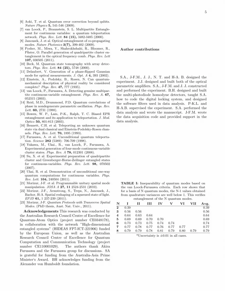
TABLE I: Inseparability of quantum modes based onthe van Loock-Furusawa criteria. Each row shows thatfor a basis of N quantum modes, the N-1 values obtainedfrom quadrature variances are well below 1. This verifies
entanglement of the N quantum modes.
N I II III IV V VI VII Avg.2 0.39 0.393 0.56 0.56 0.564 0.64 0.63 0.64 0.645 0.69 0.69 0.70 0.70 0.696 0.73 0.73 0.75 0.74 0.74 0.747 0.77 0.78 0.77 0.76 0.77 0.77 0.778 0.79 0.79 0.78 0.81 0.79 0.80 0.79 0.79
*Uncertainty is ±0.01 in all cases.

6
Supplementary Material
Virtual Networks
The virtual networks are programmed using matrixbased software on a standard PC. The networks areconcatenations of two important unitary operations:the beam splitter (BS), and the π phase shift. The BSoperation B(r) acting on inputs a1in, a2in, to produceoutputs a1out, a2out, is defined as follows:
(a1outa2out
)=
( √r√t√
t −√r
)(a1ina2in
)(3)
where r and t are the reflectivity and transimissivityof the BS, respectively, with
√t =√r − 1. The π phase
shift is equivalent to multiplying a by −1. Formally, eachspatial mode an for 1 ≤ n ≤ N is defined as
an =
8∑p=1
elnp ip (4)
where ip is the homodyne subtracted photocurrent oper-ator at photodiode p and elnp is the electronic gain appliedat p for the nth mode. For conveniece we define a vectorG containing 8 electronic gains: G =
[el1 el2 · · · el8
]such that each vector Gn =
[eln1 eln2 · · · eln8
]uniquely
projects the photocurrents ip onto the measured modean. The orthogonality between measured modes inany basis is verified by showing that the inner productbetween any two modes ai and aj (i 6= j) is zero.
For even numbered mode bases (N = 2, 4, 6, 8) themethod for creating the virtual network is as follows.The two squeezed modes a1 and a2 are combined ona half reflecting beamsplitter (HBS). As the output ofthis HBS is an EPR state we choose to call this theEBS. The EBS outputs are symmetrically combinedwith N − 2 vacua, as in Figure 1 of the main text. The
BSs are then given by B(cos−11/√
N2 − n), where n
is the number of BSs between the EBS and the BS inquestion. For N=4 and N=6 and N=8, mode output2 is swapped with mode output N-1. For N=8, anadditional swap of output modes 4 and 5 is made. Forodd numbered mode bases (N = 3, 5, 7) the method isthe same with the following modifications. The EBShas its reflectivity changed to r = 1
2 −1
2N . (See forexample references [1, 2] for more details on N = 3).The vacua are mixed using beamsplitters as above, withone output arm having one less vacuum input. π phaseshifts are applied to all BS outputs on the left of theEBS except for the one left output exiting the last BS.Mode outputs 1 and N-1 are swapped, and the networkfor N=7 has an additional swap between output modes3 and 4. The homodyne gains gi are optimised using
a genetic algorithm in order to maximally satisfy thevan Loock-Furusawa inequalities. These gains gi scalethe contributions of the quadrature variances and arenot to be confused with the electronic gains elp usedto adjust the MPHD photocurrents. Here, optimalhomodyne gains are calculated using two measures:minimising the mean of the N − 1 inequalities; andminimising the variance of the set of inequalities. Atrade-off between the two measures is needed, and pref-erence is given to minimising the mean of the inequalities.
Inseparability
Supplementary Figure 1 shows the degree of insepa-rability we would obtain with different input squeezinglevels of the two modes. The other N-2 modes are alwaysvacuaa. Entanglement holds for any moderate squeezinglevels, however the strength of inseparability becomesextremely weak, as we approach N=50.
Materials and methods
We use a dual-wavelength continuous-wave Nd:YAGlaser at 1064 nm and 532 nm. The optical parametricamplifiers (OPA) each contain a periodically poledKTP crystal in a bow-tie cavity. The squeezed beamsare almost identical in purity, with squeezing levelsof approximately -6 dB and anti-squeezing of 8.5 dB.The beam containing the 8 spatially orthogonal modes(see main text) is made highly elliptical in order tobe measured by the MPHD, which has a linear arrayof 8 photodiodes. The photodiode array used is aHamamatsu InGaAs PIN photodiode array (G7150)which actually has 16 photodiodes however we choose touse only 8 of these in the present experiment.
Cluster State Computation
Cluster state computation utilizes the entangled clus-ter state as the resource basis for computation. Being ameasurement based protocol, modifications are neededto increase the degrees of freedom in our detectionscheme. The modifications needed are as follows. First,we need to introduce the ability to measure each modein an arbitrary phase quadrature at the MPHD. Thismay be achieved by manipulating the phases betweenthe copropagating modes. By introducing a unitarymode shaping device such as that explained in references[3, 4], such access to individual phases becomes possible.Second, measurement results of arbitrary cluster nodesrequire feed-forward to remaining cluster nodes. Thismay be implemented by combining a displacement beamcontaining the necessary phase space displacements withthe beam containing the co-propagating mode to bedisplaced. The key point here is that the displacementbeam would necessarily be shaped in order to interfere
7
with only one mode, utilizing the orthogonal nature ofthe spatial modes. Detailed analysis can be found inMorizur’s PhD thesis [5].
[1] Aoki, T. et al. Experimental creation of a fully inseparabletripartite continuous-variable state. Phys. Rev. Lett. 91
(8), 080404-1 (2003).[2] Braunstein, S. L. Quantum error correction for communi-
cation with linear optics. Nature 394, 47 (1998).[3] Morizur, J-F. et al. Programmable unitary spatial mode
manipulation. JOSA A 27, 11 2524-2531 (2010).[4] Morizur, J-F., Armstrong, S., Treps, N., Janousek, J., Ba-
chor, H-A. Spatial reshaping of a squeezed state of light.EPJD 61, 1 237-239 (2011).
[5] Morizur, J-F. Quantum Protocols with Transverse SpatialModes. (PhD thesis, Aust. Nat. Univ., 2011).

8
FIG. 4: Noise variance measurements of the spatial modes. a, x quadrature measurements of the input mode basis.The squeezed 〈[∆x1]2〉 is shown in the red and anti-squeezed 〈[∆x2]2〉 is shown in the blue. The x quadrature variancesof the 6 vacua modes are measured to equal quantum noise (0dB). b, p quadrature measurements. The anti-squeezed〈[∆p1]2〉 is shown in the red and squeezed 〈[∆p2]2〉 is shown in the blue. The p quadrature variances of the 6 modes areagain measured to equal quantum noise, confirming they are vacua. c, These variances show the x quadrature correlationsbetween modes as in the first half of the L.H.S. of equation (2) of the text. Every column shows N-1 traces of x quadraturecorrelations below shot noise, as well as the blue shot noise trace (0dB) normalised to two units of vacua. Each greentrace shows 〈[∆(xN1 − xN2 )]2〉 for each N-mode basis. Each new color represents the other N-1 variance correlation traces ofequation (2). d, Correlations between measured modes in p quadrature, second half of the L.H.S. of equation (2). Eachgreen trace now shows 〈[∆(pN1 +pN2 +g3p
N3 +...+gNp
NN)]2〉. The traces overlapping shows that each pair of modes is entangled
with the same strength as any other pair of modes, a result of optimising for symmetry in the virtual networks. e, Theblue dashed line represents the bound of separability. The red rectangles are the measured experimental values given byadding together the x quadrature correlation terms and the p quadrature correlation terms (L.H.S. of equation 2). The blueline (theory) shows inseparability as a function of the number of modes in the basis, with the same two squeezed inputsused in the experiment. All experimental losses have been taken into account. The red line (theory) predicts the degreeof inseparability given two symmetric squeezed inputs of -10dB each, and again N-2 vacua. Refer to the supplementary
material for how the networks are constructed.

9
FIG. 5: Inseparability for different squeezed inputs. The blue dashed line represents the bound of separability. Alltraces have two squeezed inputs and N-2 vacua modes, as in the experiment. What changes is the amount of squeezing inthe two squeezed inputs, assumed here to be symmetric with equal anti-squeezing. From the top we have: -1dB (magenta);
-3dB (cyan); experimental parameters (blue); experimental values (red rectangles); -6dB (green); and -10dB (red).


