Embed Size (px)
Citation preview
CAEN Power Supplies: a perfect blend of tradition and innovation
The Power Supply Systems are at the heart of any experiment. They provide the High Voltage and Low Voltage required by the detectors and by the related front-end electronics.
• Universal Multichannel Systems• VME-NIM Power Supplies• Standalone Power Supplies • EASY (Embedded Assembly System)• High Power Low Voltage System• Power Supply Control Software
POWER SUPPLIES
CAEN 2016 / 2017 Product Catalog HV_001_15042016
Introduction to High and Low Voltage Power Supplies
High and low voltages are expression difficult to define in an univocal way. In the research community and in the electrical and electrotechnical industry the meaning of high and low voltage may be quite different depending on the considered application. In the United States 2014 National Electrical Code (NEC), high voltage is defined as any voltage over 1000 V (article 490.2), while the International Electrotechnical Commission and its national counterparts (IET, IEEE, VDE, etc.) defines High and Low Voltages as follows:
In the scientific community and in related industrial activities the difference between low and high voltage is almost always related to the specific application. When talking about particle detectors, “high voltage” is used to create an electric field that allows to amplify the signal produced by the particle when interacting with the detector material. Therefore, the same “high voltage” expression might mean the 6 kV needed to power a Germanium detector, the 3 kV for a photomultiplier as well as the few hundred volts for providing the reverse bias to a silicon detector. In a similar way, “low voltage” is used to power the analog and digital electronics integrated in the detectors or for other similar applications. A power supply is an electronic device that supplies electric energy to an electrical load. The primary function of a power supply is to convert one form of electrical energy to another and, as a result, power supplies are sometimes referred to as electric power converters. Power supplies are categorized in various ways, including by functional features, are packaged in different ways and classified accordingly and can be broadly divided into linear and switching types.All CAEN power supplies are the results of 35 years of experience
side by side with the research community. All of them features:• Modularity• High reliability• Mechanic solidness• High performance• Hardware and software protection against failures like over
currents, over/under voltage, shorts• Remote and local control• Dedicated control software
Introduction to Power Supplies working principles A voltage regulator is an electrical component designed to automatically maintain a constant voltage level. It can be made by a simple “feed-forward” design or may include negative feedback control loops. It may use an electromechanical mechanism, or electronic components. Depending on the design, it may be used to regulate one or more AC or DC voltages. A simple voltage regulator can be made from a resistor in series with a diode (or series of diodes). Due to the logarithmic shape of diode V-I curves, the voltage across the diode changes only slightly due to changes in current drawn or changes in the input. When precise voltage control and efficiency are not important, this design may work fine. Feedback voltage regulators operate by comparing the actual output voltage to some fixed reference voltage. Any difference is amplified and used to control the regulation element in such a way as to reduce the voltage error. This forms a negative feedback control loop; increasing the open-loop gain tends to increase regulation accuracy but reduce the stability. There will also be a trade-off between stability and the speed of the response to changes. If the output voltage is too low, the regulation element acts in order to produce a higher output voltage–by dropping less of the input voltage (for linear series regulators and buck switching regulators), or to draw input current for longer periods (boost-type switching regulators); if the output voltage is too high, the regulation element will normally be commanded to produce a lower voltage. However, many regulators have over-current protection, so
AC DCHigh Voltage (HV) > 1000 V > 1500 VLow Voltage (LV) 50 – 1000 V 120 – 1500 VExtra Low Voltage (ELV) < 50 V < 120 VSafety ELV (SELV) 25 V 60 V
2 Power Supplies
Introduction to High and Low Voltage Power Supplies
that they will entirely stop sourcing current (or limit the current in some way) if the output current is too high. Some regulators may also shut down if the input voltage is outside a given range. “Voltage regulator” Wikipedia: The Free Encyclopedia. Wikimedia Foundation, Inc. 22 July 2004. Web. 10 Aug. 2004.
Linear Power SuppliesIn electronics, a linear regulator is a system used to maintain a steady voltage. The resistance of the regulator varies in accordance with the load resulting in a constant output voltage. The regulating device is made to act like a variable resistor, continuously adjusting a voltage divider network to maintain a constant output voltage, and continually dissipating the difference between the input and regulated voltages as waste heat. Since the regulated voltage of a linear regulator must always be lower than input voltage, efficiency is limited and the input voltage must be high enough to always allow the active device to drop some voltage. Linear regulators may place the regulating device in parallel with the load (shunt regulator) or may place the regulating device between the source and the regulated load (a series regulator). Simple linear regulators may only contain a Zener diode and a series resistor; more complicated regulators include separate stages of voltage reference, error amplifier and power pass element.“Linear regulator” Wikipedia: The Free Encyclopedia. Wikimedia Foundation, Inc. 22 July 2004. Web. 10 Aug. 2004.
Switching Power Supplies A switched-mode power supply is an electronic power supply that incorporates a switching regulator to convert electrical power efficiently. Like other power supplies, it transfers power from a source to a load, while converting voltage and current characteristics. Unlike a linear power supply, the pass transistor of a switching-mode supply continually switches between low-dissipation, full-on and full-off states, and spends very little time in the high dissipation transitions, which minimizes wasted energy. Ideally, a switched-mode power supply dissipates no power. Voltage regulation is achieved by varying the ratio of on-to-off time. This
higher power conversion efficiency is an important advantage of a switched-mode power supply. Moreover they also may be substantially smaller and lighter than a linear supply due to the smaller transformer size and weight. Switching regulators are used as replacements for linear regulators when higher efficiency, smaller size or lighter weight are required. They are, however, more complicated; their switching currents can cause electrical noise problems if not carefully suppressed, and simple designs may have a poor power factor. “Switched-mode power supply” Wikipedia: The Free Encyclopedia. Wikimedia Foundation, Inc. 22 July 2004. Web. 10 Aug. 2004.
Linear and Switching Power Supplies: a comparisonIts not trivial to choose the proper power supply for a specific application. In many cases the final decision is a compromise between the advantages and the drawbacks of the two technologies. In the following, we perform a quick comparison between Linear and Switching power supplies:• Size and Weight
- Linear Power Supplies: Heatsinks for high power linear regulators and large transformers due to low operating frequency are large and add size and weight
- Switching Power Supplies: Smaller transformer due to higher operating frequency. Size and weight of adequate RF shielding may be significant.
- Linear Power Supplies: any voltage available, if a transformer is used; if transformerless, limited to what can be achieved with a voltage doubler. If unregulated, voltage varies significantly with load.
- Switching Power Supplies: any voltage available, limited only by transistor breakdown voltages in many circuits. Voltage varies little with load.
• Efficiency, heat and power dissipation:- Linear Power Supplies: if regulated, the efficiency largely
depends on voltage difference between input and output; output voltage is regulated by dissipating excess power as heat resulting in a typical efficiency of 30-40%. If unregulated, transformer iron and copper losses may be the only significant sources of inefficiency.
3Power Supplies
- Switching Power Supplies: output is regulated using duty cycle control; the transistors are switched fully on or fully off, so very little resistive losses between input and the load. The only heat generated is in the non-ideal aspects of the components and quiescent current in the control circuitry.
• Radio frequency Interference- Linear Power Supplies: mild high-frequency interference may be
generated by AC rectifier diodes under heavy current loading, while most other supply types produce no high-frequency interference.
- Switching Power Supplies: EMI/RFI produced due to the current being switched on and off sharply. Therefore, EMI filters and RF shielding are needed to reduce the disruptive interference.
- Linear Power Supplies: Unregulated power supplies may have a little AC ripple superimposed upon the DC component at twice mains frequency (100–120 Hz).
- Switching Power Supplies: Noisier due to the switching frequency. An unfiltered output may cause glitches in digital circuits or noise in analog circuits.
• Noise at the input terminals- Linear Power Supplies: causes harmonic distortion to the input
AC, but relatively little or no high frequency noise.- Switching Power Supplies: very low cost power supplies may
couple electrical switching noise back onto the mains power line, causing interference with any electronic equipment connected to the same phase. Non power-factor-corrected SMPSs also cause harmonic distortion.
• Power Factor- Linear Power Supplies: Low for a regulated supply because cur-
rent is drawn from the mains at the peaks of the voltage sinusoid, unless a choke-input or resistor-input circuit follows the rectifier.
- Switching Power Supplies: ranging from very low to medium since a simple SMPS without PFC draws current spikes at the peaks of the AC sinusoid.
“Switched-mode power supply” Wikipedia: The Free Encyclopedia. Wikimedia Foundation, Inc. 22 July 2004. Web. 10 Aug. 2004.
Providing power over Long Distances: the Voltage Drop IssueVoltage drop describes how the supplied energy of a voltage source is reduced as electric current moves through the passive elements of an electrical circuit. Voltage drops across internal resistances of the source, across conductors, across contacts, and across connectors are undesired because supplied energy is dissipated and lost. If the voltage drop is too high the operation of the electrical equipment involved could be compromised. In electronic design and power transmission, various techniques are employed to compensate for the effect of voltage drop on long circuits or where voltage levels must be accurately maintained. The simplest way to reduce voltage drop is to increase the diameter of the conductor between the source and the load, which lowers the overall resistance but with the but the drawbacks of higher costs and larger cable capacitance. In power distribution systems, a given amount of power can be transmitted with less voltage drop if a higher voltage is used. More sophisticated techniques use active elements to compensate for the undesired voltage drop. In many cases the use of long cables cannot be avoided in particular when the power supplies have to be installed away from hostile environments or the space constraints become critical. In these conditions then main challenge is providing a stable low voltage levels at the load (as low as 1.5 - 2 V) over long distances, even hundred of meters without increasing the cable sections too much because the voltage drop along the cables could be considerably higher than the voltage required by the load. Many parameters have to be taken into account when estimating if a setup is suitable in terms of stability and performances for the particular application. Among them the distance to cover, the cable capacitance and resistance, the voltage regulation time, voltage and current levels to be kept and so on. CAEN has a deep experience in successfully providing long distance power supply and features its low voltage units with reliable solutions based on sense wires which allows a full compensation of the voltage drops along tens of meters cables. Some CAEN power supplies features the so called “Line Drop Recovery” (LDR) technology which allows through a digital control to avoid the use of the sense wires. “Switched-mode power supply” Wikipedia: The Free Encyclopedia. Wikimedia Foundation, Inc. 22 July 2004. Web. 10 Aug. 2004.
Introduction to High and Low Voltage Power Supplies
4 Power Supplies
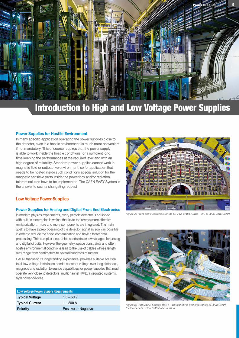
Power Supplies for Hostile EnvironmentIn many specific application operating the power supplies close to the detector, even in a hostile environment, is much more convenient if not mandatory. This of course requires that the power supply is able to work inside the hostile conditions for a sufficient long time keeping the performances at the required level and with an high degree of reliability. Standard power supplies cannot work in magnetic field or radioactive environment, so for application that needs to be hosted inside such conditions special solution for the magnetic sensitive parts inside the power box and/or radiation tolerant solution have to be implemented. The CAEN EASY System is the answer to such a changeling request
Low Voltage Power Supplies
Power Supplies for Analog and Digital Front End ElectronicsIn modern physics experiments, every particle detector is equipped with built-in electronics in which, thanks to the always more effective miniaturization, more and more components are integrated. The main goal is to have a preprocessing of the detector signal as soon as possible in order to reduce the noise contamination and have a faster data processing. This complex electronics needs stable low voltages for analog and digital circuits. However the geometry, space constraints and often hostile environmental conditions lead to the use of cables whose length may range from centimeters to several hundreds of meters. CAEN, thanks to its longstanding experience, provides suitable solution to all low voltage installation needs: constant voltage over long distances, magnetic and radiation tolerance capabilities for power supplies that must operate very close to detectors, multichannel HV/LV integrated systems, high power devices.
Low Voltage Power Supply RequirementsTypical Voltage 1.5 – 60 VTypical Current 1 – 200 APolarity Positive or Negative
Introduction to High and Low Voltage Power Supplies
Figure A: Front end electronics for the MRPCs of the ALICE TOF. © 2006-2016 CERN
Figure B: CMS ECAL Endcap DEE 4 - Optical fibres and electronics © 2008 CERN, for the benefit of the CMS Collaboration
5Power Supplies
Power Supplies for Particle Detectors
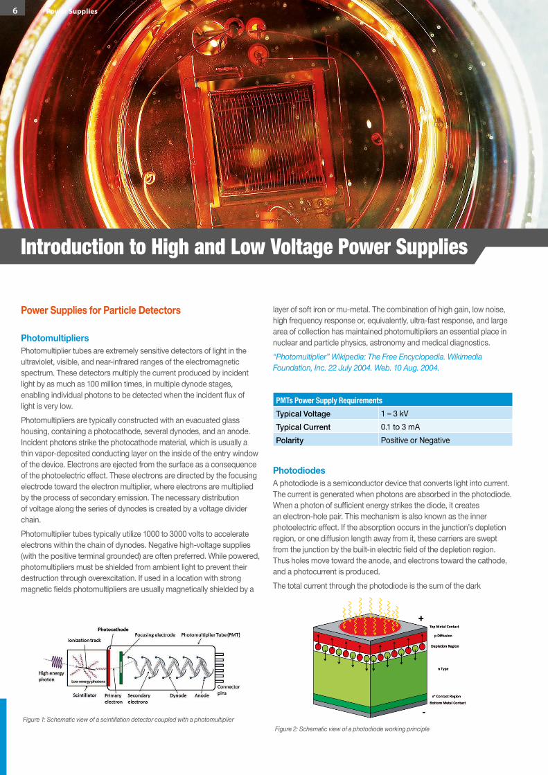
PhotomultipliersPhotomultiplier tubes are extremely sensitive detectors of light in the ultraviolet, visible, and near-infrared ranges of the electromagnetic spectrum. These detectors multiply the current produced by incident light by as much as 100 million times, in multiple dynode stages, enabling individual photons to be detected when the incident flux of light is very low. Photomultipliers are typically constructed with an evacuated glass housing, containing a photocathode, several dynodes, and an anode. Incident photons strike the photocathode material, which is usually a thin vapor-deposited conducting layer on the inside of the entry window of the device. Electrons are ejected from the surface as a consequence of the photoelectric effect. These electrons are directed by the focusing electrode toward the electron multiplier, where electrons are multiplied by the process of secondary emission. The necessary distribution of voltage along the series of dynodes is created by a voltage divider chain. Photomultiplier tubes typically utilize 1000 to 3000 volts to accelerate electrons within the chain of dynodes. Negative high-voltage supplies (with the positive terminal grounded) are often preferred. While powered, photomultipliers must be shielded from ambient light to prevent their destruction through overexcitation. If used in a location with strong magnetic fields photomultipliers are usually magnetically shielded by a
layer of soft iron or mu-metal. The combination of high gain, low noise, high frequency response or, equivalently, ultra-fast response, and large area of collection has maintained photomultipliers an essential place in nuclear and particle physics, astronomy and medical diagnostics.“Photomultiplier” Wikipedia: The Free Encyclopedia. Wikimedia Foundation, Inc. 22 July 2004. Web. 10 Aug. 2004.
PhotodiodesA photodiode is a semiconductor device that converts light into current. The current is generated when photons are absorbed in the photodiode. When a photon of sufficient energy strikes the diode, it creates an electron-hole pair. This mechanism is also known as the inner photoelectric effect. If the absorption occurs in the junction’s depletion region, or one diffusion length away from it, these carriers are swept from the junction by the built-in electric field of the depletion region. Thus holes move toward the anode, and electrons toward the cathode, and a photocurrent is produced. The total current through the photodiode is the sum of the dark
Figure 2: Schematic view of a photodiode working principle
PMTs Power Supply RequirementsTypical Voltage 1 – 3 kVTypical Current 0.1 to 3 mAPolarity Positive or Negative
Figure 1: Schematic view of a scintillation detector coupled with a photomultiplier
Introduction to High and Low Voltage Power Supplies
6 Power Supplies
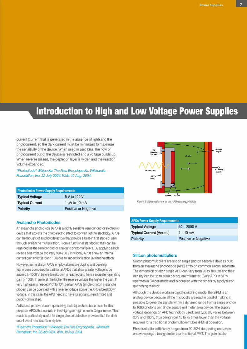
current (current that is generated in the absence of light) and the photocurrent, so the dark current must be minimized to maximize the sensitivity of the device. When used in zero bias, the flow of photocurrent out of the device is restricted and a voltage builds up. When reverse biased, the depletion layer is widen and the reaction volume expanded.“Photodiode” Wikipedia: The Free Encyclopedia. Wikimedia Foundation, Inc. 22 July 2004. Web. 10 Aug. 2004.
Avalanche PhotodiodesAn avalanche photodiode (APD) is a highly sensitive semiconductor electronic device that exploits the photoelectric effect to convert light to electricity. APDs can be thought of as photodetectors that provide a built-in first stage of gain through avalanche multiplication. From a functional standpoint, they can be regarded as the semiconductor analog to photomultipliers. By applying a high reverse bias voltage (typically 100-200 V in silicon), APDs show an internal current gain effect (around 100) due to impact ionization (avalanche effect). However, some silicon APDs employ alternative doping and beveling techniques compared to traditional APDs that allow greater voltage to be applied (> 1500 V) before breakdown is reached and hence a greater operating gain (> 1000). In general, the higher the reverse voltage the higher the gain. If very high gain is needed (105 to 106), certain APDs (single-photon avalanche diodes) can be operated with a reverse voltage above the APD’s breakdown voltage. In this case, the APD needs to have its signal current limited and quickly diminished. Active and passive current quenching techniques have been used for this purpose. APDs that operate in this high-gain regime are in Geiger mode. This mode is particularly useful for single photon detection provided that the dark count event rate is sufficiently low.“Avalanche Photodiode” Wikipedia: The Free Encyclopedia. Wikimedia Foundation, Inc. 22 July 2004. Web. 10 Aug. 2004.
Silicon photomultipliersSilicon photomultipliers are silicon single photon sensitive devices built from an avalanche photodiode (APD) array on common silicon substrate. The dimension of each single APD can vary from 20 to 100 µm and their density can be up to 1000 per square millimeter. Every APD in SiPM operates in Geiger-mode and is coupled with the others by a polysilicon quenching resistor. Although the device works in digital/switching mode, the SiPM is an analog device because all the microcells are read in parallel making it possible to generate signals within a dynamic range from a single photon to 1000 photons per single square millimeter area device. The supply voltage depends on APD technology used, and typically varies between 20 V and 100 V, thus being from 15 to 75 times lower than the voltage required for a traditional photomultiplier tubes (PMTs) operation.Photo detection efficiency ranges from 20-50% depending on device and wavelength, being similar to a traditional PMT. The gain is also
Photodiodes Power Supply RequirementsTypical Voltage 5 V to 100 VTypical Current 1 µA to 10 mAPolarity Positive or Negative
APDs Power Supply RequirementsTypical Voltage 50 – 2000 VTypical Current (Anode) 1 – 10 mAPolarity Positive or Negative
Figure 3: Schematic view of the APD working principle
Introduction to High and Low Voltage Power Supplies
7Power Supplies
similar to a PMT being approximately 106 while the G/V dependence is linear and does not follow a power law like in the case of PMTs. The signal parameters are practically independent of external magnetic fields and the small dimensions permits extremely compact, light and robust mechanical design.“Silicon Photomultiplier” Wikipedia: The Free Encyclopedia. Wikimedia Foundation, Inc. 22 July 2004. Web. 10 Aug. 2004.
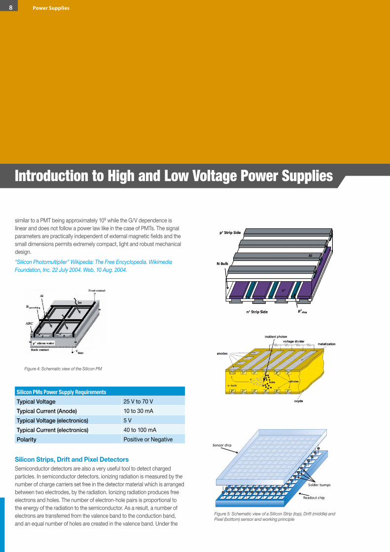
Silicon Strips, Drift and Pixel DetectorsSemiconductor detectors are also a very useful tool to detect charged particles. In semiconductor detectors, ionizing radiation is measured by the number of charge carriers set free in the detector material which is arranged between two electrodes, by the radiation. Ionizing radiation produces free electrons and holes. The number of electron-hole pairs is proportional to the energy of the radiation to the semiconductor. As a result, a number of electrons are transferred from the valence band to the conduction band, and an equal number of holes are created in the valence band. Under the
Figure 5: Schematic view of a Silicon Strip (top), Drift (middle) and Pixel (bottom) sensor and working principle
Silicon PMs Power Supply RequirementsTypical Voltage 25 V to 70 VTypical Current (Anode) 10 to 30 mATypical Voltage (electronics) 5 VTypical Current (electronics) 40 to 100 mAPolarity Positive or Negative
Figure 4: Schematic view of the Silicon PM
Introduction to High and Low Voltage Power Supplies
8 Power Supplies
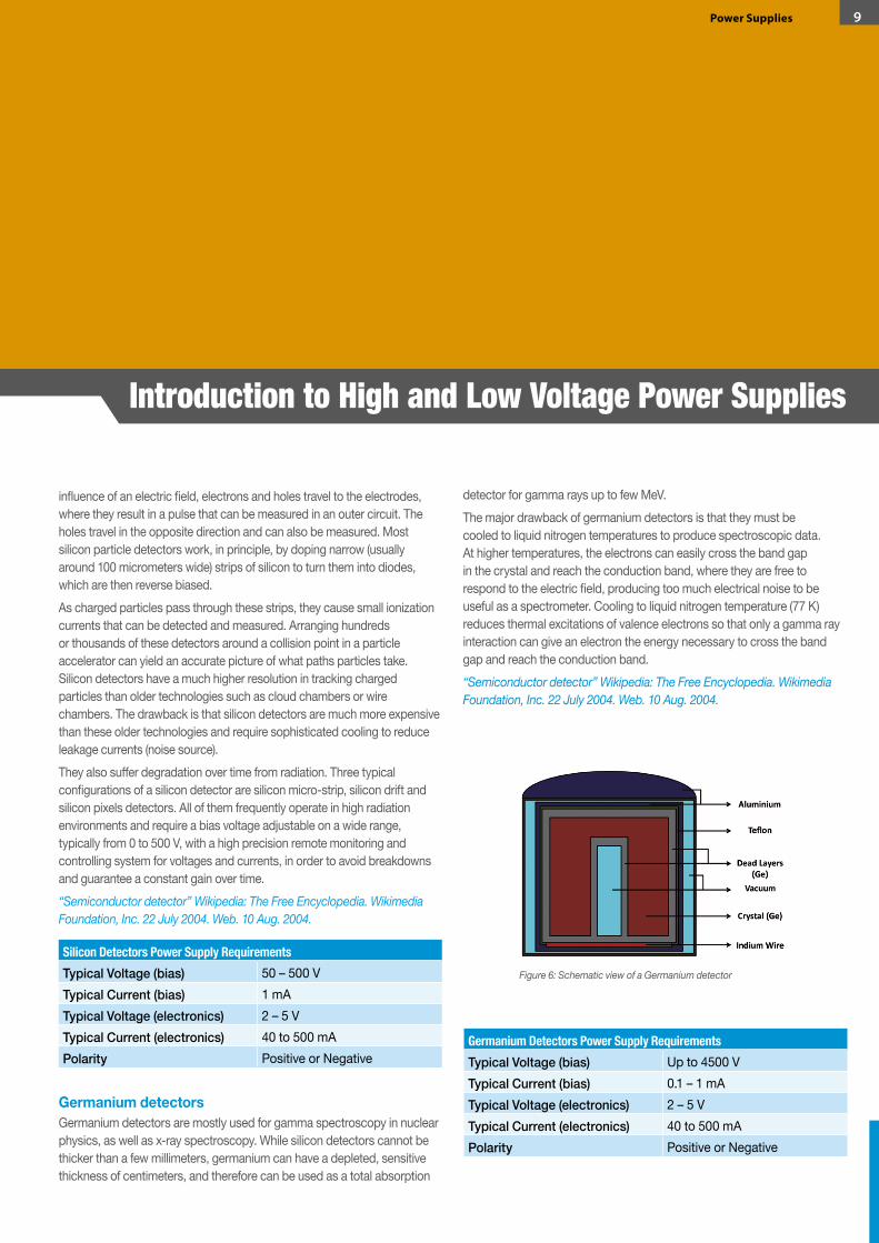
Germanium Detectors Power Supply RequirementsTypical Voltage (bias) Up to 4500 VTypical Current (bias) 0.1 – 1 mATypical Voltage (electronics) 2 – 5 VTypical Current (electronics) 40 to 500 mAPolarity Positive or Negative
Figure 6: Schematic view of a Germanium detector
Silicon Detectors Power Supply RequirementsTypical Voltage (bias) 50 – 500 VTypical Current (bias) 1 mATypical Voltage (electronics) 2 – 5 VTypical Current (electronics) 40 to 500 mAPolarity Positive or Negative
influence of an electric field, electrons and holes travel to the electrodes, where they result in a pulse that can be measured in an outer circuit. The holes travel in the opposite direction and can also be measured. Most silicon particle detectors work, in principle, by doping narrow (usually around 100 micrometers wide) strips of silicon to turn them into diodes, which are then reverse biased. As charged particles pass through these strips, they cause small ionization currents that can be detected and measured. Arranging hundreds or thousands of these detectors around a collision point in a particle accelerator can yield an accurate picture of what paths particles take. Silicon detectors have a much higher resolution in tracking charged particles than older technologies such as cloud chambers or wire chambers. The drawback is that silicon detectors are much more expensive than these older technologies and require sophisticated cooling to reduce leakage currents (noise source). They also suffer degradation over time from radiation. Three typical configurations of a silicon detector are silicon micro-strip, silicon drift and silicon pixels detectors. All of them frequently operate in high radiation environments and require a bias voltage adjustable on a wide range, typically from 0 to 500 V, with a high precision remote monitoring and controlling system for voltages and currents, in order to avoid breakdowns and guarantee a constant gain over time. “Semiconductor detector” Wikipedia: The Free Encyclopedia. Wikimedia Foundation, Inc. 22 July 2004. Web. 10 Aug. 2004.
Germanium detectorsGermanium detectors are mostly used for gamma spectroscopy in nuclear physics, as well as x-ray spectroscopy. While silicon detectors cannot be thicker than a few millimeters, germanium can have a depleted, sensitive thickness of centimeters, and therefore can be used as a total absorption
detector for gamma rays up to few MeV. The major drawback of germanium detectors is that they must be cooled to liquid nitrogen temperatures to produce spectroscopic data. At higher temperatures, the electrons can easily cross the band gap in the crystal and reach the conduction band, where they are free to respond to the electric field, producing too much electrical noise to be useful as a spectrometer. Cooling to liquid nitrogen temperature (77 K) reduces thermal excitations of valence electrons so that only a gamma ray interaction can give an electron the energy necessary to cross the band gap and reach the conduction band.“Semiconductor detector” Wikipedia: The Free Encyclopedia. Wikimedia Foundation, Inc. 22 July 2004. Web. 10 Aug. 2004.
Introduction to High and Low Voltage Power Supplies
9Power Supplies

Wire ChambersThe Wire Chambers are particle detectors belonging to the family of gaseous detectors. It is composed by a wire or an array of wires kept at high voltage (anode), which run through a chamber with conductive walls held at ground potential (cathode). Alternatively, the wires may be at ground potential and the cathode held at a high negative voltage; the key point is that a uniform electric field draws extra electrons or negative ions to the anode wires with little lateral motion. The chamber is filled with carefully chosen gas, such as an argon/methane mix, such that any ionizing particle that passes through the tube will ionize surrounding gaseous atoms. The resulting ions and electrons are accelerated by the electric field across the chamber, causing a localised cascade of ionization known as a Townsend avalanche. This allows to count the crossing particles and if chamber is used in the proportional regime to evaluate the particle energy loss. In case of a multi wire proportional chamber by computing pulses from all the wires, the particle trajectory can be found and together with the information about the energy loss, the particle identification can be performed. If one also precisely measures the timing of the current pulses of the wires and takes into account that the ions need some time to drift to the nearest wire, one can infer the distance at which the particle passed the wire. This greatly increases the accuracy of the path reconstruction and is known as a drift chamber. If two drift chambers are used with the wires of one orthogonal to the wires of the other, both orthogonal to the beam direction, a more precise detection of the position is obtained. If an additional simple detector (like the one used in a veto counter) is used
to detect, with poor or null positional resolution, the particle at a fixed distance before or after the wires, a tridimensional reconstruction can be made and the speed of the particle deducted from the difference in time of the passage of the particle in the different part of the detector. This setup gives up the detector called Time Projection Chamber (often written just TPC).“MultiWire Proportional Chamber” Wikipedia: The Free Encyclopedia. Wikimedia Foundation, Inc. 22 July 2004. Web. 10 Aug. 2004.
MicroMegas detectorsThe “Micromegas “ (Micro-MEsh GAseous Structure) detector is a gaseous particle detector coming from the development of wire chamber. The Micromegas works by amplifying the charges that have been created by ionization in the gas volume, divided in two parts by a metallic micro-mesh placed between 25 μm and 150 μm from the readout electrode. The micro-
Figure 8: Schematic view of a MicroMegas working principle
Wire Chambers Power Supply RequirementsTypical Voltage 0.5 – 10 kVTypical Current less than 1 mAPolarity Positive (common) or Negative
Figure 7: Schematic view of a Wire Chamber working principle
Introduction to High and Low Voltage Power Supplies
10 Power Supplies
mesh is the key element since it allows, at the same time a high gain of 104 with a fast signal of about 100 ns and a spatial resolution of about 100 µm.“MicroMegas detector” Wikipedia: The Free Encyclopedia. Wikimedia Foundation, Inc. 22 July 2004. Web. 10 Aug. 2004.
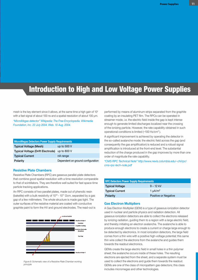
Resistive Plate ChambersResistive Plate Chambers (RPC) are gaseous parallel-plate detectors that combine good spatial resolution with a time resolution comparable to that of scintillators. They are therefore well suited for fast space-time particle tracking applications. An RPC consists of two parallel plates, made out of phenolic resin (bakelite) with a bulk resistivity of 1010 - 1011 Ωcm, separated by a gas gap of a few millimeters. The whole structure is made gas tight. The outer surfaces of the resistive material are coated with conductive graphite paint to form the HV and ground electrodes. The read-out is
performed by means of aluminum strips separated from the graphite coating by an insulating PET film. The RPCs can be operated in streamer mode, i.e. the electric field inside the gap is kept intense enough to generate limited discharges localized near the crossing of the ionizing particle. However, the rate capability obtained in such operational conditions is limited (~100 Hz/cm2 ).A significant improvement is achieved by operating the detector in the so-called avalanche mode; the electric field across the gap (and consequently the gas amplification) is reduced and a robust signal amplification is introduced at the front-end level. The substantial reduction of the charge produced in the gap improves by more than one order of magnitude the rate capability.“CMS RPC Technical Note” http://www.nevis.columbia.edu/~chi/rpc/cms-rpc-tech-note.pdf
Gas Electron MultipliersA Gas Electron Multiplier (GEM) is a type of gaseous ionization detector used in nuclear and particle physics and radiation detection. All gaseous ionization detectors are able to collect the electrons released by ionizing radiation, guiding them to a region with a large electric field, and thereby initiating an electron avalanche. The avalanche is able to produce enough electrons to create a current or charge large enough to be detected by electronics. In most ionization detectors, the large field comes from a thin wire with a positive high-voltage potential; this same thin wire collect the electrons from the avalanche and guides them towards the readout electronics. GEMs create the large electric field in small holes in a thin polymer sheet; the avalanche occurs inside of these holes. The resulting electrons are ejected from the sheet, and a separate system must be used to collect the electrons and guide them towards the readout. GEMs are one of the class of micropattern gas detectors; this class includes micromegas and other technologies.
RPC Detectors Power Supply RequirementsTypical Voltage 9 – 12 kVTypical Current 1 µA/m2
Polarity Positive or Negative
Figure 9: Schematic view of a Resistive Plate Chamber working principle
MicroMegas Detectors Power Supply RequirementsTypical Voltage (Mesh) up to 500 VTypical Voltage (Drift Electrode) up to 800 VTypical Current nA rangePolarity Dependent on ground configuration
Introduction to High and Low Voltage Power Supplies
11Power Supplies
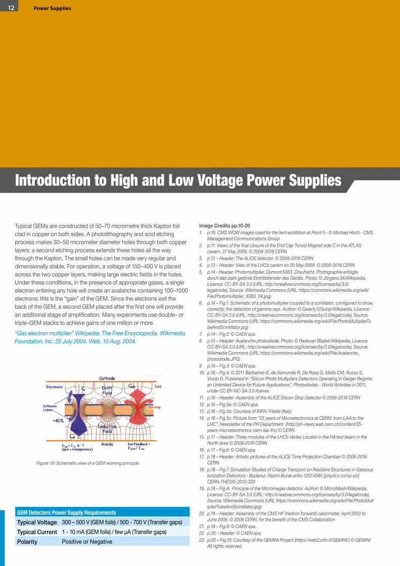
Typical GEMs are constructed of 50–70 micrometre thick Kapton foil clad in copper on both sides. A photolithography and acid etching process makes 30–50 micrometer diameter holes through both copper layers; a second etching process extends these holes all the way through the Kapton. The small holes can be made very regular and dimensionally stable. For operation, a voltage of 150–400 V is placed across the two copper layers, making large electric fields in the holes. Under these conditions, in the presence of appropriate gases, a single electron entering any hole will create an avalanche containing 100–1000 electrons; this is the “gain” of the GEM. Since the electrons exit the back of the GEM, a second GEM placed after the first one will provide an additional stage of amplification. Many experiments use double- or triple-GEM stacks to achieve gains of one million or more.“Gas electron multiplier” Wikipedia: The Free Encyclopedia. Wikimedia Foundation, Inc. 22 July 2004. Web. 10 Aug. 2004.
Image Credits pp.10-201. p.10: CMS WOW images used for the tent exhibition at Point 5 - © Michael Hoch - CMS
Management:Communications Group2. p.11:ViewsofthefinalclosureoftheEndCapToroidMagnetsideCintheATLAS
cavern, 27 May 2009. © 2009-2016 CERN3. p.12 – Header: The ALICE detector. © 2009-2016 CERN4. p.13 – Header: View of the LHCb cavern on 20 May 2009. © 2009-2016 CERN5. p.14 - Header: Photomultiplier, Dumont 6363. Draufsicht. Photographie erfolgte
durch das stark getönte Eintrittsfenster des Geräts. Photo: © Jörgens.Mi/Wikipedia, Licence: CC-BY-SA 3.0 (URL: http://creativecommons.org/licenses/by/3.0/legalcode), Source: Wikimedia Commons (URL: https://commons.wikimedia.org/wiki/File:Photomultiplier_6363_04.jpg)
6. p.14–Fig.1:Schematicofaphotomultipliercoupledtoascintillator,configuredtoshow,correctly, the detection of gamma rays. Author: © Qwerty123uiop/Wikipedia, Licence: CC-BY-SA 3.0 (URL: http://creativecommons.org/licenses/by/3.0/legalcode), Source: Wikimedia Commons (URL https://commons.wikimedia.org/wiki/File:PhotoMultiplierTubeAndScintillator.jpg)
7. p.14 – Fig.2: © CAEN spa.8. p.15–Header:Avalanchephotodiode.Photo:©RadovanBlažek/Wikipedia,Licence:
CC-BY-SA 3.0 (URL: http://creativecommons.org/licenses/by/3.0/legalcode), Source: Wikimedia Commons (URL https://commons.wikimedia.org/wiki/File:Avalanche_photodiode.JPG)
9. p.15 – Fig.3: © CAEN spa.10. p.16 – Fig.4: © 2011 Barbarino G, de Asmundis R, De Rosa G, Mollo CM, Russo S,
Vivolo D. Published in “Silicon Photo Multipliers Detectors Operating in Geiger Regime: an Unlimited Device for Future Applications”, Photodiodes - World Activities in 2011, under CC BY-NC-SA 3.0 license.
11. p.16 – Header: Assembly of the ALICE Silicon Strip Detector © 2006-2016 CERN12. p.16 – Fig.5a: © CAEN spa.13. p.16 – Fig.5b: Courtesy of INFN-Trieste (Italy).14. p.16 – Fig.5c: Picture from “25 years of Microelectronics at CERN: from LAA to the
LHC”, Newsletter of the PH Department. (http://ph-news.web.cern.ch/content/25-years-microelectronics-cern-laa-lhc) © CERN
15. p.17 – Header: Three modules of the LHCb Vertex Locator in the H8 test beam in the North Area © 2008-2016 CERN
16. p.17 – Fig.6: © CAEN spa.17. p.18 – Header: Artistic pictures of the ALICE Time Projection Chamber © 2006-2016
CERN18. p.18 – Fig.7: Simulation Studies of Charge Transport on Resistive Structures in Gaseous
Ionization Detectors - Budanur, Nazmi Burak arXiv:1207.4585 [physics.comp-ph] CERN-THESIS-2012-330
19. p.18 – Fig.8: Principle of the Micromegas detector. Author: © MicroMesh/Wikipedia, Licence: CC-BY-SA 3.0 (URL: http://creativecommons.org/licenses/by/3.0/legalcode), Source: Wikimedia Commons (URL https://commons.wikimedia.org/wiki/File:PhotoMultiplierTubeAndScintillator.jpg)
20. p.19 – Header: Assembly of the CMS HF (hadron forward) calorimeter, April 2003 to June2005.©2008CERN,forthebenefitoftheCMSCollaboration
21. p.19 – Fig.9: © CAEN spa.22. p.20 – Header: © CAEN spa.23. p.20 – Fig.10: Courtesy of the GEMINI Project (https://web2.infn.it/GEMINI/) © GEMINI
All rights reserved
GEM Detectors Power Supply RequirementsTypical Voltage 300 – 500 V (GEM foils) / 500 - 700 V (Transfer gaps)Typical Current 1 - 10 mA (GEM foils) / few µA (Transfer gaps)Polarity Positive or Negative
Figure 10: Schematic view of a GEM working principle
Introduction to High and Low Voltage Power Supplies
12 Power Supplies

We believe that a perfect blend of tradition and innovation is the footprint of our DNA. In terms of tradition, CAEN power supplies have born and grown in the years side by side with research institutions, being part of their activities since the very beginning. Thanks to our synergies with researchers and our internal expertise, our power supplies have become a de-facto standard in most Physics laboratories all around the world. Moreover, we have been the first to introduce the concept of high density multichannel power supplies, which are mandatory for large arrays of detectors.As for innovation, we have continuously introduced new features in our power supplies which have set further standards of operations.During LHC setup phase, we have been the first to design power supplies able to withstand the harsh conditions of experimental halls such as radiation and magnetic field. Our latest designs include sophisticated touch-screen control, Wi-Fi connections and single dashboard control software, in line with the most advanced consumer electronics. The demonstration of this successful long-standing blend of tradition and innovation is the “CMS Crystal Award 2009” that CAEN received for the development and production of the supply system for the CMS tracker. CAEN offers a wide selection of power supplies in different form factors and standards.For smaller set ups NIM and VME modular products as well as Desktop and Rack power supplies are the ideal fit. For larger setups, where a high number of High Voltages and Low Voltages is required, the Universal Multichannel Systems and boards (up to 48 channels/board) are the most recommended.
Universal Multichannel SystemsUniversal Multichannel Power Supply Systems are entirely developed by CAEN based on mainframes housing dedicated boards and they show features which can be useful in the most challenging environments. Typically, when there is the need of high density of channels (up to 768 channels per mainframe) and mixing high voltage and low voltage power supply boards in the same crate, the CAEN systems are the best choice to keep your power supply system compact. Another critical factor that brings the attention to this solution is the advanced control that can be established between the user and the system. It’s based on a OPC Server/EPICS software which can be easily integrated in the user’s Supervisory Control And Data Acquisition (SCADA) and
Detector Control System (DCS), allowing the setting and monitoring of all the parameters of interest on the mainframe through Ethernet connection. When all or some of these requests are met, then the Universal Power Supply System is a cost effective solution. Modularity, flexibility and reliability are the key-points of its design, enabling this module to meet the requirements needed in a wide range of experimental conditions, which range from those of LHC experiments, where the features of this model find prior application, to those of other less challenging, but still demanding, High Energy Physics experiments.
NIM High Voltage Power SuppliesThe NIM (Nuclear Instrumentation Module) standard was first defined by the U.S. Atomic Energy Commission in 1968-1969. The idea was to realize a flexible and simple system based on interchangeable modular electronics for experimental Particle and Nuclear Physics. The goal was completely accomplished, since still nowadays NIM Modules are in widespread use all around the world in experimental physics, either big projects or small laboratories. NIM High Voltage Power Supplies are the best choice for small experiments in which a really low noise feature is expected. CAEN offer a new generation of NIM Power Supplies that can operate in daisy-chain network and can be locally or remotely controlled through a dedicated software. In this way it’s possible to control up to 128 Channels and make of this setup a complete system.The NIM Line includes also the NDT Power Supplies, which are hosted in a NIM module and can be plugged in NIM crates for power but have also the chance of desktop operation thanks to a mains power supply cord.
Introduction to High and Low Voltage Power Supplies
13Power Supplies
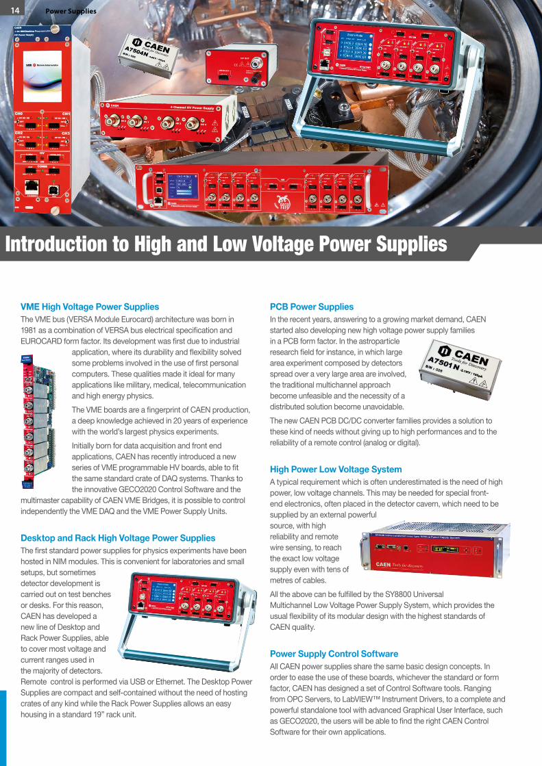
VME High Voltage Power SuppliesThe VME bus (VERSA Module Eurocard) architecture was born in 1981 as a combination of VERSA bus electrical specification and EUROCARD form factor. Its development was first due to industrial
application, where its durability and flexibility solved some problems involved in the use of first personal computers. These qualities made it ideal for many applications like military, medical, telecommunication and high energy physics.The VME boards are a fingerprint of CAEN production, a deep knowledge achieved in 20 years of experience with the world’s largest physics experiments.Initially born for data acquisition and front end applications, CAEN has recently introduced a new series of VME programmable HV boards, able to fit the same standard crate of DAQ systems. Thanks to the innovative GECO2020 Control Software and the
multimaster capability of CAEN VME Bridges, it is possible to control independently the VME DAQ and the VME Power Supply Units.
Desktop and Rack High Voltage Power SuppliesThe first standard power supplies for physics experiments have been hosted in NIM modules. This is convenient for laboratories and small setups, but sometimes detector development is carried out on test benches or desks. For this reason, CAEN has developed a new line of Desktop and Rack Power Supplies, able to cover most voltage and current ranges used in the majority of detectors. Remote control is performed via USB or Ethernet. The Desktop Power Supplies are compact and self-contained without the need of hosting crates of any kind while the Rack Power Supplies allows an easy housing in a standard 19” rack unit.
PCB Power SuppliesIn the recent years, answering to a growing market demand, CAEN started also developing new high voltage power supply families in a PCB form factor. In the astroparticle research field for instance, in which large area experiment composed by detectors spread over a very large area are involved, the traditional multichannel approach become unfeasible and the necessity of a distributed solution become unavoidable.The new CAEN PCB DC/DC converter families provides a solution to these kind of needs without giving up to high performances and to the reliability of a remote control (analog or digital).
High Power Low Voltage SystemA typical requirement which is often underestimated is the need of high power, low voltage channels. This may be needed for special front-end electronics, often placed in the detector cavern, which need to be supplied by an external powerful source, with high reliability and remote wire sensing, to reach the exact low voltage supply even with tens of metres of cables.All the above can be fulfilled by the SY8800 Universal Multichannel Low Voltage Power Supply System, which provides the usual flexibility of its modular design with the highest standards of CAEN quality.
Power Supply Control SoftwareAll CAEN power supplies share the same basic design concepts. In order to ease the use of these boards, whichever the standard or form factor, CAEN has designed a set of Control Software tools. Ranging from OPC Servers, to LabVIEW™ Instrument Drivers, to a complete and powerful standalone tool with advanced Graphical User Interface, such as GECO2020, the users will be able to find the right CAEN Control Software for their own applications.
Introduction to High and Low Voltage Power Supplies
14 Power Supplies
CAEN longstanding expertise in the design of power supplies finds its synthesis in the development of power supply systems. Our new product family conciliates the solidity of the operation with innovative connectivity and handy graphical interface.
Mainframes
High Voltage and Low Voltage Multichannel Boards
UniversalMultichannel
Systems
CAEN 2016 / 2017 Product Catalog

MechanicsThe completely redesigned mechanics is available in two robust versions: a large system able to house up to 16 boards (SY4527) or a more compact one able to house up to 6 boards (SY5527) to fit the needs of both big experiments and smaller setups.
CPUThe control section is based on a completely new CPU module. It is available in three different versions: BASIC, ADVANCED and FULL.
ModularityThe new systems are designed to be configured with the maximum flexibility.The user can compose his preferred configuration according to his needs.This modularity also further improves the system maintenance thanks to its easy-to-replace modular CPU and Power Supplies.
Control Software
A completely New Control Software with graphical interface allows the user to manage, set and monitor all the parameters of the system, the boards installed and the channels. The standard software can be enhanced with an advanced set of features like, LOGGING and SCRIPTING.
16 Power Supplies / Universal Multichannel Systems / Mainframes
MainframesSY4527 and SY5527 - Universal Multichannel Systems

17Power Supplies / Universal Multichannel Systems / Mainframes
Four simple steps to build your Mainframe!
… and now pick the boards best fitting your application from the wide selection of our Catalog!
SELECT A CHASSIS…
SELECT A CPU…
ADD MORE POWER…
ADD THE ACCESSORIES…
Power Supply Units
Three different Power Supply Units allow the user to expand the basic 600 W power supply up to 4200 W (1800 W per SY5527).
Control InterfaceThe system can be
controlled either LOCALLY, via the new
Touchscreen LCD, or REMOTELY via Gigabit Ethernet or Wi-Fi connection.
Web based control is also provided.
CompatibilityA new backplane fully compatible with all the
boards developed for the previous SY1527/SY2527 (HV and LV power supplies, branch
controllers, ...) supports now high speed communication.
18 Power Supplies / Universal Multichannel Systems / Mainframes
Features• Power supply section made of modular and easy-to-replace units• CPU module available in three versions (BASIC, ADVANCED and
FULL) to best fit the application requirements. The CPU is also easily replaceable by the user.
• REMOTE (via Gigabit Ethernet - SNMP compatible - or optionally via Wi-Fi) and LOCAL (via an optional Color Touchscreen LCD) control available
• Backplane fully-compatible with all the boards developed for the previous SY1527/SY2527: power supplies, distributors and branch controllers.
• Both the new mainframes available in the PREMIUM edition including all the options: Touchscreen Display (5.7” or 10.4” colour touchscreen LCD), Wi-Fi connectivity and the advanced software capability.
• Advanced Trip handling• Hardware current protection
• Reset and Interlock control• Modular and expandable power supply• Easy firmware upgrading• Fast, accurate setting and monitoring of channel parameters• New software developed with graphical user interface. Mainframe
operation manageable with the installed touchscreen (optional) and with any external PC/Laptop. User-friendly Java application automatically installed on user machine when connected to the mainframe with any web browser. New software GECO2020 allows to control at the same time multiple mainframes together with power supply boards in any VME and NIM crates.
• Connection via Gigabit Ethernet or Wi-Fi.• OPC Server to ease integration in Detector Control System• Integrated EPICS IOC• Secure access to the system via Intranet
SYx527
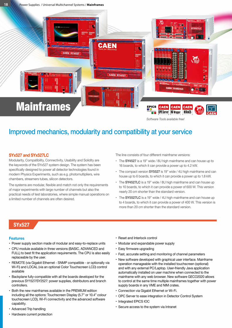
SYx527 and SYx527LCModularity, Compatibility, Connectivity, Usability and Solidity are the keywords of the SYx527 system design. The system has been specifically designed to power all detector technologies found in modern Physics Experiments, such as e.g. photomultipliers, wire chambers, streamers tubes, silicon detectors.The systems are modular, flexible and match not only the requirements of major experiments with large number of channels but also the practical needs of test laboratories, where simple manual operations on a limited number of channels are often desired.
The line consists of four different mainframe versions:• The SY4527 is a 19” wide / 8U high mainframe and can house up to
16 boards, to which it can provide a power up to 4.2 kW.• The compact version SY5527 is 19” wide / 4U high mainframe and can
house up to 6 boards, to which it can provide a power up to 1.8 kW.• The SY4527LC is a 19” wide / 8U high mainframe and can house up
to 10 boards, to which it can provide a power of 600 W. This version nearly 20 cm shorter than the standard version.
• The SY5527LC is a 19” wide / 4U high mainframe and can house up to 4 boards, to which it can provide a power of 400 W. This version is more than 20 cm shorter than the standard version.
GECO2 2 00
CA
E
N
Software Tools available free!
Improved mechanics, modularity and compatibility at your service
Mainframes

OverviewThe SYx527 system is the fully equipped experiment version of a new line of power supply systems which represent CAEN’s latest proposal in the matter of High Voltage and Low Voltage Power supplying. This system outlines a completely new approach to power generation and distribution by allowing the housing, in the same mainframe, of a wide range of boards with different functions, such as High/Low Voltage boards, generic I/O boards (temperature, pressure monitors, etc.) and branch controllers, where the latter are used to control other remote generators. Modularity, flexibility and reliability are the keypoints of its design, enabling this module to meet the requirements needed in a wide range of experimental conditions. The mainframe is housed in a 19”-wide, 4 or 8U-high euro-mechanics rack and hosts four main sections:• the Board Section, with 16 (6 for SY5527) slots to house boards,
distributors and branch controllers;• the Fan Tray Section, housing 6 (3 for SY5527) fans arranged on
two rows, with programmable rotation speed regulation;• the Power Supply Units Section, which consists of the primary
power supply and up to 3 (1 for SY5527) optional power supply units;• the CPU and Front Panel Section which includes all interface
facilities.
The CPU controller is available in 3 different versions: BASIC, ADVANCED and FULL.• The BASIC version provides all the communication interfaces, the
RESET control, the INTERLOCK control and status LEDs.• The ADVANCED version also provides the beam handshake
management connectors (CH-ON, GEN, VSEL, ISEL).• The FULL version provides the complete set of panel connectors,
the ENABLE control section, and the fan speed control.
The Power Supply Unit (PSU) is available in 3 different versions: PRIMARY, OPTIONAL SINGLE, OPTIONAL DOUBLE.• The Primary PSU is the SYx527 Primary Power Supply block. It
includes the SERVICE and the 600 W PSU for boards in a single slot module. Each SY4527/SY5527 System includes one A4531 Primary Power Supply
• The Optional Single PSU adds 600 W of power in a single slot module
• The Optional Double PSU adds 1200 W of power in a single slot module
Please note: the CAEN power supply boards require an amount of power to keep the motherboard control electronics on. When configuring the SYx527 with Primary and Optional PSUs our customers should consider also that power consumption. This could be a critical issue when several power supply boards are installed in the SYx527 systems. In similar cases, we suggest our customers to contact CAEN sales representatives and technical support for more information.
The Software User Interface features the usual friendliness of the previous CAEN systems which now also can optionally include a 5.7” (10.4” for SY4527) color touchscreen LCD.Modularity has been one of the leading criteria in the design and development of the system: both the Power Supply Units Section and the Board Section are completely modular. The Power Supply Units Section allows different configurations with up to 2 or 4 units per mainframe (up to 1800 W for SY5527 and 4200 W for SY4527),
while the Board Section can house up to 16 (6 for SY5527) boards able to perform different functions. The complete line of power supply boards that has been specially developed for SY1527/SY2527 are fully compatible with the new mainframes. The minimum working system configuration consists of the primary power supply unit, one CPU controller and one board. The system allows also to deal with power supply solutions composed by “branch controllers” (housed in the system mainframe) and on-detector “remote boards” (manufactured in order to be magnetic field and radiation tolerant). A sophisticated trip handling via software allows to control and correlate trip conditions on the channels of the crate. Live insertion and extraction of the boards, which reduces the down time of the global system and eases access to the computing core and peripherals of the system, complete the system flexibility. Easy interfacing is another key-point of the SYx527 system. The Gigabit Ethernet interface (and the optional Wi-Fi interface) allows both an easy web access and the connection via OPC Server, EPICS or LabVIEW to a SCADA control system. Enhanced software programming features a unified command set independent from the interface used to communicate with the system. The Power Supply Section and Board Section can be externally synchronized via front panel connectors. Handy maintenance and upgrading, which constitute a major issue in the reliability of a system, are further guaranteed by the possibility of accessing and servicing the system via network facilities.
Ordering Options - SY4527
Code DescriptionWSY4527BSCXA SY4527 - Universal Multichannel Power Supply System - BASIC 600W
WSY4527ADVXA SY4527 - Universal Multichannel Power Supply System - ADVANCED 600W
WSY4527FLLXA SY4527 - Universal Multichannel Power Supply System - FULL 600W
WSY4527PREXA SY4527 Premium - Includes SY4527 FULL, A4534, A4535, SW4536
Ordering Options - SY5527
Code DescriptionWSY5527BSCXA SY5527 - Universal Multichannel Power Supply System - BASIC 600W
WSY5527ADVXA SY5527 - Universal Multichannel Power Supply System - ADVANCED 600W
WSY5527FLLXA SY5527 - Universal Multichannel Power Supply System - FULL 600W
WSY5527PREXA SY5527 Premium - Includes SY5527 FULL, A5534, A4535, SW4536
Ordering Options - SYx527 Accessories
Code DescriptionWA4534XAAAAA A4534 - SY4527 10.4” LCD Touchscreen color Display Unit
WA4537XAAAAA A4537 - SY4527 5.7” LCD Touchscreen color Display Unit
WA5534XAAAAA A5534 - SY5527 5.7” LCD Touchscreen color Display Unit
WA4535XAAAAA A4535 - SY4527/SY5527 Wi-Fi Dongle for Wireless connectivity
WSW4536XAAAA SW4536 - SY4527/SY5527 Control software functionality enhancement activation code
WA4528ADVXAA A4528 - SY4527/SY5527 CPU Module ADVANCED
WA4528BSCXAA A4528 - SY4527/SY5527 CPU Module BASIC
WA4528FLLXAA A4528 - SY4527/SY5527 CPU Module FULL
WA4531XAAAAA A4531 - SY4527/SY5527 Primary Power Supply 600W
WA4532S600XA A4532 - SY4527/SY5527 Optional Single Power Supply Unit 600W
WA4533D1200X A4533 - SY4527/SY5527 Optional Double Power Supply Unit 1200W
Power Supplies / Universal Multichannel Systems / Mainframes 19
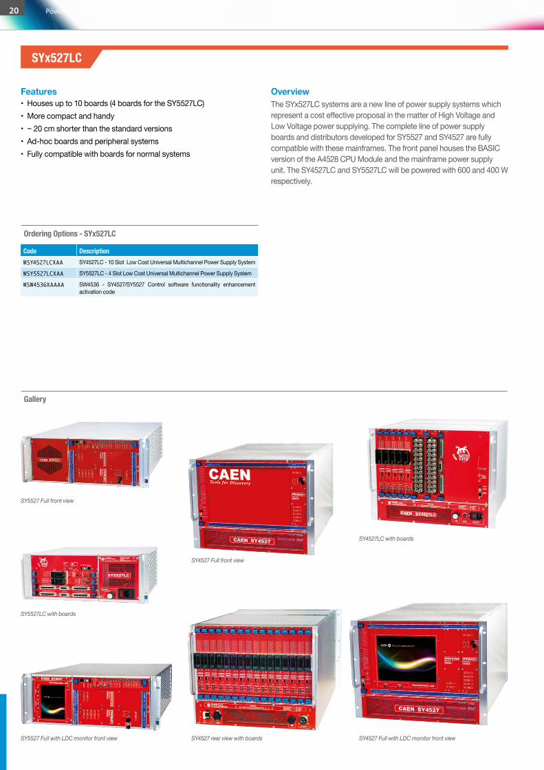
SY5527 Full front view
SY5527LC with boards
SY5527 Full with LDC monitor front view
SY4527 Full front view
SY4527 rear view with boards SY4527 Full with LDC monitor front view
SY4527LC with boards
Gallery
Ordering Options - SYx527LC
Code DescriptionWSY4527LCXAA SY4527LC - 10 Slot Low Cost Universal Multichannel Power Supply System
WSY5527LCXAA SY5527LC - 4 Slot Low Cost Universal Multichannel Power Supply System
WSW4536XAAAA SW4536 - SY4527/SY5527 Control software functionality enhancement activation code
Features• Houses up to 10 boards (4 boards for the SY5527LC)• More compact and handy• ~ 20 cm shorter than the standard versions• Ad-hoc boards and peripheral systems• Fully compatible with boards for normal systems
SYx527LC
OverviewThe SYx527LC systems are a new line of power supply systems which represent a cost effective proposal in the matter of High Voltage and Low Voltage power supplying. The complete line of power supply boards and distributors developed for SY5527 and SY4527 are fully compatible with these mainframes. The front panel houses the BASIC version of the A4528 CPU Module and the mainframe power supply unit. The SY4527LC and SY5527LC will be powered with 600 and 400 W respectively.
20 Power Supplies / Universal Multichannel Systems / Mainframes
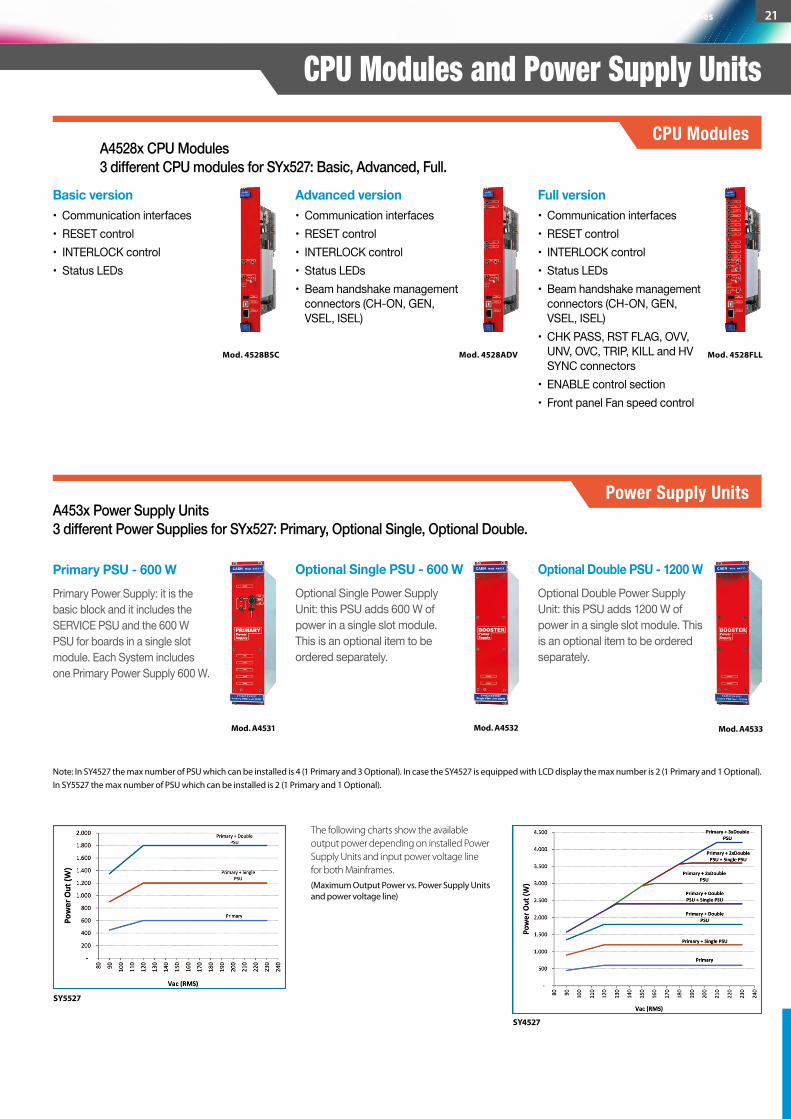
A4528x CPU Modules3 different CPU modules for SYx527: Basic, Advanced, Full.
Advanced version• Communication interfaces• RESET control• INTERLOCK control• Status LEDs• Beam handshake management
connectors (CH-ON, GEN, VSEL, ISEL)
Mod. 4528BSC Mod. 4528ADV Mod. 4528FLL
Basic version• Communication interfaces• RESET control• INTERLOCK control • Status LEDs
Full version• Communication interfaces• RESET control• INTERLOCK control• Status LEDs• Beam handshake management
connectors (CH-ON, GEN, VSEL, ISEL)
• CHK PASS, RST FLAG, OVV, UNV, OVC, TRIP, KILL and HV SYNC connectors
• ENABLE control section• Front panel Fan speed control
A453x Power Supply Units3 different Power Supplies for SYx527: Primary, Optional Single, Optional Double.
Primary PSU - 600 W Optional Single PSU - 600 W Optional Double PSU - 1200 WPrimary Power Supply: it is the basic block and it includes the SERVICE PSU and the 600 W PSU for boards in a single slot module. Each System includes one Primary Power Supply 600 W.
Optional Single Power Supply Unit: this PSU adds 600 W of power in a single slot module. This is an optional item to be ordered separately.
Optional Double Power Supply Unit: this PSU adds 1200 W of power in a single slot module. This is an optional item to be ordered separately.
Mod. A4531 Mod. A4532 Mod. A4533
Note: In SY4527 the max number of PSU which can be installed is 4 (1 Primary and 3 Optional). In case the SY4527 is equipped with LCD display the max number is 2 (1 Primary and 1 Optional). In SY5527 the max number of PSU which can be installed is 2 (1 Primary and 1 Optional).
The following charts show the available output power depending on installed Power Supply Units and input power voltage line for both Mainframes.(Maximum Output Power vs. Power Supply Units and power voltage line)
SY5527
SY4527
CPU Modules and Power Supply UnitsCPU Modules
Power Supply Units
Power Supplies / Universal Multichannel Systems / Mainframes 21
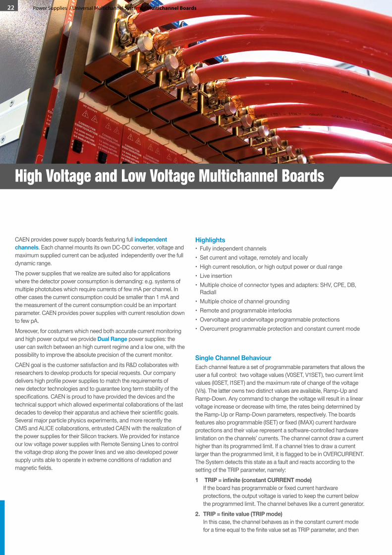
CAEN provides power supply boards featuring full independent channels. Each channel mounts its own DC-DC converter, voltage and maximum supplied current can be adjusted independently over the full dynamic range.The power supplies that we realize are suited also for applications where the detector power consumption is demanding: e.g. systems of multiple phototubes which require currents of few mA per channel. In other cases the current consumption could be smaller than 1 mA and the measurement of the current consumption could be an important parameter. CAEN provides power supplies with current resolution down to few pA. Moreover, for costumers which need both accurate current monitoring and high power output we provide Dual Range power supplies: the user can switch between an high current regime and a low one, with the possibility to improve the absolute precision of the current monitor.CAEN goal is the customer satisfaction and its R&D collaborates with researchers to develop products for special requests. Our company delivers high profile power supplies to match the requirements of new detector technologies and to guarantee long term stability of the specifications. CAEN is proud to have provided the devices and the technical support which allowed experimental collaborations of the last decades to develop their apparatus and achieve their scientific goals. Several major particle physics experiments, and more recently the CMS and ALICE collaborations, entrusted CAEN with the realization of the power supplies for their Silicon trackers. We provided for instance our low voltage power supplies with Remote Sensing Lines to control the voltage drop along the power lines and we also developed power supply units able to operate in extreme conditions of radiation and magnetic fields.
Highlights• Fully independent channels• Set current and voltage, remotely and locally• High current resolution, or high output power or dual range• Live insertion• Multiple choice of connector types and adapters: SHV, CPE, DB,
Radiall• Multiple choice of channel grounding• Remote and programmable interlocks• Overvoltage and undervoltage programmable protections• Overcurrent programmable protection and constant current mode
Single Channel BehaviourEach channel feature a set of programmable parameters that allows the user a full control: two voltage values (V0SET, V1SET), two current limit values (I0SET, I1SET) and the maximum rate of change of the voltage (V/s). The latter owns two distinct values are available, Ramp-Up and Ramp-Down. Any command to change the voltage will result in a linear voltage increase or decrease with time, the rates being determined by the Ramp-Up or Ramp-Down parameters, respectively. The boards features also programmable (ISET) or fixed (IMAX) current hardware protections and their value represent a software-controlled hardware limitation on the channels’ currents. The channel cannot draw a current higher than its programmed limit. If a channel tries to draw a current larger than the programmed limit, it is flagged to be in OVERCURRENT. The System detects this state as a fault and reacts according to the setting of the TRIP parameter, namely:1 TRIP=infinite(constantCURRENTmode)
If the board has programmable or fixed current hardware protections, the output voltage is varied to keep the current below the programmed limit. The channel behaves like a current generator.
2. TRIP=finitevalue(TRIPmode) In this case, the channel behaves as in the constant current mode for a time equal to the finite value set as TRIP parameter, and then
High Voltage and Low Voltage Multichannel Boards
22 Power Supplies / Universal Multichannel Systems / Multichannel Boards
it is switched off according to the selected Power-Down option (Kill/Ramp-Down). If the Kill option is selected, the channel will be switched off immediately. If the Ramp-Down option is selected the voltage will drop to zero at a rate determined by the value of the Ramp-Down parameter programmed for that channel.
Other indicators are foreseen to signal the channel status, such as OVERVOLTAGE, UNDERVOLTAGE and CHANNEL ON.
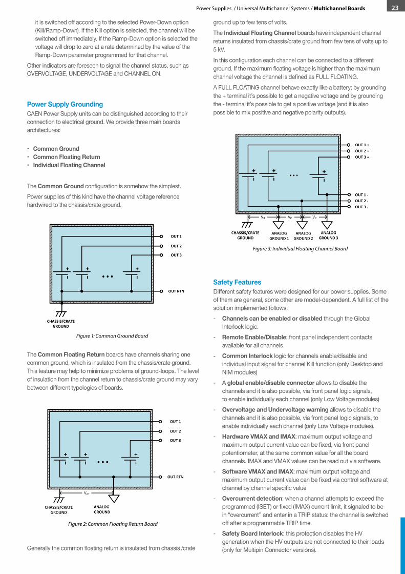
Power Supply GroundingCAEN Power Supply units can be distinguished according to their connection to electrical ground. We provide three main boards architectures: •CommonGround •CommonFloatingReturn •IndividualFloatingChannel
The Common Ground configuration is somehow the simplest. Power supplies of this kind have the channel voltage reference hardwired to the chassis/crate ground.
The Common Floating Return boards have channels sharing one common ground, which is insulated from the chassis/crate ground. This feature may help to minimize problems of ground-loops. The level of insulation from the channel return to chassis/crate ground may vary between different typologies of boards.
Generally the common floating return is insulated from chassis /crate
ground up to few tens of volts.The Individual Floating Channel boards have independent channel returns insulated from chassis/crate ground from few tens of volts up to 5 kV. In this configuration each channel can be connected to a different ground. If the maximum floating voltage is higher than the maximum channel voltage the channel is defined as FULL FLOATING.A FULL FLOATING channel behave exactly like a battery; by grounding the + terminal it’s possible to get a negative voltage and by grounding the - terminal it’s possible to get a positive voltage (and it is also possible to mix positive and negative polarity outputs).
Safety FeaturesDifferent safety features were designed for our power supplies. Some of them are general, some other are model-dependent. A full list of the solution implemented follows:- Channels can be enabled or disabled through the Global
Interlock logic.- Remote Enable/Disable: front panel independent contacts
available for all channels.- Common Interlock logic for channels enable/disable and
individual input signal for channel Kill function (only Desktop and NIM modules)
- A global enable/disable connector allows to disable the channels and it is also possible, via front panel logic signals, to enable individually each channel (only Low Voltage modules)
- Overvoltage and Undervoltage warning allows to disable the channels and it is also possible, via front panel logic signals, to enable individually each channel (only Low Voltage modules).
- Hardware VMAX and IMAX: maximum output voltage and maximum output current value can be fixed, via front panel potentiometer, at the same common value for all the board channels. IMAX and VMAX values can be read out via software.
- Software VMAX and IMAX: maximum output voltage and maximum output current value can be fixed via control software at channel by channel specific value
- Overcurrent detection: when a channel attempts to exceed the programmed (ISET) or fixed (IMAX) current limit, it signaled to be in “overcurrent” and enter in a TRIP status: the channel is switched off after a programmable TRIP time.
- Safety Board Interlock: this protection disables the HV generation when the HV outputs are not connected to their loads (only for Multipin Connector versions).
Figure 3: Individual Floating Channel Board
Figure 2: Common Floating Return Board
Figure 1: Common Ground Board
23Power Supplies / Universal Multichannel Systems / Multichannel Boards
- Status Overcurrent Bit: 0÷5 V (only PCB modules)- StatusOn/OffBit: 0÷5 V (only PCB modules)- Protection against short circuits, sparks and humidity (only
PCB modules)
Ripple and Noise BehaviourFast, switched mode power delivery allow high efficiency conversion in switching generators, but creates wideband harmonic energy too, and this undesirable energy appears as radiated and conducted components; actually, switching regulator output noise consist of coherent, high frequency residues directly related to the regulator’s switching, and these unsought components are usually called noise. All CAEN Multichannel power supplies are optimized in order to provide output voltage with low ripple and noise levels. Their contribution can be divided taking into account three different frequency ranges.The main frequency oscillation of the converter. CAEN power supplies features, on the output line, a filter that attenuates the high frequency components by some tens of dB depending on the components used. The switching frequency of CAEN power supplies ranges from some tens of kHz to about 300 kHz so, in case of frequencies around the fundamental and the switching harmonic, the spectrum amplitude can be reduced to few mV. This component depends on the load so it became less significant as the load is reduced.Contribution from non-ideal electronic components present in the feedback circuit. This noise component sits in the 10 Hz –few kHz frequency range. Several possible channel control layers can be used, i.e. current set point feedback, Vmax loop, Imax loop e other dedicated controls implemented on specific channel typology. Working on the stabilization in terms of amplitude and phase, the peak-to-peak value of this component can be reduced to few mV.The last component includes the frequencies between about few Hzfractions(about0.01)to10Hz and typically are neglected in the spectroscopy applications. A possible contribution of the order of some tens of millivolts on the output voltage can come from the reference voltage generator and its control circuit. In this range, solutions that can be applied in all possible application do not exist. A detailed study of the circuit has to be performed and a specific solution could be provided.Contribution coming from lower frequency ranges are typically related to a change of temperature that can produce a drift of the output voltage. If the mathematical correlation between the channel Vout (or Vset) and the environmental temperature has been established, a temperature control loop would allows to suppress this drift. Ripple and noise frequency ranges are divided during CAEN test measurements as follows:- f < 10 Hz to check the power supply long term and thermal stability- 10 Hz < f < 10 kHz in which many components contribute such as 50
Hz main supply and the single channel feedback loop circuit- f > 10 kHz in which the main contribution is given by the power
supply switching frequency.
Ripple, Noise and Validation MeasurementsEvery CAEN Power Supply is fully tested before shipping, according to specifications described by the designers, and doesn’t need any further check. It is possible, anyway, to schedule a periodic service by contacting our maintenance division and organize repairs, verification or recalibrations. Tests are performed by skilled personnel
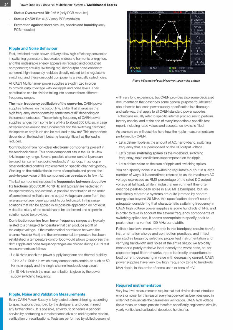
with very long experience, but CAEN provides also some dedicated documentation that describes some general purpose “guidelines”, about how to test each power supply specification in a thorough and safe way, that apply to all CAEN standard power supplies. Technicians usually refer to specific internal procedures to perform factory checks, and at the end of every inspection a specific test report, including rated values and acceptance levels, is filled. As example we will describe here how the ripple measurements are performed by CAEN.• Let’s define ripple as the amount of AC, narrowband, switching
frequency that is superimposed on the DC output voltage.• Let’s define switching spikes as the wideband, switching
frequency, rapid oscillations superimposed on the ripple.• Let’s define noise as the sum of ripple and switching spikes.You can specify noise in a switching regulator’s output in a large number of ways: it is sometimes referred to as the maximum AC voltage expressed as RMS percentage of the rated DC output voltage at full load, while in industrial environment they often describe peak-to-peak noise in a 20 MHz bandpass, but, as realistically electronic systems are quite jammed by spectral energy also beyond 20 MHz, this specification doesn’t sound adequate; considering that characteristic switching frequency in CAEN high voltage power supplies is some hundreds of kHz, and in order to take in account the several frequency components of switching spikes too, it seems appropriate to specify peak-to-peak noise in a verified 100 MHz bandwidth. Reliable low level measurements in this bandpass require careful instrumentation choice and connection practices, and in fact our studies began by selecting proper test instrumentation and verifying bandwidth and noise of the entire setup; we typically consider a purely resistive load, namely the worst case, as, for capacitor input filter networks, ripple is directly proportional to load current, decreasing in value with decreasing current. CAEN power supplies have very low high frequency (tens to hundreds kHz) ripple, in the order of some units or tens of mV.
Required instrumentationVery low level measurements require that test device do not introduce errors or noise; for this reason every test device has been designed in order not to invalidate the parameters verification. CAEN high voltage ripple measure setups provide therefore specifically engineered circuits, yearly verified and calibrated, described hereinafter.
Figure 4: Example of possible power supply noise pattern
24 Power Supplies / Universal Multichannel Systems / Multichannel Boards
• CAEN HV splitter: it is a simple insulated shunt, allowing to connect all the devices together. Connectors are chosen on the base of required voltage insulation and current rate.
• CAEN ripple checker: it basically consists of a DC blocking capacitor, which allows measurement of the ripple voltage using an AC RMS voltmeter or an oscilloscope.
A simplified schematic is shown in Figure 5.
Conceptually CAEN ripple checker consists of a capacitor of adequate value and of a switch or an equivalent solution that protect the measurement instrument:
• the switch is normally closed to prevent oscilloscope from damage during transients, and it is open at regime; it can be manually operated or implemented by remote control via relais.
• C1 must be capable of withstanding the maximum voltage to be applied, and has to be chosen to pass the lowest frequencies of interest without attenuation.
• CAEN HV voltmeter: it is a verified calibration, high voltage insulation voltmeter, with high input impedance (hundreds to thousands MΩ) and proper input connector.
• CAEN HV load: dimensioning the load is a straightforward task, but it may not be an easy task because of the high voltages involved and power considerations
• Oscilloscope: on the basis of our considerations regarding a 100 MHz verified band, it seems a proper choice to use a 300 MHz oscilloscope; maximum y-axis sensitivity should be 5 mV to discriminate very low signals.
Test setupThe measurement setup has been prepared as shown in Figure 6
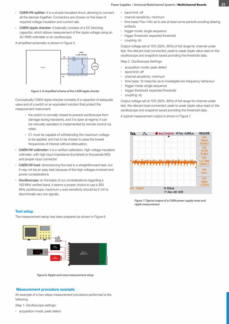
Measurement procedure exampleAn example of a two-steps measurement procedure performed is the following:Step 1. Oscilloscope settings:• acquisition mode: peak detect
• band limit: off• channel sensitivity: minimum• time base: Fsw-1/div as to see at least some periods avoiding aliasing
artifacts• trigger mode: single sequence• trigger threshold: expected threshold• coupling: dcOutput voltage set at 10% (50%, 90%) of full range for channel under test, the relevant load connected, peak-to-peak ripple value read on the oscilloscope and snapshot saved providing the threshold data.Step 2. Oscilloscope Settings:• acquisition mode: peak detect• band limit: off• channel sensitivity: minimum• time base: 10 msec/div as to investigate low frequency behaviour• trigger mode: single sequence• trigger threshold: expected threshold• coupling: dcOutput voltage set at 10% (50%, 90%) of full range for channel under test, the relevant load connected, peak-to-peak ripple value read on the oscilloscope and snapshot saved providing the threshold data.A typical measurement output is shown in Figure 7.
Figure 6: Ripple and noise measurement setup
Figure 7: Typical output of a CAEN power supply noise and ripple measurement
Figure 5: A simplified scheme of the CAEN ripple checker
25Power Supplies / Universal Multichannel Systems / Multichannel Boards
26 Power Supplies / Universal Multichannel Systems / Multichannel Boards
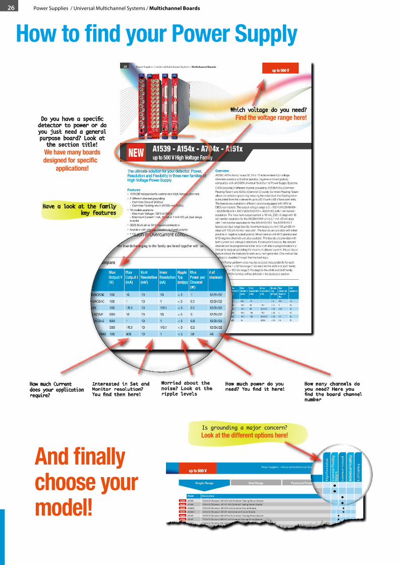
How to find your Power Supply
And finally choose your model!

Power Supplies / Universal Multichannel Systems / Multichannel Boards 27
Redefining the low voltage: extended flexibility with parallelizable channels and unprecedented digital control loop
OverviewThe family of low voltage (LV) power supplies includes single width boards housing 6 or 8 floating channels. The boards are designed to provide maximum voltages from 4.5 to 15 V, with up to 1 mV set and monitor resolution. The power supply boards A251x can provide output power up to 50 W per channel that can be connected in parallel with modularity 2 or 4 to obtain higher output power. Two possible front panels are available for these board families. Channels feature a PID (Proportional-Integrative-Derivative) digital controller, that allows to optimize the control loop to any load. The voltage drop over the cables can be recovered by using either the featured Remote Sensing Lines (A251x family), to be connected on the load for sensing the drop, or an automatic Line Drop Recovery system (the A151xB family is equipped with both features). The boards are provided with both current and voltage protections. If overcurrent occurs, the relevant channel can be programmed either to turn off after a programmable trip time or to remain on and to provide the maximum allowed current. This particular feature allows the module to perform as a current generator. A global enable/disable connector allows to disable the channels and it is also possible, via front panel logic signals, to enable individually each channel. The voltage ramp rates may be set independently for each channel. Moreover the individual floating channels allow on-detector grounding, thus allowing to reduce the noise level. Output channels are delivered through DB37 or D-sub 8 (on A251x family) connectors.
Features• 6 or 8 individual full floating channels• Up to 15 V of maximum voltage• High resolution on voltage set• Programmable TRIP parameter• Programmable ramp up / down• Current generator operation in overcurrent condition• Overcurrent programmable protections• Individual remote sense lines• Individual Line Drop Recovery (only A151x family)• 50 W Max channel output power (only A251x family)• Full Digital PID Control Loop (only A251x family)• 1/10 mV voltage monitor resolution • Up to 1 mA current monitor resolution • Voltage ripple smaller than 5/10 mVpp
Model Compare
Model Max Output V (V)
Max Output I (A)
Vset Resolution (mV)
Imon Resolution (mA)
RippleTyp. (mVpp)
Max Power per Channel (W)
# of channels
A1518B 4.5 6 10 1 < 5 27 6
A1517B 7 4 10 1 < 5 28 6
A1513B 10 2.7 10 1 < 5 27 6
A1516B 15 1.5 10 1 < 5 23 6
A2517 5 15 1 1 < 10 50 8
A2518 8 10 1 1 < 10 50 8
A2519 15 5 1 1 < 10 50 8
Ordering Options
Code Description S/DWA1518AXAAAA A1518B - SYx527 L.V. channels 4.5 V 6 A Individual Floating (6 ch) S
WA1517AXAAAA A1517B - SYx527 L.V. channels 7 V 4 A Individual Floating (6 ch) S
WA1513AXAAAA A1513B - SYx527 L.V. channels 10 V 2.7 A Individual Floating (6 ch) S
WA1516AXAAAA A1516B - SYx527 L.V. channels 15 V 1.5 A Individual Floating (6 ch) S
WA2517XAAAAA A2517 - SYx527 L.V. channels 5V 15A (50W) - Individual Floating (8 ch) S
WA2518XAAAAA A2518 - SYx527 L.V. channels 8V 10A (50W) - Individual Floating (8 ch) S
WA2518AXAAAA A2518A - SYx527 L.V. channels 8V 10A (50W) - DB37 conn. Individual Floating (8 ch)
S
WA2519XAAAAA A2519 - SYx527 L.V. channels 15V 5A (50W) - Individual Floating (8 ch) S
WA2519AXAAAA A2519A - SYx527 L.V. channels 15V 5A (50W) - DB37 conn. Individual Floating (8 ch)
S
In the following tables all the boards belonging to the family are listed together with an overview of the relevant parameters and of all the available Ordering Options.
S = Single width (5 TE wide)D = Double width (10 TE wide)
A151xB - A251xLow Voltage Boards Family
Low Voltage
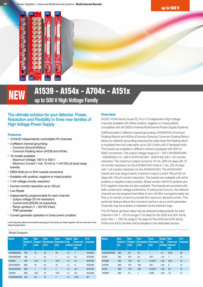
28 Power Supplies / Universal Multichannel Systems / Multichannel Boards
The ultimate solution for your detector: Power, Resolution and Flexibility in three new families of High Voltage Power Supply
OverviewA1539 / A154x family house 32, 24 or 12 independent High Voltage channels available with either positive, negative or mixed polarity compatible with all CAEN Universal Multichannel Power Supply Systems. CAEN provides 2 different channel grounding: A1539/A154x (Common Floating Return) and AG5xx (Common Ground). Common Floating Return allows on-detector grounding reducing the noise level; the floating return is insulated from the crate earth up to ±50 V (with a 65 V hardware limit). The boards are available in different versions equipped with SHV or DB25 connectors. The output voltage range is 0 ÷ 100 V (A1539/40/40H - AG539/40) or 0 ÷ 500 V (A1541/42/42H - AG541/42) with 1 mV monitor resolution. The maximum output current is 10 mA, (200 nA step) with 10 nA monitor resolution for the A1539/41/41H while is 1 mA, (20 nA step) with 1 nA monitor resolution for the A1540/42/42H. The A1541H/42H boards are dual range boards: maximum output current 100 µA (20 nA step) with 100 pA monitor resolution. The boards are available with either positive or negative output polarity. Mixed version with 6/12 positive and 6/12 negative channels are also available. The boards are provided with both current and voltage protections. If overcurrent occurs, the relevant channel can be programmed either to turn off after a programmable trip time or to remain on and to provide the maximum allowed current. This particular feature allows the module to perform as a current generator. Channels may be enabled or disabled via the Interlock logic. The HV Ramp up/down rates may be selected independently for each channel in the 1 ÷ 50 V/s range (1 V/s step) for the x539 and x541 family and in the 1 ÷ 100 V/s range (1 V/s step) for the x540 and x542 family. A704x and A151x families will be detailed in the dedicated section.
Features• 12/24/32 independently controllable HV channels• 2 different channel grounding:
- Common Ground (AG5xx) - Common Floating return (A1539 and A154x)
• 10 models available: - Maximum Voltage: 100 V or 500 V - Maximum Current 1 mA, 10 mA or 1 mA/100 μA (dual range boards)
• DB25 Multi pin or SHV coaxial connectors• Available with positive, negative or mixed polarity• 1 mV voltage monitor resolution• Current monitor resolution up to 100 pA• Low Ripple• Independently programmable for each channel:
- Output voltage (10 mV resolution) - Current limit (200/20 nA resolution) - Ramp up/down (1 ÷ 50/100 V/sec) - TRIP parameter
• Current generator operation in Overcurrent condition
In the following table all the boards belonging to the family are listed together with an overview of the relevant parameters.
Model Max Output V (V)
Max Output I (mA)
Vset Resolution (mV)
Imon Resolution (nA)
RippleTyp. (mVpp)
Max Power per Channel (W)
# of channels
A1539/AG539 100 10 10 10 < 5 1 12/24/32
A1540/AG540 100 1 10 1 < 3 0.1 12/24/32
A1540H 100 1/0.1 10 1/0.1 < 3 0.1 12/24/32
A1541/AG541 500 10 10 10 < 5 5 12/24/32
A1542/AG542 500 1 10 1 < 3 0.5 12/24/32
A1542H 500 1/0.1 10 1/0.1 < 3 0.5 12/24/32
A7040/AG7040 100 0.5 10 1 < 5 0.05 48
Model Compare
Model Max Output V (V)
Max Output I (mA)
Vset Resolution (mV)
Imon Resolution (nA)
RippleTyp. (mVpp)
Max Power per Channel (W)
# of channels
A7042/AG7042 500 0.5 10 1 < 5 0.25 48
A1510 100 10/1 20 1/0.1 < 15 1 12
A1519B 250 1/0.1 50 0.1/0.01 < 30 0.25 12
A1511B 500 10/1 100 1/0.1 < 30 5 12
A1512 500 1/0.1 100 0.1/0.01 < 30 0.5 12
A1520P 500 15 1 0.025 < 20 7.5 12
A1539 - A154x - A704x - A151xup to 500 V High Voltage FamilyNEW
up to 500 Vup to 500 V

Model Description
COMINGSOON A7040 Solution for High Density Detectors
COMINGSOON AG7040 Solution for High Density Detectors
NEW A7042 Solution for High Density DetectorsNEW AG7042 Solution for High Density Detectors
A151x - A1520P Solution for Silicon Detectors and APDs
Model Description
NEW A1540H 12/24/32 Channels 100 V, 1 mA/100 µA Common Floating Return Dual Range BoardsNEW A1542H 12/24/32 Channels 500 V, 1 mA/100 µA Common Floating Return Dual Range Boards
Model Description
NEW A1539 12/24/32 Channel 100 V/10 mA Common Floating Return BoardsNEW A1540 12/24/32 Channel 100 V/1 mA Common Floating Return BoardsNEW AG539 12/24/32 Channel 100 V/10 mA Common Ground BoardsNEW AG540 12/24/32 Channel 100 V/1 mA Common Ground BoardsNEW A1541 12/24/32 Channel 500 V/10 mA Common Floating Return BoardsNEW A1542 12/24/32 Channel 500 V/1 mA Common Floating Return BoardsNEW AG541 12/24/32 Channel 500 V/10 mA Common Ground BoardsNEW AG542 12/24/32 Channel 500 V/1 mA Common Ground Boards
Model Code Description S/DA1539 WA1539DXAAAA A1539DN - SYx527 H.V. channel -100 V 10 mA - SHV Conn.
common floating (12 ch)S
WA1539DXMAAA A1539DM - SYx527 H.V. channel (6ch +100V 10mA, 6ch -100V 10mA) - SHV Conn. common floating
S
WA1539DXPAAA A1539DP - SYx527 H.V. channel +100 V 10 mA - SHV Conn. common floating (12 ch)
S
WA1539LXAAAA A1539LN - SYx527 H.V. channel -100 V 10 mA - Multipin Conn. common floating (24 ch)
S
WA1539LXPAAA A1539LP - SYx527 H.V. channel +100 V 10 mA - Multipin Conn. common floating (24 ch)
S
WA1539SXAAAA A1539SN - SYx527 H.V. channel -100 V 10 mA - SHV Conn. common floating (24 ch 10TE wide)
D
WA1539SXMAAA A1539SM - SYx527 H.V. channel (12ch +100V 10mA, 12ch -100V 10mA) - SHV Conn. common floating (10TE)
D
WA1539SXPAAA A1539SP - SYx527 H.V. channel +100 V 10 mA - SHV Conn. common floating (24 ch 10TE wide)
D
WA1539XAAAAA A1539N - SYx527 H.V. channel -100 V 10 mA - Multipin Conn. common floating (32 ch)
S
WA1539XPAAAA A1539P - SYx527 H.V. channel +100 V 10 mA - Multipin Conn. common floating (32 ch)
S
A1540 WA1540DXAAAA A1540DN - SYx527 H.V. channel -100 V 1 mA - SHV Conn. common floating (12 ch)
S
WA1540DXMAAA A1540DM - SYx527 H.V. channel (6ch +100V 1mA, 6ch -100V 1mA) - SHV common floating
S
WA1540DXPAAA A1540DP - SYx527 H.V. channel +100 V 1 mA - SHV Conn. common floating (12 ch)
S
WA1540LXAAAA A1540LN - SYx527 H.V. channel -100 V 1 mA - Multipin Conn. common floating (24 ch)
S
WA1540LXPAAA A1540LP - SYx527 H.V. channel +100 V 1 mA - Multipin Conn. common floating (24 ch)
S
WA1540SXAAAA A1540SN - SYx527 H.V. channel -100 V 1 mA - SHV Conn. common floating (24 ch 10TE wide)
D
WA1540SXMAAA A1540SM - SYx527 H.V. channel (12ch +100V 1mA, 12ch -100V 1mA) - SHV common floating (10TE wide)
D
WA1540SXPAAA A1540SP - SYx527 H.V. channel +100 V 1 mA - SHV Conn. common floating (24 ch 10TE wide)
D
Ordering Options - A1539 / A154x S = Single width (5 TE wide)D = Double width (10 TE wide)
Com
mon
Flo
atin
g Re
turn
Com
mon
Flo
atin
g Re
turn
Com
mon
Gro
und
Com
mon
Gro
und
Full
Floa
ting
Full
Floa
ting
Indi
vidu
al F
loat
ing
Indi
vidu
al F
loat
ing
Hig
h Re
solu
tion
Hig
h Re
solu
tion
Single Range Dual Range Featured Products
Single Range Dual Range Featured Products
Com
mon
Flo
atin
g Re
turn
Com
mon
Gro
und
Indi
vidu
al F
loat
ing
Full F
loat
ing
Hig
h Re
solu
tionSingle Range Dual Range Featured Products
WA1540XAAAAA A1540N - SYx527 H.V. channel -100 V 1 mA - Multipin Conn. common floating (32 ch)
S
WA1540XPAAAA A1540P - SYx527 H.V. channel +100 V 1 mA - Multipin Conn. common floating (32 ch)
S
A1540H WA1540HDXAAA A1540HDN - SYx527 H.V. channel -100V 1mA/100µA (100pA res) - SHV Conn. common floating (12 ch)
S
WA1540HDXMAA A1540HDM - SYx527 H.V. (6ch +100V 1mA/100µA, 6ch -100V 1mA/100µA) (100pA res) - SHV Conn. comm float
S
WA1540HDXPAA A1540HDP - SYx527 H.V.channel +100V 1mA/100µA (100pA res) - SHV Conn. common floating (12 ch)
S
WA1540HLXAAA A1540HLN - SYx527 H.V. channel -100V 1mA/100µA (100pA res) - Multipin Conn. common floating (24 ch)
S
WA1540HLXPAA A1540HLP - SYx527 H.V. channel +100V 1mA/100µA (100pA res) - Multipin Conn. common floating (24 ch)
S
WA1540HSXAAA A1540HSN - SYx527 H.V. channel -100V 1mA/100µA (100pA res) - SHV Conn. common floating (24 ch 10TE)
D
WA1540HSXMAA A1540HSM - SYx527 H.V. (12ch +100V 1mA/100µA, 12ch -100V 1mA/100µA) (100pA res) SHV c. float (10TE)
D
WA1540HSXPAA A1540HSP - SYx527 H.V. channel +100V 1mA/100µA (100pA res) - SHV Conn. common floating (24 ch 10TE)
D
WA1540HXAAAA A1540HN - SYx527 H.V. channel -100V 1mA/100µA (100pA res) - Multipin Conn. common floating (32 ch)
S
WA1540HXPAAA A1540HP - SYx527 H.V. channel +100V 1mA/100µA (100pA res) - Multipin Conn. common floating (32 ch)
S
A1541 WA1541DXAAAA A1541DN - SYx527 H.V. channel -500 V 10 mA - SHV Conn. common floating (12 ch)
S
WA1541DXMAAA A1541DM - SYx527 H.V. channel (6ch +500V 10mA, 6ch -500V 10mA) - SHV Conn. common floating
S
WA1541DXPAAA A1541DP - SYx527 H.V. channel +500 V 10 mA - SHV Conn. common floating (12 ch)
S
WA1541LXAAAA A1541LN - SYx527 H.V. channel -500 V 10 mA - Multipin Conn. common floating (24 ch)
S
WA1541LXPAAA A1541LP - SYx527 H.V. channel +500 V 10 mA - Multipin Conn. common floating (24 ch)
S
WA1541SXAAAA A1541SN - SYx527 H.V. channel -500 V 10 mA - SHV Conn. common floating (24 ch 10TE wide)
D
Power Supplies / Universal Multichannel Systems / Multichannel Boards 29up to 500 V
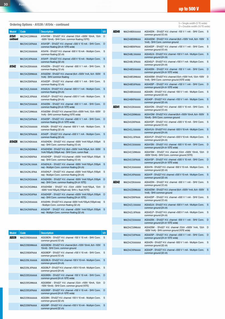
Model Code Description S/DAG539 WAG539DXAAAA AG539DN - SYx527 H.V. channel -100 V 10 mA - SHV Conn.
common ground (12 ch)S
WAG539DXMAAA AG539DM - SYx527 H.V. channel (6ch +100V 10mA, 6ch -100V 10mA) - SHV Conn. common ground
S
WAG539DXPAAA AG539DP - SYx527 H.V. channel +100 V 10 mA - SHV Conn. common ground (12 ch)
S
WAG539LXAAAA AG539LN - SYx527 H.V. channel -100 V 10 mA - Multipin Conn. common ground (24 ch)
S
WAG539LXPAAA AG539LP - SYx527 H.V. channel +100 V 10 mA - Multipin Conn. common ground (24 ch)
S
WAG539SXAAAA AG539SN - SYx527 H.V. channel -100 V 10 mA - SHV Conn. common ground (24 ch 10TE wide)
D
WAG539SXMAAA AG539SM - SYx527 H.V. channel (12ch +100V 10mA, 12ch -100V 10mA) - SHV Conn. common ground (10TE)
D
WAG539SXPAAA AG539SP - SYx527 H.V. channel +100 V 10 mA - SHV Conn. common ground (24 ch 10TE wide)
D
WAG539XAAAAA AG539N - SYx527 H.V. channel -100 V 10 mA - Multipin Conn. common ground (32 ch)
S
WAG539XPAAAA AG539P - SYx527 H.V. channel +100 V 10 mA - Multipin Conn. common ground (32 ch)
S
Ordering Options - A1539 / A154x - continued S = Single width (5 TE wide)D = Double width (10 TE wide)
up to 500 V
Model Code Description S/DA1541continued
WA1541SXMAAA A1541SM - SYx527 H.V. channel (12ch +500V 10mA, 12ch -500V 10mA) - SHV Conn. common floating (10TE)
D
WA1541SXPAAA A1541SP - SYx527 H.V. channel +500 V 10 mA - SHV Conn. common floating (24 ch 10TE wide)
D
WA1541XAAAAA A1541N - SYx527 H.V. channel -500 V 10 mA - Multipin Conn. common floating (32 ch)
S
WA1541XPAAAA A1541P - SYx527 H.V. channel +500 V 10 mA - Multipin Conn. common floating (32 ch)
S
A1542 WA1542DXAAAA A1542DN - SYx527 H.V. channel -500 V 1 mA - SHV Conn. common floating (12 ch)
S
WA1542DXMAAA A1542DM - SYx527 H.V. channel (6ch +500V 1mA, 6ch -500V 1mA) - SHV common floating
S
WA1542DXPAAA A1542DP - SYx527 H.V. channel +500 V 1 mA - SHV Conn. common floating (12 ch)
S
WA1542LXAAAA A1542LN - SYx527 H.V. channel -500 V 1 mA - Multipin Conn. common floating (24 ch)
S
WA1542LXPAAA A1542LP - SYx527 H.V. channel +500 V 1 mA - Multipin Conn. common floating (24 ch)
S
WA1542SXAAAA A1542SN - SYx527 H.V. channel -500 V 1 mA - SHV Conn. common floating (24 ch 10TE wide)
D
WA1542SXMAAA A1542SM - SYx527 H.V. channel (12ch +500V 1mA, 12ch -500V 1mA) - SHV common floating (10TE wide)
D
WA1542SXPAAA A1542SP - SYx527 H.V. channel +500 V 1 mA - SHV Conn. common floating (24 ch 10TE wide)
D
WA1542XAAAAA A1542N - SYx527 H.V. channel -500 V 1 mA - Multipin Conn. common floating (32 ch)
S
WA1542XPAAAA A1542P - SYx527 H.V. channel +500 V 1 mA - Multipin Conn. common floating (32 ch)
S
A1542H WA1542HDXAAA A1542HDN - SYx527 H.V. channel -500V 1mA/100µA (100pA res) - SHV Conn. common floating (12 ch)
S
WA1542HDXMAA A1542HDM - SYx527 H.V. (6ch +500V 1mA/100µA, 6ch -500V 1mA/100µA) (100pA res) - SHV Conn. comm float
S
WA1542HDXPAA A1542HDP - SYx527 H.V.channel +500V 1mA/100µA (100pA res) - SHV Conn. common floating (12 ch)
S
WA1542HLXAAA A1542HLN - SYx527 H.V. channel -500V 1mA/100µA (100pA res) - Multipin Conn. common floating (24 ch)
S
WA1542HLXPAA A1542HLP - SYx527 H.V. channel +500V 1mA/100µA (100pA res) - Multipin Conn. common floating (24 ch)
S
WA1542HSXAAA A1542HSN - SYx527 H.V. channel -500V 1mA/100µA (100pA res) - SHV Conn. common floating (24 ch 10TE)
D
WA1542HSXMAA A1542HSM - SYx527 H.V. (12ch +500V 1mA/100µA, 12ch -500V 1mA/100µA) (100pA res) SHV c. float (10TE)
D
WA1542HSXPAA A1542HSP - SYx527 H.V. channel +500V 1mA/100µA (100pA res) - SHV Conn. common floating (24 ch 10TE)
D
WA1542HXAAAA A1542HN - SYx527 H.V. channel -500V 1mA/100µA (100pA res) - Multipin Conn. common floating (32 ch)
S
WA1542HXPAAA A1542HP - SYx527 H.V. channel +500V 1mA/100µA (100pA res) - Multipin Conn. common floating (32 ch)
S
AG540 WAG540DXAAAA AG540DN - SYx527 H.V. channel -100 V 1 mA - SHV Conn. common ground (12 ch)
S
WAG540DXMAAA AG540DM - SYx527 H.V. channel (6ch +100V 1mA, 6ch -100V 1mA) - SHV Conn. common ground
S
WAG540DXPAAA AG540DP - SYx527 H.V. channel +100 V 1 mA - SHV Conn. common ground (12 ch)
S
WAG540LXAAAA AG540LN - SYx527 H.V. channel -100 V 1 mA - Multipin Conn. common ground (24 ch)
S
WAG540LXPAAA AG540LP - SYx527 H.V. channel +100 V 1 mA - Multipin Conn. common ground (24 ch)
S
WAG540SXAAAA AG540SN - SYx527 H.V. channel -100 V 1 mA - SHV Conn. common ground (24 ch 10TE wide)
D
WAG540SXMAAA AG540SM - SYx527 H.V. channel (12ch +100V 1mA, 12ch -100V 1mA) - SHV Conn. common ground (10TE wide)
D
WAG540SXPAAA AG540SP - SYx527 H.V. channel +100 V 1 mA - SHV Conn. common ground (24 ch 10TE wide)
D
WAG540XAAAAA AG540N - SYx527 H.V. channel -100 V 1 mA - Multipin Conn. common ground (32 ch)
S
WAG540XPAAAA AG540P - SYx527 H.V. channel +100 V 1 mA - Multipin Conn. common ground (32 ch)
S
AG541 WAG541DXAAAA AG541DN - SYx527 H.V. channel -500 V 10 mA - SHV Conn. common ground (12 ch)
S
WAG541DXMAAA AG541DM - SYx527 H.V. channel (6ch +500V 10mA, 6ch -500V 10mA) - SHV Conn. common ground
S
WAG541DXPAAA AG541DP - SYx527 H.V. channel +500 V 10 mA - SHV Conn. common ground (12 ch)
S
WAG541LXAAAA AG541LN - SYx527 H.V. channel -500 V 10 mA - Multipin Conn. common ground (24 ch)
S
WAG541LXPAAA AG541LP - SYx527 H.V. channel +500 V 10 mA - Multipin Conn. common ground (24 ch)
S
WAG541SXAAAA AG541SN - SYx527 H.V. channel -500 V 10 mA - SHV Conn. common ground (24 ch 10TE wide)
D
WAG541SXMAAA AG541SM - SYx527 H.V. channel (12ch +500V 10mA, 12ch -500V 10mA) - SHV Conn. common ground (10TE)
D
WAG541SXPAAA AG541SP - SYx527 H.V. channel +500 V 10 mA - SHV Conn. common ground (24 ch 10TE wide)
D
WAG541XAAAAA AG541N - SYx527 H.V. channel -500 V 10 mA - Multipin Conn. common ground (32 ch)
S
WAG541XPAAAA AG541P - SYx527 H.V. channel +500 V 10 mA - Multipin Conn. common ground (32 ch)
S
AG542 WAG542DXAAAA AG542DN - SYx527 H.V. channel -500 V 1 mA - SHV Conn. common ground (12 ch)
S
WAG542DXMAAA AG542DM - SYx527 H.V. channel (6ch +500V 1mA, 6ch -500V 1mA) - SHV common ground
S
WAG542DXPAAA AG542DP - SYx527 H.V. channel +500 V 1 mA - SHV Conn. common ground (12 ch)
S
WAG542LXAAAA AG542LN - SYx527 H.V. channel -500 V 1 mA - Multipin Conn. common ground (24 ch)
S
WAG542LXPAAA AG542LP - SYx527 H.V. channel +500 V 1 mA - Multipin Conn. common ground (24 ch)
S
WAG542SXAAAA AG542SN - SYx527 H.V. channel -500 V 1 mA - SHV Conn. common ground (24 ch 10TE wide)
D
WAG542SXMAAA AG542SM - SYx527 H.V. channel (12ch +500V 1mA, 12ch -500V 1mA) - SHV common ground (10TE wide)
D
WAG542SXPAAA AG542SP - SYx527 H.V. channel +500 V 1 mA - SHV Conn. common ground (24 ch 10TE wide)
D
WAG542XAAAAA AG542N - SYx527 H.V. channel -500 V 1 mA - Multipin Conn. common ground (32 ch)
S
WAG542XPAAAA AG542P - SYx527 H.V. channel +500 V 1 mA - Multipin Conn. common ground (32 ch)
S
30 Power Supplies / Universal Multichannel Systems / Multichannel Boards
up to 500 V

Unprecedented channel density for your detector
OverviewThe new line of high density general purpose power supplies offers you all the safety, performance and control of a completely independent channel technology at the cost effective price of a distributor! A7040/A7042 family house 48 independent High Voltage channels available with either positive or negative polarity, compatible with the CAEN Universal Multichannel Power Supply Systems (SY1527, SY2527, SY3527, SY4527, SY5527). CAEN provides 4 different models with different channel grounding: AG704x (Common Ground) and A704x (Common Floating Return). Common Floating Return allows on-detector grounding reducing the noise level; the floating return is insulated from the crate earth up to ±50 V (with a 65 V hardware limit). AG704x and A704x are equipped with Radiall Multipin connector. The output voltage range is 0 ÷ 100 V (A7040/AG7040) or 0 ÷ 500 V (A7042/AG7042), with 0.2 or 1 mV monitor resolution. The maximum output current is 500 µA, with up to 1 nA monitor resolution. The boards are provided with both current and voltage protections. If overcurrent occurs, the relevant channel can be programmed either to turn off after a programmable trip time or to remain on and to provide the maximum allowed current. This particular feature allows the module to perform as a current generator. The maximum output voltage can be set through a potentiometer to a value which is common to all channels and can be read out via software. Channels may be enabled or disabled via the Interlock logic. The HV ramp-up and ramp-down rates may be selected independently for each channel in the 1 ÷ 50 V/s range (1 V/s step) for the A7040 and and in the 1 ÷ 100 V/s range (1 V/s step) for the A7042.
Features• 48 independently controllable HV channels • 2 different channel grounding:
- Common Ground (AG704x) - Common Floating return (A704x)
• 4 models available: - A7040/AG7040: 0 ÷ 100 V (coming soon) - A7042/AG7042: 0 ÷ 500 V
• 500 µA maximum output current • Radiall 52 pin connector • Available with positive or negative polarity • 0.2 or 1 mV voltage monitor resolution • 1 nA current monitor resolution • Low Ripple • Independently programmable for each channel:
- Output voltage (10 mV resolution) - Current limit (1 nA resolution) - Ramp up/down (1 ÷ 50 and 1 ÷ 100 V/s) - TRIP parameter
Model Compare
Model Max Output V (V)
Max Output I (µA)
Vset Resolution (mV)
Imon Resolution (nA)
RippleTyp.(mVpp)
Max Power per Channel (mW)
# of channels
A7040/AG7040 100 500 2 1 < 5 50 48
A7042/AG7042 500 500 10 1 < 5 250 48
In the following tables all the boards belonging to the family are listed together with an overview of the relevant parameters and of all the available Ordering Options.
Ordering Options
Model Code Description S/DA7040 WA7040NXAAA4 A7040N - SYx527 H.V. channels -100 V 500 µA – Multipin
Conn. common floating (48 ch)S
WA7040PXAAA4 A7040P - SYx527 H.V. channels +100 V 500 µA – Multipin Conn. common floating (48 ch)
S
AG7040 WAG7040NXAA4 AG7040N - SYx527 H.V. channels -100 V 500 µA - Multipin Conn. common ground (48 ch)
S
WAG7040PXAA4 AG7040P - SYx527 H.V. channels +100 V 500 µA - Multipin Conn. common ground (48 ch)
S
A7042 WA7042NXAAA4 A7042N - SYx527 H.V. channels -500 V 500 µA – Multipin Conn. common floating (48 ch)
S
WA7042PXAAA4 A7042P - SYx527 H.V. channels +500 V 500 µA – Multipin Conn. common floating (48 ch)
S
AG7042 WAG7042NXAA4 AG7042N - SYx527 H.V. channels -500 V 500 µA - Multipin Conn. common ground (48 ch)
S
WAG7042PXAA4 AG7042P - SYx527 H.V. channels +500 V 500 µA - Multipin Conn. common ground (48 ch)
S
S = Single width (5 TE wide)D = Double width (10 TE wide)
Power Supplies / Universal Multichannel Systems / Multichannel Boards 31up to 500 V
A7040 - AG7040 - A7042 - AG7042Solution for High Density Detectors NEW
NEW
COMINGSOON
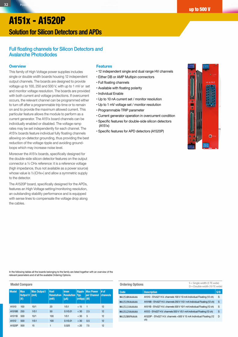
Full floating channels for Silicon Detectors and Avalanche Photodiodes
OverviewThis family of High Voltage power supplies includes single or double width boards housing 12 independent output channels. The boards are designed to provide voltage up to 100, 250 and 500 V, with up to 1 mV or set and monitor voltage resolution. The boards are provided with both current and voltage protections. If overcurrent occurs, the relevant channel can be programmed either to turn off after a programmable trip time or to remain on and to provide the maximum allowed current. This particular feature allows the module to perform as a current generator. The A151x board channels can be individually enabled or disabled. The voltage ramp rates may be set independently for each channel. The A151x boards feature individual fully floating channels allowing on-detector grounding, thus providing the best reduction of the voltage ripple and avoiding ground-loops which may increase noise level. Moreover the A151x boards, specifically designed for the double-side silicon detector features on the output connector a ½ CHx reference: it is a reference voltage (high impedance, thus not available as a power source) whose value is ½·|CHx+| and allow a symmetric supply to the detector. The A1520P board, specifically designed for the APDs, features an High Voltage setting/monitoring resolution, an outstanding stability performance and is equipped with sense lines to compensate the voltage drop along the cables.
Features• 12 independent single and dual range HV channels• Either DB or AMP Multipin connectors• Full floating channels• Available with floating polarity• Individual Enable• Up to 10 nA current set / monitor resolution• Up to 1 mV voltage set / monitor resolution• Programmable TRIP parameter• Current generator operation in overcurrent condition• Specific features for double-side silicon detectors
(A151x)• Specific features for APD detectors (A1520P)
Ordering Options
Code Description S/DWA1510XAAAAA A1510 - SYx527 H.V. channels 100 V 10 mA Individual Floating (12 ch) S
WA1519XAAAAA A1519B - SYx527 H.V. channels 250 V 1/0.1 mA Individual Floating (12 ch) S
WA1511XAAAAA A1511B - SYx527 H.V. channels 500 V 10/1 mA Individual Floating (12 ch) S
WA1512XAAAAA A1512 - SYx527 H.V. channels 500 V 1/0.1 mA Individual Floating (12 ch) S
WA1520XPAAAA A1520P - SYx527 H.V. channels +500 V 15 mA Individual Floating (12 ch)
D
Model Compare
Model Max Output V (V)
Max Output I (mA)
Vset Resolution (mV)
Imon Resolution (µA)
RippleTyp. (mVpp)
Max Power per Channel (W)
# of channels
A1510 100 10/1 20 1/0.1 < 15 1 12
A1519B 250 1/0.1 50 0.1/0.01 < 30 2.5 12
A1511B 500 10/1 100 1/0.1 < 30 5 12
A1512 500 1/0.1 100 0.1/0.01 < 30 0.5 12
A1520P 500 15 1 0.025 < 20 7.5 12
In the following tables all the boards belonging to the family are listed together with an overview of the relevant parameters and of all the available Ordering Options.
S = Single width (5 TE wide)D = Double width (10 TE wide)
32 Power Supplies / Universal Multichannel Systems / Multichannel Boards
up to 500 V
A151x - A1520P Solution for Silicon Detectors and APDs
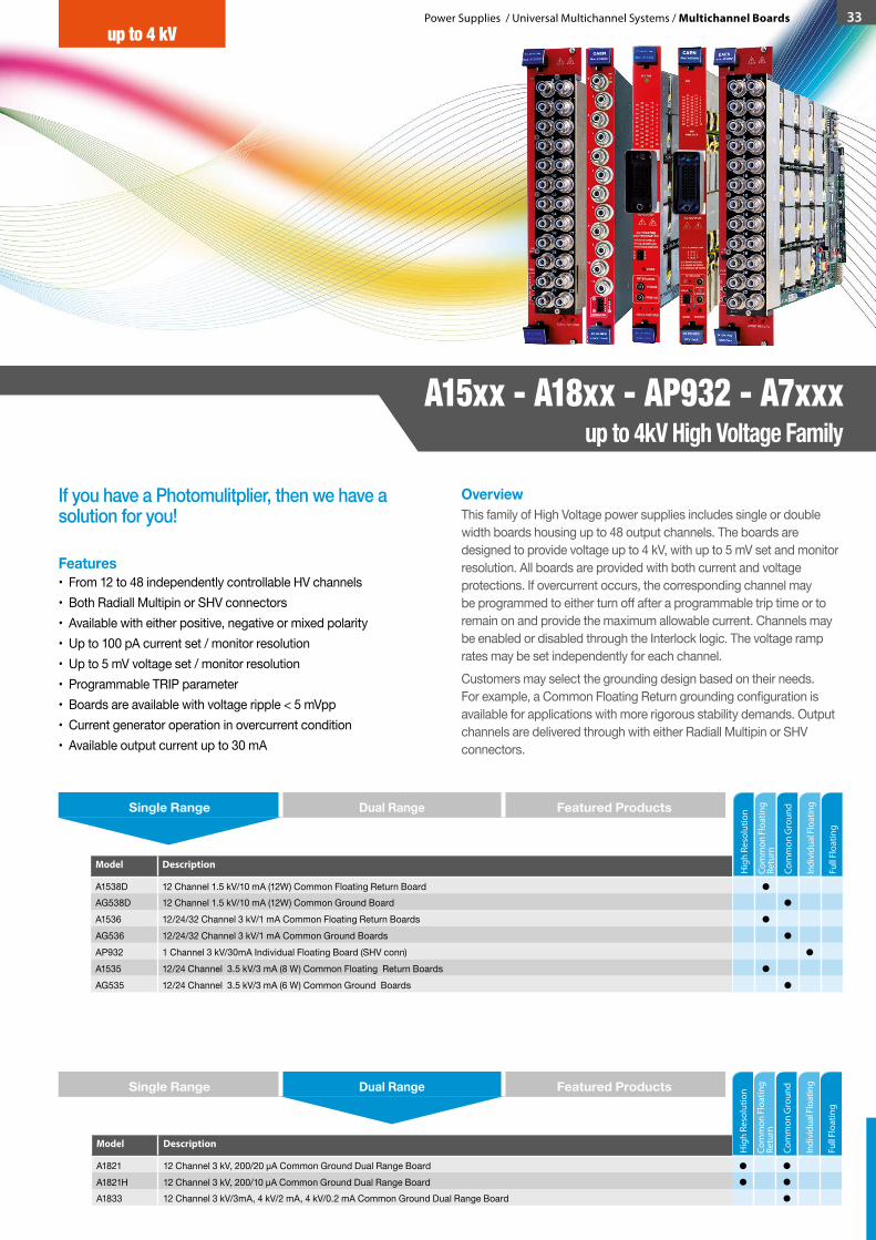
Power Supplies / Universal Multichannel Systems / Multichannel Boards 33
If you have a Photomulitplier, then we have a solution for you!
OverviewThis family of High Voltage power supplies includes single or double width boards housing up to 48 output channels. The boards are designed to provide voltage up to 4 kV, with up to 5 mV set and monitor resolution. All boards are provided with both current and voltage protections. If overcurrent occurs, the corresponding channel may be programmed to either turn off after a programmable trip time or to remain on and provide the maximum allowable current. Channels may be enabled or disabled through the Interlock logic. The voltage ramp rates may be set independently for each channel.Customers may select the grounding design based on their needs. For example, a Common Floating Return grounding configuration is available for applications with more rigorous stability demands. Output channels are delivered through with either Radiall Multipin or SHV connectors.
Features• From 12 to 48 independently controllable HV channels• Both Radiall Multipin or SHV connectors• Available with either positive, negative or mixed polarity• Up to 100 pA current set / monitor resolution• Up to 5 mV voltage set / monitor resolution• Programmable TRIP parameter• Boards are available with voltage ripple < 5 mVpp• Current generator operation in overcurrent condition• Available output current up to 30 mA
Model Description
A1538D 12 Channel 1.5 kV/10 mA (12W) Common Floating Return BoardAG538D 12 Channel 1.5 kV/10 mA (12W) Common Ground BoardA1536 12/24/32 Channel 3 kV/1 mA Common Floating Return BoardsAG536 12/24/32 Channel 3 kV/1 mA Common Ground BoardsAP932 1 Channel 3 kV/30mA Individual Floating Board (SHV conn)A1535 12/24 Channel 3.5 kV/3 mA (8 W) Common Floating Return BoardsAG535 12/24 Channel 3.5 kV/3 mA (6 W) Common Ground Boards
Model Description
A1821 12 Channel 3 kV, 200/20 μA Common Ground Dual Range BoardA1821H 12 Channel 3 kV, 200/10 μA Common Ground Dual Range BoardA1833 12 Channel 3 kV/3mA, 4 kV/2 mA, 4 kV/0.2 mA Common Ground Dual Range Board
Single Range Dual Range Featured Products
Single Range Dual Range Featured Products
Com
mon
Flo
atin
g Re
turn
Com
mon
Gro
und
Indi
vidu
al F
loat
ing
Hig
h Re
solu
tion
Full
Floa
ting
A15xx - A18xx - AP932 - A7xxxup to 4kV High Voltage Family
up to 4 kV
Com
mon
Flo
atin
g Re
turn
Com
mon
Gro
und
Indi
vidu
al F
loat
ing
Hig
h Re
solu
tion
Full
Floa
ting

Ordering OptionsModel Code Description S/DA1538D WA1538DXAAAA A1538DN - SYx527 negative H.V. -1.5 kV 10 mA 12W - SHV
Connector common floating (12 ch)S
WA1538DXPAAA A1538DP - SYx527 positive H.V. +1.5 kV 10 mA 12W - SHV Connector common floating (12 ch)
S
AG1538D WAG538DXAAAA AG538DN - SYx527 negative H.V. -1.5 kV 10 mA 12W - SHV Connector common ground (12 ch)
S
WAG538DXPAAA AG538DP - SYx527 positive H.V. +1.5 kV 10 mA 12W - SHV Connector common ground (12 ch)
S
A1536 WA1536DXAAAA A1536DN - SYx527 H.V. channels -3 kV 1 mA - SHV Conn. common floating (12 ch)
S
WA1536DXMAAA A1536DM - SYx527 H.V. channels (6ch +3kV 1mA, 6ch -3kV 1mA) - SHV Conn. common floating
S
WA1536DXPAAA A1536DP - SYx527 H.V. channels +3 kV 1 mA - SHV Conn. common floating (12 ch)
S
WA1536LXAAAA A1536LN - SYx527 H.V. channels -3 kV 1 mA - Multipin Conn. common floating (24 ch)
S
WA1536LXPAAA A1536LP - SYx527 H.V. channels +3 kV 1 mA - Multipin Conn. common floating (24 ch)
S
WA1536SVXAAA A1536SVN - SYx527 H.V. channels -3 kV 800µA - SHV Conn. common floating (24 ch 10TE wide)
D
WA1536SVXPAA A1536SVP - SYx527 H.V. channels +3 kV 800µA - SHV Conn. common floating (24 ch 10TE wide)
D
Ordering Options - continuedModel Code Description S/D
up to 4 kV
In the following tables all the boards belonging to the family are listed together with an overview of the relevant parameters and of all the available Ordering Options.
S = Single width (5 TE wide)D = Double width (10 TE wide)
Model Description
NEW A7030-AG7030 General Purpose High Density Family NEW A1515-A1515TG-A1515QG Solution For Gas Electron Multiplier DetectorsNEW A7236 - AG7236 - A7435 - AG7435 General Purpose High Power and High Resolution Power Supplies
Com
mon
Flo
atin
g Re
turn
Com
mon
Gro
und
Indi
vidu
al F
loat
ing
Hig
h Re
solu
tion
Single Range Dual Range Featured Products
WA1536SXAAAA A1536SN - SYx527 H.V. channels -3 kV 1 mA - SHV Conn. common floating (24 ch 10TE wide)
D
WA1536SXMAAA A1536SM - SYx527 H.V. channels (12ch +3kV 1mA, 12ch -3kV 1mA) - SHV Conn. common floating (10TE)
D
WA1536SXPAAA A1536SP - SYx527 H.V. channels +3 kV 1 mA - SHV Conn. common floating (24 ch 10TE wide)
D
WA1536VXAAAA A1536VN - SYx527 H.V. channels -3 kV 800µA Multipin Conn. common floating (32 ch)
S
WA1536VXPAAA A1536VP - SYx527 H.V. channels +3 kV 800µA Multipin Conn. common floating (32 ch)
S
WA1536XAAAAA A1536N - SYx527 H.V. channels -3 kV 1 mA - Multipin Conn. common floating (32 ch)
S
WA1536XPAAAA A1536P - SYx527 H.V. channels +3 kV 1 mA - Multipin Conn. common floating (32 ch)
S
AG536 WAG536DXAAAA AG536DN - SYx527 H.V. channels -3 kV 1 mA - SHV Conn. common ground (12 ch)
S
WAG536DXMAAA AG536DM - SYx527 H.V. channels (6ch +3kV 1mA, 6ch -3kV 1mA) - SHV Conn. common ground
S
WAG536DXPAAA AG536DP - SYx527 H.V. channels +3 kV 1 mA - SHV Conn. common ground (12 ch)
S
WAG536LXAAAA AG536LN - SYx527 H.V. channels -3 kV 1 mA - Multipin Conn. common ground (24 ch)
S
WAG536LXPAAA AG536LP - SYx527 H.V. channels +3 kV 1 mA - Multipin Conn. common ground (24 ch)
S
WAG536SVXAAA AG536SVN - SYx527 H.V. channels -3 kV 800µA - SHV Conn. common ground (24 ch 10TE wide)
D
WAG536SVXPAA AG536SVP - SYx527 H.V. channels +3 kV 800µA - SHV Conn. common ground (24 ch 10TE wide)
D
WAG536SXAAAA AG536SN - SYx527 H.V. channels -3 kV 1 mA - SHV Conn. common ground (24 ch 10TE wide)
D
WAG536SXMAAA AG536SM - SYx527 H.V. channels (12ch +3kV 1mA, 12ch -3kV 1mA) - SHV Conn. common ground (10TE)
D
WAG536SXPAAA AG536SP - SYx527 H.V. channels +3 kV 1 mA - SHV Conn. common ground (24 ch 10TE wide)
D
WAG536VXAAAA AG536VN -SYx527 H.V. channels -3 kV 800µA - Multipin Conn. common ground (32 ch)
S
WAG536VXPAAA AG536VP - SYx527 H.V. channels +3 kV 800µA - Multipin Conn. common ground (32 ch)
S
WAG536XAAAAA AG536N -SYx527 H.V. channels -3 kV 1 mA - Multipin Conn. common ground (32 ch)
S
WAG536XPAAAA AG536P - SYx527 H.V. channels +3 kV 1 mA - Multipin Conn. common ground (32 ch)
S
A1821 WA1821NAAAAA A1821N - SYx527 H.V. channels -3 kV 200/20 µA(20/2nA res.) - SHV Conn. (12 ch)
S
WA1821PAAAAA A1821P - SYx527 H.V. channels +3 kV 200/20 µA(20/2nA res.) - SHV Conn. (12 ch)
S
A1821H WA1821HAAAAA A1821HP - SYx527 H.V. channels +3 kV 200/10 µA(20/1nA res.) - SHV Conn. (12 ch)
S
WA1821HNAAAA A1821HN - SYx527 H.V. channels -3 kV 200/10 µA(20/1nA res.) - SHV Conn. (12 ch)
S
A1833 WA1833NAAAAA A1833N - SYx527 H.V. channels -3/4 kV 3/2 mA/200µA - SHV Conn. (12 ch)
S
WA1833PAAAAA A1833P - SYx527 H.V. channels +3/4 kV 3/2 mA/200µA - SHV Conn. (12 ch)
S
AP932 WAP932XAAAAA AP932N - SYx527 H.V. channel -3 kV 30 mA - SHV Conn. individual floating (1 ch)
S
WAP932XPAAAA AP932P - SYx527 H.V. channel +3 kV 30 mA - SHV Conn. individual floating (1 ch)
S
Full F
loat
ing
Model Compare
Model Max Output V (kV)
Max Output I (mA)
Vset Resolution (mV)
Imon Resolution (nA)
RippleTyp.(mVpp)
Max Power per Channel (W)
# of channels
A1538D 1.5 10 50 200 < 20 12 12
AG538D 1.5 10 50 200 < 20 12 12
A1536 3 1 100 50 < 10 3 12/24/32
AG536 3 1 100 50 < 10 3 12/24/32
A1821 3 0.2/0.02 250 20/2 < 30 0.6 12
A1821H 3 0.2/0.01 250 20/1 < 30 0.6 12
A1833 3/4 3/2/0.2 250 200/20 < 30 9 12
AP932 3 30 100 1000 < 30 90 1
A1535 3.5 3 500 500 < 20 8 12/24
AG535 3.5 3 500 500 < 20 8 12/24
A7236 3.5 1.5 5 1 < 10 4 32
AG7236 3.5 1.5 5 1 < 10 4 32
A7435 3.5 3.5 5 5 < 15 9 24
AG7435 3.5 3.5 5 5 < 15 9 24
A7030 3 1 50 2 < 5 1.5 12/24/36/48
AG7030 3 1 50 2 < 5 1.5 12/24/36/48
A1515TG 1 1/0.1 20 1/0.1 < 10 (CM) < 5 (DM)
0.8 14
A1515QG 1 1/0.1 20 1/0.1 < 10 (CM) < 5 (DM)
0.8 16
A1515 1 1/0.1 20 1/0.1 < 10 (CM) < 5 (DM)
0.8 16
34 Power Supplies / Universal Multichannel Systems / Multichannel Boards
up to 4 kV
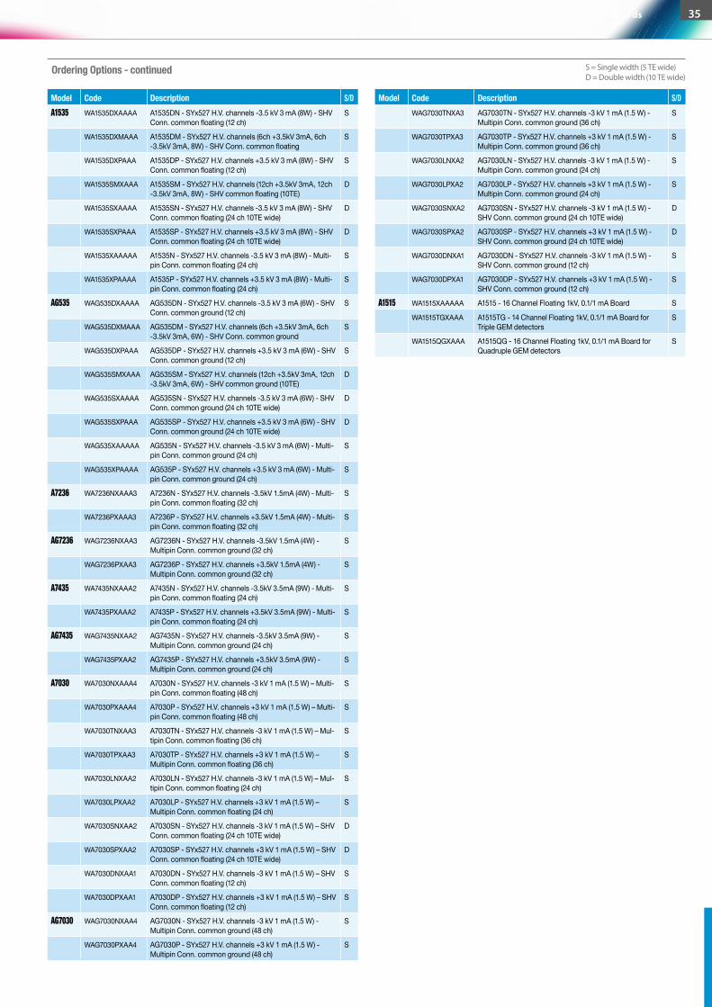
S = Single width (5 TE wide)D = Double width (10 TE wide)
WAG7030TNXA3 AG7030TN - SYx527 H.V. channels -3 kV 1 mA (1.5 W) - Multipin Conn. common ground (36 ch)
S
WAG7030TPXA3 AG7030TP - SYx527 H.V. channels +3 kV 1 mA (1.5 W) - Multipin Conn. common ground (36 ch)
S
WAG7030LNXA2 AG7030LN - SYx527 H.V. channels -3 kV 1 mA (1.5 W) - Multipin Conn. common ground (24 ch)
S
WAG7030LPXA2 AG7030LP - SYx527 H.V. channels +3 kV 1 mA (1.5 W) - Multipin Conn. common ground (24 ch)
S
WAG7030SNXA2 AG7030SN - SYx527 H.V. channels -3 kV 1 mA (1.5 W) - SHV Conn. common ground (24 ch 10TE wide)
D
WAG7030SPXA2 AG7030SP - SYx527 H.V. channels +3 kV 1 mA (1.5 W) - SHV Conn. common ground (24 ch 10TE wide)
D
WAG7030DNXA1 AG7030DN - SYx527 H.V. channels -3 kV 1 mA (1.5 W) - SHV Conn. common ground (12 ch)
S
WAG7030DPXA1 AG7030DP - SYx527 H.V. channels +3 kV 1 mA (1.5 W) - SHV Conn. common ground (12 ch)
S
A1515 WA1515XAAAAA A1515 - 16 Channel Floating 1kV, 0.1/1 mA Board S
WA1515TGXAAA A1515TG - 14 Channel Floating 1kV, 0.1/1 mA Board for Triple GEM detectors
S
WA1515QGXAAA A1515QG - 16 Channel Floating 1kV, 0.1/1 mA Board for Quadruple GEM detectors
S
A1535 WA1535DXAAAA A1535DN - SYx527 H.V. channels -3.5 kV 3 mA (8W) - SHV Conn. common floating (12 ch)
S
WA1535DXMAAA A1535DM - SYx527 H.V. channels (6ch +3.5kV 3mA, 6ch -3.5kV 3mA, 8W) - SHV Conn. common floating
S
WA1535DXPAAA A1535DP - SYx527 H.V. channels +3.5 kV 3 mA (8W) - SHV Conn. common floating (12 ch)
S
WA1535SMXAAA A1535SM - SYx527 H.V. channels (12ch +3.5kV 3mA, 12ch -3.5kV 3mA, 8W) - SHV common floating (10TE)
D
WA1535SXAAAA A1535SN - SYx527 H.V. channels -3.5 kV 3 mA (8W) - SHV Conn. common floating (24 ch 10TE wide)
D
WA1535SXPAAA A1535SP - SYx527 H.V. channels +3.5 kV 3 mA (8W) - SHV Conn. common floating (24 ch 10TE wide)
D
WA1535XAAAAA A1535N - SYx527 H.V. channels -3.5 kV 3 mA (8W) - Multi-pin Conn. common floating (24 ch)
S
WA1535XPAAAA A1535P - SYx527 H.V. channels +3.5 kV 3 mA (8W) - Multi-pin Conn. common floating (24 ch)
S
AG535 WAG535DXAAAA AG535DN - SYx527 H.V. channels -3.5 kV 3 mA (6W) - SHV Conn. common ground (12 ch)
S
WAG535DXMAAA AG535DM - SYx527 H.V. channels (6ch +3.5kV 3mA, 6ch -3.5kV 3mA, 6W) - SHV Conn. common ground
S
WAG535DXPAAA AG535DP - SYx527 H.V. channels +3.5 kV 3 mA (6W) - SHV Conn. common ground (12 ch)
S
WAG535SMXAAA AG535SM - SYx527 H.V. channels (12ch +3.5kV 3mA, 12ch -3.5kV 3mA, 6W) - SHV common ground (10TE)
D
WAG535SXAAAA AG535SN - SYx527 H.V. channels -3.5 kV 3 mA (6W) - SHV Conn. common ground (24 ch 10TE wide)
D
WAG535SXPAAA AG535SP - SYx527 H.V. channels +3.5 kV 3 mA (6W) - SHV Conn. common ground (24 ch 10TE wide)
D
WAG535XAAAAA AG535N - SYx527 H.V. channels -3.5 kV 3 mA (6W) - Multi-pin Conn. common ground (24 ch)
S
WAG535XPAAAA AG535P - SYx527 H.V. channels +3.5 kV 3 mA (6W) - Multi-pin Conn. common ground (24 ch)
S
A7236 WA7236NXAAA3 A7236N - SYx527 H.V. channels -3.5kV 1.5mA (4W) - Multi-pin Conn. common floating (32 ch)
S
WA7236PXAAA3 A7236P - SYx527 H.V. channels +3.5kV 1.5mA (4W) - Multi-pin Conn. common floating (32 ch)
S
AG7236 WAG7236NXAA3 AG7236N - SYx527 H.V. channels -3.5kV 1.5mA (4W) - Multipin Conn. common ground (32 ch)
S
WAG7236PXAA3 AG7236P - SYx527 H.V. channels +3.5kV 1.5mA (4W) - Multipin Conn. common ground (32 ch)
S
A7435 WA7435NXAAA2 A7435N - SYx527 H.V. channels -3.5kV 3.5mA (9W) - Multi-pin Conn. common floating (24 ch)
S
WA7435PXAAA2 A7435P - SYx527 H.V. channels +3.5kV 3.5mA (9W) - Multi-pin Conn. common floating (24 ch)
S
AG7435 WAG7435NXAA2 AG7435N - SYx527 H.V. channels -3.5kV 3.5mA (9W) - Multipin Conn. common ground (24 ch)
S
WAG7435PXAA2 AG7435P - SYx527 H.V. channels +3.5kV 3.5mA (9W) - Multipin Conn. common ground (24 ch)
S
A7030 WA7030NXAAA4 A7030N - SYx527 H.V. channels -3 kV 1 mA (1.5 W) – Multi-pin Conn. common floating (48 ch)
S
WA7030PXAAA4 A7030P - SYx527 H.V. channels +3 kV 1 mA (1.5 W) – Multi-pin Conn. common floating (48 ch)
S
WA7030TNXAA3 A7030TN - SYx527 H.V. channels -3 kV 1 mA (1.5 W) – Mul-tipin Conn. common floating (36 ch)
S
WA7030TPXAA3 A7030TP - SYx527 H.V. channels +3 kV 1 mA (1.5 W) – Multipin Conn. common floating (36 ch)
S
WA7030LNXAA2 A7030LN - SYx527 H.V. channels -3 kV 1 mA (1.5 W) – Mul-tipin Conn. common floating (24 ch)
S
WA7030LPXAA2 A7030LP - SYx527 H.V. channels +3 kV 1 mA (1.5 W) – Multipin Conn. common floating (24 ch)
S
WA7030SNXAA2 A7030SN - SYx527 H.V. channels -3 kV 1 mA (1.5 W) – SHV Conn. common floating (24 ch 10TE wide)
D
WA7030SPXAA2 A7030SP - SYx527 H.V. channels +3 kV 1 mA (1.5 W) – SHV Conn. common floating (24 ch 10TE wide)
D
WA7030DNXAA1 A7030DN - SYx527 H.V. channels -3 kV 1 mA (1.5 W) – SHV Conn. common floating (12 ch)
S
WA7030DPXAA1 A7030DP - SYx527 H.V. channels +3 kV 1 mA (1.5 W) – SHV Conn. common floating (12 ch)
S
AG7030 WAG7030NXAA4 AG7030N - SYx527 H.V. channels -3 kV 1 mA (1.5 W) - Multipin Conn. common ground (48 ch)
S
WAG7030PXAA4 AG7030P - SYx527 H.V. channels +3 kV 1 mA (1.5 W) - Multipin Conn. common ground (48 ch)
S
Ordering Options - continued
Model Code Description S/D Model Code Description S/D
Power Supplies / Universal Multichannel Systems / Multichannel Boards 35
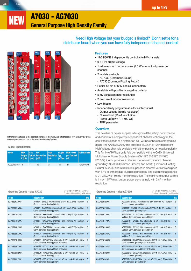
Need High Voltage but your budget is limited? Don’t settle for a distributor board when you can have fully independent channel control!
OverviewThis new line of power supplies offers you all the safety, performance and control of a completely independent channel technology at the cost effective price of a distributor! You will never have to compromise again! The A7030/AG7030 line provides 48,32,24 or 12 independent High Voltage channels available with either positive or negative polarity. This family of HV boards is fully compatible with the CAEN Universal Multichannel Power Supply Systems (SY1527, SY2527, SY4527, SY5527). CAEN provides 2 different models with different channel grounding: AG7030 (Common Ground) and A7030 (Common Floating Return). AG7030 and A7030 are supplied in different versions equipped with SHV or with Radiall Multipin connectors. The output voltage range is 0 ÷ 3 kV, with 50 mV monitor resolution. The maximum output current is 1 mA (1.5 W max. output power per channel), with 2 nA monitor resolution.
Features• 12/24/36/48 independently controllable HV channels • 0 ÷ 3 kV output voltage • 1 mA maximum output current (1.5 W max output power per
channel) • 2 models available:
- AG7030 (Common Ground) - A7030 (Common Floating Return)
• Radiall 52 pin or SHV coaxial connectors • Available with positive or negative polarity • 5 mV voltage monitor resolution • 2 nA current monitor resolution • Low Ripple • Independently programmable for each channel:
- Output voltage (50 mV resolution) - Current limit (20 nA resolution) - Ramp up/down (1 ÷ 500 V/s) - TRIP parameter
Ordering Options - Mod A7030
Code Description S/DWA7030NXAAA4 A7030N - SYx527 H.V. channels -3 kV 1 mA (1.5 W) – Multipin
Conn. common floating (48 ch)S
WA7030PXAAA4 A7030P - SYx527 H.V. channels +3 kV 1 mA (1.5 W) – Multipin Conn. common floating (48 ch)
S
WA7030TNXAA3 A7030TN - SYx527 H.V. channels -3 kV 1 mA (1.5 W) – Multipin Conn. common floating (36 ch)
S
WA7030TPXAA3 A7030TP - SYx527 H.V. channels +3 kV 1 mA (1.5 W) – Multipin Conn. common floating (36 ch)
S
WA7030LNXAA2 A7030LN - SYx527 H.V. channels -3 kV 1 mA (1.5 W) – Multipin Conn. common floating (24 ch)
S
WA7030LPXAA2 A7030LP - SYx527 H.V. channels +3 kV 1 mA (1.5 W) – Multipin Conn. common floating (24 ch)
S
WA7030SNXAA2 A7030SN - SYx527 H.V. channels -3 kV 1 mA (1.5 W) – SHV Conn. common floating (24 ch 10TE wide)
D
WA7030SPXAA2 A7030SP - SYx527 H.V. channels +3 kV 1 mA (1.5 W) – SHV Conn. common floating (24 ch 10TE wide)
D
WA7030DNXAA1 A7030DN - SYx527 H.V. channels -3 kV 1 mA (1.5 W) – SHV Conn. common floating (12 ch)
S
WA7030DPXAA1 A7030DP - SYx527 H.V. channels +3 kV 1 mA (1.5 W) – SHV Conn. common floating (12 ch)
S
Ordering Options - Mod AG7030
Code Description S/DWAG7030NXAA4 AG7030N - SYx527 H.V. channels -3 kV 1 mA (1.5 W) - Multipin
Conn. common ground (48 ch)S
WAG7030PXAA4 AG7030P - SYx527 H.V. channels +3 kV 1 mA (1.5 W) - Multipin Conn. common ground (48 ch)
S
WAG7030TNXA3 AG7030TN - SYx527 H.V. channels -3 kV 1 mA (1.5 W) - Multipin Conn. common ground (36 ch)
S
WAG7030TPXA3 AG7030TP - SYx527 H.V. channels +3 kV 1 mA (1.5 W) - Multipin Conn. common ground (36 ch)
S
WAG7030LNXA2 AG7030LN - SYx527 H.V. channels -3 kV 1 mA (1.5 W) - Multipin Conn. common ground (24 ch)
S
WAG7030LPXA2 AG7030LP - SYx527 H.V. channels +3 kV 1 mA (1.5 W) - Multipin Conn. common ground (24 ch)
S
WAG7030SNXA2 AG7030SN - SYx527 H.V. channels -3 kV 1 mA (1.5 W) - SHV Conn. common ground (24 ch 10TE wide)
D
WAG7030SPXA2 AG7030SP - SYx527 H.V. channels +3 kV 1 mA (1.5 W) - SHV Conn. common ground (24 ch 10TE wide)
D
WAG7030DNXA1 AG7030DN - SYx527 H.V. channels -3 kV 1 mA (1.5 W) - SHV Conn. common ground (12 ch)
S
WAG7030DPXA1 AG7030DP - SYx527 H.V. channels +3 kV 1 mA (1.5 W) - SHV Conn. common ground (12 ch)
S
Model Specification
Model Max Output V (kV)
Max Output I (mA)
Vset Resolution (mV)
Imon Resolution (nA)
RippleTyp.(mVpp)
Max Power per Channel (W)
# of channels
A7030/AG7030 3 1 50 2 < 5 1.5 12/24/36/48
In the following tables all the boards belonging to the family are listed together with an overview of the relevant parameters and of all the available Ordering Options.
S = Single width (5 TE wide)D = Double width (10 TE wide)
S = Single width (5 TE wide)D = Double width (10 TE wide)
36 Power Supplies / Universal Multichannel Systems / Multichannel Boards
A7030 - AG7030General Purpose High Density Family
up to 4 kV
NEW
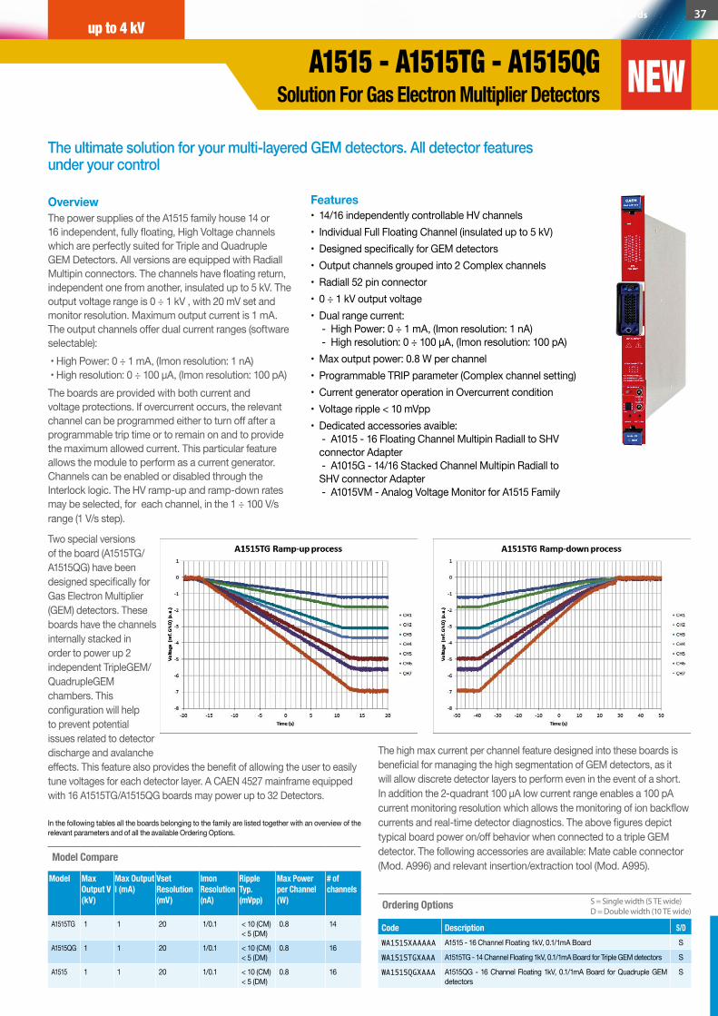
The ultimate solution for your multi-layered GEM detectors. All detector features under your control
OverviewThe power supplies of the A1515 family house 14 or 16 independent, fully floating, High Voltage channels which are perfectly suited for Triple and Quadruple GEM Detectors. All versions are equipped with Radiall Multipin connectors. The channels have floating return, independent one from another, insulated up to 5 kV. The output voltage range is 0 ÷ 1 kV , with 20 mV set and monitor resolution. Maximum output current is 1 mA. The output channels offer dual current ranges (software selectable): • High Power: 0 ÷ 1 mA, (Imon resolution: 1 nA) • High resolution: 0 ÷ 100 µA, (Imon resolution: 100 pA)The boards are provided with both current and voltage protections. If overcurrent occurs, the relevant channel can be programmed either to turn off after a programmable trip time or to remain on and to provide the maximum allowed current. This particular feature allows the module to perform as a current generator. Channels can be enabled or disabled through the Interlock logic. The HV ramp-up and ramp-down rates may be selected, for each channel, in the 1 ÷ 100 V/s range (1 V/s step).
Features • 14/16 independently controllable HV channels• Individual Full Floating Channel (insulated up to 5 kV)• Designed specifically for GEM detectors• Output channels grouped into 2 Complex channels• Radiall 52 pin connector• 0 ÷ 1 kV output voltage• Dual range current:
- High Power: 0 ÷ 1 mA, (Imon resolution: 1 nA) - High resolution: 0 ÷ 100 µA, (Imon resolution: 100 pA)
• Max output power: 0.8 W per channel • Programmable TRIP parameter (Complex channel setting)• Current generator operation in Overcurrent condition• Voltage ripple < 10 mVpp• Dedicated accessories avaible:
- A1015 - 16 Floating Channel Multipin Radiall to SHV connector Adapter - A1015G - 14/16 Stacked Channel Multipin Radiall to SHV connector Adapter - A1015VM - Analog Voltage Monitor for A1515 Family
Ordering Options
Code Description S/DWA1515XAAAAA A1515 - 16 Channel Floating 1kV, 0.1/1mA Board S
WA1515TGXAAA A1515TG - 14 Channel Floating 1kV, 0.1/1mA Board for Triple GEM detectors S
WA1515QGXAAA A1515QG - 16 Channel Floating 1kV, 0.1/1mA Board for Quadruple GEM detectors
S
Two special versions of the board (A1515TG/A1515QG) have been designed specifically for Gas Electron Multiplier (GEM) detectors. These boards have the channels internally stacked in order to power up 2 independent TripleGEM/QuadrupleGEM chambers. This configuration will help to prevent potential issues related to detector discharge and avalanche effects. This feature also provides the benefit of allowing the user to easily tune voltages for each detector layer. A CAEN 4527 mainframe equipped with 16 A1515TG/A1515QG boards may power up to 32 Detectors.
The high max current per channel feature designed into these boards is beneficial for managing the high segmentation of GEM detectors, as it will allow discrete detector layers to perform even in the event of a short. In addition the 2-quadrant 100 µA low current range enables a 100 pA current monitoring resolution which allows the monitoring of ion backflow currents and real-time detector diagnostics. The above figures depict typical board power on/off behavior when connected to a triple GEM detector. The following accessories are available: Mate cable connector (Mod. A996) and relevant insertion/extraction tool (Mod. A995).
In the following tables all the boards belonging to the family are listed together with an overview of the relevant parameters and of all the available Ordering Options.
Model Compare
Model Max Output V (kV)
Max Output I (mA)
Vset Resolution (mV)
Imon Resolution (nA)
Ripple Typ.(mVpp)
Max Power per Channel (W)
# of channels
A1515TG 1 1 20 1/0.1 < 10 (CM) < 5 (DM)
0.8 14
A1515QG 1 1 20 1/0.1 < 10 (CM) < 5 (DM)
0.8 16
A1515 1 1 20 1/0.1 < 10 (CM) < 5 (DM)
0.8 16
S = Single width (5 TE wide)D = Double width (10 TE wide)
Power Supplies / Universal Multichannel Systems / Multichannel Boards 37
A1515 - A1515TG - A1515QGSolution For Gas Electron Multiplier Detectors
up to 4 kV
NEW
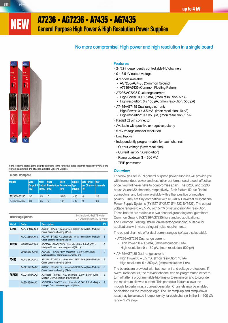
No more compromise! High power and high resolution in a single board
OverviewThis new pair of CAEN general purpose power supplies will provide you with tremendous power and resolution performance at a cost effective price! You will never have to compromise again. The x7235 and x7236 house 24 and 32 channels, respectively. Both feature 52-pin Radiall connectors, and both are available with either positive or negative polarity. They are fully compatible with all CAEN Universal Multichannel Power Supply Systems (SY1527, SY2527, SY4527, SY5527). The output voltage range is 0 ÷ 3.5 kV, with 5 mV of set and monitor resolution. These boards are available in two channel grounding configurations: Common Ground (AG7236/AG7235) for standard applications, and Common Floating Return (on-detector grounding) suitable for applications with more stringent noise requirements.The output channels offer dual current ranges (software selectable). • A7236/AG7236 Dual range current: - High Power: 0 ÷ 1.5 mA, (Imon resolution: 5 nA) - High resolution: 0 ÷ 150 µA, (Imon resolution: 500 pA)• A7435/AG7435 Dual range current: - High Power: 0 ÷ 3.5 mA, (Imon resolution: 10 nA) - High resolution: 0 ÷ 350 µA, (Imon resolution: 1 nA)The boards are provided with both current and voltage protections. If overcurrent occurs, the relevant channel can be programmed either to turn off after a programmable trip time or to remain on and to provide the maximum allowed current. This particular feature allows the module to perform as a current generator. Channels may be enabled or disabled via the Interlock logic. The HV ramp-up and ramp-down rates may be selected independently for each channel in the 1 ÷ 500 V/s range (1 V/s step).
Features• 24/32 independently controllable HV channels• 0 ÷ 3.5 kV output voltage • 4 models available:
- AG7236/AG7435 (Common Ground) - A7236/A7435 (Common Floating Return)
• A7236/AG7236 Dual range current: - High Power: 0 ÷ 1.5 mA, (Imon resolution: 5 nA) - High resolution: 0 ÷ 150 µA, (Imon resolution: 500 pA)
• A7435/AG7435 Dual range current: - High Power: 0 ÷ 3.5 mA, (Imon resolution: 10 nA) - High resolution: 0 ÷ 350 µA, (Imon resolution: 1 nA)
• Radiall 52 pin connector• Available with positive or negative polarity • 5 mV voltage monitor resolution• Low Ripple • Independently programmable for each channel: - Output voltage (5 mV resolution) - Current limit (5 nA resolution) - Ramp up/down (1 ÷ 500 V/s) - TRIP parameter
Ordering Options
Model Code Description S/DA7236 WA7236NXAAA3 A7236N - SYx527 H.V. channels -3.5kV 1.5mA (4W) - Multipin
Conn. common floating (32 ch)S
WA7236PXAAA3 A7236P - SYx527 H.V. channels +3.5kV 1.5mA (4W) - Multipin Conn. common floating (32 ch)
S
AG7236 WAG7236NXAA3 AG7236N - SYx527 H.V. channels -3.5kV 1.5mA (4W) - Multipin Conn. common ground (32 ch)
S
WAG7236PXAA3 AG7236P - SYx527 H.V. channels +3.5kV 1.5mA (4W) - Multipin Conn. common ground (32 ch)
S
A7435 WA7435NXAAA2 A7435N - SYx527 H.V. channels -3.5kV 3.5mA (9W) - Multipin Conn. common floating (24 ch)
S
WA7435PXAAA2 A7435P - SYx527 H.V. channels +3.5kV 3.5mA (9W) - Multipin Conn. common floating (24 ch)
S
AG7435 WAG7435NXAA2 AG7435N - SYx527 H.V. channels -3.5kV 3.5mA (9W) - Multipin Conn. common ground (24 ch)
S
WAG7435NXAA2 AG7435N - SYx527 H.V. channels -3.5kV 3.5mA (9W) - Multipin Conn. common ground (24 ch)
S
Model Compare
Model Max Output V (kV)
Max Output I (mA)
Vset Resolution (mV)
Imon Resolution (nA)
Ripple Typ.(mVpp)
Max Power per Channel (W)
# of channels
A7236/ AG7236 3.5 1.5 5 5/0.5 < 10 4 32
A7435/ AG7435 3.5 3.5 5 10/1 < 15 9 24
In the following tables all the boards belonging to the family are listed together with an overview of the relevant parameters and of all the available Ordering Options.
S = Single width (5 TE wide)D = Double width (10 TE wide)
38 Power Supplies / Universal Multichannel Systems / Multichannel Boards
A7236 - AG7236 - A7435 - AG7435 General Purpose High Power & High Resolution Power Supplies
up to 4 kV
NEW
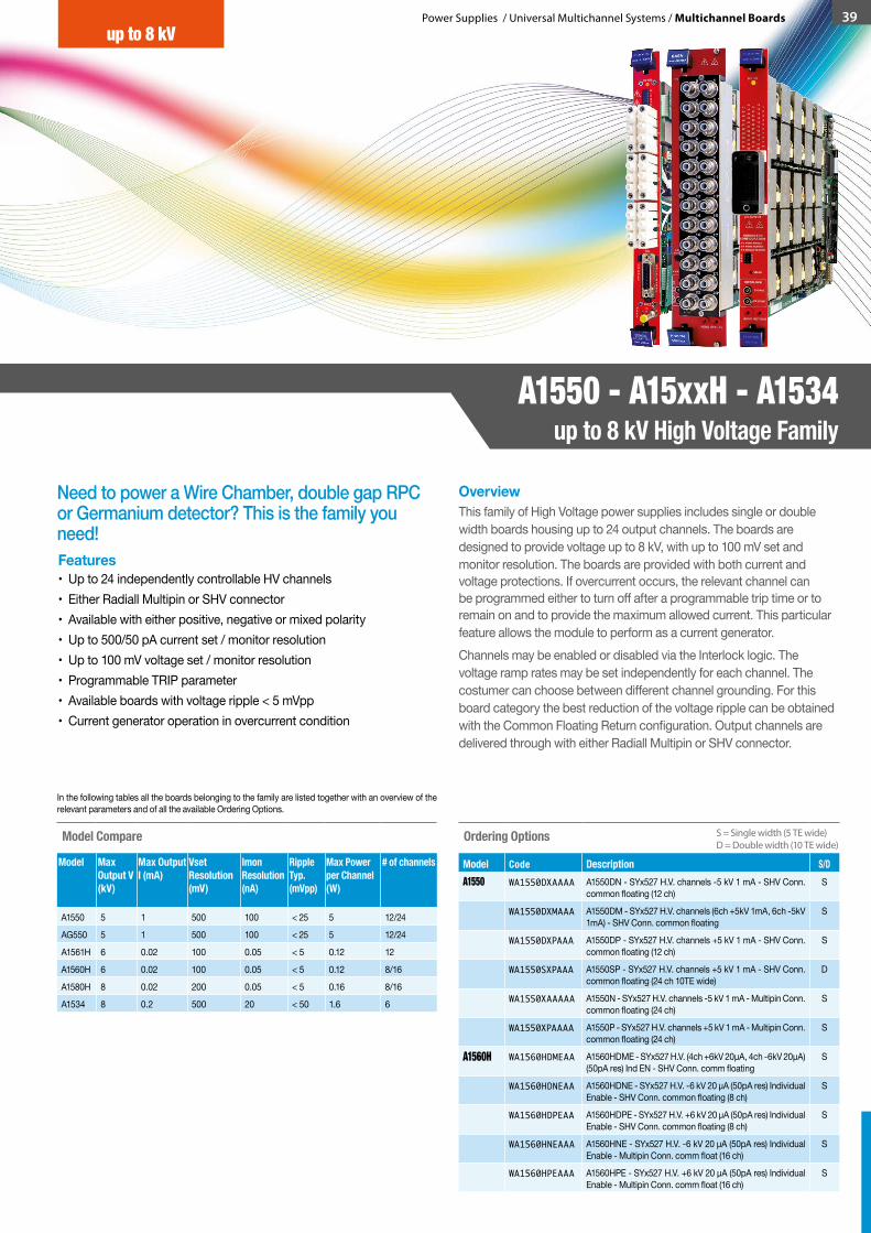
Power Supplies / Universal Multichannel Systems / Multichannel Boards 39
Ordering Options
Model Code Description S/DA1550 WA1550DXAAAA A1550DN - SYx527 H.V. channels -5 kV 1 mA - SHV Conn.
common floating (12 ch)S
WA1550DXMAAA A1550DM - SYx527 H.V. channels (6ch +5kV 1mA, 6ch -5kV 1mA) - SHV Conn. common floating
S
WA1550DXPAAA A1550DP - SYx527 H.V. channels +5 kV 1 mA - SHV Conn. common floating (12 ch)
S
WA1550SXPAAA A1550SP - SYx527 H.V. channels +5 kV 1 mA - SHV Conn. common floating (24 ch 10TE wide)
D
WA1550XAAAAA A1550N - SYx527 H.V. channels -5 kV 1 mA - Multipin Conn. common floating (24 ch)
S
WA1550XPAAAA A1550P - SYx527 H.V. channels +5 kV 1 mA - Multipin Conn. common floating (24 ch)
S
A1560H WA1560HDMEAA A1560HDME - SYx527 H.V. (4ch +6kV 20µA, 4ch -6kV 20µA) (50pA res) Ind EN - SHV Conn. comm floating
S
WA1560HDNEAA A1560HDNE - SYx527 H.V. -6 kV 20 µA (50pA res) Individual Enable - SHV Conn. common floating (8 ch)
S
WA1560HDPEAA A1560HDPE - SYx527 H.V. +6 kV 20 µA (50pA res) Individual Enable - SHV Conn. common floating (8 ch)
S
WA1560HNEAAA A1560HNE - SYx527 H.V. -6 kV 20 µA (50pA res) Individual Enable - Multipin Conn. comm float (16 ch)
S
WA1560HPEAAA A1560HPE - SYx527 H.V. +6 kV 20 µA (50pA res) Individual Enable - Multipin Conn. comm float (16 ch)
S
In the following tables all the boards belonging to the family are listed together with an overview of the relevant parameters and of all the available Ordering Options.
Need to power a Wire Chamber, double gap RPC or Germanium detector? This is the family you need!
OverviewThis family of High Voltage power supplies includes single or double width boards housing up to 24 output channels. The boards are designed to provide voltage up to 8 kV, with up to 100 mV set and monitor resolution. The boards are provided with both current and voltage protections. If overcurrent occurs, the relevant channel can be programmed either to turn off after a programmable trip time or to remain on and to provide the maximum allowed current. This particular feature allows the module to perform as a current generator. Channels may be enabled or disabled via the Interlock logic. The voltage ramp rates may be set independently for each channel. The costumer can choose between different channel grounding. For this board category the best reduction of the voltage ripple can be obtained with the Common Floating Return configuration. Output channels are delivered through with either Radiall Multipin or SHV connector.
Features• Up to 24 independently controllable HV channels• Either Radiall Multipin or SHV connector• Available with either positive, negative or mixed polarity• Up to 500/50 pA current set / monitor resolution• Up to 100 mV voltage set / monitor resolution• Programmable TRIP parameter• Available boards with voltage ripple < 5 mVpp• Current generator operation in overcurrent condition
Model Compare
Model Max Output V (kV)
Max Output I (mA)
Vset Resolution (mV)
Imon Resolution (nA)
RippleTyp.(mVpp)
Max Power per Channel (W)
# of channels
A1550 5 1 500 100 < 25 5 12/24
AG550 5 1 500 100 < 25 5 12/24
A1561H 6 0.02 100 0.05 < 5 0.12 12
A1560H 6 0.02 100 0.05 < 5 0.12 8/16
A1580H 8 0.02 200 0.05 < 5 0.16 8/16
A1534 8 0.2 500 20 < 50 1.6 6
S = Single width (5 TE wide)D = Double width (10 TE wide)
up to 8 kV
A1550 - A15xxH - A1534up to 8 kV High Voltage Family
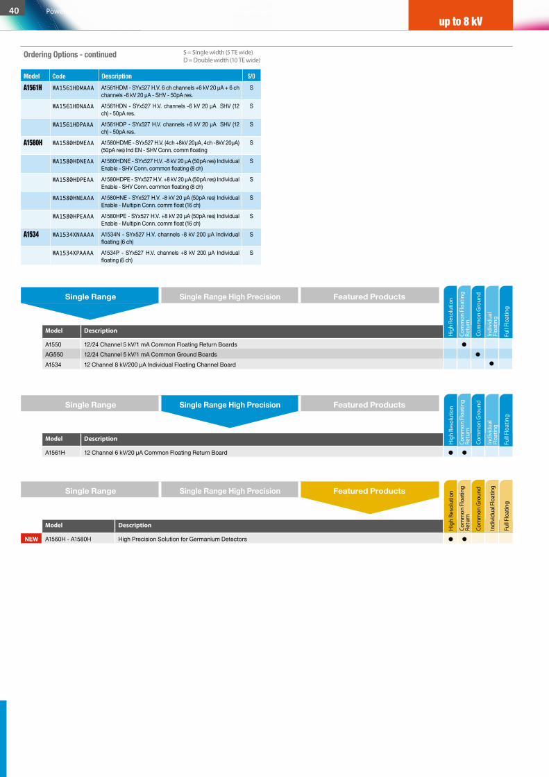
A1561H WA1561HDMAAA A1561HDM - SYx527 H.V. 6 ch channels +6 kV 20 µA + 6 ch channels -6 kV 20 µA - SHV - 50pA res.
S
WA1561HDNAAA A1561HDN - SYx527 H.V. channels -6 kV 20 µA SHV (12 ch) - 50pA res.
S
WA1561HDPAAA A1561HDP - SYx527 H.V. channels +6 kV 20 µA SHV (12 ch) - 50pA res.
S
A1580H WA1580HDMEAA A1580HDME - SYx527 H.V. (4ch +8kV 20µA, 4ch -8kV 20µA) (50pA res) Ind EN - SHV Conn. comm floating
S
WA1580HDNEAA A1580HDNE - SYx527 H.V. -8 kV 20 µA (50pA res) Individual Enable - SHV Conn. common floating (8 ch)
S
WA1580HDPEAA A1580HDPE - SYx527 H.V. +8 kV 20 µA (50pA res) Individual Enable - SHV Conn. common floating (8 ch)
S
WA1580HNEAAA A1580HNE - SYx527 H.V. -8 kV 20 µA (50pA res) Individual Enable - Multipin Conn. comm float (16 ch)
S
WA1580HPEAAA A1580HPE - SYx527 H.V. +8 kV 20 µA (50pA res) Individual Enable - Multipin Conn. comm float (16 ch)
S
A1534 WA1534XNAAAA A1534N - SYx527 H.V. channels -8 kV 200 µA Individual floating (6 ch)
S
WA1534XPAAAA A1534P - SYx527 H.V. channels +8 kV 200 µA Individual floating (6 ch)
S
up to 8 kV
Model Description
A1550 12/24 Channel 5 kV/1 mA Common Floating Return BoardsAG550 12/24 Channel 5 kV/1 mA Common Ground BoardsA1534 12 Channel 8 kV/200 µA Individual Floating Channel Board
Model Description
A1561H 12 Channel 6 kV/20 µA Common Floating Return Board
Model Description
NEW A1560H - A1580H High Precision Solution for Germanium Detectors
Com
mon
Flo
atin
g Re
turn
Com
mon
Flo
atin
g Re
turn
Com
mon
Gro
und
Com
mon
Gro
und
Indi
vidu
al
Floa
ting
Indi
vidu
al
Floa
ting
Hig
h Re
solu
tion
Hig
h Re
solu
tion
Com
mon
Flo
atin
g Re
turn
Com
mon
Gro
und
Indi
vidu
al F
loat
ing
Hig
h Re
solu
tion
Single Range Single Range High Precision Featured Products
Single Range Single Range High Precision Featured Products
Single Range Single Range High Precision Featured Products
Model Code Description S/D
S = Single width (5 TE wide)D = Double width (10 TE wide)
Ordering Options - continued
Full
Floa
ting
Full
Floa
ting
Full F
loat
ing
40 Power Supplies / Universal Multichannel Systems / Multichannel Boards
up to 8 kV
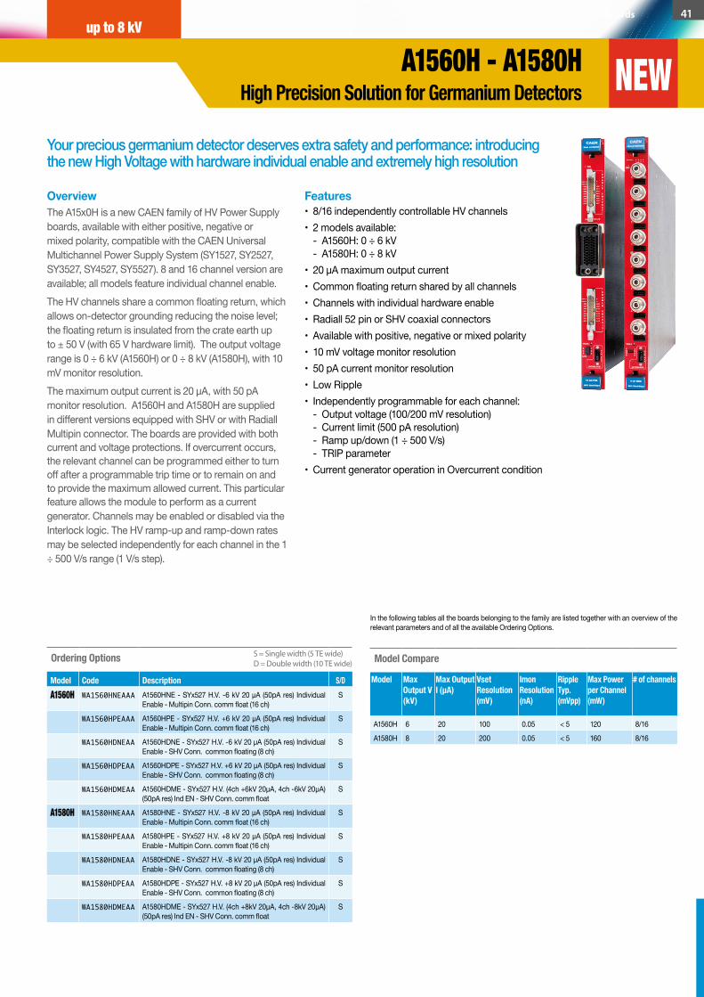
Your precious germanium detector deserves extra safety and performance: introducing the new High Voltage with hardware individual enable and extremely high resolution
OverviewThe A15x0H is a new CAEN family of HV Power Supply boards, available with either positive, negative or mixed polarity, compatible with the CAEN Universal Multichannel Power Supply System (SY1527, SY2527, SY3527, SY4527, SY5527). 8 and 16 channel version are available; all models feature individual channel enable. The HV channels share a common floating return, which allows on-detector grounding reducing the noise level; the floating return is insulated from the crate earth up to ± 50 V (with 65 V hardware limit). The output voltage range is 0 ÷ 6 kV (A1560H) or 0 ÷ 8 kV (A1580H), with 10 mV monitor resolution. The maximum output current is 20 µA, with 50 pA monitor resolution. A1560H and A1580H are supplied in different versions equipped with SHV or with Radiall Multipin connector. The boards are provided with both current and voltage protections. If overcurrent occurs, the relevant channel can be programmed either to turn off after a programmable trip time or to remain on and to provide the maximum allowed current. This particular feature allows the module to perform as a current generator. Channels may be enabled or disabled via the Interlock logic. The HV ramp-up and ramp-down rates may be selected independently for each channel in the 1 ÷ 500 V/s range (1 V/s step).
Features• 8/16 independently controllable HV channels • 2 models available:
- A1560H: 0 ÷ 6 kV - A1580H: 0 ÷ 8 kV
• 20 µA maximum output current • Common floating return shared by all channels • Channels with individual hardware enable • Radiall 52 pin or SHV coaxial connectors • Available with positive, negative or mixed polarity • 10 mV voltage monitor resolution • 50 pA current monitor resolution • Low Ripple • Independently programmable for each channel:
- Output voltage (100/200 mV resolution) - Current limit (500 pA resolution) - Ramp up/down (1 ÷ 500 V/s) - TRIP parameter
• Current generator operation in Overcurrent condition
Ordering Options
Model Code Description S/DA1560H WA1560HNEAAA A1560HNE - SYx527 H.V. -6 kV 20 µA (50pA res) Individual
Enable - Multipin Conn. comm float (16 ch)S
WA1560HPEAAA A1560HPE - SYx527 H.V. +6 kV 20 µA (50pA res) Individual Enable - Multipin Conn. comm float (16 ch)
S
WA1560HDNEAA A1560HDNE - SYx527 H.V. -6 kV 20 µA (50pA res) Individual Enable - SHV Conn. common floating (8 ch)
S
WA1560HDPEAA A1560HDPE - SYx527 H.V. +6 kV 20 µA (50pA res) Individual Enable - SHV Conn. common floating (8 ch)
S
WA1560HDMEAA A1560HDME - SYx527 H.V. (4ch +6kV 20µA, 4ch -6kV 20µA) (50pA res) Ind EN - SHV Conn. comm float
S
A1580H WA1580HNEAAA A1580HNE - SYx527 H.V. -8 kV 20 µA (50pA res) Individual Enable - Multipin Conn. comm float (16 ch)
S
WA1580HPEAAA A1580HPE - SYx527 H.V. +8 kV 20 µA (50pA res) Individual Enable - Multipin Conn. comm float (16 ch)
S
WA1580HDNEAA A1580HDNE - SYx527 H.V. -8 kV 20 µA (50pA res) Individual Enable - SHV Conn. common floating (8 ch)
S
WA1580HDPEAA A1580HDPE - SYx527 H.V. +8 kV 20 µA (50pA res) Individual Enable - SHV Conn. common floating (8 ch)
S
WA1580HDMEAA A1580HDME - SYx527 H.V. (4ch +8kV 20µA, 4ch -8kV 20µA) (50pA res) Ind EN - SHV Conn. comm float
S
In the following tables all the boards belonging to the family are listed together with an overview of the relevant parameters and of all the available Ordering Options.
Model Compare
Model Max Output V (kV)
Max Output I (µA)
Vset Resolution (mV)
Imon Resolution (nA)
RippleTyp.(mVpp)
Max Power per Channel (mW)
# of channels
A1560H 6 20 100 0.05 < 5 120 8/16
A1580H 8 20 200 0.05 < 5 160 8/16
S = Single width (5 TE wide)D = Double width (10 TE wide)
Power Supplies / Universal Multichannel Systems / Multichannel Boards 41up to 8 kV
A1560H - A1580HHigh Precision Solution for Germanium Detectors NEW
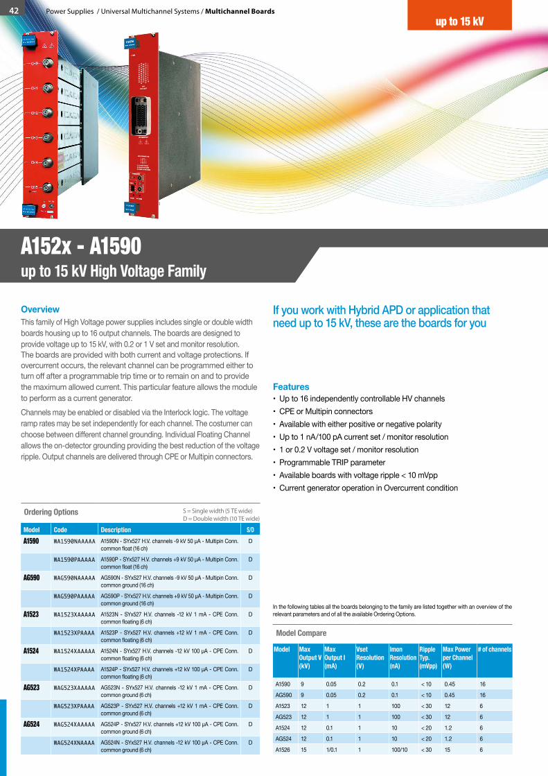
42 Power Supplies / Universal Multichannel Systems / Multichannel Boards
If you work with Hybrid APD or application that need up to 15 kV, these are the boards for you
OverviewThis family of High Voltage power supplies includes single or double width boards housing up to 16 output channels. The boards are designed to provide voltage up to 15 kV, with 0.2 or 1 V set and monitor resolution. The boards are provided with both current and voltage protections. If overcurrent occurs, the relevant channel can be programmed either to turn off after a programmable trip time or to remain on and to provide the maximum allowed current. This particular feature allows the module to perform as a current generator.Channels may be enabled or disabled via the Interlock logic. The voltage ramp rates may be set independently for each channel. The costumer can choose between different channel grounding. Individual Floating Channel allows the on-detector grounding providing the best reduction of the voltage ripple. Output channels are delivered through CPE or Multipin connectors.
Features• Up to 16 independently controllable HV channels• CPE or Multipin connectors• Available with either positive or negative polarity• Up to 1 nA/100 pA current set / monitor resolution• 1 or 0.2 V voltage set / monitor resolution• Programmable TRIP parameter• Available boards with voltage ripple < 10 mVpp• Current generator operation in Overcurrent condition
Ordering Options
Model Code Description S/DA1590 WA1590NAAAAA A1590N - SYx527 H.V. channels -9 kV 50 μA - Multipin Conn.
common float (16 ch)D
WA1590PAAAAA A1590P - SYx527 H.V. channels +9 kV 50 μA - Multipin Conn. common float (16 ch)
D
AG590 WAG590NAAAAA AG590N - SYx527 H.V. channels -9 kV 50 μA - Multipin Conn. common ground (16 ch)
D
WAG590PAAAAA AG590P - SYx527 H.V. channels +9 kV 50 μA - Multipin Conn. common ground (16 ch)
D
A1523 WA1523XAAAAA A1523N - SYx527 H.V. channels -12 kV 1 mA - CPE Conn. common floating (6 ch)
D
WA1523XPAAAA A1523P - SYx527 H.V. channels +12 kV 1 mA - CPE Conn. common floating (6 ch)
D
A1524 WA1524XAAAAA A1524N - SYx527 H.V. channels -12 kV 100 µA - CPE Conn. common floating (6 ch)
D
WA1524XPAAAA A1524P - SYx527 H.V. channels +12 kV 100 µA - CPE Conn. common floating (6 ch)
D
AG523 WAG523XAAAAA AG523N - SYx527 H.V. channels -12 kV 1 mA - CPE Conn. common ground (6 ch)
D
WAG523XPAAAA AG523P - SYx527 H.V. channels +12 kV 1 mA - CPE Conn. common ground (6 ch)
D
AG524 WAG524XAAAAA AG524P - SYx527 H.V. channels +12 kV 100 μA - CPE Conn. common ground (6 ch)
D
WAG524XNAAAA AG524N - SYx527 H.V. channels -12 kV 100 μA - CPE Conn. common ground (6 ch)
D
In the following tables all the boards belonging to the family are listed together with an overview of the relevant parameters and of all the available Ordering Options.
Model Compare
Model Max Output V (kV)
Max Output I (mA)
Vset Resolution (V)
Imon Resolution (nA)
RippleTyp.(mVpp)
Max Power per Channel (W)
# of channels
A1590 9 0.05 0.2 0.1 < 10 0.45 16
AG590 9 0.05 0.2 0.1 < 10 0.45 16
A1523 12 1 1 100 < 30 12 6
AG523 12 1 1 100 < 30 12 6
A1524 12 0.1 1 10 < 20 1.2 6
AG524 12 0.1 1 10 < 20 1.2 6
A1526 15 1/0.1 1 100/10 < 30 15 6
S = Single width (5 TE wide)D = Double width (10 TE wide)
up to 15 kV
A152x - A1590up to 15 kV High Voltage Family

up to 15 kV
Model Description
NEW A1590 16 Channel 9 kV/50 µA Common Floating Return BoardNEW AG590 16 Channel 9 kV/50 µA Common Ground Board
A1523 6 Channel 12 kV/1 mA Common Floating Return BoardA1524 6 Channel 12 kV/100 µA Common Floating Return BoardAG523 6 Channel 12 kV/1 mA Common Ground BoardAG524 6 Channel 12 kV/100 µA Common Ground Board
Single Range Single Range High Precision Featured Products
Model Description
A1526 6 Channel 15 kV, 1/0.1 mA Common Floating Return Board
Model Description
A1526 Solution for Resistive Plate Chamber and other gas detectors
Com
mon
Flo
atin
g Re
turn
Com
mon
Gro
und
Indi
vidu
al
Floa
ting
Hig
h Re
solu
tion
Com
mon
Flo
atin
g Re
turn
Com
mon
Gro
und
Indi
vidu
al F
loat
ing
Hig
h Re
solu
tion
Single Range Single Range High Precision Featured Products
Single Range Single Range High Precision Featured Products
Full
Floa
ting
Full F
loat
ing
Com
mon
Flo
atin
g Re
turn
Com
mon
Gro
und
Indi
vidu
al
Floa
ting
Hig
h Re
solu
tion
Full
Floa
ting
Power Supplies / Universal Multichannel Systems / Multichannel Boards 43up to 15 kV
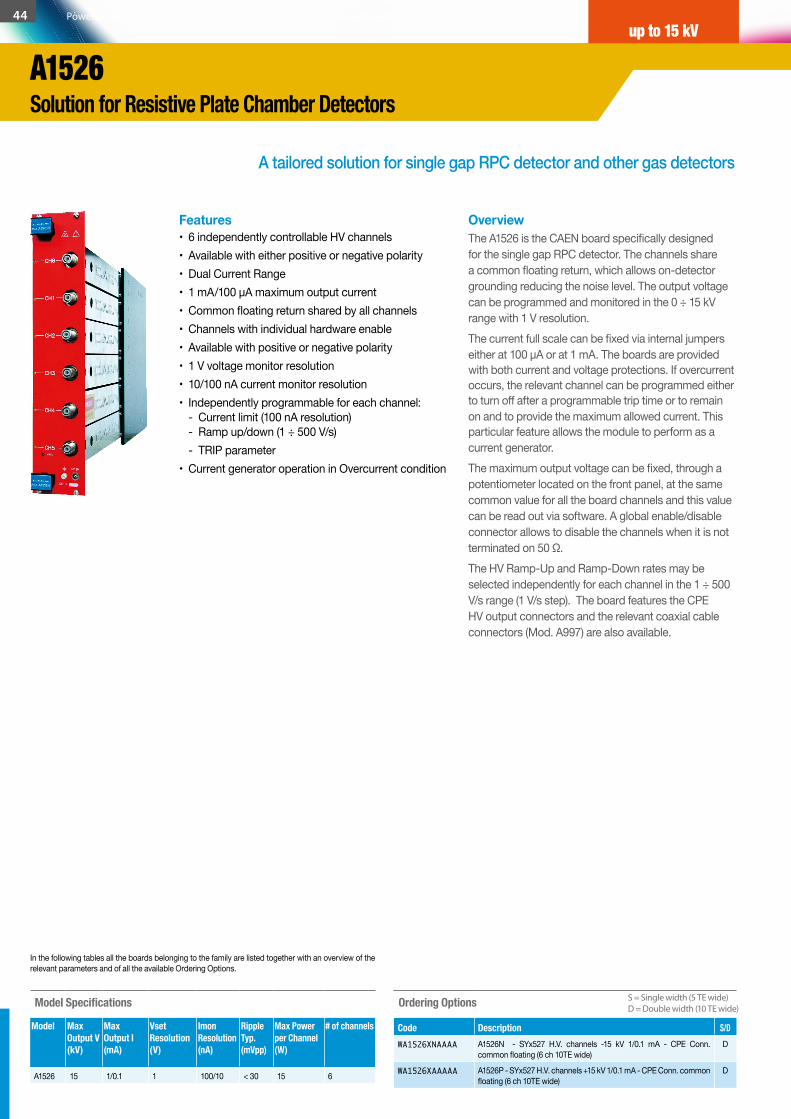
A tailored solution for single gap RPC detector and other gas detectors
OverviewThe A1526 is the CAEN board specifically designed for the single gap RPC detector. The channels share a common floating return, which allows on-detector grounding reducing the noise level. The output voltage can be programmed and monitored in the 0 ÷ 15 kV range with 1 V resolution. The current full scale can be fixed via internal jumpers either at 100 µA or at 1 mA. The boards are provided with both current and voltage protections. If overcurrent occurs, the relevant channel can be programmed either to turn off after a programmable trip time or to remain on and to provide the maximum allowed current. This particular feature allows the module to perform as a current generator.The maximum output voltage can be fixed, through a potentiometer located on the front panel, at the same common value for all the board channels and this value can be read out via software. A global enable/disable connector allows to disable the channels when it is not terminated on 50 Ω.The HV Ramp-Up and Ramp-Down rates may be selected independently for each channel in the 1 ÷ 500 V/s range (1 V/s step). The board features the CPE HV output connectors and the relevant coaxial cable connectors (Mod. A997) are also available.
Features• 6 independently controllable HV channels • Available with either positive or negative polarity• Dual Current Range• 1 mA/100 µA maximum output current • Common floating return shared by all channels • Channels with individual hardware enable • Available with positive or negative polarity • 1 V voltage monitor resolution • 10/100 nA current monitor resolution • Independently programmable for each channel:
- Current limit (100 nA resolution) - Ramp up/down (1 ÷ 500 V/s)
- TRIP parameter • Current generator operation in Overcurrent condition
Ordering Options
Code Description S/DWA1526XNAAAA A1526N - SYx527 H.V. channels -15 kV 1/0.1 mA - CPE Conn.
common floating (6 ch 10TE wide)D
WA1526XAAAAA A1526P - SYx527 H.V. channels +15 kV 1/0.1 mA - CPE Conn. common floating (6 ch 10TE wide)
D
In the following tables all the boards belonging to the family are listed together with an overview of the relevant parameters and of all the available Ordering Options.
Model Specifications
Model Max Output V (kV)
Max Output I(mA)
Vset Resolution (V)
Imon Resolution (nA)
Ripple Typ.(mVpp)
Max Power per Channel (W)
# of channels
A1526 15 1/0.1 1 100/10 < 30 15 6
S = Single width (5 TE wide)D = Double width (10 TE wide)
44 Power Supplies / Universal Multichannel Systems / Multichannel Boards
A1526Solution for Resistive Plate Chamber Detectors
up to 15 kV
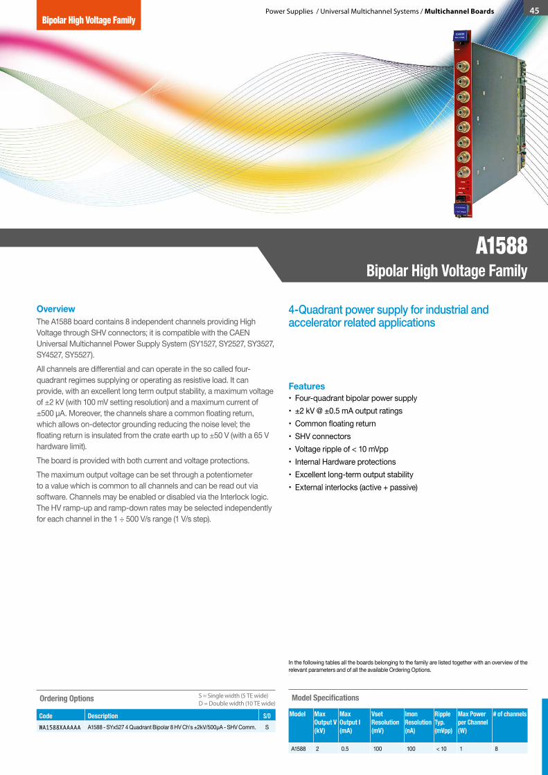
Power Supplies / Universal Multichannel Systems / Multichannel Boards 45
4-Quadrant power supply for industrial and accelerator related applications
OverviewThe A1588 board contains 8 independent channels providing High Voltage through SHV connectors; it is compatible with the CAEN Universal Multichannel Power Supply System (SY1527, SY2527, SY3527, SY4527, SY5527).All channels are differential and can operate in the so called four-quadrant regimes supplying or operating as resistive load. It can provide, with an excellent long term output stability, a maximum voltage of ±2 kV (with 100 mV setting resolution) and a maximum current of ±500 µA. Moreover, the channels share a common floating return, which allows on-detector grounding reducing the noise level; the floating return is insulated from the crate earth up to ±50 V (with a 65 V hardware limit).The board is provided with both current and voltage protections. The maximum output voltage can be set through a potentiometer to a value which is common to all channels and can be read out via software. Channels may be enabled or disabled via the Interlock logic. The HV ramp-up and ramp-down rates may be selected independently for each channel in the 1 ÷ 500 V/s range (1 V/s step).
Features• Four-quadrant bipolar power supply • ±2 kV @ ±0.5 mA output ratings • Common floating return • SHV connectors • Voltage ripple of < 10 mVpp• Internal Hardware protections • Excellent long-term output stability• External interlocks (active + passive)
In the following tables all the boards belonging to the family are listed together with an overview of the relevant parameters and of all the available Ordering Options.
Model Specifications
Model Max Output V(kV)
Max Output I(mA)
Vset Resolution(mV)
Imon Resolution(nA)
RippleTyp.(mVpp)
Max Power per Channel (W)
# of channels
A1588 2 0.5 100 100 < 10 1 8
Ordering Options
Code Description S/DWA1588XAAAAA A1588 - SYx527 4 Quadrant Bipolar 8 HV Ch's ±2kV/500µA - SHV Comm. S
S = Single width (5 TE wide)D = Double width (10 TE wide)
A1588Bipolar High Voltage Family
Bipolar High Voltage Family
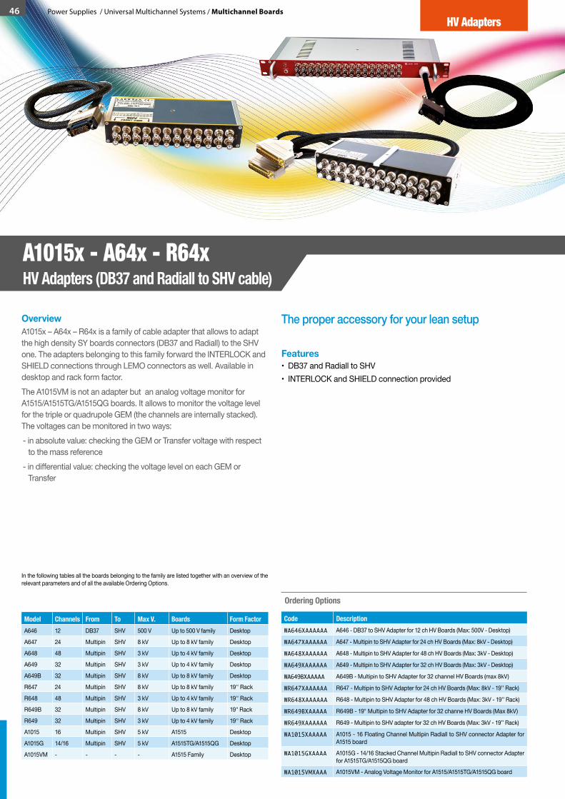
46 Power Supplies / Universal Multichannel Systems / Multichannel Boards
Model Channels From To Max V. Boards Form Factor A646 12 DB37 SHV 500 V Up to 500 V family Desktop
A647 24 Multipin SHV 8 kV Up to 8 kV family Desktop
A648 48 Multipin SHV 3 kV Up to 4 kV family Desktop
A649 32 Multipin SHV 3 kV Up to 4 kV family Desktop
A649B 32 Multipin SHV 8 kV Up to 8 kV family Desktop
R647 24 Multipin SHV 8 kV Up to 8 kV family 19'' Rack
R648 48 Multipin SHV 3 kV Up to 4 kV family 19'' Rack
R649B 32 Multipin SHV 8 kV Up to 8 kV family 19" Rack
R649 32 Multipin SHV 3 kV Up to 4 kV family 19'' Rack
A1015 16 Multipin SHV 5 kV A1515 Desktop
A1015G 14/16 Multipin SHV 5 kV A1515TG/A1515QG Desktop
A1015VM - - - - A1515 Family Desktop
The proper accessory for your lean setupOverviewA1015x – A64x – R64x is a family of cable adapter that allows to adapt the high density SY boards connectors (DB37 and Radiall) to the SHV one. The adapters belonging to this family forward the INTERLOCK and SHIELD connections through LEMO connectors as well. Available in desktop and rack form factor.The A1015VM is not an adapter but an analog voltage monitor for A1515/A1515TG/A1515QG boards. It allows to monitor the voltage level for the triple or quadrupole GEM (the channels are internally stacked). The voltages can be monitored in two ways:- in absolute value: checking the GEM or Transfer voltage with respect
to the mass reference- in differential value: checking the voltage level on each GEM or
Transfer
Features• DB37 and Radiall to SHV• INTERLOCK and SHIELD connection provided
Ordering Options
Code DescriptionWA646XAAAAAA A646 - DB37 to SHV Adapter for 12 ch HV Boards (Max: 500V - Desktop)
WA647XAAAAAA A647 - Multipin to SHV Adapter for 24 ch HV Boards (Max: 8kV - Desktop)
WA648XAAAAAA A648 - Multipin to SHV Adapter for 48 ch HV Boards (Max: 3kV - Desktop)
WA649XAAAAAA A649 - Multipin to SHV Adapter for 32 ch HV Boards (Max: 3kV - Desktop)
WA649BXAAAAA A649B - Multipin to SHV Adapter for 32 channel HV Boards (max 8kV)
WR647XAAAAAA R647 - Multipin to SHV Adapter for 24 ch HV Boards (Max: 8kV - 19’’ Rack)
WR648XAAAAAA R648 - Multipin to SHV Adapter for 48 ch HV Boards (Max: 3kV - 19’’ Rack)
WR649BXAAAAA R649B - 19" Multipin to SHV Adapter for 32 channe HV Boards (Max 8kV)
WR649XAAAAAA R649 - Multipin to SHV adapter for 32 ch HV Boards (Max: 3kV - 19’’ Rack)
WA1015XAAAAA A1015 - 16 Floating Channel Multipin Radiall to SHV connector Adapter for A1515 board
WA1015GXAAAA A1015G - 14/16 Stacked Channel Multipin Radiall to SHV connector Adapter for A1515TG/A1515QG board
WA1015VMXAAA A1015VM - Analog Voltage Monitor for A1515/A1515TG/A1515QG board
In the following tables all the boards belonging to the family are listed together with an overview of the relevant parameters and of all the available Ordering Options.
A1015x - A64x - R64xHV Adapters (DB37 and Radiall to SHV cable)
HV Adapters

The VME boards are a fingerprint of CAEN production.Initially born for data acquisition and front end applications, CAEN has recently introduced a new series of VME programmable HV boards, able to fit the same standard crate of DAQ systems. Thanks to the innovative GECO2020 Control Software and the multimaster capability of CAEN VME Bridges, it is possible to control independently the VME DAQ and the VME Power Supply Units.
NIM power supply is a trademark in CAEN products. Thanks to the latest designs CAEN offer a wider selection and an improved usability by the introduction of the GECO2020 software. The NIM Line includes also the NDT power supplies, which are hosted in a NIM module and can be plugged in NIM crates for power but have also the chance of Desktop operation thanks to a mains power supply cord.
VME-NIMPower Supplies
VME High Voltage Power Supplies
NIM High Voltage Power Supplies
NIM Low Voltage Power Supplies
CAEN 2016 / 2017 Product Catalog
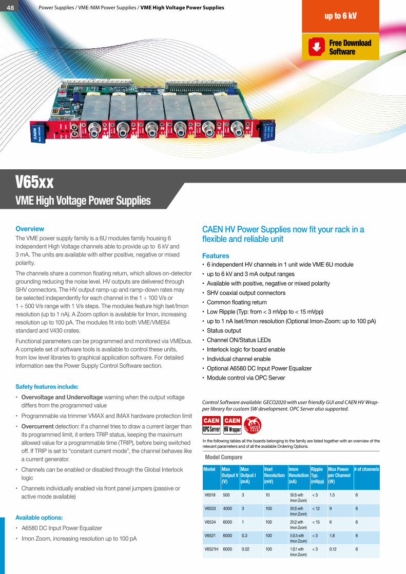
48 Power Supplies / VME-NIM Power Supplies / VME High Voltage Power Supplies
CAEN HV Power Supplies now fit your rack in a flexible and reliable unit
OverviewThe VME power supply family is a 6U modules family housing 6 independent High Voltage channels able to provide up to 6 kV and 3 mA. The units are available with either positive, negative or mixed polarity. The channels share a common floating return, which allows on-detector grounding reducing the noise level. HV outputs are delivered through SHV connectors. The HV output ramp-up and ramp-down rates may be selected independently for each channel in the 1 ÷ 100 V/s or 1 ÷ 500 V/s range with 1 V/s steps. The modules feature high Iset/Imon resolution (up to 1 nA). A Zoom option is available for Imon, increasing resolution up to 100 pA. The modules fit into both VME/VME64 standard and V430 crates.Functional parameters can be programmed and monitored via VMEbus. A complete set of software tools is available to control these units, from low level libraries to graphical application software. For detailed information see the Power Supply Control Software section.
Safety features include:• Overvoltage and Undervoltage warning when the output voltage
differs from the programmed value• Programmable via trimmer VMAX and IMAX hardware protection limit• Overcurrent detection: if a channel tries to draw a current larger than
its programmed limit, it enters TRIP status, keeping the maximum allowed value for a programmable time (TRIP), before being switched off. If TRIP is set to “constant current mode”, the channel behaves like a current generator.
• Channels can be enabled or disabled through the Global Interlock logic
• Channels individually enabled via front panel jumpers (passive or active mode available)
Available options:• A6580 DC Input Power Equalizer• Imon Zoom, increasing resolution up to 100 pA
Features• 6 independent HV channels in 1 unit wide VME 6U module• up to 6 kV and 3 mA output ranges• Available with positive, negative or mixed polarity• SHV coaxial output connectors• Common floating return• Low Ripple (Typ: from < 3 mVpp to < 15 mVpp)• up to 1 nA Iset/Imon resolution (Optional Imon-Zoom: up to 100 pA)• Status output• Channel ON/Status LEDs• Interlock logic for board enable• Individual channel enable• Optional A6580 DC Input Power Equalizer• Module control via OPC Server
Control Software available: GECO2020 with user friendly GUI and CAEN HV Wrap-per library for custom SW development. OPC Server also supported.
Model Compare
Model Max Output V(V)
Max Output I(mA)
Vset Resolution(mV)
Imon Resolution(nA)
RippleTyp.(mVpp)
Max Power per Channel (W)
# of channels
V6519 500 3 10 50 (5 with Imon Zoom)
< 3 1.5 6
V6533 4000 3 100 50 (5 with Imon Zoom)
< 12 9 6
V6534 6000 1 100 20 (2 with Imon Zoom)
< 15 6 6
V6521 6000 0.3 100 5 (0.5 with Imon Zoom)
< 3 1.8 6
V6521H 6000 0.02 100 1 (0.1 with Imon Zoom)
< 3 0.12 6
In the following tables all the boards belonging to the family are listed together with an overview of the relevant parameters and of all the available Ordering Options.
V65xxVME High Voltage Power Supplies
up to 6 kV
Free Download Software
GECO2 2 00
CA
E
N
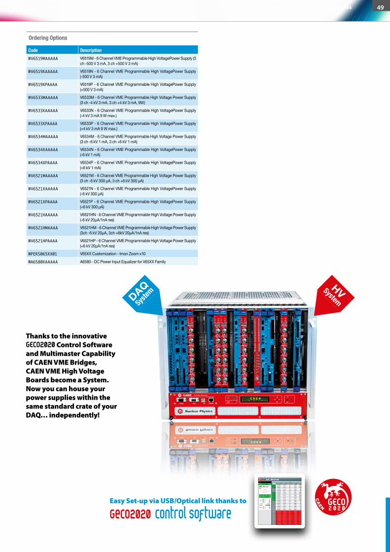
Ordering Options
Code DescriptionWV6519MAAAAA V6519M - 6 Channel VME Programmable High VoltagePower Supply (3
ch -500 V 3 mA, 3 ch +500 V 3 mA)
WV6519XAAAAA V6519N - 6 Channel VME Programmable High VoltagePower Supply (-500 V 3 mA)
WV6519XPAAAA V6519P - 6 Channel VME Programmable High VoltagePower Supply (+500 V 3 mA)
WV6533MAAAAA V6533M - 6 Channel VME Programmable High Voltage Power Supply (3 ch -4 kV 3 mA, 3 ch +4 kV 3 mA, 9W)
WV6533XAAAAA V6533N - 6 Channel VME Programmable High VoltagePower Supply (-4 kV 3 mA 9 W max.)
WV6533XPAAAA V6533P - 6 Channel VME Programmable High VoltagePower Supply (+4 kV 3 mA 9 W max.)
WV6534MAAAAA V6534M - 6 Channel VME Programmable High Voltage Power Supply (3 ch -6 kV 1 mA, 3 ch +6 kV 1 mA)
WV6534XAAAAA V6534N - 6 Channel VME Programmable High VoltagePower Supply (-6 kV 1 mA)
WV6534XPAAAA V6534P - 6 Channel VME Programmable High VoltagePower Supply (+6 kV 1 mA)
WV6521MAAAAA V6521M - 6 Channel VME Programmable High Voltage Power Supply (3 ch -6 kV 300 μA, 3 ch +6 kV 300 μA)
WV6521XAAAAA V6521N - 6 Channel VME Programmable High VoltagePower Supply (-6 kV 300 μA)
WV6521XPAAAA V6521P - 6 Channel VME Programmable High VoltagePower Supply (+6 kV 300 μA)
WV6521HAAAAA V6521HN - 6 Channel VME Programmable High Voltage Power Supply (-6 kV 20μA/1nA res)
WV6521HMAAAA V6521HM - 6 Channel VME Programmable High Voltage Power Supply (3ch -6 kV 20μA, 3ch +6kV 20µA/1nA res)
WV6521HPAAAA V6521HP - 6 Channel VME Programmable High Voltage Power Supply (+6 kV 20μA/1nA res)
WPERS065XX01 V65XX Customization - Imon Zoom x10
WA6580XAAAAA A6580 - DC Power Input Equalizer for V65XX Family
GECO2 2 00
CA
E
N
49 Power Supplies / VME-NIM Power Supplies / NIM High Voltage Power Supplies
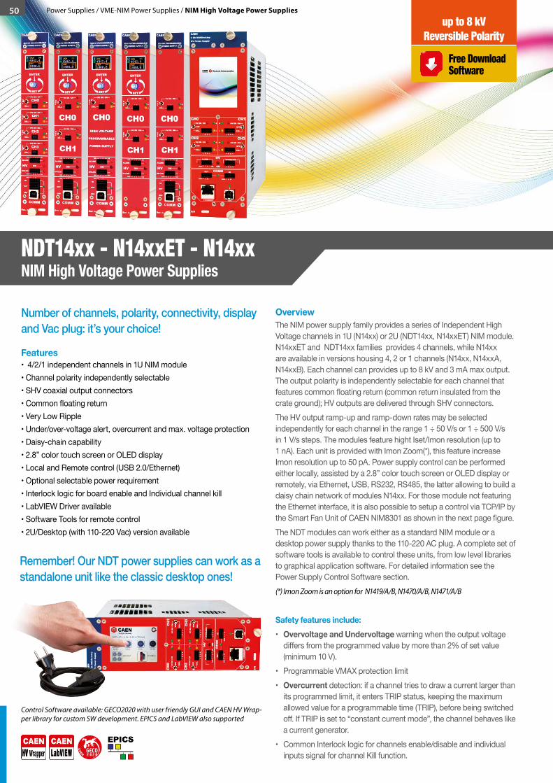
50 Power Supplies / VME-NIM Power Supplies / NIM High Voltage Power Supplies
Number of channels, polarity, connectivity, display and Vac plug: it’s your choice!
Features• 4/2/1 independent channels in 1U NIM module• Channel polarity independently selectable• SHV coaxial output connectors• Common floating return• Very Low Ripple• Under/over-voltage alert, overcurrent and max. voltage protection• Daisy-chain capability• 2.8” color touch screen or OLED display• Local and Remote control (USB 2.0/Ethernet)• Optional selectable power requirement• Interlock logic for board enable and Individual channel kill• LabVIEW Driver available• Software Tools for remote control• 2U/Desktop (with 110-220 Vac) version available
OverviewThe NIM power supply family provides a series of Independent High Voltage channels in 1U (N14xx) or 2U (NDT14xx, N14xxET) NIM module.N14xxET and NDT14xx families provides 4 channels, while N14xx are available in versions housing 4, 2 or 1 channels (N14xx, N14xxA, N14xxB). Each channel can provides up to 8 kV and 3 mA max output. The output polarity is independently selectable for each channel that features common floating return (common return insulated from the crate ground); HV outputs are delivered through SHV connectors.The HV output ramp-up and ramp-down rates may be selected independently for each channel in the range 1 ÷ 50 V/s or 1 ÷ 500 V/s in 1 V/s steps. The modules feature hight Iset/Imon resolution (up to 1 nA). Each unit is provided with Imon Zoom(*), this feature increase Imon resolution up to 50 pA. Power supply control can be performed either locally, assisted by a 2.8” color touch screen or OLED display or remotely, via Ethernet, USB, RS232, RS485, the latter allowing to build a daisy chain network of modules N14xx. For those module not featuring the Ethernet interface, it is also possible to setup a control via TCP/IP by the Smart Fan Unit of CAEN NIM8301 as shown in the next page figure. The NDT modules can work either as a standard NIM module or a desktop power supply thanks to the 110-220 AC plug. A complete set of software tools is available to control these units, from low level libraries to graphical application software. For detailed information see the Power Supply Control Software section. (*) Imon Zoom is an option for N1419/A/B, N1470/A/B, N1471/A/B
Safety features include:• Overvoltage and Undervoltage warning when the output voltage
differs from the programmed value by more than 2% of set value (minimum 10 V).
• Programmable VMAX protection limit• Overcurrent detection: if a channel tries to draw a current larger than
its programmed limit, it enters TRIP status, keeping the maximum allowed value for a programmable time (TRIP), before being switched off. If TRIP is set to “constant current mode”, the channel behaves like a current generator.
• Common Interlock logic for channels enable/disable and individual inputs signal for channel Kill function.
Control Software available: GECO2020 with user friendly GUI and CAEN HV Wrap-per library for custom SW development. EPICS and LabVIEW also supported
Remember! Our NDT power supplies can work as a standalone unit like the classic desktop ones!
GECO2 2 00
CA
E
N
NDT14xx - N14xxET - N14xx NIM High Voltage Power Supplies
Free Download Software
up to 8 kVReversible Polarity
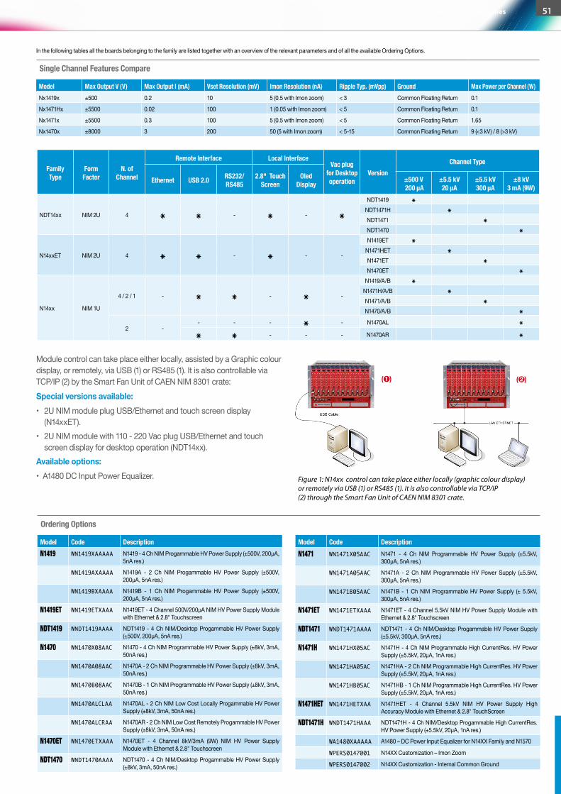
Single Channel Features Compare
Model Max Output V (V) Max Output I (mA) Vset Resolution (mV) Imon Resolution (nA) Ripple Typ. (mVpp) Ground Max Power per Channel (W)Nx1419x ±500 0.2 10 5 (0.5 with Imon zoom) < 3 Common Floating Return 0.1
Nx1471Hx ±5500 0.02 100 1 (0.05 with Imon zoom) < 5 Common Floating Return 0.1
Nx1471x ±5500 0.3 100 5 (0.5 with Imon zoom) < 5 Common Floating Return 1.65
Nx1470x ±8000 3 200 50 (5 with Imon zoom) < 5-15 Common Floating Return 9 (<3 kV) / 8 (>3 kV)
Module control can take place either locally, assisted by a Graphic colour display, or remotely, via USB (1) or RS485 (1). It is also controllable via TCP/IP (2) by the Smart Fan Unit of CAEN NIM 8301 crate:Special versions available:• 2U NIM module plug USB/Ethernet and touch screen display
(N14xxET).• 2U NIM module with 110 - 220 Vac plug USB/Ethernet and touch
screen display for desktop operation (NDT14xx).Available options:• A1480 DC Input Power Equalizer.
Family Type
Form Factor
N. of Channel
Remote Interface Local InterfaceVac plug
for Desktop operation
VersionChannel Type
Ethernet USB 2.0 RS232/RS485
2.8" Touch Screen
Oled Display
±500 V 200 µA
±5.5 kV20 µA
±5.5 kV300 µA
±8 kV 3 mA (9W)
NDT14xx NIM 2U 4 ⁕ ⁕ - ⁕ - ⁕
NDT1419 ⁕NDT1471H ⁕NDT1471 ⁕NDT1470 ⁕
N14xxET NIM 2U 4 ⁕ ⁕ - ⁕ - -
N1419ET ⁕N1471HET ⁕N1471ET ⁕N1470ET ⁕
N14xx NIM 1U
4 / 2 / 1 - ⁕ ⁕ - ⁕ -
N1419/A/B ⁕N1471H/A/B ⁕N1471/A/B ⁕N1470/A/B ⁕
2 -- - - ⁕ - N1470AL ⁕
⁕ ⁕ - - - N1470AR ⁕
In the following tables all the boards belonging to the family are listed together with an overview of the relevant parameters and of all the available Ordering Options.
Model Code DescriptionN1419 WN1419XAAAAA N1419 - 4 Ch NIM Progammable HV Power Supply (±500V, 200μA,
5nA res.)
WN1419AXAAAA N1419A - 2 Ch NIM Progammable HV Power Supply (±500V, 200μA, 5nA res.)
WN1419BXAAAA N1419B - 1 Ch NIM Progammable HV Power Supply (±500V, 200μA, 5nA res.)
N1419ET WN1419ETXAAA N1419ET - 4 Channel 500V/200µA NIM HV Power Supply Module with Ethernet & 2.8" Touchscreen
NDT1419 WNDT1419AAAA NDT1419 - 4 Ch NIM/Desktop Progammable HV Power Supply (±500V, 200µA, 5nA res.)
N1470 WN1470X08AAC N1470 - 4 Ch NIM Programmable HV Power Supply (±8kV, 3mA, 50nA res.)
WN1470A08AAC N1470A - 2 Ch NIM Programmable HV Power Supply (±8kV, 3mA, 50nA res.)
WN1470B08AAC N1470B - 1 Ch NIM Programmable HV Power Supply (±8kV, 3mA, 50nA res.)
WN1470ALCLAA N1470AL - 2 Ch NIM Low Cost Locally Progammable HV Power Supply (±8kV, 3mA, 50nA res.)
WN1470ALCRAA N1470AR - 2 Ch NIM Low Cost Remotely Progammable HV Power Supply (±8kV, 3mA, 50nA res.)
N1470ET WN1470ETXAAA N1470ET - 4 Channel 8kV/3mA (9W) NIM HV Power Supply Module with Ethernet & 2.8" Touchscreen
NDT1470 WNDT1470AAAA NDT1470 - 4 Ch NIM/Desktop Progammable HV Power Supply (±8kV, 3mA, 50nA res.)
Model Code DescriptionN1471 WN1471X05AAC N1471 - 4 Ch NIM Programmable HV Power Supply (±5.5kV,
300μA, 5nA res.)
WN1471A05AAC N1471A - 2 Ch NIM Programmable HV Power Supply (±5.5kV, 300μA, 5nA res.)
WN1471B05AAC N1471B - 1 Ch NIM Programmable HV Power Supply (± 5.5kV, 300μA, 5nA res.)
N1471ET WN1471ETXAAA N1471ET - 4 Channel 5.5kV NIM HV Power Supply Module with Ethernet & 2.8" Touchscreen
NDT1471 WNDT1471AAAA NDT1471 - 4 Ch NIM/Desktop Progammable HV Power Supply (±5.5kV, 300µA, 5nA res.)
N1471H WN1471HX05AC N1471H - 4 Ch NIM Programmable High CurrentRes. HV Power Supply (±5.5kV, 20μA, 1nA res.)
WN1471HA05AC N1471HA - 2 Ch NIM Programmable High CurrentRes. HV Power Supply (±5.5kV, 20μA, 1nA res.)
WN1471HB05AC N1471HB - 1 Ch NIM Programmable High CurrentRes. HV Power Supply (±5.5kV, 20μA, 1nA res.)
N1471HET WN1471HETXAA N1471HET - 4 Channel 5.5kV NIM HV Power Supply High Accuracy Module with Ethernet & 2.8" TouchScreen
NDT1471H WNDT1471HAAA NDT1471H - 4 Ch NIM/Desktop Progammable High CurrentRes. HV Power Supply (±5.5kV, 20µA, 1nA res.)
WA1480XAAAAA A1480 – DC Power Input Equalizer for N14XX Family and N1570
WPERS0147001 N14XX Customization – Imon Zoom
WPERS0147002 N14XX Customization - Internal Common Ground
Ordering Options
Figure 1: N14xx control can take place either locally (graphic colour display) or remotely via USB (1) or RS485 (1). It is also controllable via TCP/IP (2) through the Smart Fan Unit of CAEN NIM 8301 crate.
51Power Supplies / NIM High Voltage Power Supplies
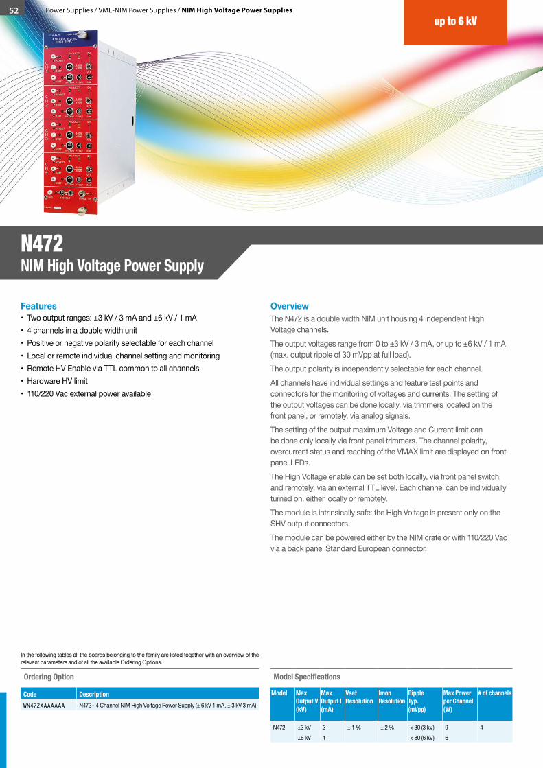
52 Power Supplies / VME-NIM Power Supplies / NIM High Voltage Power Supplies
Ordering Option
Code DescriptionWN472XAAAAAA N472 - 4 Channel NIM High Voltage Power Supply (± 6 kV 1 mA, ± 3 kV 3 mA)
Model Specifications
Model Max Output V(kV)
Max Output I(mA)
Vset Resolution
Imon Resolution
Ripple Typ.(mVpp)
Max Power per Channel (W)
# of channels
N472 ±3 kV±6 kV
31
± 1 % ± 2 % < 30 (3 kV)< 80 (6 kV)
96
4
Features• Two output ranges: ±3 kV / 3 mA and ±6 kV / 1 mA• 4 channels in a double width unit • Positive or negative polarity selectable for each channel• Local or remote individual channel setting and monitoring• Remote HV Enable via TTL common to all channels• Hardware HV limit• 110/220 Vac external power available
OverviewThe N472 is a double width NIM unit housing 4 independent High Voltage channels. The output voltages range from 0 to ±3 kV / 3 mA, or up to ±6 kV / 1 mA (max. output ripple of 30 mVpp at full load).The output polarity is independently selectable for each channel. All channels have individual settings and feature test points and connectors for the monitoring of voltages and currents. The setting of the output voltages can be done locally, via trimmers located on the front panel, or remotely, via analog signals. The setting of the output maximum Voltage and Current limit can be done only locally via front panel trimmers. The channel polarity, overcurrent status and reaching of the VMAX limit are displayed on front panel LEDs.The High Voltage enable can be set both locally, via front panel switch, and remotely, via an external TTL level. Each channel can be individually turned on, either locally or remotely.The module is intrinsically safe: the High Voltage is present only on the SHV output connectors. The module can be powered either by the NIM crate or with 110/220 Vac via a back panel Standard European connector.
In the following tables all the boards belonging to the family are listed together with an overview of the relevant parameters and of all the available Ordering Options.
up to 6 kV
N472 NIM High Voltage Power Supply
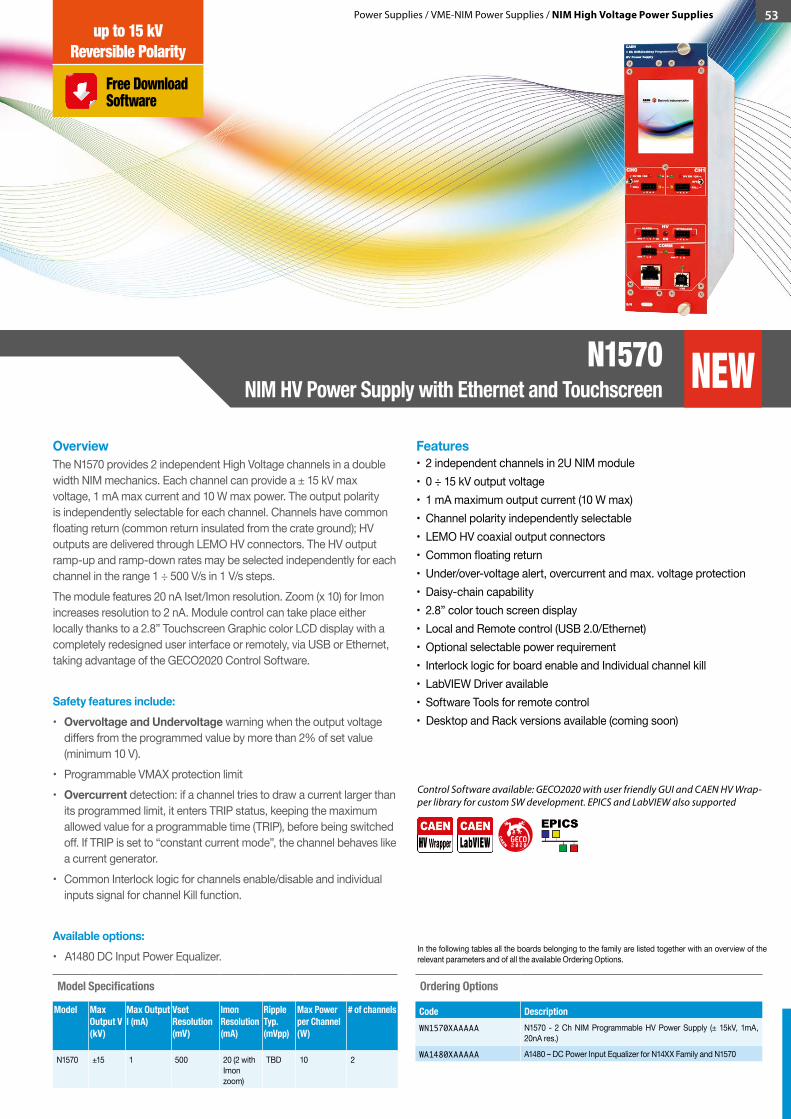
Power Supplies / VME-NIM Power Supplies / NIM High Voltage Power Supplies 53
OverviewThe N1570 provides 2 independent High Voltage channels in a double width NIM mechanics. Each channel can provide a ± 15 kV max voltage, 1 mA max current and 10 W max power. The output polarity is independently selectable for each channel. Channels have common floating return (common return insulated from the crate ground); HV outputs are delivered through LEMO HV connectors. The HV output ramp-up and ramp-down rates may be selected independently for each channel in the range 1 ÷ 500 V/s in 1 V/s steps. The module features 20 nA Iset/Imon resolution. Zoom (x 10) for Imon increases resolution to 2 nA. Module control can take place either locally thanks to a 2.8” Touchscreen Graphic color LCD display with a completely redesigned user interface or remotely, via USB or Ethernet, taking advantage of the GECO2020 Control Software.
Safety features include:• Overvoltage and Undervoltage warning when the output voltage
differs from the programmed value by more than 2% of set value (minimum 10 V).
• Programmable VMAX protection limit• Overcurrent detection: if a channel tries to draw a current larger than
its programmed limit, it enters TRIP status, keeping the maximum allowed value for a programmable time (TRIP), before being switched off. If TRIP is set to “constant current mode”, the channel behaves like a current generator.
• Common Interlock logic for channels enable/disable and individual inputs signal for channel Kill function.
Available options:• A1480 DC Input Power Equalizer.
Features• 2 independent channels in 2U NIM module• 0 ÷ 15 kV output voltage• 1 mA maximum output current (10 W max)• Channel polarity independently selectable• LEMO HV coaxial output connectors• Common floating return• Under/over-voltage alert, overcurrent and max. voltage protection• Daisy-chain capability• 2.8” color touch screen display• Local and Remote control (USB 2.0/Ethernet)• Optional selectable power requirement• Interlock logic for board enable and Individual channel kill• LabVIEW Driver available• Software Tools for remote control• Desktop and Rack versions available (coming soon)
Ordering Options
Code DescriptionWN1570XAAAAA N1570 - 2 Ch NIM Programmable HV Power Supply (± 15kV, 1mA,
20nA res.)
WA1480XAAAAA A1480 – DC Power Input Equalizer for N14XX Family and N1570
Control Software available: GECO2020 with user friendly GUI and CAEN HV Wrap-per library for custom SW development. EPICS and LabVIEW also supported
Model Specifications
Model Max Output V(kV)
Max Output I (mA)
Vset Resolution (mV)
Imon Resolution (mA)
RippleTyp.(mVpp)
Max Power per Channel (W)
# of channels
N1570 ±15 1 500 20 (2 with Imon zoom)
TBD 10 2
In the following tables all the boards belonging to the family are listed together with an overview of the relevant parameters and of all the available Ordering Options.
GECO2 2 00
CA
E
N
N1570 NIM HV Power Supply with Ethernet and Touchscreen
Free Download Software
up to 15 kVReversible Polarity
NEW
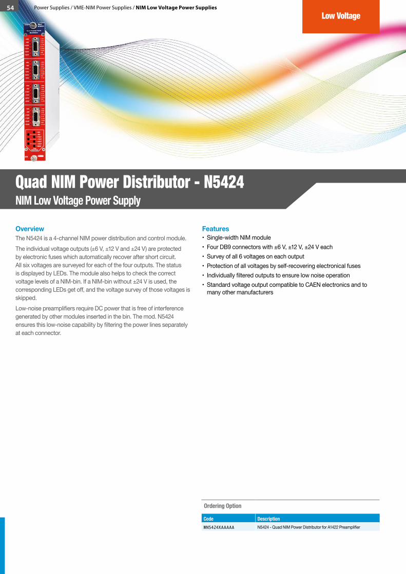
54 Power Supplies / VME-NIM Power Supplies / NIM Low Voltage Power Supplies
OverviewThe N5424 is a 4-channel NIM power distribution and control module. The individual voltage outputs (±6 V, ±12 V and ±24 V) are protected by electronic fuses which automatically recover after short circuit. All six voltages are surveyed for each of the four outputs. The status is displayed by LEDs. The module also helps to check the correct voltage levels of a NIM-bin. If a NIM-bin without ±24 V is used, the corresponding LEDs get off, and the voltage survey of those voltages is skipped. Low-noise preamplifiers require DC power that is free of interference generated by other modules inserted in the bin. The mod. N5424 ensures this low-noise capability by filtering the power lines separately at each connector.
Features• Single-width NIM module• Four DB9 connectors with ±6 V, ±12 V, ±24 V each• Survey of all 6 voltages on each output• Protection of all voltages by self-recovering electronical fuses• Individually filtered outputs to ensure low noise operation• Standard voltage output compatible to CAEN electronics and to
many other manufacturers
Ordering Option
Code DescriptionWN5424XAAAAA N5424 - Quad NIM Power Distributor for A1422 Preamplifier
Low Voltage
Quad NIM Power Distributor - N5424 NIM Low Voltage Power Supply
Tired of powered crates and chassis? Try our new Desktop power supply solutions. Today even with Ethernet!
Is your rack missing of power supply solutions? The new CAEN power supply Rack line is here.
Introducing the new CAEN PCB form factor power supplies. The new component for hardware developers & ideal for distributed solutions. Simply add the HV to your design without giving up high performances and the reliability of a remote control (analog or digital).
StandalonePower Supplies
Desktop High Voltage Power Supplies
Desktop Low Voltage Power Supplies
Rack High Voltage Power Supplies
PCB High Voltage Power Supplies
CAEN 2016 / 2017 Product Catalog
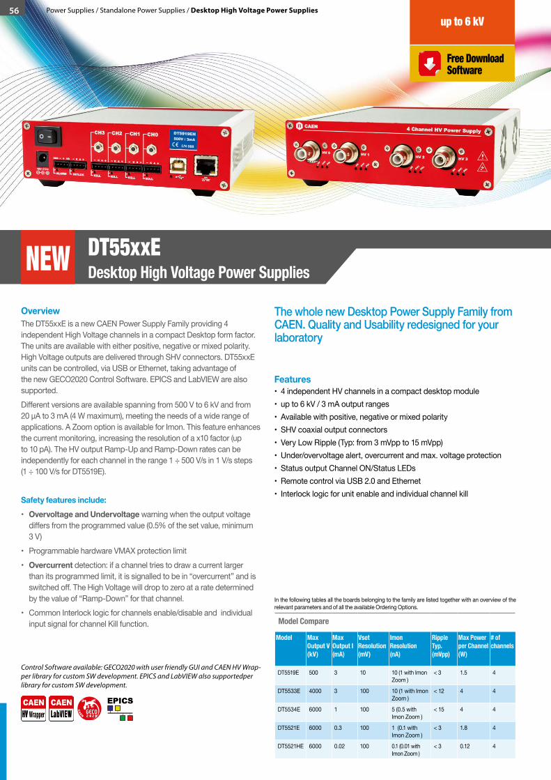
56 Power Supplies / Standalone Power Supplies / Desktop High Voltage Power Supplies
OverviewThe DT55xxE is a new CAEN Power Supply Family providing 4 independent High Voltage channels in a compact Desktop form factor. The units are available with either positive, negative or mixed polarity. High Voltage outputs are delivered through SHV connectors. DT55xxE units can be controlled, via USB or Ethernet, taking advantage of the new GECO2020 Control Software. EPICS and LabVIEW are also supported. Different versions are available spanning from 500 V to 6 kV and from 20 μA to 3 mA (4 W maximum), meeting the needs of a wide range of applications. A Zoom option is available for Imon. This feature enhances the current monitoring, increasing the resolution of a x10 factor (up to 10 pA). The HV output Ramp-Up and Ramp-Down rates can be independently for each channel in the range 1 ÷ 500 V/s in 1 V/s steps (1 ÷ 100 V/s for DT5519E).
Safety features include:• Overvoltage and Undervoltage warning when the output voltage
differs from the programmed value (0.5% of the set value, minimum 3 V)
• Programmable hardware VMAX protection limit• Overcurrent detection: if a channel tries to draw a current larger
than its programmed limit, it is signalled to be in “overcurrent” and is switched off. The High Voltage will drop to zero at a rate determined by the value of “Ramp-Down” for that channel.
• Common Interlock logic for channels enable/disable and individual input signal for channel Kill function.
Features• 4 independent HV channels in a compact desktop module• up to 6 kV / 3 mA output ranges• Available with positive, negative or mixed polarity• SHV coaxial output connectors• Very Low Ripple (Typ: from 3 mVpp to 15 mVpp)• Under/overvoltage alert, overcurrent and max. voltage protection• Status output Channel ON/Status LEDs• Remote control via USB 2.0 and Ethernet• Interlock logic for unit enable and individual channel kill
Control Software available: GECO2020 with user friendly GUI and CAEN HV Wrap-per library for custom SW development. EPICS and LabVIEW also supportedper library for custom SW development.
The whole new Desktop Power Supply Family from CAEN. Quality and Usability redesigned for your laboratory
Model Compare
Model Max Output V(kV)
Max Output I (mA)
Vset Resolution (mV)
Imon Resolution (nA)
RippleTyp.(mVpp)
Max Power per Channel (W)
# of channels
DT5519E 500 3 10 10 (1 with Imon Zoom )
< 3 1.5 4
DT5533E 4000 3 100 10 (1 with Imon Zoom )
< 12 4 4
DT5534E 6000 1 100 5 (0.5 with Imon Zoom )
< 15 4 4
DT5521E 6000 0.3 100 1 (0.1 with Imon Zoom )
< 3 1.8 4
DT5521HE 6000 0.02 100 0.1 (0.01 with Imon Zoom )
< 3 0.12 4
In the following tables all the boards belonging to the family are listed together with an overview of the relevant parameters and of all the available Ordering Options.
GECO2 2 00
CA
E
N
DT55xxE Desktop High Voltage Power Supplies
Free Download Software
up to 6 kV
NEWEthernet & USB interfaces

Ordering Options
Code DescriptionWDT5519EXNAA DT5519EN - 4 Channel 500 V/3 mA Desktop HV Power Supply (USB/
Ethernet) - Negative
WDT5519EXPAA DT5519EP - 4 Channel 500 V/3 mA Desktop HV Power Supply (USB/Ethernet) - Positive
WDT5519EXMAA DT5519EM - 4 Channel 500 V/3 mA Desktop HV Power Supply (USB/Ethernet) - Mixed
WDT5533EXNAA DT5533EN - 4 Channel 4 kV/3 mA (4 W) Desktop HV Power Supply (USB/Ethernet) - Negative
WDT5533EXPAA DT5533EP - 4 Channel 4 kV/3 mA (4 W) Desktop HV Power Supply (USB/Ethernet) - Positive
WDT5533EXMAA DT5533EM - 4 Channel 4 kV/3 mA (4 W) Desktop HV Power Supply (USB/Ethernet) - Mixed
WDT5534EXNAA DT5534EN - 4 Channel 6 kV/1 mA (4 W) Desktop HV Power Supply (USB/Ethernet) - Negative
WDT5534EXPAA DT5534EP - 4 Channel 6 kV/1 mA (4 W) Desktop HV Power Supply (USB/Ethernet) - Positive
WDT5534EXMAA DT5534EM - 4 Channel 6 kV/1 mA (4 W) Desktop HV Power Supply (USB/Ethernet) - Mixed
WDT5521EXNAA DT5521EN - 4 Channel 6 kV/300 µA Desktop HV Power Supply (USB/Ethernet) - Negative
WDT5521EXPAA DT5521EP - 4 Channel 6 kV/300 µA Desktop HV Power Supply (USB/Ethernet) - Positive
WDT5521EXMAA DT5521EM - 4 Channel 6 kV/300 µA Desktop HV Power Supply (USB/Ethernet) - Mixed
WDT5521HENAA DT5521HE - 4 Channel 6 kV/20 µA Desktop HV Power Supply (USB/Ethernet) - Negative
WDT5521HEPAA DT5521HE - 4 Channel 6 kV/20 µA Desktop HV Power Supply (USB/Ethernet) - Positive
WDT5521HEMAA DT5521HE - 4 Channel 6 kV/20 µA Desktop HV Power Supply (USB/Ethernet) - Mixed
WPERS0550001 DT55XX - Customization - Imon Zoom
Remember! Our NDT power supplies can work as a standalone unit like the classic desktop ones!
For more information, please have a look to the NIM power supplies section on this catalogue or on our website.
57Power Supplies / Standalone Power Supplies / Desktop High Voltage Power Supplies
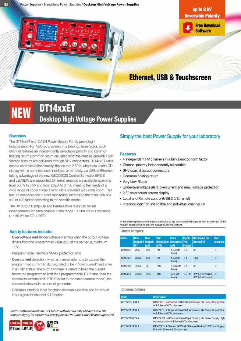
58 Power Supplies / Standalone Power Supplies / Desktop High Voltage Power Supplies
Simply the best Power Supply for your laboratoryOverviewThe DT14xxET is a CAEN Power Supply Family providing 4 independent High Voltage channels in a Desktop form factor. Each channel features an independently selectable polarity and common floating return (common return insulated from the chassis ground). High Voltage outputs are delivered through SHV connectors. DT14xxET units can be controlled either locally, thanks to a 2.8” touchscreen color LCD display with a complete user interface, or remotely, via USB or Ethernet, taking advantage of the new GECO2020 Control Software. EPICS and LabVIEW are supported. Different versions are available spanning from 500 V to 8 kV and from 20 µA to 3 mA, meeting the needs of a wide range of applications. Each unit is provided with Imon Zoom. This feature enhances the current monitoring, increasing the resolution of a x10 or x20 factor according to the specific model.The HV output Ramp-Up and Ramp-Down rates can be set independently for each channel in the range 1 ÷ 500 V/s in 1 V/s steps (1 ÷ 50 V/s for DT1419ET).
Features• 4 independent HV channels in a fully Desktop form factor • Channel polarity independently selectable • SHV coaxial output connectors • Common floating return • Very Low Ripple • Under/overvoltage alert, overcurrent and max. voltage protection • 2.8’’ color touch screen display • Local and Remote control (USB 2.0/Ethernet) • Interlock logic for unit enable and individual channel kill
Ordering Options
Code DescriptionWDT1419ETXAA DT1419ET - 4 Channel 500V/200µA Desktop HV Power Supply Unit
with Ethernet & Touchscreen
WDT1471ETXAA DT1471ET - 4 Channel 5.5kV/300µA Desktop HV Power Supply Unit with Ethernet & Touchscreen
WDT1471HETXA DT1471HET - 4 Channel 5.5kV/20 μA Desktop HV Power Supply High Accuracy Unit with Ethernet & Touchscreen
WDT1470ETXAA DT1470ET - 4 Channel 8kV/3mA (9W max) Desktop HV Power Supply Unit with Ethernet & Touchscreen
Safety features include:• Overvoltage and Undervoltage warning when the output voltage
differs from the programmed value (2% of the set value, minimum 10 V).
• Programmable hardware VMAX protection limit• Overcurrent detection: when a channel attempts to exceed the
programmed current limit, it signaled to be in “overcurrent” and enter in a TRIP status. The output voltage is varied to keep the current below the programmed limit for a programmable TRIP time, then the channel is switched off. If TRIP is set to “constant current mode”, the channel behaves like a current generator.
• Common Interlock logic for channels enable/disable and individual input signal for channel Kill function.
Control Software available: GECO2020 with user friendly GUI and CAEN HV Wrapper library for custom SW development. EPICS and LabVIEW also supported
Model Compare
Model Max Output V(V)
Max Output I (µA)
Vset Resolution (mV)
Imon Resolution (nA)
RippleTyp.(mVpp)
Max Power per Channel (W)
# of channels
DT1419ET ±500 200 10 5 (0.5 with Izoom)
< 3 0.1 4
DT1471ET ±5500 300 10 5 (0.5 with Izoom)
< 5 1.65 4
DT1471HET ±5500 20 100 1 (0.05 with Izoom)
< 5 0.1 4
DT1470ET ±8000 3000 200 50 (5 with Izoom)
< 5 - 15 9 W (<3 kV output) 8 W (>3 kV output)
4
In the following tables all the boards belonging to the family are listed together with an overview of the relevant parameters and of all the available Ordering Options.
GECO2 2 00
CA
E
N
DT14xxETDesktop High Voltage Power SuppliesNEW
Free Download Software
up to 8 kVReversible Polarity
Ethernet, USB & Touchscreen
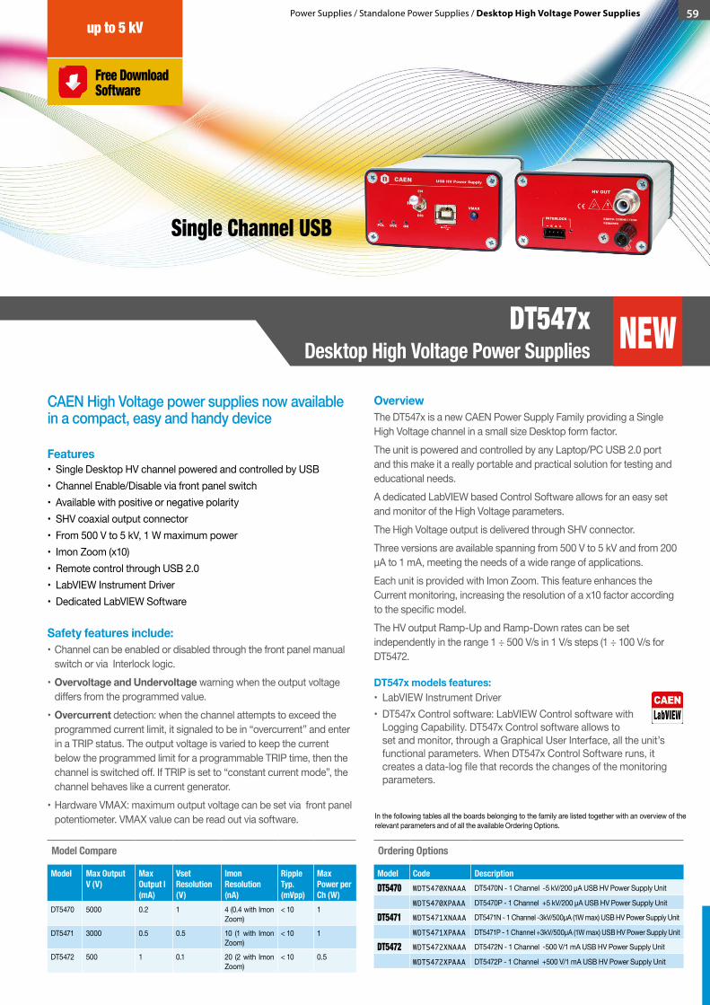
Power Supplies / Standalone Power Supplies / Desktop High Voltage Power Supplies 59
CAEN High Voltage power supplies now available in a compact, easy and handy device
OverviewThe DT547x is a new CAEN Power Supply Family providing a Single High Voltage channel in a small size Desktop form factor. The unit is powered and controlled by any Laptop/PC USB 2.0 port and this make it a really portable and practical solution for testing and educational needs. A dedicated LabVIEW based Control Software allows for an easy set and monitor of the High Voltage parameters. The High Voltage output is delivered through SHV connector.Three versions are available spanning from 500 V to 5 kV and from 200 μA to 1 mA, meeting the needs of a wide range of applications.Each unit is provided with Imon Zoom. This feature enhances the Current monitoring, increasing the resolution of a x10 factor according to the specific model.The HV output Ramp-Up and Ramp-Down rates can be set independently in the range 1 ÷ 500 V/s in 1 V/s steps (1 ÷ 100 V/s for DT5472.
Safety features include:• Channel can be enabled or disabled through the front panel manual
switch or via Interlock logic.• Overvoltage and Undervoltage warning when the output voltage
differs from the programmed value.• Overcurrent detection: when the channel attempts to exceed the
programmed current limit, it signaled to be in “overcurrent” and enter in a TRIP status. The output voltage is varied to keep the current below the programmed limit for a programmable TRIP time, then the channel is switched off. If TRIP is set to “constant current mode”, the channel behaves like a current generator.
• Hardware VMAX: maximum output voltage can be set via front panel potentiometer. VMAX value can be read out via software.
Features• Single Desktop HV channel powered and controlled by USB • Channel Enable/Disable via front panel switch • Available with positive or negative polarity• SHV coaxial output connector• From 500 V to 5 kV, 1 W maximum power• Imon Zoom (x10)• Remote control through USB 2.0• LabVIEW Instrument Driver• Dedicated LabVIEW Software
DT547x models features:• LabVIEW Instrument Driver• DT547x Control software: LabVIEW Control software with
Logging Capability. DT547x Control software allows to set and monitor, through a Graphical User Interface, all the unit’s functional parameters. When DT547x Control Software runs, it creates a data-log file that records the changes of the monitoring parameters.
In the following tables all the boards belonging to the family are listed together with an overview of the relevant parameters and of all the available Ordering Options.
Model Compare
Model Max Output V (V)
Max Output I (mA)
VsetResolution (V)
Imon Resolution (nA)
RippleTyp.(mVpp)
Max Power per Ch (W)
DT5470 5000 0.2 1 4 (0.4 with Imon Zoom)
< 10 1
DT5471 3000 0.5 0.5 10 (1 with Imon Zoom)
< 10 1
DT5472 500 1 0.1 20 (2 with Imon Zoom)
< 10 0.5
Ordering Options
Model Code DescriptionDT5470 WDT5470XNAAA DT5470N - 1 Channel -5 kV/200 µA USB HV Power Supply Unit
WDT5470XPAAA DT5470P - 1 Channel +5 kV/200 µA USB HV Power Supply Unit
DT5471 WDT5471XNAAA DT5471N - 1 Channel -3kV/500μA (1W max) USB HV Power Supply Unit
WDT5471XPAAA DT5471P - 1 Channel +3kV/500μA (1W max) USB HV Power Supply Unit
DT5472 WDT5472XNAAA DT5472N - 1 Channel -500 V/1 mA USB HV Power Supply Unit
WDT5472XPAAA DT5472P - 1 Channel +500 V/1 mA USB HV Power Supply Unit
Ethernet, USB & Touchscreen
DT547xDesktop High Voltage Power Supplies NEW
Free Download Software
up to 5 kV
Single Channel USB
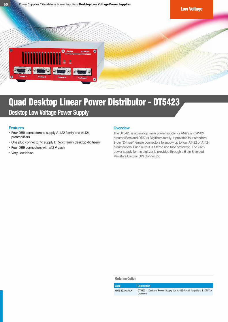
60 Power Supplies / Standalone Power Supplies / Desktop Low Voltage Power Supplies
OverviewThe DT5423 is a desktop linear power supply for A1422 and A1424 preamplifiers and DT57xx Digitizers family. It provides four standard 9-pin “D-type” female connectors to supply up to four A1422 or A1424 preamplifiers. Each output is filtered and fuse protected. The +12 V power supply for the digitizer is provided through a 6 pin Shielded Miniature Circular DIN Connector.
Features• Four DB9 connectors to supply A1422 family and A1424
preamplifiers• One plug connector to supply DT57xx family desktop digitizers• Four DB9 connectors with ±12 V each• Very Low Noise
Ordering Option
Code DescriptionWDT5423XAAAA DT5423 - Desktop Power Supply for A1422-A1424 Amplifiers & DT57xx
Digitizers
Quad Desktop Linear Power Distributor - DT5423Desktop Low Voltage Power Supply
Low Voltage

61Power Supplies / Standalone Power Supplies / Rack High Voltage Power Supplies
CAEN HV Power Supplies now fit your rack in a flexible and reliable unit
OverviewThe R14xxET is a new CAEN Power Supply Family providing 4 or 8 independent High Voltage channels in a 2U, 19” Rack-mount unit. Each channel features an independently selectable polarity and common floating return (common return insulated from the chassis ground). High Voltage outputs are delivered through SHV connectors. R14xxET units can be controlled either locally, thanks to a 2.8” touchscreen color LCD display with a complete user interface, or remotely, via USB or Ethernet, taking advantage of the new GECO2020 Control Software. EPICS and LabVIEW are supported.Different versions are available spanning from 500 V to 8 kV and from 20 µA to 3 mA, meeting the needs of a wide range of applications.Each unit is provided with Imon Zoom. This feature enhances the current monitoring, increasing the resolution of a x10 or x20 factor according to the specific model.The HV output Ramp-Up and Ramp-Down rates can be set independently for each channel in the range 1 ÷ 500 V/s in 1 V/s steps (1 ÷ 50 V/s for R1419ET / R1419ETD).
Features• 4 or 8 independent HV channels in a 2U, 19” Rackmount unit• Channel polarity independently selectable• SHV coaxial output connectors• Common floating return• Very Low Ripple• Under/overvoltage alert, overcurrent and max. voltage protection• 2.8” color touch screen display• Local and Remote control (USB 2.0/Ethernet)• Interlock logic for unit enable and individual channel kill
Control Software available: GECO2020 with user friendly GUI and CAEN HV Wrapper library for custom SW development. EPICS and LabVIEW also supported
Model Compare
Model Max Output V(V)
Max Output I (µA)
Vset Resolution (mV)
Imon Resolution (nA)
RippleTyp. (mVpp)
Max Power per Channel (W)
# of channels
R1419ET ±500 200 10 5 (0.5 with Izoom)
< 3 0.1 4
R1419ETD ±500 200 10 5 (0.5 with Izoom)
< 3 0.1 8
R1471ET ±5500 300 100 5 (0.5 with Izoom)
< 5 1.65 4
R1471ETD ±5500 300 100 5 (0.5 with Izoom)
< 5 1.65 8
R1471HET ±5500 20 100 1 (0.05 with Izoom)
< 5 0.1 4
R1471HETD ±5500 20 100 1 (0.05 with Izoom)
< 5 0.1 8
R1470ET ±8000 3000 200 50 (5 with Izoom)
< 5 - 15 9 W (<3 kV) 8 W (>3 kV)
4
R1470ETD ±8000 3000 200 50 (5 with Izoom)
< 5 - 15 9 W (<3 kV) 8 W (>3 kV)
8
In the following tables all the boards belonging to the family are listed together with an overview of the relevant parameters and of all the available Ordering Options.
Ordering Options
Model Code DescriptionR1419 WR1419ETXAAA R1419ET - 4 Channel 500V/200µA 19” HV Power Supply Unit with
Ethernet & Touchscreen
WR1419ETDXAA R1419ETD - 8 Channel 500V/200µA 19" HV Power Supply Unit with Ethernet & Touchscreen
R1471 WR1471ETXAAA R1471ET - 4 Channel 5.5kV/300µA 19” HV Power Supply Unit with Ethernet & Touchscreen
WR1471ETDXAA R1471ETD - 8 Channel 5.5kV/200µA 19" HV Power Supply Unit with Ethernet & Touchscreen
R1471H WR1471HETXAA R1471HET - 4 Channel 5.5kV/20 μA 19” HV Power Supply High Accuracy Unit with Ethernet & Touchscreen
WR1471HETDXA R1471HETD - 8 Channel 5.5kV/20 μA 19" HV Power Supply High Accuracy Unit with Ethernet & Touchscreen
R1470 WR1470ETXAAA R1470ET - 4 Channel 8kV/3mA (9W max) 19” HV Power Supply Unit with Ethernet & Touchscreen
WR1470ETDXAA R1470ETD - 8 Channel 8kV/3mA (9W max) 19" HV Power Supply Unit with Ethernet & Touchscreen
GECO2 2 00
CA
E
N
R14xxET Rack High Voltage Power Supplies NEW
Free Download Software
up to 8 kVReversible Polarity
19” Rack-mount with Ethernet & Touchscreen
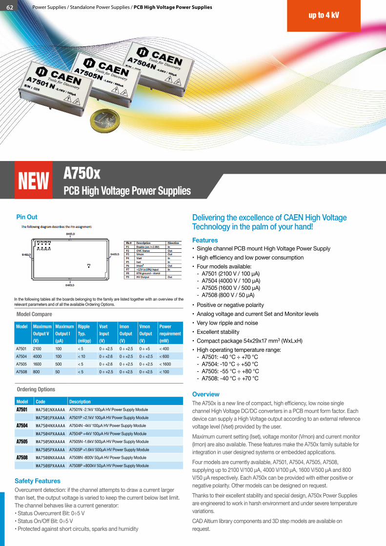
62 Power Supplies / Standalone Power Supplies / PCB High Voltage Power Supplies
Delivering the excellence of CAEN High Voltage Technology in the palm of your hand!
OverviewThe A750x is a new line of compact, high efficiency, low noise single channel High Voltage DC/DC converters in a PCB mount form factor. Each device can supply a High Voltage output according to an external reference voltage level (Vset) provided by the user. Maximum current setting (Iset), voltage monitor (Vmon) and current monitor (Imon) are also available. These features make the A750x family suitable for integration in user designed systems or embedded applications.Four models are currently available, A7501, A7504, A7505, A7508, supplying up to 2100 V/100 µA, 4000 V/100 µA, 1600 V/500 µA and 800 V/50 µA respectively. Each A750x can be provided with either positive or negative polarity. Other models can be designed on request.Thanks to their excellent stability and special design, A750x Power Supplies are engineered to work in harsh environment and under severe temperature variations.CAD Altium library components and 3D step models are available on request.
Safety FeaturesOvercurrent detection: if the channel attempts to draw a current larger than Iset, the output voltage is varied to keep the current below Iset limit. The channel behaves like a current generator: • Status Overcurrent Bit: 0÷5 V • Status On/Off Bit: 0÷5 V • Protected against short circuits, sparks and humidity
Features• Single channel PCB mount High Voltage Power Supply • High efficiency and low power consumption• Four models available:
- A7501 (2100 V / 100 μA) - A7504 (4000 V / 100 μA) - A7505 (1600 V / 500 μA) - A7508 (800 V / 50 μA)
• Positive or negative polarity• Analog voltage and current Set and Monitor levels• Very low ripple and noise• Excellent stability• Compact package 54x29x17 mm3 (WxLxH)• High operating temperature range:
- A7501: -40 °C ÷ +70 °C - A7504: -10 °C ÷ +50 °C - A7505: -55 °C ÷ +80 °C - A7508: -40 °C ÷ +70 °C
Pin Out
Model Compare
Model Maximum Output V (V)
Maximum Output I (µA)
RippleTyp. (mVpp)
Vset Input (V)
Imon Output (V)
Vmon Output (V)
Power requirement (mW)
A7501 2100 100 < 5 0 ÷ +2.5 0 ÷ +2.5 0 ÷ +5 < 400
A7504 4000 100 < 10 0 ÷ +2.6 0 ÷ +2.5 0 ÷ +2.5 < 600
A7505 1600 500 < 5 0 ÷ +2.6 0 ÷ +2.5 0 ÷ +2.5 < 1600
A7508 800 50 < 5 0 ÷ +2.5 0 ÷ +2.5 0 ÷ +2.5 < 100
In the following tables all the boards belonging to the family are listed together with an overview of the relevant parameters and of all the available Ordering Options.
Ordering Options
Model Code DescriptionA7501 WA7501NXAAAA A7501N -2.1kV 100µA HV Power Supply Module
WA7501PXAAAA A7501P +2.1kV 100µA HV Power Supply Module
A7504 WA7504NXAAAA A7504N -4kV 100µA HV Power Supply Module
WA7504PXAAAA A7504P +4kV 100µA HV Power Supply Module
A7505 WA7505NXAAAA A7505N -1.6kV 500µA HV Power Supply Module
WA7505PXAAAA A7505P +1.6kV 500µA HV Power Supply Module
A7508 WA7508NXAAAA A7508N -800V 50µA HV Power Supply Module
WA7508PXAAAA A7508P +800kV 50µA HV Power Supply Module
up to 4 kV
A750xPCB High Voltage Power SuppliesNEW
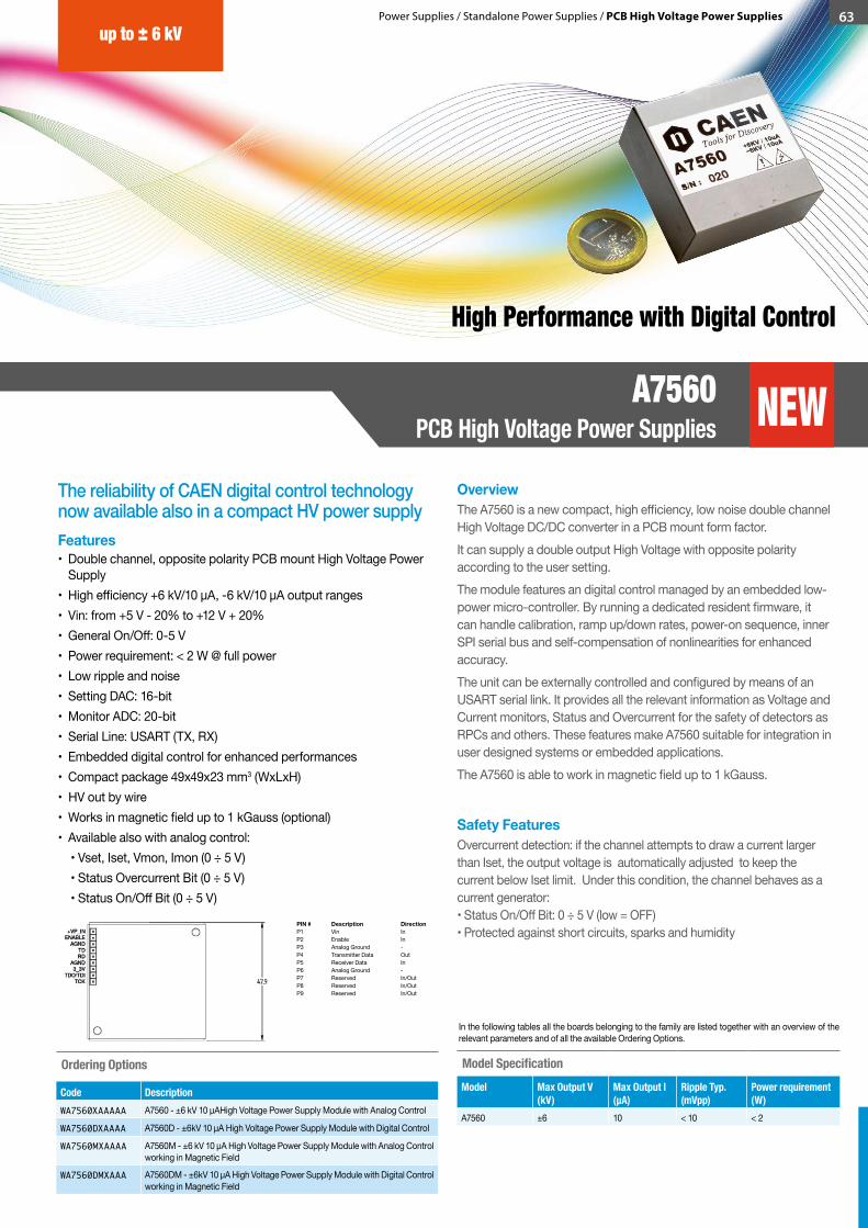
63Power Supplies / Standalone Power Supplies / PCB High Voltage Power Supplies
The reliability of CAEN digital control technology now available also in a compact HV power supply
OverviewThe A7560 is a new compact, high efficiency, low noise double channel High Voltage DC/DC converter in a PCB mount form factor.It can supply a double output High Voltage with opposite polarity according to the user setting. The module features an digital control managed by an embedded low-power micro-controller. By running a dedicated resident firmware, it can handle calibration, ramp up/down rates, power-on sequence, inner SPI serial bus and self-compensation of nonlinearities for enhanced accuracy.The unit can be externally controlled and configured by means of an USART serial link. It provides all the relevant information as Voltage and Current monitors, Status and Overcurrent for the safety of detectors as RPCs and others. These features make A7560 suitable for integration in user designed systems or embedded applications.The A7560 is able to work in magnetic field up to 1 kGauss.
Features• Double channel, opposite polarity PCB mount High Voltage Power
Supply • High efficiency +6 kV/10 µA, -6 kV/10 µA output ranges• Vin: from +5 V - 20% to +12 V + 20%• General On/Off: 0-5 V• Power requirement: < 2 W @ full power• Low ripple and noise• Setting DAC: 16-bit• Monitor ADC: 20-bit• Serial Line: USART (TX, RX)• Embedded digital control for enhanced performances• Compact package 49x49x23 mm3 (WxLxH)• HV out by wire• Works in magnetic field up to 1 kGauss (optional)• Available also with analog control: • Vset, Iset, Vmon, Imon (0 ÷ 5 V) • Status Overcurrent Bit (0 ÷ 5 V) • Status On/Off Bit (0 ÷ 5 V)
Ordering Options
Code DescriptionWA7560XAAAAA A7560 - ±6 kV 10 µAHigh Voltage Power Supply Module with Analog Control
WA7560DXAAAA A7560D - ±6kV 10 µA High Voltage Power Supply Module with Digital Control
WA7560MXAAAA A7560M - ±6 kV 10 µA High Voltage Power Supply Module with Analog Control working in Magnetic Field
WA7560DMXAAA A7560DM - ±6kV 10 µA High Voltage Power Supply Module with Digital Control working in Magnetic Field
Safety FeaturesOvercurrent detection: if the channel attempts to draw a current larger than Iset, the output voltage is automatically adjusted to keep the current below Iset limit. Under this condition, the channel behaves as a current generator: • Status On/Off Bit: 0 ÷ 5 V (low = OFF) • Protected against short circuits, sparks and humidity
Model SpecificationModel Max Output V
(kV)Max Output I(µA)
Ripple Typ. (mVpp)
Power requirement (W)
A7560 ±6 10 < 10 < 2
In the following tables all the boards belonging to the family are listed together with an overview of the relevant parameters and of all the available Ordering Options.
up to ± 6 kV
A7560 PCB High Voltage Power Supplies NEW
High Performance with Digital Control
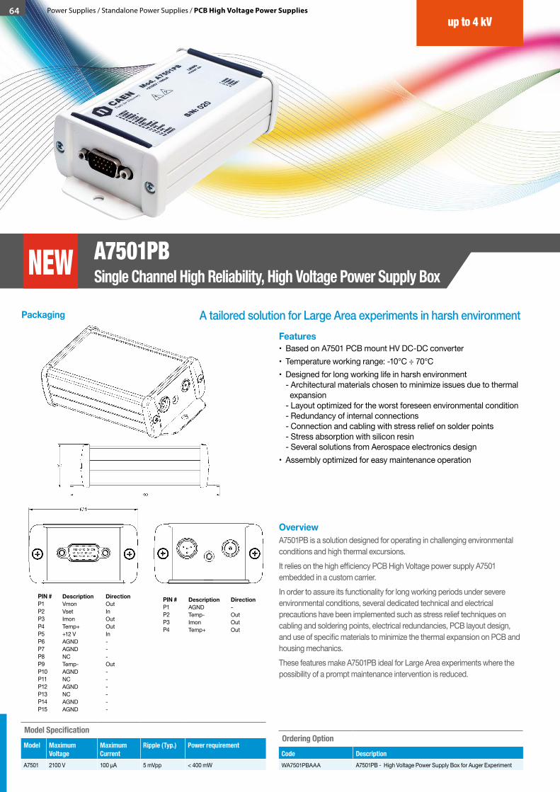
64 Power Supplies / Standalone Power Supplies / PCB High Voltage Power Supplies
up to 4 kV
A7501PBSingle Channel High Reliability, High Voltage Power Supply Box
A tailored solution for Large Area experiments in harsh environment
OverviewA7501PB is a solution designed for operating in challenging environmental conditions and high thermal excursions. It relies on the high efficiency PCB High Voltage power supply A7501 embedded in a custom carrier.In order to assure its functionality for long working periods under severe environmental conditions, several dedicated technical and electrical precautions have been implemented such as stress relief techniques on cabling and soldering points, electrical redundancies, PCB layout design, and use of specific materials to minimize the thermal expansion on PCB and housing mechanics.These features make A7501PB ideal for Large Area experiments where the possibility of a prompt maintenance intervention is reduced.
Features• Based on A7501 PCB mount HV DC-DC converter • Temperature working range: -10°C ÷ 70°C • Designed for long working life in harsh environment
- Architectural materials chosen to minimize issues due to thermal expansion - Layout optimized for the worst foreseen environmental condition - Redundancy of internal connections - Connection and cabling with stress relief on solder points - Stress absorption with silicon resin - Several solutions from Aerospace electronics design
• Assembly optimized for easy maintenance operation
NEW
Model SpecificationModel Maximum
VoltageMaximum Current
Ripple (Typ.) Power requirement
A7501 2100 V 100 µA 5 mVpp < 400 mW
Packaging
PIN # Description DirectionP1 Vmon OutP2 Vset InP3 Imon OutP4 Temp+ OutP5 +12 V InP6 AGND -P7 AGND -P8 NC -P9 Temp- OutP10 AGND -P11 NC -P12 AGND -P13 NC -P14 AGND -P15 AGND -
PIN # Description DirectionP1 AGND -P2 Temp- OutP3 Imon OutP4 Temp+ Out
Ordering OptionCode DescriptionWA7501PBAAA A7501PB - High Voltage Power Supply Box for Auger Experiment

Is your electronics working in “Hostile” area? Are you in presence of Magnetic Field or Radiation?The EASY family is the right architecture for your installation where the HV & LV power supplies are required.EASY, COTS-based & cost effective.
EASY (Embedded
Assembly SYstem)
Magnetic field: up to 2 kGauss Radiation:- up to 1·1011 p/cm2 Total Dose- up to 2·1012 n/cm2 Total Dose- up to 15 kRad Total Integrated Dose
CAEN 2016 / 2017 Product Catalog
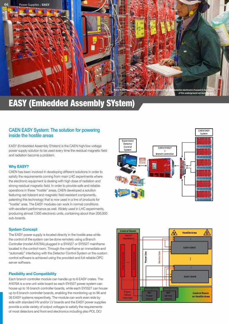
EASY (Embedded Assembly SYstem)
CAEN EASY System: The solution for powering inside the hostile areas
EASY (Embedded Assembly SYstem) is the CAEN high/low voltage power supply solution to be used every time the residual magnetic field and radiation become a problem.
Why EASY?CAEN has been involved in developing different solutions in order to satisfy the requirements coming from main LHC experiments where the electronic equipment is dealing with high dose of radiation and strong residual magnetic field. In order to provide safe and reliable operations in these “hostile” areas, CAEN developed a solution featuring rad-tolerant and magnetic field resistant components, patenting this technology that is now used in a line of products for “hostile” area. The EASY modules can work in normal conditions with excellent performance as well. Widely used in LHC experiments, producing almost 7,500 electronic units, containing about than 200,000 sub-boards.
System ConceptThe EASY power supply is located directly in the hostile area while the control of the system can be done remotely using a Branch Controller (model A1676A) plugged in a SY4527 or SY5527 mainframe located in the control room. Through the mainframe an immediate and “automatic” interfacing with the Detector Control System or the custom control software is achieved using the provided and full reliable OPC server software.
Flexibility and Compatibility Each branch controller module can handle up to 6 EASY crates. The A1676A is a one unit wide board so each SY4527 power system can house up to 16 branch controller boards, while each SY5527 can house up to 6 branch controller boards, enabling the monitoring up to 96 and 36 EASY systems respectively. The module can work even side by side with standard HV and/or LV boards and the EASY power supplies provide a wide variety of output voltages to satisfy the requirements of most detectors and front end electronics including also POL DC/
Photo©MichaelHoch-CERN–SwitzerlandViewoftheCMSdetectorelectronicshousedintwofloorsof the underground services cavern.
66 Power Supplies / EASY

DC converters (Low Voltage up to 100 A and High Voltage up to 12 kV). An unique interface and a cost effective setup for all the experiment’s power requirements!
ArchitectureThe EASY3000 (for boards up to 40 cm long, A3XXX Family) can house up to 10 boards depending on the boards width. As illustrated in the figure, the branch controller is the EASY interface between the mainframe unit (SY4527 or SY5527) and the remote boards in the EASY crate. The branch controller role is to configure the EASY channels as they belong to the supply unit slot in which the branch controller is located. In this way all the channels of the EASY boards, will be considered as channels of the branch control board, increasing hugely the number of channels the system can handle.
Tolerances• Magnetic field: up to 2 kGauss• Radiation:
- up to 1·1011 p/cm2 Total Dose - up to 2·1012 n/cm2 Total Dose - up to 15 kRad Total Integrated Dose
Available EASY Board Models
Power Supplies
Model # Channels Voltage Range Max Output Current per ch.
Max Output Power per ch.
Width (slots) Max Modules per Crate
Max Channels Per Crate
Working in Hostile Area
Ground
A3006 6 (4 pos. / 2 neg.) ± (4 ÷ 16) V 6 A 90 W 4 5 30 Yes CFG
A3009 12 1.5 ÷ 8 V 9 A 45 W 4 5 60 Yes FF
A3009B 12 2 ÷ 8 V 9 A 45 W 4 5 60 Yes FF
A3009K 12 0.5 ÷ 2 V 9 A 18 W 4 5 60 Yes FF
A3009HBP 12 8 ÷ 14 V 3 A 42 W 4 5 60 Yes IF
A3016 6 2 ÷ 8 V 16 A 90 W 4 5 30 Yes FF
A3016B 6 2 ÷ 8 V 16 A 90 W 4 5 30 Yes FF
A3016HBP 6 8 ÷ 14 V 6 A 84 W 4 5 30 Yes IF
A3025 4 2 ÷ 8 V 25 A 150 W 4 5 20 Yes FF
A3025B 4 2 ÷ 8 V 25 A 150 W 4 5 20 Yes FF
A3025HBP 4 8 ÷ 14 V 10 A 140 W 4 5 20 Yes IF
A3050 2 2 ÷ 8 V 50 A 300 W 4 5 10 Yes FF
A3050B 2 2 ÷ 8 V 50 A 300 W 4 5 10 Yes FF
A3050HBP 2 8 ÷ 14 V 20 A 280 W 4 5 10 Yes IF
A3100 1 2 ÷ 8 V 100 A 600 W 4 5 5 Yes FF
A3100B 1 2 ÷ 8 V 100 A 600 W 4 5 5 Yes FF
A3100HBP 1 8 ÷ 14 V 40 A 560 W 4 5 5 Yes IF
A3602 3 2 ÷ 7 V 5 A 35 W 4 10 30 Yes FF
A3501 p/n 12 0 ÷ 100 V 1 mA 100 mW 2 10 120 Yes IF
A3512 p/n 6 0 ÷ 12 kV 1 mA 12 W 3 7 42 Yes IF
A3535 p/n 32 0 ÷ 3.2 kV 0.5 mA 1.75 W 4 5 160 Yes CFG
A3540 p/n 12 0 ÷ 4 kV 1 mA 4 W 2 10 120 Yes IF
Front-End Boards
Model Description Ch. per Module Max Output Voltage
Max Output Current
Resolution Width (slots) Max Modules per Crate
Working in Hostile Area
A3802 DAC 128 4 V 10 mA 12 bit 1 10 Yes
FF = Full Floating CFG = Common Floating GroundIF = Individual Floating
Power Supplies / EASY 67
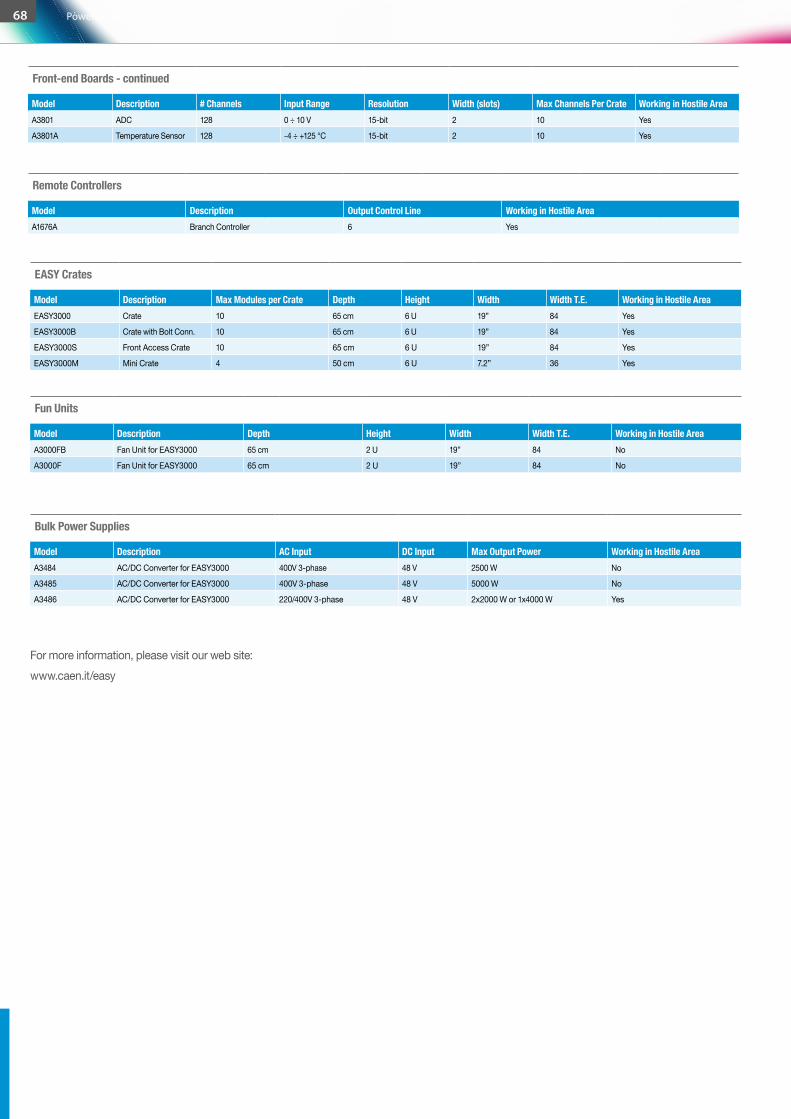
EASY Crates
Model Description Max Modules per Crate Depth Height Width Width T.E. Working in Hostile AreaEASY3000 Crate 10 65 cm 6 U 19” 84 Yes
EASY3000B Crate with Bolt Conn. 10 65 cm 6 U 19” 84 Yes
EASY3000S Front Access Crate 10 65 cm 6 U 19” 84 Yes
EASY3000M Mini Crate 4 50 cm 6 U 7.2” 36 Yes
Fun Units
Model Description Depth Height Width Width T.E. Working in Hostile AreaA3000FB Fan Unit for EASY3000 65 cm 2 U 19” 84 No
A3000F Fan Unit for EASY3000 65 cm 2 U 19” 84 No
Bulk Power Supplies
Model Description AC Input DC Input Max Output Power Working in Hostile AreaA3484 AC/DC Converter for EASY3000 400V 3-phase 48 V 2500 W No
A3485 AC/DC Converter for EASY3000 400V 3-phase 48 V 5000 W No
A3486 AC/DC Converter for EASY3000 220/400V 3-phase 48 V 2x2000 W or 1x4000 W Yes
For more information, please visit our web site:www.caen.it/easy
Front-end Boards - continued
Model Description # Channels Input Range Resolution Width (slots) Max Channels Per Crate Working in Hostile AreaA3801 ADC 128 0 ÷ 10 V 15-bit 2 10 Yes
A3801A Temperature Sensor 128 -4 ÷ +125 °C 15-bit 2 10 Yes
Remote Controllers
Model Description Output Control Line Working in Hostile AreaA1676A Branch Controller 6 Yes
68 Power Supplies / EASY

A typical requirement which is often underestimated is the need of High Power, Low Voltage channels. This may be needed for special front end electronics, often placed in the detector cavern, which need to be supplied by an external powerful source, with high reliability and remote wire sensing, to reach the exact low voltage supply even with tens of metres of cables. All the above can be fulfilled by the SY8800 Universal Multichannel Low Voltage Power Supply System, which provides the usual flexibility of its modular design with the highest standards of CAEN quality.
High Power Low Voltage
System
CAEN 2016 / 2017 Product Catalog
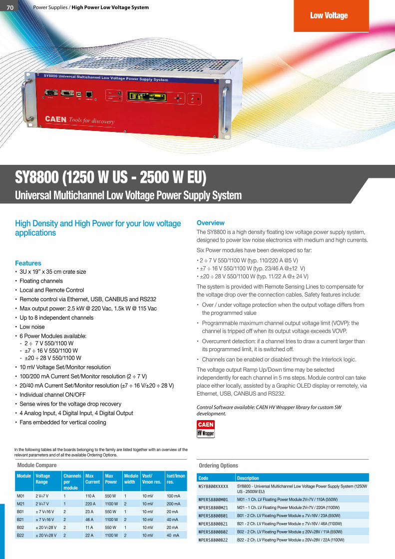
70 Power Supplies / High Power Low Voltage System
High Density and High Power for your low voltage applications
OverviewThe SY8800 is a high density floating low voltage power supply system, designed to power low noise electronics with medium and high currents.Six Power modules have been developed so far:• 2 ÷ 7 V 550/1100 W (typ. 110/220 A @5 V) • ±7 ÷ 16 V 550/1100 W (typ. 23/46 A @±12 V) • ±20 ÷ 28 V 550/1100 W (typ. 11/22 A @± 24 V)The system is provided with Remote Sensing Lines to compensate for the voltage drop over the connection cables. Safety features include:• Over / under voltage protection when the output voltage differs from
the programmed value• Programmable maximum channel output voltage limit (VOVP): the
channel is tripped off when its output voltage exceeds VOVP.• Overcurrent detection: if a channel tries to draw a current larger than
its programmed limit, it is switched off. • Channels can be enabled or disabled through the Interlock logic.The voltage output Ramp Up/Down time may be selected independently for each channel in 5 ms steps. Module control can take place either locally, assisted by a Graphic OLED display or remotely, via Ethernet, USB, CANBUS and RS232.
Features• 3U x 19” x 35 cm crate size• Floating channels• Local and Remote Control• Remote control via Ethernet, USB, CANBUS and RS232• Max output power: 2.5 kW @ 220 Vac, 1.5k W @ 115 Vac• Up to 8 independent channels• Low noise• 6 Power Modules available:
- 2 ÷ 7 V 550/1100 W - ±7 ÷ 16 V 550/1100 W - ±20 ÷ 28 V 550/1100 W
• 10 mV Voltage Set/Monitor resolution• 100/200 mA Current Set/Monitor resolution (2 ÷ 7 V)• 20/40 mA Current Set/Monitor resolution (±7 ÷ 16 V/±20 ÷ 28 V)• Individual channel ON/OFF • Sense wires for the voltage drop recovery• 4 Analog Input, 4 Digital Input, 4 Digital Output• Fans embedded for vertical cooling
Ordering Options
Code DescriptionWSY8800XXXXX SY8800 - Universal Multichannel Low Voltage Power Supply System (1250W
US - 2500W EU)
WPERS8800M01 M01 - 1 Ch. LV Floating Power Module 2V÷7V / 110A (550W)
WPERS8800M21 M21 - 1 Ch. LV Floating Power Module 2V÷7V / 220A (1100W)
WPERS8800B01 B01 - 2 Ch. LV Floating Power Module ± 7V÷16V / 23A (550W)
WPERS8800B21 B21 - 2 Ch. LV Floating Power Module ± 7V÷16V / 46A (1100W)
WPERS8800B02 B02 - 2 Ch. LV Floating Power Module ± 20V÷28V / 11A (550W)
WPERS8800B22 B22 - 2 Ch. LV Floating Power Module ± 20V÷28V / 22A (1100W)
Low Voltage
SY8800 (1250 W US - 2500 W EU)Universal Multichannel Low Voltage Power Supply System
Module CompareModule Voltage
RangeChannels per module
Max Current
Max Power
Module width
Vset/Vmon res.
Iset/Imon res.
M01 2 V÷7 V 1 110 A 550 W 1 10 mV 100 mA
M21 2 V÷7 V 1 220 A 1100 W 2 10 mV 200 mA
B01 ± 7 V÷16 V 2 23 A 550 W 1 10 mV 20 mA
B21 ± 7 V÷16 V 2 46 A 1100 W 2 10 mV 40 mA
B02 ± 20 V÷28 V 2 11 A 550 W 1 10 mV 20 mA
B22 ± 20 V÷28 V 2 22 A 1100 W 2 10 mV 40 mA
In the following tables all the boards belonging to the family are listed together with an overview of the relevant parameters and of all the available Ordering Options.
Control Software available: CAEN HV Wrapper library for custom SW development.
CAEN provides a complete software range to control, monitor and configure its Power Supply products.These tools, which support the most used operating systems, spread from low level libraries, to be used as a source for customer designed software, to all-inclusive Control Software with user friendly graphical interfaces, to meet any application need. Advanced control via OPC Server, SNMP and EPICS is supported, in order to easily include CAEN power supplies within existing setups featuring such standards.Thanks to this effort, it is now easier to take advantage of the CAEN power supply experience.All CAEN Control Software are available for free download on the www.caen.it web site, as well as User’s guides that allow to better understand all the tools’ capabilities.
Power Supply Control
Software
CAEN 2016 / 2017 Product Catalog
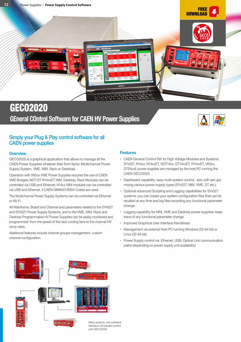
72 Power Supplies / Power Supply Control Software
Simply your Plug & Play control software for all CAEN power supplies
OverviewGECO2020 is a graphical application that allows to manage all the CAEN Power Supplies whatever their form factor (Multichannel Power Supply System, VME, NIM, Rack or Desktop).Operation with V65xx VME Power Supplies requires the use of CAEN VME Bridges; NDT-DT-R14xxET NIM, Desktop, Rack Modules can be controlled via USB and Ethernet; N14xx NIM modules can be controlled via USB and Ethernet, if CAEN NIM8301/8304 Crates are used. The Multichannel Power Supply Systems can be controlled via Ethernet or Wi-Fi. All Mainframe, Board and Channel and parameters related to the SY4527 and SY5527 Power Supply Systems, and to the VME, NIM, Rack and Desktop Programmable HV Power Supplies can be easily monitored and programmed: from the speed of the rack cooling fans to the channel HV ramp rates.Additional features include channel groups management, custom channel configuration.
Features • CAEN General Control SW for High Voltage Modules and Systems:
SYx527, N14xx, N14xxET, NDT14xx, DT14xxET, R14xxET, V65xx, DT55xxE power supplies are managed by the host PC running the CAEN GECO2020
• Dashboard capability: easy multi-system control, also with set ups mixing various power supply types (SYx527, NIM, VME, DT etc.).
• Optional advanced Scripting and Logging capabilities for SYx527 systems: you can create your system configuration files that can be recalled at any time and log files recording any functional parameter change.
• Logging capability for NIM, VME and Desktop power supplies: keep trace of any functional parameter change.
• Improved Graphical User Interface friendliness• Management via external Host PC running Windows (32-64 bit) or
Linux (32-64 bit)• Power Supply control via Ethernet, USB, Optical Link communication
paths (depending on power supply unit availability)
GECO2020GEneral COntrol Software for CAEN HV Power Supplies
GECO2 2 00
CA
E
N
Many systems, one software interface: full parallel control with GECO2020

73Power Supplies / Power Supply Control Software
Do you need to integrate CAEN Power Supplies in your control software? Here you have all you need
OverviewCAEN HV Wrapper is a set of ANSI C functions which allows to control CAEN devices. It contains a generic software interface independent by the Power Supply models and by the communication path used to exchange data with them.CAEN HV Wrapper is logically located between a higher level application and the device to be accessed.
Features• Function Library for full control of all the CAEN Power Supply products,
through the development of higher level applications, such as the CAEN GECO2020
• Available for Windows (C, LabVIEW) and Linux (C) operating systems• Unit control via Ethernet, USB, Optical Link communication paths
(depending on device availability)• Supports SYx527 systems, NIM/VME/Desktop/Rack power supplies,
NIM/VME crates, N568E spectroscopy amplifier• Available both as ANSI C function set and LabVIEW VI’s suite
CAEN HV WrapperLibrary for CAEN Power Supply Control
The HV Wrapper Library in the CAEN software and libraries conceptual scheme
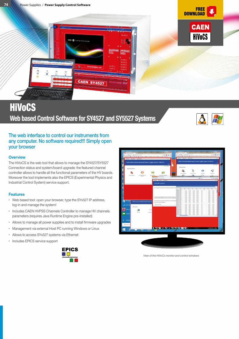
74 Power Supplies / Power Supply Control Software
The web interface to control our instruments from any computer. No software required!!! Simply open your browser
OverviewThe HiVoCS is the web tool that allows to manage the SY4527/SY5527 Connection status and system/board upgrade; the featured channel controller allows to handle all the functional parameters of the HV boards. Moreover the tool implements also the EPICS (Experimental Physics and Industrial Control System) service support.
Features• Web based tool: open your browser, type the SYx527 IP address,
log-in and manage the system!• Includes CAEN HVPSS Channels Controller to manage HV channels
parameters (requires Java Runtime Engine pre-installed)• Allows to manage all power supplies and to install firmware upgrades• Management via external Host PC running Windows or Linux • Allows to access SYx527 systems via Ethernet• Includes EPICS service support
HiVoCSWeb based Control Software for SY4527 and SY5527 Systems
View of the HiVoCs monitor and control windows
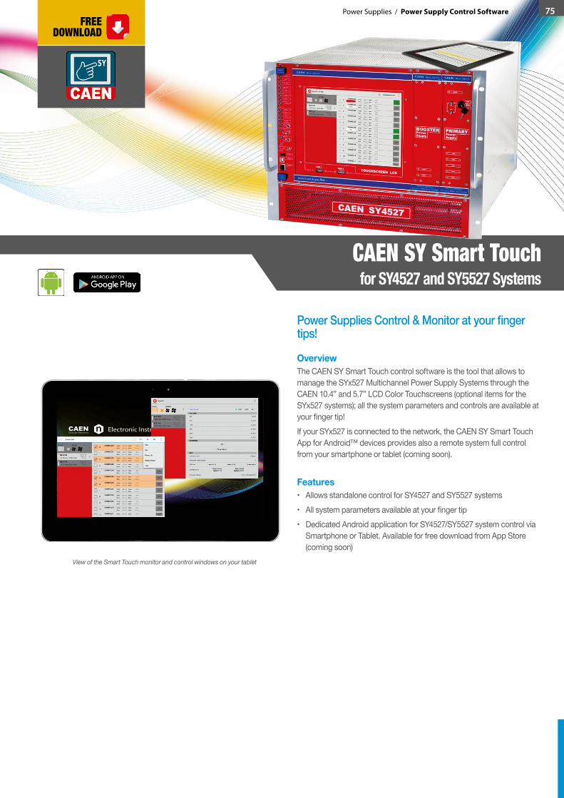
75Power Supplies / Power Supply Control Software
CAEN SY Smart Touchfor SY4527 and SY5527 Systems
Power Supplies Control & Monitor at your finger tips!
OverviewThe CAEN SY Smart Touch control software is the tool that allows to manage the SYx527 Multichannel Power Supply Systems through the CAEN 10.4” and 5.7” LCD Color Touchscreens (optional items for the SYx527 systems); all the system parameters and controls are available at your finger tip!If your SYx527 is connected to the network, the CAEN SY Smart Touch App for Android™ devices provides also a remote system full control from your smartphone or tablet (coming soon).
Features• Allows standalone control for SY4527 and SY5527 systems• All system parameters available at your finger tip• Dedicated Android application for SY4527/SY5527 system control via
Smartphone or Tablet. Available for free download from App Store (coming soon)
View of the Smart Touch monitor and control windows on your tablet
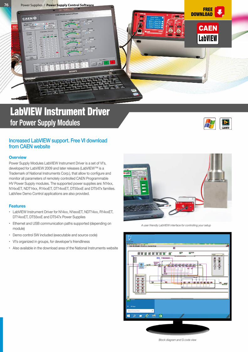
76 Power Supplies / Power Supply Control Software
Increased LabVIEW support. Free VI download from CAEN website
OverviewPower Supply Modules LabVIEW Instrument Driver is a set of VI’s, developed for LabVIEW 2009 and later releases (LabVIEW™ is a Trademark of National Instruments Corp.), that allow to configure and monitor all parameters of remotely controlled CAEN Programmable HV Power Supply modules. The supported power supplies are: N14xx, N14xxET, NDT14xx, R14xxET, DT14xxET, DT55xxE and DT547x families. LabView Demo Control applications are also provided.
Features• LabVIEW Instrument Driver for N14xx, N1exxET, NDT14xx, R14xxET,
DT14xxET, DT55xxE and DT547x Power Supplies• Ethernet and USB communication paths supported (depending on
module)• Demo control SW included (executable and source code) • VI’s organized in groups, for developer’s friendliness• Also available in the download area of the National Instruments website
LabVIEW Instrument Driverfor Power Supply Modules
Block diagram and G code view
A user friendly LabVIEW interface for controlling your setup
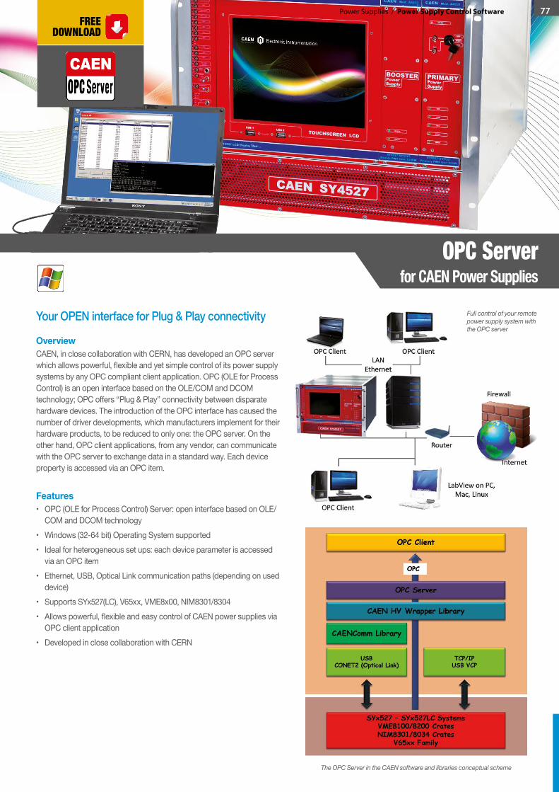
77Power Supplies / Power Supply Control Software
Your OPEN interface for Plug & Play connectivity
OverviewCAEN, in close collaboration with CERN, has developed an OPC server which allows powerful, flexible and yet simple control of its power supply systems by any OPC compliant client application. OPC (OLE for Process Control) is an open interface based on the OLE/COM and DCOM technology; OPC offers “Plug & Play” connectivity between disparate hardware devices. The introduction of the OPC interface has caused the number of driver developments, which manufacturers implement for their hardware products, to be reduced to only one: the OPC server. On the other hand, OPC client applications, from any vendor, can communicate with the OPC server to exchange data in a standard way. Each device property is accessed via an OPC item.
Features• OPC (OLE for Process Control) Server: open interface based on OLE/
COM and DCOM technology• Windows (32-64 bit) Operating System supported• Ideal for heterogeneous set ups: each device parameter is accessed
via an OPC item• Ethernet, USB, Optical Link communication paths (depending on used
device) • Supports SYx527(LC), V65xx, VME8x00, NIM8301/8304• Allows powerful, flexible and easy control of CAEN power supplies via
OPC client application• Developed in close collaboration with CERN
OPC Server for CAEN Power Supplies
Full control of your remote power supply system with the OPC server
The OPC Server in the CAEN software and libraries conceptual scheme
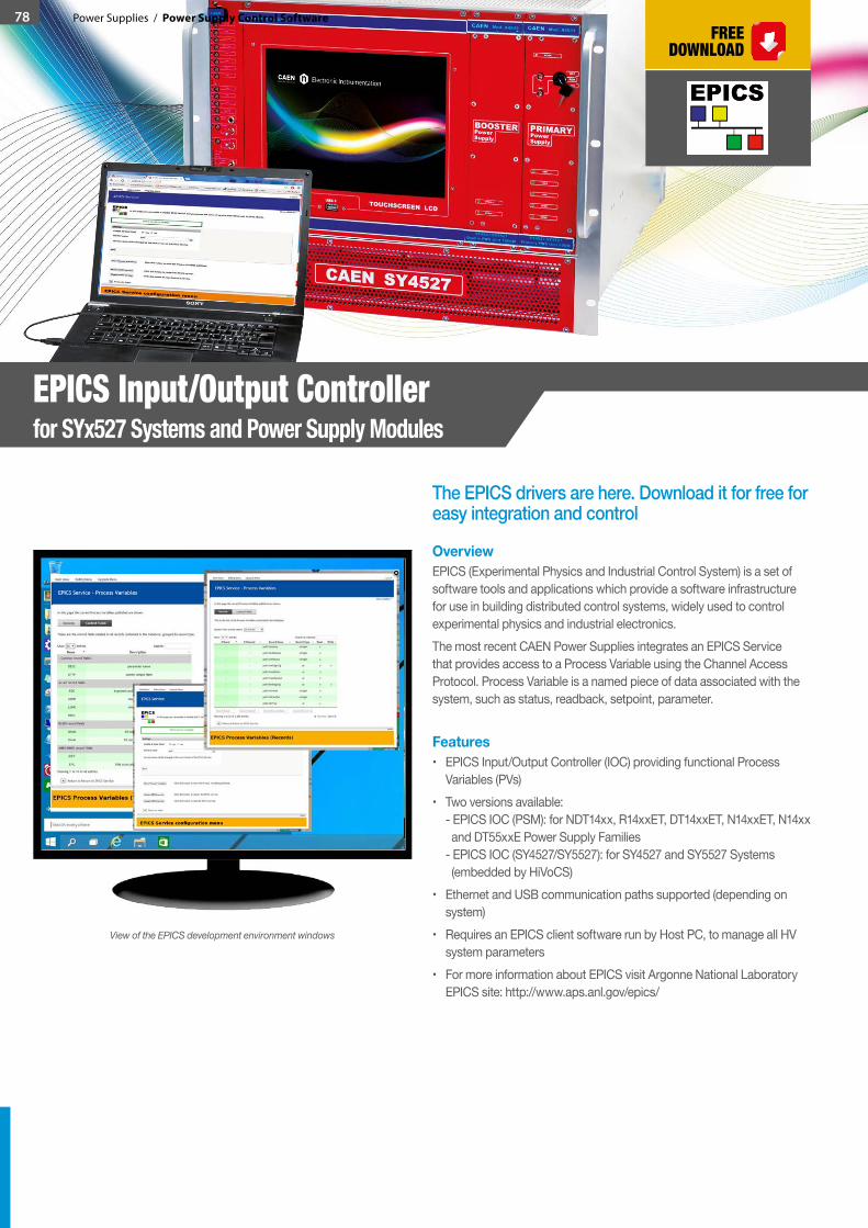
78 Power Supplies / Power Supply Control Software
The EPICS drivers are here. Download it for free for easy integration and control
OverviewEPICS (Experimental Physics and Industrial Control System) is a set of software tools and applications which provide a software infrastructure for use in building distributed control systems, widely used to control experimental physics and industrial electronics.The most recent CAEN Power Supplies integrates an EPICS Service that provides access to a Process Variable using the Channel Access Protocol. Process Variable is a named piece of data associated with the system, such as status, readback, setpoint, parameter.
Features• EPICS Input/Output Controller (IOC) providing functional Process
Variables (PVs)• Two versions available:
- EPICS IOC (PSM): for NDT14xx, R14xxET, DT14xxET, N14xxET, N14xx and DT55xxE Power Supply Families - EPICS IOC (SY4527/SY5527): for SY4527 and SY5527 Systems (embedded by HiVoCS)
• Ethernet and USB communication paths supported (depending on system)
• Requires an EPICS client software run by Host PC, to manage all HV system parameters
• For more information about EPICS visit Argonne National Laboratory EPICS site: http://www.aps.anl.gov/epics/
EPICS Input/Output Controller for SYx527 Systems and Power Supply Modules
View of the EPICS development environment windows


