Embed Size (px)
Citation preview
IEEE TRANSACTIONS ON INDUSTRIAL ELECTRONICS, VOL. 54, NO. 3, JUNE 2007 1591
Multiple-Loop H-Infinity Control Design forUninterruptible Power Supplies
Gustavo Willmann, Daniel Ferreira Coutinho, Member, IEEE,Luís Fernando Alves Pereira, and Fausto Bastos Líbano
Abstract—This paper presents an innovative tuning strategyfor the design of multiple-loop lag–lead compensators for unin-terruptible power supplies (UPSs) based on the H-infinity robustcontrol theory. Taking into account an average model of a UPS, theparameters of a double-loop controller are synthesized such thatthe upper bound on the two-norm of the input-to-output operatoris minimized while guaranteeing local stability of the closed-loopsystem for all admissible load variations. The stabilization condi-tions are cast in terms of linear matrix inequalities that are solvedvia standard software packages. To improve regulation dynamics,a newer technique to compute the root-mean-square value ofthe output voltage is also proposed. Practical results consideringa commercial UPS system demonstrate the effectiveness of theproposed approach as a tool for tuning multiloop controllers.
Index Terms—Convex optimization, dc–ac inverters, discrete-time systems, H-infinity control, robust control.
I. INTRODUCTION
THE DESIGN of controllers for dc–ac power converterssuch as uninterruptible power supplies (UPSs) and auto-
matic voltage regulators has aroused much attention from thecontrol community due to the wide variety of applications inindustrial environments. However, load variations (generally,unknown but bounded), exogenous signals, control signal con-straints, and the nonlinear behavior of switched systems makethe task of designing controllers whenever some kind of per-formance is desired for the closed-loop system difficult [1]. Forindustrial applications, the power converters are generally con-trolled by means of double-loop lag-lead compensators (e.g.,proportional–integral–differential (PID) controllers) using anaverage model of a switched system that is governed by thepulsewidth-modulation (PWM) technique [2]–[4]. The innerloop (fast dynamics) is based on proportional–differential (PD)
Manuscript received May 30, 2005; revised August 30, 2006. This workwas supported by CP Eletrônica. This paper was presented in part at the 31stAnnual Conference of the IEEE Industrial Electronics Society, Raleigh, NC,November 6–10, 2005.
G. Willmann was with the Department of Engineering and Development,CP Eletrônica, Porto Alegre 91040-600, Brazil. He is now with the Engi-neering Department, Westron Equipamentos Eletrônicos LTDA, Porto Alegre91910-460, Brazil (e-mail: [email protected]).
D. F. Coutinho, L. F. A. Pereira, and F. B. Líbano are with the Departmentof Electrical Engineering, Pontifícia Universidade Católica do Rio Grande doSul, Porto Alegre 90619-900, Brazil (e-mail: [email protected]; [email protected]; [email protected]).
Color versions of one or more of the figures in this paper are available onlineat http://ieeexplore.ieee.org.
Digital Object Identifier 10.1109/TIE.2007.894721
action in order to achieve a good transient response. The outerloop (slow dynamics) is applied to obtain good regulation ofthe output voltage by means of a proportional–integral controllaw. One of the advantages of using PID controllers is thevast number of tuning techniques that are available on thecontrol theory such as frequency-domain and optimization-based methods. Although the frequency-domain methods arewell known and largely employed by designer engineers, inpractical situations, the coupling between fast and slow dynam-ics and unmodeled nonlinearities (e.g., actuator saturation) maylead to a poor static regulation and bad dynamical response.On the other hand, standard optimization-based techniques canhandle such constraints at the cost of a strong mathematicalbackground, making the method nonattractive to majority of de-signer engineers. From the aforementioned scenario, normally,the PID parameters are tuned through empirical trial-and-errormethods starting from an initial tuning that is obtained fromZiegler–Nichols-like algorithms [5].
The appearance of new promising control approaches thatare associated with the dissemination of powerful digital signalprocessors that are devoted to the control of applications hasled many researchers to apply a wide variety of techniques thataim for improvement in the static and dynamic performancesof dc–ac power converters that are as an alternative to classicalPID controllers. Among these are the dead-beat controller[6], [7] and the sliding-mode control [8], [9]. In line withthis, exploiting the uncertain nature of the output load, someresearchers have applied the robust control theory of linear timeinvariance to control UPS systems such as those in [10]–[14].Although these alternative approaches have led to satisfactoryresults, PID controllers are still the technique that is mostlargely employed by UPS industries.
On the other hand, the robust control technique that isbased on linear matrix inequalities (LMIs) has been appliedto solving a large diversity of control problems (see, e.g., [15]and [16]). The LMI framework can deal with control constraintssuch as robustness, disturbance rejection, and bounded controlsignals using the same foundations. For instance, stabilization,performance design, and control constraints are added to thesame formulation and then solved in one single optimizationproblem. Basically, modified Lyapunov inequalities (includingthe control problem and performance constraints) are recast as aset of LMIs, which are numerically solved by means of standardpackages [17].
This paper aims to bridge the gap between the theory ofoptimization-based methods and its application to the tuning
0278-0046/$25.00 © 2007 IEEE
1592 IEEE TRANSACTIONS ON INDUSTRIAL ELECTRONICS, VOL. 54, NO. 3, JUNE 2007
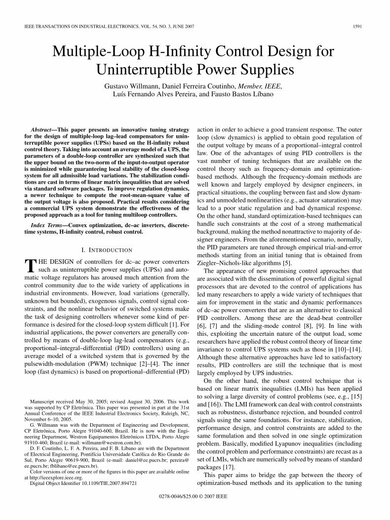
Fig. 1. Multiple-loop control strategy.
of double-loop PID parameters by UPS designer engineers inan easy and systematic way. Therefore, the UPS is modeled asdiscrete-time uncertain system where a robust state-feedbackcontrol law is designed to the ac-voltage regulation. It is sup-posed that the UPS is subject to linear load-admittance variation(with known maximal and minimal limits), disturbance signals,(which may represent a nonlinear load), and bounded controlsignals (actuator saturation). The operation condition of theUPS is supposed to be unknown but belonging to a givenellipsoidal set that characterizes the UPS limits of operation.A newer technique to compute the output-voltage rms value isalso proposed, resulting in faster regulation response. Then, theproposed approach is applied to a commercial UPS, where thecontrol parameters are obtained by means of the LMI Toolboxof Matlab. To test the overall performance, a comparative studyis carried out with a pretuned industrial multiple-loop PIDcontroller, which has a similar structure to the proposed one.Both controllers are implemented using a standard input–output(I/O) card and real-time Matlab tools. Experimental resultsshow that the multiloop controller that is tuned by the proposedapproach behaves similarly to the one from the industrial UPS,which was obtained from extensive practical tests.
The remainder of this paper is given as follows. Section IIdescribes the problem to be addressed, Section III introducesthe (average) mathematical model of the UPS, and Section IVintroduces the LMI-based control design methodology. In thesequel, Section V presents several practical results, in whicha comparative study is carried out between the proposed con-troller and one that is normally used in industrial applications.Finally, Section VI ends this paper, presenting some concludingremarks and future developments.Notation: The notation used in this paper is standard. In is
the n× n identity matrix, 0n×m is the n×m matrix of zeros,and 0n is the n× n matrix of zeros. For a real matrix P , thenotation P > 0 means that P is symmetric and positive definite,and PT is its transpose. The vector and matrix dimensions areomitted whenever they can be inferred from the context.
II. PROBLEM STATEMENT
This section briefly describes the multiloop control strategythat is generally employed in regulating the output voltage ofindustrial UPS systems and then states the problem of interestin this paper.
The multiloop control strategy, as illustrated in Fig. 1, con-sists of two loops, each one having a different purpose. Theinternal loop aims to produce good transient response, where
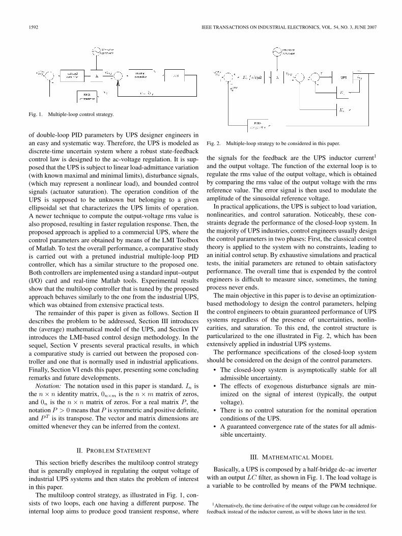
Fig. 2. Multiple-loop strategy to be considered in this paper.
the signals for the feedback are the UPS inductor current1
and the output voltage. The function of the external loop is toregulate the rms value of the output voltage, which is obtainedby comparing the rms value of the output voltage with the rmsreference value. The error signal is then used to modulate theamplitude of the sinusoidal reference voltage.
In practical applications, the UPS is subject to load variation,nonlinearities, and control saturation. Noticeably, these con-straints degrade the performance of the closed-loop system. Inthe majority of UPS industries, control engineers usually designthe control parameters in two phases: First, the classical controltheory is applied to the system with no constraints, leading toan initial control setup. By exhaustive simulations and practicaltests, the initial parameters are retuned to obtain satisfactoryperformance. The overall time that is expended by the controlengineers is difficult to measure since, sometimes, the tuningprocess never ends.
The main objective in this paper is to devise an optimization-based methodology to design the control parameters, helpingthe control engineers to obtain guaranteed performance of UPSsystems regardless of the presence of uncertainties, nonlin-earities, and saturation. To this end, the control structure isparticularized to the one illustrated in Fig. 2, which has beenextensively applied in industrial UPS systems.
The performance specifications of the closed-loop systemshould be considered on the design of the control parameters.
• The closed-loop system is asymptotically stable for alladmissible uncertainty.
• The effects of exogenous disturbance signals are min-imized on the signal of interest (typically, the outputvoltage).
• There is no control saturation for the nominal operationconditions of the UPS.
• A guaranteed convergence rate of the states for all admis-sible uncertainty.
III. MATHEMATICAL MODEL
Basically, a UPS is composed by a half-bridge dc–ac inverterwith an output LC filter, as shown in Fig. 1. The load voltage isa variable to be controlled by means of the PWM technique.
1Alternatively, the time derivative of the output voltage can be considered forfeedback instead of the inductor current, as will be shown later in the text.
WILLMANN et al.: MULTIPLE-LOOP H-INFINITY CONTROL DESIGN FOR UNINTERRUPTIBLE POWER SUPPLIES 1593
In this case, the following simplified average (time-varying)model of the power converter will be considered in this paper:
x(t) =A (Yo(t))x(t) +Bu(t) + Eio(t)
z(t) =Cx(t) +Du(t) (1)
where x(t) = [x1 x2]T = [iLf(t) vo(t)]T is the state vector
(with x1 and x2 representing inductor current iLf(t) and capac-
itor voltage vo(t), respectively), u(t) is the PWM signal, io(t) isthe output disturbance that is assumed to have bounded energy(which is possibly the current that is driven by a nonlinear load),and z(t) represents the variables of interest (e.g., the outputvoltage).
State matrix A(Yo(t)) is an affine matrix function of Yo (theload admittance), which means that the load is uncertain withan unknown rate of variation but is bounded by
Ymin ≤ Yo ≤ Ymax. (2)
For simplicity of notation, the preceding relationship will bedenoted as follows:
Yo ∈ Θ = Yo : Ymin ≤ Yo ≤ Ymax. (3)
Using the elementary electric circuit theory results in thefollowing state-space characterization:
A(Yo) =
−RLf
Lf− 1
Lf
1Cf
− Yo
Cf
B =[ 1
Lf
0
]
E =[
0− 1
Cf
](4)
where RLfis the equivalent inductor resistance, Yo is the
load admittance (which is supposed to be time varying), andLf and Cf are the output filter inductance and capacitance,respectively.
To obtain discrete-time implementation, the state variablesare measured and then sampled using a standard ZOH at sam-pling rate Ts. So, a discrete-time state representation may beobtained by means of the Euler approximation technique, i.e.,
dx(t)dt
∼= x(t+ Ts) − x(t)Ts
resulting in the following dynamics:
x(k + 1) =Ad(Y0)x(k) +Bdu(k) +Edio(k)
z(k) =Cx(k) +Du(k) (5)
where Ad(Yo) = (I + TsA(Yo)), Bd = TsB, and Ed = TsE.Notice that the control objective is to track the rms value
of the sinusoidal reference voltage vref(k) while guaranteeingmultiple design specifications. To this end, the rms value of theoutput voltage is compared with the (constant) rms referencevalue. An integrator is added to the external loop to obtain zero
steady-state error. To simplify the analysis, the dynamics of therms computation block is neglected.
From the preceding discussion, state x2(k) is redefined as therms tracking error, i.e.,
x2(k) = vrmsref (k) − vrms
o (k)
where vrmsref (k) and vrms
o are the rms values of vref(k) and vo(k),respectively. In addition, the original system is augmented usinga discrete-time integrator adding the following dynamics:
x3(k + 1) = Tsx2(k) + x3(k).
The preceding manipulations lead to the following discrete-time representation:
x(k + 1) =AD(Yo)x(k) +BDu(k) + ED(Yo)w(k)
z(k) =Cx(k) +Du(k) (6)
where the matrices and vectors are given by
x(k) =
x1(k)x2(k)x3(k)
w(k) =[io(k)vrmsref (k)
]
BD =
Ts
Lf
00
(7)
AD(Yo) =
(1 − TsRLf
Lf
)Ts
Lf0
− Ts
Cf
(1 − TsYo
Cf
)0
0 Ts 1
ED(Yo) =
0 − Ts
Lf
Ts
Cf
TsYo
Cf
0 0
. (8)
IV. CONTROL DESIGN
In the following, the LMI framework is employed to devise anumerically tractable solution to the multicriteria specificationsof the UPS closed-loop system.
Therefore, notice that the control parameters to be designedcan be viewed as the elements of state feedback gain K (seeFig. 2). More precisely, the control signal is given by
u(k) = Kx(k) = K1x1(k) +K2x2(k) +K3x3(k).
Aside from the robust closed-loop stability, consider therequirements that clearly state the multicriteria closed-loopspecifications that are given in Section II.
1) Minimize the upper bound on the finite-horizon L2 gainof the input-to-output operator,2 i.e., from disturbance
2This is also denoted as the (finite-horizon) H∞-norm of the systems [18].
1594 IEEE TRANSACTIONS ON INDUSTRIAL ELECTRONICS, VOL. 54, NO. 3, JUNE 2007
input w(k) to performance signal z(k), we minimize ascalar γ, which bounds the following:
‖Gwz‖∞,[0,τ ] = sup0 =w,τ>0
‖z(k)‖2,[0,τ ]
‖w(k)‖2,[0,τ ]
< γ (9)
where ‖(·)‖2,[0,τ ] stands for the finite-horizon two-normof the signals for some interval of time τ (which istypically the sine-wave period).
2) The rate of convergence of the state trajectory is boundedby a given positive constant r that is smaller than 1, wherethe convergence rate is defined as
r ∈ (0, 1) : ‖x(k)‖2 ≤ α ‖x(k − 1)‖2 r ∀k > 0
for some constant α.3) The control signal should be constrained to the following
set to avoid control saturation:
U = u(k) : |Kx(k)| ≤ umaxwhenever the state variables lie within the followingellipsoidal set:
X =x(k) : x(k)TXx(k) ≤ 1, X > 0; k ≥ 0
(10)
which is, hereafter, denoted as the UPS region of oper-ation, where X ∈ R
3×3 is a given constant matrix andumax is the maximum absolute value of the control signal(which is typically the dc-link voltage).
LMI-based methods allow consideration of the most diver-sified constraints in a unified framework. For instance, robuststability and performance requirement 1 can be cast as LMIconstraints from the bounded real lemma [18]. The remainingones can also be recast as new LMI constraints that are added tothe original optimization problem. In the following, the afore-mentioned control specifications are cast as LMI constraints.
A. LMI Conditions forH∞ Control Design
Design specification 1 can be described in the LMI frame-work by means of the modified Lyapunov inequalities, i.e.,the standard H∞ condition (or the bounded real lemma). Moreprecisely, the upper bound on the L2 gain, as defined previously,can be determined by minimizing γ subject to
∃V (x) > 0 : ∆V (x, Yo) +1γzT z − γwTw < 0 ∀Yo ∈ Θ
(11)
where V (x) is a Lyapunov function that proves the stability ofsystem (6) in a closed loop and ∆V (x) stands for the Lyapunovfunction variation, i.e.,
∆V (x) = V (x(k + 1)) − V (x(k)) .
Since load admittance Yo is supposed to be uncertain andvarying freely in time, the following quadratic Lyapunov func-tion is considered:
V (x(k)) = x(k)TPx(k) (12)
where P ∈ R3×3 is a (constant) symmetric positive-definite
matrix to be determined.In view of (11), the system model in (5)–(8), and the preced-
ing Lyapunov function, the following inequality is obtained:
[x(k)w(k)
]T[(AT
clPAcl−P)+ 1
γCTclCcl AT
clPED(Yo)
ETD(Yo)PAcl ET
D(Y0)PED(Yo)−γI2
]
×[x(k)w(k)
]< 0 (13)
where Acl = AD(Yo) +BDK and Ccl = C +DK.Convergence rate r can be easily assured by the following
Lyapunov inequality [19], [20]:
r (V (x(k + 1), Yo) − V (x(k) ) < 0, Yo ∈ Θ (14)
where r is a scalar that defines the convergence rate of the statetrajectory [21], i.e.,
‖x(k)‖2 ≤√λ2
λ1‖x(0)‖2 (r)k
with λ1 and λ2 being the smallest and largest eigenvalues of P ,respectively.
Joining the condition in (14) to the one in (13) leads to thefollowing inequality:
[x(k)w(k)
]T[r(AT
clPAcl−P)+ 1
γCTclCcl AT
clPED(Yo)
ETD(Yo)PAcl ET
D(Y0)PED(Yo)−γI2
]
×[x(k)w(k)
]< 0. (15)
From standard LMI machinery (for further details, see [15]and [17]), (15) is satisfied for a given K and all Yo ∈ Θ if thefollowing holds:
−rP 0 AT
clP CTcl
0 −γI2 ETD(Yo)P 0
PAcl PED(Yo) −rP 0Ccl 0 0 −γ
< 0 ∀ Yo ∈ Λ(Θ)
where Λ(Θ) stands for vertices of the set Θ (i.e., Λ(Θ) =Ymin, Ymax).
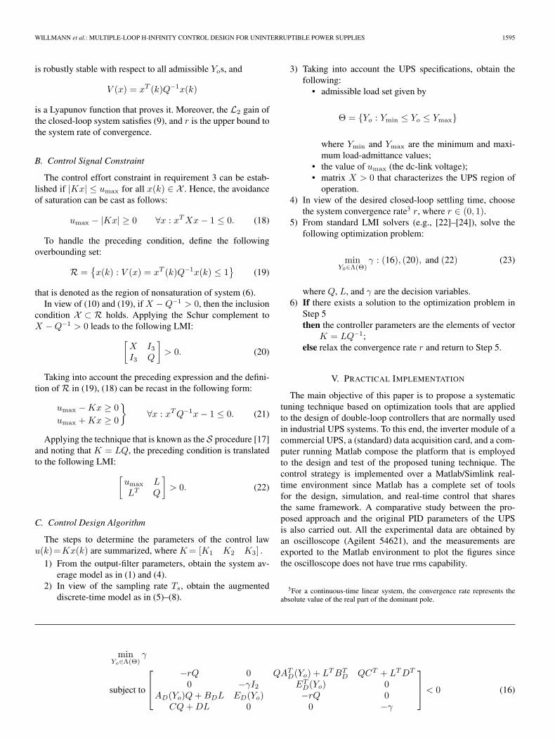
The preceding condition is an LMI in which either Lyapunovmatrix P or control gain K is given. However, one can find asolution in K and P by rewriting the condition in terms of theLyapunov matrix inverse Q = P−1 and using parameterizationL = KQ [17]. From the preceding analysis, (15) is satisfied fora given r ∈ (0, 1) if there exist matrices Q (symmetric) and L,and a positive scalar γ that solves optimization problem (16),shown at the bottom of the next page.
In the affirmative case, the closed-loop system in (6) with acontrol law
u(k) = (LQ−1)x(k) (17)
WILLMANN et al.: MULTIPLE-LOOP H-INFINITY CONTROL DESIGN FOR UNINTERRUPTIBLE POWER SUPPLIES 1595
is robustly stable with respect to all admissible Yos, and
V (x) = xT (k)Q−1x(k)
is a Lyapunov function that proves it. Moreover, the L2 gain ofthe closed-loop system satisfies (9), and r is the upper bound tothe system rate of convergence.
B. Control Signal Constraint
The control effort constraint in requirement 3 can be estab-lished if |Kx| ≤ umax for all x(k) ∈ X . Hence, the avoidanceof saturation can be cast as follows:
umax − |Kx| ≥ 0 ∀x : xTXx− 1 ≤ 0. (18)
To handle the preceding condition, define the followingoverbounding set:
R =x(k) : V (x) = xT (k)Q−1x(k) ≤ 1
(19)
that is denoted as the region of nonsaturation of system (6).In view of (10) and (19), ifX −Q−1 > 0, then the inclusion
condition X ⊂ R holds. Applying the Schur complement toX −Q−1 > 0 leads to the following LMI:[
X I3I3 Q
]> 0. (20)
Taking into account the preceding expression and the defini-tion of R in (19), (18) can be recast in the following form:
umax −Kx ≥ 0umax +Kx ≥ 0
∀x : xTQ−1x− 1 ≤ 0. (21)
Applying the technique that is known as the S procedure [17]and noting that K = LQ, the preceding condition is translatedto the following LMI: [
umax LLT Q
]> 0. (22)
C. Control Design Algorithm
The steps to determine the parameters of the control lawu(k)=Kx(k) are summarized, whereK= [K1 K2 K3] .
1) From the output-filter parameters, obtain the system av-erage model as in (1) and (4).
2) In view of the sampling rate Ts, obtain the augmenteddiscrete-time model as in (5)–(8).
3) Taking into account the UPS specifications, obtain thefollowing:
• admissible load set given by
Θ = Yo : Ymin ≤ Yo ≤ Ymax
where Ymin and Ymax are the minimum and maxi-mum load-admittance values;
• the value of umax (the dc-link voltage);• matrix X > 0 that characterizes the UPS region of
operation.4) In view of the desired closed-loop settling time, choose
the system convergence rate3 r, where r ∈ (0, 1).5) From standard LMI solvers (e.g., [22]–[24]), solve the
following optimization problem:
minY0∈Λ(Θ)
γ : (16), (20), and (22) (23)
where Q, L, and γ are the decision variables.6) If there exists a solution to the optimization problem in
Step 5then the controller parameters are the elements of vector
K = LQ−1;else relax the convergence rate r and return to Step 5.
V. PRACTICAL IMPLEMENTATION
The main objective of this paper is to propose a systematictuning technique based on optimization tools that are appliedto the design of double-loop controllers that are normally usedin industrial UPS systems. To this end, the inverter module of acommercial UPS, a (standard) data acquisition card, and a com-puter running Matlab compose the platform that is employedto the design and test of the proposed tuning technique. Thecontrol strategy is implemented over a Matlab/Simlink real-time environment since Matlab has a complete set of toolsfor the design, simulation, and real-time control that sharesthe same framework. A comparative study between the pro-posed approach and the original PID parameters of the UPSis also carried out. All the experimental data are obtained byan oscilloscope (Agilent 54621), and the measurements areexported to the Matlab environment to plot the figures sincethe oscilloscope does not have true rms capability.
3For a continuous-time linear system, the convergence rate represents theabsolute value of the real part of the dominant pole.
minYo∈Λ(Θ)
γ
subject to
−rQ 0 QATD(Yo) + LTBT
D QCT + LTDT
0 −γI2 ETD(Yo) 0
AD(Yo)Q+BDL ED(Yo) −rQ 0CQ+DL 0 0 −γ
< 0 (16)
1596 IEEE TRANSACTIONS ON INDUSTRIAL ELECTRONICS, VOL. 54, NO. 3, JUNE 2007
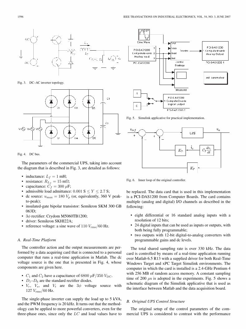
Fig. 3. DC–AC inverter topology.
Fig. 4. DC bus.
The parameters of the commercial UPS, taking into accountthe diagram that is described in Fig. 3, are detailed as follows:
• inductance: Lf = 1 mH;• resistance: RLf
= 15 mΩ;• capacitance: Cf = 300 µF;• admissible load admittance: 0.001 S ≤ Y ≤ 2.7 S;• dc source: umax = 180 Vp (or, equivalently, 360 V peak-
to-peak);• insulated-gate bipolar transistor: Semikron SKM 300 GB
063D;• 3φ rectifier: Crydom M5060TB1200;• driver: Semikron SKHI22A;• reference voltage: a sine wave of 110 Vrms/60 Hz.
A. Real-Time Platform
The controller action and the output measurements are per-formed by a data acquiring card that is connected to a personalcomputer that runs a real-time application in Matlab. The dcvoltage source is the one that is presented in Fig. 4, whosecomponents are given here.
• C1 and C2 have a capacitance of 6800 µF/350 VDC.• D1–D6 are the standard rectifier diodes.• Vr, Vs, and Vt are the 3φ voltage source with
127 Vrms/60 Hz.
The single-phase inverter can supply the load up to 5 kVA,and the PWM frequency is 20 kHz. It turns out that the method-ology can be applied to more powerful converters, even for thethree-phase ones, since only the LC and load values have to
Fig. 5. Simulink applicative for practical implementation.
Fig. 6. Inner loop of the original controller.
be replaced. The data card that is used in this implementationis a PCI-DAS1200 from Computer Boards. The card containsmultiple (analog and digital) I/O channels as described in thefollowing:
• eight differential or 16 standard analog inputs with aresolution of 12 bits;
• 24 digital inputs that can be used as inputs or outputs, withboth being fully programmable;
• two outputs with 12-bit digital-to-analog converters withprogrammable gains and dc levels.
The total shared sampling rate is over 330 kHz. The datacard is controlled by means of a real-time application runningover Matlab 6.5 R13 with a supplied driver for both Real-TimeWindows Target and xPC Target Simulink environments. Thecomputer in which the card is installed is a 2.4-GHz Pentium 4with 256 MB of random access memory. A constant samplingtime of 200 µs is adopted in the experiments. Fig. 5 shows aschematic diagram of the Simulink applicative that is used asthe interface between Matlab and the data acquisition board.
B. Original UPS Control Structure
The original setup of the control parameters of the com-mercial UPS is considered to contrast with the performance
WILLMANN et al.: MULTIPLE-LOOP H-INFINITY CONTROL DESIGN FOR UNINTERRUPTIBLE POWER SUPPLIES 1597
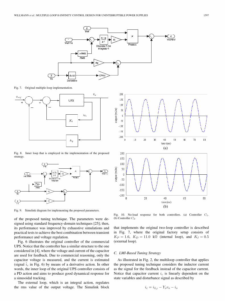
Fig. 7. Original multiple-loop implementation.
Fig. 8. Inner loop that is employed in the implementation of the proposedstrategy.
Fig. 9. Simulink diagram for implementing the proposed parameters.
of the proposed tuning technique. The parameters were de-signed using standard frequency-domain techniques [25]; then,its performance was improved by exhaustive simulations andpractical tests to achieve the best combination between transientperformance and voltage regulation.
Fig. 6 illustrates the original controller of the commercialUPS. Notice that the controller has a similar structure to the oneconsidered in [4], where the voltage and current of the capacitorare used for feedback. Due to commercial reasoning, only thecapacitor voltage is measured, and the current is estimated(signal ic in Fig. 6) by means of a derivative action. In otherwords, the inner loop of the original UPS controller consists ofa PD action and aims to produce good dynamical response fora sinusoidal tracking.
The external loop, which is an integral action, regulatesthe rms value of the output voltage. The Simulink block
Fig. 10. No-load response for both controllers. (a) Controller C1.(b) Controller C2.
that implements the original two-loop controller is describedin Fig. 7, where the original factory setup consists ofKP = 1.6, KD = 11.0 kΩ (internal loop), and KI = 0.5(external loop).
C. LMI-Based Tuning Strategy
As illustrated in Fig. 2, the multiloop controller that appliesthe proposed tuning technique considers the inductor currentas the signal for the feedback instead of the capacitor current.Notice that capacitor current ic is linearly dependent on thestate variables and disturbance signal as described by
ic = iLf− Yovo − io
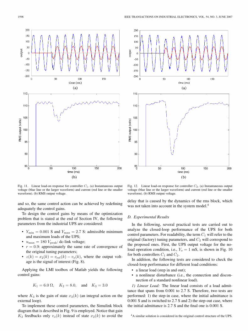
1598 IEEE TRANSACTIONS ON INDUSTRIAL ELECTRONICS, VOL. 54, NO. 3, JUNE 2007
Fig. 11. Linear load-on response for controller C1. (a) Instantaneous outputvoltage (blue line or the larger waveform) and current (red line or the smallerwaveform). (b) RMS output voltage.
and so, the same control action can be achieved by redefiningadequately the control gains.
To design the control gains by means of the optimizationproblem that is stated at the end of Section IV, the followingparameters from the industrial UPS are considered:
• Ymin = 0.001 S and Ymax = 2.7 S: admissible minimumand maximum loads of the UPS;
• umax = 180 Vpeak: dc-link voltage;• r = 0.9: approximately the same rate of convergence of
the original tuning parameters;• z(k) = x2(k) = vref(k) − vo(k), where the output volt-
age is the signal of interest (Fig. 8).
Applying the LMI toolbox of Matlab yields the followingcontrol gains:
K1 = 6.0 Ω, K2 = 8.0, and K3 = 3.0
where K3 is the gain of state x3(k) (an integral action on theexternal loop).
To implement these control parameters, the Simulink blockdiagram that is described in Fig. 9 is employed. Notice that gainK2 feedbacks only vo(k) instead of state x2(k) to avoid the
Fig. 12. Linear load-on response for controller C2. (a) Instantaneous outputvoltage (blue line or the larger waveform) and current (red line or the smallerwaveform). (b) RMS output voltage.
delay that is caused by the dynamics of the rms block, whichwas not taken into account in the system model.4
D. Experimental Results
In the following, several practical tests are carried out toanalyze the closed-loop performance of the UPS for bothcontrol parameters. For readability, the term C1 will refer to theoriginal (factory) tuning parameters, and C2 will correspond tothe proposed ones. First, the UPS output voltage for the no-load operation condition, i.e., Yo = 1 mS, is shown in Fig. 10for both controllers C1 and C2.
In addition, the following tests are considered to check theclosed-loop performance for different load conditions:
• a linear load (step in and out);• a nonlinear disturbance (i.e., the connection and discon-
nection of a standard nonlinear load).1) Linear Load: The linear load consists of a load admit-
tance that spans from 0.001 to 2.7 S. Therefore, two tests areperformed: 1) the step-in case, where the initial admittance is0.001 S and is switched to 2.7 S and 2) the step-out case, wherethe initial admittance is 2.7 S and the final one is 0.001 S.
4A similar solution is considered in the original control structure of the UPS.
WILLMANN et al.: MULTIPLE-LOOP H-INFINITY CONTROL DESIGN FOR UNINTERRUPTIBLE POWER SUPPLIES 1599
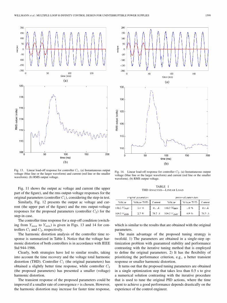
Fig. 13. Linear load-off response for controller C1. (a) Instantaneous outputvoltage (blue line or the larger waveform) and current (red line or the smallerwaveform). (b) RMS output voltage.
Fig. 11 shows the output ac voltage and current (the upperpart of the figure), and the rms output-voltage responses for theoriginal parameters (controllerC1), considering the step-in test.
Similarly, Fig. 12 presents the output ac voltage and cur-rent (the upper part of the figure) and the rms output-voltageresponses for the proposed parameters (controller C2) for thestep-in case.
The controller time response for a step-off condition (switch-ing from Ymax to Ymin) is given in Figs. 13 and 14 for con-trollers C1 and C2, respectively.
The harmonic distortion analysis of the controller time re-sponse is summarized in Table I. Notice that the voltage har-monic distortion of both controllers is in accordance with IEEEStd 944-1986.
Clearly, both strategies have led to similar results, takinginto account the time recovery and the voltage total harmonicdistortion (THD). Controller C1 (the original parameters) hasobtained a slightly better time response, while controller C2
(the proposed parameters) has presented a smaller (voltage)harmonic distortion.
The transient response of the proposed parameters could beimproved if a smaller rate of convergence r is chosen. However,the harmonic distortion may increase for faster time response,
Fig. 14. Linear load-off response for controller C2. (a) Instantaneous outputvoltage (blue line or the larger waveform) and current (red line or the smallerwaveform). (b) RMS output voltage.
TABLE ITHD ANALYSIS—LINEAR LOAD
which is similar to the results that are obtained with the originalparameters.
The main advantage of the proposed tuning strategy istwofold. 1) The parameters are obtained in a single-step op-timization problem with guaranteed stability and performancecontrasting with the iterative tuning method that is employedto define the original parameters. 2) It has the flexibility ofprioritizing the performance criterion, e.g., a better transientresponse or smaller harmonic distortion.
It turns out that the proposed tuning parameters are obtainedin a single optimization step that takes less than 0.5 s to givea numerical solution contrasting with the iterative procedurethat is used to tune the original PID actions, where the timespent to achieve a good performance depends drastically on theexperience of the control engineer.
1600 IEEE TRANSACTIONS ON INDUSTRIAL ELECTRONICS, VOL. 54, NO. 3, JUNE 2007
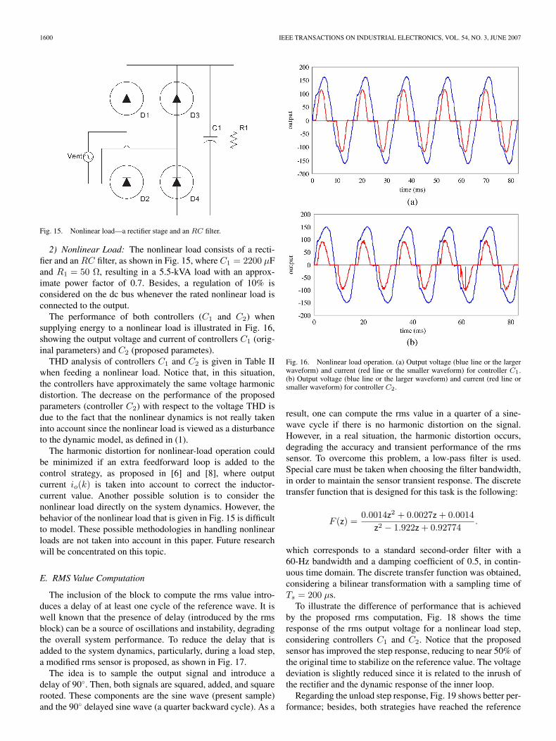
Fig. 15. Nonlinear load—a rectifier stage and an RC filter.
2) Nonlinear Load: The nonlinear load consists of a recti-fier and anRC filter, as shown in Fig. 15, where C1 = 2200 µFand R1 = 50 Ω, resulting in a 5.5-kVA load with an approx-imate power factor of 0.7. Besides, a regulation of 10% isconsidered on the dc bus whenever the rated nonlinear load isconnected to the output.
The performance of both controllers (C1 and C2) whensupplying energy to a nonlinear load is illustrated in Fig. 16,showing the output voltage and current of controllers C1 (orig-inal parameters) and C2 (proposed parametes).
THD analysis of controllers C1 and C2 is given in Table IIwhen feeding a nonlinear load. Notice that, in this situation,the controllers have approximately the same voltage harmonicdistortion. The decrease on the performance of the proposedparameters (controller C2) with respect to the voltage THD isdue to the fact that the nonlinear dynamics is not really takeninto account since the nonlinear load is viewed as a disturbanceto the dynamic model, as defined in (1).
The harmonic distortion for nonlinear-load operation couldbe minimized if an extra feedforward loop is added to thecontrol strategy, as proposed in [6] and [8], where outputcurrent io(k) is taken into account to correct the inductor-current value. Another possible solution is to consider thenonlinear load directly on the system dynamics. However, thebehavior of the nonlinear load that is given in Fig. 15 is difficultto model. These possible methodologies in handling nonlinearloads are not taken into account in this paper. Future researchwill be concentrated on this topic.
E. RMS Value Computation
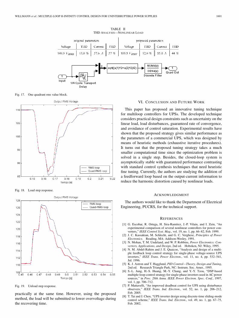
The inclusion of the block to compute the rms value intro-duces a delay of at least one cycle of the reference wave. It iswell known that the presence of delay (introduced by the rmsblock) can be a source of oscillations and instability, degradingthe overall system performance. To reduce the delay that isadded to the system dynamics, particularly, during a load step,a modified rms sensor is proposed, as shown in Fig. 17.
The idea is to sample the output signal and introduce adelay of 90. Then, both signals are squared, added, and squarerooted. These components are the sine wave (present sample)and the 90 delayed sine wave (a quarter backward cycle). As a
Fig. 16. Nonlinear load operation. (a) Output voltage (blue line or the largerwaveform) and current (red line or the smaller waveform) for controller C1.(b) Output voltage (blue line or the larger waveform) and current (red line orsmaller waveform) for controller C2.
result, one can compute the rms value in a quarter of a sine-wave cycle if there is no harmonic distortion on the signal.However, in a real situation, the harmonic distortion occurs,degrading the accuracy and transient performance of the rmssensor. To overcome this problem, a low-pass filter is used.Special care must be taken when choosing the filter bandwidth,in order to maintain the sensor transient response. The discretetransfer function that is designed for this task is the following:
F (z) =0.0014z2 + 0.0027z + 0.0014
z2 − 1.922z + 0.92774.
which corresponds to a standard second-order filter with a60-Hz bandwidth and a damping coefficient of 0.5, in contin-uous time domain. The discrete transfer function was obtained,considering a bilinear transformation with a sampling time ofTs = 200 µs.
To illustrate the difference of performance that is achievedby the proposed rms computation, Fig. 18 shows the timeresponse of the rms output voltage for a nonlinear load step,considering controllers C1 and C2. Notice that the proposedsensor has improved the step response, reducing to near 50% ofthe original time to stabilize on the reference value. The voltagedeviation is slightly reduced since it is related to the inrush ofthe rectifier and the dynamic response of the inner loop.
Regarding the unload step response, Fig. 19 shows better per-formance; besides, both strategies have reached the reference
WILLMANN et al.: MULTIPLE-LOOP H-INFINITY CONTROL DESIGN FOR UNINTERRUPTIBLE POWER SUPPLIES 1601
TABLE IITHD ANALYSIS—NONLINEAR LOAD
Fig. 17. One quadrant rms value block.
Fig. 18. Load step response.
Fig. 19. Unload step response.
practically at the same time. However, using the proposedmethod, the load will be submitted to lower overvoltage duringthe recovering time.
VI. CONCLUSION AND FUTURE WORK
This paper has proposed an innovative tuning techniquefor multiloop controllers for UPSs. The developed techniqueconsiders practical design constraints such as uncertainty on thelinear load, load disturbances, guaranteed rate of convergence,and avoidance of control saturation. Experimental results haveshown that the proposed strategy gives similar performance asthe parameters of a commercial UPS, which was designed bymeans of heuristic methods (exhaustive iterative procedures).It turns out that the proposed tuning strategy takes a muchsmaller computational time since the optimization problem issolved in a single step. Besides, the closed-loop system isasymptotically stable with guaranteed performance contrastingwith standard control synthesis techniques that need heuristicfine tuning. Currently, the authors are studying the addition ofa feedforward loop based on the output-current information toreduce the harmonic distortion caused by nonlinear loads.
ACKNOWLEDGMENT
The authors would like to thank the Department of ElectricalEngineering, PUCRS, for the technical support.
REFERENCES
[1] G. Escobar, R. Ortega, H. Sira-Ramírez, J.-P. Vilain, and I. Zein, “Anexperimental comparison of several nonlinear controllers for power con-verters,” IEEE Control Syst. Mag., vol. 19, no. 1, pp. 66–82, Feb. 1999.
[2] J. C. Kassakian, M. Schlecht, and G. C. Verghese, Principles of PowerElectronics. Reading, MA: Addison-Wesley, 1991.
[3] N. Mohan, T. M. Undeland, and W. P. Robbins, Power Electronics: Con-verters, Applications, and Design, 2nd ed. Hoboken, NJ: Wiley, 1995.
[4] N. M. Abdel-Rahim and J. E. Quaicoe, “Analysis and design of a multi-ple feedback loop control strategy for single-phase voltage-source UPSinverters,” IEEE Trans. Power Electron., vol. 11, no. 4, pp. 532–541,Jul. 1996.
[5] K. J. Astron and T. Hagglund, PID Control—Theory, Design and Tuning,2nd ed. Research Triangle Park, NC: Instrum. Soc. Amer., 1995.
[6] S.-L. Jung, H.-S. Huang, M.-Y. Chang, and Y.-Y. Tzou, “DSP-basedmultiple-loop control strategy for single-phase inverters used in AC powersources,” in Proc. 28th Annu. IEEE Power Electron. Spec. Conf., 1997,vol. 1, pp. 706–712.
[7] P. Mattavelli, “An improved deadbeat control for UPS using disturbanceobservers,” IEEE Trans. Ind. Electron., vol. 52, no. 1, pp. 206–212,Feb. 2005.
[8] T. Tai and J. Chen, “UPS inverter design using discrete-time sliding-modecontrol scheme,” IEEE Trans. Ind. Electron., vol. 49, no. 1, pp. 67–75,Feb. 2002.
1602 IEEE TRANSACTIONS ON INDUSTRIAL ELECTRONICS, VOL. 54, NO. 3, JUNE 2007
[9] M. Sun, Y. Wang, and D. Wang, “Variable-structure repetitive control: Adiscrete-time strategy,” IEEE Trans. Ind. Electron., vol. 52, no. 2, pp. 610–616, Apr. 2005.
[10] V. F. Montagner and P. L. D. Peres, “Robust state feedback control appliedto an UPS system,” in Proc. 29th Annu. Conf. IEEE Ind. Electron. Soc.,2003, vol. 3, pp. 2245–2250.
[11] R. Naim, G. Weiss, and S. Ben-Yaakov, “H∞ control applied to boostpower converters,” IEEE Trans. Power Electron., vol. 12, no. 4, pp. 677–683, Jul. 1997.
[12] T.-S. Lee, S.-J. Chiang, and J.-M. Chang, “H∞ loop-shaping controllerdesigns for the single-phase UPS inverters,” IEEE Trans. Power Electron.,vol. 16, no. 4, pp. 473–481, Jul. 2001.
[13] T.-S. Lee, K.-S. Tzeng, and M.-S. Chong, “Robust controller designfor a single-phase UPS inverter using µ-synthesis,” Proc. Inst. Electr.Eng.—Electr. Power Appl., vol. 151, no. 3, pp. 334–340, May 2004.
[14] Q.-C. Zhong, J. Liang, G. Weiss, C. Feng, and T. C. Green, “H∞ controlof the neutral point in four-wire three-phase DC–AC converters,” IEEETrans. Ind. Electron., vol. 53, no. 5, pp. 1594–1602, Oct. 2006.
[15] L. El Ghaoui and S.-I. Niculescu, Eds., Advances in Linear MatrixInequality Methods in Control. Philadelphia, PA: SIAM, 2000.
[16] R. Amirifar and N. Sadati, “Low-order H∞ controller design for an activesuspension system via LMIs,” IEEE Trans. Ind. Electron., vol. 53, no. 2,pp. 554–560, Apr. 2006.
[17] S. P. Boyd, L. El Ghaoui, E. Feron, and V. Balakrishnan, Linear MatrixInequalities in Systems and Control Theory. Philadelphia, PA: SIAM,1994.
[18] J. B. Burl, Linear Optimal Control. Reading, MA: Addison-Wesley,1999.
[19] H. K. Khalil, Nonlinear Systems, 2nd ed. Upper Saddle River, NJ:Prentice-Hall, 1996.
[20] D. F. Coutinho, M. Fu, and A. Trofino, “Robust analysis and control fora class of uncertain nonlinear discrete-time systems,” Syst. Control Lett.,vol. 53, no. 5, pp. 377–393, Dec. 2004.
[21] J.-J. E. Slotine and W. Li, Applied Nonlinear Control. Englewood Cliffs,NJ: Prentice-Hall, 1991.
[22] P. Gahinet, A. Nemirovskii, A. Laub, and M. Chilali, “The LMI controltoolbox,” in Proc. 33rd IEEE Conf. Decision Control, Lake Buena Vista,FL, 1994, vol. 3, pp. 2038–2041.
[23] R. Nikoukhah, F. Delebecque, and L. El Ghaoui, LMITOOL: A Packagefor LMI Optimization in Scilab—User’s Guide, Nov. 20, 2006. [Online].Available: http://www.scilab.org/doc/lmidoc/index.html
[24] Y. Labit, D. Peaucelle, and D. Henrion, “SEDUMI INTERFACE 1.02: Atool for solving LMI problems with SEDUMI,” in Proc. IEEE Int. Symp.Comput.-Aided Control Syst. Des., 2002, pp. 272–277.
[25] G. F. Franklin, J. D. Powell, and A. Emani-Nacini, Feedback Control ofDynamic Systems. Reading, MA: Addison-Wesley, 1994.
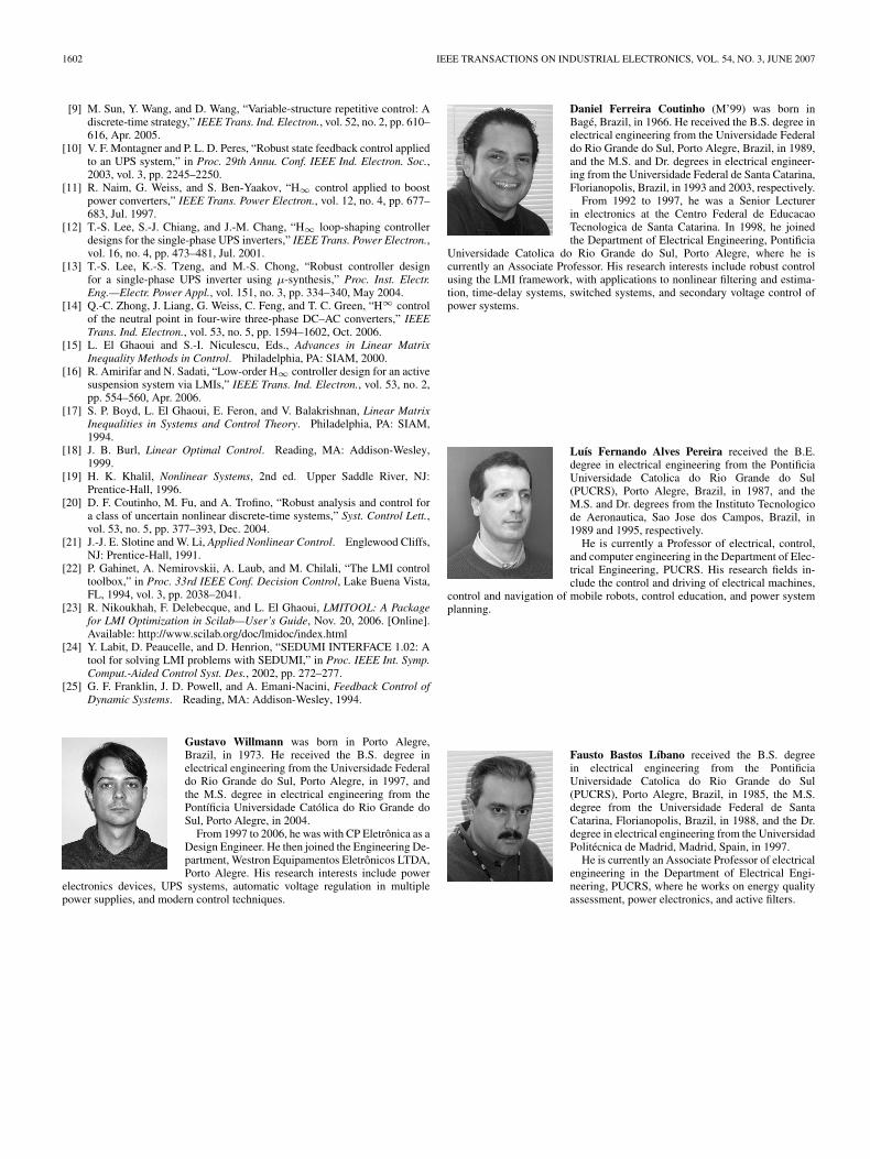
Gustavo Willmann was born in Porto Alegre,Brazil, in 1973. He received the B.S. degree inelectrical engineering from the Universidade Federaldo Rio Grande do Sul, Porto Alegre, in 1997, andthe M.S. degree in electrical engineering from thePontíficia Universidade Católica do Rio Grande doSul, Porto Alegre, in 2004.
From 1997 to 2006, he was with CP Eletrônica as aDesign Engineer. He then joined the Engineering De-partment, Westron Equipamentos Eletrônicos LTDA,Porto Alegre. His research interests include power
electronics devices, UPS systems, automatic voltage regulation in multiplepower supplies, and modern control techniques.
Daniel Ferreira Coutinho (M’99) was born inBagé, Brazil, in 1966. He received the B.S. degree inelectrical engineering from the Universidade Federaldo Rio Grande do Sul, Porto Alegre, Brazil, in 1989,and the M.S. and Dr. degrees in electrical engineer-ing from the Universidade Federal de Santa Catarina,Florianopolis, Brazil, in 1993 and 2003, respectively.
From 1992 to 1997, he was a Senior Lecturerin electronics at the Centro Federal de EducacaoTecnologica de Santa Catarina. In 1998, he joinedthe Department of Electrical Engineering, Pontificia
Universidade Catolica do Rio Grande do Sul, Porto Alegre, where he iscurrently an Associate Professor. His research interests include robust controlusing the LMI framework, with applications to nonlinear filtering and estima-tion, time-delay systems, switched systems, and secondary voltage control ofpower systems.
Luís Fernando Alves Pereira received the B.E.degree in electrical engineering from the PontificiaUniversidade Catolica do Rio Grande do Sul(PUCRS), Porto Alegre, Brazil, in 1987, and theM.S. and Dr. degrees from the Instituto Tecnologicode Aeronautica, Sao Jose dos Campos, Brazil, in1989 and 1995, respectively.
He is currently a Professor of electrical, control,and computer engineering in the Department of Elec-trical Engineering, PUCRS. His research fields in-clude the control and driving of electrical machines,
control and navigation of mobile robots, control education, and power systemplanning.
Fausto Bastos Líbano received the B.S. degreein electrical engineering from the PontificiaUniversidade Catolica do Rio Grande do Sul(PUCRS), Porto Alegre, Brazil, in 1985, the M.S.degree from the Universidade Federal de SantaCatarina, Florianopolis, Brazil, in 1988, and the Dr.degree in electrical engineering from the UniversidadPolitécnica de Madrid, Madrid, Spain, in 1997.
He is currently an Associate Professor of electricalengineering in the Department of Electrical Engi-neering, PUCRS, where he works on energy qualityassessment, power electronics, and active filters.


