Embed Size (px)
Citation preview
Desalination 152 (2002) 155–165
0011-9164/02/$– See front matter © 2002 Elsevier Science B.V. All rights reserved
Presented at the EuroMed 2002 conference on Desalination Strategies in South Mediterranean Countries:Cooperation between Mediterranean Countries of Europe and the Southern Rim of the Mediterranean.Sponsored by the European Desalination Society and Alexandria University Desalination Studies and TechnologyCenter, Sharm El Sheikh, Egypt, May 4–6, 2002.
*Corresponding author.
Power plant residual heat for seawater desalination
M. Cohena, I. Ianovicia, D. Breschib*aIsrael Electricity Corp., Mechanical System Department, POB 10, Haifa, 3100 Israel
Tel. +972 (4) 8684414; Fax +972 (4) 8684550; email: [email protected] Associate Termoimpianti – Sowit Division, Cinisello Balsamo, Milan, ItalyTel. +39 (02) 26250 272; Fax +39 (02) 26250 370; e-mail: [email protected]
Received 9 April 2002; accepted 20 April 2002
Abstract
The paper describes the results of a feasibility study jointly promoted by Israel Electricity Corporation and Aster– Sowit Division (Italy) aimed at investigation of the possible integration of the low-temperature flash (LTF) desalinationtechnology in existing IEC power stations. The LTF technology exploits the residual heat discharged by the coolingseawater for its distillation, with a dramatic reduction in steam consumption as compared to other distillation processes.A prototype LTF desalination unit has been operating at ENEL power station in Piombino, Italy since 1993, showingthe industrial applicability of this technology. In the present study an improved LTF design, with long tube, multi-stage evaporator, has been applied to a typical IEC site located on the southern shore of the Mediterranean Sea. Thestudy has been carried out both for small-scale units, devoted to boiler make-up production, and for a large plantable to produce the whole water supply for the site. The investigation has shown very interesting perspectives forsuch an application, with extremely low steam and electrical consumption and a very competitive cost of producedwater. Other advantages of LTF technology are related to the extreme plant availability, to the high purity of produceddistillate, to the absence of any chemicals consumption and environmental impact.
Keywords: Seawater distillation; LTF; Waste heat; Steam power plant; Water cost
1. LTF process overview
1.1. General
The exploitation of the heat rejected toenvironment by a steam power cycle for seawater
distillation is a consolidated practice in the desali-nation industry, through several dual-purposeinstallations especially in the Middle East, wheretypically the steam discharged by a backpressuresteam turbine feeds the brine heater of a MSFdistiller.
156 M. Cohen et al. / Desalination 152 (2002) 155–165
In such installations, the heat input is madeavailable to the distiller at temperatures in theorder of 120–140°C, significantly above theminimum condensation temperature for the steamcycle made possible by environmental conditions,i.e. decreasing the enthalpy drop available forturbine expansion and then the electrical outputof the system.
In the case of existing single-purpose steampower stations with seawater-cooled condenser,the large amount of heat rejected at ambienttemperature makes its recovery for distillateproduction very attractive from the economicalpoint of view, notwithstanding its low exergeticlevel: it is easily verified that the waste heatconveyed by the cooling seawater discharged bya steam power station can be used as thermalsource to produce, by simple flash distillation,over 1,800 m3/d water for each 100 MWe poweroutput, thus largely exceeding the water needs forthe thermal cycle itself.
33 bar abs
785 kg/h
98 t/h
Vapour 825 kg/h
Air 112 kg/h
28.0 °C 7,235 t/h
22.0 °C
8000 mm
71.6 t/h
27.2 °C
5,036 t/h
28.0 °C
5,106 t/h Distillate extraction pump
36.5 °C
Brine discharge pump
Seawater Inlet
Distillate
Vacuum System Steam Inlet
Evaporator
This paper discusses a way of exploiting forseawater distillation the waste heat as rejected byan existing condensation steam power cycle, i.e.only a few degrees above ambient temperature,without detriment to the electric output of thepower station.
Such a technology was discussed in the pastby other authors [1] but, to our knowledge, noindustrial application was installed until a prototypeplant has been developed in the early nineties bythe Italian company Sowit in the power station ofPiombino, Italy [2].
1.2. Process scheme
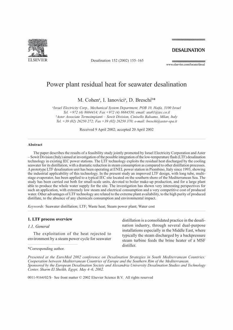
The LTF plant is basically formed by a vacuumflash evaporator-condenser for seawater distillationand by a vacuum system for venting to atmospherethe air released in the evaporator.
A schematic arrangement of the selected plant,with typical process parameters, is shown in Fig. 1.
Fig. 1. LTF plant process scheme.

M. Cohen et al. / Desalination 152 (2002) 155–165 157
The evaporator is formed by a series of inter-connected flash chambers and tube-bundle con-densers (three in the case depicted in figure). Thewarmed seawater discharged by the turbinecondenser is fed to the first evaporator chamber,where a condition of saturation equilibrium isthermodynamically maintained, at a temperaturesome degrees lower with respect to incomingseawater. In this condition, seawater flashesproducing a stream of saturated vapor, while theconcentrated portion (brine), flowing on thebottom of the evaporator, is cascaded, through asuitable orifice, to the downstream stage operatingat lower pressure. The vapor stream generated byseawater flash flows through the demisters (inorder to separate the carryover of seawaterdroplets mixed with vapor) and condenses aroundthe cooler tubes surface of the condenser placedin the upper part of each chamber. The condensersare cooled by seawater at ambient temperatureflowing in countercurrent with respect to brine,thus allowing maintaining the vapor saturationcondition in each chamber and the formation of atemperature–pressure differential through thestages. The distillate produced by this process iscollected in a suitable tray located below the tubebundle and cascaded to the subsequent stage. Thebrine cascaded to the last (coldest) stage is dis-charged back to the sea (by an extraction pumpor by gravity, according to the elevation of theevaporator), while the distillate collected in thelast stage is pumped to the storage tank. The airdissolved in the warm seawater feeding theevaporator is released when entering the flashchamber, due to the water–vapor equilibriumcondition found, and has to be vented out fromthe evaporator, in order to maintain the high degreeof vacuum requested by the low-temperaturedistillation equilibrium. The requirement of ventingnon-condensable gases is always found in seawaterdistillers, but is particularly critical in the LTFprocess given the comparatively large ratio of feedseawater to distillate and the high specific volumeof air at the low operating temperatures typicalof this process. In order to limit the motive steam
consumption, a vent extraction (vacuum) systemformed by a four-stage ejector-condenser group,has been recognized as the most cost-effective forsuch application. It should be noted that themotive steam necessary for the vacuum system isthe only steam consumption of the plant.
1.3. Plant arrangement
The LTF unit is conceived for being locatedabove the seawater discharge channel of the powerstation, in order to feed the evaporator with warmseawater and discharge the brine and the returnseawater downstream to the same channel.
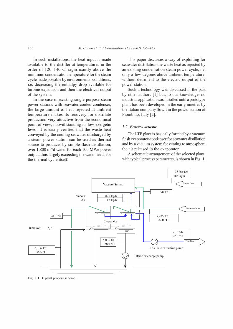
There exist two possibilities for feeding anddischarging the warm seawater to/from the evapo-rator: a feed pump with gravity discharge or afeed by pressure differential associated to a blowdown pump. Fig. 2 depicts the arrangement forgravity brine discharge (brine level at a minimumof 10 m above water level in the channel). In thisscheme, it has been selected to re-mix the dischargedcooling water (at increased temperature) into themain header upstream the turbine condenser; abooster pump is then necessary in order to over-come the additional head loss of the LTF tubebundle.
An alternative arrangement is shown in Fig. 3,where the cooling seawater is discharged straightto the channel and, consequently, the evaporatorhas to be located at a lower elevation in order toavoid seawater vaporization inside tubes. In thiscase, there is no need for the seawater booster pump,as the pressure in the main header is generallyenough to attain the requested seawater flow rate.Both solutions require some over-sizing in themain seawater intake, pump and feed line in orderto avoid penalization to the power cycle. Efficiencyloss would be, however, in practical cases negligible.
1.4. Comparison between LTF and otherdesalination processes
A general comparison related to the steam andelectric requirement, chemical consumption andblow down concentration among MSF, MED, LTF
158 M. Cohen et al. / Desalination 152 (2002) 155–165
and SWRO technologies is presented in Table 1.It is to be noted that electric consumption valuesinclude seawater feed.
2. Operational experience on Piombino LTFunit
The power station of Piombino is formed byfour steam units, each rated at 320 MWe. The totalquantity of seawater discharged by the turbinecondenser of each unit is 14 m3/s. Considering thatthe discharged water is heated of 8°C at full load,
Seawater
Turbine condenser
H
Seawater booster pump
Warm water feed pump
LTF evaporator
Fig. 2. Gravity brine discharge.
Seawater
LTF evaporator
Turbine condenser
H
Brine blowdown pump
Fig. 3. Brine blowdown pump.
it has been verified that the simple distillation ofsuch a stream, utilizing as thermal source its ownenthalpy difference to ambient, could producemore than 20,000 m3/d of pure water. However,due to space constraints in the existing site withinthe power station, and in consideration of theessentially demonstrative purpose of the project,the design capacity of the LTF desalination unit hasbeen rated at 500 m3/d production, thus utilizingonly a small quantity of the available heat, with aone-stage evaporator. The area for the installationof the demonstrative LTF plant was located in
M. Cohen et al. / Desalination 152 (2002) 155–165 159
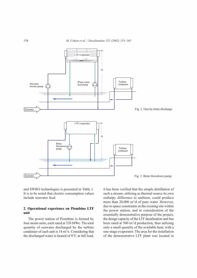
proximity of the seawater channel of the powerstation, by which the cooling seawater of theturbine condensers is discharged to the sea (Fig. 4).The commissioning of the LTF unit took place inJuly 1993. Since then, the LTF unit has been keptconstantly in operation in Piombino power station,being preferred to the previously installed MSFunits for the production of boiler make-up, due tothe following main reasons:• The operation of the plant proved to be ex-
tremely easy and reliable, with no record of anyoutage occurrences, due to the great simplicityof the installation;
• The purity of produced distillate has been con-stantly below the value of 1 µS/cm, thus greatlyreducing the post-treatment cost throughmixed-bed units for boiler make-up;
• The cost for operation and maintenance provedto be dramatically reduced if compared to the
Table 1Comparison between LTF and other desalination technologies
Fig. 4. LTF unit in Piombino power station.
corresponding cost of other types of desali-nation plants.
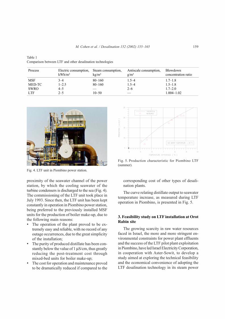
The curve relating distillate output to seawatertemperature increase, as measured during LTFoperation in Piombino, is presented in Fig. 5.
3. Feasibility study on LTF installation at OrotRabin site
The growing scarcity in raw water resourcesfaced in Israel, the more and more stringent en-vironmental constraints for power plant effluentsand the success of the LTF pilot plant exploitationin Piombino, have led Israel Electricity Corporation,in cooperation with Aster-Sowit, to develop astudy aimed at exploring the technical feasibilityand the economical convenience of adopting theLTF desalination technology in its steam power
Fig. 5. Production characteristic for Piombino LTF(summer).
Process Electric consumption, kWh/m³
Steam consumption, kg/m³
Antiscale consumption, g/m³
Blowdown concentration ratio
MSF 3–4 80–160 1.5–4 1.7–1.8 MED-TC 1–2.5 80–160 1.5–4 1.5–1.8 SWRO 4–5 — 2–6 1.7–2.0 LTF 2–5 10–50 — 1.004–1.02
160 M. Cohen et al. / Desalination 152 (2002) 155–165
stations, for both process and drinking water pro-duction. The following site characteristics havebeen envisaged as requisites for the LTF installation:• A minimum of 8°C design seawater temperature
difference across the turbine condenser, asnecessary in order to install a reasonable heattransfer surface in the distillate condenser;
• Power plant operating mainly at base load, inorder to maximize overall water production;
• A minimum yearly average seawater temperatureof 20°C, in order to keep evaporator volumewithin acceptable limits;
• Possibility of installing the LTF evaporatorabove the seawater discharge channel and inproximity of the cooling seawater feed line.
The site selected by IEC for the feasibilitystudy is Orot Rabin power station, located on thesouthern shore of the Mediterranean Sea andformed by six coal-fired power units:• Four steam units rated at 350 MW electric output,
the oldest in the site, operating with 12.5°Ctemperature rise in condensers (units 1–4);
• Two steam units rated at 550 MW electricoutput, operating with 8°C temperature risein the condensers (units 5 and 6).
All units are condensation type, using seawateras cooling medium. Approximately 50% of theheat input by coal firing is dumped to the sea atlow temperature. Based on site data records, thedesign seawater temperature for the LTF distillationunit has been selected at 22°C. In Orot Rabin site,the inherent steam and water losses are presentlymade up from an external source of raw water atabout 500 ppm TDS, which is passed through ion-exchange demineralization units before feedingthe boilers, in order to reach the requested purityof 0.05 ppm.
IEC identified the following options for LTFinstallation in Orot Rabin site, which will bediscussed in more detail in subsequent sections:• A small size desalination unit, rated at approxi-
mately 20 t/h, in order to get acquainted withthe new technology by a low investment;
• A desalination unit rated at about 50 t/h dis-tillate production, in order to replace the existingion-exchange boiler feed water make-up unitswith a new LTF installation able to cope withthe water demand of the whole power station;
• A comparatively large desalination plant,formed by more units, rated at about 560 t/hwater production and devoted to serve localdrinking water demand in addition to producingboiler make-up.
The study is aimed, in all the above cases, at theidentification of an improved LTF design, basedon the experience gained by the operation ofPiombino unit, in order to get a more significantadvantage from this technology. A design relevantto a multi-stage, long tube LTF evaporator wasthen developed, adopting a geometry somehowsimilar to various MSF evaporators installed inItaly [3], but still with an once-through schemefor both flashing brine and cooling seawater, asalready shown in Fig. 1. This solution, as comparedto the single-stage configuration of the prototypeunit, offered the obvious advantage of reducingthe condenser heat exchange surface, allowing atthe same time a lower design flow rate for coolingseawater and flashing brine. In addition, the multi-stage configuration significantly reduces theimpact of seasonal seawater temperature variationon distiller performance. Further improvementshave also been carried out on the geometry of thetube bundle condensers, enhancing the sub-coolingof the vapor–air mixture at vent extraction andconsequently reducing the vacuum ejectors suctionload.
4. Economic evaluation on LTF installation
A total water cost comparison between LTFand other desalination technologies for theproduction of both boiler feed water and drinkingwater in Orot Rabin site has been developed.
The study has been extended also to thecorresponding water cost in a new site.
M. Cohen et al. / Desalination 152 (2002) 155–165 161
4.1. Cost parameters
Presently, in Orot Rabin site boiler make-upwater at 0.05 ppm is produced from raw water atapproximately 500 ppm TDS by a demineralizationplant including a cationic/anionic ion exchangeunit and a mixed bed section. The operation ofthe demineralization unit is independent withrespect to the one of the power unit, the productbeing delivered to storage tanks.
The main cost data used for the comparisonare presented in Table 2. In the study, it has beenconsidered to connect the MP steam line for thevacuum system to the cold reheat line, at 34 barabs and 330°C, having the same cost as the servicesteam at 14 bar abs, but able to reduce consumptionby about 20% due to the higher pressure.
The evaluation has been carried out consideringthe base load operation (approximately 80% timeat 100% load) of Orot Rabin site.
Table 2Cost parameters
Raw water cost, US$/m3
0.35 Electric power cost (for domestic use), US$/kWh
0.038
MP steam cost, US$/t 3.2 Interest rate, % 6.5 Economic lifetime, years 20 Manpower cost, US$/h 49
4.2. Cost of water for selected cases
Economical evaluations were exhaustivelycarried out for two main cases:• installation of a LTF plant in an existing power
plant,• introduction of the LTF technology in the
project of a new power plant.
The economic evaluation is based on the boilerfeed water make-up price, this parameter allowingthe comparison among different desalination
technologies. The main process data relevant tothe selected LTF configurations are presented inTable 3.
4.2.1. Case 1
The LTF unit is connected to the existingdemineralization plant, replacing the raw waterfeed. Two alternatives have been investigated:
a) LTF unit rated at 20-t/h net production forboiler make-up supply to power units 5–6. Althoughdesigned based on the lowest available temperaturedifference (8°C), this alternative takes advantagefrom the actual over-design of the existing coolingseawater pumps (about 7%), thus requesting noadditional pumping system. A very favorableposition has been found for the LTF unit, in theclose vicinity of the main cooling water pump houseof units 5, 6.
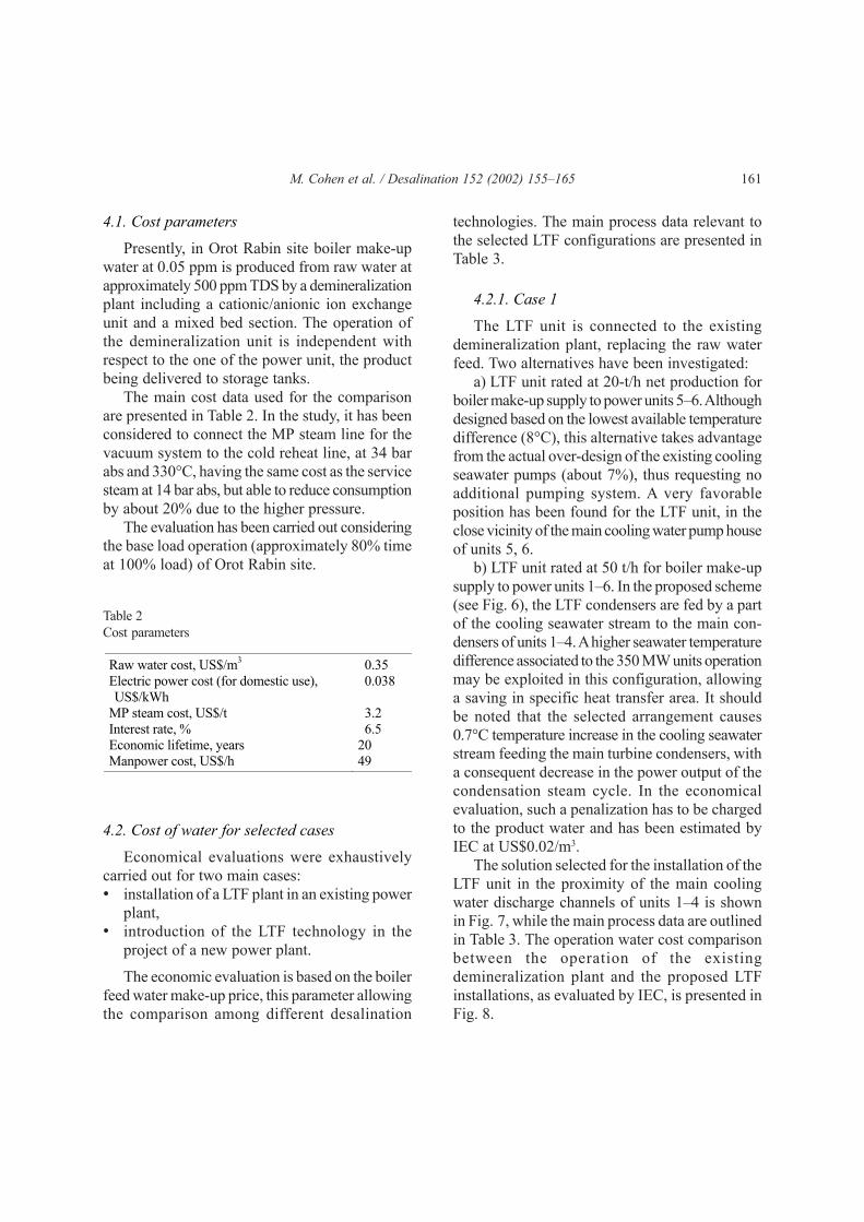
b) LTF unit rated at 50 t/h for boiler make-upsupply to power units 1–6. In the proposed scheme(see Fig. 6), the LTF condensers are fed by a partof the cooling seawater stream to the main con-densers of units 1–4. A higher seawater temperaturedifference associated to the 350 MW units operationmay be exploited in this configuration, allowinga saving in specific heat transfer area. It shouldbe noted that the selected arrangement causes0.7°C temperature increase in the cooling seawaterstream feeding the main turbine condensers, witha consequent decrease in the power output of thecondensation steam cycle. In the economicalevaluation, such a penalization has to be chargedto the product water and has been estimated byIEC at US$0.02/m3.
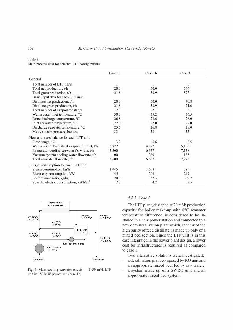
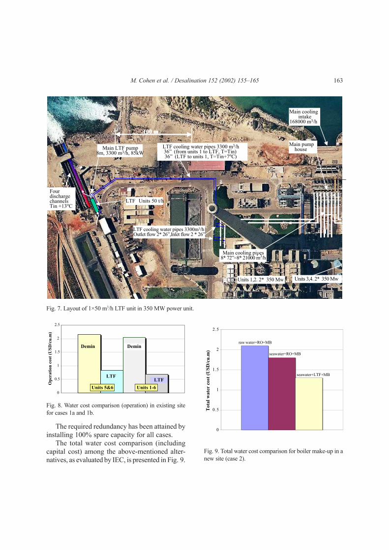
The solution selected for the installation of theLTF unit in the proximity of the main coolingwater discharge channels of units 1–4 is shownin Fig. 7, while the main process data are outlinedin Table 3. The operation water cost comparisonbetween the operation of the existingdemineralization plant and the proposed LTFinstallations, as evaluated by IEC, is presented inFig. 8.
162 M. Cohen et al. / Desalination 152 (2002) 155–165
Table 3Main process data for selected LTF configurations
Case 1a Case 1b Case 3
General
Total number of LTF units 1 1 8 Total net production, t/h 20.0 50.0 566 Total gross production, t/h 21.8 53.9 573 Basic input data for each LTF unit Distillate net production, t/h 20.0 50.0 70.8 Distillate gross production, t/h 21.8 53.9 71.6 Total number of evaporator stages 2 2 3 Warm water inlet temperature, °C 30.0 35.2 36.5 Brine discharge temperature, °C 26.8 28.6 28.0 Inlet seawater temperature, °C 22.0 22.0 22.0 Discharge seawater temperature, °C 25.5 26.8 28.0 Motive steam pressure, bar abs 33 33 33
Heat and mass balance for each LTF unit
Flash range, °C 3.2 6.6 8.5 Warm water flow rate at evaporator inlet, t/h 3,972 4,822 5,106 Evaporator cooling seawater flow rate, t/h 3,500 6,377 7,138 Vacuum system cooling water flow rate, t/h 100 280 135 Total seawater flow rate, t/h 3,600 6,657 7,273
Energy consumption for each LTF unit
Steam consumption, kg/h 1,045 1,668 785 Electricity consumption, kW 45 209 247 Performance ratio, kg/kg 20.9 32.3 89.2 Specific electric consumption, kWh/m
3 2.2 4.2 3.5
4.2.2. Case 2
The LTF plant, designed at 20 m3/h productioncapacity for boiler make-up with 8°C seawatertemperature difference, is considered to be in-stalled in a new power station and connected to anew demineralization plant which, in view of thehigh purity of feed distillate, is made up only of amixed bed section. Since the LTF unit is in thiscase integrated in the power plant design, a lowercost for infrastructures is required as comparedto case 1.
Two alternative solutions were investigated:• a desalination plant composed by RO unit and
an appropriate mixed bed, fed by raw water,• a system made up of a SWRO unit and an
appropriate mixed bed system.Fig. 6. Main cooling seawater circuit — 1×50 m3/h LTFunit in 350 MW power unit (case 1b).
M. Cohen et al. / Desalination 152 (2002) 155–165 163
100 m100 m
Units 1,2. 2* 350 Mw Units 3,4. 2* 350 Mw
Main coolingintake
168000 m3/h
Main pump house
LTF cooling water pipes 3300 m3/h36” (from units 1 to LTF, T=Tin)36” (LTF to units 1, T=Tin+7oC)
Main cooling pipes8* 72”=8* 21000 m3/h
LTF Units 50 t/h
Four discharge channels Tin +13oC
Main LTF pump 8m, 3300 m3/h, 85kW
LTF cooling water pipes 3300m3/hOutlet flow 2* 26”,Inlet flow 2 * 26”
Fig. 7. Layout of 1×50 m3/h LTF unit in 350 MW power unit.
Fig. 8. Water cost comparison (operation) in existing sitefor cases 1a and 1b.
The required redundancy has been attained byinstalling 100% spare capacity for all cases.
The total water cost comparison (includingcapital cost) among the above-mentioned alter-natives, as evaluated by IEC, is presented in Fig. 9.
0
0.5
1
1.5
2
2.5
Op
era
tio
n c
ost
(U
SD
/cu
.m)
Units 5&6 Units 1-6
Demin
LTF
Demin
LTF
0
0.5
1
1.5
2
2.5
To
tal
wa
ter
cost
(U
SD
/cu
.m)
raw water+RO+MB
seawater+RO+MB
seawater+LTF+MB
Fig. 9. Total water cost comparison for boiler make-up in anew site (case 2).
164 M. Cohen et al. / Desalination 152 (2002) 155–165
100 m100 m
Units 1,2. 2 * 350 Mw Units 3,4. 2 * 350 Mw
MaincCoolingIntake
168000 m3/h
Main pump house
Main Cooling
intake
LTF cooling water pipes 14000 m3/h54” (from units 1 to LTF,T=Tin)54” (LTF to units 1 ,T=Tin+6
oC)
Main cooling pipes8*72”=8*21000 m3/h
LTF units 140 t/h
Four discharge channels Tin+14.5oC
Main LTF pump 8m, 14000 m3/h
LTF cooling water pipes 14000 m3/hOutlet flow 2 x 42”, Inlet flow 2x42”
It should be noted that the capital cost consideredfor LTF includes the cost of interconnectingseawater piping.
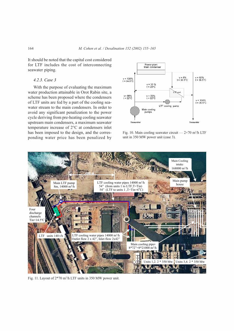
4.2.3. Case 3
With the purpose of evaluating the maximumwater production attainable in Orot Rabin site, ascheme has been proposed where the condensersof LTF units are fed by a part of the cooling sea-water stream to the main condensers. In order toavoid any significant penalization to the powercycle deriving from pre-heating cooling seawaterupstream main condensers, a maximum seawatertemperature increase of 2°C at condensers inlethas been imposed to the design, and the corres-ponding water price has been penalized by
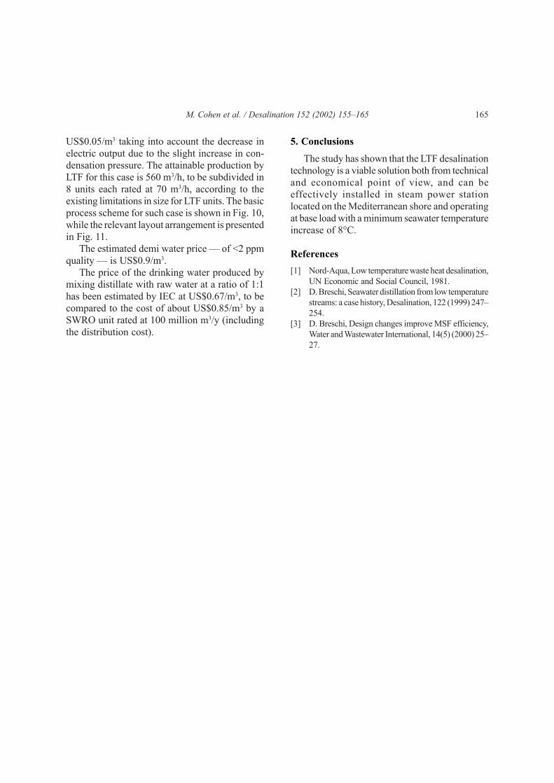
Fig. 11. Layout of 2*70 m3/h LTF units in 350 MW power unit.
Fig. 10. Main cooling seawater circuit — 2×70 m3/h LTFunit in 350 MW power unit (case 3).
M. Cohen et al. / Desalination 152 (2002) 155–165 165
US$0.05/m3 taking into account the decrease inelectric output due to the slight increase in con-densation pressure. The attainable production byLTF for this case is 560 m3/h, to be subdivided in8 units each rated at 70 m3/h, according to theexisting limitations in size for LTF units. The basicprocess scheme for such case is shown in Fig. 10,while the relevant layout arrangement is presentedin Fig. 11.
The estimated demi water price — of <2 ppmquality — is US$0.9/m3.
The price of the drinking water produced bymixing distillate with raw water at a ratio of 1:1has been estimated by IEC at US$0.67/m3, to becompared to the cost of about US$0.85/m3 by aSWRO unit rated at 100 million m3/y (includingthe distribution cost).
5. Conclusions
The study has shown that the LTF desalinationtechnology is a viable solution both from technicaland economical point of view, and can beeffectively installed in steam power stationlocated on the Mediterranean shore and operatingat base load with a minimum seawater temperatureincrease of 8°C.
References[1] Nord-Aqua, Low temperature waste heat desalination,
UN Economic and Social Council, 1981.[2] D. Breschi, Seawater distillation from low temperature
streams: a case history, Desalination, 122 (1999) 247–254.
[3] D. Breschi, Design changes improve MSF efficiency,Water and Wastewater International, 14(5) (2000) 25–27.


