Embed Size (px)
Citation preview
Materials Chemistry and Physics 113 (2009) 919–926
Contents lists available at ScienceDirect
Materials Chemistry and Physics
journa l homepage: www.e lsev ier .com/ locate /matchemphys
Polyaniline–MWCNT nanocomposites for microwave absorptionand EMI shielding
Parveen Sainia, Veena Choudharyb, B.P. Singhc, R.B. Mathurc, S.K. Dhawana,∗
a Polymeric & Soft Materials Section, National Physical Laboratory, New Delhi 110012, Indiab Centre for Polymer Science & Engineering, Indian Institute of Technology, New Delhi 110016, Indiac Carbon Technology Unit, National Physical Laboratory, New Delhi 110012, India
a r t i c l e i n f o
Article history:Received 15 July 2008Received in revised form 12 August 2008Accepted 14 August 2008
Keywords:Composite materialsFourier transform infrared spectroscopy(FTIR)
a b s t r a c t
Highly conducting polyaniline (PANI)–multi-walled carbon nanotube (MWCNT) nanocomposites wereprepared by in situ polymerization. The FTIR and XRD show systematic shifting of the characteristicbands and peaks of PANI, with the increase in MWCNT phase, suggesting significant interaction betweenthe phases. The SEM and TEM pictures show thick and uniform coating of PANI over surface of individualMWCNT. Based on observed morphological features in SEM, the probable formation mechanism of thesecomposites has been proposed. The electrical conductivity of PANI–MWCNT composite (19.7 S cm−1) waseven better than MWCNT (19.1 S cm−1) or PANI (2.0 S cm−1). This can be ascribed to the synergistic effectof two complementing phases (i.e. PANI and MWCNT). The absorption dominated total shielding effec-
Thermogravimetric analysis (TGA)Electrical conductivity
tiveness (SE) of −27.5 to −39.2 dB of these composites indicates the usefulness of these materials formicrowave shielding in the Ku-band (12.4–18.0 GHz). These PANI coated MWCNTs with large aspect ratioare also proposed as hybrid conductive fillers in various thermoplastic matrices, for making structurallystrong microwave shields.
1
mnTiwniccaTgo[sF
it
asmpi(tnpcst
0d
. Introduction
The proliferation of electronics and instrumentation in com-ercial, industrial, healthcare and defense sectors has led to a
ovel kind of pollution known as electromagnetic interference [1].his is a serious issue caused by the interference effects of currentnduced by electric and magnetic fields, emanating from nearby
ide range of electrical circuitry [2]. The interference among busi-ess machines, process equipments, consumer products and other
nstruments may lead to disturbance of usual performance or evenomplete malfunction. The disturbances across communicationhannels, automation and process control may lead to loss of valu-ble time, energy, resources, money or even precious human life.herefore some kind of shielding mechanism must be provided touard the concerned article from spurious electromagnetic noises
r pollution. Metals are most common materials for EMI shielding3,4]. But they suffered from the disadvantages like high density,usceptibility to corrosion, complex and uneconomic processing.urther, metals mainly reflect the radiation and cannot be used∗ Corresponding author. Tel.: +91 11 45609401; fax: +91 11 25726938.E-mail address: [email protected] (S.K. Dhawan).
ppipwi
tm
254-0584/$ – see front matter © 2008 Elsevier B.V. All rights reserved.oi:10.1016/j.matchemphys.2008.08.065
© 2008 Elsevier B.V. All rights reserved.
n applications where absorption is prime requisite, e.g. in stealthechnology [5,6].
In the last four decades, conducting polymers (CPs) have gainedspecial status owing to wealth of applications [7–15]. The EMI
hielding and microwave absorption properties of these poly-ers can be explained in terms of electrical conductivity and
resence of bound/localized charges (polarons/bipolarons) lead-ng to strong polarization and relaxation effects [16,17]. PolyanilinePANI) has special status among other conducting polymers dueo its non-redox doping, good environmental stability and eco-omic feasibility. The properties can be further tuned by controlledolymerization conditions and using substituted anilines, specificomonomers, dopants and fillers [18–22]. PANI has low inherentpecific strength and requires dispersion in some binding matrixo form composites for any commercially useful product. However,ercolation threshold tends to be high due to low compatibilities,hase segregated morphology and low aspect ratio of the conduct-
ng polymer particles. Therefore, high concentration of conductingolymers is required in matrix for acceptable electrical properties
hich often affect the mechanical properties of resultant compos-tes.Since their discovery [23], the exceptional mechanical, elec-
rical and thermal properties of carbon nanotube (CNT) [24,25]ade them potential candidate for high-tech applications [26–30].
9 stry an
Hpatp
aCfdoEapmaiPc
2
2
sars
2
pev4if
2
tosttrseoo
2
bafaittda
2
nTtaomwT
4AaMTtdo
3
3
ssoTdmtidpromsittuwapoaTfoiatS
3
npaaotmntitii
20 P. Saini et al. / Materials Chemi
owever, poor dispersion and lack of interfacial adhesion of CNTsossess serious obstacles to their further development. To solve thebove problems, functionalization routes have been developed [31]hat often manifested themselves in some deterioration of inherentroperties of pristine CNTs [32].
To combine the good properties of nanotubes and CPs, severalttempts have been made to introduce CNTs into the matrices ofPs. These nanocomposites have shown promising response foruturistic applications like battery materials [33], optoelectronicevices [34,35], sensors, [36,37], actuators [38] and electrorheol-gy [39]. Recently, PANI–CNT composites have been proposed forMI shielding applications [40] but only few brief reports are avail-ble on their microwave absorption characteristics [41,42]. In thisaper, we report the potential of PANI coated MWCNT as possibleicrowave absorber. The nanoporous coating of PANI may also acts
s functional handle providing good dispersibility and processabil-ty of MWCNTs due to better interaction with host matrix. TheseANI coated MWCNTs may act as hybrid conductive filler for makingomposites with insulating matrices.
. Experimental details
.1. Materials
Aniline (Loba Chemie, India) was freshly distilled before use. MWCNTs wereynthesized in laboratory by chemical vapor deposition (CVD) route. Hydrochloriccid (HCl, Merck, India) and ammonium presulfate (APS, Merck, India) were used aseceived. Aqueous solutions were prepared from the double distilled water havingpecific resistivity of 106 Ohm-cm.
.1.1. Preparation of MWCNTMWCNTs have been synthesized by thermal decomposition of toluene in
resence of iron catalyst obtained from organometallic ferrocene. In the presentxperimental setup a single zone electric furnace has been used in the place of con-entional two zone furnace. This mixture was injected into a quartz reactor (o.d.2 mm) that was kept at a constant temperature of 750 ◦C. The details of the exper-
mental set up are given elsewhere [43]. The purity of these tubes as determinedrom TGA was 88%.
.1.2. Synthesis of PANIThe doped PANI was prepared by free radical chemical oxidative polymeriza-
ion, through direct route using HCl as dopant [44]. In a typical reaction, 0.1 molf aniline was dissolved in aqueous solution of 1.0 M HCl. The above mixture wastirred continuously and the polymerization was initiated by the drop wise addi-ion of ammonium persulfate (0.1 mol, (NH4)2S2O8 in 100 ml distilled water). Theemperature of the mixture was maintained at 0 ± 0.1 ◦C throughout the course ofeaction (6 h). The polymer has been produced directly in the doped state as finelurry of dark green particles. The reaction mixture was filtered and washed repeat-dly with distilled water until filtrate becomes colorless. The wet polymer cake sobtained was dried at 60 ◦C under dynamic vacuum. The dried mass was crushed tobtain the powder of the doped PANI (emeraldine salt) designated as PCNT0.
.1.3. Synthesis of compositesThe composites were prepared in similar fashion by keeping the amounts of
oth HCl and aniline same as in preparation of pure PANI (PCNT0) and taking thedditional component, i.e. MWCNT. The required weight of MWCNT was calculatedrom the desired percentage of MWCNT relative to aniline monomer, i.e. 5, 10, 20nd, 25% for PCNT-5, PCNT-10, PCNT-20 and PCNT-25, respectively. The polymer-zation was initiated by drop wise addition of ammonium persulfate and allowedo propagate for 6 h. After complete polymerization the polymer was isolated fromhe dark green precipitate by filtration. The wet cake so obtained was dried underynamic vacuum and crushed to form the powder. The control MWCNT sample waslso prepared and designated as PCNT100.
.2. Measurements
For the conductivity measurements, pellets of length 13 mm, width 7 mm, thick-ess 1.5 mm were prepared using hydraulic press under pressure of 100 kg cm−2.he silver contacts were applied and the current–voltage (I–V) measurements were
aken in four-probe configuration using Keithley 220 Programmable Current Sourcend 181 Nanovoltmeter. The thermal stability was measured under inert atmospheref nitrogen using thermogravimetric analyzer (Mettler Toledo TGA/SDTA 851e). Theaterial is heated from 25 to 700 ◦C at a constant heating rate of 10 ◦C min−1. Theeight loss was continuously monitored as a function of temperature (or time).he infrared spectra of powdered samples were taken at resolution of 4.0 cm−1 in
tbbc[
d Physics 113 (2009) 919–926
000–400 cm−1 range, using NICOLET 5700 FTIR spectrophotometer and diamondTR accessory. The XRD spectra of powdered samples were taken in 10–70◦ range atscan rate of 0.1 degree min−1 using D8 Advance Bruker AXS X-ray diffractometer.orphologies were observed using SEM (Leo 440, UK) and TEM (Phillips, CM-12).
he EMI shielding measurements were taken on pressed rectangular pellets (2 mmhick) placed inside the homemade sample holder. The holder matches the internalimensions of Ku-band (12.4–18.0 GHz) waveguide placed between the two portsf Vector Network Analyzer (VNA E8263BAgilent Technologies).
. Results and discussion
.1. Mechanism of composite formation
On the basis of basic concepts of polymerization and cataly-is [45] and well supported by SEM/TEM measurements of ouramples, we have proposed the probable formation mechanismf the PANI–MWCNT composites depicted schematically in Fig. 1.he MWCNT being electron acceptor and aniline being electrononor form a kind of weak charge transfer complex [46]. The for-ation of complex is facilitated by the lone pair of electrons on
he amine nitrogen of aniline monomer. HCl acts as dopant andt also complexes with aniline facilitating its solubilization andispersion. Therefore, the reaction system is heterogeneous withresence of adequate aniline on the surface of MWCNT and theemaining aniline monomer in the solution phase. On additionf oxidant, polymerization proceeds both in solution (bulk poly-erization) and on the surface of MWCNTs. Like most other large
urface area nanophase materials, MWCNTs also act as polymer-zation catalyst. This increases the generation of cation radicals onhe surface of MWCNT which brings about the surface polymeriza-ion. However, in the solution phase polymerization proceeds inncatalyzed fashion and highly agglomerated polymer was formedhich can be seen in the SEM. Therefore, polymerization proceeds
t much faster rate on the surface of MWCNTs than in solutionhase. As the polymerization of aniline takes place on the surfacef MWCNTs, the additional anilinium radical cations are constantlyttached to the surface of MWCNT from the reaction medium.herefore, effective rate of deposition of PANI on MWCNTs is muchaster than bulk polymerization in solution phase. As the proportionf MWCNT increases the surface polymerization becomes moremportant than bulk polymerization. Therefore, at certain criticalmount of MWCNT the polymerization exclusively takes place onhe surface leading to uniform coating of PANI over MWCNT (seeEM and TEM).
.2. FTIR spectra
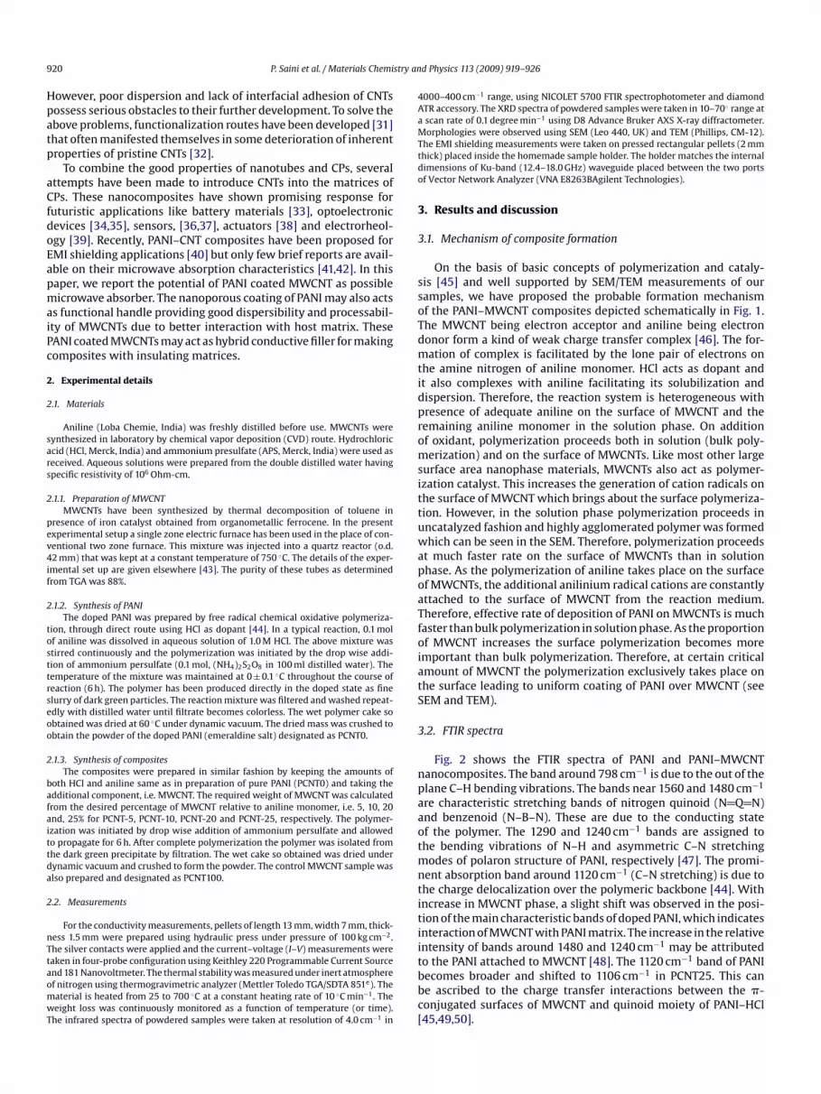
Fig. 2 shows the FTIR spectra of PANI and PANI–MWCNTanocomposites. The band around 798 cm−1 is due to the out of thelane C–H bending vibrations. The bands near 1560 and 1480 cm−1
re characteristic stretching bands of nitrogen quinoid (N Q N)nd benzenoid (N–B–N). These are due to the conducting statef the polymer. The 1290 and 1240 cm−1 bands are assigned tohe bending vibrations of N–H and asymmetric C–N stretching
odes of polaron structure of PANI, respectively [47]. The promi-ent absorption band around 1120 cm−1 (C–N stretching) is due tohe charge delocalization over the polymeric backbone [44]. Withncrease in MWCNT phase, a slight shift was observed in the posi-ion of the main characteristic bands of doped PANI, which indicatesnteraction of MWCNT with PANI matrix. The increase in the relativentensity of bands around 1480 and 1240 cm−1 may be attributed
o the PANI attached to MWCNT [48]. The 1120 cm−1 band of PANIecomes broader and shifted to 1106 cm−1 in PCNT25. This cane ascribed to the charge transfer interactions between the �-onjugated surfaces of MWCNT and quinoid moiety of PANI–HCl45,49,50].
P. Saini et al. / Materials Chemistry and Physics 113 (2009) 919–926 921
rmati
3
Pst
t
Fig. 1. Proposed mechanism for the fo
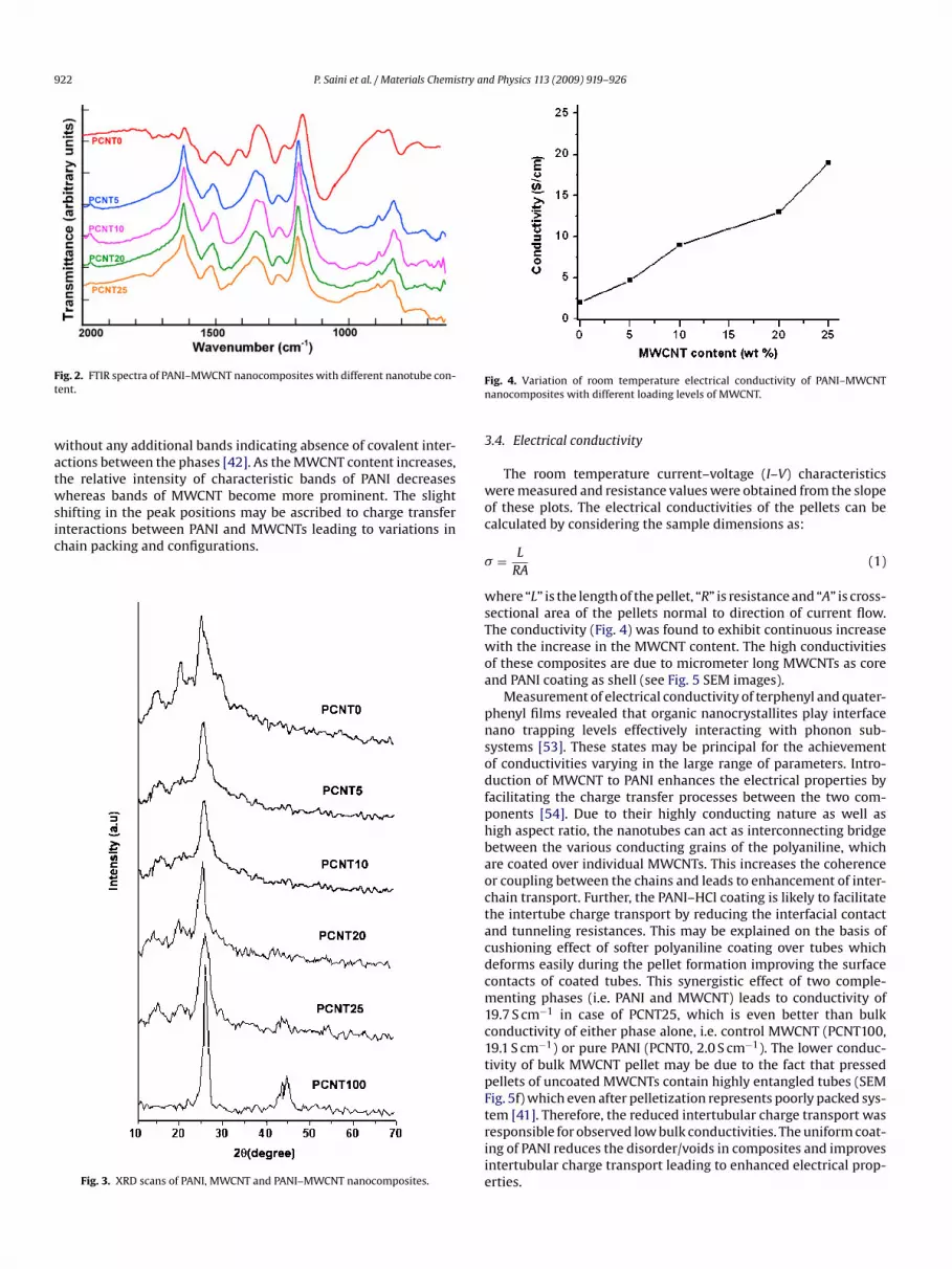
.3. XRD studies
Fig. 3 shows the XRD patterns of pure MWCNT, PANI andANI–MWCNT nanocomposites. The pure MWCNT (PCNT100)hows a sharp peak centered on 2� value of 26◦ which correspondso the (0 0 2) planes of MWCNT. The peaks around 43◦ are due to
p
a(p
on of PANI–MWCNT nanocomposites.
he (1 1 0) and (1 0 0) graphitic planes plus small amount of catalyst
article encapsulated inside the walls of the MWCNTs [51].The characteristic peaks of the doped PANI (PCNT0) are observedround 2� values of 15, 20, 25, 30◦ corresponding to (0 1 1), (0 2 0),2 0 0) and (0 2 2) reflections of emeraldine salt form [52]. The com-osites show the characteristic peaks of both PANI and MWCNT
922 P. Saini et al. / Materials Chemistry and Physics 113 (2009) 919–926
Ft
watwsic
Fn
3
wo
ig. 2. FTIR spectra of PANI–MWCNT nanocomposites with different nanotube con-ent.
ithout any additional bands indicating absence of covalent inter-ctions between the phases [42]. As the MWCNT content increases,he relative intensity of characteristic bands of PANI decreaseshereas bands of MWCNT become more prominent. The slight
hifting in the peak positions may be ascribed to charge transfer
nteractions between PANI and MWCNTs leading to variations inhain packing and configurations.Fig. 3. XRD scans of PANI, MWCNT and PANI–MWCNT nanocomposites.
c
�
wsTwoa
pnsodfphbaoctacdcm1c1tpFtriie
ig. 4. Variation of room temperature electrical conductivity of PANI–MWCNTanocomposites with different loading levels of MWCNT.
.4. Electrical conductivity
The room temperature current–voltage (I–V) characteristicsere measured and resistance values were obtained from the slope
f these plots. The electrical conductivities of the pellets can bealculated by considering the sample dimensions as:
= L
RA(1)
here “L” is the length of the pellet, “R” is resistance and “A” is cross-ectional area of the pellets normal to direction of current flow.he conductivity (Fig. 4) was found to exhibit continuous increaseith the increase in the MWCNT content. The high conductivities
f these composites are due to micrometer long MWCNTs as corend PANI coating as shell (see Fig. 5 SEM images).
Measurement of electrical conductivity of terphenyl and quater-henyl films revealed that organic nanocrystallites play interfaceano trapping levels effectively interacting with phonon sub-ystems [53]. These states may be principal for the achievementf conductivities varying in the large range of parameters. Intro-uction of MWCNT to PANI enhances the electrical properties by
acilitating the charge transfer processes between the two com-onents [54]. Due to their highly conducting nature as well asigh aspect ratio, the nanotubes can act as interconnecting bridgeetween the various conducting grains of the polyaniline, whichre coated over individual MWCNTs. This increases the coherencer coupling between the chains and leads to enhancement of inter-hain transport. Further, the PANI–HCl coating is likely to facilitatehe intertube charge transport by reducing the interfacial contactnd tunneling resistances. This may be explained on the basis ofushioning effect of softer polyaniline coating over tubes whicheforms easily during the pellet formation improving the surfaceontacts of coated tubes. This synergistic effect of two comple-enting phases (i.e. PANI and MWCNT) leads to conductivity of
9.7 S cm−1 in case of PCNT25, which is even better than bulkonductivity of either phase alone, i.e. control MWCNT (PCNT100,9.1 S cm−1) or pure PANI (PCNT0, 2.0 S cm−1). The lower conduc-ivity of bulk MWCNT pellet may be due to the fact that pressedellets of uncoated MWCNTs contain highly entangled tubes (SEMig. 5f) which even after pelletization represents poorly packed sys-em [41]. Therefore, the reduced intertubular charge transport was
esponsible for observed low bulk conductivities. The uniform coat-ng of PANI reduces the disorder/voids in composites and improvesntertubular charge transport leading to enhanced electrical prop-rties.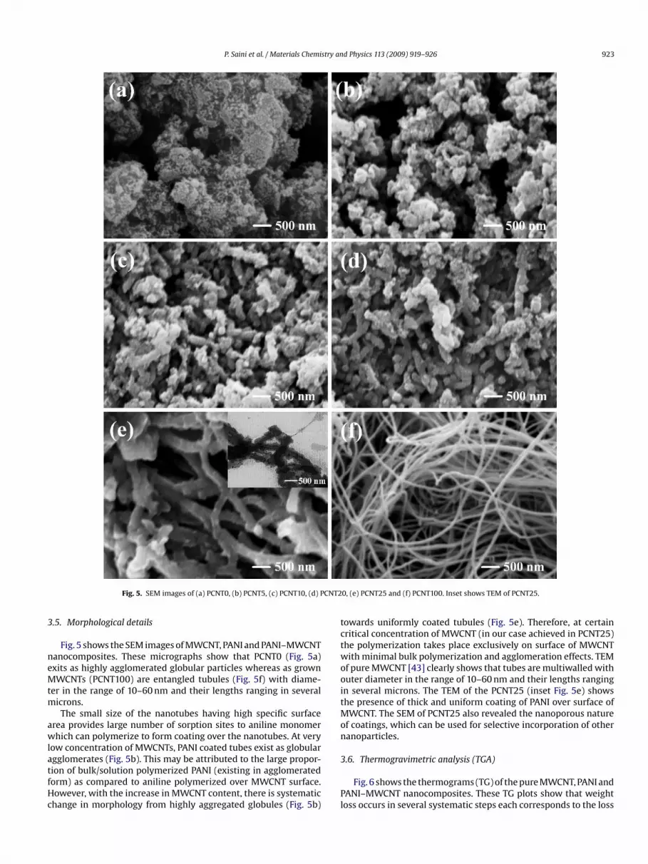
P. Saini et al. / Materials Chemistry and Physics 113 (2009) 919–926 923
CNT2
3
neMtm
awlatfHc
tctwooitMon
Fig. 5. SEM images of (a) PCNT0, (b) PCNT5, (c) PCNT10, (d) P
.5. Morphological details
Fig. 5 shows the SEM images of MWCNT, PANI and PANI–MWCNTanocomposites. These micrographs show that PCNT0 (Fig. 5a)xits as highly agglomerated globular particles whereas as grownWCNTs (PCNT100) are entangled tubules (Fig. 5f) with diame-
er in the range of 10–60 nm and their lengths ranging in severalicrons.The small size of the nanotubes having high specific surface
rea provides large number of sorption sites to aniline monomerhich can polymerize to form coating over the nanotubes. At very
ow concentration of MWCNTs, PANI coated tubes exist as globular
gglomerates (Fig. 5b). This may be attributed to the large propor-ion of bulk/solution polymerized PANI (existing in agglomeratedorm) as compared to aniline polymerized over MWCNT surface.owever, with the increase in MWCNT content, there is systematichange in morphology from highly aggregated globules (Fig. 5b)
3
Pl
0, (e) PCNT25 and (f) PCNT100. Inset shows TEM of PCNT25.
owards uniformly coated tubules (Fig. 5e). Therefore, at certainritical concentration of MWCNT (in our case achieved in PCNT25)he polymerization takes place exclusively on surface of MWCNTith minimal bulk polymerization and agglomeration effects. TEM
f pure MWCNT [43] clearly shows that tubes are multiwalled withuter diameter in the range of 10–60 nm and their lengths rangingn several microns. The TEM of the PCNT25 (inset Fig. 5e) showshe presence of thick and uniform coating of PANI over surface of
WCNT. The SEM of PCNT25 also revealed the nanoporous naturef coatings, which can be used for selective incorporation of otheranoparticles.
.6. Thermogravimetric analysis (TGA)
Fig. 6 shows the thermograms (TG) of the pure MWCNT, PANI andANI–MWCNT nanocomposites. These TG plots show that weightoss occurs in several systematic steps each corresponds to the loss

924 P. Saini et al. / Materials Chemistry an
Fn
owTt
t(edcmdtosbcbgmroim
3
isaiS
E
wtmsa
S
S
S
S
Hi
tsrtm
T
R
A = 1 − R − T (9)
Fm
ig. 6. Thermogravimetric (TG) traces of PANI, MWCNT and PANI–MWCNTanocomposites.
f particular species. However, there is always some overlap ineight loss ranges with no sharp transition between different steps.
he pure nanotubes (MWCNT) have excellent thermal stability upo 700 ◦C and weight loss was only 0.5%.
In composites, the first step loss (25–110 ◦C) may be attributedo the loss of sorbed water molecules. The second loss step110–185 ◦C) involves the loss of dopant in the form of HCl gas. Thevolved HCl acts as catalyst for the degradation reaction and rate ofegradation increases with increase in the PANI proportion in theomposites. The third loss step (185–300◦C) involves the loss of lowolecular weight fragments, cross linking of chains and onset of
egradation of polymeric backbone. As evident from the TG traces,he increasing amount of MWCNTs does not have much influencen the decomposition temperature of composites. The fourth losstep (300–470 ◦C) can be ascribed to the degradation of polymericackbone into heavier fragments. The final loss step (470–700 ◦C)orresponds to the complete breakdown of the polymeric back-one as well as heavier fragments into still smaller fractions andaseous byproducts. The char residues (remaining at 700 ◦C) areainly thermally stable inert materials like MWCNTs, iron catalyst
esidues and the carbonized polymeric fragments. As the amountf MWCNT increases, the corresponding char residue also increasesndicating increased incorporation of nanotubes inside the PANI
atrix.ni
ig. 7. (a) Schematic of the VNA used for the measurement of shielding effectiveness iaterial.
d Physics 113 (2009) 919–926
.7. Shielding effectiveness (SE)
EMI shielding is defined as the attenuation of the propagat-ng electromagnetic waves produced by the shielding material. Ashown in Fig. 7b, the shielding is a direct consequence of reflection,bsorption and multiple internal reflection losses at the existingnterfaces, suffered by incident electromagnetic (EM) waves. EMIE can be expressed as [55–58]:
MI SET = 10 logPI
PT= 20 log
∣∣∣ EI
ET
∣∣∣ = 20 log∣∣∣ HI
HT
∣∣∣ (dB) (2)
here PI (EI) and PT (ET) are the power (electric field) of incident andransmitted EM waves, respectively. For a single layer of shielding
aterial, the total EMI SET obtained from Eq. (2) is described as theum of the contribution due to reflection (SER), absorption (SEA),nd multiple reflections (SEM) as the following [59,60]:
ET = SER + SEA + SEM (dB) (3)
ER = 20 log
∣∣∣∣(1 + n2)
4n
∣∣∣∣ (dB) (4)
EA = 20 Im(k)d log e (dB) (5)
EM = 20 log
∣∣∣∣1 − (1 − n2)
(1 + n)2exp(2ikd)
∣∣∣∣ (dB) (6)
ere, n is the refractive index of shielding material and Im(k) is themaginary part of wave vector in the shielding material.
The S11 (or S22) and S12 (or S21) are the scattering parame-ers (S-parameters) of the two-port vector network analyzer (VNA)ystem and are shown schematically in Fig. 7a. They represent theeflection and transmission coefficients, respectively. The transmit-ance (T), reflectance (R), and absorbance (A) through the shielding
aterial can be described as below:
=∣∣∣ET
EI
∣∣∣2
= |S12|2(= |S12|2) (7)
=∣∣∣ER
EI
∣∣∣2
= |S11|2(= |S22|2) (8)
The SEM is a correction term whose value may be positive,egative or zero. The effect of multiple reflections between both
nterfaces of the material is negligible when SEA ≥ 10 dB [61].
n Ku-band (12.4–18.0 GHz), (b) interaction of electromagnetic waves with shield
P. Saini et al. / Materials Chemistry and Physics 113 (2009) 919–926 925
Fb
TwTAir1p
S
S
l
pod
e
S
wmmFf
mptde[
ı
wdtd
a
S
wqrltvva
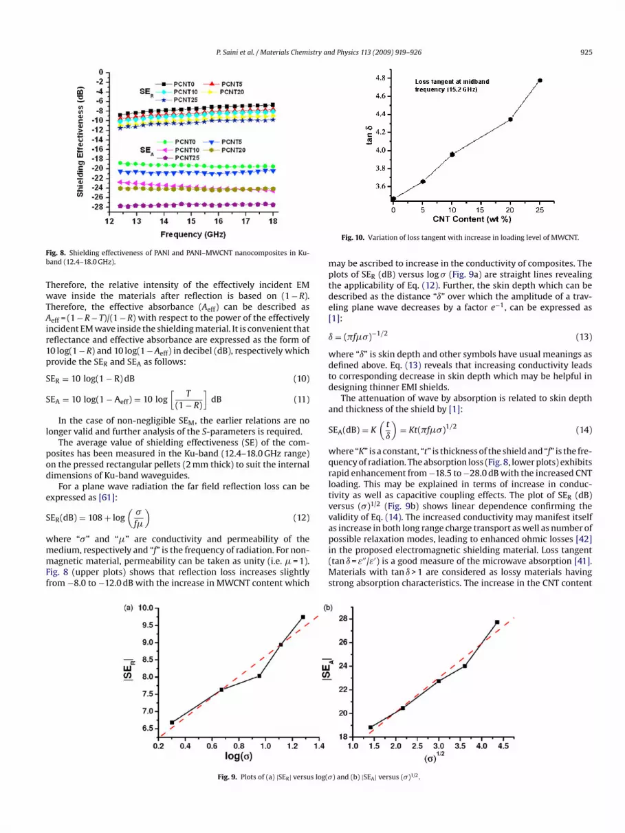
ig. 8. Shielding effectiveness of PANI and PANI–MWCNT nanocomposites in Ku-and (12.4–18.0 GHz).
herefore, the relative intensity of the effectively incident EMave inside the materials after reflection is based on (1 − R).
herefore, the effective absorbance (Aeff) can be described aseff = (1 − R − T)/(1 − R) with respect to the power of the effectively
ncident EM wave inside the shielding material. It is convenient thateflectance and effective absorbance are expressed as the form of0 log(1 − R) and 10 log(1 − Aeff) in decibel (dB), respectively whichrovide the SER and SEA as follows:
ER = 10 log(1 − R) dB (10)
EA = 10 log(1 − Aeff) = 10 log[
T
(1 − R)
]dB (11)
In the case of non-negligible SEM, the earlier relations are noonger valid and further analysis of the S-parameters is required.
The average value of shielding effectiveness (SE) of the com-osites has been measured in the Ku-band (12.4–18.0 GHz range)n the pressed rectangular pellets (2 mm thick) to suit the internalimensions of Ku-band waveguides.
For a plane wave radiation the far field reflection loss can bexpressed as [61]:
ER(dB) = 108 + log(
�
f�
)(12)
here “�” and “�” are conductivity and permeability of theedium, respectively and “f” is the frequency of radiation. For non-agnetic material, permeability can be taken as unity (i.e. � = 1).
ig. 8 (upper plots) shows that reflection loss increases slightlyrom −8.0 to −12.0 dB with the increase in MWCNT content which
pi(Ms
Fig. 9. Plots of (a) |SER| versus log(�
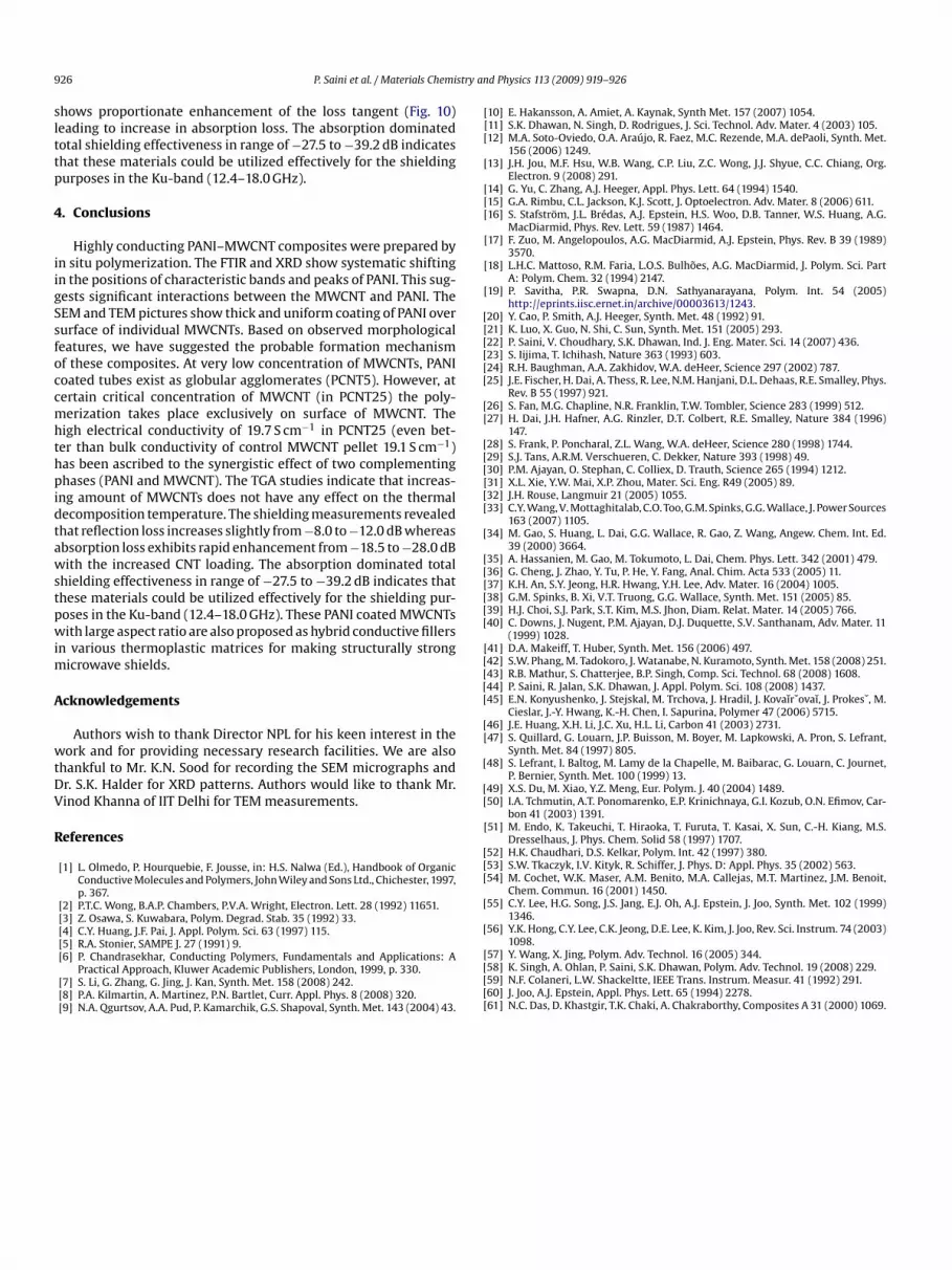
Fig. 10. Variation of loss tangent with increase in loading level of MWCNT.
ay be ascribed to increase in the conductivity of composites. Thelots of SER (dB) versus log � (Fig. 9a) are straight lines revealinghe applicability of Eq. (12). Further, the skin depth which can beescribed as the distance “ı” over which the amplitude of a trav-ling plane wave decreases by a factor e−1, can be expressed as1]:
= (�f��)−1/2 (13)
here “ı” is skin depth and other symbols have usual meanings asefined above. Eq. (13) reveals that increasing conductivity leadso corresponding decrease in skin depth which may be helpful inesigning thinner EMI shields.
The attenuation of wave by absorption is related to skin depthnd thickness of the shield by [1]:
EA(dB) = K(
t
ı
)= Kt(�f��)1/2 (14)
here “K” is a constant, “t” is thickness of the shield and “f” is the fre-uency of radiation. The absorption loss (Fig. 8, lower plots) exhibitsapid enhancement from −18.5 to −28.0 dB with the increased CNToading. This may be explained in terms of increase in conduc-ivity as well as capacitive coupling effects. The plot of SER (dB)ersus (�)1/2 (Fig. 9b) shows linear dependence confirming thealidity of Eq. (14). The increased conductivity may manifest itselfs increase in both long range charge transport as well as number of
ossible relaxation modes, leading to enhanced ohmic losses [42]n the proposed electromagnetic shielding material. Loss tangenttan ı = ε′′/ε′) is a good measure of the microwave absorption [41].
aterials with tan ı > 1 are considered as lossy materials havingtrong absorption characteristics. The increase in the CNT content
) and (b) |SEA| versus (�)1/2.
9 stry an
slttp
4
iigSsfoccmhthpidtawstpwim
A
wtDV
R
[[[
[
[[[
[
[
[
[[[[[[
[[
[[[[[[
[
[[[[[[
[[[[[
[[
[
[[
[
[[[
[
[
26 P. Saini et al. / Materials Chemi
hows proportionate enhancement of the loss tangent (Fig. 10)eading to increase in absorption loss. The absorption dominatedotal shielding effectiveness in range of −27.5 to −39.2 dB indicateshat these materials could be utilized effectively for the shieldingurposes in the Ku-band (12.4–18.0 GHz).
. Conclusions
Highly conducting PANI–MWCNT composites were prepared byn situ polymerization. The FTIR and XRD show systematic shiftingn the positions of characteristic bands and peaks of PANI. This sug-ests significant interactions between the MWCNT and PANI. TheEM and TEM pictures show thick and uniform coating of PANI overurface of individual MWCNTs. Based on observed morphologicaleatures, we have suggested the probable formation mechanismf these composites. At very low concentration of MWCNTs, PANIoated tubes exist as globular agglomerates (PCNT5). However, atertain critical concentration of MWCNT (in PCNT25) the poly-erization takes place exclusively on surface of MWCNT. The
igh electrical conductivity of 19.7 S cm−1 in PCNT25 (even bet-er than bulk conductivity of control MWCNT pellet 19.1 S cm−1)as been ascribed to the synergistic effect of two complementinghases (PANI and MWCNT). The TGA studies indicate that increas-
ng amount of MWCNTs does not have any effect on the thermalecomposition temperature. The shielding measurements revealedhat reflection loss increases slightly from −8.0 to −12.0 dB whereasbsorption loss exhibits rapid enhancement from −18.5 to −28.0 dBith the increased CNT loading. The absorption dominated total
hielding effectiveness in range of −27.5 to −39.2 dB indicates thathese materials could be utilized effectively for the shielding pur-oses in the Ku-band (12.4–18.0 GHz). These PANI coated MWCNTsith large aspect ratio are also proposed as hybrid conductive fillers
n various thermoplastic matrices for making structurally strongicrowave shields.
cknowledgements
Authors wish to thank Director NPL for his keen interest in theork and for providing necessary research facilities. We are also
hankful to Mr. K.N. Sood for recording the SEM micrographs andr. S.K. Halder for XRD patterns. Authors would like to thank Mr.inod Khanna of IIT Delhi for TEM measurements.
eferences
[1] L. Olmedo, P. Hourquebie, F. Jousse, in: H.S. Nalwa (Ed.), Handbook of OrganicConductive Molecules and Polymers, John Wiley and Sons Ltd., Chichester, 1997,p. 367.
[2] P.T.C. Wong, B.A.P. Chambers, P.V.A. Wright, Electron. Lett. 28 (1992) 11651.[3] Z. Osawa, S. Kuwabara, Polym. Degrad. Stab. 35 (1992) 33.[4] C.Y. Huang, J.F. Pai, J. Appl. Polym. Sci. 63 (1997) 115.
[5] R.A. Stonier, SAMPE J. 27 (1991) 9.[6] P. Chandrasekhar, Conducting Polymers, Fundamentals and Applications: APractical Approach, Kluwer Academic Publishers, London, 1999, p. 330.[7] S. Li, G. Zhang, G. Jing, J. Kan, Synth. Met. 158 (2008) 242.[8] P.A. Kilmartin, A. Martinez, P.N. Bartlet, Curr. Appl. Phys. 8 (2008) 320.[9] N.A. Qgurtsov, A.A. Pud, P. Kamarchik, G.S. Shapoval, Synth. Met. 143 (2004) 43.
[[[[[
d Physics 113 (2009) 919–926
10] E. Hakansson, A. Amiet, A. Kaynak, Synth Met. 157 (2007) 1054.11] S.K. Dhawan, N. Singh, D. Rodrigues, J. Sci. Technol. Adv. Mater. 4 (2003) 105.12] M.A. Soto-Oviedo, O.A. Araújo, R. Faez, M.C. Rezende, M.A. dePaoli, Synth. Met.
156 (2006) 1249.13] J.H. Jou, M.F. Hsu, W.B. Wang, C.P. Liu, Z.C. Wong, J.J. Shyue, C.C. Chiang, Org.
Electron. 9 (2008) 291.14] G. Yu, C. Zhang, A.J. Heeger, Appl. Phys. Lett. 64 (1994) 1540.15] G.A. Rimbu, C.L. Jackson, K.J. Scott, J. Optoelectron. Adv. Mater. 8 (2006) 611.16] S. Stafström, J.L. Brédas, A.J. Epstein, H.S. Woo, D.B. Tanner, W.S. Huang, A.G.
MacDiarmid, Phys. Rev. Lett. 59 (1987) 1464.17] F. Zuo, M. Angelopoulos, A.G. MacDiarmid, A.J. Epstein, Phys. Rev. B 39 (1989)
3570.18] L.H.C. Mattoso, R.M. Faria, L.O.S. Bulhões, A.G. MacDiarmid, J. Polym. Sci. Part
A: Polym. Chem. 32 (1994) 2147.19] P. Savitha, P.R. Swapna, D.N. Sathyanarayana, Polym. Int. 54 (2005)
http://eprints.iisc.ernet.in/archive/00003613/1243.20] Y. Cao, P. Smith, A.J. Heeger, Synth. Met. 48 (1992) 91.21] K. Luo, X. Guo, N. Shi, C. Sun, Synth. Met. 151 (2005) 293.22] P. Saini, V. Choudhary, S.K. Dhawan, Ind. J. Eng. Mater. Sci. 14 (2007) 436.23] S. Iijima, T. Ichihash, Nature 363 (1993) 603.24] R.H. Baughman, A.A. Zakhidov, W.A. deHeer, Science 297 (2002) 787.25] J.E. Fischer, H. Dai, A. Thess, R. Lee, N.M. Hanjani, D.L. Dehaas, R.E. Smalley, Phys.
Rev. B 55 (1997) 921.26] S. Fan, M.G. Chapline, N.R. Franklin, T.W. Tombler, Science 283 (1999) 512.27] H. Dai, J.H. Hafner, A.G. Rinzler, D.T. Colbert, R.E. Smalley, Nature 384 (1996)
147.28] S. Frank, P. Poncharal, Z.L. Wang, W.A. deHeer, Science 280 (1998) 1744.29] S.J. Tans, A.R.M. Verschueren, C. Dekker, Nature 393 (1998) 49.30] P.M. Ajayan, O. Stephan, C. Colliex, D. Trauth, Science 265 (1994) 1212.31] X.L. Xie, Y.W. Mai, X.P. Zhou, Mater. Sci. Eng. R49 (2005) 89.32] J.H. Rouse, Langmuir 21 (2005) 1055.33] C.Y. Wang, V. Mottaghitalab, C.O. Too, G.M. Spinks, G.G. Wallace, J. Power Sources
163 (2007) 1105.34] M. Gao, S. Huang, L. Dai, G.G. Wallace, R. Gao, Z. Wang, Angew. Chem. Int. Ed.
39 (2000) 3664.35] A. Hassanien, M. Gao, M. Tokumoto, L. Dai, Chem. Phys. Lett. 342 (2001) 479.36] G. Cheng, J. Zhao, Y. Tu, P. He, Y. Fang, Anal. Chim. Acta 533 (2005) 11.37] K.H. An, S.Y. Jeong, H.R. Hwang, Y.H. Lee, Adv. Mater. 16 (2004) 1005.38] G.M. Spinks, B. Xi, V.T. Truong, G.G. Wallace, Synth. Met. 151 (2005) 85.39] H.J. Choi, S.J. Park, S.T. Kim, M.S. Jhon, Diam. Relat. Mater. 14 (2005) 766.40] C. Downs, J. Nugent, P.M. Ajayan, D.J. Duquette, S.V. Santhanam, Adv. Mater. 11
(1999) 1028.41] D.A. Makeiff, T. Huber, Synth. Met. 156 (2006) 497.42] S.W. Phang, M. Tadokoro, J. Watanabe, N. Kuramoto, Synth. Met. 158 (2008) 251.43] R.B. Mathur, S. Chatterjee, B.P. Singh, Comp. Sci. Technol. 68 (2008) 1608.44] P. Saini, R. Jalan, S.K. Dhawan, J. Appl. Polym. Sci. 108 (2008) 1437.45] E.N. Konyushenko, J. Stejskal, M. Trchova, J. Hradil, J. Kovaı̌rˇovaı̌, J. Prokesˇ, M.
Cieslar, J.-Y. Hwang, K.-H. Chen, I. Sapurina, Polymer 47 (2006) 5715.46] J.E. Huang, X.H. Li, J.C. Xu, H.L. Li, Carbon 41 (2003) 2731.47] S. Quillard, G. Louarn, J.P. Buisson, M. Boyer, M. Lapkowski, A. Pron, S. Lefrant,
Synth. Met. 84 (1997) 805.48] S. Lefrant, I. Baltog, M. Lamy de la Chapelle, M. Baibarac, G. Louarn, C. Journet,
P. Bernier, Synth. Met. 100 (1999) 13.49] X.S. Du, M. Xiao, Y.Z. Meng, Eur. Polym. J. 40 (2004) 1489.50] I.A. Tchmutin, A.T. Ponomarenko, E.P. Krinichnaya, G.I. Kozub, O.N. Efimov, Car-
bon 41 (2003) 1391.51] M. Endo, K. Takeuchi, T. Hiraoka, T. Furuta, T. Kasai, X. Sun, C.-H. Kiang, M.S.
Dresselhaus, J. Phys. Chem. Solid 58 (1997) 1707.52] H.K. Chaudhari, D.S. Kelkar, Polym. Int. 42 (1997) 380.53] S.W. Tkaczyk, I.V. Kityk, R. Schiffer, J. Phys. D: Appl. Phys. 35 (2002) 563.54] M. Cochet, W.K. Maser, A.M. Benito, M.A. Callejas, M.T. Martinez, J.M. Benoit,
Chem. Commun. 16 (2001) 1450.55] C.Y. Lee, H.G. Song, J.S. Jang, E.J. Oh, A.J. Epstein, J. Joo, Synth. Met. 102 (1999)
1346.56] Y.K. Hong, C.Y. Lee, C.K. Jeong, D.E. Lee, K. Kim, J. Joo, Rev. Sci. Instrum. 74 (2003)
1098.57] Y. Wang, X. Jing, Polym. Adv. Technol. 16 (2005) 344.58] K. Singh, A. Ohlan, P. Saini, S.K. Dhawan, Polym. Adv. Technol. 19 (2008) 229.59] N.F. Colaneri, L.W. Shackeltte, IEEE Trans. Instrum. Measur. 41 (1992) 291.60] J. Joo, A.J. Epstein, Appl. Phys. Lett. 65 (1994) 2278.61] N.C. Das, D. Khastgir, T.K. Chaki, A. Chakraborthy, Composites A 31 (2000) 1069.


