Embed Size (px)
Citation preview
13 January 2022
POLITECNICO DI TORINORepository ISTITUZIONALE
Review on HVDC cable terminations / Ye, Hanyu; Fechner, Tobias; Lei, Xianzhang; Luo, Yi; Zhou, Mingyu; Han,Zhengyi; Wang, Haitian; Zhuang, Qikai; Xu, Ruoyu; Li, Duo. - In: HIGH VOLTAGE. - ISSN 2397-7264. - 3(2018), pp. 79-89(10).
Original
Review on HVDC cable terminations
GENERICO -- per es. Nature : semplice rinvio dal preprint/submitted, o postprint/AAM [ex default]
Publisher:
PublishedDOI:
Terms of use:openAccess
Publisher copyright
The original publication is available at http://digital-library.theiet.org/content/journals/10.1049/hve.2017.0144 /http://dx.doi.org/.
(Article begins on next page)
This article is made available under terms and conditions as specified in the corresponding bibliographic description inthe repository
Availability:This version is available at: 11583/2713860 since: 2018-09-25T12:36:00Z
Institution of Engineering and Technology
High Voltage
Review Article
Review on HVDC cable terminations ISSN 2397-7264Received on 22nd September 2017Revised 12th March 2018Accepted on 21st March 2018E-First on 24th April 2018doi: 10.1049/hve.2017.0144www.ietdl.org
Hanyu Ye1 , Tobias Fechner1, Xianzhang Lei1, Yi Luo1, Mingyu Zhou1, Zhengyi Han1, Haitian Wang1,Qikai Zhuang1, Ruoyu Xu1, Duo Li11Global Energy Interconnection Research Institute Europe GmbH, Markgrafenstr. 34, Berlin, Germany
E-mail: [email protected]
Abstract: With modern power utilities going green by utilising renewable energy technologies and the development of the smartpower grid, high-voltage direct current (HVDC) technologies become more and more important in the energy transmission. Inparticular, HVDC cable systems play a prominent role in undersea power transmission and offshore renewable energyintegration. As an essential part of a complete HVDC cable system, the cable termination is one of the most critical components.The mathematical and physical background of HVDC cable systems is discussed and the development of various types ofHVDC cable terminations is reviewed. Regarding the non-uniform field distribution, the influence of temperature on the non-linear conductivity is briefly discussed. Furthermore, faults of terminations caused by inappropriate installation and testing ofcable systems are discussed.
1 IntroductionIn recent years, the dramatic increasing power demand worldwideand the long-term energy transition towards a reduction of carbonlead to an increasing requirement for long-distance powertransmission, interconnection of asynchronous AC grids andintegration of renewable energy in the main power networks [1–3].In this context, high-voltage direct current (HVDC) powertransmission becomes more and more competitive compared tohigh-voltage alternative current (HVAC) power transmission. Thisis due to several technical and commercial advantages of bothHVDC transmission systems using traditional current sourceconverters (CSCs) and HVDC transmission systems using morerecently developed voltage source converters (VSCs) [4, 5].
Long-distance power transmission (above 70 km) across the seaand/or offshore wind farms often utilises submarine cables [6].Overhead lines are cheaper, but underground cable systems areattractive for crossing wide metropolitan areas. Furthermore,underground cable systems also contribute to the general public'saesthetic sensibilities and living environment when compared tooverhead lines [7]. For these reasons, HVDC cable systems havebecome more and more important nowadays.
Unlike HVAC cable systems, the electric field distribution inoperation depends not only on the electric field and temperature-dependent electrical conductivity but also on the space chargeaccumulation in the insulation materials [8]. For this reason, thefollowing aspects should be considered for the developmentprocess of HVDC cable systems:
• electrical conductivity which is dependent on temperature andelectric field,
• space charge behaviour in insulation materials and at interfaces,• DC and impulse breakdown strength of cable and accessories,• Influence of harmonic voltages coming from HVDC converter
on PD activity and the lifetime of the cable and accessories [9].
Cable terminations and joints are the least reliable componentsof a cable system due to the complexity of their electrical, thermaland mechanical design. Furthermore, they consist of manysubcomponents assembled in the field, thereby giving rise to therisk of contamination due to pollutants from the environment.Moreover, the reliability of accessories is severely affected by theability of the installer due to human error [4]. In this paper, the
important background for the development of HVDC cablesystems under different conditions is discussed. A brief overviewof the design of cable terminations, field grading techniques,designs aspects of stress cones and faults caused by theinappropriate installation is given.
2 Physical backgroundThe electric field distribution in cables and accessories underHVDC can be described by the following equations:
E = − ∇φ (1)
J = κE (2)
ρe = ∇ ⋅ ε0εrE (3)
∇ ⋅ J = − ∂ρe∂t , (4)
where E is the electric field, φ is the scalar potential, J is thecurrent density, κ is the electrical conductivity, ρe is the spacecharge, ε0 is the vacuum permittivity and εr is the relativepermittivity. By a combination of the above equations thefollowing equation can be derived:
ρe = − ε0εrκ
∂ρe∂t + J ⋅ ∇ ε0εr
κ (5)
The electrical conductivity κ of the insulation materials for HVDCcable systems tends to be highly dependent on temperature and to aless extend on electrical field [4]. This dependence is oftenexpressed using the following mathematical formulation [10]:
κ T , E = κ0 ⋅ e α T − T0 + β E − E0 , (6)
where κ0 is the electrical conductivity at the reference stress E0 andthe reference temperature T0, α and β are the temperature andelectric field coefficients, respectively.
Alternatively, the electrical conductivity can analytically bedescribed by the following equation [11]:
High Volt., 2018, Vol. 3 Iss. 2, pp. 79-89This is an open access article published by the IET and CEPRI under the Creative Commons Attribution License(http://creativecommons.org/licenses/by/3.0/)
79
κ T , E = A ⋅ e ( − ϕ ⋅ q/kB ⋅ T) ⋅ sinh B ⋅ EE , (7)
where A and B are the material constants, ϕ is the thermalactivation energy in eV, q is elementary charge, T is temperature inKelvins and kB is the Boltzmann constant.
To obtain the electric field distribution in the cable systems, thetemperature distribution should be known. This can be done bysolving the following heat conduction equation:
ρm ⋅ Cp∂T∂t = ∇ ⋅ λ ⋅ ∇T + Sheat, (8)
where ρm is the mass density, Cp is the specific heat capacity and λis the thermal conductivity. The source term Sheat represents theresistive losses in the conductor and in the insulation materials. Thelosses in the insulation and in the conductor are given by thefollowing equations:
Sheat, insulation = κ ⋅ E2 (9)
Sheat, conductor = I2 ⋅ R , (10)
in which I is the current flowing through the conductor and R is theresistance of the conductor.
During operation, HVDC cable systems will undergo severaldifferent operational stages which, due to the complex nature ofdielectrics, will result in varying field stress. Shortly afterincreasing the voltage, the distribution of the electric field iscapacitive graded and mainly determined by the permittivity of theinsulation materials:
∇ ⋅ ε0εrE = 0 (11)
Thereafter, the transition from capacitive to resistive field takesplace. In this stage, the electric field distribution is time dependent,which is governed in (1)–(4). After a sufficient amount of timeequal to 10τ [4] has passed, the field reaches the steady-resistivestate and becomes time invariant. At this stage, the followingequations can be used for the calculation:
∇ ⋅ κ T , E ⋅ E = 0 (12)
∇ ⋅ λ ⋅ ∇T + Sheat = 0. (13)
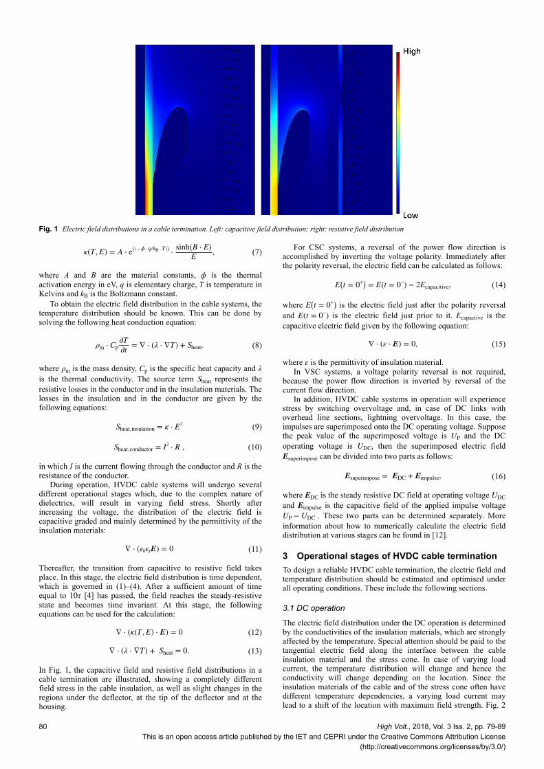
In Fig. 1, the capacitive field and resistive field distributions in acable termination are illustrated, showing a completely differentfield stress in the cable insulation, as well as slight changes in theregions under the deflector, at the tip of the deflector and at thehousing.
For CSC systems, a reversal of the power flow direction isaccomplished by inverting the voltage polarity. Immediately afterthe polarity reversal, the electric field can be calculated as follows:
E t = 0+ = E t = 0− − 2Ecapacitive, (14)
where E t = 0+ is the electric field just after the polarity reversaland E(t = 0−) is the electric field just prior to it. Ecapactive is thecapacitive electric field given by the following equation:
∇ ⋅ ε ⋅ E = 0, (15)
where ε is the permittivity of insulation material.In VSC systems, a voltage polarity reversal is not required,
because the power flow direction is inverted by reversal of thecurrent flow direction.
In addition, HVDC cable systems in operation will experiencestress by switching overvoltage and, in case of DC links withoverhead line sections, lightning overvoltage. In this case, theimpulses are superimposed onto the DC operating voltage. Supposethe peak value of the superimposed voltage is UP and the DCoperating voltage is UDC, then the superimposed electric fieldEsuperimpose can be divided into two parts as follows:
Esuperimpose = EDC + Eimpulse, (16)
where EDC is the steady resistive DC field at operating voltage UDCand Eimpulse is the capacitive field of the applied impulse voltageUP − UDC . These two parts can be determined separately. Moreinformation about how to numerically calculate the electric fielddistribution at various stages can be found in [12].
3 Operational stages of HVDC cable terminationTo design a reliable HVDC cable termination, the electric field andtemperature distribution should be estimated and optimised underall operating conditions. These include the following sections.
3.1 DC operation
The electric field distribution under the DC operation is determinedby the conductivities of the insulation materials, which are stronglyaffected by the temperature. Special attention should be paid to thetangential electric field along the interface between the cableinsulation material and the stress cone. In case of varying loadcurrent, the temperature distribution will change and hence theconductivity will change depending on the location. Since theinsulation materials of the cable and of the stress cone often havedifferent temperature dependencies, a varying load current maylead to a shift of the location with maximum field strength. Fig. 2
Fig. 1 Electric field distributions in a cable termination. Left: capacitive field distribution; right: resistive field distribution
80 High Volt., 2018, Vol. 3 Iss. 2, pp. 79-89This is an open access article published by the IET and CEPRI under the Creative Commons Attribution License
(http://creativecommons.org/licenses/by/3.0/)
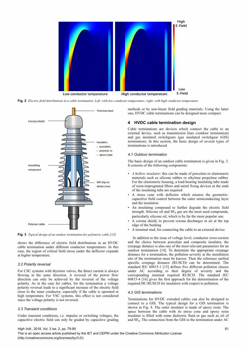
shows the difference of electric field distributions in an HVDCcable termination under different conductor temperatures. In thiscase, the region of critical field stress under the deflector expandsat higher temperature.
3.2 Polarity reversal
For CSC systems with thyristor valves, the direct current is alwaysflowing in the same direction. A reversal of the power flowdirection can only be achieved by the reversal of the voltagepolarity. As in the case for cables, for the termination a voltagepolarity reversal leads to a significant increase of the electric fieldclose to the inner conductor, especially if the cable is operated athigh temperature. For VSC systems, this effect is not consideredsince the voltage polarity is not reversed.
3.3 Transient conditions
Under transient conditions, i.e. impulse or switching voltages, thecapacitive electric field can only be graded by capacitive grading
methods or by non-linear field grading materials. Using the latterone, HVDC cable terminations can be designed more compact.
4 HVDC cable termination designCable terminations are devices which connect the cable to anexternal device, such as transmission lines (outdoor termination)and gas insulated switchgears (gas insulated switchgear (GIS)termination). In this section, the basic design of several types ofterminations is introduced.
4.1 Outdoor termination
The basic design of an outdoor cable termination is given in Fig. 3.It consists of the following components:
• A hollow insulator: this can be made of porcelain or elastomericmaterials such as silicone rubber or ethylene propylene rubber.For the elastomeric housing, a load-bearing insulating tube madeof resin-impregnated fibres and metal fixing devices at the endsof the insulating tube are required
• A stress cone with deflector which ensures the geometric-capacitive field control between the outer semiconducting layerand the insulation
• An insulating compound to further degrade the electric fieldstrength. Silicone oil and SF6 gas are the most used compounds,particularly silicone oil, which is by far the more popular one.
• A corona shield, to prevent corona discharges in air at the topedge of the bushing
• A terminal stud, for connecting the cable to an external device
In addition to the issue of voltage level, conductor cross-sectionand the choice between porcelain and composite insulator, thecreepage distance is also one of the most relevant parameters for anoutdoor termination [14]. To determine the appropriate creepagedistance for a termination, the pollution severity at the installationsite of the termination must be known. Then the reference unifiedspecific creepage distance (RUSCD) can be determined. Thestandard IEC 60815-1 [15] defines five different pollution classesunder AC according to their degree of severity and thecorresponding minimal required RUSCD. The standard IEC60815-4 [16] gives the first approach for the determination of therequired DC-RUSCD for insulators with respect to pollution.
4.2 GIS terminations
Terminations for HVDC extruded cables can also be designed toconnect to a GIS. The typical design for a GIS termination isshown in Fig. 4. The outer insulator is made of epoxy resin. Thespace between the cable with its stress cone and epoxy resininsulator is filled with some dielectric fluid or gas such as oil ofand SF6. The connection from the GIS to the termination under AC
Fig. 2 Electric field distributions in a cable termination. Left: with low conductor temperature; right: with high conductor temperature
Fig. 3 Typical design of an outdoor termination for polymeric cable [13]
High Volt., 2018, Vol. 3 Iss. 2, pp. 79-89This is an open access article published by the IET and CEPRI under the Creative Commons Attribution License(http://creativecommons.org/licenses/by/3.0/)
81
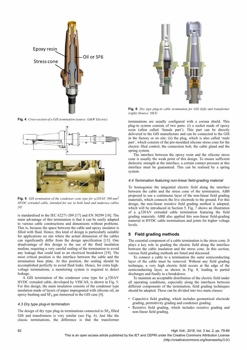
is standardised in the IEC 62271-209 [17] and EN 50299 [18]. Themain advantage of this termination is that it can be easily adaptedto various cable constructions and dimensions without problems.This is, because the space between the cable and epoxy insulator isfilled with fluid. Hence, this kind of design is particularly suitablefor applications on site where the actual dimension of the cablescan significantly differ from the design specification [13]. Onedisadvantage of this design is the use of the fluid insulationmedian, requiring a very careful sealing of the termination to avoidany leakage that could lead to an electrical breakdown [19]. Themost critical position is the interface between the cable and thetermination base plate. At this position, the sealing should beaccomplished perfectly to avoid fluid leaks. Hence, for extra high-voltage terminations, a monitoring system is required to detectleakage.
A GIS termination of the condenser cone type for ±320 kVHVDC extruded cable, developed by VISCAS, is shown in Fig. 5.For this design, the main insulation consists of the condenser typeinsulation made of layers of paper impregnated with silicone oil, anepoxy bushing and SF6 gas immersed in the GIS case [4].
4.3 Dry type plug-in termination
The design of dry type plug-in terminations connected to SF6 filledGIS and transformers is very similar (see Fig. 6). Just like theclassic terminations, the difference is that the transformer
terminations are usually configured with a corona shield. Thisplug-in system consists of two parts: (i) a socket made of epoxyresin (often called ‘female part’). This part can be directlydelivered to the GIS manufacture and can be connected to the GISin the factory or on site; (ii) the plug, which is also called ‘malepart’, which consists of the pre-moulded silicone stress cone for theelectric filed control, the connection bolt, the cable gland and thespring system.
The interface between the epoxy resin and the silicone stresscone is usually the weak point of this design. To ensure sufficientdielectric strength at the interface, a certain contact pressure at thisinterface must be guaranteed. This can be realised by a springsystem.
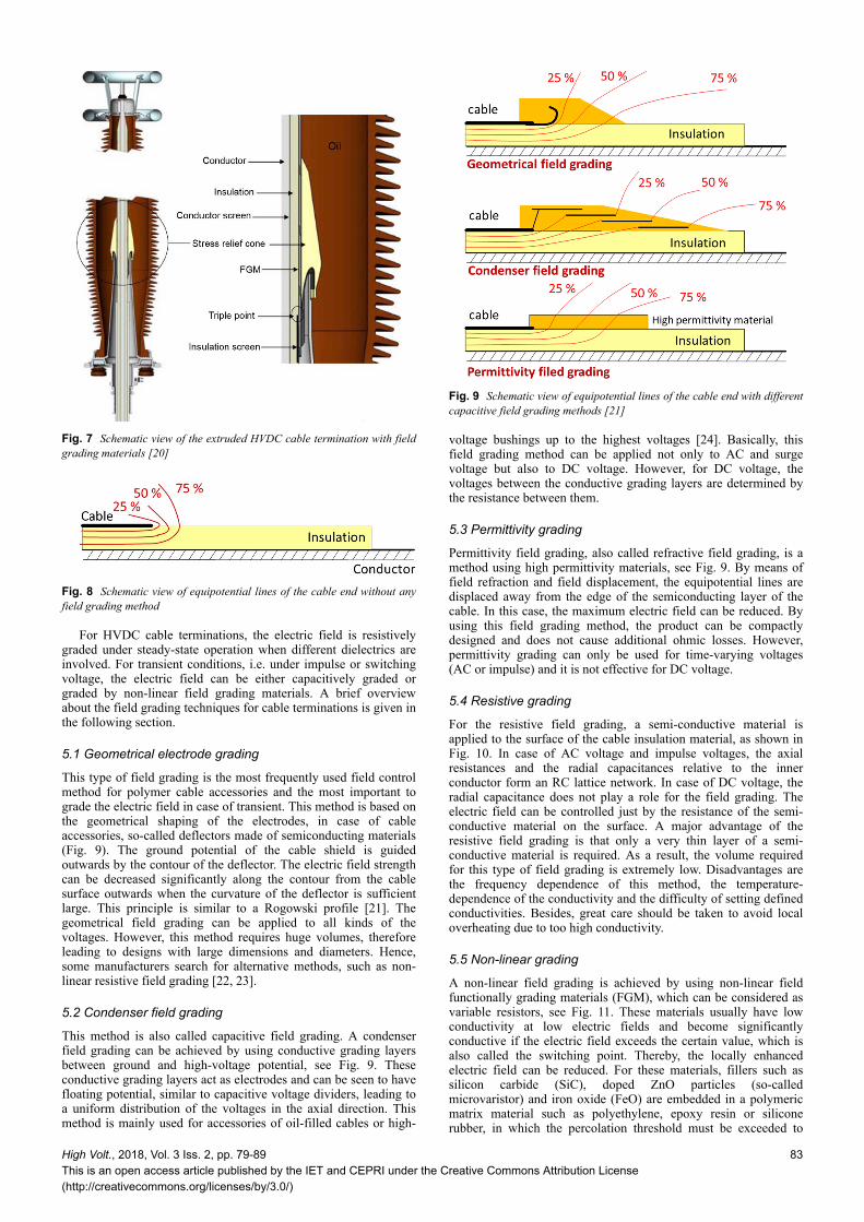
4.4 Termination featuring non-linear field-grading material
To homogenise the tangential electric field along the interfacebetween the cable and the stress cone of the termination, ABBproposed to use a continuous layer of the non-linear field gradingmaterials, which connects the live electrode to the ground. For thisdesign, the non-linear resistive field grading method is adopted,which will be introduced in Section 5. Fig. 7 shows an illustrationof a ±320 kV extruded cable termination featuring the fieldgrading materials. ABB also applied this non-linear field-gradingmaterial in HVDC cable terminations and joints for higher voltagelevels.
5 Field grading methodsThe essential component of a cable termination is the stress cone. Itplays a key role in grading the electric field along the interfacebetween the cable insulation and the stress cone. In this section,various field grading methods are listed and discussed.
To connect a cable to a termination the outer semiconductinglayer of the cable must be removed. Without any field gradingtechnique, a very high electric field occurs at the edge of thesemiconducting layer, as shown in Fig. 8, leading to partialdischarges and finally to a breakdown.
To maintain an acceptable distribution of the electric field underall operating conditions, especially along the interfaces betweendifferent components of the termination, field grading techniquesshould be adopted. These can be divided into two main classes:
• Capacitive field grading, which includes geometrical electrodegrading, permittivity grading and condenser grading.
• Resistive field grading, which includes resistive grading andnon-linear field grading.
Fig. 4 Cross-section of a GIS termination (source: G&W Electric)
Fig. 5 GIS termination of the condenser cone type for ±320 kV, 500 mm2
HVDC extruded cable, intended for use in both land and undersea cables[4]
Fig. 6 Dry type plug-in cable termination for GIS (left) and transformer(right) (Source: NKT)
82 High Volt., 2018, Vol. 3 Iss. 2, pp. 79-89This is an open access article published by the IET and CEPRI under the Creative Commons Attribution License
(http://creativecommons.org/licenses/by/3.0/)
For HVDC cable terminations, the electric field is resistivelygraded under steady-state operation when different dielectrics areinvolved. For transient conditions, i.e. under impulse or switchingvoltage, the electric field can be either capacitively graded orgraded by non-linear field grading materials. A brief overviewabout the field grading techniques for cable terminations is given inthe following section.
5.1 Geometrical electrode grading
This type of field grading is the most frequently used field controlmethod for polymer cable accessories and the most important tograde the electric field in case of transient. This method is based onthe geometrical shaping of the electrodes, in case of cableaccessories, so-called deflectors made of semiconducting materials(Fig. 9). The ground potential of the cable shield is guidedoutwards by the contour of the deflector. The electric field strengthcan be decreased significantly along the contour from the cablesurface outwards when the curvature of the deflector is sufficientlarge. This principle is similar to a Rogowski profile [21]. Thegeometrical field grading can be applied to all kinds of thevoltages. However, this method requires huge volumes, thereforeleading to designs with large dimensions and diameters. Hence,some manufacturers search for alternative methods, such as non-linear resistive field grading [22, 23].
5.2 Condenser field grading
This method is also called capacitive field grading. A condenserfield grading can be achieved by using conductive grading layersbetween ground and high-voltage potential, see Fig. 9. Theseconductive grading layers act as electrodes and can be seen to havefloating potential, similar to capacitive voltage dividers, leading toa uniform distribution of the voltages in the axial direction. Thismethod is mainly used for accessories of oil-filled cables or high-
voltage bushings up to the highest voltages [24]. Basically, thisfield grading method can be applied not only to AC and surgevoltage but also to DC voltage. However, for DC voltage, thevoltages between the conductive grading layers are determined bythe resistance between them.
5.3 Permittivity grading
Permittivity field grading, also called refractive field grading, is amethod using high permittivity materials, see Fig. 9. By means offield refraction and field displacement, the equipotential lines aredisplaced away from the edge of the semiconducting layer of thecable. In this case, the maximum electric field can be reduced. Byusing this field grading method, the product can be compactlydesigned and does not cause additional ohmic losses. However,permittivity grading can only be used for time-varying voltages(AC or impulse) and it is not effective for DC voltage.
5.4 Resistive grading
For the resistive field grading, a semi-conductive material isapplied to the surface of the cable insulation material, as shown inFig. 10. In case of AC voltage and impulse voltages, the axialresistances and the radial capacitances relative to the innerconductor form an RC lattice network. In case of DC voltage, theradial capacitance does not play a role for the field grading. Theelectric field can be controlled just by the resistance of the semi-conductive material on the surface. A major advantage of theresistive field grading is that only a very thin layer of a semi-conductive material is required. As a result, the volume requiredfor this type of field grading is extremely low. Disadvantages arethe frequency dependence of this method, the temperature-dependence of the conductivity and the difficulty of setting definedconductivities. Besides, great care should be taken to avoid localoverheating due to too high conductivity.
5.5 Non-linear grading
A non-linear field grading is achieved by using non-linear fieldfunctionally grading materials (FGM), which can be considered asvariable resistors, see Fig. 11. These materials usually have lowconductivity at low electric fields and become significantlyconductive if the electric field exceeds the certain value, which isalso called the switching point. Thereby, the locally enhancedelectric field can be reduced. For these materials, fillers such assilicon carbide (SiC), doped ZnO particles (so-calledmicrovaristor) and iron oxide (FeO) are embedded in a polymericmatrix material such as polyethylene, epoxy resin or siliconerubber, in which the percolation threshold must be exceeded to
Fig. 7 Schematic view of the extruded HVDC cable termination with fieldgrading materials [20]
Fig. 8 Schematic view of equipotential lines of the cable end without anyfield grading method
Fig. 9 Schematic view of equipotential lines of the cable end with differentcapacitive field grading methods [21]
High Volt., 2018, Vol. 3 Iss. 2, pp. 79-89This is an open access article published by the IET and CEPRI under the Creative Commons Attribution License(http://creativecommons.org/licenses/by/3.0/)
83
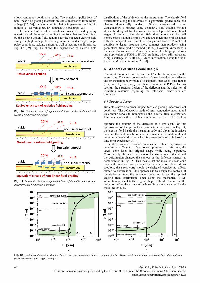
allow continuous conductive paths. The classical applications ofnon-linear field grading materials are cable accessories for mediumvoltage [25, 26], stator winding insulation in generators and in bigmotors [27] as well as 550 kV compact GIS bushings [28].
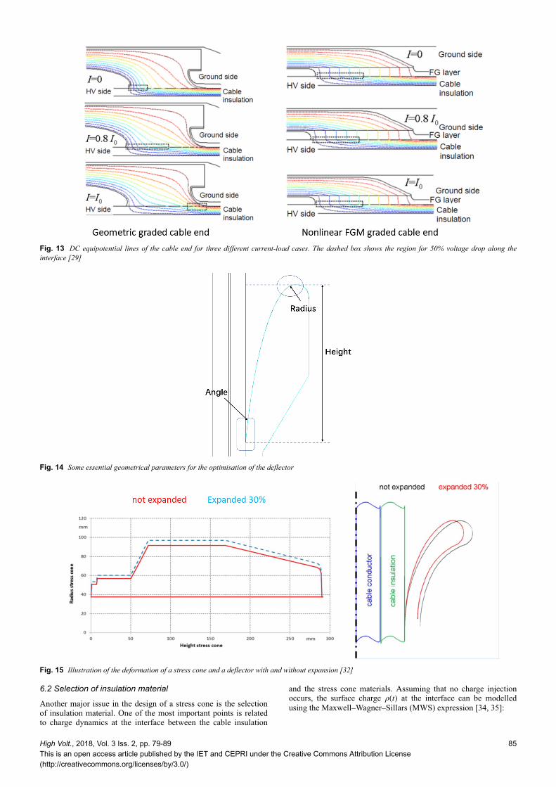
The conductivities of a non-linear resistive field gradingmaterial should be tuned according to regions that are determinedby the electric design field, required for the expected electric fieldstrength in high-voltage devices, e.g. nominal field strength, surge,pulse conditions, leakage current as well as heating conditions, seeFig. 12 [29]. Fig. 13 shows the dependence of electric field
distributions of the cable end on the temperature. The electric fielddistributions along the interface of a geometric graded cable endchange dramatically under different current-load cases.Consequently, a product using geometric field grading methodshould be designed for the worst case of all possible operationalstages. In contrast, the electric field distributions can be wellhomogenised via non-linear FGM and are much more robust underdifferent temperatures. Therefore, using non-linear FGM makes itpossible to design products more compact than products usinggeometrical field grading method [20, 29]. However, know-how inthe area of non-linear FGM is a prerequisite for the proper designand application of FGM to HVDC products, which still representsa big challenge in itself [29]. More information about the non-linear FGM can be found in [23, 30].
6 Aspects of stress cone designThe most important part of an HVDC cable termination is thestress cone. The stress cone consists of a semi-conductive deflectorand an insulation body made of elastomers, such as silicone rubber(SiR) or ethylene propylene diene monomer (EPDM). In thissection, the structural design of the deflector and the selection ofinsulation materials regarding the interfacial behaviours arediscussed.
6.1 Structural design
Deflectors have a dominant impact for field grading under transientconditions. The deflector is made of semi-conductive material andits contour serves to homogenise the electric field distribution.Finite-element-method (FEM) simulations are a useful tool to
optimise the contour of the deflector at a low cost. For thisoptimisation of the geometrical parameters, as shown in Fig. 14,the electric field inside the insulation body and along the interfacebetween the cable insulation and the stress cone insulation shouldbe under a threshold value, which is proven to be reliable based onlong-term experience [31].
A stress cone is installed on a cable with an expansion togenerate a sufficient surface contact pressure. In this case, thestress cone loses its original shape while being expanded.Consequently, the wall thickness of the stress cone reduced, andthe deformation changes the contour of the deflector surface, asdemonstrated in Fig. 15. This means that the installed stress conemay perform worse than predicted by the simulation. To avoid thisproblem, the stress cone should be designed considering effectsrelated to deformation. One approach is to design the contour ofthe deflector under the expanded condition to get the optimalelectric field distribution. Then using the mechanical FEM-simulation to calculate the original shape of the stress cone and thedeflector before the expansion, whose dimensions are used for themode design [33].
Fig. 10 Schematic view of equipotential lines of the cable end withresistive field grading methods
Fig. 11 Schematic view of equipotential lines of the cable end with non-linear resistive field grading methods
Fig. 12 Qualitative illustration sketch of how regions are determined in the E − σ plane for the σ(E) of an ideal non-linear resistive field grading material(a) AC applications, (b) DC applications [23]
84 High Volt., 2018, Vol. 3 Iss. 2, pp. 79-89
This is an open access article published by the IET and CEPRI under the Creative Commons Attribution License(http://creativecommons.org/licenses/by/3.0/)
6.2 Selection of insulation material
Another major issue in the design of a stress cone is the selectionof insulation material. One of the most important points is relatedto charge dynamics at the interface between the cable insulation
and the stress cone materials. Assuming that no charge injectionoccurs, the surface charge ρ(t) at the interface can be modelledusing the Maxwell–Wagner–Sillars (MWS) expression [34, 35]:
Fig. 13 DC equipotential lines of the cable end for three different current-load cases. The dashed box shows the region for 50% voltage drop along theinterface [29]
Fig. 14 Some essential geometrical parameters for the optimisation of the deflector
Fig. 15 Illustration of the deformation of a stress cone and a deflector with and without expansion [32]
High Volt., 2018, Vol. 3 Iss. 2, pp. 79-89This is an open access article published by the IET and CEPRI under the Creative Commons Attribution License(http://creativecommons.org/licenses/by/3.0/)
85
ρ t = εAκB − εBκAκAdB + κBdA
U0 1 − exp − tτMWS
, (17)
where εA and εB are the permittivities of the dielectrics A and B; κAand κB are the respective conductivities; dA and dB are thethickness; U0 is the applied voltage across the dielectrics, and thepolarisation time constant is given as
τMWS = dAεB + dBεAdAκB + dBκA
. (18)
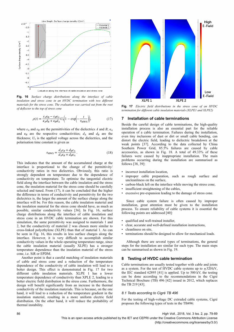
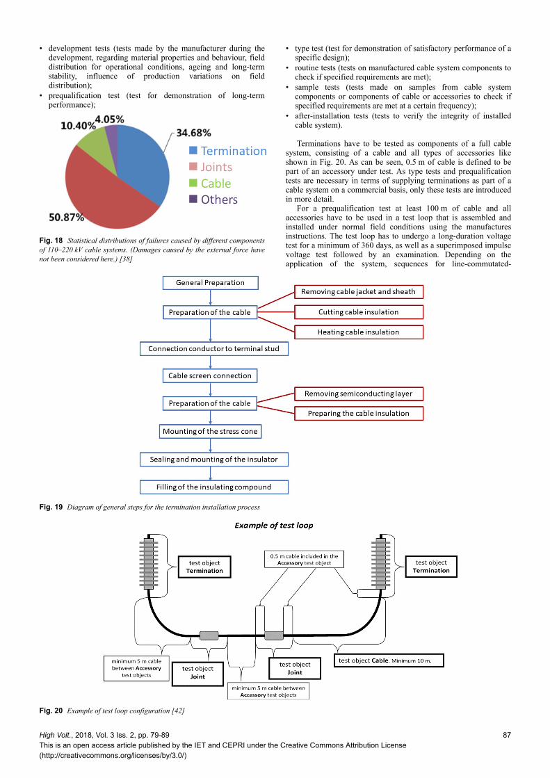
This indicates that the amount of the accumulated charge at theinterface is proportional to the change of the permittivity/conductivity ratios in two dielectrics. Obviously, this ratio isstrongly dependent on temperature due to the dependence ofconductivity on temperature. To optimise the tangential electricfield along the interface between the cable insulation and the stresscone, the insulation material for the stress cone should be carefullyselected and tuned. From (17), it can be concluded that the higherthe difference in terms of conductivity and permittivity for the twodielectrics is, the larger the amount of the surface charge along theinterface will be. For this reason, the cable insulation material andthe insulation material for the stress cone should have, as much aspossible, similar conductivity values [36]. In Fig. 16, surfacecharge distributions along the interface of cable insulation andstress cone in an HVDC cable termination are shown. For thissimulation, the same permittivity was assigned to materials 1 and2, but the conductivity of material 2 was chosen more similar tocross-linked polyethylene (XLPE) than that of material 1. As canbe seen in Fig. 16, this results in less surface charges along theinterface. However, it is very difficult to accomplish similarconductivity values in the whole operating temperature range, sincethe cable insulation material (usually XLPE) has a strongertemperature dependence than the insulation material of the stresscone, i.e. SiR or EPDM.
Another point is that a careful matching of insulation materialsof cable and stress cone and a reduction of the temperaturedependence of the conductivity of cable insulation will lead to abetter design. This effect is demonstrated in Fig. 17 for twodifferent cable insulation materials. XLPE 1 has a lowertemperature dependence of conductivity than XPLE 2, leading to abetter electric field distribution in the stress cone. Furthermore, thedesign will benefit significantly from an increase in the thermalconductivity of the insulation materials. This is because, on the onehand, it will lead to a reduction of the temperature gradient in theinsulation material, resulting in a more uniform electric fielddistribution. On the other hand, it will reduce the probability ofthermal instability.
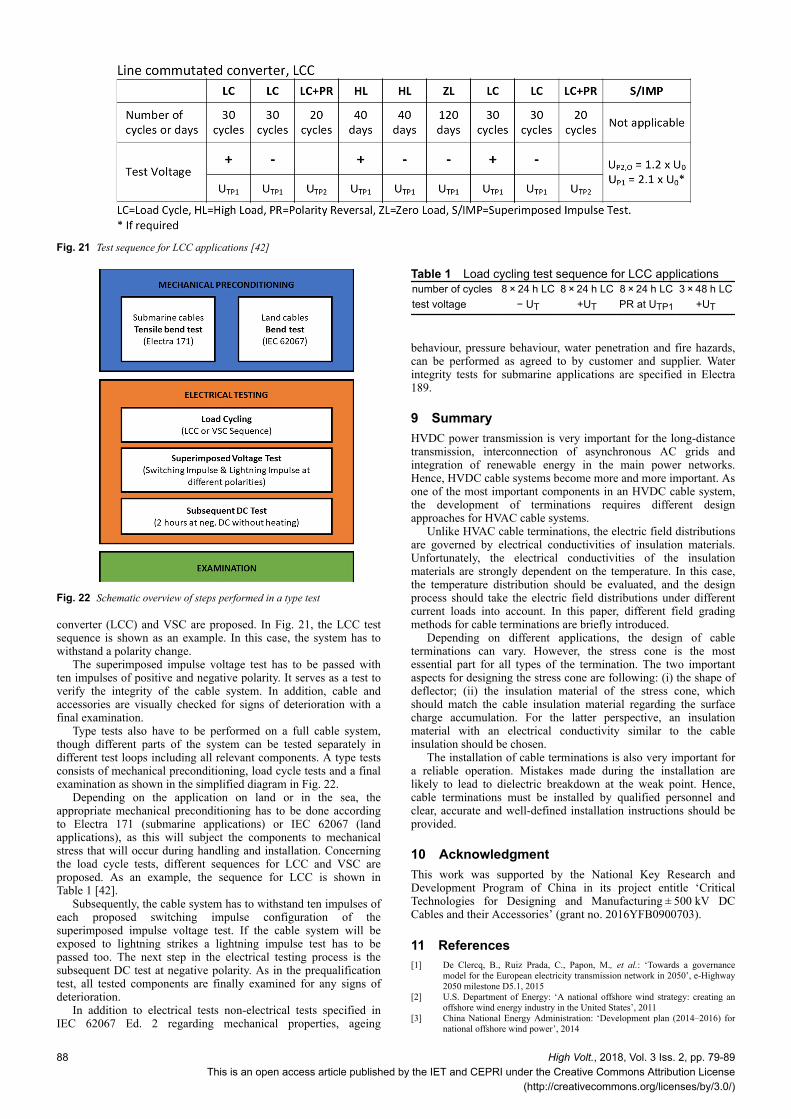
7 Installation of cable terminationsBeside the careful design of cable terminations, the high-qualityinstallation process is also an essential part for the reliableoperation of a cable termination. Failures during the installation,even tiny inclusions of dust or dirt or small cable bending, candistort the electric field, leading to dielectric breakdown at theweak points [37]. According to the data collected by ChinaSouthern Power Grid, 85.5% failures are caused by cableaccessories, as shown in Fig. 18. A total of 49.33% of thesefailures were caused by inappropriate installation. The mainproblems occurring during the installation are summarised asfollows [38, 39]:
• incorrect installation location,• improper cable preparation, such as rough surface and
uncleanliness on the surface,• carbon-black left on the interface while moving the stress cone,• insufficient straightening of the cables,• excessive pre-expansion leading to the damage of stress cone.
Since cable system failure is often caused by improperinstallation, great attention must be given to the installationprocess. To ensure reliability of cable systems it is essential thefollowing points are addressed [40]:
• qualified and well-trained installer,• clear, accurate and well-defined installation instructions,• cleanliness on site,• terminations should be designed to allow for mechanical loads.
Although there are several types of terminations, the generalsteps for the installation are similar for each type. The main stepscan be summarised as shown in Fig. 19.
8 Testing of HVDC cable terminationCable terminations are usually tested together with cable and jointsas a system. For the test of HVDC cable systems up to ±320 kV,the IEC standard 62895 [41] is applied. Up to 500 kV, the testingcan be done according to the recommendations in the CigréTechnical Brochure (TB) 496 [42] issued in 2012, which replacesthe TB 219 [43].
8.1 Tests according to Cigré TB 496
For the testing of high-voltage DC extruded cable systems, Cigréproposes the following types of tests in the TB496:
Fig. 16 Surface charge distributions along the interface of cableinsulation and stress cone in an HVDC termination with two differentmaterials for the stress cone. The evaluation was carried out from the rootof deflector to the top of stress cone
Fig. 17 Electric field distributions in the stress cone of an HVDCtermination for different cable insulation materials (XLPE1 and XLPE2)
86 High Volt., 2018, Vol. 3 Iss. 2, pp. 79-89This is an open access article published by the IET and CEPRI under the Creative Commons Attribution License
(http://creativecommons.org/licenses/by/3.0/)
• development tests (tests made by the manufacturer during thedevelopment, regarding material properties and behaviour, fielddistribution for operational conditions, ageing and long-termstability, influence of production variations on fielddistribution);
• prequalification test (test for demonstration of long-termperformance);
• type test (test for demonstration of satisfactory performance of aspecific design);
• routine tests (tests on manufactured cable system components tocheck if specified requirements are met);
• sample tests (tests made on samples from cable systemcomponents or components of cable or accessories to check ifspecified requirements are met at a certain frequency);
• after-installation tests (tests to verify the integrity of installedcable system).
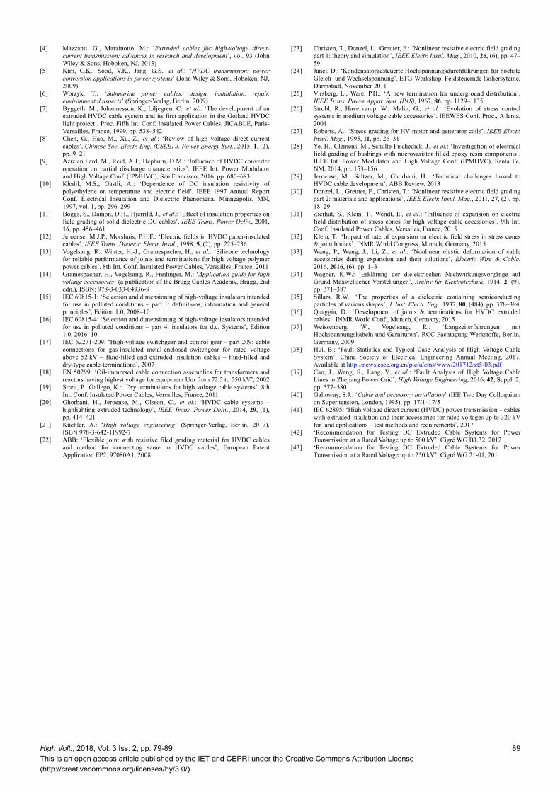
Terminations have to be tested as components of a full cablesystem, consisting of a cable and all types of accessories likeshown in Fig. 20. As can be seen, 0.5 m of cable is defined to bepart of an accessory under test. As type tests and prequalificationtests are necessary in terms of supplying terminations as part of acable system on a commercial basis, only these tests are introducedin more detail.
For a prequalification test at least 100 m of cable and allaccessories have to be used in a test loop that is assembled andinstalled under normal field conditions using the manufacturesinstructions. The test loop has to undergo a long-duration voltagetest for a minimum of 360 days, as well as a superimposed impulsevoltage test followed by an examination. Depending on theapplication of the system, sequences for line-commutated-
Fig. 18 Statistical distributions of failures caused by different componentsof 110–220 kV cable systems. (Damages caused by the external force havenot been considered here.) [38]
Fig. 19 Diagram of general steps for the termination installation process
Fig. 20 Example of test loop configuration [42]
High Volt., 2018, Vol. 3 Iss. 2, pp. 79-89This is an open access article published by the IET and CEPRI under the Creative Commons Attribution License(http://creativecommons.org/licenses/by/3.0/)
87
converter (LCC) and VSC are proposed. In Fig. 21, the LCC testsequence is shown as an example. In this case, the system has towithstand a polarity change.
The superimposed impulse voltage test has to be passed withten impulses of positive and negative polarity. It serves as a test toverify the integrity of the cable system. In addition, cable andaccessories are visually checked for signs of deterioration with afinal examination.
Type tests also have to be performed on a full cable system,though different parts of the system can be tested separately indifferent test loops including all relevant components. A type testsconsists of mechanical preconditioning, load cycle tests and a finalexamination as shown in the simplified diagram in Fig. 22.
Depending on the application on land or in the sea, theappropriate mechanical preconditioning has to be done accordingto Electra 171 (submarine applications) or IEC 62067 (landapplications), as this will subject the components to mechanicalstress that will occur during handling and installation. Concerningthe load cycle tests, different sequences for LCC and VSC areproposed. As an example, the sequence for LCC is shown inTable 1 [42].
Subsequently, the cable system has to withstand ten impulses ofeach proposed switching impulse configuration of thesuperimposed impulse voltage test. If the cable system will beexposed to lightning strikes a lightning impulse test has to bepassed too. The next step in the electrical testing process is thesubsequent DC test at negative polarity. As in the prequalificationtest, all tested components are finally examined for any signs ofdeterioration.
In addition to electrical tests non-electrical tests specified inIEC 62067 Ed. 2 regarding mechanical properties, ageing
behaviour, pressure behaviour, water penetration and fire hazards,can be performed as agreed to by customer and supplier. Waterintegrity tests for submarine applications are specified in Electra189.
9 SummaryHVDC power transmission is very important for the long-distancetransmission, interconnection of asynchronous AC grids andintegration of renewable energy in the main power networks.Hence, HVDC cable systems become more and more important. Asone of the most important components in an HVDC cable system,the development of terminations requires different designapproaches for HVAC cable systems.
Unlike HVAC cable terminations, the electric field distributionsare governed by electrical conductivities of insulation materials.Unfortunately, the electrical conductivities of the insulationmaterials are strongly dependent on the temperature. In this case,the temperature distribution should be evaluated, and the designprocess should take the electric field distributions under differentcurrent loads into account. In this paper, different field gradingmethods for cable terminations are briefly introduced.
Depending on different applications, the design of cableterminations can vary. However, the stress cone is the mostessential part for all types of the termination. The two importantaspects for designing the stress cone are following: (i) the shape ofdeflector; (ii) the insulation material of the stress cone, whichshould match the cable insulation material regarding the surfacecharge accumulation. For the latter perspective, an insulationmaterial with an electrical conductivity similar to the cableinsulation should be chosen.
The installation of cable terminations is also very important fora reliable operation. Mistakes made during the installation arelikely to lead to dielectric breakdown at the weak point. Hence,cable terminations must be installed by qualified personnel andclear, accurate and well-defined installation instructions should beprovided.
10 AcknowledgmentThis work was supported by the National Key Research andDevelopment Program of China in its project entitle ‘CriticalTechnologies for Designing and Manufacturing ± 500 kV DCCables and their Accessories’ (grant no. 2016YFB0900703).
11 References[1] De Clercq, B., Ruiz Prada, C., Papon, M., et al.: ‘Towards a governance
model for the European electricity transmission network in 2050’, e-Highway2050 milestone D5.1, 2015
[2] U.S. Department of Energy: ‘A national offshore wind strategy: creating anoffshore wind energy industry in the United States’, 2011
[3] China National Energy Administration: ‘Development plan (2014–2016) fornational offshore wind power’, 2014
Fig. 21 Test sequence for LCC applications [42]
Fig. 22 Schematic overview of steps performed in a type test
Table 1 Load cycling test sequence for LCC applicationsnumber of cycles 8 × 24 h LC 8 × 24 h LC 8 × 24 h LC 3 × 48 h LCtest voltage − UT +UT PR at UTP1 +UT
88 High Volt., 2018, Vol. 3 Iss. 2, pp. 79-89This is an open access article published by the IET and CEPRI under the Creative Commons Attribution License
(http://creativecommons.org/licenses/by/3.0/)
[4] Mazzanti, G., Marzinotto, M.: ‘Extruded cables for high-voltage direct-current transmission: advances in research and development’, vol. 93 (JohnWiley & Sons, Hoboken, NJ, 2013)
[5] Kim, C.K., Sood, V.K., Jang, G.S., et al.: ‘HVDC transmission: powerconversion applications in power systems’ (John Wiley & Sons, Hoboken, NJ,2009)
[6] Worzyk, T.: ‘Submarine power cables: design, installation, repair,environmental aspects’ (Springer-Verlag, Berlin, 2009)
[7] Byggeth, M., Johannesson, K., Liljegren, C., et al.: ‘The development of anextruded HVDC cable system and its first application in the Gotland HVDClight project’. Proc. Fifth Int. Conf. Insulated Power Cables, JICABLE, Paris-Versailles, France, 1999, pp. 538–542
[8] Chen, G., Hao, M., Xu, Z., et al.: ‘Review of high voltage direct currentcables’, Chinese Soc. Electr. Eng. (CSEE) J. Power Energy Syst., 2015, 1, (2),pp. 9–21
[9] Azizian Fard, M., Reid, A.J., Hepburn, D.M.: ‘Influence of HVDC converteroperation on partial discharge characteristics’. IEEE Int. Power Modulatorand High Voltage Conf. (IPMHVC), San Francisco, 2016, pp. 680–683
[10] Khalil, M.S., Gastli, A.: ‘Dependence of DC insulation resistivity ofpolyethylene on temperature and electric field’. IEEE 1997 Annual ReportConf. Electrical Insulation and Dielectric Phenomena, Minneapolis, MN,1997, vol. 1, pp. 296–299
[11] Boggs, S., Damon, D.H., Hjerrild, J., et al.: ‘Effect of insulation properties onfield grading of solid dielectric DC cables’, IEEE Trans. Power Deliv., 2001,16, pp. 456–461
[12] Jeroense, M.J.P., Morshuis, P.H.F.: ‘Electric fields in HVDC paper-insulatedcables’, IEEE Trans. Dielectr. Electr. Insul., 1998, 5, (2), pp. 225–236
[13] Vogelsang, R., Winter, H.-J., Gramespacher, H., et al.: ‘Silicone technologyfor reliable performance of joints and terminations for high voltage polymerpower cables’. 8th Int. Conf. Insulated Power Cables, Versailles, France, 2011
[14] Gramespacher, H., Vogelsang, R., Freilinger, M.: ‘Application guide for highvoltage accessories’ (a publication of the Brugg Cables Academy, Brugg, 2ndedn.), ISBN: 978-3-033-04936-9
[15] IEC 60815-1: ‘Selection and dimensioning of high-voltage insulators intendedfor use in polluted conditions – part 1: definitions, information and generalprinciples’, Edition 1.0, 2008–10
[16] IEC 60815-4: ‘Selection and dimensioning of high-voltage insulators intendedfor use in polluted conditions – part 4: insulators for d.c. Systems’, Edition1.0, 2016–10
[17] IEC 62271-209: ‘High-voltage switchgear and control gear – part 209: cableconnections for gas-insulated metal-enclosed switchgear for rated voltageabove 52 kV – fluid-filled and extruded insulation cables – fluid-filled anddry-type cable-terminations’, 2007
[18] EN 50299: ‘Oil-immersed cable connection assemblies for transformers andreactors having highest voltage for equipment Um from 72.5 to 550 kV’, 2002
[19] Streit, P., Gallego, K.: ‘Dry terminations for high voltage cable systems’. 8thInt. Conf. Insulated Power Cables, Versailles, France, 2011
[20] Ghorbani, H., Jeroense, M., Olsson, C., et al.: ‘HVDC cable systems –highlighting extruded technology’, IEEE Trans. Power Deliv., 2014, 29, (1),pp. 414–421
[21] Küchler, A.: ‘High voltage engineering’ (Springer-Verlag, Berlin, 2017),ISBN 978-3-642-11992-7
[22] ABB: ‘Flexible joint with resistive filed grading material for HVDC cablesand method for connecting same to HVDC cables’, European PatentApplication EP2197080A1, 2008
[23] Christen, T., Donzel, L., Greuter, F.: ‘Nonlinear resistive electric field gradingpart 1: theory and simulation’, IEEE Electr. Insul. Mag., 2010, 26, (6), pp. 47–59
[24] Janel, D.: ‘Kondensatorgesteuerte Hochspannungsdurchführungen für höchsteGleich- und Wechselspannung’. ETG-Workshop, Feldsteuernde Isoliersyteme,Darmstadt, November 2011
[25] Virsberg, L., Ware, P.H.: ‘A new termination for underground distribution’,IEEE Trans. Power Appar. Syst. (PAS), 1967, 86, pp. 1129–1135
[26] Strobl, R., Haverkamp, W., Malin, G., et al.: ‘Evolution of stress controlsystems in medium voltage cable accessories’. IEEWES Conf. Proc., Atlanta,2001
[27] Roberts, A.: ‘Stress grading for HV motor and generator coils’, IEEE Electr.Insul. Mag., 1995, 11, pp. 26–31
[28] Ye, H., Clemens, M., Schulte-Fischedick, J., et al.: ‘Investigation of electricalfield grading of bushings with microvaristor filled epoxy resin components’.IEEE Int. Power Modulator and High Voltage Conf. (IPMHVC), Santa Fe,NM, 2014, pp. 153–156
[29] Jeroense, M., Saltzer, M., Ghorbani, H.: ‘Technical challenges linked toHVDC cable development’, ABB Review, 2013
[30] Donzel, L., Greuter, F., Christen, T.: ‘Nonlinear resistive electric field gradingpart 2: materials and applications’, IEEE Electr. Insul. Mag., 2011, 27, (2), pp.18–29
[31] Zierhut, S., Klein, T., Wendt, E., et al.: ‘Influence of expansion on electricfield distribution of stress cones for high voltage cable accessories’. 9th Int.Conf. Insulated Power Cables, Versailes, France, 2015
[32] Klein, T.: ‘Impact of rate of expansion on electric field stress in stress cones& joint bodies’. INMR World Congress, Munich, Germany, 2015
[33] Wang, P., Wang, J., Li, Z., et al.: ‘Nonlinear elastic deformation of cableaccessories during expansion and their solutions’, Electric Wire & Cable,2016, 2016, (6), pp. 1–3
[34] Wagner, K.W.: ‘Erklärung der dielektrischen Nachwirkungsvorgänge aufGrund Maxwellscher Vorstellungen’, Archiv für Elektrotechnik, 1914, 2, (9),pp. 371–387
[35] Sillars, R.W.: ‘The properties of a dielectric containing semiconductingparticles of various shapes’, J. Inst. Electr. Eng., 1937, 80, (484), pp. 378–394
[36] Quaggia, D.: ‘Development of joints & terminations for HVDC extrudedcables’. INMR World Conf., Munich, Germany, 2015
[37] Weissenberg, W., Vogelsang, R.: ‘Langzeiterfahrungen mitHochspannungskabeln und Garnituren’. RCC Fachtagung Werkstoffe, Berlin,Germany, 2009
[38] Hui, B.: ‘Fault Statistics and Typical Case Analysis of High Voltage CableSystem’, China Society of Electrical Engineering Annual Meeting, 2017.Available at http://news.csee.org.cn/pic/u/cms/www/201712/zt5-03.pdf
[39] Cao, J., Wang, S., Jiang, Y., et al.: ‘Fault Analysis of High Voltage CableLines in Zhejiang Power Grid’, High Voltage Engineering, 2016, 42, Suppl. 2,pp. 577–580
[40] Galloway, S.J.: ‘Cable and accessory installation’ (IEE Two Day Colloquiumon Super tension, London, 1995), pp. 17/1–17/5
[41] IEC 62895: ‘High voltage direct current (HVDC) power transmission – cableswith extruded insulation and their accessories for rated voltages up to 320 kVfor land applications – test methods and requirements’, 2017
[42] ‘Recommendation for Testing DC Extruded Cable Systems for PowerTransmission at a Rated Voltage up to 500 kV’, Cigré WG B1.32, 2012
[43] ‘Recommendation for Testing DC Extruded Cable Systems for PowerTransmission at a Rated Voltage up to 250 kV’, Cigré WG 21-01, 201
High Volt., 2018, Vol. 3 Iss. 2, pp. 79-89This is an open access article published by the IET and CEPRI under the Creative Commons Attribution License(http://creativecommons.org/licenses/by/3.0/)
89


