Embed Size (px)
Citation preview
Planning Fundamentals
Pressure retaining valve type 586
Overview
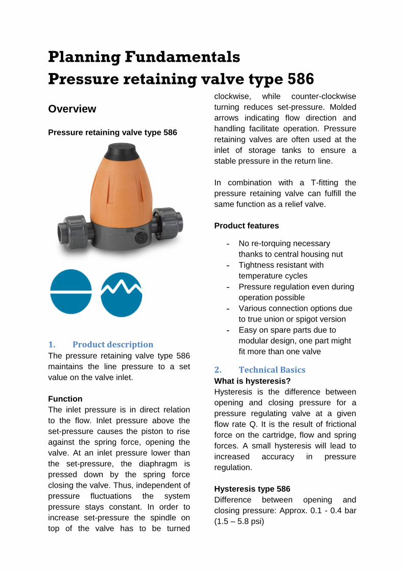
Pressure retaining valve type 586
1. Product description
The pressure retaining valve type 586
maintains the line pressure to a set
value on the valve inlet.
Function
The inlet pressure is in direct relation
to the flow. Inlet pressure above the
set-pressure causes the piston to rise
against the spring force, opening the
valve. At an inlet pressure lower than
the set-pressure, the diaphragm is
pressed down by the spring force
closing the valve. Thus, independent of
pressure fluctuations the system
pressure stays constant. In order to
increase set-pressure the spindle on
top of the valve has to be turned
clockwise, while counter-clockwise
turning reduces set-pressure. Molded
arrows indicating flow direction and
handling facilitate operation. Pressure
retaining valves are often used at the
inlet of storage tanks to ensure a
stable pressure in the return line.
In combination with a T-fitting the
pressure retaining valve can fulfill the
same function as a relief valve.
Product features
- No re-torquing necessary
thanks to central housing nut
- Tightness resistant with
temperature cycles
- Pressure regulation even during
operation possible
- Various connection options due
to true union or spigot version
- Easy on spare parts due to
modular design, one part might
fit more than one valve
2. Technical Basics
What is hysteresis?
Hysteresis is the difference between
opening and closing pressure for a
pressure regulating valve at a given
flow rate Q. It is the result of frictional
force on the cartridge, flow and spring
forces. A small hysteresis will lead to
increased accuracy in pressure
regulation.
Hysteresis type 586
Difference between opening and
closing pressure: Approx. 0.1 - 0.4 bar
(1.5 – 5.8 psi)
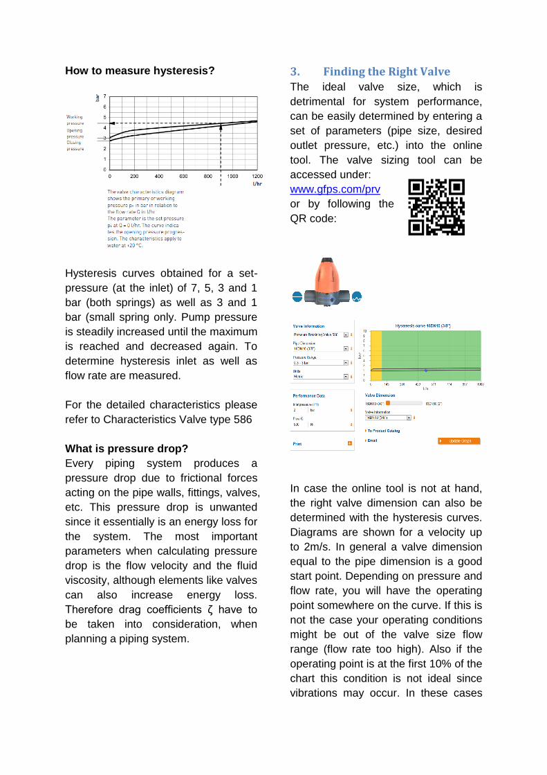
How to measure hysteresis?
Hysteresis curves obtained for a set-
pressure (at the inlet) of 7, 5, 3 and 1
bar (both springs) as well as 3 and 1
bar (small spring only. Pump pressure
is steadily increased until the maximum
is reached and decreased again. To
determine hysteresis inlet as well as
flow rate are measured.
For the detailed characteristics please
refer to Characteristics Valve type 586
What is pressure drop?
Every piping system produces a
pressure drop due to frictional forces
acting on the pipe walls, fittings, valves,
etc. This pressure drop is unwanted
since it essentially is an energy loss for
the system. The most important
parameters when calculating pressure
drop is the flow velocity and the fluid
viscosity, although elements like valves
can also increase energy loss.
Therefore drag coefficients ζ have to
be taken into consideration, when
planning a piping system.
3. Finding the Right Valve
The ideal valve size, which is
detrimental for system performance,
can be easily determined by entering a
set of parameters (pipe size, desired
outlet pressure, etc.) into the online
tool. The valve sizing tool can be
accessed under:
www.gfps.com/prv
or by following the
QR code:
In case the online tool is not at hand,
the right valve dimension can also be
determined with the hysteresis curves.
Diagrams are shown for a velocity up
to 2m/s. In general a valve dimension
equal to the pipe dimension is a good
start point. Depending on pressure and
flow rate, you will have the operating
point somewhere on the curve. If this is
not the case your operating conditions
might be out of the valve size flow
range (flow rate too high). Also if the
operating point is at the first 10% of the
chart this condition is not ideal since
vibrations may occur. In these cases
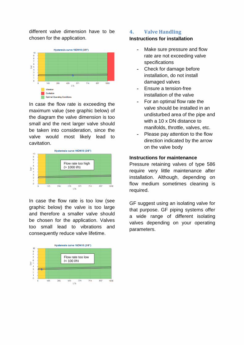
different valve dimension have to be
chosen for the application.
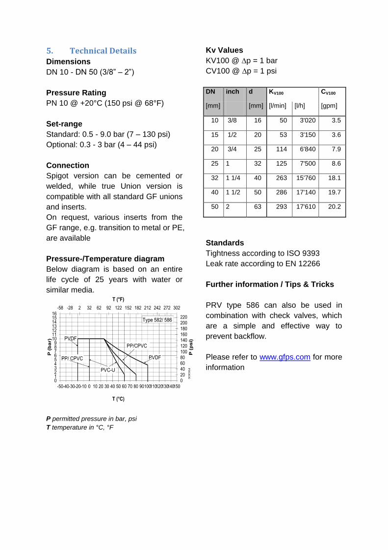
In case the flow rate is exceeding the
maximum value (see graphic below) of
the diagram the valve dimension is too
small and the next larger valve should
be taken into consideration, since the
valve would most likely lead to
cavitation.
In case the flow rate is too low (see
graphic below) the valve is too large
and therefore a smaller valve should
be chosen for the application. Valves
too small lead to vibrations and
consequently reduce valve lifetime.
4. Valve Handling
Instructions for installation
- Make sure pressure and flow
rate are not exceeding valve
specifications
- Check for damage before
installation, do not install
damaged valves
- Ensure a tension-free
installation of the valve
- For an optimal flow rate the
valve should be installed in an
undisturbed area of the pipe and
with a 10 x DN distance to
manifolds, throttle, valves, etc.
- Please pay attention to the flow
direction indicated by the arrow
on the valve body
Instructions for maintenance
Pressure retaining valves of type 586
require very little maintenance after
installation. Although, depending on
flow medium sometimes cleaning is
required.
GF suggest using an isolating valve for
that purpose. GF piping systems offer
a wide range of different isolating
valves depending on your operating
parameters.
Flow rate too high (> 1000 l/h)
Flow rate too low (< 100 l/h)
5. Technical Details
Dimensions
DN 10 - DN 50 (3/8” – 2”)
Pressure Rating
PN 10 @ +20°C (150 psi @ 68°F)
Set-range
Standard: 0.5 - 9.0 bar (7 – 130 psi)
Optional: 0.3 - 3 bar (4 – 44 psi)
Connection
Spigot version can be cemented or
welded, while true Union version is
compatible with all standard GF unions
and inserts.
On request, various inserts from the
GF range, e.g. transition to metal or PE,
are available
Pressure-/Temperature diagram
Below diagram is based on an entire
life cycle of 25 years with water or
similar media.
Kv Values
KV100 @ ∆p = 1 bar
CV100 @ ∆p = 1 psi
DN inch d KV100 CV100
[mm] [mm] [l/min] [l/h] [gpm]
10 3/8 16 50 3'020 3.5
15 1/2 20 53 3'150 3.6
20 3/4 25 114 6'840 7.9
25 1 32 125 7'500 8.6
32 1 1/4 40 263 15'760 18.1
40 1 1/2 50 286 17'140 19.7
50 2 63 293 17'610 20.2
Standards
Tightness according to ISO 9393
Leak rate according to EN 12266
Further information / Tips & Tricks
PRV type 586 can also be used in
combination with check valves, which
are a simple and effective way to
prevent backflow.
Please refer to www.gfps.com for more
information
P permitted pressure in bar, psi
T temperature in °C, °F
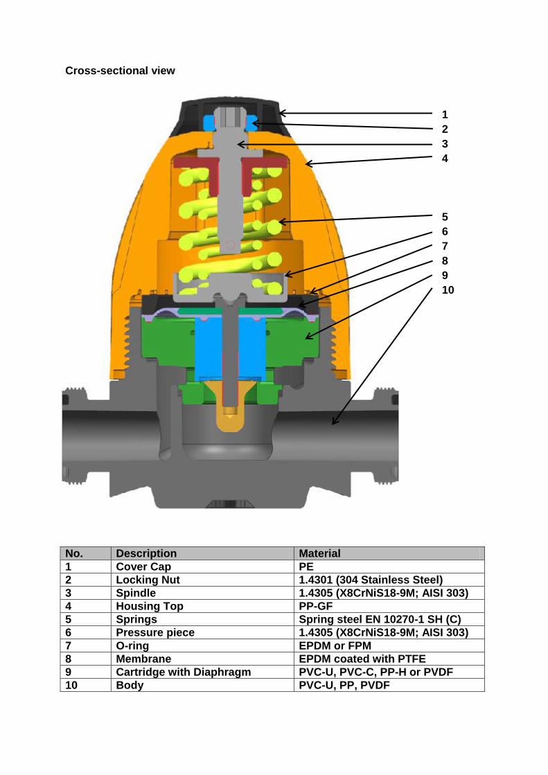
Cross-sectional view
1
2
3
4
5
6
7
8
9
10
No. Description Material
1 Cover Cap PE
2 Locking Nut 1.4301 (304 Stainless Steel)
3 Spindle 1.4305 (X8CrNiS18-9M; AISI 303)
4 Housing Top PP-GF
5 Springs Spring steel EN 10270-1 SH (C)
6 Pressure piece 1.4305 (X8CrNiS18-9M; AISI 303)
7 O-ring EPDM or FPM
8 Membrane EPDM coated with PTFE
9 Cartridge with Diaphragm PVC-U, PVC-C, PP-H or PVDF
10 Body PVC-U, PP, PVDF
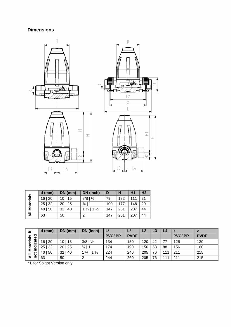
Dimensions
All M
ate
ria
ls d (mm) DN (mm) DN (inch) D H H1 H2
16 | 20 10 | 15 3/8 | ½ 79 132 111 21
25 | 32 20 | 25 ¾ | 1 100 177 148 29
40 | 50 32 | 40 1 ¼ | 1 ½ 147 251 207 44
63 50 2 147 251 207 44
All M
ate
rials
if
no
t in
dic
ate
d
d (mm) DN (mm) DN (inch) L*
PVC/ PP
L*
PVDF
L2 L3 L4 z
PVC/ PP
z
PVDF
16 | 20 10 | 15 3/8 | ½ 134 150 120 42 77 126 130
25 | 32 20 | 25 ¾ | 1 174 190 150 53 88 156 160
40 | 50 32 | 40 1 ¼ | 1 ½ 224 240 205 76 111 211 215
63 50 2 244 260 205 76 111 211 215
* L for Spigot Version only
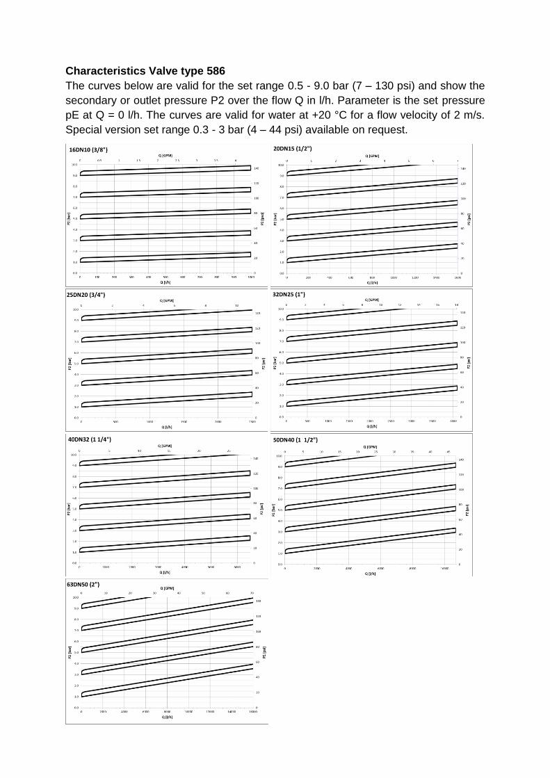
Characteristics Valve type 586
The curves below are valid for the set range 0.5 - 9.0 bar (7 – 130 psi) and show the
secondary or outlet pressure P2 over the flow Q in l/h. Parameter is the set pressure
pE at Q = 0 l/h. The curves are valid for water at +20 °C for a flow velocity of 2 m/s.
Special version set range 0.3 - 3 bar (4 – 44 psi) available on request.