Embed Size (px)
Citation preview

Piecing Together the NFV Provisioning Puzzle:Efficient Placement and Chaining of
Virtual Network Functions
Marcelo Caggiani Luizelli, Leonardo Richter Bays, Luciana Salete BuriolMarinho Pilla Barcellos, Luciano Paschoal Gaspary
Institute of Informatics – Federal University of Rio Grande do Sul (UFRGS){mcluizelli,lrbays,buriol,marinho,paschoal}@inf.ufrgs.br
Abstract—Network Function Virtualization (NFV) is a promis-ing network architecture concept, in which virtualization tech-nologies are employed to manage networking functions viasoftware as opposed to having to rely on hardware to handlethese functions. By shifting dedicated, hardware-based networkfunction processing to software running on commoditized hard-ware, NFV has the potential to make the provisioning of networkfunctions more flexible and cost-effective, to mention just a fewanticipated benefits. Despite consistent initial efforts to make NFVa reality, little has been done towards efficiently placing virtualnetwork functions and deploying service function chains (SFC).With respect to this particular research problem, it is importantto make sure resource allocation is carefully performed andorchestrated, preventing over- or under-provisioning of resourcesand keeping end-to-end delays comparable to those observed intraditional middlebox-based networks. In this paper, we formalizethe network function placement and chaining problem andpropose an Integer Linear Programming (ILP) model to solveit. Additionally, in order to cope with large infrastructures, wepropose a heuristic procedure for efficiently guiding the ILPsolver towards feasible, near-optimal solutions. Results showthat the proposed model leads to a reduction of up to 25%in end-to-end delays (in comparison to chainings observed intraditional infrastructures) and an acceptable resource over-provisioning limited to 4%. Further, we demonstrate that ourheuristic approach is able to find solutions that are very close tooptimality while delivering results in a timely manner.
I. INTRODUCTION
Middleboxes (or Network Functions - NF) play an essentialrole in today’s networks, as they support a diverse set offunctions ranging from security (e.g., firewalling and intrusiondetection) to performance (e.g., caching and proxying) [1].As currently implemented nowadays, middleboxes are difficultto deploy and maintain. This is mainly because cumbersomeprocedures need to be followed, such as dealing with avariety of custom-made hardware interfaces and manuallychaining middleboxes to ensure the desired network behavior.Further, recent studies show that the number of middleboxesin enterprise networks (as well as in datacenter and ISPnetworks) is similar to the number of physical routers [2]–[4].Thus, the aforementioned difficulties are exacerbated by thecomplexity imposed by the high number of network functionsthat a network provider has to cope with, leading to highoperational expenditures. Moreover, in addition to costs relatedto manually deploying and chaining middleboxes, the needfor frequent hardware upgrades adds up to substantial capitalinvestments.
Network Function Virtualization (NFV) has been proposedto shift middlebox processing from specialized hardware appli-ances to software running on commoditized hardware [5]. Inaddition to potentially reducing acquisition and maintenancecosts, NFV is expected to allow network providers to makemost of the benefits of virtualization on the management
of network functions (e.g., elasticity, performance, flexibility,etc.). In this context, Software-Defined Networking (SDN) canbe considered a convenient complementary technology, which,if available, has the potential to make the chaining of theaforementioned network functions much easier. In fact, it isnot unreasonable to state that SDN has the potential to revampthe Service Function Chaining (SFC)1 problem. In short, theproblem consists of making sure network flows go efficientlythrough end-to-end paths traversing sets of middleboxes. In theNFV/SDN realm and considering the flexibility offered by thisenvironment, the problem consists of (sub)optimally defininghow many instances of virtual network functions are necessaryand where to place them in the infrastructure. Furthermore, theproblem encompasses the determination of end-to-end pathsover which known network flows have to be transmitted so asto pass through the required placed network functions.
Despite consistent efforts to make NFV a reality [1],[6], little has been done to efficiently perform the placementand chaining of virtual network functions on physical in-frastructures. This is particularly challenging mainly for tworeasons. First, depending on how virtual network functionsare positioned and chained, end-to-end latencies may becomeintolerable. This problem is aggravated by the fact that pro-cessing times tend to be higher, due to the use of virtualization,and may vary, depending on the type of network function andthe hardware configuration of the device hosting it. Second, re-source allocation must be performed in a cost-effective manner,preventing over- or under-provisioning of resources. Therefore,placing network functions and programming network flows ina cost-effective manner while ensuring acceptable end-to-enddelays represents an essential step toward enabling the use ofNFV in production environments.
In this paper, we formalize the network function placementand chaining problem and propose an optimization model tosolve it. Additionally, in order to cope with large infrastruc-tures, we propose a heuristic procedure. Both optimal andheuristic approaches are evaluated considering different usecases and metrics, such as the number of instantiated virtualnetwork functions, physical and virtual resource consumption,and end-to-end latencies. The main contributions of this paperare then: (i) the formalization of the network function place-ment and chaining problem by means of an ILP model; (ii) theproposal of a heuristic solution, and (iii) the evaluation of bothproposed approaches and discussion of the obtained results.
The remainder of this paper is organized as follows. InSection 2, we discuss related work in the area of networkfunction virtualization. In Section 3, we formalize the networkfunction placement and chaining problem and propose bothan optimal ILP model and a heuristic approach to solve it. In
1In this paper, the terms network function and service function are usedinterchangeably.
Section 4, we present and discuss the results of an evaluationof the model and heuristic. Last, in Section 5 we conclude thepaper with final remarks and perspectives for future work.
II. RELATED WORK
We now review some of the most prominent research workrelated to network function virtualization and the networkfunction placement and chaining problem. We start the sectionby discussing recent efforts aimed at evaluating the technicalfeasibility of deploying network functions on top of com-modity hardware. Then, we review preliminary studies carriedout to solve different aspects of the virtual network functionplacement and chaining problem.
Hwang et al. [6] propose the NetVM platform to allownetwork functions based on Intel DPDK technology to beexecuted at line-speed (i.e., 10 Gb/s) on top of commodityhardware. According to the authors, it is possible to acceleratenetwork processing by mapping NIC buffers to user spacememory. In another investigation, Martins et al. [1] introducea high-performance middlebox platform named ClickOS. Itconsists of a Xen-based middlebox software, which, by meansof alterations in I/O subsystems (back-end switch, virtualnet devices and back and front-end drivers), can sustain athroughput of up to 10 Gb/s. The authors show that ClickOSenables the execution of hundreds of virtual network functionsconcurrently without incurring significant overhead (in termsof delay) in packet processing. The results obtained by Hwanget al. and Martins et al. are promising and definitely representan important milestone to make the idea of virtual networkfunctions a reality.
With respect to efficient placement and chaining of networkfunctions, the main contribution of this paper, Barkai et al. [7]and Basta et al. [8] have recently taken a first step towardmodeling this problem. Barkai et al., for example, proposemechanisms to program network flows to an SDN substratetaking into account virtual network functions through whichpackets from these flows need to pass. In short, the problemconsists of mapping SDN traffic flows properly (i.e., in theright sequence) to virtual network functions. To solve it in ascalable manner, the authors propose a more efficient topologyawareness component, which can be used to rapidly programnetwork flows. Note that they do not aim at providing a(sub)optimal solution to the network function placement andchaining problem as we do in this paper. Instead, the scopeof their work is more of an operational nature, i.e., buildingan OpenFlow-based substrate that is efficient enough to allowflows – potentially hundred of millions, with specific functionprocessing requirements – to be correct and timely mappedand programmed. Our solution could be used together withBarkai’s and therefore help the decision on where to optimallyplace network functions and how to correctly map networkflows.
The work by Basta et al., in turn, proposes an ILP modelfor network function placement in the context of cellularnetworks and crowd events. More specifically, the problem ad-dressed is the question on whether or not virtualize and migratemobile gateway functions to datacenters. When applicable, themodel also encompasses the optimal selection of datacentersthat will host the virtualized functions and SDN controllers.Although the paper covers optimal virtual function placement,the proposed model is restricted, as it does not have to dealwith function chaining. Our proposal is, in comparison, abroader, optimal solution. It can be applied to plan not only theplacement of multiple instances of virtual network functionson demand, but also to map and chain service functions.
Before summarizing this section, we add a note on therelation between the network function placement and chaining
problem and the Virtual Network Embedding (VNE) problem[9]–[12]. Despite some similarities, solutions to the latter arenot appropriate to the former. The reason is twofold. First,while in VNE we observe one-level mappings (virtual networkrequests ! physical network), in NFV environments we havetwo-level mappings (service function chaining requests! vir-tual network function instances ! physical network). Second,while the VNE problem considers only one type of physicaldevice (i.e., routers), a much wider number of different net-work functions coexist in NFV environments.
As one can observe from the state-of-the-art, the area ofnetwork function virtualization is still in its early stages. Mostof the effort has been focused on engineering ways of run-ning network functions on top of commodity hardware whilekeeping performance roughly the same as the one obtainedwhen deploying traditional middlebox-based setups. As far aswe are aware of, this paper consolidates a first consistent steptowards placing virtual network functions and mapping servicefunction chains. Besides, it captures and discusses the trade-off between resources employed and performance gains in theparticular context of NFV.
III. THE NETWORK FUNCTION PLACEMENT ANDCHAINING PROBLEM
In this section, we describe the network function placementand chaining problem and introduce our proposed solution.Next, we formalize it as an Integer Linear Programming model,followed by an algorithmic approach.
A. Problem OverviewAs briefly explained earlier, network function placement
and chaining consists of interconnecting a set of network func-tions (e.g., firewall, load balancer, etc.) through the networkto ensure network flows are given the correct treatment. Theseflows must go through end-to-end paths traversing a specific setof functions. In essence, this problem can be decomposed intothree phases: (i) placement, (ii) assignment, and (iii) chaining.
The placement phase consists of determining how manynetwork function instances are necessary to meet the cur-rent/expected demand and where to place them in the infras-tructure. Virtual network functions are expected to be placedon network points of presence (N-PoPs), which representgroups of (commodity) servers in specific locations of theinfrastructure (with processing capacity). N-PoPs, in turn,would be potentially set up either in locations with previouslyinstalled commuting and/or routing devices or in facilities suchas datacenters.
The assignment phase defines which placed virtual networkfunction instances (in the N-PoPs) will be in charge of eachflow. Based on the source and destination of a flow, instancesare assigned to it in a way that prevents processing timesfrom causing intolerable latencies. For example, it may bemore efficient to assign network function requests to thenearest virtual network function instance or to simply splitthe requested demand between two or more virtual networkfunctions (when possible).
In the third and final phase, the requested functions arechained. This process consists of creating paths that intercon-nect the network functions placed and assigned in the previousphases. This phase takes into account two crucial factors,namely end-to-end path latencies and distinct processing de-lays added by different virtual network functions. Figure 1depicts the main elements involved in virtual network functionplacement and chaining. The physical network is composedof N-PoPs interconnected through physical links. There is aset of SFC requests that contain logical sequences of network

functions as well as the endpoints, which implicitly define thepaths. Additionally, the provider has a set of virtual networkfunction images that it can instantiate. In the figure, largersemicircles represent instances of network functions runningon top of an N-PoP, whereas the circumscribed semicirclesrepresent network function requests assigned to the placedinstances. The gray area in the larger semicircles representsprocessing capacity allocated to network functions that is notcurrently in use. Dashed lines represent paths chaining therequested endpoints and network functions.
Region A Region B
Region C
NF2
NF1
NF3
NF4
N-PoP
Physical link
NF instances
Assigned NF instances
(a) Physical infrastructure.
A
B
A B
SFC-1
SFC-2
SFC-3
NF2
C
NF1
NF2
NF3
AA BNF1
NF3
NF4
(b) SFC requests.
Fig. 1. Example SFC deployment on a physical infrastructure to fulfill anumber of requests.
B. Topological Components of SFC RequestsSFC requests may exhibit different characteristics de-
pending on the application or flow they must handle. Morespecifically, such requests may differ topologically and/or insize. In this paper, we consider three basic types of SFCcomponents, which may be combined with one another to formmore complex requests. These three variations – (i) line, (ii)bifurcated path with different endpoints, and (iii) bifurcatedpath with a single endpoint – are explained next.
The simplest topological component that may be part ofan SFC request is a line with two endpoints and one ormore network functions. This kind of component is suitablefor handling flows between two endpoints that have to passthrough a particular sequence of network functions, such asa firewall and a Wide Area Network (WAN) accelerator.The second and third topological components are based onbifurcated paths. Network flows passing through bifurcatedpaths may end up at the same endpoint or not. Consideringflows with different endpoints, the most basic componentcontains three endpoints (one source and two destinations).Between them, there is a network function that splits thetraffic into different paths according to a certain policy. Aclassical example that fits this topological component is a loadbalancer connected to two servers. As for bifurcated paths witha single end point, we consider a scenario in which differentportions of traffic between two endpoints must be treateddifferently. For example, part of the traffic has to pass througha specific firewall, while the other part, through an encryptionfunction. Figure 2 illustrates these topological components.As previously mentioned, more sophisticated SFC requestsmay be created by freely combining these basic topologicalcomponents among themselves or in a recursive manner.
A NF1 BNFn
(a) Line.
A NF1
NF2
NF3
B
C
NFn
NFm
(b) Bifurcated path withdifferent endpoints.
A NF1 B
NFn
NFm
NF2
NF3
(c) Bifurcated path witha single endpoint.
Fig. 2. Basic topological components of SFC requests.
C. Definitions and Modeling
Next, we detail the inputs, variables, and constraints of ouroptimization model. Superscript letters represent whether a setor variable refers to service chaining requests (S) or physical(P ) resources, or whether it relates to nodes (N ) or links (L).
NFV Infrastructure and Service Function Chaining.The topology of the NFV infrastructure, as well as that ofeach SFC, is represented as a directed graph G = (N,L).Vertices N represent network points of presence (N-PoPs) inphysical infrastructures or network functions in SFCs. EachN-PoP represents a location where a network function maybe implemented. In turn, each edge (i, j) 2 L represents anunidirectional link. Bidirectional links are represented as a pairof edges in opposite directions (e.g., (a, b) and (b, a)). Thus,the model allows the representation of any type of physicaltopology, as well as any SFC forwarding graph.
In real environments, physical devices have a limitedamount of resources. In our model, the CPU capacity ofeach N-PoP is represented as C
Pi . In turn, each physical link
in the infrastructure has a limited bandwidth capacity and aparticular delay, represented by B
Pi,j and D
Pi,j , respectively.
Similarly, SFCs require a given amount of resources. Networkfunctions require a specific amount of CPU, represented asC
Si . Additionally, each SFC being requested has a bandwidth
demand and a maximum delay allowed between its endpoints,represented as B
Si,j and D
S , respectively.
Virtual Network Functions. Set F represents possible vir-tual network functions (e.g., firewall, load balancer, NAT, etc.)that may be instantiated/placed by the infrastructure operatoron top of N-PoPs. Each network function can be instantiatedat most Um times, which is determined by the number oflicenses the provider has purchased. Each virtual functioninstance requires a given amount of physical resources (whichare used by SFCs mapped to that instance). Each instanceprovides a limited amount of resources represented by F
cpum .
This enables our model to represent instances of the same typeof network function with different sizes (e.g., pre-configuredinstances for services with higher or lower demand). Eachfunction m 2 F has a processing delay associated with it,which is represented by F
delaym . Moreover, we consider that
each mapped network function instance may be shared by oneor more SFCs whenever possible.
SFC requests. Set Q represents SFCs that must be properlyassigned to network functions. SFCs are composed of chains ofnetwork functions and each requested function is representedby q. Each link interconnecting the chained functions requires agiven amount of bandwidth, represented by B
Vi,j . Furthermore,
each request has at least two endpoints, representing specificlocations on the infrastructure. The required locations of SFCendpoints are stored in set SC . Likewise, the physical locationof each N-PoP i is represented in S
P . Since the graph ofan SFC request may represent any topology, we assume thatthe set of virtual paths available to carry data between pairsof endpoints is known in advance. As there are efficientalgorithms to compute paths, we opted to compute them inadvance without loss of generality to the model. This set isrepresented by P .
Variables. The variables are the outputs of our model, andrepresent the optimal solution of the service function chainingproblem for the given set of inputs. These variables indicatein which N-PoP virtual network functions are instantiated(placed). Further, these variables indicate the assignment ofSFCs being requested to virtual network functions placed inthe infrastructure. If a request is accepted, each of its virtualfunctions is mapped to an N-POP, whereas each link in the

chain is mapped to one or more consecutive physical links(i.e., a physical path).
• yi,m,j 2 {0, 1} – Virtual network function placement,indicates whether instance j of network function m ismapped to N-PoP i.
• A
Ni,q,j 2 {0, 1} – Assignment of required network
functions, indicates whether virtual network functionj, required by SFC q, is serviced by a network functionplaced on N-PoP i.
• A
Li,j,q,k,l 2 {0, 1} – Chaining allocation, indicates
whether physical link (i, j) is hosting virtual link (k, l)from SFC q.
Based on the above inputs and outputs, we now present theobjective function and its constraints. The objective function ofour model aims at minimizing the number of virtual networkfunction instances mapped on the infrastructure. This objectivewas chosen due to the fact that this aspect has the mostsignificant and direct impact on the network provider’s costs.However, our model could be easily adapted to use otherobjective functions, such as multi-objective ones that considerdifferent factors simultaneously (e.g., number of network func-tion instances and end-to-end delays). The purpose of eachconstraint of our model is explained next.
Objective:
MinX
i2RP ,m2F,j2Um
yi,m,j (1)
Subject to:X
m2F,j2Um
yi,m,j · F cpum,j C
Pi 8i 2 R
P (2)
X
q2Q,j2RVq :q=Fm
C
Sq,j ·AN
i,q,j X
j2Um
yi,m,j · F cpum,j (3)
8i 2 R
P,m 2 F
A
Ni,q,k
X
m2F,j2Um:m=Fk
yi,m,j 8i 2 R
P, q 2 Q, k 2 R
Sq
(4)X
q2Q,(k,l)2LV
B
Sq,k,l ·AL
i,j,q,k,l B
Pi,j 8(i, j) 2 L
P (5)
X
i2RP
A
Ni,q,j = 1 8q 2 Q, k 2 R
Sq (6)
X
j2RP
A
Li,j,q,k,l�
X
j2RP
A
Lj,i,q,k,l = A
Ni,q,k �A
Ni,q,l (7)
8q 2 Q, i 2 R
P, (k, l) 2 L
Sq
A
Ni,q,j · j = A
Ni,q,k · l 8(i, j) 2 S
P, q 2 Q, (k, l) 2 S
Sq (8)
X
(i,j)2LP ,(k,l)2LSq :(k,l)2p
A
Li,j,q,k,l ·DP
i,j
+X
i2RP ,k2RSq :k2p
A
Ni,q,j · F
delayk D
Sk
8q 2 Q, p 2 Pq(9)
Constraint 2 ensures that the sum of CPU capacitiesrequired by network function instances mapped to N-PoP i
does not exceed the amount of available physical resources. Inturn, constraint 3 ensure that the sum of processing capacitiesrequired by elements of SFCs does not exceed the amountof virtual resources available on network function m mappedto N-PoP i. Constraint 4 ensures that, if a network functionbeing requested by an SFC is assigned to N-PoP i, then atleast one network function instance should be running (placed)on i. Constraint 5 ensures that the virtual path between therequired endpoints has enough available bandwidth to carrythe amount of flow required by SFCs. Constraint 6 ensures thatevery required SFC (and its respective network functions) ismapped to the infrastructure. Constraint 7 consists in buildingthe virtual paths between the required endpoints. Constraint 8ensures that the required endpoints are mapped to devices inthe requested physical locations. Last, constraint 9 ensures thatend-to-end latency constraints on mapped SFC requests will bemet (the first part of the equation is a sum of the delay incurredby end-to-end latencies between mapped endpoints, while thesecond part defines the delay incurred by packet processing onvirtual network functions).
D. Proposed HeuristicIn this subsection we present our heuristic approach for
efficiently placing, assigning, and chaining virtual networkfunctions. We detail each specific procedure it uses to build afeasible solution, and present an overview of its algorithmicprocess.
In this particular problem, the search procedure performedby the integer programming solver leads to an extensive num-ber of symmetrical feasible solutions. This is mainly becausethere is a considerable number of potential network functionmappings/assignments that satisfy all constraints, in addition tothe fact that search schemes conducted by commercial solversare not specialized for the problem in hand.
To address the aforementioned issues, our heuristic ap-proach dynamically and efficiently guides the search for solu-tions performed by solvers in order to quickly arrive at highquality, feasible ones. This is done by performing a binarysearch to find the lowest possible number of network functioninstances that meets the current demands. In each iteration,the heuristic employs a modified version of the proposedILP model in which the objective function is removed andtransformed into a constraint, resulting in a more boundedversion of the original model. This strategy takes advantageof two facts: first, there tends to be a significant numberof feasible, symmetrical solutions that meet our criteria foroptimality, and once the lowest possible number of networkfunction instances is determined, only one such solution needsto be found; and second, commercial solvers are extremelyefficient in finding feasible solutions.
Algorithm 1 presents a simplified pseudocode version ofour heuristic approach, and its details are explained next. Theheuristic performs a binary search that attempts to find a moreconstrained model by dynamically adjusting the number of net-work functions that must be instantiated on the infrastructure.The upper bound of this search is initially set to the maximumnumber of network functions that may be instantiated on theinfrastructure (line 2), while the lower bound is initialized as1 (line 3). In each iteration, the maximum number of networkfunction instances allowed is represented by variable nf ,which is increased or decreased based on the aforementionedupper and lower bounds (line 6). After nf is updated, thealgorithm transforms the original model into the bounded oneby removing the objective function (line 7) and adding a newconstraint (line 8), considering the computed value for nf . Theadded constraint is shown in Equation 10.

X
i2RP ,m2F,j2Um
yi,m,j nf (10)
In line 9, a commercial solver is used to obtain a solutionfor the bounded model within an acceptable time limit. In eachiteration, the algorithm stores the best solution found so far(i.e., the solution s with the lowest value for nf – line 11).Afterwards, it adjusts the upper or lower bound depending onwhether the current solution is feasible or not (lines 12 and 14).Last, it returns the best solution found (s0, which representsvariables y, AN and A
L).Although the proposed heuristic uses an exact approach to
find a feasible solution for the problem, timeLimit (in line 9)should be fine-tuned considering the size of the instance beinghandled to ensure the tightest solution will be found. In ourexperience, for example, a time limit in the order of minutesis sufficient for dealing with infrastructures with 200 N-PoPs.
Input: Infrastructure G, set Q of SFCs, setV NF of network functions, timeLimit
Output: V ariables yi,m,j , ANi,q,j , AL
i,j,q,k,l1 s, s
0 ;2 upperBound |F |3 lowerBound 14 nf (upperBound+ lowerBound)/25 while nf � lowerBound and nf upperBound do6 nf (upperBound+ lowerBound)/27 Remove objective function
8 Add constraint :P
i2RP ,m2F,j2Umyi,m,j nf
9 s solveAlteredModel(timeLimit)10 if s is feasible then11 s
0 s
12 upperBound nf
13 else14 lowerBound nf
15 end16 end17 if s0 = ; then18 return infeasible solution
19 else20 return s
0
21 endAlgorithm 1: Overview of the proposed heuristic.
IV. EVALUATION
In order to evaluate the provisioning of different typesof SFCs, the ILP model formalized in the previous sectionwas implemented and run in CPLEX Optimization Studio2
version 12.4. The heuristic, in turn, was implemented and runin Python. All experiments were performed on a machine withfour Intel Xeon E5-2670 processors and 56 GB of RAM, usingthe Ubuntu GNU/Linux Server 11.10 x86 64 operating system.
A. WorkloadsWe consider four different types of SFC components. Each
type uses either one of the topological components describedin Subsection III-B or a combination of them. The first com-ponent is a line composed of a single firewall between the two
2http://www-01.ibm.com/software/integration/optimization/cplex-optimization-studio/
endpoints (Figure 2(a)). The second component used consistsof a bifurcated path with different endpoints (Figure 2(b)).This component is composed of a load balancer splitting thetraffic between two servers. These two types of components arecomparable since their end-to-end paths pass through exactlyone network function. The third and fourth components use thesame topologies of the previously described ones, but vary insize. The third component is a line (like Component 1) com-posed of two chained network functions – a firewall followedby an encryption network function (e.g., VPN). The fourthcomponent is a bifurcated path (like Component 2), but afterthe load balancer, traffic is forwarded to one more networkfunction – a firewall. These particular network functions werechosen due to being commonly referenced in recent literature;however, they could be easily replaced with any other functionsif so desired. All network functions requested by SFCs havethe same requirements in terms of CPU and bandwidth. Eachnetwork function requires 12.5% of CPU, while the chainingsbetween network functions require 1Gbps of bandwidth. Whentraffic passes through a load balancer, the required bandwidthis split between the paths. The values for CPU and bandwidthrequirements were fixed after a preliminary evaluation, whichrevealed that they did not have a significant impact on theobtained results. Moreover, the establishment of static valuesfor these parameters facilitates the assessment of the impactof other, more important factors.
The processing times of virtual network functions (i.e., thetime required by these functions to process each incomingpacket) considered in our evaluation are shown in Table I.These values are based on the study conducted by Dobrescu etal. [13], in which the authors determine the average processingtime of a number of software-implemented network functions.
TABLE I. PROCESSING TIMES OF PHYSICAL AND VIRTUAL NETWORKFUNCTIONS USED IN OUR EVALUATION.
Network Function Processing Time(physical)
Processing Time(virtual)
Load Balancer 0.2158 sec 0.6475 secFirewall 2.3590 sec 7.0771 secVPN Function 0.5462 sec 1.6385 sec
Networks used as physical substrates were generated withBrite3. The topology of these networks follows the Barabasi-Albert (BA-2) [14] model. This type of topology was chosen asan approximation of those observed in real ISP environments.Physical networks have a total of 50 N-PoPs, each with totalCPU capacity of 100%, while the bandwidth of physical linksis 10 Gbps. The average delay of physical links is 30ms. Thisvalue is based on the study conducted by Choi et al. [15],which characterizes typical packet delays in ISP networks.
In order to provide a comparison between virtualizednetwork functions and non-virtualized ones, we consider base-line scenarios for each type of SFC. These scenarios aim atreproducing the behavior of environments that employ physicalmiddleboxes rather than NFV. Our baseline consists of amodified version of our model, in which the total number ofnetwork functions is exactly the number of different functionsbeing requested. Moreover, the objective function attemptsto find the minimum chaining length between endpoints andnetwork functions. In baseline scenarios, function capacitiesare adjusted to meet all demands and, therefore, we do notconsider capacity constraints. Further, processing times arethree times lower than those in virtualized environments. Thisis in line with the study of Basta et al. [8]. These processing
3http://www.cs.bu.edu/brite/
times, like the ones related to virtual network functions, areshown in Table I.
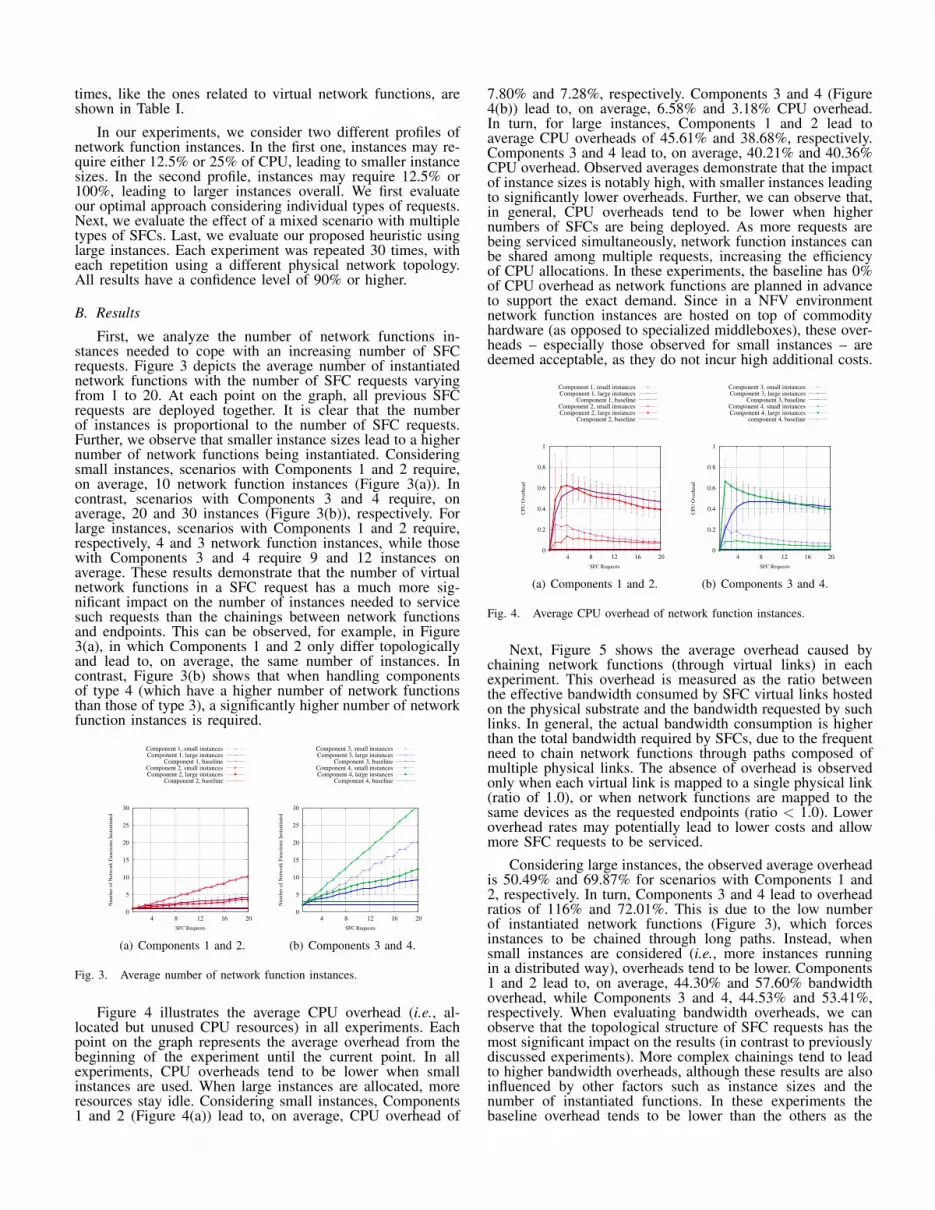
In our experiments, we consider two different profiles ofnetwork function instances. In the first one, instances may re-quire either 12.5% or 25% of CPU, leading to smaller instancesizes. In the second profile, instances may require 12.5% or100%, leading to larger instances overall. We first evaluateour optimal approach considering individual types of requests.Next, we evaluate the effect of a mixed scenario with multipletypes of SFCs. Last, we evaluate our proposed heuristic usinglarge instances. Each experiment was repeated 30 times, witheach repetition using a different physical network topology.All results have a confidence level of 90% or higher.
B. ResultsFirst, we analyze the number of network functions in-
stances needed to cope with an increasing number of SFCrequests. Figure 3 depicts the average number of instantiatednetwork functions with the number of SFC requests varyingfrom 1 to 20. At each point on the graph, all previous SFCrequests are deployed together. It is clear that the numberof instances is proportional to the number of SFC requests.Further, we observe that smaller instance sizes lead to a highernumber of network functions being instantiated. Consideringsmall instances, scenarios with Components 1 and 2 require,on average, 10 network function instances (Figure 3(a)). Incontrast, scenarios with Components 3 and 4 require, onaverage, 20 and 30 instances (Figure 3(b)), respectively. Forlarge instances, scenarios with Components 1 and 2 require,respectively, 4 and 3 network function instances, while thosewith Components 3 and 4 require 9 and 12 instances onaverage. These results demonstrate that the number of virtualnetwork functions in a SFC request has a much more sig-nificant impact on the number of instances needed to servicesuch requests than the chainings between network functionsand endpoints. This can be observed, for example, in Figure3(a), in which Components 1 and 2 only differ topologicallyand lead to, on average, the same number of instances. Incontrast, Figure 3(b) shows that when handling componentsof type 4 (which have a higher number of network functionsthan those of type 3), a significantly higher number of networkfunction instances is required.
0
5
10
15
20
25
30
4 8 12 16 20
Num
ber
of
Net
work
Funct
ions
Inst
anti
ated
SFC Requests
Component 1, small instancesComponent 1, large instances
Component 1, baselineComponent 2, small instancesComponent 2, large instances
Component 2, baseline
(a) Components 1 and 2.
0
5
10
15
20
25
30
4 8 12 16 20
Num
ber
of
Net
work
Funct
ions
Inst
anti
ated
SFC Requests
Component 3, small instancesComponent 3, large instances
Component 3, baselineComponent 4, small instancesComponent 4, large instances
Component 4, baseline
(b) Components 3 and 4.
Fig. 3. Average number of network function instances.
Figure 4 illustrates the average CPU overhead (i.e., al-located but unused CPU resources) in all experiments. Eachpoint on the graph represents the average overhead from thebeginning of the experiment until the current point. In allexperiments, CPU overheads tend to be lower when smallinstances are used. When large instances are allocated, moreresources stay idle. Considering small instances, Components1 and 2 (Figure 4(a)) lead to, on average, CPU overhead of
7.80% and 7.28%, respectively. Components 3 and 4 (Figure4(b)) lead to, on average, 6.58% and 3.18% CPU overhead.In turn, for large instances, Components 1 and 2 lead toaverage CPU overheads of 45.61% and 38.68%, respectively.Components 3 and 4 lead to, on average, 40.21% and 40.36%CPU overhead. Observed averages demonstrate that the impactof instance sizes is notably high, with smaller instances leadingto significantly lower overheads. Further, we can observe that,in general, CPU overheads tend to be lower when highernumbers of SFCs are being deployed. As more requests arebeing serviced simultaneously, network function instances canbe shared among multiple requests, increasing the efficiencyof CPU allocations. In these experiments, the baseline has 0%of CPU overhead as network functions are planned in advanceto support the exact demand. Since in a NFV environmentnetwork function instances are hosted on top of commodityhardware (as opposed to specialized middleboxes), these over-heads – especially those observed for small instances – aredeemed acceptable, as they do not incur high additional costs.
0
0.2
0.4
0.6
0.8
1
4 8 12 16 20
CP
U O
ver
hea
d
SFC Requests
Component 1, small instancesComponent 1, large instances
Component 1, baselineComponent 2, small instancesComponent 2, large instances
Component 2, baseline
(a) Components 1 and 2.
0
0.2
0.4
0.6
0.8
1
4 8 12 16 20
CP
U O
ver
hea
d
SFC Requests
Component 3, small instancesComponent 3, large instances
Component 3, baselineComponent 4, small instancesComponent 4, large instances
component 4, baseline
(b) Components 3 and 4.
Fig. 4. Average CPU overhead of network function instances.
Next, Figure 5 shows the average overhead caused bychaining network functions (through virtual links) in eachexperiment. This overhead is measured as the ratio betweenthe effective bandwidth consumed by SFC virtual links hostedon the physical substrate and the bandwidth requested by suchlinks. In general, the actual bandwidth consumption is higherthan the total bandwidth required by SFCs, due to the frequentneed to chain network functions through paths composed ofmultiple physical links. The absence of overhead is observedonly when each virtual link is mapped to a single physical link(ratio of 1.0), or when network functions are mapped to thesame devices as the requested endpoints (ratio < 1.0). Loweroverhead rates may potentially lead to lower costs and allowmore SFC requests to be serviced.
Considering large instances, the observed average overheadis 50.49% and 69.87% for scenarios with Components 1 and2, respectively. In turn, Components 3 and 4 lead to overheadratios of 116% and 72.01%. This is due to the low numberof instantiated network functions (Figure 3), which forcesinstances to be chained through long paths. Instead, whensmall instances are considered (i.e., more instances runningin a distributed way), overheads tend to be lower. Components1 and 2 lead to, on average, 44.30% and 57.60% bandwidthoverhead, while Components 3 and 4, 44.53% and 53.41%,respectively. When evaluating bandwidth overheads, we canobserve that the topological structure of SFC requests has themost significant impact on the results (in contrast to previouslydiscussed experiments). More complex chainings tend to leadto higher bandwidth overheads, although these results are alsoinfluenced by other factors such as instance sizes and thenumber of instantiated functions. In these experiments thebaseline overhead tends to be lower than the others as the

objective function prioritizes shortest paths (in terms of numberof hops) between endpoints and network functions.
0.8
1
1.2
1.4
1.6
1.8
2
2.2
4 8 12 16 20
Ban
dw
idth
Over
hea
d
SFC Requests
Component 1, small instancesComponent 1, large instances
Component 1, baselineComponent 2, small instancesComponent 2, large instances
Component 2, baseline
(a) Components 1 and 2.
0.8
1
1.2
1.4
1.6
1.8
2
2.2
4 8 12 16 20
Ban
dw
idth
Over
hea
d
SFC Requests
Component 3, small instancesComponent 3, large instances
Component 3, baselineComponent 4, small instancesComponent 4, large instances
Component 4, baseline
(b) Components 3 and 4.
Fig. 5. Average bandwidth overhead of SFCs deployed in the infrastructure.
Figure 6 depicts the average end-to-end delay, in millisec-onds, observed between endpoints in all experiments. The end-to-end delay is computed as a sum of the path delays andnetwork function processing times. In this figure, results forscenarios with small and large instances are grouped together,as average delays are the same. The observed end-to-end delayfor all components tends to be lower than the delay observedfor the baseline scenario. This is mainly due to the betterpositioning of network functions and chainings between them.Furthermore, the model promotes a better utilization of thevariety of existing paths in the infrastructure. Although thebaseline scenario aims at building minimum chainings (interms of hops), we observe that: (i) minimum chaining doesnot always lead to global minimum delay; (ii) when baselinescenarios overuse the shortest paths, other alternative pathsremain unused due to the depletion of resources in specific lo-cations (mainly in the vicinity of highly interconnected nodes).In comparison with baseline scenarios, Component 1 leads to,on average, 25% lower delay (21.55ms compared to 29.07ms),while Component 2 leads to, on average, 15.40% lower delay(19.28ms compared to 22.79ms). In turn, Component 3 leadsto, on average, 13.86% lower delay than its baseline (25.15mscompared to 29.20ms), while Component 4 leads to 15.75%lower delay (24.89ms compared to 29.55ms). In summary,even though our baseline scenarios are planned in advance tosupport exact demands and we consider processing times ofvirtual network functions to be three times those of physicalones, end-to-end delays are still lower in virtualized scenarios.This advantage may become even more significant as theestimated processing times of virtual network functions getcloser in the future to those observed in physical middleboxes.
14
16
18
20
22
24
26
28
30
32
34
4 8 12 16 20
Aver
age
End−
to−
end D
elay
(in
mil
lise
conds)
SFC Requests
Component 1Component 1, baseline
Component 2Component 2, baseline
(a) Components 1 and 2.
22
24
26
28
30
32
34
4 8 12 16 20
Aver
age
End−
to−
end D
elay
(in
mil
lise
conds)
SFC Requests
Component 3Component 3, baseline
Component 4Component 4, baseline
(b) Components 3 and 4.
Fig. 6. Average end-to-end delay of SFCs deployed in the infrastructure.
After analyzing the behavior of SFCs considering homo-geneous components, we now analyze the impact of a mixedscenario. In it, Components 1, 2, and 4 are repeatedly deployedin the infrastructure sequentially. Figure 7 presents the resultsfor the mixed scenario. Although there are different topolog-ical SFC components being deployed together in the sameinfrastructure, the results exhibit similar tendencies as thoseof homogeneous scenarios. In Figure 7(a), we observe that theaverage number of network functions (on average, 17 networkfunctions when considering small instances and 9 functionsconsidering large instances) is proportional to the obtainedaverage values depicted in Figures 3(a) and 3(b). The averageCPU overhead also remains similar (9.12% considering smallinstances and 45.37% considering large ones). In turn, theaverage overhead caused by chaining network functions inthe mixed scenario is of 59.06% and 47.51%, for small andlarge instances, respectively. Despite these similarities, end-to-end delays tend to be comparatively lower than the onesobserved in homogeneous scenarios. The delay observed inthe proposed chaining approach is 8.57% lower than that ofthe baseline (22.93ms in comparison to 25.08ms). This isdue to the combination of requests with different topologicalstructures, which promotes the use of a wider variety ofphysical paths (which, in turn, leads to lower overutilizationof paths). Similarly to homogeneous scenarios, average end-to-end delays are the same considering small and large instances.
0
5
10
15
20
25
30
4 8 12 16 20
Num
ber
of
Net
work
Funct
ions
Inst
anti
ated
SFC Requests
Small instancesLarge instances
Baseline
(a) Average number of networkfunction instances.
0
0.2
0.4
0.6
0.8
1
4 8 12 16 20
CP
U O
ver
hea
d
SFC Requests
Small instancesLarge instances
Baseline
(b) Average CPU overhead ofnetwork function instances.
0.8
1
1.2
1.4
1.6
1.8
2
4 8 12 16 20
Ban
dw
idth
Over
hea
d
SFC Requests
Small instancesLarge instances
Baseline
(c) Average bandwidth overhead.
16
18
20
22
24
26
28
30
32
34
4 8 12 16 20
Aver
age
End−
to−
end D
elay
(in
mil
lise
conds)
SFC Requests
Small, large instancesBaseline
(d) Average end-to-end delay.
Fig. 7. Mixed scenario including Components 1, 2, and 4.
We now proceed to the evaluation of our proposed heuristicapproach. The heuristic was subjected the same scenarios asthe ILP model, in addition to ones with a larger infrastructure.Considering the scenarios presented so far (i.e., with physicalinfrastructures with 50 nodes and 20 SFC requests), ourheuristic was able to find an optimal solution in all cases.We omit such results due to space constraints. We emphasize,however, that the heuristic approach was able to find an optimalsolution in a substantially shorter time frame in comparison tothe ILP model, although the solution times of both approachesremained in the order of minutes. The average solution timesof the ILP model and the heuristic considering all scenarioswere of, respectively, 8 minutes and 41 seconds and 1 minute

and 21 seconds.
Last, we evaluate our heuristic approach on a large NFVinfrastructure. In this experiment, we consider a physical net-work with 200 N-PoPs and a maximum of 60 SFC componentsof type 4. The delay limit was scaled up to 90ms in orderto account for the larger network size. Figure 8(a) depictsthe average time needed to find a solution using both theILP model and the heuristic. The ILP model was not ableto find a solution in a reasonable time in scenarios with morethan 18 SFCs (the solution time was longer than 48 hours).The heuristic approach, in turn, is able to properly scale tocope with this large infrastructure, delivering feasible, high-quality solutions in a time frame of less than 30 minutes. Asin previous experiments, small network function instances leadto higher solution times than large ones. This is mainly becausesmaller instances lead to a larger space of potential solutionsto be explored.
Although the heuristic does not find the optimal solution(due to time constraints), Figures 8(b), 8(c), 8(d) and 8(e) showthat the solutions obtained through this approach present asimilar level of quality to the ones obtained optimally. Figure8(b) depicts the average number of instantiated network func-tions with the number of SFC requests varying from 1 to 60.As in previous experiments, the number of instances remainsproportional to the number of SFC requests. Smaller instancesizes lead to a higher number of network functions beinginstantiated. Considering small sizes, 75 network functionsinstances are required on average. In contrast, for large sizes,40 instances are required on average. Figure 8(c), in turn,illustrates the average CPU overhead. For small instances,CPU overhead is limited to 18.77%, while for large instancesit reaches 48.65%. Similarly to the results concerning thenumber of network function instances, CPU overheads inthese experiments also follow the trends observed in previousones. Next, Figure 8(d) presents bandwidth overheads. Smallinstances lead to a bandwidth overhead of 300%, while forlarge instances this overhead is, on average, 410%. These par-ticularly high overheads are mainly due to the increase on theaverage length of end-to-end paths, as the physical network issignificantly larger. Note that the bandwidth overhead observedin the baseline scenario (198%) is also significantly higherthan those observed in experiments employed on the smallinfrastructure. Last, Figure 8(e) depicts the average end-to-enddelay observed in large infrastructures. In line with previousresults, the end-to-end delay tends to be lower than the delayobserved in the baseline scenario. The scenario consideringComponent 4 presents, on average, 17.72% lower delay thanthe baseline scenario (70.30ms compared to 82.76ms). In short,these results demonstrate that: (i) the heuristic is able to findsolutions with a very similar level of quality as the optimizationmodel for small infrastructures; and (ii) as both infrastructuresizes and the number of requests increase, the heuristic is ableto maintain the expected level of quality while still findingsolutions in a short time frame.
V. CONCLUSION
NFV is a prominent network architecture concept that hasthe potential to revamp the management of network functions.Its wide adoption depends primarily on ensuring that resourceallocation is efficiently performed so as to prevent over-or under-provisioning of resources. Thus, placing networkfunctions and programming network flows in a cost-effectivemanner while guaranteeing acceptable end-to-end delays rep-resents an essential step towards a broader adoption of thisconcept.
In this paper, we formalized the network function place-ment and chaining problem and proposed an optimization
0.1
1
10
100
1000
10 20 30 40 50 60
Tim
e (s
econds)
SFC Requests
Heuristic, small instancesHeuristic, large instances
ILP, small instancesILP, large instances
(a) Average time needed to finda solution.
0
10
20
30
40
50
60
70
80
10 20 30 40 50 60
Num
ber
of
Net
work
Funct
ions
Inst
anti
ated
SFC Requests
Heuristic, small instancesHeuristic, large instances
ILP, small instancesILP, large instances
Baseline
(b) Average number of networkfunction instances.
0
0.2
0.4
0.6
0.8
1
10 20 30 40 50 60
CP
U O
ver
hea
d
SFC Requests
Heuristic, small instancesHeuristic, large instances
ILP, small instancesILP, large instances
Baseline
(c) Average CPU Overhead ofnetwork function instances.
0
0.5
1
1.5
2
2.5
3
3.5
4
4.5
10 20 30 40 50 60
Ban
dw
idth
Over
hea
d
SFC Requests
Heuristic, small instancesHeuristic, large instances
ILP, small instancesILP, large instances
Baseline
(d) Average bandwidth overheadof SFCs deployed in the infras-tructure.
60
65
70
75
80
85
10 20 30 40 50 60
Av
erag
e E
nd
−to
−en
d D
elay
(in
mil
lise
con
ds)
SFC Requests
HeuristicILP
Baseline
(e) Average end-to-end delay ofSFCs deployed in the infrastruc-ture.
Fig. 8. Scenario considering a large infrastructure and components of type 4.
model to solve it. Additionally, in order to cope with largeinfrastructures, we proposed a heuristic procedure that dy-namically and efficiently guides the search for solutions per-formed by commercial solvers. We evaluated both optimaland heuristic approaches considering realistic workloads anddifferent use cases. The obtained results show that the ILPmodel leads to a reduction of up to 25% in end-to-end delaysand an acceptable resource over-provisioning limited to 4%.Further, we demonstrate that our heuristic scales to largerinfrastructures while still finding solutions that are very closeto optimality in a timely manner.
As perspectives for future work, we envision extendingthe evaluation of the proposed solutions by applying them toother types of SFCs and ISP topologies, as well as conductingan in-depth analysis of the inter-relationships between theirparameters. Moreover, we intend to explore mechanisms toreoptimize network function placements, assignments, andchainings. Further, we intend to explore exact solutions forthe problem, such as matheuristics.
REFERENCES
[1] J. Martins, M. Ahmed, C. Raiciu, V. Olteanu, M. Honda, R. Bifulco,and F. Huici, “Clickos and the art of network function virtualization,”in Proceedings of the 11th USENIX Conference on Networked SystemsDesign and Implementation, 2014.
[2] D. A. Joseph, A. Tavakoli, and I. Stoica, “A policy-aware switchinglayer for data centers,” in Proceedings of the ACM SIGCOMM Confer-ence on Data Communication, 2008.
[3] T. Benson, A. Akella, and A. Shaikh, “Demystifying configurationchallenges and trade-offs in network-based isp services,” in Proceedingsof the ACM SIGCOMM Conference on Data Communication, 2011.
[4] V. Sekar, N. Egi, S. Ratnasamy, M. K. Reiter, and G. Shi, “Design andimplementation of a consolidated middlebox architecture,” in Proceed-ings of the 9th USENIX Conference on Networked Systems Design andImplementation, 2012.
[5] Network Functions Industry Specification Group, “Network functionvirtualisation (nfv): An introduction, benefits, enablers, challenges andcall for action,” in SDN and OpenFlow World Congress, 2012, pp. 1–16.
[6] J. Hwang, K. K. Ramakrishnan, and T. Wood, “Netvm: High perfor-mance and flexible networking using virtualization on commodity plat-forms,” in Proceedings of the 11th USENIX Conference on NetworkedSystems Design and Implementation, 2014.
[7] S. Barkai, R. Katz, D. Farinacci, and D. Meyer, “Software definedflow-mapping for scaling virtualized network functions,” in Proceedingsof the Second ACM SIGCOMM Workshop on Hot Topics in SoftwareDefined Networking, 2013.
[8] A. Basta, W. Kellerer, M. Hoffmann, H. J. Morper, and K. Hoffmann,“Applying nfv and sdn to lte mobile core gateways, the functions
placement problem,” in Proceedings of the 4th Workshop on All ThingsCellular: Operations, Applications and Challenges, 2014.
[9] M. Yu, Y. Yi, J. Rexford, and M. Chiang, “Rethinking virtual networkembedding: Substrate support for path splitting and migration,” SIG-COMM Computer Communication Review, vol. 38, no. 2, pp. 17–29,Mar. 2008.
[10] M. Chowdhury, M. R. Rahman, and R. Boutaba, “Vineyard: Virtual net-work embedding algorithms with coordinated node and link mapping,”IEEE/ACM Transactions on Networking, vol. 20, no. 99, pp. 206–219,2012.
[11] M. Rabbani, R. Pereira Esteves, M. Podlesny, G. Simon, L. Zam-benedetti Granville, and R. Boutaba, “On tackling virtual data centerembedding problem,” in Integrated Network Management (IM 2013),2013 IFIP/IEEE International Symposium on, May 2013, pp. 177–184.
[12] L. R. Bays, R. R. Oliveira, L. S. Buriol, M. P. Barcellos, and L. P.Gaspary, “A heuristic-based algorithm for privacy-oriented virtual net-work embedding,” in IEEE/IFIP Network Operations and ManagementSymposium (NOMS), Krakow, Poland, May 2014.
[13] M. Dobrescu, K. Argyraki, and S. Ratnasamy, “Toward predictableperformance in software packet-processing platforms,” in Proceedingsof the 9th USENIX Conference on Networked Systems Design andImplementation, 2012.
[14] R. Albert and A.-L. Barabasi, “Topology of evolving networks: Localevents and universality,” Physical Review Letters, vol. 85, pp. 5234 –5237, Dec 2000.
[15] B.-Y. Choi, S. Moon, Z.-L. Zhang, K. Papagiannaki, and C. Diot,“Analysis of point-to-point packet delay in an operational network,”Computer Networks, vol. 51, pp. 3812–3827, 2007.


