Embed Size (px)
Citation preview

PHYSICAL REVIEW B VOLUME 29, NUMBER 4 15 FEBRUARY 1984
Physics of resonant tunneling. The one-dimensional double-barrier case
B. Ricco* and M. Ya. AzbeltIBM Thomas J. 8'atson Research Center, Forktown Heights, 1Vew Fork 10598
(Received 21 September 1983)
In this work we discuss how the occurrence of resonant tunneling through a one-dimensional (1D)double barrier involves some interesting phenomena which have so far been overlooked. The effectof an externally applied electric field is considered, and it is shown that with fully symmetrical bar-riers it leads to weaker resonances than otherwise possible. Furthermore, the time required for reso-nance to be fully established is discussed, and it is shown that, depending on the barrier transmis-sion coefficients and experimental conditions, it can be exceedingly long, thus contributing to areduction of resonance effects on the usual experimental time scale. We alsa show that resonanttunneling under the usual experimental conditions implies carrier trapping, hence a buildup of spacecharge available for modifying the potential-energy barrier. Different current behaviors then resultfrom the inherent feedback mechanism. The effects of temperature an the measured current are fi-nally discussed.
I. INTRODUCTION
In this paper, we discuss in some detail the problem ofresonant tunneling through a one-dimensional (1D) double(potential energy) barrier. Pioneering work on this subjectis primarily due to Esaki, Chang and Tsu' who usedGaAs-Ga~ zAlzAs heterostructures, and to Hirose et al.who, instead, worked on the Si-Si02 system. From atheoretical point of view significant contributions camefrom J. C. Penley and Sandomirskii in the 60's while re-cently new experiments were performed by Sollner et al.and by Ricco et al. on double barrier grown by means ofmolecular-beam epitaxy.
The purpose is primarily that of showing how, althoughthe occurrence of resonances is a simple and well-knownresult of the usual treatment of tunneling, it involves somecomplicated physical effects which have so far been al-most completely overlooked. The failure to fully under-stand the importance of such effects and the consequentlack of attention to their regard might, in our opinion, ex-plain the only partial success of the pioneering experimen-tal work' aimed at showing resonant tunneling. Al-though truly remarkable these works share the rather un-
pleasant characteristic of finding effects much weaker andless pronounced than expected from the theory. This im-plicitly suggested the idea that resonant tunneling is toocritically dependent on experimental parameters to bereally controllable and (re)producible, let alone exploited,in real life where samples' or devices conditions' (defectconcentration, surface cleanliness, actual dimensions, etc. )
are of course different from the clear-cut exact pictures oftheoretical models.
Although differences between theory and experimentsare certainly to be expected, we feel that the criticality ofresonant tunneling has been, and still is, overestimatedand that the somewhat disappointing experimental resultsmight well be due to nonoptimal samples and rneasure-ment conditions.
Recently, new experiments carried out on GaAs-Gai Al„As double barriers similar to those of Ref. 1
have produced I-V characteristics with well pronouncedpeaks. The key factor for the improvement seems here tobe the better material quality available today. From aquantitative point of view, the improvement over previousexperiments is relevant (a 6:1 ratio between peaks and val-
leys is observed) but a large discrepancy still exists withtheoretical predictions. As will be shown in this paperthis cannot, at least in part, be considered surprising sincein almost all respects, these experiments are similar tothose of Ref. 1.
Two points, in particular, are important and will bedealt with in this paper. First, while the measurementshave been carried out with a nonnegligible electric fieldapplied across the double barrier, the assumed underlyingtheory did not include it. ' The most important remarkwith respect to this is that the electric field destroyed thesymmetry of the two realized barriers and, consequently,contributed significantly to reduce the effects of reso-nances. As will be shown later, better structures thanthose used so far can be designed to maximize resonancepeaks but it is essential to take into account the effects ofthe field. This involves some nontrivial engineering.Futhermore, because the field cancels the intrinsic simplesymmetry, the optimization can only be performed for oneof the possible several peaks.
A second important point to grasp about the experi-rnent is that because of the way they were realized the oc-currence of substantial effects is not an immediatephenomenon. Resonant tunneling is time dependent and,to be fully established, requires a non-negligible time (ex-ponentially long as will be explained later). Therefore, ifthe experiments feature ramping voltages and no care istaken to allow for enough time at the peaks, resonance ef-fects might well be almost completely lost.
A further remark concerns the space-change buildupnecessarily taking place because of the accumulation of
29 1970 1984 The American Physical Society

29 PHYSICS OF RESONANT TUNNELING. THE ONE-. . . 1971
tunneling carriers within the resonant well which, to allpractical purposes, behaves as a dynamic trap (in the sensethat particles continuously get in and out of it). Since theaccumulating charge modifies the potential-energy bar-riers a feedback mechanism becomes operational and com-plicates the resonance time evolution as well as the en-gineering for optimized experiments. In particular it willbe shown that, if the amount of charge that can betrapped into the well is substantial, oscillating currents aswell as self-accelerating approaches to "stationary states"are possible.
In this paper we will also briefly consider the effects oftemperature which, when increasing, can lead to decreas-ing as well as increasing currents depending on the relativeposition of Fermi level and resonance states.
Before tackling these points, in Sec. III, the methodbased on the transfer-matrix technique will be presentedwhich allows an explict, easy treatment of the 1D doublebarrier case with no restriction on the shape of thepotential-energy diagram. Futhermore, in Sec. II a briefaccount is given in the known simplest case of square bar-riers, usually treated in textbooks, which provides a goodstarting point for our subsequent generalizations.
II. CASE OF RECTANGULAR BARRIERS
E
C9 EUJ
UJ E HG FE DC BA~ P ~ ~ W ~ ~
l 2 3 4 5bJI-DCL
E5
X
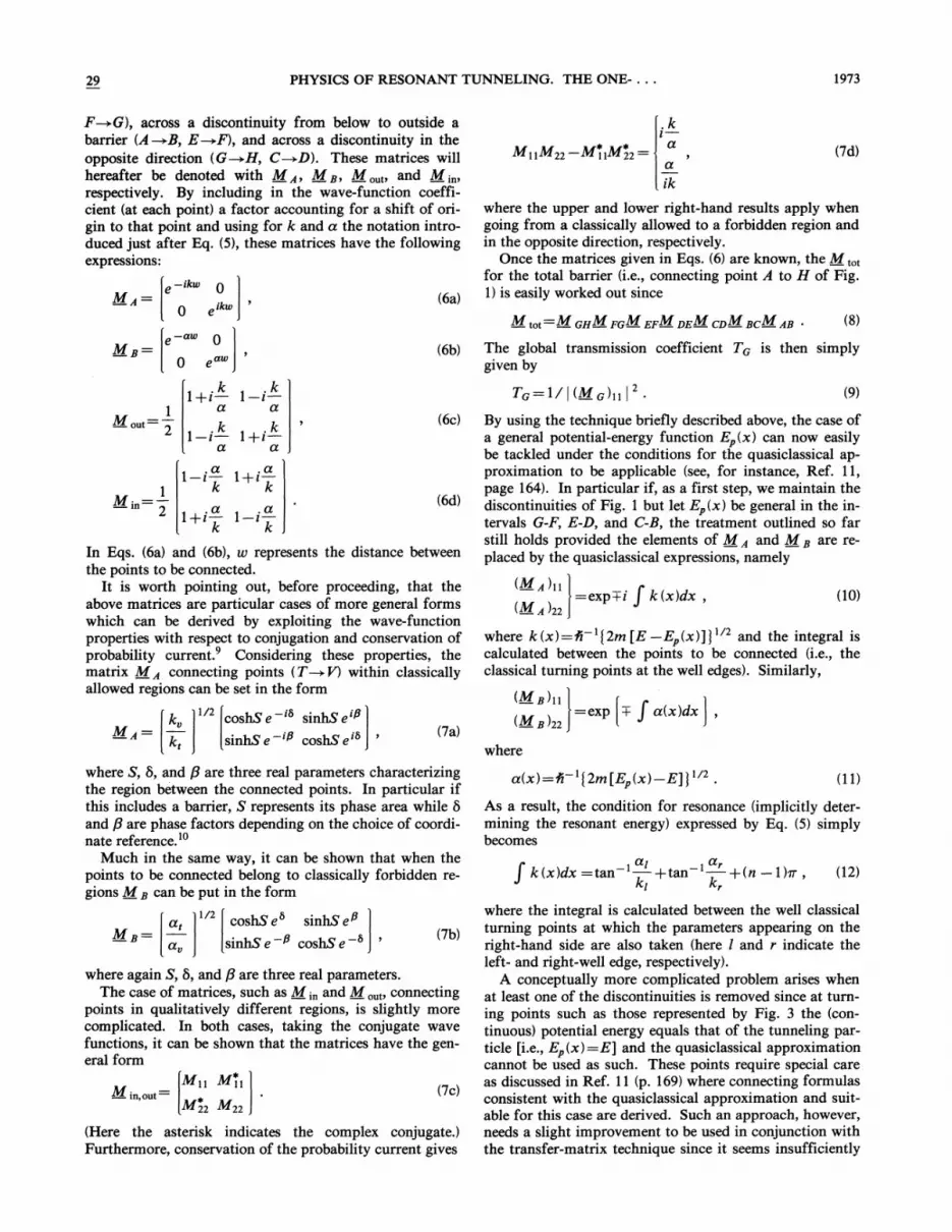
FIG. 1. Potential-energy diagram of the double rectangularbarrier case.
The case of two rectangular potential-energy barriers(such as depicted in Fig. 1) is the most elementary exam-ple where resonant tunneling occurs. Futhermore, itpresents the advantage of exact analytical solutions. Forthese reasons, it can be found in textbooks and will beonly briefiy reviewed here to be used as a guideline for themost direct understanding of the major features ofresonant tunneling. As will be shown later, all the con-cepts encountered in doing so can be generalized to themost general case of double barriers of any shape.
For the potential-energy diagram of Fig. 1, the globaltransmission coefficient TG of the whole barrier (i.e., frompoints H and A) can be exactly derived and put in the fol-lowing general form:
Cp
Tl Tr 1C)TlT, +C2 +C3 +C4
Tl Tl Tr
where T~ and T„represent the transmission coefficients ofthe left and right barrier, respectively (namely those be-tween point G-Ii and C-8) which are exponentially depen-dent on energy. In Eq. (1) the C's are (phase) factors ex-hibiting a much weaker energy dependence and, at firstorder, can essentially be treated as constants (of the sameorder of magnitude). We will only consider here the caseof "strong localization" (the meaning of this term will be-come clear later) which requires all T's to be small ( « 1).Under this condition, the denominator of Eq. (1) is dom-inated by the last term and it is
CpTG TlTr TlTr .
C4(2)
TminTG res
max
min
Tmax(3)
where T;n and T,„represent the smaller and largeramong Ti and T„,respectively, while C is either Cp/C2 ol'
Cp/C3 depending on whether or not T,„=Ti.By directly comparing Eqs. (2) and (3) it is obvious that
a resonance always implies an increasd transmission coef-ficient since it is
(4)
where TG& represents the "normal" value TG would havewithout resonance, i.e., if no well was present between thetwo barriers of Fig. 1. Such as increase is, therefore,larger for smaller Tm,„and vanishes in the limiting caseof T,„~l(which, on the other hand, is incompatiblewith the assumption of strong localization).
The result expressed in Eq. (3) [and, consequently, inEq. (4)] holds even when the internal energy well is verynarrow (provided certain conditions to be specified beloware met). This offers the best opportunity to illustrate afirst important, general concept, namely that, while thepresence of the well has scarcely any effect off resonance,it can dramatically alter the tunneling probabilitythroughout the global barrier at special energies. In par-ticular, Eq. (3) shows that regardless of how small Ti andT„are,TG„,can be of order of unity under the only con-dition Ti ——T„while Eq. (4) clearly indicates that thetransmission coefficient can easily increase at several or-ders of magnitude for arbitrarily small changes in energyproducing resonance.
For C4 to vanish, hence resonance to take place, theonly condition to be satisfied from a physical point ofview is that the energy (E) of the tunneling carrier(s)
In this case then, the presence of the potential-energy wellbetween the two barriers has, in practice, little or no effectdepending upon the way one looks at the global barrier.In particular, everything goes as points E and D in Fig. 1
were coincident and no well was present; or, alternatively,if seen without joining such points, the only effect pro-duced by the well is a reduction of the (phase) area of thetotal barrier.
For some special energies, however, C4 goes to zero; theleading term is, consequently, canceled out and a reso-nance occurs. In this case, as easily seen from Eq. (1), theglobal transmission coefficient TG„,becomes
1972 B. RICCO AND M. YA. AZBEL
matches that (E, ) of the well (quasi) eigenstates. Inmathematical terms, this can be expressed as
, a2 , a4k3d3 —tan +tan +(n —1 )lr
k3 k3
In Eq. (5) k;=A' '[2m(E E~—)j'~ and a;=A' '[2m(E&E)—]'~ (here Ez denotes the potential energy) are used to
indicate the action absolute value in classically allowedand forbidden regions, respectively (this notation will bemaintained throughout the present work).
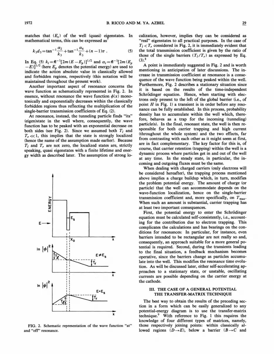
Another important aspect of resonance concerns thewave function as schematically represented in Fig. 2. Inessence, without resonance the wave function P(x) mono-tonically and exponentially decreases within the classicallyforbidden regions thus reflecting the multiplication of thesingle-barrier transmission coefficients of Eq. (2).
At resonance, instead, the tunneling particle finds "its"(eigen)state in the well where, consequently, the wavefunction has to be peaked with an exponential decrease onboth sides (see Fig. 2). Since we assumed both T& andT, «1, this implies that the state is strongly localized(hence the name of the assumption made earlier). BecauseTI and T„arenot zero, the localized states are, strictlyspeaking, quasi eigenstates with a finite lifetime and ener-
gy width as described later. The assumption of strong lo-
-ES
I
a I
j I', Xo
I
I I
I
2in y
FIG. 2. Schematic representation of the wave function "at"and "off" resonance.
calization, however, implies they can be considered as"real" eigenstates to all practical purposes. In the case ofTI & T, considered in Fig. 2, it is immediately evident thatthe total transmission coefficient is given by the ratio ofthose of the single barriers (Ti/T„) as expressed by Eq.(3) '
A point is immediately suggested in Fig. 2 and is worthmentioning in anticipation of later discussions. The in-crease in transmission coefficient at resonance is a conse-quence of the wave function being peaked within the well.Furthermore, Fig. 2 describes a stationary situation sinceit is based on the results of the time-independentSchrodinger equation. Hence, when starting with elec-trons only present to the left of the global barrier (i.e., ofpoint H in Fig. 1) a transient is in order before any reso-nance can be fully established. In this process, probabilitydensity has to accumulate within the well which, there-fore, behaves as a trap for the incoming (tunneling)particle(s). In the final, resonant state, the well is then re-sponsible for both carrier trapping and high current(throughout the whole system) and the two effects, farfrom contrasting with each other as it might seem at first,are in fact complementary. The key factor for this is, ofcourse, that carrier retention (trapping) within the well is adynamic process where particles get in and out of the well
at any time. In the steady state, in particular, the in-
coming and outgoing fluxes must be the same.When dealing with charged carriers (only electrons will
be considered hereafter), the trapping process mentionedabove implies a charge buildup which, in turn, modifiesthe problem potential energy. The amount of charge (orparticle) that the well can accommodate depends on thewave-function localization, hence on the single-barriertransmission coefficient and, more specifically, on Tm,„.%hen such an amount is substantial, carrier trapping hasat least two important consequences.
First, the potential energy to enter the Schrodingerequation must be calculated self-consistently, i.e., account-ing for the contribution due to electron trapping. Thiscomplicates the calculations and has bearings on the con-ditions for resonances: In particular, for instance, even
barriers intended to be rectangular are not really so and,consequently, an approach suitable for a more general po-tential is required. Second, during the transients leadingto the final situation, a feedback mechanism becomesoperative, since the barriers change as particles accumu-late into the well. This modifies the resonance time evolu-
tion. As will be discussed later, either self-accelerating ap-proaches to a stationary state, or unstable, oscillatingcurrents are possible depending on the carrier energy atthe cathode.
III. THE CASE OF A GENERAL POTENTIALTHE TRANSFER-MATRIX TECHNIQUE
The best way to obtain the results of the preceding sec-tion in a form which can be easily generalized to anypotential-energy diagram is to use the transfer-matrixtechnique. With reference to Fig. 1 this requires theknowledge of four different types of matrices, namely,those respectively joining points: within classically al-lowed regions (D ~E), below a barrier (8~C and
PHYSICS OF RESONANT TUNNEI. ING. THE ONE-. . . 1973
E~G), across a discontinuity from below to outside abarrier (A~8, E~I'), and across a discontinuity in theopposite direction (G~H, C~D). These matrices willhereafter be denoted with Mq, Mll, M,„„andM;„,respectively. By including in the wave-function coeffi-cient (at each point) a factor accounting for a shift of ori-gin to that point and using for k and a the notation intro-duced just after Eq. (5), these matrices have the followingexpress1ons:
e—ikN O
O ~lkN
AM11M22 —M11M22 ——.
where the upper and lower right-hand results apply whengoing from a classically allowed to a forbidden region andin the opposite direction, respectively.
Once the matrices given in Eqs. (6) are known, the M„,for the total barrier (i.e., connecting point A to H of Fig.1) is easily worked out since
(6b) The global transmission coefficient TG is then simplygiven by
TG ——1/i(MG)il i
(6c)
.a .o.'1—i—1+i—
k kM—10
l+/ l —lk
(6d)
k„coshSe ' sinhS e'~
sinkS 8 ~ cos45e (7R)
In Eqs. (6a) and (6b), w represents the distance betweenthe points to be connected.
It ls worth pointing out, before plocccdlllg, that, thcabove matrices are particular cases of more general formswhich can be derived by exploiting the wave-functionproperties with respect to conjugation and conservation ofprobability current. Considering these properties, thematrix M~ connecting points (T +V) within —classicallyallowed regions can be set in the form
By using the technique briefly described above, the case ofa general potential-energy function Ez(x) can now easilybe tackled under the conditions for the quasiclassical ap-proximation to be applicable (see, for instance, Ref. 11,page 164). In particular if, as a first step, we maintain thediscontinuities of Fig. 1 but let E~(x) be general in the in-tervals G-F, E D, and C-B-, the treatment outlined so farstill holds provided the elements of M z and M a are re-placed by the quasiclassical expressions, namely
(Mq)ll=exp+i I k(x)dx,
(M ~)22
w11cl'c k(x)=A I2Pl [E Ep(x)] j —Rnd tIM llltcglal lscalculated between the points to be connected (i.e., theclassical turning points at the well edges). Similarly,
(Ma)tl=exp + f a(x)dx—8 22
where S, 5, and p are three real parameters characterizingthe region between the connected points. In particular ifthis includes a barrier, S represents its phase area while 5and p are phase factors depending on the choice of coordi-nate reference. '
Much in the same way, it can be shown that when thepoints to be connected belong to classically forbidden re-gions M ll can be put in the form
1/2 coshS e sinhS e~M g —— . s, (7b)sinhSe ~ coshSe
~ in, out=I)) M11
(7c)
(Herc thc astcflsk llldlcatcs t11c co111plcx conjllgRtc. )
Furthermore, conservation of the probability current gives
where again S, 5, and P are three real parameters.The case of matrices, such as M;„andM,„„connecting
points in qualitatively different regions, is slightly morecomplicated. In both cases, taking the conjugate wavefunctions, it can be shown that the matrices have the gen-cl'Rl form
k xi=tan +tan + n —1m, (12)
where the integral is calculated between the well classicalturning points at which the parameters appearing on theright-hand side are also taken (here I and r indicate theleft- and right-well edge, respectively).
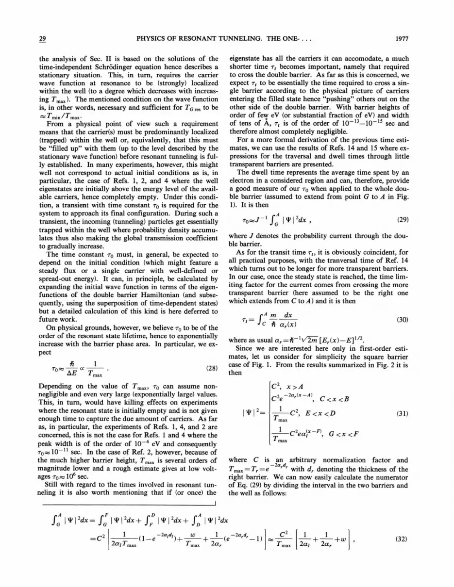
A conceptually more complicated problem arises whenat least one of the discontinuities is removed since at turn-ing points such as those represented by Fig. 3 the (con-tinuous) potential energy equals that of the tunneling par-ticle [i.e., Ez(x) =E] and the quasiclassical approximationcannot be used as such. These points require special careas discussed in Ref. 11 (p. 169) where connecting formulasconsistent with the quasiclassical approximation and suit-able for this case are derived. Such an approach, however,needs a slight improvement to be used in conjunction withthe transfer-matrix technique since it seems insufficiently
a(x)=Pi 'I2m[E~(x) —Ej
j'~2 .
As a result, the condition for resonance (implicitly deter-mining the resonant energy) expressed by Eq. (5) simplybecomes

1974 B. RICCO AND M. YA. AZBEL
CP
ZLLI
1
Tmin Tmaxsinw&
2~max
slnw2min
'2
(16)
From a inathematical point of view, Eq. (15) can be de-rived by looking at Eq. (1) and finding the energy atwhich the two leading terms in the denominator havecomparable (actually equal) absolute value. From Eq. (54)of Ref. 6, this gives
FIG. 3. Continuous turning points.
accurate to deal with both independent solutions ofSchrodinger equation on both sides of the consideredpoint. In particular the derived connecting formulas onlyprovide the (1,2)th and (2,2)th elements of the M;„(orM,„,) matrix. We can, however, exploit the general prop-erty expressed by Eq. (7c) to easily construct the wholematrix with no loss of accuracy.
When crossing takes place without discontinuities, wethen obtain'
1+i 1 —iM ou' —~2 1 i 1~i— (13a)
1 —i 1+iM' =
1 1—1+l 1 —l(13b)
Equations (12) and (14) implicitly provide an estimate ofthe resonance energies with the accuracy of the semiclassi-cal approximation which, therefore, increases with n
(namely when the resulting energy increases with respectto h).
Another important feature of resonances is that thepeaks they produce in the transmission coefficient (hencein measured currents) have a finite energy width b,Ewhich is physically due to the nonzero probability to tun-nel out of the well. As known, such a width is related tothe (resonant) state lifetime. For the reason given abovehE increases with the electron escape probability, thusessentially with T,„,namely,
(15)
As for the conditions providing resonance energies, Eq.(12) still holds with a; /k; = 1; hence tan '(a; /k; ) =~/4for the turning point(s) where E =E~(x).
The equation can, in fact, be put in a very compactform covering the cases where the turning point(s) are ei-ther "continuous" or feature a discontinuity withEz(x)~no (infinite wall with a~00). From Eq. (12) wehave
f I2in[E E~(x)]I' 'dx—= —,'(n —y)h, (14)
where the integral is calculated throughout the well, n isan integer and
0 for (infinite) walls on both well edges,
&—. 4 for one wall and one continuous edge,
—,' for two continuous edges.
(T,„)xE +4(T,„)FE DE=0 (17)
and the linear relationship of Eq. (15) immediately fol-lows.
The finite width of the resonance peaks plays a relevantrole in experiments. First of all it makes less critical theenergy matching condition required to produce a reso-nance (although, of course, the effects decrease away fromthe peak centers}. Furthermore, in the case where the tun-neling electrons are nonmonochromatic, i.e., they arespread over a whole energy range within the cathode, thelarger a peak width, the larger is the fraction of particlestaking part in resonant tunneling. Under this condition,assuming that the electron distribution can be consideredconstant over the whole AE, the current contribution dueto a resonant peak is essentially given by
TminJres ~ Tmax
Tmax
where the first term accounts for the fraction of electronsinvolved and the second represents the global transmissioncoefficient at resonances. Without resonance the sameamount of carriers would produce a current J,fr given by
2Joff ~ Tmax Tmin
It is then immediately obvious that resonance can give riseto an extremely large current increase. In particular, withthe notation used above, it is
Jres
Tmax(20)
IV. CASE OF DOUBLE BARRIERWITH AN APPLIED FIELD
A case of special interest from the point of view of ex-periments is that of a double barrier subject to an external-ly applied electric field. The structures which have beenused so far' feature barriers with the same technologi-cal parameters (height and width) as shown in Fig. 4(a).
In the case of no field (F=0) using the notation of Fig.4(a), resonances would occur at energies satisfying Eq. (12)which becomes
1 ~)i j2
fi—&2m Zw =2 tan-'
E 1/2 +(n —1}m . (21)
with w2&w& and sinwi ——0 at resonant energy Eo. Rear-ranging Eq. (16), expanding up to first order in energyabout Ep i.e., making E =Eo+AE,
r 2sinw&
Tmaxslnw2

PHYSICS OF RESONANT TUNNELING. THE ONE-. . .
0 d1
gy of the cathode conduction-band bottom (or Fermi levelwitli Iiietals) aiid J vs V (rather then J vs E) is measuredOverall tlM cncIgy d1agraID pcrt1IlcIlt to such 8 problcID 1Sschematically represented in Fig. 4(b) where I'J indicatesthe point at which tunnehng essentially takes place. (Intliis we iieglect, foi" siniplicity, tlie contrlbutlon comingfroIB carriers at 8 slightly higher energy 1n tjlc cathodewhich can, at first order, be accounted for by adjusting thebarrier height 40).
Such a technique, however, implies the use of relevantfields and these drastically change the experimental condi-tions. A first, important effect which is immediately ap-parent in Fig. 4(b) is that the applied voltage destroys thesymmetry of the barriers whose transmission coefficientsare no longer equal. In particular it is
1I
)DEa
I
I t
Il
1/'
+z
ItgE
I
l~
4 IT„=exp ———&2m3 fi
@3/2 @3/22 3
FIG. 4. (a) Symmetrical double barrier (no fie1d applied). (b)DOUble bMXMr %Vlth applied field (Do 10Ilger Symmetllcal).
Here the subtracting term in the exponent becomes zerofor triangular (rather than trapezoidal) barriers. In ourcase, of course, only the barrier on the right can be tri-angular. In Eq. (22)
The special characteristics of this case is that, because ofthe symmetry embedded in the structure, at any of suchenergies the global transmission coefficient TG would beof the order of 1 regardless of the values chosen for thebarrier and well parameters. This makes the engineeringof the sample to be used particularly simple although it
. must be 1cal1zcd that some iroportant expcriITlcntalfeatures do depend on such parameters. This is, for in-stance the case for the increase in transmission coefficientwhich becomes larger if the single barriers are made lesstransparent [Eq. (4)]. Furthermore, carrier trapping (andthe consequent feedback mechanism already mentioned)as well as the time constants required to fully establish aresonance are also affected. These considerations suggestthe need for thoughtful choice of structure parameters,but do Qot alter thc conclus1on that strUctural syromctry ls"the" condition to realize when looking for resonant tun-neling in the case of no, or rather negligible, fields.
The kind of experiments outlined above, however, re-quires the possibility to change the energy of the tunnelingcarriers so that the current ( ~ TG) versus energy curvesshovAng I'csonaQcc peaks can bc worked out.
In practice, the simplest and roost commonly used ex-perimental setup 1s oQc %@herc thc tUQ1M11ng camcrs comefrom a semiconductor (or metal) cathode. Although theirenergy can be increased (for instance by using temperatureor light), it is more convenient to act on the well eigen-states bringing them down to the same level of the carriersby applying a voltage V~ across the structure. Under thiscondition, tunnehng essentially occurs at the (fixed) ener-
(23)
4i ——40—b E i —b E2 b,E3 @o q(—2Fbd——+F~—w),
where Fi, and F represent the electric field in the barrierand well regions, respectively, and it is
Fi, ——V, /(2d+web/e ), F =e&Fb/e
Here ei, and e denote the dielectric constants of the bar-rier and me11 material while d and m denote the barrierand well width, respectively.
S1QCC 1t 1S T( Q T», WC have
4 d=exp ———&2m
3 A'
This equation, which holds for any value of V„indicatesthat the transmission coefficient TG obtainable at reso-nance cannot be too close to unity. In particular, for in-stance, for the case considered in Fig. 2 of Ref. 1 withV, =0.35 V it is T;„/T,„=10 and this implies a 4order-of-magnitude reduction in the effects at resonancewith respect to the optimal possible condition. (The case

1976 B. RICCO AND M. YA. AZBEL
(o)
I- -7—O
O -8—
-IO—
-I II
0.0 O. I
(b)
~ -6—I-
O-8
-IO
I I I
0.2 0.3 0.4VOLYAGE (V)
I
0.5
if this can be achieved, it would be true only for a particu-lar resonance peak (hence voltage).
To see this point in some more detail let us consider Eq.(25). For a given set (P) of technological parameters (No,d~, w, and d„where d~ and d„indicate the thickness of theleft and right barrier, respectively, and w the well width)we can try to solve (25) for the voltage V, (entering theequation through Fb), giving T;„=T,„.Depending onthe chosen set of parameters, this problem may or maynot have a solution and overall it defines a function V,'(P)and a domain where such a function exists.
Although the obtained voltages are those at which thetwo barriers (defined by the parameters I') are functionallyequal (i.e., TI = T, ) they may not necessarily give rise to aresonance peak. In the way to be discussed just below,another function V,"(P) can be defined for the voltages atwhich resonances occur. The optimized experimental con-ditions can then be realized if the two functions V,
'and
V," intersect and the intersections define the structure to
be used.As already anticipated, such optimized conditions do
not always exist, their search involves some not-straightforward engineering and, in any case, they arespecific of a given resonance peak. In this sense the situa-tion is just opposite to that of the zero-field case.
As for the voltages at which resonance occurs, the func-tion V,"(P) defined above can be obtained by solving Eq.(12) which, in the case under consideration, becomes
~3/2 E3/22 1—v'2m—
3 qI'
, c'2= tan + tan + (n —1)~, (26)
-I4 I
O. IO O.I5
II
0.20 0.25
VOLTAGE (V)
I
0.50
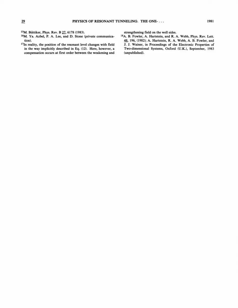
FIG. 5. Calculated transmission coefficient for the cases ofRefs. 1(a) and 3(b).
of Ref. 2 is even worse in this respect. )
Figure 5(a) shows the transmission coefficient TG forsuch a case calculated by means of the transfer-matrixtechnique outlined previously and good agreement isfound both with the TG value at the peak (not fullyresolved in the figure because of the voltage scale) calcu-lated analytically from Eq. (25) and with the experimentalresonance voltage. Figure 5(b) shows, instead, the calcula-tion for the case of Ref. 4 and the agreement with experi-ments is excellent as far as the voltage at which resonanceoccurs is concerned.
An important point to be made with regard to the abovediscussion is that by using a nonsymmetrical structurewith the left barrier thinner than the right one, the condi-tion for TI ——T, might be recreated thus enhancing the ef-fects looked for in experiments. There are, however, twoqualitative differences with the symmetrical, zero-fieldcase already discussed: The possibility to realize the op-timized condition (i.e., TG -1) is not guaranteed and, even
where the notation is that of Fig. 4(b) and
E( hE) qFbd )——, ——
E,=E, +bE, =q(Fbd, +F u) . (27)
As already mentioned the agreement with the experimentsof Ref. 4 is excellent since we get V, =0.21 V. For thecases of Figs. 1 and 2 of Ref. 1, Eq. (26) gives V, =0.22and 0.3 V, respectively, as positions of the lowest reso-nance peak. No higher peak, however, can be found sincewhen V, &0.6 the second barrier disappears (i.e., C&q & 0).Those shown in the mentioned reference can only be justi-fied by assuming a large voltage drop due to series resis-tance (so that the actual voltage applied across the doublebarrier is actually lower) or invoking other phenomena.Among these, resonant tunneling via defect-related statesof the type suggested and discussed in Ref. 13 might pro-vide a reasonable explanation.
V. TIME DEVELOPMENTOP RESONANT TUNNELING
As already anticipated, a crucial aspect usually over-looked in experiments is that, depending on the initialconditions, a non-negligible time might be required beforea high-conductivity resonant state is fully established.
In this respect, it is, perhaps, worth stressing again that
29 PHYSICS OF RESONANT TUNNELING. THE ONE-. . . 1977
the analysis of Sec. II is based on the solutions of thetime-independent Schrodinger equation hence describes astationary situation. This, in turn, requires the carrierwave function at resonance to be (strongly) localizedwithin the well (to a degree which decreases with increas-ing T,„).The mentioned condition on the wave functionis, in other words, necessary and sufficient for TG„,to be
Tmin ~Tmax'From a physical point of view such a requirement
means that the carrier(s) must be predominantly localized(trapped) within the well or, equivalently, that this mustbe "filled up" with them (up to the level described by thestationary wave function) before resonant tunneling is ful-
ly established. In many experiments, however, this mightwell not correspond to actual initial conditions as is, inparticular, the case of Refs. 1, 2, and 4 where the welleigenstates are initially above the energy level of the avail-able carriers, hence completely empty. Under this condi-tion, a transient with time constant rp is required for thesystem to approach its final configuration. During such atransient, the incoming (tunneling) particles get essentiallytrapped within the well where probability density accumu-lates thus also making the global transmission coefficientto gradually increase.
The time constant wo must, in general, be expected todepend on the initial condition (which might feature asteady flux or a single carrier with well-defined orspread-out energy). It can, in principle, be calculated byexpanding the initial wave function in terms of the eigen-functions of the double barrier Hamiltonian (and subse-quently, using the superposition of time-dependent states)but a detailed calculation of this kind is here deferred tofuture work.
On physical grounds, however, we believe rp to be of theorder of the resonant state lifetime, hence to exponentiallyincrease with the barrier phase area. In particular, we ex-pect
Tmax(28)
Depending on the value of T,„,rp can assume non-negligible and even very large (exponentially large) values.This, in turn, would have killing effects on experimentswhere the resonant state is initially empty and is not givenenough time to capture the due amount of carriers. As faras, in particular, the experiments of Refs. 1, 4, and 2 areconcerned, this is not the case for Refs. 1 and 4 where thepeak width is of the order of 10 eV and consequently1 p 10 " sec. In the case of Ref. 2, however, because ofthe much higher barrier height, T,
„
is several orders ofmagnitude lower and a rough estimate gives at low volt-ages 7.o-10 sec.
Still with regard to the times involved in resonant tun-neling it is also worth mentioning that if (or once) the
eigenstate has all the carriers it can accomodate, a muchshorter time ~, becomes important, namely that requiredto cross the double barrier. As far as this is concerned, weexpect ~, to be essentially the time required to cross a sin-gle barrier according to the physical picture of carriersentering the filled state hence "pushing" others out on theother side of the double barrier. With barrier heights oforder of few eV (or substantial fraction of eV) and widthof tens of A, r, is of the order of 10 ' —10 ' sec andtherefore almost completely negligible.
For a more formal derivation of the previous time esti-mates, we can use the results of Refs. 14 and 15 where ex-pressions for the traversal and dwell times through littletransparent barriers are presented.
The dwell time represents the average time spent by anelectron in a considered region and can, therefore, providea good measure of our vo when applied to the whole dou-ble barrier (assumed to extend from point 6 to A in Fig.1). It is then
(29)
where J denotes the probability current through the dou-ble barrier.
As for the transit time r„it is obviously coincident, forall practical purposes, with the tranversal time of Ref. 14which turns out to be longer for more transparent barriers.In our case, once the steady state is reached, the time lim-iting factor for the current comes from crossing the moretransparent barrier (here assumed to be the right onewhich extends from C to 2) and it is then
"m dxC $ Q(x)
(30)
C, x)AC2e r C&X &B
C, E&x &D1
max
1 2 (x P)C aI ', G&x&FTmax
(31)
where C is an arbitrary normalization factor and—2ardrT,„=T„=e" " with d„denoting the thickness of theright barrier. %e can now easily calculate the numeratorof Eq. (29) by dividing the interval in the two barriers andthe well as follows:
where as usual a, =A' 'V2m [E„(x) E]'~ . —Since we are interested here only in first-order esti-
mates, let us consider for simplicity the square barriercase of Fig. 1. From the results summarized in Fig. 2 it isthen
=C 1
2ug Tmax
r
C2
max r Tm» 2nl 2Art.
(32)

1978 B. RICCO AND M. YA. AZBEL
where w represents the width of the central well. Sincethe transmitted current is given by
the double barrier (reaching the barrier of transmissioncoefficient T;„andT,„,respectively), it is
J=C —kg, I @min I
I @max I
min7
Tmax(36)
it is
1 m 1 1 17O- + +mT,
„
fi kz 2ai 2a,
From Eq. (30), instead, we have
m 17)= d„
(34)
(35)
and, when T~,„&~Tm;„, I 4~;„Ibecomes negligible.
T~,„,then, controls the dominant part of 4 outside thebarrier.
Let us denote with L,„and 8' the size of the regionoutside the double barrier (where 4 is not negligible) andthe well width, respectively. If we deal with one particle,the fraction of captured carrier is essentially given by
From this, it can be seen that for comparable values ofa' s, k's, and geometrical factors ro and r, essentially differfor the factor I/T,
„
in agreement with what was dis-cussed previously in this section.
Another interesting phenomenon concerning the reso-nance time dependence involves the effect of temperature.The key point is that the thermal motion of the atoms inany sample contributes in making the potential energytime dependent. As far as this effect is concerned, from aqualitative point of view different cases can be dis-tinguished. If the variations of potential energy Ez arevery small or/and very slow (compared to ro), then Ez canbe considered not to depend on time to all practical pur-poses. Under this circumstances the considerationsdeveloped in this paper fully apply.
If, instead, Ez significantly varies in values on a timescale comparable or smaller than ro, then a more compli-cated analysis is required. Work aimed at exploring thisaspect of resonant tunneling is now in progress. '
Overall we expect the temperature to give rise to abroadening of the resonance peaks and to a decrease intheir effects on the current measured in experiments.
As a final comment to this section, it is perhaps worthanticipating that the described evolution of empty statestoward their final condition may be substantially affectedby the space-charge buildup inherent to the mrrier accu-mulation taking place within the well. This can modifythe potential-energy barrier with a feedback mechanismwhose major resulting effects are described in the next sec-tion.
VI. THE EFFECTS OF SPACE-CHARGE BUILDUPDUE TO CARRIER TRAPPING
As already discussed, resonance implies the presence in-side the well of a certain amount of carriers which, atleast in the most common experimental situtations, are notthere at the beginning. When dealing with electrons, thismeans that a space charge builds up. If the resonanteigenstate can accommodate enough charge this affectsthe potential energy making it time dependent and givingrise to a feedback mechanism linking the changes in po-tential energy with mrrier trapping.
The amount of charge that a resonant state can containdepends, in general, on its degree of localization. This, in
turn, essentially decreases with increasing T,„since, ifwe denote with 4;„and4
„
the wave function outside
~+ Tmax max
If there are many particles incident on the barrier (sayfrom the left) the question of exclusion arises, and it be-comes important to evaluate the number X of system lev-els contained within the width hE, of the resonant state.Denoting with AEI the distance between the allowed level,it is
AE,
The number X„ofcarriers trapped into the well is thenessentially given by (here we assume all of the à level tobe occupied)
N„=Nf . (39)
Indicating with Lr the total system dimensions (actuallythe region where 4 is not negligible), b,EI can be estimat-ed as
VFh
T(40)
where vF is the electron Fermi velocity. From this, it isimmediately obvious that for an unlimited system(LT +ao and the energy —spectrum becomes a continuum)a resonant state with finite width can contain any numberof particles. If LT is finite, Eq. (38) has to be evaluated.For this we use the expression
AE, =T,„hv, (41)
where v is the attempt-to-escape frequency relative to thecentral well. For a rough estimate we assume u =uF/w.It is then
I.T~max
W(42)
A slightly different mse, which is important because itoccurs in the experiments mentioned in this paper, is thatwhere the incoming particles comes from a cathode whichessentially behaves as an infinite reservoir of carriers atdifferent energies as schematically represented in Fig. 6.Here the appropriate boundary condition is that the densi-
ty of carriers is kept fixed at the mthode. Two points arerelevant. First only the electrons within the energy win-dow of the eigenstate width play a role in trapping sincethe wave function of the others exponentially decreases

29 PHYSICS OF RESONANT TUNNELING. THE ONE-. . . 1979
CATHODE
FIG. 6. Energy configuration under the usual experimentalconditions.
below the first barrier and, consequently, their density inthe well is negligible. Second, Ti (i.e., the transmissioncoefficient of the barrier facing the cathode) takes theplace of T,
„
in the previous equations (regardless ofwhether or not Ti=T,„).States deep into the barrier,hence close to its boundary on the right of Fig. 6, produceslow (and little) trapping in spite of their T,„being high.
If the amount of charge contained in a well is not negli-gible at any given time the potential energy must be calcu-lated in a self-consistent way, i.e., taking into account thecontribution due to the trapped carriers.
There is, however, a point worth dealing with in somemore details which concerns the way the system ap-proaches the steady state (if this can ever be reached).From this point of view, we expect two different behaviorsaccording to whether or not the incoming particles aremonochromatic. In case they are, and their energy E isfixed, the (negative) space-charge buildup pushes the stateenergy E, upward, thus breaking the energy matchingcondition for resonance. When this happens, the statestarts losing its particle content (again with a transient onthe time scale of its lifetime) thus being lowered in energyuntil E =E, again and resonance is restored. The net ef-fect is, of course, that the system oscillates in timewithout ultimately reaching a stable steady state. The re-sulting oscillations (of frequency =1/rp where 'pp is theeigenstate lifetime) should be observable in the tunnelingcurrent in experiments where ~o is not negligibly small.These oscillations could also, perhaps, be exploited from adevice point of view.
A completely different behavior must, instead, be ex-pected in the case where the energy of the incoming parti-cles covers the whole range swept by the rising E,.(Naturally if this reaches and exceeds the upper limit ofthe tunneling carrier energy oscillations of the typedescribed above are in order. ) The dominant feature hereis that resonance conditions are maintained as E, movesand, consequently, the resonant state can keep increasingits charge content until it reaches a final steady configura-tion. As it does so, the charge buildup changes thepotential-energy barriers on account of two different ef-fects: It weakens and strengthens the field, respectively,on the left- and right-hand side of the well while, at thesame time reducing the barrier heights (because E, rises).
In practice, the overall result is that both barriers becomemore transparent (i.e., Ti and T„increase) as can, for in-
stance, be schematically seen in Fig. 7. Here the well, andhence the trapped charge, has been replaced by a 5 func-tion while, for simplicty, the depth of the eigenstate hasbeen kept fixed' (i.e., 4& is considered unchanged by thecharge buildup) and it is evident that the barrier (phase)area can only decrease. This has two important conse-quences, namely, (i) the state degree of localization de-creases (as T,
„
increases) thus decreasing the amount ofcharge the well can eventually accommodate, and (ii) forthe same reason, the transient to reach the final stationarystate becomes shorter [as indicated in Eq. (28)]. Thislatter effect is very important since it implies a self-accelerating (or positive feedback) mechanism in that asmore charge is trapped into the well, trapping itself getsfaster. If the final configuration is one of high conduc-tivity the system will therefore, rapidly converge to it giv-
ing rise to abrupt, very large increase in tunneling current.As described in Ref. 13, we believe this could be the
way in which breakdown phenomena occurs in thin insu-lating films where only low voltages are required to reachthe high fields causing the material failure.
VII. TEMPERATURE EFFECTS
In Sec. V we mentioned an interesting phenomenon re-lating the temperature ( T) with resonance time evolution.
Here we consider instead the effect due to the electronthermal population and the important conclusion isreached that at resonance a variety of current-versus-T re-lationships can result depending on the relative position ofthe resonant state and the Fermi energy (E~). In particu-lar, currents increasing as well as decreasing with T andcomplicated nonmonotonic temperature behaviors are pos-sible. Each state gives rise to its own (individual) J vs Tdependence according to its energy position. In real sam-ples where many such states are present, then a different(individual) current behavior is to be expected at eachresonant peak. This is in agreement with experimentsshowing that the conductance at a peak is proportional toexp[(Tp/T)' ] where Tp is individual for the considered
FIG. 7. Schematic representation of the charges on the poten-tial energy induced by electron trapping.

B. RICCO AND M. VA. AZBEL
peak. ' The physical effects of concern of this section areessentially the following.
As the temperature varies the cathode carrier concen-tration at the resonant energy also varies and so does thecurrent J measured in experiments. At the same time thecarrier thermal velocity also increases with T and, withsemiconductor or metal cathodes, this implies an increasein the electron flux hitting the barrier, hence J. This latteris, however, only a minor effect (because the thermal velo-city depends on v T ) with respect to that mentioned ear-lier whose temperature dependence comes fmm the ex-ponential factor in the Fermi distribution function.
Because we essentially deal with the carrier concentra-tion within a definite narrow energy window (the width ofa resonant eigenstate centered on E,} the effects to be ex-pected depend on its position relative to E,. If E, and Ezare close (compared with kT) an increase of T spreadingout the distribution function can only lead to a decrease ofparticle concentration at the resonance energy, hence to adecrease of tunneling current. In this case J exhibits ametallic type of behavior.
In any case, for large increase of temperature a subse-quent increase in current may occur since, as the distribu-tion function spreads out, the carrier concentration canbecome non-negligible at other, higher eigenstates whosecontribution will rapidly become important. If, on theother hand, the distance between E, and E~ is large, an in-crease in current is first expected to occur as a conse-quence of the increase in carrier concentration availablefor resonant tunneling. Here too, however, a subsequentmetallic type of behavior can arise for the same reasonsgiven above.
VIII. CONCLUSIONS
In this paper, we have presented an assessment of thebasic physical phenomena involved in resonant tunnelingthrough a one-dimensional double barrier structure. Inparticular we have shown that, although they are astraightfoward, well-known feature of the transmissioncoefficient versus energy (or field) characteristics, the oc-currence of resonances involves interesting physical phe-nomena which complicate the search for experimentalconditions able to emphasize their effects.
In this respect, me have shown that experiments per-formed on structures with semiconductor electrodes withvarying applied voltages, can, at most, only be optimizedfor a particular resonance peak.
%'e have also pointed out that, under the most usual ex-perimental conditions, a time-dependent process withnon-negligible time constant is necessary to reach thesteady state situation. At the beginning of the mentionedtransient, the conductivity throughout the double barriercan be much lower than in the final state and this mightexplain some experimental results. Furthermore, we havediscussed how at resonance carrier trapping (as well ashigh conductivity} occurs. This, in turn, brings about aspace-charge effect making the potential-energy barriertime dependent. Because of this a feedback mechanismtakes place and either a self-accelerating approach to anequilibrium state or a permanent oscillating current canresult.
Finally the effect of temperature has been briefly treat-ed and the conclusion is reached that metallic- as mell assemiconductor-type behavior can be found.
'On leave from the University of Padua, 35100 Padua, Italy.On leave from the University of Tel Aviv, Tel Aviv 69978, Is-
rael.~L. L. Chang, L. Esaki, and R. Tsu, Appl. Phys. Lett. 24, 593
(1974).2M. Hirose, M. Morita, and Y. Osaka, Jpn. J. Appl. Phys. 16,
561 (1977).3J. C. Penley, Phys. Rev. 128„596(1962).4T. C. L. G. Sollner, %. D. Goodhue, P. E. Tannenwald, C. D.
Parker, and D. D. Peck, Appl. Phys. Lett. 43, 588 (1983).5R. Tsu and L. Esaki, Appl. Phys. Lett. 22, 562 (1973).6E. O. Kane, Tunneling Phenomena in Solids, edited by E. Burn-
stein and D. Lundquist (Plenum, New York, 1969).7The last term in the equation differs by a factor of 2 from that
of Ref. 6 [Eq. (61)] probably due to a misprint.8It is perhaps worth mentioning that in the opposite case of
T, g T~ the wave function of Fig. 2 does not represent an ade-
quate description of the problem with electrons corning fromthe left (of point 0 in Fig. 1). This "boundary condition" canbe dealt with by either of the following approaches. %'e canconsider the dual case of particles coming from the right (ofcourse completely symmetrical with respect to that of Fig. 2)and exploit the general property of transmission coefficientsto be independent on the side the barriers are looked at. Insuch a way, the results follow immediately from that of Fig.2. Alternatively, we can construct the wave function (((x) ap-propriate to the case at hand by means of two independent
solutions of Schrodinger equation. Pi, represented in Fig. 2,can be used as one of them while the other, P2, can be workedout from it. In particu1ar the most general wave function Pcan be expressed in terms of P~ in the following way:
P=APi+BP& I I/Pidx, where A and 8 represent the coeffi-cients of the linear combination P must be constructed from.
9M. Ya. Azbel, Phys. Rev. 8 28, 4106 (1983).ioThe factor in front of the matrix is not present in Eqs. (7) be-
cause the carrier momentum does not change in a given r'egion
of Fig. 1. If, however, a global matrix for a barrier' is con-structed by taking M; M~M,„,and the momentum on its,
sides is different, it can be easily seen that the resulting deter-rninant is k„jk,. Consequently, the matrix can be put in theform given in Eq. (7a). The same applies in the case of Eq.7(b).
iiL. D. Landau and E. M. Liftshitz, Quantum Mechanics, 3rded. (Pergamon, Oxford, 1976).
«2It is, perhaps, interesting to notice at this regard that the resultcoincides with that obtainable by arbitrarily introducing adiscontinuity at the crossing point (symmetrical with respectto the energy of the tunneling particle to maintain o;=k as inthe real case—see dotted line in Fig. 3) and letting it go tozero. This procedure is, however, not completely rigorous,
~38. Ricco, M. Ya. Azbel, and M. H. Brodsky, Phys. Rev. Lett.51, 1795 (1983).
~"M. Buttiker and R. Landauer, Phys. Rev. Lett. 49, 1739(1982).
PHYSICS QF RESONANT TUNNELING. THE ONE-. . .
«5M. Buttiker, Phys. Rev. B 27, 6178 (1983).6M. Ya. Azbel, P. A. Lee, and D. Stone (private communica-
tion).«~In reality, the position of the resonant level changes with field
in the way imphcitly described in Eq. (12). Here, however, acompensation occurs at first order between the weakening and
strengthening field on the well sides.«SA. B. Fowler, A. Hartstein, and R. A. Webb, Phys. Rev. Lett.
48, 196, (1982); A. Hartstein, R. A. Webb, A. B. Fowjer, andJ. J. Wainer, in Proceedings of the Electronic Properties ofTwo-dimensional Systems, Oxford (U.K.), September, 1983(unpubhshed).


