Embed Size (px)
Citation preview
Horizontal frequencies30 - 83kHz
ServiceService
Service
TABLE OF CONTENTS
Published by BCU Monitors Printed in suzhou Copyright reserved Subject to modification F Apr .1 2005
Description Page
Important Safety Notice---------------------------------- 2
Technical Data/Installation---------------------------3~7
On-Screen Display/Aging Mode---------------------8~9
Mechanical instructions----------------------------13~14
Trouble shooting-------------------------------------17~18
Factory Mode/Pixel defect policy-----------------10~12
Display adjustment/Warning message----------15~16
Electrical Instructions-------------------------------19~22
LightFrameDR----------------------------------------23~24
Safety Test Requirements------------------------------25
DDC Instructions/DATA----------------------------26~34
ISP Instructions--------------------------------------35~37
Wiring Diagram---------------------------------------38~39
Description Page
Block Diagram--------------------------------------------40
Scaler Diagram/C.B.A-----------------------------41~52
USB Diagram/C.B.A--------------------------------53~58
Audio Diagram/C.B.A------------------------------59~60
Control&Audio Diagram/C.B.A-------------------61~63
Power Diagram/C.B.A-----------------------------64~66
Exploded View-------------------------------------- 67~68
Recommended Parts list-------------------------------69
Spare Parts list--------------------------------------70~72
Different parts list----------------------------------73~76
Repair Tips/Repair Flow Chart-------------------77~81
General product specification------------------82~110
REFER TO BACK COVER FOR IMPORTANT SAFETY GUIDELINES
CAUTION: USE A SEPARATE ISOLATION TRANSFORMER FOR THIS UNIT WHEN SERVICING.
ANY PERSON ATTEMPTING TO SERVICE THIS CHASSIS MUST FAMILIARIZE HIMSELF WITH THE CHASSIS
AND BE AWARE OF THE NECESSARY SAFETY PRECAUTIONS TO BE USED WHEN SERVICING ELECTRONIC
EQUIPMENT CONTAINING HIGH VOLTAGES.
SAFETY NOTICE
Family: SH6L
GB 3138 106 10460
PHILIPS LCD Monitor190P6ES/00190P6EB/27190P6EG/00190P6EG/93190P6EB/00170P6EB/93170P6EG/00170P6EG/93170P6ES/00170P6EB/27

Important Safety Notice2
FOR PRODUCTS CONTAINING LASER :
Invisible laser radiation when open.
AVOID DIRECT EXPOSURE TO BEAM.
Use of controls or adjustments or
performance of procedures other than
those specified herein may result in
hazardous radiation exposure.
The use of optical instruments with this
product will increase eye hazard.
DANGER-
CAUTION-
CAUTION-
TO ENSURE THE CONTINUED RELIABILITY OF
THISPRODUCT, USE ONLY ORIGINAL
MANUFACTURER'S REPLACEMENT PARTS,
WHICH ARE LISTED WITH THEIR PART NUMBERS
IN THE PARTS LIST SECTION OF THIS SERVICE
190P6&170P6 LCD
Proper service and repair is important to the safe,
reliable operation of all Philips Consumer Electronics
Company** Equipment. The service procedures
recommended by Philips and described in this service
manual are effective methods of performing service
operations. Some of these service operations require
the use of tools specially designed for the purpose. The
special tools should be used when and as
recommended.
It is important to note that this manual contains various
CAUTIONS and NOTICES which should be carefully
read in order to minimize the risk of personal injury to
service personnel. The possibility exists that improper
service methods may damage the equipment. It is also
important to understand that these CAUTIONS and
NOTICES ARE NOT EXHAUSTIVE. Philips could not
possibly know, evaluate and advise the service trade of
all conceivable ways in which service might be done or
of the possible hazardous consequences of each way.
Consequently, Philips has not undertaken any such
broad evaluation. Accordingly, a servicer who uses a
service procedure or tool which is not recommended by
Philips must first satisfy himself thoroughly that neither
his safety nor the safe operation of the equipment will
be jeopardized by the service method selected.
* * Hereafter throughout this manual, Philips ConsumerElectronics Company will be referred to as Philips.
WARNING
Critical components having special safety
characteristics are identified with a by the Ref. No.
in the parts list and enclosed within a broken line*(where several critical components are grouped in one
area) along with the safety symbol on the
schematics or exploded views.
Use of substitute replacement parts which do not have
the same specified safety characteristics may create
shock, fire, or other hazards.
Under no circumstances should the original design be
modified or altered without written permission from
Philips. Philips assumes no liability, express or implied,
arising out of any unauthorized modification of design.Servicer assumes all liability.
* Broken Line
Take care during handling the LCD module withBacklight unit
- Must mount the module using mounting holesarranged in four corners.
- Do not press on the panel, edge of the framestrongly or electric shock as this will result indamage to the screen.
- Do not scratch or press on the panel with any sharpobjects, such as pencil or pen as this may result indamage to the panel.
- Protect the module from the ESD as it may damagethe electronic circuit (C-MOS).
- Make certain that treatment person s body aregrounded through wrist band.
- Do not leave the module in high temperature and inareas of high humidity for a long time.
- Avoid contact with water as it may a short circuitwithin the module.
- If the surface of panel become dirty, please wipe itoff with a soft material. (Cleaning with a dirty orrough cloth may damage the panel.)
Go to cover page
3190P6&170P6 LCD
Go to cover page
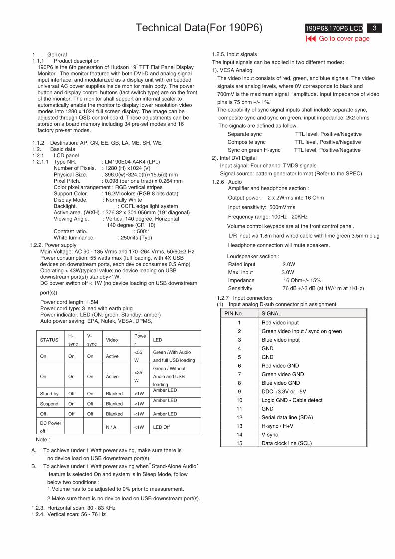
Technical Data(For 190P6)
1. General1.1.1 Product description
190P6 is the 6th generation of Hudson 19 TFT Flat Panel DisplayMonitor. The monitor featured with both DVI-D and analog signalinput interface, and modularized as a display unit with embeddeduniversal AC power supplies inside monitor main body. The powerbutton and display control buttons (tact switch type) are on the frontof the monitor. The monitor shall support an internal scaler toautomatically enable the monitor to display lower resolution videomodes into 1280 x 1024 full screen display. The image can beadjusted through OSD control board. These adjustments can bestored on a board memory including 34 pre-set modes and 16factory pre-set modes.
1.1.2 Destination: AP, CN, EE, GB, LA, ME, SH, WE1.2. Basic data1.2.1 LCD panel1.2.1.1 Type NR. : LM190E04-A4K4 (LPL)
Number of Pixels. : 1280 (H) x1024 (V)
Physical Size. : 396.0(w)�324.0(h)�15.5(d) mmPixel Pitch. : 0.098 (per one triad) x 0.264 mmColor pixel arrangement : RGB vertical stripesSupport Color. : 16.2M colors (RGB 8 bits data)Display Mode. : Normally WhiteBacklight. : CCFL edge light systemActive area. (WXH). : 376.32 x 301.056mm (19 diagonal)Viewing Angle. : Vertical 140 degree, Horizontal
140 degree (CR=10)Contrast ratio. : 500:1White luminance. : 250nits (Typ)
1.2.2. Power supply
Main Voltage: AC 90 - 135 Vrms and 170 -264 Vrms, 50/60�2 HzPower consumption: 55 watts max (full loading, with 4X USBdevices on downstream ports, each device consumes 0.5 Amp)Operating < 43W(typical value; no device loading on USBdownstream port(s)) standby<1W.DC power switch off < 1W (no device loading on USB downstream
port(s))
Power cord length: 1.5MPower cord type: 3 lead with earth plugPower indicator: LED (ON: green, Standby: amber)Auto power saving: EPA, Nutek, VESA, DPMS,
STATUSH-
sync
V-
syncVideo
Powe
rLED
On On On Active<55
W
Green /With Audio
and full USB loading
On On On Active<35
W
Green / Without
Audio and USB
loading
Stand-by Off On Blanked <1WAmber LED
Suspend On Off Blanked <1WAmber LED
Off Off Off Blanked <1W Amber LED
DC Power
offN / A <1W LED Off
Note :
A. To achieve under 1 Watt power saving, make sure there is
no device load on USB downstream port(s).
B. To achieve under 1 Watt power saving when Stand-Alone Audio
feature is selected On and system is in Sleep Mode, follow
below two conditions :
1.Volume has to be adjusted to 0% prior to measurement.
2.Make sure there is no device load on USB downstream port(s).
1.2.3. Horizontal scan: 30 - 83 KHz1.2.4. Vertical scan: 56 - 76 Hz
""
"
"
1.2.5. Input signals
The input signals can be applied in two different modes:
1). VESA Analog
The video input consists of red, green, and blue signals. The video
signals are analog levels, where 0V corresponds to black and
700mV is the maximum signal amplitude. Input impedance of video
pins is 75 ohm +/- 1%.
The capability of sync signal inputs shall include separate sync,
composite sync and sync on green. input impedance: 2k2 ohms
The signals are defined as follow:
Separate sync TTL level, Positive/Negative
Composite sync TTL level, Positive/Negative
Sync on green H-sync TTL level, Positive/Negative
2). Intel DVI Digital
Input signal: Four channel TMDS signals
Signal source: pattern generator format (Refer to the SPEC)
1.2.6 AudioAmplifier and headphone section :
Output power: 2 x 2Wrms into 16 Ohm
Input sensitivity: 500mVrms
Frequency range: 100Hz - 20KHz
Volume control keypads are at the front control panel.
L/R input via 1.8m hard-wired cable with lime green 3.5mm plug
Headphone connection will mute speakers.
Loudspeaker section :
Rated input 2.0W
Max. input 3.0W
Impedance 16 Ohm+/- 15%
Sensitivity 76 dB +/-3 dB (at 1W/1m at 1KHz)
1.2.7 Input connectors(1) Input analog D-sub connector pin assignment
PIN No. SIGNAL
1 Red video input
2 Green video input / sync on green
3 Blue video input
4 GND
5 GND
6 Red video GND
7 Green video GND
8 Blue video GND
9 DDC +3.3V or +5V
10 Logic GND - Cable detect
11 GND
12 Serial data line (SDA)
13 H-sync / H+V
14 V-sync
15 Data clock line (SCL)
4 190P6&170P6 LCD
Go to cover page
Technical Data(For 190P6)
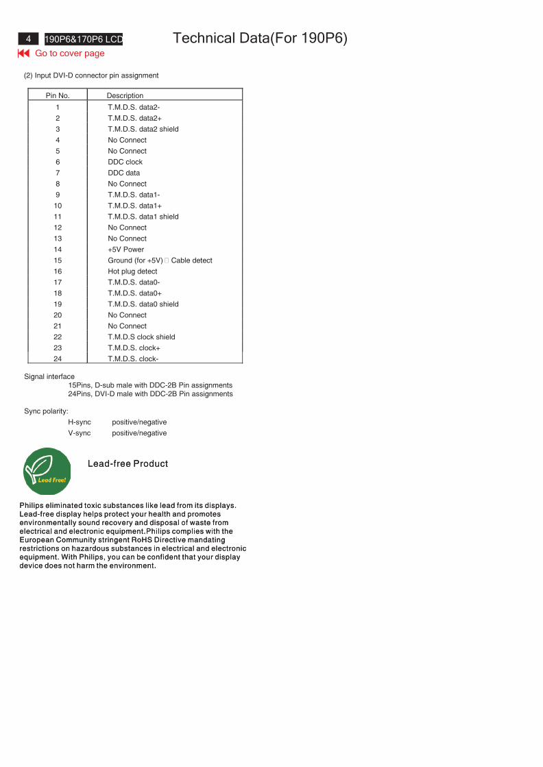
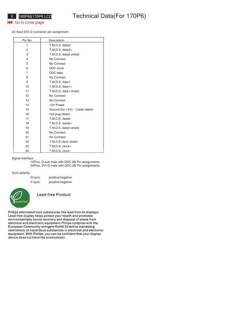
(2) Input DVI-D connector pin assignment
Pin No. Description
1 T.M.D.S. data2-
2 T.M.D.S. data2+
3 T.M.D.S. data2 shield
4 No Connect
5 No Connect
6 DDC clock
7 DDC data
8 No Connect
9 T.M.D.S. data1-
10 T.M.D.S. data1+
11 T.M.D.S. data1 shield
12 No Connect
13 No Connect
14 +5V Power
15 Ground (for +5V) – Cable detect
16 Hot plug detect
17 T.M.D.S. data0-
18 T.M.D.S. data0+
19 T.M.D.S. data0 shield
20 No Connect
21 No Connect
22 T.M.D.S clock shield
23 T.M.D.S. clock+
24 T.M.D.S. clock-
Signal interface15Pins, D-sub male with DDC-2B Pin assignments24Pins, DVI-D male with DDC-2B Pin assignments
Sync polarity:
H-sync positive/negative
V-sync positive/negative
Lead-free Product
Philips eliminated toxic substances like lead from its displays.Lead-free display helps protect your health and promotesenvironmentally sound recovery and disposal of waste fromelectrical and electronic equipment.Philips complies with theEuropean Community stringent RoHS Directive mandatingrestrictions on hazardous substances in electrical and electronicequipment. With Philips, you can be confident that your displaydevice does not harm the environment.
5190P6&170P6 LCD
Go to cover page
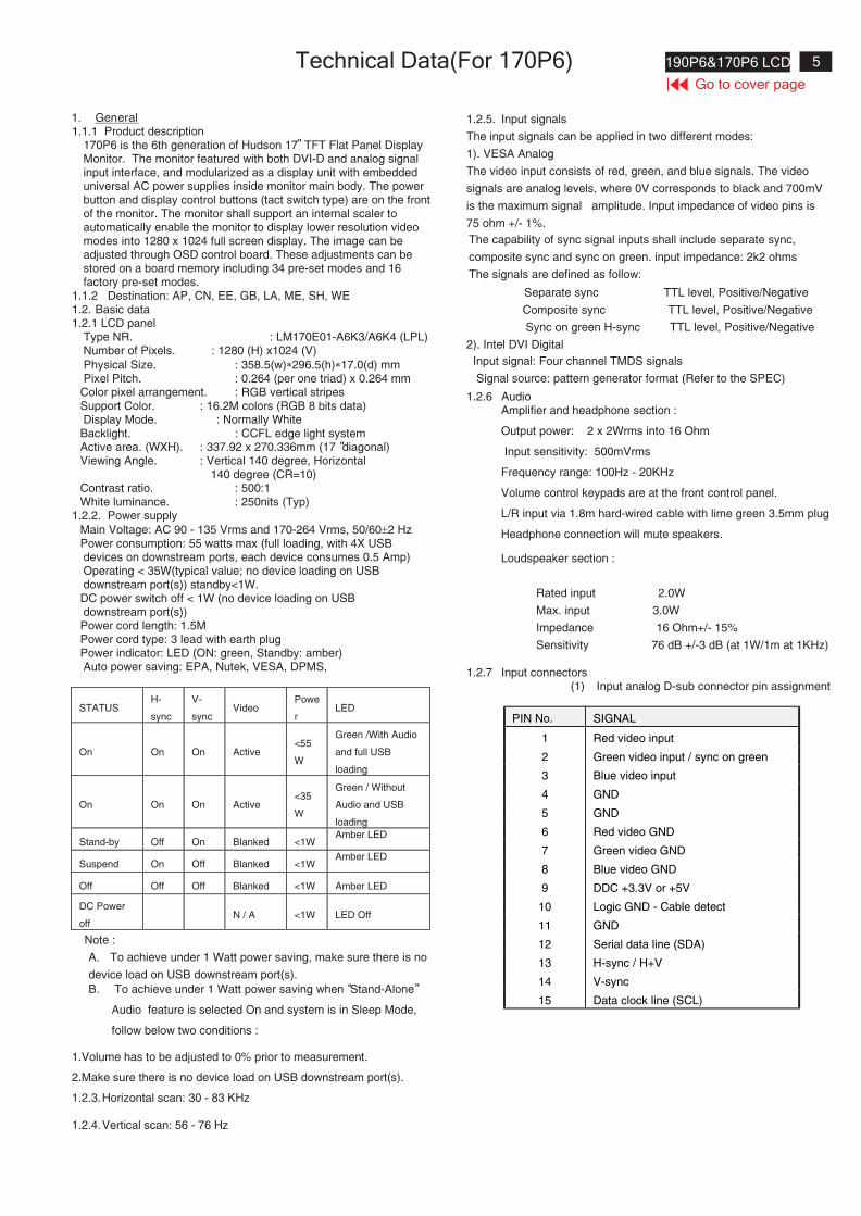
Technical Data(For 170P6)
""
"
"
1. General1.1.1 Product description
170P6 is the 6th generation of Hudson 17 TFT Flat Panel DisplayMonitor. The monitor featured with both DVI-D and analog signalinput interface, and modularized as a display unit with embeddeduniversal AC power supplies inside monitor main body. The powerbutton and display control buttons (tact switch type) are on the frontof the monitor. The monitor shall support an internal scaler toautomatically enable the monitor to display lower resolution videomodes into 1280 x 1024 full screen display. The image can beadjusted through OSD control board. These adjustments can bestored on a board memory including 34 pre-set modes and 16factory pre-set modes.
1.1.2 Destination: AP, CN, EE, GB, LA, ME, SH, WE1.2. Basic data1.2.1 LCD panel
Type NR. : LM170E01-A6K3/A6K4 (LPL)Number of Pixels. : 1280 (H) x1024 (V)
Physical Size. : 358.5(w)�296.5(h)�17.0(d) mmPixel Pitch. : 0.264 (per one triad) x 0.264 mm
Color pixel arrangement. : RGB vertical stripesSupport Color. : 16.2M colors (RGB 8 bits data)Display Mode. : Normally White
Backlight. : CCFL edge light systemActive area. (WXH). : 337.92 x 270.336mm (17 diagonal)Viewing Angle. : Vertical 140 degree, Horizontal
140 degree (CR=10)Contrast ratio. : 500:1White luminance. : 250nits (Typ)
1.2.2. Power supply
Main Voltage: AC 90 - 135 Vrms and 170-264 Vrms, 50/60�2 HzPower consumption: 55 watts max (full loading, with 4X USBdevices on downstream ports, each device consumes 0.5 Amp)Operating < 35W(typical value; no device loading on USBdownstream port(s)) standby<1W.DC power switch off < 1W (no device loading on USBdownstream port(s))Power cord length: 1.5MPower cord type: 3 lead with earth plugPower indicator: LED (ON: green, Standby: amber)Auto power saving: EPA, Nutek, VESA, DPMS,
STATUSH-
sync
V-
syncVideo
Powe
rLED
On On On Active<55
W
Green /With Audio
and full USB
loading
On On On Active<35
W
Green / Without
Audio and USB
loading
Stand-by Off On Blanked <1WAmber LED
Suspend On Off Blanked <1WAmber LED
Off Off Off Blanked <1W Amber LED
DC Power
offN / A <1W LED Off
Note :
A. To achieve under 1 Watt power saving, make sure there is no
device load on USB downstream port(s).
B. To achieve under 1 Watt power saving when Stand-Alone
Audio feature is selected On and system is in Sleep Mode,
follow below two conditions :
1.Volume has to be adjusted to 0% prior to measurement.
2.Make sure there is no device load on USB downstream port(s).
1.2.3.Horizontal scan: 30 - 83 KHz
1.2.4.Vertical scan: 56 - 76 Hz
1.2.5. Input signals
The input signals can be applied in two different modes:
1). VESA Analog
The video input consists of red, green, and blue signals. The video
signals are analog levels, where 0V corresponds to black and 700mV
is the maximum signal amplitude. Input impedance of video pins is
75 ohm +/- 1%.
The capability of sync signal inputs shall include separate sync,
composite sync and sync on green. input impedance: 2k2 ohms
The signals are defined as follow:
Separate sync TTL level, Positive/Negative
Composite sync TTL level, Positive/Negative
Sync on green H-sync TTL level, Positive/Negative
2). Intel DVI Digital
Input signal: Four channel TMDS signals
Signal source: pattern generator format (Refer to the SPEC)
1.2.6 AudioAmplifier and headphone section :
Output power: 2 x 2Wrms into 16 Ohm
Input sensitivity: 500mVrms
Frequency range: 100Hz - 20KHz
Volume control keypads are at the front control panel.
L/R input via 1.8m hard-wired cable with lime green 3.5mm plug
Headphone connection will mute speakers.
Loudspeaker section :
Rated input 2.0W
Max. input 3.0W
Impedance 16 Ohm+/- 15%
Sensitivity 76 dB +/-3 dB (at 1W/1m at 1KHz)
1.2.7 Input connectors(1) Input analog D-sub connector pin assignment
PIN No. SIGNAL
1 Red video input
2 Green video input / sync on green
3 Blue video input
4 GND
5 GND
6 Red video GND
7 Green video GND
8 Blue video GND
9 DDC +3.3V or +5V
10 Logic GND - Cable detect
11 GND
12 Serial data line (SDA)
13 H-sync / H+V
14 V-sync
15 Data clock line (SCL)
6 190P6&170P6 LCD
Go to cover page
Technical Data(For 170P6)
Lead-free Product
Philips eliminated toxic substances like lead from its displays.Lead-free display helps protect your health and promotesenvironmentally sound recovery and disposal of waste fromelectrical and electronic equipment.Philips complies with theEuropean Community stringent RoHS Directive mandatingrestrictions on hazardous substances in electrical and electronicequipment. With Philips, you can be confident that your displaydevice does not harm the environment.
(2) Input DVI-D connector pin assignment
Pin No. Description
1 T.M.D.S. data2-
2 T.M.D.S. data2+
3 T.M.D.S. data2 shield
4 No Connect
5 No Connect
6 DDC clock
7 DDC data
8 No Connect
9 T.M.D.S. data1-
10 T.M.D.S. data1+
11 T.M.D.S. data1 shield
12 No Connect
13 No Connect
14 +5V Power
15 Ground (for +5V) – Cable detect
16 Hot plug detect
17 T.M.D.S. data0-
18 T.M.D.S. data0+
19 T.M.D.S. data0 shield
20 No Connect
21 No Connect
22 T.M.D.S clock shield
23 T.M.D.S. clock+
24 T.M.D.S. clock-
Signal interface15Pins, D-sub male with DDC-2B Pin assignments24Pins, DVI-D male with DDC-2B Pin assignments
Sync polarity:
H-sync positive/negative
V-sync positive/negative
7190P6&170P6 LCD
Go to cover page
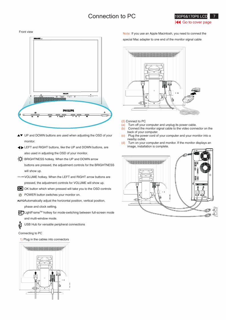
Connection to PC
Front view
UP and DOWN buttons are used when adjusting the OSD of your
monitor.
LEFT and RIGHT buttons, like the UP and DOWN buttons, are
also used in adjusting the OSD of your monitor.
BRIGHTNESS hotkey. When the UP and DOWN arrow
buttons are pressed, the adjustment controls for the BRIGHTNESS
will show up.
VOLUME hotkey. When the LEFT and RIGHT arrow buttons are
pressed, the adjustment controls for VOLUME will show up.
OK button which when pressed will take you to the OSD controls
POWER button switches your monitor on.
Automatically adjust the horizontal position, vertical position,
phase and clock setting.
LightFrameTM hotkey for mode-switching between full-screen mode
and multi-window mode.
USB Hub for versatile peripheral connections
VOLUME
Connecting to PC
1) Plug in the cables into connectors
Note: If you use an Apple Macintosh, you need to connect the
special Mac adapter to one end of the monitor signal cable
(2) Connect to PC(a) Turn off your computer and unplug its power cable.(b) Connect the monitor signal cable to the video connector on the
back of your computer.(c) Plug the power cord of your computer and your monitor into a
nearby outlet.(d) Turn on your computer and monitor. If the monitor displays an
image, installation is complete.
8 190P6&170P6 LCD
Go to cover page
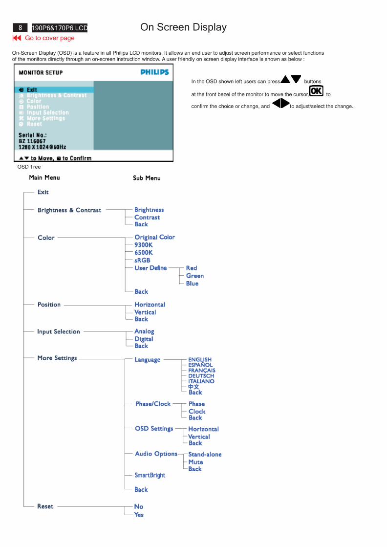
On Screen Display
On-Screen Display (OSD) is a feature in all Philips LCD monitors. It allows an end user to adjust screen performance or select functionsof the monitors directly through an on-screen instruction window. A user friendly on screen display interface is shown as below :
In the OSD shown left users can press buttons
at the front bezel of the monitor to move the cursor, to
confirm the choice or change, and to adjust/select the change.
OSD Tree
9190P6&170P6 LCD
Go to cover page
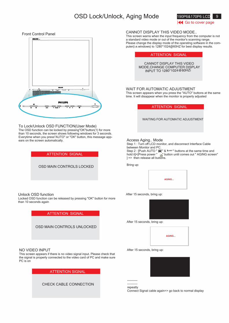
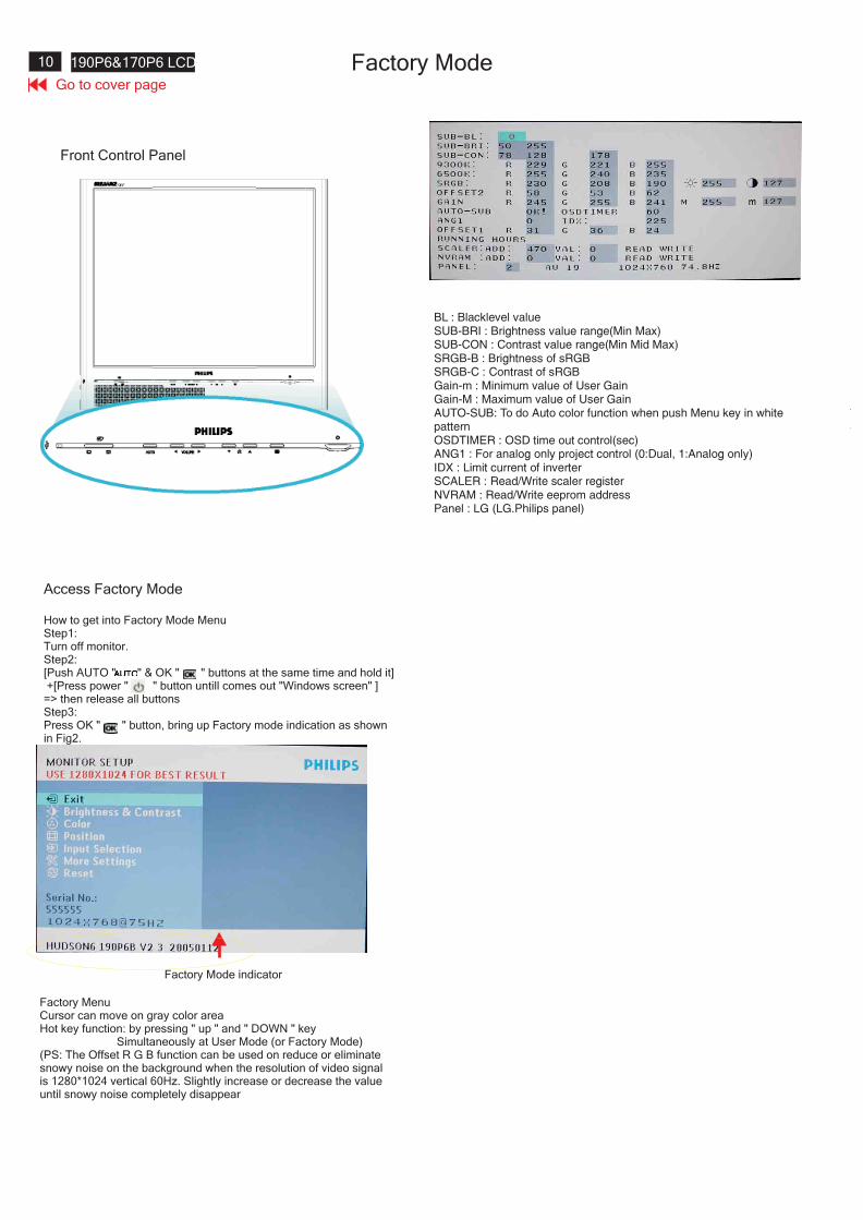
Front Control Panel
To Lock/Unlock OSD FUNCTION(User Mode)The OSD function can be locked by pressing"OK"button(1) for morethan 10 seconds, the screen shows following windows for 3 seconds.Everytime when you press"AUTO" or "OK" button, this message app-ears on the screen automatically.
ATTENTION SIGNAL
OSD MAIN CONTROLS UNLOCKED
Unlock OSD functionLocked OSD function can be released by pressing "OK" button for morethan 10 seconds again
ATTENTION SIGNAL
OSD MAIN CONTROLS LOCKED
NO VIDEO INPUTThis screen appears if there is no video signal input. Please check thatthe signal is properly connected to the video card of PC and make surePC is on
ATTENTION SIGNAL
CHECK CABLE CONNECTION
CANNOT DISPLAY THIS VIDEO MODE..This screen warns when the input frequency from the computer is nota standard video mode or out of the monitor's scanning range.Please change the display mode of the operating software in the com-puter(i.e.windows) to 1280*1024@60HZ for best display results.
ATTENTION SIGNAL
CANNOT DISPLAY THIS VIDEOMODE,CHANGE COMPUTER DISPLAY
INPUT TO 1280*1024@60HZI
WAIT FOR AUTOMATIC ADJUSTMENTThis screen appears when you press the "AUTO" buttons at the sametime. It will disappear when the monitor is properly adjusted
ATTENTION SIGNAL
WAITING FOR AUTOMATIC ADJUSTMENT
Access Aging.. ModeStep 1 : Turn off LCD monitor, and disconnect Interface Cablebetween Monitor and PC.Step 2 : [Push AUTO " " & " " buttons at the same time andhold it]+[Press power " " button until comes out " AGING screen"] => then release all buttons.
Bring up:
AGING...
After 15 seconds, bring up:
After 15 seconds, bring up:
AGING...
After 15 seconds, bring up:
--------------------repeatlyConnect Signal cable again=> go back to normal display
OSD Lock/Unlock, Aging Mode
10 190P6&170P6 LCD
Go to cover page
Front Control Panel
Access Factory Mode
How to get into Factory Mode MenuStep1:Turn off monitor.Step2:[Push AUTO " " & OK " " buttons at the same time and hold it]+[Press power " " button untill comes out "Windows screen" ]=> then release all buttonsStep3:Press OK " " button, bring up Factory mode indication as shownin Fig2.
Factory Mode indicator
Factory MenuCursor can move on gray color areaHot key function: by pressing " up " and " DOWN " key
Simultaneously at User Mode (or Factory Mode)(PS: The Offset R G B function can be used on reduce or eliminatesnowy noise on the background when the resolution of video signalis 1280*1024 vertical 60Hz. Slightly increase or decrease the valueuntil snowy noise completely disappear
BL : Blacklevel valueSUB-BRI : Brightness value range(Min Max)SUB-CON : Contrast value range(Min Mid Max)SRGB-B : Brightness of sRGBSRGB-C : Contrast of sRGBGain-m : Minimum value of User GainGain-M : Maximum value of User GainAUTO-SUB: To do Auto color function when push Menu key in whitepatternOSDTIMER : OSD time out control(sec)ANG1 : For analog only project control (0:Dual, 1:Analog only)IDX : Limit current of inverterSCALER : Read/Write scaler registerNVRAM : Read/Write eeprom addressPanel : LG (LG.Philips panel)

11190P6&170P6 LCD
Go to cover page
Philips' Flat Panel Monitors Pixel Defect Policy
Pixels and Subpixels
Types of Pixel Defects
Philips strives to deliver the highest quality products. We use some ofthe industry's most advanced manufacturing processes and practicestringent quality control. However, pixel or subpixel defects on the TFTLCD panels used in flat panel monitors are sometimes unavoidable.No manufacturer can guarantee that all panels will be free from pixeldefects, but Philips guarantees that any monitor with an unacceptablenumber of defects will be repaired or replaced under warranty.This notice explains the different types of pixel defects and definesacceptable defect levels for each type. In order to qualify for repair orreplacement under warranty, the number of pixel defects on a TFT LCDpanel must exceed these acceptable levels.For example, no more than 0.0004% of the subpixels on a 15" XGAmonitor may be defective. Furthermore, Philips sets even higher qualitystandards for certain types or combinations of pixel defects that aremore noticeable than others. This policy is valid worldwide .
A pixel, or picture element, is composed of three subpixels in theprimary colors of red, green and blue. Many pixels together form animage. When all subpixels of a pixel are lit, the three colored subpixelstogether appear as a single white pixel. When all are dark, the threecolored subpixels together appear as a single black pixel.Other combinations of lit and dark subpixels appear as single pixels ofother colors.
Pixel and subpixel defects appear on the screen in different ways.There are two categories of pixel defects and several types of subpixeldefects within each category.Bright Dot Defects Bright dot defects appear as pixels or subpixels thatare always lit or "on".These are the types of bright dot defects:
One lit red, green or blue subpixel
Two adjacent lit subpixels:- Red + Blue = Purple- Red + Green = Yellow- Green + Blue = Cyan (Light Blue)
Three adjacent lit subpixels(one white pixel)
Black Dot Defects
Proximity of Pixel Defects
Pixel Defect Tolerances
Black dot defects appear as pixels or subpixels that are always dark or"off".These are the types of black dot defects:
One dark subpixel
Two or three adjacent dark subpixels
Because pixel and subpixels defects of the same type that are nearbyone another may be more noticeable, Philips also specifies tolerancesfor the proximity of pixel defects.
In order to qualify for repair or replacement due to pixel defects duringthe warranty period, a TFT LCD panel in a Philips flat panel monitormust have pixel or subpixel defects exceeding the tolerances listed inthe following tables.
BRIGHT DOT DEFECTS ACCEPTABLE LEVEL
MODEL 190P6 190B6 190S6
1 lit subpixel 0 0 3 or fewer
2 adjacent lit subpixels 0 0 1 or fewer
3 adjacent lit subpixels (one
white pixel)0 0 0
Distance between two bright
dot defects*0 0
25 mm or
more
Total bright dot defects of all
types0 0 3 or fewer
BLACK DOT DEFECTS ACCEPTABLE LEVEL
MODEL 190P6 190B6 190S6
1 dark subpixel 0 0 5 or fewer
2 adjacent dark subpixels 0 0 2 or fewer
3 adjacent dark subpixels 0 0 0
Distance between two black
dot defects*0 0
15 mm or
more
Total black dot defects of all
types0 0 5 or fewer
TOTAL DOT DEFECTS ACCEPTABLE LEVEL
MODEL 190P6 190B6 190S6
Total bright or black dot
defects of all types0 0 5 or fewer
Pixel Defect Policy
12 190P6&170P6 LCD
Go to cover page
Pixel Defect Policy
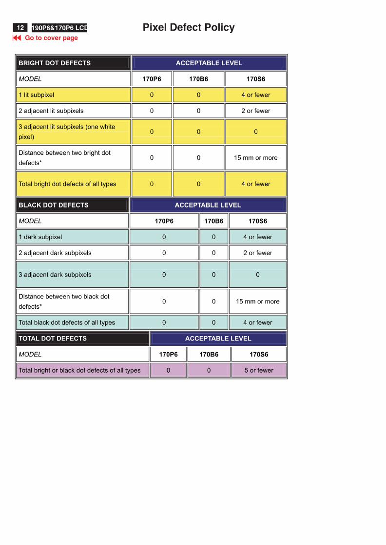
BRIGHT DOT DEFECTS ACCEPTABLE LEVEL
MODEL 170P6 170B6 170S6
1 lit subpixel 0 0 4 or fewer
2 adjacent lit subpixels 0 0 2 or fewer
3 adjacent lit subpixels (one white
pixel)0 0 0
Distance between two bright dot
defects*0 0 15 mm or more
Total bright dot defects of all types 0 0 4 or fewer
BLACK DOT DEFECTS ACCEPTABLE LEVEL
MODEL 170P6 170B6 170S6
1 dark subpixel 0 0 4 or fewer
2 adjacent dark subpixels 0 0 2 or fewer
3 adjacent dark subpixels 0 0 0
Distance between two black dot
defects*0 0 15 mm or more
Total black dot defects of all types 0 0 4 or fewer
TOTAL DOT DEFECTS ACCEPTABLE LEVEL
MODEL 170P6 170B6 170S6
Total bright or black dot defects of all types 0 0 5 or fewer
13190P6&170P6 LCD
Go to cover page
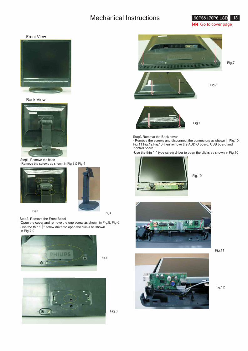
Front View
Back View
Step1. Remove the base-Remove the screws as shown in Fig.3 & Fig.4
Step2. Remove the Front Bezel-Open the cover and remove the one screw as shown in Fig.5, Fig.6
-Use the thin " " screw driver to open the clicks as shownin Fig.7-9
Step3.Remove the Back cover- Remove the screws and disconnect the connectors as shown in Fig.10 ,Fig.11 Fig.12,Fig.13 then remove the AUDIO board, USB board andcontrol board
-Use the thin " " type screw driver to open the clicks as shown in Fig.10
Fig.4
Fig.5
Fig9
Fig.10
Fig.11
Fig.3
Fig.8
Fig.7
Fig.6
Fig.12
Mechanical Instructions
14 190P6&170P6 LCD
Go to cover page
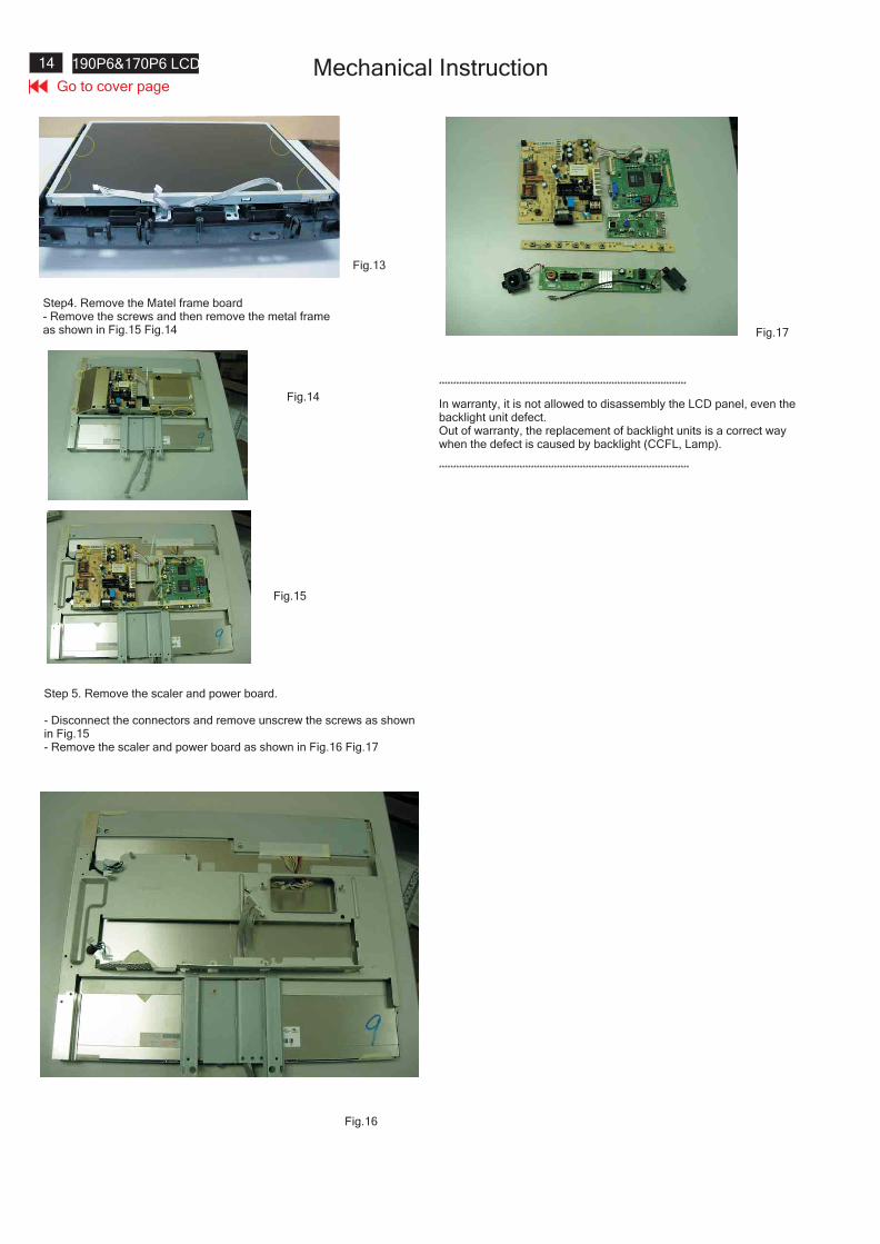
Step 5. Remove the scaler and power board.
- Disconnect the connectors and remove unscrew the screws as shownin Fig.15- Remove the scaler and power board as shown in Fig.16 Fig.17
**************************************************************************************
***************************************************************************************
In warranty, it is not allowed to disassembly the LCD panel, even thebacklight unit defect.Out of warranty, the replacement of backlight units is a correct waywhen the defect is caused by backlight (CCFL, Lamp).
Fig.17
Fig.13
Fig.16
Step4. Remove the Matel frame board- Remove the screws and then remove the metal frameas shown in Fig.15 Fig.14
Fig.14
Fig.15
Mechanical Instruction
15190P6&170P6 LCD
Go to cover page
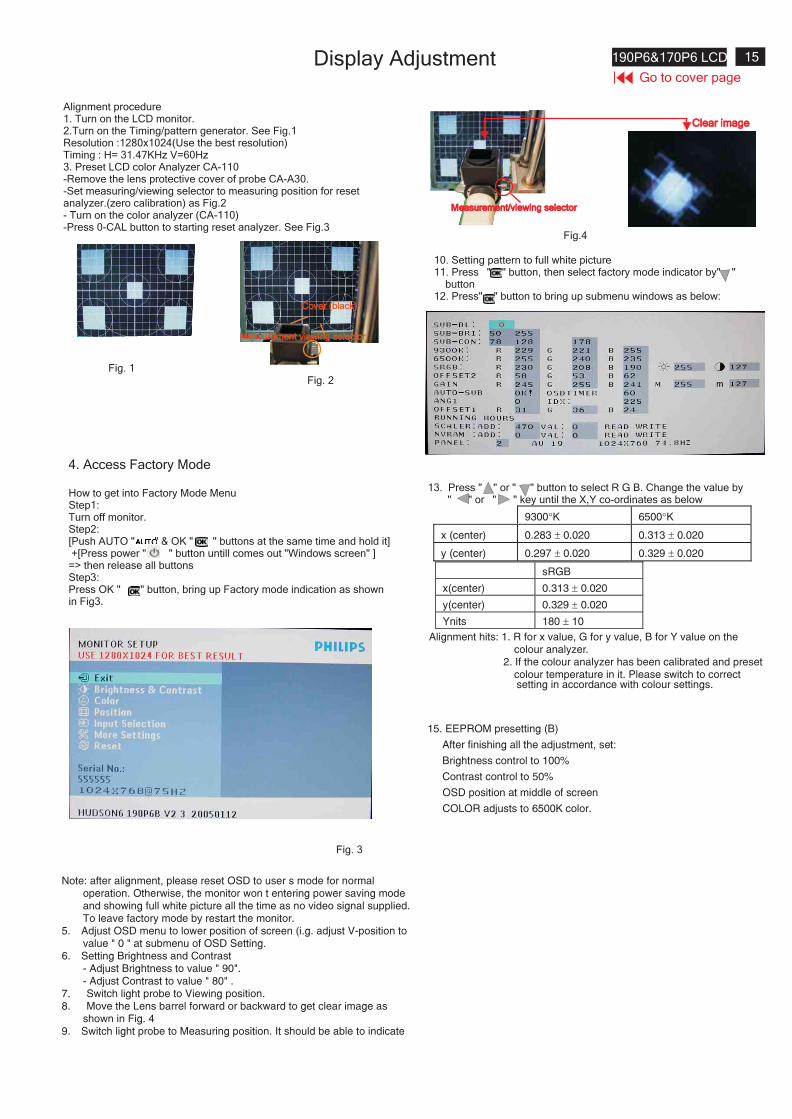
Alignment procedure1. Turn on the LCD monitor.2.Turn on the Timing/pattern generator. See Fig.1Resolution :1280x1024(Use the best resolution)Timing : H= 31.47KHz V=60Hz3. Preset LCD color Analyzer CA-110-Remove the lens protective cover of probe CA-A30.-Set measuring/viewing selector to measuring position for resetanalyzer.(zero calibration) as Fig.2- Turn on the color analyzer (CA-110)-Press 0-CAL button to starting reset analyzer. See Fig.3
Fig. 1Fig. 2
Cover (black)Cover (black)
Measurement viewing selectorMeasurement viewing selector
Note: after alignment, please reset OSD to user s mode for normaloperation. Otherwise, the monitor won t entering power saving modeand showing full white picture all the time as no video signal supplied.To leave factory mode by restart the monitor.
5. Adjust OSD menu to lower position of screen (i.g. adjust V-position tovalue " 0 " at submenu of OSD Setting.
6. Setting Brightness and Contrast- Adjust Brightness to value " 90".- Adjust Contrast to value " 80" .
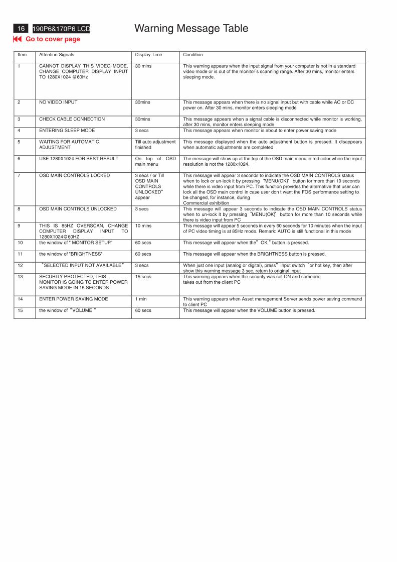
7. Switch light probe to Viewing position.8. Move the Lens barrel forward or backward to get clear image as
shown in Fig. 49. Switch light probe to Measuring position. It should be able to indicate
Clear imageClear image
Measurement/viewing selectorMeasurement/viewing selector
Alignment hits: 1. R for x value, G for y value, B for Y value on thecolour analyzer.
2. If the colour analyzer has been calibrated and presetcolour temperature in it. Please switch to correctsetting in accordance with colour settings.
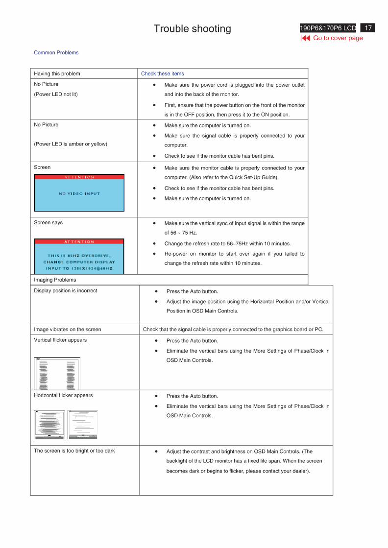
4. Access Factory Mode
How to get into Factory Mode MenuStep1:Turn off monitor.Step2:[Push AUTO " " & OK " " buttons at the same time and hold it]+[Press power " " button untill comes out "Windows screen" ]=> then release all buttonsStep3:Press OK " " button, bring up Factory mode indication as shownin Fig3.
Fig. 3
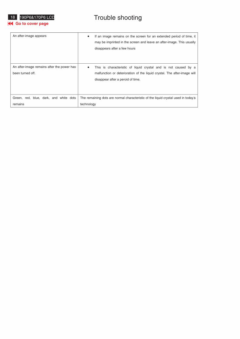
10. Setting pattern to full white picture11. Press button, then select factory mode indicator by" " " "
button12. Press" " button to bring up submenu windows as below:
13. Press " " or " " button to select R G B. Change the value by" " or " " key until the X,Y co-ordinates as below
Fig.4
15. EEPROM presetting (B)
After finishing all the adjustment, set:
Brightness control to 100%
Contrast control to 50%
OSD position at middle of screen
COLOR adjusts to 6500K color.
9300�K 6500�K
x (center) 0.283 � 0.020 0.313 � 0.020
y (center) 0.297 � 0.020 0.329 � 0.020
sRGB
x(center) 0.313 � 0.020
y(center) 0.329 � 0.020
Ynits 180 � 10
Display Adjustment
16 190P6&170P6 LCD
Go to cover page
Warning Message Table
Item Attention Signals Display Time Condition
1 CANNOT DISPLAY THIS VIDEO MODE,CHANGE COMPUTER DISPLAY INPUT
TO 1280X1024 @60Hz
30 mins This warning appears when the input signal from your computer is not in a standardvideo mode or is out of the monitor s scanning range. After 30 mins, monitor enters
sleeping mode.
2 NO VIDEO INPUT 30mins This message appears when there is no signal input but with cable while AC or DC
power on. After 30 mins, monitor enters sleeping mode
3 CHECK CABLE CONNECTION 30mins This message appears when a signal cable is disconnected while monitor is working,after 30 mins, monitor enters sleeping mode
4 ENTERING SLEEP MODE 3 secs This message appears when monitor is about to enter power saving mode
5 WAITING FOR AUTOMATIC
ADJUSTMENT
Till auto adjustment
finished
This message displayed when the auto adjustment button is pressed. It disappears
when automatic adjustments are completed
6 USE 1280X1024 FOR BEST RESULT On top of OSD
main menu
The message will show up at the top of the OSD main menu in red color when the input
resolution is not the 1280x1024.
7 OSD MAIN CONTROLS LOCKED 3 secs / or Till
OSD MAIN
CONTROLS
UNLOCKEDappear
This message will appear 3 seconds to indicate the OSD MAIN CONTROLS status
when to lock or un-lock it by pressing MENU(OK) button for more than 10 seconds
while there is video input from PC. This function provides the alternative that user can
lock all the OSD main control in case user don t want the FOS performance setting tobe changed, for instance, during
Commercial exhibition
8 OSD MAIN CONTROLS UNLOCKED 3 secs This message will appear 3 seconds to indicate the OSD MAIN CONTROLS status
when to un-lock it by pressing MENU(OK) button for more than 10 seconds whilethere is video input from PC
9 THIS IS 85HZ OVERSCAN, CHANGE
COMPUTER DISPLAY INPUT TO
1280X1024@60HZ
10 mins This message will appear 5 seconds in every 60 seconds for 10 minutes when the input
of PC video timing is at 85Hz mode. Remark: AUTO is still functional in this mode
10 the window of " MONITOR SETUP" 60 secs This message will appear when the OK button is pressed.
11 the window of "BRIGHTNESS" 60 secs This message will appear when the BRIGHTNESS button is pressed.
12 SELECTED INPUT NOT AVAILABLE 3 secs When just one input (analog or digital), press input switch or hot key, then after
show this warning message 3 sec, return to original input
13 SECURITY PROTECTED, THIS
MONITOR IS GOING TO ENTER POWER
SAVING MODE IN 15 SECONDS
15 secs This warning appears when the security was set ON and someone
takes out from the client PC
14 ENTER POWER SAVING MODE 1 min This warning appears when Asset management Server sends power saving command
to client PC
15 the window of VOLUME 60 secs This message will appear when the VOLUME button is pressed.
"
"
""
" "
" "
" "
" "
" "
'
17190P6&170P6 LCD
Go to cover page
Trouble shooting
Common Problems
Display position is incorrect � Press the Auto button.
� Adjust the image position using the Horizontal Position and/or Vertical
Position in OSD Main Controls.
Image vibrates on the screen Check that the signal cable is properly connected to the graphics board or PC.
Vertical flicker appears � Press the Auto button.
� Eliminate the vertical bars using the More Settings of Phase/Clock in
OSD Main Controls.
Horizontal flicker appears � Press the Auto button.
� Eliminate the vertical bars using the More Settings of Phase/Clock in
OSD Main Controls.
The screen is too bright or too dark � Adjust the contrast and brightness on OSD Main Controls. (The
backlight of the LCD monitor has a fixed life span. When the screen
becomes dark or begins to flicker, please contact your dealer).
Having this problem Check these items
No Picture
(Power LED not lit)
� Make sure the power cord is plugged into the power outlet
and into the back of the monitor.
� First, ensure that the power button on the front of the monitor
is in the OFF position, then press it to the ON position.
No Picture
(Power LED is amber or yellow)
� Make sure the computer is turned on.
� Make sure the signal cable is properly connected to your
computer.
� Check to see if the monitor cable has bent pins.
Screen � Make sure the monitor cable is properly connected to your
computer. (Also refer to the Quick Set-Up Guide).
� Check to see if the monitor cable has bent pins.
� Make sure the computer is turned on.
Screen says � Make sure the vertical sync of input signal is within the range
of 56 ~ 75 Hz.
� Change the refresh rate to 56~75Hz within 10 minutes.
� Re-power on monitor to start over again if you failed to
change the refresh rate within 10 minutes.
Imaging Problems
18 190P6&170P6 LCD
Go to cover page
Trouble shooting
An after-image appears � If an image remains on the screen for an extended period of time, it
may be imprinted in the screen and leave an after-image. This usually
disappears after a few hours
An after-image remains after the power has
been turned off.
� This is characteristic of liquid crystal and is not caused by a
malfunction or deterioration of the liquid crystal. The after-image will
disappear after a peroid of time.
Green, red, blue, dark, and white dots
remains
The remaining dots are normal characteristic of the liquid crystal used in today’s
technology
19190P6&170P6 LCD
Go to cover page
Electrical instructions(190P6)
20 190P6&170P6 LCD
Go to cover page
Electrical instructions(190P6)
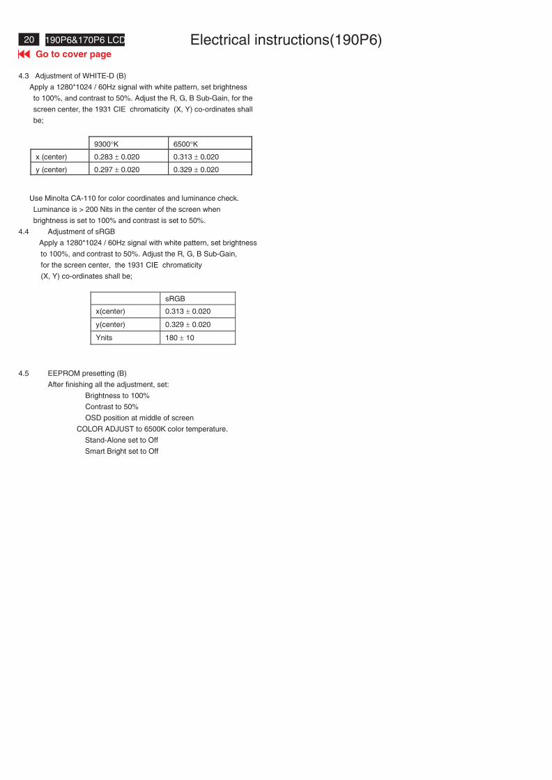
4.3 Adjustment of WHITE-D (B)
Apply a 1280*1024 / 60Hz signal with white pattern, set brightness
to 100%, and contrast to 50%. Adjust the R, G, B Sub-Gain, for the
screen center, the 1931 CIE chromaticity (X, Y) co-ordinates shall
be;
Use Minolta CA-110 for color coordinates and luminance check.
Luminance is > 200 Nits in the center of the screen when
brightness is set to 100% and contrast is set to 50%.
4.4 Adjustment of sRGB
Apply a 1280*1024 / 60Hz signal with white pattern, set brightness
to 100%, and contrast to 50%. Adjust the R, G, B Sub-Gain,
for the screen center, the 1931 CIE chromaticity
(X, Y) co-ordinates shall be;
sRGB
x(center) 0.313 � 0.020
y(center) 0.329 � 0.020
Ynits 180 � 10
4.5 EEPROM presetting (B)
After finishing all the adjustment, set:
Brightness to 100%
Contrast to 50%
OSD position at middle of screen
COLOR ADJUST to 6500K color temperature.
Stand-Alone set to Off
Smart Bright set to Off
9300�K 6500�K
x (center) 0.283 � 0.020 0.313 � 0.020
y (center) 0.297 � 0.020 0.329 � 0.020
21190P6&170P6 LCD
Go to cover page
Electrical instructions(170P6)
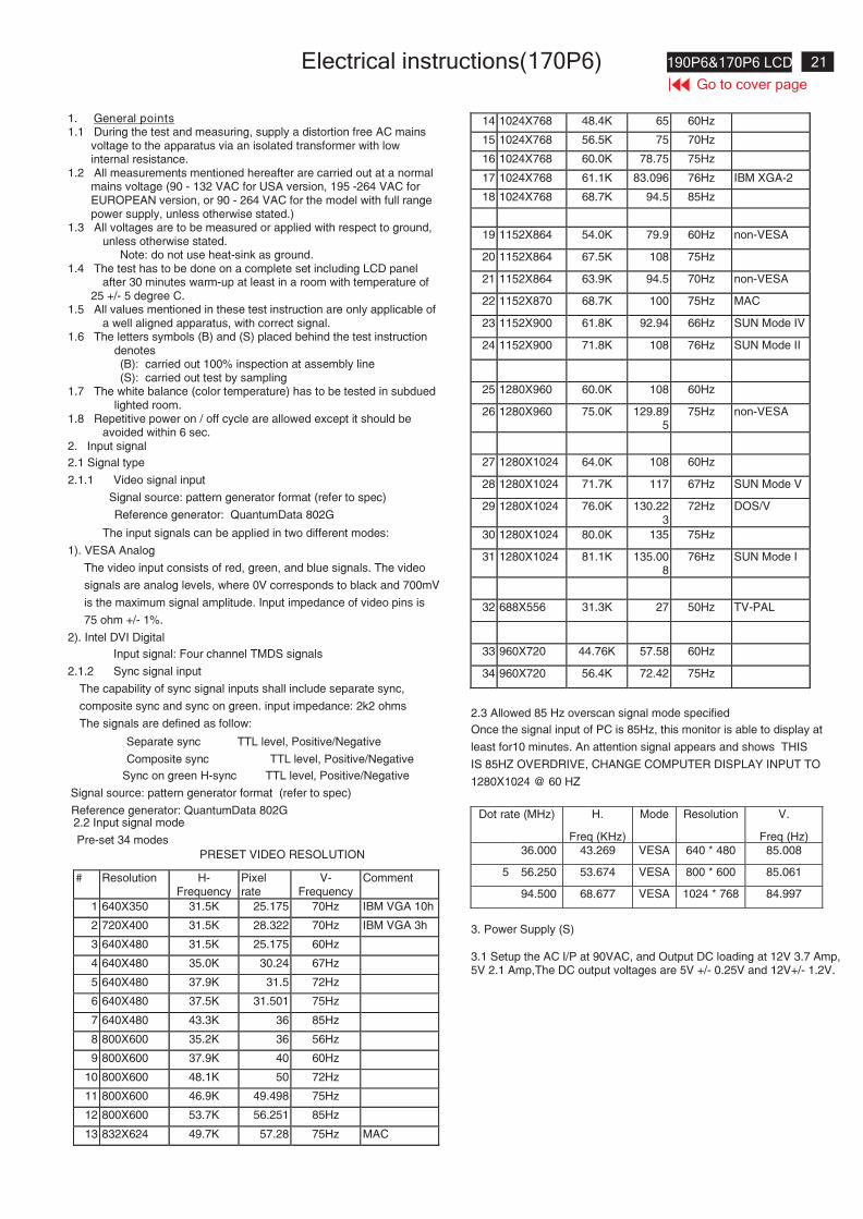
1. General points1.1 During the test and measuring, supply a distortion free AC mains
voltage to the apparatus via an isolated transformer with lowinternal resistance.
1.2 All measurements mentioned hereafter are carried out at a normalmains voltage (90 - 132 VAC for USA version, 195 -264 VAC forEUROPEAN version, or 90 - 264 VAC for the model with full rangepower supply, unless otherwise stated.)
1.3 All voltages are to be measured or applied with respect to ground,unless otherwise stated.
Note: do not use heat-sink as ground.1.4 The test has to be done on a complete set including LCD panel
after 30 minutes warm-up at least in a room with temperature of25 +/- 5 degree C.
1.5 All values mentioned in these test instruction are only applicable ofa well aligned apparatus, with correct signal.
1.6 The letters symbols (B) and (S) placed behind the test instructiondenotes(B): carried out 100% inspection at assembly line(S): carried out test by sampling
1.7 The white balance (color temperature) has to be tested in subduedlighted room.
1.8 Repetitive power on / off cycle are allowed except it should beavoided within 6 sec.
2. Input signal
2.1 Signal type
2.1.1 Video signal input
Signal source: pattern generator format (refer to spec)
Reference generator: QuantumData 802G
The input signals can be applied in two different modes:
1). VESA Analog
The video input consists of red, green, and blue signals. The video
signals are analog levels, where 0V corresponds to black and 700mV
is the maximum signal amplitude. Input impedance of video pins is
75 ohm +/- 1%.
2). Intel DVI Digital
Input signal: Four channel TMDS signals
2.1.2 Sync signal input
The capability of sync signal inputs shall include separate sync,
composite sync and sync on green. input impedance: 2k2 ohms
The signals are defined as follow:
Separate sync TTL level, Positive/Negative
Composite sync TTL level, Positive/Negative
Sync on green H-sync TTL level, Positive/Negative
Signal source: pattern generator format (refer to spec)
Reference generator: QuantumData 802G2.2 Input signal mode
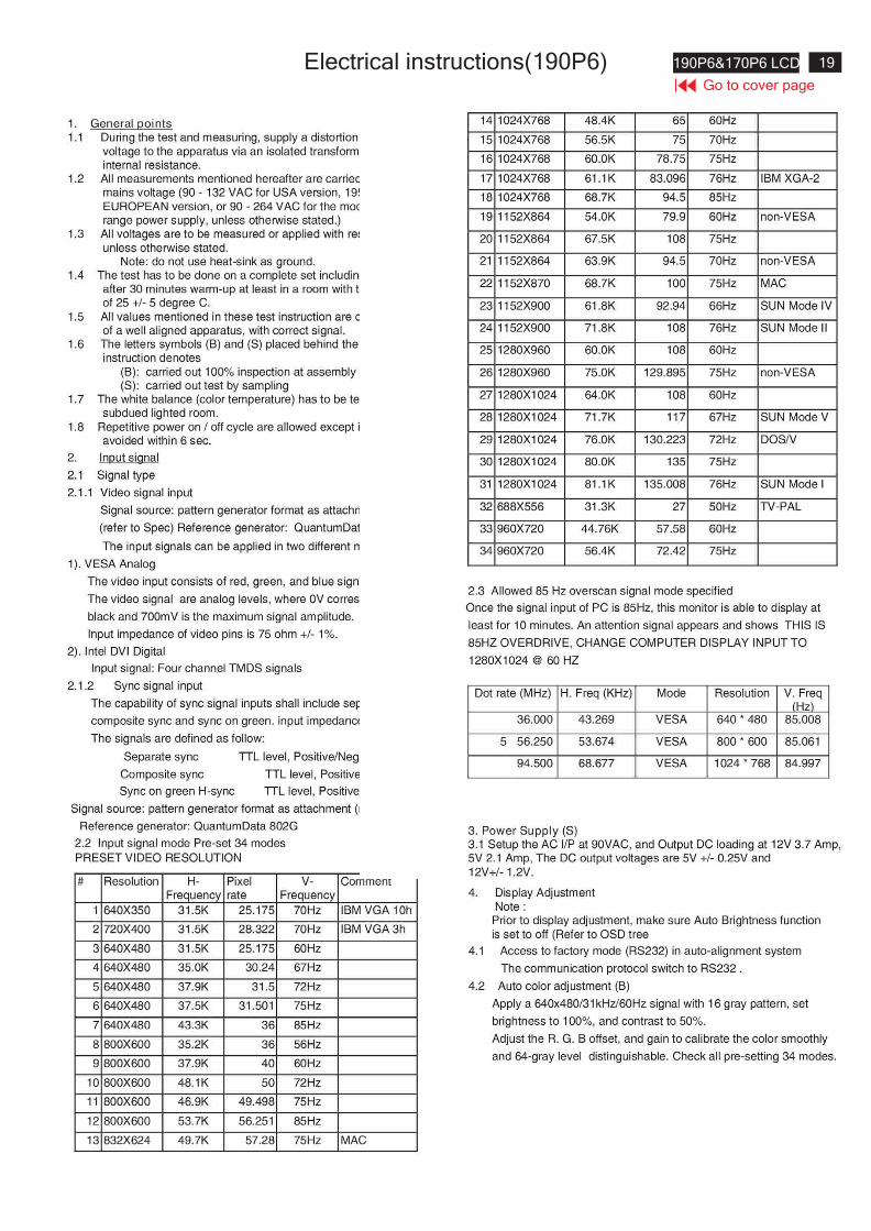
Pre-set 34 modes
PRESET VIDEO RESOLUTION
# Resolution H-Frequency
Pixelrate
V-Frequency
Comment
1 640X350 31.5K 25.175 70Hz IBM VGA 10h
2 720X400 31.5K 28.322 70Hz IBM VGA 3h
3 640X480 31.5K 25.175 60Hz
4 640X480 35.0K 30.24 67Hz
5 640X480 37.9K 31.5 72Hz
6 640X480 37.5K 31.501 75Hz
7 640X480 43.3K 36 85Hz
8 800X600 35.2K 36 56Hz
9 800X600 37.9K 40 60Hz
10 800X600 48.1K 50 72Hz
11 800X600 46.9K 49.498 75Hz
12 800X600 53.7K 56.251 85Hz
13 832X624 49.7K 57.28 75Hz MAC
14 1024X768 48.4K 65 60Hz
15 1024X768 56.5K 75 70Hz
16 1024X768 60.0K 78.75 75Hz
17 1024X768 61.1K 83.096 76Hz IBM XGA-2
18 1024X768 68.7K 94.5 85Hz
19 1152X864 54.0K 79.9 60Hz non-VESA
20 1152X864 67.5K 108 75Hz
21 1152X864 63.9K 94.5 70Hz non-VESA
22 1152X870 68.7K 100 75Hz MAC
23 1152X900 61.8K 92.94 66Hz SUN Mode IV
24 1152X900 71.8K 108 76Hz SUN Mode II
25 1280X960 60.0K 108 60Hz
26 1280X960 75.0K 129.895
75Hz non-VESA
27 1280X1024 64.0K 108 60Hz
28 1280X1024 71.7K 117 67Hz SUN Mode V
29 1280X1024 76.0K 130.223
72Hz DOS/V
30 1280X1024 80.0K 135 75Hz
31 1280X1024 81.1K 135.008
76Hz SUN Mode I
32 688X556 31.3K 27 50Hz TV-PAL
33 960X720 44.76K 57.58 60Hz
34 960X720 56.4K 72.42 75Hz
2.3 Allowed 85 Hz overscan signal mode specified
Once the signal input of PC is 85Hz, this monitor is able to display at
least for10 minutes. An attention signal appears and shows THIS
IS 85HZ OVERDRIVE, CHANGE COMPUTER DISPLAY INPUT TO
1280X1024 @ 60 HZ
Dot rate (MHz) H.
Freq (KHz)
Mode Resolution V.
Freq (Hz)36.000 43.269 VESA 640 * 480 85.008
5 56.250 53.674 VESA 800 * 600 85.061
94.500 68.677 VESA 1024 * 768 84.997
3. Power Supply (S)
3.1 Setup the AC I/P at 90VAC, and Output DC loading at 12V 3.7 Amp,5V 2.1 Amp,The DC output voltages are 5V +/- 0.25V and 12V+/- 1.2V.
22 190P6&170P6 LCD
Go to cover page
Electrical instructions(170P6)
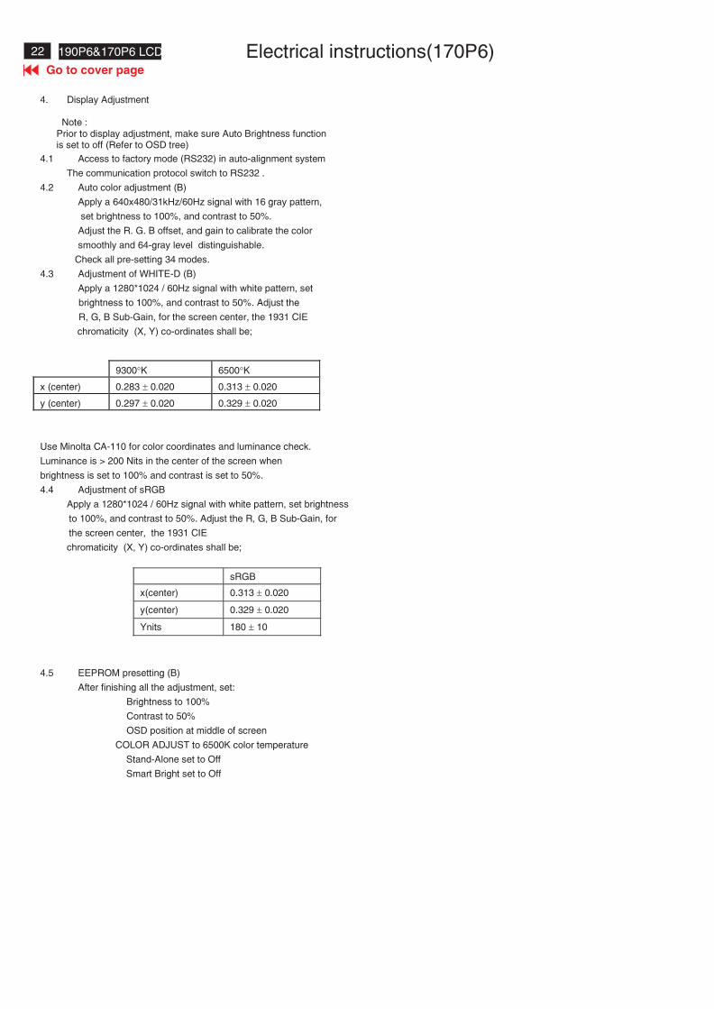
4. Display Adjustment
Note :Prior to display adjustment, make sure Auto Brightness functionis set to off (Refer to OSD tree)
4.1 Access to factory mode (RS232) in auto-alignment system
The communication protocol switch to RS232 .
4.2 Auto color adjustment (B)
Apply a 640x480/31kHz/60Hz signal with 16 gray pattern,
set brightness to 100%, and contrast to 50%.
Adjust the R. G. B offset, and gain to calibrate the color
smoothly and 64-gray level distinguishable.
Check all pre-setting 34 modes.
4.3 Adjustment of WHITE-D (B)
Apply a 1280*1024 / 60Hz signal with white pattern, set
brightness to 100%, and contrast to 50%. Adjust the
R, G, B Sub-Gain, for the screen center, the 1931 CIE
chromaticity (X, Y) co-ordinates shall be;
Use Minolta CA-110 for color coordinates and luminance check.
Luminance is > 200 Nits in the center of the screen when
brightness is set to 100% and contrast is set to 50%.
4.4 Adjustment of sRGB
Apply a 1280*1024 / 60Hz signal with white pattern, set brightness
to 100%, and contrast to 50%. Adjust the R, G, B Sub-Gain, for
the screen center, the 1931 CIE
chromaticity (X, Y) co-ordinates shall be;
sRGB
x(center) 0.313 � 0.020
y(center) 0.329 � 0.020
Ynits 180 � 10
4.5 EEPROM presetting (B)
After finishing all the adjustment, set:
Brightness to 100%
Contrast to 50%
OSD position at middle of screen
COLOR ADJUST to 6500K color temperature
Stand-Alone set to Off
Smart Bright set to Off
9300�K 6500�K
x (center) 0.283 � 0.020 0.313 � 0.020
y (center) 0.297 � 0.020 0.329 � 0.020
23190P6&170P6 LCD
Go to cover page
LightFrame DRTM
LightFrameTM Digital Reality (LightFrameTM DR) for Windows
IntroductionPhilips LightFrameTM DR feature enriches your photo and videoexperience with preset modes ideal for your favorite applications:Internet, TV/video viewing, photos and gaming. The LightFrameTM DRengine optimizes brightness, sharpness, contrast, color, JPG noise forphotos and skin tone for videos.InstallationFirst things first: Philips LightFrameTM DR only works with latest PhilipsLCD Monitor which is sepcially built to use this software. That isLightFrameTM DR can only work on 170X5,190X5 or 170P6/190P6 orlater version LCD monitor. Earlier Philips monitors or othermanufacturers monitors will not work with this picture enhancementsoftware. You can identify compatible Philips monitors by theLightFrame logo on the front of the monitor.LightFrameTM DR works with true Windows-based programs andDOS-based programs that operate in a Windows environment. It doesnot work with DOS-based programs operating only in a DOSenvironment.To control the LightFrameTM DR feature in your monitor, you'll want installthe LightFrameTM DR application found on this CD-ROM.To install LightFrameTM DR, place the CD in your CD-ROM drive.When the CD menu appears on your screen,1) select preferred language2) select model number (17P6 or 190P6)3) click on Install LightFrameTM Digital Reality.Follow the on-screen prompts to properly install the program. The softwarechecks to see if you have a compatible monitor. You must agree to thelicense terms in order to install the software.After installation, the LightFrameTM DR shortcut icon automatically appearsat your desktop, click it to load the control bar on screen.
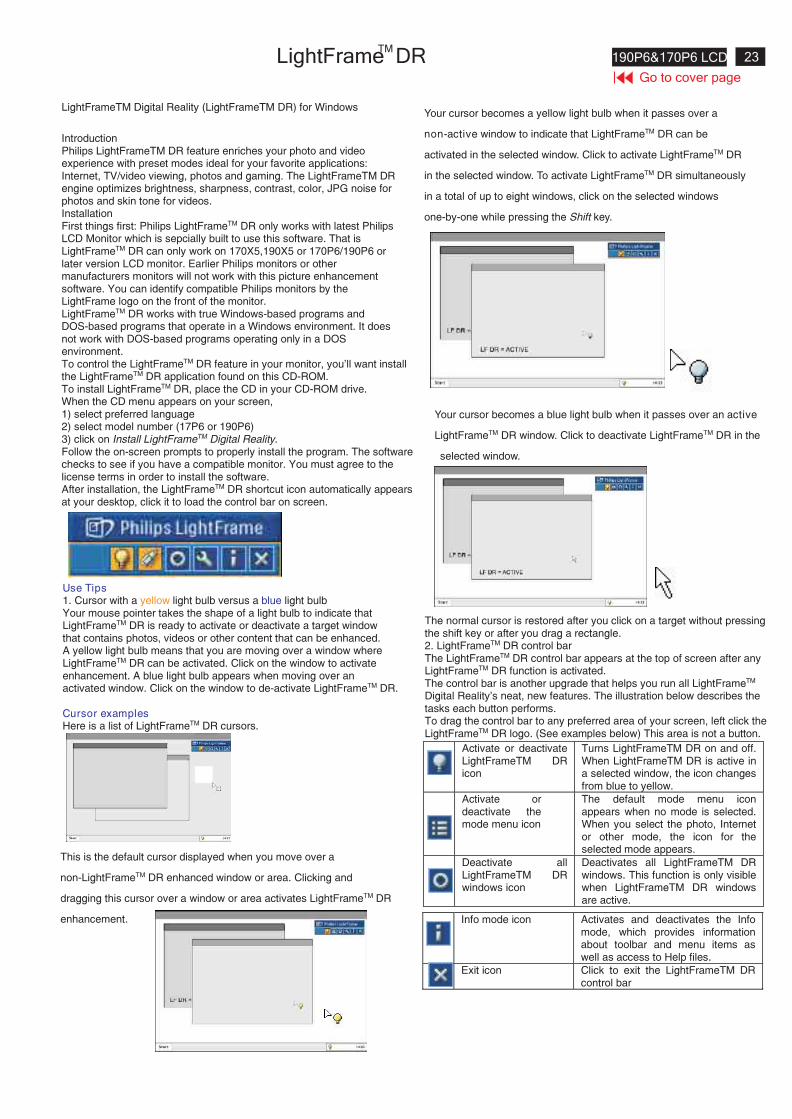
Use Tips1. Cursor with a yellow light bulb versus a blue light bulbYour mouse pointer takes the shape of a light bulb to indicate thatLightFrameTM DR is ready to activate or deactivate a target windowthat contains photos, videos or other content that can be enhanced.A yellow light bulb means that you are moving over a window whereLightFrameTM DR can be activated. Click on the window to activateenhancement. A blue light bulb appears when moving over anactivated window. Click on the window to de-activate LightFrameTM DR.
Cursor examplesHere is a list of LightFrameTM DR cursors.
This is the default cursor displayed when you move over a
non-LightFrameTM DR enhanced window or area. Clicking and
dragging this cursor over a window or area activates LightFrameTM DR
enhancement.
Your cursor becomes a yellow light bulb when it passes over a
non-active window to indicate that LightFrameTM DR can be
activated in the selected window. Click to activate LightFrameTM DR
in the selected window. To activate LightFrameTM DR simultaneously
in a total of up to eight windows, click on the selected windows
one-by-one while pressing the Shift key.
Your cursor becomes a blue light bulb when it passes over an active
LightFrameTM DR window. Click to deactivate LightFrameTM DR in the
selected window.
The normal cursor is restored after you click on a target without pressingthe shift key or after you drag a rectangle.2. LightFrameTM DR control barThe LightFrameTM DR control bar appears at the top of screen after anyLightFrameTM DR function is activated.The control bar is another upgrade that helps you run all LightFrameTM
Digital Reality's neat, new features. The illustration below describes thetasks each button performs.To drag the control bar to any preferred area of your screen, left click theLightFrameTM DR logo. (See examples below) This area is not a button.
Activate or deactivateLightFrameTM DRicon
Turns LightFrameTM DR on and off.When LightFrameTM DR is active ina selected window, the icon changesfrom blue to yellow.
Activate ordeactivate themode menu icon
The default mode menu iconappears when no mode is selected.When you select the photo, Internetor other mode, the icon for theselected mode appears.
Deactivate allLightFrameTM DRwindows icon
Deactivates all LightFrameTM DRwindows. This function is only visiblewhen LightFrameTM DR windowsare active.
Info mode icon Activates and deactivates the Infomode, which provides informationabout toolbar and menu items aswell as access to Help files.
Exit icon Click to exit the LightFrameTM DRcontrol bar
24 190P6&170P6 LCD
Go to cover page
LightFrame DRTM
Properties icon Provides access to the Propertiesmenu, which includes these options:LightFrameTM DR auto start: Yes/noPosition: LightFrameTM DR Alwayson topWarning messages: On/offTarget selection: Automatic/manualMonitor selection: Chose among twomonitors connected to the same PCPlace LightFrameTM DR icon in thetaskbar: Yes/no
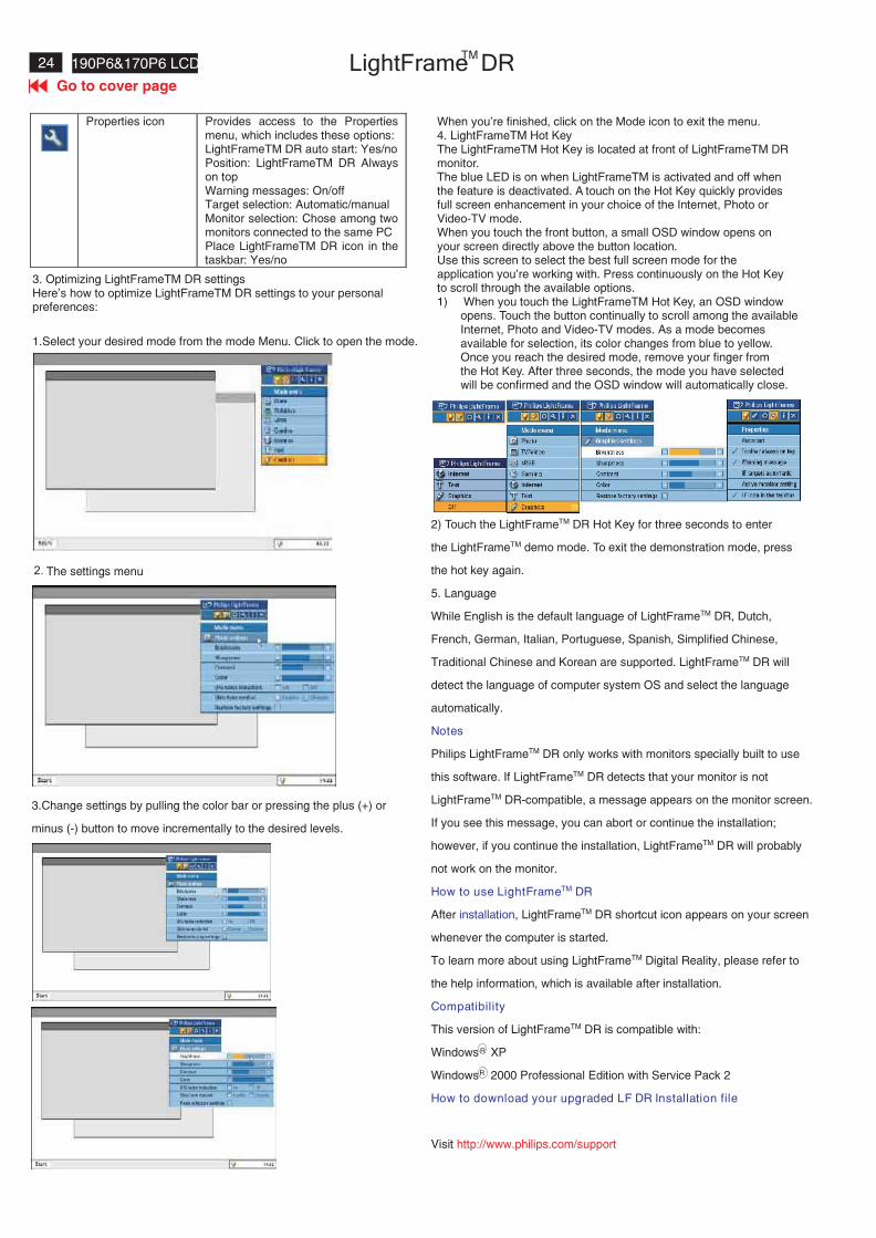
3. Optimizing LightFrameTM DR settingsHere's how to optimize LightFrameTM DR settings to your personalpreferences:
1.Select your desired mode from the mode Menu. Click to open the mode.
The settings menu2.
3.Change settings by pulling the color bar or pressing the plus (+) or
minus (-) button to move incrementally to the desired levels.
When you're finished, click on the Mode icon to exit the menu.4. LightFrameTM Hot KeyThe LightFrameTM Hot Key is located at front of LightFrameTM DRmonitor.The blue LED is on when LightFrameTM is activated and off whenthe feature is deactivated. A touch on the Hot Key quickly providesfull screen enhancement in your choice of the Internet, Photo orVideo-TV mode.When you touch the front button, a small OSD window opens onyour screen directly above the button location.Use this screen to select the best full screen mode for theapplication you're working with. Press continuously on the Hot Keyto scroll through the available options.1) When you touch the LightFrameTM Hot Key, an OSD window
opens. Touch the button continually to scroll among the availableInternet, Photo and Video-TV modes. As a mode becomesavailable for selection, its color changes from blue to yellow.Once you reach the desired mode, remove your finger fromthe Hot Key. After three seconds, the mode you have selectedwill be confirmed and the OSD window will automatically close.
2) Touch the LightFrameTM DR Hot Key for three seconds to enter
the LightFrameTM demo mode. To exit the demonstration mode, press
the hot key again.
5. Language
While English is the default language of LightFrameTM DR, Dutch,
French, German, Italian, Portuguese, Spanish, Simplified Chinese,
Traditional Chinese and Korean are supported. LightFrameTM DR will
detect the language of computer system OS and select the language
automatically.
Notes
Philips LightFrameTM DR only works with monitors specially built to use
this software. If LightFrameTM DR detects that your monitor is not
LightFrameTM DR-compatible, a message appears on the monitor screen.
If you see this message, you can abort or continue the installation;
however, if you continue the installation, LightFrameTM DR will probably
not work on the monitor.
How to use LightFrameTM DR
After installation, LightFrameTM DR shortcut icon appears on your screen
whenever the computer is started.
To learn more about using LightFrameTM Digital Reality, please refer to
the help information, which is available after installation.
Compatibility
This version of LightFrameTM DR is compatible with:
Windows XP
Windows 2000 Professional Edition with Service Pack 2
How to download your upgraded LF DR Installation file
Visit http://www.philips.com/support
R
R
25190P6&170P6 LCD
Go to cover page
All units that are returned for service or repair must pass theoriginal manufactures safety tests. Safety testing requires both
and testing.Hipot Ground Continuity
HI-POT TEST INSTRUCTION1.Application requirements
2.
1.1 All mains operated products must pass the Hi-Pot test asdescribed in this instruction.
1.2 This test must be performed again after the covers havebeen refitted following the repair, inspection or modificationof the product.
2.1 Connecting conditions
2.1.1 The test specified must be applied between the parallel-blade plug of the mainscord and all accessible metalparts of the product.
2.1.2 Before carrying out the test, reliable conductiveconnections must be ensured and thereafter bemaintained throughout the test period.
2.1.3 The mains switch(es) must be in the "ON" position.
2.2 Test RequirementsAll products should be HiPot and Ground Continuity tested asfollows:
Test 2820VDC 1700VDC Test current:voltage (2000VAC) (1200VAC) 25A,AC
Test time:Test time 3 seconds 1 second 3 seconds(min.)(min.) Resistance
required:Trip set at 100 uA 5 mA <=0.09+Rohm,current for Max. R is the(Tester) limitation; set resistance of
at 0.1 uA for the mains cord.Min. Limitation
Ramp set at 2time seconds(Tester)
Test method
Condition HiPot Test for HiPot Test for Ground Continuityproducts where products where Test requirementthe mains input the mains input isrange is Full 110V AC(USArange(or 220V type)AC)
2.2.1 The minimum test duration for Quality Control Inspectormust be 1 minute.
2.2.2 The test voltage must be maintained within the specifiedvoltage + 5%.
2.2.3 There must be no breakdown during the test.
2.2.4 The grounding blade or pin of mains plug must beconducted with accessible metal parts.
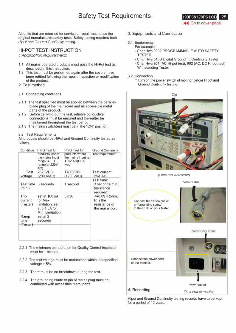
3. Equipments and Connection
3.1. Equipments
For example :
- ChenHwa 9032 PROGRAMMABLE AUTO SAFETYTESTER
- ChenHwa 510B Digital Grounding Continuity Tester
- ChenHwa 901 (AC Hi-pot test), 902 (AC, DC Hi-pot test)Withstanding Tester
3.2. Connection
4. Recording
Hipot and Ground Continuity testing records have to be keptfor a period of 10 years.
* Turn on the power switch of monitor before Hipot andGround Continuity testing.
Connect the "video cable"or "grounding screw"to the CLIP on your tester.
Video cable
(Rear view of monitor)
Connect the power cord
to the monitor.
Grounding screw
Power outlet
(ChenHwa 9032 tester)
Clip
Clip
26 190P6&170P6 LCD DDC Instructions
To MonitorD-sub/DVI cable
DC 8~12V
To Printer port
Powerindicator
To MonitorD-sub cable
DC 8~12V
To Printer port
Powerindicator
General
DDC Data Re-programming
Analog DDC IC, & EEPROM
Additional information
In case the DDC data memory IC or main EEPROM which storage allfactory settings were replaced due to a defect, the serial numbers haveto be re-programmed" ".It is advised to re-soldered DDC IC and main EEPROM from the oldboard onto the new board if circuit board have been replaced, in this casethe DDC data does not need to be re-programmed.
Additional information about DDC (Display Data Channel) may beobtained from Video Electronics Standards Association (VESA).Extended Display Identification Data(EDID) information may be alsoobtained from VESA.
1. An i486 (or above) personal computer or compatible.2. Microsoft operation system Windows 95/98 .
Y o Install the EDID_PORT_Tool under Win2000/XP . AsFig. 1 .
A. Cody the "UserPort.sys" to C:\WINNT\system32\drivers(win2000)C:\WINDOWS\system32\drivers(winXP)
B. Running " io.exe" everytime, Before you start to programmingedid data .
4. DDC 2BI-ISP TOOL:
Inclusion :A. DDC2BI-ISP TOOL(3138 106 10396) x1 (as Fig. 2)B. Printer cable x1c. (D-Sub) to (D-Sub) cable x2D. D-SUB to DVI cable X1
Note: The EDID46.EXE is a windows-based program, which cannotbe run in MS-DOS.
System and equipment requirements
ou have t
3. EDID46 Release For writing block4.EXE program .
Fig. 2Fig. 2
Fig. 1Fig. 1
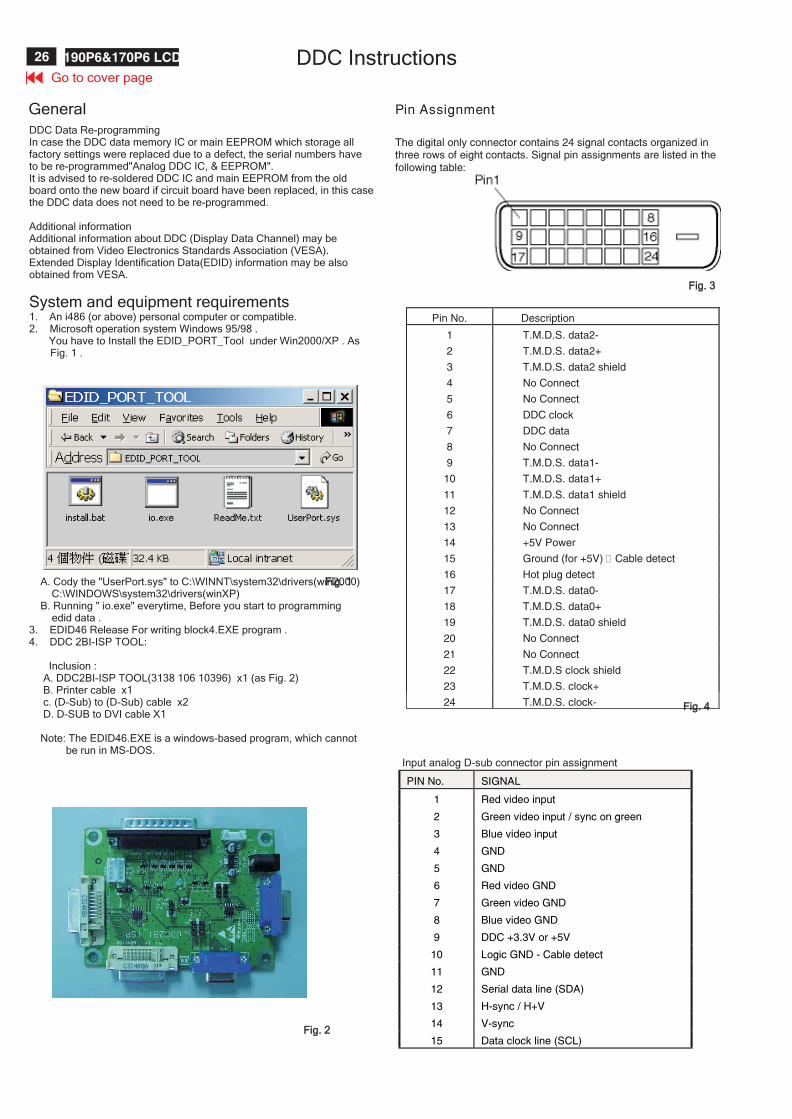
Pin Assignment
The digital only connector contains 24 signal contacts organized inthree rows of eight contacts. Signal pin assignments are listed in thefollowing table:
Fig. 3Fig. 3
Fig. 4Fig. 4
Pin No. Description
1 T.M.D.S. data2-
2 T.M.D.S. data2+
3 T.M.D.S. data2 shield
4 No Connect
5 No Connect
6 DDC clock
7 DDC data
8 No Connect
9 T.M.D.S. data1-
10 T.M.D.S. data1+
11 T.M.D.S. data1 shield
12 No Connect
13 No Connect
14 +5V Power
15 Ground (for +5V) – Cable detect
16 Hot plug detect
17 T.M.D.S. data0-
18 T.M.D.S. data0+
19 T.M.D.S. data0 shield
20 No Connect
21 No Connect
22 T.M.D.S clock shield
23 T.M.D.S. clock+
24 T.M.D.S. clock-
Input analog D-sub connector pin assignment
PIN No. SIGNAL
1 Red video input
2 Green video input / sync on green
3 Blue video input
4 GND
5 GND
6 Red video GND
7 Green video GND
8 Blue video GND
9 DDC +3.3V or +5V
10 Logic GND - Cable detect
11 GND
12 Serial data line (SDA)
13 H-sync / H+V
14 V-sync
15 Data clock line (SCL)
Go to cover page
27190P6&170P6 LCDDDC Instructions
Step 3: Installation of EDID45.EXE
Method 1: Start on DDC program
Start Microsoft Windows.1. The Program"EDID45.EXE" in service manual cd-rom be copyed to C:\ .2. Click , choose Run at start menu of Windows as shown
In Fig. 6.
Fig. 6
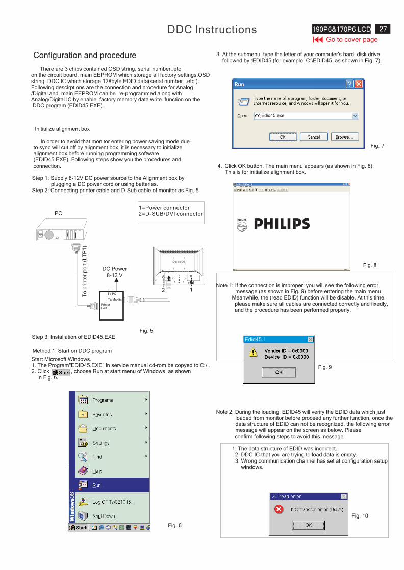
4. Click button. The main menu appears (as shown in Fig. 8).OKThis is for initialize alignment box.
Fig. 8
Fig. 7
Fig. 9
Note 1: If the connection is improper, you will see the following errormessage (as shown in Fig. 9) before entering the main menu.
Meanwhile, the (read EDID) function will be disable. At this time,please make sure all cables are connected correctly and fixedly,and the procedure has been performed properly.
3. At the submenu, type the letter of your computer's hard disk drivefollowed by :EDID45 (for example, C:\EDID45, as shown in Fig. 7).
Note 2: During the loading, EDID45 will verify the EDID data which justloaded from monitor before proceed any further function, once thedata structure of EDID can not be recognized, the following errormessage will appear on the screen as below. Pleaseconfirm following steps to avoid this message.
1. The data structure of EDID was incorrect.2. DDC IC that you are trying to load data is empty.3. Wrong communication channel has set at configuration setup
windows.
1
Configuration and procedure
There are 3 chips contained OSD string, serial number..etcon the circuit board, main EEPROM which storage all factory settings,OSDstring. DDC IC which storage 128byte EDID data(serial number ..etc.).Following descirptions are the connection and procedure for Analog/Digital and main EEPROM can be re-programmed along withAnalog/Digital IC by enable factory memory data write function on theDDC program (EDID45.EXE).
Initialize alignment box
In order to avoid that monitor entering power saving mode dueto sync will cut off by alignment box, it is necessary to initializealignment box before running programming software(EDID45.EXE). Following steps show you the procedures andconnection.
Step 1: Supply 8-12V DC power source to the Alignment box byplugging a DC power cord or using batteries.
Step 2: Connecting printer cable and D-Sub cable of monitor as Fig. 5
Fig. 5
PC1=Power connector2=D-SUB/DVI connector
To
pri
nte
rp
ort
(LT
P1
)
DC Power8-12 V
Fig. 10
PrinterPort
To Monitor
To PC2
----
->
1
----
->
Edid45.exe
Edid45.1
Go to cover page
28 190P6&170P6 LCD DDC Instructions
PC
To
pri
nte
rp
ort
(LT
P1
)
PrinterPort
To Monitor
To PC
To MonitorD-sub/DVI cable
DC 8~12V
To Printer port
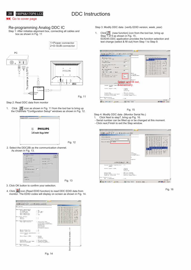
Re-programming Analog DDC ICStep 1: After initialize alignment box, connecting all cables and
box as shown in Fig. 11
Fig. 12
Step 2: Read DDC data from monitor
1. Click icon as shown in Fig. 11 from the tool bar to bring upthe Channels "Configuration Setup" windows as shown in Fig. 12.
Step 3: Modify DDC data (verify EDID version, week, year)
1. Click (new function) icon from the tool bar, bring upStep 1 of 9 as shown in Fig. 15 .EDID45 DDC application provides the function selection andtext change (select & fill out) from Step 1 to Step 9.
Step 4: Modify DDC data (Monitor Serial No.)Next1. Click to step7, bring up Fig. 16.
- Serial number can be filled up or be changed at this moment.- Click next,Finish to exit the Step window.
3. Click OK button to confirm your selection.
4. Click icon (Read EDID function) to read DDC EDID data frommonitor. The EDID codes will display on screen as shown in Fig. 14.
Fig. 16
2. Select the DDC2Bi as the communication channel.As shown in Fig. 13.
Fig. 11
1=Power connector2=D-SUB connector
Fig. 13
Fig. 14
Fig. 15
Do
n't
clo
se
this
scre
en
.--
->
Select and fill out,If necessary.
Go to cover page
29190P6&170P6 LCDDDC Instructions
To MonitorD-sub/DVI cable
DC 8~12V
To Printer port
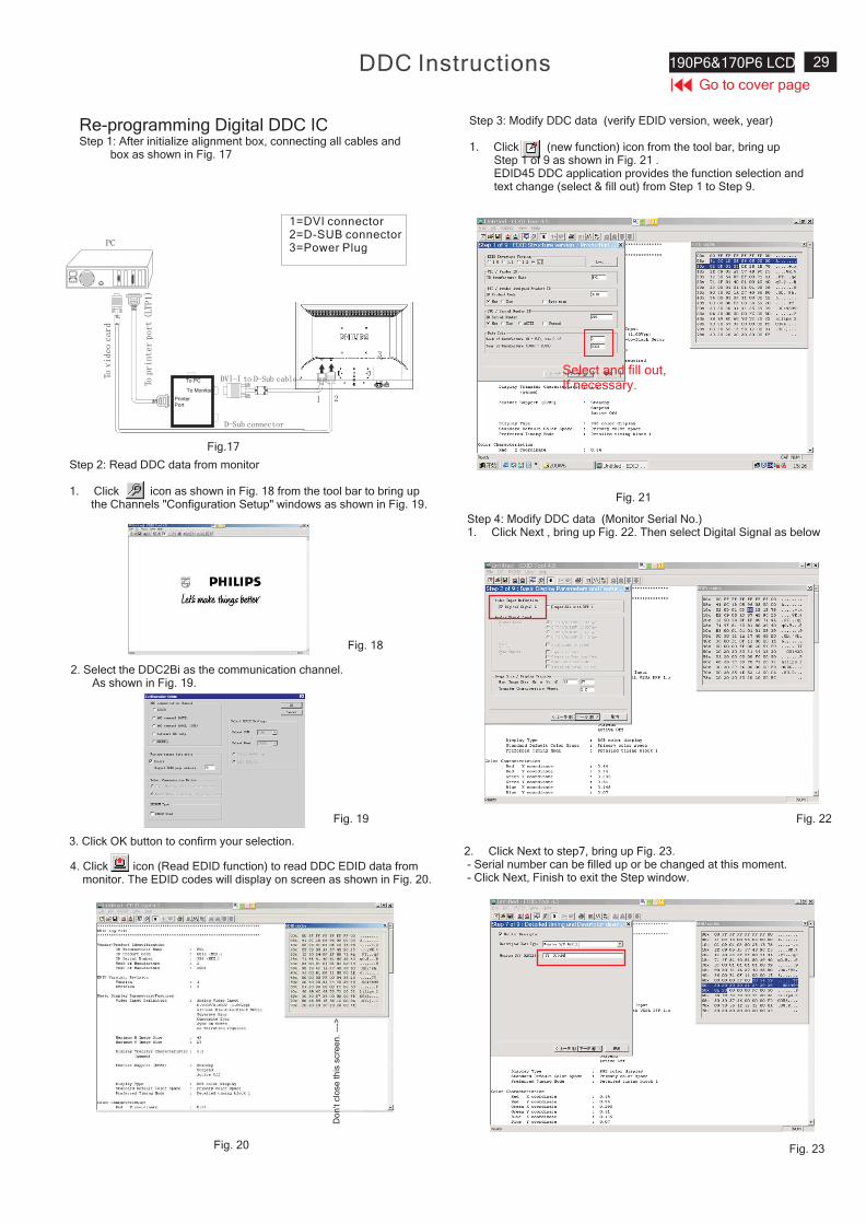
Re-programming Digital DDC ICStep 1: After initialize alignment box, connecting all cables and
box as shown in Fig. 17
Fig. 18
Step 2: Read DDC data from monitor
1. Click icon as shown in Fig. 18 from the tool bar to bring upthe Channels "Configuration Setup" windows as shown in Fig. 19.
Step 3: Modify DDC data (verify EDID version, week, year)
1. Click (new function) icon from the tool bar, bring upStep 1 of 9 as shown in Fig. 21 .EDID45 DDC application provides the function selection andtext change (select & fill out) from Step 1 to Step 9.
Step 4: Modify DDC data (Monitor Serial No.)Next1. Click , bring up Fig. 22. Then select Digital Signal as below
3. Click OK button to confirm your selection.
4. Click icon (Read EDID function) to read DDC EDID data frommonitor. The EDID codes will display on screen as shown in Fig. 20.
Fig. 22
Fig. 23
2. Select the DDC2Bi as the communication channel.As shown in Fig. 19.
Fig. 19
Fig. 20
Fig. 21
Fig.17
PrinterPort
To Monitor
To PC
1=DVI connector2=D-SUB connector3=Power Plug
3
Do
n't
clo
se
this
scre
en
.--
->
To MonitorD-sub/DVI cable
DC 8~12V
Select and fill out,If necessary.
2. Click to step7, bring up Fig. 23.Next- Serial number can be filled up or be changed at this moment.- Click Next, Finish to exit the Step window.
Go to cover page
30 190P6&170P6 LCD DDC Instructions
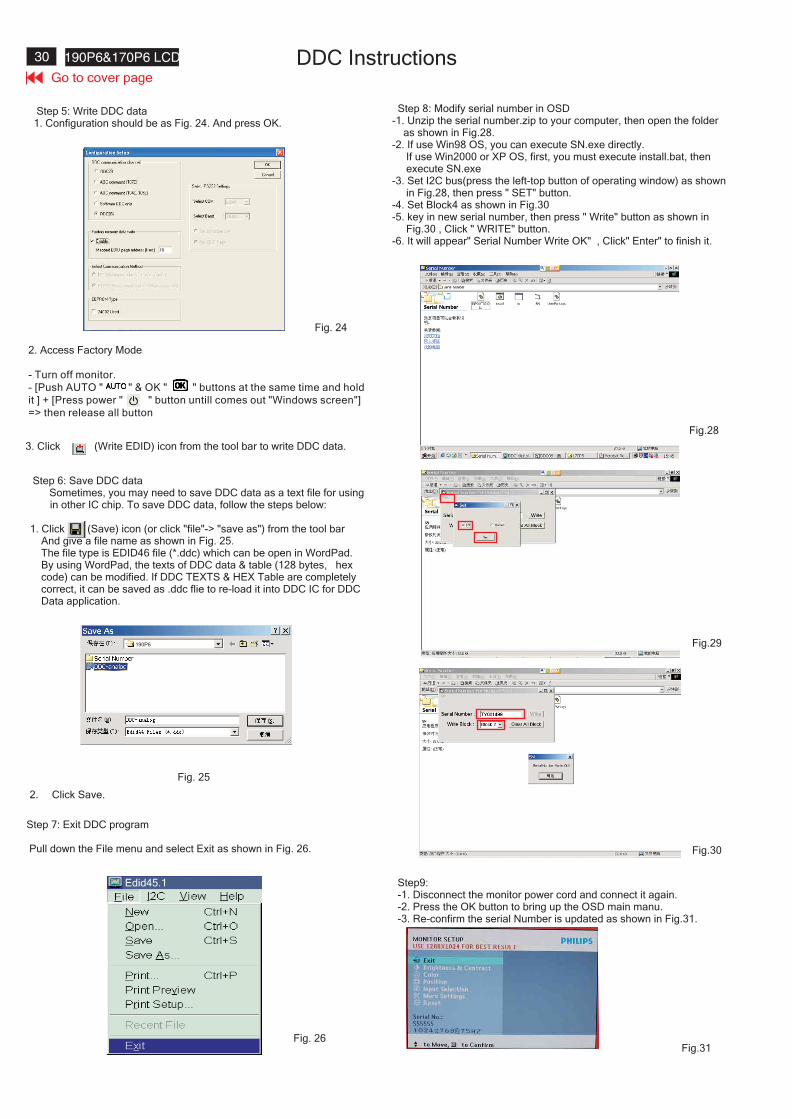
Step 6: Save DDC dataSometimes, you may need to save DDC data as a text file for usingin other IC chip. To save DDC data, follow the steps below:
1. Click (Save) icon (or click "file"-> "save as") from the tool barAnd give a file name as shown in Fig. 25.The file type is EDID46 file (*.ddc) which can be open in WordPad.By using WordPad, the texts of DDC data & table (128 bytes, hexcode) can be modified. If DDC TEXTS & HEX Table are completelycorrect, it can be saved as .ddc flie to re-load it into DDC IC for DDCData application.
2. Click .Save
Step 7: Exit DDC program
Pull down the File menu and select Exit as shown in Fig. 26.
Step 5: Write DDC data1. Configuration should be as Fig. 24. And press OK.
3. Click (Write EDID) icon from the tool bar to write DDC data.
Fig. 24
Fig. 26
Fig. 25
2. Access Factory Mode
[Push AUTO " " & OK " " buttons at the same time and hold
it ] + [Press power " " button untill comes out "Windows screen"]
=> then release all button
- Turn off monitor.
-
Step9:-1. Disconnect the monitor power cord and connect it again.-2. Press the OK button to bring up the OSD main manu.-3. Re-confirm the serial Number is updated as shown in Fig.31.
Step :8 Modify serial number in OSD-1. Unzip the serial number.zip to your computer, then open the folder
as shown in Fig.28.-2. If use Win98 OS, you can execute SN.exe directly.
If use Win2000 or XP OS, first, you must execute install.bat, thenexecute SN.exe
-3. Set I2C bus(press the left-top button of operating window) as shownin Fig.28, then press " SET" button.
-4. Set Block4 as shown in Fig.30-5. key in new serial number, then press " Write" button as shown in
Fig.30 , Click " WRITE" button.-6. It will appear" Serial Number Write OK" , Click" Enter" to finish it.
Fig.28
Fig.29
Fig.30
Edid45.1
Fig.31
190P6
Go to cover page
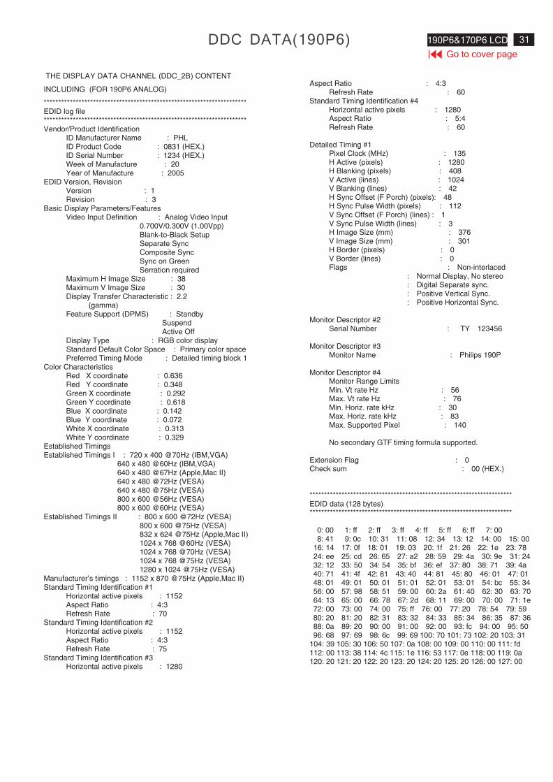
31190P6&170P6 LCDDDC DATA(190P6)
THE DISPLAY DATA CHANNEL (DDC_2B) CONTENT
INCLUDING (FOR 190P6 ANALOG)
**********************************************************************EDID log file**********************************************************************Vendor/Product Identification
ID Manufacturer Name : PHLID Product Code : 0831 (HEX.)ID Serial Number : 1234 (HEX.)Week of Manufacture : 20Year of Manufacture : 2005
EDID Version, RevisionVersion : 1Revision : 3
Basic Display Parameters/FeaturesVideo Input Definition : Analog Video Input
0.700V/0.300V (1.00Vpp)Blank-to-Black SetupSeparate SyncComposite SyncSync on GreenSerration required
Maximum H Image Size : 38Maximum V Image Size : 30Display Transfer Characteristic : 2.2
(gamma)Feature Support (DPMS) : Standby
SuspendActive Off
Display Type : RGB color displayStandard Default Color Space : Primary color spacePreferred Timing Mode : Detailed timing block 1
Color CharacteristicsRed X coordinate : 0.636Red Y coordinate : 0.348Green X coordinate : 0.292Green Y coordinate : 0.618Blue X coordinate : 0.142Blue Y coordinate : 0.072White X coordinate : 0.313White Y coordinate : 0.329
Established TimingsEstablished Timings I : 720 x 400 @70Hz (IBM,VGA)
640 x 480 @60Hz (IBM,VGA)640 x 480 @67Hz (Apple,Mac II)640 x 480 @72Hz (VESA)640 x 480 @75Hz (VESA)800 x 600 @56Hz (VESA)800 x 600 @60Hz (VESA)
Established Timings II : 800 x 600 @72Hz (VESA)800 x 600 @75Hz (VESA)832 x 624 @75Hz (Apple,Mac II)1024 x 768 @60Hz (VESA)1024 x 768 @70Hz (VESA)1024 x 768 @75Hz (VESA)1280 x 1024 @75Hz (VESA)
Manufacturer's timings : 1152 x 870 @75Hz (Apple,Mac II)Standard Timing Identification #1
Horizontal active pixels : 1152Aspect Ratio : 4:3Refresh Rate : 70
Standard Timing Identification #2Horizontal active pixels : 1152Aspect Ratio : 4:3Refresh Rate : 75
Standard Timing Identification #3Horizontal active pixels : 1280
Aspect Ratio : 4:3Refresh Rate : 60
Standard Timing Identification #4Horizontal active pixels : 1280Aspect Ratio : 5:4Refresh Rate : 60
Detailed Timing #1Pixel Clock (MHz) : 135H Active (pixels) : 1280H Blanking (pixels) : 408V Active (lines) : 1024V Blanking (lines) : 42H Sync Offset (F Porch) (pixels): 48H Sync Pulse Width (pixels) : 112V Sync Offset (F Porch) (lines) : 1V Sync Pulse Width (lines) : 3H Image Size (mm) : 376V Image Size (mm) : 301H Border (pixels) : 0V Border (lines) : 0Flags : Non-interlaced
: Normal Display, No stereo: Digital Separate sync.: Positive Vertical Sync.: Positive Horizontal Sync.
Monitor Descriptor #2Serial Number : TY 123456
Monitor Descriptor #3Monitor Name : Philips 190P
Monitor Descriptor #4Monitor Range LimitsMin. Vt rate Hz : 56Max. Vt rate Hz : 76Min. Horiz. rate kHz : 30Max. Horiz. rate kHz : 83Max. Supported Pixel : 140
No secondary GTF timing formula supported.
Extension Flag : 0Check sum : 00 (HEX.)
**********************************************************************EDID data (128 bytes)**********************************************************************
0: 00 1: ff 2: ff 3: ff 4: ff 5: ff 6: ff 7: 008: 41 9: 0c 10: 31 11: 08 12: 34 13: 12 14: 00 15: 00
16: 14 17: 0f 18: 01 19: 03 20: 1f 21: 26 22: 1e 23: 7824: ee 25: cd 26: 65 27: a2 28: 59 29: 4a 30: 9e 31: 2432: 12 33: 50 34: 54 35: bf 36: ef 37: 80 38: 71 39: 4a40: 71 41: 4f 42: 81 43: 40 44: 81 45: 80 46: 01 47: 0148: 01 49: 01 50: 01 51: 01 52: 01 53: 01 54: bc 55: 3456: 00 57: 98 58: 51 59: 00 60: 2a 61: 40 62: 30 63: 7064: 13 65: 00 66: 78 67: 2d 68: 11 69: 00 70: 00 71: 1e72: 00 73: 00 74: 00 75: ff 76: 00 77: 20 78: 54 79: 5980: 20 81: 20 82: 31 83: 32 84: 33 85: 34 86: 35 87: 3688: 0a 89: 20 90: 00 91: 00 92: 00 93: fc 94: 00 95: 5096: 68 97: 69 98: 6c 99: 69 100: 70 101: 73 102: 20 103: 31
104: 39 105: 30 106: 50 107: 0a 108: 00 109: 00 110: 00 111: fd112: 00 113: 38 114: 4c 115: 1e 116: 53 117: 0e 118: 00 119: 0a120: 20 121: 20 122: 20 123: 20 124: 20 125: 20 126: 00 127: 00
Go to cover page
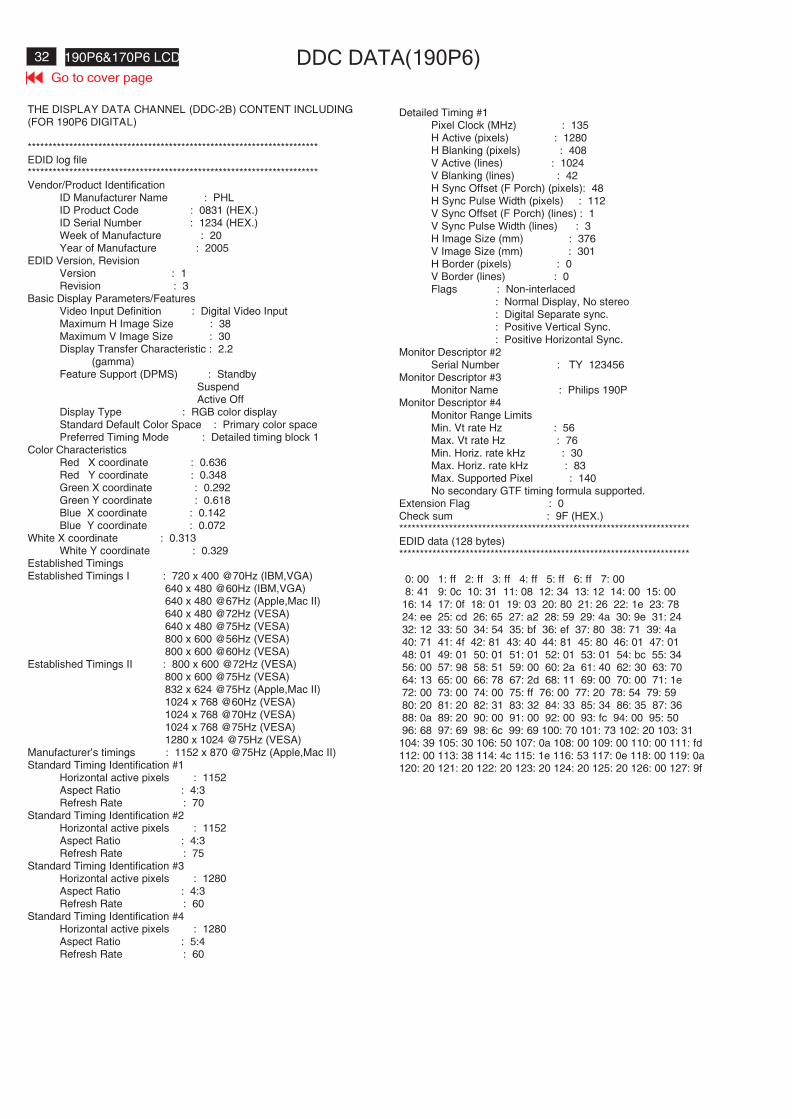
32 190P6&170P6 LCD DDC DATA(190P6)
THE DISPLAY DATA CHANNEL (DDC-2B) CONTENT INCLUDING(FOR 190P6 DIGITAL)
**********************************************************************EDID log file**********************************************************************Vendor/Product Identification
ID Manufacturer Name : PHLID Product Code : 0831 (HEX.)ID Serial Number : 1234 (HEX.)Week of Manufacture : 20Year of Manufacture : 2005
EDID Version, RevisionVersion : 1Revision : 3
Basic Display Parameters/FeaturesVideo Input Definition : Digital Video InputMaximum H Image Size : 38Maximum V Image Size : 30Display Transfer Characteristic : 2.2
(gamma)Feature Support (DPMS) : Standby
SuspendActive Off
Display Type : RGB color displayStandard Default Color Space : Primary color spacePreferred Timing Mode : Detailed timing block 1
Color CharacteristicsRed X coordinate : 0.636Red Y coordinate : 0.348Green X coordinate : 0.292Green Y coordinate : 0.618Blue X coordinate : 0.142Blue Y coordinate : 0.072
White X coordinate : 0.313White Y coordinate : 0.329
Established TimingsEstablished Timings I : 720 x 400 @70Hz (IBM,VGA)
640 x 480 @60Hz (IBM,VGA)640 x 480 @67Hz (Apple,Mac II)640 x 480 @72Hz (VESA)640 x 480 @75Hz (VESA)800 x 600 @56Hz (VESA)800 x 600 @60Hz (VESA)
Established Timings II : 800 x 600 @72Hz (VESA)800 x 600 @75Hz (VESA)832 x 624 @75Hz (Apple,Mac II)1024 x 768 @60Hz (VESA)1024 x 768 @70Hz (VESA)1024 x 768 @75Hz (VESA)1280 x 1024 @75Hz (VESA)
Manufacturer's timings : 1152 x 870 @75Hz (Apple,Mac II)Standard Timing Identification #1
Horizontal active pixels : 1152Aspect Ratio : 4:3Refresh Rate : 70
Standard Timing Identification #2Horizontal active pixels : 1152Aspect Ratio : 4:3Refresh Rate : 75
Standard Timing Identification #3Horizontal active pixels : 1280Aspect Ratio : 4:3Refresh Rate : 60
Standard Timing Identification #4Horizontal active pixels : 1280Aspect Ratio : 5:4Refresh Rate : 60
Detailed Timing #1Pixel Clock (MHz) : 135H Active (pixels) : 1280H Blanking (pixels) : 408V Active (lines) : 1024V Blanking (lines) : 42H Sync Offset (F Porch) (pixels): 48H Sync Pulse Width (pixels) : 112V Sync Offset (F Porch) (lines) : 1V Sync Pulse Width (lines) : 3H Image Size (mm) : 376V Image Size (mm) : 301H Border (pixels) : 0V Border (lines) : 0Flags : Non-interlaced
: Normal Display, No stereo: Digital Separate sync.: Positive Vertical Sync.: Positive Horizontal Sync.
Monitor Descriptor #2Serial Number : TY 123456
Monitor Descriptor #3Monitor Name : Philips 190P
Monitor Descriptor #4Monitor Range LimitsMin. Vt rate Hz : 56Max. Vt rate Hz : 76Min. Horiz. rate kHz : 30Max. Horiz. rate kHz : 83Max. Supported Pixel : 140No secondary GTF timing formula supported.
Extension Flag : 0Check sum : 9F (HEX.)**********************************************************************EDID data (128 bytes)**********************************************************************
0: 00 1: ff 2: ff 3: ff 4: ff 5: ff 6: ff 7: 008: 41 9: 0c 10: 31 11: 08 12: 34 13: 12 14: 00 15: 00
16: 14 17: 0f 18: 01 19: 03 20: 80 21: 26 22: 1e 23: 7824: ee 25: cd 26: 65 27: a2 28: 59 29: 4a 30: 9e 31: 2432: 12 33: 50 34: 54 35: bf 36: ef 37: 80 38: 71 39: 4a40: 71 41: 4f 42: 81 43: 40 44: 81 45: 80 46: 01 47: 0148: 01 49: 01 50: 01 51: 01 52: 01 53: 01 54: bc 55: 3456: 00 57: 98 58: 51 59: 00 60: 2a 61: 40 62: 30 63: 7064: 13 65: 00 66: 78 67: 2d 68: 11 69: 00 70: 00 71: 1e72: 00 73: 00 74: 00 75: ff 76: 00 77: 20 78: 54 79: 5980: 20 81: 20 82: 31 83: 32 84: 33 85: 34 86: 35 87: 3688: 0a 89: 20 90: 00 91: 00 92: 00 93: fc 94: 00 95: 5096: 68 97: 69 98: 6c 99: 69 100: 70 101: 73 102: 20 103: 31
104: 39 105: 30 106: 50 107: 0a 108: 00 109: 00 110: 00 111: fd112: 00 113: 38 114: 4c 115: 1e 116: 53 117: 0e 118: 00 119: 0a120: 20 121: 20 122: 20 123: 20 124: 20 125: 20 126: 00 127: 9f
Go to cover page
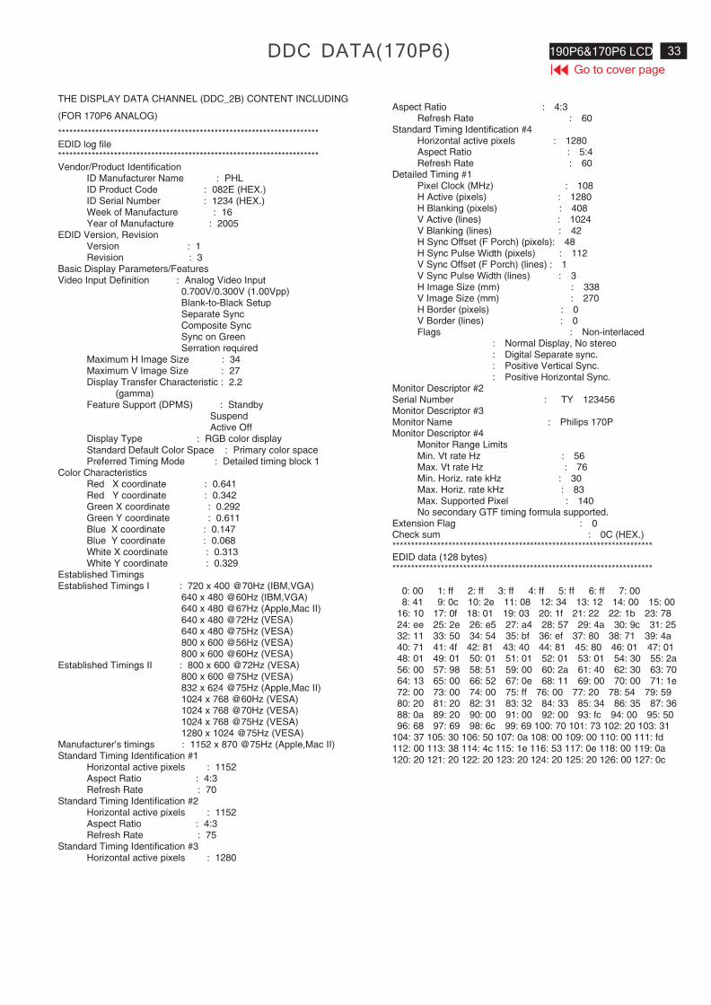
33190P6&170P6 LCDDDC DATA(170P6)
THE DISPLAY DATA CHANNEL (DDC_2B) CONTENT INCLUDING
(FOR 170P6 ANALOG)
**********************************************************************EDID log file**********************************************************************Vendor/Product Identification
ID Manufacturer Name : PHLID Product Code : 082E (HEX.)ID Serial Number : 1234 (HEX.)Week of Manufacture : 16Year of Manufacture : 2005
EDID Version, RevisionVersion : 1Revision : 3
Basic Display Parameters/FeaturesVideo Input Definition : Analog Video Input
0.700V/0.300V (1.00Vpp)Blank-to-Black SetupSeparate SyncComposite SyncSync on GreenSerration required
Maximum H Image Size : 34Maximum V Image Size : 27Display Transfer Characteristic : 2.2
(gamma)Feature Support (DPMS) : Standby
SuspendActive Off
Display Type : RGB color displayStandard Default Color Space : Primary color spacePreferred Timing Mode : Detailed timing block 1
Color CharacteristicsRed X coordinate : 0.641Red Y coordinate : 0.342Green X coordinate : 0.292Green Y coordinate : 0.611Blue X coordinate : 0.147Blue Y coordinate : 0.068White X coordinate : 0.313White Y coordinate : 0.329
Established TimingsEstablished Timings I : 720 x 400 @70Hz (IBM,VGA)
640 x 480 @60Hz (IBM,VGA)640 x 480 @67Hz (Apple,Mac II)640 x 480 @72Hz (VESA)640 x 480 @75Hz (VESA)800 x 600 @56Hz (VESA)800 x 600 @60Hz (VESA)
Established Timings II : 800 x 600 @72Hz (VESA)800 x 600 @75Hz (VESA)832 x 624 @75Hz (Apple,Mac II)1024 x 768 @60Hz (VESA)1024 x 768 @70Hz (VESA)1024 x 768 @75Hz (VESA)1280 x 1024 @75Hz (VESA)
Manufacturer's timings : 1152 x 870 @75Hz (Apple,Mac II)Standard Timing Identification #1
Horizontal active pixels : 1152Aspect Ratio : 4:3Refresh Rate : 70
Standard Timing Identification #2Horizontal active pixels : 1152Aspect Ratio : 4:3Refresh Rate : 75
Standard Timing Identification #3Horizontal active pixels : 1280
Aspect Ratio : 4:3Refresh Rate : 60
Standard Timing Identification #4Horizontal active pixels : 1280Aspect Ratio : 5:4Refresh Rate : 60
Detailed Timing #1Pixel Clock (MHz) : 108H Active (pixels) : 1280H Blanking (pixels) : 408V Active (lines) : 1024V Blanking (lines) : 42H Sync Offset (F Porch) (pixels): 48H Sync Pulse Width (pixels) : 112V Sync Offset (F Porch) (lines) : 1V Sync Pulse Width (lines) : 3H Image Size (mm) : 338V Image Size (mm) : 270H Border (pixels) : 0V Border (lines) : 0Flags : Non-interlaced
: Normal Display, No stereo: Digital Separate sync.: Positive Vertical Sync.: Positive Horizontal Sync.
Monitor Descriptor #2Serial Number : TY 123456Monitor Descriptor #3Monitor Name : Philips 170PMonitor Descriptor #4
Monitor Range LimitsMin. Vt rate Hz : 56Max. Vt rate Hz : 76Min. Horiz. rate kHz : 30Max. Horiz. rate kHz : 83Max. Supported Pixel : 140No secondary GTF timing formula supported.
Extension Flag : 0Check sum : 0C (HEX.)**********************************************************************EDID data (128 bytes)**********************************************************************
0: 00 1: ff 2: ff 3: ff 4: ff 5: ff 6: ff 7: 008: 41 9: 0c 10: 2e 11: 08 12: 34 13: 12 14: 00 15: 00
16: 10 17: 0f 18: 01 19: 03 20: 1f 21: 22 22: 1b 23: 7824: ee 25: 2e 26: e5 27: a4 28: 57 29: 4a 30: 9c 31: 2532: 11 33: 50 34: 54 35: bf 36: ef 37: 80 38: 71 39: 4a40: 71 41: 4f 42: 81 43: 40 44: 81 45: 80 46: 01 47: 0148: 01 49: 01 50: 01 51: 01 52: 01 53: 01 54: 30 55: 2a56: 00 57: 98 58: 51 59: 00 60: 2a 61: 40 62: 30 63: 7064: 13 65: 00 66: 52 67: 0e 68: 11 69: 00 70: 00 71: 1e72: 00 73: 00 74: 00 75: ff 76: 00 77: 20 78: 54 79: 5980: 20 81: 20 82: 31 83: 32 84: 33 85: 34 86: 35 87: 3688: 0a 89: 20 90: 00 91: 00 92: 00 93: fc 94: 00 95: 5096: 68 97: 69 98: 6c 99: 69 100: 70 101: 73 102: 20 103: 31
104: 37 105: 30 106: 50 107: 0a 108: 00 109: 00 110: 00 111: fd112: 00 113: 38 114: 4c 115: 1e 116: 53 117: 0e 118: 00 119: 0a120: 20 121: 20 122: 20 123: 20 124: 20 125: 20 126: 00 127: 0c
Go to cover page
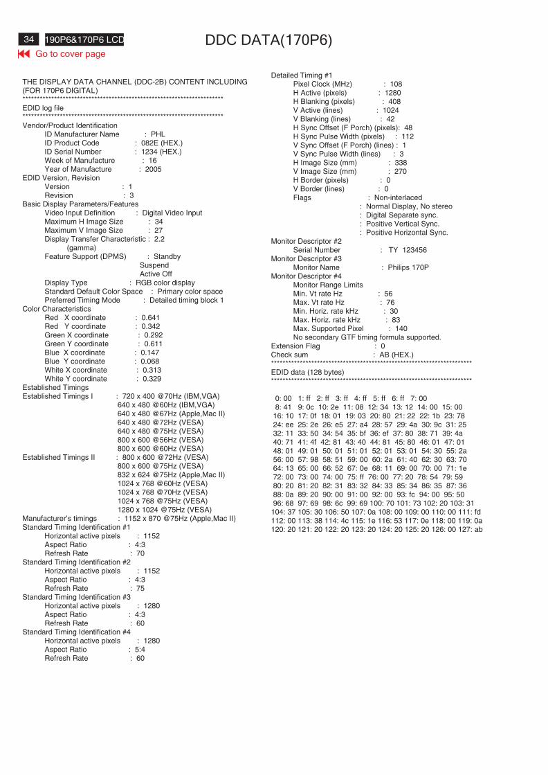
34 190P6&170P6 LCD DDC DATA(170P6)
THE DISPLAY DATA CHANNEL (DDC-2B) CONTENT INCLUDING(FOR 170P6 DIGITAL)**********************************************************************EDID log file**********************************************************************Vendor/Product Identification
ID Manufacturer Name : PHLID Product Code : 082E (HEX.)ID Serial Number : 1234 (HEX.)Week of Manufacture : 16Year of Manufacture : 2005
EDID Version, RevisionVersion : 1Revision : 3
Basic Display Parameters/FeaturesVideo Input Definition : Digital Video InputMaximum H Image Size : 34Maximum V Image Size : 27Display Transfer Characteristic : 2.2
(gamma)Feature Support (DPMS) : Standby
SuspendActive Off
Display Type : RGB color displayStandard Default Color Space : Primary color spacePreferred Timing Mode : Detailed timing block 1
Color CharacteristicsRed X coordinate : 0.641Red Y coordinate : 0.342Green X coordinate : 0.292Green Y coordinate : 0.611Blue X coordinate : 0.147Blue Y coordinate : 0.068White X coordinate : 0.313White Y coordinate : 0.329
Established TimingsEstablished Timings I : 720 x 400 @70Hz (IBM,VGA)
640 x 480 @60Hz (IBM,VGA)640 x 480 @67Hz (Apple,Mac II)640 x 480 @72Hz (VESA)640 x 480 @75Hz (VESA)800 x 600 @56Hz (VESA)800 x 600 @60Hz (VESA)
Established Timings II : 800 x 600 @72Hz (VESA)800 x 600 @75Hz (VESA)832 x 624 @75Hz (Apple,Mac II)1024 x 768 @60Hz (VESA)1024 x 768 @70Hz (VESA)1024 x 768 @75Hz (VESA)1280 x 1024 @75Hz (VESA)
Manufacturer's timings : 1152 x 870 @75Hz (Apple,Mac II)Standard Timing Identification #1
Horizontal active pixels : 1152Aspect Ratio : 4:3Refresh Rate : 70
Standard Timing Identification #2Horizontal active pixels : 1152Aspect Ratio : 4:3Refresh Rate : 75
Standard Timing Identification #3Horizontal active pixels : 1280Aspect Ratio : 4:3Refresh Rate : 60
Standard Timing Identification #4Horizontal active pixels : 1280Aspect Ratio : 5:4Refresh Rate : 60
Detailed Timing #1Pixel Clock (MHz) : 108H Active (pixels) : 1280H Blanking (pixels) : 408V Active (lines) : 1024V Blanking (lines) : 42H Sync Offset (F Porch) (pixels): 48H Sync Pulse Width (pixels) : 112V Sync Offset (F Porch) (lines) : 1V Sync Pulse Width (lines) : 3H Image Size (mm) : 338V Image Size (mm) : 270H Border (pixels) : 0V Border (lines) : 0Flags : Non-interlaced
: Normal Display, No stereo: Digital Separate sync.: Positive Vertical Sync.: Positive Horizontal Sync.
Monitor Descriptor #2Serial Number : TY 123456
Monitor Descriptor #3Monitor Name : Philips 170P
Monitor Descriptor #4Monitor Range LimitsMin. Vt rate Hz : 56Max. Vt rate Hz : 76Min. Horiz. rate kHz : 30Max. Horiz. rate kHz : 83Max. Supported Pixel : 140No secondary GTF timing formula supported.
Extension Flag : 0Check sum : AB (HEX.)**********************************************************************EDID data (128 bytes)**********************************************************************
0: 00 1: ff 2: ff 3: ff 4: ff 5: ff 6: ff 7: 008: 41 9: 0c 10: 2e 11: 08 12: 34 13: 12 14: 00 15: 00
16: 10 17: 0f 18: 01 19: 03 20: 80 21: 22 22: 1b 23: 7824: ee 25: 2e 26: e5 27: a4 28: 57 29: 4a 30: 9c 31: 2532: 11 33: 50 34: 54 35: bf 36: ef 37: 80 38: 71 39: 4a40: 71 41: 4f 42: 81 43: 40 44: 81 45: 80 46: 01 47: 0148: 01 49: 01 50: 01 51: 01 52: 01 53: 01 54: 30 55: 2a56: 00 57: 98 58: 51 59: 00 60: 2a 61: 40 62: 30 63: 7064: 13 65: 00 66: 52 67: 0e 68: 11 69: 00 70: 00 71: 1e72: 00 73: 00 74: 00 75: ff 76: 00 77: 20 78: 54 79: 5980: 20 81: 20 82: 31 83: 32 84: 33 85: 34 86: 35 87: 3688: 0a 89: 20 90: 00 91: 00 92: 00 93: fc 94: 00 95: 5096: 68 97: 69 98: 6c 99: 69 100: 70 101: 73 102: 20 103: 31
104: 37 105: 30 106: 50 107: 0a 108: 00 109: 00 110: 00 111: fd112: 00 113: 38 114: 4c 115: 1e 116: 53 117: 0e 118: 00 119: 0a120: 20 121: 20 122: 20 123: 20 124: 20 125: 20 126: 00 127: ab
Go to cover page

35190P6&170P6 LCD
Go to cover page
ISP CABLE FOR CPU
Configuration and procedure
ISP ( In System Program) software is provided by Genesis to upgradethe firmware of CPU.
ISP cable is for the interface between "Parallel port of PC" and"15 pin-D-SUB connector of monitor.
System and equipment requirements:1. An i386 (or above ) personal computer or compatible.2. Microsoft operation system Win 95/98 or Win 20003. ISP software4. ISP cable (3138 106 10148) as shown in Fig.1
Fig.1 ISP CABLE :12NC IS "3138 106 10148".
5.Connect ISP cable and main cord to monitor as shown in Fig.2.
6. Install and setup the Gprobe 4.5.0.5.exe program
step 1. Create a folder in your PC .for example: D:\190P6step 2.Copy ISP software 190P6 software .Zip into your folderstep 3.Unzip ISP.ZIP into your folder as shpwn in Fig.3step 4.Double click the Gprobe4.5.0.5.exe icon to install theapplication as shown Fig.4
Fig.3
Fig.4
Step 5 . Click the next till the setup finished. And creat a short cut on the desktop.
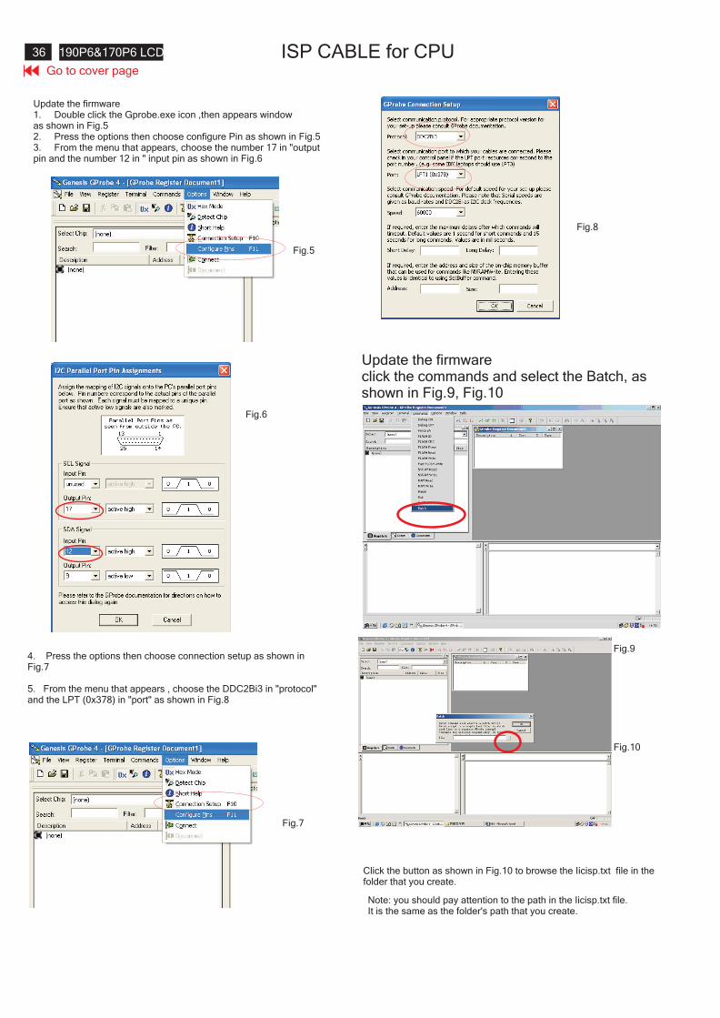
Go to cover page
36 190P6&170P6 LCD ISP CABLE for CPU
Update the firmware1. Double click the Gprobe.exe icon ,then appears windowas shown in Fig.52. Press the options then choose configure Pin as shown in Fig.53. From the menu that appears, choose the number 17 in "outputpin and the number 12 in " input pin as shown in Fig.6
Fig.5
Fig.6
4. Press the options then choose connection setup as shown inFig.7
5. From the menu that appears , choose the DDC2Bi3 in "protocol"and the LPT (0x378) in "port" as shown in Fig.8
Fig.7
Update the firmwareclick the commands and select the Batch, asshown in Fig.9, Fig.10
Fig.8
Fig.9
Fig.10
Click the button as shown in Fig.10 to browse the Iicisp.txt file in thefolder that you create.
Note: you should pay attention to the path in the Iicisp.txt file.It is the same as the folder's path that you create.
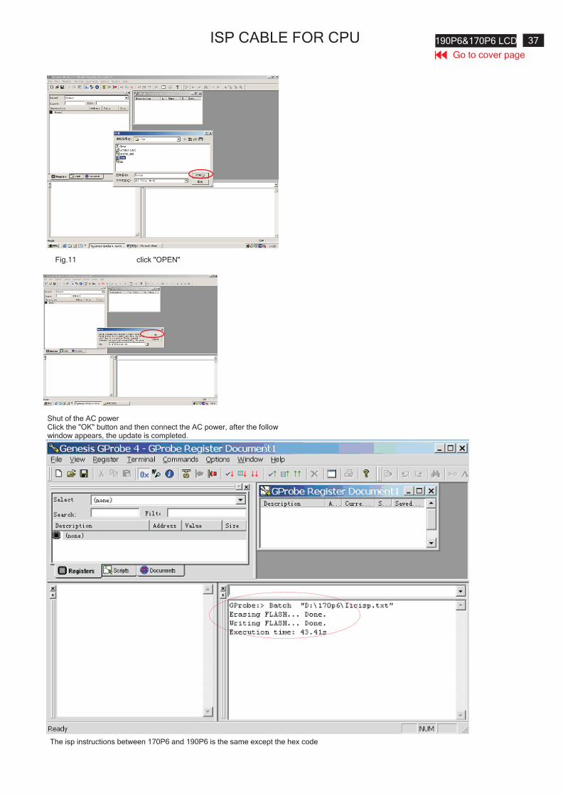
37190P6&170P6 LCD
Go to cover page
ISP CABLE FOR CPU
Fig.11 click "OPEN"
Shut of the AC powerClick the "OK" button and then connect the AC power, after the followwindow appears, the update is completed.
The isp instructions between 170P6 and 190P6 is the same except the hex code
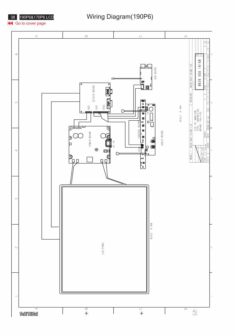
Go to cover page
38 190P6&170P6 LCD Wiring Diagram(190P6)
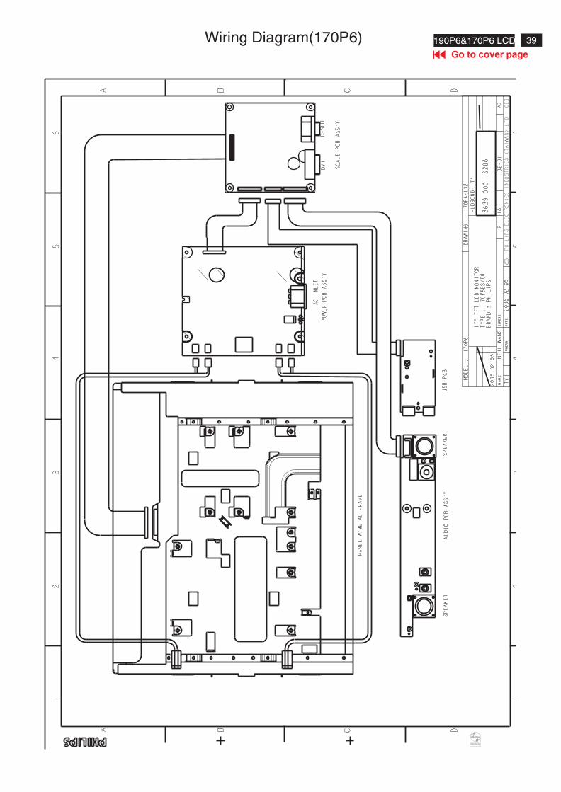
39190P6&170P6 LCD
Go to cover page
Wiring Diagram(170P6)
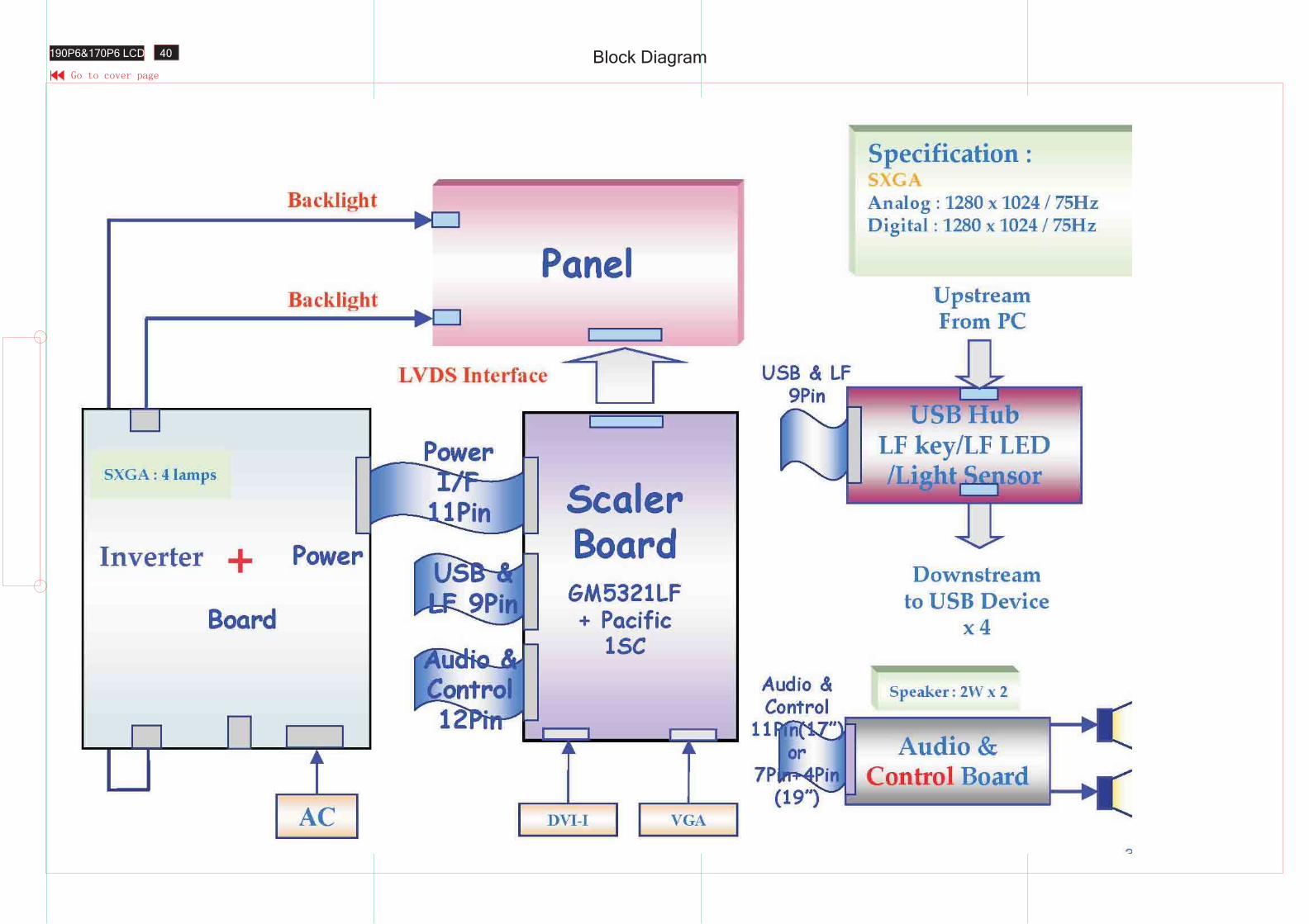
Block Diagram40190P6&170P6 LCD
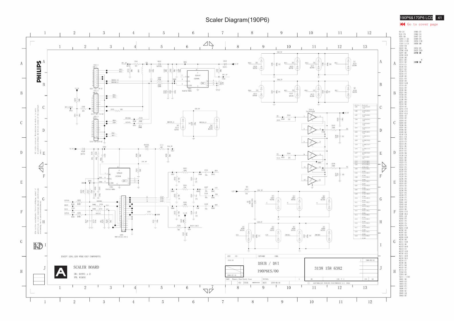
Scaler Diagram(190P6) 41190P6&170P6 LCD
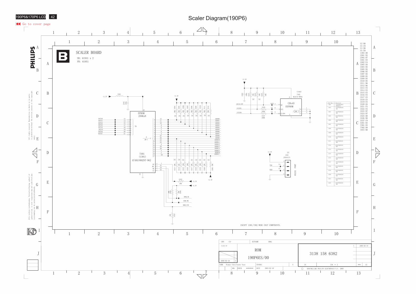
Scaler Diagram(190P6)42190P6&170P6 LCD
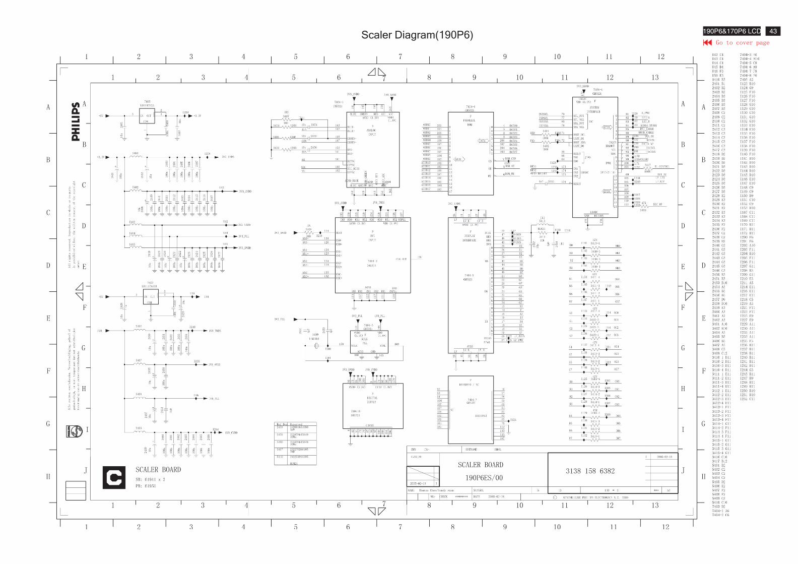
Scaler Diagram(190P6) 43190P6&170P6 LCD
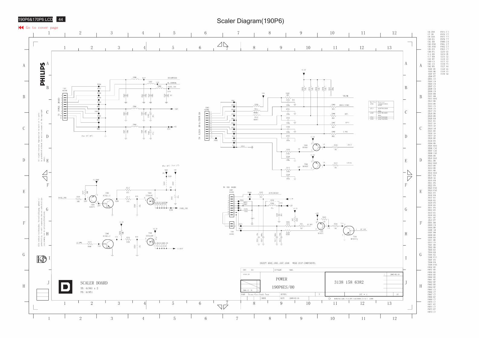
Scaler Diagram(190P6)44190P6&170P6 LCD
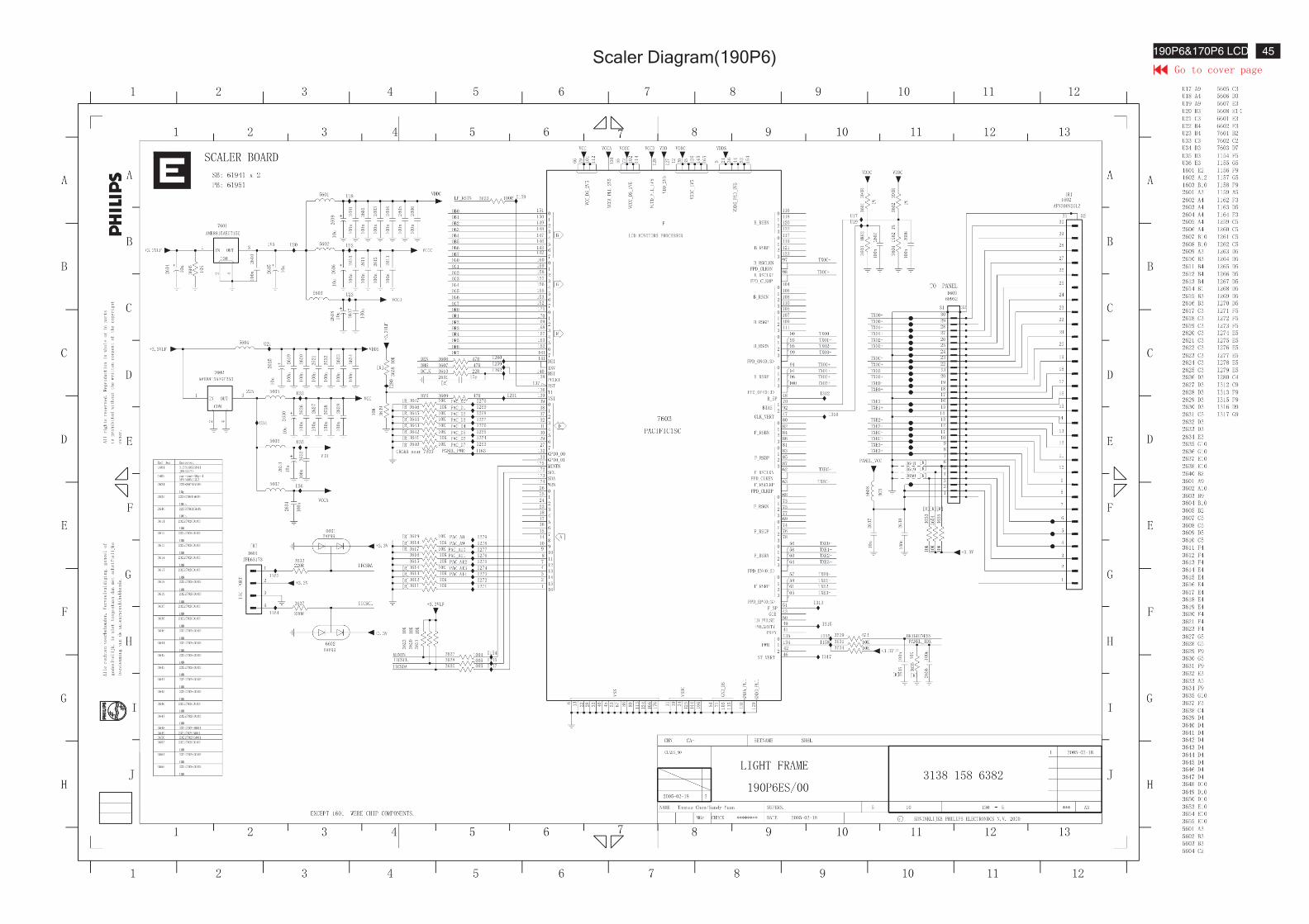
Scaler Diagram(190P6) 45190P6&170P6 LCD
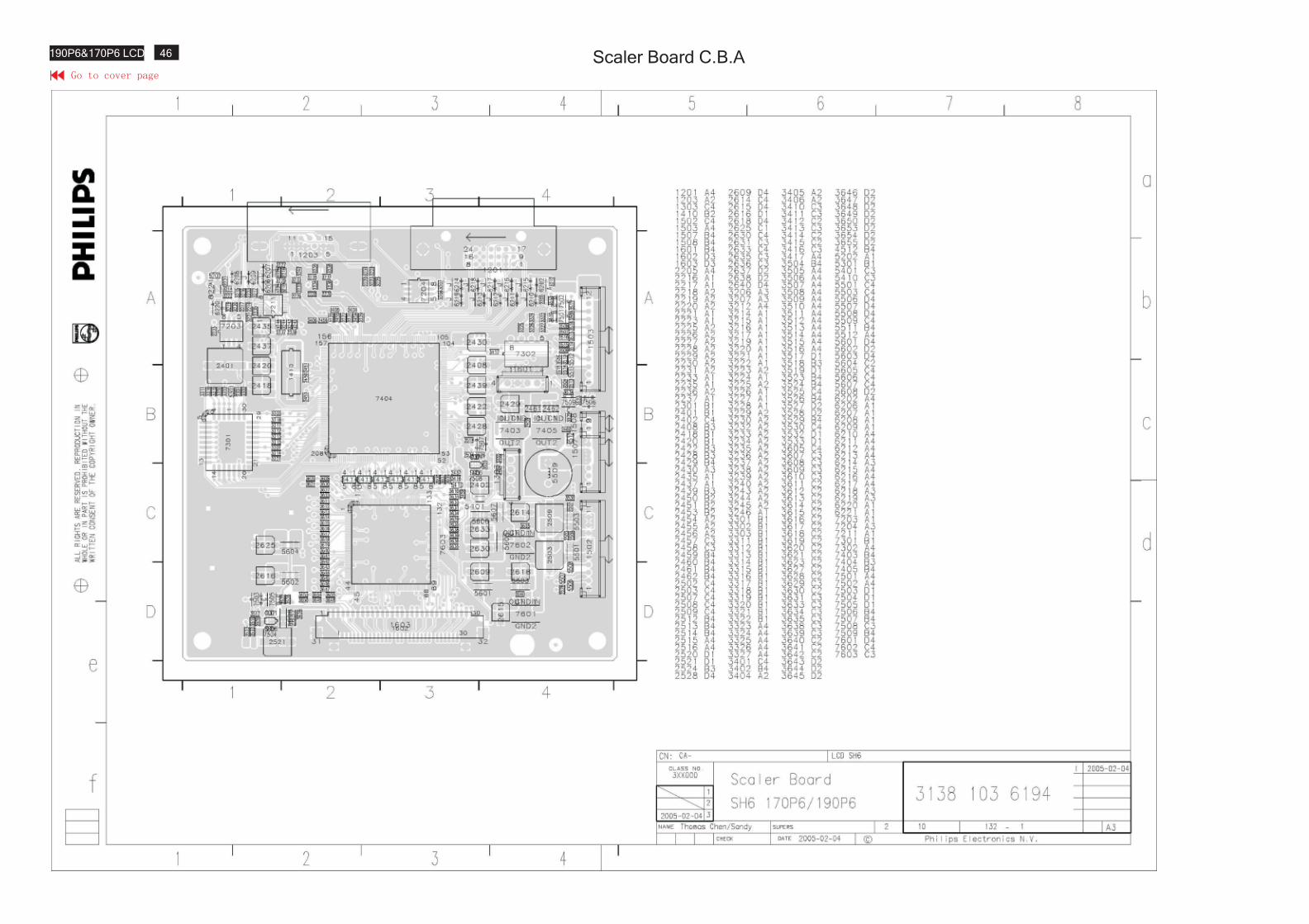
Scaler Board C.B.A46190P6&170P6 LCD
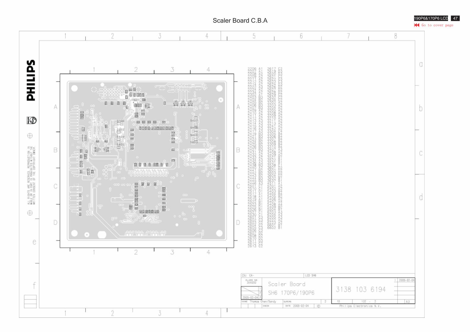
Scaler Board C.B.A47190P6&170P6 LCD
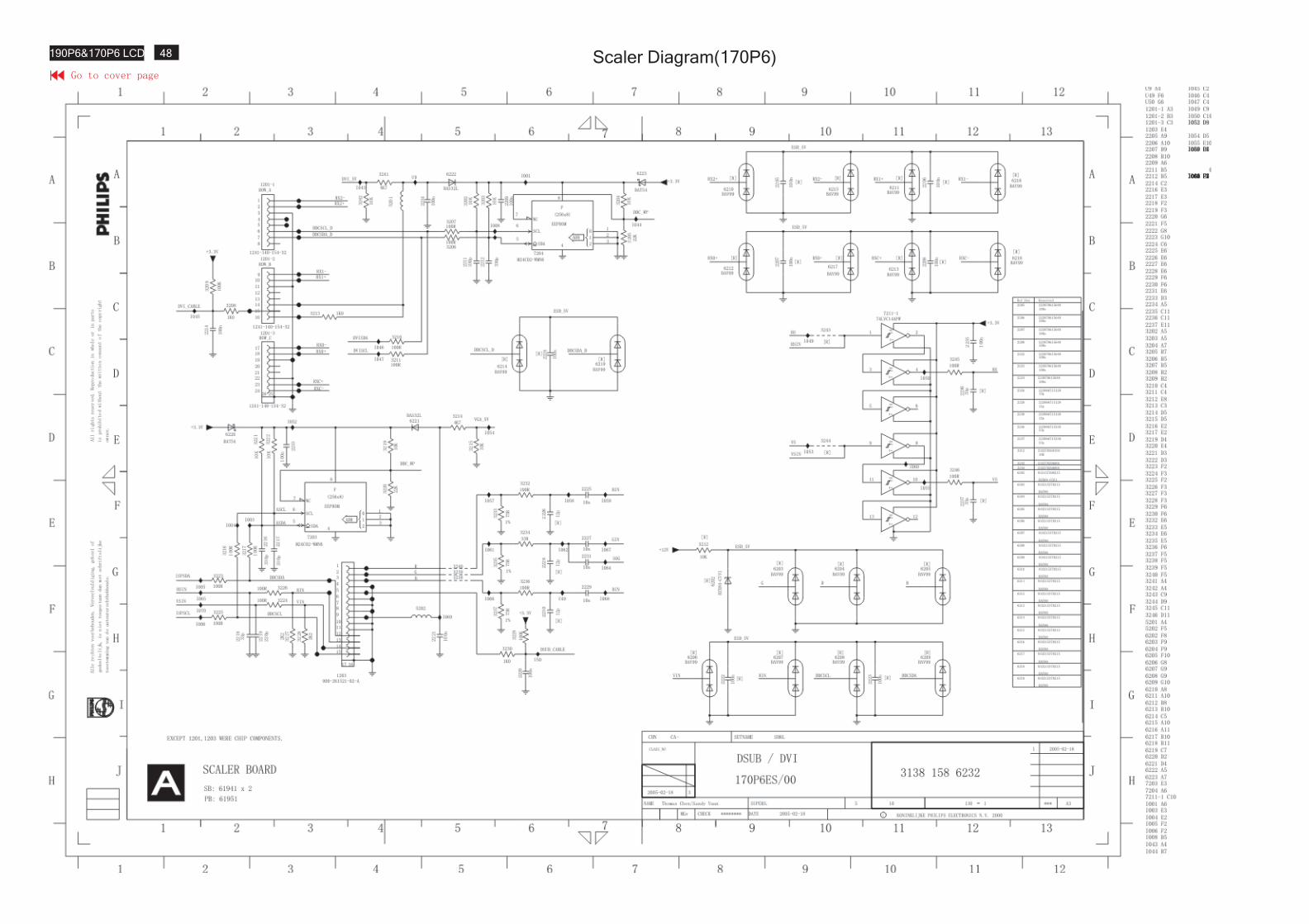
Scaler Diagram(170P6)48190P6&170P6 LCD
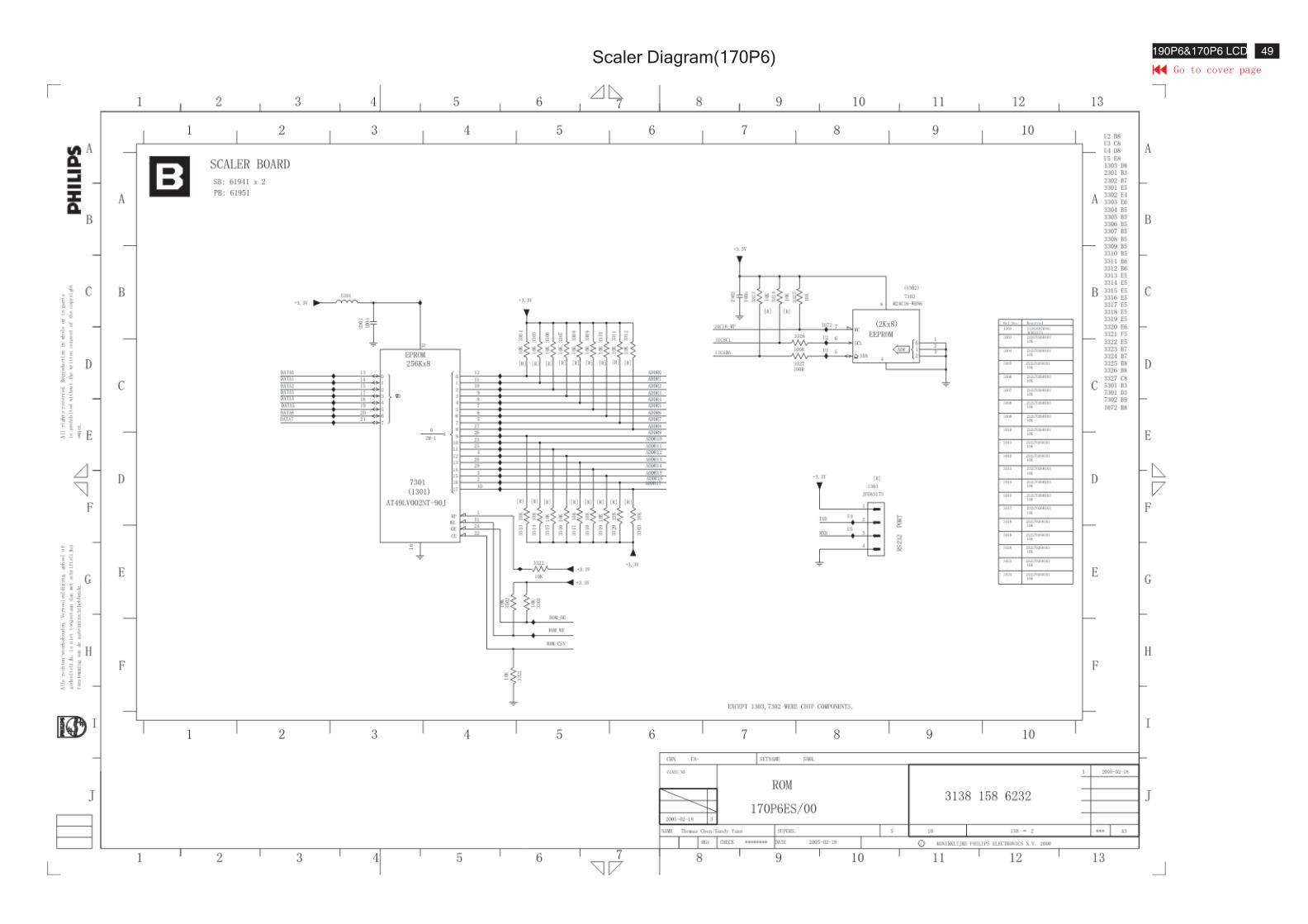
Scaler Diagram(170P6) 49190P6&170P6 LCD
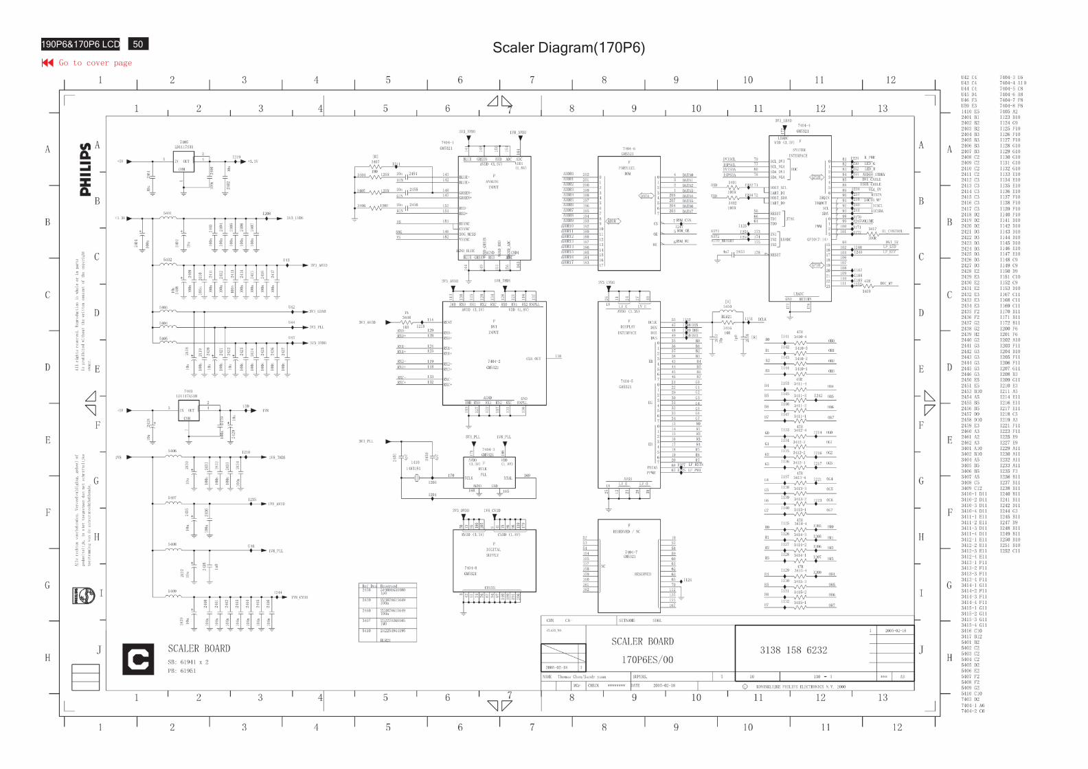
Scaler Diagram(170P6)50190P6&170P6 LCD
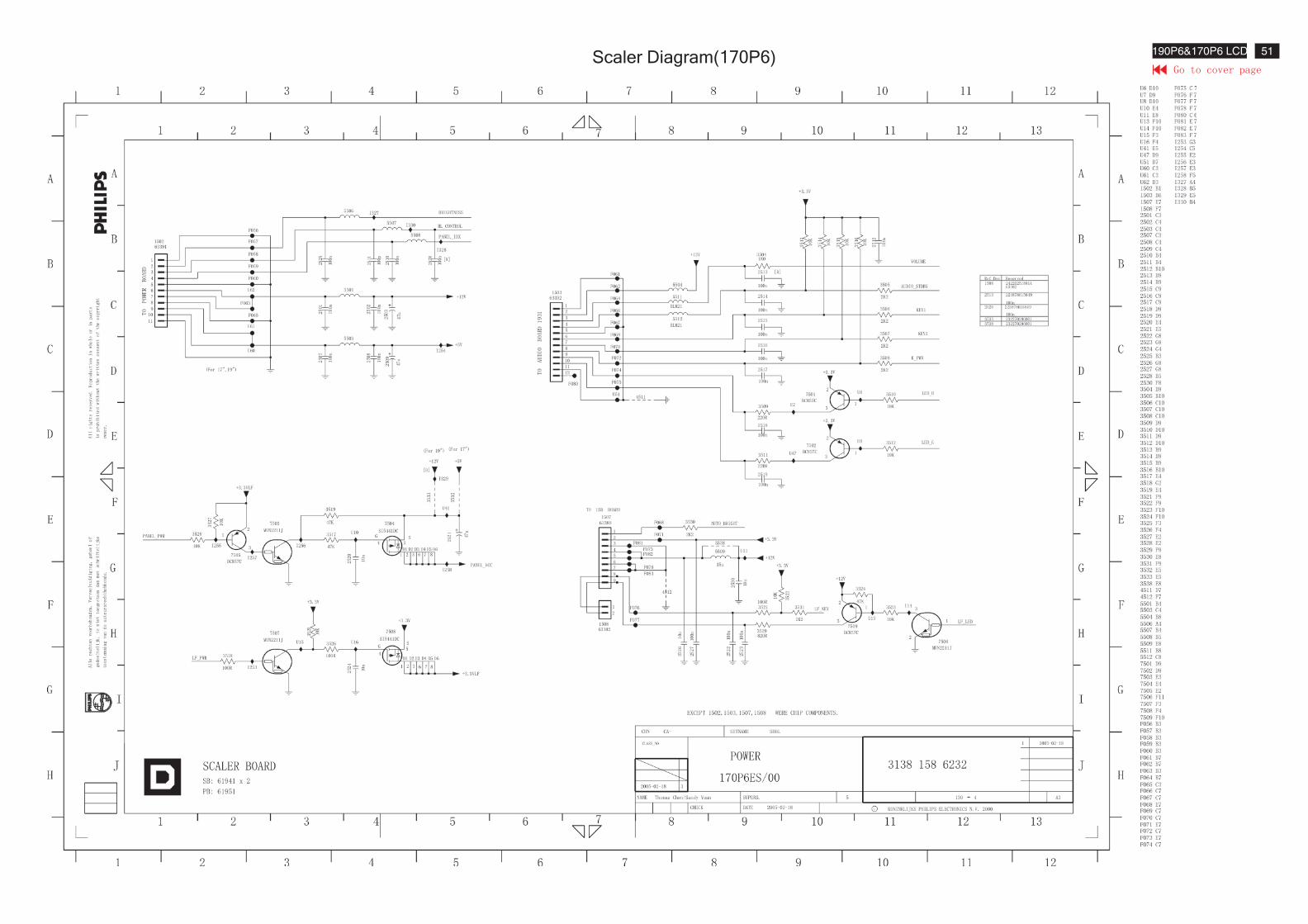
Scaler Diagram(170P6) 51190P6&170P6 LCD
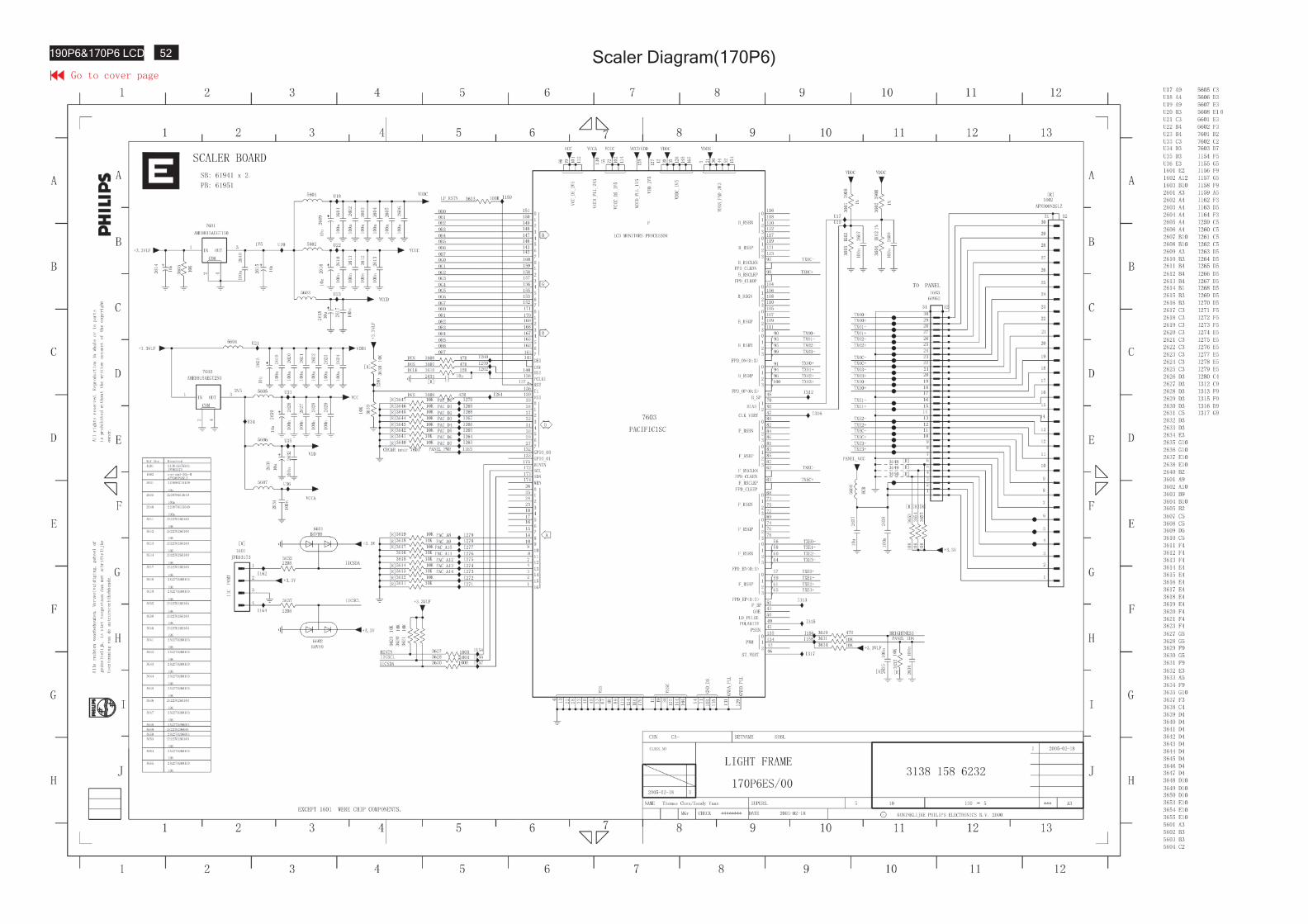
Scaler Diagram(170P6)52190P6&170P6 LCD
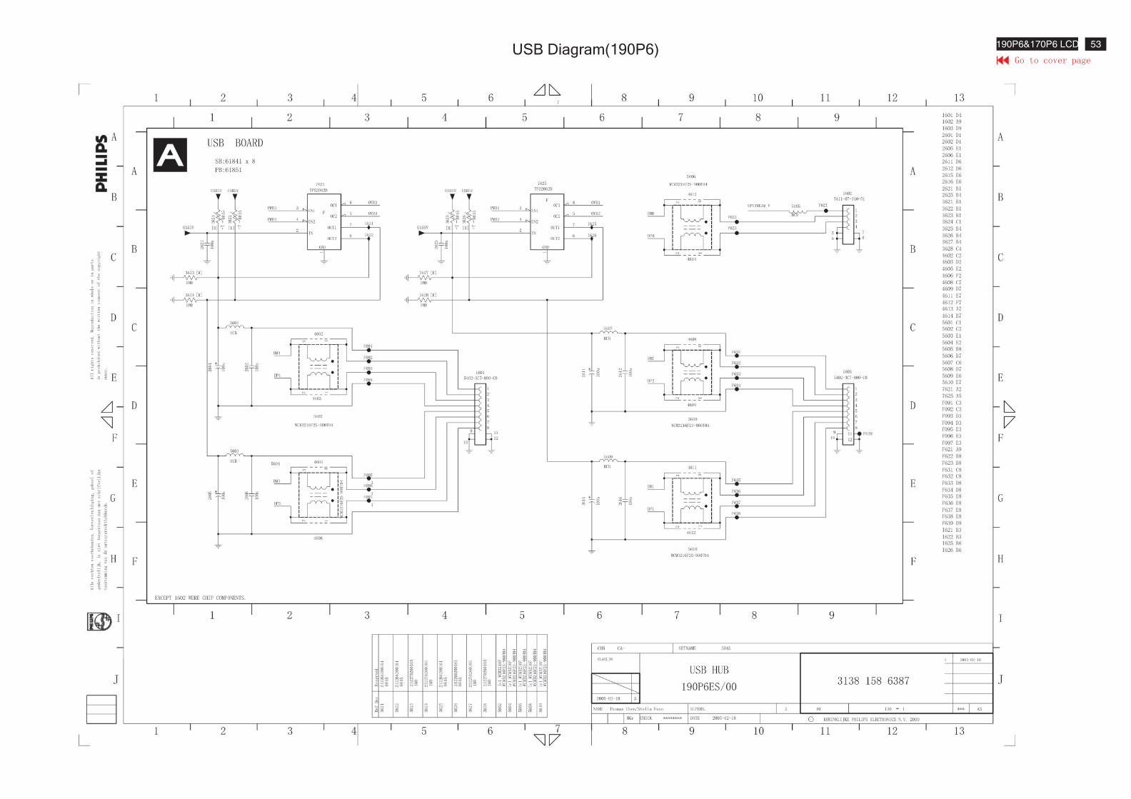
USB Diagram(190P6) 53190P6&170P6 LCD
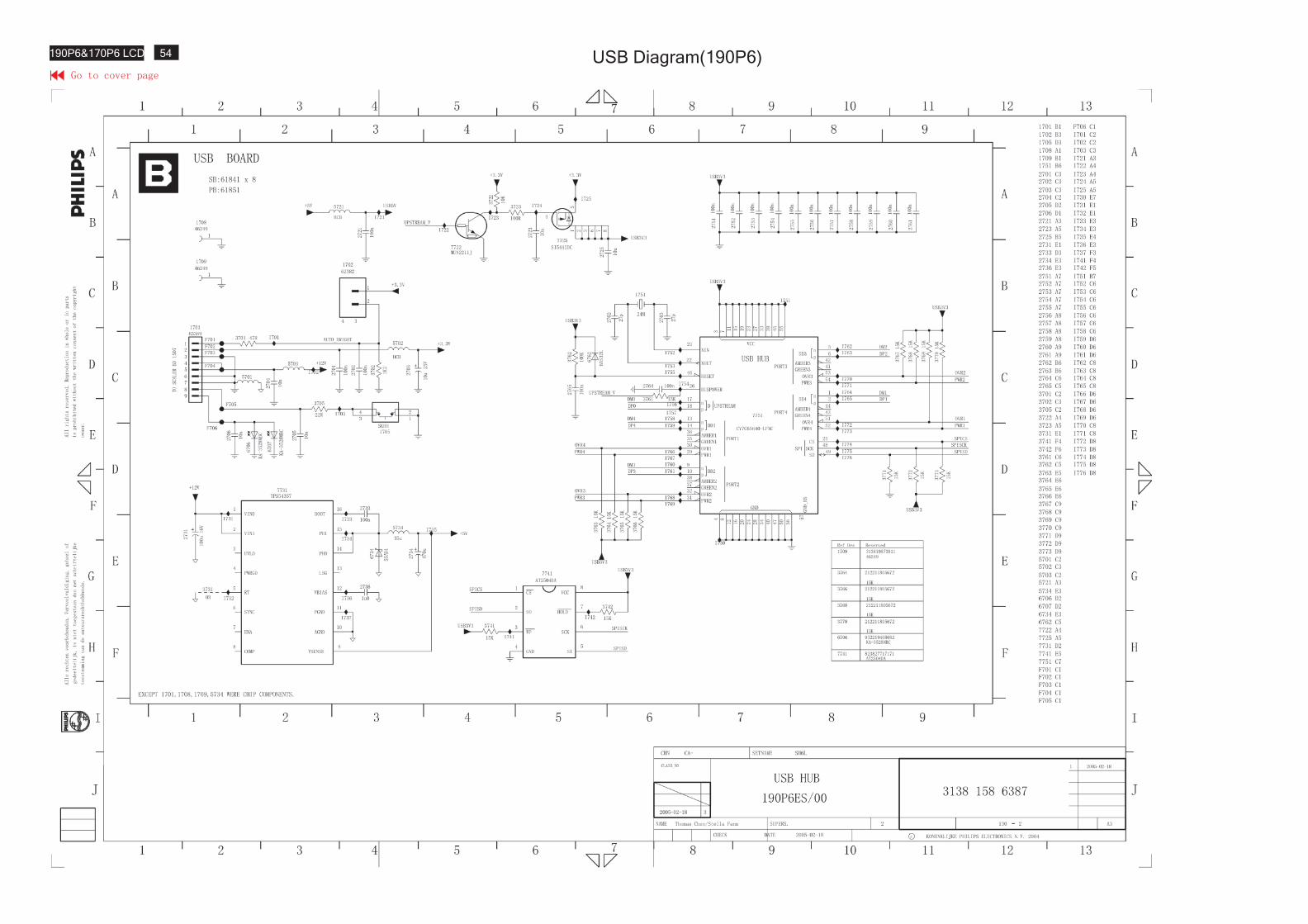
USB Diagram(190P6)54190P6&170P6 LCD
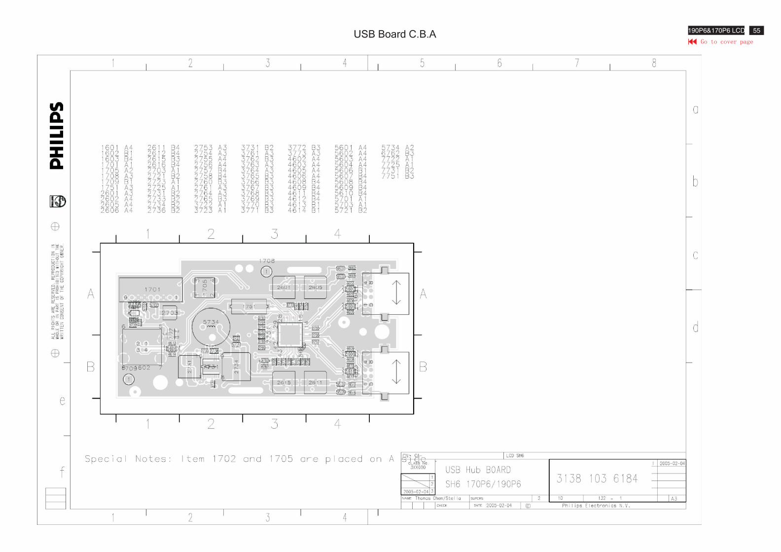
USB Board C.B.A55190P6&170P6 LCD
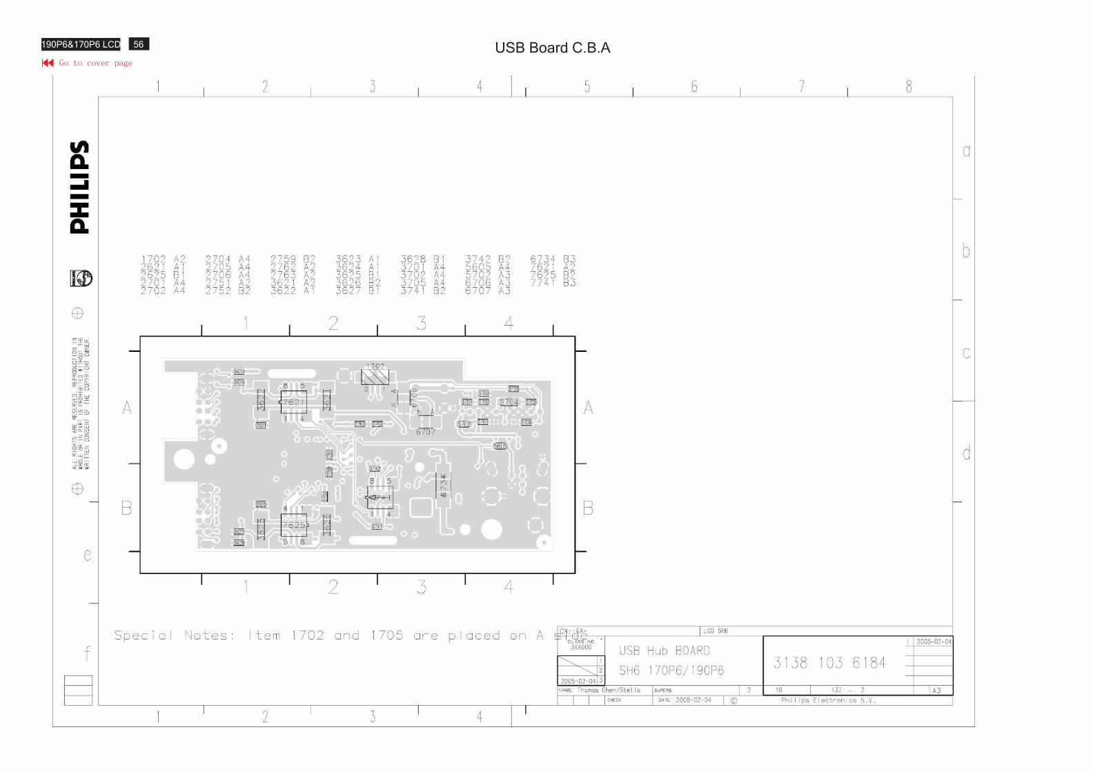
USB Board C.B.A56190P6&170P6 LCD
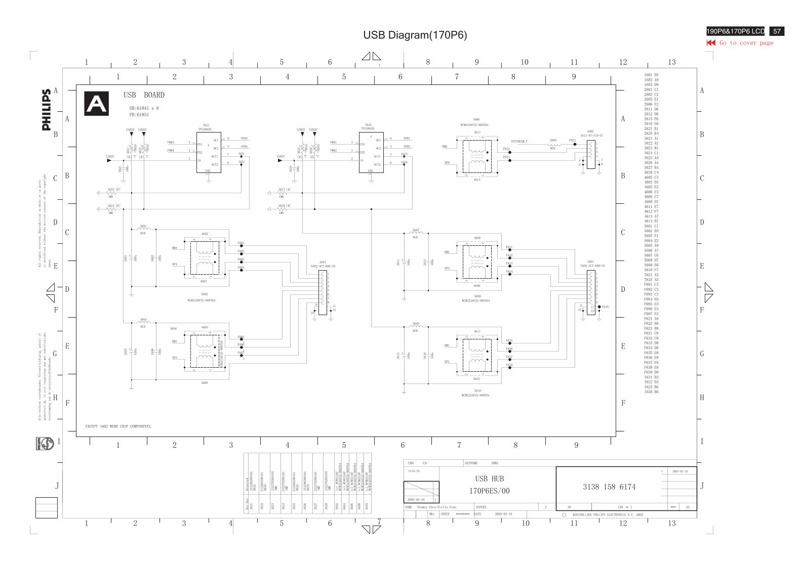
USB Diagram(170P6) 57190P6&170P6 LCD
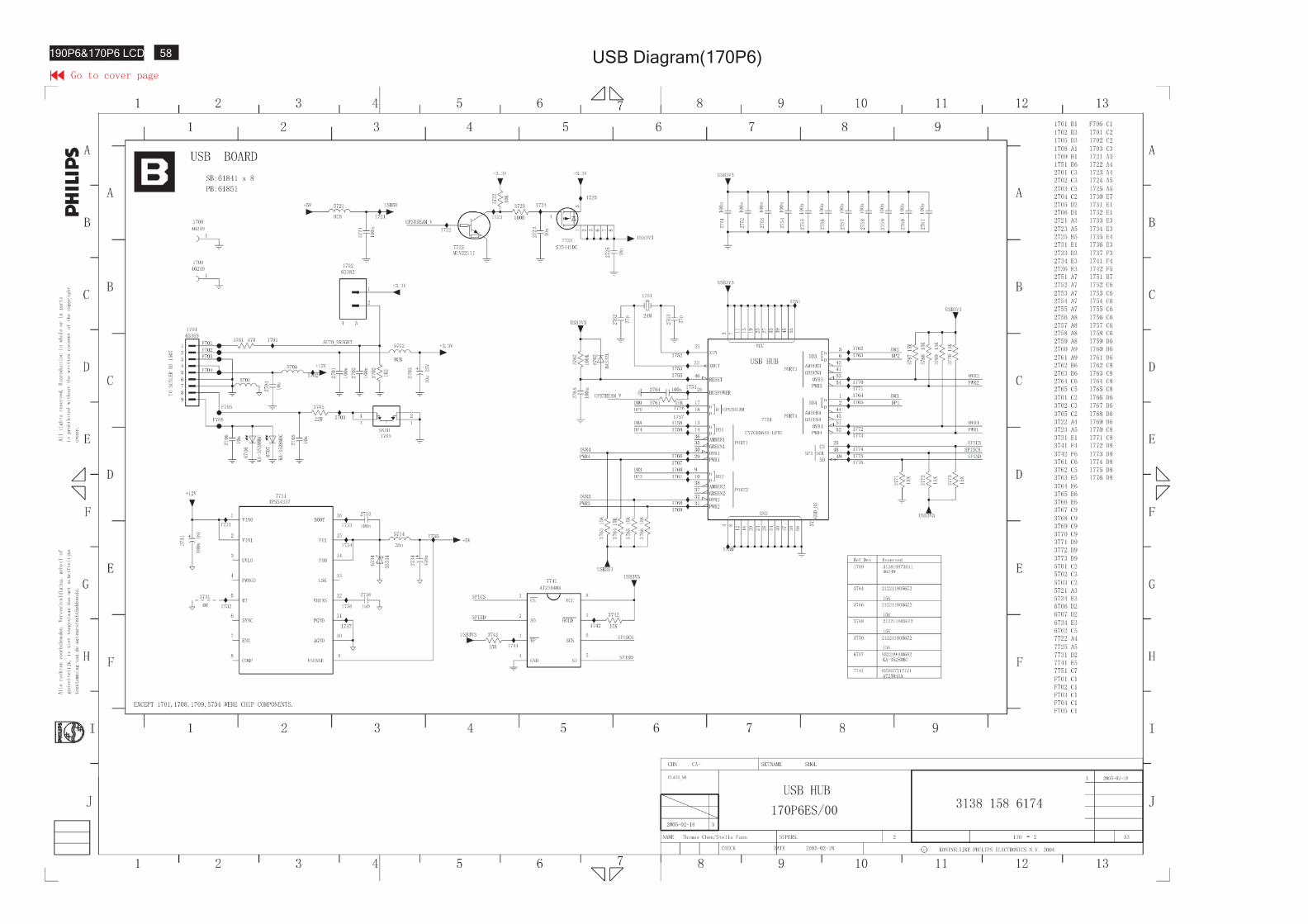
USB Diagram(170P6)58190P6&170P6 LCD
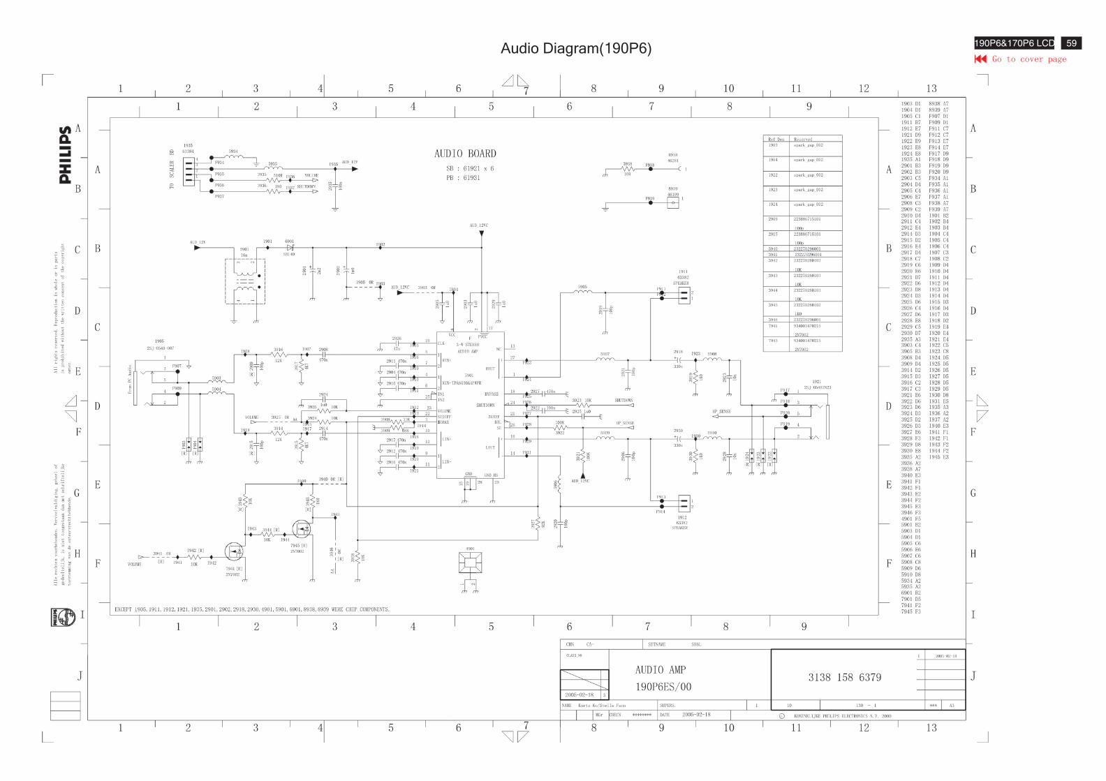
Audio Diagram(190P6) 59190P6&170P6 LCD
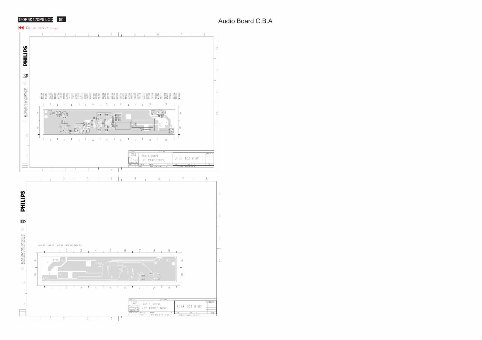
Audio Board C.B.A60190P6&170P6 LCD
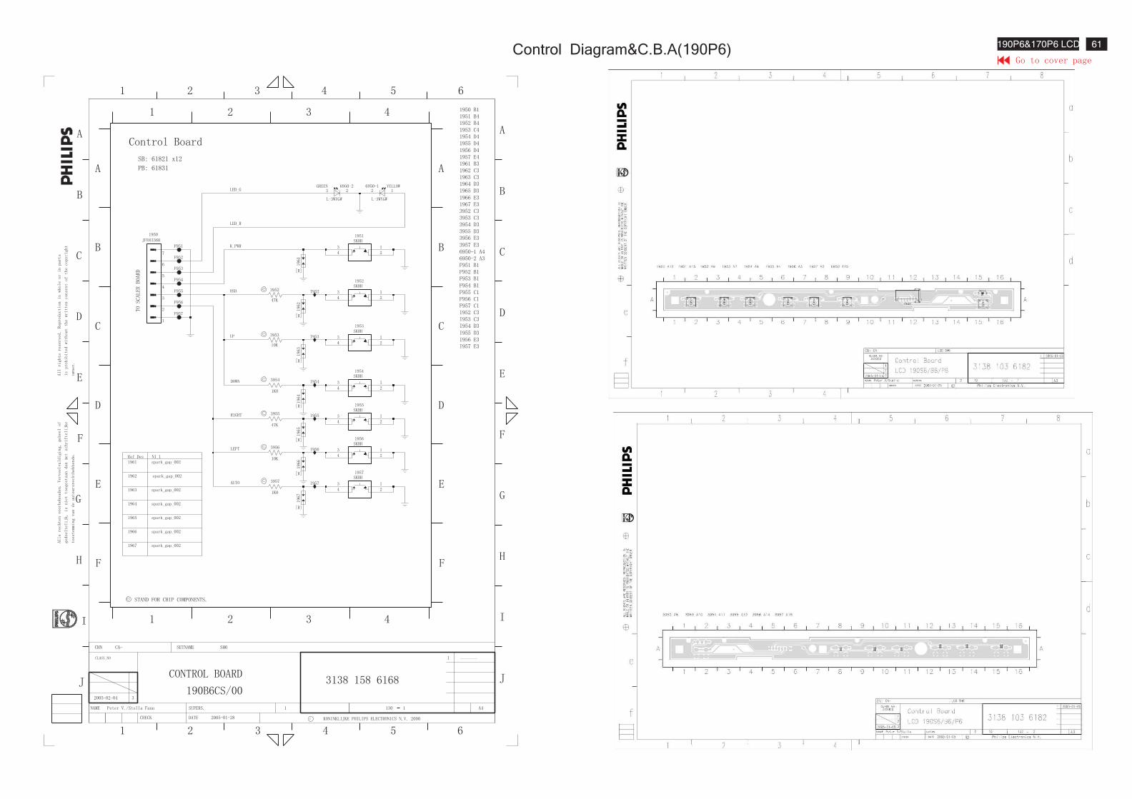
Control Diagram&C.B.A(190P6) 61190P6&170P6 LCD
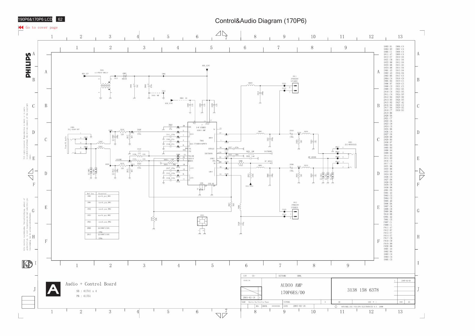
Control&Audio Diagram (170P6)62190P6&170P6 LCD
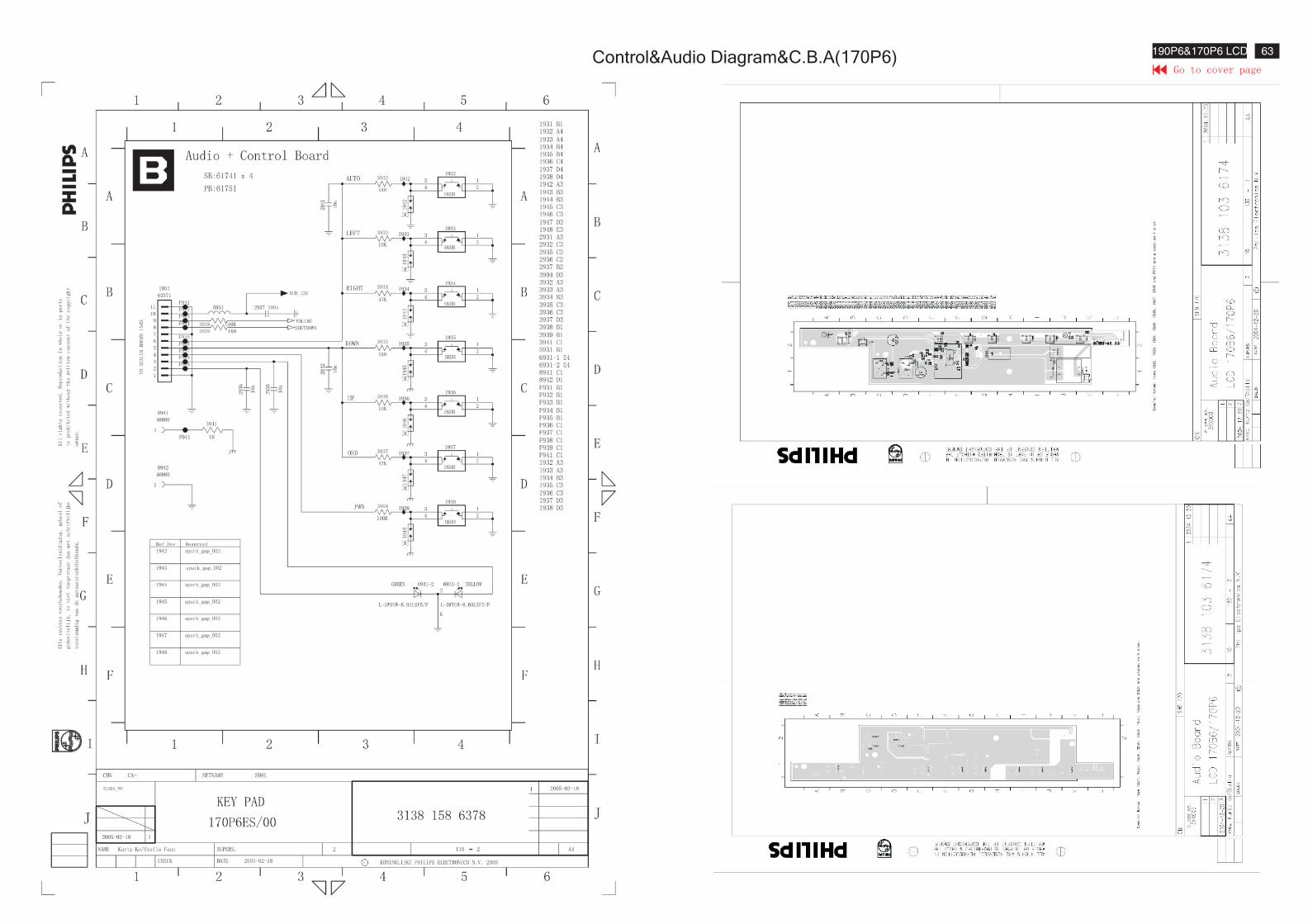
Control&Audio Diagram&C.B.A(170P6)63190P6&170P6 LCD
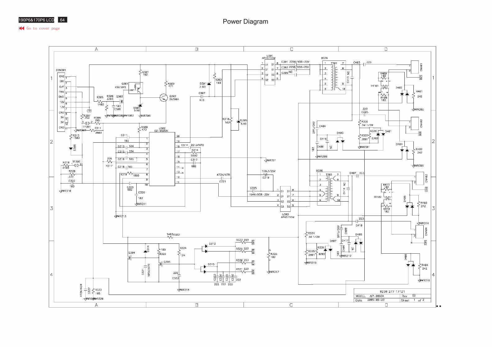
Power Diagram64190P6&170P6 LCD
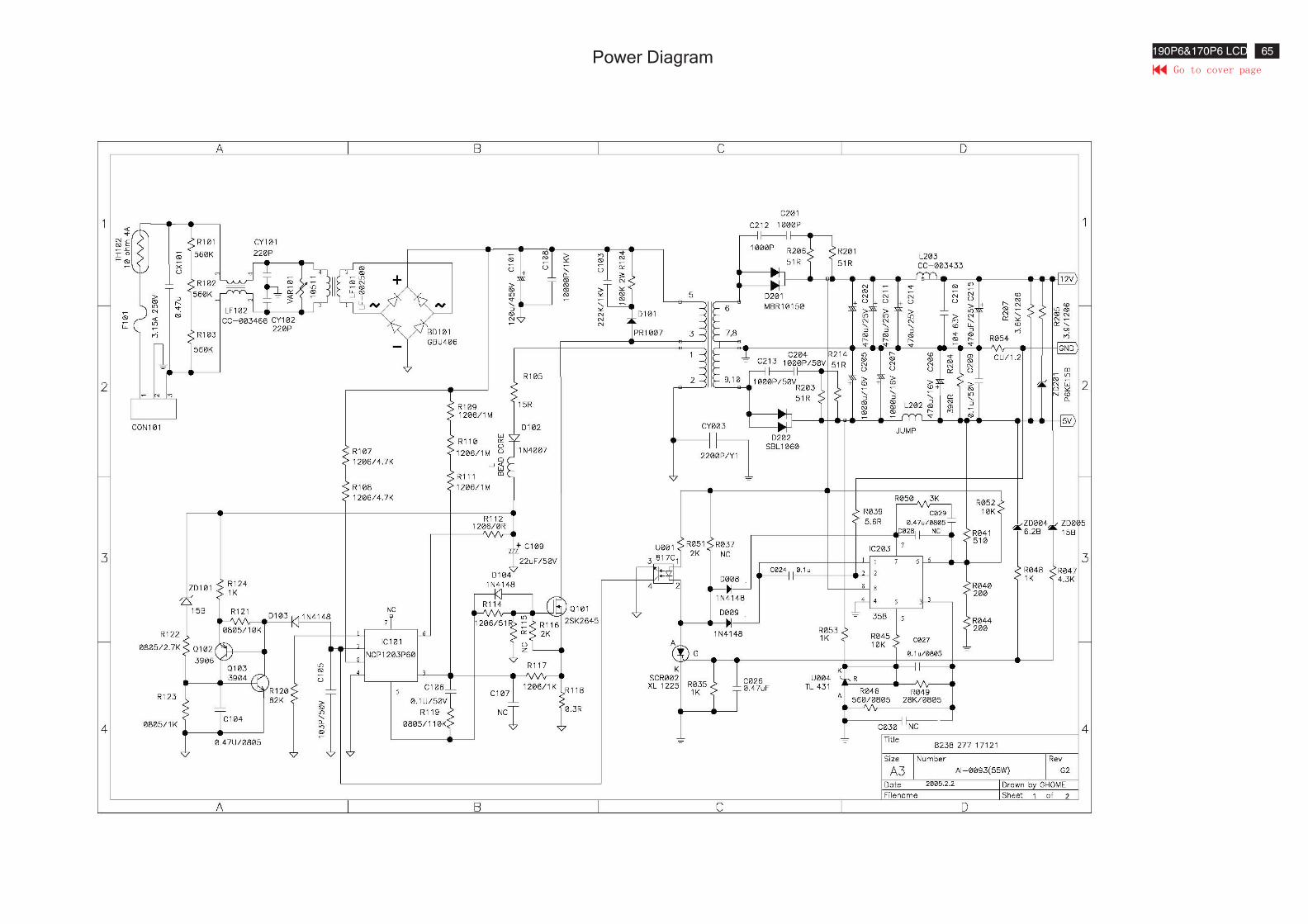
Power Diagram 65190P6&170P6 LCD
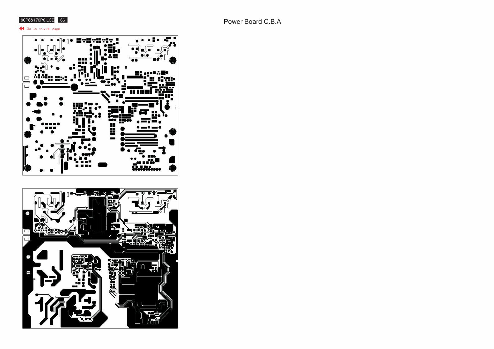
Power Board C.B.A66190P6&170P6 LCD
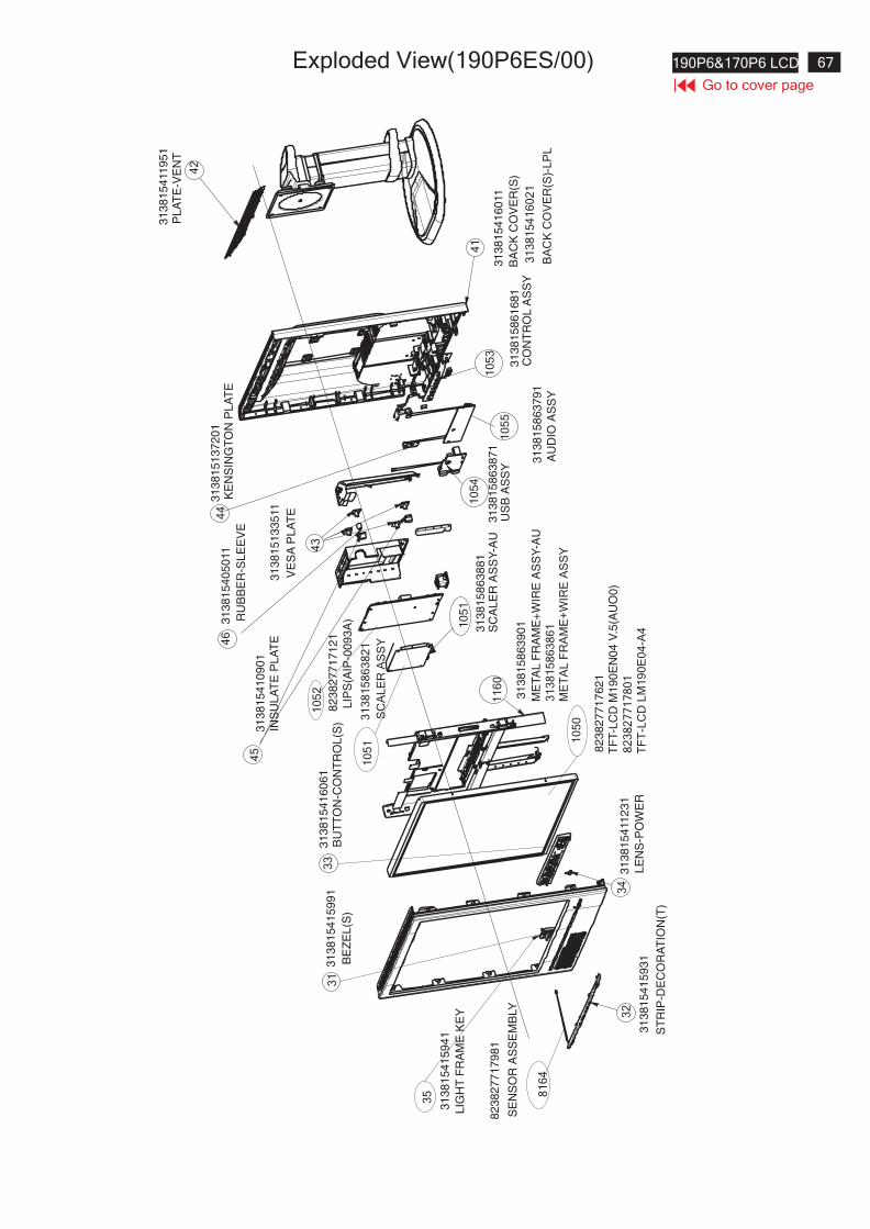
67190P6&170P6 LCD
Go to cover page
Exploded View(190P6ES/00)
81
64
82
38
27
71
79
81
SE
NS
OR
AS
SE
MB
LY
32
31
38
15
41
59
31
ST
RIP
-DE
CO
RA
TIO
N(T
)
31
31
38
15
41
59
91
BE
ZE
L(S
)
33
31
38
15
41
60
61
BU
TT
ON
-CO
NT
RO
L(S
)
34
31
38
15
411
23
1
LE
NS
-PO
WE
R
10
50
82
38
27
71
76
21
TF
T-L
CD
M1
90
EN
04
V.5
(AU
O0
)
35
31
38
15
41
59
41
LIG
HT
FR
AM
EK
EY
11
60
31
38
15
86
39
01
ME
TA
LF
RA
ME
+W
IRE
AS
SY
-AU
10
51
31
38
15
86
38
81
SC
AL
ER
AS
SY
-AU
10
52
82
38
27
71
71
21
LIP
S(A
IP-0
09
3A
)
31
38
15
41
09
01
INS
UL
AT
EP
LA
TE
45
46
31
38
15
40
50
11
RU
BB
ER
-SL
EE
VE
31
38
15
13
35
11
VE
SA
PL
AT
E
43
31
38
15
13
72
01
KE
NS
ING
TO
NP
LA
TE
44
31
38
15
86
38
71
US
BA
SS
Y
31
38
15
86
37
91
AU
DIO
AS
SY
10
54
10
55
31
38
15
86
16
81
CO
NT
RO
LA
SS
Y
10
53
31
38
15
41
60
11
BA
CK
CO
VE
R(S
)
41
31
38
15
411
95
1P
LA
TE
-VE
NT
42
31
38
15
41
60
21
BA
CK
CO
VE
R(S
)-L
PL
82
38
27
71
78
01
TF
T-L
CD
LM
19
0E
04
-A4
31
38
15
86
38
21
SC
AL
ER
AS
SY
10
51
31
38
15
86
38
61
ME
TA
LF
RA
ME
+W
IRE
AS
SY
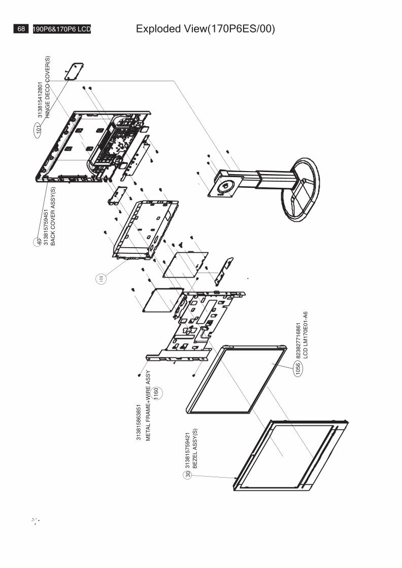
68 190P6&170P6 LCD Exploded View(170P6ES/00)
To Printer port
31
38
15
75
94
21
BE
ZE
LA
SS
Y(S
)
30
82
38
27
71
68
61
LC
DL
M1
70
E0
1-A
6
10
56
31
38
15
86
38
51
ME
TA
LF
RA
ME
+W
IRE
AS
SY
11
60
31
38
15
75
94
51
BA
CK
CO
VE
RA
SS
Y(S
)
40
31
38
15
41
28
01
HIN
GE
DE
CO
CO
VE
R(S
)
10
1
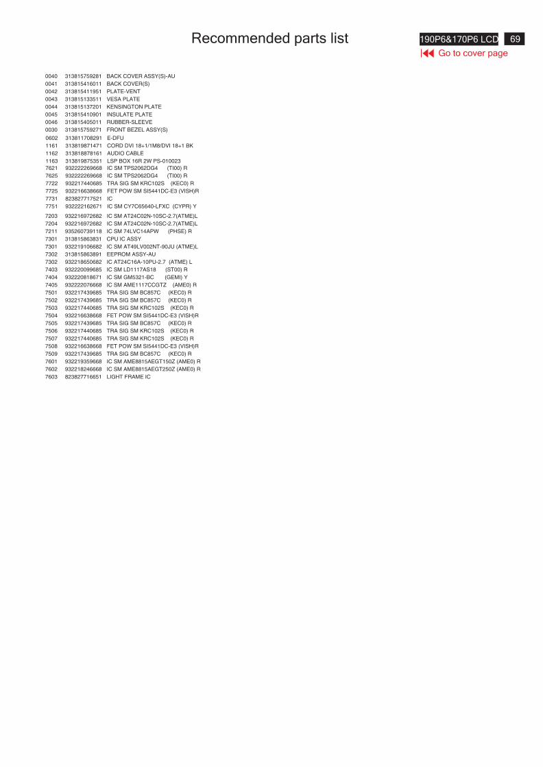
69190P6&170P6 LCD
Go to cover page
Recommended parts list
0040 313815759281 BACK COVER ASSY(S)-AU
0041 313815416011 BACK COVER(S)
0042 313815411951 PLATE-VENT
0043 313815133511 VESA PLATE
0044 313815137201 KENSINGTON PLATE
0045 313815410901 INSULATE PLATE
0046 313815405011 RUBBER-SLEEVE
0030 313815759271 FRONT BEZEL ASSY(S)
0602 313811708291 E-DFU
1161 313819871471 CORD DVI 18+1/1M8/DVI 18+1 BK
1162 313818878161 AUDIO CABLE
1163 313819875351 LSP BOX 16R 2W PS-010023
7621 932222269668 IC SM TPS2062DG4 (TI00) R
7625 932222269668 IC SM TPS2062DG4 (TI00) R
7722 932217440685 TRA SIG SM KRC102S (KEC0) R
7725 932216638668 FET POW SM SI5441DC-E3 (VISH)R
7731 823827717521 IC
7751 932222162671 IC SM CY7C65640-LFXC (CYPR) Y
7203 932216972682 IC SM AT24C02N-10SC-2.7(ATME)L
7204 932216972682 IC SM AT24C02N-10SC-2.7(ATME)L
7211 935260739118 IC SM 74LVC14APW (PHSE) R
7301 313815863831 CPU IC ASSY
7301 932219106682 IC SM AT49LV002NT-90JU (ATME)L
7302 313815863891 EEPROM ASSY-AU
7302 932218650682 IC AT24C16A-10PU-2.7 (ATME) L
7403 932220099685 IC SM LD1117AS18 (ST00) R
7404 932220818671 IC SM GM5321-BC (GEMI) Y
7405 932222076668 IC SM AME1117CCGTZ (AME0) R
7501 932217439685 TRA SIG SM BC857C (KEC0) R
7502 932217439685 TRA SIG SM BC857C (KEC0) R
7503 932217440685 TRA SIG SM KRC102S (KEC0) R
7504 932216638668 FET POW SM SI5441DC-E3 (VISH)R
7505 932217439685 TRA SIG SM BC857C (KEC0) R
7506 932217440685 TRA SIG SM KRC102S (KEC0) R
7507 932217440685 TRA SIG SM KRC102S (KEC0) R
7508 932216638668 FET POW SM SI5441DC-E3 (VISH)R
7509 932217439685 TRA SIG SM BC857C (KEC0) R
7601 932219359668 IC SM AME8815AEGT150Z (AME0) R
7602 932218246668 IC SM AME8815AEGT250Z (AME0) R
7603 823827716651 LIGHT FRAME IC
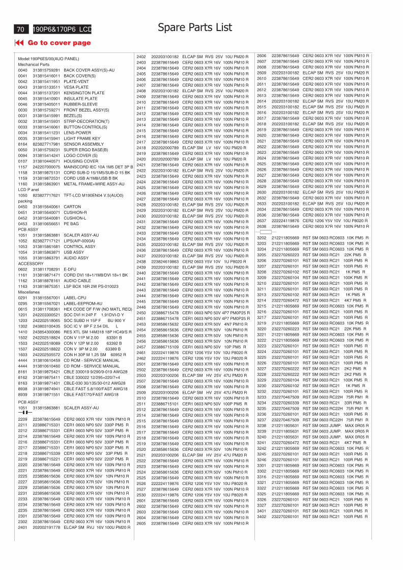
190P6&170P6 LCD
Go to cover page
70
Model:190P6ES/00(AUO PANEL)
Mechanical Parts
0040 313815759281 BACK COVER ASSY(S)-AU
0041 313815416011 BACK COVER(S)
0042 313815411951 PLATE-VENT
0043 313815133511 VESA PLATE
0044 313815137201 KENSINGTON PLATE
0045 313815410901 INSULATE PLATE
0046 313815405011 RUBBER-SLEEVE
0030 313815759271 FRONT BEZEL ASSY(S)
0031 313815415991 BEZEL(S)
0032 313815415931 STRIP-DECORATION(T)
0033 313815416061 BUTTON-CONTROL(S)
0034 313815411231 LENS-POWER
0035 313815415941 LIGHT FRAME KEY
8164 823827717981 SENSOR ASSEMBLY
0050 313815759231 SUPER ERGO BASE(B)
0094 313815414241 LOGO COVER (S)
0107 313810440571 HOUSING COVER
1157 242207000075 MAINSCORD IEC 10A 1M5 DET 3P B
1158 313819875131 CORD SUB-D 15/1M5/SUB-D 15 BK
1159 313819872531 CORD USB A/1M8/USB B BK
1160 313815863901 METAL FRAME+WIRE ASSY-AU
LCD P anel
1050 823827717621 TFT-LCD M190EN04 V.5(AUO0)
packing
0450 313815640061 CARTON
0451 313815640071 CUSHION-R
0452 313815640081 CUSHION-L
0453 313810656651 PE BAG
PCB ASSY
1051 313815863881 SCALER ASSY-AU
1052 823827717121 LIPS(AIP-0093A)
1053 313815861681 CONTROL ASSY
1054 313815863871 USB ASSY
1055 313815863791 AUDIO ASSY
ACCESSORY
0602 313811708291 E-DFU
1161 313819871471 CORD DVI 18+1/1M8/DVI 18+1 BK
1162 313818878161 AUDIO CABLE
1163 313819875351 LSP BOX 16R 2W PS-010023
Miscellanea
0291 313815567001 LABEL-CPU
0295 313815567021 LABEL-EEPROM-AU
0615 313811708361 HEX CODE OF F/W (NO MATL REQ)
1201 242203300521 SOC DVI H 24P F 1.91DVI-D Y
1203 242202518065 SOC SUBD H 15P F BU 900 Y
1302 243803100435 SOC IC V 8P F 2.54 DIL L
1410 243854300086 RES XTL SM 14M318 18P HC49/S R
1502 242202518824 CON V 11P M 2.00 63391 B
1503 242202518089 CON V 12P M 2.00 63392 B
1507 242202518822 CON V 9P M 2.00 63389 B
1603 242202505572 CON H 30P M 1.25 SM 60952 R
4444 313810610459 CD ROM - SERVICE MANUAL
4444 313810610460 CD ROM - SERVICE MANUAL
8161 313819875421 CBLE 330019 9/290/9-019 AWG28
8162 313819875411 CBLE 330022 12/295+220/7+4
8163 313819871401 CBLE-030 30/135/30-012 AWG28
8938 313819874941 CBLE FAST 5.8/100/FAST AWG18
8939 313819871551 CBLE FAST/70/FAST AWG18
PCB ASSY
1051 313815863881 SCALER ASSY-AU
2209 223878615649 CER2 0603 X7R 16V 100N PM10 R
2211 223886715331 CER1 0603 NP0 50V 330P PM5 R
2212 223886715331 CER1 0603 NP0 50V 330P PM5 R
2214 223878615649 CER2 0603 X7R 16V 100N PM10 R
2216 223886715331 CER1 0603 NP0 50V 330P PM5 R
2217 223886715331 CER1 0603 NP0 50V 330P PM5 R
2218 223886715339 CER1 0603 NP0 50V 33P PM5 R
2219 223886715221 CER1 0603 NP0 50V 220P PM5 R
2220 223878615649 CER2 0603 X7R 16V 100N PM10 R
2221 223878615649 CER2 0603 X7R 16V 100N PM10 R
2225 223858615636 CER2 0603 X7R 50V 10N PM10 R
2227 223858615636 CER2 0603 X7R 50V 10N PM10 R
2229 223858615636 CER2 0603 X7R 50V 10N PM10 R
2231 223858615636 CER2 0603 X7R 50V 10N PM10 R
2233 223878615649 CER2 0603 X7R 16V 100N PM10 R
2234 223878615649 CER2 0603 X7R 16V 100N PM10 R
2235 223878615649 CER2 0603 X7R 16V 100N PM10 R
2301 223878615649 CER2 0603 X7R 16V 100N PM10 R
2302 223878615649 CER2 0603 X7R 16V 100N PM10 R
2401 202002191778 ELCAP SM RVJ 16V 100U PM20 R
2402 202203100182 ELCAP SM RVS 25V 10U PM20 R
2403 223878615649 CER2 0603 X7R 16V 100N PM10 R
2404 223878615649 CER2 0603 X7R 16V 100N PM10 R
2405 223878615649 CER2 0603 X7R 16V 100N PM10 R
2406 223878615649 CER2 0603 X7R 16V 100N PM10 R
2407 223878615649 CER2 0603 X7R 16V 100N PM10 R
2408 202203100182 ELCAP SM RVS 25V 10U PM20 R
2409 223878615649 CER2 0603 X7R 16V 100N PM10 R
2410 223878615649 CER2 0603 X7R 16V 100N PM10 R
2411 223878615649 CER2 0603 X7R 16V 100N PM10 R
2412 223878615649 CER2 0603 X7R 16V 100N PM10 R
2413 223878615649 CER2 0603 X7R 16V 100N PM10 R
2414 223878615649 CER2 0603 X7R 16V 100N PM10 R
2415 223878615649 CER2 0603 X7R 16V 100N PM10 R
2416 223878615649 CER2 0603 X7R 16V 100N PM10 R
2417 223878615649 CER2 0603 X7R 16V 100N PM10 R
2418 202202000789 ELCAP SM LV 16V 10U PM20 R
2419 223878615649 CER2 0603 X7R 16V 100N PM10 R
2420 202202000789 ELCAP SM LV 16V 10U PM20 R
2421 223878615649 CER2 0603 X7R 16V 100N PM10 R
2422 202203100182 ELCAP SM RVS 25V 10U PM20 R
2423 223878615649 CER2 0603 X7R 16V 100N PM10 R
2424 223878615649 CER2 0603 X7R 16V 100N PM10 R
2425 223878615649 CER2 0603 X7R 16V 100N PM10 R
2426 223878615649 CER2 0603 X7R 16V 100N PM10 R
2427 223878615649 CER2 0603 X7R 16V 100N PM10 R
2428 202203100182 ELCAP SM RVS 25V 10U PM20 R
2429 202203100182 ELCAP SM RVS 25V 10U PM20 R
2430 202203100182 ELCAP SM RVS 25V 10U PM20 R
2431 223878615649 CER2 0603 X7R 16V 100N PM10 R
2432 223878615649 CER2 0603 X7R 16V 100N PM10 R
2433 223878615649 CER2 0603 X7R 16V 100N PM10 R
2434 223878615649 CER2 0603 X7R 16V 100N PM10 R
2435 202203100182 ELCAP SM RVS 25V 10U PM20 R
2436 223878615649 CER2 0603 X7R 16V 100N PM10 R
2437 202203100182 ELCAP SM RVS 25V 10U PM20 R
2438 223824619863 CER2 0603 Y5V 10V 1U P8020 R
2439 202203100182 ELCAP SM RVS 25V 10U PM20 R
2440 223878615649 CER2 0603 X7R 16V 100N PM10 R
2441 223878615649 CER2 0603 X7R 16V 100N PM10 R
2442 223878615649 CER2 0603 X7R 16V 100N PM10 R
2443 223878615649 CER2 0603 X7R 16V 100N PM10 R
2444 223878615649 CER2 0603 X7R 16V 100N PM10 R
2445 223878615649 CER2 0603 X7R 16V 100N PM10 R
2446 223878615649 CER2 0603 X7R 16V 100N PM10 R
2450 223886715478 CER1 0603 NP0 50V 4P7 PM0P25 R
2451 223886715478 CER1 0603 NP0 50V 4P7 PM0P25 R
2453 223858615632 CER2 0603 X7R 50V 4N7 PM10 R
2454 223858615636 CER2 0603 X7R 50V 10N PM10 R
2455 223858615636 CER2 0603 X7R 50V 10N PM10 R
2456 223858615636 CER2 0603 X7R 50V 10N PM10 R
2457 223886715109 CER1 0603 NP0 50V 10P PM5 R
2461 222224119876 CER2 1206 Y5V 10V 10U P8020 R
2462 222224119876 CER2 1206 Y5V 10V 10U P8020 R
2501 223878615649 CER2 0603 X7R 16V 100N PM10 R
2502 223878615649 CER2 0603 X7R 16V 100N PM10 R
2503 202203100206 ELCAP SM HV 25V 47U PM20 R
2507 223878615649 CER2 0603 X7R 16V 100N PM10 R
2508 223878615649 CER2 0603 X7R 16V 100N PM10 R
2509 202203100206 ELCAP SM HV 25V 47U PM20 R
2510 223878615649 CER2 0603 X7R 16V 100N PM10 R
2511 223886715101 CER1 0603 NP0 50V 100P PM5 R
2512 223878615649 CER2 0603 X7R 16V 100N PM10 R
2514 223878615649 CER2 0603 X7R 16V 100N PM10 R
2515 223878615649 CER2 0603 X7R 16V 100N PM10 R
2516 223878615649 CER2 0603 X7R 16V 100N PM10 R
2517 223878615649 CER2 0603 X7R 16V 100N PM10 R
2518 223878615649 CER2 0603 X7R 16V 100N PM10 R
2519 223878615649 CER2 0603 X7R 16V 100N PM10 R
2520 223858615636 CER2 0603 X7R 50V 10N PM10 R
2521 202203100206 ELCAP SM HV 25V 47U PM20 R
2522 223878615649 CER2 0603 X7R 16V 100N PM10 R
2523 223878615649 CER2 0603 X7R 16V 100N PM10 R
2524 223858615636 CER2 0603 X7R 50V 10N PM10 R
2525 223878615649 CER2 0603 X7R 16V 100N PM10 R
2526 222224119876 CER2 1206 Y5V 10V 10U P8020 R
2527 223878615649 CER2 0603 X7R 16V 100N PM10 R
2530 222224119876 CER2 1206 Y5V 10V 10U P8020 R
2601 223878615649 CER2 0603 X7R 16V 100N PM10 R
2602 223878615649 CER2 0603 X7R 16V 100N PM10 R
2603 223878615649 CER2 0603 X7R 16V 100N PM10 R
2604 223878615649 CER2 0603 X7R 16V 100N PM10 R
2605 223878615649 CER2 0603 X7R 16V 100N PM10 R
2606 223878615649 CER2 0603 X7R 16V 100N PM10 R
2607 223878615649 CER2 0603 X7R 16V 100N PM10 R
2608 223878615649 CER2 0603 X7R 16V 100N PM10 R
2609 202203100182 ELCAP SM RVS 25V 10U PM20 R
2610 223878615649 CER2 0603 X7R 16V 100N PM10 R
2611 223878615649 CER2 0603 X7R 16V 100N PM10 R
2612 223878615649 CER2 0603 X7R 16V 100N PM10 R
2613 223878615649 CER2 0603 X7R 16V 100N PM10 R
2614 202203100182 ELCAP SM RVS 25V 10U PM20 R
2615 202203100182 ELCAP SM RVS 25V 10U PM20 R
2616 202203100182 ELCAP SM RVS 25V 10U PM20 R
2617 223878615649 CER2 0603 X7R 16V 100N PM10 R
2618 202203100182 ELCAP SM RVS 25V 10U PM20 R
2619 223878615649 CER2 0603 X7R 16V 100N PM10 R
2620 223878615649 CER2 0603 X7R 16V 100N PM10 R
2621 223878615649 CER2 0603 X7R 16V 100N PM10 R
2622 223878615649 CER2 0603 X7R 16V 100N PM10 R
2623 223878615649 CER2 0603 X7R 16V 100N PM10 R
2624 223878615649 CER2 0603 X7R 16V 100N PM10 R
2625 223878615649 CER2 0603 X7R 16V 100N PM10 R
2626 223878615649 CER2 0603 X7R 16V 100N PM10 R
2627 223878615649 CER2 0603 X7R 16V 100N PM10 R
2628 223878615649 CER2 0603 X7R 16V 100N PM10 R
2629 223878615649 CER2 0603 X7R 16V 100N PM10 R
2630 202203100182 ELCAP SM RVS 25V 10U PM20 R
2632 223878615649 CER2 0603 X7R 16V 100N PM10 R
2633 202203100182 ELCAP SM RVS 25V 10U PM20 R
2634 223878615649 CER2 0603 X7R 16V 100N PM10 R
2636 223878615649 CER2 0603 X7R 16V 100N PM10 R
2637 222224119876 CER2 1206 Y5V 10V 10U P8020 R
2638 223878615649 CER2 0603 X7R 16V 100N PM10 R
3202 212211805669 RST SM 0603 RC0603 10K PM5 R
3203 212211805669 RST SM 0603 RC0603 10K PM5 R
3204 212211805669 RST SM 0603 RC0603 10K PM5 R
3205 232270260223 RST SM 0603 RC21 22K PM5 R
3206 232270260101 RST SM 0603 RC21 100R PM5 R
3207 232270260101 RST SM 0603 RC21 100R PM5 R
3208 232270260102 RST SM 0603 RC21 1K PM5 R
3209 232270260104 RST SM 0603 RC21 100K PM5 R
3210 232270260101 RST SM 0603 RC21 100R PM5 R
3211 232270260101 RST SM 0603 RC21 100R PM5 R
3213 232270260102 RST SM 0603 RC21 1K PM5 R
3214 232270260472 RST SM 0603 RC21 4K7 PM5 R
3215 212211805669 RST SM 0603 RC0603 10K PM5 R
3216 232270260101 RST SM 0603 RC21 100R PM5 R
3217 232270260101 RST SM 0603 RC21 100R PM5 R
3219 212211805669 RST SM 0603 RC0603 10K PM5 R
3220 232270260223 RST SM 0603 RC21 22K PM5 R
3221 212211805669 RST SM 0603 RC0603 10K PM5 R
3222 212211805669 RST SM 0603 RC0603 10K PM5 R
3223 232270260101 RST SM 0603 RC21 100R PM5 R
3224 232270260101 RST SM 0603 RC21 100R PM5 R
3225 232270260101 RST SM 0603 RC21 100R PM5 R
3226 232270260101 RST SM 0603 RC21 100R PM5 R
3227 232270260222 RST SM 0603 RC21 2K2 PM5 R
3228 232270260222 RST SM 0603 RC21 2K2 PM5 R
3229 232270260104 RST SM 0603 RC21 100K PM5 R
3230 232270260102 RST SM 0603 RC21 1K PM5 R
3232 232270260101 RST SM 0603 RC21 100R PM5 R
3233 232270467509 RST SM 0603 RC22H 75R PM1 R
3234 232270260339 RST SM 0603 RC21 33R PM5 R
3235 232270467509 RST SM 0603 RC22H 75R PM1 R
3236 232270260101 RST SM 0603 RC21 100R PM5 R
3237 232270467509 RST SM 0603 RC22H 75R PM1 R
3238 212211805631 RST SM 0603 JUMP. MAX 0R05 R
3239 212211805631 RST SM 0603 JUMP. MAX 0R05 R
3240 212211805631 RST SM 0603 JUMP. MAX 0R05 R
3241 232270260472 RST SM 0603 RC21 4K7 PM5 R
3242 212211805669 RST SM 0603 RC0603 10K PM5 R
3245 232270260101 RST SM 0603 RC21 100R PM5 R
3246 232270260101 RST SM 0603 RC21 100R PM5 R
3301 212211805669 RST SM 0603 RC0603 10K PM5 R
3302 212211805669 RST SM 0603 RC0603 10K PM5 R
3316 212211805669 RST SM 0603 RC0603 10K PM5 R
3321 212211805669 RST SM 0603 RC0603 10K PM5 R
3322 212211805669 RST SM 0603 RC0603 10K PM5 R
3325 212211805669 RST SM 0603 RC0603 10K PM5 R
3326 232270260101 RST SM 0603 RC21 100R PM5 R
3327 232270260101 RST SM 0603 RC21 100R PM5 R
3401 232270260101 RST SM 0603 RC21 100R PM5 R
3402 232270260101 RST SM 0603 RC21 100R PM5 R
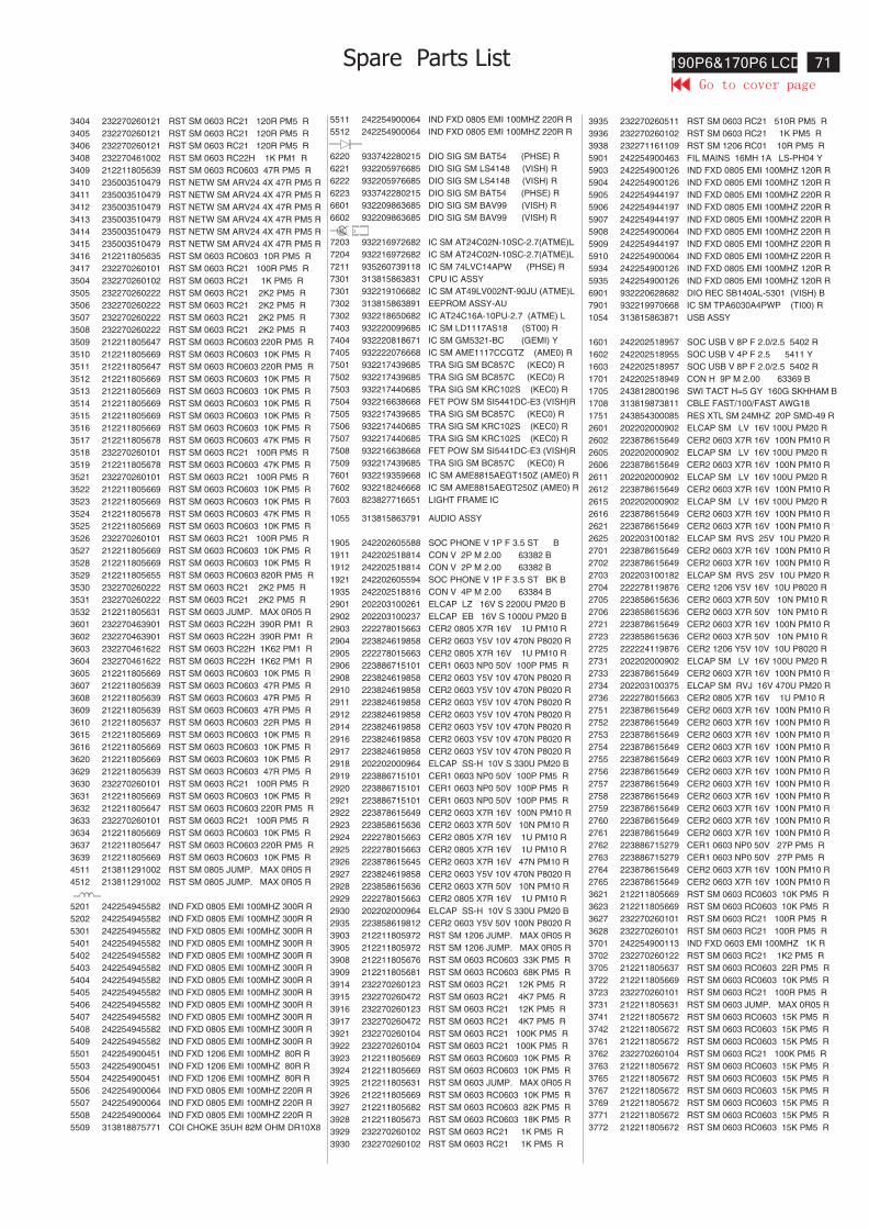
71190P6&170P6 LCD
3404 232270260121 RST SM 0603 RC21 120R PM5 R
3405 232270260121 RST SM 0603 RC21 120R PM5 R
3406 232270260121 RST SM 0603 RC21 120R PM5 R
3408 232270461002 RST SM 0603 RC22H 1K PM1 R
3409 212211805639 RST SM 0603 RC0603 47R PM5 R
3410 235003510479 RST NETW SM ARV24 4X 47R PM5 R
3411 235003510479 RST NETW SM ARV24 4X 47R PM5 R
3412 235003510479 RST NETW SM ARV24 4X 47R PM5 R
3413 235003510479 RST NETW SM ARV24 4X 47R PM5 R
3414 235003510479 RST NETW SM ARV24 4X 47R PM5 R
3415 235003510479 RST NETW SM ARV24 4X 47R PM5 R
3416 212211805635 RST SM 0603 RC0603 10R PM5 R
3417 232270260101 RST SM 0603 RC21 100R PM5 R
3504 232270260102 RST SM 0603 RC21 1K PM5 R
3505 232270260222 RST SM 0603 RC21 2K2 PM5 R
3506 232270260222 RST SM 0603 RC21 2K2 PM5 R
3507 232270260222 RST SM 0603 RC21 2K2 PM5 R
3508 232270260222 RST SM 0603 RC21 2K2 PM5 R
3509 212211805647 RST SM 0603 RC0603 220R PM5 R
3510 212211805669 RST SM 0603 RC0603 10K PM5 R
3511 212211805647 RST SM 0603 RC0603 220R PM5 R
3512 212211805669 RST SM 0603 RC0603 10K PM5 R
3513 212211805669 RST SM 0603 RC0603 10K PM5 R
3514 212211805669 RST SM 0603 RC0603 10K PM5 R
3515 212211805669 RST SM 0603 RC0603 10K PM5 R
3516 212211805669 RST SM 0603 RC0603 10K PM5 R
3517 212211805678 RST SM 0603 RC0603 47K PM5 R
3518 232270260101 RST SM 0603 RC21 100R PM5 R
3519 212211805678 RST SM 0603 RC0603 47K PM5 R
3521 232270260101 RST SM 0603 RC21 100R PM5 R
3522 212211805669 RST SM 0603 RC0603 10K PM5 R
3523 212211805669 RST SM 0603 RC0603 10K PM5 R
3524 212211805678 RST SM 0603 RC0603 47K PM5 R
3525 212211805669 RST SM 0603 RC0603 10K PM5 R
3526 232270260101 RST SM 0603 RC21 100R PM5 R
3527 212211805669 RST SM 0603 RC0603 10K PM5 R
3528 212211805669 RST SM 0603 RC0603 10K PM5 R
3529 212211805655 RST SM 0603 RC0603 820R PM5 R
3530 232270260222 RST SM 0603 RC21 2K2 PM5 R
3531 232270260222 RST SM 0603 RC21 2K2 PM5 R
3532 212211805631 RST SM 0603 JUMP. MAX 0R05 R
3601 232270463901 RST SM 0603 RC22H 390R PM1 R
3602 232270463901 RST SM 0603 RC22H 390R PM1 R
3603 232270461622 RST SM 0603 RC22H 1K62 PM1 R
3604 232270461622 RST SM 0603 RC22H 1K62 PM1 R
3605 212211805669 RST SM 0603 RC0603 10K PM5 R
3607 212211805639 RST SM 0603 RC0603 47R PM5 R
3608 212211805639 RST SM 0603 RC0603 47R PM5 R
3609 212211805639 RST SM 0603 RC0603 47R PM5 R
3610 212211805637 RST SM 0603 RC0603 22R PM5 R
3615 212211805669 RST SM 0603 RC0603 10K PM5 R
3616 212211805669 RST SM 0603 RC0603 10K PM5 R
3620 212211805669 RST SM 0603 RC0603 10K PM5 R
3629 212211805639 RST SM 0603 RC0603 47R PM5 R
3630 232270260101 RST SM 0603 RC21 100R PM5 R
3631 212211805669 RST SM 0603 RC0603 10K PM5 R
3632 212211805647 RST SM 0603 RC0603 220R PM5 R
3633 232270260101 RST SM 0603 RC21 100R PM5 R
3634 212211805669 RST SM 0603 RC0603 10K PM5 R
3637 212211805647 RST SM 0603 RC0603 220R PM5 R
3639 212211805669 RST SM 0603 RC0603 10K PM5 R
4511 213811291002 RST SM 0805 JUMP. MAX 0R05 R
4512 213811291002 RST SM 0805 JUMP. MAX 0R05 R
5201 242254945582 IND FXD 0805 EMI 100MHZ 300R R
5202 242254945582 IND FXD 0805 EMI 100MHZ 300R R
5301 242254945582 IND FXD 0805 EMI 100MHZ 300R R
5401 242254945582 IND FXD 0805 EMI 100MHZ 300R R
5402 242254945582 IND FXD 0805 EMI 100MHZ 300R R
5403 242254945582 IND FXD 0805 EMI 100MHZ 300R R
5404 242254945582 IND FXD 0805 EMI 100MHZ 300R R
5405 242254945582 IND FXD 0805 EMI 100MHZ 300R R
5406 242254945582 IND FXD 0805 EMI 100MHZ 300R R
5407 242254945582 IND FXD 0805 EMI 100MHZ 300R R
5408 242254945582 IND FXD 0805 EMI 100MHZ 300R R
5409 242254945582 IND FXD 0805 EMI 100MHZ 300R R
5501 242254900451 IND FXD 1206 EMI 100MHZ 80R R
5503 242254900451 IND FXD 1206 EMI 100MHZ 80R R
5504 242254900451 IND FXD 1206 EMI 100MHZ 80R R
5506 242254900064 IND FXD 0805 EMI 100MHZ 220R R
5507 242254900064 IND FXD 0805 EMI 100MHZ 220R R
5508 242254900064 IND FXD 0805 EMI 100MHZ 220R R
5509 313818875771 COI CHOKE 35UH 82M OHM DR10X8
5511 242254900064 IND FXD 0805 EMI 100MHZ 220R R
5512 242254900064 IND FXD 0805 EMI 100MHZ 220R R
6220 933742280215 DIO SIG SM BAT54 (PHSE) R
6221 932205976685 DIO SIG SM LS4148 (VISH) R
6222 932205976685 DIO SIG SM LS4148 (VISH) R
6223 933742280215 DIO SIG SM BAT54 (PHSE) R
6601 932209863685 DIO SIG SM BAV99 (VISH) R
6602 932209863685 DIO SIG SM BAV99 (VISH) R
7203 932216972682 IC SM AT24C02N-10SC-2.7(ATME)L
7204 932216972682 IC SM AT24C02N-10SC-2.7(ATME)L
7211 935260739118 IC SM 74LVC14APW (PHSE) R
7301 313815863831 CPU IC ASSY
7301 932219106682 IC SM AT49LV002NT-90JU (ATME)L
7302 313815863891 EEPROM ASSY-AU
7302 932218650682 IC AT24C16A-10PU-2.7 (ATME) L
7403 932220099685 IC SM LD1117AS18 (ST00) R
7404 932220818671 IC SM GM5321-BC (GEMI) Y
7405 932222076668 IC SM AME1117CCGTZ (AME0) R
7501 932217439685 TRA SIG SM BC857C (KEC0) R
7502 932217439685 TRA SIG SM BC857C (KEC0) R
7503 932217440685 TRA SIG SM KRC102S (KEC0) R
7504 932216638668 FET POW SM SI5441DC-E3 (VISH)R
7505 932217439685 TRA SIG SM BC857C (KEC0) R
7506 932217440685 TRA SIG SM KRC102S (KEC0) R
7507 932217440685 TRA SIG SM KRC102S (KEC0) R
7508 932216638668 FET POW SM SI5441DC-E3 (VISH)R
7509 932217439685 TRA SIG SM BC857C (KEC0) R
7601 932219359668 IC SM AME8815AEGT150Z (AME0) R
7602 932218246668 IC SM AME8815AEGT250Z (AME0) R
7603 823827716651 LIGHT FRAME IC
1055 313815863791 AUDIO ASSY
1905 242202605588 SOC PHONE V 1P F 3.5 ST B
1911 242202518814 CON V 2P M 2.00 63382 B
1912 242202518814 CON V 2P M 2.00 63382 B
1921 242202605594 SOC PHONE V 1P F 3.5 ST BK B
1935 242202518816 CON V 4P M 2.00 63384 B
2901 202203100261 ELCAP LZ 16V S 2200U PM20 B
2902 202203100237 ELCAP EB 16V S 1000U PM20 B
2903 222278015663 CER2 0805 X7R 16V 1U PM10 R
2904 223824619858 CER2 0603 Y5V 10V 470N P8020 R
2905 222278015663 CER2 0805 X7R 16V 1U PM10 R
2906 223886715101 CER1 0603 NP0 50V 100P PM5 R
2908 223824619858 CER2 0603 Y5V 10V 470N P8020 R
2910 223824619858 CER2 0603 Y5V 10V 470N P8020 R
2911 223824619858 CER2 0603 Y5V 10V 470N P8020 R
2912 223824619858 CER2 0603 Y5V 10V 470N P8020 R
2914 223824619858 CER2 0603 Y5V 10V 470N P8020 R
2916 223824619858 CER2 0603 Y5V 10V 470N P8020 R
2917 223824619858 CER2 0603 Y5V 10V 470N P8020 R
2918 202202000964 ELCAP SS-H 10V S 330U PM20 B
2919 223886715101 CER1 0603 NP0 50V 100P PM5 R
2920 223886715101 CER1 0603 NP0 50V 100P PM5 R
2921 223886715101 CER1 0603 NP0 50V 100P PM5 R
2922 223878615649 CER2 0603 X7R 16V 100N PM10 R
2923 223858615636 CER2 0603 X7R 50V 10N PM10 R
2924 222278015663 CER2 0805 X7R 16V 1U PM10 R
2925 222278015663 CER2 0805 X7R 16V 1U PM10 R
2926 223878615645 CER2 0603 X7R 16V 47N PM10 R
2927 223824619858 CER2 0603 Y5V 10V 470N P8020 R
2928 223858615636 CER2 0603 X7R 50V 10N PM10 R
2929 222278015663 CER2 0805 X7R 16V 1U PM10 R
2930 202202000964 ELCAP SS-H 10V S 330U PM20 B
2935 223858619812 CER2 0603 Y5V 50V 100N P8020 R
3903 212211805972 RST SM 1206 JUMP. MAX 0R05 R
3905 212211805972 RST SM 1206 JUMP. MAX 0R05 R
3908 212211805676 RST SM 0603 RC0603 33K PM5 R
3909 212211805681 RST SM 0603 RC0603 68K PM5 R
3914 232270260123 RST SM 0603 RC21 12K PM5 R
3915 232270260472 RST SM 0603 RC21 4K7 PM5 R
3916 232270260123 RST SM 0603 RC21 12K PM5 R
3917 232270260472 RST SM 0603 RC21 4K7 PM5 R
3921 232270260104 RST SM 0603 RC21 100K PM5 R
3922 232270260104 RST SM 0603 RC21 100K PM5 R
3923 212211805669 RST SM 0603 RC0603 10K PM5 R
3924 212211805669 RST SM 0603 RC0603 10K PM5 R
3925 212211805631 RST SM 0603 JUMP. MAX 0R05 R
3926 212211805669 RST SM 0603 RC0603 10K PM5 R
3927 212211805682 RST SM 0603 RC0603 82K PM5 R
3928 212211805673 RST SM 0603 RC0603 18K PM5 R
3929 232270260102 RST SM 0603 RC21 1K PM5 R
3930 232270260102 RST SM 0603 RC21 1K PM5 R
3935 232270260511 RST SM 0603 RC21 510R PM5 R
3936 232270260102 RST SM 0603 RC21 1K PM5 R
3938 232271161109 RST SM 1206 RC01 10R PM5 R
5901 242254900463 FIL MAINS 16MH 1A LS-PH04 Y
5903 242254900126 IND FXD 0805 EMI 100MHZ 120R R
5904 242254900126 IND FXD 0805 EMI 100MHZ 120R R
5905 242254944197 IND FXD 0805 EMI 100MHZ 220R R
5906 242254944197 IND FXD 0805 EMI 100MHZ 220R R
5907 242254944197 IND FXD 0805 EMI 100MHZ 220R R
5908 242254900064 IND FXD 0805 EMI 100MHZ 220R R
5909 242254944197 IND FXD 0805 EMI 100MHZ 220R R
5910 242254900064 IND FXD 0805 EMI 100MHZ 220R R
5934 242254900126 IND FXD 0805 EMI 100MHZ 120R R
5935 242254900126 IND FXD 0805 EMI 100MHZ 120R R
6901 932220628682 DIO REC SB140AL-5301 (VISH) B
7901 932219970668 IC SM TPA6030A4PWP (TI00) R
1054 313815863871 USB ASSY
1601 242202518957 SOC USB V 8P F 2.0/2.5 5402 R
1602 242202518955 SOC USB V 4P F 2.5 5411 Y
1603 242202518957 SOC USB V 8P F 2.0/2.5 5402 R
1701 242202518949 CON H 9P M 2.00 63369 B
1705 243812800196 SWI TACT H=5 GY 160G SKHHAM B
1708 313819873811 CBLE FAST/100/FAST AWG18
1751 243854300085 RES XTL SM 24MHZ 20P SMD-49 R
2601 202202000902 ELCAP SM LV 16V 100U PM20 R
2602 223878615649 CER2 0603 X7R 16V 100N PM10 R
2605 202202000902 ELCAP SM LV 16V 100U PM20 R
2606 223878615649 CER2 0603 X7R 16V 100N PM10 R
2611 202202000902 ELCAP SM LV 16V 100U PM20 R
2612 223878615649 CER2 0603 X7R 16V 100N PM10 R
2615 202202000902 ELCAP SM LV 16V 100U PM20 R
2616 223878615649 CER2 0603 X7R 16V 100N PM10 R
2621 223878615649 CER2 0603 X7R 16V 100N PM10 R
2625 202203100182 ELCAP SM RVS 25V 10U PM20 R
2701 223878615649 CER2 0603 X7R 16V 100N PM10 R
2702 223878615649 CER2 0603 X7R 16V 100N PM10 R
2703 202203100182 ELCAP SM RVS 25V 10U PM20 R
2704 222278119876 CER2 1206 Y5V 16V 10U P8020 R
2705 223858615636 CER2 0603 X7R 50V 10N PM10 R
2706 223858615636 CER2 0603 X7R 50V 10N PM10 R
2721 223878615649 CER2 0603 X7R 16V 100N PM10 R
2723 223858615636 CER2 0603 X7R 50V 10N PM10 R
2725 222224119876 CER2 1206 Y5V 10V 10U P8020 R
2731 202202000902 ELCAP SM LV 16V 100U PM20 R
2733 223878615649 CER2 0603 X7R 16V 100N PM10 R
2734 202203100375 ELCAP SM RVJ 16V 470U PM20 R
2736 222278015663 CER2 0805 X7R 16V 1U PM10 R
2751 223878615649 CER2 0603 X7R 16V 100N PM10 R
2752 223878615649 CER2 0603 X7R 16V 100N PM10 R
2753 223878615649 CER2 0603 X7R 16V 100N PM10 R
2754 223878615649 CER2 0603 X7R 16V 100N PM10 R
2755 223878615649 CER2 0603 X7R 16V 100N PM10 R
2756 223878615649 CER2 0603 X7R 16V 100N PM10 R
2757 223878615649 CER2 0603 X7R 16V 100N PM10 R
2758 223878615649 CER2 0603 X7R 16V 100N PM10 R
2759 223878615649 CER2 0603 X7R 16V 100N PM10 R
2760 223878615649 CER2 0603 X7R 16V 100N PM10 R
2761 223878615649 CER2 0603 X7R 16V 100N PM10 R
2762 223886715279 CER1 0603 NP0 50V 27P PM5 R
2763 223886715279 CER1 0603 NP0 50V 27P PM5 R
2764 223878615649 CER2 0603 X7R 16V 100N PM10 R
2765 223878615649 CER2 0603 X7R 16V 100N PM10 R
3621 212211805669 RST SM 0603 RC0603 10K PM5 R
3623 212211805669 RST SM 0603 RC0603 10K PM5 R
3627 232270260101 RST SM 0603 RC21 100R PM5 R
3628 232270260101 RST SM 0603 RC21 100R PM5 R
3701 242254900113 IND FXD 0603 EMI 100MHZ 1K R
3702 232270260122 RST SM 0603 RC21 1K2 PM5 R
3705 212211805637 RST SM 0603 RC0603 22R PM5 R
3722 212211805669 RST SM 0603 RC0603 10K PM5 R
3723 232270260101 RST SM 0603 RC21 100R PM5 R
3731 212211805631 RST SM 0603 JUMP. MAX 0R05 R
3741 212211805672 RST SM 0603 RC0603 15K PM5 R
3742 212211805672 RST SM 0603 RC0603 15K PM5 R
3761 212211805672 RST SM 0603 RC0603 15K PM5 R
3762 232270260104 RST SM 0603 RC21 100K PM5 R
3763 212211805672 RST SM 0603 RC0603 15K PM5 R
3765 212211805672 RST SM 0603 RC0603 15K PM5 R
3767 212211805672 RST SM 0603 RC0603 15K PM5 R
3769 212211805672 RST SM 0603 RC0603 15K PM5 R
3771 212211805672 RST SM 0603 RC0603 15K PM5 R
3772 212211805672 RST SM 0603 RC0603 15K PM5 R
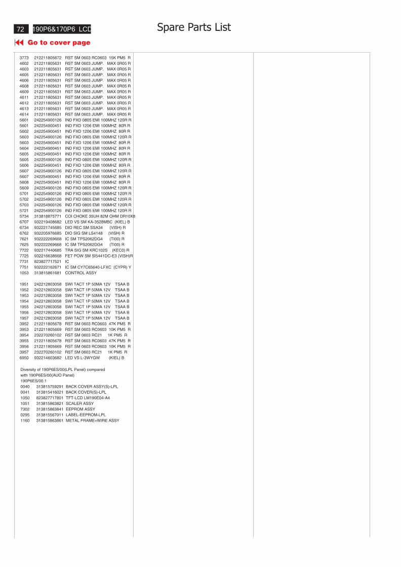
190P6&170P6 LCD
Go to cover page
72
3773 212211805672 RST SM 0603 RC0603 15K PM5 R
4602 212211805631 RST SM 0603 JUMP. MAX 0R05 R
4603 212211805631 RST SM 0603 JUMP. MAX 0R05 R
4605 212211805631 RST SM 0603 JUMP. MAX 0R05 R
4606 212211805631 RST SM 0603 JUMP. MAX 0R05 R
4608 212211805631 RST SM 0603 JUMP. MAX 0R05 R
4609 212211805631 RST SM 0603 JUMP. MAX 0R05 R
4611 212211805631 RST SM 0603 JUMP. MAX 0R05 R
4612 212211805631 RST SM 0603 JUMP. MAX 0R05 R
4613 212211805631 RST SM 0603 JUMP. MAX 0R05 R
4614 212211805631 RST SM 0603 JUMP. MAX 0R05 R
5601 242254900126 IND FXD 0805 EMI 100MHZ 120R R
5601 242254900451 IND FXD 1206 EMI 100MHZ 80R R
5602 242254900451 IND FXD 1206 EMI 100MHZ 80R R
5603 242254900126 IND FXD 0805 EMI 100MHZ 120R R
5603 242254900451 IND FXD 1206 EMI 100MHZ 80R R
5604 242254900451 IND FXD 1206 EMI 100MHZ 80R R
5605 242254900451 IND FXD 1206 EMI 100MHZ 80R R
5605 242254900126 IND FXD 0805 EMI 100MHZ 120R R
5606 242254900451 IND FXD 1206 EMI 100MHZ 80R R
5607 242254900126 IND FXD 0805 EMI 100MHZ 120R R
5607 242254900451 IND FXD 1206 EMI 100MHZ 80R R
5608 242254900451 IND FXD 1206 EMI 100MHZ 80R R
5609 242254900126 IND FXD 0805 EMI 100MHZ 120R R
5701 242254900126 IND FXD 0805 EMI 100MHZ 120R R
5702 242254900126 IND FXD 0805 EMI 100MHZ 120R R
5703 242254900126 IND FXD 0805 EMI 100MHZ 120R R
5721 242254900126 IND FXD 0805 EMI 100MHZ 120R R
5734 313818875771 COI CHOKE 35UH 82M OHM DR10X8
6707 932219408682 LED VS SM KA-3528MBC (KIEL) B
6734 932221745685 DIO REC SM SSA34 (VISH) R
6762 932205976685 DIO SIG SM LS4148 (VISH) R
7621 932222269668 IC SM TPS2062DG4 (TI00) R
7625 932222269668 IC SM TPS2062DG4 (TI00) R
7722 932217440685 TRA SIG SM KRC102S (KEC0) R
7725 932216638668 FET POW SM SI5441DC-E3 (VISH)R
7731 823827717521 IC
7751 932222162671 IC SM CY7C65640-LFXC (CYPR) Y
1053 313815861681 CONTROL ASSY
1951 242212803058 SWI TACT 1P 50MA 12V TSAA B
1952 242212803058 SWI TACT 1P 50MA 12V TSAA B
1953 242212803058 SWI TACT 1P 50MA 12V TSAA B
1954 242212803058 SWI TACT 1P 50MA 12V TSAA B
1955 242212803058 SWI TACT 1P 50MA 12V TSAA B
1956 242212803058 SWI TACT 1P 50MA 12V TSAA B
1957 242212803058 SWI TACT 1P 50MA 12V TSAA B
3952 212211805678 RST SM 0603 RC0603 47K PM5 R
3953 212211805669 RST SM 0603 RC0603 10K PM5 R
3954 232270260102 RST SM 0603 RC21 1K PM5 R
3955 212211805678 RST SM 0603 RC0603 47K PM5 R
3956 212211805669 RST SM 0603 RC0603 10K PM5 R
3957 232270260102 RST SM 0603 RC21 1K PM5 R
6950 932214603682 LED VS L-3WYGW (KIEL) B
Diversity of 190P6ES/00(LPL Panel) compared
with 190P6ES/00(AUO Panel)
190P6ES/00.1
0040 313815759291 BACK COVER ASSY(S)-LPL
0041 313815416021 BACK COVER(S)-LPL
1050 823827717801 TFT-LCD LM190E04-A4
1051 313815863821 SCALER ASSY
7302 313815863841 EEPROM ASSY
0295 313815567011 LABEL-EEPROM-LPL
1160 313815863861 METAL FRAME+WIRE ASSY
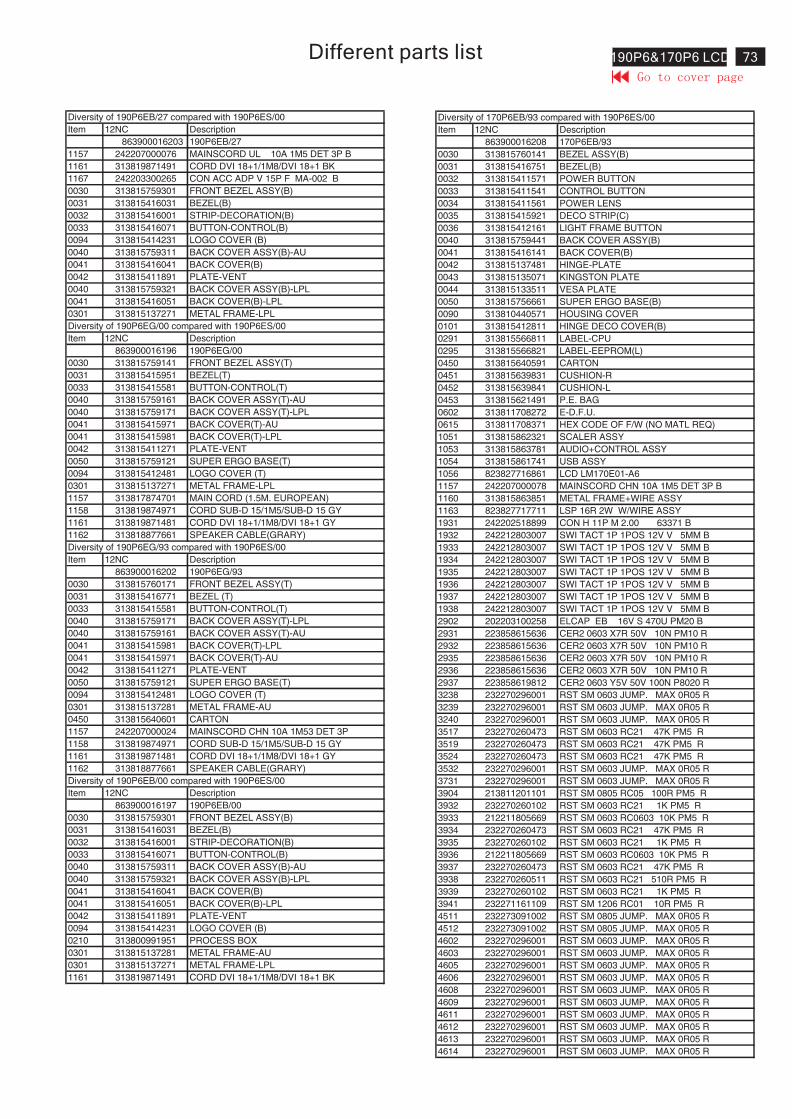
73190P6&170P6 LCDDifferent parts list
Item 12NC Description
863900016203 190P6EB/27
1157 242207000076 MAINSCORD UL 10A 1M5 DET 3P B
1161 313819871491 CORD DVI 18+1/1M8/DVI 18+1 BK
1167 242203300265 CON ACC ADP V 15P F MA-002 B
0030 313815759301 FRONT BEZEL ASSY(B)
0031 313815416031 BEZEL(B)
0032 313815416001 STRIP-DECORATION(B)
0033 313815416071 BUTTON-CONTROL(B)
0094 313815414231 LOGO COVER (B)
0040 313815759311 BACK COVER ASSY(B)-AU
0041 313815416041 BACK COVER(B)
0042 313815411891 PLATE-VENT
0040 313815759321 BACK COVER ASSY(B)-LPL
0041 313815416051 BACK COVER(B)-LPL
0301 313815137271 METAL FRAME-LPL
Item 12NC Description
863900016196 190P6EG/00
0030 313815759141 FRONT BEZEL ASSY(T)
0031 313815415951 BEZEL(T)
0033 313815415581 BUTTON-CONTROL(T)
0040 313815759161 BACK COVER ASSY(T)-AU
0040 313815759171 BACK COVER ASSY(T)-LPL
0041 313815415971 BACK COVER(T)-AU
0041 313815415981 BACK COVER(T)-LPL
0042 313815411271 PLATE-VENT
0050 313815759121 SUPER ERGO BASE(T)
0094 313815412481 LOGO COVER (T)
0301 313815137271 METAL FRAME-LPL
1157 313817874701 MAIN CORD (1.5M. EUROPEAN)
1158 313819874971 CORD SUB-D 15/1M5/SUB-D 15 GY
1161 313819871481 CORD DVI 18+1/1M8/DVI 18+1 GY
1162 313818877661 SPEAKER CABLE(GRARY)
Item 12NC Description
863900016202 190P6EG/93
0030 313815760171 FRONT BEZEL ASSY(T)
0031 313815416771 BEZEL (T)
0033 313815415581 BUTTON-CONTROL(T)
0040 313815759171 BACK COVER ASSY(T)-LPL
0040 313815759161 BACK COVER ASSY(T)-AU
0041 313815415981 BACK COVER(T)-LPL
0041 313815415971 BACK COVER(T)-AU
0042 313815411271 PLATE-VENT
0050 313815759121 SUPER ERGO BASE(T)
0094 313815412481 LOGO COVER (T)
0301 313815137281 METAL FRAME-AU
0450 313815640601 CARTON
1157 242207000024 MAINSCORD CHN 10A 1M53 DET 3P
1158 313819874971 CORD SUB-D 15/1M5/SUB-D 15 GY
1161 313819871481 CORD DVI 18+1/1M8/DVI 18+1 GY
1162 313818877661 SPEAKER CABLE(GRARY)
Item 12NC Description
863900016197 190P6EB/00
0030 313815759301 FRONT BEZEL ASSY(B)
0031 313815416031 BEZEL(B)
0032 313815416001 STRIP-DECORATION(B)
0033 313815416071 BUTTON-CONTROL(B)
0040 313815759311 BACK COVER ASSY(B)-AU
0040 313815759321 BACK COVER ASSY(B)-LPL
0041 313815416041 BACK COVER(B)
0041 313815416051 BACK COVER(B)-LPL
0042 313815411891 PLATE-VENT
0094 313815414231 LOGO COVER (B)
0210 313800991951 PROCESS BOX
0301 313815137281 METAL FRAME-AU
0301 313815137271 METAL FRAME-LPL
1161 313819871491 CORD DVI 18+1/1M8/DVI 18+1 BK
Diversity of 190P6EB/27 compared with 190P6ES/00
Diversity of 190P6EG/00 compared with 190P6ES/00
Diversity of 190P6EG/93 compared with 190P6ES/00
Diversity of 190P6EB/00 compared with 190P6ES/00
Item 12NC Description
863900016208 170P6EB/93
0030 313815760141 BEZEL ASSY(B)
0031 313815416751 BEZEL(B)
0032 313815411571 POWER BUTTON
0033 313815411541 CONTROL BUTTON
0034 313815411561 POWER LENS
0035 313815415921 DECO STRIP(C)
0036 313815412161 LIGHT FRAME BUTTON
0040 313815759441 BACK COVER ASSY(B)
0041 313815416141 BACK COVER(B)
0042 313815137481 HINGE-PLATE
0043 313815135071 KINGSTON PLATE
0044 313815133511 VESA PLATE
0050 313815756661 SUPER ERGO BASE(B)
0090 313810440571 HOUSING COVER
0101 313815412811 HINGE DECO COVER(B)
0291 313815566811 LABEL-CPU
0295 313815566821 LABEL-EEPROM(L)
0450 313815640591 CARTON
0451 313815639831 CUSHION-R
0452 313815639841 CUSHION-L
0453 313815621491 P.E. BAG
0602 313811708272 E-D.F.U.
0615 313811708371 HEX CODE OF F/W (NO MATL REQ)
1051 313815862321 SCALER ASSY
1053 313815863781 AUDIO+CONTROL ASSY
1054 313815861741 USB ASSY
1056 823827716861 LCD LM170E01-A6
1157 242207000078 MAINSCORD CHN 10A 1M5 DET 3P B
1160 313815863851 METAL FRAME+WIRE ASSY
1163 823827717711 LSP 16R 2W W/WIRE ASSY
1931 242202518899 CON H 11P M 2.00 63371 B
1932 242212803007 SWI TACT 1P 1POS 12V V 5MM B
1933 242212803007 SWI TACT 1P 1POS 12V V 5MM B
1934 242212803007 SWI TACT 1P 1POS 12V V 5MM B
1935 242212803007 SWI TACT 1P 1POS 12V V 5MM B
1936 242212803007 SWI TACT 1P 1POS 12V V 5MM B
1937 242212803007 SWI TACT 1P 1POS 12V V 5MM B
1938 242212803007 SWI TACT 1P 1POS 12V V 5MM B
2902 202203100258 ELCAP EB 16V S 470U PM20 B
2931 223858615636 CER2 0603 X7R 50V 10N PM10 R
2932 223858615636 CER2 0603 X7R 50V 10N PM10 R
2935 223858615636 CER2 0603 X7R 50V 10N PM10 R
2936 223858615636 CER2 0603 X7R 50V 10N PM10 R
2937 223858619812 CER2 0603 Y5V 50V 100N P8020 R
3238 232270296001 RST SM 0603 JUMP. MAX 0R05 R
3239 232270296001 RST SM 0603 JUMP. MAX 0R05 R
3240 232270296001 RST SM 0603 JUMP. MAX 0R05 R
3517 232270260473 RST SM 0603 RC21 47K PM5 R
3519 232270260473 RST SM 0603 RC21 47K PM5 R
3524 232270260473 RST SM 0603 RC21 47K PM5 R
3532 232270296001 RST SM 0603 JUMP. MAX 0R05 R
3731 232270296001 RST SM 0603 JUMP. MAX 0R05 R
3904 213811201101 RST SM 0805 RC05 100R PM5 R
3932 232270260102 RST SM 0603 RC21 1K PM5 R
3933 212211805669 RST SM 0603 RC0603 10K PM5 R
3934 232270260473 RST SM 0603 RC21 47K PM5 R
3935 232270260102 RST SM 0603 RC21 1K PM5 R
3936 212211805669 RST SM 0603 RC0603 10K PM5 R
3937 232270260473 RST SM 0603 RC21 47K PM5 R
3938 232270260511 RST SM 0603 RC21 510R PM5 R
3939 232270260102 RST SM 0603 RC21 1K PM5 R
3941 232271161109 RST SM 1206 RC01 10R PM5 R
4511 232273091002 RST SM 0805 JUMP. MAX 0R05 R
4512 232273091002 RST SM 0805 JUMP. MAX 0R05 R
4602 232270296001 RST SM 0603 JUMP. MAX 0R05 R
4603 232270296001 RST SM 0603 JUMP. MAX 0R05 R
4605 232270296001 RST SM 0603 JUMP. MAX 0R05 R
4606 232270296001 RST SM 0603 JUMP. MAX 0R05 R
4608 232270296001 RST SM 0603 JUMP. MAX 0R05 R
4609 232270296001 RST SM 0603 JUMP. MAX 0R05 R
4611 232270296001 RST SM 0603 JUMP. MAX 0R05 R
4612 232270296001 RST SM 0603 JUMP. MAX 0R05 R
4613 232270296001 RST SM 0603 JUMP. MAX 0R05 R
4614 232270296001 RST SM 0603 JUMP. MAX 0R05 R
Diversity of 170P6EB/93 compared with 190P6ES/00
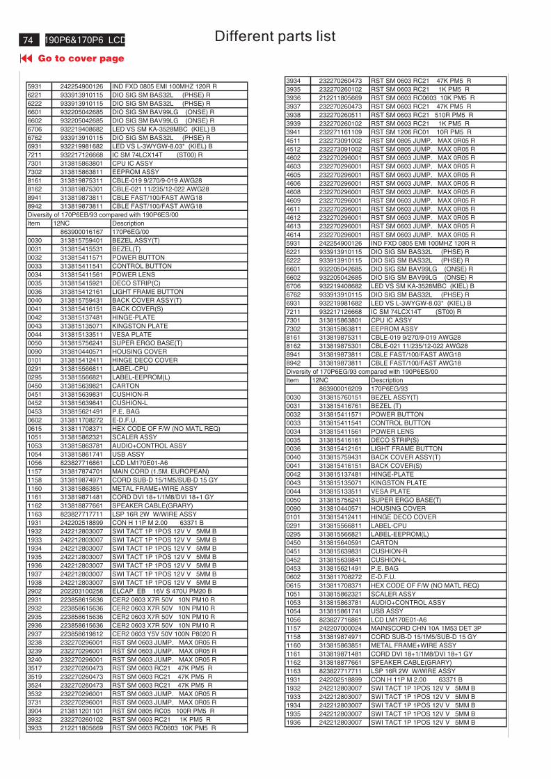
190P6&170P6 LCD
Go to cover page
74
5931 242254900126 IND FXD 0805 EMI 100MHZ 120R R
6221 933913910115 DIO SIG SM BAS32L (PHSE) R
6222 933913910115 DIO SIG SM BAS32L (PHSE) R
6601 932205042685 DIO SIG SM BAV99LG (ONSE) R
6602 932205042685 DIO SIG SM BAV99LG (ONSE) R
6706 932219408682 LED VS SM KA-3528MBC (KIEL) B
6762 933913910115 DIO SIG SM BAS32L (PHSE) R
6931 932219981682 LED VS L-3WYGW-8.03* (KIEL) B
7211 932217126668 IC SM 74LCX14T (ST00) R
7301 313815863801 CPU IC ASSY
7302 313815863811 EEPROM ASSY
8161 313819875311 CBLE-019 9/270/9-019 AWG28
8162 313819875301 CBLE-021 11/235/12-022 AWG28
8941 313819873811 CBLE FAST/100/FAST AWG18
8942 313819873811 CBLE FAST/100/FAST AWG18
Item 12NC Description
863900016167 170P6EG/00
0030 313815759401 BEZEL ASSY(T)
0031 313815415531 BEZEL(T)
0032 313815411571 POWER BUTTON
0033 313815411541 CONTROL BUTTON
0034 313815411561 POWER LENS
0035 313815415921 DECO STRIP(C)
0036 313815412161 LIGHT FRAME BUTTON
0040 313815759431 BACK COVER ASSY(T)
0041 313815416151 BACK COVER(S)
0042 313815137481 HINGE-PLATE
0043 313815135071 KINGSTON PLATE
0044 313815133511 VESA PLATE
0050 313815756241 SUPER ERGO BASE(T)
0090 313810440571 HOUSING COVER
0101 313815412411 HINGE DECO COVER
0291 313815566811 LABEL-CPU
0295 313815566821 LABEL-EEPROM(L)
0450 313815639821 CARTON
0451 313815639831 CUSHION-R
0452 313815639841 CUSHION-L
0453 313815621491 P.E. BAG
0602 313811708272 E-D.F.U.
0615 313811708371 HEX CODE OF F/W (NO MATL REQ)
1051 313815862321 SCALER ASSY
1053 313815863781 AUDIO+CONTROL ASSY
1054 313815861741 USB ASSY
1056 823827716861 LCD LM170E01-A6
1157 313817874701 MAIN CORD (1.5M. EUROPEAN)
1158 313819874971 CORD SUB-D 15/1M5/SUB-D 15 GY
1160 313815863851 METAL FRAME+WIRE ASSY
1161 313819871481 CORD DVI 18+1/1M8/DVI 18+1 GY
1162 313818877661 SPEAKER CABLE(GRARY)
1163 823827717711 LSP 16R 2W W/WIRE ASSY
1931 242202518899 CON H 11P M 2.00 63371 B
1932 242212803007 SWI TACT 1P 1POS 12V V 5MM B
1933 242212803007 SWI TACT 1P 1POS 12V V 5MM B
1934 242212803007 SWI TACT 1P 1POS 12V V 5MM B
1935 242212803007 SWI TACT 1P 1POS 12V V 5MM B
1936 242212803007 SWI TACT 1P 1POS 12V V 5MM B
1937 242212803007 SWI TACT 1P 1POS 12V V 5MM B
1938 242212803007 SWI TACT 1P 1POS 12V V 5MM B
2902 202203100258 ELCAP EB 16V S 470U PM20 B
2931 223858615636 CER2 0603 X7R 50V 10N PM10 R
2932 223858615636 CER2 0603 X7R 50V 10N PM10 R
2935 223858615636 CER2 0603 X7R 50V 10N PM10 R
2936 223858615636 CER2 0603 X7R 50V 10N PM10 R
2937 223858619812 CER2 0603 Y5V 50V 100N P8020 R
3238 232270296001 RST SM 0603 JUMP. MAX 0R05 R
3239 232270296001 RST SM 0603 JUMP. MAX 0R05 R
3240 232270296001 RST SM 0603 JUMP. MAX 0R05 R
3517 232270260473 RST SM 0603 RC21 47K PM5 R
3519 232270260473 RST SM 0603 RC21 47K PM5 R
3524 232270260473 RST SM 0603 RC21 47K PM5 R
3532 232270296001 RST SM 0603 JUMP. MAX 0R05 R
3731 232270296001 RST SM 0603 JUMP. MAX 0R05 R
3904 213811201101 RST SM 0805 RC05 100R PM5 R
3932 232270260102 RST SM 0603 RC21 1K PM5 R
3933 212211805669 RST SM 0603 RC0603 10K PM5 R
Diversity of 170P6EB/93 compared with 190P6ES/00
3934 232270260473 RST SM 0603 RC21 47K PM5 R
3935 232270260102 RST SM 0603 RC21 1K PM5 R
3936 212211805669 RST SM 0603 RC0603 10K PM5 R
3937 232270260473 RST SM 0603 RC21 47K PM5 R
3938 232270260511 RST SM 0603 RC21 510R PM5 R
3939 232270260102 RST SM 0603 RC21 1K PM5 R
3941 232271161109 RST SM 1206 RC01 10R PM5 R
4511 232273091002 RST SM 0805 JUMP. MAX 0R05 R
4512 232273091002 RST SM 0805 JUMP. MAX 0R05 R
4602 232270296001 RST SM 0603 JUMP. MAX 0R05 R
4603 232270296001 RST SM 0603 JUMP. MAX 0R05 R
4605 232270296001 RST SM 0603 JUMP. MAX 0R05 R
4606 232270296001 RST SM 0603 JUMP. MAX 0R05 R
4608 232270296001 RST SM 0603 JUMP. MAX 0R05 R
4609 232270296001 RST SM 0603 JUMP. MAX 0R05 R
4611 232270296001 RST SM 0603 JUMP. MAX 0R05 R
4612 232270296001 RST SM 0603 JUMP. MAX 0R05 R
4613 232270296001 RST SM 0603 JUMP. MAX 0R05 R
4614 232270296001 RST SM 0603 JUMP. MAX 0R05 R
5931 242254900126 IND FXD 0805 EMI 100MHZ 120R R
6221 933913910115 DIO SIG SM BAS32L (PHSE) R
6222 933913910115 DIO SIG SM BAS32L (PHSE) R
6601 932205042685 DIO SIG SM BAV99LG (ONSE) R
6602 932205042685 DIO SIG SM BAV99LG (ONSE) R
6706 932219408682 LED VS SM KA-3528MBC (KIEL) B
6762 933913910115 DIO SIG SM BAS32L (PHSE) R
6931 932219981682 LED VS L-3WYGW-8.03* (KIEL) B
7211 932217126668 IC SM 74LCX14T (ST00) R
7301 313815863801 CPU IC ASSY
7302 313815863811 EEPROM ASSY
8161 313819875311 CBLE-019 9/270/9-019 AWG28
8162 313819875301 CBLE-021 11/235/12-022 AWG28
8941 313819873811 CBLE FAST/100/FAST AWG18
8942 313819873811 CBLE FAST/100/FAST AWG18
Item 12NC Description
863900016209 170P6EG/93
0030 313815760151 BEZEL ASSY(T)
0031 313815416761 BEZEL (T)
0032 313815411571 POWER BUTTON
0033 313815411541 CONTROL BUTTON
0034 313815411561 POWER LENS
0035 313815416161 DECO STRIP(S)
0036 313815412161 LIGHT FRAME BUTTON
0040 313815759431 BACK COVER ASSY(T)
0041 313815416151 BACK COVER(S)
0042 313815137481 HINGE-PLATE
0043 313815135071 KINGSTON PLATE
0044 313815133511 VESA PLATE
0050 313815756241 SUPER ERGO BASE(T)
0090 313810440571 HOUSING COVER
0101 313815412411 HINGE DECO COVER
0291 313815566811 LABEL-CPU
0295 313815566821 LABEL-EEPROM(L)
0450 313815640591 CARTON
0451 313815639831 CUSHION-R
0452 313815639841 CUSHION-L
0453 313815621491 P.E. BAG
0602 313811708272 E-D.F.U.
0615 313811708371 HEX CODE OF F/W (NO MATL REQ)
1051 313815862321 SCALER ASSY
1053 313815863781 AUDIO+CONTROL ASSY
1054 313815861741 USB ASSY
1056 823827716861 LCD LM170E01-A6
1157 242207000024 MAINSCORD CHN 10A 1M53 DET 3P
1158 313819874971 CORD SUB-D 15/1M5/SUB-D 15 GY
1160 313815863851 METAL FRAME+WIRE ASSY
1161 313819871481 CORD DVI 18+1/1M8/DVI 18+1 GY
1162 313818877661 SPEAKER CABLE(GRARY)
1163 823827717711 LSP 16R 2W W/WIRE ASSY
1931 242202518899 CON H 11P M 2.00 63371 B
1932 242212803007 SWI TACT 1P 1POS 12V V 5MM B
1933 242212803007 SWI TACT 1P 1POS 12V V 5MM B
1934 242212803007 SWI TACT 1P 1POS 12V V 5MM B
1935 242212803007 SWI TACT 1P 1POS 12V V 5MM B
1936 242212803007 SWI TACT 1P 1POS 12V V 5MM B
Diversity of 170P6EG/93 compared with 190P6ES/00
Different parts list
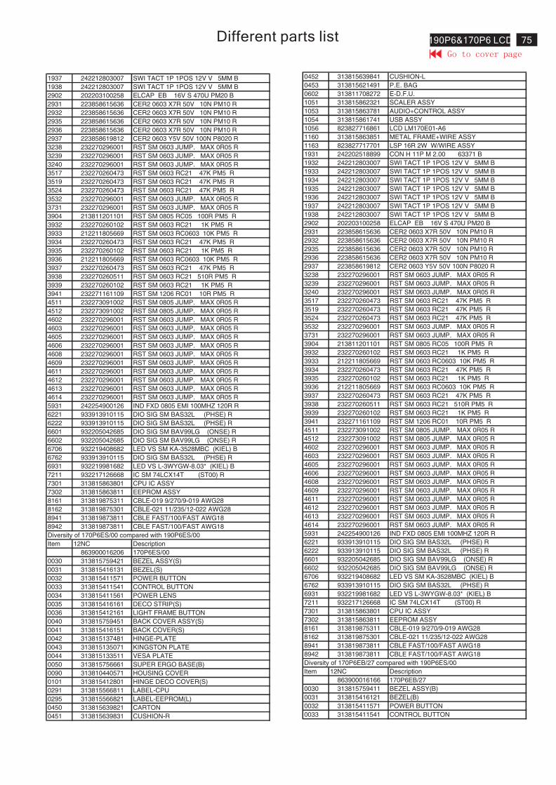
75190P6&170P6 LCDDifferent parts list
1937 242212803007 SWI TACT 1P 1POS 12V V 5MM B
1938 242212803007 SWI TACT 1P 1POS 12V V 5MM B
2902 202203100258 ELCAP EB 16V S 470U PM20 B
2931 223858615636 CER2 0603 X7R 50V 10N PM10 R
2932 223858615636 CER2 0603 X7R 50V 10N PM10 R
2935 223858615636 CER2 0603 X7R 50V 10N PM10 R
2936 223858615636 CER2 0603 X7R 50V 10N PM10 R
2937 223858619812 CER2 0603 Y5V 50V 100N P8020 R
3238 232270296001 RST SM 0603 JUMP. MAX 0R05 R
3239 232270296001 RST SM 0603 JUMP. MAX 0R05 R
3240 232270296001 RST SM 0603 JUMP. MAX 0R05 R
3517 232270260473 RST SM 0603 RC21 47K PM5 R
3519 232270260473 RST SM 0603 RC21 47K PM5 R
3524 232270260473 RST SM 0603 RC21 47K PM5 R
3532 232270296001 RST SM 0603 JUMP. MAX 0R05 R
3731 232270296001 RST SM 0603 JUMP. MAX 0R05 R
3904 213811201101 RST SM 0805 RC05 100R PM5 R
3932 232270260102 RST SM 0603 RC21 1K PM5 R
3933 212211805669 RST SM 0603 RC0603 10K PM5 R
3934 232270260473 RST SM 0603 RC21 47K PM5 R
3935 232270260102 RST SM 0603 RC21 1K PM5 R
3936 212211805669 RST SM 0603 RC0603 10K PM5 R
3937 232270260473 RST SM 0603 RC21 47K PM5 R
3938 232270260511 RST SM 0603 RC21 510R PM5 R
3939 232270260102 RST SM 0603 RC21 1K PM5 R
3941 232271161109 RST SM 1206 RC01 10R PM5 R
4511 232273091002 RST SM 0805 JUMP. MAX 0R05 R
4512 232273091002 RST SM 0805 JUMP. MAX 0R05 R
4602 232270296001 RST SM 0603 JUMP. MAX 0R05 R
4603 232270296001 RST SM 0603 JUMP. MAX 0R05 R
4605 232270296001 RST SM 0603 JUMP. MAX 0R05 R
4606 232270296001 RST SM 0603 JUMP. MAX 0R05 R
4608 232270296001 RST SM 0603 JUMP. MAX 0R05 R
4609 232270296001 RST SM 0603 JUMP. MAX 0R05 R
4611 232270296001 RST SM 0603 JUMP. MAX 0R05 R
4612 232270296001 RST SM 0603 JUMP. MAX 0R05 R
4613 232270296001 RST SM 0603 JUMP. MAX 0R05 R
4614 232270296001 RST SM 0603 JUMP. MAX 0R05 R
5931 242254900126 IND FXD 0805 EMI 100MHZ 120R R
6221 933913910115 DIO SIG SM BAS32L (PHSE) R
6222 933913910115 DIO SIG SM BAS32L (PHSE) R
6601 932205042685 DIO SIG SM BAV99LG (ONSE) R
6602 932205042685 DIO SIG SM BAV99LG (ONSE) R
6706 932219408682 LED VS SM KA-3528MBC (KIEL) B
6762 933913910115 DIO SIG SM BAS32L (PHSE) R
6931 932219981682 LED VS L-3WYGW-8.03* (KIEL) B
7211 932217126668 IC SM 74LCX14T (ST00) R
7301 313815863801 CPU IC ASSY
7302 313815863811 EEPROM ASSY
8161 313819875311 CBLE-019 9/270/9-019 AWG28
8162 313819875301 CBLE-021 11/235/12-022 AWG28
8941 313819873811 CBLE FAST/100/FAST AWG18
8942 313819873811 CBLE FAST/100/FAST AWG18
Item 12NC Description
863900016206 170P6ES/00
0030 313815759421 BEZEL ASSY(S)
0031 313815416131 BEZEL(S)
0032 313815411571 POWER BUTTON
0033 313815411541 CONTROL BUTTON
0034 313815411561 POWER LENS
0035 313815416161 DECO STRIP(S)
0036 313815412161 LIGHT FRAME BUTTON
0040 313815759451 BACK COVER ASSY(S)
0041 313815416151 BACK COVER(S)
0042 313815137481 HINGE-PLATE
0043 313815135071 KINGSTON PLATE
0044 313815133511 VESA PLATE
0050 313815756661 SUPER ERGO BASE(B)
0090 313810440571 HOUSING COVER
0101 313815412801 HINGE DECO COVER(S)
0291 313815566811 LABEL-CPU
0295 313815566821 LABEL-EEPROM(L)
0450 313815639821 CARTON
0451 313815639831 CUSHION-R
Diversity of 170P6ES/00 compared with 190P6ES/00
0452 313815639841 CUSHION-L
0453 313815621491 P.E. BAG
0602 313811708272 E-D.F.U.
1051 313815862321 SCALER ASSY
1053 313815863781 AUDIO+CONTROL ASSY
1054 313815861741 USB ASSY
1056 823827716861 LCD LM170E01-A6
1160 313815863851 METAL FRAME+WIRE ASSY
1163 823827717701 LSP 16R 2W W/WIRE ASSY
1931 242202518899 CON H 11P M 2.00 63371 B
1932 242212803007 SWI TACT 1P 1POS 12V V 5MM B
1933 242212803007 SWI TACT 1P 1POS 12V V 5MM B
1934 242212803007 SWI TACT 1P 1POS 12V V 5MM B
1935 242212803007 SWI TACT 1P 1POS 12V V 5MM B
1936 242212803007 SWI TACT 1P 1POS 12V V 5MM B
1937 242212803007 SWI TACT 1P 1POS 12V V 5MM B
1938 242212803007 SWI TACT 1P 1POS 12V V 5MM B
2902 202203100258 ELCAP EB 16V S 470U PM20 B
2931 223858615636 CER2 0603 X7R 50V 10N PM10 R
2932 223858615636 CER2 0603 X7R 50V 10N PM10 R
2935 223858615636 CER2 0603 X7R 50V 10N PM10 R
2936 223858615636 CER2 0603 X7R 50V 10N PM10 R
2937 223858619812 CER2 0603 Y5V 50V 100N P8020 R
3238 232270296001 RST SM 0603 JUMP. MAX 0R05 R
3239 232270296001 RST SM 0603 JUMP. MAX 0R05 R
3240 232270296001 RST SM 0603 JUMP. MAX 0R05 R
3517 232270260473 RST SM 0603 RC21 47K PM5 R
3519 232270260473 RST SM 0603 RC21 47K PM5 R
3524 232270260473 RST SM 0603 RC21 47K PM5 R
3532 232270296001 RST SM 0603 JUMP. MAX 0R05 R
3731 232270296001 RST SM 0603 JUMP. MAX 0R05 R
3904 213811201101 RST SM 0805 RC05 100R PM5 R
3932 232270260102 RST SM 0603 RC21 1K PM5 R
3933 212211805669 RST SM 0603 RC0603 10K PM5 R
3934 232270260473 RST SM 0603 RC21 47K PM5 R
3935 232270260102 RST SM 0603 RC21 1K PM5 R
3936 212211805669 RST SM 0603 RC0603 10K PM5 R
3937 232270260473 RST SM 0603 RC21 47K PM5 R
3938 232270260511 RST SM 0603 RC21 510R PM5 R
3939 232270260102 RST SM 0603 RC21 1K PM5 R
3941 232271161109 RST SM 1206 RC01 10R PM5 R
4511 232273091002 RST SM 0805 JUMP. MAX 0R05 R
4512 232273091002 RST SM 0805 JUMP. MAX 0R05 R
4602 232270296001 RST SM 0603 JUMP. MAX 0R05 R
4603 232270296001 RST SM 0603 JUMP. MAX 0R05 R
4605 232270296001 RST SM 0603 JUMP. MAX 0R05 R
4606 232270296001 RST SM 0603 JUMP. MAX 0R05 R
4608 232270296001 RST SM 0603 JUMP. MAX 0R05 R
4609 232270296001 RST SM 0603 JUMP. MAX 0R05 R
4611 232270296001 RST SM 0603 JUMP. MAX 0R05 R
4612 232270296001 RST SM 0603 JUMP. MAX 0R05 R
4613 232270296001 RST SM 0603 JUMP. MAX 0R05 R
4614 232270296001 RST SM 0603 JUMP. MAX 0R05 R
5931 242254900126 IND FXD 0805 EMI 100MHZ 120R R
6221 933913910115 DIO SIG SM BAS32L (PHSE) R
6222 933913910115 DIO SIG SM BAS32L (PHSE) R
6601 932205042685 DIO SIG SM BAV99LG (ONSE) R
6602 932205042685 DIO SIG SM BAV99LG (ONSE) R
6706 932219408682 LED VS SM KA-3528MBC (KIEL) B
6762 933913910115 DIO SIG SM BAS32L (PHSE) R
6931 932219981682 LED VS L-3WYGW-8.03* (KIEL) B
7211 932217126668 IC SM 74LCX14T (ST00) R
7301 313815863801 CPU IC ASSY
7302 313815863811 EEPROM ASSY
8161 313819875311 CBLE-019 9/270/9-019 AWG28
8162 313819875301 CBLE-021 11/235/12-022 AWG28
8941 313819873811 CBLE FAST/100/FAST AWG18
8942 313819873811 CBLE FAST/100/FAST AWG18
Item 12NC Description
863900016166 170P6EB/27
0030 313815759411 BEZEL ASSY(B)
0031 313815416121 BEZEL(B)
0032 313815411571 POWER BUTTON
0033 313815411541 CONTROL BUTTON
Diversity of 170P6EB/27 compared with 190P6ES/00
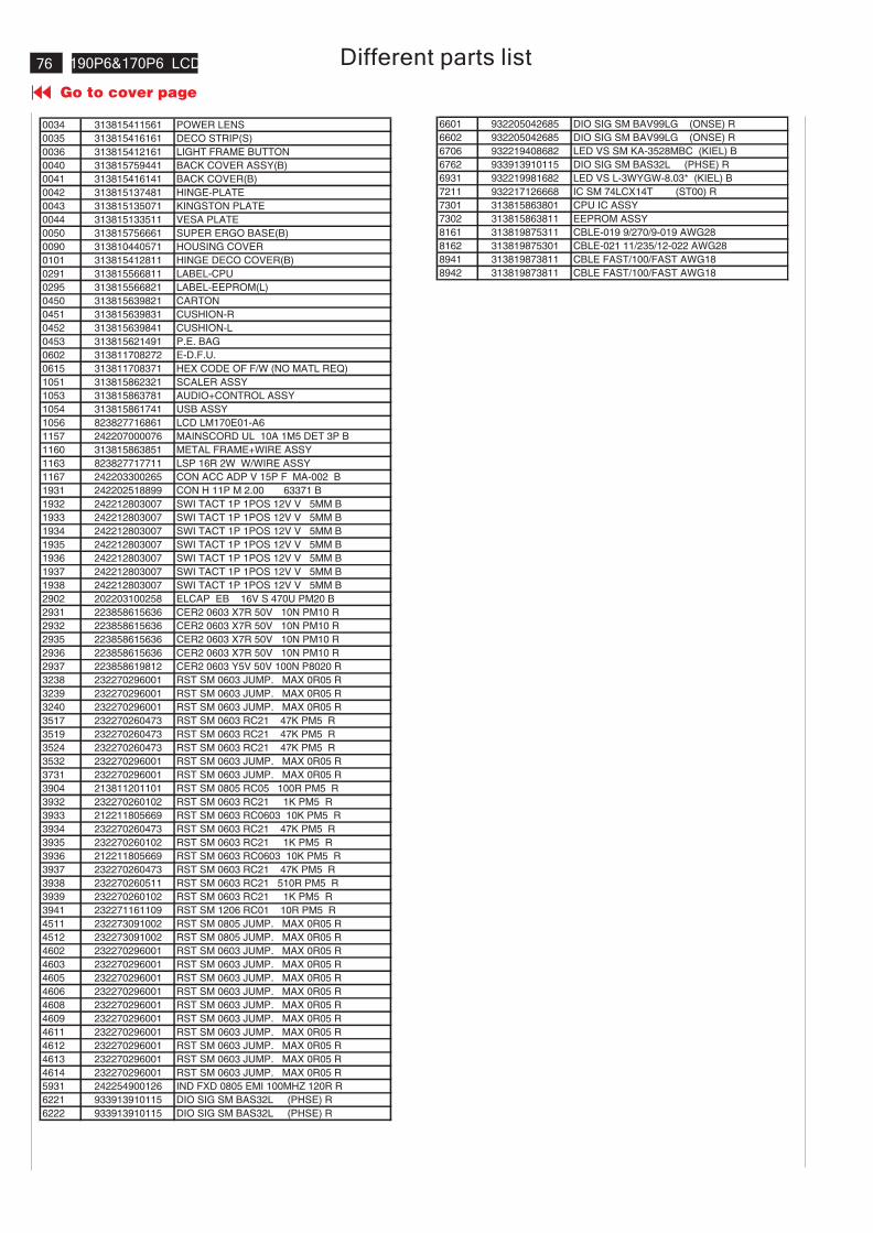
190P6&170P6 LCD
Go to cover page
76 Different parts list
0034 313815411561 POWER LENS
0035 313815416161 DECO STRIP(S)
0036 313815412161 LIGHT FRAME BUTTON
0040 313815759441 BACK COVER ASSY(B)
0041 313815416141 BACK COVER(B)
0042 313815137481 HINGE-PLATE
0043 313815135071 KINGSTON PLATE
0044 313815133511 VESA PLATE
0050 313815756661 SUPER ERGO BASE(B)
0090 313810440571 HOUSING COVER
0101 313815412811 HINGE DECO COVER(B)
0291 313815566811 LABEL-CPU
0295 313815566821 LABEL-EEPROM(L)
0450 313815639821 CARTON
0451 313815639831 CUSHION-R
0452 313815639841 CUSHION-L
0453 313815621491 P.E. BAG
0602 313811708272 E-D.F.U.
0615 313811708371 HEX CODE OF F/W (NO MATL REQ)
1051 313815862321 SCALER ASSY
1053 313815863781 AUDIO+CONTROL ASSY
1054 313815861741 USB ASSY
1056 823827716861 LCD LM170E01-A6
1157 242207000076 MAINSCORD UL 10A 1M5 DET 3P B
1160 313815863851 METAL FRAME+WIRE ASSY
1163 823827717711 LSP 16R 2W W/WIRE ASSY
1167 242203300265 CON ACC ADP V 15P F MA-002 B
1931 242202518899 CON H 11P M 2.00 63371 B
1932 242212803007 SWI TACT 1P 1POS 12V V 5MM B
1933 242212803007 SWI TACT 1P 1POS 12V V 5MM B
1934 242212803007 SWI TACT 1P 1POS 12V V 5MM B
1935 242212803007 SWI TACT 1P 1POS 12V V 5MM B
1936 242212803007 SWI TACT 1P 1POS 12V V 5MM B
1937 242212803007 SWI TACT 1P 1POS 12V V 5MM B
1938 242212803007 SWI TACT 1P 1POS 12V V 5MM B
2902 202203100258 ELCAP EB 16V S 470U PM20 B
2931 223858615636 CER2 0603 X7R 50V 10N PM10 R
2932 223858615636 CER2 0603 X7R 50V 10N PM10 R
2935 223858615636 CER2 0603 X7R 50V 10N PM10 R
2936 223858615636 CER2 0603 X7R 50V 10N PM10 R
2937 223858619812 CER2 0603 Y5V 50V 100N P8020 R
3238 232270296001 RST SM 0603 JUMP. MAX 0R05 R
3239 232270296001 RST SM 0603 JUMP. MAX 0R05 R
3240 232270296001 RST SM 0603 JUMP. MAX 0R05 R
3517 232270260473 RST SM 0603 RC21 47K PM5 R
3519 232270260473 RST SM 0603 RC21 47K PM5 R
3524 232270260473 RST SM 0603 RC21 47K PM5 R
3532 232270296001 RST SM 0603 JUMP. MAX 0R05 R
3731 232270296001 RST SM 0603 JUMP. MAX 0R05 R
3904 213811201101 RST SM 0805 RC05 100R PM5 R
3932 232270260102 RST SM 0603 RC21 1K PM5 R
3933 212211805669 RST SM 0603 RC0603 10K PM5 R
3934 232270260473 RST SM 0603 RC21 47K PM5 R
3935 232270260102 RST SM 0603 RC21 1K PM5 R
3936 212211805669 RST SM 0603 RC0603 10K PM5 R
3937 232270260473 RST SM 0603 RC21 47K PM5 R
3938 232270260511 RST SM 0603 RC21 510R PM5 R
3939 232270260102 RST SM 0603 RC21 1K PM5 R
3941 232271161109 RST SM 1206 RC01 10R PM5 R
4511 232273091002 RST SM 0805 JUMP. MAX 0R05 R
4512 232273091002 RST SM 0805 JUMP. MAX 0R05 R
4602 232270296001 RST SM 0603 JUMP. MAX 0R05 R
4603 232270296001 RST SM 0603 JUMP. MAX 0R05 R
4605 232270296001 RST SM 0603 JUMP. MAX 0R05 R
4606 232270296001 RST SM 0603 JUMP. MAX 0R05 R
4608 232270296001 RST SM 0603 JUMP. MAX 0R05 R
4609 232270296001 RST SM 0603 JUMP. MAX 0R05 R
4611 232270296001 RST SM 0603 JUMP. MAX 0R05 R
4612 232270296001 RST SM 0603 JUMP. MAX 0R05 R
4613 232270296001 RST SM 0603 JUMP. MAX 0R05 R
4614 232270296001 RST SM 0603 JUMP. MAX 0R05 R
5931 242254900126 IND FXD 0805 EMI 100MHZ 120R R
6221 933913910115 DIO SIG SM BAS32L (PHSE) R
6222 933913910115 DIO SIG SM BAS32L (PHSE) R
6601 932205042685 DIO SIG SM BAV99LG (ONSE) R
6602 932205042685 DIO SIG SM BAV99LG (ONSE) R
6706 932219408682 LED VS SM KA-3528MBC (KIEL) B
6762 933913910115 DIO SIG SM BAS32L (PHSE) R
6931 932219981682 LED VS L-3WYGW-8.03* (KIEL) B
7211 932217126668 IC SM 74LCX14T (ST00) R
7301 313815863801 CPU IC ASSY
7302 313815863811 EEPROM ASSY
8161 313819875311 CBLE-019 9/270/9-019 AWG28
8162 313819875301 CBLE-021 11/235/12-022 AWG28
8941 313819873811 CBLE FAST/100/FAST AWG18
8942 313819873811 CBLE FAST/100/FAST AWG18
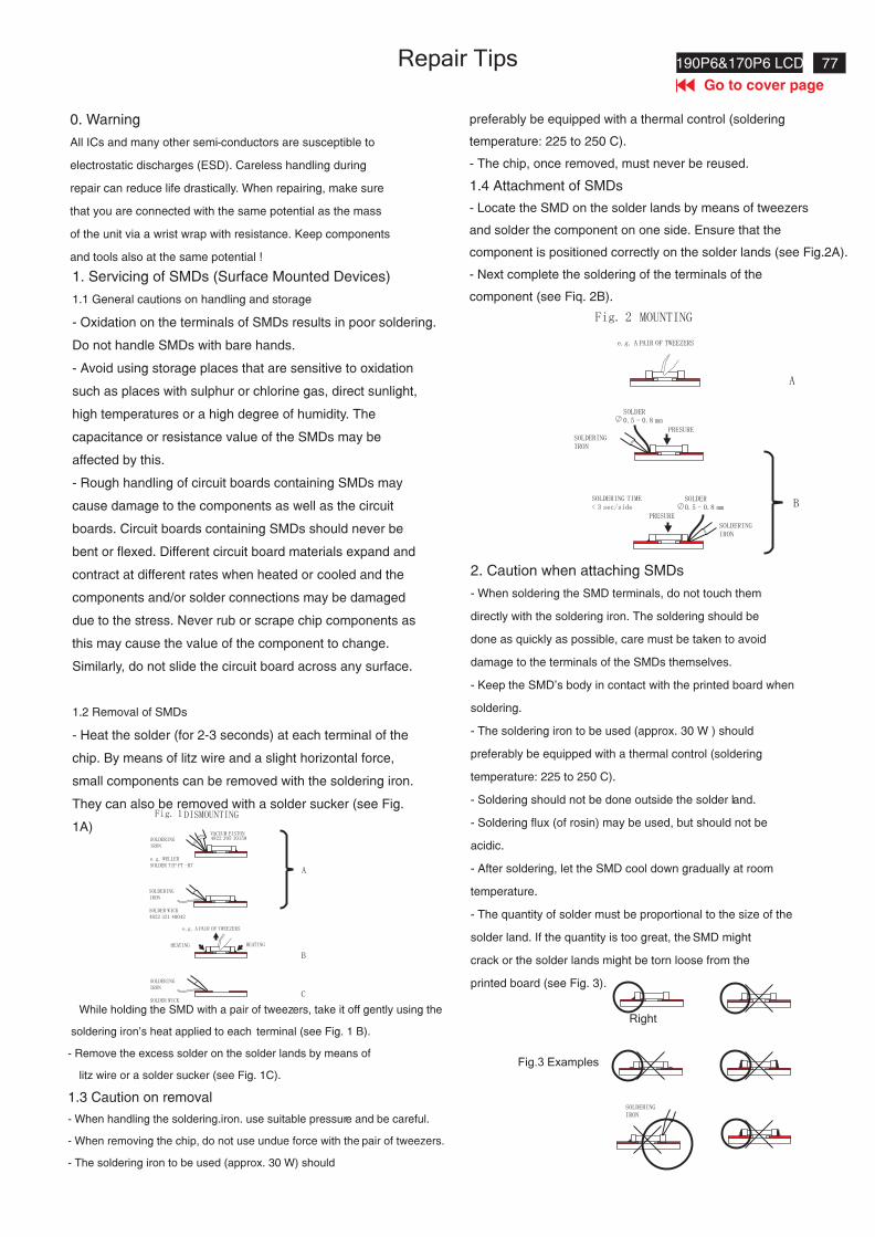
77190P6&170P6 LCD
Go to cover page
Repair Tips
0. Warning
All ICs and many other semi-conductors are susceptible to
electrostatic discharges (ESD). Careless handling during
repair can reduce life drastically. When repairing, make sure
that you are connected with the same potential as the mass
of the unit via a wrist wrap with resistance. Keep components
and tools also at the same potential !
1. Servicing of SMDs (Surface Mounted Devices)
1.1 General cautions on handling and storage
- Oxidation on the terminals of SMDs results in poor soldering.
Do not handle SMDs with bare hands.
- Avoid using storage places that are sensitive to oxidation
such as places with sulphur or chlorine gas, direct sunlight,
high temperatures or a high degree of humidity. The
capacitance or resistance value of the SMDs may be
affected by this.
- Rough handling of circuit boards containing SMDs may
cause damage to the components as well as the circuit
boards. Circuit boards containing SMDs should never be
bent or flexed. Different circuit board materials expand and
contract at different rates when heated or cooled and the
components and/or solder connections may be damaged
due to the stress. Never rub or scrape chip components as
this may cause the value of the component to change.
Similarly, do not slide the circuit board across any surface.
1.2 Removal of SMDs
- Heat the solder (for 2-3 seconds) at each terminal of the
chip. By means of litz wire and a slight horizontal force,
small components can be removed with the soldering iron.
They can also be removed with a solder sucker (see Fig.
1A)
While holding the SMD with a pair of tweezers, take it off gently using the
soldering iron's heat applied to each terminal (see Fig. 1 B).
- Remove the excess solder on the solder lands by means of
litz wire or a solder sucker (see Fig. 1C).
1.3 Caution on removal
- When handling the soldering.iron. use suitable pressure and be careful.
- When removing the chip, do not use undue force with the pair of tweezers.
- The soldering iron to be used (approx. 30 W) should
preferably be equipped with a thermal control (soldering
temperature: 225 to 250 C).
- The chip, once removed, must never be reused.
1.4 Attachment of SMDs
- Locate the SMD on the solder lands by means of tweezers
and solder the component on one side. Ensure that the
component is positioned correctly on the solder lands (see Fig.2A).
- Next complete the soldering of the terminals of the
component (see Fiq. 2B).
2. Caution when attaching SMDs
- When soldering the SMD terminals, do not touch them
directly with the soldering iron. The soldering should be
done as quickly as possible, care must be taken to avoid
damage to the terminals of the SMDs themselves.
- Keep the SMD's body in contact with the printed board when
soldering.
- The soldering iron to be used (approx. 30 W ) should
preferably be equipped with a thermal control (soldering
temperature: 225 to 250 C).
- Soldering should not be done outside the solder land.
- Soldering flux (of rosin) may be used, but should not be
acidic.
- After soldering, let the SMD cool down gradually at room
temperature.
- The quantity of solder must be proportional to the size of the
solder land. If the quantity is too great, the SMD might
crack or the solder lands might be torn loose from the
printed board (see Fig. 3).
Fig.3 Examples
Right
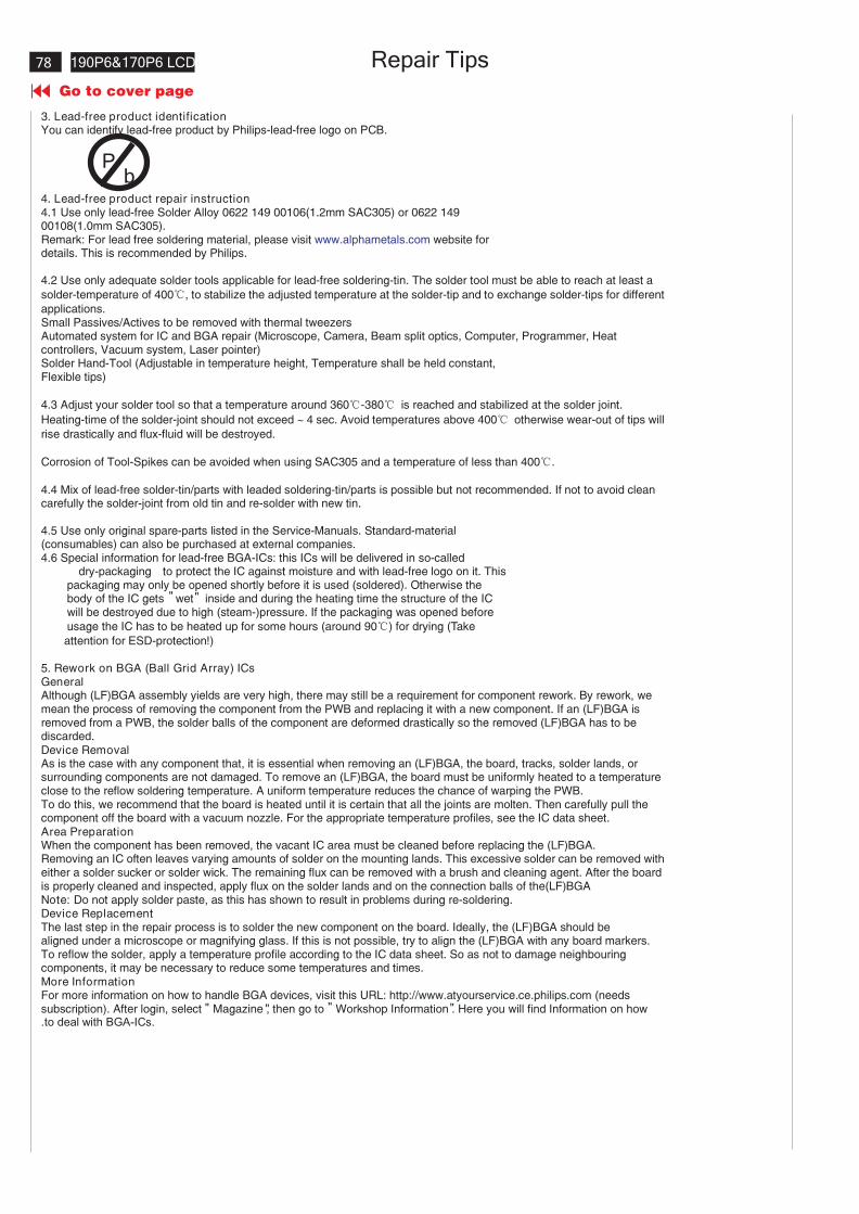
190P6&170P6 LCD
Go to cover page
78 Repair Tips
3. Lead-free product identificationYou can identify lead-free product by Philips-lead-free logo on PCB.
4. Lead-free product repair instruction4.1 Use only lead-free Solder Alloy 0622 149 00106(1.2mm SAC305) or 0622 14900108(1.0mm SAC305).Remark: For lead free soldering material, please visit www.alphametals.com website fordetails. This is recommended by Philips.
4.2 Use only adequate solder tools applicable for lead-free soldering-tin. The solder tool must be able to reach at least a
solder-temperature of 400 , to stabilize the adjusted temperature at the solder-tip and to exchange solder-tips for different
applications.Small Passives/Actives to be removed with thermal tweezersAutomated system for IC and BGA repair (Microscope, Camera, Beam split optics, Computer, Programmer, Heatcontrollers, Vacuum system, Laser pointer)Solder Hand-Tool (Adjustable in temperature height, Temperature shall be held constant,Flexible tips)
4.3 Adjust your solder tool so that a temperature around 360 -380 is reached and stabilized at the solder joint.
Heating-time of the solder-joint should not exceed ~ 4 sec. Avoid temperatures above 400 otherwise wear-out of tips will
rise drastically and flux-fluid will be destroyed.
Corrosion of Tool-Spikes can be avoided when using SAC305 and a temperature of less than 400 .
4.4 Mix of lead-free solder-tin/parts with leaded soldering-tin/parts is possible but not recommended. If not to avoid cleancarefully the solder-joint from old tin and re-solder with new tin.
4.5 Use only original spare-parts listed in the Service-Manuals. Standard-material(consumables) can also be purchased at external companies.4.6 Special information for lead-free BGA-ICs: this ICs will be delivered in so-called
dry-packaging to protect the IC against moisture and with lead-free logo on it. Thispackaging may only be opened shortly before it is used (soldered). Otherwise thebody of the IC gets wet inside and during the heating time the structure of the ICwill be destroyed due to high (steam-)pressure. If the packaging was opened before
usage the IC has to be heated up for some hours (around 90 ) for drying (Take
attention for ESD-protection!)
5. Rework on BGA (Ball Grid Array) ICsGeneralAlthough (LF)BGA assembly yields are very high, there may still be a requirement for component rework. By rework, wemean the process of removing the component from the PWB and replacing it with a new component. If an (LF)BGA isremoved from a PWB, the solder balls of the component are deformed drastically so the removed (LF)BGA has to bediscarded.Device RemovalAs is the case with any component that, it is essential when removing an (LF)BGA, the board, tracks, solder lands, orsurrounding components are not damaged. To remove an (LF)BGA, the board must be uniformly heated to a temperatureclose to the reflow soldering temperature. A uniform temperature reduces the chance of warping the PWB.To do this, we recommend that the board is heated until it is certain that all the joints are molten. Then carefully pull thecomponent off the board with a vacuum nozzle. For the appropriate temperature profiles, see the IC data sheet.Area PreparationWhen the component has been removed, the vacant IC area must be cleaned before replacing the (LF)BGA.Removing an IC often leaves varying amounts of solder on the mounting lands. This excessive solder can be removed witheither a solder sucker or solder wick. The remaining flux can be removed with a brush and cleaning agent. After the boardis properly cleaned and inspected, apply flux on the solder lands and on the connection balls of the(LF)BGANote: Do not apply solder paste, as this has shown to result in problems during re-soldering.Device ReplacementThe last step in the repair process is to solder the new component on the board. Ideally, the (LF)BGA should bealigned under a microscope or magnifying glass. If this is not possible, try to align the (LF)BGA with any board markers.To reflow the solder, apply a temperature profile according to the IC data sheet. So as not to damage neighbouringcomponents, it may be necessary to reduce some temperatures and times.More InformationFor more information on how to handle BGA devices, visit this URL: http://www.atyourservice.ce.philips.com (needssubscription). After login, select Magazine , then go to Workshop Information . Here you will find Information on how.to deal with BGA-ICs.
"
""" "
"
Pb
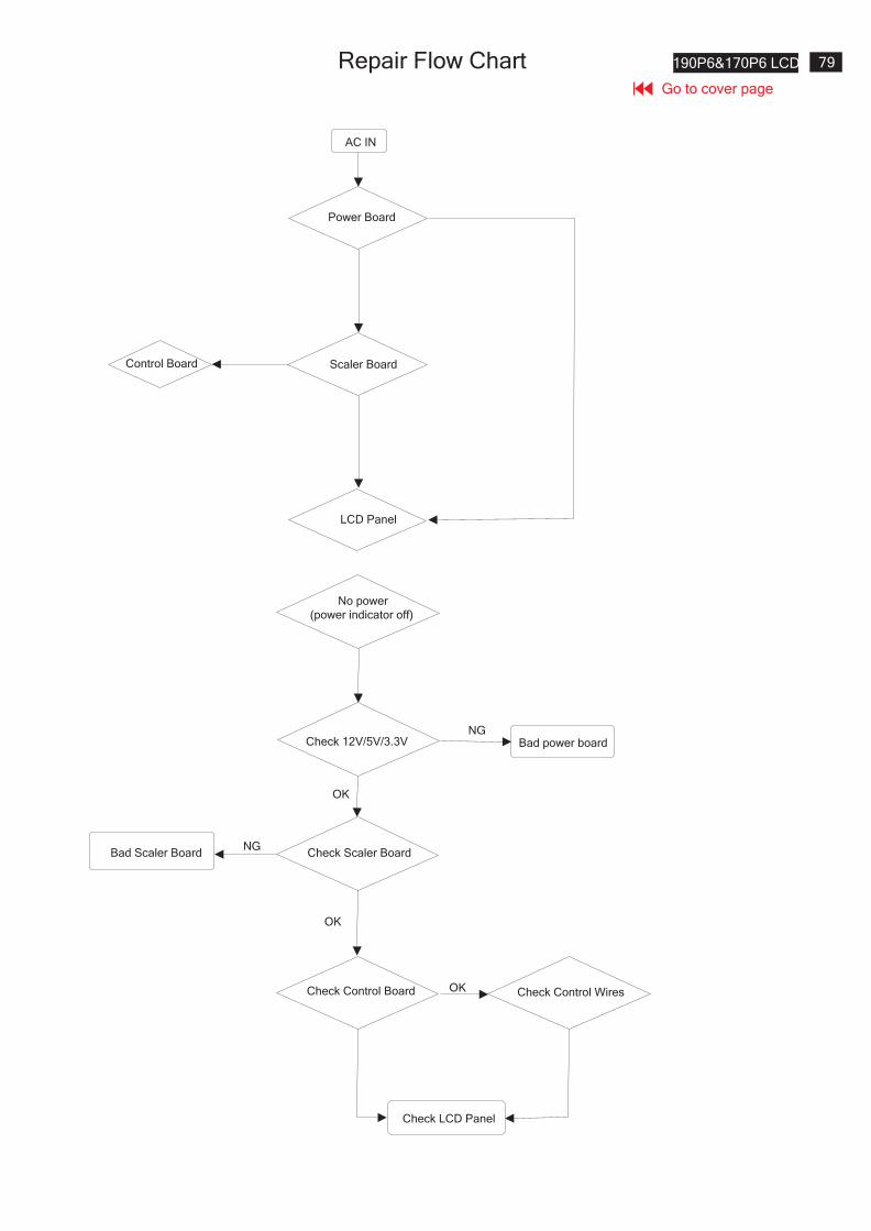
Repair Flow Chart 190P6&170P6 LCD
Go to cover page
79
AC IN
Power Board
Control Board Scaler Board
LCD Panel
No power
(power indicator off)
Check 12V/5V/3.3VNG
Bad power board
Check Control Board Check Control Wires
Check Scaler Board
OK
NG
OK
Bad Scaler Board
Check LCD Panel
OK
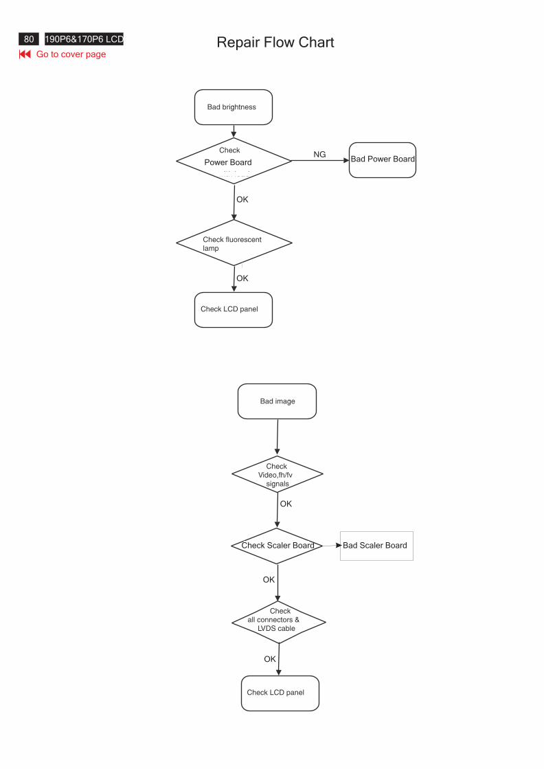
X21Repair Flow Chart80 190P6&170P6 LCD
Go to cover page
Power Board Bad Power Board
OK
NG
OK
OK
Check Scaler Board Bad Scaler Board
OK
OK
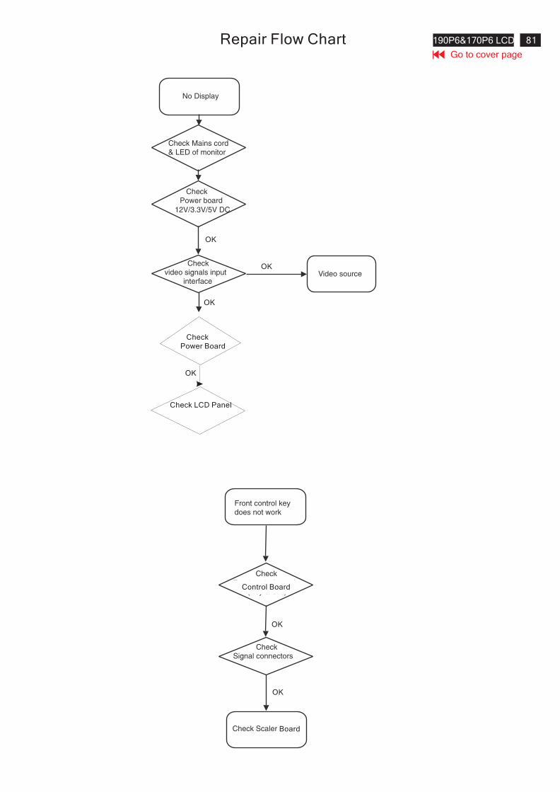
190P6&170P6 LCDRepair Flow ChartGo to cover page
81
Check
Power Board
OK
Check LCD Panel
OK
OK
OK
Control Board
OK
OK
Board
82 190P6&170P6 LCD GENERAL PRODUCT SPECIFICATIONGo to cover page
8639 000 16198BRAND :PHILIPS
19 inch LCD Monitor
TYPE :190P6ES/00
2005-02-05
2005-02-05
29Thomas chen 590 1
HUDSON-6 190P6GENERAL PRODUCT
SPECIFICATION
. ANALOG AND DIGITAL DUAL INPUT
. AUTO PICTURE ADJUSTMENT
. 16 FACTORY PRESET MODES AND 34 PRESET MODES WHICHCAN BE RECOVERED TO PRESET MODES
. USER FRIENDLY OSD DISPLAY FOR MODE IDENTIFICATION/ADJUSTMENT
. DDC-CI COMMUNICATION CAPABILITY
. MAX. RESOLUTION 1280*1024 NON-INTERLACED AT 75 HZ
. 19”COLOR TFT LCD FLAT PANEL
. SUPER ERGO BASE
. FULL RANGE POWER SUPPLY 90 -264 VAC
. CE ENVIRONMENTAL POLICY
. ANTI-GLARE TO REDUCE LIGHT REFLECTION
. POWER MANAGEMENT CAPABILITY
. SOG SUPPORT
. TCO 99/2003
. AUDIO
. PROVIDE USB HUB
. SMART BRIGHT
. WALL MOUNT KIT (OPTION)
. PROTECTIVE COVER (OPTION)
2
190P6&170P6 LCD 83
590
Go to cover pageGENERAL PRODUCT SPECIFICATION
BRAND : PHILIPS
TYPE :190P6ES/00 8639 000 16198
2005-02-05
2005-02-05
29Thomas chen
19 inch LCD Monitor
CONTENTS
1.0 Foreword
2.0 Product profile2.1 LCD
2.2 Scanning frequencies
2.3 Video dot rate
2.4 Power input
2.5 Power consumption
2.6 Dimensions
2.7 Weight
2.8 Functions
2.9 Ambient temperature
2.10 Regulatory compliance
3.0 Electrical characteristics
3.1 Interface signals3.2 Interface
3.2.1 D-sub cable3.2.2 DVI cable3.2.3 OSD function control3.3 Timing requirement
3.3.1 Mode storing capacity3.3.2 Factory preset timings
3.3.3 Horizontal scanning3.3.4 Vertical scanning3.4 Power input connection
3.5 Power management
3.6 Display identification
3.6.1 Analog DDC
3.6.2 Digital DDC
4.0 Visual characteristics
4.1 Test conditions
4.2 Resolution
4.3 Brightness
4.4 Image size
4.4.1 Actual display size
4.4.2 Max scan size
4.5 Brightness uniformity4.6 Check cross talk
4.7 White color adjustment
4.8 Light frame features
84 190P6&170P6 LCD GENERAL PRODUCT SPECIFICATIONGo to cover page
8639 000 16198BRAND :PHILIPS
19 inch LCD Monitor
TYPE :190P6ES/00
2005-02-05
2005-02-05
29Thomas chen 590 3
5.0 Mechanical characteristics5.1 Controls5.2 Unit dimension / weight5.3 Foldable base5.4 Transportation packages5.4.1 Shipping dimension / weight5.4.2 Block unit / palletization
6.0 Environmental characteristics6.1 Susceptibility of display to external environment6.2 Transportation tests6.3 Display disturbances from external environment6.4 Display disturbances to external environment6.4.1 EMI
7.0 Audio7.1 Amplifier section
7.2 Speaker section
8.0 USB 2.0 Hub
9.0 Smart Bright
10.0 Reliability10.1 Mean time between failures
11.0 Quality assurance requirements11.1 Acceptance test
12.0 Serviceability
13.0 Philips Flat panel monitors pixel defect policy
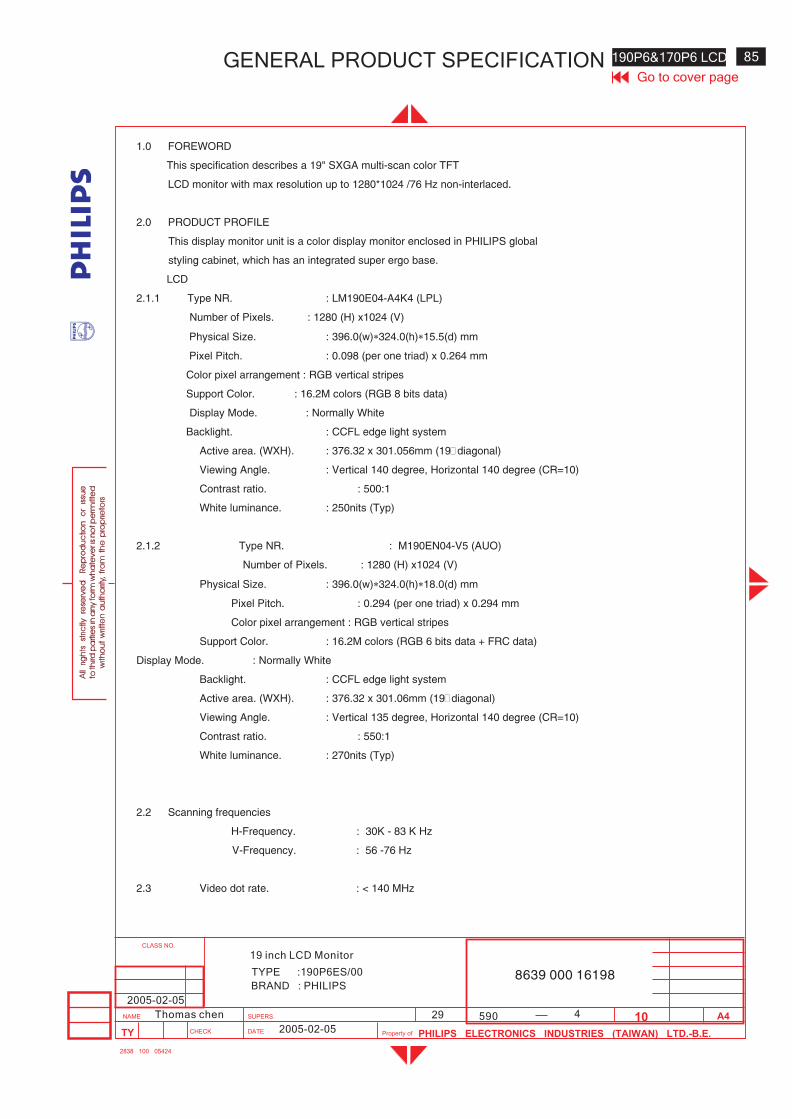
4
190P6&170P6 LCD 85
590
Go to cover pageGENERAL PRODUCT SPECIFICATION
BRAND : PHILIPS
TYPE :190P6ES/00 8639 000 16198
2005-02-05
2005-02-05
29Thomas chen
19 inch LCD Monitor
1.0 FOREWORD
This specification describes a 19" SXGA multi-scan color TFT
LCD monitor with max resolution up to 1280*1024 /76 Hz non-interlaced.
2.0 PRODUCT PROFILE
This display monitor unit is a color display monitor enclosed in PHILIPS global
styling cabinet, which has an integrated super ergo base.
LCD
2.1.1 Type NR. : LM190E04-A4K4 (LPL)
Number of Pixels. : 1280 (H) x1024 (V)
Physical Size. : 396.0(w)�324.0(h)�15.5(d) mm
Pixel Pitch. : 0.098 (per one triad) x 0.264 mm
Color pixel arrangement : RGB vertical stripes
Support Color. : 16.2M colors (RGB 8 bits data)
Display Mode. : Normally White
Backlight. : CCFL edge light system
Active area. (WXH). : 376.32 x 301.056mm (19”diagonal)
Viewing Angle. : Vertical 140 degree, Horizontal 140 degree (CR=10)
Contrast ratio. : 500:1
White luminance. : 250nits (Typ)
2.1.2 Type NR. : M190EN04-V5 (AUO)
Number of Pixels. : 1280 (H) x1024 (V)
Physical Size. : 396.0(w)�324.0(h)�18.0(d) mm
Pixel Pitch. : 0.294 (per one triad) x 0.294 mm
Color pixel arrangement : RGB vertical stripes
Support Color. : 16.2M colors (RGB 6 bits data + FRC data)
Display Mode. : Normally White
Backlight. : CCFL edge light system
Active area. (WXH). : 376.32 x 301.06mm (19”diagonal)
Viewing Angle. : Vertical 135 degree, Horizontal 140 degree (CR=10)
Contrast ratio. : 550:1
White luminance. : 270nits (Typ)
2.2 Scanning frequencies
H-Frequency. : 30K - 83 K Hz
V-Frequency. : 56 -76 Hz
2.3 Video dot rate. : < 140 MHz
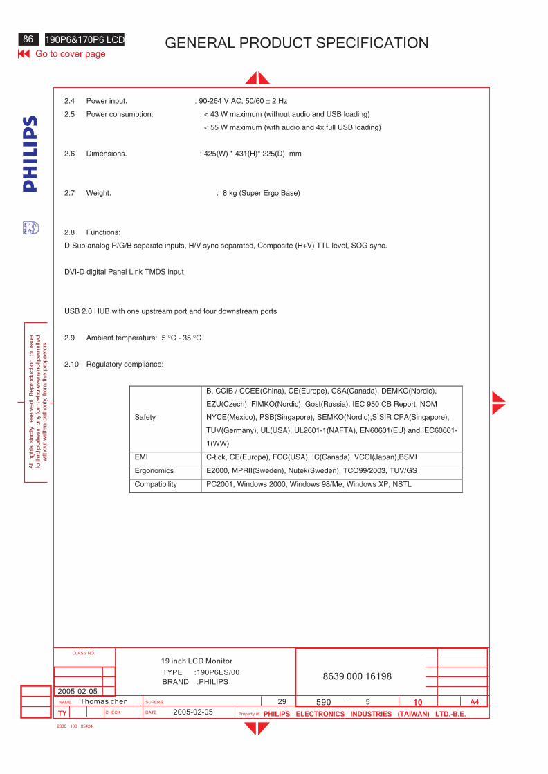
86 190P6&170P6 LCD GENERAL PRODUCT SPECIFICATIONGo to cover page
8639 000 16198BRAND :PHILIPS
19 inch LCD Monitor
TYPE :190P6ES/00
2005-02-05
2005-02-05
29Thomas chen 590 5
2.4 Power input. : 90-264 V AC, 50/60 � 2 Hz
2.5 Power consumption. : < 43 W maximum (without audio and USB loading)
< 55 W maximum (with audio and 4x full USB loading)
2.6 Dimensions. : 425(W) * 431(H)* 225(D) mm
2.7 Weight. : 8 kg (Super Ergo Base)
2.8 Functions:
D-Sub analog R/G/B separate inputs, H/V sync separated, Composite (H+V) TTL level, SOG sync.
DVI-D digital Panel Link TMDS input
USB 2.0 HUB with one upstream port and four downstream ports
2.9 Ambient temperature: 5 �C - 35 �C
2.10 Regulatory compliance:
Safety
B, CCIB / CCEE(China), CE(Europe), CSA(Canada), DEMKO(Nordic),
EZU(Czech), FIMKO(Nordic), Gost(Russia), IEC 950 CB Report, NOM
NYCE(Mexico), PSB(Singapore), SEMKO(Nordic),SISIR CPA(Singapore),
TUV(Germany), UL(USA), UL2601-1(NAFTA), EN60601(EU) and IEC60601-
1(WW)
EMI C-tick, CE(Europe), FCC(USA), IC(Canada), VCCI(Japan),BSMI
Ergonomics E2000, MPRII(Sweden), Nutek(Sweden), TCO99/2003, TUV/GS
Compatibility PC2001, Windows 2000, Windows 98/Me, Windows XP, NSTL
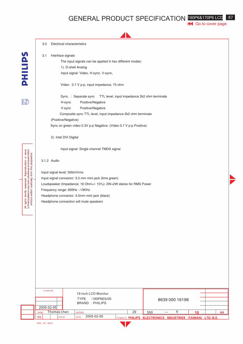
6
190P6&170P6 LCD 87
590
Go to cover pageGENERAL PRODUCT SPECIFICATION
BRAND : PHILIPS
TYPE :190P6ES/00 8639 000 16198
2005-02-05
2005-02-05
29Thomas chen
19 inch LCD Monitor
3.0 Electrical characteristics
3.1 Interface signals
The input signals can be applied in two different modes:
1). D-shell Analog
Input signal: Video, H-sync, V-sync,
Video: 0.7 V p-p, input impedance, 75 ohm
Sync. : Separate sync TTL level, input impedance 2k2 ohm terminate
H-sync Positive/Negative
V-sync Positive/Negative
Composite sync TTL level, input impedance 2k2 ohm terminate
(Positive/Negative)
Sync on green video 0.3V p-p Negative. (Video 0.7 V p-p Positive)
2). Intel DVI Digital
Input signal: Single channel TMDS signal
3.1.2 Audio
Input signal level: 500mVrms
Input signal connector: 3.5 mm mini jack (lime green)
Loudspeaker (Impedance: 16 Ohm+/- 15%): 2W+2W stereo for RMS Power
Frequency range: 650Hz ~13KHz
Headphone connector: 3.5mm mini jack (black)
Headphone connection will mute speakers
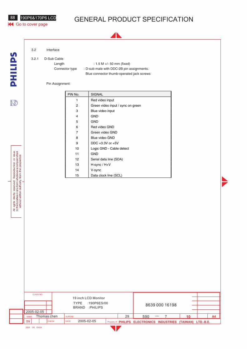
88 190P6&170P6 LCD GENERAL PRODUCT SPECIFICATIONGo to cover page
8639 000 16198BRAND :PHILIPS
19 inch LCD Monitor
TYPE :190P6ES/00
2005-02-05
2005-02-05
29Thomas chen 590 7
3.2 Interface
3.2.1 D-Sub Cable
Length : 1.5 M +/- 50 mm (fixed)
Connector type : D-sub male with DDC-2B pin assignments.
Blue connector thumb-operated jack screws
Pin Assignment:
PIN No. SIGNAL
1 Red video input
2 Green video input / sync on green
3 Blue video input
4 GND
5 GND
6 Red video GND
7 Green video GND
8 Blue video GND
9 DDC +3.3V or +5V
10 Logic GND - Cable detect
11 GND
12 Serial data line (SDA)
13 H-sync / H+V
14 V-sync
15 Data clock line (SCL)
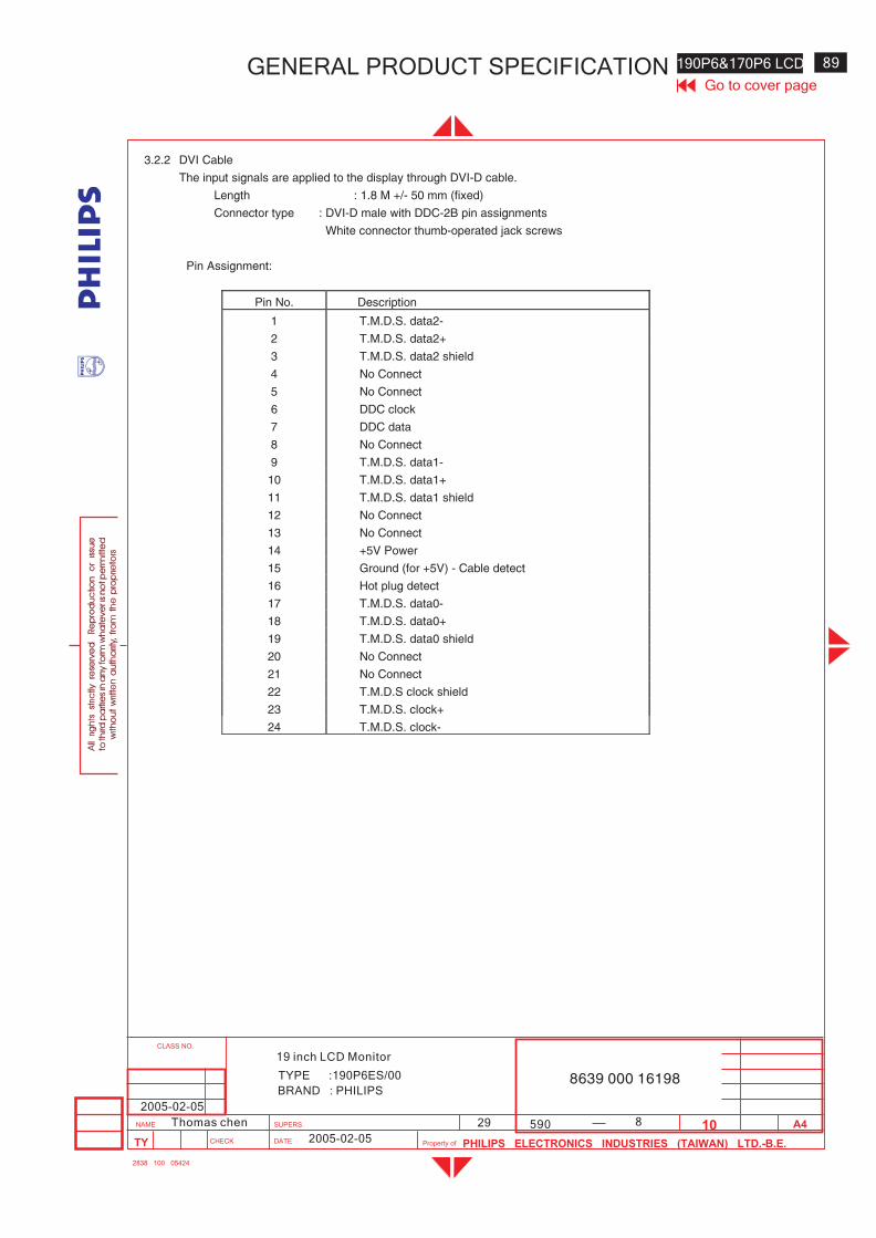
8
190P6&170P6 LCD 89
590
Go to cover pageGENERAL PRODUCT SPECIFICATION
BRAND : PHILIPS
TYPE :190P6ES/00 8639 000 16198
2005-02-05
2005-02-05
29Thomas chen
19 inch LCD Monitor
3.2.2 DVI Cable
The input signals are applied to the display through DVI-D cable.
Length : 1.8 M +/- 50 mm (fixed)
Connector type : DVI-D male with DDC-2B pin assignments
White connector thumb-operated jack screws
Pin Assignment:
Pin No. Description
1 T.M.D.S. data2-
2 T.M.D.S. data2+
3 T.M.D.S. data2 shield
4 No Connect
5 No Connect
6 DDC clock
7 DDC data
8 No Connect
9 T.M.D.S. data1-
10 T.M.D.S. data1+
11 T.M.D.S. data1 shield
12 No Connect
13 No Connect
14 +5V Power
15 Ground (for +5V) - Cable detect
16 Hot plug detect
17 T.M.D.S. data0-
18 T.M.D.S. data0+
19 T.M.D.S. data0 shield
20 No Connect
21 No Connect
22 T.M.D.S clock shield
23 T.M.D.S. clock+
24 T.M.D.S. clock-
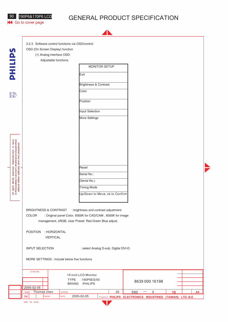
90 190P6&170P6 LCD GENERAL PRODUCT SPECIFICATIONGo to cover page
8639 000 16198BRAND :PHILIPS
19 inch LCD Monitor
TYPE :190P6ES/00
2005-02-05
2005-02-05
29Thomas chen 590 9
3.2.3 Software control functions via OSD/control
OSD (On Screen Display) function
(1) Analog interface OSD:
Adjustable functions:
MONITOR SETUP
Exit
Brightness & Contrast
Color
Position
Input Selection
More Settings
Reset
Serial No.:
(Serial No.)
Timing Mode
Up/Down to Move, ok to Confirm
BRIGHTNESS & CONTRAST : brightness and contrast adjustment.
COLOR : Original panel Color, 9300K for CAD/CAM , 6500K for image
management, sRGB, User Preset: Red Green Blue adjust.
POSITION : HORIZONTAL
VERTICAL
INPUT SELECTION : select Analog D-sub, Digital DVI-D.
MORE SETTINGS : Include below five functions
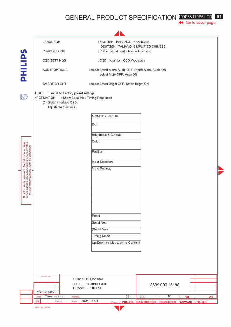
10
190P6&170P6 LCD 91
590
Go to cover pageGENERAL PRODUCT SPECIFICATION
BRAND : PHILIPS
TYPE :190P6ES/00 8639 000 16198
2005-02-05
2005-02-05
29Thomas chen
19 inch LCD Monitor
LANGUAGE : ENGLISH , ESPANOL , FRANCAIS ,
DEUTSCH, ITALIANO, SIMPLIFIED CHINESE,
PHASE/CLOCK : Phase adjustment, Clock adjustment
OSD SETTINGS : OSD H-position, OSD V-position
AUDIO OPTIONS : select Stand-Alone Audio OFF, Stand-Alone Audio ON
select Mute OFF, Mute ON
SMART BRIGHT : select Smart Bright OFF, Smart Bright ON
RESET : recall to Factory preset settings.
INFORMATION : Show Serial No./ Timing Resolution
(2) Digital interface OSD:
Adjustable functions:
MONITOR SETUP
Exit
Brightness & Contrast
Color
Position
Input Selection
More Settings
Reset
Serial No.:
(Serial No.)
Timing Mode
Up/Down to Move, ok to Confirm
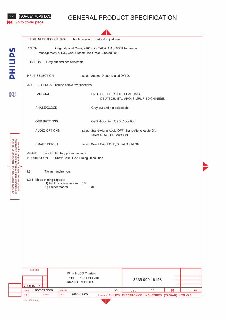
92 190P6&170P6 LCD GENERAL PRODUCT SPECIFICATIONGo to cover page
8639 000 16198BRAND :PHILIPS
19 inch LCD Monitor
TYPE :190P6ES/00
2005-02-05
2005-02-05
29Thomas chen 590 11
BRIGHTNESS & CONTRAST : brightness and contrast adjustment.
COLOR : Original panel Color, 9300K for CAD/CAM , 6500K for image
management, sRGB, User Preset: Red Green Blue adjust.
POSITION : Gray out and not selectable
INPUT SELECTION : select Analog D-sub, Digital DVI-D.
MORE SETTINGS : Include below five functions
LANGUAGE : ENGLISH , ESPANOL , FRANCAIS ,
DEUTSCH, ITALIANO, SIMPLIFIED CHINESE,
PHASE/CLOCK : Gray out and not selectable
OSD SETTINGS : OSD H-position, OSD V-position
AUDIO OPTIONS : select Stand-Alone Audio OFF, Stand-Alone Audio ON
select Mute OFF, Mute ON
SMART BRIGHT : select Smart Bright OFF, Smart Bright ON
RESET : recall to Factory preset settings.
INFORMATION : Show Serial No./ Timing Resolution
3.3 Timing requirement
3.3.1 Mode storing capacity(1) Factory preset modes : 16(2) Preset modes : 34
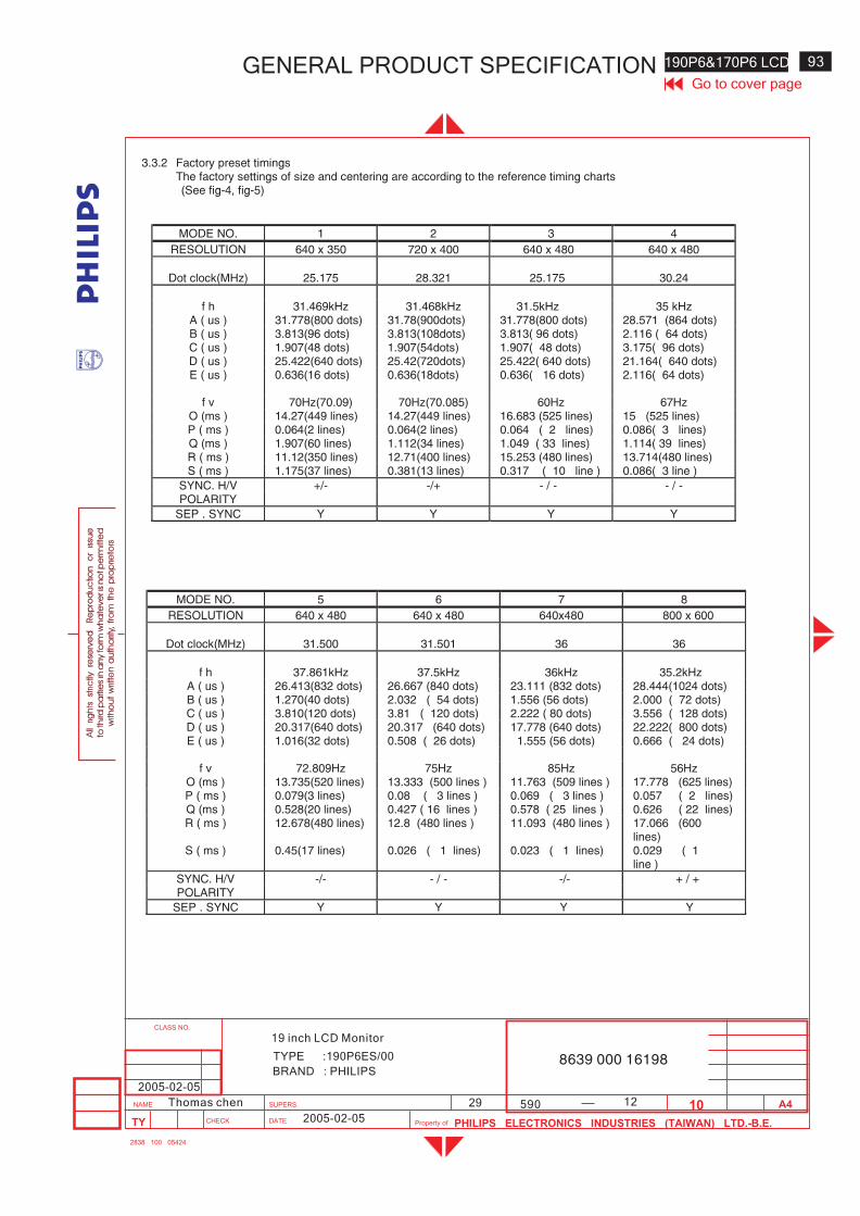
12
190P6&170P6 LCD 93
590
Go to cover pageGENERAL PRODUCT SPECIFICATION
BRAND : PHILIPS
TYPE :190P6ES/00 8639 000 16198
2005-02-05
2005-02-05
29Thomas chen
19 inch LCD Monitor
3.3.2 Factory preset timingsThe factory settings of size and centering are according to the reference timing charts(See fig-4, fig-5)
MODE NO. 1 2 3 4
RESOLUTION 640 x 350 720 x 400 640 x 480 640 x 480
Dot clock(MHz) 25.175 28.321 25.175 30.24
f h 31.469kHz 31.468kHz 31.5kHz 35 kHzA ( us ) 31.778(800 dots) 31.78(900dots) 31.778(800 dots) 28.571 (864 dots)B ( us ) 3.813(96 dots) 3.813(108dots) 3.813( 96 dots) 2.116 ( 64 dots)C ( us ) 1.907(48 dots) 1.907(54dots) 1.907( 48 dots) 3.175( 96 dots)D ( us ) 25.422(640 dots) 25.42(720dots) 25.422( 640 dots) 21.164( 640 dots)E ( us ) 0.636(16 dots) 0.636(18dots) 0.636( 16 dots) 2.116( 64 dots)
f v 70Hz(70.09) 70Hz(70.085) 60Hz 67HzO (ms ) 14.27(449 lines) 14.27(449 lines) 16.683 (525 lines) 15 (525 lines)P ( ms ) 0.064(2 lines) 0.064(2 lines) 0.064 ( 2 lines) 0.086( 3 lines)Q (ms ) 1.907(60 lines) 1.112(34 lines) 1.049 ( 33 lines) 1.114( 39 lines)R ( ms ) 11.12(350 lines) 12.71(400 lines) 15.253 (480 lines) 13.714(480 lines)S ( ms ) 1.175(37 lines) 0.381(13 lines) 0.317 ( 10 line ) 0.086( 3 line )
SYNC. H/V +/- -/+ - / - - / -POLARITY
SEP . SYNC Y Y Y Y
MODE NO. 5 6 7 8
RESOLUTION 640 x 480 640 x 480 640x480 800 x 600
Dot clock(MHz) 31.500 31.501 36 36
f h 37.861kHz 37.5kHz 36kHz 35.2kHzA ( us ) 26.413(832 dots) 26.667 (840 dots) 23.111 (832 dots) 28.444(1024 dots)B ( us ) 1.270(40 dots) 2.032 ( 54 dots) 1.556 (56 dots) 2.000 ( 72 dots)C ( us ) 3.810(120 dots) 3.81 ( 120 dots) 2.222 ( 80 dots) 3.556 ( 128 dots)D ( us ) 20.317(640 dots) 20.317 (640 dots) 17.778 (640 dots) 22.222( 800 dots)E ( us ) 1.016(32 dots) 0.508 ( 26 dots) 1.555 (56 dots) 0.666 ( 24 dots)
f v 72.809Hz 75Hz 85Hz 56HzO (ms ) 13.735(520 lines) 13.333 (500 lines ) 11.763 (509 lines ) 17.778 (625 lines)P ( ms ) 0.079(3 lines) 0.08 ( 3 lines ) 0.069 ( 3 lines ) 0.057 ( 2 lines)Q (ms ) 0.528(20 lines) 0.427 ( 16 lines ) 0.578 ( 25 lines ) 0.626 ( 22 lines)R ( ms ) 12.678(480 lines) 12.8 (480 lines ) 11.093 (480 lines ) 17.066 (600
lines)S ( ms ) 0.45(17 lines) 0.026 ( 1 lines) 0.023 ( 1 lines) 0.029 ( 1
line )
SYNC. H/V -/- - / - -/- + / +POLARITY
SEP . SYNC Y Y Y Y

94 190P6&170P6 LCD GENERAL PRODUCT SPECIFICATIONGo to cover page
8639 000 16198BRAND :PHILIPS
19 inch LCD Monitor
TYPE :190P6ES/00
2005-02-05
2005-02-05
29Thomas chen 590 13
MODE NO. 9 10 11 12
RESOLUTION 800 x 600 800 x 600 800 x 600 800 x 600
Dot clock(MHz) 40 50 49.498 56.251
f h 37.9kHz 48.077kHz 46.9kHz 53.7kHzA ( us ) 26.4 (1056 dots) 20.80 (1040dots) 21.333 (1056 dots) 18.631 (1048 dots)B ( us ) 3.2 ( 128 dots) 2.400 ( 120 dots) 1.616 ( 80 dots) 1.138 ( 64 dots)C ( us ) 2.2 ( 88 dots) 1.280 ( 64 dots) 3.232 ( 160 dots) 2.702 ( 152 dots)D ( us ) 20 ( 800 dots) 16.00 ( 800 dots) 16.162 ( 800 dots) 14.222 ( 800 dots)E ( us ) 1 ( 40 dots) 1.120 ( 56 dots) 0.323 ( 16 dots) 0.569 ( 32 dots)
f v 60Hz 72Hz ( 72.188) 75Hz 85HzO (ms ) 16.579 (628 lines) 13.85 (666 lines) 13.333 (625 lines) 11.756(631 lines)P ( ms ) 0.106 ( 4 lines) 0.125 ( 6 lines) 0.064 ( 3 lines) 0.056 ( 3 lines)Q (ms ) 0.607 ( 23 lines) 0.478 ( 23 lines) 0.448 ( 21 lines) 0.503 ( 27 lines)R ( ms ) 15.84 (600lines) 12.48 (600 lines) 12.8 (600 lines) 11.179 (600 lines)S ( ms ) 0.026 ( 1 line ) 0.770 ( 37 line ) 0.021 ( 1 line ) 0.018 ( 1 lines)
SYNC. H/V + / + + / + + / + + / +POLARITY
SEP . SYNC Y Y Y Y
MODE NO. 13 14 15 16
RESOLUTION 832 x 624 1024 x 768 1024 x 768 1024 x 768
Dot clock(MHz) 57.28 65 75 78.75
f h 49.7kHz 48.363kHz 56.5kHz 60kHzA ( us ) 20.11(1152 dots) 20.677(1344 dots) 17.707(1328 dots) 16.66 (1312dots)B ( us ) 1.117(64 dots) 2.092(136 dots) 1.813(136 dots) 1.219 ( 96 dots)C ( us ) 3.91(224 dots) 2.462(160 dots) 1.920(144 dots) 2.235 ( 176 dots)D ( us ) 14.52(832 dots) 15.754(1024 dots) 13.653(1024 dots) 13.003 ( 1024 dots)E ( us ) 0.563(32 dots) 0.369(24 dots) 0.321 (24 dots) 0.203 ( 16 dots)
f v 75Hz 60.004Hz 70.004Hz 75Hz ( 75.000)O (ms ) 13.41(667 lines) 16.666(806 lines) 14.272(806 lines) 13.328 (800 lines)P ( ms ) 0.06(3 lines) 0.124(6 lines) 0.106(6 lines) 0.05( 3 lines)Q (ms ) 0.784(39 lines) 0.600(29 lines) 0.514(29 lines) 0.446 ( 28 lines)R ( ms ) 12.55(624 lines) 15.880(768 lines) 13.599(768 lines) 12.80 (768 lines)S ( ms ) 0.016(1 lines) 0.062(3 lines) 0.053(3 lines) 0.017 ( 1 line )
SYNC. H/V +/+ - / - -/- + / +POLARITY
SEP . SYNC Y Y Y Y
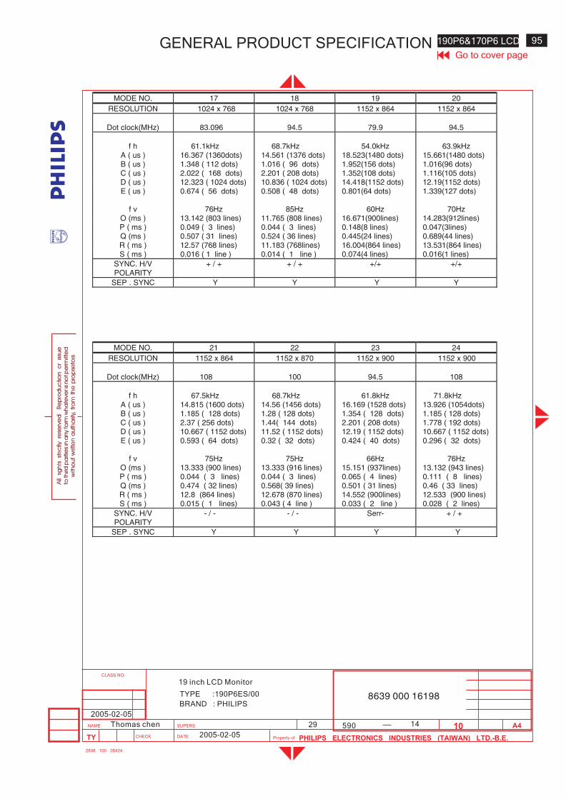
14
190P6&170P6 LCD 95
590
Go to cover pageGENERAL PRODUCT SPECIFICATION
BRAND : PHILIPS
TYPE :190P6ES/00 8639 000 16198
2005-02-05
2005-02-05
29Thomas chen
19 inch LCD Monitor
MODE NO. 17 18 19 20
RESOLUTION 1024 x 768 1024 x 768 1152 x 864 1152 x 864
Dot clock(MHz) 83.096 94.5 79.9 94.5
f h 61.1kHz 68.7kHz 54.0kHz 63.9kHzA ( us ) 16.367 (1360dots) 14.561 (1376 dots) 18.523(1480 dots) 15.661(1480 dots)B ( us ) 1.348 ( 112 dots) 1.016 ( 96 dots) 1.952(156 dots) 1.016(96 dots)C ( us ) 2.022 ( 168 dots) 2.201 ( 208 dots) 1.352(108 dots) 1.116(105 dots)D ( us ) 12.323 ( 1024 dots) 10.836 ( 1024 dots) 14.418(1152 dots) 12.19(1152 dots)E ( us ) 0.674 ( 56 dots) 0.508 ( 48 dots) 0.801(64 dots) 1.339(127 dots)
f v 76Hz 85Hz 60Hz 70HzO (ms ) 13.142 (803 lines) 11.765 (808 lines) 16.671(900lines) 14.283(912lines)P ( ms ) 0.049 ( 3 lines) 0.044 ( 3 lines) 0.148(8 lines) 0.047(3lines)Q (ms ) 0.507 ( 31 lines) 0.524 ( 36 lines) 0.445(24 lines) 0.689(44 lines)R ( ms ) 12.57 (768 lines) 11.183 (768lines) 16.004(864 lines) 13.531(864 lines)S ( ms ) 0.016 ( 1 line ) 0.014 ( 1 line ) 0.074(4 lines) 0.016(1 lines)
SYNC. H/V + / + + / + +/+ +/+POLARITY
SEP . SYNC Y Y Y Y
MODE NO. 21 22 23 24
RESOLUTION 1152 x 864 1152 x 870 1152 x 900 1152 x 900
Dot clock(MHz) 108 100 94.5 108
f h 67.5kHz 68.7kHz 61.8kHz 71.8kHzA ( us ) 14.815 (1600 dots) 14.56 (1456 dots) 16.169 (1528 dots) 13.926 (1054dots)B ( us ) 1.185 ( 128 dots) 1.28 ( 128 dots) 1.354 ( 128 dots) 1.185 ( 128 dots)C ( us ) 2.37 ( 256 dots) 1.44( 144 dots) 2.201 ( 208 dots) 1.778 ( 192 dots)D ( us ) 10.667 ( 1152 dots) 11.52 ( 1152 dots) 12.19 ( 1152 dots) 10.667 ( 1152 dots)E ( us ) 0.593 ( 64 dots) 0.32 ( 32 dots) 0.424 ( 40 dots) 0.296 ( 32 dots)
f v 75Hz 75Hz 66Hz 76HzO (ms ) 13.333 (900 lines) 13.333 (916 lines) 15.151 (937lines) 13.132 (943 lines)P ( ms ) 0.044 ( 3 lines) 0.044 ( 3 lines) 0.065 ( 4 lines) 0.111 ( 8 lines)Q (ms ) 0.474 ( 32 lines) 0.568( 39 lines) 0.501 ( 31 lines) 0.46 ( 33 lines)R ( ms ) 12.8 (864 lines) 12.678 (870 lines) 14.552 (900lines) 12.533 (900 lines)S ( ms ) 0.015 ( 1 lines) 0.043 ( 4 line ) 0.033 ( 2 line ) 0.028 ( 2 lines)
SYNC. H/V - / - - / - Serr- + / +POLARITY
SEP . SYNC Y Y Y Y
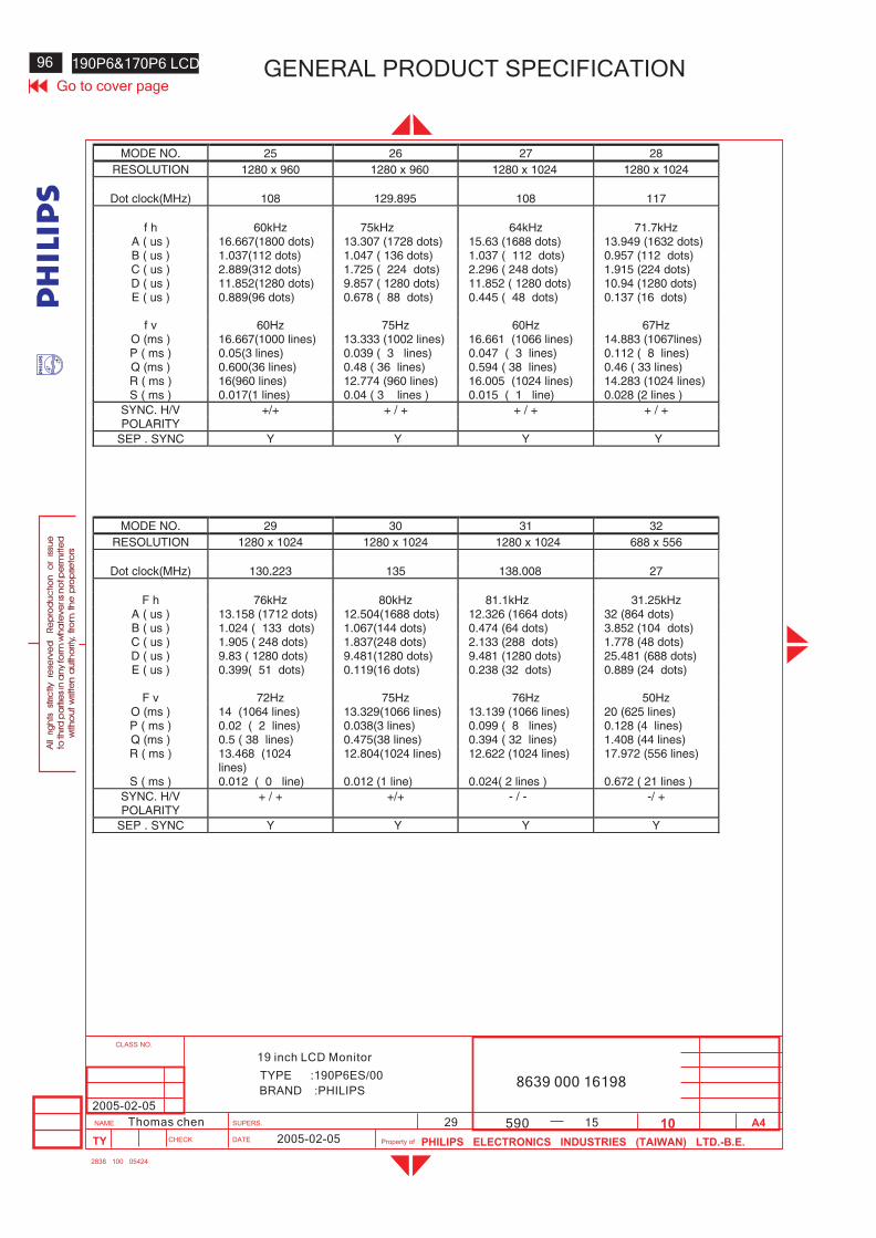
96 190P6&170P6 LCD GENERAL PRODUCT SPECIFICATIONGo to cover page
8639 000 16198BRAND :PHILIPS
19 inch LCD Monitor
TYPE :190P6ES/00
2005-02-05
2005-02-05
29Thomas chen 590 15
MODE NO. 25 26 27 28
RESOLUTION 1280 x 960 1280 x 960 1280 x 1024 1280 x 1024
Dot clock(MHz) 108 129.895 108 117
f h 60kHz 75kHz 64kHz 71.7kHzA ( us ) 16.667(1800 dots) 13.307 (1728 dots) 15.63 (1688 dots) 13.949 (1632 dots)B ( us ) 1.037(112 dots) 1.047 ( 136 dots) 1.037 ( 112 dots) 0.957 (112 dots)C ( us ) 2.889(312 dots) 1.725 ( 224 dots) 2.296 ( 248 dots) 1.915 (224 dots)D ( us ) 11.852(1280 dots) 9.857 ( 1280 dots) 11.852 ( 1280 dots) 10.94 (1280 dots)E ( us ) 0.889(96 dots) 0.678 ( 88 dots) 0.445 ( 48 dots) 0.137 (16 dots)
f v 60Hz 75Hz 60Hz 67HzO (ms ) 16.667(1000 lines) 13.333 (1002 lines) 16.661 (1066 lines) 14.883 (1067lines)P ( ms ) 0.05(3 lines) 0.039 ( 3 lines) 0.047 ( 3 lines) 0.112 ( 8 lines)Q (ms ) 0.600(36 lines) 0.48 ( 36 lines) 0.594 ( 38 lines) 0.46 ( 33 lines)R ( ms ) 16(960 lines) 12.774 (960 lines) 16.005 (1024 lines) 14.283 (1024 lines)S ( ms ) 0.017(1 lines) 0.04 ( 3 lines ) 0.015 ( 1 line) 0.028 (2 lines )
SYNC. H/V +/+ + / + + / + + / +POLARITY
SEP . SYNC Y Y Y Y
MODE NO. 29 30 31 32
RESOLUTION 1280 x 1024 1280 x 1024 1280 x 1024 688 x 556
Dot clock(MHz) 130.223 135 138.008 27
F h 76kHz 80kHz 81.1kHz 31.25kHzA ( us ) 13.158 (1712 dots) 12.504(1688 dots) 12.326 (1664 dots) 32 (864 dots)B ( us ) 1.024 ( 133 dots) 1.067(144 dots) 0.474 (64 dots) 3.852 (104 dots)C ( us ) 1.905 ( 248 dots) 1.837(248 dots) 2.133 (288 dots) 1.778 (48 dots)D ( us ) 9.83 ( 1280 dots) 9.481(1280 dots) 9.481 (1280 dots) 25.481 (688 dots)E ( us ) 0.399( 51 dots) 0.119(16 dots) 0.238 (32 dots) 0.889 (24 dots)
F v 72Hz 75Hz 76Hz 50HzO (ms ) 14 (1064 lines) 13.329(1066 lines) 13.139 (1066 lines) 20 (625 lines)P ( ms ) 0.02 ( 2 lines) 0.038(3 lines) 0.099 ( 8 lines) 0.128 (4 lines)Q (ms ) 0.5 ( 38 lines) 0.475(38 lines) 0.394 ( 32 lines) 1.408 (44 lines)R ( ms ) 13.468 (1024
lines)12.804(1024 lines) 12.622 (1024 lines) 17.972 (556 lines)
S ( ms ) 0.012 ( 0 line) 0.012 (1 line) 0.024( 2 lines ) 0.672 ( 21 lines )
SYNC. H/V + / + +/+ - / - -/ +POLARITY
SEP . SYNC Y Y Y Y
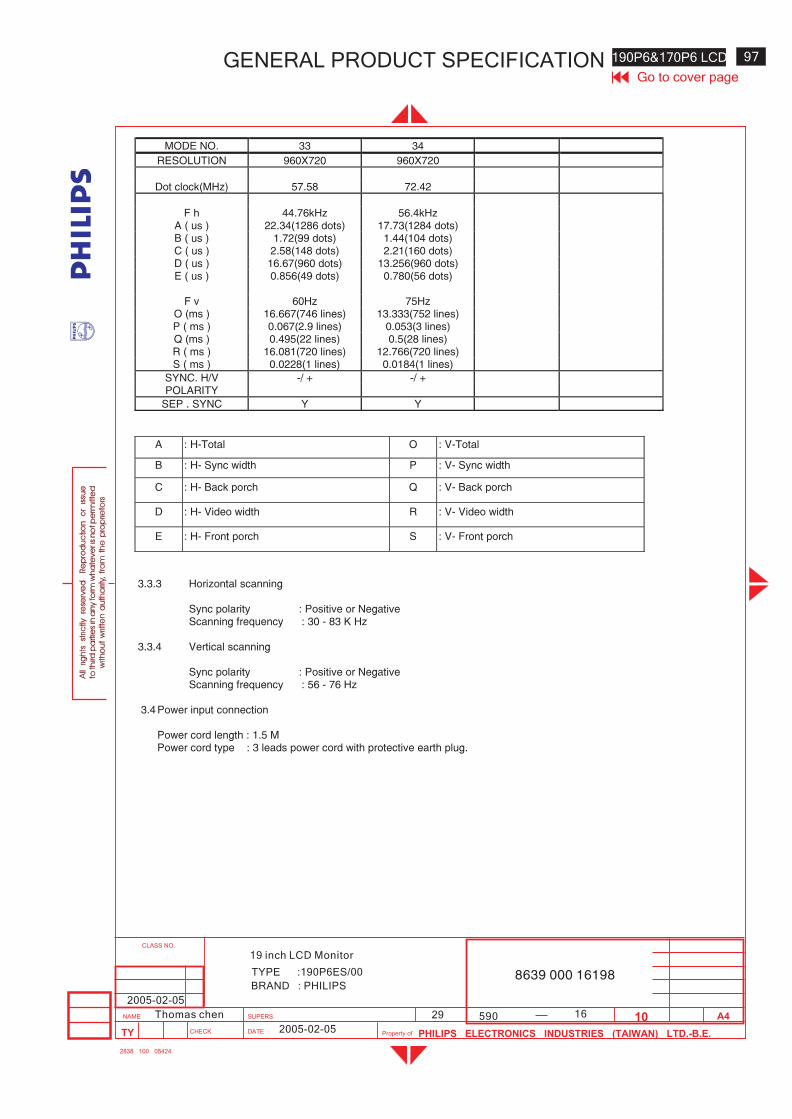
16
190P6&170P6 LCD 97
590
Go to cover pageGENERAL PRODUCT SPECIFICATION
BRAND : PHILIPS
TYPE :190P6ES/00 8639 000 16198
2005-02-05
2005-02-05
29Thomas chen
19 inch LCD Monitor
MODE NO. 33 34
RESOLUTION 960X720 960X720
Dot clock(MHz) 57.58 72.42
F h 44.76kHz 56.4kHzA ( us ) 22.34(1286 dots) 17.73(1284 dots)B ( us ) 1.72(99 dots) 1.44(104 dots)C ( us ) 2.58(148 dots) 2.21(160 dots)D ( us ) 16.67(960 dots) 13.256(960 dots)E ( us ) 0.856(49 dots) 0.780(56 dots)
F v 60Hz 75HzO (ms ) 16.667(746 lines) 13.333(752 lines)P ( ms ) 0.067(2.9 lines) 0.053(3 lines)Q (ms ) 0.495(22 lines) 0.5(28 lines)R ( ms ) 16.081(720 lines) 12.766(720 lines)S ( ms ) 0.0228(1 lines) 0.0184(1 lines)
SYNC. H/V -/ + -/ +POLARITY
SEP . SYNC Y Y
A : H-Total O : V-Total
B : H- Sync width P : V- Sync width
C : H- Back porch Q : V- Back porch
D : H- Video width R : V- Video width
E : H- Front porch S : V- Front porch
3.3.3 Horizontal scanning
Sync polarity : Positive or NegativeScanning frequency : 30 - 83 K Hz
3.3.4 Vertical scanning
Sync polarity : Positive or NegativeScanning frequency : 56 - 76 Hz
3.4 Power input connection
Power cord length : 1.5 MPower cord type : 3 leads power cord with protective earth plug.
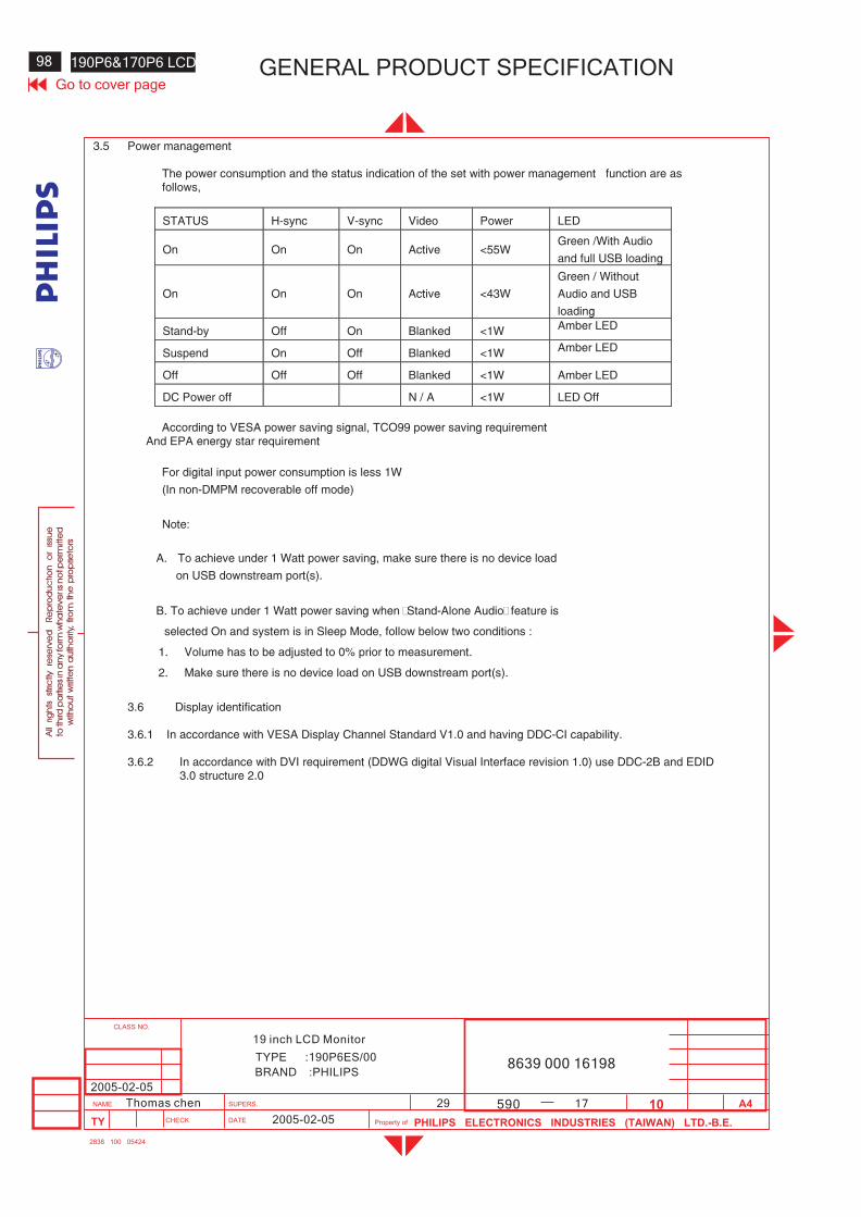
98 190P6&170P6 LCD GENERAL PRODUCT SPECIFICATIONGo to cover page
8639 000 16198BRAND :PHILIPS
19 inch LCD Monitor
TYPE :190P6ES/00
2005-02-05
2005-02-05
29Thomas chen 590 17
3.5 Power management
The power consumption and the status indication of the set with power management function are asfollows,
STATUS H-sync V-sync Video Power LED
On On On Active <55WGreen /With Audio
and full USB loading
On On On Active <43W
Green / Without
Audio and USB
loading
Stand-by Off On Blanked <1W Amber LED
Suspend On Off Blanked <1W Amber LED
Off Off Off Blanked <1W Amber LED
DC Power off N / A <1W LED Off
According to VESA power saving signal, TCO99 power saving requirementAnd EPA energy star requirement
For digital input power consumption is less 1W
(In non-DMPM recoverable off mode)
Note:
A. To achieve under 1 Watt power saving, make sure there is no device load
on USB downstream port(s).
B. To achieve under 1 Watt power saving when “Stand-Alone Audio”feature is
selected On and system is in Sleep Mode, follow below two conditions :
1. Volume has to be adjusted to 0% prior to measurement.
2. Make sure there is no device load on USB downstream port(s).
3.6 Display identification
3.6.1 In accordance with VESA Display Channel Standard V1.0 and having DDC-CI capability.
3.6.2 In accordance with DVI requirement (DDWG digital Visual Interface revision 1.0) use DDC-2B and EDID3.0 structure 2.0
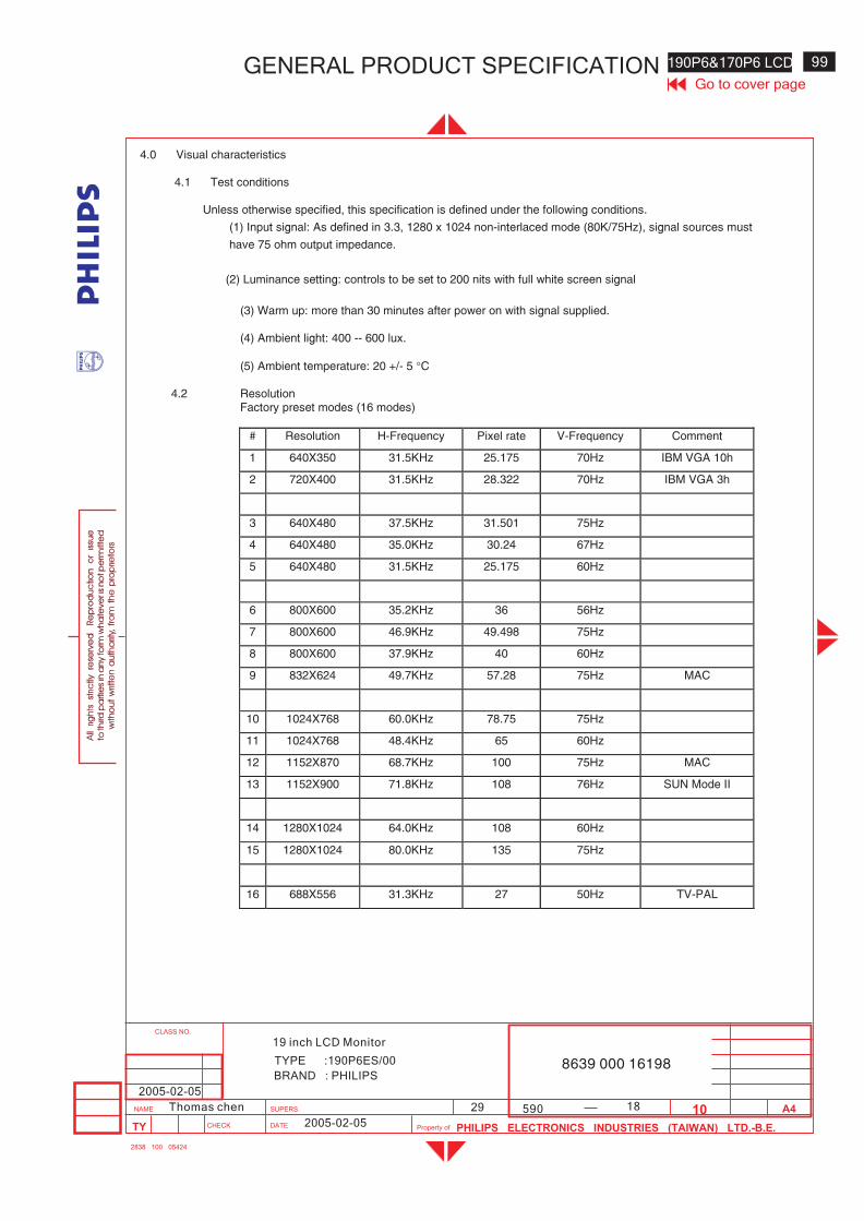
18
190P6&170P6 LCD 99
590
Go to cover pageGENERAL PRODUCT SPECIFICATION
BRAND : PHILIPS
TYPE :190P6ES/00 8639 000 16198
2005-02-05
2005-02-05
29Thomas chen
19 inch LCD Monitor
4.0 Visual characteristics
4.1 Test conditions
Unless otherwise specified, this specification is defined under the following conditions.
(1) Input signal: As defined in 3.3, 1280 x 1024 non-interlaced mode (80K/75Hz), signal sources must
have 75 ohm output impedance.
(2) Luminance setting: controls to be set to 200 nits with full white screen signal
(3) Warm up: more than 30 minutes after power on with signal supplied.
(4) Ambient light: 400 -- 600 lux.
(5) Ambient temperature: 20 +/- 5 �C
4.2 ResolutionFactory preset modes (16 modes)
# Resolution H-Frequency Pixel rate V-Frequency Comment
1 640X350 31.5KHz 25.175 70Hz IBM VGA 10h
2 720X400 31.5KHz 28.322 70Hz IBM VGA 3h
3 640X480 37.5KHz 31.501 75Hz
4 640X480 35.0KHz 30.24 67Hz
5 640X480 31.5KHz 25.175 60Hz
6 800X600 35.2KHz 36 56Hz
7 800X600 46.9KHz 49.498 75Hz
8 800X600 37.9KHz 40 60Hz
9 832X624 49.7KHz 57.28 75Hz MAC
10 1024X768 60.0KHz 78.75 75Hz
11 1024X768 48.4KHz 65 60Hz
12 1152X870 68.7KHz 100 75Hz MAC
13 1152X900 71.8KHz 108 76Hz SUN Mode II
14 1280X1024 64.0KHz 108 60Hz
15 1280X1024 80.0KHz 135 75Hz
16 688X556 31.3KHz 27 50Hz TV-PAL
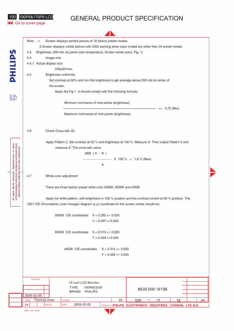
100 190P6&170P6 LCD GENERAL PRODUCT SPECIFICATIONGo to cover page
8639 000 16198BRAND :PHILIPS
19 inch LCD Monitor
TYPE :190P6ES/00
2005-02-05
2005-02-05
29Thomas chen 590 19
Note : 1. Screen displays perfect picture at 16 factory preset modes.
2.Screen displays visible picture with OSD warning when input modes are other than 34 preset modes
4.3 Brightness: 200 nits (at panel color temperature, Screen center point, Fig. 1)
4.4 Image size
4.4.1 Actual display size
376x301mm
4.5 Brightness uniformity
Set contrast at 50% and turn the brightness to get average above 200 nits at center of
the screen.
Apply the Fig 1. It should comply with the following formula:
Minimum luminance of nine points (brightness)
>= 0.75 (Min)
Maximum luminance of nine points (brightness)
4.6 Check Cross talk (S)
Apply Pattern 2. Set contrast at 50 % and brightness at 100 %. Measure A. Then output Pattern 3 and
measure A. The cross talk value:
ABS ( A - A )
��������� X 100 % < 1.8 % (Max)
A
4.7 White color adjustment
There are three factory preset white color 9300K, 6500K and sRGB
Apply full white pattern, with brightness in 100 % position and the contrast control at 50 % position. The
1931 CIE Chromaticity (color triangle) diagram (x,y) coordinate for the screen center should be:
9300K CIE coordinates X = 0.283 +/- 0.020
Y = 0.297 +/-0.020
6500K CIE coordinates X = 0.313 +/- 0.020
Y = 0.329 +/-0.020
sRGB CIE coordinates X = 0.313 +/- 0.020
Y = 0.329 +/- 0.020
'
'
20
190P6&170P6 LCD 101
590
Go to cover pageGENERAL PRODUCT SPECIFICATION
BRAND : PHILIPS
TYPE :190P6ES/00 8639 000 16198
2005-02-05
2005-02-05
29Thomas chen
19 inch LCD Monitor
4.8 Light Frame features
4.8.1 Full screen mode --- accessed by HOT-KEY at front of panel.
Provide three options: Internet, Video and Photo
4.8.2 Multi-window mode --- accessed by Light Frame application program
Brightness control
Sharpness enhancement
Contrast enhancement
Color boosting
5.0 Mechanical characteristics
5.1 ControlsFront side: DC power switch
OSD function key OKUP / DOWN (Brightness key)LEFT / RIGHT (Volume control)AUTO keyLF KeySmart Bright Sensor
Rear side: D-SUB signal connectorDVI signal connectorPower cord socketAudio In jackHeadphone jackUSB upstream port
Left side: 4X USB downstream ports
5.2 Unit dimension / Weight
Set dimension (incl. pedestal): 425(W) * 431(H)* 225(D) mmNet weight. : 8 kg
102 190P6&170P6 LCD GENERAL PRODUCT SPECIFICATIONGo to cover page
8639 000 16198BRAND :PHILIPS
19 inch LCD Monitor
TYPE :190P6ES/00
2005-02-05
2005-02-05
29Thomas chen 590 21
5.3 Super-Ergo base
tilt angle : -5 � to +25 �
5.4 Transportation packages
5.4.1 Shipping dimension/Weight
Carton dimension. : 496(W) * 500(D) * 271(H) mm
Gross weight. : 9.5 Kg
5.4.2 Block unit / Palletization
layers / block sets/layer sets/block unit
8 4 32
blocks/container
20 feet 40 feet
10 22
6.0 Environmental characteristics
The following sections define the interference and susceptibility condition limits that
might occur between external environment and the display device.
6.1 Susceptibility of display to external environment
Operating
- Temperature. : 5 to 35 degree C
- Humidity. : 80% max
- Altitude. : 0 to 12,000 feet
Storage
- Temperature. : -20 to 60 degree C
- Humidity. : 100% max (< 40 )
- Altitude. : 0 to 30,000 feet
Note: recommend at 5 to 35�C, Humidity less than 60 %
22
190P6&170P6 LCD 103
590
Go to cover pageGENERAL PRODUCT SPECIFICATION
BRAND : PHILIPS
TYPE :190P6ES/00 8639 000 16198
2005-02-05
2005-02-05
29Thomas chen
19 inch LCD Monitor
6.2 Transportation tests
Standard Philips UAN-D1400 NSTA
Height 61.0 cm 61.0 cm
1 corner 1 corner
Drop Sequence 3 edges 3 edges
Test (Room temp) 6 faces (Room temp) 6 faces
Electrical function ok
Test Mechanical function ok
Result No serious damage on set appearance
(Room temp 20 ~23 , humidity 40%~65%)
(1) PACKAGING
Sequence 5~500 Hz, 0.73 Grms, Truck spectrum 30 min
(2) OPERATING
Vibration 10-55-10, 0.35 mm amplitude, 30 min. /axis. 3axes
Test Test Electrical function ok
Result Mechanical function ok
No serious damage on set appearance
6.3 Display disturbances from external environmentAccording to IEC 801-2 for ESD disturbances
6.4 Display disturbances to external environment
6.4.1 EMIEMI: FCC, VCCI, CE, C-Tick, MPRIII, BCIQ,
7.0 Audio
Input signal level: 500mVrms
Input signal connector: 3.5 mm mini jack (lime green)
Loudspeaker (Impedance: 16 Ohm+/- 15%): 2W+2W stereo for RMS Power
Frequency range: 650Hz ~13KHz
Headphone connector: 3.5mm mini jack (black)
Headphone connection will mute speakers
104 190P6&170P6 LCD GENERAL PRODUCT SPECIFICATIONGo to cover page
8639 000 16198BRAND :PHILIPS
19 inch LCD Monitor
TYPE :190P6ES/00
2005-02-05
2005-02-05
29Thomas chen 590 23
8.0 USB 2.0 Hub
The USB hub shall be self-powered by the internal power supply of the monitor. Thecommunication protocol shall comply with USB specification revision 2.0. A singleupstream connector shall serve as connection to the CPU or other USB hub. Each of the4 downstream ports shall include current-limited power of 5VDC at 500mA for use by an attacheddevice.
USB SignalsUSB signals shall meet the timing and signal level standards for high speed devices set forth byindustry standard USB specification revision 2.0. Each downstream port shall provide 5VDC at up to500mA for use by an attached USB device.
Communication ProtocolUSB connections shall be established via 4-conductor USB cables. USB cables must beshielded in accordance with the USB specification for high speed devices.
Protocol ParametersThe USB hub and associated ports shall be compliant with the USB specification forhigh speed devices. The USB device speed shall be 480 Mbit/sec. The maximum polling rate shallbe every 256 ms.
9.0 Smart Bright
Set Smart Bright feature on (refer to 3.2.3), the monitor shall be able to detectambient luminance and adjust its brightness to proper value according to the intensityof the ambient luminance. Brightness will be adjusted higher in light environment and adjusted lowerin dark environment. Ambient luminance change must remain steadyfor at least 4 seconds for this feature to start to adjust monitor s brightness; in order toavoid unnecessary brightness change due to swift or random ambient luminancevariation.
10.0 Reliability
10.1 Mean Time Between FailuresSystem MTBF (Excluding the LCD panel and CCFL): 50,000 hrs
CCFL MTBF: 30,000 hrs (50% of original brightness)
'
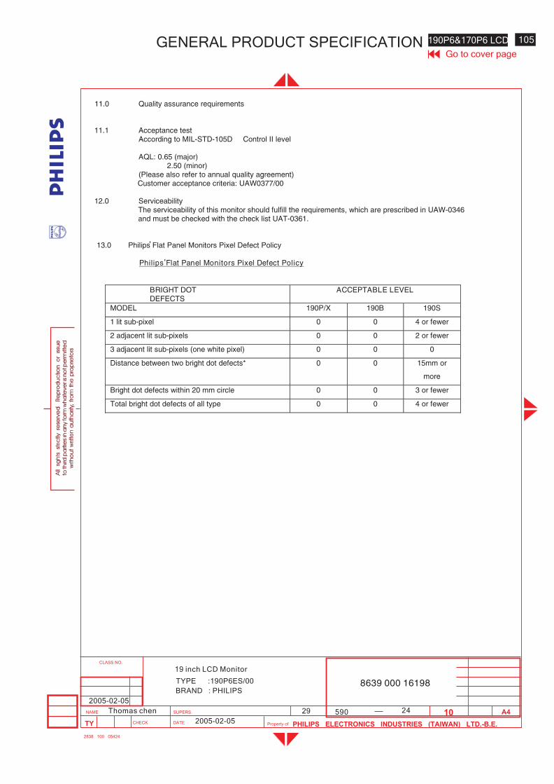
24
190P6&170P6 LCD 105
590
Go to cover pageGENERAL PRODUCT SPECIFICATION
BRAND : PHILIPS
TYPE :190P6ES/00 8639 000 16198
2005-02-05
2005-02-05
29Thomas chen
19 inch LCD Monitor
11.0 Quality assurance requirements
11.1 Acceptance testAccording to MIL-STD-105D Control II level
AQL: 0.65 (major)2.50 (minor)
(Please also refer to annual quality agreement)Customer acceptance criteria: UAW0377/00
12.0 ServiceabilityThe serviceability of this monitor should fulfill the requirements, which are prescribed in UAW-0346and must be checked with the check list UAT-0361.
13.0 Philips Flat Panel Monitors Pixel Defect Policy
Philips Flat Panel Monitors Pixel Defect Policy
BRIGHT DOTDEFECTS
ACCEPTABLE LEVEL
MODEL 190P/X 190B 190S
1 lit sub-pixel 0 0 4 or fewer
2 adjacent lit sub-pixels 0 0 2 or fewer
3 adjacent lit sub-pixels (one white pixel) 0 0 0
Distance between two bright dot defects* 0 0 15mm or
more
Bright dot defects within 20 mm circle 0 0 3 or fewer
Total bright dot defects of all type 0 0 4 or fewer
'
'
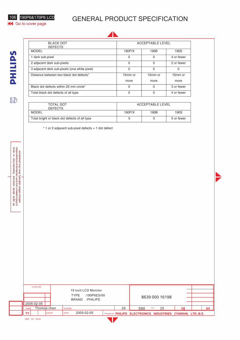
106 190P6&170P6 LCD GENERAL PRODUCT SPECIFICATIONGo to cover page
8639 000 16198BRAND :PHILIPS
19 inch LCD Monitor
TYPE :190P6ES/00
2005-02-05
2005-02-05
29Thomas chen 590 25
BLACK DOTDEFECTS
ACCEPTABLE LEVEL
MODEL 190P/X 190B 190S
1 dark sub-pixel 0 0 4 or fewer
2 adjacent dark sub-pixels 0 0 2 or fewer
3 adjacent dark sub-pixels (one white pixel) 0 0 0
Distance between two black dot defects* 15mm or
more
15mm or
more
15mm or
more
Black dot defects within 20 mm circle* 0 0 3 or fewer
Total black dot defects of all type 0 0 4 or fewer
TOTAL DOTDEFECTS
ACCEPTABLE LEVEL
MODEL 190P/X 190B 190S
Total bright or black dot defects of all type 0 0 5 or fewer
* 1 or 2 adjacent sub-pixel defects = 1 dot defect

26
190P6&170P6 LCD 107
590
Go to cover pageGENERAL PRODUCT SPECIFICATION
BRAND : PHILIPS
TYPE :190P6ES/00 8639 000 16198
2005-02-05
2005-02-05
29Thomas chen
19 inch LCD Monitor
Fig 1: Brightness and Uniformity
1 2 3
7 8
W/10
L
W
L/10L/2
W/2
4 5 6
9
Position 5 = Screen center point
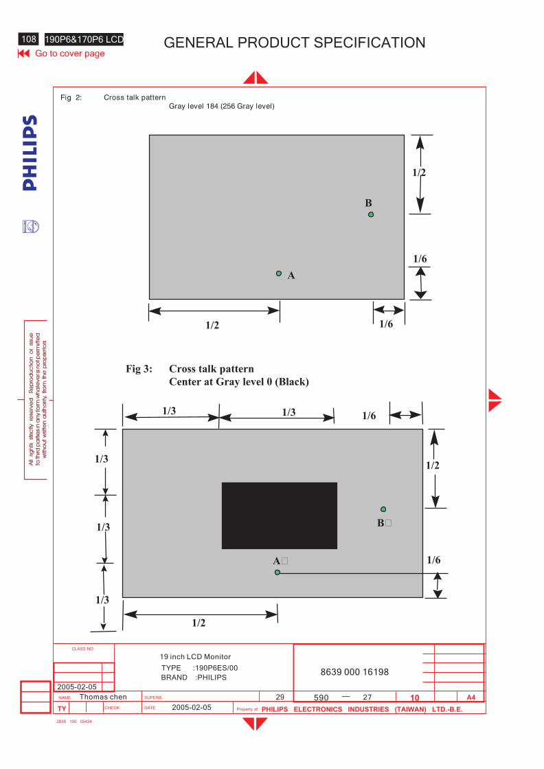
108 190P6&170P6 LCD GENERAL PRODUCT SPECIFICATIONGo to cover page
8639 000 16198BRAND :PHILIPS
19 inch LCD Monitor
TYPE :190P6ES/00
2005-02-05
2005-02-05
29Thomas chen 590 27
Fig 2: Cross talk patternGray level 184 (256 Gray level)
B
1/2
1/61/2
A
1/6
Fig 3: Cross talk pattern
Center at Gray level 0 (Black)
B’
1/6
1/2
1/61/3
1/3
1/3
1/3
1/2
A’
1/3
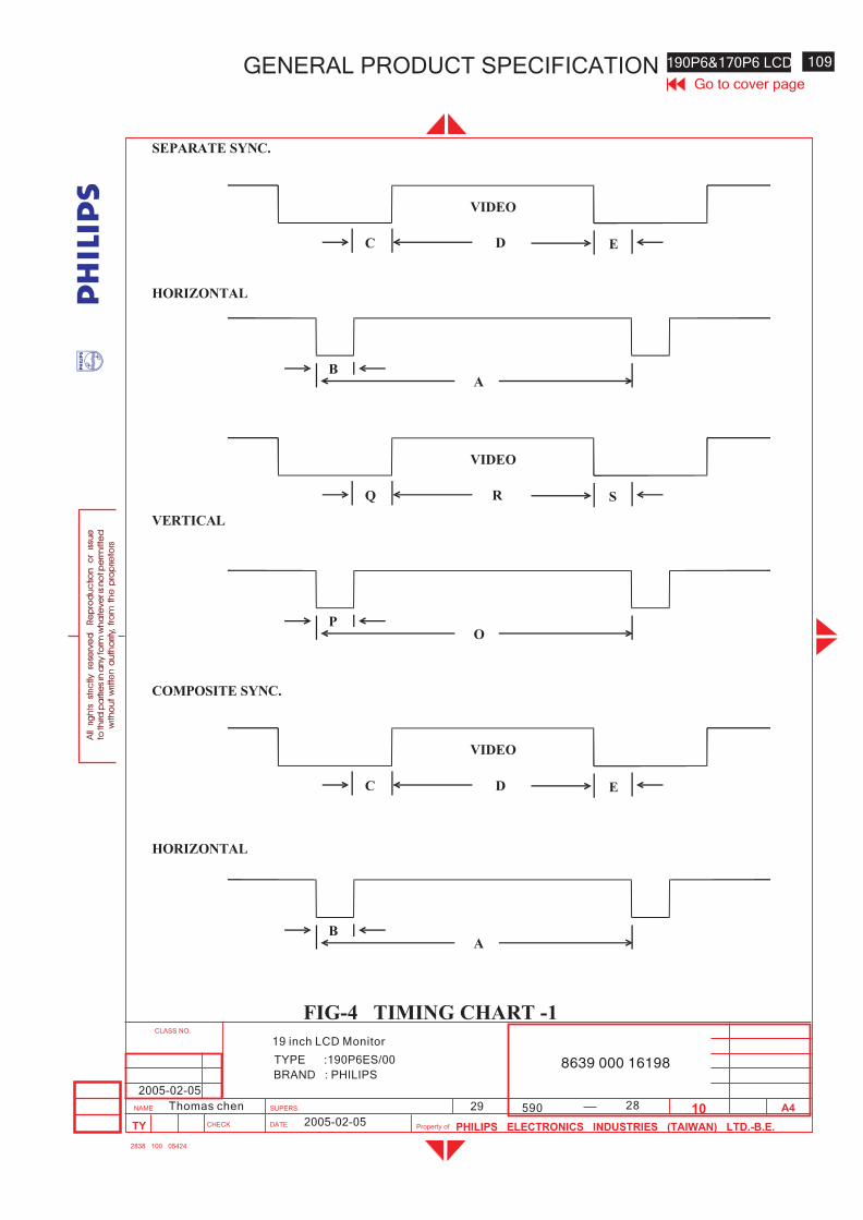
28
190P6&170P6 LCD 109
590
Go to cover pageGENERAL PRODUCT SPECIFICATION
BRAND : PHILIPS
TYPE :190P6ES/00 8639 000 16198
2005-02-05
2005-02-05
29Thomas chen
19 inch LCD Monitor
D
VIDEO
C E
SEPARATE SYNC.
HORIZONTAL
BA
R
VIDEO
Q S
PO
D
VIDEO
C E
BA
VERTICAL
HORIZONTAL
COMPOSITE SYNC.
FIG-4 TIMING CHART -1
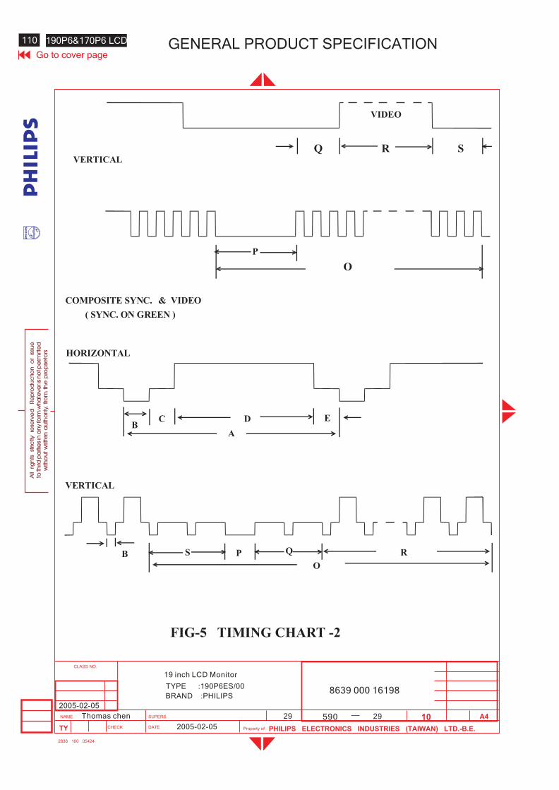
110 190P6&170P6 LCD GENERAL PRODUCT SPECIFICATIONGo to cover page
8639 000 16198BRAND :PHILIPS
19 inch LCD Monitor
TYPE :190P6ES/00
2005-02-05
2005-02-05
29Thomas chen 590 29
D
VIDEO
C E
B
A
VERTICAL
COMPOSITE SYNC.
FIG-5 TIMING CHART -2
O
P
Q R S
& VIDEO
B
S P Q
O
R
( SYNC. ON GREEN )
HORIZONTAL
VERTICAL
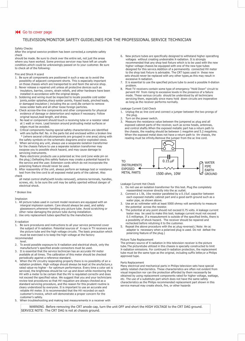
Safety Checks
Fire and Shock H azard
Implosion
X-radiation
After the original swevice problem has been corrected,a complete safetycheckshould be made. Be sure to check over the entire set, not just the areaswhere you have worked. Some previous servicer may have left an unsafecondition,which could be unknowingly passed on to your customer. Be sureto check all of the following:
1. Be sure all components are positioned in such a way as to avoid thepossibility of adjacent component shorts. This is especially importanton those chassis which are transported to and feom the service shop.
2. Never release a repaired unit unless all protective devices such asinsulators, barries, covers, strain reliefs, and other hardware have beeninstalled in accordance with the original design.
3. Soldering and wiring must be inspected to locate possible cold solderjoints,solder splashes,sharp solder points, frayed leads, pinched leads,or damaged insulation ( including the ac cord).Be certain to removeloose solder balls and all other loose foreign particles.
4. Check across-the-line components and other components for physicalevidence of damage or deteriortion and replace if necessary. Followoriginal layout,lead length, and dress.
5. No lead or component should touch a receiving tube or a resistor ratedat 1 watt or more. Lead tension around protruding metal surfaces oredges must be avoided.
6. Critical components having special safety characteristics are identifiedwith ans bythe Ref. No. in the parts list and enclosed within a broken line* (where seceral criticalcomponents are grouped in one area) along with
the safety symbols on the schematic diagrams and/or exploded views.7. When servicing any unit, always use a seoparate isolation transformer
for the chassis Failure to use a separate isolation transformer mayexopose you to possible shock hazard, and may cause damage toservicing instruments.
8. Many electronic products use a polarized ac line cord (one wide pin onthe plug.) Defeating this safety feature may create a potential hazard tothe service and the user. Extension cords which do not incorporate thepolarizing feature should never be used.
9. After reassembly of the unit, always perform an leakage test or resistancetest from the line cord to all exposed metal parts of the cabinet. Also
checkall metal control shafts(with knobs removed), antenna terminals, handles,screws, etc. to be sure the unit may be safety operted without danger ofelectrical shock.
* Broken line
1. All picture tubes used in current model receivers are equipped with anintergral implosion system. Care should always be used, and safetyglassesworn,whenever handling any picture tube. Avoid scratching orother rwise damaging the picture tube during installation.
2. Use only replacement tubes specified by the manufacturer.
1. Be sure procedures and instructions to all your service personnel coverthe subject of X-radiation. Potential sources of X-rays in TV receivers arethe picture tube and the high voltage circuits. The basic precaution whichmust be exercised is to keep the high voltage at the factory
recommendedlevel.
2. To avoid possible exposure to X-radiation and electrical shock, only themanufacturer's specified anode connectors must be used.
3. It is essential that the service technician has an accurate HV meteravailable at all times. The calibration of this meter should be checkedperiodically against a reference standard.
4. When the HV circuitry isoperating properly there is no possibility of an x-radiation problem. High voltage should always be kept at the anufacture,srated value-no higher - for optimum performance. Every time a color set isserviced, the brightness should be run up and down while monitoring theHV with a meter to be certain that the HV is requlated correctlv and doesnot exceed the specified value. We suggest that you and your techniciansreview test procedures so that HV requation are always checked as astandard servicing procedure, and the reason for this prudent routine iscleary understood by everyone. It is important to use an accurate andreliable HV meter. It is recommended that the HV recorded on eachcustomer's invoice, which will demonstrate a proper concern for thecustomer's safety.
5. When troubleshooting and making test measurements in a receiver with
:
:
WARNING OFFSERVICE NOTE
Before removing the CRT anode cap, turn the unit and short the HIGH VOLTAGE to the CRT DAG ground.The CRT DAG is not at chassis ground.
TELEVISION/MONITOR SAFETY GUIDELINES FOR THE PROFESSIONAL SERVICE TECHNICIAN
6. New picture tubes are specifically designed to withstand higher operathngvoltages without creating undesirable X-radiation. It is stronglyrecommended that any shop test fixture which is to be used with the newhigher voltage chassis be equipped with one of the new type tubesdesigned for this service.Addition of a permanently connected HV meterto the shop test fixture is advisable. The CRT types used in these newsets should never be replaced with any other types,as this may result inexcessive X-radiation.
7. It is essential to use the specified picture tube to avoid a possible X-diationproblem.
8. Most TV receivers contain some type of emergency "Hold Down" circuit topervent HV from rising to excessive levels in the presence of a failuremode. These various circuits should be understood by all techniciansservicing them, especially since many hold down circuits are inoperativeas long as the receiver performs normally.
1. Unplug the ac line cord and connect a jumper between the two prongs ofthe plug.
2. Turn on the power switch.3. Measure the resistance value between the jumpered ac plug and all
exposed cabinet parts of the receiver, such as screw heads, antennas,and control shafts.When the exposed metallic part has a return path tothe chassis, the reading should be between 1 megohm and 5.2 megohms.When the exposed metal does not have a return path to thr chassis, thereading must be infinity.Remove the jumper from the ac line cord.
1. Do not use an isolation transformer for this test. Plug the completelyreassembled receiver directly into the ac outlet.
2. Connect a 1.5k, 10w resistor paralleled by a 0.15uf. capacitor betweeneach exposed metallic cabinet part and a good earth ground such as awater pipe, as shown above.
3. Use an ac voltmeter with at least 5000 ohmsy volt sensitivity to measurethe potential across the resistor.
4. The potential at any point should not exceed 0.75 volts. A leakage currenttester may be used to make this test; leakage current must not exceed0.5 milliamps. If a measutement is outside of the specified limits, there isa possibility of shock hazard. The receiver should be repaired andrechecked before retutning it to the customer.
5. Repeat the above procedure with the ac plug reversed.( Note: An acadapter is necessary when a polarized plug is used. Do not defeat thepolarizing feature of the plug.)
The primary source of X-radiation in this television receiver is the picturetube.The picturetube utilized in this chassis is specially constructed to limitX-radiation emissions. For continued X-radiation protection, the replacementtube must be the same type as the original, including suffix letter,or a Philipsapproved tupe.
Many electrical and mechanical parts in Philips television sets have specialsafety related charcteristics. These characteristics are often not evident fromvisual inspection nor can the protection afforded by them necessarily beobtained by using replacement components rated for higher voltage, wattage,etc. The use of a substitute part which does not have the same safetycharacteristics as the Philips recommended replacement part shown in thisservice manual may create shock, fire, or other hazards
Leakage Current Cold Check
Leakage Current Hot Check
Picture Tube Replacement
Parts Replacement
1500 ohm, 10W
0.15 uF WATERPIPEEARTHGROUND
TOINSTRUMENTSEXPOSEDMETAL PARTS
Go to cover page


