Embed Size (px)
Citation preview
Permeation Behavior of Polysulfone Membranes Modified by FullyOrganic Layer-by-Layer AssembliesBartosz Tylkowski,†,‡ Federico Carosio,§ Joandiet Castaneda,† Jenny Alongi,§ Ricard García-Valls,†
Giulio Malucelli,§ and Marta Giamberini*,†
†Departament de Enginyeria Química, Universitat Rovira i Virgili, Av. Països Catalans, 26, 43007 Tarragona, Spain‡Centre Tecnologic de la Quimica de Catalunya, Carrer de Marcelli Domingo, s/n Campus Sescelades, 43007 Tarragona, Spain§Department of Applied Science and Technology, Politecnico di Torino, Viale T. Michel 5, 15121 Alessandria, Italy
ABSTRACT: This paper investigates the effect of the deposition of layer-by-layer (LbL) assemblies on the swelling,permeability, and anthracene rejection of polysulfone (PSf) membranes obtained through a phase inversion precipitationtechnique. More specifically, the latter have been dip-coated on one side with a completely organic assembly (made ofpoly(acrylic acid)/branched polyethyleneimine bilayers), varying the number of deposited bilayers (BL) from 10 BL to 20 BL.Prior the deposition, the surface of the polysulfone membranes has been subjected to plasma activation. Static contact angle,scanning electron microscopy, and attenuated total reflectance infrared spectroscopy measurements have been exploited forevaluating the modification of polysulfone after the LbL deposition, as well as the homogeneity of the distribution and coverageof the coatings on the polymeric substrate. The swelling of both untreated and LbL-treated membranes has been evaluated inthree different solvents, i.e., methanol, isopropanol, and n-hexane; subsequently, the permeation features of the treatedmembranes toward these solvents have been assessed and correlated with the presence of the deposited assembly; finally, theretention of anthracene in its n-hexane solutions has been evaluated.
1. INTRODUCTION
Polysulfone (PSf) is a well-known polymer broadly used in theindustry. It has very good chemical and thermal stability andallows easy manufacture of membranes with reproducibleproperties and controllable size of pores down to 40 nm. Forthis reason, it has been extensively used as a base material forultrafiltration membranes in applications such as hemodialysis,wastewater recovery, food and beverage processing, and gasseparation.1,2 In order to enhance their final properties, PSfmembranes can be subjected to different surface modifications,among which, the layer-by-layer (LbL) approach seems to bevery effective.The LbL technique is a step-by-step build-up process that
falls in the category of self-assembled coatings and can beexploited to modify the surface of different plastic substratesquite easily. Although this method was initially described in1966,3 it has been rediscovered and optimized decades later;4−7
nowadays, LbL applications include membranes for directmethanol fuel cells,8 polymer catalytic electrodes,9 field-effecttransistors,10 antireflection,11 antibacterial12 or electrical con-ductive coatings,13 and humidity sensors.14 In addition, thismethod has been also used for conferring flame retardancy toplastics and textiles.15−19
The main advantages of LbL, with respect to more-traditional thin-film deposition techniques, include (i) facileincorporation of functional species, (ii) processing underambient conditions (e.g., room temperature, atmosphericpressure), and (iii) low environmental impact (water is mostlyused as solvent and the concentrations of the solutions/dispersions are usually below 1 wt %).The technique was introduced in 1991 for polyanion/
polycation films in order to obtain the so-called “polyelectrolyte
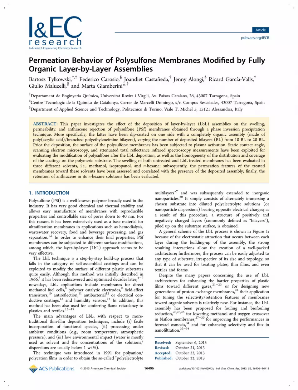
multilayers”7 and was subsequently extended to inorganicnanoparticles.20 It simply consists of alternately immersing achosen substrate into diluted polyelectrolyte solutions (ornanoparticle dispersions) bearing opposite electrical charges; asa result of this procedure, a structure of positively andnegatively charged layers (commonly defined as “bilayers”),piled up on the substrate surface, is obtained.A general scheme of the LbL process is shown in Figure 1:
because of the electrostatic attraction that occurs between eachlayer during the building-up of the assembly, the strongresulting interactions allow the creation of a well-packedarchitecture; furthermore, the process can be easily adjusted toany type of substrate, irrespective of its size and topology, sothat it can be used for treating plates, thin films, and eventextiles and foams.Despite the many papers concerning the use of LbL
architectures for enhancing the barrier properties of plasticfilms toward different gases,21−23 or for designing newgenerations of proton exchange membranes,24 their applicationfor tuning the selectivity/retention features of membranestoward organic solvents is relatively new. For instance, the LbLassembly has been proposed for fouling and biofoulingreduction,20,25,26 for lowering methanol and oxygen crossoverin Nafion membranes,27−30 for improving the performances inforward osmosis,31 and for enhancing selectivity and flux innanofiltration.32−34
Received: September 6, 2013Revised: October 21, 2013Accepted: October 22, 2013Published: October 22, 2013
Article
pubs.acs.org/IECR
© 2013 American Chemical Society 16406 dx.doi.org/10.1021/ie402942g | Ind. Eng. Chem. Res. 2013, 52, 16406−16413
Therefore, in the present work, polysulfone films, preparedby means of a phase inversion precipitation technique, havebeen LbL-treated with 10 and 20 bilayers of poly(acrylic acid)/branched polyethyleneimine, with the objective of assemblinga fully organic coating on one side of the polymer surface, thusobtaining asymmetric membranes.First of all, the growth of the obtained architectures has been
assessed through scanning electron microscopy (SEM) andFourier transform infrared−attenuated total reflectance (FTIR-ATR) spectroscopy measurements.Unmodified and modified membranes were tested with
respect to their swelling properties, organic solvent perme-ability, and anthracene rejection. In this way, it was assessedthat the performances of PSf membranes can be improved byLbL treatments and that these modified materials can beapplied to nanofiltration also as membranes resistant to organicsolvents.
2. EXPERIMENTAL SECTION
2.1. Materials. Polysulfone (PSf) (Aldrich, Mw ≈ 35 000 byLS), anthracene (Sigma−Aldrich), N,N-dimethylformamide(DMF) (Panreac, 99.8% PS), isopropanol (Panerac, QP), n-hexane (Scharlau, 99% reagent grade), methanol (Scharlau,reagent grade), were used as received.Poly(acrylic acid) (PAA) and branched polyethyleneimine
(BPEI) were purchased from Sigma−Aldrich (Milwaukee, WI)and used, without any further modification, for preparing 0.1 or0.2 wt % aqueous solutions, respectively, employing 18.2 MΩdeionized water supplied by a Q20 Millipore system (Milano,Italy). The pH values of PAA and BPEI solutions were set at 4and 10, respectively.
2.2. Preparation of Polysulfone Membranes. Flat sheetpolysulfone membranes were prepared using a phase inversionprecipitation (PIP) process, in which a homogeneous polymersolution is cast on a suitable support and immersed in acoagulation bath containing a nonsolvent. Precipitation occursbecause of the exchange of solvent and nonsolvent molecules incontact with the polymer. In order to prepare asymmetricmembranes, PSf polymer was dissolved in DMF at 22 (± 2) °Cby stirring for 8 h to obtain 15 wt % homogeneous solution.Next, the solution was cast on a glass plate by means of acustom-made casting knife (gap of 200 μm) connected with a KPaint Applicator (R K Print Coat Instruments, Ltd., U.K.).Then, the cast films were coagulated in a bath containingdistilled water as a nonsolvent. After primarily phase separationand formation, the membranes were stored in water for 24 h toguarantee complete phase separation. This allows the water-soluble components in the membrane to be leached out. As thefinal stage, the membranes were dried by placing them betweentwo sheets of filter paper for 24 h at room temperature.Hereafter, the obtained membranes will be coded as M0, M1,
and M2, where “0” stands for untreated, while “1” and “2” referto the deposition of 10 and 20 bilayer (BL) assemblies,respectively.
2.3. Layer-by-Layer Deposition. Prior to the layer-by-layer deposition, M0 films were activated with cold plasma(oxygen (10 cm3/min) and argon (10 cm3/min)), using a 40kHz Pico 1.1.2 semiautomatic controlled system (DienerElectronic GmbH), operating at 50 W for 5 min.
Figure 1. Schematic of the layer-by-layer (LbL) deposition process.
Figure 2. Flow diagram of the cross-flow nanofiltration apparatus.
Industrial & Engineering Chemistry Research Article
dx.doi.org/10.1021/ie402942g | Ind. Eng. Chem. Res. 2013, 52, 16406−1641316407

After the plasma treatment, the polysulfone substrates werecoupled two by two and alternately immersed into thepositively (BPEI) and the negatively (PAA) charged baths,thus performing the LbL treatment just on one side of each film(dipping apparatus: KSV DX2S-500 LM dip coater, Helsinki,Finland); after each adsorption step, the substrates werewashed with deionized water by static dipping for 5 min. Theimmersion period for the first couple of layers was set at 10min, in order to promote uniformity and stability; thesubsequent layers were obtained after 5 min of dipping. Theprocess was repeated until 10 and 20 BL were built on eachspecimen type.2.2. Characterization Techniques. The growing of the
coatings deposited through LbL on polysulfone was assessed byattenuated total reflectance (ATR) spectroscopy. ATR spectrawere recorded at room temperature in the range of 4000−600cm−1 (16 scans and 4 cm−1 resolution), using a Frontier FT-IR/FIR spectrophotometer, equipped with a Universal ATRsampling accessory (diamond crystal: depth of penetration 1.66μm, as stated by the producer). Both the untreated and LbL-treated membranes were imaged using a scanning electronmicroscopy (SEM) sytem (LEO, Model 1450VP) equippedwith a back-scattered electron detector. Small pieces (5 mm × 5mm) were cut and fixed to conductive adhesive tapes andmetallized with gold. The average thickness of the membraneand of the BL assemblies (10 measures) was calculated fromSEM micrographs of the cross sections, using an Image-ProPlus5 software (Media Cybernetics, Inc., USA). The membraneporosity was evaluated by means of IFME software on thecross-section SEM micrographs.35 At least 20 measurementswere replicated, to ensure reproducibility.The flux and rejection experiments were carried out using a
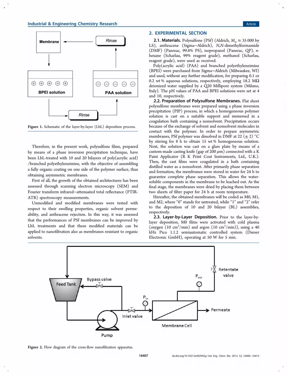
self-made stainless steel cross-flow nanofiltration apparatuscontaining a disk membrane module. The effective membranearea in the module is 12.6 cm2. Figure 2 shows the flow diagramof the cross-flow nanofiltration apparatus. The feed to thefiltration cells is supplied by a piston pump and damped by apulsation dampener before the membrane cells. During the
experiments, the temperature of feed/retentate and permeate,as well as pressure in the membrane cells are controlled.The flux and rejection experiments were performed using the
following procedure: after the initial insertion of the membranefilms in the cells with the LbL-treated side toward the feed, theplant was run first for 15 min without feed pressure in order tocondition the system and, hence, for 15 min with a feedpressure of 10 bar, to reach a steady-state permeate flux and tocomplete the initial membrane compaction. As far asexperiments at a pressure of 10 bar are concerned, wheneverthe solution in the feed tank was changed, the entire apparatuswas washed three times with the new solvent before continuingthe experiments. In addition, the system was run with a feedpressure of 10 bar for at least 15 min in order to facilitate theremoval of the former solvent. Then, compaction at 10 bar feedpressure was done again until steady-state conditions werereached.Membrane performances were evaluated on the basis of the
solvent flux and rejection experiments.36 The flux (J) throughthe membrane can be described by the following equation:
=Δ
JV
A t (1)
where V is the permeate volume, A the membrane area, and Δtis the permeation time. The anthracene rejection rate wascalculated using the following equation:
= − ×⎛⎝⎜⎜
⎞⎠⎟⎟R
C
C(%) 1 100p
f (2)
where Cp and Cf (mg/mL) are the concentrations of permeateand feed solutions, respectively. The anthracene concentrationwas determined spectrophotometrically, by measuring itsabsorbance at 375 nm,37 with a UV−Vis spectrophotometer(Model U-2800, Hitachi, Japan) upon calibration.The wettability of the surfaces after the LBL deposition was
assessed by static contact angle measurements, using a KSVCAM 200 apparatus (Nordtest, Italy), using double distilledwater (Sigma−Aldrich) as the solvent.
Figure 3. Attenuated total reflection (ATR) spectrum of the untreated polysulfone (PSf) membrane.
Industrial & Engineering Chemistry Research Article
dx.doi.org/10.1021/ie402942g | Ind. Eng. Chem. Res. 2013, 52, 16406−1641316408

Swelling experiments were accomplished for evaluating thechemical resistance of the membranes.Swelling (Sw)
38 was referred to the weight increase due tosolvent absorption, according to the following equation:
=−
×⎛⎝⎜
⎞⎠⎟S
W WW
100ww d
d (3)
where Wd and Ww are the weights of dry and wet membranesamples, respectively.In order to investigate influence of LbL modification on PSf
membrane swelling and resistance behaviors, a study wasperformed using the same self-made stainless steel cross-flownanofiltration apparatus, previously described in flux andrejection experiments. During the swelling study, the apparatuswas filled with appropriate solvent and only the modifiedmembrane surface was exposed to it for 72 h, at 24 °C, atatmospheric pressure, while during the solvent resistanceexperiments, a pressure of 10 bar was applied. All swellingexperiments were replicated with at least three samples of eachmembrane and the values averaged.
3. RESULTS AND DISCUSSION3.1. Surface Characterization of the LbL Assemblies.
ATR spectroscopy has been exploited for assessing the growthof the deposited coatings on polysulfone films. Figure 3 showsthe ATR spectrum of untreated PSf membrane: aromatic in-plane ring stretching vibrations occur in the region from 1620cm−1 to 1430 cm−1. A C−H symmetric deformation vibrationof C(CH3)2 is shown as two weak-medium bands in the rangeof 1385−1350 cm−1. Aryl−O-aryl group has a characteristicstrong band centered at 1240 cm−1, associated with the C−O−C asymmetric stretching vibration. The asymmetric OSOstretching vibration occur in the 1350−1280 cm−1 region andthe band due to the symmetric stretching vibration is observedwithin 1180 and 1145 cm−1. The band at 835 cm−1 results fromthe in-phase out-of-plane hydrogen deformation for para-substituted phenyl groups.39 Figure 4 compares the collected
spectra of polysulfone treated by 10 and 20 BL with that of theuntreated substrate. It is worth noticing that the typical signalsof the PSf are completely hidden by the LbL deposition,irrespective of the number of deposited bilayers. Indeed, somecharacteristic peaks of PAA can be distinguishable (namely, at1470 cm−1, s ν(COO−) asymmetric and symmetric);furthermore, the strong band located at 1580 cm−1 may bethe result of an overlapping between strong −COO−asymmetric stretching and medium-to-strong NH2 and NH3
+
stretching.40
In order to confirm this hypothesis, SEM analyses have beenused to investigate the morphology of the deposited coatings.Figure 5 shows the typical morphology of LbL-treated anduntreated substrates.Figure 5a shows the typical SEM micrographs of the
untreated M0 membrane: it is asymmetric and exhibitsmacrovoids, since it consists of a dense skin layer and aspongelike porous inner structure. It is well-known that, in aphase separation process, liquid−liquid demixing and poly-
Figure 4. ATR spectra of untreated and LbL-treated PSf membranes.
Figure 5. SEM micrographs of (a) the M0 cross-section, (b) the M0surface, (c) the M1 cross-section, and (d) the M2 cross-section.
Industrial & Engineering Chemistry Research Article
dx.doi.org/10.1021/ie402942g | Ind. Eng. Chem. Res. 2013, 52, 16406−1641316409

mer−liquid demixing in a polymer/solvent/nonsolvent systemplay a very important role in determining the membranestructure.41 Niwa et al.42 reported that the liquid−liquidexchange rate between the solvent and the nonsolvent has agreat influence on the skin layer thickness and on themembrane structure. Asymmetric membranes formed bydelayed demixing possess a dense skin layer supported by asponge-type structure, while the membranes formed byinstantaneous demixing exhibit an ultrathin top skin layersupported by a finger-type structure. The delay time is ∼1 s orless for rapid demixing conditions, whereas, for delayeddemixing, the precipitation time can range from seconds tominutes. The asymmetric morphology with macrovoids isfound when membranes are prepared by immersion precip-itation using DMF/water as the solvent/nonsolvent pair,43 as inthe present study. Indeed, SEM micrographs of M0 membrane(Figure 5a) show a smooth surface with the presence of defects.Conesa et al.44 and Smolders et al.45 hypothesized that in PSf/DMF/H2O system the macrovoid structure is a consequence ofthe fast polymer precipitation rate that arises from a highmiscibility between the solvent/nonsolvent pair. In addition,the Monte Carlo diffusion model described by Termonia46
theorizes that the solvent/nonsolvent interaction parameter isthe main controlling step in the formation of macrovoids. Morespecifically, this latter was ascribed to nonsolvent penetrationthrough skin defects. The faster solvent exchange fornonsolvent through the defects was thought to be responsiblefor the growth of macrovoids. On the other hand, when thesolvent/nonsolvent pair was chloroform/methanol, regardlessof the membrane thickness, macrovoids were never detected,because of the slower exchange of chloroform with methanol.Membrane thickness, calculated by Image-ProPlus 5 software
on ESEM micrographs, was ∼71.6 (±0.8) μm. The pore meansize of the membrane as well as its asymmetry yielded values ofca. 4.26 (±0.03) μm and 19%, respectively; pore sizes rangedbetween 12.4 μm and 0.10 μm.Figures 5c and 5d show the cross-section morphologies of
M1 and M2 membranes, respectively. The thicknesses of theLbL assembly were around 3.1 (±0.1) μm (M1) and 5.1 (±0.3)μm (M2): they can be be ascribed to the exponential growth ofthe coating combined with the adopted deposition times.Indeed, it has been reported in the literature that BPEI andPAA (at pH 10 and 4, respectively) can yield an exponentialgrowth of the LbL films.22,47 This has been explained on thebasis of an “in and out” diffusion mechanism, where thepolymer chains not only adsorb on the LbL film surface butalso interpenetrate into inner layers, thus exponentiallyincreasing the total film thickness.Furthermore, it can be easily observed that the LbL
deposition is able to homogeneously cover the surface,irrespective of the number of deposited bilayers. The poremean size of the modified membranes was similar to that of theM0 counterpart (i.e., ∼4.25 μm). This finding suggests thatpositively and negatively charged aqueous solutions do notpenetrate the PSf membrane during the repeated immersionsteps, because of the high hydrophobic character of themembrane, as assessed by static contact angle measurementswith water (ϑ = 98°, Table 1). This value, which is slightlyhigher than those reported in the literature,48 can be ascribed tothe different solvent−nonsolvent interactions during the phase-inversion process, as well as to the different conditions adoptedfor the membrane preparation. In addition, as expected, theLbL deposition of a coating made of polar layers (BPEI and
PAA) is capable of significantly reducing the water contactangle, i.e., increasing its hydrophilicity (see Table 1). It is worthnoticing that the decrease in contact angle is independent ofthe number of deposited bilayers.Resistance tests were carried out on M0, M1, and M2
membranes in order to assess their stability in water, methanol,isopropanol, and n-hexane after 72 h of exposure, with theexperimental setup previously described. It was observed thatM1 and M2 LbL assemblies readily dissolved into water:indeed, the deposited layers were prepared starting from watersolutions. At variance, all the tested membranes showed anexcellent stability in the three organic solvents.The swelling values of the different types of membranes are
collected in Table 1. M0 exhibits the highest degree of swellingin all of the organic solvents, while M1 and M2 membranesshow a different behavior: indeed, their swelling in methanoland isopropanol is ∼40% and ∼60% lower than M0. From anoverall point of view, both the dielectric constant of the solventand the difference in solubility parameters between polymerand solvent govern the swelling behavior.38 Membrane swellingis higher in polar solvents such as methanol (polarity index =76.2 (water polarity index = 100)) due to its high dielectricconstant (ε = 32.6), and lower with nonpolar solvents such asn-hexane (polarity index = 0.9, ε = 1.9). The same trend isobserved by comparing the membrane swelling in methanoland isopropanol (polarity index = 54; ε = 18.3).In all cases, swelling decreases on going from M0 to M2. In
LbL-treated membranes, the deposited assembly limits thepermeation of the wetting solvents used: this effect is moreevident on increasing the number of deposited bilayers, whichensures a more homogeneous coverage of the membranesurface.M0 and M1 membrane performances were evaluated using
the three pure solvents, as well as an anthracene solution in n-hexane (0.01M); M2 membrane could not be tested due to thetendency of the LbL assembly to form cracks.Tables 2 and 3 present flux values and some of the physical
properties49 of the used solvents. First of all, it is worthy to notethat the fluxes of organic solvents decrease after the LbLdeposition, irrespective of the type of solvent used.
Table 1. Static Contact Angle with Water and MembraneSwellinga at 22 (± 2) °C
Weight Swelling (%)
membranebatch
static contact angle(deg) methanol isopropanol n-hexane
M0 98 ± 2 375 ± 8 335 ± 7 50 ± 1M1 45 ± 2 218 ± 4 200 ± 3 44 ± 1M2 45 ± 2 150 ± 1 137 ± 2 31 ± 1
aPercentage of weight increase after exposure to the different solventsfor 72 h.
Table 2. Flux of Organic Solvents and Anthracene Rejectionthrough M0 and M1 Membranes at 10 bar and 22 (± 2) °C
Flux, J (L m−2 h−1)
membranetype isopropanol n-hexane methanol
anthracenerejection(%)
M0 370 ± 8 296 ± 11 498 ± 13 715 ± 15 11 ± 1M1 433 ± 5 540 ± 16 68 ± 1
Industrial & Engineering Chemistry Research Article
dx.doi.org/10.1021/ie402942g | Ind. Eng. Chem. Res. 2013, 52, 16406−1641316410
The description of transport mechanism to nonaqueoussystems is complex and depends on the structures andproperties of the solvents.50 Membrane−solvent interactionscan be expected to vary with changes in such solvent propertiesas viscosity, dielectric constant, molecular size, dipole moment,solubility parameter, and surface tension. According toMachado et al.51 and Bhanushali et al.,52 viscosity is the keyparameter affecting solvent flow through nanofiltrationmembranes. Except for the anomalous behavior of water,53 allthe other solvents show a consistent increase in flux when theirviscosities decrease.Comparing the flux values for isopropanol and n-hexane, the
flux of pure isopropanol is lower than that of n-hexane, becauseof the higher viscosity of the former and its higher dielectricconstant. These results indicate that the transport ofisopropanol and n-hexane through PSf membranes is governedby a viscous flow permeation mechanism. The same mechanismwas described by Schmidt et al.,54 who investigated theinfluence of the physical properties of n-hexane andisopropanol on the transport mechanism through Starmem122, which is a commercial polyimide-based membrane.Comparing the flux values for n-hexane and methanol, the
permeate flux of this latter is higher, with respect to n-hexane.This finding indicates that, in this case, permeation is notdominated by viscosity: indeed, the higher solubility parameterof methanol, with respect to n-hexane, results in a greateraffinity between methanol and the membranes. Furthermore,the flux values decrease when moving from methanol toisopropanol, i.e., by lengthening the alcohol structure withadditional CH2 groups. This result is consistent with literaturedata, which clearly show that flux decreases with increasingmolecular length, irrespective of the transport mechanism.53,55
Machado et al.51 observed that flux values for alcohol moleculesdecrease with changes in surface tension. The addition of one Catom to the alcoholic structure increases the surface tension bya constant factor of ∼1.03. In addition, the viscosity of smallalcohol molecules (C <3) is enhanced by ca. 0.51−0.55 andthat of large molecules (C >3) is enhanced by 0.77.The toxicity of anthracene, which is a common polycyclic
aromatic hydrocarbon (PAH), has been extensively assessedunder environmentally realistic conditions. PAHs are ubiq-uitous and persistent, for instance, in contaminated soils,waters, and sediments and exhibit a significant risk to theenvironment and human health.56 They are generally formed asbyproducts of the incomplete combustion of organic materialincluding fossil fuels, wood, and refuse, and are emitted frominternal combustion and diesel processing.57 Because of its lowmolecular weight, compared to most of the other PAHs,anthracene has a higher solubility and can be found atsignificant levels in the environment. Therefore, it is importantto develop new inexpensive and environmentally friendlymethods for its separation or concentration.
In order to assess the effectiveness of the LbL treatment onthe rejection features of M1 membranes, the anthraceneconcentrations in the permeate and retentate were analyzedand its rejection was calculated according to eq 2. As can beseen in Table 2, ∼90% of the anthracene passes through theasymmetric structure of the untreated PSf membrane; atvariance, only 32% of the PAH diffuses through the dense layerof the 10-BL-treated membrane. This finding is in agreementwith Su et al.,58 who tested negatively charged PSf ultrafiltrationmembranes treated with bilayers of poly(diallyl-dimethylam-monium chloride) and poly(styrene sulfonate).Recently, Ahmadiannamini et al. studied rejection of rose
bengale (RB) from RB/isopropanol feed solution usingmultilayered polyelectrolyte complexes membrane based onthe LBL method from poly(diallyldimethylammonium chlor-ide) (PDDA) as polycation.34 Based on the high (i.e. >99%)retention value of RB from RB/isopropanol, with a high fluxvalue (1.57 L m−2 h−1 bar−1), the authors strongly recommendthese LbL membranes as a promising solvent-resistantnanofiltration (SRNF) membrane. In our investigation, insteadof a high-molecular-weight compound as RB (MW 1017 g/mol), we tested an anthracene/isopropanol feed solution.Despite the low molecular weight of anthracene (MW = 178 g/mol), which is 6 times lower than that of RB, we weresuccessful to reject 68% of it with a flux of 29.6 L m−2 h−1 bar−1.It is worth noting that this flux value is ∼60 times higher thanthe flux value of the RB/isopropanol feed solution throughSRNF-modified PSf/SPEEK membranes (0.47 L m−2 h−1
bar−1) reported by Li et al.33 Therefore, the combination ofhigh retention of very low-molecular-weight compounds andvery high fluxes of the prepared 10 LbL/PSf films make themvery promising for commercial SRNF.
4. CONCLUSIONS
Polysulfone (PSf) membranes were successfully layer-by-layer(LbL)-treated, using poly(acrylic acid) and branched poly-ethyleneimine layers. Attenuated total reflectance (ATR)spectroscopy confirmed the deposition of homogeneouscoatings on the membrane. Their thickness ranged from 3μm to 5 μm, for 10 and 20 bilayer (BL) assemblies,respectively. The swelling of the membranes in methanol,isopropanol, and n-hexane was found to decrease withincreasing the number of deposited bilayers. Permeation testsshowed that the transport of isopropanol and n-hexane throughPSf membranes is governed by a viscous flow permeationmechanism; at variance, moving from methanol to isopropanol,i.e., by lengthening the alcohol structure with additional CH2groups, the flux decreases with increasing molecular length,irrespective of the transport mechanism. The anthracenerejection evaluated on 10-BL-coated membranes was found toincrease up to 68%, as a consequence of LbL treatment, ascompared to 11% of untreated PSf, with a flux of 29.6 L m−2
h−1 bar−1. These results suggest that the LbL treatment canwiden the application of PSf membranes to new fields such asorganic solvents nanofiltration or concentration/separation ofcarcinogenic (i.e., anthracene) as well as biological activecompounds.
■ AUTHOR INFORMATION
Corresponding Author*Tel.: +34977558174. Fax: +34977559621. E-mail: [email protected].
Table 3. Physical Properties of the Organic Solvents Useda
solventpolarityindexb
ε at20 °C
solubilityparameterc
(MPa0.5)
surfacetension(mN/m)
viscosity(mPa s)
methanol 76.2 32.6 29.7 22.5 0.59isopropanol 54.6 18.3 23.8 21.7 2.00n-hexane 0.90 1.90 14.9 18.4 0.31
aUsing data taken from ref 49, unless noted otherwise. bWater polarityindex: 100. cData taken from ref 59.
Industrial & Engineering Chemistry Research Article
dx.doi.org/10.1021/ie402942g | Ind. Eng. Chem. Res. 2013, 52, 16406−1641316411

NotesThe authors declare no competing financial interest.
■ ACKNOWLEDGMENTSThe authors would like to gratefully acknowledge LLP/ERASMUS Program between Universitat Rovira i Virgili andPolitecnico di Torino.
■ REFERENCES(1) Mulder, M. Basic Principles of Membrane Technology; KluwerAcademic Publishers: Dordrecht, The Netherlands, 1997.(2) Esser-Kahn, A. P.; Odom, S. A.; Sottos, N. R.; White, S. R.;Moore, J. S. Triggered Release from Polymeric Microcapsules.Macromolecules 2011, 44, 5539−5553.(3) Iler, R. K. Multilayers of colloidal particles. J. Colloid Interface Sci.1966, 21, 569−594.(4) Ariga, K.; Hill, P.; Ji, Q. Layer-by-layer assembly as a versatilebottom-up nanofabrication technique for exploratory research andrealistic application. Phys. Chem. Chem. Phys. 2007, 9 (19), 2319−2340.(5) Hammond, P. T. Form and Function in Multilayer Assembly:New Applications at the Nanoscale. Adv. Mater. 2004, 16, 1271−1293.(6) Decher, G.; Hong, J.-D. Buildup of ultrathin multilayer films by aself-assembly process, 1. Consecutive adsorption of anionic andcationic bipolar amphiphiles on charged surfaces. Makromol. Chem.Macromol. Symp. 1991, 46 (1), 321−327.(7) Decher, G. Polyelectrolite Multilayers: An Overview. InMultilayer Thin Films, Sequential Assembly of Nanocomposite Materials;Decher, G., Schlenoff, J. B., Eds.; Wiley−VCH: Weinheim, Germany,2003; pp 1−46.(8) Jiang, S. P.; Liu, Z.; Tian, Z. Q. Layer-by-Layer Self-Assembly ofComposite Polyelectrolyte−Nafion Membranes for Direct MethanolFuel Cells. Adv. Mater. 2006, 18 (8), 1068−1072.(9) Farhat, T. R.; Hammond, P. T. Engineering Ionic and ElectronicConductivity in Polymer Catalytic Electrodes Using the Layer-By-Layer Technique. Chem. Mater. 2005, 18 (1), 41−49.(10) Cui, T.; Liu, Y.; Zhu, M. Field-effect transistors with layer-by-layer self-assembled nanoparticle thin films as channel and gatedielectric. Appl. Phys. Lett. 2005, 87 (18), 183105.(11) Hiller, J. A.; Mendelsohn, J. D.; Rubner, M. F. Reversiblyerasable nanoporous anti-reflection coatings from polyelectrolytemultilayers. Nat. Mater. 2002, 1 (1), 59−63.(12) Falentin-Daudre, C.; Faure, E.; Svaldo-Lanero, T.; Farina, F.;Jerome, C.; Van De Weerdt, C.; Martial, J.; Duwez, A.-S.;Detrembleur, C. Antibacterial Polyelectrolyte Micelles for CoatingStainless Steel. Langmuir 2012, 28 (18), 7233−7241.(13) Luther, J. M.; Law, M.; Song, Q.; Perkins, C. L.; Beard, M. C.;Nozik, A. J. Structural, Optical, and Electrical Properties of Self-Assembled Films of PbSe Nanocrystals Treated with 1,2-Ethanedithiol.ACS Nano 2008, 2 (2), 271−280.(14) Nohria, R.; Khillan, R. K.; Su, Y.; Dikshit, R.; Lvov, Y.;Varahramyan, K. Humidity sensor based on ultrathin polyaniline filmdeposited using layer-by-layer nano-assembly. Sens. Actuators, B 2006,114 (1), 218−222.(15) Alongi, J.; Carosio, F.; Malucelli, G. Layer by layer complexarchitectures based on ammonium polyphosphate, chitosan and silicaon polyester-cotton blends: Flammability and combustion behaviour.Cellulose 2012, 19 (3), 1041−1050.(16) Alongi, J.; Colleoni, C.; Malucelli, G.; Rosace, G.. Hybridphosphorus-doped silica architectures derived from a multistep sol−gel process for improving thermal stability and flame retardancy ofcotton fabrics. Polym. Degrad. Stab. 2012, 97 (8), 1334−1344.(17) Carosio, F.; Alongi, J.; Malucelli, G. α-Zirconium phosphate-based nanoarchitectures on polyester fabrics through layer-by-layerassembly. J. Mater. Chem. 2011, 21 (28), 10370−10376.(18) Carosio, F.; Alongi, J.; Malucelli, G. Layer by Layer ammoniumpolyphosphate-based coatings for flame retardancy of polyester−cotton blends. Carbohydr. Polym. 2012, 88 (4), 1460−1469.
(19) Carosio, F.; Laufer, G.; Alongi, J.; Camino, G.; Grunlan, J. C.Layer-by-layer assembly of silica-based flame retardant thin film onPET fabric. Polym. Degrad. Stab. 2011, 96 (5), 745−750.(20) Tang, Z.; Kotov, N. A.; Magonov, S.; Ozturk, B. Nanostructuredartificial nacre. Nat. Mater. 2003, 2, 413−418.(21) Jang, W.-S.; Rawson, I.; Grunlan, J. C. Layer-by-layer assemblyof thin film oxygen barrier. Thin Solid Films 2008, 516 (15), 4819−4825.(22) Priolo, M. A.; Gamboa, D.; Holder, K. M.; Grunlan, J. C. SuperGas Barrier of Transparent Polymer−Clay Multilayer Ultrathin Films.Nano Lett. 2010, 10 (12), 4970−4974.(23) Priolo, M. A.; Gamboa, D.; Grunlan, J. C. Transparent Clay−Polymer Nano Brick Wall Assemblies with Tailorable Oxygen Barrier.ACS Appl. Mater. Interfaces 2010, 2 (1), 312−320.(24) Farhat, T. R.; Hammond, P. T. Designing a New Generation ofProton-Exchange Membranes Using Layer-by-Layer Deposition ofPolyelectrolytes. Adv. Funct. Mater. 2005, 15 (6), 945−954.(25) Pontie, M.; Ben Rejeb, S.; Legrand, J. Anti-microbial approachonto cationic-exchange membranes. Sep. Purif. Technol. 2012, 101 (0),91−97.(26) Ishigami, T.; Amano, K.; Fujii, A.; Ohmukai, Y.; Kamio, E.;Maruyama, T.; Matsuyama, H. Fouling reduction of reverse osmosismembrane by surface modification via layer-by-layer assembly. Sep.Purif. Technol. 2012, 99 (0), 1−7.(27) Jiang, S. P.; Tang, H. Methanol crossover reduction by Nafionmodification via layer-by-layer self-assembly techniques. Colloids Surf.,A 2012, 407, 49−57.(28) Zhang, H.; Huang, H.; Shen, P. K. Methanol-blocking Nafioncomposite membranes fabricated by layer-by-layer self-assembly fordirect methanol fuel cells. Int. J. Hydrogen Energy 2012, 37 (8), 6875−6879.(29) Yılmazturk, S.; Ercan, N.; Deligoz, H. Influence of LbL surfacemodification on oxygen cross-over in self-assembled thin compositemembranes. Appl. Surf. Sci. 2012, 258 (7), 3139−3146.(30) Deligoz, H.; Yılmazturk, S.; Yılmazog lu, M.; Damyan, H. Theeffect of self-assembled multilayer formation via LbL technique onthermomechanical and transport properties of Nafion 112 basedcomposite membranes for PEM fuel cells. J. Membr. Sci. 2010, 351 (1−2), 131−140.(31) Saren, Q.; Qiu, C. Q.; Tang, C. Y. Synthesis and Character-ization of Novel Forward Osmosis Membranes based on Layer-by-Layer Assembly. Environ. Sci. Technol. 2011, 45 (12), 5201−5208.(32) Malaisamy, R.; Talla-Nwafo, A.; Jones, K. L. Polyelectrolytemodification of nanofiltration membrane for selective removal ofmonovalent anions. Sep. Purif. Technol. 2011, 77 (3), 367−374.(33) Li, X. F.; Feyter, S. D.; Vankelecom, I. F. J. Poly(sulfone)/sulfonated poly(ether ether ketone) blend membranes: Morphologystudy and application in the filtration of alcohol based feeds. J. Membr.Sci. 2008, 324 (1−2), 67−75.(34) Ahmadiannamini, P.; Li, X.; Goyens, W.; Meesschaert, B.;Vanderlinden, W.; Feyter, S. D.; Vankelecom, I. F. J. Influence ofpolyanion type and cationic counter ion on the SRNF performance ofpolyelectrolyte membranes. J. Membr. Sci. 2012, 403−404, 216−226.(35) Torras, C.; Garcia-Valls, R. Quantification of membranemorphology by interpretation of scanning electron microscopy images.J. Membr. Sci. 2004, 233 (1−2), 119−127.(36) Tylkowski, B.; Trusheva, B.; Bankova, V.; Giamberini, M.; Peev,G.; Nikolova, A. Extraction of biologically active compounds frompropolis and concentration of extract by nanofiltration. J. Membr. Sci.2010, 348 (1−2), 124−130.(37) Xu, H.; Liu, Q. Spectroscopy characterization of anthracene inSDS/BA/H2O system. Spectrochim. Acta, Part A 2008, 70 (2), 243−246.(38) Shukla, R.; Cheryan, M. Performance of ultrafiltrationmembranes in ethanol−water solutions: Effect of membraneconditioning. J. Membr. Sci. 2002, 198 (1), 75−85.(39) Kwon, Y.-N.; Leckie, J. O. Hypochlorite degradation ofcrosslinked polyamide membranes: II. Changes in hydrogen bondingbehavior and performance. J. Membr. Sci. 2006, 282 (1−2), 456−464.
Industrial & Engineering Chemistry Research Article
dx.doi.org/10.1021/ie402942g | Ind. Eng. Chem. Res. 2013, 52, 16406−1641316412

(40) Socrates, G. Infrared and Raman Characteristic GroupFrequencies: Tables and Charts; John Wiley & Sons: Chichester,U.K., 2004; pp 107, 125.(41) Chen, S.-H.; Liou, R.-M.; Lai, J.-Y.; Lai, C.-L. Effect of thepolarity of additional solvent on membrane formation in polysulfone/N-methyl-2-pyrrolidone/water ternary system. Eur. Polym. J. 2007, 43(9), 3997−4007.(42) Niwa, M.; Kawakami, H.; Kanamori, T.; Shinbo, T.; Kaito, A.;Nagaoka, S. Gas Separation of Asymmetric 6FDA PolyimideMembrane with Oriented Surface Skin Layer. Macromolecules 2001,34 (26), 9039−9044.(43) van de Witte, P.; Dijkstra, P. J.; van den Berg, J. W. A.; Feijen, J.Phase separation processes in polymer solutions in relation tomembrane formation. J. Membr. Sci. 1996, 117 (1−2), 1−31.(44) Conesa, A.; Gumí, T.; Palet, C. Membrane thickness andpreparation temperature as key parameters for controlling themacrovoid structure of chiral activated membranes (CAM). J.Membr. Sci. 2007, 287 (1), 29−40.(45) Smolders, C. A.; Reuvers, A. J.; Boom, R. M.; Wienk, I. M.Microstructures in phase-inversion membranes. Part 1. Formation ofmacrovoids. J. Membr. Sci. 1992, 73 (2−3), 259−275.(46) Termonia, Y. Fundamentals of polymer coagulation. J. Polym.Sci., Part B 1995, 33 (2), 279−288.(47) Yang, Y.-H.; Haile, M.; Park, Y. T.; Malek, F. A.; Grunlan, J. C.Super Gas Barrier of All-Polymers Multilayers Thin Films. Macro-molecules 2011, 44, 1450−1459.(48) Wavhal, D. S.; Fisher, E. R. Modification of polysulfoneultrafiltration membranes by CO2 plasma treatment. Desalination2005, 172 (2), 189−205.(49) Smallwood, I. M. Handbook of Organic Solvent Properties;Butterworth−Heinemann: New York, 1996.(50) Yang, X. J.; Livingston, A. G.; Freitas dos Santos, L.Experimental observations of nanofiltration with organic solvents. J.Membr. Sci. 2001, 190 (1), 45−55.(51) Machado, D. o. R.; Hasson, D.; Semiat, R. Effect of solventproperties on permeate flow through nanofiltration membranes. Part I:Investigation of parameters affecting solvent flux. J. Membr. Sci. 1999,163 (1), 93−102.(52) Bhanushali, D.; Kloos, S.; Kurth, C.; Bhattacharyya, D.Performance of solvent-resistant membranes for non-aqueous systems:Solvent permeation results and modeling. J. Membr. Sci. 2001, 189 (1),1−21.(53) Buonomenna, M. G.; Golemme, G.; Jansen, J. C.; Choi, S. H.Asymmetric PEEKWC membranes for treatment of organic solventsolutions. J. Membr. Sci. 2011, 368 (1−2), 144−149.(54) Schmidt, P.; Kose, T.; Lutze, P. Characterisation of organicsolvent nanofiltration membranes in multi-component mixtures:Membrane rejection maps and membrane selectivity maps forconceptual process design. J. Membr. Sci. 2013, 429 (0), 103−120.(55) Zhao, Y.; Yuan, Q. Effect of membrane pretreatment onperformance of solvent resistant nanofiltration membranes inmethanol solutions. J. Membr. Sci. 2006, 280 (1−2), 195−201.(56) Bonnet, J. L.; Guiraud, P.; Dusser, M.; Kadri, M.; Laffosse, J.;Steiman, R.; Bohatier, J. Assessment of anthracene toxicity towardenvironmental eukaryotic microorganisms: Tetrahymena pyriformis andselected micromycetes. Ecotoxicol. Environ. Saf. 2005, 60 (1), 87−100.(57) Lane, D. A. Polycyclic Aromatic Hydrocarbons: AtmosphericPhysics and Chemistry. In Organic Chemistry of the Atmosphere,Hansen, L. D., Eatough, D. J., Eds.; CRC Press: Boca Raton, FL, 1991;pp 155−198.(58) Su, B.; Wang, T.; Wang, Z.; Gao, X.; Gao, C. Preparation andperformance of dynamic layer-by-layer PDADMAC/PSS nanofiltrationmembrane. J. Membr. Sci. 2012, 423−424, 324−331.(59) Barton, A. F. M. Handbook of Solubility Parameters; CRC Press:Boca Raton, FL, 1983.
Industrial & Engineering Chemistry Research Article
dx.doi.org/10.1021/ie402942g | Ind. Eng. Chem. Res. 2013, 52, 16406−1641316413